/

Tags: weapons
Year: 1944

Text
WAR DEPARTMENT TECHNICAL MANUAL
TM 9-395
This Technical Manual supersedes TM 9-395, 4 5" .Rocket Materiel, dated 13 September 1943,
and ТВ 9-395-1 dated 13 May 1944.
4.5" AIRCRAFT ROCKET
MATERIEL
WAR DEPARTMENT • 12 SEPTEMBER 1944
RESTRICTED DISSEMINATION OF RESTRICTED MATTER—
The information contained^restricted documents and the essential char-
acteristics of restricted material may be given to any person known to be in
the service of the United States and to persons of undoubted loyalty and
discretion who are cooperating in Government work, but will not be com-
municated to the public or to the press except by authorized military public
relations agencies. (See also paragraph 23£, AR 380-5, 15 March 1944.)
WAR DEPARTMENT
Washington 25, D. C., 12 September 1944
TM 9-395, 4.5" Aircraft Rocket Materiel, is published for the in-
formation and guidance of all concerned.
[A.G. 300.7 (4 Sep 44)~|
0.0. 300.7/2001 J
By order of the Secretary of War:
G. C. MARSHALL,
Chief of Staff.
Official:
J. A. ULIO,
Major General,
The Adjutant General.
Distribution: Armies (10); Corps (10); SvC (10); Depts (10);
D (2); R 1 (4); Bn 1 (2); IC 9 (10); Tech Svs (2);
Arm & Sv Boards (2); P, C & Stas (1); Gen & Sp Sv
Schools (10); ROTC (1); Ord Decentralized Sub-0
(3); Ord Dist О (5); Ord Reg О (3); PE’s (Ord O)
(5); H & R Points (5); Ord Dist Br О (3); Ord
Establishments (.5).
IC 9—T/O 9-17; 9-57; 9-257; 9-417.
(For explanation of symbols, see FM 21-6.)
Index.
CONTENTS
Section
I Launchers Paragraph* 1-12 Page* 1-12
II. Rockets 13-19 12-23
III. References 20-23 24-25
26
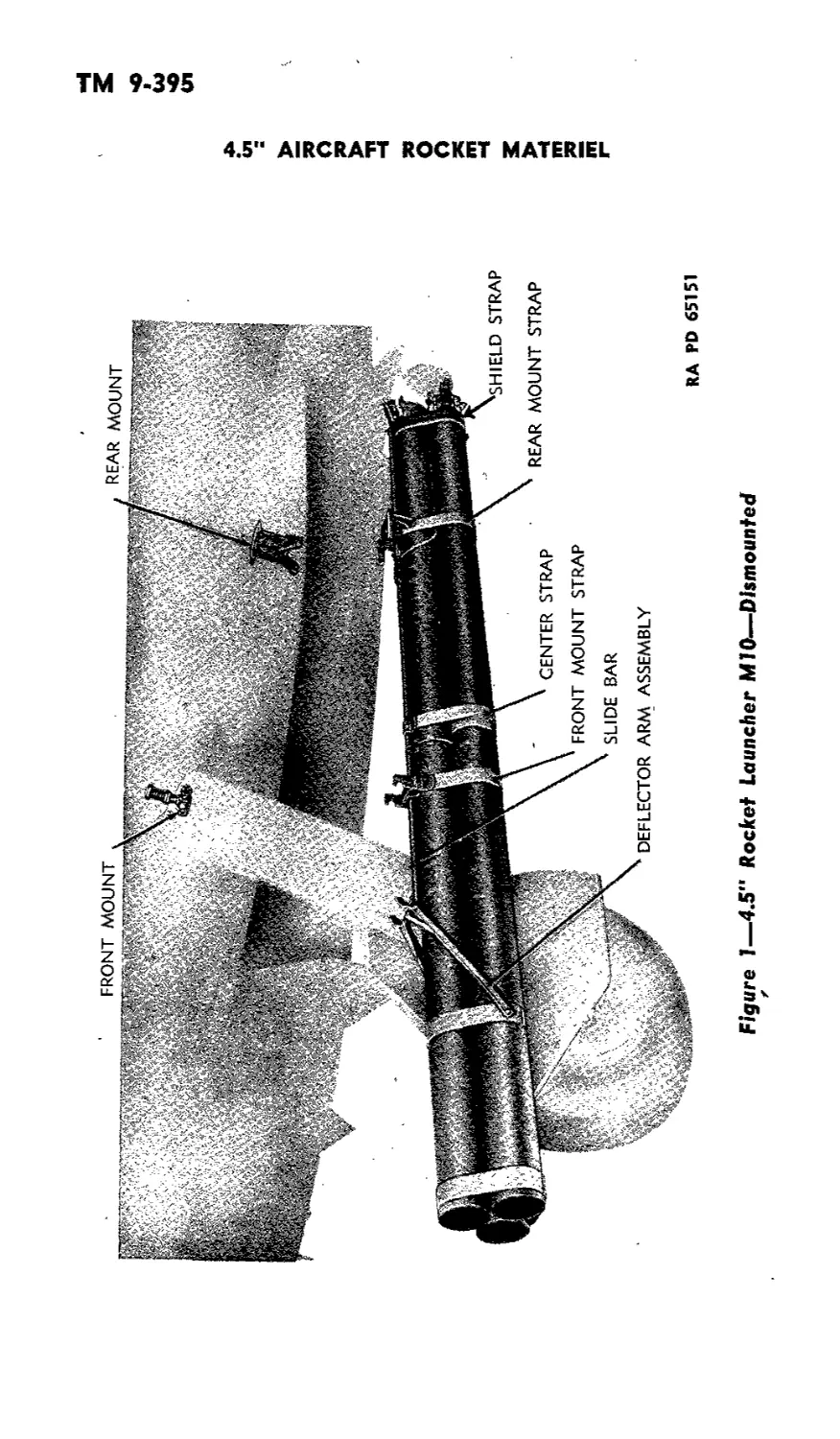
Figure 1—4.5“ Rocket Launcher MIO—Dismounted
4.5" AIRCRAFT ROCKET MATERIEL
z
«о
*©
<л
ТМ 9-395
1-3
RESTRICTED
This Technical Manual supersedes TM 9-395, 4.5" Rocket Materiel, dated 13 September 1943,
and ТВ 9-395-1, dated 13 May 1944.
Section I
LAUNCHERS
1. SCOPE.
a. This manual contains a description of the 4.5" Rocket -Launchers
MIO, M14, and Ml5. In addition, :t contains technical information
required for the identification, use, and care of the launcher and am-
munition. This manual does not cover electrical wiring or switches
in the plane, or the firing selector mechanism. The procurement and
installation of such accessories is the responsibility of AAF.
2. REPORTS.
a. Field Report of Accidents. When an accident involving am-
munition occurs during practice, the incident will be reported as
prescribed in AR 750-10 by the Ordnance officer under whose super-
vision the ammunition is maintained or issued. Where practicable,
reports covering malfunctions of ammunition in combat will be made
to the Chief of Ordnance, giving the type of malfunction, type of
ammunition, the lot number of the complete rounds or separate-
loading components, and condition under which fired.
b. Unsatisfactory Equipment Report. Suggestions for im-
provement in design, maintenance, safety, and efficiency of operation
prompted by chronic failure or malfunction of the weapon, spare
parts, or equipment should- be reported on WDAGO Form No. 468,
Unsatisfactory Equipment Report, with all pertinent information
necessary to initiate corrective action. The report should be forwarded
to the Office of Chief of Ordnance, Field Service Maintenance Di-
vision, through command channels in accordance with instruction
number 7 on the form. Such suggestions are encouraged in order
that other organizations may benefit.
3. TABULATED DATA.
a. Launchers.
Model
Material of tubes ......
Weight of launcher
Length of tubes ........
Thickness of tubes......
M10 M14 M15
Plastic......Steel , . Magnesium alloy
80 lb .190 lb..............86 lb
10 ft........10 ft..............10 ft.
У4 in........Vs in...............in.
ТМ 9-395
3-5
4.5“ AIRCRAFT ROCKET MATERIEL
b. Rockets.
Length fuzed..........................................33 in.
Weight fuzed...<......................................40 lb
Muzzle velocity.................................850 ft per sec
Range, maximum ................................... 4,600 yd
4. 4.5" ROCKET LAUNCHER MIO.
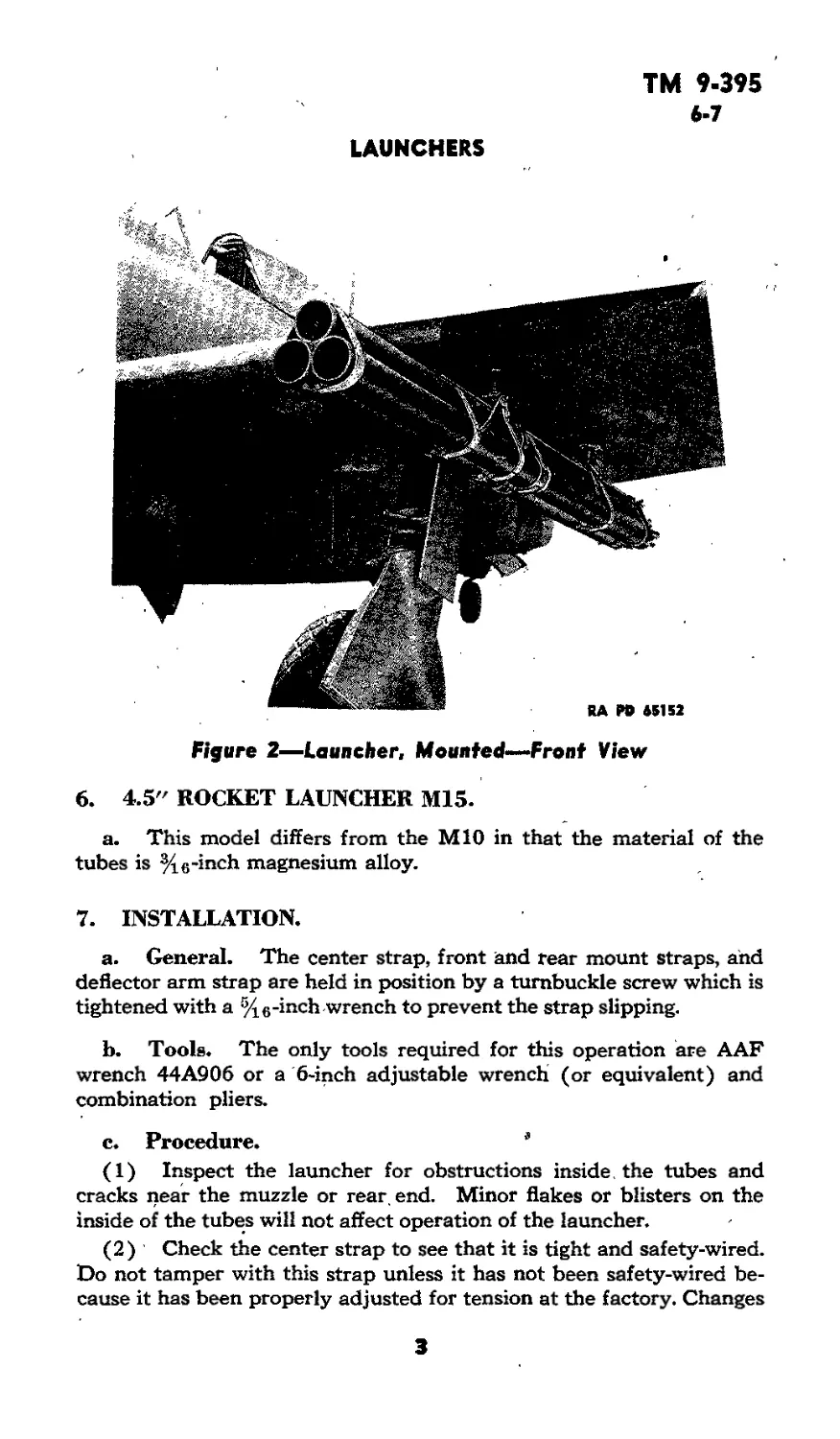
a. The Launcher MIO consists of a cluster of three 10-foot tubes
of Winch plastic which are attached by steel strapping to a slide bar,
and by two mounts to the under side of the wing of the plane (figs.
1 to 3). The straps are tightened around the tube by turnbuckle
screws tightened and wired in place.
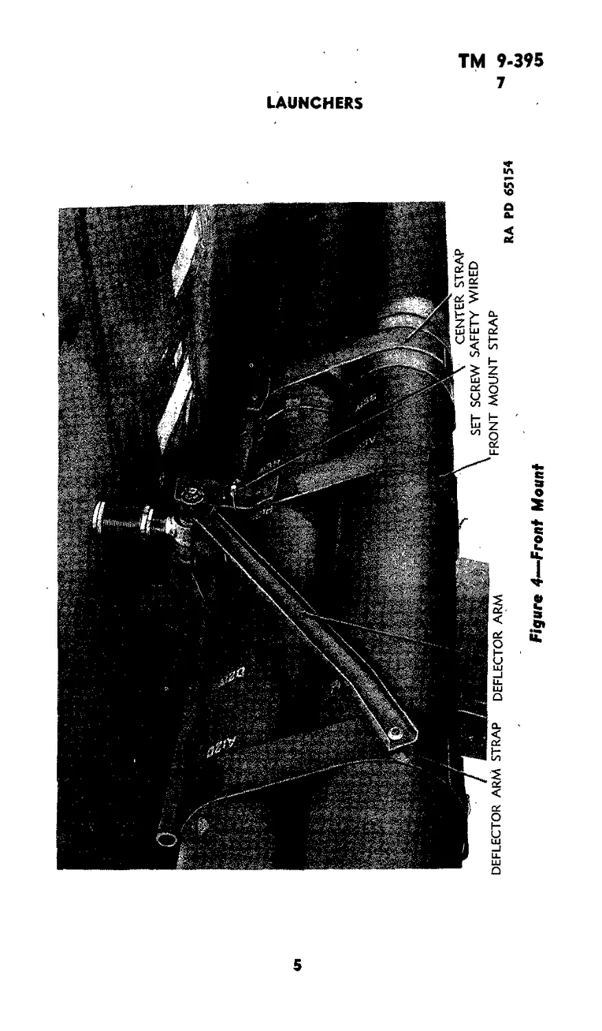
b. The front mount consists of a T-shaped hanger attached to
the plane, a front mount strap on which are mounted two hooks, and
a deflector assembly (fig. 4). Two set screws are provided to fasten
the strap in position on the slide bar. The deflector assembly con-
sists of two 18-inch arms attached to a deflector strap and bearing
on the front hanger. When the launcher is dropped, the arms serve
to direct the nose of the launcher downward as air pressure pushes
the tubes to the rear.
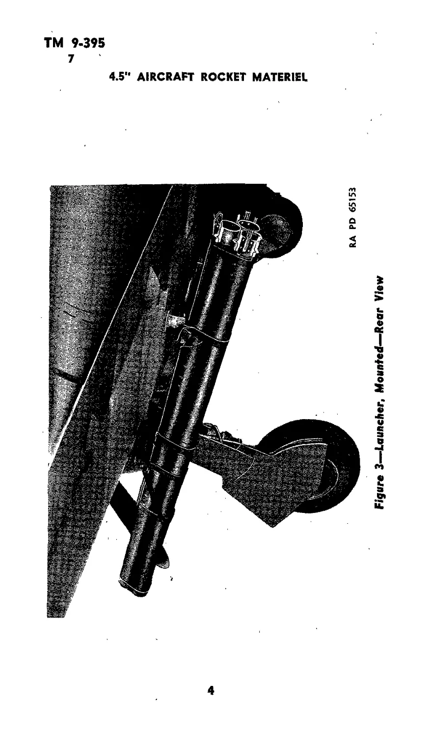
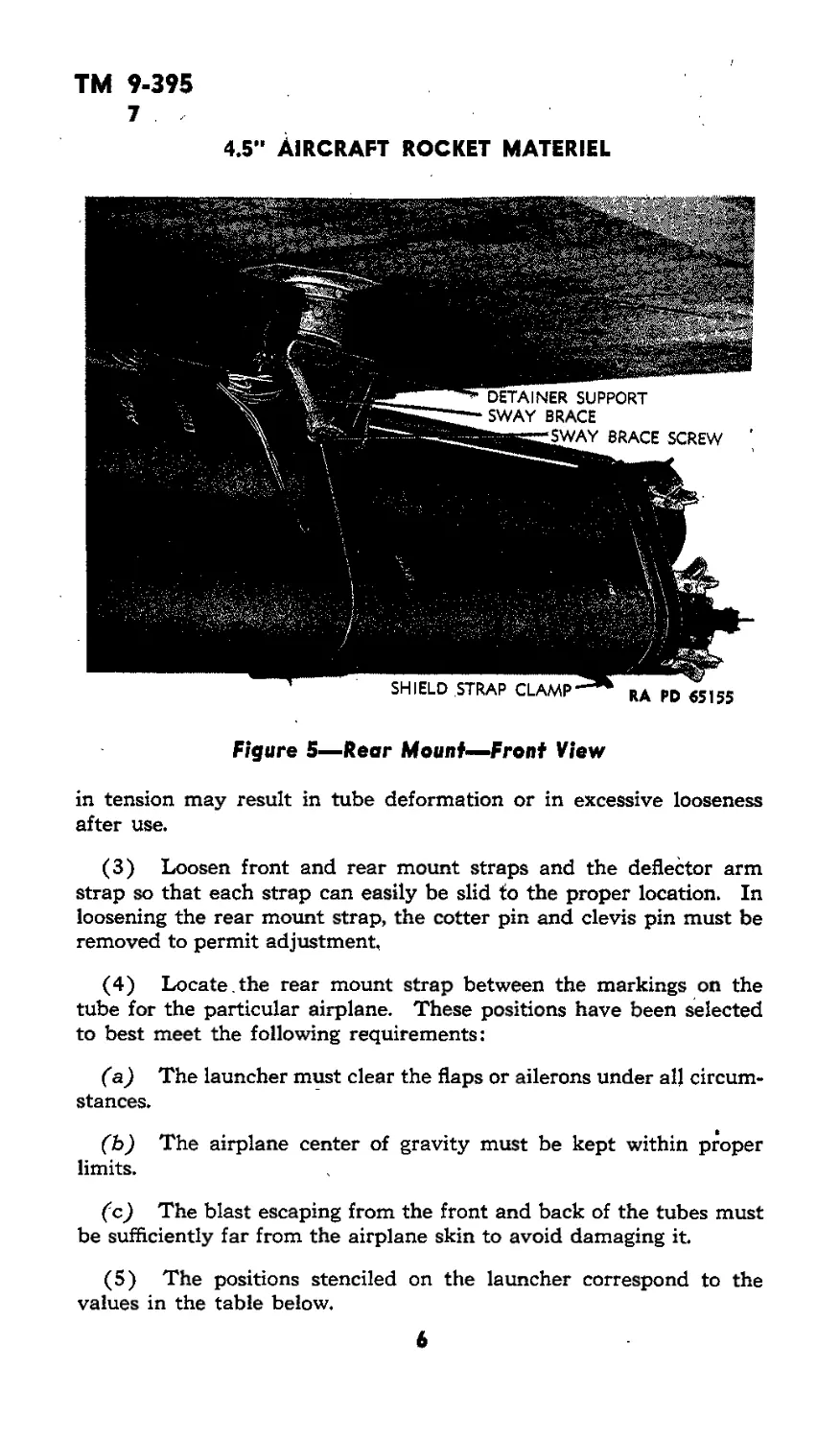
c. The rear mount (figs. 5 and 6) consists of a hanger containing
the release mechanism and a socket for electrical connections, and a
V-shaped sway brace. The rear mount strap has a suspension lug and
two L-shaped detainer supports. When the launcher is dropped, the
detainer supports engage the arms of the sway brace and prevent the
rear end dropping until the deflector pushes the front end downward.
The rear mount strap is positioned on the slide bar by a clevis pin.
d. In addition to the front and rear mount straps, there is a cen-
ter strap riveted to the slide bar and tightened to proper tension by
the manufacturer. One inch ahead of the rear end there is a deflector
strap to protect the release and contact mechanisms from flying links
and fired cases from the plane’s guns.
5. 4.5" ROCKET LAUNCHER M14.
a. This model differs from the MIO in that the material of the
tubes is Winch steel. The tube assembly has sufficient weight to in-
sure its dropping when released and, as a consequence, the deflector
arms and strap are omitted. In addition, the center strap is welded
to the tubes.
2
TM 9-395
6-7
LAUNCHERS
Figure 2—Launcher, Mounted-—Front View
6. 4.5" ROCKET LAUNCHER M15.
a. This model differs from the MIO in that the material of the
tubes is % 6-inch magnesium alloy.
7. INSTALLATION.
a. General. The center strap, front and rear mount straps, and
deflector arm strap are held in position by a turnbuckle screw which is
tightened with a % 6-inch wrench to prevent the strap slipping.
b. Tools. The only tools required for this operation are AAF
wrench 44A906 or a б-inch adjustable wrench (or equivalent) and
combination pliers.
c. Procedure. *
(1) Inspect the launcher for obstructions inside, the tubes and
cracks near the muzzle or rear, end. Minor flakes or blisters on the
inside of the tubes will not affect operation of the launcher.
(2) Check the center strap to see that it is tight and safety-wired.
Do not tamper with this strap unless it has not been safety-wired be-
cause it has been properly adjusted for tension at the factory. Changes
3
ТМ 9-395
7
4.5м AIRCRAFT ROCKET MATERIEL
Figure 3—Launcher, Mounted—Rear View
4
<Л
Figure 4—Front Mount
LAUNCHERS
TM 9-395
7
4.5м Aircraft rocket materiel
Figure 5—Rear Mount—Front View
in tension may result in tube deformation or in excessive looseness
after use.
(3) Loosen front and rear mount straps and the deflector arm
strap so that each strap can easily be slid to the proper location. In
loosening the rear mount strap, the cotter pin and clevis pin must be
removed to permit adjustment,
(4) Locate.the rear mount strap between the markings on the
tube for the particular airplane. These positions have been selected
to best meet the following requirements:
(a) The launcher must clear the flaps or ailerons under all circum-
stances.
(b) The airplane center of gravity must be kept within proper
limits.
(c) The blast escaping from the front and back of the tubes must
be sufficiently far from the airplane skin to avoid damaging it.
(5) The positions stenciled on the launcher correspond to the
values in the table below.
6
TM 9-395
7
LAUNCHERS
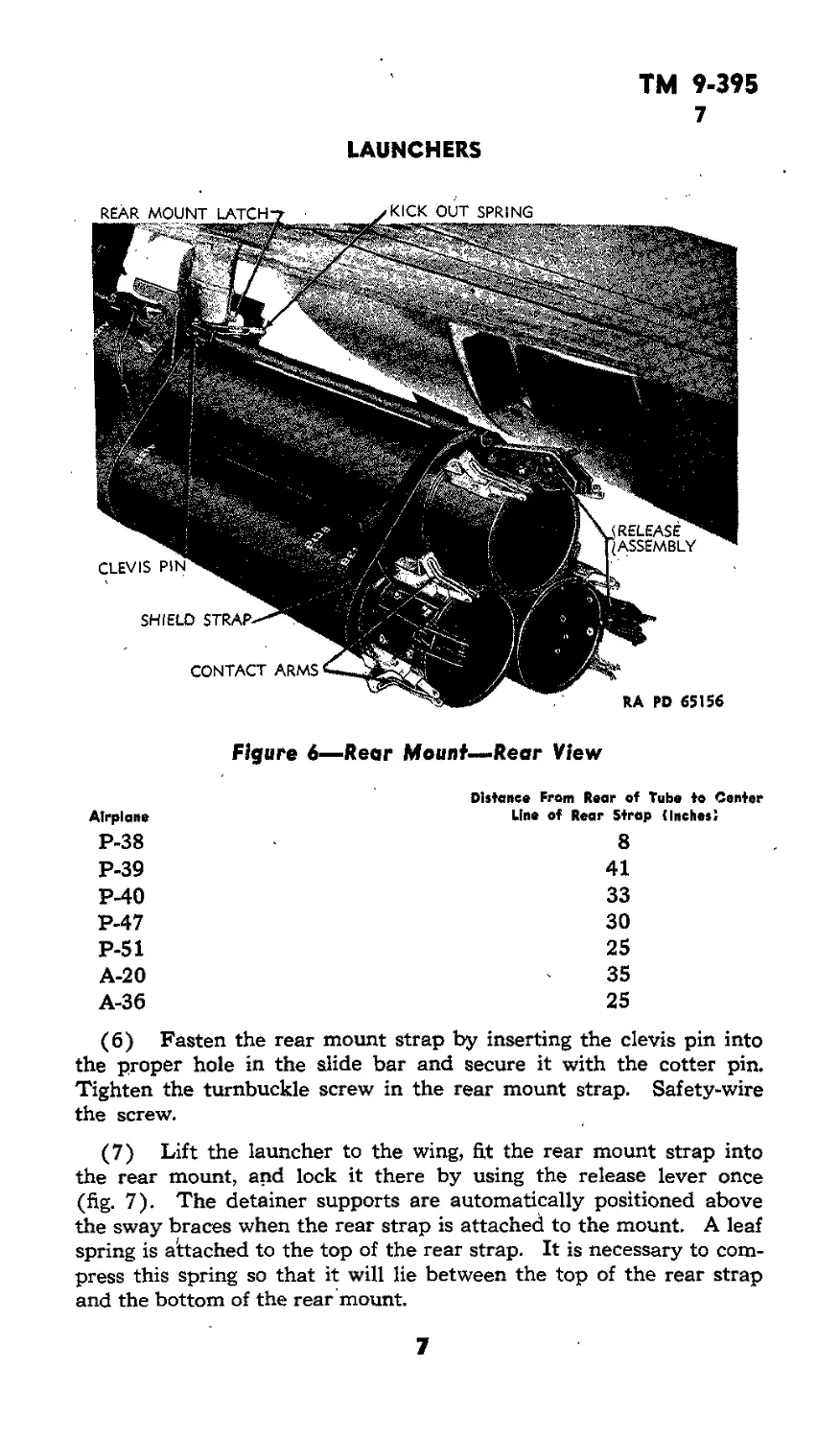
Figure 6—Rear Mount—Rear View
Airplane
P-38
P-39
P-40
P-47
P-51
A-20
A-36
Distance From Rear of Tube to Center
Line of Rear Strap (Inches!
8
41
33
30
25
35
25
(6) Fasten the rear mount strap by inserting the clevis pin into
the proper hole in the slide bar and secure it with the cotter pin.
Tighten the turnbuckle screw in the rear mount strap. Safety-wire
the screw.
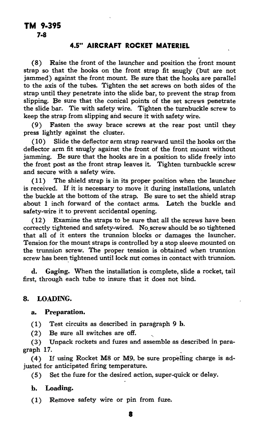
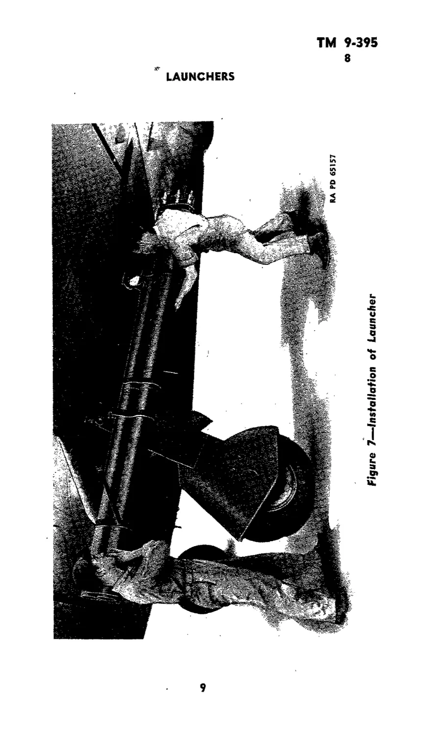
(7) Lift the launcher to the wing, fit the rear mount strap into
the rear mount, and lock it there by using the release lever once
(fig. 7). The detainer supports are automatically positioned above
the sway braces when the rear strap is attached to the mount. A leaf
spring is attached to the top of the rear strap. It is necessary to com-
press this spring so that it will lie between the top of the rear strap
and the bottom of the rear mount.
7
ТМ 9-395
7-8
4.5" AIRCRAFT ROCKET MATERIEL
(8) Raise the front of the launcher and position the front mount
strap so that the hooks on the front strap fit snugly (but are not
jammed) against the front mount. Be sure that the hooks are parallel
to the axis of the tubes. Tighten the set screws on both sides of the
strap until they penetrate into the slide bar, to prevent the strap from
slipping. Be sure that the conical points of the set screws penetrate
the slide bar. Tie with safety wire. Tighten the turnbuckle screw to
keep the strap from slipping and secure it with safety wire.
(9) Fasten the sway brace screws at the rear post until they
press lightly against the cluster.
(10) Slide the deflector arm strap rearward until the hooks on' the
deflector arm fit snugly against the front of the front mount without
jamming. Be sure that the hooks are in a position to slide freely into
the front post as the front strap leaves it. Tighten turnbuckle screw
and secure with a safety wire.
(11) The shield strap is in its proper position when the launcher
is received. If it is necessary to move it during installations, unlatch
the buckle at the bottom of the strap. Be sure to set the shield strap
about 1 inch forward of the contact arms. Latch the buckle and
safety-wire it to prevent accidental opening.
(12 ) Examine the straps to be sure that all the screws have been
correctly tightened and safety-wired. No_ screw should be so tightened
that all of it enters the trunnion blocks or damages the launcher.
Tension for the mount straps is controlled by a stop sleeve mounted on
the trunnion screw. The proper tension is obtained when trunnion
screw has been tightened until lock nut comes in contact with trunnion.
d. Gaging. When the installation is complete, slide a rocket, tail
first, through each tube to insure that it does not bind.
8. LOADING.
a. Preparation.
(1) Test circuits as described in paragraph 9 b.
(2) Be sure all switches are off.
(3) Unpack rockets and fuzes and assemble as described in para-
graph 17.
(4) If using Rocket M8 or M9, be sure propelling charge is ad-
justed for anticipated firing temperature.
(5) Set the fuze for the desired action, super-quick or delay.
b. Loading.
(1) Remove safety wire or pin from fuze.
8
Figure 7—Installation of Launcher
О
w
СЛ
ТМ 9-395
8-9
4.5" AIRCRAFT ROCKET MATERIEL
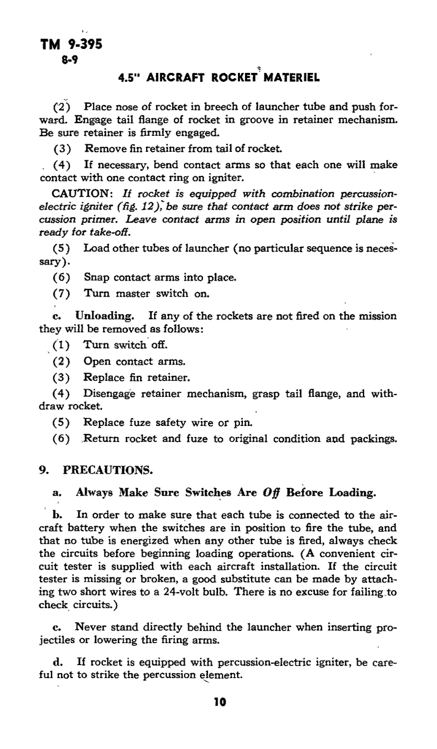
(2 ) Place nose of rocket in breech of launcher tube and push for-
ward. Engage tail flange of rocket in groove in retainer mechanism.
Be sure retainer is firmly engaged.
(3) Remove fin retainer from tail of rocket.
(4) If necessary, bend contact arms so that each one will make
contact with one contact ring on igniter.
CAUTION: If rocket is equipped with combination percussion-
electric igniter (fig. 12)^be sure that contact arm does not strike per-
cussion primer. Leave contact arms in open position until plane is
ready for take-off.
(5) Load other tubes of launcher (no particular sequence is neces-
sary).
(6) Snap contact arms into place.
(7) Turn master switch on.
c. Unloading. If any of the rockets are not fired on the mission
they will be removed as follows:
(1) Turn switch off.
(2) Open contact arms.
(3) Replace fin retainer.
(4) Disengage retainer mechanism, grasp tail flange, and with-
draw rocket.
(5) Replace fuze safety wire or pin.
(6) .Return rocket and fuze to original condition and packings.
9. PRECAUTIONS.
a. Always Make Sure Switches Are Off Before Loading.
b. In order to make sure that each tube is connected to the air-
craft battery when the switches are in position to fire the tube, and
that no tube is energized when any other tube is fired, always check
the circuits before beginning loading operations. (A convenient cir-
cuit tester is supplied with each aircraft installation. If the circuit
tester is missing or broken, a good substitute can be made by attach-
ing two short wires to a 24-volt bulb. There is no excuse for failing to
check circuits.)
c. Never stand directly behind the launcher when inserting pro-
jectiles or lowering the firing arms.
d. If rocket is equipped with percussion-electric igniter, be care-
ful not to strike the percussion element.
10
im
10-11
LAUNCHERS
10. FAILURE TO FIRE. '
a. A rocket may fail to fire because of the following:
(1 ) Electrical open circuit or short circuit
(2 ) The round is defective. If teats «how nothing wrong with the
electrical system, the round will be considered defective and will be .
turned over to Ordnance personnel for disposition.
11, MAINTENANCE.
a* . Materials..
BURLAP, jute
CLOTH, wiping, cotton
COMPOUND, rust-preventive, light
OIL, lubricating, preservative, special
SOAP, castile, white
SODA ASH
SOLVENT, dry-cleaning
b. During Storage and Shipmenu The tubes and metal parts
should be protected by observing normal precautions, such as cover-
ing the launchers with tarpaulins while stowed, or storing them under
a roof where possible. When stored for 30 days or less or before
shipping, the launchers should be treated as follows except when
already prepared by the manufacturer. Coat the inside of the steel
and magnesium tubes and the outside unpainted surfaces with light
rust-preventive compound. The plastic launchers need not be treated.
Rust-preventive compound will be removed by scrubbing with dry-
cleaning solvent and the launcher wiped thoroughly dry before oiling.
c. Aller Firing.
(1) STebi. Tubes. After firing, swab the inside of the steel tubes
to insure complete removal of powder residue and primer salts.
Under no circumstances will the launcher remain without cleaning
after return from a flight in which it has been fired. Swab the tubes
with a cleaning solution of one-half pound of soda ash to each gallon
of water. Rinse with clean warm water. After drying thoroughly
with jute burlap, apply a film of special preservative lubricating oiL
If soda ash is not available, a soap sponging solution may be prepared
by dissolving 1 pound of castile soap in 4 gallons of water. If castile
soap is not available, government issue soap may be used as a sub-
stitute. The soap should be shaved from the bar to facilitate dissolv-
ing. It should then be added to water and the water heated until
the soap is dissolved. The water should be stirred as quietly as pos-
sible to prevent foaming. To avoid the necessity of handling large
receptacles, as much soap aa is required for all the water to be used
can be dissolved in one pail of water. Thia concentrated soap solution
11
Л 9-ЗТ5
11-13
4.5” AIRCRAFT ROCKET MATERIEL
i then be added to water in other receptacles to make up the pre-
ibed proportions. Special precautions must be taken to rinse the
jm thoroughly before drying if government issue soap is used in the
ution, because .of the possibility of soap leaving a gummy residue,
d of corrosion tram the presence of free caustic in the soap. In an
lergency, water alone, preferably hot, may. be used for cleaning,
jpeat this procedure on 3 consecutive days there after or until there
no longer evidence of sweating,
(2) Magnesium Tubbs, Clear hot water only will be used to
ab the imide of magnesium tubes.
d. Before Firing» Before loading, wipe the tubes with clean, dry
irlap or wiping cloths, to insure. that the tubes are clean and dry.
e. Daily. When the launcher is not being fired, clean out the
bee daily by thoroughly wiping with dean burlap, and apply a thin
m of oil.
L CONSERVATION.
a. Plastic tubes and accessories will withstand a minimum of five
cket launchings without rupture and, therefore, each cluster is to
‘ jettisoned or discarded after the fifth launching. However, efforts
iou1d be made to conserve and use other parts as long as possible,
ay wire which makes dependable contact is usable. • Although they
ust be bent or adjusted to make electrical contact, firing arms can
• used repeatedly. Holding latches have sometimes become sq worn
battered that the projectile would slip out of . the tube when a
ssrby rocket was fired (this battering, is never found in. the first
be of a launcher to fire, and is worse in the third tube, because gas
iters the muzzle and jolts the projectile backward in the breech)
it the latches may be repaired or replaced and in an emergency, the
ojectile can be held in place with wire.
Section II
ROCKETS
1 DESCRIPTION.
a. Data. The 4.54nch rocket (fig. 8) w a fin^tabilized projec-
le approximately 33 inches in length and weighing 40.0 pounds as
red. Maximum velocity is approximately fiSO feet per 'second at 70
«t from the launcher. Maximum range is approximately • 4,600
aids, but a large inherent'dispersion limits effective aimed fire to
iuch shorter ranges. The effect of the high-explosive rocket is
12
TM 9.395
13
KOCKETS
similar to that of a 105-mm Shell Ml. The impact fuze authorized
for air use и P,D. Rocket Fuze M4, SQ-0.015 sec, delay, with
Auxiliary Booster Ml, and modifications of this model.
К Components The rocket consists of a fuze, shell» and motor
body. The shell is loaded with high explosive for service rounds, or
inert material for practice rounds. A dummy fuze is used with prac-
tice rounds. Otherwise, the service and practice rounds have identical
components.
c. Fuse and Booster. Fuze and booster are described below
(pan 15), .
d. ShelL 'The rocket shell (sometimes referred to as the
“Head") consists of a body and a hunter tube (fig. 9). Tbi body
is approximately. 1,6 calibers in length, and has an ogive of 2 calibers
radius. The burster tube extends about 15 inches, from the base,
of the body into the motor. In addition to increasing the explosive
capacity of. the shell, the burster tube has the advantage of using the
motor as an additional source, of fragments. The shell body contains
a fuze well which is. closed in storage and transit by a plug screwed
into the nose of the shell end held by a set screw. The bursting charge
consists of 4.3 pounds of cast TNT.
e. Motor. The basic components of tbe motor are the body,
the propellant, the trap and the igniter. The motor body is a steel
tube which is constricted near the tail end to form a. nozzle. The
forward end is threaded for assembly to the rocket shell» and the
rear end Is adapted for attachment of. the fin assembly. The fin as-
sembly consists of a. fin ring Holding a circle of six fins which are held
folded into the constriction of the motor tube by a fin retainer. When
the rocket leaves the launcher, tbe fins are opened by set-back to a
12-inch spread. A safety groove is formed in the motor body to per-
mit it to separate at a definite point, should an. excessive pressure be
generated within tbe motor body on firing. Such occurrences are very
rare, but can be expected if the rocket is fired when its temperature is
above that given as its safe operating temperature, or if the nozzle
should become blocked., When separations occur, the shell and tbe
propellent charge will travel forward with low velocity end have
a range of from 100 to 1,000 yards; The motor body will be blown
backward from the launcher tube for some distance.
f. Propelling Charge. The propelling, charge (fig. 10) consists
of 30 sticks of double-base powder mounted on the wires of a cage-
like trap. The trap consists of ten wires attached to a base ring and
an annular trap plate which is slotted to receive, the top ends of the
wires. The trap plate rests on a trap seat formed by a shoulder in the
forward end of the motor tube. The weight of powder used varies
13
Figure 8—4.5" HJgk-eip/esfve Rocket MB
Ядеге 9—Rocket—Sectional View
4.5" AIRCRAFT ROCKET MATERIEL
TM 9-395
13-14
ROCKETS
with each Lot* Since the burning rate of smokeless powder varies
with the initial temperature, the weight of each charge is adjusted so
that, when fired within the temperature range specified for the rocket,
excessive and dangerous pressures will not be produced.
Igniter. The igniter (figs. 9 and 12 ) consists essentially of a
charge of blade powder and an electric squib. In earlier models, the
squib and black powder are contained in a plastic cup which is
cemented in the nozzle opening. The leads of. the squib are con-
nected to a contact disk and a contact ring on the base of the cup
(fig. 9). In combination igniters, a percussion primer is assembled in
the base. In later models, the igniter is assembled in a long tube at-
tached to the trap with the igniter wires leading to a contact plate
in the nozzle. This plate has, in addition to the contact rings, a cord
and plug attachment for electrical connection. When this igniter Is
used in the launchers equipped with spring contact arms, the plug
wires should be cut close to the contact tings.
h. Painting. High-explosive rackets are painted olive drab and
narked in yellow. Practice, rocket shell ate' painted blue and
marked in white, and the motor is painted olive drab and marked
in yellow.
i. Marking, Rocket shell are marked with the lot number of
the metal parts stamped in the metal in small figures and the loading
lot number, stenciled in larger figures. Practice shell have the word
“INERT” stenciled on the shell. Rocket motors are marked with
the metal parts Jot number stamped in small figures, and the ammuni-
tion lot nqmber stenciled in larger figures. The type and model of
the rocket and the temperature limits are stenciled on the motor body.
J 4. MODIFICATIONS.
a. The various models and modifications of 4-5" rockets are
described below (fig. 11).
b. High-explosive Rocket MB and Practice Rocket M9.
(1) The original model of the 4.5" rocket has a comparatively
light shell and motor. As a consequence, safe temperature ranges are
Harrow, and it is necessary to change the propelling charge to provide
for full coverage of the temperature range. As issued, the charge is
adjusted for firing at temperatures between 20°F and 90°F. The
charge may be modified as described below for firing at temperatures
between 50’F and 130’F, The temperature at the time of firing
governs the selection of the charge. Under no circumstances should
a rocket be fired at a temf erature outside the range for which the
charge is adjusted.
15
TM 9-395
14
4.S” AIRCRAFT ROCKET MATERIEL
RING. TRAP
14
TM 9-395
14
ROCKETS
17
4.5" AIRCRAFT ROCKET MATERIEL
ГМ 9-395
н
ELECTRIC PERCUSSION - ELECTRIC
Figure 12—dgnJfers
T22
RA FD 26760
( 2 ) The propelling charge may be adjusted for high temperatures
is follows:
(a} Unscrew the shell from the body, using two strap wrenches.
(b) Place the rocket on its tail on a clean level surface, and lift
the shell out of the body.
(c) Lift the powder trap out of the body» Be careful not to rub
the igniter bags ^against the wall of the body.
(d) Remove tape bolding wires in place in trap plate.
. (t>) Push trap wires-putwerd ai^d remove the three silver-painted
iticks of powder.
. (i) Return trap wires to slots, and replace tape to hold' wires in
place.
(£) Lower trap assembly into the. motor body» Be careful that
the powder bags ore on the outside of the powder, sticks, and that
they ara not damaged 'by nibbing against the body when the trap »
lowered into, place.
fh) Replace the shell in the rocket body, using the strap wrenches
to insure a tight joint.
(i) Mark the rocket body to indicate the change , in the charge.
W rocket is repacked, mark packings as well
(j) If there is a probability that the low temperature charge will
leed to be restored, mark tbe rocket body and the removed sticks
so that the same three sticks may be returned, to that rocket It is
thqndatory that the same sticks be replaced because the weight of the
tick varies with each powder lot and is adjusted for each rocket
c. High-exploaive Rocket M8A1 and Practice Rocket M9A1.
This modification has a strengthened motor body and may be fired
it temperatures between —10DF and -f-105 °F. No modification of
the propelling charge is necessary.
18
ТМ 9-395
14-15
ROCKETS
d. High-explosive Rocket M8A2 and Practice Rocket M9A2.
This modification, in addition to the heavier motor body, has a
smaller, heavier-walled shell. Its temperature limits are the same,
—IOGF to | 105'T, and its velocity is slightly higher than the —Aj
modification.
e. High-explosive Rocket M8A3 and Practice Rocket M9A3.
In this modification, each fin has a slight bur nr crimp to insure a
tight fit in the fin ring when the fin opens. The rockets are otherwise
the same as the —A2 modifications. Temperature ranges are the
same as the —A2 rockets.
L High-explosive Rocket T22 and Practice Rocket T46. Thia
modification retains the heavier* shell of the —rockets A2. The motor
body is further strengthened, the fin assembly is modified. The
igniter is assembled in a tube attached to the trap and extending the
length of the propelling charge. Its temperature limits are —204F
to -f-120 °F.
15. ROCKET FUZE AND MODIFICATIONS M4.
a. Description. The Point-detonating Rocket Fuze M4 (fig, 13),
is a point-detonating, selective, superquick-delay type. The time of
delay is indicated in the nomenclature and id marked oh the fuze.
It is 0.1 second for ground use and 0.015 second for aircraft use.
Auxiliary Booster Ml (fig. 14) is an essential part of the fuze and is
packed in the same can, The fuze is detonator safe, that is, the
detonator is held out of line until after the rocket is fired. Accidental
arming of the fuze is prevented by a safety cotter pin and ring in
earlier models, and by a safety wire in later modifications. The
safety pin or wire must be removed just prior to loading the rocket
into the launcher and at no other time. The striker of the fuse is
held in place by a shear wire which passes through the striker and
the fuze body a°d appears in the groove just behind the point of the
fuze. The shear wire must not be disturbed, and if it is missing, the
fuze should be handled, point down, with extreme care, until it can
be destroyed.
J*. Fuze Setting. The action of the fuze is selected by means of
a setting pin which appears at the side of the fuse. The head of the
pin is slotted and is marked with an indicator dot. The fuze body is
marked on either side of the setting pin . with “SQ" and “0.Q15 SEC.
DELAY" (or “0,1 SEQ DELAY"). The action of the fuze is selected
by turning the pin so that the dot indicates the desired action. Note
that the pin slot should always be parallel to the axis of the fuze.
The fuze may be reset at any time prior to firing,
C. Arming. This type of fuze arms in three steps: the first step
is the removal of the safety pin or wire; the second, the forces of set-
19
N
.SHEAR WIRE
SAFETY PIN RING
i.Q?
Li
M4
Figure T3—Яие>
fiA PD W63
4.5” AIRCRAFT ROCKET MATERIEL
ТМ 9-395
15
SOCKETS
RA PD 267M
RA PO 151H
FJger* I4^4oxiHoqf Boosters Ml oatf MUI
back initiate arming when the rocket is fired; the third, when set-back
ceases, spring action unlocks the detonator slider and moves the
detonator into line in the explosive train Note that the fuze cannot
function unless the safety pin or wire is removed before firing. The
Fuze M4 will arm on the set-back force resulting from 165 G accelera-
tion. Later modifications require only 100 G. Compared with artillery
and trench-mortar fuzes, this force is extremely small. The set-back
force in artillery ammunition will be produced by an acceleration as
great as 20,000 G and in trench-mortar ammunition by an accelera-
tion as great as 4,000 G. Consequently, once the safety pin has been
removed, rockets should be handled with extreme care.
d. Fuze M4AL This fuze differs from the M4 in that a lighter
set-back is required to arm the fuze. The setting pin is recessed, and
a piece of scotch tape covers the nose. The setting pin is recessed in
order to prevent its partial turning upon impact, as a partial turn
21
М 9-375
15*17
4.5" AIRCRAFT ROCKIT MATERIEL
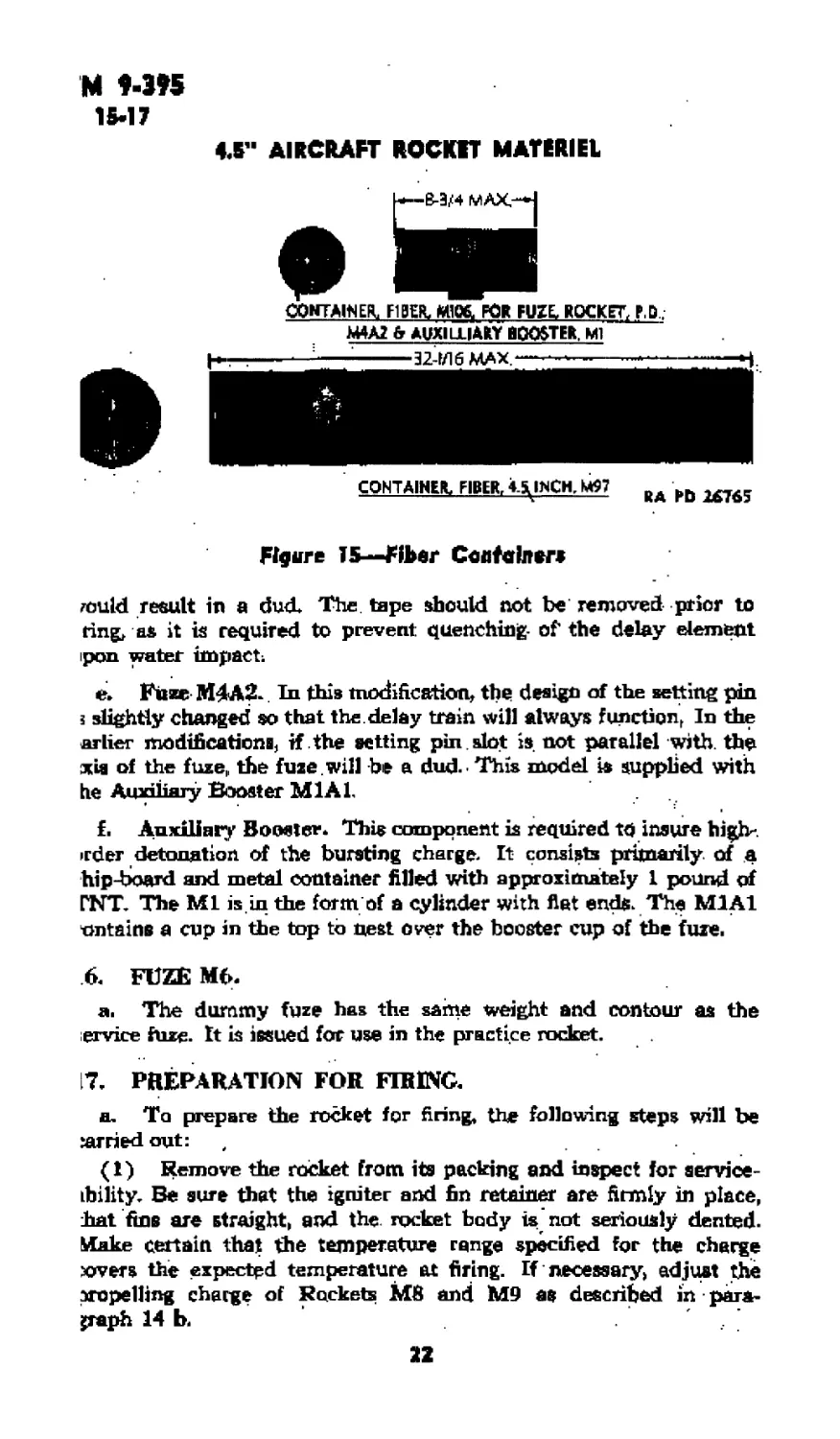
CQNTAINEFL FIBER. М106, FOR FUZE, ROCKET, P,D .
M4A2 fr AUXIULIAKY BOOSTER, Ml
CONTAINER, FIBER, 4Д INCH, M67 DA brt
--------- —— -----4-------- KA rD XbiD;
Figure 15—Fiber Container*
could result in a dud. The. tape should not be removed prior to
ring, as it is required to prevent quenching- of the delay element
pon water impact;
e. Fuze M4A2-. In this modification, the design of the setting pin
з slightly changed so that the. delay train will always function, In the
arlier modifications, if the setting pin . slot is. not parallel with, the
Kia of the fuze,, the fuze , will be a dud. ' This model is supplied with
he Amoiiary Booster Ml AL
f. Auxiliary Booster. This component is required to insure high*
irder detonation of the bursting charge. It consists primarily of a
hip-board and metal container filled with approximately 1 pound of
□NT. The Ml is.in the form of a cylinder with flat ends. The M1A1
xmtains a cup in the top to nest over the booster cup of the fuze.
6. FUZE Mb.
a. The dummy fuze has the same weight and contour as the
ervice fuze- It is issued for use in the practice rocket.
17, PREPARATION FOR FIRING.
a. To prepare the rocket for firing, the following steps will be
carried out:
(1) Remove the rocket from its packing and inspect for service-
ihility. Be sure that the igniter and fin retainer are firmly in place,
hat fins are straight, and the. rocket body is not seriously dented.
Make certain that the temperature range specified for the charge
xxvers the expected temperature at firing. If necessary, adjust the
propelling charge of Rockets MB and M9 as described in para-
graph 14 b.
22
ТМ 9-395
17-19
ROCKETS
(2) Fuze the rocket as follows:
faj Unpack fU?e end inspect for corrosion and other evidence of
unserviceabtlity. Be sure safety pin and shear wire are in place.
(b) Set the fuze for the desired action (par< 15 }>).
(с) Loosen set screw in nose of rocket and unscrew closing plug.
Examine fuze well to he sure that it is free of foreign material
fdj Insert auxiliary booster into the fuze well with the end:
marked “THIS END UP” toward the nose of the rocket
(e) Screw the fuze into the rocket and tighten with fuze wrench.
(f) Tighten set screw.
(3) Remove the safety pin or wire from the fuze.
(4) Load the rocket into the launcher in accordance with direC'
tions in paragraph 8.
(5) If the rocket is not used it will be unfuzed and returned to
storage, reversing the above steps.
18. PRECAUTIONS.
a» The propellent powder used in rockets is very sensitive to
temperature. It is important that rockets are not fired at temperatures
outside the stated limits, and that rockets in storage and transit be
protected against sources of high temperature,
b. When a rocket is fired, the blast of flame extends to the rear
approximately 75 feet, Personnel and materiel should be kept clear
of this area from the time the launcher is loaded until after the
rocket is fired.
c. When propelling charge of Rocket M8 or M9 is changed to
high temperature range, rockets must be marked to indicate change.
If rockets are repacked, containers also must be marked. The charge
may be restored to low temperature range only if sticks removed
can be identified and returned to the same rocket.
d. Igniter must be securely in place. If an igniter is loose, it
should be pressed firmly and evenly into the rocket nozzle. If neceS’
вагу, the igniter should be recemented in place.
e. Fuzes with broken or missing shear wires should be destroyed
as ammunition in dangerous condition.
f. Rockets with dented bodies, or like defects should nut be used,
19. PACKINC,
a. Rockets of this caliber are packed unfuzed, but otherwise
complete, one per fiber container, two containers per wooden box.
Fuzes are packed one fuze and one booster per container, 14 or 15
such containers per box (fig. 15),
23
ГМ 9-395
20-21
О11 AIRCRAFT ROCKET MATERIEL
Section III
REFERENCES
SO. PUBLICATIONS INDEXES,
The following publications indexes should be consulted frequently
for latest changes or revisions of references given in this section and
For new publications relating to materiel covered in this manual:
a. Introduction to Ordnance Catalog (explain-
ing SNL system) .......................... ASF Cat*
ORD 1 IOC
b. Index (index to SNL*S)................. ASF Cat.
ORD 2 OPSI
e. Index to Ordnance Publications (listing FM^s,
ТЮ, TC’s and ТВЪ of interest to Ord-
nance personnel, OPSR, FSMWO’s, BSD,
S of SR’s, OSSC’b, and OFSB’s and includ- *
ing alphabetical listing of Ordnance major
items with publications pertaining thereto) OFSB 1-1
(L List of Publications for Training (listing MR4
MTP’s, FM4 ТМЧ TRV ТВ’з> MWO’s,
SB’s, WDLO’s, and FTs)............;. ...J. FM 21-6
e. List of Training Films, Film Strips, and Film
Bulletins (listing TF*s, FS*s, and FB*s by
serial number and subject)................ FM 21-7
f. Military Training Aids (listing graphic train-
ing aids, models, devices, and displays).. FM 21-3
g. Index to Bombing Tables (Listing current,
bombing tables for bombs, clusters, and
Hares and firing tables for aircraft rockjets)
Zl. STANDARD NOMENCLATURE LISTS.
Cleaning, preserving, and lubricating ma-
terials; recoil fluids, special oils, and mis-
cellaneous related items.............. ORD 5
SNL K-l
24
TM $-395
21-23
REFERENCES
Rockets, all types, and component»...... ORD 11
SNL S-9
22* EXPLANATORY PUBLICATIONS.
Ammunition, general...................... .... TM 9-1900
Ammunition: net prices.............. ,, SB 9 AMM 3
. Ammunition identification code (АДС.)-- SB 9-AMM 5
Cleaning, preserving, lubricating, and welding
materials, and similar items issued by the
Ordnance Department....................... TM 9-350
23. FIRING TABLES (see index to bombing
tables)’........................................ RT 4ЛАОА-1
* RT 4J5AC-B-1
t
2Б
TM 9-395
4.5" AIRCRAFT ROCKET MATERIEL
INDEX
A *‘«9*
Auxiliary booster..................... 22
c
Conservation of materiel...... 12
D
Dummy fuze Мб.................. 22
F
Firing
precautions ................... 23
preparation for. . . ....... 22
Fuzes, rocket, description, fuze-set-
ting and arming of:
M4.......................... 19
M4A1........................ 21
M4A2 ....................... 22
I
Igniters, description.......... 15
L
Launchers, rocket
description x
MIO and M14.................. 1
M15 . ................... 3
installation
. data ....................... 7
procedure ................... 3
loading 8
maintenance and failure to fire. . 11
precautions in loading........ 10
tabulated data................. 1
unloading*.................... 10
M
Magnesium tubes, maintenance. . 12
Maintenance (launchers ).
after firing and during storage
and shipment.................... 11
daily and before firing...... ,12
RAPD4JUN45- 8MR 26
PUBLICATIONS DEP ART ME!
materials used in .............. 11
.Motor (rocket) ................... 13
P
Painting and marking (rockets) . . 15
Percussion electric igniters ...... 10
Propelling charge
description ..................... 13
high-temperature range....... 23
R
Reports, field report of accidents
and unsatisfactory equipment. .. 1
Rockets
components........... ....... 13
description and data
rockets...................... 12
shell, motor, and propelling
charge .................... 13
fuzes, for ............... . 19, 21, 22
igniters; painting and marking. . 15
modifications
M8 and M9..................... 15
M8A1 and M9A1............... 1»
M8A2 and M9A2.............. 19
M8A3 and M9A3................. 19
T22 and T46................... 19
packing ......................... 24
tabulated data .................... 2 ’
s
Shell, rocket, description..... 13
Storage and shipment............... 11
Switches ..............;........... 10
T
Tabulated data..................... 1
Tools, required for installation ... 3
u
Unloading the launcher............. 10
IT • RARITAN ARSENAL