/


Tags: weapons military affairs
Year: 1941


Text
115,974
Application Date : 22nd July, 1941. No. 2237/4/.
(Sec. 63A : Including Cognate No. 3948/41.)
Applicant (Actual Inventor')
Application and Provisional Specification
Xo. 2237/J,I
Application and Provisional Specification
Xo. 3948/.)/
Complete Specification (Sec. 63 (л), Patents
Act 1903-1935)
Complete Specification . .
Acceptance Advertised (Sec. 50)
Evelyn Ernest Owen.
Accepted, 19 th March, 1942.
Accepted, 9th March, 1942.
Lodged, 26th March, 1942.
Accepted, 2nd October, 1942.
18th February, 1943.
Class 89.3.
Drawings (2 sheets) attached.
CO Al ELET £ S PECIEICATION.
“ Improvements relating to automatic firearms.”
1, Evelyn Ernest Owen, Draughtsman,
of 82 Cliff Road, Wollongong, in the State
of New South Wales, Commonwealth of
Australia, hereby declare this invention and
5 the manner in which it is to be performed
ro be fully described and ascertained in
and by the following statement:—
The present invention is concerned with
automatic firearms and particularly sub-
10 machine guns of the recoil type. Its con-
st) nation is such that it can be carried easily
anti operated by one man and furthermore
a striking lever often provided in the recoil
type .sub-machine guns is unnecessary, an
15 advantage being that a more positive action
of the breech bolt and strike)' pin is attained.
The invention has particular reference to
the trigger and sear for releasing a breech
bolt connected to a cocking bolt by a pin and
20 .-lot connection and to fire control mean'
i’s-ociated with the trigger whereby the gun
may he adjusted for firing a single shot or
admvnatively-rapid burstnf.Mints, on one
depression of the trigger and also for lock-
ing the sear and trigger against accidental
use.
A snb-machine gun in accordance with
the present invention includes a body of 5
tubular formation, a barrel detachably
secured to the said body, a spring projected
brooch bolt retractable in said body, a
cocking bolr, said breech bolt carrying a
firing pin, a magazine for feeding cartridges 10
to the breech of the said barrel, a sear, a
trigger, and a fire control device.
In rhe cycle of operations in the present
invention the breech bolt which is capable
of being drawn manually to the roar of a 15
tubular steel body by a cocking handle,
against the action of a main compression
spring in the initial cocking action of the
gun, is returned to this cocked position by
momentum caused by the discharge of the 20
projectile. The breech bolt is. capable of
beiug held in thrs cocked position by a
pivoted jii£iiiljeiUte.rmcd a sear which in the
2
481.—25/2/43.—130.—Price, Is. 6d. post free.
115,974
present invention is directly under the con-
trol of the trigger. The movement of the
trigger is limited by a fire control device
which determines whether a single shot or
5 a burst of shots is to be fired, on a single
operation of the trigger, or whether the
trigger and the sear are to be locked against
accidental operation which would result in
the release of the breech bolt from the
10 cocked position when not desired.
The barrel of the gun is removably
attached to a tubular body which latter has
a cartridge magazine detachably secured
thereto and from which the cartridges are
15 fed one at a time by the breech bolt to the
breech portion of the barrel. The empty
cartridge cases are ejected through an open-
ing in the body below the magazine. The
breech bolt is mounted in the body in a
20 reciprocating manner and is forced for-
wards by a main coiled spring which is
seated at its rear end against an abutment
collar in the tubular body. In one form
of the invention there is a movable striking
25 pin mounted in the outer end of the breech
bolt. The breech bolt is connected to a
cocking bolt by a pin and slot connection
in such manner that when the breech bolt
has been shot forward by the main spring
30 and momentarily comes to rest after placing
the cartridge in the breech, the striking pin
and with it a firing pin which is disposed
on the end thereof continue to move forward
resulting in the detonation of the cartridge
35 cap by the said firing pin.
In a modified form the breech bolt is
provided with a firing pin which is integral
therewith.
The cartridge is engaged by the front
40 face of the breech bolt and the rim of the
cartridge enters an extractor of conventional
form which facilitates its discharge through
the said opening previously referred to, in
the body when the head of the cartridge case
45 engages a projection on the magazine pro-
vided for that purpose. A cocking handle
is secured to the cocking bolt by means of
which the breech bolt is drawn back manu-
ally into cocked position against the action
50 of the main spring prior to the first shot
being fired.
There is a further opening in the tubular
body through which one end of a pivoted
.-'ear is projected under action of a sear
55 spring when the breech bolt is in the cocked
position the said end of the sear being
adapted to enter a recess in the breech bolt
in said position and remain therein until the
trigger is operated to fire a shot or a burst
of shots as the case may be.
The opposite end of the sear directly 5
engages with the trigger in such manner
that according to the position of a fire con-
trol device the sear is permitted to re-engage
the breech bolt after each shot has been
fired or alternatively is held out of engage- Ю
ment with the breech bolt while a burst of
shots is being fired, in each instance by a
single depression of the trigger. To facili-
tate the above operation the trigger has an
elongated orifice through which its pivot 15
pin passes the trigger being normally
pressed rearwardly by a spring against the
said pivot pin. The trigger is also pro-
vided with a main spring whose purpose is
to return the said trigger to its normal posi- 20
tion when released by the firing finger.
The .said fire control device is mounted in
the housing of the gun for radial movement;
in its simplest form it consists of a trans-
verse member having three faces capable 25
of engagement by the trigger. One of these
faces is used when firing single shots, the
second when firing a burst of shots, and the •
third for locking the trigger to prevent it
being depressed or operated accidentally or 30
otherwise.
In order that the invention may be more
readily understood reference will now be
made to the accompanying drawings
. wherein :— 35
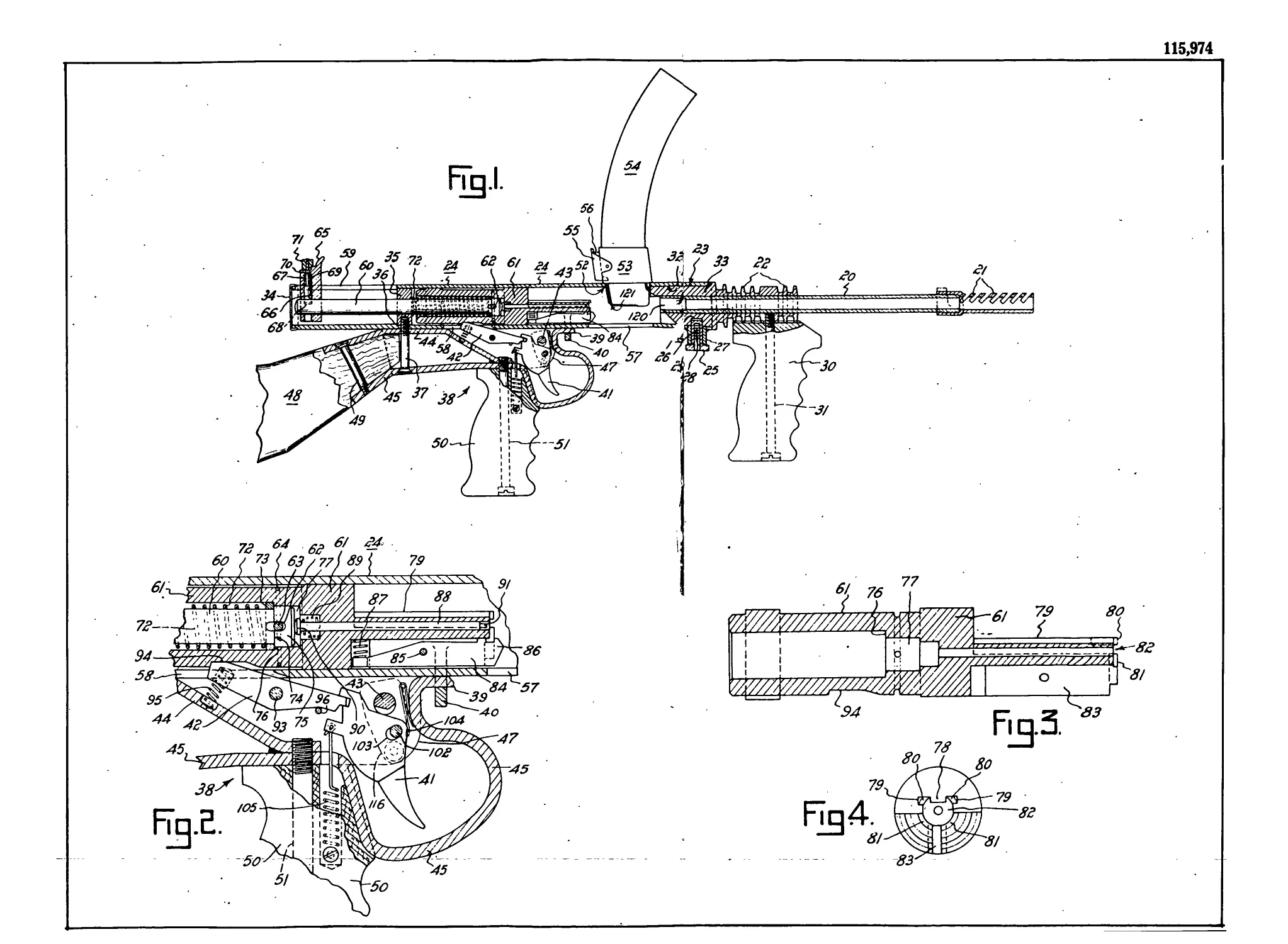
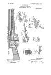
Figure 1 is a part longitudinal sectional
elevation of a sub-machine gun illustrating
the present invention.
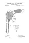
Figure 2 is an enlarged detail view of the
sear and trigger mechanism in the cocked 40
position and with the fire control device in
burst fire position corresponding to Figure
1 and illustrating in greater detail the pin
and slot connection between the cocking bolt
and the breech bolt. 45
Figure 3 is an enlarged longitudinal sec-
tional elevation of the breech bolt seen in
Figures 1 and 2. In this view the striking-
pin and the extractor have been removed.
Figure 4 is an end elevational view of 50
the breech bolt looking towards the left in
Figures 1, 2 and 3 and showing the cart-
ridge engaging faces.
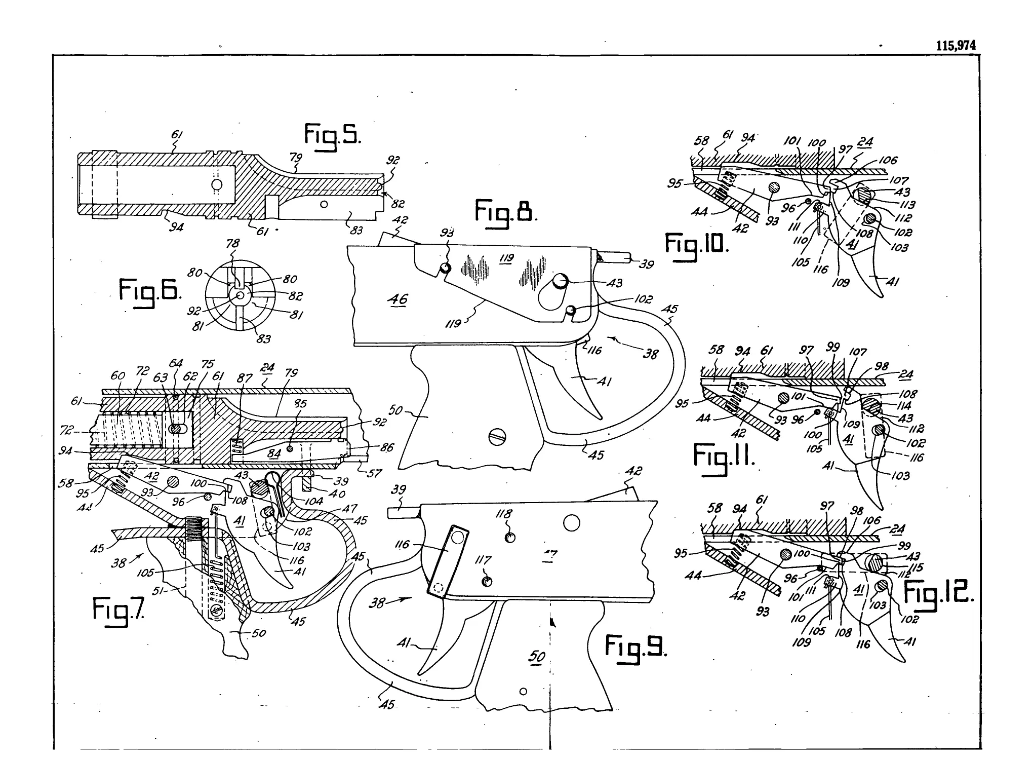
Figure is an enlarged longitudinal sec
tional elevation of a modified breech bolt 55
wherein the firing pin is formed integral
3
4
115,974
with the said bolt as distinct from the strik-
ing pin method seen in Figures 1, 2. 3 and
4. In this illustration also the extractor has
been removed.
5 Figure 6 is an end elevaticnal view of
the form of breech bolt seen in Figure 5
looking towards the left thereof.
Figure 7 is an enlarged detail view of
the sear and trigger mechanism in the
10 cocked position,-with the fire control device
in burst fire position and illustrating the
modified form of the invention using the
breech bolt of Figures 5 and 6.
Figure 8 is a detail view illustrating the
15 locking plate provided to secure the sear
pin. the trigger pin and the fire control
shaft in the trigger housing.
Figure 9 is a detail view of the trigger
housing seen on the opposite side to that
20 seen in Figure 8 showing the fire control
thumb piece in the position it would occupy
for a burst of shots.
Figure 10 is a diagrammatic view illus-
trating the position of the fire control
25 device, the trigger, and the sear when the
gun is cocked and at the instant the trigger
has been drawn back to release the breech
bolt to fire a single shot.
Figure 11 is a diagrammatic view illns-
30 trading the position of the fire .control
device, the trigger and the sear when the
gun is cocked and at the instant the trigger
has been drawn back to release the breech
bolt to fire a burst of shots.
35 Figure 12 is a diagrammatic view illus-
trating the fire control device, the trigger
and sear, when the gun is cocked and the fire
control device has been placed in the locked
position to prevent accidental use of the
40 S1111-
The barrel 20 has cooling fins 22 and
may be provided with a compensator 21
which is slotted diagonally for the discharge
of gases and may be removable. The inner
45 end of the barrel 20 is tapered externally
and is removably held in a tapered socket
23 in the outer end of the body 24 by a
barrel locking pin such as 25 seated in a
recess 26 in the barrel 20 and slidable in
50 a boss 27 which is shown welded to the
body 24. A pin 28 is passed through a hole
in the boss 27 and engages a spring 29
which is seated in a centrally bored cavity
of the said locking pin 25. As the latter
55 has a slot through which the pin 28 passes
___the barrel lockijig pin_ 25-ma.y be- W-ithdrawiL
5,
from the recess 26 in the barrel 20 against
the action of spring 29 when it is desired
to remove the barrel 20 from the body 24.
Л fore grip 30 is shown secured to the
barrel 20 by a bolt 31. 5
It will be appreciated that the barrel 20
and the tapered portion 32 provided for
engaging the tapered socket 23 of the body
may be formed as an integral part, or the
said barrel 20 may he fitted into a sleeve 10
portion 33 adapted to engage the tapered
socket 23 of the body 24 as illustrated in
Figure 1 which also shows the foregrip 30
secured to the said sleeve portion.
The said body 24 which is of tubular IB
construction has an end cover 34 at the
opposite end thereof to the tapered socket
23 provided to receive the barrel 20. A
body plug 35 engages a shoulder 36 in the
body and is held therein by a bolt 37, which 20
also secures the rear part of the trigger
housing 38 to the body 24; the forward part
of the said housing 38 has a lug 39 which
enters a slotted projection 40 on the said
body 24. 25
The trigger housing which receives a
trigger 41 a sear 42 and a fire control device
43, as illustrated comprises a top strap 44,
a bottom strap 45 and two side plates 46,
47, see Figures 1, 2, 7, 8 and 9. The trigger 30
housing 38 receives the inner end. of the
butt 48 which is held in position by means
of a bolt 49.
A “ pistol ” grip 50 for the gun is secured
to the trigger housing 38 by a bolt 51. 35
Returning to the body 24 it will be
observed that this has an opening 52
adjacent to the breech of the gun above
which a magazine retaining sleeve 53 is .
secured. The magazine 54 may be of known 40
design, one wherein two parallel banks of
cartridges are disposed in such manner that
the lowermost cartridge is fed forward by
a compression spring at the desired moment,
being suitable. The magazine 54' is held 45
in position by a pivoted clip 55 forced
inwardly by either a coiled spring, or a flat
spring shown diagrammatically at 56 in
Figure 1. In addition to the above opening
for the magazine 54 the body 24 has a 50
cartridge ejecting slot 57 a sear slot 58 and
a cocking handle slot 59. The latter slot
is illustrated in the upper surface of the
body 24 but it may be disposed substan-
tially at- an angle-of-90°- therefrom. —55-
6
115,974
5
1.0
15
20
25
30
35
40
45
50
55
The cocking bolt 60 which is provided
to manually retract the breech bolt 61 and
which reciprocates therewith slides through
the plug 35 and ha.s at its forward end an
elongated slot 62 which receives a breech
bolt pin 63 which is protected against dis-
placement by a circle clip 64 the construc-
tion being such that a pin and slot connec-
tion is made between the said cocking bolt
60 and the breech bolt 61 subject to this
limited movement the said bolts 60 and 61
move as one. The cocking bolt 60 has a
rocking handle 65, which is removably held
upon the said cocking boll 60 by a plunger
66 slidable in a hole 67 bored in the said
handle 65. The plunger 66 is normally
engaged in a recess 68 in the cocking bolt
60 by means of a spring 69 which latter is
disposed concentrically upon a stem 70 of
the plunger 66 said stem 70 having a
knurled cap nut 71 by means of which the
plunger 66 may be withdrawn from the
recess 68 in the cocking bolt 60 when it is
desired to disengage the cocking handle 65
from the said cocking bolt 60 as in the act
of dismantling the gun.
The breech bolt 61, see Figure 1, is a
“liding fit in the body 24 and is bored cen-
trally to receive a main spring 72 which is
diown in compression disposed concentri-
cally upon the inner portion of the cocking
bolt 60.
In the form of the invention seen in
Figures 1, 2, 3, the main spring 72 is dis-
posed between the body plug 35 and a collar
73 which is seated partly upon a shoulder
74 formed by the head 75 of the cocking
bolt 60 and partly upon a shoulder 76
formed by a cavity in the breech bolt 61
and provided to receive the head 75 of the
said cocking bolt 60. The forward end of
the breech bolt 61 is of considerably reduced
section to the main portion thereof as will
be seen from Figures 1, 2, 3 and 4. The
aid forward end of the breech bolt 61 has
a groove 78 formed by two longitudinal
ridges 79 which terminate forwardly in
faces 80 both of which arc disposed in the
same plane as the end faces 81. Below these
faces a recess 82 is formed which receives
the head of the cartridge in a manner to be
explained.
In the lower portion of the forward end
of the breech bolt 61 there is a longitudinal
slot 83. see Figures 3 and 4; 5 and 6 in
which an extractor 84 is pivoted upon a
7
pin 85. see Figures 1, 2 and 7. The said
extractor has a hooked portion 86 which is
moved upwardly by a spring 8?. The for-
ward end of the breech bolt 61 in Figures
1, 2. 3, and 4 is bored centrally to receive 5
a striking pin 88 and is also bored to a
larger diameter to receive a striking pin
spring 89 which tends, in the position of
the breech bolt seen in Figures 1 and 2, to
cause engagement of the head 90 of the said 10
striking pin with the face of the head 75
of the cocking bolt 60 in what might be
termed the retracted position of the firing
pin 91. The breech bolt pin 63 and slot
62 will permit sufficient relative movement. 15
between the cocking holt 60 and the breech
bolt 61 to compress the striking pin spring
and extend the firing pin 91 into firing
position as will be clear when the operation
of the gun is explained later. 20
The modified breech bolt seen in Figures
5, 6 and 7 is similar in construction and
operation to that described in reference to
Figures 1, 2, 3 and 4, except, that the strik-
ing pin 88 is replaced by a firing pin 92 25
which is formed integral with the breech
bolt 61. On referring to Figure 7, it will
be seen that in the modified breech bolt pin
63 and slot 62 connection is provided
between the cocking bolt. 60 and the breech 30
bolt 61. Tn the modification illustrated in
Figures 5, 6 and 7, however, the main
spring 72 seats upon the head 75 only of
the cocking bolt 60.
Referring now to Figures 1, 2 and 7 the 35
sear 42 i= mounted upon a pivot pin .93.
carried in thc'respective .side plates, 46 and
47, see Figures 8 and 9 of the trigger hous-
ing 38. The sear 42 is adapted to engage
a recess 94 in the breech bolt 61 under the 40
action of a sear spring 95 and rests upon a
pin 96 when the breech bolt 61 is in the
cocked position seen in Figures 1, 2 and 7.
The forward’end of the sear 42 is adapted
for engagement by the trigger 41; and the 45
sear 42 therefore has a tongue 97 forming
an upper «ear face 98, an inclined sear face
93 and an intermediate sear face 100; .said
ear also baling a lower face 101.
The trigger 41 is mounted upon a trigger 50
pin 102 which is. carried by the side plates
46 and 47 of the trigger housing 38, said
pin 102 passing through a slot 103 in the
trigger 41. A trigger pivot spring 104
normally causes engagement between the 55
forward end of the slot 103 and the trigger
$
115,974
5
10
' 5
20
25
"0
35
40
45
50
55
pin 102 a trigger spring 105 being provided
to bring the trigger 41 to its normal posi-
tion, seen in Figures 1, 2 and 7 when the
firing finger of the marksman is removed
therefrom. The rear or sear engaging por-
tion of the trigger is provided with a trig-
ger stop 106, a trigger channel 107 adapted
to receive the sear tongue 97, said trigger
channel 107 having a lower channel face
108. The trigger also has an inclined
trigger face 109 and a projection 110 having
an upper projection face 111. The upper
edge 112 of the trigger 41 is adapted to
engage the fire control device 43.
The fire control device 43 as illustrated is
mounted in the side plates 46 and 47. see
Figures 8 and 9 of the trigger housing 38
said control device having three faces 113,
114 and 115 capable of being engaged by
the upper edge 112 of the trigger 41. each
of the said faces being formed at a different
distance from the centre of the said control
device,43 so as to permit of two different
movements of the trigger necessary for fir-
ing a single shot, or a burst of shots respec-
tively, and provide a third position for
locking the trigger 41 against movement
which would result in accidental operation.
The fire control device 43 is operated by
a thumb piece 116 which is shown in Figure
9 in the burst fire position; the correspond-
ing positions for single shot and locking are
indicated by the recesses 117 and 118 respec-
tively in Figure 9.
A.s a convenient means for securing the
sear pivot pin 93, the fire control device
43 and the trigger pin 102 in the housing
plates 46 and 47, a locking plate 119 is
provided which is seen in Figure 8. This
is adapted to engage grooves formed in the
steins of the respective pins, the opposite
ends of which have heads for engaging the
side plate 47, such form of construction
being well known.
Assuming it is desired to fire single shots,
the thumb piece 116 of the fire control
device 43 is engaged by the thumb of the-
firing hand of the marksman and is moved
to the position indicated by recess 117 in
Figure 9 and as seen in broken lines in
Figure 10. Tn this position the face 113
of the fire control device 43 is in a position
to be engaged by the upper edge 112 of the
trigger 41, when the latter is drawn back
by the marksman against the action of
trigger, spring 105 to the position seen in
Figure 10. It will be observed that the edge
112 of the trigger engages the face 113 of
the fire control device 43, which a< stated
iias been placed in the appropriate position
by the thumb piece 116. The act of draw- 5
ing the trigger backwards to the position
Figure 10 causes the latter to turn upon the
trigger pin 102 and in so doing the lower
face 108 of the trigger channel 107 owing
to engagement with the intermediate face jq
100 of the sear 42 raises the forward end
of the latter about the .-ear pivot pin 93
with the result that the breech bolt 61 is
released from the sear 42 and moves for-
ward under the action of the main spring 15
72. It will be noted that in this single
shot position the trigger projection 110 doe<
not engage the lower sear face 101. The
release of the breech bolt 61 by the sear 42
takes place just prior to the separation of 20
the faces 108 and 100, in which position
they are seen in Figure 10. During the
forward movement of the breech bolt 61 in
either of the forms seen in Figures 3 or 5,
either one or other of the faces 80 of the 25
breech bolt depending npojn from which
of the two parallel banks of cartridges in
the magazine 54 the cartridge i.s being fed,
engages a cartridge and moves it towards
the breech portion 120 of the barrel 20 of 30
the gun in known manner.
The direction of movement of the cart-
ridge leaving the magazine and entering
the breech is due to the shape of the maga-
zine and the lead on the barrel body. At 35
the same time as the cartridge i.s entering
the breech 120 the rimmed portion of the
cartridge slides down from the face 80 into
the recess 82 in the end of the breech bolt,
Figure 4 or Figure 6 as the case may be 40
and i.s engaged by the hooked portion 86 of
the extractor 84. The cartridge is then
pushed home into the breech 120 thus stop-
ping the forward movement of the breech
bolt 61 in well known manner. In the case 45
of the breeeh bolt seen in Figures 1, 2, 3
and 4 the cocking bolt 60 i1- carried further
forward by momentum, engages the head 90
of the striking pin 88 compresses the strik-
ing pin spring 89, and causes the firing pin 50
91 l.o strike the cap of the cartridge which
has been placed in the breeeh 120 causing
detonation in the usual way.
In the case- of the modified bolt seen in
Figures 5, G and 7 the firing pin 92 func- 55
tioiu to strike the t?a-p of the. mt-rtridge, hnt-
10
115,974
without the delayed action which is attend-
ant upon the form of the breech bolt seen
in Figures 1, 2, 3 and 4. The force of the
explosion in either case causes the bullet to
5 leave the barrel 20 and the cartridge case
to rebound sufficiently to initiate the return
stroke of the breech bolt 61 against the
action of its spring 72. In the initial stage
of the return stroke of the breech bolt 61
10 the empty cartridge case is held by the
hooked portion 86 of the extractor 84 until
a projection 121 on the magazine 54, which
is adapted to project into the groove 78 in
the breech bolt 61 in its forward position
15 engages the head of the empty cartridge case
spins the cartridge ease downwardly and
outwardly, about the hooked portion 86 of
the extractor 84 as a centre, through the
ejection slot 57 in the body 24. The breech
20 holt 61 continues its return stroke until it
is snubbed out either by the main spring 72
or by engagement with the plug 35. In the
case of the breech bolt Figures 1, 2, 3 and 4,
the striking pin 88 is free to snub out on
25 the main spring 72 due to the head 90 of
the said pin 88 engaging the head 75 of
the cocking bolt 60. This reduces impact
on the breech bolt pin 63. In the case of
the form of breech bolt seen in Figures 5,
30 6 and 7 provision for snubbing the firing
pin 92 does not arise, but the breech bolt
pin 63 is protected by the spring 72.
Prior to the snubbing of the breech bolt
61 the rear end thereof engages the sear and
35 rid es over it until the breech bolt 61 roaches
the cocked position whereupon the sear
again enters the recess 94 in the breech bolt
and assumes the position seen in Figures 1,
2 and 7. It will be observed from Figure
40 10 that when the fire control device 43 is
set for firing single shots the sear 42 is free
to turn upon its pivot 93 under action of
spring 95 irrespective of whether the marks-
man removes his finger from the trigger
45 after having drawn it back to fire a single
shot.
If now the finger is removed from the
trigger or pressure thereon is relaxed the
trigger spring 105 comes into operation and
50 causes the trigger 41 to resume its normal
position. In so doing the inclined trigger
face 109 slides over the inelined sear face
99, and the faces 108 and 100 are again
brought into engagement. This displace-
55 ment of the trigger necessary to enable the
faces 108 and 100 to again assume engage
11
ment and the tongue 97 to enter the channel
107 is permitted by the mounting of the
trigger pin 102 in the elongated slot 103
and by providing the pivot spring 104. On
the conclusion of the above operation the 5
gun is ready to fire another single shot.
If, however, it is desired to now fire a
burst of shots the fire control thumb piece
116 is moved to a position seen in Figure
11. to bring the face 114 into a position 10
where it will be engaged by the upper edge
112 of the trigger 41 when the latter is
drawn back by the marksman and assumes
the position .seen in the said Figure 11.
The cocking handle 65 is drawn back to 15
cock the gnu if it has not already been
cocked by a previous hot or burst of shots.
On the trigger 41 being drawn back to the
position, Figure 11 and held in that posi-
tion the following sequence of events takes 20
nlace; the trigger end of the sear is lifted
by the engagement of trigger face 108 with
sear face 100 which separate, and the trigger
projection face 111 engages the lower sear
face 101 and prevents the sear 42 from 25
returning to a position where it may be re-
engaged by the breech bolt 61, until the
desired burst of shots has been fired and
the trigger 41 released. In the case of a
burst of shots the operation of the breech 30
bolt, 61 and its associated mechanism is the
same as described above for a single shot
except that the sear 42 does not re-engage
the said breech bolt 61 after each shot the
said breech bolt 61 continuing to move for- 35
ward again under the action of the spring
72 after each shot. If now the trigger is
released it will be returned to its normal
position by the trigger spring 105, in the
maimer described for firing a single shot. 40
When it is desired to protect the gun
against accidental operation, the fire con-
trol thumb piece 116 is moved to the broken
line position Figure 12 to bring the face
115 into a position to engage the upper face 45
112 of the trigger 41, in which position the
trigger 41 cannot be drawn back to release
the sear 42 should the gun be cocked.
Having now fully described and ascer-
tained my said invention and the manner 50
in which it is to be performed, I declare
that what I claim is :—
1. Improvements in automatic firearms
operated by means of reaction pressure com-
prising a barrel, a trigger housing and a 55
12
115,974
magazine attachable to a tubular body; a
breech bolt slidable longitudinally in said
body for placing a cartridge in said barrel,
firing means slidable in the said breech bolt,
5 a cocking bolt slidable in said tubular body
and having a pin and slot connect’on with
the breech bolt, a main spring mounted
concentrically upon the cocking bolt and
also disposed concentrically within the
10 breech bolt, said main spring exerting pres-
sure between the breech bolt and a collar
fixed in the tubular body, a sear pivotally
mounted in the said trigger housing for
engaging the breech bolt when in cocked
15 position, said sear also having engagement
with a trigger mounted in the housing, and
adjustable fire control means for engage-
ment by the trigger and capable of deter-
mining the extent of movement imparted to
JO the trigger. Provisional Specification Xo.
•2237 of 22nd July, 1941.
2. Improvements in automatic firearms as
claimed in Claim I, characterised in that
the cocking bolt slides through a plug in
25 the body and has at its forward end a head
and a slot, said head being received in a
recess in the said breech bolt and said slot
receiving a pin carried by the breech bolt,
and a cocking handle mounted upon the rear
30 end of the cocking bolt for retracting the
breach bolt manually. Provisional Speci-
fication Ko. 2237 of 22nd July, 1941.
3. Improvements in automatic firearms as
claimed in Claim 1, characterised in that
35 the breech holt is bored centrally to receive
a main spring and the forward end of a
cocking bolt, a recess being formed in the
breech bolt for receiving the head formed
mi the cocking bolt, a slot in the cocking
40 bolt and a pin carried bv the breech bolt
whereby the breech bolt may be manually
drawn back by the cocking bolt said pin and
slot connection providing limited relative
movement between the breech bolt and the
45 cocking bolt, said movement being utilised
for firing a cartridge and for snubbing the
breech bolt. Provisional Specification Xo.
2237 of 22nd -July, 1941.
4. Improvements in automatic firearms as
50 claimed in Claim 3, characterised in that
the spring is mounted concentrically upon
the cocking bolt and i.s disposed between a
body plug and a collar seated partly upon a
shoulder formed by the head of the cocking
- 55 bolt and partly upon а гТгоиМгт -formed rrr
13
tbe recess in the breech bolt. Provisional
Specification Xo. 2237 of 22nd July. 1941.
5. Improvements in automatic firearms
as claimed in Claim 3, characterised in that
the breech bolt has a longitudinal groove 5
for co-operating with a portion of the
magazine for the purpose of ejecting an
empty cartridge case through a slot in the
body during the return stroke of' the said
bolt. Provisional Specification Xo. 2237 10
of 22nd July, 1941.
6. Improvements in automatic firearms
as claimed in Claim 3, characterised in that
the breech bolt has a lower longitudinal slot
for pivotally receiving an extractor having 15
=1 hooked portion for engaging a cartridge.
Provisional Specification Xo. 2237 of 22nd
July, 1941.
7. Improvements in automatic firearms
as claimed in Claim 3, characterised in that 20
the forward end of the breech bolt is bored
rxially and receives a striking pin having
" head and carrying a firing pin, a spring
being disposed in a recess in the breech bolt
for engaging the head of the striking pin 25
and tending to draw tlie said pin towards
the cocking bolt, said spring being capable
of being compressed by the momentum of
the cocking bolt when the breech bolt comes
to rest upon a cartridge placed in the barrel 30
by the breech bolt, the compression of said
spring enabling the firing pin to strike the
cap of said cartridge. Provisional Speci-
fication Xo. 2237 of 22nd July, 194J.
<S. Improvements in automatic firearms 35
operated by means of reaction pressure com-
prising a barrel, a trigger housing and a
magazine attachable to a tubular body; a
breech bolt slidable longitudinally in said
body and having a firing pin formed integ- 40
ral therewith a cocking bolt slidable in said
tubular body and having a pin and slot con-
nection with the bree h bolt, a main spring
mounted concentrically upon the cocking
holt and also disposed concentrically within 45
the breech bolt, said main .spring exerting
pressure between the head of the cocking
bolt and a collar fixed in the tubular body,
a sear pivotally mounted in the satd trigger
housing for engaging the breech bolt when 50
in cocked position, said .-ear also having
engagement with a trigger mounted in the
housing, and fire control means capable of
determining the extent- of movement im-
parted to the. trigger. ProvLsicnal Speci- 55
fic<Tfidn~Xb. 3943, of iXtli’"December, 1941.
14
115,974
9. Improvements in automatic firearms
as claimed in Claim 8, further characterised
in that the breeeh bolt is bored centrally to
receive the said spring, the said cocking bolt
5 being disposed partly within the said spring
and being provided with a head, said breech
bolt also having a recess to receive the said
head, a slot in the cocking bolt head and a
pin carried by the breech bolt whereby the
10 latter ipay be manually drawn back by the
cocking bolt, said pin and slot connection
providing limited relative movement
between the breech bolt and the cocking bolt,
said movement being utilized for firing a
15 cartridge and for snubbing the breech bolt.
Provisional Specification Xo. 3948 of 18th
December, 1941.
10. Improvements in automatic firearms
as claimed in Claim 8, further characterised
20 in that the breech bolt has a longitudinal
groove for co-operating with a portion of
the magazine for the purpose of ejecting an
empty cartridge case through a slot in the
body during the return stroke of the said
25 bolt. Provisional Specification Xo. 3 948 of
18th December, 1941.
11. Improvements in automatic firearms
having a barrel, a trigger housing and a
magazine attachable to a body and also hav-
30 inlg a breech bolt driven forward by a
spring, characterised in that, a sear is
pivoted in the trigger housing and is
adapted to engage a recess in the breech
bolt under action of a sear spring, said sear
35 at its forward end being adapted for engage-
ment by a trigger, said forward end of the
sear having a tongue forming an upper sear
face an inclined sear face and an inter-
mediate sear face, the forward end of the
40 sear also having a lower face for engage-
ment by the trigger when a burst of shots
is desired to be fired. Provisional Speci-
fication Xo. 2337 of 22nd July, 1941.
12. Improvements in automatic firearms
45 as claimed in Claim 11, characterised in
that the trigger is pivoted upon a pin which
passes through a slot in the trigger, a trigger
pivot spring being provided to normally
cause the forward end of the said slot to
50 be engaged by the trigger pin. Provisional
Specification Ko. 2237 of 22nd July, 1941
13. Improvements in automatic firearms
a.s claimed in Claim 11, characterised in
that the trigger has a sear engaging portion
55 consisting of a trigger stop, a trigger chan-
nel for receiving the said tongue, a lower
15
face formed on said channel, an inclined
face, and a projection having air upper face
for engaging a lower face formed on the
sear. Provisional Specification Xo. 2237
of 22nd July, 1941. 5
14. Improvements in automatic firearms
•is claimed in Claim 1, characterised in that
ihe fire control means consists of a device
having three faces capable of being engaged
selectively with the trigger for the purpose 10
>f limiting the movement thereof to three
different positions. Provisional Specifica-
tion Xo. 2237 of 22nd July, 1941.
15. The improvements in automatic fire-
arms as claimed in Claim 1, further char- 15
acterised in that the fire control means are
such that in a position of adjustment for
firing single shots the trigger is permitted
to be drawn back to an extent enabling a
'ower channel face of the trigger by engage- 20
inent with an intermediate sear face to raise
the forward end of the sear and release the
latter from engagement with the breech bolt
prior to the said faces parting and releasing
the -ear from engagement with the trigger 25
during the continued depression of the
trigger. Provisional Specification Xo.
2237 of 22nd July, 1941.
16. The improvements in automatic fire-
arms as claimed in Claim 1, further char- 30
acterised in that the fire control means are
such that in a position of adjustment for
firing a burst of shots the trigger is per-
mitted to be drawn back to an extent
enabling a lower channel face of the trigger 35
to slide over an intermediate sear face and
bring into engagement a trigger projection
and a lower face of the sear whereby the
sear is held out of engagement with the
breech bolt so long as the trigger continue? 40
to be drawn back. Provisional Specification
Xo. 2237 of 22nd July, 1941.
17. The improvements in automatic fire-
arms a.s claimed in Claim 16 further char-
acterised in that on the release of the trigger 45
the latter is returned to its normal position
by a spring and in so doing an inclined
face on the sear and an inclined face on
the trigger slide one upon the other and
move the trigger with relation to its pivot 50
pin against the action of a trigger pin
spring until the said inclined faces dis-
engage. and the said lower channel face and
the said intermediate sear face re-engage.
Provisional Specification Xo. 2237 of 22nd 55
July, 1941.
16
115,974
18. Improvements in automatic firearms
as claimed in Claim 14, characterised in
that the fire control means is engaged by
the trigger and prevents the latter from
5 being operated when the said means is in a
position of adjustment for preventing acci-
dental release of the sear. Provisional
Specification No. 2237 of 22nd July, 1941.
19. Improvements in automatic firearms
10 substantially as described and as illustrated
with reference to Figures 1, 2, 3, 4, 10, 11
and 12 of the accompanying drawings.
Provisional Specification No. 2237 of 22nd
.Inly, 1941.
17
20. Improvements in automatic firearms
substantially as described and as illustrated
with reference to Figures 5, 6 and 7 of the
accompanying drawings. Provisional
Specification No. 3948 of 18th December,
1941.
Dated this 25th day of March, 1942.
Evelyn Ernest Owen,
By his Patent Attorneys,
Eowd. Waters & Sons, I*1
Fellows Institute of Patent Attorneys
of Australia.
Witness— J. E. Wells.
18
Printed and Published for the Department of Patents. Common wealth of Australia,
by L. If. Johnston, Commonwealth Government Pi inter, Canberra.
в
115,974
115,974