/

Tags: elektronik elektrotechnik
Similar


Text
;,
CU
~
·-
~
QO
c
0
·-
1r
ns
ns1 r
"'
c
Pocket 56 K
zertifiziert für:
SIEMENS HICOM 300E V3.o für die
Verbindung zu Unixware 7 gemäß
Testreport vom 26.•01.2001
certificated for:
Siemens HICOM 300E V3 .0 for the
connection with Uni~ware 7 according
to the testing report from 26.01.2001
Artikel Nr.:
Siemens Art.Nr.:
Version 1.3 I 04_03
110.156k.PO .SI
530122-X-7362 -X
,NSYS
MICROELECTRDNICS
lnstallationguide Pocke! 56k (S30 122-X 7362- XJ
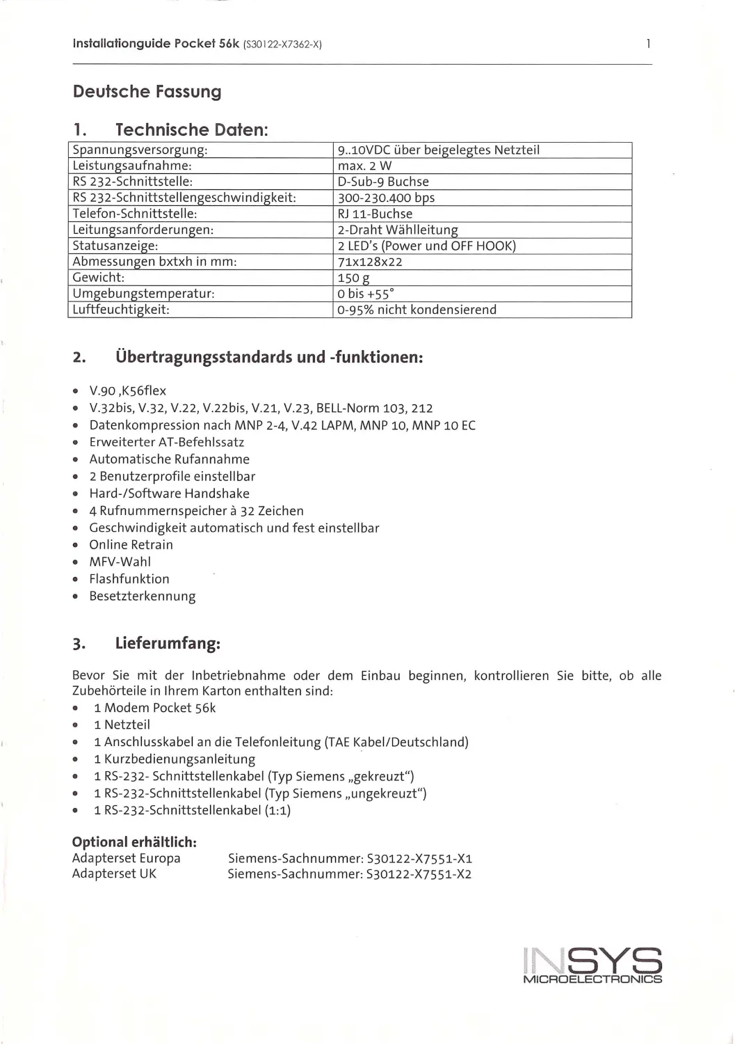
Inhaltsverzeichnis I Contents
DEUTSCHE FASSUNG •• •• •••• ••••••••• •• •••••••••• ••••• ••••• •••••••••• •••• •• ••• ••• •••• ••• ••••••• •••• •••• •• ••••• •• 1
1.
TECHNISCHE DATEN: •••. ••• ••••• ••••• .••• ••••• ••• .•••• . ••••• •••••• •••••••••••••••••••••• ••••••••••••••• 1
2.
Übertragungsstandards und -funktionen:........................................................ „ .. . „ .„1
3.
Lieferumfang: . . ... .. . ... ...... . ............. ........ . .. . .. . .. .. . .. ... . . ....... . ... . ... . ... .... .. .. . . ... ..... .. ........... 1
4.
Installation und Inbetriebnahme des Pocket 56k ... ... .. .. .... ..................... ................ .... 2
4.1 Schrittweise Inbetriebnahme ................ .... ..... ............... ... ..... .......... ...... ....... ...... ... ..... ...2
s.
Umschaltbarkeit zwischen DCD- und DSR- Leitung bei HICOM-Anlagen . . .... ... . . ..........2
6.
Kurzübersicht der AT-Befehle................................................ .... .... ...... .......................3
1.
Zulassungen: ........... ........... .. ... ......... .... .... ................. ......... ........ ................. ..............5
ENG LISH VERSION ••••••• ••••• •••• •••••••• •••• •• •••• ••••• •••• •••••• ••••• •••••••••••••••••••••••••••••••• ••••• •• •• ••• 6
1.
Technical data........... ...................................................... .. .. .. .. ...... ... .... ................... ... 6
2.
Transmission standards and functions . . .. ... . . .. .. . .. ... . . . ........... ........ .. ..... .. ..... .. ........ ... ... 6
3.
Delivery scope. .... . .. . . ........ ... ....... . . . ........ . .... . ...... .. ..... ... .. . . ... .. ... .... .... .. ..... .. .................. 6
4.
Installation and operating the Pocket 56k ..... .......................... ............................. .....?
4.1 Step s of inst all atio n ..... ....... ........ ....... .......... ... ............ ... ......... .... ..... ........... .... ....... .. .. .. ..7
s.
Switching -option between DCD and DSR line w ith HICOM ....... ... .. ... .. ... ... ................. .7
6.
Quick reference guide of the AT commands ... ..... . ......... .. . . .. . .... .... . ...... .. . . .. ... . .. . .. ........ 8
1.
Approval .............. ..... ........................ .............................. ............. ............................10
INS YS
M ICROELECT RONICS
lnstallationguide Pocke! 56k (S30 122-X7362-X)
Deutsche Fassung
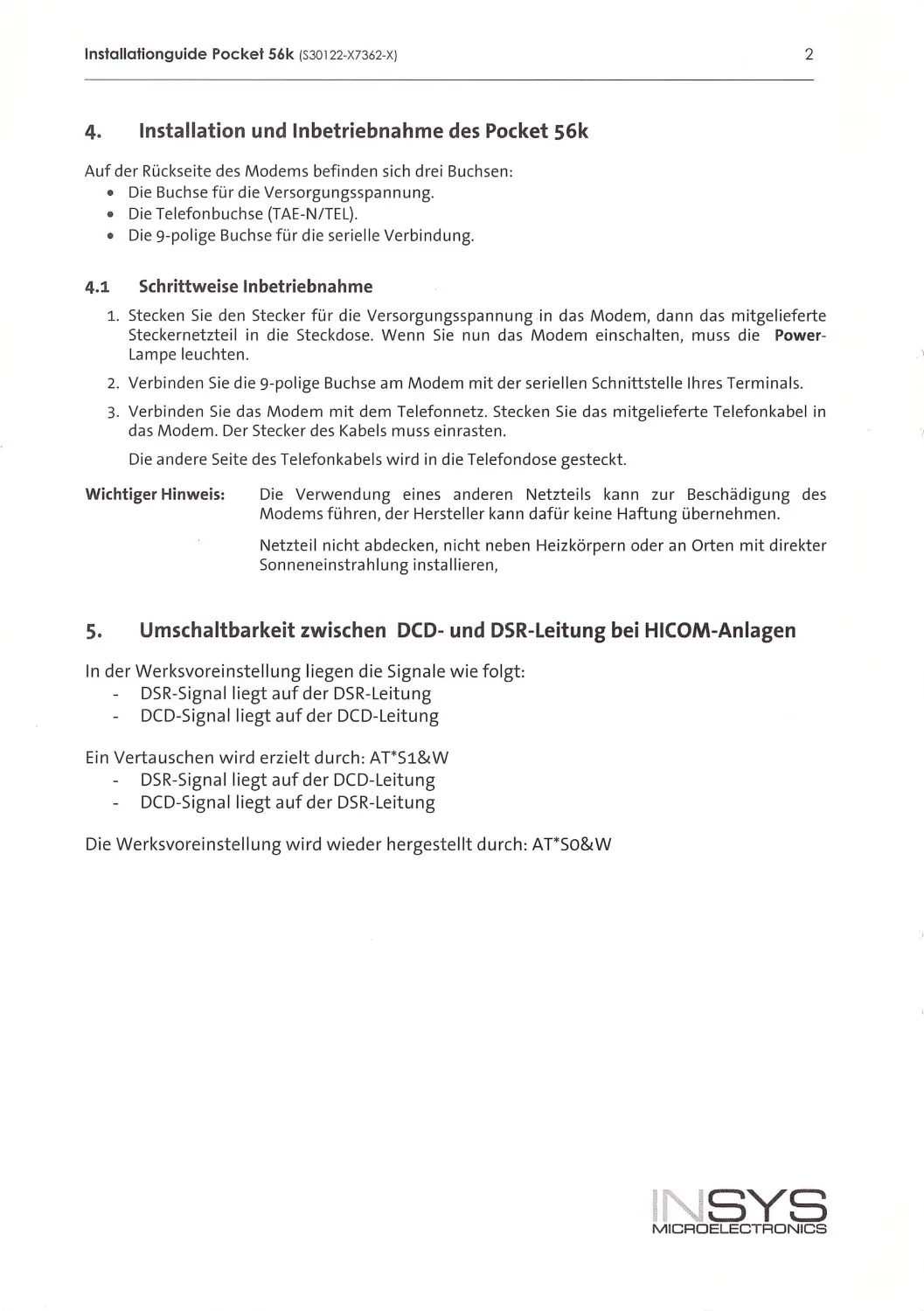
1. Technische Daten:
Spannungsversorgung:
9.. 10VDC ü be r beige legtes Netzte il
Leistungsaufnahme:
max.2W
RS 232-Schn ittstel le:
D-Sub -9 Bu chse
RS 232-Sch nittstellengeschwindigkeit:
300-230.400 bps
Telefon-Schnittstell e:
RJ 11- Buc hse
Leitu ngsa nforderu ngen:
2-Draht Wählleitung
Statusanzeige:
2 LED's (Power und OFF HOOK)
Abmessu ngen bxtxh i n m m:
71X128X22
Gewicht:
1SO g
Umgebu ngstem peratur:
obis+SS0
Luftfeuchtigkeit:
0-9S % nicht ko ndens ierend
2. Übertragungsstandards und -funktionen:
•
V.90 ,KS6flex
•
V.32b is, V.32, V.22 , V.22bis, V.21 , V.23, BELL -Norm 103, 212
•
Datenkompression nach MNP 2-4 , V.42 LAPM , MNP 10, M NP 10 EC
•
Erweiterter AT-B efehl ssatz
•
Automatische Rufannahme
•
2 Benutz erprofile ein st ell ba r
•
Hard -/Software Handshake
•
4 Rufnummernspeicher ä 32 Zeichen
•
Geschwind igkeit automatisch und fest ei nstell bar
•
Online Retrain
•
M FV-Wa hl
•
Flashfunktion
•
Besetzterkennung
3, Lieferumfang:
Bevor Sie mit der Inbetriebna hme oder dem Einb a u be g innen, kontrollie r en Sie bitte, ob all e
Zubehörtei le in Ihre m Karton en thalten si nd:
1 Modem Pocket S6k
•
1 Netzteil
1 An sc hlusskabel an die Te lefonleitung (TAE Kabel/ Deutschland)
1 Kurzbedi enungsa n leitu ng
1 RS-232- Schnittst ellenkabe l (Typ Siemens „ gekreuzt ")
1 RS-2 32-Schn ittstellenkabel (Typ Siemens „unge kreuzt" )
1 RS-232-Schnittstellenka bel (1:1)
Optional erhältlich:
Ad apters et Europa
Adapter set UK
Si eme ns- Sachnumme r : S30 122-X7 SS1-X 1
Siem en s- Sac hn ummer : S30122- X7 SS1-X2
1 SYS
M ICROEL ECTRONICS
lnslallationguide Pocke! 56k (S30122-X7362-XJ
2
4. Installation und Inbetriebnahme des Pocket 56k
Auf de r Rückseite des Modems befi nde n sich drei Buchse n:
•
Die Buc h se für die Versorgungsspa n nung.
•
Die Telefonbuchse {T AE-N / TEL).
•
Die 9-po lige Buch se für die serielle Verbindung.
4.1 Schrittweise Inbetriebnahme
1. Stecken Sie den Stecker für die Ve rsorgu ngsspannung in das Modem, da n n das mitge li eferte
Steckernetzteil in d ie Steckdose. Wenn Sie nun das M odem ei nscha lte n, muss d ie Power-
Lampe le uchten.
2. Verbinden Sie die 9-polige Buchse am Modem mit der seriellen Sc hnittstelle Ih res Term inals.
3. Verb i nd e n Sie da s Modem m it dem Telefon netz. Stecken Sie da s mitgel ieferte Telefo nkabel i n
da s Mod e m. De r Stecker des Kabe ls mu ss einrasten.
Die andere Se ite des Telefonkabel s w i rd in die Telefondose gesteckt.
Wichtiger Hinweis:
Die Verwend u ng ei nes anderen Netzt eil s kann zur Beschädig u ng des
Mode ms fü hren, der Herstel ler ka n n dafür keine Haftu ng ü be rnehm en.
Netzte il n icht abdecken , n icht n eben He izkörpern oder an Orten mit direkt er
Sonneneinstrah l ung in st al lieren,
s. Umschaltbarkeit zwischen DCD- und DSR-Leitung bei HICOM-Anlagen
In der Werksvoreinstellung li egen d ie Signa le w i e folgt:
DSR-Signa l liegt aufder DSR-Leitung
DCD-S igna l l iegt auf der DCD- Le itung
Ein Verta uschen w i rd erzielt durch: AT* S1&W
DSR-Signal liegt auf der DCD-Leitung
DCD-Signal liegt aufder DSR-Leitung
Die Werksvore i nstellung wird w i eder h ergestellt durch: AT*So&W
INSYS
MICROELECTRONICS
lnstallationguide Pocket 56k (S30 122-X7362-XJ
3
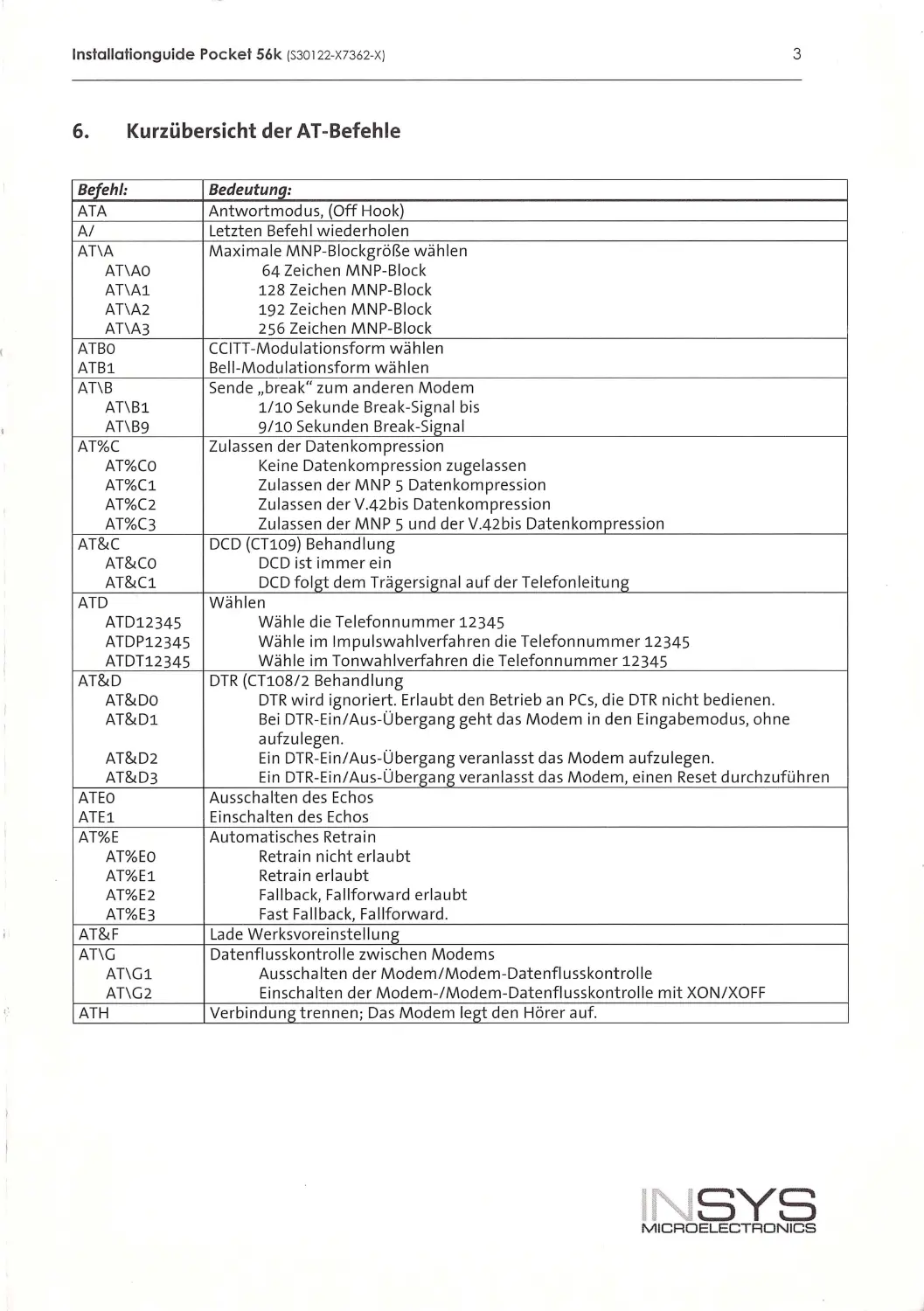
6. Kurzübersicht der AT-Befehle
Befehl:
Bedeutunq:
ATA
Antwortmodus, (Off Hook)
A/
Letzt en Befehl w iederho len
AT\A
Maxi ma le MNP-Blockgröße wählen
AT\AO
64 Zeichen MNP-Block
AT\Al
128 Zeichen MNP-Block
AT\A2
192 Zeichen MNP-Block
AT\A3
256 Zeichen MNP- Block
ATBO
CC ITT-Modu lationsform wählen
ATBl
Be ll -Modulationsform wäh len
AT\B
Sende „break " zum anderen Modem
AT\Bl
1/10 Sekunde Break-Signa l bis
AT\B9
9/10 Sekunden Break -Signal
AT%C
Zu l assen der Datenkompression
AT%CO
Keine Date n kompression zugelassen
AT%Cl
Zulassen der MNP 5 Datenkompression
AT%C2
Zula ssen der V.42b is Datenkompression
AT%C3
Zulassen der MNP 5 und der V.42b is Da tenkompression
AT&C
DCD (CT109) Behandlung
AT&Co
DCD ist immer ein
AT&Cl
DCD folgt dem Trägersign al auf der Telefonleitung
ATD
Wählen
ATD12345
Wäh le die Telefonnummer 12345
ATDP12345
Wäh le i m Impulswahlverfahren d ie Telefonnummer 12345
ATDT12345
Wäh le im Tonwah lverfahren die Te lefonnummer 12345
AT&D
DTR (CT108 / 2 Behand lung
AT&Do
DTR wird ignoriert. Er laubt den Betrieb an PCs, d ie DTR nicht bediene n .
AT&Dl
Bei DTR-Ein/Aus-Übergang geht das Modem in den Ein gabemod us, o hne
AT&D2
aufzu lege n .
Ein DTR -Ein/Aus- Übergang vera nl asst das Modem aufzu legen .
AT&D3
Ein DTR-Ein/Aus - Übergang veran lasst das Modem , ei nen Reset d urchzuführe n
ATEO
Au ssc halten des Echos
ATEl
Einschalten des Echos
AT%E
Automatisches Retra i n
AT%EO
Retra i n nicht erlaubt
AT%El
Retrain erlaubt
AT%E2
Fal lbac k, Fa llforward erlaubt
AT%E3
Fast Fa llback, Fa llforward.
AT&F
Lade Werksvoreinste ll ung
AT\G
Date nfluss kontro ll e zwi sc he n Modems
AT\Gl
Au ssc halten der Modem / Modem- Datenflusskontrolle
AT\G2
Einschalten der Modem-/Modem-Datenflusskontrolle mit XON /XOFF
ATH
Verbindung trennen; Das Modem legt den Hörer auf.
INSYS
MICROELECTRONICS
lnstallationguide Pocke ! 56k (S30 122- X7362- X)
4
Befehl:
Bedeutuna:
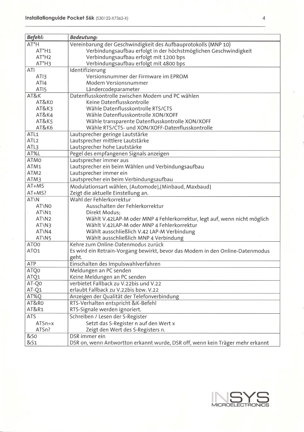
AT'H
Vereinbarung der Ge schw indig keit de s Aufba uprotokolls (MNP 10)
AT*Hl
Verbindu ngsaufbau erfolgt in de r höchstmöglichen Geschwi ndigkeit
AT*H2
Verbindu ngsa ufbau erfolgt mit 1200 bps
AT* H3
Verbindu ngsa ufbau erfolgt mit 4800 bps
ATI
Id entifizieru ng
ATl3
Version snummer der Firm ware im EPROM
AT 14
Modem Ve rsi onsn umme r
ATIS
Lände rcode pa rameter
AT&K
Datenflusskontrolle zwischen Modem u nd PC wählen
AT&Ko
Keine Datenflusskontrolle
AT&K3
Wä hl e Datenflusskontrolle RTS/CTS
AT&K4
Wähle Datenflu ssko ntrolle XON/XOFF
AT&Ks
Wähle tra n spa rente Date nfl usskontroll e XON /XOFF
AT&K6
Wäh le RTS/CTS- und XON /XOFF-Datenflu ss kontrolle
ATLl
Laut sprecher geringe Laut stärke
ATL2
Lautsprecher m ittlere Lautstärke
ATL3
Lautsorecher hohe Lautstärke
AT%L
Pegel des empfangenen Signals anze igen
ATMO
Lautsp rec her im mer aus
ATMl
Lautsprec her ei n beim Wählen und Verbindu ngsa ufbau
ATM 2
Lautsprecher im mer ein
ATM3
Lautsorecher ei n beim Verbindungsaufbau
AT+MS
Modulationsart wä hl en, [Automode],[Mi nbaud, Ma xba ud]
AT+MS?
Ze iet die aktuelle Einstell uni:>: an.
AT\N
Wahl der Fehle r korrektur
AT\NO
Aussc halten der Fehl erkorrektur
AT\Nl
Dire kt Modus;
AT\N2
Wählt V.42LAP-M oder MNP 4 Fehlerkorrektur, legt auf, wenn nicht möglich
AT\N3
Wählt V.42 LAP-M oder MNP 4 Fehlerkorrektur
AT\N4
Wählt aussch ließlich V.42 LAP-M Verbindung
AT\NS
Wählt aussc h ließlich MNP 4 Verbindung
ATOO
Ke hre zum On line -D atenmodus zurück
ATOl
Es w i rd ein Retra in-Vo rgang bewi rkt, bevor das Modem in den Online-Date nmodu s
geht.
ATP
Ein sc halten des Impul swa hl v erfahren
ATQO
Meldungen an PC senden
ATQl
Keine Meldungen a n PC se nd en
AT-QO
ve rbietet Fallbac k zu V. 22bis und V.22
AT -Ql
erla ubt Fallback zu V.2 2bi s bzw. V .22
AT%Q
Anze i een der Qua lität der Telefo nverb i ndune
AT&Rü
RTS -Verhalten e ntspricht &K-Befehl
AT&Rl
RT S-S igna le werde n ignorie rt.
ATS
Sc hreiben/ Lesen der S- Re g iste r
ATSn =x
Setzt das S- Register n auf de n Wert x
ATSn ?
Zeigt den Wert des S-Registers n.
&so
DSR immer ein
&Sl
DSR on, wenn Antwo rtton erkannt wurde, DS Roff, we nn kein Träger mehr erkan nt
'NSYS
MICROELECTRONICS
lnslallalionguide Pocke! 56k (S30 122- X7362-XI
5
Befehl:
Bedeutung:
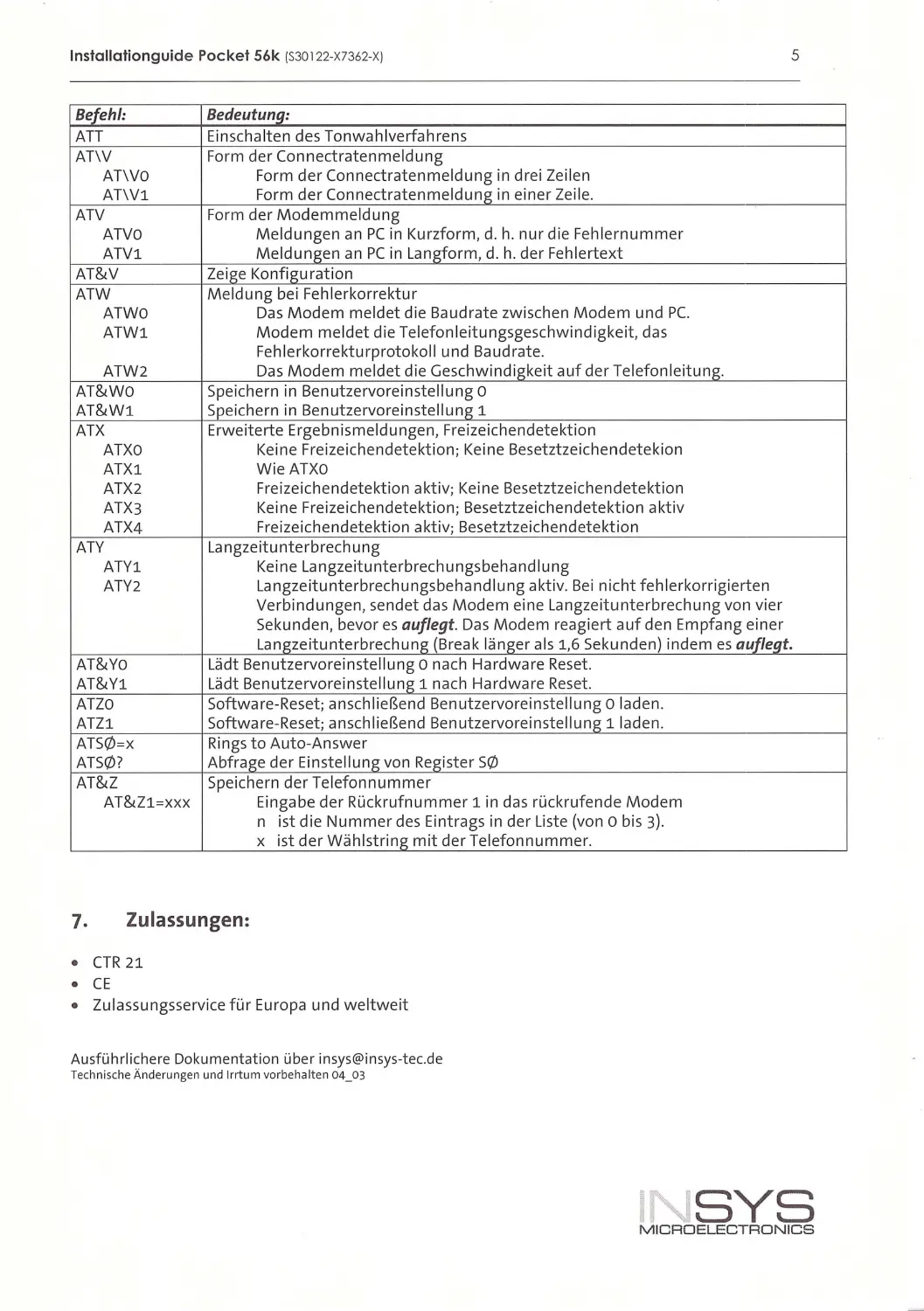
ATT
Ein sc halten des To nwah lverfahrens
AT\V
Form de r Connectraten meldung
AT\VO
Form der Connect ratenmeldun g i n drei Ze ilen
AT\Vl
Form der Connectratenmeldun g i n eine r Ze il e.
ATV
Form der Modemmeldu ng
ATVO
Meldungen an PC in Kurzform , d . h. nur d ie Feh le rnum mer
ATVl
Meldungen an PC in Langform, d . h. der Feh lerte xt
AT&V
Ze ige Konfiguratio n
ATW
Meldung bei Feh lerkorrektur
ATWO
Das Modem meldet die Baudrate zwischen Modem und PC.
ATWl
Modem meldet die Telefonleitungsgeschwindigkeit, das
Feh lerkorrekturprotokoll und Baudrate.
ATW2
Das Modem meldet d ie Geschwindigkeit auf der Telefonleitung.
AT&WO
Speichern i n Benutzervorein ste llung o
AT&Wl
Speic hern i n Benutzervorein stel lung 1
ATX
Erweiterte Ergebn i sme ldungen, Fre iz eichendete ktion
ATXO
Ke i ne Freizeichendetektion; Keine Besetztze ichendetekion
ATXl
W ieATXO
ATX2
Freizeichendetektion aktiv ; Keine Besetztzeic hendetektion
ATX3
Keine Fre ize ichendetektion; Besetztze ic hendetektion aktiv
ATX4
Freizeichendetektion aktiv; Besetztze ichendetektion
ATY
Langzeitunterbrechu ng
ATYl
Keine La ngzeitu nterbrech ungsbeha nd 1ung
ATY2
La ngze itunterbrechungsbehandlu ng aktiv. Bei n icht feh lerkorrigierte n
Verbindungen, sendet das Modem eine Langzeitunterbrechung von v ier
Sekunden, bevor es auflegt. Das Mod em r eag iert auf den Empfang ei ne r
Langzeitunterbrechung (Break länger als 1,6 Sekunden) indem es auflegt.
AT&Yo
Lädt Benutzervoreinstell ung o nach Hardwa r e Reset.
AT&Yl
Lädt Benutzervo re i nste ll ung 1 nach Ha rdware Reset.
ATZO
Software- Re set; anschl ießend Benutze rvoreinstell ung o l aden.
ATZl
Software-Reset; ansch li eßend Benutze rvo re i nstell ung 1 laden .
ATS0=x
Rings to Auto-Answer
ATSQ)?
Abfrage der Ei nstell ung von Regi ster SQ)
AT&Z
Spei chern der Te lefo nnumm er
AT&Zl=XXX
Eingabe der Rückrufnumm er 1 in das r ückrufende Modem
n ist die Nummer des Eintrags in der Liste (von o bis 3).
X ist der Wäh lstring mit der Telefo nn ummer.
7. Zulassungen:
•
CTR 21
•
CE
•
Zulassungsservice für Eu ropa und weltweit
Ausführlichere Dokument ation über insys@ in sys-tec.de
Technische Änderungen und Irrtum vorbehalten 04_03
SYS
M ICRDELECTRDNICS
lnslallalionguide Pocket 56k (S30122-X7362-X)
English version
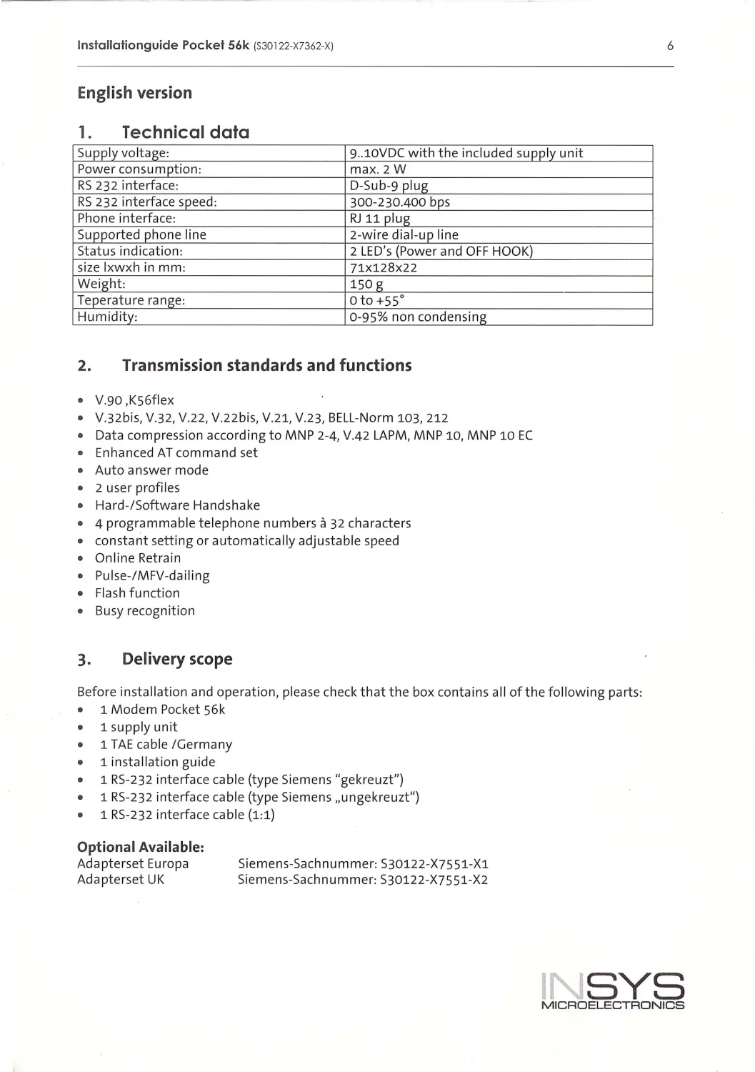
1. Technical data
Supply voltage:
9..lOVDC with the includ ed supply unit
Power consumption :
max. 2W
RS 232 interface:
D-Sub-9 plug
RS 232 interfa ce speed:
300-230.400 bps
Phone interface:
RJ 11 plug
Supported phone li ne
2-wire dial-up lin e
Status indication:
2 LED's (Power and OFF HOOK)
size lxwxh in mm:
71X128x22
Weight:
150 g
Teperature range:
oto+ss 0
Humidity:
0-95% non conde nsing
2. Transmission standards and functions
•
V.90 ,KS6fle x
•
V.32bis, V.32, V.22 , V .22bis, V .21, V.23, BELL -Norm 103, 212
•
Data compression according to MNP 2-4, V.42 LAPM, MNP 10, MNP 10 EC
•
Enhanced AT command set
•
Auto answer mode
•
2 user profiles
•
Hard-/Software Handshake
•
4 programmable tel ephone numbers a 32 characters
•
constant setting or automatical ly adjustable speed
•
Online Retra in
•
Pulse-/MFV-dai ling
•
Fl as h function
•
Busy recognition
3. Delivery scope
Before insta ll ation and operation, please check that the box conta ins all of the following parts:
1 Modem Pocket S6k
1 supply unit
1 TAE cab le /Germany
1 install ation guide
1 RS -232 interface cable (type Siemens "gekreuzt")
1 RS -232 interface cab l e (type Siemens ,,un gekreuzt")
1 RS-232 interface cable (1:1)
Optional Available:
Adapterset Europa
Adapterset UK
Siemens-Sachnummer: S30122-X7S51-X1
Sieme n s-Sachn ummer: S30122 -X7551-X2
6
INSYS
MICROELECTRONICS
lnstallationguide Pocket 56k (S30122-X7362-XJ
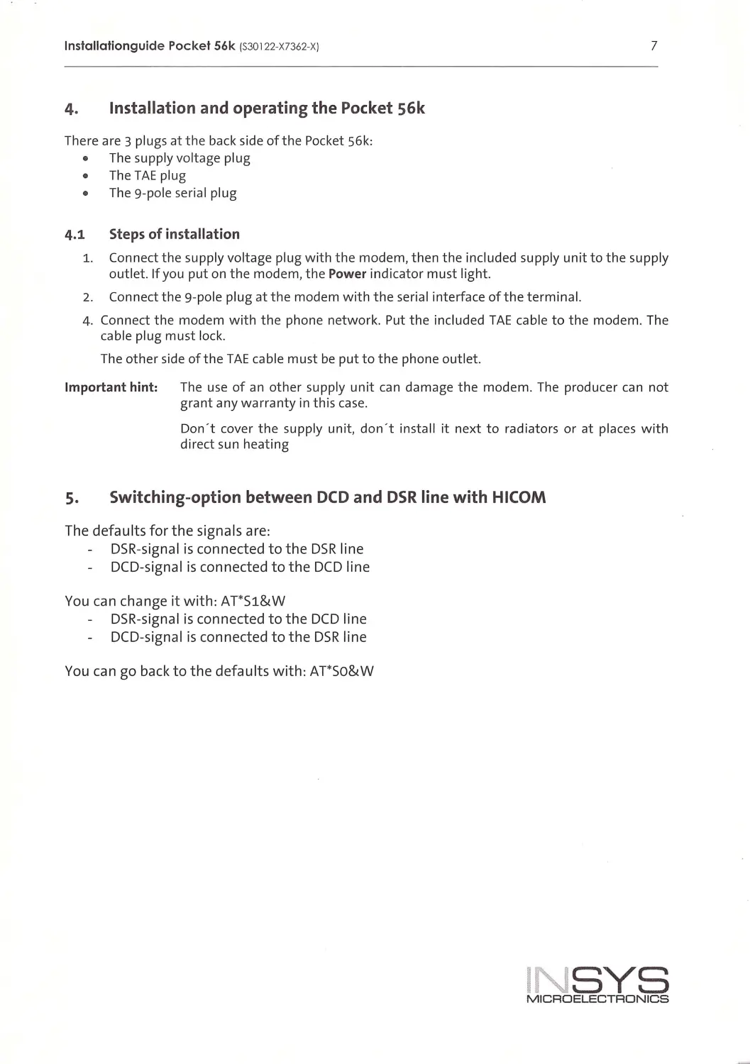
4. Installation and operating the Pocket 56k
There are 3 plugs atthe back side of the Pocket S6k:
The supply vo ltage plug
The TAE plug
The 9-pole seria l pl ug
4.1 Steps of installation
7
1. Connect the supply vo ltage plug w ith the modem, then the included supply un it to the supply
outlet. If you put on the modem , the Power indicator must light.
2. Connect the 9-pole plug at the modem with the ser ial interface of the term i nal.
4. Connect the modem with the phone network. Put the included TAE cab le to the modem. The
cable pl ug must lock.
The other side of the TAE cable must be put to the phone outlet.
Important hint: The use of an other supp ly unit can damage the modem . The producer can not
grant any warranty in th is case .
Don't cover the supp ly un it, don ' t instal l it next to radiators or at places wit h
direct sun heating
s. Switching-option between DCD and DSR line with HICOM
The defaults for the signals are:
DSR-s igna l is connected to the DSR l ine
DCD-s igna l is connected to the DCD l i ne
You can change it w ith: AT*Sl&W
DSR-signal is connected to the DCD line
DCD-s igna l is connected to the DSR line
You can go back to the defau lts with: AT*So&W
INSYS
MICROELECTRONICS
lnstallationguide Pocket 56k (S30122-X7362-X)
8
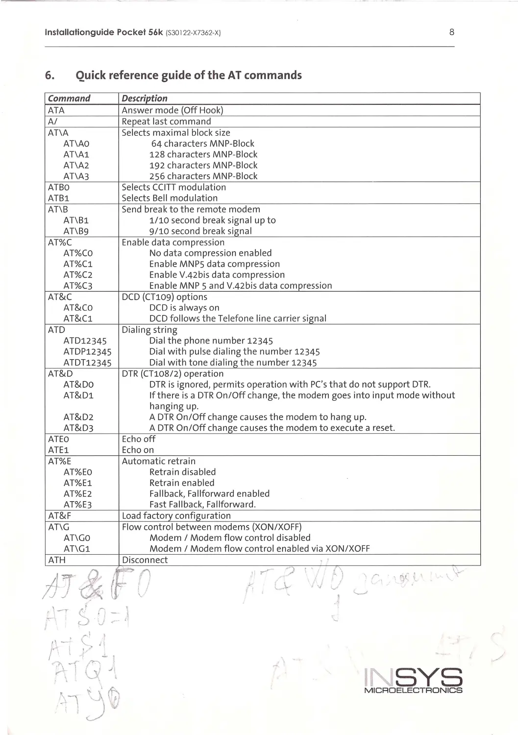
6. Quick reference guide of the AT commands
Command
Description
ATA
Ans wer mode {Off Hook)
A/
Repeat last com m and
AT\A
Selects maxima l block size
AT\AO
64 ch aracte r s MNP-Block
AT\Al
1 28 ch ar acters MNP-Bl ock
AT\A2
192 ch aracters MNP-Bl ock
AT\A3
256 ch ara cters MNP-Bl ock
ATBO
Select s CCI TT modulation
ATBl
Selects Bell modulation
AT\B
Send break to the remote modem
AT\Bl
1/ 10 second break signal up to
AT\B9
9/10 second brea k signal
AT%C
En able data compression
AT%CO
No data compress i on enabled
AT%C1
Enabl e MNP5 data compression
AT%C2
Enab l e V.42 bis data compression
AT%C3
En able MNP 5 and V.42bis data comp ression
AT&C
DCD {CT109) options
AT&Co
DCD is always on
AT& Cl
DCD foll ows the Te l efone line carrier signal
ATD
Di aling stri ng
ATD12345
Di al the phone number 12345
ATDP12345
Di al with pulse dialing the number 12345
ATDT12345
Dial with tone dialing the number 12345
AT&D
DTR (CT108 / 2) operation
AT&Do
DTR i s ignored, permits operation with PC's that do not support DTR.
AT&Dl
If there i s a DTR On / Off change, the modem goes into i nput mode without
hangi ng up.
AT&D2
A DTR On/Off change ca u ses the modem to han g up.
AT&D3
A DTR On/Off ch an ge causes t h e modem to execute a reset.
ATEO
Ec ho off
ATEl
Echo on
AT%E
Automatic retra i n
AT%EO
Retrai n disabled
AT%E1
Ret ra i n enabled
AT%E2
Fal lback, Fallforward enabled
AT%E3
Fast Fallbac k, Fallforward .
AT&F
Loa d factory co nfiguration
AT\G
Flow control between mod ems {XO N/XOFF)
AT\Go
M odem I Modem fl ow control disabled
AT\G l
Modem I Modem fl ow control enabled vi a XO N/XOFF
ATH
Disconnect
tJI&FD
'i~,. ? I.
')
\'-"
'r
, qf _;_'
"
-..,..\_...
.
I
•vv
I.
'
'---'
,\
INSYS
M IC ROELECTRONICS
lnstallationguide Pocket 56k {S30122-X7362-XJ
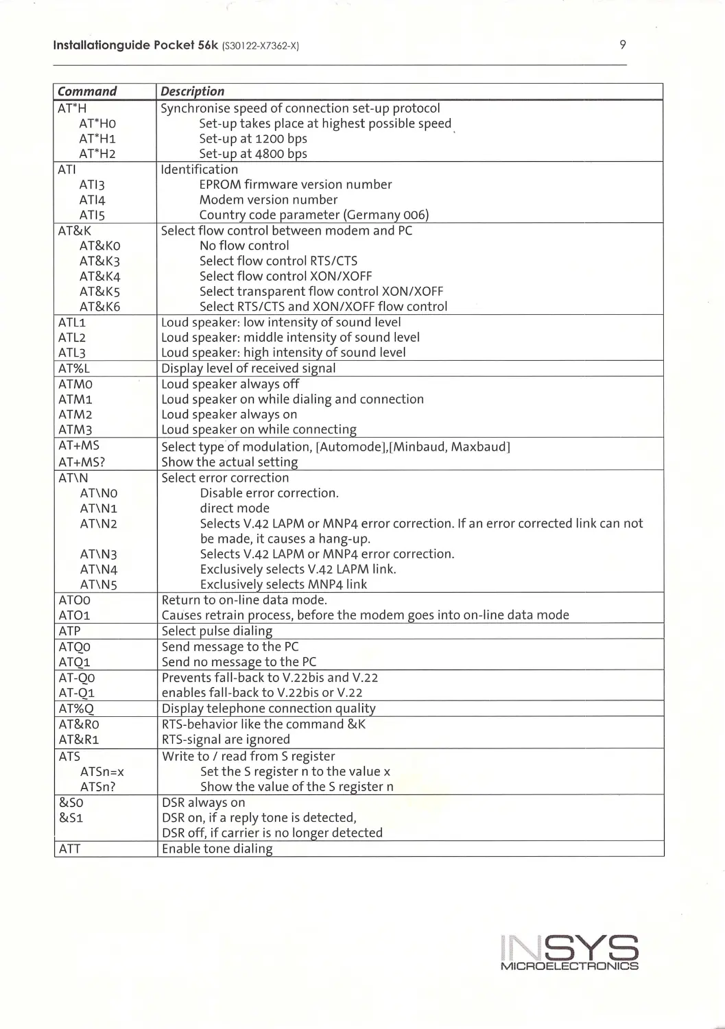
9
Command
Description
AT*H
Synchron i se speed of connect ion set-up protocol
AT' HO
Set-up takes place at highest possible speed
AT' H1
Set-up at 1200 bps
AT'H2
Set-up at 4800 bps
ATI
Identification
AT l3
EPROM firmware version number
AT 14
Modem version number
ATIS
Country code parameter (Germany 006)
AT&K
Select flow control between modem and PC
AT&Ko
No flow control
AT&K3
Select flow control RTS/CTS
AT&K4
Select flow control XON/XOF F
AT&Ks
Select transparent flow contro l XON/XOFF
AT&K6
Select RTS/CTS and XON/XOFF flow contro l
ATL1
Loud speaker: low intensity of sound leve l
ATL2
Loud speaker: m idd le intensity of sound level
ATL3
Loud speaker: high i ntens ity of sound level
AT%L
Disp lay level of received signa l
ATMO
Loud speaker always off
ATM1
Loud speaker on wh il e dia ling and connection
ATM2
Loud speaker always on
ATM3
Loud speaker on wh il e connect ing
AT+MS
Se lect type of modu lation, [Automode],[Minbaud, Maxbaud]
AT+MS?
Show the actua l setting
AT\N
Se lect error correct ion
AT\NO
Disable error correct ion.
AT\N1
d irect mode
AT\N2
Selects V.42 LAPM or MNP4 error correct ion. If an error corrected link can not
be made, it causes a hang-up.
AT\N3
Selects V.42 LAPM or MNP4 error correction.
AT\N4
Exclusive ly se lects V.42 LAPM link.
AT\NS
Exclusively se lects MNP4 link
ATOO
Return to on-line data mode.
AT01
Causes retra i n process, before the modem goes i nto on- l ine data mode
ATP
Select pu lse dia li ng
ATQO
Send message to t he PC
ATQ1
Send no message to the PC
AT -QO
Prevents fal l-back to V.22bis and V.22
AT -01
enab les fa l l-back to V.22bis or V.22
AT%Q
Disp l ay t elephone connection qua lity
AT&Ro
RTS-behavior l i ke the command &K
AT&R1
RTS-signa l are ignored
ATS
Write to I read from S reg ister
ATSn =x
SettheSregisterntothevalue x
ATSn?
Show the va lue ofthe Sregister n
&so
DSR always on
&S1
DSR on, if a rep ly tone is detected,
DSR off, if carrier is no longer detected
ATT
Enable tone d ial ing
I SYS
MICROELECTRONICS
lnstallationguide Pocket 56k (S30122-X7362-XJ
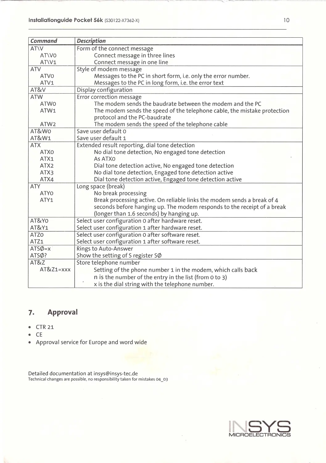
10
Command
Description
AT\V
Form of the connect message
AT\VO
Connect message in three lines
AT\Vl
Connect message in one l ine
ATV
Style of m o d em message
ATVO
Messages to the PC in short form, i . e. on ly the error numbe r.
ATV1
Messages to the PC in l ong form, i . e. the error text
AT&V
Di splay configuration
ATW
Error correction message
ATWO
The modem sends the baud rate between the modem and t he PC
ATW1
The modem sends the speed of the telephone cable, the m i sta ke p rotection
protoco l and the PC-baudrate
ATW2
The modem sends the speed of the telephone cable
AT&Wo
Save user defau lt o
AT&W1
Save u ser d efault 1
ATX
Extended resu lt reportin g, dial tone detection
ATXO
No dial ton e detection, No engaged t one detect ion
ATX1
As ATXO
ATX2
Dial tone detection active, No engaged tone detection
ATX3
No dial tone detection, Engaged ton e detection active
ATX4
Di al tone detection active, Enga ged tone detection active
ATV
Long space (b r eak)
ATYO
No b re ak processing
ATY1
Break processing active. On reliable li nks the modem send s a break of 4
se conds before hanging u p. Th e modem responds to the r eceipt of a break
{longer than 1.6 second s) by hanging up.
AT&Yo
Se l ect u ser co nfiguration o after h ardware r eset.
AT&Y1
Select user configuration 1 after hardwa r e r eset.
ATZO
Select user configuration o after software reset.
ATZ1
Select user configuration 1 after software reset.
ATS0=x
Rings to Aut o-Answer
ATS0?
Show the setting of S register S0
AT&Z
Store telephone number
AT&Zl=XXX
Setting ofthe phone number 1 in t he modem, which calls back
n is t he number ofthe entry in the list {from o to 3)
xis the dial string with the t elephone number.
1. Approva l
•
CTR 21
•
CE
•
Approval se rvice for Europe and word wide
Det ailed do cumentation at insys@in sys -tec.d e
Technical cha nge s are possible, no responsibility taken for mi stakes 04_03
INSYS
MICROELECTRONICS