/


Tags: weapons military affairs patent
Year: 1990

Text
United States Patent [»]
Zedrosser et al.
[11] Patent Number: 4,941,394
[45] Date of Patent: Jul. 17,1990
[54] HAND-HELD AUTOMATIC FIREARM
[75] Inventors: Ulrich Zedrosser; Walter Schwarz,
both of Steyr, Austria
[73] Assignee: Steyr-Daimler-Puch AG, Vienna,
Austria
[21] Appl. No.: 404,114
[22] Filed: Sep. 7, 1989
[30] Foreign Application Priority Data
Sep. 28, 1988 [AT] Austria........... 2390/88
[51] Int. 0.5....................F41A 19/02
[52] U.S. Cl.............. 89/129.02; 89/141;
89/142
[58] Field of Search...... 89/129.02, 139, 140,
89/141, 142, 144, 145
[56] References Cited
U.S. PATENT DOCUMENTS
4,745,843 5/1988 Zedrosser et al.... 89/132
FOREIGN PATENT DOCUMENTS
0123871 11/1984 European Pat. Off. .
579096 6/1933 Fed. Rep. of Germany.. 89/140
2323352 11/1974 Fed. Rep. of Germany .
3227180A1 1/1984 Fed. Rep. of Germany .
Primary Examiner—Stephen C. Bentley
Attorney, Agent, or Firm—Marmorek, Guttman &
Rubenstein
[57] ABSTRACT
The trigger mechanism of a hand-held automatic fire-
arm comprises a catch lever, which is pivoted on a
transverse axis and is provided at its forward end with
a pivoted catch pawl, which in a catching position en-
gages a catching lug of a slider to arrest the slider as it
moves forwardly from a rear position, to which the
slider, which constitutes a part of a firing mechanism of
the firearm, has moved against spring force when a
round has been discharged. In order to provide such a
firearm which has a trigger mechanism which is reliable
in operation and can be made at low cost, the catch
lever is adapted to be locked in its catching position
against the force of a catch lever spring, the catch pawl
is pivoted to the catch lever by means which permit a
longitudinal movement of the catch pawl and the catch
pawl is pivotally supported at its other end on an abut-
ment, which is fixed to the receiver of the firearm.
6 Claims, 5 Drawing Sheets
18
U.S. Patent Jui. 17,1990
Sheet 1 of 5
4.941.394
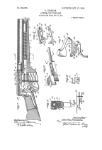
FIG.1
U.S. Patent Jui. 17,1990
Sheet 2 of 5
4,941,394
U.S. Patent Jui. 17,1990
Sheet 3 of 5
4.941394
U.S. Patent Jul. 17,1990 Sheet 4 of 5 4,941,394
FIG. 4
U.S. Patent Jui. 17,1990
Sheet 5 of 5
4.941.394
is zxa ла
4,941,
1
HAND-HELD AUTOMATIC FIREARM
BACKGROUND OF THE INVENTION
I. Field of the Invention 5
This invention relates to a hand-held automatic fire-
arm, particularly to a trigger mechanism for such fire-
arm, which mechanism comprises a catch lever, which
is pivoted on a transverse axis and is provided at its
forward end with a pivoted catch pawl, which in a 10
catching position engages a catching lug of a slider to
arrest the slider as it moves forwardly from a rear posi-
tion, to which the slider, which constitutes a part of a
firing mechanism of the firearm, has moved against
spring force when a round has been discharged. 15
2. Description of the Prior Art
In firearms provided with such trigger mechanism
the slider, which may consist of a breechblock or of a
carriage which by means of a cam mechanism cooper-
ates with a transversely displaceable firing chamber or 20
another part of the firing mechanism is restrained from
performing a forward movement which would be re-
quired for the discharge of a round and is released only
from time to time for the discharge of a round. To re-
strain the slider, the catch pawl is pivotally moved into 25
the path of the slider to catch the slider as it tends to
advance under its spring bias. As is apparent from U.S.
Pat. No. 4,745,843 the catch pawl, which is pivoted to
the catch lever, is supported relative to the catch lever
and relative to a trigger housing and the catch pawl 30
itself constitutes a member which controls the move-
ment of the catch lever to its catching position and to its
releasing position. That arrangement involves a consid-
erable structural expenditure and the loads which are
applied by the slider to the catch pawl must also be 35
taken up by the catch lever and by the pivotal mount-
ings for the pawl and the catch lever. Because said loads
are suddeenly applied, they require that the materials,
the shapes and the dimensions of the parts which coop-
erate to catch the slider are properly selected. The parts 40
must be made of high-strength materials, particularly of
hardened steel, so that the parts are heavy and can be
manufactured and particularly machined only with
difficulty. Nevertheless, very strong forces, which may
be exerted, e.g., when the firearm falls on the ground, 45
may result in an inadvertent release of the slider so that
a round is inadvertently discharged.
EP-A No. 1-0 121 871 and Published German Appli-
cation No. 23 23 352 disclose trigger mechanisms which
comprise spring-loaded catch pawls, which are pivoted 50
directly to the trigger housing and serve to catch the
breechblock. Said catch pawls are operable by means of
a lever, which cooperates with the trigger. That lever is
also spring-loaded and either has a nose which enters a
recess of the catch pawl or is connected to the catch 55
pawl by a rotatable pinion, which upon an actuation of
the trigger is pivotally moved to move the catch pawl
to a releasing position against the force of the catch
pawl spring. As the trigger is released, said lever is
swung back by spring force so that the catch pawl can
jump up to its catching position. Special controlling
means including separate control levers, which pro-
trude into the path of the breechblock, are provided and
ensure that the release of the catch pawl will be per-
formed exactly when the breechblock has moved to the
desired position and that the catching position will
properly be assumed. In such an arrangement the loads
which are applied to the catch pawl as the breechblock
394
2
is caught can directly be transmitted by the catch pawl
to the trigger housing but the mechanisms described are
heavy and expensive and intended for use in automatic
cannons and cannot be incorporated in hand-held fire-
arms.
Published German Application No. 32 27 180 dis-
closes self-loading pistols in which the loading mecha-
nism comprises an actuating lever, which engages a
two-armed lever that is approximately parallel to the
path for the breechblock, one arm of the two-armed
lever cooperates with a pivoted breechblock locking
member and the other arm of the two-armed lever co-
operates with a acatch pawl associated with the striking
hammer. In such an arrangement the breechblock lock-
ing member is forced upwardly into the path for the
breechblock by a nose of the magazine and after the
discharge of the last cartridge catches the breechblock
in its rear position. In that case the operating lever can
be operated so that the two-armed lever will cause the
breechblock to be released and the striking hammer to
be uncocked. Said self-loading pistols are single-round
firearms, in which the trigger is not directly connected
to the loading means and in which an actuation of the
trigger will cause the striking hammer to be cocked and
when a release position has been reached to be released
for the discharge of a round independently of the oper-
ating lever and the two-armed lever.
SUMMARY OF THE INVENTION
For this reason it is an object of the invention to
eliminate said disadvantages and to provide a hand-held
automatic firearm which is of the kind described first
hereinbefore and comprises a trigger mechanism which
is simpler in design and can be manufactured at lower
cost and will be highly reliable in operation even
though lightweight materials are widely employed.
That object is accomplished in accordance with the
invention in that the catch lever is adapted to be locked
in its catching position against the force of a catch lever
spring, the catch pawl is pivoted to the catch lever by
means which permit a longitudinal movement of the
catch pawl and the catch pawl is pivotally supported at
its other end on an abutment, which is fixed to the re-
ceiver of the firearm. Because a separate catch pawl is
provided to arrest and retain the slider and said catch
pawl is connected to the catch lever by a lost-motion
coupling and for taking up a load is directly supported
by a rigid abutment, which is fixed to the receiver of the
firearm, the catching and retaining forces which are
exerted will substantially be transmitted by the catch
pawl directly to the abutment so that the catch lever
will be relieved from substantial loads and serves virtu-
ally only as a lever for operating the catch pawl. For
this reason only the catch pawl must be made of a high-
strength material and the catch lever and most of the
other components of the trigger mechanism may be
made from lighter materials: Besides, the specific com-
bination of the catch lever and the catch pawl will
ensure a more reliable catching because when the catch
pawl has been pivotally raised from the catch lever into
the path of the catching lug of the slider the slider will
tend to further raise the catch pawl to assist its catching
function so that the reliability in operation will not
adversely be affected even in case of a deformation of
the catching lug or the catch pawl.
For a discharge of single rounds and for a sustained
fire the catch lever usually cooperates with a releasing
4,941,394
4
ratchet tooth during a forward rotation of the control
disk constitutes an elevated stop for engagement by a
coupling portion of the locking lever. When the safety
slider is in its sustained-fire position, the catch lever will
not be locked after each round but under the control of
the reciprocating slider will permit a sustained fire. In
that case the actuating lug of the catch lever will oper-
ate the actuating pawl to rotate the control disk by one
tooth pitch after each round until the ratchet tooth
10 which constitutes an elevated stop lifts the locking lever
from its locking position so that the interrupter is re-
leased and the burst will be terminated. In said control
operations the locking pawl will prevent an unintended
reverse rotation of the control disk and will ensure that
15 the control disk will be rotated by one tooth pitch and
that the burst will reliably be terminated after rounds
have been discharged in a number which equals the
number of teeth. When the burst has been terminated in
that the disconnector has been released to lock the
catch lever in its catching position after the discharge of
the last round, the trigger will have to be released for
the discharge of the next round so that the slidable
trigger will then move forwardly to move the control
disk out of the path of the locking pawl. The control
disk can then reversely be rotated to its initial position
and the release member and the disconnector will obvi-
ously also move to their initial position. In dependence
on the position of the safety slide another actuation of
the trigger will then result in the discharge of a single
round or of a predetermined number of rounds.
Within the scope of the invention the structural ex-
penditure and the space requirement may be decreased
in that the disconnector and the control disk are coaxi-
ally mounted on the slidable trigger and the control disk
and the locking pawl may be biased by a single spring.
The manufacturing costs may further be reduced within
the scope of the invention in that only the pivot pins,
bearing bushings, springs and similar small parts and the
catch pawl are made of metal whereas the remaining
parts of the trigger mechanism are made of plastic so
that the weight will be reduced and the impact forces to
be taken up will be damped.
BRIEF DESCRIPTION OF THE DRAWING
FIGS. 1 to 3 are fragmentary side elevations showing
partly in section a portion of a firearm embodying the
invention and provided with a trigger mechanism in
three different operating positions for a discharge of a
single round.
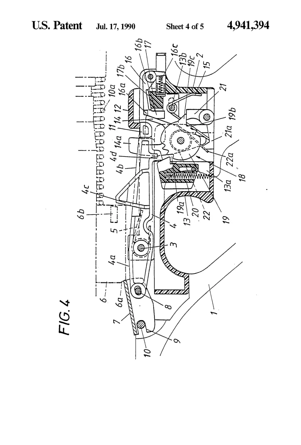
50 FIGS. 4 to 7 are fragmentary side elevations showing
partly in section a firearm embodying the invention and
provided with a trigger mechanism in four different
operating positions during a sustained fire.
DETAILED DESCRIPTION OF THE
PREFERRED EMBODIMENT
An illustrative embodiment of the invention will now
be described more in detail with reference to the dia-
grammatic drawing.
A hand-held firearm 1 comprises a stationary receiver
2, in which a straight two-armed catch lever 4 is pivoted
on a transverse pivot 3 and is biased by a catch lever
spring 5 toward a position in which it is clear of the path
of a slider 6. That slider is only diagrammatically indi-
cated and cooperates with the firing mechanism, not
shown, of the firearm 1 and is reciprocable in the longi-
tudinal direction of the barrel. The forward lever arm
4a of the catch lever 4 is provided with a catch pawl 7
3
member, a disconnector and with a locking lever. In
such firearms, a particularly desirable arrangement will
be obtained if a straight two-armed catch lever is pro-
vided, which is approximately parallel to the path for
the slider and at its forward lever arm carries the catch 5
pawl whereas its rear lever arm is provided with a lock-
ing lug for engaging the releasing member and the dis-
connector, the trigger is longitudinally slidable and is
spring-loaded and provided with a releasing nose so
that the trigger constitutes also the releasing member
the disconnector is spring-loaded and comprises a dis-
connecting nose and is pivoted to the slidable trigger,
the releasing nose and the disconnecting nose in an
operative position overlap the locking lug, the locking
lever in its locking position limits the pivotal movement
of the disconnector before it reaches its operative posi-
tion, and a transversely slidable safety slide is provided,
which is provided with camming surfaces, which serve
to displace the locking lever out of its locking position
against the force of a locking lever spring when said 20
safety slide is in a single-round position, permit the
locking lever to move to said locking position when said
safety slide is in a sustained-fire position, and to lock the
trigger in an initial position when the safety slide is in a
safety position. Such a trigger mechanism will be com- 25
pact and the trigger will be operable by the operator
under the same conditions for single rounds and for a
sustained fire. When the trigger has been unlocked, the
operator can simply pull the trigger and in dependence
on the position of the safety slide will effect a discharge 30
of single rounds or discharge a sustained fire. By means
of the safety slide, the locking lever is enabled and/or
disabled and by means of the locking lever the discon-
nector will be enabled and disabled so that the discon-
nector will arrest the catch lever independently of the 35
trigger after the discharge of each round or will cause
the catch lever to be released only by the releasing nose
of the trigger for a discharge of a sustained fire. The
provision of a slidable trigger and the provision of a
single member which constitutes the trigger and the 40
releasing member result in a relatively simple and robust
arrangement, which is particularly reliable in operation.
The trigger and the disconnector cannot perform the
assigned functions unless they are spring-loaded. The
trigger is spring-urged to its initial position and the 45
disconnector is spring-urged to its catching position.
Within the scope of the invention the trigger and the
disconnector may be biased by a common spring so that
the arrangement is further simplified. That spring is
suitably secured to slidable trigger and bears at one end
on a stationary part of the trigger mechanism and at its
other end on the disconnector, which consists of a le-
ver.
It may be desirable to discharge a sustained fire con-
sisting of an exactly predetermined number of rounds. 55
For that purpose it is known that trigger mechanisms
may be provided with a burst size control mechanism.
In a particularly desirable embodiment of the invention
the burst size control mechanism comprises a torsion-
ally spring-loaded control disk, which is rotatably 60
mounted in the slidable trigger and is provided on one
side with ratchet teeth for cooperating with a spring-
loaded locking pawl, which is mounted on the receiver
of the firearm, and the disk is provided on the other side
with drive teeth for cooperating with a spring-loaded 65
actuating pawl, which is pivoted to the trigger. The
actuating pawl is operable by an actuating lug of the
catch lever and that ratchet tooth which is the leading
4,941,394
5
for cooperating with an associated catch lug 6a of the
slider 6, which is biased forwardly by a spring 10a,
which is directly supported on the receiver 2 of the
firearm. The catch pawl 7 is mounted in the catch lever
4 in a longitudinally extending slot 8 for a lost motion in 5
the longitudinal direction and is formed with a bearing
recess 9, which is pivotally supported on an abutment
10 that is fixed to the receiver 2. As a result, the impact
forces which are exerted as the slider 6 moving for-
wardly by the spring 10a is caught by the catch pawl 10
will also be substantially applied by the catch pawl 7
directly to the receiver 2 of the firearm 1 whereas the
catch lever 4 and the remainder of the trigger mecha-
nism will be substantially relieved from such forces.
The rear lever arm 46 of the catch lever 4 is provided 15
with a locking lug 11, which cooperates with a releasing
nose 12 of the slidable trigger 13, which constitutes a
releasing member and comprises a pushpiece portion
13a. The locking lug 11 also cooperates with a discon-
nector nose 14a of a disconnector 14, which is pivoted 20
to the pushpiece portion 13a. A common spring 15
biases the disconnector 14 in a catching direction and
biases the pushpiece portion 13a to oppose the pulling
of the trigger. That trigger spring 15 consists of a coiled
torsion spring, which is mounted on a guide pin 136 of 25
the pushpiece portion 13a and has end legs which are
respectively supported on the receiver 2 and the discon-
nector 14.
A locking lever 16 is pivoted in the receiver 2 and
limits the pivotal movement of the disconnector. As a 30
result, the locking lever 16 can be operated to enable
and disable the disconnector 14. The locking lever 16 is
operable by a transversely adjustable safety slide 17,
which is movable to a safety position, in which the
safety slider 17 locks the trigger 13 in its initial position, 35
to a single-round position, in which the safety slide 17
holds the locking lever 16 out of its operative position,
and to a sustained-fire position, in which the safety slide
permits the locking lever to move to its operative posi-
tion. For that purpose the safety slide 17 is provided 40
with camming surfaces 17a, 176 and the locking lever
16 is biased by a locking lever spring 16c against said
camming surfaces so that the locking lever 16 will be
raised or lowered in response to the movement of the
safety slide 17 and stops 16a provided on the locking 45
lever 16 and limiting the movement of the disconnector
14 are moved into and out of the path for the disconnec-
tor 14.
The discharge of single rounds will now be explained
with reference to FIGS. 1 to 3. When the safety slide 17 50
is in its single-round position, the stops 16a of the lock-
ing lever 16 are disposed outside the range of the dis-
connector 14. In the initial position the catch lever 4 is
initially locked in its catching position by the engage-
ment of the releasing nose 12 and the locking lug 11 and 55
the catch pawl 7 supported by the abutment 10 has been
pivotally raised into the path for the slider so that when
the slider 6 tends to move forwardly its catching lug 6a
will engage the catch pawl 7 to arrest the slider 6 before
it reaches its foremost position (FIG. 1). When the trig- 60
ger 13 is then actuated, the releasing nose 12 will release
the locking lug 11 and the spring 5 will pivotally actuate
the catch lever 4 to raise the rear lever arm 46 and to
lower the forward lever arm 4a to move the catch pawl
7 to its inoperative position. The slider 6 can then be 65
moved forwardly to its foremost position and a round
will be discharged (FIG. 2). After the round has been
discharged, the slider 6 is thrown back, e.g., by a gas
drive, not shown, which is actuated by the propellant
gases which have been produced. The slider 6 is pro-
vided with a control lug 66, which during the return of-
the slider 6 cooperates with a suitable ramp surface 4c of
the catch lever 4, which is thus forced back against the
force of the catch lever spring 5 until the disconnecting
nose 14a of the disconnector 14, which is biased by the
spring 15, can snap behind the locking lug 11 during its
reverse pivotal movement to lock the catch lever 4 in its
catching position. During the reverse pivotal move-
ment of the catch lever 4, the catch pawl 7 is also pivot-
ally raised into the path for the slider so that as the slider
6 has been reversed and moves forwardly again its
catching lug 6a will again strike against the catch pawl
to stop the movement of the slider and a discharge of
another round will thus be prevented. The disconnector
14 locks the catch lever 4 when the trigger 13 has been
pulled and the releasing nose 12 is out of reach so that
only a single round can be discharged (FIG. 3). As soon
as the trigger 13 has been released, the spring 15 will
push the trigger portion 13a to its initial position so that
the releasing nose 12 snaps behind the locking lug 11 to
lock the catch lever 4 before the disconnecting nose 14a
of the disconnector 14, which is moved in unison with
the trigger 13, is disengaged from the locking lug 11.
Now the initial position has been reached and the next
round can be discharged (FIG. 1).
The use of the firearm 1 for sustained fire is illustrated
in FIGS. 4 to 7. The safety slider 17 is in its sustained-
fire position, in which the camming surface 176 engages
the locking lever 16 in its locking position so that the
locking stop 16a prevents a pivotal movement of the
disconnector 14 as far as to its disconnecting position.
When the trigger 13 has been pulled for the discharge of
a round the catch lever 4 is swung back after the dis-
charge of the round and the catch lever 4 is no longer
locked when it has been swung back because the lock-
ing lug 11 of the catch lever 4 cannot be engaged by the
releasing nose 12 or by the disconnecting nose 14a and
because the catch lever 4 is unlocked it will not inter-
rupt the forward movement of the slider 6 but by said
forward movement will be pivotally raised automati-
cally. Consecutive rounds will now be discharged as
long as the trigger 13 is pulled and the releasing nose 12
remains retracted (FIGS. 5 and 6). Only when the trig-
ger 13 has been released is the releasing nose 12 moved
into the range of the locking lug 11 so that the catch
lever 4 can no longer be pivotally raised but will pre-
vent a release of the slider 6 and the discharge of an-
other round.
In order to limit the burst of sustained fire, e.g., to
three consecutive rounds, the trigger mechanism "is
provided with a burst size control mechanism 18. That
control mechanism comprises a spring-loaded control
disk 19, which is mounted in the slidable trigger 13 for
rotation on the same axis as the disconnector 14. A
spring-loaded actuating pawl 20 is pivoted to the trigger
and a spring-loaded locking pawl 21 is pivoted to the
receiver. The actuating pawl 20 cooperates with drive
teeth 19a of the control disk 19 and is operable by an
actuating lug 4d of the catch lever 4. The locking pawl
21 cooperates with the ratchet teeth 196 of the control
disk 19. That of said ratchet teeth 196 which is the
leading ratchet tooth during a rotation of the control
disk 19 in a forward sense constitutes an elevated stop
19c for cooperation with a coupling member 166 of the
locking lever 16. In its sustained-fire position the safety
slide 17 permits the locking lever 16 to move to its
4,941
7
locking position and the disconnector 14 will remain
ineffective as long as the pivotal movement of the dis-
connector is limited by the locking stops 16a of the
locking lever 16. The catch lever 4 is held in its initial
position by the disconnecting nose 12 of the trigger 13.
The locking pawl 21 supports the control disk 19 at its
stop 19c against the action of the return spring 22,
which by means of an end leg 22a biases the arm 21a of
the locking pawl 21. The actuating pawl 20 is outside
the range of the actuating lug 4d (FIG. 4). Upon an
actuation of the trigger 13, the releasing nose 12 will
release the catch lever 4 and the actuating pawl 20 will
be pushed under the actuating lug 4d and the locking
pawl 21 will reach its locking position for cooperating
with the ratchet teeth 196. When the catch lever 4 is
now swung back after the discharge of each round, the
actuating lug 4d will depress the actuating pawl 20 into
engagement with the drive teeth 19a so that the control
disk 19 will be rotated by one tooth pitch after the
discharge of each round. A reverse rotation of the con-
trol disk 19 by the return spring 22 is prevented by the
locking pawl 21, which like the actuating pawl 20 snaps
behind the next following tooth after the discharge of
each round (FIG. 6).
After the discharge of the third round the control
disk 19 has been rotated to such an extent that the stop
19c has raised the coupling lug 166 of the locking lever
16, which has thus been moved out of its locking posi-
tion so that the disconnector 14 can pivotally move to
its disconnecting position and the disconnecting nose
14a snaps behind the locking lug 11 of the rearwardly
moving catch lever 4, which is thus locked in its catch-
ing position (FIG. 7). The burst has thus been termi-
nated and before shooting can be resumed the trigger 13
must be released so that the releasing nose 12 again
snaps behind the locking lug 11 before the disconnect-
ing nose 14a slips off. Because the actuating pawl 20 and
the control disk 19 are moved in unison with the trigger,
the ratchet teeth 196 are disengaged from the locking
pawl 21 and the control disk 19 is reversely rotated until
the stop 19c engages the pawl 21 so that the initial posi-
tion shown in FIG. 4 has been reached. In dependence
on the position of the safety slide 17, a renewed actua-
tion of the trigger 13 will result in the discharge of a
single round or in sustained fire or the trigger 13 cannot
be actuated at all when the safety slider is in its safety
position.
We claim:
1. A hand-held automatic firearm comprising
a receiver, which defines a slider path extending in a
longitudinal direction,
a firing mechanism, which is mounted in said receiver
and is operable to discharge a round and comprises
a slider, that comprises a catching lug and is
mounted in said receiver to be movable along said
slider path forwardly from a rear position and rear-
wardly to said rear position,
a slider spring, which biases said slider forwardly
along said path, and
a trigger mechanism including a catch lever, which is
pivoted in said receiver on an axis which is trans-
verse to said longitudinal direction, which catch
lever is pivotally movable to and from a catching
position and has a forward end portion, and a catch
pawl, which is pivoted to said forward end portion
of said catch lever and engages said catching lug to
arrest said slider as it moves forwardly from said
5
10
15
20
25
30
35
40
45
50
55
60
65
,394
8
rear position when said catch lever is in said catch-
ing position,
a catch lever spring, which urges said catch lever
away from said catching position,
catch lever locking means for locking said catch lever
in said catching position against the force of said
lever spring,
an abutment fixed to said receiver, and
said catch pawl having a first end portion, which is
pivoted to said catch lever for a lost motion gener-
ally in said longitudinal direction, and a second end
portion, which is pivotally supported on said abut-
ment.
2. The firearm set forth in claim 1 in which said trig-
ger mechanism comprises a releasing member, a discon-
nector and a locking lever, wherein
said catch lever is a straight, two-armed lever extend-
ing generally in said longitudinal direction and
having forward and rear lever arms,
said catch pawl is pivoted to said forward lever arm,
said rear lever arm is provided with a locking lug,
which is engageable by said releasing member and
said disconnector,
said trigger mechanism comprises a trigger, which is
under a trigger spring bias and is slidably mounted
in said receiver for a movement in said longitudinal
direction and constitutes a releasing member pro-
vided with a releasing nose and is rearwardly mov-
able from an initial position against said trigger
spring bias to permit said releasing nose to engage
said locking lug,
said disconnector is pivoted to said trigger and com-
prises a disconnecting nose and is under a discon-
nector spring bias and is movable against said dis-
connector spring bias to a disconnecting position to
permit said disconnecting nose to engage said lock-
ing lug,
said locking lever is movable to a locking position
and in said locking position is arranged to prevent
a movement of said disconnector to said discon-
necting position,
a locking lever spring is provided, which urges said
locking lever to said locking position,
a safety slider is slidably mounted in said receiver and
accessible from the outside of said firearm and is
manually movable transversely to said longitudinal
direction to a single-round position, a sustained-fire
position and a safety position and is provided with
camming surfaces for cooperating with said lock-
ing lever and with said trigger to keep said locking
lever away from said locking position against the
force of said locking lever spring when said safety
slider is in said single-round position, to permit said
locking lever to move to said locking position
when said safety slider is in said sustained-fire posi-
tion, and to lock said trigger in said initial position
when said safety slide is in said safety position.
3. The firearm set forth in claim 2, wherein a common
spring is provided for exerting said trigger spring bias
and said disconnector spring bias.
4. The firearm set forth in claim 2 further comprising
a burst size control mechanism, wherein said burst size
control mechanism comprises
a control disk, which is mounted in said trigger for
rotation in mutually opposite, forward and reverse
senses and is under a torsional spring bias acting in
said reverse sense,
4,941,394
9
ratchet teeth carried by said control disjt on one side
thereof,
drive teeth carried by said control disk on the other
side thereof, and
a spring-loaded locking pawl, which is mounted in 5
said receiver for cooperation with said ratchet
teeth to prevent a rotation of said control disk in
said reverse sense while permitting a rotation of
said control disk in said forward sense,
a spring-loaded actuating pawl, which is mounted in 10
said trigger for cooperation with said drive teeth,
and wherein
said locking lever is provided with an actuating lug
for cooperating with said actuating pawl to rotate
by means of said actuating pawl said control disk 15
by one tooth pitch of said drive teeth in said for-
ward sense by the cooperation of said actuating
pawl with said drive teeth against the action of said
locking pawl after the discharge of a round when
10
said safety slide is in said sustained-fire position,
and
one of said ratchet teeth is a leading ratchet tooth
during a rotation of said control disk in said for-
ward sense and protrudes radially beyond at least
one additional one of said ratchet teeth,
said locking lever comprises a coupling member for
engaging said stop, and
said trigger is arranged to hold said ratchet teeth out
of engagement with said locking pawl when said
trigger is in said initial position.
5. The firearm set forth in claim 4, wherein said dis-
connector and said control disk are mounted on said
trigger for a movement about a common axis.
6. The firearm set forth in claim 4, which comprises a
common spring for biasing said control disk to rotate in
said reverse sense and for biasing said locking pawl
toward said ratchet teeth.
25
30
35
40
45
50
55
60
65