/
Tags: weapons military affairs patent
Year: 1962


Text
Feb. 13,
Filed Jan,
!962 A. MERKEL 3,020,662
REPEATING MAGAZINE RIFLE WITH ROTATABLE AND
FORWARDLY MOVABLE BARREL
9, 1959
3 Sheets-Sheet 1
Feb. 13, 1962 A. merkel 3,020,662
REPEATING MAGAZINE RIFLE WITH ROTATABLE AND
FORWARDLY MOVABLE BARREL
Filed Jan. 9, 1959 3 Sheets-Sheet 2
Feb. 13, 1962 A. merkel 3,020,662
REPEATING MAGAZINE RIFLE WITH ROTATABLE AND
FORWARDLY MOVABLE BARREL
Filed Jan. 9, 1959 3 Sheets-Sheet 3
Fig. 9
Fig.tO Adam Merk a!
194
3,020,662
Patented Feb. 13, 1962
United States Patent Office
1
3,020,662
REPEATING MAGAZINE RIFLE WITH ROTAT-
ABLE AND FORWARDLY MOVABLE BARREL
Adam Merkel, 16 Fraunauses Wiebelsbach, Kreis Dieburg
(Odenwald), Hessen, Germany
Filed Jan. 9, 1959, Ser. No. 785,923
3 Claims. (Cl. 42—11)
This invention relates to repeating rifles, especially to
rifles provided with a box magazine, and it has for its
primary object to produce a new and improved type of
firearm especially suitable for hunting.
One of the main objects of the invention consists in
providing a hunting rifle of the shortest possible over-all
length. A further main object of the invention consists
in providing a rifle in which the breech lock is not
movable but is fixed, while the barrel is movable and is
moved towards the breech bolt or breech lock and se-
curely locked thereto.
A further main object of the invention consists in pro-
viding a rifle having an auxiliary or pistol butt member
around which the hand closes and which is provided with
a slidable cocking member operated by the closing of the
three last Angers of the hand, while the index finger is on
the trigger. The latter is arranged in front of the auxiliary
or pistol butt. The cocking piece cocking the trigger and
firing mechanism and making it ready for firing is movable
within said auxiliary or pistol butt.
Another main object of the invention consists in the
fact that the entire sear and trigger mechanism as well as
the ejector are carried in a butt section of the stock which
is separable from the section carrying the breech bolt and
barrel section of the rifle and is hinged thereto, the move-
ment around the hinge exposing the entire mechanism
from above for inspection and repair.
A further main object of the invention consists in pro-
viding a rifle of the type mentioned with a sear and trigger
mechanism to be moved by the cocking piece and the
trigger, which, upon movement of the former, moves the
parts of the mechanism including the firing pin into their
position of readiness for firing, in which position the parts
of the sear and trigger mechanism and of the firing pin
actuating mechanism are in such a position that upon pull-
ing of the trigger, the gun may be fired.
A further object of the invention consists in an ejector
mechanism, the spring of which is simultaneously also
active as a returning spring for both main parts of the
sear and trigger mechanism.
Further objects of the invention are of a more specific
character and will preferably be explained in connection
with the detailed specification.
The invention is illustrated in the accompanying draw-
ing by way of example. It is, however, to be understood
that the drawing essentially shows one embodiment of the
invention which has been selected in order to explain the
principle of the invention and the best mode of applying
the same. It will be clear that many members, organs and
parts may be arranged differently so that a departure from
the specific embodiment shown is not necessarily a de-
parture from the essence of the invention.
In the drawing:
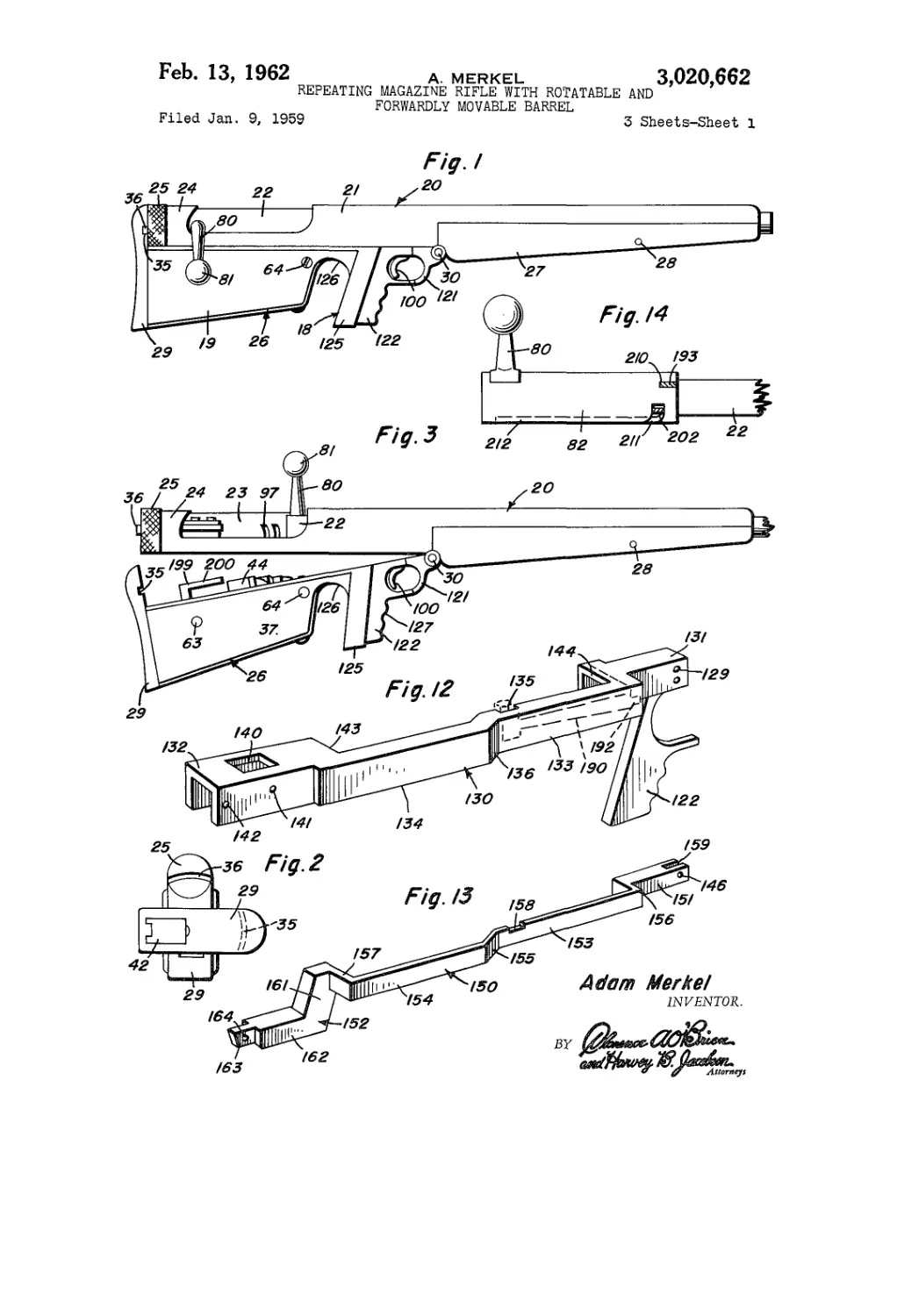
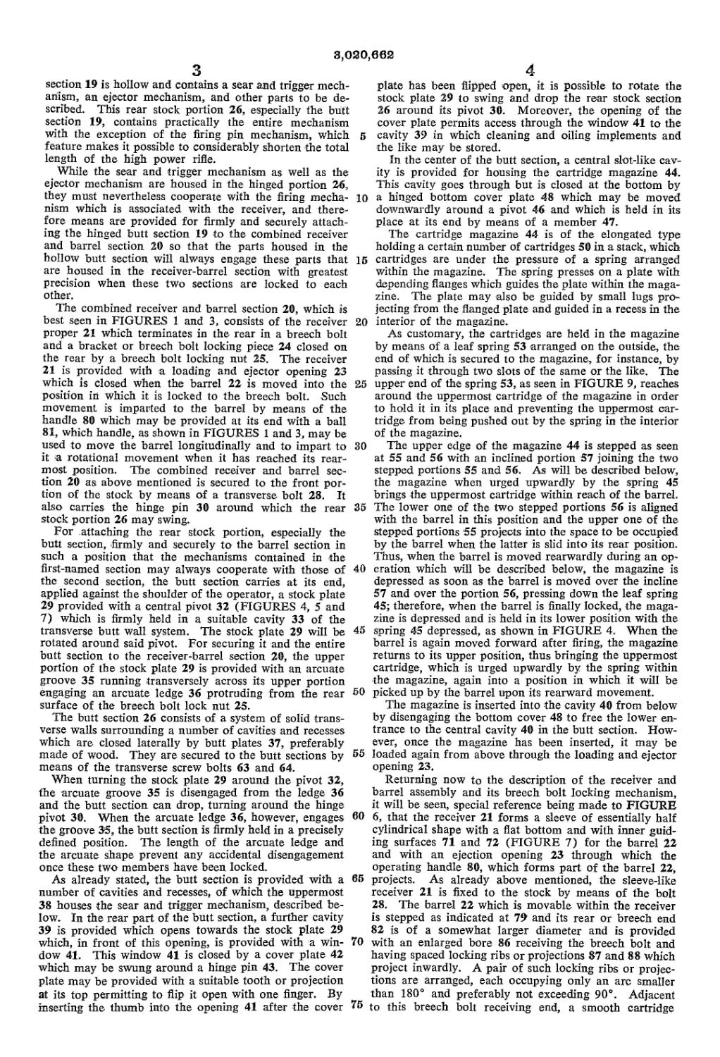
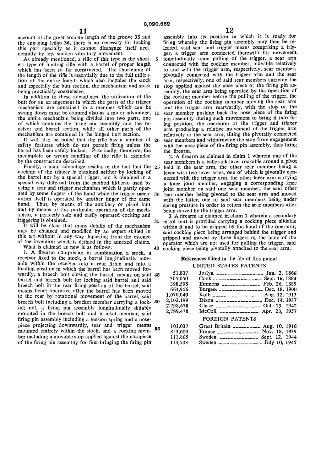
FIGURE 1 is an elevational side view of the rifle
in position for cocking and firing.
FIGURE 2 is an elevational back view of the rifle, in
which view the stock plate at the end of the butt section
is shown as having been turned around.
FIGURE 3 is an elevational side view of the rifle shown
in a position in which the butt section is lowered, the
barrel being in its forward position and the loading and
ejection opening of the receiver being open.
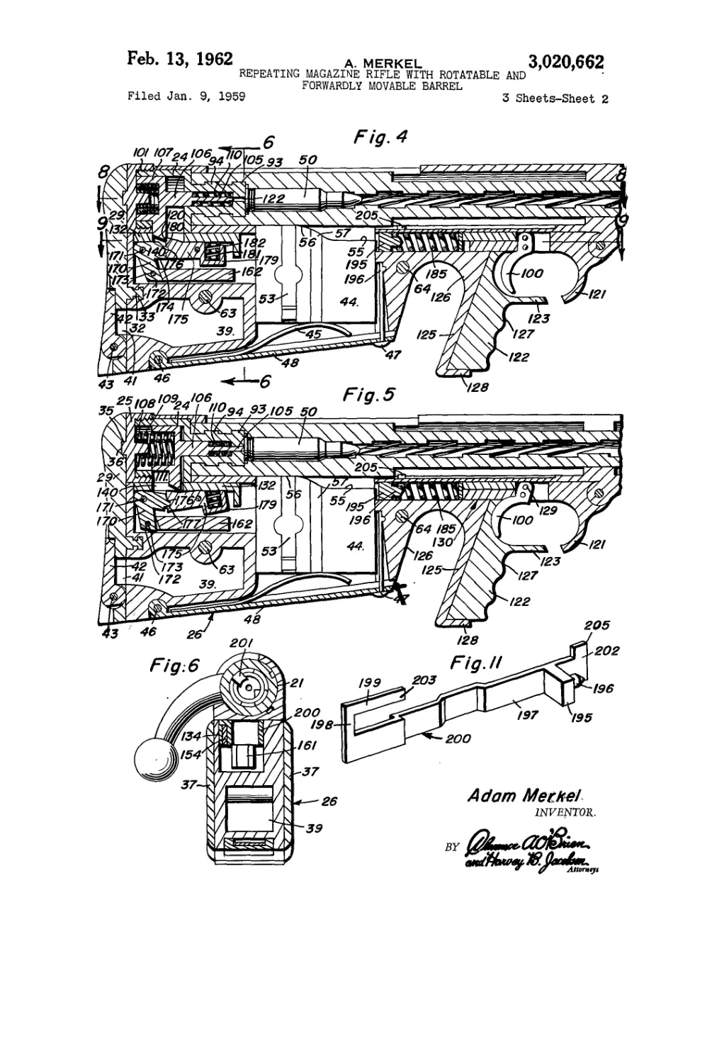
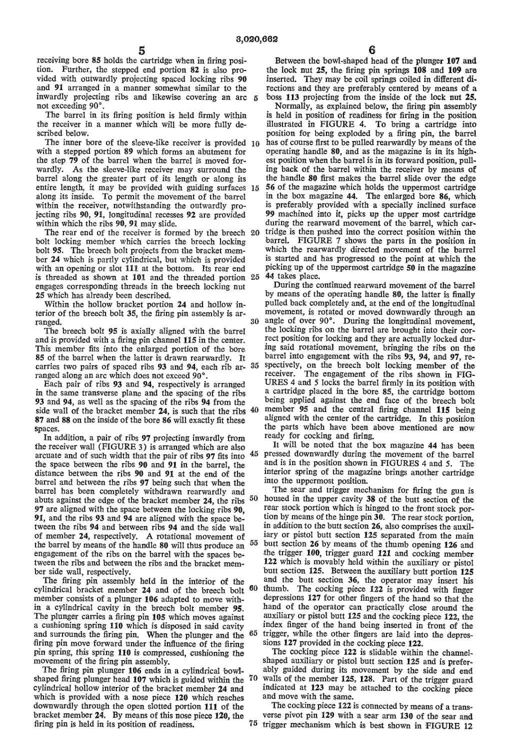
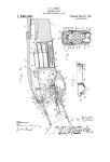
FIGURE 4 is an elevational sectional view of the rear
portion of the rifle when cocked, with all the parts in
5
10
15
20
25
30
35
40
45
50
55
60
65
70
2
position for firing a cartridge which has been inserted into
the breech portion of the barrel, the section being taken
along the median plane of the rifle.
FIGURE 5 is a similar sectional and elevational view
of the rifle, the section being again taken along the median
plane and the parts being shown in the position in which
they are after pulling the trigger in order to produce an
explosion of the cartridge.
FIGURE 6 is an elevational cross-sectional view of the
rifle when in the position shown in FIGURE 4, the sec-
tion being taken along the line 6—6 of FIGURE 4.
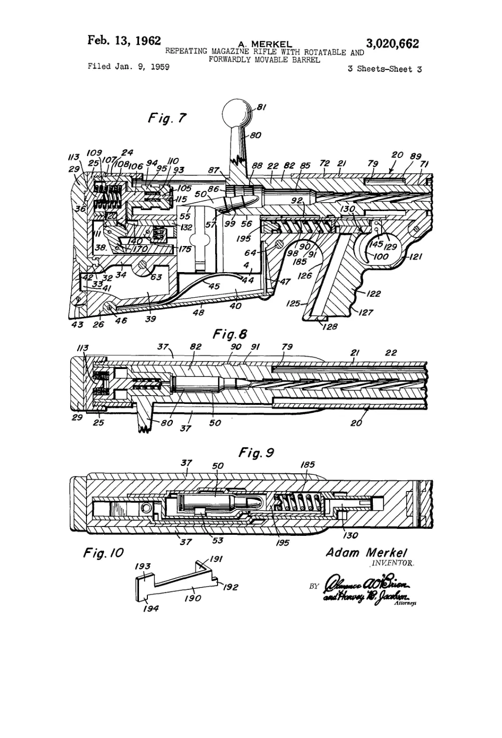
FIGURE 7 is a sectional elevational view of the rear
portion of the rifle showing the same in a position in
which, after the forward movement of the gun in order to
eject the cartridge, a new cartridge is picked up from the
magazine to be inserted into the breech portion of the
barrel.
FIGURE 8 is a sectional plan view, the section being
taken along the line 8—8 of FIGURE 4.
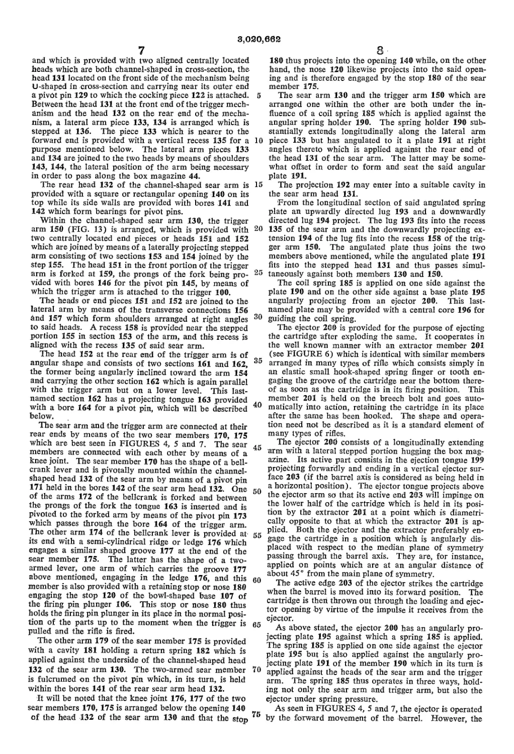
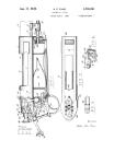
FIGURE 9 is another sectional plan view through the
rear portion of the gun, the section being taken along line
9—9 of FIGURE 4.
FIGURE 10 is a perspective view of an intermediate
angular spring pressure plate.
FIGURE 11 is a perspective view of the ejector.
FIGURE 12 is a perspective view of the sear plate or
sear arm connected with the cocking piece.
FIGURE 13 is a perspective view of the trigger arm
which is operated by the trigger.
FIGURE 14 is a view of the barrel from below show-
ing the groove 212 in which the lug 202 of the ejector
member slides and the curved slot for the lug at the end
of said groove and further showing the locking slot into
which the lug 193 of member 190 enters in order to pre-
vent automatic cocking or firing in any intermediae posi-
tion of the barrel which does not correspond to the cor-
rect firing position of the barrel.
The short stock repeating rifle according to the inven-
tion is based on the principle of moving the barrel within
a quasi stationary receiver, imparting to it a longitudinal
and a rotary movement relatively to the receiver by means
of a handle. The longitudinal movement of the barrel
brings a new cartridge into position from a magazine
which is in an elevated position and depresses the maga-
zine again, and a rotational movement of the barrel locks
the barrel against the breech bolt and the receiver, thus
leaving the rifle in readiness for cocking and firing.
After firing of the rifle, a forward movement of the
barrel preceded by a rotating movement produced by the
upturning of the handle unlocks the breech bolt, and un-
locks the barrel from the receiver; it also removes the
spent cartridge from the barrel, ejecting it through an
ejector opening which is freed by this forward movement.
Further, according to another principle of the invention,
the rear stock portion of the rifle and all its annexed
parts including sear and trigger mechanism, the ejector,
etc. are separated from the barrel and the breech bolt by
a rotary or swinging movement around a hinge, thus mak-
ing these mechanisms accessible from above and permit-
ting cleaning, oiling, adjusting and other operations, while
leaving the firing mechanism in its position.
In FIGURES 1, 2, and 3 a high power, short stock re-
peating rifle according to the invention is illustrated in
the two positions which have been described above.
As seen from these figures, the rifle comprises the com-
bined receiver and barrel structure 20 mounted on and
secured to the front portion of the stock 27, while the
rear portion of the stock, generally designated by 26,
comprises the butt section proper 19 and the auxiliary
or pistol butt 18 with a cocking piece 122 and trigger
100, the entire rear portion of the stock being hinged
to the front portion by means of the pivot 30. The butt
3,020,662
3
section 19 is hollow and contains a sear and trigger mech-
anism, an ejector mechanism, and other parts to be de-
scribed. This rear stock portion 26, especially the butt
section 19, contains practically the entire mechanism
with the exception of the firing pin mechanism, which
feature makes it possible to considerably shorten the total
length of the high power rifle.
While the sear and trigger mechanism as well as the
ejector mechanism are housed in the hinged portion 26,
they must nevertheless cooperate with the firing mecha-
nism which is associated with the receiver, and there-
fore means are provided for fhmly and securely attach-
ing the hinged butt section 19 to the combined receiver
and barrel section 20 so that the parts housed in the
hollow butt section will always engage these parts that
are housed in the receiver-barrel section with greatest
precision when these two sections are locked to each
other.
The combined receiver and barrel section 20, which is
best seen in FIGURES 1 and 3, consists of the receiver
proper 21 which terminates in the rear in a breech bolt
and a bracket or breech bolt locking piece 24 closed on
the rear by a breech bolt locking nut 25. The receiver
21 is provided with a loading and ejector opening 23
which is closed when the barrel 22 is moved into the
position in which it is locked to the breech bolt. Such
movement is imparted to the barrel by means of the
handle 80 which may be provided at its end with a ball
81, which handle, as shown in FIGURES 1 and 3, may be
used to move the barrel longitudinally and to impart to
it a rotational movement when it has reached its rear-
most position. The combined receiver and barrel sec-
tion 20 as above mentioned is secured to the front por-
tion of the stock by means of a transverse bolt 28. It
also carries the hinge pin 30 around which the rear
stock portion 26 may swing.
For attaching the rear stock portion, especially the
butt section, firmly and securely to the barrel section in
such a position that the mechanisms contained in the
first-named section may always cooperate with those of
the second section, the butt section carries at its end,
applied against the shoulder of the operator, a stock plate
29 provided with a central pivot 32 (FIGURES 4, 5 and
7) which is firmly held in a suitable cavity 33 of the
transverse butt wall system. The stock plate 29 will be
rotated around said pivot. For securing it and the entire
butt section to the receiver-barrel section 20, the upper
portion of the stock plate 29 is provided with an arcuate
groove 35 running transversely across its upper portion
engaging an arcuate ledge 36 protruding from the rear
surface of the breech bolt lock nut 25.
The butt section 26 consists of a system of solid trans-
verse walls surrounding a number of cavities and recesses
which are closed laterally by butt plates 37, preferably
made of wood. They are secured to the butt sections by
means of the transverse screw bolts 63 and 64.
When turning the stock plate 29 around the pivot 32,
the arcuate groove 35 is disengaged from the ledge 36
and the butt section can drop, turning around the hinge
pivot 30. When the arcuate ledge 36, however, engages
the groove 35, the butt section is firmly held in a precisely
defined position. The length of the arcuate ledge and
the arcuate shape prevent any accidental disengagement
once these two members have been locked.
As already stated, the butt section is provided with a
number of cavities and recesses, of which the uppermost
38 houses the sear and trigger mechanism, described be-
low. In the rear part of the butt section, a further cavity
39 is provided which opens towards the stock plate 29
which, in front of this opening, is provided with a win-
dow 41. This window 41 is closed by a cover plate 42
which may be swung around a hinge pin 43. The cover
plate may be provided with a suitable tooth or projection
at its top permitting to flip it open with one finger. By
inserting the thumb into the opening 41 after the cover
5
10
15
20
25
30
35
40
45
50
55
60
65
70
75
4.
plate has been flipped open, it is possible to rotate the
stock plate 29 to swing and drop the rear stock section
26 around its pivot 30. Moreover, the opening of the
cover plate permits access through the window 41 to the
cavity 39 in which cleaning and oiling implements and
the like may be stored.
In the center of the butt section, a central slot-like cav-
ity is provided for housing the cartridge magazine 44.
11118 cavity goes through but is closed at the bottom by
a hinged bottom cover plate 48 which may be moved
downwardly around a pivot 46 and which is held in its
place at its end by means of a member 47.
The cartridge magazine 44 is of the elongated type
holding a certain number of cartridges 50 in a stack, which
cartridges are under the pressure of a spring arranged
within the magazine. The spring presses on a plate with
depending flanges which guides the plate within the maga-
zine. The plate may also be guided by small lugs pro-
jecting from the flanged plate and guided in a recess in the
interior of the magazine.
As customary, the cartridges are held in the magazine
by means of a leaf spring 53 arranged on the outside, the
end of which is secured to the magazine, for instance, by
passing it through two slots of the same or the like. The
upper end of the spring 53, as seen in FIGURE 9, reaches
around the uppermost cartridge of the magazine in order
to hold it in its place and preventing the uppermost car-
tridge from being pushed out by the spring in the interior
of the magazine.
The upper edge of the magazine 44 is stepped as seen
at 55 and 56 with an inclined portion 57 joining the two
stepped portions 55 and 56. As will be described below,
the magazine when urged upwardly by the spring 45
brings the uppermost cartridge within reach of the barrel.
The lower one of the two stepped portions 56 is aligned
with the barrel in this position and the upper one of the
stepped portions 55 projects into the space to be occupied
by the barrel when the latter is slid into its rear position.
Thus, when the barrel is moved rearwardly during an op-
eration which will be described below, the magazine is
depressed as soon as the barrel is moved over the incline
57 and over the portion 56, pressing down the leaf spring
45; therefore, when the barrel is finally locked, the maga-
zine is depressed and is held in its lower position with the
spring 45 depressed, as shown in FIGURE 4. When the
barrel is again moved forward after firing, the magazine
returns to its upper position, thus bringing the uppermost
cartridge, which is urged upwardly by the spring within
-the magazine, again into a position in which it will be
picked up by the barrel upon its rearward movement.
Tire magazine is inserted into the cavity 40 from below
by disengaging the bottom cover 48 to free the lower en-
trance to the central cavity 40 in the butt section. How-
ever, once the magazine has been inserted, it may be
loaded again from above through the loading and ejector
opening 23.
Returning now to the description of the receiver and
barrel assembly and its breech bolt locking mechanism,
it will be seen, special reference being made to FIGURE
6, that the receiver 21 forms a sleeve of essentially half
cylindrical shape with a flat bottom and with inner guid-
ing surfaces 71 and 72 (FIGURE 7) for the barrel 22
and with an ejection opening 23 through which the
operating handle 80, which forms part of the barrel 22,
projects. As already above mentioned, the sleeve-like
receiver 21 is fixed to the stock by means of the bolt
28. The barrel 22 which is movable within the receiver
is stepped as indicated at 79 and its rear or breech end
82 is of a somewhat larger diameter and is provided
with an enlarged bore 86 receiving the breech bolt and
having spaced locking ribs or projections 87 and 88 which
project inwardly. A pair of such locking ribs or projec-
tions are arranged, each occupying only an arc smaller
than 180° and preferably not exceeding 90°. Adjacent
to this breech bolt receiving end, a smooth cartridge
8,020,662
5
receiving bore 85 holds the cartridge when in firing posi-
tion. Further, the stepped end portion 82 is also pro-
vided with outwardly projecting spaced locking ribs 90
and 91 arranged in a manner somewhat similar to the
inwardly projecting ribs and likewise covering an arc
not exceeding 90°.
The barrel in its firing position is held firmly within
the receiver in a manner which will be more fully de-
scribed below.
The inner bore of the sleeve-like receiver is provided
with a stepped portion 89 which forms an abutment for
the step 79 of the barrel when the barrel is moved for-
wardly. As the sleeve-like receiver may surround the
barrel along the greater part of its length or along its
entire length, it may be provided with guiding surfaces
along its inside. To permit the movement of the barrel
within the receiver, notwithstanding the outwardly pro-
jecting ribs 90, 91, longitudinal recesses 92 are provided
within which the ribs 90, 91 may slide.
The rear end of the receiver is formed by the breech
bolt locking member which carries the breech locking
bolt 95. The breech bolt projects from the bracket mem-
ber 24 which is partly cylindrical, but which is provided
with an opening or slot 111 at the bottom. Its rear end
is threaded as shown at 101 and the threaded portion
engages corresponding threads in the breech locking nut
25 which has already been described.
Within the hollow bracket portion 24 and hollow in-
terior of the breech bolt 35, the firing pin assembly is ar-
ranged.
The breech bolt 95 is axially aligned with the barrel
and is provided with a firing pin channel 115 in the center.
This member fits into the enlarged portion of the bore
85 of the barrel when the latter is drawn rearwardly. It
carries two pairs of spaced ribs 93 and 94, each rib ar-
ranged along an arc which does not exceed 90°.
Each pair of ribs 93 and 94, respectively is arranged
in the same transverse plane and the spacing of the ribs
93 and 94, as well as the spacing of the ribs 94 from the
side wall of the bracket member 24, is such that the ribs
87 and 88 on the inside of the bore 86 will exactly fit these
spaces.
In addition, a pair of ribs 97 projecting inwardly from
the receiver wall (FIGURE 3) is arranged which are also
arcuate and of such width that the pair of ribs 97 fits into
the space between the ribs 90 and 91 in the barrel, the
distance between the ribs 90 and 91 at the end of the
barrel and between the ribs 97 being such that when the
barrel has been completely withdrawn rearwardly and
abuts against the edge of the bracket member 24, the ribs
97 are aligned with the space between the locking ribs 90,
91, and the ribs 93 and 94 are aligned with the space be-
tween the ribs 94 and between ribs 94 and the side wall
of member 24, respectively. A rotational movement of
the barrel by means of the handle 80 will thus produce an
engagement of the ribs on the barrel with the spaces be-
tween the ribs and between the ribs and the bracket mem-
ber side wall, respectively.
The firing pin assembly held in the interior of the
cylindrical bracket member 24 and of the breech bolt
member consists of a plunger 106 adapted to move with-
in a cylindrical cavity in the breech bolt member 95.
The plunger carries a firing pin 105 which moves against
a cushioning spring 110 which is disposed in said cavity
and surrounds the firing pin. When the plunger and the
firing pin move forward under the influence of the firing
pin spring, this spring 110 is compressed, cushioning the
movement of the firing pin assembly.
The firing pin plunger 106 ends in a cylindrical bowl-
shaped firing plunger head 107 which is guided within the
cylindrical hollow interior of the bracket member 24 and
which is provided with a nose piece 120 which reaches
downwardly through the open slotted portion 111 of the
bracket member 24. By means of this nose piece 120, the
firing pin is held in its position of readiness.
6
10
15
20
25
30
35
40
45
50
55
60
65
70
75
6
Between the bowl-shaped head of the plunger 107 and
the lock nut 25, the firing pin springs 108 and 109 are
inserted. They may be coil springs coiled in different di-
rections and they are preferably centered by means of a
boss 113 projecting from the inside of the lock nut 25.
Normally, as explained below, the firing pin assembly
is held in position of readiness for firing in the position
illustrated in FIGURE 4. To bring a cartridge into
position for being exploded by a firing pin, the barrel
has of course first to be pulled rearwardly by means of the
operating handle 80, and as the magazine is in its high-
est position when the barrel is in its forward position, pull-
ing back of the barrel within the receiver by means of
the handle 80 first makes the barrel slide over the edge
56 of the magazine which holds the uppermost cartridge
in the box magazine 44. The enlarged bore 86, which
is preferably provided with a specially inclined surface
99 machined into it, picks up the upper most cartridge
during the rearward movement of the barrel, which car-
tridge is then pushed into the correct position within the
barrel. FIGURE 7 shows the parts in the position in
which the rearwardly directed movement of the barrel
is started and has progressed to the point at which the
picking up of the uppermost cartridge 50 in the magazine
44 takes place.
During the continued rearward movement of the barrel
by means of the operating handle 80, the latter is finally
pulled back completely and, at the end of the longitudinal
movement, is rotated or moved downwardly through an
angle of over 90°. During the longitudinal movement,
the locking ribs on the barrel are brought into their cor-
rect position for locking and they are actually locked dur-
ing said rotational movement, bringing the ribs on the
barrel into engagement with the ribs 93, 94, and 97, re-
spectively, on the breech bolt locking member of the
receiver. The engagement of the ribs shown in FIG-
URES 4 and 5 locks the barrel firmly in its position with
a cartridge placed in the bore 85, the cartridge bottom
being applied against the end face of the breech bolt
member 95 and the central firing channel 115 being
aligned with the center of the cartridge. In this position
the parts which have been above mentioned are now
ready for cocking and firing.
It will be noted that the box magazine 44 has been
pressed downwardly during the movement of the barrel
and is in the position shown in FIGURES 4 and 5. The
interior spring of the magazine brings another cartridge
into the uppermost position.
The sear and trigger mechanism for firing the gun is
housed in the upper cavity 38 of the butt section of the
rear stock portion which is hinged to the front stock por-
tion by means of the hinge pin 30. The rear stock portion,
in addition to the butt section 26, also comprises the auxil-
iary or pistol butt section 125 separated from the main
butt section 26 by means of the thumb opening 126 and
the trigger 100, trigger guard 121 and cocking member
122 which is movably held within the auxiliary or pistol
butt section 125. Between the auxiliary butt portion 125
and the butt section 36, the operator may insert his
thumb. The cocking piece 122 is provided with finger
depressions 127 for other fingers of the hand so that the
hand of the operator can practically close around the
auxiliary or pistol butt 125 and the cocking piece 122, the
index finger of the hand being inserted in front of the
trigger, while the other fingers are laid into the depres-
sions 127 provided in the cocking piece 122.
The cocking piece 122 is slidable within the channel-
shaped auxiliary or pistol butt section 125 and is prefer-
ably guided during its movement by the side and end
walls of the member 125, 128. Part of the trigger guard
indicated at 123 may be attached to the cocking piece
and move with the same.
The cocking piece 122 is connected by means of a trans-
verse pivot pin 129 with a sear arm 130 of the sear and
trigger mechanism which is best shown in FIGURE 12
3,020,662
7
and which is provided with two aligned centrally located
heads which are both channel-shaped in cross-section, the
head 131 located on the front side of the mechanism being
U-shaped in cross-section and carrying near its outer end
a pivot pin 129 to which the cocking piece 122 is attached.
Between the head 131 at the front end of the trigger mech-
anism and the head 132 on the rear end of the mecha-
nism, a lateral arm piece 133, 134 is arranged which is
Stepped at 136. The piece 133 which is nearer to the
forward end is provided with a vertical recess 135 for a
purpose mentioned below. The lateral arm pieces 133
and 134 are joined to the two heads by means of shoulders
143, 144, the lateral position of the arm being necessary
in order to pass along the box magazine 44.
The rear head 132 of the channel-shaped sear arm is
provided with a square or rectangular opening 140 on its
top while its side walls are provided with bores 141 and
142 which form bearings for pivot pins.
Within the channel-shaped sear arm 130, the trigger
arm 150 (FIG. 13) is arranged, which is provided with
two centrally located end pieces or heads 151 and 152
which are joined by means of a laterally projecting stepped
arm consisting of two sections 153 and 154 joined by the
Step 155. The head 151 in the front portion of the trigger
arm is forked at 159, the prongs of the fork being pro-
vided with bores 146 for the pivot pin 145, by means of
which the trigger arm is attached to the trigger 100.
The heads or end pieces 151 and 152 are joined to the
lateral arm by means of the transverse connections 156
and 157 which form shoulders arranged at right angles
to said heads. A recess 158 is provided near the stepped
portion 155 in section 153 of the arm, and this recess is
aligned with the recess 135 of said sear arm.
The head 152 at the rear end of the trigger arm is of
angular shape and consists of two sections 161 and 162,
the former being angularly inclined toward the arm 154
and carrying the other section 162 which is again parallel
with the trigger arm but on a lower level. This last-
named section 162 has a projecting tongue 163 provided
with a bore 164 for a pivot pin, which will be described
below.
The sear arm and the trigger arm are connected at their
rear ends by means of the two sear members 170, 175
which are best seen in FIGURES 4, 5 and 7. The sear
members are connected with each other by means of a
knee joint. The sear member 170 has the shape of a bell-
crank lever and is pivotally mounted within the channel-
shaped head 132 of the sear arm by means of a pivot pin
171 held in the bores 142 of the sear arm head 132. One
of the arms 172 of the bellcrank is forked and between
the prongs of the fork the tongue 163 is inserted and is
pivoted to the forked arm by means of the pivot pin 173
which passes through the bore 164 of the trigger arm.
The other arm 174 of the bellcrank lever is provided at
its end with a semi-cylindrical ridge or ledge 176 which
engages a similar shaped groove 177 at the end of the
sear member 175. The latter has the shape of a two-
armed lever, one arm of which carries the groove 177
above mentioned, engaging in the ledge 176, and this
member is also provided with a retaining stop or nose 180
engaging the stop 120 of the bowl-shaped base 107 of
the firing pin plunger 106. This stop or nose 180 thus
holds the firing pin plunger in its place in the normal posi-
tion of the parts up to the moment when the trigger is
pulled and the rifle is fired.
The other arm 179 of the sear member 175 is provided
with a cavity 181 holding a return spring 182 which is
applied against the underside of the channel-shaped head
132 of the sear arm 130. The two-armed sear member
is fulcrumed on the pivot pin which, in its turn, is held
within the bores 141 of the rear sear arm head 132.
It will be noted that the knee joint 176, 177 of the two
sear members 170, 175 is arranged below the opening 140
of the head 132 of the sear arm 130 and that the stop
5
10
15
20
25
30
35
40
45
50
55
60
65
70
75
8 •
180 thus projects into the opening 140 while, on the other
hand, the nose 120 likewise projects into the said open-
ing and is therefore engaged by the stop 180 of the sear
member 175.
The sear arm 130 and the trigger arm 150 which are
arranged one within the other are both under the in-
fluence of a coil spring 185 which is applied against the
angular spring holder 190. The spring holder 190 sub-
stantially extends longitudinally along the lateral arm
piece 133 but has angulated to it a plate 191 at right
angles thereto which is applied against the rear end of
the head 131 of the sear arm. The latter may be some-
what offset in order to form and seat the said angular
plate 191.
The projection 192 may enter into a suitable cavity in
the sear arm head 131.
From the longitudinal section of said angulated spring
plate an upwardly directed lug 193 and a downwardly
directed lug 194 project. The lug 193 fits into the recess
135 of the sear arm and the downwardly projecting ex-
tension 194 of the lug fits into the recess 158 of the trig-
ger arm 150. The angulated plate thus joins the two
members above mentioned, while the angulated plate 191
fits into the stepped head 131 and thus passes simul-
taneously against both members 130 and 150.
The coil spring 185 is applied on one side against the
plate 190 and on the other side against a base plate 195
angularly projecting from an ejector 200. This last-
named plate may be provided with a central core 196 for
guiding the coil spring.
The ejector 20® is provided for the purpose of ejecting
the cartridge after exploding the same. It cooperates in
the well known manner with an extractor member 201
(see FIGURE 6) which is identical with similar members
arranged in many types of rifle which consists simply in
an elastic small hook-shaped spring finger or tooth en-
gaging the groove of the cartridge near the bottom there-
of as soon as the cartridge is in its firing position. This
member 201 is held on the breech bolt and goes auto-
matically into action, retaining the cartridge in its place
after the same has been hooked. The shape and opera-
tion need not be described as it is a standard element of
many types of rifles.
The ejector 200 consists of a longitudinally extending
arm with a lateral stepped portion hugging the box mag-
azine. Its active part consists in the ejection tongue 199
projecting forwardly and ending in a vertical ejector sur-
face 203 (if the barrel axis is considered as being held in
a horizontal position). The ejector tongue projects above
the ejector arm so that its active end 203 will impinge on
the lower half of the cartridge which is held in its posi-
tion by the extractor 201 at a point which is diametri-
cally opposite to that at which the extractor 201 is ap-
plied. Both the ejector and the extractor preferably en-
gage the cartridge in a position which is angularly dis-
placed with respect to the median plane of symmetry
passing through the barrel axis. They are, for instance,
applied on points which are at an angular distance of
about 45° from the main plane of symmetry.
The active edge 203 of the ejector strikes the cartridge
when the barrel is moved into its forward position. The
cartridge is then thrown out through the loading and ejec-
tor opening by virtue of the impulse it receives from the
ejector.
As above stated, the ejector 200 has an angularly pro-
jecting plate 195 against which a spring 185 is applied.
The spring 185 is applied on one side against the ejector
plate 195 but is also applied against the angularly pro-
jecting plate 191 of the member 190 which in its turn is
applied against the heads of the sear arm and the trigger
arm. The spring 185 thus operates in three ways, hold-
ing not only the sear arm and trigger arm, but also the
ejector under spring pressure.
As seen in FIGURES 4, 5 and 7, the ejector is operated
by the forward movement of the barrel. However, the
8,030,662
9
forward movement of the barrel must have progressed
already to a certain extent when the ejector 200 strikes
the cartridge, in order that the loading and ejector open-
ing may have been opened sufficiently to permit the car-
tridge to be thrown out. Thus, the first part of the bar-
rel movement does not operate the ejector. The ejector
200 is operated by an upstanding lug 202 which reaches
into a groove 212 of the barrel. This groove (FIGURE
14) must be arranged laterally of the median plane of
the rifle in view of the fact that also the ejector 200 is
arranged in a lateral position. The lug 202 first slides
in this groove when the barrel is moved forwardly until
the groove comes to an end. Then the ejector is moved
forward against the tension of the spring 185 and ejects
the cartridge which is held on the diametrically opposite
side by the extractor 201. The spring 185 is compressed
during this forward movement of the ejector; the ejector
is returned by the spring when the barrel is again drawn
rearwardly by the operator.
The operation of the rifle will be readily understood
from the foregoing description.
It may first be assumed that the butt section is firmly
locked by means of its groove 35 and the arcuate ridge
or ledge 36 to the breech bolt and barrel section. The
parts are then in the position shown in FIGURE 7, ex-
cept that the barrel is shown in this figure as being moved
rearwardly about half way. In order to load the rifle,
the cover plate 48 is dropped by moving the spring 47
out of engagement with the cover plate and the box
magazine 44 is inserted. In the first insertion of course
the box magazine may be loaded, but after the car-
tridges in the box magazine have been fired, the magazine
may be loaded again through the loading and ejecting
opening after the barrel has been pushed forward by
means of the handle 80 and 81. As has been explained,
the topmost cartridge is held on one side by the finger
on spring 53 and is under spring pressure from below.
The topmost cartridge is always in the same position with
the cartridge about flush with the elevated portion of the
box magazine 55 whatever the number of cartridges in
the box magazine.
In order to bring the rifle into position for firing, the
operator pulls back the barrel 22 by means of handle 80
and ball 81, pulling the handle into its rearmost posi-
tion and then rotating it downwardly through an angle of
about 100°. The barrel thus moves within the receiver
and during this operation the barrel first slides along the
upper edge 55 of the box magazine 44, taking up the top
cartridge, the tip of which projects above the more de-
pressed portion 55. The tip of the cartridge is then di-
rected by means of the incline 99 towards the space 85
and upon rearward movement of the barrel the cartridge
enters the space 85 and occupies the position which is,
for instance, shown in FIGURES 4 and 5.
As long as the box magazine 44 is loaded, one car-
tridge is always held in this position between spring pres-
sure from below and the finger-like end of spring 53.
Upon continued rearward movement of the barrel
performed by the operator of the rifle, it will be seen that
a further rearward movement after picking up the car-
tridge will result in depressing the magazine 44 as the bar-
rel slides over the incline, bringing the magazine into the
position which is shown in FIGURES 4 and 5.
Towards the end of the rearward movement of the
barrel, the locking ribs 87, 88, 90, 91 on the barrel have
reached positions in which these ribs are aligned with the
spaces between the ribs 93 and 94 and between 94 and the
end surface of the bracket member 24, and upon rotation
of the handle 80 which follows, the ribs on the barrel
engage the ribs on the breech bolt and on the receiver,
so that the barrel is firmly locked in the position in which
it is ready for firing. In this position, it will be clear
from FIGURES 4 and 5 that the breech bolt closes the
breech opening of the barrel with a cartridge held there-
in. With the locking of the breech bolt, it will be clear
5
10
15
20
25
30
35
40
45
50
55
60
65
70
75
10
that also the extractor 201 snaps into its position in which
it holds and engages the groove near the bottom of the
cartridge.
The rifle can be carried when the barrel is in this posi-
tion because an accidental movement of the trigger would
not be sufficient to produce firing of the rifle which can
only take place after two coordinated movements have
been performed.
When sighting the target and making the rifle ready
for firing, the mechanism must first be cocked, which
is done by inserting the thumb into the opening 126
between the butt section and the pistol grip and firmly
gripping the auxiliary butt portion or pistol butt 125.
When the fingers close around the pistol grip and are
inserted into the grooves 127 and pull back the cocking
piece 122, the rifle is made ready for firing by the trig-
ger. The pulling back of the cocking piece 122 operates
the sear and trigger mechanism, in the first place operat-
ing the sear arm which is pushed back against the pres-
sure of the spring 185, thus bringing the sear arm into
the position which is shown in FIGURE 4.
The sear arm and the trigger arm both move together
so that the position of the sear members is not changed.
This common movement of the sear arm and the trigger
arm is obtained by means of the coupling element 190.
During this movement of the trigger arm and sear
arm, the stop or nose member 180 of the sear member
175 pushes the firing pin plunger rearwardly by engag-
ing the nose 120 against which the stop 180 is applied.
The firing pin is thus under tension and all parts are
now ready for firing.
When the trigger is now pulled, the trigger arm 150
moves rearwardly relative to the sear arm. This trips
the two sear members 170 and 175; the arm 174 of the
former is now moved downwardly and this, by means
of the knee joint 176, 177, also trips the other sear
member 175. This movement is performed by means
of the trigger arm head 163 which pushes the sear mem-
ber 170 to the left in FIGURE 5. This movement of
the sear member 170 entails a movement of the sear
member 175 which moves the stop 180 out of engage-
ment with nose 120, and thus releases the firing pin which
will snap forward through the influence of the com-
pressed springs 108 and 109 and which will push the
firing pin 105 into the cartridge. This movement of the
firing pin is cushioned by spring 110 in the central cavity
of the breech bolt.
The cartridge is exploded upon this movement of the
firing pin.
The release of the trigger brings the firing pin and the
trigger arm back into its original position which is shown
in FIGURE 7, if the grip around the cocking piece 122
is released after the shot. The sear and trigger arms
are both moved back by the spring 185 and the operator
of the rifle has now to move the barrel again forwardly
in order to eject the spent cartridge. In order to do so,
the handle 80 is seized and has first to be turned around
and then to be moved forwardly, bringing the parts to
the position shown in FIGURE 7. It is during this move-
ment that the ejector is operated as above described.
The next movement of the operator will again be the
drawing back of the barrel in order to bring another
cartridge into the correct position for firing.
For the purpose of cleaning and inspecting or repair-
ing the rifle, the butt section 26 may be disengaged from
the barrel and receiver section and swung around the
pivot 30. It will be noted that the entire trigger mech-
anism as well as the ejector mechanism is carried by the
butt section 26 which is swung around the pivot. The
upper side of the entire mechanism is thus accessible.
In order to unhinge the butt section with the least pos-
sible effort, it is only necessary to open the flap 42 of
the stock plate, which may be done by means of a finger-
nail, and to insert a finger into the window 41 which is
now open, and to turn the stock plate around. On
3,030,662
11
account of the great arcuate length of the groove 35 and
the engaging ledge 36, there is no necessity for locking
this part specially as it cannot disengage itself acci-
dentally by any sudden vibratory movement.
As already mentioned, a rifle of this type is the short-
est type of hunting rifle with a barrel of proper length
which has been so far constructed. The shortening of
the length of the rifle is essentially due to the full utiliza-
tion of the entire length which also includes the stock
and especially the butt section, the mechanism and stock
being practically coextensive.
In addition to these advantages, the utilization of the
butt for an arrangement in which the parts of the trigger
mechanism are contained in a member which can be
swung down must be counted also as a major advantage,
the entire mechanism being divided into two parts, one
of which contains the firing pin assembly and the re-
ceiver and barrel section, while all other parts of the
mechanism are contained in the hinged butt section.
It will also be noted that the rifle has a number of
safety features which do not permit firing unless the
barrel has been safely locked. Practically, therefore, the
incomplete or wrong handling of the rifle is excluded
by the construction described.
Finally, a main advantage resides in the fact that the
cocking of the trigger is obtained neither by locking of
the barrel nor by a special trigger, but is obtained in a
special way different from the method hitherto used by
using a sear and trigger mechanism which is partly oper-
ated by some fingers of the hand while the trigger mech-
anism itself is operated by another finger of the same
hand. Thus, by means of the auxiliary or pistol butt
and by means of this particular operation of the mech-
anism, a perfectly safe and easily operated cocking and
triggering is obtained.
It will be clear that many details of the mechanism
may be changed and modified by an expert skilled in.
this art without in any way departing from the essence
of the invention which is defined in the annexed claims.
What is claimed as new is as follows:
1. A firearm comprising in combination a stock, a
receiver fixed to the stock, a barrel longitudinally mov-
able within the receiver into a rear firing and into a
loading position in which the barrel has been moved for-
wardly, a breech bolt closing the barrel, means on said
barrel and breech bolt for locking said barrel and said
breech bolt in the rear firing position of the barrel, said
means being operative after the barrel has been moved
to the rear by rotational movement of the barrel, said
breech bolt including a bracket member carrying a lock-
ing nut, a firing pin assembly longitudinally slidably
mounted in the breech bolt and bracket member, said
firing pin assembly including a tension spring and a nose-
piece projecting downwardly, sear and trigger means
mounted entirely within the stock, and a cocking mem-
ber including a movable stop applied against the nosepiece
of the firing pin assembly for first bringing the firing pin
5
10
15
20
25
30
35
40
45
50
55
12
assembly into its position in which it is ready for
firing whereby the firing pin assembly may then be re-
leased, said sear and trigger means comprising a trig-
ger, a trigger arm connected therewith for movement
longitudinally upon pulling of the trigger, a sear arm
connected with the cocking member, movable relatively
to and with the trigger arm, respectively, sear members
pivotally connected with the trigger arm and the sear
arm, respectively, one of said sear members carrying the
stop applied against the nose piece of the firing pin as-
sembly, the sear arm being operated by the operation of
the cocking member before the pulling of the trigger, the
operation of the cocking member moving the sear arm
and the trigger arm rearwardly, with the stop on the
sear member pushing back the nose piece of the firing
pin assembly during such movement to bring it into fir-
ing position, the operation of the trigger and trigger
arm producing a relative movement of the trigger arm
relatively to the sear arm, tilting the pivotally connected
sear members and withdrawing the stop from engagement
with the nose piece of the firing pin assembly, thus firing
the firearm.
2. A firearm as claimed in claim 1 wherein one of the
sear members is a bellcrank lever rockable around a pivot
held in the sear arm, the other sear member being a
lever with two lever arms, one of which is pivotally con-
nected with the trigger arm, the other lever arm carrying
a knee joint member, engaging a corresponding knee
joint member on said one sear member, the said other
sear member being pivoted to the sear arm and moved
with the latter, one of said sear members being under
spring pressure in order to return the sear members after
being moved by the trigger arm.
3. A firearm as claimed in claim 1 wherein a secondary
pistol butt is provided carrying a cocking piece slidable
within it and to be gripped by the hand of the operator,
said cocking piece being arranged behind the trigger and
gripped and moved by those fingers of the hand of the
operator which are not used for pulling the trigger, said
cocking piece being pivotally attached to the sear arm.
References Cited in the file of this patent
UNITED STATES PATENTS
51,837 Joslyn_____________________Jan. 2, 1866
305,050 Cook_____________________Sept. 16, 1884
398,595 Emmens_____________________Feb. 26, 1889
663,956 Burgess___________________Dec. 18, 1900
1,070,040 Kolb______________________Aug. 12, 1913
2,102,199 Dixon_____________________Dec. Г4, 1937
2,298,678 Chase_____________________Oct. 13, 1942
2,789,478 McColl___________________Apr. 23, 1957
FOREIGN PATENTS
101,037 Great Britain_____________Aug. 10, 1916
853,003 France__________________Nov. 18, 1939
111,805 Sweden__________________Sept. 12, 1944
114,503 Sweden_____________________July 10, 1945