/


Tags: weapons military affairs
Text
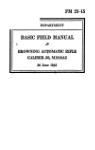
BROWNING
Automatic Machine Rifle
TYPE D
with detachable barrel
Fabrique Nationale
d'Armes de Guerre
S о c i ё t ё Anonyme
HERSTAL - LEZ-LltGE
(BELGIUM)
BROWNING
Automatic Machine Rifle
TYPE D
with detachable barrel
Fabrique Nationale
d’Armes de Guerre
Societe Anonyme
HERSTAL - LEZ -LIEGE
(BELGIUM)
---®---
INTRODUCTION
The Browning automatic rifle was originally designed
by John Browning in 1917, to meet the requirements of the
American Army during the 1914-1918 war. For this purpose
it was mass-produced by the Colt Company in America,
and used by the U. S. Armed Forces during the first world
war and also in the second.
John M. Browning had for several years worked in
Liege in close collaboration with Fabrique Nationale
d'Armes de Guerre, and during this time had perfected
many inventions. It was, therefore, natural that the
Browning automatic machine rifle patents should be
entrusted to them for manufacture.
During the period between the two wars F. N. in-
troduced several modifications and improvements. These
culminated in the ‘Type 30", made to the requirements
of the Belgian Government, and incorporated a gas regu-
lator and a slowing-up device to be used to reduce the
rate of fire, when required.
Fabrique Nationale have now put on the market the
present Model “D”, which embodies the experience gained
during the last war, and the technical advantages of
modern steels and methods of production. The main
features of the original design are still maintained, but in
the new model the barrel has been made removable, and
it is possible to take out the breech-block mechanism
without complete stripping.
Its light weight, accuracy and speed into action,
combined with its robustness and simplicity, make the
Browning automatic machine rifle suitable for use in the
field both as an automatic rifle and as a light machine gun.
Plate I.
F. N. Browning automatic machine rifle type D with detachable barrel.
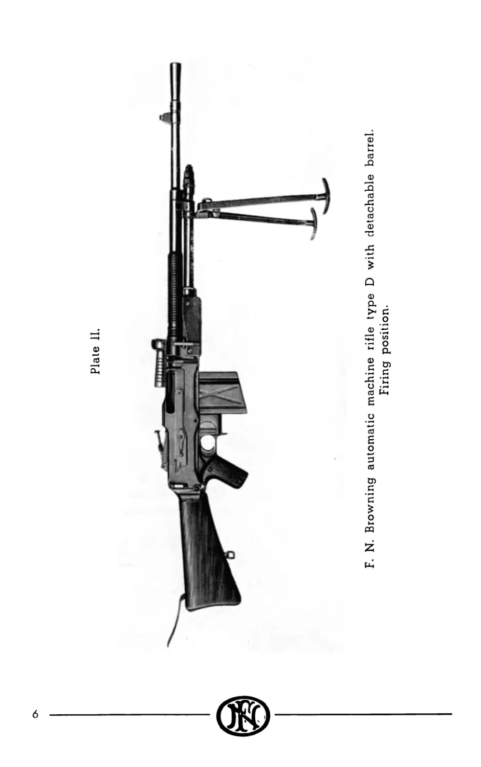
Plate 11.
F. N. Browning automatic machine rifle type D with detachable barrel.
Firing position.
GENERAL CHARACTERISTICS
Method of operation. — The breech mechanism is auto-
matically opened by means of gas operating through
the gas cylinder on a piston. The closing of the
breech is done by means of the usual return springs.
During the actual firing of the cartridge the breech-
block is positively locked, but remains held in the
rear position after the opening operation has been
performed.
Detachable barrel. — This is held in the receiver by a
differential nut, which takes up any play or clearance
between the barrel and receiver. The barrel is air-
cooled by flanges, and is equipped with a handle
for transport or dismounting of the barrel.
Method of feed. — The method of feed is by means of a
20-round magazine positioned in the underside of
the receiver. This position reduces visibility to an
enemy, and magazines can be changed without the
firer betraying his position.
Rates of fire. — The normal rate of fire is 600 rounds per
minute, but a specially designed slowing-up device,
which is incorporated in the trigger guard, enables
this rate to be reduced to 350 rounds per minute.
Stripping. — Stripping is possible in two stages. In the
first place the breech-block can be quickly removed
by the firer, whilst still in the firing position, for the
purpose of replacing a firing pin or extractor.
Complete stripping of the mechanism can be done
in the same position by hinging the butt downwards
to form a support, leaving both hands free to handle
the mechanism.
Safety. — Every care has been taken to ensure safety under
all conditions. In addition to the normal mechanical
safeties, the breech-block is also positively locked at
the moment of firing, which cannot occur premature-
ly. The mechanism being held in the rear position
after a round has been fired enables the chamber to
cool more quickly, and there is no danger from a
cartridge being left in a hot barrel.
Suppleness. — The Browning automatic rifle has a re-
markable suppleness of action because the opening
of the bolt is progressive by means of cams. The
extraction of the case does not occur by a straight
pull but by soft primary extraction. This avoids
hardship of the mechanism and allows a good
functioning without cleaning nor oiling event with
ammunition which are not perfect. It is one of
the reasons why the gun is able to function without
breakages or stoppages of any kind.
Gas regulator. — The amount of gas taken from the barrel
into the gas cylinder is controlled by a regulator,
based on the exhaust type, that is to say the regu-
lator allows sufficient gas to enter the gas cylinder
to operate the mechanism and the surplus is vented
outside. By this means, it is possible to regulate the
functioning of the gun to suit atmospheric conditions
or variation in types of ammunition. The fouling of
the mechanism is also reduced to a minimum, and
the flow of escaping gas ensures constant clearance
of gas fouling.
Holding open device. — When the magazine is empty a
special device keeps the mechanism open. One has
just to drop the empty magazine and put a full one
in place: firing may be resumed at once without
cocking the gun.
Buffering. — The final rearward movement of the me-
chanism is damped by a specially designed buffer,
housed in the butt, which absorbs the final shock of
recoil, and thereby reduces wear on the mechanism
and fatigue of the firer.
Ejection. — Ejection is to the right and slightly forward.
Weatherproofness. - All openings have been provided
with covers to ensure maximum protection against
dust and mud.
Portability. — The weight and balance of the weapon are
such that it can be carried quite easily by the carry-
ing handle.
Calibre. - The gun can be produced to fire any type of
infantry rimless ammunition.
Accessories. — A bipod is provided for stability during
firing. This is also the purpose of the shoulder strap
fitted on the butt. If required, a light tripod can be
provided, so that the gun may be used in a heavier
machine gun role.
SUMMARY DESCRIPTION
Principal parts of the F. N. Browning automatic rifle
type D:
1. Barrel group: barrel, foresight, regulator and handle,-
2. Receiver group: receiver, gas cylinder and bipod;
3. Mechanism,-
4. Trigger guard with slowing-up device,-
5. Butt with buffer and return springs,-
6. Magazine.
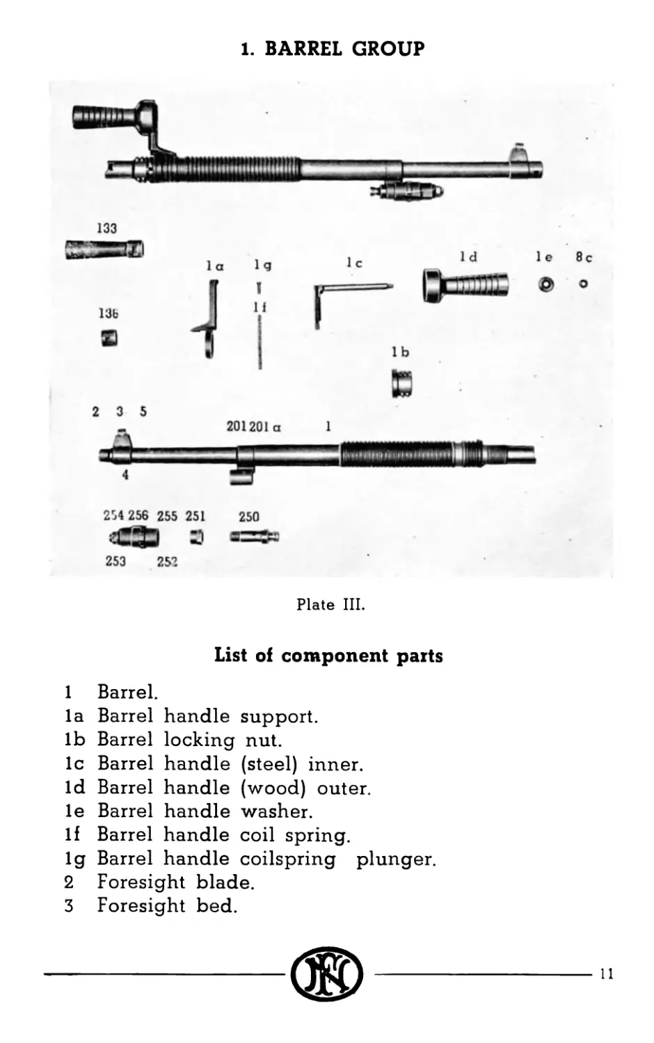
1. BARREL GROUP
Plate III.
List of component parts
1 Barrel.
la Barrel handle support.
lb Barrel locking nut.
1c Barrel handle (steel) inner.
Id Barrel handle (wood) outer.
le Barrel handle washer.
If Barrel handle coil spring.
1g Barrel handle coilspring plunger.
2 Foresight blade.
3 Foresight bed.
11
4 Foresight bed key.
5 Foresight bed pin.
8c Nut for barrel handle.
133 Flash hider.
136 Muzzle ring.
201 Gas cylinder tube bracket.
201a Gas cylinder tube bracket pin.
250 Regulator.
251 Regulator fixing nut.
252 Regulator operating screw.
253 Regulator operating screw head.
254 Regulator operating screw assembling pin.
255 Regulator sliding shroud.
256 Regulator sliding shroud spring.
The barrel (1) is provided at the front by a foresight
bed (3) which is supporting the foresight blade (2). It has
also a gas cylinder bracket (201) which is a housing for the
regulator (250-256).
The lower wall of the barrel has a hole in the gas
cylinder bracket. It is through this hole that the gas is
blown into the gas cylinder.
At the rear end the barrel has a handle (la) connected
with the locking nut (lb) which has an external and inter-
nal differential thread. The internal thread engages the
barrel, the external thread engages the receiver.
By swinging the handle, it is thus possible, for the
differential thread, to tighten the barrel on the receiver
so as to avoid any clearance which is automatically
absorbed.
By pulling the handle, in the same way as if one
wished to separate it from the barrel, it is loosened from
the notch in the locking nut and the handle is no more
connected to the nut and can swing freely. It may then
be used as a handle to carry the gun.
The muzzle of the barrel has a thread which may be
used to screw the muzzle ring (136) the flash hider (133)
or the blank firing device (503).
12
®---
The rear of the barrel has a recess for the extractor (45)
and a ramp guiding the cartridges in the chamber.
The barrel has flanges to increase air cooling.
The regulator is of the exhaust type. In the unscrewed
position it enables most of the gas to escape outside while
only a small part of it is allowed to penetrate into the gas
cylinder. In the screwed position, most of the gas goes
straight in the gas cylinder.
This has the advantage to allow just the quantity of
gas required to operate the gun to come into the mecha-
nism.
13
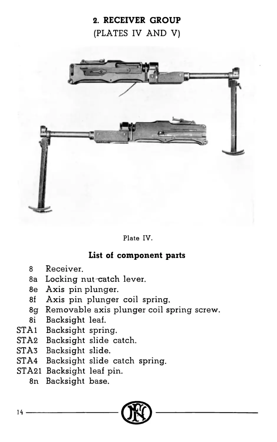
2. RECEIVER GROUP
(PLATES IV AND V)
Plate IV.
List of component parts
8 Receiver.
8a Locking nuthatch lever.
8e Axis pin plunger.
8f Axis pin plunger coil spring.
8g Removable axis plunger coil spring screw.
8i Backsight leaf.
STA1 Backsight spring.
STA2 Backsight slide catch.
STA3 Backsight slide.
STA4 Backsight slide catch spring.
STA21 Backsight leaf pin.
8n Backsight base.
14
8n 80 8i STA21 STA 1
BH ’ I-------
STA 3 STA 2
] fSTH
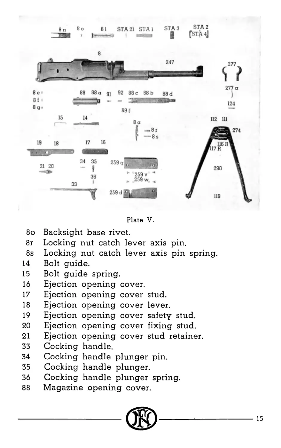
Plate V.
8o Backsight base rivet.
8r Locking nut catch lever axis pin.
8s Locking nut catch lever axis pin spring.
14 Bolt guide.
15 Bolt guide spring.
16 Ejection opening cover.
17 Ejection opening cover stud.
18 Ejection opening cover lever.
19 Ejection opening cover safety stud.
20 Ejection opening cover fixing stud.
21 Ejection opening cover stud retainer.
33 Cocking handle.
34 Cocking handle plunger pin.
35 Cocking handle plunger.
36 Cocking handle plunger spring.
88 Magazine opening cover.
---®---
88a Magazine opening cover hinge.
88b Magazine opening cover support.
88c Magazine opening cover support spring box.
88d Magazine opening cover support stop spring.
89 Magazine opening cover axis pin.
91 Magazine opening cover stop pin.
92 Magazine opening cover stop pin spring.
Ill Bipod pivot.
112 Bipod assembly block.
116R Bipod legs external plug.
117R Bipod legs internal plug.
119 Bipod legs shoe.
124 Bipod fixing pin.
247 Gas cylinder.
259D Handguard plate right.
259G Handguard plate left.
259v Handguard plate screws.
259w Handguard plate screws lock washers.
274 Sling swivel.
275 Sling swivel pin.
277 Bipod head.
277a Bipod head spring.
290 Bipod legs.
The receiver (8) is a housing for the whole mechanism.
The backsight is mounted on the receiver. In the left side
plate is a groove guiding the cocking handle (33). Above
this groove is a push button (placed upon the bolt guide)
(14). This button loosens the bolt for quick dismounting.
The left side plate has also the trigger guard retaining
pin (52) as well as the marks referring to the kind of firing
required (M for automatic firing, R for automatic firing
at slowed rate, S for safety).
On the right side plate, is the ejection opening with
its cover (16). (This cover opens automatically when
cocking the gun or firing.) The bottom of the receiver has
an opening for the magazine (127) [during transport this
opening is closed by a cover (88)] and an opening for the
16
trigger guard. At the rear the butt support (8h) is fastened
by means of a removable axis (8d) and an axis screw (8b).
Inside the receiver are two grooves guiding the s’ide
(205) an opening for the bolt guide (14) and its spring (15),
the recess for the breech-block (41) and the two guides
for the bolt (11-12).
The front of receiver has an interrupted thread to
fasten the barrel and a recess for the gas cylinder (247)
to which the forearm plates (259G, 259D) and the magazine
opening cover (88) are fastened.
The gas cylinder (247) is fastened to the receiver.
Three openings for exhaust of the gun are bored at the
front of the gas cylinder. The gas cylinder is open at
the front side for the regulator (250). At the upper front
part, the gas cylinder has two wings to support and guide
the barrel and make it easy to locate it.
The bipod is fastened at the fore-end of the gas
cylinder by means of the bipod assembly block (112)
pinned on the bipod head (277). It has two legs (290) at
the ends of which are the bipod shoes (119). The sling
swivel (274) is fastened on the bipod head.
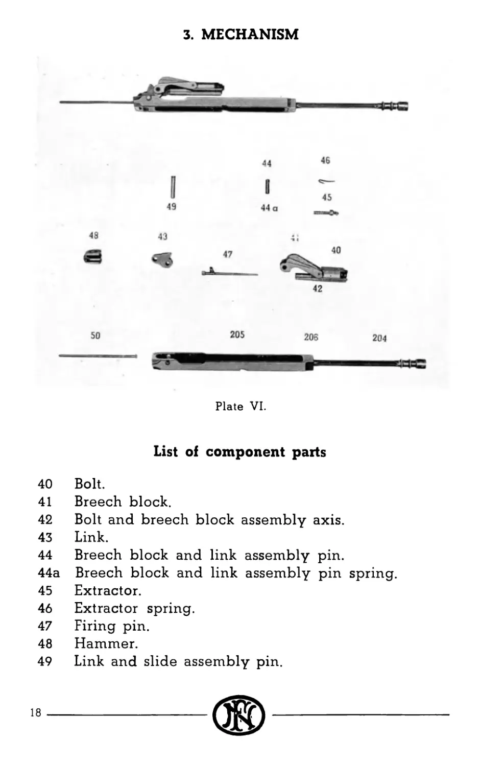
3. MECHANISM
Plate VI.
List of component parts
40 Bolt.
41 Breech block.
42 Bolt and breech block assembly axis.
43 Link.
44 Breech block and link assembly pin.
44a Breech block and link assembly pin spring.
45 Extractor.
46 Extractor spring.
47 Firing pin.
48 Hammer.
49 Link and slide assembly pin.
18
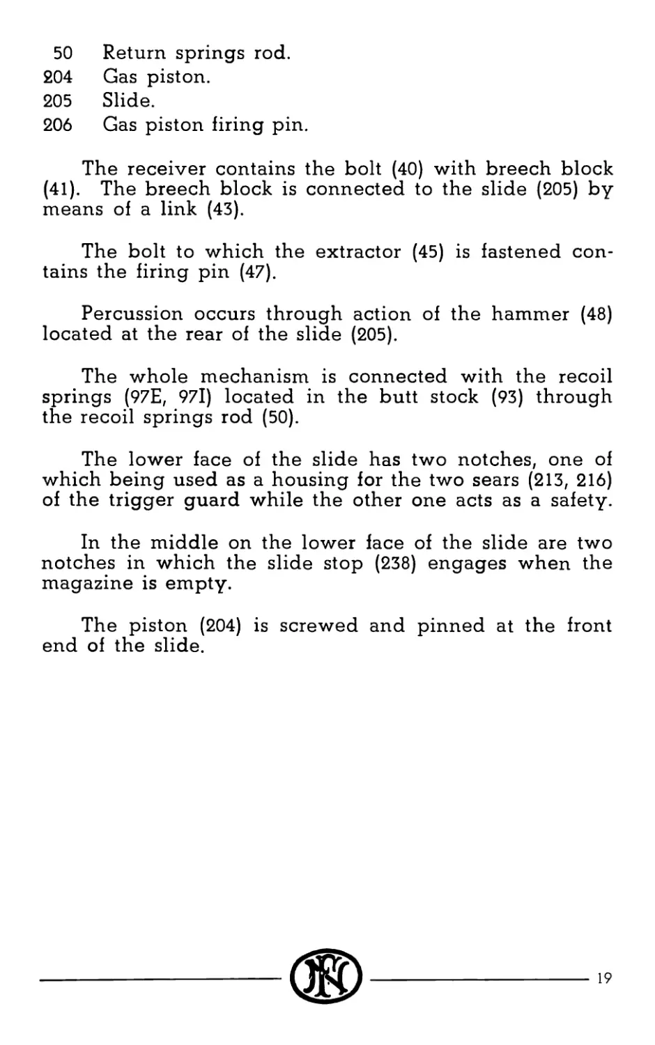
50 Return springs rod.
204 Gas piston.
205 Slide.
206 Gas piston firing pin.
The receiver contains the bolt (40) with breech block
(41). The breech block is connected to the slide (205) by
means of a link (43).
The bolt to which the extractor (45) is fastened con-
tains the firing pin (47).
Percussion occurs through action of the hammer (48)
located at the rear of the slide (205).
The whole mechanism is connected with the recoil
springs (97E, 97l) located in the butt stock (93) through
the recoil springs rod (50).
The lower face of the slide has two notches, one of
which being used as a housing for the two sears (213, 216)
of the trigger guard while the other one acts as a safety.
In the middle on the lower face of the slide are two
notches in which the slide stop (238) engages when the
magazine is empty.
The piston (204) is screwed and pinned at the front
end of the slide.
---®
19
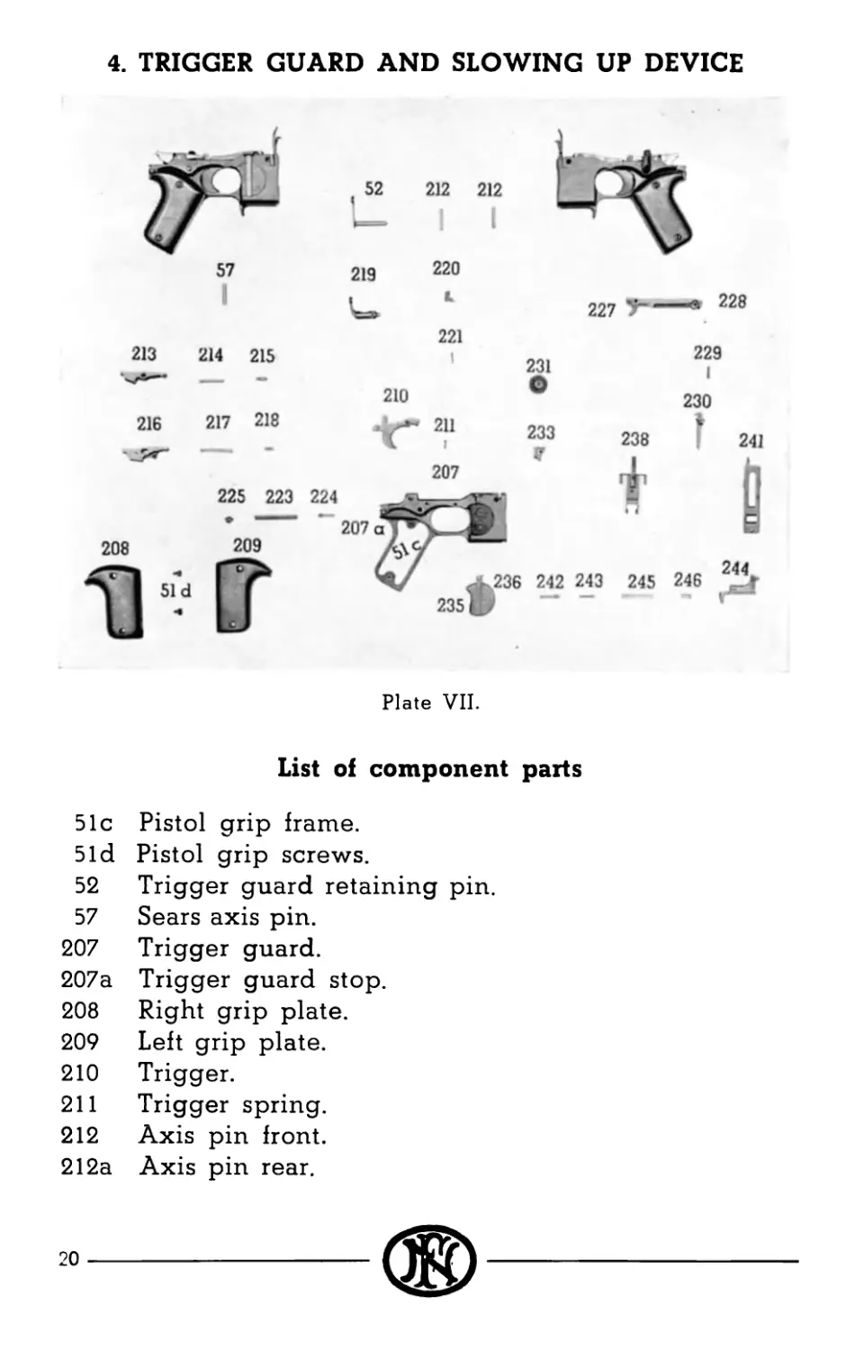
4. TRIGGER GUARD AND SLOWING UP DEVICE
Plate VII.
List of component parts
51c Pistol grip frame.
51d Pistol grip screws.
52 Trigger guard retaining pin.
57 Sears axis pin.
207 Trigger guard.
207a Trigger guard stop.
208 Right grip plate.
209 Left grip plate.
210 Trigger.
211 Trigger spring.
212 Axis pin front.
212a Axis pin rear.
20
213 Right sear.
214 Right sear and change lever spring.
215 Change lever stop.
216 Left sear.
217 Left sear spring.
218 Left sear spring stop pin.
219 Change lever.
220 Slowing-up device catch.
221 Slowing-up device catch spring.
223 Slowing-up device lever spring.
224 Slowing-up device lever plunger.
225 Slowing-up device lever spring stop.
227 Slowing-up device lever.
228 Rack pin.
229 Rack spring.
230 Rack.
231 Slowing-up device pinion.
233 Ratchet.
235 Trigger guard cover.
236 Trigger guard cover spring.
238 Slide stop.
241 Ejector.
242 Ejector plunger.
243 Ejector plunger spring.
244 Magazine catch.
245 Magazine catch spring.
246 Magazine catch spring plunger.
The trigger guard contains the trigger mechanism,
the slowing-up device, the slide stop, the magazine catch
and the ejector.
The slowing-up device has a lever (227) articulated
to a rack (230) which engages hooks of the pinion (231).
The pinion engages a ratchet (233).
The left sear (216) acts the slowing-up device lever
(227) through the catch (220). (Functioning of the device
is described in separate chapter.)
21
The right sear (213) releases the slide (205).
On the left side of the trigger guard, is the change
lever (219). The change lever acts the left sear (216)
according the rate of fire required and puts the gun in
safety.
The ejector (241) and the slide stop (238) are at the
front end of the trigger guard.
The magazine catch (244) is at the bottom of the trigger
guard.
On both sides of the grip of the trigger guard are
wooden plates (208, 209) fastened by screws (51d).
22
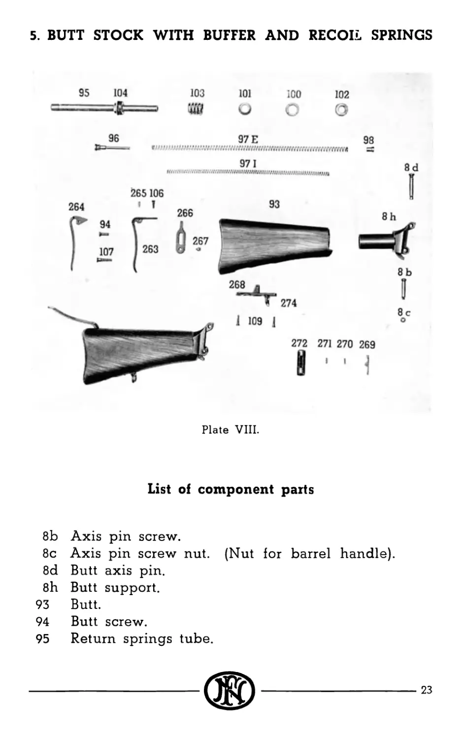
5. BUTT STOCK WITH BUFFER AND RECOIL SPRINGS
Plate VIII.
List of component parts
8b Axis pin screw.
8c Axis pin screw nut. (Nut for barrel handle).
8d Butt axis pin.
8h Butt support.
93 Butt.
94 Butt screw.
95 Return springs tube.
---®
23
96 Return springs tube screw.
97E External return spring.
97l Internal return spring.
98 Return springs cap.
100 Buffer friction ring.
101 Buffer friction cone.
102 Buffer plug.
103 Buffer spring.
104 Buffer tube nut.
106 Butt plate screw (short).
107 Butt plate screw (long).
109 Butt support screw.
263 Butt plate.
264 Shoulder strap.
265 Shoulder strap axis pin.
266 Shoulder strap spring.
267 Shoulder strap spring screw.
268 Butt support.
269 Butt support socket catch.
270 Butt support socket catch axis pin.
271 Butt support socket catch spring.
272 Butt support socket ring.
274 Sling swivel.
The butt (93) in walnut, has a butt plate (263) with
a swinging shoulder strap (264) which makes it easier to
aim the gun.
The butt is fastened to its support (8h) by a screw (94).
The butt plate is fastened by screws to the butt (106,
107) and to the butt support (94).
The bushing (268) is fastened on the lower part of the
butt by screws (109). (This device makes it possible to
fasten the gun to a light tripod.)
24
At the front end of the butt the support (8h) contains
the buffer consisting of a plug (102), four friction rings (100),
four cones (101) and the buffer spring (103).
A tube (95) is screwed at the end of the support by a
ring (104). The tube (95) contains the recoil springs (97E,
97l) with their cap (98) and screw (96).
25
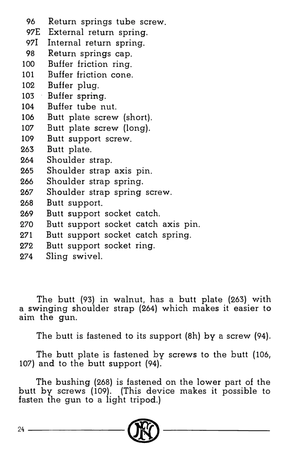
6. MAGAZINE
131
I,
127 )32 130
Plate IX.
List of component parts
127 Magazine.
130 Magazine bottom plate.
131 Magazine platform.
132 Magazine platform spring.
The magazine contains 20 cartridges. It is made of
steel sheet reinforced by stamped grooves.
The upper face is open. The cartridges slide out along
the lips of the upper opening of the magazine.
The magazine platform (131) pushes upward the car-
tridges through the action of the spring (132) which leans
against the bottom plate (130) of the magazine.
The platform has at the rear a tail which acts the slide
stop (238) when the magazine is empty.
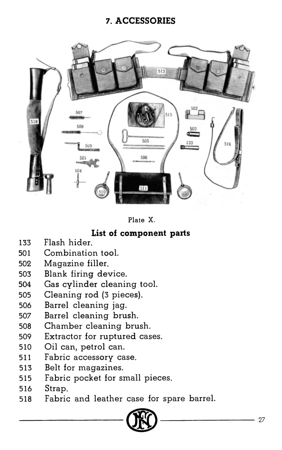
7. ACCESSORIES
Plate X.
List of component parts
133 Flash hider.
501 Combination tool.
502 Magazine filler.
503 Blank firing device.
504 Gas cylinder cleaning tool.
505 Cleaning rod (3 pieces).
506 Barrel cleaning jag.
507 Barrel cleaning brush.
508 Chamber cleaning brush.
509 Extractor for ruptured cases.
510 Oil can, petrol can.
511 Fabric accessory case.
513 Belt for magazines.
515 Fabric pocket for small pieces.
516 Strap.
518 Fabric and leather case for spare barrel.
27
FUNCTIONING
FORWARD MOVEMENT
The gun being cocked, when the trigger (210) is pulled,
the slide (205) is released by the right sear (213) and the
mechanism is pushed forward by the recoil springs (97E,
971). The bottom of the bolt (40) strikes the upper part
of the first cartridge and pushes it into the chamber. The
base of the cartridge case slides up the front face of the
bolt (40) behind the extractor (45). When the lower cam
surface of the breech-block (41) strikes the end of the bolt
supports (11, 12) the breech-block raises up. The bolt (40)
stops against the rear face of the barrel. The breech-block
(41) pushed upward through the link (43) by the slide (205),
which moves forward, comes in the locking recess of the
receiver (8). The breech-block leaning against the locking
face of the receiver completely locks the gun. The slide
(205) continues forward with the hammer (48) which strikes
the firing pin (47) and fires the primer of the cartridge.
The forward movement of the slide is stopped when its
shoulder strikes the rear part of the gas cylinder (247).
BACKWARD MOVEMENT
After the shot has been fired, when the bullet passes
the gas opening in the barrel, a part of the expanding
powder gases passes through the opening into the gas
cylinder (247) and pushes to the rear the piston (204) and
the slide (205). The slide (205), through the link (43) pulls
down the breech-block (41) and unlocks the gun. The
bolt (40) starts very slowly backwards, gaining speed as
the breech-block (41) nears its completely unlocked posi-
tion. When this point is reached the bolt (40) and breech-
block (41) travel at the same speed as the slide (205). The
withdrawal of the firing pin (47) results from the action
of the slope cut in the breech-block (41) on the firing pin
heel. The empty case is drawn from the chamber by the
extractor (45) and is held against the front face of the bolt
(40) until it strikes the ejector (241) which throws it out to
the right through the ejection opening.
The backward movement limited to the rear by the
buffer (102) produces the compression of the return springs
(97E, 971). The opening movement being complete, the
slide (205) and the whole firing mechanism is held to the
rear as the slide (205) is hooked by the right sear (213).
A remarkable feature of the Browning automatic rifle
is the extreme softness with which the case is drawn out
of the chamber. At the beginning of the opening move-
ment when the breech-block reaches its low position, it
is slightly pushed backward by a progressive movement
when its cam comes in contact with the rear parts of the
bolt guides (11, 12). That slight movement to the rear
loosens the case from the chamber before it is carried out
by direct pull. Extraction occurs thus by a double move-
ment: first loosen the case from the chamber, then pull
out by direct pull. That is one of the reasons why the
gun is able to function correctly even with irregular
ammunition.
AUTOMATIC FIRING AT FULL RATE
Cock the gun and set change lever (219) in position
”M”. Pull the trigger. Firing will be going on at full
rate until the pull on the trigger is released. With change
lever (219) in the ‘M” position, the left sear (216) is switched
off and does not interfere with the movement of the slide
(205). The slowing-up device has consequently no action
on the mechanism.
AUTOMATIC FIRING AT SLOW RATE
Cock the gun and set change lever (219) in position
R”. The slide is kept in the rear position by the right
sear (213) which is a little longer than the left sear (216).
By pulling the trigger (210) the sear (213) releases the slide
(205). The slide (205) pushed forward by the recoil springs
(97E, 971) is retained by the second sear (216) which moves
slightly forward owing the oval hole of its pin (57). The
left sear drives forward the catch (220) which releases the
slowing-up device lever (227). This lever raises up under
the action of the spring (223). The raising movement of
the lever is slowed by the interference of the rack (230),
29
the pinion (231) and the ratchet (233). That slowing-up
movement constitutes the slowing-up of the rate of fire
itself.
The lever (227) being raised, swings up the forward
end of the left sear (216) and draws down the rear end of
the sear. When the raising movement of the lever (227)
is completed, the sear (216) disengages completely from
the notch in the slide and the slide is released and pushed
forward by the return springs (97E, 971). When moving
forward the slide (205) depresses the lever (227) which is
caught again by the latch (220).
SINGLE SHOT FIRING
Cock the gun and set change lever (219) in position
R" (same as for slow automatic firing). Release the
trigger after each shot. The rate of fire is slow enough to
release the trigger quickly enough to prevent double shots.
GAS INLET ADJUSTMENT
The gun being ready in firing position, the adjustment
of the gas inlet is made as follows:
Unscrew the shroud (255) by means of the screw (253)
and the combined tool (501) until the gas escape holes are
nearly discovered. Cock the gun and set change lever
(219) in position "R”. Firing shot by shot the mechanism
must remain open after every shot, the slide being stopped
at the rear, and the ejection must be normal, i.e. the empty
cases are projected about one and a half yard away.
If the functioning is not correct screw the mantle a
little more, in order to obturate a little more the gas escape
holes, until functioning is correct.
If the ejection is too violent unscrew the shroud until
functioning is as described above.
FUNCTIONING OF THE BUFFER
After every shot, the slide (205) is violently projected
to the rear. That movement is slowed by the return springs
(97E, 97l) through the return spring rod (50).
30
The slide strikes the plug (102) which recoils and
pushes back the first friction ring (100) and the first cone
(101) which is pressed into the ring and pushes the next
one and so on the last one compressing the buffer spring
(103). The friction rings (100) who are split, open slightly
under action of the cones (101) and rub against the tube
(8h) containing the buffer. The friction of the rings (100)
added to the action of the return springs (97E, 971) and
that of the buffer spring (103) absorb the recoil of the
mechanism.
31
HOW TO OPERATE THE GUN
TO PUT THE GUN IN FIRING POSITION
Squeeze slightly the two legs of the bipod (290) and
swing them to the front until they are perpendicular to
the gun. Release the legs which will open under action
of their spring (121R). The tops of the legs will insert
themselves in the grooves of the head of the bipod (112).
The bipod is then in position to support the gun. Swing
the handle (Id) to the left and engage end of the handle
in the groove of the nut (lb). Open magazine cover (88)
by swinging it forward. Open ejection opening cover (16).
Raise shoulder plate (265).
TO REMOVE THE GUN FROM FIRING POSITION
Lower the shoulder plate (265).
Close ejection opening cover (16). Close magazine
cover (88). Disengage the handle (Id) out of the nut (lb)
and swing it upward. Squeeze the legs of the bipod (290)
in order to disengage their heads from the grooves in the
bipod head (112) and swing them backward along the gas
cylinder.
TO PUT THE GUN IN SAFETY
Push the change lever (219) in front of the letter ”S".
In that position the trigger (210) is locked and unable to
act on the sear (213).
TO LOAD THE GUN
Pull back the cocking lever (33) as far as possible to
the rear in order to let the slide (205) be caught by the
sear (213). Push forward cocking lever (33). Push a filled
magazine upward in the receiver.
Push the change lever (219) in the desired position
(full or slow rate of fire). The gun is ready to fire.
32
®- ---
TO UNLOAD THE GUN
Drop the magazine by pulling the magazine catch
(244). Close the mechanism by pulling the trigger. Push
lever (219) in safety position "S”.
TO REMOVE THE BARREL
Make sure that the end of the handle (la) is inserted
in the groove of the locking nut (lb). Press the locking
lever (8a) and turn the handle (Id) upward to the vertical
position. Take off the barrel by pushing forward on the
handle.
TO REPLACE THE BARREL
Take the barrel by the handle (Id) the regulator being
downward. Introduce the rear of the barrel in the receiver
(8) the front of the barrel leaning in its V support in the
front part of the gas cylinder (247) on its flat face. The
regulator is then introduced in the gas cylinder (247). Pull
the barrel to the end in the receiver (8) and swing to the
left as far as possible the handle (Id). The barrel is locked
to the receiver.
33
DISMOUNTING AND ASSEMBLING
A. DISMOUNTING AND ASSEMBLING
OF THE MECHANISM
I
PARTIAL DISMOUNTING
The rifle is left in the firing position, resting on its
bipod.
Remove the magazine (127) by pulling the magazine
catch (244).
Pull the trigger (210) to allow the mechanism to move
forward.
Remove the trigger guard retaining pin (52) and the
trigger guard (207).
With the left hand pull the cocking handle to the
rear as far as possible; keep it in that position and press
the right hand thumb on the bolt guide stud (14) which
is placed on the receiver left side, above the cocking
handle (33).
The bolt guide is withdrawn and the bolt (40) dis-
engages itself under the action of its own weight.
Let the mechanism move forward.
The shooter can thus reach the bolt (40), the bolt lock
(41), the extractor (45), the extractor spring (46) and the
firing pin (47); the three latter parts can be replaced if
necessary. This quick dismounting makes it also possible
to have the trigger guard checked and dismounted if
needed.
PARTIAL ASSEMBLING
Replace the firing pin (47), the extractor (45) and its
spring (46).
With the left hand, pull the cocking handle (33) to
the rear as far as possible.
34
With the right hand, grasp the bolt (40) and, while
keeping the firing pin home (47), introduce the bolt (40)
in the receiver (8) in order to engage the bolt head behind
the bolt support (11 and 12).
Press upwards in order to overcome the resistance of
the bolt guide (14).
Let the mechanism come forward under the action of
the return springs (971, 97E).
Replace the trigger guard and its retaining pin (52).
Replace the magazine.
II
COMPLETE DISMOUNTING
The weapon is placed in the firing position on its
bipod.
Remove the magazine and let the mechanism come
forward by pulling the trigger.
Remove the trigger guard retaining pin (52) and the
trigger guard (207) (for the dismounting of the trigger
guard, see special chapter).
Pull completely to the right the butt axis pin (8d)
fixing the butt to the receiver.
Swing completely downward the butt (93),- the
weapon is thus held standing by the bipod and the butt.
By means of the recoil spring rod (50), pull to the
rear the mechanism off the weapon, that is the slide (205),
the piston (204), the bolt (40), the breech block (41), the
link (43), the hammer (48) and the return spring rod (50).
Remove the firing pin (47) from the bolt (40).
Remove the hammer pin (49). The slide is thus sepa-
rated from the hammer (48) and from the link-bolt-breech
block group.
Withdraw the hammer (48) from the slide (205).
---®
35
Remove the return spring rod (50).
Remove the link pin (44). The link (43) is thus sepa-
rated from the bolt-breech-block group.
Put the firing pin under the head of the extractor
(45) and disengage the extractor from the bolt (40), remove
the extractor (45).
Remove the extractor spring (46).
COMPLETE ASSEMBLING
Replace the extractor spring (46) in the extractor (45).
Replace the extractor (45) in the bolt by pressing the
head of the extractor and pushing it completely home.
Reconnect the bolt-breech-block group to the link (43)
by means of the link pin (44).
Replace the return spring rod (50) in the slide (205).
Replace the hammer (48) in the slide.
Reconnect the bolt-link group to the slide (205) and
to the hammer (48) by means of the hammer pin (49) taking
care to place the head of this pin on the right side of the
slide.
Replace the firing pin (47) in the bolt (40).
Replace the parts constituting the mechanism in the
receiver (8). Push home all the parts of the mechanism
in the receiver by introducing the slide in its housing and
keeping the bolt in the upper part of the receiver in such
a way as to introduce it in its guiding grooves.
Swing the butt (93) upwards.
Fix the butt (93) to the receiver (8) by pushing home
the axis pin (8d).
Replace the trigger guard (207) and its retaining pin
(52).
Replace the magazine (127).
36
®---
В. COMPLETE DISMOUNTING AND ASSEMBLING
OF THE WEAPON
I
COMPLETE DISMOUNTING OF THE BARREL
a) Remove the barrel of the weapon as indicated in
the chapter “How to use the gun ’.
b) Dismounting of the handle. - Unscrew the barrel
ring (lb); to do so, disengage it from the handle support
(lc), swing the handle until its nozzle is turned downwards
and remove it. Unscrew the handle screw (8c), remove the
washer (le) and the handle (Id). The handle (lc) can then
be disengaged from the main body of the handle liber-
ating the spring (If) and the handle spring head (lg).
c) Dismounting of the regulator. - Unscrew the
regulator (252) by means of its nut (253) and remove the
parts. Unscrew the regulator fixing screw (251) and
remove the regulator (250) from behind.
d) Unscrew the flash hider (133) or the muzzle ring
(136).
COMPLETE ASSEMBLING OF THE BARREL
a) Assembling of the regulator. - Insert the regu-
lator (250) in the gas cylinder tube bracket. Screw the
regulator by means of the fixing screw (251) and screw
the regulator nut (252).
b) Assembling of the carrying handle. - Replace
the handle spring (If) in the handle grip, fit the handle
spring head (lg) on its spring (le), insert the handle (lc)
in the handle support (la) and push it home in order to
press the spring completely, then introduce the handle
(Id) completely home. Replace the washer (le) and the
nut (8c).
c) Replace the carrying handle on the barrel, proceed-
ing by reverse way as when dismounting it.
d) Replace the flash hider (133) or the muzzle ring (136).
37
II
COMPLETE DISMOUNTING OF THE RECEIVER
After dismounting of the mechanism (see chapter
complete dismounting of the mechanism"), separate the
butt group" from the receiver (8) by pulling as far as
possible to the right the axis (8d) and unscrewing the butt
axis pin screw nut (8b) fixing the butt to the receiver (8).
a) Bipod. — To disengage the bipod push out the
swivel pin (124) and pull the bipod downwards. The
bipod head and its spring are thus disengaged (277, 277a).
The assembly [the bipod legs (290), swivel (112), pivot
(111), outside and inside plugs (116R, 117R), leg brace spring
(121R), shoes (119)] being riveted cannot be dismounted.
b) Cocking handle. - To remove the cocking handle
(33) push down the plunger pin (34) in order to enable it to
move over the slot of the lever groove. Withdraw the
operating handle (33) forward. Push the small cocking
handle plunger (35) (by means of the firing pin) to the
bottom, push the handle plunger pin (34) out and let the
operating handle plunger (35) come back under the action
of its spring (36).
c) Bolt guide. — Turn the receiver upside down and
disengage the forward part of the bolt guide spring (15)
from the slot in the bolt guide (14) then draw back the
back part of the spring from its housing as well as the
bolt guide (14).
d) Magazine opening cover. - Disengage the stop
spring (92) from the magazine opening cover support (88d)
and draw the magazine opening cover spring (88b) to the
rear, as well as the magazine opening cover (88). This
latter part disengages from its support by chasing the
magazine opening cover axis (89) thus liberating the pin
of the cover (91) and its spring (92).
e) Ejector opening cover. - Swing the cover stud
retainer (21) a quarter turn towards the bottom. The cover
lever (18), the cover (16) and the fixing stud (21) are thus
disengaged.
f) Backsight. — Expel the pin from the backsight base
(STA21). Press on the back of the backsight base (8) to
compress the backsight spring (STA1) and enable the
disengagement of the backsight leaf from the backsight
base (8n). At the same time, push forward. Pull the
backsight spring (STA1) to the rear. By pressing on the
two backsight slide catches (STA2) disengage the backsight
slide (STA3) from the backsight leaf (8i). Pull the knobs
(STA2) and the springs (STA4). The backsight base (8n)
remains riveted to the receiver (8).
g) Handguard plates. - Remove the handguard plates
(259D, 259G) by unscrewing the screws (259v) and remove
the lock washers (259w).
h) Locking nut catch lever. - It can be dismounted
by expelling its axis (8r) disengaging thus the lever (8a)
and its spring (8s).
i) Butt axis pin. - The axis pin (8d) is disengaged by
unscrewing the screw (8g) which liberates the spring (8f)
and the axis pin plunger (8e).
COMPLETE ASSEMBLING OF THE RECEIVER
a) Butt axis pin. — Replace the axis pin (8d) in its place
(upper hole) on the receiver (8). Turn the receiver upside
down and introduce the plunger (8e), the spring (8f) and
the screw (8g) in their place on the end of the right side
of the receiver.
b) Locking nut catch lever. — Put the lever spring
(8s) in its base on the lever (8a). Place the lever on the
receiver by compressing the spring (8s) and introduce the
axis pin (8r).
c) Handguard plates. — Screw the plates (259D, 259G)
and insert the lock washers (259w) between the screws
(259v) and the receiver.
d) Backsight. — Replace the catches (STA2) and the
springs (STA4) on the backsight slide (STA3 ) by pressing
on both catches (STA2). Introduce the backsight leaf (8i)
in the slide (STA3). Replace the spring (STA1) in its hous-
ing, then press on that spring using the backsight leaf (8i)
to enable the reengagement of the leaf knobs in the base
(8n). Introduce the backsight base pin (STA21).
e) Ejector opening cover. — After the cover (16) has
been reconnected to the lever (18), place them on the
receiver in the "open” position. Introduce the cover stud
retainer (STA21), press it against the receiver and turn the
stud (STA21) one quarter of a turn to the left.
f) Magazine opening cover. - Introduce the spring
(92) and the plunger (91) in the support spring box of the
cover (88c), fit it in the hinge of the cover (88a) and press
to introduce the axis (89). Replace the support (88d) and
the cover (88) in its grooves making sure that the stop
spring (92) is in the right position.
g) Bolt guide. - Replace the bolt guide (14) by pro-
ceeding in the reverse way used for dismounting.
h) Cocking lever. — Introduce the cocking handle
spring (36) and the small plunger (35) in the handle of the
cocking lever so as to have the ovale part of the plunger
turned downward. Push the plunger, by means of the
firing pin, so as to be able to introduce the pin (34) through
the lower opening of the handle, the longer part of the pin
(34) being introduced first. Replace the cocking lever in
the groove of the receiver so that the plunger pin (34)
overleaps the notch of the lever's groove.
i) Bipod. - Replace the bipod head spring (277a)
into its position, locate the two parts of the bipod head
(277) at the end of the gas cylinder (247) and introduce the
bipod head in the assembly block (112) so as to have the
sling swivel turned forward. Place the bipod legs at mid
position between the carrying and the firing position, then
replace the fixing pin (124).
To replace the butt, screw the axis screw (8b) fasten-
ing the butt to the receiver.
HI
DISMOUNTING AND ASSEMBLING THE MECHANISM
See chapter “Dismounting and assembling of the me-
chanism”, page 34.
IV
COMPLETE DISMOUNTING OF THE TRIGGER GUARD
Remove the pin (52) and the trigger guard (208) from
the receiver.
By means of the firing pin, expel the pin (57) pushing
with the thumb on both right and left sear (213, 216) and
remove the sears and their springs (215, 218).
Remove the change lever (219) by pressing the fore-
end of lever (227).
With a screw driver, press the catch spring plug (225)
and turn it one quarter of a turn. This lets free the spring
plug (225), the spring (223) and the plunger (224).
Remove the pin (212) by means of the firing pin.
Keep the lever plunger (224) off the action of the catch
(220) by pushing it forward, at the same time depress the
rear end of the lever (227) so as to raise its fore-end.
Remove the lever (227), the rack and the rack spring
(229), and disassemble them.
Raise the trigger guard cover spring (236) and turn
the cover (235) one quarter of a turn to the left. Remove
the cover (235).
Remove the pinion (231).
Remove the ratchet (233) by turning it one quarter of
a turn to the right.
Remove trigger pin (212) by means of the firing pin.
Remove the trigger (210) and trigger spring (211).
Remove the catch (220) and the catch spring (221).
Push to its rearmost position the magazine catch (244)
and, using the cartridge tip, or the firing pin, push the
ejector plunger (242) in so as to liberate the plunger from
the ejector (241). Pull up the ejector as far as possible.
Let the magazine catch go: the magazine catch (244), the
spring (245) and the plunger (246) are disengaged.
----------------------®---------------------------
Remove the ejector (241) and the slide stop (238).
Unscrew the hand grip screws (51d) and remove right
and left hand grip plates (208, 209).
COMPLETE ASSEMBLING OF THE TRIGGER GUARD
Replace the grip plates (208, 209) and fasten them with
the screws (51d).
Replace the ejector (241) and the slide stop (238) in
their grooves (the upper one for the ejector). Stop the
ejector (241) when its lower part reaches the upper edge
of the housing of the magazine catch (244).
Push the slide stop (238) as far as possible. Replace the
magazine catch (244), the spring (245) and the plunger (246).
Push the catch to the rear. Push the ejector (241) down
in its groove until it comes in touch with the plunger (242).
Push the plunger (242) in, using the point of a cartridge,
push the ejector home.
Replace the slowing-up device catch (220) and the
spring (221).
Replace the trigger (210), the spring (211) and the
trigger pin (212).
Replace the ratchet (233) and the pinion (231).
Replace the trigger guard cover (235).
Assemble the lever (227), the rack (230) and the rack
spring (229).
Replace the assembled lever (227) so that the rack
engages the hooks of the pinion (231). Fasten the lever
with the trigger pin (210).
Replace the lever spring (233), the lever plunger (224)
and the spring plunger (225) by proceeding in the reverse
way used for dismounting.
Replace the change lever (219) by pushing slightly
down the fore-end of the lever (227).
42
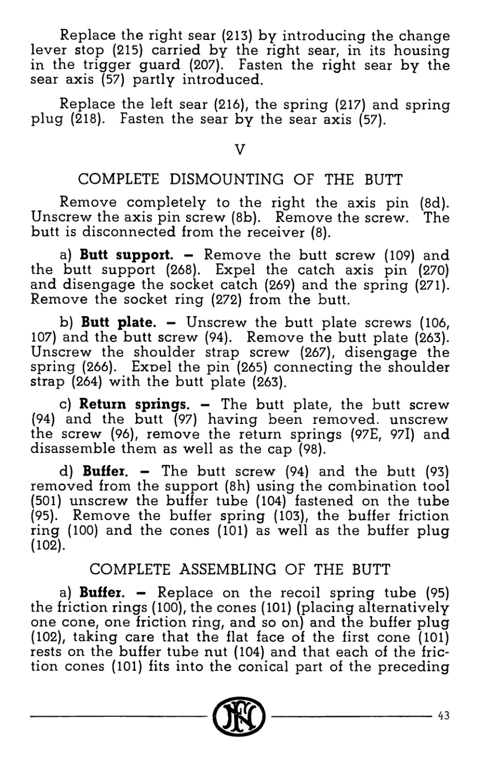
Replace the right sear (213) by introducing the change
lever stop (215) carried by the right sear, in its housing
in the trigger guard (207). Fasten the right sear by the
sear axis (57) partly introduced.
Replace the left sear (216), the spring (217) and spring
plug (218). Fasten the sear by the sear axis (57).
V
COMPLETE DISMOUNTING OF THE BUTT
Remove completely to the right the axis pin (8d).
Unscrew the axis pin screw (8b). Remove the screw. The
butt is disconnected from the receiver (8).
a) Butt support. — Remove the butt screw (109) and
the butt support (268). Expel the catch axis pin (270)
and disengage the socket catch (269) and the spring (271).
Remove the socket ring (272) from the butt.
b) Butt plate. - Unscrew the butt plate screws (106,
107) and the butt screw (94). Remove the butt plate (263).
Unscrew the shoulder strap screw (267), disengage the
spring (266). Expel the pin (265) connecting the shoulder
strap (264) with the butt plate (263).
c) Return springs. — The butt plate, the butt screw
(94) and the butt (97) having been removed, unscrew
the screw (96), remove the return springs (97E, 97l) and
disassemble them as well as the cap (98).
d) Buffer. — The butt screw (94) and the butt (93)
removed from the support (8h) using the combination tool
(501) unscrew the buffer tube (104) fastened on the tube
(95). Remove the buffer spring (103), the buffer friction
ring (100) and the cones (101) as well as the buffer plug
(Ю2).
COMPLETE ASSEMBLING OF THE BUTT
a) Buffer. — Replace on the recoil spring tube (95)
the friction rings (100), the cones (101) (placing alternatively
one cone, one friction ring, and so on) and the buffer plug
(102), taking care that the flat face of the first cone (101)
rests on the buffer tube nut (104) and that each of the fric-
tion cones (101) fits into the conical part of the preceding
®---------------------------------------------
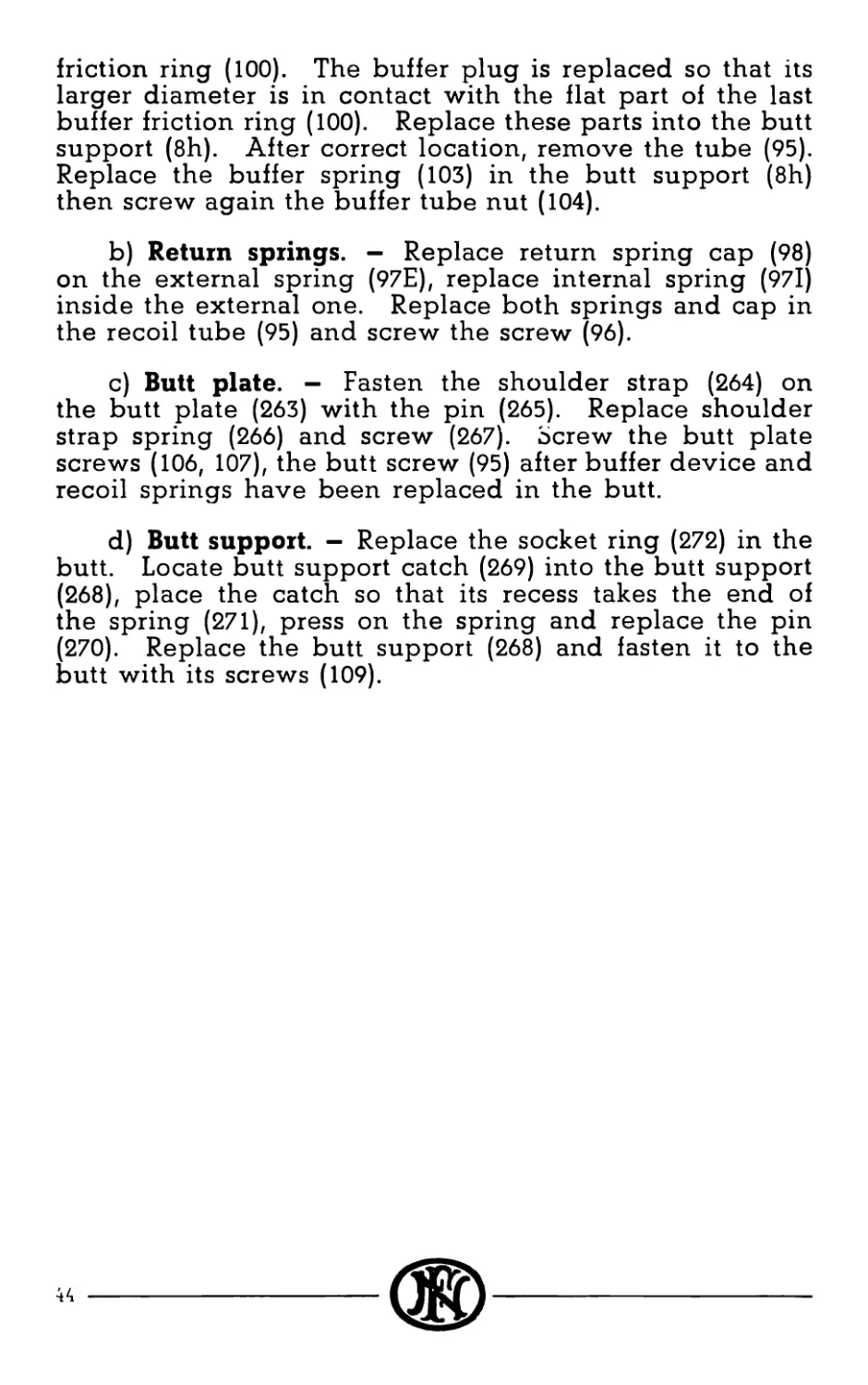
friction ring (100). The buffer plug is replaced so that its
larger diameter is in contact with the flat part of the last
buffer friction ring (100). Replace these parts into the butt
support (8h). After correct location, remove the tube (95).
Replace the buffer spring (103) in the butt support (8h)
then screw again the buffer tube nut (104).
b) Return springs. — Replace return spring cap (98)
on the external spring (97E), replace internal spring (97l)
inside the external one. Replace both springs and cap in
the recoil tube (95) and screw the screw (96).
c) Butt plate. — Fasten the shoulder strap (264) on
the butt plate (263) with the pin (265). Replace shoulder
strap spring (266) and screw (267). Screw the butt plate
screws (106, 107), the butt screw (95) after buffer device and
recoil springs have been replaced in the butt.
d) Butt support. — Replace the socket ring (272) in the
butt. Locate butt support catch (269) into the butt support
(268), place the catch so that its recess takes the end of
the spring (271), press on the spring and replace the pin
(270). Replace the butt support (268) and fasten it to the
butt with its screws (109).
®---
RECOMMENDATIONS
1. Always carry the gun in safety position.
2. Oil very slightly the moving parts. It is important
to keep from oiling too much the gun when used in a sandy
country. The gun must be kept nearly dry.
3. See that the barrel is clean and clear before firing.
4. See that gas inlet has the proper setting.
5. Make sure that magazine is clean and dry with-
out oil.
6. Make sure that magazine is well inserted in the
receiver and well fastened.
7. Do not introduce by hand a cartridge in the
chamber of a hot barrel.
8. In case of stoppage drop the magazine and cock
the gun.
9. In case of misfire wait 3 seconds before opening
the mechanism.
10. In order to be ready to fire at once, it is possible
to carry the gun safely with closed mechanism and a filled
magazine inserted in the receiver. One has just to cock
the gun to be ready to open fire.
11. When the rifle is not in use the magazine cover
and the ejection opening cover would be kept closed to
prevent introduction of sand or dust in the mechanism.
---®
45
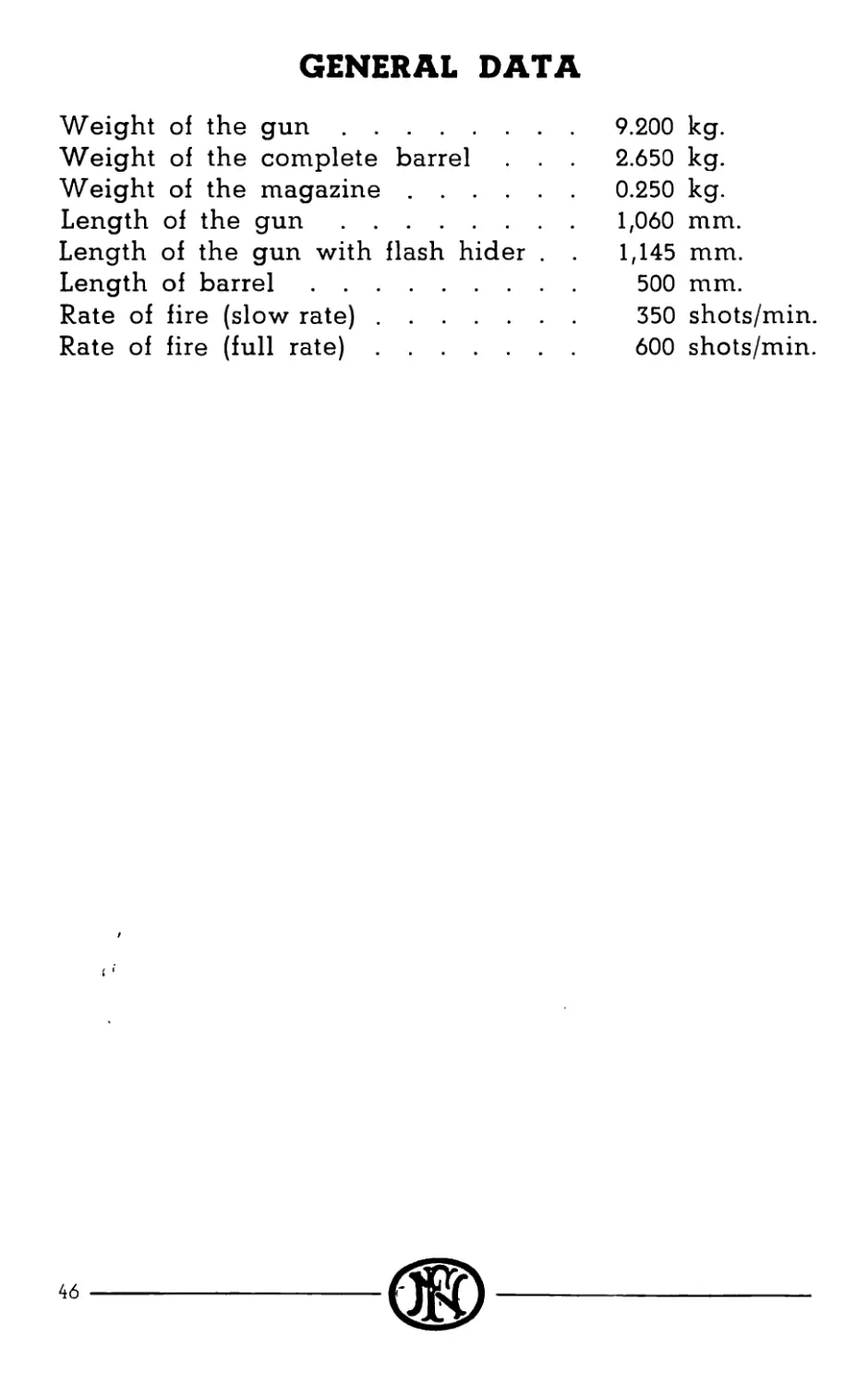
GENERAL DATA
Weight of the gun...................... 9.200 kg.
Weight of the complete barrel . . . 2.650 kg.
Weight of the magazine................ 0.250 kg.
Length of the gun..................... 1,060 mm.
Length of the gun with flash hider . . 1,145 mm.
Length of barrel........................ 500 mm.
Rate of fire (slow rate)................. 350 shots/min.
Rate of fire (full rate)................. 600 shots/min.
STANDARD EQUIPMENT
SPARE PARTS
1 assembled barrel,
1 link and breech block assembly pin,
2 link and assembly pins,
1 sear axis pins,
11 magazines,
2 trigger guard retaining pins,
2 assembly axis (receiver - butt),
1 ejector,
2 extractors,
1 trigger axis pins,
1 slowing-up lever pin,
2 firing pins,
1 link axis spring,
2 extractor springs,
1 bolt guide spring,
1 return spring (outside and inside),
2 return spring rods.
ACCESSORIES
133 Flash hider.
501 Combination tool.
502 Magazine filler.
503 Blank firing device.
504 Gaz cylinder and piston cleaning tool.
505 Cleaning rod (3 parts).
506 Barrel cleaning jag.
507 Barrel cleaning brush.
508 Chamber cleaning brush.
509 Extractor for ruptured cases.
510 Oil can.
Petrol can.
---®
47
511 Fabric accessory case.
513 Belt for magazines.
515 Fabric pocket for small pieces.
516 Strap.
518 Fabric and leather case for spare barrel.
48
F. N. BROWNING AUTOMATIC RIFLE
Type D
WITH DETACHABLE BARREL
LIST OF PARTS
N" Part Number
1 Barrel..................................... 1
la Barrel handle support..................... 1
lb Barrel locking nut......................... 1
lc Barrel handle (steel) inner............... 1
Id Barrel handle (wood) outer................ 1
le Barrel handle washer...................... 1
If Barrel handle coil spring................. 1
lg Barrel handle coil spring plunger .... 1
2 Foresight blade............................ 1
3 Foresight bed.............................. 1
4 Foresight bed key......................... 1
5 Foresight bed pin......................... 1
8 Receiver.............................. 1
8a Locking nut catch lever................... 1
8b Axis pin screw........................ 1
* 8c Axis pin screw nut. (Nut for barrel handle) 1
8d Butt axis pin......................... 1
* 8e Axis pin plunger...................... 1
* 8f Axis pin plunger coil spring.......... 1
* 8g Axis pin plunger coil spring screw ... 1
8h Butt support............................... 1
8i Backsight leaf............................. 1
N. B. - The parts marked with an asterisk * don't appear on
the maps representing the cross section of the weapon.
----------------------(Ж)-----------------------------w
Part
Number
№
STA1 Backsight spring ......................... 1
STA2 Backsight slide catch.......................2
STA3 Backsight slide............................ 1
*STA4 Backsight slide catch spring...............2
*STA21 Backsight leaf pin........................ 1
8n Backsight base............................ 1
8o Backsight base rivet....................... 1
* 8q Gas cylinder pin.......................... 1
8r Locking nut catch lever axis pin .... 1
8s Locking nut catch lever axis pin spring 1
9 Top plate.............................. 1
11 Bolt support right........................ 1
12 Bolt support left..........................1
13 Bolt support rivet.........................6
14 Bolt guide................................ 1
* 15 Bolt guide spring......................... 1
16 Ejection opening cover................. 1
17 Ejection opening cover stud............1
18 Ejection opening cover lever...........1
19 Ejection opening cover safety stud ... 1
20 Ejection opening cover fixing stud ... 1
21 Ejection opening cover stud retainer . . 1
33 Cocking handle......................... 1
34 Cocking handle plunger pin ................ 1
35 Cocking handle plunger................. 1
36 Cocking handle plunger spring .... 1
40 Bolt ...................................... 1
41 Breech block........................... 1
* 42 Bolt and breech block assembly axis ... 1
43 Link ...................................... 1
44 Breech block and link assembly pin ... 1
* 44a Breech block and link assembly pin spring . 1
N. B. - The parts marked with an asterisk * don't appear on
the maps representing the cross section of the weapon.
50 ---------------------I ikjj--------------------------
Part
Number
№
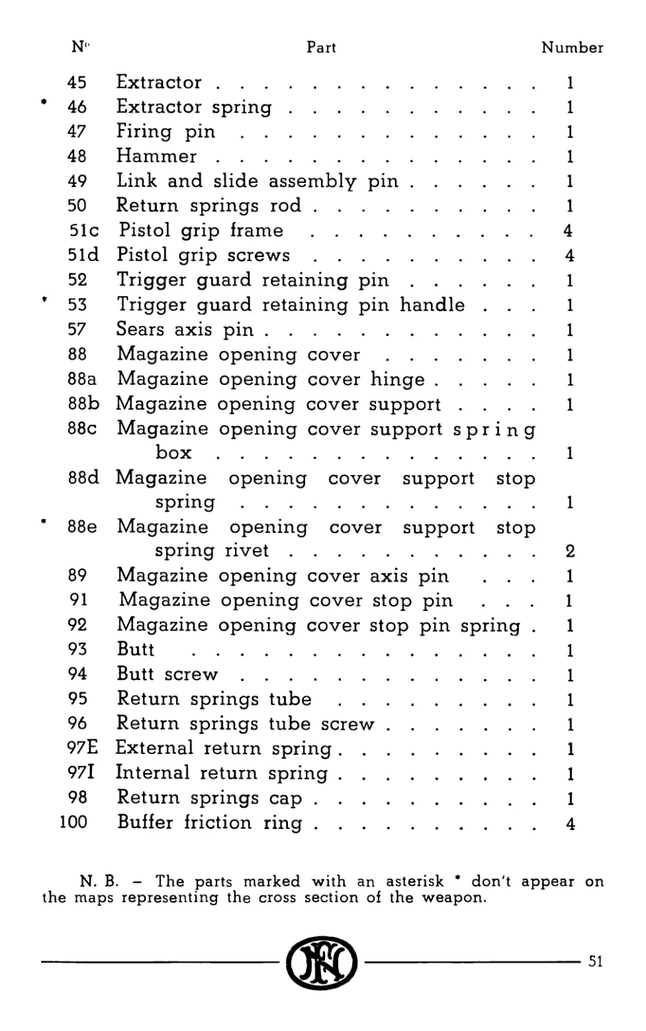
45 Extractor............................. 1
* 46 Extractor spring...................... 1
47 Firing pin............................ 1
48 Hammer................................ 1
49 Link and slide assembly pin........... 1
50 Return springs rod.................... 1
51c Pistol grip frame.....................4
5Id Pistol grip screws....................4
52 Trigger guard retaining pin........... 1
* 53 Trigger guard retaining pin handle ... 1
57 Sears axis pin........................ 1
88 Magazine opening cover................ 1
88a Magazine opening cover hinge.......... 1
88b Magazine opening cover support .... 1
88c Magazine opening cover support spring
box............................... 1
88d Magazine opening cover support stop
spring............................ 1
* 88e Magazine opening cover support stop
spring rivet......................2
89 Magazine opening cover axis pin ... 1
91 Magazine opening cover stop pin ... 1
92 Magazine opening cover stop pin spring . 1
93 Butt ..................................... 1
94 Butt screw............................ 1
95 Return springs tube................... 1
96 Return springs tube screw............. 1
97E External return spring................ 1
97l Internal return spring................ 1
98 Return springs cap.................... 1
100 Buffer friction ring..................4
N. B. — The parts marked with an asterisk * don't appear on
the maps representing the cross section of the weapon.
N'
Part
Number
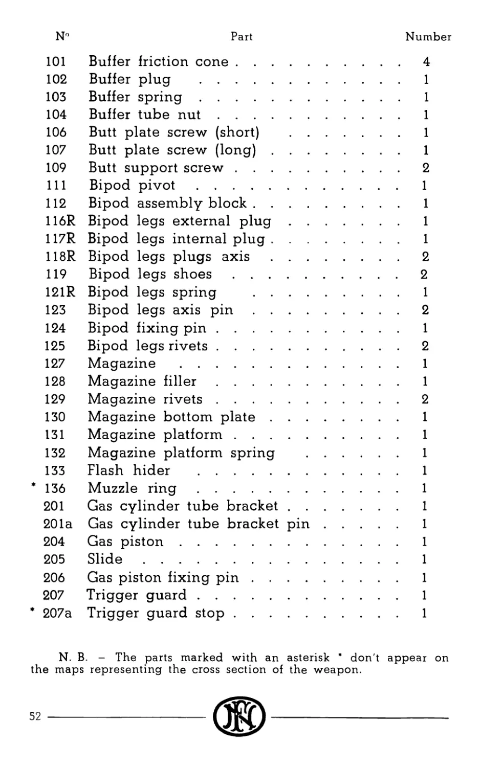
101 Buffer friction cone......................4
102 Buffer plug ........................... 1
103 Buffer spring............................ 1
104 Buffer tube nut.......................... 1
106 Butt plate screw (short) ................. 1
107 Butt plate screw (long)................... 1
109 Butt support screw.........................2
111 Bipod pivot............................... 1
112 Bipod assembly block...................... 1
116R Bipod legs external plug.................. 1
117R Bipod legs internal plug.................. 1
118R Bipod legs plugs axis......................2
119 Bipod legs shoes..........................2
121R Bipod legs spring ....................... 1
123 Bipod legs axis pin.......................2
124 Bipod fixing pin......................... 1
125 Bipod legs rivets.........................2
127 Magazine ................................. 1
128 Magazine filler......................... 1
129 Magazine rivets..........................2
130 Magazine bottom plate................... 1
131 Magazine platform....................... 1
132 Magazine platform spring ............... 1
133 Flash hider .............................. 1
* 136 Muzzle ring............................... 1
201 Gas cylinder tube bracket................. 1
201a Gas cylinder tube bracket pin............. 1
204 Gas piston................................ 1
205 Slide..................................... 1
206 Gas piston fixing pin..................... 1
207 Trigger guard............................. 1
* 207a Trigger guard stop........................ 1
N. B. - The parts marked with an asterisk * don't appear on
the maps representing the cross section of the weapon.
52---------------------(®)------------------------------
N
Part
Number
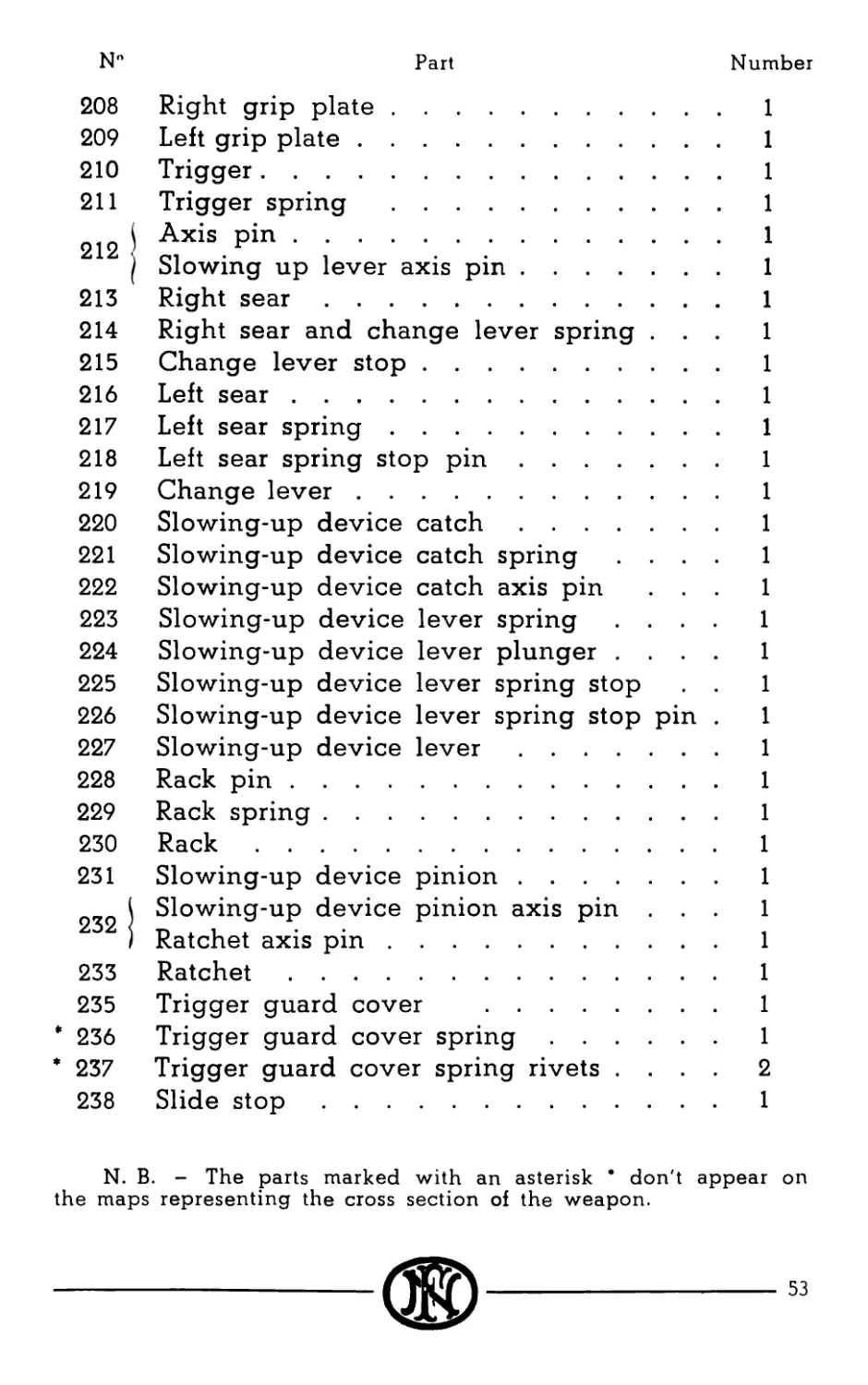
208
209
210
211
212
213
214
215
216
217
218
219
220
221
222
223
224
225
226
227
228
229
230
231
232
233
235
* 236
* 237
238
Right grip plate......................... 1
Left grip plate.......................... 1
Trigger.................................. 1
Trigger spring .......................... 1
j Axis pin................................. 1
( Slowing up lever axis pin................ 1
Right sear............................... 1
Right sear and change lever spring ... 1
Change lever stop........................ 1
Left sear................................ 1
Left sear spring..........................1
Left sear spring stop pin................ 1
Change lever............................. 1
Slowing-up device catch.................. 1
Slowing-up device catch spring .... 1
Slowing-up device catch axis pin ... 1
Slowing-up device lever spring .... 1
Slowing-up device lever plunger .... 1
Slowing-up device lever spring stop . . 1
Slowing-up device lever spring stop pin . 1
Slowing-up device lever.................. 1
Rack pin................................. 1
Rack spring.............................. 1
Rack..................................... 1
Slowing-up device pinion................. 1
i Slowing-up device pinion axis pin ... 1
I Ratchet axis pin......................... 1
Ratchet.................................. 1
Trigger guard cover ..................... 1
Trigger guard cover spring............... 1
Trigger guard cover spring rivets .... 2
Slide stop............................... 1
N. B. - The parts marked with an asterisk * don't appear on
the maps representing the cross section of the weapon.
53
N" Part Number
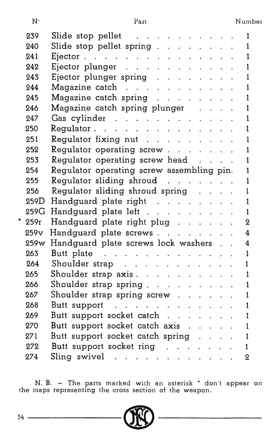
239 Slide stop pellet ......................... 1
240 Slide stop pellet spring............... 1
241 Ejector................................ 1
242 Ejector plunger............................ 1
243 Ejector plunger spring..................... 1
244 Magazine catch............................. 1
245 Magazine catch spring..................... 1
246 Magazine catch spring plunger .... 1
247 Gas cylinder........................... 1
250 Regulator.............................. 1
251 Regulator fixing nut................... 1
252 Regulator operating screw.............. 1
253 Regulator operating screw head .... 1
254 Regulator operating screw assembling pin. 1
255 Regulator sliding shroud............... 1
256 Regulator sliding shroud spring .... 1
259D Handguard plate right.................. 1
259G Handguard plate left................... 1
* 259r Handguard plate right plug.............2
259v Handguard plate screws.................4
259w Handguard plate screws lock washers . . 4
263 Butt plate............................. 1
264 Shoulder strap......................... 1
265 Shoulder strap axis.................... 1
266 Shoulder strap spring.................. 1
267 Shoulder strap spring screw............ 1
268 Butt support........................... 1
269 Butt support socket catch.............. 1
270 Butt support socket catch axis......... 1
271 Butt support socket catch spring .... 1
272 Butt support socket ring............... 1
274 Sling swivel...........................2
N. B. - The parts marked with an asterisk * don't appear on
the maps representing the cross section of the weapon.
Part
Number
N"
275 Sling swivel pin........................... 1
276 Sling butt swivel pin...................... 1
277 Bipod head................................. 1
277a Bipod head spring......................... 1
290 Bipod legs..................................2
N. B. - The parts marked with an asterisk * don't appear on
the maps representing the cross section of the weapon.
------------------------------®-------------------------------------55
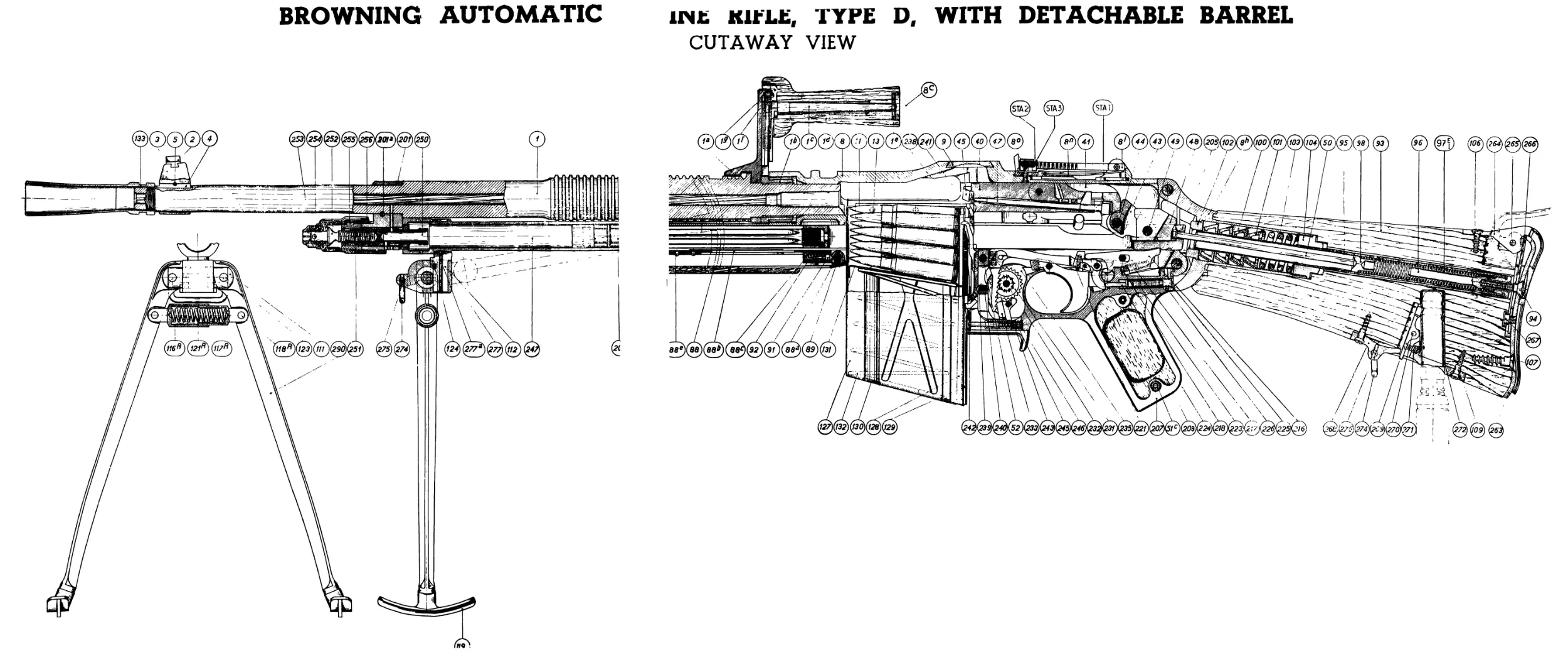
BROWNING AUTOMATIC
init KltLt, TYPE D, WITH DETACHABLE BARREL
CUTAWAY VIEW
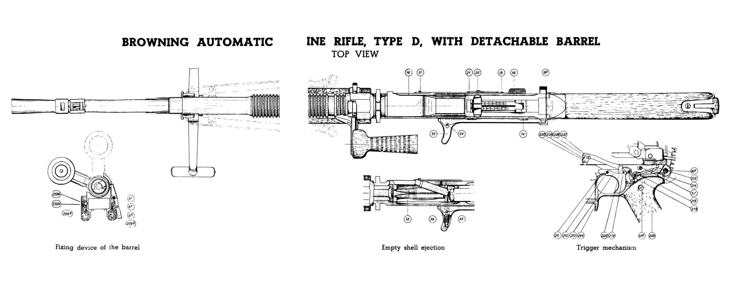
BROWNING AUTOMATIC
INE RIFLE, TYPE D, WITH DETACHABLE BARREL
TOP VIEW
Fixing device of the barrel
Empty shell ejection Trigger mechanism