/

Tags: radio
Year: 1945


Text
WAR DEPARTMENT TECHNICAL MANUAL
TELEPHONES
EE-8, EE-8-A
AND EE-8-B
WARNING: The material forming the subject matter of this manual Is the property of
the United States Government and It is printed and distributed solely for the use of the
military, naval, and civilian personnel of the War and Navy Departments, and may not
be published or reproduced in whole or In part in any manner or form except upon
specific approval by authorized military public relations agencies.
IVAR DEPARTMENT
MARCH 1945
ТМ 11-333
С 1
TECHNICAL MANUAL
TELEPHONES
EE-8, EE-8-A, AND EE-8-B
Changes! DEPARTMENT OF THE ARMY
No. 1 ] Washingto.n 25, D. C., 0 June, l&dO
TM 11-333, 23 March 1945, is changed as follows:
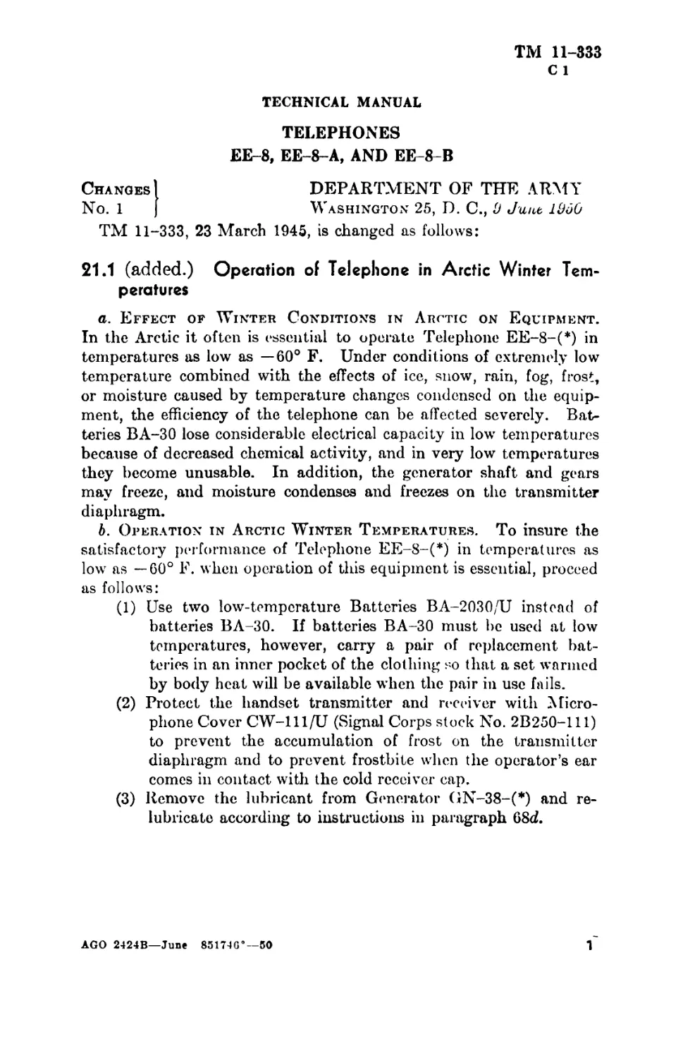
21.1 (added.) Operation of Telephone in Arctic Winter Tem-
peratures
a. Effect of Winter Conditions in Arctic on Equipment.
In the Arctic it often is essential to operate Telephone EE-8-(*) in
temperatures as low as —60° F. Under conditions of extremely low
temperature combined with the effects of ice, snow, rain, fog, frost,
or moisture caused by temperature changes condensed on the equip-
ment, the efficiency of the telephone can be affected severely. Bat-
teries BA-30 lose considerable electrical capacity in low temperatures
because of decreased chemical activity, and in very low temperatures
they become unusable. In addition, the generator shaft and gears
may freeze, and moisture condenses and freezes on the transmitter
diaphragm.
b. Operation in Arctic Winter Temperatures. To insure the
satisfactory performance of Telephone EE-8-(*) in temperatures as
low as —60° F. when operation of this equipment is essential, proceed
as follows:
(1) Use two low-temperature Batteries BA-2030/U instead of
batteries BA-30. If batteries BA-30 must be used at low
temperatures, however, carry a pair of replacement bat-
teries in an inner pocket of the clothing so that a set warmed
by body heat will be available when the pair in use fails.
(2) Protect the handset transmitter and receiver with Micro-
phone Cover CW-lll/U (Signal Corps stock No. 2B250-111)
to prevent the accumulation of frost on the transmitter
diaphragm and to prevent frostbite when the operator’s ear
comes in contact with the cold receiver cap.
(3) Remove the lubricant from Generator GN-38-(*) and re-
lubricate according to instructions in paragraph 68d.
AGO 2424B—June 851746°—50
1
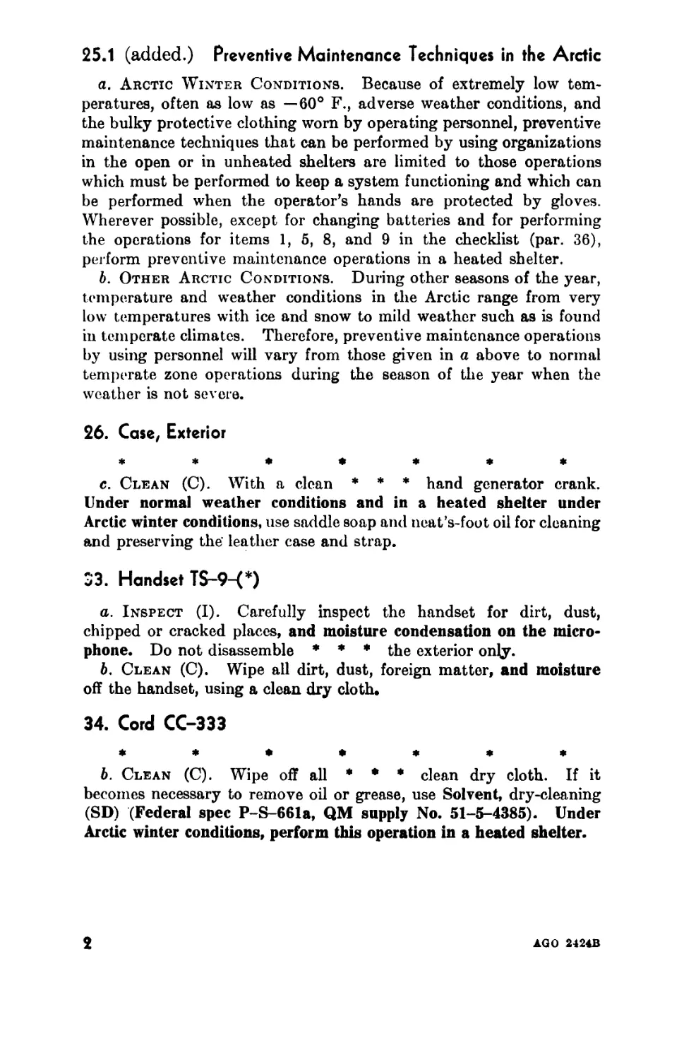
25.1 (added.) Preventive Maintenance Techniques in the Arctic
a. Arctic Winter Conditions. Because of extremely low tem-
peratures, often as low as —60° F., adverse weather conditions, and
the bulky protective clothing worn by operating personnel, preventive
maintenance techniques that can be performed by using organizations
in the open or in unheated shelters are limited to those operations
which must be performed to keep a system functioning and which can
be performed when the operator’s hands are protected by gloves.
Wherever possible, except for changing batteries and for performing
the operations for items 1, 5, 8, and 9 in the checklist (par. 36),
perform preventive maintenance operations in a heated shelter.
b. Other Arctic Conditions. During other seasons of the year,
temperature and weather conditions in the Arctic range from very
low temperatures with ice and snow to mild weather such as is found
in temperate climates. Therefore, preventive maintenance operations
by using personnel will vary from those given in a above to normal
temperate zone operations during the season of the year when the
weather is not severe.
26. Case, Exterior
*******
c. Clean (C). With a clean * * * hand generator crank.
Under normal weather conditions and in a heated shelter under
Arctic winter conditions, use saddle soap and neat’s-foot oil for cleaning
and preserving the leather case and strap.
S3. Handset TS-9-(*)
a. Inspect (I). Carefully inspect the handset for dirt, dust,
chipped or cracked places, and moisture condensation on the micro-
phone. Do not disassemble ♦ ♦ ♦ the exterior only.
b. Clean (C). Wipe all dirt, dust, foreign matter, and moisture
off the handset, using a clean dry cloth.
34. Cord CC-333
*******
b. Clean (C). Wipe off all * * * clean dry cloth. If it
becomes necessary to remove oil or grease, use Solvent, dry-cleaning
(SD) (Federal spec P-S-661a, QM supply No. 51-5-4385). Under
Arctic winter conditions, perform this operation in a heated shelter.
2
AGO 2424B
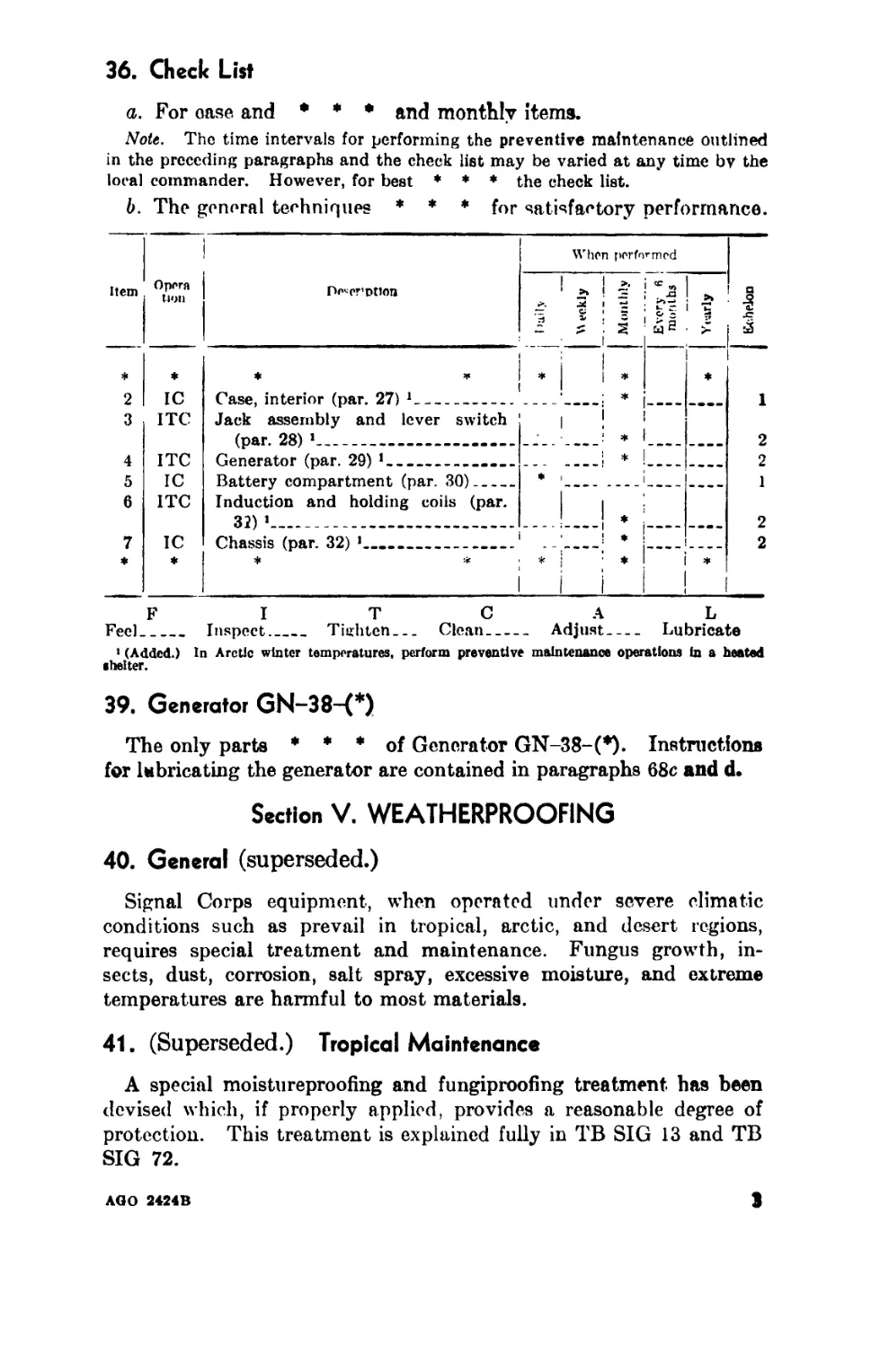
36. Check List
a. For case and • ♦ • ftn(j monthly items.
Note. The time intervals for performing the preventive maintenance outlined
in the preceding paragraphs and the check list may be varied at any time by the
local commander. However, for best ♦ ♦ ♦ the check list.
b. The general techniques * * ♦ for satisfactory performance.
Item
I
°,V,T De^r’Dtton
*
2
3
4
5
6
7
*
IC
ITC
ITC
IC
ITC
IC
♦ ¥ I ¥
Case, interior (par. 27) * 1___________
Jack assembly and lever switch
(par. 28) 1................... ...
Generator (par. 29) 1__________________
Battery compartment (par. 30)______ *
Induction and holding coils (par.
32) 1________________________________
Chassis (par. 32) *._»_____________1
When performed
F I T C A L
Feel_______ Inspect________ Tighten______ Clean_________ Adjust-------- Lubricate
1 (Added.) In Arctic winter temperatures, perform preventive maintenance operations in a heated
shelter.
39. Generator GN-38-(*)
The only parts ♦ ♦ ♦ of Generator GN-38-(*). Instructions
for lubricating the generator are contained in paragraphs 68c and d.
Section V. WEATHERPROOFING
40. General (superseded.)
Signal Corps equipment, when operated under severe climatic
conditions such as prevail in tropical, arctic, and desert regions,
requires special treatment and maintenance. Fungus growth, in-
sects, dust, corrosion, salt spray, excessive moisture, and extreme
temperatures are harmful to most materials.
41. (Superseded.) Tropical Maintenance
A special moistureproofing and fungiproofing treatment, has been
devised which, if properly applied, provides a reasonable degree of
protection. This treatment is explained fully in ТВ SIG 13 and ТВ
SIG 72.
ЛОО 2424B
3
42. Moistureproofing and Funsiproofins Telephone EE-8-(*)
*******
42.1 (Added.) Winter Maintenance
a. General. Special precautions necessary to make equipment
perform satisfactorily and to prevent total operational failure in
extremely low temperatures are explained fully in ТВ SIG 66 and
ТВ SIG 219.
b. Telephone EE-8-(*). Telephone EE-8-(*) will give satis-
factory performance in temperatures as low as — 60° F. provided
additional maintenance is performed and precautions are taken to
prevent equipment failure. When the telephone is used under condi-
tions such as prevail in the Arctic during the winter, the following
problems may be encountered:
(1) The shock-resistant characteristics of material change at
very low temperatures, and steel shrinks and becomes
brittle. Handle the equipment with reasonable care.
(2) Leather becomes stiff and should be given all possible pro-
tection to prevent damage from freezing. When using a
telephone with a leather case, keep the leather as dry as
possible. Apply a light coat of neat’s-foot oil to the rough
side of the leather once a week to improve its resistance to
moisture.
(3) Canvas will freeze and lose its pliability. Handle telephones
with a canvas case carefully to avoid cracking the canvas.
(4) Dry-cell batteries may become completely nonoperative at
extremely low temperatures. Use low-temperature batteries
or keep extra batteries warm in an inner pocket of the cloth-
ing so that they will be operative when the ones in u8e fail
(par. 21.16).
(5) Extreme cold will cause cords and wiring to become brittle.
Handle handset cords and wiring carefully.
(6) Frost which forms from the breath in the holes of the handset
transmitter affects transmission. Place a protective cover
(par. 21.16) over the transmitter before placing the equip-
ment in operation, and have a spare transmitter unit avail-
able in case the one in use fails to function properly.
(7) Water in the receiver will freeze and impede the action of the
diaphragm, and a receiver exposed to very low temperatures
may freeze the operator’s ear if he uses the receiver in contact
with his ear. Place a protective cover (par. 21.16) over
the handset receiver before using the equipment. If the
receiver becomes wet, unscrew the bakelite cap, remove
the ice, and wipe the receiver unit dry with a dry cloth.
4
▲OU 24ОД
(8) The shafts and gears of the hand generator will be difficult to
turn if these parts are not lubricated properly for cold
weather operation. Lubricate for Arctic winter operation
according to instructions in paragraph 68d.
42.2 (added.) Desert Maintenance
a. General. Special precautions necessary to prevent equipment
failure in areas subject to extremely high temperatures, low humidity,
and excessive sand and dust are explained fully in ТВ SIG 76.
b. Telephone EE-8-(*). Special dustproofing treatment is not
necessary for Telephone EE-8-(*). Take all possible precautions to
keep dust, dirt, and sand from getting on lubricated parts. Daily
inspection and cleaning of the equipment is recommended. Instead
of merely adding new lubricants to the generator, clean and relubri-
cate the equipment whenever practicable.
42.3 (added.) Lubrication Under Extreme Temperature Con-
ditions
The effects of extreme cold and heat on materials and lubricants
are explained in ТВ SIG 69. Observe all precautions and pay strict
attention to all lubrication instructions when operating equipment
under conditions of extreme cold or heat.
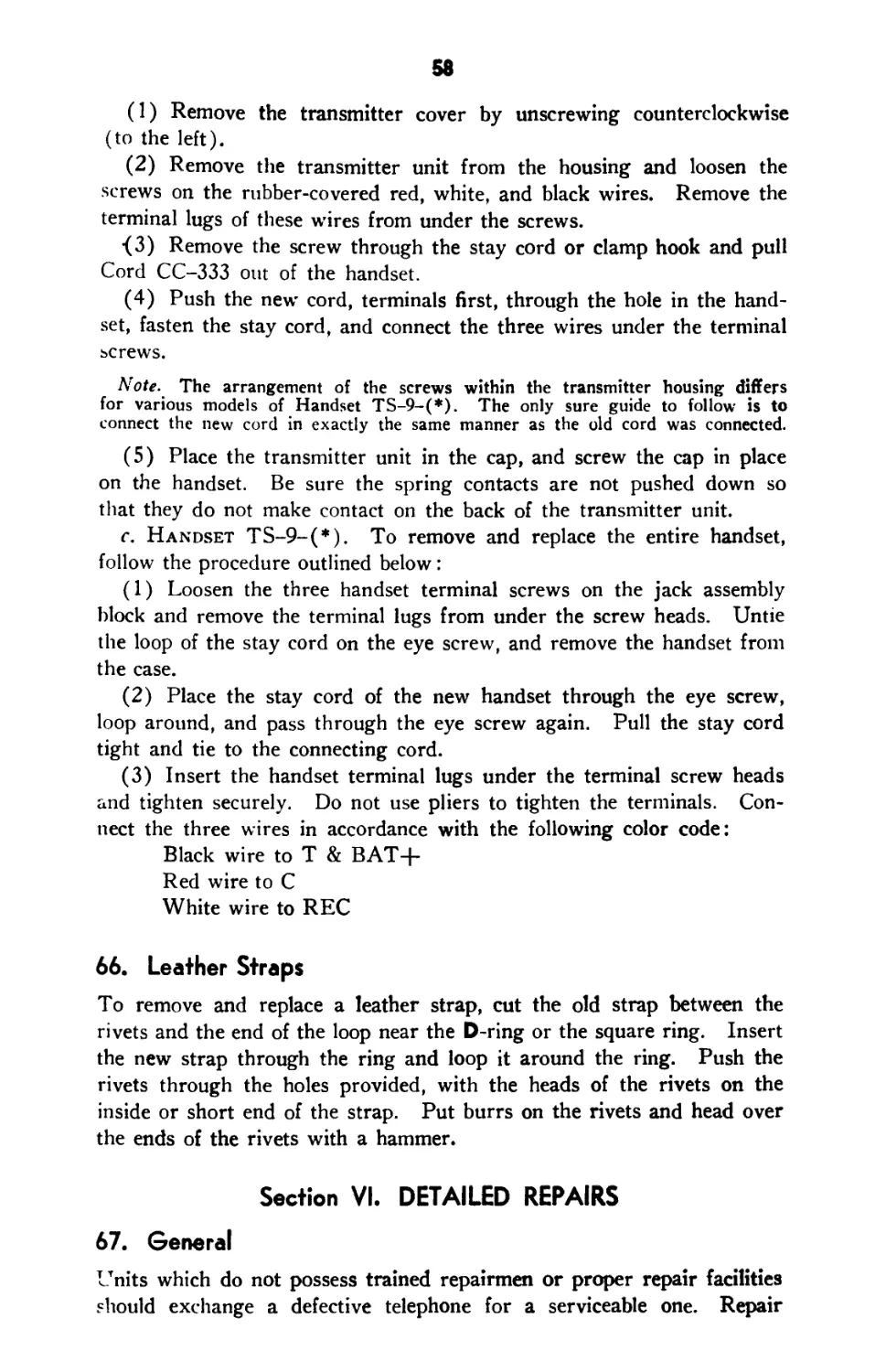
In figure 32, change designation PS to read PL; change the lubri-
cant key to read РЬ-OIL, LUBRICATING, PRESERVATIVE,
SPECIAL—J AN-L-644; GL—GREASE, LUBRICATING, IN-
STRUMENT—USA 2-134.
68. Generator GN-38-(*)
Failure of the * * * replace the generator.
*******
c. Lubrication Under Normal Conditions. Normally, it will
* * * should be lubricated. Under normal or temperate zone
temperature conditions, use oil (PL) (Ordnance supply No. 14-0-
2833) and grease (GL) (Ordnance supply No. 14-G-611) as directed
in figure 32. Before lubricating parts with oil (PL), wipe dust from
exposed surfaces. Lubricate sparingly to * * * on electrical
contacts. Use only solvent (SD) for cleaning the generator.
d. (Added.) Lubrication for Operation in Arctic Winter
Temperatures. To insure satisfactory performance of Generator
GN-38-(*) at temperatures as low as —60° F., proceed as follows:
(1) Remove the lubricant from the generator gears and hearing»,
using solvent (SD) and a small, stiff bristle brush.
AGO 3424B
5
(2) Rclubrieate sparingly—the points indicated in figure 32—
with Oil, lubricating, aircraft instrument (Army-Navy spec
AN-0-11, Quartermaster supply No. 14-0-1341). Be
especially careful not to overlubricate, and be sure that the
lubricant does not touch electrical contact parts. If elec-
trical contact parts have been touched with oil, make sure
that no oil remains on any contact surfaces. During other
seasons of the year when weather in the Arctic becomes
milder, relubricate according to directions in c above.
APPENDIX II
REFERENCES AND ABBREVIATIONS
9. Other Technical Publications
SR 110-1-1 Index of Army Motion Picture and Filzr Strips.
SR 310-20 series FM 21-8 * * ТВ SIG 75 Indexes of Army Publications. Military Training Aids. ***** Desert Maintenance of Ground Signal Equip- ment.
ТВ SIG 219 Operation of Signal Equipment at Low Temperatures.
ТВ 11-430-1 Maintenance of Batteries in Nontemperate Areas.
* * *****
[AG 300.7 (9 May 50)]
By order of the Secretary of the Army:
Official:
EDWARD F. WITSELL
Major General, USA
The Adjutant General
J. LAWTON COLLINS
Chiqf of Staff, United States Army
6
АОО 2424 В
Distribution:
Tech Sv (2) except 11 (50); Arm & Sv Bd (1); AFF Bd (ea Sv
Test Sec) (1); AFF (5); OS Maj Comd (5); Base Comd (3);
MDW (5); A (20); CHQ (2); FC (2); Sch (2) except 11 (10);
Gen Dep (2); Dep 11 (5); Tng Div (2); PE (10), OSD (2);
Lab 11 (2); 4th & Sth Ech Maint Shops 11 (2); Two (2) copies
to each of the following T/O & E’s: 2-26; 3-26; 3-27; 3-267;
4-157; 4-260-1; 5-16N; 5-17N; 5-36; 5-37; 5-72; 5-76; 5-122;
5-136; 5-166T; 5-192; 5-216N; 5-217N; 5-218N; 5-250-1; 5-
297; 5-324; 5-327; 5-367-OS; 5-526T; 5-627; 6-10-1N; 6-12; 6-
20-1; 6-26-OS; 6-26N; 6-26; 6-27N; 6-29N; 6-50-1; 6-56-OS;
6-56; 6-57; 6-67; 6-76; 6-77; 6-86; 6-87; 6-127; 6-160-1N;
6 -166N;6-167N; 6-169N; 6-176; 6-177; 6-186; 6-187; 6-196N;
6-197N; 6-200-1T; 6-216T; 6-217T; 6-218T; 6-226T; 6-227T;
6-327; 6-336N; 6-337N; 6-339N; 6-357; 6-367; 6-397; 6-437;
6-457; 6-467; 6-497T; 7-12N; 7-13N; 7-36T; 7-46S; 7-47S;
7-52T; 7-56T; 7-96; 8-7N; 8-16N; 8-17N; 8-18N; 8-27; 8-56;
8-580; 8-59IT; 8-667; 9-7; 9-8N; 9-17; 9-37; 9-66N; 9-76;
9-127; 9-316; 10-17N; 10-46N; 10-47N; 10-48N; 10-67; 10-
157; 10-197; 10-536; 11-7S; 11-7N; 11-16; 11-47; U-57N:
11 87S; 11-97; 11-107; 11-127; 11-500 EF, EO, ET, GM,
GS, GT, IA, IB, IF, IJ, IK, IP, IQ, IR, IS, IU, IV, IW, SG,
SH, SI, SJ, SiM, SN; 11-537S; 11-537T; 11-557T; 11-587;
11-592; 11-597; 11-657S; 11-667S; 11-687S; 11-697S; 17-17;
17-20; 17-26N; 17-27; 17-27N; 17-36N; 17-37N; 17-37N-22;
17-46N; 17-52; 17-53; 17-56; 17-58; 19-27N; 19-37; 19-56;
19-57; 20-7N; 30-17T; 30-30T; 30-600; 41-500; 44-7; 44-8;
44 -10-1; 44-12; 44-16; 44-17; 44-26; 44-27; 44-76N; 44-116;
44 -117; 44-126; 44-127; 44-136; 44-138; 44-200-1; 44-276T;
44-277T; 44-278T; 55-17; 55-19; 55-37; 55-117; 55-118;
55-227; SPECIAL DISTRIBUTION.
For explanation of distribution formula, see SR 310-90-1.
£QO 2424B
7
IVAR DEPARTMENT TECHNICAL MANUAL
TM 11-333
This manual supersedes TM 11-333, 6 March 1942, including С 1, 2 April 1943, and C 2,
19 September 1944; TM 11-349, 14 August 1943; ТВ 11-333-1, 22 March 1944; ТВ 11-333-2,
25 April 1944; ТВ 11-333-3, December 1944.
TELEPHONES
EE-8, EE-8-A
AND EE-8-B
IVAR DEPARTMENT • MARCH 1945
United States Government Printing Office
Washington: 1945
WAR DEPARTMENT.
Washington 25, D. C., 23 March, 1945
TM 11-333, Telephones EE-8, EE-8-A, and EE-8-B, is published
for the information and guidance of all concerned.
[AG 300.7 (24 Aug 44)]
By order of the Secretary of War :
G. C. Marshall
Chief of Staff
Official :
J. A. ULIO
Major General
The Adjutant General
Distribution :
AAF (5) ; AGF (5) ; ASF (2); T of Opn (5); Dept (5) ; Def
Comd (2) ; Base Comd (5) ; AAF Comd (2) ; Arm & Sv Bd
(2); S Div ASF (1); Tech Sv (2); SvC (5); Area ASvC
(2); WDGS Lib (5); PC&S (2); PE (2); Dep 11 (2) ; Gen
Oversea SOS Dep (Sig Sec) (2); GH (2); M Cone C (2);
Air Base Hosp (2); Gen Sv Sch (5) ; Sp Sv Sch (10); USMA
(10); ROTC (5); Lab 11 (2); Sig AS (2); Rep Shop 11
(2); A (5); D (2); В 2, 4, 6, (5); Rn 2, 4, 5, 7 (5); Bn 2,
3, 4, 5, 6, 7, 9 (5), 11 (10); C 2, 3, 4, 5, 6, 7, 9 (5), 11 (10);
AF (2); W (5); G (5); S (5); F (5).
Refer to FM 21-6 for explanation of distribution formula.
ii
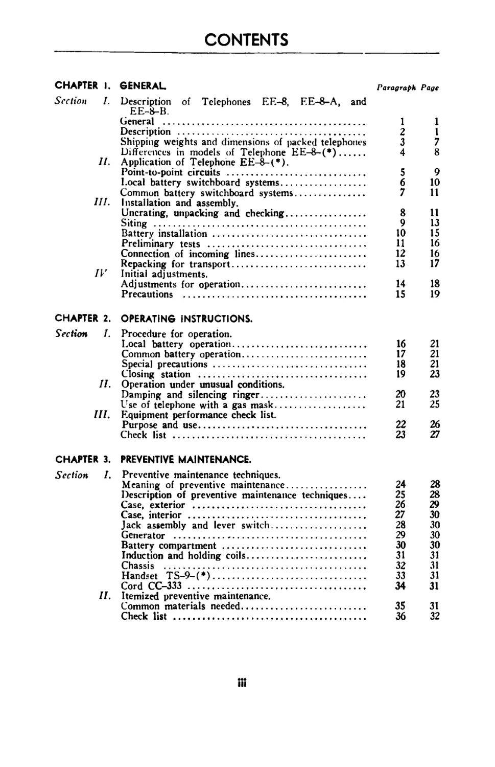
CONTENTS
CHAPTER I. GENERAL. Paragraph Page
Section I. Description of Telephones EE-8, EE-8-A, and
EE-8-B.
General .................................................................... 1 1
Description ................................................. 2 1
Shipping weights and dimensions of packed telephones 3 7
Differences in models of Telephone EE-8-(*)................. 4 8
II. Application of Telephone EE-8-(*).
Point-to-point circuits .................................... 5 9
Local battery switchboard systems........................... 6 10
Common battery switchboard systems.......................... 7 11
III. Installation and assembly.
Uncrating, unpacking and checking........................... 8 11
Siting ..................................................... 9 13
Battery installation........................................ 10 15
Preliminary tests .......................................... И 16
Connection of incoming lines................................ 12 16
Repacking for transport..................................... 13 17
IV Initial adjustments.
Adjustments for operation................................... 14 18
Precautions ................................................ 15 19
CHAPTER 2. OPERATING INSTRUCTIONS.
Section I. Procedure for operation.
Local battery operation.................................................. 16 21
Common battery operation................................... 17 21
Special precautions........................................ 18 21
Closing station ........................................... 19 23
II. Operation under unusual conditions.
Damping and silencing ringer.................................... 20 23
Use of telephone with a gas mask........................... 21 25
III. Equipment performance check list.
Purpose and use.................................................. 22 26
Check list ................................................ 23 27
CHAPTER 3. PREVENTIVE MAINTENANCE.
Section I. Preventive maintenance techniques.
Meaning of preventive maintenance..................................... 24 28
Description of preventive maintenance techniques.... 25 28
Case, exterior .......................................... 26 29
Case, interior .......................................... 27 30
Jack assembly and lever switch........................... 28 30
Generator ............................................... 29 30
Battery compartment ..................................... 30 30
Induction and holding coils.............................. 31 31
Chassis ................................................. 32 31
Handset TS-9-(*)......................................... 33 31
Cord CC-333 ........................................... 34 31
II. Itemized preventive maintenance.
Common materials needed...................................... 35 31
Check list .......................................... 36 32
in
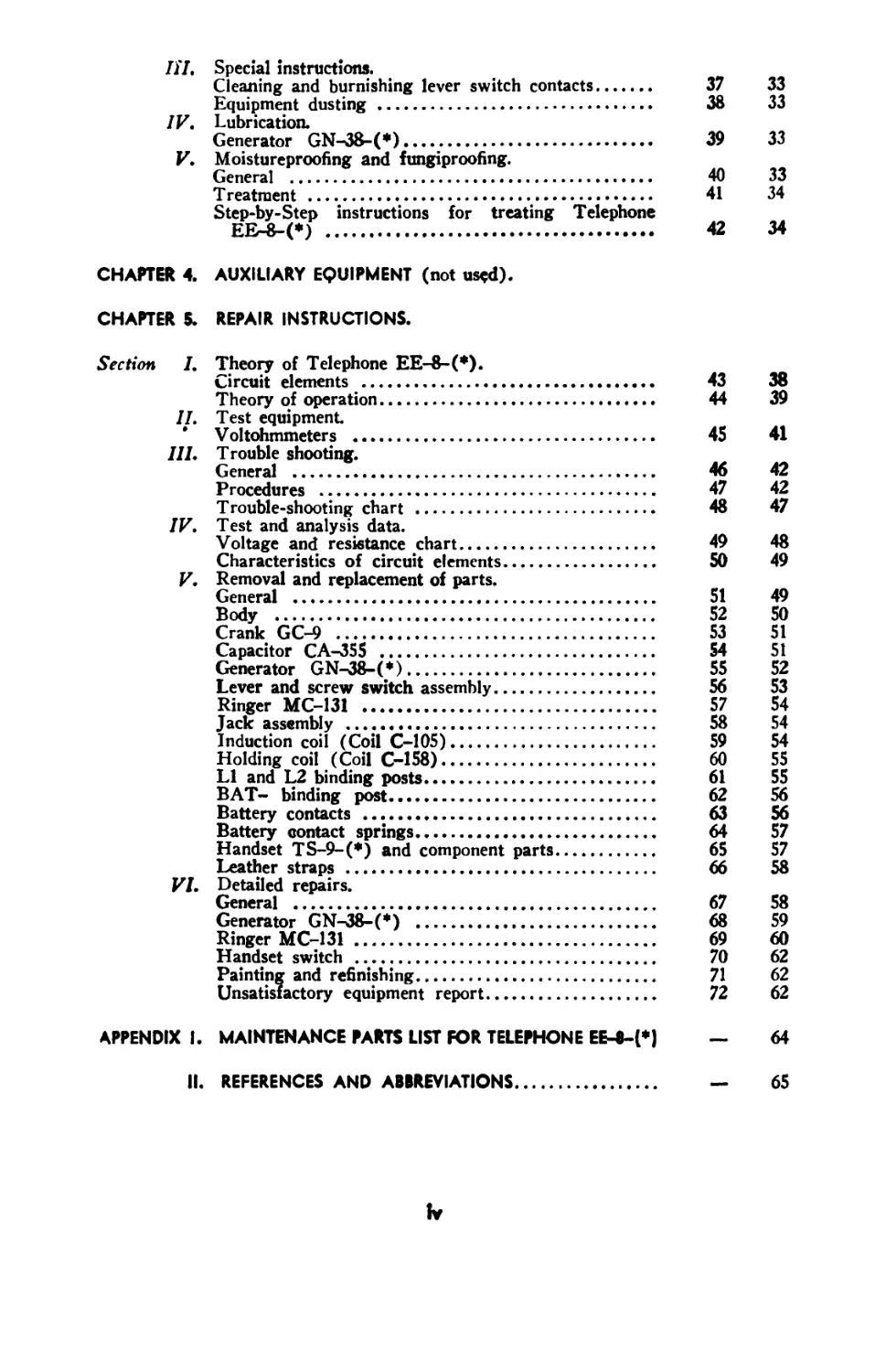
III. Special instructions.
Cleaning and burnishing lever switch contacts..... 37 33
Equipment dusting ...................................... 38 33
IV. Lubrication.
Generator GN-38-(*)..................................... 39 33
V. Moistureproofing and fungiproofing.
General ................................................ 40 33
Treatment ..........................•_.................. 41 34
Step-by-Step instructions for treating Telephone
EE-8-(*) .............................................. 42 34
CHAPTER 4. AUXILIARY EQUIPMENT (not used).
CHAPTER 5. REPAIR INSTRUCTIONS.
Section I. Theory of Telephone EE-8-(*).
Circuit elements ....................................... 43 38
Theory of operation..................................... 44 39
II. Test equipment
’ Voltohmmeters ......................................... 45 41
Hl. T rouble shooting.
General ................................................ 46 42
Procedures ............................................. 47 42
Trouble-shooting chart ................................. 48 47
IV. Test and analysis data.
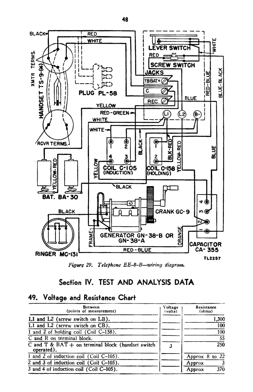
Voltage and resistance chart............................ 49 48
Characteristics of circuit elements..................... 50 49
V. Removal and replacement of parts.
General ................................................ 51 49
Body ................................................. 52 50
Crank GC-9 ............................................. 53 51
Capacitor CA-355 ..................................... 54 51
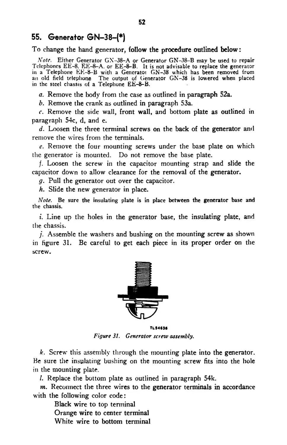
Generator GN-n38-(*).................................... 55 52
Lever and screw switch assembly......................... 56 53
Ringer MC-131 .......................................... 57 54
Jack assembly .......................................... 58 54
Induction coil (Coil C-105)............................. 59 54
Holding coil (Coil C-158)............................... 60 55
LI and L2 binding posts................................. 61 55
BAT- binding post....................................... 62 56
Battery contacts ....................................... 63 56
Battery contact springs................................. 64 57
Handset TS-9-(*) and component parts.................... 65 57
Leather straps ......................................... 66 58
VI. Detailed repairs.
General ................................................ 67 58
Generator GN-38-(*) .................................... 68 59
Ringer MC-131 .......................................... 69 60
Handset switch ......................................... 70 62
Painting and refinishing................................ 71 62
Unsatisfactory equipment report......................... 72 62
APPENDIX 1. MAINTENANCE PARTS LIST FOR TELEPHONE EE-8-(*} — 64
II. REFERENCES AND ABBREVIATIONS........................... — 65
tv
DESTRUCTION NOTICE
WHY — To prevent the enemy from using or salvaging this equipment
for his benefit.
WHEN — When ordered by your commander.
HOW-1. Smash — Use sledges, axes, hand axes, pickaxes, hammers,
crowbars, heavy tools.
2. Cut — Use axes, handaxes, machetes.
3. Burn — Use gasoline, kerosene, oil, flame throwers, in-
cendiary grenades.
4. Explosives—Use firearms, grenades, TNT.
5. Disposal — Bury in slit trenches, fox holes, other holes.
Throw in streams. Scatter.
USE ANYTHING IMMEDIATELY AVAILABLE FOR DESTRUC-
TION OF THIS EQUIPMENT
WHAT—1. Smash — Holding coil, induction coil, ringer coils, capaci-
tors, generator armature, generator gears, all switches,
transmitter, receiver, and handset handle.
2. Cut — all chassis wiring, handset cord, and handset wiring.
3. Bum — All remaining equipment, smashed parts, technical
manuals, circuit labels, and traffic diagrams.
4. Bury or scatter — All of the above pieces after destroying
their usefulness.
DESTROY EVERYTHING
BLANK
This manual supersedes TM 11-333, 6 March 1942, including С 1, 2 April 1943,
and C 2, 19 September 1944; TM 11-349, 14 August 1943; ТВ 11-333-1, 22 March
1944; ТВ 11-333-2, 25 April 1944; ТВ 11-333-3, December 1944.
CHAPTER I
GENERAL
Section I. DESCRIPTION OF TELEPHONES EE-8, ES-8-A,
AND EE-8-B
I. General
a. Characteristics. Telephone EE-8-(*) is a portable field tele-
phone designed for use on either local or common battery telephone
systems. It is compact, rugged, and portable, and in performance equals
the best present day commercial telephones. It contains all the elements
necessary for a combination local battery and common battery telephone,
and the circuit elements are arranged for antisidetone transmission. The
talking and signaling range of the telephone varies with the type of line
wire use, the condition of the wire, whether the wire is dry or wet, and
whether the wire is on the ground or in the air. The telephone will
operate satisfactorily over the distances usually found in corps and
subordinate wire systems, provided the lines are well constructed. When
Telephone EE-8-(*) is used as a local battery telephone, talking range
of 11 to 17 miles may be expected on Wire W-110-B, depending on
weather conditions and the type of construction of the wire line. These
distances may be increased by the proper use of loading coils. Capabilities
of the telephone when applied to different systems are discussed in
paragraphs 5, 6, and 7.
b. Nomenclature. Telephones EE-8, EE-8-A, and EE-8-B are
referred to in this Technical Manual as Telephone EE-8-(*). Such
nomenclature refers to any one or all of the above three models. Similarly,
Generator GN-38-(*) refers to Generators GN-38, GN-38-A, and
GN-38-B, and Handset TS-9-(*) refers to Handsets TS-9-A, -С, -E,
-F, -G, -H, -J, -K, -L, -N, -O, -Q, -R, -T, -U, -V, -W, -AA, -AC,
-AE, -AF, -AJ, and -AL.
2. Description
a. General. Telephones EE-8-A and EE-8-B are each contained
in a case by 7JJ by 3^4 inches and weigh about 9^4 pounds, including
batteries. Telephone EE-8 is contained in a case 9^4 by 7)4 by 3^4
2
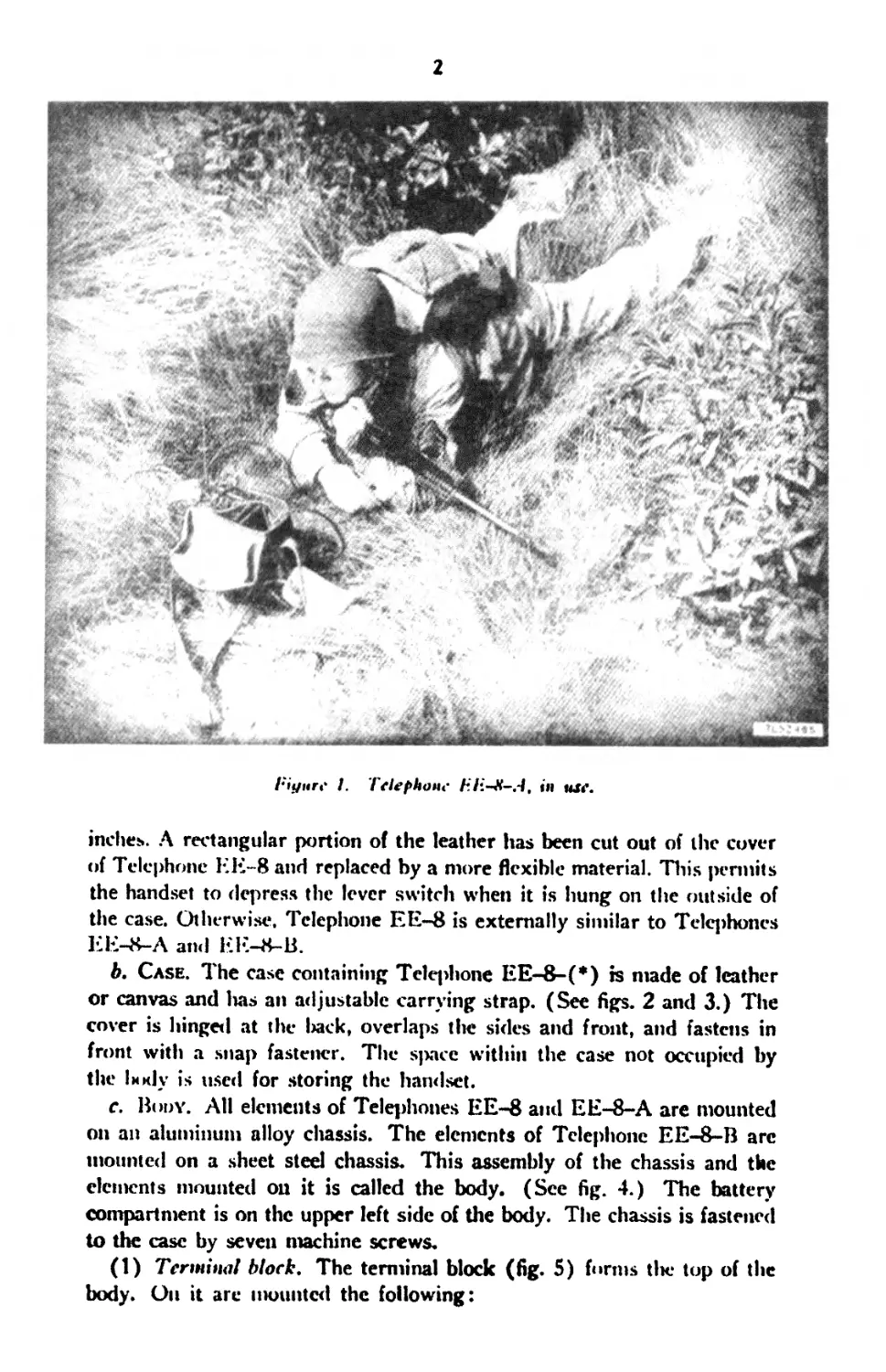
I’iyitrc I. Telephone F.T.-X-el, m uxr.
inches. A rectangular portion of the leather has been cut out of the cover
of Telephone EE-8 and replaced by a more flexible material. This pennits
the handset to depress the lever switch when it is hung on the outside of
the case. Otherwise. Telephone EE-8 is externally similar to Telephones
ЕЕ-8-Л and EE-8-B.
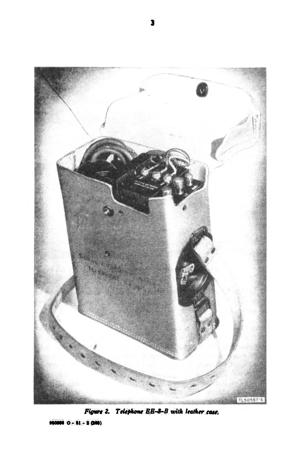
b. Case. The case containing Telqihone EE-8-(*) is made of leather
or canvas and lias an adjustable carrying strap. (See figs. 2 and 3.) The
cover is hinged at the liack, overlaps tlie sides and front, and fastens in
front with a snap fastener. The space within the case not occupied by
the liody is used for storing the handset.
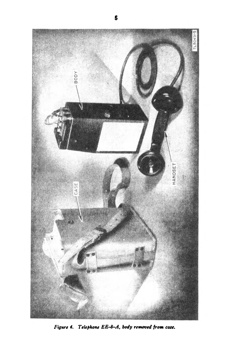
c. Body. All elements of Telephones EE-8 and EE-8-A are mounted
on an aluminum alloy cliassis. The elements of Telephone EE-8-B arc
mounted on a sheet steel chassis. This assembly of the chassis and the
elements mounted on it is called the body. (See fig. 4.) The battery
compartment is on the upper left side of the body. The chassis is fastened
to the case by seven machine screws.
(1) Terminal block. The terminal block (fig. 5) firms the top of the
body. On it are mounted the following:
(«и)t-11-0 tMOM
'тишм Ш1М я+Я9м<МФ1 'г
t
4
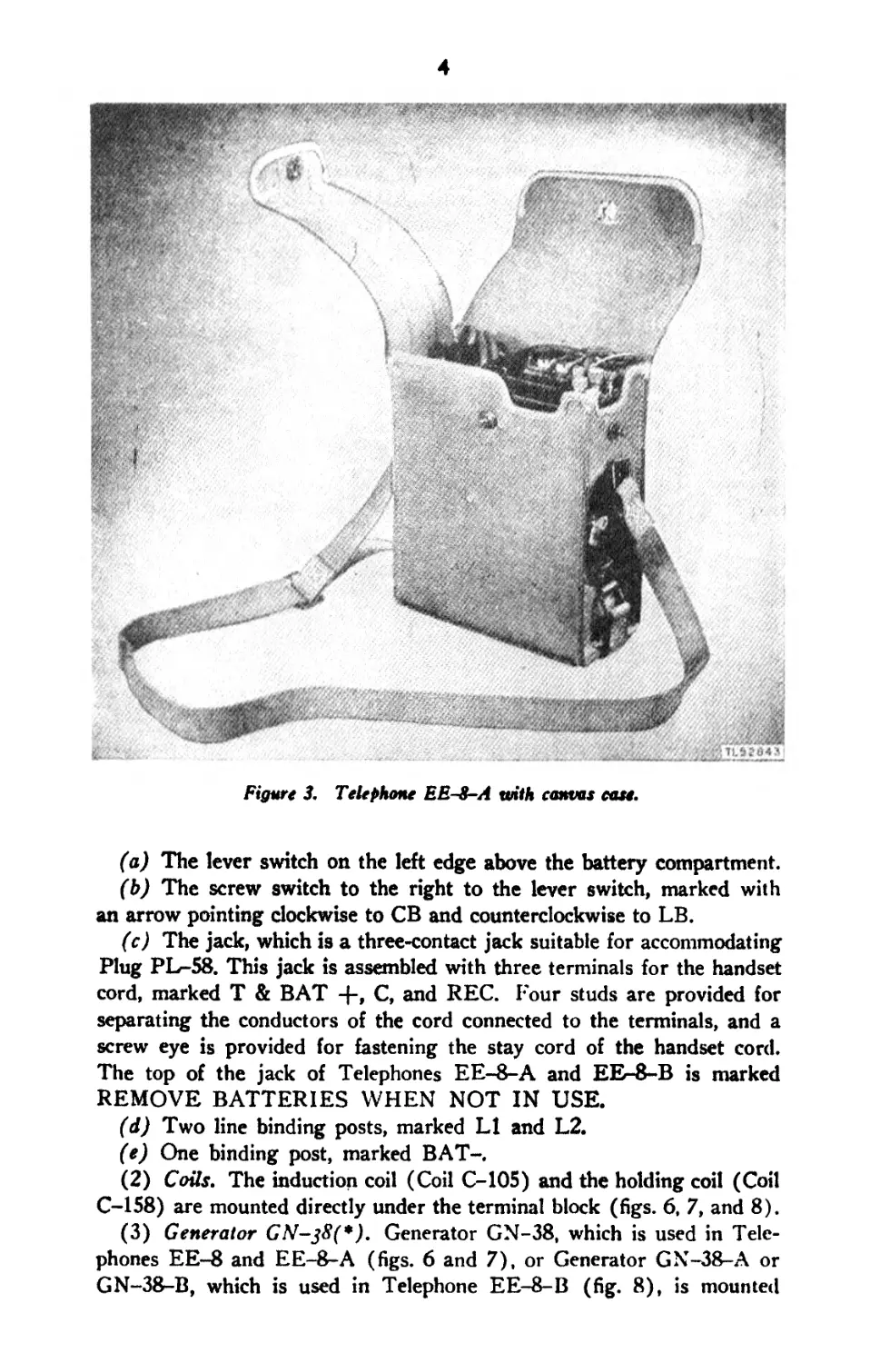
Figure 3. Telephone EE-8-A with canvas case.
(a) The lever switch on the left edge above the battery compartment.
(b) The screw switch to the right to the lever switch, marked with
an arrow pointing clockwise to CB and counterclockwise to LB.
(c) The jack, which is a three-contact jack suitable for accommodating
Plug PL-58. This jack is assembled with three terminals for the handset
cord, marked T & BAT -f-, C, and REC. Four studs are provided for
separating the conductors of the cord connected to the terminals, and a
screw eye is provided for fastening the stay cord of the handset cord.
The top of the jack of Telephones EE-8-A and EE-8-B is marked
REMOVE BATTERIES WHEN NOT IN USE.
(d) Two line binding posts, marked LI and L2.
(e) One binding post, marked BAT-.
(2) Coils. The induction coil (Coil C-105) and the holding coil (Coil
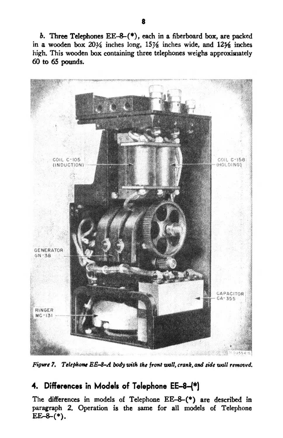
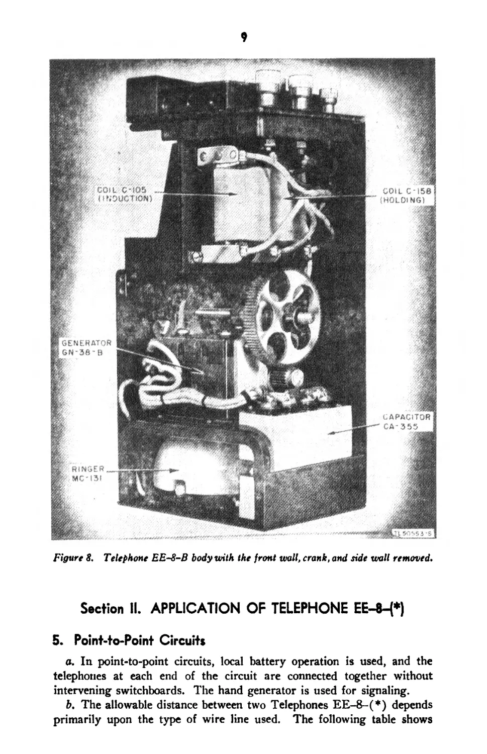
C-158) are mounted directly under the terminal block (figs. 6, 7, and 8).
(3) Generator GN~38(*). Generator GN-38, which is used in Tele-
phones EE-8 and EE-8-A (figs. 6 and 7), or Generator GN-38-A or
GN-38-B, which is used in Telephone EE-8-B (fig. 8), is mounted
5
Figure 4. Telephone EE-8-A, body removed from case.
Tk50-»5bS
6
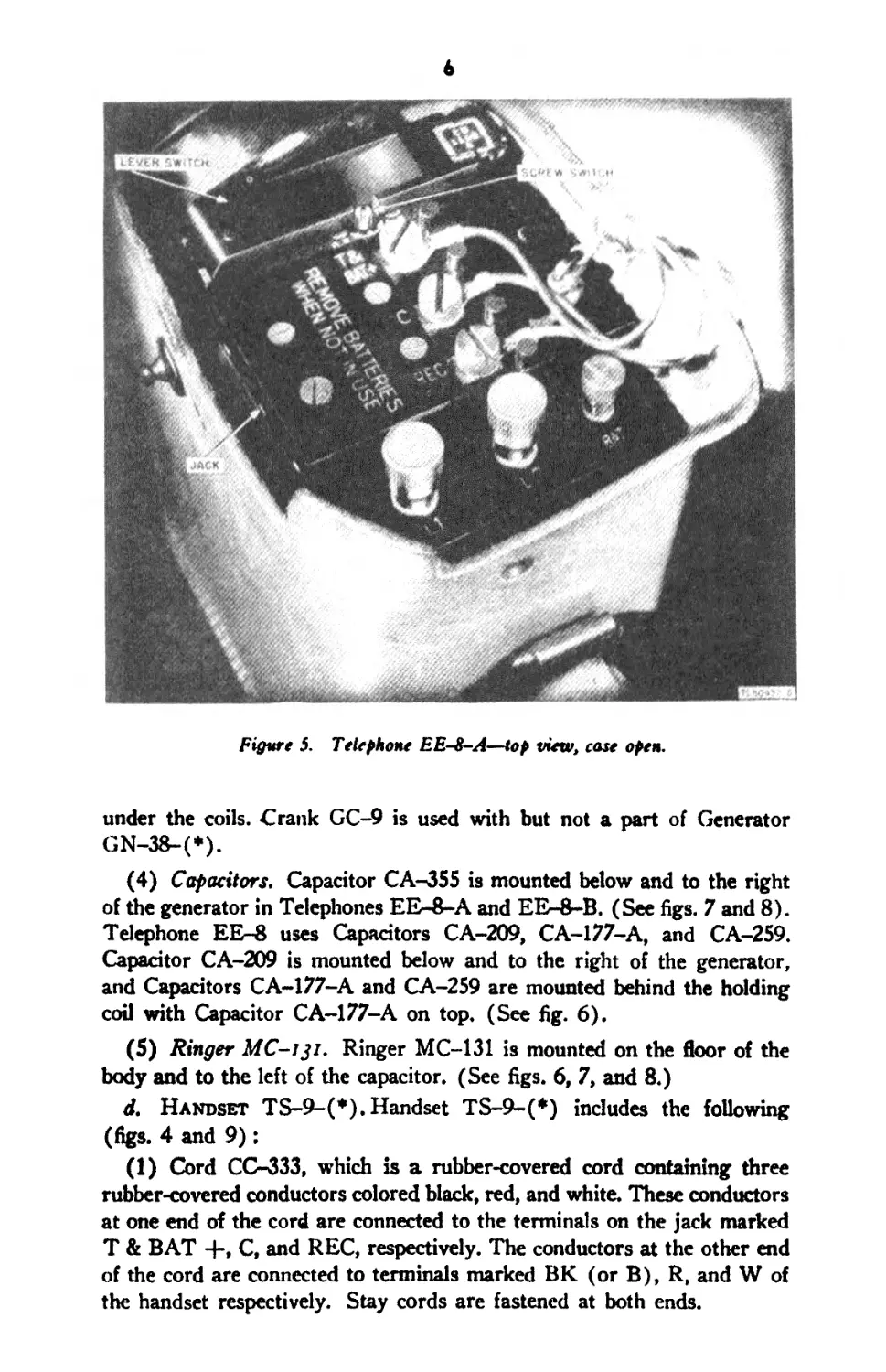
Figure 5. Telephone EE-8-A—top view, case open.
under the coils. Crank GC-9 is used with but not a part of Generator
GN-38-(*).
(4) Capacitors. Capacitor CA-355 is mounted below and to the right
of the generator in Telephones EE-8-A and EE-8-B. (See figs. 7 and 8).
Telephone EE-8 uses Capacitors CA-209, CA-177-A, and CA-259.
Capacitor CA-209 is mounted below and to the right of the generator,
and Capacitors CA-177-A and CA-259 are mounted behind the holding
coil with Capacitor CA-177-A on top. (See fig. 6).
(5) Ringer MC-131. Ringer MC-131 is mounted on the floor of the
body and to the left of the capacitor. (See figs. 6, 7, and 8.)
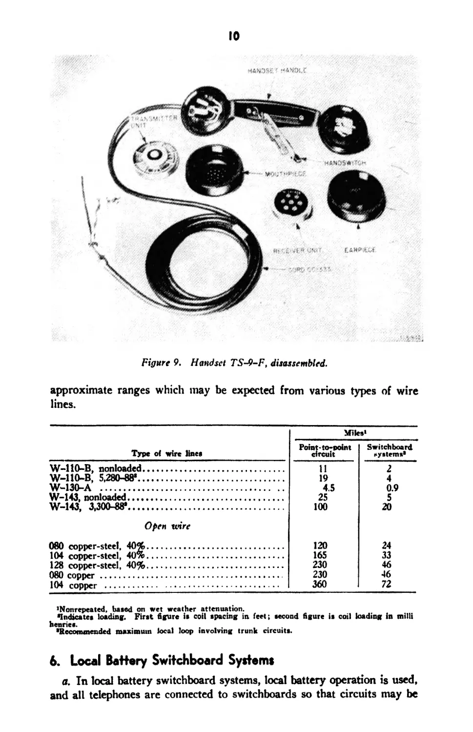
d. Handset TS-9-(*), Handset TS-9-(*) includes the following
(figs. 4 and 9):
(1) Cord CC-333, which is a rubber-covered cord containing three
rubber-covered conductors colored black, red, and white. These conductors
at one end of the cord are connected to the terminals on the jack marked
T & BAT -h, C, and REC, respectively. The conductors at the other end
of the cord are connected to terminals marked BK (or B), R, and W of
the handset respectively. Stay cords are fastened at both ends.
7
(2) The handle, which contains suitable terminals, connections between
the parts of the handset, and the handset switch in the transmitter circuit.
(3) A receiver element or unit in one end of the handle and a
transmitter element or unit in the other end.
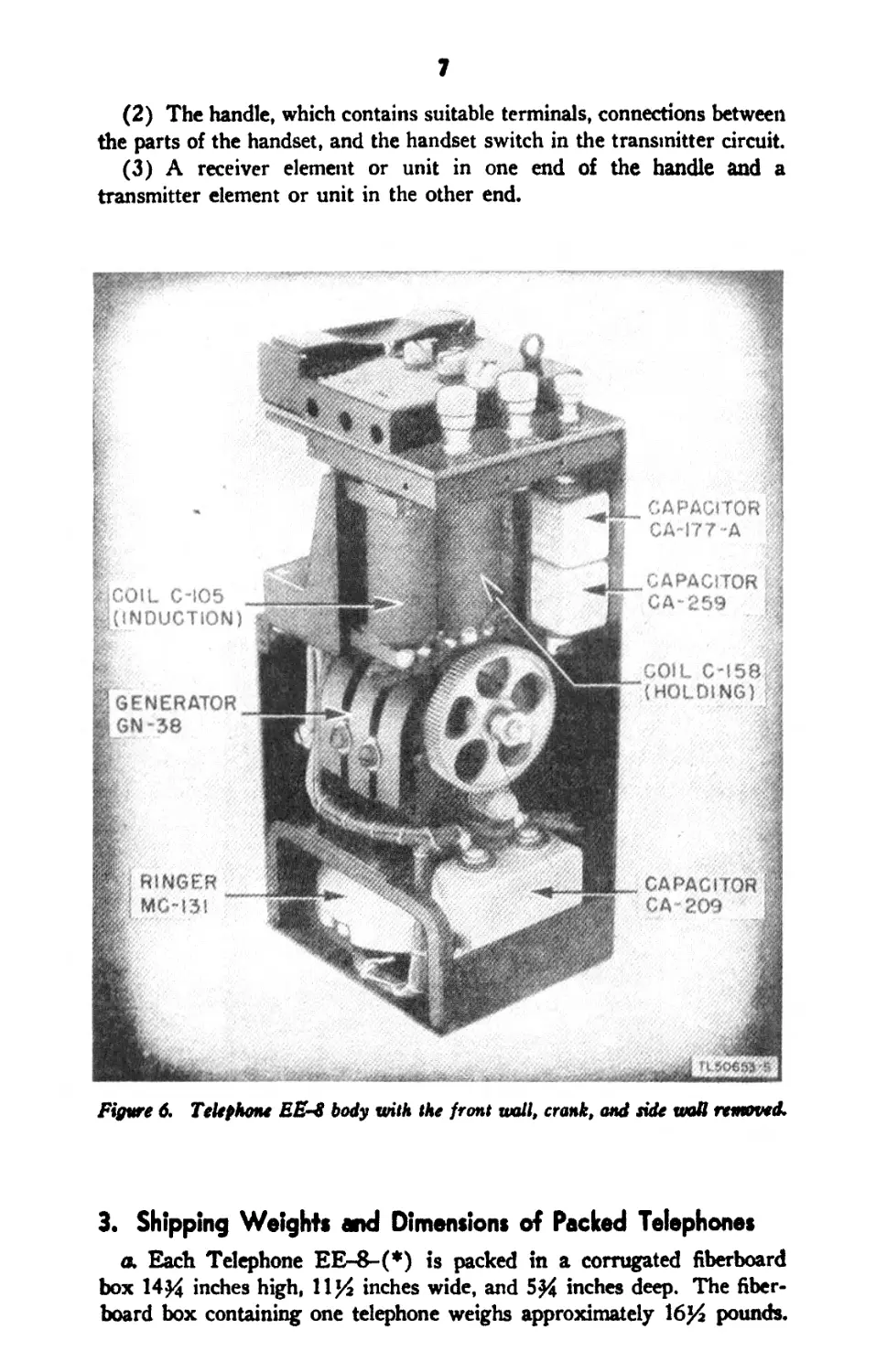
Figure 6. Telephone EE-8 body with the front wall, crank, and side wall removed.
3. Shipping Weights and Dimensions of Packed Telephones
a. Each Telephone EE-8-(#) is packed in a corrugated fiberboard
box 14^ inches high, 11)4 inches wide, and 5# inches deep. The fiber-
board box containing one telephone weighs approximately 16)4 pounds.
8
b. Three Telephones EE-8-(*), each in a fiberboard box, are packed
in a wooden box 20^4 inches long, 15^ inches wide, and 12^4 inches
high 'This wooden box containing three telephones weighs approximately
60 to 65 pounds.
Figure 7. Telephone EE-&-A body with the front wall, crank, and tide wall removed.
4. Differences in Models of Telephone EE-8—(*)
The differences in models of Telephone EE-8-(*) are described in
paragraph 2. Operation is the same for all models of Telephone
EEr-&-(*),
9
Figure 8. Telephone EE-8-B body with the front wall, crank, and side wall removed.
Section II. APPLICATION OF TELEPHONE EE-84*)
5. Point-to-Point Circuits
a. In point-to-point circuits, local battery operation is used, and the
telephones at each end of the circuit are connected together without
intervening switchboards. The hand generator is used for signaling.
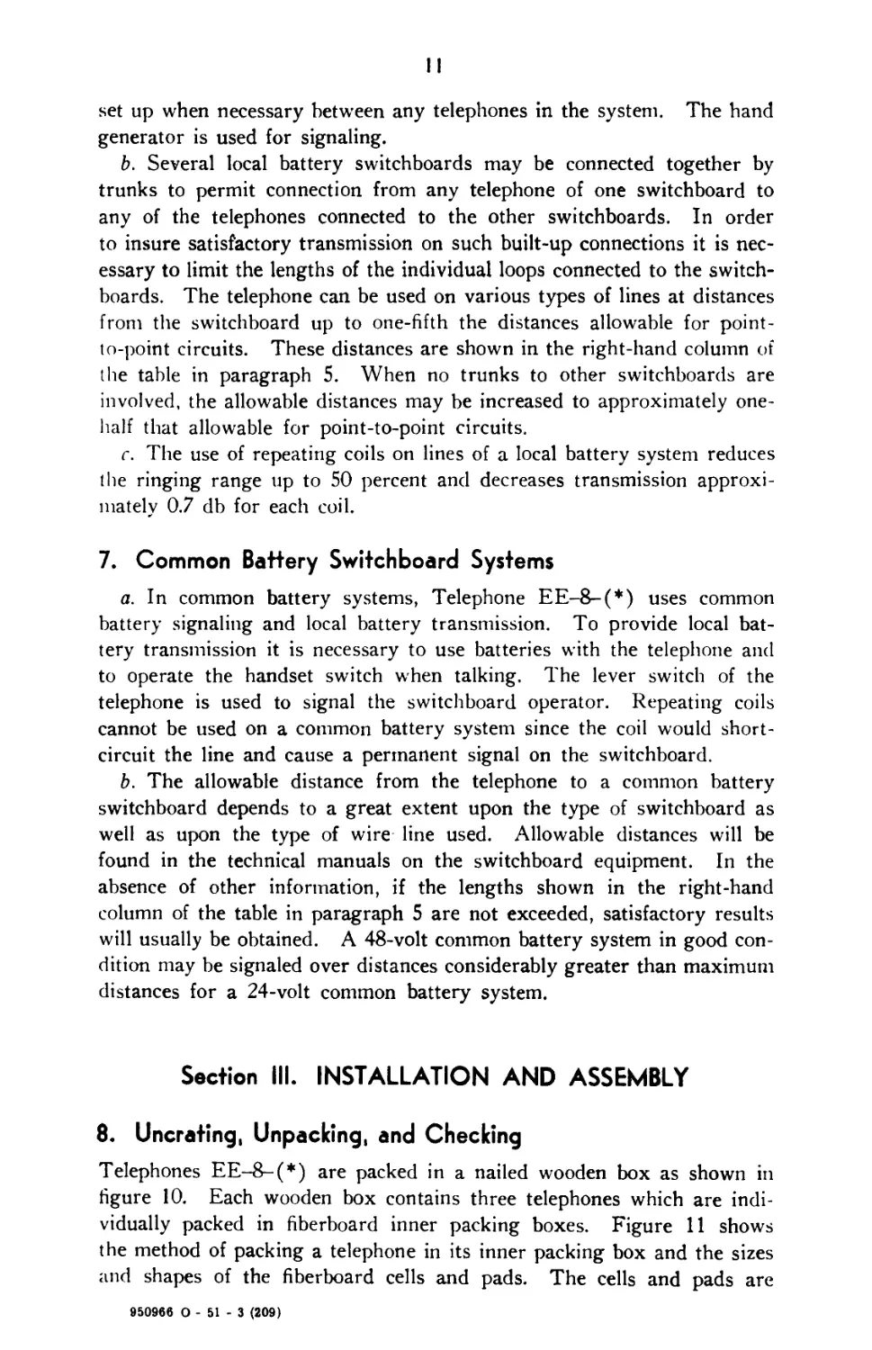
b. The allowable distance between two Telephones EE-8-(*) depends
primarily upon the type of wire line used. The following table shows
10
H4N3Sf ' «А>ИИ.С
Figure 9. Handset TS-9-F, disassembled.
approximate ranges which may be expected from various types of wire
lines.
Miles’
Type of wire lines
W-110-B, nonloaded................................
W-HO-B, 5,280-88*.................................
W-130-A ..........................................
W-143, nonloaded..................................
W-143, 3,300-88*..................................
Point-to-point
circuit
11
19
4.5
25
100
Switch bee rd
systems’
4
0.9
5
20
Open wire
080 copper-steel, 40%...................................
104 copper-steel, 40%...................................
128 copper-steel, 40%...................................
080 copper .............................................
104 copper .............................................
120
165
230
230
360
24
33
46
46
72
’Nonrepeated, based on wet weather attenuation.
•Indicates loading. First figure is coil spacing in feet; second figure is coil loading in mill!
henries.
•Recommended maximum local loop involving trunk circuits.
6. Local Battery Switchboard Systems
a. In local battery switchboard systems, local battery operation is used,
and all telephones are connected to switchboards so that circuits may be
II
set up when necessary between any telephones in the system. The hand
generator is used for signaling.
b. Several local battery switchboards may be connected together by
trunks to permit connection from any telephone of one switchboard to
any of the telephones connected to the other switchboards. In order
to insure satisfactory transmission on such built-up connections it is nec-
essary to limit the lengths of the individual loops connected to the switch-
boards. The telephone can be used on various types of lines at distances
from the switchboard up to one-fifth the distances allowable for point-
to-point circuits. These distances are shown in the right-hand column of
the table in paragraph 5. When no trunks to other switchboards are
involved, the allowable distances may be increased to approximately one-
half that allowable for point-to-point circuits.
c. The use of repeating coils on lines of a local battery system reduces
the ringing range up to 50 percent and decreases transmission approxi-
mately 0.7 db for each coil.
7. Common Battery Switchboard Systems
a. In common battery systems, Telephone EE-8-(*) uses common
battery signaling and local battery transmission. To provide local bat-
tery transmission it is necessary to use batteries with the telephone and
to operate the handset switch when talking. The lever switch of the
telephone is used to signal the switchboard operator. Repeating coils
cannot be used on a common battery system since the coil would short-
circuit the line and cause a permanent signal on the switchboard.
b. The allowable distance from the telephone to a common battery
switchboard depends to a great extent upon the type of switchboard as
well as upon the type of wire line used. Allowable distances will be
found in the technical manuals on the switchboard equipment. In the
absence of other information, if the lengths shown in the right-hand
column of the table in paragraph 5 are not exceeded, satisfactory results
will usually be obtained. A 48-volt common battery system in good con-
dition may be signaled over distances considerably greater than maximum
distances for a 24-volt common battery system.
Section III. INSTALLATION AND ASSEMBLY
8. Uncrating, Unpacking, and Checking
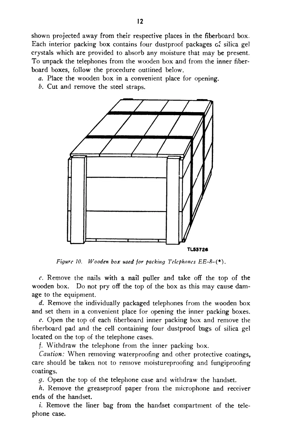
Telephones EE-8-(*) are packed in a nailed wooden box as shown in
figure 10. Each wooden box contains three telephones which are indi-
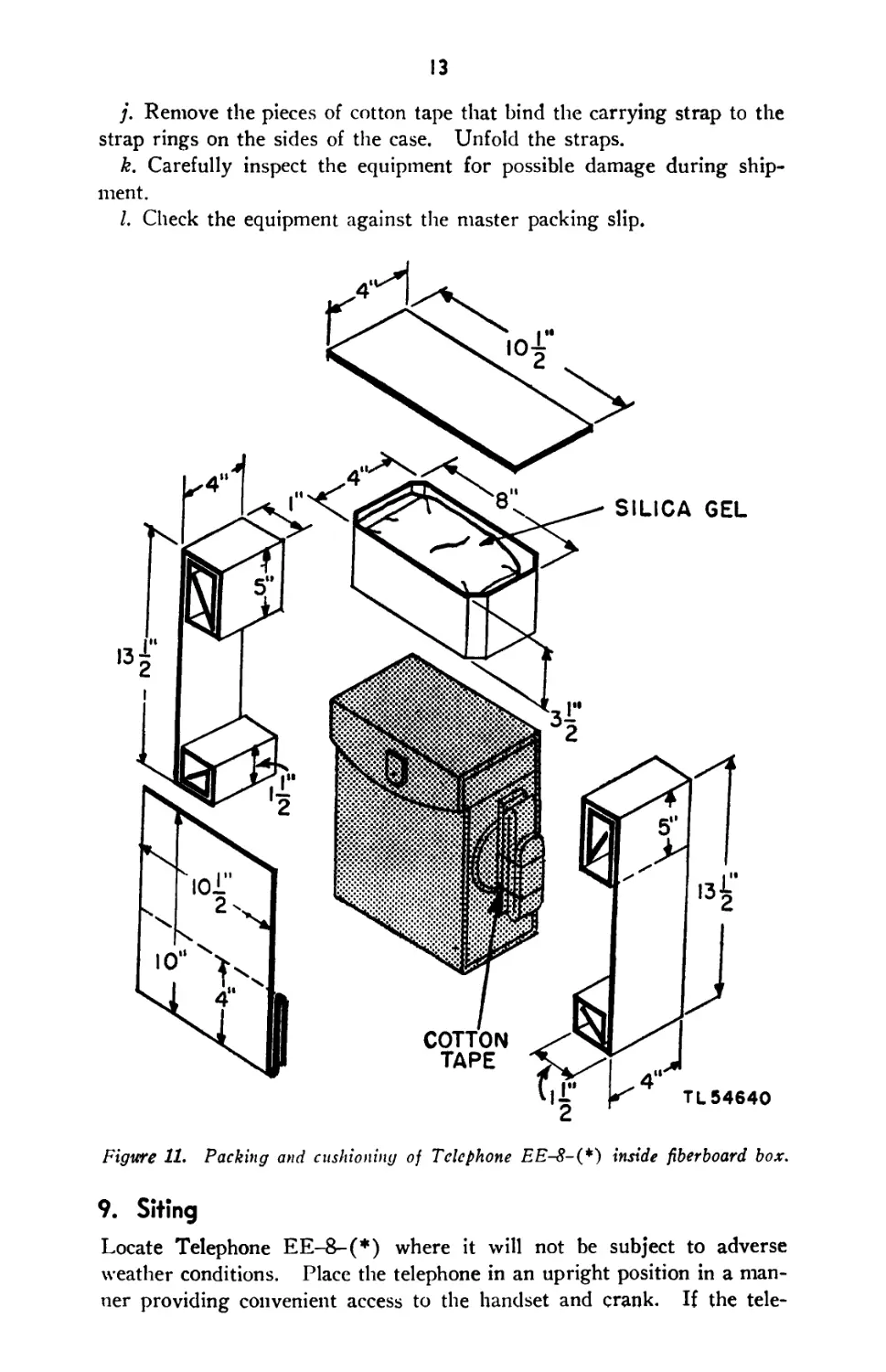
vidually packed in fiberboard inner packing boxes. Figure 11 shows
the method of packing a telephone in its inner packing box and the sizes
and shapes of the fiberboard cells and pads. The cells and pads are
950966 0 - 51 - 3 (209)
12
shown projected away from their respective places in the fiberboard box.
Each interior packing box contains four dustproof packages g2 silica gel
crystals which are provided to absorb any moisture that may be present.
To unpack the telephones from the wooden box and from the inner fiber-
board boxes, follow the procedure outlined below.
a. Place the wooden box in a convenient place for opening.
b. Cut and remove the steel straps.
c. Remove the nails with a nail puller and take off the top of the
wooden box. Do not pry off the top of the box as this may cause dam-
age to the equipment.
d. Remove the individually packaged telephones from the wooden box
and set them in a convenient place for opening the inner packing boxes.
e. Open the top of each fiberboard inner packing box and remove the
fiberboard pad and the cell containing four dustproof bags of silica gel
located on the top of the telephone cases.
f. Withdraw the telephone from the inner packing box.
Caution: When removing waterproofing and other protective coatings,
care should be taken not to remove moistureproofing and fungiproofing
coatings.
g. Open the top of the telephone case and withdraw the handset.
h. Remove the greaseproof paper from the microphone and receiver
ends of the handset.
i. Remove the liner bag from the handset compartment of the tele-
phone case.
13
j. Remove the pieces of cotton tape that bind the carrying strap to the
strap rings on the sides of the case. Unfold the straps.
k. Carefully inspect the equipment for possible damage during ship-
ment.
I. Check the equipment against the master packing slip.
Figure 11. Packing and cushioning of Telephone EE-8-(*) inside fiberboard box.
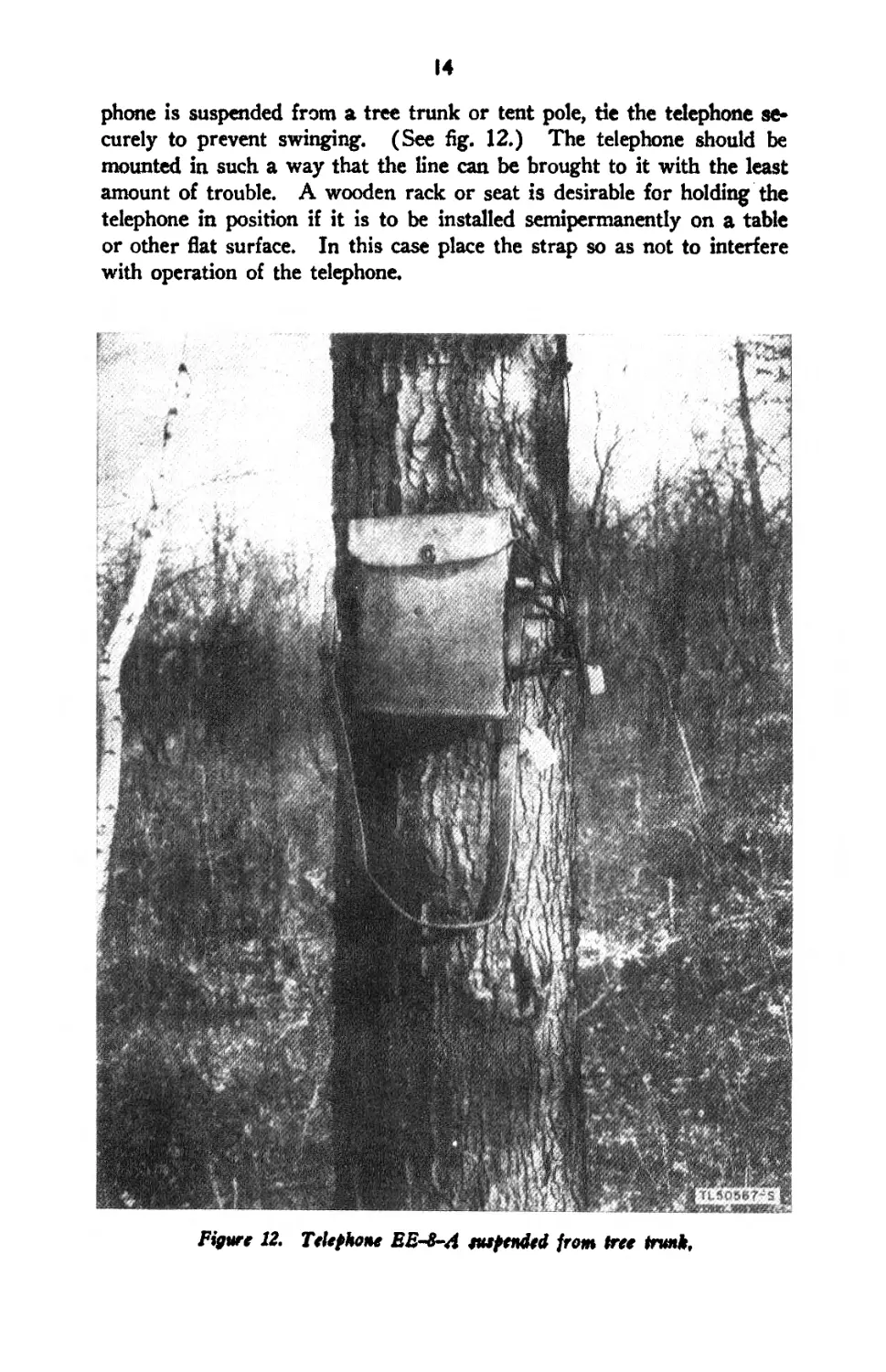
9. Siting
Locate Telephone EE-8-(*) where it will not be subject to adverse
weather conditions. Place the telephone in an upright position in a man-
ner providing convenient access to the handset and crank. If the tele-
14
phone is suspended from a tree trunk or tent pole, de the telephone se-
curely to prevent swinging. (See fig. 12.) The telephone should be
mounted in such a way that the line can be brought to it with the least
amount of trouble. A wooden rack or seat is desirable for holding the
telephone in position if it is to be installed semipermanently on a table
or other fiat surface. In this case place the strap so as not to interfere
with operation of the telephone.
Figure 12. Telephone EE-8-A euepended from tree trunk.
15
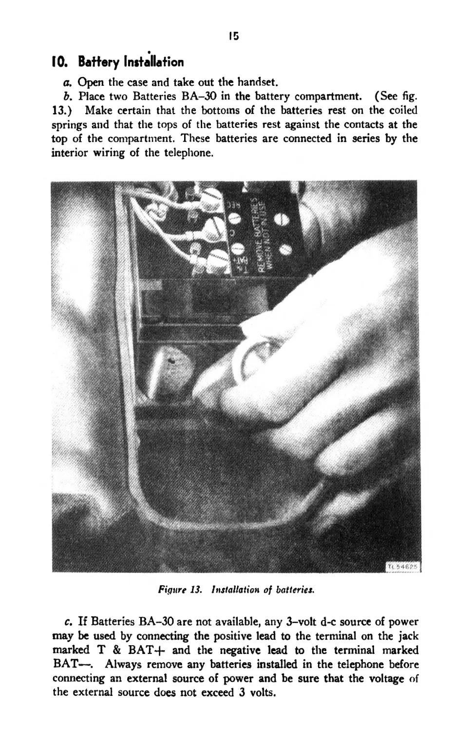
10. Battery Installation
a. Open the case and take out the handset.
b. Place two Batteries BA-30 in the battery compartment. (See fig.
13.) Make certain that the bottoms of the batteries rest on the coiled
springs and that the tops of the batteries rest against the contacts at the
top of the compartment. These batteries are connected in series by the
interior wiring of the telephone.
Figure 13. Installation of batteries.
c. If Batteries BA-30 are not available, any 3-vo!t d-c source of power
may be used by connecting the positive lead to the terminal on the jack
marked T & BAT-4- and the negative lead to the terminal marked
BAT—. Always remove any batteries installed in the telephone before
connecting an external source of power and be sure that the voltage of
the external source does not exceed 3 volts.
16
11. Preliminary Tests
a. Testing Transmitter and Receiver. Hold the receiver to the
ear and blow steadily into the transmitter while alternately operating and
releasing the handset switch. The sound (sidetone) should be heard
strongly in the receiver when the switch is in the operated position, but
should not be heard when the switch is in the unoperated position.
b. Testing Generator. While holding the receiver to the ear, rap-
idly turn the generator clockwise for several turns. The generator should
turn easily and the impulses should be heard in the receiver. The ringer
should not operate. Short circuit line terminals LI and L2 with a screw
driver or short piece of field wire, hold the receiver to the ear, and again
turn the generator. The generator should now turn hard as though a
drag had been placed on it, the impulses should be heard in the receiver,
and the bell should not ring. Remove the short circuit.
c. Testing Ringer. Connect terminals LI and L2 to the correspond-
ing line terminals of another telephone known to be serviceable. Turn
the generator of the other telephone. The bell of the telephone under
test should ring.
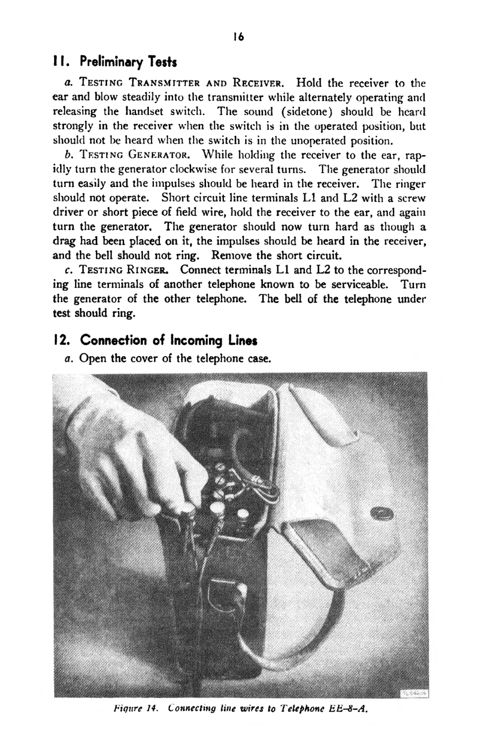
12. Connection of Incoming Lines
a. Open the cover of the telephone case.
Figure 14. Connecting line wires to Telephone EE-S-A.
17
b. Starting approximately 4 inches from the ends of the wires to
which t!ie telephone is to be connected, strip off about 2 inches of insula-
tion. Scrape and clean the bared metal of the wires.
c. If the telephone is being connected to a metallic circuit, connect one
wire of the line to the terminal marked LI on the terminal block of the
telephone. Connect the other line wire to the terminal marked L2. (See
fig. 14.)
d. If the telephone is being connected to a ground-return circuit, con-
nect tlie line wire to either line terminal LI or L2. Connect the other
line terminal to a good ground.
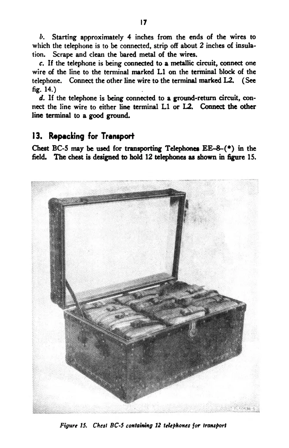
13. Repacking for Transport
Chest BC-5 may be used for transporting Telephones EE-8-(*) in the
field. The chest is designed to hold 12 telephones as shown in figure 15.
Figure 15. Chest BC-5 containing 12 telephones jor transport
It
Section IV. INITIAL ADJUSTMENTS
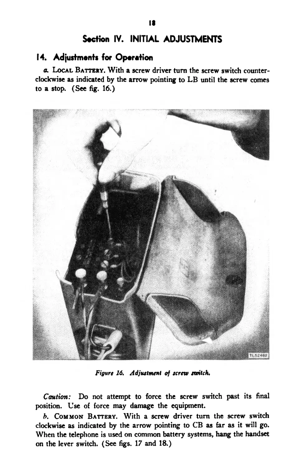
14. Adjustments for Operation
a. Local Battery. With a screw driver turn the screw switch counter-
clockwise as indicated by the arrow pointing to LB until the screw comes
to a stop. (See fig. 16.)
Figure 16, Adjustment of screw switch.
Caution: Do not attempt to force the screw switch past its final
position. Use of force may damage the equipment.
b. Common Battery. With a screw driver turn the screw switch
clockwise as indicated by the arrow pointing to CB as far as it will go.
When the telephone is used on common battery systems, hang the handset
on the lever switch. (See figs. 17 and 18.)
19
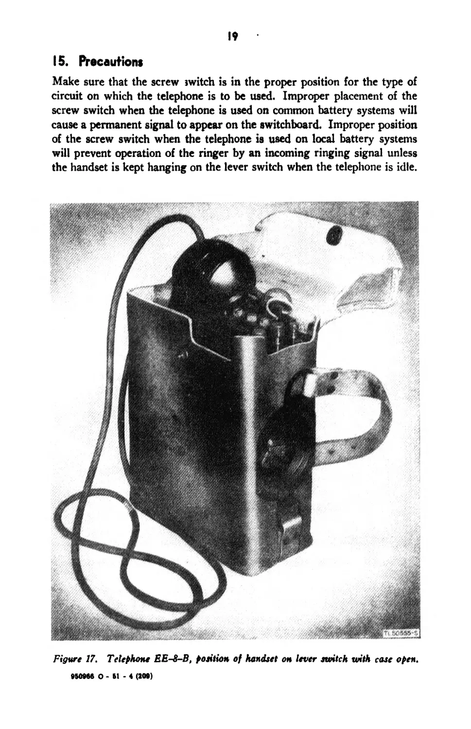
15. Precautions
Make sure that the screw switch is in the proper position for the type of
circuit on which the telephone is to be used. Improper placement of the
screw switch when the telephone is used on common battery systems will
cause a permanent signal to appear on the switchboard. Improper position
of the screw switch when the telephone is used on local battery systems
will prevent operation of the ringer by an incoming ringing signal unless
the handset is kept hanging on the lever switch when the telephone is idle.
Figure 17. Telephone EE-8-B, petition of handset on lever switch with case open.
950966 O - 61 - 4 (200)
20
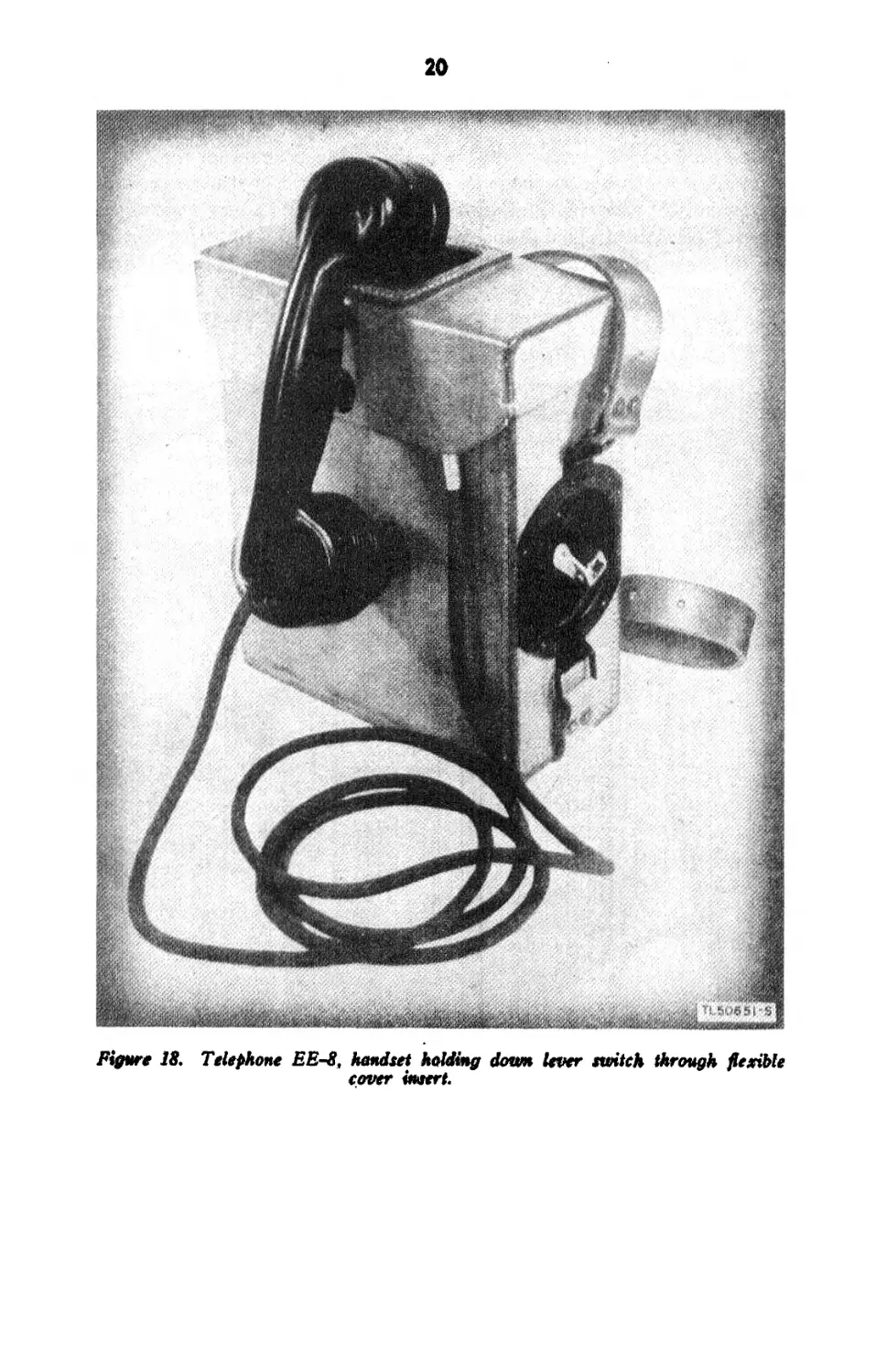
Figure 18. Telephone EES, handset holding down lever switch through flexible
cover insert.
CHAPTER 2
OPERATING INSTRUCTIONS
Note. For instructions on destroying the equipment to prevent enemy use. see
destruction notice at the front of this manual.
Section I. PROCEDURE FOR OPERATION
16. Local Battery Operation
a. Signaling. Turn the generator rapidly in a clockwise direction for
several turns.
b. Transmitting and Receiving. Hold the handset with the trans-
mitter close to the lips and the receiver to the ear. While talking, hold
the handset switch operated with the thumb and talk directly into the
transmitter. Release the handset switch while listening to conserve the
batteries.
c. Ringing Off. When conversation is completed on a call established
through a switchboard, ring off by two or three sharp turns of the
generator crank. This w’ill operate a supervisory light or drop on the
switchboard to notify the switchboard operator that the connection is no
longer wanted or that a new connection is desired. After ringing off,
if a new connection is not desired, replace the handset in the case.
17. Common Battery Operation
a. Signaling. To signal the switchboard operator on a common
battery system, remove the handset from its position on the lever switch.
b. Transmitting and Receiving. These operations are the same for
both local and common battery operation. (See par. 16b.)
c. To Recall Operator. Slowly depress and release the lever switch
several times.
d. To Indicate Completion of Call. Replace the handset in position
on the lever switch so that the lever switch is depressed.
18. Special Precautions
a. Battery Deterioration. Avoid battery deterioration which will
cause leakage of highly corrosive chemicals in the telephone. This
deterioration begins in a short time (48 hours) if the handset switch is
left in its operated position, and also if the telephone is stored for a long
period with batteries installed even though this switch is not in the
21
22
operated position. The pressure of the spiral spring tends to break down
the battery physically. This pressure, if left on very long, will break
the sealing compound and allow the electrolyte to leak out, causing
corrosion. Consequently, when a telephone is removed from a circuit, or
turned in for test, repair, replacement, storage, shipment, or other
purpose, always inspect it, and if it is not to be installed immediately on
another circuit, remove the batteries.
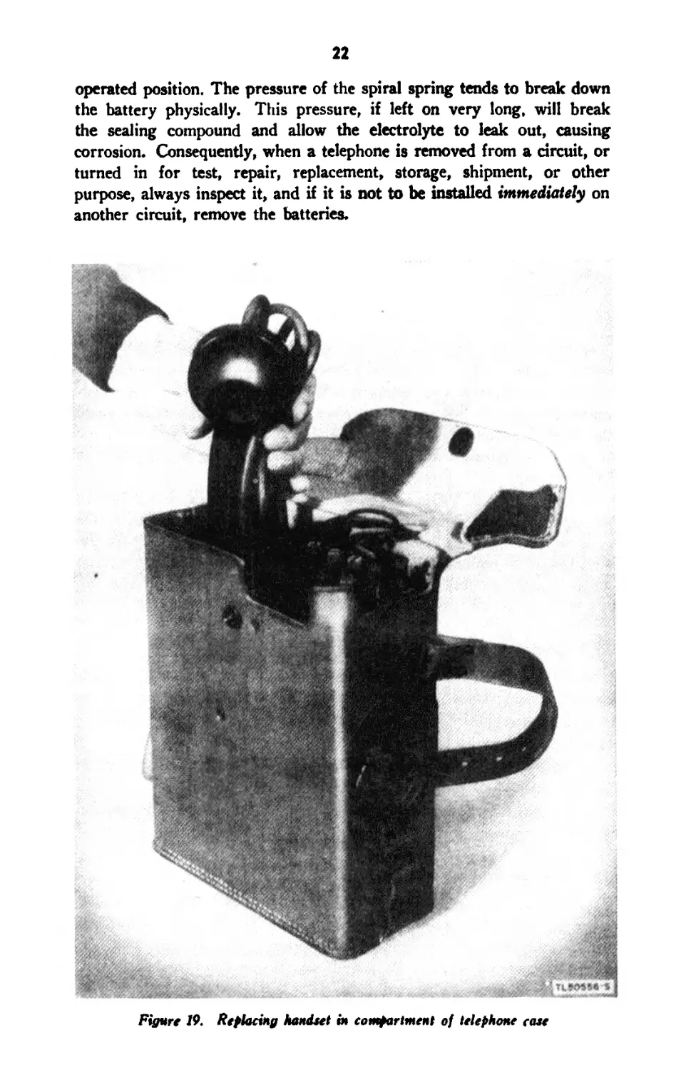
Figure 19. Replacing handset in compartment of telephone сале
23
b. Protection. Protect the telephone from the weather as far as
practicable when installed, and place it in a cool, dry spot when stored.
c. Cleanliness. Do not permit dirt to accumulate on any part of
the telephone. This applies particularly to terminals, binding posts, and
contacts.
d. Connections. Keep all wire connections and screws tight.
19. Closing Station
Remove the connections from line terminals LI and L2. Remove the
batteries unless the telephone is to be installed on another circuit im-
mediately. Fold the cord loosely into folds about as long as the handset,
place the folds alongside the handset, and insert the handset, receiver end
first, into its compartment in the case. (See fig. 19.) Do not wrap the
cord around the handset because this may operate the handset switch
and, if the batteries have not been removed from the telephone, may
exhaust the batteries and cause serious damage to the telephone.
Section II. OPERATION UNDER UNUSUAL CONDITIONS
20. Damping and Silencing Ringer
a. General. The use of Telephone EE-8-(*) in positions close to
the enemy might disclose the location of the operator if the audible
signal of the ringer were not partially or wholly silenced. Methods of
damping or completely silencing the ringer are given in b and c below.
The method used will depend upon the tactical situation or requirements
of the operator.
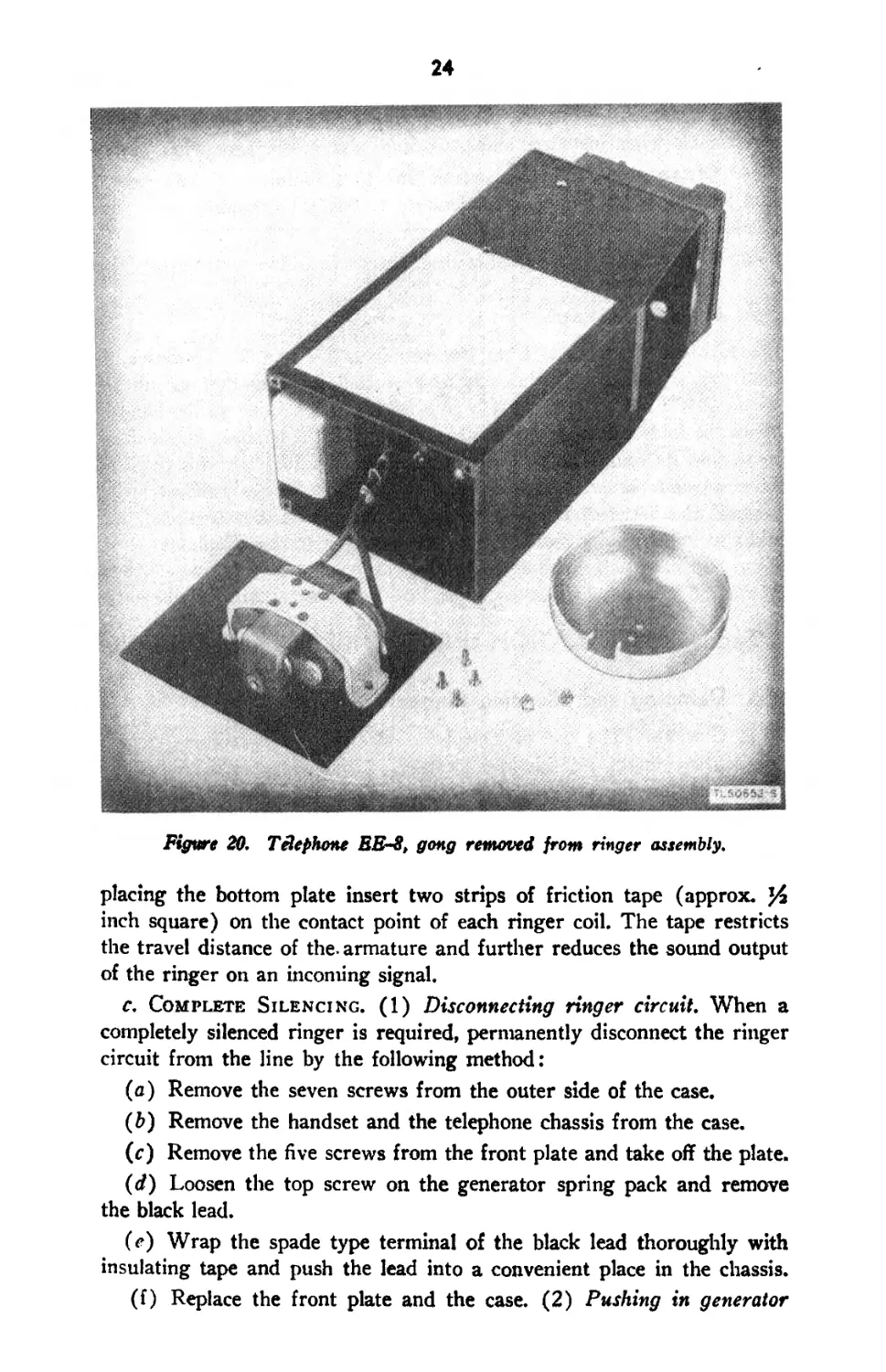
b. Damping. (1) Removal of gong (fig. 20). With the gong removed,
the incoming ringing signal will be a dull vibrating sound. To remove
the gong:
(a) Open the top flap of the case.
(b) Remove the seven screw's from the outer side of the case.
(c) Remove the handset and the telephone chassis from the case.
(d) Remove the four corner screws from the bottom plate of the
chassis, and pull out the plate sufficiently to provide access to the screws
on top of the gong. Do not disconnect the wiring.
(c) Remove the two screw’s from the top of the gong and take out
the gong.
(f) Replace the bottom plate and the case. (2) Taping ringer
armature. Further damping of the ringer can be accomplished by taping
the points where the ringer armature strikes the pole pieces of the
ringer. Follow the above steps for removal of the gong, but before re-
24
Figure 20. Telephone БЕ-8, gong removed from ringer assembly.
placing the bottom plate insert two strips of friction tape (approx.
inch square) on the contact point of each ringer coil. The tape restricts
the travel distance of the. armature and further reduces the sound output
of the ringer on an incoming signal.
c. Complete Silencing. (1) Disconnecting ringer circuit. When a
completely silenced ringer is required, permanently disconnect the ringer
circuit from the line by the following method:
(a) Remove the seven screws from the outer side of the case.
(b) Remove the handset and the telephone chassis from the case.
(c) Remove the five screws from the front plate and take off the plate.
(d) Loosen the top screw on the generator spring pack and remove
the black lead.
(c) Wrap the spade type terminal of the black lead thoroughly with
insulating tape and push the lead into a convenient place in the chassis.
(f) Replace the front plate and the case. (2) Pushing in generator
25
handle. In case the telephone has not been previously damped or silenced
and an emergency requires immediate silencing of an incoming call, push
in the hand generator handle. This disconnects the ringer from the line.
The generator handle must be held in to keep the ringer disconnected
from the line.
d. Visual Signal. When it is desired to substitute a visual signal
for the ringer, Adapter Plug U-4/GT, if available, may be used. Dis-
connect the ringer as described in c above and connect Adapter Plug
U-4/GT across line terminals LI and L2. For a description of Adapter
Plug U-4/GT, see ТВ SIG 147.
e. Identification of Modified Telephones. Tag each telephone
with a description of any modifications which have been made. The tag
readily identifies the telephone for future use and prevents another user
from thinking the telephone is defective.
21. Use of Telephone with Ges Mask
a. General. Equipment has been provided to aid in maintaining tele-
phone communication when a gas mask is worn. Microphone T-45, the
lip microphone, or Microphone Т-ЗО, the throat microphone, used when
Microphone T-45 is not available, will afford satisfactory communication
under any gas mask when suitably connected to Telephohes EE-8,
or EE-8-A, or EE-8-B as described in ТВ SIG 50. However, some
users of the telephone may not have Microphone T-45 or Microphone
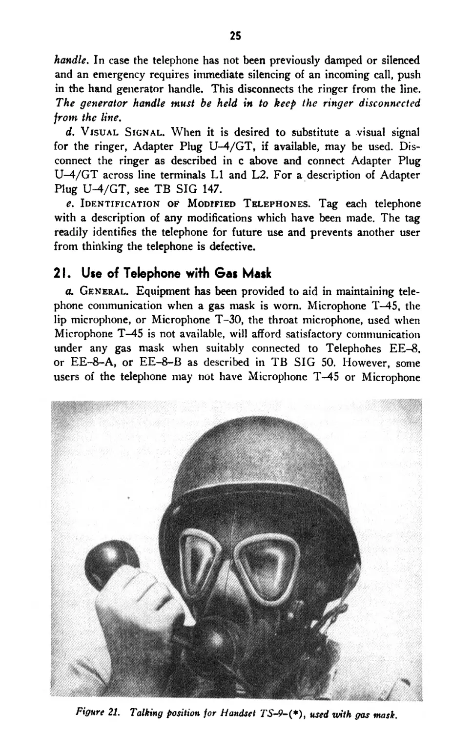
Figure 21. Talking position for Handset used with gas mask.
1Ь
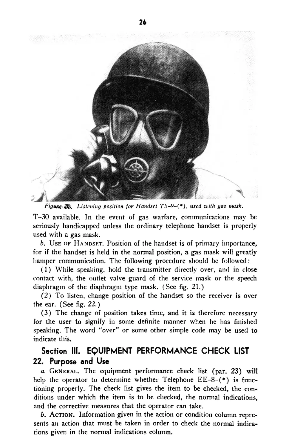
Figure Listening position for Handset TS-9-(*), used ivith gas mask.
T-30 available. In the event of gas warfare, communications may be
seriously handicapped unless the ordinary telephone handset is properly
used with a gas mask.
b. Use of Handset. Position of the handset is of primary importance,
for if the handset is held in the normal position, a gas mask will greatly
hamper communication. The following procedure should be followed:
(1) While speaking, hold the transmitter directly over, and in close
contact with, the outlet valve guard of the service mask or the speech
diaphragm of the diaphragm type mask. (See fig. 21.)
(2) To listen, change position of the handset so the receiver is over
the ear. (See fig. 22.)
(3) The change of position takes time, and it is therefore necessary
for the user to signify in some definite manner when he has finished
speaking. The word “over” or some other simple code may be used to
indicate this.
Section III. EQUIPMENT PERFORMANCE CHECK LIST
22. Purpose and Use
a. General. The equipment performance check list (par. 23) will
help the operator to determine whether Telephone EE-8-(*) is func-
tioning properly. The check list gives the item to be checked, the con-
ditions under which the item is to be checked, the normal indications,
and the corrective measures that the operator can take.
b. Action. Information given in the action or condition column repre-
sents an action that must be taken in order to check the normal indica-
tions given in the normal indications column.
27
c. Normal Indications. The normal indications listed include visible
and audible signs that the operator will perceive when he checks the
items listed. If the indications are not normal, the operator should apply
the recommended corrective measures.
d. Corrective Measures. The corrective measures listed are those
that the operator can make without turning the equipment in for repairs.
References to paragraph 48 in the table indicate that the trouble cannot
be corrected during operation and that trouble shooting by an ex-
perienced repairman is required. If the set is completely inoperative or
if the recommended corrective measures do not yield results, trouble
shooting is necessary. However, if the tactical situation requires that
communication be maintained and if the set is not completely inoperative,
the operator must maintain the set in operation as long as it is possible
to do so.
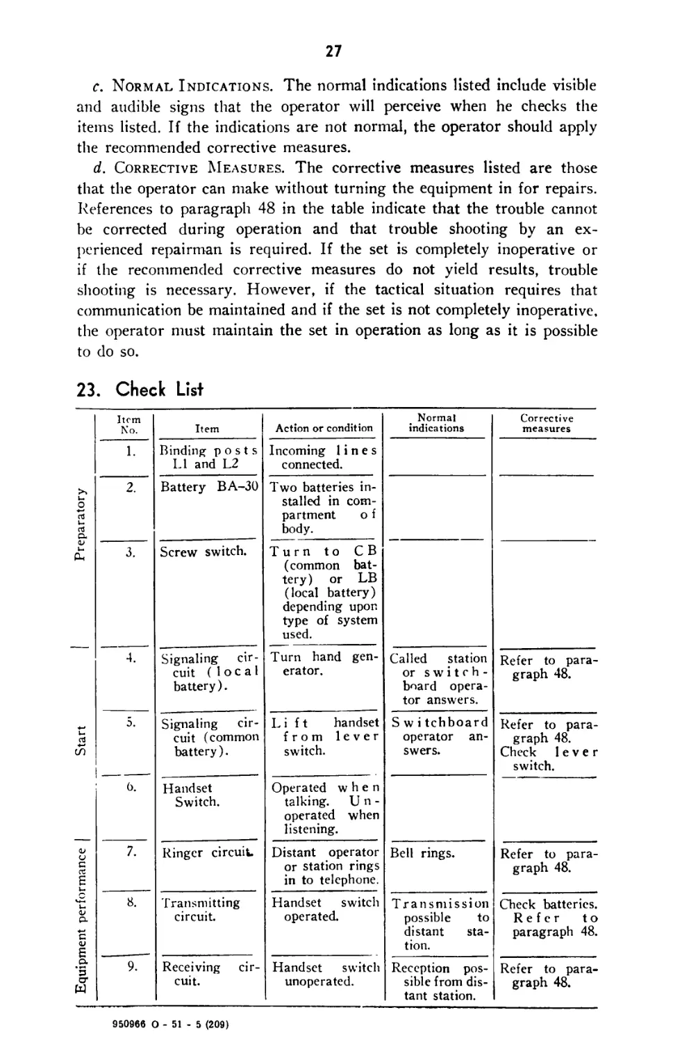
23. Check List
| Equipment performance | Start | Preparatory | Item No. Item Action or condition Normal indications Corrective measures
1. Binding posts LI and L2 Incoming lines connected.
2. Battery BA-30 Two batteries in- stalled in com- partment о f body.
3. Screw switch. Turn to CB (common bat- tery) or LB (local battery) depending upon type of system used.
4. Signaling cir- cuit (local battery). Turn hand gen- erator. Called station or switch- board opera- tor answers. Refer to para- graph 48.
5. Signaling cir- cuit (common battery). Lift handset from lever switch. S w i tchboard operator an- swers. Refer to para- graph 48. Check lever switch.
6. Handset Switch. Operated when talking. Un- operated when listening.
7. Ringer circuit. Distant operator or station rings in to telephone. Bell rings. Refer to para- graph 48.
8. 9?” Transmitting circuit. Handset switch operated. Transmission possible to distant sta- tion. Check batteries. Refer to paragraph 48.
Receiving cir- cuit. Handset switch unoperated. Reception pos- sible from dis- tant station. Refer to para- graph 48.
950966 0 - 51 - 5 (209)
CHAPTER 3
PREVENTIVE MAINTENANCE
Section I. PREVENTIVE MAINTENANCE TECHNIQUES
24. Meaning of Preventive Maintenance
Preventive maintenance is a systematic series of operations performed
at regular intervals on equipment to eliminate major break-downs and
unwanted interruptions in service, and to keep the equipment operating
at top efficiency. To understand what is meant by preventive main-
tenance, it is necessary to distinguish between preventive maintenance,
trouble shooting, and repair. The primary function of preventive main-
tenance is the prevention of break-downs and, therefore, the need for
repair. On the other hand, the primary function of trouble shooting and
repair is the location and correction of existing defects. The importance
of preventive maintenance cannot be overemphasized. The entire system
of wire communication depends upon each set being in operation when
it is needed and also upon its operating efficiency.
Note: The operations in sections I and TI, are considered first and second echelon
(organization operators and repairmen) maintenance. Some operations in sections
(V and V are considered higher echelon maintenance.
25. Description of Preventive Maintenance Techniques
a. General. Most of the parts used in Telephone EE-8-(*) require
routine preventive maintenance. Those requiring maintenance differ in
the amount and kind required. Because hit-or-miss maintenance tech-
niques cannot be applied, definite and specific instructions are needed.
This section of the manual contains these specific instructions and serves
as a guide for personnel assigned to perform the six basic maintenance
operations: Feel, Inspect, Tighten, Clean, Adjust, and Lubricate.
Throughout this manual the following lettering system will be used for
the six operations:
F —Feel
I — Inspect
T — Tighten
C — Clean
A — Adjust
L — Lubricate
The first two operations establish the need for the other four. The
selection of operations is based on the general knowledge of field needs.
28
29
For example, dust encountered on dirt roads during cross-country travel
filters into the equipment no matter how much care is taken to prevent it.
Rapid changes in weather (such as heavy rain followed by blistering
heat), excessive dampness, snow and ice tend to cause corrosion of ex-
posed surfaces and parts. Without frequent inspections and the per-
formance of necessary tightening, cleaning, and lubricating operations,
equipment becomes undependable and subject to break-down.
b. Feel. The feel operation is used most often to check for overheating.
c. Inspect. Inspection is the most important operation in the preven-
tive maintenance program. A careless observer will overlook the evidences
of minor trouble. Although these minor defects may not interfere with
the performance of the equipment, valuable time and effort can be saved
if they are corrected before they lead to major break-downs. Make every
effort to become thoroughly familiar with the indications of normal
functioning, in order to be able to recognize the signs of defective equip-
ment. Inspection consists of carefully observing all parts of the equipment,
noticing their color, placement, state of cleanliness, etc. Inspect for the
following conditions:
(1) Overheating, as indicated by discoloration, blistering, or bulging
of the parts or surface of the container; leakage of insulating compounds;
and oxidation of metal contact surfaces.
(2) Placement, by observing that all leads and cabling are in their
original positions.
(3) Cleanliness, by carefully examining all recesses in the units for
accumulation of dust, especially between connecting terminals. Parts,
connections, and joints should be free of dust, corrosion, and other foreign
matter. In tropical and high humidity locations, look for fungus growth
and mildew.
(4) Tightness, by testing any connection or mounting which appears
to be loose.
d. Tighten, Clean, and Adjust. These operations are self-explana-
tory. Specific procedures for performing them are given in paragraphs 26
through 34 whenever necessary.
Caution: Screws, bolts, and nuts should not be tightened carelessly.
Fittings tightened beyond the pressure for which they are designed will
be damaged or broken. Whenever a loose connection is tightened,
moistureproof and fungiproof it again by applying the varnish with a small
brush. See section V for details of moistureproofing and fungiproofing.
c. Lubricate. Lubrication means the addition of oil or grease to
form a film between two surfaces that slide against each other, in order
to prevent mechanical wear from friction.
26. Case, Exterior
a. Inspect (I). Carefully examine the leather case and strap for cut
or torn places, dirt, oil, grease, and mildew. Inspect the metal parts of
30
the case for damaged places, dirt, dust, rust, corrosion, and loose,
damaged, or missing screws.
b. Tighten (T). With a suitable screw driver, tighten all screws
snugly.
c. Clean (C). With a clean dry cloth, wipe all dirt and dust off the
case. Pay particular attention to the small crevices around the hand
generator crank. Use saddle soap and neat’s-foot oil for cleaning and
preserving the leather case and strap.
27. Case, Interior
Note. Tn order to perform the preventive maintenance operations contained in
the following paragraphs, it will be necessary to remove the telephone from its case.
a. Inspect (T). Inspect the interior of the case for damaged places,
dirt, dust, oil, grease, and mildew.
b. Clean (C.) With a clean dry cloth, wipe all dirt, dust, and
foreign matter from the inside of the case.
28. Jack Assembly and Lever Switch
a. Inspect (I). Carefully inspect the jack assembly and lever switch
for dirt, dust, rust, and corrosion. Inspect the jack assembly for loose,
damaged, or missing terminals, and for loose, damaged, or missing mount-
ing screws. Carefully inspect the contacts of the lever switch for dirt,
corrosion, and pitted places.
b. Tighten (T). Tighten all of the jack assembly and lever-switch
screws securely, using a suitable screw driver.
c. Clean (C). Carefully wipe all dirt, dust, and foreign matter from
the jack assembly, using a clean dry cloth. With a soft bristle brush,
remove all dirt, dust, and foreign matter under the lever switch. Carefully
burnish and flush the lever switch contacts as outlined in paragraph 37.
29. Generator
a. Inspect (I). Inspect the generator for dirt, dust, rust, corrosion,
and foreign matter, and for damaged, loose, or missing mounting screws
and terminal screws. Do not remove the cover from the generator
(Generator GN-38-B).
b. Tighten (T). Tighten all terminal screws and mounting screws
securely.
c. Clean (C). Carefully remove all dirt, dust, and foreign matter
on the generator, using a soft bristle brush. Be careful not to disconnect
any wires when performing this operation.
30. Battery Compartment
a. Inspect (I). Carefully inspect the battery compartment for dirt,
dust, corrosion, and loose or missing battery contact springs.
31
b. Clean (C). With a soft bristle brush, remove all dirt, dust, and
foreign matter from the battery compartment. Carefully clean the battery
contact springs with crocus cloth to insure good electrical connections.
31. Induction and Holding Coils
a. Inspect (I). Carefully inspect the induction and holding coils for
damaged places, worn or frayed insulation, dirt, dust, and loose or missing
mounting screws.
b. Tighten (T). Tighten all mounting screws securely.
c. Clean (C). Remove all dirt and dust, using a soft bristle brush.
Be careful not to disconnect any wires while performing this operation.
32. Chassis
a. Inspect (I). Carefully inspect the chassis of the telephone for
damaged places, dirt, dust, and corrosion. Pay particular attention to the
small crevices and obscure places.
b. Clean (C). With a soft bristle brush, carefully remove all dirt,
dust, and foreign matter from the chassis. Be careful not to disconnect
any wiring. Brush all dirt and dust away from the component parts that
are mounted on the chassis.
33. Handset TS-9-(*)
a. Inspect (I). Carefully inspect the handset for dirt, dust, and
chipped or cracked places. Do not disassemble the handset. Inspect
the exterior only.
b. Clean (C). Wipe all dirt, dust, and foreign matter off the handset,
using a clean dry cloth.
34. Cord CC-333
a. Inspect (I). Inspect the cord for dirt, dust, oil, grease, and
damaged or broken insulation. Examine the cord, where it enters the
handset, for worn places and tightness of connection.
b. Clean (C). Wipe off all dust and dirt, using a clean dry cloth.
If it becomes necessary to remove oil or grease, use dry-cleaning solvent.
Section II. ITEMIZED PREVENTIVE MAINTENANCE
35. Common Materials Needed
Note: The tools and materials listed below must be at hand before starting the
preventive maintenance procedures.
The following is a list of the tools and materials needed for performing
preventive maintenance operations on Telephone EE-8-(*).
Long-nose pliers
Diagonal pliers
32
3j4 inch cabinet screwdriver
Solvent, dry-cleaning, Federal Spec. No. P-S-661a
Saddle soap
Neat’s-foot oil
Contact burnisher
Bristle brushes
Cleaning cloths
Crocus cloth
Note. Leaded gasoline will not be used as a cleaning fluid for any purpose.
Solvent, dry-cleaning, Federal Spec. No. P-S-661a, is available as a cleaning fluid
through established supply channels. Oil, Fuel, Diesel, U. S. Army Spec. 2-102B,
may be used for cleaning purposes when dry-cleaning solvent is not at hand. Since
unleaded gasoline is available only in limited quantities, and only in certain localities,
it should be used for cleaning purposes only when no other agent is available.
Carbon tetrachloride, or fire-extinguishing liquid (carbon tetrachloride base), will
be used, if necessary, only on contact parts of electronic equipment.
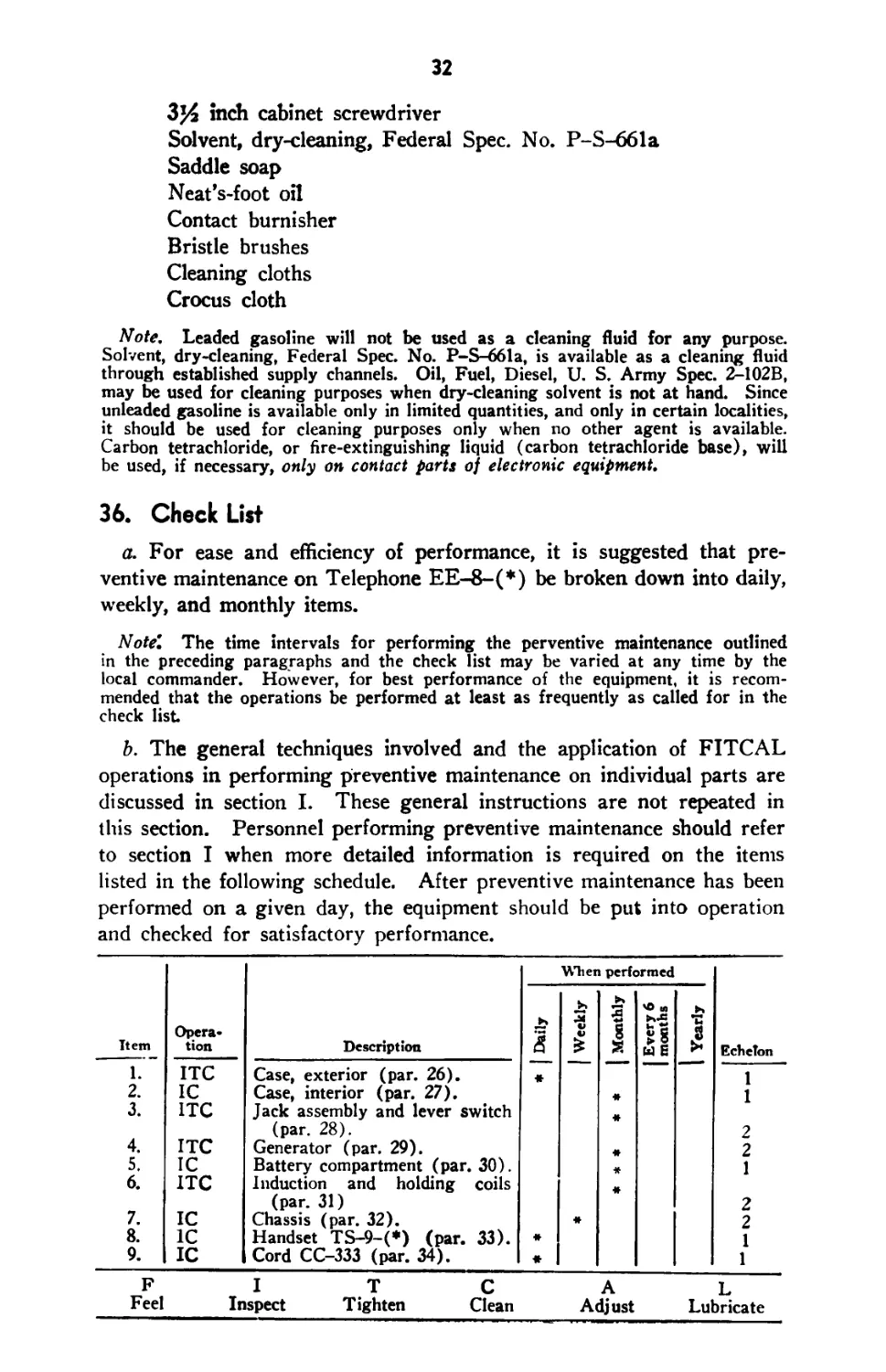
36. Check List
a. For ease and efficiency of performance, it is suggested that pre-
ventive maintenance on Telephone EE-8-(*) be broken down into daily,
weekly, and monthly items.
Note”. The time intervals for performing the perventive maintenance outlined
in the preceding paragraphs and the check list may be varied at any time by the
local commander. However, for best performance of the equipment, it is recom-
mended that the operations be performed at least as frequently as called for in the
check list
b. The general techniques involved and the application of FITCAL
operations in performing preventive maintenance on individual parts are
discussed in section I. These general instructions are not repeated in
this section. Personnel performing preventive maintenance should refer
to section I when more detailed information is required on the items
listed in the following schedule. After preventive maintenance has been
performed on a given day, the equipment should be put into operation
and checked for satisfactory performance.
Item Opera- tion Description Wien performed Echelon
Daily Weekly Monthly Every 6 months Yearly
1. ITC Case, exterior (par. 26). « 1
2. IC Case, interior (par. 27). # 1
3. ITC Jack assembly and lever switch
4. (par. 28). 2
ITC Generator (par. 29). # 2
5. IC Battery compartment (par. 30). * 1
6. ITC Induction and holding coils
(par. 31) 2
7. IC Chassis (par. 32). # 2
8. IC Handset TS-9-(*) (par. 33). # 1
9. IC Cord CC-333 (par. 34). « 1
FI T C AL
Feel Inspect Tighten Clean Adjust Lubricate
33
Section III. SPECIAL INSTRUCTIONS
37. Cleaning and Burnishing Lever Switch Contacts
a. General. Under extreme dust conditions, dust filters into the
lever switch contacts of Telephone EE-8-(*). To correct this con-
dition, it is necessary to clean and burnish the lever switch contacts.
b. Cleaning and Burnishing. (1) Flush spring contacts with dry-
cleaning solvent applied with a pencil brush, taking care to keep cleaning
fluid away from insulators. Wipe dry with a clean cloth.
(2 ) After cleaning, burnish spring contacts with a fine grained con-
tact burnisher. Do not use a file. Two strokes of the burnisher between
the contacts with the lever switch in its operated position should be
sufficient.
(3 ) Clean the burnisher before using and during use with dry-cleaning
solvent, wiping dry with a clean cloth. Do not touch or rub the blade
with fingers.
38. Equipment Dusting
a. Fashion a cleaning stick from %-inch wood, 1% inches wide and
11 inches long. When cleaning flat surfaces, place a cloth over the clean-
ing stick holding the loose ends of the cloth in the hand to prevent loose
dust and lint from being shaken from the cloth while cleaning is being
done.
b. Shift the cloth on the cleaning stick from time to time so as to pre-
sent a new surface to the area being cleaned. When one side of the cloth
is no longer serviceable, reverse it and proceed in a similar manner. In
this way, the entire area of the cloth may be utilized. Continue to shift
the cloth with respect to the cleaning stick until there is some indication
that its absorption qualities are such that it will no longer pick up and hold
dust and lint.
Section IV. LUBRICATION
39. Generator GN-38-(*)
The only parts of Telephone EE-8-(*) which require lubrication are
the moving parts of Generator GN-38-(*). Instructions for lubricating
the generator are contained in paragraph 68c.
Section V. MOISTUREPROOFING AND
FUNGIPROOFING
40. General
The operation of Signal Corps equipment in tropical areas where tem-
perature and relative humidity are extremely high requires special atten-
tion. The following items represent problems which may be encountered
in operation:
34
a. Resistors, capacitors, coils, etc., fail.
b. Electrolytic action takes place in resistors, coils, etc., causing eventual
breakdown.
c. Hook-up wire and cable insulation break down. Fungus growth
accelerates deterioration.
d. Moisture forms electrical leakage paths on terminal boards and
insulating strips, causing flash-overs and crosstalk.
e. Moisture provides leakage paths between battery terminals.
41. Treatment
A moistureproofing and fungiproofing treatment has been devised which,
if properly applied, provides a reasonable degree of protection against
fungus growth, insects, corrosion, salt spray, and moisture. The treat-
ment involves the use of a moisture- and fungi-resistant varnish applied
with a spray gun or brush. Refer to ТВ SIG 13, Moistureproofing and
Fungiproofing Signal Corps Equipment, for a detailed description of the
varnish-spray method of moistureproofing and fungiproofing and the sup-
plies and equipment required in this treatment.
Caution: Varnish spray may have poisonous effects if inhaled. To
avoid inhaling spray, use respirator if available; otherwise, fasten cheese-
cloth or other cloth material over the nose and mouth.
42. Step-by-Step Instructions for Treating Telephone EE-8-(*)
a. Preparation. Make all repairs and adjustments necessary for
proper operation of the equipment.
b. Disassembly. (1) Remove the seven screws from the outside
of the case.
(2) Remove the handset and chassis from the case.
(3) Remove the handset leads from the three terminals on top of the
chassis.
(4) Untie the stay cord, and remove the handset and cord.
(5) Remove the batteries.
(6) Remove the five screws from the front plate and take off the plate.
(7) Remove the generator handle.
(8) Remove the three screws from the generator side of the chassis
and take off the plate.
(9) Remove the rubber and steel washers from the generator gear.
(10) Remove the four screws from the bakelite cover plate and re-
move the cover plate from the top of the chassis.
(11) Remove the two screws under the lever switch.
(12) Remove the screw eye from the top panel.
(13) Lift the lever switch, jack assembly, and terminal block. DO
NOT UNSOLDER THE LEADS.
(14) Remove the seven screws from the bottom plate of the chassis
and take off the plate.
(15) Remove the two screws from the ringer and remove the gong
from the assembly.
35
(16) Remove the ringer coils and clapper assembly.
(17) Remove the three generator leads.
(18) Remove the four screws from the bottom of the generator as-
sembly.
(19) Remove the generator.
(20) Remove the bakelite instrument plate.
(21) Remove Capacitor CA-355 (for Telephones EE-8-A and EE-
8-B only). Remove Capacitors CA-209, CA-259, and CA-177 (for
Telephone EE-8 only). DO NOT UNSOLDER THE LEADS.
(22) Remove the screws holding Coils C-105 and C-158 to the chassis
and remove the coils. DO NOT UNSOLDER THE LEADS.
(23) Remove the two screws from the generator spring pack, and take
off the spring pack.
(24) Remove the four screws from the top of the generator.
(25) Remove the two lower screws from each side plate of the gen-
erator.
(26) Remove the bottom field plate and the magnets. (Generator
GN-38 only).
(27) Remove the two screws from the handset lever swatch, and lift
out the handset switch assembly. DO NOT UNSOLDER THE
LEADS.
(28) Remove the receiver cap, and take out the receiver unit.
(29) Remove the transmitter cap, and take out the transmitter unit.
(30) Tighten all loosened screws where electrical contact is made.
(31) Clean all dirt, dust, rust, fungus, oil, grease, etc., from the equip-
ment.
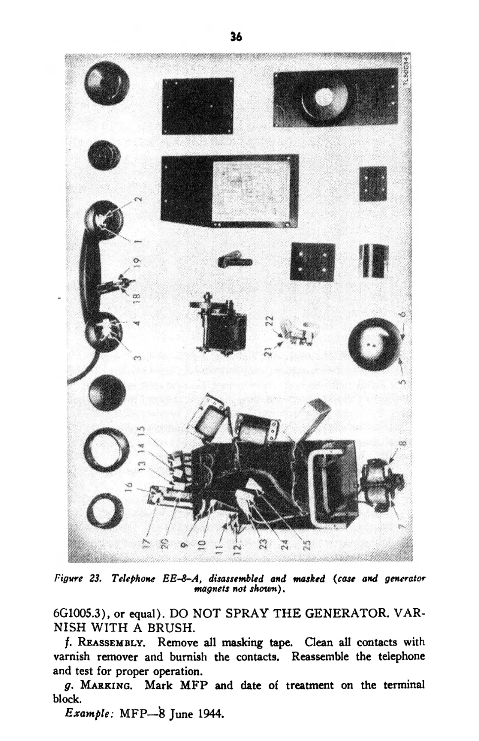
c. Masking. Cover the following parts with masking tape. (1) The
electrical contact points on the receiver (fig. 23 (1) and (2)) and on the
transmitter (fig. 23 (3) and (4)).
(2) The two points where the clapper strikes the gong (fig. 23 (5)
and (6)).
(3) The core contacts on the ringer coils (fig. 23 (7) and (8)).
(4) The battery contacts (fig. 23 (9), (10), (11), and (12)).
(5) The jack holes (fig. 23 (13), (14), and (15)).
(6) The spring contacts of the lever switch and handset switch (fig.
23 (16), (17), (18), and (19)).
(7) The opening below the screw switch (fig. 23 (20)).
(8) The contact points on the generator spring pack (fig. 23 (21) and
(22)).
(9) The spade terminals of the three leads to the generator (fig. 23
(23), (24), and (25)).
d. Drying. Place all equipment, except the case and the batteries,
in an oven. Dry for 2 to 3 hours at 160° F. DO NOT APPLY HEAT
TO THE BATTERIES.
e. Varnishing. Apply three coats of moisture- .and fungi-resistant
varnish (Lacquer, Fungus-resistant, Spec. No. 71-2202 (stock No.
36
Figure 23. Telephone EES-A, disassembled and masked (case and generator
magnets not shown).
6G1OO5.3), or equal). DO NOT SPRAY THE GENERATOR. VAR-
NISH WITH A BRUSH.
f. Reassembly. Remove all masking tape. Clean all contacts with
varnish remover and burnish the contacts. Reassemble the telephone
and test for proper operation.
g. Marking. Mark MFP and date of treatment on the terminal
block.
Example: MFP—fc June 1944.
CHAPTER 4
AUXILIARY EQUIPMENT
(Not used)
37
CHAPTER 5
REPAIR INSTRUCTIONS
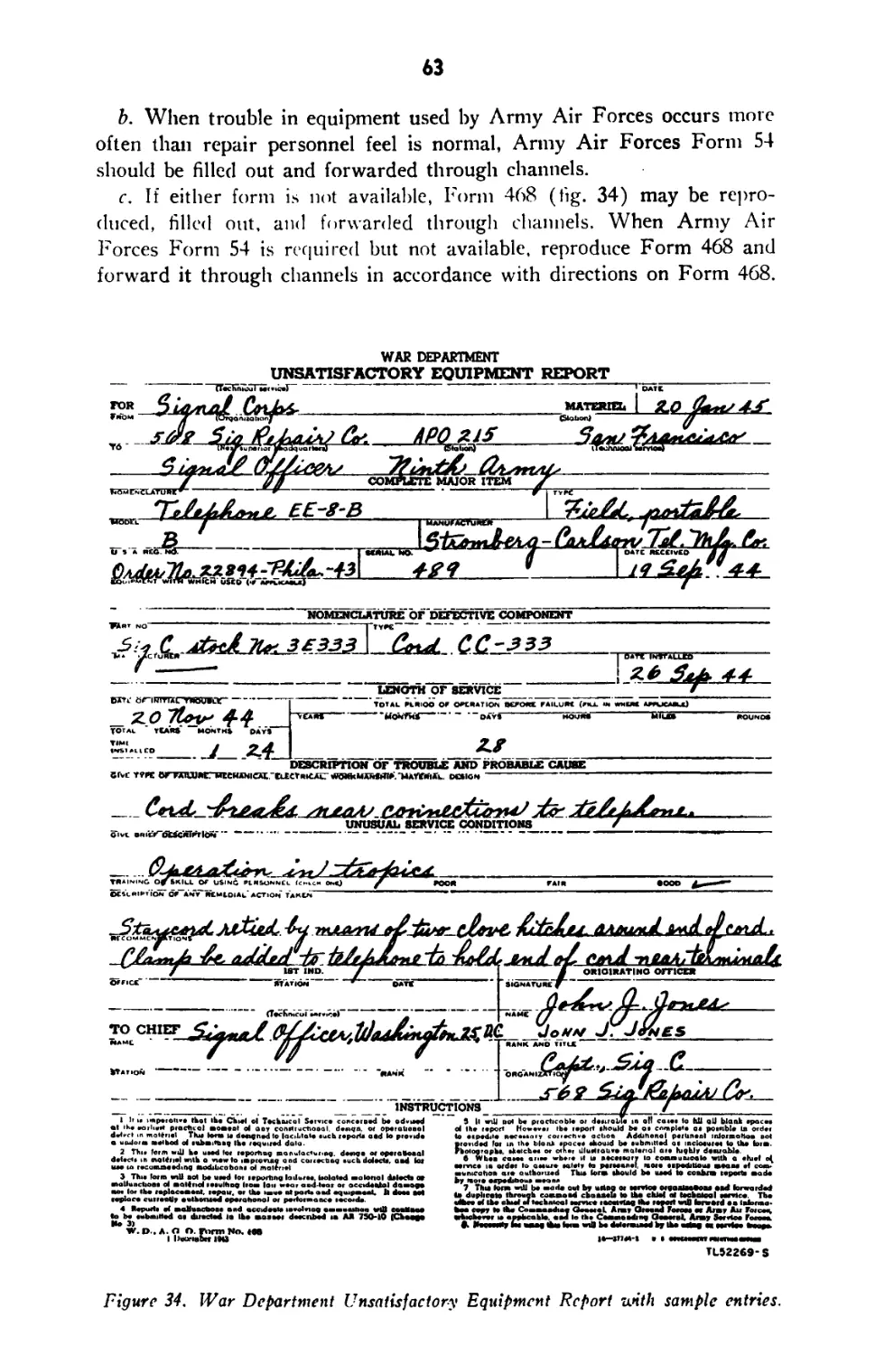
Note. Failure or unsatisfactory performance of equipment used by Army Ground
Forces and Army Service Forces will be reported on WD, AGO Form 468 (Un-
satisfactory Equipment Report) ; by Army Air Forces, on Army Air Forces Form
54 (Unsatisfactory report). If neither form is available, prepare the data according
to the sample form reproduced in figure 34.
Section I. THEORY OF TELEPHONE EE-8-(*)
43. Circuit Elements
a. Handset TS-9-(*). Handset TS-9-(*) contains a high output
nonpositional transmitter and a high fidelity receiver. The transmitter
element is of the granular carbon type. The diaphragm, carbon inclosure,
and frame are constructed in unit form making the element readily
replaceable. The receiver element is a permanent-magnet, diaphragm
type. It gives high fidelity response over the audible frequency range, and
is effectively compensated for stable performance over a wide tempera-
ture range.
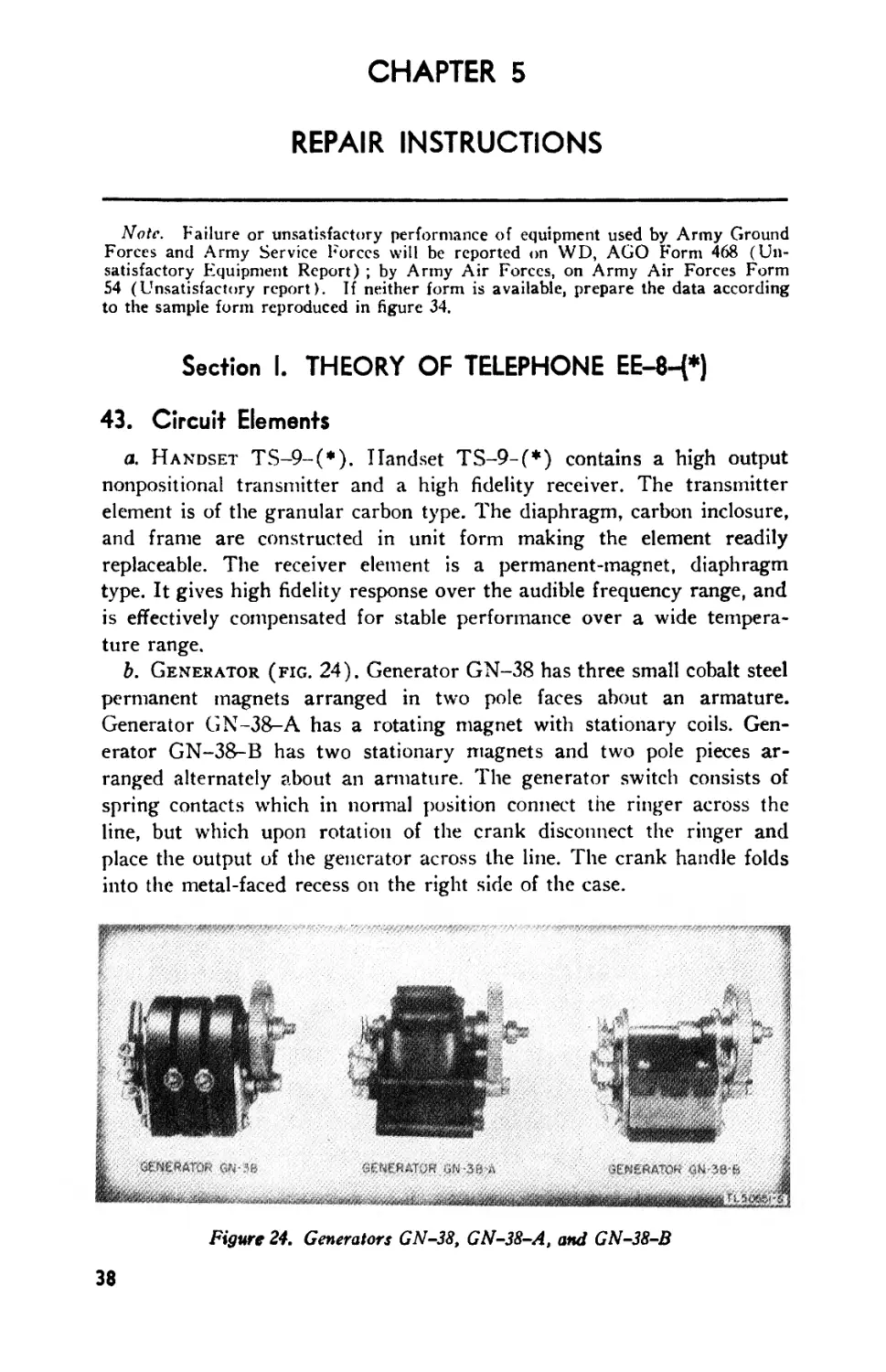
b. Generator (fig. 24). Generator GN-38 has three small cobalt steel
permanent magnets arranged in two pole faces about an armature.
Generator GN-38-A has a rotating magnet with stationary coils. Gen-
erator GN-38-B has two stationary magnets and two pole pieces ar-
ranged alternately about an armature. The generator switch consists of
spring contacts w’hich in normal position connect the ringer across the
line, but which upon rotation of the crank disconnect the ringer and
place the output of the generator across the line. The crank handle folds
into the metal-faced recess on the right side of the case.
Figure 24. Generators GN-38, GN-38-A, and GN-38-B
38
39
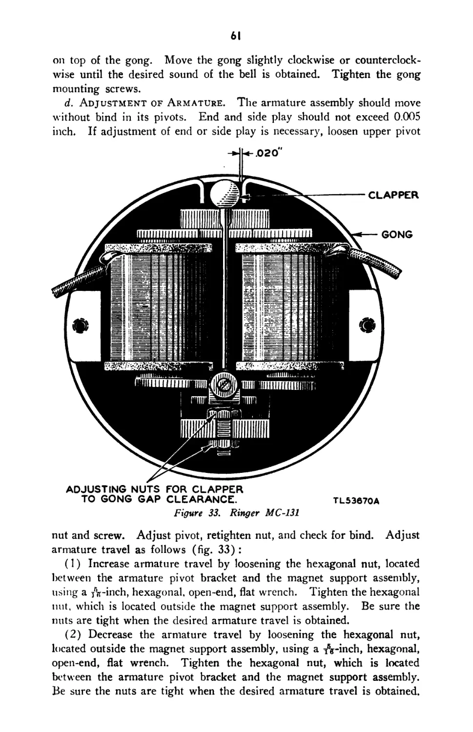
c. Ringer. Ringer MC-131 is of the single-gong type. The ringer
coils, armature, and clapper are mounted internally to the gong (figs. 6,
7, 8, and 20). When energized by ringing current, the armature operates
the clapper about a pivot to strike alternately two internal projections of
the gong rim. The acoustical output is high for a relatively low electrical
input.
d. Holding Coil. The holding coil (Coil C-158) is bridged across
the line circuit when the screw switch is in the CB position and the
lever switch is released. With the lever switch depressed, the coil is
disconnected. If the screw switch is in the LB position, the coil is
permanently disconnected, independent of the lever switch position. The
purpose of this coil is to provide a low resistance d-c path through the
telephone for operating the line relay and holding the supervisory relay
energized on a common battery switchboard. The holding coil has high
impedance to voice-frequency currents to minimize transmission losses.
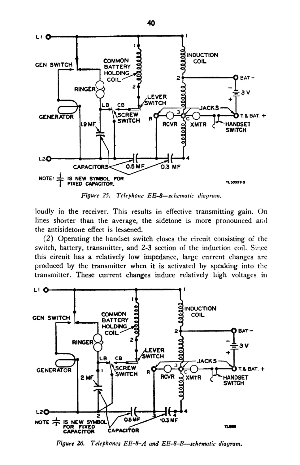
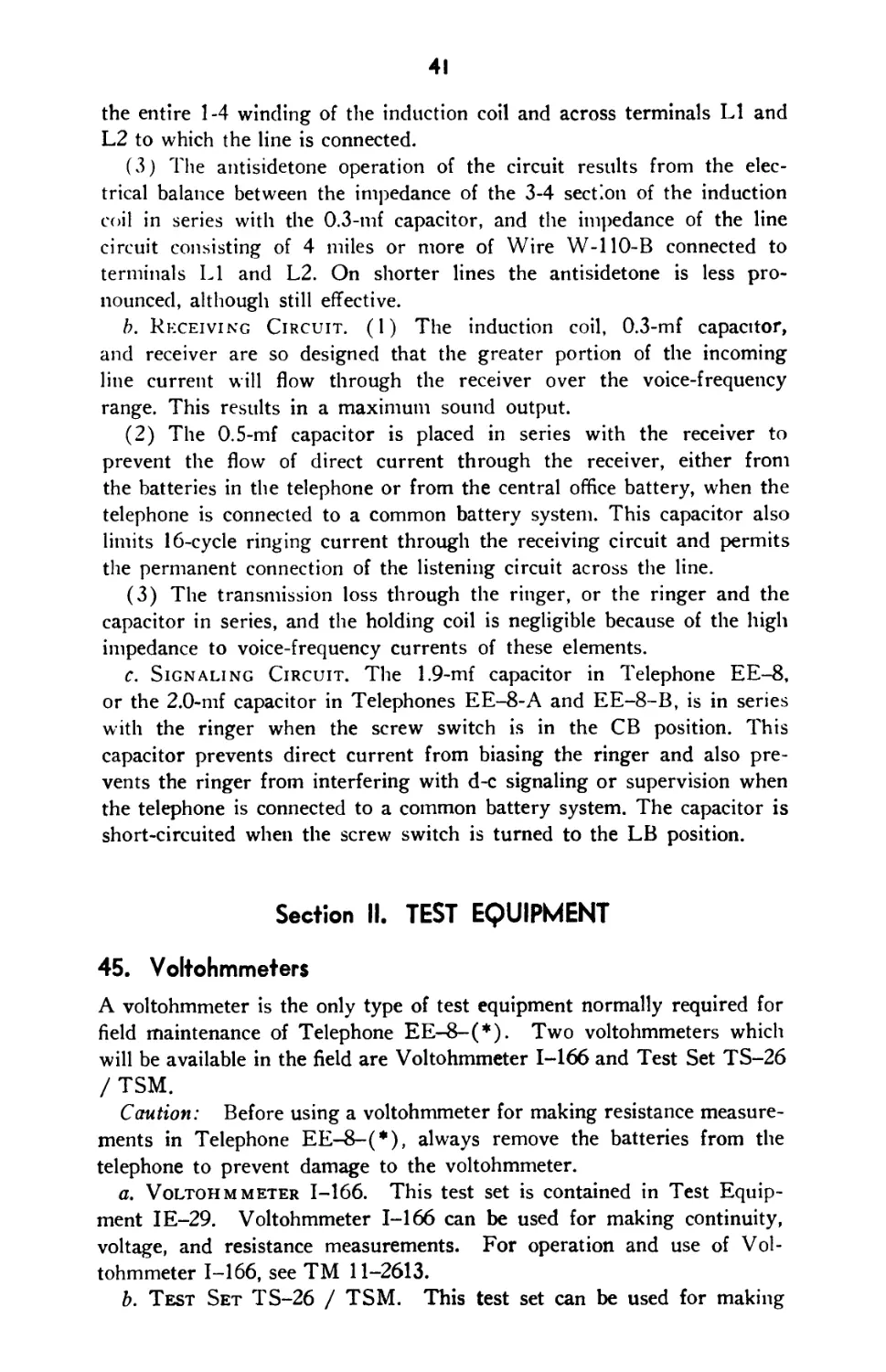
e. Induction Coil. The induction coil (Coil C-105) is an autotrans-
former with one continuous winding tapped at terminals 2 and 3 so as
to form the 1-2 section, the 2-3 section, and the 3-4 section. (See figs. 25
and 26.)
j. Lever Switch, The lever switch has two contacts which are
operated by a hinged lever and plunger. The switch is held depressed
by the weight of the handset which is hung on it, and is automatically
raised by a spring when the handset is removed. The contacts are open
when the lever switch is depressed and closed when the switch is released.
The lever switch is used only on common battery circuits.
g. Capacitors. In Telephone EE-8, three physically separate capaci-
tors, of 1.9-mf, 0.5-mf, and 0.3-mf capacitance are used. (See figs. 25
and 27.) In Telephones EE-8-A and EE-8-B, Capacitor CA-355 com-
prises a 2.0-mf, a 0.5-mf, and a 0.3-mf capacitance element, all assembled
into one container and internally connected to the terminals numbered
1, 2, 3, and 4. (See figs. 26, 28, and 29.)
44. Theory of Operation
The schematic diagram of Telephone EE-8 is shown in figure 25 and the
schematic diagram of Telephones EE-8-A and EE-8-B is shown in
figure 26.
a. Transmitting Circuit. (1) The transmitter, receiver, induction
coil, and the 0.3-mf capacitor are connected in an antisidetone circuit
in which the impedance of these elements and the characteristic im-
pedance of the average line (Wire W-110-B) are so balanced as to
reduce the sidetone in the receiver to the proper level. This results in an
effective gain since the effect of noise in the vicinity of the transmitter
of the receiving telephone is reduced. The user also unconsciously speaks
more loudly into the transmitter when he does not hear his own voice
40
GEN SWITCH
GENERATOR
L2O
RINGER
LEVER
1.9 MF
CAPACITORS
LB CB
SWITCH R
COMMON
BATTERY
HOLDING^
COIL^
A 2
XMTR
0.3 MF
INDUCTION
BAT-
JACKS
RCVR
T.8. BAT +
HANDSET
SWITCH
NOTE! zt:
3 V
IS NEW SYMBOL FOR
FIXED CAPACITOR.
TL5O559-S
Figure 25. Telephone EES—schematic diagram.
loudly in the receiver. This results in effective transmitting gain. On
lines shorter than the average, the sidetone is more pronounced and
the antisidetone effect is lessened.
(2) Operating the handset switch closes the circuit consisting of the
switch, battery, transmitter, and 2-3 section of the induction coil. Since
this circuit has a relatively low impedance, large current changes are
produced by the transmitter when it is activated by speaking into the
transmitter. These current changes induce relatively high voltages in
Figure 26. Telephones EE-8-A and EE-8-B—schematic diagram.
41
the entire 1-4 winding of the induction coil and across terminals LI and
L2 to which the line is connected.
(3) The antisidetone operation of the circuit results from the elec-
trical balance between the impedance of the 3-4 section of the induction
coil in series with the 0.3-mf capacitor, and the impedance of the line
circuit consisting of 4 miles or more of Wire W-110-B connected to
terminals LI and L2. On shorter lines the antisidetone is less pro-
nounced, although still effective.
b. Receiving Circuit. (1) The induction coil, 0.3-mf capacitor,
and receiver are so designed that the greater portion of the incoming
line current will flow through the receiver over the voice-frequency
range. This results in a maximum sound output.
(2) The 0.5-mf capacitor is placed in series with the receiver to
prevent the flow of direct current through the receiver, either from
the batteries in the telephone or from the central office battery, when the
telephone is connected to a common battery system. This capacitor also
limits 16-cycle ringing current through the receiving circuit and permits
the permanent connection of the listening circuit across the line.
(3) The transmission loss through the ringer, or the ringer and the
capacitor in series, and the holding coil is negligible because of the high
impedance to voice-frequency currents of these elements.
c. Signaling Circuit. The 1.9-mf capacitor in Telephone EE-8,
or the 2.0-mf capacitor in Telephones EE-8-A and EE-8-B, is in series
with the ringer when the screw switch is in the CB position. This
capacitor prevents direct current from biasing the ringer and also pre-
vents the ringer from interfering with d-c signaling or supervision when
the telephone is connected to a common battery system. The capacitor is
short-circuited when the screw switch is turned to the LB position.
Section II. TEST EQUIPMENT
45. Voltohmmeters
A voltohmmeter is the only type of test equipment normally required for
field maintenance of Telephone EE-8-(*). Two voltohmmeters which
will be available in the field are Voltohmmeter 1-166 and Test Set TS-26
/TSM.
Caution: Before using a voltohmmeter for making resistance measure-
ments in Telephone EE-8-(*), always remove the batteries from the
telephone to prevent damage to the voltohmmeter.
a. Voltohmmeter 1-166. This test set is contained in Test Equip-
ment IE-29. Voltohmmeter 1-166 can be used for making continuity,
voltage, and resistance measurements. For operation and use of Vol-
tohmmeter 1-166, see TM 11-2613.
b. Test Set TS-26 / TSM. This test set can be used for making
42
continuity, voltage, and resistance measurements. For operation, and
use of Test Set TS-26 / TSM, see TM 11-2017.
Section III. TROUBLE SHOOTING
46. General
No matter how well equipment is designed and manufactured, faults occur
in service. When such faults occur the repairman must locate and
correct them as rapidly as possible. This section contains general in-
formation to aid personnel engaged in the important duty of trouble
shooting.
a. Trouble-shooting Data. Take advantage of the material supplied
in this manual to help in the rapid location of faults. Consult the follow-
ing trouble-shooting data when necessary:
(1) Trouble-shooting chart (par. 48).
(2) W iring diagrams of Telephone EE-8-(*) (figs. 27, 28, and 29).
(3) Complete schematic diagrams (figs. 25 and 26).
(4) Voltage and resistance chart (par. 49).
(5) Illustrations of components which aid in locating or identifying
parts (figs. 5, 6, 7, and 8).
b. Trouble-shooting Steps. First, analyze the trouble report to
determine the probable causes of the trouble. When analyzing the trouble
report, use the schematic diagram to localize the fault to a particular
component. Make a complete visual inspection of the wiring and con-
nections to the associated equipment. If no wires or connections are
broken, the trouble must be located by making continuity? voltage, and
resistance measurements. By following the circuit with a systematic
process of elimination, the fault can usually be located in the least amount
of time. Start at a point where the circuit is known, from the analysis,
to be good and proceed step-by-step eliminating parts of the circuit until
the fault is located.
47. Procedures
a. General. To aid the repairman in locating or localizing faults,
the indications of trouble and tests for localizing the fault are described
in the following subparagraphs. The troubie-shooting chart (par. 48),
if properly used, simplifies trouble shooting. Before starting these tests
be sure the screw switch is turned in the direction of the arrow pointing
to LB as far as it will go. Also, see that the batteries are installed.
b. Sidetone Test. Hold the receiver of the telephone to the ear and
blow steadily into the transmitter while alternately operating and releas-
ing the handset switch.
c. Generator Test. While holding the receiver to the ear, rapidly
turn the generator clockwise for several turns.
43
XMTR TERMS
BLACK
LEVER SWITCH
c.
BLUE
[РЁЕ
3
0.3 MF CAP.
CAP-259 REI
0.5MF CAP.
CA-I77-A
COIL C-158
(HOLDING)
BAT. BA-30
RED
WHITE
hr
PLUG PL-58
</)
YELLOW
TERMS
BLACK
CRANK GC-9
RINGER MC-131
1.9MF CAR
CA-209
RED-GREEN—*
WHITE
TL 50556-s
Figure 27. Telephone EE-8— wiring diagram.
GENERATOR GN-38
ORANGE
RED-BLUE
RCVR
BLACK
тавдт+
WHITE
COIL C-105
(INDUCTION)
SCREW SWITCH
{jacks
ф
d. Indications of Trouble. After making the test in b and c above,
one of the four following combinations will be obtained:
(1) No sidetone, or slight sidetone, and generator current heard in the
receiver.
(2) Full sidetone but no generator current heard in the receiver.
(3) Neither sidetone nor generator current heard in the receiver.
(4) Both sidetone and generator current heard in the receiver. Al-
though this condition usually indicates a good telephone, certain parts
may be defective as explained in subparagraph h below.
e. No Stdetone, or Slight Sidetone, and Generator Current
Heard in Receiver. Under this condition, the trouble will usually be
44
dead batteries, open transmitter, short-circuited transmitter, short-
circuited induction coil, open 3-4 winding of induction coil, or reversed
black and white leads from the handset.
(1) Dead batteries. Replace with new batteries.
(2) Open transmitter. If the transmitter or either the red or black
lead in the handset cord is open, the results as indicated in the three
tests described below will be obtained.
(a) While listening in the receiver, short circuit terminals T & BAT-f-
and C. A loud click will be heard in the receiver.
(b) Remove the black lead from terminal T & BAT-j-, and, while
listening in the receiver, short-circuit terminals T & BAT-|- and C. A
loud click will be heard in the receiver.
(c) Replace the black lead on terminal T & BAT-}-, and, while listening
in the receiver, operate the handset switch. No click will be heard in
the receiver.
(3) Short-circuited transmitter. If the transmitter or the red and
black leads in the handset cord are short-circuited, the results as indicated
in (2) (cr) and (b) above will be obtained. However, the test described
in (2) (c) above will produce a loud click in the receiver.
(4) Short-circuited induction coil. If the induction coil is short-
circuited, the results as indicated in the following two tests will be
obtained.
(a) While listening in the receiver, short-circuit terminals T & BAT-{-
and C. A faint click will be heard in the receiver.
(b) Short-circuit line terminals LI and L2 and then make the sidetone
test described in b above. With the line terminals short-circuited, a
slight increase in sidetone will be noted.
(5) Open 3-4 winding of induction coil. If the 3-4 winding of the
induction coil, or the 0.3-mf capacitor is open, the result indicated in
(4) (a) above will be obtained. However, the test described in (4) (b)
above will produce full sidetone in the receiver.
(6) Reversed black and white leads from handset. If the black and
white leads from the handset are reversed, the results as indicated in the
following two tests will be obtained.
(a) While listening in the receiver, short-circuit terminals T & BAT-f-
and C. A loud click will be heard in the receiver.
(b) Remove the black lead from terminal T & BAT-|-, and while
listening in the receiver, short-circuit terminals T & BAT-|- and C.
A faint click or no click will be heard in the receiver.
f. Full Sidetone but No Generator Current Heard in Receiver.
Under this condition, the trouble will usually be an open generator, short-
circuited generator, or open 1-2 winding of the induction coil.
(1) Open generator. If the generator coil or the leads to the
generator contacts are open, the results indicated for the following two
tests will be obtained.
45
BLACK
(Л
S
tr
Ш
1 RED
WHITE
x
PLUG PL-58
yellow
I----------------------------1
I | SCREW SWITCH
] LEVER SWITCH
I RED
'JACKS
la
!*
BLUE
I REC.
WHITE
RCVR TERMS.
BAT. BA-30
o>
I
(Л
з
RINGER MC-131
CAPACITOR
CA-355
RED-GREEN*
WHITE
GENERATOR GN-38
ORANGE
RED-BLUE
Figure 28. Telephone EE-8-.1—wiring diagram.
TL50560-S
COIL C-105
(INDUCTION)
COILC-I58>
(HOLDING)
BLACK
BLACK
CRANK GC-9
s
(a) W ith all conditions normal, the generator will turn easily.
(b) With line terminals LI and L2 short-circuited, the generator will
turn easily.
(2) Short-circuited generator. If the generator is short-circuited, the
results indicated for the following two tests will be obtained.
(a) With all conditions normal, the generator will turn hard as if a
drag had been placed on it.
(b) W'ith line terminals LI and L2 short-circuited, little or но change
will be noted in the drag on the generator.
(3) Open 1-2 winding of induction coil. Short-circuit line terminal
LI and terminal BAT—, and while listening in the receiver. ?.::n the
46
generator. If the 1-2 winding of the induction coil is open, the generator
current will be heard.
g. Neither Sidetone nor Generator Current Heard in Receiver.
Under this condition the trouble will usually be an open receiver, a short-
circuited receiver, or an open 2-3 winding of the induction coil.
(1) Open receiver. If the receiver or either the white or red lead
in the handset cord is open, the results as indicated by the two tests
described below will be obtained.
(a) While holding two fingers of one hand on terminals C and R,
turn the generator. The generator current will be felt.
(b) While listening in the receiver, operate the handset switch and
turn the generator. The generator current will not be heard.
(2) Short-circuited receiver. If the receiver or the red and white
leads in the handset cord are short-circuited, the results as indicated in the
three tests described below will be obtained.
(a) While holding two fingers of one hand on terminals C and R,
turn the generator. The generator current will not be felt.
(b) While listening in the receiver, operate the handset switch and
turn the generator. The generator current will not be heard.
(c) Remove the white lead from terminal R. While holding two
fingers of one hand on terminals C and R, turn the generator. The
generator current will be felt.
(3) Open 2-3 winding of induction coil. If the 2-3 winding of the
nduction coil is open, the results as indicated in the two tests described
below will be obtained.
(a) While holding two fingers of one hand on terminals C and R,
turn the generator. The generator current will not be felt.
(b) While listening in the receiver, operate the handset switch and
turn the generator. The generator current will be heard.
h. Both Sidetone and Generator Current Heard in Receiver.
This condition ordinarily indicates a good telephone. However, the hand-
set switch could be short-circuited, the ringer could be open or short-
circuited, or the holding coil could be open.
(1) Short-circuited handset switch. If the handset switch is short-
circuited, sidetone will be heard when making the sidetone test (b above)
with the handset switch xinopcrated.
(2) Open ringer. Connect terminals LI and L2 of the telephone under
test to the corresponding terminals of another telephone known to be
serviceable. If the generator of the good telephone turns easily and the
ringer of the telephone under test does not operate, the ringer is open.
(3) Short-circuited ringer. Repeat the test described in (2) above.
If the generator of the good telephone turns hard as if a drag had been
placed on it and if the ringer of the telephone under test does not operate,
the ringer is short-circuited.
(4) Open holding coil. Turn the screw switch in the direction indi-
47
cated by the arrow pointing to CB until the screw comes to a stop. While
turning the generator, release the lever switch and note any difference in
drag on the generator. If no difference in drag is noted, either the
holding coil or the lever switch is open.
48. Trouble-Shooting Chart
Symptoms r Probable Trouble C orrections
1. No transmission; nor- mal reception. Batteries dead. Replace batteries.
Faulty or packed trans- mitter unit. Replace transmitter unit.
Dirty or open contacts of handset switch. Clean or adjust contacts. Replace handset switch.
Spring contacts to trans- mitter unit dirty or not making. Clean or adjust contacts.
Open conductor (black) in handset cord. Replace handset cord.
2. No reception; normal transmission. Faulty receiver unit. Replace receiver unit.
Spring contacts to re- ceiver unit dirty or not making. Clean or’ adjust contact
Open conductor (white) in handset cord. Replace handset cord.
3. No transmission and no reception. Open handset cord. Replace handset cord. Replace induction coil. Replace holding coil.
Open or shorted induc- tion coil. Shbrted holding coil when screw switch is on CB.
Open 0.5-mf or 0.3-mf capacitor.* Replace capacitor.
4. Bell does not ring on incoming signal. Open or shorted ringer. Replace ringer.
Break contact on gen- erator dirty or not making. Clean or adjust contact.
Open 1.9-mf capacitor (Telephone EE-8) or 2.0-mf capacitor (Telephones EE-8-A orEE-8-B) when screw switch is on CB. Replace capacitor.
5. Cannot ring out. Open or shorted gen- erator coil. Replace generator.
Make contact on genera- tor dirty or not making. Clean or adjust contact.
6. Cannot signal operator on common battery line. Open or dirty contacts on lever switch. Clean or adjust contacts.
Open contact of screw switch. Replace screw switch.
Open holding coil. Replace holding coil.
7. Poor transmission; normal reception. Parkerized lockwashers on battery contact terminals. Replace lockwashers with nickel-plated lockwash- ers, Sig C stock No. 61.73006.
48
~~~i
BLACK<
£
UJ
in
LEVER SWITCH
RED «-^3—
1 RED
11 WHITE
I I SCREW SWITCH
I JACKS
се
si
REC
(*)
4BLACK
(W
RED-BLUE
RINGER MC-131
Figure 29. Telephone EE-8-B—wiring diagram.
CAPACITOR
CA-355
TL22S7
COIL C-158 £
(HOLDING)
LU
GENERATOR GN-38-B OR §
GN-38-A £
3
(h
।
in
RCVR TERMS.
PLUG PL-58
YELLOW
RED-GREEN
WHITE
WHITE-*
J COIL C-105
ш (INDUCTION)
BLUE
BAT. BA-30
BLACK
CRANK GC-9
Section IV. TEST AND ANALYSIS DATA
49. Voltage and Resistance Chart
Between (points of measurement) Voltage (volts) Resistance (ohms)
LI and L2 (screw switch on LB). 1,300
LI and L2 (screw switch on CB). 100
1 and 2 of holding coil (Coil C-158). 100
C and R on terminal block. 55
C and T & BAT + on terminal block (handset switch operated). 3 250
1 and 2 of induction coil (Coil C-105). Approx 8 to 22 Approx 3
2 and 3 of induction coil (Coil C-105).
3 and 4 of induction coil (Coil C-105). Approx 370
49
50. Characteristics of Circuit Elements
a. Transmitter.
(1) Average direct current through transmitter in
use ........................................0.1 ampere
(2) Power output (over voice frequency range)......3 milliwatts
b. Receiver.
(1) D-c resistance (approx.) .....................55 ohms
(2) Average motional impedance (600 to 1,000
cycles) ..........................................256 ohms
c. Generator.
(1) D-c resistance of armature (approx.).........400 ohms
(2) Output frequency at 1,000 rpm................16 cycles
(3) Open circuit voltage (approx.)...............100 volts
(4) Output current at 1,000 rpm:
(a) 200 ohm load..................................90 milliamperes
(£) 1,000 ohm load................................50 milliamperes
(c) 10,000 ohm load...............................9.5 milliamperes
d. Ringer.
(1) D-c resistance, two coils in series (approx.).... 1,300 ohms
(2) Inductance ......................... ........3.0 henries
(3) Impedance at 1,000 cycles....................18,750 ohms.
e. Holding Coil.
(1) D-c resistance (approx.).....................100 ohms
(2) Inductance ..................................1 henry
(3) Impedance at 1,000 cycles....................6,300 ohms
(4) Transmission loss when bridged across circuit. . .less than 0.4 db
f. Induction Coil.
Section of winding D-c resistance (ohms) Inductance (millihenries)
1-2 2-3 2-3 to 1^1 8 to 22 (approx.) 3 approx 370 (approx.) 120 ± 10 percent 5 ± 10 percent 80 ± 10 percent 42 ± 10 percent
Section V. REMOVAL AND REPLACEMENT OF PARTS
51. General
When trouble has been localized to a specific unit, it is necessary to gain
access to the defective part to inspect, adjust, or replace it. Parts are
either directly accessible or are reached by removing other parts and
screws, as necessary. Consult the wiring diagram when replacing parts
to be certain that the wiring color code is followed accurately. The follow-
ing paragraphs give information on the removal and replacement of only
those units which require special means and involve certain precautions.
Note. Those parts of replaced units which can be salvaged should be retained
by the repairman for his own use. If the repairman has no use for them, they
60
should be disposed of through the established channels for salvage. It wfU be par-
ticularly advantageous to retain parts of replaced generators and handsets at these
units vary in design when produced by different manufacturers. Possession of such
parts may enable the repairman to make emergency repairs which would be im*
possible otherwise.
Figure 30. Principal parts used in Telephone EE-8-(*).
52. Body
a. To remove the body from the case, remove the seven screws in die
outside of the case and lift out the body assembly.
b. To replace the body, insert it in the case and tighten the seven
mounting screws securely.
51
53. Crank GC-9
a. To remove the generator crank, pull on the handle of the crank, and
at the same time, turn counterclockwise (to the left) off the shaft.
b. To replace the crank, carefully pull out the rubber disk on the shaft
behind the side wall. Be careful that the lockwasher on the shaft behind
the disk does not fall down inside the case. Force the hub on the arm
of the crank through the hole in the disk. Screw the crank clockwise (to
the right) on the shaft. Push the disk through the hole in the side wall.
54. Capacitor CA-355
When removing and replacing Capacitor CA-355, follow the procedure
outlined below:
a. Remove the body from the case as outlined in paragraph 52a.
b. Remove the generator crank as outlined in paragraph 53a.
c. Remove the side wall by taking out the three screws in the edges of
the wall.
d. Remove the front wall by taking out the five screws in the edges of
the wall.
e. Remove the bottom plate by taking out the four screws in the corners
of the plate.
f. Unsolder the leads on the four terminals of the capacitor.
g. Loosen the outside screw in the capacitor strap and slip the capaci-
tor from under the strap.
h. Slip the new capacitor under the strap so that terminal 1 (stamped
on the capacitor) is to the left. Tighten the strap.
i. Replace the wires in the terminal lugs, connecting the wires in ac-
cordance with the following color code:
Red-blue and blue-black to terminal 1
Orange and yellow-red to terminal 2
Blue to terminal 3
Yellow to terminal 4
j. Resolder the wires and press down the lugs.
k. Mount the bottom plate in place, insert the four mounting screws
in the corners, and tighten securely. Be sure the capacitor rests on the
bottom plate.
I. Mount the front wall in place, insert the five mounting screws in
the edges of the wall, and tighten the screws securely.
Note. If the front wall does not fit easily, loosen the two screws in the front
edge of the bottom plate, secure the front wall in place, and tighten the bottom
plate. Mount the side wall in place, insert the four mounting screws in the edges
of the wall, and tighten the screws securely.
m. Replace the crank as outlined in paragraph 53b.
n. Replace the body in the case as outlined in paragraph 52b.
52
55. Generator GN-38-(*)
To change the hand generator, follow the procedure outlined below:
Note. Either Generator GN-38-A or Generator GN-38-B may be used to repair
Telephones EE-8, EE-8-A. or EE-8-B, It is not advisable to replace the generator
in a Telephone EE-8-B with a Gencratot GN-38 which has been removed from
an old field telephone The output of Generator GN-38 is lowered when placed
in the steel chassis of a Telephone EE-8-B.
a. Remove the body from the case as outlined in paragraph 52a.
b. Remove the crank as outlined in paragraph 53a.
c. Remove the side wall, front wall, and bottom plate as outlined in
paragraph 54c, d, and e.
d. Loosen the three terminal screws on the back of the generator and
remove the wires from the terminals.
e. Remove the four mounting screws under the base plate on which
the generator is mounted. Do not remove the base plate.
j. Loosen the screw in the capacitor mounting strap and slide the
capacitor down to allow clearance for the removal of the generator.
g. Pull the generator out over the capacitor.
h. Slide the new generator in place.
Note. Be sure the insulating plate is in place between the generator base and
the chassis.
i. Line up the holes in the generator base, the insulating plate, and
the chassis.
j. Assemble the washers and bushing on the mounting screw as shown
in figure 31. Be careful to get each piece in its proper order on the
screw.
Т1.94СЭ*
Figure 31. Generator screw assembly.
k. Screw this assembly through the mounting plate into the generator.
Be sure the insulating bushing on the mounting screw fits into the hole
in the mounting plate.
I. Replace the bottom plate as outlined in paragraph 54k.
m. Reconnect the three wires to the generator terminals in accordance
with the following color code:
Black wire to top terminal
Orange wire to center terminal
White wire to bottom terminal
53
n. Tighten the terminal screws securely. Be careful that the spade
lugs do not touch the generator frame.
o. Replace the lockwasher on the generator shaft.
p. Replace the side and front walls as outlined in paragraph 541.
q. Replace the crank as outlined in paragraph 53b.
r. Replace the body as outlined in paragraph 52b.
56. Lever and Screw Switch Assembly
To remove and replace the lever and screw switch assembly, proceed as
outlined below:
a. Remove the body from the case as outlined in paragraph 52a.
b. Remove the stay cord, the eye screw, and the large screw opposite
the eye screw on the jack assembly.
c. Remove the two screws in the top of the battery compartment next
to the battery contacts.
d. Unsolder the three leads on the screw switch and the two leads on
the lever switch.
e. Remove the lever switch and screw switch.
f. Place the new lever switch and screw switch in position in the body
assembly.
g. Insert the white wire up through the two lugs on the right of the
lever switch and solder it to each lug. Be careful that solder does not
run down to the lever switch.
h. Insert the red-blue wire through the other lever switch terminal
and solder.
i. Bend the terminal lugs down slightly on the right of the screw
switch.
j. Insert the blue-black wire through the upper right terminal of the
screw switch, from top down. Turn the end of the wire over and solder.
Push the terminals up.
k. Insert the white wire up through the lower right terminal on the
screw switch. Turn the end of the wire over and solder.
I. Insert the red wire through the lug on the left side of the screw
switch. Turn the end of the wire over and solder.
;n. Fasten the switches to the chassis with the two screws in the top
of the battery compartment.
Note. Check to be sure the lower right terminal on the screw switch does not
touch the upper terminal or nut on the terminal board. Equalize the clearance by
forcing a screw driver between the contacts. Be sure the left terminal does not
touch the nut on the terminal board.
n. Lay the red and yellow wires on the terminal board so that they
run around and to the front of the screw switch. This allows for clear-
ance of the wires under the pack assembly block.
o. Replace the jack assembly block, the eye screw, the stay cord, and
the large screw opposite the eye screw.
p. Replace the body in the case as outlined in paragraph 52b.
54
57. Ringer MC-131
To remove and replace Ringer MC-131, follow the procedure outlined
below:
a. Remove the body from the case as outlined in paragraph 52a.
b. Remove the bottom plate as outlined in paragraph 54e.
c. Remove the two screws holding the ringer to the bottom plate.
d. Unsolder the two wires on the coils and remove the ringer.
e. Solder the two wires on the new ringer so that the black wire is
on the left coil terminal lug and the red-blue wire is on the right coil
terminal lug (ringer positioned with clapper facing front).
f. Mount and secure the ringer in position on the bottom plate. Push
the wires against the bottom plate. If the wires touch the ringer, the
sound will be deadened.
g. Replace the bottom plate on the chassis as outlined in paragraph
54k.
h. Replace the body in the case as outlined in paragraph 52b.
58. Jack Assembly
To remove and replace the jack assembly, follow the procedure outlined
below:
a. Remove the stay cord, the eye screw, and the large screw opposite
the eye screw.
b. Unsolder the three wires on the bottom of the jack assembly and
remove the jack assembly.
c. Solder the wires to the new jack assembly in accordance with the
following color code:
Yellow wire to T & BAT-|-
Red-green wire to C
Blue wire to REC
d. Mount the new jack assembly in position and replace the two screws
and the stay cord.
59. Induction Coil (Coil C-105)
To remove and replace the induction coil, follow the procedure outlined
below:
a. Remove the body from the case as outlined in paragraph 52a.
b. Remove the crank as outlined in paragraph 53a.
c. Remove the side and front walls as outlined in paragraph 54c and d.
d. Unsolder the wires from the four terminals on the induction coil.
e. Remove the two screws that hold the induction coil in place. Be
careful not to lose the washers.
/. Install the new coil by placing the top screw through the washer and
the hole in the coil. Hold in place with a screw driver. Guide into
place and tighten the screw. Replace the bottom screw and washer.
55
g. Twist the wires around the terminals and solder, following the color
code given below:
White wire to terminal 1
Black wire to terminal 2
Red-green wire to terminal 3
Yellow wire to terminal 4
Л. Replace the side and front walls as outlined in paragraph 541.
i. Replace the crank as outlined in paragraph 53b.
j. Replace the body in the case as outlined in paragraph 52h.
60. Holding Coil (Coil C-158)
To remove and replace the holding coil, follow the procedure outlined
below:
a. Remove the body from the case as outlined in paragraph 52a.
b. Remove the crank as outlined in paragraph 53a.
c. Remove the side and front walls as outlined in paragraph 54c and <1.
d. Remove the two screws from the induction coil and move it aside.
e. Unsolder the two wires on the holding coil.
f. Unscrew the two mounting screws and remove the holding coil.
g. Install the new holding coil by placing the top screw' through the
washer and the hole in the coil. Hold in place with a screw driver.
Guide into place and tighten the screw. Replace the bottom screw and
washer.
h. Twist the wires around the terminals and solder. Follow the color
code given below':
Black-red wire to terminal 1
Red-blue wire to terminal 2
i. Replace the induction coil as outlined in paragraph 59f.
;. Replace the side and front walls as outlined in paragraph 541.
k. Replace the crank as outlined in paragraph 53b.
I. Replace the body in the case as outlined in paragraph 52b.
61. LI and L2 Binding Posts
To remove and replace a line binding post, follow the procedure outlined
below:
a. Remove the body from the case as outlined in paragraph 52a.
b. Remove the crank as outlined in paragraph 53a.
c. Remove the side and front walls as outlined in paragraph 54c and d.
d. Unscrew the jack assembly as outlined in paragraph 58a. Do not
unsolder the wires.
e. Unscrew the lever switch assembly as outlined in paragraph 56b
and c. Do not unsolder the wires.
f. Lift up the terminal board. Remove the nuts, terminals, lockwasher,
washer, and spacer from the binding post to be replaced. When taking
56
off the nuts, hold the head of the binding post with pliers or a pin
inserted through the head of the binding post.
g. Insert the new binding post through the hole in the terminal board.
Replace the spacer, washer, lockwasher, nut, terminal lugs on the ends of
the wires, and the nut. If both binding posts are to be replaced, connect
the wires in accordance with the following color code:
Black-red wire and two white wires to post LI
Yellow-red (or orange) wire and red wire to post L2
h. Replace the lever switch and jack assembly as outlined in paragraph
56m, n, and o.
i. Replace the side and front walls as outlined in paragraph 541.
j. Replace the crank as outlined in paragraph 53b.
k. Replace the body as outlined in paragraph 52b.
62. Bat — Binding Post
To remove and replace the BAT— binding post, follow the procedure
outlined below:
a. Remove the body from the case as outlined in paragraph 52a.
b. Remove the crank as outlined in paragraph 53a.
c. Remove the side and front walls as outlined in paragraph 54c and d.
d. Unscrew the jack assembly as outlined in paragraph 58a. Do not
unsolder the wires.
e. Unscrew the lever switch as outlined in paragraph 56b and c. Do not
unsolder the wires.
f. Lift up the terminal board and remove the nuts, terminals, lock-
washer, washer, and spacer from the binding post. When taking off the
nuts, hold the head of the binding post with pliers or a pin inserted
through the hole in the head of the binding post.
g. Insert the new binding post through the hole in the terminal board.
Replace the spacer, washer, lockwasher, nut, terminal lugs on the ends of
the wires, and the nut.
h. Replace the lever switch and jack assembly as outlined in paragraph
56m, n, and o.
i. Replace the side and front walls as outlined in paragraph 541.
j. Replace the crank as outlined in paragraph 53b.
k. Replace the body in the case as outlined in paragraph 52b.
63. Battery Contacts
To remove and replace a battery contact, follow the procedure outlined
below:
a. Remove the body from the case as outlined in paragraph 52a.
b. Unscrew the jack assembly as outlined in paragraph 58a. Do not
unsolder the wires.
c. Unscrew the lever switch as outlined in paragraph 56b and c. Do
not unsolder the wires.
57
d. Remove the nut on the contact by holding the insulator tightly with
pliers and unscrewing the nut.
e. Insert the new contact through the insulator and insert through the
hole in the terminal board. Replace the terminal lug, lockwasher, and
the nut; tighten securely.
f. Replace the lever switch and jack assembly as outlined in paragraph
56m, n, and o.
g. Replace the body in the case as outlined in paragraph 52b.
64. Battery Contact Springs
To remove and replace a battery contact spring, follow the procedure
outlined below:
a. Remove the body from the case as outlined in paragraph 52a.
b. Remove the crank as outlined in paragraph 53a.
c. Remove the side and front walls as outlined in paragraph 54c and d.
d. Loosen the induction coil as outlined in paragraph 59e. Do not
unsolder the wires.
e. Loosen the holding coil as outlined in paragraph 60f. Do not unsolder
the wires.
f. Unsolder the wire from the end of the spring and remove the spring
by pulling the offset out of the battery block.
g. Place the bottom of the new spring in the seat in the battery block.
With pliers, force the offset into the hole in the top of the battery block.
Be careful not to bend the spring.
h. Twist the wire around the end of the spring and solder securely.
Keep the wire as close to the end of the spring as possible.
i. Replace the holding coil as outlined in paragraph 60g.
j. Replace the induction coil as outlined in paragraph 59f.
k. Replace the side and front walls as outlined in paragraph 541.
I. Replace the crank as outlined in paragraph 53b.
m. Replace the body in the case as outlined in paragraph 52b.
65. Handset TS-9-{*) and Component Parts
a. General. The component parts of Handset TS-9-(*) are easily
accessible and, therefore, no difficulty should be encountered in removing
and replacing these parts. However, care should be taken when replace-
ments are made to be sure the replacement part is correct. This is par-
ticularly applicable when salvaged parts are used for replacements. The
handset switch assemblies are interchangeable on all Handsets TS-9-(*).
Also, if the letter replacing the parenthesis in Handset TS-9-(*) is the
same on two handsets, then all corresponding parts on the two handsets
are interchangeable.
b. Cord CC-333. To remove and replace Cord CC-333 in the handset,
follow the procedure outlined below:
58
(1) Remove the transmitter cover by unscrewing counterclockwise
(to the left).
(2) Remove the transmitter unit from the housing and loosen the
screws on the rubber-covered red, white, and black wires. Remove the
terminal lugs of these wires from under the screws.
•(3) Remove the screw through the stay cord or clamp hook and pull
Cord CC-333 out of the handset.
(4) Push the new cord, terminals first, through the hole in the hand-
set, fasten the stay cord, and connect the three wires under the terminal
screws.
biote. The arrangement of the screws within the transmitter housing differs
for various models of Handset TS-9-(*). The only sure guide to follow is to
connect the new cord in exactly the same manner as the old cord was connected.
(5) Place the transmitter unit in the cap, and screw the cap in place
on the handset. Be sure the spring contacts are not pushed down so
that they do not make contact on the back of the transmitter unit.
c. Handset TS-9-(*). To remove and replace the entire handset,
follow the procedure outlined below:
(1) Loosen the three handset terminal screws on the jack assembly
block and remove the terminal lugs from under the screw heads. Untie
the loop of the stay cord on the eye screw, and remove the handset from
the case.
(2) Place the stay cord of the new handset through the eye screw,
loop around, and pass through the eye screw again. Pull the stay cord
tight and tie to the connecting cord.
(3) Insert the handset terminal lugs under the terminal screw heads
and tighten securely. Do not use pliers to tighten the terminals. Con-
nect the three wires in accordance with the following color code:
Black wire to T & BAT+
Red wire to C
White wire to REC
66. Leather Straps
To remove and replace a leather strap, cut the old strap between the
rivets and the end of the loop near the D-ring or the square ring. Insert
the new strap through the ring and loop it around the ring. Push the
rivets through the holes provided, with the heads of the rivets on the
inside or short end of the strap. Put burrs on the rivets and head over
the ends of the rivets with a hammer.
Section VI. DETAILED REPAIRS
67. General
Units which do not possess trained repairmen or proper repair facilities
should exchange a defective telephone for a serviceable one. Repair
59
should not be attempted beyond the tightening of loose connections, and
the repair of broken connections.
68. Generator GN-38-{*)
Failure of the generator to deliver output to the line may be caused by
an open or short-circuited armature coil, or the generator contact springs
may be dirty or out of adjustment. If the armature coil is open or short-
circuited, replace the generator.
a. Cleaning Generator Contacts. (1) Remove the telephone
body from the case (par. 52a) and take off the front wall of the telephone
(par. 54d).
(2) Clean the contacts by applying dry-cleaning solvent with a pencil
brush to the contact points.
(3) Burnish the contacts with a fine-grained contact burnisher. Do
not use a file.
b. Adjusting Generator Contact Springs. (1) Remove the gen-
erator from the chassis (par. 55).
(2) With the crankshaft in the normal position, the center (float)
contact spring should make contact with the short inner contact spring,
and should clear the end of the crankshaft by approximately 1 /32 inch.
(3) The separation between the outer contact spring and the float
spring should be 1/32 inch when the crankshaft is in the normal position.
(4) When the crankshaft is moved to its fully operated position, the
float spring should make contact with the outer contact spring with a
follow of 1/32 inch.
LUBRICANT
CRANK SHAFT BEARINGS.
С1 OR 2 DROPS )
CRANK SHAFT DRIVE GEAR.
WIPE OLD LUBRICANT FROM
TEETH.THEN COAT SPARINGLY.
REMOVE EXCESS LUBRICANT.
CRANK HINGE C 2 OR 3 DROPS )
CRANK CAM ANO SHAFT.
C COAT LIGHTLY )
ARMATURE DRIVE PINION .
WIPE OLD LUBRICANT FROM
TEETH.THEN COAT SPARINGLY.
REMOVE EXCESS LUBRICANT.
ARMATURE SHAFT BEARINGS.
С 1 OR 2 DROPS >
-KEY -
________________________ LUBRICANT____________________________
PS-OIL.LUBRICATING. PRESERVATIVE « SPECIAL . US. ARMY 2~I2O
GL- GREASE . LUBRICATING . SPECIAL . SPEC NO. AXS-637
TL907B5A
Figure 32. Lubricants and lubrication points for Generator GN-38-(*)
60
(5) Adjust the springs with a spring bender or duck bill pliers by
applying pressure to the spring at the point where it leaves the spring
assembly.
c. Lubrication. Normally, it will not be necessary to lubricate Gen-
erator GN-38-(*). However, when the generator has been disassembled
in a repair shop for other repairs, the moving parts of Generator GN-
38-(*) should be lubricated. Use either oil (lubricating, preservative,
special), or grease (lubricating, special) as directed in figure 32. The
lubricants recommended can be used at all temperatures. Before lubri-
cating parts with oil (lubricating, preservative, special), wipe dust from
exposed surfaces. Lubricate sparingly to prevent lubricant from enter-
ing the generator case or getting on electrical contacts. Use only dry-
cleaning solvent for cleaning the generator.
69. Ringer MC-131
A number of Telephones EE-8-(*) were equipped with Ringers MC-
131 having both clapper and gong made of steel. When this condition
exists, a leakage path is formed for the magnetic flux of the ringer magnet,
causing the ringer to stick. Also, the ringer may fail to operate because
of dirt which has filtered into the bottom of the telephone or because of
the gong or armature being out of adjustment.
a. Elimination of Magnetic Leakage. (1) If clapper and gong
are both made of steel, either may be replaced with one made of brass
from stock or a discarded set.
(2) When neither a brass clapper or a brass gong is available, the
travel of the armature may be adjusted so that there will be clearance of
0.020 to 0.025 inch between clapper and the nearest gong projection
when the armature is against the pole piece, as indicated on figure 33.
b. Cleaning. (1) Keep the ringer free from dirt, grease, corrosion,
and extraneous matter, particularly between the core ends, armature
stop pins, and pivots of the armature assembly. If ringer is mounted
in telephone, remove mounting screws so that ringer will be accessible
for cleaning. Brush off ringer with a suitable brush and blow out with
compressed air.
(2) With reasonable care in keeping the leather or canvas cover of
Telephone EE-8-(*) closed, there should not be an excessive amount
of dirt filtering into the bottom of this equipment. The cause of the
ringer sticking is more likely to be the high humidity to which the equip-
ment is being subjected, and will require more preventive maintenance
than if it were used in relatively dry climate. Do not use lubricants. The
application of lubricants to the pivot bearings will aggravate the condition,
as particles of dust or other extraneous material will have a tendency
to adhere to the bearings.
c. Adjustment of Gong. (1) Remove the ringer from the tele-
phone (par. 57a, b, c, and d). Do not disconnect wiring.
(2) With a screw driver, loosen the two gong mounting screws located
61
on top of the gong. Move the gong slightly clockwise or counterclock-
wise until the desired sound of the bell is obtained. Tighten the gong
mounting screws.
d. Adjustment of Armature. The armature assembly should move
without bind in its pivots. End and side play should not exceed 0.005
inch. If adjustment of end or side play is necessary, loosen upper pivot
k-,020
ADJUSTING NUTS FOR CLAPPER
TO GONG GAP CLEARANCE. TL53670A
Figure 33. Ringer MC-131
nut and screw. Adjust pivot, retighten nut, and check for bind. Adjust
armature travel as follows (fig. 33):
(1) Increase armature travel by loosening the hexagonal nut, located
between the armature pivot bracket and the magnet support assembly,
using a jVinch, hexagonal, open-end, flat wrench. Tighten the hexagonal
nut, which is located outside the magnet support assembly. Be sure the
nuts are tight when the desired armature travel is obtained.
(2) Decrease the armature travel by loosening the hexagonal nut,
located outside the magnet support assembly, using a -j^-inch, hexagonal,
open-end, flat wrench. Tighten the hexagonal nut, which is located
between the armature pivot bracket and the magnet support assembly.
Be sure the nuts are tight when the desired armature travel is obtained.
62
70. Handset Switch
Trouble in the handset switch will usually be caused by dirty contacts
or by contact springs being out of adjustment.
a. Cleaning Handset Switch Contacts. (1) Remove the switch
from the handset by removing the two mounting screws and pulling
the switch out of the recess in the handset handle. Do not disconnect the
wiring.
(2) Clean the contacts by applying dry-cleaning solvent to the contact
points with a pencil brush.
(3) Burnish the contacts with a fine-grained contact burnishing tool.
Do not use a file or abrasive cloth or paper.
b. Adjusting Handset Switch Contacts. (1) Remove the switch
from the handset handle (a(l) above).
(2) Contact separation should be at least зС inch when the switch is in
the normal position.
(3) When the switch is operated to the maximum position, the inner
contact springs should make contact with the outer contact springs with
a follow of approximately 1/64 inch.
(4) Adjust the springs as required, using a spring bender or duck
bill pliers. Apply pressure at a point on the spring where it leaves the
spring pile-up.
71. Painting and Refinishing
When any painted portion of the body or chassis has been scarred or
damaged, rust and corrosion can be prevented by touching up the bared
surfaces in the following manner:
a. Using No. 00 or No. 000 sandpaper, clean the surface down to the
bare metal. Obtain a bright smooth finish. In severe cases it may be neces-
sary to use dry-cleaning solvent to soften the rust, and sandpaper to com-
plete the preparation for painting.
Caution; The use of steel wool, although permitting rapid removal of
rust, is not recommended. Minute particles of steel wool frequently sift
into the equipment and cause harmful shorting or grounding of circuits.
b. After cleaning the surface thoroughly as outlined above, apply the
paint with a small brush, making sure the entire bared surface is covered.
Paint used will be authorized consistent with existing regulations.
72. Unsatisfactory Equipment Report
a. When trouble in equipment used by Army Ground Forces or Army
Service Forces occurs more often than repair personnel feel is normal,
War Department Unsatisfactory Equipment Report, WD AGO Form
468 (fig. 34), should be filled out and forwarded through channels to The
Chief Signal Officer, Washington 25, D. C.
63
b. When trouble in equipment used by Army Air Forces occurs more
often than repair personnel feel is normal, Army Air Forces Form 54
should be filled out and forwarded through channels.
c. If either form is not available, Form 468 (fig. 34) may be repro-
duced, filled out, and forwarded through channels. When Army Air
Forces Form 54 is required but not available, reproduce Form 468 and
forward it through channels in accordance with directions on Form 468.
WAR DEPARTMENT
UNSATISFACTORY EQUIPMENT REPORT
NOMENCLATORE Or'DEftCTIVE COMPONENT
"PART no • 1 -------------ГТУГЕ ---- " ------
C 3£333 CoU CO 333
!_________________________________________________________I
LENGTH ОГ SERVICE f
®ITt' TOTAL PLRIQO ОГ ORCRATION BEFORE FAILURt (FAX «N WMCM AFFMCAAX)
_ 2/? Туж 44 _ I VCARS ~ '“DAY» ' NOURS SHuS
TOTAL ' YEARS “’months DAY»"“~’
/ 2.4
DESCRIPTION OF TROUBLE AND PROBABLE CAUSE
ervc Y?₽C &F*7XTUJRtrTCeHJD4ieAL"CL£eYRieAu W&fkMXNftfA.*MAinfRl£L. DESIGN --- - -
ROUNDS
OESLRtFT tON ОГ ANY REMEDIAL* ACTION TAKCn"
Figure 34. War Department Unsatisfactory Equipment Report with sample entries.
APPENDIX I
MAINTENANCE PARTS LIST FOR TELEPHONE EE-8-(*)
For maintenance parts information, see appropriate section of Army
Service Forces Signal Supply Catalog SIG 8 EE-8, Higher Echelon
Spare Parts.
64
APPENDIX II.
REFERENCES AND ABBREVIATIONS
L Army Regulations
AR 380-5, Restricted Documents.
2. Parts List
SIG 1, Introduction to ASF Signal Supply Catalog.
SIG 2, Complete Index to ASF Signal Supply Catalog.
SIG 3, List of Items for Troop Issue.
SIG 4-1, Allowances of Expendable Supplies.
SIG 4-2, Allowances of Expendable Supplies for Schools, Training
Centers, and Boards.
SIG 5, Stock List of All Items.
SIG 6, Sets and P&I Control List.
SIG 7 (series), Organizational Spare Parts.
SIG 8 (series), Higher Echelon Spare Parts.
SIG 10, Fixed Plant.
SB 11-6, Dry Battery Supply Data.
3. Technical Manuals on Auxiliary Equipment and Test Equip-
ment
TM 11-2017, Test Set TS-26/TSM.
TM 11-2057, Test Set TS-27/TSM.
TM 11-361, Test Sets EE-65 and EE-65-A through -G.
TM 11-2613, Voltohmmeter 1-166.
4. Painting, Preserving, and Lubrication
ТВ SIG 123, Preventive Maintenance Practices for Ground Signal
Equipment.
5. Shipping Instruction
U.S. Army Spec. No. 100-14A, Army-Navy General Specification for
Packaging and Packing for Oversea shipment.
6. Decontamination
TM 3-220, Decontamination.
7. Demolition
FM 5-25, Explosives and Demolitions.
8. Camouflage
FM 5-20, Camouflage, Basic Principles.
9. Other Technical Publications
FM 21-6, List of Publications for Training.
65
66
FM 21-7, List of Training Filins, Film Strips, and Film Bulletins.
FM 21-8, Military Training Aids.
FM 21-40, Defense Against Chemical Attack.
FM 24-5, Signal Communication.
FM 24-20, Field Wire Systems.
ТВ SIG 13, Moistureproofing and Fungiproofing Signal Corps Equip-
ment.
ТВ SIG 25, Preventive Maintenance of Power Cords.
ТВ SIG 29, Impedance Unbalance Tests for Coils C-161 and C-288.
ТВ SIG 66, Winter Maintenance of Signal Equipment.
ТВ SIG 69, Lubrication of Ground Signal Equipment.
ТВ SIG 72, Tropical Maintenance of Ground Signal Equipment.
ТВ SIG 75, Desert Maintenance of Ground Signal Equipment.
ТВ 11-430-1, Maintenance of Batteries in Nontemperate Areas.
TM 11-430, Batteries for Signal Communication Except Those Per-
taining to Aircraft.
TM 1-455, Electrical Fundamentals.
TM 11-457, Local Battery Telephone Equipment.
TM 11-462, Reference Data.
TM 11-473, Central Office Maintenance.
TM 11-498, Fundamentals of Telephony and Manual Telegraphy.
TM 38-250, Basic Maintenance Manual.
10. Forms
WD, AGO Form 468, Unsatisfactory Equipment Report.
AAF Form 54, Unsatisfactory Report.
11. Abbreviations
AAF ..................................Army Air Forces
AGO ..................................Adjutant General’s Office
ASF ..................................Army Service Forces
db ...................................decibel (s)
d-c ..................................direct current
fig...................................figure
gen...................................generator
mf ...................................microfarad
No....................................number
par...................................paragraph
revr..................................receiver
rpm ..................................revolutions per minute
spec..................................specification
subpar................................subparagraph
term..................................terminal
v.....................................volt(s)
WD ...................................War Department
xmtr..................................transmitter
U. S. GOVERNMENT PRINTING OFFICE : О—19S1