/


Tags: radio
Year: 1957


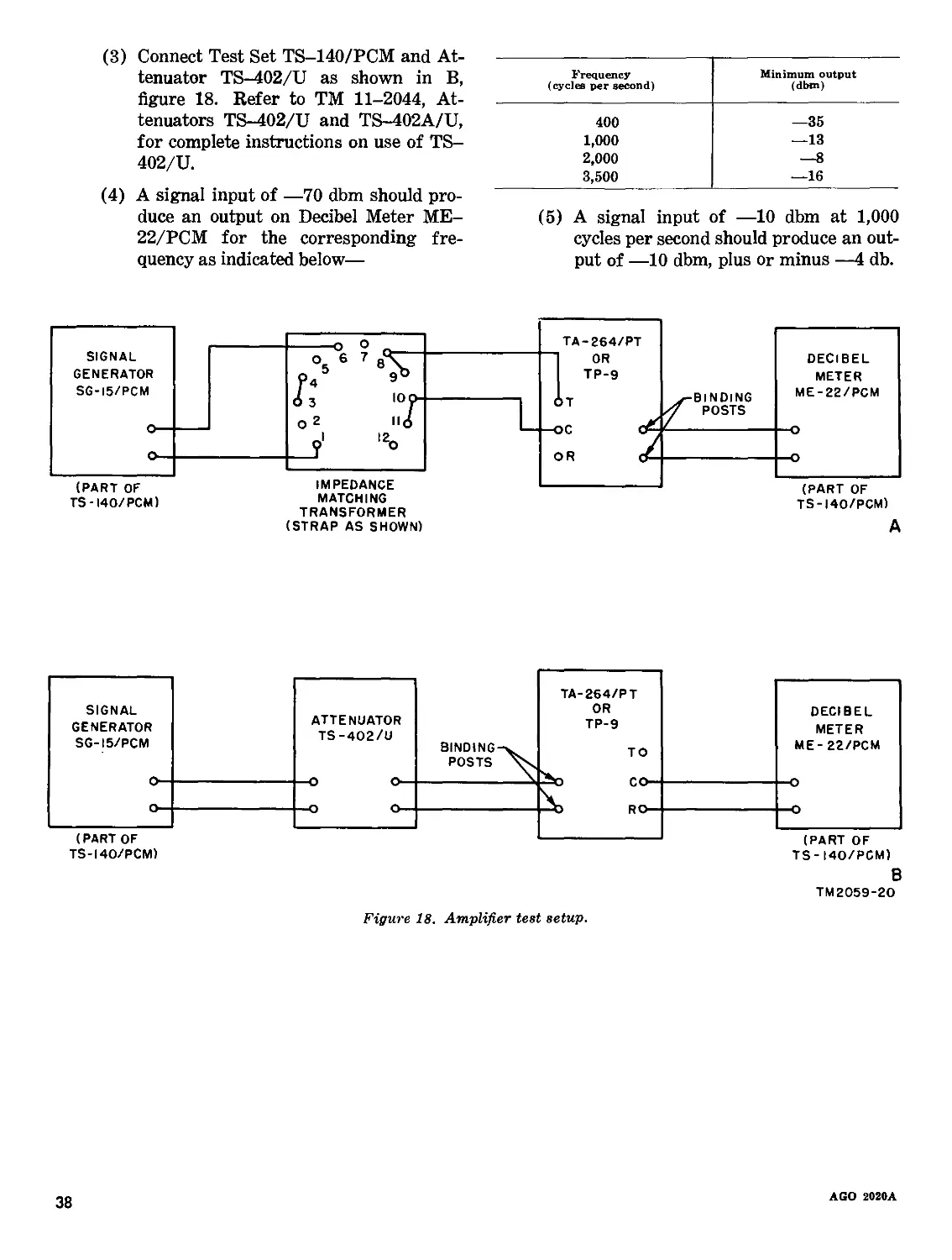
Text
DEPARTMENT OF THE ARMY TECHNICAL MANUAL
DEPARTMENT OF THE AIR FORCE TECHNICAL ORDER
TO
W IMS
TELEPHONE TP-9
AND
TELEPHONE SET
TA-264/PT
DEPARTMENTS OF THE ARMY AND THE AIR FORCE
OCTOBER 1957
AGO 2020A—Oct
ТМ 11—2059/ТО 31W1—ЗТР9—21
Technical Manual^
NO. 11-2059 (
Technical Order /
No. 31W1-3TP9-21 )
DEPARTMENTS OF THE ARMY AND
THE AIR FORCE
Washington 25, D. C., 17 October 1957
TELEPHONE TP-9 AND TELEPHONE SET TA-264/PT
Paragraph Page
Chapter 1. INTRODUCTION
Sectioa I. General______________________________________________________________________ 1,2 3
II. Description and data_________________________________________________________ 3-8 3
Chapter 2. INSTALLATION AND OPERATION
Section I. Service upon receipt of equipment___________________________________________ 9-11 6
II. Installation______________________________________________________________ 12,13 6
III. Operation under usual conditions___________________________________________ 14-19 8
IV. Operation under unusual conditions_________________________________________ 20-23 9
Chapter 3. ORGANIZATIONAL MAINTENANCE
Section I. First echelon (operator) maintenance_______________________________________ 24-27 11
II. Second echelon maintenance_________________________________________________ 28-33 16
Chapter 4. THEORY___________________________________________________________________ 34-41 19
6. FIELD MAINTENANCE
Section I. General troubleshooting information________________________________________ 42-46 24
II. Removal and replacement---------------------------------------------------- 47-61 28
III. Lubrication and adjustments________________________________________________ 62-67 32
IV. Final testing______________________________________________________________ 68-72 36
Chapter 6. SHIPMENT AND LIMITED STORAGE AND DEMOLITION TO PREVENT
ENEMY USE
Section I. Shipment and limited storage_____________________________________________ 73,74 39
II. Demolition of materiel to prevent enemy use_______________________________ 75, 76 39
Index__________________________________________________________________________________ ______ 45
* This manual supersedes TM 11-2059, 9 December 1944, including С 1, 20 December 1945, C 2, 5 June 1950, and C 3, 14 April 1954.
AGO 2020A
1
Figure 1. Telephone TP-9.
2
AGO 2020A
CHAPTER 1
INTRODUCTION
Section I. GENERAL
1. Scope
a. This manual covers the installation, opera-
tion, and maintenance of Telephone TP-9 and
Telephone Set TA-264/PT.
b. Forward any comments on this publication
direct to Commanding Officer, U. S. Army Signal
Publications Agency, Fort Monmouth, N. J.
c. Throughout this manual, the term tele-
phones will be used to identify Telephone TP-9
and Telephone Set TA-264/PT.
2. Forms and Records
a. Unsatisfactory Equipment Reports. Fill out
and forward DA Form 468 (Unsatisfactory Re-
port to Commanding Officer) Signal Equipment
Support Agency, Fort Monmouth, New Jersey,
as prescribed in AR 700-38.
b. Damaged or Improper Shipment. Fill out
and forward DD Form 6, (Report of Damaged or
Improper Shipment) as prescribed in AR 700-58
((Army) ; Navy Shipping Guide, Article 1850-4
(Navy); and AFR 71-4 (Air Force)).
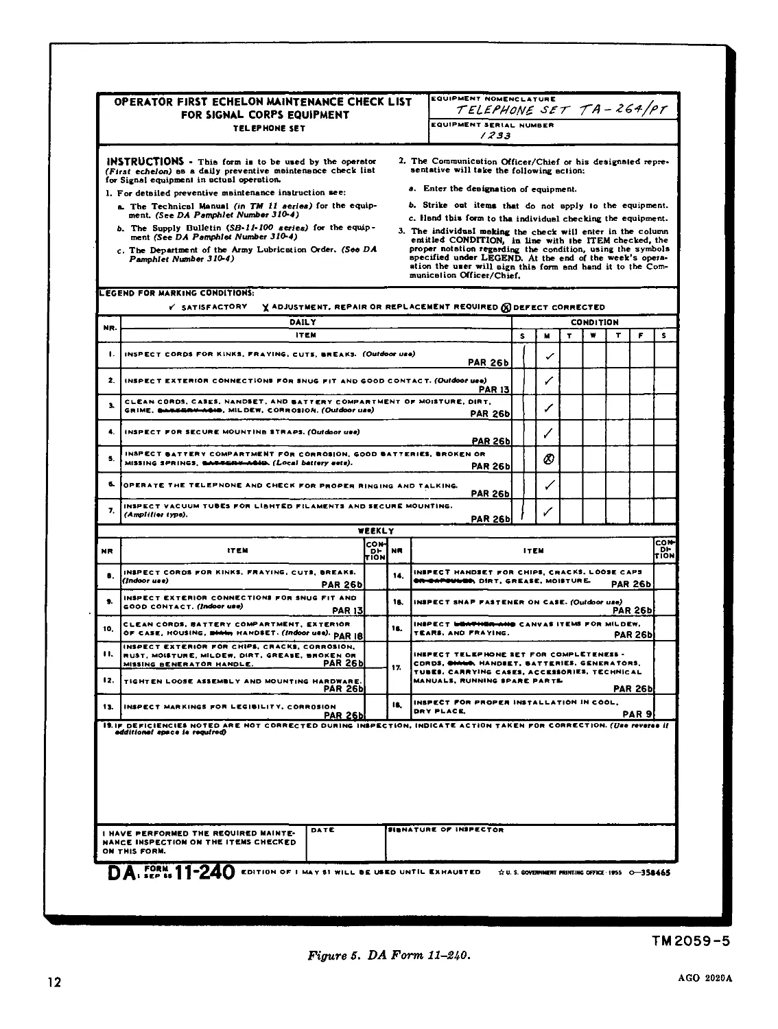
c. Preventive Maintenance Forms.
(1) Prepare DA Form 11-240 (fig. 5)
(Operator First Echelon Maintenance
Checklist for Signal Corps Equipment
—Telephone Set) in accordance with
instructions on the back of the form.
(2) Prepare DA Form 11-241 (fig. 6) (Sec-
ond and Third Echelon Maintenance
Checklist for Signal Corps Equipment
—Telephone Set) in accordance with
instructions on the back of the form.
Section II. DESCRIPTION AND DATA
3. Purpose and Use
The telephones are used to extend the range
and improve the quality of long field wire cir-
cuits where it is not feasible to install and main-
tain repeaters. They are used at terminals (and
at intermediate points between terminals) of a
2-wire line. When used in this way, and noise
and cross talk conditions permit, the telephones
approximately double the transmission range ob-
tained with ordinary local battery sets. Although
the telephones are used primarily on field wire
circuits, they may be used with other line facili-
ties. The transmission ranges differ with the
characteristics of the line. Best results are ob-
tained when a Telephone TP-9 or Telephone Set
TA-264/PT is used at each end of the line.
4. Technical Characteristics
Power supply____________Dry batteries:
One Battery BA-65 (or
BA-35), 1% volts.
One Battery BA-27, 4%-
Current drain volts. Three Batteries BA-2, 22% volts. __255 ma.
Number of tubes __4 (1 spare).
Operating temperature —60° F. to 132° F.
limits. Frequency range 400 to 3,500 cps.
Power levels:
Transmitting_________23 dbm (maximum).
Sidetone_____________—20 dbm to —35 dbm at all
frequencies in the 400 to
3,500 cps range, when out-
put at the line terminals is
+13 dbm into a 600-ohm
resistor.
Range--------------------65 db circuits (maximum).
Impedance--------------- 600 ohms ±10 percent.
Gain:
Transmitter__________15 db.
Receiver_____________55 db.
AGO 2020A
3
LATCH COVER FOR OPERATING
CARRYING
STRAP
UPPER
HOUSING
INSTRUCTION
LABEL
HANDSET
TERMINALS
VISUAL
SIGNAL
LEAF
BINDING
POSTS
JACK
ASSEMBLY
HOUSING LUGS
ANO SCREWS
UPPER
HOUSING
HANDSET
CORO
LOWER
HANDSET
CRADLE
SWITCH
LEVER
CRADLE
GAIN |
CONTROL
HOUSING HANDSET SWITCH
|sig-bell|
SWITCH
TM2059-3
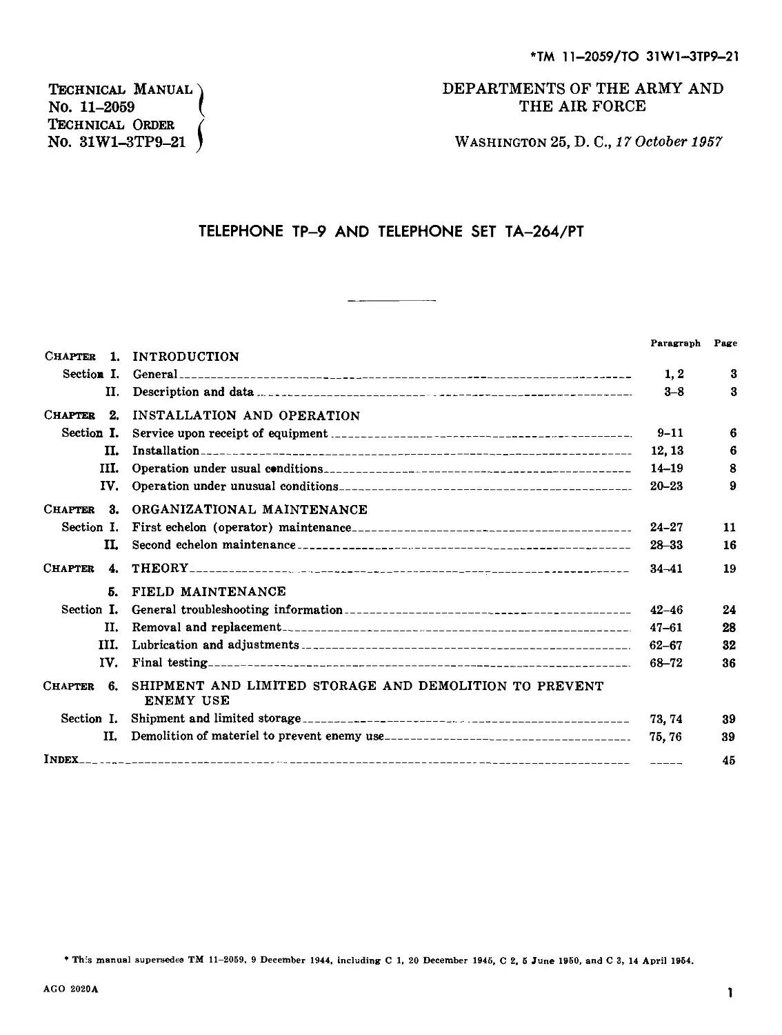
Figure 8. Telephone TP-8, upper housinff open.
4
AGO 2«2«A
5. Components
The telephones are self-contained units consist-
ing of a handset, generator, ringer, and ampli-
fiers. A spare tube (3Q5GT/G) is mounted on
the tube mounting board. Two technical manuals
are provided with each equipment.
6. Description
(fig. 2)
a. Each telephone consists of an upper housing,
lower housing and a hinged cover. The upper
housing mounts all the operating components.
The handset and control equipment extend be-
yond the upper housing and are inclosed by the
hinged cover. The amplifier and the batteries ex-
tend below the upper housing and are inclosed by
the lower housing. The generator crank extends
through the side of the upper housing. When not
in use, the crank folds into a recess provided for
this purpose. When assembled, the telephones are
made waterproof by a composition gasket sep-
arating the upper and lower housings and by
gaskets protecting the openings for the generator
crank, binding posts, switches, and controls.
b. Operating power is furnished by batteries
located in the lower housing.
c. The telephones are provided with a bell for
audible signaling and with a visual signal leaf for
noiseless signaling. A switch is provided to select
either type of signaling.
7. Additional Equipment Required
a. The following equipment is not supplied as
part of the telephones but is required for opera-
tion:
(1) One 4^-volt Battery BA-27 for the
transmitter and relay power supply.
(2) Three 22i/£-volt Batteries BA-2 for the
plate voltages.
(3) One 1^-volt Battery BA-65 (or BA-
35) for the filament power supply.
Note. Under normal conditions of inter-
mittent operation, the batteries should last
about 3 or 4 weeks. However, this period will
vary with climatic and operating conditions.
b. To insure the satisfactory performance of
the telephones in temperatures as low as —60° F.
when operation of this equipment is essential,
substitute the above batteries as follows:
(1) The three Batteries BA-2 with low-
temperature Batteries BA-2002/U.
(2) Battery BA-27 with Battery BA-
2027/U.
(3) Battery BA-65 with Battery BA-
2065/U.
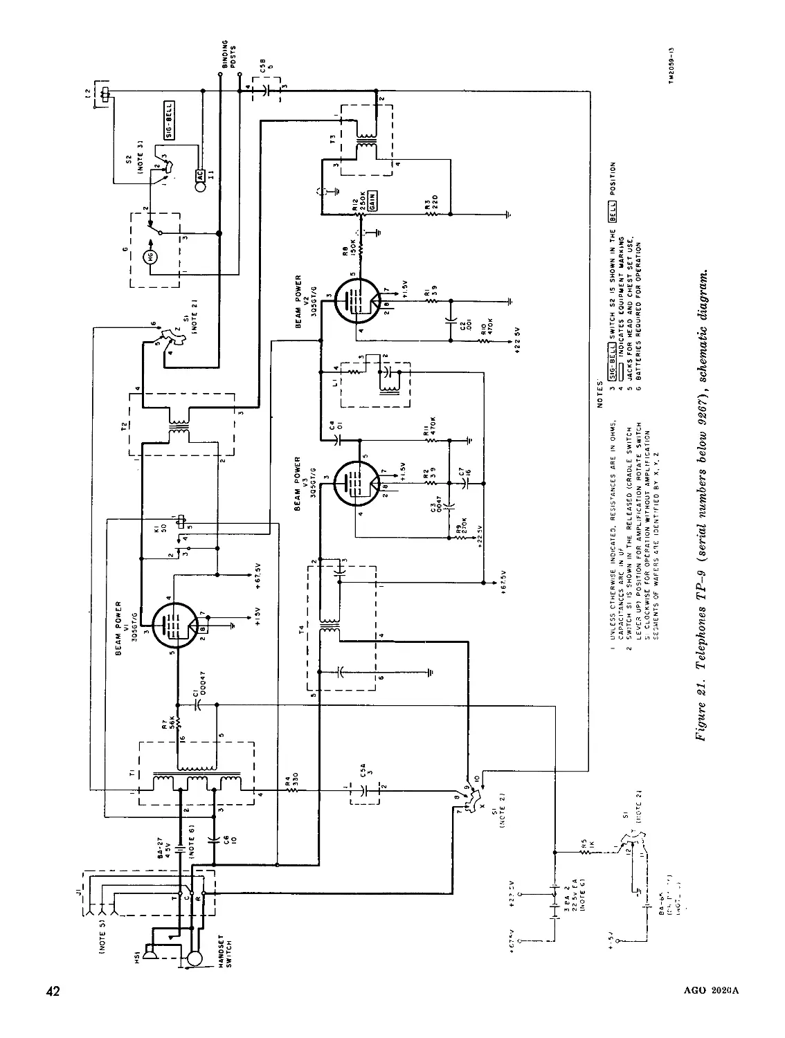
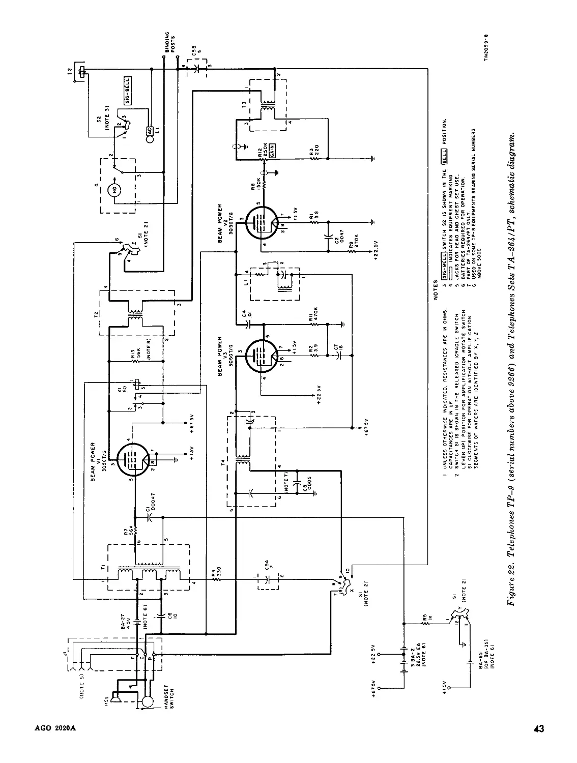
8. Differences in Models
All Telephones TP-9 are similar in purpose,
operation, and appearance. Telephones TP-9,
serial numbers above 9266 include slight improve-
ments in circuitry and a newer hand ringing
generator. Telephone Sets TA-264/PT are simi-
lar to the TP-9, serial numbers above 9266.
AGO 2020A
5
CHAPTER 2
INSTALLATION AND OPERATION
Section I. SERVICE UPON RECEIPT OF EQUIPMENT
9. Siting
Select a site close to the base of operations, free
from dust, dirt, and excessive moisture. Place
the telephone on a convenient work bench or
table, near enough to the signal lines so that con-
nections can be made easily.
10. Unpacking
a. Packaging Data. When packed for export
shipment, the telephones are placed in a close-
fitting, water-resistant, fiberboard box, sealed
with pressure sensitive tape. The telephone is
adequately cushioned within the fiberboard box.
The approximate weight of the packaged units is
19 pounds and displaces about 1,230 cubic inches.
Varying quantities of telephones are packed
within a nailed wooden box. Shipping containers
are reinforced with steel strapping, generally ap-
plied girthwise.
b. Removing Contents. Be careful when un-
packing equipment. Do not thrust tools into the
interior of the shipping container; this procedure
may damage the equipment. Follow the steps
given in (1) through (5) below:
(1) Place the packing case on a secure flat
surface.
(2) Cut the steel straps.
(3) Remove the nails, using a nail puller,
and remove the sides and top of the
packing case. Do not pry the sides and
top off. This procedure may damage
the equipment.
(4) Lift out the corrugated fiberboard box
containing the equipment.
(5) Slit the taped seams of the corrugated
fiberboard box and lift out the tele-
phone.
11. Checking
a. Check the contents against the packing slip.
b. Examine the equipment carefully for pos-
sible damage during shipment.
c. Report damaged equipment in accordance
with instructions contained in paragraph 2.
Section II. INSTALLATION
12. Preparation for Use
(figs. 3 and 4)
a. Before the telephones can be installed for
use, batteries (par. 7) must be installed and con-
nected as outlined in (1) through (10) below.
(1) Unfasten the four screws which hold
the upper and lower housings together
(fig. 2). Turn the equipment upside
down and separate the housings.
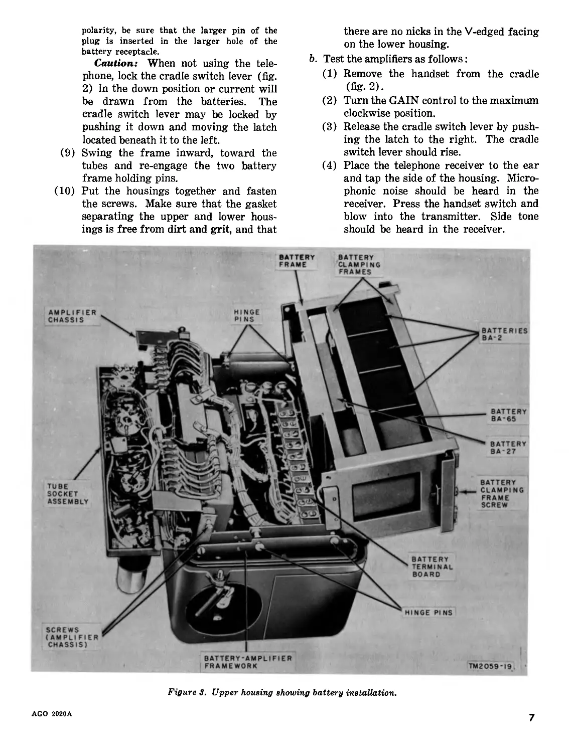
(2) Unfasten the two battery clamping
frame screws and remove both battery
clamping frames (fig. 3).
(3) Install Battery BA-27 in the position
shown in figure 3.
(4) Replace the center battery clamping
frame.
(5) Install three Batteries BA-2 and one
Battery BA-65 as shown in figure 3.
(6) Replace the other battery clamping
frame and tighten the battery clamping
frame screws.
(7) Disengage the two battery frame hinge
pins nearest the row of tubes and swing
the battery frame outward, away from
the tubes.
(8) Connect the batteries to the battery ter-
minal board as shown in figure 4.
Note. Battery BA-65 has a two-prong con-
nector-plug receptacle. To insure correct
6
AGO 2020A
polarity, be sure that the larger pin of the
plug is inserted in the larger hole of the
battery receptacle.
Caution: When not using the tele-
phone, lock the cradle switch lever (fig.
2) in the down position or current will
be drawn from the batteries. The
cradle switch lever may be locked by
pushing it down and moving the latch
located beneath it to the left.
(9) Swing the frame inward, toward the
tubes and re-engage the two battery
frame holding pins.
(10) Put the housings together and fasten
the screws. Make sure that the gasket
separating the upper and lower hous-
ings is free from dirt and grit, and that
there are no nicks in the V-edged facing
on the lower housing.
b. Test the amplifiers as follows:
(1) Remove the handset from the cradle
(fig. 2).
(2) Turn the GAIN control to the maximum
clockwise position.
(3) Release the cradle switch lever by push-
ing the latch to the right. The cradle
switch lever should rise.
(4) Place the telephone receiver to the ear
and tap the side of the housing. Micro-
phonic noise should be heard in the
receiver. Press the handset switch and
blow into the transmitter. Side tone
should be heard in the receiver.
Figure 3. Upper housing showing battery installation.
AGO 2020A
7
13. Connections
To use the telephone at the end of a line, strip
the insulation from the end of the line wires and
connect the line wires to the binding posts (fig.
2). To use the telephone at an intermediate
point, bridge the telephone across the line with-
out interrupting the continuity of the circuit.
Strip the insulation from the line wires and make
a loop connection to the binding posts. Do not
cut the line wires.
Section III. OPERATION UNDER USUAL CONDITIONS
14. Controls and Control Functions
Control
Function
GAIN control
Handset switch
SIG-BELL switch
Cradle switch lever
I
i Volume control: adjusts volume of sound heard at the receiver in the handset.
Operated, allows speech transmission; unoperated, allows speech reception.
When set at BELL position, provides audible signal; when set at SIG position, pro-
vides visual signal.
When held down, provides transmission and reception without amplification; when
released, provides transmission and reception with amplification.
8
AGO 2020A
15. Types of Operation
a. The telephones may be used with or with-
out amplification. It is not possible to talk to and
hear from the distant station simultaneously.
Close cooperation between the talker and listener
is necessary for efficient operation.
b. When the telephones are used on a circuit
which is connected to a switchboard, a break-in
signal (par. 19) may be assumed to be a ring-off
signal by the switchboard operator. In this case,
it will be necessary to answer the operator’s
challenge and continue the conversation.
16. Signaling
Turn the generator crank briskly in a clock-
wise direction to signal another telephone on the
line. To receive a signal, set the SIG-BELL
switch for the desired type of signal. Set the
SIG—BELL switch to BELL for an audible sig-
nal ; to SIG for a visual signal. If the visual signal
is used in darkness, it will be necessary for the
operator to note its position by passing his hand
over the leaf. The visual signal is a leaf that flies
up when ringing current is received.
17. Conversation Without Amplification
To carry on a conversation without amplifica-
tion, proceed as follows:
a. Remove the handset from the cradle (fig.
2).
Section IV. OPERATION Uh
20. General
The efficiency of the telephones can be severely
affected in regions where extreme cold, heat,
moisture, sand conditions, etc., prevail. Para-
graphs 21, 22, and 23 contains information on the
operation of the telephones under these unusual
conditions.
21. Operation in Arctic Climates
Subzero temperatures and climatic conditions
associated with cold weather affect the efficient
operation of the equipment.
a. Dry-cell batteries lose considerable electrical
capacity in low temperatures because of decreased
chemical activity, and become unusable. Replace
Batteries BA-2, BA-27 and BA-65 with the bat-
teries listed in paragraph 7b.
b. Grease on the generator shaft and gears may
b. Lock the cradle switch lever down by push-
ing the latch to the left.
c. Operate the handset switch and talk into the
transmitter.
d. Release the handset switch and listen.
18. Conversation With Amplification
To carry on a conversation with amplification,
proceed as follows:
a. Remove the handset from the cradle.
b. Release the cradle switch lever by pushing
the latch to the right, allowing the cradle switch
lever to rise.
c. Operate the handset switch and talk into the
transmitter.
d. Release the handset switch and listen.
e. Adjust the GAIN control to produce the
most suitable listening level.
19. Break-in Signal
To interrupt the talker at the distant station,
transmit a ringing signal (break-in signal) by
turning the generator crank. This will operate
the bell or visual signal at the distant station to
signal the person talking from the distant station
to stop talking immediately and release the hand-
set switch. As soon as the distant station has
stopped talking, operate the handset switch and
start talking.
;r unusual conditions
freeze. Move equipment to a location in which
the grease will thaw. Then clean the generator
shaft and gears of grease and relubricate.
c. Moisture may form on the transmitter and
receiver. Unscrew the bakelite cap and wipe dry.
d. A receiver exposed to very low temperatures
may freeze the operator’s ear if he uses the re-
ceiver in contact with his ear. Protect the hand-
set transmitter and receiver with Microphone
Cover CW-111 to prevent frostbite when the
operator’s ear may come in contact with the cold
receiver cap.
22. Operation in Tropical Climates
When operated in tropical climates, the tele-
phone may be installed in tents, huts, or when
necessary, in underground dugouts. When equip-
ment is installed below ground and when it is
AGO 2O20A
9
set up in.swampy areas, it is subjected to more
acute moisture conditions than those that are
normal in the tropics. Ventilation is usually poor,
and the high relative humidity causes condensa-
tion to form on the equipment whenever the tem-
perature becomes lower than the surrounding
air. Wipe the handset dry with a dry cloth. A
special moistureproofing and fungiproofing treat-
ment has been applied during manufacture and
provides a reasonable degree of protection.
23. Operation in Desert Climates
Special dustproofing treatment is not necessary
for the telephones. Take all possible precautions
to keep dust, dirt, and sand from getting on
lubricated parts (Generator GN-38-B). Daily
inspection and cleaning of the equipment is rec-
ommended. Instead of merely adding new lubri-
cants to the generator, clean and relubricate the
equipment whenever practicable.
10
AGO 2020A
CHAPTER 3
ORGANIZATIONAL MAINTENANCE
Section I. FIRST ECHELON (OPERATOR) MAINTENANCE
24. Scope of Operator's Maintenance
This section contains information on mainte-
nance to be performed by the operator. These
procedures do not require special tools or test
equipment. This maintenance will consist of
routine inspections, cleaning, visual checking,
and replacement of batteries. Tubes may be re-
placed only by substituting a new tube.
25. Tools and Materials
The tools and materials necessary to maintain
the equipment at this level are cheesecloth or
other lint-free cloth and Tool Equipment TE-33.
No other tools, materials or test equipment are
necessary at this level of maintenance.
26. Preventive Maintenance
a. DA Form 11-240. DA Form 11-240 (fig.
5) is a preventive maintenance checklist to be
used by the operator. Items not applicable to the
equipment are lined out in the figure. References
in the ITEM block in the figure refer to para-
graphs which contain additional maintenance
information pertinent to the particular item. In-
structions for the use of the form appear on the
top of the form.
b. Items. The information in this subpara-
graph is supplementary to DA Form 11-240. The
item numbers correspond to the ITEM numbers
on the form.
Item
3
4
5
6
7
8
9
10
11
12
Item
Maintenance procedures
Maintenance procedures
1
2
Remove all kinks from the signal lines and hand-
set cord; inspect the signal line and handset
cord for fraying, cuts, and breaks. Report any
defects for correction by personnel at higher
echelons.
Check the signal line connections to the binding
posts. Remake the connections if the signal
lines do not make good contact at the binding
posts.
13
14
15
16
17
18
Remove dirt, dust, grease, and moisture from the
cord, handset, housings, and battery compart-
ment.
Inspect the carrying strap for cuts, tears or fray-
ing. Report any defects for correction by per-
sonnel at higher echelons.
Remove all corrosion and dead batteries from the
battery compartment (pars. 12 and 27).
Signal the distant station; ask them to signal
back. Talk and listen on the circuit and observe
transmission quality.
Separate the upper and lower housings (par. 12);
release the cradle switch lever. Check the tubes
for lighted filaments and secure mounting.
Same as for item 1 above.
Same as for item 2 above.
Same as for item 3 above.
Inspect the upper and lower housings for chips,
cracks, corrosion, rust, broken or missing gen-
erator handle. Report any defects for correc-
tion by personnel at higher echelons. Remove
any moisture, mildew, dirt, or grease.
Tighten upper and lower housing screws, handset
cord terminal screws on jack assembly, cradle
switch lever mounting screw, jack assembly
mounting screws, transmitter cap, receiver cap,
and cradle screws.
Clean the panel markings; remove corrosion.
Check the handset for chips or cracks. Report
any defects for correction by personnel at
higher echelons. Tighten loose caps. Remove
dirt, grease, moisture. ,
Examine the snap fastener on the upper housing.
Report any defects for correction by personnel
at higher echelons.
Same as for item 4 above.
Inspect the telephone for completeness. One tube
is the only running spare supplied.
Check the installation site for coolness and dry-
ness.
27. Equipment Performance Checklist
The equipment performance checklist is used
to check equipment performance systematically.
All corrective measures which the operator can
AGO 2020A
11
OPERATOR FIRST ECHELON MAINTENANCE CHECK LIST FOR SIGNAL CORPS EQUIPMENT TELEPHONE SET EQUIPMENT NOMENCLATURE . TELEPHONE SET Г A- 264-/er
EQUIPMENT SERIAL NUMBER /233
INSTRUCTIONS - Thie form is to be used by the operator 2. The Communicetion Officer/Chief or his designated repre- (First echelon) bb a daily preventive meintenence check list sentative will take the following вс lion: for Signal equipment in ectuel operation. 1. For detailed preventive meintenance instruction see: * Enter ,he d'=iP“tion of equipment. a. The Technics! Manual (in TM 11 aeries) for the equip- b. Strike out item* that do not epply Io the equipment, ment. (See DA Pamphlet Number 310-4) c, цвпд this form to individual checking the equipment. b. The Supply Bulletin (SB-ff-fOO eerie.) for the equip- 3 indivldoBl „,b1Ui4e thB chBck will entBr in thB column ment (See DA Pamphlet Number 310-4) entitled CONDITION, in line with lhe ITEM checked, the c. The Department of the Army Lubrication Order. (See DA proper notation regarding the condition, using the symbols Pamphlet Number 310-4) specified under LEGEND. At the end of the week’s oper- ation the user will sign this form end hand it to the Com- municelion Officer/Chief.
LEGEND FOR MARKING CONDITIONS: / SATISFACTORY X ADJUSTMENT. REPAIR OR REPLACEMENT REQUIRED (g) DEFECT CORRECTED
NR. DAILY CONDITION
ITEM S M T w T F S
1. INSPECT CORDS FOR KINKS. FRAYING. CUTS. BREAKS. (Outdoor uao) PAR 26b Z
2. INSPECT EXTERIOR CONNECTIONS FOR SNUG FIT AND GOOD CONTACT. (Outdoor uao) PAR 13 /
3. CLEAN CORDS. CASES. NANDSET. AND BATTERY COMPARTMENT OF MOISTURE. DIRT, /
4. INSPECT FOR SECURE MOUNTlNB STR APS. (Outdoor uaa) PAR 26b /
S. INSPECT BATTERY COMPARTMENT FOR CORROSION. GOOD BATTERIES, BROKEN OR
e. OPERATE THE TELEPHONE AND CHECK FOR PROPER RINGING AND TALKING. PAR 26b /
7. INSPECT VACUUM TUBES FOR LlBNTED FILAMENTS AND SECURE MOUNTING. fAmpn/re, tn,.)- PAR 26b /
WEEKLY
NR ITEM CON- DI- TION NR ITEM CON- DI- TION
3. INSPECT CORDS FOR KINKS. FRAYING, CUTS. BREAKS. PAR 26b 14. INSPECT NANDSET FOR CHIPS, CRACKS. LOOSE CAPS
9. INSPECT EXTERIOR CONNECTIONS FOR SNUG FIT AND good contact, (indoor uao) PAR 13 13. INSPECT SNAP FASTENER ON CASE. (Outdoor иве) PAR 26b
10. CLEAN CORDS. BATTERY COMPARTMENT. EXTERIOR OF CASE. HOUSING. NANDSET. (Indoor ива). рДр |g 18. TEARS. AND FRAYING. рДр 26Ь
11. INSPECT EXTERIOR FOR CHIPS. CRACKS. CORROSION. RUST. MOISTURE. MILDEW. DIRT. GREASE. BROKEN OR MISSING BENERATOR HANDLE. PAR 26Ь 17. INSPECT TELEPHONE SET FOR COMPLETENESS • CDRDS. HANDSET. BATTERIES. GENERATORS. TUBES. CARRYING CASES. ACCESSORIES. TECHNICAL MANUALS. RUNNING SPARE PARTS- PAR 26b
12. TIGHTEN LOOSE ASSEMBLY AND MOUNTING HARDWARE. PAR 26b
IS. INSPECT MARKINGS FOR LEGIBILITY. CORROSION PAR 26b It. INSPECT FOR PROPER INSTALLATION IN COOL. DRY PLACE. PAR 9
I9.IF DEFICIENCIES NOTED ARE NOT CORRECTED DURING INSPECTION, INDICATE ACTION TAKEN FOR CORRECTION. (Uaa revetoe it additional apace la required)
I HAVE PERFORMED THE REQUIRED MAINTE*
NANCE INSPECTION ON THE ITEMS CHECKED
ON THIS FORM.
• (•NATURE OF INSPECTOR
DA
ft U. $. eOVEMNMCNT HUNTING OFFICE 1S55 O—353465
Figure 5. DA Form 11-24-0.
TM2059-5
12
AGO 2020A
perform are given in the corrective measures col-
umn. If the action taken by the operator does not
correct the fault, additional maintenance is re-
quired by personnel at a higher echelon. The
operator should note on the repair tag how the
equipment performed and what corrective meas-
ures were taken. In using the checklist, start at
the beginning, following each step consecutively
to locate trouble. However, if trouble is suspected
in a particular area, start checking at that point
and continue the steps sequentially. Operate the
equipment as shown in the checklist below.
AGO 2020A
13
AGO 2020A
Item No. Item Action or condition
1 Batteries Install batteries as directed in par- agraph 12.
2 Handset Remove from cradle.
3 GAIN control Turn to maximum clockwise posi- tion.
я 4 Cradle switch lever Release by pushing latch to right
о Ен ◄ 5 Telephone receiver Place to ear. Tap side of housing
Й ◄ № Н й Рч 6 Telephone transmitter Press handset switch. Blow into transmitter.
7 Telephone at end of line Connect line wires to binding posts.
8 Telephone at intermediate points Bridge telephone across line. Strip insulation from line wires and make loop connection to binding posts.
9 SIG-BELL switch Move to BELL for audible signal. Move to SIG for visual signal.
Ен 10 Cradle switch lever (operation Lock by pushing cradle switch lever
Рч without amplification). down and moving latch to left.
Н и 11 GAIN control (operation with am- plification) . Turn to midposition.
12 Cradle switch lever (operation with amplification). Release by pushing latch to right.
ы о Й 13 Signalling circuit To send signal, turn generator crank clockwise.
◄ S 14 Transmitting circuit (operation Operate handset switch and talk
й о й without amplification). into the transmitter.
й ы й Ен Й Ы 15 Receiving circuit (operation with- out amplification). Release handset switch
S 16 Transmitting circuit (operation Operate handset switch and talk
й 1—< & Gt Ы with amplification). into transmitter.
Normal indications Corrective measures
Cradle switch lever rises. Microphonic noise heard in receiver. Check batteries. Check tubes. Higher echelon maintenance required.
Sidetone heard in receiver. Check batteries. Check tubes. Higher echelon maintenance required.
Cradle lever rises.
Operation of bell or visual signal at distant station. Check line wires at binding posts. Higher echelon maintenance re- quired.
Conversation heard at distant sta- tion. Check line wires at binding posts. Check Battery BA-27. Higher echelon maintenance re- quired.
Conversation heard from distant station. Check line wires at binding posts. Higher echelon maintenance re- quired.
Conversation heard at distant sta- tion. Check line wires at binding posts. Check batteries. Check tube VI (par. 24). Higher echelon maintenance re- quired.
AGO 2020A
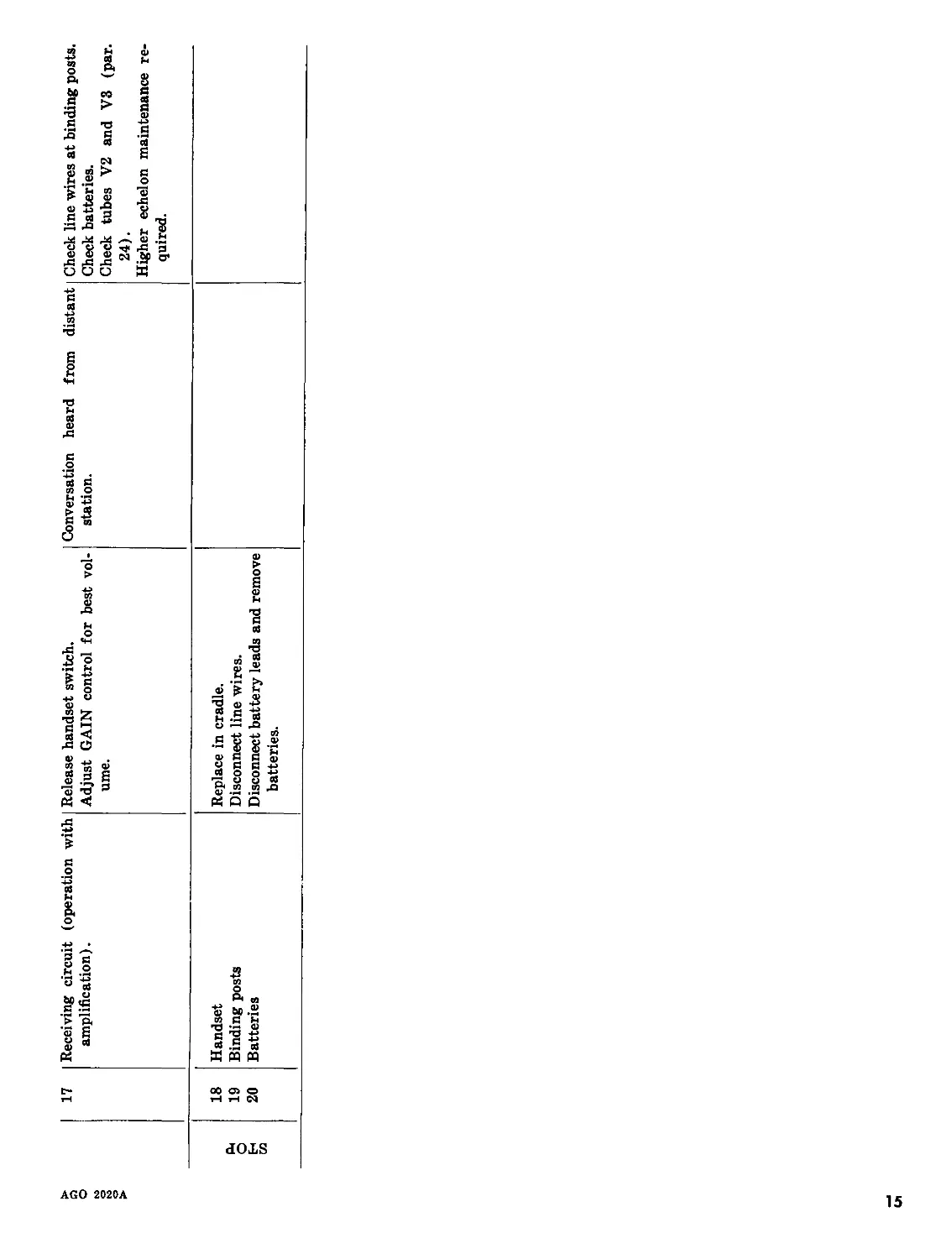
17 Receiving circuit amplification). (operation with Release handset switch. Adjust GAIN control for best vol- ume. Conversation station. heard from distant Check line wires at binding posts. Check batteries. Check tubes V2 and V3 (par. 24). Higher echelon maintenance re- quired.
18 Handset Replace in cradle.
сц о 19 Binding posts Disconnect line wires.
н и 20 Batteries Disconnect battery leads and remove batteries.
Ul
Section II. SECOND ECHELON MAINTENANCE
28. Scope of Second Echelon Maintenance
a. The extent of second echelon maintenance
is limited by the tools, materials, test equipment,
and by the skill of the personnel.
b. Second echelon maintenance for the tele-
phones consists of the following:
(1) Visual inspection (par. 31).
(2) Preventive maintenance (par. 30).
(3) Replacement of defective tubes (par.
32).
(4) Troubleshooting (par. 33).
29. Tools, Materials, and Test Equipment
The tools, materials, and test equipment re-
quired for second echelon maintenance are listed
below.
a. Tools. Tool Equipment TE-41.
b. Materials. Cleaning cloth.
c. Test Equipment.
(1) Multimeter ME-77/U.
(2) Electron Tube Test Set TV-7/U.
30. Preventive Maintenance
a. Use of DA Form 11-241. DA Form 11-241
(fig. 6) is a preventive maintenance checklist to
be used by the second echelon maintenance per-
sonnel. Items not applicable to the equipment are
lined out in the figure. References in the ITEM
block in the figure are to paragraphs which con-
tain additional maintenance information perti-
nent to the particular item. Instructions for the
use of the form appear on the back of the form.
b. Items. The information given in this sub-
paragraph is supplementary to DA Form 11-241.
The item numbers correspond to the ITEM num-
bers on the form. Items 1 through 18 are the
same as those listed on DA Form 11-240 and
described in paragraph 26. Refer to paragraph
26 for maintenance information for these items.
Item
20
21
22
23
24
25
26
30
31
Maintenance procedures
Remove dirt, dust, grease, moisture and mildew
from the telephone housings, chassis and bat-
tery compartments.
Examine all wiring and connections for good con-
tact, breaks, fraying, and cuts. Report any
defects for maintenance by personnel at higher
echelons.
Examine Generator GN-38-B for worn or chip-
ped gears, loose screws or broken contact
springs. Report any defects for maintenance
by personnel at higher echelons.
Generator GN-38-B only; burnish generator con-
tacts.
Tighten upper and lower housing screws, hand-
set cord terminal screws on jack assembly,
cradle switch lever mounting screw, and jack
assembly mounting screws.
Operate the SIG-BELL switch, GAIN control,
handset switch, and cradle switch. Check for
positive action and good contact. Report any
defects for maintenance by personnel at higher
echelons.
Check the tubes for lighted filaments and secure
mounting.
Clean the cradle switch and SIG-BELL switch.
Remove dirt and dust.
Clean and tighten the handset cord connections
to the jack assembly; clean and tighten the
signal line connections to the binding posts.
Item Maintenance procedures
19 Remove all kinks from the signal lines and hand-
set cord; inspect the signal line and handset
cord for fraying, cuts, and breaks. Report any
defects for correction by personnel at higher
echelons.
31. Visual Inspection
a. When failure is encountered and the cause
is not immediately apparent, check as many of
the items listed in b below as is practicable be-
fore starting a systematic operational check of
the equipment. Do not disassemble the telephone
for a complete inspection without some knowledge
of the operational symptoms. If possible, obtain
information from the operator of the equipment
regarding performance at the time trouble
occurred.
b. Complete or partial failure of the telephone
often may be caused by one or more of the follow-
ing faults:
(1) Improper positioning of operating con-
trols.
(2) Worn, broken, or disconnected signal
lines or handset cord.
(3) Broken or loose wires in chassis and
jack assembly.
16
AGO 2020A
SECOND AND TNIRD ECHELON MAINTENANCE TELEPNM
INSTWCTIOHS;
EQUIPMENT NOMENCLATURE , TSLtWiiE St? ' Zb*/
LBGSND FOR MARKING CONDITIONS: Sat iefactory; X Adj Mt NOTB: Strike oat it
NO. ITEM i!
1 INSPECT CORDS FOR KINKS, FRAYING, CUTS, DREAMS. (Outdoor ua«J. PAR 26b
2 INSPECT EXTERIOR CONNECTIONS FOR SNUG FIT ANO 6000 CONTACT. (Outdoor eee). PAR. 13
3 CHAN CORDS, CASES, HANDSET, AMD BATTERY COMPARTMENT OF MOISTURE, 01RT, GRIME, 6ATTGRV >611, MILDER, CORROSION. pAR 26b
4 INSPECT FOR SECURE MOUNTING STRAPS. (Outdoor mo). PAR 26b
5 INSPECT BATTERY COMPARTMENT FOR CORROSION, GOOD BATTERIES, BROKEN OR MISSING SPRINGS, BATTHY AB IB» (Leeef hettwy ”t<b PAR. 26b
6 OPERATE THE TELEPHONE ANO CHECK FOR PROPER RINGING AND TALKING. РАЙ 26b
7 INSPECT VACUUM TUBES FOR LIGHTED FILAMENTS ANO SECURE MOUNTING. (Anpif/Ier typo)* PAR 26b
8 INSPECT CORDS FOR KINKS, FRAYING, CUTS, BREAKS. (Indoor u»e). PAR 26b
3 INSPECT EXTERIOR CONNECTIONS FOR SNUG FIT AND 6000 CONTACT. (Indoor uoo). PAR 26b
10 CLEAN CORDS, BATTERY COMPARTMENT, EXTERIOR OF CASE, HOUSING, Pt*fr, HANDSET. (Indoor mo). PAR 26b
11 INSPECT EXTERIOR FOR CHIPS, CRACKS, CORROSION, RUST, MOISTURE, MILDEW. DIRT, GREASE, BROKEN OR MISSING GENERATOR HANDLE. рдр 26b
12 TIGHTEN LOOSE ASSEMBLY ANO MOUNTING HARDWARE. PAR 26b
13 INSPECT MARKINGS FOR LEGIBILITY, CORROSION. PAR 26b
14 INSPECT HANDSET FOR CHIPS, CRACKS, LOOSE CAPS OR CAPSULES, DIRT, GREASE, MOISTURE. « - . PAR 26b
15 INSPECT SNAP FASTENER ON CASE. (Outdoor mo). PAR 26b
U INSPECT LEATHER AND CANVAS ITEMS FOR MILDEM, TEARS, AND FRAYING. PAR 26 b
34 IF DEFICIENCIES NOTEO ME NOT CORRECTED DURING INSPECTION, INOIC
DA 1 ««Г* 11-241 «П»сн M AGO Г0«» 4
CHECK LIST FOR SIGNAL CORPS EQUIPMENT ME SET
ether aide
EQUIPMENT SERIAL RO. / 2 3 5
unit, repair or replacement repaired; ф Defect corrected, tens tot applicable.
NO. ITEM
11 INSPECT TELEPHONE SET FOR COMPLETENESS - COROS, BIRUh HANDSET, BATTERIES, GENERATORS, TUBES, CARRYING CASES, ACCESSORIES, TECHNICAL MANUALS, RUNNING SPARE FART^r
IB INSPECT FOR PROPER INSTALLATION IN COOL, DRY PLACE. PAR 9
1» INSPECT CORDS ANO LINE TERMINALS FOR FRAYING, BREAKS, PAR. 30b
20 CLEAN INTERIORS OF TELEPHONE HOUSINGS, CHASSIS, CARRYING CASES, BATTERY COMPARTMENTS OF ALL CORROSION, MOISTURE, MILDEW, RUST, EXCESS SOLDER, DIRT, GRIME, GREASE. рддздь
21 INSPECT INTERIOR WIRING ANO CONNECTIONS FOR GOOD CONTACT, BREAKS, CUTS, PRATING. PAR 3ob
22 INSPECT GENERATOR FOR WORN OR CHIPPED GEARS, LOOSE SCREWS, WORN RUBBER, BROKEN CONTACT SPRINGS. (Local battery aete). PAR 30b
23 BURNISH GENERATOR CONTACTS ANO AOUUST SPRINGS. (Leeaf battery aete). PAR 67
24 TIGHTEN ALL LOOSE ASSEMBLY AND MOUNTING SCREWS. PAR 30b
25 SWITCH AND CONTROL SWITCHES FOR POSITIVE ACTION ANO GOOO CONTACT. PAR 30b
26 INSPECT VACUUM TUBES FOR SECURE MOUNTING, VISIBLE CAMAGE, AND LIGHTED FILAMENT. (Anplf/fer type). PAR 30b
27 UHP6CT l»bUG6 AND VAIM FOR ONUB МВ AND BBW BONVHb
28
2»
30 CLEAN SWITCHES ANB RELAY! OF 01ЯТ, DUST ANO MOISTURE. PAR 30b
31 CLEAN ANO TIGHTEN ALL TERMINAL CONNECTIONS. PAR 30b
32 THE ARMY LUBA 1 BAY IBM ORBBR. PAR 63
33 INSPECT THE TELEPHONE SET FOR PROPER MOISTURE ANO FUNGUS PROOFING.
ATE ACTION TAKEN FOR CORRECTION.
сЛ—1&—M3M-1 619, 1 DEC 60, WHICH IS OBSOLETE-
ТМ2059-е
Figure 6. DA Form 11-Ц1.
17
(4) Defective tubes.
(5) Overheated capacitors.
(6) Burned insulation and resistors.
32. Tube Testing and Replacement
When trouble occurs, check all connections and
batteries before removing any tubes. Try to iso-
late the trouble to a component or stage. If tube
failure is suspected, use the applicable procedure
below to check the tubes.
a. Using Tube Tester. Remove and test one
tube at a time. Discard a tube only if its defect is
obvious or if the tube tester shows it to be defec-
tive. Do not discard a tube that tests at or
slightly below its minimum test limit. Replace the
original tube, or install a new one if required, be-
fore testing the next one.
b. Tube Substitution Method. Replace a sus-
pected tube with a new tube. If this does not cor-
rect the trouble, remove the new tube and put
back the original tube. Repeat this procedure
with each suspected tube until the defective tube
is located.
33. Troubleshooting by Using Equipment Per-
formance Checklist
The equipment performance checklist (par.
27) gives an action or condition, normal indica-
tions, and corrective measures information which
will help the organizational repairman locate
trouble in the equipment. To use this list, follow
the items in numerical sequence. When the pro-
cedure referred to in the corrective measures
column is beyond the scope of organizational per-
sonnel, troubleshooting at a held maintenance
level is required.
18
AGO 202OA
CHAPTER 4
THEORY
34. General
The telephones are equipped with vacuum-tube
amplifiers in both the transmitting and receiving
circuits. They can be used without amplification,
as local battery sets. The distance over which
satisfactory telephone communication can be ac-
complished is limited by the attenuation of the
line, noise, crosstalk, and other interference
present in the circuit. To extend the range, a
transmitting amplifier is used to apply stronger
signals on the line, and thereby provides a more
favorable signal-to-noise ratio. To compensate
for the losses in the line, amplifiers in the receiv-
ing circuit are used. The receiving amplifiers in-
crease the communication range, provided that a
good signal-to-noise ratio is maintained.
35. Amplification
a. In the telephones, amplifiers are self-con-
tained. The transmitting circuit uses one stage
of amplification; the receiving circuit uses two
stages of amplification. To provide a more fav-
orable signal-to-noise ratio, the speech energy
originating at the transmitter is amplified and
sent out on the line at a comparatively high level
(15 decibels referred to 1 milliwatt in 600 ohms
(dbm input)). The speech energy received at
the telephone terminals is amplified through two
stages of amplification to provide a maximum
gain of approximately 55 decibels (db).
b. Losses caused by the capacitive effects in the
line increase at higher frequencies. To overcome
these losses, the receiving amplifiers of the tele-
phones are designed to provide greater amplifica-
tion at higher voice frequencies (fig. 7). In this
way, an equalizing action is obtained which re-
sults in a satisfactory overall frequency response
characteristic.
c. Transmission of speech energy from both
ends of the line simultaneously is not possible
when the amplifier is used. The coupling of
energy between the transmitting and the receiv-
ing amplifiers would cause oscillation and make
conversation unintelligible. The handset is
equipped with a nonlocking type switch which
must be operated for transmission and released
for listening. A relay in the telephone is operated
by the handset switch and makes the receiving
circuit inoperative during transmission, and the
transmitting circuit inoperative when speech is
being received.
d. The handset rests in a cradle and operates a
cradle switch lever. Filament circuits are com-
pleted to ground through contacts 11 and 12 of
switch SI (fig. 21) when the handset is removed
from the cradle and the cradle switch lever is up.
When the cradle switch lever is held down (a
latch is provided) and the handset removed from
the cradle, the telephone is used as a local battery
set (without amplification).
36. Local Battery Operation
When the telephone is to be used without ampli-
fication (as a local battery set), the cradle switch
lever is locked down. This action closes the switch
SI contacts 4 and 6 in the transmitting circuit
and 7, 8, and 10 in the receiving circuit. Contacts
11 and 12 are opened and disconnect the filament
voltage from the amplifier tubes.
37. Receiving Circuit Without Amplification
(fig. 8)
Incoming speech signals at the binding posts
(line terminals) of the telephone flow through
contacts 4 and 6 of cradle switch SI, winding 1-3
of transformer Tl, and capacitor C6 to the re-
ceiver of the handset. From the receiver in the
handset, the currents flow through contacts 7
and 10 of switch SI and capacitor C5B back to
the line.
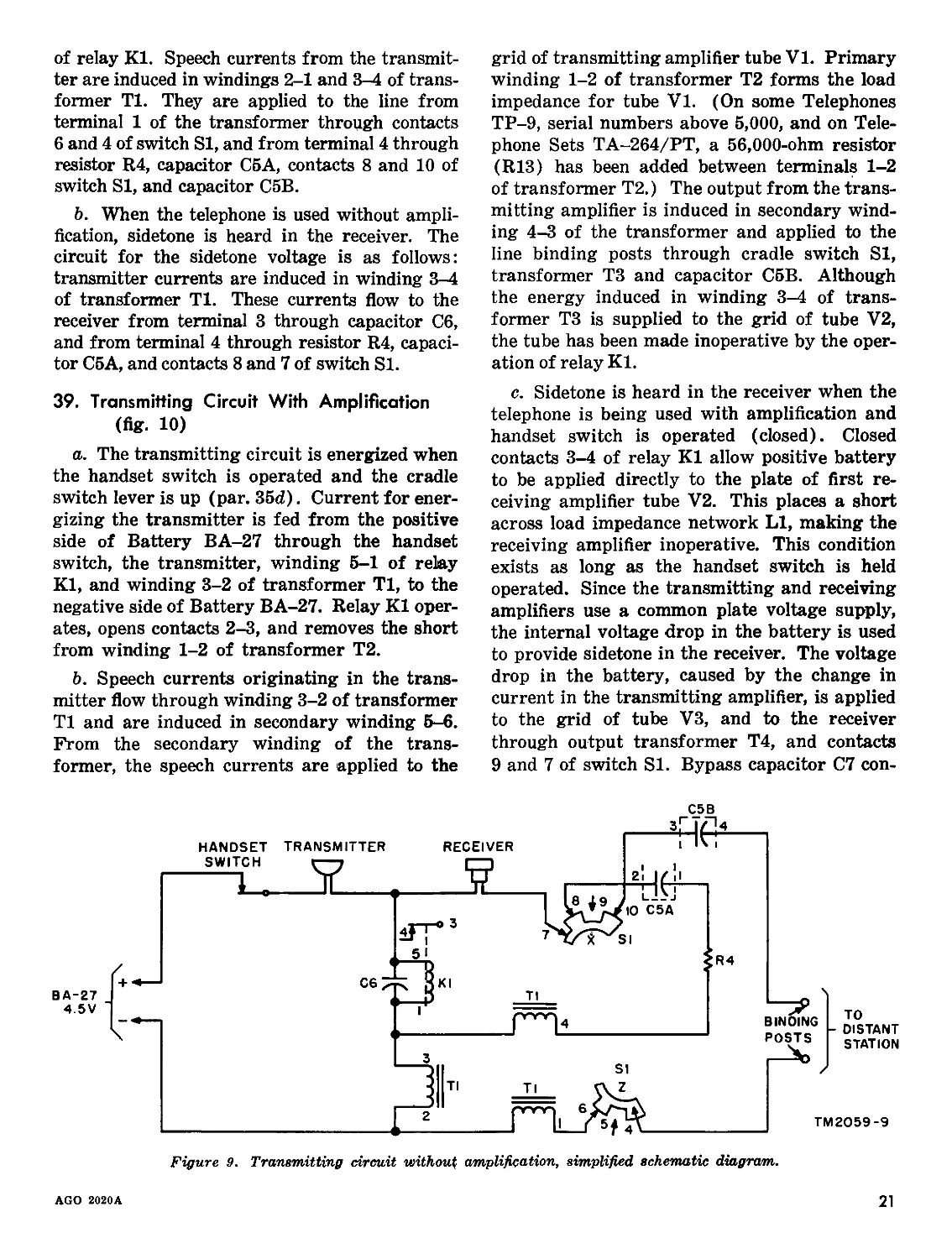
38. Transmitting Circuit Without Amplification
(fig. 9)
a. When the handset switch is closed, a com-
plete circuit for Battery BA-27 is formed through
winding 2-3 of transformer Tl and winding 1-5
AGO 2020A
19
70
RECE IVER GAIh
ъо
ЭО
2 40 <
DB < 4 )
JU
20
1Л TR ANSM ITTE R GA IN
IQ
2 € 10 14 FREQUENCY 20 24 IN HUNDREDS OF 30 CYCLES TM2059-7
Figure 7. Amplifier gain characteristics.
20
AGO 2020A
of relay KI. Speech currents from the transmit-
ter are induced in windings 2-1 and 3-4 of trans-
former Tl. They are applied to the line from
terminal 1 of the transformer through contacts
6 and 4 of switch SI, and from terminal 4 through
resistor R4, capacitor C5A, contacts 8 and 10 of
switch SI, and capacitor C5B.
b. When the telephone is used without ampli-
fication, sidetone is heard in the receiver. The
circuit for the sidetone voltage is as follows:
transmitter currents are induced in winding 3-4
of transformer Tl. These currents flow to the
receiver from terminal 3 through capacitor C6,
and from terminal 4 through resistor R4, capaci-
tor C5A, and contacts 8 and 7 of switch SI.
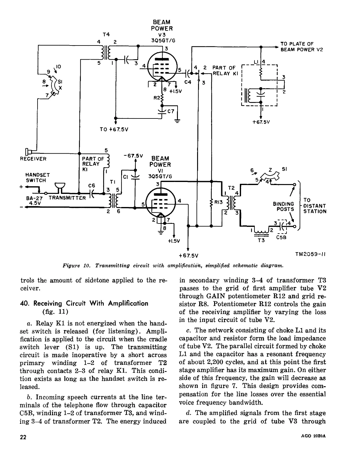
39. Transmitting Circuit With Amplification
(fig. 10)
a. The transmitting circuit is energized when
the handset switch is operated and the cradle
switch lever is up (par. 35d). Current for ener-
gizing the transmitter is fed from the positive
side of Battery BA-27 through the handset
switch, the transmitter, winding 5-1 of relay
KI, and winding 3-2 of transformer Tl, to the
negative side of Battery BA-27. Relay KI oper-
ates, opens contacts 2-3, and removes the short
from winding 1-2 of transformer T2.
b. Speech currents originating in the trans-
mitter flow through winding 3-2 of transformer
Tl and are induced in secondary winding 5-6.
From the secondary winding of the trans-
former, the speech currents are applied to the
grid of transmitting amplifier tube V1. Primary
winding 1-2 of transformer T2 forms the load
impedance for tube VI. (On some Telephones
TP-9, serial numbers above 5,000, and on Tele-
phone Sets TA-264/PT, a 56,000-ohm resistor
(R13) has been added between terminals 1-2
of transformer T2.) The output from the trans-
mitting amplifier is induced in secondary wind-
ing 4-3 of the transformer and applied to the
line binding posts through cradle switch SI,
transformer T3 and capacitor C5B. Although
the energy induced in winding 3-4 of trans-
former T3 is supplied to the grid of tube V2,
the tube has been made inoperative by the oper-
ation of relay KI.
c. Sidetone is heard in the receiver when the
telephone is being used with amplification and
handset switch is operated (closed). Closed
contacts 3-4 of relay KI allow positive battery
to be applied directly to the plate of first re-
ceiving amplifier tube V2. This places a short
across load impedance network LI, making the
receiving amplifier inoperative. This condition
exists as long as the handset switch is held
operated. Since the transmitting and receiving
amplifiers use a common plate voltage supply,
the internal voltage drop in the battery is used
to provide sidetone in the receiver. The voltage
drop in the battery, caused by the change in
current in the transmitting amplifier, is applied
to the grid of tube V3, and to the receiver
through output transformer T4, and contacts
9 and 7 of switch SI. Bypass capacitor C7 con-
AGO 2020A
21
BEAM
POWER
T4 v3
+67.5 V
TO +67.5V
+ 67.5V
ТМ2О5Э-Н
Figure 10. Transmitting circuit with amplification, simplified schematic diagram.
trols the amount of sidetone applied to the re-
ceiver.
40. Receiving Circuit With Amplification
(fig. ID
a. Relay KI is not energized when the hand-
set switch is released (for listening). Ampli-
fication is applied to the circuit when the cradle
switch lever (SI) is up. The transmitting
circuit is made inoperative by a short across
primary winding 1-2 of transformer T2
through contacts 2-3 of relay KI. This condi-
tion exists as long as the handset switch is re-
leased.
b. Incoming speech currents at the line ter-
minals of the telephone flow through capacitor
C5B, winding 1-2 of transformer T3, and wind-
ing 3-4 of transformer T2. The energy induced
in secondary winding 3-4 of transformer T3
passes to the grid of first amplifier tube V2
through GAIN potentiometer R12 and grid re-
sistor R8. Potentiometer R12 controls the gain
of the receiving amplifier by varying the loss
in the input circuit of tube V2.
c. The network consisting of choke LI and its
capacitor and resistor form the load impedance
of tube V2. The parallel circuit formed by choke
LI and the capacitor has a resonant frequency
of about 2,200 cycles, and at this point the first
stage amplifier has its maximum gain. On either
side of this frequency, the gain will decrease as
shown in figure 7. This design provides com-
pensation for the line losses over the essential
voice frequency bandwidth.
d. The amplified signals from the first stage
are coupled to the grid of tube V3 through
22
AGO 2020A
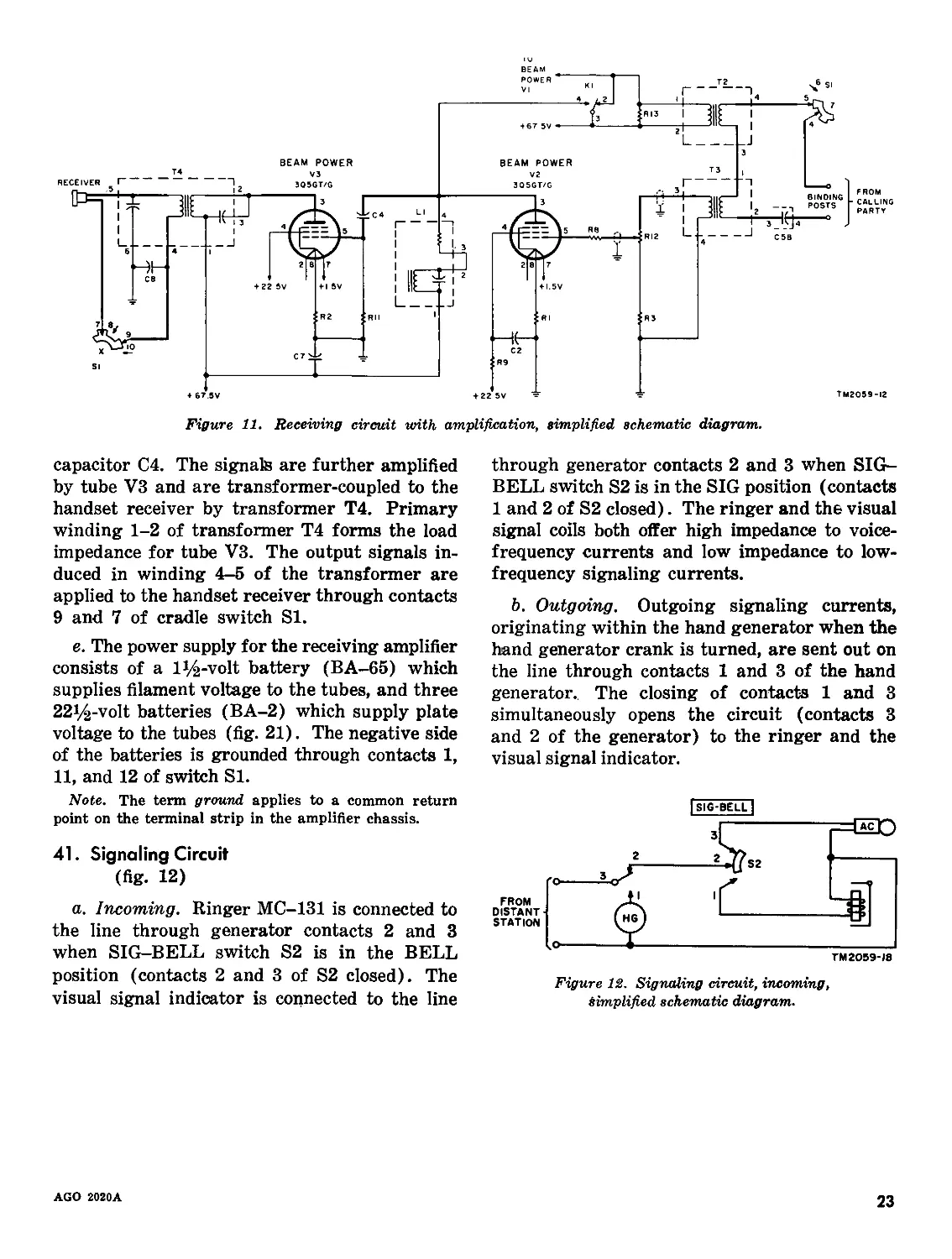
Figure 11. Receiving circuit with amplification, simplified schematic diagram.
capacitor C4. The signals are further amplified
by tube V3 and are transformer-coupled to the
handset receiver by transformer T4. Primary
winding 1-2 of transformer T4 forms the load
impedance for tube V3. The output signals in-
duced in winding 4-5 of the transformer are
applied to the handset receiver through contacts
9 and 7 of cradle switch SI.
e. The power supply for the receiving amplifier
consists of a l^-volt battery (BA-65) which
supplies filament voltage to the tubes, and three
22i/£-volt batteries (BA-2) which supply plate
voltage to the tubes (fig. 21). The negative side
of the batteries is grounded through contacts 1,
11, and 12 of switch SI.
Note. The term ground applies to a common return
point on the terminal strip in the amplifier chassis.
41. Signaling Circuit
(fig. 12)
a. Incoming. Ringer MC-131 is connected to
the line through generator contacts 2 and 3
when SIG-BELL switch S2 is in the BELL
position (contacts 2 and 3 of S2 closed). The
visual signal indicator is connected to the line
through generator contacts 2 and 3 when SIG-
BELL switch S2 is in the SIG position (contacts
1 and 2 of S2 closed). The ringer and the visual
signal coils both offer high impedance to voice-
frequency currents and low impedance to low-
frequency signaling currents.
b. Outgoing. Outgoing signaling currents,
originating within the hand generator when the
hand generator crank is turned, are sent out on
the line through contacts 1 and 3 of the hand
generator. The closing of contacts 1 and 3
simultaneously opens the circuit (contacts 3
and 2 of the generator) to the ringer and the
visual signal indicator.
Figure 12. Signaling circuit, incoming,
simplified schematic diagram.
AGO 2020A
23
CHAPTER 5
FIELD MAINTENANCE
Section I. GENERAL TROUBLESHOOTING INFORMATION
42. General
The first step in servicing a defective equip-
ment is to sectionalize the fault. Sectionaliza-
tion means tracing the fault to the major com-
ponent or to the circuit responsible for abnormal
operation. The second step is to localize the
fault. Localization means tracing the fault to
the defective subchassis, circuit, or stage. Isola-
tion means tracing the fault to the defective
part. Some faults such as burned-out relay coils,
relay contacts, resistors, etc, often may be iso-
lated by inspection. The majority of faults,
however, must be isolated by checking voltages
and resistances.
43. Localizing Trouble
a. Troubles in a system in which the tele-
phones are used may occur either in the line
wires or in the telephone itself. In general, an
indication of the condition of the line and the
telephone can be determined to some extent by
the ringing signals. If a ringing signal is re-
ceived, but it is impossible to hear over the
circuit, the telephone may be at fault. If no
ringing signals or speech signals can be re-
ceived, the line may be at fault. Noisy operation
may occur as a result of trouble in either the
line or the telephone.
b. When trouble is encountered, a quick check
may be made by changing the telephone to local
battery operation (par. 17). This check is es-
pecially useful for determining the origin of
trouble causing noisy operation, and also for
checking the condition of the amplifiers. This
check will be satisfactory only when losses in
the circuit are not excessive. A more reliable
way of testing the telephone is to disconnect it
from the line and connect it to a telephone which
is known to be in working order. Telephone
TA-43/PT or TA-312/PT may be used for this
purpose.
c. After the trouble has been localized to
either the line or the telephone, proceed to iso-
late the trouble.
(1) If it has been determined that the line
is at fault, report the trouble to wire
maintenance personnel.
(2) If the trouble is in the telephone, follow
the procedure outlined in the trouble-
shooting chart (par. 44). To further
assist in locating trouble in the tele-
phone, schematic diagrams (figs. 21
and 22), wiring diagram (fig. 23), a
point-to-point voltage chart (par. 45),
and a resistance chart (par. 46) are
supplied.
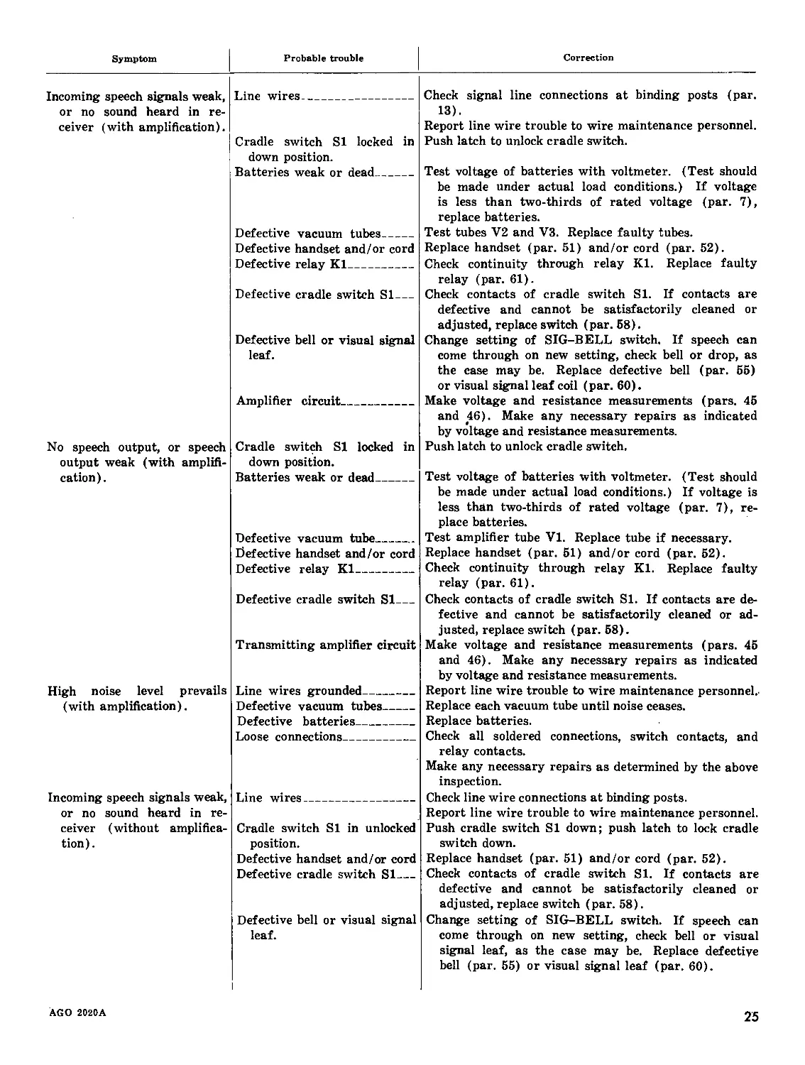
44. Troubleshooting Chart
The most common troubles that occur in the
telephones together with a listing of the prob-
able causes and the corrective action, are given
in the following chart. This list of troubles
does not represent all the troubles that might
occur or all the probable causes for each condi-
tion, but does include those which occur in the
majority of cases. The probable causes or the
items in which the causes may be found are
listed under each heading. The references in-
cluded after the corrective action furnish a
cross-reference to paragraphs in other sections
of this manual.
24
AGO 2020A
Symptom
Probable trouble
Correction
Incoming speech signals weak, or no sound heard in re- ceiver (with amplification). No speech output, or speech output weak (with amplifi- cation). High noise level prevails (with amplification). Incoming speech signals weak, or no sound heard in re- ceiver (without amplifica- tion). Line wires Cradle switch SI locked in down position. Batteries weak or dead Defective vacuum tubes Defective handset and/or cord Defective relay KI Defective cradle switch SI Defective bell or visual signal leaf. Amplifier circuit Cradle switch SI locked in down position. Batteries weak or dead Defective vacuum tube Defective handset and/or cord Defective relay KI Defective cradle switch SI Transmitting amplifier circuit Line wires grounded Defective vacuum tubes Defective batteries Loose connections Line wires Cradle switch SI in unlocked position. Defective handset and/or cord Defective cradle switch SI Defective bell or visual signal leaf. Check signal line connections at binding posts (par. 13). Report line wire trouble to wire maintenance personnel. Push latch to unlock cradle switch. Test voltage of batteries with voltmeter. (Test should be made under actual load conditions.) If voltage is less than two-thirds of rated voltage (par. 7), replace batteries. Test tubes V2 and V3. Replace faulty tubes. Replace handset (par. 51) and/or cord (par. 52). Check continuity through relay KI. Replace faulty relay (par. 61). Check contacts of cradle switch SI. If contacts are defective and cannot be satisfactorily cleaned or adjusted, replace switch (par. 58). Change setting of SIG-BELL switch. If speech can come through on new setting, check bell or drop, as the case may be. Replace defective bell (par. 55) or visual signal leaf coil (par. 60). Make voltage and resistance measurements (pars. 45 and 46). Make any necessary repairs as indicated by voltage and resistance measurements. Push latch to unlock cradle switch. Test voltage of batteries with voltmeter. (Test should be made under actual load conditions.) If voltage is less than two-thirds of rated voltage (par. 7), re- place batteries. Test amplifier tube VI. Replace tube if necessary. Replace handset (par. 51) and/or cord (par. 52). Check continuity through relay KI. Replace faulty relay (par. 61). Check contacts of cradle switch SI. If contacts are de- fective and cannot be satisfactorily cleaned or ad- justed, replace switch (par. 58). Make voltage and resistance measurements (pars. 45 and 46). Make any necessary repairs as indicated by voltage and resistance measurements. Report line wire trouble to wire maintenance personnel.- Replace each vacuum tube until noise ceases. Replace batteries. Check all soldered connections, switch contacts, and relay contacts. Make any necessary repairs as determined by the above inspection. Check line wire connections at binding posts. Report line wire trouble to wire maintenance personnel. Push cradle switch SI down; push latch to lock cradle switch down. Replace handset (par. 51) and/or cord (par. 52). Check contacts of cradle switch SI. If contacts are defective and cannot be satisfactorily cleaned or adjusted, replace switch (par. 58). Change setting of SIG-BELL switch. If speech can come through on new setting, check bell or visual signal leaf, as the case may be. Replace defective bell (par. 55) or visual signal leaf (par. 60).
AGO 2020A
25
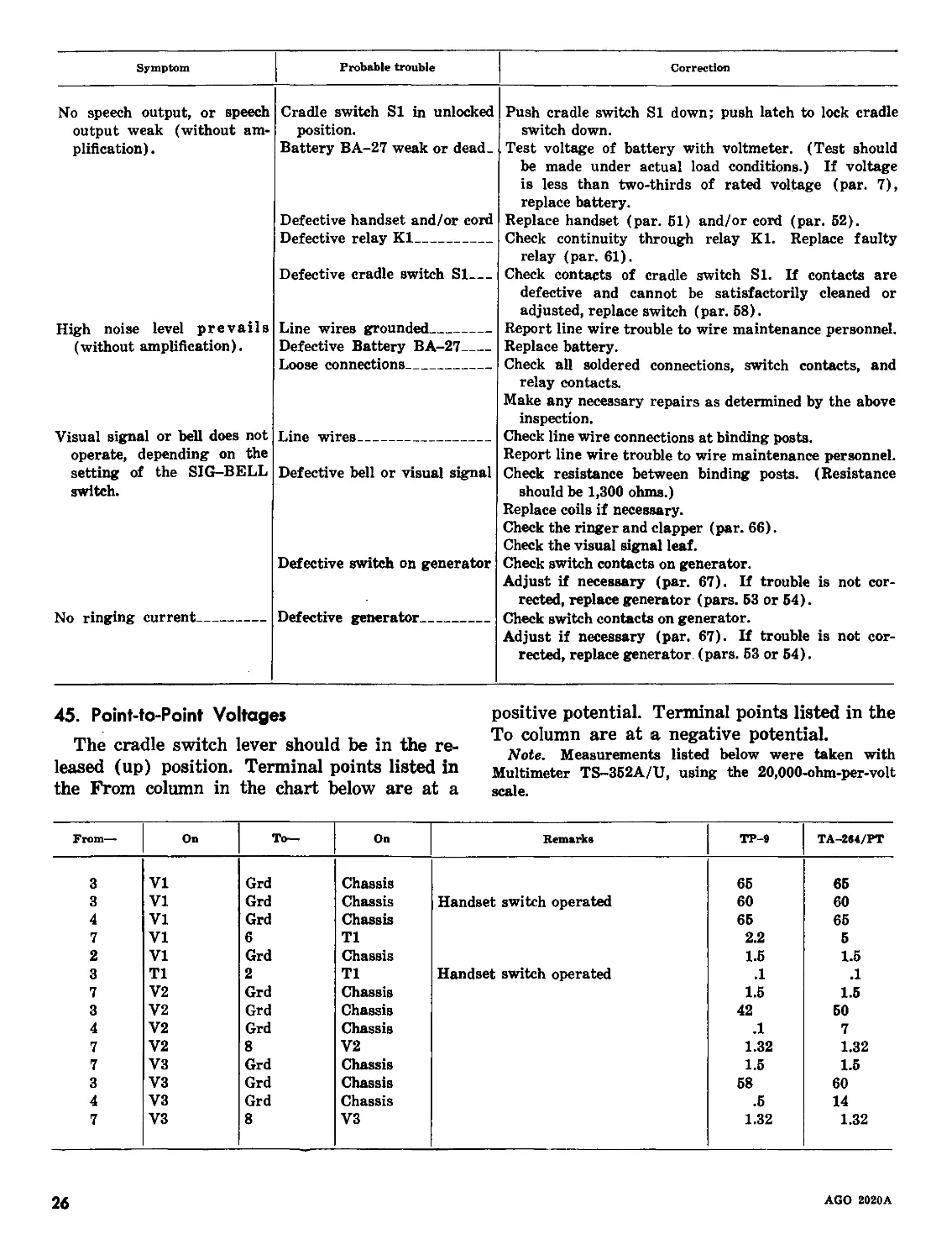
Symptom Probable trouble Correction
No speech output, or speech Cradle switch SI in unlocked Push cradle switch SI down; push latch to lock cradle
output weak (without am- position. switch down.
plification). Battery BA-27 weak or dead. Defective handset and/or cord Defective relay KI Defective cradle switch SI Test voltage of battery with voltmeter. (Test should be made under actual load conditions.) If voltage is less than two-thirds of rated voltage (par. 7), replace battery. Replace handset (par. 51) and/or cord (par. 52). Check continuity through relay KI. Replace faulty relay (par. 61). Check contacts of cradle switch Si. If contacts are defective and cannot be satisfactorily cleaned or adjusted, replace switch (par. 58).
High noise level prevails Line wires grounded Report line wire trouble to wire maintenance personnel.
(without amplification). Defective Battery BA-27 Loose connections Replace battery. Check all soldered connections, switch contacts, and relay contacts. Make any necessary repairs as determined by the above inspection.
Visual signal or hell does not operate, depending on the Line wires Check line wire connections at binding posts. Report line wire trouble to wire maintenance personnel.
setting of the SIG-BELL switch. Defective bell or visual signal Defective switch on generator Check resistance between binding posts. (Resistance should be 1,300 ohms.) Replace coils if necessary. Check the ringer and clapper (par. 66). Check the visual signal leaf. Check switch contacts on generator. Adjust if necessary (par. 67). If trouble is not cor- rected, replace generator (pars. 53 or 54).
No ringing current Defective generator Check switch contacts on generator. Adjust if necessary (par. 67). If trouble is not cor- rected, replace generator. (pars. 53 or 54).
45. Point-to-Point Voltages
The cradle switch lever should be in the re-
leased (up) position. Terminal points listed in
the From column in the chart below are at a
positive potential. Terminal points listed in the
To column are at a negative potential.
Note. Measurements listed below were taken with
Multimeter TS-352A/U, using the 20,000-ohm-per-volt
scale.
From— On To— On Remarks TP-2 TA-264/PT
3 VI Grd Chassis 65 65
3 VI Grd Chassis Handset switch operated 60 60
4 VI Grd Chassis 65 65
7 VI 6 Tl 2.2 5
2 VI Grd Chassis 1.5 1.5
3 Tl 2 Tl Handset switch operated .1 .1
7 V2 Grd Chassis 1.5 1.5
3 V2 Grd Chassis 42 50
4 V2 Grd Chassis .1 7
7 V2 8 V2 1.32 1.32
7 V3 Grd Chassis 1.5 1.5
3 V3 Grd Chassis 58 60
4 V3 Grd Chassis .5 14
7 V3 8 V3 1.32 1.32
26
AGO 2020A
AGO 2020A
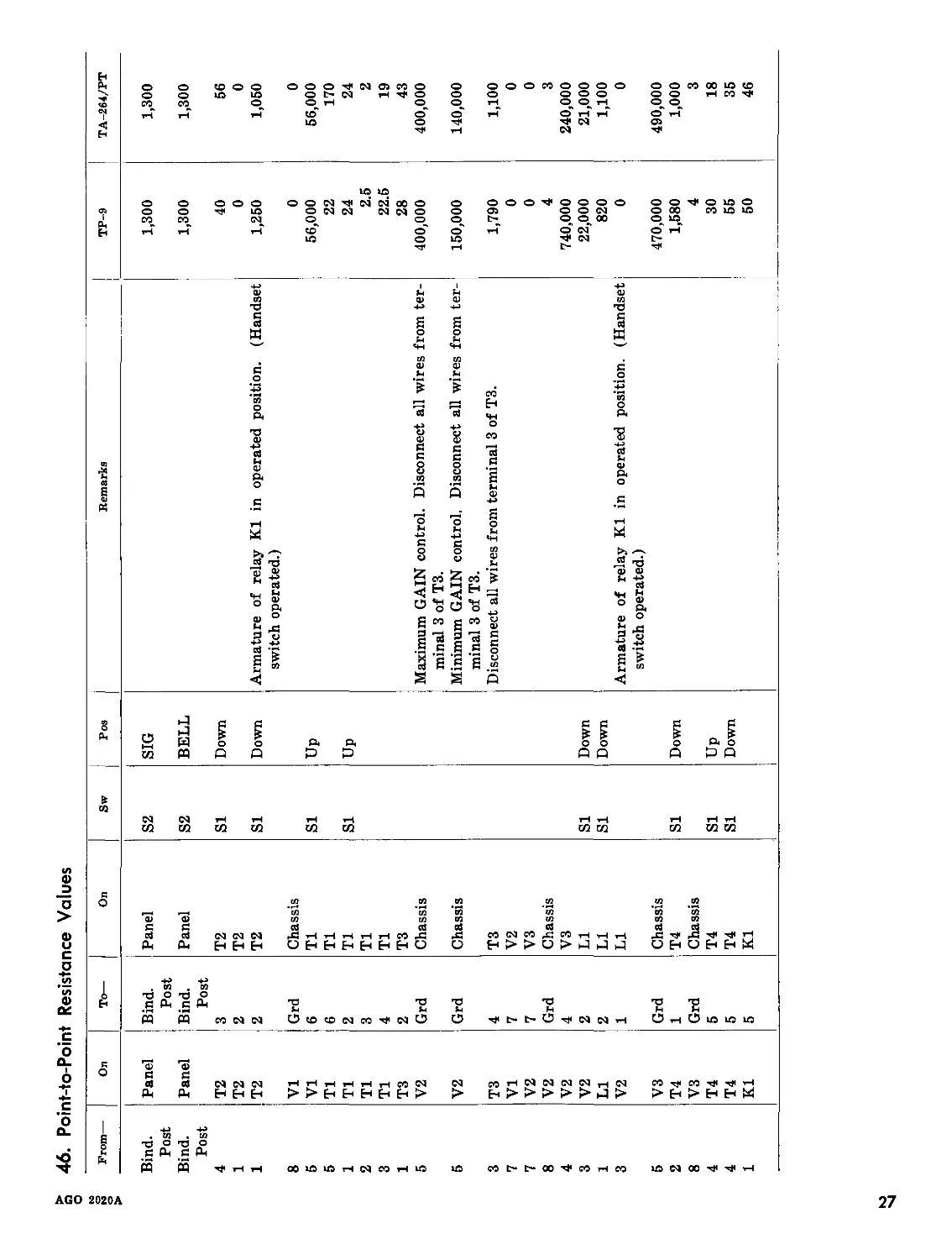
46. Point-to-Point Resistance Values
From— On To— On Sw Pos
Bind. Panel Bind. Panel S2 SIG
Post Post
Bind. Panel Bind. Panel S2 BELL
Post Post
4 T2 3 T2 SI Down
1 T2 2 T2
1 T2 2 T2 SI Down
8 VI Grd Chassis
5 VI 6 Tl SI Up
5 Tl 6 Tl
1 Tl 2 Tl SI Up
2 Tl 3 Tl
3 Tl 4 Tl
1 T3 2 T3
5 V2 Grd Chassis
5 V2 Grd Chassis
3 T3 4 T3
7 VI 7 V2
7 V2 7 V3
8 V2 Grd Chassis
4 V2 4 V3
3 V2 2 LI SI Down
1 LI 2 LI SI Down
3 V2 1 LI
5 V3 Grd Chassis
2 T4 1 T4 SI Down
8 V3 Grd Chassis
4 T4 5 T4 SI Up
4 T4 5 T4 SI Down
1 KI 5 KI
Remarks TP-9 TA-264/PT
1,300 1,300
1,300 1,300
40 56
0 0
Armature of relay KI in operated position. (Handset 1,250 1,050
switch operated.)
0 0
56,000 56,000
22 170
24 24
2.5 2
22.5 19
28 43
Maximum GAIN control. Disconnect all wires from ter- 400,000 400,000
minal 3 of T3.
Minimum GAIN control. Disconnect all wires from ter- 150,000 140,000
minal 3 of T3.
Disconnect all wires from terminal 3 of T3. 1,790 1,100
0 0
0 0
4 3
740,000 240,000
22,000 21,000
820 1,100
Armature of relay KI in operated position. (Handset 0 0
switch operated.)
470,000 490,000
1,580 1,000
4 3
30 18
55 35
50 46
Section II. REMOVAL AND REPLACEMENT
47. General
a. Most assemblies of the telephone should be
removed before they are dismantled for repairs.
This section describes the recommended pro-
cedure for removal and replacement of defective
parts for the telephone. It does not duplicate
information on preventive maintenance con-
tained in paragraphs 24 through 33. Except in
cases of extreme emergency, all removal and
replacement should be completed by personnel
thoroughly trained in telephone maintenance.
b. It may be necessary to unsolder connec-
tions to transformers, capacitors, resistors,
switches, and the gain control when they are
removed and replaced. When replacing appa-
ratus on any of the units, be careful not to drop
excess solder on other parts or wiring terminals.
Use only rosin-core solder. Avoid dll soldering
pastes or acids.
48. Removal and Replacement of Upper and
Lower Housing
It is necessary to remove the lower housing to
check, remove, and replace batteries and tubes;
to troubleshoot the amplifier circuits of the
telephone; and to remove and replace other
components of the telephone such as the bell,
generator, visual signal leaf coils, switches,
capacitors and resistors.
a. Removal.
(1) Place the telephone in the normal up-
right position on a work bench or other
suitable area.
(2) Loosen the four screws (two in front,
one on each side) that hold the two
housings together.
(3) Lift the upper housing (which con-
tains all of the components) from the
lower housing.
(4) Place the upper housing on the work
bench in an inverted manner (on its
top) so that the tubes and batteries
are up.
b. Replacement. Replace the housings by re-
versing the procedure outlined in a above.
49. Removal and Replacement of Battery Frame
(fig. 3)
a. Removal.
(1) Remove the lower housing (par. 48a).
(2) Disengage the two (one on each end)
hinge pins nearest the amplifier chas-
sis. Swing the battery frame up on
the remaining two hinge pins and away
from the tubes.
(3) Disconnect all battery connections to
battery terminal board (if batteries
are installed).
(4) Disengage the remaining two hinge
pins and remove the battery frame.
b. Replacement.
(1) Replace the battery frame by reversing
the procedure outlined in a (2) through
(4) above.
(2) Replace the lower housing (par. 486).
50. Removal and Replacement of Amplifier
Chassis
(fig. 3)
a. Removal.
(1) Remove the lower housing (par. 48a).
(2) Remove the (four) screws (two at
each end) that hold the amplifier
chassis to the battery-amplifier frame-
work attached to the casting. Remove
the amplifier chassis.
(3) Move the amplifier chassis aside and
unsolder all connections for a complete
removal of the amplifier chassis.
b. Replacement.
(1) Replace the amplifier chassis by re-
versing the procedure outlined in a (2)
and (3) above.
(2) Replace the lower housing (par. 486).
51. Removal and Replacement of Handset
(fig. 2)
a. Removal.
Note. The handset includes the cord.
(1) Place the telephone in the normal oper-
ating position, with the upper housing
cover open.
(2) Remove the cord fastener screw from
the jack assembly and remove the cord
fastener on Telephone Set ТА-264/
PT.
28
AGO 2020A
(3) Untie the stay cord from the fastener
on the jack assembly on Telephone
TP-9.
(4) Loosen the three screw terminals on
the jack assembly and remove the
handset, including cord.
b. Replacement. Replace the handset by re-
versing the removal procedure outlined in a
above.
52. Removal and Replacement of Handset Cord
a. Removal.
(1) Remove the handset and cord (par.
51a).
(2) Unscrew the transmitter cap and re-
move the transmitter unit.
(3) Loosen the three screws holding the
three conductors to the body of the
handset.
(4) Remove the cord fastener screw and
remove the cord.
b. Replacement. Replace the handset cord by
reversing the removal procedure outlined in a
above.
53. Removal and Replacement of Generator
GN-38-B (TP-9 Only)
(fig. 13)
a. Removal.
(1) Remove the lower housing (par. 48a)
and move the battery frame (par.
49a(2)).
(2) Remove the amplifier chassis (par.
50a(2)). Move the amplifier chassis
aside gently, so as not to break any
wires.
(3) Remove the four screws which hold the
generator to the top of the upper
housing.
(4) Move the generator to one side and
disengage the clutch plate which con-
nects the armature shaft to the gen-
erator crank.
(5) Lift the generator out of the housing.
(6) Remove the three screws which hold
the terminal lugs to the generator.
These are the only connections on the
generator.
Note. It is not necessary to remove the
waterproof bearing which holds the shaft of
the generator crank when removing the gen-
erator.
b. Replacement.
(1) Replace the generator by reversing the
removal procedure outlined in a(3)
through (6) above. Using an ohm-
meter, check to see that the generator
frame is not grounded to the housing.
Caution: Do not tighten the screws
too tightly. The threads in the alum-
inum castings are easily stripped.
(2) Replace the amplifier chassis (par.
506(1)).
(3) Replace the battery frame (par.
496(1)).
(4) Replace the lower housing (par. 486).
54. Removal and Replacement of Generator
G-42/PT (TA-264/PT Only)
a. Removal.
(1) Remove the lower housing (par. 48a)
and move the battery frame (par.
49a(2)).
(2) Remove the amplifier chassis (par.
50a (2)). Move the amplifier chassis
aside gently, so as not to break any
wires.
(3) Unsolder the leads from terminals 1,
2, and 3 on the generator.
(4) Remove the screw and washer from
the center of the generator hand wheel.
Remove the generator hand wheel.
(5) Remove the mounting nut and washer
that secure the generator to the hous-
ing.
(6) Slide the generator away from the
mounting portion of the housing and
remove it from the housing.
6. Replacement.
(1) Replace the generator by reversing the
removal procedure outlined in a(3)
through (6) above.
(2) Replace the amplifier chassis (par.
506(1)).
(3) Replace the battery frame (par.
496(1)).
(4) Replace the lower housing (par.
486).
AGO 2020A
29
Figure IS. Telephone TP-9, battery frame and amplifier chassis swung outward.
55. Removal and Replacement of Ringer
MC-131
(fig. 13)
a. Removal.
(1) Remove the lower housing (par. 48a)
and move the battery frame (par.
49a(2)).
(2) Remove the amplifier chassis (par.
50a(2)).
(3) Remove the two screws which hold the
ringer to the upper housing. Lift the
ringer out of the housing.
(4) Unsolder the wires connected to the
ringer.
b. Replacement.
(1) Replace the ringer by reversing the
removal procedure outlined in a(3)
and (4) above.
(2) Replace the amplifier chassis (par.
50b(l)).
(3) Replace the battery frame (par.
49b(1)).
(4) Replace the lower housing (par. 48b).
56. Removal and Replacement of SIG-BELL
Switch
(figs. 2 and 13)
a. Removal.
(1) Place the telephone in the normal oper-
ating position, with the upper housing
cover open.
(2) Loosen the setscrew in the knob on the
front panel and take the knob off
(fig. 2).
(3) Remove the nut (on the front panel)
which holds the switch to the housing.
30
AGO 2020A
Use a crescent wrench to remove this
nut, not pliers.
(4) Remove the lower housing (par. 48a)
and move the battery frame (par.
49a(2)).
(5) Remove the amplifier chassis (fig. 13
and par. 50a(2)).
(6) Carefully pull the SIG-BELL switch
out of the housing.
(7) Unsolder the three connections.
b. Replacement.
(1) Solder the three connections to the
proper terminals.
(2) Replace the SIG-BELL switch in the
housing. While holding the switch in
place, install the nut (on the front
panel) which holds the switch to the
housing.
(3) Replace the amplifier chassis (par.
506(1)).
(4) Replace the battery frame (par.
496(1)).
(5) Replace the lower housing (par. 486).
(6) Replace the knob on the switch and
tighten the setscrew.
57. Removal and Replacement of GAIN Con-
trol
(figs. 2 and 13)
a. Removal. Remove the GAIN control by
following the procedures given for the removal
of the SIG-BELL switch (par. 56a).
6. Replacement. Replace the GAIN control
by following the procedures given for the re-
placement of the SIG-BELL switch (par. 566).
58. Removal and Replacement of Cradle Switch
(figs. 2 and 13)
a. Removal.
(1) Place the telephone in the normal op-
erating position, with the upper hous-
ing cover open.
(2) Remove the two screws which hold the
cradle and latch to the housing (fig. 2).
Remove the cradle and latch.
(3) Remove the cradle switch lever set-
screw. Pull the lever off the shaft.
(4) Remove the nut (on the front panel)
which holds the switch to the housing.
Use a crescent wrench to remove this
nut, not pliers.
(5) Remove the lower housing (par. 48a)
and move the battery frame (par.
49a(2)).
(6) Remove the amplifier chassis (fig. 13
and par. 50a (2)).
(7) Carefully pull the cradle switch out of
the housing. On Telephones TP-9, the
cradle switch can be pulled out from
the housing much easier if Generator
GN-38-B is removed first (par. 53a).
(8) Unsolder the connections.
6. Replacement.
(1) Solder all connections.
(2) Replace the cradle switch in the hous-
ing. While holding the switch in place,
install the nut (on the front panel)
which holds the switch to the housing.
On Telephone TP-9, if the generator
has been removed, replace the gener-
ator (par. 536).
(3) Replace the amplifier chassis (par.
506(1)).
(4) Replace the battery frame (par.
496(1)).
(5) Replace the lower housing (par. 486).
(6) Place the telephone in the normal oper-
ating position, with the upper housing
cover open.
(7) Replace the cradle switch lever on the
shaft. Tighten the lever setscrew.
(8) Replace the cradle and latch on the
housing. Tighten the screws.
59. Removal and Replacement of Jack Assembly
(figs. 2 and 13)
a. Removal.
(1) Place the telephone in the normal
operating position, with the upper hous-
ing cover open (fig. 2).
(2) Remove the cord fastener screw and re-
move the cord fastener on Telephone
Set TA-264/PT. Untie the stay cord
from the fastener on Telephone TP-9
and remove (by unscrewing) the fast-
ener.
(3) Remove the four screws from the jack
cover. Remove the cover.
(4) Remove the lower housing (par. 48a)
and move the battery frame (par.
49a(2)).
(5) Place the telephone on its back.
AGO 2020A
31
(6) Hold each of the (three) screws (fig.
13), on the underside of the housing,
stationary while removing the (three)
screws from each of the (three) spring
contacts on the top of the jack assembly.
(7) Remove the jack assembly.
b. Replacement.
(1) Place the telephone on its back.
(2) Place the jack assembly in position on
the housing.
(3) Insert the (three) screws in the under-
side of the housing (fig. 13).
(4) Insert the (three) screws through the
spring contacts, through the (top of)
jack assembly, and into the three screws
which have been inserted in the under-
side of the housing. Tighten the
screws.
(5) Replace the battery frame (par.
496(1)) and lower housing (par. 486).
(6) Place the telephone in the normal
operating position, with the upper hous-
ing cover open (fig. 2).
(7) Replace the jack cover with the (four)
screws.
(8) Replace the stay cord fastener and stay
cord on Telephone TP-2. Replace the
cord fastener and cord on Telephone
Set TA-264/PT.
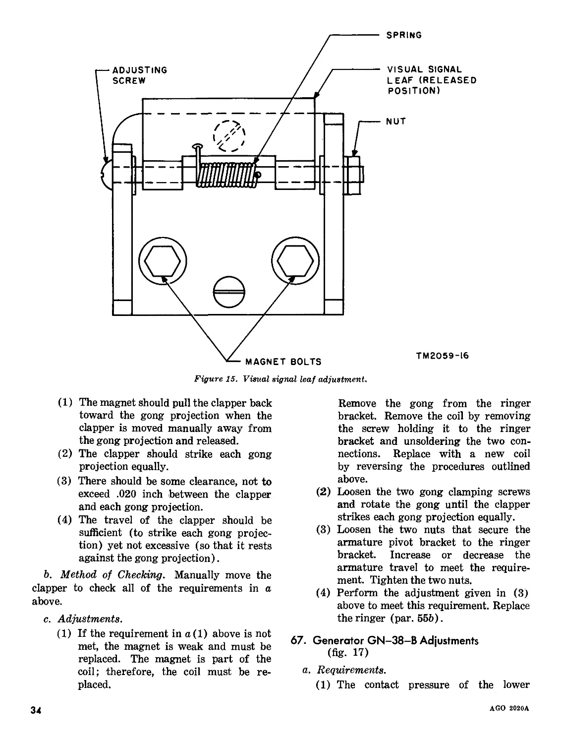
60. Removal and Replacement of Visual Signal
Leaf Coils
(fig. 13)
a. Removal.
(1) Remove the lower housing (par. 48a).
(2) Remove the amplifier chassis (par.
50a(2)).
(3) Place the telephone on its back.
(4) With the visual signal leaf in the re-
leased position, remove the two magnet
bolts.
(5) Withdraw the coils as far as possible
and unsolder the connections.
6. Replacement.
(1) Solder the three connections to the
proper terminals.
(2) With the telephone on its back, replace
the coils with the two magnet bolts.
(3) Replace the amplifier chassis (par.
506(1)).
(4) Replace the lower housing (par. 486).
61. Removal and Replacement of Relay, Choke
Coil, and Transformers
a. Removal.
(1) Remove the lower housing (par. 48a).
(2) Remove the amplifier chassis (par.
50a(2)).
(3) Loosen the two screws (one at each
end) located on top of the amplifier
chassis which holds the tube socket as-
sembly to the amplifier chassis.
(4) Open the tube socket assembly on its
hinge pins to reach the amplifier com-
ponents.
(5) Remove the two nuts to withdraw the
relay; remove the two screws to with-
draw any transformer or the choke coil.
(6) Unsolder the connections and remove
the component.
6. Replacement.
(1) Replace the relay, transformers, or
choke coil by reversing the removal pro-
cedure outlined in a(3) through (6)
above.
(2) Replace the amplifier chassis (par.
506(1)).
(3) Replace the lower housing (par. 486).
Section III. LUBRICATION AND ADJUSTMENTS
62. Recommended Lubricants
In general, lubrication as a field service is not
required. The moving parts of Generator GN-
42/PT (Telephone Set TA-264/PT) have been
lubricated during manufacture and do not require
subsequent lubrication. However, when Tele-
phone TP-9 is in a repair station for recondition-
ing, Generator GN-38-B should be lubricated
before it is put back in service. The only lubri-
cants recommended for the telephones are—
a. Oil, lubricating, preservative, special, Ord-
nance Stock No. 14-0-2834-10 (1 qt can).
6. Grease, aircraft and instruments, Federal
Stock No. 9150-261-8297 (8 oz container).
32
AGO 2020A
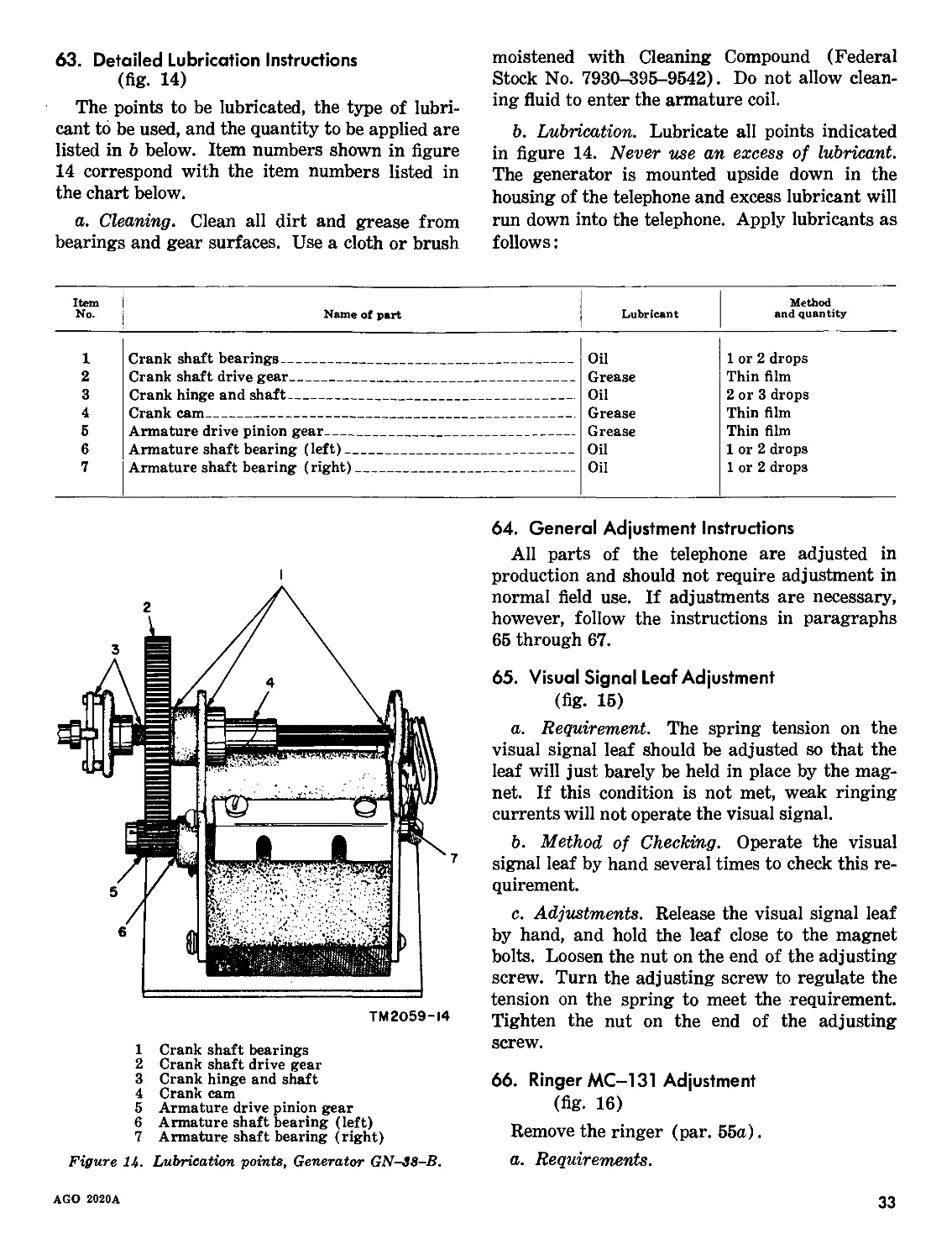
63. Detailed Lubrication Instructions
(fig. 14)
The points to be lubricated, the type of lubri-
cant to be used, and the quantity to be applied are
listed in b below. Item numbers shown in figure
14 correspond with the item numbers listed in
the chart below.
a. Cleaning. Clean all dirt and grease from
bearings and gear surfaces. Use a cloth or brush
moistened with Cleaning Compound (Federal
Stock No. 7930-395-9542). Do not allow clean-
ing fluid to enter the armature coil.
b. Lubrication. Lubricate all points indicated
in figure 14. Never use an excess of lubricant.
The generator is mounted upside down in the
housing of the telephone and excess lubricant will
run down into the telephone. Apply lubricants as
follows:
Item No. Name of part Lubricant Method and quantity
1 Crank shaft bearings Oil 1 or 2 drops
2 Crank shaft drive gear Grease Thin film
3 Crank hinge and shaft Oil 2 or 3 drops
4 Crank cam Grease Thin film
5 Armature drive pinion gear Grease Thin film
6 Armature shaft bearing (left) Oil 1 or 2 drops
7 Armature shaft bearing (right) Oil 1 or 2 drops
1 Crank shaft bearings
2 Crank shaft drive gear
3 Crank hinge and shaft
4 Crank cam
5 Armature drive pinion gear
6 Armature shaft bearing (left)
7 Armature shaft bearing (right)
Figure 14. Lubrication points, Generator GN-38-B.
64. General Adjustment Instructions
All parts of the telephone are adjusted in
production and should not require adjustment in
normal field use. If adjustments are necessary,
however, follow the instructions in paragraphs
65 through 67.
65. Visual Signal Leaf Adjustment
(fig. 15)
a. Requirement. The spring tension on the
visual signal leaf should be adjusted so that the
leaf will just barely be held in place by the mag-
net. If this condition is not met, weak ringing
currents will not operate the visual signal.
b. Method of Checking. Operate the visual
signal leaf by hand several times to check this re-
quirement.
c. Adjustments. Release the visual signal leaf
by hand, and hold the leaf close to the magnet
bolts. Loosen the nut on the end of the adjusting
screw. Turn the adjusting screw to regulate the
tension on the spring to meet the requirement.
Tighten the nut on the end of the adjusting
screw.
66. Ringer MC-131 Adjustment
(fig. 16)
Remove the ringer (par. 55a).
a. Requirements.
AGO 2020A
33
ADJUSTING
SCREW
NUT
VISUAL SIGNAL
LEAF (RELEASED
POSITION)
SPRING
Figure 15. Visual signal leaf adjustment.
TM2059-I6
(1) The magnet should pull the clapper back
toward the gong projection when the
clapper is moved manually away from
the gong projection and released.
(2) The clapper should strike each gong
projection equally.
(3) There should be some clearance, not to
exceed .020 inch between the clapper
and each gong projection.
(4) The travel of the clapper should be
sufficient (to strike each gong projec-
tion) yet not excessive (so that it rests
against the gong projection).
b. Method of Checking. Manually move the
clapper to check all of the requirements in a
above.
c. Adjustments.
(1) If the requirement in a(l) above is not
met, the magnet is weak and must be
replaced. The magnet is part of the
coil; therefore, the coil must be re-
placed.
Remove the gong from the ringer
bracket. Remove the coil by removing
the screw holding it to the ringer
bracket and unsoldering the two con-
nections. Replace with a new coil
by reversing the procedures outlined
above.
(2) Loosen the two gong clamping screws
and rotate the gong until the clapper
strikes each gong projection equally.
(3) Loosen the two nuts that secure the
armature pivot bracket to the ringer
bracket. Increase or decrease the
armature travel to meet the require-
ment. Tighten the two nuts.
(4) Perform the adjustment given in (3)
above to meet this requirement. Replace
the ringer (par. 556).
67. Generator GN-38-B Adjustments
(fig. 17)
a. Requirements.
(1) The contact pressure of the lower
34
AGO 2020A
CLAPPER
ARMATURE
TM2O59-I5
Figure 16. Ringer adjustment.
spring against the end of the armature
should be at least 100 grams (3.5
oz).
(2) The clearance between the two upper
springs should be at least .035 inch.
(3) The clearance between the buffer on
the crankshaft and the nearest spring
should be at least .025 inch when the
shaft is in its normal position.
(4) When the shaft is in the cranking po-
sition, the contact pressure between the
two upper springs should be between
75 grams (2.6 oz) and 125 grams
(4.4 oz).
b. Adjustments. All of the above require-
ments in a above are met by adjusting the springs
by bending them.
AGO 2020A
35
UNOPERATED CONDITION
UPPER
SPRING
OPERATED CONDITION
TM2O59-I7
Figure 17. Generator GN-38-B, contact spring adjustments.
Section IV. FINAL TESTING
68. Purpose of Final Testing
The tests described in this section are designed
to measure the performance capability of a re-
paired equipment. Equipment that meets the
minimum standards stated in the tests will fur-
nish satisfactory operation.
36
AGO 2020A
69. Test Equipment Required for Final Testing
The following equipment is required for final
testing of the telephones:
Test equipment Technical manual
Telephone Test Set AN/PTM-6 Test Set TS-140/PCM Electron Tube Test Set TV-2/U Attenuator TS-402/U Impedance matching transformer (Federal Stock No. 5950-570-6614). TM 11-2062. TM 11-2096. TM 11-2661. TM 11-2044.
70. Handset Test
a. Transmission. Connect the transmitter line
terminals (red and black leads) to the L1-L2
jack on Telephone Test Set AN/PTM-6. Set con-
trol DI at 3, D3 at 3, D5 at 1, and the equalizer to
the IN position. Precondition and locate the
transmitter element in accordance with para-
graph 24b (1) and (2), TM 11-2062. Operate
key 1 to LBPE, key 2 to RCT, key 7 to AC, and
key 8 to TRANS. Operate the handset switch,
then depress key 9. The reading of the meter Ml
should be to the right of —6 db. There should
be no output when the handset switch is released.
b. Reception. Connect the receiver line termi-
nals (red and white leads) to the L1-L2 jack on
Telephone Test Set AN/PTM-6. Set control D2
at 2, D4 at 6, D5 at 1, and the equalizer to the
OUT position. Locate the receiver element in ac-
cordance with paragraph 24c (1), TM 11-2062.
Operate key 1 to LBPE, key 2 to RCT, key 7 to
AC, key 8 to REC. Depress key 9. The reading
of meter Ml should be to the right of —4 db.
71. Generator, Ringer, and Insulation Tests
Note. All paragraph references contained herein are
to TM 11-2062, unless otherwise indicated.
a. Generator Test. Test the generator in ac-
cordance with paragraph 29. Turn the generator
crank at approximately 200 revolutions per min-
ute; the deflection of meter Ml should be to the
right of 0 db.
b. Ringer Test. Test the ringer in accordance
with paragraph 30b. Set control D5 at 1. Test
Ringer MC-131 with the SIG-BELL switch in
the BELL position and the visual signal leaf in-
dicator with the SIG-BELL switch in the SIG
position.
c. Insulation Resistance Test. Test the insula-
tion in accordance with paragraph 31. The
insulation resistance test must be made with the
handset cord and handset switch wired to the
handset, but with the transmitter and receiver
units removed. The deflection of meter Ml should
be to the left of —6 db.
72. Amplifier Test
(fig. 18)
An ear test for sound volume and tone quality
is the usual procedure for determining approxi-
mate amplifier gain and frequency response.
However, where a more accurate and dependable
test is required, proceed as described in a and b
below.
a. Transmitting Circuit.
(1) Install the batteries required for opera-
tion (par. 12).
(2) Disconnect the handset; allow the cradle
switch lever to rise.
(3) Connect Test Set TS-140/PCM and the
impedance matching transformer as
shown in A, figure 18. Refer to TM
11-2096 for complete instructions on
use of the TS-140/PCM.
(4) A signal input of —10 dbm as indicated
on the meter of Signal Generator SG-
15/PCM should produce an output on
Decibel Meter ME-22/PCM for the cor-
responding frequency as indicated be-
low:
Minimum output (dbm)
Frequency (cycles per second) TP-9 (serial No. below 9267) TP-9 (serial No. above 9266) and TA-264/PT
400 —2 +2
1,000 + 1 +5
2,000 +4 +8
3,500 +4 +8
b. Receiving Circuit.
(1) Perform steps in a (1) and (2) above.
(2) Set the GAIN control for maximum
gain.
AGO 2020A
37
(3) Connect Test Set TS-140/PCM and At-
tenuator TS—402/U as shown in B,
figure 18. Refer to TM 11-2044, At-
tenuators TS—402/U and TS-402A/U,
for complete instructions on use of TS-
402/U.
(4) A signal input of —70 dbm should pro-
duce an output on Decibel Meter ME-
22/PCM for the corresponding fre-
quency as indicated below—
Frequency (cycles per second) Minimum output (dbm)
400 —35
1,000 —13
2,000 —8
3,500 —16
(5) A signal input of —10 dbm at 1,000
cycles per second should produce an out-
put of —10 dbm, plus or minus —4 db.
TS-I40/PCM) TS-I40/PCM)
в
TM2059-20
Figure 18. Amplifier test setup.
38
AGO 2020A
CHAPTER 6
SHIPMENT AND LIMITED STORAGE AND DEMOLITION TO PREVENT ENEMY USE
Section I. SHIPMENT AND LIMITED STORAGE
73. Disassembly of Equipment
To disassemble the telephone for shipment or
storage, proceed as follows:
a. Remove the signal line connections and all
batteries from the battery compartment.
b. Mount the handset inside the cover to pre-
vent it from shifting during shipment. Close
the cover.
74. Repacking for Shipment and Limited Stor-
age
The exact procedure for repacking depends
on the material available and the conditions
under which the equipment is to be shipped or
stored. Use the original shipping container
(par. 10) or a suitable substitute. Reverse the
unpacking instructions (par. 10).
Section II. DEMOLITION OF MATERIEL TO PREVENT ENEMY USE
75. Authority for Demolition
Demolition of the equipment will be accom-
plished only upon the order of the commander.
The destruction procedures outlined in para-
graph 76 will be used to prevent further use
of the equipment.
76. Methods of Destruction
Use any of the following methods to destroy
the equipment:
a. Smash. Smash the controls, tubes, switches,
capacitors, and transformers; use sledges, axes,
handaxes, pickaxes, hammers, or crowbars.
b. Cut. Cut the handset cord and all other
wiring; use axes, handaxes, or machetes.
c. Bum. Burn the handset cord and technical
manuals; use gasoline, kerosene, oil, flame
throwers, or incendiary grenades.
d. Bend. Bend the upper housing and cover.
e. Explode. If explosives are necessary, use
firearms, grenades, or TNT.
f. Dispose. Bury or scatter the destroyed
parts in slit trenches, fox holes, or throw them
into streams.
AGO 2020A
39
RESISTOR COLOR CODE MARKING
(MIL-STD RESISTORS)
AXIAL-LEAD RESISTORS
(INSULATED)
RADIAL-LEAD RESISTORS
(UNINSULATED)
RC-COM POSITION
RZ-COMPOSITION
SECOND SIGNIFICANT
FIGURE
--------FIRST SIGNIFICANT FIGURE
(DOUBLE WIDTH SIGNIFIES
FIXED WIRE-WOUND
RESISTORS)
RU-WIRE-WOUND
FIGURE
RZ-COMPOSITION
RESISTOR COLOR CODE
BAND A OR BOOY* BAND В OR END* BAND C OR DOT OR BANO* BAND 0 OR ENO*
COLOR FIRST SIGNIFICANT FIGURE COLOR SECONO SIGNIFICANT FIGURE COLOR MULTIPLIER COLOR RESISTANCE TOLERANCE (PERCENT)
BLACK 0 BLACK 0 BLACK 1 BODY t 20
BROWN 1 BROWN 1 BROWN 10 SILVER ± 10
REO 2 RED 2 RED 100 GOLD ± 5
ORANGE 3 ORANGE 3 ORANGE 1,000
YELLOW 4 YELLOW 4 YELLOW 10,000
GREEN 5 GREEN 5 GREEN 100,000
BLUE 6 BLUE 6 BLUE 1,000,000
, PURPLE IVIOLET) 7 PURPLE (VIOLET) 7
GRAY S GRAY S GOLD 0.1
WHITE 9 WHITE 9 SILVER 0.01
* FOR WIRE-WOUND-TYPE RESISTORS, BAND A SHALL BE DOUBLE-WIDTH.
WHEN BODY COLOR IS THE SAME AS THE DOT (OR BAND) OR END COLOR,
THE COLORS ARE DIFFERENTIATED BY SHADE, GLOSS, OR OTHER MEANS.
EXAMPLES (BAND MARKING): EXAMPLES (BODY MARKING):
IO OHMS ±20 PERCENT: BROWN BAND A; BLACK BAND B; 10 OHMS ±20 PERCENT: BROWN BODY; BLACK END; BLACK DOT
BLACK BAND C; NO BAND D. OR BAND; BODY COLOR ON TOLERANCE END.
4.7 OHMS ±5 PERCENT: YELLOW BANO A; PURPLE BAND B) 3,000 OHMS ±10 PERCENT: ORANGE BODY, BLACK END; RED DOT
GOLD BAND C; GOLD BAND 0. OR BANO; SILVER END. STD-RI
Figure 19. MIL-STD resistor color code marking.
40
AGO 2020A
CAPACITOR COLOR CODE MARKING
(MIL-STD CAPACITORS)
TYPE INDICATOR *
FIRST SIGNIFICANT FIGURE
SECOND SIGNIFICANT FIGURE
INDICATOR
(READING DIRECTION)
DECIMAL MULTIPLIER**
TOLERANCE
CHARACTERISTIC
CHARACTERISTIC
MIL BUTTON-MICA—
IDENTIFIER (BLACK)
FIRST SIGNIFICANT FIGURE
SECOND SIGNIFICANT FIGURE
DECIMAL MULTIPLIER
CAPACITANCE TOLERANCE
BUTTON-MICA (CB)
FIRST SIGNIFICANT FIGURE-» ---SECOND SIGNIFICANT FIGURE
CHARACTERISTIC
* BLACK DOT: MICA DIELECTRIC
SILVER DOT: PAPER DIELECTRIC
**INDICATES NUMBER OF ZEROS ON PAPER TYPE.
MICA (CM) AND PAPER (CN)
-MIL IDENTIFIER
(BLACK DOT)
DECIMAL MULTIPLIER
CAPACITANCE TOLERANCE
INNER-ELECTRDDE’
TERMINAL
SECOND SIGNIFICANT FIGURE—
FIRST SIGNIFICANT FIGURE
TEMPERATURE------------
COEFFICIENT —
INNER- ------с=зс=
ELECTRODE TERMINAL L
DECIMAL MULTIPLIER
CAPACITANCE TOLERANCE
SECOND SIGNIFICANT FIGURE---
FIRST SIGNIFICANT FIGURE
TEMPERATURE
COEFFICIENT
INNER-ELECTRODE
TERMINAL
DECIMAL MULTIPLIER
CAPACITANCE TOLERANCE
NOTE:
SPOTS MAY BE USED INSTEAD OF BANDS; TEMPERATURE
COEFFICIENT MARKING IS LARGER.
FIRST SIGNIFICANT FIGURE
SECOND SIGNIFICANT FIGURE
DECIMAL MULTIPLIER
CAPACITANCE TOLERANCE
IBLACK SPOT)
NOTES:
I. SPOTS MAY BE USED ON TUBULAR CAPACITORS;
CHARACTERISTIC SPOT IS LARGER AND MIL IDENTIFIER
IS ON SIDE DIAMETRICALLY OPPOSITE COLOR SPOTS.
2. MIL IDENTIFIER OF DISK TYPE IS ON REVERSE SIDE;
CHARACTERISTIC SPOT IS LARGER OR SPACE BETWEEN
CHARACTERISTIC AND TOLERANCE SPOTS IS THREE
TIMES SPACE BETWEEN ADJACENT SPOTS.
3. TOLERANCE: YELLOW, +100%,-20% .
CERAMIC-TEMPERATURE COMPENSATING (CC)
CERAMIC-GENERAL PURPOSE (CK)
CAPACITOR COLOR CODE
COLOR SIG FIG. MULTIPLIER CHARACTERISTIC1 2 TOLERANCE 2 TEMPERATURE COEFFICIENT (UUF/UF/*C)
DECIMAL NUMBER OF ZEROS CM CN CB CK CM CN CB CC
OVER IOUUF IOUUF OR LESS CC
BLACK 0 1 NONE A 20 20 20 2D 2 ZERO
BROWN 1 10 1 В E в w 1 -30
RED 2 100 2 c H X 2 2 2 -so
ORANGE 3 1,000 3 0 J D 30 -150
YELLOW 4 10,000 4 E p -220
GREEN 5 5 F R 5 0.5 -330
BLUE 6 6 S -470
PURPLE (VIOLET) 7 7 T W -750
GRAY в в X 0.25 + 30
WHITE 9 9 10 1 -3301-500) 3
GOLD 0.1 5 5 + 100
SILVER D.DI 10 ID 10
I. LETTERS ARE IN TYPE DESIGNATIONS GIVEN IN MlL-C SPECIFICATIONS.
2. IN PERCENT, EXCEPT IN UUF FOR CC-TYPE CAPACITORS OF ID UUF OR LESS.
3. INTENDED FOR USE IN CIRCUITS NOT REQUIRING COMPENSATION.
Figure 20, MIL-STD capacitor color code marking.
AGO 2020A
41
NOTES
I UNLESS OTHERWISE INDICATED. RESISTANCES ARE IN OHMS,
CAPACITANCES ARE IN Ur
2 SWITCH SI IS SHOWN IN THE RELEASED (CRADLE SWITCH
LEVER UP) POSITION FOR AMPLIFICATION ROTATE SWITCH
si clockwise for operation without amplification
SEGMENTS OF WAFERS ARE IDENTIFIED В* X, Y. Z
TM2059-I5
AGO 202
Figure 21. Telephones TP-9 (serial numbers below 9267), schematic diagram.
AGO 2020A
NOTES.
co
ед-65
IOR 0A-35)
INOTE 6)
I UNLESS OTHERWISE INDICATED, RESISTANCES ARE IN OHMS,
CAPACITANCES ARE IN UF
2 SWITCH SI IS SHOWN IN THE RELEASED (CRADLE SWITCH
LEVER UP) POSITION FOR AMPLIFICATION ROTATE SWITCH
SI CLOCKWISE FOR OPERATION WITHOUT AMPLIFICATION
SEGMENTS OF WAFERS ARE IDENTIFIED BY X, Y, 2
з Isig-belTI switch S2 is shown in the (belli position.
4 г ~1 INDICATES EQUIPMENT MARKING
5 JACKS FOR HEAD AND CHEST SET USE.
6 BATTERIES REQUIRED FOR OPERATION.
7 PART OF TA-264/PT ONLY.
6 USED ON SOME TP-9 EQUIPMENTS BEARING SERIAL NUMBERS
ABOVE 5000
TM2O59-8
Figure 22. Telephones TP-9 {serial numbers above 9266) and Telephones Sets TA-26&/PT, schematic diagram.
24 RED-WHT
12 RED-BLK
IB BRN
22 RED
II RED
25 BRN
16 RED-WHT
23 GRN
17 GRN
12 BLK
18 BLK
22 BLK
24 BLK
19 REQ
24 RED
21 BLK
25 BRN
II GRN (NOTE 2)
22 GRN INOTE 2)
25 YEL INOTE I)
(NDTE I)
BRN 20
BRN 24
BLK 21
BLK 15
GRN II
INDTE 2)
GRN 22
BLU-YEL-13
BRN 18
BRN 16
BLU 14
BLU 22
QRN-BRN 23
QRN-BRN 13
5 ft)
м ft)
GRN 19
BLU 20
BLU 25
QRN-BRN 20
GRN 20
BLU 17
RED 22
BLK 21
YEL 17
REO-WHT 20
24 BLU
12 BLU
24 YEL
gO QRN-BRN
11 QRN-BRN
о - BRN 11
Ui BLU-YEL 19
A л BRN-GY 11
BLK !!
13 QRN-BRN
14 BRN
13 BRN
13 BRN-GY
19 GRN
19 RED
13 BLK
15 BLK
w V BRN II
' BRN 20
A-
0 0 'V
BLU 20
15 YEL
O-
0
0
(t-
GRN 16
V“- BLK (1
M BLU-YEL 12
BLK IS
м Ф
O-
GRN 15
O-
RED-WHT 20
RED 12
м BRN 20
-E BRN 14
RED-WHT 12
GRN 20
GRN 12
21 BLK
22 RED-BLK
15 BLU-YEL
16 RED
17 BLU
17 GRN
17 RED-WHT
R4
QRN-BRN1
BRN 2
BRN-GY 4
GRN 2
RED 2
BLK 4
RED-BLK 6
YEL 6
RED-BLK 6
BLU-YEL 4
RED-BLK 4
RED 4
BLU 2
GRN 4
RED-WHT 2
WHT 3
Figure 23. Telephones TP-9 and Telephone Sets TA-264/PT, wiring diagram.
В GRN
3 GRN
4 BRN
7 GRN
9 GRN
8 GRN
10 GRN
5 YEL
5 BLU-YEL
9 GRN —
4 BRN Ui
5 ORN-BRN м
co
BRN 7
BRN 10
RED 12
GRN 12
WHT I
QRN-BRN 3
BRN-GY II
CO fM M YEL 9
Q— ORN-BRN 10
BLU-YEL S
l> |ga!n| j CONTROL 0) RED-BLK |l
RED-BLK 12
YEL 11
II BRN
II GRN м м mi — —О । M м mi — 2 BATTERY TERMII
c 12 BLU M M Ml —
1 BLU-YEL —1 NAL В
12 RED-WHT A Ml- OARD
II RED П4-
4 YEL rJ-
INDEX
Paragraph Page
Additional equipment required----------- 7 5
Adjustment instructions, general-------- 64 33
Adjustments:
Generator GN-38-B--------------------- 67 34
Ringer MC-131_________________________ 66 33
Visual signal leaf-------------------- 66 33
Amplification:
Conversation with (operation)------ 18 9
Conversation without (operation)— 17 9
Theory:
General___________________________ 35 19
Receiving circuit with------------ 40 22
Receiving circuit without------ 37 19
Transmitting circuit with------ 39 21
Transmitting circuit without--- 38 19
Amplifier chassis, removal and replace- 50 28
ment.
Amplifier test, final______________________ 72 37
Arctic climates, operation_________________ 21 9
Authority for demolition___________________ 75 39
Battery frame, removal and replacement— 49 28
Battery operation, local___________________ 36 19
Break-in signal____________________________ 19 9
Characteristics, technical__________________ 4 3
Charts:
Point-to-point resistance_____________ 46 27
Point-to-point voltages____________ 45 26
Troubleshooting_______________________ 44 24
Chassis, amplifier, removal and replace- 50 28
ment.
Checking___________________________________ 11 6
Checklist, equipment performance________ 27 11
Choke coil, removal and replacement_____ 61 32
Circuits:
Receiving, with amplification______ 40 22
Receiving, without amplification___ 37 19
Signaling_____________________________ 41 23
Transmitting, with amplification___ 39 21
Transmitting, without amplification 38 19
Climates, operation:
Arctic________________________________ 21 9
Desert________________________________ 23 10
Tropical______________________________ 22 9
Coils, removal and replacement_____________ 60 32
Components__________________________________ 5 5
Connections________________________________ 13 8
Controls and control functions_____________ 14 8
Conversation with amplification____________ 18 9
Conversation without amplification______ 17 9
Cord, handset, removal and replacement___ 52 29
Cradle switch, removal and replacement--. 58 31
Paragraph Page
Demolition, authority______________________ 75 39
Description_________________________________ 6 5
Desert climates, operation_________________ 23 10
Destruction, methods----------------------- 76 39
Detailed lubrication instructions---------- 63 33
Differences in models----------------------- 8 5
Disassembly of equipment, shipment 73 39
and limited storage.
Equipment, disassembly, shipment 73 39
and limited storage.
Equipment performance checklist_________ 27 11
Equipment required, additional_________ . 7 5
Final testing:
Amplifier_____________________________ 72 37
Generator_____________________________ 71 37
Handset_______________________________ 70 37
Insulation____________________________ 71 37
Purpose_______________________________ 68 36
Ringer________________________________ 71 37
Test equipment required_______________ 69 37
Forms and records___________________________ 2 3
Function, controls_________________________ 14 8
Gain control, removal and replacement___ 57 31
General:
Adjustment instructions_______________ 64 33
Removal and replacement_______________ 47 28
Theory________________________________ 34 19
Troubleshooting_______________________ 42 24
Unusual operation_____________________ 20 9
Usual operation_______________________ 15 9
Generator, final test______________________ 71 37
Generator GN-38-B, adjustments__________ 67 34
Generator, removal and replacement:
G-42/PT_______________________________ 54 29
GN-38-B_______________________________ 53 29
Handset cord, reihoval and replacement__ 52 29
Handset, removal and replacement________ 51 28
Handset test, final________________________ 70 37
Housings, removal and replacement_______ 48 28
Inspection, visual_________________________ 31 16
Instructions, adjustment, general_______ 64 33
Insulation test, final_____________________ 71 37
Jack assembly, removal and 59 31
replacement.
Leaf adjustment, signal____________________ 65 33
Limited storage, repacking_________________ 74 39
Local battery operation____________________ 36 19
AGO 2020A
45
Paragraph Page
Localizing trouble----------------------- 43 24
Lower housing, removal and 48 28
replacement.
Lubricants, recommended_____________________ 62 32
Lubrication instructions, detailed------- 63 33
Maintenance:
Preventive (operator’s)_________________ 26 11
Preventive (second echelon)------------- 30 16
Scope of operator’s--------------------- 24 11
Scope of second echelon_________________ 28 16
Materials:
And tools (operator’s)___________________ 25 11
Tools and test equipment (second 29 16
echelon).
Methods of destruction______________________ 76 39
Models, differences-------------------------- 8 5
Operation:
Arctic climates------------------------- 21 9
Break-in signal------------------------- 19 9
Conversation with amplification------ 18 9
Conversation without amplification— 17 9
Desert climates------------------------- 23 10
General_________________________________ 15 9
Local battery--------------------------- 36 19
Signaling---------------------------- 16 9
Theory:
Amplification______________________ 35 19
General____________________________ 34 19
Local battery---------------------- 36 19
Receiving circuit with 40 22
amplification.
Receiving circuit without 37 19
amplification.
Signaling circuit------------------ 41 23
Transmitting circuit with 39 21
amplification.
Transmitting circuit without 38 19
amplification.
Tropical climates----------------------- 22 9
Types----------------------------------- 15 9
Operator’s:
Maintenance, scope---------------------- 24 11
Preventive maintenance------------------ 26 11
Tools and materials--------------------- 25 11
Performance checklist, equipment--------- 27 11
Point-to-point resistance values------------ 46 27
Point-to-point voltages--------------------- 45 26
Preparation for use------------------------- 12 6
Preventive maintenance (operator’s)------ 26 11
Scope___________________________________ 24 11
Tools and materials--------------------- 25 11
Preventive maintenance (second 30 16
echelon).
Scope___________________________________ 28 16
Tools, materials and test equip- 29 16
ment
Purpose and use------------------------------ 3 8
Purpose of final testing____________________ 68 36
Paragraph Page
Receiving circuit with amplification____ 40 22
Receiving circuit without amplifi- 37 19
cation.
Recommended lubricants___________________ 62 32
Records and forms__________________________ 2 3
Relay, removal and replacement____________ 61 32
Removal and replacement:
Amplifier chassis____________________ 50 28
Battery frame________________________ 49 28
Choke coil___________________________ 61 32
Cradle switch______________________ 58 31
GAIN control_______________________ 57 31
General______________________________ 47 28
Generator G-42/PT__________________ 54 29
Generator GN-38-B__________________ 53 29
Handset______________________________ 51 28
Handset cord_______________________ 52 29
Jack assembly________________________ 59 31
Relay________________________________ 61 32
Ringer MC-131________________________ 55 30
SIG-BELL switch____________________ 56 30
Transformers_________________________ 61 32
Upper and lower housings------------- 48 28
Visual signal leaf___________________ 60 32
Repacking for shipment and limited 74 39
storage.
Replacement, tube testing and_____________ 32 18
Ringer MC-131:
Adj astment__________________________ 66 33
Final test_________________________ 71 37
Removal and replacement-------------- 55 30
Second echelon maintenance______________ 28 16
Shipment and limited storage, 74 39
repacking.
SIG-BELL switch, removal and 56 30
replacement.
Signal leaf coils, visual, removal and 60 32
replacement.
Signaling (operation)_____________________ 16 9
Signaling circuit (theory)________________ 41 23
Siting------------------------------------- 9 6
Technical characteristics__________________ 4 3
Test equipment required for final 69 37
testing.
Test, final:
Amplifier-------------------------- 72 37
Generator-------------------------- 71 37
Handset______________________________ 70 37
Insulation___________________________ 71 37
Ringer------------------------------- 71 37
Testing, final, purpose___________________ 68 36
Tools and materials (operator’s)---------- 25 11
Tools, materials and test equipment_____ 29 16
Transformers, removal and replace- 61 32
ment.
Transmitting circuit with amplifi- 39 21
cation (theory).
Transmitting circuit without amplifi- 38 19
cation (theory).
46
AGO 2020A
Paragraph Page
Trouble, localizing..-------------------- 43 24
Troubleshooting chart---------------------- 44 24
Troubleshooting, using equipment 33 18
performance checklist.
Tube testing and replacement--------------- 32 18
Unpacking--------------------------------- 10 6
Upper and lower housings, removal 48 28
and replacement.
Paragraph Page
Use, preparation____________________________ 12 6
Use, purpose and_____________________________ 3 3
Values, resistance, point-to-point _________ 46 27
Visual inspection___________________________ 31 16
Visual signal leaf:
Adjustment------------------------------ 65 33
Coils, removal and replacement_______ 60 32
Voltages, point-to-point____________________ 45 26
By Order of the Secretaries of the Army and the Air Force :
Official :
HERBERT M. JONES,
Major General, United States Army,
The Adjutant General.
Official :
J. L. TARR,
Colonel, United States Air Force,
Air Adjutant General.
Distribution:
Active Army:
ASA
CNGB
Technical Stf, DA
Technical Stf Bd
USA Arty Bd
USA Armor Bd
USA Inf Bd
USA Air Def Bd
USA Abn & Elct Bd
USA Avn Bd
USA Armor Bd Test Sec
USA Air Def Bd Test Sec
USA Arctic Test Bd
USCONARC
US ARADCOM
OS Maj Comd
MDW
Armies
Corps
Div
USATC
Ft & Camp
Svc Colleges
Br Svc Sch
Gen Depots
Sig Sec, Gen Depots
Sig Depots
Fid Comd, AFSWP
Engr Maint Cen
Army Pictorial Cen
MAXWELL D. TAYLOR,
General, United States Army,
Chief of Staff.
THOMAS D. WHITE,
Chief of Staff, United States Air Force.
WRAMC
AFIP
AMS
Port of Emb (OS)
Trans Terminal Comd
Army Terminals
OS Sup Agcy
USA Sig Pub Agcy
USA Sig Comm Engr Agcy
USA Comm Agcy
TAS SA
USA White Sands Sig Agcy
Yuma Test Sta
USA Sig Eqp Spt Agcy
USA Elct PG
Sig Fid Maint Shops
Sig Lab
Mil Dist
JBUSMC
Mil Mis: Argentina: Cuba:
Ecuador
Units org under fol TOE:
5-315
5-316
6-100
6-101
6-200
6-201
6-225
6-226
AGO 2020A
47
6-300 11-127
6-301 11-128
6-315 11-500 (AA-AE)
6-316 11-557
6-325 11-587
6-326 11-592
6-401 11-597
6-415 19-27
6-416 39-61
6-501 44-7
6-515 44-15
6-525 44-16
6-545 44-17
6-558 44-25
6-575 44-27
6-576 44-35
6-577 44-36
6-635 44-37
8-15 44-70
8-16 44-90
8-17 44-101
8-18 44-112
10-17 44-115
10-377 44-116
11-7 44-201
11-15 44-275
11-16 44-276
11-18 44-315
11-57 44-316
11-95 44-415
11-97 44-416
NG: State AG; units—same as Active Army.
US AR: None.
For explanation of abbreviations used see AR 320-Б0.
AU. S. GOVERNMENT PRINTING OFFICE : 1958 О - 4 4 04 74 ( 5Z49-A)
48
AGO 2020A