/
Tags: radio
Year: 1954

Text
DEPARTMENT OF THE ARMY
TECHNICAL MANUAL
та и-ж
DEPARTMENT OF THE AIR
FORCE TECHNICAL ORDER
TELEPHONE
SET
TA-43/PT
DEPARTMENTS OF THE ARMY AND THE AIR FORCE
JULY 1951t
TAGO 272B—Jul
ТМ 11—337/ТО 16—35ТА43—5
Technical Manual DEPARTMENTS OF THE ARMY AND
No. 11-337 I THE AIR FORCE
Technical Order । Washington 25, D. C., 16 July 195 b
No. 16-35TA43-5 J
TELEPHONE SET TA-43/PT
Chapter L INTRODUCTION Paragraphs Page
Section I. General _ 1,2 3
II. Description and data _ 3-11 4
Chapter 2. OPERATING INSTRUCTIONS
Section I. Service upon receipt of equipment ...12-15 10
II. Controls - .. 16,'17 13
III. Operation under usual conditions —18-22 14
IV. Operation under unusual conditions. —23-30 15
Chapter 3. ORGANIZATIONAL MAINTENANCE
INSTRUCTIONS
Section I. Preventive maintenance services ...31-36 18
II. Lubrication and weatherproofing- ...37-38 23
III. Troubleshooting at organizational maintenance
level .39-42 24
Chapter 4. THEORY
Section I. Theory of components ...43-48 28
II. Circuit analysis. ... . . . ...49, 50 36
Chapter 5. FIELD MAINTENANCE INSTRUCTIONS
Section I. Troubleshooting at field maintenance level. ...51-57 41
II. Repairs ...58-62 46
III. Lubrication during repair ...63, 64 .. 65, 66 52 53
IV. Refinishing
V. Final testing ...67-69 53
Chapter 6. SHIPMENT AND LIMITED STORAGE AND
DEMOLITION to prevent enemy
USE ............................. 70-72
Index _________________________________________ ______ 57
TAGO 272B—Jul
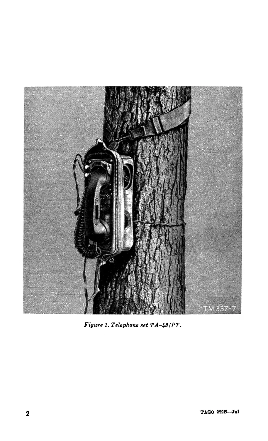
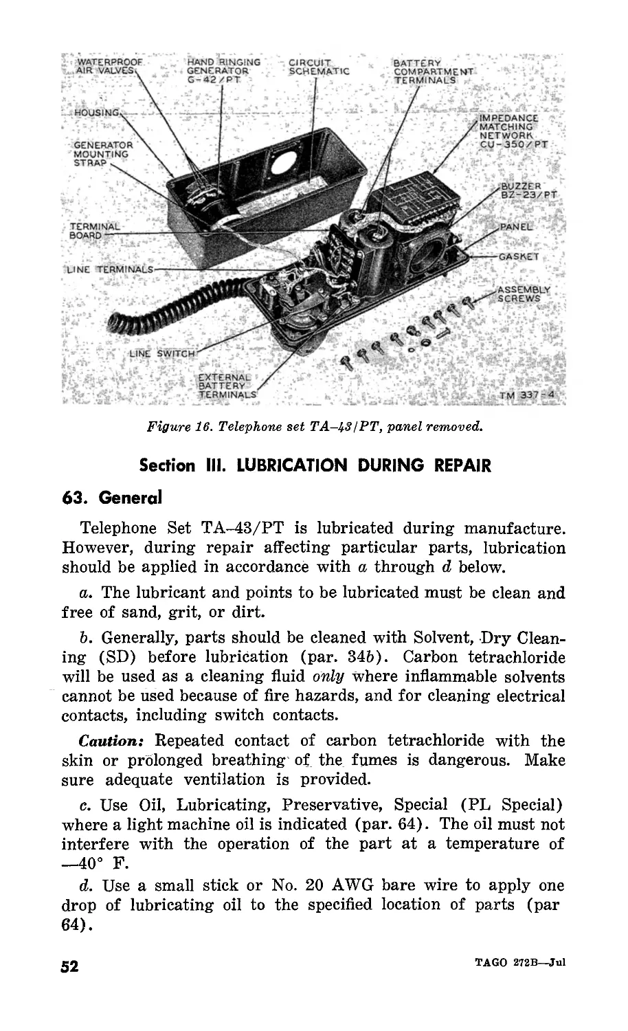
Figure 1. Telephone set ТА-ЬЗ/РТ.
2
TAGO 2T2B—Jul
CHAPTER 1
INTRODUCTION
Section I. GENERAL
1. Scope
This manual is published for the use of all concerned. It con-
tains information on the installation, operation, maintenance,
theory of operation, and repair of Telephone Set TA-43/PT.
2. Forms and Records
The following forms will be used for reporting unsatisfactory
conditions of army equipment and in performing preventive
maintenance.
a. DD Form 6, Report of Damaged or Improper Shipment, will
be filled out and forwarded as prescribed in SR 745-45-5 (Army),
Navy Shipping Guide, Article 1850-4, and AFR 71-4 (Air Force).
b.__DA Form 468, Unsatisfactory Equipment Report, will be
filled out and forwarded to the office of the Chief Signal Officer,
as prescribed in SR 700-45-5.
c. DD Form 535, Unsatisfactory Report, will be filled out and
forwarded to the Commanding General, Air Materiel Command,
Wright-Patterson Air Force Base, Dayton, Ohio, as prescribed in
SR 700-45-5 and AF TO 00-35D-54.
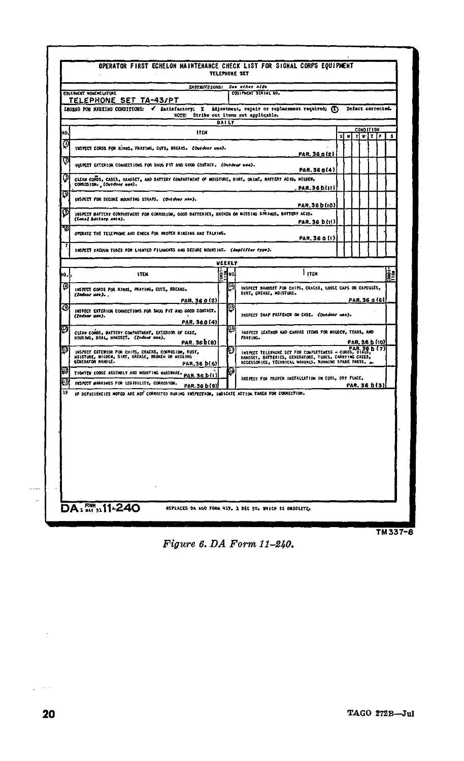
d. DA Form 11-240, Operator First Echelon Maintenance
Check List for Signal Corps Equipment (Telephone Set), will
be prepared in accordance wit hinstructions on the back of the
form (par. 35).
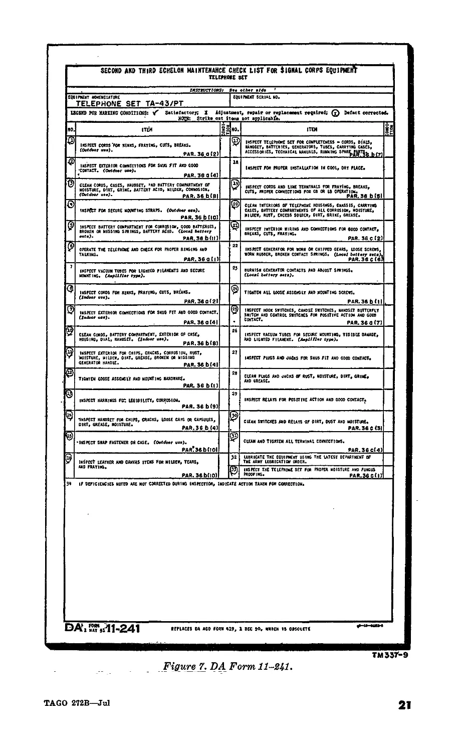
e. DA Form 11-241, Second and Third Echelon Maintenance
Check List for Signal Corps Equipment (Telephone Set), will be
prepared in accordance with instructions on the back of the form
(par. 35).
f. Use other forms and records as authorized.
TAGO 272B—Jul
3
Section II. DESCRIPTION AND DATA
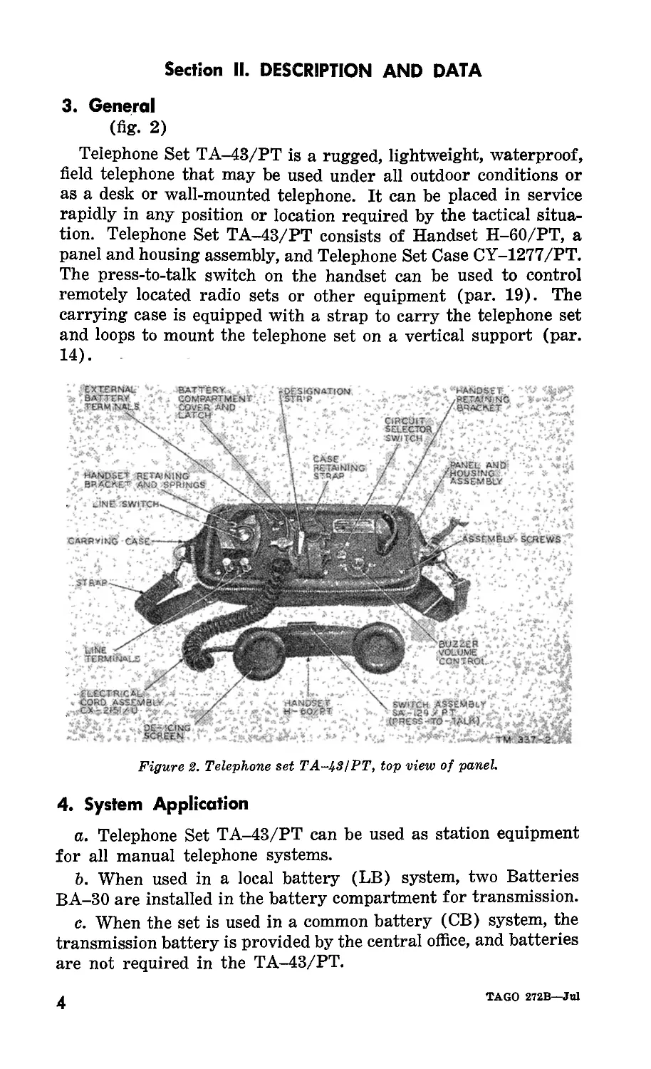
3. General
(fig. 2)
Telephone Set TA-43/PT is a rugged, lightweight, waterproof,
field telephone that may be used under all outdoor conditions or
as a desk or wall-mounted telephone. It can be placed in service
rapidly in any position or location required by the tactical situa-
tion. Telephone Set TA-43/PT consists of Handset H-60/PT, a
panel and housing assembly, and Telephone Set Case CY-1277/PT.
The press-to-talk switch on the handset can be used to control
remotely located radio sets or other equipment (par. 19). The
carrying case is equipped with a strap to carry the telephone set
and loops to mount the telephone set on a vertical support (par.
14).
DESIGNATION
UNS SWITCH.
ASSEMBLY
STRAP
ICING
1EEN-
CIRCUIT
SELECTOR
SWITCH >
BATTERY. - .
COMPARTMENT
COVER AMD
LATCH . • >
RETAINING
STRAP
HANDSET RETAINING
BRACKED and SPRINGS
EXTERNAL
BATTERY.
TERMINALS
HANDSET
,RE.TAfN‘NG
/BRACKET
HANDSET
W-fcOzRT
.PANEL AND
HOUSING ;
ASSEMBLY
LINE
TERMINALS
SWITCH ASSEMBLY
SA-129 7 ,
XPRESS-ТО-Л^ЬЙ).
BUZZER
Is ‘ VOLUME J
‘CONTROL
CARRYING CASE
SCREWS
Figure 2. Telephone set ТА~^31РТ, top view of panel.
4. System Application
a. Telephone Set TA-43/PT can be used as station equipment
for all manual telephone systems.
b. When used in a local battery (LB) system, two Batteries
BA-30 are installed in the battery compartment for transmission.
c. When the set is used in a common battery (CB) system, the
transmission battery is provided by the central office, and batteries
are not required in the TA-43/PT.
4
TAGO 272B—Jul
5. Technical Characteristics
a. Types of circuits in the set are as shown below.
Circuit selector switch setting Type of service
CB Common battery talk and common battery signaling.
LB Local battery talk and hand ringing generator signaling.
CBS Local battery talk and common battery signaling.
b. The special features of Telephone Set TA-43/PT are shown
below.
Altitude limits—.................Will operate above 10,000 feet and dur-
ing descent from 1,500 feet as rapid
as 50 feet per second.
Water protection.. ............. Splashproof: may be immersed in shal-
low water for short periods of time.
Gun blast protection............ Transmitter and receiver elements can
withstand severe acoustic shock.
Temperature limits:
Storage (without batteries)_—80° F. to +160° F.
Operation—40° F. to -4-131° F.
Transmission frequency range_300 cps to 3,200 cps.
c. The maximum distance for efficient operation between two
Telephone Sets TA-43/PT depends primarily on the type of
conductors used. The table below lists the line description, type
or gage of wire, and transmission range (miles). This table may
be used to approximate operational distances between two Tele-
phone Sets TA-43/PT.
Line description Type or gage Transmission range (miles)
Wet Dry
Field wire...... WD-l/TT . 14 22
Field wire WD-14/TT ... Loaded Nonloaded
Spiral-4 cable CC-358 . 14 48 22
Spiral-4 cable. CC-368 ... .. 27
Spiral-4 cable. CX-1065/G 50 29
5 pair cable. . CX-162/G 23
Lead covered cable. 19 gage.. .... 30
Lead covered cable 22 gage .... 20
Lead covered cable.. 24 gage 15
Open wire lines W-2 #14 AWG copper 230
Open wire lines W-74 #12 AWG copper.. — 520
Note. The transmission ranges in this table are from station to station.
Intermediate switchboards do not increase these limits.
TAGO 272B—Jul
5
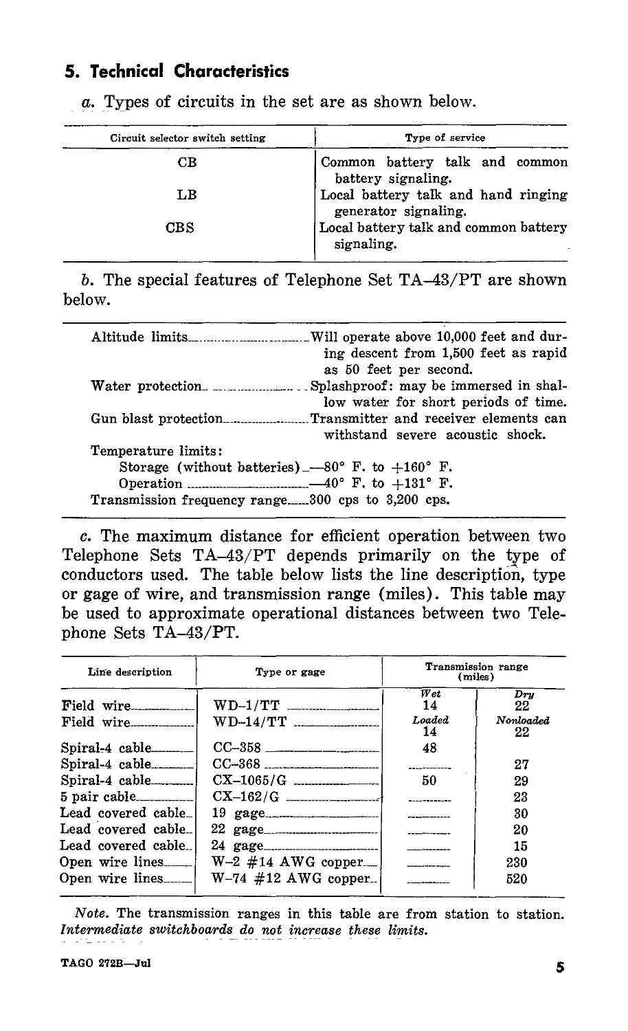
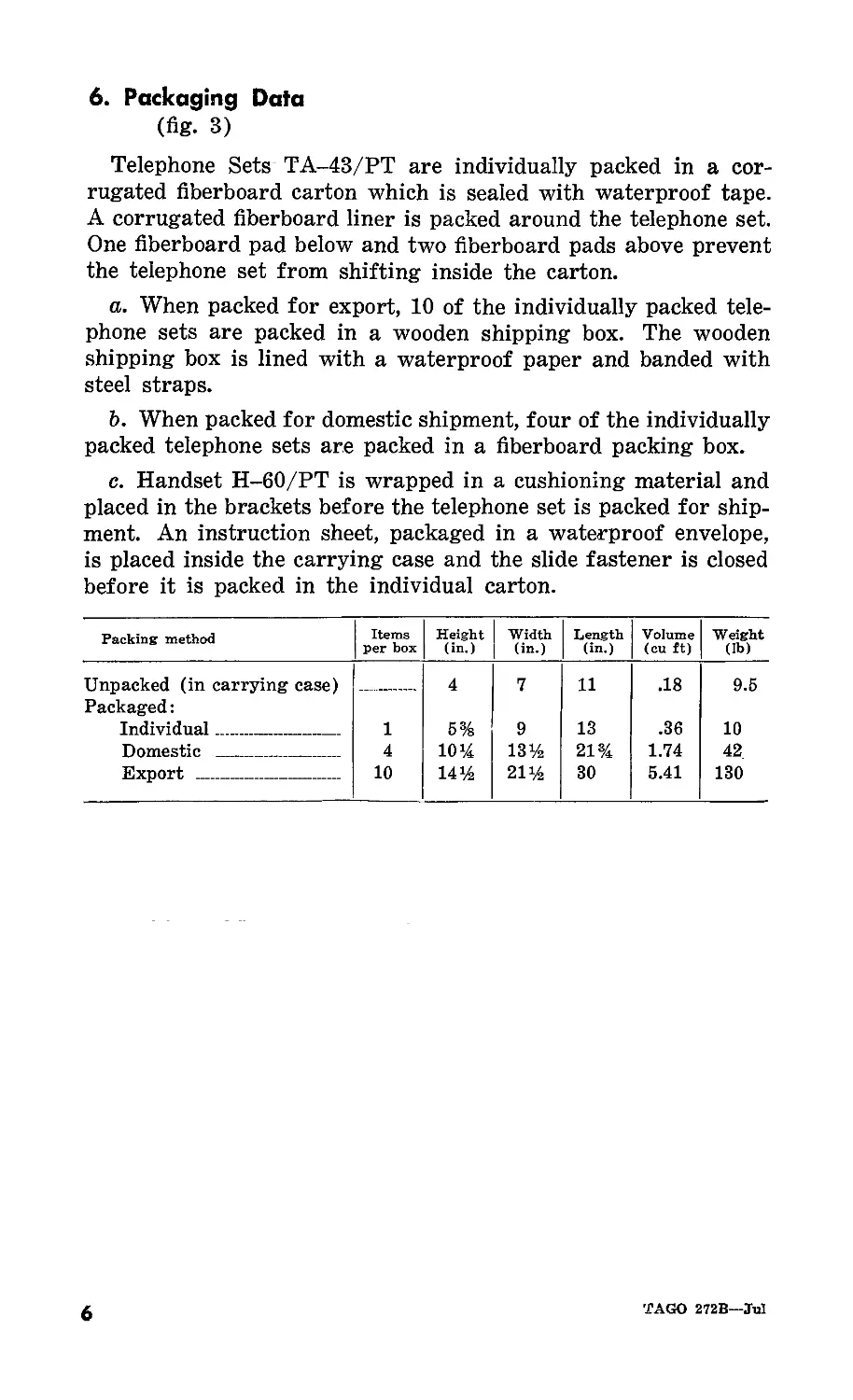
6. Packaging Data
(fig. 3)
Telephone Sets TA-43/PT are individually packed in a cor-
rugated fiberboard carton which is sealed with waterproof tape.
A corrugated fiberboard liner is packed around the telephone set.
One fiberboard pad below and two fiberboard pads above prevent
the telephone set from shifting inside the carton.
a. When packed for export, 10 of the individually packed tele-
phone sets are packed in a wooden shipping box. The wooden
shipping box is lined with a waterproof paper and banded with
steel straps.
b. When packed for domestic shipment, four of the individually
packed telephone sets are packed in a fiberboard packing box.
c. Handset H-60/PT is wrapped in a cushioning material and
placed in the brackets before the telephone set is packed for ship-
ment. An instruction sheet, packaged in a waterproof envelope,
is placed inside the carrying case and the slide fastener is closed
before it is packed in the individual carton.
Packing method Items per box Height (in.) Width (in.) Length (in.) Volume (cu ft) Weight (lb)
Unpacked (in carrying case) Packaged: — 4 7 11 .18 9.5
Individual 1 5% 9 13 .36 10
Domestic 4 10% 13% 21% 1.74 42
Export 10 14% 21% 30 5.41 130
6
TAGO 272B—Jul
Figure 3. Packaging diagram for telephone set ТА-ЬЗ/РТ.
7. Table of Major Components
Component Height (in.) Width (in.) Length (in.) Weight (lb.)
Handset H-60/PT 2 2 7 1.5
Panel and housing assembly .. 2.5 6 10 7
Telephone Set Case .. - CY-1277/PT. 4 - 7 11 1
Note. This list is for general information only. See appropriate publications
for information pertaining to requisition of spare parts.
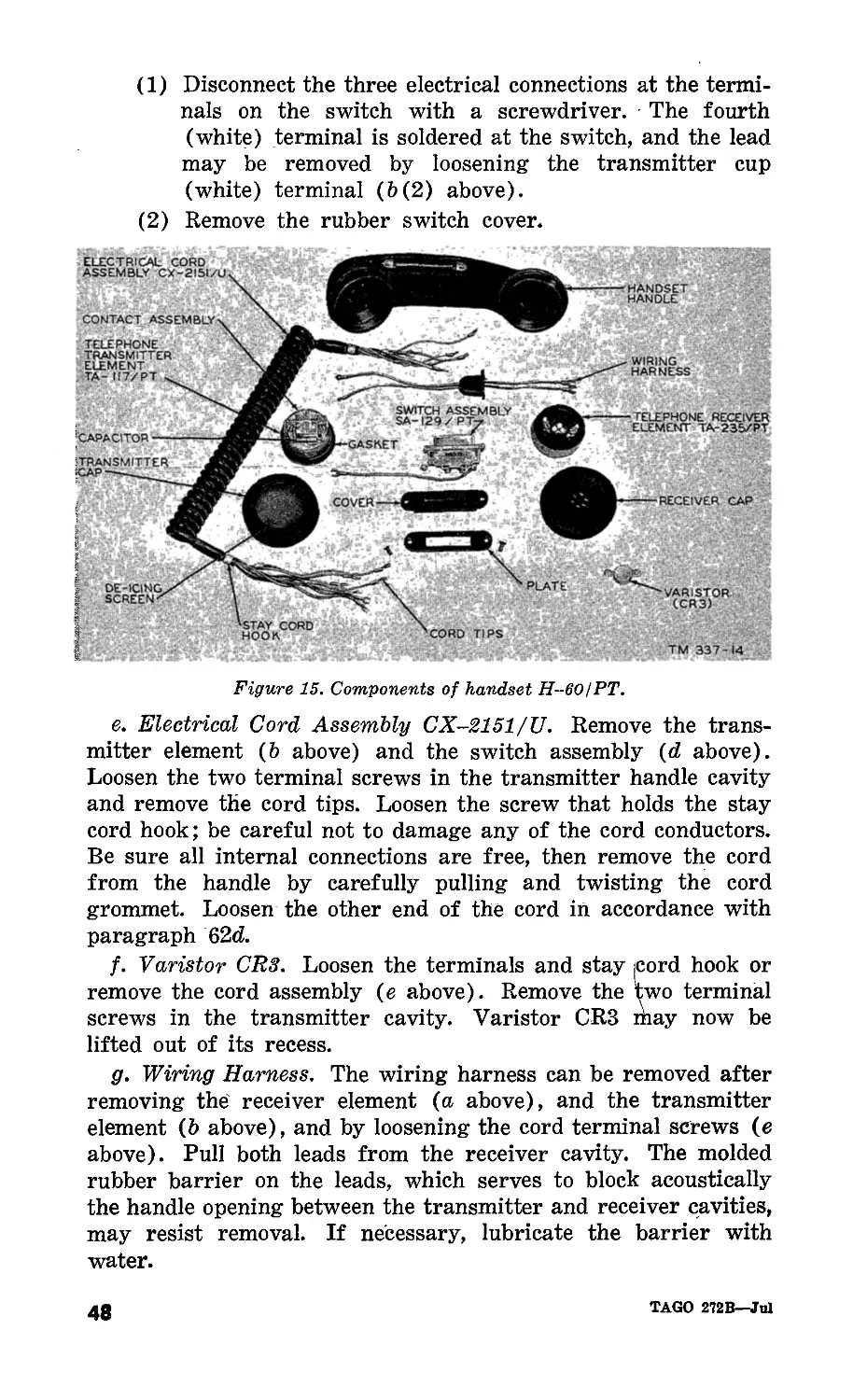
8. Description of Handset H-60/PT
Handset H-60/PT contains a dull-finished, black plastic handle
with convenient mounting spaces for the transmitter, receiver,
and press-to-talk switch. The receiver end of the handle is shaped
TAGO 272B—Jul
7
so that it will fit under a standard field helmet. Terminals are
provided inside the transmitter compartment for connecting the
coiled handset cord to the handset. A de-icing screen is provided
to prevent ice from forming on the transmitter when the handset
is used in subfreezing temperatures.
9. Panel and Housing Assembly
The panel and housing assembly contains all of the circuit
components and wiring for the telephone. The underside of the
panel (cover) is used to mount all of the components except the
hand ringing generator, mounted in the side of the housing. The
upperside of the panel is used to mount all of the controls required
for the operation of the telephone set. A bracket is mounted at
each end of the panel to hold the handset when it is not in use.
All of the openings in the panel and the housing are gasketed and
the assembly is submersionproof.
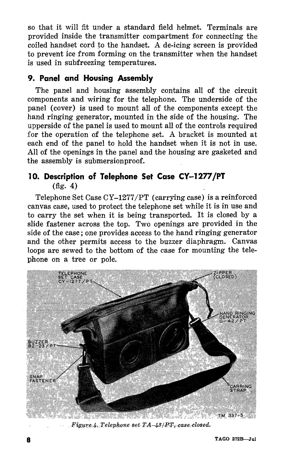
10. Description of Telephone Set Case CY-1277/PT
(fig- 4)
Telephone Set Case CY-1277/PT (carrying case) is a reinforced
canvas case, used to protect the telephone set while it is in use and
to carry the set when it is being transported. It is closed by a
slide fastener across the top. Two openings are provided in the
side of the case; one provides access to the hand ringing generator
and the other permits access to the buzzer diaphragm. Canvas
loops are sewed to the bottom of the case for mounting the tele-
phone on a tree or pole.
8
TAGO 272B—Jul
11. Description of Minor Components
Item Fig. ref. Description
Hand Ringing Generator G-42/PT Buzzer BZ-23/PT Impedence Matching Network CU-350/PT Line switch CB-LB-CBS switch Electrical Cord Assembly CX-2151/U 4 4 4 4 3 2 Provides 20-cps signaling current. Provides audible incoming signal. Houses circuit components. Connects telephone to line. 3-position rotary switch for cir- cuit selection. 7-conductor, retractile handset cord.
TAGO 272B—Jul
9
CHAPTER 2
OPERATING INSTRUCTIONS
Section I. SERVICE UPON RECEIPT OF EQUIPMENT
12. Unpacking and Checking New Equipment
a. Export Shipment (fig. 3). To unpack the export packed
telephone sets follow the instructions in (1) through (7) below.
(1) Cut and remove the metal Strapping if the box is
strapped.
(2) Remove the nails from the lid with a nail puller, and lift
the lid.
(3) Cut or tear the top from the waterproof liner inside the
wooden box.
(4) Remove the individually packed telephone sets from the
box.
(5) Cut or tear the sealing tape on the top of the individual
corrugated fiberboard container and open the top flaps.
(6) Remove the two pads from the top of the telephone set.
(7) Remove the telephone set from the container and check
it as described in paragraph 13.
b. Domestic Shipment (fig. 3) To unpack the domestic packed
telephone sets, open the top flaps of the packing box by cutting
or tearing the sealing tape. Tq complete the unpacking of the
TA-43/PT, refer to a (4) through (7) above.
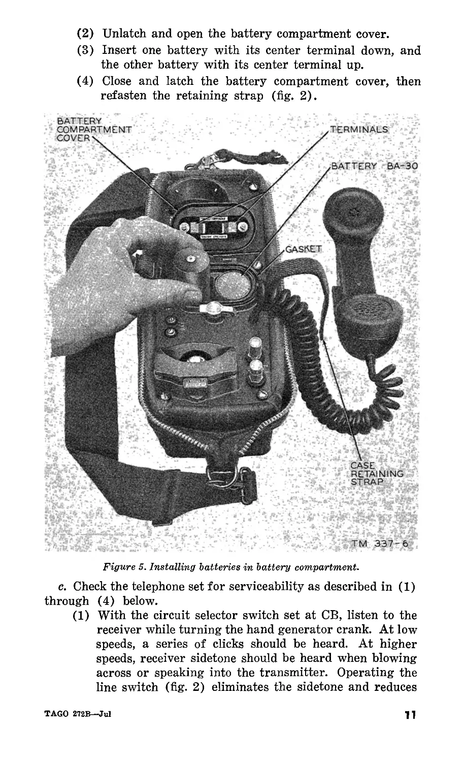
13. Preinstallation Checks
(fig. 5)
a. Open the carrying case by sliding the fastener to the end
of its run. Remove the handset from its packing. Fold the top
of the case down around the housing to expose the handset and
panel, without obstructing the generator and buzzer openings
on the side of the housing.
b. Install two batteries BA-30 as described in (1) through (4)
below.
(1) Loosen the retaining strap that secures the panel and
housing assembly.
10
TAGO 272B—Jul
(2) Unlatch and open the battery compartment cover.
(3) Insert one battery with its center terminal down, and
the other battery with its center terminal up.
(4) Close and latch the battery compartment cover, then
refasten the retaining strap (fig. 2).
Figure 5. Installing batteries in battery compartment.
c. Check the telephone set for serviceability as described in (1)
through (4) below.
(1) With the circuit selector switch set at CB, listen to the
receiver while turning the hand generator crank. At low
speeds, a series of clicks should be heard. At higher
speeds, receiver sidetone should be heard when blowing
across or speaking into the transmitter. Operating the
line switch (fig. 2) eliminates the sidetone and reduces
TAGO 272B—Jul
11
the turning force required to turn the generator crank by
removing the electrical load on the generator.
(2) With the circuit selector switch set at LB, push the
handset press-to-talk switch (fig. 2). Receiver sidetone
should be heard when blowing across or speaking into
the transmitter. Releasing the press-to-talk switch elimi-
nates the sidetone and also reduces the turning force
required to turn the generator crank;
(S) With the circuit selector switch set at CBS, repeat the
checks for the LB circuit ((2) above). Operating the
handset press-to-talk switch should not affect the opera-
tion of the generator, but depressing the line switch
should reduce the turning force required to turn the
generator crank.
(4) With the handset mounted in the retaining brackets,
connect the line terminals to the corresponding terminals
of another telephone set or an equivalent source of signal-
ing power. The buzzer of the telephone set should respond
to the signaling power of the other set or power source
The volume should vary from a low buzz to a loud signal
as the buzzer volume control knob is turned from LOW
to LOUD.
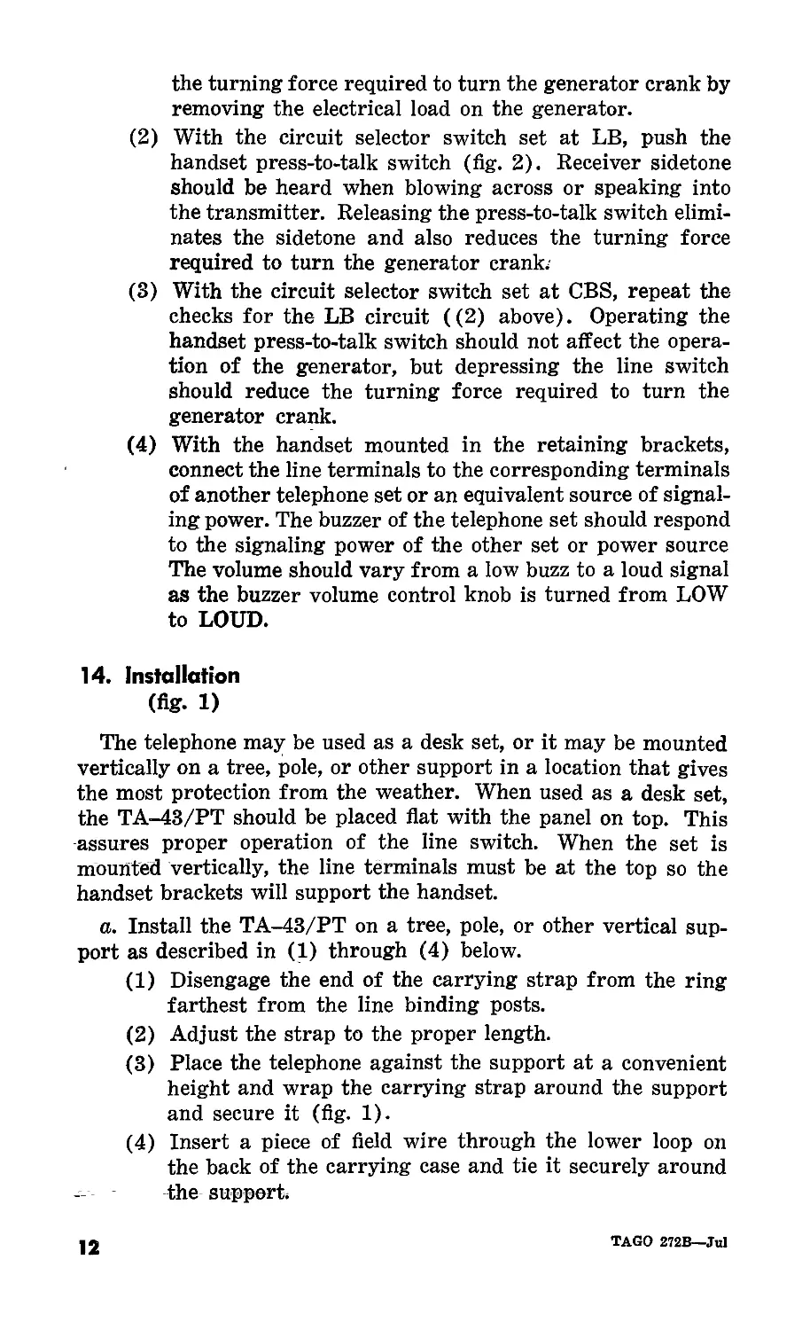
14. Installation
(fig. 1)
The telephone may be used as a desk set, or it may be mounted
vertically on a tree, pole, or other support in a location that gives
the most protection from the weather. When used as a desk set,
the TA-43/PT should be placed flat with the panel on top. This
assures proper operation of the line switch. When the set is
mounted vertically, the line terminals must be at the top so the
handset brackets will support the handset.
a. Install the TA-43/PT on a tree, pole, or other vertical sup-
port as described in (1) through (4) below.
(1) Disengage the end of the carrying strap from the ring
farthest from the line binding posts.
(2) Adjust the strap to the proper length.
(3) Place the telephone against the support at a convenient
height and wrap the carrying strap around the support
and secure it (fig. 1).
(4) Insert a piece of field wire through the lower loop on
the back of the carrying case and tie it securely around
the support.
12
TAGO 272B—Jul
b. Remove the insulation from the incoming pair of wires and
connect to binding posts marked LINE 1 and 2 as described in
(1) through (5) below.
(1) Remove approximately 1 inch of insulation from each
of the wires.
(2) Fold the skinned portion of the wires back one-half of
an inch.
(3) Push down the spring-loaded binding post marked LINE
1 and insert the folded bare skinner of one wire into
the slot in the binding post.
(4) Release the binding post to allow the wire to be securely
clamped.
(5) Repeat the procedure described in (3) and (4) above
to connect the other wire to binding post LINE 2.
c. Make the proper circuit selection for common battery, local
battery, or common battery signaling with local battery talking
by adjusting the circuit selector switch. When the circuit selector
switch is in the LB or CBS positions, install two Batteries BA-30
properly poled (one up and one down) in the battery compartment
to provide transmission current.
15. Service Upon Receipt of Used or Reconditioned Equipment
a. Follow the instructions in paragraph 12 for unpacking and
checking equipment.
b. Check the controls for positive action.
c. Perform the installation procedures in paragraphs 13 and
14.
Section II. CONTROLS
Note. The various controls and instruments for the proper operation of
the equipment are described, located, and illustrated in this section. It also
gives the operator enough information to operate the controls.
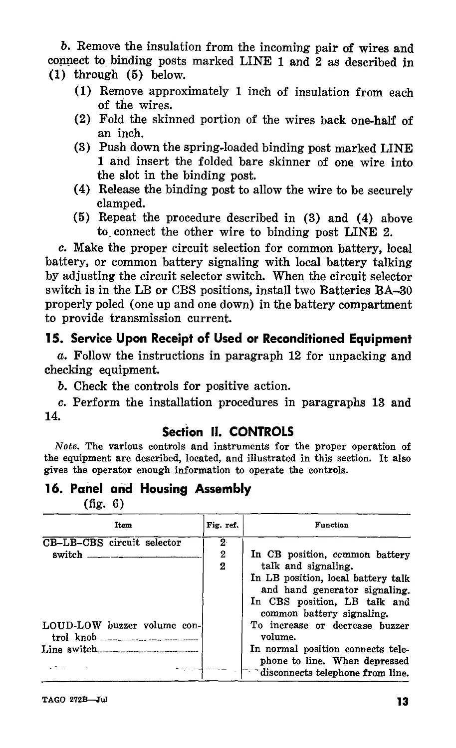
16. Panel and Housing Assembly
(fig. 6)
Item Fig. ref. Function
CB-LB-CBS circuit selector switch LOUD-LOW buzzer volume con- trol knob Line switch 2 2 2 In CB position, common battery talk and signaling. In LB position, local battery talk and hand generator signaling. In CBS position, LB talk and common battery signaling. To increase or decrease buzzer volume. In normal position connects tele- phone to line. When depressed disconnects telephone from line.
TAGO 272B—Jul
13
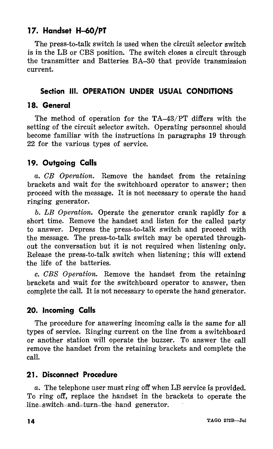
17. Handset Н-60/РТ
The press-to-talk switch is used when the circuit selector switch
is in the LB or CBS position. The switch closes a circuit through
the transmitter and Batteries BA-30 that provide transmission
current.
Section III. OPERATION UNDER USUAL CONDITIONS
18. General
The method of operation for the TA-43/PT differs with the
setting of the circuit selector switch. Operating personnel should
become familiar with the instructions in paragraphs 19 through
22 for the various types of service.
19. Outgoing Calls
a. CB Operation. Remove the handset from the retaining
brackets and wait for the switchboard operator to answer; then
proceed with the message. It is not necessary to operate the hand
ringing generator.
b. LB Operation. Operate the generator crank rapidly for a
short time. Remove the handset and listen for the called party
to answer. Depress the press-to-talk switch and proceed with
the message. The press-to-talk switch may be operated through-
out the conversation but it is not required when listening only.
Release the press-to-talk switch when listening; this will extend
the life of the batteries.
c. CBS Operation. Remove the handset from the retaining
brackets and wait for the switchboard operator to answer, then
complete the call. It is not necessary to operate the hand generator.
20. Incoming Calls
The procedure for answering incoming calls is the same for all
types of service. Ringing current on the line from a switchboard
or another station will operate the buzzer. To answer the call
remove the handset from the retaining brackets and complete the
call.
21. Disconnect Procedure
a. The telephone user must ring off when LB service is provided.
To ring off, replace the handset in the brackets to operate the
line switch and turn the hand generator.
14
TAGO 272B—Jul
b. When all calls are completed be sure that the handset is
replaced in the retaining brackets. This depresses the line switch
and removes the telephone circuit from the line, leaving only the
buzzer across the line awaiting the next incoming signal. If the
line switch is not depressed by the handset, the buzzer may not
operate on the next incoming call.
22. Operation of Radio Remote Control Equipment
The LB circuit can be used to control the operation of a radio
set connected by wire to the telephone set. A direct current (de)
telephone line current, supplied from an auxiliary source, operates
a relay at the radio set. This relay switches the radio set to talking
(transmitting) condition from the listening (receiving) condi-
tion, corresponding to the operation of the press-to-talk switch.
Section IV. OPERATION UNDER UNUSUAL CONDITIONS
23. General
Operation of Telephone Set TA-43/PT may be difficult in
regions where extreme cold, heat, humidity, moisture, sand, and
other unusual conditions prevail. Paragraphs 24 through 30 pro-
vide instructions for minimizing the effects of these conditions.
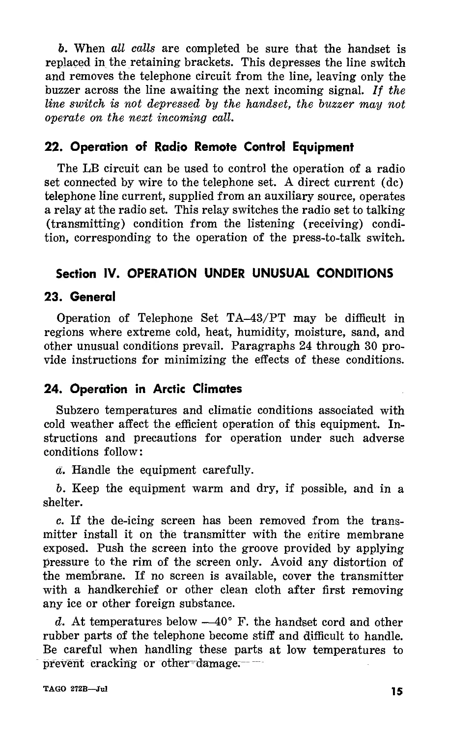
24. Operation in Arctic Climates
Subzero temperatures and climatic conditions associated with
cold weather affect the efficient operation of this equipment. In-
structions and precautions for operation under such adverse
conditions follow:
a. Handle the equipment carefully.
b. Keep the equipment warm and dry, if possible, and in a
shelter.
c. If the de-icing screen has been removed from the trans-
mitter install it on the transmitter with the entire membrane
exposed. Push the screen into the groove provided by applying
pressure to the rim of the screen only. Avoid any distortion of
the membrane. If no screen is available, cover the transmitter
with a handkerchief or other clean cloth after first removing
any ice or other foreign substance.
d. At temperatures below —40° F. the handset cord and other
rubber parts of the telephone become stiff and difficult to handle.
Be careful when handling these parts at low temperatures to
prevent cracking or other damage.----
TAGO 272B—Jul
15
e. If the batteries fail at low temperatures, substitute a battery
with screw-type terminals connected to the external battery con-
nections. Keep the substitute batteries in one of the operator’s
inside pockets to keep them warm.
25. Operation in Tropical Climates
The TA-43/PT may be operated in a tropical climate where
moisture conditions are very acute. High relative humidity causes
condensation of moisture on the equipment whenever the tempera-
ture of the equipment is lower than that of the surrounding air.
Try to minimize the effect of this condition as much as possible.
26. Operation in Desert Climates
a. In desert climates where sand, dirt, and wind prevail, keep
the TA-43/PT as free from dust and grit as possible.
b. Keep the slide fastener closed when the equipment is not in
use.
c. Do not secure the incoming line to the wall of a tent. Desert
areas are subject to sudden wind squalls that may loosen the
connections or break the line.
d. Make frequent battery checks.
27. Operation at High Altitudes
The waterproof air valves provide pressure equalization for all
critical components of the telephone set. At extreme altitudes, the
transmission characteristics of the transmitter and receiver ele-
ments may change appreciably, but speech will continue to be
intelligible.
28. Operation in Noisy Areas
When the TA-43/PT is being used in a noisy area, speak
directly into the transmitter in a loud clear voice. For CB opera-
tion, cover the transmitter with one hand while listening to the
distant party. For LB or CBS operation, release the press-to-talk
switch when listening to the distant party. Covering the trans-
mitter or releasing the press-to-talk switch reduces or completely
eliminates sidetone; this makes it much easire to hear the incom-
ing message.
29. Operation on Long Telephone Loops
The LB and CBS circuits provide better transmission over a
long loop than the CB circuit. When the TA-43./PT is used on
16
TAGO 272B—Jul
a long CB circuit and the transmission is noticeably affected,
change the circuit selector switch to CBS and install batteries
(fig. 2 and 3).
30. Emergency Operation (Sound Power)
If no battery supply is available, emergency transmission can
be obtained over short distances (less than 4 miles) by using
the receiver element as a sound powered transmitter element.
Use the following procedure for this operation:
a. Signal by means of the hand generator.
b. Remove the handset and speak directly into the receiver;
then listen while the distant party is transmitting.
TAGO 272B—Jul
17
CHAPTER 3
ORGANIZATIONAL MAINTENANCE INSTRUCTIONS
Section I. PREVENTIVE MAINTENANCE SERVICES
31. General
The tools and materials listed in paragraph 32 are required for
organizational maintenance of the TA-43/PT. The chart gives
the description of the tool or material and the Signal Corps stock
number.
32. Tools and Materials
Description Signal Corps stock No.
Knife TL-29 6Q60229
Pliers TL-13 6R4513
Pouch CS-34 6R6534
Cloth, clean, lint-free 6Z1989
Solvent, Dry Cleaning (SD) *51-S—4385-1
* Quartermaster stock number.
33. Definition of Preventive Maintenance
Preventive maintenance is work performed on equipment
(usually when the equipment is not in use) and precautions taken
during its use to keep it in good working condition so that break-
downs and needless interruptions in service will be kept to a
minimum. Preventive maintenance differs from troubleshooting
and repair since its object is to prevent certain troubles from
occurring.
34. General Preventive Maintenance Techniques
a. If available, use No. 0000 sandpaper to remove corrosion.
b. Use a clean, dry, lint-free cloth or a dry brush for cleaning.
(1) If necessary, except for electrical contacts, moisten or
brush with solvent (SD); then wipe the parts with a
cloth.
18
IAGO 272B—Jul
(2) Clean electrical contacts with a toothpick moistened with
carbon tetrachloride if available. Never touch switch
contacts with the fingers.
Caution: Repeated contact of carbon tetrachloride with
the skin or prolonged breathing of the fumes is danger-
ous. Make sure adequate ventilation is provided.
c. If available, dry compressed air may be used at a line pres-
sure not exceeding 60 pounds per square inch (psi) to remove
dust from inaccessible places; be careful not to direct the air
blast toward parts that may be damaged from the air blast.
d. For further information on preventive maintenance tech-
niques, refer to ТВ SIG 123, Preventive Maintenance Practices for
Ground Signal Equipment.
35. Use of Preventive Maintenance Forms
(figs. 6 and 7)
a. The decision as to which items on DA Forms 11/240 and
11-241 are applicable to Telephone Set TA-43/PT is a tactical
decision to be made in case of first echelon maintenance by the
communications officer/chief or his designated representative, and
in the case of second or third echelon maintenance, by the in-
dividual making the inspection. Instructions for the use of each
form appear on the reverse side of the form.
b. Circled items in figures 6 and 7 are partially or totally
applicable to Telephone Set TA-43/PT. References in the ITEM
column refer to paragraphs in the text that contain additional
maintenance information.
TAGO 272B—Jul
19
OPERATOR FIRST ECHELON MAINTENANCE CHECK LIST FOR SIGNAL CORPS EQUIPMENT - - TELEPHONE UT
INSTMCTIONS! Soo othor oldo
EQUIPMENT NOMENCLATURE TELEPHONE SET TA-43/PT EQUIPMENT SERIAL NO.
LEGEND FOB WRUNG CONDITIONS: / Sdtlatactory; X MJwtaeat, repair от replaeeoMt required; ф Detect corrected* NOTE! Strike cot itetna sot applicable.
DAI LT
NO ITEM SSflEBoSS
INSPECT CORDS FOR KINKS, FRAYING, CUTS. BREAKS. (Outdoor one). PAR. 36a(2l
-INSPECT EXTERIOR CONNECTIONS FOR SNUG FIT AND GOOD CONTACT. (Outdoor uno). PAR. 360(4)
$ CLEAN COWS, CASES, HANDSET. AND BATTERY COMPARTMENT OF MOISTURE, DIRT. ORIME, BATTERY ACID. MIU7E*.
INSPECT FOR SECURE MOUNTING STRAPS. (Outdoor ooo). PAR.36b(10)
INSPECT BATTERY CONPARTMERT FOR CORROSION, GOOD BATTERIES, BROKEN OR MISSING SWINGS, BATTERY ACIO. (UcnlMtoryooto). PAR. 36Ь (ID
OPERATE THE TELEPHONE AND CHECK FOR PROPER RINGING AND TALKING. PAR. 36 0(1)
7 INSPECT VACUUM TUBES FOR LIGHTED FILAMENTS ANG SECURE MOUNTING, (Aupliflor typo).
WEEKLY
Ю. , ITEM i! NO 1 ITEM
INSPECT CORDS FOR KINKS, MAYING, CUTS, BREAKS. (indoor tu)< . PAR. 36 0(2) INSPECT HANDSET FOR CHIPS, CRACKS, LOOSE CAPS OR CAPSULES, DIRT, GREASE, MOISTURE. PAR. 36 a (61
© INSPECT EXTERIOR CONNECTIONS FOR SNUG FIT AND GOOD CONTACT. (Indoor tree). PAR. 360(4) $ INSPECT SNAP FASTENER ON CASE. (Outdoor uoo).
£ CLEAN COr'dS, BATTERY COnPARTMENT, EXTERIOR OF CASE, HOUSING, DIAL, HANDSET. (Indoor uoo). . PAR.36D(8) INSPECT LEATHER AND CANVAS ITEMS FOR MILDEW, TEARS, AMO FRAYING. PAR. 36 b (10)
p INSPECT EXTEVtOR FOR CHIPS, CRACKS. CORROSION, RUST, MOISTURE, MILDEW, DIRT, GREASE, BROKEN OR MISSING GENERATOR HANDLE. РАЯ.ЗбЬ(б) PAR. 36 b (?i INSPECT TELEPHONE SET FOt COMPLETENESS - CUR05, DIALS, HANDSET, BATTERIES, GENERATORS, TUBES, CARRYING CASES, ACCESSORIES, TECHNICAL MANUALS, RUNNING SPARE PARTS. ».
TIGHTEN LOOSE ASSEMBLY AND MOUNTING HARDWARE. __ k,.\ INSPECT FOR PROPER INSTALLATION IN COOL, DRY PLACE. PAR. 36 b<3)
0 INSPECT MARKINGS FOR LEGIBILITY, CORROSION. - _ _ . ,e,
19 IF DEFICIENCIES NOTED ARE NOT CORRECTED DURING INSPECTION. INDICATE ACTION TAKEN FOR CORRECTION.
DA 11-240 KtPL.CEB OA AGO FOR. О». 1 DEC JO» WHICH IS OBSOLETE-
TM 337-8
Figure 6. DA Form ll-2iO.
20
TAGO 272B—Jul
SECOND AKO THIRD ECHELON MAINTENAHCE CHECK LIST FOR SIGNAL CORPS EQUIPHEHT TELEPHOIE SET
I/tSTtUCTIONSr See other aide '
EQUIPMENT NOMENCLATURE TELEPHONE SET TA-43/PT EQUIPMENT SERIAL NO.
UGBMD FOB MASKING CONDITIONS: Z Satisfactory; X idjuetaeat, repair or repUceoeat rwvired; 0 Defact corrected. NOTE: Strike oat iterae aot applicabfe.
NO ITEM Ss NO. ITEM
INSPECT CORDS'FOR KINKS, FRAYING, CUTS, BREAKS. (Oetdoor ее,). . . PAR. Зв 0 (2) INSPECT TELEPHONE SET FOR COMPLETENESS * CORDS, DIALS, HANDSET, BATTERIES, GENERATORS, TUBES, CARRYING CASES, ACCESSORIES. TECHNICAL MANUALS, RUNNING fcf?)
INSPECT EXTERIOR CONNECTIONS FOR SNUG FIT AND 6000 CONTACT. (Octdoor ем). • PAR. 36 0 (4) IB INSPECT FOR PROPER INSTALLATION IN COOL, DRY PLACE.
$ CLEAN COROS, CASES, HAUBSET, ‘NO BATTERY COMPARTMENT OF MOISTURE, DIRT, GRIME, BATTER! ACID, MILDER, CORROSION. (Oatdoor ate). PAR. ЗбЬ(8| $ INSPECT CORDS ANO LINE TERMINALS FOR FRAYING, BREAKS, CUTS, PROPER CONNECTIONS FOR OS OR LB OPERATION. PAR. 36 Ь (61
® IXSPftT FOR SECURE MOW!ING STRAPS. (Outdoor me). PAR. 36 b (10) l&l CLEAN INTERIORS OF TELEPHONE HOUSINGS, CHASSIS, CARRYING CASES, BATTERY COMPARTMENTS OF ALL CORROSION, MOISTURE, MILDEW, RUST, EXCESS SOLDER, DIRT, GRIKE, GREASE.
£ INSPECT BATTERY COMPARTMENT FOR CORRQSION, GOOD BATTERIES, BROKEN OR MISSING SPRINGS, BATTERY ACIO. (Local battery PAR. 36 Ь (It) INSPECT INTERIOR WIRING AND CONNECTIONS FOR GOOD CONTACT, BREAKS, CUTS, FRAYING. PAR. 36C (2)
£ OPERATE THE TELEPHONE ANO CHECK FOR PROPER RINGING AND TALKING. PAR.36a(l) 22 INSPECT GENERATOR FOR WORN OR CHIPPED GEARS, LOOSE SCREWS, WORK RUBBER, BROKEN CONTACT SPRINGS. (Leeef battery e.taX PAR. 36 C (61
1 INSPECT VACUUM TUBES FOR LIGHTED FIlAHENTS ANO SECURE MOUNTING. (SapUflor type). 23 BURNISH GENERATOR CONTACTS AND ALMOST SPRINGS. (Local bettetf net»).
3 INSPECT CORDS FOR KINKS, PRATING, CUTS, BREAKS. (Indoor e»,). , . PAR.36o(2l TIGHTEN ALL LOOSE ASSENGLT AND MOUNTING SCREWS. PAR.36 bill
INSPECT EXTERIOR CONNECTIONS FOR SNUG FIT ANO GOOD CONTACT. (Indoor она). PAR. 36 a (41 @ INSPECT HOOK SWITCHES, CANDLE SWITCHES, HANDSET BUTTERFLY SWITCH AND CONTROL SWITCHES FOR POSITIVE ACTION ANO GOUB С“,ЛСТ' PAR. 3.0 tTl
CLEAN CORDS, BATTERY CONPARTmEhT, EXTERIOR OF CASE, HOUSlNO, DIAL, HANDSET. (Indoor me), , . PAR.36b(8) 26 tKSPECT VACUUM TUBES FOR SECURE MOUNTING, VISIBLE DAMAGE, AHO LIGHTED FILAMENT. (SapUfler type).
INSPECT EXTERIOR FOR CHIPS, CRACKS, CORROSION, RUST, YtOISTURE, MILDEW, DIRT. GREASE, BROKEN OR MISSING GENERATOR HANDLE. PAR.36b(4l 2? INSPECT PLUGS AND JACKS FOR SNUB FIT ANO GDCO CONTACT.
TIGHTEN LOOSE ASSEUJlT AND MOUNTING HARDWARE. PAR. 36 Ь (1) 28 CLEAN PLUGS ANO JACKS OF RUST, N01STURE, DIRT, GRIME, AND GREASE.
© INSPECT HARKINGS FOC LEGIBILITY, CORROSION. PAR. 36 b (9) 29 INSPECT RELAYS FOR POSITIVE ACTION AND GOOD CONTACT.
ls>) INSPECT HANDSET FOR CHIPS, CRACKS, LOOSE CAPS OR CAPSULES, ШШ, mw. мв.ззЬМ) [0 CLEAN SWITCHES AND RELATS -OF DIRT, DUST AND MOISTURE. PAR. 36 C (31
•INSPECT SNAP FASTENER ON CASE. (Outdoor им). PAR?36b(t0l CLEAN AND TIGHTEN ALL TERMINAL CONNECTIONS. PAR.36c(4)
9 INSPECT LEATHER AND CANVAS ITEMS FOR MILDEW, TEARS, AND FRAYING. PAR. 36b(io) 32 LUBRICATE THE E0U1PNEHT USING THE LATEST DEPARTMENT OF THE ARMY LUBRICATION ORDER.
$ IKSPECT THE TELEPHONE SET FOR PROPER MOISTURE ANO FUNGUS PROOFING. PAR.36C(l)
31 IF DEFICIENCIES NOTEO ARE NOT CORRECTED DURING INSPECTION, INDICATE ACTION TAKEN FOR CORRECTION.
DA\ NAySj/I 1*241 REPLACES M AGO FORI «19, 1 OK DO, WHICH IS OBSOLETE F "НП1
TM 357-9
Figure 7. DA Form 11-2Ц.
TAGO 272B—Jul
21
36. Performing Preventive Maintenance
A suggested schedule of preventive maintenance for the TA-
43/PT is given in a through c below. The operations indicated
should be performed by organizational personnel at the intervals
indicated unless those intervals are changed by the local com-
mander.
a. Daily.
(1) Check for proper operation of the telephone.
(2) Inspect the handset cord for cuts, kinks, breaks, or
fraying.
(3) Check the generator operating handwheel and crank for
ease of operation.
(4) Check the line binding post connections.
(5) Inspect the buzzer diaphragm for dents or other damage.
(6) Check the receiver and transmitter caps for tightness.
(7) Inspect the line switch and the press-to-talk switch for
ease of operation.
(8) Inspect the handset retaining springs for proper spring
tension.
b. Weekly.
(1) Inspect all accessible screws for tightness.
(2) Inspect all gaskets for tightness or damage.
(3) Check installation site for maximum protection of the
TA-43/PT.
(4) Check the handset for chips, cracks, or other damage.
(5) Check the spring-loaded binding posts for positive spring
action.
(6) Check the panel and housing assembly for scratches,
cracks, dents, or other damage.
(7) Check for completeness and general condition of the
telephone, handset, and carrying case.
(8) Remove dirt, dust, grease, and moisture from the exterior
of the carrying case, panel and housing assembly, and
the handset.
(9) Inspect all markings for legibility and cleanliness.
(10) Inspect the carrying case and strap for tears, rips,
broken or bent snap fasteners, broken or missing snap
rings.
(11) Inspect the battery compartment for corrosion, broken
or bent contacts or loose cover or cover latch.
22
TAGO 272B—Jul
(12) Check the circuit selector switch for ease of operation
and positive detent action.
c. Monthly.
(1) Inspect moistureproofing and fungiproofing for general
condition. Whenever a loose connection is soldered or
a break in the protective coating is found, it should be
moistureproofed and fungiproofed. Apply the varnish
with a small brush.
(2) Check the local wiring for damaged insulation. Repair
the damaged insulation with electrical tape and dress
the wiring.
(3) Check all switches for dust, dirt, or grease.
(4) Check all screw-type terminal connections for tightness.
(5) Check for loose soldered connections.
(6) Check the hand ringing generator for worn or damaged
parts.
Section II. LUBRICATION AND WEATHERPROOFING
37. Lubrication
All moving parts of the TA-43/PT have been lubricated by
the manufacturer. No furthei’ lubrication is required.
38. Weatherproofing
a. General. Signal Corps equipment, when operated under
severe climatic conditions, such as prevail in tropical, arctic, and
desert regions, requires special treatment and maintenance. Fun-
gus growths, insects, dust, corrosion, salt spray, excessive mois-
ture, and extreme temperature are harmful to most materials.
b. Tropical Maintenance. A special moistureproofing and fungi-
proofing treatment has been devised, which, if properly applied,
provides a reasonable degree of protection. Refer to ТВ SIG 13,
Moistureproofing and Fungiproofing Signal Corps Equipment, and
ТВ SIG 72, Tropical Maintenance of Signal Corps Equipment.
c. Winter Maintenance. Special precautions necessary to pre-
vent poor performance or total operational failure of equipment in
extremely low temperatures are explained in ТВ SIG 66, Winter
Maintenance of Signal Equipment, and ТВ SIG 219, Operation
of Signal Equipment at Low Temperatures.
d. Desert Maintenance. Special precautions necessary to pre-
vent equipment failure in areas subject to extremely high tempera-
tures, low humidity, and excessive sand and dust are explained in
ТВ SIG 75, Desert Maintenance of Ground Signal Equipment..
TAGO 272B—Jul
23
Section III. TROUBLESHOOTING AT ORGANIZATIONAL
MAINTENANCE LEVEL
39. General
The troubleshooting and repair work that can be performed at
the organizational maintenance level (operators and repairmen)
is limited in scope by the tools, test equipment, replacement parts
issued, and by the existing tactical situation. Accordingly, trouble-
shooting is based on the performance of the equipment and the
use of the senses in determining such troubles as broken leads,
burned-out resistors, etc. Paragraphs 40 through 42 will help
in determining a faulty component.
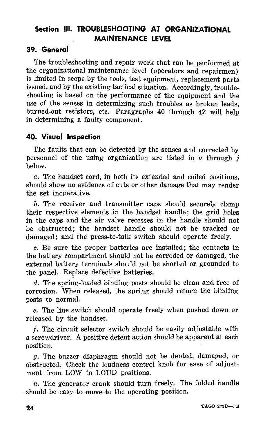
40. Visual Inspection
The faults that can be detected by the senses and corrected by
personnel of the using organization are listed in a through j
below.
a. The handset cord, in both its extended and coiled positions,
should show no evidence of cuts or other damage that may render
the set inoperative.
b. The receiver and transmitter caps should securely clamp
their respective elements in the handset handle; the grid holes
in the caps and the air valve recesses in the handle should not
be obstructed; the handset handle should not be cracked or
damaged; and the press-to-talk switch should operate freely.
c. Be sure the proper batteries are installed; the contacts in
the battery compartment should not be corroded or damaged, the
external battery terminals should not be shorted or grounded to
the panel. Replace defective batteries.
d. The spring-loaded binding posts should be clean and free of
corrosion. When released, the spring should return the binding
posts to normal.
e. The line switch should operate freely when pushed down or
released by the handset.
/. The circuit selector switch should be easily adjustable with
a screwdriver. A positive detent action should be apparent at each
position.
g. The buzzer diaphragm should not be dented, damaged, or
obstructed. Check the loudness control knob for ease of adjust-
ment from LOW to LOUD positions.
h. The generator crank should turn freely. The folded handle
should be easy to move to the operating position.
24
TAGO 272B—Ju)
i. The panel and housing assembly should not be dented or
deformed. The handset retaining brackets should hold the handset
securely with the telephone mounted vertically (fig. 1) and should
not prevent its removal. The assembly screws or gasket seals
should not be loose or missing.
j. The carrying case should not obstruct the use or functioning
of the telephone set.
41. Troubleshooting, Using Equipment Performance Check List
a. General. The equipment performance check list (par. 42)
will help to locate trouble in the equipment. The list gives the
item to be checked, the normal indications and tolerances of correct
operation, and the corrective measures to be taken by the operator.
To use this list, follow the items in numerical sequence.
b. Action or Condition. For some items, the information given
in the action or condition column consists of various switch control
settings under which the item is to be checked. For other items,
it represents an action that must be taken to check the normal
indication given in the normal indications column.
c. Normal Indications. The normal indications listed are the
visible and audible signs that the operator should perceive when
he checks the items. If the indications are not normal, the operator
should apply the recommended corrective measures.
d. Corrective Measures. The corrective measures listed are
those the operator can apply without turning the equipment in
for repairs. A reference in the table to chapter 5 indicates that
troubleshooting by an experienced repairman is necessary. If
the equipment is completely inoperative or if the recommended
corrective measures do not yield results, troubleshooting at field
level is required. However, if the tactical situation requires that
communication be maintained, and if the set is not completely
inoperative, the operator must keep the set in operation as long
as it is possible to do so.
TAGO 272B—Jul
25
IV
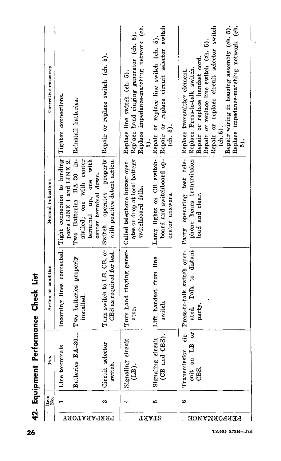
°* 42- Equipment Performance Check List
TAGO 272B—Jul
Item No. Item Action or condition
PREPARATORY 1 3 Line terminals Batteries BA-30 Circuit selector switch. Incoming lines connected. Two batteries properly installed. Turn switch to LB, CB, or CBS as required for test.
| START | 4 6 Signaling circuit (LB). Signaling circuit (CB and CBS). Turn hand ringing gener- ator. Lift handset from line switch.
I PERFORMANCE | 6 Transmission cir- cuit on LB or CBS. Press-to-talk switch oper- ated. Talk to distant party.
Normal indications Corrective measures
Tight connection to binding posts LINE 1 and LINE 2. Two Batteries BA-30 in- stalled; one with center terminal up, one with center terminal down. Switch operates properly with positive detent action. Tighten connections. Reinstall batteries. Repair or replace switch (ch. 5).
Called telephone buzzer oper- ates or drop at local battery switchboard falls. Replace line switch (ch. 5). Replace hand ringing generator (ch. 6). Replace impedance-matching network (ch. 5).
Lamp lights on CB switch- board and switchboard op- erator answers. Repair or replace line switch (ch. 5). Repair or replace circuit selector switch (ch. 6).
Party operating test tele- phone hears transmission loud and clear. Replace transmitter element. Replace Press-to-talk switch. Repair or replace handset cord. Repair or replace line switch (ch. 5). Repair or replace circuit selector switch (ch. 6). Repair wiring in housing assembly (ch. 5). Replace impedance-matching network (ch. 5).
TAGO 272B—Jul
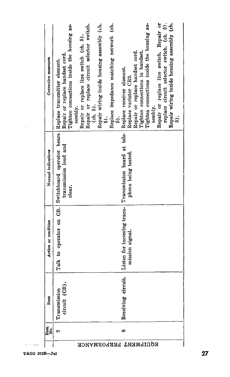
Item I No. | Item Action or condition Normal indications Corrective measures
PERFORMANCE 1 7 Transmission circuit (CB). Talk to operator on CB. Switchboard operator hears transmission loud and clear. Replace transmitter element. Repair or replace handset cord. Tighten connections inside the housing as- sembly. Repair or replace line switch (ch. 5). Repair or replace circuit selector switch, (ch. 5). Repair wiring inside housing assembly (ch. 5). Replace impedance matching network (ch. 5).
1 EQUIPMENT 8 Receiving circuit. Listen for incoming trans- mission signal. Transmission heard at tele- phone being tested. Replace receiver element. Replace varistor CR3. Repair or replace handset cord. Tighten connections in handset. Tighten connections inside the housing as- sembly. Repair or replace line switch. Repajr or replace circuit selector switch, (ch. 5). Repair wiring inside housing assembly (ch. 5).
ьз
CHAPTER 4
THEORY
Section I. THEORY OF COMPONENTS
43. General
Telephone Set TA-43/PT is designed for use with any manual
common battery or local battery field telephone system. The
theory of the components of the telephone set are described in
paragraphs 44 through 48 and the theory of operation is discussed
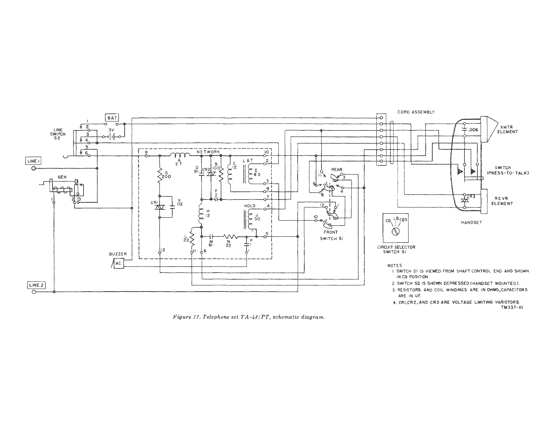
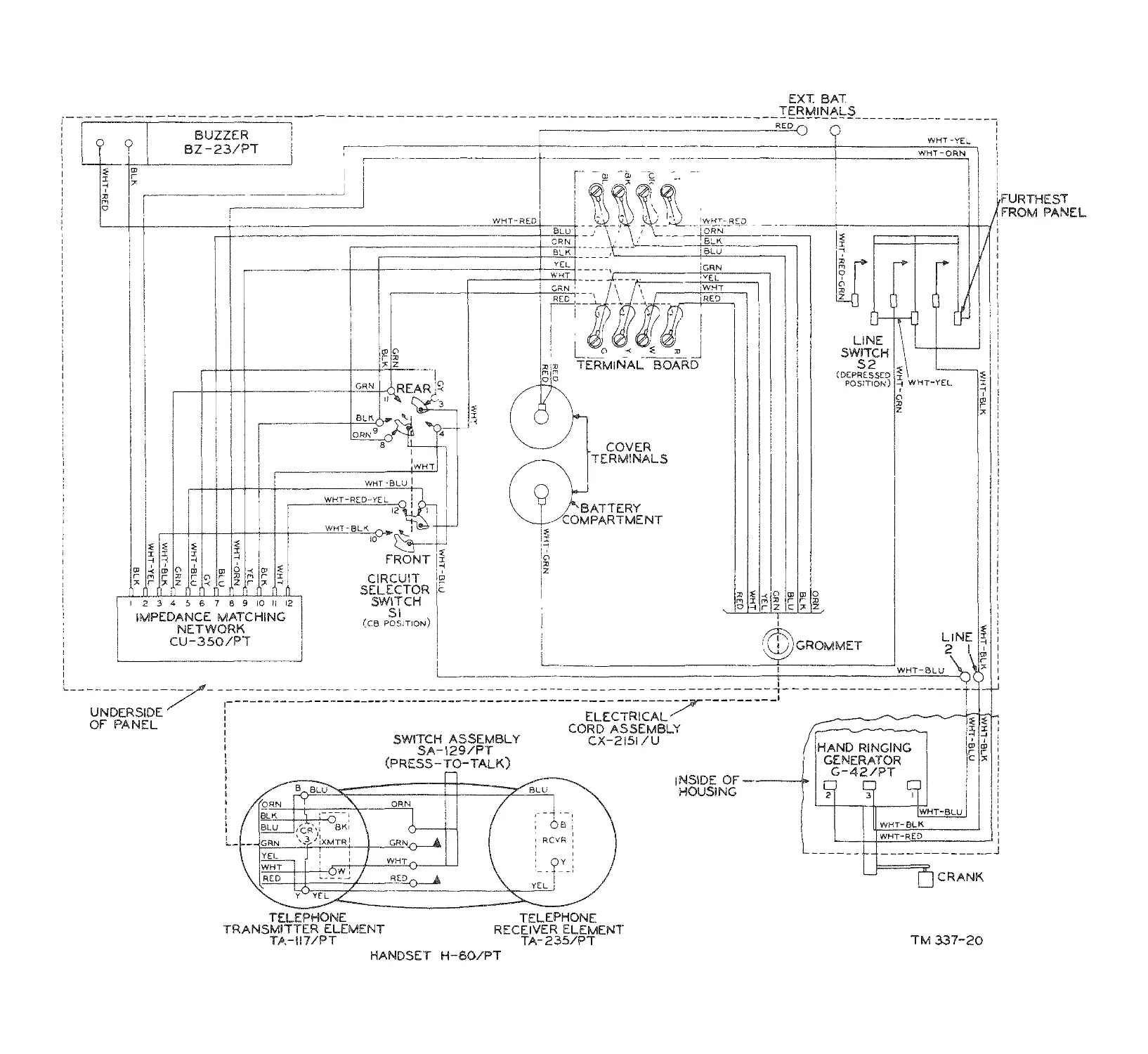
in paragraphs 49 and 50. Figure 17 is the schematic diagram and
figure 18 is the wiring diagram for the TA-43/PT.
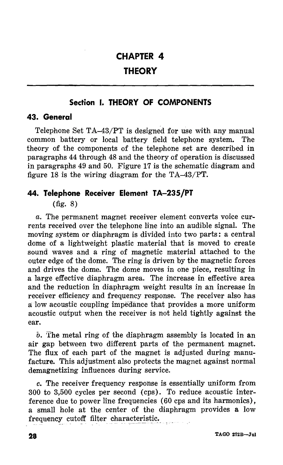
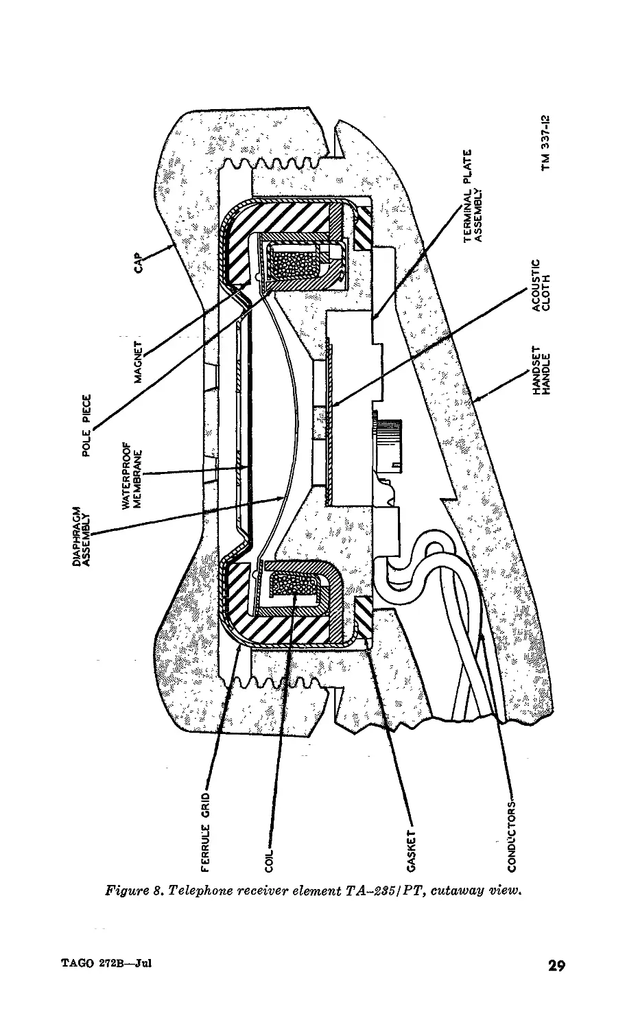
44. Telephone Receiver Element TA-235/PT
(fig. 8)
a. The permanent magnet receiver element converts voice cur-
rents received over the telephone line into an audible signal. The
moving system or diaphragm is divided into two parts: a central
dome of a lightweight plastic material that is moved to create
sound waves and a ring of magnetic material attached to the
outer edge of the dome. The ring is driven by the magnetic forces
and drives the dome. The dome moves in one piece, resulting in
a large effective diaphragm area. The increase in effective area
and the reduction in diaphragm weight results in an increase in
receiver efficiency and frequency response. The receiver also has
a low acoustic coupling impedance that provides a more uniform
acoustic output when the receiver is not held tightly against the
ear.
o. The metal ring of the diaphragm assembly is located in an
air gap between two different parts of the permanent magnet.
The flux of each part of the magnet is adjusted during manu-
facture. This adjustment also protects the magnet against normal
demagnetizing influences during service.
c. The receiver frequency response is essentially uniform from
300 to 3,500 cycles per second (cps). To reduce acoustic inter-
ference due to power line frequencies (60 cps and its harmonics),
a small hole at the center of the diaphragm provides a low
frequency cutoff filter characteristic.
28
TAGO 272B—Jul
Figure 8. Telephone receiver element TA-235! PT, cutaway view.
DIAPHRAGM
d. The front of the receiver is protected by a thin waterproof
membrane between the grid and diaphragm. A rubber gasket
on the rear of the receiver provides a water seal in the handset
assembly.
e. The varistor CR3 shunts the receiver element and minimizes
clicks in the receiver and protects the receiver against demagneti-
zation.
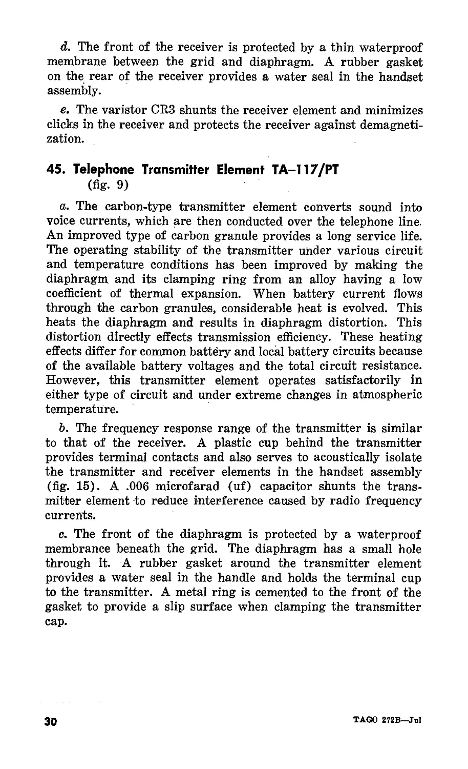
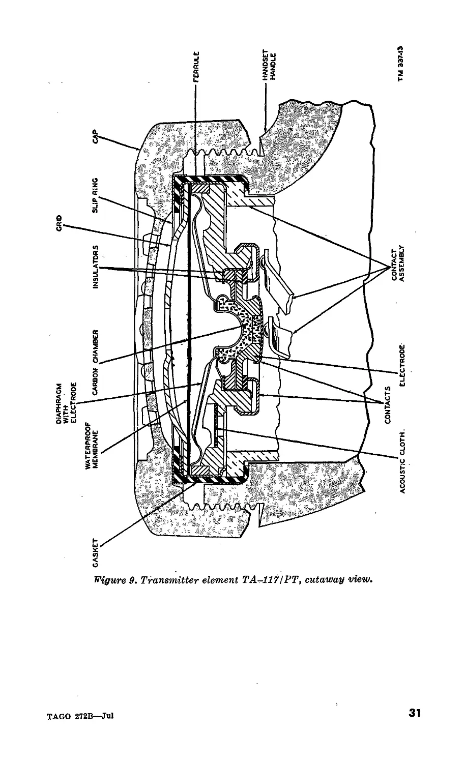
45. Telephone Transmitter Element TA-117/PT
(fig. 9)
a. The carbon-type transmitter element converts sound into
voice currents, which are then conducted over the telephone line.
An improved type of carbon granule provides a long service life.
The operating stability of the transmitter under various circuit
and temperature conditions has been improved by making the
diaphragm and its clamping ring from an alloy having a low
coefficient of thermal expansion. When battery current flows
through the carbon granules, considerable heat is evolved. This
heats the diaphragm and results in diaphragm distortion. This
distortion directly effects transmission efficiency. These heating
effects differ for common battdry and local battery circuits because
of the available battery voltages and the total circuit resistance.
However, this transmitter element operates satisfactorily in
either type of circuit and under extreme changes in atmospheric
temperature.
b. The frequency response range of the transmitter is similar
to that of the receiver. A plastic cup behind the transmitter
provides terminal contacts and also serves to acoustically isolate
the transmitter and receiver elements in the handset assembly
(fig. 15). A .006 microfarad (uf) capacitor shunts the trans-
mitter element to reduce interference caused by radio frequency
currents.
c. The front of the diaphragm is protected by a waterproof
membrance beneath the grid. The diaphragm has a small hole
through it. A rubber gasket around the transmitter element
provides a water seal in the handle and holds the terminal cup
to the transmitter. A metal ring is cemented to the front of the
gasket to provide a slip surface when clamping the transmitter
cap.
30
TAGO 272B—Jul
<>
H’igure 9. Transmitter element TA-117! PT, cutaway view.
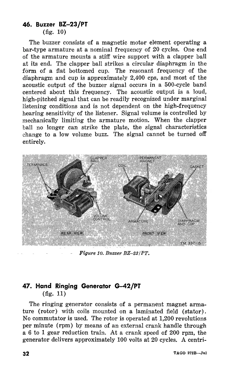
46. Buzzer BZ-23/PT
(fig. 10)
The buzzer consists of a magnetic motor element operating a
bar-type armature at a nominal frequency of 20 cycles. One end
of the armature mounts a stiff wire support with a clapper ball
at its end. The clapper ball strikes a circular diaphragm in the
form of a flat bottomed cup. The resonant frequency of the
diaphragm and cup is approximately 2,400 cps, and most of the
acoustic output of the buzzer signal occurs in a 500-cycle band
centered about this frequency. The acoustic output is a loud,
high-pitched signal that can be readily recognized under marginal
listening conditions and is not dependent on the high-frequency
hearing sensitivity of the listener. Signal volume is controlled by
mechanically limiting the armature motion. When the clapper
ball no longer can strike the plate, the signal characteristics
change to a low volume buzz. The signal cannot be turned off
entirely.
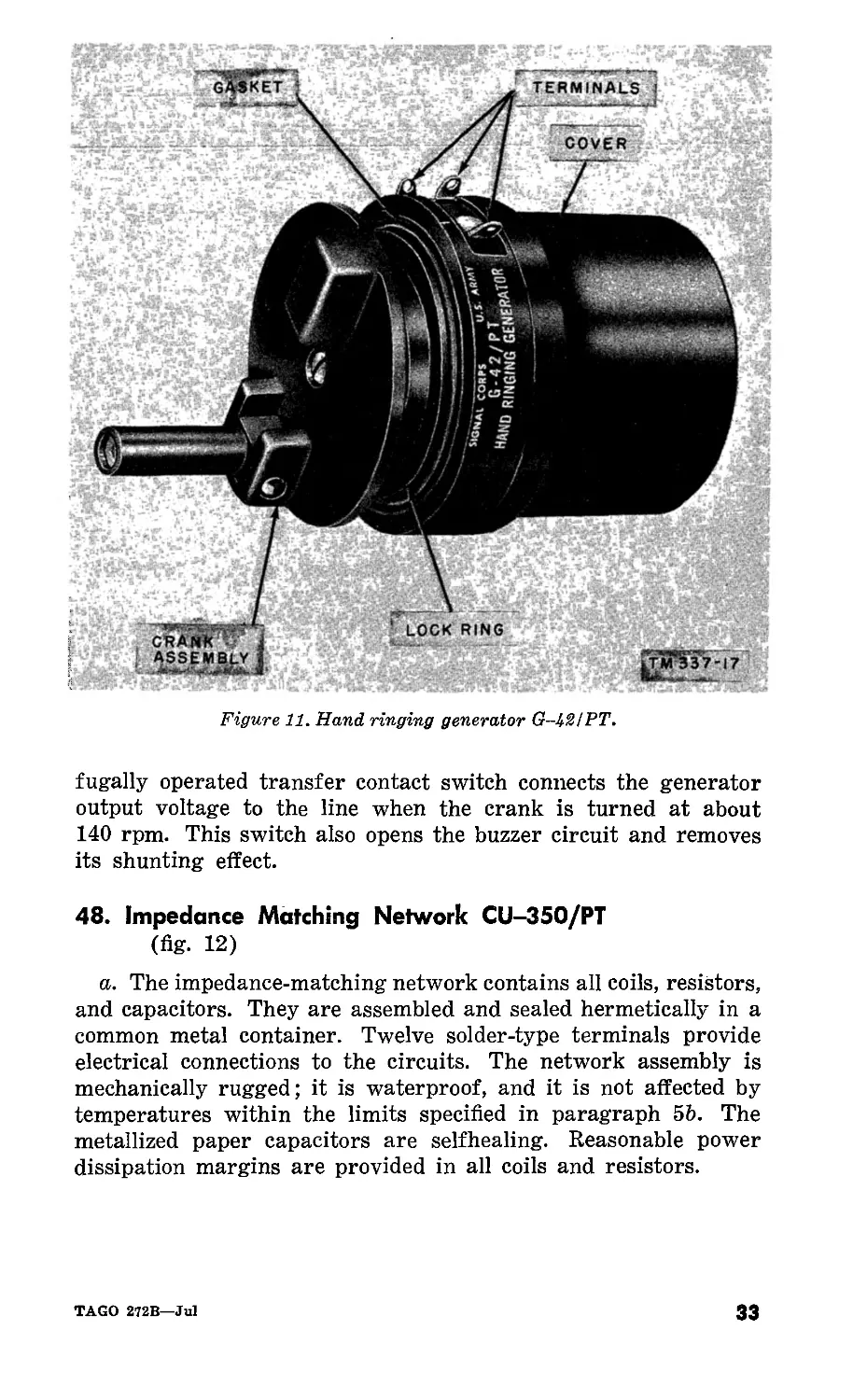
47. Hand Ringing Generator G-42/PT
(fig. 11)
The ringing generator consists of a permanent magnet arma-
ture (rotor) with coils mounted on a laminated field (stator).
No commutator is used. The rotor is operated at 1,200 revolutions
per minute (rpm) by means of an external crank handle through
a 6 to 1 gear reduction train. At a crank speed of 200 rpm, the
generator delivers approximately 100 volts at 20 cycles. A centri-
32
TAGO 272B—Jul
Figure 11. Hand ringing generator G-12IPT.
fugally operated transfer contact switch connects the generator
output voltage to the line when the crank is turned at about
140 rpm. This switch also opens the buzzer circuit and removes
its shunting effect.
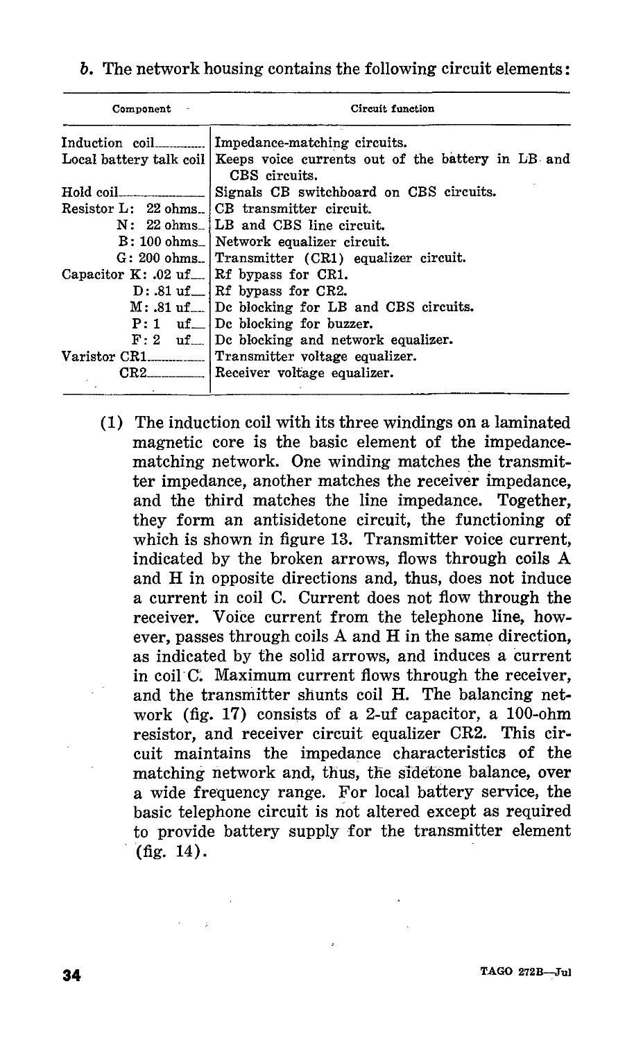
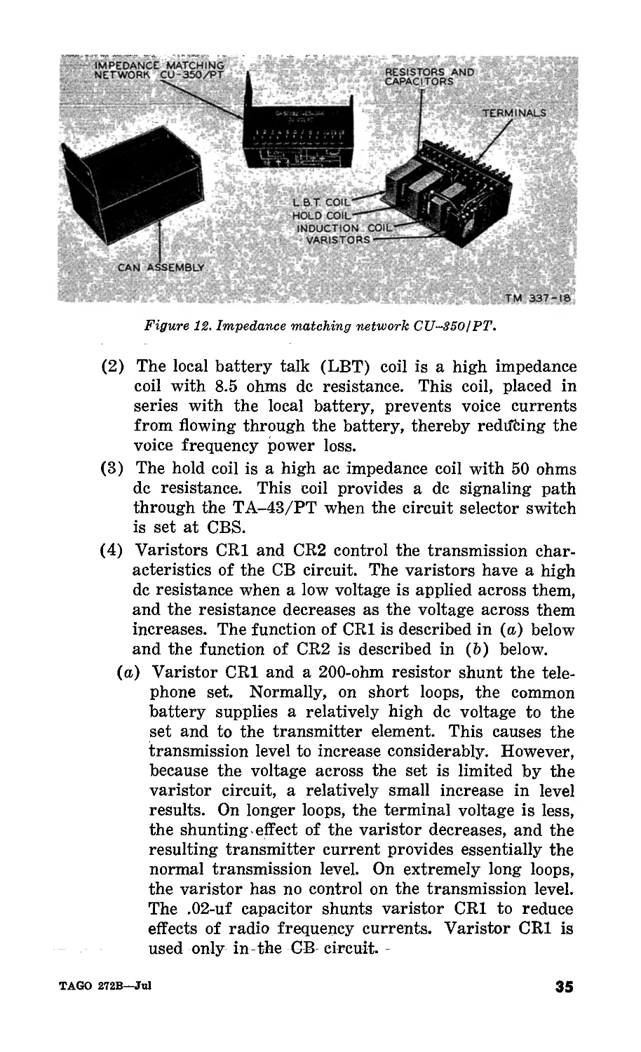
48. Impedance Matching Network CU-35O/PT
(fig. 12)
a. The impedance-matching network contains all coils, resistors,
and capacitors. They are assembled and sealed hermetically in a
common metal container. Twelve solder-type terminals provide
electrical connections to the circuits. The network assembly is
mechanically rugged; it is waterproof, and it is not affected by
temperatures within the limits specified in paragraph 5b. The
metallized paper capacitors are selfhealing. Reasonable power
dissipation margins are provided in all coils and resistors.
TAGO 272B—Jul
33
b. The network housing contains the following circuit elements:
Component Circuit function
Induction coil Impedance-matching circuits.
Local battery talk coil Keeps voice currents out of the battery in LB and CBS circuits.
Hold coil Signals CB switchboard on CBS circuits.
Resistor L: 22 ohms.. CB transmitter circuit.
N: 22 ohms.. LB and CBS line circuit.
В: 100 ohms.. Network equalizer circuit.
G: 200 ohms.. Transmitter (CR1) equalizer circuit.
Capacitor K: .02 uf Rf bypass for CR1.
D: .81 uf— Rf bypass for CR2.
M: .81 uf.... De blocking for LB and CBS circuits.
P: 1 uf— De blocking for buzzer.
F: 2 uf.... De blocking and network equalizer.
Varistor CR1 Transmitter voltage equalizer.
CR2 Receiver voltage equalizer.
(1) The induction coil with its three windings on a laminated
magnetic core is the basic element of the impedance-
matching network. One winding matches the transmit-
ter impedance, another matches the receiver impedance,
and the third matches the line impedance. Together,
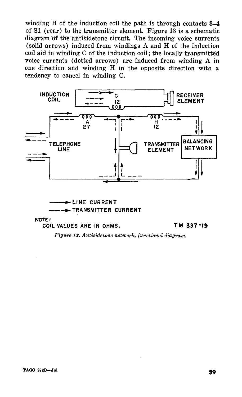
they form an antisidetone circuit, the functioning of
which is shown in figure 13. Transmitter voice current,
indicated by the broken arrows, flows through coils A
and H in opposite directions and, thus, does not induce
a current in coil C. Current does not flow through the
receiver. Voice current from the telephone line, how-
ever, passes through coils A and H in the same direction,
as indicated by the solid arrows, and induces a current
in coil C. Maximum current flows through the receiver,
and the transmitter shunts coil H. The balancing net-
work (fig. 17) consists of a 2-uf capacitor, a 100-ohm
resistor, and receiver circuit equalizer CR2. This cir-
cuit maintains the impedance characteristics of the
matching network and, thus, the sidetone balance, over
a wide frequency range. For local battery service, the
basic telephone circuit is not altered except as required
to provide battery supply for the transmitter element
(fig. 14).
34
TAGO 272B—Jul
Figure 12. Impedance matching network CU-350IPT.
(2) The local battery talk (LBT) coil is a high impedance
coil with 8.5 ohms de resistance. This coil, placed in
series with the local battery, prevents voice currents
from flowing through the battery, thereby redifting the
voice frequency power loss.
(3) The hold coil is a high ac impedance coil with 50 ohms
de resistance. This coil provides a de signaling path
through the TA-43/PT when the circuit selector switch
is set at CBS.
(4) Varistors CR1 and CR2 control the transmission char-
acteristics of the CB circuit. The varistors have a high
de resistance when a low voltage is applied across them,
and the resistance decreases as the voltage across them
increases. The function of CR1 is described in (a) below
and the function of CR2 is described in (b) below.
(a) Varistor CR1 and a 200-ohm resistor shunt the tele-
phone set. Normally, on short loops, the common
battery supplies a relatively high de voltage to the
set and to the transmitter element. This causes the
transmission level to increase considerably. However,
because the voltage across the set is limited by the
varistor circuit, a relatively small increase in level
results. On longer loops, the terminal voltage is less,
the shunting effect of the varistor decreases, and the
resulting transmitter current provides essentially the
normal transmission level. On extremely long loops,
the varistor has no control on the transmission level.
The .02-uf capacitor shunts varistor CR1 to reduce
effects of radio frequency currents. Varistor CR1 is
used only in the CB circuit.
TAGO 272B—Jul
35
(&) Low resistance varistor CR2 shunts the transmitter
and receiver elements and affects the transmission
levels of both. When the transmitter terminal voltage
is high, the resistance of varistor CR2 decreases.
This causes induction coil winding H (fig. 17) to
shunt the transmitter circuit, and the 2-uf capacitor
to shunt the receiver circuit. When the transmitter
terminal voltage is low, varistor CR2 has very I little
effect on transmission. This varistor is not removed
during circuit changes, but its effect in the LB and
CBS circuit is negligible. The .81-uf capacitor shunts
varistor CR2 to reduce the effects of radio frequency
currents.
(5) The 1-uf capacitor, in series with the buzzer winding,
prevents the de line current from flowing through the
buzzer circuit. It also forms a series resonant circuit
at 20 cps providing a low impedance path to the signal-
ing current.
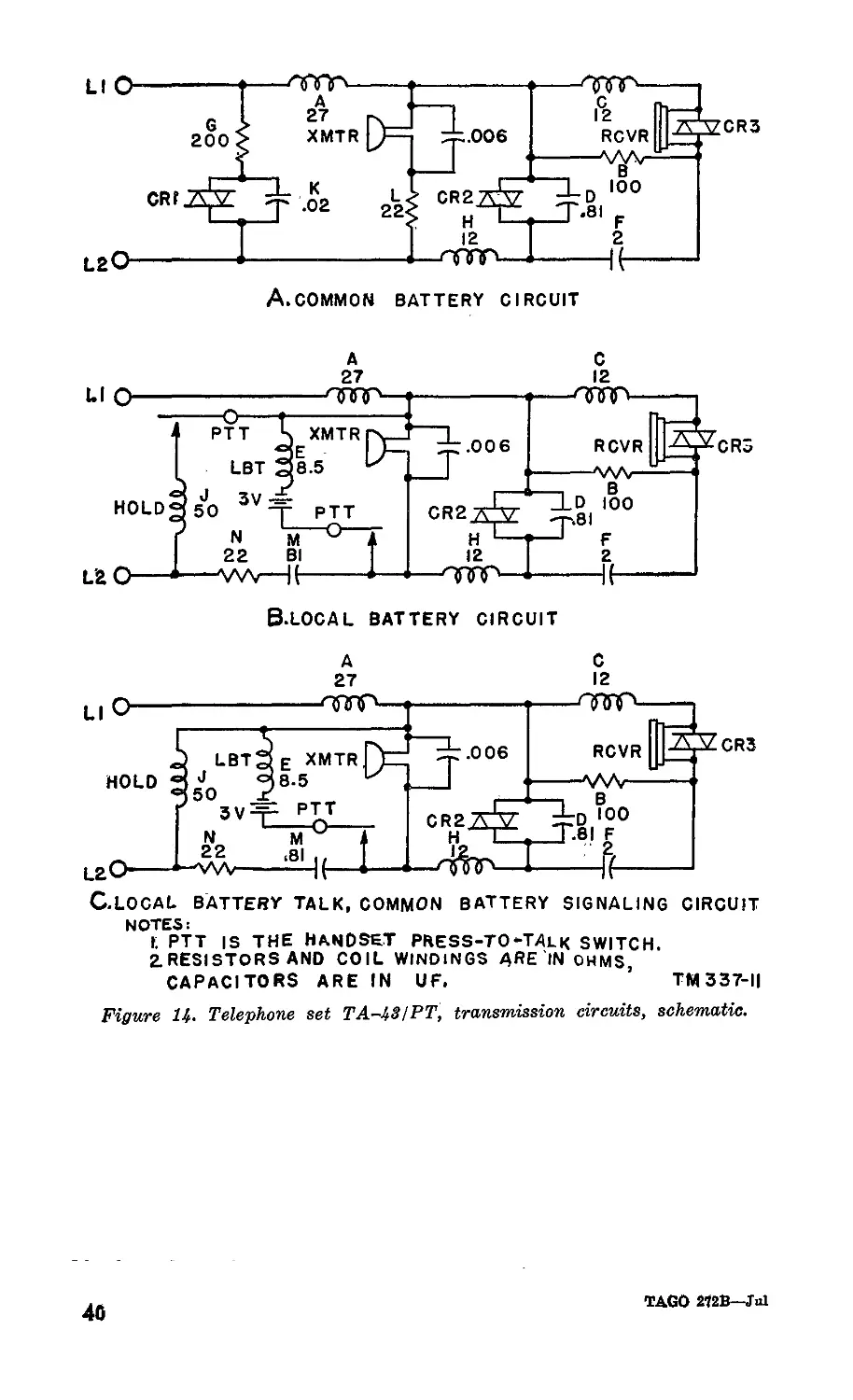
c. The three basic antisidetone transmission circuits (fig. 13)
function identically, except for the transmitter battery supply
and the method of operating supervisory signals. The line switch
(fig. 2) disconnects the transmission circuits when the telephone
set is not in use. The high alternating current (ac) impedance
of the buzzer circuit minimizes transmission loss when the set
is used.
Section II. CIRCUIT ANALYSIS
49. Signaling
(fig. 17)
a. Incoming. The 20 5 ringing current from a distant source
operates the buzzer in the TA-43/PT over the following path:
from binding post LINE 1 through contacts 3-2 on the centrifugal
switch of the G-42/PT to terminal 1 on the terminal strip,
through the buzzer to capacitor P in the impedance-matching
network; from capacitor P to binding post LINE 2. This operates
the buzzer, signaling the local telephone user.
b. Signaling Local Battery Switchboard. When a call is placed
to a local battery switchboard or a distant telephone, the hand
generator crank is turned before lifting the handset. As the
generator crank is turned, the centrifugal switch operates con-
necting the generator to the line. The 20 ringing current
flows from terminal 1 on the generator to binding post LINE 2
through the line and the apparatus being signaled and back to
36
TAGO 272B—Jul
binding post LINE 1; to terminal 3 on the generator through
the operated contacts of the centrifugal switch and back to the
generator. The 20 $ ringing current operates the device that
indicates an incoming call at the local battery switchboard or
causes the signaling device in a distant telephone to operate.
c. Signaling Common Battery Switchboard. When the TA-
43/PT is connected to a common battery switchboard, the operator
is signaled by lifting the handset from the brackets, releasing
the line switch. The circuit closed by the line switch is as fol-
lows: Battery from the switchboard to binding post LINE 1
flows through contacts 5-6 of the line switch to terminal 8 on the
impedance-matching network, through winding A of the induction
coil to terminal 10 of the impedance-matching network, then
through the transmitter unit to terminal 11 of the impedance-
matching network. The current then flows through resistor L,
terminal 6 of the impedance-matching network, contact 3 of SI
(rear), contact 1 of SI (front), to ground at the switchboard
over binding post LINE 2. This causes the lamp at the switch-
board to light.
d. Common Battery Signaling (CBS). When signaling the
switchboard operator, the circuit is as follows: Battery on bind-
ing post LINE 1 flows through contacts 5-6 of the line switch
through terminal 8 on the impedance-matching network, through
the A winding of the induction coil, terminal 10 of the impedence
matching network, through contacts 9-11 of SI (rear) to terminal
4 of the network; from terminal No. 4 of the network through
the hold coil (J), through terminal 5 of the network to ground
at the switchboard through the binding post LINE 2. The hold
coil (J) provides a medium resistance de path for signaling the
CB switchboard but prevents shunting voice currents by a high
impedance to voice frequency ac.
50. Transmission
(fig. 17)
a. Transmitting.
(1) Common battery. Direct current is supplied to the trans-
mitter in the TA-43/PT from the common battery
central office over the circuit described in paragraph 49c.
This current is changed to voice currents by the action
of the transmitter. Resistor G and varistor CR1 provide
protection for the transmitter against high voltages.
They also limit the current through the transmitter to
obtain the same transmission level when the set is
changed from LB to CB. Capacitor К provides a low
TAGO 272B—Jul
37
impedance shunt path for radio frequency signals, there-
by eliminating them from the transmitter circuit of
the TA-43/PT.
(2) Local battery. With the circuit selector switch in the
LB position, current is supplied to the transmitter from
the negative battery terminal through contacts 3-4 of
the line switch through terminal 2 on the impedance
matching network, through coil E (LBT), terminal 3
on the impedence matching network, through contact
10 of SI (front), through contact 9 Si (rear), through
the transmitter element, and through the press-to-talk
switch to the positive battery terminal. Coil E (LBT)
has a low de resistance and a high impedance to voice
frequency; this permits de to be supplied to the trans-
mitter but prevents shunting the voice currents through
the battery. The voice current path is as follows: from
one side of the transmitter element through contacts
4-3 SI (rear), capacitor M, resistor N, to binding LINE
2, through the distant telephone and back to binding
post LINE 1. From binding post LINE 1, the return
path is through contacts 5-6 of the line switch, terminal
8 on the impedance-matching network, winding A,
through terminal 10 of the impedance-matching network
to the transmitter.
(3) Common battery signaling. The circuit for battery feed
and transmitting is the same as the LB circuit ((2)
above).
b. Receiving. The receiving circuit in the TA-43/PT is the
same for all selector switch settings; that is, from one side of
the receiver element through terminal 9 of the impedance-match-
ing network, winding C of the induction coil, resistor B, terminal
7 of the network, and back to the other side of the receiver
element. This circuit is coupled electrically to the transmission
circuit through windings A and H of the induction coil.
c. Antisidetone. The transmitter, receiver, induction coil,
capacitor D, and resistor L are connected in an antisidetone cir-
cuit that reduces the sidetone heard in the receiver. The anti-
sidetone circuit with the circuit selector switch set in the CB
position is as follows: from one side of the transmitter through
terminal 10 on the impedance-matching network to capacitor
D; from capacitor D through winding H of the induction coil,
resistor L, terminal 11 of the impedance-matching network, and
back to the other side of the transmitter. When used on LB or
CBS, the circuit is the same as for the CB position, except from
38
TAGO 272B—Jul
winding H of the induction coil the path is through contacts 3-4
of Si (rear) to the transmitter element. Figure 13 is a schematic
diagram of the ahtisidetone circuit. The incoming voice currents
(solid arrows) induced from windings A and H of the induction
coil aid in winding C of the induction coil; the locally transmitted
voice currents (dotted arrows) are induced from winding A in
one direction and winding H in the opposite direction with a
tendency to cancel in winding C.
INDUCTION
COIL
C
12
T-rfl RECEIVER
Г-Ц] ELEMENT
-----►LINE CURRENT
-----► TRANSMITTER CURRENT
NOTE:
COIL VALUES ARE IN OHMS.
TM 337*19
Figure 13. Antisidetone network, functional diagram.
TAGO 272B—Jul
39
LI О
L2O
A.common battery circuit
B.LOCAL BATTERY CIRCUIT
C.LOCAL BATTERY TALK, COMMON BATTERY SIGNALING CIRCUIT
NOTES:
t ptt is the handset phess-to-talk switch.
2. RESISTORS AND COIL WINDINGS ARE IN OHMS,
CAPACITORS ARE IN UF. ’ ТМ337-Ц
Figure 14. Telephone set TA-43/PT, transmission circuits, schematic.
IAGO 272B—Jul
40
CHAPTER 5
FIELD MAINTENANCE INSTRUCTIONS
Note. This chapter contains information for field maintenance of Telephone
Set TA-43/PT. The amount of repair that can be performed by units having
field maintenance responsibility is limited only by tools and test equipment
available and by the skill of the repairman.
Section I. TROUBLESHOOTING AT FIELD MAINTENANCE
LEVEL
51. Troubleshooting Procedures
The first step in servicing defective equipment is to sectionalize
the fault. Sectionalization means tracing the fault to the major
component or circuit responsible for abnormal operation of the
equipment. The second step is to localize the fault. Localization
means tracing the fault to the defective part. Some faults, such
as burned-out resistors, arcing, or shorted induction coils can be
located by smell or hearing. The majority of faults must be
localized, however, by checking voltages and resistances.
52. Troubleshooting Data
The material supplied in this manual will help in the rapid
location of faults. Consult figures 17 and 18 for troubleshooting
data.
53. Test Equipment Required for Troubleshooting
The test equipment required for troubleshooting the TA-43/PT
is listed below. Technical manuals associated with the test equip-
ment also are listed.
Test equipment Technical manuals
Multimeter TS-352/U Test Set 1-142, I-142A, and I-142B.... TM 11-5527 TM 11-2062
TAGO 272B—Jul
41
54. General Precautions
Whenever the equipment is being serviced, observe the follow-
ing precautions carefully. Failure to observe these precautions
may result in further damage to the equipment.
a. Do not operate the press-to-talk switch when not trans-
mitting. This will shorten the life of the batteries.
b. Careless replacement of parts often makes new faults in-
evitable. Note the following points carefully:
(1) Before a part is unsoldered, note the position of the
leads connected to it. If the part has a number of leads
and terminals, tag each lead so it may be replaced easily
and correctly.
(2) Be careful not to damage other leads by pulling or push-
ing them out of the way. This is particularly important
in used or old equipment since the insulation deteriorates
with age.
(3) Do not allow drops of solder to fall into the equipment.
They may cause short circuits or other troubles.
(4) A carelessly soldered connection may create a new fault
that is hard to locate. It is very important to make
well-soldered joints.
(5) When a part is replaced in the equipment, it must be
replaced exactly as the original. Give particular atten-
tion to proper tightening of mounting screws and term-
inal screws.
55. Operational Tests
The following tests generally require no special test equipment
and may serve to identify the defective component. When trouble
is indicated, follow the procedures described in the
trouble-shooting chart (par. 56).
a. CB Circuit. Listen to the receiver while turning the genera-
tor crank. At low speeds, a clicking sound should be heard. At
higher speeds, receiver sidetone should be heard when blowing
across or speaking into the transmitter. Depress the line switch
(fig. 2) to eliminate the sidetone and reduce the torque required
to turn the generator crank.
b. LB Circuit. Depress the handset press-to-talk switch (fig.
2). Sidetone should be heard when blowing in the transmitter.
Release the press-to-talk switch to eliminate the sidetone. Turn
the hand ringing generator while operating and releasing the
press-to-talk switch. Additional torque is required to turn the
42
TAGO 272B—Jul
hand ringing generator when the press-to-talk switch is depressed.
This will electrically test the batteries, transmitter apd receiver
elements, all contacts of the press-to-talk switch, all contacts of
the line switch, the generator switch, the hold coil, the LBT coil,
and the continuity of the entire LB circuit.
c. CBS Circuit. Repeat the tests for the LB circuit (b above).
Operation of the press-to-talk switch should not affect the opera-
tion of the generator, but depressing the line switch reduces the
torque required to turn the generator.
d. Buzzer Circuit. With the handset mounted in the retaining
brackets (fig. 2), connect the telephone set being tested to another
telephone set known to be in operating condition. Operate the
hand ringing generator of the test telephone. The buzzer should
operate and the volume should vary as the volume control knob
in the telephone set being tested is rotated clockwise from the
LOW position to the LOUD position. The function of the entire
buzzer circuit is tested with this test.
e. Overall Set Test. Use the two telephones connected together
(d above). Install new Batteries BA-30 in each of the telephone*
sets and adjust both circuit selector switches for LB or CBS.
Complete a two-way conversation between the two telephone
sets. When talking at approximately the same loudness from
each of the two telephone sets, the output at each handset should
be about the same acoustic level. This is a simple method that
can be used to test the efficiency of the transmitter and receiver
elements.
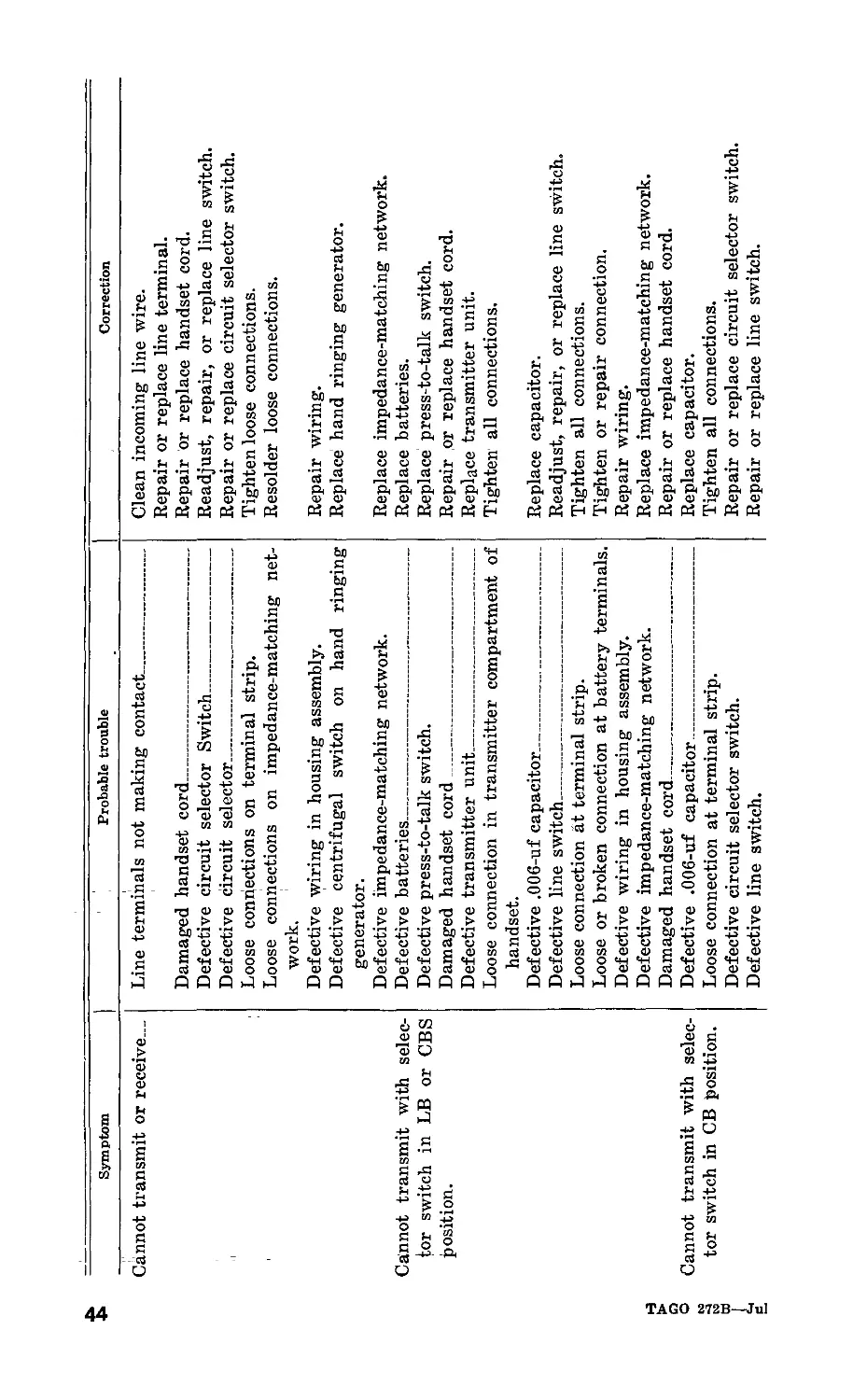
56. Troubleshooting Chart
The troubleshooting chart indicates the symptoms of probable
troubles and suggests corrective remedies. When making some
of the checks, it is necessary to partially disassemble the telephone
set. Follow the procedures described in paragraphs 58 through
62, and use the equipment described in paragraph 32 as required.
All testing done with a telephone or test instrument must be
done with equipment known to be in perfect operating condition.
TAGO 272B- -Jul
43
u
Symptom
Probable trouble
Cannot transmit or receive_
Cannot transmit with selec-
tor switch in LB or CBS
position.
TAGO 272B—Jul
Cannot transmit with selec-
tor switch in CB position.
Line terminals not making contact______________
Damaged handset cord___________________________
Defective circuit selector Switch______________
Defective circuit selector_____________________
Loose connections on terminal strip.
Loose connections on impedance-matching net-
work.
Defective wiring in housing assembly.
Defective centrifugal switch on hand ringing
generator.
Defective impedance-matching network.
Defective batteries____________________________
Defective press-to-talk switch.
Damaged handset cord
Defective transmitter unit
Loose connection in transmitter compartment of
handset.
Defective .006-uf capacitor.___________________
Defective line switch
Loose connection at terminal strip.
Loose or broken connection at battery terminals.
Defective wiring in housing assembly.
Defective impedance-matching network.
Damaged handset cord
Defective .006-uf capacitor____________________
Loose connection at terminal strip.
Defective circuit selector switch.
Defective line switch.
Correction
Clean incoming line wire.
Repair or replace line terminal.
Repair or replace handset cord.
Readjust, repair, or replace line switch.
Repair or replace circuit selector switch.
Tighten loose connections.
Resolder loose connections.
Repair wiring.
Replace hand ringing generator.
Replace impedance-matching network.
Replace batteries.
Replace press-to-talk switch.
Repair or replace handset cord.
Replace transmitter unit.
Tighten all connections.
Replace capacitor.
Readjust, repair, or replace line switch.
Tighten all connections.
Tighten or repair connection.
Repair wiring.
Replace impedance-matching network.
Repair or replace handset cord.
Replace capacitor.
Tighten all connections.
Repair or replace circuit selector switch.
Repair or replace line switch.
TAGO 272B—Jul
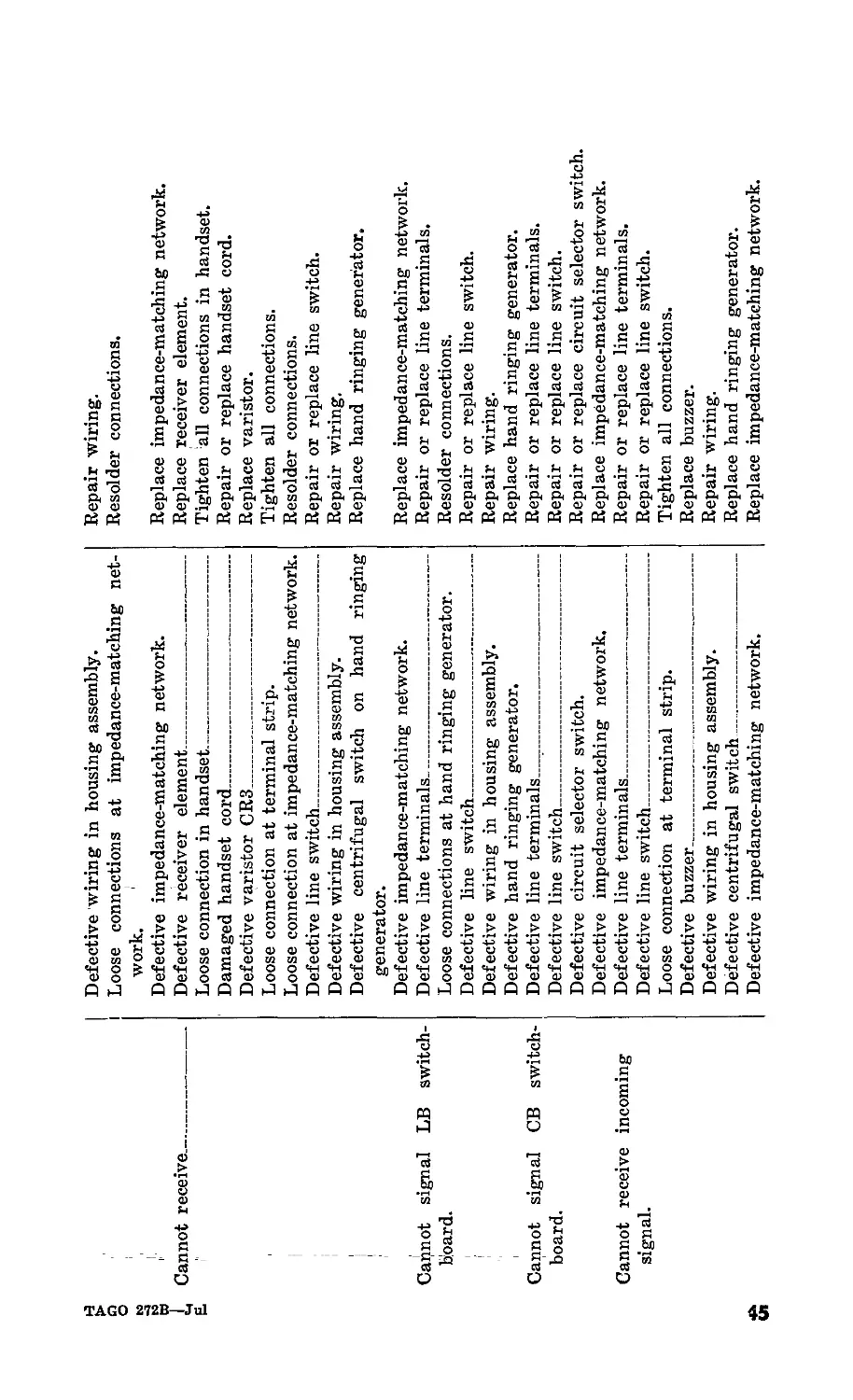
Cannot receive_________
Cannot signal LB switch-
board.
Cannot signal CB switch-
board.
Cannot receive incoming
signal.
Defective wiring in housing assembly.
Loose connections at impedance-matching net-
work.
Defective impedance-matching network.
Defective receiver element
Loose connection in handset
Damaged handset cord___________________________
Defective varistor CR3
Loose connection at terminal strip.
Loose connection at impedance-matching network.
Defective line switch
Defective wiring in housing assembly.
Defective centrifugal switch on hand ringing
generator.
Defective impedance-matching network.
Defective line terminals_______________________
Loose connections at hand ringing generator.
Defective line switch__________________________
Defective wiring in housing assembly.
Defective hand ringing generator.
Defective line terminals
Defective line switch
Defective circuit selector switch.
Defective impedance-matching network.
Defective line terminals_______________________
Defective line switch
Loose connection at terminal strip.
Defective buzzer
Defective wiring in housing assembly.
Defective centrifugal switch
Defective impedance-matching network.
Repair wiring.
Resolder connections.
Replace impedance-matching network.
Replace receiver element.
Tighten ‘all connections in handset.
Repair or replace handset cord.
Replace varistor.
Tighten all connections.
Resolder connections.
Repair or replace line switch.
Repair wiring.
Replace hand ringing generator.
Replace impedance-matching network.
Repair or replace line terminals.
Resolder connections.
Repair or replace line switch.
Repair wiring.
Replace hand ringing generator.
Repair or replace line terminals.
Repair or replace line switch.
Repair or replace circuit selector switch.
Replace impedance-matching network.
Repair or replace line terminals.
Repair or replace line switch.
Tighten all connections.
Replace buzzer.
Repair wiring.
Replace hand ringing generator.
Replace impedance-matching network.
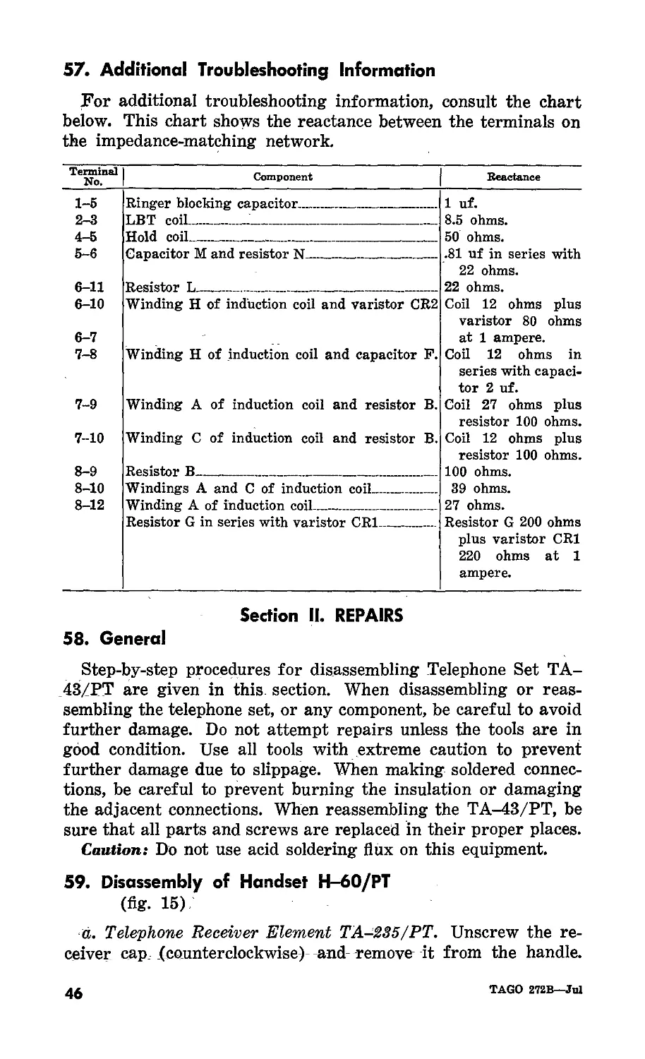
57. Additional Troubleshooting Information
For additional troubleshooting information, consult the chart
below. This chart shows the reactance between the terminals on
the impedance-matching network.
Terminal No. Component Reactance
1-5 Ringer blocking capacitor. .. „ . .. 1 uf.
2—3 LBT coil.... ... .... ........ . .. 8.5 ohms.
4-5 Hold coil . _ 50 ohms.
5-6 Capacitor M and resistor N . .... . .81 uf in series with
6-11 Resistor L .... 22 ohms. 22 ohms.
6-10 6-7 7-8 7-9 7-10 8-9 Winding H of induction coil and varistor CR2 Winding H of induction coil and capacitor P. Winding A of induction coil and resistor B. Winding C of induction coil and resistor B. Resistor B. .... . .... . . .. Coil 12 ohms plus varistor 80 ohms at 1 ampere. Coil 12 ohms in series with capaci- tor 2 uf. Coil 27 ohms plus resistor 100 ohms. Coil 12 ohms plus resistor 100 ohms. 100 ohms.
8-10 8-12 Windings A and C of induction coil Winding A of induction coil.. 39 ohms. 27 ohms.
Resistor G in series with varistor CR1 Resistor G 200 ohms plus varistor CR1 220 ohms at 1 ampere.
Section II. REPAIRS
58. General
Step-by-step procedures for disassembling Telephone Set TA-
43/PT are given in this section. When disassembling or reas-
sembling the telephone set, or any component, be careful to avoid
further damage. Do not attempt repairs unless the tools are in
good condition. Use all tools with extreme caution to prevent
further damage due to slippage. When making soldered connec-
tions, be careful to prevent burning the insulation or damaging
the adjacent connections. When reassembling the TA-43/PT, be
sure that all parts and screws are replaced in their proper places.
Caution: Do not use acid soldering flux on this equipment.
59. Disassembly of Handset H-60/PT
(fig. 15)
d. Telephone Receiver Element TA-235/PT. Unscrew the re-
ceiver cap (counterclockwise) and remove it from the handle.
46
TAGO 272B—Jul
The cap normally is hand tightened during assembly and should
be removable with a firm hand grip.
(1) Hold the handset cap side down. Gently tap the handle
as required to remove the receiver element.
(2) Disconnect the electrical connections at the receiver
terminals with a screwdriver. The position of the cord
tips with respect to the terminals is controlled by molded
projections on the terminal detail.
(3) During reassembly, be sure that the rubber gasket is
in place, that the molded projections on the terminal,
detail are toward the handle recess opening, and that
no conductor lead is ^pinched under the gasket as the
receiver cap is tightened.
b. Telephone Transmitter Element TA-117/PT. Unscrew the
transmitter cap (counterclockwise) and remove it from the handle.
The cap normally is hand tightened during assembly and should1
be removable with a firm hand grip.
(1) Hold the handset cap side down. Gently tap the handle
as required to remove the transmitter element assembly.
(2) Disconnect the electrical connections at the terminals on
the cup with a screwdriver. The position of the cord
tips with respect to the terminals is controlled by the
molded projections on the terminal detail.
(3) By removing the terminal screws entirely, the .006-uf
capacitor assembly can be removed from the cup.
(4) Remove the contact assembly from the transmitter ele-
ment by slipping the edge out from under the rubber
gasket.
(5) Remove the rubber gasket from the transmitter element.
The metal slip ring normally cemented to the front of
the gasket may become loosened. Do not lose it.
(6) During reassembly, be sure that the gasket is in place
at all points, that the slip ring is properly positioned,
and that no conductor lead is pinched under the gasket
as the transmitter cap is tightened.
c. De-Icing Screen. Remove the de-icing screen from the trans-
mitter cap by inserting a thin tool, such as a knife blade, into the
notch provided in the transmitter cap, and pry the screen from
its slot. Be careful when removing the screen to avoid damaging
the transmitter cap or the screen.
d. Switch Assembly SA-129/PT. Remove the two screws from
the plate, then lift the switch assembly out of the cavity in the
handle.
TAGO 272B—Jul
47
(1) Disconnect the three electrical connections at the termi-
nals on the switch with a screwdriver. The fourth
(white) terminal is soldered at the switch, and the lead
may be removed by loosening the transmitter cup
(white) terminal (b(2) above).
(2) Remove the rubber switch cover.
Figure 15. Components of handset H-60/PT.
e. Electrical Cord Assembly CX-2151/U. Remove the trans-
mitter element (b above) and the switch assembly (d above).
Loosen the two terminal screws in the transmitter handle cavity
and remove the cord tips. Loosen the screw that holds the stay
cord hook; be careful not to damage any of the cord conductors.
Be sure all internal connections are free, then remove the cord
from the handle by carefully pulling and twisting the cord
grommet. Loosen the other end of the cord in accordance with
paragraph 62d.
f. Varistor CR3. Loosen the terminals and stay cord hook or
remove the cord assembly (e above). Remove the two terminal
screws in the transmitter cavity. Varistor CR3 ihay now be
lifted out of its recess.
g. Wiring Harness. The wiring harness can be removed after
removing the receiver element (a above), and the transmitter
element (b above), and by loosening the cord terminal screws (e
above). Pull both leads from the receiver cavity. The molded
rubber barrier on the leads, which serves to block acoustically
the handle opening between the transmitter and receiver cavities,
may resist removal. If necessary, lubricate the barrier with
water.
48
TAGO 272B—Jul
Caution: Proper atmospheric pressure equalization for the re-
ceiver element requires a slight air leakage past the rubber barrier.
Therefore, in reassembly, do not apply vaseline or a similar
lubricant to the barrier, or pull it too far into the handle.
h. Waterproof Air Valves. The waterproof air valves are
cemented into the cavities and cannot be removed without damage.
60. Disassembly of Panel and Housing Assembly
(fig. 16)
Rubber water seal gaskets are provided around all assembly
screws, between the panel and housing details, between the
buzzer diaphragm and housing, and at all other external openings.
Avoid damage to these seals during any disassembly or reassembly.
a. Loosen the carrying case retaining strap (fig. 2) and re-
move the case.
b. Remove the four assembly screws that secure the buzzer to
the housing and then remove the six assembly screws on the face
of the panel (fig. 16).
c. Lift the panel off the housing; be careful not to damage
the leads to the ringing generator (fig. 16). All internal com-
ponents now are exposed.
61. Disassembly of Hand Ringing Generator G-42/PT
(fig. 16)
a. Unsolder the three leads to the generator terminals.
b. Remove the screw and lockwasher that hold the generator
crank assembly on the shaft. Remove the crank assembly.
c. Unscrew and remove the nut that secures the generator to
the housing.
d. Remove the two screws and the metal strap at the rear of
the generator mounting in the housing (fig. 16). Lift the gen-
erator from the housing. The spacer detail, including the three
waterproof air valves, is a separate part of the telephone and can
be removed at this time.
e. Unscrew and remove the back cover of the generator. This
exposes the centrifugal switch contact assembly. The gasket be-
tween the back cover and the generator frame provides a water-
proof seal.
f. Unsolder and tag the five conductors oh the switch assembly.
Remove the four mounting screws and the fiber switch mounting
plate. The centrifugal governor type mechanism that operates
the switch contacts then will be exposed.
TAGO 272B—Jul
49
g. Remove the nylon switch button at the center of the mechan-
ism. Carefully force the two weights apart and remove the screw
with the prong extension. Remove the centrifugal switch sub-
assembly from the generator shaft and further disassemble as
required.
h. Remove the two main assembly screws. If the front end
plate, stator, and rear end plate do not have position markers,
mark them with chalk, crayon, or pencil to make replacement of
the main assembly screws easier. Slide the rear end plate off
the rotor shaft. Remove the rotor and the stator as a unit from
the front end plate; be careful not to damage the coil or leads.
The stator prevents demagnetization of the rotor.
i. To replace the gear train in the G-42/PT, disassemble the
generator as follows:
(1) Screw one of the main assembly screws into the front
end plate and tap it gently with a 4-ounce hammer until
the gear case comes loose.
(2) Remove the gear assembly from the inside of the gear
case by lifting it from its stud.
(3) Remove the spur gear and shaft by placing a small drift-
pin against the shaft on the outside of the front cover
and pushing the shaft to the inside.
(4) Replace any of the disassembled parts that are worn
or damaged. Lubricate parts With Grease, Aircarft and
Instruments (GL), and reassemble the hand ringing
generator by reversing the procedure for disassembly.
62. Disassembly of Panel Components
(figs. 2 and 16).
The components mounted on the panel can be removed for
repair or replacement. The step-by-step procedure for removing
each of the components is described in a through h below.
a. Battery Compartment. Remove the two screws on the inside
of the cover (fig. 16) to remove the contact strip. Remove the
nut on the underside of the battery compartment to free the
bottom contact springs. Be careful not to damage the insulator
strip which is not removed. Remove the nut holding the cover
latch to remove the latch assembly.
b. Buzzer BZ-23/PT. Unsolder the leads at the buzzer termi-
nals. Remove the small wire Coupling pin that fastens the volume
control shaft to the flexible coupling detail and remove the buzzer
from the panel.
Note. When reinstalling the buzzer oh the panel, substitute a small cotter
pin for the small wire coupling pin. _
50
TAGO 272B—Jul
(1) To remove the coil and core from the frame, remove the
two assembly screws.
Caution: Do not loosen the two screws that hold the
pole plate to the frame, because any change in the posi-
tion of the pole plate will change the operating char-
' acteristics of the buzzer.
(2) The diaphragm is removed from the buzzer frame by
driving the two pins from the rear of the assembly. Use
the same pins when reassembling the buzzer.
(3) To remove the volume control knob, loosen the setscrew.
(4) Release the snap ring on the volume control shaft to
remove it from the volume control shaft bearing.
(5) Remove the volume control shaft bearing assembly by
loosening the locknut with a wrench of the proper size.
c. Circuit Selector Switch. Remove the buzzer (6 above) and
remove the impedance-matching network mounting screws and
lay the network aside. Remove the nut on the front panel and
lift the switch off the panel. Observe the method of keying the
switch to the panel. Unsolder the leads, and disassemble the
switch as required. Observe the position of the leads on the switch
to be sure that they are placed in the proper place when re-
assembled.
d. Electrical Cord Assembly CX-2151/U. Remove all cord
conductors from the terminal board, loosen the screw holding
the stay cord hook, and remove the cord from the panel by
carefully pulling and twisting the grommet on the end of the
cord. Loosen the other end of the cord in accordance with
paragraph 59e.
e. External Battery Connections. Remove the nut from the
underside of the panel, and push the terminal out of the panel.
The terminal is keyed to the panel.
f. Line Switch. Remove the two screws that hold the flat
restoring spring, the three screws that hold the switch button
assembly, the snap ring on the shaft, the shaft, and the rubber
diaphragm assembly from the bearing. Unsolder the leads and
disassemble the spring contact pileup as required.
g. Line Terminals. Unsolder the leads to the terminals, remove
the nut and push the terminal out of the panel. The terminal
bushing is keyed to the panel.
h. Impedance Matching Network CU-350/PT. Tag and un-
solder all leads to the network. Remove the small wire coupling
pin from the volume control shaft on the buzzer and move the
buzzer aside. Remove the four mounting screws and lift the
network from the panel.
IAGO 272B—Jul
51
HOUSING.
PANEL
GASKET
waterproof
AIR VALVES<
EXTERNAL
BATTERY
ASSEMBLY
SCREWS
HAND RINGING
GENERATOR
G-42/PT
• BUZZER
BZ-23/PT
BATTERY
COMPARTMENT
TERMINALS
CIRCUIT
SCHEMATIC
IMPEDANCE
MATCHING
NETWORK
CU-350/PT
TERMINAL
BOARD —
LINE TERMINALS-
GENERATOR
MOUNTING
STRAP
LINE SWITCH-
TERMINALS
TM 337 r 4
Figure 16. Telephone set TA-43/РТ, panel removed.
Section III. LUBRICATION DURING REPAIR
63. General
Telephone Set TA-43/PT is lubricated during manufacture.
However, during repair affecting particular parts, lubrication
should be applied in accordance with a through d below.
a. The lubricant and points to be lubricated must be clean and
free of sand, grit, or dirt.
b. Generally, parts should be cleaned with Solvent, Dry Clean-
ing (SD) before lubrication (par. 34b). Carbon tetrachloride
will be used as a cleaning fluid only where inflammable solvents
cannot be used because of fire hazards, and for cleaning electrical
contacts, including switch contacts.
Caution: Repeated contact of carbon tetrachloride with the
skin or prolonged breathing of the fumes is dangerous. Make
sure adequate ventilation is provided.
c. Use Oil, Lubricating, Preservative, Special (PL Special)
where a light machine oil is indicated (par. 64). The oil must not
interfere with the operation of the part at a temperature of
—40° F.
d. Use a small stick or No. 20 AWG bare wire to apply one
drop of lubricating oil to the specified location of parts (par
64).
52
TAGO 272B—Jul
Caution: Apply oil only to those locations which require lubrica-
tion.
64. Lubrication of Parts
a. Buzzer BZ-23/PT. Apply one drop of light lubricating oil
to the loudness control knob shaft bearing.
b. Hand Ringing Generator G-4-2/PT. Apply one drop of light
lubricating oil to the bearings at each end of the rotor. For
lubrication of the main crankshaft and gear train, use grease
(GL).
c. Other Parts. Apply one drop of light lubricating oil to
other parts as follows:
Part Point to be lubricated
Circuit selector switch Line switch Line terminals Shaft bearing. Plunger shaft bearing. Spring-loaded cap of each terminal.
Section IV. REFINISHING
65. General
When the finish on the panel or housing has been badly scarred
or damaged, prevent corrosion by touching up bared surfaces.
Complete refinishing is preferable to a large number of touchup
spots.
66. Repainting
a. Use No. 000 sandpaper to clean the surface; obtain a bright,
smooth finish.
Caution: Do not use steel wool. Minute particles may enter the
case and cause subsequent short-circuiting or grounding of the
circuits.
b. Remove corrosion, dirt, and grease, by cleaning with solvent
(SD). In severe cases, it may be necessary to use solvent (SD)
and sandpaper to complete the preparation for painting.
c. The paint used will be authorized and consistent with exist-
ing regulations.
Section V. FINAL TESTING
67. General
These tests are used to determine the quality of repaired
telephone sets. The test procedures described in paragraph 69
TAGO 272B—Jul
53
may be performed by maintenance personnel with adequate test
equipment and the necessary skills.
68. Equipment Required for Final Testing
Tests must be made with Test Set 1-142. (The set must be
adjusted and maintained in accordance with TM 11-2062, Test
Sets 1-142, I-142A, and I-142B). All connections must be made
at the line terminals of Telephone Set TA-43/PT.
69. Final Test Requirements
After the telephone set has been repaired and before it is
repacked (par. 71), it must meet the following requirements.
a. Screws. All assembly and mounting screws must be tight.
b. Handset Brackets. The handset retaining brackets must be
capable of holding the handset when the telephone set is in the
vertical position (fig. 1).
c. Switches. The line switch and the handset press-to-talk
switch must operate and restore freely. The circuit selector
switch must be easy to adjust with a screwdriver and have a
positive detent action at each position.
d. Water Seals. Water must not enter the sealed cavities, either
past the gaskets or through the waterproof air valves, when the
telephone set is immersed in water to a depth of 2 feet for 5
minutes.
e. Generator Test. Test the generator in accordance with para-
graph 29, TM 11-2062. With the line switch depressed, turn the
generator crank at approximately 200 rpm; the deflection of
meter Ml should be to the right of 0 db.
f. Buzzer Test. Test the buzzer in accordance with paragraph
30, TM 11-2062. With the line switch depressed, set control D5
to position 1, operate key 4 to RINGER, key 6 to CKT, and turn
the test set generator crank at the speed required to produce a
sustained audible signal. The deflection of meter Ml should be
to the left of 0 db for all positions of the buzzer loudness control
knob. In the LOW volume position, the clapper should not strike
the buzzer diaphragm. _______________
g. Insulation Resistance. Test the insulation resistance in ac-
cordance with paragraph 31, TM 11-2062. The deflection of meter
Ml should be to the left of —6 db.
h. Transmitter Circuit Tests. Connect the telephone set LINE
terminals to L1-L2 jack, on Test Set 1-142. Set control DI at 5,
D3 at 2, operate key 8 to TRANS and the equalizer to the OUT
position. Precondition and locate the transmitter element in
accordance with paragraph 246(1) and (2), TM 11-2062, then
complete the tests for the specified telephone set circuit as follows:
(1) CB circuit. Operate key 1 and key 2 to STA and depress
key 9. The reading of meter Ml should be to the right
of —7 db. There should be no output when the line
switch is depressed.
(2) LB and CBS circuits. Depress the handset press-to-talk
switch, then depress key 9. The reading of meter Ml
should be to the right of —2 db. There should be no
output when the press-to-talk switch is released.
i. Receiver Circuit Tests. Connect the telephone set LINE termi-
nals to L1-L2 jack on Test Set 1-142. Set control D2 at 3, D4
at 6, operate key 2 to RCT, key 8 to REC and the equalizer to the
OUT position. Locate the receiver element in accordance with
paragraph 24c (1), TM 11-2062. With the telephone set adjusted
for the CB circuit, depress key 9. The reading of meter Ml should
be to the right of 0 db.
TAGO 272B—JuJ
55
CHAPTER 6
SHIPMENT AND LIMITED STORAGE AND
DEMOLITION TO PREVENT ENEMY USE
70. Disassembly
To disassemble the telephone set for shipment or storage, pro-
ceed as follows:
a. Remove field line connections and both batteries from the
battery compartment.
b. Mount the handset inside the case with enough cushioning
material to prevent it from shifting during shipment.
c. Fold the case over the handset and close the zipper.
Note. The set and case should be dry and clean before packing.
71. Repacking for Shipment or Limited Storage
To repack the telephone set for shipment or storage, use the
original shipping container (par. 6) or a suitable substitute.
Reverse the unpacking instructions (par. 12).
72. Methods of Destruction
The demolition procedure given below will be used to prevent
the enemy from using or salvaging this equipment. Demolition of
the equipment will be accomplished only upon order of the com-
mander.
a. Smash. Smash the handset, switches, housing assembly,
buzzer diaphragm, and battery compartment; use sledges, axes,
pickaxes, hammers, crowbars, or other heavy tools.
b. Cut. Cut all cords, cables, and wiring; use axes, handaxes,
or machetes.
c. Burn. Burn cords, wiring, generator, handset, impedance-
matching network, and technical manuals; use gasoline, kerosine,
oil, flame throwers, or incendiary grenades.
d. Bend. Bend panel and housing assembly.
e. Explode. If explosives are necessary, use firearms, grenades,
or TNT.
f. Dispose. Bury or scatter the destroyed parts in slit trenches,
fox holes, or other holes, or throw them into streams.
g. Destroy. Destory everything.
56
TAGO 272B—Jul
INDEX
Paragraph Page
Additional troubleshooting information___________________________ 57 46
Antisidetone, circuit analysis__________________________________ 50c 38
Application, system----------------------------------------------- 4 4
Arctic climate, operation________________________________________ 24 15
Batteries, installing___________________________________________ 13b 10
Buzzer BZ-23/PT:
Final test requirements _______________________________ 69/' 54
Lubrication ________________________________________________ 64a 53
Theory ______________________________________________________ 46 32
Buzzer circuit, operational test-------------------------------- 55d 42
Calls incoming___________________________________________________ 20 14
Carrying Case CY-1277/PT, description---------------------------- 10 8
CB circuit:
Circuit analysis, transmitting------------------------- 50a (1) 37
Operational test_______________________________________ 55a 42
Signaling CB switchboard------------------------------- 49c 37
CBS circuit:
Circuit analysis:
Signaling CB switchboard--------------------------- 49d 37
Transmission_______________________________________ 50a (3) 37
Operation_________<____________________________________ 19c 14
Chart, troubleshooting____,_____________________________________ 56 43
Check:
Preinstallation ____________________________________________ 13c 11
Preventive maintenance:
Daily--------------------------------------------------- 36a 22
Monthly_________________________________________________ 36c 23
Weekly________________________________________________ 36b 22
Check list:
Equipment performance_________________________________________ 42 26
Using equipment performance___________________________________ 41 25
Circuit analysis:
Antisidetone _______________________________________________ 50c 38
Buzzer circuit _____________________________________________ 49a 36
CB circuit:
Signaling CB switchboard________________________________ 49c 37
Transmitting_________________________________________ 50a(l) 37
CBS circuit:
Signaling CB switchboard________________________________ 49d 37
Transmitting_________________________________________ 50a(3) 38
LB Circuit:
Signaling LB switchboard________________________________ 49b 36
Transmitting_______________________________________ 50a (2) 38
Receiving--------------------------------------------------- 50b 38
Circuit elements, Impedance Matching Network CU-350/U______ 48b 36
Circuit selector switch, lubrication____________________________ 64c 53
Components, major------------------------------------------------- 7 7
TAGO 272B—Jul 57
Paragraph Page
Connecting incoming lines_____________________________________ 146 12
Control panel, description_______________________________ ' 9 8
Controls, Handset H-60/PT______________________________________ 17 14
Daily check, preventive maintenance___________________________ 36a 22
Data, troubleshooting__________________________________________ 52 41
Definition of preventive maintenance___________________________ 33 18
Description:
Control panel_______________________________________________ 9 8
Handset H-60/PT_____________________________________________ 8 7
Panel and housing assembly__________________________________ 9 8
Desert;
Operation _________________________________________________ 26 16
Weatherproofing___________________________________________ 38d 23
Destruction, method____________________________________________ 72 56
Disassembly:
For packing________________________________________________ 70 56
Handset H-60/PT____________________________________________ 59 16
Panel and housing assembly_________________________________ 60 49
Disconnect procedure___________________________________________ 21 14
Domestic packed Telephone Set TA-43/PT, unpacking________ 126 10
Emergency operation____________________________________________ 30 17
Equipment performance check list_______________________________ 42 26
Equipment performance check list, use__________________________ 41 25
Equipment test_________________________________________________ 53 41
Export packed Telephone Set TA-43/PT, unpacking__________ 12a 10
Final test requirement___________________________________ 68, 69 54
Forms and records_______________________________________________ 2 3
Generator, Hand Ringing G-42/PT:
Final test requirements___________________________________ 69e 54
Lubrication_______________________________________________ 646 53
Theory ______________________________________________ 47 32
Handset brackets, final test requirements--------------------- 696 54
Handset H-60/PT:
Controls------------------------------------------------- 17 14
Description------------------------------------------------- 7 7
Disassembly ----------------------------------------------- 59 46
Minor components------------------------------------------ 11 9
High altitude operation________________________________________ 27 16
Impedance Matching Network CU-350/PT:
Circuit elements------------------------------------------ 486 34
Theory____________________________________________________ 48a 33
Incoming calls ------------------------------------------------ 20 14
Incoming lines, connecting------------------------------------ 146 13
Incoming signal, circuit analysis----------------------------- 48a 33
Information, additional, troubleshooting----------------------- 57 46
Inspection, visual--------------------------------------------- 40 24
Installation, Telephone Set TA-43/PT--------------------------- 14 12
Installing batteries------------------------------------------ 136 10
Insulation resistance, final test requirement----------------- 69# 54
58
TAGO 272B—Jul
Paragraph Page
- LB circuit, operational test_________________________________ 556 42
LB operation:
Circuit analysis, transmission_______________________ 50a(2) 38
Outgoing calls____________________________________________ 196 14
Receiving_________________________________________________ 506 38
Line switch, lubrication_______________________________________ 64c 53
Line terminals, lubrication____________________________________ 64c 53
Long loop, operation____________________________________________ 29 16
Lubricants, types_________________________________________ 63c 52
Lubrication:
Buzzer BZ-23/PT___________________________________________ 64a 53
Circuit selector switch___________________________________ 64c 53
Hand Ringing Generator G-42/PT____________________________ 646 53
Preparation_____:____________________________________ 636 52
Telephone Set TA-43/PT_____________________________________ 37 23
Maintenance:
Forms, preventive, use_____________________________________ 35 19
Preventive:
Daily check___________________________________________ 36a 22
Definition_____________________________________________ 33 18
Monthly check_________________________________________ 36c 23
Techniques--------------------------------------------- 34 18
Weekly check _________________________________________ 366 22
Major components_________________________________________________ 7 7
Materials, tools________________________________________________ 32 18
Method of destruction___________________________________________ 72 56
Minor components________________________________________________ 11 9
Network, impedance matching, theory---------------------------- 48a 33
Noisy area, operation___________________________________________ 28 16
Operation:
Arctic climates____________________________________________ 24 15
Desert climates ------------------------------------------- 26 16
Emergency__________________________________________________ 30 17
High altitudes--------------------------------------------- 27 16
Long loops______Z__—_—------------------------------------- 29 16
Noisy areas---------------------------------------------- 28 16
Radio remote control_______________________________________ 22 15
Tropical climates__________________________________________ 25 16
Usual conditions, outgoing calls___________________________ 19 14
Operational test___________________‘______________________ 55 42
Packaging data--------------------------------------------------- 6 6
Packing, disassembly ___________________________________________ 70 56
Panel and housing assembly:
Controls___________________________________________________ 16 13
Description ________________________________________________ 8 7
Disassembly ----------------------------------------------- 60 49
Minor components__________________________________________ 116 9
Performance checklist, equipment________________________________ 42 26
Precautions_____________________________________________________ 54 42
Preinstallation checks 13o 11
TAGO 272B—Jul
59
Paragraph Page
Preparation for lubrication______________________________ ,563b 52
Preventive maintenance:
Daily checks_________________________________________ 36a 22
Definition ------------------------------------------------ 33 18
Forms______________________________________________________ 35 19
Monthly check ____________________________________________ 36c 23
Techniques------------------------------------------------- 34 18
Weekly checks--------------------------------------------- 366 22
Procedure, troubleshooting___________________________________ 51 41
Radio remote control operation_________________________________ 22 15
Ranges, transmission___________________________________________ 3c 4
Receiver:
Final test requirement------------------------------------ 69г 55
Element, theory-------------------------------------------- 44 28
Receiving circuit analysis------------------------------------ 506 38
Records, forms__________________________________________________ 2 3
Repacking for shipment or storage______________________________ 71 56
Repainting ____________________________________________________ 66 53
Ringing off--------------------------------------------------- 21a 14
Seals, water, final test requirements_________________________ 69d 54
Service of used or reconditioned equipment--------------------- 15 13
Shipment or storage, repacking--------------------------------- 71 56
Signaling CB switchboard--------------------------------------- 49 36
Signaling LB switchboard, circuit analysis_____________________ 49 36
Storage or shipment, repacking_________________________________ 71 56
Switches, final test requirements_____________________________ 68c 54
System application______________________________________________ 4 4
Technical characteristics-----------------_-------------- 5 5
Techniques, maintenance, preventive____________________________ 34 18
Test equipment_________________________________________________ 53 41
Test requirements, final_________________________________ 68, 69 54
Theory:
Buzzer BZ-23/PT ___________________________________________ 46 32
Hand Ringing Generator G-42/PT____________________________ 47 32
Impedance Matching Network CU-350/PT______________________ 48a 33
Receiver element___________________________________________ 44 28
Transmitter element________________________________________ 45 30
Tools and material------------------------------------------- 32 18
Transmission circuit analysis---------------------------------- 50 37
Transmission circuits, impedance matching network________ 48c 36
Transmission ranges-------------------------------------------- 3c 4
Transmitter:
Circuit, final test requirement__________________________ 69Л. 54
Element, theory_______________________'______________ 45 30
Tropical climate:
Operation__________________________________________________ 25 16
Weatherproofing------------------------------------------- 386 23
Troubleshooting;
Chart ----------------------------------------------------- 56 43
Data-------.--------------52 41
60
TAGO 272B—Jul
Troubleshooting—Continued
Paragraph Page
Information, additional____________________________________ 57 46
Procedures_________________________________________________ 51 41
Types of lubricants___________________________________________ 63c 52
Unpacking______________________________________________________ 12 10
Visual inspection______________________________________________ 40 24
Water seals, final test requirement______________:_______ 69d 54
Weatherproofing _______________________________________________ 38 23
Weekly check, preventive maintenance__________________________ 36b 22
TAGO 272B
61
[AG 413.42 (23 Jun Б4)]
By order of the Secretaries of the Army and the
Air Force:
M. B. Ridgway,
General, United States Army,
Chief of Staff.
Official :
John a. Klein,
Major General, United States Army,
The Adjutant General.
N. F. Twining,
Official: Chief of Staff, United States Air Force.
K. E. Thiebaud,
Colonel, United States Air Force,
Air Adjutant General.
Distribution :
Active Army:
Tec Svc, DA (1)
Tec Svc Bd (1)
AFF (5)
AFF Bd (incl ea Test Sec) (1)
Army A A Comd (2)
OS Maj Comd (5)
OS Base Comd (5)
Log Comd (5)
MDW (2)
Armies (5)
Corps (2)
Tng Div (2)
Ft & Cp (2)
Gen & Br Svc Sch (5)
SigC Sch (25)
Gen Depots (2)
SigC Sec, Gen Depots (10)
Sig C Depots (20)
POE (2)
Os Sup Agencies (2)
SigC Fid Maint Shops (3)
SigC Lab (5)
MilDist(l)
Units organized under following T/O&E:
11-127, Sig Rep Co (2)
11-128A, Sig Depot Co (2)
11-500A (AA-AE); Sig Admin Team (2)
11-587, Sig Base Maint Co (2)
11-592, Hq & Hy Co, Sig Base Depot (2)
11-597, Sig Base Depot Co (2)
NG: Same as Active Army except allowance is one copy for each unit.
US AR: None.
Unless otherwise noted, distribution applies to C0NUS and overseas.
For explanation of abbreviations used;"see SR~320-50-l.
62
* U S GOVERNMENT PRINTING OFFICE 1981 341-647/1391
CORD ASSEMBLY
2 SWITCH S2 IS SHOWN DEPRESSED(HANDSET MOUNTED),
3 RESISTORS AND COIL WINDINGS ARE IN OHMS.CAPACITORS
ARE IN UF,
4, CRl,CR2, ANO CR3ARE VOLTAGE LIMITING VARISTORS.
ТМ337-Ю
Figure 17. Telephone set TA-431 PT, schematic diagram.
EXT. BAT
TERMINALS
BUZZER
BZ-23/PT
I 2 3 4 5 6 7 8 9 10 II 12
IMPEDANCE MATCHING
NETWORK
CU-350/PT
WHT-BLU J
CIRCUIT
SELECTOR c
SWITCH
SI
(CB position)
UNDERSIDE
OF PANEL
FURTHEST
FROM PANEL
ELECTRICAL-^
CORD ASSEMBLY
CX-2I5I/U
SWITCH ASSEMBLY
SA-I29/PT
(PRESS-TO-TALK)
TELEPHONE
RECEIVER ELEMENT
TA-235/PT
INSIDE OF
HOUSING
TELEPHONE
TRANSMITTER ELEMENT
TA-II7/PT
TM 337-20
HANDSET H-6O/PT