/


Text
WAR DEPARTMENT T
TM 11-259
CHNICAL MANUAL
RESTRICTED
WD. Clr. 33 1946
RADIO SET
AN/PRT-1
WAR DEPARTMENT
16 JUNE 1 9 4 5
i
WAR DEPARTMENT,
Washington 25, D. C., 16 June 1945.
TM 11-259, Radio Set AN/PRT-1, is published for the inform-
ation and guidance of all concerned.
[A. G. 300.7 (30 March 45).]
By Order of the Secretary of War :
G. C. MARSHALL,
Chief of Staff.
Official :
J. A. ULIO,
Major General,
The Adjutant General.
Distribution :
AAF (2) ; AGF (2) ; ASF (2); T of Opn (2) ;
Dept (2); Def Comd (2) ; Arm & Sv Bd (2) ; S Div
ASF (1) ; Tech Sv (2) ; SvC (2) ; PE (2) ; Gen
Overseas SOS Dep (Sig Sec) (2) ; Dep 11 (2) ;
Gen & Sp Sv Sch (2) ; USMA (10) ; WDGS Lib (5);
Lab 11 (2) ; A (2) ; Three (3) copies to each of the
following: T/O & E 11-107; 11-127; 11-587; 11-592;
11-597.
(For explanation of symbols see FM 21-6.)
ii
TABLE OF CONTENTS
Paragraph Page
PART ONE. Introduction.
Section I. Description of Radio Set AN/PRT-1.
General....................................... 1 1
Application..................... 2 1
Technical characteristics of
Radio Set AN PRT-1............ 3 1
Table of components............. 4 2
Packaging data.................. 5 2
Description of major
components ..................... 6 3
IL Installation of Radio Set AN/PRT-1.
Unpacking, uncrating, and
checking ....................... 7 4
Installation of batteries..... 8 5
PART TWO. Operating instructions.
Section III. Controls and their use.
Transmitter controls ........................... 9 7
IV. Operation.
General................................ 10 7
Testing........................ 11 7
Starting procedure for
delayed operation ............. 12 8
Instantaneous operation
instructions .................. 13 9
Master switch ................. 14 9
Use ........................... 15 10
Antenna arrangements .......... 16 11
PART THR EE. Maintenance instructions (not used).
PART FOU R. Auxiliary equipment (not used).
iii
TABLE OF CONTENTS
Paragraph Page
PART FIV E. Repair instructions
Section V. Theory of equipment.
General..................................... 17 17
Simplified schematic diagram.. 18 17
VI. Trouble shooting (not used).
VII. Repairs.
General............................... 19 20
Unsatisfactory Equipment
Report........................ 20 20
VIII. Alignment and adjustment (not used).
APPENDIX.
Section IX. References.
Publications................................. 21 24
Forms......................... 22 24
Abbreviations ................ 23 24
Glossary ..................... 24 24
X. Maintenance parts.
Maintenance parts for
Radio Set AN/PRT-1 ................. 25 24
LIST OF ILLUSTRATIONS
Fig. Ne. Title Page
1 Radio Set AN/PRT-1............................ VI
2 Radio Set AN/PRT-1, transmitter unit....... 3
3 Transmitter unit, showing location of wingnuts. 4
4 Transmitter unit, end plate removed............ 5
5 Transmitter unit, disassembled................. 6
6 Time clock set for delayed operation........... 8
7 Time clock set for instantaneous operation. 9
8 Vertical antenna arrangement.................. 11
9 Alternate antenna arrangement, directional.... 12
10 Alternate antenna arrangement, nondirectional. 12
11 Transmitter unit, schematic diagram........... 18
12 W.D., A.G.O. Form No. 468 with sample entries. 21
iv
DESTRUCTION NOTICE
WHY —To prevent the enemy from using or salvaging this equip-
ment for his benefit.
WHEN —When ordered by your commander.
HOW —1. Smash—Use sledges, axes, handaxes, pickaxes, ham-
mers, crowbars, heavy tools.
2. Cut —Use axes, handaxes, machetes.
3. Burn —Use gasoline, kerosene, oil, flame throwers,
incendiary grenades.
4. Explosives—Use firearms, grenades, TNT.
5. Disposal —Bury in slit trenches, fox holes, other
holes. Throw in streams. Scatter.
USE ANYTHING IMMEDIATELY AVAILABLE FOR
DESTRUCTION OF THIS EQUIPMENT.
WHAT—1. Smash—Batteries, reels, transformer, clock, switch,
spark gap, coils, and capacitors.
2. Cut —Wires and rope.
3. Burn —Housing, technical manuals.
4. Bury or scatter—Any or all of the above pieces after
breaking.
DESTROY EVERYTHING
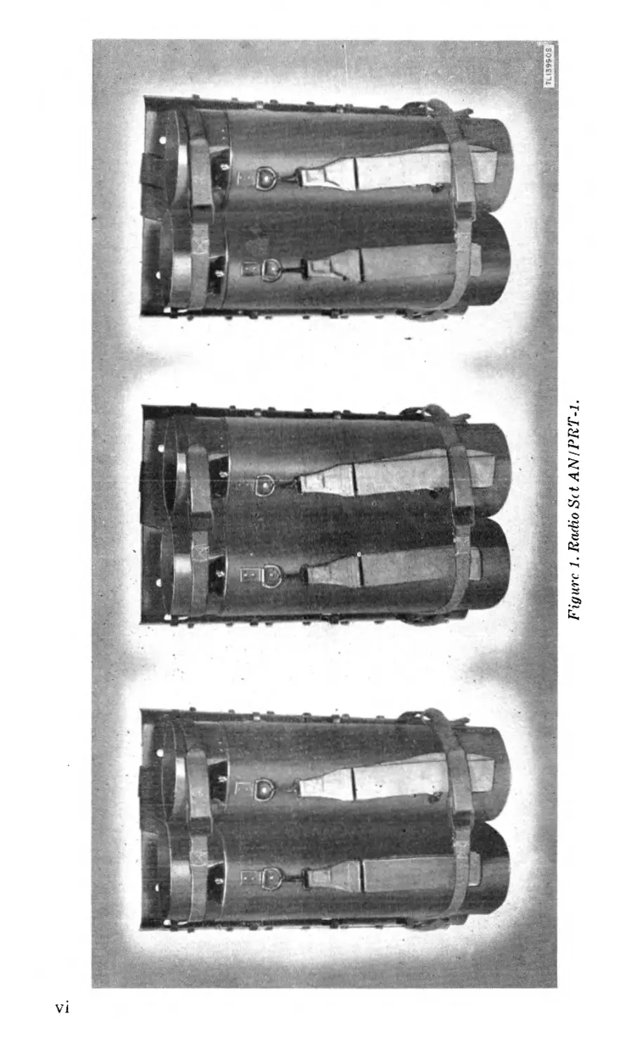
Figure 1. Radio Set AN/PRT-1.
PART ONE
INTRODUCTION
SECTION I
DESCRIPTION OF RADIO SET AN/PRT-1
1.. GENERAL.
Radio Set AN/PRT-1 is an expendable barrage-type jammer
for use against enemy radio communications. The radio set trans-
mits continuous broad-band spark signals effective over a very
wide frequency range. Two transmitters are carried on a standard
Quartermaster packboard, three of which are supplied with each
Radio Set AN/PRT-1 (fig. 1). If the use of the packboard is not
desirable, the transmitters may be carried by means of a shoulder
sling supplied with each unit. Preset time operation is provided by
a timer mechanism, or the units may be set to operate immediately
after placement.
2. APPLICATION.
a. General. Radio Set AN/PRT-1 consists of a group of six units
which cover a frequency band of 950 to 7,000 kilocycles (kc). The
six units are intended to be used in a group.
b. Power Source. For each transmitter sixteen dry-cell Batter-
ies BA-37 connected in series-parallel to supply 12 volts, give an
operating life of 4 hours. Ninety-six Batteries BA-37 are required
for Radio Set AN/PRT-1.
3. TECHNICAL CHARACTERISTICS OF RADIO SET AN/PRT-1.
Frequency range:
Radio Transmitter T-135 PRT-1........ 950 to 1,330 kc
Radio Transmitter T-136 PRT-1.......1,330 to 1,850 kc
Radio Transmitter T-137 PRT-1.......1,850 to 2,580 kc
Radio Transmitter T-138 PRT-1.......2,580 to 3,600 kc
' Radio Transmitter T-139 PRT-1.......3,600 to 5.020 kc
Radio Transmitter T-140 PRT-1.......5,020 to 7,000 kc
Type of signal emitted..........................damped wave
Antenna ........................................straight-wire
1
Counterpoise ......
Number of tubes . . .
Type of transmitter
............straight-wire
.....................none
....................spark
Power output.........................1.5 to 4 watts depending
on frequency: lower
output at higher fre-
quencies.
Power supply............................Batteries BA-37, 16 re-
quired for each trans-
mitter ; 96 required for
complete Radio Set
AN/PRT-1.
4. TABLE OF COMPONENTS.
NOTE: This list is for general information only. See appropriate
publications for information pertaining to requisition of spare parts.
I , Component Required No. Diameter I (in.) i Length (in.) Weight i (IbJ
j Package 1: 1 i I
Radio Transmitter i T-135 PRT-l 1 6’2 22’« 18 i
Radio Transmitter T-136 PRT-l 1 6’2 22?* । 18
Packboard 1 15* 25’2 6’2
[ Package 2:
Radio Transmitter T-137 PRT-l 1 1 1 ! 6’2 22\ 18
Radio Transmitter t-138 prt-1 ; 1 1 1 6’2 22-’ч 18
Packboard I 1 !.->• 25’2 6’2
Package 3:
Radio Transmitter T 139 PRT-l 1 C.'> i 22\ 18
Radio Transit itter ! T 149 PRT 1 । 1 I G1 •> 1 22 \ IS
Packboard 1 15* 25’2 6’2
* Width measurement.
NOTE: Batteries are not shipped with set.
5. PACKAGING DATA.
a. General. Radio Set AN PRT-l is packed in three boxes. Each
transmitter is padded and wrapped with paper and put into a
2
moistureproof foil bag. The units are then placed in paper cartons
and packed two each in wooden export boxes.
b. Packed for Domestic and Export Shipping.
1 Box No. Required 1 Height (in.) Depth (in.) length (in.) | Gross ! weight (lb.)
!' ‘ ~ 1 15 20 32 i 70
, 2 1 1 - |_ lo ! 20 32 ' 70
3 1 I la 20 32 1 70
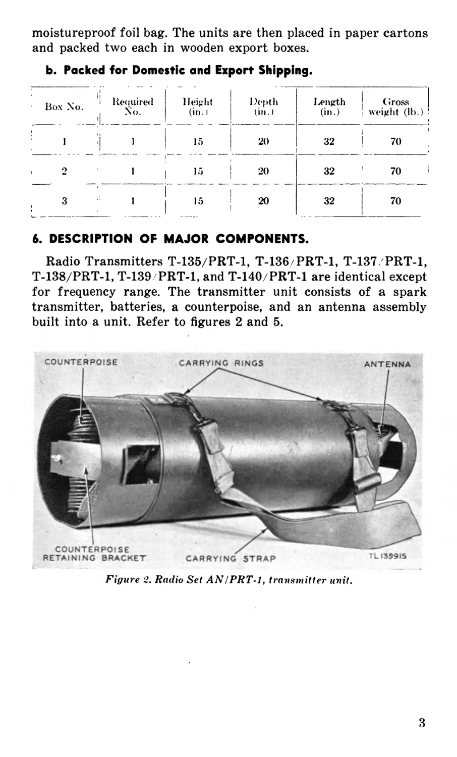
6. DESCRIPTION OF MAJOR COMPONENTS.
Radio Transmitters T-135/PRT-1, Т-136/PRT-1, T-137/PRT-1,
T-138/PRT-1, T-139 PRT-1, and Т-140/PRT-1 are identical except
for frequency range. The transmitter unit consists of a spark
transmitter, batteries, a counterpoise, and an antenna assembly
built into a unit. Refer to figures 2 and 5.
COUNTERPOISE CARRYING RINGS ANTENNA
Figure 2. Radio Set AN I PRT-1, transmitter unit.
3
SECTION II
INSTALLATION OF RADIO SET AN/PRT-1
7. UNPACKING. UNCRATING. AND CHECKING.
Three boxes are used to ship Radio Set AN PRT-l. Each box
should be opened carefully with the proper tools. Steel strapping
can be broken easily with a claw hammer or tin snips. Remove the
nails from the lid of each box with a nail puller, wrecking bar, or
claw hammer, and lift out the transmitters and packboard. Take
each carton out of the export box before removing any packing
or paper. Inspect each piece of equipment as soon as it is unpacked
for any possible damage caused in shipment.
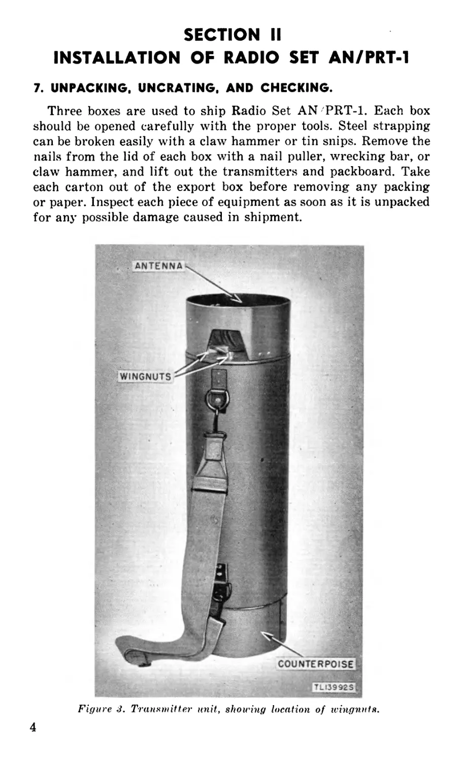
Figure J. Transmitter unit, showing location of wingnuts.
4
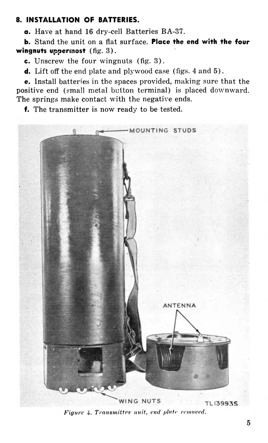
8. INSTALLATION OF BATTERIES.
a. Have at hand 16 dry-cell Batteries BA-37.
b. Stand the unit on a flat surface. Place the end with the four
wingnuts uppermost (fig. 3).
c. Unscrew the four wingnuts (fig. 3).
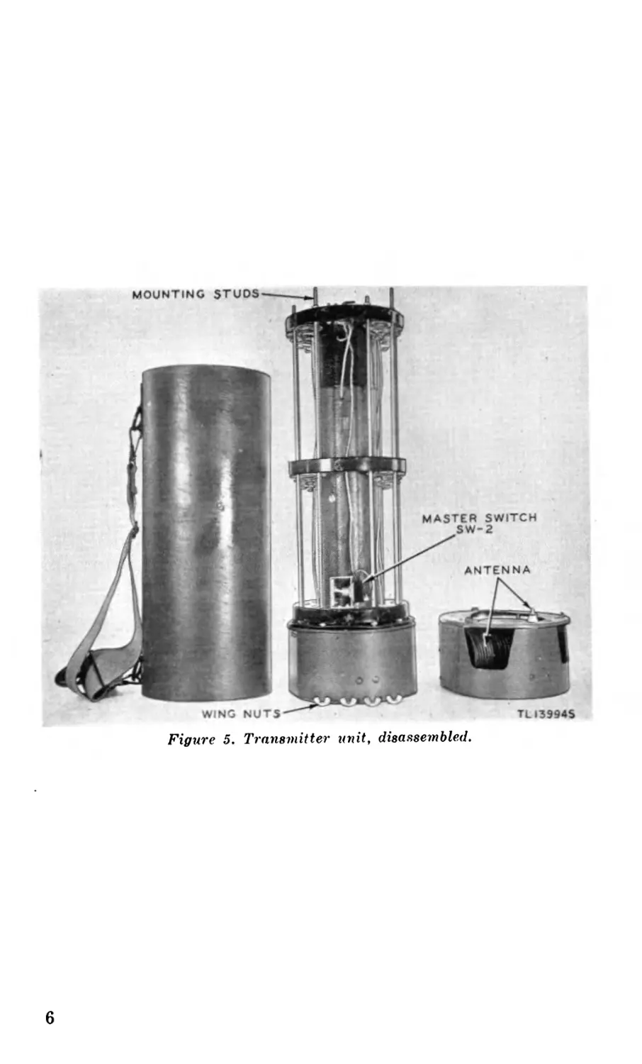
d. Lift off the end plate and plywood case (figs. 4 and 5).
e. Install batteries in the spaces provided, making sure that the
positive end (small metal button terminal) is placed downward.
The springs make contact with the negative ends.
f. The transmitter is now ready to be tested.
Figure 4. Transmitter unit, end plate removed.
5
Figure 5. Transmitter unit, disassembled.
6
PART TWO
OPERATING INSTRUCTIONS
NOTE: For information on destroying the equipment to prevent enemy
use, refer to the destruction notice at the front of the manual.
SECTION III
CONTROLS AND THEIR USE
9. TRANSMITTER CONTROLS (figs. 5, 6, and 7).
The controls for the transmitter unit consist of a master switch
to control application of power, and four controls located on the
clockface of each unit, as follows:
a. A lever installed on the lower part of the clockface provides
for instant or delayed operation.
b. On the front of the clock is a key for winding.
c. Two pointers are provided on the face of the clock for timing.
(I) The white pointer sets the time for operation to start.
(2) The black pointer sets the time for operation to stop.
SECTION IV
OPERATION
10. GENERAL.
Each unit is adjusted for proper functioning during manufac-
ture and no further adjustment should be attempted. Radio Set
AN/PRT-1 is expendable equipment. If any unit of the set fails
to operate properly after the following test, use a new unit and
destroy the faulty equipment, after having filled out an unsatis-
factory equipment report (par. 20).
11. TESTING.
a. Set lever on clock to INSTANT position ( fig. 7).
b. Set the master switch to the ON position (fig. 5). A buzzing
sound should be heard.
7
c. At the completion of above test, set the master switch to the
OFF position.
d. If a radio receiver is available, the following test is recom-
mended :
(1) Tune the receiver to a frequency within the range of the
units being tested.
(2) Select the units to be tested, and place them within 10 feet
of the receiver.
(£) Throw lever on clock to INSTANT position (fig. 7).
(4) Throw master switch to ON position.
(5) If unit is operating properly, a roaring sound will be heard
in the receiver.
(£) At the completion of above test, throw master switch to
OFF position.
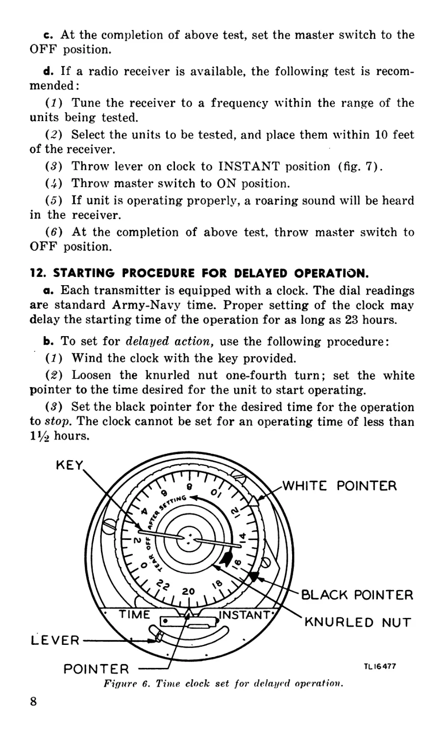
12. STARTING PROCEDURE FOR DELAYED OPERATION.
a. Each transmitter is equipped with a clock. The dial readings
are standard Army-Navy time. Proper setting of the clock may
delay the starting time of the operation for as long as 23 hours.
b. To set for delayed action, use the following procedure:
(1) Wind the clock with the key provided.
(2) Loosen the knurled nut one-fourth turn; set the white
pointer to the time desired for the unit to start operating.
(#) Set the black pointer for the desired time for the operation
to stop. The clock cannot be set for an operating time of less than
V/> hours.
Figure 6. Time, clock set for delayed operation.
8
(4) Turn the dial until the time of day is opposite pointer.
(5) Tighten the knurled nut while holding the dial, making sure
the white and black pointers are still in position.
(£) Be sure the lever is moved to the TIME position.
(7) Tear off the paper clock dial.
(8) For an example of how to set the clock, see figure 6. The
clock is set to start the unit at 1200 hours and to stop at 1600
hours. The time of day is 2000 hours.
(.9) After the clock has been set, reassemble the unit.
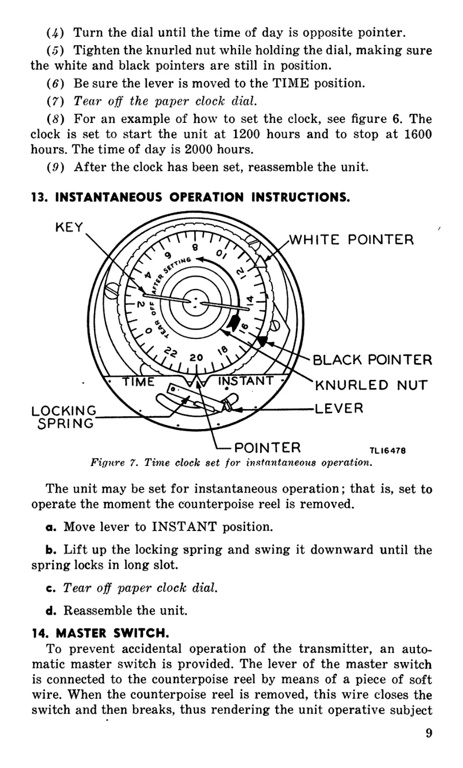
13. INSTANTANEOUS OPERATION INSTRUCTIONS.
Figure 7. Time clock set for instantaneous operation.
The unit may be set for instantaneous operation; that is, set to
operate the moment the counterpoise reel is removed.
a. Move lever to INSTANT position.
b. Lift up the locking spring and swing it downward until the
spring locks in long slot.
c. Tear off paper clock dial.
d. Reassemble the unit.
14. MASTER SWITCH.
To prevent accidental operation of the transmitter, an auto-
matic master switch is provided. The lever of the master switch
is connected to the counterpoise reel by means of a piece of soft
wire. When the counterpoise reel is removed, this wire closes the
switch and then breaks, thus rendering the unit operative subject
9
to the time switch on the clock. The set will not become operative
until the master switch has been closed by the removal of the
counterpoise reel.
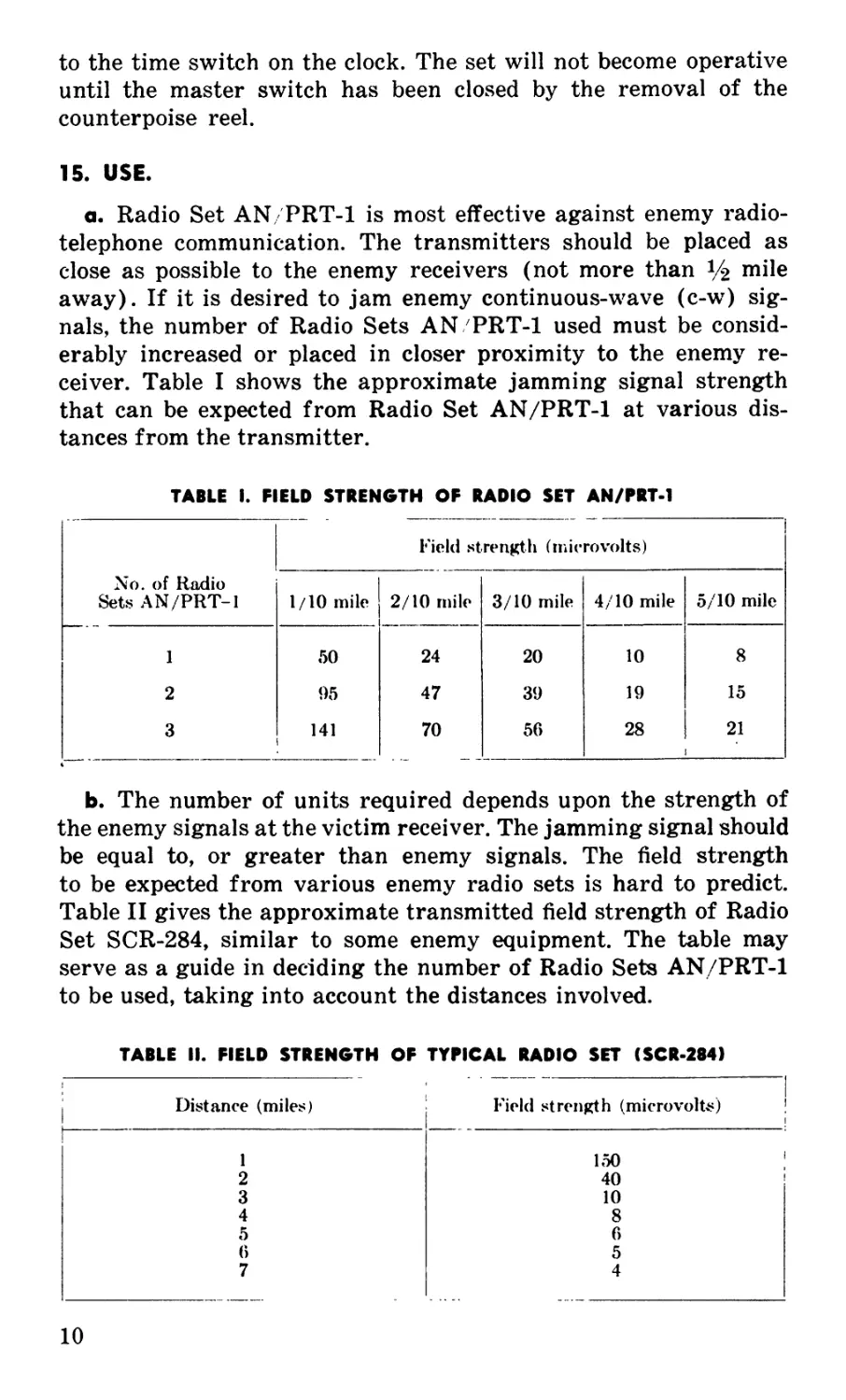
15. USE.
a. Radio Set AN/PRT-1 is most effective against enemy radio-
telephone communication. The transmitters should be placed as
close as possible to the enemy receivers (not more than Ц mile
away). If it is desired to jam enemy continuous-wave (c-w) sig-
nals, the number of Radio Sets AN PRT-1 used must be consid-
erably increased or placed in closer proximity to the enemy re-
ceiver. Table I shows the approximate jamming signal strength
that can be expected from Radio Set AN/PRT-1 at various dis-
tances from the transmitter.
TABLE I. FIELD STRENGTH OF RADIO SET AN/PRT-1
Field strength (microvolts)
No. of Radio Sets AN/PRT-1 1/10 mile 2/10 mile 3/10 mile 4/10 mile 5/10 mile
1 *50 24 20 10 8
2 95 47 39 19 15
3 141 70 56 28 21
b. The number of units required depends upon the strength of
the enemy signals at the victim receiver. The jamming signal should
be equal to, or greater than enemy signals. The field strength
to be expected from various enemy radio sets is hard to predict.
Table II gives the approximate transmitted field strength of Radio
Set SCR-284, similar to some enemy equipment. The table may
serve as a guide in deciding the number of Radio Sets AN/PRT-1
to be used, taking into account the distances involved.
TABLE II. FIELD STRENGTH OF TYPICAL RADIO SET (SCR-284)
j Distance (miles) Field strength (microvolts)
1 150 ;
2 40 ’
3 10
4 8
5 6
6 5
7 4
10
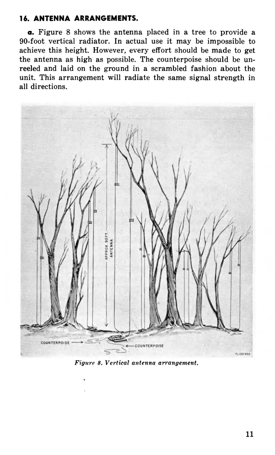
16. ANTENNA ARRANGEMENTS.
a. Figure 8 shows the antenna placed in a tree to provide a
90-foot vertical radiator. In actual use it may be impossible to
achieve this height. However, every effort should be made to get
the antenna as high as possible. The counterpoise should be un-
reeled and laid on the ground in a scrambled fashion about the
unit. This arrangement will radiate the same signal strength in
all directions.
Figure 8. Vertical antenna arrangement.
11
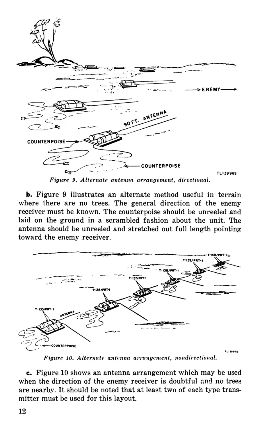
ENEMY---->
Figure 9, Alternate antenna arrangement, directional.
TLI3996S
b. Figure 9 illustrates an alternate method useful in terrain
where there are no trees. The general direction of the enemy
receiver must be known. The counterpoise should be unreeled and
laid on the ground in a scrambled fashion about the unit. The
antenna should be unreeled and stretched out full length pointing
toward the enemy receiver.
Figure 10. Alternate antenna arrangement, nondirectional.
c. Figure 10 shows an antenna arrangement which may be used
when the direction of the enemy receiver is doubtful and no trees
are nearby. It should be noted that at least two of each type trans-
mitter must be used for this layout.
12
PART THREE
MAINTENANCE INSTRUCTIONS
NOT APPLICABLE
13
14
PART FOUR
AUXILIARY EQUIPMENT
NOT USED
15
16
PART FIVE
REPAIR INSTRUCTIONS
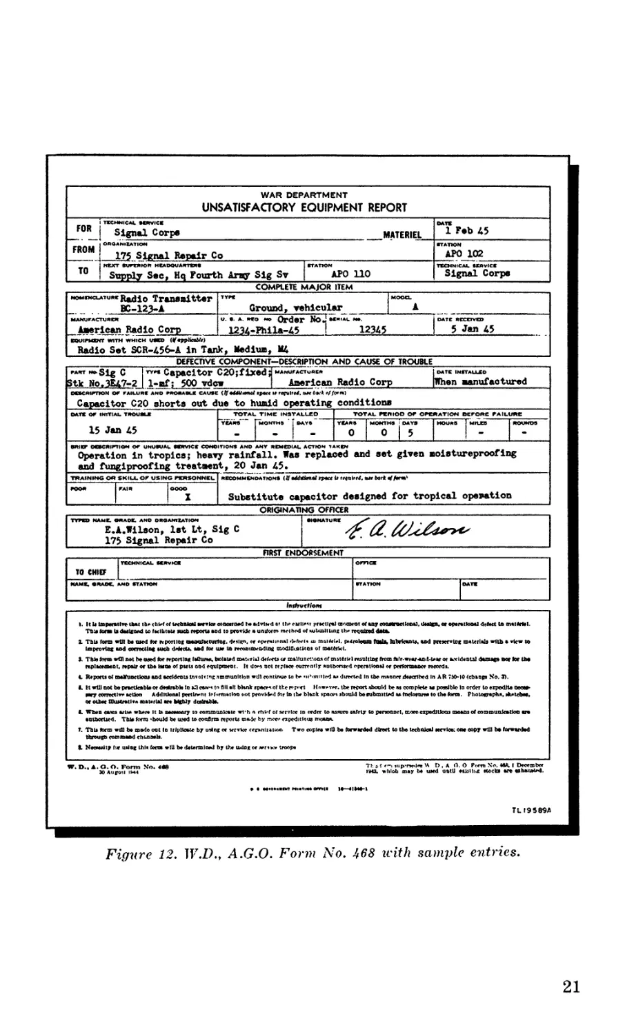
NOTE: Failure or unsatisfactory performance of equipment used by
Army Ground Forces and Army Service Forces will be reported on
W.D., A.G.O. Form No. 468 (Unsatisfactory Equipment Report) ; by
Army Air Forces, on Army Air Forces Form No. 54 (Unsatisfactory
Report). If either form is not available, prepare the data according
to the sample form reproduced in figure 12.
SECTION V
THEORY OF EQUIPMENT
17. GENERAL.
Each unit of this set is a simple spark transmitter which will
jam enemy radio communications over a very wide band of fre-
quencies. Thus, fewer transmitter units are required for jamming
an extremely wide range of frequencies. Spark interference is par-
ticularly effective against amplitude-modulated signals, widely
used by the enemy. Since the equipment is expendable and has a
short life, the design of this equipment is as simple as possible.
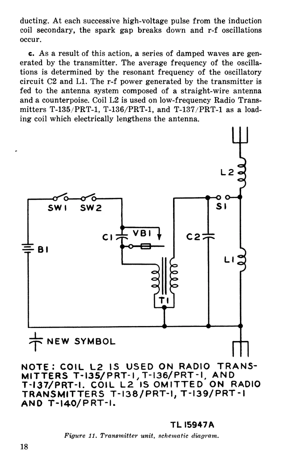
18. SIMPLIFIED SCHEMATIC DIAGRAM.
For the following circuit analysis, refer to the schematic diagram
(fig. 11).
a. When switches SW1 and SW2 are closed, current flows from
the 12-volt battery supply through switches SW1 and SW2, vi-
brator VB1, and the primary of the induction coil to the negative
side of the battery. Time switch SW1 is operated by the time clock,
and is also controlled by the lever which provides instant or delayed
operation. Both switches must be closed to make the unit operate.
To prevent operation of the unit before it is desired, master
switch SW2 remains open until the counterpoise reel is removed.
At this time, switch SW2 closes automatically.
b. The vibrator interrupts the direct current, so that a pulsating
current flows through the primary of induction coil Tl. Capacitor
Cl reduces sparking at the vibrator points. The pulsating current
in the primary induces a high voltage across the secondary of in-
duction coil Tl. This high voltage is applied across capacitor C2
which is part of the radio-frequency (r-f) oscillating circuit com-
posed of coil LI and capacitor C2. This high voltage breaks down
the spark gap SI, so that capacitor C2 discharges through coil LI
and r-f oscillations occur in this circuit. These oscillations continue
until the energy is dissipated and the spark gap becomes noncon-
17
ducting. At each successive high-voltage pulse from the induction
coil secondary, the spark gap breaks down and r-f oscillations
occur.
c. As a result of this action, a series of damped waves are gen-
erated by the transmitter. The average frequency of the oscilla-
tions is determined by the resonant frequency of the oscillatory
circuit C2 and LI. The r-f power generated by the transmitter is
fed to the antenna system composed of a straight-wire antenna
and a counterpoise. Coil L2 is used on low-frequency Radio Trans-
mitters T-135/PRT-1, T-136/PRT-1, and T-137/PRT-1 as a load-
ing coil which electrically lengthens the antenna.
NOTE; COIL L2 is used on radio trans-
MITTERS T-I35/PRT-I, T-I36/PRT-I, AND
T-I37/PRT-I. COIL L2 IS OMITTED ON RADIO
TRANSMITTERS T-I38/PRT-I, T-I39/PRT-I
AND T-I40/PRT-I.
TL 15947 A
Figure 11. Transmitter unit, schematic diagram.
18
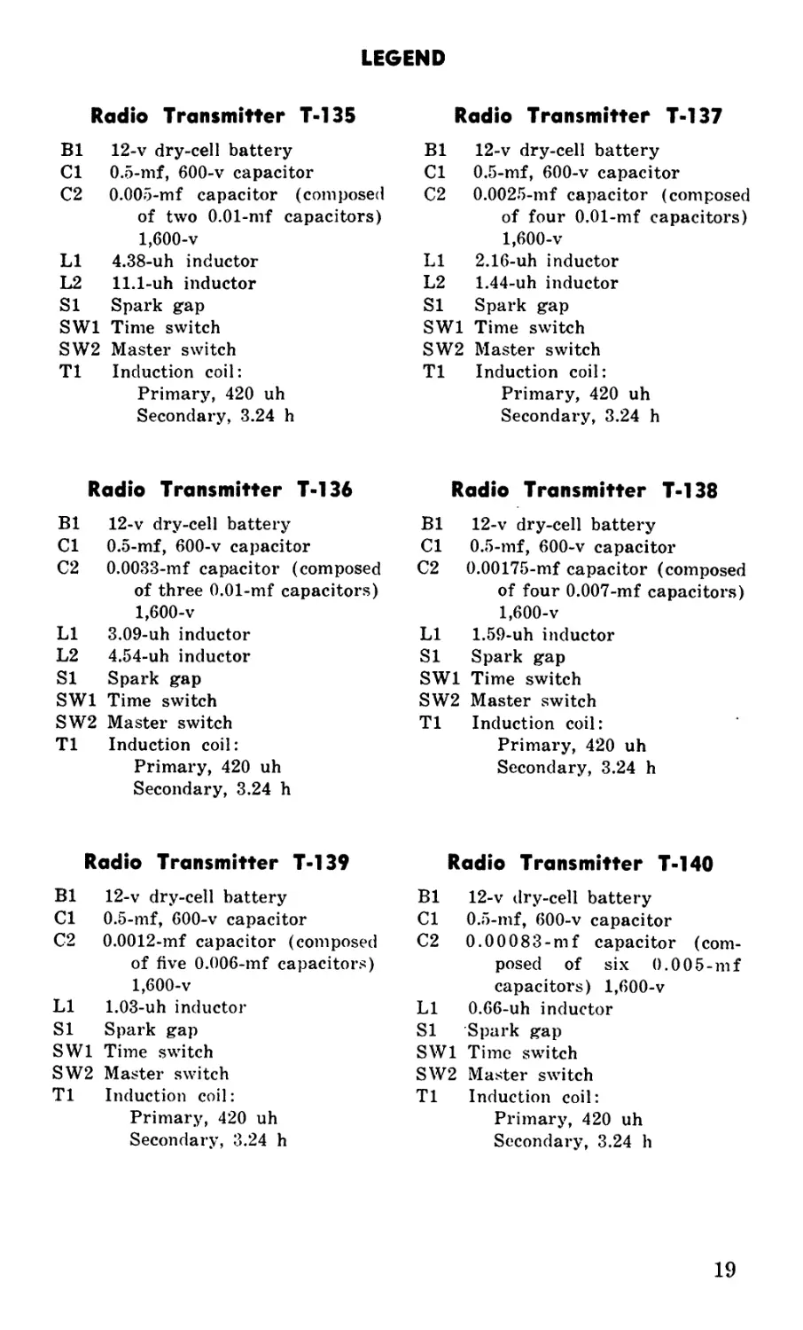
LEGEND
Radio Transmitter T-137
Radio Transmitter T-135
Bl 12-v dry-cel I battery Bl 12-v dry-cell battery
Cl 0.5-mf, 600-v capacitor Cl 0.5-mf, 600-v capacitor
C2 0.005-mf capacitor (composed of two 0.01-mf capacitors) 1,600-v C2 0.0025-mf capacitor (composed of four 0.01-mf capacitors) 1,600-v
LI 4.38-uh inductor LI 2.16-uh inductor
L2 11.1-uh inductor L2 1.44-uh inductor
SI Spark gap SI Spark gap
SW1 Time switch SW1 Time switch
SW2 Master switch SW2 Master switch
T1 Induction coil: Primary, 420 uh Secondary, 3.24 h T1 Induction coil: Primary, 420 uh Secondary, 3.24 h
Radio Transmitter T-136 Radio Transmitter T-138
Bl 12-v dry-cell battery Bl 12-v dry-cell battery
Cl 0.5-mf, 600-v capacitor Cl 0.5-mf, 600-v capacitor
C2 0.0033-mf capacitor (composed of three 0.01-mf capacitors) 1,600-v C2 0.00175-mf capacitor (composed of four 0.007-mf capacitors) 1,600-v
LI 3.09-uh inductor LI 1.59-uh inductor
L2 4.54-uh inductor SI Spark gap
SI Spark gap SW1 Time switch
SW1 Time switch SW2 Master switch
SW2 Master switch T1 Induction coil:
T1 Induction coil: Primary, 420 uh Secondary, 3.24 h Primary, 420 uh Secondary, 3.24 h
Radio Transmitter T-139 Radio Transmitter T-140
Bl 12-v dry-cell battery Bl 12-v dry-cell battery
Cl 0.5-mf, 600-v capacitor Cl 0.5-mf, 600-v capacitor
C2 0.0012-mf capacitor (composed of five 0.006-mf capacitors) 1,600-v C2 0.00083-mf capacitor (com- posed of six 0.005-mf capacitors) 1,600-v
LI 1.03-uh inductor LI 0.66-uh inductor
SI Spark gap SI Spark gap
SW1 Time switch SW1 Time switch
SW2 Master switch SW2 Master switch
T1 Induction coil: Primary, 420 uh Secondary, 3.24 h T1 Induction coil: Primary, 420 uh Secondary, 3.24 h
19
SECTION VI
TROUBLE SHOOTING
NOT APPLICABLE
SECTION VII
REPAIRS
19. (GENERAL.
Sira. ce Radio Set AN/PRT-1 is an expendable item, no repair
instrui ctions are required. Defective equipment should be destroyed,
after determining that no batteries have been left in the unit.
20. U «SATISFACTORY EQUIPMENT REPORT.
a. "^Vhen trouble in equipment used by Army Ground Forces or
Army”" Service Forces occurs more often than repair personnel feel
is normal, War Department Unsatisfactory Equipment Report,
W.D.„ A.G.O. Form No. 468, should be filled out and forwarded
throu j^rh channels to the Office of the Chief Signal Officer, Wash-
ingtoin 25, D. C.
b. "%¥hen trouble in equipment used by Army Air Forces occurs
more often than repair personnel feel is normal, Army Air Forces
Form No. 54 should be filled out and forwarded through channels.
с. I f either form is not available, prepare the data according to
the mple form reproduced in figure 12.
20
WAR DEPARTMENT UNSATISFACTORY EQUIPMENT REPORT
FOR i tkcssnical axwvicx Signal Corps MATERIEL СМТЖ 1 Fob 45
FROM OROANIXATIOH 175 Signal Repair Co STATION APO 102
TO NEXT SureWION HEADQUARTER* I ETATTON Supply Sec, Hq Fourth Army Sig Sv | APO 110 TECHNICAL SEAVICE Signal Corps
NOMXNctATumrRadio Transmitter
......... BC-123-A______________
MANUFACTURER
American Radio Corp_____________
COMPLETE MAJOR ITEM
Groundy vehicular
1234-Phila-45
1
12345
j DATE RCCXrVW
I 5 Jan 45
Radio Set SCR-456-A in Tank, Medium, Щ
DEFECTIVE COMPONENT—DESCRIPTION AND CAUSE OF TROUBLE
I DATE 1НЯТА1ХСО
[When Manufactured
Sig C |rY'* Capacitor C20;fixed d manufactU»cr
a.3E47-2 | 1-af; 500 vdew________________ | American Radio Corp
5tk No,3E47-
Capacitor C20 shorts out due to humid operating condition»
15 Jan 45
тот*'
0
Operation in tropica; heavy rainfall. Was replaced and set given moistureproofing
and fungiproofing treatment, 20 Jan 45•
Substitute capacitor designed for tropical operation
ORIGINATING OFFICER
E.A.Wilson, 1st Lt, Sig C
175 Signal Repair Co
«•NATURE
Г
TO CHIEF I
FIRST ENDORSEMENT
/nsfrvcf/on*
I. It to itnpmilve chat tb.ctilHef technical servkaeeactriiad baadvtxdat th«-<-ulxt i>rKtlral mccoetit of any eMMroetlcaal, <toa&u ce eparattooal detect la mattetel.
Ttiatom 11 dtilcood to faclhtote meh repoeu and to prorUe • uniform method ofmbuiltung th. required data.
1 This form will bo med toe n-poniog aaoafeenirtac. derlxn. w opernimnal rkfrei, ш maiteiel. PMroleam ftMb> hthriamto, ted pmeertoc material! with » view to
Impeovtet and oonectln< such MttU. and for u» In r*eomn»rcdlagt tnrtdiavo'.loo» of mattetcl.
J. Thto torn» wfll not be used tor reporting lathuM, belated CM.*.*rld drferti <л malfunottoas of mitfrkl Nisnlttox from Mr-Wear-and-tear or aeeldante! dams*» вот tor U»o
4. Repoeu of таХшкИош and ««Idcnuinrolrinc immuoltlon will continue to b. «ii'.mitlcd a. durrted In the manner described In AR 750-10 (cbiopo No. 3>.
C. It »ffl not bo practtoabla or dMrabto io a3 co*-’ to fill ell blsnk «рост, of the r pct Itnwrvrr. the report aboold be at complete u possible In order to expedite oocee-
игу ccnectlr. action Additional perttownt inf.irmatltm not provbbd tor la ibr blank spocm should boxubmttted a* toctorana to the torn. Photocrnphi. dtaldMC,
or olbrc muteratlsa mawrtel m Mcbly dadrabto.
L When entes orb* wborr it to паемоагу to communicate wvh n ehkf of wrvlcc in order to assure cafety to personnel, more expeditions means of eomrouukatke «re
eutborteed. TtUo form 'bould be used tocoaflrta reports ®n!t by men- expeditious mcana.
T. Thb fcrm win bo mode cut Io irlpltoete by udnr re terrke «x»nli*t«<» Two copies will bo torwwded direct to the technical мгНов; co* copy will be torwtaM
Tl:s!r-I.ipwte* 1>.A 0.0 Preen No. ИК I December
ИИ1* whloti may Ы used until otBilij: stocks are eahauated.
TLI958SA
Figure 12. W.D., A.G.O. Form No. i68 u-ith sample entries.
21
22
SECTION VIII
ALIGNMENT AND ADJUSTMENT
NOT APPLICABLE
23
APPENDIX
SECTION IX
REFERENCES
21. F* OBLIGATIONS.
S IG 4-1
S- IG 4-2
SB
ГВ
TJI
гм
11-6
SIG 5
1-455
11-455
Allowances of Expendable Supplies
Allowances of Expendable Supplies for Schools,
Training Centers, and Boards
Dry Battery Supply Data
Defense against Radio Jamming
Electrical Fundamentals
Radio Fundamentals
22. F=ORMS.
V^f.D., A.G.O. Form No. 468 (Unsatisfactory Equipment
Report).
-Army Air Forces Form No. 54 (Unsatisfactory Report).
23. ^ABBREVIATIONS.
c-w _ .....................................continuous-wave
h . . _ ................................henry
in. . _ ..................................inch
kc . _ ..................................kilocycle
lb . . _ ..................................pound
mf . _ ..................................microfarad
uh . _ ..................................microhenry
r-f . _ ...................................radio-frequency
v . . _ ...................................volt
24. «GLOSSARY.
Re^rfer to glossary in TM 11-455.
SECTION X
MAINTENANCE PARTS
25. ^MAINTENANCE PARTS FOR RADIO SET AN/PRT-1.
Tim. is radio set is 100 percent expendable; it is used once and
then «destroyed. Therefore there are no maintenance parts for this
equi>z»ment.
Order No. 2555-MPD-45; 5895 copies; 16 June 45
24