/

Tags: weapons military affairs submachine gun
Year: 1973


Text
USER HANDBOOK
| sterling"!
SUB-MACHINE GUN
9-mm. MK 4
(S.M.G. 9mm. L.2.A.3.)
STERLING ARMAMENT COMPANY LIMITED
DAGENHAM ESSEX ENGLAND
CON7RACIORS TO MINISTRY Ob DEFENCE, HER MAJESTY'S GOVERNMENT.
CROWN AGENTS, AND OVERSEAS GOVERNMENTS.
(War Department Approved Inspection Organisation)
Telephone: 01-595 2226 Telex: 23986 Diesel Dagenham Cables: SIEHLING. DAGENHAM. ENGLAND
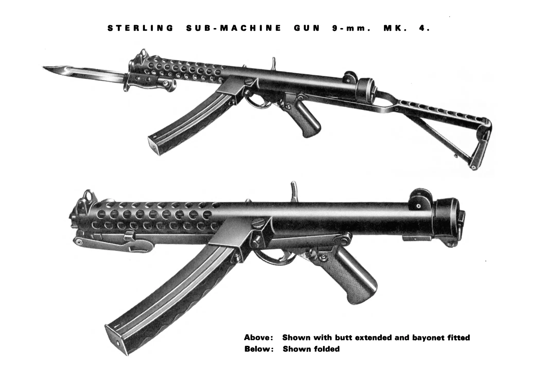
STERLING SUB-MACHINE GUN 9-mm
M К
4
CONTENTS
SECTION 1—GENERAL page para. SECTION 3—STRIPPING AND
Introduction 4 1.0 ASSEMBLY
Technical Details 4 2.0 Elementary Stripping and Assembly To Remove Return Spring
Special Features 6 3.0 To Remove Trigger Group
Butt 6 3.1 Assembly
Body 6 3.2 Advanced Stripping and Assembly
Trigger and Safety Mechanism 6 3.3 To Remove Ejector
Backsight 6 3.4 To Strip Trigger Group To Remove Extractor
Bayonet SECTION 2—DESCRIPTION AND OPERATION 6 3.5 To Remove Pistol Grip To Remove Barrel To Strip Magazine To Remove Foresight
The Backward Action 8 4.1 To Remove Backsight
The Forward Action 9 4.2 To Assemble Trigger Group
Action of the Trigger Mechanism 10 5.0 To Replace Barrel
Single Shot Fire 10 5.1 To Assemble Foresight To Assemble Backsight
Automatic Fire 13 5.2 To Assemble Magazine
Applied Safety 13 5.3 SECTION 4—ZEROING
To Open Butt 14 6.0
To Close Butt 14 7.0 SECTION 5—CLEANING
page para.
15 8.0
15 8.1
16 8.2
16 8.3
17 9.0
17 9.1
18 9.2
19 9.3
19 9.4
20 9.5
20 9.6
21 9.7
21 9.8
21 9.9
21 9.10
21 9.11
22 9.12
22 9.13
22 10.0
22 11.0
3
SECTION I—GENERAL
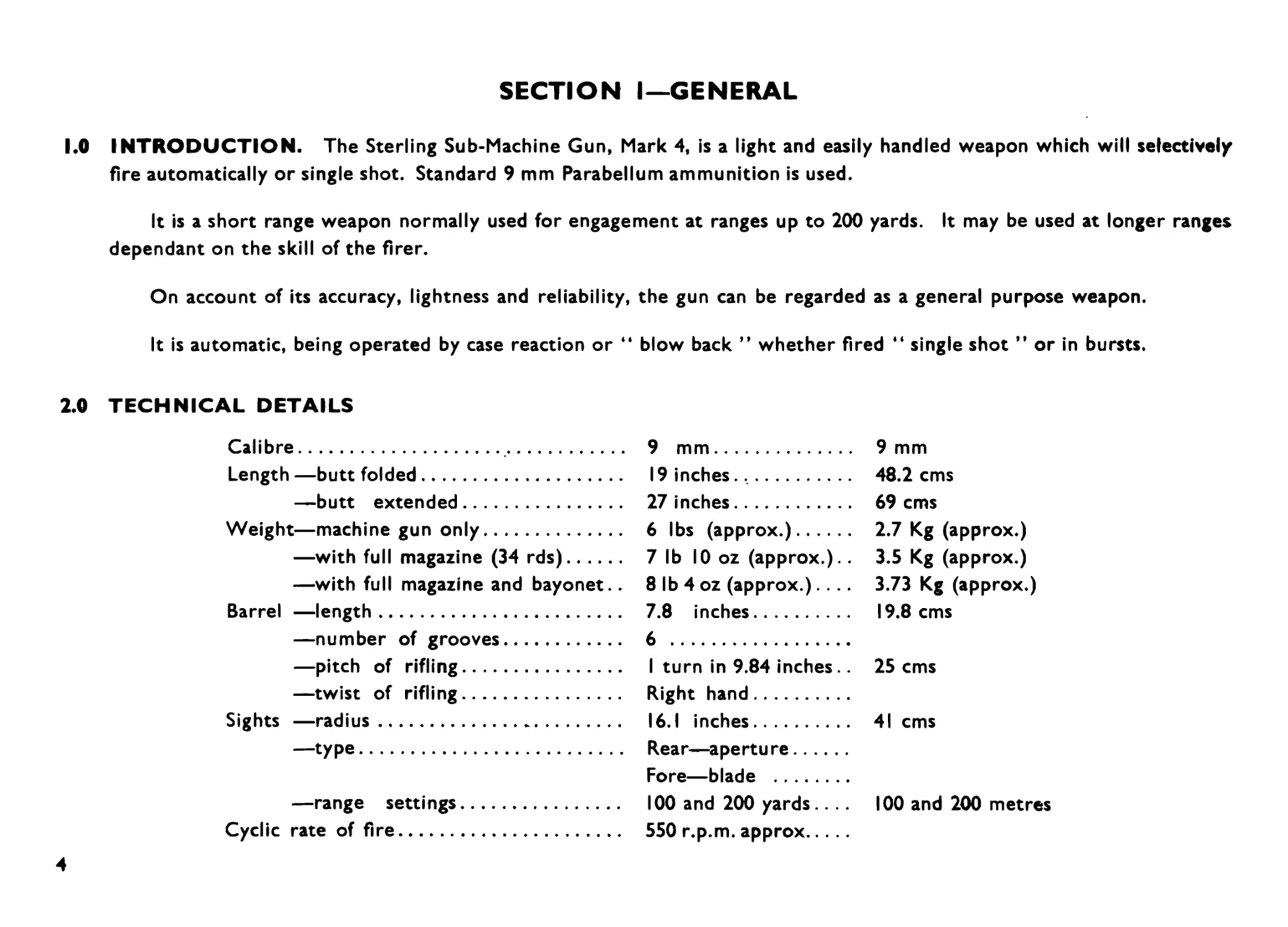
KO INTRODUCTION. The Sterling Sub-Machine Gun, Mark 4, is a light and easily handled weapon which will selectively
fire automatically or single shot. Standard 9 mm Parabellum ammunition is used.
It is a short range weapon normally used for engagement at ranges up to 200 yards. It may be used at longer ranges
dependant on the skill of the firer.
On account of its accuracy, lightness and reliability, the gun can be regarded as a general purpose weapon.
It is automatic, being operated by case reaction or “ blow back ” whether fired “ single shot ” or in bursts.
2.0 TECHNICAL DETAILS
Calibre.................................
Length —butt folded.....................
—butt extended...................
Weight—machine gun only.................
— with full magazine (34 rds)....
— with full magazine and bayonet..
Barrel —length..........................
— number of grooves..............
— pitch of rifling...............
— twist of rifling...............
Sights —radius..........................
—type............................
— range settings.................
Cyclic rate of fire.....................
9 mm.................
19 inches.,.........
27 inches............
6 lbs (approx.)......
7 1b 10 oz (approx.)..
8 lb 4 oz (approx.). . ..
7.8 inches...........
6 ...................
I turn in 9.84 inches..
Right hand...........
16.1 inches.........
Rear—aperture.......
Fore—blade ..........
100 and 200 yards....
550 r.p.m. approx....
9 mm
48.2 cms
69 cms
2.7 Kg (approx.)
3.5 Kg (approx.)
3.73 Kg (approx.)
19.8 cms
25 cms
41 cms
100 and 200 metres
4
TECHNICAL DETAILS (CONTINUED)
TERMINAL VELOCITY AND KINETIC ENERGY OF STANDARD 9 mm BULLET
RANGE VELOCITY KINETIC ENERGY
Yards Metres Ft/Sec M/Sec Ft/lbs Kgm
0 0 1280 390 447 62.2
109 100 1115 340 339 47.0
218 200 975 298 262 36.4
327 300 872 266 207 28.7
436 400 780 238 167 23.2
545 500 700 214 135 18.8
654 600 632 193 109 15.2
763 700 572 174 89 12.3
872 800 518 158 74 10.2
3.0 SPECIAL FEATURES
3.1 BUTT. When not in use the butt is folded under the weapon reducing the overall length by 9 inches. With the butt
folded the weapon can be used as a pistol.
3.2 BODY. The forward part of the body, i.e. the barrel casing, is perforated to assist cooling. It will be found that even
after prolonged firing the body remains comfortably cool. Finger guards are fitted at both ends of the barrel casing.
3.3 TRIGGER AND SAFETY MECHANISM. The trigger mechanism is fitted with a change lever which can be set
to give either automatic fire or single shot. The change lever also has a SAFE position which locks the trigger and sear,
irrespective of the position of the bolt, which eliminates the possibility of a round being fired if the weapon is dropped.
3.4 BACKSIGHT. The rear peephole sight is instantly changed from 100 to 200 yards range setting by rocking over.
3.5 BAYONET. The bayonet is mounted so that it is off-set when the weapon is in the firing position. It will be found
that, when the weapon is held in the “ on-guard ” position for bayonet fighting, the natural balance of the weapon, with
or without magazine, brings the bayonet into the upright position.
6
SECTION 2—DESCRIPTION AND OPERATION
4.0 The weapon (Fig. I) is operated by case reaction or “ blow back ”.
Fig. I. Sectional arrangement
7
4.1 THE BACKWARD ACTION (Fig. 2). When the cartridge is fired the propellant gases exert an equal pressure
against both the bullet and the cartridge case, the latter being supported by the bolt and the compression of the return
spring. The gas pressure accelerates the bullet also the cartridge case and bolt in opposite directions and as the weight
of the bullet is considerably less than that of the combined weight of the cartridge case and bolt, the bullet attains a much
greater velocity than that of the cartridge case and bolt. When the bullet clears the muzzle all have reached their maximum
velocities but the cartridge case has not yet cleared from the chamber, thus preventing the gases escaping from the breech.
The cartridge case does not clear the breech until the gases behind the bullet have dispersed into the air, ensuring that
pressures are down to safe limits before the breech is unsealed.
The bolt is now being decelerated by the compression of the return spring.
The empty cartridge case, held against the face of the bolt by the extractor, is carried back until it strikes the ejector
and is ejected through the opening on the right side of the weapon.
Fig. 2. Backward action
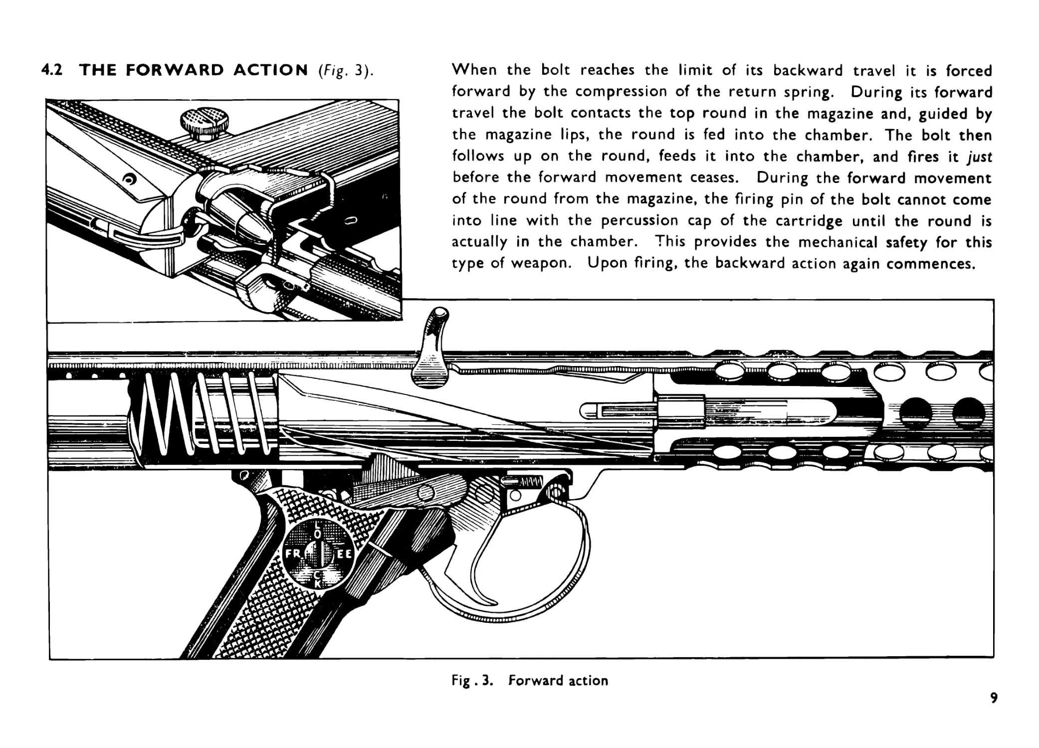
When the bolt reaches the limit of its backward travel it is forced
forward by the compression of the return spring. During its forward
travel the bolt contacts the top round in the magazine and, guided by
the magazine lips, the round is fed into the chamber. The bolt then
follows up on the round, feeds it into the chamber, and fires it just
before the forward movement ceases. During the forward movement
of the round from the magazine, the firing pin of the bolt cannot come
into line with the percussion cap of the cartridge until the round is
actually in the chamber. This provides the mechanical safety for this
type of weapon. Upon firing, the backward action again commences.
4.2 THE FORWARD ACTION (Fig. 3).
Fig . 3. Forward action
9
5.0 ACTION OF THE TRIGGER MECHANISM (Figs. 4, 5, 6 and 7).
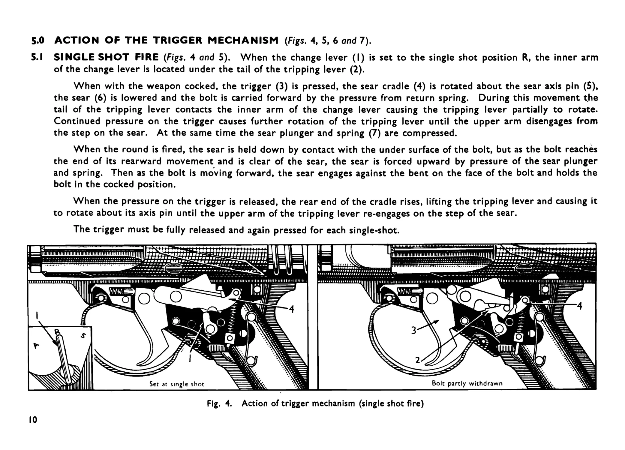
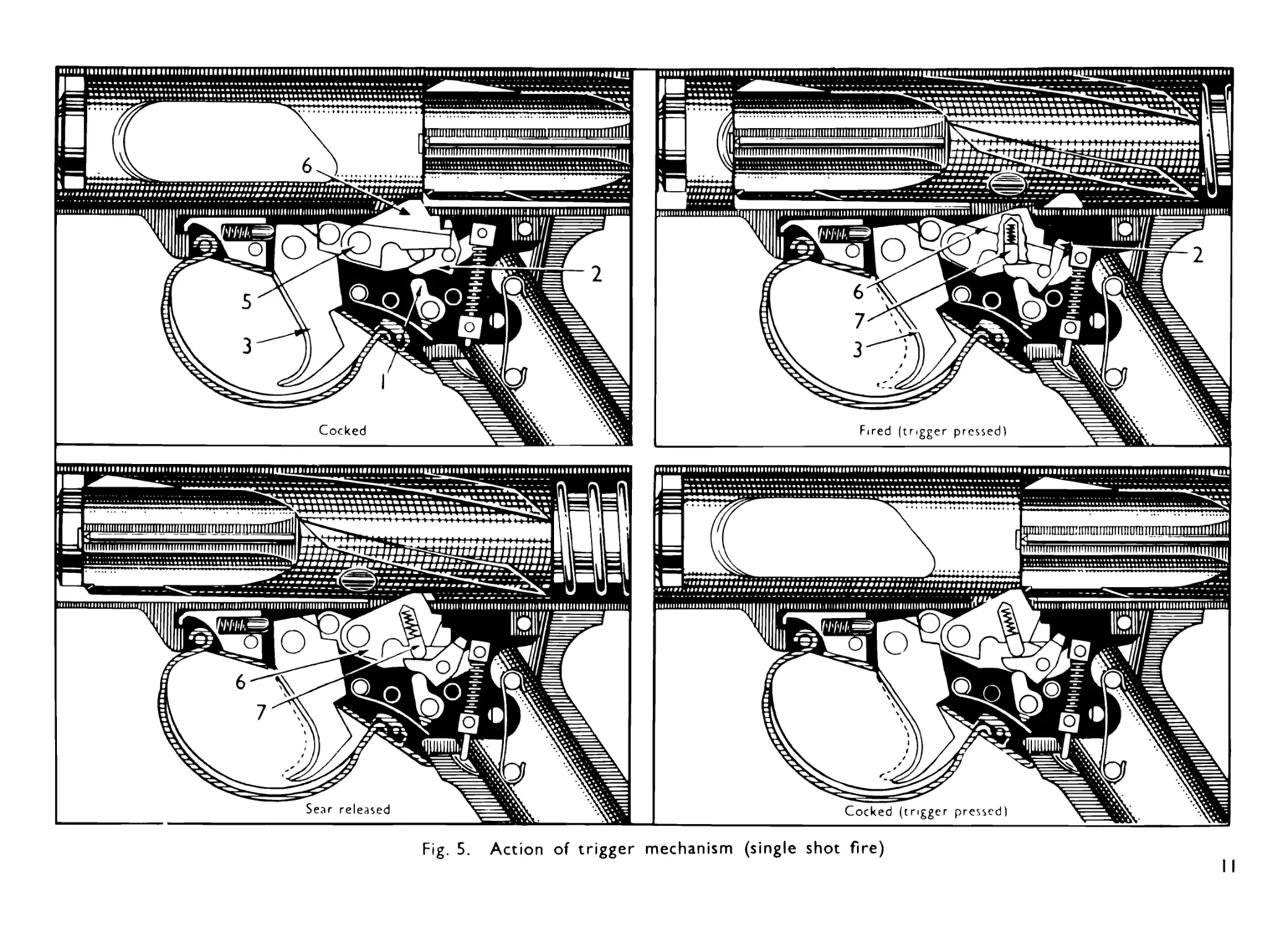
5.1 SINGLE SHOT FIRE (Figs. 4 and 5). When the change lever (I) is set to the single shot position R, the inner arm
of the change lever is located under the tail of the tripping lever (2).
When with the weapon cocked, the trigger (3) is pressed, the sear cradle (4) is rotated about the sear axis pin (5),
the sear (6) is lowered and the bolt is carried forward by the pressure from return spring. During this movement the
tail of the tripping lever contacts the inner arm of the change lever causing the tripping lever partially to rotate.
Continued pressure on the trigger causes further rotation of the tripping lever until the upper arm disengages from
the step on the sear. At the same time the sear plunger and spring (7) are compressed.
When the round is fired, the sear is held down by contact with the under surface of the bolt, but as the bolt reaches
the end of its rearward movement and is clear of the sear, the sear is forced upward by pressure of the sear plunger
and spring. Then as the bolt is moving forward, the sear engages against the bent on the face of the bolt and holds the
bolt in the cocked position.
When the pressure on the trigger is released, the rear end of the cradle rises, lifting the tripping lever and causing it
to rotate about its axis pin until the upper arm of the tripping lever re-engages on the step of the sear.
The trigger must be fully released and again pressed for each single-shot.
Fig. 4. Action of trigger mechanism (single shot fire)
10
Fig. 5. Action of trigger mechanism (single shot fire)
II
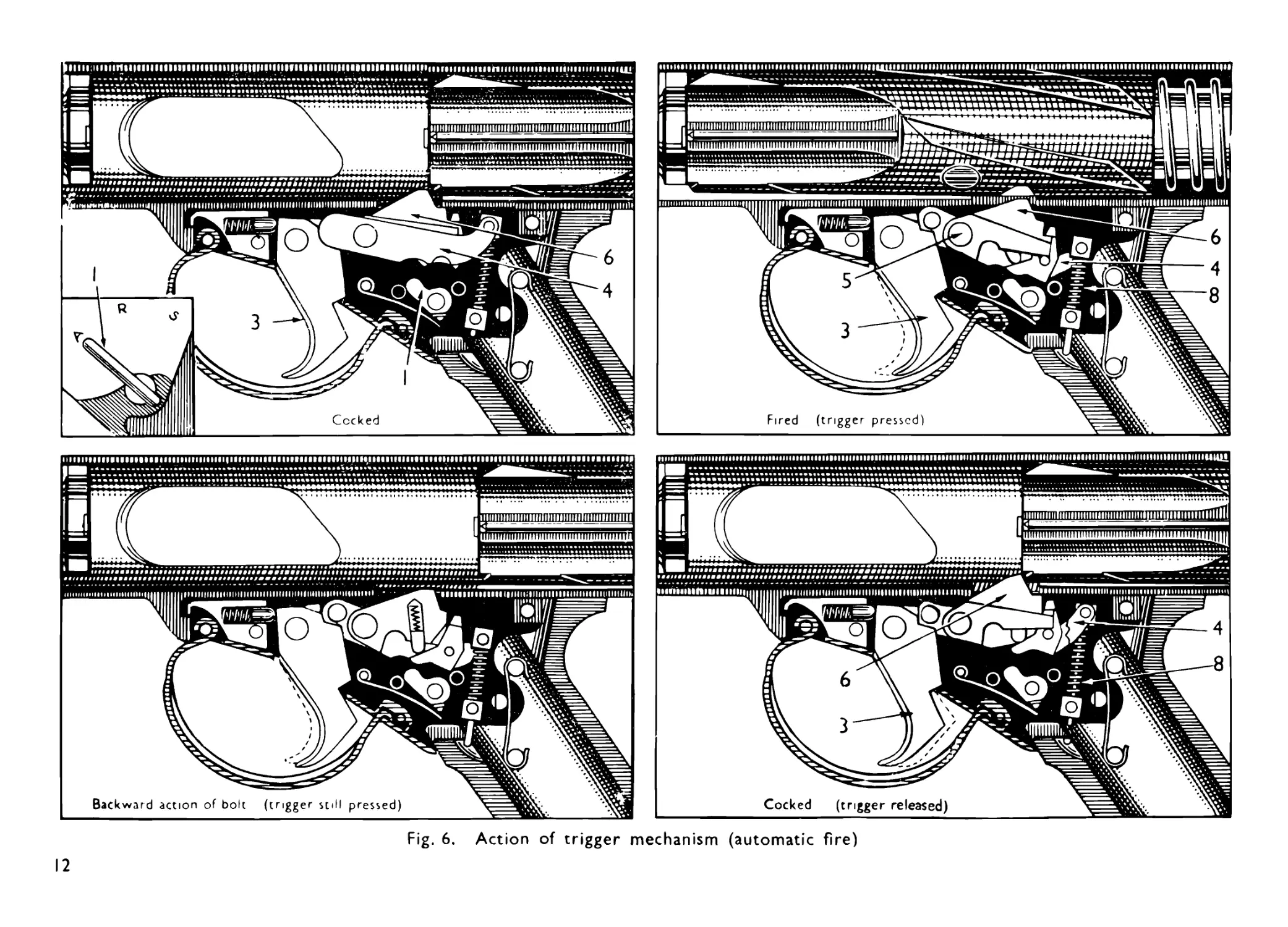
Fig. 6. Action of trigger mechanism (automatic fire)
12
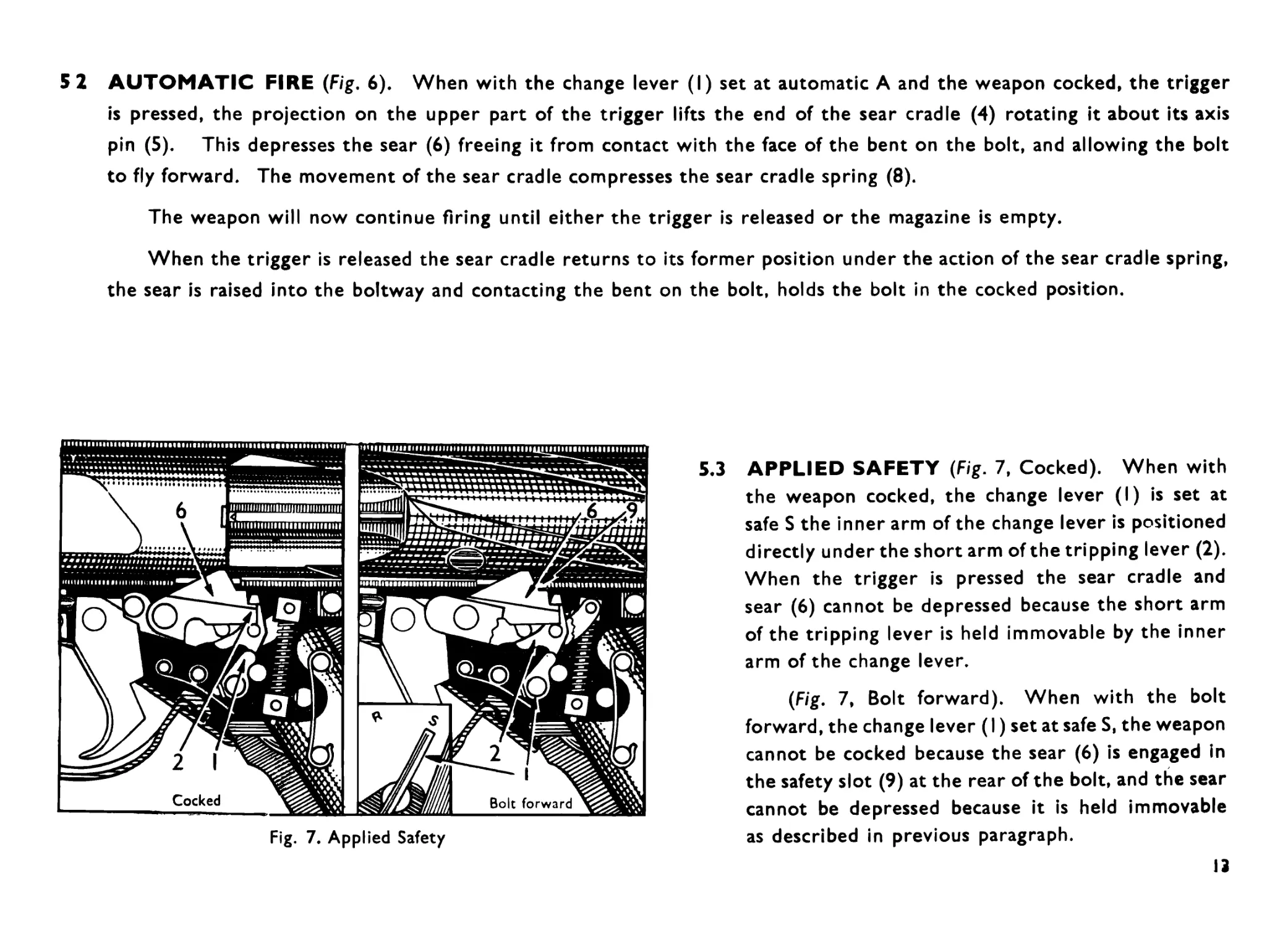
5 2 AUTOMATIC FIRE (Fig. 6). When with the change lever (I) set at automatic A and the weapon cocked, the trigger
is pressed, the projection on the upper part of the trigger lifts the end of the sear cradle (4) rotating it about its axis
pin (5). This depresses the sear (6) freeing it from contact with the face of the bent on the bolt, and allowing the bolt
to fly forward. The movement of the sear cradle compresses the sear cradle spring (8).
The weapon will now continue firing until either the trigger is released or the magazine is empty.
When the trigger is released the sear cradle returns to its former position under the action of the sear cradle spring,
the sear is raised into the boltway and contacting the bent on the bolt, holds the bolt in the cocked position.
Fig. 7. Applied Safety
5.3 APPLIED SAFETY (Fig. 7, Cocked). When with
the weapon cocked, the change lever (I) is set at
safe S the inner arm of the change lever is positioned
directly under the short arm of the tripping lever (2).
When the trigger is pressed the sear cradle and
sear (6) cannot be depressed because the short arm
of the tripping lever is held immovable by the inner
arm of the change lever.
(Fig. 7, Bolt forward). When with the bolt
forward, the change lever (I) set at safe S, the weapon
cannot be cocked because the sear (6) is engaged in
the safety slot (9) at the rear of the bolt, and the sear
cannot be depressed because it is held immovable
as described in previous paragraph.
13
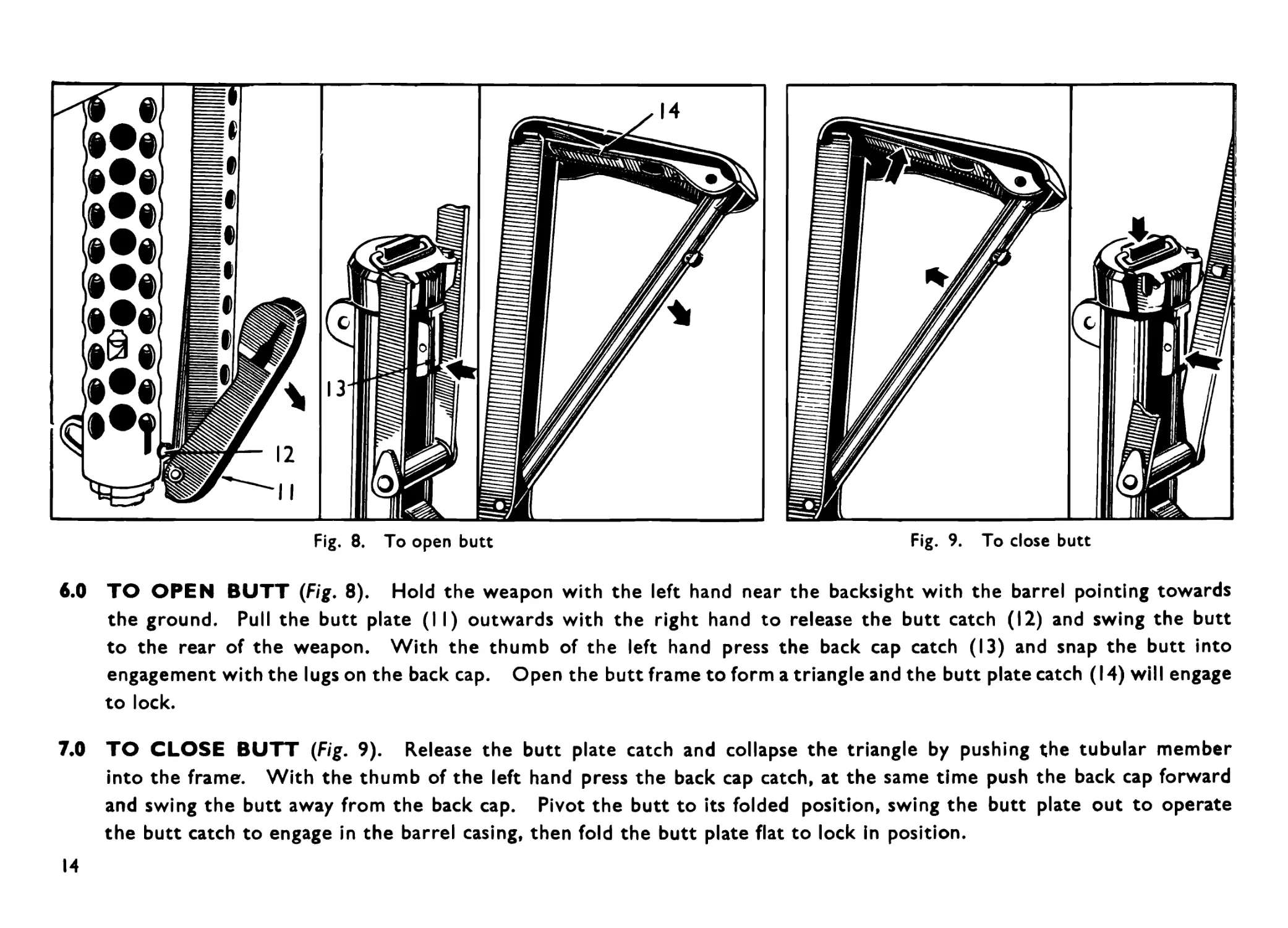
Fig. 9. To close butt
Fig. 8. To open butt
6.0 TO OPEN BUTT (Fig. 8). Hold the weapon with the left hand near the backsight with the barrel pointing towards
the ground. Pull the butt plate (II) outwards with the right hand to release the butt catch (12) and swing the butt
to the rear of the weapon. With the thumb of the left hand press the back cap catch (13) and snap the butt into
engagement with the lugs on the back cap. Open the butt frame to form a triangle and the butt plate catch (14) will engage
to lock.
7.0 TO CLOSE BUTT (Fig. 9). Release the butt plate catch and collapse the triangle by pushing the tubular member
into the frame. With the thumb of the left hand press the back cap catch, at the same time push the back cap forward
and swing the butt away from the back cap. Pivot the butt to its folded position, swing the butt plate out to operate
the butt catch to engage in the barrel casing, then fold the butt plate flat to lock in position.
14
SECTION 3—STRIPPING AND ASSEMBLING
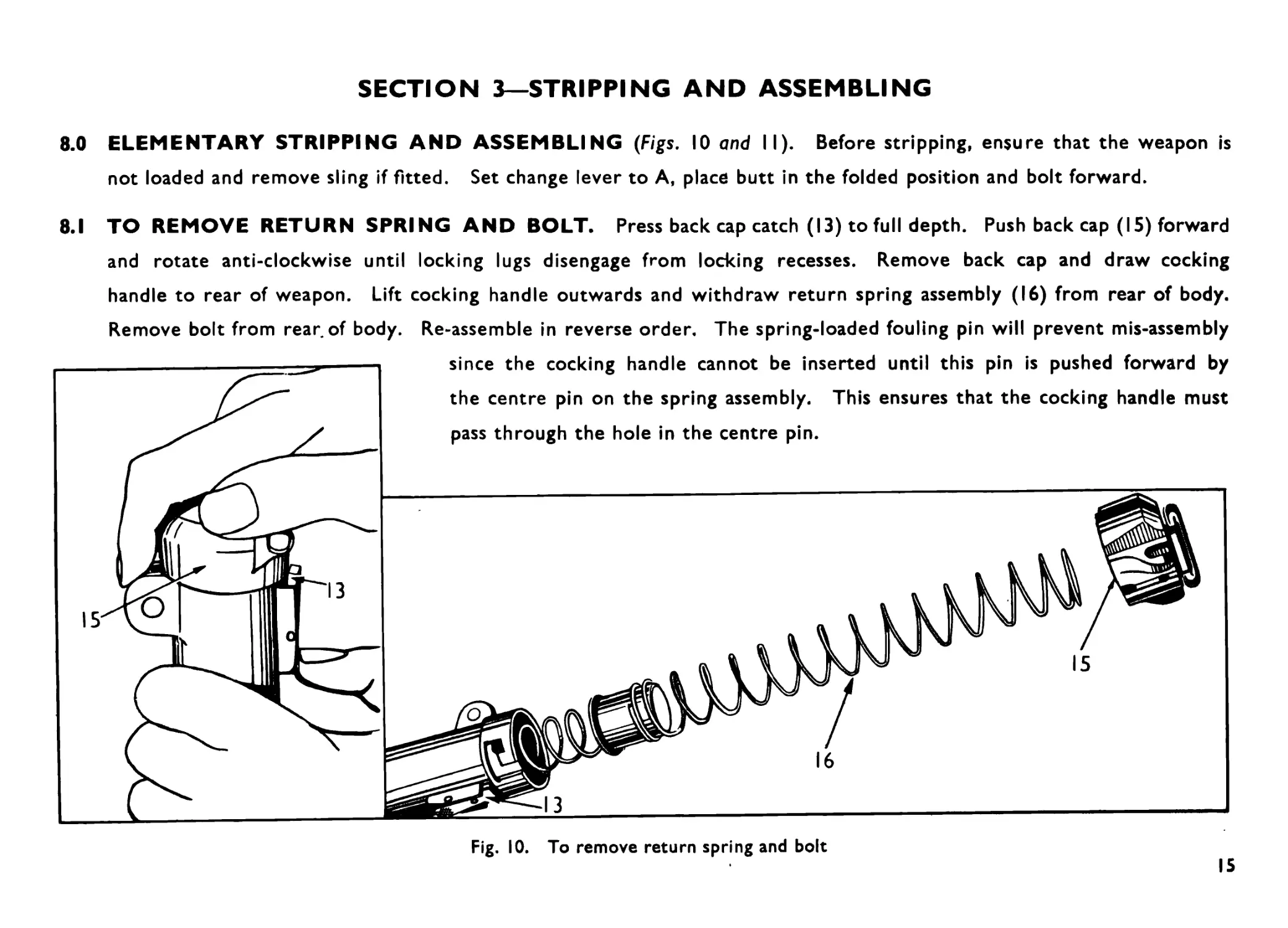
8.0 ELEMENTARY STRIPPING AND ASSEMBLING (Figs. 10 and II). Before stripping, ensure that the weapon is
not loaded and remove sling if fitted. Set change lever to A, place butt in the folded position and bolt forward.
8.1 TO REMOVE RETURN SPRING AND BOLT. Press back cap catch (13) to full depth. Push back cap (15) forward
and rotate anti-clockwise until locking lugs disengage from locking recesses. Remove back cap and draw cocking
handle to rear of weapon. Lift cocking handle outwards and withdraw return spring assembly (16) from rear of body.
Remove bolt from rear of body. Re-assemble in reverse order. The spring-loaded fouling pin will prevent mis-assembly
Fig. 10. To remove return spring and bolt
15
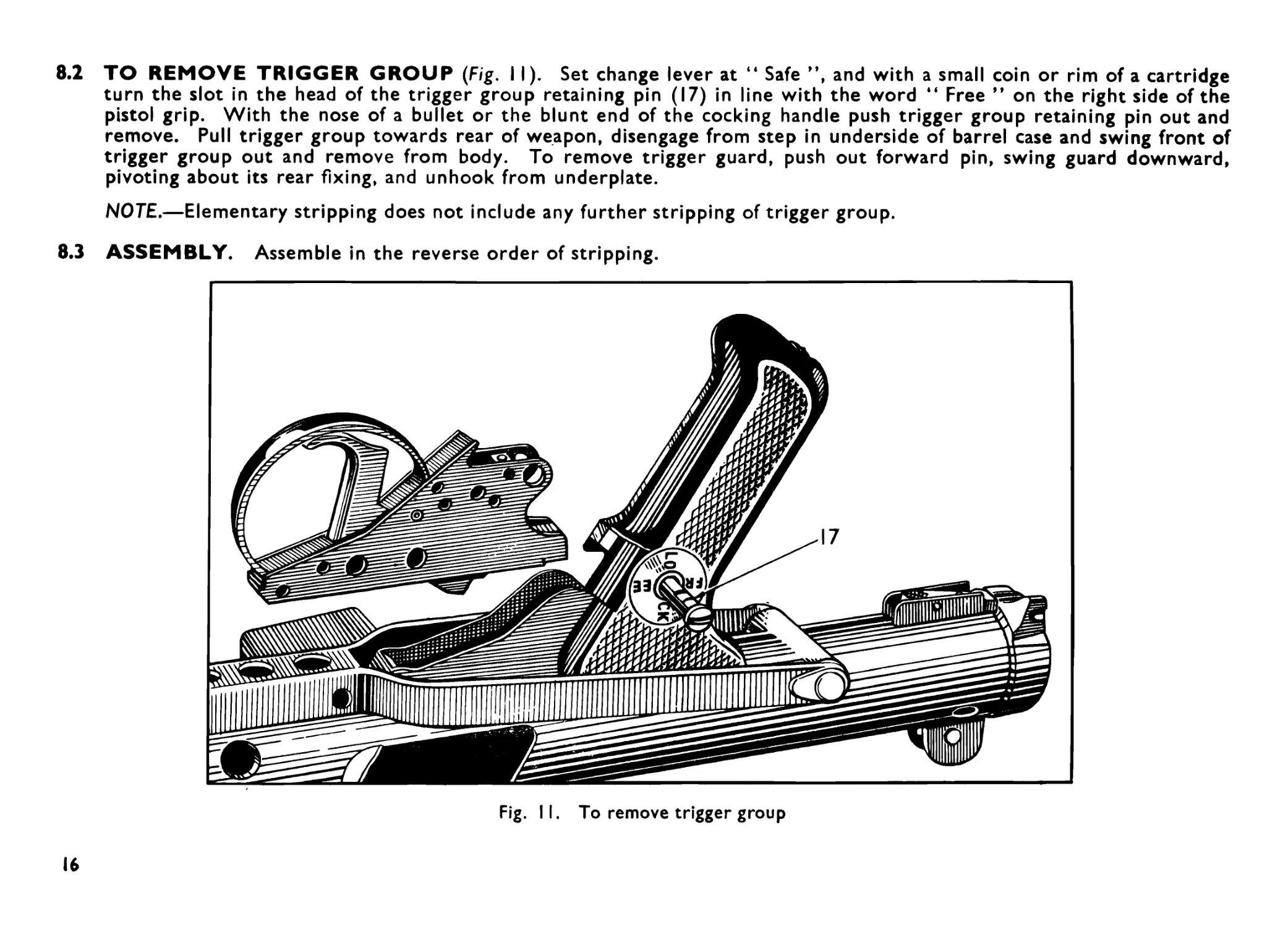
8.2 TO REMOVE TRIGGER GROUP (Fig. I I). Set change lever at “ Safe ”, and with a small coin or rim of a cartridge
turn the slot in the head of the trigger group retaining pin (17) in line with the word “ Free ” on the right side of the
pistol grip. With the nose of a bullet or the blunt end of the cocking handle push trigger group retaining pin out and
remove. Pull trigger group towards rear of weapon, disengage from step in underside of barrel case and swing front of
trigger group out and remove from body. To remove trigger guard, push out forward pin, swing guard downward,
pivoting about its rear fixing, and unhook from underplate.
NOTE.—Elementary stripping does not include any further stripping of trigger group.
8.3 ASSEMBLY. Assemble in the reverse order of stripping.
Fig. II. To remove trigger group
16
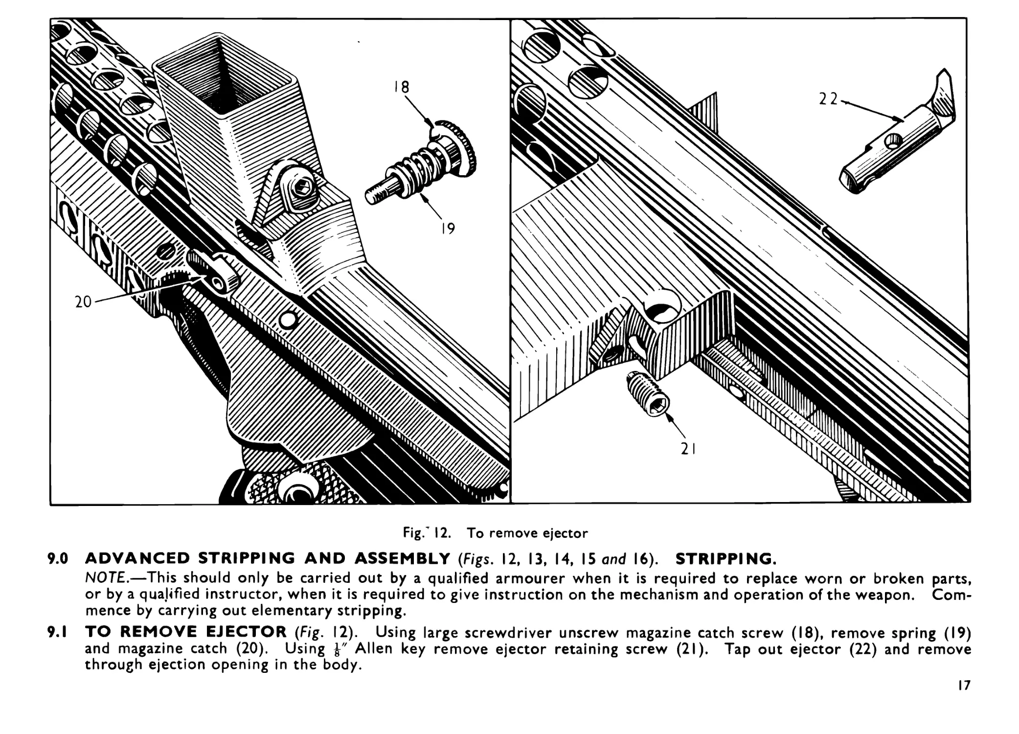
Fig/ 12. To remove ejector
9.0 ADVANCED STRIPPING AND ASSEMBLY (Figs. 12, 13, 14, 15 and 16). STRIPPING.
NOTE.—This should only be carried out by a qualified armourer when it is required to replace worn or broken parts,
or by a qualified instructor, when it is required to give instruction on the mechanism and operation of the weapon. Com-
mence by carrying out elementary stripping.
9.1 TO REMOVE EJECTOR (Fig. 12). Using large screwdriver unscrew magazine catch screw (18), remove spring (19)
and magazine catch (20). Using Allen key remove ejector retaining screw (21). Tap out ejector (22) and remove
through ejection opening in the body.
17
Fig. 13. To strip trigger group
9.2 TO STRIP TRIGGER GROUP (Fig. 13). Push out sear axis pin (5) and lift out sear group from trigger group. Push
out trigger axis pin (23) and remove trigger (3) downwards through trigger guard.
Push out tripping lever axis pin (24) and lift tripping lever (2) from sear cradle (4) and lift sear (6) from sear cradle.
18
25
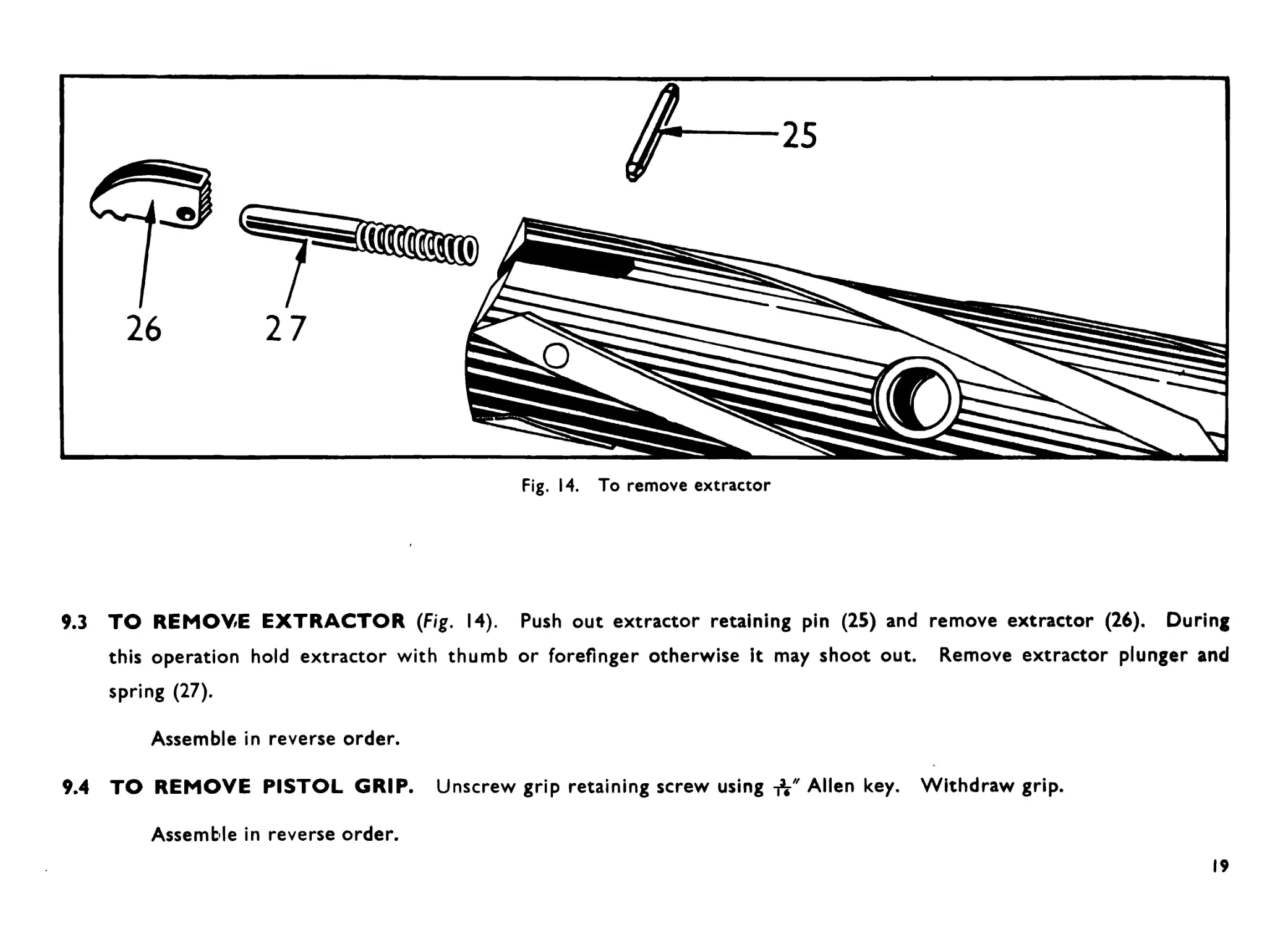
9.3 TO REMOVE EXTRACTOR (Fig. 14). Push out extractor retaining pin (25) and remove extractor (26). During
this operation hold extractor with thumb or forefinger otherwise it may shoot out. Remove extractor plunger and
spring (27).
Assemble in reverse order.
9.4 TO REMOVE PISTOL GRIP. Unscrew grip retaining screw using-ft" Allen key. Withdraw grip.
Assemble in reverse order.
19
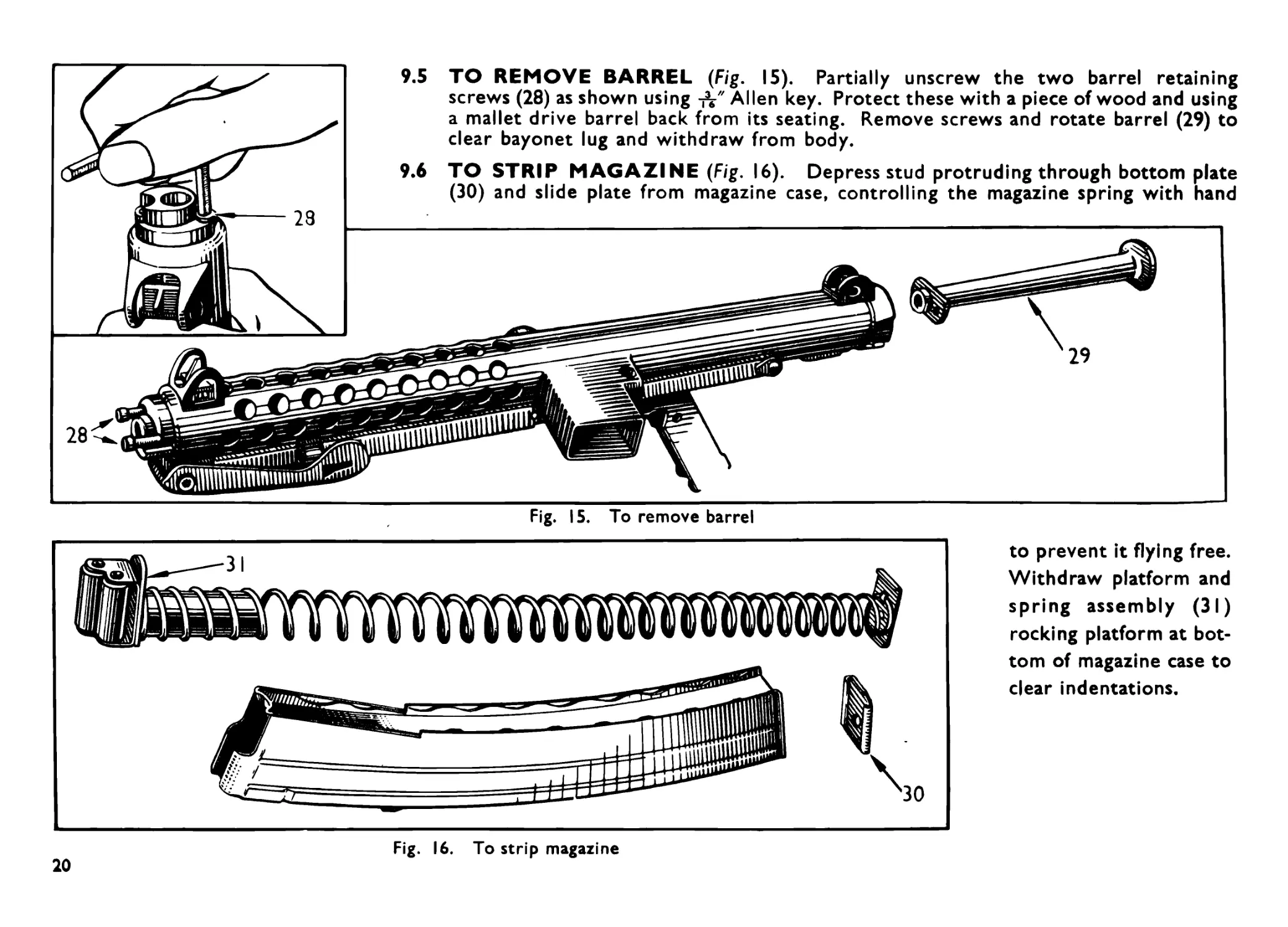
Fig. 15. To remove barrel
TO REMOVE BARREL (Fig. 15). Partially unscrew the two barrel retaining
screws (28) as shown using -fr" Allen key. Protect these with a piece of wood and using
a mallet drive barrel back from its seating. Remove screws and rotate barrel (29) to
clear bayonet lug and withdraw from body.
TO STRIP MAGAZINE (Fig. 16). Depress stud protruding through bottom plate
(30) and slide plate from magazine case, controlling the magazine spring with hand
Fig. 16. To strip magazine
to prevent it flying free.
Withdraw platform and
spring assembly (31)
rocking platform at bot-
tom of magazine case to
clear indentations.
20
9.7 FORESIGHT. The foresight fits into a dovetail in the barrel case. It is a spring fit, there being no retaining pin or
screw. To remove, tap right out from either side with a drift.
9.8 BACKSIGHT. This should not be removed unless absolutely necessary.
To remove the backsight, drive out the pin, lift out sight and spring, taking care not to lose small collars.
ASSEMBLY
9.9 TRIGGER GROUP.
9.9.1 Ensure change lever is at automatic A.
9.9.2 Replace tripping lever and its axis pin in sear cradle, ensuring that the head of the tripping lever is engaged on the
lower step of the sear.
9.9.3 Insert sear group into trigger group housing. Line up the sear, sear cradle and trigger housing, using trigger group
retaining pin as a drift, and replace sear axis pin.
9.9.4 Insert trigger upwards through trigger guard ensuring that the trigger plunger is depressed within its housing. Line
up, using trigger group retaining pin as a drift, and replace trigger axis pin.
9.9.5 Test trigger group for correct functioning at safe, single-shot and automatic.
9.10 BARREL.
9.10.1 Insert barrel into case and push forward, rotating the barrel to clear bayonet lug. The extractor clearance groove
in the barrel face should be in line with the ejector opening.
9.10.2 Replace barrel retaining screws hand tight, then finally tighten, a little on each screw at a time using Allen key.
9.11 FORESIGHT. To assemble, insert foresight into dovetail and tap into the required position.
21
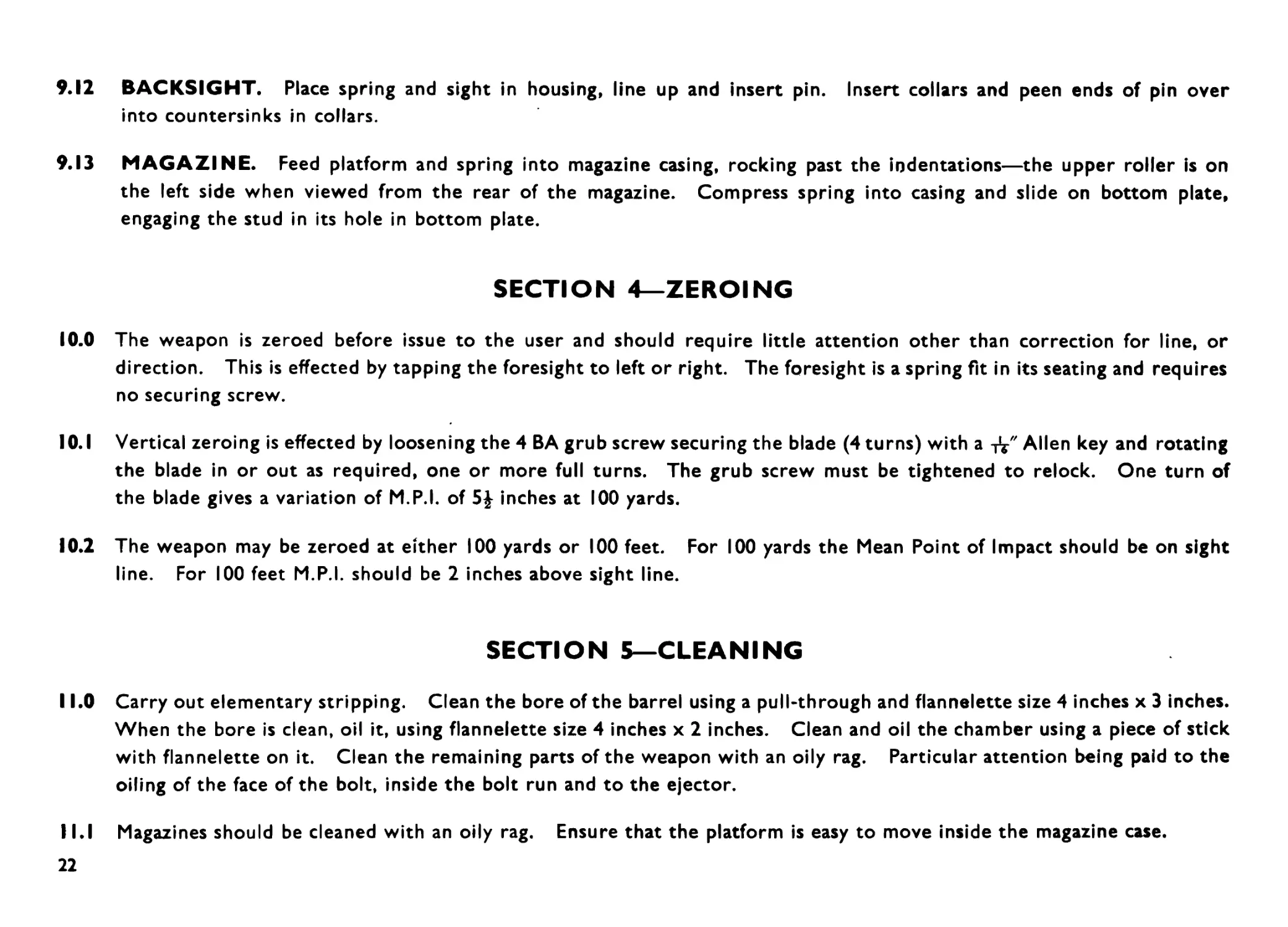
9.12 BACKSIGHT. Place spring and sight in housing, line up and insert pin. Insert collars and peen ends of pin over
into countersinks in collars.
9.13 MAGAZINE. Feed platform and spring into magazine casing, rocking past the indentations—the upper roller is on
the left side when viewed from the rear of the magazine. Compress spring into casing and slide on bottom plate,
engaging the stud in its hole in bottom plate.
SECTION 4—ZEROING
10.0 The weapon is zeroed before issue to the user and should require little attention other than correction for line, or
direction. This is effected by tapping the foresight to left or right. The foresight is a spring fit in its seating and requires
no securing screw.
10.1 Vertical zeroing is effected by loosening the 4 BA grub screw securing the blade (4 turns) with a Allen key and rotating
the blade in or out as required, one or more full turns. The grub screw must be tightened to relock. One turn of
the blade gives a variation of M.P.I. of 5| inches at 100 yards.
10.2 The weapon may be zeroed at either 100 yards or 100 feet. For 100 yards the Mean Point of Impact should be on sight
line. For 100 feet M.P.I. should be 2 inches above sight line.
SECTION 5—CLEANING
11.0 Carry out elementary stripping. Clean the bore of the barrel using a pull-through and flannelette size 4 inches x 3 inches.
When the bore is clean, oil it, using flannelette size 4 inches x 2 inches. Clean and oil the chamber using a piece of stick
with flannelette on it. Clean the remaining parts of the weapon with an oily rag. Particular attention being paid to the
oiling of the face of the bolt, inside the bolt run and to the ejector.
11.1 Magazines should be cleaned with an oily rag. Ensure that the platform is easy to move inside the magazine case.
22
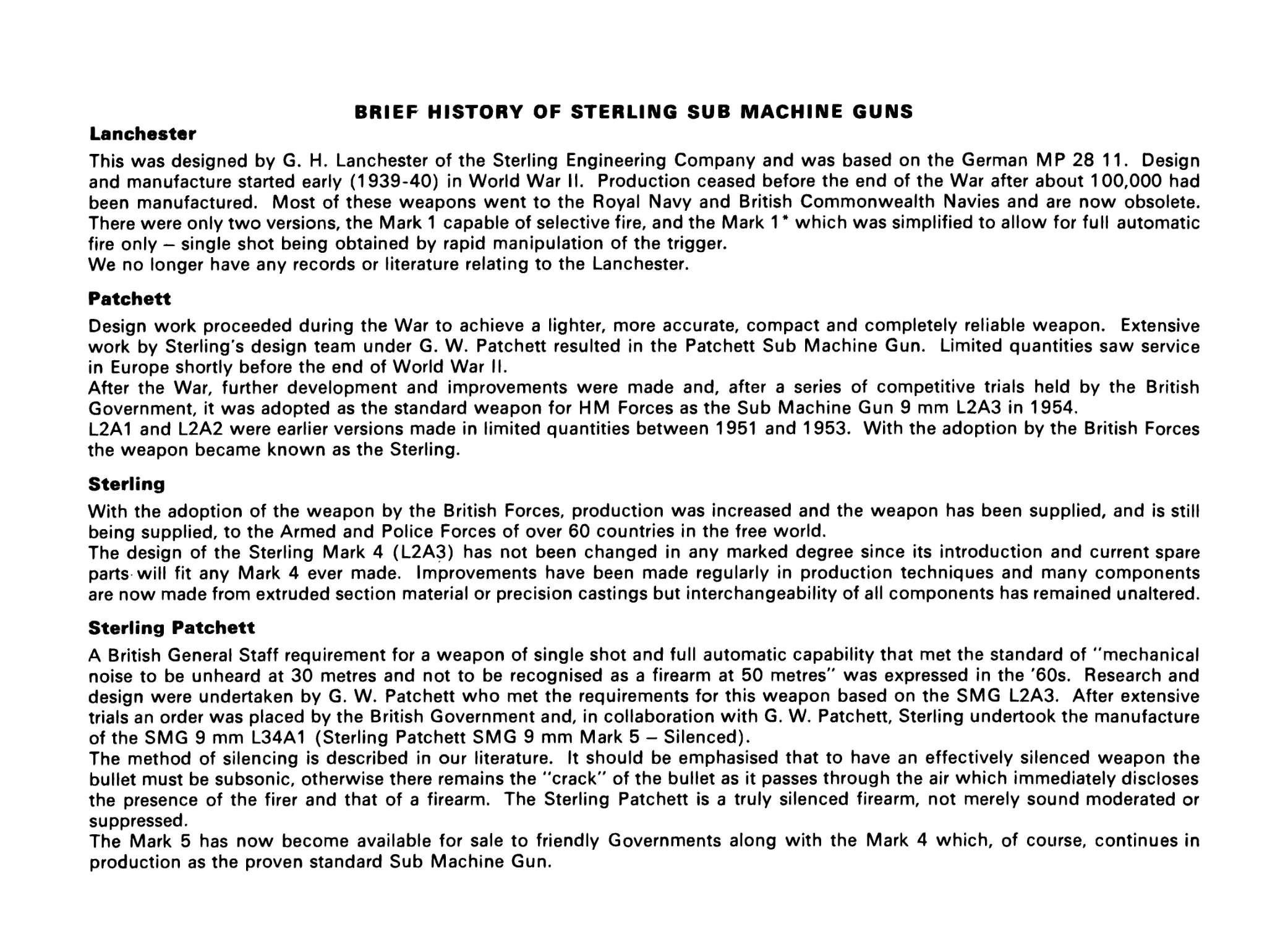
BRIEF HISTORY OF STERLING SUB MACHINE GUNS
Lanchester
This was designed by G. H. Lanchester of the Sterling Engineering Company and was based on the German MP 28 11. Design
and manufacture started early (1939-40) in World War II. Production ceased before the end of the War after about 100,000 had
been manufactured. Most of these weapons went to the Royal Navy and British Commonwealth Navies and are now obsolete.
There were only two versions, the Mark 1 capable of selective fire, and the Mark 1 * which was simplified to allow for full automatic
fire only - single shot being obtained by rapid manipulation of the trigger.
We no longer have any records or literature relating to the Lanchester.
Patchett
Design work proceeded during the War to achieve a lighter, more accurate, compact and completely reliable weapon. Extensive
work by Sterling's design team under G. W. Patchett resulted in the Patchett Sub Machine Gun. Limited quantities saw service
in Europe shortly before the end of World War II.
After the War, further development and improvements were made and, after a series of competitive trials held by the British
Government, it was adopted as the standard weapon for HM Forces as the Sub Machine Gun 9 mm L2A3 in 1954.
L2A1 and L2A2 were earlier versions made in limited quantities between 1951 and 1953. With the adoption by the British Forces
the weapon became known as the Sterling.
Sterling
With the adoption of the weapon by the British Forces, production was increased and the weapon has been supplied, and is still
being supplied, to the Armed and Police Forces of over 60 countries in the free world.
The design of the Sterling Mark 4 (L2A3) has not been changed in any marked degree since its introduction and current spare
parts will fit any Mark 4 ever made. Improvements have been made regularly in production techniques and many components
are now made from extruded section material or precision castings but interchangeability of all components has remained unaltered.
Sterling Patchett
A British General Staff requirement for a weapon of single shot and full automatic capability that met the standard of "mechanical
noise to be unheard at 30 metres and not to be recognised as a firearm at 50 metres" was expressed in the '60s. Research and
design were undertaken by G. W. Patchett who met the requirements for this weapon based on the SMG L2A3. After extensive
trials an order was placed by the British Government and, in collaboration with G. W. Patchett, Sterling undertook the manufacture
of the SMG 9 mm L34A1 (Sterling Patchett SMG 9 mm Mark 5 - Silenced).
The method of silencing is described in our literature. It should be emphasised that to have an effectively silenced weapon the
bullet must be subsonic, otherwise there remains the "crack" of the bullet as it passes through the air which immediately discloses
the presence of the firer and that of a firearm. The Sterling Patchett is a truly silenced firearm, not merely sound moderated or
suppressed.
The Mark 5 has now become available for sale to friendly Governments along with the Mark 4 which, of course, continues in
production as the proven standard Sub Machine Gun.
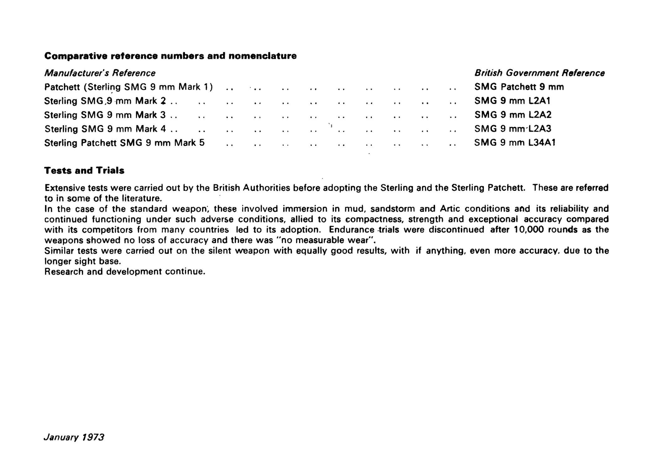
Comparative reference numbers and nomenclature
Manufacturer's Reference
Patchett (Sterling SMG 9 mm Mark 1)
Sterling SMG,9 mm Mark 2...............................
Sterling SMG 9 mm Mark 3 ..
Sterling SMG 9 mm Mark 4...............................
Sterling Patchett SMG 9 mm Mark 5 ..............
British Government Reference
SMG Patchett 9 mm
SMG 9 mm L2A1
SMG 9 mm L2A2
SMG 9 mm L2A3
SMG 9 mm L34A1
Tests and Trials
Extensive tests were carried out by the British Authorities before adopting the Sterling and the Sterling Patchett. These are referred
to in some of the literature.
In the case of the standard weapon; these involved immersion in mud, sandstorm and Artic conditions and its reliability and
continued functioning under such adverse conditions, allied to its compactness, strength and exceptional accuracy compared
with its competitors from many countries led to its adoption. Endurance trials were discontinued after 10,000 rounds as the
weapons showed no loss of accuracy and there was "no measurable wear".
Similar tests were carried out on the silent weapon with equally good results, with if anything, even more accuracy, due to the
longer sight base.
Research and development continue.
January 1973