/


Text
MADSEN
SUB-MACHINE GUN
DANSK INDUSTRI SYNDIKAT
COMPAGNIE MADSEN
COPENHAGEN
HANDBOOK
for the
MADSEN
SUB-MACHINE GUN
DANSK INDUSTRI SYNDIKAT
COMPAGNIE MADSEN
COPENHAGEN
245.E.EJ.
CONTENTS
Page
Principle of design.................................. 5
Short description of the main parts.............. 9
Action of the gun................................... 13
Firing.............................................. 17
Instructions for loading the magazine............... 19
Instructions for stripping and assembling........... 19
Components of gun................................... 22
Sectional view of gun............................... 23
PRINCIPLE OF DESIGN
The MADSEN sub-machine gun was developed to fill the
need for a sub-machine gun which would be absolutely re-
liable, and still a lightweight weapon, combining the fewest
possible parts with simplicity of manufacture. This aim was
achieved mainly by means of a special safety device to ex-
clude accidental firing, and a flat shape of the frame, this
latter being divided vertically in longitudinal section per-
mitting the two halves, which are hinged at the rear and form
the receiver, the magazine housing and the pistol grip, to be
opened like a box.
Constructed in this manner the MADSEN sub-machine
gun is easy to strip for inspecting and cleaning; furthermore
all the parts are easy to survey, so that the action of the gun
is easily learned. The sub-machine gun has a bottom-
mounted magazine, and it is fitted with a carrying sling
which, owing to the flat shape of the gun, permits it to be
carried hanging on the gunner’s back, the sling over his left
shoulder, muzzle downwards and magazine inserted, thereby
enabling the gunner to open fire almost instantaneously in
case of surprise encounters. It is equiped with a folding
skeleton butt, and the gun can be fired with this shoulder
piece extended or with the shoulder piece folded.
Most of the sub-machine guns developed during the Se-
cond World War have the fault that it is dangerous to carry
the weapon with a loaded magazine inserted and the mecha-
nism cocked, as a jar may fire it, and a shot may also be
fired accidentally by a cocking motion being performed too
short; in the MADSEN sub-machine gun there is, in addi-
5
tion to an ordinary safety device acting on the trigger me-
chanism, also a front safety, the breech block retainer,
which prevents the gun from being fired without the gunner
having his hand round the magazine housing to support the
gun and simultaneously releasing the breech block retainer,
the release of which does not require any attention as his
thumb in the most natural way presses against the down-
ward lever of the breech block retainer.
The rate of fire is 500—550 rounds per minute, which is
generally considered to be very nearly the ideal rate for sub-
machine guns used in full automatic fire; the gun was de-
liberately slowed down to this figure.
Normally it is chambered for the 9 mm Parabellum pistol
cartridge, but it can also be chambered for the standard .45
automatic pistol cartridge without increasing the weight of
the gun. While it is normally intended to be used at a range
under 100 metres, it may be used still with good accuracy
up to 200 metres.
6
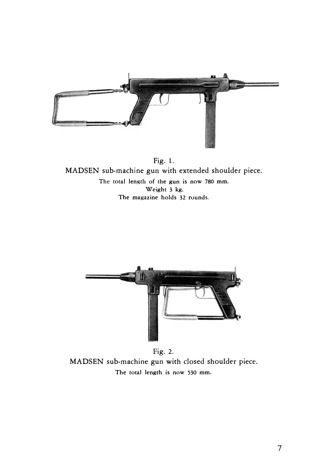
Fig- 1-
MADSEN sub-machine gun with extended shoulder piece.
The total length of the gun is now 780 mm.
Weight 3 kg.
The magazine holds 32 rounds.
Fig. 2.
MADSEN sub-machine gun with closed shoulder piece.
The total length is now 530 mm.
7
SHORT DESCRIPTION OF
THE MAIN PARTS
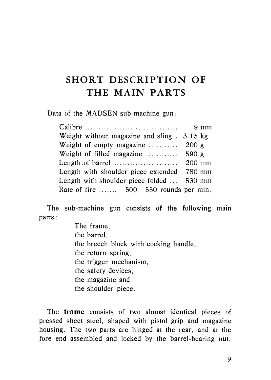
Data of the MADSEN sub-machine gun:
Calibre .............................. 9 mm
Weight without magazine and sling . 3.15 kg
Weight of empty magazine ........... 200 g
Weight of filled magazine .......... 590 g
Length .of barrel .................. 200 mm
Length with shoulder piece extended 780 mm
Length with shoulder piece folded ... 530 mm
Rate of fire . 500—550 rounds per min.
The sub-machine gun consists of the following main
parts:
The frame,
the barrel,
the breech block with cocking handle,
the return spring,
the trigger mechanism,
the safety devices,
the magazine and
the shoulder piece.
The frame consists of two almost identical pieces of
pressed sheet steel, shaped with pistol grip and magazine
housing. The two parts are hinged at the rear, and at the
fore end assembled and locked by the barrel-bearing nut.
9
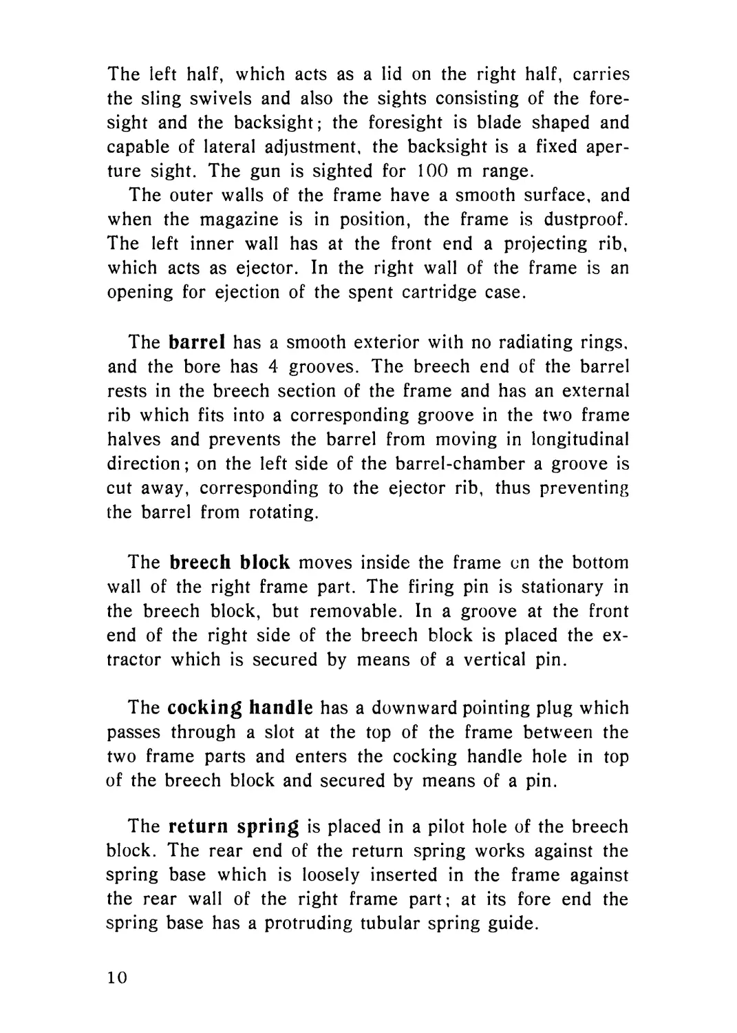
The left half, which acts as a lid on the right half, carries
the sling swivels and also the sights consisting of the fore-
sight and the backsight; the foresight is blade shaped and
capable of lateral adjustment, the backsight is a fixed aper-
ture sight. The gun is sighted for 100 m range.
The outer walls of the frame have a smooth surface, and
when the magazine is in position, the frame is dustproof.
The left inner wall has at the front end a projecting rib,
which acts as ejector. In the right wall of the frame is an
opening for ejection of the spent cartridge case.
The barrel has a smooth exterior with no radiating rings,
and the bore has 4 grooves. The breech end of the barrel
rests in the breech section of the frame and has an external
rib which fits into a corresponding groove in the two frame
halves and prevents the barrel from moving in longitudinal
direction; on the left side of the barrel-chamber a groove is
cut away, corresponding to the ejector rib, thus preventing
the barrel from rotating.
The breech block moves inside the frame on the bottom
wall of the right frame part. The firing pin is stationary in
the breech block, but removable. In a groove at the front
end of the right side of the breech block is placed the ex-
tractor which is secured by means of a vertical pin.
The cocking handle has a downward pointing plug which
passes through a slot at the top of the frame between the
two frame parts and enters the cocking handle hole in top
of the breech block and secured by means of a pin.
The return spring is placed in a pilot hole of the breech
block. The rear end of the return spring works against the
spring base which is loosely inserted in the frame against
the rear wall of the right frame part; at its fore end the
spring base has a protruding tubular spring guide.
10
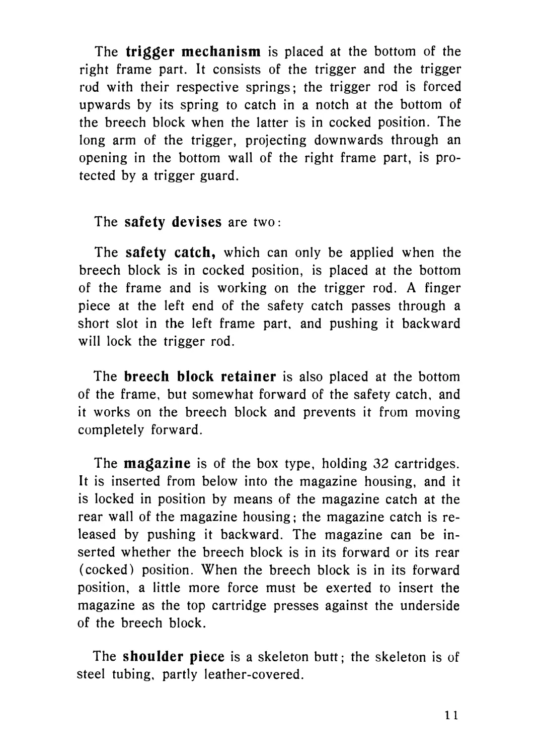
The trigger mechanism is placed at the bottom of the
right frame part. It consists of the trigger and the trigger
rod with their respective springs; the trigger rod is forced
upwards by its spring to catch in a notch at the bottom of
the breech block when the latter is in cocked position. The
long arm of the trigger, projecting downwards through an
opening in the bottom wall of the right frame part, is pro-
tected by a trigger guard.
The safety devises are two:
The safety catch, which can only be applied when the
breech block is in cocked position, is placed at the bottom
of the frame and is working on the trigger rod. A finger
piece at the left end of the safety catch passes through a
short slot in the left frame part, and pushing it backward
will lock the trigger rod.
The breech block retainer is also placed at the bottom
of the frame, but somewhat forward of the safety catch, and
it works on the breech block and prevents it from moving
completely forward.
The magazine is of the box type, holding 32 cartridges.
It is inserted from below into the magazine housing, and it
is locked in position by means of the magazine catch at the
rear wall of the magazine housing; the magazine catch is re-
leased by pushing it backward. The magazine can be in-
serted whether the breech block is in its forward or its rear
(cocked) position. When the breech block is in its forward
position, a little more force must be exerted to insert the
magazine as the top cartridge presses against the underside
of the breech block.
The shoulder piece is a skeleton butt; the skeleton is of
steel tubing, partly leather-covered.
11
It is hinged to the rear end of the right frame part, the
lower hinge being behind the pistol grip. It is retained in
extended and in folded position by means of a notch and a
lug in the hinge, and it can be moved from the one position
to the other by a slight jerk. By means of the lock on the
upper shoulder piece bolt the shoulder piece can be locked
in extended position. When swung forward it lies partly
along the right side of the frame, and in this position it is
very compact, making it possible to use the weapon as an
automatic pistol using both hands.
12
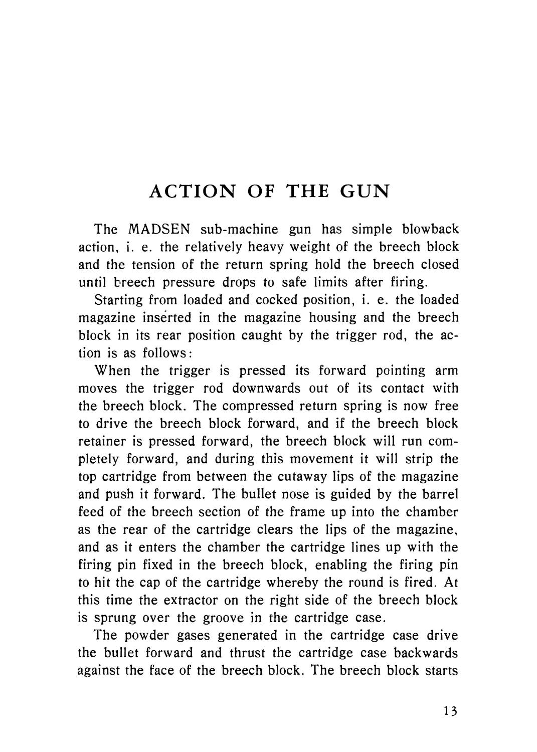
ACTION OF THE GUN
The MADSEN sub-machine gun has simple blowback
action, i. e. the relatively heavy weight of the breech block
and the tension of the return spring hold the breech closed
until breech pressure drops to safe limits after firing.
Starting from loaded and cocked position, i. e. the loaded
magazine inserted in the magazine housing and the breech
block in its rear position caught by the trigger rod, the ac-
tion is as follows:
When the trigger is pressed its forward pointing arm
moves the trigger rod downwards out of its contact with
the breech block. The compressed return spring is now free
to drive the breech block forward, and if the breech block
retainer is pressed forward, the breech block will run com-
pletely forward, and during this movement it will strip the
top cartridge from between the cutaway lips of the magazine
and push it forward. The bullet nose is guided by the barrel
feed of the breech section of the frame up into the chamber
as the rear of the cartridge clears the lips of the magazine,
and as it enters the chamber the cartridge lines up with the
firing pin fixed in the breech block, enabling the firing pin
to hit the cap of the cartridge whereby the round is fired. At
this time the extractor on the right side of the breech block
is sprung over the groove in the cartridge case.
The powder gases generated in the cartridge case drive
the bullet forward and thrust the cartridge case backwards
against the face of the breech block. The breech block starts
13
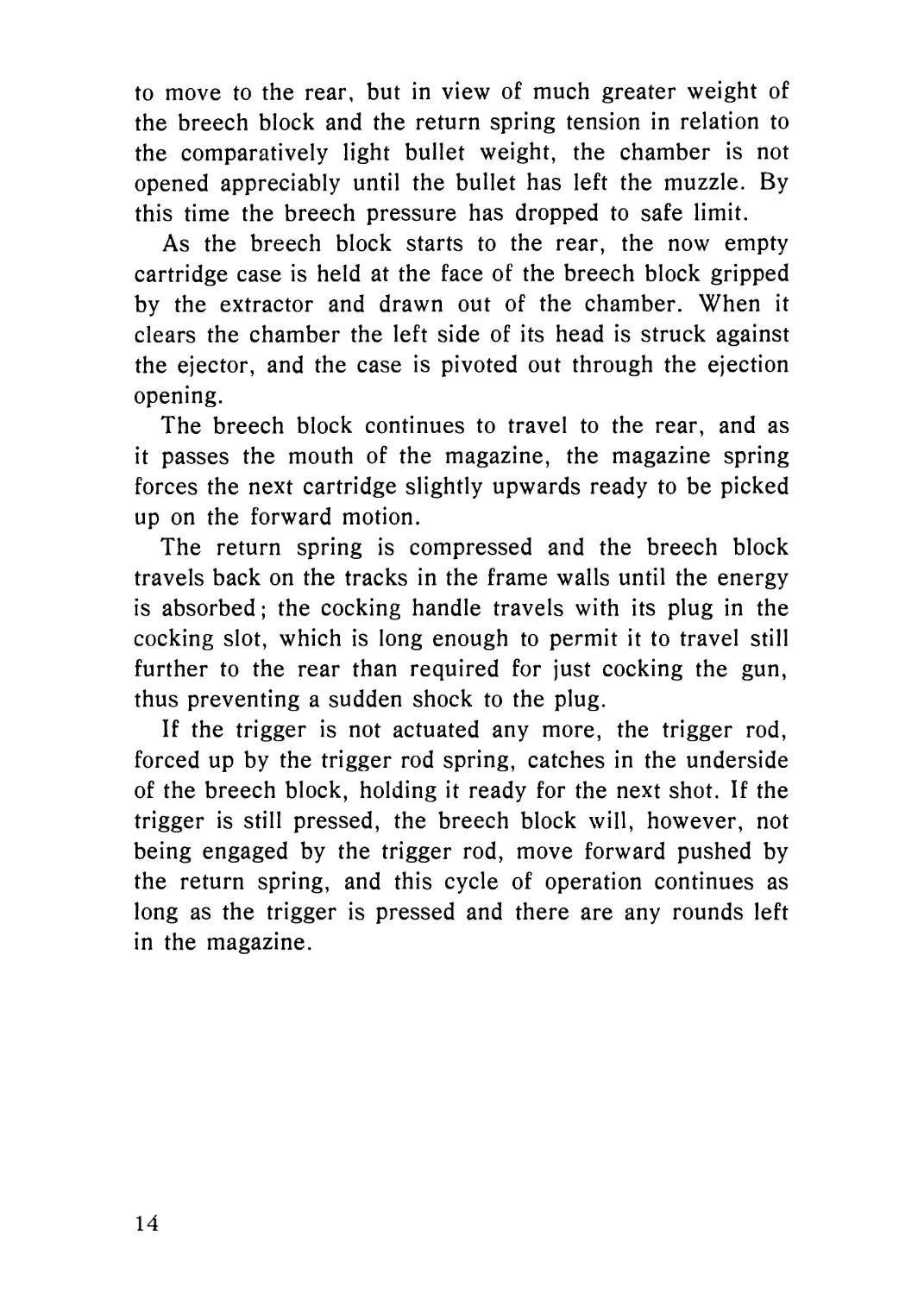
to move to the rear, but in view of much greater weight of
the breech block and the return spring tension in relation to
the comparatively light bullet weight, the chamber is not
opened appreciably until the bullet has left the muzzle. By
this time the breech pressure has dropped to safe limit.
As the breech block starts to the rear, the now empty
cartridge case is held at the face of the breech block gripped
by the extractor and drawn out of the chamber. When it
clears the chamber the left side of its head is struck against
the ejector, and the case is pivoted out through the ejection
opening.
The breech block continues to travel to the rear, and as
it passes the mouth of the magazine, the magazine spring
forces the next cartridge slightly upwards ready to be picked
up on the forward motion.
The return spring is compressed and the breech block
travels back on the tracks in the frame walls until the energy
is absorbed; the cocking handle travels with its plug in the
cocking slot, which is long enough to permit it to travel still
further to the rear than required for just cocking the gun,
thus preventing a sudden shock to the plug.
If the trigger is not actuated any more, the trigger rod,
forced up by the trigger rod spring, catches in the underside
of the breech block, holding it ready for the next shot. If the
trigger is still pressed, the breech block will, however, not
being engaged by the trigger rod, move forward pushed by
the return spring, and this cycle of operation continues as
long as the trigger is pressed and there are any rounds left
in the magazine.
14
Fig. 4.
MADSEN sub-machine gun
carried on the march.
Fig. 3.
MADSEN sub-machine gun
carried on guard duty.
From this position the gun can be shifted
round to the back, the muzzle pointing
downwards to the right.
15
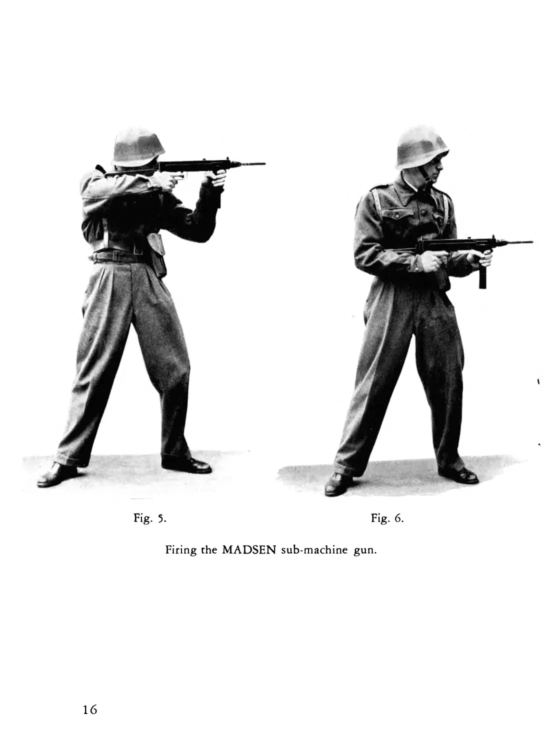
Fig. 5.
Fig. 6.
Firing the MADSEN sub-machine gun.
16
FIRING
The sub-machine gun can be fired from many different
positions, but whether firing from the hip, kneeling, sitting,
standing or prone, the correct grip is always with left hand
firmly round the magazine housing, the thumb pressing
against the breech block retainer, and with the right hand
round the pistol grip and as usual pressing the trigger when
a burst is to be fired. Single shots may be fired by quickly
releasing the trigger, the normal, however, being short
bursts of two or three rounds.
It should always be remembered that this weapon fires
when the breech block goes fully forward; if the breech block
retainer, however, is not released, the breech block will be
stopped on its way forward and no round will be fired. In
order to continue firing the cocking handle must then be
pulled back as far as it will go. Accidental firing caused by
an incomplete cocking motion or by an unintended rearward
movement of the breech block as a result of a shock to the
gun if dropped or laid down hard, is also excluded owing
to the breech block retainer.
17
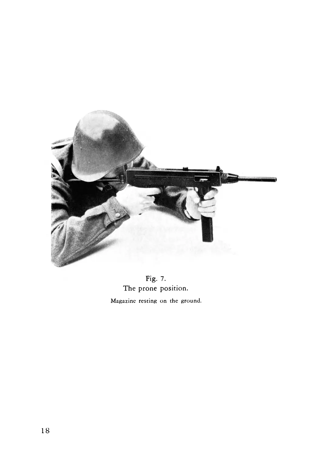
Fig- 7.
The prone position.
Magazine resting on the ground.
18
INSTRUCTIONS
FOR LOADING THE MAGAZINE
AND FOR STRIPPING AND ASSEMBLING
THE GUN
Loading the magazine. A special magazine loading ap-
paratus is issued with each sub-machine gun and can be
carried inside the pistol grip. It consists of a short housing
into which the magazine can be inserted; on top of the
housing is a spring-actuated button. By pushing down firmly
on the button the magazine spring and any cartridge will be
pressed down by a plunger.
Hold the loading apparatus and the magazine together by
the left hand in such a manner that the thumb can press the
button; the magazine must be supported in a suitable man-
ner. Insert a round under the lips of the magazine mouth,
base first, with the right hand, release the button when the
cartridge encounters the plunger of the apparatus and press
the cartridge in until it meets the rear wall of the magazine.
Repeat these actions until the magazine is filled.
If no loading apparatus is available, cartridges may be
inserted by hand.
Stripping and assembling the gun. Following parts
can be removed without tools: barrel-bearing nut, barrel,
spring base, return spring and breech block with cocking
handle. When these are removed, the frame is easily ac-
cessible for cleaning inside.
19
When the sub-machine gun is to be stripped, the maga-
zine must be withdrawn, the shoulder piece folded and the
breech block in its forward position. The first thing to do is
to unscrew the barrel-bearing nut.
Lay the gun on its right side on table or knee. Open the
frame by pulling at the front sling swivel with the right
hand, the left hand pressing against the barrel. Remove the
barrel.
Remove the return spring by pressing the spring base
forward and upwards, whereafter the return spring can be
withdrawn from the pilot hole in the breech block. Lift the
breech block up. Any further stripping should be done only
by qualified armourer.
After cleaning the parts should be oiled very lightly. As-
sembly is carried out in opposite order.
The magazine can be cleaned by removing the bottom.
20
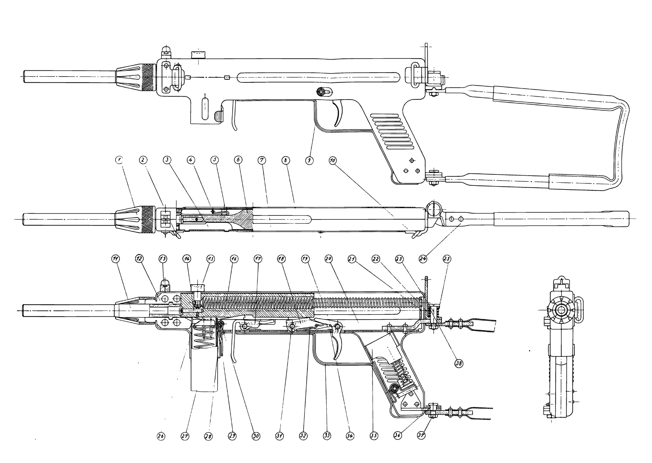
21
COMPONENTS OF GUN
1
2
3
4
5
6
7
8
9
10
11
12
13
14
15
16
17
IS
19
20
21
22
23
24
25
26
28
29
30
31
32
33
34
35
36
37
38
Barrel-bearing nut
Sling swivel
Ejector
Extractor pin
Extractor
Breech block
Frame half (left)
Frame half (right)
Safety catch
Sling swivel
Barrel
Barrel bearing
Corn
Firing pin
Cocking handle
Return spring
Breech block retainer
Trigger rod
Trigger
Trigger plate
Return spring guide (complete)
Rear sight plate
Shoulder piece bolt (upper)
Shoulder piece
Shoulder piece spring
Firing pin rivet
Magazine
Magazine catch pin
Magazine catch
Magazine catch spring
Trigger rod pin
Trigger rod spring
Trigger guard
Trigger spring
Magazine loading apparatus
Shoulder piece bolt (lower)
Shoulder piece bolt nut
Shoulder piece lock
22