/


Tags: weapons military affairs submachine gun
Year: 1984


Text
USER HANDBOOK
| sterling!
SUB-MACHINE GUN
9-mm. MK 4
(S.M.G. 9mm. L.2.A.3.)
I T t R L IN 6 ARMAMENT COMPANY LIMITED
DAGENHAM ESSEX ENGLAND
CONTRACTORS TO MINISTRY О MWCL Htt MAJESTY 5 GO*t>HMfNT
CROWN AGCNTL ANO О¥Щ£М GOVIRNHfNTS
|W«r Deetrrww Адом* tawrtwirt Otnamfiwl
FeJtopAwv. 0t*59S ПХ
Citiu- STERLING. DAGENHAM. ENGLAND
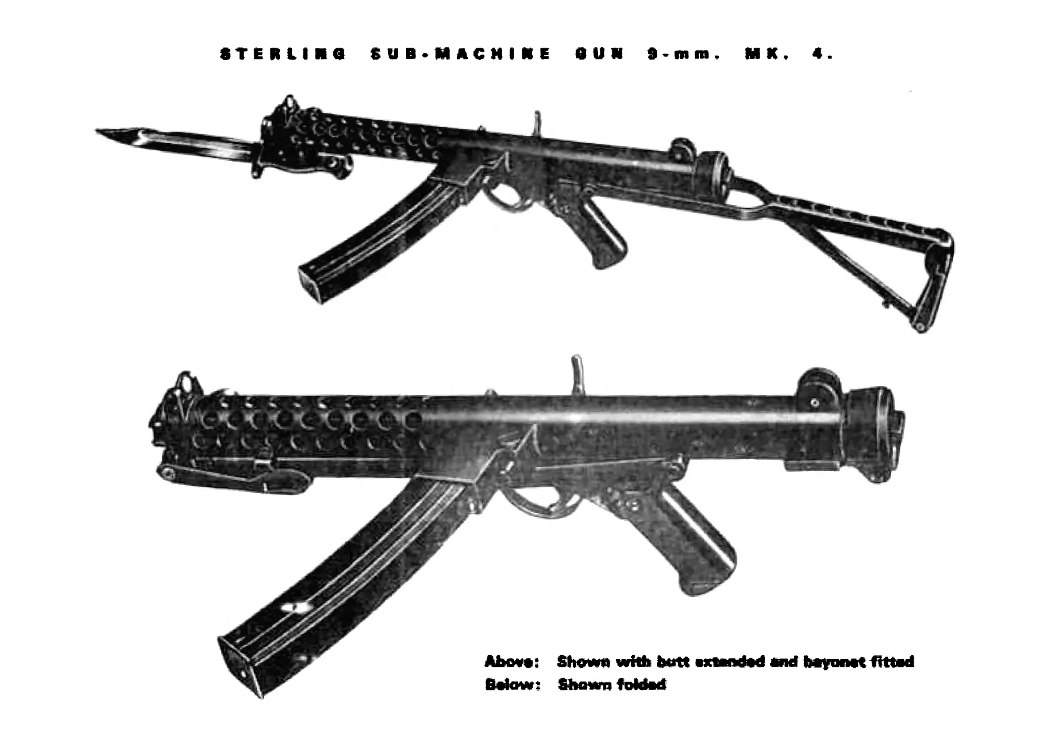
STERLING SUB.MACHINE SUN 9-mm. MX. 4
CO NT
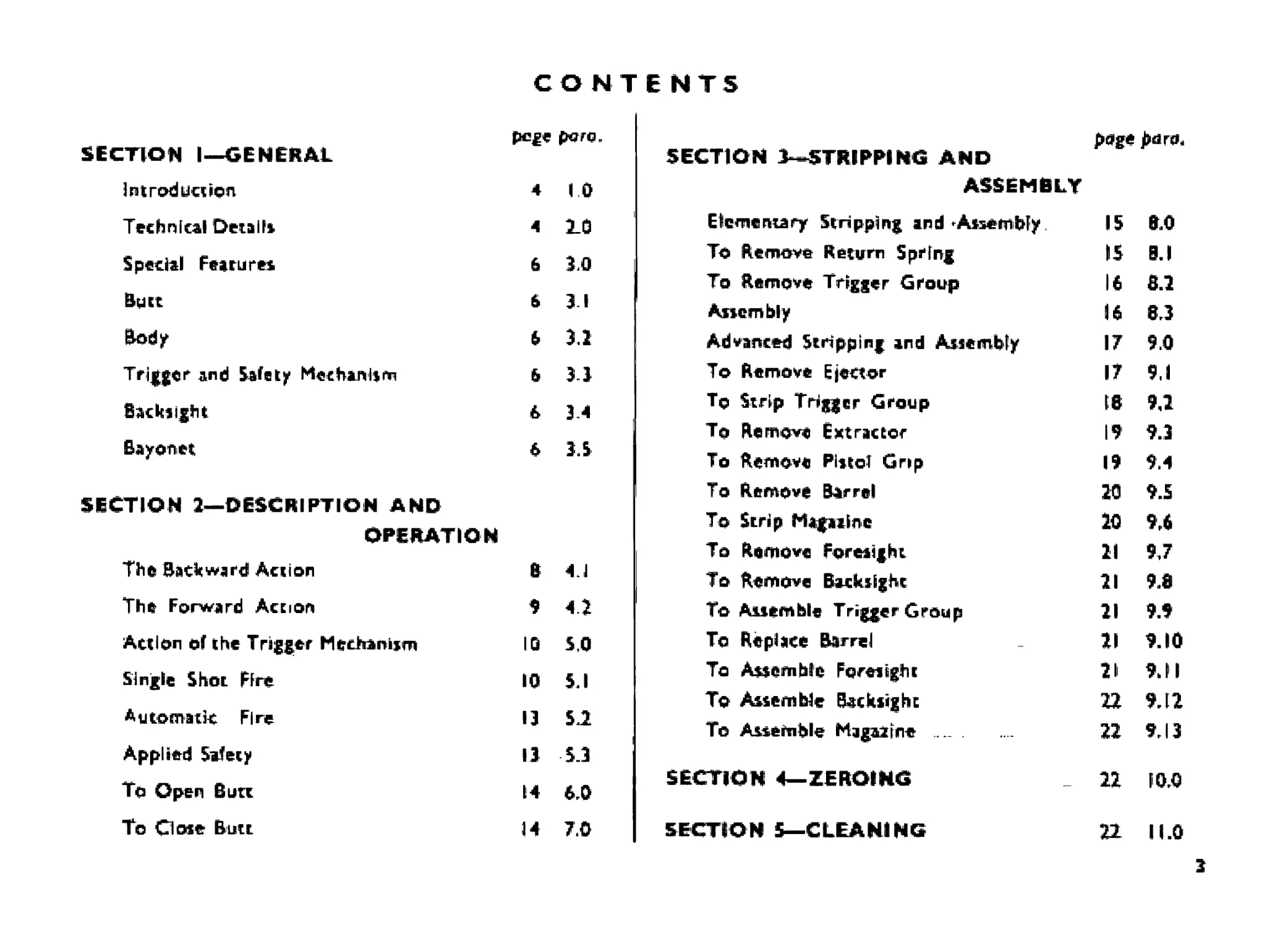
SECTION 1—GENERAL pcge para.
IntrodLJWCTl 4 1.0
Technical Details 4 2-0
Special Fearurti 6 10
Burt 6 11
Body & 11
Trigger and Safety Mechanism & 13
Backlight & 3 4
Bayonet 6 15
SECTION 2—DESCRIPTION AND
OPERATION
The Backward Action В 4.1
The Forward Action $ 4 2
Action of the Trigger Mechanism 10 5,0
Single Shot Hre 10 11
Automatic Fire 13 SJL
Applied Safety 13 13
To Open Burt 14 10
To Close Butt M 7.0
ENTS
page j>dro.
SECTION 3—STRIPPING AND
ASSEMBLY
Elementary Stripping and * Assembly 15 BO
To Remove Return Spring 15 0.1
To Remove Trigger Group 16 8.1
Assembly 16 83
Advanced Stripping and Assembly IT 0.0
To Remove Ejector IT 9,1
To Strip Trigger Group 18 9Д
To Remove Extractor 19 9.3
To Remove Pistol Grip 19 9.4
To Remove Barrel 20 9.5
To Scrip Mapilne 20 M
To Remove Foresight 21 9J
To Remove Backsight 21 9.8
To Assemble Trigger Group 21 9.9
To Replace Barrel 21 9.10
To Assemble Foresight 21 9JI
To Assemble Backsight 22 9.12
To Assemble Magazine 22 9.13
SECTION 4—ZEROING 22 10.0
SECTION 5—CLEANING 22 11.0
3
SECTION I—GENERAL
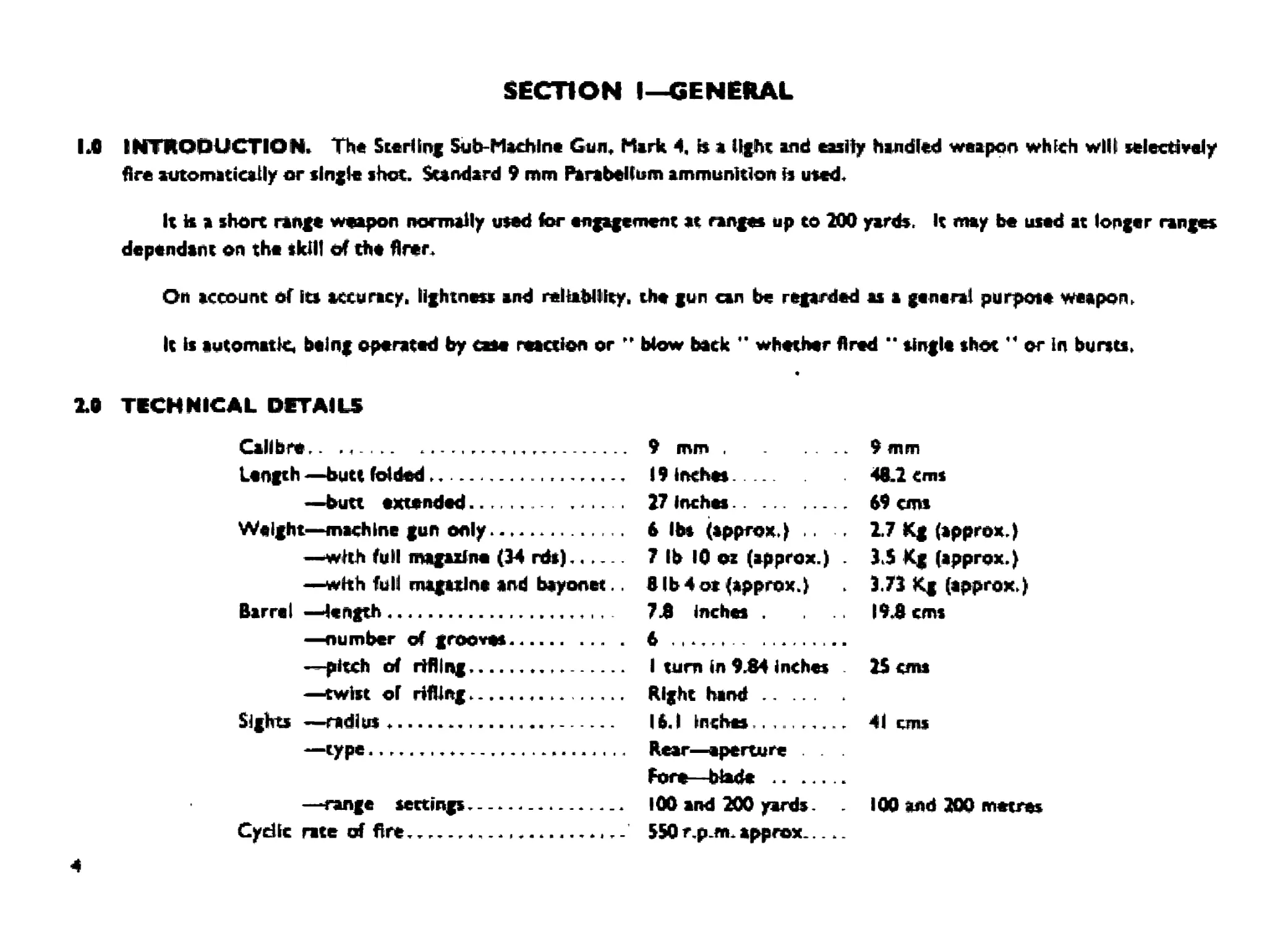
1Л INTRODUCTION. The Sterling Sub-МаеЫпе Gun, Mirk 4, b a light and easily handled weapon which will selectively
fire automatically or tingle shot. Standard 9 mm Parahelium ammunition h used.
It it a short range weapon normally used for engagement at ranges up to 200 yards. It may be used at longer range*
dependant on the skill of the firer
On account of Its accuracy, lightness and reliability, the gun can be regarded as a genera! purpose weapon,
It Is automatic being operated by cut reaction or H blow back " whether fired " tingle shot or in bursts,
X0 TECHNICAL DETAILS
Calibre.. 9 mm 9 mm
Length —butt folded I9inch« 48.2 cms
—butt extended 27 Inches 69 cms
Weight—machine gun only 6 lbs (approx.) .. 2.7 Kg (approx.)
—with full magazine (34 rds) 7 lb Ю oz (approx.) - IS Kg (approx.)
—with full magazine and bayonet.. В lb 4 oi (approx J 3.73 Kg (approx.)
Barrel —length 7 £ Inches . . .. 19.8 cms
—number of grooves ... . 6
—pitch of rilling 1 turn in 9.84 inches 15 cms
—twist of rifling. Right hand
Sights —radius . 1 ft. 1 inches.. 41 cms
- - Rear—aperture Fore—blade .. .....
—range settings.- lOO and 200 yards. 100 and 200 metres
Cydic rice of fire., 550 r,p_m. approx
4
TECHNICAL DETAILS (CONTINUED)
TERMINAL VELOCITY AND KINETIC ENERGY OF STANDARD 9 mm BULLET
RANGE VELOCITY KINETIC ENERGY
Yards Metre* Fc/Sec M Sec Ft/lb* Kgm
0 0 1280 390 447 62J
10$ 100 1115 340 339 47.0
319 200 $75 296 262 36.4
327 300 «72 266 207 28.7
436 400 760 218 167 23.2
MS 500 700 214 13$ 18.8
654 «00 632 193 109 15.2
761 700 572 174 B9 12.3
872 800 518 158 74 10.2
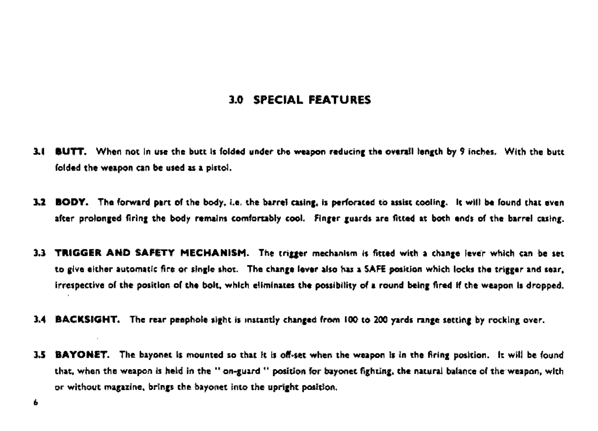
ЗЛ SPECIAL FEATURES
XV BUTT, When not In use the butt is folded under the weapon reducing the ovarall length by 9 inches. With the butt
folded the weapon can be used as a pistol.
ЗЛ BODY* The forward pan of the body* Le. the barrel casing. is perforated to wist cooling. It will be found that even
after prolonged firing the body remains comfortably cool Finger guards are fitted at both ends of the barrel casing.
3.3 TRIGGER AND SAFETY MECHANISM. The trigger mechanism is fitted with a change lever which can be set
to give either automatic Яге or single shot. The change lever also has a SAFE position which locks the trigger and sear*
irrespective of the position of the bolt, which eliminates the possibility of a round being fired If the weapon Is dropped,
3.4 BACKSIGHT. The rear peephole sight is instantly changed from 100 to 200 yards range setting by rocking over.
ЗЛ BAYONET. The bayonet is mounted so that It is offset when the weapon Is In the firing position. It will be found
that, when the weapon is held in the " on-guard 44 position for bayonet fighting, the natural balance of the weapon, with
or without magazine* brings the bayonet into the upright position.
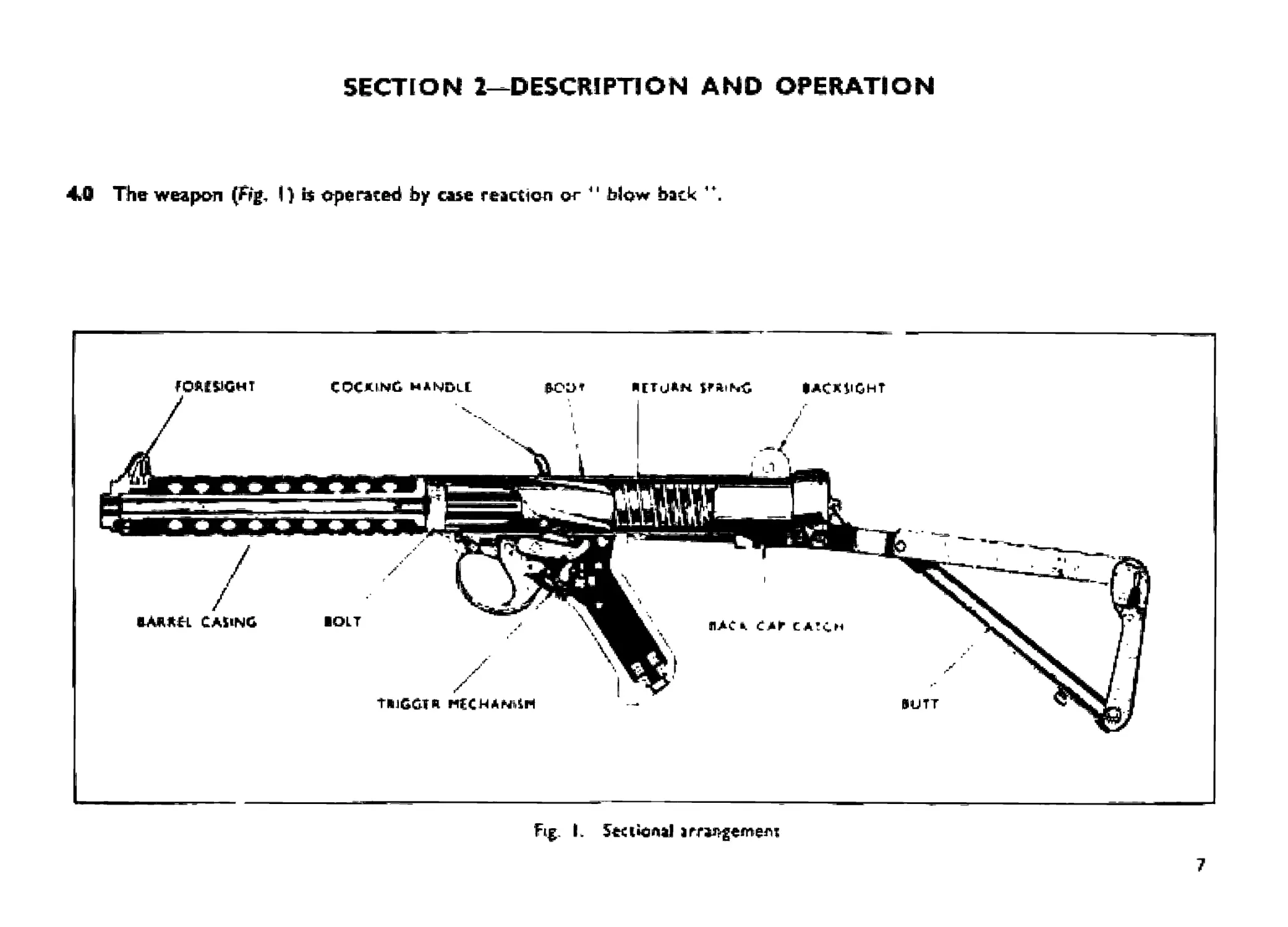
SECTION 1—DESCRIPTION AND OPERATION
40 The weapon (Frg, I) operated by case reaction or " Ы-ow back ,+.
Fig. I. 5«ikmal irrar-gemem
7
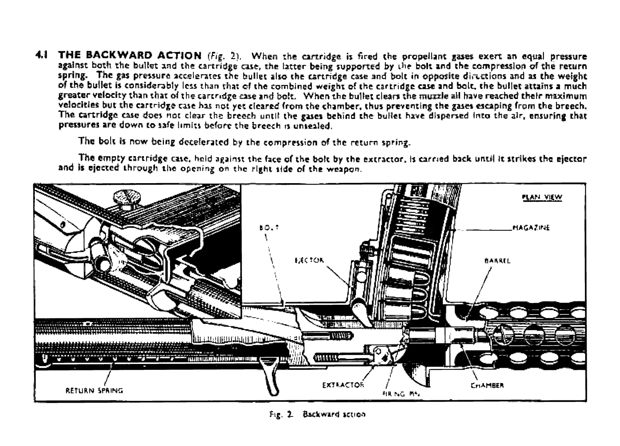
4.1 THE BACKWARD ACTION (Fig. 2], When the cartridge is Fred the propellant gases exert an equal pressure
against both the bullet and the cartridge case,, the latter being supported by die bolt and the compression of the return
spring. The gas pressure accelerates the bullet also the cartridge case and bole in opposite directions and as the weight
of the bullet is considerably less than that cf the combined weight of the cartridge case and bolt, the bullet attains a much
greater velocity than that of the carer edge case and bolt. When the bullet clears the muzzle all have reached1 their maximum
velocities but the cartridge case has not yet cleared from the chamber, thus preventing the gases escaping from the breech.
The Cartridge case does not clear the breech until the gases behind the bullet have dispersed Into the air. ensuring that
pressures are down to safe limits before the breech rs unsealed.
The bolt is now being decelerated by the compression of the return spring.
The empty cartridge cate, held against the face of the bolt by the extractor* Is earned back until) It strikes the ejector
and1 is ejected through the opening on the right side of the weapon.
Fig, X Backward setter
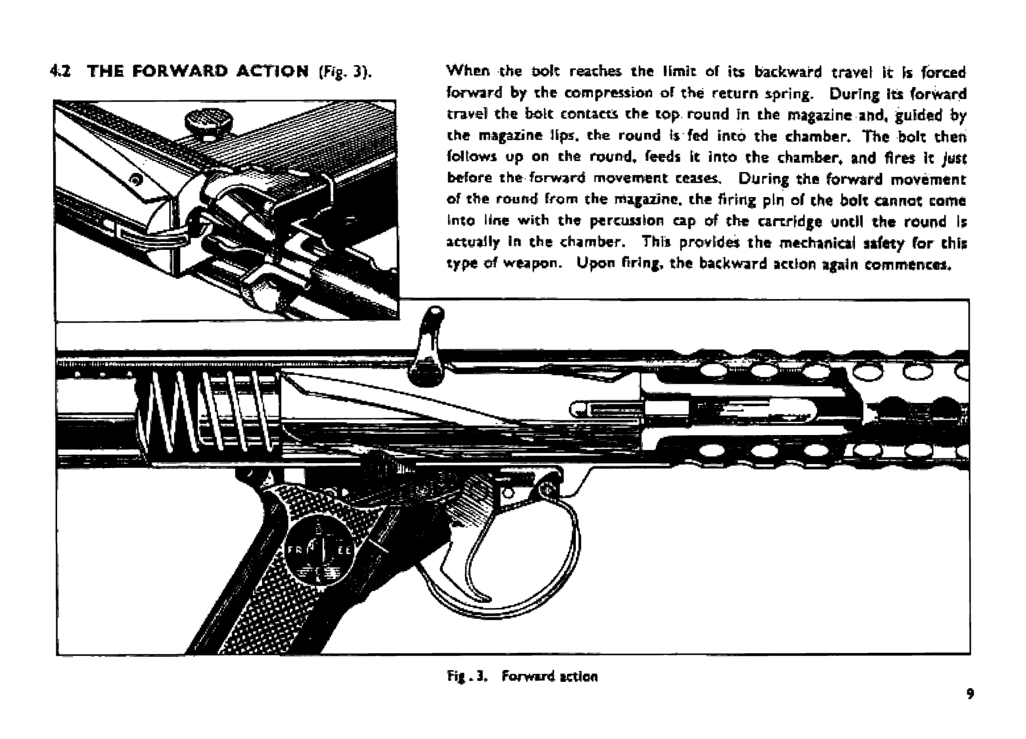
When the bolt reaches. the limit of its backward travel it Is forced
forward by the compression of the return spring. During its forward
travel the bolt contacts the top round In the magazine and, guided by
the magazine lips, the round Is fed into the chamber. The bolt then
follows up on rhe round, feeds it into the chamber* and fires It Just
before the forward movement ceases. During the forward movement
of the round from the magazine, the firing pin of the bolt cannot come
Into line with the percussion cap of the cartridge until the round Is
actually In the chamber. This provides the mechanical safety for this
type of weapon. Upon firing, the backward action again commences.
4,2 THE FORWARD ACTION (Fig. 3).
Fig. 3, Fwwird action
9
5Л ACTION OF THE TRIGGER MECHANISM (figs. 4. 5# i omf 7).
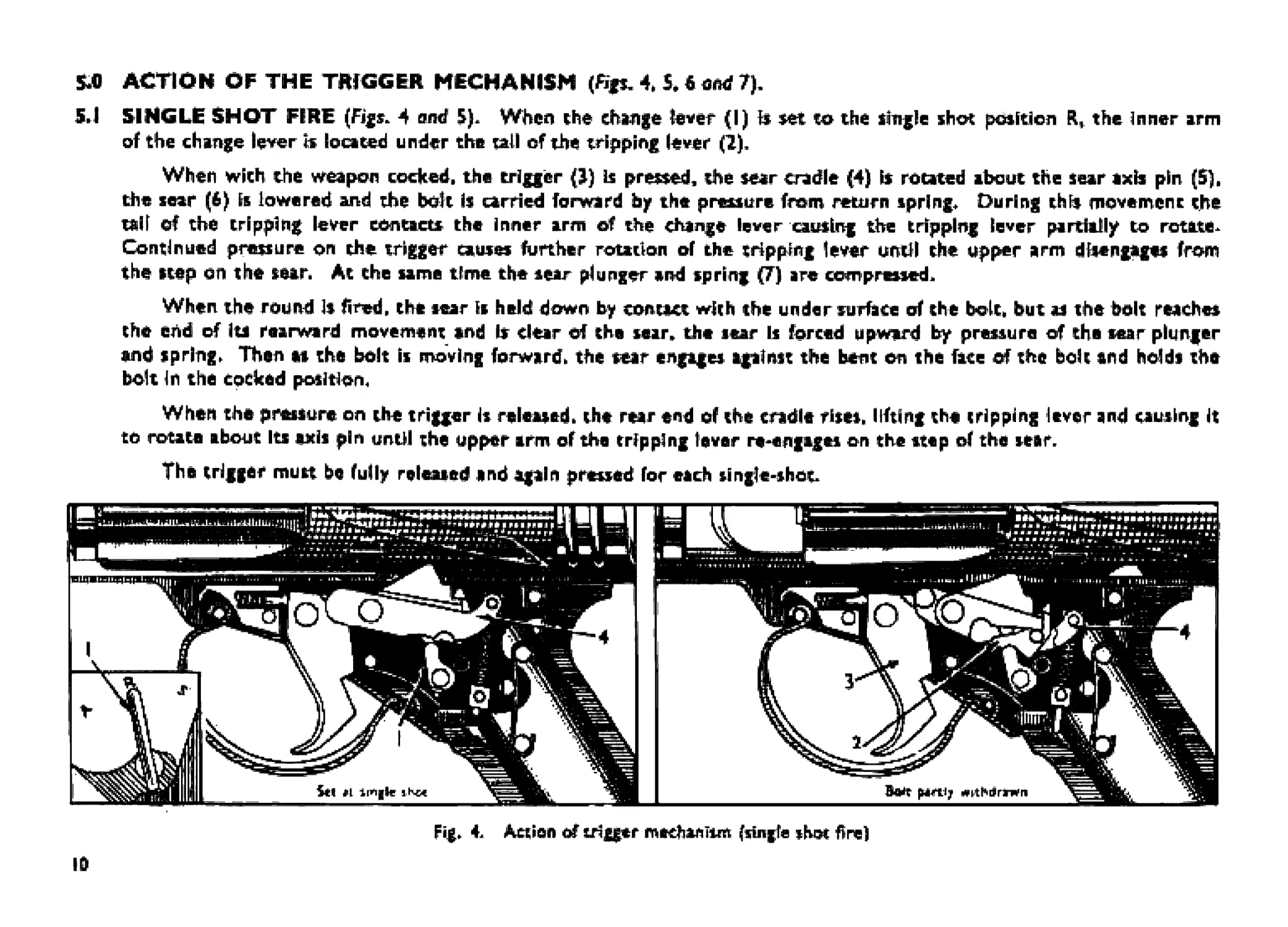
5J SINGLE SHOT FIRE (Figs. 4 and 5). When she change hver (I) Is set to the single shot position R, the inner arm
of the change lever b located under the tall of the tripping lever (1),
When with the weapon cocked, the trigger {J) к pressed. the sear cradle (4) is rotated about the sear axis pin (5).
the sear (6) is lowered and the bolt h carried forward by the pressure from return spring* During this movement the
tell of the tripping lever contacts the inner arm of the change lever causing the tripping lever partially to rctite^
Continued pressure on the trigger causes further rotation of the tripping lever until the upper arm disengages from
the step on the sear» Ac the same time the sear plunger and spring (7) are compressed.
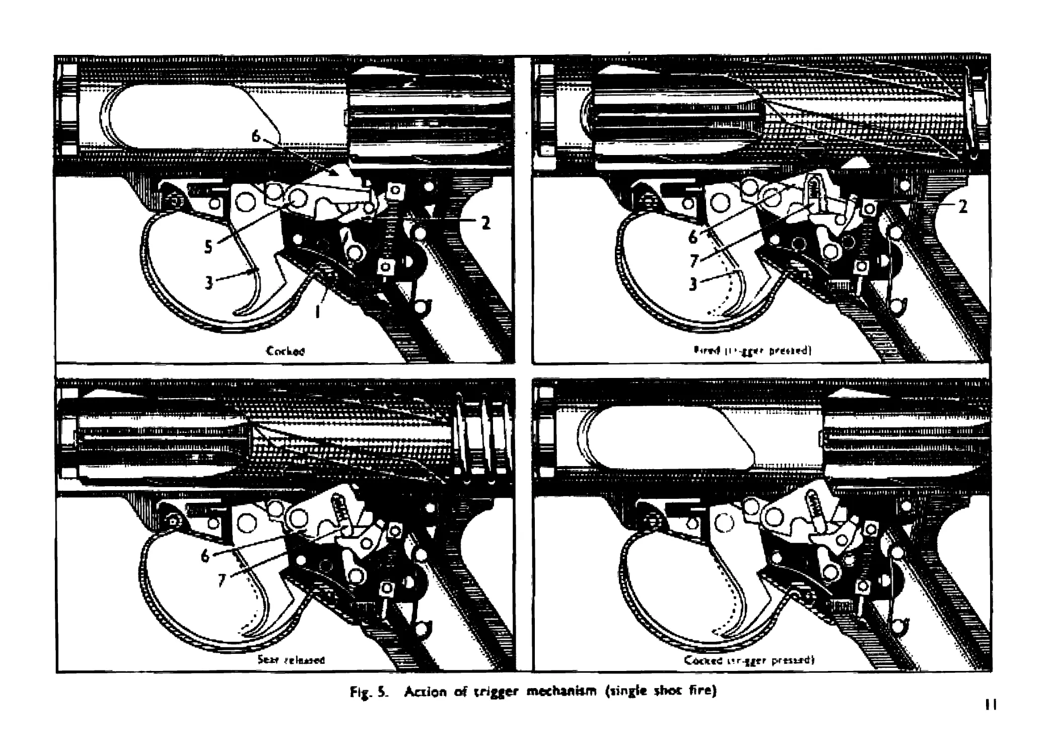
When the round Is fired, the sear is held down by contact with the under surface erf the bolt, but as the bolt reaches
the end of Its rearward movement end Is clear of the sear, the sear Is forced upward by pressure of the wear plunger
and spring* Then a* the bolt Is moving forward, the sear engages against the bent on the fate of the bolt and holds the
bolt In the cocked position*
When the pressure on the trigger is released, the rear end of the cradle rises, lifting the tripping lever and causing It
to rotate about Its axis pin until the upper arm of the tripping lever re-engagei on the step of the star.
The trigger mutt be fully released and again pressed for each single-shot.
Fig* L Action erf trigger mechanism (sbigfe shot fire)
lb
Flj. 5- Aciion of trigger mechaeUm (tingle shoe fire)
II
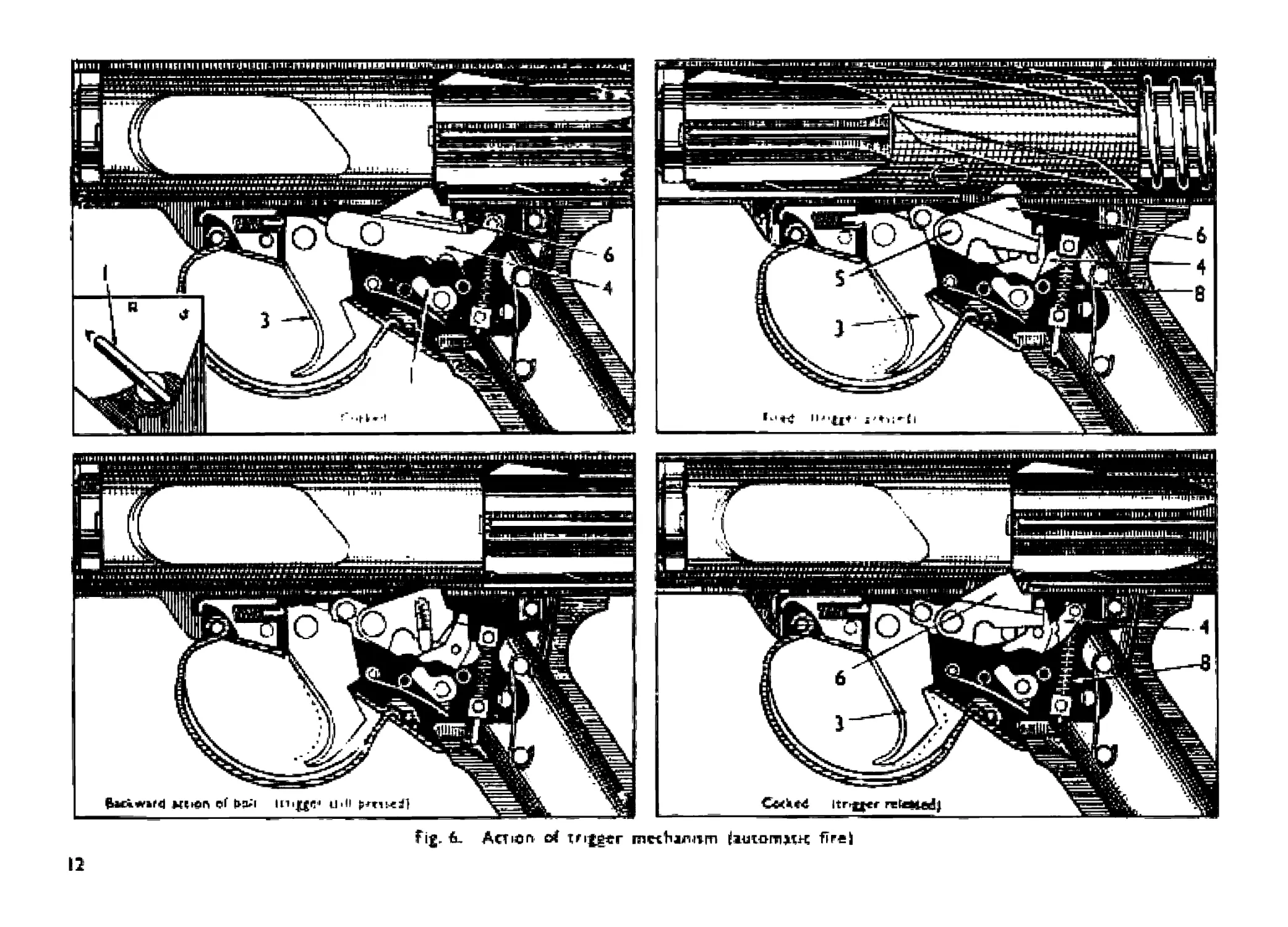
Fig. 6, Action c4 T fitter mKhirivm iiutornMK Я re i
12
52 AUTOMATIC FIRE (Frg. £}, When with the change lever (I) sec at automatic A arid the weapon cocked, the trigger
Is pressed; the projection on the upper part of the trigger Hfrs the end of the sear cradle (4) rotating it about its axis
pin (5)+ This depresses the sear (6) freeing H from contact with the face of the bent on the bolt, and allowing the bolt
to fly forward. The movement of the sear cradle compresses the sear cradle spring (0),
The weapon will now continue firing until either the trigger Is released or the magazine Is empty.
When the trigger is released the sear cradle returns to les former position under the action of the seer crad le Spring,
the sear li raised into the bolt way and contacting the bent on the bok, holds the bolt In the cocked position.
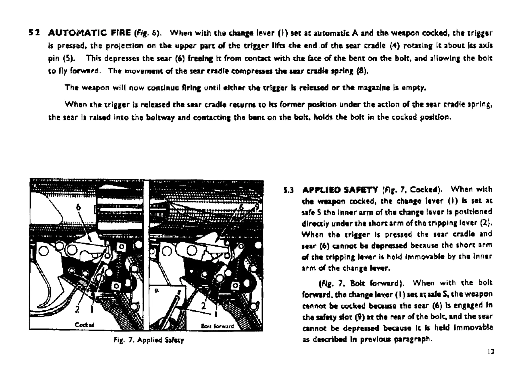
Fig. 7. Applied Safety
5.3 AFPUEO SAFETY (Fig. 7, Cocked), When with
the weapon cocked* the change lever (I) Is set at
safe $ the inner arm of the change Inver h positioned
directly under the short arm of the tripping fever (2).
When the trigger Is pressed the sear cradle and
iw (6) cannot be depressed because the short arm
of the tripping fever Is held immovable by the Inner
arm of the change fever.
(Fig. 7> Bolt forward |. When with the bolt
forward, the change fever (I) set at safe S, the weapon
cannot be cocked because the sear (6) is engaged In
the safety slot (9) at the rear of the bolt, and the sear
cannot be depressed because It is held Immovable
as described In previous paragraph.
13
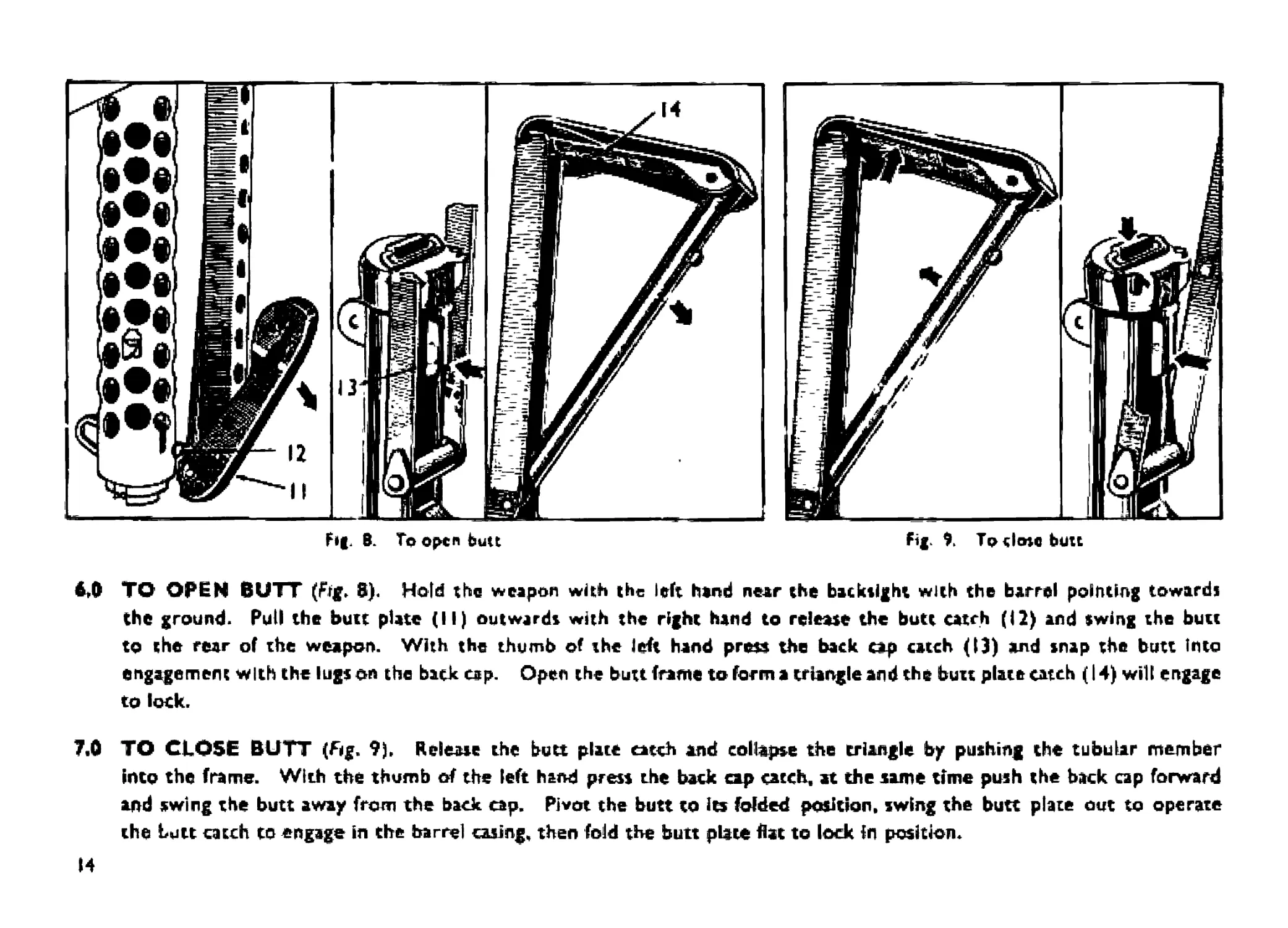
М ТО OPEN BUTT (Ffg. 8). Hold the weapon with the left hand near the backsight with the barrel pointing towards
the ground. Pull the butt plate (II) outwards with the right hand to release the butt catch (12) and swing the butt
to the rear of the weapon. With the thumb of the left hand press the back cap catch (13) and snap the butt into
engagement with the lugs on the back cap. Open the butt frame to form a triangle and the butt plate catch (14) will engage
to lock.
7.0 TO CLOSE BUTT (fig. 9)» Release the butt plate catch and collapse the triangle by pushing the tubular member
into the frame. With the thumb of the left hand press the back cap catch, at the same time push the back cap forward
and swing the butt away from the back cap. Pivot the butt to Its folded position, swing the butt plate out to operate
the butt catch to engage in the barrel casing, then fold the butt plate flat to lock in position.
И
SECTION 3—STRIPPING AND ASSEMBLING
8.0
ВЛ
loaded and remove iltng if fitted. Set change lever to A. place butt in the folded position and bolt forward-
ELEMENTARY STRIPPING AND ASSEMBLING (Figs. Ш and 11 )* Before stripping, ensure that the weapon is
not
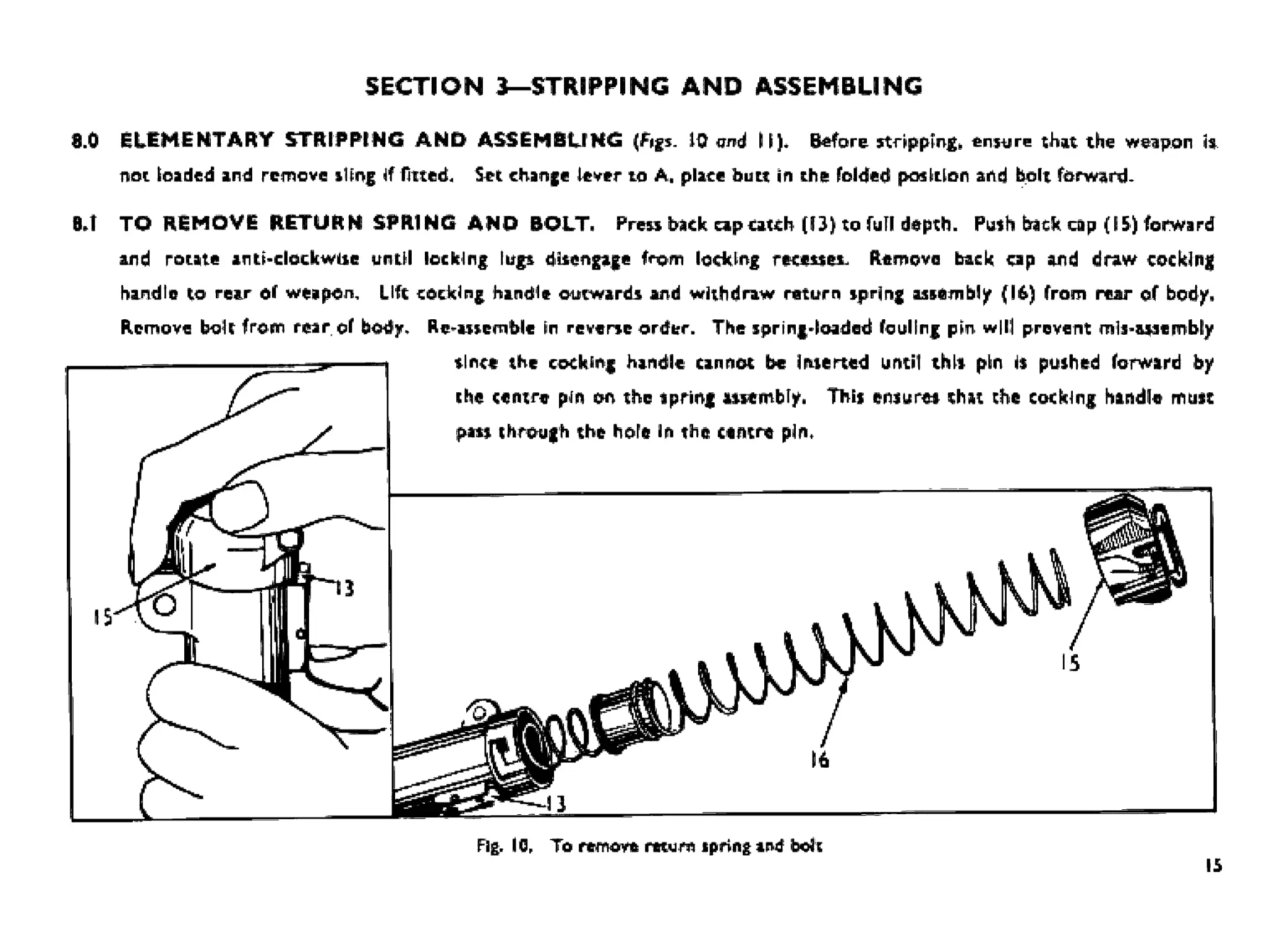
REMOVE RETURN SPRING AND BOLT. Prew back capcatch (□) to full depth. Push back cap (15) forward
rotate antt-clock wiie until locking I up disengage from locking recesses- Remove back cap and draw cocking
TO
and
handle to rear of weapon, Life cocking handle outwards and withdraw return spring assembly (lb) from rear of body.
Remove bolt from rear of body.
Re^assemblc in reverse order. The spring-loaded fouling pm will prevent mli-ataembly
since the cocking handle cannot be inserted until this pin is pushed forward by
the centre pin on the spring assembly. This ensures chat the cocking handle must
pais through the hole in the centre pin.
Fig. 10, To remove return spring and bdt
15
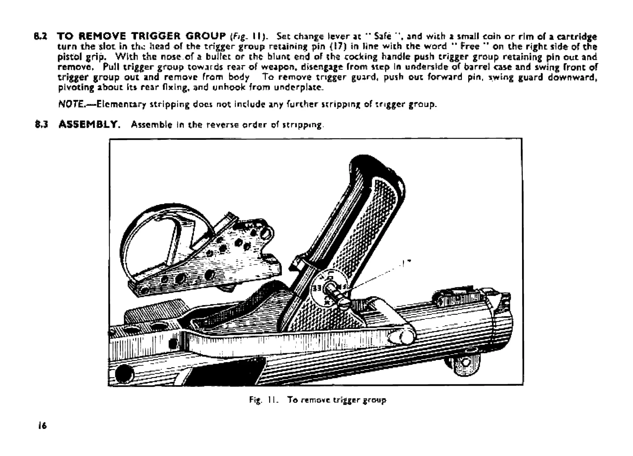
&Д ТО REMOVE TRIGGER GROUP (Fig- 11). Set change lever at ” Safe 4*. and with a small coir* or rim of a cartridge
turn the slot In tta head of the trigger group retaining pin (17) in line with the word •• Free ” on the right side of the
pistol grip. With the nose.of a bullet or the blunt end of the cocking handle push trigger group retaining pin out and
remove, Pull trigger group towards rear of weapon» disengage from step In underside of Parrel case and swing Front of
trigger group out and remove from body To remove trigger guard, push out forward pin, swing guard downward,
pivoting about its rear fixing, and unhook from underplate.
MQTE.—Elementary stripping does not in elude any further stripping of trigger group.
8J ASSEMBLY. Assemble In the reverse order of stripping,
Fig. 11. To гетпомс trigger group
16
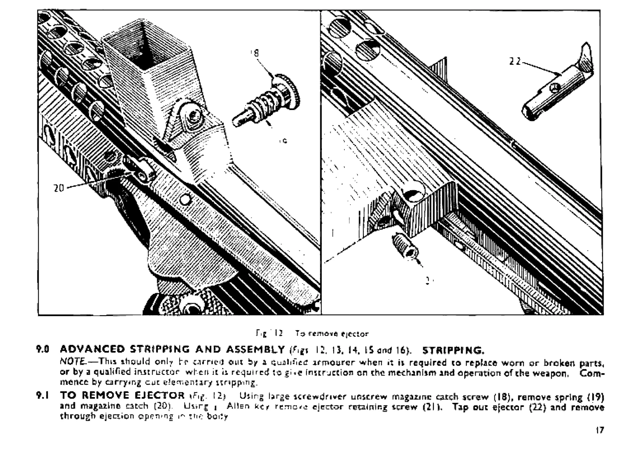
fig 15 T:> ejCClQS*
ЭД ADVANCED STRIPPING AND ASSEMBLY 12. 11 H„ U). STRIPPI NG*
MOTE.—Thu ihauld cml? br earned out Ь/ a Qualified armourer when it h required is replace warn or broken parts.,
or by a qualified irutriictor wl’en it h required gi*e IniErjction an rhe mechinlim and operation of the weapon. Com-
mence by carry mg cut nnppmg.
9.1 TO REMOVE EJECTOR I 2j Using large screwdf»*^ unscrew rnagaunc catch strew (IS), remove spring (19)
and magazine catch (20). Using « Alien кек remote ejector rntzimr.g tcrew (21 К Tap out ejector (12) and remove
through ejection cspervng m the body
17
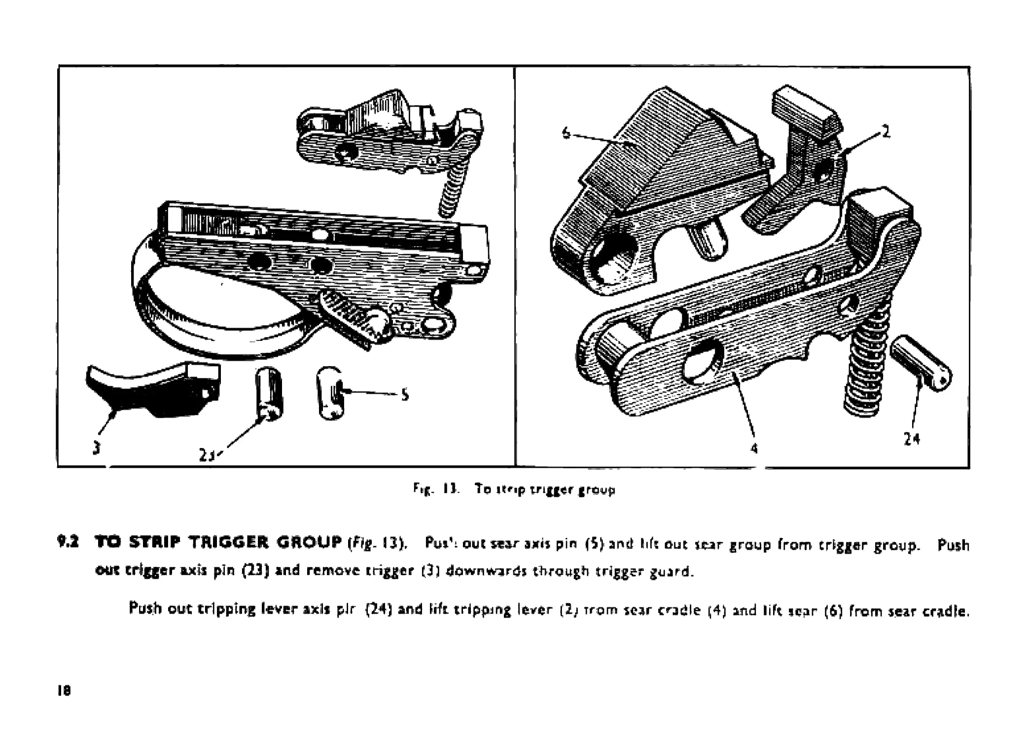
IJ. To пгф trigger group
♦.1 TO STRIP TRIGGER GROUP 13), Put1- out sear axis pin (5) and h(s out near group from trigger group. Push
ш trigger axis pin (23) and remove trigger (31 downwards through trigger guard.
Push out tripping lever axils plr {14} and lift trippjng lever (2j тгогп sear cradle ^4) and lift tear (6) from sear cradle.
18
25
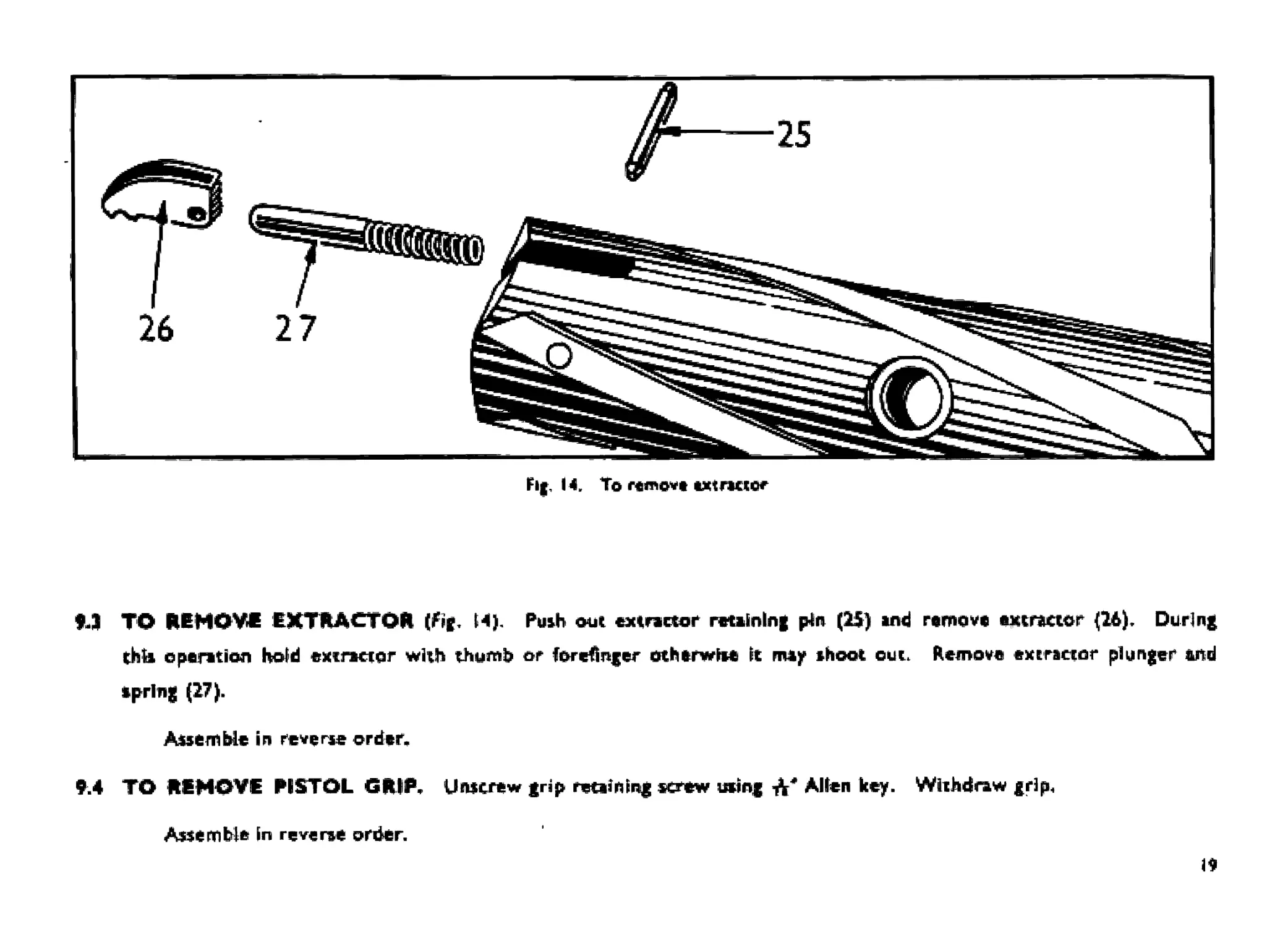
9-J TO REMOVE EXTRACTOR (fir M). Posh out extractor retaining pin (25) and remove extractor (26). During
thU operation hold extractor with thumb or forefinger otherwiie It may ihoot cut. Remove extractor plunger and
spring (27).
Assemble in reverse order,.
9.4 TO REMOVE PISTOL GRIP. Unscrew grip retaining screw using Alien key. Withdraw grip.
Assemble in reverse order.
19
9.5
9.6
38
ИТ
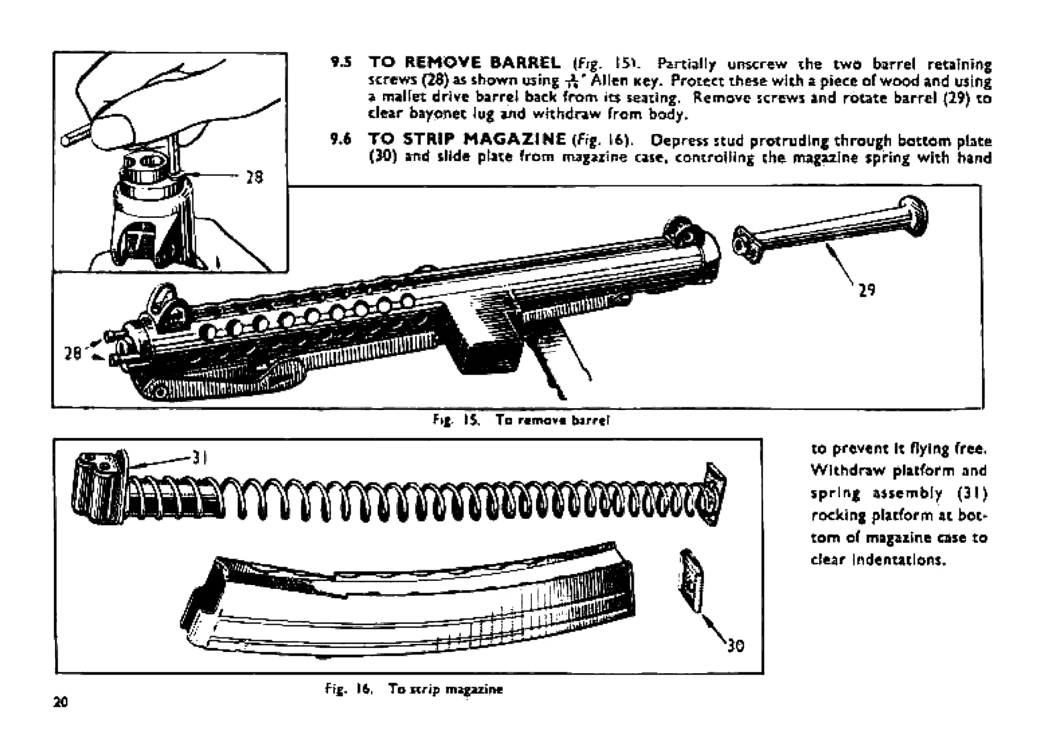
Fkjg. 1$. Tn nnw*i pirre!
TO1 REHOVE BARREL (Frg. ISV Partially unscrew the two barrel retaining
screws (26) as shown из m g Allen кеу. Protect these with a piece of wood and using
a mallet drive barrel back from its seating. Remove screws and rotate barrel (29) to
clear bayonet log and withdraw from body,
TO STRIP MAGAZINE (Fig, 1Б), Depress stud protruding through bottom plate
(30) and slide ptite from magazine case. controlling the magazine spring with hand
Ffg. IS, Ta icrip magazine
to prevent it Пу lag free.
Withdraw platform and
spring assembly (31)
rocking platform at bot-
tom of magazine case to
dear Indentations.
20
9.7 FORESIGHT. The foresight fits into a dovetail in the barrel case. к к a spring fit, there being no retaining pin or
screw. To remove» tap right out from either side with a drift
9.8 BACKSIGHT. This should not be removed unless absolutely necessary.
To remove the backlight, drive out the pin, lift out sight and spring, taking care not to lose small collars.
ASSEMBLY
9.9 TRIGGER GROUP.
9.9* 1 Ensure change lever Is at automatic A.
9.9 .2 Replace tripping lever and Its axis pin in sear cradle, ensuring that the head of the tripping lever к engaged on the
lower step of the sear,
9.9 Л Insert sear group Into trigger group housing. Line up the sear, sear cradle and trigger housing, using trigger group
retaining pin as a drift, and sear axis pin.
9Л.4 Insert trigger upwards through trigger guard ensuring that the trigger plunger is depressed within Its housing. Line
up. using trigger group retaining pin as a drift. and replace trigger axis pin.
9*9,5 Test trigger group for correct functioning at safe, single-shot and automatic
9*10 BARREL.
9*10.1 Insert barrel into case and push forward, routing the barrel to dear bayonet lug. The extractor clearance groove
In the barrel face should be In line with the elector opening.
9.10.2 Replace barrel retaining screws hand tight, then finally tighten, a little on each screw at a time using Allen key.
9.11 FORESIGHT. To assemble» insert foresight into dovetail and tap Into the required position.
2<
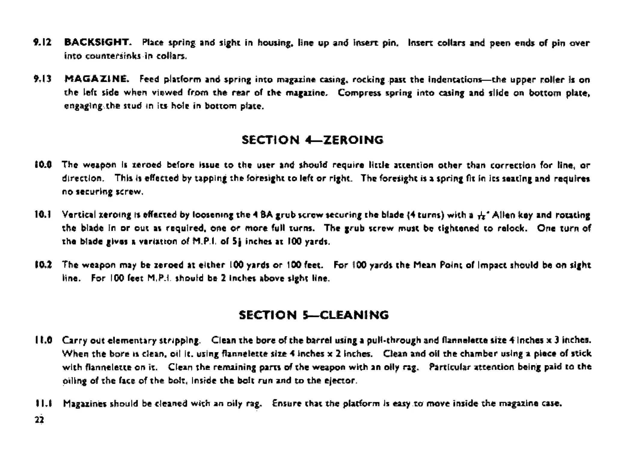
&I2 BACKSIGHT. Place spring and sight in housing. line up and Insert pin. Insert collars and peen ends of pin over
into countersinks in collars.
MAGAZINE. Feed platform and spring into magazine casing* rocking put the Indentations—the upper roller Is on
the left side when viewed from the rear of the magazine. Compress spring into casing and slide on bottom plate»
engaging.the stud in its hole in bottom place.
SECTION 4—ZEROING
10.0 The weapon Is zeroed before issue to the user and should require little attention other than correction for line, or
direction. This h effected by tapping the foresight to left or right. The foresight is a spring fit in its seating and requires
no securing screw.
10J Vertical zeroing is effected by loosening the 4 BA grub screw securing the blade (4 turns) with a fa* Allen key and rotating
the blade In or out at required, one or more full turns. The grub screw must be tightened co relock. One turn of
the blade gives я variation of MPI of 5} inches at 100 yards.
10*2 The weapon may be zeroed at either 100 yards or 100 feet. For 100 yards the Mean Point of Impact should be on sight
lino. For IOO feet M.PJ. should be 2 Inches above sight line,
SECTION Б—CLEANING
11.0 Carry otic elementary stripping. Clean the bore of the barrel using a pull-through and flannelette size 4 inches ж J inches.
When the born is clean, oil It. using flannelette slut 4 Inches x 2 inches. Clean and oil the chamber using a piece of stick
with flannelette on it. Clean the remaining pira of the weapon with an oily rag. Particular attention being paid to the
piling of the face of the bolt. Inside the boh run and to the ejector.
11,1 Magazines should be cleaned with an oily rag. Ensure chat the platform Is easy to move inside the magazine case.
22
CQfTTpwrwiive пймпи number* шч! nonnmcMrlw*
МлпиГа^^гьг'я Referent» &bb*h Gefttffftmtfnil flafttfrtnc#
PatcTiuR ISlOfhftgSMG9mmMirk It SMG PtfteMt9mm
Star*1 hg SMG 9j mm Ma rfc 2 . SMGSmm 12 Al
Sorting SMG 9 mm M*rt 3 SMGSmmUAJ
Swlirm SMG 9 mm Mari 4 SMGQmmlJAa
Sterling Patchen SMG ® mm Mart В SMG9mrr LWH
Swltoy Carbin# & mm M*it & N/A
Staging Para Fiatbl V mm Mart 7 Л4 and M N.-A
Stbtling Prttol В mm Mart 7 C4 and C® HA
Sterling Curftina 9 mm Mark 6 HA
T«artandTrhrt
Ё ie»U *vWH c*«Tiud chj1 by Мне Briiiah Аи^Ьдонт ЬеЯдое adopting rhe Starting and пм SwinngPfru^irrt Thaw йгй relarmd'to in ьпгпл nf rh«
literaltn в
In the сави (И th* ilBhd-JHd MWMtpon. thwe ihroivMl immerncp ю mud. мпдиснт Archecondrtiont and nr reiiBbilHv йгн1 ccirIwmjwI tunchornnQ
under вucti BdvatBB eondihonв. eilMwJtoni согпрвгдгчавв Brrength andeira^bortai веса» асу <omp^i*d with ИяеотреШам from many counirna lint
1n iti декцршт gndwr*nc* H*eU we+w ilrteontirtowJ after i0jjoa *ot/mda * th# «weepori* thawed fkj loi* ol accuracy and ifier# wet ’no meaauraijiH
wear”
Similar tetli ware carried out flrf* I'M alien* лгмраъ errth equal >y g-ood feauto., wdli d arwirnng aven mar# лсоигасу, ehj-e Co th# I anger i.-ghi (ia«a
Ranoaich and сйгуФооггьвлЗ coniimue
DTEH 1984