/
Tags: weapons military affairs patent
Year: 1977


Text
United States Patent [19]
Johnson et al.
Hi] 4,061,074
[45] Dec. 6, 1977
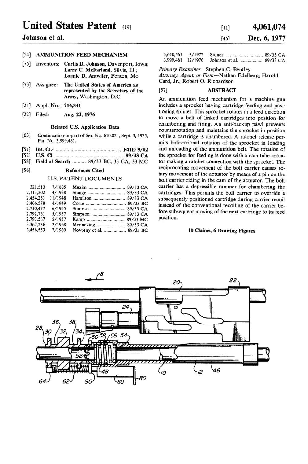
[54] AMMUNITION FEED MECHANISM
[75] Inventors: Curtis D. Johnson, Davenport, Iowa; Larry C. McFarland, Silvis, Ill.; Lonnie D. Antwiler, Fenton, Mo.
[73] Assignee: The United States of America as represented by the Secretary of the Army, Washington, D.C.
[21] Appl. No.: 716,841
[22] Filed: Aug. 23, 1976
Related U.S. Application Data
[63] Continuation-in-part of Ser. No. 610,024, Sept. 3, 1975,
Pat. No. 3,999,461.
[51] Int. Cl.2................................ F41D 9/02
[52] U.S. Q.................................. 89/33 CA
[58] Field of Search ....... 89/33 BC, 33 CA, 33 MC
[56] References Cited
U.S. PATENT DOCUMENTS
321,513 7/1885 Maxim ..................... 89/33 CA
2,113,202 4/1938 Stange .................... 89/33 CA
2,454,251 11/1948 Hamilton .................. 89/33 CA
2,466,578 4/1949 Corte ..................... 89/33 BC
2,710,477 6/1955 Simpson ................... 89/33 CA
2,792,761 5/1957 Simpson ................... 89/33 CA
2,793,567 5/1957 Kamp ...................... 89/33 MC
3,367,236 2/1968 Menneking ................. 89/33 CA
3,456,553 7/1969 Novotny et al.................. 89/33 BC
3,648,561 3/1972 Stoner............... 89/33 CA
3,999,461 12/1976 Johnson et al....... 89/33 CA
Primary Examiner—Stephen C. Bentley
Attorney, Agent, or Firm—Nathan Edelberg; Harold
Card, Jr.; Robert O. Richardson
[57] ABSTRACT
An ammunition feed mechanism for a machine gun
includes a sprocket having cartridge feeding and posi-
tioning splines. This sprocket rotates in a feed direction
to move a belt of linked cartridges into position for
chambering and firing. An anti-backup pawl prevents
counterrotation and maintains the sprocket in position
while a cartridge is chambered. A ratchet release per-
mits bidirectional rotation of the sprocket in loading
and unloading of the ammunition belt. The rotation of
the sprocket for feeding is done with a cam tube actua-
tor making a ratchet connection with the sprocket. The
reciprocating movement of the bolt carrier causes ro-
tary movement of the actuator by means of a pin on the
bolt carrier riding in the cam of the actuator. The bolt
carrier has a depressible rammer for chambering the
cartridges. This permits the bolt carrier to override a
subsequently positioned cartridge during carrier recoil
instead of the conventional recoiling of the carrier be-
fore subsequent moving of the next cartridge to its feed
position.
10 Claims, 6 Drawing Figures
U.S. Patent Dec. 6, 1977
Sheet 1 of 3
4,061,074
U.S. Patent Dec. 6, 1977
Sheet 2 of 3 4,061,074
U.S. Patent Dec. 6, 1977
Sheet 3 of 3 4,061,074
48-
50
4,061,074
AMMUNITION FEED MECHANISM
GOVERNMENT RIGHTS
The invention described herein may be manufactured 5
and/or used by or for the Government for governmen-
tal purposes without the payment of any royalty
thereon.
CONTINUATION-IN-PART
This application is a continuation-in-part of pending
patent application Ser. No. 610,024 filed Sept. 3, 1975
for Modular Lightweight Squad Automatic Weapon
System, now U.S. Pat. No. 3,999,461 which issued Dec.
28, 1976.
BACKGROUND OF PRESENT INVENTION
Conventional self-powered machine gun feed mecha-
nisms are typically of the reciprocating transverse vari-
ety. This type of mechanism incorporates a feed lever, 20
generally located near the top of the weapon, which
pivots in a rather large feed cover and tray member. As
the bolt carrier reciprocates it moves the feed lever
back and forth. The feed lever actuates a pawl which
advances belted rounds of ammunition to the feed posi-
tion. The rounds are held in this position by another
pawl, which is also controlled by the feed lever. This is
a complex mechanism consisting of many moving parts,
springs, etc. For example, there are 75 parts in the feed
mechanism of the M60 machine gun now in use. Obvi-
ously a mechanism of this type would be more suscepti-
ble to failure or breakage than one containing fewer
parts.
Another disadvantage of this prior art system is that
the feed cover is pivotally mounted at its forward end
and must be pivoted upward in order to load or clear
the weapon. This is a shortcoming because, from the
prone position, a gunner would have to expose too
much of himself to accomplish the loading or clearing
function, to his possible detriment.
SUMMARY OF PRESENT INVENTION
The ammunition feed mechanism of the present in-
vention includes a sprocket rotatably mounted on a 45
support. This sprocket has three rows of cartridge posi-
tioning teeth or splines spaced apart by cylindrical sec-
tions. As the sprockets rotates in a feed direction, the
center splines engage the links to move the belted
rounds of ammunition into a feed position from which 50
they may be chambered. The center splines also eject
the links freed by the chambering of their associated
cartridges. The freed links pass over fingers in the cylin-
drical sections which prevent jamming as the links are
ejected from the weapon. A cam tube actuator rotates 55
the sprocket as the bolt carrier moves from its battery
position to its position of recoil. This rotation is caused
by longitudinal movement of a pin connected to the bolt
carrier. This pin rides in the cam of the actuator to
impart rotational movement to it.
The cam tube actuator has a drive ratchet which
engages and rotates the sprocket in one direction in the
feeding operation and an anti-backup pawl prevents
counterrotation of the sprocket during the chambering
cycle of the bolt carrier. However, a ratchet release is
provided to permit bidirectional rotation of the
sprocket in loading and unloading of the ammunition
belt.
The bolt carrier has a depressible rammer for cham-
bering cartridges as it moves to battery position. This
permits the bolt carrier to override a subsequently posi-
tioned cartridge during carrier recoil instead of the
conventional recoiling of the carrier before subsequent
moving of the next cartridge to its feed position. This
provides smoother and more reliable operation.
In a preferred embodiment wherein the receiver com-
prises vertically spaced, horizontally positioned parallel
tubes, the feed mechanism apparatus is positioned on
the lower tube which serves as its mounting structure.
By using this existing mounting structure and by using
the existing bolt carrier movement to cause sprocket
rotation, the number of parts necessary to feed belted
ammunition to a position for chambering (by counterre-
coil of the bolt carrier) is reduced to approximately J
the number of parts used in previous feed mechanisms.
BRIEF DESCRIPTION OF DRAWINGS
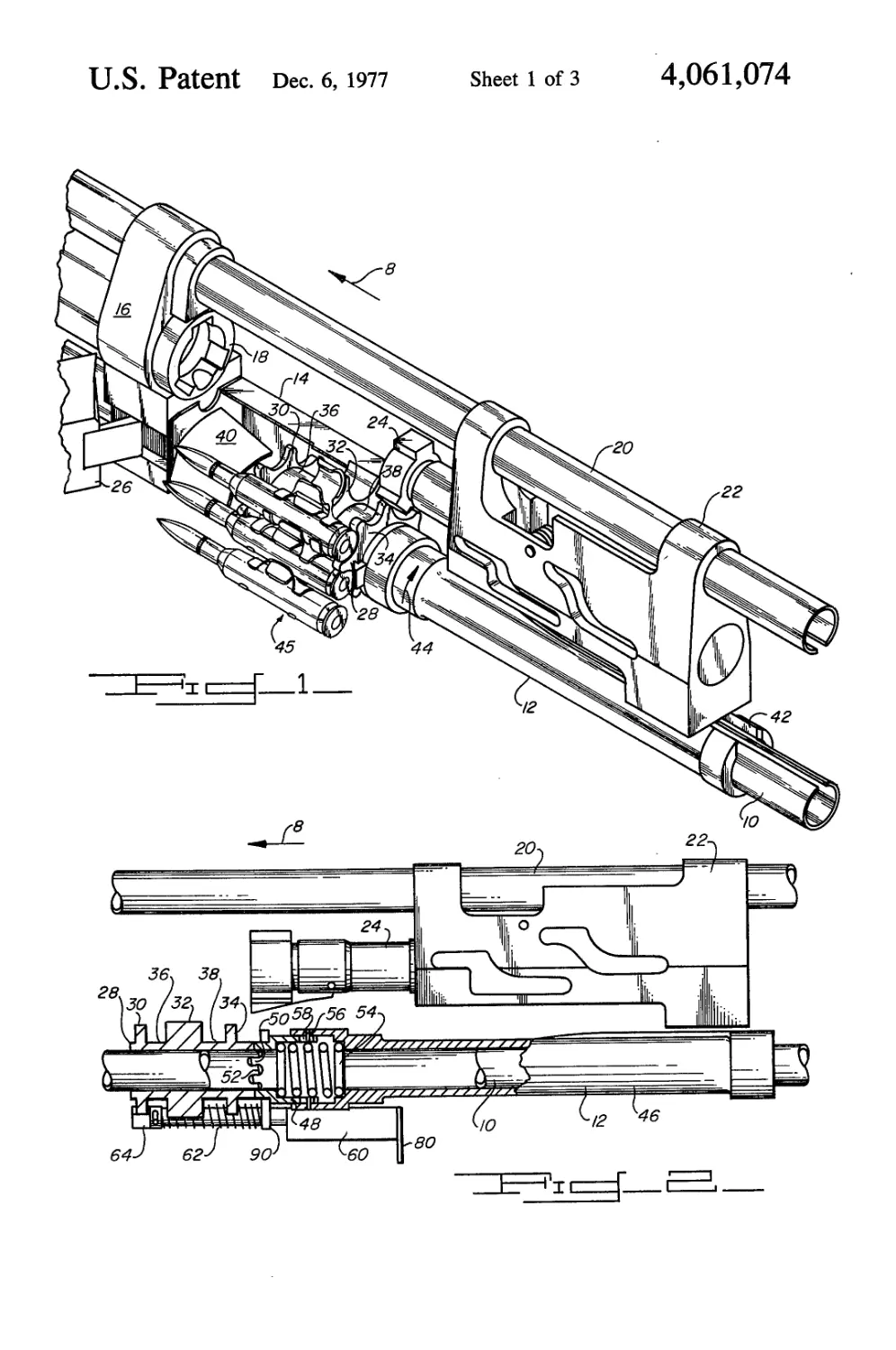
FIG. 1 is a perspective view showing the components
of the ammunition feed mechanism,
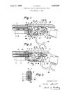
FIG. 2 is a left side elevation view partially in section
showing the ratchet drive mechanism,
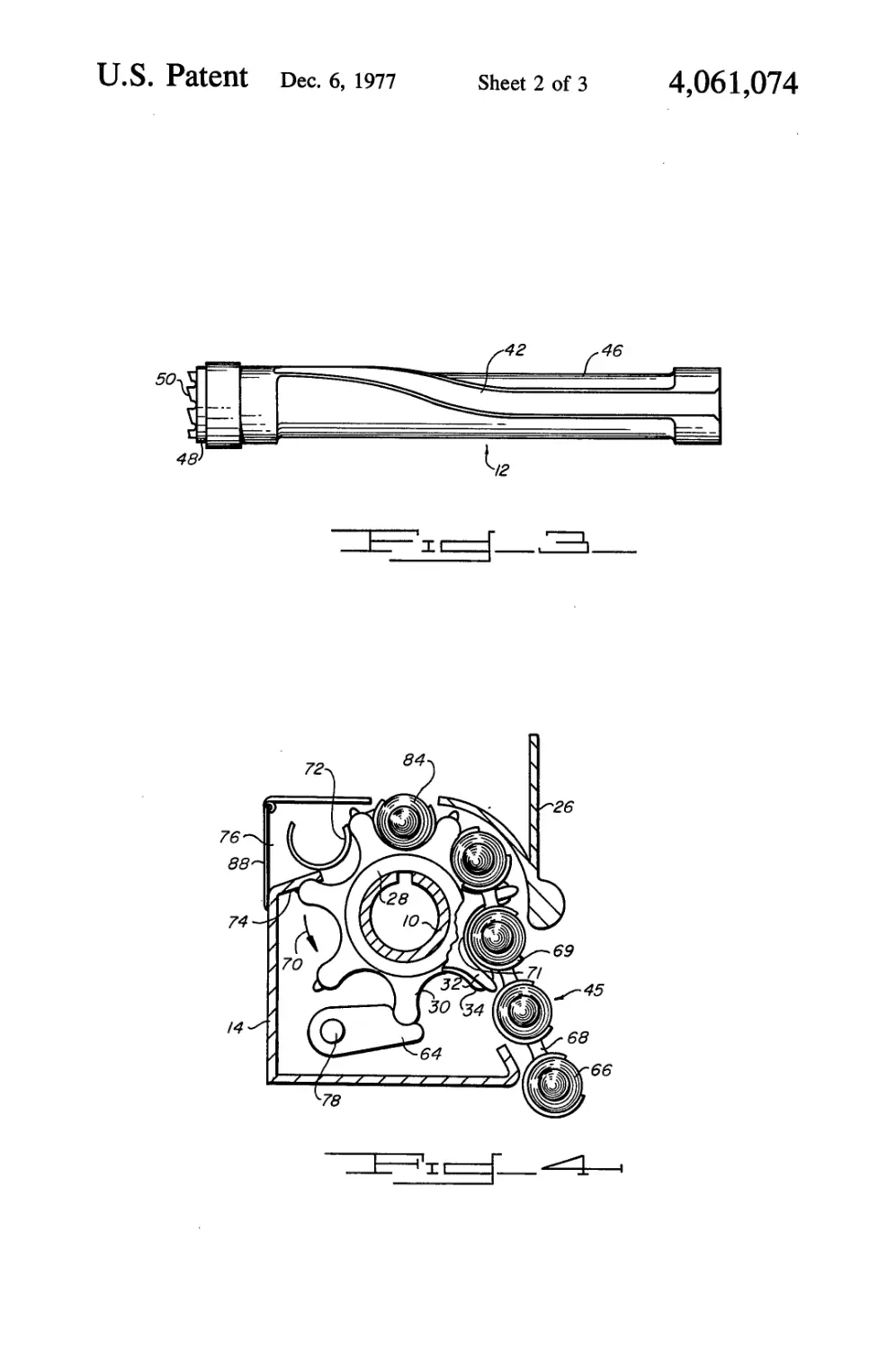
FIG. 3 is a plan view of the cam tube assembly,
FIG. 4 is a front section in elevation illustrating the
sprocket operation,
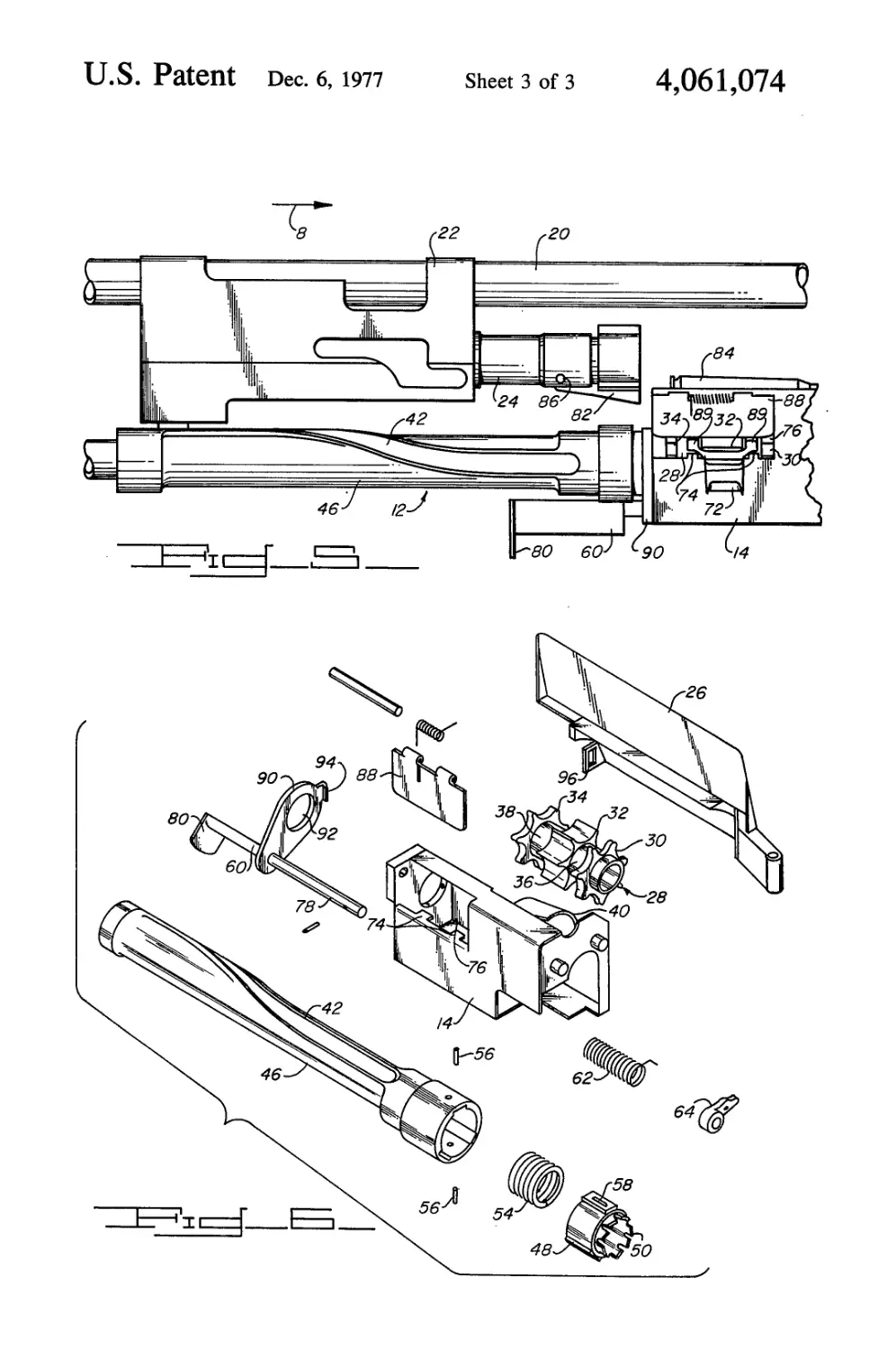
FIG. 5 is a right side elevation view showing the link
ejection apparatus, and
FIG. 6 is an exploded view showing the feed system
components.
DETAILED DESCRIPTION OF ILLUSTRATIVE
EMBODIMENT
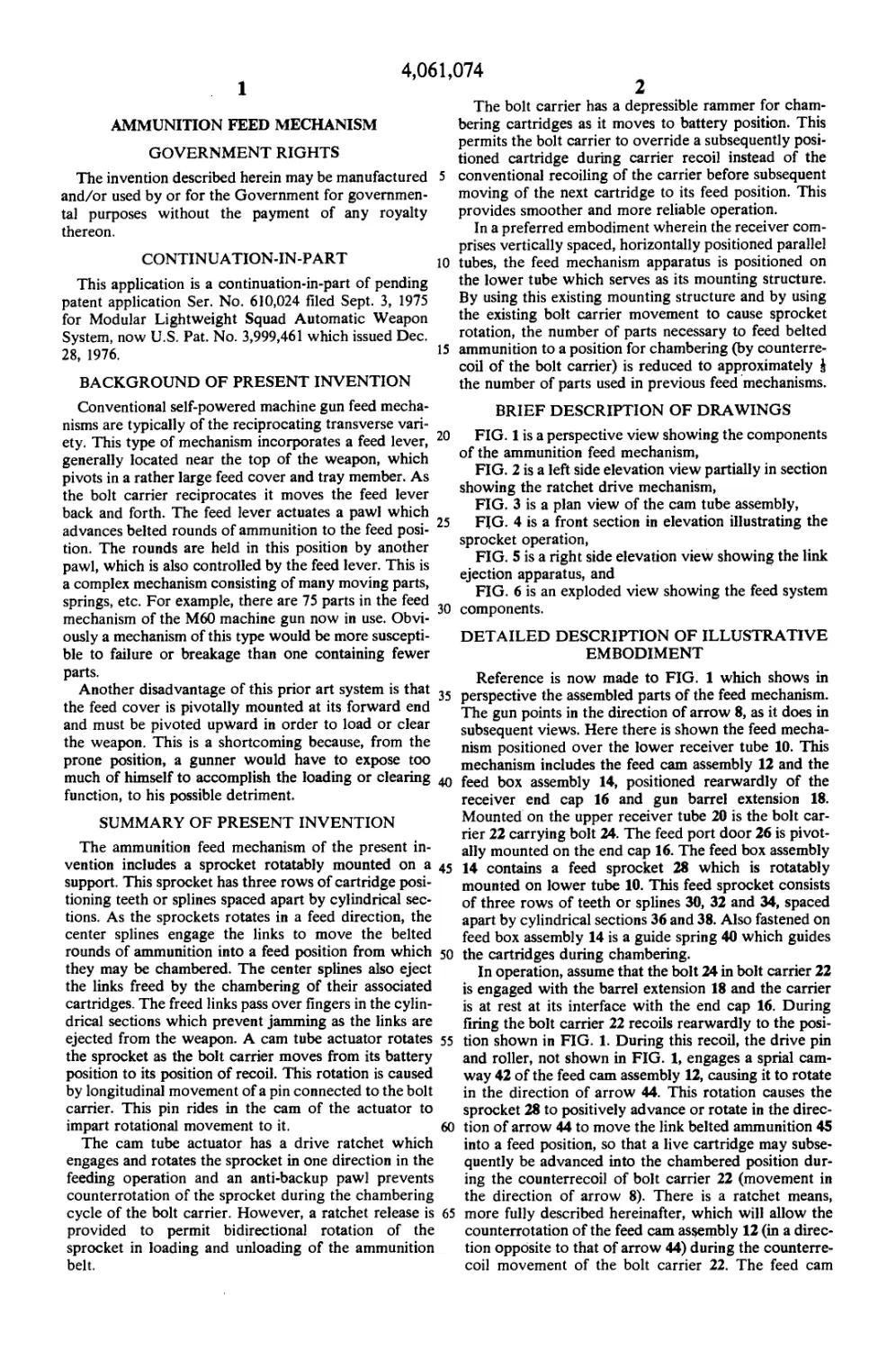
Reference is now made to FIG. 1 which shows in
perspective the assembled parts of the feed mechanism.
The gun points in the direction of arrow 8, as it does in
subsequent views. Here there is shown the feed mecha-
nism positioned over the lower receiver tube 10. This
mechanism includes the feed cam assembly 12 and the
feed box assembly 14, positioned rearwardly of the
receiver end cap 16 and gun barrel extension 18.
Mounted on the upper receiver tube 20 is the bolt car-
rier 22 carrying bolt 24. The feed port door 26 is pivot-
ally mounted on the end cap 16. The feed box assembly
14 contains a feed sprocket 28 which is rotatably
mounted on lower tube 10. This feed sprocket consists
of three rows of teeth or splines 30, 32 and 34, spaced
apart by cylindrical sections 36 and 38. Also fastened on
feed box assembly 14 is a guide spring 40 which guides
the cartridges during chambering.
In operation, assume that the bolt 24 in bolt carrier 22
is engaged with the barrel extension 18 and the carrier
is at rest at its interface with the end cap 16. During
firing the bolt carrier 22 recoils rearwardly to the posi-
tion shown in FIG. 1. During this recoil, the drive pin
and roller, not shown in FIG. 1, engages a sprial cam-
way 42 of the feed cam assembly 12, causing it to rotate
in the direction of arrow 44. This rotation causes the
sprocket 28 to positively advance or rotate in the direc-
tion of arrow 44 to move the link belted ammunition 45
into a feed position, so that a live cartridge may subse-
quently be advanced into the chambered position dur-
ing the counterrecoil of bolt carrier 22 (movement in
the direction of arrow 8). There is a ratchet means,
more fully described hereinafter, which will allow the
counterrotation of the feed cam assembly 12 (in a direc-
tion opposite to that of arrow 44) during the counterre-
coil movement of the bolt carrier 22. The feed cam
4,061,074
3
assembly 12 is then in a position to advance the sprocket
28 during the next recoil cycle when the next feed oper-
ation takes place.
The details of the ratcheting structure is best shown
in FIG. 2 where parts are broken away to more clearly
show this structure. Here is shown the feed cam assem-
bly 12 rotatably mounted over the lower tube 10. This
assembly consists of the feed cam tube 45 having at its
inner end a drive ratchet 48. This ratchet has a row of
seven teeth 50 that engage with a mating row of seven
teeth 52 on the feed sprocket 28. Drive ratchet 48 is
telescopically movable in an axial direction within cam
tube 46 and is urged outwardly by spring 54. It is re-
tained in the assembly by pins 56 in slots 58 of the drive
ratchet. Also shown in FIG. 2 is a ratchet release assem-
bly 60 which is positioned and retained by the feed box
(not shown). This ratchet release assembly 60 can be
moved rearwardly, that is, to the right, by the operator
and in opposition to spring 62 for the purpose of reload-
ing or downloading the weapon. When the operator
pulls rearwardly on the ratchet release handle 80 of the
ratchet release assembly, it disengages the ratchet 48
from the feed sprocket 28. It also disengages the
sprocket anti-backup pawl 64 from sprocket teeth 30
and disengages the feed door latch so the door, shown
in FIG. 6, may be opened for loading, unloading or to
clear a jam.
FIG. 3 shows the feed cam assembly 12 with a spiral
cam path 42. It can be seen that as a pin moves from
right to left within the groove, it will cause the assembly
to rotate downwardly and as the pin moves from left to
right it causes the assembly to rotate upwardly to ad-
vance the sprocket to the next position.
FIG. 4 is a front end view of sprocket 28 with some
of the sprocket teeth 30 broken away to more clearly
show the operation of the feed mechanism. Here is
shown a belt of ammunition 45 consisting of cartridges
66 linked together by links 68. In this view the sprocket
28 rotates in a counterclockwise direction, shown by
arrow 70, to advance each round into a feed position.
Round 84 at the top is in this feed position from which
chambering of the round will subsequently occur. The
fore and aft rows of teeth 30 and 34 provide positive
control of the rounds as they are rotated into the feed
position. The center row of teeth 32 fit between the
links around adjacent cartridges and the cartridge encir-
cling portions 69 of links 68 are cradled in the recesses
71 between the teeth 32. This provides control of the
links 68 and prevents their forward movement during
the stripping process. Continued rotation of sprocket 28
pushes the empty links 72 through the link ejection port
76 and cover 88 after their associated rounds have been
chambered. Other structure, described hereinafter with
reference to FIG. 5, will strip the uppermost cartridge
84 from the linkage and move it into the barrel exten-
sion 18 into a chambered position ready for firing.
When this cartridge is moved forward, it frees the link
72 for ejection during the next feed cycle. Fingers 74 on
feed box assembly 14 bear toward the cylindrical sec-
tions 36 and 38 of the feed sprocket 28 to lift the freed
linkage out and away from the sprocket 28 so that it
may be ejected through link port 76.
Also shown in FIG. 4 is the anti-backup pawl 64
which engages the front teeth 30 of the feed sprocket 28
to permit- unidirectional rotation only of sprocket 28 in
the direction of arrow 70. This pawl also accurately
positions sprocket 28 so that top round 84 is in feed
position. This anti-backup pawl 64 pivots on a pin 78
5
10
15
20
25
30
35
40
45
50
55
60
65
4
which is the forward extension of the ratchet release
assembly 60 shown in FIG. 2. Pawl 64 is urged into the
positive engagement as shown by the torsional aspects
of spring 62 which has both compressional and torsional
capabilities. As previously mentioned, this pawl may be
disengaged by pulling rearwardly on ratchet release
handle 80, shown in FIG. 2, for loading and unloading
of the cartridge belt from the gun.
FIG. 5 is a right side elevational view showing the
rammer 82 prior to engagement with the round 84 in the
feed position. Counterrecoil movement of the bolt car-
rier 22 and bolt 24, in the direction of arrow 8, provides
engagement of the rammer 82 with the round 84. Fur-
ther movement strips the round 84 from the link and
positions it in the weapon chamber. The rammer 82 is
pivotally mounted to the bolt 24 by a pin 86 and biased
downwardly by a spring (not shown). This eliminates
the need for additional clearance cuts in the barrel ex-
tension 18 to accomodate the rammer at the “in battery”
position of the bolt 24. More importantly, since the
rammer can be pivoted up over the next round to be fed,
the next feed cycle can be initiated immediately upon
recoil of the bolt carrier 22. Since the entire duration of
recoil can be used for feeding, much smoother opera-
tion is achieved. In prior art designs a solid lug is used
as a rammer. The lug must therefore pass the base of the
round before the round can be moved to the feed posi-
tion. This accounts for the violent jerking action of the
ammunition belt in conventional machine guns which
does not occur in the present feed system. FIG. 5 shows
the link 72 being ejected. Legs 89 of link 72 are carried
by fingers 74 on feed box assembly 14 which are in-
wardly directed toward cylinder portions 36 and 38 of
sprocket 28. The link ejection port 76 is provided with
a pivotally mounted spring biased cover 88 to prevent
foreign particles from entering the mechanism.
FIG. 6 is an exploded view showing the feed system
components separately in perspective. In this view the
structure of the ratchet release can be seen. The ratchet
release assembly 60 supports a plate 90. When assem-
bled the teeth 50 on the drive ratchet 48 protrude
through the opening 92 in plate 90. The plate then rests
against the shoulder of the drive ratchet 48. When the
ratchet release handle 80 is pulled rearwardly the plate
90 pulls the drive ratchet 48 out of engagement with
sprocket teeth 52. The plate 90 also carries a latch 94
which engages slot 96 to retain the feed port door 26 in
the latched position until the ratchet release handle 80 is
pulled.
The invention in its broader aspects is not limited to
the specific combinations, improvements and instru-
mentalities described but departures may be made
therefrom within the scope of the accompanying claims
without departing from the principles of the invention
and without sacrificing its chief advantages.
What is claimed is:
1. A belted ammunition feed mechanism for a gun
having a bolt carrier, said mechanism comprising:
a rotatable sprocket,
said sprocket having first and second end rows of
teeth between which rounds of ammunition may
be cradled,
said sprocket having a center row of teeth both radi-
ally and axially longer than the teeth in said first
and second end rows and extending between adja-
cent round connecting links to prevent their for-
ward movement while associated rounds cradled
,074
6
connection with said sprocket to prevent its counterro-
tation during the chambering cycle of said bolt carrier.
7. A belted ammunition feed mechanism as set forth
in claim 6, and release means to disengage said ratchet
connection and said pawl connection to permit bidirec-
tional rotation of said sprocket for loading and unload-
ing of said belted ammunition.
8. A belted ammunition feed mechanism as set forth
in claim 7 wherein said ratchet connection is made with
ratchet teeth on said sprocket and ratchet teeth on said
actuator, said ratchet teeth on said actuator being axi-
ally depressible by said release means.
9. A belted ammunition feed mechanism as set forth
in claim 1 wherein said sprocket has front and back
cartridges cradling teeth and a middle set of link hold-
ing teeth spaced from said cradling teeth by cylindrical
portion on said sprocket.
10. A belted ammunition feed mechanism as set forth
in claim 9 wherein fingers on said gun extend toward
said cylindrical portions to carry freed links being
ejected.
*****
4,061
5
between adjacent teeth are stripped forwardly and
chambered by the bolt carrier on said gun,
said center row of teeth having recesses between said
adjacent teeth in which the cartridge encircling
portions of said links are cradled. 5
2. A belted ammunition feed mechanism as set forth
in claim 1, and means operable by said bolt carrier to
rotate said sprocket.
3. A belted ammunition feed mechanism as set forth
in claim 2, wherein said sprocket is rotated during the 10
recoil cycle of said bolt carrier.
4. A belted ammunition feed mechanism as set forth
in claim 3 wherein said bolt carrier has a depressible
rammer to permit its override over a cartridge during
said recoil cycle. 15
5. A belted ammunition feed mechanism as set forth
in claim 2 wherein said means is a rotary cam actuator
driven by a pin on said bolt carrier.
6. A belted ammunition feed mechanism as set forth
in claim 5 wherein said actuator has a ratchet connec- 20
tion with said sprocket whereby said sprocket rotates in
one direction during feeding operation, and a pawl
30
35
40
45
50
55
60
65