/
Tags: weapons military affairs patent
Year: 1949

Text
April 5, 1949.
A. CORTE
2,466,577
A. CORTE
BOLT MECHANISM FOR GUNS
April 5, 1949.
Filed Dec. 6, 1944
2,466,577
5 Sheets-Sheet 2
April 5, 1949.
2,466,577
A. CORTE
BOLT MECHANISM FOR GUNS
Sheets-Sheet 3
5
6,4
165
81
80
Filed Dec. 6, 1944
I II 67
6.4
105
О
97
154
89
105
14
87
86
35
65
17
—162
e-i63
94
Aio
не
109 R
67 ?------- Ю5
76 75 74 71
155
68
157 15
' 113
I J09
-11
108
9
70
80
155
116 94 101 l93 104 106
86
83
67
94
68
74
105
72
120
-J.22
121
BY
109
AGENT
81
9§4
117
III
!?2
20
114 III 119
99 111
110
87
102
107
--II3
102
107
INVENTOR.
Alfred Gorte
April 5, 1949.
A. CORTE
2,466,577
BOLT MECHANISM FOR GUNS
April 5, 1949.
2,466,577
A. CORTE
BOLT MECHANISM FOR GUNS
Patented Apr. 5, 1949
2,466,577
UNITED STATES PATENT OFFICE
2,466,577
BOLT MECHANISM FOR GUNS
Alfred Corte, Glendale, Calif., assignor to Lock-
heed Aircraft Corporation, Burbank, Calif.
Application December 6,1944, Serial No. 566,806
15 Claims.
1
This invention relates to ordnance, and relates
more particularly to automatic or machine guns.
A general object of the invention is to provide a
machine gun or cannon mechanism embodying a
practical and particularly effective breech block
and breech bolt assembly.
The mechanism of the present invention is
intended for use in a machine gun wherein a live
round is withdrawn from the ammunition belt,
then introduced into the cartridge chamber for
firing, and following the firing of the round, the
empty cartridge case is withdrawn from the
chamber and replaced in the ammunition belt.
When this sequence is performed in connection
with the firing of successive rounds, the ammuni-
tion belt is partially emptied and then rebuilt or
refilled as it passes through the gun. The re-
insertion of the empty cartridge cases in the
ammunition belt completely avoids the necessity
for providing means to handle the empty cases,
and where disintegrating belts are employed, the
re-insertion of the empty cases prevents disinte-
gration of the belt so that the continuous belt
carrying the empty cases may be readily directed
into an appropriate receiver or storage space. If
desired, the belt may be re-used without the
necessity of re-assembling its individual links.
In order to successively withdraw a round from
the belt, fire the round and then replace the
empty case in the belt, the gun mechanism re-
quires a plurality of bolts for cooperating with
a single breech block, with round extracting
means associated with the bolts. The present
invention is concerned primarily with the barrel
extension and multiple bolt assembly and the as-
sociated elements.
It is an object of the invention to provide a
barrel extension and multi-bolt combination of
the character above referred to that is positive,
dependable and rapid in operation.
Another object of the invention is to provide
a sturdy, effective means for successively locking
the individual bolts in the barrel extension for
the firing of the successive rounds.
Another object of the invention is to provide
a simple, rapid-action means for actuating and
releasing the breech locks. The mechanism em-
bodies jaws or locks adapted to be simultaneously
operated upon the insertion and withdrawal of
the bolts, and a positive quick-action rack mech-
anism for projecting and retracting the locks.
A further object of tire invention is to provide
a mechanism of the- character referred to em-
bodying a- simple latch means which- serves to
positively' hold the breech locks retracted to
(CI. 89—159)
2
permit free insertion of the bolts and which
further serves to prevent premature release of
the breech locks.
It is a further object of the invention to pro-
5 vide an effective extractor mechanism for the
breech bolts, which automatically operates to
withdraw the live rounds from the ammunition
belt and later insert the empty cases into the
belt.
10 A still further object of the invention is to
provide a gun mechanism of the character re-
ferred to in which a firing pin device is associated
with each individual bolt, and embodies a safety
unit for preventing inadvertent and premature
15 actuation of the firing pin.
Other objects and features of the invention will
be readily understood from the following detailed
description of a typical preferred form of the
invention wherein reference will be made to the
20 accompanying drawings in which:
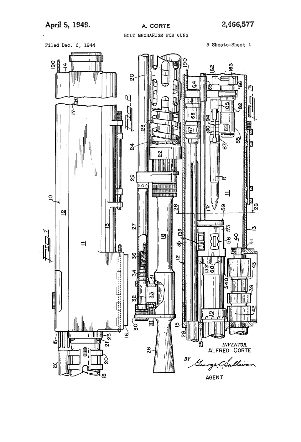
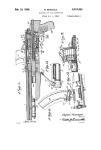
Figure 1 is an elevation of the rear portion
of a gun embodying the invention;
Figure 2 is an elevation of the forward por-
tion of the gun with certain parts broken away
25 to appear in longitudinal cross section;
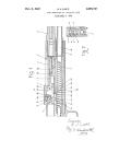
Figure 3 is a longitudinal detailed sectional
view through the forward portion of the gun re-
ceiver showing the internal parts in elevation;
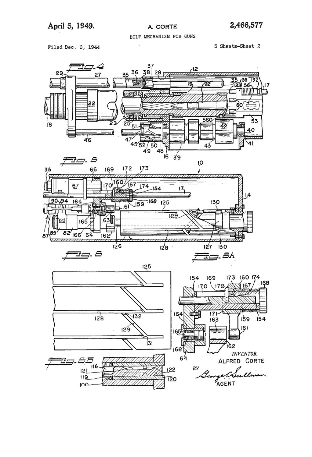
Figure 4 is a fragmentary longitudinal sec-
30 tional view of a portion of the gun illustrating
the ammunition sprocket and its operating mech-
anism, and showing portions of the barrel and
gas cylinder mechanism in elevation;
Figure 5 is a longitudinal sectional view of the
35 rear portion of the gun with the bolt assembly
and a portion of the mechanism for turning the
same appearing in elevation;
Figure 6 is a stretch-out view of the drum
cam for rotating the bolts;
40 Figure 6A is an enlarged fragmentary sectional
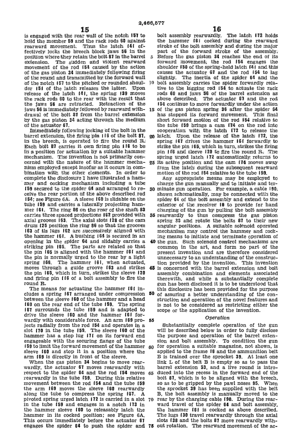
view illustrating the cocking mechanism;
Figure 6B is an enlarged fragmentary sectional
view of the firing pin safety means;
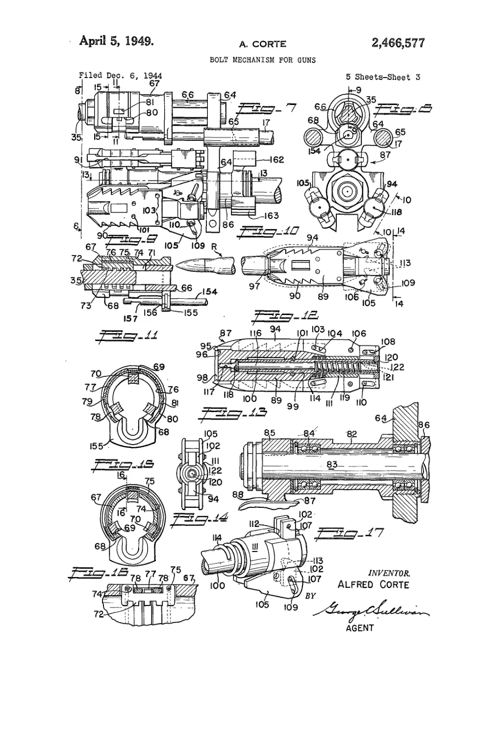
Figure 7 is a side elevation of the bolt assembly
45 and its associated actuator;
Figure 8 is a front elevation of the bolt as-
sembly taken substantially as indicated by line
3—8 on Figure 7;
Figure 9 is a fragmentary longitudinal sec-
50 tional view of the actuator assembly taken as
indicated by line 9—-9 on Figure 8;
Figure 10 is a face elevation of one of the
bolts carrying a round and showing the two posi-
tions of the extractors, being a view taken sub-
55 stantially as indicated by line 19—10 on Figure 8;
2,466,677
3
Figure 11 is an enlarged transverse sectional
view of the actuator taken substantially as in-
dicated by line 1 I—11 on Figure 7;
Figure 12 is a longitudinal sectional view of
one of the bolt units;
Figure 13 is an enlarged fragmentary longi-
tudinal section taken substantially as indicated
by line 13—13 on Figure 7;
Figure 14 is a front view of one of the bolts;
Figure 15 is an enlarged transverse sectional
view of the actuator, taken as indicated by line
15— 15 on Figure 7;
Figure 16 is an enlarged fragmentary sectional
view taken as indicated by line 16—16 on Fig-
ure 15;
Figure 17 is a fragmentary perspective view of
a portion of a bolt assembly;
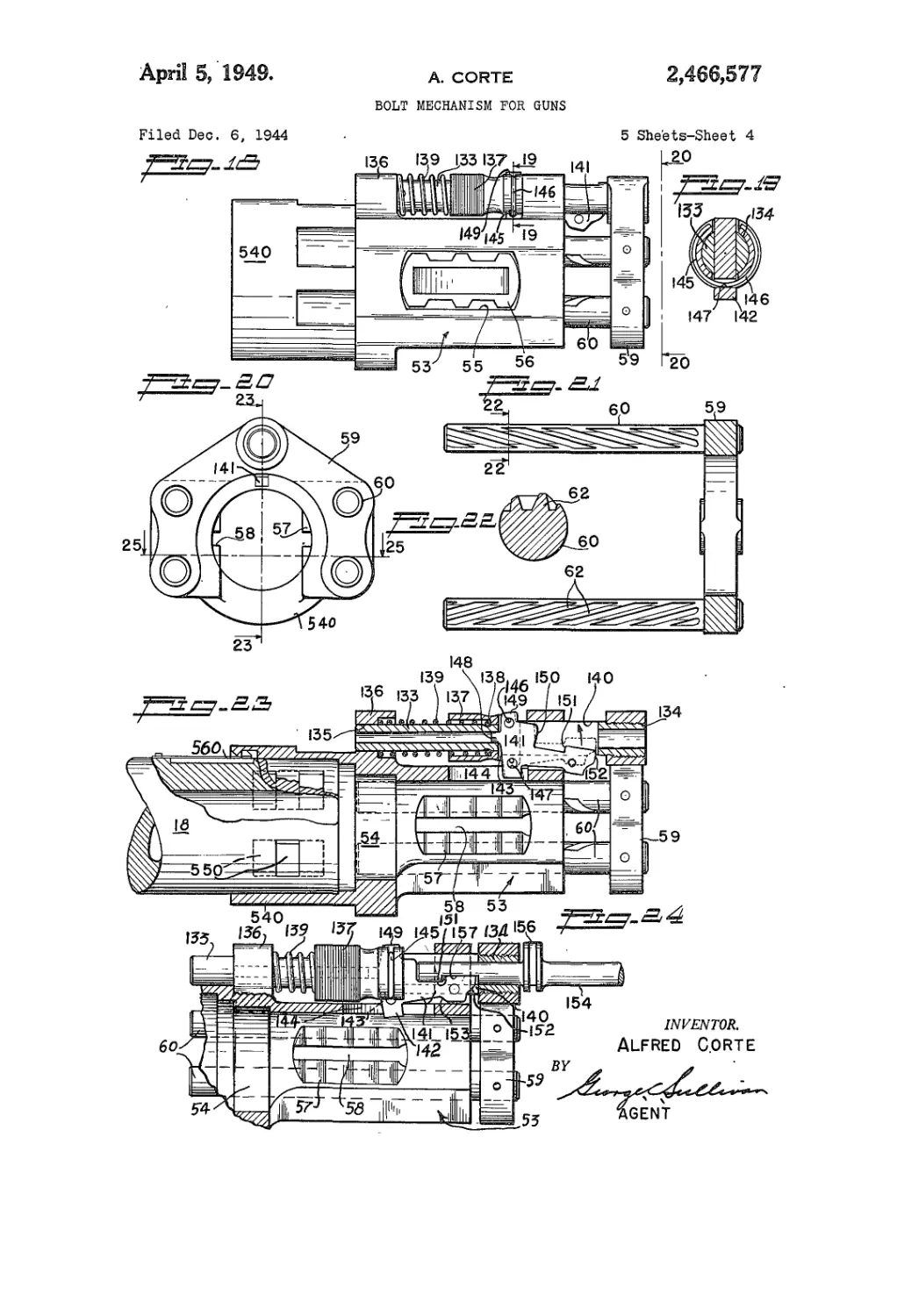
Figure 18 is an enlarged side elevation of the
barrel extension assembly;
Figure 19 is an enlarged vertical section taken
as indicated by line 19—19 on Figure 18;
Figure 20 is an end view of the barrel exten-
sion assembly taken as indicated by line 20—20
on Figure 18;
Figure 21 is a horizontal sectional view of the
rack unit showing the two racks in elevation;
Figure 22 is an enlarged transverse section
taken as indicated by line 22—22 on Figure 21;
Figure 23 is a longitudinal detailed sectional
view of the barrel extension assembly taken as
indicated by line 23—23 on Figure 20;
Figure 24 is a fragmentary view illustrating
the breech latch mechanism;
Figure 25 is a horizontal detailed sectional
view of the block assembly taken as indicated
by line 25—25 on Figure 20;
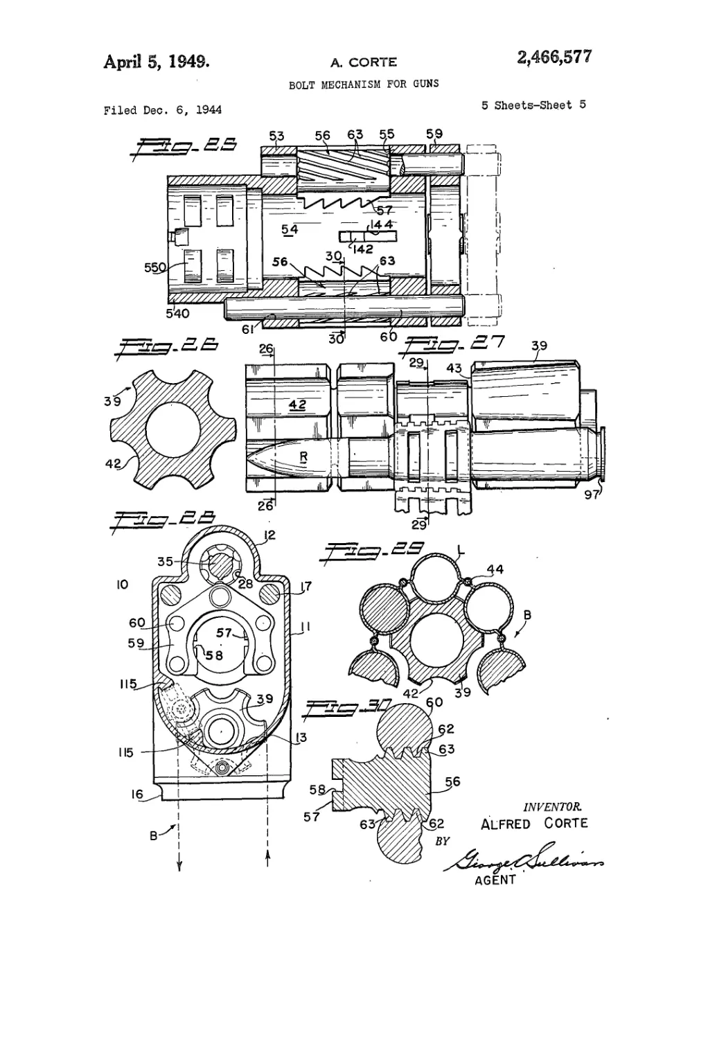
Figure 26 is a transverse cross section of the
sprocket taken as indicated by line 26—26 on
Figure 27;
Figure 27 is a side elevation of the sprocket
and ammunition belt assembly;
Figure 28 is a vertical detailed sectional view
taken as indicated by line 28—28 on Figure 3;
Figure 29 is a fragmentary vertical sectional
view taken as indicated by line 29—29 on Figure
27; and
Figure 30 is a transverse section of one of the
racks and its jaws as indicated by line 30—30
on Figure 25.
The features of the present invention may be
embodied in ordnance varying considerably in
caliber and construction. In the drawings the
invention is disclosed in association with a sub-
stantially complete gun structure, it being under-
stood that the invention is not to be construed
as limited to the particular details illustrated
and described below.
The gun illustrated includes a housing or re-
ceiver (0, which is a relatively stationary com-
ponent being adapted for support by either a
stationary or flexible gun mount. The receiver
10 serves as a support for the various other ele-
ments and contains the principal operating parts.
As the present invention is not primarily con-
cerned with the construction of the receiver 10,
it will suffice to describe it as an elongate hollow
member having generally vertical side walls (I,
a top wall having a longitudinally extending
partially cylindrical crown (2, a bottom wall
13 presenting a cylindrically concave internal
surface, and end walls 14 and 15. The forward
portion of the bottom wall 13 has a rectangular
downwardly opening magazine frame 16 for de-
tachably mounting a suitable magazine, not
shown. Horizontally spaced guide rods 17 ex-
5
10
15
20
25
30
35
40
45
50
55
60
65
70
75
4
tend longitudinally through the receiver IG to
carry the bolt assembly for axial movement os
will be subsequently described. While I have
referred to the receiver 10 as having side wails
and top and bottom walls, it is to be understood
that the gun may be mounted and employed in
any position; for example, it may be supported
so that the parallel walls 11 form the upper and
lower walls of the receiver.
The gun barrel t8 extends forwardly from I,he
receiver 10 and is supported for axial movement
as required during the recoil and counter recoil
phases of operation. The forward wall ! 5 of the
receiver to carries a suitable slide bearing unit
(9 cooperating with a splined or grooved portion
of the barrel 18 to support the barrel for Use
required limited axial movement. The details of
the bearing (9 and its mounting form no part
of the present invention. The barrel IS extends
rearwardly into the receiver 1Э for association
with the extension 53 to be subsequently de-
scribed. A suitable recoil mechanism is provided
for the barrel assembly. This includes a tubular
jacket 20 secured to the forward end of the re-
ceiver (0 by screws 21 and extending outwardly
in spaced surrounding relation to the barrel IS.
The jacket 20 is perforated or slotted for the
ready dissipation of heat and its forward end car-
ries a bearing means 22 which assists in support-
ing the barrel 18 for axial movement. A helical
recoil spring 23 is arranged in the jacket 2i) in
surrounding relation to the barrel IS. The for-
ward end of the spring 23 is engaged by a part
24 of the bearing means 22 which travels with
the barrel 18 and the rear end of the spring
23 bears on a ring 25 which is stationaiy on the
receiver 10; see Figures 2 and 4. With this
arrangement of parts, the spring 23 is compres-
sed during recoil movement of the barrel 18 and
the energy stored in the spring during recoil
serves to move the barrel and associated parts
forwardly for the counter recoil stroke. A. flaring
muzzle member 26 is provided on the forward
end of the barrel 18 and may contain a suitable
flash tube, not shown. It is to be understood
that the barrel 18 is suitably rifled and may be
of any selected construction and caliber.
Certain elements of the gun mechanism are
gas operated; that is, they are operated by a
portion of the gas pressure built up in the bore
of the barrel 18 when the projectile leaves its
cartridge case. A gas cylinder 27 extends in
parallel relation with the barrel 18. The cylin-
der 27 travels with the barrel and enters an
opening 28 in the forward wall of the receiver
10. A yoke member 29 engages about the barrel
18 and the cylinder 27 to secure the cylinder to
the barrel; see Figure 2. The yoke member is
attached to the barrel 18 adjacent the bearing
means 22. The forward end of the gas cylinder
27 is closed and secured to the barrel 18 by a
connecting member 30. Aligned ports 3! and 32
are provided in the forward parts of the barrel
18 and cylinder 27 and are connected by a tubular
junction member 33 engaged about the cylinder
and secured on the barrel 13 adjacent its muzzle
26. The ports 31 and 32 and the tubular junc-
tion member 33 serve to conduct gas pressure
from the bore of the barrel 18 to the forward
portion of the cylinder 27.
A piston 34 is operable in the cylinder 27 and is
adapted to be driven rearwardly by the gas pres-
sure conducted to the cylinder from the barrel 18
immediately following the ejection of the pro-
jectile from the barrel. The piston 34 is closed
2,466,677
5
at its forward end but itsmajor portion is tubular.
A tubular piston Extension 35 (continues rear-
wardly from the piston to project from the rear
end of the cylinder into the receiver 10. Aspring
36 is .arranged under compression between the
closed forward end of the .piston 3'4 and a block
37 slidably engaged in the tubular piston ex-
tension 35; see Figure 4. Pins 38 pass through
axial slots in the extension 35 and anchor the
block 37 to the -wall of the cylinder 27 so that the
block forms an effective abutment for the spring.
Upon rearward movement of the piston 34 under
the action iof the gas pressure, the spring .36 is
compressed between the rearwardly moving
(closed end of the piston and the block 37. When
the gas pressure is relieved, the energy stored in
the .spring 361 drives the piston 34 forwardly. The
forward and rearward movements ;of the piston
34 are utilized to translate the holt assembly, as
will ibe subsequently described.
The .‘gun mechanism further includes a sprock-
et 3S arranged in the forward portion of the re-
ceiver J 0 to handle the ammunition belt В as it
moves through the gun. The shape and action
<nf the sprocket 39 will wary somewhat depending
upon the nature and caliber of the rounds R.
Furthermore, the sprocket 39 may be driven or
rotated in various appropriate manners to effect
an automatic feed of the ammunition belt B. In
the .construction illustrated, the counter recoil
motion .of the barrel Г8 is employed to intermit-
tently rotate the sprocket 39, and the sprocket
serves to advance the belt В in timed relation to
the elements , of the mechanism.
The.sprocket 39 is positioned adjacent the mag-
azine frame 1:6, and has its axis of rotation par-
allel with the ’barrel. The sprocket 39 is fixed
to its .shaft 40, and the shaft is carried by suit-
able bearings 41 at the frame 16; see Figure 4.
Equally spaced longitudinal grooves42 are formed
in the periphery of the sprocket 39 to receive the
rounds R, and a circumferential groove 43 is
formed in the sprocket to receive the links L of the
belt B. The axial .grooves 42 are of rearwardly in-
creasing depth to properly receive the projectiles
.and their cases. The particular belt В illustrated
is of the non-disintegrating type comprising gen-
erally tubular links L interconnected by hinges 44;
see Figure 29. As indicated by broken lines in Fig-
ure 28, the belt В enters the opening of the frame
13, passes 180° .around the sprocket 39, and then
passes outwardly through the frame opening. It
will be observed that the belt В enters and leaves
a single side of the -gun, thereby greatly sim-
plifying the mounting of the gun and permitting
it to be positioned in confined spaces where only
one side is accessible.
The sprocket 39 is rotated substantially 60°
during each counter recoil stroke of the barrel 18.
The mechanism for producing this intermittent
rotation of the sprocket 39 may take various forms
and the invention is not primarily concerned with
the particular mechanism employed. In the
drawings the mechanism for this purpose is illus-
trated in a more or less diagrammatic manner,
and comprises a drum 45 fixed to the forward end
of the sprocket shaft 40; see Figure 4. The drum
45 may be positioned in front of the receiver >10
and may have a suitable casing, not shown. The
sprocket rotating mechanism further includes a
rod 46 fixed to the above described yoke 29 to
move with the barrel 18. The rod 46 extends
rearwardly to enter the forward end of the drum
45. A flange or collar 47 is fixed to the rod 46
to operate within the drum. The sprocket drum
6
45 is provided with six equally spaced axial slots
48. Correspondingly pitched helical slots 49 are
-formed in the wall of the drum 45 to extend be-
tween and connect the adjacent axial slots 48.
5 Pivoted spring urged switches 50 are provided
at the junction of the slots 48 and 49. The
switches 50 occur at the rearward ends of the
helical slots 49 and are designed to direct for-
wardly moving objects in the slots 48 into the
10 helical slots 49. Lugs 51 are provided on the
flange 47 to move in the slots 48 and 49, it being
preferred to provide a lug 5.1 for each axial slot.
The lugs 51 are diamond shaped to have pairs
of parallel sides operable in both the axial slots
25 48 and pitched slots 49. Pivoted spring urged
switches 52 are provided at the forward ends Of
the helical slots 49 to prevent the lugs 51 from
moving into the slots 49 as they travel rear-
wardly through the straight slots 48.
20 With the barrel 18 in its forward-most posi-
tion, the lugs 51 are engaged in the forward ends
of the axial slots 48. When the barrel moves
rearwardly the lugs 51 move to the rear in the
axial slots and move the switches 50 out of their
25 paths as they travel rearwardly. The instant the
lugs 51 pass the switches 50, the latter swing back
to their active positions under the action of their
springs. It is to be noted that the engagement
of the lugs 51 in the axial slots 48 holds the
30 sprocket 39 against rotation throughout the re-
coil stroke of the barrel 18. When the barrel 18
moves forwardly during the counter recoil stroke,
the lugs 51 travel forwardly in the axial slots 48
until they encounter the switches 50. The
35 switches 50 direct the lugs 51 into the helical slots
49 and as the forward movement continues, the
lugs travel forwardly in the helical slots. The
cooperation of the lugs 51 with the walls of the
helical slots 49 rotates the drum 45 and sprocket
40 39. By the time the lugs 51 move out of the
slots 49, past the switches 52, into the adjacent
axial slots 48, the sprocket 39 will have been
turned 60°. The re-entry of the lugs 51 into the
axial slots 48 definitely terminates the rotation
45 of the sprocket 39. Thus during each recoil
stroke the sprocket 39 is held stationary, and
during each counter recoil stroke the sprocket is
rotated 60°, and then brought to a stop in a defi-
nite angular position.
50 The invention provides a barrel extension 53 of
special construction for receiving and cooperat-
ing with the plurality of bolts 87. The extension
53 is secured to the rear end of the barrel 18 to
operate axially in the forward portion of the re-
55 -ceiver 10. It is preferred to construct the exten-
sion 53 as an integral member provided at its
forward end with a tubular boss 540 for receiving
the rear end of the barrel 18. The barrel and ex-
tension are connected by cooperating interrupted
go splines 550 and a spring latch 560 engages in a
notch 561 in the extension to hold the barrel and
block against relative angular movement in the
relationship where the splines are in coopera-
tion. The body of the barrel extension 53 has
65 a longitudinal opening 54 in axial alignment with
the bore of the barrel 18. The major, generally
rectangular portion of the extension 53 is cut
away at one side, the lower side, as shown in
Figures 20 and 23, to provide clearance for the
70 sprocket 39 and other elements. The opening
54 is cylindrical and is proportioned to succes-
sively receive the individual bolts.
Effective lock means is associated with the bar-
rel extension 53 to lock the bolts 87 in the ppen-
75 ing 54 for the firing of the rounds. The pppos-
2,466,577
7
ing walls of the extension 53 have aligned gener-
ally rectangular windows or openings 55. Lock
blocks or jaws 55 are arranged' in the openings
55 for movement toward and away from the
longitudinal axis of the opening 54. The jaws 56
may be socketed at their outer faces to reduce
the weight. Series of teeth or serrations 57 are
formed on the inner faces of the jaws. The ser-
rations have abrupt forward faces and inwardly
and forwardly sloping rear surfaces. An axial
groove 58 extends through each series of serra-
tions 57. The end walls of the openings 55 are
preferably concave and the ends of the jaws 56
are correspondingly curved to conform thereto.
The lock means of the barrel extension 53 fur-
ther includes a rack mechanism for actuating
and retracting the jaws 56. This mechanism em-
bodies a substantially U-shaped member 59 ar-
ranged at the rear of the extension 53. Two pairs
of spaced rods 60 are fixed in openings in the
member 59 and extend forwardly therefrom to
slidably operate in axial openings 6 ( in the walls of
the extension 53. The openings 61 partially in-
tersect the jaw openings 55, so that the rods
60 may cooperate with the jaws. The rods
60 are in the nature of actuating members or
racks having series of pitched or inclined rack
teeth 62 formed on then’ opposing sides. The
teeth 62 are parallel but are pitched with respect
to the longitudinal axes of the rods 60 to be dia-
gonal relative to said axes. The diagonal rack
teeth 62 may be formed by machining angular
grooves in the rods. The opposite sides of the
jaws 56 have correspondingly pitched diagonal
teeth 63 meshing with the teeth 62 of the rack
rods; see Figures 25 and 30. The direction of
pitch or inclination of the mating rack teeth 62
and 63 is such that upon forward movement of
the rods 60 the jaws 56 are moved inwardly rela-
tive to the axis of the opening 54 by the cooperat-
ing teeth and upon rearward movement of the
rods, the cooperation of the teeth moves the
jaws outwardly. It is to be observed that both
the actuation and retraction of the jaws 56 are
positive and rapid and that the movements of
the jaws are simultaneous and equal. Simple
forward and rearward movement of the rack
member 59 with respect to the barrel extension
53 effects actuation and retraction of the two
jaws 56. The engagement of the rack rods 60 50
with the opposite sides of the jaws 56 normally
prevents both inward and outward radial move-
ment of the jaws.
The breech bolt assembly is an important com-
ponent of the mechanism provided by the in-
vention. This assembly is movable axially in the
receiver 10 and embodies a multiple bolt unit
that is intermittently rotated during each com-
plete cycle of operation of the gun. The bolt as-
sembly includes a traveling carrier or spider 64
having two elongate tubular bosses 65 which re-
ceive and ride on the above mentioned guide rods
17; see Figures 7 and 8. The rods 17 support
the bolt assembly for free axial movement. The
carrier or spider 64 also carries a tube 66 which
receives the rear portion of the gas piston ex-
tension 35. The piston extension 35 and the
tube 66 may have sliding spline engagement to
assist in preventing undesirable relative rota-
tion between the parts. The piston extension and
the spider tube 66 are related for relative axial
movement, and the invention provides a slack or
lost motion connection between these two ele-
ments.
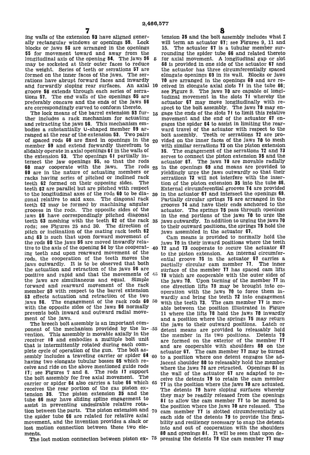
The lost motion connection between piston ex-
8
tension 35 and the bolt assembly includes what I
will term an actuator 67; see Figures 9, 11 and
15. The actuator 67 is a tubular member sur-
rounding the spider tube 66 and related thereto
for axial movement. A longitudinal gap or slot
68 is provided in one side of the actuator 67 and
the actuator has three circumferentially spaced
elongate openings 69 in its wall. Blocks or jaws
70 are arranged in the openings 69 and are re-
10 ceived in elongate axial slots 71 in the tube 66;
see Figure 9. The jaws 70 are capable of longi-
tudinal movement in the slots 71 whereby the
actuator 67 may move longitudinally with re-
spect to the bolt assembly. The jaws 70 may en~
15 gage the ends of the slots 71 to limit this relative
movement and the end of the actuator 67 en-
gages the spider 64 to assist in limiting the rear-
ward travel of the actuator with respect to the
bolt assembly. Teeth or serrations 72 are pro-
20 vided on the inner faces of the jaws 70 to mesh
with similar serrations 73 on the piston extension
35. The engagement of the serrations 72 and 73
serves to connect the piston extension 35 and the
actuator 67. The jaws 70 are movable radially
25 in the openings 69 and means are provided to
yieldingly urge the jaws outwardly so that their
serrations 72 will not interfere with the inser-
tion of the piston extension 35 into the tube 86.
External circumferential grooves 74 are provided
30 in the actuator 67 and intersect the openings 69.
Partially circular springs 75 are arranged in the
grooves 74 and have their ends anchored to the
actuator. The springs 75 pass through openings
in the end portions of the jaws 70 to urge the
35 jaws outwardly. In addition to urging the jaws 70
to their outward positions, the springs 75 hold the
jaws assembled in the actuator 67.
Cam means is provided to normally hold the
jaws 70 in their inward positions where the teeth
40 72 and 73 cooperate to secure the actuator 67
to the piston extension. An internal circumfer-
ential groove 76 in the actuator 67 carries a
partially circular cam member 77. The inner
surface of the member 77 has spaced cam lifts
4‘J 78 which are cooperable with the outer sides of
the jaws 70. Upon turning of the member 77 in
one direction lifts 78 may be brought into co-
operation with the jaws 70 to force them in-
wardly and bring the teeth 72 into engagement
with the teeth 73. The cam member 77 is mov-
able between the position illustrated in Figure
11 where the lifts 78 hold the jaws 70 inwardly
and a position where the springs 75 may return
the jaws to their outward positions. Latch or
155 detent means are provided to releasably hold
the member in its two positions. Detents 79
are formed on the exterior of the member 77
and are cooperable with shoulders 80 on the
actuator 67. The cam member 77 may be turned
00 to a position where one detent engages the ad-
jacent shoulder 80 to releasably hold the member
where the jaws 70 are retracted. Openings 81 in
the wall of the actuator 67 are adapted to re-
ceive the detents 79 to retain the cam member
65 77 in the position where the jaws 70 are actuated.
The detents 79 have sloping surfaces whereby
they may be readily released from the openings
81 to allow the cam member 77 to be moved to
the position where the jaws 70 are released. The
70 cam member 77 is slotted circumferentially at
each side of the detents 79 to provide the flexi-
bility and resiliency necessary to snap the detents
into and out of cooperation with the shoulders
80 and openings 81. It will be seen that upon de-
75 pressing the detents 79 the cam member 77 may
2,468,577
9
be turned between its two positions to actuate
and release the toothed jaws 70. The releasable
slack connection between the bolt assembly and
the piston extension 35 afforded by the actuator
57 described above, is such that the bolt assembly
is moved rearwardly and forwardly with each
full cycle of operation of the piston 34 by the
gas pressure and spring 35. The lost motion
allowed by the construction described abdVC
serves to control the sear and hammer mecha-
nism and to permit other actiohs to be subse-
quently described.
The bolt assembly further includes a tube 82
threaded in an opening in the spider 64 to ex-
tend forwardly from the spider in parallel rela-
tion to the barrel (8; see Figure 13. A shaft 83
extends through the tube 82 and is- supported
for rotation therein by spaced bearings 84. A
fihg 85 is keyed or otherwise fixed to the for-
ward portion of the shaft 83 to carry the bolts
and a similar ring 86 is fixed to the rear portion
of the shaft 83 for a purpose to be later described.
The bolts 87 are fixed to the ring 85 to be'equally
spaced circumferentially and to be in parallel re-
lation to the barrel' 18. In the particular gun
illustrated there are three bolts 87 spaced 120°
apart. Projecting arms 88 on the rotatable ring
85 carry the three bolts 87. The bolt assemblies
are identical and I will proceed with a detailed
description of one Of therm it being understood
that this description applies to all of the bolt
Units.
Each bolt 87 includes an elongate body 89' that
is generally rectangular in tranSvterse cross sec-
tion. The bolt body 89 is proportioned to readily
enter the opening 54 of the barrel extension
53 arid is provided at its opposite sides with ser-
rations 90 for cooperating with the serrations
ST of the jaws 56. The sef ration’s 90- have" abrupt
rear faces for locking with the abrupt- forward1
faces of the serrations 57, and have outwardly arid
rearwardly sloping forward' surfaces for engag-
ing the sloping faces of the teeth 57. Longi-
tudinal slots 91 are provided in the bOlt body
89 for the purpose which will later become ap-
parent, and extend through' the sets of serra-
tions 90 to divide the serrations iri' spaced series.
Upon forward movement of the bolt dsseriibly,
the bolt 87, which is aligned with the'barrel' 18,
eritefs the opening 54 arid introduces the new
round into the firing chamber 92 of the bafr’el.
Each bolt 87 is equipped with extractor means
for extracting a round R frorii the aihiriunition
belt В and' for retaining the' round' as the belt
riioves rearwardly and then forwardly so that the
round is introduced into- the firing chamber. The
extractor means further serves to withdraw the
eriipty case following firing the round arid later
introduces the empty case into the bdlt’ B. The
extractor ihearis iricludes pawls 94' exteridirig
through the grooves 9'1 to be partially contained
and guided therein. The above riierit'ibtied
grooves 58 in the breech jaws’ 56 receive the pro-
trudirig portions of the pawls 94 when- the bolt
is locked iri the breech block. The pawls' 94 ex-
tend beyond the forward ends of the bolt body
89' arid their projecting portioris have beveled
noses 98 provided with internal shOUldefs' 96'' for
engaging arid gripping' the flange 97 at' the base
Of the Cartridge case. The ShbuldOfS- 96' are'
arPuate arid abrupt to coliform to the flange
97' and-the forward iriterrial surfaces of the pawl
noses 95 slope away froni the shoulders'so that
thOiriOses may snap over |;fig flaiige. The'forward
grid'Of the bolt body 89’has a'cirOultir depf'esSidn'
6
10
16
20
25
30
35
40
45
50
55
60
65
70
75
до
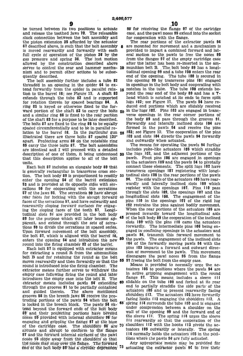
98’ fof receiving the flange 97 of the cartridge
case', and the pawl noses 95 extend into the socket
for coOperation with the flange.
The rear portions of the extractor pawls 94
are mounted for movement and a mechanism is
provided to impart a combined forward and lat-
eral motion to this, pawls to free the noses 95
from the flanges- 97 of the empty cartridge case
after the latter, has. been re-inserted in the am-
munition belt B. . The. bolt body 89 has a longi-
tudinal opening 99 and a tube 100 enters the rear
end of the opening. The tube 100 is secured in
the opening 99 by. transverse pins 101 engaged
in openings in the bolt body and cooperating with
notches in the tube. The tube 100 extends be-
yond the rear end of the body 89 and has a T-
head which is notched at its ends to. form split
lugs 102; see Figure 17. The pawls 94 have re-
duced- end portions which are slidably received
in the'lugs’.102. Pins 103 are engaged in trans-
verse openings in the rear corner portions of
the body 89 and pass through the. grooves 91.
Forwardly and laterally. inclined slots 104 are
formed iri the pawls. 94 and receive the pins
103; see Figure 12; The cooperation of the pins
103 and slots 104 directs-the pawls 94 forwardly
and outwardly when actuated.
The means for operating the. pawls 94 further
includes yoke-like actuators 105 which straddle
the lugs .102, and the. adjacent portions of the
pawls. Pivot pins .106 are engaged .in openings
in the actuators. 105’and the pawls 94 to pivotally
connect these elements; The split lugs 102 have
transverse openings 107 registering with- longi-
tudinal slots 108 in the.rear portions of the pawls
94. The side'walls of the actuators 105 have rear-
wardly and laterally inclined. slots 109 which
register with the openings 107. Pins. 11 O' pass
through- the slots 109, the openings 107 and the
longitudinal slots 108. The engagement of the
pins 110 in the openings 107 of the rigid lug
I.-02 restrains the pins against bodily movement.
When the rear portions of the actuators 105 are
pressed inwardly. toward' the longitudinal axis
of the bolt body 89 the cooperation of the inclined
slots 109 with the pins Г10 cams the. actuators
forwardly. The intermediate pins 106 being en-
gaged in confining-openings1 in the actuatorsand
pawls 94, transmit this forward movement to
the pawls. The engagement-of the inclined slots
1’04 of the forwardly moving pawls 94 with the
pins 103 imparts a forward and outward direc-
tion of movement to the pawls. This movement
disengages the pawl noses 95 from the flange
97 freeing the bolt from the empty case.
Means is provided to normally urge the. ac-
tuators 105 to positions where the pawls 94 are
in active. gripping engagement with the round
flange 97. This means, includes a sleeve 111
slidable on the tube 100 and forked at its rear
end to partially straddle the side parts- of the
actuators 105 and to present rearwardly facing
shoulders (12. The actuators 105 have forwardly
facing hooks 113 engaging'the shoulders Ii2. A
spring 114 surrounds tile tube 180 and is' erigaged
under compression between a shoulder on the
wiill of the operiirig 98 and the forward erid of
the sleeve I I I-. The spring 114 urges the sleeve
111 rearwardly sb’ that the cooperation of the
shoulders' 112 with the hooks I I3 pivots the ac-
tuators (05 outwardly or laterally. The spring
114 riormally holds the actuators 105 in the pbsl-
tibris where the pavMS 94 are fully actuated.
Ariy appropriate tnearis rday be provided for
actuating the extractor pawls 94 to' free' their
3,466,677
11
noses 95 from the cartridge flanges 97. In the
simple case illustrated, cam projections 115 are
suitably located on the walls of the receiver 10
to be engaged at the proper time by the actuators
1Й5. The outer surfaces of the pawl actuators
105 are inclined rearwardly and laterally, and
upon contacting the cams 1 15, produce inward
movement of the actuators toward the longitu-
dinal axis of the bolt assembly. As above de-
scribed, this movement results in forward and
lateral movement of the pawls 94 to open their
round-gripping noses 95. It is to be understood
that other means may be utilized to operate the
pawl actuators 105, and the invention is not to
be construed as limited to the use of the cams
1 1 5 but is to be considered as contemplating any
practical operating means.
Each bolt 87 further includes a firing pin 116
and a novel safety means for the pin. The firing
pin 116 is arranged longitudinally within the tube
ISO and is capable of limited axial movement.
Its forward end portion is pointed and operates
in a reduced opening 1 17 leading to the forward
end of the bolt body 89. A flange 1(8 on the
pin К 6 is engageable with the forward end of
the tube 100 to limit the rearward travel of the
pin and may engage a shoulder on the wall of the
opening 117 to limit the forward travel of the
pin. A spring 119 surrounds the pin 116 and
is engaged between a rearwardly facing internal
shoulder in the tube 100 and a sleeve 120 sur-
rounding the rear portion of the firing pin. The
rear end of the pin 116 is exposed at the end of
the tube 110. The above mentioned safety means
includes the sleeve 120 surrounding the rear por-
tion of the firing pin 116 and slidable within the
tube 100. A series of circumferentially spaced
longitudinally extending grooves 121 is provided
in the rear part of the firing pin 116 to be within
the sleeve 120. The end walls of the grooves 121
curve or slope outwardly to the periphery of the
pin IIS. A ball 122 operates in each groove 121
and rides on the internal surface of the sleeve
120. The rear end of the sleeve 120 is exposed
at the end of the bolt body 89 and may be pro-
jected slightly from the end of the firing pin.
The spring 119 urges the sleeve 120 to the rear
end and the balls 122 engage the end walls of
the grooves 121 to limit rearward travel of the
sleeve relative to the pin 116 and to transmit
the rearward spring pressure to the pin. In the
event that the firing pin 116 is moved forwardly
independently of the sleeve 120, the balls 122
ride up the sloping end walls of the grooves 121
and bind to prevent actuation of the firing pin.
However, when the sleeve 120 is struck first, or
when the sleeve and the firing pin are simul-
taneously moved forwardly, the balls 122 remain
in intermediate position and the firing pin is
free to operate.
During each reciprocation of the bolt assembly
its three bolts 87 are turned as a unit a distance
of 120° to provide for the required sequence of
round extracting, insertion of the round into
the firing chamber 92 and the insertion of the
empty cartridge case into the belt B. The pres-
ent invention is not primarily concerned with the
means for effecting this rotation of the bolts 87,
except as such means may occur in combination
with the elements of the invention, and it is
contemplated that the bolts may be rotated by
any appropriate means actuated either by the
gas cylinder mechanism or by the recoil or
counter recoil of the barrel 18.
5
10
15
20
25
30
35
40
45
50
55
60
65
70
75
12
In the drawings there is illustrated in a more
or less schematic manner, one means for produc-
ing the required rotation of the bolts 87 during
the forward stroke of the gas piston 34. This
means includes a tubular drum 125 secured to
the rear wall 14 of the receiver 10 and a tube
or rod 126 secured to the shaft 83 of the rotatable
bolt unit and extending rearwardly into the drum.
If desired, the rod 126 may be a simple extension
of the shaft. A collar or flange 127 is fixed to
the rod 126 and operates in the drum 125. Three
axial slots 128 spaced 120° apart are provided
in the walls of the drum 125. The slots 128 are
connected by pitched or helical slots 129. The
slots 128 and 129 are of uniform width and are
adapted to slidably receive lugs 139 formed on
the periphery of the flange 127. There is a lug
130 for each axial slot 128 and the lugs have
pairs of parallel side surfaces adapted to slidably
ride along the walls of the axial slots and helical
slots. The helical slots 129 join the rear end
portions of the axial slots 128. Each helical slot
129 extends from immediately adjacent the rear
end of one axial slot to join the next axial slot
a relatively short distance from its rear extrem-
ity. This leaves the major forward portions of
the axial slots 128 entirely uninterrupted. A
pivoted switch 131 is provided at the rearmost
end of each helical slot 129. The switches 131
are spring urged to the positions illustrated in
Figure 6 where they direct the lugs (30 from the
axial slots 128 into the helical slots when the
lugs are traveling forwardly. The switches 131
are swung out of the way by the lugs as the lugs
travel rearwardly in the axial slots 128. Similar
switches 132 are provided at the forward ends
of the helical slots 129. The switches 132 are
pivoted and spring urged to positions where they
prevent the lugs (30, traveling rearwardly
through the axial slots 128, from entering the
helical slots.
Upon rearward movement of the gas piston 34,
the lugs 130 travel rearwardly through the axial
slots 128 from the forward ends of the slots to
their rear ends. This engagement of the lugs
130 in the slots 128 prevents rotation of the bolts
87 and assures true rearward movement of the
bolts so that the bolt in the barrel extension 53
moves out of the extension without interference
and the bolt that has engaged the new round R
in the belt В withdraws the round from the belt
without any angular movement. The lugs 130
travel substantially the entire lengths of the slots
128 and are prevented from entering the helical
slots 129 by the switches 132. When the bolt
assembly begins to move forwardly under the
action of the spring 36, the lugs 130 almost
immediately encounter the switches 131 and are
diverted thereby into the helical slots 129. The
lugs 130 travel forwardly through the helical slots
129 and their engagement with the slots of the
stationary cam drum 125 produces rotation of
the bolt assembly through a distance of 120°.
Owing to the pitch of the slots 129, this rotation
of the bolt assembly is rather abrupt and the
angular movement is completed by the new round
carried by the bolt 87, which is being brought
into alignment with the breech before the round
can interfere with the barrel extension 53 or the
parts associated therewith. Upon leaving the
helical slots 129, the lugs 130 engage the switches
132 and swing them out of the way. Upon
passing out of the slots 129, the lugs 130 move
forwardly in the axial slots 128 and remain in
the axial slots until the forward stroke of the
2;4в6.-577
13
gas piston lias been completed. The engagement
of the lugs 130 in the axial slots (28 definitely
maintains the bolts 87 in the angular position
where the new round is in alignment with the
breech, and where the empty cartridge case is
aligned with its empty belt link L for insertion
therein. It is to be observed that the bolt as-
sembly is turned in the same direction as the
sprocket 39 btit is turned 120° with each complete
cycle whereas the sprocket is turned oiily 60°.
The cartridge feeding mechanism above de-
scribed forms the subject of my copending ap-
plication Serial Number 659,985, filed April 5,
1946.
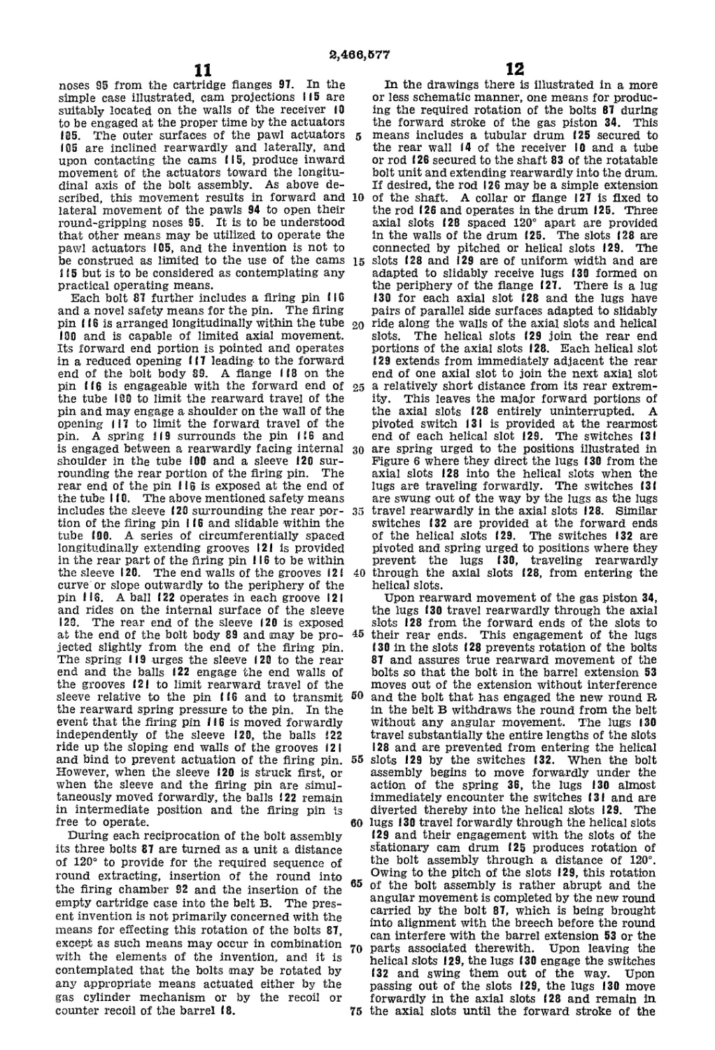
The above described jaws 56 of the barrel
extension 53 and rack mechanism fOr operating
the jaws are dependably latched in positions
where the bolt 87 carrying the new round R may
freely enter the barrel extension upon forward
movement Of the bolt assembly without inter-
ference ЬУ the jaws 56. The latch mechanism
fOr holding the jaws retracted is released or
conditioned for release during forward movement
Of the gas piston 34 by a part associated with
the above described actuator 67. The latch
means includes a tube (33 fixed in an opening
134 in the intermediate portion of the member
59. The tube 133 projects forwardly to extend
along one side of the breech block 53; see Figures
18 and 23. The tube 133 is slidably guided in
openings 135 of spaced lugs 136 projecting from
the block. The parts are related so that the
tube 133 remains in cooperation With the open-
ings 135 throughout the entire range of move-
ment of the rack supporting member 59. A sleeve
137 surrounds the tube 133 and has an internal
shoulder 138. The sleCVe 137 normally bears
rearwardly against the rear lug 136. A spring
139 is arranged under compression between the
forward lug (36 and shoulder 138 to urge the
tube 133 and sleeve 137 rearwardly. The spring
139 is of sufficient strength to normally hold the
member 59 in its rearmost position where the
jaws 56 are fully retracted.
The tube 133 has ah elongate axial slot 140
receiving a latch 141. The latch has an inwardly
projecting ear 142 on its inner edge received in
a notch 143 in the sleeve 137 and- operating in
an axial slot 144 in the wall of the barrel exten-
sion 53; see Figures 23 and 24. An annular
groove 145 is formed in the exterior of the sleeve
137 and receives a wire ring 146. The ear 142
of the latch has a transverse opening 147 and
the ring 146 passes through the opening to retain
the latch 141 in the slot 140; see Figure 19. The
latch 141 also has a projection 148 on its forward
end freely received in the opening of the1 tube
133. An ear 149 projects from the outer edge
of the latch 141 and is engaged by the rear end
of the sleeve 137. The spring urged sleeve 137,
acting on the forward edge of the latch 141 and
its ear 149, normally urges the latch to the full
line position of Figure 23. The longitudinal out-
wardly facing edge of the latch 141 has an abrupt
Shoulder 150 facing rearwardly. The shoulder
(5(F is pitched forwardly and inwardly to some
degree when the latch 141 is in the normal full
liHe position of Figure 23. The same edge of the
latch 141 has a shorter forWardly facing shoulder
151 which is also pitched forwardly and inwardly.
The rear end surface 152 of the latch is engage-
able with the end wall Of the slot 140 to normally
prevent forward movement of the member 59
and its rack rods 60 relative to the barrel exten-
sion 53. This- Surface of the latch is slightly
14
inclined ahd founded away so as to clear the
end wall of the slot 140 and enter the ttibe 133
Upon slight swinging movement Of the latch 141
ih the direction indicated by the arrow in Figure
5 23. The inner edge of the latch 1 41 has a sloping
shoulder 153 engageable with the rear end of
the barrel extension 53. It will be seen that the
spring 139 holds the latch 141 in the full line posi-
tion of Figure 23 where the surface 152 engages
10 the ehd wall of the slot 140 to positively prevent
forward movement of the member 59 and rack
fttdS 60 so that the jaws 56 are retained in their
retracted positions.
Means is provided for releasing the latch 141
15 jUst prior to forWafd actuation of the tack mem-
ber 59. This means includes a rod 154 carried
by the actuator 67. The actuator has a yoke 155
open to its interior and the rod 154 is provided
With a grooved flange 156 seated in the yoke so
20 as to be normally rigid with the actuator. The
engagement of the flange 156 in the yoke 155 posi-
tively holds the rod 154 against anguldf move-
ment. The rod 154 extends both forwardly and
reafWardly from the yOke 155, and its longitudi-
2'5 nal axis is coincident With the axis of the tube
I S3. During the final portion of forward motion
of the gas piston 34 and the actuator 67, the rod
154 enters the tube 133. The above described
notch 68 in the actuator freely clears or passes
30 the lugs 136 of the barrel extension during this
movement. The advancing end of the rod 154
may be somewhat beveled to readily enter the
tube 133. One side of the tod 154 has an in-
wardly facing notch 157 and is cut away to soffie
35 extent to Clear the rear portion of the latch 141
when entering the tube. The ehd of the for-
wardly moving rod 154 is adapted to Strike the
pitched shOulder 158- to swing the latch 141 to
the broken line position of Figure 23. This piVot-
40 ing of the latch 141 moves the portion Of the latch
occurring between the shoulder 151 and the sur-
face 152 into the notch 157 of the rod 154. The
engagement of the rod 154 with the shoulder 150
may not be sufficient to cause the latch to swing
45 the entire distance, but the cooperation of the
rear wall Of the slot 140 With the rounded end
surface 152 Of the latch completes the swinging
of the latch. When the latch 141 has been Swung
to the position of Figure 24, the rack rOds 60 are
50 ffee to move forwardly and actuate the jaws 56
to cooperate with the bolt serrations 9'0. It is
to be Observed that during forward movement
Of the bolt assembly the actuator 67 is in its
forward position relative to the spider 64 because
55 the actuator is, in effect, pulling the spider and
bolt assembly forward. Accordingly, the latch
14 ( is released or conditioned for release by the
rbd 154, on the “leading” actuator, before the
yoke 155 engages the member 59 or before the
60 spider 64- of the bolt assembly conies into contact
with the yoke 155. When the bolt assembly is
drawn forwardly by the actuator 67, the rod 154
first releases or conditions the latch 141 for re-
lease and the yoke 165 then engages the member
65 59. The spider 64 moves up to its final position
to introduce the bblt 87 into the block 53, inertia
carrying the bolt assembly forward while the
actuator lags slightly by reason of its engagement
with the latch. The actuator continues to move
70 forwardly after the spider stops, and the actuator
strikes the member 59, to driVe the rack pins 60
forwardly and actuate the breech block jaws 56.
Whefi the jaws 56 are fully actuated, the latch
141 is in the position illustrated hi Figure 24.
75 With the’ latch ifi this position' it's Orid sufface 162
2,430,577
IS
is engaged with the near wall of the notbh 157 to
hold the member 5!) and the rack rods 80 against
rearward movement, Thus the latch (41 ef!-
fectively locks the breech block jaws S6 ini the
position Where they retain the belt 81 in the barrel
extension. The sudden and Violent rearward
movement of the tod IS# caused by the action
of the gas piston 84 immediately following firing
of the round aiid transmitted by the toward wall
of the notch 137 to the pitched or rounded shoul-
der I Si of the lateh releases the latter. Upon
release of the lateh ill, the spring 139 moves
the rack rods BO to the rear with the result that
the jaws 56 are retracted. Retraction of the
jaws 56 is immediately followed by rearward with-
drawal of the bolt 37 from the barrel extension
by’ the gas piston 34 acting through the medium
of the actuator ST.
immediately following locking of the bolt in the
barrel extension; the flrilig pin 116 of the bolt 81,
in the breech, is operated to fire the round Rj
Each bolt ВТ carries it own firing pin i 1 fl to be
tn! a position for actuation by a suitable hammer
mechanism. The invention is not primarily con-
cerned with the nature of the hammer mecha-
nism employed except insofar as it occurs in com-
bination with the other elements. In order to
complete ths disclosure I have illustrated a ihauiH
mer and cocking mechanism including a tube
159 secured to the spider S4 and arranged to re-
ceive the rear portion of the above described, rod
154; see Figure 6A. A sleeve 160 is slidable on the
tube 159 and carries a laterally projecting ham-
mer 161. The ring 86 on ths rear of the shaft 83
carries three spaced projections 162 provided with
axial grooves l@3; The axial slots 128 of the cam
drum 125 position the ring 86 so that the grooves
163 of tis lugs 162 are successively aligned with
the hammer 161. A bushing 164 is secured in an
opening in the spider 64 and slidably carries a
striking pin 165. The parts are related so that
the pin 165 is aligned with the hammer 161 and
the pin is normally urged to the rear by a light
spring 166. The hammer 161, when actuated,
moves through a guide groove 163 and strikes
the pin 165, which in turn, strikes the sleeve 120
and firing pin 116 of a bolt assembly to fire the
round R.
The means for actuating the hammer 161 in-
cludes a spring 16T arranged under compression
between the sleeve 160 of the hammer and a head
(63 on the rear end of the tube 159. The spring
I6T surrounds the tube 159 and is adapted to
drive the sleeve 160 and the hammer 161 for-
wardly with considerable force. An arm 169 pro-
jects radially from the rod 154 and operates in a
slot (TO in the tube 159. The sleeve 160 of the
hammer has a stop lug IT! on its forward end
engageable with the securing flange of the tube
159 to limit the forward movement of the hammer
sleeve 160 and stop it in a position where the
arm 169 is directly in front of the sleeve.
When the gas piston 34 begins to move rear-
wardly, the actuator 6T moves rearwardly with
respect to the spider 64 and the rod 154 moves
rearwardly in the tube 159. During this relative
movement between the rod 154 and the tube 159
the arm 169 moves the sleeve 160 rearwardly
along the tube to compress the spring 16T. A
pivoted spring urged latch 1T2 is carried in a slot
in the tube 159 and engages in a notch 173 in
the hammer sleeve 160 to releasably latch the
hammer in its cocked position; see Figure 6A.
This occurs immediately before the actuator 6T
engages the spider 64 to push the spider and
16
bolt assembly rearwardly. The lateh IT2 holds
the hammer 161 cocked during the rearward
stroke of the bolt assembly and during the major
part of the forward stroke of the assembly;
Before the gas piston 34 reaches the end of its
forward movement, the rod 154 engages the
shoulder 150 Of the spring-held latch 1'41 and Ulis
causes the actuator 61 and the rod 154 to lag
slightly. Hie inertia of the spider 64 and the
bolt assembly carries the spider forwardly rela-
tive to the lagging rod 154, to actuate the rack
rods 60 and jaws 56 of the barrel extension as
above described; The actuator 61 and the rod
154 continue to move forwardly under the action
of the gas piston spring 36 after the spider 64
has stopped its forward movement. This final
short forward motion of the rod 154 relative to
the tube 159 brings a cam 114 on the rod Inta
cooperation with the latch (12 to release the
latch. Upon the release of the latch 112, the
spring 167 drives the hammer 161 forwardly to
strike the pin 165s, which in turn, strikes the firing
pin 1 66 and sleeve 129 to fire the round R. The
spring urged latch 112 automatically returns to
its; active position and the cam 174 moves away
from the lateh during ths subsequent rearward
motion of the rod 154 relative to the tube 158.
Any appropriate means may be employed to
charge the gun manually and to initiate and ter-
minate gun operation. For example, a cable 190;
shown schematically, may be connected with the
spider 64 of the bolt assembly and extend to the
exterior of the .receiver til to provide for hand
charging of the gun by pulling the bolt assembly
rearwardly to thus compress the gas piston
spring 35 afld rotate the bolts 8T to their new
angular positions. A suitable solenoid operated
mechanism may control the hammer and cock-
ing means to initiate and terminate operation of
the gun. Such solenoid control mechanisms are
common in the art, and form no part of the
present invention and are therefore considered
unnecessary to an understanding of the construc-
tion provided by the invention. This invention
is concerned with the barrel extension and bolt
assembly combination and elements associated
therewith, and while a substantially complete
gun has been disclosed it is to be understood that
this disclosure has been provided for the purpose
of assuring a better understanding of the con-
struction and operation of the novel features and
is not to be considered as restricting either the
scope or the application of the invention.
Operation
Substantially complete operation of the gun
will be described below in order to fully disclose
the purpose and operation of the barrel exten-
sion and bolt assembly. To condition the gun
for operation a suitable magazine, not shown, is
applied to the frame 16 and the ammunition belt
Б is trained over the sprocket 39. At least one
link L of the belt В is empty so as to pass the
barrel extension 53, and a live round is intro-
duced into the recess in the forward end of the
bolt 87, which is to be aligned with the breech,
so as to be gripped by the pawl noses 95. When
the sprocket 39 has been supplied with the belt
B, the bolt assembly is manually moved to the
rear by the charging cable 190. During the rear-
ward travel of the spider 64 and bolt assembly,
the hammer 161 is cocked as above described.
The lugs 130 travel rearwardly through the axial
slots 138 and the bolts 87 move rearwardly with-
out rotation, The rearward movement of the ac-
5
10
15
20
25
30
35
40
45
50
55
60
65
70
75
2,466,677
17
tuator 67 with the bolt assembly causes rearward
travel of the gas piston 34 and the spring 36 is
compressed so that energy is stored therein.
Upon completion of rearward travel of the bolt
assembly the gun is ready for operation.
The bolt assembly may be released for for-
ward movement under the action of the spring
36 by a suitable control device, either direct or
remote. For present purposes it may be con-
sidered that the operator merely releases the
charging cable to allow the spring 36 to move the
bolt assembly forward. During the first phase of
forward movement of the spider 64 and bolt as-
sembly, the lugs 130 move through the helical
slots 139 to rotate the bolts 120°. This brings
the bolt 87, which is carrying the live round, into
alignment with the cartridge chamber 92. Dur-
ing the remainder of the forward motion of the
bolt assembly, the bolts are held against rotation
and the bolt 87, carrying the round, enters the
barrel extension and introduces the round into
the cartridge chamber. The actuator pawls 94,
of an empty bolt 87, cooperate with the next
round in the belt В to have their noses 95 grip
the flange 97 of the round. As above described,
the rod 154 enters the tube 133 and contacts the
latch shoulder 150 to release the latch 141 so that
the member 59 and the rods 60 may move for-
wardly to operate the jaws 56. The latch 141
operates to retain the member 59 and the rods
60 in their forward positions where the jaws 56
are actuated so that the bolt 87 is locked in the
barrel extension. During the final phase of for-
ward movement of the bolt assembly and actua-
tor 67, the cam 174 releases the latch 172 and
the hammer 161 is actuated to fire the round.
Upon firing of the round, the gas pressure
developed in the bore of the barrel 18 acts on
the gas piston 34 to drive it rearwardly. Rear-
ward movement of the gas piston moves the actu-
ator 67 to the rear. This releases the latch 141
as described above so that the spring 139 may
move the rack rods 69 to the rear and retract
the jaws 56. The initial rearward movement of
the actuator 67 also compresses the hammer
spring 167 and cocks the hammer 161. Thus by
the time the rearward travel of the actuator 67
relative to the spider 64 is completed the jaws 56
are retracted to release the bolt 87 and the
hammer 161 is cocked. The actuator 67 then
engages the spider 64 to move the bolt assembly
to the rear. During rearward movement of the
bolt assembly the lugs 130 move through the axial
Slots 128. The rearward movement of the bolt
assembly also results in withdrawal of the empty
cartridge case from the chamber 92 and the
new round gripped in the pawls 94 of a bolt 87
is pulled out of the belt B. Thus one empty
cartridge case and one live round are moved to
the rear with the bolt assembly. During the re-
coil of the barrel 18, accompanying firing of the
round, the lugs 51 travel rearwardly through the
axial slots 48 and the sprocket 39 remains sta-
tionary.
Upon counter recoil of the barrel 18, the lugs
51 move through the helical slots 49 to rotate
the sprocket 39 and thus position the sprocket
to receive the empty cartridge case and to bring
the next round into position for extraction by
the pawls of the now empty bolt 87. The spring 70
36 initiates forward movement of the bolt as-
sembly immediately following rearward travel of
the assembly. During the forward stroke of the
bolt assembly, the lugs 130 cooperate with the
helical slots 129 to turn the bolt assembly to the 7Б
18
position where the new round is aligned with the
firing chamber 92 and the empty cartridge case
is aligned with its emtpy link L of the belt B.
The lugs 130 move into the axial slots 128 and
5 during the remainder of the forward motion of
the bolt assembly the bolts are held against rota-
tion. During the final phases of forward motion
of the bolt assembly, the new round R is in-
troduced into the firing chamber 92 and the bolt
10 87 enters the barrel extension opening 54. The
rod 154 of the actuator assembly releases the
latch 141 so that the jaws 56 may be actuated
to lock the bolt in the barrel extension. The
empty cartridge case is introduced into the empty
15 link L of the bolt during the final forward motion
of the bolt assembly, and the actuators 105 of
the bolt 87, which carries the empty cartridge
case, are operated through engagement with the
cams 115 so that the pawls 94 release the empty
20 case. The pawls 94 remain in the released con-
dition until the bolt assembly begins its rearward
travel during the next cycle of operation and the
released pawls allow the empty case to remain in
the belt B. The final phases of forward move-
25 ment of the actuator 67 release the latch 174 so
that the hammer 161 is actuated to fire the round.
The above sequence of operations is repeated
during successive automatic firing cycles of the
gun.
30 Having described only a typical form of the in-
vention, I do not wish to be limited to the specific
details herein set forth, but wish to reserve to
myself any variations or modifications that may
appear to those skilled in the art or fall within
35 the scope of the following claims.
I claim;
1. A gun mechanism having a barrel and a
barrel extension provided with an opening and
characterized by a bolt assembly including a
40 series of bolts supported for intermittent rota-
tion as a single unit, each bolt being engageable
in the opening of the extension, serrations on
the bolts, means supporting said assembly for
axial movement toward and away from the ex-
45 tension so that the individual bolts are entered in
the opening of the extension, and serrated lock
means on the extension for cooperating with the
serrations of the bolts to lock the bolts in the
block.
*0 2. A gun having a barrel and comprising an
extension on the barrel having an axial opening
aligned with the barrel and a lateral opening, a
bolt to be introduced into said axial opening and
having serrations, a lock jaw contained in said
Ы lateral opening for movement in a radial direc-
tion relative to said axial opening and having
serrations for cooperating with the first named
serrations, and translatory rack means for moving
the jaw in said radial direction, to bring its
60 serrations into cooperation with said first named
serrations.
3. A gun having a barrel and comprising an
extension on the barrel having an axial opening
aligned with the barrel and a lateral opening, a
5® bolt to be introduced into said axial opening and
having serrations, a lock jaw contained in said
lateral opening for movement radially of said
axial opening and having serrations on its inner
side for cooperating with the first named serra-
tions, inclined rack teeth on the jaw, and an actu-
ating member movable axially on the extension
and having inclined teeth cooperating with the
first named teeth to move the jaw radially in said
lateral opening for the purpose of engaging and
disengaging the serrations.
2;466,677
19
4.' A gun having a barrel arid comprising an
extension on the barrel’having an axial opening
aligned with the barrel and a lateral opening, a
bolt to be- introduced into said ’axialopening and
having serrations, a lock jaw contained in said
lateral opening for movement radially of said
axial opening and having serrations for coop-
erating with the first named serrations, diagonal
tfeeth on opposite sides of the jaw, and spaced
rack rods movable axially of the extension and
having diagonal teeth meshing with the first
named teeth to move the jaw between positions
retracted from the axial opening and! positions
where its serrations’mesh with the serrations
of'the bolts.
5; A gun having a barrel and comprising an
extension on the barrel having a main axial open-
ing aligned with the barrel, spaced axial bores
and radial openings communicating with the
main opening, a bolt to be introduced axially
into the main opening having serrations, block-
like jaws contained, in the radial openings1 and
supported therein for radial movement, the jaws
having serrations for- meshing with the serrations
of the bolt, diagonal rack teeth on the jaws, rack
rods1 shiftable in said bores and having teeth
cooperating with the teeth of the' jaws to move
tlie jaws radially between retracted positions and
positions where their serrations engage the ser-
rations of the’bolt tb retail! the bolt in the ex-
tension.
6. A'gun having a barrel - comprising an'ex-
tension on the barrel-having an opening" aligned
with the' barrel, a- breech- bolt movable axially
into and out of’ the opening, jaws- carried in
the extension for transverse movement- between
positions^ clear of the opening and positions
where they- lock the bolt in the extension, and
a single latch means; operable to releasably latch
the; jaws in both of said positions.
7: In a gun1 having a- barrel the combination
of an extension secured to the-barrel and hav-
ing ari opening- aligned1 with the barrel, a' breech
bolt movable axially- into and out of1 the open-
ing; a jaw in the extension movable transversely
Of-the opening between a; position-clear of the
opening, to allow-the entrance-of the bolt therein
and an actuated position where it locks- the* bolt
in the extension, means for moving the bolt into
and- out- of the opening including- an actuator
having- a slack- connection with the bolt, and
latch means for-holding the jaw-in the retracted
position- and released by relative movement be-
tween-the actuator and bolt.
8. In a-' gun- having- a barrel the combination
of- an extension secured to- the barrel and having
an opening aligned with the barrel, a- breech
bolt movable axially into and out of the open-
ing, a jaw in the-extension-movable transversely
of- the opening between a- position clear of the
opening to allow entrance of the bolt therein and
an actuated position where the jaw locks the
bolt, in the extension, means for moving the bolt
into-and out of the opening including an actuator
having a slack connection with the bolt, and-rack
means for moving the: jaw between said two posi-
tions and: controlled by relative movement be-
tween the actuator and bolt.
Jh Ima gun having a barrel extension provided
with an opening aligned - with the barret the
combination-of a breech bolt movable axially into
and out of the opening, a jaw in the barrel ex-
tension- movable- transversely of the opening be-
tween a- position clear of the - opening to- allow
entrance of the bolt therein- and an- actuated
20
position where it locks the bolt in the extension,
means for moving the bolt into and out of the
opening including an actuator having a slack
connection with the -bolt, rack means for mov-
5 ing the jaw’between said two positions controlled
by relative movement between the actuator and
bolt, and latch means for holding the jaw in the
retracted position released by relative movement
between the actuator and bolt.
10 10. In a gun having a barrel extension the
combination of, a carrier movable axially relative
to the barrel extension, a plurality of breech
bolts supported on the carrier for simultaneous
intermittent rotation as a unit so as to be in-
25 dividually align able with the barrel extension,
lock means in the extension for locking the bolts
therein, a member for moving the carrier axially,
a lost motion connection between the member
and carrier, and’a latch for the lock means con-
20 trolled by. relative movement between the member
and carrier.
11. In a gun having a barrel extension the
combination of; a carrier movable axially rela-
tive to the barrel extension, a plurality of breech
25 bolts supported on the carrier fOr simultaneous
intermittent rotation1 as; a1 unit so as to be in-
dividually alignable1 with the barrel extension, a
member for moving- the carrier axially, lock
means for locking the bolts in the barrel exten-
30 sion, the carrier being; operable to actuate the
lock means when the- carrier moves toward the
barrel extension,. arid; a, latch for holding the
lock means retracted; and released by said mem-
ber before the carrier actuates the lock means.
35 12. In a gun having? a1 barrel extension the
combination of, a carrier movable axially rela-
tive to the barrel extension, a plurality of- breech
bolts? supported on-the carrier for simultaneous
intermittent rotation' as a unit so as to be in-
to dividually' alignable- with the barrel extension,
a member for moving the carrier axially, lock
means-for locking: the<bolts; in the barrel exten-
sion; the carrier being operable to actuate1 the
lock-means when the carrier moves toward the
4® bloek, latch, means- for holding- the lock- means in
a- retracted position - and operable to latch the
lock means in its operated- position; and a part
on said member for releasing: the-latch means to
free the.lock means for actuation before the car-
50 rier actuates, the lock-means-while traveling to-
ward- the barrel extension and- operable to
release the latch means to, allow- retraction of
the lock means when; the member initiates its
movement in- the direction? to move the carrier
55 away from the barrel extension.
13. A gun comprising a barrel, an extension
fixed- to the barrel and- having an; axial opening
constituting a continuation of the bore of the
barrel, a spider at the rear of the extension sup-
00 ported for axial movement toward and away
from the extension, a circular series of three
equally spaced bolts supported by the spider for
rotation as a unit about an1 axis parallel with
the barrel, the bolts being proportioned so as to be
85 individually receivable in said opening of the
extension, and means, for imparting axial move-
ment.to the spider and rotary movement to said
series to successively introduce the. bolts, in said
opening and then withdraw them, from the same;
70 14. A gun comprising, a barrel, an extension
fixed on the- barrel and having an- opening con-
stituting a continuation, of the bore, of the bar-
rel; a circular series, of , three equally spaced bolts
supported for, axial movement as a unit toward
75 and away, from.- the extension- and’ for rotation; as
2,466,677’
21
a unit about an axis parallel with the barrel, each
bolt being designed for reception in said opening,
and means for imparting reciprocating motion
and intermittent rotation to said series so that
the bolts are successively entered into and with-
drawn from said opening.
15. In a gun having a barrel, the combination
of an extension secured to the barrel and having
an opening aligned with the barrel, a breech bolt
movable axially into and out of the opening, jaws 10
carried in the extension for transverse movement
between positions clear of the opening and posi-
tions where they lock the bolt in the extension,
inclined teeth on the jaws, a pair of shiftable ac-
tuating rack members having inclined teeth for 15
cooperating with the first named teeth to oper-
ate each jaw between said positions, and latch
means associated with the rack members for re-
leasably holding the jaws in their said two posi-
tions. 20
ALFRED CORTE.
22
REFERENCES CITED
The following references are of record in the
file of this patent:
UNITED STATES PATENTS
Number Name Date
269,660 Gamma_________________Dec. 26, 1882
532,380 Johnson_______________Jan. 8, 1895
689,283 Browning______________Dec. 17, 1901
698,472 Driggs________________Apr. 29, 1902
861,939 Benet et al.__________July 30, 1907
862,384 Bristol_______________Aug. 6, 1907
863,101 Schwarzlose___________Aug. 13, 1907
1,907,163 White_________________May 2, 1933
2,098,727 Lahti_________________Nov. 9, 1937
FOREIGN PATENTS
Number Country Date
13,446 Great Britain__________________1915
312,399 Germany________________May 11,1920