/
Tags: weapons military affairs patent
Year: 1968


Text
June 11, 1968 к. arndt 3,387,398
CARTRIDGE FEED IN LEVER-OPERATED RIFLE
Filed March 4, 1966
Fig. 1
KARL
# T TO#*/ ГУ
3,387,398
Patented June 11, 1968
United States Patent Office
1
3,337,398
CARTRIDGE FEED IN LEVER-OPERATED RIFLE
Kart Arndt, Laaf, near Nurnberg, Germany
Filed Mar. 4, 1966, Ser. No. 531,990
Claims priority, application Germany, Mar. 4, 1965,
R 40,039
1 Claim, (CI. 42—17)
ABSTRACT OF THE DISCLOSURE
A cartridge feed for guns comprising a box-like vertical-
ly displaceable conveyer for the cartridge in the rifle
receiver. The conveyer is actuated by a lever mechanism
which moves it upward from a normal position to a posi-
tion in front of the rifle barrel. The cartridge is guided by
the receiver along both its longitudinal sides and at its
rear end by a stop plate.
The invention relates to a cartridge feed in magazine-
fed rifles which permits the firing of a plurality of suc-
cessively arranged cartridges in succession from a tubular
magazine in a gun barrel, using a part controlled by a
breech block.
According to the invention this is achieved by means
of a cartridge feed which is characterized by a stop plate
and side guide rails for guiding the cartridges on a vertical-
ly displaceable chamber-like magazine carrier, the for-
ward end of which is disposed in the plane of the rear
ends of the tubular magazine and the rifle bore respective-
ly and the carrying surface of which, corresponding to the
length of the cartridge, is aligned either with the tubular
magazine or the rifle bore in such a manner that the rear-
most cartridge in the tubular magazine is pressed upon 35
the carrier surface by spring force or is disposed in front
of the rifle bore in the cartridge chamber, a chamber lock
with a pair of recesses disposed at different levels, the
upper one of which serves to stop the tensioned chamber
lock and the lower one to receive the return impact and 40
a control part of the carrier actuated by an actuating
lever guard.
A further embodiment of the invention comprises a
two-arm lever mounted on a pin in the rifle stock, the
forward, longer arm of which has a longitudinal slot for 45
a claw provided in the carrier, the rearward shorter arm
being positioned below, under the influence of a leaf spring
disposed in a chamber and arranged on the top of an
angular lever with a guide head, said guide head being
rotatable about a pin mounted in the rifle stock, a further 59
angular lever with a longitudinal slot being seated on
said bolt, for securing to a link and a lever whose guide
pin extends into the longitudinal slot of the angular lever’s
arm.
Particularly advantageous is the rounded portion of the 55
release angle element extending into a corresponding
recess, to assure a trouble-free stoppage of the bolt.
Furthermore, the guide rails extend to the level of the
rifle bore and abut the cartridges in the chamber with
clamping action, resulting in a jam-proof transfer of the G0
cartridges and preventing the cartridges from falling out.
Finally, the guide tracks are formed with a rounded
recess at the level of the tubular magazine, corresponding
to the outer diameter of the cartridge.
The invention is illustrated, schematically by way of 65
example in the drawing, in which:
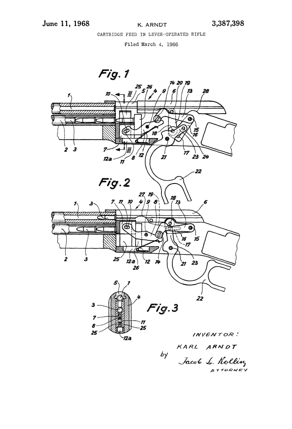
FIG. 1 is a partial section in the area of the breech of
a magazine-fed rifle in unlocked condition;
FIG. 2 illustrates the breech of FIG. 1, but in loaded
condition and
FIG. 3 is a cross-section taken on line III—III of ‘
FIG. 1.
2
The magazine-fed rifle consists of a gun barrel 1 and a
tubular magazine 2 for receiving cartridges 3, which are
under spring tension, in known manner. The rear ends of
the gun barrel and the magazine lie in the same plane.
Back of these is the breech bolt 4 and receiver 5 and
receiver lock 6, which is under the tension of a pressure
spring (not shown) and is provided, forwardly, with a
cartridge extractor. A conveyer 7 is disposed in the cham-
ber, the forward end of the conveyer contacting the rear
end of the tubular magazine and of the gun barrel, the
cartridge bearing surface of the conveyer being displace-
able vertically of the tubular magazine or of the gun
barrel, the rear end of the conveyer abutting a stop plate
26 and its side cheeks being slidable between clamping
guide bars 25. At the same time, the length of the con-
veyer or the distance between the stop plate 26 and the
rear side of the gun barrel, corresponds to the length of
the cartridge. The movement of the conveyer is effected
by means of a two-armed conveyer lever 8 which is
mounted on a pin 9. The front lever arm has a longi-
tudinal slit 10 into which extends a pin 11. The lower
side of the rear arm is biased by a spring 12 mounted in
the chamber 12л and is loaded to hold the conveyer in
the position shown in FIG. 1.
A release member 13 having a guide head 14 actuates
the upper side of the rear of conveyer lever arm 8, said
angular member being swingably mounted about pin 15
of the rifle stock. Another angular iever arm 16 is further
seated on the pin 15, and is provided with a longitudinal
slot 17 and a pin 18 for controlling a link 19, which is
provided on the pressure pin 20 of ihe release member 13.
The rifle stock is further provided with a pin 21 for
the lever 22, 23, both of which are integral. The lever
has a guide pin 24, which extends into the longitudinal
slot 17 of the angular lever arm 16. When the lever 22
moves into the position shown in FIG. 2, the cartridges
on the conveyer 7 are moved by the control parts 8, 13,
16,19 in front of the gun barrel.
The breech bolt 4 has on its underside a pair of recesses
27 and 28. A claw of the release angle 13 extends into
the former whereby the receiver lock 6 is held in tensioned
condition. Should the release member 13 be pressed
downward by the movement of the lever 22, 23 the re-
ceiver lock 6 is released, whereby the cartridge which is
in rear of the gun barrel, is moved into the latter. At the
same time the L-shaped lever 16 reaches into the second
recess 28 and blocks the receiver lock 6 in a locked
position.
It should be noted that the front lever of conveyer lever
8 is longer than the rear one and that the recess 27 is
deeper to the right than to the left, when the conveyer 7
with the cartridge 3 thereon is already in front of the
gun barrel.
Should the cartridges have been fired, the expended
shell remaining in the rifle is expelled by means of a
claw from the barrel, the bolt is tensioned and stopped
and the conveyer 7 moved downward. As it reaches its
lowest position, the rearmost cartridge is pushed out of
the tubular magazine and reaches the position shown in
FIG. 1.
The leaf spring 12, tensions the rear arm of the lever 8,
which presses the free end of the release angle 13 and
thereby assures the stopping of the bolt.
I claim:
1. In a rifle, a stock, a tubular magazine for cartridges
and a gun barrel secured to said stock above said maga-
zine; means for feeding cartridges from said magazine
into said gun barrel; said means comprising a guide for
said means defined by the rear end faces of said magazine
and said rifle barrel, and by a pair of spaced side guide
clamp bars and a rear stop plate; a box-shaped cartridge
3,387,398
3
conveyer slidable vertically in said guide, said conveyer
being alignable with either of said rear end faces, a pin
extending transversely of said conveyer; a double-armed
lever pivotable in said stock, the forward arm of said
double armed lever having a slot engageable with said 5
pin; a spring secured in said stock and normally biasing
upwardly the rear arm of said double-armed lever to
thereby align said conveyer with said magazine and means
for depressing the rear arm of said lever against the bias
of said spring, to thereby align said conveyer with said 10
gun barrel.
4
References Cited
UNITED STATES PATENTS
231,879 8/1880 Williams________________42—21
269,660 12/1882 Gamma___________________42—17
307,407 10/1884 Moses___________________42—21
373,277 11/1887 Ehbets__________________42—21
373,410 11/1887 Mullins_________________42—21
854.771 5/1907 Strasburg_______________42—21
861,632 7/1907 Brader__________________42—21
BENJAMIN A. BORCHELT, Primary Examiner.