/
Tags: weapons military affairs machine gun patent
Year: 1890
Text
(No Model.)
5 Sheets—Sheet 1.
H. S. MAXIM.
MACHINE GUN.
No. 439,248. Patented Oct. 28, 1890.
THE NORRIS PETERS CO , PHOTO-LITHO , WASHINGTON, D C
(No Model.)
5 Sheets—Sheet 2.
H. 8. MAXIM.
MACHINE GUN.
THE NORRIS PETERS CO , PHOTO-UTHO , •wkshr.otch. D c
5 Sheets—Sheet 3.
(No Model.)
H. 8. MAXIM.
MACHINE GUN.
Ho. 439,248.
Patented Oct. 28, 1890.
^2
THE NORRIS PETERS CO , PHOTO-UTHO , WASHINGTON, О C.
(No Model.)
5 Sheets—Sheet 4.
H. 8. MAXIM.
MACHINE GUN.
No. 439,248. Patented Oct. 28, 1890.
7>'<
THE MORRIS PETERS CO , PHOTO-UTHO , WASHINGTON, О C
.(No Model.)
No. 439,248.
5 Sheets—Sheet 5.
H. S. MAXIM.
MACHINE GUN.
Patented Oct. 28, 1890.
THE NORRIS PETERO CO , FHOTO-LfTHO , WASHINGTON, D C
United States Patent Office
HIRAM STEVENS MAXIM, OF LONDON, ENGLAND.
MACHINE-GUN.
SPECIFICATION forming part of Letters Patent No. 439,248, dated October 28, 1890.
Application filed April 4,1890. Serial So. 346,607. (So model.) Patented in England December 1, 1886, So, 15,7341 in Bel-
gium November 15,1887, So, 79,005 ; in Italy Hovember 26,1887, XXI, 22,500; in France December 14,1887, So. 185,641;
in Austria-Hungary April 21,1888, Ho, 34,166 ; in Germany August 24, 1888, Ho, 44,208, and in Spain January 25, 1889, Ho,
8,895,
To all whom it may concern:
Be it known that I, Hiram Stevens Maxim,
a citizen of the United States, residing at Lon-
don, England, have invented certain new and
5 useful Improvements in Automatic or Ma-
chine Guns, (for which I have obtained pat-
ents as follows: in England, No. 15,734, dated
December 1, 1886; in France, No. 185,641,
dated December 14, 1887; in Germany, No.
io 44,208, dated August24,1888; in Austria-Hun-
gary, No. 34,166, dated April 21,1888; in Italy,
No. 22,500, dated November 26,1887; in Spain,
No. 8,895, dated January 25,1889, and in Bel-
gium, No. 79,005, dated November 15, 1887,)
15 of which the following is a specification.
My invention relates chiefly to automatic
guns of that kind or class wherein the barrel
and breech mechanism are arranged to slide
longitudinally in a stationary frame or sup-
го port, and wherein the breech-block is locked
to the barrel during the earlier part of the
recoil, and is then released and moved back-
ward away from the barrel to extract the
empty cartridge-shell and permit the intro-
25 duction of a fresh cartridge between the
breech-block and the rear end of the barrel.
I have hitherto constructed such guns with
mechanical devices whereby the breech-block
will during the recoil be unlocked from the
30 barrel and driven backward therefrom, and
with one or more springs for storing up en-
ergy during the recoil and utilizing such en-
ergy for effecting the forward or return move-
ment of the barrel and performing the vari-
35 ous operations necessary in loading and fir-
ing the gun or preparing it for the next dis-
charge.
One object of my present Invention is to
substitute for such mechanical devices hy-
40 draulic apparatus, whereby I am enabled to
insure the proper movement of the breech-
block without at any time imparting a high
velocity to the said block, and also to insure
the closing of the breech without jar or shock.
45 In large and heavy guns this feature is espe-
cially advantageous, because by reason of the
great weight of the moving parts a high ve-
locity thereof would be liable to cause injury
to the gun by concussion. Moreover, by the
employment of such hydraulic apparatus I 50
am enabled to provide in a very simple and
efficient manner for regulating or controlling
the velocity of the moving parts, as herein-
after described, notwithstanding differences
in the weight and explosive force of the 55
charges used in the gun, and I am also en-
abled to provide in a very simple manner for
regulating the speed of firing, as hereinafter
set forth.
An important feature of my said invention 60
is the construction and arrangement of the
parts in such manner that at the termination
of the recoil or backward movement of the
barrel the breech-block will be unlocked there-
from, and will then be caused to continue its 65
backward movement by force applied to the
said block by the barrel in its forward or re-
turn movement either by means of hydraulic
apparatus or otherwise. It is evident that
under these conditions the extraction of the 70
empty cartridge-shell wall be effected partly
by the withdrawal of the same from the bar-
rel by the breech-block in its rearward move-
ment and partly by the removal of the barrel
from the said shell. It is, moreover, evident 75
that in order to permit the introduction of a
fresh cartridge between the barrel and the
breech-block the said block will only require
to move back through a distance equal to or
slightly greater than the length of a cartridge 80
minus the length of the forward movement of
the barrel, or, in other words, minus the dis-
tance through which the barrel recoils.
My said invention, moreover, comprises
various other improvements hereinafter set 85
forth.
Certain of my present improvements are
applicable to other kinds of automatic guns,
such as are described in the specifications of
Letters Patent already granted to me, and 90
also to guns designed to be worked by hand.
Moreover, my said improvements are applica-
ble to machine-guns and to military rifles and
other small-arms, and also to large and heavy
guns or ordnance. 95
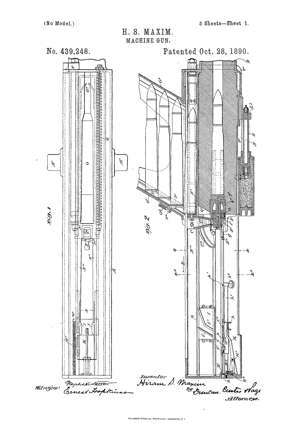
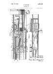
In the accompanying drawings, Figure lis
a plan, and Fig. 2 a vertical longitudinal sec-
tion, of my improved automatic gun, showing
2
439,248
the parts in the positions which they occupy
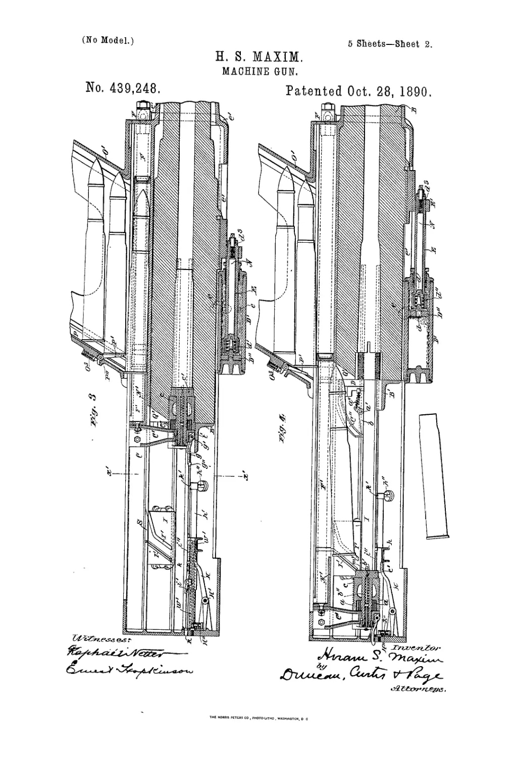
at the instant of firing. Fig. 3 is a vertical
longitudinal section showing the parts in the
positions which they occupy after the gun has
5 been fired and the barrel has terminated its
recoil. Fig. 4 is a similar view showing the
parts in the positions which they occupy after
the barrel has returned to its firing position
and the breech-block has reached the rear end
io of its stroke or movement, and showing the
empty cartridge-shell falling from the gun.
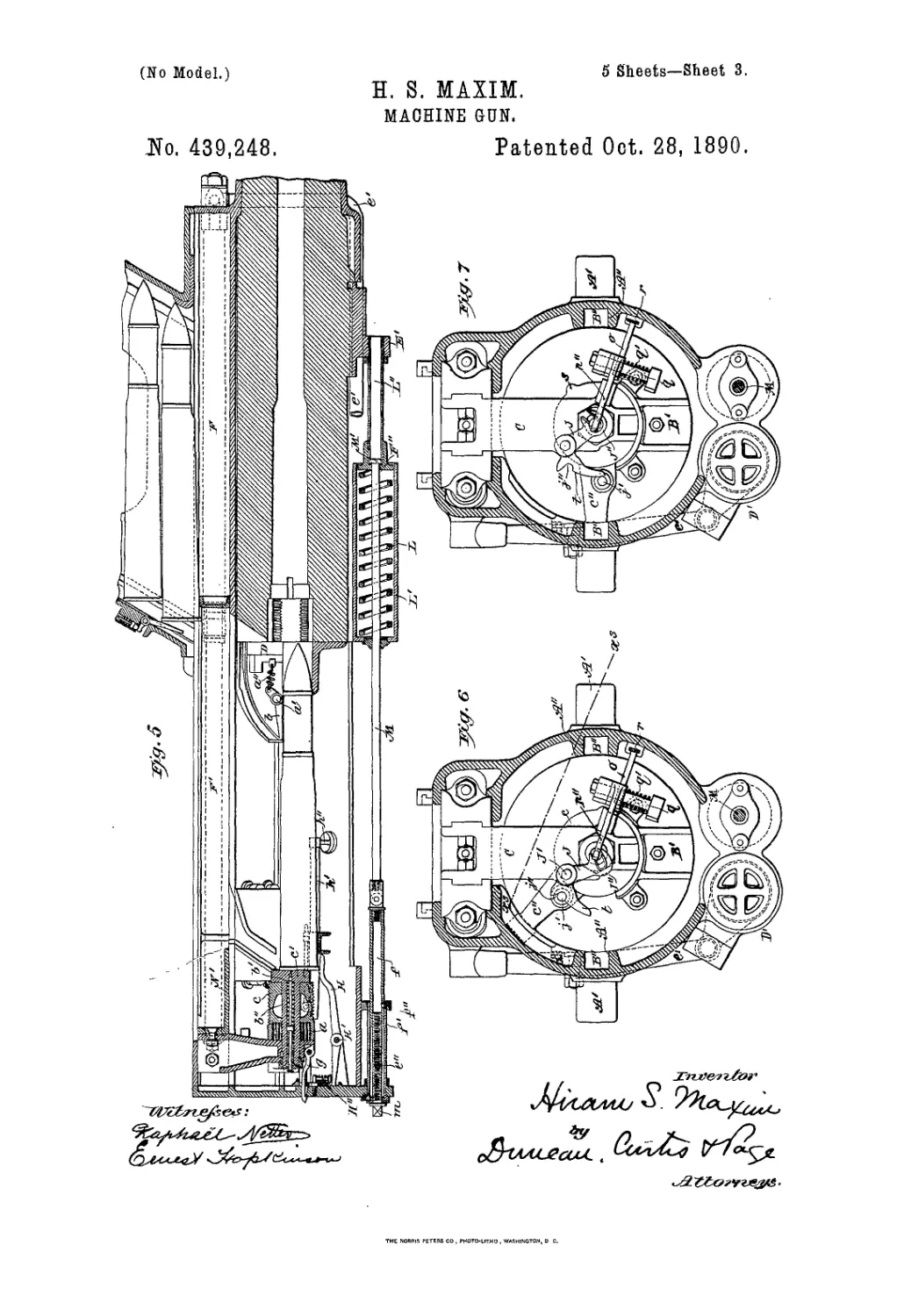
Fig. 5 is a similar view showing the parts in
the positions which they occupy after a fresh
cartridge has fallen from the magazine into
15 position in front of the breech-block and has
liberated the said block, as hereinafter speci-
fied. Fig. 6 is a transverse section on the line
x x, Fig. 2, showing the parts in the positions
which they occupy at the instant of discharge,
го Fig. 7 is a transverse section on the line ж'ж',
Fig. 3, showing the parts in the positions
which the occnpy when the barrel has termi-
nated the recoil and the breech-block is un-
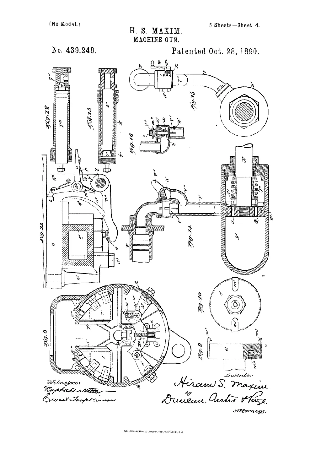
locked from the barrel. Fig. 8 is a transverse
25 section on the line x" x", Fig. 2, looking in
the direction indicated by the arrow у in this
figure. Fig. 9 is a plan, partly in horizontal
section, and Fig. 10 an end elevation, of a part
of the breech-block, illustrating the arrange-
30 meat of the extractors. Fig. 11 is a section
on the line ж3 ж3, Fig. 6, showing details of
construction. Figs. 12 and 13 are longitudi-
nal sections illustrating modifications of my
said invention hereinafter described. Fig.
35 14 is a vertical longitudinal section, and Fig.
15 is a front elevation, of means for regulat-
ing the speed of firing. Fig. 16 is a vertical
longitudinal section showing anotherform of
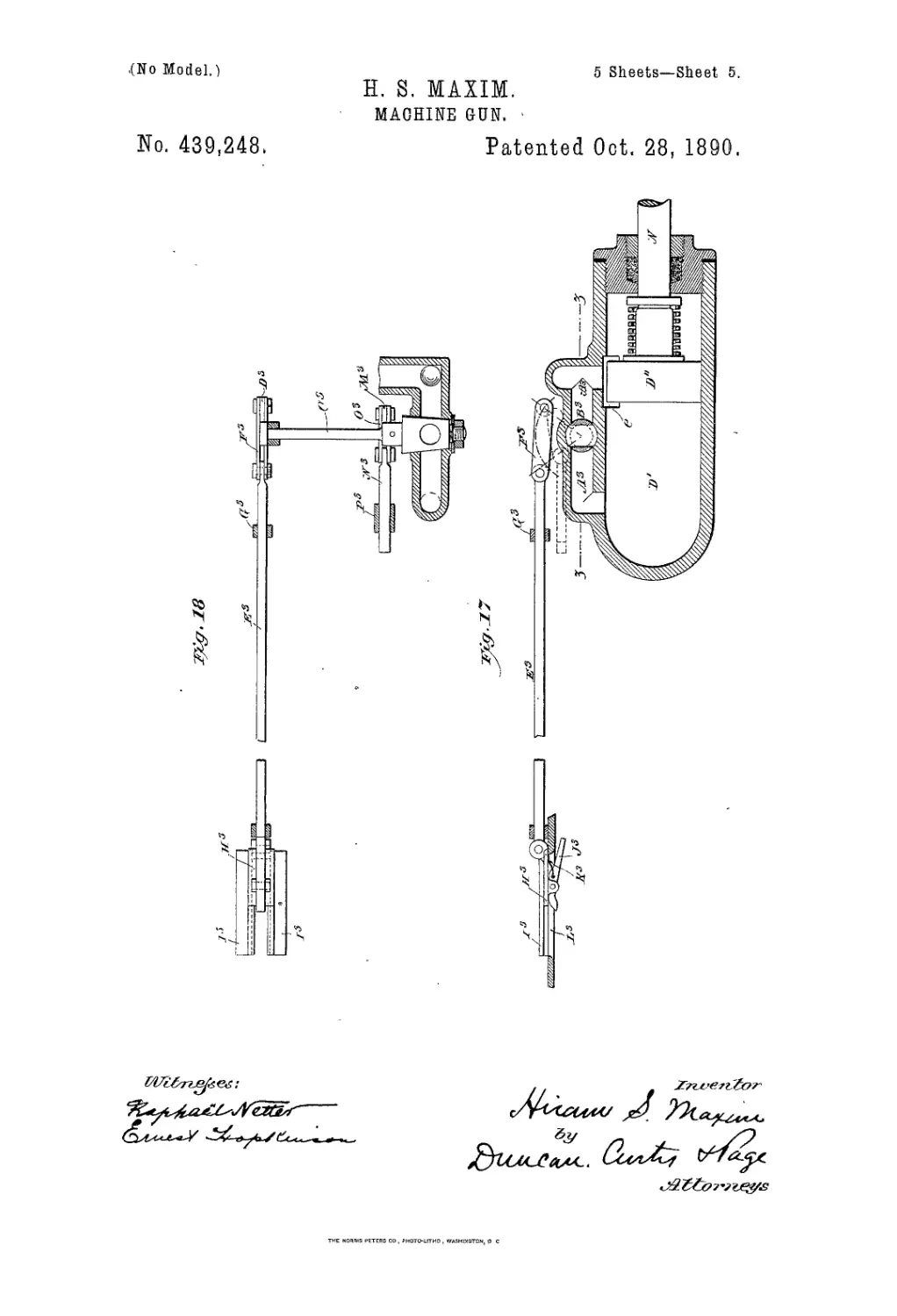
the regulating devices. Fig. 17 is a horizon -
40 tai section showing mechanism for opening
communication between the two ends of the
hydraulic cylinder hereinafter specified, Fig.
18 is a vertical section on line z z, Fig. 17.
A is the stationary frame or support, which
45 is provided with trunnions A', whereby it
may be mounted in a suitable carriage or
mounting.
В is the barrel; C, the breech-block or
breech-plug.
50 The barrel В is provided at its rear end
with an extension or frame B', whereby the
breech-bloclrwhen in the firing position will
besuppe'/cedand lateral displacement thereof
prevented. The barrel is, moreover, pro-
55z-vkled with ribs or projections B", fitted to
/ slide in guideways A" in the frame A for the
purpose of guiding the barrel in itsto-and-fro
movement.
The breech-block or breech-plug C com-
60 prises an outer tubular piece cand a central
or core piece o'. The outer part c is provided
on its circumference with an intermittent or
divided screw-thread adapted to fit a corre-
sponding screw-thread in the breech end of
65 the barrel. The said outer part cis arranged
to rotate upon the central or core piece o',
which is firmly secured to a vertical block or
piece O'. To the rear end of the piece c is
secured an arm c", the free extremity of which
works in an inclined or spiral groove or guide- 70
way C"in the frame A, so that when the bar-
rel has nearly terminated its rearward move-
ment the said arm 0" will be moved down-
ward and the breech-block thus unlocked or
unscrewed from the barrel. The part cof the 75
breech-block is provided wTith a coiled spring
a, which is wound up or compressed in the
unlocking of the breech-block, and subse-
quently reacts to effect the locking of the said
block to the barrel. 80
A switch b is pivoted at a' to the frame A,
and is acted upon by a spring a", which bends
to hold the said switch in the position shown
in Fig. 2, so that in the forward or return
movement of the barrel the arm 0" will be 85
held down, thus permitting the insertion of
the breech-block in the barrel before the part
c is acted upon by its spring a to lock the
said block therein.
b' is the firing-pin, and b" its spring, both 90
of which are arranged within the core-piece
c' of the breech-block.
A vertical groove or guideway D, Figs. 4
and 5, is formed in the frame A, so that when
the breech-block has been driven home the 95
free end of the arm 0" may slide in the said
groove or guideway and the breech-block be
locked to the barrel under the action of the
spring a.
D' is a hydraulic cylinder, which is firmly 100
secured to the frame A, and in which works
a piston D", provided with a hollow piston-
rod E. This rod is firmly connected to a
bracket E', formed on or rigidly attached to
the barrel B, and works in a stuffing-box in 105
the forward end of the cylinder D'. The said
piston D" is provided with a central aper-
ture or port d and with a valve d', acted upon
by a spring d", which presses the said valve
against its seat and thus closes the said aper- no
ture or port d. When the barrel recoils, the
liquid in the rear part of the cylinder D' is
forced through the opening or port d into the
forward end of said cylinder. In the forward
or return movement of the barrel the spring 115
d" closes the valve d', thus preventing the
return of the liquid to the opposite side of
the piston D". It is therefore forced through
an aperture in the cylinder, for the purpose
hereinafter described. 120
e is a port or passage in the side of the cyl-
inder D' and communicating by means of a
pipe e' with a cylinder F, secured to the outer
frame A. In this cylinder is fitted to slide
another cylinder or tubular ram F', firmly 125
connected with the part C' of the breech-
block C. The transverse sectional area of the
hollow piston-rod E is equal to that of the
stationary tube F, or to the collective area of
the stationary tubes when more than one are 130
used. Therefore in the recoil of the barrel
and breech-block the liquid displaced from
the cylinder D' by the progressive immersion
of the piston-rod E will fill the empty space
439,248
8
left in the front end of the cylinder F by the
rearward movement of the ram F'. When
the barrel has terminated its recoil, the liquid
in the cylinder D' will have been forced from
5 the rear to the front of the piston D". In the
forward or return movement of the barrel
the aperture or port d will be closed by the
spring d", as above described. The liquid
in the cylinder D' will therefore be forced
io from the said cylinder into the cylinders or
tubes F, and, acting upon the ram F', will
cause the breech-block C to continue its back-
ward movement while the barrel is moving
forward. The return movement of the piston
15 D"creates a partial vacuum in the rear of the
cylinder D'. The velocity of the backward
movement of the breech-block will depend
partly upon the relative areas of the hydraulic
cylinders L>' and F and partly upon the ve-
20 locity of the barrel in its forward or return
movement.
For effecting the return movement of the
barrel I provide a spring L, inclosedin a cyl-
inder L', firmly secured to the under side of
25 the frame A. The cylinder L' is fitted with
a piston F", arranged to bear on one end of
the said spring. The other end thereof bears
against the end of the cylinder L'. The pis-
ton F" is secured to a hollow piston-rod L",
30 the forward end of which is attached to the
lug or projection E' on the under side of the
barrel. It will be seen that when the barrel
recoils the spring L will be compressed and
energy will be stored therein to effect the re-
35 turn movement of the barrel. To provide for
opening the breech by hand, a rod Mis fitted
to slide through the piston F". This rod has
a solid endM',loosely fittingthehollowpiston-
rod L". The rear end of the rod M is connected
40 to a hollow piston-rod f, arranged to slide in
a cylinder or tube /', secured to the frame A.
A pin f" fits in a groove in the hollow piston-
rod/ and prevents rotation thereof. A screw-
threaded rod e” fits a corresponding internal
45 screw-threaded portion in the end of the hol-
low piston-rod/. This rod is fitted in a bush
in the end of the cylinder or tube /' and is
provided with a square end m. By these
means the barrel may be drawn backward
50 and the breech opened by hand.
The port or passage e, through which the
liquid is forced from the larger cylinder, is
preferably tapered at its forward end, so that
when the barrel has nearly terminated its for-
55 ward stroke or movement it will be gradually
cushioned by the liquid in the said cylinder.
The barrel will therefore be brought to rest
without jar or shock.
At the termination of the forward move-
60 ment of the barrel the piston D" uncovers
the rear end of the port or passage e. The
plunger F' then acts upon the liquid in the
cylinder F and forcesit through the said port
or passage into the rear of the cylinder D'.
65 This movement of the plunger F' is effected
partly by the pressure exerted by the atmos-
phere upon the rear end of said plunger and
partly by a spring G, Fig. 1, attached at its
rear end to a projection on the side of the
breech-block and secured at its forward end 70
to the front end of the casing A, so that the
said spring will be extended during the recoil
and will by its reaction assist in effecting
the forward or return movement of the breech-
block and parts carried thereby. 75
To prevent or diminish concussion on the
closing of the breech, I sometimes provide
the plunger F' with a conical or plug shaped
end T, Fig. 12, which will enter a neck or con-
tracted part T' at the rear end of the cylinder 80
F when the breech-block has nearly termi-
nated its forward movement, and will thus
close or contract the space for the passage of
liquid from the said cylinder, and thereby
gradually diminish the velocity of the breech- 85
block.
In the apparatus shown in Fig. 13 the cyl-
inder F is designed to be connected with the
breech-block and the tubular plunger F'
with the barrel. In this case the said cylin- 90
der is provided with a plug T, adapted to en-
ter a contracted part T' of the said plunger,
for the purpose above mentioned.
To provide for regulating or controlling the
velocity of the moving parts, I employ means 95
for adjusting the tension or compression of
the spring d" to increase or diminish the force
required to open the valve d' during the re-
coil.
N is a rod fitted to rotate in the hollow pis- 100
ton-rod E. Said rod is provided with a screw-
threaded portion ds, fitted into a correspond-
ing screw-threaded portion in the hollow pis-
ton-rod E. The said rod N is, moreover, pro-
vided with a square end, by means of which 105
it may be turned in one or the other direc-
tion, thereby extending or compressing the
spring d" and regulating the speed of the re-
turn movement of the barrel. It will thus be
seen that by these means the resistance to no
the recoil can be adjusted according to the
weight and explosive force of the charge em-
ployed.
The core-piece c' of the breech-block car-
ries the extractors m', Figs. 9 and 10, which 115
are so constructed and arranged that when
the breech-block is driven home the outer
edges of the said extractors will fit into re-
cesses in the breech end of the barrel, and
will thus be caused to engage with Vne flange 120
of the cartridge in the barrel. Each extractor
m' is formed with a stud or projection which .
fits into a recess in the piece d and is acted
upon by a spring m", which, while allowing
the extractor to pass freely over the flange of 125
a cartridge, tends to keep the said extractor
in engagement with the flange of the said
cartridge. In the extraction of the empty
cartridge-shell, which is effected by the move-
ment of the barrel and breech-block in op- 130
posite directions after the barrel has termi-
nated its recoil, the extractors, by reason of
the peculiar construction and arrangement
of the same, are held tightly in engagement
4
439,243
with the flange of the said shell, and the
stronger the pull upon the said extractors
the more tightly they will be held in engage-
ment with the said flange. The breech-block
5 C has firmly connected with the part C' there-
of a frame N', fitted to slide to and fro in
grooves or guideways N" in the frame A.
The said frame N' is formed with an aper-
ture 0, into which the lowermost cartridge
io in the vertical hopper or magazine 0' will
fall when the breech-block is driven home.
The frame N' in the recoil or backward move-
ment of the breech-block will transfer jthe
said cartridge from the magazine into such a
15 position that it will fall in front of the breech-
block at the termination of the rearward
movement thereof.
To prevent the backward movement of the
cartridge by the frame N' before the breech-
20 block is unlocked from the barrel, the said
frame is made of such length that its forward
end will not come in contact with the point of
the projectile until the barrel has terminated
its recoil. The said frame is, moreover, made
25 with a solid bottom extending forward a short
distance from its rear end. While the flange
of the cartridge rests on the said solid part the
said cartridge cannot pass under the rear end
of the magazine. The said frame N' is pro-
30 vided near its forward end with springs 0",
so arranged that as soon as the flange of the
cartridge drops over the solid portion of the
frame the said springs will grip the bullet
end of the cartridge.
35 The magazine 0' is formed with guide-
ways P, in which the flanges of the cartridges
slide. The said magazine is also provided
with a lever P', pivoted thereto at P". The
short arm of the said lever is acted upon by
40 a spring O3, which tends to keep the said lever
in- such a position that tlie column of car-
tridges in the magazine will be held up therein
until the lowermost cartridge is transferred
from the magazine by the frame N'.
45 A slot or groove Q' is formed in the breech
end of the barrel, through which the bullet
end of a cartridge will pass when the said
cartridge falls into position in front of the
breech-block. The rearward movement of
50 the barrel may by these means be shortened.
A sear 0 is pivoted at o' to a bracket 0", firmly
secured to the breech end of the barrel, and
is acted^ifpon by a spring p, whereby it is
caused to engage with the bentf/ of the ham-
53'merf>", said hammer being carried by a rod
q, supported between the brackets 0" and act-
uated by a spring q on said rod. The sear 0
is connected by means of a rod r to the trig-
ger. The safety-sear r', also pivoted at o', is
60 provided with an extension r", adapted to en-
gage with a lug or projection son the breech-
block, which lug or projection is so arranged
that when the breech-block is locked to the
barrel the said lug will hold the safety-sear
65 out of engagement with the bent p', and thus
allow the said bent to be operated by means
of the sear 0 to fire the gun.
A projection s' on the breech-block is pro-
vided with a recess or groove s", into which
the hammer j/'is arranged to slide. In the 70
rearward movement of the breech-block the
projection s' acts upon the hammer p" and
pushes it into its cocked position, where it is
held by the sear 0 until the gun is fired. At
the same time the projection s releases the 75
safety-sear and allows it to come into opera-
tive position with the bent p'.
It will be seen from the foregoing descrip-
tion that the hammer cannot be operated un-
til the breech-block is driven home and locked 80
to the barrel.
I provide an additional safety device by
which the accidental firing of the gun is pre-
vented—that is to say, J is a lever pivoted at
J' to the breech-block and provided with a 85
forked end J". The ends of said fork are
made tapered or wedge-shaped, as at J, Fig.
11, so that when the lever J is caused to ro-
tate upon its pivot J' the said forked end
thereof will engage with the firing-pin b' and 90
hold the same out of reach of the cartridge in
the barrel. A pin/, secured to the arm c" of
the breech-block, is adapted to engage with
a recess j” in the arm t of the lever J. It
will thus be seen that as soon as the arm c" 95
is rotated to unlock the breech-block from
the barrel the pin J' will cause the lever J to
be rotated on its pivot J', and the fork J",
engaging with the firing-pin, will hold said
pin out of reach of tlie cartridge until the 100
breech-block has completed its backward and
forward movement and is again locked to
the barrel. Therefore should the hammer/'
by any chance be released from the sears and
strike the firing-pin no explosion will take 105
place.
To provide for retaining the breech-block
in its rearmost position while a cartridge falls
in front thereof and then releasing the said
block to permit its forward movement, I some- no
times employ the device hereinafter de-
scribed—that is to say, a bar or catch g is piv-
oted at д' to the breech-block C and is formed
with a hook g" and with a projection f to
hold it in its horizontal position. At the ter- 115
mination of the backward movement of the
breech-block the hooked end of this bar passes
through an aperture R in the rear end of the
frame A and engages with said frame, thus
holding back the breech-block until released, 120
as hereinafter described.
H is a lever, pivoted at H' to a bracket on
the frame A. The short arm of this lever is
adapted to engage with the lower edge of a
vertically-sliding plate H", which works be- 125
tween guides on the rear end of the frame A.
This sliding plate is provided with an open-
ing R', Fig. 8, through which the end or catch
g is pushed in the backward movement of
the breech-block. The plate H" is, moreover, 130
provided with a spring R", which tends to
keep said plate in its lowermost position.
11 are two parallel plates firmly secured to
the frame A and havingguide-pieces I' formed
439,248
or fixed thereon. In the backward movement
of the frame N' the cartridge is pushed back
by means of springs O", the flange of said
cartridge being supported between the lower
5 projecting flanges of the guideway N" until
it is allowed to fall through the extended
opening S in said flangesand passes between
the guide-pieces I'. The flange of the car-
tridge then strikes the end of the lever H,
to which operates the sliding plate H" to force
the rod or catch g out of engagement with
the aperture R in the rear end of the frame
A. The breech-block is then moved forward
through the medium of its springs.
15 To prevent the falling of the cartridge from
the gun and to retain it in position to be
pushed forward into the barrel, I provide a
frame or cradle 7г, adapted to slide to and fro
on horizontal guide-rods 7г', which are secured
20 at one end to the rear end of the frame A
and are carried at the other end in brackets
7г", also secured to the frame A. On one
side of the frame or cradle 7г is a lug or projec-
tion w, to which is attached the forward end
25 of a spiral spring w', the other end being
firmly secured to the rear end of the frame
A. The said frame or cradle is, moreover,
provided with an extension w", to which is
pivoted a lever i, one arm of which is acted
30 upon by a spring i', which tends to keep said
lever in the position shown in Fig. 2. The
other arm of the lever i is arranged to be op-
erated by a rod i", working in guides in the
frame or cradle 7i and having a wedge-shaped
35 end 7c. In the forward movement of the
breech-block the arm c" of said block impinges
against the end of the lever i, thereby forcing
the frame or cradle 7i forward and extending
the spring w. When the said frame or cra-
40 die has moved forward a predetermined dis-
tance, the rod i" strikes a projection 7c’ on the
bracket 7г", thereby forcing the end of the
lever i downward and releasing it from the
arm c" of the breech-block. The spring id
45 then reacts upon the frame or cradle 7г, caus-
ing it to assumeits original position. It will
thus be seen that the flange of the cartridge
is supported in a horizontal position and the
cartridge carried forward by the frame or
50 cradle 7i to a sufficient distance to insure the
entrance thereof into the barrel before the
said frame is withdrawn from the said car-
tridge.
It is obvious that I may, if desired, employ
55 two or more of the aforesaid hydraulic cylin-
ders and pistons in combination with the bar-
rel communicating with one or more hydraulic
rams connected with the breech-block.
Where I use hydraulic apparatus con-
60 structed and arranged as above described I
am enabled to provide in a very simple and
efficient manner for regulating the speed of
firing. For this purpose I employ means for
controlling the flow of liquid from the cylin-
65 der F to the cylinder D'.
In Figs. 14 and 15, V is the pipe or passage
between the cylinders D' and F. V'isavalve
arranged in the said pipe in such a manner
that although the liquid can flow freelyfrom
the cylinder D' into the cylinder F, the said 70
valve will close th e passage against the flow of
liquid in the reverse direction. V" is a by-pass
or branch passage, which is connected with
the pipe Von each side of the said valve and
is provided with a cock W. This cock is to 75
be opened more or less to permit the flow of
liquid from the cylinderF to the cjflinder D'.
The handle W' of the said cock is provided
with an index or pointer AV", and the exte-
rior of the cock is provided with a graduated 80
scale X, so that the said cock may be readily
turned to regulate or control the flow of the
liquid through the branch passage V", ac-
cording to the speed of firing desired.
I sometimes so arrange the valve V' that it 85
may be adjusted in such a manner as to per-
mit the flow of liquid with greater or less ve- *
locity from the cylinder F i;sto the cylinder
D'. An arrangement of this kind is shown
in Fig. 16, in which the valve V'is made with 90
a screw - threaded stem x, which is passed
through a stuffing-box x', and on which is
screwed a nut x". This nut bears upon the
gland of the stuffing-box, so that by turning
the said nut in one or the other direction the 95
said valve can be raised or lowered, and its
downward movement can be limited, so as to
perm it the flow of the liquid with greater or less
velocity. The said valve is acted upon by a
spring y, which effects its return or downward 100
movement after it has been raised by the liq-
uid flowing from the cylinder D' to the- cylin-
der F. The rotation of the valve V' is pre-
vented by a set-screw y', fitting into a ver-
tical groove in the said valve, or other suit- 105
able means are provided for this purpose. An
index or pointer y" is attached to the nut ж",
and a collar or head z is fixed on the outer
end of the stem x and is provided with a
graduated scale, so that the speed of firing no
can be accurately regulated or controlled.
According to another part of my invention
I so construct the hydraulic apparatus that
when the smallest charge to be used is ex-
ploded in the barrel the recoil will only move 115
the piston D" backward through a distance
equal to about two-thirds of the length of the
cylinder, and when a heavier charge is used
the recoil will move the piston back through
a greater distance, and there will be in the 120
cylinder in front of the said piston an excess
of liquid above the quantity required to move
back the breech-block. It is necessary in this
case to provide for opening communication
between the two ends of the cylinder as soon 125
as or before the breech-block terminates its
backward movement in order to permit the
continuance of the forward movement of the
barrel until it arrives at the firing position.
For this purpose I connect the two ends of 130
the said cylinder by means of a pipe or pas-
sage provided with a cock or valve arranged
to be operated by a stud or projection on the
breech-block, or on one of the sliding cylin-
6
439,248
ders or plungers, or on some part connected
therewith, so that when thh gnn has recoiled
and the breech-block has been moved back-
ward to the end of its stroke by the partial
5 forward movement of the barrel the said cock
or valve will be opened to permit the free pas-
sage of the liquid from the front to the rear
of the piston, and the forward movement of
the barrel maybe completed without affecting
io the breech-block. A spring or other suitable
device is provided for closing the said cock
-or valve as soon as the breech - block com-
mences to move forward.
In Figs. 17 and 18, A3 is a pipe or passage
15 connecting the two ends of the cylinder D' and
provided with a cock B3. A rod or spindle
C3 is fixed on the plug of this cock, and has
formed thereon an arm D3, to which a rod E3
is coupled by means of a link F3. The rod
20’ E3 is fitted to slide longitudinally in lugs G3,
formed on or attached to the frame A, and is
coupled at its rear end to a bar II3, fitted to
slide between guides I3, formed on the said
frame. The bar IIs has pivoted thereto a
25 pawl J3, acted upon by a spring K3, which tends
to hold it in the position shown. This pawl
extends through an aperture L3 in the sideof
the frame A, the said frame being ronnded on
the inner side at the rear end of the said ap-
30 erture, for the purpose hereinafter specified.
The spindle C3 is also provided with an arm
M3, to which a bar № is coupled by means of
a link O3. The said bar № is fitted to slide
longitudinally between guides P3, formed on
35 or attached to the frame A, and is arranged
to be operated by a shoulder or projection on
the barrel, (not shown in the drawings,) as
and for the purpose hereinafter explained.
The operation of this mechanism is as fol-
40 lows, viz: When the lightest charge to be used
is exploded in the barrel of the gun, the bar-
rel in its recoil will move the piston D"
through, say, two-thirds of its stroke. In the
forward or return movement of the barrel,
45 the breech-block will be moved backward,
and when it has nearly terminated its back-
ward stroke or movement will strike the for-
ward end of the pawl J3, and thus move the
rod E3 backward and open the cock B3. In
50 the continued backward movement of the
breech-block the short arm of the pawl J3
will strike the rounded edge at the rear end
of the aperture L3, and the said pawl will thus
be disengaged from the breech-block. On the
55 return of the barrel to the firing position it
will pushjkifward the rod №, and thus close
the cooii B3. If a heavier charge is used, the
barrel in its recoil will move back the piston
D" through more than two-thirds of its stroke,
,6'э and in the forward movement of the barrel
the cock B3 will be opened by the breech-
block, as above described, so that any excess
of liquid in front of the piston D" above that
required to move back the breech-block to
65 the rear end of its stroke or movement will
be forced through the pipe or passage A3 into
the rear end of the cylinder D', thus permit-
ting the return of the barrel to the firing po-
sition.
By const ructing and arranging the parts in 70
the manner above described with reference
to Figs. 17 and 18 of the drawings I provide
for insuring the proper movement of the bar-
rel and breech-block notwithstanding differ-
ences in the weight and explosive force of the 75
charges used in the gun—that is to say, I so
proportion the cylinder D' that the smallest
charge used in the gun will cause the recoil
thereof to such an extent that the liquid in
front of the piston at the termination of the 80
recoil will be just sufficient for effecting the
backward movement of the breech-block dur-
ing the forward or return movement of the
barrel. If a heavier charge is used, the breech-
block will arrive at the rear end of its move- 85
inent before the barrel has terminated it s for-
ward movement, and in the remainder of the
forward movement of the barrel the liquid
will be forced from the front to the rear end
of the piston. 90
What I claim is—
1. In a magazine gun or fire-arm, the com-
bination of a barrel, a breech-block normally
locked thereto and both capable of longitudi-
nal movement due to recoil, means for un- 95
locking the barrel and breech-block at the
limit of backward movement of the barrel, and
mechanism between the barrel and breech-
block brought into operation by the forward
movement of the barrel and adapted to con- 100
tinue the backward movement of the breech-
block, as herein set forth.
2. In a magazine gun or fire-arm, the com-
bination of a barrel and a breech-block nor-
mally locked together, a stationary frame or 105
support in which they are adapted to slide lon-
gitudinally, means for unlocking the breech-
block at the termination of the recoil of the
barrel, and a hydraulic cylinder with a pis-
ton connected with the breech-block and no
adapted to be charged by the barrel in its
forward movement and to thereby continue
the backward movement of the breech-block.
3. In a magazine gun or fire-arm, the com-
bination of a barrel and a breech-block nor- 115
mally locked together, a stationary frame or
support in which they are adapted to slide
longitudinally, and a releasing device in the
path of the breech-block and adapted to un-
lock the same from the barrel when encoun- 120
tered by the said breech-block at the limit of
backward movement of the barrel, as set forth.
4. In a magazine or machine gun, the com-
bination, with a stationary frame or support,
of a barrel capable of a given longitudinal 125
movement in said frame, a breech-block hav-
ing a longer range or path of longitudinal
movement than the barrel, and retractile
mechanism connected with the barrel and the
breech-block for returning them to the for- 130
ward position, as set forth.
5. The combination, in a machine-gun, with
a longitudinally-sliding barrel and breech-
block normally locked together, of means for
439,248
.7
5
ю
15
20
25
3°
35
4о
45
5°
55
бс
б5
unlocking or disengaging the breech-block
from the barrel, adapted to be brought into
operation by and at the end of the backward
movement of said barrel, and a device for ap-
plying the force of the return of the barrel to
continuing the backward movement of the
breech-block, as set forth.
6. In a machine-gun, the combination, with
a stationary frame or support, of a barrel and
breech-block normally locked together and
botli adapted to slide longitudinally in said
frame, a projection or extension on said
breech-block, and a stationary part or point
with which said projection by the backward
movement of the barrel is brought into en-
gagement and by which the locking portion
of the breech-block is turned to disengage the
breech-block from the barrel, as set forth.
7. In a machine-gun, the combination, with
a barrel capable of longitudinal movement in
its frame or supports, of a breech-block, a
part of which engages with the barrel and is
capable of being rotated relatively to the re-
maining parts, and a projection or arm extend-
ing from the rotary portion and adapted in the
backward movement of the barrel to encoun-
ter a stationary part of the gun and to there-
by turn and disengage the part of the breech-
block engaging with the barrel.
8. In a machine-gun, the combination, with
a barrel capable of longitudinal movement in
its frame, of a breech-block locked thereto, an
arm or projection on said breech - block
adapted to encounter a stationary part of the
gun and to thereby turn and disengage the
breech-block, and a spring brought under ten-
sion by the turning of the breech-block and
adapted to re-engage or lock the same with
the barrel, as set forth.
9. The combination, in a machine-gun hav-
ing a sliding barrel and breech-block, of a
hydraulic cylinder secured to the frame, a
piston therein and connected with the barrel,
a second cylinder communicating with the
first and secured to the gun-frame, a piston
therein connected with the breech-block, and
a spring connected with the barrel and adapt-
ed to be compressed by its recoil, as herein
set forth.
10. The combination, with the sliding bar-
rel and breech-block, of a hydraulic cylinder
attached to the stationary frame or supports
of the gun, a piston-connection with the bar-
rel and working in said cylinder, a valve in
said piston through which the water passes
on the backward movement of the barrel, a
cylinder secured to the frame, and a piston
connected with the breech-block and working
therein, and a passage of communication be-
tween the two cylinders whereby the forward
movement of the barrel will effect the con-
tinued backward movement of the breech-
block, substantially as set forth.
11. The combination, in a machine-gun, of
a barrel capable of sliding longitudinally in
its frame or supports, a breech-block movable
with said barrel and capable of a backward
movement of greater extent than the barrel,
springs connected with the barrel for effect-
ing the return of the same after a recoil, and 7c
intermediate mechanism between the barrel
and breech-block adapted to be operated by
the return or forward movement of the bar-
rel to impart a continued backward move-
ment to the breech-block, as set forth. 7 =
12. In a machine-gun, the combination,with
the. sliding barrel, of a block adapted to slide
to and fro from the breech end of the barrel,
a breech-plug capable of turning said block
and formed with divided or intermittent 80
screw-threads engaging with corresponding
screw-threads in thie barrel, and means for
partially rotating said plug alternately in op-
posite directions, for the purpose set forth.
13. The combination, with the sliding bar- 85
rel, of a breech-block composed of a central
block or core-piece provided with hooks or
extractors, the breech-plug capable of turning-
on the core and having the divided screw, the
arm or projection on the plug by which it is 90
turned and unlocked from the barrel, and a
coiled spring between the core and plug-
adapted to be compressed by the partial ro-
tation of the latter, as set forth.
14. The combination, with the breech-block 95
having a central core-piece or block with a
flanged or enlarged head and a sleeve sur-
rounding the core back of the head, of the
extractors consisting of L-shaped plates or
bars with studs bearing in recesses in the rear too
of the flanged head of the core, and springs
contained in recesses in the rear of said
flanged head and upon which the ends of the
extractors bear, the extractors being formed
with hooked ends for engaging with the flange 1 c 5
of a cartridge, as set forth.
15. The combination, with the sliding bar-
rel, of a breech-block having a rotating por-
tion engaging with the barrel, an arm extend-
ing from said portion, a stationary cam with 110
which the arm engages during the backward
movement of the barrel, whereby it is par-
tially rotated in a direction perpendicularly
to the barrel to disengage the breech-block,
and a coiled spring between the main and 115
re voluble parts of the breech-block for return-
ing said arm and re-engaging the breech-
block and barrel, as set forth.
16. The combination, with a sliding barrel,
of a breech-block having a revoluble por- 120
tion adapted to lock into or engage with the
barrel, means for turning the said locking-
portion during the backward movement of
the barrel to disengage it from the barrel, and
a pivoted lever or switch with which said arm 125
or projection engages on the return of the
breech-block and by which the arm is pre-
vented from turning back until the locking
portion of the breech-block has entered the
barrel, as herein set forth. 130
.17. The combination of the magazine, the
ways or guides therein and set obliquely to
the axis of the barrel for holding the car-
tridges in a vertical row, the sliding breech-
s'
439,248
block and frame connected therewith for
transferring. the cartridges from the maga-
zine to the breech, and a spring-actuated lever
pivoted in the lower part of the magazine in
5 position to press against the butt of the lower-
most cartridge, whereby the forward end of
the same is prevented from dropping down
from the magazine first, as and for the pur-
pose set forth.
io 18. The combination, with the breech-block
having a revoluble portion that engages or
locks with the barrel, of a firing-pin passing
through the breech-block and a forked or
slotted arm pivoted to the breech-block and
15 normally surrounding the end of the firing-pin,
and adapted to be shifted out of engagement
or contact with the pin by the engagement
with itself of a projection on the revoluble
portion of the breech-block when turned into
20 position to lock the breech-block to the bar-
rel, as set forth.
• 19. The combination, with the sliding
breech-block, of a hook carried thereby and
adapted to engage with a stationary part of
25 the gun when the breech-block is in its rear-
most position, and a tripping device for re-
leasing said catch in position to be encoun-
tered by a cartridge dropping into position
forward of the breech-block and to be oper-
3c ated thereby to release the breech-block, as
set forth.
20. The combination, with the sliding
breech-block, of a hooked bar pivoted there-
to, a sliding plate on the frame of the gun
35 with which the hooked bar engages when the
breech-block has reached the limit of its back-
ward movement, a cradle back of the breech
upon which the cartridges fall when trans-
ferred from the magazine, and a lever pivoted
40 to the frame, one end being in engagement
with the sliding plate and the other in posi-
tion to be struck by a cartridge dropping
onto the cradle, as set forth.
21. The combination, with the stationary
45 frame or support and the gun -barrel movable
longitudinally therein, of a cylinder or barrel
connected to the frame, a spiralspring inclosed
in the cylinder, a hollow piston connected with
the gun-barrel, provided with a head for coin-
50 pressing the spring in the cylinder, a rod
passing through the spring from the rear of
the gun and entering the hollow piston, to
which it is secured by a head, and a screw-
threaded rod -Connected therewith and passing
55 through a part of the stationary frame, where-
by the гиптаггеГтау be drawn back by hand,
as sefforth.
_Х^2. The combination, with the sliding
breech-block and barrel, of a frame connected
with the breech-block and working under the 60
cartridge-magazine, said frame being formed
with a solid bottom extending forward a short
distance from its rear and being of such length
that the forward portion or end will not en-
counter on the backward movement of the 65
breech-block the point of a cartridge until the
barrel has reached the limit of its recoil, as
set forth.
23. The combination, with a stationary
frame or support,’of a sliding barrel and 70
breech-block separable from and in line with
the barrel and a cartridge-feed mechanism
adapted to supply cartridges from above be-
tween the breech-block and barrel, the said
barrel being formed with a slot or groove in 75
the upper side of the breech end thereof for
the reception of the bullet end of a cartridge
as it falls into line with the bore of the bar-
rel, as set forth.
24. In a machine-gun, the combination, with 80
a sliding barrel and breech-block, of a station-
ary hydraulic cylinder, a piston working there-
in and connected with the barrel, a second
hydraulic cylinder connected with the first
and provided with a neck or contracted part, 85
and a piston therein connected with the
breech-block, the said piston or plunger be-
ing formed with a conical end to operate in
conjunction with the contracted part of the
cylinder, as set forth. 90
25. In a machine-gun, the combination,with
a sliding barrel and breech-block, of a station-
ary hydraulic cylinder, a piston therein con-
nected with the barrel, a second hydraulic
cylinder, a piston therein connected with the 95
breech-block, a passage of communication be-
tween said cylinders, and a valve or cock
therein for regulating the passage of water
through the same from one cylinder to the
other. 100
26. In a machine-gun, the combination, with
the sliding barrel and breech-block, of two hy-
draulic cylinders and pistons working therein
and connected, respectively, with the barrel
and the breech-block, a passage of communi- 105
cation between the ends of the cylinder on
opposite sides of the piston connected with the
barrel, a valve or cock in said passage, and
means for turning the same adapted to be
actuated by the movement of the barrel, as no
set forth.
HIRAM STEVENS MAXIM.
Witnesses:
David Young,
Chas. B. Burdon.