/


Tags: weapons military affairs patent
Year: 1911

Text
L. SOHMEISSER.
AUTOMATIC FIBEABM.
APPLICATION FILED SEPT. 7, 1910.
989,432.
Patented Apr. 11,1911.
THE NORRIS PETERS CO , WASHINGTON, D. C.
UNITED STATES PATENT OFFICE.
LOUIS SCHMEISSEK, OE EKEUKT, GERMANY.
AUTOMATIC FIKEAKM.
989,432. specification of Letters Patent. Patented Apr. 11, 1911.
Application filed September 7, 1910. Serial No. 580,891.
To all whom it may concern:
Be it known that I, Louis Sciimeissek,
engineer, a subject of the German Emperor,
residing at 8 Strassburgerstrasse, Erfurt,
S Germany, have invented certain new and
useful Improvements in Automatic Fire-
arms; and I do hereby declare the following
to be a full, clear, and exact description of
the invention, such as will enable others
.W skilled in the art to which it appertains to
make and use the same.
My invention relates to improvements in
automatic fire arms, and more particularly
to automatic fire arms with stationary bar-
16 rel. And the object of the improvements is
to provide a fire arm of this class in which
the parts which must be dismounted for
thoroughly cleaning the firearm can easily
be mounted or dismounted, by hand. For
20 this purpose a slidable or otherwise movable
locking bar is provided, at the upper part of
the firearm which enables the barrel to be
easily secured or dismounted.
For the purpose of explaining the inven-
25 lion an example embodying the same has
been shown in the accompanying drawing
in which the same letters of reference have
been used in all the views to indicate cor-
responding parts.
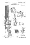
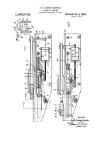
30 In said drawing Figure 1 is a vertical lon-
gitudinal section of the forward and upper
part of a pistol of this class, the parts being-
shown in the closed position of the pistol, Fig.
2 is a cross-section of the pistol taken on the
35 line A—В of Fig. 1, Fig. 3, is a front view
of the pistol, Fig. 4 is a vertical longi-
tudinal section of the fore upper part of
the pistol, the breech block being withdrawn,
Fig. о is a cross-section of the pistol taken
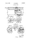
40 on the line C—D of Fig. 4, Fig. 6 is a top
view of the pistol in the closed position, Fig.
7 is a side view of the breech block seen
from the left. Fig. 8 is a front view of the
same, Fig. 9, is a top view of the same, Fig.
45 io is a side view of the barrel seen from
the left, and Fig. 11 is a front view of the
barrel.
Referring to the example illustrated in
the drawing, the breech block В is slidably
50 supported within and has an interlocking-
engagement with the receiver A within
which it can be shifted in a longitudinal
direction. A stud c of the barrel C is fitted
in a notch of the receiver (Figs. 1, 4 and 5).
55 The barrel C and the breech block В are
provided over their whole lengths with
grooves providing a seat for a slide bar D.
Below the barrel a closing spring F is pro-
vided which with its rear end bears against
a relatively stationary part of the receiver 50
and with its front end against a stud A pro-
jecting downward from the breech block B.
The said spring is guided on a pin G.
When the spring F has been placed into the
receiver A, and the breech block В is 65
pushed backward on the receiver A a suffi-
cient distance, the barrel C with its stud c
can be placed into the receiver A. The for-
ward movement of the breech block В under
the action of the spring F is limited by con- 70
tact with the barrel, while the rearward
movement of the said block is arrested by '
the stud striking against a relatively sta-
tionary part of the receiver.
When the slide bar 1) has been pushed 75
into its seat formed by the grooves of the
breech block В and the barrel C, the barrel
which before was prevented only from be-
ing displaced longitudinally and laterally,
is locked against upward displacement. 80
When using the pistol the slide bar D is
locked against displacement by means of the
sight E which has a rocking support on bar
I). A spring e1 tends to force a pin e of the
said sight into a recess Ъ of the breech block 85
B, as soon as the slide bar D has arrived in
its proper position, as is shown in Figs. 1,
3 and 4. The slide bar D may also carry the
front sight.
As shown in Fig. 4, when shifting the 90
breech block В backward an aperture is
formed through which the cartridges can be
thrown out laterally.
The parts of the pistol are dismounted by
raising the sight E, and shifting the slide D 95
backward sufficiently to enable the barrel C
to be removed from the stock in an upward
direction. Now the breech block B, its
spring F, and the guide pin G of the latter
can be removed from the stock by shifting 100
the same forward.
Having now particularly described and
ascertained the nature of my said invention
and in what manner the same is to be per-
formed, I declare that what I claim is: 105
1. In automatic firearms, the combination
with the stock, the barrel, and the breech
block, said barrel and breech block being
formed with registering guideways, of a
stud projecting downward from said barrel 110
989,432
and fitting in a notch of the stock, and a
slide bar seated within the guideways of said
breech block and barrel.
2. In automatic firearms, the combination
5 with the stock, the barrel, and the breech’
block, said barrel and breech block being
formed with registering guideways, of a
stud projecting downward from said barrel
and fitting in a notch of the stock, a slide
10 bar seated within the guideways of said
breech block and barrel, and means to lock
said slide bar on the breech block.
3. In automatic firearms, the combination
with the stock, the barrel, and the breech
15 block, said barrel and breech block being
formed with registering guideways, of a
stud projecting downward from said bar-
rel and fitting in a notch of the stock, a slide
bar seated within the guideways of said
20 breech block and barrel, a spring pressed
rear sight having a rocking support on said
slide bar, and means connected with said
rear sight to lock said slide bar on the
breech block.
25 4. In automatic firearms, the combination
with a stock, of a removable barrel, a breech
• block interlocked to and slidable on the
stock, said barrel and breech block having
registering guidew’ays, a slide fitted in said
guideways, and means detachably locking зо
said slide.
5. In automatic firearms, the combination
with a stock, of a removable barrel, a breech
block interlocked to and slidable on the
stock, said barrel and breech block having 35
registering guideways, a slide fitted in said
guideways, and means detachably locking
said slide to the breech block.
6. In automatic firearms, the combination
with a stock, of a removable barrel, a breech 40
block interlocked to and slidable on the
stock, said barrel and breech block having
registering guideways, a slide fitted in said
guideways, a projection carried by said slide
for entering a recess in said breech block, 45
and yielding means for holding said projec-
tion in said recess.
In testimony whereof, I have signed this
specification in the presence of two subscrib-
ing witnesses.
LOUIS SCIIMEISSER.
Witnesses:
Woldemab Haupt,
Arthur Schroeder.
Copies of this patent may be obtained for five cents each, by addressing the “ Commissioner of Patents,
Washington, В. C.”