/
Tags: weapons military affairs patent
Year: 1947
Text
Nov. 11, 1947.
R. L. JENKINSON
2,430,680
BREECH BOLT AND RETRACTING MEANS THEREFOR
Filed Sept. 4, 1944
2 Sheets-Sheet 1
Nov. 11, 1947. r. l. jenkinson 2,430,680
BREECH BOLT AND RETRACTING MEANS THEREFOR
Filed Sept.. 4, 1944
2 Sheets-Sheet 2
Patented Nov. 11, 1947
2,430,680
UNITED STATES PATENT OFFICE
3,430,680
BREECH BOLT AND RETRACTING MEANS
THEREFOR
Robert L. Jenkinson, Teaneck, N. J., assignor to
The Marlin Firearms Company, New Haven,
Conn., a corporation of Connecticut
Application September 4, 1944, Serial No. 552,639
4 Claims.
1
This invention relates to firearms, and more
particularly to a firearm of the semi-automatic
type. As shown, it is applied to a semi-auto-
matic bolt-action rifie, although it will be under-
stood that in certain of its aspects the invention
is applicable to other types of firearms.
Distinction is usually made between an auto-
matic firearm and one of the semi-automatic type,
in that a fully automatic gun continues to fire as
long as the trigger is held back, while in the
semi-automatic type of gun the trigger must be
released and pulled again for each successive
discharge, although the loading and cocking of
the gun are effected automatically.
In a gun of this type it is necessary that the
introduction of the new cartridge into the cham-
ber from the magazine be accomplished with
smoothness and ease, for, as will be obvious, the
movement of the bolt takes place very rapidly
upon the discharge of the gun. It is, therefore,
contemplated by the present invention to provide
a new and improved carrier to move a fresh car-
tridge from the magazine into a position to be
forced into the barrel by the return of the bolt.
Also it is desirable in guns of this type, and par-
ticularly in a gun adapted for civilian use, to
provide for a ready conversion of the gun from
one of the semi-automatic type to one of the
manual or single-shot type, wherein the loading
and cocking operations are effected manually.
In bolt-action guns it is more or less usual to
provide a threaded plug or bumper at the rear
of the receiver, against which the bolt and striker
springs react. When it is desired to remove the
bolt and other parts of the action from the re-
ceiver, this plug is unscrewed and the parts are
removed. The parts, however, become disassem-
bled to some extent in such an operation, and are
difficult of reassembly and replacement into the
receiver due to the fact that the springs must be
compressed to some extent in this operation. In
the present invention the receiver plug or bump-
er is held in place by a bayonet joint, and means
are provided for locking the bolt to this bumper
when it is desired to remove the bolt and asso-
ciated parts from the receiver, so that the bolt
and bumper may be removed in assembled posi-
tion so that the tension of the springs does not
have to be released.
One object of the present invention is to pro-
vide a new and improved firearm of the semi-
automatic type.
Still another object of the invention is to pro-
vide a bolt-action firearm wherein the bolt and
(Cl. 42—16)
2
associated parts may be readily removed from the
receiver and replaced therein.
A still further object of the invention is to
provide a firearm of the semi-automatic type,
5 which may be readily converted into a manually
operated bolt-action single-shot firearm.
Still another object of the invention is the im-
provement of the loading mechanism of an auto-
matic firearm, which mechanism serves to trans-
it) fer a fresh cartridge from the magazine into a
position to be inserted into the chamber upon
the return of the bolt.
To these and other ends the invention consists
in the novel features and combinations of parts
13 to be hereinafter described and claimed.
In the accompanying drawings:
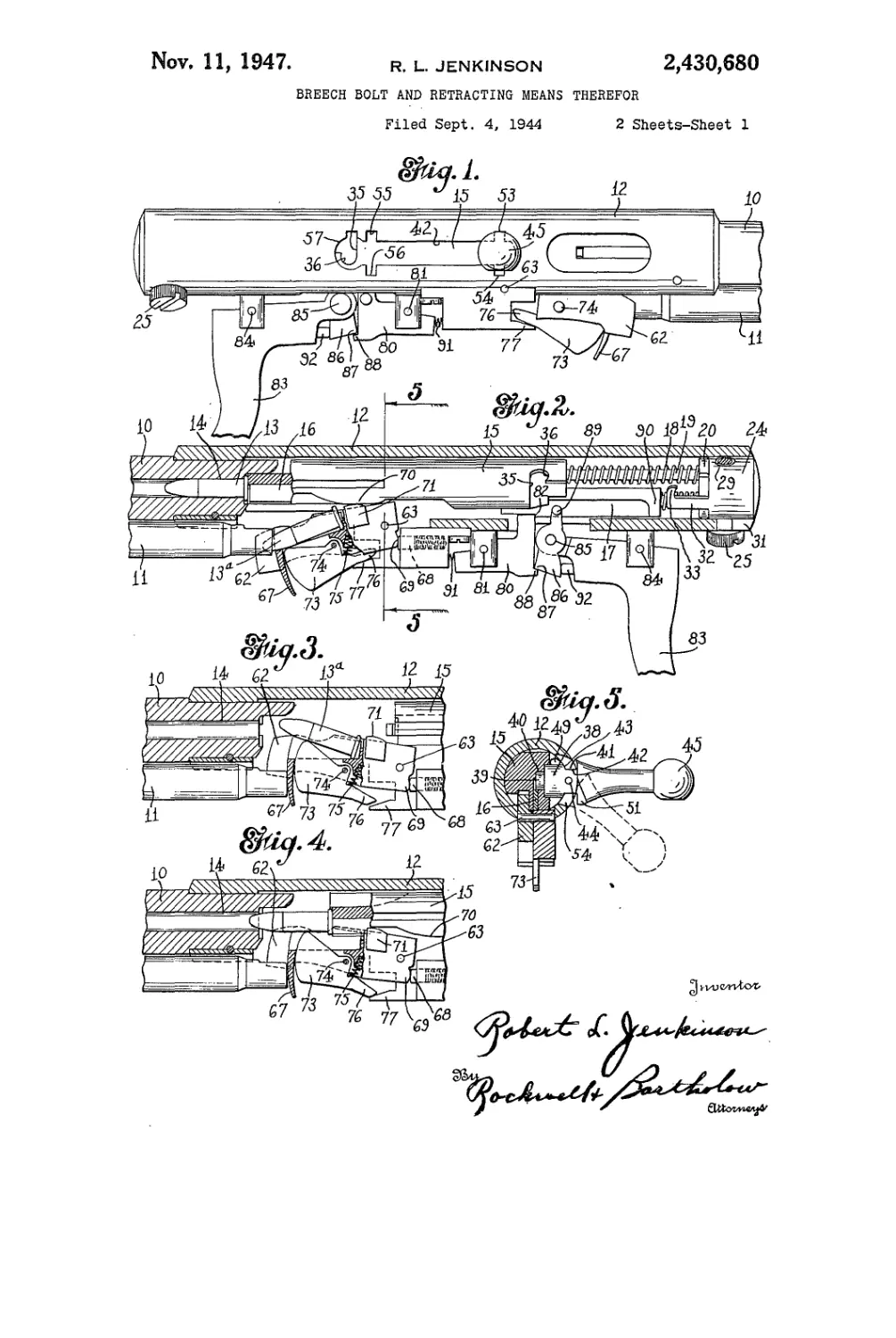
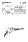
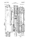
Fig. 1 is a side elevational view of the receiver
portion of a firearm embodying my invention;
Fig. 2 is a longitudinal sectional view of the
20 parts shown in Fig. 1;
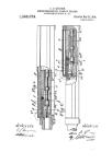
Fig. 3 is a fragmentary sectional view similar
to Fig. 2, but showing the cartridge carrier in
another position;
Fig. 4 is a view similar to Fig. 3, showing still
25 another position of the parts when a fresh car-
tridge is about to be inserted into the chamber;
Fig. 5 is a sectional view on line 5—5 of Fig. 2;
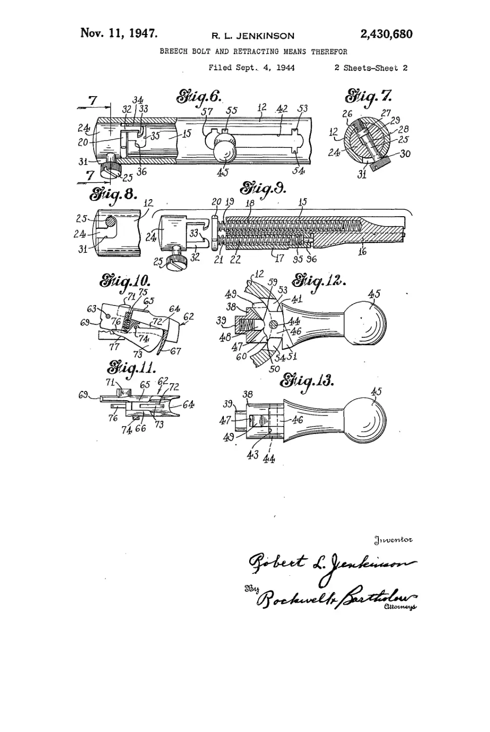
Fig. 6 is a side elevational view, partly in sec-
tion, of the rear end of the receiver, showing the
30 provision for coupling together the bolt and the
receiver plug or bumper;
Fig. 7 is a sectional view on line 7—7 of Fig. 6;
Fig. 8 is a side elevational view of the rear
end of the receiver from a slightly different angle
35 from that shown in Fig. 1;
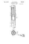
Fig 9 is an exploded view of the receiver bump-
er and bolt, the latter being shown in section;
Fig. 10 is a detail view of the cartridge car-
rier;
40 Fig. 11 is a top plan view of the carrier shown
in Fig. 10;
Fig. 12 is an enlarged view of the bolt handle
and associated structure, certain parts being
shown in section for the sake of clearness; and
45 Fig. 13 is a side elevational view of the bolt
handle.
To illustrate a preferred embodiment of my
invention I have shown my improvements as ap-
plied to a repeating rifie having a barrel 10, mag-
50 azine it and receiver 12, a cartridge 13 being
shown in Fig. 2 in the chamber 14.
Within the receiver is mounted a bolt 15 de-
signed to be retracted by the recoil from the firing
of the cartridge, the bolt having slidably mounted
55 therein a firing pin t6 (Fig. 9) adapted to be ac-
2,430,680
4
handle in place and engaged with the bolt, and
the engagement of the reduced neck portion of
the member 38 prevents any rotary movement of
the bolt in the receiver.
Pivoted to the member 33 on a pin 44 is the bolt
handle 45, this handle being provided with a stem
46. received within a slot 47 in the member 38,
and a spring-pressed plunger 48 engages the in-
ner surface of the stem to releasably hold the
handle in a predetermined position. The width
of the body of the stem 46 is substantially that
of the- slot 42; but' at its inner end the stem is
somewhat enlarged laterally or circumferential-
ly of. the receiver to-provide a locking lug 49 and
IS a guide lug. 50i Also provided on the handle 45
opposite the lug:49-is a second locking lug 5!, and,
as shown in Figs. 1 and 6, the longitudinal slot 42
in the receiver in which the bolt handle slides is
provided: with laterally extending recesses 53 and
2Q 54 adjacent its front end, similarly arranged re-
cesses 55 and 56 adjacent its rear end, and an
opening of keyhole shape 57 at. its rear end.
As shown in Fig. 5,. the handle 45 may be swung
through a small angle about the pivot pin 44.
25 When the handle stands- in. the full-line position
shown in Fig. 5, the. gun will operate as a semi-
automatic gun, as the bolt will be free to move
rearwardly under the impulse of the recoil, due
to the. discharge of the cartridge. If, however,
30 it.is not desired-to. have automatic operation, but
to use the.gun as a single-shot firearm, the handle
45 is moved, to the dotted-line position shown in
this figure. This-effects engagement of the lock-
ing lug 49 in the recess 53 at the forward end of
35 the slot 42, and also engagement of the locking
lug. 5! in the recess 54, and prevents the bolt
being moved back by the force of the recoil. The
operator may, after discharge of the gun, swing
the handle. 45 to-its full-line position, and there-
40 after retract the bolt by means of the handle,
thus throwing a new cartridge into the. chamber
and. cocking the gun;
To remove the bolt and-associated mechanism-
from the receiver, the operator- moves the handle
45 45 and bolt rearwardly. to the position shown in
Fig. 6, and’ then, swings the handle through, a
slight angle, about its pivot to engage, the locking-
lugs 49. and- 51. in the recesses: 55 and. 56,. and-thus,
prevent, the return.of the. bolt-by its.spring. The-
50 bolt is now in position shown in Fig. 6, wherein
the hooked-ends 33.register.with.the.circumferen-
tial.portion 35. of. the bolt slot. If now. the screw
25. is. loosened and- the-bumper, 24 given- a slight
turn,, the, hooked ends 33- of the- fingers- 3.2 will-
65 engage the shoulders 36- of the slot portions 35
and lock, the bumper and-bolt together. Thus-
the return of the bolt, will now be prevented be-
cause it is locked, to the bumper, and the handle
45-may be disengaged,from the slots 55 and 56.
Normally the bolt is never retracted to a greater
extent, than shown in Fig. 6, as in this position it
is against the. disk. 20,. which in. turn is. against,
the bumper 24. However, when the bumper is
rotated through a slot angle to bring the fingers
32' into engagement with the shoulders 36‘, the
screw 25 is moved into the longitudinal portion
of the slot 31; thus'permitting the bumper to be'
moved-longitudinally out'of the receiver; There-
fore, the-bolt may now be moved* a-slight distance
70 rearwardly by the handle 45 from the position
shown in Fig; 6, until the- post- 381 of the handle
stands in the keyhole-shaped* portion 57 of the
slot 42. This permits the entire handle mecha-
nism, shown in Fig. 13- for example, to- be with-
75 drawn freely from the bolt, so that the bolt and
3
tuated by a striker 17, also slidably associated
with the bolt. A bolt spring 18 serves to urge the
bolt forwardly, this spring being disposed within
a recess in the bolt and surrounding a pin 19 se-
cured to a disk-like member 20. Also secured to 5
the member 20 is a pin 21 surrounded by a striker
spring 22 disposed within a recess or opening in
the striker 17.
As shown in Fig. 6, the member 20, against
which the springs 18 and 22 react, abuts against 10
a bumper or plug 24 which closes the rear end of
the receiver. This bumper is held in place by a-
screw 25 (Fig. 7) which is rotatably mounted: in-
the bumper and threaded into an opening in the
receiver, as shown at 26. The screw 25 is- also
capable of movement in the direction of its length-
in the bumper, but is prevented from being re-
moved entirely by a collar 27 on the screw which
bears against the bottom shoulder 28 of an en-
larged recess 29 forming a continuation of the
opening in the bumper 24. in which, the screw is
disposed.
The portion of the screw adjacent the head 39'
projects through the receiver and' is received' in
an L-shaped slot 31 (Fig. 8), thus forming a bay-
onet joint between these two parts. It will be
obvious that when the screw is in the. position
shown in Fig. 7, in which it is threadedly en-
gaged with the receiver at 26., the bumper is.
locked to the receiver. However, when the screw
has been backed off sufficiently to disengage: its
threads from the receiver, it may be.given a slight
movement of rotation in the lateral or circumfer-
ential portion of the slot 31, and then, by a longi-
tudinal movement, thebumper may be withdrawn
from the receiver.
As shown more especially in Figs. 6 and 9, the
bumper is provided with a- pair of prongs or
fingers 32, each having a hook-shaped end- 33.
Each of these prongs is adapted1 to-be received in
an L-shaped slot in the bolt, this slot having- a
longitudinal or axial portion- 34 and a: transverse
or circumferential portion 35. In the normal po-
sition of the parts shown in Figs. 6, 7 and 8, the
fingers 32 are not in locked engagement with the
bolt, but slide freely through the-longitudinal por-
tion 34 of the slot in-the bolt, so that the bolt has
free reciprocating movement in the operation cf
the gun. However, when the screw- 25. is disen-
gaged from the receiver and-given a partial rotary
motion as permitted by the L-shaped’slot 31, the-
hooked ends 33 of the fingers'32 engage the'shoul-
der 33 of the circumferentialportion.of the slot in
the bolt and lock the bolt and- bumper together.
At this time, as will be presently explained, the
bumper, together wtih the bolt and. associated
parts, may be freely withdrawn from the-receiver;.
It will be understood that at this time the-disk
20 will be clamped between the bumper and
springs so that this withdrawal will not be af- flo
fected by the tension of the springs 18 and 22;
the tension of which will be carried by the locked
engagement of- the bumper and bolt so that the
entire bolt mechanism will be withdrawn as. a
unit. 96
The bolt handle mechanism is shown more
especially in Figs. 5, 12 and 13,. and; comprises a
cylindrical post or plug 38 having at its. inner'end'
a reduced portion 39 freely socketed’ima recess 49
in the bolt. The sides of the member: 38 are flat-
tened or cut away adjacent: its outer end, as
shown at 41, to provide a reduced neck: portion
which slides- in the slot 42 in the receiver,, the-
shoulders 43 beyond these cut-away portions' en-
gaging the. inner: edges: of this slot: to: hold: the.
2,430,680
5
bumper assembly are loose in the receiver and
may be freely withdrawn as a unit, the parts being
held together by the engagement of the hooked
ends 33 of the fingers 32 in the slots 35, with the
springs compressed between these two parts. The
parts may, of course, be reassembled by reversing
the process just described, and it will be obvious
that this provides an easy and convenient way
for removing the operating parts from the re-
ceiver when such is desired. It will also be under-
stood that normally the handle 45 cannot be dis-
engaged from the bolt due to the fact that the
body portion of the post 33 is larger than the slot
42, and the shoulders below the flattened portion
41 prevent the handle being removed through this
slot. The recesses 53, 54, 55 and 56 merely permit
the swinging of the handle member 45 from full
to dotted-line position shown in Fig. 5, but do
not permit the withdrawal of the post 38 there-
through. The lower end of the stem 46 is pro-
vided with recesses 59 and 69 to receive the
plunger 48, and thus releasably hold the handle
in either its full or dotted-line position.
At the rear of the magazine 11, a carrier or
cradle 62 is pivotally attached to the receiver at
63. This carrier is shown more especially in Fig.
11, and is provided with a hollow body portion 64
adapted to receive the cartridge, which body por-
tion opens upwardly so that the cartridge may
be delivered through this opening to the chamber.
At the rear portion of the cradle, overhanging
flanges 65 and 66 are provided to hold the car-
tridge in the cradle until it has been moved for-
wardly to some extent by the bolt. Also adjacent
its forward end the carrier is provided with a tail
portion 67 to close the opening at the rear of the
magazine when the carrier is lifted to transfer
a cartridge to the receiver. A spring-pressed
plunger 68, mounted in a portion of the receiver,
engages the lower rear corner 69 of the carrier,
tending to swing the carrier upwardly about its
pivot 63. As shown more especially in Fig. 2, this
upward movement is prevented when the bolt is
in its forward breech-closing position by a cam
surface 70 formed on the bolt, which engages a
lug 71 on the carrier disposed forwardly of its
pivot. However, when the bolt is moved rear-
wardly and the cam surface disengages the lug
71, the spring is then free to swing the forward
end of the latter upwardly about its pivot and
transfer a fresh cartridge into position to be
moved into the chamber.
As shown more especially in Figs. 10 and 11, the
body portion 64 of the carrier is provided with
a slot 72, and a lifting finger 73 is pivoted to the
carrier at 74 and designed to project through
this slot under the force of a spring 75 mounted
in the carrier and acting against a tail portion
76 of the finger 73. Movement of this finger
may be limited by a stop 77 formed on a part of
the receiver, and adapted to engage the tail por-
tion 76 when the lifting finger has been moved
upwardly to its furthest extent, as shown in Fig. 4.
The operation of this cartridge transfer mech-
anism may now be described. As shown in Fig. 2,
the gun is in cocked position ready to be dis-
charged. When the cartridge i3 is fired, the
bolt 15 is forced rearwardly, thus moving the
cam surface 70 from, engagement with the lug
71. The carrier 62 is then thrown upwardly
about its pivot 63 by the spring-pressed plunger
68 to the position shown in Fig. 3, wherein the
fresh cartridge I3a is in position to be forced
into the chamber. It will be noted that the rear
end of the cartridge is in engagement with the
5
10
15
20
25
30
35
40
45
50
55
60
65
70
75
6
overhanging flanges 65 and 66, and thus the lift-
ing finger 73 is held downwardly against the
tension of its spring 75 by the engagement of
the forward end of this finger with the cartridge.
The bolt is now moved forwardly by the bolt
spring 18, and the forward end of the bolt en-
gages the rear end of the cartridge, moving it
forwardly out of engagement with the flanges
65 and 66. At this time the spring 75 moves
the forward end of the lifting finger upwardly to
a slight extent, thus moving the rear end of the
cartridge upwardly so that the latter is in a
correct position to enter the chamber. It will
be noted that the lifting finger 73 has a delayed
action, and a slight movement under impulse of
its spring independently of the carrier 62 in order
to properly position the cartridge in front of the
chamber.
When the bolt is returned to its forward po-
sition, shown in Fig. 2, the cam surface 70 re-
engages the lug 71, thus moving the carrier down-
wardly into the position shown in Fig. 2. At this
time the tail 76 of the lifting finger 73 engages
the stop 77, and the lifting finger is moved in a
reverse direction about its spring so that its
forward end is lowered in the slot 72, thus per-
mitting a fresh cartridge to slide from the maga-
zine into the body portion or cradle of the car-
rier without interference.
A sear 80 is pivoted at 81 to the receiver, the
sear engaging at its upper rear corner a bent 82
formed on the striker 17, the sear being actuated
by a trigger S3 of the usual form, pivoted to the
receiver at 84. Pivoted to the forward end of
the trigger at 85 is a dog 86 having a corner 87
engaging a bent 83 on the sear to move the latter
downwardly about its pivot 81 out of engagement
with the bent 82 of the striker when the trigger
is pulled.
Usually the trigger will be pulled rearwardly
a sufficient distance to disengage the members
87 and 83, so that the sear 88 will be free im-
mediately after it is released to move upwardly
again and engage the bent 32 of the striker when
the latter is carried rearwardly with the hammer
after discharge. However, this disengagement is
insured by a lug 83 at the upper end of the con-
nector member 86, which lug is engaged by a
portion 99 on the striker 17, so that, as the
striker reaches its forward position to discharge
the shell, the connecting member 8G will be moved
about its pivot 85 and disengaged from the sear
80, thus permitting the latter to be moved up-
wardly or in a counterclockwise direction by its
spring 9f. The member 86 is normally held in
engagement with the sear by a spring-pressed
plunger 92 carried by the trigger 83.
The striker spring, as shown in Fig. 9, acts at
its front end against a headed pin 95, slidably
associated with the striker 17 and projecting for-
wardly a slight distance from the front end of
the striker, to engage the shoulder 96 formed on
the bolt adjacent the firing pin 16 when the
striker is in its forward position. It will thus be
seen that the tension of the spring 22, after the
gun has been discharged and the striker is in its
forward position, is borne by the pin 95 and not
by the striker itself. Therefore, when the parts
are in this position the striker will have slight
play to and fro, which permits the firing pin to
assume a retracted position out of engagement
with a cartridge in the chamber. It will, of
course, be understood that when the gun is dis-
charged the inertia of the forward movement of
the striker under impulse of the spring 22 will
2,430,680
7
cause the striker to drive forwardly against the
shoulder 9S, as the pin 95 is slidably mounted in
the striker. The impact of the striker, however,
against this shoulder will cause it to return
slightly, to the position shown in Fig. 9, thus also
permitting the firing pin IS to return from its
extreme forward position, so that its front end is
flush with the adjacent portion of the bolt, as
shown in this figure.
While I have shown and described a preferred
embodiment of my invention, it will be under-
stood that it is not to be limited to all of the
details shown, but is capable of modification and
variation within the spirit of the invention and
within the scope of the claims.
What I claim is:
1. A firearm comprising a receiver, a bolt re-
ciprocably mounted therein longitudinally of the
receiver, said receiver having a longitudinally
extending slot in the wall thereof, a plug remov-
ably engaged with the bolt, a handle pivoted to
the plug to swing in a plane transverse to the
movement of the bolt and means on the handle
to engage with a part of the slot and restrain the
bolt against longitudinal movement.
2. A firearm comprising a receiver, a bolt re-
ciprocably mounted therein longitudinally of the
receiver, said receiver having a longitudinally
extending slot in the wall thereof, a plug remov-
ably engaged with the bolt, a handle pivoted to
the plug to swing in a plane transverse to the
movement of the bolt, said plug being disposed in
a recess in the bolt and normally retained therein
by engagement of the handle with the edges of
the slot and means on the handle to engage with
a part of the slot and restrain the bolt against
longitudinal movement.
3. A firearm comprising a receiver, a bolt re-
ciprocably mounted therein longitudinally of the
receiver, said receiver having a longitudinally
extending slot in the wall thereof, a plug remov-
ably engaged with the bolt, a handle pivoted to
the plug to swing in a plane transverse to the
movement of the bolt, means on said handle to
engage with a part of the slot and restrain the
5
10
15
20
25
30
35
40
45
8
bolt against longitudinal movement said plug
being disposed in a recess in the bolt and nor-
mally retained therein by engagement of the
handle with the edges of the slot, and said slot
having an enlarged portion permitting detach-
ment of the handle and plug from the bolt when
the handle is moved to a position opposite the
enlarged portion.
4. A firearm comprising a receiver, a bolt re-
ciprocably mounted therein, said receiver having
a longitudinally extending slot in the wall thereof,
a plug removably engaged with the bolt, a handle
pivoted to the plug to swing in a plane transverse
to the movement of the bolt, said plug being dis-
posed in a recess in the bolt and normally retained
therein by engagement of the handle with the
edges of the slot, a bumper closing the rear end
of the receiver, interengageable means on the
rear end of the bolt and the front end of the
bumper for connecting the bumper and bolt to-
gether upon movement of the bolt to its rearmost
position, whereby the bolt may be removed from
the receiver by removal of the bumper therefrom.
ROBERT L. JENKINSON.
REFERENCES CITED
The following references are of record in the
file of this patent:
UNITED STATES PATENTS
Number Name Date
2,146,941 Crockett Feb. 14, 1939
1,637,235 Norman July 26, 1927
2,099,035 Rowley Nov. 16, 1937
2,214,071 Swebilius Sept. 10, 1940
1,178,747 Nelson Apr. 11, 1916
2,296,242 Brewer Sept. 22, 1942
2,072,197 Bergmann _ Mar. 2, 1937
1,586,048 Schmeisser May 25, 1926
1,433,945 Eickhoff . Oct. 31, 1922
2,337,150 Burton FOREIGN PATENTS . Dec. 21, 1943
Number Country Date
175,582 Great Britain Jan. 27, 1922