/


Tags: weapons
Year: 1965


Text
FM 23-11
DEPARTMENT OF THE ARMY FIELD MANUAL
90MM RECOILLESS RIFLE, M67
This copy is a reprint which includes
current changes in iorce -- C 2 aid C 3,
These changes arc located at the back
of this publication.
EADQUARTERS, DEPARTMENT OF THE ARMY
JULY 1965
*FM 23-11
Field Manual
No. 23-11
HEADQUARTERS
DEPARTMENT OF THE ARMY
Washington, D.C., 6 July 1966
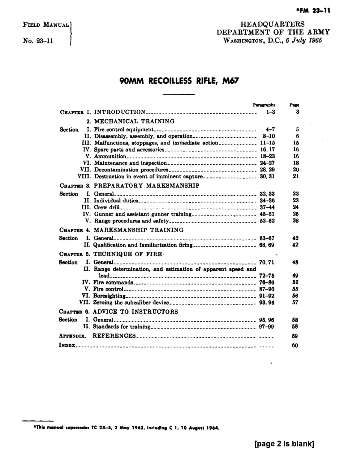
90MM RECOILLESS RIFLE, M67
Paragraphs Page
Chapter 1. INTRODUCTION_______________________________________ 1-3 3
2. MECHANICAL TRAINING
Section I. Fire control equipment____________________________ 4-7 5
II. Disassembly, assembly, and operation_______________ 8-10 6
III. Malfunctions, stoppages, and immediate action_____ 11-15 15
IV. Spare parts and accessories_______________________ 16,17 16
V. Ammunition________________________________________ 18-23 16
VI. Maintenance and inspection________________________ 24-27 18
VII. Decontamination procedures________________________ 28,29 20
VIII. Destruction in event of imminent capture__________30,31 21
Chapter 3. PREPARATORY MARKSMANSHIP
Section I. General________________________________________ 32,33 23
II. Individual duties_________________________________ 34-36 23
HI. Crew drill________________________________________ 37-44 24
IV. Gunner and assistant gunner training______,_______45-51 25
V. Range procedures and safety___________-___________ 52-62 38
Chapter 4. MARKSMANSHIP TRAINING
Section I. General________________________________________ 63-67 42
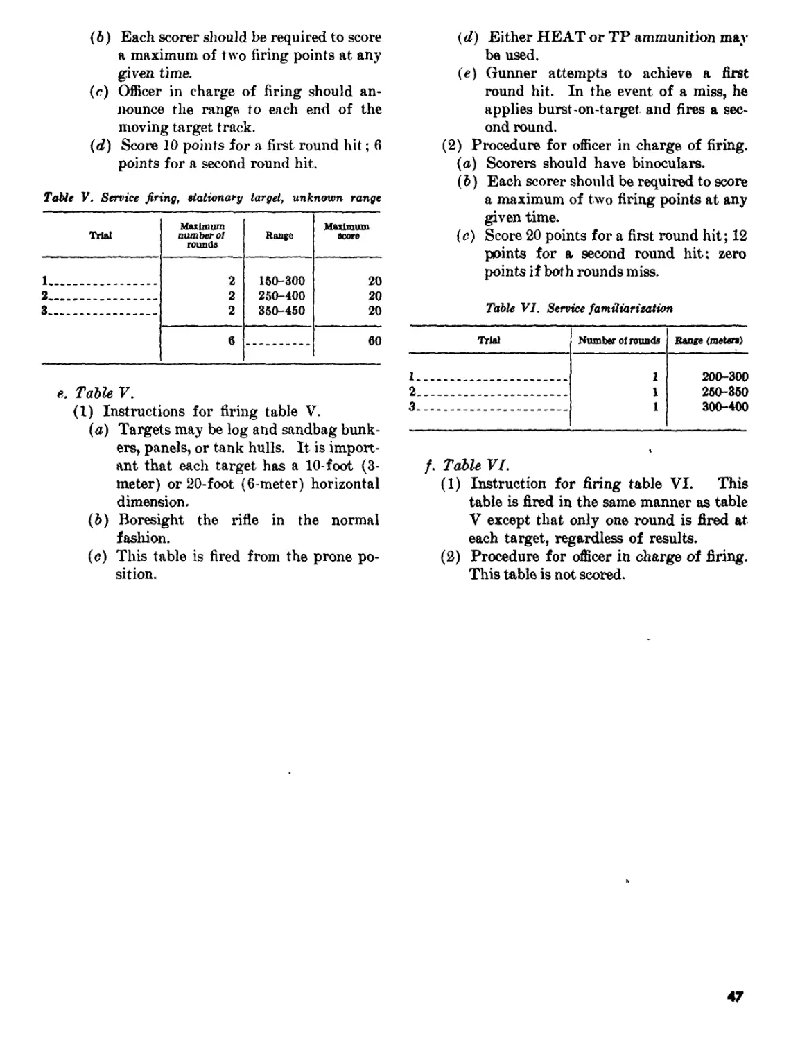
II. Qualification and familiarization firing__________ 68, 69 42
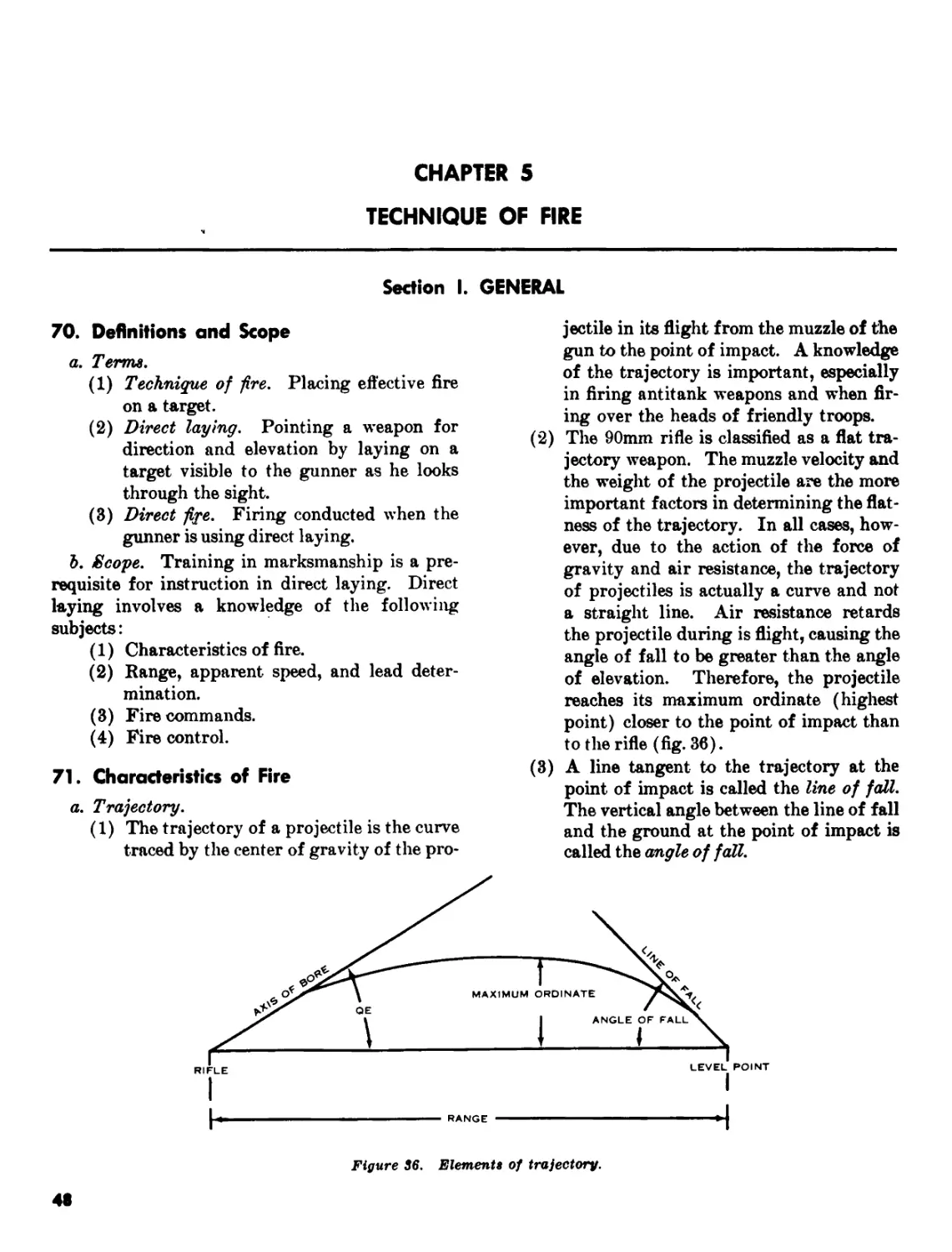
Chapter 5. TECHNIQUE OF FIRE
Section I. General_________________________________________70,71 48
II. Range determination, and estimation of apparent speed and
lead-_________________________________________________ 72-75 49
IV. Fire commands_____________________________________ 76-86 52
V. Fire control______________________________________ 87-90 55
VI. Boresighting______________________________________ 91-92 56
VII. Zeroing the subcaliber device_____________________ 93,94 57
Chapter 6. ADVICE TO INSTRUCTORS
Section I. General____________________________________________ 95,96 58
II. Standards for training_____________________________ 97-99 58
Appendix. REFERENCES_______________________________________________ 59
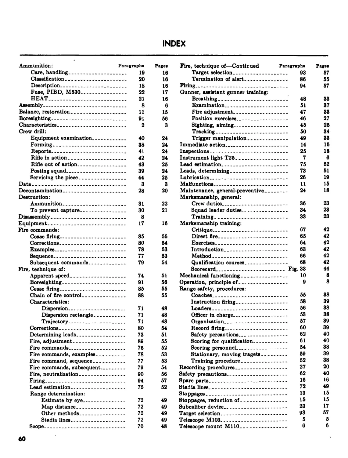
Index______________________________________________________________ 60
•ТЫ» manual supurtudes TC 23-5, 2 May 1962, Including С 1, 10 August 1964.
[page 2 is blank]
CHAPTER 1
INTRODUCTION
1. Purpose and Scope
a. This manual provides information for train-
ing personnel to operate the 90mm recoilless rifle,
M67. It includes mechanical training, fire control
instruments, spare parts and equipment, mainte-
nance, ammunition and fuzes, crew drill, marks-
manship, technique of fire, and advice to
instructors concerning the weapon. The material
presented herein is applicable to nuclear and
nonnuclear warfare.
b. For information pertaining to detailed disas-
sembly and assembly, refer to TM 9-1015-223-12.
c. Doctrine in FM 7-11 on the tactical employ-
ment of the platoon antitank weapon applies to
the 90mm rifle, M67.
d. Users of this manual are encouraged to sub-
mit recommended changes or comments to improve
the manual. Comments should be keyed to the
specific page, paragraph, and line of the text in
which the change is recommended. Reasons
should be provided for each comment to insure un-
derstanding and complete evaluation. Comments
should be forwarded direct to the Commandant,
United States Army Infantry School, Fort Ben-
ning, Ga., 31905.
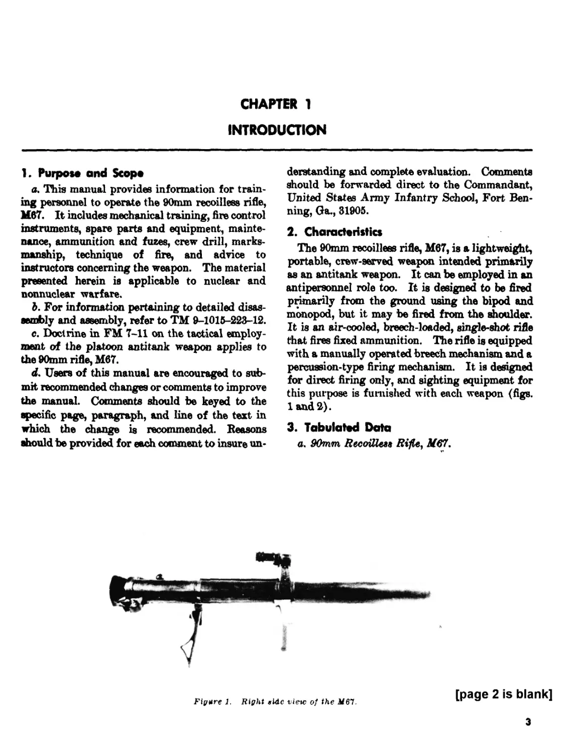
2. Characteristics
The 90mm recoilless rifle, M67, is a lightweight,
portable, crew-served weapon intended primarily
as an antitank weapon. It can be employed in an
antipersonnel role too. It is designed to be fired
primarily from the ground using the bipod and
monopod, but it may be fired from the shoulder.
It is an air-cooled, breech-loaded, single-shot rifle
that fires fixed ammunition. The rifle is equipped
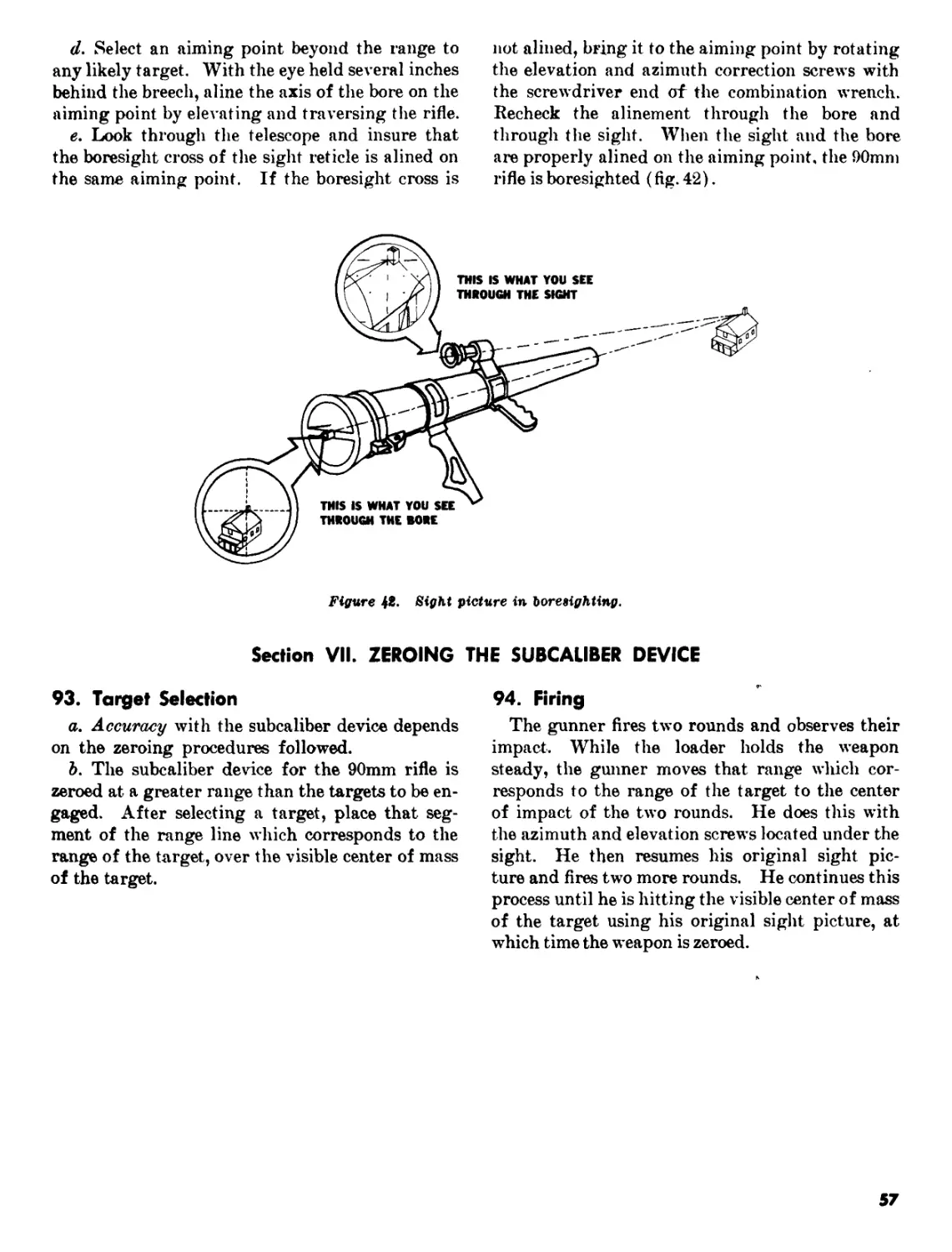
with a manually operated breech mechanism and a
percussion-type firing mechanism. It is designed
for direct firing only, and sighting equipment for
this purpose is furnished with each weapon (figs.
1 and 2).
3. Tabulated Data
a. 90mm RecoiUeM Rifle, M67.
Figure J. Right elde view of the
[page 2 is blank]
3
с
Figure 2. Left side view of the M67.
(1) Weight:
Complete system (unloaded) __ 35 pounds.
Telescope with mount and
instrument light----------------2% pounds.
(2) Overall length______________58 inches,
(8) Height, ground mounted
(apprdx.) ______________________17 inches.
(4) Maximum tang® (approx.) -- 2,100 meters.
(h) Maximum range (as deter-
mined by sight graduations) - 800 meters.
(6) Maximum effective range — 450 meters.
(7) Rates of fire----------------Rapid: 1 round
each 6 seconds,
not to exceed 5
rounds.
Sustained: 1
round per min-
ute indefinitely.
Note.* When firing the rapid rate of fire, a IS-mlnute
cooling period must be observed after every five rounds.
b. Ammunition,
(1)* Type used HEAT 9% pounds... TP. 9% pounds.
(2) Weight of round (approx.).
(3) Weight of pro- jectile (approx.). 6% pounds... pounds.
(4) Muxzle velocity (approx.). 700 feet per second. 700 feet per second.
CHAPTER 2
MECHANICAL TRAINING
Section I. FIRE CONTROL EQUIPMENT
4. General
In order to keep the M67 operating effectively,
all crew members must know the following:
a. Disassembly and assembly of the weapon to
the extent authorized.
b. Common causes of stoppages.
c. Immediate actions to clear the weapon.
d. Maintenance procedures.
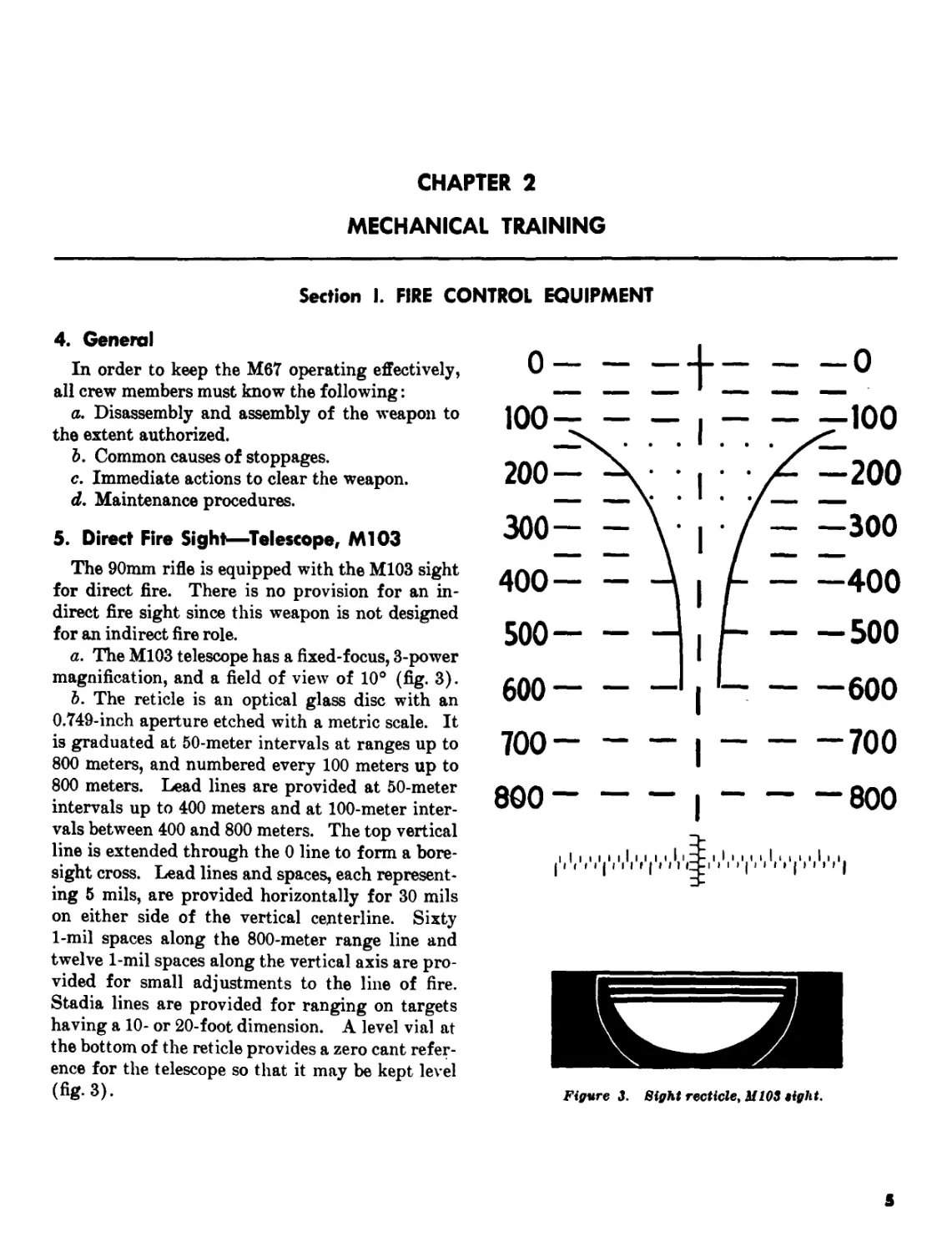
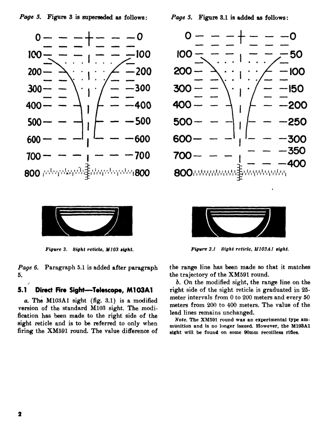
5. Direct Fire Sight—Telescope, Ml03
The 90mm rifle is equipped with the M103 sight
for direct fire. There is no provision for an in-
direct fire sight since this weapon is not designed
for an indirect fire role.
a. The M103 telescope has a fixed-focus, 3-power
magnification, and a field of view of 10° (fig. 3).
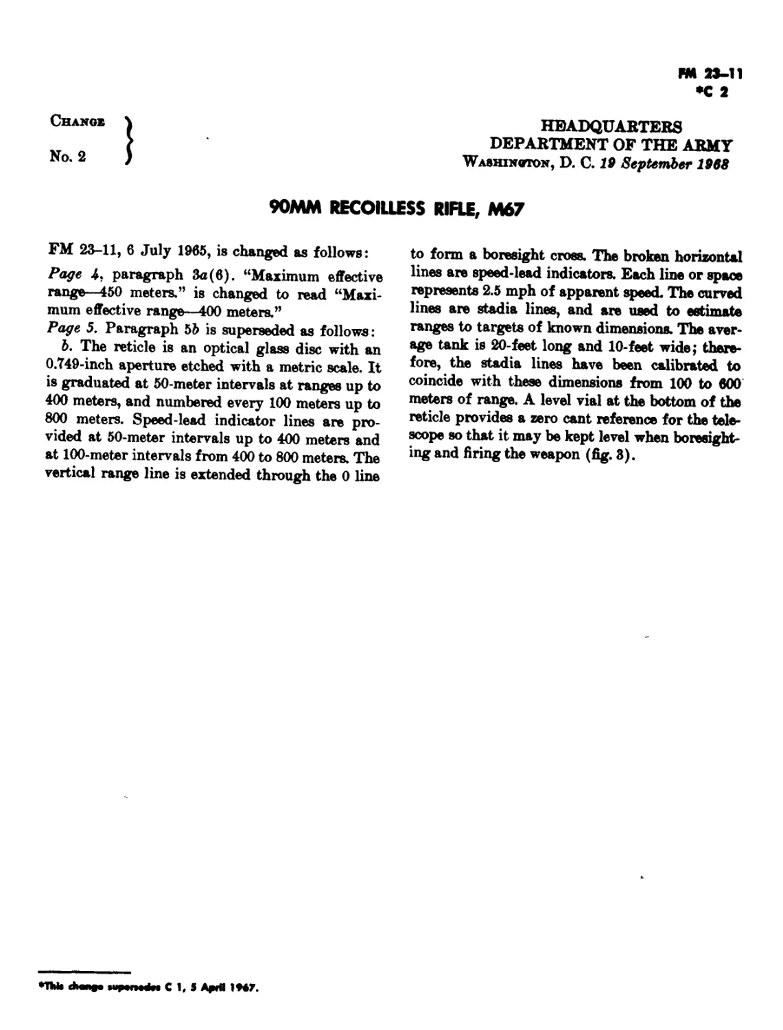
b. The reticle is an optical glass disc with an
0.749-inch aperture etched with a metric scale. It
is graduated at 50-meter intervals at ranges up to
800 meters, and numbered every 100 meters up to
800 meters. Lead lines are provided at 50-meter
intervals up to 400 meters and at 100-meter inter-
vals between 400 and 800 meters. The top vertical
line is extended through the 0 line to form a bore-
sight cross. Lead lines and spaces, each represent-
ing 5 mils, are provided horizontally for 30 mils
on either side of the vertical centerline. Sixty
1-mil spaces along the 800-meter range line and
twelve 1-mil spaces along the vertical axis are pro-
vided for small adjustments to the line of fire.
Stadia lines are provided for ranging on targets
having a 10- or 20-foot dimension. A level vial at
the bottom of the reticle provides a zero cant refer-
ence for the telescope so that it may be kept level
(fig.3).
Figure 3. Sight recticle, M103 eight.
S
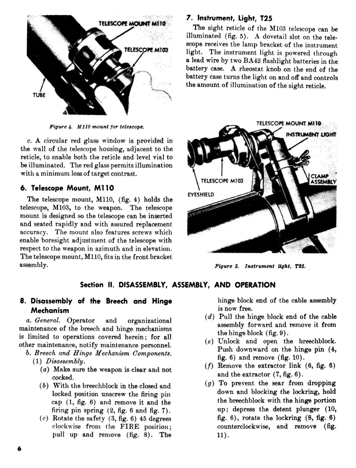
Figure 4- MHO mount for telescope.
c. A circular red glass window is provided in
the wall of the telescope housing, adjacent to the
reticle, to enable both the reticle and level vial to
be illuminated. The red glass permits illumination
with a minimum loss of target contrast.
6. Telescope Mount, Ml 10
The telescope mount, MHO, (fig. 4) holds the
telescope, M103, to the weapon. The telescope
mount is designed so the telescope can be inserted
and seated rapidly and with assured replacement
accuracy. The mount also features screw’s which
enable boresight adjustment of the telescope with
respect to the weapon in azimuth and in elevation.
The telescope mount, MHO, fits in the front bracket
assembly.
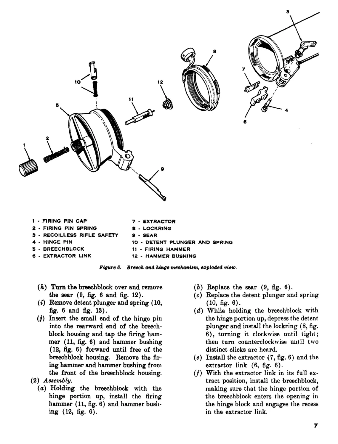
7. Instrument, Light, T25
The sight reticle of the M103 telescope can be
illuminated (fig. 5). A dovetail slot on the tele-
scope receives the lamp bracket of the instrument
light. The instrument light is powered through
a lead wire by two BA42 flashlight batteries in the
battery case. A rheostat knob on the end of the
battery case turns the light on and off and controls
the amount of illumination of the sight reticle.
Figure 5. Instrument light, T25.
Section II. DISASSEMBLY, ASSEMBLY, AND OPERATION
8. Disassembly of the Breech and Hinge
Mechanism
a. General. Operator and organizational
maintenance of the breech and hinge mechanisms
is limited to operations covered herein; for all
other maintenance, notify maintenance personnel.
Ъ. Breech and Hinge Mechanism Components.
(1) Disassembly.
(a) Make sure the weapon is clear and not
cocked.
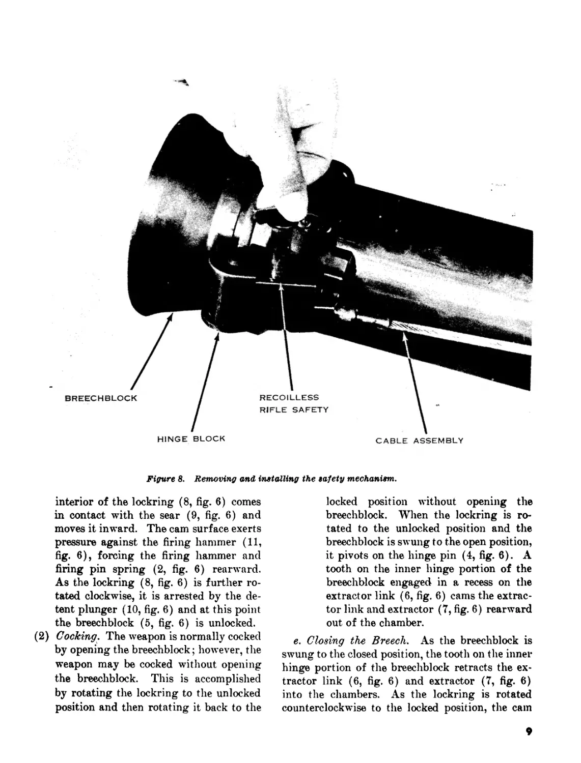
(&) With the breechblock in the closed and
locked position unscrew the firing pin
cap (1, fig. 6) and remove it and the
firing pin spring (2, fig. 6 and fig. 7).
(c) Rotate the safety (3, fig. 6) 45 degrees
clockwise from the FIRE position;
pull up and remove (fig. 8). The
hinge block end of the cable assembly
is now free.
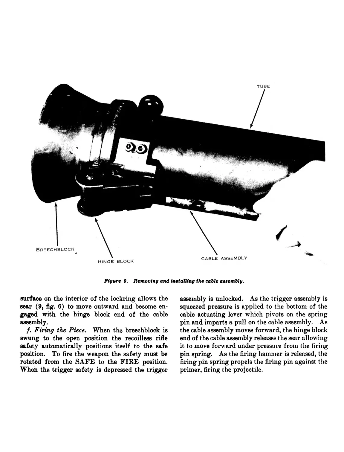
(d) Pull the hinge block end of the cable
assembly forward and remove it from
the hinge block (fig. 9).
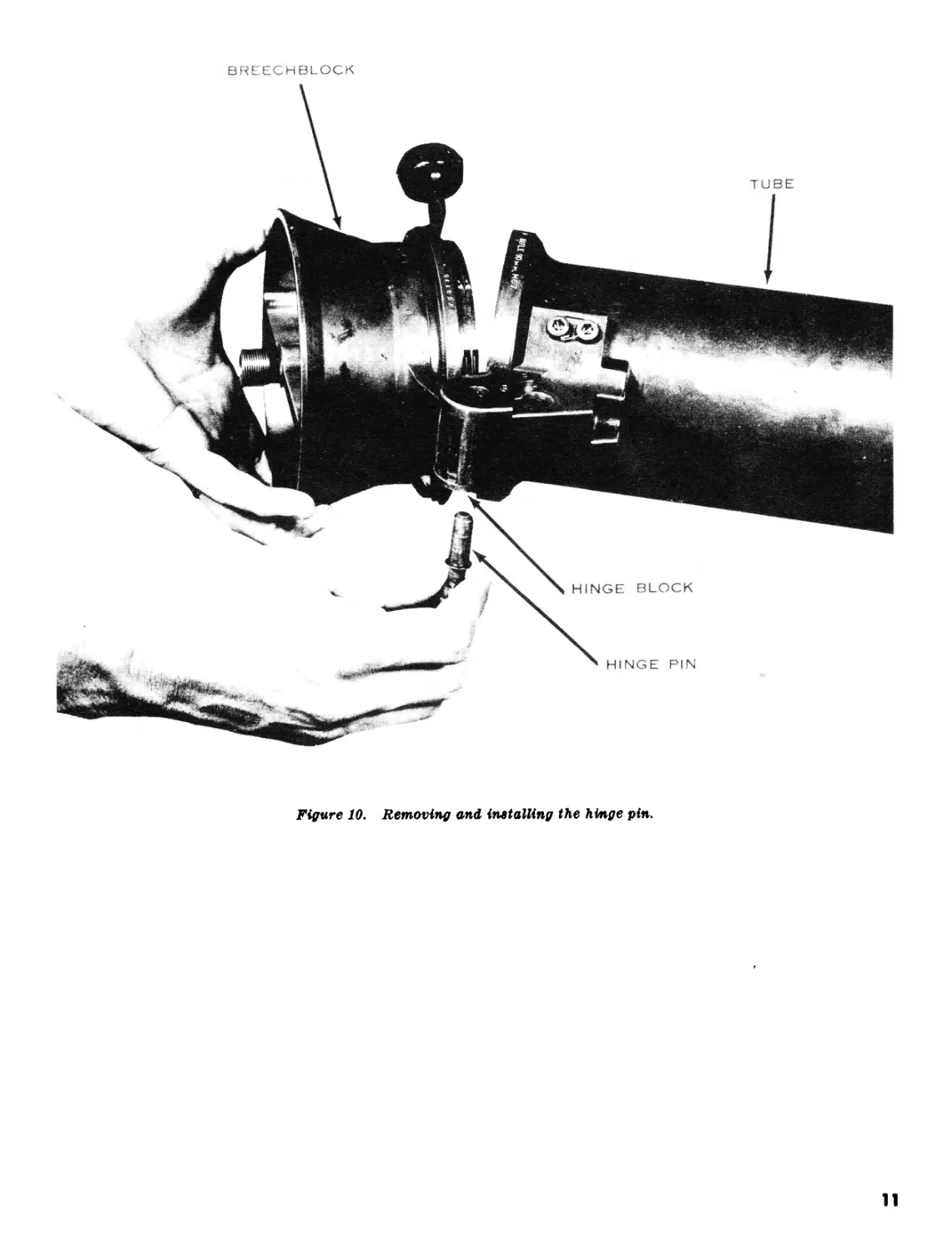
(e) Unlock and open the breechblock.
Push downward on the hinge pin (4,
fig. 0) and remove (fig. 10).
(/) Remove the extractor link (6, fig. 6)
and the extractor (7, fig. 6).
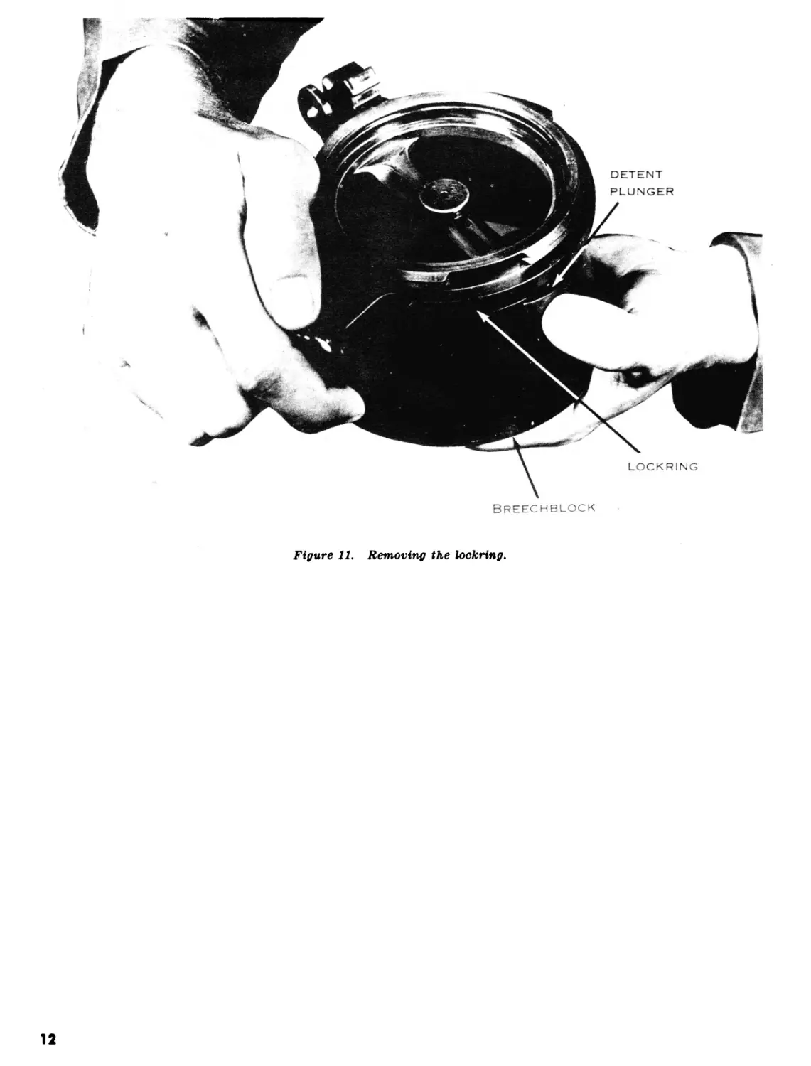
(g) To prevent the sear from dropping
down and blocking the lockring, hold
the breechblock with the hinge portion
up; depress the detent plunger (10,
fig. 6), rotate the lockring (8, fig. 6)
counterclockwise, and remove (fig.
11).
6
3
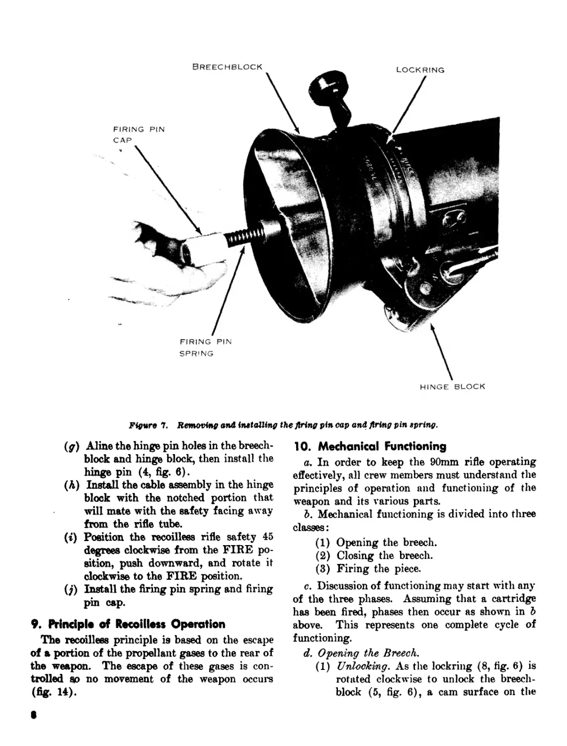
1 - FIRING PIN CAP 7 - EXTRACTOR
2 - FIRING PIN SPRING 8 - LOCKRING
3 - RECOILLESS RIFLE SAFETY 9 - SEAR
4 - HINGE PIN IO - DETENT PLUNGER AND SPRING
5 - BREECHBLOCK 11 • FIRING HAMMER
e - EXTRACTOR LINK 12 - HAMMER BUSHING
Figure 6. Breech and hinge mechanism, exploded view.
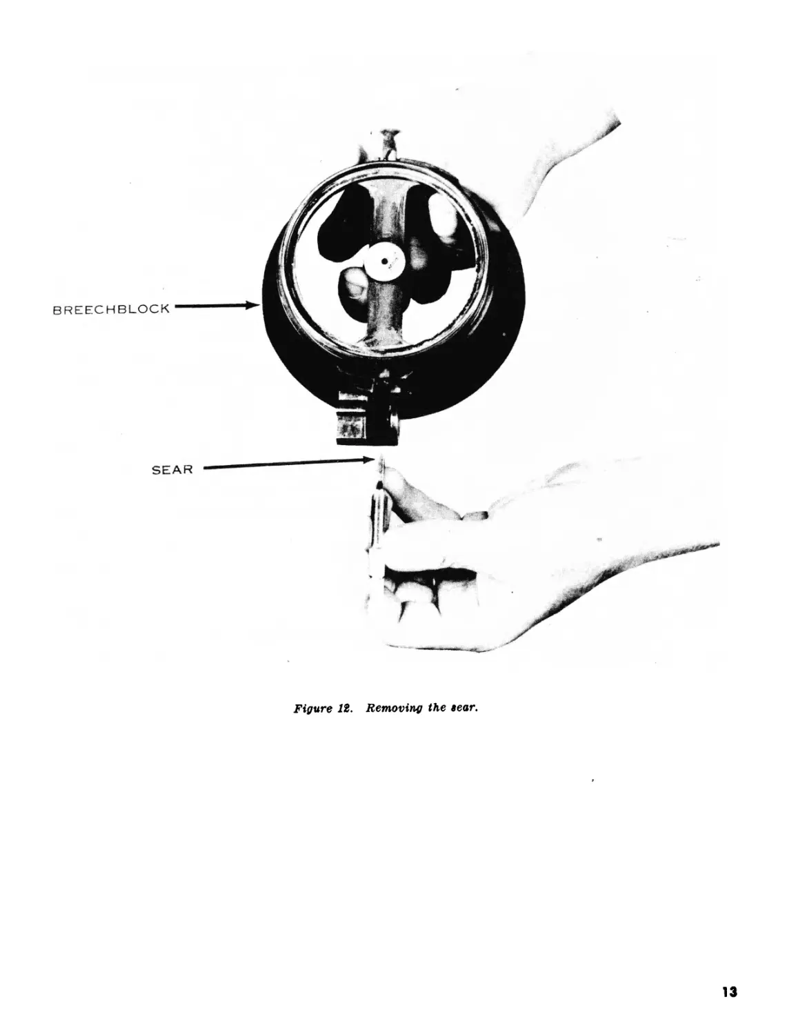
(Л) Turn the breechblock over and remove
the sear (9, fig. 6 and fig. 12).
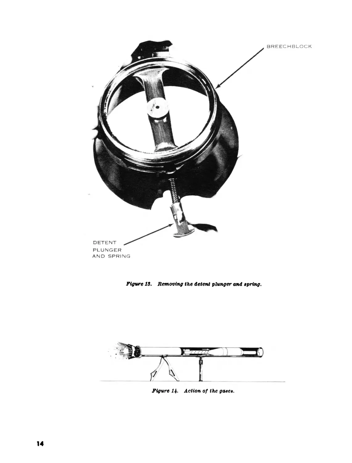
(г) Remove detent plunger and spring (10,
fig. 6 and fig. 13).
(j) Insert the small end of the hinge pin
into the rearward end of the breech-
block housing and tap the firing ham-
mer (11, fig. 6) and hammer bushing
(12, fig. 6) forward until free of the
breechblock housing. Remove the fir-
ing hammer and hammer bushing from
the front of the breechblock housing.
(2) Assembly.
(a) Holding the breechblock with the
hinge portion up, install the firing
hammer (11, fig. 6) and hammer bush-
ing (12, fig. 6).
(&) Replace the sear (9, fig. 6).
(c) Replace the detent plunger and spring
(10, fig. 6).
(d) While holding the breechblock with
the hinge portion up, depress the detent
plunger and install the lockring (8, fig.
6), turning it clockwise until tight;
then turn counterclockwise until two
distinct clicks are heard.
(e) Install the extractor (7, fig. 6) and the
extractor link (6, fig. 6).
(/) With the extractor link in its full ex-
tract position, install the breechblock,
making sure that the hinge portion of
the breechblock enters the opening in
the hinge block and engages the recess
in the extractor link.
7
Breechblock
lockring
Figure 7. Removing and installing the firing pin cap and firing pin spring.
(g) Aline the hinge pin holes in the breech-
block and hinge block, then install the
hinge pin (4, fig. 6).
(A) Install the cable assembly in the hinge
block with the notched portion that
will mate with the safety facing away
from the rifle tube.
(г) Position the recoilless rifle safety 45
degrees clockwise from the FIRE po-
sition, push downward, and rotate it
clockwise to the FIRE position.
(j) Install the firing pin spring and firing
pin cap.
9. Principle of Recoilless Operation
The recoilless principle is based on the escape
of a portion of the propellant gases to the rear of
the weapon. The escape of these gases is con-
trolled sp no movement of the weapon occurs
(fig. 14).
10. Mechanical Functioning
a. In order to keep the 90mm rifle operating
effectively, all crew members must understand the
principles of operation and functioning of the
weapon and its various parts.
b. Mechanical functioning is divided into three
classes:
(1) Opening the breech.
(2) Closing the breech.
(3) Firing the piece.
c. Discussion of functioning may start with any
of the three phases. Assuming that a cartridge
has been fired, phases then occur as shown in b
above. This represents one complete cycle of
functioning.
d. Opening the Breech.
(1) Unlocking. As the lockring (8, fig. 6) is
rotated clockwise to unlock the breech-
block (5, fig. 6), a cam surface on the
Figure 8. Removing and installing the safety mechanism.
interior of the lockring (8, fig. 6) comes
in contact with the sear (9, fig. 6) and
moves it inward. The cam surface exerts
pressure against the firing hammer (11,
fig. 6), forcing the firing hammer and
firing pin spring (2, fig. 6) rearward.
As the lockring (8, fig. 6) is further ro-
tated clockwise, it is arrested by the de-
tent plunger (10, fig. 6) and at this point
the breechblock (5, fig. 6) is unlocked.
(2) Cocking. The weapon is normally cocked
by opening the breechblock; however, the
weapon may be cocked without opening
the breechblock. This is accomplished
by rotating the lockring to the unlocked
position and then rotating it back to the
locked position without opening the
breechblock. When the lockring is ro-
tated to the unlocked position and the
breechblock is swung to the open position,
it pivots on the hinge pin (4, fig. 6). A
tooth on the inner hinge portion of the
breechblock engaged in a recess on the
extractor link (6, fig. 6) cams the extrac-
tor link and extractor (7, fig. 6) rearward
out of the chamber.
e. Closing the Breech. As the breechblock is
swung to the closed position, the tooth on the inner
hinge portion of the breechblock retracts the ex-
tractor link (6, fig. 6) and extractor (7, fig. 6)
into the chambers. As the lockring is rotated
counterclockwise to the locked position, the cam
9
TUBE
Figure 9. Removing and installing the cable assembly.
surface on the interior of the lockring allows the
sear (9, fig. 6) to move outward and become en-
gaged with the hinge block end of the cable
assembly.
/. Firing the Piece, When the breechblock is
swung to the open position the recoilless rifle
safety automatically positions itself to the safe
position. To fire the weapon the safety must be
rotated from the SAFE to the FIRE position.
When the trigger safety is depressed the trigger
assembly is unlocked. As the trigger assembly is
squeezed pressure is applied to the bottom of the
cable actuating lever which pivots on the spring
pin and imparts a pull on the cable assembly. As
the cable assembly moves forward, the hinge block
end of the cable assembly releases the sear allowing
it to move forward under pressure from the firing
pin spring. As the firing hammer is released, the
firing pin spring propels the firing pin against the
primer, firing the projectile.
Breechblock
Figure 11. Removing the lockring.
12
BREECHBLOCK
SEAR
Figure 12. Removing the eear.
13
PLUNGER
AND SPRING
BREECHBLOCK
Figure IS. Removing the detent plunger and wring.
Figure 1$. Action of the gaten.
14
Section III. MALFUNCTIONS, STOPPAGES, AND IMMEDIATE ACTION
11. Malfunctions and Restoration of Balance
When a recoilless weapon functions properly, it
does not move when fired. The forces acting on the
rifle neutralize each other and the rifle is balanced.
If there is a major movement (either forward or
rearward) when the rifle is fired, it must be sent
to maintenance for restoration of balance.
12. Terms
a. A stoppage is an unintentional interruption
of the cycle of operation.
b. Immediate action is the unhesitating applica-
tion of a probable remedy to reduce a stoppage
without considering the cause of the stoppage.
13. Stoppages
Prevention is the best solution to all stoppages.
When the crew completely understands the opera-
tion of the weapon and applies normal care and
frequent cleaning, the most common types of stop-
pages seldom occur. By making frequent checks
and inspections, the crew insures the detection of
worn or broken parts. Some of the more common
stoppages causing the 90mm rifle to function im-
properly are:
a. Failure to Fire. This stoppage may be
caused by—
(1) Defective primer of the ammunition.
(2) Weak or broken firing pin spring.
(3) Broken or deformed firing pin.
(4) Accumulation of carbon in the firing
mechanism.
(5) Broken or ma lad j usted firing cable.
(6) Failure of breechblock to lock.
Ъ. Failure to Cock. This stoppage may be
caused by—
(1) Broken or damaged sear or sear catch.
(2) В roken or damaged cable assembly.
c. Failure to Extract. This stoppage may be
caused by—
(1) Broken or damaged extractor.
(2) Broken or damaged link assembly.
(3) Deformed cartridge case.
(4) Broken or damaged tooth on breechblock
hinge.
d. Failure to Load. This stoppage may be
caused by—
(1) Damaged or deformed rotating band.
(2) Deformed or oversized round.
(3) Dirt, unburned propellant, or pieces of
the cartridge case liner accumulated in the
lands and grooves near the chamber.
14. Immediate Action
a. When the rifle fails to fire, the gunner releases
pressure on the trigger and calls MISFIRE. The
loader repeats MISFIRE, and waits 1 minute.
Then the loader unlocks and locks the breeclf and
calls UP. The gunner attempts to fire.
Ъ. Should the rifle still fail to fire, the gunner
releases pressure on the trigger and calls MIS-
FIRE. The loader repeats MISFIRE, and again
waits 1 minute. Then the loader opens the breech
and unloads, being careful to catch the round as
it is extracted. If the rifle has been fired con-
tinuously for a considerable length of time be-
fore a misfire occurs, it becomes hot. This
might cause the propellent charge to ignite by
cookoff. If the rifle is hot, cool with water be-
fore removing the cartridge. If waterjs not
available, all personnel will leave their posi-
tions until the rifle has coofed (training only).
15. Reduction of Stoppages
If the rifle has misfired a second time and im-
mediate action procedures fail to reduce the stop-
pages, it is necessary to apply additional measures.
a. After unloading the cartridge and placing it
in a safe area, the gunner and loader should Con-
sider the following questions in determining the
cause of the stoppage:
(1) What type of stoppage is this ?
(2) What causes this type of stoppage ?
(3) What parts have failed to function ?
b. After determining the cause, corrective action
is taken.
15
Section IV. SPARE PARTS AND ACCESSORIES
16. Spare Parts
Each using unit is provided with a set of spare
parts for the 90mm rifle. These are issued as field
replacements for those parts most likely to become
worn, broken, or otherwise unserviceable. Requisi-
tion parts to keep the set complete. Components
of the set are listed in TM 9-1015-223-12.
17. Equipment
a. Tools and material necessary for authorized
disassembly, assembly, and maintenance of the rifle
are issued with it. Covers and tool rolls are also
issued with the rifle. Use these items for pre-
scribed purposes only. This equipment is listed in
TM 9-1015-223-12.
5. All new 90mm rifles are equipped with a
sound suppressor ring. The purpose of this sound
suppressor is to eliminate the telltale ring which is
heard when the weapon is hit by a solid object.
Section V. AMMUNITION
18. General Description
Ammunition for the 90mm rifle is issued in
complete fixed cartridges. The term “fixed”
means that the projectile and the cartridge case
are crimped together. This insures correct aline-
ment of the projectile and the cartridge case. It
also permits faster loading because the projectile
and the cartridge case are loaded as one unit. The
rear end of the cartridge case is made of frangible
material that is completely destroyed when fired.
19. Care, Handling, and Preservation
Complete rounds are packed individually in
moistureproof fiber containers and sealed with
tape. Two rounds in containers are packed in a
wooden box and weigh approximately 47 pounds.
This packaging is designed to withstand normal
field use. Since moisture and heat adversely af-
fect ammunition, observe the following precau-
tions:
a. Do not take the sealing tape off the fiber con-
tainer until the ammunition is to be fired.
6. Protect the ammunition from high tempera-
tures and from direct rays of the sun. Do not
disassemble any part of the round.
c. Return all unfired rounds to their original
containers and mark them. Fire these rounds
first in subsequent firing.
d. Never handle duds. If a projectile is fired
and fails to explode, the fuze may be armed. Any
movement of the projectile may cause it to explode.
In training areas, dud locations are marked and
reported to the range officer for destruction.
20. Classification
There are two authorized rounds for the 90mm
recoilless rifle, MAT. These are TP M371 and
16
HEAT M371E1. The target practice (TP) round
is not standard, but it is available for issue in cer-
tain areas. It- is ballistically identical to the high
explosive antitank (HEAT) round but contains
only a small spotting charge as the projectile
filler.
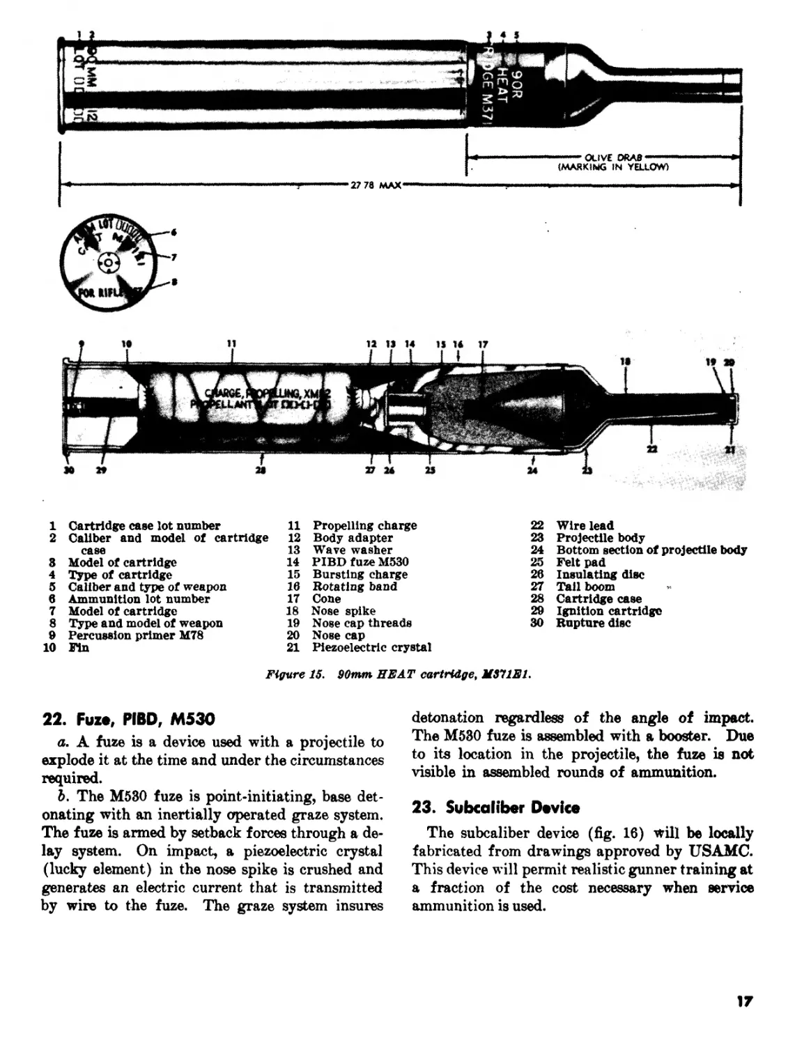
21. High Explosive, Antitank, M371E1
«. The high explosive, antitank round (fig. 15)
utilizes a special fin-stabilized projectile which em-
ploys the shaped-charge principle to defeat armor.
It does not deperid upon velocity at the moment of
impact for its effect. It relies upon a concentra-
tion of the effect of the explosive filler through
its shape. The conical shape of the filler concen-
trates the force of the explosion into a hot jet that
blows its way through the armor. The shape of
the filler is maintained by a metal cone which
forms a slug when the filler is exploded. This
slug or metal may or may not follow the explosive
jet through the armor. The complete cartridge
weighs approximately 9^ pounds. The projec-
tile weighs approximately 6% pounds, and has a
muzzle velocity of approximately 700 feet per
second.
5. For maximum effect, the shaped filler must
be at exactly the right distance from the face of
the armor when it detonates. This distance is
called “stand-off.” Stand-off is provided by the
ogive, or nose spike on the nose of the projectile.
c. The HEAT round is used primarily against
armor. It can be used against secondary targets
such as gun emplacements and pillboxes with ex-
cellent results. The warhead is capable of pene-
trating the armor of any known tank.
......— OLIVE ORA» —
(MARKING IN YELLOW)
27 78 MAX ........................... *.. ........mow.,.,,.....
1 Cartridge case lot number
2 Caliber and model of cartridge
case
3 Model of cartridge
4 Type of cartridge
5 Caliber and type of weapon
6 Ammunition lot number
7 Model of cartridge
8 Type and model of weapon
9 Percussion primer M78
10 Fin
11 Propelling charge
12 Body adapter
13 Wave washer
14 PIBDfuzeM530
15 Bursting charge
16 Rotating band
17 Cone
18 Nose spike
19 Nose cap threads
20 Nose cap
21 Piezoelectric crystal
22 Wire lead
23 Projectile body
24 Bottom section of projectile body
25 Felt pad
26 Insulating disc
27 Tail boom
28 Cartridge case
29 Ignition cartridge
30 Rupture disc
Figure 15. 90mm HEAT cartridge, M311E1.
22. Fuze, PIBD, M530
a. A fuze is a device used with a projectile to
explode it at the time and under the circumstances
required.
b. The M530 fuze is point-initiating, base det-
onating with an inertially operated graze system.
The fuze is armed by setback forces through a de-
lay system. On impact, a piezoelectric crystal
(lucky element) in the nose spike is crushed and
generates an electric current that is transmitted
by wire to the fuze. The graze system insures
detonation regardless of the angle of impact.
The M530 fuze is assembled with a booster. Due
to its location in the projectile, the fuze is not
visible in assembled rounds of ammunition.
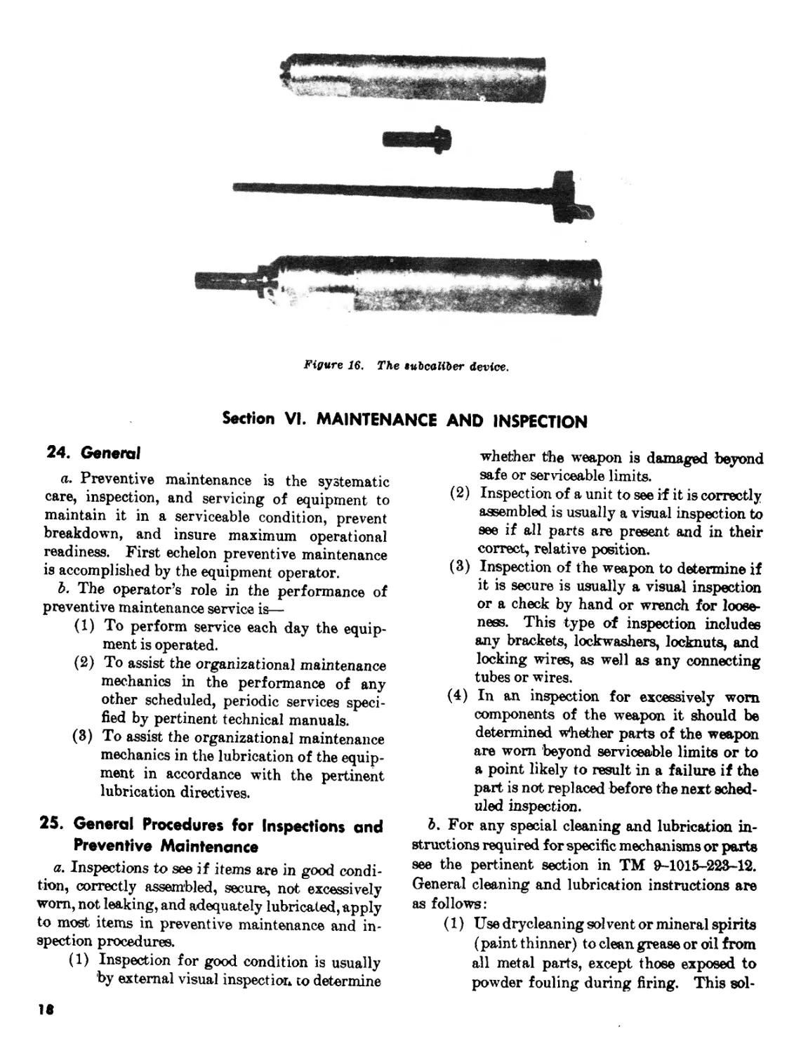
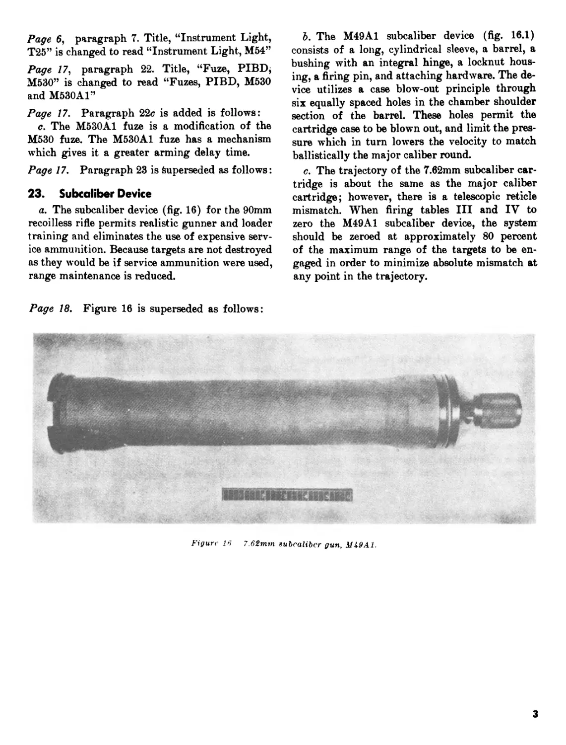
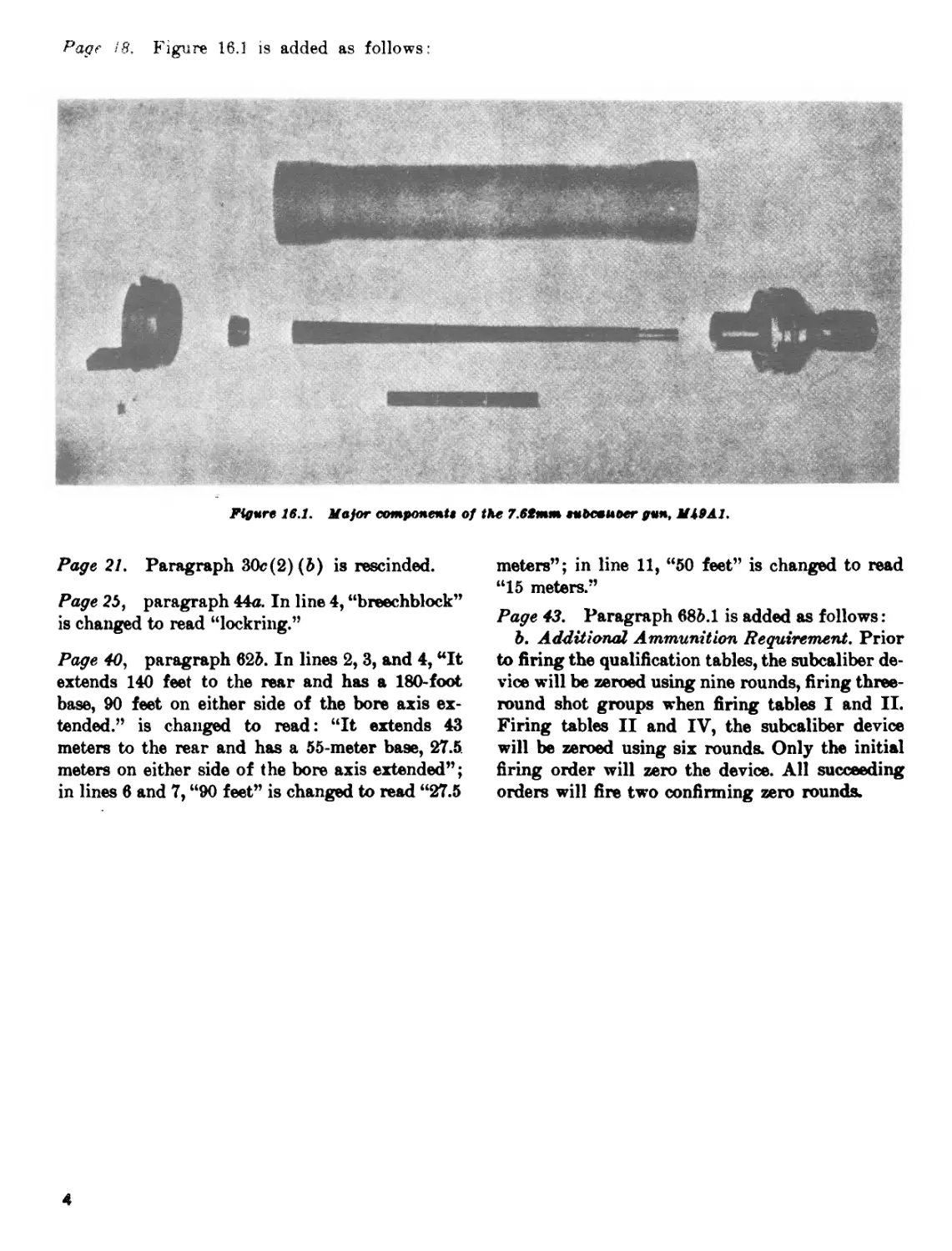
23. Subcaliber Device
The subcaliber device (fig. 16) will be locally
fabricated from drawings approved by USAMC.
This device will permit realistic gunner training at
a fraction of the cost necessary when service
ammunition is used.
17
Figure 16. The tubcaliber device.
Section VI. MAINTENANCE AND INSPECTION
24. General
a. Preventive maintenance is the systematic
care, inspection, and servicing of equipment to
maintain it in a serviceable condition, prevent
breakdown, and insure maximum operational
readiness. First echelon preventive maintenance
is accomplished by the equipment operator.
b. The operator’s role in the performance of
preventive maintenance service is—
(1) To perform service each day the equip-
ment is operated.
(2) To assist the organizational maintenance
mechanics in the performance of any
other scheduled, periodic services speci-
fied by pertinent technical manuals.
(3) To assist the organizational maintenance
mechanics in the lubrication of the equip-
ment in accordance with the pertinent
lubrication directives.
25. General Procedures for Inspections and
Preventive Maintenance
a. Inspections to see if items are in good condi-
tion, correctly assembled, secure, not excessively
worn, not leaking, and adequately lubricated, apply
to most items in preventive maintenance and in-
spection procedures.
(1) Inspection for good condition is usually
by external visual inspection co determine
18
whether the weapon is damaged beyond
safe or serviceable limits.
(2) Inspection of a unit to see if it is correctly
assembled is usually a visual inspection to
see if all parts are present and in their
correct, relative position.
(3) Inspection of the weapon to determine if
it is secure is usually a visual inspection
or a check by hand or wrench for loose-
ness. This type of inspection includes
any brackets, lockwashers, locknuts, and
locking wires, as well as any connecting
tubes or wires.
(4) In an inspection for excessively worn
components of the weapon it should be
determined whether parts of the weapon
are worn beyond serviceable limits or to
a point likely to result in a failure if the
part is not replaced before the next sched-
uled inspection.
b. For any special cleaning and lubrication in-
structions required for specific mechanisms or parts
see the pertinent section in TM 9-1015-223-12.
General cleaning and lubrication instructions are
as follows:
(1) Use drycleaning solvent or mineral spirits
(paint thinner) to clean grease or oil from
all metal parts, except those exposed to
powder fouling during firing. This sol-
vent will not readily dissolve the corrosive
salts from powder and primer composi-
tions.
(2) Use rifle bore cleaner to clean all arma-
ment parts which have been exposed to
powder fouling during firing» After
cleaning a part with rifle bore cleaner it is
necessary that the part be wiped dry and
oiled.
(3) After all parts are cleaned, rinse and dry
them thoroughly. Apply preservative
lubricating (PL) (special) oil to all pol-
ished metal surfaces, other than optical
equipment, to prevent rusting.
(4) When authorized to install new parts re-
move any preservative materials such as
rust-preventive compound or protective
grease. Prepare parts as required, and
for those parts requiring lubrication ap-
ply the lubricant prescribed in the tech-
nical manual.
c. General precautions in cleaning are as fol-
lows:
(1) Drycleaning solvent and mineral spirits
should not be used near an open flame.
Fire extinguishers should be provided
when these materials are used. Use only
well-ventilated areas.
(2) These cleaners evaporate quickly and
have a drying effect on the skin. If used
without gloves, they may cause cracks in
the skin and, in the case of some individ-
uals, a mild irritation or inflammation.
(3) Avoid getting petroleum products, such
as drycleaning solvent, mineral spirits, or
lubricants on rubber parts as they will de-
teriorate the rubber.
(4) The use of diesel fuel oil, gasoline, or ben-
zine (benzol) for cleaning is prohibited.
d. To prevent formation of damaging mildew,
shake out and air the canvas cover for several
hours at frequent intervals. Have any loose grom-
mets or rips in the canvas repaired without delay.
Failure to make immediate repairs may allow a
minor defect to develop into major damage. Mil-
dewed canvas is 'best cleaned with a dry brush. If
water is necessary to remove dirt it must not be
used until mildew has been removed. If mildew
is present, examine the fabric carefully for evi-
dence of rotting or weakening of fabric by stretch-
ing and pulling.
26. Lubricating Instructions
a. Usual Conditions.
(1) handle. After firing, or every 7
days, disassemble and clean with clean-
ing solvent; wipe dry and lubricate with
PL (special).
(2) Monopod assembly. Daily and after fir-
ing, wipe dry and coat threaded portion
with a light film of PL (special).
(3) Front bracket assembly. Before firing,
wipe dry and lightly lubricate with PL
(special). After firing, or every 7 days,
clean with cleaning solvent, wipe dry and
lightly lubricate with PL (special).
(4) Cable assembly. Before firing' remove,
wipe dry and lightly lubricate with PL
(special). After firing, or every 7 days,
remove, clean, wipe dry, and lightly lubri-
cate with PL (special).
(5) Breech and hinge mechanism group. Be-
fore firing, wipe dry and lubricate tooth
on inner hinge portion of the breechblock
and all threaded portions of the breech-
block with Aircraft Instrument Grease
MIL-L-46000. Apply a light coat of PL
(special) to all other surfaces. Wipe ex-
ternal surfaces dry before firing. After
firing, and on 3 consecutive days there-
after, clean with rifle bore cleaner. After
the fourth cleaning, dry and lubricate as
above. When the weapon is not fired, dis-
assemble, clean with cleaning solvent;
wipe dry and relubricate every 7 days.
(6) Rear mounting bracket group. Before
firing, wipe dry all parts and lightly lub-
ricate with PL (special). After firing, or
every 7 days, clean with cleaning solvent;
wipe dry all parts and lightly lubricate
with PL (special).
(7) Tube. After firing and on 3 consecu-
tive days thereafter, clean bore with bore
cleaner. After the fourth cleaning, dry
and lubricate bore with PL (special).
When weapon is not fired, clean the tube,
wipe dry, and reoil every 7 days. Wipe
dry before firing.
b. Unusual Conditions. Reduce or increase lu-
brication intervals as required to compensate for
abnormal operation and extreme conditions, such
as high and low temperatures, prolonged periods
of high rate operation, continued operation in
sand or dust, or exposure to moisture. Any one
19
of the above may quickly destroy the protective
qualities of the lubricant. Lubrication intervals
may be extended during inactive periods.
(1) Extreme cold weather lubrication. Ap-
ply a light coat of low temperature lubri-
cating oil to the rifle, and move the func-
tioning parts frequently during periods
of low temperature to insure proper func-
tioning. In extreme cold weather areas,
the weapon must be wiped dry after lu-
brication so that only a minimum amount
of lubricant remains.
(2) Extreme hot weather lubrication. Spe-
cial lubricants will ordinarily not be re-
quired at extremely high temperatures
because the lubricants prescribed for the
weapon provide adequate protection.
However, more frequent servicing is nec-
essary because heat dissipates the lubri-
cants.
(3) Lubrication for humid and salt air con-
ditions. High humidity, moisture, or salt
air tend to contaminate the lubricant,
necessitating frequent servicing.
(4) Lubrication after operation under dusty
or sandy conditions. Thoroughly clean
the weapon and lubricate as prescribed in
a above.
27. Recording Procedures
The equipment record system provides for re-
cording repairs required and accomplished on
specific items of equipment. This will include,
but is not limited to, adjusting, cleaning, and re-
placing. Deficiencies discovered before, during,
or after operation that cannot be corrected by the
operator will be entered on DA Form 2404, Equip-
ment Inspection and Maintenance Worksheet.
Deficiencies immediately corrected by the operator
are not recorded, except when such corrections are
made by replacing parts, or which constitute re-
pairs above first echelon. Such repairs will be
recorded as organizational maintenance.
Section VII. DECONTAMINATION PROCEDURES
28. Preparation and Testing
Oil rifles completely if chemical, biological, or
radiological attacks are anticipated. Also oil
accessories, except ammunition. Keep ammuni-
tion waxed when possible. Test for contamina-
tion, using detector paper for liquids or detector
crayon for vapors. If equipment is not contam-
inated, clean and prepare it for use.
29. Decontamination
If equipment is contaminated, decontaminating
personnel should use a complete suit of protective
clothing (permeable or impermeable), including
impermeable gloves and protective mask.
a. Equipment contaminated with chemicals,
other than the blister agent or G-series agents, is
decontaminated by airing. For faster decontam-
ination and to protect against corrosion, clean the
rifle and accessories with rifle bore cleaner, dena-
tured alcohol, or soap and water.
b. Equipment contaminated by blister agents is
decontaminated as follows:
(1) Remove all dirt, dust, grease, and oil.
(2) Expose all parts to air.
(3) Decontaminate all metal surfaces except
the bore with agent, decontaminating,
noncorrosive (DANC) (FM 21^0).
Hot soapy water is also an effective
cleaner.
(4) Protective ointment, M5, can be used for
emergency decontamination (FM 21^0).
(5) Test with detector kit to determine if
decontamination is complete. If com-
plete, clean, dry, oil, and prepare rifle
for use.
(6) Burn, or preferably bury, all rags or
wiping materials.
Note. Caution should be used to protect men
against vapors created by burning.
c. In general, these actions are applicable to
equipment contaminated by biological or radio-
logical attack. Detailed information on decon-
tamination is contained in FM 21-40 and TM
3-220.
20
Section VIII. DESTRUCTION IN EVENT OF IMMINENT CAPTURE
30. Destruction To Prevent Enemy Use
a. treneraZ. Destruction of material is accom-
plished on. authority delegated by division or
higher commander. This is usually a matter of
standing operating procedures. It is ordered only
after all measures to save the equipment have been
taken,
b. Principles of Destruction,
(1) Methods of destruction are adequate, uni-
form, and easily followed in the field.
(2) Destruction is as complete as possible
within the limitations of time, equipment,
and personnel. In any event, the most
important parts of the weapon are de-
stroyed or evacuated. The same essential
parts are destroyed or evacuated on all
like units to prevent the enemy from con-
structing pne complete rifle from several
damaged ones.
(3) Crews are trained in prescribed methods
of destruction.
(4) Certain methods of destruction require
special tools and equipment such as TNT
or incendiary grenades. Issue of such
special equipment and its use are com-
mand decisions and depend on the tactical
situation.
c. Destruction of the Rifle,
(1) Method No, 1—demolition materials.
When planning for simultaneous detona-
tion, prepare the following demolition
charges using TNT blocks or an equiv-
alent to make up the required charge.
(a) One-pound charge. Insert the charge
in the muzzle of the rifle to a distance
of about 1 foot. Plug the bore to a
distance of about 8 inches with earth,
stone, or similar material, being careful
not to damage the detonating cord.
(3) Two-pound charge. Insert the charge
into the chamber. Pass the detonating
cord out of the chamber through one
of the vents in the breechblock. Plug
the vents with any available material
such as rags or mud, being careful not
to damage the detonating cord.
(c) Connect the two charges for simul-
taneous detonation with detonating
cord. For complete details on the use
of demolition materials and methods of
priming and detonating demolition
charges refer to FM 5-25.
(2) Method No, &—burning with incendiary
grenades, Destruction of essential parts
followed by burning in an intense fire will
usually render the rifle and related mate-
rial useless. Since the rifle and related
material are made almost entirely of
metal, effective destruction by this means
requires larger amounts of combustible
material than may be available. How-
ever, the use of incendiary grenades will
render the rifle useless.
(a) Insert two incendiary grenades, end-to-
end, midway in the tube. Place a third
incendiary grenade, fitted with a time
blasting fuze, adjacent to the grenades
in the tube.
tfote. Time blasting fuze burns at a rate
of 1 foot in approximately 40 seconds; test
before using.
(5) With the breech open, place two in-
cendiary grenades in the chamber.
Place a third incendiary grenade, fitted
with time blasting fuze, adjacent to the
grenades in the chamber.
(<?) Ignite the fuzed grepade. The time
blasting fuze may be ignited by a blast-
ing fuze igniter or a match. The metal
from the grenades will fuze with the
tube and will also weld the breechblock
and vent bushing.
Ttiote. When fitting incendiary grenades
with time blasting fuzes, the fuzes should
be of sufficient length so personnel may safely
leave the immediate area before the grenades
are detonated.
(3) Method No. 3—by gun fire. From an
adjacent rifle or gun, fire on the rifle and
related material to be «destroyed. Al-
though one well-placed direct hit may
render the rifle and related material tem-
porarily useless, several hits may be re-
quired for complete destruction.
(4) Optical instruments. Remove the direct
fire sight. It is relatively lightweight
and easy to carry, and is costly and diffi-
21
cult to replace. It should be evacuated if
possible. When evacuation is impractical
then smash the sight and mount.
31. Destruction of Ammunition
Ammunition is most effectively destroyed by
burning. To accomplish this, stack rounds (either
packed or unpacked) in piles, preferably in a
trench or depression. Place flammable materials
such as paper, rags, and wood around and on the
pile. Pour gasoline and oil over the combustible
materials and over the entire ammunition pile.
Ignite by means of an incendiary grenade fired
from a safe distance, a burst from a flamethrower,
a combustible train of suitable length, or other ap-
propriate means. Take cover immediately.
22
CHAPTER 3
PREPARATORY MARKSMANSHIP
Section I. GENERAL
32. Introduction
a. Preparatory marksmanship training teaches
essential skills and develops fixed and correct
habits of marksmanship before range practice be-
gins. Thorough instruction and carefully super-
vised practice in the preparatory phase saves time
and ammunition during range firing and develops
habits and procedures necessary for well-trained
gun crews.
6. Marksmanship and firing explained herein
cover both subcaliber and field firing.
33. Sequence of Training
Preparatory marksmanship is divided into steps
normally taught in the following sequence:
a. Sighting and aiming.
b. Positions.
c. Adjustment of fire.
d. Trigger manipulation.
e. Tracking.
f. Examination.
Section II. INDIVIDUAL DUTIES
34. Duties of Squad Leader
The weapons squad leader is in direct command
of the crew and is responsible for its equipment.
He observes, adjusts, controls, and supervises the
conduct of fire of the 90mm rifle. He employs the
squad according to orders of the platoon leader and
is responsible for properly concealing the weapon.
He keeps the platoon leader informed of the status
of the ammunition supply and supervises his
crew’s ammunition resupply.
35. Organization and Equipment for Crew
Drill
Crew members
No. 1: Gunner_________
No. 2: Assistant
gunner (loader am-
munition bearer).
Individual
weapon Individual load
Pistol_____ 90mm rifle with
telescope sight.
Pistol_____ Ammunition carry-
ing strap, tools,
spare parts,
cleaning ma-
terial, and 3
rounds of 90mm
ammunition.
Individual
Crew members weapon Individual load
No. 3: Ammunition Rifle_________ Ammunition carry-
bearer*. ing strap and 4
rounds of 90mm
ammunition. 3
rounds in strap
and 1 in hands.
•Note. See current TOE. The third crew member, while not
currently authorized, is considered necessary for efficient opera-
tions. In the absence of an individual to perform the duties
assigned to No. 3, ammunition bearer, No. 2, the loader, will be
responsible for these duties too.
36. Duties of Crew Members
a. No. 1, the gunner, lays and fires the 90mm
rifle and is the crew leader. He makes necessary
fire adjustments as called for by the squad leader.
He is responsible for the maintenance of the rifle
and coordinates his actions with No. 2.
ft. No. 2, the loader, is responsible for loading
the 90mm rifle and acts as gunner should the
necessity arise. He secures ammunition and checks
clearance of the backblast area prior to firing. He
23
assists in the maintenance of the rifle and coordi-
nates his movements and duties with No. 1.
c. No. 3, the ammunition bearer, is responsible
Section ill.
37. General
a. Purpose. The objective of crew drill is to
train the individual as a member of the crew to
place the rifle in and out of action with precision
and speed.
b. Training. The attainment of precision is the
first step in developing an expert crew and is ac-
quired by strict adherence to the prescribed pro-
cedure. Only after the desired individual preci-
sion has been attained are the next phases—team-
work and speed—undertaken.
с. Театпшюгк. Teamwork is assured by rotation
of duties during drill so each crew member, by
practice, becomes familiar with the duties of every
other member. Continuity of action is made cer-
tain by this phase of training.
d. Speed. Practice for speed is instituted as the
last phase of instruction in crew drill. Care must
be taken during this phase to insure that precision
and teamwork are not sacrificed for speed.
38. Forming for Crew Drill
At the command FORM FOR CREW DRILL,
members of the crew, except the squad leader, fall
in at attention in a column with five paces between
men and face the squad leader. To assign posi-
tions for crew drill, the squad leader commands
COUNT OFF. On that command, the crew calls
off from front to rear starting with No. 1 (the
gunner),
39. Posting the Squad
At the command POST, all crew members move
forward at double time to prone positions directly
behind their equipment which is laid out in order.
40. Examine Equipment Before Drill
At the command EXAMINE EQUIPMENT
BEFORE DRILL (while crew is in the prone
position), crew members examine equipment as
follow's:
a. No. /, (rwrvner.
(1) Checks to see that sight and sight mount
are workable, cross level vial is not
for securing ammunition. While not engaged in
ammunition resupply, he provides security for the
rifle position.
CREW DRILL
broken, and sight is clean and tight in the
bracket.
(2) Checks the operation of the bipod and the
monopod.
(3) Checks the chamber and the functioning
of the lockring.
(4) Checks the firing mechanism and the
safety lever for proper functioning.
b. No. 2, Loader.
(1) Checks his ammunition for amount and
proper seal of the containers.
(2) Checks tools, spare parts, and cleaning
material.
c. No.3^AnvmAjinituyn Bearer.
(1) Checks his ammunition for amount.
(2) Checks the seals of ammunition contain-
ers.
41. Reports
When all equipment is checked, the following
reports are given (incorrect items are reported
when a deficiency exists) :
a. No. 3, the ammunition bearer, reports AM-
MUNITION CORRECT.
ft. No. 2, loader, reports AMMUNITION,
TOOLS, SPARE PARTS, AND CLEANING
MATERIAL CORRECT.
c. No. 1, gunner reports ALL CORRECT.
42. Placing Rifle Into Action
To place the weapon into action, the squad
leader commands ACTION, and designates by
pointing the direction of fire and the general area
of the rifle position. He places himself on the
flank in a position from which he can observe and
control the fire. At the command ACTION, the
crew moves rapidly to the position indicated.
Where necessary, the squad leader may also in-
dicate the type of position to be taken by No. 1
(prone, sitting).
a. No. 1 selects the exact spot and assumes the
firing position from which he can best accomplish
his mission. He lays the rifle on the target, places
his right hand on the trigger grip, and awaits a
report that the rifle is ready to fire. He fires as di-
rected by the squad leader.
24
b. No. 2 assists No. 1 in placing the rifle in ac-
tion by holding the rifle while the gunner places
his body in position or while the gunner adjusts
the bipod. He opens the breech. He inserts the
cartridge into the chamber and seats it firmly. He
then closes and locks the breech and inspects the
backblast area to see that it is clear. If it is clear,
he rotates the safety arm to the fire position, taps
the gunner, and calls UP to indicate that the rifle
is ready to fire.
c. No. 3 takes a position on the right flank
from which he can readily bring up ammunition
and from which he can provide security for the
position.
d. After firing, the loader opens the breech with
his right hand and ejects the expended cartridge
case.
43. Taking the Rifle Out of Action
The squad leader commands OUT OF ACTION.
Upon this command, the loader clears the 90mm
rifle, calls CLEAR, and closes the breech. No. 2
takes the rifle from No. 1. (When the rifle is fired
from the prone position, No. 2 holds the rifle while
No. 1 adjusts the bipod for the shoulder carry.)
No. 2 now secures his ammunition and tools. No. 3
secures his ammunition. The squad leader indi-
cates the line of march by facing in that direction.
The crew places itself in column behind the gun-
ner, and moves on command from the squad leader.
44. Service of the Piece
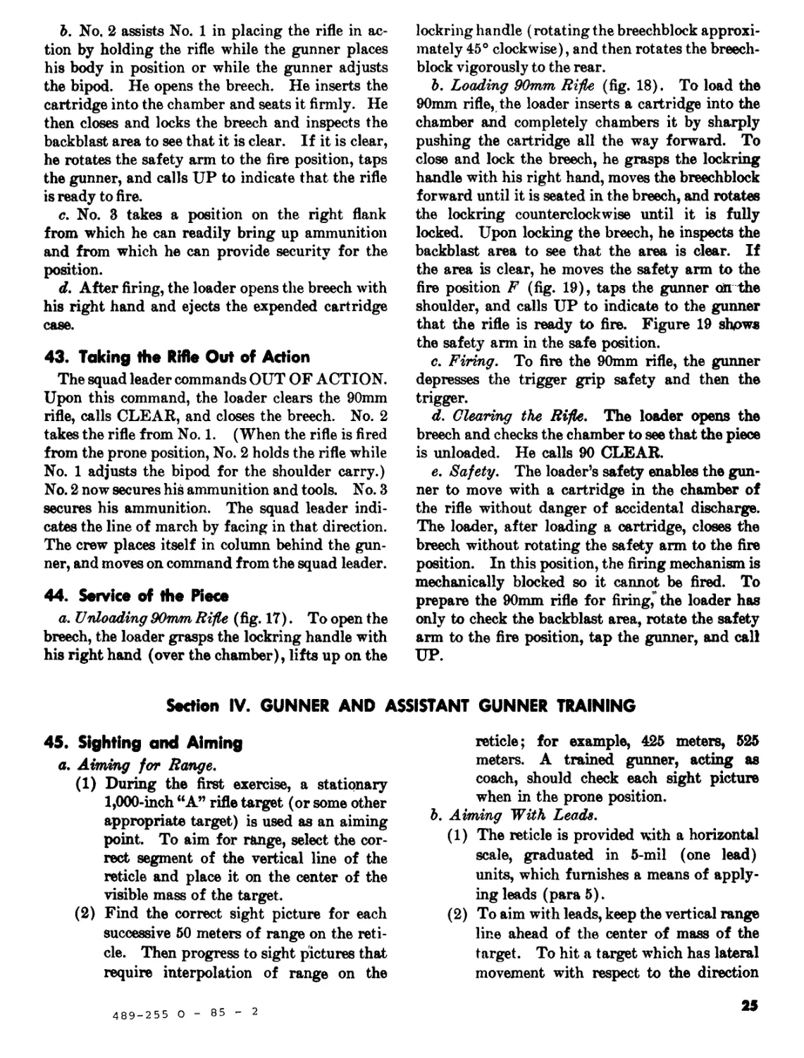
a. Unloading90num Rifle (fig. 17). To open the
breech, the loader grasps the lockring handle with
his right hand (over the chamber), lifts up on the
Section IV. GUNNER AND /
45. Sighting and Aiming
a. Aiming for Range.
(1) During the first exercise, a stationary
1,000-inch “A” rifle target (or some other
appropriate target) is used as an aiming
point. To aim for range, select the cor-
rect segment of the vertical line of the
reticle and place it on the center of the
visible mass of the target.
(2) Find the correct sight picture for each
successive 50 meters of range on the reti-
cle. Then progress to sight pictures that
require interpolation of range on the
lockring handle (rotating the breechblock approxi-
mately 45° clockwise), and then rotates the breech-
block vigorously to the rear.
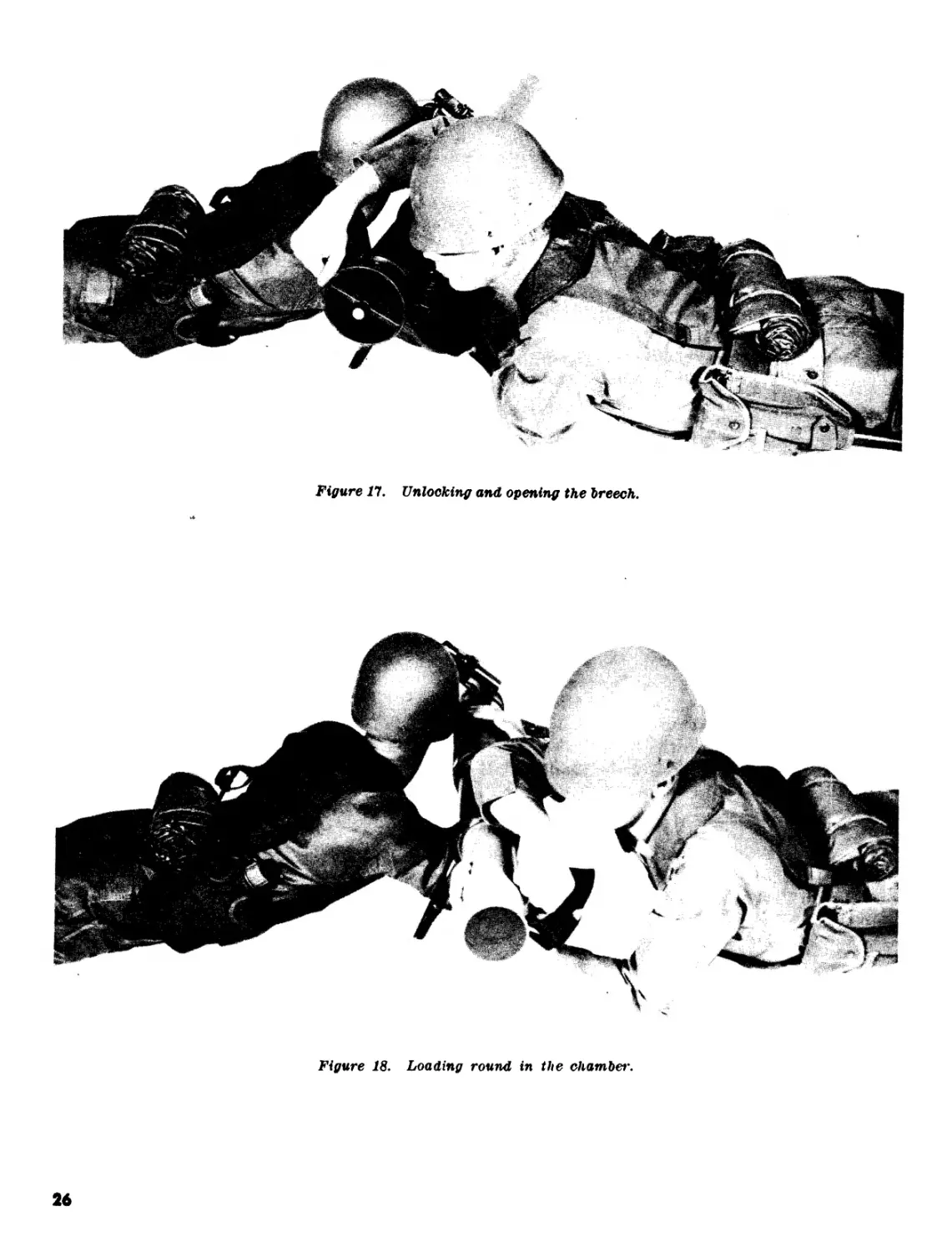
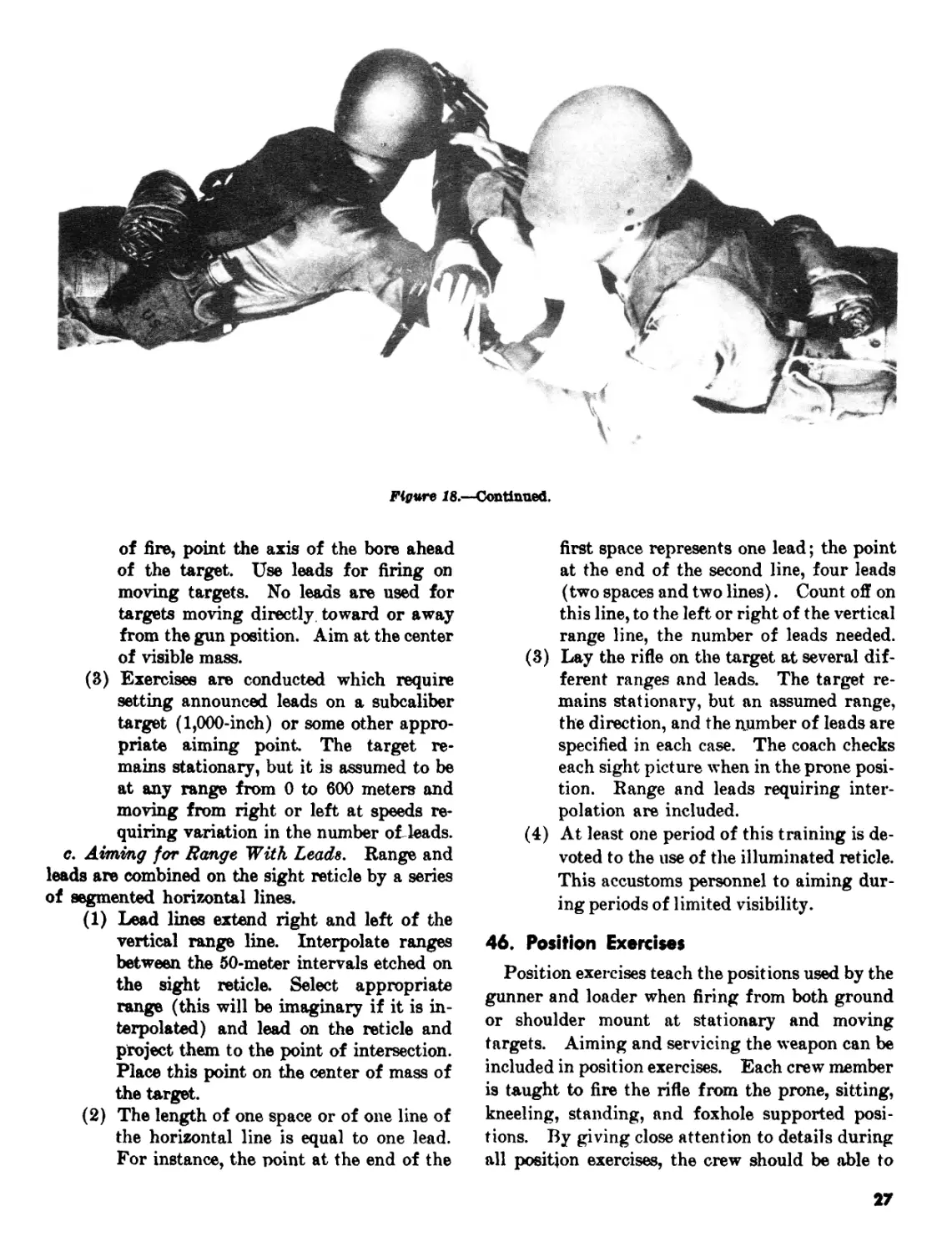
b. Loading 90mm Rifle (fig. 18). To load the
90mm rifle, the loader inserts a cartridge into the
chamber and completely chambers it by sharply
pushing the cartridge all the way forward. To
close and lock the breech, he grasps the lockring
handle with his right hand, moves the breechblock
forward until it is seated in the breech, and rotates
the lockring counterclockwise until it is fully
locked. Upon locking the breech, he inspects the
backblast area to see that the area is clear. If
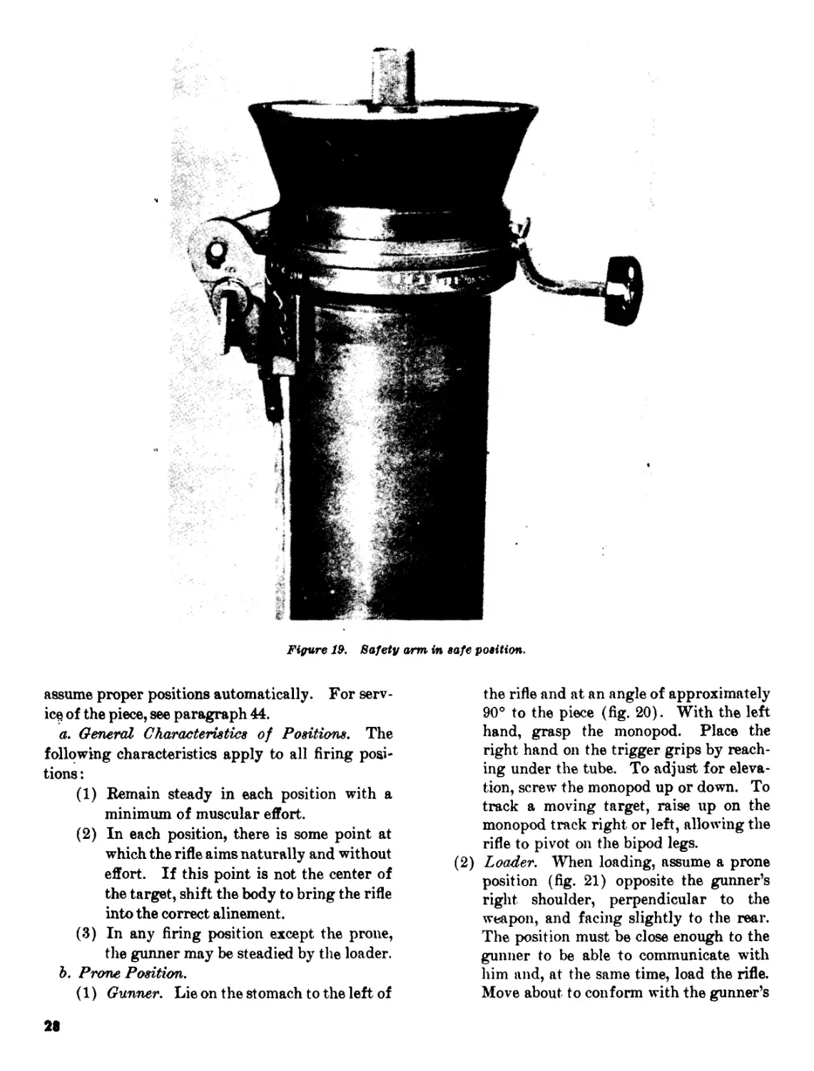
the area is clear, he moves the safety arm to the
fire position F (fig. 19), taps the gunner on the
shoulder, and calls UP to indicate to the gunner
that the rifle is ready to fire. Figure 19 shows
the safety arm in the safe position.
c. Firing. To fire the 90mm rifle, the gunner
depresses the trigger grip safety and then the
trigger.
d. Clearing the Rifle. The loader opens the
breech and checks the chamber to see that the piece
is unloaded. He calls 90 CLEAR.
e. Safety. The loader’s safety enables the gun-
ner to move with a cartridge in the chamber of
the rifle without danger of accidental discharge.
The loader, after loading a cartridge, closes the
breech without rotating the safety arm to the fire
position. In this position, the firing mechanism is
mechanically blocked so it cannot be fired. To
prepare the 90mm rifle for firing, the loader has
only to check the backblast area, rotate the safety
arm to the fire position, tap the gunner, and call
UP.
1STANT GUNNER TRAINING
reticle; for example, 425 meters, 525
meters. A trained gunner, acting as
coach, should check each sight picture
when in the prone position.
b. Aiming With Leads.
(1) The reticle is provided with a horizontal
scale, graduated in 5-mil (one lead)
units, which furnishes a means of apply-
ing leads (para 5).
(2) To aim with leads, keep the vertical range
line ahead of the center of mass of the
target. To hit a target which has lateral
movement with respect to the direction
489-255 О
85
2
25
Figure 17. Unlocking and opening the breech.
Figure 18. Loading round in the chamber.
26
Figure 18.—Continued.
of fire, point the axis of the bore ahead
of the target. Use leads for firing on
moving targets. No leads are used for
targets moving directly toward or away
from the gun position. Aim at the center
of visible mass.
(3) Exercises are conducted which require
setting announced leads on a subcaliber
target (1,000-inch) or some other appro-
priate aiming point The target re-
mains stationary, but it is assumed to be
at any range from 0 to 600 meters and
moving from right or left at speeds re-
quiring variation in the number of leads.
c. Aiming for Range With Leads. Range and
leads are combined on the sight reticle by a series
of segmented horizontal lines.
(1) Lead lines extend right and left of the
vertical range line. Interpolate ranges
between the 50-meter intervals etched on
the sight reticle. Select appropriate
range (this will be imaginary if it is in-
terpolated) and lead on the reticle and
project them to the point of intersection.
Place this point on the center of mass of
the target.
(2) The length of one space or of one line of
the horizontal line is equal to one lead.
For instance, the point at the end of the
first space represents one lead; the point
at the end of the second line, four leads
(two spaces and two lines). Count off on
this line, to the left or right of the vertical
range line, the number of leads needed.
(3) Lay the rifle on the target at several dif-
ferent ranges and leads. The target re-
mains stationary, but an assumed range,
the direction, and the number of leads are
specified in each case. The coach checks
each sight picture when in the prone posi-
tion. Range and leads requiring inter-
polation are included.
(4) At least one period of this training is de-
voted to the use of the illuminated reticle.
This accustoms personnel to aiming dur-
ing periods of limited visibility.
46. Position Exercises
Position exercises teach the positions used by the
gunner and loader when firing from both ground
or shoulder mount at stationary and moving
targets. Aiming and servicing the weapon can be
included in position exercises. Each crew member
is taught to fire the rifle from the prone, sitting,
kneeling, standing, and foxhole supported posi-
tions. By giving close attention to details during
all position exercises, the crew should be able to
27
Figure 19. Safety am in safe position.
assume proper positions automatically. For serv-
ice of the piece, see paragraph 44.
a. General Characteristics of Positions. The
following characteristics apply to all firing posi-
tions :
(1) Remain steady in each position with a
minimum of muscular effort.
(2) In each position, there is some point at
which the rifle aims naturally and without
effort. If this point is not the center of
the target, shift the body to bring the rifle
into the correct alinement.
(3) In any firing position except the prone,
the gunner may be steadied by the loader.
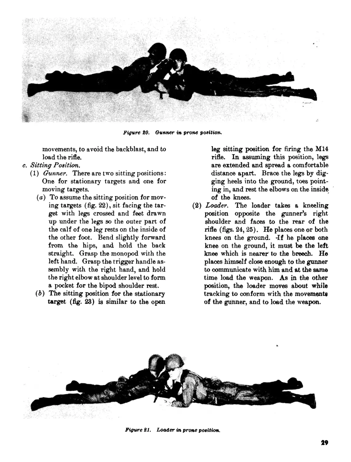
b. Prone Position.
(1) Gunner. Lie on the stomach to the left of
the rifle and at an angle of approximately
90° to the piece (fig. 20). With the left
hand, grasp the monopod. Place the
right hand on the trigger grips by reach-
ing under the tube. To adjust for eleva-
tion, screw the monopod up or down. To
track a moving target, raise up on the
monopod track right or left, allowing the
rifle to pivot on the bipod legs.
(2) Loader. When loading, assume a prone
position (fig. 21) opposite the gunner’s
right shoulder, perpendicular to the
weapon, and facing slightly to the rear.
The position must be close enough to the
gunner to be able to communicate with
him and, at the same time, load the rifle.
Move about to conform with the gunner’s
28
Figure 20. Gunner in prone position.
movements, to avoid the backblast, and to
load the rifle.
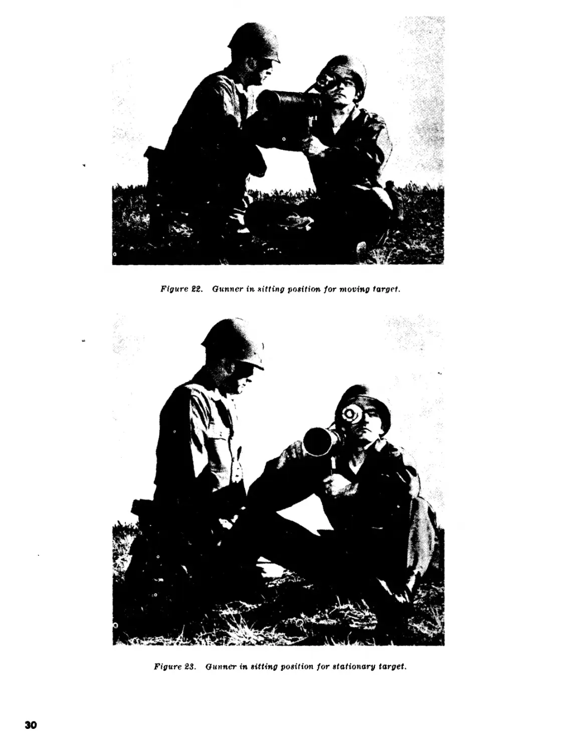
c. Sitting Position.
(1) Gunner. There are two sitting positions:
One for stationary targets and one for
moving targets.
(a) To assume the sitting position for mov-
ing targets (fig. 22), sit facing the tar-
get with legs crossed and feet drawn
up under the legs so the outer part of
the calf of one leg rests on the inside of
the other foot. Bend slightly forward
from the hips, and. hold the back
straight. Grasp the monopod with the
left hand. Grasp the trigger handle as-
sembly with the right hand, and hold
the right elbow at shoulder level to form
a pocket for the bipod shoulder rest.
(b) The sitting position for the stationary
target (fig. 23) is similar to the open
leg sitting position for firing the M14
rifle. In assuming this position, legs
are extended and spread a comfortable
distance apart. Brace the legs by dig-
ging heels into the ground, toes point-
ing in, and rest the elbows on the inside
of the knees.
(2) Loader. The loader takes a kneeling
position opposite the gunner’s right
shoulder and faces to the rear of the
rifle (figs. 24, 25). He places one or both
knees on the ground. «If he places one
knee on the ground, it must be the left
knee which is nearer to the breech. He
places himself close enough to the gunner
to communicate with him and at the same
time load the weapon. As in the other
position, the loader moves about while
tracking to conform with the movements
of the gunner, and to load the weapon.
Figure 21. Loader in prone position.
29
Figure 22. Gunner in flitting position for moving target.
Figure 23. Gunner in sitting position for stationary target.
30
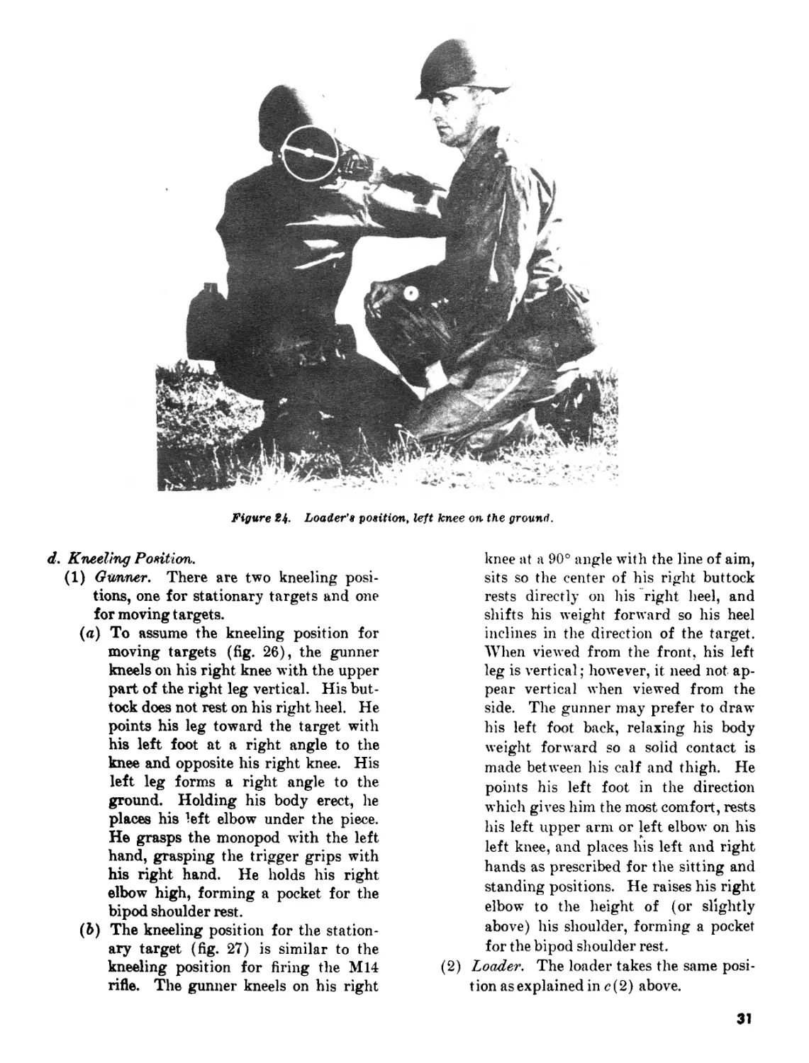
Figure %4- Loader’s position, left knee on the ground.
d. Kneeling Position.
(1) Gunner. There are two kneeling posi-
tions, one for stationary targets and one
for moving targets.
(a) To assume the kneeling position for
moving targets (fig. 26), the gunner
kneels on his right knee with the upper
part of the right leg vertical. His but-
tock does not rest on his right heel. He
points his leg toward the target with
his left foot at a right angle to the
knee and opposite his right knee. His
left leg forms a right angle to the
ground. Holding his body erect, he
places his left elbow under the piece.
He grasps the monopod with the left
hand, grasping the trigger grips with
his right hand. He holds his right
elbow high, forming a pocket for the
bipod shoulder rest.
(b) The kneeling position for the station-
ary target (fig. 27) is similar to the
kneeling position for firing the M14
rifle. The gunner kneels on his right
knee at a 90° angle with the line of aim,
sits so the center of his right buttock
rests directly on his right heel, and
shifts his weight forward so his heel
inclines in the direction of the target.
When viewed from the front, his left
leg is vertical; however, it need not ap-
pear vertical when viewed from the
side. The gunner may prefer to draw
his left foot back, relaxing his body
weight forward so a solid contact is
made between his calf and thigh. He
points his left foot in the direction
which gives him the most comfort, rests
his left upper arm or left elbow on his
left knee, and places his left and right
hands as prescribed for the sitting and
standing positions. He raises his right
elbow to the height of (or slightly
above) his shoulder, forming a pocket
for the bipod shoulder rest.
(2) Loader. The loader takes the same posi-
tion as explained in e( 2) above.
31
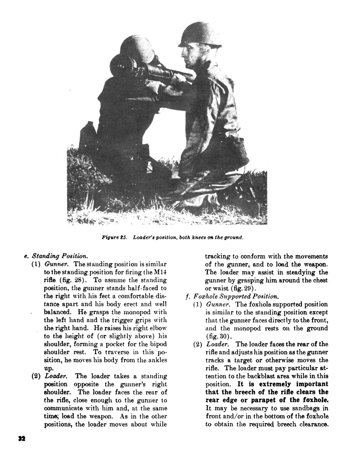
Figure 25. Loader's position, both knees on the ground.
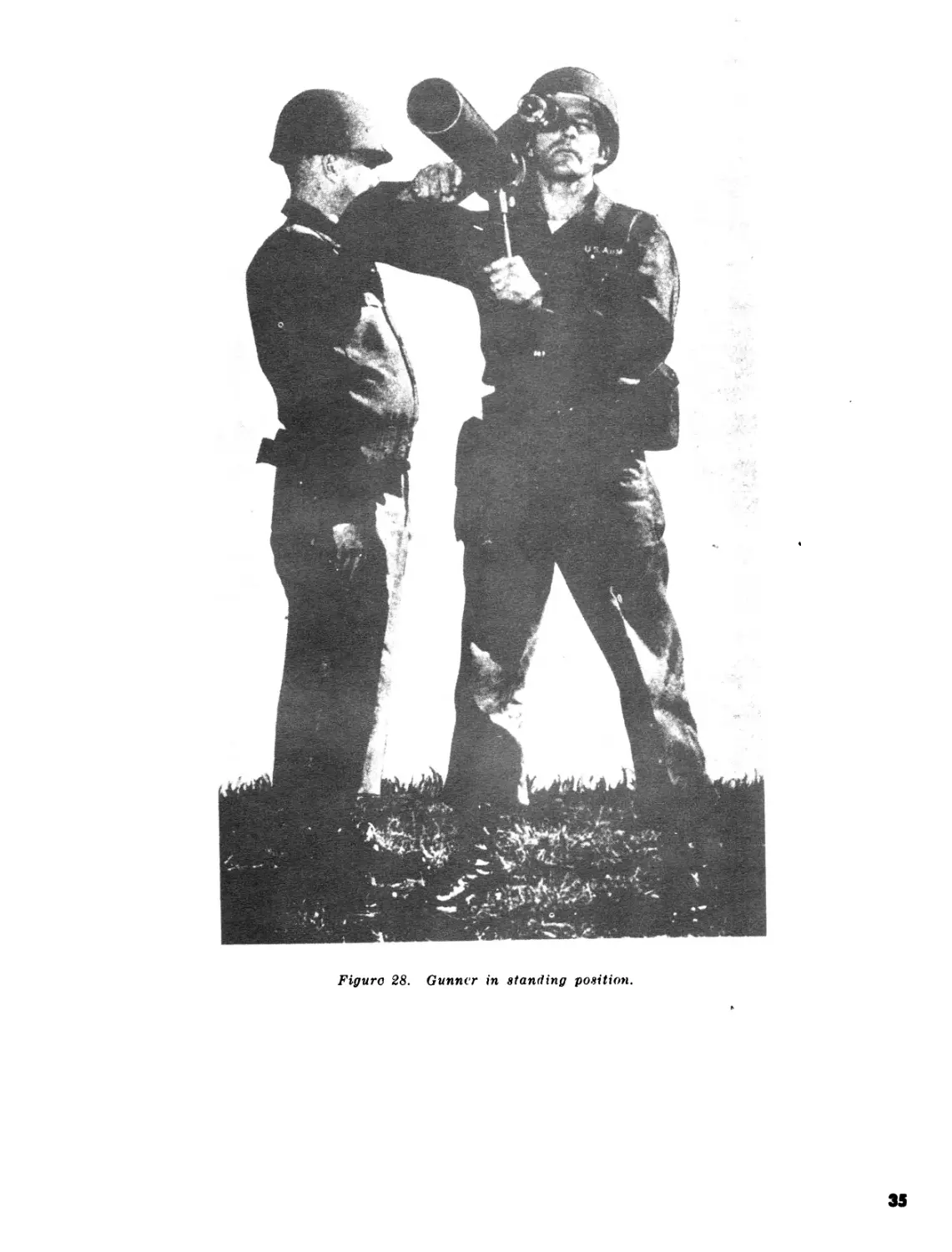
e. Standing Position.
(1) Gunner. The standing position is similar
to the standing position for firing the M14
rifle (fig. 28). To assume the standing
position, the gunner stands half-faced to
the right with his feet a comfortable dis-
tance apart and his body erect and well
balanced. He grasps the monopod with
the left hand and the trigger grips with
the right hand. He raises his right elbow
to the height of (or slightly above) his
shoulder, forming a pocket for the bipod
shoulder rest. To traverse in this po-
sition, he moves his body from the ankles
up.
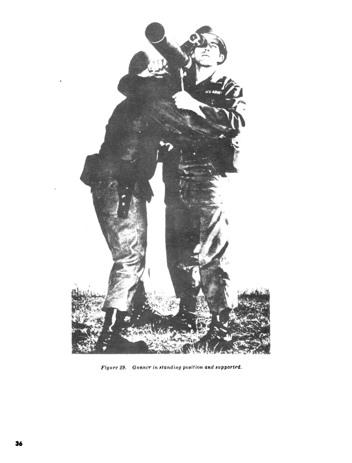
(2) Loader. The loader takes a standing
position opposite the gunner’s right
shoulder. The loader faces the rear of
the rifle, close enough to the gunner to
communicate with him and, at the same
time; load the weapon. As in the other
positions, the loader moves about while
tracking to conform with the movements
of the gunner, and to load the weapon.
The loader may assist in steadying the
gunner by grasping him around the chest
or waist (fig. 29).
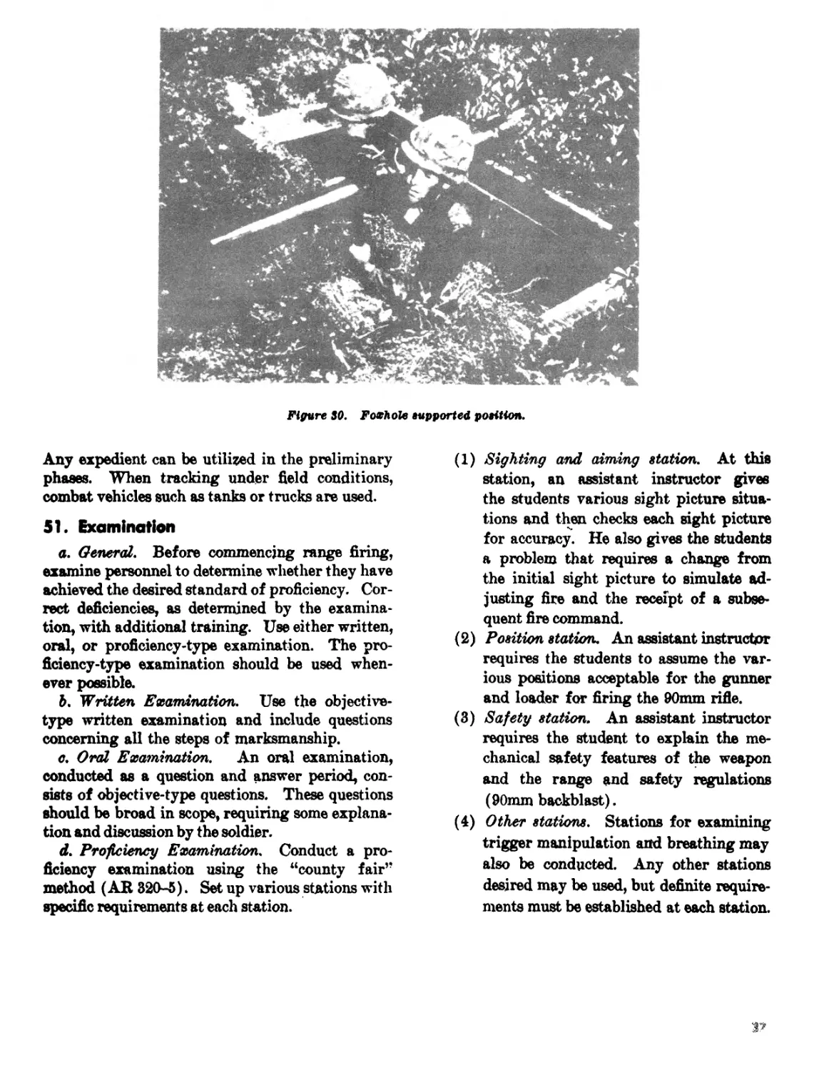
/. Foxhole Supported Position.
(1) Gunner. The foxhole supported position
is similar to the standing position except
that the gunner faces directly to the front,
and the monopod rests on the ground
(fig. 30).
(2) Loader. The loader faces the rear of the
rifle and adjusts his position as the gunner
tracks a target or otherwise moves the
rifle. The loader must pay particular at-
tention to the backblast area while in this
position. It is extremely important
that the breech of the rifle clears the
rear edge or parapet of the foxhole.
It may be necessary to use sandbags in
front and/or in the bottom of the foxhole
to obtain the required breech clearance.
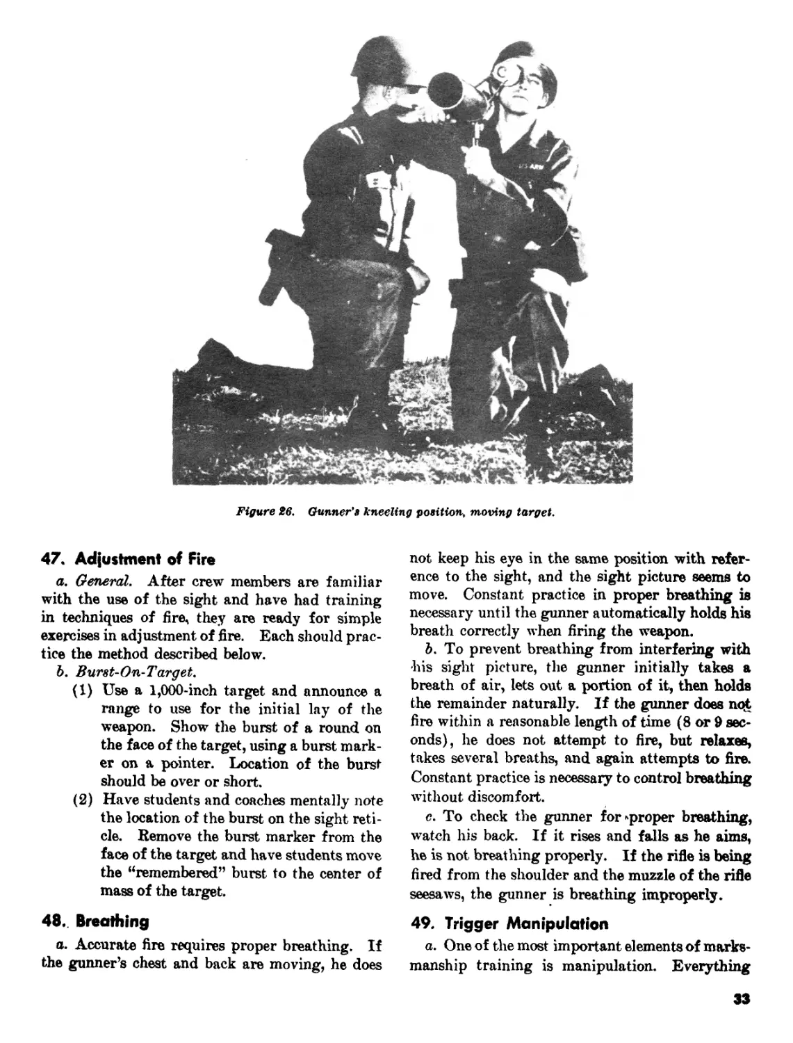
Figure 26. Gunner's kneeling position, moving target.
47. Adjustment of Fire
a. General. After crew members are familiar
with the use of the sight and have had training
in techniques of fire, they are ready for simple
exercises in adjustment of fire. Each should prac-
tice the method described below.
b. Burst-On-Target.
(1) Use a 1,000-inch target and announce a
range to use for the initial lay of the
weapon. Show the burst of a round on
the face of the target, using a burst mark-
er on a pointer. Location of the burst
should be over or short.
(2) Have students and coaches mentally note
the location of the burst on the sight reti-
cle. Remove the burst marker from the
face of the target and have students move
the “remembered” burst to the center of
mass of the target.
48. Breathing
a. Accurate fire requires proper breathing. If
the gunner’s chest and back are moving, he does
not keep his eye in the same position with refer-
ence to the sight, and the sight picture seems to
move. Constant practice in proper breathing is
necessary until the gunner automatically holds his
breath correctly when firing the weapon.
b. To prevent breathing from interfering with
his sight picture, the gunner initially takes a
breath of air, lets out a portion of it, then holds
the remainder naturally. If the gunner does not
fire within a reasonable length of time (8 or 9 sec-
onds), he does not attempt to fire, but relaxes,
takes several breaths, and again attempts to fire.
Constant practice is necessary to control breathing
without discomfort.
c. To check the gunner for*proper breathing,
watch his back. If it rises and falls as he aims,
he is not breathing properly. If the rifle is being
fired from the shoulder and the muzzle of the rifle
seesaws, the gunner is breathing improperly.
49. Trigger Manipulation
a. One of the most important elements of marks-
manship training is manipulation. Everything
33
about the position and aiming may be perfect, but
unless **the trigger is manipulated properly, the
weapon will be pulled to the left or right. Al-
though jerking the trigger may appear to disturb
the sight only slightly, the slightest movement
spoils a good shot. A more extensive movement,
made in anticipation of firing, is called flinching.
It occurs only if the gunner knows the exact mo-
ment.yvhen the rifle will fire. The gunner should
manipulate the trigger so he does not know the
exact moment the 90mm rifle will fire.
b. The gunner takes a breath, expels part of it,
and locks in the rest with his throat muscles. He
then alines the sight on the target and depresses
the trigger safety with the crotch of the hand be-
tween the thumb and index finger. He exerts a
slight initial pressure on the trigger, then continues
to squeeze with a steady, smooth pressure to the
rear. He holds the correct sight picture, squeezes
the trigger, and continues to hold the trigger brief-
ly after the round is fired. If this procedure is
followed, each round fired comes as a surprise to
the gunner, thereby eliminating flinching. Con-
stant practice of trigger manipulation under the
observation and supervision of a good coach great-
ly improves accuracy.
c. Important points about trigger manipulation:
(1) Depress the trigger safety before putting
any initial pressure on the trigger.
(2) Apply smooth, steady pressure on the
trigger straight to the rear.
(3) Do not wait too long to fire a round.
(4) Concentrate on the sight picture rather
than the right hand.
(5) Every shot must come as a surprise to the
gunner.
(6) Do not “snap shoot” because it will exag-
gerate flinching.
50. Tracking
When proficiency is obtained in sighting and
aiming, positions and trigger manipulation train-
ing in tracking a moving target begins. This
training progresses from simple tracking to mov-
ing objects at 25 meters to more difficult exercises
of tracking moving targets under field conditions.
34
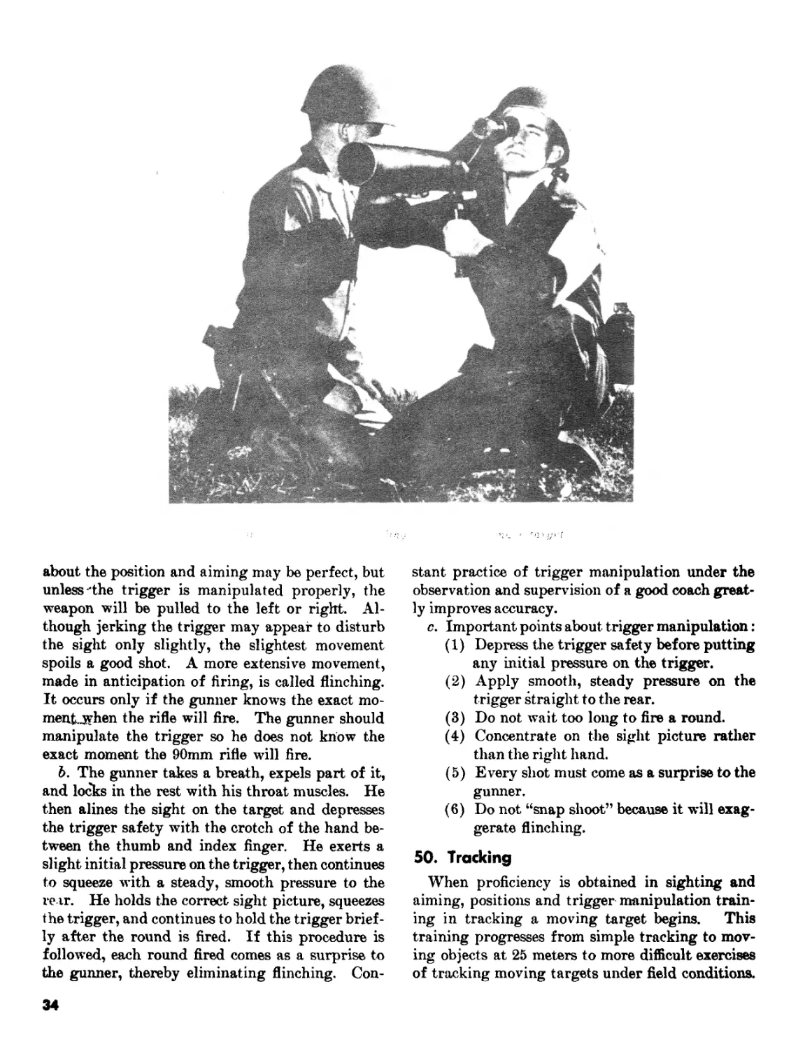
Figure 28. Gunner in standing position.
35
Figure 29. Gunner in standing position and supported.
ЗА
Figure SO. Foxhole supported position.
Any expedient can be utilized in the preliminary
phases. When tracking under field conditions,
combat vehicles such as tanks or trucks are used.
51. Examination
a. General. Before commencing range firing,
examine personnel to determine whether they have
achieved the desired standard of proficiency. Cor-
rect deficiencies, as determined by the examina-
tion, with additional training. Use either written,
oral, or proficiency-type examination. The pro-
ficiency-type examination should be used when-
ever possible.
b. Written Examination. Use the objective-
type written examination and include questions
concerning all the steps of marksmanship.
c. Oral Examination. An oral examination,
conducted as a question and answer period, con-
sists of objective-type questions. These questions
should be broad in scope, requiring some explana-
tion and discussion by the soldier.
d. Proficiency Examination. Conduct a pro-
ficiency examination using the “county fair’’
method (AR 320-5). Set up various stations with
specific requirements at each station.
(1) Sighting and aiming station. At this
station, an assistant instructor gives
the students various sight picture situa-
tions and then checks each sight picture
for accuracy. He also gives the students
a problem that requires a change from
the initial sight picture to simulate ad-
justing fire and the receipt of a subse-
quent fire command.
(2) Position station. An assistant instructor
requires the students to assume the var-
ious positions acceptable for the gunner
and loader for firing the 90mm rifie.
(3) Safety station. An assistant instructor
requires the student to explain the me-
chanical safety features of the weapon
and the range and safety regulations
(90mm backblast).
(4) Other stations. Stations for examining
trigger manipulation and breathing may
also be conducted. Any other stations
desired may be used, but definite require-
ments must be established at each station.
Section V. RANGE PROCEDURES AND SAFETY
52. Training Procedure
a. During all instructional firing, emphasis
should be placed on rapid adjustment of fire and a
target hit with the second round as a minimum
goal.
b. During the initial phases of instruction fir-
ing, the officer conducting the firing may, at his
discretion, reduce the speed of the target and the
number of cartridges fired in each run. The ob-
ject of this is to increase the mans confidence and
place emphasis on manipulation and accuracy.
c. All exercises are fired in the order listed in
the tables (chap. 4) and are controlled by appro-
priate fire commands.
d. Moving target firing is preceded by one or
more dry runs during instruction firing.
e. All 90mm rifles are inspected by a qualified
individual before and after each firing to make
sure the rifle has the correct adjustment, is clean
and free from excessive wear, and operates
properly.
/. Instructors insure that no part of any per-
son’s body is behind the breech of the rifle when a
live cartridge is in the 90mm chamber. The load-
ers, in particular, are cautioned to keep their arms
from moving behind the breech during firing.
g, Extreme caution must be exercised in open-
ing the breech of any rifle which fails to fire.
Danger of accidents is greatest at this time. After
the rifle is cleared, it will be inspected by a quali-
fied individual to determine the cause of the fail-
ure. Do not use a rifle that has failed to fire until it
has been examined and approved by a qualified
individual,
53. O'Rcer in Charge
The < fficer in charge—
a. A signs, coordinates, and supervises the fir-
ing Ипэ.
b. Organizes the range.
c. Determines which position is to be used in
firing each table.
d. Issues fire commands and general instruc-
tions to the firing line.
e. Enforces safety precautions prescribed in AR
385-63.
/. Decides whether an alibi run should be au-
thorized in the event of breakage or stoppage in
the range apparatus.
35
54. Scoring Personnel
Scoring personnel detailed to supervise record
firing are normally from organizations other than
the one firing. Before record firing, they famil-
iarize themselves thoroughly with firing proce-
dures and the following specific duties:
a. Issue scorecards.
b. Check scoring spaces.
c. Inspect each target before firing to insure
that it contains no unpasted shot holes.
d. Count number of rounds of ammunition fired
by the gunner for each exercise.
e. See that firing is conducted in accordance
with prescribed procedure.
f. Decide whether misfires and malfunctions of
the rifle are the fault of the finer.
g. Score the targets on each exercise fired and
record the score.
55. Coaches
During all instruction firing, a coach is at each
rifle to instruct and assist the gunner; however, no
coach is present at the rifle for the record firing.
The loader is present at all firings. The coaches—
a. Require each gunner and loader to observe all
safety precautions and see that they comply with
instructions pertaining to the service of the
weapon.
b. Supervise the work at the weapon and make
sure the commands are executed properly. Re-
peat orders and instructions when necessary to in-
sure correct understanding and timely execution.
c. Report all misfires, malfunctions, or discrep-
ancies to the officer conducting the firing.
d. Critique the firing.
56. Loader
The primary duty of the loader is to service the
90mm rifle during all firing exercises. During
record firing, the loader does not coach or instruct
the gunner in any way. He—
a. Loads the 90mm rifle in accordance with the
commands of the officer conducting the firing.
b. Taps the gunner and reports UP when the
weapon is loaded and he is clear of the breech, and
the backblast area is clear.
c. Signals READY to the officer conducting the
firing.
d. Repeats all orders to unload, cease fire, and
clear the weapon.
e. Announces to the gunner the number of
rounds to be fired in each exercise, and sees that the
correct number of rounds are available.
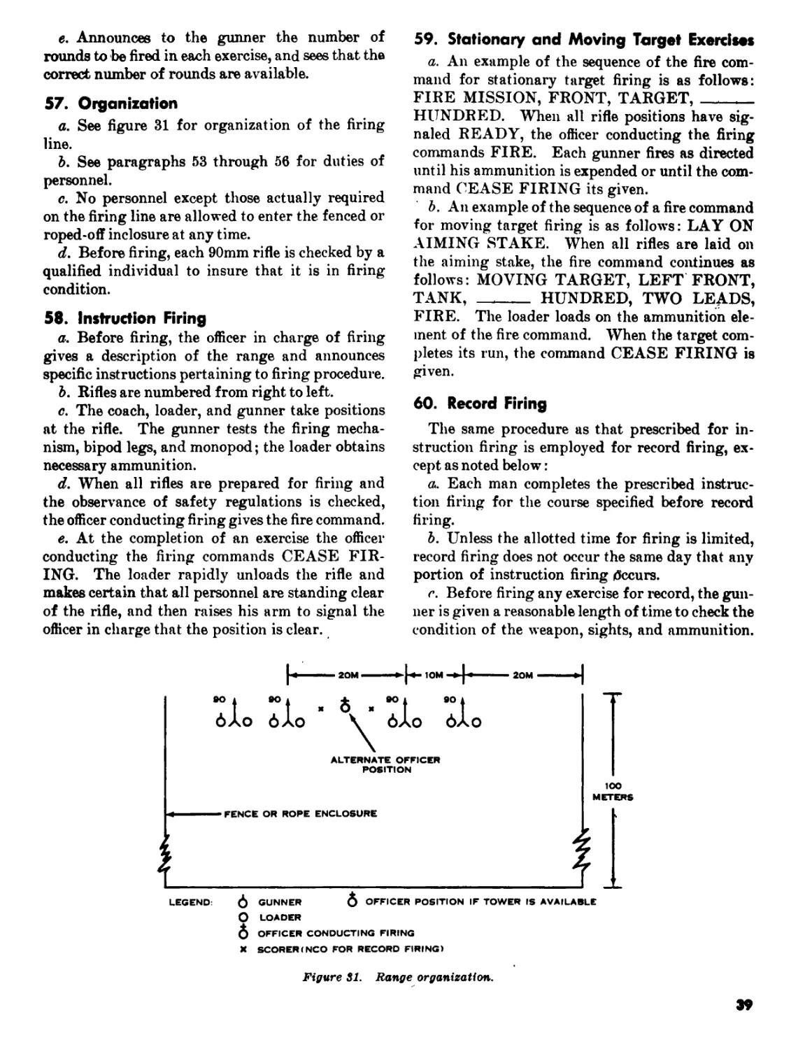
57. Organization
a. See figure 31 for organization of the firing
line.
b. See paragraphs 53 through 56 for duties of
personnel.
c. No personnel except those actually required
on the firing line are allowed to enter the fenced or
roped-off inclosure at any time.
d. Before firing, each 90mm rifle is checked by a
qualified individual to insure that it is in firing
condition.
58. Instruction Firing
a. Before firing, the officer in charge of firing
gives a description of the range and announces
specific instructions pertaining to firing procedure.
b. Rifles are numbered from right to left.
c. The coach, loader, and gunner take positions
at the rifle. The gunner tests the firing mecha-
nism, bipod legs, and monopod; the loader obtains
necessary ammunition.
d. When all rifles are prepared for firing and
the observance of safety regulations is checked,
the officer conducting firing gives the fire command.
e. At the completion of an exercise the officer
conducting the firing commands CEASE FIR-
ING. The loader rapidly unloads the rifle and
makes certain that all personnel are standing clear
of the rifle, and then raises his arm to signal the
officer in charge that the position is clear.
59. Stationary and Moving Target Exercises
a. An example of the sequence of the fire com-
mand for stationary target firing is as follows:
FIRE MISSION, FRONT, TARGET,
HUNDRED. When all rifle positions have sig-
naled READY, the officer conducting the firing
commands FIRE. Each gunner fires as directed
until his ammunition is expended or until the com-
mand CEASE FIRING its given.
b. An example of the sequence of a fire command
for moving target firing is as follows: LAY ON
AIMING STAKE. When all rifles are laid on
the aiming stake, the fire command continues as
follows: MOVING TARGET, LEFT FRONT,
TANK, HUNDRED, TWO LEADS,
FIRE. The loader loads on the ammunition ele-
ment of the fire command. When the target com-
pletes its run, the command CEASE FIRING is
given.
60. Record Firing
The same procedure as that prescribed for in-
struction firing is employed for record firing, ex-
cept as noted below :
a. Each man completes the prescribed instruc-
tion firing for the course specified before record
firing.
b. Unless the allotted time for firing is limited,
record firing does not occur the same day that any
portion of instruction firing Occurs.
e. Before firing any exercise for record, the gun-
ner is given a reasonable length of time to check the
condition of the weapon, sights, and ammunition.
X SCORER(NCO FOR RECORD FIRING)
Figure 31. Range organization.
39
d. The gunner boresights or zeros his own
weapon before record firing.
e. The target speed and the allotted time are des-
ignated to each gunner before firing.
/. In record firing, when a misfire, stoppage, or
malfunction occurs, the gunner or loader holds up
his hand and calls MISFIRE. Thereafter neither
the loader nor gunner touches the rifle until the
scorer examines It.
g. If a misfire, stoppage, or malfunction occurs
through no fault of the gunner, the score is dis-
regarded and the gunner is permitted to refire the
exercise.
Д. Decisions to disregard scores or to authorize
refiring of portions of the course rest with the
officer in charge.
г. If a misfire or malfunction is clearly the fault
of the gunner, he is not permitted to refire that
portion of the course.
61. Scoring an Individual for Qualification
a. A departure from the mandatory provisions
of this course disqualifies the firer involved.
b. After a man has started an exercise, all rounds
fired by him count as part of the exercise.
c. A gunner is given credit for only those hits
that strike the correct target or scoring space.
d. A hit is scored for each bullet hole found in
a target or scoring space, except that no more than
the prescribed number of shots are counted. In
field service firing, observation of the strike on the
target counts as a hit. The target does not have
to be marked.
e. For 25-meter firing, the name of the gunner
is placed on each target before firing. Except
under the supervision of the scorer, no person
handles any target until it has been scored.
f. A bullet hole that touches the outer line of a
scoring space is classed as a hit. A bullet hole cut-
ting or touching the line between two scoring
spaces receives credit for the higher value score.
g. For moving target firing, ammunition not
fired during the exposure time of this target is
forfeited.
A Holes made by ricocheting bullets, rocks, or
other foreign matter are not counted.
i. Each individual entry for record practice is
made on the scorecard in ink or indelible pencil
and is authenticated by the scorer. Erasures are
not permitted; only the scorer can make alterations
and these must be initialed by him.
62. Safety Precautions
a. Because of the danger to personnel from the
backblast of recoilless weapons, exercise extreme
care in all phases of instruction. Emphasize this
danger during the earliest stages of training. Con-
duct all crew drills, position exercises, tracking
exercises, and subcaliber firing as though service
ammunition is being fired.
b. The backblast area is pentagonal in shape
(fig. 32) with the apex at the breech. It extends
140 feet to the rear and has a 180-foot base, 90 feet
on either side of the bore axis extended. It is
divided into two areas: A danger area and a cau-
tion area. In the danger area, which extends 90
feet to the rear of the breech, serious casualties or
fatalities are likely to occur due to blast and flying
debris. In the caution area an individual is rela-
tively safe providing he does not face the breech.
This area extends an additional 50 feet to the rear
of the danger area. It is habitually kept clear
during training situations.
c. Do not fire the 90mm rifle from confined
spaces such as dugouts or rooms. Structural dam-
age to the inclosure may occur and occupants might
be injured by falling debris. Severe concussion
and concentration of toxic gases may result. There
is also danger of starting a fire.
d. Most conventional weapon emplacements are
unsuitable for this weapon. Any emplacement
where there is an obstruction too near the breech
is unsuitable since the obstruction may deflect the
concussion toward the crew. The most suitable
emplacements are those which leave the rear of the
rifle exposed (or semiexposed) with no obstruction
behind the breech, and which provide cover for
operating personnel on either side of the rifle.
e. If the 90mm rifle has been subjected to con-
tinuous firing for a considerable length of time,
the tube and chamber will become overheated. The
heat of the rifle could possibly cause the propellant
to ignite. An ignition under such circumstances
is called a cookoff. Cookoffs normally occur be-
tween 10 to 30 seconds after a cartridge has been
loaded into a hot chamber. If a misfire occurs
while the tube is hot, all personnel must stay clear
of the muzzle and backblast danger area until the
rifle is cool, after which the cartridge will be
removed.
/. Because of the possibility of a hangfire or a
40
BREECH END OF RIFLE
A. 90 FT
B. 50 FT
«- - 90 FT
180 FT
A-DANGER AREA
В-CAUTION AREA
Figure St. Backblast area.
cookoff, the following immediate action proce-
dures will be observed when a misfire occurs with
the 90mm rifle:
(1) Keep the weapon aimed at the target and
keep all personnel clear.
(2) Wait 1 minute and recock the weapon
and attempt to fire again.
(3) If the rifle does not fire a second time, wait
one more minute and remove the round.
Check the primer for an indent from the
firing pin; however, if an indent is pres-
ent the cause of the malfunction is in
the round and it must be destroyed ac-
cording to unit SOP. If the primer is
not indented, examine the rifle to deter-
mine the cause of the malfunction. Be
careful that the round does not drop on
the ground.
g. Do not disassemble ammunition at any time.
h. Comply with safety instructions in AR
385-63.
г. When firing service ammunition, the weapon
may become dangerous to touch because of heat
after two or three rounds. Be careful not to touch
the tube.
/ When firing from the prone position, the crew
should have their shirt or jacket collars turned up
and the top buttons fastened. ^This will afford
protection to the neck from foreign material
thrown up by the backblast.
41
CHAPTER 4
MARKSMANSHIP TRAINING
Section I. GENERAL
63. Introduction
Field firing develops individual proficiency and
teamwork for all phases of combat. The unit is
conducted through a series of exercises simulating
battlefield conditions as nearly as possible. The
situation for each exercise is given by the instruc-
tor who acts as umpire. Unit commanders direct
and control their units in the actions required. At
the completion of each exercise, a critique is held
by the umpire.
64. Exercises
Where possible, the terrain is varied for each
exercise so the unit is presented with a new situa-
tion. The following paragraphs are given as a
guide for the preparation of such exercises.
65. Direct Fire
a. Purpose, To give the squad leaders practice
in control of their units as they engage various
types of targets. Direct fire teaches members of
the crew selection of positions, use of individual
cover and concealment, ammunition supply, and
technique of fire.
b. Unit, One 90mm rifle crew.
c. Situation. Crew is located in an assembly
area and is issued ammunition. The squad leader
is given pertinent portions of an operation order
to include position areas, sectors of fire, and loca-
tion of friendly troops.
66. Method
The squad leader selects his route of approach
and his crew’s position. He issues necessary orders
to place the crew in action. When a target is indi-
cated, the squad leader issues fire commands, opens
fire, and adjusts the fire. Neutralization fire is not
a part of these exercises. As soon as the fire of
the crew has been adjusted, duties of individuals
in the crews are rotated and a new target is desig-
nated. The squad leader is prepared at any time
to displace forward to an alternate or supple-
mentary position or to withdraw to a covered area
67. Critique
At the completion of each exercise, the instruc-
tor conducts a critique covering the following
points (care is taken by the officer conducting the
critique to avoid confusing effectiveness of fire with
overall unit performance):
a. Reconnaissance.
b. Actions and orders of unit leaders.
c. Suitability of observation posts.
d. Suitability of firing positions.
e. Suitability of alternate positions.
/. Use of cover and concealment.
g. Technique of fire.
Л. Ammunition resupply plans.
Section II. QUALIFICATION AND FAMILIARIZATION FIRING
68. Qualification Courses
Three qualification courses are prescribed for
the 90mm rifle. These courses consist of various
combinations of the tables outlined in paragraph
69. The course used will normally be determined
by the facilities available.
a. Fundamentals, Fundamentals emphasized
in the qualification courses are:
42
(1) Rapid estimation of range, apparent
speed, and leads.
(2) Rapid and accurate firing of the initial
round.
(3) Rapid and accurate adjustment of fire.
(4) Rapid engagement of successive targets.
b. Conduct of Fire. For safety precautioAs,
range procedures, and operational instructions, see
chapter 3.
c. Courses of Fire. The courses of fire are or-
ganized as shown below.
Table Course A 11nstruction record Course В1 Instruction record Course C > Instruction record Instruction course (modified)
I Fired once... Not fired Fired once... Not fired Fired twice. _ Fired twice.. Fired once.
П Fired once... Not fired. Fired once... Not fired Fired twice. _ Fired twice. _ Not fired.
Ш Fired once... Fired once... Fired once... Fired twice. _ Not fired Not fired Fired once.
IV Fired once... Fired once... Fired once... Fired twice. _ Not fired Not fired Not fired.
V Not fired Fired once... Not fired. Not fired Not fired Not fired Not fired.
VI Not fired.... Not fired.._. Not fired.... Not fired Not fired Not fired Fired once.
1 Used if faculties are available for service firing.
1 Used if midrange subcaliber range is available, but service range facilities are not.
< Used if neither midrange subcaliber nor service range facilities are available.
d. Qualification Scores. CourteA Course В 320-400 Course C 315-380
Expert 210-260
First class gun- ner Second class gunner Unqualified- 185-209 280-319 160-184 240-279 Below 160 Below 240 270-314 230-269 Below 230
e. Scorecard. DA Form 2974—R, Individual Scorecard 90mm Recoilless Rifle (fig. 33) will be reproduced locally on 8" x 10^" paper.
69. Tables
Table I. $5-meler subcaliber firing—stationary target
Trial Number of rounds Time (seconds) Maximum score
1 5 75 25
2 5 75 25
3 5 75 25
4 5 75 25
20 — 100
Note. The number of rounds fired in this table may be reduced at the
discretion of the officer in charge of firing.
a. Table I.
(1) Instructions for firing table I.
(a) Target layout consists of five 1,000-
inch “A” rifle targets for each firing
point. Targets are emplaced 1 meter
apart and 50 centimeters off the ground
(fig. 34).
(b) Zero the rifle at 25 meters using any de-
sired range line, but insure that all
rifles on the firing line are zeroed with
the same range line.
(<?) This table is fired from the prone posi-
tion.
(</) Use 7.62mm ball ammunition only.
(2) Procedure for officer in charge of firing.
(a) During instructional firing, the officer
in charge of firing announces TIME at
the end of the prescribed time. He
does not command GEASE FIRE until
all gunners have completed firing.
(5) During record firing, the officer in
charge of firing commands CEASE
FIRE at the end of the prescribed time.
(c) Hits on the 1,000-inch “A” rifle target
are given the numerical value as shown
on the target.
Table II. 25-meter subcaliber firing, moving target (level
track)
Trial Number of rounds Time ex- posed (sec) Target speed (cm/ sec) Maximum
Leads Score
1 3 60 20 0-1-2 15
2 3 60 20 0-1-2 15
3 3 50 25 0-1-2 15
4 3 50 25 0-1-2 15
5 3 40 30 0-1-2 15
6 3 40 30 0-1-2 15
18 — 90
43
INDIVIDUAL SCORECARD 90MM RECOILLESS RIFLE I (FM 23-11) )ATE у /Я- 2-^77
NAMU^/?£v^ GRAIV-6- ORGANIZATION T$ g D&TX., STU Bfil
" TABLE I (Course A) TABLE IV (Course A)
Trial Poss- ible Instruction Score Record Score Trial Poss- ible Instruction Score Record Score
1 25 iJ" 1 10 '6 lb
2 25 2.6" 2 10 /6
3 25 2b 3 10 s' /0
4 25 2 b' 4 10 s' /b
Total 5 10 lb 16
FABLE II (Course A) 6 10 )b
1 IS tS"
7 10 lb s'
2 15 . /6
8 10 S' !b
3 15 /б"'
9 10 /6 lb
4 15 “ /<
10 10 S' lb
5 15 м
Total 75" 90
6 15 /<
TABLE V (Course A)
Total ъъ 1 20 26 26
TABLE Ш (Course A) 2 20 lb 3.b
1 10 S'' 76
3 20 2й Л6
2 10 lb lb
Total 5 (>b
3 10 /0 /6
Table Instruction Record
4 10 Course Course
A В c A в c
5 10 th I ХЛХ
6 10 lb lb II 96 AXX
7 10 10 lb Ш ЯО 9b
8 10 16 IV 75^ 96
9 10 /й s' V 5'6 (d)
10 10 id lb Total 3S6 2ЦЬ
Total 96 9b
Signature of Firer ( Signature of Scoter * Л h \
Signature of Officer ,J -T“<> r Ш —- Date
DA FORM 2974-R
Figure 33. ticoreeurd.
44
TARGET STAKES ARE MADE OF ANY SUITABLE SIZE LUMBER. A PRONE
"F SILHOUETTE TARGET IS TACKED TO THE TOP OF EACH STAKE.
1.000-INCH “A” RIFLE TARGETS ARE PASTED ONTO THE SILHOUETTE
TARGETS.
Figure SJ. Target array for table I.
b. Table II.
(1) Instructions for firing table II.
(a) The standard A-22 subcaliber target is
used in firing this table (fig. 35). It
may be modified by painting over the
scoring spaces. A scoring template is
then required.
(5) Scoring templates may be locally fab-
ricated.
(c) Zero the rifle in the same manner as in
table I.
(d) This table is fired from the kneeling
position.
(e) Use 7.62mm ball ammunition only.
(/) Gunner fires one round at each tank in
the following order: Top, center, and
bottom as target moves in either direc-
tion. He uses zero leads when firing at
the top tank; one lead when firing at
the center tank; and two leads when
firing at the bottom tank. Gunner fires
on the left vertical column of tanks
Figure 35. Moving target 25-meter subcaliber firing.
45
when the target is moving right to left,
and on the right column when target is
moving left to right.
(2) Procedure for officer in charge of firing.
(a) The command CEASE FIRE is given
at the end of the prescribed time dur-
ing both instructional and record firing.
(&) Score five points for each hit in a scor-
ing space; but do not score more than
three hits in each top silhouette and
three hits in each scoring space.
c. Table III.
(1) Instructions for firing table III.
(a) Targets should be spread laterally in at
least a 30-degree fan. Targets should
be arranged at random in depth at
ranges varying from 200 to 450 meters.
(d) Target panels must have a 10-foot (3-
meter) or 20-foot (6-meter) horizontal
dimension. Bunker targets may be any
size.
Table III, Midrange subcaliber firing, stationary target,
unknown range
Tria) Maximum number of rounds Range (meters) Target Maximum score
1 2 200-450 PaneL 10
2 2 200-450 Panel. 10
3 2 200-450 Panel 10
4 2 200-450 Panel 10
5 2 200-450 Bunker 10
6 2 200-450 Panel 10
7 2 200-450 Panel 10
8 2 200-450 Panel 10
9 2 200-450 Bunker 10
10 2 200-450 Panel 10
20 — 100
(c) Zero the rifle at a known range between
400 and 450 meters.
(d) This table is fired from the prone posi-
tion.
(e) Use 7.62mm tracer ammunition only.
(/) Gunner estimates range to each panel
target by use of stadia lines. Gunner
estimates range to bunker targets by
eye and by noting location in relation
to panel targets already engaged.
(^) Gunner attempts to achieve a first
round hit on each target. In the event
of a miss, he fires a second round using
the burst-on target method of adjust-
ment.
(2) Procedure for officer in charge of firing.
(a) Scorers should have binoculars.
(d) Number of rifles firing at any given
time should be controlled so that я
scorer need watch only one weapon at a
time.
(c) Score 10 points for a first round hit; six
points for a second round hit; and zero
points if both rounds miss.
(d) In the event of a first round hit, a sec-
ond round will not be fired.
Table IV. Midrange subcaliber firing, moving target, known
range
Trial Maximum number of rounds Target km/hr Speed mph Leads (per- pendicular track) Maximum score
1 2 16 10 4 10
2 2 16 10 4 10
3 2 24 15 6 10
4 2 24 15 6 10
5 2 16 10 4 10
6 2 16 10 4 10
7 2 24 15 6 10
8 2 24 15 6 10
9 2 16 10 4 10
10 2 16 10 4 10
20 — 100
d. Table IV.
(1) Instructions for firing table IV.
(a) If possible, use a tank as the target.
(&) A diagonal track is preferable to a per-
pendicular track. When a diagonal
track is used, the number of leads will
be reduced.
(c) Zero the rifle at a known range be-
tween 400 and 450 meters.
(d) This table is fired from the foxhole
supported position.
(e) Use 7.62mm tracer ammunition only.
(/) Gunner attempts to achieve a first
round hit on each target run. In the
event of a miss, he fires a second round
using the burst-on-target method of ad-
justment.
(2) Procedure for officer in charge of firing,
(a) Scorers should have binoculars.
44
(6) Each scorer should be required to score
a maximum of two firing points at any
given time.
(<?) Officer in charge of firing should an-
nounce the range to each end of the
moving target track.
(d) Score 10 points for a first round hit; 6
points for a second round hit.
ТаЫе V. Service firing, stationary target, unknown range
Trial Maximum number o! rounds Range Maximum score
1 2 150-300 20
2 2 250-400 20
3 2 350-450 20
6 — 60
e, Table V.
(1) Instructions for firing table V.
(a) Targets may be log and sandbag bunk-
ers, panels, or tank hulls. It is import-
ant that each target has a 10-foot (3-
meter) or 20-foot (6-meter) horizontal
dimension.
(b) Boresight the rifle in the normal
fashion.
(c) This table is fired from the prone po-
sition.
(d) Either HEAT or TP ammunition may
be used.
(e) Gunner attempts to achieve a first
round hit. In the event of a miss, he
applies burst-on-target and fires a sec-
ond round.
(2) Procedure for officer in charge of firing.
(a) Scorers should have binoculars»
(6) Each scorer should be required to score
a maximum of two firing pointe at any
given time.
(c) Score 20 points for a first round hit; 12
points for a second round hit; zero
pointe if both rounds miss.
Table VI. Service familiarization
Trial Number of rounds Range (meters)
1___ 1 200-300
2 1 250-350
3 1 300-400
f. Table VI.
(1) Instruction for firing table VI. This
table is fired in the same manner as table
V except that only one round is fired at
each target, regardless of results.
(2) Procedure for officer in charge of firing.
This table is not scored.
47
CHAPTER 5
TECHNIQUE OF FIRE
Section I. GENERAL
70. Definitions and Scope
a. Terms.
(1) Technique of fire. Placing effective fire
on a target.
(2) Direct laying. Pointing a weapon for
direction and elevation by laying on a
target visible to the gunner as he looks
through the sight.
(3) Direct fife. Firing conducted when the
gunner is using direct laying.
b. Scope. Training in marksmanship is a pre-
requisite for instruction in direct laying. Direct
laying involves a knowledge of the following
subjects:
(1) Characteristics of fire.
(2) Range, apparent speed, and lead deter-
mination.
(3) Fire commands.
(4) Fire control.
71. Characteristics of Fire
a. Trajectory.
(1) The trajectory of a projectile is the curve
traced by the center of gravity of the pro-
jectile in its flight from the muzzle of the
gun to the point of impact. A knowledge
of the trajectory is important, especially
in firing antitank weapons and when fir-
ing over the heads of friendly troops.
(2) The 90mm rifle is classified as a flat tra-
jectory weapon. The muzzle velocity and
the weight of the projectile are the more
important factors in determining the flat-
ness of the trajectory. In all cases, how-
ever, due to the action of the force of
gravity and air resistance, the trajectory
of projectiles is actually a curve and not
a straight line. Air resistance retards
the projectile during is flight, causing the
angle of fall to be greater than the angle
of elevation. Therefore, the projectile
reaches its maximum ordinate (highest
point) closer to the point of impact than
to the rifle (fig. 36).
(3) A line tangent to the trajectory at the
point of impact is called the line of fall.
The vertical angle between the line of fall
and the ground at the point of impact is
called the angle of fall.
Figure 36. Elements of trajectory.
48
b. Dispersion.
(1) When firing a large number of rounds
from a rifle having elevation, di-
rection, and other conditions as nearly
identical as possible, the points of im-
pact of the projectile are scattered both
in range and deflection. This scattering
is called dispersion. The greatest concen-
tration of points of impact is near the
center of the group. Approximately as
many points fall short of the center as
fall beyond, and a few will fall to the
right or to the left.
(2) Among factors that cause dispersion are
variations in weight and composition of
the propellant, weight and balance of
the projectile, and atmospheric condition.
c. Dispersion Rectangle and Probable Error.
In general, the points of impact of projectiles fired
from a rifle, using the identical sight picture for
each cartridge fired, may be included in a rec-
tangle with its longer axis along the gun-target
line. This is called a dispersion rectangle. If this
rectangle is divided into eight equal parts by lines
drawn perpendicular to the line of fire, the per-
centage of points of impact to be expected in each
part is as shown in figure 37. Notice that each
of the two segments nearest the center of the dis-
persion rectangle contain 25 percent of all impacts.
The length (in the direction of fire) of each of the
segments of the dispersion rectangle represents one
range probable error. The value in meters of one
range probable error, which varies with the range
from the rifle to the center of impact, is given in
the firing table pertaining to the type of ammuni-
tion being fired.
Figure, 31. Dispersion rectangle.
Se ction II. RANGE DETERMINATION, AND ESTIMATING LEAD AND APPARENT SPEED
72. Range Determination
a. General.
(1) Ability to accurately estimate range is
essential to achieve first round hits. The
length of time available to fire is in many
cases limited; therefore, quick and ac-
curate determination of range is extreme-
ly important.
(2) The methods used to determine range to
a given target are:
(a) Using stadia lines in the sight reticle.
(b) Using map distance.
(c) Estimating by eye.
(d) Obtaining the range from other units.
(e) Firing other weapons.
(/) Measuring ground distance.
(g) Using binoculars.
b. Stadia Lines. The stadia lines in the sight
reticle are a readily available means of estimating
range (fig. 38). These lines are developed from
the mil relation formula and are designed to en-
able the gunner to estimate range to targets having
a 10- or 20-foot dimension. Most tanks are ap-
proximately 10 feet wide and 20 feet long. To
49
estimate range, the gunner adjusts the lay of the
rifle until the target exactly fits between the stadia
lines. The point on the vertical (range) line of
the reticle, that corresponds to the center of mass
of the target, indicates the range. The target in
figure 38 is at a range of 275 meters. On targets
showing more of the flank than the front, a full
stadia picture is used. If more of the front than
the flank is shown, a half stadia picture is neces-
sary (fig. 39). It is important to remember that
a deflection adjustment must be made from a half
stadia picture to obtain the correct sight picture
for target engagement.
c. Map Distance. Accuracy of determining
range from a map depends on skill in map reading
and the accuracy of the map (FM 21-26).
d. Estimating Range by Eye. See FM 23-71
for explanation.
e. Obtaining the Range From Other Units.
Often, a unit relieved from a combat position pos-
sesses range cards and other information that may
be of use to the relieving unit. Also, other units
of the same organization as the relieving unit may
have the desired information. This latter source
of information is usually reliable, especially if the
unit has previously engaged targets in the area.
Figure 38. Full stadia picture.
Figure 39. Half stadia picture.
50
In many cases, other weapons have been fired at
targets near the target being engaged by the 90mm
rifle, and their range data may be useful in deter-
mining the desired range.
f. Firing Other Weapons. You may use the
fire of other weapons to determine range. The
fire of smaller individual weapons, such as the M14
rifle using tracer ammunition, does not disclose
the position as readily as do larger type weapons
and is effective to ranges of approximately 500
meters.
g. Measuring Grownd Distance. If the situa-
tion permits freedom of movement, pace off the
distance or measure it with tape or speedometer.
h. Using Binoculars. Binoculars, used in con-
junction with the mil relation (WORM) formula,
are useful in determining ranges. To use this
method, select a house, door, window, highway, or
a telephone pole—something which has a known
size or can be closely estimated. Using the mil
scale in the binoculars, measure the height or
width of the object. Then substitute in the mil
W
relation formula: where R equals range
in thousands of meters, m equals width in mils,
and W equals width of the object in meters.
73. Determining Leads
The primary method of determining leads for
the 90mm rifle is as follows:
a. Estimate apparent speed of the target.
b. Convert the apparent speed to leads.
74. Apparent Speed Estimation
The speed at which a target seems to move to-
ward or away from the line of sight is called ap-
parent speed. It is determined by establishing a
line of sight and then estimating the target’s speed
as it moves toward or away from this line of sight.
In figure 40, tank A has no apparent speed no mat-
ter how fast it is moving because it is moving di-
rectly toward the gunner. The same applies if
the tank is moving directly away from the gunner.
Tank В has an apparent speed equal to its actual
(APPARENT SPEED - THE SPEED AT WHICH A TARGET SEEMS
TO MOVE TOWARD OR AWAY FROM THE LINE OF SIGHT)
।
GUN POSITION
TANK A
GUN POSITION
TANK В
Figure ^0. Determining apparent speed.
51
speed, because it is moving perpendicular to the
gunner’s line of sight. Tank C, moving at the
oblique, has an apparent speed less than its actual
speed. Constant practice is the only method by
which the gunner can acquire proficiency in esti-
mating apparent speed.
75. Lead Estimation
a. A moving target is led by the distance it
travels from the time the rifle is fired until the
projectile crosses the path of the target. Angular
leads are measured with the direct fire sight M103,
5 mils being equal to one lead. The number of
leads applied varies with the apparent speed of the
target, but not the range.
b. Ballistic characteristics of the 90mm rifle are
such that one lead is applied on the sight reticle
for each %y2 miles per hour of apparent speed of
the target.
e. An alternate means of determining leads is
the common lead rule. The number of leads re-
quired is determined by the direction the target
is moving in relation to the gun position (fig. 41).
Target speed is assumed to be 15 miles per hour.
If the target is moving directly toward or away
from the gun position, no leads are required. If
the target is moving from 1 or 11 o’clock, two leads
are used; from 2 or 10 o’clock, four leads; and
from 3 or 9 o’clock, six leads.
6 LEADS
LEADS (5 MILS) FOR
ANGLES OTHER THAN 90’
MUST BE ESTIMATED ON
THE SIGHT RETICLE
Figure Jfl. Common lead rule.
Section IV. FIRE COMMANDS
76. General
a. Fire commands are instructions issued to en-
able a weapons crew to engage a target. The squad
leader normally issues the fire commands. In some
cases, however, the time element involved may
require the gunner to issue an abbreviated com-
mand. In either case, a standard sequence is
followed (para 78).
b. Training in fire commands is designed to de-
velop squad proficiency to such a degree that all
fire after the initial shot can be adjusted without
command from the squad leader, until the target
is destroyed or the squad leader decides to resume
adjustment.
c. There are two kinds of fire commands: initial
and subsequent. Initial fire commands include all
data necessary for laying, loading, and firing the
rifle. Subsequent fire commands include those
52
commands issued to adjust, shift, cease, or suspend
fire. They normally include only those elements
necessary to accomplish these actions.
d. A correct fire command is as brief as clarity
permits. It includes all the elements needed to
accomplish the fire mission and is given in logical
sequence to accustom the crew to executing in-
structions in a definite order. It is transmitted at
a rate that permits receipt and application of in-
structions without confusion. Any unnecessary
elements are omitted.
e. Fire commands are usually given orally.
When oral delivery is not practicable, they may be
transmitted by telephone, radio, messenger, or
arm-and-hand signals worked out with the crew.
/. Numbers are announced as illustrated in the
following examples:
10_________________ONE ZERO
25_________________TWO FIVE
800________________THREE HUNDRED
475________________FOUR SEVEN FIVE
g. When the squad leader issues fire commands,
the gunner repeats all commands except when
firing at a moving target.
77. Sequence of Initial Fire Commands
a. Sequence. The following sequence is pre-
scribed for the initial fire command. Any of these
elements that do not pertain to a specific fire com-
mand are omitted.
(1) Alert.
(2) Type of ammunition.
(3) Direction.
(4) Target description.
(5) Range.
(6) Leads.
(7) Control.
b. Alert. The alert is always the first element
of the initial fire command. It consists of the
command FIRE MISSION in the case of a sta-
tionary target or the command MOVING TAR-
GET in the case of a moving target. The alert
puts the rifle crew in readiness to execute a fire
command with the least practicable delay.
c. Anvmunition. This element may be omitted
unless TP ammunition is to be fired. When this
element is omitted, HEAT will be loaded as soon
as the alert is given.
d. Direction. Direction may be given either
orally, by pointing, or by a combination of these
two methods. The squad leader may use a refer-
ence point in designating those targets that are
difficult for the gunner to locate. The clock sys-
tem of indicating direction may also be used.
e. Target Description. Targets are described
as quickly and simply as is consistent with clarity.
The squad leader uses the following word or
words to designate targets:
Any tank------------------------TANK
Any unarmored vehicle___________TRUCK
Personnel_______________________TROOPS
Automatic weapon________________MACHINEGUN
Any antitank or artillery piece_ANTITANK
Any other target________________Briefest descriptive
form.
If several targets are in view, he designates the
particular target or part of target to fire on; for
example, LEADING TANK or LAST TRUCK.
/. Range. Range is announced in meters (es-
timated or determined) either orally or by signals.
g. Leads. This element has application only in
the case of moving targets. Leads are announced
in units of 5-mil angular leads, as: TWO LEADS,
or THREE AND ONE-HALF LEADS.
h. Control. This element is given as FIRE, or
when a short delay is necessary, AT MY COM-
MAND. This is followed at the desired time by
the command FIRE.
78. Examples of Initial Fire Commands
a. Stationary Target at IfiO Meters.
FIREMISSION
HEAT
RIGHT FRONT
TANK
FOUR HUNDRED
FIRE
b. Moving Target at 300 Meters and 15 Miles
Per Hour Apparent Speed.
MOVING TARGET
HEAT
FRONT
TANK
THREE HUNDRED
SIX LEADS
FIRE
53
c. Examples of Initial Fire Commands 'When
the Gunner is Issuing the Command.
MOVING TARGET
HEAT
LEFT FRONT
Note. The gunner issues only those elements that affect
other members of the squad.
79. Subsequent Fire Commands
a. Sensing. In direct fire, sense each burst for
deflection and range. Do not announce either
sensing. See paragraph 89 for a discussion of
sensing and conduct of fire.
b. Elements, Elements of a subsequent fire com-
mand generally include only those elements in
which there is a change from the previous fire com-
mand. Range and control elements are always
included.
c. Announcing Subsequent Fire Commands,
Give subsequent commands as corrections to the
previous sight picture. Use the following terms to
announce these corrections:
Fire at the same range___REPEAT RANGE
Increase range___________ADD
Decrease range___________DROP
Моте the burst or strike to right—RIGHT
Move the burst or strike to left—LEFT
Increase leads___________MORE
Decrease leads___________LESS
80. Corrections
a. Deflection. When firing on stationary tar-
gets, give corrections in deflection (in mils) as
RIGHT FIVE, LEFT ONE ZERO. When de-
flection is correct, omit this element from subse-
quent fire command.
b. Range. Always include this element in the
subsequent fire command. If a correction is needed
announce it as ADD ONE HUNDRED, DROP
FIVE ZERO. If the range is correct, give this
element as REPEAT RANGE.
c, Leads. When firing at moving targets, give
the correction leads as TWO MORE, ONE LESS.
Include this element in subsequent fire commands
only when necessary.
81. Subsequent Fire Commands for Station-
ary Targets When the Squad Leader Is
Adjusting the Fire
a. LEFT TWO ZERO
DROP ONE HUNDRED
FIRE
b, RIGHT FIVE
ADD ONE HUNDRED
FIRE
c. REPEAT RANGE
FIRE
82. Subsequent Fire Commands for Moving
Targets When the Squad Loader Is Ad-
justing the Fire
a. DROP ONE HUNDRED
ONE LESS
FIRE
b. ADD ONE HUNDRED
TWO MORE
FIRE
c. REPEAT RANGE
ONE LESS
FIRE
83. Gunner's Subsequent Commands
When the gunner issues the initial fire command
and adjusts his own fire, there is no subsequent fire
command. It is desirable that all subsequent fire
adjustments be made by the gunner in order to
save time. When such adjustments are being
made, firing continues uninterrupted until the mis-
sion is accomplished.
84. Repeating and Correcting Commands
a. Repealing, If the loader or gunner fails to
understand any element of the fire command, he
requests a repetition of that element by announc-
ing DEFLECTION, RANGE, or AMMUNI-
TION. He uses a rising inflection in his voice to
denote a question. When any crew member asks
that an element be repeated, misunderstanding is
avoided by prefacing the repeated element or ele-
ments with the phrase THE COMMAND WAS
This phrase is used only when
repeating an element of an unexecuted fire com-
mand.
b. Corrections. In all initial fire commands, cor-
rect or erroneous command by saying CORREC-
TION, and give the new command. To correct an
erroneous range command of 200 meters to 300
meters, the procedure is: CORRECTION,
THREE HUNDRED, FIRE. (NOTE that the
corrected initial fire command is followed by the
54
command to FIRE.) To correct an error in a
subsequent fire command, the observer says COR-
RECTION and repeats the entire subsequent com-
mand correctly.
85. Cease Firing
CEASE FIRING is announced when the squad
leader desires to interrupt firing for any reason.
It indicates the completion of firing with the data
in the gunner’s possession. Firing is then re-
newed by an initial fire command. SUSPEND
FIRING is the command for a temporary halt in
firing a particular mission. Given COMMENCE
FIRING after SUSPEND FIRING, the crew
continues to fire the mission under the previous fire
command.
86. Termination of Alert
To allow the crew to relax between missions so
its response to subsequent alerts is more complete,
termination of the alert is announced as CEASE
FIRING, END OF MISSION. If oral com-
mands are not practicable, appropriate (arm-and-
hand) signals may be used.
Section V. FIRE CONTROL
87. General
Fire control implies the ability of a leader to
open fire at the instant he desires, adjust the fire of
his rifle or rifles upon the target, shift fire from
one target to another, regulate the rate of fire, and
to cease firing at will. A leader must accomplish
these promptly if the fire is to be effective. Lack
of good fire control results in loss of surprise effect,
premature disclosure of position, and fire on unim-
portant targets. It also results in a loss of time in
securing adjustment and a waste of ammunition.
Fire control depends on thorough discipline, tech-
nical training, and the initiative of crew members.
Because of noise, semi-isolation of firing positions,
limited vision, and fleeting opportunity, fire con-
trol must be simple to insure effective execution of
the mission and the engagement of new and un-
expected targets.
88. Chain of Fire Control
The commander responsible for employment of
the rifle issues the necessary orders directly to the
platoon leader. The platoon leader, in turn, gives
his orders to his squad leaders. The squad leader
is responsible for the ultimate control of the crew
and the accomplishment of its mission.
89. Adjustment of Fire
a. General,
(1) Adjustment of fire is one of the most im-
portant phases of fire control. If first
round hits are not achieved during firing,
rapid adjustments of fire are made with
subsequent rounds.
(2) Target misses are sensed prior to issu-
ance of subsequent corrective fire adjust-
ments. The term eeneing means that the
person controlling the fire of the weapon
notes where the projectile bursts in rela-
tion to the target. His sensing includes
both range and deflection observations.
After the observer has made his sensing,
he determines the corrections necessary
to obtain a target hit, and gives the ap-
propriate subsequent fire command. For
example, if the miss w as sensed 10 mils
to the left and 100 meters over the target
the correct subsequent^ fire command
would be—
RIGHT ONE ZERO
DROP ONE HUNDRED
FIRE
ft. Buret-On-Target Method.
(1) This method is primary with the 90mm
rifle. It may be used up to the maximum
range graduation of the sight reticle.
With a w ell-trained gunner, it is the most
accurate and rapid system of fire adjust-
ment. The gunner has complete control
over the adjustment of his fire. This sys-
tem cuts the time lag between firing, and
eliminates time required for the observer
to sense the burst and formulate and issue
a subsequent fire command. It also elimi-
nates time required by the crew to inter-
pret and execute the command.
(2) The burst-on-target method is based on
the fact that the rifle is boresighted. As
long as this condition exists, the burst of
each round fired at a given range will ap-
55
pear on the same place in the sight ret-
icle. If the gunner moves the point-of-
burst on the sight to the center of mass
of the target, a hit will be obtained with
the next round.
(3) In using the burst-on-target method, the
gunner makes his own sensings and then
applies the corrected data to the rifle.
The squad leader, after issuing the initial
fire command, remains silent. He is
ready, however, to take over if the gunner
needs help or if the gunner cannot see
the burst-on-target relationship through
the sight. In this case, the squad leader
issues normal subsequent commands to
adjust the fire. The gunner uses a sight
picture for his initial firing from the
elements of the squad leader’s initial fire
command.
FIRE MISSION
HEAT
FRONT
TANK
TWO HUNDRED
FIRE
(a) The gunner fires the rifle and, while
the projectile is on the way to the tar-
get, he checks his sight picture and
makes any corrections necessary be-
cause of the movement of the weapon
when fired.
(6) He notes the point on the sight reticle
where the burst appears and moves this
point onto the center of mass of the
target.
(c) He again fires. This should give him
Section VI.
91. General
Accurate marksmanship with the weapon re-
quires accurate boresighting. Improper bore-
sighting or zeroing results in an inability to hit the
target. To aline the axis of the 90mm bore (ex-
tended) and the telescopic line of sight, converge
both on some distant aiming point beyond 500
meters.
92. Procedure
a. Four notches, 90° apart, are located on the
muzzle end of the 90mm rifle. Place two pieces of
a target hit; if not, he applies the same
principle and fires again; this time he
should have a target hit.
(4) The most difficult step to achieve iri the
burst-on-target method is the movement
of the burst point to the target. The burst
indication is either a puff of smoke or a
cloud of dust which settles rapidly. The
gunner chooses some mark on his sight
reticle in the center of burst before the
burst indication disappears. He then
moves that exact point to the center of
mass of the target to fire his subsequent
round. In selecting this point, the gun-
ner chooses a lead line, a range gradua-
tion, or interpolates between lines. A
failure to hit with the second round nor-
mally indicates an inaccurate movement
of the center of burst. Should the gunner
fail to achieve a hit with his second round,
he repeats the process, moving the new
center-of-burst to the center of the target
by manipulation of the bipod or moving
the rifle right or left, whichever the case
may be.
90. Neutralization Fire
The squad leader or gunner may desire to place
a number of rounds on the target to destroy or
neutralize it. Because of the ammunition re-
supply problem, he does not command FIRE FOR
EFFECT. He estimates the number of rounds
needed for neutralization or destruction^ checks
the ammunition on hand, and issues a subsequent
fire command for each additional cartridge to be
fired. Example: REPEAT RANGE, FIRE.
BORESIGHTING
thread or some similar material across opposite
notches. The point of intersection marks the axis
of the bore at the muzzle end of the weapon.
6. Insert a boresight disc, issued with each
weapon, in the chamber to determine the axis of the
bore at the breech.
c. In the event the boresight disc is riot avail-
able, insert the breechblock into the chamber, after
removing the firing pin, so the axis of the bore at
the breech is defined by the firing pin hole in the
breechblock.
d. Select an aiming point beyond the range to
any likely target. With the eye held several inches
behind the breech, aline the axis of the bore on the
aiming point by elevating and traversing the rifle.
e. Look through the telescope and insure that
the boresight cross of the sight reticle is alined on
the same aiming point. If the boresight cross is
not alined, bring it to the aiming point by rotating
the elevation and azimuth correction screws with
the screwdriver end of the combination wrench.
Recheck the alinement through the bore and
through the sight. When the sight and the bore
are properly alined on the aiming point, the 90mm
rifle is boresighted (fig. 42).
Figure 42. Sight picture in boresighting.
Section VII. ZEROING THE SUBCALIBER DEVICE
93. Target Selection
a. Accuracy with the subcaliber device depends
on the zeroing procedures followed.
b. The subcaliber device for the 90mm rifle is
zeroed at a greater range than the targets to be en-
gaged. After selecting a target, place that seg-
ment of the range line which corresponds to the
range of the target, over the visible center of mass
of the target.
94. Firing
The gunner fires two rounds and observes their
impact. While the loader holds the weapon
steady, the gunner moves that range which cor-
responds to the range of the target to the center
of impact of the two rounds. He does this with
the azimuth and elevation screws located under the
sight. He then resumes his original sight pic-
ture and fires two more rounds. He continues this
process until he is hitting the visible center of mass
of the target using his original sight picture, at
which time the weapon is zeroed.
57
CHAPTER 6
ADVICE TO INSTRUCTORS
Section I. GENERAL
95. Purpose
This chapter is a guide for instructors in prepar-
ing, organizing, and presenting instruction on
90mm rifle.
96. Methods of Instruction
Basic teaching methods covered in FM 21-5 and
FM 21-6 apply to instruction for the 90mm rifle.
The specific nature of the subjects involved lends
itself to demonstration and application as the most
effective methods of instruction.
Section II. STANDARDS FOR TRAINING
97. Mechanical Training
Men are trained to—
a. Disassemble and assemble the 90mm rifle.
b. Explain how the 90mm rifle functions.
c. Determine the causes of common stoppages
in the weapon and reduce them quickly.
d. Know the capabilities of the ammunition and
care for and prepare ammunition for firing.
e. Care for and clean the 90mm rifle.
/. Destroy the rifle when directed to do so.
98. Marksmanship
Men аге trained to—
a. Perform the duties of all members of the
crew.
b. Load the 90mm properly.
c. Put the weapon in action.
d. Boresight the 90mm rifle.
e. Observe safety precautions.
/. Fire the weapon using the subcaliber device
and service ammunition.
g. Qualify as a second class gunner or higher.
99. Technique of Fire
Men are trained to—
a. Describe the dispersion pattern.
b. Engage targets.
c. Estimate ranges quickly and accurately.
d. Estimate apparent speed quickly and accur-
ately.
e. Determine leads.
/. Fire direct fire.
58
APPENDIX REFERENCES
AR 320-5 AR 385-63 FM 5-15 FM 5-20 FM 5-25 FM 7-11 FM 7-15 FM 21-5 FM 21-6 FM 21-26 FM 21-30 FM 21-40 Dictionary of United States Army Terms. Regulations for Firing Ammunition for Training, Target Practice, and Combat. Field Fortifications. Camouflage, Basic Principles and Field Camouflage. Explosives and Demolitions. Rifle Company, Infantry, Airborne, and Mechanized. Rifle Platoon and Squads, Infantry, Airborne, and Mechanized. Military Training. Techniques of Military Instruction. Map Reading. Military Symbols. Small Unit Procedures in Chemical, Biological, and Radiological (CBR) Oper- ations.
FM 23-71 ТВ 9-1300-204/1 Rifle Marksmanship. Cartridge, 90mm HEAT, M371 for Rifle, M67: Description, Functioning, and Use.
TM 3-220 TM 9-575 TM 9-1015-223-12 TM 9-1015-223-20P TM 9-1300-204 TM 38-750 DA Pam 108-1 DA Form 2404 Chemical, Biological, and Radiological (CBR) Decontamination. Auxiliary Sighting and Fire Control Equipment. Operator and Organizational Maintenance Manual; 90mm Recoilless Rifle, M67. Organizational Maintenance, Repair Parts, and Special Tool List. Ammunition for Recoilless Rifles. Army Equipment Record Procedures. Index of Army Motion Pictures, Filmstrips, Slides, and Phono-Recordings. Equipment Inspection and Maintenance Worksheet.
59
INDEX
Ammunition: Paragraphs Pages
Care, handling_________________________ 19 16
Classification_________________________ 20 16
Description____________________________ 18 16
Fuse, PIBD, M530_______________________ 22 17
HEAT___________________________________ 21 16
Assembly____________________________________ 8 6
Balance, restoration_______________________ 11 15
Boresighting----------------------------- 91 56
Characteristics. .__________________________ 2 3
Crew drill:
Equipment examination___________________40 24
Forming________________________________ 38 24
Reports______________________________ 41 24
Rifle in action________________________ 42 24
Rifle out of action____________________ 43 25
Posting squad__________________________ 39 24
Servicing the piece___________________ 44 25
Data________________________________________ 3 3
Decontamination___________________________ 28 20
Destruction:
Ammunition_____________________________ 31 22
To prevent capture_____________________ 30 21
Disassembly________________________________ 8
Equipment_________________.____________ 17 16
Fire commands:
Cease firing--------------------------- 85 55
Corrections---------------------------- 80 54
Examples_______________________________ 78 53
Sequence_______________________________ 77 53
Subsequent commands____________________ 79 54
Fire, technique of:
Apparent speed_____________________________ 74 51
Boresighting-------------------------- 91 56
Cease firing ______________________ 85 55
Chain of fire control__________________ 88 55
Characteristics:
Dispersion_________________________ 71 48
Dispersion rectangle............... 71 48
Trajectory_________________________ 71 48
Corrections____________________________ 80 54
Determining leads_____________________ 73 51
Fire, adjustment....................... 89 55
Fire commands__________________________ 76 52
Fire commands, examples______________ 78 53
Fire command, sequence................. 77 53
Fire commands, subsequent........ 79 54
Fire, neutralization_________________ 90 56
Firing_________________________________ 94 57
Lead estimation_____________________ 75 52
Range determination:
Estimate by eye..__________________ 72 49
Map distance______________________ 72 49
Other methods______________________ 72 49
Stadia lines_______________________ 72 49
Scope-------------------------------- 70 48
Fire, technique of—Continued Paragraphs Pages
Target selection_______________________ 93 57
Termination of alert___________________ 86 55
Firing______________________________________ 94 57
Gunner, assistant gunner training:
Breathing___________________________________ 48 33
Examination____________________________ 51 37
Fire adjustment________________________ 47 33
Position exercises______________________ 46 27
Sighting, aiming________________________ 45 25
Tracking________________________________ 50 34
Trigger manipulation___________________ 49 33
Immediate action____________________________ 14 15
Inspections._________________________________ 25 18
Instrument light T25_________________________ 7 6
Lead estimation______________________________ 75 52
Leads, determining__________________________ 73 51
Lubrication_________________________________ 26 19
Malfunctions_________________________________ 11 15
Maintenance, general-preventive________ 24 18
Marksmanship, general:
Crew duties______________________________ 36 23
Squad leader duties_____________________ 34 23
Training_______________________________ 33 23
Marksmanship training:
Critique___________________________________ 67 42
Direct fire____________________________ 65 42
Exercises......_........--.......— 64 42
Introduction__________________________ 63 42
Method____________________________- 66 42
Qualification courses__________________ 68 42
Scorecard.........................Fig- 33 44
Mechanical functioning______________________ 10 8
Operation, principle of______________________ 9 8
Range safety, procedures:
Coaches___________________-............... 55 38
Instruction firing_____________________ 58 39
Loaders________________________________ 56 38
Officer in charge---------------------- 53 38
Organization___________________________ 57 39
Record firing__________________________ 00 39
Safety percautions............-— 02 40
Scoring for qualification-------------- 01 40
Scoring personnel______________________ 54 38
Stationary, moving tragets------------- 59 39
Training procedure_____________________ 52 38
Recording procedures________________________ 27 20
Safety precautions......................... 02 40
Spare parts__________________________________ Ю Ю
Stadia lines______________________________ 72 49
Stoppages_________________________________ 13 15
Stoppages, reduction of_____________________ 15 15
Subcaliber device___________________________ 23 17
Target selection__________- -.........- - - 93 57
Telescope Ml03_______________________________ 5 5
Telescope mount Ml 10________________________ 0 0
60
By Order of the Secretary of the Army:
Official:
J. C. LAMBERT,
Major General, United States Army,
The Adjutant General.
HAROLD K. JOHNSON,
General, United States Army,
Chief of Staff.
Distribution:
Active Army:
DCSPER (2) Armies (5)
ACSI (2) MDW (6)
DCSLOG (2) Corps (3)
ACSFOR (2) Div (10)
CORC (2) Div Arty (1)
CNGB (6) Bde (3)
CRD (1) Regt/Gp/bg (1)
СОА (1) CC (2)
CINFO (1) Bn (2)
TIG (1) Co/Btry (1)
USCONARC (5) USATC (5)
USACDC (5) Br. Svc Sch (1)
USAMC (5) USAOC&S (3)
USAIB (5) USA Corps (8)
1GGVQMD (1)
NG: State AG (3) ; units—same as Active Army except allowance is one (1) copy each unit.
US AR: Units—Same as Active Army except allowance is one copy each unit.
For explanation of abbreviations used, see AR 320-60.
61
FM 23-11
•С 2
Change
No. 2
HEADQUARTERS
DEPARTMENT OF THE ARMY
Washington, D. C. 19 September 1968
90MM RECOILLESS RIFLE, M67
FM 23-11, 6 July 1965, is changed as follows:
Page b* paragraph 3a (6). “Maximum effective
range—450 meters.” is changed to read “Maxi-
mum effective range—400 meters.”
Page 5. Paragraph 55 is superseded as follows:
5. The reticle is an optical glass disc with an
0.749-inch aperture etched with a metric scale. It
is graduated at 50-meter intervals at ranges up to
400 meters, and numbered every 100 meters up to
800 meters. Speed-lead indicator lines are pro-
vided at 50-meter intervals up to 400 meters and
at 100-meter intervals from 400 to 800 meters. The
vertical range line is extended through the 0 line
to form a boresight cross. The broken horizontal
lines are speed-lead indicators. Each line or space
represents 2.5 mph of apparent speed. The curved
lines are stadia lines, and are used to estimate
ranges to targets of known dimensions. The aver-
age tank is 20-feet long and 10-feet wide; there-
fore, the stadia lines have been calibrated to
coincide with these dimensions from 100 to 600
meters of range. A level vial at the bottom of the
reticle provides a zero cant reference for the tele-
scope so that it may be kept level when boresight-
ing and firing the weapon (fig. 3).
*TMt dMNif» мф»гм4м С 1, 9 April 1V47.
Page 5. Figure 3 is superseded as follows :
Page 5. Figure 3.1 is added as follows:
Figure 3. Sight reticle, Ml 03 tight.
Figure 3.1 Sight reticle, M103A1 tight.
Page 6. Paragraph 5.1 is added after paragraph
5.
5.1 Direct Fire Sight—Telescope, Ml 03Al
a. The M103A1 sight (fig. 3.1) is a modified
version of the standard M103 sight. The modi-
fication has been made to the right side of the
sight reticle and is to be referred to only when
firing the XM591 round» The value difference of
the range line has been made so that it matches
the trajectory of the XM591 round.
b. On the modified sight, the range line on the
right side of the sight reticle is graduated in 25-
meter intervals from 0 to 200 meters and every 50
meters from 200 to 400 meter’s. The value of the
lead lines remains unchanged.
Note. The XM591 round was an experimental type am-
munition and is no longer issued. However, the M103A1
sight will be found on some 90mm recoilless rifles.
2
Page 6, paragraph 7. Title, “Instrument Light,
T25” is changed to read “Instrument Light, M54”
Page 17, paragraph 22. Title, “Fuze, PIBD;
M530” is changed to read “Fuzes, PIBD, M530
and М530АГ’
Page 17. Paragraph 22c is added is follows:
c. The M530A1 fuze is a modification of the
M530 fuze. The M530A1 fuze has a mechanism
which gives it a greater arming delay time.
Page 17. Paragraph 23 is Superseded as follows:
23. Subcaliber Device
a. The subcaliber device (fig. 16) for the 90mm
recoilless rifle permits realistic gunner and loader
training and eliminates the use of expensive serv-
ice ammunition. Because targets are not destroyed
as they would be if service ammunition were used,
range maintenance is reduced.
b. The M49A1 subcaliber device (fig. 16.1)
consists of a long, cylindrical sleeve, a barrel, a
bushing with an integral hinge, a locknut hous-
ing, a firing pin, and attaching hardware. The de-
vice utilizes a case blow-out principle through
six equally spaced holes in the chamber shoulder
section of the barrel. These holes permit the
cartridge case to be blown out, and limit the pres-
sure which in turn lowers the velocity to match
ballistically the major caliber round.
c. The trajectory of the 7.62mm subcaliber car-
tridge is about the same as the major caliber
cartridge; however, there is a telescopic reticle
mismatch. When firing tables III and IV to
zero the M49A1 subcaliber device, the system
should be zeroed at approximately 80 percent
of the maximum range of the targets to be en-
gaged in order to minimize absolute mismatch at
any point in the trajectory.
Page 18. Figure 16 is superseded as follows:
Figure 16 7.62mm subcaliber gun,
3
Page i8. Figure 16.1 is added as follows:
Figure 16.1. Major component» of the 7.6tmm »ubcouoer gun, M49A1.
Page 21. Paragraph 30c(2) (ft) is rescinded.
Page 25, paragraph 44a. In line 4, “breechblock”
is changed to read “lockring.”
Page 40, paragraph 62ft. In lines 2, 3, and 4, “It
extends 140 feet to the rear and has a 180-foot
base, 90 feet on either side of the bore axis ex-
tended.” is changed to read: “It extends 43
meters to the rear and has a 55-meter base, 27.5.
meters on either side of the bore axis extended”;
in lines 6 and 7, “90 feet” is changed to read “27.5
meters”; in line 11, “50 feet” is changed to read
“15 meters.”
Page 43. Paragraph 68ft. 1 is added as follows:
ft. Additional Ammunition Requirement. Prior
to firing the qualification tables, the subcaliber de-
vice will be zeroed using nine rounds, firing three-
round shot groups when firing tables I and II.
Firing tables II and IV, the subcaliber device
will be zeroed using six rounds. Only the initial
firing order will zero the device. All succeeding
orders will fire two confirming zero rounds.
4
Page 41. Figure 32 is superseded as follows:
A - DANGER AREA
В - CAUTION AREA
Figure 32. Backblati area.
Page 46, paragraph 59c(l)(a). In line 4, “200
to 450 meters” is changed to read: “150 to 350
meters.”
Page 46, table III. In the Range (metric) col-
umn, “200-450” is changed to read “150-350” (for
each trial 1-10).
Page 46. Paragraph 69c(l)(c) is superseded as
follows:
(c) Zero the rifle at a known range between
250 and 300 meters, or use a distance which is 80
percent of the most distant target.
Page 47, table V. In the Range column “250-
400” is changed to read “200-350 (trial 2) ; “350-
450” is changed to read “300-400” (trial 3).
5
Page 50. Figure 38 is superseded as follows:
800 800
Page 50. Figure 39 is superseded as follows:
0------tz z z°
700------I--------700
800 800
Figure 38. Half stadia picture.
Figure 39. Full stadia picture.
Page 57. Paragraph 93d is superseded as fol-
lows:
b. When firing tables III and IV, it is recom-
mended that the subcaliber device be zeroed at a
range of 80 percent of the most distant target in
order to eliminate the requirement for zeroing at
each specific range, and to reduce the mismatch
between the trajectory and the sight reticle.
By Order of the Secretary of the Army:
W. C. WESTMORELAND,
General, United States Army,
Official: Chief of Staff.
KENNETH G. WICKHAM,
Major General. United States Army,
The Adjutant General,
Distribution:
To be distributed in accordance with DA Form 12-11 requirements for 90-MM Recoilless Rifles, M67.
6
Changes in force: C 2 and C 3
FM 23-11
C3
Change
No. 3
HEADQUARTERS
DEPARTMENT OF THE ARMY
Washington, D. С.» 28 April 1970
90-MM RECOILLESS RIFLE, M67
FM 23-11,6 July 1965, is changed as follows:
Page 1>. Paragraph 3a(6) (as changed by C2) is
superseded as follows:
(6) Maximum effective range:
HEAT, TP........................ 400 meters
Antipersonnel ... 300 meters
Page 4, paragraph 3b. A column for “antiper-
sonnel” is added as follows:
(l)APERS.
(2) 6.79 pounds.
(3) 3.97 pounds.
(4) 1250 feet per second.
Page 6, paragraph 8b (1) (c). In line 2, “clock-
wise” is changed to read “counterclockwise.”
Page 16. Paragraph 20 is superseded as follows:
20. Classification
There are three authorized rounds for the 90-mm
recoilless rifle, M67. These are TP M371, HEAT
M371E1, and 90-mm canister, XM590E1. The tar-
get practice (TP) round is not standard, but it is
available for issue in certain areas. It is ballis-
tically identical to the high explosive antitank
(HEAT) round but contains only a small spotting
charge as the projectile filler. The 90-mm canister
round, XM590E1, is a fixed type antipersonnel
found which functions at muzzle action.
1
I3O6S
Figure 15.1. 90-mm canister cartridge XM590E1.
2
Page 17. Paragraph 21.1 is added after para-
graph 21.
21.1 90-mm Canister, Antipersonnel,
XM590E1
a. The 90-mm canister, antipersonnel round is
designed for close-in defense against massed at-
tacks or assaults on personnel positions. The can-
ister consists of a thin-walled, deep-drawn, scored
aluminum body which contains a payload of 2400
eight-grain, low-drag, fin-stabilized, steel-wire
fragments called flechettes. The complete car-
tridge weights approximately 6.79 pounds. The
projectile weights approximately 3.97 pounds and
has a muzzle velocity of approximately 1250 feet
per second.
b. The aluminum cartridge case (Ml 12) is 16.29
inches long and weights 1.0 pounds. A flange at
the base contains a plastic rupture disc that ob-
structs the gas flow during the early stages of pro-
pellent combustion. When the propellant is ignited,
the rotating band on the base traps the propellent
gases, building up an internal pressure which
bleeds through the holes in the base. The built-up
pressure bursts the body with the payload from
the case when the canister leaves the rifle. The
scored aluminum body strips back and the eight-
grain flechettes are released, dispersing in a cone
angle of approximately 8 degrees.
Warning: Overhead firing is prohibited.
Page 17, paragraph 22b. In line 5, “(lucky ele-
ment)” is deleted.
Page 20, paragraph 28. In line 2, “radiological” is
changed to read “nuclear.”
Page 20, paragraph 29c. In line 2, “radiological”
is changed to read “nuclear.”
Page Paragraph 69c(l) (c) (as superseded by
C2) is superseded as follows:
(c) Zero the rifle at a known range between
350 and 400 meters, or use a distance which is 80
percent of the most distant target.
Page £6. Paragraph 69d(l) (c) is superseded as
follows:
(c) Zero the rifle at a known range between
350 and 400 meters, or use a distance which is 80
percent of the most distant target.
Page 53, paragraph 76p. In line 2, “except when
firing at a moving target” is deleted.
Page 53, paragraph 77c. In line 2, “or antiper-
sonnel” is added after “TP”
By Order of the Secretary of the Army:
Official:
KENNETH G. WICKHAM,
Major General, United States Army,
The Adjutant General
W. C. WESTMORELAND,
General, United States Army,
Chief of Staff.
Distribution:
’ To be distributed in accordance with DA Form 12-11 requirements for 90-MM Recoilless Rifle, M67.
3
U.S. GOVERNMENT PRINTING OFFICE: 1985 О
489-255