/


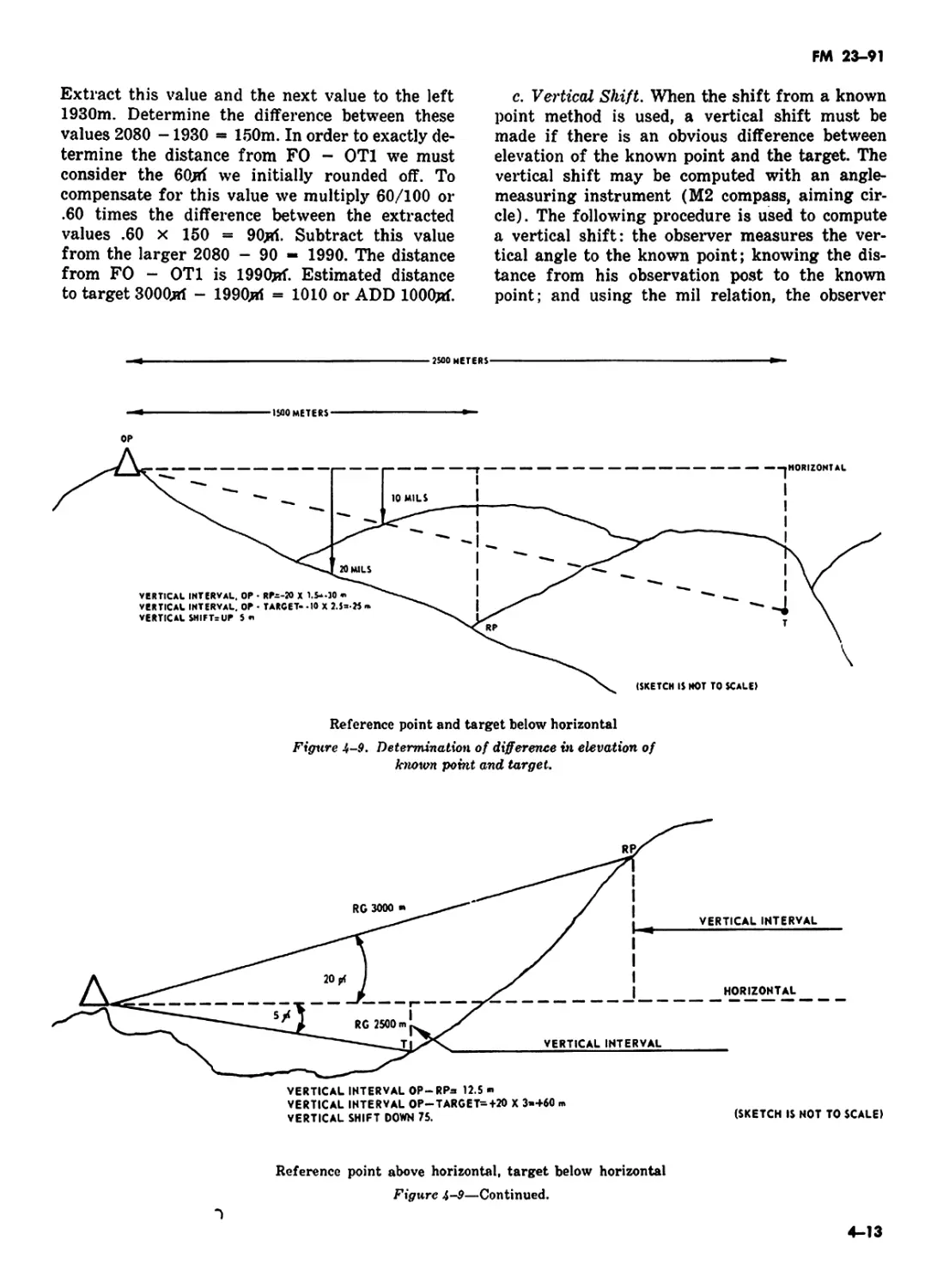
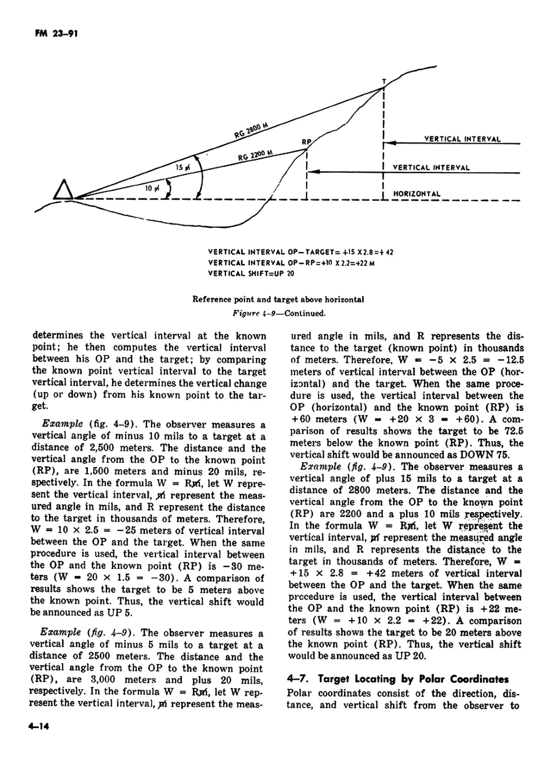


Text
FM 23-91
FIELD MANUAL
MORTAR GUNNERY
HEADQUARTERS, DEPARTMENT OF THE ARMY
DECEMBER 1971
FM 23-91
Field Manual
No. 23-91
HEADQUARTERS
DEPARTMENT OF THE ARMY
Washington, D. C., 17 December 1971
MORTAR GUNNERY
Paragraph Pag»
PART ONE INTRODUCTION AND FUNDA-
MENTALS
Chapter 1. INTRODUCTION 1-1—1-6 1-1
2. Section I. FUNDAMENTALS OF MORTAR GUNNERY Elements of Firing Data and Ballistics - 2-1—2-22 2-1
II. Dispersion and Probability 2-23—2-31 2-14
PART TWO Chapter 3. Section I. FORWARD OBSERVATION PRO- CEDURES OBSERVER PROCEDURES Introduction ... 3—1—3-5 8-1
II. Preparatory Operations 3-6—3-9 3-2
Chapter 4. LOCATING TARGETS 4-1—4-8 4-1
5. CALL FOR FIRE 5-1—5-11 5-1
6. Section I. ADJUSTMENT PROCEDURE BY GROUND OBSERVER General ... 6—1—6—6 6-1
II. Adjustment of Deviation .. 6—7—6—8 6-2
III. Adjustment of Range 6-9—6-13 6-6
IV. Adjustment of Height of Burst . . .... 6-14—6-17 6-8
V. Subsequent Corrections 6-18—6-31 6-9
Chapter 7. Section I. ADJUSTMENT OF FIRE BY THE AIR OBSERVER Introduction 7-1—7-2 7-1
I. Preflight Preparations 7—3—7—4 7-1
III. Determination of Initial Data 7-6—7-8 7-1
IV. Adjustment Procedures 7-9—7-10 7-8
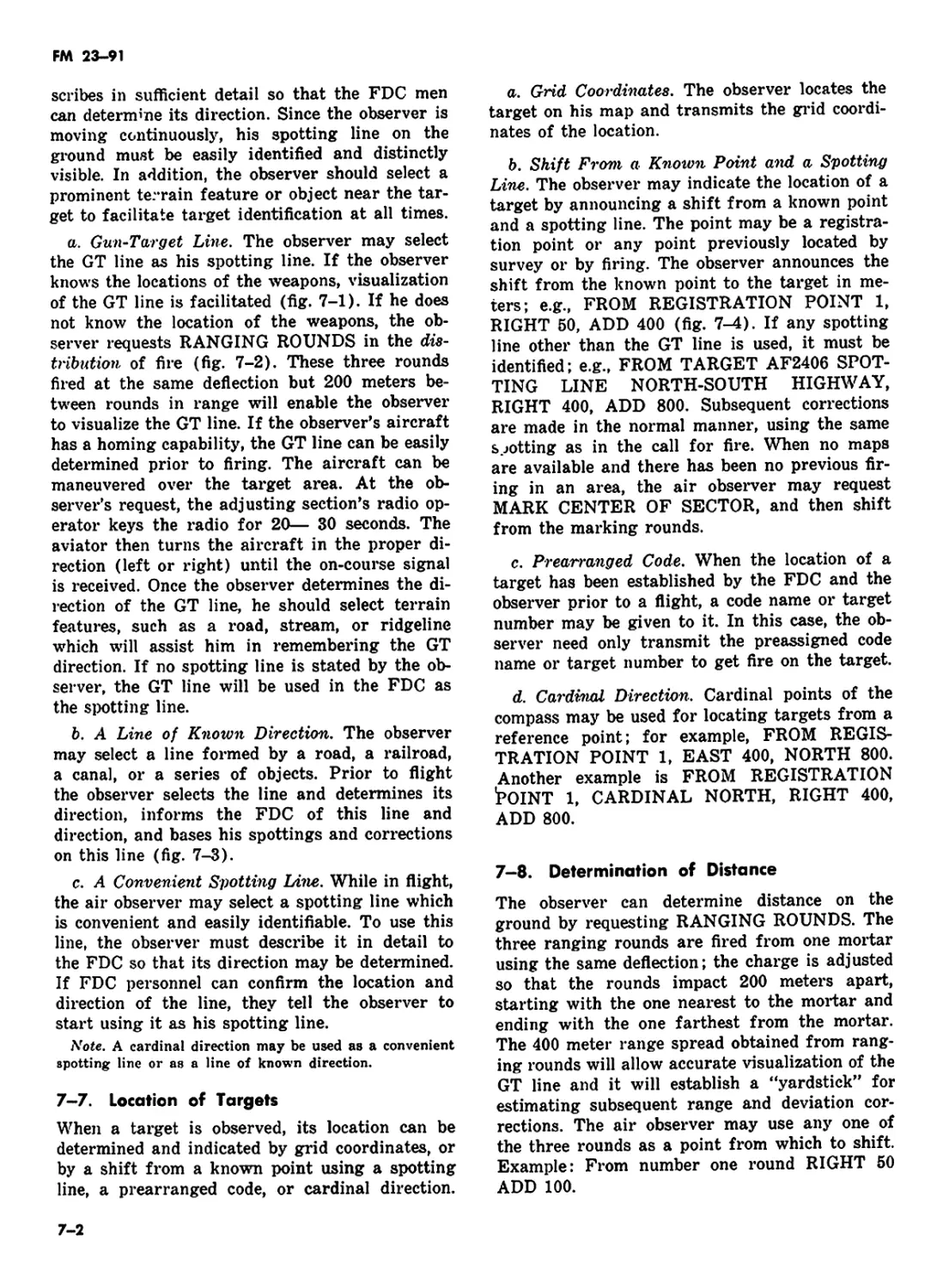
Chapter 8. Section I. PRECISION AND AREA FIRES Precision Fire ... 8-1» 8—3 8-1
II. Area Fire - 8-4—8-7 8-1
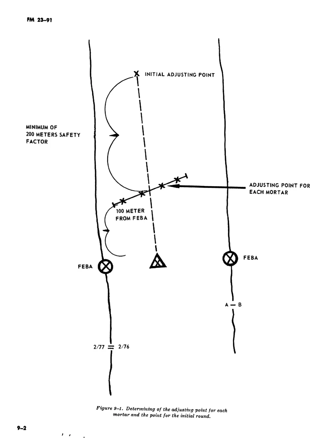
Chapter 9. PART THREE Chapter 10. Section I. ADJUSTMENT PROCEDURE FOR SPECIAL SITUATIONS FIRE DIRECTION PROCEDURES FIRE DIRECTION, GENERAL Introduction ... ... 9-1—9-10 10-1—10-3 9-1 10-1
II. Fire Direction Center 10-4—10-6 10-1
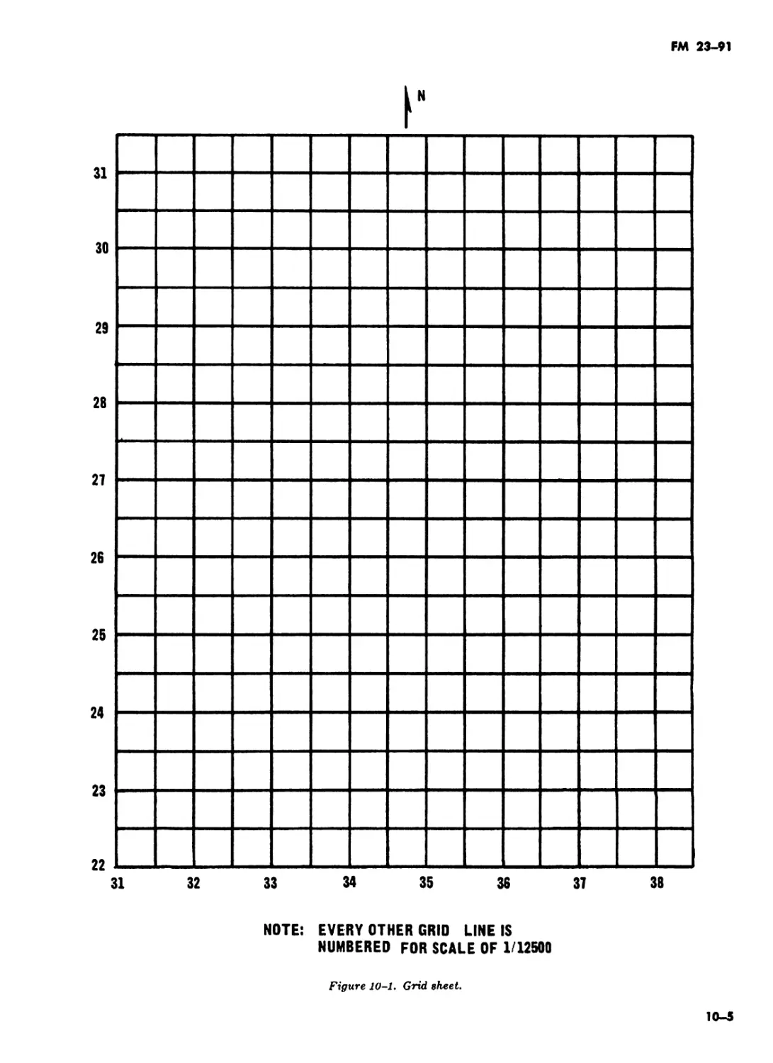
III. Firing Charts .. .. Ю-7—10-12 10-3
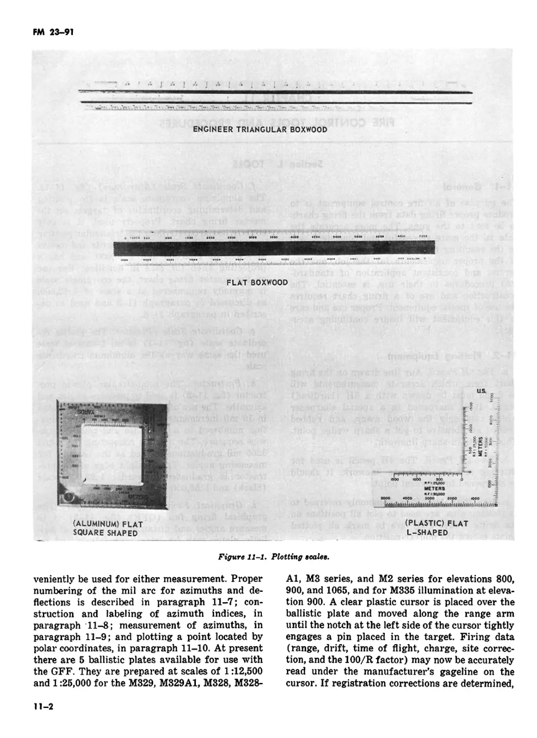
Chapter 11. Section I. FIRE CONTROL TOOLS AND PROCEDURES Tools 11-1—11-2 11-1
II. Procedures 11-3—11-13 11-7
Chapter 12. Section I. THE SURVEYED FIRING CHART Preparing the Chart 12-1—12-10 12-1
FM 23-91
Paragraph Рая*
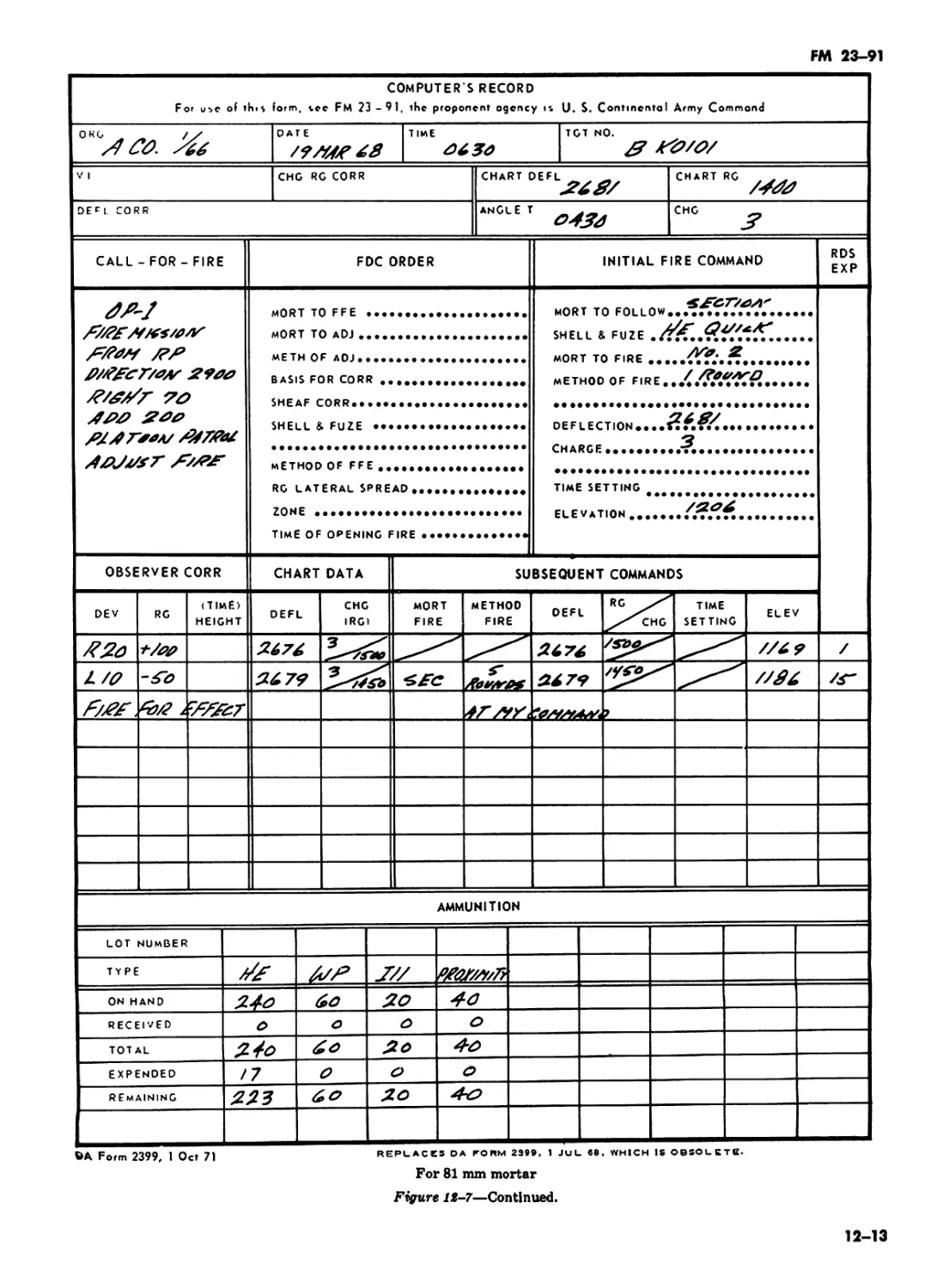
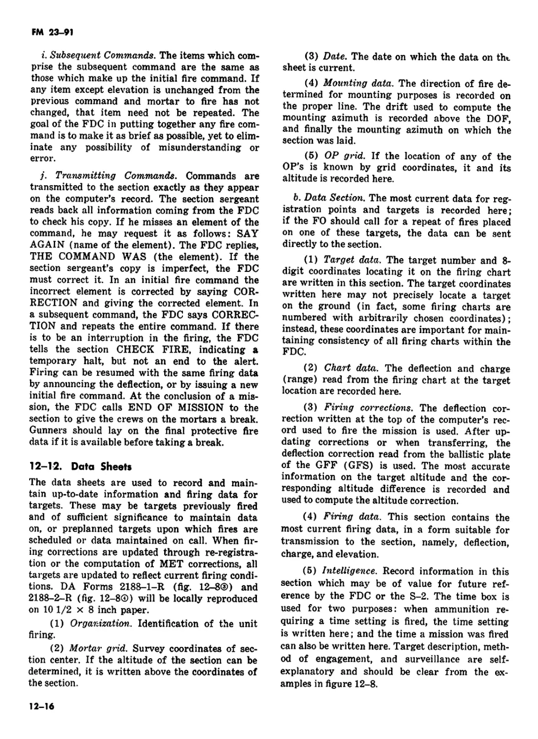
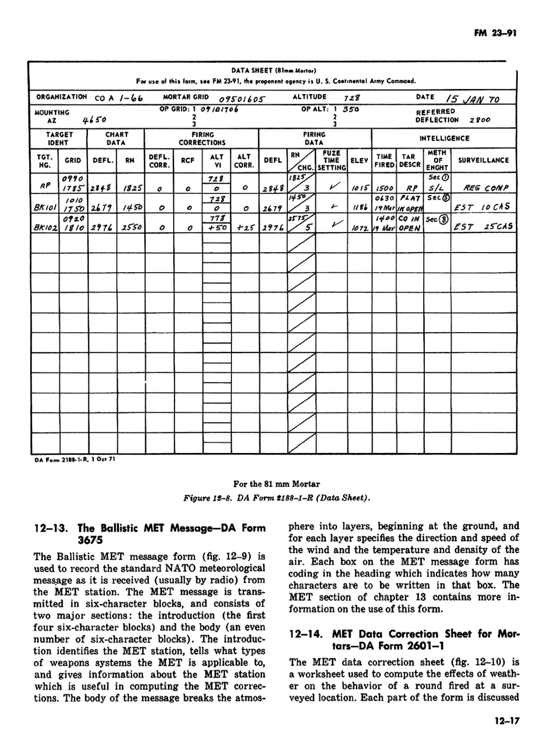
II. Firing Records and Commands . 12-11—12-14 12-11
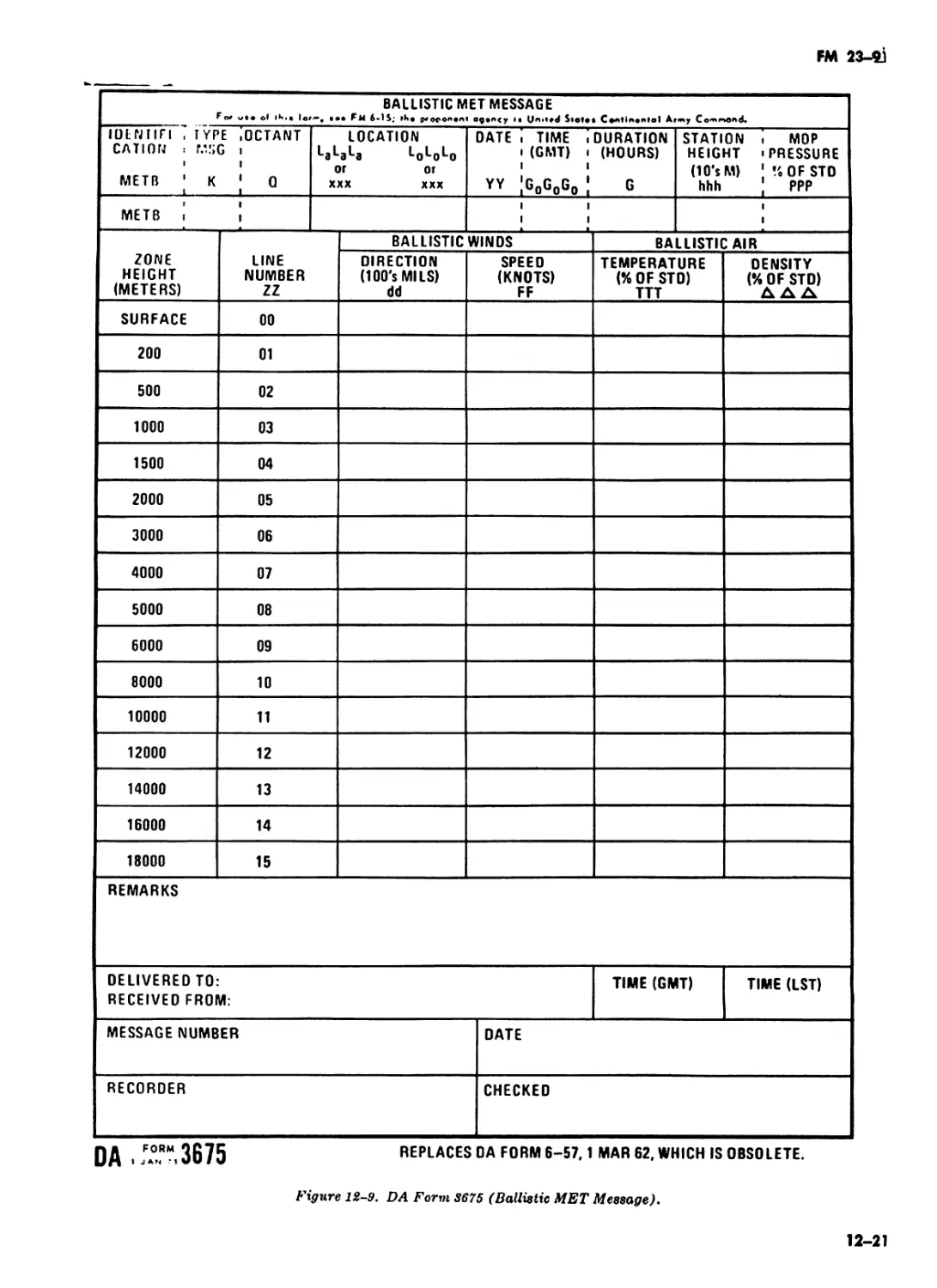
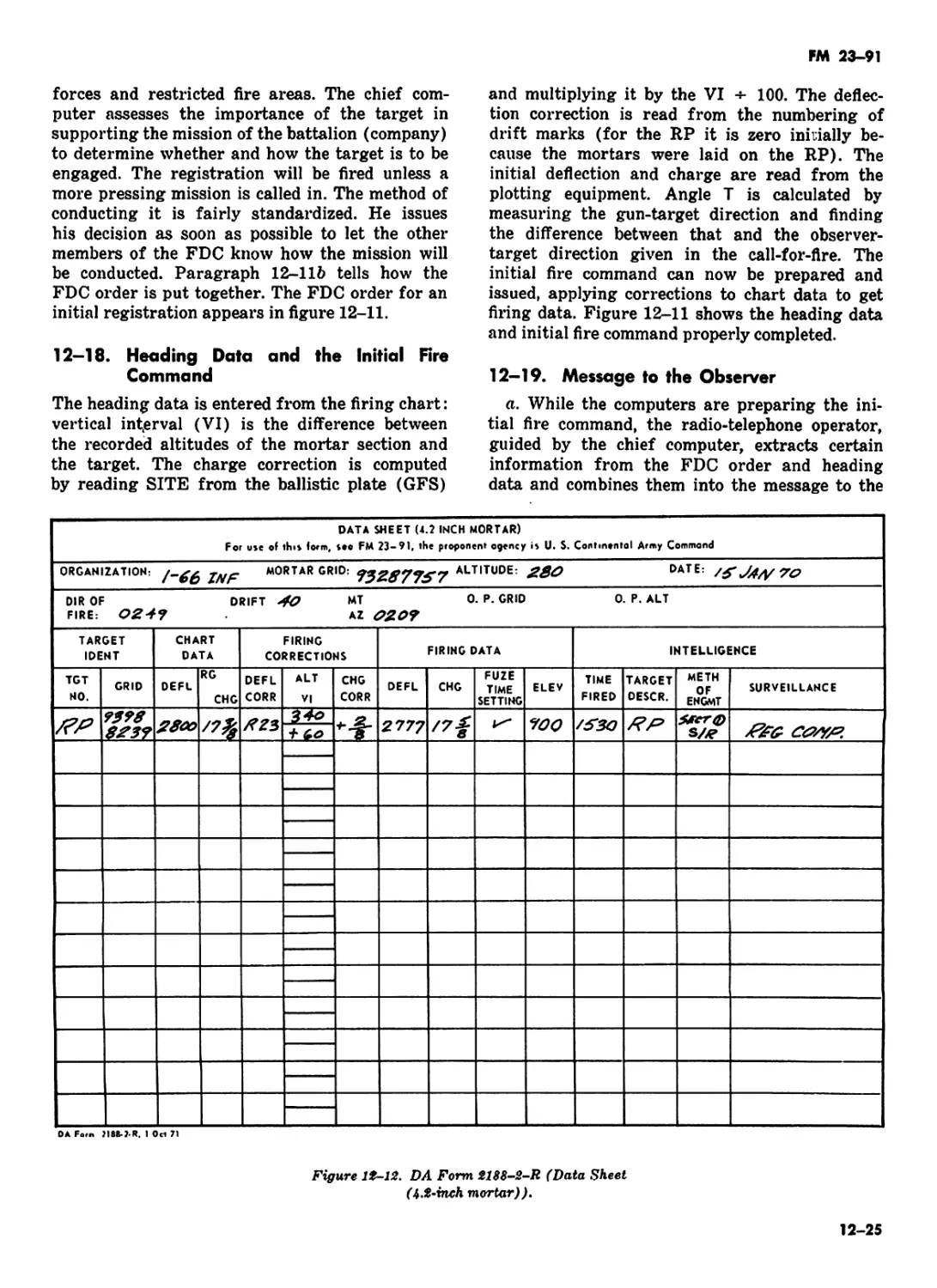
III. Registration and the Conduct of a Mission 12-15—12-22 12-24
IV. Engaging Standard Targets . 12-23—12-27 12-29
Chapter 13. ADVANCED PROCEDURES
Section I. Special Types of Missions 13-1—13-10 13-1
II. Advanced Techniques for Determining Corrections ... 13-11—13-25 13-14
Chapter 14. OBSERVED AND M0DIF1ED- OBSERVED FIRING CHARTS AND TRANSFER _. . 14-1—14-7 14-1
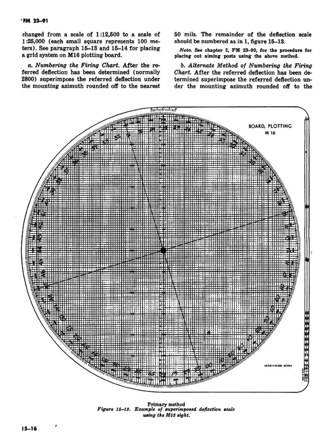
15. FIRE CONTROL WITH THE M16 PLOTTING BOARD 15-1—15-36 15-1
16. FIRE PLANNING AND TARGET ANALYSIS AND ATTACK
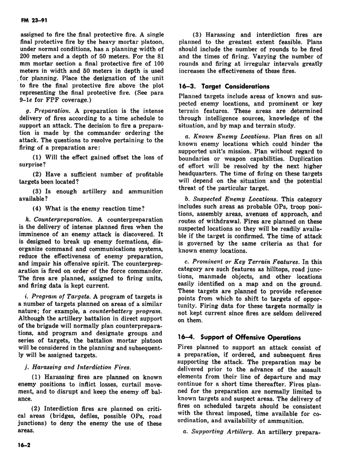
Section I. Fire Planning . 16-1—16-9 16-1
II. Target Analysis and Attack . . 16-10—16-18 16-11
Chapter 17. OPERATIONS .... 17-1—17-16 17-1
Appendix A. REFERENCES _ . A-l
B. DUTIES OF SAFETY OFFICER . B-l
C. COMMON MISTAKES AND MAL- PRACTICES . C-l
D. 4.2-INCH MORTAR AND FDC EQUIPMENT D-l
Index . Index 1
H
FM 23-91
PART ONE
INTRODUCTION AND FUNDAMENTALS
CHAPTER 1
INTRODUCTION
1-1. Purpose
a. Mortar gunnery includes a practical appli-
cation of ballistics and a system combining those
principles, techniques, and procedures essential
to the delivery of timely and accurate mortar fire.
Since prescribed methods cannot cover all situa-
tions, the information in this manual should be
used as a guide.
b. The principles, techniques, and procedures
in this manual are applicable to 60 mm, 81 mm,
and 4.2-inch mortar. For information pertaining
to mechanical training, crew drill, and general
information concerning each mortar refer to the
appropriate manual: FM 23-85 60 mm, FM 23-
90 81 mm, or FM 23-92 4.2-inch mortar.
1—2. Changes or Corrections
Users of this publication are encouraged to sub-
mit recommended changes and comments to im-
prove the publication. Comments should be keyed
to the specific page, paragraph, and line of text
in which the change is recommended. Reasons
will be provided for each comment to insure un-
derstanding and complete evaluation. Comments
should be prepared using DA Form 2028 (Recom-
mended Changes to Publication) and forwarded
to the Commandant, United States Army Infantry
School, ATTN: ATSIN-I-T, Fort Benning, Geor-
gia 31905.
1—3. Mission
The mission of the mortar platoon is to provide
close and continuous indirect fire support for the
infantry battalions companies.
1—4. General
a. Doctrine demands the timely and accurate
delivery of fire to meet the requirement of sup-
ported units. All members of the indirect fire
team must be continually indoctrinated with a
sense of urgency; they must strive to reduce by
all possible measures, the time required to ex-
ecute an effective fire mission.
b. For mortar fire to be effective, it must be of
adequate density and must hit the target at the
proper time and with the appropriate projectile
and fuze.
c. Good observation permits delivery of the
most effective fire. Limited observation results
in a greater expenditure of ammunition and less
effective fire. Some type of observation is desira-
ble for every target fired on in order to insure that
fire is placed on the target. Observation of close-in
battle area is usually visual. When targets are
hidden by terrain features or when great dis-
tance or limited visibility is involved, observa-
tion may be by radar or sound. When observa-
tion is available, corrections can be made to place
the mortar fire on the target by adjustment pro-
cedure; however, lack of observation must not
preclude firing on targets that can be located by
other means.
d. Mortar fire must be delivered by the most
accurate means which time and the tactical situa-
tion permit. When possible, survey will be used to
locate the mortar position and the target ac-
curately. Under some conditions, only a rapid
estimate of the relative location of weapons and
targets may be possible; however, a survey of all
installations should be as complete as time per-
mits in order to achieve the most effective massed
fires. Inaccurate fire wastes ammunition and re-
duces the confidence of supported troops in mortar
fire.
e. The immediate objective is to deliver a mass
of accurate and timely fire so that the maximum
number of casualties are inflicted. The number of
casualties inflicted in a target area can be in-
U1
FM 23-91
creased in most instances by surprise fire. If
surprise massed fires cannot be achieved, the time
required to bring effective fire on the target should
be kept to the minimum.
f. The greatest demoralizing effect on the enemy
can be achieved by delivery of a maximum num-
ber of rounds from all the mortars in the mortar
section in the shortest possible time and without
adjustment.
g. Mortar units must be prepared to handle
multiple fire missions when the situation dictates.
h. Mortar units can provide a heavy volume of
accurate and sustained fire on a close and con-
tinuous basis. The mortar platoon may be
employed to neutralize or destroy area or point tar-
gets, to screen large areas with smoke for sus-
tained periods, to provide illumination, or attack
targets with chemical fires.
i. In the mechanized infantry battalion, the
mortars are normally fired from armored car-
riers; however, infrequently they are fired from
ground positions. On-carrier firing permits rapid
displacement and quick reaction to the tactical
situation. In the infantry, airborne, airmobile, and
light infantry battalions, displacement and re-
action times are normally greater in moving situa-
tions.
j. The relationship between the 4.2-inch mor-
tar platoon and the companies within the bat-
talion is the same as the relationship between the
81 mm mortars and the platoons within the com-
pany.
1-5. Mortar Gunnery Problems
Mortars are normally emplaced in defilade to
conceal them from the enemy. For the vast ma-
jority of targets, placing the mortars in defilade
precludes sighting the weapons directly at the
target (direct lay). Consequently, indirect fire
must be employed to attack the targets. The
gunnery problem is primarily the problem of in-
direct fire. The solution of this problem requires
weapon and ammunition settings which, when
applied to the weapon and the ammunition, will
cause the projectile to burst on, or at a proper
height above, the target. The steps in the solution
of the gunnery problem are:
a. Location of the target and mortar positions.
b. Determination of chart data (direction,
range, and vertical interval from mortars to tar-
get).
c. Conversion of chart data to firing data.
d. Application of firing data to the weapon and
the ammunition.
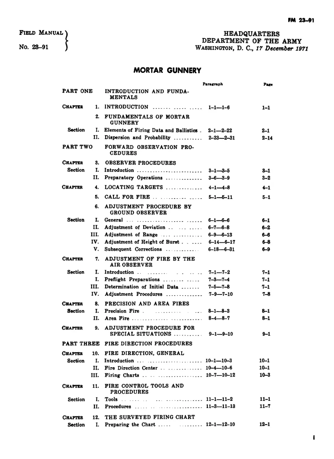
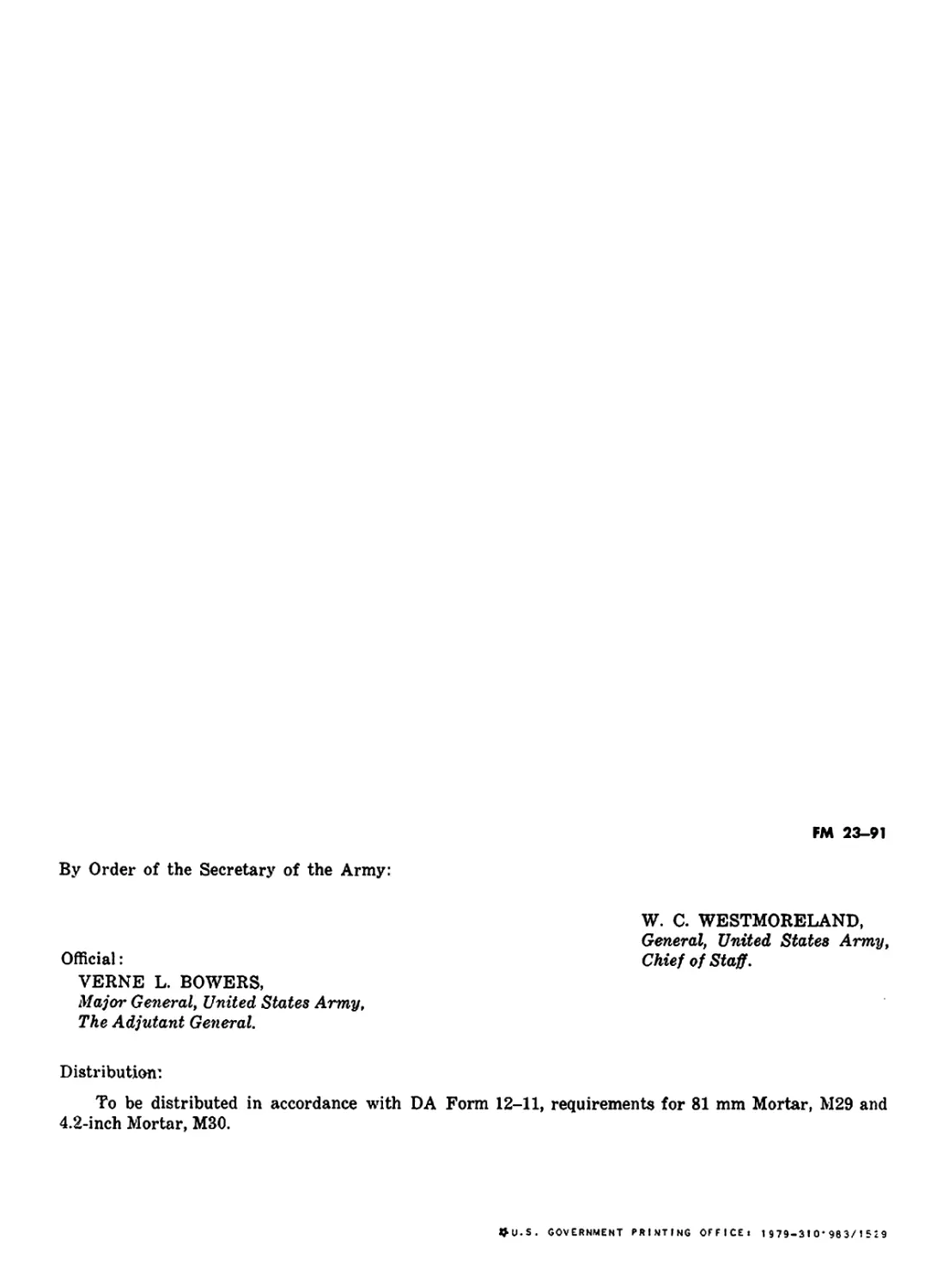
1-6. The Indirect Fire Team (fig. 1—1)
The coordinated efforts of the indirect fire team
must be connected by a communications system.
The elements of the indirect fire team are:
a. Forward Observation Section. The observers
detect and locate targets, initiate a call for fire,
and if necessary, adjust fires.
b. Fire Direction Center. The fire direction
center (FDC) evaluates the information received
from the observers, determines firing data, and
furnishes this data in the form of fire commands
to the mortar section.
c. Mortar Section. The mortar section applies
the firing data to the weapons and fires the wea-
pons.
1-2
FM 23-91
MORTAR SECTION
APPLIES THE FIRE COMMAND TO THE
MORTARS AND FIRES THE MORTARS.
Figure 1-1. The indirect fire team.
1-3
FM 23-91
CHAPTER 2
FUNDAMENTALS OF MORTAR GUNNERY
Section I. ELEMENTS OF FIRING DATA AND BALLISTICS
2—1. Elements of Firing Data
a. General. The data required to lay (point) a
mortar cannon so that the projectile, when fired
will burst at the desired location are called firing
data. These data are based on the direction, hori-
zontal range, vertical interval, and meteorological
conditions from the weapons to the target and
on the desired pattern of bursts at the target.
b. The Mil. The unit of angulai- measurement in
mortar gunnery is the mil. A mil is the angle sub-
tended by an arc which is 1/6400 of the circum-
ference of a circle (para 4-3t>).
c. Direction. Direction is expressed as a hori-
zontal angle measured from a fixed reference.
The indirect fire team normally uses grid north
(the direction of the north-south grid lines on a
tactical map) for the fixed reference and meas-
ures the angle clockwise from grid north. When
weapons are emplaced, they are laid for direc-
tion, and the direction in which they are laid is
used as a basis for angular shifts to point the
weapons at the target. The direction to the target
may be computed, determined graphically, or
estimated (fig. 2-1).
d. Range. Range is the horizontal distance from
the gun to the target and is expressed in meters.
Range may be computed, measured graphically,
or estimated. The range achieved by a projectile
is a function of the charge (muzzle velocity) and
the vertical angle (elevation) to which the weapon
is raised (fig. 2-1).
e. Vertical Interval. Vertical interval is the
difference in altitude between the mortar section
or observation post and the target or point of
burst. The altitude is determined from maps, by
survey, or by a shift from a known point (fig.
2-1).
f. Distribution of Bursts. Distribution of bursts
is the pattern of bursts in the target area. Nor-
mally, all weapons of the platoon fire with the
same deflection, fuze setting, charge, and eleva-
tion. However, since targets may be of various
shapes and sizes, it is sometimes desirable to ad-
just the pattern of bursts to the shape and size of
the target.
(1) In some cases, individual weapon cor-
rections for deflection, fuze setting, charge, and
elevation are computed and applied to get a speci-
fic pattern of bursts. These corrections are called
special corrections.
(2) The term sheaf denotes the lateral dis-
tribution of the bursts of two or more weapons
fired together. The width of the sheaf is the
lateral distance (perpendicular to the direction
of fire) between the centers of the flank bursts.
The front covered by any sheaf is the width of the
sheaf plus the effective width of one burst. A
sheaf may be in any one of the following forms
(fig. 2-2):
(a) Parallel sheaf (normal). A parallel
sheaf is one in which the trajectories of all wea-
pons are parallel.
(b) Converged sheaf. A converged sheaf
is one in which the trajectories intersect at the
target.
(c) Open sheaf. An open sheaf is one in
which the lateral distance between the center of
any two adjacent bursts is equal to the maximum
effective width of one burst (fig. 2-2).
(d) Special sheaf. A special sheaf is any
sheaf other than one of those described above.
2-2. Interior Ballistics
Interior ballistics is the science which deals with
the factors affecting the motion of the projectiles
before they leave the muzzle of the weapon. The
total effect of all interior ballistic factors de-
termines the velocity with which the projectile
leaves the muzzle. This velocity is called the muz-
zle velocity and is expressed in meters per second.
2-1
FM 23-91
TGT
Figure 2-1, Elements from which firing data
is determined.
2-3. Nature of Propellants and Projectile
Movement
a. A propellant is a low order explosive which
burns rather than detonates. The mortar fires
semi-fixed ammunition. When the gases generated
by the burning propellant develop pressure suf-
ficient to overcome initial bore resistance the pro-
jectile begins to move.
b. The gas pressure builds up quickly to a peak
and gradually subsides shortly after the projec-
tile begins to move. The peak pressure, together
with the travel of the projectile in the bore, de-
termines the speed at which the projectile leaves
the tube.
c. Factors which affect the velocity perfor-
mance of a weapon-ammunition combination are
given in (1) through (5) below.
(1) An increase or decrease in the rate of
burning of the propellant increases or decreases
resultant gas pressure.
(2) An increase in the size of the chamber
of the weapon without a corresponding increase
in the amount of propellant decreases gas pres-
sure.
(3) Gas escaping around the projectile in the
barrel decreases pressure.
(4) An increase in bore resistance to pro-
jectile movement before peak pressure further in-
creases pressure.
(5) An increase in bore resistance at any
time has a dragging effect on the projectile and
decreases velocity. Temporary variations in bore
resistance are caused by extraneous deposits in
the barrel.
2-2
FM 23-91
Figure 2-2. Sheaves (distribution).
2-3
FM 23-91
2—4. Standard Muzzle Velocity
ft. Appropriate firing tables give the standard
value of muzzle velocity for each charge. These
standard values are based on an assumed stand-
ard tube. The standard values are points of de-
parture, not absolute standards, since they can-
not be reproduced in a given instance; that is, a
specific weapon-ammunition combination cannot
be selected with the knowledge that it will result
in a standard muzzle velocity when fired.
b. Charge velocities are established indirectly
by the military characteristics of a weapon. Can-
nons capable of high-angle fire (4.2-in and 81 mm)
require a greater choice in number of charges
than do cannons primarily capable of low-angle
fire (guns). This greater choice is needed in
order to achieve range overlap between charges
in high-angle fire and desired range-trajectory.
Other factors considered in establishing charge
velocities are the maximum range specified for
the weapon and the maximum elevation and
charge (with resulting maximum pressure)
which the weapon can accommodate.
2-5. Factors Causing Nonstandard Muzzle
Velocity
In gunnery techniques, nonstandard velocity is
expressed as a variation (plus or minus so many
meters per second) from an accepted standard.
Round-to-round corrections for dispersion can-
not be made. In the discussion in a through к
below, each factor is treated as a single entity
assuming no influence from related factors.
ft. Velocity Trends. Not all rounds of a series
fired from the same weapon using the same am-
munition lot will develop the same muzzle velocity.
The variations in muzzle velocity follow a normal
probability distribution about the average muz-
zle velocity. This phenomenon is called velocity
dispersion. Under most conditions, the first few
rounds follow a somewhat regular pattern rather
than the radom pattern associated with normal
dispersion. This phenomenon is called velocity
trend. The magnitude and extent (number of
rounds) of velocity trends vary with the mortar,
charge, and tube condition at round 1 of the
series, and firings proceding the series. Velocity
trends cannot be quantitatively predicted; there-
fore, any attempt to correct for the effect of a
velocity trend is impractical.
b. Ammunition Lots. Each lot of ammunition
has its own performance level when related to a
common tube. Although the round-to-round prob-
2-4
able error within each lot is about the same, the
mean velocity developed by one lot may be higher
or lower than that of another lot. Variations in
the projectile, e.g., the diameter and hardness of
the rotating disk, affect muzzle velocity. (Pro-
jectile variations have a much more apparent
effect on exterior ballistics.)
c. Tolerances in New Weapons. All new mortars
of a given caliber and model will not necessarily
develop the same muzzle velocity. In a new tube,
the predominant factors are variations in the
powder chamber and the interior dimensions of
the bore. If a battalion armed with new mortars
fired all of them with a common lot of ammuni-
tion, a velocity difference of 3 or 4 meters per
second between the mortar with the highest muz-
zle velocity and the mortar with the lowest muz-
zle velocity would not be unusual.
d. Wear of Tube. Continued firing of a mortar
wears away portions of the bore by the action of
heated gases, chemical action, and movement of
the projectile. These erosive actions are more
pronounced when higher charges are being fired.
Increased tube wear trends to decrease muzzle
velocity by allowing more room for expanding
gases, allowing the expanding gases to escape
past the rotating disk, and decreasing resistance
to initial projectile movement which lessens pres-
sure buildup. Although normal wear cannot be
prevented, it can be minimized by careful selec-
tion of the charge and proper cleaning of weapon
and ammunition.
e. Rotating Disks. Ideal rotating disks allow
proper seating, provide obturation, create proper
resistance to initial projectile movement to allow
uniform pressure buildup, and also provide a
minimum dragging effect on the projectile once
motion has started. Dirt or burrs on the rotating
disk cause improper seating, which increases tube
wear and contributes to velocity dispersion. If
excessively worn, the lands may not sufficiently
engage the rotating disks to impart proper spin to
the projectile. Insufficient spin reduces projectile
stability in flight and can result in dangerously
short, erratic rounds. When erratic rounds occur
or excessive tube wear is noted, an ordnance
ballistic and technical service team should be
asked to determine the serviceability of each tube
by wear measurements and other checks.
f. Propellant Temperature. Any combustible
material burns more rapidly when it is heated
prior to ignition. When a propellant burns more
rapidly, the resultant pressure on the projectile
FM 23-91
is greater and muzzle velocity is increased. The
firing tables show the magnitude of this change.
Appropriate corrections to firing data can be
computed; however, such corrections are valid
only as they reflect the true propellant tempera-
ture. The temperature of propellants in sealed
packing cases remains fairly uniform, though not
necessarily standard (70s F.). Once the propellant
is unpacked, its temperature tends to approach
the prevailing air temperature. The time and type
of exposure to weather result in propellant tem-
perature variations between rounds as well as
mean propellant temperature variations between
mortars. It is not practical to measure propellant
temperature and apply corrections for each round
fired by each mortar. Action must be taken to
maintain uniform propellant temperatures; fail-
ure to do so results in erratic firing. The effect
of a sudden change in propellant temperature can
invalidate even the most recent registration cor-
rections.
(1) Ready ammunition should be kept off
the ground; should be protected from dirt, mois-
ture, and the direct rays of the sun; and should
have an air space between the ammunition and
protective covering. This procedure allows pro-
pellants to approach atmospheric temperature at
a uniform rate.
(2) A sufficient number of rounds should be
unpacked in advance so that it is not necessary
during a mission to mix freshly unpacked am-
munition with ammunition which has been opened
for some time.
(3) Rounds should be fired in the same order
as they are unpacked.
g. Moisture Content of Propellant. Handling
and storage can cause changes in the moisture
content of the propellant, which will affect the
velocity. The moisture content of the propellant
cannot be measured or corrected for; therefore,
ammunition must be provided maximum protec-
tion from the elements.
h. Weight of Projectile. The weight of like pro-
jectiles varies within certain weight zones. The
appropriate weight zone is stenciled on the pro-
jectile. A heavier than standard projectile is
harder to push throughout the length of the tube
and a decreased velocity results; whereas, a
lighter projectile is easier to push throughout the
length of the tube and a higher velocity results.
(Weight of projectile is also a factor in exterior
ballistics.)
i. Tube Condition. The temperature on the tube
has a direct bearing on the developed velocity.
For example, a cold tube offers a different resist-
ance to projectile movement than a warm tube.
j. Propellant Residues. Residues from the
burned propellant and certain chemical agents
mixed with the expanding gases are deposited on
the bore surface in a manner similar to copper-
ing. Unless the tube is properly cleaned and cared
for, these residues aggravate subsequent tube
wear by causing pitting and augmenting the ab-
rasive action of the projectile.
k. Oil or Moisture. Oil or moisture in the tube
or on the rotating disk tends to increase velo-
city of the particular round by causing a better
initial gas seal and reducing projectile friction on
the bore surface. The oily tube condition usually
exists concurrently with the cold tube condi-
tion. Hence the high velocities induced by oil
combining with the erratic velocities character-
istic of a cold tube complicate normal velocity
trends. Moisture on the projectile normally affects
only that particular round. Generally, firing with
a cold, dry tube is preferable to firing with a cold,
oily tube; for that reason, the projectiles should
be dried before firing regardless of the tube con-
ditions.
2-6. Exterior Ballistics
Exterior ballistics is the science which deals with
the factors affecting the motion of a projectile
after it leaves the muzzle of a weapon. At the
time the projectile leaves the tube, the total ef-
fect of interior ballistics in terms of developed
muzzle velocity and spin have been imparted to
the projectile. Were it not for gravity and the
atmosphere, the projectile would continue inde-
finitely at constant velocity along a prolongation
of the tube.
a. Gravity. Gravity causes the projectile to re-
turn to the surface of the earth.
b. Atmosphere. If the projectile were fired in a
vacuum, the path (trajectory) would be simple
to trace. All projectiles, regardless of size, shape,
or weight, would follow paths of the same shape
and would achieve the same range for a given
muzzle velocity and tube elevation. However, if
the projectile were fired in atmosphere, the path
(trajectory) would be different. There are two
reasons for this:
(1) Projectiles of different sizes or weights
respond differently to identical atmospheric con-
ditions.
2-5
FM 23-91
(2) A standard atmosphere can be defined,
but it is seldom experienced. A given elevation
and muzzle velocity can result in a wide variety
of trajectories, depending on the combined prop-
erties of both the projectile and the atmosphere.
2-7. The Trajectory
The trajectory is the curve traced by the center of
gravity of the projectile in its flight from the
muzzle of the weapon to the point of impact or
point of burst.
2-8. Elements of the Trajectory
The elements of the trajectory are classified in
three groups intrinsic elements, initial elements,
and terminal elements. Intrinsic elements are
those which are characteristics of a trajectory
by its very nature. Initial elements are those
which are characteristic at the origin of the
trajectory. Terminal elements are those which
are characteristic at the point of impact or point
of burst.
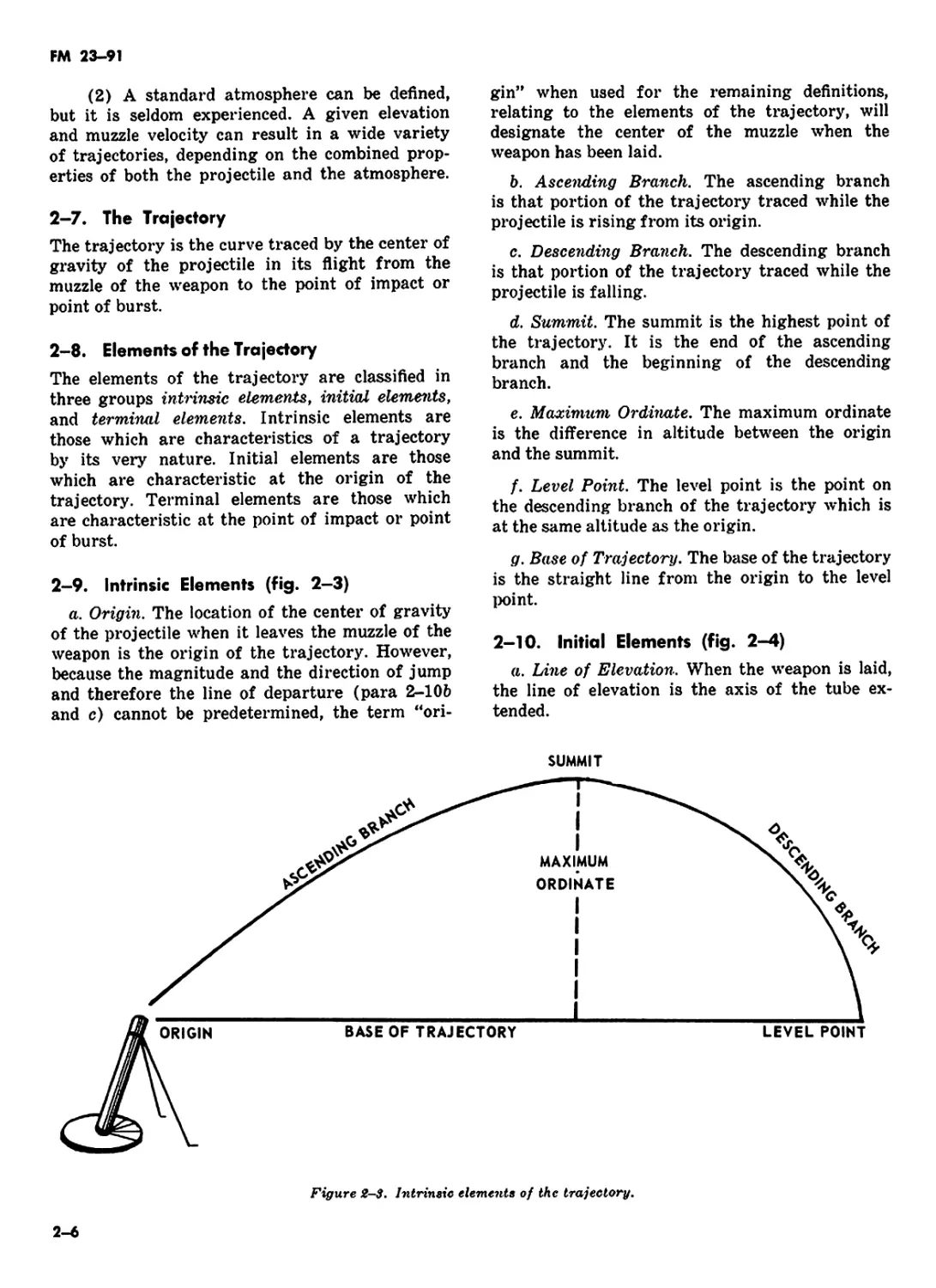
2-9. Intrinsic Elements (fig. 2—3)
a. Origin. The location of the center of gravity
of the projectile when it leaves the muzzle of the
weapon is the origin of the trajectory. However,
because the magnitude and the direction of jump
and therefore the line of departure (para 2-10b
and c) cannot be predetermined, the term “ori-
gin” when used for the remaining definitions,
relating to the elements of the trajectory, will
designate the center of the muzzle when the
weapon has been laid.
b. Ascending Branch. The ascending branch
is that portion of the trajectory traced while the
projectile is rising from its origin.
c. Descending Branch. The descending branch
is that portion of the trajectory traced while the
projectile is falling.
d. Summit. The summit is the highest point of
the trajectory. It is the end of the ascending
branch and the beginning of the descending
branch.
e. Maximum Ordinate. The maximum ordinate
is the difference in altitude between the origin
and the summit.
f. Level Point. The level point is the point on
the descending branch of the trajectory which is
at the same altitude as the origin.
g. Base of Trajectory. The base of the trajectory
is the straight line from the origin to the level
point.
2-10. Initial Elements (fig. 2-4)
a. Line of Elevation. When the weapon is laid,
the line of elevation is the axis of the tube ex-
tended.
2-6
FM 23-91
b. Line of Departure. The line of departure is
a line tangent to the trajectory at the instant the
projectile leaves the tube.
c. Jump. Jump is the displacement of the line
of departure from the line of elevation that exists
at the instant the projectile leaves the tube. Jump
is caused by the shock of firing during the interval
from the ignition of the propelling charge to the
departure of the projectile from the tube.
d. Angle of Site (fig. 2-4). The angle of site is
the smaller angle in the vertical plane from the
base of the trajectory to the straight line joining
the origin and the target. The angle of site is
plus when the target is above the base of the
trajectory and minus when the target is below
the base of trajectory. The angle of site is the
angle subtended by the vertical interval (para
2-1 e) at the gun-target range. For a discussion
of how to compensate for vertical interval, for
81 mm mortar, and 4.2-inch mortar, see para-
graph 12-86.
e. Angle of Elevation. The angle of elevation
is the smaller angle at the origin, in a vertical
plane, from the line of site to the line of elevation.
2—11. Terminal Elements (fig. 2—5)
a. Point of Impact. The point of impact is the
point where the projectile first strikes in the
target area. (The point of burst is the point at
which a projectile bursts in the air.)
b. Line of Fall. The line of fall is the line
tangent to the trajectory at the level point.
c. Angle of Fall. The angle of fall is the smal-
lest vertical angle, at the level point, between the
line of fall and the base of the trajectory.
d. Line of Impact. The line of impact is a line
tangent to the trajectory at the point of impact.
(2) TRAJECTORY WITH AH AHGLE OF SITE
Figure 2-t. Initial elements of the trajectory.
2-7
FM 23-91
Figure £-5. Terminal elements of the trajectory.
Figure £-6. Trajectory relationships.
e. Angle of Impact. The angle of impact is the
acute angle, at the point of impact, between the
line of impact and a plane tangent to the surface
at the point of impact. This term should not be
confused with the term “angle of fall.”
2—12. The Trajectory in a Vacuum (fig. 2-6)
a. The factors which must be known to con-
struct a firing table for firing in a vacuum are the
angle of departure, the muzzle velocity, and the
acceleration due to the force of gravity. The ini-
tial velocity imparted to a projectile consists of
two components, a horizontal velocity and a ver-
tical velocity.
b. The relative magnitudes of horizontal and
vertical velocity components vary with the angle
of elevation. For example, if the elevation were
zero, the initial velocity imparted to the projectile
would be horizontal; there would be no vertical
component. If the elevation were 1,600 mils (dis-
regarding the effect of rotation of the earth),
the initial velocity imparted to the projectile
would be vertical; there would be no horizontal
component.
c. Gravity causes a projectile in flight to fall to
2-8
FM 23-91
earth. Because of gravity, the height of the pro-
jectile at any instant is less than it would be if
no such force were acting on it. In a vacuum, the
vertical velocity decreases from the initial velo-
city to 0 on the ascending branch of the tra-
jectory and increases from 0 to the initial velo-
city on the descending branch. Zero vertical
velocity occurs at the trajectory summit. For
every vertical velocity value upward on the as-
cending branch there is an equal vertical velocity
value downward equidistant from the summit on
the descending branch. Since there is no resist-
ance to the forward motion of the projectile in
a vacuum, the horizontal velocity component is
a constant. The acceleration due to the force of
gravity (9.8 meters per second) affects only ver-
tical velocity.
d. In a vacuum, the form of the trajectory
would be determined entirely by the elevation of
the tube, the muzzle velocity, and gravity. The
form would be parabolic with the angle of fall
equal to the angle of elevation. The summit
would be at a point halfway between the origin
and the level point.
2-13. The Trajectory in the Atmosphere
The resistance of the air to a projectile depends
on the air movement, density, and temperature.
An assumed density, and temperature structure
and a condition of no wind are used as a point of
departure for computing firing tables. The air
structure so derived is called the standard atmos-
phere.
2—14. Characteristics of Trajectory in Standard
Atmosphere (fig. 2-6)
The most apparent difference between the trajec-
tory in a vacuum and the trajectory in standard
atmosphere is the reduction of the range. This
reduction occurs mainly because, in the atmos-
phere, the horizontal velocity component is not a
constant, but is continually decreased by the re-
tarding effect of the air. The vertical velocity
component is likewise affected by air resistance.
The characteristics of a trajectory in a vacuum
are as follows:
a. The velocity at the level point is less than
the velocity at origin.
b. The mean horizontal velocity of the pro-
jectile beyond the summit is less than the mean
velocity before the summit; therefore, the pro-
jectile travels a shorter horizontal distance, the
descending branch is shorter than the ascending
branch, and the angle of fall is greater than the
angle of elevation. Also, since the mean vertical
velocity is less beyond the summit than before
it, the time of descent is greater than the time
of ascent.
c. The spin (rotational motion) initially im-
parted to the projectile causes it to respond dif-
ferently than in a vacuum because of air re-
sistance.
d. A trajectory in standard atmosphere, as op-
posed to one in a vacuum, will be shorter and
lower after any specific time of flight. Therefore,
the summit in a vacuum is midway between the
origin and the level point; in the atmosphere, it
is nearer the level point, and the angle of fall in
a vacuum is equal to the angle of elevation; in
the atmosphere, it is greater. This is because:
(1) Horizontal velocity is no longer a con-
stant but decreases with each succeeding time
interval.
(2) Vertical velocity is affected not only by
gravity but also by the additional retardating ef-
fect of the atmosphere.
2-15. Standard Conditions and Corrections
Certain atmospheric conditions and material
conditions are accepted as standard. These condi-
tions are outlined generally in the introduction to
firing tables.
b. When variations from standard conditions
are experienced, the trajectory will not conform
to the predicted trajectory. Some of these varia-
tions can be measured, and corrections can be
made to compensate for them. Among the condi-
tions for which corrections may be determined
are:
(1) Difference in altitude between cannon
and target.
(2) Propellant temperature.
(3) Drift (fig. 2-7).
(4) Ballistic wind.
(5) Air temperature.
(6) Air density.
(7) Weight of projectile.
2-16. Firing Tables
a. Firing tables are based on actual firing of
the weapon and its ammunition under, or corre-
lated to, a set of conditions defined and accepted
as standard. These standards are points of depar-
2-9
FM 23-91
TARGET
MOUNTING AZIMUTH
DIRECTION OF FIRE
MORTAR
---ACTUAL PATH OF
PROJECTILE CAUSED BY
ROTATION AND AIR PRESSURE
(NOT TO SCALE)
ANGLE OF DRIFT
(GIVEN IN FIRING TABLE IN MILS)
Figure S-7. Drift.
2-10
FM 23-91
ture used to compensate for variables in the wea-
pon-weather-ammunition combination that are
known to exist at a given instant and location.
The atmospheric standards accepted in United
States firing tables reflect the mean annual condi-
tion in the North Temperate Zone.
b. The principal elements measured in experi-
mental firing include angle of elevation, angle of
departure, muzzle velocity, attained range, drift,
and concurrent atmospheric conditions.
c. The main purpose of a firing table is to pro-
vide the data required to bring effective fire on a
target under any set of conditions. Data for firing
tables are obtained by conducting firings with
the weapon at various elevations and charges
(4.2-in mortar elevations 800, 900, 1065, and
various charges). Computed trajectories, based on
the equations of motion, are compared with the
data obtained in the firings. The computed tra-
jectories are then adjusted to the measured re-
sults and data tabulated. Data for elevations
(charges for the 4.2-in mortar) not fired are de-
termined by interpolation. Firing table data de-
fine the performance of a projectile of known
properties under conditions of standard muzzle
velocity and weather.
2—17. Unit Corrections
a. Firing tables describe unit corrections as
range corrections for an increase or decrease in
range wind, air temperature, density, and pro-
jectile weight followed by the appropriate unit
value in meters.
b. Each correction is computed on the assump-
tion that all other conditions are standard. Ac-
tually, any given correction will differ slightly
from that computed if one or more of the other
conditions are nonstandard. The amount of dif-
ference depends on the effect of the other
nonstandard conditions. The effect of one non-
standard condition on the effect of another non-
standard condition is known as an interaction
effect.
c. The effect of a nonstandard condition is a
function of the time the projectile is exposed to
that condition.
d. The extent to which weather affects a pro-
jectile can be determined from a meteorological
(MET) message if the maximum ordinate
achieved is known.
e. Correction for these effects can be com-
pensated for in the appropriate firing tables
(FT 4.2-H-2) (FT 81-AI-2).
2-18. Standard Range
a. The standard range is the range opposite
the charge in the firing table. It is assumed to
be measured along the surface of a sphere con-
centric with the earth and passing through the
muzzle of a weapon. For practical purposes,
standard range is the horizontal distance from
origin to level point.
b. The attained range is the range which is
developed as a result of firing with a given
elevation and charge. If actual firing conditions
duplicate the ballistic properties and meteoro-
logical conditions upon which the firing table is
based, the attained range and standard range
will be equal.
c. The corrected range is that range which
corresponds to the given elevation and charge
that must be fired to reach the target.
2-19. Effect of Nonstandard Conditions
a. Deviations from standard conditions, if not
corrected in computing firing data, will cause the
projectile to impact or burst at some point other
than the desired point.
b. Corrections for nonstandard conditions are
made to improve accuracy. The accuracy of mor-
tar fires depends on the accuracy and complete-
ness of the data available, computational pro-
cedures used, and care in laying the weapons.
Accuracy should not be confused with precision.
Precision is related to tightness of the dispersion
pattern without regard to its proximity to a
desired point. Accuracy is related to the location
of the mean point of impact with respect to a
desired point.
2-20. Range Effects
a. Vertical jump is the angle formed by the
lines of elevation and departure. The shock of
firing causes a momentary vertical and rotational
movement of the tube prior to the ejection of
the projectile. Vertical jump has the effect of
a small change in elevation. The effect of vertical
jump depends mainly on the eccentricity of the
center of gravity of the recoiling parts with
respect to the axis of the bore. In modern weap-
ons, vertical jump cannot be predicted and is
usually small. For these reasons, vertical jump
is not considered separately in the gunnery prob-
2-H
FM 23-91
lem; it is a minor contributing factor to range
dispersion.
ft. Muzzle velocity is the speed of the pro-
jectile at the time it is protected from the muz-
zle; the greater the velocity of a given projectile,
the greater the attained range.
c. The weight of the projectile affects muzzle
velocity. Two opposing factors affect the flight
of a projectile of nonstandard weight. A heavier
projectile is more efficient in overcoming air re-
sistance; however, because it is more difficult
to push through the tube, its muzzle velocity is
normally lower. An increase in projectile effici-
ency increases range, but a decrease in muzzle
velocity decreases range. In firing tables, cor-
rections for these two opposing factors are com-
bined into a single correction. The change in
muzzle velocity predominates at shorter times
of flight; the change in projectile efficiency pre-
dominates at longer times of flight. Hence, for
a heavier than standard projectile, the correction
is plus at the shorter times of flight and minus
at the longer times of flight. The reverse is true
for a lighter than standard projectile.
d. Air resistance affects the flight of the pro-
jectile both in range and deflection. The com-
ponent of air resistance in the direction opposite
to that of the forward motion of the projectile
is called drag. Because of drag, both the hori-
zontal and vertical components of velocity are
less at any given time of flight than they would
be if drag were zero, as in a vacuum. This de-
crease in velocity varies directly in magnitude
with drag and inversely with the mass of the
projectile. This means, in terms of attained
range, the greater the drag, the shorter the
range; and the heavier the projectile, the longer
the range, all other factors being equal. Several
factors considered in the computation of drag
are:
(1) Air density. The drag of a given pro-
jectile is proportional to the density of the air
through which it passes. For example, an in-
crease in air density by a given percentage in-
creases the drag by the same percentage. Since
the air density at a particular place, time, and
altitude varies widely, the standard trajectories
reflected in the firing table are computed with
a fixed relation between density and altitude.
(AIR RESISTANCE IS LEAST WHEN CENTER OF
PRESSURE IS ON THE TRAJECTORY: THAT IS ZERO YAW.)
Figure 2-8. Yaw of projectile rn flight.
2-12
FM 23-91
(2) Velocity. The faster a projectile moves,
the more the air resists its motion. Examina-
tion of a set of firing tables shows that for a
given elevation, the effect of 1 percent air den-
sity (hence 1 percent drag) increases with an
increase of charge; that is, muzzle velocity. The
drag is approximately proportional to the square
of the velocity except in the vicinity of the ve-
locity of sound. There the drag increases more
rapidly because of the increase in pressure behind
the sound wave.
(3) Diameter. Two projectiles of identical
shape but different size will not experience the
same drag. For example, a large projectile will
offer a larger area for the air to act upon; hence
its drag will be increased by this factor.
(4) Drag coefficient. The drag coefficient
combines several ballistic properties of typical
projectiles. These properties include yaw (the
angle between the direction of motion of the
projectile and the axis of the projectile (fig.
2-8) and the mach number, the ratio of the
velocity of the projectile to the speed of sound
(fig. 2-9)).
MACH NUMBER
VELOCITY OF PROJECTILE
1. MACH NUMBER3 SPEED OF SOUND
2. THE SPEED OF SOUND IS FASTER IN WARM AIR; HENCE AN INCREASE (DECREASE)
IN AIR TEMPERATURE DECREASES (INCREASES) THE MACH NUMBER.
3. A CHANGE IN THE MACH NUMBER CAN CHANGE THE VALUE OF THE DRAG COEFFICIENT
EITHER UPWARD OR DOWNWARD, DEPENDING ON THE MACH NUMBER AT WHICH THE
CHANGE OCCURS.
4. AN INCREASE (DECREASE) IN THE VALUE OF THE DRAG COEFFICIENT DECREASES
(INCREASES) THE DEVELOPED RANGE.
Figure 2-9. Effect of velocity (mach number) on
drag coefficient.
2-13
FM 23-91
e. The shell surface finish affects muzzle ve-
locity. A rough surface on the projectile or fuze
will increase air resistance, thereby decreasing
range.
/. The ballistic coefficient of a projectile relates
its efficiency in overcoming air resistance to that
of an assumed standard projectile. For ease in
computations, all projectile types are classified
into certain standard groups. Each projectile,
however, has its own efficiency level. Each pro-
jectile lot has its own efficiency level; that is,
ballistic coefficient. In order to establish firing
tables, it is necessary to select and fire one spe-
cific projectile lot. Based on the performance of
this lot, standard ranges are determined. The
ballistic coefficient of this particular projectile
lot becomes the firing table standard. However,
other projectile lots of the same type may not
have the same ballistic coefficient as the one re-
flected in the firing tables. If one of the other
lots is more efficient, that is, has a higher bal-
listic coefficient than the firing table standard,
it will achieve a greater range when fired. The
reverse is true for a less efficient projectile lot.
g. As the air temperature increases the drag
increases, thereby increasing range. This does
not hold true as the projectile approaches the
speed or sound. Here drag is related to the mach
number and the relationship changes abruptly
in the vicinity of mach 1.
h. Air density effects have been previously
discussed as directly related to drag, with the
more dense air offering greater resistance and
vice versa.
i. Range wind is that component of the bal-
listic wind blowing parallel to the direction of
fire and in the plane of fire. The plane of fire is a
vertical plane that contains the line of elevation.
Range wind changes the relationship between
the velocity of the projectile and the velocity
of the air near the projectile. If the air is moving
with the projectile (tailwind), it offers less re-
sistance to the projectile and a longer range re-
sults ; a headwind has the opposite effect.
2—21. Deflection Effects
a. Lateral jump is caused by a slight lateral
and rotational movement of the tube at the in-
stant of firing. It has the effect of a small error
in deflection. The effect is ignored, since it is
small and varies from round to round.
b. Drift is defined as the departure of the
projectile from standard direction because of
the combined action of air resistance, projectile
spin, and gravity. In order to fully understand
the forces that cause drift, it is necessary to
understand the angle or yaw, which is that angle
between the direction of motion of the projectile
and the axis of the projectile. The direction of
this angle is constantly changing in a spinning
projectile—right, down, left and up. This initial
yaw is greatest near the muzzle and gradually
subsides as the projectile stabilizes. The atmos-
phere offers greater resistance to a yawing pro-
jectile; therefore, it is fundamental in the design
of projectiles that yaw be kept to a minimum
and be quickly damped out in flight. At the
summit, where the descending branch of the
trajectory begins, summital yaw is introduced
and the effect on the projectile is to keep the
nose pointed slightly toward the direction of the
spin. Therefore, since mortar projectiles (4.2-
in.) have a clockwise spin, they drift to the right.
The magnitude of drift (expressed as lateral dis-
tance on the ground) depends on the time of
flight and rotational speed of the projectile and
the curvature of the trajectory.
c. The crosswind is that component of the
ballistic wind blowing across the direction of
Are. Crosswind tends to carry the projectile with
it and causes a deviation from the direction of
fire. However, the lateral deviation of the pro-
jectile will not be as large as the velocity of the
crosswind acting on that projectile. Wind com-
ponent tables simplify the reduction of a ballis-
tic wind into its two components with respect
to the direction of fire.
2-22. Time of Flight
Those nonstandard conditions which affect range
also affect time of flight.
Section II. DISPERSION AND PROBABILITY
2—23. General
a. If a number of rounds of the same caliber
and same lot of ammunition are fired from the
same weapon with the same charge, elevation,
and deflection, the rounds will not all fall at a
single point, but will be scattered in a pattern
of bursts. In discussions of mortar fire, the nat-
ural phenomenon of change is called dispersion.
The array of the bursts on the ground is the
dispersion pattern.
2-14
FM 23-91
b. The points of impact of the projectiles will
be scattered both laterally (deflection) and in
depth (range). Dispersion is the result of minor
variations of many elements from round to round
and must not be confused with variations in
point of impact caused by mistakes or constant
errors. Mistakes can be eliminated and constant
errors compensated for. Those inherent errors
which are beyond control and cause dispersion
are caused in part by:
(1) Conditions in the bore. Muzzle veloc-
ity is affected by minor variations in weight,
moisture content, and temperature of the pro-
pelling charge; variations in the arrangement
of the propellent charge; differences in the ig-
nition of the charge; differences in the weight
of the projectile and in the form of the rotating
disk; and variations in the temperature of the
bore from round to round.
(2) Conditions of the standard. Direction
and elevation are affected by play (looseness) in
the traversing mechanisms of the standard, phys-
ical limitations on precision in setting scales,
and nonuniform reaction to firing stresses.
(3) Conditions during flight. Air resistance
is affected by differences in weight, velocity, and
form of the projectile; and by changes in air
density, wind velocity, and temperature.
2—24. Mean Point of Impact
For any large number of rounds fired, it is
possible to draw a diagram showing a line per-
pendicular to the line of fire that will divide
the points of impact into two equal groups. Half
of the rounds considered will be beyond the line,
or over when considered from the weapon; half
will be inside the line, or short. For this same
group of rounds there will also be a line parallel
to the line of fire that will divide the rounds
equally. Half of the rounds will fall to the right
of the line; half will fall to the left of the line.
The first line, perpendicular to the line of fire,
represents the mean range; the second line, par-
allel to the line of fire, represents the mean de-
flection. The intersection of the two lines is the
mean point of impact (fig. 2-10).
2-25. Probable Error
Consider for a moment only the rounds 'hat
have fallen over (or short) of the mean ;<‘int
of impact. There is some point along th- ine
of fire, beyond the mean point of imp.»».- at
LEFT
2-15
FM 23-91
which a second line perpendicular to the line of
fire can be drawn that will divide the overs into
two equal parts (line AA, fig. 2-11). Ail of the
rounds beyond the mean point of impact manifest
an error in range—they are all over. Some of the
rounds falling over are more in error that others.
If the distance from the mean point of impact
to line AA is a measure of error, it is clear that
half of the rounds over have a greater error and
half of the rounds over have a lesser error. The
distance from the mean point of impact to line
AA thus becomes a convenient unit of measure.
This distance is called one probable error. The
most concise definition of a probable error is
that it is the error which is exceeded as often
as it is not exceeded.
2—26. Dispersion Pattern
In the distribution of rounds in a normal burst
pattern, the number of rounds short of the mean
point of impact (MPI) will be the same as the
number of rounds over the mean point of im-
pact. The probable error will be the same in
both cases.
a. It is a coincidence of nature that for any
normal distribution (such as mortar fire) a dis-
tance of four probable errors on either side of
the mean point of impact will include virtually
all of the rounds in the pattern. This is not pre-
cisely true, since a very small fraction of the
rounds (about 7 out of 1,000) will fall outside
4 probable errors on either side of the mean
point of impact, but it is true for all practical
purposes.
b. The total pattern of a large number of
bursts is roughly elliptical (fig. 2-11). However,
using the fact that four probable errors on either
side of the mean point of impact (in range and
in deflection) will encompass virtually all rounds,
a rectangle normally is drawn to include the
full distribution of the rounds. This rectangle
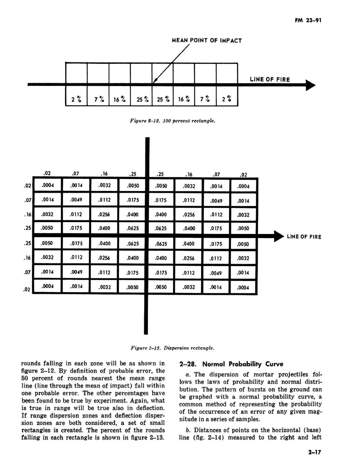
is the 100-percent rectangle (fig. 2-12).
2-27. Dispersion Scale
If one probable error is used as the limit of meas-
urement to divide the dispersion rectangle evenly
into eight zones in range, the percentage of
Figure £-11. Range probable error.
2-16
FM 23-91
Figure 2-12. 100 percent rectangle.
.02 .07 .16 .25 .25 .16 .07 .02
.02 .0004 .0014 .0032 .0050 .0050 .0032 .0014 .0004
.07 .0014 .0049 .0112 .0175 .0175 .0112 .0049 .0014
.16 .0032 .0112 .0256 .0400 .0400 .0256 .0112 .0032
.25 .0050 .0175 .0400 .0625 .0625 .0400 .0175 .0050
.25 .0050 .0175 .0400 .0625 .0625 .0400 .0175 .0050
.16 .0032 .0112 .0256 .0400 .0400 .0256 .0112 .0032
.07 .0014 .0049 .0112 .0175 .0175 .0112 .0049 .0014
.02 .0004 .0014 .0032 .0050 .0050 .0032 .0014 .0004
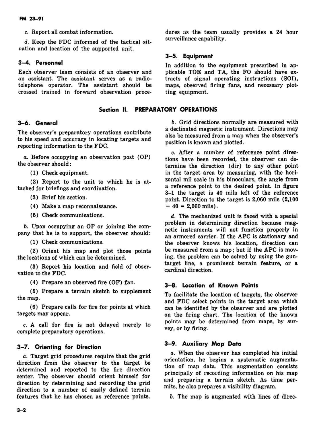
Figure 2-13. Dispersion rectangle.
rounds falling in each zone will be as shown in
figure 2-12. By definition of probable error, the
50 percent of rounds nearest the mean range
line (line through the mean of impact) fall within
one probable error. The other percentages have
been found to be true by experiment. Again, what
is true in range will be true also in deflection.
If range dispersion zones and deflection disper-
sion zones are both considered, a set of small
rectangles is created. The percent of the rounds
falling in each rectangle is shown in figure 2-13.
2-28. Normal Probability Curve
a. The dispersion of mortar projectiles fol-
lows the laws of probability and normal distri-
bution. The pattern of bursts on the ground can
be graphed with a normal probability curve, a
common method of representing the probability
of the occurrence of an error of any given mag-
nitude in a series of samples.
b. Distances of points on the horizontal (base)
line (flg. 2-14) measured to the right and left
2-17
FM 23-91
of the center represent errors in excess (over)
or in deficiency (short). The area under the
curve inclosed by vertical lines cutting the base
line and the curve represents the probability of
the occurrence of an error within the magnitudes
represented by the ends of the base line segment
considered. In figure 2-14 the shaded area rep-
resents the number of rounds falling over and
within one probable error of the mean point of
impact, which is 26 percent.
c. The curve (fig. 2-14) expresses the follow-
ing facts:
(1) In a large number of samples, errors
in excess and errors in deficiency are equally
frequent (probable), as shown by the symmetry
of the curve.
(2) The errors are not uniformly distri-
buted. The smaller errors occur more frequently
than the larger errors, as shown by the greater
height of the curve in the middle.
2-29. Range Probable Error
The approximate value of the probable error
in range (PEr) is shown in the firing tables
and can be taken as an index of the precision of
the piece. Firing table values for probable errors
are based on the firing of specific ammunition
under controlled conditions. The actual round-to-
round probable error experienced in the field will
normally be larger.
2—30. Deflection Probable Error
The value of the probable error in deflection
(PEd) is given in the firing tables. For can-
nons, the deflection probable error is considera-
bly smaller than the range probable error. For
I PER
( 1 PROBABLE ERROR IN RANGE)
Figure 2-14. Probability curve.
2-18
FM 23-91
example, for a 4.2-inch mortar firing charge 21
at a range of 3600 meters, elevation 900, the de-
flection error is 6 meters. In other words, 50
percent of the projectiles fired will hit within 6
meters, 82 percent will hit within 12 meters, and
96 percent will hit within 18 meters of the mean
deflection.
2—31. Application of Probable Errors
a. Normal distribution is expressed in terms
of probable errors (PE’s), because the distri-
bution of bursts about the mean is the same re-
gardless of the magnitude of the probable error.
Firing tables list probable errors for range, de-
flection, height of burst, and time to burst at
each listed range. It is possible to express a given
distance in terms of probable errors and solve
problems by using the dispersion scale or pro-
bability tables.
b. To compute the probability of a round land-
ing within an error of a certain magnitude,
reduce the specified error to equivalent probable
errors in one direction along the dispersion scale,
and multiply the sum by 2. For example, a 4.2-
inch mortar has fired a number of rounds with
charge 21, elevation 900, and the mean point of
impact has been determined to be at 3600 meters.
What is the probability that the next round
fired will fall within 54 meters of the mean point
of impact?
Solution:
Range PE at 3600 meters (charge 21) =
27 meters.
Equivalent of 54 meters in PE’s (54/27)
= 2.
Percent of rounds falling within 2 PE
2(25% +16%) = 82% (fig. 2-13).
2-19
FM 23-91
PART TWO
FORWARD OBSERVATION PROCEDURES
CHAPTER 3
OBSERVER PROCEDURES
Section I. INTRODUCTION
3-1. General
a. Mortars are employed in a manner requir-
ing some type of observation. This observation
may be visual, it may be electronic, or it may
be indirect observation through study of aerial
photographs or maps.
b. Electronics devices generally fall into two
classes—radar ranging equipment and sound
ranging equipment.
c. Observer procedures discussed in this manual
pertain solely to visual observation and include
both air and ground observer techniques. When
appropriate, these techniques are explained in
the light of their relationship to other phases of
gunnery, primarily the fire direction phase.
d. Target grid procedure, on which fire direc-
tion and observation are based, relieve the ob-
server of many functions normally required of
him by other gunnery systems, such as firing
without a FDC. However, the observer is an im-
portant member of the gunnery team. The ob-
server is the only member of the team who can
actually see the enemy forces, the friendly
forces, and the fires placed on the enemy by all
combat arms. His ability to observe and his
knowledge of the battle situation must be ex-
ploited to assist in keeping his unit informed
at all times. Moreover, the observer must know
and understand the FDC procedures. He can
then combine this knowledge with his own judge-
ment to assist the gunnery team in fulfilling
its purpose.
3-2. Purpose
Observation by mortar units has four purposes:
target acquisition, adjustment of fires when neces-
sary, surveillance of fire for effect, and battle-
field surveillance.
a. Target acquisition is concerned with detect-
ing suitable targets and determining their ground
locations. This information is reported to the
FDC where it may be used in the production of
firing data.
b. Adjustment of fires is necessary to get ef-
fective fire on the target when the location of
the mortar position and the target location is in
question, and when current meteorological or
registration corrections are not available.
c. Surveillance of fire for effect is a follow-
through of target acquisition. As the observer
can see the target, he can direct fire and report
its effect to the fire direction center. This report
should include an accurate account of damage
and any shifts necessary to make the fire more
effective.
d. Battlefield surveillance (intelligence) is a
very important byproduct of forward observa-
tion. Observers must report all enemy activity.
Information not necessary for the conduct of
fire must be reported promptly, but such action
must not delay fire missions.
3-3. Duties of the Observer Teams
The teams are to—
a. Accompany the forward units and advise
the commander of the supported units of the
capabilities of the mortar.
b. Request fires for the supported units, ob-
serve and adjust fires for the mortar platoon.
They may request and adjust artillery fires
through the mortar platoon FDC.
3-1
FM 23-91
c. Report all combat information.
d. Keep the FDC informed of the tactical sit-
uation and location of the supported unit.
3-4. Personnel
Each observer team consists of an observer and
an assistant. The assistant serves as a radio-
telephone operator. The assistant should be
crossed trained in forward observation proce-
dures as the team usually provides a 24 hour
surveillance capability.
3-5. Equipment
In addition to the equipment prescribed in ap-
plicable TOE and TA, the FO should have ex-
tracts of signal operating instructions (SOI),
maps, observed firing fans, and necessary plot-
ting equipment.
Section II. PREPARATORY OPERATIONS
3-6. General
The observer’s preparatory operations contribute
to his speed and accuracy in locating targets and
reporting information to the FDC.
a. Before occupying an observation post (OP)
the observer should:
(1) Check equipment.
(2) Report to the unit to which he is at-
tached for briefings and coordination.
(3) Brief his section.
(4) Make a map reconnaissance.
(6) Check communications.
b. Upon occupying an OP or joining the com-
pany that he is to support, the observer should:
(1) Check communications.
(2) Orient his map and plot those points
the locations of which can be determined.
(3) Report his location and field of obser-
vation to the FDC.
(4) Prepare an observed fire (OF) fan.
(5) Prepare a terrain sketch to supplement
the map.
(6) Prepare calls for fire for points at which
targets may appear.
c. A call for fire is not delayed merely to
complete preparatory operations.
3-7. Orienting for Direction
a. Target grid procedures require that the grid
direction from the observer to the target be
determined and reported to the fire direction
center. The observer should orient himself for
direction by determining and recording the grid
direction to a number of easily defined terrain
features that he has chosen as reference points.
b. Grid directions normally are measured with
a declinated magnetic instrument. Directions may
also be measured from a map when the observer’s
position is known and plotted.
c. After a number of reference point direc-
tions have been recorded, the observer can de-
termine the direction (dir) to any other point
in the target area by measuring, with the hori-
zontal mil scale in his binoculars, the angle from
a reference point to the desired point. In figure
3-1 the target is 40 mils left of the reference
point. Direction to the target is 2,060 mils (2,100
- 40 - 2,060mils).
d. The mechanized unit is faced with a special
problem in determining direction because mag-
netic instruments will not function properly in
an armored carrier. If the APC is stationary and
the observer knows his location, direction can
be measured from a map; but if the APC is mov-
ing, the problem can be solved by using the gun-
target line, a prominent terrain feature, or a
cardinal direction.
3-8. Location of Known Points
To facilitate the location of targets, the observer
and FDC select points in the target area which
can be identified by the observer and are plotted
on the firing chart. The location of the known
points may be determined from maps, by sur-
vey, or by firing.
3—9. Auxiliary Map Data
a. When the observer has completed his initial
orientation, he begins a systematic augmenta-
tion of map data. This augmentation consists
principally of recording information on his map
and preparing a terrain sketch. As time per-
mits, he also prepares a visibility diagram.
b. The map is augmented with lines of direc-
3-2
FM 23-91
Figure 3-1. Use of reference point direction and binocular
scales to determine direction to target.
tion radiating from the observer’s position at
convenient angular intervals. These lines are
intersected with arcs of distance by using the
observer’s position as the center (fig. 3-2). The
observer then marks points of importance which
were not included on the map when printed. He
also marks any points which he might need
frequently, such as reference points, registration
points, targets, and likely points of enemy activ-
ity.
c. An observed fire (OF) fan may be used
instead of marking a map as in b above. The
observed fire fan (fig. 3-3) is a fan-shaped pro-
tractor constructed of transparent material, cov-
ering a 1600 mils sector. This fan is divided by
radial lines 100 mils apart. Arcs representing dis-
tances from the OP are printed on the fan in
increments of 500 meters from 1,000 to 6,000
meters. To use the OF fan the observer orients
the fan on his map with the vertex on his OP
location, the fan centered approximately on the
zone of observation, and one of the radial lines
parallel to a grid line or other line of known
direction. The fan is then taped or tacked to the
map. The line of known direction is labeled
3-3
I-M 23-91
Figure 3-2. Map augmented to show lines of direction and
distance from the observer's position.
with their directions. If desired, only the 200-mil
direction lines are labeled.
d. Another device to assist in the location of
targets is the terrain sketch (fig. 3-4). The ter-
rain sketch is a panoramic representation of the
terrain, sketched by the observer, showing ref-
erence points, registration points, targets, and
points of probable activity. The terrain sketch
is a rapid means of orienting relief personnel.
e. When available, photographs of the area
of observation should be marked, showing per-
tinent points and lines of direction, and used
in conjunction with the terrain sketch. Copies
of the photograph and the terrain sketch may
be required for reference at the fire direction
center.
f. The visibility diagram (fig. 3-5) is a sketch
of the area of observation, drawn to map scale,
showing those portions which cannot be ob-
served from a given OP. This diagram may be
prepared by observers or by FDC personnel if the
position of the OP is plotted on FDC maps.
(1) When the observer prepares the visi-
bility diagram, a copy on overlay paper is sent
to the FDC. The diagram is prepared by con-
structing profiles of the terrain along radial
lines emanating from the OP (FM 21-26). Each
adjacent pair of rays should form an angle no
greater than 100 mils. When the profile along
each ray is completed, straight lines are drawn
from the observer’s position to each point of
high ground in the field of observation. These
rays represent lines of vision; all areas between
a peak point of tangency and the intersection of
a ray with the ground are blindspots (fig. 3-6).
3-4
FM 23-91
Figure 3-3. The observed fire fan.
3-5
LONE TREE
DIR 2200
ALT 70
DIS 4000
FM 23-91
HILL 80
DIR 1300
DIS 2800
HILL 150
DIR 1540
DIS 3800
AA0050
DIR 1800
ALT 110
DIS 3500
FARM HOUSE
DIR 2650
ALT 80
DIS 4800
RG 700
DESTROYED TANK
*RP2
Figure 3-i. Terrain sketch.
FM 23-91
These blindspots are projected to the base of
the diagram and transferred to the appropriate
line of direction on the observer’s map or on a
piece of overlay paper. Related points are con-
nected and blind areas are shaded (fig. 3-6).
(2) Use of a visibility diagram will reduce
the chance of observer error in reporting target
locations. If the target is plotted in an area
which is not visible, the location data are ob-
viously in error. The diagram aids the S2 in
evaluating target area coverage and in determin-
ing the best places for additional observation
posts.
Figure 3-5. Construction of visibility diagram using
direction rays.
3-7
FM 23-91
Figure 3-6. Use of profile to show blindspots
(shaded areas).
3-8
FM 23-91
CHAPTER 4
LOCATING TARGETS
4-1. General
The most accurate means available are used in
locating targets and determining initial data in
order to insure safety to friendly troops, to save
ammunition, to save time in adjustment, and to
increase effectiveness of fire. This initial accuracy
is gained by using data from all previous firing
in the area as well as maps, photographs, or
panoramic sketches of the area. The preparatoiy
operations discussed in chapter 3 are desirable
and necessary; however, failure to complete them
on occupation of an OP will not keep the observer
from calling for fire as soon as targets are ob-
served. Firing often begins before the prepara-
tion phase is completed; and the firing may be
precision fire, which places fire on a specific point,
or area fire, which covers a given area with fire.
With either precision or area fire, the observer
processes the call for fire through the FDC by
using a standard sequence of procedure. The se-
quence follows:
a. Target locating.
b. Preparation and submission of a call for fire.
c. Adjustment of fire, if necessary.
d. Surveillance of fire for effect.
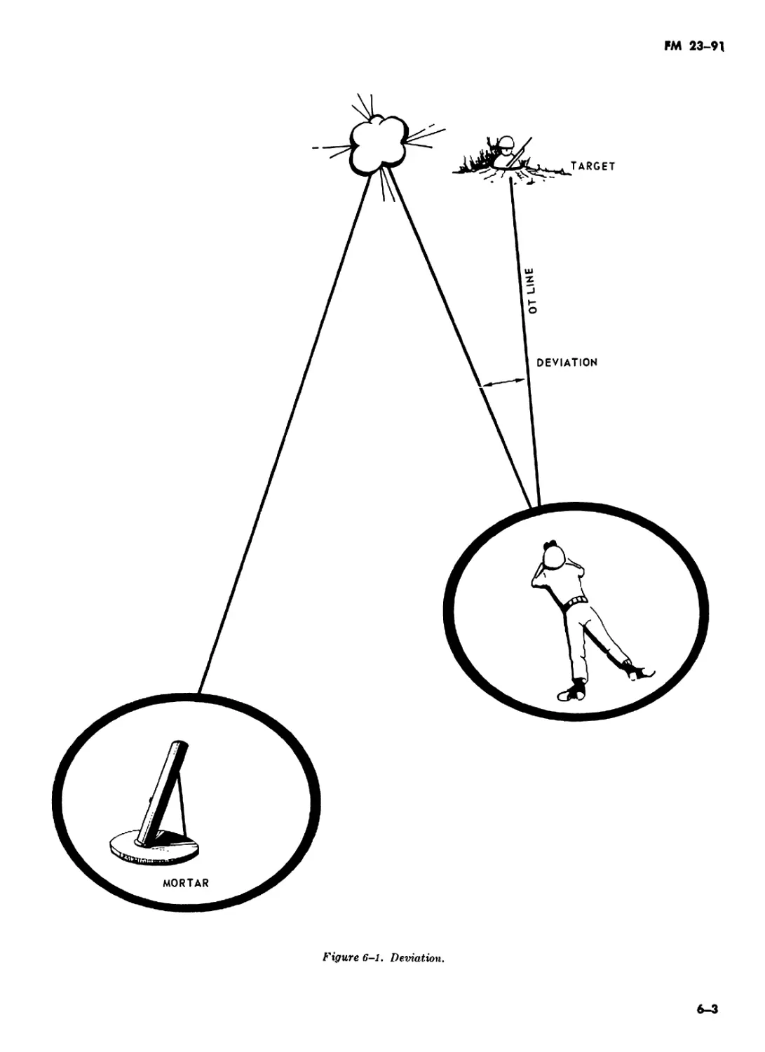
4—2. Target Locating
a. Methods. The following four methods are
used by the observer in designating the location
of targets so that FDC troops may plot them on
their charts:
(1) Grid coordinates (para 4-5).
(2) Shifting from a known point or reference
point (para 4-6).
(3) Polar coordinates (para 4-7).
(4) Marking round (para 4-8).
b. Accuracies and Announcement of Data. All
data for target locations in calls for fire and
subsequent corrections are determined to an ac-
curacy consistent with the equipment used for
determination. The observer will normally round
off and announce his data as follows:
(1) Direction—to the nearest 10 mils.
(2) Deviation—to the nearest 10 meters.
(3) Vertical change—to the nearest me-
ters.
(4) Distance—to the nearest 100 meters.
(5) Grid coordinates—to the nearest 10 me-
ters.
Note. Round off rule, 0.1 to 0.4 round down, 0.5 to 0.9
round up.
4-3. Determination of Distance
The observer must be able to determine quickly
and accurately the distance between objects, tar-
gets, or burst in order to determine basic data
and to adjust fire effectively. Distances can be
determined by estimation or computation.
a. Estimation of Distance. Estimating distance
is facilitated by establishing a yardstick on the
ground in the target area. This yardstick can be
established by firing three rounds with 200 me-
ters apart in range between rounds for the same
piece. The observer can also establish a known
distance in the target area by determining from
his map or photograph the distance between two
points which he can identify both on the map and
on the ground. The approximate distance from
the observer to a sound source (bursting shell,
weapon firing, etc.) can be estimated by timing
sound. Speed of sound in still air at 59° F. is
about 340 meters per second. Wind and variation
in temperature alter this speed somewhat. For
practical use by the observer, the speed of sound
may be taken as 350 meters per second under all
conditions. The sound can be timed with a watch or
by counting from the time the flash appears until
the sound is heard by the observer. For example,
the observer counts “one 1,000, two 1,000," etc. to
determine the approximate time in seconds. The
time in seconds is multiplied by 350 to get the
approximate distance in meters.
4-1
FM 23-91
Example: The observer wishes to determine the
distance from his position to a burst. He begins
counting when the burst appears and stops count-
ing when he hears the sound. He counted 4 sec-
onds; therefore, the burst was about 1,400 me-
ters (850 x 4) from his position.
b. Computation of Distance. Distance may be
computed by using the angle measured from one
point to another and the known lateral distance
between the two points. The distance from the
observer may be computed by applying the mil
relation formula. The mil relation formula is based
on the assumption that an angle of 1 mill will
subtend a width 1 meter at a distance of 1,000
W
meters. The formula is expressed as = 1,
where jri is the angular measurement in mils be-
tween the two points, R is the distance in thou-
sands of meters (expressed to the nearest 100)
to the known points from which angle jrt was
measured (fig. 4-1), and W is the lateral dis-
tance in meters.
c. A convenient way of using the mil rela- '
W
tion formula,, is to cover the value desired
and perform the calculation indicated, for exam-
ple; to find the range the “R” would be covered
leaving the width (W) to be divided by the mils
Of).
Example. An observer measured an angle of 5
mils between the ends of a flat car which he knows
to be 16 meters long. The distance from the ob-
server to the flat car is determined by substituting
W 16
in the formula R r- (R = -=— = 3.2)
pa о
The distance is 3,200 meters.
4—4. Measurement of Angles
An observer usually uses an angle-measuring de-
vice, such as binoculars, an aiming circle, or a
compass to measure angles. When instruments
are not available, angles can be measured by ufe-
ing the hand and finger held at a fixed distance
from the eye. The specific angle subtended by
Figure 4-1. Mil relation formula.
4-2
FM 23—91
the hand in various attitudes must be determined
by the soldier before he goes into the field and
must be memorized for rapid use (fig. 4-2).
4-5. Target Locating by Grid Coordinates
a. Auxiliary map data greatly simplifies the
determination of accurate grid coordinates of a
target. When the observer sees a target that is
located where it cannot be plotted by rapid in-
spection, he must first determine the target di-
rection. He determines the direction by using any
method described in paragraph 3-7.
b. After the observer has determined the direc-
tion and his location, he refers to the correspond-
ing line of direction on the map (or observed fire
fan). He selects the point on this line which best
describes the target location. He may locate this
point by comparing map features with ground
features or by estimating the distance from his
position to the target. In figure 4-3, the ob-
server has measured a direction of 680 mils to
a target located on a small hill an estimated 3,000
meters from his location. He has pinpointed the
target on the map by plotting a distance equiva-
lent about 3,000 meters along a ray corresponding
to direction 680 mils on the observed fire fan. A
study of the contour lines helps the observer
estimate the range more accurately.
c. After the observer has located the target on
the map, he marks the location and determines
the grid coordinates with a coordinate scale or by
estimation. When properly used, the coordinate
scale enables the observer to measure both east-
ing (E) and northing (N) coordinates with one
Figure 4-2. Measurement of angles by hand and fingers.
4-3
FM 23-91
Figure k-3. Use of observed fire fan to assist in
reading coordinates.
placement of the scale. To measure the coordina-
tes of a target, the observer first determines the
grid coordinates of the lower left-corner of the
grid square containing the target. Starting at this
grid intersection, he slides the coordinate scale to
the right, keeping the horizontal scale in coinci-
dence with the E-W grid line, until the target is
reached by the vertical scale. He then reads the
distance east and the distance north from the
scale (fig. 4-4) and adds these readings to the co-
ordinates of the grid square to get the coordinate
of the target; i.e., 53152475.
d. Grid coordinates may also be determined by
relating the target location to one of several
ground features marked on the map. Use this
system with care, especially in deceptive terrain,
unless the location is such as to preclude error
(road junction, building, bridge, etc.). A rapid
check of the accuracy of the coordinates can be
made by use of the contour lines on the map. If
the plotted altitude of the target shows marked
disagreement with the actual ground conforma-
tion, the target should be replotted.
4-6. Target Locating by Shift From a Known
Point
To locate a target by a shift from a known point,
FDC troops must have the location of the known
point plotted on their charts. Either the observer
or the chief computer may select points for use as
known points, but both the observer and the FDC
troops must know their location and designations.
Registration points, prominent terrain features,
and previously fired targets are commonly used
as known points. To locate a target by a shift
from a known point, the observer must determine
the observer target direction, a horizontal shift,
and a vertical shift.
a. Observer-Target Direction. The observer-
target (ОТ) direction is normally determined by
measuring the angular deviation from a refer-
ence point to the target and applying the meas-
4-4
FM 23-91
Figure 4-4. Use of coordinate scale.
ured deviation to the direction from the observer
to the reference point. The measured deviation
is added if the target to the right of the
reference point and subtracted if the target is to
the left of the reference point. Observer-target
direction may also be measured with a properly
declinated magnetic instrument.
b. Horizontal Shift. The horizontal shift (flg.
4-5) from a known point to a target consists of
a lateral shift in meters and a shift in range
along the ОТ line. The lateral shift is made from
the known point along a line perpendicular to
the ОТ line at the point (Tl) at which the
perpendicular intersects the ОТ line. The shifts
are plotted in the FDC on a target grid oriented
on the ОТ direction. The method used by the
observer to compute the horizontal shift depends
on the size of the angular deviation measured
from the known point to the target.
(1) Deviation of less than 600 mils. When
the angular deviation from a known point to the
target is less than 600 mils, the mil relation
formula (para 4-36) is used to compute the lat-
eral shift. The shift in range is determined by
comparing the distance from the observer to the
known point to the distance from the observer
to the target.
Example. An observer measures an angular de-
viation from the known point to the target as
right 250 mils. He knows the distance to the
known point to be 3,200 meters and estimates the
distance to target to be 3,700 meters (fig. 4-5).
The lateral shift is determined by substituting
in the formula W = Rnf (W - 3.2 x 250, or right
4-5
НИ 23-91
ОТ =3700 METERS
NOTE: ОТ1 IS ASSUMED TO
EQUAL OBSERVER - RP 1
DISTANCE
Figure i-S. Computation of a lateral shift.
800 meters). The shift is announced as RIGHT
800, ADD 500.
(2) Deviation of 600 mils or greater.
(a) Using sine factor formula. When the
angular deviation from a known point to the
target is 600 mils or greater, the mil relation
formula for computing the lateral shift is no
longer valid, and a different method must be used
to determine the horizontal shift. This method
uses the relationship between the two sides of the
right triangle. In figure 4-6, the sine of angle A
is the length of the side opposite angle A divided
by the length of the hypotenuse. The sine of
л . side opposite angle A ,
“nEle A---------hypotenuse----- ' The f°mula
w
used is F = -p where F is the sine factor
for the angular deviation jri (value taken to the
nearest 100 mils), D is the known distance to the
reference point (length of hypotenuse), and W is
the width of the side opposite the angle jatf. Note
the D (distance) is not reduced to units of thou-
sands of meters when sine factors are used. The
sine factors follow:
FM 23-91
(1600 MILS)
SINE OF ANGLE “A” =
SIDE OPPOSITE
HYPOTENUSE
Figure i-6. Sine factor.
Апкк in mUu
100
200
300
400
500
600
700
800
900
1000
1100 ..
1200 --
1300
1400
1500 .
1600
Sine factor
0.1
.2
.3
.4
.6
.6
.6
.7
.8
.8
.9
.9
1.0
1.0
1.0
1.0
The lateral shift is computed by substituting in
the formula W = F x D where F is the sine
factor of the angular deviation from a known
point to the target and D is the distance (to
the nearest 100 meters) to the known point.
Example (fig. 4-7). An observer measures the
angular deviation from registration point 1 to
the target as right 850 mils (rounded off to 900
mils). The distance from the observer to regis-
tration point 1 is 2,500 meters.
Solution: Lateral shift is W = 0.8 (sine factor
of 900 mils) x 2,500 = 2,000 or Right 2000.
To determine the range shift, it is first necessary
to determine the distance from the observer to
the point at which a perpendicular from RP
#1 to the ОТ line strikes the ОТ line (Tl). This
is accomplished by substituting again in the
formula W = F x D where, this time, F is the
sine factor of the angle complementary to the
angle of deviation and D again, the distance
from the observer to RP #1. The range shift is
determined by comparing the OT1 distance and
the observer-target distance.
Note. Every triangle contains 3200 mils. To determine
the complementary angle subtract the angle of deviation
from 1600 mils. The right angle of the triangle contains
the other 1600 mils. In the example in figure 4-7, the
complementary angle - 1600 mils minus the angle of
deviation 1600xt — 850m •* 750Л1, rounded off equals
800 mils).
Example (fig. 4-7). Angle complementary to
the angle of deviation is 750 mils (round off to
800 mils). The distance to RP #1 is 2,500 meters.
Solution: W = 0.7 (sine factor of 800 mils) x
2,500 = the distance from the observer where
the perpendicular strikes the ОТ line (Tl),
which is 2,000 meters. The difference between
the ОТ distance and observer Tl distance is ОТ
distance minus OT1 distance - range shift, 3000
meters (ОТ distance) minus 2000 meters (OT1
distance) = 1000 meters or ADD 1000. Total
shift from known point in example given be-
comes RIGHT 2000, ADD 1000.
4-7
FM 23-91
Computing lateral shift
Figure 4-7. Computation of lateral and range shift using
the sine factor.
(b) Sine factor table. To assist the FO in
quickly computing the deviation and range
change, the Sine factor table shown in figure 4-8
may be used. This table can be used by the FO
to engage a target, when absolute accuracy is
necessary and time is available; or it can be
4-8
used to help the FO quickly engage targets ac-
curately withoui having to use the sine factor
formula.
(c) Most expedient method of use of the
Sine factor table.
1. Determine the distance to the RP
rounded off to the nearest 100 meters.
FM 23-91
ESTIMATED
3000
Computing range shift
Figure 4-7—Continued.
4-9
FM 23-91
X MILS RANCE, TO Rp\ 100 L 200 К 300 J 400 1 500 M 600 G 700 F 800 E 900 D 1000 c 1100 8 1200 A WHEN COMPUTING RANGE CHANGES FOR ANGLES. 400 z OR GREATER, USE THE FOLLOWING GUIDE.
100 10 20 30 40 50 60 60 70 80 80 90 90
200 20 40 60 80 90 110 130 140 150 170 183 180
300 30 60 90 HO 140 170 190 210 230 250 260 280
400 40 80 120 150 190 220 250 280 310 330 350 370
500 50 100 ISO 190 240 280 320 350 390 420 440 460
600 60 120 170 230 280 330 380 420 460 500 530 550
700 70 140 200 270 330 390 44 0 490 540 580 620 650
doo BO 160 230 310 380 440 510 570 620 670 710 740 ANGLE FROM RP TO TGT
900 90 180 260 340 420 500 570 640 700 750 790 830
1000 Ю0 200 290 380 470 560 630 710 770 B30 B80 920
1100 no 210 320 420 520 610 700 780 850 910 970 1020 COLUMN USED FOR RANGE CHANGE
1200 120 230 350 460 570 670 760 850 930 1000 1060 1110
1300 130 250 380 500 610 720 820 940 IOOO 1080 1150 1200
1400 140 270 410 $40 660 780 890 990 1080 1160 1230 1290
1500 150 290 44 0 570 710 В 30 950 1060 1160 1250 1320 1390 f 1
1600 160 310 460 610 750 890 1020 1130 1240 1330 1410 1480
1700 170 330 490 650 800 940 1080 1200 1310 1410 1500 1570 400 *
1800 ISO 350 520 690 850 1000 1140 1270 1390 1500 1590 1660
1900 190 370 550 730 900 1060 1210 1340 1470 15B0 1680 1760 500 В 600 C
2000 200 390 580 770 940 1110 1270 1410 1550 1660 1760 1850
2100 210 410 610 810 990 1170 1330 1480 1620 1750 1850 1940
2200 220 130 640 840 1040 1220 1400 1560 1700 1830 1940 2030 700 D
2300 230 450 670 880 1080 1280 1460 1630 1780 1910 2030 2120
2400 240 470 700 920 1130 1330 1520 1700 1860 2000 2120 2220 800 E
2500 250 <90 730 960 1180 1390 1590 1770 1930 2080 2200 2310
900 F
2600 250 510 750 1000 1230 1440 1650 1840 2010 2160 2290 2400
2700 260 530 780 1030 1270 1500 1710 1910 2090 2250 2380 2490 1000 G
2800 270 550 810 1070 1320 1560 1780 1980 2160 2330 2470 2590
2900 280 570 840 1110 1370 1610 1840 2060 2240 2410 2560 2680 1100 H
3000 290 590 870 1150 1410 1670 1900 2120 2320 2490 26SO 2770
3100 300 600 900 1190 1460 1720 1970 2190 7400 2580 2730 2860 1700 1
3200 310 620 930 1220 1510 1780 2030 2260 2470 2660 2820 2960 1300 J
3300 ftO 640 960 1260 1560 1830 2090 2330 2550 2740 2910 3050
3400 330 660 990 1300 1600 1890 2160 2400 2630 2830 3000 3140 uoo к 1500 L
3500 340 680 1020 1340 1650 1940 2220 2470 2710 2910 3090 3230
3600 350 700 1050 1380 1700 2000 2280 2 550 2780 2990 3170 3330
3700 360 720 1070 1420 1740 2060 2350 2620 2860 3080 3260 3420
3800 370 740 1100 1450 1790 2110 2410 2690 2940 3160 3350 3510 TGT ft). TO Dt-i’ !>. СМЙ i’. Г01МТ pancc colu«*«. ;•// and ANCi6 r t ojvoto 50.н s” f lUTCrHC’ • • v Nlf VALJt TO » Г’ - . о» X. - - • । qn i . <ahg! f0 TQ ОТ - *н(и» гачьс ;ol: r?c- TaCL( At-Q.C A'i COuj**:»* z.v- Nt»r ut.u( to rue ЛГ1 - > •- o»rt0CMCt • cp Oi’ANCt to 3? » - о» л:о
3900 380 760 1130 1490 1840 2170 2470 2760 3010 3240 3440 3600
4000 390 780 1160 1530 1890 2220 2540 2830 3090 3330 3530 3700
4100 400 800 1190 1570 1930 2280 2600 2900 3170 3410 3620 3790
4200 410 820 1220 1610 1980 2330 2660 2970 3250 3490 3700 3880
4200 420 840 1250 1650 2030 2390 2730 3040 3320 3580 3790 3970
4400 430 860 1280 1680 2070 2440 2790 3110 3400 3660 3880 4070
4500 440 880 1310 1720 2120 2500 2850 3180 3480 3740 3970 4160
4600 450 900 1340 1760 2170 2560 2920 3250 3560 3820 4060 4250
4700 460 920 1360 1800 2220 2610 2980 3320 3630 3910 4140 4340
4800 470 940 1390 1840 2260 2670 3050 3390 3710 3990 4730 4410
4900 480 960 1420 I860 2310 2720 3110 3460 3790 4 070 4320 4530
5000 490 980 1450 1910 2360 2760 3170 3540 3870 4)60 4410 4620
5100 500 10 «Ю 1480 1950 2400 2830 3240 36Ю 3940 4240 4500 4710
5200 510 1010 1510 1990 2450 2890 3300 3680 1020 4 $20 4590 4800
5300 520 1330 1540 2030 2500 294C 3360 3750 4 iaa 44 10 46П 49Г.Э
5400 530 1050 1570 2070 2550 300C 3.130 3820 4170 447<i I? 60 49r»v
5500 540 1070 1600 2100 2590 3060 3J90 3H9Q 4250 4570 4852 SC 80
5600 550 1090 1630 2140 2640 3’10 3SS0 2960 43 30 466: :<*4.. 5 1
5700 560 1110 1650 7180 2690 3170 3620 4 330 4110 Г1Г *i * • r 52 ’0
5800 570 ИЗО 1680 2 229 27 30 31-20 3o8Ci 4 IOC • u^ । *; - i < •
5900 580 1 150 1710 2260 C 3280 3?4? 1 'l ? 4$6' :: Г • • •
6000 $90 1 170 17 4Л 2300 28 30 < J 30 J R b J 4? 40 4$ 4V
Front
Figure i-8. Sine Factor Table.
4-10
FM 23-91
MOST EXPEDIENT METHOD
1. DETERMINE THE DISTANCE TO THE RP ROUNDED OFF TO THE NEAREST 100 METERS.
2. MEASURE THE MIL ANGLE FROM THE RP TO THE TARGET TO THE NEAREST 100 MILS.
3. TO DETERMINE THE LATERAL DISTANCE USING THE SINE FACTOR CARD, LOCATE THE LINE
CORRESPONDING TO THE RANGE TO THE RP IN THE LEFT HAND COLUMN, (RANGE TO RP
COLUMN). AFTER ROUNDING OFF THE MIL ANGLE FROM RP TO TARGET TO THE NEAREST
100 MILS, ();>< TO 49pi ROUND DOWN; 50m TO 990 ROUND UP), LOCATE THE APPROPRIATE MILS
COLUMN AND ACROSS THE LINE CORRESPONDING TO THE RANGE TO RP. WHERE THESE TWO
INTERSECT IS THE LATERAL DEVIATION, DISTANCE IN METERS TO WHERE A PERPENDICU-
LAR FROM THE RP WILL MEET THE ОТ LINE (POINT OT1).
4. TO DETERMINE A RANGE CHANGE, GO TO BOX ON RIGHT OF CARD, FIND LINE CORRESPOND-
ING TO MIL ANGLE OF DEVIATION, (ROUNDED OFF TO THE NEAREST 1000) READ LETTER AT
RIGHT ON SAME LINE, GO TO COLUMN AT TOP OF SINE FACTOR TABLE AND LOCATE APPRO-
PRIATE COLUMN CORRESPONDING TO THE LETTER. MOVE DOWN THIS COLUMN TO LINE OF
RANGE TO RP. WHERE THEY INTERSECT IS THE RANGE IN METERS TO WHERE THE PERPEN-
DICULAR WILL MEET THE ОТ LINE (POINT OT1). SUBTRACT THIS VALUE FROM THE ESTIMATED
RANGE TO THE TARGET TO DETERMINE THE RANGE CORRECTION.
MOST ACCURATE METHOD
1. DETERMINE THE FO-RP DISTANCE ROUNDED OFF TO THE NEAREST 100 METERS.
2. MEASURE THE MIL ANGLE FROM THE RP TO THE TARGET TO THE NEAREST 10|rt.
3. TO DETERMINE LATERAL DISTANCE FROM RP TO OT1, LOCATE THE LINE CORRESPONDING TO
THE RANGE TO THE RP IN THE LEFT HAND COLUMN (RANGE TO RP COLUMN). LOCATE THE
APPROPRIATE MILS COLUMN ACROSS THE TOP (ROUNDED DOWN TO THE NEAREST IOOjK). MOVE
DOWN THE APPROPRIATE MILS COLUMN AND ACROSS THE LINE CORRESPONDING TO THE
RANGE TO RP. EXTRACT THE VALUE SHOWN AT THIS POINT OF INTERSECTION AND THE
VALUE SHOWN IN THE NEXT HIGHER MIL COLUMN. INTERPOLATE BETWEEN THE TWO TO DETERMINE THE
MINE THE LATERAL DISTANCE FROM RP TO OT1 TO THE NEAREST 10 METERS.
4. TO DETERMINE A RANGE CHANGE, GO TO BOX ON RIGHT OF CARD. FIND LINE CORRESPOND-
ING TO MIL ANGLE OF DEVIATION, ROUNDED DOWN TO THE NEAREST 100m; READ THE LETTER
AT RIGHT ON SAME LINE. GO TO COLUMN AT TOP OF SINE FACTOR TABLE AND LOCATE
APPROPRIATE COLUMN CORRESPONDING TO THE LETTER. MOVE DOWN THIS COLUMN TO LINE
OF RANGE TO RP. WHERE THEY INTERSECT EXTRACT THIS VALUE AND THE NEXT VALUE TO
THE LEFT. INTERPOLATE BETWEEN THE TWO VALUES TO DETERMINE THE RANGE TO WHERE
A PERPENDICULAR FROM RP INTERSECTS OT1. DETERMINE THE DIFFERENCE BETWEEN THIS VALUE
VALUE AND THE ROUNDED OFF RANGE TO THE TARGET. APPLY THIS DIFFERENCE (ADD OR
SUBTRACT) TO THE ESTIMATED FO - TGT DISTANCE TO DETERMINE THE RANGE CORRECTION.
Back
Figure Ь-8—Continued.
4-11
FM 23-91
2. Measure the mil angle from the RP
to the target to the nearest 100 mils.
.?. To determine the lateral distance us-
ing the sine factor card, locate the line corre-
sponding to the range to the RP in the left
hand column, (Range to RP column). After
rounding off the mil angle from RP to target
to the nearest 100 mils, (Ш to 49д1 round down;
50j»f to 99X round up), locate the appropriate
mils column across the top. Move down the ap-
propriate mils column and across the line cor-
responding to the range to RP. Where these two
intersect is the lateral deviation, distance in
meters to where a perpendicular from the RP
will meet the ОТ line (point OT1).
Example. Mil deviation from RP to target is
right 640 mils (rounded off to 600 mils), and
range to RP is 2485 (rounded off to 2500 me-
ters). Move down left hand column to 2500
line and across top line of 600 column; then
across 2500 line and down 600 column to where
they intersect, which gives a lateral distance of
1390 meters, or RIGHT 1390.
4. To determine a range change, go to
box on right of card, find line corresponding to
mil angle of deviation, (round off to nearest
lOOnf read letter at right on same line, go to
column at top of sine factor table and locate ap-
propriate column corresponding to the letter.
Move down this column to line of range to RP.
Where they intersect is the range in meters
to where the perpendicular will meet the ОТ
line (point OT1). Subtract this value from the
estimated range to the target to determine the
range correction.
Example. Mil deviation from RP to target is
right 640 mils (rounded off to 600 mils), and
range to RP is 2485 (rounded off to 2500 meters).
Box at right indicates column “C.” Move down
column “C” to where 2500 line intersects. Range
to point OT1 is 2080 meters. Estimated range to
target is 3000 meters. Subtract 2080 meters from
estimated range to target (3000 meters), which
is 920 meters or rounded off to 900 meters. Range
correction to target is therefore, ADD 900.
Note. If estimated distance to target is less than dis-
tance to point OT1, subtract ОТ distance from OT1 dis-
tance to determine range correction.
Example. Estimated distance to target is 2000
meters; distance to point OT1 as determined by
sine factor card is 2080 meters: 2080 meters
minus 2000 meters 80 meters (rounded off
to 100 meters). Range change correction is there-
fore DROP 100.
(d) Most accurate method.
1. Determine the FO-RP distance
rounded off to the nearest 100 meters.
2. Measure the mil angle from the RP
to the target to the nearest 10m.
3. Determine lateral distance from RP
to OT1, locate the line corresponding to the range
to the RP in the left hand column (range to RP
column). Locate the appropriate mils column
across the top (rounded down to the nearest
lOQnf). Move down the appropriate mils column
and across the line corresponding to the range
to RP. Extract the value shown at this point
of intersection and the value shown in the next
higher mil column. Subtract the extracted values
and interpolate between the two to determine
the lateral distance from RP to ОТ to the near-
est 10 meters.
Example. Mil deviation from RP to target is
right 660 mils (rounded down to 600 mils), and
range to RP is 2485 (rounded off to 2500 meters).
Move down left hand column to 2500 meter line
and across top line to 600 mils column; then
across 2500 line and down 600 column to where
they intersect; extract this value (1390jri) and
the value shown in the next higher mil column
(1590jtf); determine the difference between the
extracted values (1590 — 1390 200). To exact-
ly determine the lateral shift in meters we must
consider the 60xi we initially rounded off. To
compensate for this value we multiply 60/100 or
.60 times the difference between the extracted
values .60 x 200 - 120.00 add this value to the
smaller of the extracted values 1390 + 120. »
1510. Therefore, the lateral shift will be RIGHT
1510j₽ri.
4. To determine a range change, go to
box on right of card. Find line corresponding to
mil angle of deviation, rounded down to the
nearest lOOjrf; read the letter at right on same
line. Go to column at top of sine factor table and
locate appropriate column corresponding to that
letter. Move down this column to line of range to
RP. Where they intersect extract this value and
the next value to the left. Interpolate between the
two values to determine the range. Determine the
difference between this value and the rounded
off range to the target. Apply this difference
(add or subtract) to the estimated FO — Tgt -
Distance to determine the range correction.
Example. Mil deviation from RP to target is
660 mils (rounded down to 600), and range to
RP is 2485 (rounded off to 2500 meters) box at
right 600x1 indicates column “C.” Move down
column “C” to where 2500 line intersects 208Qiri.
4-12
FM 23-91
Extract this value and the next value to the left
1930m. Determine the difference between these
values 2080 -1930 = 150m. In order to exactly de-
termine the distance from FO - OT1 we must
consider the 60jrf we initially rounded off. To
compensate for this value we multiply 60/100 or
.60 times the difference between the extracted
values .60 x 150 = 90jd. Subtract this value
from the larger 2080 - 90 - 1990. The distance
from FO - OT1 is 199Qjrf. Estimated distance
to target 3000л! - 1990л! = 1010 or ADD lOOQjtf.
c. Vertical Shift. When the shift from a known
point method is used, a vertical shift must be
made if there is an obvious difference between
elevation of the known point and the target. The
vertical shift may be computed with an angle-
measuring instrument (М2 compass, aiming cir-
cle). The following procedure is used to compute
a vertical shift: the observer measures the ver-
tical angle to the known point; knowing the dis-
tance from his observation post to the known
point; and using the mil relation, the observer
2500 METERS
1500 METERS
Figure 4-P. Determination of difference in elevation of
known point and target.
VERTICAL INTERVAL OP-RP= 12.5 »
VERTICAL INTERVAL OP-TARGET=+20 X 3«+60 m
VERTICAL SHIFT DOWN 75. (SKETCH IS NOT TO SCALE)
Reference point above horizontal, target below horizontal
Figure 4-9—Continued.
4-13
FM 23-91
Reference point and target above horizontal
Figure 1,-9—Continued.
determines the vertical interval at the known
point; he then computes the vertical interval
between his OP and the target; by comparing
the known point vertical interval to the target
vertical interval, he determines the vertical change
(up or down) from his known point to the tar-
get.
Example (fig. 4-9). The observer measures a
vertical angle of minus 10 mils to a target at a
distance of 2,500 meters. The distance and the
vertical angle from the OP to the known point
(RP), are 1,500 meters and minus 20 mils, re-
spectively. In the formula W = Rjri, let W repre-
sent the vertical interval, jri represent the meas-
ured angle in mils, and R represent the distance
to the target in thousands of meters. Therefore,
W = 10 x 2.5 = -25 meters of vertical interval
between the OP and the target. When the same
procedure is used, the vertical interval between
the OP and the known point (RP) is —30 me-
ters (W - 20 x 1.5 = -30). A comparison of
results shows the target to be 5 meters above
the known point. Thus, the vertical shift would
be announced as UP 5.
Example {fig. 4-9). The observer measures a
vertical angle of minus 5 mils to a target at a
distance of 2500 meters. The distance and the
vertical angle from the OP to the known point
(RP), are 3,000 meters and plus 20 mils,
respectively. In the formula W = Rjri, let W rep-
resent the vertical interval, yd represent the meas-
ured angle in mils, and R represents the dis-
tance to the target (known point) in thousands
of meters. Therefore, W = — 5 x 2.5 = -12.5
meters of vertical interval between the OP (hor-
izontal) and the target. When the same proce-
dure is used, the vertical interval between the
OP (horizontal) and the known point (RP) is
+ 60 meters (W - +20 x 3 • +60). A com-
parison of results shows the target to be 72.5
meters below the known point (RP). Thus, the
vertical shift would be announced as DOWN 75.
Example {fig. 4-9). The observer measures a
vertical angle of plus 15 mils to a target at a
distance of 2800 meters. The distance and the
vertical angle from the OP to the known point
(RP) are 2200 and a plus 10 mils .respectively.
In the formula W = Rjfi, let W represent the
vertical interval, jrf represent the measured angle
in mils, and R represents the distance to the
target in thousands of meters. Therefore, W e
+ 15 x 2.8 = +42 meters of vertical interval
between the OP and the target. When the same
procedure is used, the vertical interval between
the OP and the known point (RP) is +22 me-
ters (W = +10 x 2.2 - +22). A comparison
of results shows the target to be 20 meters above
the known point (RP). Thus, the vertical shift
would be announced as UP 20.
4—7. Target Locating by Polar Coordinates
Polar coordinates consist of the direction, dis-
tance, and vertical shift from the observer to
FM 23-91
the target. The observer’s location must be
plotted on the charts at the FDC if the polar
coordinate method is to be used. The principal
advantage of the polar coordinates method is the
rapidity with which the observer can determine
the target location. If the direction is correct and
accurate corrections are applied to firing data,
the first round(s) fired should fall on or close to
the line which passes through the observation
post and the target (ОТ line). Subsequent cor-
rections are then easier to determine. As in the
grid coordinate method, the observer measures
or computes the direction and estimates the dis-
tance to the target. In figure 4-10, the polar co-
ordinates of the target would be reported to the
FDC as DIRECTION 1000, DISTANCE 2000.
A vertical shift must be made if there is an
obvious difference in altitude between the ob-
server’s location and the target. The observer,
using an aiming circle or М2 compass, measures
the vertical angle to the target. This vertical
angle is measured from the horizontal plane
through the observer’s location to the target.
Substituting the measured vertical angle and the
estimated distance to the target for jA and R,
respectively, in the mil relation formula, the ob-
server computes the vertical shift.
Example. The observer measures the vertical
I—«---------------------------------------------2000
angle to the target of +20 mils. The estimated
distance to the target from the observation post
is 2,000 meters. According to the mil relation, 20 =
W
2 Q-, W = 40 meters. A vertical shift would then
be included as follows: DIRECTION 1000, DIS-
TANCE 2000, UP 40.
4-8. Marking Rounds
a. Poor visibility, unreliable maps, deceptive
terrain, or rapid movement through unfamiliar
terrain sometimes make it difficult, if not im-
possible, for the observer to accurately locate the
target or himself. In the event the observer should
ever find himself in such a situation, he can re-
quest that the FDC fire rounds on specific points
on the battle field to help him to locate and orient
himself. Rounds fired for this purpose are known
as marking rounds.
b. The observer may call for a marking round
to be fired on a registration point, a previously
fired target, or a prominent terrain feature; e.g.,
MARK REGISTRATION POINT NUMBER 1,
MARK TARGET AA 0050 or MARK HILL 437.
c. As a last resort, the observer may call for
a round to be fired in the center of the target
area. This type of mission is known as MARK
——= 1 OR *>2.0 X 20=40 METERS OR CORRECTION OF UP 40.
Rft
Figure i-10. Polar coordinates vertical shift.
4-15
FM 23-91
CENTER OF SECTOR. This type of adjustment
procedure should only be used in the event that
the firing section has not registered or fired on
any other targets in the area.
d. The FO usually calls for a type of projectile
which is easily identifiable, such as white
phorphorus or illumination.
e. After the FO identifies the marking round,
he then uses the shift from a known point method
to engage the target.
4-16
FM 23-91
CHAPTER 5
CALL FOR FIRE
5-1. Elements and Sequence of Calls for Fire
a. When an observer has located a target on
which he wishes mortar fire, he transmits a call
for fire. A call for fire is a concise message pre-
pared by the FO containing the information
needed by the FDC for the determination of
data and volume of fire required to achieve the
desired result. The call for fire contains six ele-
ments arranged in a prescribed sequence.
b. The following is a list of the elements and
the sequence in which they are transmitted
(para 5-3 through 5-8).
(1) Observer identification.
(2) Warning order.
(3) Location of target.
(4) Description of target.
(5) Method of engagement.
(6) Method of fire and control.
5—2. Standardization of Terminology
Many military operations involve forces of allied
nations. Therefore, the sequence and terminology
used in calls for fire has been standardized
among allied nations so that an observer may
call for and adjust the fires of another nation’s
indirect fire weapons. For example, azimuth is
stated as direction, and coordinates are stated
as grid. Other examples are evident in the suc-
ceeding paragraphs.
5-3. Observer Identification
The element observer identification consists of
appropriate call signs or codes necessary to es-
tablish contact between the observer and the unit
FDC to which he is calling for fire. For example,
the observer transmits HOTEL 40 (call sign of
FDC), THIS IS HOTEL 42 (call sign of ob-
server).
5-4. Warning Order
The warning order is the notice sent by the
observer to get communication priority and to
alert the fire direction center. The warning or-
der is announced as FIRE MISSION.
5-5. Location of Targets
a. The location of target contains two or more
elements, depending on the way it is reported
by the observer. One element is always required
in the call for fire by the ground observer is
the reference line. The following are examples
of reporting the direction of the reference line:
(1) Grid azimuth from observer to target
—DIRECTION 4310.
(2) Magnetic azimuth from observer to tar-
get—MAGNETIC DIRECTION 2450.
(3) Gun-target line (GT line)—DIREC-
TION GUN TARGET.
Note. И no direction is ordered by an air observer, the
GT line will be used as the spotting line.
b. When a target is located by grid coordinates,
the elements of the target location are transmitted
in the following way:
(1) Grid coordinates—GRID 67513428.
(2) Grid azimuth from observer to target—
DIRECTION 4310.
c. When a target is to be located by a shift
from a known point, the elements of the target
location are transmitted in the following se-
quence :
(1) Known point—FROM TARGET AA-
0050.
(2) Observer-target azimuth—DIREC-
TION 1670.
(3) Lateral shift (if any)—RIGHT
(LEFT) 200.
(4) Range (distance) shift (if any)—ADD
(DROP) 400.
(5) Vertical shift (if any)—UP (DOWN)
20.
(6) If there is no shift in a particular di-
mension, that element is omitted—FROM REG-
ISTRATION POINT 1, DIRECTION 860
5-1
FM 23-91
RIGHT 400, UP 40 or FROM TARGET AA0051,
DIRECTION 1060, ADD 400 UP 20.
d. The target number and known point are
locations which are known to the fire direction
center and to the observer. If a known point is
to be fired on, the target location would be re-
ported as:
(1) REGISTRATION POINT 2, DIREC-
TION 4320.
(2) TARGET AA0055, DIRECTION 120.
e. When the location of a target is reported
by polar coordinates, the elements of the target
location are transmitted in the sequence:
(1) Observer-target azimuth—DIREC-
TION 1620.
(2) Observer-target distance—DISTANCE
2500.
(3) Vertical shift (if any)—UP 55.
5-6. Description of Target
The element indicating the description of target
includes a description of the installation to in-
clude degree of protection, personnel, equipment,
or activity which is observed. The description
should be brief but sufficiently informative to
enable the chief computer to determine the rela-
tive importance of the target and the best man-
ner of attack.
a. The observer should state the approximate
number of men or units of material comprising
the target—INFANTRY PLATOON IN OPEN.
b. The observer should give a clear descrip-
tion of the target shape only when it is signifi-
cant. When the target is rectangular in shape,
the observer gives the length and width in me-
ters and the azimuth on the long axis to the
nearest 50 mils—400 by 200, ATTITUDE 2850.
When the target is circular the observer gives the
radius—RADIUS 200.
5—7. Method of Engagement
ct. Type of Adjustment. In adjustment, two
types of fire may be used, area or precision.
(1) If no specific type of adjustment is des-
ignated, area fire will be used. (Split a 100 meter
bracket.)
(2) When precision fire is desired, the ob-
server announces either REGISTRATION or
DESTRUCTION, depending on the reason for
firing. (Split a 50 meter bracket.)
(3) The term danger close will be included
in the method of engagement when the target
is within 400 meters of freindly troops.
b. Type of Trajectory (Artillery Only). A
choice of two trajectories normally is available:
low-angle or high-angle. When low-angle fire is
desired, this element is omitted. If the observer
desires high-angle, he requests HIGH ANGLE.
When the observer omits a reference to trajec-
tory but computations in the FDC indicate high-
angle fire to be necessary, the S3 will notify the
observer that high-angle fire will be used.
c. Ammunition. If the observer does not re-
quest a specific projectile or fuze, he is given
shell HE, fuze quick.
(1) The observer may request one type of
projectile initially and subsequently request an-
other type of projectile to complete the fire mis-
sion. This also applies to fuzes.
(2) When the observer requests smoke, the
chief computer normally will direct the use of
HE initially in the adjustment and smoke for
the completion of the adjustment and fire for ef-
fect.
(3) When the observer wants a combina-
tion of projectiles, or fuzes in effect, he must
so state in this element of the call for fire—
HE AND WP IN EFFECT or VT AND QUICK
IN EFFECT.
(4) The observer may also request the vol-
ume of the fire he deems necessary in fire for ef-
fect —3 ROUNDS. If the observer does not specify
the number of rounds to be fired in effect the
FDC should notify the observer of the number
of rounds that will be fired in fire for effect.
d. Distribution of Fire. A parallel sheaf is
fired on an area target in fire for effect, when
another type of sheaf is desired, the observer
must so announce—CONVERGE or OPEN
SHEAF.
5—8. Method of Fire and Control
a. Method of Fire. Adjustment normally is
conducted with the number two mortar. The
observer may, however, request any weapon or
combination of weapons to adjust. For example,
if the observer wants to see where each of the
mortars in the section hits, he may request SEC-
TION RIGHT (LEFT). The normal interval of
time between rounds fired by a section right or
left is 10 seconds. If the observer wants some
other interval he may so specify.
5-2
FM 23-91
b. Method of Control. The control element in-
dicates the control which the observer will exer-
cise over the time of delivery of fire, and whether
an adjustment is to be made or fire is to be de-
livered without adjustment. Method of control
is announced by the observer by use of the
terms below.
(1) At my command. AT MY COMMAND
indicates that the observer desires to control the
time of delivery of fire. The observer announces
AT MY COMMAND immediately preceding the
announcement in (2) or (3) below—AT MY
COMMAND, ADJUST FIRE or AT MY COM-
MAND, FIRE FOR EFFECT. When the weapons
are ready to fire, the FDC personnel announce
SECTION IS READY to the observer who an-
nounces FIRE when he wants the mortar sec-
tion to fire. AT MY COMMAND remains in ef-
fect until the observer announces CANCEL AT
MY COMMAND.
(2) Adjust fire. ADJUST FIRE indicates
that an adjustment is necessary and that the
observer can see and adjust the fire. Unless AT
MY COMMAND has been included, ADJUST
FIRE also indicates that the firing unit may begin
firing when ready.
(3) Fire for effect. When the location of a
target is sufficiently accurate to eliminate the
need for an adjustment, the observer announces
FIRE FOR EFFECT. Accurate, immediate fire
for effect has appreciable surprise value and is
preferred whenever possible. Fire for effect with-
out an adjustment is warranted when the target
has been fired upon previously, or when it is
within transfer limits of the RP (±1500#, R or
L 400#) and its location is either surveyed or
accurately specified by the FO. FIRE FOR EF-
FECT indicates that the observer can see the
fires and, unless he has requested that the mis-
sion be conducted AT MY COMMAND, that the
firing unit may fire when ready.
(4) Cannot observe. CANNOT OBSERVE
indicates that the observer is unable to adjust
fire; however, he has reason to believe that a tar-
get exists at the given location and that it is of
sufficient importance to justify firing on it with-
out adjustment.
5-9. Call for Fire Format
The following is the format for a call for fire
and some examples.
a. Format for call for fire.
(1) Observer identification.
(2) Warning order.
(3) Location of target.
(a) Grid coordinates, direction.
(b) Shift from a known point: direction,
lateral shift, range shift, vertical shift.
(<;) Polar coordinates: direction, distance,
vertical shift from the OP.
(4) Description of target.
(5) Method of engagement.
(a) Type of adjustment:
1. Area.
2. Precision.
(a) Registration.
(b) Destruction.
3. Danger close.
(b) Type of trajectory (artillery only).
(<?) Ammunition and fuze.
(d) Distribution.
1. Parallel sheaf.
2. Open sheaf.
3. Converged sheaf.
J. Special sheaf.
5. Range spread or lateral spread or
range lateral spread (ilium, only).
(6) Method of fire and control.
(a) Method of fire.
(b) Method of control.
1. At my command.
2. Adjust fire.
3. Fire for effect.
4. Cannot observe.
b. Example of an initial call for fire using
grid coordinates to register the mortars.
FO HOTEL 40 THIS IS HOTEL 42
FO FIRE MISSION OVER
FDC HOTEL 42 THIS IS HOTEL 40
FIRE MISSION OUT
FO GRID 86829141 DIRECTION 1100
OVER
FDC GRID 86829141 DIRECTION 1100
OUT
FO REGISTRATION (split a 50 meter
bracket)
FO ADJUST FIRE OVER
FDC REGISTRATION
ADJUST FIRE OUT
c. Example of an initial call for fire using grid
coordinates to locate the target.
FO HOTEL 40 THIS IS HOTEL 42
FO FIRE MISSION OVER
FDC HOTEL 42 THIS IS HOTEL 4c
FIRE MISSION OUT
FM 23-91
FO GRID 85429781 DIRECTION 800
OVER
FDC GRID 85429781 DIRECTION 800
OUT
FO INFANTRY PLATOON IN OPEN
200 BY 100 METERS ATTI-
TUDE 1100
FO ADJUST FIRE OVER
FDC INFANTRY PLATOON IN OPEN
200 BY 100 METERS ATTI-
TUDE 1100
FDC ADJUST FIRE OUT
d. Example of an initial call for fire using
shifts from a known point.
FO HOTEL 40 THIS IS HOTEL 42
FO FIRE MISSION OVER
FDC HOTEL 42 THIS IS HOTEL 40
FIRE MISSION OUT
FO FROM ROAD JUNCTION 49 DI-
RECTION 700 RIGHT 200
DROP 200 OVER
FDC FROM ROAD JUNCTION 49 DI-
RECTION 700 RIGHT 200
DROP 200 OUT
FO INFANTRY PLATOON DUG IN
WITH OVERHEAD COVER
FO DESTRUCTION
FO DELAY IN EFFECT
FO ADJUST FIRE OVER
FDC INFANTRY PLATOON DUG IN
WITH OVERHEAD COVER
FDC DESTRUCTION
FDC DELAY IN EFFECT
FDC ADJUST FIRE OUT
e. Example of an initial call for fire using polar
coordinates.
FO HOTEL 40 THIS IS HOTEL 42
FO FIRE MISSION OVER
FDC HOTEL 42 THIS IS HOTEL 40
FIRE MISSION OUT
FO DIRECTION 1540 DISTANCE
2500 UP 50 OVER
FDC DIRECTION 1540 DISTANCE
2500 UP 50 OUT
FO INFANTRY SQUAD IN OPEN
FO VT IN EFFECT
FO ADJUST FIRE OVER
FDC INFANTRY SQUAD IN OPEN
FDC VT IN EFFECT
FDC ADJUST FIRE OUT
5-10. When Transmitting Elements in the Call
for Fire
The observer may announce two or more elements
in one transmission commensurate with estab-
lished procedures and the training and experience
of men concerned. Examples of the elements and
subelements contained in a call for fire are shown
in paragraph 5-9. The radiotelephone procedure
is prescribed by ACP-125C.
5—11. Correction of Errors
«. Errors may be made by the observer trans-
mitting erroneous data or by someone transmit-
ting an incorrect read-back. If an observer
realizes that he has made an error in his trans-
mission, he announces CORRECTION and trans-
mits the corrected data. If the observer notes
that the FDC read-back is incorrect, he an-
nounces WRONG and transmits the correct data.
If two or more elements or subelements of the
initial call for fire were contained in one er-
roneous transmission, the observer will correct
only that element or subelement in error if the
remainder of the transmitted data will not be
affected by the correction. If an error is made
in the subsequent call for fire the entire subse-
quent call for fire is repeated.
Example. The observer has transmitted FROM
REGISTRATION POINT #2 DIRECTION 5680,
RIGHT 100 ADD 200 OVER. FDC Read back
FROM REGISTRATION POINT #2 DIREC-
TION 5580 RIGHT 100 ADD 200 OUT. FO an-
nounces WRONG, DIRECTION 5680 OVER.
b. When an error has been made in a sub-
element and the correction of that subelement
will affect other transmitted data, the incorrect
subelement and the affected data will be trans-
mitted in proper sequence following the word
CORRECTION.
Example. The observer has transmitted LEFT
200, ADD 400, UP 40. He then realizes he should
have sent DROP 400. To correct this element, he
will send CORRECTION, LEFT 200, DROP
400, UP 40, because the LEFT 200 and UP 40
would have been canceled if not included in the
corrected transmission.
c. If the observer has transmitted his entire
call for fire and then discovers that he has made
an error or omitted an element or subelement,
the correct version of that element or subelement
must be transmitted together with other affected
data.
Example. The FO sent: HOTEL 40 THIS IS
HOTEL 42 FIRE MISSION OVER. FROM REG-
ISTRATION POINT 2 DIRECTION 5680 LEFT
200 ADD 400 UP 40 OVER, INFANTRY IN
OPEN, ADJUST FIRE. He then realized that
proximity (VT) is a better fuze to use on this
target. To correct this error, he must send
CORRECTION, VT IN EFFECT, OVER.
5-4
FM 23-91
CHAPTER 6
ADJUSTMENT PROCEDURE BY GROUND OBSERVER
Section I.
6-1. When to Adjust
When the observer cannot locate the target with
sufficient accuracy to warrant fire for effect, he
will adjust. Inaccuracy in the location may result
from poor visibility, deceptive terrain, poor maps,
or difficulty on the part of the observer in pin-
pointing the target. If, in his opinion, fire for
effect can be delivered on the basis of target
location, and surprise is desired, he will request
FIRE FOR EFFECT in his call for fire. If reg-
istration has not been accomplished recently, ad-
justment may be directed by the chief computer
regardless of the accuracy of the target location.
6-2. Adjusting Point
The obseiwer must select a point upon which to
adjust (adjusting point). In precision fire, the
adjusting point is the target. In area fire, the
adjusting point should be a well-defined point
near the center of the area occupied by the target.
6-3. Appearance of Bursts
The observer must be able to identify the type
of shell and fuze used from the appearance of
the burst. Descriptions of types of shells and
fuzes with which an observer will be concerned
are given in a through d below. These types
apply to all indirect fire weapons; however, the
size of the bursts will vary according to the
caliber of the weapon.
a. Shell HE, Airburst, Fuze Time or Fuze
Proximity (VT). A fuze time or fuze proximity
(VT) is characterized by a flash, a sharp explo-
sion, and puff of black smoke which becomes
elongated along the trajectory. The effect of
fragments on the terrain may be seen below the
burst if the burst is not too high and soil condi-
tions are favorable.
b. Shell HE, Fuze Quick. A burst resulting
from a fuze quick detonation is characterized by
black smoke, discolored by dirt, which spreads
GENERAL
upward and laterally. If the impact occurs on a
rock or other hard surface, a flash may also
appear. Fuze quick fired into a wooded area will
sometimes result in airbursts, caused by the pro-
jectile striking the trees and detonating before
reaching the ground.
c. Shell HE, Fuze Delay, Mine Action. A mine
action burst is characterized by the eruption of
a vertical column of earth, often with clods of
earth. There is very little smoke, and the ex-
plosion is muffled.
d. Shell WP, Fuze Quick. A fuze quick WP
shell burst is characterized by a fountain of
brilliant white smoke and burning phosphorus.
Small particles of phosphorus are spread upward
and outward as a pillar of smoke forms and rises.
6-4. Fuze Selection for High-Explosive
Projectiles
The effect attained with an HE projectile depends
on the fuze action.
a. Fuze Proximity (VT). A proximity (VT)
fuze is a radio-activated fuze which detonates the
projectile automatically at a predetermined
height above the earth’s surface. Therefore, a
height-of-burst adjustment is not required. Dur-
ing the adjustment, fuze quick normally is em-
ployed to speed and facilitate observer spottings.
Fuze proximity (VT) is suitable for use against:
(1) Troops in the open or in foxholes with-
out overhead cover.
(2) Area targets when neutralization is de-
sired.
b. Fuze Time. A time fuze detonates the pro-
jectile on operation of a preset time mechanism
or on impact. The height of burst is controlled
by the observer. Since the observer must adjust
the height of burst, use of this fuze is more time
consuming than fuze proximity (VT). However,
with the fuze time the observer may get any
6-1
FM 23-91
height of burst desired. Fuze time is suitable for
use against the same types of targets as those
against which fuze proximity (VT) is used, with-
in the limits imposed by the vertical probable
error of the fuze.
c. Fuze Delay. When delay action of the fuze is
used, the projectile has time after impact and
before detonation either to penetrate and produce
mine action. Fuze delay is used with shell HE
for destruction missions which require penetra-
tion. When penetration occurs and the shell is in
the earth at the instant of detonation, there is
little fragmentation effect above the ground. Pen-
etration into a bunker or dugout will produce
casualties by blast effect and fragmentation.
Penetration into a structure built of logs, sand-
bags, or similar materials results in the blowing
apart of constituent units. Effectiveness depends
on the amount of high-explosive filler.
d. Fuze Quick. Quick (superquick) fuze ac-
tion bursts the projectile immediately on impact.
Ease of spotting a fuze quick burst, together
with the fact that no height-of-burst adjustment
is necessary, makes possible a rapid adjustment.
Fuze quick is suitable for use against:
(1) Troops in the open.
(2) Troops in sparsely wooded terrain where
tree bursts give the effect of a low airburst.
(3) Material, when penetration is not re-
quired.
e. Combined Fuze Action in Fire for Effect.
When the target is such that more than one
type of fuze action will add to the effectiveness
of fire for effect, the observer will include the
fuzes desired in the call for fire or subsequent
corrections.
6-5. Spottings
Determination by the observer of the location of
a burst or group of bursts with respect to the
adjusting point as observed along the ОТ line
is called a spotting. Spottings are made for
height of burst, range, and deviation. Spottings
must be made by the observer at the instant
the burst occurs except when delayed to take
advantage of drifting smoke.
a. The observer should be required to announce
his spottings during his early training. As an
observer gains experience, spottings need not be
announced.
b. Under certain conditions the observer may
be able to make a spotting, even though he can-
not see the burst. For example, if the observer
heard the burst and the only possible place
the burst could occur and not be visible to the
observer was in a ravine beyond the adjusting
point, then the burst could be properly spotted
as being beyond the adjusting point.
c. If visibility is temporarily impaired or if
the observer is unable to get a spotting for a
'particular round, he reports UNOBSERVED,
REPEAT.
6-6. Corrections
The observer causes the mean point of impact or
burst to be placed on, or close to the target by
making corrections during the adjustment. From
his spottings, the observer determines deviation
and range corrections in meters; he announces
these corrections in that sequence as commands
to bring the bursts onto the ОТ line; and to es-
tablish the appropriate bracket of the adjusting
point along the ОТ line.
Section II. ADJUSTMENT OF DEVIATION
6-7. Deviation Spottings
a. Deviation is the lateral distance from the
burst center to the ОТ line. A deviation spotting
is the angular amount and direction of the devia-
tion. During conduct of fires, the observer meas-
ures, in mils, the angular amount from the ОТ
line to the center of each burst or group of
bursts (fig. 6-1).
b. A burst, or the center of a group of bursts,
may be on the ОТ line or it may be right or left
of the ОТ line. Possible deviation spottings are
LINE or (so much) RIGHT (LEFT). For ex-
ample, the observer sees a burst which he meas-
ures to be 20 mils to the right of the ОТ line.
His deviation spotting in the instance is 20
RIGHT.
6-8. Deviation Corrections
a. A deviation correction is the distance in
meter’s perpendicular to the ОТ line required to
move a subsequent group of bursts to the ОТ
line. Except when the observer is entering fire
for effect, or when the rounds persist in falling
on the same side LEFT (RIGHT) of the ОТ
6-2
FM 23-91
Figure 6-1, Deviation,
6-3
FM 23-91
line, minor deviations (20 meters or less) should
be ignored in the adjustment of area fire unless
such action precludes getting range spottings. In
the adjustment phase of a precision mission or
when adjusting a sheaf, all deviations, however
minor, must be corrected to the ОТ line.
b. Deviation corrections are computed by mul-
tiplying the deviation spotting by the ОТ factor.
The ОТ factor is the ОТ distance in thousands of
meters. If the ОТ distance is 1,000 meters or
greater, the ОТ factor is expressed to the nearest
thousand. If the ОТ distance is less than 1,000
meters, the ОТ factor is expressed to the nearest
hundred. The following are examples of computa-
tions of deviation corrections:
ОТ distance ОТ factor Spotting Deviation correction
3600 4 40 RIGHT LEFT 160
3500 4 40 RIGHT LEFT 160
3400 3 50 LEFT RIGHT 160
800 0.8 40 LEFT RIGHT 30
c. The deviation correction is expressed to the
nearest 10 meters and announced to the FDC as
LEFT (RIGHT) (so many meters). The direc-
tion of the correction is always opposite the
direction of the spotting.
d. When the angle between the ОТ line and the
gun-target (GT) line (angle T) is between 500
and 2700 mils, the FDC will notify the FO of this
fact after the first SHOT is given (fig. 6-2). When
angle T is between 500 and 2700, the observer
Figure 6-2. Angle T.
FM 23-91
should consider the range dispersion of the
weapon when determining corrections. What the
FO sees as deviation may be due, in whole or in
part, to range dispersion which cannot be cor-
rected by deviation corrections. In figure 6-3 the
two rounds shown were fired at the same deflec-
tion and elevation. The difference in locations
of the burst is due to range dispersion along the
GT line. As viewed by observer 1, from whose
location the angle T is relatively small, there
appears to be little difference in the amount of
deviation correction needed to bring the bursts
to the ОТ line. However, as viewed by observer
2, round 2 bursts appear to be twice as far from
the ОТ line as round 1 bursts.
OBSERVER 1
Figure G—3. The effect of Angle T when viewing
range dispersion.
6-5
FM 23-91
Section III. ADJUSTMENT OF RANGE
6-9. General
The normal procedure for the adjustment of
range is the establishment of a bracket along the
ОТ line (fig. 6-4). A bracket is established when
one group of rounds falls over and one group
of rounds falls short of the adjusting point. The
observer must establish the bracket early in the
adjustment and then successively decrease the
size of the bracket until it is appropriate to enter
fire for effect.
6-10. Range Spottings
«. Definite range spottings are required to
make a proper range adjustment. Any range
spotting other than DOUBTFUL or LOST (UN-
OBSERVED) is definite.
(1) A burst or group of bursts on the ОТ
line normally gives a definite range spotting.
Figure 6-5 is a guide showing approximate areas
for the various spottings.
(2) Definite range spottings may be made
when the burst(s) is not on the ОТ line by using
a knowledge of the terrain, drifting smoke,
shadows, and wind. However, even experienced
observers must exercise caution and good judg-
ment when making such spottings.
(3) Spottings of airbursts for range are
based on the location of the burst fragmentation
pattern on the ground.
b. Possible range spottings follow:
(1) Over. A burst which appears beyond
the adjusting point is OVER.
(2) Short. A burst which appears between
the observer and the adjusting point is SHORT.
(3) Target. A round that bursts within the
target area.
(4) Range correct. A burst or center of a
group of bursts which is at the proper range is
RANGE CORRECT.
(5) Doubtful. A burst which can be observ-
ed but cannot be determined as over, short, tar-
get, or range correct is DOUBTFUL.
(6) Lost over (short). Make a correction
for a burst which is not observed but is known to
be definitely beyond or short of the adjusting
point.
6-11. Miscellaneous Spotting
a. Lost. A burst is lost when its location cannot
be determined. Lost rounds must be reported to
the FDC and a bold shift in deviation or range
should be made.
b. Erratic. A round which varies greatly from
normal behavior is classified as an erratic round.
6-12. Bracketing
a. When the fii’st definite range spotting is
obtained, the FO should make a range correction
that is expected to result in a range spotting in
the opposite direction; e.g., if the first definite
range spotting is SHORT, the observer should
add enough to get an OVER on the next round.
The inexperienced FO should use the following
guide to determine the initial range change to
establish a bracket:
Aftnirnttm
ОТ dfataiuv range change
(ADD ar DROP)
Up to 999 meters........... 100 meters
Over 1,000 to 1,999 meters 200 meters
2,000 meters and over...... 400 meters
b. Once a bracket has been established it is
successively decreased, usually by splitting it in
half, until it is appropriate to enter, fire for
effect. Fire for effect is usually requested in
area fire when a 100 meter bracket is split.
c. The procedures in a and b above are not to
be inflexible. The observer must use his knowl-
edge of the terrain, knowledge gained from pre-
vious firing, general experience, and good judg-
ment in determining the size of the initial and
subsequent range changes. For example, if the
observer adds 800 after an initial range spotting
of SHORT and the second range spotting is
OVER but the bursts are much closer to the
adjusting point than the initial rounds, a range
change of DROP 200 would be appropriate.
6-13. Creeping Method of Adjustment
When danger close mission is requested, use the
creeping method of adjustment. When the ob-
server requests an adjustment on a target that
is within 400 meters of friendly troops he adds a
200 meter safety factor to insure that the first
round does not fall short. When the initial round
is spotted, he estimates the overage in meters.
He then makes the correction for range by drop-
ping half of the estimated overage. Once he has
given a correction of DROP FIVE-ZERO, he
continues to DROP FIVE-ZERO until he has
either a RANGE CORRECT or TARGET or a
SHORT spotting. If, during the adjustment, a
round falls short of the target the observer con-
tinues the adjustment using the bracket method
of adjustment.
6-6
FM 23-91
FIRST ROUND
V
BRACKET
TARGET
SECOND ROUND
ОТ LINE
Figure 6-4• Establishing a bracket for range.
FM 23-91
DIRECTION OF
ОТ LINE
Figure 6-5. Range spotting.
Section IV. ADJUSTMENT OF HEIGHT OF BURST
6-14. General
In firing fuze time in area fire, the observer must
adjust the height of burst. The adjustment of
deviation and range is conducted with fuze quick
and upon splitting the range bracket, (normally
100 meters) or on getting a range correct spotting,
the adjustment of height of burst is begun and
further corrections to deviations and range are
not usually required. The FO spots the height of
burst and determines and announces the correc-
tion to the nearest 5 meters as UP (DOWN)
(so much) to raise or lower the bursts to the
desired height. Computations are made by using
the mil relation in the same way as for devia-
tion shifts. The proper height of burst for fire
for effect is 20 meters above the target. Any time
two bursts are widely separated in height the
observer must report this fact to the FDC. When
proximity (VT) fuze is used, only malfunctions
and graze bursts are reported.
6-8
FM 23-91
6-15. Height of Burst Spottings
Height of burst spottings for fuze time follow:
a. Air. A round or group of rounds bursting
in the air is spotted AIR.
b. Graze. A round or group of rounds bursting
on impact is spotted GRAZE.
e. Mixed. A group of rounds resulting in an
equal number of air bursts and graze bursts is
spotted MIXED.
d. Mix Air. A group of rounds resulting in
both air bursts and graze bursts is spotted
MIXED AIR when the majority of the bursts
are airbursts.
e. Mixed Graze. A group of rounds resulting
in both air bursts and graze bursts is spotted
MIXED GRAZE when the majority of the bursts
are graze bursts.
6-16. Height of Burst During Adjustment
a. The adjustment of time fuze is begun at
the split of a 200 meter range bracket with the
objective of getting a 20 meter height of burst.
Fire for effect is entered only when a correct
height of burst (20 meters) is assured. (Two
mortars should be used when adjusting height
of burst.)
b. During the adjustment of time there are
three possible height of burst spottings AIR,
GRAZE, or MIXED. Rules for height of burst
adjustment follow:
(1) When the initial rounds are AIR, ad-
just to 20 meter height of burst and fire for
effect. However, if very high airbursts occur and
the observer is not sure that the next correction
will produce a 20 meter height of burst, a correc-
tion to HOB without entering fire for effect is
proper (judgment and experience are the govern-
ing factors).
(2) When the initial rounds are GRAZE,
apply UP 40 and continue the adjustment. A 40
meter height of burst correction will be applied
until spottings of AIR or MIXED occur and then
the rules in (1) above or (3) below apply.
(3) When the initial rounds are MIXED,
apply UP 20 and fire for effect.
(4) Widely separated bursts must be re-
ported to the FDC and in most cases a repeat
command is given, e.g., REPEAT, 100 METER
HEIGHT OF BURST SPREAD; 60 METER
MEAN HEIGHT OF BURST.
c. The height of burst is determined by meas-
uring the vertical deviation in mils between the
target and the burst or the center of the group
of bursts and then multiplying the vertical de-
viation by the ОТ factor. The height of burst
thus determined is compared with the desired
height of burst in order to compute the correc-
tion.
Example. The ОТ factor is 3. The observer
measures the vertical deviation from the target
to the burst as plus 20 mils. The height of burst
is the 60 meters above the target (W « R x
= 3 x 20). The correction is DOWN 40,
FFE (the desired height of burst is 20 meters
and the 60 meters above the desired height of
burst).
6-17. Fuze Proximity (VT)
No adjustment of height of burst is possible
with fuze proximity (VT). The height of burst
is influenced by the angle of fall of the pro-
jectile; the greater the angle of fall, the lower
the height of burst.
Section V. SUBSEQUENT CORRECTIONS
6—18. General
a. After the initial burst(s) appears, the ob-
server transmits subsequent corrections until the
mission is completed. These corrections include
proper changes in parts of the call for fire pre-
viously transmitted and the necessary correc-
tions for deviation, range, and height of burst.
Announce these in the following order—
(1) Observer-target direction.
(2) Method of fire.
(3) Distribution.
(4) Projectile.
(5) Fuze.
(6) Deviation.
(7) Range.
(8) Height of burst.
(9) Control.
b. Any element for which a change or cor-
rection is not desired is omitted.
6-19. Change in Observer-Target Direction
A change in observer-target direction is given
when it deviates from the announced direction
6-9
FM 23-91
by more than 100 mils. For example, an observer
began an adjustment on several self-propelled
guns, using a tree at direction 6620 as the ad-
justing point. During the adjustment the self-
propelled guns moved to a new position an
appreciable distance from the adjusting point.
The FO selects a new adjusting point in the
vicinity of the target and measures direction
6840 to that point. The first element of his next
correction is DIRECTION 5840.
6-20. Change in Method of Fire
The observer must announce any change he de-
sires in the method of fire. For example, in order
to change from volley firing (all weapons firing
simultaneously) to mortars firing in order from
left to right the observer requests SECTION
LEFT. This change may be requested to take
advantage of the wind when smoke shells are
being fired or to clarify spottings when one burst
is obscuring another. SECTION LEFT is can-
celed by saying CANCEL SECTION LEFT.
6—21. Change in Distribution
If the observer desires a sheaf other than paral-
lel, he must specify the type desired; e.g., CON-
VERGE or OPEN. If the observer wishes to
change to a parallel sheaf, he requests CANCEL
(CONVERGE, OPEN).
6-22. Change in Projectile
When the observer desires to change the type of
projectile, he announces the desired change;
e.g., WP, SMOKE, etc.
6-23. Change in Fuze
When the observer desires to change the fuze
or fuze action, he announces the desired change;
e.g., PROXIMITY (VT), FUZE DELAY, etc.
6-24. Correction for Deviation
The observer transmits deviation corrections to
the nearest 10 meters as RIGHT (LEFT) (so
much).
6-25. Correction for Range
If there is no range correction, the range ele-
ment is omitted; e.g., RIGHT 200, OVER.
a. ADD. The term “ADD” is used by the
observer to move subsequent burst(s) away from
the observer along or parallel to the ОТ line. If
the burst(s) falls short of the target, the obser-
ver commands DROP (so much).
b. DROP. The term “DROP” is used by the
observer to move subsequent burst(s) toward
the observer along or parallel to the ОТ link If
the burst(s) appears beyond the target, the ob-
server commands DROP (so much).
6-26. Correction for Height of Burst
The observer transmits height-of-burst correc-
tions to the nearest 5 meters as UP (DOWN)
(so much).
6-27. Change in Control
When the observer wants to change the method
of control (other than AT MY COMMAND, he
announces the new method of control; e.g., FIRE
FOR EFFECT.
6—28. Repeating Previously Fired Data
a. The term “REPEAT” is used to indicate
that the observer wants a subsequent round or
group of rounds fired but does not want to make
any changes, corrections, or additions. For ex-
ample, if several rounds burst in the area of
observation simultaneously and the FO could not
determine which rounds to observe, he would re-
quest REPEAT.
b. The term “REPEAT” is also used to indicate
that the observer wants fire for effect repeated
with or without changes or corrections to any
of the elements; e.g., ADD 50, REPEAT.
6-29. Correction of Errors
If the observer discovers an error or omission
in the transmission or read-back of a subsequent
correction, he corrects the error as outlined in
paragraph 5-11.
6-30. Additional Information
If the FO wishes to transmit information neces-
sary to the conduct of a mission and there is no
specific format prescribed, he should transmit
the infonnation in clear, concise language in a
sequence least likely to cause confusion and most
likely to expedite the mission.
6—31. Calls for Fire From Higher Headquarters
Calls for fire from higher headquarters and calls
for fire from the FO are similar in format.
Higher headquarters’ call for fire will specify in
6-10
FM 23-91
the warning order the fire unit to fire for effect,
whereas the observer’s call for fire can only
request the fire unit. An example of a call for fire
from higher headquarters follows:
Warning order ........ FIRE MISSION
Target location ...... TARGET AA0055
Description of target INFANTRY BATTALION
ASSEMBLY AREA
♦Method of engagement .. VT 3 ROUNDS
Control ............ TIME ON TARGET WILL
BE 10 MINUTES FROM
NOW.
The time on target may be set by giving the time
of day that fire is to be delivered. For example,
the order may state TIME ON TARGET IS
0915, TIME IS 0903__________NOW.
*Note. Projectile and fuze if other than HE quick will
be specified.
6-11
FM 23-91
CHAPTER 7
ADJUSTMENT OF FIRE BY THE AIR OBSERVER
Section I. INTRODUCTION
7—1. General
Observation and adjustment of mortar fires may
be accomplished by use of Army aircraft. An
air observer usually is employed, since it is dif-
ficult for a pilot to navigate and observe at the
same time. However, the pilot should be well
trained in the adjustment of fire, since such
knowledge is valuable in training a new air ob-
server and improves the chance of getting prompt
and accurate fire if an observer is not available.
7-2. Observation From Army Aircraft
Observation from Army aircraft usually is limit-
ed to altitudes and locations which allow the
aircraft to avoid enemy ground fire and enemy
fighter aircraft.
Section II. PREFLIGHT PREPARATIONS
7-3. General
The air observer and pilot should be given a pre-
flight briefing by the intelligence (S2) and op-
erations (S3) officers.
7-4. Preflight Briefing
я. A pilot and an observer flying a mission
should be briefed on points pertinent to the
mission, including:
(1) Locations of mortar positions, registra-
tion points, targets, known points, reference
lines to be used in making corrections (if GT
line is not used), suspected targets, and areas to
be searched.
(2) Tactical situation, to include locations
of friendly troops and no-fire lines and zones of
action of supported troops.
(8) Surveillance required, time of mission,
type of adjustment to be made, maps and photo-
graphs to be used, known enemy air defense,
flight instructions, and security restrictions.
(4) Communication details, to include loca-
tions of ground radios and panel stations, fre-
quencies to be used, call signs, check-in time(s),
and prearranged signals.
b. All important enemy locations, lines, and
areas discussed in the briefing are recorded on
the proper map. Photographs, oblique or vertical,
are gridded when possible and direction and
locations of critical points, lines, and areas are
marked on the photographs.
Section III. DETERMINATION OF INITIAL DATA
7-5. General
The air observer must transmit a call for fire in
the same sequence as the ground observer. Most
target locations are given as military grid ref-
erences ; other target locations are given in terms
of a shift from a known point and a reference
line.. Since the plane is constantly moving, the
observer-target line method of adjustment is not
applicable. Therefore, spottings are based on a
given reference line (spotting line) instead of
an ОТ line.
7-6. Determination of a Spotting Line
The air observer makes spottings and corrections
with respect to a spotting line. The spotting line
and its direction must be known by the FDC
personnel of the unit for which the observer is
adjusting fires. If possible, the spotting line is
established prior to flight. There are three spot-
ting lines which the observer may select for use
in making his adjustment, the GT line, a line of
known direction, or a convenient spotting line
which the observer selects when in flight and de-
7-1
FM 23-91
scribes in sufficient detail so that the FDC men
can determine its direction. Since the observer is
moving continuously, his spotting line on the
ground must be easily identified and distinctly
visible. In addition, the observer should select a
prominent terrain feature or object near the tar-
get to facilitate target identification at all times.
a. Gun-Target Line. The observer may select
the GT line as his spotting line. If the observer
knows the locations of the weapons, visualization
of the GT line is facilitated (fig. 7-1). If he does
not know the location of the weapons, the ob-
server requests RANGING ROUNDS in the dis-
tribution of fire (fig. 7-2). These three rounds
fired at the same deflection but 200 meters be-
tween rounds in range will enable the observer
to visualize the GT line. If the observer’s aircraft
has a homing capability, the GT line can be easily
determined prior to firing. The aircraft can be
maneuvered over the target area. At the ob-
server’s request, the adjusting section’s radio op-
erator keys the radio for 20— 30 seconds. The
aviator then turns the aircraft in the proper di-
rection (left or right) until the on-course signal
is received. Once the observer determines the di-
rection of the GT line, he should select terrain
features, such as a road, stream, or ridgeline
which will assist him in remembering the GT
direction. If no spotting line is stated by the ob-
server, the GT line will be used in the FDC as
the spotting line.
b. A Line of Known Direction. The observer
may select a line formed by a road, a railroad,
a canal, or a series of objects. Prior to flight
the observer selects the line and determines its
direction, informs the FDC of this line and
direction, and bases his spottings and corrections
on this line (fig. 7-3).
c. A Convenient Spotting Line. While in flight,
the air observer may select a spotting line which
is convenient and easily identifiable. To use this
line, the observer must describe it in detail to
the FDC so that its direction may be determined.
If FDC personnel can confirm the location and
direction of the line, they tell the observer to
start using it as his spotting line.
Note. A cardinal direction may be used as a convenient
spotting line or as a line of known direction.
7—7. Location of Targets
When a target is observed, its location can be
determined and indicated by grid coordinates, or
by a shift from a known point using a spotting
line, a prearranged code, or cardinal direction.
7-2
a. Grid Coordinates. The observer locates the
target on his map and transmits the grid coordi-
nates of the location.
b. Shift From a Known Point and a Spotting
Line. The observer may indicate the location of a
target by announcing a shift from a known point
and a spotting line. The point may be a registra-
tion point or any point previously located by
survey or by firing. The observer announces the
shift from the known point to the target in me-
ters; e.g., FROM REGISTRATION POINT 1,
RIGHT 50, ADD 400 (fig. 7-4). If any spotting
line other than the GT line is used, it must be
identified; e.g., FROM TARGET AF2406 SPOT-
TING LINE NORTH-SOUTH HIGHWAY,
RIGHT 400, ADD 800. Subsequent corrections
are made in the normal manner, using the same
shotting as in the call for fire. When no maps
are available and there has been no previous fir-
ing in an area, the air observer may request
MARK CENTER OF SECTOR, and then shift
from the marking rounds.
c. Prearranged Code. When the location of a
target has been established by the FDC and the
observer prior to a flight, a code name or target
number may be given to it. In this case, the ob-
server need only transmit the preassigned code
name or target number to get fire on the target.
d. Cardinal Direction. Cardinal points of the
compass may be used for locating targets from a
reference point; for example, FROM REGIS-
TRATION POINT 1, EAST 400, NORTH 800.
Another example is FROM REGISTRATION
'POINT 1, CARDINAL NORTH, RIGHT 400,
ADD 800.
7—8. Determination of Distance
The observer can determine distance on the
ground by requesting RANGING ROUNDS. The
three ranging rounds are fired from one mortar
using the same deflection; the charge is adjusted
so that the rounds impact 200 meters apart,
starting with the one nearest to the mortar and
ending with the one farthest from the mortar.
The 400 meter range spread obtained from rang-
ing rounds will allow accurate visualization of the
GT line and it will establish a “yardstick” for
estimating subsequent range and deviation cor-
rections. The air observer may use any one of
the three rounds as a point from which to shift.
Example: From number one round RIGHT 50
ADD 100.
FM 23-91
INITIAL CALL FOR FIRE SUBSEQUENT CORRECTIONS
AFO HOTEL 40 THIS IS BASKETBALL AFO RIGHT 100 DROP 400 OVER
FIRE MISSION OVER FDC RIGHT 100 DROP 400 OUT
FDC BASKETBALL THIS IS HOTEL 40 FDC SHOT OVER
FIRE MISSION OUT AFO SHOT OUT
AFO GRID 92610421 OVER AFO ADD 200 OVER
FDC GRID 92610421 OUT FDC ADD 200 OUT
AFO PLATOON DUG IN FDC SHOT OVER
FUZE DELAY IN EFFECT AFO SHOT OUT
ADJUST FIRE OVER AFO DROP 100 OVER
FDC PLATOON DUG IN FDC DROP 100 OUT
FUZE DELAY IN EFFECT FDC SHOT OVER
ADJUST FIRE OUT AFO SHOT OUT
FDC SHOT OVER AFO DROP 50 FFE OVER
AFO SHOT OUT FDC DROP 50 FFE OUT
NOTE: AFO • AERIAL FORWARD OBSERVER
FDC - FIRE DIRECTION CENTER
Piffure 7-1. Gun-target line.
7-3
FM 23-91
INITIAL CALL FOR FIRE
AFO HOTEL 40 THIS IS BASKETBALL FIRE MISSION OVER AFO FROM ROUND 1 LEFT 100 DROP 200 OVER
FDC BASKETBALL THIS IS HOTEL 40 FIRE MISSION OUT FDC FROM ROUND 1 LEFT 100 DROP 200 OUT
AFO GRID 92610421 OVER FDC SHOT OVER
FDC GRID 92610421 OUT AFO SHOT OUT
AFO PLATOON DUG IN AFO ADD 100 OVER
FUZE DELAY IN EFFECT FDC ADD 100 OUT
3 RANGING ROUNDS FDC SHOT OVER
ADJUST FIRE OVER AFO SHOT OUT
FDC PLATOON DUG IN AFO ADD 50 FFE OVER
FDC AFO FUZE DELAY IN EFFECT 3 RANGING ROUNDS ADJUST FIRE OUT SHOT OVER SHOT OUT FDC ADD 50 FFE OUT
Figure 7-2. Ranging rounds (gun-tar get line).
7-4
FM 23-9i
INITIAL CALL FOR FIRE
AFO HOTEL 40 THIS IS BASKETBALL
FIRE MISSION OVER
FDC BASKETBALL THIS IS HOTEL 40
FIRE MISSION OUT
AFO GRID 92610421 SPOTTING LINE JONES ROAD SOUTH TO NORTH OVER
FDC GRID 92610421 SPOTTING LINE JONES ROAD SOUTH TO NORTH OUT
AFO PLATOON DUG IN
FUZE DELAY IN EFFECT
ADJUST FIRE OVER
FDC PLATOON DUG IN
FUZE DELAY IN EFFECT
ADJUST FIRE OUT
Figure 7-3. Line of known direction.
7-5
FM 23-91
INITIAL CALL FOR FIRE
AFO HOTEL 40 THIS IS BASKET BALL
FIRE MISSION OVER
FDC BASKETBALL THIS IS HOTEL 40
FIRE MISSION OUT
AFO FROM REG POINT 1 LEFT 100 ADD 400 OVER
FDC FROM REG POINT 1 LEFT 100 ADD 400 OUT
AFO PLATOON DUG IN
FUZE DELAY IN EFFECT
ADJUST FIRE OVER
FDC PLATOON DUG IN
FUZE DELAY IN EFFECT
ADJUST FIRE OUT
Shift from a known point using GT line
Figure 7-4. Shift from, a known point.
7-6
FM 23-91
INITIAL CALL FOR FIRE
AFO HOTEL 40 THIS IS BASKET BALL
FIRE MISSION OVER.
FDC BASKETBALL THIS IS HOTEL 40
FIRE MISSION OUT.
AFO FROM REG POINT 1 LEFT 50 ADD 400 OVER GRID 92610421
SPOTTING LINE JONES ROAD SOUTH TO NORTH OVER
FDC FROM REG POINT 1 LEFT 50 ADD 400 OUT GRID 92610421
SPOTTING LINE JONES ROAD SOUTH TO NORTH OUT
AFO PLATOON DUG IN
FUZE DELAY IN EFFECT
ADJUST FIRE OVER
FDC PLATOON DUG IN
FUZE DELAY IN EFFECT
ADJUST FIRE OUT
Shift from a known point using a line of known direction
F-iffiire 7-i—Continued.
7-7
FM 23-91
Section IV. ADJUSTMENT PROCEDURES
7-9. General
Adjustment procedures for the air observer are
the same as those for the ground observer except
as noted in paragraph 7-10.
a. Considerations for the selection of an ad-
justing point are the same for both air and
ground observers.
b. The air observer can adjust mortar fire at
night by using standard procedures. However,
artificial illumination may be necessary to make
the target area discernible. The illumination may
be accomplished by searchlight, illumination
rounds or parachute flares. When parachute flares
are used, it is desirable that the flares be released
from an aircraft other than the observer’s air-
craft so that the observer will not be looking
into the target area directly past a burning flare.
Night adjustment missions should be planned
during daylight hours. Plans should include a day-
light flight over the proposed area of operation
for the selection of checkpoints and for general
terrain orientation. The aerial observer must con-
sider the different shapes and shadows which
will be formed in the target area as a result of
the illumination. Orientation may also be a prob-
lem, especially on very dark nights. However, fire
can be placed on the target by a well-trained ob-
server.
c. The air observer may use AT MY COM-
MAND during the adjustment so that the air-
craft can be positioned for proper observation
of each round. The time of flight is included in
the message to the observer to facilitate aircraft
orientation. A new time of flight will be an-
nounced when it changes more than 5 seconds
from that originally announced. A 5-second splash
warning is transmitted from the FDC to the ob-
server for each round.
7—10. Adjustments
a. Adjustment of Deviation. The air observer
determines deviation in meters with respect to
the GT line or other spotting line, and announces
corrections in meters. In some instances, it may
be faster and more accurate to bracket the GT
line for deviation than to attempt precise devia-
tion corrections to the GT line.
b. Adjustment of Range. The air observer spots
bursts for range with respect to the chosen spot-
ting line and the target. Using the bracket method
of adjustment, he announces range corrections in
meters.
c. Adjustment of Height of Burst. The air ob-
server cannot readily determine differences in
height of burst; consequently, he seldom will be
requested to adjust height of burst. He may be
required to observe time registrations in which
only spottings of AIR or GRAZE are transmitted.
7-8
FM 23-91
CHAPTER 8
PRECISION AND AREA FIRES
Section I. PRECISION FIRE
8—1. General
a. Precision fire is used in registration and
destruction missions. The adjustment in precision
fire is normally conducted with number 2 mortar.
b. The observer requests fire for effect upon
splitting a 50 meter range bracket, getting a
range correct, or getting, a target hit.
8-2. Registration Mission
Registration missions are normally conducted
with fuze quick. During the adjustment phase of
a registration with fuze quick, the observer an-
nounces the range and deviation spotting as out-
lined in paragraph 6-8 and 6-12. Registration is
completed when a 50 meter bracket has been
split. However, a confirming round can be fired if
requested by the observer. The sheaf is fired upon
completion of the registration to determine if
any sheaf corrections are necessary.
8-3. Destruction Mission
a. In a destruction mission, the FO will nor-
mally use fuze quick in the adjustment. This pro-
cedure facilitates valid spottings by the observer
and expedites determination of an adjusted de-
flection and elevation at the FDC. Subsequently,
the FO will use the fuze that will be the most
effective against the target; e.g., fuze delay. When
a 50 meter bracket has been split the fire for
effect phase will begin.
b. During fire for effect, the observer announces
corrections just as he does in a registration with
fuze quick.
c. Fire for effect consists of a number of rounds
fired singly or in groups of two or three by the
adjusting mortar. The FDC informs the observer
of the number of rounds that are to be fired in
the initial group and in subsequent groups if a
change is to be made in the number of rounds to
be fired. If during the fire for effect the observer
notes that the center of impact of the rounds
does not fall on the target, he will send corrections
to bring subsequent rounds onto the target.
d. Fire for effect is continued until the ob-
server notifies the FDC that the target has been
destroyed.
Section II.
8-4. General
a. In area fire, the observer normally requests
fire for effect at the conclusion of an adjustment.
However, he may fire for effect when his target
location is accurate enough to preclude the need
for adjustment.
b. The type and volume of fire delivered in fire
for effect are determined by the chief computer.
His decision is based on the observer’s request,
description of the target effect sought, and
status of ammunition supply. If fire for effect is
ineffective or insufficient, necessary corrections
are made and additional fire for effect is called
for by requesting REPEAT.
AREA FIRE
c. Upon completion of fire for effect, the ob-
server sends END OF MISSION and reports the
effect observed.
8-5. Fire for Effect After Adjustment
a. Deviation. The adjustment of deviation is
complete when the mean point of impact or burst
is on the ОТ line. Since, during the adjustment,
the observer sends successive deviation correc-
tions to place the bursts on the ОТ line, it should
not be necessary to make a large shift upon enter-
ing fire for effect.
b. Range. The adjustment of range is complete
when the observer has obtained bursts at the
8-1
FM 23-91
same range as the adjusting point (range cor-
rect) or when he has split the appropriate range
bracket. When the target is fixed, of little depth,
and clearly visible it is proper to split a 100-
meter range bracket. When the target is moving,
has substantial depth, or is poorly defined, it may
be better to employ zone fire (fig. 8-1).
8-6. Distribution
a. Normally, the chief computer determines the
proper distribution of fire for a target. His de-
cision is based on the observer’s call for fire
and other available information. Unless the na-
ture and size of the target requires a special
sheaf, the chief computer directs the fire to be
delivered at center range in a parallel sheaf.
The chief computer may also direct FDC to fire
100 or 200 meter zone fire for greater range cover-
age.
b. When appropriate, the observer may call for
a particular sheaf. This should be announced in
the call for fire when possible. It may be an-
nounced later if it becomes apparent that the
sheaf being fired does not provide satisfactory
distribution. In making such a request, the ob-
server announces the type of sheaf desired; e.g.,
OPEN SHEAF 50 METERS.
c. When the number of pieces allocated to the
mission is not adequate to cover the target with
an open sheaf, the observer may make succes-
sive shifts in fire for effect to insure coverage of
the target.
8—7. Surveillance of Fire for Effect
The observer carefully observes the results of the
fire for effect, and takes that action necessary to
complete the mission.
a. If the fire has been effective and sufficient,
the observer announces END OF MISSION
and reports the effect observed; for example, 20
CASUALTIES, ENEMY DISPERSED. If he de-
sires to make a correction to improve the ac-
curacy of the replot of the target but not to repeat
8-2
FM 23-91
fire, he announces the correction; e.g., LEFT 20,
and follows it immediately by END OF MIS-
SION.
b. If the fire has been insufficient but accurate,
the observer may request REPEAT to get addi-
tional fire.
c. If any element of the fire for effect (devia-
tion, range or height of burst) was sufficiently in
error so that the effect sought was not attained,
the observer should correct the element(s) in
error and continue to fire for effect; for example,
ADD 50, REPEAT.
d. If the observer wants the target replotted
for future use, he announces appropriate correc-
tions and RECORD AS TARGET, END OF
MISSION, and reports the effect observed. The
fire direction center will assign the target a target
number and notify the observer of that number.
8-3
FM 23-91
CHAPTER 9
ADJUSTMENT PROCEDURE FOR SPECIAL SITUATIONS
9—1. Final Protective Fires
a. A final protective fire (FPF) is a prear-
ranged barrier of fire designed to protect friendly
troops and installations by impeding enemy move-
ment across defensive lines or areas.
(1) The general location of the 4.2-inch mor-
tar FPF is designated by the battalion com-
mander. Based on the general location, the com-
pany commander, in whose area the FPF is to be
located, selects the exact location. After selec-
tion of the exact location, it is pointed out on the
ground to the heavy mortar FO, who records its
location on his target list. After the completed
target list has been approved by the company
commander, it is forwarded to the heavy mortar
platoon FDC.
(2) The location of the 81 mm mortar FPF
is designated by the company commander. Based
on the weapons platoon leader’s recommendation,
the company commander assigns each mortar
squad a FPF or assigns the entire section a FPF.
The FPF should cover approaches into the com-
pany area not covered by heavier final protective
fires or extend or supplement the coverage of
heavier final protective fires.
b. The characteristics of a mortar final protec-
tive fire—
(1) Final protective fires are usually planned
so that the near edge of their impact area is as
close as practical to friendly troops in no case is
it more than 200 meters from friendly troops
(FEBA). Because the FPF is within 200 meters
of friendly troops, the adjustment of a FPF is a
danger close mission.
(2) The maximum width of a 4.2-inch mor-
tar FPF is 200 meters. The maximum width of
an 81 mm mortar FPF is 100 meters.
(3) It is integrated in the final protective
fires of the supporting unit.
(4) It requires current firing data from the
time it is established until the time it is with-
drawn.
(5) It is stationary after being established.
(6) It has priority over all other fires. Some
ammunition should be prepared in advance, and
the mortars should be laid on the FPF unless
they are engaged in another mission.
c. After the FO has been shown on the ground,
the exact location of the FPF by the company
commander, he should:
(1) Record the grid coordinates to the center
of mass of the FPF on his target list. Once the
company commander approves of the target list
it will be sent to the FDC, either by messenger
(preferred method) or called in on field phone.
If the use of a messenger phone is impossible, the
FO will contact the FDC and call in his target
list by radio. When the FO uses his radio to call
in his target list, he will encode the grid location
of each of his targets using the shackle code in the
SOI. When transmitting data pertaining to the
FPF, do not describe the FPF, but give it a code
name taken from the current SOL
(2) Determine the exact location of the front-
line troops with respect to the FPF.
(3) Advise the company commander (for
4.2-in) or the rifle platoon leader (for 81 mm) of
the relative danger during the adjustment of the
FPF.
(4) Determine the time that the FPF can be
adjusted.
(5) Determine the adjusting points for each
mortar (fig. 9-1). The exact location of the ad-
justing points can be determined by use of the mil
relation formula. When selecting the adjusting
points, the 4.2-inch mortar center of burst should
be no more than 20 meters from the left and right
limits of the FPF. The 81 mm mortar center of
burst should be no more than 15 meters from the
left and right limits of the FPF. The distance
between each burst should be no more than:
(a) 81 mm mortar__________ 35 meters
(b) 4.2-inch mortar ..... 40 meters
d. The FO formulates a call for fire as outlined
9-1
**М 23-91
Figure 9-j
9-2
FM 23-91
in figure 9-2 in order to begin the adjustment of
the FPF.
(1) The FO may use the grid coordinate,
polar coordinate, or shift from a known point
method of target location, to locate the initial
adjusting point of the FPF.
(2) Since a FPF is located within 200 me-
ters of the friendly troops, the creeping method of
fire adjustment is used (para 6-13). The FO must
establish an initial adjusting point for the FPF
at least 200 meters beyond the ultimate location
of the FPF along the ОТ line (fig. 9-1).
(3) The FO must include the words DAN-
GER CLOSE in the method of engagement of the
call for fire.
(4) Delay fuze action should be requested
during the adjustment of the FPF to minimize
the danger to friendly troops. This fuze action
reduces the danger to friendly troops in case of
short or erratic rounds.
(5) Initially the FO will request a section
left (right) depending on the wind direction, in
order to determine the ATTITUDE (axis of the
length) of the sheaf.
(a) After ascertaining the ATTITUDE
of the sheaf, he will compare it to the ATTITUDE
of the FPF in order to determine which flank
mortar to use to adjust fire. He will choose the
flank mortar (I or 4 for 4.2-inch; 1 or 3 for 81
mm) which strikes closest to its final location in
the FPF (fig. 9-3).
(&) After determining which flank mor-
tar to use, he will drop its fire one half of the
estimated overage until it is adjusted to its ad-
justing point.
Example. Number 1 (4) ADJUST, DROP 100
(fig. 9-3).
(c) After the flank mortar has been ad-
justed, the FO will notify the FDC, NUMBER
1 (or 4) ADJUSTED. He will then begin ad-
justing the next mortar (number 2 or 3 for 4.2-
in; number 2 for 81 mm) by requesting NUM-
BER 2 (or 3) REPEAT, and he will continue the
process until all mortars are adjusted along the
FPF line with the centers of burst at proper dis-
tance between each other. The observer ends the
mission by stating END OF MISSION, SHEAF
ADJUSTED, OVER.
e. In some situations the width of the mortars
final protective fire may be less than the maximum
size. To determine the adjusting points for each
mortar, the distance of the FPF should be divided
equally by the number of mortars that will be
used to fire the FPF. The maximum effective
sizes of mortar FPF are:
(1) J№-inch mortar:
(a) 2 mortars—100 by 50 meters.
(b) 4 mortars—200 by 50 meters.
(2) 81 mm mortar:
(a) 1 mortar—35 by 50 meters.
(6) 2 mortars—70 by 50 meters.
(c) 3 mortars—100 by 50 meters.
Note. 4.2-inch mortars are not employed singly in a
FPF.
FO: HOTEL 40 THIS IS HOTEL 42. FO: DROP 100 OVER.
FO: FIRE MISSION OVER. FDC: NUMBER ONE ADJUST.
FDC: HOTEL 42 THIS IS HOTEL 40 FDC: DROP 100 OUT.
FIRE MISSION OUT. FDC: SHOT OVER.
FO: FROM BLUE—DIRECTION 1100 FO: SHOT OVER.
ADD 200 OVER. FO: DROP 50 OVER.
FDC: FROM BLUE—DIRECTION 1100 FDC: DROP 50 OUT.
ADD 200 OUT. FDC: SHOT OVER.
FO: DANGER CLOSE. FO: SHOT OUT.
FO: FUZE DELAY IN ADJUSTMENT. FO: DROP 50 OVER.
FO: SECTION RIGHT. FDC: DROP 50 OUT.
FO: ADJUST FIRE OVER. FDC: SHOT OVER.
FDC: DANGER CLOSE. FO: SHOT OUT.
FDC: FUZE DELAY IN ADJUSTMENT. FO: ADD 25 NUMBER ONE AD-
FDC: SECTION RIGHT. JUSTED NUMBER TWO RE-
FDC: ADJUST FIRE OUT. PEAT OVER.
FDC: SHOT OVER. FDC: ADD 25 NUMBER ONE AD-
FO: SHOT OUT. JUSTED NUMBER TWO RE-
FO: NUMBER ONE ADJUST. PEAT OUT.
Figwre 9-2. Example of a call for final protective fire.
9- .1
FM 23-91
Deciding which mortar to adjust first
Figure 9—3. Adjustment of final protective fire.
f. Ammunition availability permitting, any time
the section will fire within 200 meters of friendly
troops, the entire section should be fired in ad-
justment.
9—2. Battlefield Illumination
The purpose of battlefield illumination is to pro-
vide friendly forces with light to assist them in
night operations. When properly used, night il-
lumination increases the morale of friendly troops,
facilitates operations, and harasses and blinds the
enemy. The mortar section/weapons platoon is
responsible for providing illumination for the bat-
talion/company. Prior to firing illumination, the
FDC checks with the battalion fire support co-
ordinator to insure that the illumination will not
adversely affect friendly operations.
9-3. Conduct of Fire Using Illuminating Round
a. Uses. Illuminating projectiles are used for—
(1) Illuminating areas of suspected enemy
movements.
(2) Providing illumination for night adjust-
ment or surveillance of mortar fire by an air or
ground observer.
(3) Harassing the enemy positions or instal-
lations.
(4) Furnishing direction to friendly troops
for attacks or patrol activities. (Illumination
rounds must be placed well forward of friendly
troops to avoid illuminating the troops.)
(5) Guiding low-level tactical bombers on
targets within mortar range.
b. Ammunition. The tabulation data (fig. 9-4)
gives some factors to consider in the use of il-
luminating rounds. These data are approximate
and vary with conditions.
c. Call for Fire. When the observer wants to
illuminate the battlefield, he calls for fire using
procedures described in chapters 4 and 5. Ele-
ments of the call for fire that require special con-
sideration are:
9-4
FM 23-91
Adjusting the flank mortar which is nearest the FPF
Figure 9-3—Continued.
(1) Method of engagement. The size and
shape of the area to be illuminated, ОТ distance,
conditions of visibility, and candlepower of the
projectile influence the selection of the method
engagement. The following methods of engage-
ment may be used:
(a) One gun. One round from one gun.
(6) Two guns. One round from each of two
guns firing simultaneously with the same data
and at about the same point in the air.
(c) Two guns lateral spread. One round
from each of two guns bursting simultaneously at
the same range but separated in deflection. (For
distance between bursts, see fig. 9-4.) (All
spreads are made with respect to the GT line.)
(d) Two guns, range spread. One round
from each of two guns bursting simultaneously
but at different ranges along the GT line. (For
distance between bursts, see fig. 9-4.)
(e) Four guns, range lateral spread. One
round from each of four guns fired to provide a
lateral spread and a range spread simultaneously
(fig. 9-5).
(2) Type of projectile. Illuminating must be
specified.
(3) Type of fuze. Fuze time is used with il-
luminating projectile. Therefore, this element is
omitted from the call for fire.
d. Adjustment.
(1) Range and deviations are adjusted by
using standard observed fire procedures. Because
of the large area illuminated by a single round,
adjustment is considered complete when the il-
lumination is within 200 meters of the desired
location. Normally, deviation, range and height
of burst are adjusted concurrently. If the height
of burst is drastically in error, it may be neces-
sary to adjust the height of burst before, adjust-
ing the other elements in order to have enough
light to see the target.
(2) The correct relative position of the flare
to the adjusting point depends on the terrain
and the wind. Generally, the position of the flare
should be to one flank of the adjusting point and
at about the same range. In a strong wind, the
9-5
FM 23-91
Cannon Projectile Initial HOB (meters) Distance between Burst* (spread) Burning time (sec) Rate of continuous illumination (rounds per min) Rate of fall (meters per sac) Candle power
4-2 in 835 700 500 60 2 10 500,000
4-2 in 335A1 700 500 70 2 10 500,000
4-2 in 335A2 400 1000 90 1 5 850,000
81 mm 301A1 400 500 60 2 6 500,000
81 mm 301A2 400 500 60 2 6 500,000
81 mm 301A3 600 500 60 2 6 500,000
Figure 9-Ь. Tabulated data using illuminating rounds.
FM 23-91
\
DIRECTION
OF FIRE
Figure 9-5. Mortar illumination—four gun*.
9-7
FM 23—91
point of burst will have to be some distance from
the adjusting point because of the drift of the
flare. If the target is on a forward slope, the
flare should be on the flank and at a slightly
shorter range. If the adjusting point is a promi-
nent target, better visibility may be obtained by
placing the flare beyond the target to silhouette
it.
(3) The proper height of burst is that which
will allow the flare to strike the ground just as it
stops burning. Changes in heights of burst are
made in multiples of Б0 meters (any fraction of
50 meters is rounded UP). The variation in the
time of burning of flares makes any finer adjust-
ment of the height of burst useless. Con-ections
for range and deviation are made in multiples of
200 meters.
(4) When the point of burst is too high, the
height-of-burst change is estimated from the
height of the flare as it burned out. When the
point of burst is too low, the change required is
estimated from the length of time (T) in seconds
that the flare burned on the ground. For example,
multiplying T x 5 (approximate rate of descent
of projectile 335A2 flare, 5 meters per second),
the observer can determine the approximate cor-
rection required.
Example. Flare burned 13 seconds on the
ground; 13 x 5 « 65; the correction is UP 100.
(5) After the observer has adjusted the flare
to the desired location, he should control the rate
of fire and number of pieces firing to keep am-
munition expenditure to the minimum needed for
the required observation.
e. Illumination for HE adjustment.
(1) If adjustment of the illuminating round
discloses a suitable mortar target, the observer
should request CONTINUOUS ILLUMINATION
while he adjusts HE fire on the target.
(2) As soon as the observer has located a
suitable target for HE fire, he should initiate a
normal call for fire. If no better means of designat-
ing the location of the target is possible, the
burst center of the illumination can be used as a
reference point.
(8) If the observer decides to adjust both
the illuminating fire and the HE fire concurrently,
he prefaces the corrections pertaining to illumina-
tion with the word ILLUMINATING and those
pertaining to HE with the letters HE; for ex-
ample, ILLUMINATING, ADD 200: HE, RIGHT
60, ADD 200. This method usually requires an at
my command method of control.
(4) If the HE adjustment is made on an
immobile target, such as a disabled vehicle or a
bridge under construction, the observer may be
able to conserve illuminating ammunition by
coordinating illumination with the adjustment of
HE. The observer requests COORDINATED IL-
LUMINATION instead of continuous illumina-
tion and requests control to be BY ROUND, AT
MY COMMAND. This indicates that both HE
and illuminating rounds will be fired only at the
observer’s command. As soon as the FDC reports
that illuminating and HE fires are ready, the ob-
server commands the firing of the illuminating
round and then gives the command to fire the
HE round so that the rounds will arrive during
the period of maximum illumination of the target.
/. Following is an example of a call for fire
(illumination):
FO: HOTEL 40 THIS IS HOTEL 42;
FIRE MISSION OVER.
FDC: HOTEL 42 THIS IS HOTEL 40;
FIRE MISSION OUT.
FO: GRID 689857; DIRECTION 1100
OVER.
FDC: GRID 689857; DIRECTION HOC
OUT.
FO: SUSPECTED PATROL;
ILLUMINATION 1 ROUND;
ONE MORTAR;
ADJUST FIRE OVER.
FDC: SUSPECTED PATROL;
ILLUMINATION 1 ROUND;
ONE MORTAR;
ADJUST FIRE OUT.
FDC: SHOT OVER
FO: SHOT OUT.
FO: LEFT 400 OVER.
FDC: LEFT 400 OUT.
FO: REPEAT OVER.
FDC: REPEAT OUT.
FDC: SHOT OVER.
FO: SHOT OUT.
FO: END OF MISSION OVER. NO
TARGET OBSERVED.
9-4. Screening Missions
a. A smoke screen is a cloud of smoke used to
mask friendly installations and maneuvers from
enemy observation. The type of smoke screen us-
ually employed by mortal's is the smoke curtain.
A smoke curtain is used mainly at the forward
edge of the battle area to deny or restrict enemy
ground observation of friendly positions and ac-
tivities. It is a dense, vertical development of
9-8
FM 23-91
smoke rather than a horizontal blanket spread
out over an area. However, the effects of the
weather (para 9-5) determine whether the smoke
screen will be a vertical curtain or a horizontal
blanket. A screening mission requires authoriza-
tion by the highest command whose troops will
be affected by the smoke.
b. A mortar smoke screen is used to prevent
enemy ground observation of friendly areas such
as:
(1) Movement of elements, equipment, or
supplies.
(2) Construction of emplacements and weap-
ons sites.
(3) River crossings.
(4) Clearing of enemy or friendly minefields.
9-5. Factors That Affect the Screen
a. Wind is the major consideration in the em-
ployment of a screen. Wind factors that affect
the screen include:
(1) Direction. The direction of the wind de-
termines which mortar will be used in adjustment
and where the adjusting point will be.
(2) Speed. The speed of the wind determines
how long the smoke will remain in an area. A de-
sirable wind speed is between 4 and 10 knots. At
speeds below 3 knots and above 17 knots, con-
siderable difficulty will be experienced in a screen-
ing mission. Wind gusts also affect the screen.
b. The stability of the atmosphere is expressed
as a temperature gradient (increase or decrease
in temperature with respect to height above the
ground). Temperature gradients are measured
by subtracting the air temperature 1 meter above
the round from the air temperature 16 meters
above the ground. Within logistical limitations,
smoke can be produced under any temperature
gradient condition. The temperature gradient
conditions are expressed as follows:
(1) Lapse. A lapse condition exists when
there is a decrease in temperature with an in-
crease in height above the ground. The air is
unstable with much air turbulence. During lapse
conditions, smoke tends to rise and diffuse rap-
idly. Lapse conditions are favorable for estab-
lishing and maintaining a smoke screen in the
form of a smoke curtain. Lapse conditions nor-
mally exist on a clear day.
(2) Inversion. An inversion condition exists
when there is an increase in temperature with
an increase in height above the ground. During
inversion conditions, smoke jpreads and diffuses
slowly. Inversion conditions are favorable for
the employment of a smoke screen in the form of
a smoke haze. Inversion conditions normally exist
on clear nights.
(3) Neutral. During neutral conditions, the
characteristics of the smoke screen vary between
those of lapse and inversion conditions. A neu-
tral condition tending toward lapse is good for
the production of smoke curtains. When neutral
conditions tend toward inversion, a smoke blan-
ket screen may be produced.
c. Humidity can affect a smoke screen con-
siderably. The higher the percentage of humid-
ity, the more dense the smoke screen will be. The
smoke particles tend to absorb the moisture in
the air and stay closer to the ground.
d. When the sky is covered with clouds, the
atmosphere is moderately stable and conditions
are favorable for the use of smoke. As the amount
of cloud cover decreases during the day, lapse
conditions develop; as the amount of cloud cover
decreases during the night, inversion conditions
develop.
e. Smoke normally follows the contours of the
earth’s surface. On flat, unbroken terrain and
over water, smoke spreads and is carried away
quickly. Obstructions, such as trees, tend to slow
the smoke, making a more effective screen. Hill
masses and very rugged terrain cause cross cur-
rents which disperse smoke and make holes in
the screen.
9-6. Steps in Conducting a Screen
A screening mission is conducted in four steps
as follows:
a. Adjustment. The adjusting mortar and ad-
justing point are selected based on the direction
of the wind in the target area (fig. 9-6). The
location of the adjusting point right, left, short
or over the enemy position is varied by the
observer to fit the weather and terrain condi-
tions. The observer choses his initial adjusting
point based on his estimate of the wind direction
in the target area. Depending on the direction
of the wind the observer • will choose his final
adjusting point on the upwind side and use the
upwind mortar for adjustment. The adjustment
step is begun with high explosive ammunition
using normal observer procedures. The last round
fired in adjustment is WP, to check the results
achieved with one round.
9-9
FM 23-91
0 0 Q 0
ENEMY
LEGEND:
A HEAD WIND ADJUSTING POINT
В TAIL WIND ADJUSTING POINT
C FLANKING WIND ADJUSTING POINT
D QUARTER HEAD WIND ADJUSTING POINT
E QUARTER TAIL WIND ADJUSTING POINT
Figure 9-6. The adjusting paint.
b. Opening the Sheaf. After the adjustment is
completed, the observer sends a subsequent cor-
rection to open the sheaf. As a guide, the observer
opens the sheaf three-fourths of the distance to
be screened for a flanking or quartering wind
(fig. 9-7 and 9-8). For a head or a tail wind,
the parallel sheaf is used (fig. 9-9).
Example. (4.2-in. mortar) The wind is from
the flank at 3 o’clock. The area to be screened is
600 meters wide. The adjusting point is short
and right of the enemy position. The last round
in the adjustment (WP) has been fired. To de-
termine the amount the sheaf should be opened,
the observer multiplies the total distance to be
screened (600 meters) by 3/4; 3/4 x 600 = 450
meters. The subsequent correction to open the
sheaf is OPEN LEFT 450, SECTION LEFT.
SECTION LEFT is used so that the smoke of
one round will not obscure the burst of another
round. The observer determines the number of
mils equal to 150 meters (the interval between
bursts) and picks points on the ground where
each burst should occur. If the rounds do not
impact on or near the selected points, the ob-
server makes corrections as necessary. Once the
sheaf has been opened, it is desirable to keep
smoke continuously on the area to be screened.
Corrections for the guns are sent back in turns
(1 turn = lOjri for speed, and fire for effect
is requested immediately.
c. Establishing the Screen (Fire for Effect).
After the screen is adjusted or a small correction
is made, the observer requests FIRE FOR EF-
FECT. The fire direction center determines the
number of rounds needed to establish the screen.
The fire direction center may request informa-
tion about the weather, terrain, and wind con-
ditions in the target area. If the initial fire for
effect does not effectively establish the screen,
the observer may repeat fire for effect or make
corrections and repeat fire for effect. He must
insure that the screen is established before en-
tering the next step. During the establishment
phase of the smoke screen the observer must
determine the control factors he will use during
the maintenance phase. He then sends his method
of control to the FDC; e.g., CONTINUOUS
FIRE FROM THE RIGHT (LEFT).
d. Maintaining the Screen.
(1) Flanking wind. With a flanking wind
(parallel to the front to be screened) 150 meters
is the frontage that can be screened by one
mortar without traversing. Under these condi-
tions, the section (4.2-in. mortar) can screen
a frontage of 600 meters employing section fire
and using an open sheaf. The 81 mm platoon can
screen a frontage of 300 meters using 3 mortars.
The rounds are placed far enough upwind from
the target so that when the wind spreads the
smoke a heavy concentration will settle over that
flank. It may be necessary to place the heaviest
concentration upwind and small concentrations
at intervals on the downwind part of the target.
The rate of fire is increased or decreased by the
observer as necessary. If one flank of the screen
9-10
FM 23-91
Figure 9-7. Flanking wind.
QUARTERING WIND
320 METERS
Figure 9-8. Quartering wind.
thins out, he may increase the rate of fire on
that flank. Corrections for rate of fire or devia-
tion may be necessary for individual mortars or
the entire section.
Example. NUMBER ONE, DOUBLE RATE OF
FIRE, RIGHT TWO TURNS, or SECTION DOU-
BLE RATE OF FIRE, LEFT THREE TURNS.
(2) Quartering wind. With a quartering
wind (oblique to the front to be screened), 30
meters is the average frontage that can be
screened by one mortar without traversing. Un-
der these circumstances, the 4.2-inch mortar sec-
tion can screen a frontage of about 320 meters
when an open sheaf is employed. Under these
conditions the 81 mm mortar can screen about
200 meters. The line of impact is to the upwind
flank. The range center of impact is about 500
meters upwind of the target for a quartering
9-11
FM 23-91
HEAD WINO
=---------------------------- 160 METERS
TAIL WIND
40 METERS —
-------------------------- 160 METERS ---------------------------Э
Figure 9-9. Head wind and tail wind.
9-12
FM 23-91
tailwind or 100 meters upwind of the target for
a quartering headwind. The observer should re-
quest SECTION RIGHT (LEFT) to start the
maintenance phase and control the firing as in
a flanking wind, (1) above.
(8) Headwind or tailwind. With a head-
wind or tailwind (perpendicular to the area to
be screened), 40 meters is the average frontage
that can be screened by one mortar without
traversing. Under these conditions, the 4.2-inch
mortar section can screen a frontage of about
160 meters when a parallel sheaf is employed.
Under these conditions the 81 mm platoon can
screen 200 meters. The range center of impact
is placed about 500 meters short of the target
for a tailwind and about 100 meters over the
target for a headwind. After the establishment
phase the observer should request CONTINU-
OUS FIRE RIGHT (LEFT), to start the main-
tenance phase, and control the firing as in a
flanking wind (1) above.
e. Mortar screening capabilities. A mortar
unit of four 4.2-inch mortars can screen a front
of about 600 meters; under the most favorable
conditions it can screen three times its average
front.
9-7. Corrections by Turns
a. The FO may change deviation spottings to
turns when speed is essential as in a screening
mission. He must know the gun-target range and
be located within 100 meters of the GT line before
he can use this method of adjustment. The FDC
acts as a relay station when corrections are sent
in turns. It relays all commands from the FO to
the firing section. The formula used to com-
pute turns is — ?• S = T; F = the factor
ОТ distance c . , , **. .
gun-target range' S = the °bserver s 3₽ottlng in
mils; 10 is the number of mils in one turn of the
traversing handwheel; and T = the number of
turns required. This gives the number of turns
required to move the mortar so that the round
bursts at the proper position in the sheaf. Turns
are computed to the nearest one-half turn.
Example. Observer-target distance is 8,000
meters. Gun-target range is 4,000 meters.
Observer-target distance 8000 _ 8 .
gun-target range or 4000 “ "4" ' ac or)
Spotting is 20 mils left.
(8 15
у x 20 - (mils per turn)
= 11/2 turns x = T
T = one and one-half turns
The correction relayed through the FDC is No.
(mortar in error), RIGHT ONE AND ONE-
HALF TURNS.
b. The observer may request his location in
reference to the gun-target line and the gun-
target range from the FDC. He may also deter-
mine this information from a map if the coor-
dinates of the mortar position are known and a
map of the area is available.
9-8. Toxic Chemical Agents
a. General. Toxic chemical rounds are fired
within restrictions imposed by higher authority.
Wind velocity and direction are always carefully
considered so that friendly troops are not en-
dangered. Data for these rounds should be the
most accurate obtainable. To achieve surprise,
adjustment is conducted with HE quick.
b. Persistent Toxic Chemical Agents. Persis-
tent agents are most effective against troops
when well distributed on vegetation, material,
and the ground. Dispersion from several mortars
causes better distribution than a number of
rounds from one mortar. For details on the use
of persistent and nonpersistent chemical agents,
see FM 3-8 and TM 3-240.
9-9. Adjustment of Fire by Sound
When observer visibility is restricted, fire may
be adjusted by use of sound alone.
a. Target Location. Target locations may be
reported to the observer by the supported unit
or they may be determined by the observer. If
the observer can hear noises at the enemy posi-
tion (weapon firing, vehicles, troop movement,
etc.), he can estimate a direction and distance
from his position.
b. The Call for Fire. When adjustment by
sound is to be used, the observer so indicates
in the call for fire. If troop safety is involved,
the call for fire must produce data that is safe.
c. Adjustment.
(1) Only one gun is used in the adjustment.
Upon hearing the burst of the adjusting round,
the observer estimates the direction to the burst
and compares it to the direction to the target.
9-13
FM 23-91
The deviation is converted to a lateral shift in
meters by using the estimated distance from the
observer’s position to the target.
(2) Distance to the adjusting burst is diffi-
cult to judge; therefore, it may be necessary for
the observer to use creeping techniques to adjust
onto the target. Distance can be determined by
measuring the time that it takes for the sound
of burst to reach the observer and multiplying
the time interval by the speed of sound, which
is 340 (round off to 350) meters per second.
(In this case, the time of impact must be an-
nounced by the FDC.)
(3) The observer must be cautious in rug-
ged terrain. In hills or mountains the sound may
have traveled around a hill before arriving at
the observer, thus producing a false direction to
the burst.
d. Adjustment With More Thau One Observer.
(1) A more accurate target location can be
derived if two or more observers can hear the
noises produced at the enemy location. Each ob-
server reports an estimated direction to the en-
emy location. The FDC can plot the data and
determine the target location by intersection.
(2) During the adjustment, each observer
reports the direction to the burst and the FDC
plots the data. The FDC uses intersection to
determine the impact point of the round and
applies correction to bring the next round to
the target.
9-10. Mean-Point-Impact Registration
a. General. At night, visual adjustment of fire
on a ground registration point is impossible with-
out illumination. In desert, jungle, or arctic oper-
ations, clearly defined registration points in the
target areas are often unavailble. There are spe-
cial procedures to permit registration under these
conditions. One such procedure is a wean-powit-
impact registration.
b. Orientation of Observers. In a mean-point-
impact registration (MPI), two observers are
normally employed. The location of each ob-
server and the desired point of impact must be
known by the FDC. The FDC will determine and
furnish to each observer the grid direction and
vertical angle to the expected point of burst. A
typical message to the observers from the FDC
follows: PREPARE TO OBSERVE MPI REG-
ISTRATION. HOTEL 42 DIRECTION 2580
VERTICAL ANGLE + 40; HOTEL 41 DIREC-
TION 2850 VERTICAL ANGLE +10 REPORT
WHEN READY TO OBSERVE.
c. Conduct of Registration. The observers will
orient their aiming circle on the direction and
vertical angle given and report when ready to
observe. (PREPARED TO OBSERVE MPI.) The
chief computers will direct the firing of the
orienting round. The orienting round will be
within 50 mils of the expected point of impact.
If either of the observers has a spotting of 50
mils or more they must reorient their instru-
ments on the burst and send back a new direction
to the FDC. The chief computer will then direct
the firing of as many rounds as are necessary
to get six usuable spottings. The observer will
record each deviation spotting and send it to
the FDC. The observer should not later reorient
his aiming circle if the first round strikes within
50 mils of the expected point of burst. Once the
chief computer is satisfied that a sufficient num-
ber of valid spottings has been received (disre-
gard spottings which are obviously erratic), he
will inform the observer that the mission is
complete.
9-14
FM 23-91
PART THREE
FIRE DIRECTION PROCEDURES
CHAPTER 10
FIRE DIRECTION, GENERAL
Section I. INTRODUCTION
10-1. Definitions
a. Fire Direction. Fire direction is the tactical
employment of firepower, the exercise of tactical
command of one or more units in the selection
of targets, the concentration or distribution of
fire, and the allocation of ammunition for each
mission. Fire direction also includes the methods
and techniques used in fire direction centers to
convert calls for fire into proper fire commands.
b. Tactical Fire Direction. Tactical fire direc-
tion is the exercise of tactical control by the
FDC over the mortar section in the selection of
targets, the designation of the units to fire, and
the allocation of ammunition for each mission.
c. Technical Fire Direction. Technical fire di-
rection is the conversion of calls for fire received
from the FO to firing data and fire commands
for the mortar section.
d. Fire Direction Center. The fire direction
center is the element of the mortar platoon head-
quarters which controls the fire of the mortar
section, relays combat information and intelli-
gence from the observers to higher headquarters,
and acts as net control station (NCS) for the
mortar platoon fire direction net.
10-2. Scope
This section of the manual is concerned with
technical fire direction for the heavy mortar
platoon at battalion level and the 81 mm mortar
platoon within the rifle company. For tactical
fire direction procedures, see chapter 16 of this
manual, FM 7-10, and FM 7-20.
10-3. Principles of Fire Direction
Fire direction methods must insure:
a. Continuous, accurate, and timely fire sup-
port under all conditions of weather, visibility,
and terrain.
b. Flexibility to engage all types of targets
within the company battalion's area of respon-
sibility.
c. Ability to engage two or more targets si-
multaneously.
Section II. FIRE DIRECTION CENTER
10-4. Role of the Fire Direction Center (FDC)
The FDC is the element of the indirect fire team
which receives the call for fire from the FO
or higher headquarters, determines firing data,
and announces the resulting fire commands to the
firing section. The FDC also determines and ap-
plies corrections to standard firing table values
in order to achieve accuracy in firing.
10-5. Principles of Operation
a. Production of Firing Data. Firing data
normally are produced in the FDC. However, fir-
ing data may be produced by the squad leader
when the section is firing without an FDC.
b. Processing Fire Missions. Accuracy, flex-
ibility, and speed in the execution of fire mis-
sions depends on:
10-1
FM 23-91
(1) Accurate and rapid preparation of fir-
ing data from the firing chart, and transmission
of commands to the mortar section.
(2) Accurate and rapid verification of fir-
ing data.
(3) Efficient division of duties.
(4) Adherence to standard techniques and
procedures.
(5) Efficient use of FDC plotting equip-
ment and data determining devices.
(6) Teamwork and operating in a specified
sequence.
(7) Efficient use of communication equip-
ment, including the FDC switchboard.
10-6. Fire Direction Center Personnel and
Duties
The fire direction center of the 4.2-inch mortar
platoon consists of four men: One staff sergeant
E6 fire direction chief, two specialist E5 fire
direction computers (one is trained as a driver),
and one PFC E3 driver/radio telephone operator.
The FDC of the 81 mm mortar platoon consists
of two specialist E5 fire direction computers
(one is trained as a driver).
a. Fire Direction Chief. The fire direction
chief (chief computer) is the senior enlisted
member of the FDC. He plans, coordinates, and
supervises the activities of the FDC and is re-
sponsible for the training of all FDC troops.
He must be able to operate and supervise the
operation of all FDC equipment. His duties in-
clude:
(1) Makes the decision to fire. When a tar-
get is reported, the chief computer examines its
location relative to friendly troops, boundary
lines, no-fire lines, and fire coordination lines.
This information, along with the nature of the
target, ammunition available, and the policy of
the commander, provides the basis for making
the decision to fire. If the decision is to engage
the target, this same information is useful in
deciding how to attack the target.
(2) Issues the FDC order. Once the chief
computer has decided to engage a target, he
issues the FDC order to inform the other mem-
bers of the FDC how the mission will be con-
ducted (para 12-18).
(3) Verifies corrections and commands. Fir-
ing corrections obtained from a registration or
a MET message must be verified before they are
applied. The chief computer insures that all fir-
ing data and fire commands sent to the mortar
section has been cross-checked to eliminate er-
rors. If a discrepancy of more than Б mils of
deflection or 1/8 charge is detected, the chief
computer resolves it.
(4) Determines the altitude of a target (de-
termined from the map). Normally it is an-
nounced immediately after the FDC order so
that the computers may compute and apply
(charge) correction.
(5) Maintains records for all fire missions
and all corrections to be applied.
(6) Evaluates and relays information which
comes into the FDC in the form of target sur-
veillance or intelligence reports from observers.
(7) Coordinates with the direct support ar-
tillery regarding sectors of responsibility and
up-to-date tactical information. In the event the
FDC gets a call for fire at a target it cannot en-
gage immediately or effectively, it may relay the
call to the artillery. Survey of the mortar section
position and the target area must be requested
from the artillery. Finally, the artillery provides
support for the section, and assumes responsi-
bility for the mortar sector of responsibility
during displacement.
(8) Performs the duties of section sergeant
when—
(a) In the heavy mortar platoon of the
mechanized infantry battalion there is no sec-
tion sergeant. His duties are performed by the
chief computer.
(b) In the 81 mm mortar platoon, the
platoon sergeant performs the duties of both
chief computer and section sergeant.
b. Fire Direction Computers. There are two
specialist E5 fire direction computers in the
FDC of the 4.2-inch and 81 mm mortar platoons.
The firing chart, a standard artillery grid sheet,
is used by the computers of the 4.2-inch FDC
to plot observer data and convert it to fire com-
mands to be sent to the firing section. The M16
plotting board is the primary means of fire con-
trol for the 81 mm mortar platoon and alternate
means for the 4.2-inch mortar platoon. To pre-
vent errors in the FDC, two charts should be
kept at all times, one to cross-check the other.
The computer’s duties include:
(1) Prepare and maintain a horizontal con-
trol chart for the plotting of targets and pro-
duction of firing data.
10-2
FM 23-91
(2) Plot target locations called in by the
observer, and update them with observer correc-
tions.
(3) Determine and announce charge, ele-
vation, and deflection.
(4) Determine the size of angle T and an-
nounce it when necessary.
(5) Replot targets and number for future
reference.
(6) Compute and apply registration and
MET corrections.
(7) Post information to the firing chart or
M16 plotting board concerning the location of
friendly elements, supported unit boundaries, ob-
servers, no-fire lines, and safety limits.
(8) Maintain the firing data sheet with cur-
rent firing information on all targets.
(9) In the 81 mm mortar platoon, one of the
computers will act as RTO for communications
with the observers, and the other will relay
fire commands to the section.
(10) In the 4.2-inch mortar platoon one of
the computers will drive a 11/4 ton truck. There
are several reasons for having two computers in
the FDC. Not only is there a vastly reduced
possibility of error, but speed and efficiency of
operation are increased, and the section may be
split to fire multiple missions. If all the members
of the FDC are cross-trained in computing, ro-
tation of men for around-the-clock operations is
possible.
c. Driver/Radio-Telephone Operator. The ra-
dio-telephone operator in the FDC is also the
driver for one of the two 11/4 ton trucks as-
signed to the FDC. The RTO must be trained
in FDC communication procedures and should
also be trained in the duties of the computers.
His specific duties are to operate the telephones
and radios within the FDC; install remote wire,/
radio circuits from the radio truck to the FDC;
repeat calls for fire received from the observer;
make communications checks as required; drive
and maintain one of the two 11/4 ton trucks
in the FDC; and issue the message to observer
(para 12-19).
Section III. FIRING CHARTS
10-7. General
The firing chart is a grid sheet, or plotting board
on which are shown the relative locations of
mortars, registration points, targets, and other
details needed in preparing firing data. Maps
and photomaps are not normally, but could be,
used as firing charts.
10-8. Map
Maps (usually 1:50,000) are used to supplement
firing charts. A map is only as accurate as the
ground survey from which it is made. Maps based
on accurate ground survey require the least ad-
ditional survey for mortar section use. These
maps provide direction and horizontal and verti-
cal control and can be used as the basis for sur-
vey from which it is made. Maps based on accu-
rate ground survey require the least additional
survey for mortar section use. These maps pro-
vide direction and horizontal and vertical con-
trol and can be used as the basis for survey.
However, if the map is not based on accurate
and adequate ground control, it should only be
used to get approximate locations and altitudes
to supplement a grid sheet firing chart.
10-9. Photomap
A photomap is a reproduction of an aerial photo-
graph or a mosaic on which are added grid lines,
marginal information, and place names. A photo-
map must not be considered exact until its accu-
racy has been verified. Errors caused by tilt,
distortion due to relief, and errors due to poor
assembly may be detected in photomaps by in-
spection. The scale must be determined before
points can be located on the photomap to survey
accuracy. Normally, vertical control can be es-
tablished only by estimation. Some photomaps
have spot elevations, but interpolation is difficult
and inaccurate.
10-10. Firing Charts
a. Grid Sheets (fig. 10-1). A grid sheet is a
sheet of paper on which are printed equally-
spaced horizontal and vertical lines called grid
lines. Since the grid sheet bears no relation to
the ground and basic information must come
from other sources, any scale desired may br
used. Chapters 12 through 14 discuss the grid
sheet used as the primary means of fire control
for the battalion mortars. However, many tech-
niques of fire control can be used with the M16
10-3
FM 23-91
plotting board by a competent computer. (For
a discussion of the grid sheet, see para ll-2e.)
b. Plotting Board. The plotting board (fig.
15-1) consists of a rotation disk of transparent
plastic, and a removable range arm, both attached
to a flat grid base. The base is a white plastic
sheet bonded to a magnesium alloy backing. On
the base grid is printed a grid in red or green
at a scale of 1:12,500. The M16 plotting board
is a primary means of fire control for the com-
pany mortars and an alternate means for the
battalion mortars. For a discussion of the M16
plotting board, see chapter 15.
10—11. Purpose of the Firing Chart
The firing chart is used to determine the range
(charge), direction (deflection), and vertical in-
terval (charge correction) from the mortar sec-
tion to the target. The effectiveness of mortar
fire depends in large measure on the speed and
accuracy with which the firing chail is used.
10-12. Types of Firing Charts
There are three types of charts used in the FDC:
the surveyed firing chart, the observed firing
chart, and the modified-observed chart.
a. The surveyed firing chart is one on which
the locations of all key points (mortar position,
registration points, and usually OP’s) are known
to survey accuracy. (In this manual, survey accu-
racy means: known to at least 8-digit coordi-
nates—within 10 meters.) Plotted points are in
correct relation to one another and are tied to-
gether by actual map coordinates. The procedures
pertaining to construction of a surveyed firing
chart and determination of data from it are
discussed in chapter 11.
b. The observed firing chart is used when no
positions are known to survey accuracy, and an
accurate coordinate system cannot be superim-
posed. All that is needed to construct it is an
approximate direction and distance from the
mortars to a target. The locations of all targets
are determined by the adjustment of fire. Pro-
cedures for determining data from the observed
firing chart are discussed in chapter 14.
c. The difference between the observed and
modified-observed firing charts is that on the
latter, one point (either the section or a target)
is known to survey accuracy, permitting a real
coordinate system to be superimposed on the
chart. Otherwise, all procedures of data deter-
mination are the same. The modified-observed
firing chart is also discussed in chapter 14.
FM 23-91
N
NOTE: EVERY OTHER GRID LINE IS
NUMBERED FOR SCALE OF 1/12500
Figure 10-1. Grid sheet.
10-5
FM 23-91
CHAPTER 11
FIRE CONTROL TOOLS AND PROCEDURES
Section I.
11—1. General
The purpose of all fire control equipment is to
produce proper firing data from the firing charts
to be sent to the guns. The more accurate the
data is, the more successful and consistent will
be the resulting fires. To this end, the selection
of the proper implements for the job, and the
precise and consistent application of standard-
ized procedures in their use, is essential. The
construction and use of a firing chart requires
the use of special equipment. Proper use and care
of this equipment will insure continuing accu-
racy.
11-2. Plotting Equipment
a. The 6H Pencil. Any line drawn on the firing
chart from which accurate measurements will
be made must be drawn with a 6H (hardlead)
pencil. It is sharpened in a special sharpener
which cuts only the wood away, and rubbed
against an abrasive to get a sharp wedge point.
This results in sharp linework.
b. The 4H Pencil. The 4H pencil is used for
lettering and to accentuate linework. It should
be sharpened to a conical point.
c. Map Pins. Map Pins, commonly referred to
as plotting pins, are used to plot all positions on
the firing chart. They are to mark all plotted
points except the mortar position.
d. Vertex Pin. The vertex pin is placed in the
mortar location to act as a pivot for the graph-
ical firing fan or range-deflection protractor dis-
cussed below.
e. Platting Scale. Because of the large scale of
mortar firing charts, the plotting scale (fig. 11-1)
is rarely used for plotting. However, it is the
most accurate tool for determining distances and
plotting coordinates, and should be used if extreme
accuracy is desired at the expense of speed.
(Para 11-5 describes the method.)
TOOLS
f. Coordinate Scale (Aluminum) (fig. 11-1).
The aluminum coordinate scale is for plotting
and determining coordinates of targets on the
mortar firing chart. Properly used, it is only
slightly less accurate than the triangular plotting
scale. The scale is graduated in yards and meters
at scales of 1:25,000 and 1:50,000, and has a
projecting knob for ease in handling. For use
on the mortar firing chart, the coordinate scale
is normally renumbered at a scale of 1:12,500,
as discussed in paragraph 11-3 and used as de-
scribed in paragraph 11-4.
g. Coordinate Scale (Plastic). The plastic co-
ordinate scale (fig. 11-1) is an L-shaped scale
used the same way as the aluminum coordinate
scale.
h. Protractor. The semi-circular plastic pro-
tractor (fig. 11-2) is used to measure angles and
azimuths. The arc of the half circle is graduated
in 10 mil increments with each 100 mil gradua-
tion numbered in a clockwise and counterclock-
wise sequence. The hairline connecting the 0 and
3200 mil graduations is used as the baseline for
measuring angles. The straight edge of the pro-
tractor is graduated in yards: 1:25,000 scale
(black) and 1:50,000 scale (red) (para 11-1).
i. Graphical Firing Fan (Aluminum). The
graphical firing fan (GFF) (fig. 11-3) is to
measure angles and distances. A number of bal-
listic plates may be interchangeably placed on
the range arm so that ballistic data for most
ammunition may be determined directly from the
firing chart The left edge of the range arm of
the GFF is graduated in meters, both 1:25,000
and 1:12,500 scales, and ballistic plates are avail-
able for both. The mil arc of the GFF is grad-
uated both outside and inside in 5 mil increments
with each 100 mil increment indicated by a long
line. The outside arc, which covers 1400 mils, is
normally used to measure deflections; the inside
arc, which covers 1100 mils, is normally used
for azimuths, although either scale may con-
11-1
FM 23-91
*• ! л J A I ••
ENGINEER TRIANGULAR BOXWOOD
FLAT BOXWOOD
(ALUMINUM) FLAT
SQUARE SHAPED
(PLASTIC) FLAT
L-SHAPED
Figure 11-1. Plotting acalet.
veniently be used for either measurement. Proper
numbering of the mil arc for azimuths and de-
flections is described in paragraph 11-7; con-
struction and labeling of azimuth indices, in
paragraph 11-8; measurement of azimuths, in
paragraph 11-9; and plotting a point located by
polar coordinates, in paragraph 11-10. At present
there are 5 ballistic plates available for use with
the GFF. They are prepared at scales of 1:12,500
and 1:25,000 for the M329, M329A1, M328, M328-
Al, М3 series, and М2 series for elevations 800,
900, and 1065, and for M335 illumination at eleva-
tion 900. A clear plastic cursor is placed over the
ballistic plate and moved along the range arm
until the notch at the left side of the cursor tightly
engages a pin placed in the target. Firing data
(range, drift, time of flight, charge, site correc-
tion, and the 100/R factor) may now be accurately
read under the manufacturer’s gageline on the
cursor. If registration corrections are determined,
11-2
FM 23-91
Figure U-S. Protractor.
a new gageline can be drawn on the cursor with
the 6H pencil, so that data can be read for any
given range.
j. Range-Deflection Protractor (Aluminum).
The aluminum range-deflection protractor (RDP)
(fig. 11-4) is used to measure angles and dis-
tances in the same way as the GFF. It differs
from the latter in three major respects:
(1) The mil arc is graduated only on the out-
side ; it spans 1000 mils and is graduated in 5 mil
increments with a longer graduation every 60
mils.
(2) The range arm is graduated only at a
scale of 1:25,000 meters.
(3) The RDP does not have ballistic plates;
instead, the computer must determine a range
to the target, and with this range find the proper
data either on the graphical firing scale (k.
below) or in the appropriate firing tables.
k. Graphical Firing Scale. The graphical firing
scale 4.2-H-l (fig. 11-5) contains the same in-
formation, in very nearly the same form as the
ballistic plates with the GFF. It has a sliding
plastic cursor with a manufacturer’s gageline,
and penciled gagelines may be drawn to reflect
firing corrections.
I. Grid Sheet. The standard grid sheet is lined
at a scale of 1:25,000. In the mortar FDC, the
firing chart is prepared from the sheets at a scale
of 1:12,500. This change of scale is accomplished
by letting each preprinted square represent 500
meters instead of 1000. When map coordinates
are superimposed on the grid sheet, the numbers
are written along the bottom and the extreme
left edge of the sheet, and only every other grid
line is numbered. The coordinate numbering
scheme is chosen (usually by the chief computer)
so that as much as possible of the sector of re-
sponsibility on the battlefield can be plotted on
the firing chart. In any event, all charts in the
FDC should be made as uniform as possible to
facilitate cross-checking of data (fig. 10-1).
m. Tabular Firing Tables. The tabular firing
tables are the most complete compilation of bal-
listic data available to the FDC. In addition to
firing data they provide supplemental informa-
tion such as maximum ordinate and probable
errors, as well as correction factors for computing
MET corrections. The most current 4.2-inch
mortar tables are FT 4.2-H-2; they differ from
FT 4.2-H-l in that they contain data for rounds
XM630 (tactical CS) and M335A2 (illumina-
tion), and that table C has changed.
11-3
FM 23-91
Figure 11-3, Graphical firing fan.
FM 23-9^
lililililililililililililililililililililililililililililililililililililililililililililililililililJililililililililililJJHilililililililililililililililililililililililihlililihlililililililililililiiililililihlililHiTrr^
Figure 11-4. Range-deflection protractor.
11-5
'фОЗ бЩМ} •g-ITMltyj
FM 23-91
FM 23-91
Section II.
11—3. Converting the Aluminum Coordinate
Scale to a Scale of 1:12,500 Meters
The aluminum coordinate scale is manufactured
with graduations at scales of 1:50,000 and
1:25,000 yards and meters. The firing charts
normally constructed in the 4.2-inch mortar FDC
employ a scale of 1:12,500, necessitating a re-
numbering of one of the scales. Because most FDC
maps are at a scale of 1:50,000 and because the
1:25,000 scale can be renumbered to give a full
1000 meters at 1:12,500, the 1:25,000 meter scale
is used. First, place a thin strip of masking tape
over the numbering for 1:25,000 meters. With
this old numbering, each small graduation rep-
resented 20 meters and each longer one, 100; after
renumbering, they should represent 10 and 50
meters, respectively. To superimpose the new
numbers on the masking tape, count 2 large grad-
uations (10 small ones) from the lower right
corner of the square and neatly draw the number
1; count 2 (10) more graduations and number
2; continue until the entire square is renumbered
as in figure 11-6.
11-4. Plotting and Determining Coordinates
With the Aluminum Coordinate Scale
On any map or firing chart numbered using the
US Military Grid Reference System, all location
coordinates must contain an even number of dig-
its. The first half of these digits specify the
easting (distance east of the lower left-hand cor-
ner of the 100,000-meter square containing the
point), and the other half specify the northing.
A 1000-meter grid square is referenced by means
of the first two digits of the easting, which tell
the numbering of the north-south grid line of
the left side of the square, and the first two
digits of the northing, which tell the numbering
of the east-west grid line running along the bot-
tom of the square. Closer specification of locations
within the square is accomplished by measuring
right and up from where those two lines inter-
sect. Measure with an instrument graduated to
the same scale as the chart.
a. Plotting. To plot a point using the coordi-
nate scale, first break the coordinate into two
equal parts. Locate the north-south grid line num-
bered with the first two digits of the easting and
the east-west grid line numbered with the first
two digits of the northing. Place the aluminum
coordinate scale on the chart with the taped
scales on the bottom and right and the comer
PROCEDURES
where the scales meet at the intersection of the
two grid lines. Keeping the edge of the bottom
scale just touching the east-west line, slide the
coordinate scale to the right until the last part of
the easting (beginning with the third digit) is
read on the bottom scale opposite the grid inter-
section. (The third digit of a coordinate is read
from the numbering on the taped scale, the
fourth is counted along the small unnumbered
graduations, fifth and subsequent digits must be
interpolated.) Without moving the coordinate
scale, locate the last part of the northing on the
vertical scale in the same way. This point is the
location desired; push a plotting pin into the
chart to mark the position.
b. Determining Coordinates. To determine the
coordinates of a plotted position, place the co-
ordinate scale on the chart with the bottom scale
along a numbered east-west grid line and the
right scale over the center of the pinhole mark-
ing the location. An intersection of numbered grid
lines somewhere along the bottom scale gives the
first two digits of the easting and northing and
provides an index for reading the rest of the
easting from the bottom scale. The rest of the
northing is read from the vertical scale at the
pinhole.
11-5. Plotting Coordinates and Measuring
Distances With a Plotting Scale
The plotting scale is used instead of the coordi-
nate square when extreme accuracy is desired or
when printed grid lines on the chart are not
spaced at the proper interval.
a. A normal grid is a grid which is printed to
the exact scale of the plotting scale. To plot a
point, grid 0472986684, on a normal grid, first
locate the grid square 0486. Then, using the grid
square above 0486, place the 0 graduation of the
plotting scale on the north-south line 04 and the
1000 meter graduation on the north-south line
05. Mark off 729 meters with a map pin. Move the
scale to the grid square below 0486 and repeat
the process. Remove the pins and using the 6H
pencil, connect the centers of the two pinholes
with a thin, light line (fig. 11-7). This line is the
north-south line passing through the desired
point. Using the grid squares to the right and
left of 0486, construct the east-west line through
the desired point in the same way. The inter-
section of the lines marks the coordinate location,
11-7
FM 23-91
Figure 11-6. Converting the plotting scale with tape.
and should be marked with a hollow cross (para
11-6).
b. Because of poor manufacturing processes or
the shrinking or stretching of the grid paper the
distance between grid lines sometimes varies, so
special procedures for plotting are required.
(1) When grid lines are closer than normal,
plot the point in the same manner as in a above,
inclining the scale so that the 0 of the scale is on
one grid line and the 1000 meter graduation is on
the other grid line. The point will then be plotted
in its true relation to the grid, as the slant of the
scale reduces the scale proportionally to fit the
grid (fig. 11-8).
(2) If the grid lines are farther apart than
normal, measure the distance between the grid
lines and find how much farther apart than nor-
mal this is. The proportional part of this distance
is then added to a measurement. For example, if
the distance between grid lines is measured to be
1,020 meters, the difference from normal is 20
meters. The proportional part of this distance for
11-8
FM 23-91
Figure 11-7. Plotting a point from coordinates
(normal grid).
a 400 meter measurement is 400/1000 x 20, or 8
meters. The 400 meter measurement is then scaled
as 408 meters (1, fig. 11-9). Similar results can
be attained by inclining the plotting scale so that
the 0 graduation of the scale is on one grid line
and the 2000 meter graduation on the adjacent
grid line. The desired measurement is multiplied
by 2 (to compensate for the slant), and that re-
sult is scaled. For example, when the easting co-
ordinate is plotted as in 2, figure 11-9, the 400
meter measurement would be scaled as 800 on
the inclined plotting scale.
c. Grid coordinates are measured in the same
way as they are plotted, with the distance read
directly between the point and the numbered
grid lines below and to the left of it. The first
two digits of the easting coordinate are the num-
bers of the north-south grid line immediately
west of the point. The rest of the easting co-
ordinate is the distance (number of meters) of
the point east of this north-south line, as meas-
ured with the scale. The first two digits of the
northing are taken from the numbering of the
east-west grid line immediately below the point,
and the rest are the distance of the point from
the line.
11-9
FM 23-91
Figure 11-3. Plotting a point front coordinates (grid lines
doser than normal).
Figure 11-9. Plotting a point from coordinates (grid lines
more distant than normal).
11-10
FM 23-91
M-6. Hollow Crosses
a. A hollow cross is a symbol used to mark the
pinhole which represents the location of an in-
stallation or a target plotted on the firing chart
(fig. 11-10). It is constructed in the form of a
cross, the lines beginning 20 meters from the pin-
hole and extending to 100 meters from the pin-
hole (1:12,500 scale). Normally the lines of the
hollow cross are drawn parallel to the grid lines
on the firing chart; however, if the plotted point
falls on or very close to a grid line, the tick mark
is drawn at a 45-degree angle to the grid lines.
There are three types of hollow crosses:
(1) Surveyed point. The hollow cross for any
surveyed location is drawn in black (4H pencil),
indicating its grid location is known to at least
8-digit coordinates.
(2) Firedrin location. Very few targets are
surveyed; instead, the observer locates them by
shifting from a known point or adjusting. What
is known about such a target is not its location,
but the firing data which hit it. The hollow
cross marking such a location is drawn in red.
(3) Temporary location. Occasionally it is
necessary to plot temporarily a location which
will either be moved or not included as a perma-
nent part of the firing chart. Temporary loca-
tions are plotted with black (4H pencil) dashed
lines.
b. The identification of the point is placed in
the upper right quadrant of the hollow cross.
(1) Mortar. The mortar position is desig-
nated by a black (4H) M.
(2) Registration points. Registration points
are indicated by RP and the number of the point,
in black, e.g., RP3.
(3) Forward observation post. The military
symbol and the call number of the observer are
shown in black. If the observer is from another
unit, both the call sign and call number will be
used.
(4) Targets. The assigned target number is
shown in black; e.g., AF2415.
c. The altitude in meters of the plotted point
is placed in the lower left quadrant in black.
d. Optionally, the fuze type fired is included in
the lower right quadrant in black.
11—7. Numbering the Mil Arc of the Graphical
Firing Fan or Range-Deflection Protrac-
tor
The mil arc of the GFF (RDP) is used for fast
and accurate measurements of angles and de-
flections on the firing chart. However, because of
the variety of uses to which this equipment is put
by its many users, the angular scales are not
prenumbered by the manufacturer. For use in
the mortar FDC, the following methods of num-
bering have proven best:
a. Graphical Firing Fan. The directional con-
trol indexed by the gunner on the mortar sight is
called deflection. It increases numerically as the
mortar cannon is shifted to the left. Deflection is
read on the outside scale of the mil arc of the
GFF whenever possible. The long graduations on
the outside scale are numbered with consecutive
integers from 0 to 9 beginning at the long grad-
uation beside the range arm (i.e., from left to
right). To preclude confusion between deflections
and azimuths, the azimuths increase in the other
direction (counterclockwise). These are meas-
ured and read from the inside scale of the GFF.
Number the long graduations of the inside scale
from 0 to 9 beginning at the right-hand side.
Figure 11-11 shows a properly renumbered GFF.
Because the surface of the mil arc is smooth
metal, numbers applied with pen or pencil are
easily rubbed off. For greater permanence it is
suggested that small pieces of tape be cut and
placed on the mil arc, and the numbers penciled
on the tape. To avoid confusing azimuths with
deflections, it is further suggested that different
colors be used for numbering the two scales, e.g.,
blue for deflections and red for azimuths.
b. Range-Deflection Protractor. The RDP dif-
fers from the GFF in that only the outside of the
mil arc has angular graduations. On the RDP,
therefore, both deflections and azimuths must be
read from the outside scale. The deflection scale
is numbered as before, beginning with 0 at the
leftmost long graduation, and increasing con-
secutively through 9. The azimuth scale is num-
bered directly under the deflection scale, begin-
ning with 0 at the rightmost long graduation
and increasing through 9. The numbering of the
RDP is shown in figure 11-12. Here again it is
recommended that the numbers be written on
tape in two different colors.
11
М 23-91
TARGET
NUMBER
FIRED-IN locotion - cross drown in red pencil.
M
I
(TEMPORARY
LOCATION)
381
SURVEYED
f
I
TEMPORARY (DASHED BLACK LINES)
Figure 11—10. Hollow стой (examplee).
11-12
Figure 11-11. Numbering the mil are.
11-13
FM 23-91
Figure 11-12. Numbering the mil arc of the
range-deflection protractor.
11-14
FM 23-91
11-8. Construction of Azimuth Indices for the
GFF (RDP)
a. Azimuths are used to describe the direction
from a specific point to some other point of in-
terest; for the azimuth to have meaning, the
specific point from which it is measured usually
must be known. On the firing chart each point
from which azimuths will be measured (plotted)
must be plotted, and each point must have its own
azimuth indices.
b. An azimuth index is a line constructed on
the firing chart opposite which the numbering of
the azimuth scale on the GFF (RDP) can be
read. The mil arc is numbered at 100 mil inter-
vals from 0 through 9 (we actually read through
999), which means that indices should be con-
structed at 1000 mil intervals, and numbered in
thousands of mils. The thousands digit of an
azimuth will be read from the index; the hund-
reds digit, from the numbering on the mil arc;
and the tens and units digits, by interpolation.
c. Azimuth indices are constructed so that when
the left edge of the range arm is aligned on an
azimuth which is an integral multiple of 1000,
the appropriately numbered index is opposite
the 0 (rightmost) graduation of the arc. The
procedure for constructing azimuth indices fol-
lows:
(1) Plot a location directly north or south
(i.e., with the same easting coordinate), or east
or west (i.e., with the same northing coordinate)
of the vertex point at a range of about 3000 me-
ters, and place a pin in it. This establishes a
precise reference line (not drawn) at an azimuth
of 0000, 3200,1600, or 4800 mils, respectively.
(2) Place a vertex pin in the vertex point,
and engage it with the vertex of the GFF (RDP).
Orient the GFF (RDP) so that the left edge of
the range arm is tight against the plotting pin.
Find the second digit of the azimuth along which
the range arm is pointing (e.g., 2 for 3£00).
Locate the digit on the numbering of the azimuth
scale of the mil arc, and place a plotting pin in
the firing chart beside the corresponding long
graduation. This is illustrated for azimuth 3200
in figure 11-13 using the GFF.
(3) Rotate the GFF (RDP) so that the left
edge of the range arm is over the index pinhole
(the pin has been removed). Using the 6H pencil,
draw a fine line from the pinhole to 1 to 11/2
inches from the mil arc. The index is labeled with
the appropriate identification (M for mortar, 42
for the OP with call sign HOTEL 42), the letters
A2, so that it cannot be confused with other in-
dices, and the thousands digit which should be
read at the index. For example, the identification
of the mortar section’s 3000 mil azimuth index
would be MAZ3 (or MAZ8000).
(4) Enough azimuth indices should be placed
out so that any azimuth within a mortar’s (OP’s)
sector of responsibility can be determined. To
construct an azimuth index 1,000 mils right
(left) of a previously established index, measure
1,000 mils right (left) of the old index mark,
place a pin beside the mil arc, and draw the
index as in (3) above. Figure 11-14 shows proper
procedure using the RDP. Since azimuths in-
crease to the right, the index will be numbered
one higher if it is to the right of the old one and
one lower if it is to the left. The only exception
to this procedure is the 6000 mil index, which is
only 400 mils left of 0000 (0000 is also 6400).
11-9. Measuring and Plotting Azimuths and
Angles With the GFF (RDP).
a. Once the appropriate azimuth indices have
been drawn, measurement of azimuths is quick
and simple. Place a pin in the location to which
an azimuth is desired, and rotate the range arm
until its left edge is against the pin. The first
digit of the azimuth is red from the information
printed beside the index mark touching the scale.
The second digit of the azimuth is read from
the numbering superimposed on the azimuth
scale of the mil arc. The third and fourth digits
are read from the finer (unnumbered) gradua-
tions on the mil scale.
b. To plot an azimuth, rotate the GFF (RDP)
until the appropriate index mark touches the mil
scale beside the desired azimuth. The range arm
then points along the desired azimuth.
c. To measure an angle with the GFF (RDP),
place a vertex pin in the chart at the vertex of
the angle, and engage it with the vertex of the
GFF (RDP). Rotate the range arm to the left
until it touches a pin pushed into the left edge
of the angle. Place a pin in the chart next to the 0
mark on the azimuth scale. Rotate the range arm
to the right until the left edge of the range arm
is against a pin on the right edge of the angle.
Read the azimuth opposite the pin by the azi-
muth scale; this is the size of the angle in mils.
If the angle is over 1,000 mils, the index pin must
be moved in increments of 1,000 mils until the
right edge of the angle is reached. The size of the
11 -ie
FM 23-91
N
Figure U-1S. Constructing an axwnuth hide» with
the GFF.
11-16
fM 23-91
P-А* \
г п »
15 U*
_oL
L-y* ° I Я NI
J&-U ° / Г"$( 7^
В’1* 1 lb 0 о п $ 8 6
fe-1 < /К
1 э \ л 1 ° X X''чХ
E.U \ fe-u \ к ’Sr ) 7 га
Хул
К %* р-1 IS
Lu /
уо 1
386
Figure 77-74. Constructing additional azimuth indices
with the RDP.
angle is then the azimuth ready by the index pin
plus however many thousands of mils the index
was moved. If azimuth indices have been con-
structed, the size of the angle is simply the dif-
ference in mils between the azimuth of the left
side of the angle and the azimuth of the right
side of the angle.
d. The value for angle T may be computed by
comparing the gun-target azimuth, read off the
inner scale of the mil arc, and the observer direc-
tion. If the result is greater than 8200 mils, sub-
tract it from 6400 to determine the actual value
for angle T.
Example A
Gun-target azimuth . . 6000 yd
Observer direction ................ 4100 pi
Results equals...................... 1900 yd
Value is between 500 and 2700 and is sent
to observer as “angle T equals 1900.”
11-17
FM 23-91
Example В
Observer direction ________ — .. 6000 jarf
Gun-target azimuth ........... .. 050 jri
Results equals 5950
6400 Mi
Value is greater than 3200, so sub-
tract .. . ........... -5950 jri
Actual angle T equals _________ . 450 yA
Value is less than 500 and is not sent to
observer.
e. To plot an angle from a given point, much
the same procedure is used. First, move the range
arm of the GFF (RDP) against a pin in the
given point. If the angle is to be plotted to the
right (left) of the given point, index 0 (the size
of the angle to be plotted) on the azimuth scale
with a pin. Rotate the range arm to the right
(left) until the size of the angle to be plotted (0)
is read at the index pin. The range arm then
points along the desired direction. Once again, if
azimuth indices have been constructed, the pro-
cedure is simplified. Measure the azimuth to the
given point, and add (right shift), or subtract
(left), the size of the angular shift to it. Index
the result and the desired azimuth has been
plotted.
11-10. Plotting a Point Located by Polar
Coordinates or Intersection
a. Polar Coordinates. The observer locates a
point by polar coordinates in his call for fire by
giving the direction and distance from his OP to
the point. His position must be known to survey
accuracy (8-digit coordinate), plotted on the fir-
ing chart, and azimuth indices constructed. The
vertex pin is pushed into the plotted observer
position, and engaged with the vertex of the GFF
(RDP). Rotate the GFF (RDP) until the ap-
propriately numbered azimuth index touches the
mil scale opposite the direction announced by the
observer. The range arm then points along the
observer’s line of sight to the point. Slide the
plastic cursor along the range arm until the manu-
facturer's gageline is over the range announced
by one observer. Place a plotting pin in the firing
chart. The point has been located, and the com-
puter may return the vertex pin to the mortar
location and determine firing data.
b. Intersection. The intersection method of
target location requires two observers in surveyed
locations. Each of them announces the direction
from his position to the target point, and one of
them may also give a vertical shift; however, no
estimation of distance is necessary. A point located
by intersection from two surveyed locations is
considered surveyed. On the firing chart, both
OP locations must be plotted, and azimuth indices
must be constructed. First, move the vertex pin
to one of the OP’s and position the GFF (RDP)
so that the range arm points along the corres-
ponding observer’s direction to the target. Using
the 6H pencil, draw a fine light line along the
range arm. Repeat the process for the other OP.
Where the two light lines cross, place a plotting
pin; this is the location of the target. After return-
ing the vertex pin to the mortar location, firing
data may be determined.
11-11. Measuring and Plotting Angles With
the Protractor
a. To determine the grid azimuth of a line
from one point to another on the firing chart or on
a map, use the following procedure:
(1) Draw a thin light line with the 6H pen-
cil from the plotted starting position to the other
plotted point (i.e., the point to which the grid
azimuth is desired).
(2) Place the index of the protractor (the
pinhole drilled through the plastic) over the
plotted starting position, and put a pin in it to
use as a pivot.
(3) Rotate the protractor until the 0-3200
jri line is parallel to a north-south grid line on
the chart.
(4) Read the value of the azimuth where the
thin light line crosses the outside numbered scale.
If the rounded arc of the protractor is to the
right (east) of the pivot pin, this value is the
desired azimuth, i.e., the azimuth is less than
3100 jeA as in 1, figure 11-15. If the arc is to the
left (west) as in 2, figure 11-15, the computer
must add 3200 to the value read from the scale
to get the desired azimuth.
b. To plot a direction line from a. known point
on the firing chart (as in polar plot) the pro-
cedure is similar:
(1) Place the index of the protractor over
the known point and insert a plotting pin.
(2) Aline the 0-3200 mil line of the pro-
tractor parallel to a north-south grid line. The
arc should be on the east side if the angle is less
than 3200 mils, and on the west side if greater
than 3200.
(3) Find the desired azimuth reading on the
11-18
FM 23-91
GRID AZIMUTH - 100
Protractor east of pivot point
Figure 11-15. Measuring a grid azimuth with a protractor.
11-19
FM 23-91
GRID AZIMUTH = 4400
Protractor west of pivot point
Figure 11-15—Continued.
11-2*
FM 23-91
mil arc (desired azimuth minus S200 if greater
than 3200), and place a plotting pin beside it.
(4) Remove the pin and connect the known
position and the direction pinholes with a fine
line. This line is the grid direction line. If a
specific distance is to be plotted from the known
point, as in polar plot, measure this distance from
the known point and place a plotting pin in the
chart.
11-12. Target Grid
a. General. The target grid is a convenient de-
vice for plotting shifts and corrections called in
by the observer with respect to his line of sight.
This procedure enables the observer to make all
of his corrections with respect to the line con-
necting his position and the target (the ОТ line).
In the FDC, on the other hand, all data is com-
puted with respect to the gun-target (GT) line.
A target grid is therefore used with each chart
in the FDC to expedite plotting. An arrow extends
across the target grid indicating the direction in
which the observer is looking. Around the out-
side of the grid is an azimuth scale, graduated
every 10 mils and numbered every 100. It is num-
bered in a counterclockwise direction because the
scale is read opposite a stationary index on the
chart. The scale of the target grid must be the
same as that of the firing chart on which it is
used. On a 1 .*25,000 scale chart, each small square
represents 100 meters; on a 1:12,500 chart, 50
meters (fig. 11-16).
b. Positioning the Target Grid. Whenever a tar-
get grid is first positioned and oriented, a pin
must be placed in the center of the grid as a
pivot. Since this center point is used very fre-
quently, it wears quickly unless reinforced; a small
piece of masking tape on the bottom side of the
grid is normally used. With a pin through the
center, the target grid may be placed anywhere
and oriented as in c below; however, it will al-
most always be placed on a target previously
plotted.'When properly oriented, it can be used
to shift from some known point to a new target.
c. Orienting the Target Grid. Once the target
grid has been placed on the chart at some con-
venient location with a pin through the center
to act as a pivot, an index must be drawn for
proper orientation. This index is drawn directly
north of the center of the grid in the following
way.
(1) Rotate the target grid until the arrow
points generally north.
(2) Make fine adjustments until the lines
on the grid are exactly parallel to the grid lines
on the firing chart.
(3) Mark the location of 0 on the azimuth
scale with a pinprick on the chart, lift the target
grid slightly and a fine line running in a north-
south direction is drawn from slightly below the
pinprick to about 1 inch above it. This index line
is labeled with an “N” so it will not be con-
fused with other indices.
(4) Rotate the target grid until the ОТ di-
rection given in the call-for-fire is opposite the
index mark. Observer-target direction is AL-
WAYS rounded to the nearest 10 mils.
d. Plotting Observer Corrections. Once the
target grid has been oriented, plotting correc-
tions is straightforward. All corrections are plot-
ted from the last round fired (last point plotted).
To plot a correction, move the pin from its last
position in the direction indicated in the cor-
rection: ADD means move the pin toward the
arrowhead along one of the lines which parallel
the arrow; DROP means move it away from the
arrowhead; RIGHT means move it to the right
of the arrow along one of the lines perpendicular
to the arrow; LEFT, move it to the left.
e. Plotting a Target by Shift From a Known
Point. The target grid is placed with a pin in its
center over the known point, and oriented on the
direction given by the observer. The shift is plot-
ted in the same manner as an observer cor-
rection discussed in d above. Figure 11-17 shows
the plot of the following observer’s shift: FROM
REGISTRATION POINT 1, DIRECTION 4110,
RIGHT 600, DROP 1000.
f. Measuring an Angle. The target grid may be
used to measure an angle when a high degree of
accuracy is not required. An angle is measured by
placing the center of the target grid over the
apex of the angle to be measured and the 0 of
the azimuth scale over the right edge of the
angle. The size of the angle in mils is read from
the azimuth scale at the point where the other
side of the angle crosses it.
g. Marking the Target Grid. Especially in early
computer training, it is helpful to mark the target
grid for easier reading. With a red pencil darken
the 0-3200 mil line and the 1600-4800 line. In the
quadrant from 0 to 1600 put a large +R; in the
1600 to 3200 quadrant put -R; in the 3200 to
4800 quadrant put -L; and in the 4800-0 quad-
rant put + L. These should help the computer see
11-21
FM 23-91
TARGET GRID
Figure 11-16. Target grid.
which direction to move the plotting pin for any
type of shift or correction.
11-13. Angle T
a. General. Angle T is the angle between the
observer-target line and the gun-target line. It
is significant when it reaches 500 mils, for at
that point range changes with respect to the GT
line begin to appear as deviation changes to the
observer. It is an uncorrectable ballistic charac-
teristic of mortars that range probable error
(the statistical uncertainty as to exactly where
along the GT line the round will impact) is
fairly large; a round could easily land 25 meters
over or short of a target, firing the same data.
Deviation probable error is small by comparison.
This relationship explains why the FO corrects
deviation to the nearest 10 meters, but range only
to the nearest 50. When angle T is over 500
mils, range probable errors begin to show them-
selves as deviations to the FO. He is therefore
informed by the FDC when angle T is between
500 and 2700 mils, and halves all the deviation
corrections he calls in. For the procedure to
compute angle T see paragraph ll-9d. To meas-
11-22
FM 23-91
11-23
FM 23-91
ure angle T using target grid see paragraph
ll-13c.
b. Measuring Angle T With the GFF (RDP).
If azimuth indices have been constructed for the
gun position, angle T can be measured as dis-
cussed in the last part of paragraph ll-9d by
finding the difference between the ОТ and GT
azimuths. The ОТ azimuth was given by the
observer in the call for fire. The GT azimuth
is found by rotating the range arm of the GFF
(RDP) against a plotting pin in the target, and
reading the azimuth where the appropriate index
mark touches the azimuth scale on the mil arc.
c. Measuring Angle T Using the Target Grid.
Since angle T need not be known to exact ac-
curacy, the target grid may be used to measure
it. To use the target grid for measuring any
angle, the center of the grid must be over the
target (where the ОТ line and the GT line inter-
sect). The target grid is oriented along the ob-
server azimuth given in the call for fire in the
usual way (para ll-12e); the observer’s line of
sight is represented by the 0-3200 line on the
grid. To measure angle T, rotate the range arm
into contact with the pin in the center of the
target grid. Angle T is the angle between the
range arm and the 0-3200 line on the grid; the
computer should count graduations from which-
ever end of the 0-3200 line is visible over to the
range arm. Each graduation on the target grid
represents 10 mils, and that is the accuracy to
which angle T is recorded.
d. Angle T is always measured and recorded
on the Computer’s Record (DA Form 2399) to
the nearest 10 mils. If it is between 500 mils and
2700, it is transmitted to the FO in the message
to the observer rounded to the nearest 100 mils.
11-24
FM 23-91
CHAPTER 12
THE SURVEYED FIRING CHART
Section I. PREPARING THE CHART
12-1. General
The surveyed firing chart is the most complete
and accurate of three types which can be pre-
pared in the mortar FDC. To prepare it, you
must know: the exact location of the mortars
and the RP surveyed or spotted to survey ac-
curacy; and the altitudes of both points. The
surveyed firing chart is the preferred means of
fire control as the data derived from it is most
consistent and reliable. This chapter describes
procedures for setting up a surveyed firing chart,
registering to get firing corrections, and con-
ducting standard missions on it. If, however,
the FDC has insufficient information to prepare
a surveyed chart, one of the other types is. used.
The observed firing chart is used when only an
estimated distance and direction from the mortar
section to the target is available. The modified-
observed chart is prepared when one of the
points becomes known to survey accuracy, en-
abling the computer to superimpose a real co-
ordinate system. The FDC procedures employed
in preparing and using both observed and modi-
fied-observed charts are similar to those for the
surveyed chart, so familiarity with the proce-
dures discussed in this chapter is a prerequisite
to understanding the observed and modified-ob-
served charts. The construction and use of ob-
served and modified-observed firing charts, and
transfer of data to more accurate charts as in-
formation becomes available, is discussed in
chapter 14.
12-2. Choosing the Most Effective Coordinate
Numbering System for the Chart
The FDC will normally have a map (scale
1:50,000) and unnumbered artillery grid sheets
(scale 1:25,000). The grid sheet is normally
used by the mortar FDC at a scale of 1:12,500
to increase the accuracy of plotting. Each pre-
printed square on the grid sheet will then rep-
resent a 500-meter square on the firing chart, so
only alternate lines are numbered.
a. Considerations. To plot fires on the maxi-
mum hostile battlefield area with a single firing
chart, care must be taken in plotting the mortar
location. The computer considers:
(1) The general direction to the center of
sector (usually the location of the RP).
(2) The width of the sector upon which
fires must be placed.
(3) Allowance for displacement of the
mortars to alternate positions (up to 500 jfi).
b. Procedure. By plotting both the mortar and
RP locations on his map (or by tentatively plot-
ting them on a blank grid sheet) the chief com-
puter determines a general direction of fire
(DOF) from the mortars to the RP. He has a
computer orient his GFF (RDP) in this direc-
tion and place it on an unnumbered grid sheet.
Keeping the GFF (RDP) oriented the same di-
rection, the computer slides it over his grid sheet
until:
(1) The vertex is between 500 X and 1,000
X from the edge of the sheet.
(2) With the vertex there, he can shift at
least 400 mils in either direction (preferably to
the limits of his sector).
(3) The number “8” on the outside mil arc
of the GFF (RDP) is at least one inch inside
the edge of the chart, permitting construction
of a deflection index (para 12-5). The vertex of
the GFF (RDP) now lies in the 500 pi square in
which the mortar location should be plotted.
c. Numbering the Grid Sheet. Remember that
each square on the grid sheet represents only
one-quarter of a grid square on the map. By
looking at the section coordinates or the plot on
his map, the computer can see which quarter of
the 1,000 X grid square the mortars are plotted
in, and transfer the coordinate numbering from
12-1
FM 23-91
his map to the proper intersection on the grid
sheet. After numbering, the mortar should not
have moved from its original square. In early
FDC training this procedure is made more
understandable by having the computer work
with both a map and a grid sheet. He should
draw lines through the map square containing
the mortar, dividing it into quarters so that the
correspondence to the grid sheet will be more
apparent. Then, orienting the map to the grid
sheet, he should mark off on the grid sheet with
dark lines the 1,000 m grid square containing
the mortar position (it should be 2 squares by 2
squares). The coordinates of the grid square
containing the mortars are superimposed at the
lower left-hand corner of the darkened square
on the grid sheet. The procedure is illustrated for
a mortar positioned at 17405960 in figure 12-1.
To complete the numbering of the firing chart,
the easting coordinate is brought down to the
very bottom of the firing chart, and the northing
coordinate is moved to the extreme left edge of
the sheet. For a scale of 1:12,500, every other
line on the grid sheet should be numbered se-
quentially from the numbers just entered.
12—3. Plotting Tactical Information
a. General. Once the firing chart has been
numbered, all surveyed locations are plotted.
With the addition of indices, the firing chart is
ready to produce data; however, the firing chart
is not ready for missions to be conducted on it.
The chief computer’s decision to fire a mission
is based in part on safety considerations and
restrictions imposed by higher headquarters. In-
formation concerning these limitations of fire
is posted onto the firing chart as it is received.
b. Definitions.
(1) Area- of responsibility. A defined area
z t
62 —
0 1 “
/л
oU Hl I 1
t_L
59 — 17
co —
□q ““ 1: : 25,00 0
C7 1:12 ,500
3/
c >9 1 0 1 1 1 2 1 3 1 4 1 5 1 6 f 11 в
Figure 12-1. Numbering the grid sheet after the mortar
location has been chosen.
12-2
FM 23-91
of land for which responsibility is specifically
assigned to the commander of the area for the
control of movement and the conduct of tactical
operations involving troops under his control,
along with authority to exercise these functions.
(2) No fire line. A line, short of which artil-
lery does not fire except on request of the sup-
ported commander, but beyond which they may
fire at any time without danger to friendly troops.
(3) Controlled fire zone. An area into which
fires cannot be directed unless certain predeter-
mined situations arise or permission of the com-
mander imposing the control is secured.
(4) Fire coordination line. A line between
two forces beyond which fire may not be de-
livered without coordination with the affected
forces.
(5) Fire support coordination line. A line
established by the appropriate ground command-
er to insure coordination of fire not under his
control but which may affect current tactical
operations. The fire support coordination line
should follow well defined terrain features.
(6) Target acquisition installation. A sta-
tion established for the detection, identification,
and location of targets in sufficient detail to
permit the effective employment of weapons.
(7) Target. Personnel, materiel, or a prom-
inent terrain feature which warrants engage-
ment by fire and/or numbering for future refer-
ence.
c. Use. The FO will plan and call for fires
within his unit’s area of responsibility. He may
find it necessary to call for fires on targets out-
side this area. Therefore, the FDC should know
of any restrictions on firing into adjacent areas
and get necessary clearance before ordering the
mortars to fire. This information is obtained
from the battalion S3, the Bn S2, and from the
artillery battalion FDC and S2. This information
is plotted in its size (to scale), shape, and loca-
tion on the firing chart. Normally linework limit-
ing fires is done in red; radar installations are
plotted in green; and other information is plotted
in a noticeable color which will not lead to con-
fusion.
12-4. Mounting Azimuth
a. Direction of Fire. The direction of fire is
the grid azimuth measured to the nearest mil
from section center (surveyed) to a surveyed
location in the principal direction of fire (it is
normally the RP, chosen in the center of the area
of responsibility). It is measured using either
the azimuth scale of the GFF (RDP) or the
plastic protractor. Figure 12-2 illustrates a di-
rection of fire of 6345.
b. Drift. Drift is the characteristic curvature
to the right of the trajectory of any (right)
spin-stabilized projectile. It can be depicted by a
smooth curve, as in figure 12-2. The amount a
projectile has curved away from the direction
along which it was fired at any given range can
be expressed in mils. This mil value is found on
the ballistic plate of the GFF, the GFS, or in the
tabular firing tables. If the 4.2-inch mortar is
aimed directly at a target, the curving of the
trajectory will cause it to miss the target; if the
tube is pointed slightly to the left of the target,
by the amount of the drift at the target range,
the round should hit the target. Since the 81 mm
mortar round is fin-stabilized, it does not drift.
c. Mounting Azimuth. The mounting azimuth
is the azimuth on which the mortars are mounted
and laid. For the 4.2-inch mortar, the mounting
azimuth is to the left of the direction of fire by
the amount of drift at the gun-RP range. Com-
pute by subtracting the drift from the direction
of fire. In figure 12-2, with a DOF of 6345 and
a drift of 46, the mounting azimuth is 6299. Note
from the diagram, however, that the mounting
azimuth compensates for the drift only at the
gun-RP range; to engage targets at greater or
shorter ranges, additional compensations, called
deflection corrections (para 12-9), are included.
For the 81 mm mortar, which has no drift, the
mounting azimuth is simply the direction of fire.
12-5. Deflection
a. Deflection Definitions.
(1) Deflection. The horizontal, clockwise
angle measured from the rearward extension of
the axis of the mortar tube to the line connecting
the sight and a designated aiming point. When
the section displaces to a new location, the
mortars should be boresighted; this procedure
alines the 0-3200 line of the sight with the axis
of the mortar tube. When the section is laid,
all tubes point along the mounting azimuth.
(2) Refer. To bring the sights onto a spe-
cified aiming point or deflection reading without
moving the cannon of the weapon itself. Once
the mortars have been laid, the tubes should all
point the same direction, but the sights may all
read different deflections. The section sergeant
12-3
М 23-91
will command the mortars to refer a particular
deflection and set out aiming posts.
(3) Referred, deflection. With the mortars
laid on the mounting azimuth, the deflection to
which the sight is referred is the deflection to
use to place out aiming posts. Any deflection
between 0 and 6400 (0 and 3200 with the M34A2
sight) can be chosen, though 2800 is normally
used. (See FM 23-92, para 52 for the procedures
for placing out aiming post.) As soon as the
section sergeant chooses the referred deflection
he will use, he sends this information and an
ammunition count to the FDC.
b. Deflection Index. The referred deflection
received from the section sergeant is the link
used to tie the firing charts to the weapons. By
laying the mortars on the mounting azimuth,
the FDC has them pointing in the proper direc-
tion to hit the RP under standard conditions.
The weapons read the referred deflection (2800)
on their sights; the FDC should read the same
deflection on its firing charts. Deflections will
be read from the outside mil arc of the GFF
(RDT) opposite an index in much the same way
that azimuths were read from the inside. Para-
graph 11-7 has instructions on numbering the
12-4
FM 23-91
mil arc. The thousands digit is read from
the appropriate index mark; hundreds, from the
numbering on the tape; tens and units, from the
smaller graduations. To construct the deflection
index, engage the vertex pin and rotate the range
arm of the GFF (RDP) until its left edge is tight
against a pin in the RP. Find the hundreds, tens,
and units digits of the referred deflection on the
outside mil scale, and place a pin in the firing
chart opposite the location. Rotate the range arm
over the pinhole, and using the 6H (wedge)
pencil, draw a fine line 1 to 11/2 inches long
outward from the hole. Usually a small arrow-
head pointing toward the hole is drawn about
1/8 inch out along the line from it. The deflection
index is normally identified with just the
thousands digit read from that index (e.g., "2”
for the index constructed by the 8 on the mil
arc for deflection 2800). If there is more than
one mortar section plotted, or if there are many
azimuth indices on the chart, further identifica-
tion may be desirable or necessary. If, for ex-
ample, the sections were split and there were a
number of azimuth indices, a right section de-
flection index might be lettered RSDF3 for
Right Section DeFlection, 3000 mil index.
c. Supplementary Deflection Indices. Supple-
mentary indices for deflection are constructed
1,000 mils apart just as for azimuths, except that
here the numbers increase to the left and de-
crease to the right. This is the LARS rule:
Left Add, Right Subtract.
12-6. The 6400 Mil Firing Chart
The situations presented by fast-moving combat
frequently yield a target area larger than that
which can be effectively engaged using the nor-
mal firing chart. The larger 6400 mil firing chart
enables the FDC to plot fires in a full circle
around the mortar position on a single grid sheet.
For these purposes use a grid sheet at least 36
inches square. Procedures for plotting and de-
termining firing data are the same as those used
on the smaller charts, though a few additional
procedures are necessitated by the size of the
chart.
a. Numbering the Firing Chart. Since fires
will be plotted all the way around the mortar
position, the mortar location should be plotted
as close to the center of the grid sheet as possi-
ble. By counting grid lines or squares, find the
intersection of grid lines which is closest to the
center of the grid sheet and mark it with a
small "x.” Darken the lines which surround the
grid square containing the x. Number the lower
left-hand corner of the square with the coordinates
of the grid square containing the mortar position.
These numbers are brought to the bottom and left
edges of the grid sheet and the other lines are
numbered.
b. Constructing Deflection Indices. Once the
grid system has been superimposed, all surveyed
locations are plotted. These should include the
mortar position, OP’s, and RP’s. Azimuth in-
dices are constructed all around the firing chart
for the mortar and in the areas to be observed
from the OP’s. It is not unusual for the GFF
(RDP) to measure a few mils more or less than
6400 mils around the chart; when this occurs,
distribute the error evenly among the indices
rather than all at one point. One of the RP’s is
normally chosen as the principal direction of fire
for the purpose of laying the mortars. The di-
rection of fire is measured, drift read, and the
mounting azimuth computed and sent down to
the section. A deflection index is constructed at
the referred deflection reported by the section
sergeant, and supplementary indices drawn all
the way around the firing chart. Once again,
distribute the measured difference from 6400
equally among all the indices. Figure 12-3 shows
firing charts with 6400 mil capability prepared
for use with the M53 sight and the M34A2 sight.
c. Special Consideration. Speed of adjustment,
especially of the first round, is frequently slowed
by the large deflection shifts encountered in pro-
viding 6400 mil coverage. This loss of time,
caused by shifting the mortar, can be minimized
by announcing a rough azimuth or deflection im-
mediately after the chief computer accepts the
mission, but before the initial fire command is
issued. The estimate need only be accurate to
approximately the nearest 100 mils, so the com-
puter may estimate the direction or use azimuth
or deflection indices to get a quick approxima-
tion. If the estimate is forwarded to the section
as an azimuth, it is advisable to have azimuth
stakes set out in the firing section for the cardi-
nal directions.
12-7. Determining Chart Data
Chart data is read directly from the firing chart
and plotting equipment, before the corrections
discussed in paragraphs 12-8 and 12-9 are ap-
plied. The vertex of the GFF (RDP) engages the
pin in the mortar location; the left edge of the
range arm is tight against a pin in the target
location.
12-5
FM 23-91
1. FIRING CHART NUMBERED WITH 6400 MIL DEFLECTION CAPABILITY
FOR THE M53 SIGHT UNIT.
Figure 12-S. Numbering deflection indices on the 6i00
mH chart.
a. Graphical Firing Fan. When using the GFF
with ammunition for which a ballistic plate is
available, chart data consists of a deflection and
charge. The deflection is that read at the appro-
priate index mark, expressed to the nearest mil.
The charge is read to the nearest 1/8 charge. It
is read from the manufacturer’s gageline if no
adjusted charge gageline has been constructed
to reflect current firing conditions. If adjusted
charge gagelines have been constructed, it is
read from the gageline which the chief computer
believes most accurately represents current firing
conditions at the target. If there is no ballistic
plate for the ammunition being fired, range (to
the nearest 10 meters) is read as chart data
rather than charge. The appropriate firing tables
can then be entered to determine the corre-
sponding charge.
b. Range Deflection Protractor. With the RDP,
chart data is always a deflection and range. To
determine the charge, the GFS or tabular firing
tables must be consulted.
12-8. Target Altitude, Vertical Interval (VI),
and Charge Correction
a. Target altitude. The altitude of a target may
be determined by one of the following four meth-
ods:
(1) Determined by survey.
(2) Contained in the call for fire (usually
this is the case when another unit or higher
headquarters determines the target location).
(3) The call for fire may locate the target
with respect to a known point. In this case, the
vertical shift is applied to the known or assumed
altitude of the known point to determine the
altitude of the target. If no vertical shift is
12-6
FM 23-91
Figure 12-3—Continued.
specified, the altitude of the target is assumed
to be the same as the altitude of the known
point, i.e., map altitude is disregarded. The ob-
servation post is the known point in a polar
plot mission.
(4) The altitude is determined from the
map when the observer has located the target
by grid coordinates.
b. Vertical Interval (VI). The vertical inter-
val is determined by subtracting the altitude of
the mortar position from the altitude of the tar-
get. If the altitude of the target is greater than
that of the mortar position, the sign of the
vertical interval is plus. If it is less, the sign is
minus.
c. Charge Correction. The charge read from
the ballistic plate, GFS, or tabular firing tables
is accurate only for targets at the same altitude
as the mortar section. Figure 12-4 shows the
effects of firing on three targets, all at the same
range, but different altitudes. The round fired
at a target higher than the mortars falls short,
while the round fired at a point below the mor-
tars overshoots the target. It is therefore neces-
sary to compensate for the difference. For the
81 mm mortar, the FDC corrects by applying
one-half the vertical interval to the gun-target
range before determining charge and elevation.
For the 4.2-inch mortar, the charge is adjusted;
the procedure for determining the size of the
correction is described below.
d. Computing the Charge Correction, 1.2-
inch mortar. First the vertical interval is de-
termined (it must always be recorded with a
sign). With the GFF, index the target with the
12-7
FM 23-91
Figure 12-4. Engaging targets at the same range but
different altitudes.
plastic cursor and determine which site zone
the gageline crosses on the ballistic plate. With
the RDP, range is determined and site found
on the GFS. Site is the fraction of a charge
needed to compensate for 100 meters of VI. If
the difference is greater or less than 100 meters,
the correction is proportionally more or less than
the site. Figure 12-5 shows a table of corrections
for different sites and vertical intervals. As an
example of how to use the table, suppose the
vertical interval is +80 meters. The site deter-
mined from the ballistic plate is 4/8. Enter the
4/8 column in the table; search down that column
until an interval which includes the determined
vertical interval is found (here it is the 63-87
interval); read across that line to the left-hand
column to find the charge correction. It will
be +8/8, taking the same sign as the VI. If the
sign is plus, the correction is added to the chart
charge; if it is minus, it is subtracted.
12—9. Deflection Correction
The deflection indices constructed on the firing
chart cannot be moved when firing corrections
are determined as can the charge gageline. Also,
because there is a different amount of drift at
every range, adjustments must be made to chart
deflections in determining firing data. These ad-
justments are called deflection corrections. The
basis for deflection corrections is the precision
registration. The deflection correction (LARS)
necessary to transform the chart deflection read
at the surveyed location to the firing data de-
flection which hit the RP is applied as the de-
flection correction for the RP range. The
numbering is applied to the drift numbers on the
ballistic plate or GFS and read where the charge
gageline crosses the charge scale. The drift mark
closest to the chart charge at the RP is numbered
with the RP deflection correction. Since drift
causes rounds to curve to the right, corrections
beyond the RP become progressively more left;
12-8
FM 23-91
CHANGE IN CHARGE ADJUSTMENT FOR VERTICAL INTERVAL
Charge 2/8 VI (m) 3/8 VI (m) 4/8 VI (m) 5/8 VI (m)
0 0-25 0-16 0-12 0-10
1/8 26-75 17-50 13-37 11-30
2/8 76-125 51-83 38-62 31-50
3/8 126-175 84-116 63-87 51-70
4/8 176-225 117-150 88-112 71-90
5/8 226-275 151-183 113-137 91-110
6/8 276-325 184-216 138-162 111-130
7/8 326-375 217-250 163-187 131-150
1 376-425 251-283 188-212 151-170
1 1/8 284-316 213-237 171-190
1 V8, 317-350 238-262 191-210
1 3/8 351-383 263-287 211-230
1 4/8 384-416 288-312 231-250
1 5/8 313-337 251-270
1 6/8 338-362 271-290
1 7/8 363-387 291-310
2 388-412 311-330
2 1/8 331-350
2 2/8 351-370
2 3/8 371-390
2 4/8 391-410
Figure 12-5. Change in charge adjustment far
vertical interval.
those short of the RP, more right. The number-
ing of deflection corrections is consecutive be-
cause of the smooth curving of the trajectory.
Figure 12-6 shows the trajectories of rounds
fired at three different ranges. The registration
yielded no deflection or charge corrections, so
drift mark 40 on the ballistic plate (GFS) was
renumbered with “0.” A round fired at a shorter
range would not curve as much as the drift com-
pensated for in the mounting azimuth; therefore,
a right correction is necessary to bring it back
on the gun-target line. Similarly, a round fired
at a greater range requires a left correction. On
a 6400 mil chart, there are likely to be different
deflection corrections at each of the several RP’s.
Numbering several sets of deflection corrections
on the ballistic plate (BFS) would be confusing,
so instead, a “T” scale, a small, two-column
scale relating the deflection corrections to the
corresponding drift mark numberings is con-
structed.
12-10. Firing Data
Firing data is sent to the section in fire com-
mands. It is computed by applying the total de-
flection correction to the chart deflection and the
charge correction to the chart charge. It includes
a time setting, read or computed from the time
of flight read from the ballistic plate, GFS, or
firing tables. And finally, it includes the eleva-
tion, which in the absence of other control is
the command to fire.
12-<
FM 23-91
Figure 1S-6. Deflection correction for drift at registration
point range.
12-10
FM 23-91
Section II. FIRING RECORDS AND COMMANDS
12-11. The Computer's Record—DA Form 2399
The computer’s record (fig. 12-7) is a worksheet
used to record corrections, data, and commands
during a fire mission. The computer uses a com-
puter’s record for each mission received and
fired by the FDC. Each computer will keep a file
of all computer's records for missions fired; if
questions later arise concerning the conduct of
a mission, reference can be made to the file.
a. CaH-for-Fire. The call-for-fire begins every
normal fire mission. It alerts the FDC to prepare
to compute, and supplies the target location, ОТ
direction, and description used by the chief com-
puter in deciding whether and how to fire the
mission.
b. FDC Order. As soon as the call-for-fire is re-
ceived, the chief computer has the target plotted
to see that it is within his area of responsibility,
that it does not endanger friendly troops, and
also to find out what clearances are necessary.
He considers whether the mission will support
the overall mission of the unit, and whether the
ammunition necessary can be spared. If he de-
cides to accept the mission, he decides how the
target will be engaged. The FDC order is issued
to the other members of the FDC as soon as it is
prepared, to let them know how the mission will
be conducted.
(1) MORT TO FFE. Specifies which mor-
tars will participate in the FFE. It can be the
section, or any lesser combination of mortars.
(2) MORT TO ADJ (mortar to adjust).
Tells which mortar(s) will fire during the adjust-
ment. For HE missions, it usually includes the
base piece; for screening or illumination mis-
sions, a flank piece is normally used. If this line
is the same as MORT TO FFE above, it may be
left blank.
(3) METH OF ADJ (method of ad-
justment). Gives the number of rounds to be
fired from each adjusting mortar in each step
of the adjustment, e.g., ®.
(4) BASIS FOR CORR (basis for correc-
tions). If registration corrections have been de-
termined (several RP’s may have been fired up-
on), the point at which the corrections to be
applied to this target were determined, e.g., RP1.
(5) SHEAF CORR (sheaf corrections). Spe-
cifies any unusual sheaf to be fired, such as one
converged on number 4 mortar or a sheaf fired
at attitude 1650jati.
(6) SHELL AND FUZE. If the same type
of fuze and shell will be fired in adjustment
and FFE, the type is written on the first line.
If different types are to be used, the type to be
used to adjust is written on the first line with
“in adj,” and the type to be fired for effect, on
the second line with “in FFE.”
(7) METHOD OF FEE. Tells the number
of rounds to be fired from each mortar in the
FFE.
(8) RG/LATERAL SPREAD (range lateral
spread). Used only with illumination ammuni-
tion. A range spread is two rounds, normally
fired with the 2 and 8 mortars, spread (spacing
depends on the type of ammunition) along the
GT line. A lateral spread, normally fired with 1
and 4, is spread to the sides from the GT line.
(9) ZONE. When an area target is engaged,
a zone may be fired to spread the FFE along the
line of fire. By firing different charges on the
rounds, they may be made to fall about 50 meters
apart; without extension, the charges are cut
3/8 charge apart; with extension, 4/8 apart. For
a platoon-sized target, the section fires three
rounds for a 100 meter zone; for company, five
rounds for a 200 meter zone.
(10) TIME OF OPENING FIRE. Tells what
control the FDC is exercising over the section,
e.g., AMC (at my command) or W/R (when
ready).
c. Heading Data. At the end of the FDC order
the chief computer may announce a target num-
ber if he believes the target may be of value
as a future reference; target number is recorded
in the upper right corner of the computer’s rec-
ord. Organization identification and the date may
already be entered on the form; if not, that in-
formation and the time the mission was received
is recorded at the top. If the target is located by
coordinates, the chief computer checks his map
to determine the altitude of the target, which he
announces to the computers. Data for the target
is determined as follows:
(1) VI. The difference in altitude between
the mortar section and the target. The sign is
plus if the target is above the mortars.
(2) CHG/RG CORR (charge/range correc-
tions). The correction which must be applied to
12-11
FM 23-91
COMPUTER S RECORD For Uic of thn form, ice FM 23-91,- the proponent agency 15 U. S. Contincntol Army Command
0R0 /-М JTvr DATE TIME TGT NO. /5 JM72 2/30 ^2} 0003
Vl -80 CHG RG CORR _ CHART DEFL 2797 CHART RG
DEFL CORR /33 ANCLE T 320/ CHG ,
CALL-FOR-FIRE FDC ORDER INITIAL FIRE COMMAND RDS EXP
ОГЗ £/7 Я? /?/?! £7/? 0200 L/OO + 400 ow do CO /A' O£>£77 /bX/ZO/f? /}/£ ААПРТ TO FFE s&c. MORT TO FOLL SHELL & FUZE MORT TO FIRE METHOD OF FH Ф
MORT T METH 0 BASIS F SHEAF SHFLL 0 ADJ « /'2 zZr<S>
F ADJ £
DR COR 2ORR«« R ?E
— r ov 77/£
L PI17P //PG /А АОУ DEFLEC CHARGE TIME SE elevai
//£ Я&2 //v 74 */£
METHOD OF FFE RG LATERAL SPREAD ..ГЛ..# TTING |ЛМ
ZOt TIM <e ; 200 Af 700
E OF OPENING FIRE
OBSERVER CORR CHART DATA SUBSEQUENT COMMANDS
DEV RG iTImE) HEIGHT DEFL CHG <RG) MORT FIRE METHOD FIRE defl RG 2^ CHG TIME SETTING ELEv
Z -200 2802 /4% 2247 /?/# 700
f/OO 2832 /4 2827 740
-£O /zz 2843 /4 % zse 2840 /4%
/4%
/3%
/3% 24 7oo
£0/7 £$Г sous.
AMMUNITION
LOT NUMBER L0P/&S lop#*
TYPE S/£G WP £4/Wax £*Owdt
ON HAND /ЗО' /00 20
RECEIVED О 0 0
TOTAL /74Г /00 20
EXPENDED 23 0 20
REMAINING /72 /00 О 20
0A Form 2399, 1 Oct 71
REPLACES DA FORM 2399. t JUL «8, WHICH IS OBSOLETE-
For the 4.2-inch mortar
Figure 12-7, DA Form 2399 (Computer's Record).
12-12
FM 23-91
COMPUTER’S RECORD
For inc of this form, see FM 23-91, the proponent ogcncy is U. S. Continental Army Command
CHG RC CORR
DATE
TIME
TGI NO.
& tf?/O/
CHART defl _ _
__________243/
angle т _ ._
0430
CHART RG
DECL CORR
CHG
CALL - FOR - FIRE FDC ORDER INITIAL Fl RE COMMAND RDS EXP
37-7 ///?£M/es/tA'' /?/> jP/f&rw /?/ОУГ 70 4OOOS 7 4070 MORT T MORT T METH 0 BASIS F( SHEAF ( SHELL * 0 FFE •••••••«••••••••••••• MORT T SHELL * MORT Ti METHOD 0 FOLLOW..
OaDJ 1, fuze
F ADJ 0 FIRE e< £••••••• ••
DR CORR . I OF FIRE • ••••••
:orr««•••••••••••••••••••••
i fuze •••••••••••••••••«•• DEFLEC Гы A Of E Zfj?/.
3
METHOD RG LAT ► OF FFE *
eral SPREAD TIME SE ELEVA7 TTING
ZONE
TIME OF OPENING f :IRE •••••••••••••• ION
OBSERVER CORR CHART DATA SUBSEQUENT COMMANDS
DEV RG (TIME) HEIGHT DEFL CHG IRG) MORT FIRE METHOD FIRE OEFl RG TIME SETTING ELEV
#2o +/t>0 2674 3 ^-"70*0 2474 //4 9 /
4/0 -7o 24 79 2479 //#4
7/77. 7/407 4Г//4 7
AMMUNITION
LOT NUMBER
ON HAND
RECEIVED
TOTAL
EXPENDED
REMAINING
24o
о
П4о
/7
223
do
7//
no
fifar/A/fr
S»A Form 2399, 1 Ос» 71
REPLACES DA FORM 239», 1 JUL «8, WHICH IS OBSOLETE,
4a
О
60
For 81 nun mortar
Figure 12-7—Continued.
12-13
FM 23-91
the chart charge/range to compensate for the VI.
To compute a charge correction (4.2-in. mortar),
find the site factor at the target range, search
the corresponding column in the charge correc-
tion table (fig. 12-5), and read the charge cor-
rection from that line in the left-hand column.
A range correction (81 mm mortar) is equal to
one half of the VI.
(3) DEFL CORR (deflection corrections).
The correction which must be applied to the
chart deflection read from the firing chart to
compensate for drift and the deviation effects
determined from a registration. It is read from
the renumbering of the drift marks of the bal-
listic plate (GFS) at the drift mark closest to
where the charge gageline crosses the charge
scale.
(4) CHART DEFL (chart deflection). The
deflection read with the range arm against a pin
in the surveyed location from the deflection index
on the firing chart.
(5) CHART RG (chart range). The range
from the mortars to the plotted location of the
target. It is only used with the GFF when there
is no ballistic plate for the ammunition being
fired.
(6) ANGLE T. The angle formed by the ОТ
line and the GT line. It is significant when it is
500 mils or greater, for then the observer halves
his deviation corrections. When it reaches this
size it is reported to the FO in the message to
the observer. To insure that it will be detected
if it reaches this size, angle T is measured and
recorded at the beginning of every fire mission
(para 11-13) to the nearest 10 mils.
(7) CHG (charge). The chart charge is
read from the ballistic plate of the GFF, from
the GFS, or from the firing tables. It is read
and recorded to the nearest 1/8 charge.
d. Initial Fire Command. The mortar section
should have been alerted to prepare for a fire
mission as soon as it becomes apparent that the
chief computer intended to accept the mission.
Issuing the initial fire command once data has
been computed does two things: it provides the
first firing data for the mortar(s) which will be
adjusting; and it tells the section sergeant which
mortar(s) will be firing in effect, and the number
and type of rounds to have ready for the FFE.
It includes the following information, taken or
synthesized from information in the parts pre-
viously discussed:
(1) MORT TO FOLLOW.
(2) SHELL AND FUZE.
(3) MORT TO FIRE.
(4) METHOD OF FIRE.
(5) DEFLECTION.
(6) CHARGE.
(7) TIME SETTING.
(8) ELEVATION.
e. Elements of the Initial Fire Command.
(1) MORT TO FOLLOW. The mortar(s)
which will follow the adjusting piece(s) in de-
flection, though not actually firing. Usually if the
section is to fire for effect it will follow the ad-
justing mortar in deflection so that a large deflec-
tion change will not be necessary just before the
FFE.
(2) SHELL AND FUZE. The shell and fuze
to be fired on the first adjusting round, or if no
adjustment is to be conducted, on the FFE.
(3) MORT TO FIRE. The mortar (s) des-
ignated to fire the first round.
(4) METHOD OF FIRE. The adjusting
mortar(s) is told how many rounds to fire, how to
fire, and any special control desired. The second
line warns what type and how many rounds will
be fired in effect if an adjustment is conducted.
(a) Volley fire. A volley may be fired by
two or more mortars. The command for volley
fire is SECTION (so many) ROUNDS. Fire is
begun at the section sergeant’s command FIRE
(he normally controls the first round). Each des-
ignated mortar then fires the remaining number
of rounds as rapidly as in consistent with ac-
curacy and safety, without regard to the other
mortars.
(5) Section fire. In section fire the rounds
are fired at short, fixed intervals (10 seconds
unless otherwise specified), with each mortar fir-
ing successively from the right or left as desig-
nated. Section fire is used when the observer is
adjusting the sheaf or when firing a screening mis-
sion. The command for the section to be fired at
10 second intervals beginning at the right flank
is ONE ROUND, SECTION RIGHT. When all
squads report their mortars ready, the section
sergeant commands FIRE; thereafter control is
in the hands of the squad leader next to fire un-
less the section sergeant specifies otherwise.
(c) Continuous fire. In continuous fire a
series of sections or volleys are fired without
further command until the method of fire is
changed or CHECK FIRE/CEASE FIRE is given.
12-14
FM 23-91
It is used to maintain smokescreens and when
firing illumination and FPF’s. The command to
initiate fires is CONTINUOUS FIRE (FROM
THE RIGHT [LEFT]), with the designated
mortars firing at 10 second intervals unless other-
wise specified in the command. Since interrup-
tions to the fire are to be avoided, changes in de-
flection (and range for the 81 mm mortar) are
commanded in turns of traverse (and elevation).
(d) Zone fire. With the 4.2-inch mortar,
deep targets are engaged by firing a zone using a
series of different charges. For the 81 mm mor-
tar, zone coverage, called searching fire, is ac-
complished by varying elevation.
(e) Traversing fire. When a target is too
wide to be covered by a parallel sheaf and addi-
tional mortars are not available, the target may
be covered by opening the sheaf and employing
traversing fire. Traversing fire consists of firing
volleys with a number (designated by the FDC)
of traversing turns between rounds, all the rounds
being fired at the same range. Prior to sending
the command to the section, the FDC announces,
SECTION, PREPARE TO TRAVERSE RIGHT
(LEFT). This warns the section to move the
traversing mechanism to the extreme left (right)
and back off two turns before laying on the aim-
ing posts. The command to begin traversing fire
is (so many) ROUNDS, TRAVERSE RIGHT
(LEFT) (so many) TURNS. If a repeat is nec-
essary, the section begins at the deflection where
it left off and traverses the other direction.
(5) DEFLECTION. The deflection which
should be placed on the mortar sight. It should be
the initial deflection with the deflection correction
applied. The word “DEFLECTION” always pre-
cedes the sight setting when the command is for-
warded to the section, e.g., DEFLECTION 2751.
When different deflections will be fired by two or
more mortars, the number of the mortar to which
each deflection applies is written before the de-
flection, e.g., 4-2805 if number 4 is to fire de-
flection 2805.
(6) CHARGE. The charge(s) which should
be cut at the mortar section. The charge correc-
tion has been applied to the chart charge de-
termined with the plotting equipment. If several
charges are to be fired (as with a zone), they are
recorded in order from highest to lowest. The
word “CHARGE” always precedes the amount,
e.g., CHARGE 16 5/8.
(7) TIME. The time setting to be placed on
the round. For mechanical time fuzes, it is re-
corded to the nearest 0.1 second. Foi' proximity
fuzes, a special time setting is required. The time
of flight for the lowest charge to be fired is de-
termined, rounded DOWN to the nearest whole
second, and one second is subtracted from it. The
result is recorded (still rounded to the nearest
whole second) beside the lowest charge (fig. 12-
7).
(8) ELEVATION. This element serves two
purposes: it gives the exact elevation setting to
be placed on the mortar sight, and in the ab-
sence of controls imposed in the method of fire,
it serves as the command to fire. The word “ELE-
VATION” always precedes the amount when the
command is sent to the section. Unlike deflection
and charge, which need not be repeated if they
and the mortars to fire do not change, the ele-
vation must be included in every fire command
which initiates fires (the command DOUBLE
RATE OF FIRE during continuous fire; for
example, would require no elevation).
f. Rounds Expended. The number and type
of rounds fired is recorded, as the data is being
computed for a command, in the right-hand col-
umn of the computer’s record. When a SHOT is
received from the section, the number is circled
to signify that the rounds have been fired. The
numbers in this column represent cumulative
totals. As soon as END OF MISSION is re-
ceived, the totals expended are posted to the ex-
pended line at the bottom of the page. The am-
munition remaining at the section is computed
by adding the number of rounds received to the
number originally on hand, and subtracting the
number fired on this mission. The result is car-
ried forward and entered on the ON HAND line
of the next computer’s record to be used.
g. Observer Corrections. Information received
from the FO is recorded in this section. Space is
provided for the most common corrections re-
ceived, namely, deviation and range corrections
and adjustments to height of burst. Other in-
formation, including request for FFE, deviation
corrections in turns, modification of the method
of fire, and intelligence, are recorded in any con-
venient manner.
h. Chart Data. These are the deflection and
charge (range if there is no ballistic plate for the
type of ammunition being fired) read from the
plotting equipment. If a range is recorded, the
charge corresponding to it is frequently writ-
ten either in the lower part of the CHG box or in
parentheses in the adjoining unused MORT FIRE
box.
12-15
FM 23-91
i. Subsequent Commands. The items which com-
prise the subsequent command are the same as
those which make up the initial fire command. If
any item except elevation is unchanged from the
previous command and mortar to fire has not
changed, that item need not be repeated. The
goal of the FDC in putting together any fire com-
mand is to make it as brief as possible, yet to elim-
inate any possibility of misunderstanding or
error.
j. Transmitting Commands. Commands are
transmitted to the section exactly as they appear
on the computer’s record. The section sergeant
reads back all information coming from the FDC
to check his copy. If he misses an element of the
command, he may request it as follows: SAY
AGAIN (name of the element). The FDC replies,
THE COMMAND WAS (the element). If the
section sergeant’s copy is imperfect, the FDC
must correct it. In an initial fire command the
incorrect element is corrected by saying COR-
RECTION and giving the corrected element. In
a subsequent command, the FDC says CORREC-
TION and repeats the entire command. If there
is to be an interruption in the firing, the FDC
tells the section CHECK FIRE, indicating a
temporary halt, but not an end to the alert.
Firing can be resumed with the same firing data
by announcing the deflection, or by issuing a new
initial fire command. At the conclusion of a mis-
sion, the FDC calls END OF MISSION to the
section to give the crews on the mortars a break.
Gunners should lay on the final protective fire
data if it is available before taking a break.
12-12. Data Sheets
The data sheets are used to record and main-
tain up-to-date information and firing data for
targets. These may be targets previously fired
and of sufficient significance to maintain data
on, or preplanned targets upon which fires are
scheduled or data maintained on call. When fir-
ing corrections are updated through re-registra-
tion or the computation of MET corrections, all
targets are updated to reflect current firing condi-
tions. DA Forms 2188-1-R (fig. 12-8®) and
2188-2-R (fig. 12-8®) will be locally reproduced
on 10 1/2 x 8 inch paper.
(1) Organization.. Identification of the unit
firing.
(2) Mortar grid. Survey coordinates of sec-
tion center. If the altitude of the section can be
determined, it is written above the coordinates of
the section.
(3) Date. The date on which the data on the
sheet is current.
(4) Mounting data. The direction of fire de-
termined for mounting purposes is recorded on
the proper line. The drift used to compute the
mounting azimuth is recorded above the DOF,
and finally the mounting azimuth on which the
section was laid.
(5) OP grid. If the location of any of the
OP’s is known by grid coordinates, it and its
altitude is recorded here.
b. Data Section. The most current data for reg-
istration points and targets is recorded here;
if the FO should call for a repeat of fires placed
on one of these targets, the data can be sent
directly to the section.
(1) Target data. The target number and fl-
digit coordinates locating it on the firing chart
are written in this section. The target coordinates
written here may not precisely locate a target
on the ground (in fact, some firing charts are
numbered with arbitrarily chosen coordinates);
instead, these coordinates are important for main-
taining consistency of all firing charts within the
FDC.
(2) Chart data. The deflection and charge
(range) read from the firing chart at the target
location are recorded here.
(3) Firing corrections. The deflection cor-
rection written at the top of the computer’s rec-
ord used to fire the mission is used. After up-
dating corrections or when transferring, the
deflection correction read from the ballistic plate
of the GFF (GFS) is used. The most accurate
information on the target altitude and the cor-
responding altitude difference is recorded and
used to compute the altitude correction.
(4) Firing data. This section contains the
most current firing data, in a form suitable for
transmission to the section, namely, deflection,
charge, and elevation.
(5) Intelligence. Record information in this
section which may be of value for future ref-
erence by the FDC or the S-2. The time box is
used for two purposes: when ammunition re-
quiring a time setting is fired, the time setting
is written here; and the time a mission was fired
can also be written here. Target description, meth-
od of engagement, and surveillance are self-
explanatory and should be clear from the ex-
amples in figure 12-8.
12-16
FM 23-91
DATA SHEET (81mm Mortar)
For use of this form, too FM 23-91, the proponent agency is U. S. Continental Army Command.
ORGANIZATION COA/-tfe MORTAR GRID ALTITUDE 7X? DATE
MOUNTING OP GRID: 1 Of lOITOb OP ALT: 1 550 REFERRED AZ blTO 2 » DEFLECTION 2 TOO J w
TARGET IDENT CHART DATA FIRING CORRECTIONS FIRING DATA INTELLIGENCE
TGT. NG. GRID DEFL. RN DEFL. CORR. RCF ALT VI ALT CORR. DEFL RN / /CHG. FUZE TIME SETTING ELEV TIME FIRED TAR DESCR METH OF ENGHT SURVEILLANCE
/гР 0ЗЗ0 /7g5T 2З48 /*-z5* <7 0 723 0 О 234-8 /jzsx /s iSOO RP Зесф s/<- KES COMP
ВКю! ЮЮ /75~o zl71 /4 я О О 728 О О 2113 145°/ X 3 lit к Ok3O 14 Mir Р2Л7 /HOPEfl Sec® E5T /OCAS
BK10Z ofto /8/0 2?7l яГГо О 0 778 Г 27 237l tris^ /S ton H far CO /Н OPEN See® ?5T 25~CAS
—
—
—
—
—
— у/
—
—
—
—
—
DA Form 2188- 1-R, 1 Ос» 71
For the 81 mm Mortar
Figure 12-8. DA Form 2188-1-R (Data Sheet).
12-13. The Ballistic MET Message—DA Form
3675
The Ballistic MET message form (fig. 12-9) is
used to record the standard NATO meteorological
message as it is received (usually by radio) from
the MET station. The MET message is trans-
mitted in six-character blocks, and consists of
two major sections: the introduction (the first
four six-character blocks) and the body (an even
number of six-character blocks). The introduc-
tion identifies the MET station, tells what types
of weapons systems the MET is applicable to,
and gives information about the MET station
which is useful in computing the MET correc-
tions. The body of the message breaks the atmos-
phere into layers, beginning at the ground, and
for each layer specifies the direction and speed of
the wind and the temperature and density of the
air. Each box on the MET message form has
coding in the heading which indicates how many
characters are to be written in that box. The
MET section of chapter 13 contains more in-
formation on the use of this form.
12-14. MET Data Correction Sheet for Mor-
tars—DA Form 2601—1
The MET data correction sheet (fig. 12-10) is
a worksheet used to compute the effects of weath-
er on the behavior of a round fired at a sur-
veyed location. Each part of the form is discussed
12-17
ЯМ 23-91
DATA SHEET (4.2 INCH MORTAR) For use of this form, sec FM 23-91, the proponent agency it U. S. Continental Army Command
ORGANIZATION: /3//- MORTAR GRID: 02658625 ALTITUDE: /£Q DATE: ^/^/7 70
DIR OF DRIFT о, MT 0. P. CRIPW 0345B72QQ. P. ALT (O 3£Z> FIRE: 0350 AZ 03/9 (9J0SV98763 (3>/7S-
TARGET IDENT CHART DATA FIRING CORRECTIONS FIRING DATA INTELLIGENCE
TGT NO. GRID DEFL RG CHG DEFL CORR ALT VI CHG CORR DEFL CHG FUZE TIME SETTING ELEY TIME FIRED TARGET DESCR. METH OF ENGMT SURVEILLANCE
/?p 033/ 8807 28oo "% /?// 2/0 1- 60 2789 /2% 1/^ 9oo /330 /?p зесф S/L- Oo/Y^.
Mo&Sb 0303 8365 2998 /4% /?8 2/0 + 4,0 2980 /5% 900 //2o PLAT /A'Off» IOOH20& SST /О CAS.
MooSTi 0344 8895 2792 ,7% /?3 300 + /S0 -1 2709 /8% 900 /440 wooom BLOG &4& H£D bldg- out o'er £ cas
Л/ООЯ 04/0 876o 23/5 12 /7/2 5Ъ -/00 I <>o\* 2803 "i 900 /500 TPUHC WPOAO SfCQ) НТО ТЯисГ £>XST £*T 3
AAcefj 034/ 8788 27+8 "% /?/5 70 ~8o -4 2&& to % 20 <?0O /6/5 Co м/ /ix /А1л змпма X^r Sb
—
—
—
—
—
—
—
DA Fem ШМ-R. 1 Oct 71
For the 4.2-inch Mortar
Figure 12S—Continued.
specifically and in detail in the MET section of ing corrections so determined to get current firing
chapter 13, along with the procedures for apply- data.
12-18
FM 23-91
DATASHEET (81mm Morior) For uto of thio form, *oe FM 23-91, the proponent agency io U. S. Continental Army Command.
ORGANIZATION MORTAR GRID ALTITUDE DATE
MOUNTING 0P GRID: 1 0,1 ALT: 1 REFERRED AZ j j DEFLECTION
TARGET IDENT CHART DATA FIRING CORRECTIONS FIRING DATA INTELLIGENCE
TGT. NG. GRID DEFL. RN DEFL. CORR. RCF ALT VI ALT CORR. DEFL RN / /CHG. FUZE TIME SETTING ELEV TIME FIRED TAR DESCR METH OF ENGHT SURVEILLANCE
OA Form 2188» l*R, I Oct 71
Blank form (81 mm mortar), to be reproduced locally.
Figure 12-$—Continued.
12-19
FM 23-91
DATA SHEET (4.2 INCH MORTAR) For use of this form, soe FM 23-91, the proponent ogency is U. S. Continental Army Command
ORGANIZATION: MORTAR GRID: ALTITUDE: DATE:
DIR OF DRIFT MT 0. P. GRID 0. P. ALT FIRE: AZ
TARGET IDENT CHART DATA FIRING CORRECTIONS FIRING DATA INTELLIGENCE
TGT NO. GRID DEFL RG CHG DEFL CORR ALT VI CHG CORR DEFL CHG FUZE TIME SETTING ELEV TIME FIRED TARGET DESCR. METH OF ENGMT SURVEILLANCE
ОД 2181-2- R. I Oct 71
Blank form (4.2-inch mortar), to be reproduced locally.
Figure 12-8—Continued.
12-20
FM 23-4J
BALLISTIC MET MESSAGE F °* of ih.a FM 6-1S; th* proponent Оф»п<у ta United Stele* Continental Army Commend,
IOENIIFI , TYPE (OCTANT CATION : t.l.'JG i । i METB ' К ' 0 i i LOCATION Ш-аЧ ^o^o^-o or or XXX XXX DATE i TIME 1 DURATION । (GMT) । (HOURS) i i YY [GqGoGo ! 6 STATION > MOP HEIGHT 'PRESSURE (10'sM) * % OF STD hhh J PPP
METB ; ; 1 1 1 1 I 1 1 1
ZONE HEIGHT (METERS) LINE NUMBER ZZ BALLISTIC WINDS BALLISTIC AIR
DIRECTION (100's MILS) dd SPEED (KNOTS) FF TEMPERATURE (% OF STD) TTT DENSITY (% OF STD) AAA
SURFACE 00
200 01
500 02
1000 03
1500 04
2000 05
3000 06
4000 07
5000 08
6000 09
8000 10
10000 11
12000 12
14000 13
16000 14
18000 15
REMARKS
DELIVERED TO: RECEIVEO FROM: TIME (GMT) TIME (LST)
MESSAGE NUMBER DATE
RECORDER CHECKED
DA /”"3675 REPLACES DA FORM 6-57,1 MAR 62, WHICH IS OBSOLETE.
Figure 12-9. DA Form 3675 (Ballistic MET Message).
12-21
FM 23-91
MET DATA CORRECTION SHEET FOR MORTARS For use of this form, see FM 23-91; the proponent ogency is U. S. Continentol Army Commend.
COMMAND DATA MET MESSAGE
CHARGE CHART range /7^ ELEVATION ЯОО TYPE ST S3 3 ation г-И 985 DATE . - 07
ALT OF MORTARS(m) H-loO TIME /ООО -IWO ALT MDP Mo LINE NUMBER 3
ALT OF MD₽ Wo WIND DIRECTION 2300 WIND VELOCITY AIR TEMP /00.4- AIR DENSITY 38 J
ABOVE 4 SECTION MOP Д H 6belqw^ О 30 Л H CORRECTIONS ./ ad® J
CORRECTED VALUES /00-5 48.*
WINO COMPONENTS AND DEFLECTION CORRECTION
WHEN DIRECTION OF WIND IS LESS THAN DIRECTION OF FIRE ADO 6400
DIRECTION OF WIND MOO
ЯЗоо
DIRECTION OF FIRE ~4300
CHART DIR OF WIND 5000
crosswind 2,6^ x Q 23*5 KN0TS x О.Я — L 27 VELOCITY COMPONENT LATERAL WIND CORR FACTOR DEFL CORR RANCE WINO 2 4 X th) *2,0 ® KNOTS VELOCITY COMPONENT RANGE WIND
met range corrections
KNOWN VALUE STANDARD values variation FROM STANDARDS UNIT CORRECTIONS PLUS MINUS
POWDER TEMP 549F 0 ? 0.7 23.4 17
RANGE WIND & 4.8 0 ® 4.8 5J 24
AIR TEMP ioe.5 IOO Ф .5 0
AIR DENSITY M.4- 100 • l.b -b.7 //
WT OF PROJECTILE 3 о 2 □ Q I II II
MET CORRECTION TO APPLY TOTAL 52 //
//
DEFL RANGE range corr
4/
LAST MESSAGE L R 4
THIS MESSAGE ? 2.1 о
CORR TO APPLT L R 4
REPLACES DA FORM 2001-1. 1 JUN 67. Y/HICH 15 OBSOLETE-
DA,2601—1
Figure 12-10. DA Form 2601-1 (MET data correction
sheet for mortars).
12-22
FM 23-91
COMPUTER'S RECORD For us* of this form, see FM 23-91; the proponent ogency is U. S. Continentol Army Command
0RC /-66 INF DATE TIME TGT NO. /FJAN 72 /F3O RP
76o CHG RG CORR , 2s CHART DEFL CHART RG
OEFLCORR & ANCLET 220* CHC /7
CALL-FOR-FIRE FDC ORDER INITIAL FIRE COMMAND RDS EXP
OR/ FAf RP DIR 0470 RFG A/P МАРТ ТП PPP src MORT TO FOLL SHELL 8. FUZE MORT TO FIRE MFTHnn nF Fll ow....£££. Ф
MORT T METH 0 BASIS Fl SHPAP Г 0 ADJ . F ADJ. ::3==: ... .ftp® . . ' 4F 2
DR COR 'ПРР.. ,₽. Jti
SHELL & FUZE • DEFLEC CHARGE /7%
METHOD OF FFE
RG LATERAL SPREAD TIME SETTING
ZOb TIM ELEVA1 |OkJ 900
С ЛС nOCkJUJC Cl DC - - _ e. ---
OBSERVER CORR CHART DATA SUBSEQUENT COMMANDS
DEV RG (TIME) HEIGHT DEFL CHG 1 RG) MORT FIRE METHOD FIRE DEFL RG :hg TIME SETTING ELEV
J?FO <400 27F? /9% 27F9 ZF Л 900
-200 277/ !8‘/e 277/ /878 <700 (g>
-too 2777 17 2777 /7 900 ^7
'FO 278/ F7% 278/ /7% <7oe
Ftp +2F £OM RttCMP 2777 /7%
S£t 'Т/ОЛ/ /г/cFr SFC ф */л DNF 2777 /7 % <7oo 9
Ъ/?6О Ф 27F8 <7oo &
#/£20 MF 2704
£0/4 S/ '£AF A Vl/S/B? src 2777 2FA/./OF A.F
AMMUNITION
LOT NUMBER /0Р&О7 7//6О-/Я/
TYPE Nf# Fi.F/?cx
ON HAND /aa (pt) 30
RECEIVED 0 о 0
TOTAL /00 30
EXPENDED о О
REMAINING 60 30
DA Form 2399, 1 Oct 71 replaces da form 239», 1 jul 08. which is obsol » n
Figure 12-11. DA Form 2399 (Computer's Record).
(See fig. 13-7 for completed example of form.)
FM 23-91
Section III. REGISTRATION AND THE CONDUCT OF A MISSION
12-15. The Purpose of Registration
If conditions of materiel and weather were al-
ways standard on the battlefield, firing the mortar
at a particular elevation and charge would cause
the projectile to travel the distance shown in the
firing table corresponding to that data. Similarly,
with the proper deflection set on the weapon (in-
cluding drift correction for the 4.2-in mortar),
the projectile would burst right on the gun-target
line. However, standard conditions seldom exist
simultaneously for so many variables, and the
projectile rarely hits the target with the stand-
ard data. Nonstandard atmospheric conditions,
materiel tolerances, and errors in survey or the
firing chart may all contribute errors. The num-
ber of meters by which the projectile misses the
target is the combined effect of these errors. The
magnitude of the combined errors, and hence the
corrections necessary to bring the burst of the
rounds back on target, can be determined by
registration. To do this, an adjustment is con-
ducted to determine firing data (called adjusted
data) which will place the mean burst location of
rounds fired with it at the target point. The dif-
ference between the data originally fired and this
adjusted data is the amount of correction neces-
sary at the gun-target range; it is used to compute
corrections at other ranges. In this section, regis-
tration is discussed (see chapter 13 for other
means of deriving corrections), and to the extent
that a registration mission is like any other,
the steps outlined in the next five paragraphs are
similar of those followed in every mission. A
registration should be conducted, whenever the
situation permits, upon occupation of any new
firing position. Firing data should be kept current
by reregistration or other means at regular in-
tervals (atmospheric conditions normally change
sufficiently in 3-5 hours to require it). Assume the
section has just moved into a new position and
the squads are off-loading the mortars. The chief
computer issues the data for constructing a sur-
veyed firing chart: mortar location 9.3287957,
altitude 280 meters; RP location 93988239, alti-
tude 340 meters. The appropriate coordinate sys-
tem is superimposed on the firing chart (lower
left-hand corner should be 91 79); elevation 900
will be fired, mounting data is determined as fol-
lows: DOF 0249, DFT 40, MA 0209. The mor-
tars are laid, and the FDC receives the section
sergeant’s report, which normally contains the
following—
(1) Referred deflection: TWO EIGHT
HUNDRED.
(2) Limits of traverse: UNLIMITED.
(3) Limits of elevation: UNLIMITED.
(4) Ammunition: HEQ, 100RDS M329A1,
lot No. 10P657; WP, 60RDS M328A1, lot No.
LS164; fuze proximity (VT), 30, lot No. SAB
711-60-121; weight zone, HE 3—, WP 2___
(5) Powder temperature: 54° F.
Before targets can be engaged, the baseplates of
ground-mounted mortars must be settled. The
highest elevation (1065 for the 4.2) and charge
within safety limits is used to exert the greatest
amount of force downward on the baseplates. The
number of rounds used depends on the soil, though
two are usually sufficient. The deflection of the
center of sector is used unless friendly troops are
known to be in the area. If possible, the location
of the RP should be coordinated with the FO
before he leaves to join his company; if this is
the case he may call for fires on it by a prede-
termined number, e.g., RP2, without having to
specify a grid location. The registration point
may be any point, but it should be readily identi-
fiable both on the ground and on the map (firing
chart), relatively pennanent, fixed in nature,
and near the center of the target area (if the
target area is large, there should be more than
one).
12-16. The Observer's Call-for-Fire
Once the FO has selected and occupied his OP,
he should establish communications with the
FDC, informing them that he is ready to observe.
If the RP location has been coordinated, he locates
it and prepares his call-for-fire; if not, he selects
the RP, and formulates his call-for-fire. Example:
HOTEL 42 THIS IS HOTEL 41
FIRE MISSION
GRID 93988239
DIRECTION 0470
REGISTRATION
ADJUST FIRE
It would be recorded on the computer’s record
(DA Form 2399) as shown in figure 12-11, ab-
breviating as much as possible.
12-17. FDC Order
If the RP (or any target called in) has not been
previously plotted, the computers do so immedi-
ately to check its location reltaive to friendly
12-24
FM 23-91
forces and restricted fire areas. The chief com-
puter assesses the importance of the target in
supporting the mission of the battalion (company)
to determine whether and how the target is to be
engaged. The registration will be fired unless a
more pressing mission is called in. The method of
conducting it is fairly standardized. He issues
his decision as soon as possible to let the other
members of the FDC know how the mission will
be conducted. Paragraph 12-1 Id tells how the
FDC order is put together. The FDC order for an
initial registration appears in figure 12-11.
12-18. Heading Data and the Initial Fire
Command
The heading data is entered from the firing chart:
vertical interval (VI) is the difference between
the recorded altitudes of the mortar section and
the target. The charge correction is computed
by reading SITE from the ballistic plate (GFS)
and multiplying it by the VI + 100. The deflec-
tion correction is read from the numbering of
drift marks (for the RP it is zero initially be-
cause the mortars were laid on the RP). The
initial deflection and charge are read from the
plotting equipment. Angle T is calculated by
measuring the gun-target direction and finding
the difference between that and the observer-
target direction given in the call-for-fire. The
initial fire command can now be prepared and
issued, applying corrections to chart data to get
firing data. Figure 12-11 shows the heading data
and initial fire command properly completed.
12—19. Message to the Observer
a. While the computers are preparing the ini-
tial fire command, the radio-telephone operator,
guided by the chief computer, extracts certain
information from the FDC order and heading
data and combines them into the message to the
DATA SHEET (4.2 INCH MORTAR) For use of this form, $•© FM 23-91, the proponent ogency is U. S. Continental Army Command
ORGANIZATION: j^p MORTAR GRID: ^^877^7 ALT,TUDE: Z8& DATE: JA/y 70
DIR OF DRIFT 40 MT 0. P. GRID 0. P. ALT FIRE: 0247 to. 0207
TARGET IDENT CHART DATA FIRING CORRECTIONS FIRING DATA INTELLIGENCE
TGT NO. GRID DEFL RG CHG DEFL CORR ALT V| CHG CORR DEFL CHG FUZE TIME SETTING ELEV TIME FIRED TARGET OESCR. METH OF ENGMT SURVEILLANCE
9998 8Z39 28oo /7^ Я23 34o + 60 2777 700 /£30 /?/=> Я№Тф s/8 /2^ aw/z
—
—
—
—
—
—
—
—
—
—
—
DA Forn JI8B-2R, I Od 71
Figure 12-12. DA Form 2188-2-R (Data Sheet
(4.2-inch mortar)).
12-25
FM 23-91
observer. The purpose of this message is to let
him know the mission is being conducted, and
to give him information which will make his ob-
servation more effective. It consists of the follow-
ing elements:
(1) Mortar to fire for effect (if it is not
what the observer expects).
(2) Mortar to adjust (if other than the base
mortar).
(3) Method of fire for adjustment (if it is not
what the observer expects.
(4) Angle T (when it is between 600 mils
and 2700 mils).
(5) Shell and fuze (if other than HE quick).
(6) Method of fire for effect (always).
(a) Zone.
(b) Volley.
(c) Section left (right).
(7) Target number (if the observer requests
MARK AS TARGET or the chief computer deems
the target of sufficient importance to receive a
number).
b. The message should be transmitted as early
as possible, usually before the first round is fired,
especially if angle T is 500 mils or greater. Other
information not included in the initial transmis-
sion is sent later.
12-20. Observer Corrections
After each round is fired, the FO sends back a
correction to move the strike of the round nearer
the target. For normal missions, he establishes a
range bracket around the target and successively
splits it until he splits a 100-meter bracket, at
which time he calls for fire for effect. In a pre-
cision mission such as the registration, however,
the adjustment is not complete until a 50-meter
range bracket is split. To plot the observer’s cor-
rections, the target grid must be properly oriented
on the firing chart (para 11-12). After each cor-
rection is received, the computer plots it, and
determines and records new chart data from the
firing chart on the DA Form 2399 (Computer’s
Record) (fig. 12-11). The vertical interval and
deflection corrections are applied to the chart
data to get the new firing data, which is recorded
and transmitted to the section along with any
changes to method of fire. At the end of the ad-
justment, the observer will usually request a fire
for effect; however, since registration is not a
destructive mission, no FFE is required. If the
observer includes END OF MISSION, REGIS-
TRATION COMPLETE with his last correction,
the FDC computes only chart data and warns
the section CHECK FIRE, REGISTRATION
COMPLETE. At the section, mortar crews may
relax a bit, but realize that the mission alert is
not terminated; the FDC may wish to adjust the
sheaf. If the FDC plans to do so, it warns the
observer PREPARE TO ADJUST THE SHEAF,
at which time he picks out adjusting points for
each of the mortars with respect to the RP, de-
termines the approximate direction of the wind
(he wants the mortars fired successively begin-
ning at the downward side), and calls back SEC-
TION RIGHT (LEFT) accordingly. If the FDC
decides not to adjust the sheaf, it calls END OF
MISSION to the section. *
12-21. Adjusting the Sheaf
Once the observer has told the FDC which way
he wants the section fired during the adjustment
of the sheaf, the FDC can prepare a fire com-
mand from the last chart data determined.
MORTAR TO FIRE has changed to SECTION,
but since the FDC knows number 2 mortar is
hitting in the right place, it need not be refired.
METHOD OF FIRE, therefore, is ONE ROUND
SECTION RIGHT (LEFT), NUMBER TWO DO
NOT FIRE. The section right (left) is fired (10
second intervals between rounds), and the ob-
server notes carefully where each one lands. He
sends back deviation corrections in meters; range
corrections are ignored if less than 50 meters. If
a deviation correction is 50 meters or greater, it
must be refired; corrections to be refired should
always be transmitted first by the FO. Each de-
viation correction is recorded on a separate line
with the number of the mortar to which it per-
tains. To compute piece corrections, the 100/R
factor at the surveyed RP range is determined
(it could have been recorded in the DEFL CORR
box at the beginning). The 100/R factor tells how
many mils deflection must be changed to move
the strike of the round 100 meters. For a smaller
correction, the proper fraction must be used, e.g.,
in figure 12-11, for number four mortar, the cor-
rection is RIGHT 60. The deflection adjustment
will be 60/100 x (100/R factor) = 0.6 x 35
21 mils. When the round fired from number
four landed 60 meters off, the sights read a de-
flection of 2777. To this must be added an adjust-
ment of right 21 mils. Using the “left add, right
subtract” (LARS) rule, subtracting 21 from 2777
gives a new deflection of 2756. After the observer
sees that the sheaf is properly adjusted, he calls
back END OF MISSION, SHEAF ADJUSTED.
12-26
FM 23-91
At the section, all four mortars point in exactly
the same direction, although they may read
several different deflections on the sights (as is
the case with the registration recorded in figure
12-11). To make sure that the sights read the
same deflection when the mortars point the same
direction, and to insure an alined sight picture
at the RP deflection, the FDC issues the command
SECTION, DEFLECTION (the firing deflection
corresponding to final chart deflection), REFER
AND REALINE AIMING POSTS. Without mov-
ing the weapons themselves, the mortar crews
refer the indicated deflection and set their aim-
ing posts out in an alined sight picture. The
section should always refer and realine at the
conclusion of a registration.
12-22. Applying Registration Corrections to
the Fire Control Equipment
As the firing chart is being prepared, the data
sheet can be filled in with available information,
specifically, all of the heading data and the target
data section for the RP. Unlike most of the
targets which will be engaged on the surveyed fir-
ing chart, the final marked location for the RP
will be the location originally plotted. The plot-
ting pin should be returned to the surveyed loca-
tion. Once the deflection index is constructed on
the firing chart, it cannot be moved; the chart
deflection at the RP is therefore 2800. The com-
puter can, however, change the gageline with
which he reads charge. Copy the last charge in the
chart charge column (17 3/8) from the computer’s
record to the data sheet, as in figure 12-12. Slide
the plastic cursor of the GFF (GFS) until it is
tight against the pin in the RP (at the surveyed
RP range). Draw a small mark over the adjusted
chart charge, and using a straightedge, connect
the dot and the pin with a fine black line, as in
figure 12-4. (On the GFS, draw a vertical line
through the adjusted charge as in fig. 12-14).
Additional information may now be copied from
the computer’s record, to include the altitude of
the RP, the VI, charge correction, firing data
deflection, charge, and elevation, and all of the
intelligence information. Only one space remains
to be filled, the deflection correction. It is easily
computed as the LARS correction which must be
applied to the chart deflection to get the firing
data (deflection). It must have both a magnitude
and a direction (RIGHT 23, in fig. 12-12). The
deflection correction can now be applied to the
plotting equipment. Find which drift mark is
closest to where the adjusted charge gageline
crosses the charge scale. This drift mark will be
renumbered with the deflection correction just
determined. As range increases, drift will increase
to the right. To correct for it, corrections must
increase to the LEFT as range increases. It is
apparent that for the trajectory of the round to be
a smooth curve, deflection corrections must be
consecutive numbers. If drift mark 40 is renum-
bered R23, then 41 would be R23 + LI = R22,
and 39 would be R23 + R1 = R24. Figure 12-13
shows the ballistic plate of the GFF properly
numbered, and figure 12-14 shows the proper
GFS numbering. Over what size area of the bat-
tlefield are these corrections valid, though ? Trans-
fer limits, define the area in which, if the ob-
server locates the target to survey accuracy, the
section can expect to fire for effect successfully
without first conducting an adjustment. They
prescribe the size of the area in which correc-
tions are valid. For the 4.2-inch mortar, transfer
limits are 400 mils right and left of the RP, and
1,500 meters over and short of it, as shown in
figure 12-15. Outside this area the corrections
are normally used in the absence of anything
more accurate, but the computer should be aware
that an adjustment onto the target is necessary.
Any time a large area is to be supported, espe-
cially a 6400 mil area, several RP’s should be
chosen and registered. Each one will probably re-
quire a different adjusted charge gageline and a
different deflection correction scale. A different
cursor may be used for each RP, or two or three
different charge gagelines may be drawn on each.
In eithei' case, each gageline should be clearly
marked with the number of the RP to which it
applies. Numbering two or more deflection correc-
tion scales on the ballistic plate or GFS is out of
the question. Instead, a small scale is drawn on an
unused edge of the firing chart or the back of
the data sheet for each RP. One column has the
numbering of the drift marks from the ballistic
plate (GFS), and the other column has the de-
flection correction for each drift mark. As with
the charge gagelines, deflection correction scales
must be carefully numbered with the identifica-
tion of the RP to which they pertain.
12-27
FM 23-91
CHART RG 2910^
Figure 12-18. Ballistic plate after registration.
ADJUSTED CHART CHARGE (17 3/8)
CHART RG 2П0«
о
1 1 1 In! 1 1 -1—L
ADJUSTED CHART CHARGE (17 3 8>
О
Jul
|”'Г—-г I 1 "I "| I У I | I1 I
JL_ ___LLT_____2_____2
I I I I I I I H I I I I
111111111111111
Т113ИГЮПИ1
I U I I I Id I I I Id I I I I-................
"^'''Ь|1|ЦцДцц1цц1ш1Ццуцц11|||| i i i 11 u Ц.Ш
Figure 12-14. Graphical firing scale after regieration.
12-28
FM 23-91
TRANSFER LIMITS FOR ONE RP
Figure li-15. Transfer limits.
Section IV. ENGAGING STANDARD TARGETS
12—23. Adjustment Procedures
a. Bracketing Method. Adjustment can be
speeded by establishing a range bracket of bursts
on both sides of the target and successively split-
ting it until the burst of the rounds is sufficiently
close to the target that dispersion makes further
adjustment unnecessary or ineffectual. The ob-
server locates the target as precisely as he can
in the call-for-fire. After the first round is fired,
the observer attempts to make a range correc-
tion which is as small as possible, yet which will
cause the next round to burst on the other side of
the target. For inexperienced observers, the mini-
mum range change guide is used: for ОТ distance
less than 1000 meters, minimum observer correc-
tion (first round) to range is 100 meters; for ОТ
distances of 1000-2000 meters, minimum correc-
tion is 200 meters; over 2000 meters, 400 meters.
For more experienced observers, discretion should
temper use of the guide. Subsequent corrections
12-29
FM 23-91
reduce the size of the bracket until the observer
calls for fire for effect. He does so on normal mis-
sions when a 100-meter bracket is split; in de-
struction missions, precision registrations, and
adjustment of the FPF, a 50-meter bracket must
be split. When the target grid is properly oriented
on the firing chart, all range corrections (except
a final 25 meter correction) can be plotted on the
grid lines of the target grid.
b. Creeping Method. When friendly troops are
within 400 meters of where fires are being ad-
justed, the FO announces DANGER CLOSE and
adjusts by the creeping method. The location he
calls in to the FDC should be 200 meters farther
from friendly troops than the target. Ammuni-
tion permitting, the observer moves the burst of
the rounds closer to the target by sending in cor-
rections which are half the estimated distance
from the last burst to the target. Once the cor-
rection is 50 meters, it should not be changed.
Any time the section is to be fired for effect
within 200 meters of friendly troops, the FDC
should insure that the entire section is fired in
adjustment once the 200 meter mark is reached.
Take special care to see that the section receives
and fires correct data on danger close missions.
12—24. Zone Fire
Many times a target will either be spread over an
area so large or its location may be sufficiently
uncertain to the observer, that the fire for effect
must cover an area greater in depth than that
expected with normal range dispersion. Size of
the target area is indicated by the observer’s de-
scription of the target, e.g., PLATOON IN
OPEN, or COMPANY ASSEMBLY AREA 200
x 200. The 4.2-inch mortar engages a zone by
firing different charges to achieve ranges about
50 metei*s different for each round fired. The
observer’s adjusting point is the center of the
target; in the fire for effect, rounds are fired at
this range and an equal number of ranges over
and short of it, as illustrated in figure 12-16. To
get the 50 meter range spacing between rounds,
charges are cut 3/8 charge apart when firing
without extension, and 4/8 charge apart with
extension. These increments are added to, and
subtracted from, the middle or base charge. With
the 81 mm mortar, range variation is achieved by
searching (changing the elevation a number (spe-
cified by the FDC) of turns between rounds).
The observer adjusts the base mortar to a point
on either the near or far edge of the target,
tells the FDC the size of the target so that they
can calculate how many turns of search are re-
quired between rounds, and issues the proper fire
command to the section.
12-25. Wide and Extremely Large Targets
When a target is too wide to engage with a
parallel sheaf, the section can employ traversing
fire in the fire for effect. The observer chooses
an adjusting point on one of the flanks of the
target and reports its location to the FDC along
with the width of the target and the number
of the flank mortar to adjust. At the end of the
adjustment the FDC divides the target into equal
segments, as in figure 12-17. The number of
rounds needed to cover the segment is computed
from its width, and the number of turns of
traverse between rounds (1 turn is about 10
mils). A different starting deflection is required
for each mortar, computed as follows: The width
of the target is divided by the number of mortars
to fire (4 for 4.2, 3 for 81), and 40 (the distance
between mortars) is subtracted. This is divided
by 100 and multiplied by the 100/R factor cor-
responding to the gun-target range. The result
is the difference in the deflections of adjacent
mortars. If the right flank mortar was used in
adjustment, the deflection for number two is the
deflection for number one plus the difference
computed above; number three is the same
amount greater than number two. If the left-
flank nortar is used to adjust, the difference is
subtracted from each successive deflection. For
example, let the number four mortar be adjusting
on a target 400 meters wide; 100/R is 35, and
the adjusted deflection fired with number four is
2720. Each mortar must cover 400 meters +•
4 = 100 meters; however, when firing the same
deflection on all mortars the rounds will strike
40 meters apart. A deflection adjustment must
be computed which will move the point of im-
pact 100 - 40 60 meters to the right. This
deflection adjustment is 60/100 times the 100/R
factor » 0.6 x 35 = 21 mils. Number 3 deflec-
tion is therefore 2720 - 21 = 2699; if number 2
were also fired at 2699 it would strike only 40
meters right of number 3, so the adjustment
must also be applied to it. Number two deflec-
tion is 2678, and number one deflection, 2657.
To calculate the number of turns of traverse
between rounds, the 100/R factor is used again.
The distance between bursts is computed by
dividing the width of the sector by the number
of rounds allocated to it. This is converted to
mils by dividing it by 100 and multiplying it by
the 100/R factor. The result is converted to
12-30
FM 23-91
ADJUSTING POINT - 4.2 INCH
ADJUSTING P0INT-81mm
Figure 12-1 в. Engaging area targets with zone fire.
mils by dividing it by 100 and multiplying it by
the 100/R factor. The result is converted to turns
by dividing by 10 and rounding to the nearest
half turn. For extremely large or unusually
shaped targets, traversing and searching can be
combined. For example, the section can traverse
one direction, search to a different range, tra-
verse to the other direction, etc., almost indefi-
nitely.
12—26. Destruction
Dispersion, characteristics of all indirect fire
weapons, makes mortars more effective against
area targets than point targets. Nonetheless, if
a point target is of sufficient significance and
there is time and ammunition available to engage
it, precision fire may be directed to destroy it.
Field experience has shown that engagement of
such targets by a single mortar firing a large
number of rounds yields the most satisfactory
results, and also leaves the rest of the section
free for other missions during the lengthly ad-
justment. If however, the chief computer desires
to fire the entire section in effect, the fires are
converged on the adjusting mortar. Both tech-
niques are described below.
a. Single Mortar. If the chief computer decides
to fire for effect with just one mortar, he desig-
12-31
FM 23-91
TARGET WIDTH 400 METERS
100 METERS
» *>
ONE SEGMENT
NO. 4 MORTAR
ROUNDS IN SEGMENT
Figure 12-17. Traversing fire.
nates which one under MORT TO FFE in the
FDC order. It should be a flank weapon; if it
is number four, then number two can adjust
missions for the rest of the section. When the
initial fire command is issued only the adjusting
mortar is designated to follow the deflections
announced for the mission. Any time a mortar
other than number two is used to adjust, a spe-
cial deflection correction must be computed and
added to the deflection correction read from the
plotting equipment. The deflection read opposite
the deflection index on the firing chart is the
deflection for the number two mortar to hit the
target; however, if number four (one) were to
fire the same deflection, it would strike 80 meters
to the left (40 meters to the right) of where
number two would have hit. The special deflec-
tion correction is computed by converting the
number of meters the strike of the round is to
be moved to mils using the 100/R factor. For
number four, the correction is applied to move
the strike of the round to the right; for number
one, to the left. Figure 12-18 illustrates the
following example: the observer’s call-for-fire lo-
cates the target at a range of 8400 meters from
the section at an initial deflection of 2917, with
a deflection correction of R19. The 100/R factor,
read from the manufacturer’s gageline, is 30
at that range. For a number four adjust, the
special correction is 80/100 x 100/R “ 0.8 X
30 - 24 mils to the right. For number one it
is 0.4 x 30 = 12 mils to the left. The deflection
correction recorded by the computer in the head-
ing of the computer’s record is the sum of the
correction read from the plotting equipment and
the special correction computed above. For num-
ber four he would record R19 + R24 = R43,
and for number one, R19 + L12 = R7. The de-
flections for number four and number one to
hit the target are 2874 and 2910, respectively.
At the end of an adjustment conducted to the
nearest 25 meters of range, the observer will call
for the fire for effect. This will be a number
of rounds large enough in the opinion of the
chief computer to destroy the target described by
the observer. If it does not do so, the observer
12-32
FM 23-91
MOVE THE BURST 80 m RIGHT
MOVE THE BURST
_ 40 m LEFT
Я
RAHGE 3400 m
DEFL CORR R19jrf
100/R 30 К
Figure 12-18. Moving the burst of rounds m the sheaf
using the 100/R factor.
may make further adjustments and/or call for a
repeat fire for effect. When the FDC receives
END OF MISSION, the target will probably be
recorded on the data sheet. The deflections on the
data sheet should be recorded as if number two
mortar had conducted the adjustment, that is,
12-33
FM 23-91
the special deflection correction is omitted from
the recorded deflection correction and the com-
mand deflection.
b. Entire Section to FFE. The precision ad-
justment is normally conducted with the base
mortar. A new element is added to the FDC
order; CONVERGE ON (the adjusting mortar)
is written under SHEAF CORR. Even though
each mortar will fire a different deflection in ef-
fect, the entire section should be designated to
follow the adjusting mortar during the adjust-
ment. Then, when the observer calls for FFE,
the following mortars will have only small de-
flection changes to make, thus speeding the com-
pletion of the mission. The observer adjusts onto
the target with the same precision as in the one
mortar situation. When FFE is called for, the
entire section must fire on the spot to which the
base mortar has been adjusted. The most accurate
method of doing this would be to plot each mor-
tar individually, construct a deflection index for
each mortar, and read four different deflections
to the final adjusting point. This procedure is
so complex and time consuming, that it is rarely
used. Instead, the 100/R factor is used to move
the strike of rounds fired from the other mortars
to the same spot as those fired from the adjust-
ing mortar, as illustrated in figure 12-18. A sep-
arate line of the computer's record is used to
record each mortar’s deflection, the deflection
itself being preceded by the number of the mor-
tar to which it applies. For the situation depicted
in figure 12-18, the firing (command) deflec-
tions would look like this:
1-2910
2-2898
3-2886
4-2874
Because of dispersion and the error inherent in
computation, it is not expected that every round
fired will impact on the target. For this reason,
a large number of rounds must be fired for effect
to destroy any small, sturdy target.
12—27. Proximity (VT) Fuze
The proximity (VT) fuze is used to achieve an
air burst above enemy troops. It operates on the
radar principle, bouncing a signal off the ground;
when the returning signal becomes strong enough
to indicate the round is close to the target, it
detonates. The height of burst increases with the
density of the ground near impact, and decreases
with high angles of fire; however, there is noth-
ing the section can do to change the height of
burst, which averages about 3-6 meters. The
proximity (VT) fuze is extremely expensive com-
pared with other types, and should be used
ONLY when no other fuze will accomplish the
same results. The FO adjusts onto the target,
normally with the base mortar, until his ad-
justment splits a 100-meter range bracket, at
which time he fires for effect. The section should
have been alerted in the initial fire command to
the number of rounds of HE proximity (VT) to
have ready for the fire for effect. If all rounds are
to be fired at the same range in the fire for
effect, the time setting which is sent to the sec-
tion as part of the subsequent fire command is
the time of flight (read from the ballistic plate,
GFS, or firing tables) rounded DOWN to the
nearest second, with one subtracted. For exam-
ple, if the time of flight is 26.3 seconds, the
computer would round down to 26 and subtract
one to get 25, which is sent to the section. If
zone fire is to be employed in the FFE, the com-
puter determines the time of flight corresponding
to the lowest charge to be fired in the zone,
rounds down, and subtracts one; this time set-
ting is placed on all rounds fired in the zone.
12-34
FM 23-91
CHAPTER 13
ADVANCED PROCEDURES
Section I. SPECIAL TYPES OF MISSIONS
13-1. The Screening Mission
The techniques used by the mortar unit in at-
tacking targets with smoke are influenced by
factors independent of the mission itself, e.g.,
weather, terrain, dispersion, adjustment, dis-
tribution of fire, and ammunition availability.
a. Types of Screening Missions.
(1) Smoke curtains (screens) are estab-
lished between enemy observation and friendly
units or installations to hamper observation, to
reduce hostile observed fire, to hamper and con-
fuse hostile operations, and to deceive the enemy
regarding friendly operations.
(2) Blinding smoke is placed directly on
the enemy position to obscure enemy visual ob-
servation into friendly territory, and to produce
casualties.
b. Getting Clearance to Fire. The primary
consideration in planning for a smokescreen is
that it must accomplish its purpose without in-
terfering with the activities of friendly troops.
This requires considerable advance planning in
the FDC. Authority to fire smoke missions rests
with the highest commander whose troops will
be affected (normally a brigade or battalion
commander). The flank unit commanders will
be notified by the approving authority; however,
the supported unit commander must check with
commanders of the flank units which will be
affected to insure that they have been informed.
The platoon leader directs and closely supervises
the employment of smoke once he is authorized
to fire the mission.
c. Considerations in Firing a Screening Mis-
sion. Generally the platoon leader is given the
mission of firing snoke through command chan-
nels. The method he uses to accomplish the mis-
sion is not usually prescribed, but is developed by
the chief computer and the FO who will adjust
the mission. The chief computer considers the
following factors in deciding how to engage the
target:
(1) Ammunition requirements. The number
of rounds required to establish and maintain
a screen is influenced by various factors. Most
important is the size of the target and meteorolog-
ical conditions affecting the dispersion of the
smoke. Since the chief computer cannot accu-
rately determine the weather conditions that
will exist at the time the mission is fired, he
determines the amount of ammunition for the
most unfavorable conditions which might rea-
sonably be expected at that time and place.
Techniques for computing the number of rounds
required are discussed in d below and paragraph
18-2.
(2) Mortars required. The heavy mortar
platoon can, under favorable conditions with a
flanking wind to spread the smoke, screen a
front of 800 meters using all four mortars. A
limitation, however, is the maximum rate of fire
of the weapons. At maximum charge, the 4.2-
inch mortar can fire 18 rounds the first minute,
9 rounds per minute for the next 5 minutes,
and thereafter, a sustained rate of 3 rounds pei’
minute indefinitely. For the entire section, multi-
ply these rates by four. (If the required number
of rounds per minute exceeds these rates of fire,
the platoon leader must get more weapons tem-
porarily or use field expedient techniques for
cooling the weapons.)
(3) Casualty or blinding effects. If smoke
is to be placed directly on the target for blind-
ing or casualty-producing effects, the observer
adjusts the center of impact of the rounds onto
the center of the target as with a destructive
(HE) mission. The number of rounds per minute
to produce this effect is twice that for a normal
screening mission.
d. Computing the Number of Rounds Required
for a Screen. A screening mission is conducted
in four phases. First, the observer adjusts the
upwind flank mortar to the upwind edge of the
area to be screened using HE ammunition; at
the end of the adjustment, one round of smoke
is fired to see that it hits at the same location.
13-1
FM 23-91
Second, the observer calls for the sheaf to be
opened; the FDC spaces the section evenly over
the area to be screened, and each mortar fires
one round to confirm that it is hitting where it
should. Third, the screen is established by firing
twice the number of rounds required to maintain
the screen for one minute, or 10 rounds, which-
ever is greater; these rounds are fired as quickly
as possible. Finally, the screen is maintained by
firing a certain number (determined by the
procedure discussed below) of rounds per minute.
The smoke chart (fig. 13-1) is used to compute
the rate of fire necessary to maintain the screen.
This chart is prepared for various weather con-
ditions for a screen 500 meters wide; other
widths are computed by scaling the values pro-
portionally. To extract the proper value from the
card, the chief computer must know the wind
speed and direction, relative humidity, and tem-
perature gradient (this tells whether smoke will
rise or linger on the battlefield). Wind speed
and direction at ground level are reported in
SMOKE AMMUNITION REQUIREMENTS FOR 4.2-INCH MORTARS
A. SMOKE CURTAIN. NUMBER OF WP ROUNDS PER MINUTE TO MAINTAIN
A SMOKE CURTAIN ON A 500-METER FRONT IN FLANK WINDS.
RELATIVE HUMIDITY (PERCENT) TEMPERATURE GRADIENT WIND SPEED, KNOTS
2 4 9 13 18 22 26
30 LAPSE NEUTRAL INVERSION 13 9 6 13 9 6 11 7 4 11 7 13 9 9 11
60 LAPSE NEUTRAL INVERSION 9 6 3 9 6 3 7 4 3 9 4 9 6 7 9
90 LAPSE NEUTRAL INVERSION 7 4 3 7 4 3 6 3 3 6 3 7 4 6 6
FOR QUARTERING WINDS, MULTIPLY TABLE VALUES BY 2.
FOR TAIL WINDS, MULTIPLY TABLE VALUES BY 2.
FOR HEAD WINDS, MULTIPLY TABLE VALUES BY 2-1/2.
TABLE QUANTITIES ARE FOR SHELL IMPACT ON LAND; FOR
WATER IMPACTS, MULTIPLY TABLE VALUES BY 1.4.
FOR CURTAINS GREATER OR LESS THAN 500 METERS IN
WIDTH, SCALE THE TABLE VALUES UP OR DOWN
PROPORTIONALLY.
TO ESTABLISH A SMOKE CURTAIN, EMPLOY VOLLEY FIRE,
USING TWICE THE TABLE VALUE (BUT NOT LESS THAN
10 ROUNDS).
B. OBSCURING SMOKE EFFECT. THE NUMBER OF ROUNDS PER
MINUTE REQUIRED TO MAINTAIN AN OBSCURING SMOKE
EFFECT ON A 500-METER FRONT IS OBTAINED BY DOUBLING
THE VALUES IN A ABOVE.
Figure 13—1. The smoke chart for computing ammunition
requirements.
13-2
FM 23-91
line 00 of the MET message, but should be con-
firmed just before the mission is fired by the FO.
The other information may be obtained from
the MET data station, the battalion S2, instru-
ments near the section, or estimation. The rela-
tive humidity (amount of moisture in the air) is
rounded to the value nearest one of those in the
table, and the table is entered at that point.
Temperature gradient is a measure of how air
temperature changes with altitude; lapse is the
most common condition existing when the air
temperature decreases with increasing altitude;
neutral conditions exist when there is no appre-
ciable temperature change with altitude; and
inversion exists when the temperature rises with
altitude (as in the early morning). The temper-
ature gradient determines which line to use.
The wind speed in KNOTS determines which
column to use. The box at which the proper
row and column meet contains the number of
rounds per minute needed to MAINTAIN a screen
500 meters wide for one minute with a flank
wind. For a wider or narrower screen increase
or decrease the number in the box proportionally.
For a quartering (diagonal) wind, or a tail wind,
multiply the value by two; for a head wind, by
two and one-half. For a condition of 60 percent
humidity, neutral temperature gradient, and a
four knot wind, it would take 6 rounds per minute
to maintain a 500 meter screen with a flank
wind. With a tail wind, the value must be multi-
plied by two; 12 rounds per minute are required.
If the screen is to be only 400 meters wide,
multiply by 400/500, or 0.8; the result (9.6 in
this case) is ALWAYS ROUNDED UP since
the section can’t fire a fraction of a round, and
since the values so determined are the minimum
requirement. In the example, then, 10 rounds
per minute are required. To establish a screen,
twice the number of rounds needed to maintain
the screen for one minute is computed; at least
10 rounds are always fired to establish a screen.
The total number of smoke rounds needed for
the mission is computed as follows:
Adj ustment phase 1 (all missions)
Opening phase 4 (all misions)
Establishment (2 x number to
phase maintain for one
Maintaining minute; at least 10) (number to main-
phase tain for one min-
Total ute x number of minutes)
For the purpose of ordering for a mission, the
FDC makes estimates as to what weather will
exist, remembering that it is better to have too
much ammunition than too little.
13-2. Conduct of a Screening Mission
a. Receipt of the Mission Directive. The di-
rective to fire a screening mission will come to
the FDC in a form similar to the following:
HEAVY MORTAR PLATOON ESTABLISH
SMOKE CURTAIN FROM (COORDINATES)
TO (COORDINATES) AT H MINUS FIVE
MINUTES AND MAINTAIN UNTIL H PLUS
FIVE MINUTES. Using the firing chart con-
structed in paragraph 12-16, these coordinates
might be 9510 8276 to 9563 8248. The chief
computer plots the area to be screened on the
firing chart and on his map, analyzing the ter-
rain to determine whether special adjustments
or unusual distribution of fire will be necessary.
b. Ordering Ammunition. The chief computer
measures the width of the required screen to
be 600 meters. He estimates that the worst con-
ditions likely to exist at the time the mission is
fired will be: 60 percent humidity, lapse, two
knot quartering wind. The table value for those
conditions is 9 rounds per minute times two
(for quartering wind), or 18. For a 600 meter
front, he multiplies by 600/500 ” 1.2, and gets
21.6, or 22, rounds per minute. He must order 1
round for adjustment, 4 for opening, 2 x 22 =
44 for establishment, and 10 x 22 = 220 for
the maintaining phase, a total of 269 rounds.
c. Briefing the Observer. Because of the many
clearances required to fire the mission, the chief
computer normally will have ample time to brief
the observer on the screening misssion. This
briefing includes a map reconnaissance of the
area to be screened so that the observer will
have no difficulty identifying it on the ground,
and selection of an OP from which the entire
screen can be observed.
d. CaU~for-Fire. At the appointed time, usu-
ally 10-20 minutes before the screen is to be
fired so that data can be prepared in advance
and ammunition prepared at the section, the
observer prepares and transmits his call-for-
fire, as recorded in figure 13-2. He should have
checked the wind so that his call-for-fire will
specify the upwind mortar to be used in ad-
justment. Since the FDC already knows the co-
ordinates of the ends of the screen, his call will
locate the point he has chosen as an adjusting
point.
13-3
FM 23-91
e. Exact Ammunition Requirement. About the
time the call-for-fire is received, the chief com-
puter makes a final check on the weather and
directs the computation of the exact ammunition
requirements for the mission. For example in
figure 13-2, humidity is 60 percent, neutral,
with a 4 knot flank wind. Table value is 6, which
must be multiplied by 1.2 for a 600 meter screen
to get 7.2 or 8 rounds per minute. Total smoke
ammunition needed is adjustment 1, opening 4,
establishment 2 x 8 = 16, and maintaining
10 x 8 - 80, for a total of 101 rounds. The
chief computer calls the section to have at least
that much smoke broken down and on the sec-
tion.
f. Computing the Mission. The chief computer
issues the FDC order (fig. 13-2); method of
FFE is the number of rounds computed to es-
tablish the screen, 16, divided by the number of
mortars to FFE, 4. Time of opening fire is at
the chief computer’s command; he will begin
the adjustment at a time so that the screen can
be established at H minus 5 minutes. Once the
first round of smoke has burst, there should be
no delays; deviation corrections are requested in
turns and relayed to the section. Once the first
round of smoke is fired, all commands should be
such that they can be applied with a minimum of
reaction time. The computer, upon receipt of the
FDC order, determines heading data. The de-
flection correction must compensate for adjust-
ment by number one mortar rather than the
base piece. This is done using the 100/R factor
as described in paragraph 12-26«. The initial fire
command is prepared and issued. HE is adjusted
to within 100 meters of the adjusting point for
range. The observer splits the 100-meter bracket
and calls for WP to see that smoke will strike
the adjusting point and to determine how large
an area one mortar can screen. The deflection
to be fired with smoke is the same as would be
fired if the final adjusting round were HE, but
since M328A1 WP ammunition is much heavier
than HE, a different charge must be computed.
In the example, the section sergeant reported
that the HE was 3 □ ammunition and WP was
2 □. The computer checks the table of equivalent
weights at the front of the firing tables to de-
termine the weight difference. The difference is
found to be +6 □ in the example. Checking
Table D, columns 18 and 19, the computer finds
that each square of additional weight at the
adjusted target range is equivalent to firing 14
meters farther. The total weight difference, then,
is equivalent to firing 6 x 14 - 84 meters far-
ther. This difference is added to the adjusted
target range to read the charge to be cut on
the smoke rounds, in this case, 23 6/8. The ob-
server’ makes corrections as necessary, then calls
for the sheaf to be opened. In the example he
would call OPEN LEFT 450. Each mortar will
fire a different deflection, and the bursts will be
spaced equally across the area to be screened.
Rather than plotting each mortar separately,
the 100/R factor is used to open the sheaf. The
amount to be opened is divided by 3 (there are
three open spaces separating 4 mortars); from
the result 40 is subtracted (the bursts will be
40 meters apart firing the same deflection on all
mortars); this difference is divided by 100 and
then multiplied by the 100/R factor recorded
beside the deflection correction in the heading.
The final result should be the difference in de-
flections between adjacent mortars; moving from
right to left, each sight should read this differ-
ence more than the mortar to its right. In the
example, 450/3 - 150; 150-40 = 110;
110/100 x 27 = 29.7, or 30. In the call to open
the sheaf the observer also requests SECTION
RIGHT (LEFT), asking for the downwind mor-
tal* to be fired first, so that he can check the
spacing of the bursts. Piece corrections are in
turns (1 turn is about 10 mils), and the FDC
quickly relays these to the section. Rarely is there
a range change after the command to open the
section, so time can be saved by cutting all
charges at the charge specified in the command
to open the sheaf. When the observer requests
FFE, the FDC tells the section how many rounds
to shoot employing volley fire. The maintenance
phase begins almost immediately; the FDC sim-
ply relays observer corrections to the section.
If the observer notices the screen thinning in
one place (frequently the upwind end), he may
double the rate of fire from one or more mortars.
Control in ending the screening mission rests
with the commander who order it established;
normally screens will be fired according to a time
schedule; however, even with a schedule, the
commander may order it maintained beyond the
scheduled termination time. In the absence of
external control, the FDC will control the timing,
ordering the section to cease fire. The section
sergeant should give the FDC a count of rounds
expended (or remaining) at the end of the mis-
sion.
13-3. Tactical Chemical Missions
Whenever chemical projectiles are used, particu-
lar attention must be given to selection of the
13-4
FM 23-91
COMPUTER S RECORD For use of this form, ... FM 23-91; the proponent agency is U. $. Continental Army Command
ORC DATE TIME TGT NO. /£144/72 /&*>
V1 CHG RG CORR ? CHART DEFL .. 23838 CHART RG
DEFL CORR Я77 +£// - /?£ (% =27) ANGLE T 200 pt CHG -as 22%
CALL-FOR-FIRE FDC ORDER INITIAL FIRE COMMAND RDS EXP
0P1 P/V AW 9ЛЗ 8248 0/2 0482 &/. 0£F. Pas. 804/» A4&/F 8е/?8£лг/8а МАРТ ТП FFF MORT TO FOLL SHELL & FUZE MORT TO FlPF ow..*££ 0
MORT T METH 0 0 ADJ .
F ADJ .<2 ^7
JASIS FOR CORR >HEAF CORR..... iHELL & FUZE . l//S> /2 888 METHОС deflec CHARGE TIME SE ELEVA! > OF FIRE....... :tion.....^?.^5 22 &A
AETHOD OF FFE =IG LATERAL SPREAD TTING < inu
ZOh TIM IE Г00
y/A/Z* E OF OPENING FIRE ........
OBSERVER CORR CHART DATA SUBSEQUENT COMMANDS
DEV RG (TIME) HEIGHT DEFL CHG (RG) MORT FIRE METHOD FIRE DEFL RG У' TIME SETTING ELEV
2383 22% 23<7 23% ?0O
0/2 Pi ’/>£47 23% ®ivP 23%
/>Р£Л/ LfTT 40*A S£C Sp*a /2387
2-2327
3-24/7
4-2447 23% 744
*3», wri '71/88/ PP£ ®/vp #3/?27 ?00
С4Л/Г/, WQl/S 2/08 A 73/81 t/elr c/7?@ 9203 /= 77/80 78 <306
&/tex W/rA \4;/Ли£ #>7. Г 7,2 c//£eP 3}4;р£/ /,2
£0/7 /4287 SCJ?£EA/£-£> AMMUNITION £0/f (®W»
LOT NUMBER /00887 IC/44
TYPE WP
ON HAND 80
RECEIVED a 0/a
TOTAL <7/ 278
EXPENDED 2 /0/
REMAINING 97 /4?
1
DA Form 2399, ] Oct 71 replaces da form 2309. i jul «8. which is obsolete.
Figure 1 -2. DA Form 2399 Computer's record for a
screening mission.
13-5
FM 23-91
area into which chemical projectiles will be fired.
Wind direction, velocity, and temperature gra-
dient are factors of great importance in this
selection and will determine the number of chem-
ical projectiles to fire to achieve the desired re-
sults. If chemical rounds are to be fired over
friendly troops, or if friendly troops are down-
wind- from the target area, they must mask. See
FM 8-10 for information concerning the com-
putation of safety distance. Chemical rounds for
the 4.2-inch mortar are base-ejecting, similar to
the illumination round. Ballistic data, to include
charge, drift, and time setting, are included in
the firing tables 4.2-H-2.
13-4. The Air Observer
Army aircraft are used extensively for surveil-
lance of large areas. With the inclusion of a
trained FO, fires may be directed at targets of
opportunity over a wider area than is possible
with a ground observer. Because the air observer
is constantly moving, however, the FDC has
difficulty converting his corrections into plots
on the firing charts unless the observer can make
these corrections with respect to a line whose
direction is known to the FDC. There are three
convenient groupings for these lines:
a. Gun-Target (GT) Line. The observer may
be able to see both the section and the target
simultaneously, enabling him to “see” the gun-
target line. His aircraft may be equipped with
a radio homing device, so that with the target
in sight he can fly toward the mortar position.
Frequently, however, neither of these is the
case, and the FDC must identify the GT line
for the observer. It does this by firing three rang-
ing rounds toward the location identified by the
observer as the target, one 200 meters short of
it, one on it, and one 200 meters beyond it, in
that order, in rapid succession. Not only does
this tell the observer the direction upon which
to base his corrections, but it provides a con-
venient yardstick for distance. In the FDC a
pin is placed in the initial target location on the
firing chart. The pin is removed, placed in the
center of the target grid, and returned to the
hole. The target grid is then rotated until the
0-3200 line lies along the edge of the range
arm of the GFF (RDP) pushed tight against
the pin, with the 0 end (arrowhead) pointing
away from the mortar position. The target grid
is taped in place, and corrections are plotted in
the usual way. The three ranging rounds are
individually plotted and different charges read.
13-4
Since the order of firing is critical, the charges in
the INITIAL FIRE COMMAND should read as
follows: CHARGE FIRST ROUND 16 6/8,
CHARGE SECOND ROUND 16 7/8, CHARGE
THIRD ROUND 18 1/8. The observer will make
his first correction from whichever round bursts
closest to the target.
b. Line of Known Direction. This may be any
line recognizable from the air and on the firing
chart, and is coordinated in the FDC before the
air observer leaves on the mission. The observer
may refer to this line by its direction, by a code
name previously coordinated with the FDC, or
by the terrain features which comprise it. In the
FDC the attitude of the line is determined (since
it is coordinated in advance this will normally
have been done already), and the target grid is
oriented in the proper direction over the new
target or the point being shifted from.
c. Convenient Spotting Line. If the observer
has not coordinated a spotting line or is unable
to use it, he may call in any other convenient
line. This may be a cardinal direction, a linear
terrain feature, or an imaginary line connecting
two prominent features. Regardless of what he
uses, the observer must be sufficiently specific
in describing his intended spotting line so that
the FDC can determine exactly what he means,
and orient its equipment to the proper direction.
The observer will normally specify a general
direction to clarify which way he is looking along
the line, but the direction used by the FDC is the
direction of the linear feature(s) measured to
the nearest 10 mils (the measurement is made
on the straight portion nearest the target).
13-5. Adjusting the FPF
The FPF is the highest priority mission fired
by the mortar section; when the call for the
FPF comes in, the section is ordered to check
fire on the mission being conducted, bring the
weapons onto the FPF data, and fire until the
alert is over or the ammunition exhausted. There-
fore, care should be taken in the planning and
adjustment of the FPF. The FPF should be
closely integrated with other defenses, and un-
der no circumstances should it be planned morel
than 200 meters from friendly troops. /
a. Precautions. Because the FPF will be ad-
justed to within 200 meters of friendly troops,
the adjustment is danger close, so add at least
200 meters to the initial range for safety. Use
the creeping method of adjustment. Fuze delhy
FM 23-91
is used on the adjusting rounds to further reduce
the danger. Unless the exact orientation of the
sheaf is known by the observer, the entire sec-
tion should fire one round so that he can choose
the mortar closest to its final position in the FPF
(i.e., closest to freindly troops) to adjust. That
way, when the first mortar has been adjusted,
the FO can call for a repeat of that data on the
next mortar knowing it will hit outside the FPF.
b. Procedure. After coordinating the location
of the FPF with the appropriate commander,
the FO plots its location on his map, adds a
200 meter safety zone and determines coordi-
nates, if possible, to the first adjusting point.
He watches the first round fired by the entire
section to see which flank mortar is closest to
its final FPF location (1, fig. 13-3). He calls
back the number of that mortar and the cor-
rection which will bring it half the distance to
its final position in the FPF. He continues the
creeping adjustment (para 12-246) until the
burst is in its proper location (2, fig. 13-3).
The observer then tells the FDC (number of
the mortar next to the one just adjusted) RE-
PEAT. The FDC commands the next mortar
to fire the deflection, charge, and elevation with
which the other completed adjustment. When
this round is fired, (3, fig. 13-3) it should hit
slightly outside its proper location in the FPF;
the observer creeps it into the proper location.
He has the next mortar fired at the repeat data
with which the second mortar hit its proper
location and adjusts it (4, fig. 13-3). Finally, the
last mortar is adjusted. Note that at no time
was there danger of a round landing too close
to friendly troops.
c. Precut Ammunition for the FPF. Many
units have an SOP to lay the section on the
deflection of the FPF when not engaged in a
fire mission. In this case, it is desirable to have
a certain number of rounds precut at the ad-
justed FPF charge for almost instantaneous ini-
tiation of fires. The number of rounds precut and
set aside is based on the following considera-
tions :
(1) Unit SOP.
(2) Availability of ammunition.
(a) Basic load.
(6) Ammunition on hand.
(c) Ammunition carried by the battal-
ion.
(3) Daily ammunition supply rate (ASR).
Record data for all four mortars in the FDC.
When updated firing corrections are determined,
they should be applied to the FPF data, and this
new data should be forwarded to the section.
13-6. Illumination
Illumination is used generally so that daylight
tactics may be used during hours of limited
visibility. Before firing it, consider whether or
not it will help the enemy as much as friendly
troops. Clearance to fire must always be ob-
tained, as with smoke and chemical rounds,
from the highest unit commander affected. Co-
ordination must be made with all affected sub-
ordinate commanders so as not to jeopardize
their mission. Finally, consider the amount and
placement of illumination rounds necessary to
achieve the desired results.
a. Adjustment. The ejection point of the il-
luminating round must usually be adjusted to
achieve the best illumination. A strong wind will
necessitate large adjustments to range or de-
flection because of the burning time of the rounds.
However, once illumination has been adjusted
over a known point, the same adjustments to
range and deflection can be applied in illuminat-
ing other targets in the same way that registra-
tion corrections are applied to the adjustment
of HE missions. One other consideration in ad-
justing illumination is safety. The range to im-
pact must be checked for possible friendly posi-
tions, and the range adjusted if there is danger
of friendly casualties in the event the round
malfunctions.
b. Number of Rounds Required. The size of
the area illuminated depends on the observing
distance and atmospheric conditions. Two rounds
fired from adjacent mortars should be used for
observing under adverse conditions due to haze,
smoke, dust, or an extended observing range; the
observer requests TWO MORTARS. If a large
area is to be illuminated, two (four) rounds may
be fired from two (four) mortars with the
bursts spaced 500 or 1000 meters apart (depend-
ing on the ammunition) in range or (and) de-
flection.
13-7. Computing Single and Multiple-Mortar
Illumination
The FO calls in the mission in the usual way,
specifying a location, which is plotted on the
firing chart, and an ОТ direction, which is in-
dexed on the target grid for plotting corrections.
Because of the large area illuminated by a single
13-7
FM 23-91
1) THE ENTIRE SECTION IS FIRED AND THE
OBSERVER CHOOSES THE MORTAR CLOSEST
TO ITS FINAL POSITION IN THE FPF TO
ADJUST FIRST.
©THE OBSERVER CREEPS THE CLOSEST MORTAR
INTO ITS FINAL POSITION IN THE FPF.
NUMBER 3 IS FIRED AT THE REPEAT
DATA OF NUMBER 4 AND CREPT
INTO ITS FINAL POSITION
THEN 2 AND 1 ARE ADJUSTED.
CROSSES REPRESENT THE ADJUSTING POINTS FOR THE MORTARS IN THE FPF.
Figure 13-3. The steps in adjusting the FPF.
13-8
FM 23-91
round, corrections to range or deflection must be
multiples of 200 meters, and height of burst cor-
rections, multiples of 50 meters. All corrections
are applied to the preceding round fired. Once the
location above which the illumination is desired
has been plotted, the deflection and range are read
from the GFF (RDP). The firing tables are en-
tered (take care to use the proper table for the
ammunition on hand) under range to determine
the charge (elevation for 81 mm) and time setting
required. For illumination, no corrections are ap-
plied for drift, vertical interval, or adjustment
with a mortal* other than the base piece, since
these corrections would make so small a difference
compared to the area illuminated. For the same
reason, only elevation 900 is used for illumination
with the 4.2-inch mortar. Corrections for range
and deviation are simply plotted on the firing
chart, and a new deflection and range read. For
corrections to height of burst, the firing tables
show correction factors for charge and time set-
ting to change the height of burst Б0 meters.
To increase the height of burst, charge is added
and time setting decreased; to decrease height
of burst, charge is reduced and time setting in-
creased. For corrections of more than 50 meters,
the correction factors are multiplied by the ap-
propriate number, e.g., for a 200 meter height
of burst correction (4 x 50), the unit corrections
would be mltiplied by 4.
a. Single Mortar Illumination. Especially with
the new (M335A2) ammunition, the area illumi-
nated by a single round is so large that rarely
is more than one mortar required to fire illumina-
tion. A flank piece is used to fire single mortar
illumination, usually the one farthest from the
base piece so the latter can adjust HE missions
for the remaining three mortars. If number 2
is used to adjust HE, then number 4 should fire
the illumination. Whenever possible, 1, 2, and 8
should fire HE at elevation 900 when number 4
firing illumination.
b. Two Mortars, Same Deflection. This tech-
nique is used only under conditions of poor visi-
bility. Two mortars, usually numbers 3 and 4,
fire rounds simultaneously at the same deflection,
charge, and time setting to provide a large
amount of light in a small area.
c. Two Mortars, Range Spread. If the suspect-
ed target is so large or the observer is so un-
certain of its location that he desires a larger
area illuminated, he may call for TWO MOR-
TARS, RANGE SPREAD. Two mortars fire one
round each at the same deflection but different
charges, so that the rounds burst at different
distances along the same line. Normally number
2 and 3 mortars are used to fire a range spread.
The location called in by the FO is plotted on the
firing chart. The target grid is positioned with
its center over the plotted location, and oriented
with the 0-3200 line along the GT line (along
the range arm). If the illumination ammunition
on hand is M335A2, a point is plotted 500 meters
beyond the target on the GT line, and another
one 500 meters short of it, and firing data is
computed for both; the result will be two rounds
1000 meters apart. For all other types of 4.2-inch
and 81 mm ammunition, data is determined for
points 250 meters over and short of the target.
With the 4.2, a range spread may be fired with
one mortar and two different charges.
d. Two Mortars, Lateral Spread. If the area
to be illuminated is thought to be wide rather
than deep, the observer will call for lateral
spread rather than range spread. It is normally
fired with the two flank mortars. Once again, the
point located by the FO is plotted on the firing
chart, and the charge and time setting to achieve
the proper range computed. The deflection to the
plotted point is read; and the 100/R factor is
used to move the burst of the rounds 500 (250)
meters to the right and left.
e. Four Mortars, Range-Lateral Spread. If the
target area is extremely large or conditions of
limited visibility exist, the observer may call
for RANGE-LATERAL SPREAD, which com-
bines the two methods described above. The re-
sult is a large diamond-shaped pattern of bursts
on the sky. By using the flank mortars for the
lateral spread and the center mortars for the
range spread, the danger of rounds crossing paths
in flight is eliminated.
13—8. Conduct of an Illumination Mission
A call-for-fire is received from the FO specifying
the general location of suspected enemy trucks,
as in figure 13-4. The location is plotted on the
firing chart; the chief computer accepts the mis-
sion and issues the FDC order.
a. For example—SECTION LOCATION 785-
25333, ALT 210 M; RP LOCATION 79145727,
ALT 300 M; ELEVATION 900 W/O EXT.;
RESULTS OF REGISTRATION, DATA TO
HIT THE RP: DEFL 2834, CHG 22 4/8 (includes
+3/8 site charge); AMMUNITION HEQ 100,
M335A2 ILLUM 50. The computer plots the
13-9
FM 23-91
location on his firing chart to determine head-
ing data. For illumination, charge and deflection
corrections are disregarded, so 0 is written in the
spaces on the computer’s record. Chart deflection
read from the chart is 2700 and chart range,
3750 meters. Most of the information for the
initial fire command is copied straight from
FDC order and the heading; however, the charge
and time setting must be determined from the
firing tables, FT 4.2-H-2. Since the ammuni-
tion on hand is M335A2, the computer* turns to
Part 4 of the firing tables. He finds the meas-
ured range in column 1 (if the exact range is not
shown, as in this case, he rounds UP to the next
higher range in the table). Following the line
corresponding to that range across the page, he
finds the proper charge (column 2) and fuze
setting to the nearest 0.1 second (column 3). He
also checks the range to impact (column 6) on his
firing chart to see whether he is endangering
friendly troops.
b. If there is any wind at all, the observer will
probably want to adjust the opening point of the
round for better illumination of the target area.
These corrections are in multiples of 200 meters
for range and deviation, and multiples of 50
meters for altitude of burst. In the example,
the observer calls back corrections for both
range and height of burst. The computer plots
the correction on the firing chart and determines
a new deflection and range. He enters the tables
at this range to determine the corresponding
charge and time setting. In this case, however,
there is also a correction to height of burst, which
means that corrections must be applied to both.
The procedure for applying the correction fol-
low:
(1) Divide the amount of the correction by
50 to get the multiplier; here, 100 + 50 = 2.
(2) Find the corrections corresponding to
the range being fired in the table; here, +2/8
charge and —0.18 second.
(3) Multiply the corrections by the multi-
plier; here, 2 x ( + 2/8) = +4/8, 2 x (-0.18)
= —0.36, which should be rounded to the near-
est 0.1, or -0.4.
(4) If the FO correction was UP, apply the
corrections as the signs indicate (here, charge
231/8 and time setting 30.7); if the correction
is DOWN, reverse the signs.
(5) The FO corrections are always applied
to the last height of burst fired, even if a new
range is fired. For example, if a round was fired
at range 3400 with a correction of UP 100 ap-
plied and the FO called back a correction which
changed the range 200 meters and the height
of burst up another 50 meters, the correction to be
computed at the new range would be UP 150
from the values in the table. When the second
round of illumination is fired, the observer agrees
with the range but feels height of burst should
be raised another 50 meters. To do this, the com-
puter simply applies 50 + 50 и 1 times the
correction factors already read for that range to
the last charge and time fired, to get a charge of
23 3/8 and a time setting of 30.5. At this point, if
no enemy activity is sighted, the observer calls
back END OF MISSION, NO PATROL OB-
SERVED. If, however, there is a target worthy
of being engaged, he calls in a normal call-for-
fire on that target, requesting coordinated il-
lumination, so that he can see the burst of the
HE with respect to the target and make correc-
tions. An illumination round will be fired just
prior to each HE round; for purposes of main-
taining the ammunition count the illumination
round fired with the first HE round is recorded
on the computer’s record with the original il-
lumination mission.
13—9. Conduct of a Coordinated Illumination
Mission
The adjustment of HE onto the target revealed
by the illumination is recorded on a separate
computer’s record. The observer will issue a call-
for-fire specifying the location to be engaged
with HE, and giving the direction of the line
with respect to which his corrections will be
made. Since the precise timing of the firing of
illumination and HE is critical (the observer
will wait until the illumination opens to see that
it has functioned properly before calling for HE;
however, since the illumination only burns 90
seconds [70 or less for other types of ammuni-
tion], and since time of flight can be up to 40
seconds, the command to fire HE must be re-
layed to the section as soon as it is received by
the FDC), the FDC should have the section
standing by, ready to fire when the observer is
told that the section is ready. All rounds are
fixed at the command of the observer. A typical
call-for-fire for a coordinated illuminated mis-
sion is recorded in figure 13-5.
a. FDC Order. Because the number 4 mortar is
firing the illumination, only 1, 2, and 3 will be
able to fire HE. The registration corrections de-
termined previously are applied to firing HE.
13-10
FM 23-91
COMPUTER S RECORD
For use of this form, FM 23 — 91; the proponent agency is U. S. Continental Army Command
°RG /~44 TA/P
DATE
/5jA/!/ 72
TIME
23 OQ
TCT NO.
v' 0 CHG RG CORR & CHART DEFL ~ 2700 CMART ™375O
DEFL CORR @ ANGLE T 40 a CHC 22%
CALL-FOR-FIRE FDC ORDER INITIAL FIRE COMMAND RDS EXP
OP 2 PAf p/? ppi 0300 P4-OO- 200 SUSP P/U7?0L ILL Ap MORT T MORT T METH 0 BASIS F SHEAF 0 FFE • MORT T SHELL / MORT T METHOC AA4 0 FOLLOW. ....... ........... Ф
0 ADJ & FUZE
faoj $ 0 FIRE ..»..»».мммммм»
OR CORR ) OF FIRE••••••£••••••••••••
1 1 1 >HELL & FUZE DEFLECTION....^?j4V? CH.RGF. . ....
AETHOC LAT ZONE • > OF FFE *
ERAL SPREAD * TIME SE ELEVA1 TT,NG • ’ION .
Г1МЕ OF OPENING FIRE
OBSERVER CORR CHART DATA SUBSEQUENT COMMANDS
DEV RG (TIME) HEIGHT DEFL CHG (RG) MORT FIRE METHOD FIRE DEFL RG s'" TIME SETTING ELEV
L200 u/oo 2755 3770 2755 23% 30.7 700
U50 23% 30.5 700
4T А/ЧС 7oo
- (NOTE:' This rouni 11 lum inatii d is really 1 an m i ssion he first rou fFia. nd of the c< and it reeoi >ordinoted rded an
this Computer's Record for booking purposes. It Is fired _ to illuminate the kurtt nf the fir«t ME round.)
AMMUNITION
LOT NUMBER
TYPE
ON HAND
RECEIVED
TOTAL
EXPENDED
REMAINING
/00
О
/00
О
/00
42 ZU
50
О
50
44
DA Form 2399, ] Oct 71
REPLACES DA FORM 23DD. 1 JUL OS. WHICH IS OBSOLETE.
Figure J3-4. DA Form 2399 Computer's record for an illumination misoion.
19-11
FM 23-91
All rounds will be fired at the command of the
observer (relayed through the FDC) when both
the illumination and HE are reported ready to
fire.
b. Heading Data and Initial Fire Command.
Data is prepared just as for any other HE mis-
sion: the altitude of the target gives the vertical
interval, and with the SITE read from the bal-
listic plate, charge correction can be determined.
The deflection correction and charge are read
from the ballistic plate (or GFS) in the usual
way. The initial fire command is issued as soon
as it is ready. Note AT MY COMMAND under
the method of fire.
c. Adjustment. The observer calls back IL-
LUMINATION REPEAT so that another illumi-
nation round is prepared for firing with the next
adjusting round of HE. The correction for HE
is plotted and new firing data determined in the
usual manner. If changes in the wind or move-
ment of the target necessitate an adjustment to
the illumination, these corrections are computed
as discussed in paragraph 13-8 above.
d. Fire for Effect. Once the observer has ad-
justed the HE, he calls for fire for effect. The
FDC orders the mortar firing illumination to cut
enough ammunition to fire continuous illumina-
tion (1 round every 30 seconds unless visibility
is poor). The data for the FFE is given to the
rest of the section. When both illumination and
HE are ready, the observer will request CON-
TINUOUS ILLUMINATION, wait until the
target area is adequately illuminated, and call for
fire for effect. Normally the continuous illumina-
tion continues for a short time after the HE
has been fired to allow target surveillance. The
observer will normally signal when to cease fir-
ing illumination.
13—10. Engaging Targets at a Specified At-
titude
The dispersion, particularly range dispersion, of
mortal's makes them well suited to engage area
targets. Even clearly defined targets can be ef-
fectively engaged by allowing the dispersion of
the weapons to saturate the area containing the
target with fire. In certain circumstances, how-
ever, as for an FPF or interdictory fires on a
road, the tactical significance of the linear na-
ture of the target justifies the extra time and
effort required. On any danger close mission, the
method described in paragraph 13-6 should be
used to adjust the attitude. For other targets
the following method may be used:
a. Preparing the Chart. The attitude at which
the section is laid is determined by having the
section sergeant measure it as accurately as pos-
sible. All four mortars are plotted at this attitude
in their proper positions relative to that for the
base piece. The strike of each mortar is plotted
relative to the RP on the same attitude. Finally
a small, light deflection index is drawn for each
mortar (since these will only be required for
this mission, they should be erased at its con-
clusion).
b. Adjustment. The observer should choose one
edge of the target as an adjusting point and
specify the flank mortar to adjust. The vertex
pin should be moved to the proper hole, and fir-
ing data computed using only the corrections
read from the plotting equipment (i.e., no addi-
tional deflection correction is necessary). The
adjustment is conducted in the usual way.
c. Fire for Effect. At the end of the adjust-
ment the target grid is moved so that its center
is over the hole for the last adjustment. A new
north index is drawn, and the grid is oriented
to the attitude of the target specified by the
observer (since the observer can only estimate
the attitude, the best method is for him to iden-
tify the linear feature for the FDC so the chief
computer can find the exact attitude from his
map; otherwise, the coordinates of both ends of
the target should be given). The computed width
of the target is divided by 4, and the other
mortar’s strikes are plotted at this interval on
the target grid. Data is read from the plotting
equipment for each mortar. The same corrections
applied to the adjusting mortar are applied to
the others to get firing data.
13-12
FM 23-91
COMPUTER'S RECORD For use of this, form, see FM 23-9); the proponent ogency is U. S. Contrnentol Army Commond
°RC /-^ 77VA DATE TIME TGT NO. /EJ//N72 23/Г /700$-/
*' + 70 CHG RG CORR 3y CHART DEFL „ 2 776 CHART RC
DEFL CORR _ L 30 ANGLE T л ~ fl CHC /8%
CALL-FOR-FIRE FDC ORDER INITIAL FIRE COMMAND RDS EXP
ш /war COO/?0//M7EO JU &//? 6/00 1200 -tOO 2М%Л/7ЯУ ЯГ MORT TO FFE MORT TO ADJ . METH OF ADJ* BASIS FOR COR SHEAF CORR** SHELL A FU7F /, 2, 3 / 2 ъ MORT TO FOI 1 ~ Ф //eq
0. .... R „^z ...<й&. SHELL i MORT T< METH^C DEFLEC CHARGE l FUZE 0 FIRE LOF FIRE..&i&?£ :tion • • »*^^^?^ ••• •••••••••
A 77
AETHOD OF FFE Qi L
RC LATERAL SPREAD**• TIME SETTING
ZON TIM МА/Я ELEVAT 'I AM 900
E OF OPENING FIRE *x/*35f*
OBSERVER CORR CHART DATA SUBSEQUENT COMMANDS
DEV RG (TlMEl HEIGHT DEFL CHC (RG 1 MORT FIRE METHOD FIRE DEFL RG 'У' :hg TIME SETTING ELEV
rILLi T #4 ?oo
*40 + eoo 277/ /7% 4/2 282/ 20% 700
fILLI ’EPEA T #4 700 c
tHE -too 2784 17% #2 28/4 /7% 700
(CON TJNUC WILL *4- COMTUL AMC 700 c
Ы / EE 2787 /7% /2.3 @AMC 28/7 20%
/7%
Еомр. ip/3 RERSED /7% 700
rsi ’ 30 c AS. ENOCH Af/Sf/Л
AMMUNITION
LOT NUMBER
TYPE /7fQ A2EU
ON HAND /00 46
RECEIVED 0 0
TOTAL /00 46
EXPENDED /f //
REMAINING 8^'
i rA 1 Л ГЛ 1 rt а елоM 9.' 1 JUL. 6 B. WHICH IS OBSOLETE.
DA Form 2399, 1 Oct 71
Figure 13-5. DA Form 2399 Computer's record for a
coordinated illumination, mission.
13-13
FM 23-91
Section II. ADVANCED TECHNIQUES FOR DETERMINING CORRECTIONS
13-11. Re-registration
The corrections determined from the initial reg-
istration will generally be valid for only a few
hours. Changing weather, further settling of the
baseplates, changes in ammunition temperature,
and other factors tend to invalidate them. There-
fore, every three to five hours firing correction
should be verified and updated if necessary. One
way of doing this is the re-registration, in which
the same RP(s) is (are) refired to determine how
much firing corrections have changed.
13-12. Conduct of a Re-registration
The chief computer will normally decide when
a re-registration will be conducted. He coordinates
with an FO to adjust the re-registration, and
alerts his computers to receive the FO’s call-for-
fire.
a. Example. The re-registration will be con-
ducted on the same firing chart as that con-
structed in paragraph 13-8a. In the initial reg-
istration, data to hit the RP was DEFL 2834.
and CHG 22 4/8. Having no better first approxi-
mation for the data to hit the RP, the computer
should use the final adjusted data from the initial
registration for the first round.
b. FDC Order and Initial Fire Command. Un-
less a large number of rounds have been fired,
the sheaf will still be parallel. All that is neces-
sary from the re-registration is the data to bring
the strike of the base piece back onto the regis-
tration point. The chief computer therefore des-
ignates only number 2 to fire. Since the results
of the last registration are the starting point
for the re-registration, RP1 is the basis for cor-
rections. The heading data is computed and rec-
orded as for any other mission, as in figure 13-6.
The initial fire command is prepared and issued
from the FDC order and the heading data.
c. Corrections. The observer’s corrections are
plotted on the firing chart, and data is computed
and sent to the section. When the observer splits
a 50 meter range bracket, he announces END OF
MISSION, RE-REGISTRATION COMPLETE
with his correction. The computer measures chart
data and computes the final firing data, but it
is not sent to the section (note the parenthesis
around it on the computer’s record in fig. 13-6).
END OF MISSION is sent to the section. The
chief computer may adjust the sheaf again if he
has reason to suspect it, but generally this is not
done.
13-13. Applying Re-registration Corrections to
Fire Direction Equipment
Return the plotting pin to the surveyed RP
location.
a. Updating the Data Sheet. The adjusted fir-
ing data for the RP should be in parenthesis on
the last completed line of the computer’s record
(fig. 13-6). Skip a line on the data sheet (or
write RE-REGISTRATION on the line) and
copy the new firing data in the proper spaces.
The chart deflection is the deflection read at the
surveyed point, in this case, 2800. The new de-
flection correction is the LARS correction which
must be applied to the chart deflection to get the
firing deflection; here LEFT 30 is necessary to
get from 2800 to 2830. The new chart charge is
taken from the last line of the computer’s record
under initial data, here, 21 5/8.
b. Charge Gageline. The old adjusted charge
gageline should be erased. The plastic cursor
should be moved to the pin in the surveyed loca-
tion (the cursor of the GFS should be over the
surveyed range); a new adjusted charge gageline
is drawn through the chart charge on the data
sheet.
c. Deflection Correction Scale. A new deflec-
tion correction scale is constructed for the RP
(if there is only one RP, the drift marks of the
ballistic plate (GFS) are renumbered). The drift
mark closest to where the new adjusted charge
gageline crosses the charge scale is renumbered
with the RP deflection correction on the data
sheet, here, drift mark 46 is renumbered with
L30. The other drift marks are numbered ac-
cordingly.
13—14. Updating Previously Determined Data
With Corrections From a Re-registration
Once the re-registration corrections have been
applied to the fire control equipment, updating
the firing data for a target previously engaged
becomes a comparatively simple task. All of the
target locations should have been plotted and
numbered on the firing chart at the end of the
adjustment. To determine new chart data for a
target, place a plotting pin in its plotted location
and read the data from the plotting equipment.
The deflection correction is read from the de-
13-14
FM 23-91
COMPUTER'S RECORD For u>e of this form, see FM 23—91; the proponent agency is U. S. Continental Army Command
ORG /Д/Р Date time tgt no. /&JM72 0 300 RP/
V 1 * ?0 CHG/RG CORR 2/ * % CHART DEFL 2934 CHART RG
OEFL CORR ANGLE T 560 VP "C 22 Ys
CALL-FOR-FIRE FDC ORDER INITIAL FIRE COMMAND RDS EXP
OP 3 FM RP1 DIR ЬООО fi/P MORT T MORT T METH 0 BASIS F SHEAF 0 FFE 0 ADJ j. MORT TO FOLL SHELL & FUZE MORT TO FIRE METHOD OF FIR ow 0
F ADJ DR CORR :ORR« -
SHELL 8. FUZE DEFLEC CHARGE ZZVf
4ETHOD OF FFE.e..e
RG/LATERAL SPREAD TIME SETTING <?OO
ZOh TIM IE ELEVAI •1
E OF OPENING FIRE
OBSERVER CORR CHART DATA SUBSEQUENT COMMANDS
DEV RG (TIME) HEIGHT DEFL CHC (RG> MORT FIRE METHOD FIRE DEFL RG .S' TIME SETTING ELEV
L 50 -too Z93I 21 Vs 2931 21 Vs 4oo ®
RZO +50 Z93* XI 2939 Zl /r 200 (3)
'15 so* Atocoor Z930 5- EOM
AMMUNITION
LOT NUMBER
TYPE
ON HAND
RECEIVED 0
TOTAL 95
EXPENDED 3
REMAINING 2Z
ft 4 il 11 Aft UUUI С Ы IQ в
OA Form 2399, 1 Oct 71
Figure 13-6. DA Form 9399 Computer’s record for a
re-registration.
13-15
FM 23-91
flection correction scale; the charge (VI) cor-
rection remains the same. Updated firing data is
obtained by applying the corrections to the chart
data. The procedure is repeated for all targets
to be updated.
13-15. Mean-Point-of-Impact (MPI) Registra-
tion
a. The most convenient way to conduct a reg-
istration is for a FO to adjust one mortar until
it hits the object or terrain feature selected as
the RP. This method, however, requires the FO
to be able to see and identify the registration
point, conditions which may not always exist in
combat. A mean-point-of-impact registration, on
the other hand, allows the FDC to determine cur-
rent firing corrections during periods of darkness
and on featureless terrain.
b. The MPI registration may be used to de-
termine either initial firing corrections, if it is
the first registration conducted after moving into
a position, or updated corrections from an earlier
registration or application of MET corrections.
13-16. Conduct of an MPI Registration
a. Two observers will conduct an MPI regis-
tration. Their locations, and those of the mortar
section and the expected point of burst (the
target), must be known by the FDC to survey
accuracy. The altitudes of all four points must
also be known.
b. In selecting a point on the ground to be used
as the expected point of burst, the terrain and
visibility from the OP’s must be considered. Both
observers must be able to see the bursts of all
rounds fired during the registration. For this
reason the target point should be selected by
ground reconnaissance during daylight hours. If
this is impossible, a close map reconnaissance
may suffice. The ideal location for the expected
point of burst is on a gradual uphill slope that is
free of vegetation.
c. Once the locations of the observers and the
target point have been plotted, the FDC can
compute and report orienting data to the obser-
vers so that the instruments with which they
will observe the rounds (М2 aiming circle if
possible) may be oriented on the expected point
of burst. The orienting data includes—
(1) A direction from each OP to the target
point.
13-16
(2) The vertical angle between each OP and
the target point.
d. Orienting data is determined as follows:
First, the direction from each of the OP’s to the
target is measured on the firing chart to the
nearest 1 mil (the computer may use the GFF
(RDP) if azimuth indices have been constructed
for the OP’s, or the protractor if they have not).
These directions are recorded in the proper spaces
at the top of the MPI computer’s record DA
Form 2399-1-R (fig. 13-7Ф). DA Form 2399-1-
R (fig. 13-7®) will be locally reproduced on
8 x 10 1/2 inch paper. The vertical angle from
the OP to the target must also be determined,
because a significant difference in altitude be-
tween the two might otherwise hinder observa-
tion. The computer again uses the MPI com-
puter’s record. The altitudes of the OP’s and the
target are recorded in the proper spaces, and a
VI is determined for each OP. The 100/R corre-
sponding to each ОТ distance is written in the
propel* space. Finally, the VI is converted to a
vertical angle, and the result, rounded to the
nearest mil, is copied above in the MESSAGE
TO OBSERVER space. It can now be transmitted
to the FO.
e. For example, the orienting data from figure
13-7 would be transmitted to the observers as
follows:
FDC HOTEL 41, HOTEL 42, THIS IS
HOTEL 40, OVER.
OP1 HOTEL 40, THIS IS HOTEL 41,
OVER.
OP2 HOTEL 40, THIS IS HOTEL 42,
OVER.
FDC PREPARE TO OBSERVE MPI
REGISTRATION.
HOTEL 41, DIRECTION 4203,
VERTICAL ANGLE—22.
HOTEL 42, DIRECTION 4936,
VERTICAL ANGLE—104.
REPORT WHEN READY TO OB-
SERVE, OVER.
OP1 HOTEL 41, DIRECTION 4203,
VERTICAL ANGLE—22,
OVER.
OP2 HOTEL 42, DIRECTION 4936,
VERTICAL ANGLE—104,
OVER.
FDC HOTEL 40, OUT.
During the next few minutes the observers orient
their equipment to observe the registration.
FM 23-91
COMPUTER’S RECORD (MPI) For use of this form, see FM 23-91; the proponent ogency is U. S. Continentol Army Commend.
UNIT /- 66 /MF DATE !5 JAN 72 TIME 2340
MESSAGE TO OBSERVER: OBSERVERS' SPOTTINGS:
PREPARE TO OBSERVE MPI REGISTRATION np / nip //203 22 ROUND NO. OP / op 2
1 30R 5010
op 2 dir 4936_ REPORT WHEN READY TO VA^> /04 2 4-2 R 7L
OBSERVE. 3 A-5R IOR
VERTICAL ANGLE COMPUTATIONS 4 40 R 25 R
TGT ALTITUDE LZ51— 5 35 R !5R
OP 1 TGT ALT I7_J -OP ALT 240 VI 65 100 R= 32 VI 100 x .7 (NEAREST .11 уаЛ> 2.2 (NEAREST MIL) OP tgt ait /75* -OP ALT 402- vi 2.2-7 100 R- 45 vi loo x 2'3 (NEAREST .1) 104 (NEAREST MIL) 6 38 R 2-0 R
7 32 R
8
9 (TOTAL R) 232 R 99 R
10 (TOTAL L) OL 7L
TOTAL SPOTTINGS (L-R OR R-L) .232. R qzR
AVG. OF SPOTTINGS ( TOTAL +6) ytR \5R
INITIAL OBS. DIR. 420 3 ЗОЮ
DIR TO MPI (RALS) 424^ 5025
DATA SECTION
MPI ALT / 6..Q. M ALT SOQ. Vl£> /Fl'Q (USE THIS VI TO COMP. THE CHG. CORR.) ГЦаОТ rUADr.C TH TUC MPI CHARGE FIRED 28% CHG. rnRR^ ^3 (SUBTRACT IF + ADD IF -) 29^% CHART DE FL. TO MPI DEF L^F 1R E D 28QO \ GIVES R DEFL) CORR. (J) (DETERMINE THE LARS CORR. TO GET FROM MPI TO RP DEFL.)
GRID OF THE MPI: 4507 2619
CHART RANGE TO THE MPI 4QOO
DA Form 2399-1-R, I Oet 71
Figure 13-7. Mean-point-of<mpact registration
computer’» record
When an observer is ready to observe, he reports
to the FDC as follows:
OP1 HOTEL 40, THIS IS HOTEL 41,
OVER.
FDC HOTEL 41, THIS IS HOTEL 40,
OVER.
OP1 READY TO OBSERVE, DIREC-
TION 4203, VERTICAL AN-
GLE—22, OVER.
FDC HOTEL 40, OUT.
/. A single round is fired at data which the
FDC computes should hit the target point. The
round is used by the FO’s to check the orienta-
tion of their instruments. If it bursts less than
13-17
FM 23-91
COMPUTER’S RECORD (MPI) For use of this form, see FM 23-91; the proponent agency is U. $. Continental Army Command.
UNIT DATE TIME
MESSAGE TO OBSERVERS: OBSERVERS’ SPOTTINGS:
PREPARE TO OBSERVE MPI REGISTRATION +• OP • DIR VA_= OP DIR VA REPORT WHEN READY TO OBSERVE. ROUND NO. OP" OP
1
2
3
VERTICAL ANGLE COMPUTATIONS 4
TGT ALTITUDE 5
OP" TGT ALT -OP ALT VI ± 100/R = VI/100 X (NEAREST .1) VA ± (NEAREST MIL) 0 P TGT ALT -OP ALT VI ± 100/R= VI/100 X (NEAREST .1) VA± (NEAREST MIL) 6
7
8
9 (TOTAL R)
10 (TOTAL L)
TOTAL SPOTTINGS (L-R OR RD
AVG. OF SPOTTINGS (TOTAL +6)
INITIAL OBS. DIR.
DIR TO MPI (RALS)
DATA SECTION
MPI ALT M ALT VI ± CHARGE FIRED CHG. CORR.— (SUBTRACT IF + ADD IF -) CHART D ^Xt DEFL. Fl \gi\ DEFeCC (DETERM EFL. TO MPI 0 RED <ES R )RR. 1
(USE THIS VI TO COMP. THE CHG. CORR.) INE THE LARS CORR. TO
CHART ГНАРГ.Р ТП THE MPI GET FROM MPI TO RP DEFL.)
GRID OF THE MPI:
CHART RANGE TO THE MPI
DA Form 2399-1-R. 1 Oct 71
(Blank form for local reproduction)
Figure 13-7—Continued.
50 mils from the expected point of burst, the
observer sends the FDC a spotting telling them
the number of mils right or left of the expected
point of burst that it landed, e.g., 27 RIGHT.
If the round lands 50 mils or more from the
expected point of burst, the observer re-orients
his instrument and announces the new direction
to the FDC. Six usable spottings are necessary;
if one observer re-orients his instrument, the
spotting of the other observer is disregarded.
Observers will not re-orient their instruments if
the first round is within 50 mils of the expected
point of burst. When both observers report their
instruments are properly oriented the number
of rounds necessary to get six usable spottings
are fired at 10 second intervals unless the ob-
server specifies otherwise.
g. After all the rounds have been fired, each
13-18
FM 23-91
FO reports a deviation spotting to the FDC for
each round fired, and the FDC, in turn, records
them on the MPI computer’s record (DA Form
2399-1-R) as in figure 13-7. The six usable
spottings are totaled and divided by six to deter-
mine the average spotting of each FO. This aver-
age is then added to (if it is RIGHT) or sub-
tracted from (if it is LEFT) the direction on
which the observer’s instrument was oriented
when he made the spottings (remember that in
the example observer number 2 re-oriented to
5010). The resulting azimuths are the directions
from the surveyed locations of the observers to
the mean point of impact of the six usable rounds.
Using either the GFF (or RDP) or the semi-
circular protractor, the computer constructs on
the firing chart a thin line from each observer’s
location along the azimuth to the MPI. Where
these two lines cross is the mean-point-of-im-
pact.
13-17. Determining and Applying MPI
Corrections
a. General. By plotting the intersection of the
two ОТ directions, the FDC has determined a
survey-accuracy location for the MPI. It may
be designated by a black hollow cross. The com-
puter knows the exact firing data which hit the
MPI. This information is sufficient to determine
current firing corrections.
b. Charge Correction. The location of the MPI
should be marked with a plotting pin on the firing
chart. It is probably at a different range from
the section and a different altitude from the
target point upon which fires were originally
plotted and computed. The manufacturer’s gage-
line on the plastic cursor will therefore generally
show an incorrect chart charge for engaging
that point, and an adjusted charge gageline will
have to be drawn. To compute the chart charge
which should be read from the plotting equip-
ment, the computer must strip an altitude cor-
rection computed at the MPI (not at the expected
point of burst) from the charge the mortar fixed
to hit the MPI. The coordinates of the MPI are
determined from the firing chart, and the altitude
of that location is read from a map. By
comparing this altitude with that of the sec-
tion (using the appropriate spaces on the MPI
computer’s record (DA Form 2399-1-R) fig. 13-
7), the vertical interval can be determined. This
VI is used to calculate a new charge correction
which is removed from the charge fired to give
the chart charge to the MPI. Index the pin in the
MPI with the plastic cursor of the GFF (index
the range to the MPI with the GFS), and draw
the adjusted charge gageline through the chart
charge just determined.
c. Deflection Correction. The deflection correc-
tion is the difference between the deflection meas-
ured at the MPI and the deflection the computer
knows hit the MPI. It is the LARS correction
which must be applied to the deflection read on
the firing chart at the MPI (chart data) to get
proper firing data to hit it (see the MPI com-
puter’s record (DA Form 2399-1-R) fig. 13-7).
The drift graduations (or the appropriate de-
flection correction scale if there are several) are
renumbered to reflect the correction. The drift
mark closest to the initial charge for the MPI
is numbered with the deflection correction deter-
mined above; the other drift marks are renum-
bered accordingly.
d. Use of Corrections. The corrections from
the MPI registration may be used in the same
way as corrections determined by precision reg-
istration.
13-18. Using MPI for Re-registration
The MPI is suited just as well to re-registration
as to initial registration. The RP from the earlier
registration may be used as the expected point
of burst of the rounds; however, any point chosen
must be visible to two observers. Once the correc-
tions have been determined and applied to the
plotting equipment, the procedure for updating
target information is the same as for re-registra-
tion, discussed in paragraph 13-14.
13-19. The Ballistic MET Message
a. To place fire on a target without adjust-
ment, a mortar unit must know the exact location
of the target, and be able to compensate for all
nonstandard conditions. The re-registration is
the most accurate method for determining and
maintaining current firing corrections, but re-
registration is not always practical. The Ballistic
MET message provides a means of determining
the corrections necessary for changes in many
of the conditions that affect the flight of rounds
during the periods between registrations. These
conditions include changes in powder tempera-
ture, projectile weight, air temperature and den-
sity, and the speed and direction of the wind.
Assumed that all other factors remain relatively
constant until the section displaces.
b. The following paragraphs on the MET mes-
13-19
FM 23-91
sage provide FDC men with the rules and proce-
dures for computation of the MET message. For
the 4.2-inch mortar, firing tables FT 4.2-H-2
provide MET information for M329A1 and M32-
8A1 ammunition. Computation of meteorological
corrections is also possible with the 81 mm
mortar using firing tables FT 81-AI-2. In gen-
eral, plus signs have been omitted from the fir-
ing tables; numbers without signs are considered
positive.
c. By themselves, corrections computed from
the MET message are not adequate firing cor-
rections. To be of value to the FDC, a valid MET
message must be received concurrent (within
4 hours) with a registration. The registration
corrects for all nonstandard conditions; a MET
received and computed concurrent with the reg-
istration tells the FDC how much of the total
registration correction is attributable to weather.
By comparing the corrections obtained from a
later MET message, the FDC can modify the
registration corrections to account for changes
in weather. The use of MET corrections there-
fore eliminates the need for re-registration.
d. The Ballistic MET message (fig. 13-8) has
two parts; the introduction, which identifies and
describes the MET station, and the body, con-
taining meteorological data; both parts are de-
scribed in detail in the introduction to the firing
tables and in paragraph 13-20. MET messages
can normally be obtained from the division artil-
lery MET station every 4 hours. When a corps
field artillery target acquisition battalion (FA-
TAB) MET station is in the same area, the two
MET stations may alternate the transmission
of messages. Since MET information is normally
broadcast on AM radios, it will come to the FDC
through battalion headquarters.
13-20. Recording the MET Message (DA Form
3675)
a. Format of the MET Message. The MET
message is broadcast in 6-character blocks, as
shown in figure 13-8. The first four 6-character
groups are known as the introduction, and are
recorded on the top line of the recording form.
The rest of the message is the body; two 6-
character groups comprise each line of the body.
b. Introduction. The first four 6-character
groups of the MET message are the introduction,
identifying the type of message and the station
transmitting the message. The recording of the
introduction in figure 13-8 on DA Form 3675
(Ballistics MET Message), (fig. 13-9), is dis-
cussed below. For a more detailed description of
the meaning of each of the characters which
make up the introduction, see the introduction
section of the firing tables. The meaning of the
characters in the introduction recorded in figure
13-9 follows:
GROUP 2
344985 *
049982
GROUP 4
INTRODUCTION
002618 009976
012618 009978
022720 008978
032924 004981
042927 0029 8 2 BODY
053129 004987
063228 004010
073227 004008
083228 002007
093128 001005
Figure 1S-8. Sample Bailie tic MET meatage.
FM 23-91
BALLISTIC MET MESSAGE For ute ot thl« term, tat FM 6-1$; the proponent agency 1» United Stole» Continental Army Commend.
IDENTIFI- । TYPE iOCTANT CATION i MSG i i i METB ' К 1 Q 1 l LOCATION LqLqLq or or XXX XXX DATE ' TIME I DURATION i (GMT) i (HOURS) i i *Y :g0g0g0: g STATION ! MDP HEIGHT 'PRESSURE (10'sM) ' % OF STD hhh ; PPP
METB ! 3 ! / z>7 \/0 /if\
ZONE HEIGHT (METERS) LINE NUMBER zz BALLISTIC WINDS BA LLISTIl C AIR
DIRECTION (100'$ MILS) dd SPEED (KNOTS) FF TEMPERATURE (% OF STD) TTT DENSITY (% OF STD) AAA
SURFACE 00 xc /5 00 Я Ш
200 01 o& У J7J__
500 02 £0 0 о 8
1000 03 з4 60 4 i/S /
1500 04 60 -
2000 05 il go if
3000 06 3 2- О о 4 6} о
4000 07 3a. 6 о Ц 6o 8
5000 08 3 i 2,8
6000 09 3 / 0 6 ( 0 0 $
8000 10
10000 11
12000 12
14000 13
16000 14
18000 15
REMARKS
DELIVERED TO: RECEIVED FROM: TIME (GMT) TIME (LST)
MESSAGE NUMBER DATE
RECORDER CHECKED
ОД F0RM 3675 REPLACES DA FORM 6-57,1 MAR 62, WHICH IS OBSOLETE.
Figure 13-9. Proper recording of a MET message on DA Form 3(1'5.
13-21
FM 23-91
METS31 (Group 1)
MET_______Indicates that the transmission is
a MET message.
S ________Type fire: must be an “S” for sur-
face to surface fire for the rest
of the message to be copied by
the mortar FDC.
3 ... ...Type msg: must be a “3” for the
message to apply to mortars.
1 ______ .Octant: indicates in which octant
of the earth the MET station is
located (for the key to the oc-
tant designation system see the
introduction section of the ap-
propriate firing tables); 1 desig-
nates north latitude, 90° to 180°
west longitude.
344985 (Group 2)
344 . . Indicates the latitude of the MET
station expressed in degrees and
tens of minutes: hence, 344 =
latitude 34° 40'.
985 . . Indicates the longitude of the MET
station expressed in degrees and
tens of minutes. Whenever the
longitude is equal to or greater
than 100°, the first digit, 1, will
be omitted; for example, 053 =
105° 30'. The octant specified in
Group 1 tells the FDC whether
the station is located in north or
south latitude and east or west
longitude.
071014 (Group 3)
07 .... Indicates the day of the month the
period of validity of the message
begins; 07 = the seventh day of
the month.
10 .. .Indicates in Greenwich Mean Time
the hour at which the period of
validity begins; 10 — 1000 hours
GMT. Greenwich Mean Time
must be converted to local time
for local use.
14 Indicates the hour, GMT, at which
the period of validity ends.
049982 (Group 4)
049 Indicates the altitude of the MET
station (also referred to as the
meteorological datum plane, or
MDP), recorded in tens of me-
ters. The altitude should be writ-
ten on the recording form exactly
as it is received to avoid con-
fusion ; 049 written on the sheet
means 490 meters.
982 ......Atmospheric pressure at the MET
station. This value is not used to
determine MET corrections for
mortars, but is recorded to avoid
confusion in recording the mes-
sage.
c. Body. The atmosphere is divided into height
zones parallel to the meteorological datum plane,
as depicted in figure 13-10. Meteorological con-
ditions are determined for each height zone and
recorded in two six-digit groups. The data for
each zone is numbered, beginning at 00 for the
zone containing the MET station, and recorded
on the line bearing the corresponding number.
The data for line C3 is shown below as an
example.
032924
03 ... The first two digits of any line in
the body of the MET message in-
dicate its line number. These
numbers run sequentially from
00 (surface conditions) up to
15 (18,000 meters); however,
with present ammunition only
lines 00 through 06 are used
since mortar projectiles never
exceed the zone height corre-
sponding to line 06. Record the
entire MET message to reduce
the chance of omitting significant
data.
29 .. . . Indicates the direction from which
the ballistic wind is blowing. It
is a grid azimuth expressed in
hundreds of mils, e.g., 29 = 2900
mils.
24 . .Indicates the speed of the ballistic
wind expressed to the nearest
whole knot; 24 = 24 knots.
004981
004 .. .Indicates the ballistic air tempera-
ture expressed to the nearest
0.1% of standard. When the val-
ue is equal to or greater than 100
(whenever the first digit trans-
mitted is less than 4), the initial
digit, 1, has been omitted in
transmision. The computer re-
cording the message may add the
1 for clarity if he desires to do
so. Here, 004 100.4%.
13-22
FM 23-91
LINE 06 ZONE HEIGHT 3000 M- - ' —...........
LINE 02
ZONE HEIGHT 500 M
981 ______Indicates the ballistic air density
expressed to the nearest 0.1 % of
standard. As with temperature,
the initial 1 is omitted in trans-
mission when the value equals or
exceeds 100.0. In this case, 981
- 98.1%.
d. Correcttotts and Owtsstons. At the end of
the transmission of a MET message, the recorder
checks to see that his copy is complete. The for-
13-23
FM 23-91
mat of the message enables the recorder to ask
for a repetition of only the part he has missed,
as in SAY AGAIN INTRODUCTION, or SAY
AGAIN LINE 04. When his copy is complete the
recorder reads back the entire message to check
it for errors. If line 05 has been recorded in-
correctly, the transmitting station would catch
the error and report WRONG, LINE 05 : 053129
004987.
13-21. Firing Tables
The firing tables provide data for computing the
meteorological effects on the trajectory of a mor-
tar projectile. The ballistic data for standard A
high explosive ammunition appears in part I of
the firing tables FT 4.2-H-2 and 81-AI-2. The
types of data in each of the tables are outlined
below:
a. Table A. Breaks a one knot (unit) wind into
cross wind and range wind components to show
the effect on a round in flight. The chart direc-
tion of the wind is the angle formed by the direc-
tion of fire and the direction of the wind.
b. Table B. Shows corrections which must be
applied to the ballistic air temperature and density
to compensate for the difference in altitude be-
tween the mortar section and the MET datum
plane (MET station).
c. Table C. Shows the correction to muzzle ve-
locity for various temperatures of the propellant
charges.
d. Table D. Contains firing data and correction
factors which convert variations from standard
to mils and meters.
e. Table E. Gives supplemental data which is
not used in computing MET corrections.
13-22. DA Form 2601—1 (Computing MET
Data Corrections Sheets for Mortars)
a. Known Data. Known data is that which is
available to the FDC prior to the receipt of a
MET message. It is collected by the chief com-
puter from his computers and the section ser-
geant, and recorded in the proper spaces on the
MET data correction sheet when received. Known
data consists of the following items:
(1) Charge. This is the most up-to-date fir-
ing data charge on the data sheet for the RP.
This charge determines which line of the firing
tables is consulted to determine the correction
factors to be used, and which line of the MET
message to use.
(2) Chart range. For purposes of applying
MET corrections, the chart range is the distance
measured on the firing chart between the plotted
locations of the mortars and the RP.
(3) Elevation. The elevation used to deter-
mine the adjusted charge; corrections will be
taken from the same section of the firing tables.
(4) Direction of fire. For use with the MET
measured to the nearest degree fahrenheit or
the mortars to the plotted location of the RP,
rounded to the nearest 100 mils. It is measured
from the firing chart, or with a surveyed chart,
it may be read from the mounting information
at the top of the data sheet.
(5) Altitude. The altitude of the firing sec-
tion is read from the data sheet, rounded to
the nearest 10 meters, and recorded in the proper
box.
(6) Powder temperature. The temperature
of the ammunition propellant at the section is
measured to the nearest degree fahrenheit or
centigrade. If the propellant temperature cannot
be determined, air* temperature can be substituted.
(7) Projectile weight. Projectile weights
vary from lot to lot and among different types of
ammunition. The weight, expressed in squares,
is normally shown near the lot number. Two
squares (2 □) has been set as standard projectile
weight.
b. Computation. Once the known data has been
recorded on the MET data correction sheet, the
transmission of the MET message is awaited.
The computation of the MET corrections is
quick and more accurate if the computer has
organized his thoughts and data before the mes-
sage is received. Figure 13-11 shows a MET data
correction sheet which indicates the sources,
movements, and precisions of the data recorded
on the sheet. The following is a guide for or-
ganizing MET computations:
(1) Any known data not previously recorded
should be written in the proper spaces prior to
receipt of the MET message.
(2) Enter the proper subsection of the firing
tables, find the firing charge in column 2, read
across to find which line of the MET message to
use (col. 6).
(3) After the MET message is received
and recorded on DA Form 3675, extract the in-
formation contained in the introduction of the
13-24
FM 23-91
message and in the line of the body determined
above, and record this information in the proper
spaces of the MET data correction sheet.
(4) Compute corrected values for air tem-
perature and density; determine the chart direc-
tion of the wind and the corresponding wind
components; and compute the deflection correc-
tion.
(6) Compute the MET range correction.
(6) The corrections for deflection and range
are rounded to the nearest 1 mil and 10 meters,
respectively, and recorded in the THIS MES-
SAGE box at bottom to determine the correction
to apply.
c. Example. The following known data will be
used to compute corrections based on the sample
meteorological message contained in figure 13-8
and recorded in figure 13-9:
Adjusted charge
Chart range
Elevation
Direction of fire
Section altitude
Ammunition
Propellant temp.
17 4/8
2910 meters
900 w/o ext.
4320 m
460 meters
3 □ M329A1
60° F.
d. Procedure for Using DA Form 2601-1 to
Compute MET Corrections.
(1) Known data. Record all known data in
the spaces provided.
(2) Determination of line number. Enter
Part I of the firing tables, the section for eleva-
tion 900 w/o ext., and search down column 2 until
the adjusted charge (17 4/8) is found. Read across
to column 6 (5 for FT 81-AI-2) to determine
the line number of the MET message to use (in
this case, 3).
(3) MET values. Record the data from the
introduction and the appropriate line (03) of the
MET message in the proper spaces on DA Form
2601-1 (fig. 13-12). For brevity, the location of
the MET station should remain as it appears in
the MET message. All other data should be
changed to read their actual values: altitude
should be changed from 049 to 490; wind direc-
tion, from 29 to 2900. Values for the altitude of
the MET station, wind direction, and wind speed
are used in other sections of the sheet, and
should be recorded in these other sections at this
time.
(4) Temperature and density corrections.
Determining дН and corrected values for air
temperature and density. дН is the difference in
altitude between the mortar section and the
MDP; the sign is plus if the section is above the
MDP and minus if it is below:
Altitude of the MDP 490
-Altitude of mortars 460
ДН -30 (Section
below
MDP)
The дН corrections modify the values of air
temperature and density determined at the MET
station to what they would be at the mortar sec-
tion. The value for дН is used to locate the ap-
propriate corrections in table В (fig. 13-13).
Corrections for air temperature (дТ) and air
density (дО) are arranged in four double rows
in the table. The number 0, +100—, +200-,
+ 300-, located in the left column of the table
represent дН expressed in hundreds of meters;
the numbers 0, +10—, through +90— across
the top represent дН in tens of meters. Where
the proper hundreds row crosses the proper tens
column, the corrections may be found. The nu-
merical sign of the corrections will be the opposite
of the sign of дН. In the example дН = -30,
the corrections are found where the 0 row crosses
the +30- column. The sign of дН is minus,
making the corrections plus: дТ is +0.1 and
aD is +0.3. Enter these in the spaces provided
on the form and determine the corrected values
for temperature and density (fig. 13-13).
(5) Wind components. The wind direction
should already have been entered in the proper
space, and also the direction of fire. If the direc-
tion of fire is larger than the direction of the
wind, add 6400 to the latter (4300 is larger than
2900; 2900 + 6400 = 9300). Subtract the direc-
tion of fire: the result is the chart direction of
the wind (9300 - 4300 = 5000). Enter table A
(fig. 13-14) and find the chart direction of the
wind just determined. Read across that row to
find the cross wind and range wind components
(LEFT 0.98 and HEAD 0.20); copy these in the
proper spaces. Multiply the components by the
wind speed to get lateral wind and range wind.
The range wind (24 x L 0 = L 23.5) is multi-
plied by the correction factor corresponding to
the adjusted charge (17 4/8) taken from table D
(basic data), column 9 (1, fig. 13-15) to get the
deflection correction (L 23.5 x 0.9 = L 21.2,
which rounds to L 21). The result is moved to the
bottom and placed in the THIS MESSAGE space
for deflection correction.
13-25
FM 23-91
MET DATA CORRECTION SHEET FOR MORTARS For use of this form, see FM 23—91; the proponent agency is U. S. Continental Army Command
CHART DATA MET MESSAGE
charge chart range ELEVATION data sneer TYPE STATION MET /NTAO MET INTRO DATE MET INTRO
ALT OF MORTARS (m) sc nj 4 TIME /ИЕТ INTRO ALT MOP мет intro LINE NUMBER TABLE D. LINE L
ALT OF MD₽ STATION цньнг /NTRQPUCT90H OF MET WINO DIREC ЛЛЕТ 0( TION JOY WINO ’ Л1Е7 VELOCITY BOOT AIR temp MET BODY AIR DENSITY MET BODY
ABOVE + SECTION MOP Д Н BELO* - ^SUBTRACT ALT OFMDP FRON\ —Alt ОЯДМГАЦ A H COR SECTIONS AT + TABLE - В
CORRECTS! > VALUES ALOSGfiAlC W* Of ThfO gfXrSAftOWr AtaeeRAil jum of rvo 0OYES ABftvf
WINO COMPONENTS AND DEFL •CTION CORF ECTION
WHEN DIRECTION OF WIND IS LESS THAN DIRECTION OF FIRE ADD 6400 — ZV£WST AHL / DEFL CORR
DIRECTION OF WIND
DIRECTION OF FIRE PATH SM«T fiWARfST 100)
CHART DIR OF WIND
crosswind R TUPLE Д — *AtfME5T.l KN0TS 11 VELOCITY 7 COMPONENT LATERAL WIND > T л т RANGE WIND Г X H 77?Щ-Е Д IMfljSLtSU KNOTS VELOCITY COMPONENT RANGE WIND TABLE D 1 COL. ?
CORR FACTOR
MET RAJMJE CORRECTIONS^ /
KNOWN VALUE STANDARD VALETS vari>tTon F RQM^TAN DADD'S UNXT CORRECTIONS PLUS MINUS
POWDER TEMP SEC. SERGEANT & TABLE C s' ° S TABLE 0 /COL,IO on II /?0l mo
RANGE WIND H V/ / H / TABLE 0 COL. 12 OR 13 «ESI iLTS
AIR TEMP D У 1 / table p COL.IHoR is TO THE
AIR DENSITY 100 1 table d COL.IG OAI7 HER REST
WT OF PROJECTILE section SERGEAMT 2 1 1 ° / TABLE D COL.lt OR П WH ^LE
MET CORRECTION TO APPLY / TOTAL MEI ER
SUBTOTAL SU&TOTAI*
OEFL J^rflGE p fttt
LAST MESSAGE L R У TO: AL
THIS MESSAGE L f RMMRFST MIL
CORR TO APPLY L R
REPLACES DA FORM 2001-!. 1 JUN «7, WHICH IJ OBSOLETE.
DA .oF??“„ 2601-1
Figure 13-11. DA Form 2601-1, Sources, movements, and
precisions of data on the MET data correction sheet.
13-26
FM 23-91
MET DATA CORRECTION SHEET FOR MORTARS For use of this form, seeFM 23-91; the proponent agency is U. S. Continental Army Command
COMMAND DATA MET MESSAGE
CHARGE . chartrance /7 78 29/0 ELEVATION 900 TYPE _ STATION S3 344 98^ DATE 07
ALT OF MORTARS fm) 460 TIME /ОО0-/4ОО ALT MDP _ -470 LINE NUMBER 03
ALT OF MDP 490 WIND DIRECTION 2.900 WIND VELOCITY AIR TEMP /00.4 AIR DENSITY 78./
ABOVE 4- SECTION MOP Л H ^below^ + 0 30 к н CORRECTIONS
CORRECTED VALUES /00. S' 78-4
wind COMPONENTS AND DEFLECTION CORRECTION
WHEN DIRECTION OF WIND IS LESS THAN DIRECTION OF FIRE ADD 6400
DIRECTION OF WIND 29oo
9300
DIRECTION OF FIRE -4300
CHART DIR OF WIND SOOO
CROSSWIND 4- x — Q 23~5* KNOTS X Q. У — LSLt VELOCITY COMPONENT LATERAL WIND CORR FACTOR DEFL CORR RANGE WIND 2 4* x >20 (hj) 4'8 KNOTS VELOCITY COMPONENT RANGE WIND
MET RANGE CORRECTIONS
KNOWN VALUE STANDARD VALUES VARIATION FRDM STANDARDS UNIT CORRECTIONS PLUS MINUS
POWDER TEMP GO °F 0 © Z,Z- i o.£ +23.9 /2 1 —
range wind <S> 4.8 0 гй) 4-3 24 1
air TEMP /00.6 ЮО © 0.6 О
AIR DENSITY 48.4 100 . /6 -G7 ’ //
WT OF PROJECTILE за 2 □ 6>O a + // и
MET CORRECTION TO APPLY TOTAL 47 //
//
DEFL RANGE RANGE CORR
LAST MESSAGE L R 1 + 36
THIS MESSAGE ? 21 ? 40
CORR TO APPLY L R 1 4-
REPLACES DA FORM 2001-1. 1 JUN «7. WHICH IS OBSOLETE.
OA 2601-1
Figure 13-12. DA Form tGOl-1 (MET data correction
sheet for mortars).
13-27
23-91
FT 4.2-Н • 2
PROJECTILE. НЕ, М329А1
W/O EXTENSION
FUZE, PD, M557
TABLE В
AIR TEMPERATURE AND DENSITY CORRECTIONS
|9OOnS|
CORRECTIONS TO TEMPERATURE (ДТ) AND DENSITY (A D). IN PERCENT,
TO COMPENSATE FOR THE DIFFERENCE IN ALTITUDE,
IN METERS, BETWEEN THE BATTERY AND THE MDP
Д H 0 + 10 +20- T > +30- +40- +50- +60- +70- +80- +90-
0 ZS T 0.0 0.0 0.0 -0.1 + -0.1+ -0.1 + -0.2+ -0.2+ -0.2+
A D 0.0 -0.1 + -0.2 + . -0.3 + -0.4 + -0.5+ -0.6 + -0.7+ -0.8+ -0.9+
+100- Д T -0.2+ -0.2+ -0.2+ -0.3+ -0.3+ -0.3+ -0.3+ -0.4+ -0.4+ -0.4+
A D -1.0+ -1.1 + -1.2+ -1.3+ -1.4+ -1.5+ -1.6+ -1.7+ -1.8+ -1.9+
+250- ZST -0.5+ -0.5+ -0.5+ -0.6+ -0.6+ -0.6+ -0.6+ -0.7 + -0.7+ -0.7+
Д D -2.0+ -2.1 + -2.2+ -2.3+ -2.4+ -2.5+ -2.6+ -2.7+ -2.8+ -2.9+
+300- AT -0.7+ -0.7+ -0.7+ -0.7+ -0.8+ -0.8+ -0.8+ -0.9+ -0.9+ -0.9+
-3.0+ -3.1 + -3.2+ -3.3+ -3.4+ -3.5+ -3.6+ -3.7+ -3.8+ -3.9+
NOTE - ДН IS THE HEIGHT OF THE BATTERY, IN METERS, WITH REFERENCE TO
THE MDP. IF THE BATTERY IS ABOVE THE MDP, USE THE SIGN THAT
PRECEDES THE NUMBER. IF THE BATTERY IS BELOW THE MDP, USE THE
SIGN THAT FOLLOWS THE NUMBER.
Figure 13-13. Table B, air temperature and density
corrections.
(6) Range correction. All known values
should already be written in the proper spaces
except aV, which is found as follows. The com-
puter enters table C (fig. 13-16) and finds the
temperature closet to that recorded for the pro-
pellant (it may be either fahrenheit or centi-
grade) ; aV appears in the center column on the
same line as the temperature. The computer now
determines the amount by which these known
values vary from the standard values upon which
the firing tables are based. The variations from
standard must be multiplied by correction factors
from table D (2, fig. 13-15) to convert them to
range corrections in meters. Enter table D (cor-
rection factors) on the line corresponding to the
adjusted charge (or the range corresponding to
the adjusted charge) and find the correction fac-
tor for each variation from standard; enter the
factor with its sign on the MET sheet. Multiply
the variation from standard by the correction
factor and place the result (rounded to the nearest
whole meter) in the column with the same sign
as the correction factor. When all of the cor-
rections have been multiplied, sum the two col-
umns and determine the net correction (36 in
the example). Round the result to the nearest ten
meters and write it in the range box for THIS
MESSAGE.
(7) MET correction. The contribution of
meteorological factors at the time the MET was
computed in the amount recorded by THIS MES-
SAGE, here, L21, +40.
13-23. Determining and Applying MET Firing
Corrections
a. Concurrent MET. If the MET is computed
concurrent with a registration, the registration
corrections compensate for ALL nonstandard con-
ditions, and the MET merely tells how much of
13-28
FM 23-91
FT 4.2-H-2
TABLE A
PROJECTILE, HE, М329Д1
W/O EXTENSION
FUZE, PD, M557
WIND COMPONENTS
1900» |
CORRECTION COMPONENTS OF A ONE KNOT WIND
CHART CROSS RANGE
DIRECTION WIND WIND
OF WIND
MIL KNOT KNOT
0 0 H1.00
100 R.10 H.99
200 R.20 H.98
300 R.29 H.96
400 R.38 H.92
500 R.47 H.88
600 R.56 H.83
700 R.63 H.77
800 R.71 H.71
900 R.77 H.63
1000 R.83 H.56
1100 R.88 H.47
1200 R.92 H.38
1300 R.96 H.29
1400 R.98 H.20
1500 R.99 Н.Ю
1600 R1.00 0
1700 R.99 T.10
1800 R.98 T.20 -
1900 R.96 T.29
2000 R.92 T.38
2100 R.88 T.47
2200 R.83 T.56
2300 R.77 T.63
2400 R.71 T.71
2500 R.63 T.77
2600 R.56 T.83
2700 R.47 T.88
2800 R.38 T.92
2900 R.29 T.96
3000 R.20 T.98
3100 R.10 T.99
3200 0 T1.00
CHART DIRECTION OF WIND MIL CROSS WIND KNOT RANGE WIND KNOT
3200 0 T1.00
3300 L. 10 T.99
3400 L.20 T.98
3500 L.29 T.96
3600 L.38 T.92
3700 L.47 T.88
3800 L.56 T.83
3900 L.63 T.77
4000 L.71 T.71
4100 L.77 T.63
4200 L.83
4300 L.88 T.47
4400 L.92 T.38
4500 L.96 T.29
4600 L.98 T.20
4700 L.99 T.10
4800 L1.00 0
4900 L.99 H.10
► 5000 (L?9§) (7i?25)
5100 L.96 H.29
5200 L.92 H.38
5300 L.88 H.47
5400 L.83 H.56
5500 L.77 H.63
5600 L.71 H.71
5700 L.63 H.77
5800 L.56 H.83
5900 L.47 H.88
6000 L.38 H.92
6100 L.29 H.96
6200 L.20 H.98
6300 L.10 H.99
6400 0 H1.00
Figure 13-1A. Table A—wind components.
13-29
Л 23-91
TABLE D
900pi
BASIC DATA
FT 4.2-Н-2
CTG, HE, M32941
W 0 EXTENSION
FUZE, PD, M557
1 2 3 4 5 6 7 8 1 1 9
R c D CHG FS FOR DR LINE TIME AZIMUTH
A H PER GRAZE PER NO. OF CORRECTIONS
N A 100 M BURST 1 8 FLIGHT
G R DR INC DRIFT cw
E G FUZE D CHG (CORR OF
E M564 TO L) 1 KNOT
M INC INC M NO. SEC MIL MIL
2410 14 58 25.6 21 3 25.8 36.5 0.8
2430 14-1 '8 5 '8 25.7 21 3 25.9 36.7 0.8
2450 14-2 '8 5 8 25.8 21 3 26.0 36.8 0.8
2470 14-3/8 5'8 25.9 21 3 26.2 36.9 0.8
2490 14-4/8 5/8 26.0 21 3 26.3 37.0 0.9
2510 14-5/8 5/8 26.2 21 3 26.4 37.2 0.9
2530 14-6/8 5 8 26.3 21 3 26.5 37.3 0.9
2550 14-7 '8 5'8 26.4 21 3 26.6 37.4 0.9
2570 15 5/8 26.5 21 3 26.8 37.5 0.9
2590 15-1/8 5/8 26.6 21 3 26.9 37.6 0.9
2620 15-2/8 5/8 26.8 21 3 27.0 37.8 0.9
2640 15-3/8 5'8 26.9 21 3 27.1 37.9 0.9
2660 15-4/8 5/8 27.0 21 3 27.2 38.0 0.9
2680 15-5/8 5/8 27.1 21 3 27.3 38.2 0.9
27 00 15-6/8 5/8 27.2 21 3 27.5 38.3 0.9
2720 15-7/8 5/8 27.3 21 3 27.6 38.4 0.9
2740 16 5/8 27*. 5 21 3 27.7 38.5 0.9
2760 16-1/8 5/8 27.6 21 3 27.8 38.7 0.9
2780 16-2/8 5/8 27.7 21 3 27.9 38.8 0.9
2800 16-3/8 5/8 27.8 21 J - 28-° 38.9 0.9
2830 16-4/8 5/8 27.9 _ 21 3_ 28.2 39.1 0.9
2850 16-5 '8 5/8 28.0 21 3 28.3 39.2 0.9
2870 16-6/8 5/8 28.2 21 3 28.4 39.3 0.9
2890 16-7 z8 5/8 28.3 21 3 28.5 39.4 0.9
2910 17 5/8 28.4 21 3 28.6 39.6 0.9
2930 17-1/8 5/8 28.5 21 3 28.7 39.7 0.9
2950 17-2Z8 5/8 28.6 21 3 28.8 39.8 0.9
2970 17-3/8 5/8 28.7 21 3 29.0 40.0 0.9
—3000» • 17-4/8 5/8 28.8 21 3 29.1 40.1 |
3020 17.5/8 5'8 29.0 21 3 29.2 40.2 0.9
3040 17-6/8 5/8 29.1 21 3 29.3 40.4 0.9
3060 17-7/8 5/8 29.2 21 3 29.4 40.5 0.9
3080 18 5/8 29.3 21 3_ 29.5 40.6 0.9
3100 18-1/8 5/8 29.4 21 3 29.6 40.8 0.9
3120 18-2/8 5/8 29.5 22 3 29.8 40.9 0.9
3150 18-3 '8 5/8 29.7 22 3 29.9 41.0 0.9
3170 18-4/8 5/8 29.8 22 3 30.0 41.1 0.9
Basic data
Figure 13-15. Table D.
13-30
FM
FT4.2-H-2 table d
CTG, HE, M329A1
W 0 EXTENSION FUZE, PD, M557 |900rt
1 10 11 12 13 14 15 16 17 18 19
R A N G E RANGE CORRECTIONS FOR
MUZZLE VELOCITY 1 M S RANGE WIND 1 KNOT AIR TEMP 1 PCT AIR DENSITY 1 PCT PROJ WT OF 1 SQ 2 SQ STD
DEC INC HEAD TAIL DEC INC DEC INC DEC INC
M M M M M M M M M M M
2410 23.0 -22.6 3.8 -2.8 0.0 0.0 -4.5 4.6 -9 10
2430 23.1 -22.6 3.8 -2.8 0.0 0.0 -4.5 4.7 -9 10
2450 23.1 -22.7 3.9 -2.8 0.0 0.0 -4.6 4.7 -9 10
2470 23.1 -22.7 3.9 -2.9 0.0 0.0 -4.7 4.8 -10 10
2490 23.2 -22.8 4.0 -2.9 0.0 0.0 -4.8 4.9 -10 10
2510 23.2 -22.8 4.0 -2.9 0.0 0.0 -4.8 5.0 -10 10
2530 23.3 -22.8 4.1 -3.0 0.0 0.0 -4.9 5.1 -10 10
2550 23.3 -22.9 4.1 -3.0 0.0 0.0 -5.0 5.1 -10 10
2570 23.3 -22.9 4.2 -3.0 0.0 0.0 -5.1 5.2 -10 10
2590 23.4 -23.0 4.2 -3.1 0.0 0.0 -5.1 5.3 -10 10
2620 23.4 -23.0 4.2 -3.1 0.0 0.0 -5.2 5.4 -10 10
2640 23.4 -23.0 4.3 -3.1 0.0 0.0 -5.3 5.4 -10 10
2660 23.4 -23.1 4.3 -3.2 0.0 0.0 -5.4 5.5 -10 10
2680 23.5 -23.1 4.4 -3.2 0.0 0.0 -5.5 5.6 -10 10
2700 23.5 -23.1 4.4 -3.2 0.0 0.0 -5.5 5.7 -10 10
2720 23.5 -23.2 4.5 -3.3 0.0 0.0 -5.6 5.8 -10 10
2740 -23.6 -23.2 4.5 -3.3 0.0 0.0 -5,7 5.9 -10 10
2760 23.6 -23.2 4.6 -3.3 0.0 0.0 -5.8 5.9 -10 to
2780 23.6 -23.3 4.6 -3.4 0.0 0.0 -5.9 6.0 -10 10
2800 23.6 -23.3 4.6 -3.4 0.0 0.0 -5.9 6.1 -10 10
2830 23.7 -23.3 4.7 -3.4 0.0 0.0 -6.0 6.2 -10 10
2850 23.7 -23.4 4.7 -3.5 0.0 0.0 -6.1 6.3 -10 10
2870 23.7 -23.4 4.8 -3.5 0.0 0.0 -6.2 6.4 -10 11
2890 23.7 -23.4 4.8 -3.6 0.0 0.0 -6.3 6.5 -10 11
2910 23.8 -23.5 4.9 -3.6 0.0 0.0 -6.4 6.6 -10 11
2930 23.8 -23.5 4.9 -3.6 0.0 0.0 -6.4 6.7 -10 11
2950 23.8 -23.5 5.0 -3.7 0.0 0.0 -6.5 6.7 -10 I)
2970 23.8 -23.6 5.0 -3.7 0.0 0.0 -6.6 6.8 -10 11
► 3000 -23.6 (j-1^) -3.7 0.0 ВЫГ^Л 6.9 -10
3020 23.9 -23.6 5.1 -3.8 0.0 0.0 -6.8 7.0 -10 11
3040 23.9 -23.6 5.2 -3.8 0.0 0.0 -6.9 7.1 -10 11
3060 23.9 -23.7 5.2 -3.9 0.0 0.0 -7.0 7.2 -11 11
3080 23.9 -23.7 5.3 -3.9 0.0 0.0 -7.1 7.3 -11 11
3100 24.0 -23.7 5.3 -3.9 0.0 0.0 -7.2 7.4 -11 11
3)20 24.0 -23.7 5.3 -4.0 0.0 0.0 -7.2 7.5 -П 11
3150 24.0 -23.8 5.4 -4.0 0.0 0.0 -7.3 7.6 -11 11
3170 24.0 -23.8 5.4 -4.0 0.0 0.0 -7.4 7.7 -11 11
Correction factors
Figure 19-.15—Continued.
13-31
23-91
FT 4.2-H- 2
TABLE С
PROPELLENT TEMPERATURE
PROJECTILE , HE, M329A1
W. P EXTENSION
FUZE, PD. M557
900
CHANGES IN MUZZLE VELOCITY FOR PROPELLENT TEMPERATURE
TEMPERATURE OF PROPELLANT DEGREES F CHANGE IN VELOCITY M/S TEMPERATURE OF PROPELLANT DEGREESC
-40 -5.5 -40.0
-35 -5.2 -37.2
-30 -5.0 -34.4
-25 -4.7 -31.7
-20 -4.4 -28.9
-15 -4.2 -26.1
-10 -3.9 -23.3
-5 -3.7 -20.6
0 -3.4 -17.8
5 -3.1 -15.0
10 -2.9 -12.2
15 -2.6 -9.4
20 -2.4 -6.7
25 -2.1 -3.9
30 -1.9 -1.1
35 -1.7 1.7
40 -1.4 4.4
45 -1.2 7.2
50 -0.9 10.0
55 -0.7 12.8
60 15.6
65 -0.2 18.3
70 0.0 21.1
75 0.2 23.9
80 0.5 26.7
85 0.7 29.4
90 0.9 32.2
95 1.1 35.0
100 1.3 37.8
105 1.6 40.6
110 1.8 43.3
115 2.0 46.1
120 2.2 48.9
125 2.4 51.7
130 2.6 54.4
Figure 13-1 ft. Table C—propellant temperature.
13 32
FM 23-91
the corrections are the result of weather. In this
case, the MET correction values are saved to be
compared with values calculated several hours
later. The values on the THIS MESSAGE line
are recorded on the LAST MESSAGE line of the
MET data correction sheet on which the next
MET will be computed.
b. Subsequent MET. When a subsequent MET
is received and computed, the MET corrections de-
termined can be compared with the corrections
determined from the preceding MET to find how
much the weather effects on projectiles fired at the
RP have changed. Since all other conditions are
assumed to be constant, the difference in weath-
er conditions is the only change to compensate
for in updating firing corrections.
c. Determining the Correction to Apply. To
calculate the correction to apply to the fire con-
trol equipment to compensate for meteorological
changes, find the change from the LAST MES-
MAGE corrections to those for THIS MES-
SAGE. Example: Several hours later, another
MET is computed, the corrections being L8,
+ 100. These would appear on the bottom of the
MET data correction sheet as follows:
Deflection Капке
© ©
(Concurrent MET) LAST MESSAGE 21 40
R —
© ©
(1st Subsequent) THIS MESSAGE 8 100
R —
L +
CORR TO APPLY
R —
The change in the deflection correction is ex-
pressed as the direction and number of mils
change from the concurrent MET (L21) to the
1st subsequent MET (L8). The horizontal scale
of figure 13-17 illustrates a convenient method
for determining the difference, in this case
RIGHT 13. The range change is the difference be-
tween the range correction for the concurrent
MET (+40) and that for the subsequent MET
( + 100). The vertical scale of figure 13-7 shows
how to determine the range correction, here, + 60.
The completed MET CORR TO APPLY section
would look like this:
Deflection Range
© ©
LAST MESSAGE 21 40
R
© ©
THIS MESSAGE 8 100
R
L @
CORR TO APPLY 13 60
The method for placing the CORR TO APPLY
(R13, +60) on the fire control equipment is
described in d below. If several hours later an-
other MET is received and calculated (call this
the second subsequent MET), the corrections to
apply would be calculated by finding the changes
in deflection and range corrections between the
first subsequent MET (which is now in the LAST
MESSAGE box) and the second subsequent MET,
using exactly the same method as was used be-
fore.
d. Applying MET corrections to fire control
equipment. If the MET range correction to be ap-
plied is anything but 0, a new adjusted charge
gageline will have to be drawn. The procedure for
doing this follows:
(1) Add the MET range correction to be ap-
plied (subtract if the sign is minus) to the chart
range to the RP recorded at the top of the MET
data correction sheet.
(2) Index this range with the plastic cursor
of the GFF (or GFS) and read the charge under
the adjusted charge gageline (if there is no ad-
justed charge gageline, use the manufacturer's
gageline). This is the new chart charge for firing
at the RP.
(3) Return the cursor to the surveyed RP
range and erase the old gageline.
(4) Draw the new adjusted charge gageline
through the new chart charge for the RP de-
termined in (2) above. Example: The chart
range to the RP is 2910 meters, the old chart
charge for the RP was 17 3/8, and the MET range
correction to apply is +60. Adding 60 to 2910,
the computer gets 2970; indexing it, he reads a
charge of 17 6/8 under the gageline. He moves
the cursor back to the RP (range) and draws
the new adjusted charge gageline through charge
17 6/8. Applying the deflection correction is even
simpler. The computer applies the correction he
determines algebraically to the numbering of all
existing deflection corrections. For example, if the
13-33
FM 23-91
13-34
FM 23-91
registration gave drift mark 40 a deflection cor-
rection of L23 and the MET deflection correction
to apply was, as in the correction above, R13, the
old and new deflection correction scales would
look like the following:
Deflection cor- L25 L24 L23 L22 L21 Defl corr
rection scale —|--------1------1-----1------1----------
after the initial 42 41 40 39 38 Dftmark
registration
Deflection cor- L12 Lil LIO L9 L8 Defl corr
rection scale | |------[-----1------[----------
after 1st subse- 42 41 40 39 38 Dft mark
quent MET
13—24. Updating Firing Data With MET Cor.
rections
After the new firing corrections have been ap-
plied to the fire control equipment, it is possible
to determine updated initial and firing data for
all plotted targets. This should be done as soon
as the situation permits. The procedure for up-
dating target information is exactly the same as
with re-registration corrections. The plotting pin
is placed in a target location, and new chart data
(charge) and corrections (deflection correction)
are read from the firing chart. When the correc-
tions are applied to the chart data on the data
sheet, new firing data is produced.
13-25. The 6400 Mil МП
a. General. Frequently the target area is larger
than the transfer limits of the RP, and yet time,
ammunition, and the tactical situation will permit
only one registration. By assuming negligible
error in survey or maps, the lay of the weapons,
and preparation of the firing charts, the registra-
tion corrections for the RP can be broken into
two parts. The first part is a correction which
is only a function of the range fired, and is
constant for a given range regardless of direc-
tion. The second part is a function of the direc-
tion fired. If the amount of the concurrent MET
computed for the RP is subtracted from the total
registration correction, the result is an absolute
registration correction which does not change
with the direction fired, and which is independent
of weather. The FDC can then plot imaginary
RP at the same range as the original RP but in
other directions (usually 800 mils apart), com-
pute a MET correction for each of these other
directions, and by adding the different MET cor-
rections to the absolute registration correction,
determine different firing corrections for each of
the imaginary RP. The firing corrections de-
termined for the imaginary RP can then be ap-
plied when engaging targets within their transfer
limits.
b. Computing MET Corrections for Large Sec-
tor Capability. A special worksheet, such as that
shown in figure 13-18 is needed to compute multi-
ple MET from a single registration. The supple-
mental (imaginary) RP are spaced 800 mils apart,
extending to the right and left of the RP as far
as needed to cover the sector of responsibility.
The example in figure 13-13 shows a full 6400
mi) capability. On the firing chart all of the
imaginary RP are plotted at the same range
from the mortar position as the real RP. Compute
the MET as follows:
(1) Fill in the top section of the sheet and
compute дН and the corrected values for air
temperature and density in the usual way.
(2) Determine the chart direction of the
wind as on a regular MET. Copy the result into
the box marked I (RP) and as many others as
there are imaginary RP (II is 800 mils clockwise
from the RP, and the numbers increase in a
clockwise direction to VIII, which is 800 mils
counterclockwise from the RP).
(3) Add the directional variations to the
chart direction of the wind, subtracting 6400 if
necessary to keep the result less than 6400.
(4) Copy the wind velocity into the first row
of boxes under deflection corrections and range
corrections. Do not use any column which does
not have the chart direction of the wind written
at the top.
(5) From table A extract the appropriate
cross wind component (record it in the deflec-
tion corrections section) and range wind com-
ponent (record in the range corrections section)
for each value of chart wind to check points.
(6) Multiply the velocity by the components
to get values for cross wind and range wind.
(7) Find the cross wind correction factor in
table D, col. 9 (fig. 13-15) corresponding to the
adjusted RP charge. Multiply it by the cross wind
to get the MET deflection correction.
(8) Find the proper range wind unit cor-
rections in table D, col. 12 and 13 (fig. 13-15).
Multiply it by the range wind to get the range
wind correction.
(9) Compute the range corrections for
powder temperature, air temperature, air density,
and projectile weight in the usual manner. The
net of the four is the ballistic range correction.
13-35
FM 23-91
MET DATA CORRECTION SHEET 6400 MlLStMORTARSI For vsc of this, form, tee FM 23»9); the proponent ogency is U, $. Continental Army Commond.
FIRING DATA MET MESSAGE
CHARGE ti I CHART RANGE 171 29/0 ELEVATION QOO TYPE S3 JT*T,0H3V¥ 485 PATS 0 7
ALTITUDE OF MORTARS <M| 4<o0 TIME ALT MOP 440 LIRE NUMBER 03.
altitude of mdp MO WIND DIRECTION 2&OQ WIND VELOCITY AIR TEMP too. AIR DENSITY "fa/
ABOVE + SECTION MDP л H Qbelqw-j e 30 Л H CORRECTIONS дтф ./ A°<g 3
CORRECTED VALUES tOO. 5 78.4
WIND COMPONENTS
WHEN DIRECTION OF WIND IS LESS THAN DIRECTION OF FIRE ADD №00 (RP) I л ИГ ТГ X "SI "ИГ ЗЕШ
DIRECTION OF wind
total 43оЪ
DIRECTION OF FIRE -4300
CHART DIRECTION OF WINO I ADD 64M IF LESS THAN CORRESPONDING DIRECTIONAL VARIATION TO CHECK POINTSI 5000 5000 5000 5000 5000 5000 5000 5000 5000
DIRECTIONAL variation TO CHECK POINTS -О -300 -IbOO -Z4oo -3200 4000 -4300 -5b00
CHART WIND TO CHECK POINTS 5000 зчоо 2G00 /300 /ООО 200 5300
DEFLECTION CORRECTIONS
WINO VELOCITY IKNOTSl 24 24 24 24 24 24 24 24
CROSS WIND COMPONENT Ч?1 .£3 .27) m.83 (И .20 У 5 b
CROSS WINO i 4.8 (h 236 tb 4.8 W/3.4
CROSS WIND CORRECTION FACTOR 5 .? .4 .4 .? .4
DEFLECTION CORRECTION 1? 21 it TT (fe 12 (b 21 db /У (LJL V /2
RANGE CORRECTIONS
WIND VELOCITY (KNOTS! 24- 24 Z4 24 24 24 24 24
range wind component b) H . ^.<73 41.23 .20 [н).У6 m -48 ^.87
RANGE WIND .И 4.9 ^/3.4 ^225 4.3 ft) 2.3,5
range wind unit correction 5-1 -3.1 —3,7 -3.7 -3.7 5! 61 5.!
RANGE wino CORRECTION У 24 & 50 & 77 & 74 £>18 k>3 S )20 -tot
KNOWN VALUE STANDARD values variation FROM STANDARD UNIT CORRECTIONS PLUS MINUS
PQWOERTEMP^g p Av = - 0.5 о ’ 0.5 23.? /2
AIR TEMP /00. 5 100 < 0
AIR DENSITY <TZ,4 100 ’ # /.4» -k>.7 II
PROJECTILE WT 3 D X a . ъ IB II //
ABSOLUTE REGISTRATION CORRECTIONS 23 H
II
REGISTRATION CORRECTION Ф \oO 1 k> 23
BALLISTIC RANGE CORR. /2.
RP MET CORRECTION ® 4-0 ’ У 21
ABSOLUTE REG. CORRECTION ® 20 1 ? 2
DIRECTIONAL CORRECTIONS X IRP> П Ш XT X Д. 3ZH ТДП.
BALLISTIC RANGE CORR. Ф l2 1® i2 IZ ® 12 /2 12 ? /2 - 12
RANGE WIND CORRECTION ® 24 I© 60 < & 77 ® 74 (=) lb 120 Ф 101
TOTAL RANGE CORRECTION ® 40 |<*> цо c Ъ 70 & e> 10 ® 80 Ф /30 ® HO
MET CORRECTION $70 r 4 6 0&П 6>IO(% 2! L -80(^13 i) •- -130(5)4 ^110^ IZ
ABSOLUTE REG. CORRECTION -2.0 r Z м hj -20 R 2 9“ о « Э1 ад x
CORRECTIONS TO APPLY ® (9 U i -fro R U|"20 r20 ’ ho R (o & L a -100 14 l ~100®1<‘ i) l ~I5O@Z -130 Я 14
DA Form 2601*2» R, 1 Oct 71
Figure 13-18. DA Form 2601-2-R (MET data correction
sheet) (6^00 mils mortars).
13-36
FM 23-91
MET DATA CORRECTION SHEET 6400 MILS(MORTARSI For u>e of thr$ form, ice FM 23-9); the proponent ogency i* U. S. Continental Army Commend.
firing Data MET MESSAGE
CHARGE CHART RaHCE ELEVATION TYPE STATION DATE
ALTITUDE OF MORTARS TIME ALT MDP LINE^NUMBER
ALTITUDE OF MD₽ WIND DIRECTION | MIND VELOCITY AIR TEMP AIR DENSITY
ABOVE 4 SECTION NO»» a H BELON— 4 д H CORRECTIONS AT t д° ★
CORRECTED VALUES
WIND COMPONENTS
WHEN DIRECTION OF WIND IS LESS THAN DIRECTION OF FIRE ADD (RP) I П Ш TZ T П TH THL
DIRECTION OF wind
TOTAL
DIRECTION OF FIRE
CHART DIRECTION OF WIND (ADD MOO IF LESS THAN CORRESPONDING DIRECTIONAL VARIATION TO CHECK POINTS)
DIRECTIONAL VARIATION TO CHECK POINTS
CHART WINO TO CHECK POINTS
DEFLECTION CORRECTIONS
WINO VELOCITY IKNOTSI
CROSS WIND COMPONENT L R T к L R L R. L _R T R L R
CROSS WIND L R i R V R TT r: L R L R T R T J
CROSS WIND CORRECTION FACTOR
DEFLECTION CORRECTION T R b L R "C A L R L R т R
RANGE CORRECTIONS
WIND VELOCITY (KNOTS)
range wmd component T N H Y H T H л H T H T M T H‘
RANGE WIND T H T k X H T H T. H Г" •4 T H T N
RANGE WIND UNIT CORRECTION
RANGE WINO CORRECTION 4* 4. 4 4 i 4 4. —
KNOWN VALUE STANDARD values VARIATION FROM STANDARD UNIT CORRECTIONS PLUS MINUS
POWDER TEMP AV= - D 1
AIR TEMP D ' 1.
AIR DENSITY Df I
PROJECTILE WT о □ D 1
ABSOLUTE REGISTRATION CORRECTIONS
REGISTRATION CORRECTION 4 L R
BALLISTIC RANGE CORR.
RP MET CORRECTION ¥ L’ R
ABSOLUTE REG. CORRECTION 4 I R
DIRECTIONAL CORRECTIONS X (RP) П Ш. J3T X ZL HL Ж
BALLISTIC range corr. ¥ 4- 4 — 4- 4 4
range wind CORRECTION 4- + 4 4 * 4 +' ¥
TOTAL RANGE CORRECTION +• 4 t + 4 + r 4
MET CORRECTION I + » r* 4 L R f L R 4 L R » r 4 L К 1 4- JO r 4 L - R
ABSOLUTE REG. CORRECTION 4 L - R 4 L 4 - R h L' R 4 L - R + L. ~ R a > 1 1 r X r 4 L. R
CORRECTIONS TO APPLY + L R 4 I -I “ R h L R 4 L R 4 L ~ ‘R. 4 L “ R 4 L "" R .4 L " R
DA Form 2601-2-R . 1 Oct 71
Blank form, to be reproduced locally.
Figure 1 or-1 Continued.
13-37
rM 23-91
(10) Combine the ballistic range correction
with the various range wind corrections to get
the total range corrections, which are rounded
to the nearest 10 meters and recorded.
(11) The total MET corrections are obtained
by bringing together the range correction and
the deflection correction for each of the points.
(12) Determine the absolute registration cor-
rection. First, calculate the registration correc-
tion. The registration range correction is the dif-
ference between the chart range to the RP and
the range corresponding to the initial range at
the RP; it is plus if the chart range is smaller.
The deflection correction is the LARS correction
which must be applied to the initial deflection
read at the RP to get the firing deflection which
hit it. The RP MET correction, which has been
recorded under I (RP), is then subtracted from
the registration correction; the result is the ab-
solute registration correction.
(13) The absolute registration correction is
added to each point MET correction to get the
corrections to apply at the points.
c. Applying Corrections to Fire Control Equip-
ment. The imaginary RP should all be plotted on
the firing chart, 800 mils apart and at the same
range from the mortar section as the real RP.
By measuring the coordinates of the imaginary
RP and consulting a topographical map, altitudes
may be determined to compute VI corrections
if the observer wants one of these points (whose
locations are not known to the observers) marked
by fire. A separate adjusted charge gageline and
deflection correction scale must be constructed
for each imaginary RP. To draw the adjusted
charge gageline, first add the range correction
under CORR TO APPLY to the chart range to
the RP. Index that range with the cursor and
read the charge under the manufacturer’s gage-
line. Return the cursor to the chart range to
the RP and draw the gageline through the charge
just determined; mark the gageline with the
number of the RP to which it applies. Find the
drift mark closest to where the new adjusted
charge gageline crosses the charge scale; con-
struct a deflection correction scale which equates
that drift mark with the deflection correction
under" CORR TO APPLY. Repeat the process for
each of the imaginary RP.
d. Example. The 6400 mil MET data correction
sheet in figure 13-18 was prepared using the
same data as was used in paragraph 13-21 c to
prepare the regular MET data correction sheet
in figure 13-12. Note that the corrections de-
determined in figure 13-18 for I (RP) are
exactly the same as in figure 13-12. For the
6400 mil MET, however, seven imaginary RP
were plotted 800 mils apart at a range of 2910
meters from the section, and data for them was
computed in figure 13-18. The charges through
which the adjusted charge gagelines for the eight
points would be drawn, and the deflection cor-
rections applied at the points, are shown below.
Point KRP) II III IV V VI VII vin
Adj chg 17 3/8 17 6/8 17 7/8 17 5/8 17 16 6/8 16 6/8 16 7/8
Defl corr L23 L14 R2 R16 R19 R10 L6 L20
The deflection correction scale constructed for
imaginary RP III would look like this:
HI
43 о
42 R1
41 R2
40 R3
39 R4
e. Subsequent MET. When a subsequent MET
is received, it is computed in the same way as
the concurrent MET, and the MET corrrection
for each point is recorded at the bottom. The
absolute registration correction does not change
when a subsequent MET is computed. It is added
to each of the point MET corrections to get the
new corrections to apply. Add the new range
correction to apply to the chart range to the
RP, index the result with the cursor, and read
the charge under the manufacturer’s (not the
adjusted charge) gageline. Return the cursor to
the chart range, erase the old charge gageline,
and draw a new one through the charge just
determined. The deflection correction to apply
replaces the old numbering of the drift mark
nearest the adjusted charge gageline, and the
other drift marks are renumbered accordingly.
13-38
FM 23-91
CHAPTER 14
OBSERVED AND MODIFIED-OBSERVED FIRING CHARTS AND TRANSFER
14-1. The Observed Firing Chart
The mobile nature of modern combat frequently
requires the mortars to provide accurate and re-
sponsive indirect fire support before survey in-
formation becomes available. The observed firing
chart provides this capability. All that is re-
quired is an approximate direction and distance
from the section to the target to set up the
chart, and thereafter targets are called in by
shifts from previous targets and plotted in the
locations of the last adjusting rounds. There is
no coordinate system (since neither target nor
mortar is located by coordinates), so an arbi-
trary (assumed) grid system may be introduced
if a grid sheet is used.
14—2. Construction and Use of the Observed
Firing Chart
a. Construction. The first target (RP) is spec-
ified to the FDC by a direction and distance
from the mortar location. The computer orients
the range arm of his GFF (RDP) on his grid
sheet (see para 24-3 for procedure with no grid
system) pointing in the approximate direction
to the RP. He moves the fan, keeping it pointing
the same direction, until—
(1) The vertex is on an intersection of grid
lines 500 meters from the edge of the sheet.
(2) The range arm can be moved at least
400 mils either direction and still be on the
sheet.
(3) The entire mil arc of the GFF (RDP)
is on. the sheet, enabling him to draw a deflec-
tion index. The mortar location is plotted with a
red hollow cross at the grid intersection, and
azimuth indices are constructed. The target (RP)
is plotted with a dashed, or temporary, hollow
cross along the specified azimuth at the specified
distance. Moving the range arm tight against
the pin in the RP, a deflection index is marked
and constructed at the referred deflection (usu-
ally 2800). (The mounting azimuth should have
been computed by subtracting the drift at the
target range from the reported azimuth and sent
to the section as soon as the RP information be-
came available.) The firing chart is ready for the
firing of the first mission.
b. Engaging Targets. Since the direction and
distance to the RP were at best good estimates,
and since nonstandard firing conditions must be
compensated for, a registration should be con-
ducted when the situation permits. The observer
specifies the ОТ azimuth, and the FDC orients
the target grid along it to plot observer correc-
tions. On the observed firing chart, the final
pinhole, the one from which the data which hits
the target is read, is plotted as the actual tar-
get location with a red hollow cross. This is true
for the RP and other targets as well. At the
end of the registration, the temporary hollow
cross at the original location is erased, and a red
hollow cross is drawn at the final plot. Note
that no mention was made of the altitudes of the
mortars or the RP; on the observed chart it is
assumed that the difference in altitudes is zero.
Since other targets are located by them if they
are not at the same altitude. Targets of opportu-
nity are engaged in the usual manner; the FFE
location is marked with a red hollow cross. Data
for the RP and targets is recorded on the data
sheet just as with the surveyed chart. The arbi-
trary grid numbering which may be placed on
the observed chart is used when discrepancies
arise between the chief chart and check chart.
c. Updating Firing Corrections. Regardless of
the type of firing chart used to generate data,
meteorological and other changes necessitate up-
dating firing corrections every 3-5 hours. Be-
cause дН cannot be determined, the MET mes-
sage is not used to update firing corrections, and
a re-registration is conducted. The first round is
fired at the old registration data, but normally
corrections are necessary. Rather than moving
the final plot for the RP (and all the targets to
be updated) the pin is returned to the hollow
cross from the initial registration. An adjusted
charge gageline is drawn through the new
14-1
FM 23-91
charge to hit the RP. The drift mark nearest the
new charge is renumbered with the LARS cor-
rection which must be applied to the deflection
read at the pin to obtsin the new firing deflec-
tion. All other targets are updated by placing
.a plotting pin in their marked locations, read-
ing new initial data and corrections from the
firing chart, and applying them to generate cur-
rent firing data on the data sheet.
14-3. The Modified-Observed Firing Chart
a. General. Although it may not be possible to
determine target locations to survey accuracy,
the introduction of a real coordinate system is of
benefit to the observer (when maps are avail-
able). The FDC can superimpose a grid coordi-
nate system on the firing chart if one point
(usually the mortar position) can be located to
survey accuracy. The requirements for a modi-
fied-observed firing chart, then, are one surveyed
location, and a direction and distance from the
mortars to the RP.
b. Setting Up the Chart. To locate the mortar
position on the firing chart, orient the range
arm in the general direction of fire and move
it until—
(1) The vertex is 500-1000 meters from the
edge of the chart.
(2) Several hundred mils’ shift either di-
rection from the RP is possible.
(3) A deflection index can be drawn on the
chart. The coordinate numbering system is super-
imposed on the chart and the mortar position
plotted. Azimuth indices are constructed and the
RP plotted at the proper distance and direction.
c. Targets. A registration is conducted, and
the final RP location is marked in red. Targets
are plotted and firing data determined in exactly
the same way as for the observed firing chart.
Update firing corrections periodically by re-
registration.
14—4. Transfer
An understanding of the limitations on each of
the three types of firing charts should make clear
the desirability of using the most precise firing
chart that the available data will permit. Fre-
quently, however, accurate data does not become
available until after the firing chart has been
constructed and several targets engaged. It is
therefore necessary to have the capability of
transferring data from one type of firing chart
to a more precise type. The next three para-
graphs outline techniques for transferring data.
A principle common to all types of transfer is
that: the firing data which hits the target does
not change when the firing chart from which
it is read is altered. Firing data is the basis for
p-ansfer; however, only chart data can be read
from the firing chart. The existing firing data must
therefore be converted to new chart data, which,
in turn, is plotted on the firing chart.
14-5. Transfer From Observed to Modified*
Observed Firing Chart
The data from an observed firing chart can be
transferred to a modified-observed chart as soon
as either the mortar or a target location (usually
the mortar location) becomes known to survey
accuracy. From the coordinates of the known
point and the general direction of fire, the grid
sheet is numbered by the method described in
paragraph 12-2. Azimuth indices are constructed
for the mortar position. Use the following proce-
dure to transfer data to the new firing chart:
a. Determine the direction on which to plot
the RP. Record the direction of fire correspond-
ing to the referred deflection at the top of the
data sheet; this correspondence provides the link
between azimuths and deflections. Also known
is the deflection which actually hit the RP; what
needs to be determined is the azimuth corre-
sponding to that deflection. Calculate the LARS
correction to get from the referred deflection to
the final firing deflection. Apply this correction
(using the RALS rule) to the azimuth corre-
sponding to the referred deflection. The result is
the desired azimuth. The method is illustrated by
the following example: the referred deflection,
2800, corresponds to a direction of Are of 0473.
The deflection which hit the RP was 2835.
L35
AZIMUTH 0473 0438 RALS
DEFLECTION 2800 2835” LARS
L35
A correction of L35 is necessary to get from
2800 to 2835. Applying this same correction to
azimuth 0473 yields 0438, the azimuth on which
the RP is to be plotted.
b. The RP is plotted in red on the direction
determined at a range corresponding to the ad-
justed charge which hit it. On the modified-
observed chart a new altitude may be found for
the known point, but it is still assumed that the
altitudes of the mortars and the RP are the
14-2
FM 23-91
same, so the RP is labeled with the same altitude
as the mortars. The range arm of the GFF
(RDP) is moved against the pin in the RP,
and a deflection index is constructed at the final
deflection which hit the RP. The drift mark
nearest the manufacturer’s gageline is renum-
bered 0, and all of the other drift marks renum-
bered accordingly. (Even if a re-registration has
been conducted, it is possible to transfer the
data so that no adjusted charge gageline is nec-
essary.) Record the RP data on the data sheet.
c. To update targets, first bring down the
firing data which hit them on the data sheet.
Update target altitude (remember that the verti-
cal interval should not have changed) and bring
down the charge correction. Strip the charge
correction from the firing charge to get the chart
charge. Index the chart charge with the cursor
and read the deflection correction (record it on
the data sheet). This must always be done be-
cause the deflection correction read from the
plotting equipment changes if there is a large
change during the adjustment of a mission;
however, the deflection correction recorded on
the data sheet was that read at the initial target
location called in by the observer. The new de-
flection/correction is stripped from the firing de-
flection, leaving a new initial deflection. Plot the
target on the firing chart at the new chart
deflection and charge. Repeat the process for
each target to be transferred.
14—6. Transfer From Modified-Observed to
Surveyed Firing Chart
(i. When both the mortar location and a target
location are known to survey accuracy, the sur-
veyed firing chart can be constructed. Number
the firing chart as described in paragraph 12-2;
the numbering should be the same as on the
modified-observed chart. The mortar and target
(it need not be the RP) locations are plotted
with black hollow crosses. The range arm of the
GFF (RDP) is brought against the pin marking
the surveyed target, and a permanent deflection
index is drawn at the firing deflection which hit
the target.
b. Once two locations are known to survey
accuracy, chances are small that the vertical in-
terval for the RP is 0, as was originally assumed.
Enter the surveyed altitude of the target on the
data sheet (the firing data for the target should
be brought down if this has not already been
done) and compute a new VI for the surveyed
target. Indexing the surveyed target with the
cursor site is read, and the charge correction
calculated and recorded. The charge correction
is stripped from the firing charge and the result
recorded as the new chart charge to the surveyed
target. The adjusted charge gageline is drawn
through this chart charge. The drift mark closest
to it is numbered 0, and the other drift marks,
accordingly.
c. To update other targets, first bring down
the firing data on the data sheet. Determine the
difference between the assumed VI for the sur-
veyed target (used before transfer) and the ac-
tual VI. For example, assume the surveyed target
is the RP (frequently it will be); the assumed
VI was 0, but checking the surveyed coordinates
on a topographic map, the difference is found to
be +80 meters. The difference between the ac-
tual difference, +80, and the assumed difference,
0, is +80. Apply this difference to the VI as-
sumed for all other targets, and record the re-
sults as the updated VI. Compute a new charge
correction for each target based on the new VI,
and strip it from the firing charge. The result is
the new chart charge for the target. Index the
new chart charge with the cursor and read the
new deflection correction. Strip the new deflec-
tion correction from the firing deflection to get
the new chart deflection. Plot the target at the
new initial charge and deflection.
14-7. Transfer From Ml 6 Plotting Board to the
Modified-Observed Firing Chart
Frequently the M16 plotting board is used as a
secondary means of fire control with the 4.2-inch
mortar, especially in fast-moving situations and
inclement weather. When the situation becomes
more stable, it may be desirable to transfer from
an observed chart on the M16 to a modified-
observed or surveyed firing chart. This para-
graph describes the procedure for transferring to
a modified-observed chart; by combining it with
the procedure in paragraph 14-6, the transfer to
a surveyed chart can be accomplished. First, a
modified-observed chart is constructed.
a. The direction of fire is rounded to the near-
est 50 mils for computing mounting data and for
numbering deflections on the M16 plotting board.
Remembering this, use the same procedure de-
scribed in paragraph 14-6a to determine the azi-
muth on which to plot the RP. For example, if
the direction to the RP was 1820 mils, referred
deflection 2800, and the deflection to hit the RP
2764, the azimuth to the final plot is figured as
follows: the DOF is rounded to the nearest 50, or
14-3
FM 23-91
1800, and equated to the referred deflection. The
correction to get from 2800 to 2764 is R36; ap-
plying this to azimuth 1800 (and using the
LARS rule), the azimuth to the Anal plot is 1836.
The RP is plotted on this azimuth at a distance
corresponding to the charge which hit the RP.
The deflection index is drawn opposite the de-
flection which hit the RP; the drift mark under
the manufacturer’s gageline is renumbered 0,
and the other marks renumbered accordingly.
b. Once the proper indices and corrections
have been applied to the Are control equipment,
the data is transferred just as from an observed
chart to a modified-observed firing chart. The
firing data is brought down on the data sheet
and the charge correction stripped out of the
firing charge. The new chart charge which re-
sults is indexed and the new deflection correction
read. When this is removed from the firing de-
flection, the remainder is the new chart deflec-
tion. The target is plotted at the new chart
charge and deflection.
14-4
FM 23-91
CHAPTER 15
FIRE CONTROL WITH THE Ml 6 PLOTTING BOARD
15-1. General
The M16 plotting board (fig. 15-1) is a fire con-
trol instrument (firing chart or firing chart sub-
stitute) designed to assist the operator in com-
puting firing data by providing the range and
direction (deflection) from the mortar position
to the target. It is sturdy, easy to operate, ac-
curate, and suitable for use in the field by all
infantry mortars. It is the primary means of fire
control for the 81 mm mortar and the secondary
means for the 4.2-inch mortar.
15-2. Description of Ml 6 Plotting Board
The plotting board consists of a rotating disk of
transparent plastic and a removable range arm,
both attached to a flat grid base (fig. 15-2).
a. Base. The base is a white plastic sheet
AZIMUTH DISK
Figure 15-1. M16 plotting board and carrying caae.
15-1
^3-91
Figure 15-2. M16 plotting board.
bonded to a magnesium alloy backing (fig. 15-2).
On the base is printed a grid in red or green, at
a scale of 1:12,500.
Note. The verical centerline is graduated and numbered
upward and downward from the center (pivot point) from
0 through 31 in hundreds of meters. The numbers are
spaced every second (thin) horizontal line. Each small
grid square represents 50 meters. To the left of the
vertical centerline is an alternate range scale 0 to 6000
meters inclusive. This scale facilitates range determina-
tion when the mortars are plotted below the pivot point.
(1) The index mark points to the center of
the vernier scale at the edge of the plotting
board. The index mark is the point at which de-
flections or azimuths may be read to the nearest
10 mils. The operating position of the board is
with the straight side of the base to the opera-
tor’s right. When plotting at the pivot point, it
represents the location of the #2 mortar.
(2) In addition to the grid pattern, a ver-
nier scale is printed on the base. It is used to get
greater accuracy when reading the mil scale on
the azimuth disk. The vernier scale permits the
operator to read azimuths and deflections ac-
curately to the nearest 1 mil when the index
15-2
FM 23-91
mark is between one of the 10-mil graduations
on the scale of the azimuth disk.
(3) On the straight edge of the base, a
double map scale in meters with representative
fractions of 1:50,000 and 1:25,000 is available
for use in transferring data to and from a map
that has one of these scales.
b. Azimuth Disk. The rotating azimuth disk is
made of plastic. It is roughened on the upper
surface to receive pencil marks. A mil scale on
the outer edge runs clockwise to conform to the
azimuth scale of a compass, and is used for plot-
ting azimuths and angles. The scale is divided
into 10-mil increments from 0 to 6400 and is
numbered every 100 mils. In addition, the disk
has two black lines referred to as centerlines.
They are printed across the center of the disk
from 0 to 3200 and from 1600 to 4800 mils. They
serve no purpose in mortar gunnery other than
to assist in orienting the disk (fig. 15-2).
c. Range Arm. The range arm is used when
the mortars are located at the pivot point. It is
made of plastic and can be plugged into the pivot
point. On the arm is a range scale, a centerline,
and a vernier scale. The arm eliminates the need
for rotating the disk away from the observer-
target (ОТ) azimuth to read deflections or
ranges (fig. 15-2).
15-3. Care of the Ml 6 Plotting Board
a. Handling. Handle the plotting board with
care to prevent bending, scratching, or chipping.
Avoid excessive heat or prolonged exposure to
the sun which may cause the board to warp.
When storing the board, place it in its carrying
case, base down on a horizontal surface. Do not
place the plotting board on end or store other
equipment on it.
b. Cleaning. It can normally be cleaned with
a nongritty (art gum) eraser. If the board is
excessively dirty, a damp cloth may be used.
The contact surfaces of the disk and base should
be cleaned frequently. Remove the disk by push-
ing a blunt instrument through the pivot point
from the back of the base. Do not attempt to re-
move the disk by lifting its outer edges. (For
further information on the M16 with the green
grid base, see TM 9-1220-204-14.) Do not use
cleaning fluids, solvents, or gritty substances on
the plastic portion of the plotting board. Clean-
ing solvents or paint thinner may be used on the
metal surfaces. Do not use map pins, needles, or
ink when making plots.
15—4. Operation
Plotting should be done with a very sharp, soft
lead pencil (No. 2 or softer). Be careful when
placing a plot on the disk, for a very small
plotting error could cause the final data to be off
as much as 25 meters in range and more than 10
mils in deflection. To avoid distortion, the com-
puter should place his eye directly over the loca-
tion of a plot and hold the pencil perpendicular
to the board. The plot should be so small that it
is difficult to see. For ease of identification, each
plot is circled and numbered.
15-5. Plotting at the Pivot Point
a. The simplest and fastest method of using
the board is used when the mortars are located
at the pivot point. This method allows the use
of the range arm. To prepare the plotting board,
chart data must be determined. This is normally
determined from a map by measuring the range
and grid azimuth from the mortar position to
the target or registration point. For example,
assume the range to the registration point is
2,600 meters and the azimuth is 2320 mils.
b. In order to set up the board with this chart
data, the azimuth must be rounded off to the
nearest 50 mils. This is necessary in order to
have a 50-mil graduation as a starting point for
the deflection scale. In this case, the mounting
azimuth would be rounded off to 2300 mils (for
greater simplicity in reading deflections). When
this has been done, rotate the disk to azimuth
2300 mils (azimuth 2300jri over the index mark
of the base). Place the deflection scale on the
disk starting with the referred deflection (norm-
ally 2800) (fig. 15-3), and directly below azi-
muth 2300 mils. The remainder of the deflection
scale would be placed on the disk as shown in
figure 15-3. This deflection scale is placed on the
disk by following the LARS rule (left add, right
subtract). The next step is to determine the de-
flection which corresponds to the grid azimuth
(232QM) to the registration point. To do this, ro-
tate the disk to an azimuth of 2320, and holding
the disk in place, read the corresponding deflec-
tion, in this case, deflection 2780.
c. To make the plot for the first round, insure
that deflection 2780 jri is opposite the index mark.
Read on the range scale 2600 meters, and make
a small plot at that range directly over the ver-
tical centerline. For ease of identification circle
the plot and label it 1 (for first plot) (fig. 15-3).
d. The observer would be notified to register
15-3
№ 23-91
Figure 15-3. Example of superimposed deflection scale
and plotting for the first round.
the section. In his call for fire, the observer will
report his direction to the registration point
(example: 2150jtrt). Assume that the first round
is fired, and the observer makes a correction of
RIGHT 50, DROP 200. Since the observer made
his correction with respect to the ОТ line, the
FDC must make corrections with respect to the
same line. Rotate the disk until azimuth 2150
mils (ОТ direction) falls over the index on the
base. To help in referring rapidly to the ОТ
azimuth, it can be marked with the ОТ symbol.
Note. When using the range arm, the rotatable plastic
disk must remain indexed at the ОТ azimuth. This orients
the plotting board to the azimuth (direction) from which
the observer is looking at the target. Each small grid
square has a value of 50 meters; therefore, the correction
of RIGHT 50, DROP 200, would be one square to the
right of the initial plot and four squares down. At this
point make a second plot, circle it and label it 2 (flg.
15-4).
e. After the first plot is made, use the range
arm to determine all subsequent ranges and de-
flections. Rotate the arm until the centerline
falls over the No. 2 plot. The range is determined
to the nearest 25 meters on the range scale (2,425
meters). The deflection is determined by using
the index and vernier scale of the range arm.
Use the index to find the deflection to the nearest
10 mils. In this case the index falls between
2740/6 and 2750/6. Since the deflection scale in-
creases to the left, the first three digits of the
deflection are 274. To determine the last digit
of the deflection (to the nearest mil) use the left
portion of the vernier scale (the right portion is
used to read azimuths to the nearest mil), count-
ing vernier scale graduations to the left until one
alines exactly with a graduation on the mil scale.
For this problem, the 7-mil graduation alines
directly with a graduation on the azimuth scale.
15-4
FM 23-91
Figure 15-4. Plotting the observer correction.
15-5
FM 23-91
Figure 15-5. Use of the range arm.
The deflection for plot No. 2 is then 2747 mils
(fig. 15-5).
/. The second round would be fired with a de-
flection of 2747 mils and at a range of 2,425
meters.
ff. All subsequent corrections from the ob-
server would be computed on the plotting board
using the same procedures outlined above, mov-
ing from the strike of the previously plotted
round.
h. When the observer reports END OF MIS-
SION, REGISTRATION COMPLETE, the final
round plotted will then be the plot for the regis-
tration point. This plot should be marked with
a hollow cross and labeled RP (fig. 15-6). The
other plots will be erased from the board.
i. All target plots will be represented by a
hollow cross on the M16 plotting board (fig. 15-
7). Plots located within survey accuracy will be
marked with an ‘S’ ( ) in the upper left
hand quadrant.
15-6. Adjustment of Parallel Sheaf
a. After the registration by the base mortar
is completed, the computer directs the observer
to adjust the sheaf. Although the mortars are
laid parallel with a compass or aiming circle, the
sheaf produced on the ground in the target area
may not be parallel. This may be caused by the
differences in the settling of the baseplates of
the mortars.
b. There are two methods to adjust the sheaf.
The method used depends on the location of the
observer with respect to the gun-target line
(whether angle T is greater or less than 500
mils). The angle T is the difference between the
azimuth of the GT line and the azimuth of the
ОТ line.
c. Whenever possible the computer selects an
observer located near the GT line so that the
angle T will be less than 500 mils.
15-6
FM 23-91
RP
Figure 15-6. Registration point symbol (nonsurvey).
15-7. Adjustment of Parallel Sheaf When Ob-
server is Near Gun-Target Line (Angle
T is Less Than 500 Mils)
a. The computer issues a fire command to No.
1 and 3 (and 4 with the 4.2-in. mortar) mortars
to fire a section right (or left) with the same
adjusted deflection and elevation obtained by the
No. 2 mortar. The observer sends back individual
deviation corrections in meters for any burst
that needs correcting to place it in the proper
position in the sheaf. Using the mil relation
formula for the 81 mm mortar, the computer
changes these corrections in meters to mils (for
the 4.2-in. mortar, use the 100/R scale). These
corrections are then applied to the deflection on
the mortars. The mortars are relaid on the aim-
ing post with this deflection. Another section
right (or left) may be fired to recheck the sheaf
if necessary.
Note. Any correction of 50 meters or more is refired.
When a parallel sheaf is attained, the computer notifies
the gunners to refer all mortar sights to a common de*
flection and to re-aline aiming posts. This common
deflection is the deflection for the base (No. 2) mortar
to hit the registration point. The computer disregards
small range errors when adjusting the sheaf. The range
determined for the base (No. 2) mortar is used by all
mortars in the section.
b. For example, a deflection of 2850 and a
range of 1,200 meters. The observer’s corrections
are:
NUMBER ONE, LEFT THREE ZERO
END OF MISSION
SHEAF ADJUSTED
(1) Mortar No. 3. Since no correction was
reported by the observer for the No. 3 mortar,
its position in the sheaf is correct. The computer
determines the correct deflection for mortar No.
1 as in (2) below.
(2) Mortar No. 1. The observer’s correction
of LEFT THREE ZERO (in meters) is equal to
25 mils at a range of 1,200 meters (using the
100/R factor or the mil-relation formula), the
left 25 mils is added (LARS) to the deflection
setting of 2850 because the observer’s correction
was left and becomes 2875 mils. The computer
issues the command NUMBER ONE, DO NOT
15-7
s_l_
Figure 15-7. Surveyed point symbol.
FIRE, DEFLECTION TWO EIGHT SEVEN
FIVE, ELEVATION ONE TWO SIX EIGHT.
The gunner of mortar No. 1 lays his mortar with
the announced deflection and elevation. When the
mortar is laid, the computer issues the following
command:
SECTION
DEFLECTION TWO EIGHT FIVE ZERO
REFER
RE-ALINE AIMING POSTS
The gunner of mortar No. 1 refers his sight to a
deflection of 2850 mils and directs the No. 3 man
in his squad to re-aline the aiming posts without
moving the mortar. All mortars are then laid
parallel with a common deflection of 2850 mils.
Therefore, to fire a parallel sheaf on any target,
each mortar of the section is given the same de-
flection, the one determined for the base mortar.
15-8. Plotting Board Method of Adjusting a
Parallel Sheaf
a. General. The plotting board may be used to
convert the observer’s corrections from meters to
mils for mortars out of sheaf. This technique
eliminates the need for the computer to convert
the observer’s correction to mils using the mil-
relation formula or deflection conversion table
and then applying the LARS rule to determine
the deflection.
b. Procedure. The FO’s correction in meters
for the mortar out of sheaf is plotted as a shift
from the registration point with the disk ori-
ented on the ОТ azimuth. The range arm is then
rotated over the plot, and the deflection is read
at the centerline for the mortar(s) out of sheaf.
After the deflection has been determined, the plot
is removed from the plotting board. If the mor-
tars are not plotted at the pivot point, the same
procedure is followed except for the application
of the parallel line method when determining
the deflection reading. The computer determines
the deflection which would move the No. 2 mortar
the distance specified by the observer in his cor-
rection. Since all mortars were fired with a com-
mon deflection, a deflection which would move
the No. 2 mortar a specified distance would also
move the No. 1 and/or No. 3 mortar the same
distance.
c. Sample Problem. The section mounted on
an azimuth of 2000 mils completed registration
15-8
FM 23-91
with a range of 2,450 meters and deflection 2749
mils. The section fires for sheaf adjustment and
the observer reports, NUMBER THREE,
RIGHT THREE ZERO. The observer’s azimuth
is 2150 mils. To plot the correction, rotate the
disk to the observer’s azimuth and make a plot
30 meters to the right of the registration point.
Rotate the range arm over the plot and determine
the deflection (2737). This is the deflection
which would move the No. 2 mortar 30 meters
to the right. Since No. 3 mortar has the same
deflection as No. 2 mortar on the sight, it will
also move the No. 3 mortar 30 meters to the
right.
15-9. Adjustment of Parallel Sheaf When the
Observer is Not Near the Gun-Target
Line (Angle T More Than 500 Mils)
Procedure when mortar section is located at pivot
point or below:
a. After the base mortar has adjusted on the
registration point, the computer and the FO co-
ordinate adjusting a converged sheaf. The com-
puter determines the firing data to converge the
sheaf on the registration point.
b. The FO adjusts each mortar except the
base mortar on the registration point, one at a
time.
c. The computer orients the plotting board on
the ОТ azimuth. He plots each correction with
the plotting board oriented on this azimuth. He
considers the registration point as the plot for
the first round from each of the mortars. After
each mortar completes the adjustment, the com-
puter orients the board to the GT azimuth, then
places a plot 30-35 meters (the distance between
mortars) left and right of the final adjusted plot
for each mortar. The range arm of the M16
plotting board can be used to determine the de-
flection for each mortar to open the sheaf when
plotting from the pivot point. To do this, rotate
the range arm to the desired position to the right
of the registration point and determine the de-
flection for the No. 1 mortar. Repeat the process
to the left for the No. 3 mortar.
d. After each mortar is laid with the correct
deflection to form a parallel sheaf, the section is
referred to a common deflection and the aiming
posts are re-alined.
15-10. Firing Tables
a. Firing tables (abridged or unabridged) are
provided for each type of 81 mm mortar ammu-
nition. Abridged firing tables are printed in card
form and are included in some ammunition pack-
ing boxes. See figure 15-8 for an example of an
abridged firing table.
b. In commencing a fire mission, take care in
selecting data for firing the first round. When
two sets of data are available for the desired
range for the first round, select a charge zone
that allows the greatest increase and decrease
in range without changing charge zones. Once
the mission begins, use the same charge zone as
long as possible.
c. In selecting a charge zone for the initial
round, if both charge zones have equal latitude
for increasing or decreasing range, select the
lower charge zone. Less dispersion results with
a lower charge because of a lower maximum ordi-
nate.
15-11. Plotting on the Firing Chart by Map
Coordinates
a. When the coordinates of the mortar posi-
tion and registration point are known, a sur-
veyed firing chart may be established on the
plotting board. This information may be ob-
tained from a terrain map or survey data from
the artillery.
b. To establish a surveyed firing chart, a co-
ordinate system must be placed on the plotting
board. After the coordinate system has been
established, the plotting board represents a
1:12,500 map of the firing area. This is one of
the most desirable ways of using the plotting
board.
15—12. Establishing a Coordinate System on
the Ml6 Plotting Board
a. Orienting the Board. To place a coordinate
system on the plotting board, the disk must be
oriented to azimuth 0. This orients the vertical
lines of the grid on the base to a north-south
direction. The coordinates can now be placed on
the plastic disk. When plotting by coordinates or
reading coordinates of a given location on the
disk, the disk must be oriented to azimuth 0.
b. Selecting and Numbering the Grid System.
Careful selection of the major grid designator
representing the pivot point is necessary. The
computer must select this grid intersection so
that the pivot point (center of the board) will
not interfere with the area concerned. This can
normally be done by selecting a grid intersection
15-9
oi-si
FM 23—91
•ANGE m EL6V NILS CHG elev NILS CMC
T$ 1500 0
100 1476 0
12$ 1445 0
ISO 1412 0
ITS 1379 0
200 1344 0 1502 1
225 1309 0 1490 1
250 1271 0 1470 1
275 1231 0 1465 1
300 1119 0 1452 1
525 1142 0 1439 1
550 1089 0 142T 1
575 1025 0 1414 1
400 9)8 0 1400 1
425 13*7 1
450 1374 1
475 1360 1
SCO 1429 2 1346 X
525 1420 2 13’2 X
550 14U 2 1318 X
575 1402 2 1303 X
6C0 1393 2 1288 X
625 1384 2 1273 1
650 1375 2 1257 X
675 1)65 2 1241 X
7 CO 1356 2 1225 1
725 1346 2 1208 1
750 13)6 2 1141 1
715 1326 2 1173 X
•CO 1316 2 1154 1
• 25 1306 2 1134 1
•50 1296 2 1113 X
ei5 1286 2 1091 X
900 1275 2 1060 1
925 1265 2 1042 X
930 1254 2 1014 X
97$ 1243 2 962 X
2000 1231 2 945 X
XANGE m ELtV NILS CHG EL8V NILS CHG
1000 123X 2 945 1
1025 1220 2 895 X
1050 1208 2
1075 1196 2
1100 1184 2
1125 1171 2 1298 1
1150 1158 2 1290 3
1175 1144 2 1282 3
1200 1131 2 1274 3
1225 1116 2 1266 3
1250 1101 2 1258 3
1275 1086 2 1250 3
1300 1069 2 1241 3
1325 1052 2 Г2ЭЭ 3
1330 1014 2 1224 3
1375 1014 2 121$ 3
1400 99? 2 1206 3
1425 969 2 1197 3
1450 942 2 1188 s
1475 909 2 1178 3
1500 865 2 1169 3
1525 1159 3
1550 1149 3
1575 1138 3
16G0 1248 4 1128 3
162$ 1241 4 1137 3
1450 1234 4 1106 3
1675 1227 4 IC94 3
1700 1220 4 1082 3
1773 1213 4 1070 3
1730 1206 4 1057 3
1775 1199 4 1044 3
1800 1191 4 1029 3
1825 1184 4 101$ 3
1850 1176 4 999 3
1875 1168 4 982 3
1900 1160 4 963 3
ХАНОЕ m ELEV NILS CHG ELEV NILS CHG
1900 1160 4 963 3
1925 1152 4 943 3
1950 1144 4 919 3
1975 1136 4 891 3
2000 1127 4 854 3
2025 1119 4
2050 1110 4
2075 1101 4
2100 1091 4 1205 5
212$ 1082 4 1199 5
2150 1072 4 1193 5
217$ 1061 4 1187 5
22C0 1051 4 1181 5
2225 1040 4 1174 5
2250 1028 4 1168 5
2275 1017 4 1161 5
2300 1004 4 1154 5
2325 991 4 1147 5
2350 977 4 1141 5
2375 962 4 1133 $
24C0 946 4 1126 5
2425 928 4 1H9 5
2450 9O> 4 1112 5
2475 884 4 1104 $
2500 854 4 1096 5
2525 802 4 1088 5
2550 1080 5
2$75 1072 5
2600 1063 5
2625 1163 6 1055 $
2650 1158 6 1046 5
2675 1152 6 1036 $
2700 1146 6 1027 $
2725 1140 6 1017 $
2750 11)4 6 1006 $
277$ 1128 6 99$ $
2800 1121 6 984 5
XANGE m I ElEV 1 nils CHG UtV NILS CHC
2800 na 6 984 5
2850 1108 6 959 5
2900 1095 ь 9)1 5
2950 1081 6 897 $
ЭСОО 1067 6 • SO 9
ЭС50 1051 6
3100 10)6 6
3150 1019 6 1123 7
>200 1001 6 1112 7
3250 981 6 1100 7
3)00 960 6 1088 7
3350 936 6 1016 7
Э40О 908 6 1063 7
3450 874 6 1049 7
3500 821 6 10)5 7
3550 1020 7
3600 1004 7
3650 987 7
3700 1075 • 969 T
3750 106) 8 949 7
3600 1051 8 926 7
3150 10)6 8 901 7
3900 1024 • •69 7
3950 1010 • 823 7
4COO 99$ 8
4C50 979 8
4Ю0 962 8 1054 9
4150 944 8 1042 9
4200 923 8 10)0 9
4250 899 • 1017 9
4300 •71 • 1004 9
4350 831 8 990 9
4400 975 9
4450 958 9
4500 941
4550 921 9
4600 •99 9
4650 •7) 9
4700 •39 9
Figure 15-В. Abridged firing table.
FM 23-91
to represent the pivot point which is to one
flank of the area of operation, and insuring that
the pivot point is as close to the area of operation
as possible, (this is to insure that the entire
target area will be on the plotting board). The
grid intersection which represents the pivot
point should be 1500 to 2000 meters in front of
the mortar position (fig. 15-9). By selecting these
coordinate designators properly, the mortars,
when located by coordinates, will be positioned
so their maximum range can be accommodated
on the plotting board. To prepare the board, each
second large grid line is numbered, giving each
small grid square a value of 50 by 50 meters. The
board prepared as shown in figure 15-10 rep-
resents the expected firing area as shown i.i fig-
ure 15-9.
c. Locating the Mortars and Registration
Point by Coordinates. The coordinate system es-
tablished gives each small square a value of 50
Figure 15-9. Using overlay of the area of operations to
determine grid intersection of pivot point.
15-1 i
FM 23-91
Figure 15-10. Board prepared for operation in plotting
by coordinated.
meters by 50 meters, thereby facilitating plot-
ting to the nearest 10 meters. For example, as-
sume the following positions have been located
by map inspection of the terrain shown in figure
15-9.
Mortar section coordinates ............ 22296031.
Registration point coordinates........... 23545134.
With the disk oriented at azimuth 0, the posi-
tions are plotted as shown in figure 15-10 using
map reading procedures.
15-13. Preparing the Chart for Firing
a. Determining Azimuth. To determine the
azimuth between the mortar section and the reg-
istration point, rotate the disk until the mortar
position and the registration point are alined on
the same vertical line or equally distant between
the same two vertical lines with the mortar posi-
tion to the bottom. Bead the azimuth at the index
mark (fig. 15-11). Using the example in para-
graph 15-12c, the following data is obtained:
15-12
FM 23-91
(1) Azimuth to registration point 0934
mils. The azimuth is determined in the same
manner used when plotting at the pivot point.
(2) Range to registration point 1660
meters. The range is interpolated to the nearest
25 meters by counting the number of 50 meters
grid squares or measuring the distance between
the two points with a straight edge and applying
it to one of the range scales on the plotting board.
b. Superimposing the Deflection Scale. In or-
der to superimpose the deflection scale at a 50-
mil graduation on the disk, azimuth 0930 is
rounded off to the nearest 50 mils (0950). This
is the mounting azimuth. The deflection scale is
then superimposed on the disk.
c. Firing the First Round in Registration. The
first round in the registration is fired at the de-
flection which corresponds to the actual azimuth
to the registration point or target. Rotate the
disk until the mortar plot and the registration
point plot are parallel to a vertical grid line and
read the deflection at the index mark.
d. Use of Corrections. Errors resulting from
poor map inspection, map errors, or atmospheric
Figure 15-11. Parallel line method.
15-13
FM 23-91
conditions will be corrected in the data obtained
in registration. Upon completion of registration,
neither the coordinate location of the registra-
tion point nor the section position is replotted.
The difference in adjusted data (obtained by
registration) and plotted data is carried in the
form of correction factors.
15—14. Plotting Location of Observer on Firing
Chart
a. Resection. The computer directs the FO to
give the azimuths from his OP to two reference
points whose locations are plotted on the plotting
board. The computer then orients the board on
the azimuth to one reference point. He draws a
line from this reference point along a vertical
grid line or parallel to the nearest vertical grid
line toward the bottom of the board. He does
the same for the other reference point. The point
of intersection of the two lines is the location of
the observer. For accuracy, the angle of inter-
section should be greater than 500 mils.
b. Coordinates. The position of the FO can be
plotted by coordinates when the coordinate sys-
tem of plotting is used by the FDC.
15-15. Plotting New Targets Using the Shift
Method
After orienting the plotting board on the ОТ
azimuth, the computer plots the initial target
location given in the observer’s call for fire by
moving right or left, and adding or dropping
from the reference point or numbered target. If
the mortars are located at the pivot point, the
range arm may be used to determine range and
deflection. If the mortars are not located at the
pivot point, use the parallel line method to deter-
mine deflection and range. Subsequent correc-
tions throughout an adjustment are plotted in
the same way (board oriented on ОТ azimuth)
for each round fired by moving from the location
of the previously plotted point. After fires for
effect, when the observer informs the computer
that the mission is accomplished, the computer
removes the OP symbol and the plots for all
the observer’s corrections except the final plot.
This he labels with a target number. These la-
beled targets are now called reference points
(AA0025, AA0039).
15—16. Plotting New Targets by Intersection
When the locations of two observers are known
and plotted on the plotting board, the computer
may plot the initial location of a new target by
intersection. This procedure follows:
a. The computer plots the locations of two FO
on the plotting board, and then directs each FO
to read the azimuth from his OP to the same
point on the new target and to report the azi-
muth reading.
b. The computer rotates the disk to the azi-
muth read by one observer. He draws a line from
this observer’s location along one of the vertical
grid lines or parallel to the nearest vertical grid
lines toward the top of the plotting board.
c. He follows the same procedure for the azi-
muth reported by the other observer.
d. The point of intersection of the two lines
is the location of the target. For accuracy, the
angle of intersection should be greater than 500
mils.
15-17. Plotting New Targets by Polar Coordi*
nates
When the chart location of an FO is known and
plotted on the plotting board, the initial location
of a new target may be plotted by polar co-
ordinates. This method is particularly desirable
in the case of large lateral shifts and short ОТ
distances. The computer plots the new target on
the azimuth and at the distance from the ob-
server’s plotted location as reported by the ob-
server in his call for fire.
15-18. Correcting ОТ Azimuth
The observer may send the FDC an ОТ azimuth
which is in error. The resulting error in orienta-
tion of the plotting board on the ОТ azimuth
should be corrected if it is large enough to cause
the observer difficulty in adjustment.
Example: The observer’s first correction re-
sults in a burst which is short and on the ОТ
line (plot No. 1, fig. 15-12). His next correction
is ADD TWO HUNDRED. The computer moves
up the ОТ line (vertical centerline or grid line
parallel to it which passes through the target
plot) from plot No. 1 and makes the correction
as plot No. 2. A round is fired with the data from
this plot, and the observer’s next correction of
RIGHT ONE HUNDRED should indicate the
reported ОТ azimuth is in error. The computer
moves right 100 meters from plot No. 2 and
marks a plot No. 3, the position of the con-
structed line shot on the plotting board. If the
round fired from the data for plot 3 bursts on
15-14
FM 23-91
the ОТ line (observer’s correction for the round
is DROP ONE HUNDRED) the computer ro-
tates the disk until an imaginary line connecting
plots 1 and S is parallel to the vertical centerline.
The plotting board is now oriented correctly on
the ОТ azimuth and the corrected ОТ aximuth
is read over the index mark on the base. The
correction for DROP ONE HUNDRED would
then be made with the disk oriented on the cor-
rected ОТ azimuth.
15-19. The 6400 Mil Firing Chart
The 6400 mil chart enables the FDC to plot fires
in a full circle around the mortar position with
a single plotting board. Since fires will be plotted
all the way around the mortar position, the mor-
tar location should be plotted at the pivot point
or near the pivot point, so that a range of 3000
meters may be obtained in all directions. If it
is necessary to obtain the maximum range in a
6400 mil capability the chart scale must be
CORRECTED DIRECTION
OF GRID
Figure 15-12. Correcting misorientation of plotting board.
15-15
FM 23-91
changed from a scale of 1:12,500 to a scale of
1:25,000 (each small square represents 100 me-
ters). See paragraph 15-13 and 15-14 for placing
a grid system on M16 plotting board.
a. Numbering the Firing Chart. After the re-
ferred deflection has been determined (normally
2800) superimpose the referred deflection under
the mounting azimuth rounded off to the nearest
50 mils. The remainder of the deflection scale
should be numbered as in 1, figure 15-13.
Note. See chapter 2, FM 23-90, for the procedure for
placing out aiming posts using the above method.
b. Alternate Method of Numbering the Firing
Chart. After the referred deflection has been de-
termined superimpose the referred deflection un-
der the mounting azimuth rounded off to the
Primary method
Figure 16-13. Example of superimposed deflection scale,
using the MS3 eight.
15-16 *
FM 23-91
nearest 50 mils. The remainder of the deflection
scale should be numbered as in 2, figure 15-13.
Note. See chapter 2, FM 23-90, for the procedure for
placing out aiming posts using the above method.
15—20. Obtaining Maximum Ranges on the
M16 Plotting Board
a. Obtaining Ranges. To get ranges greater
than 3,200 meters, the mortars are plotted away
from the pivot point. Plotting the mortar position
away from the pivot point does not change the
procedure for computing firing data. The com-
puter plots the desired location of a burst with
the board oriented on the observer’s azimuth, and
computes the firing data by using the parallel
line method.
b. Preparation of the Plotting Board. The plot-
ting board is prepared initially by determining
Alternate method
Figure 15-13—Continued.
15-17
FM 23-91
the azimuth to the registration point or center of
sector and rounding the azimuth off to the near-
est 50 mils. The disk is then oriented to the
mounting azimuth and the deflection scale super-
imposed. The mortar position will then be plotted
away from the pivot point and parallel to the
mounting azimuth. This plot must be located in
such a position so that the maximum range of
the weapon can be attained. Plot the mortar
position 3000 meters below the pivot point and
500 meters left or right of the vertical center-
line. (This is necessary to place the pivot point
to the left or right of the vertical centerline and
decrease the likelihood of plotting fire on the
pivot point.) The plot for the first round is made
by rotating the disk to the actual azimuth of the
registration point or center of sector and the
plot made using the parallel line method of plot-
ting.
15-21. Replotting Mortar Position and Regis-
tration Point (Observed Fire)
Occasionally, with observed fire, the computer
will plot the mortars at the pivot poi.:t, register
the section, and then move the plot oelow the
pivot point to get more range. There are two
ways to move the mortar plot and registration
point plot. Both methods accomplish the desired
result, but the first method is faster and easier.
a. Rotate the disk to the deflection at which
the registration point was hit. Replot both the
mortar position and the registration point on the
same vertical line using the adjusted range to
the registration point.
b. Rotate the disk to the mounting azimuth
and plot the mortar position on the vertical cen-
terline. Rotate the disk to the deflection of the
registration point and plot the registration
point at the required range using the parallel
line method of plotting.
15—22. Using the Ml 6 Plotting Board as an
Observed Firing Chart With 4.2-inch
Mortar
The computer must first determine a direction of
fire and range to the registration point or target.
This information is usually taken from a map.
The grid azimuth taken from the map is rounded
off to the nearest 50 mils to superimpose the de-
flection scale. The amount of drift is subtracted
from the direction of fire and becomes the mount-
ing azimuth. The deflection scale is superimposed
on the rotating plastic disk with the referred
deflection at the rounded off direction of Are.
The mortar position and registration point (tar-
get) are plotted on the actual direction of fire
on the index line. The number of mils of round
off in the direction of fire is compensated for in
the chart deflection. When the registration is
complete or when the target is hit, the final
deflection is indexed at the index mark and the
mortar position and the target plot are replotted
on the plastic disk at the index line. The mortar
position is normally located 3,000 meters below
the pivot point.
15-23. Survey Firing Chart (Ml 6 Plotting
Board) With 4.2-inch Mortar
The first action of the computer is to superimpose
the survey data (COORDINATE SYSTEM) on
the plastic disk of the plotting board. The disk is
first rotated until 0 is indexed at the index mark.
The next step is to locate the mortar position
and the registration point by an eight digit grid
coordinate. The mortar position and the registra-
tion point are paralleled along the same vertical
grid line insuring that the mortar position is
located at the bottom of the board. By reading
an azimuth at the index mark an initial direc-
tion of fire can be determined by rounding this
azimuth off to the nearest 50 mils. The amount of
drift for the initial round is then subtracted
from the direction of fire and becomes the mount-
ing azimuth. The referred deflection is superim-
posed at the rounded off direction of fire (LEFT
ADD RIGHT SUBTRACT). To fire the first
round the deflection must coincide with the di-
rection of fire that was determined when the mor-
tar position and the registration point were
alined along the same vertical grid line.
15-24. Targets Less Than 100 Meters Wide
(4.2-in Mortar)
Targets less than 100 meters wide are normally
engaged with one or two mortars, depending on
the width. To engage point targets, one mortar
is usually sufficient. Converging or opening the
sheaf of the section is not normally done unless
the target requires it, because it slows the de-
livery of FFE by necessitating individual cor-
rections for each mortar rather than firing all
mortars with the same data (parallel sheaf).
15-25. Converging Sheaf
It is sometimes necessary to converge the sheaf
to engage targets of a special size and shape or
to enable the FDC to adjust the sheaf of a unit
15-18
FM 23-91
when the FO is more than 600 mils off the GT
line. The sheaf may be converged by using the
mil-relation formula, 100/R factor (used with
4.2-in. mortar), or by using the plotting board.
a. Formula Method. When using the mil-relation
formula, or 100/R factor, the computer converts
the distance in meters between mortars to mils at
the range determined by the base mortar adjust-
ment on the registration point or target. He ap-
plies the number of mils to the deflection of each
mortar other than the base mortar, using the
LARS rule.
b. Plotting Method. The computer determines
the deflections for mortars No. 1 and No. 3 (and
in the case of the 4.2, No. 4) to hit the registra-
tion point. To do this, the computer alines the
registration point plot with each mortar position
and reads the deflection at the index mark. The
mortar unit position plot on the disk represents
the No. 2 (base) mortar of the unit. To deter-
mine the deflection for each of the other mortars,
use either of the following methods:
(1) When the mortar position is located be-
low the pivot point, the location of the Nos. 1
and 3 mortars can be plotted with respect to
the base mortar. Do this by rotating the disk to
the mounting azimuth (the section front is usu-
ally perpendicular to the mounting azimuth) and
plotting the positions of Nos. 1 and 3 mortars
40 meters right and left of the dot on the index
line (representing the No. 2 mortar).
(2) When the mortar position is located at
the center of the plotting board, the pivot point
obscures part of the grid. To determine the de-
flection for each mortar, the computer rotates
the disk until the mark representing the desired
location of the initial burst from each of the
mortars appears as follows :
(a) No. 1..-----35-40 meters right of
the index line (the distance between mortars).
(b) No. 2_____ .on the index line.
(c) No. 3... 35-40 meters left of the
index line.
(d) No. 4..... .35-40 meters left of No.
3.
15-26. Attacking Wide Targets
a. Targets that are wider than the front of the
section parallel sheaf (150 meters) are not nor-
mally assigned to the mortar section because
they require large amounts of ammunition.
However, targets as wide as 450 meters can be
engaged. When it is necessary to engage targets
that are wider than the front of a section parallel
sheaf, use one of the following methods:
(1) The parallel sheaf of the section is
shifted successively to engage portions of the
target, shifting fire.
(2) The sheaf is opened and the individual
mortars cover the target by traversing.
b. To engage a target of this nature, the FDC
should knowr the dimensions of the target in me-
ters and the target attitude.
c. For example—300 x 100, attitude 5100.
(1) Shifting fire.
(a) To shift fire, divide the target into
segments of 150 meters and place fire on each
segment, one at a time. Shifting the fire of the
section normally should not be done more than
twice in engaging any one target. Overlapping
fire on each segment is desirable. Therefore, tar-
gets between 150 and 450 meters wide can be
engaged by shifting fire.
(b) The computer plots on the plotting
board the point in the target area to w'hich the
ОТ azimuth was read. Adjustment on this point
is made with one mortar to determine the cor-
rect range and deflection to the point. When the
FDC plans to engage a target by shifting fire,
often a flank mortar is used to adjust. In such
case, the point of adjustment is the flank of the
target. In computing firing data for other than
the No. 2 mortar, the computer rotates the disk
until the plot for each correction and the posi-
tion of the particular mortar concerned are
along, or the same distance from, the same ver-
tical line. After this adjustment, the computer
indicates the limits of the target (as reported by
the observer) on the plotting board by orienting
the board on the ОТ azimuth and drawing a line
from the final adjusted plot to the right and
left limits of the target (fig. 15-14). On this line,
representing the entire width of the target, he
marks the dividing point between segments. The
computer determines the firing data for the sec-
tion to engage each segment of the target by
using the data obtained for the adjusting mortar
to each segment. After fire for effect is delivered
on the first segment, the sheaf of the section is
shifted to the second segment and fire for ef-
fect is delivered on that segment. The amount of
shift to the second segment is determined from
the plotting board, the mil-relation formula, or
100/R factor. To speed delivery of fire for effect
on the second and third segment, it may be given
in number of turns of the traversing handwheel.
15-19
Figure 15-14. Section engaging target in width by
shifting or traversing.
(2) Traversing fire.
(a) Traversing fire is accomplished by di-
viding the width of the target into equal seg-
ments for each mortar. Each mortar is laid on
the left (right) of its segment and all segments
are covered by traversing the mortal’s to the
right (left). Traversing fire by a section can be
used to engage targets between 150 and 450
meters wide.
(6) The computer plots on the plotting
board the point in the target area to which the
ОТ azimuth was read. Adjustment is made with
the base mortar to determine the correct range
and deflection of the point. The computer then
indicates the limits of the target on the plotting
board by orienting the board on the ОТ azimuth
and drawing a line from the final adjusted plot
to the right and left limits of the target as re-
ported by the observer. On this line, representing
the entire width of the target, he places pencil
marks to represent the desired location of the
initial burst of each mortar. These marks are
placed on the opposite side of each segment from
the desired direction of traverse (to the left of
15-20
FM 23-91
each segment if the desired direction of traverse
is right). He does this by dividing the width of
the target into a number of segments equal to the
number of mortars to fire for effect on the target.
He numbers these marks 1, 2, and 3 (and 4 when
firing four mortars) to correspond with the mor-
tars in the section firing position. To get firing
data for each mortar, the computer uses the pa-
rallel line principle with each mortar plot The
deflection is used at the index mark. He determines
the range for each mortar by referring to the
range scale or by counting the squares between the
mortar position and the plot of the desired loca-
tion of the burst. If the range difference between
flank mortars is less than 25 meters, the computer
uses the range of the base mortar for all the
mortars.
d. Example.
(1) The following call for fire is received at
the FDC; OP TWO, FIRE MISSION, FROM
TARGET AA0031 DIRECTION ZERO EIGHT
HUNDRED, RIGHT ONE HUNDRED, DROP
TWO HUNDRED, TROOPS IN OPEN 300 x 50
ATTITUDE 2500, FIRE FOR EFFECT.
(2) Fire on target AA0031 by the base mor-
tar (No. 2) on deflection 3040 and at a range
of 1,650 meters (mounting azimuth 1300, fig.
15-14). No adjustment on the target is desired
by the observer. The computer decides to fire
four rounds for effect with each mortar and tra-
verse left.
(3) The computer plots the target on the
plotting board, divides it into three equal seg-
ments and plots the desired location of the ini-
tial round from each mortar. He determines the
firing data by rotating the disk until the desired
location of the initial round for the particular
mortar and the mortar position are along, or the
same distance from the same vertical line.
(4) The computer determines the number of
turns for each mortar by using the mil relation
formula. He divides the intervals (one less than
the number of rounds e.g., 4 rounds = 3 intervals)
into the width of the target in turns. The target
W ion
width in mils is/rt = »42rfi
4 2
(mils per turn of traversing handwheel) -
4.2 = 4 turns. Dividing this number (4) by the
number of intervals (3), = 11/3. Each mor-
tar would traverse 1 1/3 turns between rounds.
The computer issues the following fire command:
SECTION
HE QUICK
FOUR ROUNDS, PREPARE TO
TRAVERSE LEFT
NUMBER ONE, DEFLECTION TWO
NINE ZERO FIVE
NUMBER TWO, DEFLECTION TWO
NINE THREE FIVE
NUMBER THREE, DEFLECTION TWO
NINE SEVEN FIVE
CHARGE THREE
ELEVATION ONE ONE EIGHT TWO
AT MY COMMAND
(5) After the gunners have placed this in-
formation on their mortars and they are pre-
pared to fire, they will inform the FDC. The
subsequent command would be:
TRAVERSE LEFT ONE AND ONE THIRD
TURNS, FIRE
15-27. Attack of Deep Targets
a. Attack of targets 100 meters in depth. An
81 mm section laid parallel firing three rounds
from each mortar, can be expected to cover an
area about 150 meters wide by 50 meters deep
with casualty-producing fragments. By firing five
or more rounds from each mortar at greater
ranges, this depth can be expected to increase
to 100 meters due to greater dispersion.
b. Attack of Targets More Than 100 Meters
in Depth. Targets 100 to 300 meters in depth
may be covered by searching fire. The method of
distributing fire over a target in depth is the
same as that employed in delivering traversing
fire, except that the gunner depresses (or ele-
vates) the mortar after each round the number of
turns of the elevating crank specified in the com-
mand.
15-28. Traversing and Searching Fire
The mortar can be used against targets that
extend laterally or in depth, or both, by travers-
ing and searching fire. Areas to be covered with
fire are restricted because of the mortar’s limited
traverse and its inability to neutralize target
areas without a great expenditure of ammuni-
tion. On the other hand, when a large amount
of ammunition is available, area targets can be
covered effectively. A single mortar firing four
rounds correctly distributed in width or depth,
covers a target approximately 100 meters wide
or deep with casualty producing fragments. An
area target 100 meters wide can be covered with
15-21
FM 23-91
a single mortar by a series of traversing and
searching fires. A section can cover an area target
up to 100 meters deep by 300 meters wide. For the
4.2-inch mortar changes in charge are used in-
stead of changes in elevation.
15-29. Split Section Fire
«. When the mortars are operating independ-
ently or displacing (located in separate firing po-
sitions), a computer normally accompanies each
mortar and operates an FDC for that mortar.
The section may be located in three different mor-
tar positions or in two positions (two mortars
in one position area).
b. When the mortars are located in a section
firing position but have been assigned different
sectors of fire, the computers determine firing
data for each mortar.
c. When the mortars are located in three sep-
arate firing positions but have the same sector
of fire, or when a portion of the sector of fire
of each overlaps, the section leader controls the
fire of all mortars. When more than one mission
is requested, the section leader determines the
priority of missions. When two or three fire
missions are of equal importance, he assigns a
fire mission to each mortar.
d. Plotting Mortar Location.
(1) Since the M16 plotting board was con-
structed to a scale of 1:12,500 meters, it is readily
adaptable to both plotting targets and locating
new firing positions by coordinates. If accurate
maps or survey data are available, target loca-
tion can be reported by the FO using coordinates.
This will speed up the delivery of fires for effect
since little adjustment will be necessary.
(2) If the computer has his plotting board
set up for coordinates, he can displace one or
more mortars to new locations by first locating
the position of the displaced mortar(s) on the
map and then transferring this coordinate data
to the plotting board.
(3) If proper communications are available,
the FDC can control the fires of any displaced
mortar from a central location. If this is not possi-
ble, a computer can be assigned to displace with
the mortar squad and function as an FDC.
(4) It is desirable to have the mortar that
was displaced use the same registration point as
the section (-) as this will facilitate the adjust-
ment of fires. When operating under these con-
ditions the FDC, after plotting the mortar loca-
tion on the board, would determine a mounting
azimuth using the parallel line method of plott-
ing. The computer would then place the referred
deflection scale for this mortar under the mount-
ing azimuth.
(5) When the location of the displaced mor-
tar is such that known registration points or tar-
gets cannot be used, the computer assigned will
have to determine the mounting azimuth and reg-
ister the mortar following normal FDC pro-
cedures.
(6) For example (fig. 15-15). A mortar
section is located at grid 05308280. The computer,
through map inspection of his company area, de-
cided to register on a point located at grid
04498120. He determined the azimuth to this
point to be 3680 mils and a range of 1,800 meters.
He then mounted the mortars on an azimuth of
3700 mils with a referred deflection of 2800 mils.
A message came to the FDC to displace one mor-
tar squad to the 2d platoon’s area. The section
leader sent the No. 1 mortar squad with instruc-
tions to maintain communications with FDC.
When this squad reached their location they re-
ported to the FDC they were located at grid
05058055. The computer plotted this location, ro-
tated the disk until the No. 1 mortar and the
registration point were parallel and determined
the mounting azimuth (true azimuth 5680, range
850 meters) to be 5700 with a referred deflection
of 2800.
15-30. Computing Firing Data
The following is a procedure for massing fires
of all three mortars on a single target when all
mortal’s are located in separate firing positions
(fig. 15-16).
a. For example, the following data is known
to the FDC:
(1) The No. 2 mortar is located at grid
00647713, the registration point (RP) is located
at grid 99377883. The azimuth from No. 2 to the
RP is 5740 mils. The mounting azimuth is 5750
mils with a referred deflection of 2800 mils.
(2) No. 1 mortar has moved from No. 2
mortar along an azimuth of 0300 a distance of
1,000 meters, resulting in a location at grid 009-
37808. The azimuth from No. 1 to the RP is
5250 mils. The mounting azimuth is 5250 mils
with a referred deflection of 2800 mils.
(3) No. 3 mortar has moved from No. 2
mortar along an azimuth of 3800 a distance of
15-22
FM 23-91
Figure 15-15. Split section firing survey data.
1,000 meters resulting in a location at grid 0080-
7630. The azimuth from No. 3 to the RP is 6120.
The mounting azimuth is 6100 mils with a re-
ferred deflection of 2800 mils.
b. When the fires of all mortars are desired
on one target, the computer(s) determines the
firing data for each mortar. A different deflection
and elevation (range) for each mortar is included
in the fire command. An observer sends the fol-
lowing call for fire to the FDC:
THIS IS OP NUMBER TWO
FIRE MISSION
FROM REGISTRATION POINT NUMBER
ONE
DIRECTION FIVE NINE HUNDRED
RIGHT TWO HUNDRED DROP ONE
HUNDRED
PLATOON IN OPEN
FIRE FOR EFFECT
15-23
FM 23-91
Figure 15-16. Masamg fire».
c. The computer rotates the disk until it is
oriented on the observer-target azimuth, 6900
mils. The observer’s correction is measured from
the registration point, 200 meters to the right and
100 meters toward the bottom of the board. The
computer then marks the location of the target
with a plot and labels it 1.
d. To get the deflection and range to the target
for No. 1 mortar, the computer rotates the disk
until the plot representing the location of the
new target, and the plot representing the loca-
tion of No. 1 mortar position, are parallel. He
reads the deflection at the index as 2732 and the
range as 1,550 meters.
e. To determine the deflection and range for
No. 2 mortar, the computer rotates the disk until
the plot representing the new target is parallel
to No. 2 mortar. He reads the deflection as 2714
and the range as 2,000 meters.
f. To determine the deflection and range for
No. 3 mortar, the computer rotates the disk until
15-24
FM 23-91
the plots representing the target and the No. 3
mortar are parallel, and reads the deflection over
the index as 2700 mils and the range as 2,600
meters.
g. The technique outlined above would con-
verge all three mortars on the target. To engage
a target it may be necessary to Are a parallel
sheaf. To do this, the computer plots the desired
point of impact for each mortar in the target
area. To determine the deflection and range for
each mortar, the target plot is alined parallel
with its respective mortar.
15—31. Correction of Adjusted Data
a. Although a target has been adj'listed upon
once, it may be necessary to apply different firing
data to the mortar to hit the same target at a
later date. This is caused by weather and material.
b. Determine this correction by firing on the
registration point. Correct both range and de-
flection. Apply the correction factors—range and
deflection—when firing on any targets which
have already been fired upon and for which data
has been obtained. Readjust on the registration
point several times each day, particularly after
any weather change, to determine any correc-
tion factors. To determine corrections without
readjustment on the registration point, it is
necessary to compute meteorological corrections.
c. To determine the range correction factor,
first determine the range difference between the
initial registration and the latest adjusted reg-
istration. The difference is divided by the range
factor from the initial registration expressed in
thousands of meters (rounded to the nearest
hundred). The result is the range correction fac-
tor, expressed as plus or minus so many meters per
thousand meters. If the adjusted range is larger
than the initial registration range, the range
correction factor (RCF) is plus; if the adjusted
range is smaller, the RCF is minus. The correct
range to any target now fired at is determined
•by multiplying the range correction factor by
the initial adjusted range (in thousands of me-
ters) to the particular target fired at and then
adding or subtracting the result, depending on
whether the range correction factor is plus or
minus, from the initial adjusted range to the
target.
d. To determine the deflection correction factor,
subtract the deflection used in the initial regis-
tration from the deflection used in the adjusted
registration. This difference is expressed as either
plus or minus and is applied to the deflection for
any target previously fired upon.
e. For example—
(1) The initial firing data necessary to ad-
just on the registration point calls for a deflec-
tion of 2880 mils and a range of 1,500 meters.
Several hours after this initial registration, the
observer readjusted on the registration point to
determine if there were any firing corrections
necessary. The date to hit the registration point
this time was a deflection of 2870 mils and range
of 1,475 meters. The correction factors to apply
to firing data for other targets already fired upon
are determined as follows:
Range correction =
(latest registration range minus initial registra-
tion range)_____________________________________
(initial adjusted range (R) to registration point
in thousands of meters)
1475-1500 -25 1C
- -----L5----------ГГ= 16
Deflection correction factor = deflection for last
registration minus correction for initial registra-
tion = 2870 - 2880 - -10 mils.
(2) The initial adjusted data for target AA-
0025 was deflection 2710 and a range of 1,100
meters. The FO wanted to fire at target AA0025
again. The firing data now to be placed on the
mortar to hit target AA0025 is determined as
follows:
(a) Range: range correction factor times
the initial adjusted range to target AA0025 (in
thousands of meters) —16 x 1.1 — —18 meters.
(d) Correct range to target AA0025:
1100 - 18 1082 or 1075 meters (nearest 25
meters).
(c) Deflection: deflection used in the ini-
tial adjusted data to hit target AA0025 plus the
deflection correction factor: 2710 + (-10)
- 10 = 2700 mils.
(d) Correct deflection for target AA0025
= deflection 2700 mils.
(3) When firing corrections have been de-
termined as indicated above, this information is
recorded on the firing data sheet. When fire for
effect is requested for a target (or final protective
fire) for which firing data has previously been
determined by fire adjustment, these firing cor-
rections are applied to the range and deflection
data determined from the firing chart (M16
plotting board) or taken from the firing data
sheet. Firing corrections are not considered in
15-25
FM 23-91
an adjust fire mission until the Are mission has
been completed, and then they are used to deter-
mine the data for replot (or to determine data
to be recorded on the firing data sheet). The
data for replot is determined by removing the
firing correction from final adjusted data (signs
+ or - must be reversed). This data is used to
plot the permanent chart location of the target
and is also the data recorded or the firing data
sheet for new targets.
15-32. Map Correction Factors (Adjustment
Made on Registration Point)
a. When initial data for the registration point,
targets, and final protective fires is obtained from
a map or photomap and the adjustment is limited
to the registration point, map correction factors
are established. To get correct ranges and direc-
tions to these targets and final protective fires,
the correction factors are applied to the initial
data determined for these targets from the map
or photomap.
Example: Adjusted range to registration point,
1,800 meters.
Map range to registration point,
1,750 meters.
Map range correction factor =
(range for adjustment or registration minus map
range to registration point)_______________________
(map range (R) to registration point in thou-
sands of meters)
1800-1750 +50
1.7 “ 1.7
- +29 meters.
Range: Map range to target 2,400 meters.
Corrected range - map range to target plus
(RCF times map range to target in thousands of
meters) - 2400 + (29 x 2.4) - 2,470 or 2,475
meters (to nearest 25 meters).
b. The section is mounted on azimuth 1500
mils (center of sector) with a referred deflection
of 2800 mils. The adjusted deflection to the reg-
istration point is 2760 mils. The map azimuth to
the registration point is 1560 mils. Map deflection
correction factor (DCF) = adjusted azimuth to
registration point minus map azimuth (grid) to
the registration point equals 1540 — 1560 =
- 20 mils. Deflection: Corrected azimuth - map
azimuth to target plus DCF. Then change cor-
rected azimuth to a corresponding deflection
equals 1420 + (—20) = 1400 mils (azimuth).
Mounting azimuth of 1500 mils corresponds to
referred deflection of 2800 mils, therefore cor-
rected (target) azimuth of 1400 mils equals a de-
flection of 2900 mils. Corrected deflection to place
fire on new target located by map is 2900 mils.
The latest adjusted range and deflection (azi-
muth) are used to determine the map correc-
tion factors.
c. The above method of determining map cor-
rection factors and corrected data (range and de-
flection) can be used to place fire on new targets
located by map if adjustment is not possible or
desirable, or, if it was necessary to increase the
range to deliver accurate fire on other targets.
d. If it was necessary to move the mortar tube
to the right to hit the registration point, then it
will be necessary to move the mortar tube to the
right to deliver accurate fire on other targets.
15-33. Data for Replot
a. General. All targets are plotted on the plot-
ting board and recorded on the firing data sheet
without firing corrections. These corrections are
determined after a registration or reregistration.
All fires which are conducted after this registra-
tion will include the corrections which caused
the difference in the registration. It is necessary
that all plots on the plotting board reflect the
same conditions; that is, it is undesirable to have
some targets plotted with data determined before
the registration and other plotted with data de-
termined after, when the registration has shown
that different firing conditions prevail. All cor-
rection factors, therefore, are removed from ad-
justed firing data before the final plot for that
target is placed on the firing chart or before the
adjusted data is recorded on the firing data sheet.
AU targets are plotted as if they had been fired
at the same time the registration point adjust-
ment was conducted. The data which is recorded
on the firing data sheet or plotted on the firing
chart is the data for replot. It is the adjusted
data less all firing corrections. Thus, as new
firing corrections are determined by registration,
they can be applied as such to all plotted data
on the same basis, regardless of when it was
plotted. When the mortars displace, or when for
any other reason a new firing chart is made up,
the process starts over again.
b. When Removing Firing Corrections. If a
deflection correction is LEFT so many mils, the
computer would add it in applying the correction
but would subtract in removing it. If the current
range correction at a given range is —120 meters,
the computer would add it when removing the
correction.
15-26
FM 23-91
c. Adjust Fire Missions. During the adjust-
ment on a target, the effects of the correction
factors are included in the subsequent correction
of the observer. When the FO notified the FDC
that the adjustment is satisfactory, the computer
plots this target on the plotting board for future
reference. The data that is presently on the mor-
tar, although accurate to hit the target at this
time, would not be accurate to hit the target
under the conditions which existed at the time
of the initial registration, since it includes the
corrections for the new conditions. This data,
therefore, must have all firing corrections re-
moved before it can be replotted. The data for
replot for an adjust fire mission is the adjusted
data less all current correction factors.
d. Fire for Effect Missions. Before a fire for
effect mission, the current correction factors are
applied to the firing chart range and deflection.
If the corrections are removed after the comple-
tion of a mission, the data remaining will be
that data taken from the chart.
e. Correction Factors. Once correction factors
have been determined, they are either applied
before firing or removed after firing. In adjust
fire missions (where correction factors are not
applied) they must be removed before plotting
that target on the firing chart. In fire for effect
missions (where correction factors are applied to
the firing chart data) there is no replot; the
chart data is the data for replot.
Example. As a result of re-registration, firing
correction factors have been determined to be:
Range correction factor ..................... — 63 meters
Deflection correction factor.................... +30 mils
The observer has been conducting an adjust fire
mission and reports to the FDC, END OF MIS-
SION, TARGET DESTROYED. The computer’s
final plot indicates that the adjusted data to hit
this target was range 2,300 meters, deflection
3075 mils. The data for replot for this target is
determined as follows:
Range: Range correction factor times . —63 meters
Target range (in thousands of
meters) . ..................... 2.3
Total range correction .......... —145 meters
Adjusted range to target plus . ......... 2,300 meters
Total range correction.................... -145
Range data for replot (to nearest 25) . — 2,450 meters
The range correction factor was added to the
adjusted range because, if conditions were the
same as when the initial registration was con-
ducted, the mortars would have had to fire at a
range of 2,445 meters to hit the target.
Deflection: Firing chart deflection minus .. 3075 mils
Deflection correction factor........... -(+30) mils
Deflection data for replot............ 3045 mils
The deflection correction was subtracted from
the adjusted deflection because, if conditions
were the same as when the initial registration
was conducted, the mortars would have had to
fire with deflection 3045 to hit the target.
15—34. Correction for Vertical Interval
When there is a difference in altitude between
the mortar position and the target, a range cor-
rection is made. Since the mortar round has a
steep angle of fall, corrections are made only
when differences of 50 meters or more in altitude
exist. Correct the chart range by one-half the
difference in altitude expressed in meters. Add
the correction when the target is above the mor-
tar, subtract when the target is below the mor-
tar. Difference in altitude can be determined
from contour maps, by estimating, or by meas-
uring the angle of sight, using the mil relation
formula.
Example. The map shows that the altitude of
the target is 100 meters higher than the altitude
of the mortar position. The correct range to the
target is 1,800 + (1/2 x 100) = 1,850 meters.
15-35. Use of Smoke
a. It the call for fire for a screening mission
indicates that an adjustment is necessary to lo-
cate one flank of the screen accurately, that ad-
justment is conducted. The sheaf is then opened
on the plotting board as requested by the FO. To
do this, the computer indicates the limits of the
target on the plotting board by orienting the
board to the ОТ azimuth and drawing a line
from the final adjusted plot to the right or left
limit of the target area, as indicated by the ob-
server correction. On this line, representing the
entire width of the target, he places pencil marks
to indicate the initial burst from each mortar.
Normally, the two flank mortars are designated
to fire at the flanks of the target while the re-
maining mortar spaces the fire an equal distance
from the flanks. Firing data for each mortar is
then obtained by paralleling each mortar posi-
tion plot with its respective target plot.
b. The FDC may cause a section right (left)
to be fired to allow the observer to adjust the
15-27
FM 23-91
rounds on the area to be screened and to confirm
the wind direction and velocity. The FDC in-
forms the FO of the method of engaging the
target so that he will have a basis for corrections.
From the available information, the computer
determines the number of rounds to establish
the initial screen. The observer maintains the
screen by requesting the necessary rounds and
by filling in any gaps which appear by sending
individual corrections for the mortars. The com-
puter converts these corrections in meters to mils
of deflection and mils of elevation and sends them
to the mortar position. Changes to data are ap-
plied so as not to break the continuity of fire.
The correction may be sent in turns of traversing
handwheel and the elevating crank so as not to
delay the mission by requiring the mortar to re-
lay.
15-36. FDC Procedure in Use of Illumination
a. After the FDC determines the direction and
range at which to place the flare, the proper fir-
ing table is used to find the correct charge, fuze
setting, and elevation. The table also gives the
change in fuze setting (seconds) to increase the
height of burst 50 meters. Data from the table
produces a height of 1,250 feet. For ranges up to
500 meters, the burst appears on the ascending
part of the trajectory.
b. To adjust the height of burst, the observer
changes (increases or decreases) it in incre-
ments of 50 meters. He announces the height
correction as UP or DOWN between the devia-
tion and range elements of the subsequent cor-
rection. Once a height correction factor of UP or
DOWN has been given for any one range, that
same height correction factor will be applied for
each subsequent round regardless of the range at
which it is fired.
Example. The FDC computed the range for
the initial round to be 1,500 meters; using the
firing table, the FDC would send the following
to the mortar: CHARGE THREE, TIME 20.9
ELEVATION 1114. The FO spotting for the
round was SHORT, 50 LOW; thus his subsequent
correction would be UP 50, ADD 200. Then the
computer would see that elevation for 1,700
meters is 0930 mils with charge three and the
fuze setting of 17.8 seconds. After applying the
height correction constant of UP 50, the FDC
would send the subsequent fire command: TIME
17.3 (17.8 - 5 = 17.3), ELEVATION 0939.
When the burst is too high or too low, the
change required is measured from the position
of the flare when it burns out oi* hits the ground,
whichever is sooner.
c. Use two or more rounds set to burst simul-
taneously when observation conditions are poor
because of range. Such a pair of rounds fired
from separate mortars permit better observation
than two rounds from the same mortar bursting
at the same position. To illuminate a large area,
rounds properly located to cover the area should
be fired simultaneously.
d. The rate of fire for ideal continuous illumi-
nation is one round per 30 seconds. This provides
one round bursting, one round halfway down,
and one just burning out. A rate of one round
per minute provides for one round bursting as
the preceding one burns out. Continuous illumi-
nation fire requires a large expenditure of
ammunition which must be stocked prior to the
mission.
e. When required by the situation, night ad-
justment of HE fire can be done using the illumi-
nating round to aid observation. With one or
more mortars providing continuous illumination
of the target area, an FO can adjust the fire of
other mortars on the target.
/. The illuminating shell should not be fired
to burst in rear of or above friendly forces except
in emergencies. Such flares aid the enemy in
observing positions; in addition, each round
ejects parts which can produce casualties through
free fall.
15—28
FM 23-91
CHAPTER 16
FIRE PLANNING AND TARGET ANALYSIS AND ATTACK
Section I. FIRE PLANNING
16-1. General
Mortar platoons can engage targets with accu-
rate and sustained fires. The extent to which this
capability is exploited depends in part on the
precision and thoroughness of their fire plan-
ning. Because fire planning is a continuous proc-
ess, the flow of information takes on the char-
acteristics of an uninterrupted cycle. Fire plan-
ning is going on concurrently at all levels of
command. Issuance of a fire plan does not slow
down the process and continual planning and
updating is necessary. The principles of fire
planning by the artillery apply to the mortar
platoons also. The more important ones are:
a. Close and continuous support of the bat-
talion.
b. Maximum prearrangement of fires.
c. Coordination with adjacent and higher
units.
d. Continuous planning.
16-2. Fire Planning Terms
a. Target. A target may be personnel, mate-
rial, or terrain that warrants engagement by fire
and which may be numbered for future refer-
ence. A solid cross is the symbol used to desig-
nate a target with the center of the cross rep-
resenting the center of the target. The target
number, consists of letters and numbers allocated
by higher headquarters. This numbering system
identifies the unit that planned the target and
prevents duplication of targets.
b. Target of Opportunity. Targets of oppor-
tunity are those for which fires have not been
planned.
c. Planned Targets. Planned targets are those
on which a later need for fire is anticipated. They
may be scheduled or on call.
(1) Scheduled targets are those which will
be fired on at a specific time e.g., minutes before
or after H-hour, or upon completion of a pre-
determined movement or task.
(2) On-call targets are those fires for which
a need is anticipated but which will be fired only
upon request. On-call targets are further sub-
divided as:
(a) Targets for which firing data is kept
current (e.g., countermortar targets).
(b) Targets for which firing data is not
prepared in advance (e.g., prominent terrain
features such as a road junction which the FO
may use as a reference point).
d. Groups of Targets. A group of targets con-
sists of two or more targets to be fired simul-
taneously. It is designated by circling the tar-
gets as a group and identifying it with a group
number. This is done at the FDC of the artillery
battalion in direct support of the brigade. The
designation is normally based on a request from
an FO, liaison officer, or lower supported unit.
The designation of a group of targets does not
preclude the firing at any individual target with-
in the group.
e. Series of Targets. A series of targets is a
number of targets or groups of targets planned
to support a maneuver. For example: A series
of targets may be planned on a large objective so
that fires will be lifted or shifted as the supported
unit advances. It is designated by the use of a
code word; i.e., series “Bear.” The FDC of the
artillery battalion in direct support of the bri-
gade plans the series based on the requests of
FO’s, liaison officers, and lower supported units.
f. Final Protective Fire. The final protective
fire is an immediately available prearranged bar-
rier of fire designed to impede enemy movement
across defensive lines or areas. The final protec-
tive fire is represented on a map or firing chart
by a linear plot (or a rectangular plot). The
length of the plot depends on the type of unit
16-1
FM 23-91
assigned to fire the final protective fire. A single
final protective fire by the heavy mortar platoon,
under normal conditions, has a planning width of
200 meters and a depth of 50 meters. For the 81
mm mortar section a final protective fire of 100
meters in width and 50 meters in depth is used
for planning. Place the designation of the unit
to fire the final protective fire above the plot
representing the final protective fire. (See para
9-1 e for FPF coverage.)
g. Preparation. A preparation is the intense
delivery of fires according to a time schedule to
support an attack. The decision to fire a prepara-
tion is made by the commander ordering the
attack. The questions to resolve pertaining to the
firing of a preparation are:
(1) Will the effect gained offset the loss of
surprise?
(2) Have a sufficient number of profitable
targets been located?
(3) Is enough artillery and ammunition
available?
(4) What is the enemy reaction time?
h. Counterpreparation. A counterpreparation
is the delivery of intense planned fires when the
imminence of an enemy attack is discovered. It
is designed to break up enemy formations, dis-
organize command and communications systems,
reduce the effectiveness of enemy preparation,
and impair his offensive spirit. The counterprep-
aration is fired on order of the force commander.
The fires are planned, assigned to firing units,
and firing data is kept current.
t. Program of Targets. A program of targets is
a number of targets planned on areas of a similar
nature; for example, a counterbattery program.
Although the artillery battalion in direct support
of the brigade will normally plan counterprepara-
tions, and program and designate groups and
series of targets, the battalion mortar platoon
will be considered in the planning and subsequent-
ly will be assigned targets.
j. Harassing and Interdiction Fires.
(1) Harassing fires are planned on known
enemy positions to inflict losses, curtail move-
ment, and to disrupt and keep the enemy off bal-
ance.
(2) Interdiction fires are planned on criti-
cal areas (bridges, defiles, possible OPs, road
junctions) to deny the enemy the use of these
areas.
(3) Harassing and interdiction fires are
planned to the greatest extent feasible. Plans
should include the number of rounds to be fired
and the times of firing. Varying the number of
rounds and firing at irregular intervals greatly
increases the effectiveness of these fires.
16—3. Target Considerations
Planned targets include areas of known and sus-
pected enemy locations, and prominent or key
terrain features. These areas are determined
through intelligence sources, knowledge of the
situation, and by map and terrain study.
a. Known Enemy Locations. Plan fires on all
known enemy locations which could hinder the
supported unit’s mission. Plan without regard to
boundaries or weapon capabilities. Duplication
of effort will be resolved by the next higher
headquarters. The time of firing on these targets
will depend on the situation and the potential
threat of the particular target.
b. Suspected Enemy Locations. This category
includes such areas as probable OPs, troop posi-
tions, assembly areas, avenues of approach, and
routes of withdrawal. Fires are planned on these
suspected locations so they will be readily availa-
ble if the target is confirmed. The time of attack
is governed by the same criteria as that for
known enemy locations.
c. Prominent or Key Terrain Features. In this
category are such features as hilltops, road junc-
tions, manmade objects, and other locations
easily identified on a map and on the ground.
These targets are planned to provide reference
points from which to shift to targets of oppor-
tunity. Firing data for these targets normally is
not kept current since fires are seldom delivered
on them.
16-4. Support of Offensive Operations
Fires planned to support an attack consist of
a preparation, if ordered, and subsequent fires
supporting the attack. The preparation may be
delivered prior to the advance of the assault
elements from their line of departure and may
continue for a short time thereafter. Fires plan-
ned for the preparation are normally limited to
known targets and suspect areas. The delivery of
fires on scheduled targets should be consistent
with the threat imposed, time available for co-
ordination, and availability of ammunition.
a. Supporting Artillery. An artillery prepara-
16-2
FM 23-91
tion is usually phased to permit successive at-
tacks of certain targets. The phasing should be
planned to provide for early domination of
enemy fire support means, then the attack of
local reserves and command and control installa-
tions, and later the attack of enemy forward
elements. The detail and extent of preparation
plans depends on the availability of intelligence.
b. Heavy Mortar Platoon. The battalion fire
plan table for a preparation may include fires
by the heavy mortar platoon. These fires should
be limited to the engagement of enemy forward
elements. Once the preparation is fired, the mortar
platoon is available for fire support of the battal-
ion maneuver elements. In some situations the
battalion commander may exclude the mortars
from the preparation and retain them for targets
of opportunity throughout the attack.
c. Company Mortar Platoon. The company
mortal’ platoon may be required to fire prepara-
tion fires. These fires are limited to the engage-
ment of enemy forward elements. Before commit-
ting the mortars to preparation fires, consideration
should be given to ammunition resupply and
availability of mortars to quickly attack targets
of opportunity.
d. Fires Supporting the Attack.
(1) Fires planned in support of the attack
are shifted to conform to the movements of the
supported unit. These fires are planned in the
form of targets, groups of targets, and series of
targets. They may be fired on a time schedule or
on-call, and include targets from the line of de-
parture to the objective, on the objective, and
beyond the objective.
(2) Supporting fires are planned to—
(a) Assist the advance of the supported
unit by neutralizing enemy forces, weapons, and
observation short of the objective.
(b) Assist the supported unit in gaining
fire superiority on the objective so that the as-
sault echelon can close to assault distance.
(c) Protect the supported unit during
periods of reorganization. (Protective, on-call
targets are planned on likely assembly areas and
routes for enemy counterattacks.)
(d) Prevent the enemy from reinforcing,
supplying, or disengaging his forces.
(e) Quickly provide mutual fire support
to lower, adjacent, and higher headquarters.
16-5. Support of Defensive Operations
Fires in support of defensive operations include
long-range fires, close defensive fires, final pro-
tective fires, and fires within the battle area.
a. Long-Range fires. Long-range fires are de-
signed to engage the enemy as early as possible
to inflict casualties, delay his advance, harass,
interdict, and disrupt his organization. They con-
sist of the fires of the COP and supporting
weapons within the battle area capable of long
range fire. The enemy is engaged by long range
weapons as soon as he comes within range. The
volume of fire increases as he continues his ad-
vance and comes within range of additional
weapons. A counter-preparation, designed to
disrupt the enemy’s attack preparations prior
to the actual launching of the attack, may be
fired as part of long-range fires.
b. Close Defensive fires. These are supporting
fires employed to destroy the enemy attack forma-
tions prior to the assault.
c. Final Protective Fires. Final protective fires
(FPF) are fires planned to prohibit or break up
the enemy assault on the forward defense area.
These fires consist of prearranged fires of sup-
porting weapons and include machinegun final
protective lines (FPL) and mortar and artillery
(indirect) FPF. Only those weapons whose FPF
are in front of the threatened unit fire their as-
signed fires; all other available weapons use ob-
served fire to supplement or reinforce the FPF
in the threatened area. Direct fire weapons en-
gage targets of opportunity while indirect fire
weapons fire targets in front of the threatened
area to reinforce FPF or to engage other targets.
(1) The artillery and mortar FPF are in-
tegrated with the FPL of the machineguns. Each
artillery battery will normally fire one FPF.
The mortar platoon of the battalion may fire one
or two FPF; however, their fire is more effective
in one FPF than in two.
(2) A single FPF of a 4.2-inch mortar
platoon is, under normal conditions, 200 meters
wide and about 50 meters deep. The mortar pla-
toon may be split and may fire two FPF, each
100 meters wide. The 105 mm howitzer battery
FPF is 200 meters wide. The depth of an FPF
is not fixed. It will depend upon such factors
as the bursting area of the round, the range
dispersion, and the gun formation. The 155 mm
howitzer battery is 300 meters wide. If necessary,
the pattern of an FPF may be varied to fit the
tactical situation.
16-3
FM 23-91
(3) The FPF of the direct support artillery
are available to the supported brigade and its
battalions. The FPF of any artillery reinforcing
direct support battalion is also normally availa-
ble. The brigade commander designates the gen-
eral areas for available FPF or allocates them
to the maneuver battalions. The maneuver bat-
talion commander, in turn, designates general
locations or allocates them to maneuver com-
panies. The precise location of an FPF is the
responsibility of the company commander in
whose sector it falls. The exact locations of FPF
within each forward company are included in the
fire plan and reported to battalion.
(4) Fires within the battle area. Fires are
planned within the battle area to limit penetra-
tions and to support counterattacks.
16-6. Coordination and Control Measures
a. General. To facilitate rapid coordination
and to provide safe-guards for friendly troops
and installations, various coordinating and con-
trol measures are used.
b. Boundaries. Boundaries define areas of re-
sponsibility. These boundaries are also used as
a means of coordinating fire support. For ex-
ample, if a battalion locates a target in another
battalion’s area, they must coordinate with that
battalion before engaging the target.
c. No-Fire Line (NFL). The no-fire line is a
line short of which no indirect fire unit may
fire without prior clearance from the unit which
established it. However, a unit may fire beyond
the NFL without coordinating with anyone. The
location of the NFL is based on the tactical
plans of the supported units and is established
by the commander of the direct support artillery
battalion. The purpose of the NFL is to expedite
firing across boundaries into adjacent zones with-
out endangering the forward elements of the
maneuver force. The NFL is shown by a broken
red line on the maps and firing charts of all
indirect fire units. A date time group at which
it becomes effective accompanies the NFL. Infor-
mation concerning the NFL is disseminated
laterally to adjacent units and up and down the
chain of command.
d. Fire Coordination Line (FCL). The FCL
is established to coordinate all fires between air-
borne forces and linkup forces or between two
converging forces. Fires with effects extending
across the line must be cleared with the head-
quarters of the force on the other side of the
line prior to firing. The FCL is established by
the next higher commander who controls the
affected units. It should be designated on easily
identifiable terrain features.
16-7. The Company Fire Plan
a. Procedures. Company fire planning is ini-
tiated by the company commander’s announce-
ment of his concept of fire support for his com-
pany’s initial commitment into battle. The
company fire planning team consists of the com-
pany commander, the company mortar platoon
leader, the artillerj' FO, and the heavy mortar
FO.
(1) The company commander gives guid-
ance to the fire planning team in the form of a
concept which briefly outlines his scheme of
maneuver and his desires for fire support. Later,
when the mortar platoon leader submits the pro-
posed consolidated target list/company fire plan
to him, he approves it or directs changes to it.
(2) The company mortar platoon leader su-
pervises the preparation of the company mortar
fire plan and coordinates the fire planning ac-
tivities of the heavy mortar FO, and the artillery
FO with those of the company. In coordination
with the rifle platoon leaders, and based on the
recommendations (target lists) of the 81 mm
mortar FO’s, he draws up the company fire plan
(fig. 16-1). He consolidates this with copies of
the target lists prepared by the heavy mortar
FO, and the artillery FO (figs. 16-2 and 16-3).
He submits the consolidated lists to the company
commander for approval (fig. 16-4).
(3) The artillery FO and the heavy mortar
FO inform the supported company commander of
the fire support available and get the following
information from him:
(a) Location of forward elements.
(t>) Scheme of maneuver.
(c) Known enemy location, avenues of ap-
proach, and assembly areas.
(d) Fires desired.
(e) The exact location of heavy mortar
and artillery FPLs.
(/) Location of the command post.
Upon receipt of this information they start plan-
ning fires to support the company. Through map
inspection, terrain analysis, and coordination
with the mortar platoon leader of the supported
company, the target lists are prepared. If time
and facilities permit, an overlay giving a graphic
representation may also be prepared (fig. 16-5).
16-4
FM 23-91
COMPANY FIRE PLAN
< WPNS PLAT LDR TARGET LIST)
LN NO TARGET NUMBER DESCRIPTION LOCATION REMARKS
1 FPF 14898346
2 Defensive Target 14948381
3 Defensive Target 15488353
4 Defensive Target 15008325
5 Defensive Target 15528303
6 OP 14218287 On Call
7 Hilltop 14848250
8 OP 15108245
9 Hill 15128286
10 Enemy Position 16188288 On Call
11 Road Junction 14608190 On Call
12 Crossroads 15248171
13 Rood Junction 15638160
14 Road Junction 16308183 On Call
15
Figure 16-1. Company fire plan (weapons platoon
leader's target list).
16-5
FM 23-91
HEAVY MORTAR FO TARGET LIST
LN NO TARGET HUMBER DESCRIPTION LOCATION REMARKS
1 FPF 15508330
2 Defensive Target 15802424
3 Defensive Target 15278336
4 Defensive Target 15368319
5 Hilltop 14848250
6 Hilltop 15038196
7 Crossroads 15248171
8 Ridge 15118081
9 Mortar Position 152802 100 m tone
10
11
12
13
14
15
Figure 16-2. Heavy mortar FO target list.
16-6
FM 23-91
ARTY FO TARGET LIST
LN NO TARGET NUMBER DESCRIPTION LOCATION REMARKS
1 FPF 15908330
2 Defensive Target 15808424
3 Defensive Target 15488353
4 Defensive Target 15968320
5 Road Junction 15728272
6 Bridge 152791 Destroy on Call
7
8
9
10
11
12
13
14
15
Figure 16-3. Artillery FO target list.
16-7
FM 23-91
CONSOLIDATED TARGET LIST
LN NO TARGET LIST DESCRIPTION LOCATION REMARKS
1 C FPF 14898346
2 1 -66 FPF 15508330
3 1 -45 FPF 15908330
4 AA0050 Defensive Target 15278336
5 AA0051 Defensive Target 15368319
6 AA0052 Hilltop 14848250
7 AA0053 Hi Htop 15038196
8 AA0054 Crossroads 15248171
9 A AO055 Ridge 15118081
10 AA0056 Mortar Position 152802 100 m Zone
11 A AO 150 Defensive Target 14948381
12 AA0152 Defensive Target 15008325
13 AA0153 Defensive Target 15528303
14 AA0154 OP 14218287 On Call
15 AA0155 OP 15108245
16 A AO 156 Hill 15128286
17 AA0157 Enemy Position 16)88288 On Call
18 AA0158 Road Junction 14608190 On Call
19 AA0159 Road Junction 15638160
20 AA0160 Road Junction 16308183 On Call
21 AL7000 Defensive Target 15808424
22 AL7001 Defensive Torget 15488353
23 AL7002 Defensive Target 15968320
24 AL7003 Road Junction 15728272
25 AL7004 Bridge 152791 Destroy on Coll
Figure 16-4. Consolidated target list.
16-8
FM 23-91
The target lists include, for each target, map
coordinates, description, and amplifying remarks
if required. They do not include target altitudes.
These are determined by the respective FDCs.
When time is a limiting factor, target informa-
tion may be submitted by telephone or radio
directly to an FDC.
(4) The company mortar platoon leader as-
signs numbers to targets not included in the
artillery and heavy mortar lists. Numbers from
the separate target lists are transferred to the
corresponding targets on the approved consoli-
dated target list/company fire plan. Targets on
the list are arranged by target number alphabeti-
cally and in numerical sequence.
b. Distribution. Once the fire plan is prepared
it is distributed to those who will need it to in-
clude rifle platoon leaders, the mortar FOs, the
fire direction center, the company fire planners,
and the battalion S3. Coordinating with the com-
pany mortar platoon leader, the artillery FO and
the heavy mortar FO prepare their target lists.
Each gives a copy of this list to the company pla-
toon leader. In addition, the heavy mortar FO
sends a copy of his target list to his FDC, and
the artillery FO sends his list to the artillery
liaison officer at battalion headquarters. The heavy
mortar FDC, and the artillery liaison officer as-
sign numbers to targets on their respective lists
and give this information back to their respective
FOs.
16-8. Battalion Fire Support Plan
a. Fire planning at battalion level is initiated
on the same basis as that in the company. The
battalion fire planning team consists of the bat-
talion commander, the S3, the heavy mortar pla-
toon leader, and the artillery liaison officer. As
the heavy mortar platoon must always be directly
responsive to the desires of the battalion com-
mander, the platoon leader positions himself where
he can best assist the S3 in planning and in
getting fire support. The artillery liaison officer
is normally the battalion FSCOORD, but in his
absence, the heavy mortar platoon leader serves
as such.
b. The battalion commander, assisted by the
S3, presents the commander’s concept of the op-
eration which, as in the case of the company,
includes the scheme of maneuver and the plan
for fire support. After the FSCOORD has con-
solidated the target lists prepared by the heavy
mortar FO and the artillery FO, the battalion
commander approves the consolidated target list
as part of the battalion fire support plan. This
plan, when written out, becomes an annex to
the operation plan.
c. The heavy mortar platoon leader coordinates
and consolidates target lists prepared by the heavy
mortar FO. He gives the list to the chief com-
puter at the FDC. The chief computer has data
computed to engage all targets within range.
He eliminates duplications and safety hazards
and insures that the most appropriate fires are
planned. Target numbers are assigned, if not in-
cluded already, and the altitude of all planned
targets is determined. The product of this FDC
procedure is the heavy mortar fire plan. It nor-
mally consists of an overlay (the graphic portion),
a consolidated target list, and marginal data.
There should be a copy for each observer, a copy
for each organic and attached company, one for
retention, and one copy to forward to the bat-
talion FSCOORD for coordination and approval.
d. The artillery liaison officer is usually the
battalion FSCOORD. He receives target lists from
the artillery FO and from the heavy mortar
FDC. Once duplications are eliminated, all fire
plans are updated by assigning target numbers or
by consolidating targets as appropriate. After
this is done the FSCOORD submits all fire plans/
target lists to the battalion S3 as the proposed
battalion fire support plan.
e. The S3 insures that the proposed fire support
plan does support the scheme of maneuver. After
the fire plan is approved by the battalion com-
mander, it becomes an annex to the battalion op-
eration plan and is disseminated to all subordinate
elements to include rifle companies and the heavy
mortar platoon.
16-9. Artillery Fire Plan
a. General. The battalion artillery fire plan
represents the details of how the artillery portion
of the battalion fire support plan will be imple-
mented. When published, the artillery fire plan
becomes an appendix to the battalion fire support
plan. Heavy mortar planned fires are coordi-
nated and integrated into the artillery fire plan at
maneuver battalion level.
(1) Target list. The target list includes all
targets. It shows the target number, its descrip-
tion, location by coordinates, altitude, and perti-
nent remarks. The targets on a target list are
arranged alphabetically and in numerical se-
quence.
16-9
1 4
17
Figure 16-5. Company fire plan overlay.
16-10
FM 23-91
(2) Target overlay. On the target overlay of
the fire plan, symbols indicate areas or targets
on which fires have been planned and includes
graphic symbols representing control measures.
(3) Written portion. The written portion
includes instructions necessary to understand the
fire plan and any special information regarding
the employment of mortar and artillery fire in
support of the battalion; for example—the tacti-
cal plan, priority of fires, and request for special
missions. The written portion has a formal head-
ing and ending. There is no particular format for
the body. The ending of this portion of the fire
plan is the battalion commander’s signature.
(4) Fire plan tables. The fire plan table
allocates targets to firing units. In addition, it
specifies—
(a) Times for the engagement of sched-
uled targets.
(b) The expenditure of ammunition by
each fire unit on each target.
(c) The type of ammunition to fire at
each target.
(d) On-call targets.
(e) The time for opening fire. The artil-
Section II. TARGET
16-10. General
The chief computer, when planning fires or when
deciding to engage a target, must insure that the
fire conforms to the scheme of maneuver of the
supported unit, and that his knowledges of the
enemy situation is as complete as possible.
16-11. Target Description
The method of attacking a target depends largely
on its description. Target description includes the
type, size, density, cover, mobility, and impor-
tance. These factors are weighed against the
guides established by the commander and a de-
cision is made by the FDC as to type of projectile,
fuze, fuze setting, and ammunition expenditure.
a. Fortified targets must be destroyed bj' point-
type fire, using projectiles and fuzes appropriate
for penetration. Mortar fire does not usually de-
stroy armor. However, it can harass and disrupt
armor operations. (The 81 mm mortar is not a
point-type fire weapon. It has no armor destroy-
ing ammunition.)
b. A target consisting of both men and materiel
lery fire plan table may be fired on order, at a
predetermined time, or when a specific event oc-
curs.
(/) Any special instructions.
b. Table of Groups of Targets. If groups of tar-
gets have been planned, a table of groups of
targets is necessary. This table is to indicate tar-
gets within a group of targets to be fired simul-
taneously. Each target is normally assigned to a
separate firing unit.
c. Structure. An artillery fire plan will vary in
detail depending on the tactical situation and the
time available. It must include four parts. These
parts are the target list, the target overlay, writ-
ten portion, and fire plan tables. If an attack or-
der is to be executed in a matter of hours, the
plan may consist of only a target list. But if a
unit has been in a defensive position for several
days, the fire plan should be fairly complete. Al-
though continual updating is taking place, the
basic structure remains the same. Once this struc-
ture has been developed, subsequent operations
should require a reduced amount of planning. This
is because the fire plan for one operation nor-
mally forms the basis for the fire planning in sup-
port of the next operation.
ANALYSIS AND ATTACK
is normally attacked by area fire using air or
impact bursts to neutralize the area.
c. Engage flammable targets with WP projec-
tiles to ignite the materiel, and with HE projec-
tiles to inflict fragmentation damage.
16-12. Results Desired
The method of attacking a target is governed by
the results desired. Results are of four types:
destruction, neutralization, harassing, and inter-
diction.
a. Destruction Fire. Fire delivered for the sole
purpose of destroying materiel.
b. Neutralization Fire. Fire delivered for the
purpose of reducing the combat efficiency of the
enemy by hampering and interrupting the fire
of his weapons, by reducing his freedom of action
by reducing his ability to inflict casualties on
friendly troops, and by reducing his movement
within an area. Neutralization is often main-
tained by following the initial fires with repeated
fires of less intensity at varying intervals.
16-11
FM 23-91
c. Harassing Fire. Fire delivered for purposes
of disturbing the rest, curtailing movement, and
lowering morale of enemy troops by the threat of
casualties or losses in materiel.
d. Interdiction Fire. Fire delivered to restrict
the enemy’s use of an area or point. Interdiction
fire is usually less intense than neutralization fire.
16-13. Registration and Survey Control
a. Transfer limits should be maintained
through registration, survey data, and current
MET message. When this data is not available,
or inadequate, attack targets with observed fire
since, in such cases, unobserved fires may be
ineffective.
b. When possible, surveillance should be ob-
tained on all missions to determine the results of
fire for effect. If accurate, fire for effect without
adjustment is highly effective against troops and
mobile equipment because damage is inflicted be-
fore the target can take evasive action. All de-
struction missions and missions fired at moving
targets must be observed, and fire for effect ad-
justed on the target.
16-14. Area to be Attacked
a. The size of the area to be engaged is de-
termined by the size of the target, or by the size
of the area in which the target is known or sus-
pected to be located. This information is usually
an estimate based on intelligence and experience
in similar situations. The size of the area to be
attacked is a limitation when considering units
to fire.
b. The 4.2-inch mortar, because of its versatility
in making range changes and maintaining high
rates of fire without changing elevation, is the
best weapon for engaging targets in depth. The
4.2-inch and 81 mm mortars can both shoot tra-
versing fires with only minor manipulations.
16-15. Maximum Rate of Fire
a. The greater effect is achieved when surprise
fire is delivered with maximum intensity. Inten-
sity is best attained by massing the fires of sev-
eral organic battalion units with supporting fires,
using time-on-target (TOT) procedures. The in-
tensity of fires available is limited by each unit’s
maximum rate of fire and ammunition supply.
b. The maximum rates of fire shown in figure
16-6 are guides. These rates cannot be exceeded
without danger of damaging the tube. To main-
tain these rates (either to maintain neutraliza-
tion on a target, or to attack a series of targets),
it is important that the pieces be rested or cooled
from previous firing, or the heat may cause igni-
tion of the increment or charges on a round be-
fore it reaches the bottom of the tube. The lowest
charge possible should be used during periods of
prolonged firing, since heating is more pronounc-
ed with the higher charges.
16-16. Amount and Type of Ammunition
a. The amount of ammunition available is an
important consideration in the attack of targets.
The available supply rate (ASR) should not be
exceeded except by authority of higher head-
quarters. When the ASR is low, missions should
60 mm Mortar
Cartridge Mortar Maximum Sustained
M49A2, El & M30E1 60 mm 30RPM for 1 min. 18RPM for 4 min. 8 RPM
81 mm Mortar
Cartridge Mortar Maximum Sustained
M362 M29 15RPM for 2 min. 27RPM for 1 min. 4 RPM
M362 M29E1 21RPM for 2 min. 80RPM for 1 min. 5 RPM
M374 & M375 M29 18RPM for 2 min. 30RPM for 1 min. 5 RPM
M374 & M375 M29E1 25RPM for 2 min. 30RPM for min. 8 RPM
4.2-ZncA Mortar
Cartridge Mortar Maximum Sustained
All Ammunition M-30 18RPM for 1 min. 3 RPM
5RPM for 9 min.
Figure 16-6. Rates of fire.
16-12
FM 23-91
be limited to those which contribute the most to
the mission of the supported units. When the
ASR is high, missions fired may include targets
which affect planning or future operations, and
targets which require massing of fires without
adjustment.
b. The selection of a charge with which to
engage a target depends on the elevation selected.
The range and the terrrain dictates the elevation
to be used, so targets at a great range require
the lowest elevations and greatest charge, while
targets in deep defilade require the highest eleva-
tions. Targets in deep defilade and at great range
are difficult to engage since the low elevation
necessary to reach this target prevents the round
from having the highest trajectory. The 4.2-
inch mortars use one of three constant elevations,
while making range changes by varying the
charge. The 81 mm and 60 mm mortars vary
both the elevation and charge, but attempt to stay
at a constant charge while varying the elevation.
The elevation and charge selected to engage a
target should provide the greatest latitude as to
range, so that time is not lost in being forced to
change their elevation (4.2-in. mortars), or
charge (81 mm and 60 mm mortars) during the
mission. This is especially applicable to targets
located by approximate methods where the range
may vary greatly from the initial range reported.
60 mm Mortar
HE PD
WP PD
Ill. Time (fixed, 14.6 sec.)
81 mm Mortar
HE PD (SQ or Delay), Proximity
WP PD (SQ or Delay), Proximity
Ill. MT
4.2-inch Mortar
HE PD (SQ or Delay) Proximity (VT).
MTSQ
WP PD (SQ or Delay)
Ill. MT
Gas MTSQ
Figure 16-7. Ammunition and fuze options.
c. The type of ammunition selected to engage a
target depends on the nature of the target and the
characteristics of the ammunition available (fig.
16-7).
d. The effect of HE ammunition varies with
the fuze used.
(1) Use fuze quick and superquick for im-
pact detonation (fig. 16-8). Use the highest ele-
vation that can be used since the effective frag-
mentation of an impact HE projectile is greatest
if it lands on hard ground at a large angle of
impact (fig. 16-9). When the projectile passes
through trees, detonation may occur in the foli-
16-13
FM 23-91
Figure 16-9. High trajectory buret.
age and its effectiveness may be either improved
or lost, depending on the density of the foliage
and the nature of the target.
(2) Use fuze proximity (VT) and time with
HE ammunition to get airbursts (fig. 16-10). Il-
luminating ammunition uses a standard time fuze.
(a) A proximity (VT) fuze detonates auto-
matically upon approach to an object. It is used
to get airbursts without having to adjust the
height of burst. If the proximity element fails to
function, a fuze quick action occurs upon impact.
The height of burst varies according to the caliber
of projectile, the slope of fall, and the type of
terrain in the target area. If the terrain is wet or
marshy, the height of burst will be increased.
Light foilage has little effect on a proximity fuze,
but heavy foliage will increase the height of burst
by about the height of the foliage. Since it is not
limited by range and has a small height-of-burst
probable error, the proximity fuze is preferred to
a time fuze for targets which are at long ranges,
which require high angle fire, or which may be
engaged at night. The greater the angle of fall,
the closer the burst will be to the ground. When
the target is close to friendly troops, the highest
practical elevation should be used to get an ex-
treme angle of fall.
(b) Fuze time gives an airburst, depend-
ing on the time set on it. This setting is de-
pendent on the charge and elevation fired. If the
time element fails to function a fuze quick action
occurs upon impact. When fuze time is used the
height of burst can be adjusted, but because of
dispersion, not all bursts will be at the desired
height. The highest practical charge should be
used with fuze time to minimize the height-of-
16-14
FM 23-91
Figure 16-10. Effect of an airburst using a proximity
(VT) or time fuze.
burst probable error. A height-of-burst probable
error greater than 15 meters is considered exces-
SiyA
(3) Use fuze delay to produce a mine action
caused by the round’s penetration before detona-
tion (fig. 16-11). Fuze delay can be used to de-
stroy earth and log formations, and is effective
against some masonry and concrete. Do not use
fuze delay against heavy armor. The depth of
penetration depends on the type soil and the ter-
minal velocity of the round.
e. Chemical ammunition is used for producing
casualties, for incendiary, for screening, for
marking, and to harass. Among the types of
fillings in chemical projectiles are gas agents
and white phosphorus.
(1) Projectiles filled with toxic chemical
agents are useful for causing casualties in forti-
fied position or installations. See FM 3-10 for in-
formation on the use of chemical projectiles. Toxic
chemical agents may be used at low expenditure
rates to harass the enemy and force them to wear
protective masks for prolonged periods.
(2) The influence of weather (wind direction,
velocity, temperature, temperature gradient, and
humidity) has a lot to do with the effectiveness
and tactical desirability of chemical agents. If the
weather is favorable, toxic agents are more ef-
fective than HE on a round-for-round basis in
certain situations.
16-17. Considerations in Selection of Units to
Fire
a. The unit selected for a mission must have
weapons of the proper caliber and range to cover
the target area quickly, effectively, and economi-
cally. Many targets are of such size as to allow a
wide choice in the selection of the units to be
16-15
FM 23-91
Figure 16-11. Effect of fuze delay.
used. If the unit selected to fire cannot mass its
fire in an area as small as the target area, am-
munition will be wasted. Conversely, if a unit
can cover only a small part of the target area at
a time, surprise is lost during the shifting of fire
and the rate of fire for the area may be in-
adequate to get the desired effect. The decision
whether to have many units firing a few rounds
on a large target or a few units firing many
rounds is often a critical one.
b. Many overlapping factors affect the selection
of units and the number of units and the number
of rounds to fire on a target. Some of these fac-
tors are discussed below.
(1) Availability of mortar fire. When the
number of available mortar units is small, more
targets must be assigned to each mortar unit.
(2) Size of the area to be covered. The size
of the area to be covered must be compared to the
effective depth and width of the sheaf to be used
by the platoon or platoons available.
(3) Increased area coverage. Targets grdfr
in depth and width than the standard sizes can
be covered by—
(a) Increasing the number of units firing.
(b) Dividing the target into several targets
and assigning portions to different platoons.
(c) Shifting fire laterally or using zone
fire with a single unit or with a number of units
controlled as a single fire unit.
(4) Caliber and type of unit. The projectiles
of larger calibers are more effective for destruc-
tion missions.
(5) Surprise. For surprise, a few rounds
from many pieces are better than many rounds
from a few pieces.
(6) Accuracy to target location. Certain im-
16-16
FM 23-91
portant targets which are not accurately located
may justify the fire of several units to insure
coverage.
(7) Critical targets. The emergency nature
of certain targets may justify the use of all
available mortar units and the supporting artil-
lery unit. Enemy counterattack formations are
such targets.
(8) Dispersion. At extreme ranges for a
given mortar, fire is less dense because of in-
creasing probable error. More ammunition is re-
quired to effectively cover the target. To com-
pensate for this dispersion when firing at a target
at an extreme range, select a unit whose GT
line coincides with the long axis of the target.
(9) Maintenance of neutralization and in-
terdiction. Neutralization and interdiction fires
may be maintained by the use of a few small
units. A unit may be able to fire other missions
during the period that it is maintaining neutrali-
zation or interdiction fires.
(10) Vulnerability of targets. Some targets
should be attacked rapidly with massed fire while
they are vulnerable. Examples of such targets are
truck parks and troops in the open.
16-18. Typical Targets and Method of Attack
Mortar targets include enemy materiel, fortifica-
tions, and troops in sufficient numbers to justify
ammunition expenditure (fig. 16-12). Mortar fire
is not effective against minefields and barbed
wire:
a. Minefields. HE ammunition is ineffective for
clearing minefields. The mines are detonated only
by direct hits. Mortar fire fails to clear the mine-
field and compounds the problem of locating and
removing the mines by hand and of moving equip-
ment across the mined area.
b. Barbed Wire. The employment of mortars to
breach wire requires extravagant use of ammuni-
tion.
16-17
23-91
TY*E 0* TARGET TYPE OF ADJUSTMENT PROJECTILE FUZE ТЭРЕ OP URt REMARKS <SSE FOOTNOTES)
CROUP 1
VEHICLES (RENDEZVOUS). observed. unobserved ME. VP. $0, VT. TL NEUTRALIZATION DESTRUCTION. III. IT.'. (JI
VCM 1 CL Ci (MOVING!. OBSERVED. HR. HP. Sa vt. ti. NF'TRaLIZATION. OBSTRUCTION. <>l. 1И III.
«CAPONS iPORTlPl(D), OBSERVED. HE, 30. DELAY. DESTRUCTION NEUTRALIZATION. AIRBURSTSARE DESIRABLE IP WEAPON is FIRING. AFTER "CAPON IS SILENCED, и is attacked FO* DESTRUCTION. CHOICE OF PUZE IS determined BY TYPE OF FORTIFICA- TION. SEE FORTIFICATIONS.
WEAPONS UN OPENS OBSERVED, unobserved. WE. WP. VT. TL NFUTRALi ZATiON DESTRUCTION (11. I7l <JI.
GROUT II
80AYK OBSERVED. HE. VT. Tl. NEUTRALIZATION. DIRECT. AJRBUOSTS AGAINST PERSONNEL NAN- NINGBOATL DESTRUCTION BY DIRECT FIRE.
BRIDGES. observed, unobserved. HE. SO. DELAY. DESTRUCTION HARASSING. INTERDICTION. DIRECTION DP FIRE PREFERABLY W1TW LONG AKIS OF BRIDGE. DESTRUCTION OP permanent bricges is accom- plished BEST BY KNOCKING OUT BRIDGE SUPPORT. FUZE QUICK FOR WOODEN O* PONTOON BRIDGES.
BLRLOINGS (FRAMES OBSERVER. UNOBSERVED ME, RP. Sa NEUTRALIZATION I3L
BUILOMGS ImaSOnRY) OBSERVED. UNOBSERVED Ht SO. OIL AY. DESTRUCTION. NEUTRALIZATION OF LARGE AREAS. several "Capons cam re converged on оме BULGING. IN DESTROYING UASOHtv BUILDINGS. THE PACT THAT RUBBLE AIDS DEFENSIVE FiGhYINQ AND DELAYS PRIENOLY MOBILE ELE- MENT» MUST BE CONSIDERED. I«X
FORTIFICATIONS (CDNCRETCL OBSERVED. S 0. DELAY DESTRUCTION. ASSAULT. DIRECT. USE HIGHEST PRACTICAL CHARGE, (J|.
fortifications (Earth, logs etc*) observed. ИЕ. So. delay DESTRUCTION. assault, direct. USE M*GMCST PRACTICAL CHARGE . (4X
PERSONNEL UN OPEN). OBSERVED . unobserved HE. *». ti. a NEUTRALIZATION. HARASSING. TQf MISSIONS ARC MOST EFFECTIVE. FUZE QUICK SHOULD BE FiRIDaT LONEST PRACTICAL CHARGE (STEEP angle of fall Gives better FRAG- MENTATION!. INTERMITTENT FiR( IS BETTER THAN CONTINUOUS TIRE. ( II.
PERSONNEL (DUG INK observed. HE NF. VT. TL NEUTRALIZATION. HARASSING. OESTRvCTlOH. aiRBURSTS ARE NECESSARY. SURPRISE NOT NECESSARY. "PIS USEFUL IN DRIVING PERSONNEL OUT OF HOLES AND INTO OPEN.
PERSONNEL UN DUGOUTS OR CAVES) . observed ME. SO. OELay. DESTRUCTION. ASSAULT. DIRECT. KA
P|RS0MM|L (UNDER LICHT COVtRl. OBSCRVCO. UNOBSERVED nF. $a vt. ti.delay IRICOCMETX NEUTRALIZATION lZ|
RO AOS AND RAILROADS. observed. ME. DELAY destruction ATTACK CRITICAL POINTS DEFILES. fills, crossings, culverts. BRIDGES, ANO NARROW PORTIONS. Direction of fi*e should coin- cide with CrRECTKM OF roao.
unobserved. ME. *>. ti. a HARASSING. interdiction.
supply installations. OBSERVED. UNOBSERVED. HE. WP. so. VT. Tl NEUTRALIZATION. DESTRUCTION. H>. (JL ,
Ml AREA IS NEUTRALIZED WITH PROJECTILE N< (AIRBURSTS IF PRACTICAL). SURPRISE IS ESSENTIAL TO PROOUCB CASUALTIES. MATERIEL REMAINING Ж AREA SHOULD BC ATTACKED FOR OBSTRUCTION BY VSINO APPROPRIATE PROJECTILE AND FUZE. Ul PROJECTILE VP SHOULD BE COMftNEO *ITM H| WHEN THE TARGET CONTAMS INFLAM- MABLE MATERIAL AND THE SMOKE PILL NOT OBSCURE ADJUSTMENT. (A) PROJECTILE HE WITH FUZE QUICK IS FIRED AT INTERVALS TO CLEAR AVaT CAMOU- FLAGE. EARTH COVER. ANO RUBBLE. IS) THE FIRST OBJECTIVE in FIRWG On muixNG YfMlCLES IS TO STOP THE MOVEMENT, FOR THIS PURPOSE A DEEP BRACKET is ESTABLISHED SO THAT the TARGET WILL NOT wove OUT or THE INITIAL BRACKET DURING ADJUSTMENT. SPEED OP ADJUSTMENT IS ESSENTIAL. IP P0SSI8L I. THE COLUMN SHOULD BE STOPPED AT a POINT «ИСКЕ VEHICLES CANNOT CHANCE TrICIR ROUTE AND NNCRC ONE STALLED VEHICLE "ILL CAUSE OTNf RS YO STO». V<m»CLES MOVING ON A RUAD CAN DC ATTACKED BY ADJUSTING ON a POINT ON Th* ROAD AHO THEN TIMING THE FOUNDS FIRED SO THAT TN(V ARRIVE Al THAT POINT MHffN A VEHICLE IS PASSINO IT. a Firing U»mT OR SEVERAL UMTS. IF AVAILABLE. MAY FIRE /Т OCPFERCNT POINTS OH THE ROAD DWULT MMFQUKV.
Figure 16-12. Targets and methods of attack.
16-18
FM 23-9)
CHAPTER 17
OPERATIONS
17—1. Methods of Employment
There are three methods of employment for mor-
tars: general support (GS), direct support (DS),
and attached (atch).
a. In general support the platoon supports the
entire unit. This is the most common and most
desirable method of employment because it pro-
vides flexibility in shifting and massing fires
and it simplifies control and logistical support.
General support is the method of employment to
use whenever centralized control will permit de-
livery of fires in support of all or a major portion
of the unit throughout its zone or sector.
b. In direct support the platoon, or part of the
platoon, has the mission of supporting one ele-
ment (subunit) of the unit. It must answer di-
rectly to the supported subunit’s request for fire
support. The subunit that has the mortar platoon,
or part of it in DS, issues fire missions directly
to, and gets priority of fire from the mortar unit.
When not firing a mission for the subunit to
which it must give direct support, the mortar unit
may fire in response to a request from another
subunit. Direct support is the usual method of
employment when the unit front is so broad that
the mortars cannot give adequate support from
one position. The mortar platoon is then split so
part is in DS of one subunit and part in DS of
another subunit.
c. When a mortar platoon or squad is attached,
it is commanded by the commander of the unit
to which it is attached. That commander selects
the attached mortar(s) position(s) and controls
its displacement as well as its fires. He is also
responsible for the logistical support and the
security of the attached mortar unit. Mortars are
attached to isolated rifle units on separate mis-
sions such as, COP, roadblock, ambush, etc., when
these missions are conducted out of range of the
mortar platoon’s initial location. This method, and
its additional burdens on the tactical commander
should be avoided if adequate fire support can be
provided some other way.
d. A common compromise between GS and DS
is frequently arranged by assigning the mortar
platoon the mission of—general support with
priority of fire to one of the subunits. This pro-
vides the advantages of centralized control while
arranging for one subunit to have priority of fire.
The commander may give a subunit priority of
fire because it is making the main effort, because
it is defending the most dangerous approach, be-
cause it lacks an equitable share of other fire
support, or because the terrain indicates it needs
more indirect fire support than adjacent elements.
17-2. Daylight Attacks
In planning for the attack, the mortar section
should be positioned well forward to give the sec-
tion as much range as possible before it must
displace. The platoon leader should determine
where the unit commander plans to locate his
final coordination line to determine if and where
the mortars will be displaced in order to provide
close supporting fires. The final coordination line
will normally be located from 100 to 150 meters
from the objective. Indirect fires normally are
lifted or shifted when the leading elements reach
this point. If the commander wants a high as-
surance of receiving no casualties from friendly
supporting fires, four range probable errors must
not exceed 100 or 150 meters, depending on how
far from the objective the commander wants the
final coordination line.
17-3. Preparatory Fires
a. Fires planned for the preparation are limit-
ed to known and suspected target areas. The de-
livery of scheduled fires should be consistent with
the threat imposed, time available for coordina-
tion, and the availability of ammunition.
b. The force commander ordering the attack
decides whether there will be a preparation and
its duration. He considers—
(1) Whether the probable effect of the prep-
aration will justify the attendant loss of surprise.
17-1
FM 23-91
(2) Available fire support and the supply of
ammunition.
(8) The number of worthwhile targets that
can be located in time to prepare and assign fires.
(4) Whether the effect sought can be ac-
complished before the enemy can change his tacti-
cal dispositions to meet the attack. This is par-
ticularly important when fires are delivered in
support of an exploitation.
c. Preparations may be divided into phases to
concentrate fires successively on the various tar-
gets. What can be accomplished in each phase is
limited by the gun-target range.
(1) First phase fires—to interdict routes,
and neutralize enemy command, communications,
and observation systems.
(2) Second phase fires—to neutralize de-
fensive areas, weapons, reserves, assembly of unit
and to destroy obstacles.
(3) Third phase fires—to neutralize targets
engaged during phases I and II, to deliver massed
fires on enemy forward defensive areas with pri-
ority to those positions that threaten the success
of the maneuver unit’s attack.
17—4. Displacement
a. During any tactical operation, it is desir-
able to have at least a portion of the mortars in
position to fire at all times. If the distance from
the line of departure to the objective is such that
the mortars cannot provide close supporting fire
on the objective, the section must displace during
the attack to a firing position from which they
can fire close supporting fires. It is undesirable
to have all the mortars displacing at the same
time, the section should displace in echelons. The
section can displace in the following ways:
(1) Displace one or two mortars initially,
and then displacing the remaining mortar(s)
when the displacing elements are in position and
ready to fire.
(2) Displace the entire section at the same
time. This is the least desirable method because
continuous fire support is not provided.
b. In determining the method of displacement,
consider the tactical situation. If the commander
anticipates a requirement for heavy fire support
early in the attack, and then a lessening require-
ment until the final objective is reached, he might
wish to displace only one mortar initially.
c. If he does not visualize a heavy require-
ment for mortar fire in the initial phases of the
attack, he may choose to displace two mortars
initially.
d. If the commander anticipates a long and slow
movement from the line of departure to the ob-
jective, he might decide to displace one mortar at
a time, and if the distance is great, leapfrog the
mortars to a series of positions, until the entire
section is in position to provide close supporting
fire on the final objective. One advantage of this
method is that there are always two mortars in
position to fire; however, displacement to the
final section position takes longer.
e. In displacing, when a temporary position is
occupied it should be as near as possible to the
main route of advance to provide for rapid dis-
placement to the next location.
17—5. Ammunition
Before the attack starts, the unit should have on
hand enough ammunition to carry it through the
attack and to fight off a counterattack that might
come after the objective has been taken. If the
enemy position to be assaulted is not well prepared
with overhead cover, the amount of proximity
(VT) fuzes should be increased. If the enemy posi-
tions are well prepared with overhead cover, the
number of delay fuzes should be increased. The
delay fuze is excellent for disrupting dug-in com-
munications lines, and collapsing lightly covered
earth bunkers and weapons positions.
17-6. Night Attacks
a. If a preparation is to be fired in support of a
night attack, it should be short and violent. In
determining whether a preparation is to be fired,
the probable effects of the preparation in sup-
porting the maneuver must be weighed against
the effect of a surprise attack by the maneuver
force.
b. Fires should be planned to isolate the zone of
attack, and to protect the supported unit upon its
arrival at the objective. If a preparation is not
fired, the mortar section should continue to fire
its pattern of harassing fires. These harassing
fires can be used to cover the noise of the move-
ment of the attacking troops. The section should
plan for the use of illumination, and be prepared
to fire it, should the commander decide to use it
after the attack has been discovered, or if he
decides to make a night attack using daylight
techniques.
c. If possible, the section should be in a firing
position prior to the attack that is forward far
enough to preclude the need for displacement
17-2
FM 23-91
during the attack. It is also desirable to have the
section forward far enough to fire beyond the ob-
jective without making a night displacement once
the objective is secured.
d. In planning the fires to isolate the objective,
and prevent reinforcement of the objective, it is
wise to use the “limit of advance line” for
ground troops as a no-fire line. The unit com-
mander may require that he be the only one who
can give permission to fire inside of the “limit
of advance line.”
17-7. Exploitation and the Pursuit
a. In the exploitation and pursuit the section
must make many rapid displacements. In this type
of action, the commander will probably displace
one mortar at a time, and leapfrog the remaining
mortars, providing for continuous movement and
fire support.
b. In this type of operation ammunition resupply
is more difficult than a normal attack. The use of
Army aircraft is one way of solving this problem.
c. In this type of operation, fire planning is more
difficult. The majority of targets are targets of
opportunity, and usually are fleeting in nature.
17-8. Movement to Contact and Security
Missions
During a movement to contact, the mortars are
employed as in an exploitation, but the displace-
ments are not as rapid. During other type security
missions, such as flank security, it may be better
to employ the mortars attached using fire without
an FDC. The length of the area to be secured
usually will be the determining factor.
17—9. Defense
a. Use of the FO Teams. In any defense, the
mortar section’s FO teams are a vital link in fire
planning. Normally one FO team is attached to
each subordinate unit or where best utilized. The
FO must work in close coordination with the unit
leader to which he is attached when planning
fires to support the defense. Fires should be plan-
ned forward of the defensive positions to repel
enemy attacks and within the positions to limit
penetrations and to support counterattacks.
b. The Mortar Section Location.
(1) Locate the mortar section forward far
enough to support the combat outpost, and far
enough to the rear to fire in support of a counter-
attack. The mortar section should be located near
the reserve unit or some other installation for
security. However, it should not be so close to the
unit than enemy fire placed on the unit will
cause casualties the mortar section or that fire on
the section will cause casualties in the unit. The
firing position should be near routes of with-
drawal. Routes of withdrawal and firing posi-
tions along these routes should be reconnoitered.
/Time permitting, alternate and supplementary
positions should be prepared, and the base mortar
should be moved to these positions and adjusted
on the registration point, final protective fires,
and as many targets as possible. When time or the
situation does not permit such registration, the
alternate and supplementary positions are sur-
veyed with respect to the location of the base
mortar at the primary positions to the alternate
and supplementary positions. The alternate and
supplementary positions are then plotted on the
plotting board. Firing data can be determined
from these positions to the registration point and
other targets that are fired by the unit while in
the primary position.
(2) If the position will be occupied for an
extended period of time with the unit remaining
in defense, ammunition should be stockpiled on
positions, so the sections’s vehicles can be used for
resupply.
(3) Wire communication should be estab-
lished with all observers, and should be the pri-
mary means of communications in the defense.
17-10. Retrograde Operations
a. Withdrawal Under Enemy Pressure. As the
withdrawal begins, the mortar section should lay
down a heavy volume of fire and a smokescreen,
if authorized to help forward forces disengage.
Mortar squads displaced to the rear by echelon.
Stockpiles of ammunition that cannot be with-
drawn are fired or destroyed at the last possible
moment. If, in the withdrawal, the zone to be
covered is wide, the section may be split to sup-
port the forward companies.
b. Withdrawals Not Under Enemy Pressure.
Withdrawals not under enemy pressure con-
stitute a more orderly movement to the rear.
(1) If possible, use a reconnaissance party.
One or more of the mortars may accompany the
reconnaissance party if they are not needed at
the position from which the unit is withdrawing.
(2) At least one of the mortal’s should be
left with the detachments left in contact to give
the appearance of normal fire support.
17-3
FM 23-91
(3) The mortar(s) with the detachment left
in contact should be left only that ammunition
they are expected to use prior to their withdrawal.
When more than one mortar is left in support of
detachment left in contact, the ammunition al-
lowance left behind may include enough rounds to
allow the detachment to increase its rate of fire
until the displaced mortars can resume firing. All
other ammunition should leave with the main body
and reconnaissance party to the new position. If
the withdrawal is conducted during periods of
reduced visibility leave sufficient illuminating
rounds with the detachment left in contact.
c. Delaying Actions. Delaying actions are usual-
ly conducted over wider frontages than a normal
defense. Decisive combat is avoided and positions
are organized to be held for a limited time.
(1) In a delay, maximum firepower is located
well forward to take the enemy under fire as soon
as possible to cause his early deployment. The
FOs select OPs which give them the best long-
range observation.
(2) Since the squads will displace frequent-
ly, the positions occupied should allow rapid dis-
placements to the rear.
(3) In conducting a delay, it may be neces-
sary to launch limited counterattacks to disen-
gage forces that become decisively engaged. Fires
should be planned to support these limited count-
erattacks.
(4) Since long-range fires are desired, use
air observers as much as possible.
17-11. River Crossings
In river crossing, operations, use the mortars
for tasks that apply to the situation, such as:
«. Illuminate the crossing sites.
b. Screen the crossing sites and enemy OPs.
c. Cover crossing noise with harassing fires.
d. Support feints to deceive the enemy as to
the true crossing sites. Because of the light
weight of the 81 mm mortar, and its ability to
be hand-carried, the mortar platoon should be
in one of the earlier (usually the second) waves
in the crossing, to provide indirect fire support
before other indirect fire support means can be
transported across the river. When the mortars
are hand-carried, additional support must be
given the section for carrying ammunition. The
section has little capability to hand-carry the
mortars and. ammunition.
17—12. Defense of a Riverline
In planning fires for the defense of a riverline,
try to halt and destroy the enemy before he
reaches the river. Plan fires on assembly areas
near likely crossing sites, on the approaches to
them, and on the likely crossing sites themselves.
Also plan fires on routes out of the crossing sites
on the near bank, particularly when minimum
forces are employed forward. If the enemy suc-
ceeds in crossing some forces, fires should be
placed on the far bank of the river in an attempt
to isolate the successful crossing so that those
forces can be destroyed before they can be rein-
forced. Final protective fires are normally
planned on the far bank at probable crossing sites.
17-13. Reliefs
During a relief, the departing unit should relay
as much information as possible to the relieving
unit. The new FOs should be shown the observa-
tion posts and the location of the registration
point, final protective fires, and other targets.
If at all possible, the base plates and aiming
stakes should be left in place; the entire weapon
may be exchanged. The FDC should turn over to
the new unit its firing data sheet to aid in the
determining of firing data for the new unit. Once
in position, the new unit can fire confirming
rounds on the registration point.
17-14. Desert Operations
a. Because the soil in most deserts is sandy,
it presents some special problems to the mortar
section. In very sandy soil, the baseplate will not
settle properly. It will tend to shift to the rear
during firing. This can be solved somewhat by
digging a baseplate hole and placing sandbags
under the baseplate.
b. Deserts are also characterized by frequent
windstorms. These windstorms carry large
amounts of sand so the mortars must be pro-
tected against the abrasive effect of the wind-
borne sand. During windstorms, the mortars
should be covered. The mortars should also be
free of oil and cleaned frequently.
c. In a desert, it is difficult to conceal a
mortar firing position. Camouflage nets must be
used. Trucks should not be parked at the firing
position.
d. It is difficult to estimate range in a desert.
There is usually an absence of prominent terrain
features to use as references. Sand dunes may
change locations in a windstorm so they make
poor references.
17-4
FM 23-91
17—15. Cold Weather Operations
a. Protect proximity (VT) fuzes from long
exposure to temperatures below —20° F. Prox-
imity (VT) fuzes should not be used in tempera-
tures below -25° F. Store fuzes where they will
be protected from the weather. At the mortar
positions, fuzes can be kept inside the clothing
to reduce the effects of extreme cold.
b. Since metal parts become brittle when ex-
posed to extreme cold for long periods of time,
be careful when handling the mortar.
c. Six inches of snow or more will reduce the
fragmentation effect of ammunition armed with
the superquick fuze as much as 80 percent. Be-
cause of this, use proximity (VT) fuzes to get
the desired results.
d. Baseplate holes must be dug so that the
baseplates will settle properly. Placing sandbags
under the baseplates will also provide more ac-
curate fire.
17—16. Operations in Tropical Climates
a. The fragmentation effect with superquick
fuzes in marshy areas, or areas with dense under-
brush, is greatly reduced. In these areas also, the
proximity (VT) fuze must be used to get the best
results.
b. A heavy tree canopy will often cause the
superquick fuze to function at the top of the
canopy, causing little effect below the canopy.
It will also usually cause the proximity (VT)
fuze to function above the canopy with little of
the desired results. In dense canopies where this
occurs, the fuzes should be set at delay. Using
the delay fuze under these conditions will usually
result in an airburst below the canopy.
17-5
FM 23-91
APPENDIX A REFERENCES
AR 385-63 Regulations for Firing Ammunition for Training, Target Practice, and Combat.
FM 3-8 (C) FM 3-10B FM 3-50 FM 6-20-1 FM 6-20-2 FM 6-40 FM 6-135 FM 7-10 FM 7-20 FM 23-85 FM 23-90 FM 23-92 ASubjScd 7-27 FT 4.2-F-l Chemical Reference Handbook. Employment of Chemical Agents (U). Chemical Smoke Generator Units and Smoke Operations. Field Artillery Tactics. Field Artillery Techniques. Field Artillery Cannon Gunnery. Adjustment of Artillery Fire by the Combat Soldier. The Rifle Company, Platoons, and Squads. The Infantry Battalions. 60 mm Mortar, M19. 81 mm Mortar, M29. 4.2-inch Mortar, M30. Heavy Mortar Platoon Tactical Training. Mortar, 4.2-inch, M430, Firing Projectile, HE, M329 and M329B1; Pro- jectile, HE, M3A1; Projectile, HE, М3, and М3 Alternate; Projectile, Chemical, М2 Al (WP, FS, HD); Projectile, Chemical, М2 and М2 Alternate (WP, FS, FM, H, HT, HD, CG); Projectile, Chemical E84R7 (WP); Projectile, Illuminating, M335 (E71R1).
FT 4.2-H-2 Firing Tables for Mortar 4.2-inch M30; Carrier 107 mm Mortar, M106A1 and M106 Firing Ctg., HE M329A1, Ctg, Smoke, WP, M328A1; Ctg., Tactical CS, M630; Ctg. Illumination, M335A1; Ctg. Illumination, M335A2.
FT 60-L-l Mortar, 60 mm, M19 and М2; Firing Shell, HE, M49A2; Shell, Practice, M50A2; Shell, Smoke, WP, M302; Shell, Illuminating, M83A1; Projec- tile, Training, M69.
FT 60-L-2 Mortar, 60 mm, M19 and М2; Firing Cartridge, HE, M49A2 Cartridge, TP, M50A2; Cartridge, Smoke, WP, M302; Cartridge, Illuminating, M83A1.
FT 60-L-4 Mortar, 60 mm, M19 and М2; Firing Cartridge, HE, M49A2E2; Cartridge, TP, M50A2E1; Cartridge, Smoke, WP, M302E1.
FT 81-AB-2 Firing Tables for Mortar, 81 mm, M29 and Ml; Firing Cartridge, HE, M362; Cartridge, HE, M43A1 and TP, M43A1; Cartridge, WP, M57 and M57A1; Cartridge, Illuminating, M301A1 and M301A2; Cartridge, Il- luminating, M301AB.
FT 81-AI-2 Mortar, 81 mm, M29; Mortar, 81 mm, SP: M125A1 and M125; Assault Ve- hicle, Full-Tracked, Amphibious, XM733; Firing Cartridge, HE, M374; Cartridge, WP, M375.
TM 3-240 TM 9-1015-215-12 Field Behavior of Chemical, Biological, and Radiological Agents. Operator and Organizational Maintenance Manual: Mortar, 4.2-inch: Can- non M30 on Mount M24 or M24A1; and Mortar Subcaliber, 60 mm, M31.
TM 9-1220-204-14 Operator, Organizational, Field and Depot Maintenance Manual: Fire Con- trol, Indirect Fire, Plotting Board, M16.
TM 9-1300-200 TM 9-1300-203 Ammunition, General. Artillery Ammunition.
A-1
FM 23-91
TM 9-1300-206
ТВ 34-9-137
GTA 7-1-5
GTA 7-1-17
Care, Handling, Preservation, and Destruction of Ammunition.
NATO Code of Colors for Identifying All Ammunition 20 mm in Caliber
and Above.
Target Grid Method of Fire Control.
Mortar Fire Without a Fire Direction Center.
A-2
FM 23-91
APPENDIX A
DUTIES OF THE SAFETY OFFICER
В—1. General
Safety is a command responsibility. Safety of-
ficers must assist commanders in satisfying this
responsibility. The safety officer has two prin-
cipal duties: first, he must insure that the section
is properly laid so that the rounds, when fired,
will land in the prescribed impact area; second,
he must insure that all safety precautions are
observed at the firing point.
B—2. Duties of Safety Officer Before Departing
for Range
a. Read and understand the following:
(1) AR 385-63.
(2) Post range and terrain regulations.
(3) Terrain request of firing area for safety
limits and coordinates of firing position.
(4) Appropriate field and technical manuals
covering weapon and ammunition to be fired.
b. Coordinate with officer-in-charge for pro-
curement of following equipment and informa-
tion :
(1) Appropriate safety card (para B-6).
(2) Appropriate firing tables (tabular).
(3) Ammunition repack card (if used).
(4) Aiming circle.
(5) Gunner’s quadrant or boresight device
M45.
(6) Schedule of fires to include anticipated
ammunition expenditure.
(7) Range safety limits and grid mounting
azimuth.
B-3. Duties of Safety Officer Before Firing
a. Verify that mortar safety card applies to
the unit and exercise.
b. Verify that firing position is same as shown
on safety card.
c. Verify that boresighting and sight calibra-
tion are correct.
d. Verify laying of the mortars.
e. Determine right and left deflection limits.
f. Verify firing chart, if FDC is in firing posi-
tion.
g. Draw safety diagram (paraB-7).
h. Supervise placing of safety stakes (if used).
i. See that all ammunition at firing position
is placed to minimize the possibility of ignition,
explosion, or detonation in case of an accident.
It should be in a dry place and protected from
the direct rays of the sun by a tarpaulin or other
covering.
j. Inform each safety NCO and gunner of the
right and left limits, maximum elevation and
charge, minimum elevation and charge, and min-
imum time settings for fuzes.
k. Check lot number and weight zone mark-
ings of ammunition.
I. Check communication to control point and
ask for range clearance.
m. Determine if all or part of the impact area
is visible, checking to see that it is clear of per-
sonnel and unauthorized material.
n. Notify OIC when range is clear.
o. Ascertain that medical personnel are on
station.
p. See if safety card specifies overhead fire,
insuring that firing is in accordance with AR
385-63.
q. Insure mortars are safe to fire by checking
the following:
(1) Mask and overhead clearance.
(2) Safety checks made on weapons and
ammunition (see appropriate TM).
(3) Sights are properly seated on weapons.
B—4. Duties of Safety Officer During Firing
After his preliminary checks are made, the
safety officer will indicate to the OIC that the
B-1
FM 23-91
mortars are safe to fire. During firing, the safety
officer will—
a. Enforce safety regulations at all times.
(1) Allow no open fires within 100 meters
of any ammunition.
(2) Check for careless handling of ammuni-
tion, smoking near weapons, and other safety
procedures. Require all unused charges to be
put in an ammunition pit at least 30 meters to
the rear of each piece.
(3) See that steel helmets are worn during
firing.
b. Allow no piece to be fired with incorrect
settings which will cause projectile to burst out-
side of safety limits. Check charge, elevation,
deflection.
c. Indicate to OIC when it is safe to fire (if
required).
d. Supervise action in removal of misfire.
e. In case of malfunction of ammunition or
weapons, take appropriate action. (Malfunction
of ammunition, see AR 385-63 sec. VII; malfunc-
tion of weapon, see appropriate TM.)
f. See that the squad leader does not signal
that the squad is “Ready to Fire” until safety
officer has declared that the mortar is “Safe to
Fire.”
ff. Apply registration corrections to safety
limit as announced by FDC immediately after
registration (if surveyed data is used and main-
tained).
h. See that all piece settings are to remain
as last announced until subsequent command is
announced by FDC. If command “Cease Fire”
is given other than at end of a mission, the gun
squad will “Fall In” in rear of the mortar and
allow no persons near the piece until a new fire
mission or other instructions are received from
OIC of firing.
i. See that different ammunition lot numbers
are not mixed.
B-5. Misfires
A misfire is sometimes the result of a mechanical
failure and sometimes the result of a human
error. Whatever the cause, when a misfire has
occurred, the action required in AR 385-63, FM
23-90, and FM 23-92 must be observed. Notify
explosive ordnance disposal personnel for the
proper disposal of malfunctioning ammunition.
B-2
B-6. Safety Card
a. The safety officer should receive a copy of
the safety card from the OIC of firing before
allowing fire to begin. The safety officer con-
structs a safety diagram based on the informa-
tion contained on the safety card. There is no
prescribed format for the safety card; however,
it should contain:
(1) Problem number or unit firing.
(2) Type weapon and fire.
(3) Authorized projectile, fuze, and charge-
zone.
(4) Grid of the platoon center.
(5) Azimuth of left and right limit.
(6) Minimum and maximum range and ele-
vation.
(7) Any special instructions to allow for
any varying limits on special ammunition or
situations.
b. A safety card should be prepared and ap-
proved foi- each firing position.
B-7. Safety Diagram
a. The safety officer, on receipt of the safety
card, constructs a safety diagram. The diagram
need not be drawn to scale but must accurately
list the piece settings which delineate the impact
area; the diagram serves as a convenient means
of checking the commands announced to the gun
crews against those commands which represent
the safety limits. The diagram shows the right
and left limits, expressed in deflections corre-
sponding to those limits; the maximum and mini-
mum elevations; and the minimum fuze settings
(when applicable) for each charge to be fired.
The diagram must not be cluttered with unnec-
essary information.
b. The safety diagram is a graph portrayal of
the data on the safety card. On the safety diagram
are shown the minimum and maximum range
line, the left and right azimuth limits, the de-
flections corresponding to the azimuth limits,
and the direction in which the guns are laid.
Unless a registration has been fired and correc-
tions have been applied, all rounds must be fired
in the central portion of the impact area. After
a registration has been fired (and surveyed data
is used and maintained), the deflection limits
of the safety diagram must be corrected by
applying the deflection correction to each deflec-
tion limit (an example of a safety diagram is at
fig. B-l).
FM 23-91
•SAFETY DIAGRAM
MAX RANGE
CHG ELEV
81mm MORTAR
(CIRCLE MORTAR FIRED)
CHG MIN ELEV. MIN TIME VT FUZE
6
FIRING POSITION COORDINATES-------------------------
MOUNTING AZIMUTH------------------------------------
‘NOTE: A SEPARATE SAFETY FAN WILL BE PREPARED FOR
EACH FIRING POSITION AND TYPE OF MORTAR.
Figure B-l. Safety diagram.
B-3
FM 23-91
B-8. Actions After Firing
a. Personally dispose of unused propellent in-
crements by burning in a safe area at least 50
meters from troops, trucks, mortars, and tentage.
The burning area must be 100 meters from any
other ammunition or explosives. Burn propellent
increments at the termination of each problem by
placing the increments in a single layer 1 to 2
feet wide in a shallow ditch, or on bare ground.
To ignite the increments a train of flammable
material, such as excelsior, of sufficient length
to allow the person igniting the charges to reach
a safe distance, is placed so that it and the
powder burn into the wind. Men must be upwind
when igniting increments. Parallel beds of in-
crements prepared for burning must be separated
by not less than 50 feet. If increments are to
be ignited directly, a safety fuze and fuze lighter
must be used. The safety fuze must be long
enough to permit troops to reach a safe distance.
Under no circumstances will a fuze be used that
burns through in less than 2 minutes. The safety
fuze train will be laid out so that it and the
train of powder burn into the wind. Burning must
not be repeated on previously burned plots
within 24 hours.
b. Inventory and return unused ammunition
and empty containers to the proper agency ac-
cording to post regulations and SOPs. Prepare
ammunition repack cards in duplicate. Place
one inside of the empty ammunition box before
it is repacked and staple the other to the out-
side so as to prevent opening of the box without
destroying the card.
c. Inspect the weapons to insure that the bar-
rels are free of any obstruction and insure equip-
ment logbooks have been properly filled out.
B-4
FM 23-91
APPENDIX C
COMMON MISTAKES AND MALPRACTICES
C— 1. General
Inaccuracies and waste in mortar fire too often
occur from mistakes and malpractices of a re-
curring nature. A mistake is an unintentional
error in action or perception committed while
following correct procedure. A mistake usually
indicates carelessness or lack of concentration
and can be detected only by a positive, inde-
pendent check or very close supervision. A mal-
practice is a procedural error and usually indi-
cates incomplete or incorrect training. The best
prevention for mistakes and malpractices is the
use of proper habits in training by insisting on
exactness and allowing no deviation from correct
procedures. This section lists some of the com-
mon errors.
C—2. Common Mistakes
a. Fire Direction Center.
(1) Failure to apply LARS rule when super-
imposing deflection scale.
(2) Failure to refer to ОТ direction when
computing subsequent corrections.
(3) Using incorrect value of squares on plot-
ting board or target grid.
(4) Selection of improper charge and eleva-
tion from firing table.
(5) Sending fire commands to the mortar
improperly.
(6) Failure to mark the RP when the mis-
sion is completed (RP or target).
(7) Improper use of the deflection conver-
sion table.
(8) Improper use of mil relation formula.
(9) Failure to plot correction properly.
(10) Failure to apply LARS rule in deter-
mining deflection once shift in mils has been
determined.
(11) Failure to index new ОТ direction.
(12) Failure to include section in Are com-
mand.
(13) Failure to include proper number of
rounds in fire command.
(14) Failure to superimpose new referred
deflection and scale properly.
(15) Failure to relocate RP properly.
(16) Failure to aline mortar position and
target properly.
(17) Failure to superimpose grid system
properly.
(18) Failure to locate mortar position prop-
erly.
(19) Failure to determine separate fire com-
mand for each mortar squad (when needed).
(20) Failure to locate forward observers
position properly.
b. Mortars.
(1) Mounting and boresighting weapon in-
correctly.
(2) Placing improper deflection and elevation
on sight (100 mil and 3200 mil errors common
on M34 series sight).
(3) Failure to level mortar for elevation
and deflection.
(4) Failure to place out aiming posts cor-
rectly.
(5) Failure to use correct sight picture
(compensated).
(6) Improper charge.
(7) Failure to remove safety wire.
(8) Failure to set proper time setting on
fuze when applicable.
(9) Failure to make proper safety checks
and premount checks.
(10) Failure to realine aiming posts prop-
erly.
(11) Failure to fire at FDC command.
c. Forward Observer.
(1) Failure to determine correct ОТ direc-
tion.
(2) Failure to spot the round correctly.
(3) Poor range estimation.
C-1
FM 23-91
(4) Mil relation formula not used or used
incorrectly.
(5) Failure to use minimum range change
guide to establish a bracket.
(6) Failure to request section right or left
when appropriate.
(7) Failure to use binoculars.
(8) Failure to request fire for effect in call
for fire.
(9) Failure to request proper sheaf.
(10) Failure to state “DANGER CLOSE”
and give attitude of target when appropriate.
FM 23-91
APPENDIX D
4.2-INCH MORTAR AND FDC EQUIPMENT
ITEM FSN
Aiming Circle М2_________________________________ 1290-614-0008
Battery, Dry 1.5V, Flat Surf. Term Cyl BA 30 ...... 6135-120-1020
Binocular, 6 x 30 Military Reticle M13A1 ......... 6650-530-0973
Binocular, 7 x 50 Military Reticle M17A1__________ 6650-530-0974
Board, Drawing and Trestle... ................... 6675-248-1243
Board, Plotting M16 w/Eqpt .................... . 1220-602-7941
Brush, Cleaning, Artillery .................. 1015-857-0421
Case, Carrying .. .......................... . 1290-694-5191
Case, Sight Unit M166_________________ __________ 1240-823-5611
Chest, Light M21 ___________ ________________ 1290-654-5472
Chest, Plotting Eqpt Command Post . .............. 6675-049-5132
Clipboard, File: 12Ц X 9 in ..................... 7520-281-5918
Compass, Unmounted Magnetic Mil Graduations . .... 1290-560-6596
Cover, Muzzle Assy_______... ............ .... 1015-830-0254
Fire Direction Set, Artillery 15,000m .. .... ___ 1290-299-6893
Fuze, Setter M27 __ __________ ______ .. 1290-764-7761
Fuze, Setter M63 ... ______ __________ 1290-966-9318
Graphical Firing Fan M329 ___ .... 1220-999-5473
Case, Carrying GFF ..... . _____ 1220-999-5474
Light, Aiming Post M14 ..................... 1290-535-7629
w/Red & Green Filters
Filter, Green .. .......... . 1290-617-3860
Filter, Red . .. ____________________________ 1290-617-3781
Light, Instrument, M42 (In case M78) .... 1290-769-0603
Light, Instrument M53 -------... 1240-691-5537
Magnifier, Monocular .. . ............ 6650-527-7451
Map Tack, Metal, Plastic or Glass Spherical Head,
1/8 in 1g Steel Pin 3/8 in—100 per box
Black . . . .. .................... 7510-272-3086
Blue . . ... __ ... 7510-272-3087
Green____________ .. ________ .. . 7510-272-3091
Red.. .......................... .. _________ 7510-272-3096
Map Tack, Metal Spherical Head 1/4 in 1/8 in 1g—100
per box
Black . .... .................. 7510-274-5450
Blue .. ...................... 7510-274-5451
Green ... . ................ 7510-274-5452
Red .. ___________ 7510-274-5453
Mortar, 4.2-In on Mount M30 on Mount M24A1 1015-840-1840
Paper, Tracing
17 x 22 in—100 sheets 7530-235-4033
20 yd roll—21 in wide____ .. ... ______________ 7530-236-9305
Pencil Pointer 7 1/4 in 1g 1 3/8 in wide 3/16 in thk .. 7510-237-4926
Plastic Sheet, Cellulose Acetate _________________ . 9330-282-8324
D-l
FM 23-91
ITEM ESN
Transparent Mat Finish 20 in wide, 50 ft roll
Plotting needle, Red Head, Tapered Shaft . . ..... 7510-851-9854
11/16 in 1g, 0.020 to 0.030 in dia.
11/8 in 1g, 4 per folder
Plotting Set, Artillery Fire Control .. ........ .. 6675-641-3680
Plotting Sheet, 100m grid ______________________ 7530-656-0818
Protractor, Fan, Range, Deflection 15,000m Range .... 1290-266-6890
Protractor, Semi-Circular, Plastic, 16 in dia .... 6675-556-0118
Post, Aiming M1A2 Set ..... _______________________ F035-5800118
Post Aiming M1A2 . . ___________________________ 1290-535-7617
Cover, Aiming Post M401 ______________ 1290-653-7993
Quadrant, Fire Control Gunners M1A1 ... _____ 1290-891-9999
Scale, Plotting, Aluminum Hollow Sq Shape.... 6675-283-0018
Scale, Plotting, Wood & Plastic Flat, Rectangular . 6675-283-0037
Scale, Plotting, Wood & Plastic, Triangular . . . 6675-288-0040
Screwdriver ____ _____________________ ___ ... . 5120-278-1269
Screwdriver, Jeweler’s . . .. ............. 5120-180-0728
Sight, Bore, Optical M45 . .......... ..... 1240-690-8811
Sight Unit, M34A2 ___ _____ ____________ 1240-300-7989
Sight Unit M53_______________________________ 1240-856-9452
Shears, Straight Trimmers, Steel Blade & Handle 9
in 1g _________________ __________________________ 5110-161-6912
Slide, Rule, Double Face, Field Arty............... 7520-656-0660
Metal 111/2 to 12 1/2 in 1g w/Leather Case
Staff, Section Cleaning, Artillery_ ..... .. .... 1090-699-0633
Triangle, Drafting, Plastic, Right Angle 30 deg, 10 6675-190-5867
in 1g.
Triangle, Drafting, Plastic, Right Angle, 45 deg, 6675-190-5862
8 in 1g.
D-2
FM 23-91
INDEX
Paragraph Раяе
Adjustment of deviations:
Deviation corrections 6-8 6-2
Deviation spottings 6-7 6-2
Adjustment of fire by the air
observer:
Adjustment procedures 7-9 7-8
Determination of initial data . 7-5 7-1
Preflight briefing . ..... . 7-4 7-1
Adjustment of height of burst 6-14 6-8
Adjustment of range:
Bracketing 6-12 6-6
Creeping 6-13 6-6
Range spottings 6-10 6-6
Adjustment procedures:
Bracketing method .. 12-23 12-29
Creeping method ...... 12-23 12-29
Ammunition and fuze options (fig.
16-7) . 16-13
Angle T - 11-13 11-22
Appearance of bursts (types of
fuzes) 6-3 6-1
Attachment _. . 17-1 17-1
Attacking targets:
Deep targets 15-27 15-21
Less than 100 meters wide .. 15-24 15-18
Wide targets 15-26 15-19
Auxiliary map data 3-9 3-2
Ballistics:
Exterior . .... 2-6 2-5
Interior .... 2-2 2-1
Calls for fire:
Calls for fire from higher
headquarters 6-31 6-10
Elements 5-1 5-1
Format ... 5-9 5—3
Computer’s record . 12-11 12-11
Corrections:
Correction for vertical inter-
val - 15-34 15-27
Correction of adjusted data . 15-31 15-25
Map correction factors 15-32 15-26
Subsequent corrections 6-18 6-9
Direct support 17-1 17-1
Dispersion -. 2-23 2-14
Displacement .. 17-4 17-2
Elements of the trajectory 2-8 2-6
Engaging standard targets:
Adjustment procedures . ... 12-23 12-29
Destruction 12-26 12-31
Proximity (VT) fuze 12-27 12-34
Wide and extremely large tar-
gets 12-25 12-30
Zone fire 12-24 12-30
1 Paragraph Раке
Equipment . App D D-l
Estimating distance 4-3 4-1
FDC procedure in use of illumina-
tion 15-36 15-28
Final protective fires 9-1, 13-5 9-1, 13-6
Fire direction:
Definitions . 10-1 10-1
Fire direction center ... 10-4 10-1
Firing charts 10-7 10-3
Fire planning:
Artillery fire plan 16-9 16-9
Battalion fire support plan _.. 16-8 16-9
Company fire plan 16-7 16-4
Coordination and control meas-
ures ... . 16-6 16-4
Terms . 16-2 16-1
Fires:
Area fire ... 8-4 8-1
Precision fire 8-1 8-1
Preparatory fires . 17-3 17-1
Zone fire ...... 12-24 12-30
Firing chart:
Modified observed firing chart. 14-3 14-2
Observed firing chart 14-2 14-1
The 6400 mil firing chart .. 15-19 15-15
Transfer from modified observed
to surveyed firing chart 14-6 14-3
Transfer from observed to
modified observed firing
chart 14-5 14-2
Firing data:
Elements .... 4. 2-1 2-1
Updating with MET correc-
tions .. 13-24 13-35
Firing tables:
Deflection effects . 2-21 2-14
Effect of nonstandard condi-
tions 2-19 2-11
General 2-16 2-9
Range effects 2-20 2-11
Standard range . 2-18 2-11
Types of data 13-21 13-24
Unit corrections 2-17 2-11
General support 17-1 17-1
Illumination:
FDC procedure in use of illum-
ination ... 15-36 15-28
Illuminating missions .... 9-3, 13-6 9-4, 13-7
Indirect fire team . 1-6 1-2
Marking rounds . - 4-8 4-15
Mean-point-impact registration . 9-10, 13-15 9-14,
13-16
lndex-1
FM 23-91
Paragraph Раяе
Meteorological message:
Computing MET corrections . 13-22 13-24
Recording 13-20 13-20
The 6400 mil MET _ . ... 13-25 13-35
Use .. 13-19 13-19
Methods of employment 17-1 17-1
Mil relation formula 4-3 4-1
Mistakes and malpractices ...... Арр C C-l
Observer procedures 3-1 3-1
Observer's preparatory operations 3-6 3-2
Operations:
Daylight attacks 17-2 17-1
Defense 17-9 17-3
Desert operations 17-14 17-4
Exploitation and pursuit . . 17-7 17-3
Night attacks 17-6 17-2
Operations in tropical
climates 17-16 17-5
Retrograde 17-10 17-3
River crossing . ... 17-11 17-4
Orienting for direction 3-7 8-2
Plotting:
By intersection . . .... 15-16 15-14
By polar coordinates 15-17 15-14
Equipment 11-2 11-1
Procedures ... . 11-3 11-7
Plotting board, M16:
Adjustment of parallel sheaf . 15-6 15-6
Care of . 15-8 15-3
Coordinate system on the M16 15-12 15-9
Description . 15-2 15-1
Plotting at the pivot point 15-5 15-3
Plotting by intersection 15-16 15-14
Plotting by map coordinates .. 15-11 15-9
Plotting by polar coordinates . 15-17 15-14
Preparing the chart for firing 15-13 15-12
Range probable error ..... . . . 2-29 2-18
Rates of fire (fig. 16-6) 16-12
References App A A-l
Registration:
Adjusting the sheaf 12-21 12-26
Applying registration correc-
tions to fire control equip-
ment 12-22 12-27
FDC order . 12-17 12-24
Paragraph Page
Heading data and initial fire
command 12-18 12-25
Message to the observer 12-19 12-25
Observer corrections ...... . 12-20 12-26
Observer’s call for fire ...... 12-16 12-24
Purpose - 12-15 12-24
Registration and survey con-
trol 16-13 16-12
Reregistration 13-11 13-14
Safety:
Duties of safety officer Арр В B-l
Safety diagram (fig. B-l) ... B-3
Screening:
Screening missions 9-4, 13-1 9-8, 13-1
Use of smoke 15-35 15-27
Split section fire 15-29 15-22
Standard conditions and correc-
tions 2-15 2-9
Surveyed firing chart:
Coordinate numbering sys-
tems 12-2 12-1
Deflection 12-5 12-8
Determining chart data 12-7 12-5
Firing data . - . 12-10 12-9
Mounting azimuth 12-4 12-3
Plotting tactical information . 12-3 12-2
Target altitude 12-8 12-6
Target analysis and attack:
Amount and type of ammuni-
tion 16-16 16-12
Rate of fire 16-15 16-12
Registration and survey con-
trol 16-18 16-12
Results desired 16-12 16-11
Selection of unit to fire 16-17 16-15
Size of area to be attacked 16-14 16-12
Target locating:
General 4-1 4-1
Locating by grid coordinates . 4-5 4—3
Locating by polar coordinates. 4-7 4-14
Toxic chemical agent missions .... 9-8, 13-3 9-13,
13-4
Visibility diagram 3-9 3-2
Wide and extremely large targets. 12-25 12-30
Index-2
FM 23-91
By Order of the Secretary of the Army:
W. C. WESTMORELAND,
General, United States Army,
Official: Chief of Staff.
VERNE L. BOWERS,
Major General, United States Army,
The Adjutant General.
Distribution:
To be distributed in accordance with DA Form 12-11, requirements for 81 mm Mortar, M29 and
4.2-inch Mortar, M30.
#U.S. GOVERNMENT PRINTING OFFICE» 1979-310*983/1529
DCPARTMCNT OF THl ARMY
US ARMY AG PUBLICATIONS CENTER
2B00 EASTERN BOULEVARC
BALTIMORE MARYLAND 11110
OFFICIAL BUSINESS
PENALTY FOR PRIVATE USE «300
POSTAGE AND FEES PAID
DEPARTMENT OF THE ARMY
DOD 314
SPECIAL FOURTH CLASS BOOK
RATE