/


Tags: weapons military affairs patent
Year: 1862
Text
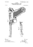
J. HURSH.
Muzzle-Loading Ordnance.
No, 35,877.
Patented July 15. 1862.
I
Tfiiiitsses:
J7iutn7(ir
N. PETERS, PHOTO-LITHOGRAPHER, WASHINGTON. О C
United States Patent Office,
JOSEPH HURSH, OF PHILADELPHIA, PENNSYLVANIA.
IMPROVEMENT IN ARRANGING WATER-TUBES FOR COOLING THE BREECH OF ORDNANCE.
Specification forming part of Letters Patent No. 35,8'??', dated July 15, 1862.
To all whom it may concern:
Be it known that I, Joseph Hursh, of the
city and county of Philadelphia, and State of
Pennsylvania, have invented a new and useful
Improvement in Cannons; and I do hereby de-
clare that the following is a full, clear, and ex-
act description.of the Construction and opera-
tion of the same, reference being had to the
annexed drawings,making a part of thisspeci-
flcation, in which—
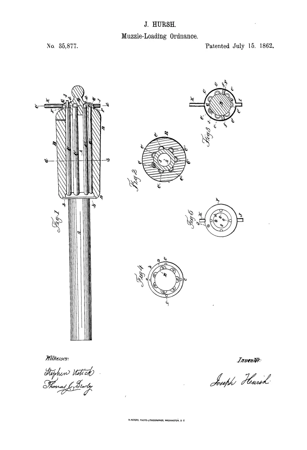
Figure 1 is a longitudinal section of the gun.
Fig. 2 is a cross-section of the same at the red
line а Ъ of Fig. 1; Fig. 3 is a cross-section at
the red line c d of Fig. 1. Fig. 4 is a rear view
of the chamber-ring D detached. Fig. 5 is a
face view of the chamber-ring F.
Like letters in all the figures represent the
same parts.
The nature of my invention consists in the
combination of a series of tubes around the
barrel of the gun, for the passage of cold water
or air for the purpose of cooling the gun dur-
ing rapid firing of the same.
To enable others skilled in the art to-make
and use my invention, I will proceed to de-
scribe its construction and operation.
A is the barrel of the gun.
В is a jacket which surrounds the rear or
breech end of the same.
С С С C and С' С' C' are tubes which extend
through the interior of the jacket, and which
surround the breech end of the barrel A, for
the passage of cold water for the purpose of
cooling the barrel, to admit of the rapid firing
of the gun.
D is a ring which surrounds the barrel A at
the front end of the jacket B, and which forms
an annular chamber, E, on the barrel, with
which the above-described tubes are connected
at their front ends by means of openings a, as
seen in Fig. 4. The said ring has a flange, Ъ,
with openings c, through which screws pass
into the end of the jacket В to confine the ring-
in its place. The ring F, on the rear end of
the jacket B, is confined by means of screws
in the openings c of the flange d. The said
ring, being hollow on its inside and fitting on
the annular depression d' of the jacket B,
forms a chamber, G, with which the rear ends
of the cooling-tubes С С С C and С' С' C' com-
nuvnicatc.
H is a supply-tube on the ring F, through
which the water passes into the chamber G.
There being partitions//in the said cham-
ber, the water, as it enters the latter, passes
through the tubes С С С C into the chamber
E, and from it into the front ends of the tubes
O', O', and O', and flows back into the chamber
G, beneath the partitions //, and makes its
exit through the discharge-pipe L.
If desired, the supply-pipe H and discharge-
pipe I may be at opposite ends of the jacket B,
so as to have the water enter the cooling-tubes
at one end and pass out at the other. Then
the partitions//are dispensed with; or the
circuit of the water maybe extended by hav-
ing a continuous stream passing through the
tubes in succession, from the highest to the
lowest, by means of partitions so arranged in
the chambers E and G as to effect such opera-
tion.
J is a sighting-tube arranged within one of
the cooling-tubes C, leaving a sufficient space
between the latter and the former for a cur-
rent of water. The ends of the said sighting-
tube extendthrough the rings D and F through
suitable openings, which are made water-tight.
The rear end of said tube is shown in Figs. 1
and 5. There may be a sighting-tube arranged
in each of the cooling-tubes, which will en-
able the gunners to get a much more perfect
range of an object than is ordinarily obtained.
When it may be inconvenient to use water
for cooling the gun, the object may be partially
accomplished by taking off the chamber-rings
D and F to allow currents of cold air to flow
through the tubes, in lieu of the water. In this
case the sighting-tube J is dispensed with,and
the cooling-tubes, being open at each end, are
used for sighting.
My usual plan of constructing the gun with
the cooling-tubes is as follows: In the first
place, I construct the barrel A with the tubes,
and then cast the jacket В around the same.
In the cooling of the jacket, the particles of
iron composing the rear end of the barrel A
are consequently condensed by the shrinking
of the jacket, thereby giving increased cohe-
sive strength to the iron. As all founders are
familiar with the mode of preparing the molds
to cast bodies of iron around other pieces, a
particular description I deem unnecessary.
I am aware that a cooling-tube winding
around the barrel of the gun has been pat-
ented; but this mode of construction and ar-
rangement is liable to serious objections, es-
2 35,877
pecially as to its filling with sediment, it hav-
ing no way of being cleaned ont. Mine is
free from this objection, as by taking off the
chamber - rings 1) and F the tubes, being
straight, can readily be cleaned. Another ad-
vantage is in my having the facility of using
the sighting-tube J, or in using the cooling-
tubes also for sighting when the chamber-rings
D and F are removed for the purpose of allow-
ing cold air to flow through them for cooling
the barrel. In the heating of the gun the air
in the tubeswill consequently become rarefied,
and the surrounding air, which is denser and
colder, will continually rush in to take its
place in a more perfect degree than in a wind-
ing tube.
Having thus fully described the improve-
ment in cannons invented by me, I do not claim,
broadly, the use of cooling-tubes; but
I claim—
1. Constructing the barrel with a series of
straight tubes arranged, substantially as de-
scribed, in relation to the barrel and to the
jacket which is cast around it, the tubes being
connected witli the chambers E and G, or their
equivalents.
2. Arranging the sighting-tube J in one of
the cooling-tubes, substantially as described,
and for the purpose set forth.
In testimony that the above is my invention
I have hereunto set my hand and seal this 12th
day of June, 1862.
JOSEPH HURSH. [l. s.
Witnesses:
Stephex Ustick,
Thomas J. Bewley.