/
Tags: weapons military affairs patent
Year: 1905

Text
No. 804,986.
PATENTED NOV. 21, 1905.
H. STAMM.
SELF LOADING FIREARM.
APPLICATION PILED JULY 21, 1902.
7 SHEETS-SHEET 1.
No. 804,986.
PATENTED NOV. 21, 1905.
H. STAMM.
SELF LOADING FIREARM.
APPLICATION FILED JULY21, 1902.
Witnesses:
7 SHEETS-SHEET 2.
No. 804,986.
PATENTED NOV. 21, 1905.
H. STAMM.
SELF LOADING FIREARM.
APPLICATION PILED JULY 21,1902.
7 SHEETS—SHEET 3.
No. 804,986.
PATENTED NOV. 21, 1905.
H. STAMM.
SELF LOADING FIREARM.
APPLICATION FILED JULY 21, 1902.
7 SHEETS—SHEET 4.
No. 804,986.
PATENTED NOV. 21, 1905.
H. STAMM.
SELF LOADING FIREARM.
APPLICATION FILED JULY 21.1902.
7 SHEETS-SHEET S.
No. 804,986.
PATENTED NOV. 21, 1905.
H. STAMM.
SELF LOADING FIREARM.
APPLICATION PILED JULY21, 1902.
7 SHEETS-SHEET 6.
No. 804,986.,
PATENTED NOV. 21, 1905.
H. STAMM.
SELF LOADING FIREARM.
APPLICATION PILED JULY21, 1902.
7 SHEETS-SHEET 7.
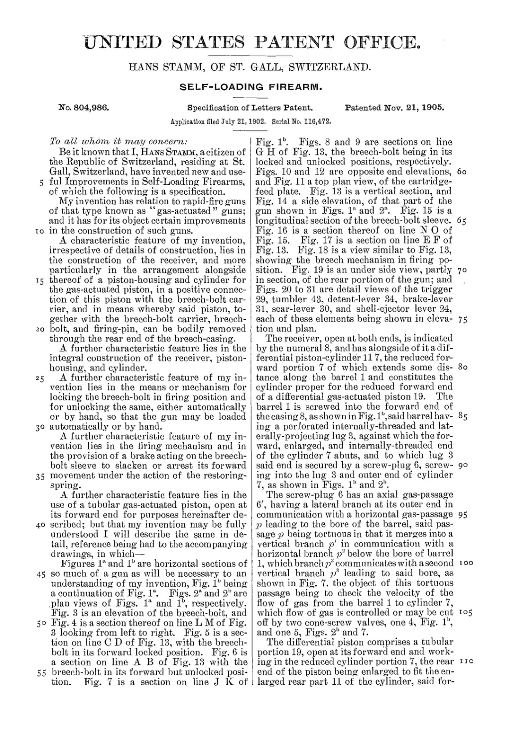
UNITED STATES PATENT OFFICE.
HANS STAMM, OF ST. GALL, SWITZERLAND.
SELF-LOADING FIREARM.
No, 804,986.
Specification of Letters Patent.
Patented Nov. 21, 1905.
Application filed July 21,1902, Serial No. 116,472,
To all whom it may concern:
Be it known that I, Hans Stamm, a citizen of
the Republic of Switzerland, residing at St.
Gall, Switzerland, have invented new and use-
5 ful Improvements in Self-Loading Firearms,
of which the following is a specification.
My invention has relation to rapid-fire guns
of that type known as “gas-actuated” guns;
and it has for its object certain improvements
io in the construction of such guns.
A characteristic feature of my invention,
irrespective of details of construction, lies in
the construction of the receiver, and more
particularly in the arrangement alongside
15 thereof of a piston-housing and cylinder for
the gas-actuated piston, in a positive connec-
tion of this piston with the breech-bolt car-
rier, and in means whereby said piston, to-
gether with the breech-bolt carrier, breech-
20 bolt, and firing-pin, can be bodily removed
through the rear end of the breech-casing.
A further characteristic feature lies in the
integral construction of the receiver, piston-
housing, and cylinder.
25 A further characteristic feature of my in-
vention lies in the means or mechanism for
locking the breech-bolt in firing position and
for unlocking the same, either automatically
or by hand, so that the gun may be loaded
30 automatically or by hand.
A further characteristic feature of my in-
vention lies in the tiring mechanism and in
the provision of a brake acting on the bree.ch-
bolt sleeve to slacken or arrest its forward
35 movement under the action of the restoring-
spring.
A further characteristic feature lies in the
use of a tubular gas-actuated piston, open at
its forward end for purposes hereinafter de-
40 scribed; but that my invention may be fully
understood I will describe the same in de-
tail, reference being had to the accompanying
drawings, in which—
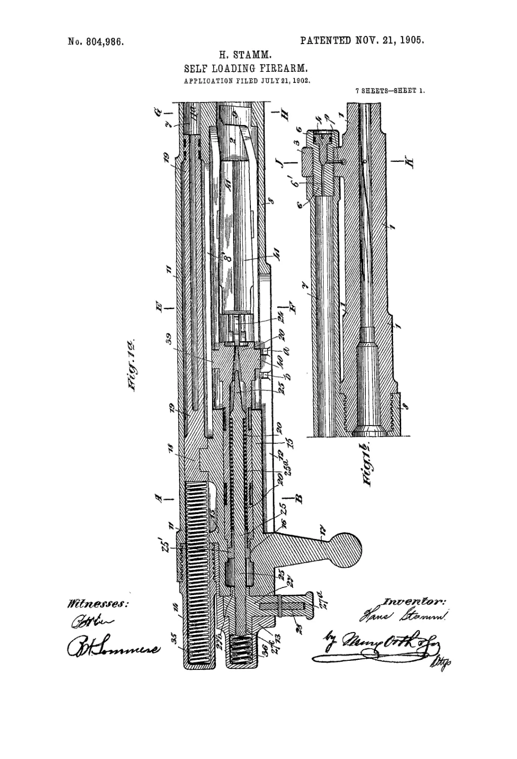
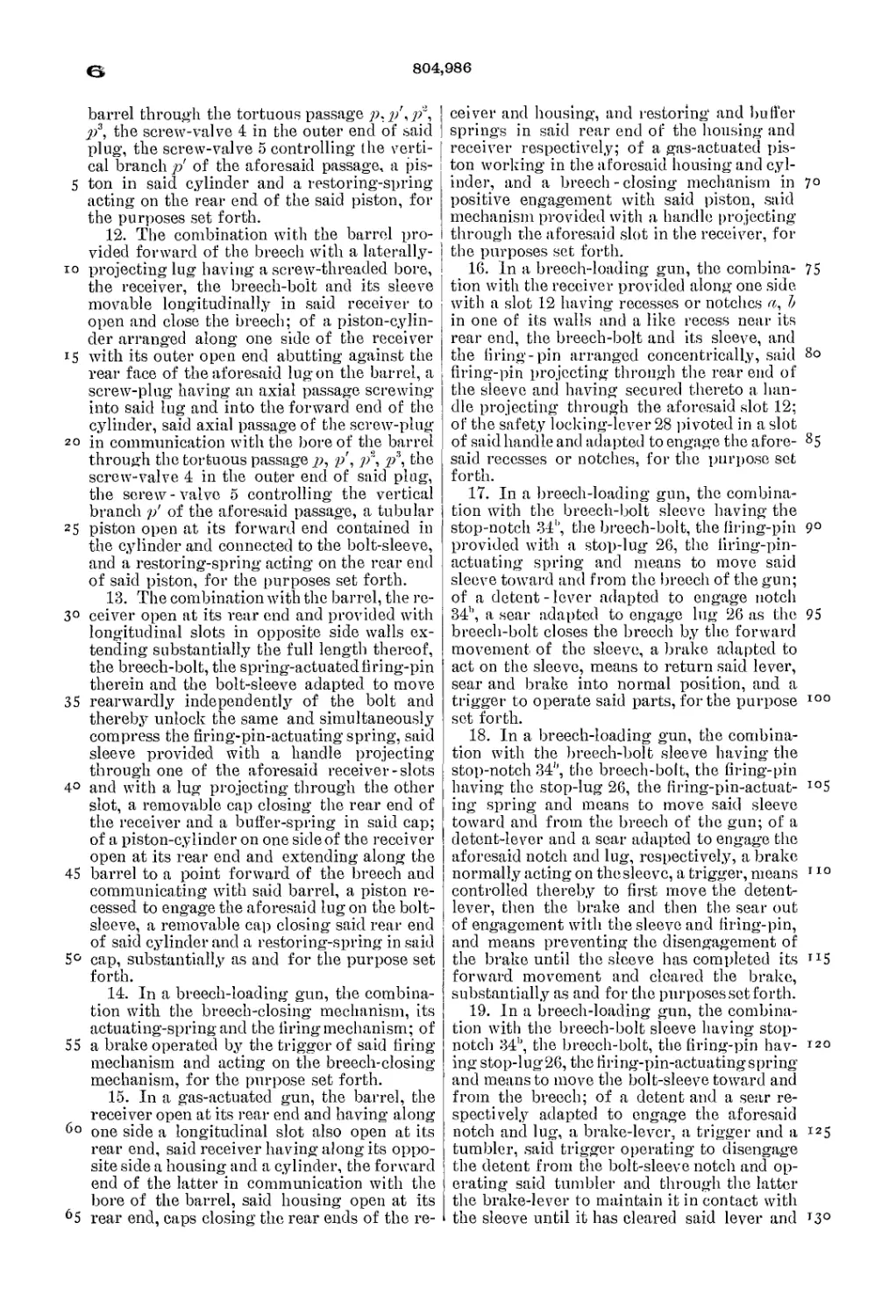
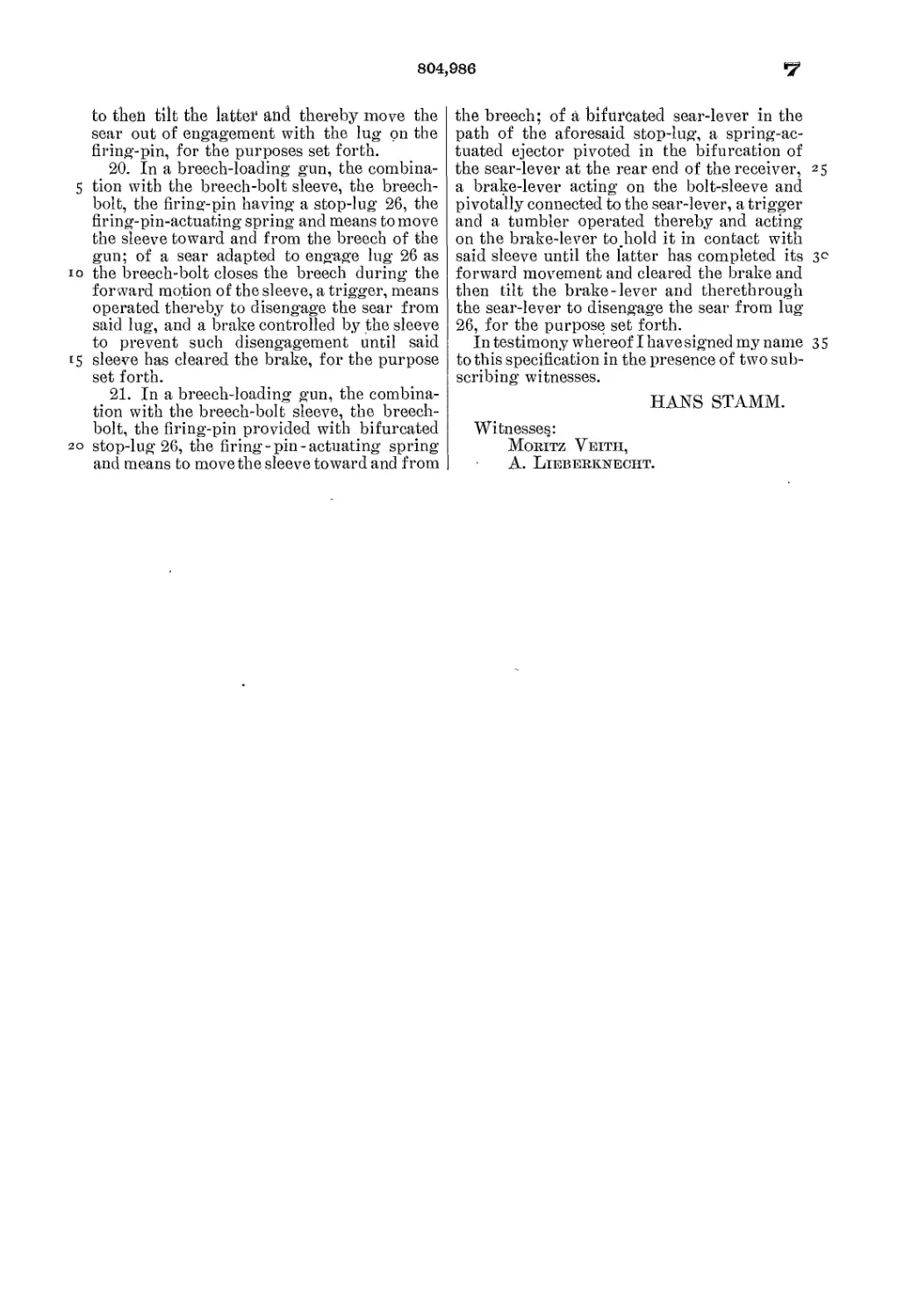
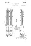
Figures I0, and lb are horizontal sections of
45 so much of a gun as will be necessary to an
understanding of my invention, Fig. lb being
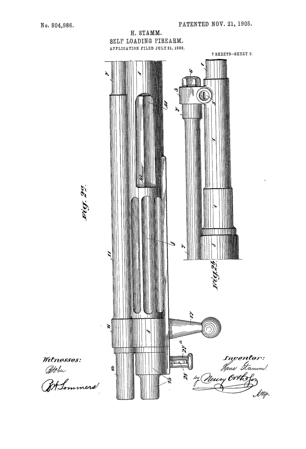
a continuation of Fig. la. Figs. 2a and 2b are
.plan views of Figs. la and lb, respectively.
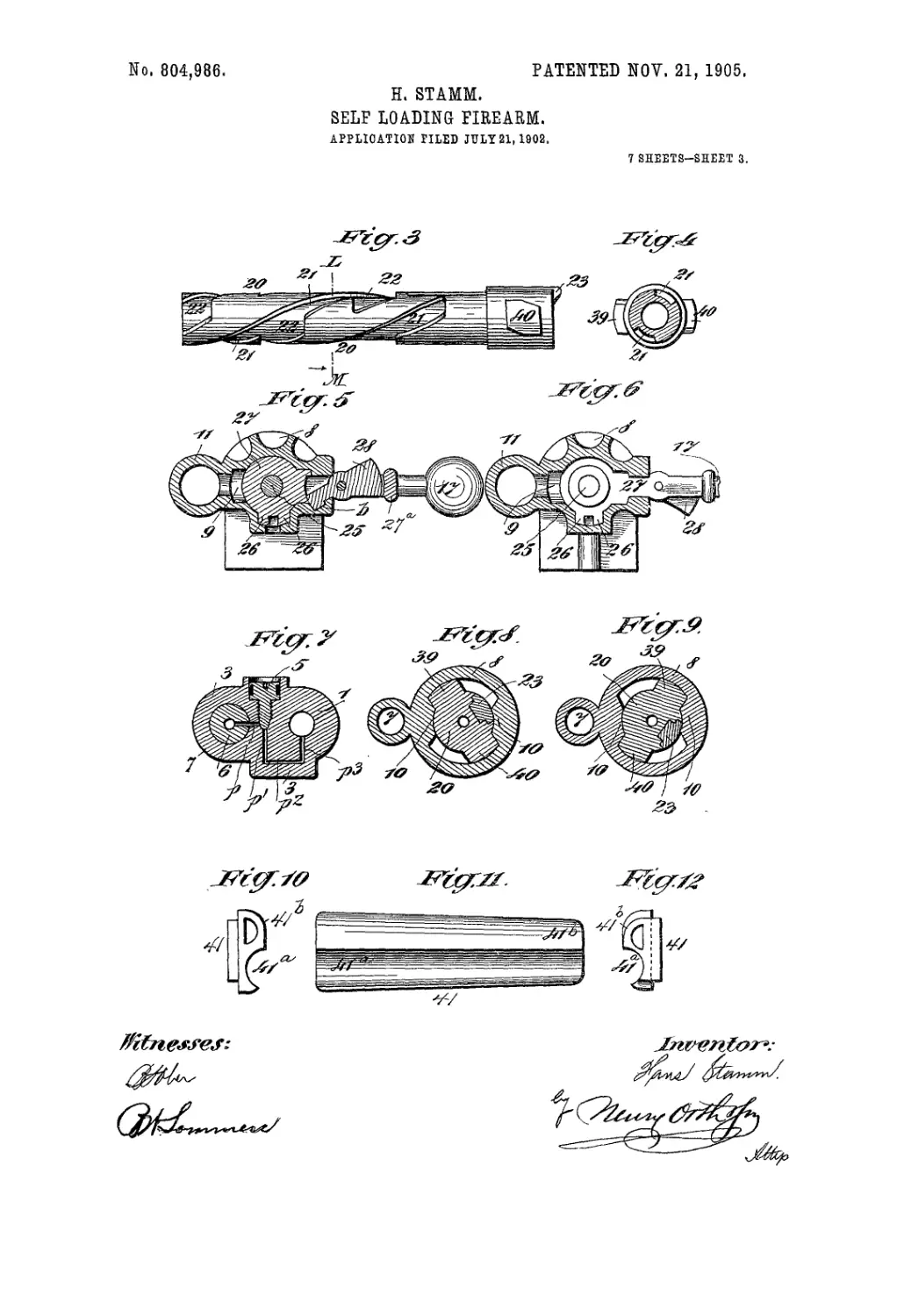
Fig. 3 is an elevation of the breech-bolt, and
50 Fig. 4 is a section thereof on line L M of Fig.
3 looking from left to right. Fig. 5 is a sec-
tion on line C D of Fig. 13, with the breech-
bolt in its forward locked position. Fig. 6 is
a section on line A В of Fig. 13 with the
55 breech-bolt in its forward but unlocked posi-
tion. Fig. 7 is a section on line J К of
Fig. lb. Figs. 8 and 9 are sections on line
G H of Fig. 13, the breech-bolt being in its
locked and unlocked positions, respectively.
Figs. 10 and 12 are opposite end elevations, 60
and Fig. 11 a top plan view, of the cartridge-
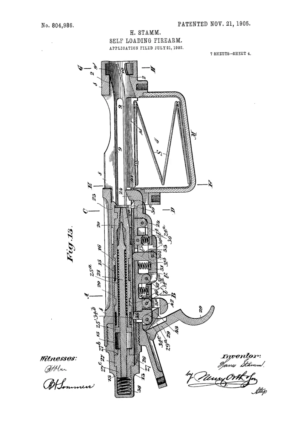
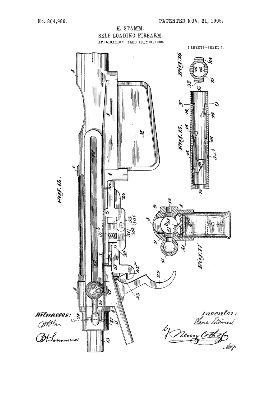
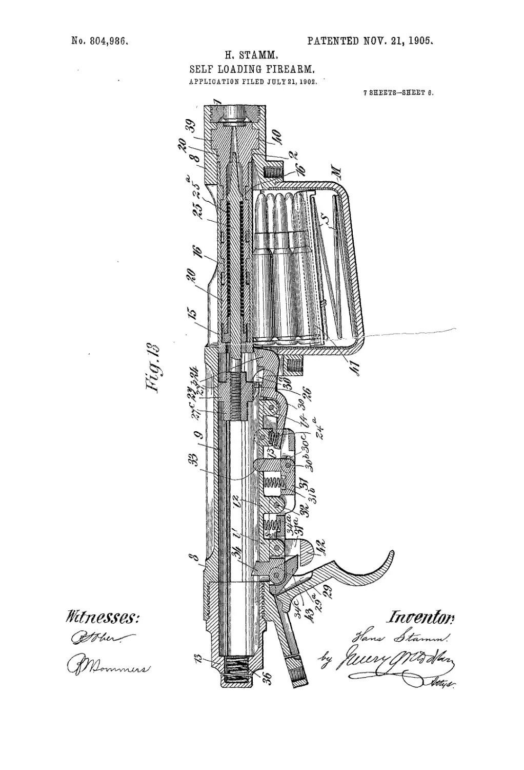
feed plate. Fig. 13 is a vertical section, and
Fig. 14 a side elevation, of that part of the
gun shown in Figs. la and 2a. Fig. 15 is a
longitudinal section of the breech-bolt sleeve. 65
Fig. 16 is a section thereof on line N О of
Fig. 15. Fig. 17 is a section on line E F of
Fig. 13. Fig. 18 is a view similar to Fig. 13,
showing the breech mechanism in firing po-
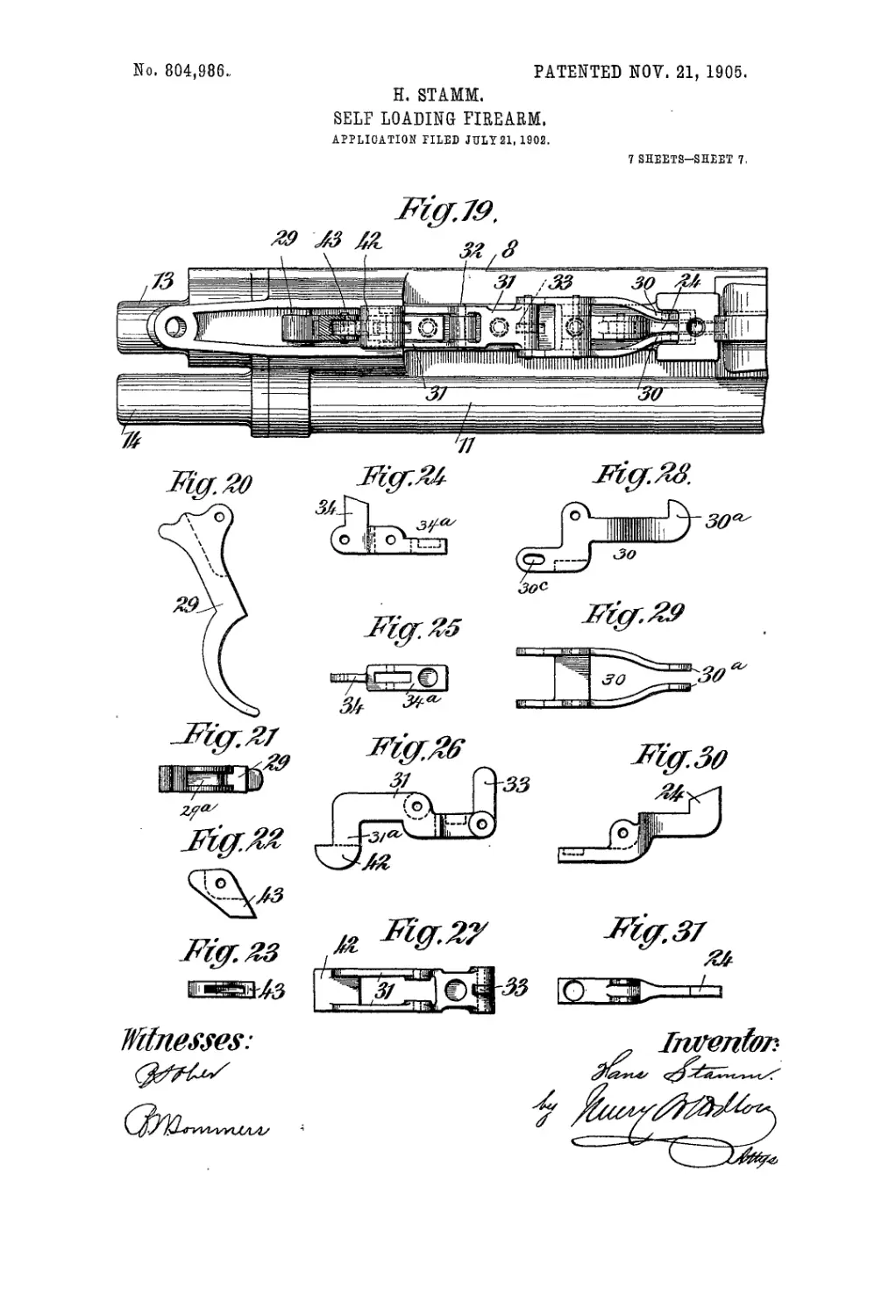
sition. Fig. 19 is an under side view, partly 70
in section, of the rear portion of the gun; and
Figs. 20 to 31 are detail views of the trigger
29, tumbler 43, detent-lever 34, brake-lever
31, sear-lever 30, and shell-ejector lever 24,
each of these elements being shown in eleva- 75
tion and plan.
The receiver, open at both ends, is indicated
by the numeral 8, and has alongside of it a dif-
ferential piston-cylinder 117, the reduced for-
ward portion 7 of which extends some dis- 80
tance along the barrel 1 and constitutes the
cylinder proper for the reduced forward end
of a differential gas-actuated piston 19. The
barrel 1 is screwed into the forward end of
thecasing 8, as shown in Fig. lb, said barrel hav- 85
ing a perforated internally-threaded and lat-
erally-projecting lug 3, against which the for-
ward, enlarged, and internally-threaded end
of the cylinder 7 abuts, and to which lug 3
said end is secured by a screw-plug 6, screw- 90
ing into the lug 3 and outer end of cylinder
7, as shown in Figs. lb and 2b.
The screw-plug 6 has an axial gas-passage
6', having a lateral branch at its outer end in
communication with a horizontal gas-passage 95
p leading to the bore of the barrel, said pas-
sage p being tortuous in that it merges into a
vertical branch p' in communication with a
horizontal branch рг below the bore of barrel
1, which branch^2 communicates with asecond 100
vertical branch p3 leading to said bore, as
shown in Fig. 7, the object of this tortuous
passage being to check the velocity of the
flow of gas from the barrel 1 to cylinder 7,
which flow of gas is controlled or may be cut 105
off by two cone-screw valves, one 4, Fig. lb,
and one 5, Figs. 2b and 7.
The differential piston comprises a tubular
portion 19, open at its forward end and work-
ing in the reduced cylinder portion 7, the rear no
end of the piston being enlarged to fit the en-
larged rear part 11 of the cylinder, said for-
2
804,986
5
10
i5
20
25
3°
35
4о
45
5°
55
6о
65
ward end of the piston being suitably packed.
The piston-cylinder is closed at its rear end
b.y a tubular cap 14, screwing into said rear
end, while the rear end of the receiver is like-
wise closed by a tubular screw-cap 13, screw-
ing into said rear end, as shown in Figs. Iя
and 13.
The breech-bolt-actuating sleeve 15, here-
inafter referred to as the “bolt-sleeve,” has
a handle 17 that projects laterally through a
longitudinal slot 12 in the side of the receiver
8 and contains the tubular breech-bolt 20,
which latter contains the firing-pin 25, cen-
tered in the bore of the breech-bolt by a
tubular centering-screw 25', screwed into the
rear end of the bolt and in which screw the
firing-pin has motion.
The rear end of the firing-pin 25 is screwed
into a sleeve 27, which has reduced tubular ex-
tensions 27” 27° projecting into an opening
in the rear end of bolt-sleeve 15 and into the
cap 13, respectively, which latter contains a
buffer-spring 36 and serves to limit the rear-
ward movement of the bolt-sleeve 15. The
sleeve 27 has a handle 27“, that projects through
the casing-slot 12, and has a longitudinal slot
in which is pivoted a locking-lever 28, Figs.
1“ and 5, whose outer end is of such width as
to project sufficiently from the upper or lower
face of the handle 27“ as to be readily actuated
by a finger to cause the inner end of the lever
to engage or be disengaged from one of three
recesses formed in one edge of the longitudi-
nal slot 12 of receiver 8. In Fig. Iя I have
shown two of the recesses a and J, respec-
tively, the former serving to lock the firing-
pin when not under the tension of its spring
25я and the latter serving to lock said pin
when the spring 25“ is under tension. The
third recess (not shown) is located near the
rear end of the receiver-slot 12 to admit of the
locking of the firing-pin 25 in its rearward
position.
The differential piston 19, as stated above,
has its cylindrical rear end enlarged to fit the
enlarged part 11 of cylinder 7, and said pis-
ton is recessed for the reception of a lug 18
on bolt-sleeve 15, which lug projects through
a longitudinal slot 8', Fig. Iя, into the piston-
cylinder, said slot 8' being diametrically op-
posite the aforementioned slot 12 and, like it,
extends from end to end of the receiver. In
rear of said enlarged end of the piston and in
said cap 14 is located the restoring-spring 35.
It is obvious that by unscrewing the caps
13 and 14 and drawing the bolt-sleeve back
by means of its handle 17 the appliances in
the receiver and piston-cylinder can be simul-
taneously withdrawn.
In opposite sides of the receiver 8 are
formed guide-grooves 9, Figs. 5, 6, 17, and
18, into which project peripheral lugs 37 and 38
near the forward end of bolt-sleeve 15, Fig. 16,
to guide the same toward and from the breech
of the gun. The forward ends of these
grooves have an upward and a downward
trend, respectively, as shown in Fig. 13, and
merge into recesses 9' in front of inward pro-
jections 2, which form shoulders or abutments
that serve to lock the breech-bolt 20 to the 70
breech of the gun, said bolt having on its for-
ward enlarged end or head peripheral lugs or
projections 39 and 40, fitting the grooves 9
and guided thereby, ribs or ledges 10 10,
Figs. 8, 9, and 13, being provided, which 75
serve as bearings for said lugs 39 and 40.
The bolt-sleeve 15 has internal screw-scg-
mcnts 16, that fit corresponding helical grooves
21 in the breech-bolt 20, and in said helical
grooves are formed lateral recesses 22, Fig. 80
3, forming locking-shoulders for said seg-
ments when the bolt is turned in one direc-
tion to cause said bolt to move with the
sleeve, and in the head of said bolt is seated
in the usual manner the shell-extractor 23. 85
The magazine M depends from the forward
end of the receiver 8, which is open at top,
and said magazine is provided with a carrier-
plate 41, under the influence of a spring S,
Figs. 13, 17, and 18, said carrier-plate having 90
a seat 41“ for the lowermost cartridge and a
raised portion 41", Fig. 17, which latter when
the magazine is empty projects into the re-
ceiver and prevents the breech-bolt from mov-
ing into its forward position, thereby indicat- 95
ing to the marksman that the magazine is
empty, this being also indicated by the posi-
tion of the handle 17 on bolt-sleeve 15, then
nearly at the rear end of slot 12.
On the under side of the bolt-sleeve 15 is 100
formed a stop-notch 34”, Figs. 13 and 15, and
on the under side of sleeve 27, that carries
the firing-pin 25, are formed two lugs 26,
Figs. 5, 6, 13, and 18, for purposes herein-
after explained. 105
Referring now more particularly to Figs.
13, 14, 18, 19, and 20 to 31, the receiver has
on its under side four lugs l! I,31', Figs.
13 and 18, and to a pin 32 on lug Z“ is ful-
crumed an angle-lever 31, the shape of which no
is shown in Figs. 26 and 27 and which will
hereinafter be referred to as the “brake-le-
ver,” the forward end of which is under the
influence of a spring 31”, and, as shown, the
said forward end of said lever has a vertical 115
extension 33, that projects through a slot in
the receiver into the path of the bolt-sleeve
15, while the rear end of said lever 31 has
downward extensions 31“ connected to a
head 42. 120
To the lug Z', projecting into the space be-
tween the sides or cheeks of brake-lever 31, is
pivoted an angle-lever 34, (shown in detail in
Figs. 24 and 25 and hereinafter referred to
as the “detent-lever,”) the rear end of which 125
projects through a slot in the receivers in the
path of the notch 34” in bolt-sleeve 15, here-
inabove referred to, while the horizontal arm
34“ of said lever is under the influence of a
spring which tends to hold the vertical 130
804,986
member of the lever in the path of the afore-
said notch, while spring 31b tends to maintain
the vertical extension 33 or brake of lever 31
in a normal position relatively to and barely
5 in contact with the bolt-sleeve 15.
To a pin 34°, at the rear end of detent-le-
ver 34, is pivoted a tumbler 43, Figs. 22 and
23, and to the tumbler-pivot 34c is pivoted the
trigger 29, Figs. 20 and 21, that actuates said
io tumbler, which latter actuates the brake-le-
ver. To the lug V is pivoted the-angle-lever
30, hereinafter ref erred to as the “sear-lever,”,
the form of which is shown in Figs. 28 and
29 and whose side bars or cheeks converge at
15 their front ends and have vertical hook-shaped
extensions or sears 30a that project through a
slot in the receiver into the path of the stop-
lugs 26 on the under side of the firing-pin
sleeve 27, hereinabove referred to.
20 The side bars or cheeks of the sear-lever are
slotted longitudinally, as shown at 30°, and
into said slots project the ends of a pin 30b,
secured in the front end of brake-lever 31.
Finally, to lug Z4 is pivoted the ejector-lever
25 24, Figs. 30 and 31, whose rearwardly-in-
clined vertical member or nose projects also
through a slot in the receiver 8 into the path
of the bolt-sleeve 15 under the influence of a
spring 24a, so that when said sleeve moves to
3° its forward position to close the breech it will
ride over the aforesaid nose of the ejector-
lever and depress the same against the stress
of its spring, said nose lying in line with the
notch between the stop-lugs 26 on firing-pin
35 sleeve 27, which notch is shown in Figs. 5
and 6.
In the position of the described elements
shown in Fig. 13 it is presumed that the bolt-
sleeve 15, breech-block 20, firing-pin 25, and
4° piston 19 have been moved back by hand, as
will be necessary before firing the first shot,
whereby the restoring-spring is brought un-
der tension, the detent-lever 34 engaging the
notch 34b in said sleeve 15 and locking the
+5 breech mechanism against forward motion, a
cartridge being pushed into the receiver-
chamber by carrier-plate 41 as soon as the
breech-block 20 has moved rearward a suffi-
cient distance to clear said chamber. At the
5° beginning of the rearward movement of the
bolt-sleeve 15 the latter moves independently
of the breech-bolt and imparts to it a partial
rotation to unlock it, as hereinafter described,
and at the same time compresses the firing-
55 pin-actuating spring 25 between the tubular
screw 25' in the breech-bolt and an enlarge-
ment near the forward end of the firing-pin.
If the trigger 29 is now pulled back, the fol-
lowing will take place: During the first part
6° of the movement of the trigger and before
the tumbler 43 acts upon the head 42 of
the brake-lever 31 said trigger will first tilt
the detent-lever 34, thereby releasing the
bolt-sleeve 15, which is rapidly driven for-
65 ward by the restoring - spring 35 acting on
piston 19, and the cartridge in the receiver
is driven into the breech of the gun by the
breech-bolt 20. Before the bolt-sleeve 15
and breech-bolt-20 have completed their for-
ward movement the sear-hooks 30a on le- 70
ver 30 will engage the lugs 26 on firing-pin-
sleeve 27 and hold the same against further
movement with the bolt-sleeve 15, and, as
above stated, the ejector lever 24 is depressed
against the stress of its spring 24“ by said for- 75
ward movement of the bolt-sleeve, and as said
bolt-sleeve completes its forward movement
the bolt is locked to the breech, the parts be-
ing now in their relative positions shown in
Fig. 18, the extractor engaging the rim or 80
flange of the cartridge in the breech. The
pull on the trigger 29 applies the brake 33 on
the brake-lever 31 to the bolt-sleeve 15, so that
its rapid forward movement under the stress
of the restoring-spring35 can be checkedsuf- 85
ficiently to insure the engagement of the sear-
hooks 30° on sear-lever 30 with the lugs 26
on the sleeve 27 of the firing-pin 25, whereby
liability of breakage of the engaging parts,
particularly of the sears 30a, is avoided, and, 90
as will be readily understood, this forward
movement of the carrier may be entirely
checked by said brake 33 if sufficient power
is applied to the trigger 29. As soon as the
bolt-sleeve 15 clears the brake 33 the brake- 95
lever is free to move, and a continued pull on
the trigger 29 will cause the tumbler 43 to act
on the head 42 of said lever, thereby depress-
ing its rear end and raising its forward end
against the stress of its spring 31b and through 100
the pin 30b acting on'the rear end of thesear-
lever 30 raises said rear end and depresses its
forward end to move the sears 30a out of en-
gagement with the lugs 26 on the sleeve 27 of
the firing-pin 25, releasing the latter, which 105
is driven forward under the stress of its
spring 25a and explodes the cartridge, while
said continued pull on the trigger 29 causes
the tumbler 43 to slide off head 42 of brake-
lever 31. As the cartridge is exploded the n°
gases of explosion acting on the piston 19 will
drive the same and the bolt-sleeve 15 rear-
ward, thereby placing the restoring-spring
under tension, the shock of which movement
is taken up partly by said restoring-spring IZ5
and partly by the buffer-spring 36.
It has been stated that the piston is a tubu-
lar one and open at its forward end. The ob-
ject of this is to minimize the recoil of the
piston, the gases acting thereon by expansion, 120
as will be readily understood.
As the brake-lever 31 is released simulta-
neously with the release of the firing-pin
said lever will at once resume its normal po-
sition under theaction of itsspring31b, there- 125
by withdrawing the brake 33 into its normal
position and returning the sear-lever 30 to
its normal position as the bolt-sleeve 15 is be-
ing driven rearwardly by the gases of explo-
sion, the lugs on the sleeve 27 of the firing- 130
4
804,986
5
10
i5
20
25
3°
35
4с
45
5°
55
6о
65
pin having rear inclined faces, Figs 13 and
18, whichslideover the forward rounded faces
of the sears 30a. At the same time the ejec-
tor 24 is moved into line with the notch be-
tween said lugs 26 into the path of the shell
extracted by the extractor 23 and ejects the
same from the receiver, which is open at top,
in a well-known manner.
It will be readily seen that so long as the
trigger 29 is held back the spring .s- of the
detent-lever 34 cannot return the hitter, the
tumbler 43, and the trigger itself into their
normal positions, and as it is quite impossible
to release the trigger before the bolt-sleeve
15 is again driven forward by the restoring-
spring, owing to the rapidity with which said
sleeve is driven rearwardly by the gases of
explosion, the detent 34 will not be in posi-
tion to lock the bolt-sleeve 15 against forward
movement, so that the breech mechanism
under the respective action of the gases of
explosion and the restoring-spring will be
driven rearward and then immediately for-
ward into the position, Fig. 18, by the time
the detent 34, the tumbler 43, and trigger 29
have again assumed their normal positions,
Fig. 18, the gun being ready for firing.
Of course it will be understood that at each
forward movement of the breech-bolt and its
sleeve 15 with the piston 19 the gas in the
cylinder part 7 will be driven out of said part
into the barrel 1 before the next cartridge can
be exploded, so that the admission-passage
performs also the function of exhaust-pas-
sage, whereby the provision of a separate
exhaust-port, as is commonly the case, is
avoided.
From the description of the construction
and operation of the gun its operation by
hand through the medium of the handle 17
will be readily understood, and in this opera-
tion the communication between the barrel 1
and cylinder 7 will of course be cut off by
means of the screw-valve 5 or both screw-
valves 4 and 5.
The unlocking and locking of the breech-
bolt is effected as follows: By the rearward
movement of the bolt-sleeve 15 the firing-pin-
actuating spring 25a is brought under tension,
as above stated, while the breech-bolt is ro-
tated sufficiently by the screw-segments 16 on
the sleeve 15 traveling along the spiral
grooves 21 in bolt 20 to bring the locking-
lugs 39 and 40 of said bolt in line with the
forward ends of guide-grooves 9, said lugs
bearing on ribs 10, Fig. 8. As the lugs 39
and 40 travel along the inclined front ends of
grooves 9 the breech-bolt is further rotated,
whereby the screw-segments 16 will enter the
aforesaid recesses 22, and thereby lock the
bolt to its sleeve 15, both moving back, and
with them the firing-pin, to the position shown
in Figs. Tl and 13. The locking of the breech-
bolt 20 to the breech takes place in reverse
order—that is to say, as the lugs 39 40 travel
along the inclined front ends of grooves 9 the
bolt is turned in a direction opposite to that
above described, so that the screw-segments
16 on the bolt-sleeve 15 will now lie in groove
21, thereby disengaging the bolt from said 70
sleeve, at which time said lugs 39 40 will have
cleared grooves 9, when the sleeve completing
its forward movement turns the bolt with its
lugs 39 40 onto the ribs 10 10, Fig. 9, and
into engagement with the locking - shoul- 75
ders 2 2.
It has hereinbefore been stated that when
the last cartridge has been fired the part 41”
of the carrier-plate 41 will project into the re-
ceiver and path of the breech-bolt 20, thus 80
preventing its forward motion. When in
this position and in view of brake-arm 33 con-
tacting with the bolt-sleeve 15, but a slight
backward movement can be imparted to the
trigger 29—namely, to such an extent as 85
would in operation disengage the detent-lever
34 from carrier-notch 34” or until the tum-
bler 43 comes in contact with lever 31, as will
readily be seen—and this limited movement
of the trigger will also indicate to the marks- 90
man that the magazine is empty.
The strong closing-caps 13 and 14, with their
equally strong screw-threads, preclude all
danger of the bolt-sleeve 15 and piston 19
breaking said caps or shearing their threads 95
and flying out rearwardly, and, as hereinbe-
fore stated, the only means for removing the
breech mechanism and piston is through the
rear end of the receiver 8, so that the latter
can be built as strongly as desired. On the 100
other hand, the gun presents another very
great advantage in that the breech-bolt 20
cannot be unlocked before the projectile has
left the gun, which is of great importance to
anaccurateaim. This result is due to the com- 105
bination of the very narrow and tortuous
channel p p' 7/ 7/, which connects cylinder 7
with the barrel 1, the means for accurately
controlling the volume of gases to said cylin-
der—namely, the screw-valves 4 and 5—and no
the tubular piston 19, so that the gases of ex-
plosion before acting on the piston must fill
the same, during which time the pressure on
the breech-bolt and its locking-surfaces is
such as to prevent any rotary movement of 115
said bolt until the projectile has left the bar-
rel and the bolt is relieved of pressure, when
the gases will drive the sleeve 15 back, the
exhaust of the gases back into the barrel
through the channel referred to taking place 120
comparatively slowly, so that by these means
a too violent backward movement of the
sleeve 15 and parts connected therewith is also
avoided.
Having thus described my invention, what 125
I claim as new therein, and desire to secure by
Letters Patent, is—
1. The receiver open at its rear end and pro-
vided with longitudinal slots in its opposite
side walls extending substantially from end to 13°
804,986
5
10
i5
20
25
3°
35
40
45
5°
55
6о
65
etid thereof, the barrel secured to the receiver,
a piston-cylinder alongside thereof and re-
movable caps closing the ends of said cylinder
and receiver respectively and forming-cham-
bers for restoring and buffer springs.
2. The combination with the barrel, the re-
ceiver open at its rear end, a removable cap to
close said end, the breech-bolt and its sleeve
movable longitudinally in said receiver to
open and close the breech; of a piston-cylin-
der arranged along one side of the receiver
and open at its rear end, the forward end of
said cylinder in communication with the bar-
rel, a piston in said cylinder connected to the
breech-bolt sleeve, a restoring-spring acting
on the rear end of said piston and a removable
cap to close the rear end of said cylinder, for
the purpose set forth.
3. The combination with the barrel, the re-
ceiver open at its rear end, a removable cap to
close said end, the breech-bolt and its sleeve
movable longitudinally in said receiver to
open and close the breech, and a buffer-spring
in rear of said sleeve; of a piston-cylinder ar-
ranged along one side of the receiver and open
at its rear end, the forward end of said cylin-
der in communication with the barrel, a pis-
ton in said cylinder connected to the bolt-
sleeve, a restoring-spring acting on the rear
end of said piston and a removable cap to
close the rear end of said cylinder, for the
purposes set forth.
4. The combination with the barrel, the re-
ceiver open at its rear end, a removable cap to
close said end, the breech-bolt and its sleeve
movable longitudinally in said receiver to
open and close the breech; of a piston-cylin-
der arranged along one side of the receiver
and open at its rear end, the forward end of
said cylinder in communication with the bar-
rel, a piston in said cylinder detachably con-
nected to the breech-bolt sleeve, a restoring-
spring acting on the rear end of the piston
and a removable cap to close the rear end of
the cylinder, for the purpose set forth.
5. The combination with the barrel, receiver
and breech mechanism; of apiston-cylinder in
communication with said barrel at a point for-
ward of the breech, a piston connected with
said breech mechanism said piston being hol-
low and open at its forward end, whereby the
action of the gases of explosion is delayed un-
til the hollow piston is filled.
. 6. The combination with the barrel, the re-
ceiver, the breech-bolt and its sleeve; of a pis-
ton-cylinder on one side of the receiver and
extending along the barrel to a point forward
of the breech, a communication between said
barrel and forward end of the cylinder, and
a hollow piston open at its forward end and
connected to the bolt-sleeve whereby the ac-
tion of the gases of explosion is delayed until
the hollow piston is filled.
7. The combination with the barrel, the re-
ceiver, the breech-bolt and its sleeve; of a pis-
ton-cylinder on one side of the receiver and
extending along the barrel to a point forward
of the breech, a gas-passage of alternate op- •
posite direction leading from the barrel to
the forward end of the cylinder, and a hollow 70
piston connected to the bolt-sleeve and open
at its forward end to retard the flow of the
gases of explosion to the cylinder and cause
them .to act expansively on the piston.
8. The combination with the barrel, the re- 75
ceiver, the breech-bolt and its sleeve; of a pis-
ton-cylinder on one side of the receiver and
extending along the barrel to a point forward
of the breech, a gas-passage of alternate op-
posite direction leading from the barrel to 80
the forward end of the cylinder to more or
less check the flow of gases thereto, said gas-
passage also serving as exhaust-passage, and
a hollow piston connected to the bolt-sleeve
and open at its forward end to delay the ac- 85
tion of the gases of explosion on the piston
and to prevent the opening of the breech un-
til the projectile has left the barrel.
9. The combination with the barrel pro-
vided forward of the breech with a laterally- 90
projecting lug having a screw-threaded bore,
the receiver, the breech-bolt and its sleeve
movable longitudinally in said receiver to open
and close the breech; of a piston-cylinder ar-
ranged along one side of the receiver with its 95
outer open end abutting against the rear face
of the aforesaid lug on the barrel, a screw-
plug having, an axial passage, screwing into
said lug and into the forward end of the cyl-
inder, said axial passage of the screw-plug in юо
communication with the bore of the barrel
through a passage in the lug, and a regulat-
ing. and cut-off valve screwing into the for-
ward end of the aforesaid screw-plug, a pis-
ton in said cylinder connected to the breech- 105
bolt sleeve and a restoring-spring acting on
the rear end of said piston.
10. The combination with the barrel, the re-
ceiver, Lhe breech-bolt and its actuating-sleeve;
of a cylinder on one side of said receiver ex- no
tending along the barrel to a-point forward
of the breech, a piston connected to the bolt-
sleeve, said piston hollow and open at its for-
ward end and said forward end of the cylin-
der in communication with the barrel and a 115
cut-off in' said communication, substantially
as and for the purpose set forth.
11. The combination with the barrel pro-
vided forward of the breech with a laterally-
projecting lug having a screw-threaded bore, 120
the receiver, the breech-bolt and its sleeve
movable longitudinally in said receiver to
open and close the breech; of a piston-cylin-
der arranged along one side of the receiver
with its outer open end abutting against the 125
rear face of the aforesaid lug on the barrel, a
screw-plug, having an axial passage, screw-
ing into said lug and into the forward end of
the cylinder, said axial passage of the screw-
plug in communication with the bore of the 130
(3
804,986
5
ю
i5
20
25
3°
35
4о
45
5°
55
бо
65
barrel through the tortuous passage p~p' ..p2,
p\ the screw-valve 4 in the outer end of said
plug, the screw-valve 5 controlling the verti-
cal branch p' of the aforesaid passage, a pis-
ton in said cylinder and a restoring-spring
acting on the rear end of the said piston, for
the purposes set forth.
12. The combination with the barrel pro-
vided forward of the breech with a laterally-
projecting lug having a screw-threaded bore,
the receiver, the breech-bolt and its sleeve
movable longitudinally in said receiver to
open and close the breech; of a piston-cylin-
der arranged along one side of the receiver
with its outer open end abutting against the
rear face of the aforesaid lug on the barrel, a
screw-plug having an axial passage screwing
into said lug and into the forward end of the
cylinder, said axial passage of the screw-plug
in communication with the bore of the barrel
through the tortuous passage p^ p', p\ p\ the
screw-valve 4 in the outer end of said plug,
the screw-Valve 5 controlling the vertical
branch p' of the aforesaid passage, a tubular
piston open at its forward end contained in
the cylinder and connected to the bolt-sleeve,
and a restoring-spring acting on the rear end
of said piston, for the purposes set forth.
13. The combination with the barrel, the re-
ceiver open at its rear end and provided with
longitudinal slots in opposite side walls ex-
tending substantially the full length thereof,
the breech-bolt, the spring-actuated firing-pin
therein and the bolt-sleeve adapted to move
rearwardly independently of the bolt and
thereby unlock the same and simultaneously
compress the firing-pin-actuating spring, said
sleeve provided with a handle projecting
through one of the aforesaid receiver-slots
and with a lug projecting through the other
slot, a removable cap closing the rear end of
the receiver and a buffer-spring in said cap;
of a piston-cylinder on one side of the receiver
open at its rear end and extending along the
barrel to a point forward of the breech and
communicating with said barrel, a piston re-
cessed to engage the aforesaid lug on the bolt-
sleeve, a removable cap closing said rear end
of said cylinder and a restoring-spring in said
cap, substantially as and for the purpose set
forth.
14. In a breech-loading gun, the combina-
tion with the breech-closing mechanism, its
actuating-spring and the firing mechanism; of
a brake operated by the trigger of said firing
mechanism and acting on the breech-closing
mechanism, for the purpose set forth.
15. In a gas-actuated gun, the barrel, the
receiver open at its rear end and having along
one side a longitudinal slot also open at its
rear end, said receiver having along its oppo-
site side a housing and a cylinder, the forward
end of the latter in communication with the
bore of the barrel, said housing open at its
rear end, caps closing the rear ends of the re-
ceiver and housing, and restoring and buffer
springs in said rear end of the housing and
receiver respectively; of a gas-actuated pis-
ton working in the aforesaid housing and cyl-
inder, and a breech - closing mechanism in 7°
positive engagement with said piston, said
mechanism provided with a handle projecting
through the aforesaid slot in the receiver, for
the purposes set forth.
16. In a breech-loading gun, the combina- 75
tion with the receiver provided along one side
with a slot 12 having recesses or notches a, b
in one of its walls and a like recess near its
rear end, the breech-bolt and its sleeve, and
the firing-pin arranged concentrically, said 8°
firing-pin projecting through the rear end of
the sleeve and having secured thereto a han-
dle projecting through the aforesaid slot 12;
of the safety locking-lever 28 pivoted in a slot
of said handle and adapted to engage the afore- 85
said recesses or notches, for the purpose set
forth.
17. In a breech-loading gun, the combina-
tion with the breech-bolt sleeve having the
stop-notch 34b, the breech-bolt, the firing-pin 9°
provided with a stop-lug 26, the iiring-pin-
actuating spring and means to move said
sleeve toward and from the breech of the gun;
of a detent-lever adapted to engage notch
34b, a sear adapted to engage lug 26 as the 95
breech-bolt closes the breech by the forward
movement of the sleeve, a brake adapted to
act on the sleeve, means to return said lever,
sear and brake into normal position, and a
trigger to operate said parts, for the purpose 100
set forth.
18. In a breech-loading gun, the combina-
tion with the breech-bolt sleeve having the
stop-notch 34b, the breech-bolt, the firing-pin
having the stop-lug 26, the firing-pin-actuat- I05
ing spring and means to move said sleeve
toward and from the breech of the gun; of a
detent-lever and a sear adapted to engage the
aforesaid notch and lug, respectively, a brake
normally acting on the sleeve, a trigger, means 110
controlled thereby to first move the detent-
lever, then the brake and then the sear out
of engagement with the sleeve and firing-pin,
and means preventing the disengagement of
the brake until the sleeve has completed its rI5
forward movement and cleared the brake,
substantially as and for the purposes set forth.
19. In a breech-loading gun, the combina-
tion with the breech-bolt sleeve having stop-
notch 34b, the breech-bolt, the firing-pin hav- 120
ing stop-lug26, the firing-pin-actuating spring
and means to move the bolt-sleeve toward and
from the breech; of a detent and a sear re-
spectively adapted to engage the aforesaid
notch and lug, a brake-lever, a trigger and a I25
tumbler, said trigger operating to disengage
the detent from the bolt-sleeve notch and op-
erating said tumbler and through the latter
the brake-lever to maintain it in contact with
the sleeve until it has cleared said lever and T3°
804,986
*7
to then tilt the lattei' and thereby move the
sear out of engagement with the lug on the
firing-pin, for the purposes set forth.
20. In a breech-loading gun, the combina-
5 tion with the breech-bolt sleeve, the breech-
bolt, the firing-pin having a stop-lug 26, the
firing-pin-actuating spring and means to move
the sleeve toward and from the breech of the
gun; of a sear adapted to engage lug 26 as
io the breech-bolt closes the breech during the
forward motion of the sleeve, a trigger, means
operated thereby to disengage the sear from
said lug, and a brake controlled by the sleeve
to prevent such disengagement until said
15 sleeve has cleared the brake, for the purpose
set forth.
21. In a breech-loading gun, the combina-
tion with the breech-bolt sleeve, the breech-
bolt, the firing-pin provided with bifurcated
2o stop-lug 26, the firing - pin - actuating spring
and means to move the sleeve toward and from
the breech; of a bifurcated sear-lever in the
path of the aforesaid stop-lug, a spring-ac-
tuated ejector pivoted in the bifurcation of
the sear-lever at the rear end of the receiver, 25
a brake-lever acting on the bolt-sleeve and
pivotally connected to the sear-lever, a trigger
and a tumbler operated thereby and acting
on the brake-lever to.hold it in contact with
said sleeve until the latter has completed its 3C
forward movement and cleared the brake and
then tilt the brake-lever and therethrough
the sear-lever to disengage the sear from lug
26, for the purpose set forth.
In testimony whereof I have signed my name 3 5
to this specification in the presence of two sub-
scribing witnesses.
HANS STAMM.
Witnesses:
Moritz Veith,
A. Lieberknecht.