/
Tags: weapons military affairs patent
Year: 1907


Text
No, 861,632.
PATENTED JULY 30, 1907.
J. BEADER.
BREECH LOADING MECHANISM.
APPLICATION FILED JUNE 11, 1906.
3 SHEETS—SHEET 1.
PATENTED JULY 30, 1907.
No. 861,632.
J. BRADER.
BREECH LOADING MECHANISM.
APPLICATION FILED JUNE 11, 1906.
No. 861,632.
PATENTED JULY 30, 1907.
J. BRADER.
BREECH LOADING MECHANISM.
APPLICATION FILED JUNE 11. 1906.
3 SHEETS—SHEET 3.
UNITED STATESJPATENT OFFICE.
JULIUS BRADER, OF MILWAUKEE, WISCONSIN.
BREECH-LOADING MECHANISM.
No. 861,632.
Specification of Letters Patent.
Patented July 30, 1907.
Application filed June 11,1906. Serial Ho. 321,164.
б
10
15
20
25
30
35
40
45
50
55
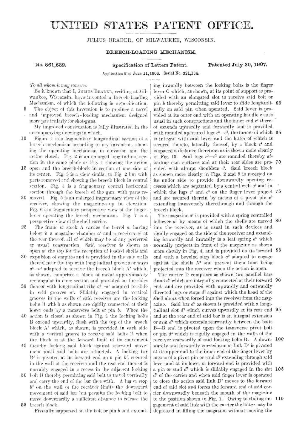
To all whom it may concern:
Be it known that I, Juuus Bradbk. residing at Mil-
waukee, Wisconsin, have invented a Breech-Loading
Mechanism, of which the following is a specification.
The object of this invention is to produce a novel
and improved breech - loading mechanism designed
more particularly for shot-guns.
My improved construction is fully illustrated in the
accompanying drawings in which.
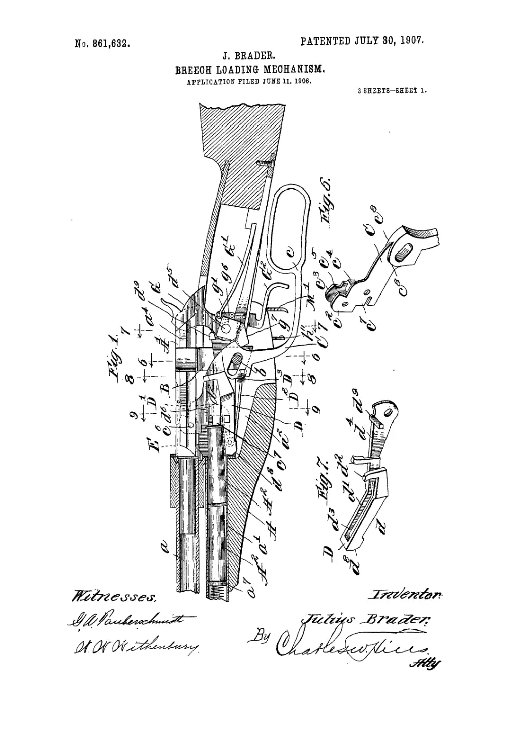
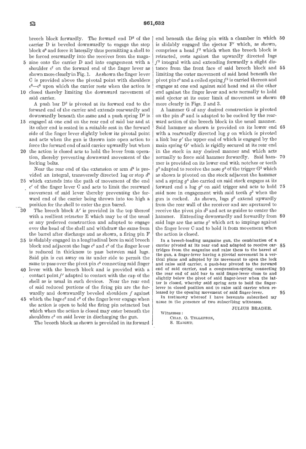
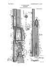
Figure 1 is a fragmentary longitudinal section of a
hreech mechanism according to my invention, shelv-
ing the operating mechanism in elevation and the
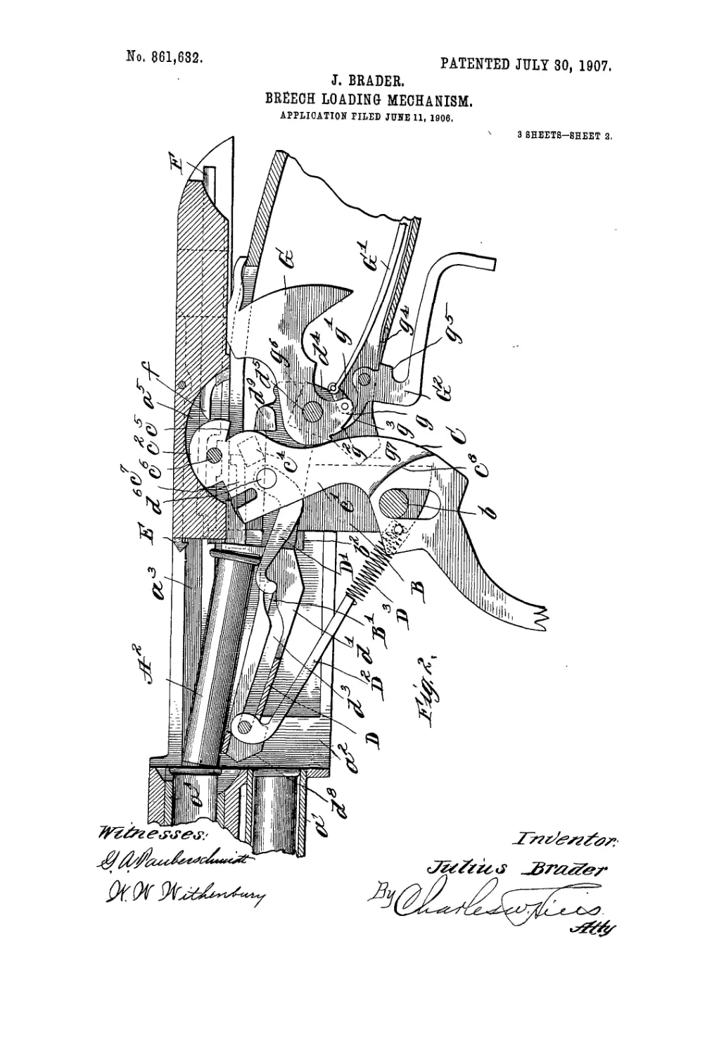
action closed. Fig. 2 is an enlarged longitudinal sec-
tion in the same plane as Fig. J showing the action
open and the breech-block in section at one side of
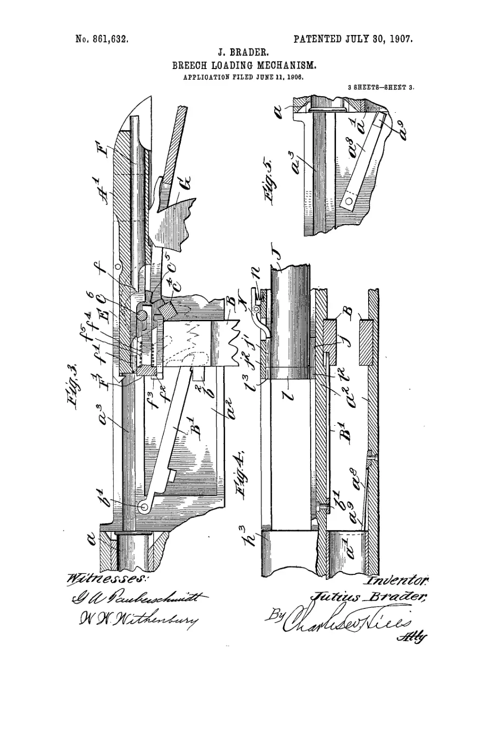
its center. Fig. 3 is a view similar to Fig 2 bm with
parts removed and showing the breech block in central
section, Fig. -1 is a fragmentary central horizontal
section through the breech of the gun. with parts re-
moved. Fig. 5 is an enlarged fragmentary view of the
receiver, showing the magazine-stop in elevation.
Fig. 6 is a fragmentary perspective view of the finger-
lever operating the breech mechanism. Fig. 7 is a
perspective л iew of the she]] carrier.
The frame or stock A canies the banal a. having
below it a magazine chamber a' and a receiver a2 at
the rear thereof, all of which may be of any preferred
or usual construction. Said receiver is shown as
open at the top for (lie reception of loaded shells and
expulsion of empties and is provided in tin- side walls
thereof near the top with longitudinal groovts or ways
a:1—a3 adapted to receive the breech block :V which,
as shown, comprises a block of metal approximately
rectangular in cross section and provided on the sides
thereof with longitudinal ribs a1—c* adapted to slide
in said grooves cP. Slidably engaged in vertical
grooves in the walls of said receiver are flu1 locking
bolts В which as shown are rigidly connected at their
lower ends by a transverse bolt or pin b. Wien the
action is closed as shown in Fig. 1 the locking bolts
В extend upwardly, flush with the top of the breech
block A2 -which, as shown, is provided in each side
with a vertical groove to receive said bolts В when
the block is at the forward limit of its movement
thereby locking said block against rearward move-
ment until said bolts are retracted. A locking bar
IF is pivoted at its forward end on a pin b'. secured
in the wall of the receiver and the rear mid thereof is
movably engaged in a recess in tin1 adjacent locking
bolt В thereby permitting said bolt to travel vertically
and carry the end of the bar therewith. A lug or stop
b- on the wall of the receiver limits the downward
movement of said bar but permits the locking bolt to
move downwardly a sufficient distance to release the
breech block.
Pivotally supported on the bolt or pin b and extend-
ing inwardly between the locking bolts is the finger
lever C which, as shown, at its point of support is pro-
vided with an elongated slot to receive said bolt or
pin 6 thereby permitting said lever to slide longitudi- 60
nally on said pin when operated. Said lever is pro-
vided at its outer end with an operating handle c as is
usual in such constructions and the inner end c' there-
of extends upwardly and forwardly and is provided
with rounded apertured lugs c'2—c3, the former of which 65
is integral with said lever and the latter of which is
secured thereto, laterally thereof, by a block c4 and
is spaced a distance therefrom as is shown more clearly
in Fig. 10. Said lugs c-—c3 are rounded thereby af-
fording cam surfaces and at their rear sides are pro- 70
vidcd with abrupt shoulders c5. Said breech block
as shown more clearly in Figs. 2 and 9 is recessed on
its under side to provide downwardly opening re-
cesses which, are separated by a central web a5 and in
which the lugs c2 and c3 on the finger lever project 75
and are secured therein by means of a pivot pin c11
extending transversely therethrough and through the
breech block.
The magazine a' is provided with a. spring controlled
follower a7 by means of which the shells are moved 80
into the receiver, as is usual in such devices and
rigidly engaged on the side of the receiver and extend-
ing forwardly and inwardly is a leaf spring as which
normally projects in front of the magazine as shown
more clearly in Fig. 4, and is provided on its forward 85
end with a beveled stop block a” adapted to engage
against the shells A2 and prevent them from being
projected into the receiver when the action is open.
The canier D comprises as shown 1 wo parallel bar's
d and d' which arc integrally connected at their forward 90
ends and are provided with upwardly and outwardly
directed lugs or stops cP against which the head of the
shell abuts when forced into the receiver from the mag-
azine. Said bar d' as shown is provided with a longi-
tudinal slot d3 which curves upwardly at its rear end 95
and at the rear end of said bar is an integral extension
or arm d“ which extends rearwardly between the bolts
В—В and is pivoted upon the transverse pivot bolt
or pin d3 which is rigidly engaged in the walls of the
receiver rearwardly of said locking bolts B. A down- 100
wardly and forwardly curved arm or link Dz is pivoted
at its upper end to the inner end of the finger lever by
means of a pivot pin or stud de extending through said
lever and at its lower or forward end is provided with
a pin or stud d7 which is slidably engaged in the slot 105
d3 of the carrier and when said finger lever is operated
to close the action said link IF moves to the forward
end of said slot and forces the forward end of said car-
rier downwardly beneath the mouth of the magazine
to the position shown in Fig. 1. О win a to sliding en- 110
gagement of said link with the carrier the latter may be
depressed in filling the magazine without moving the
861,632
breech block forwardly. The forward end Ds of the
carrier D is beveled downwardly to engage the stop
block a9 and force it laterally thus permitting a shell to
be forced rearwardly into the receiver from the maga-
5 zine onto the carrier D and into engagement with a
shoulder c7 on the forward end of the finger lever as
shown more clearly in Fig. 1. As shown the finger lever
C is provided above the pivotal point with shoulders
cs—c8 upon which the carrier rests when the action is
10 closed thereby limiting the downward movement of
said carrier.
A push bar I)7 is pivoted at its forward end to the
forward end of the carrier and extends rearwardly and
downwardly beneath the same and a push spring D3 is
15 engaged at one end on the rear end of said bar and at
its other end is seated in a suitable seat in the forward
side of the finger lever slightly below its pivotal point
and acts when the gun is thrown into open action to
force the forward end of said earner upwardly but when
20 the action is closed acts to hold the lever from opera-
tion, thereby preventing downward movement of the
locking bolts.
Near the rear end of the extension or arm d4 is pro-
vided an integral, transversely directed lug or stop <P
25 which extends into the path of movement of the end
c' of the finger lever C and acts to limit the rearward
movement of said lever thereby preventing the for-
ward end of the carrier being thrown into too high a
position for the shell to enter the gun barrel.
30 The breech block Az is provided in the top thereof
with a resilient retractor E which may be of the usual
or any preferred construction and adapted to engage
over the head of the shell and withdraw the same from
the barrel after discharge and as shown, a firing pin F
35 is slidably engaged in a longitudinal bore in said breech
block and adjacent the lugs c2 and c3 of the finger lever
is reduced in thickness to pass between said lugs.
Said pin is cut away on its under side to permit the
same to pass over the pivot pin c6 connecting said finger
40 lever with the breech block and is provided with a
. contact point f' adapted to contact with the cap of the
shell as is usual in such devices. Near the rear end
of said reduced portions of the firing pin are the for-
wardly and downwardly beveled shoulders f against
45 which the lugs c2 and c3 of the finger lever engage when
the action is open to hold the firing pin retracted but
which when the action is closed may enter beneath the
shoulders c5 on said lever in discharging the gun.
The breech block as shown is provided in its forward
end beneath the firing pin with a chamber in which 50
is slidably engaged the ejector Fz which, as shown,
comprises a head /2 which when the breech block is
retracted, rests against the upwardly directed lugs
/3 integral with and extending forwardly a slight dis-
tance from the front face of said breech block and 55
limiting the outer movement of said head beneath the
pivot pin cG and a coiled spring/5 is carried thereon and
engages at one end against said head and at the other
end against the finger lever and acts normally to hold
said ejector at its outer limit of movement as shown 60
more clearly in Figs. 2 and 3.
A hammer G of any desired construction is pivoted
on the pin d5 and is adapted to be cocked by the rear-
ward action of the breech block in the usual manner.
Said hammer as shown is provided on its lower- end 65
with a rearivardly directed lug- g on which is pivoted
a link bar g' the upper end of which is engaged by the
main spring Gz which is rigidly secured at its rear end
in the stock in any desired manner and which acts
normally to force said hammer forwardly. Said ham- 7 0
iner is provided on its lower end with notches or teeth
p7 adapted to receive the nose p3 of the trigger G2 which
as shown is pivoted on the stock adjacent the hammer
and a spring p' also carried on said stock engages at its
forward end a lug p5 on said trigger and acts to hold 7 5
said nose in engagement with said teeth p2 when the
gun is cocked. As shown, lugs p° extend upwardly
from the rear wall of the receiver and are apertured to
receive the pivot pin d5 and act as guides to center the
hammer. Extending downwardly and forwardly from 80
said lugs are the arms p7 which act to impinge against
the finger lever C and to hold it from movement when
the action is closed.
In a breech-loading magazine gun, the combination of a
carrier pivoted at its rear end and adapted to receive car- 85
tridges from the magazine and raise them to the barrel of
the gun, a finger-lever having a pivotal movement in a ver-
tical plane and adapted by its movement to open the lock
and raise said carrier, a push-bar pivoted to the forward
end of said carrier, and a compression-spring connecting 90
the rear end of said bar to said finger-lever close to and
slightly below the pivot of said finger-lever when the lat-
ter is closed, whereby said spring acts to hold the finger-
lever in closed position and to raise said carrier when re-
leased by the opening movement of said finger-lever. 95
In testimony whereof I have hereunto subscribed my
name in the presence of two subscribing witnesses.
JULIUS BRAUER.
Witnesses :
Chas. O. Tbllbitson,
S. Haight.