/


Author: Raymer D.P.
Tags: modeling construction aircraft modeling design for homebuilders simplified aircraft design
ISBN: 0-9722397-0-7
Year: 2003


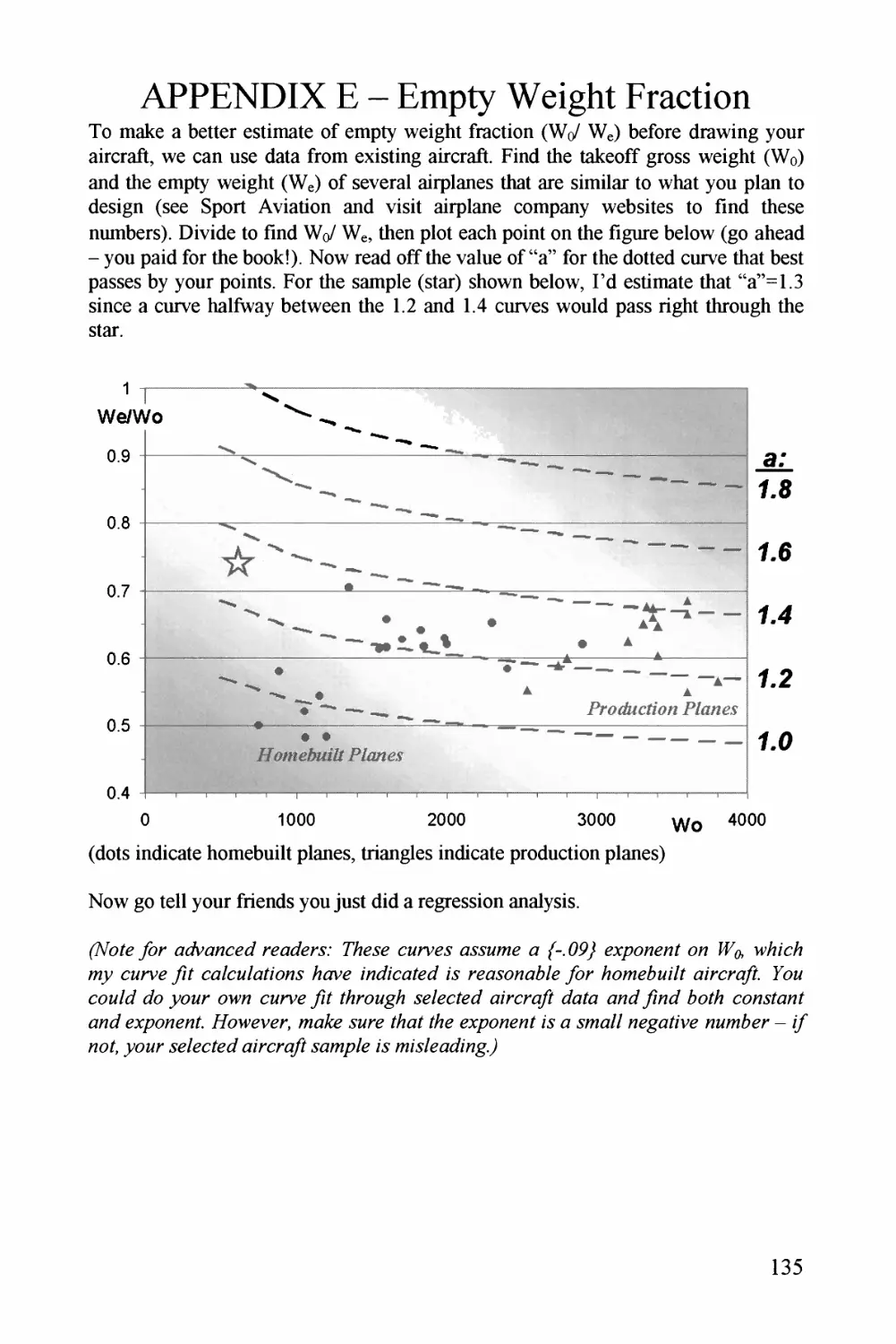
Text
Dan Raymer's
SIMPLIFIED AIRCRAFT
DESIGN FOR HOMEBUILDERS
By
Danie! P. Raymer, Ph.D.
President, Conceptual Research Corporation
Dan Raymer's
SIMPLIFIED AIRCRAFT DESIGN FOR
HOMEBUILDERS
ISBN 0-9722397-0-7
Library of Congress Control Number: 2002094899
First Edition
2003
Copyright @ 2003 by Daniel P. Raymer. Printed and bound in the United States of America. All Rights
Reserved including translation into foreign languages and conversion to electronic media. No part of this
book may be reproduced or transmitted in any form or by any means without written permission from the
publisher, except by a reviewer who may quote brief passages in a review. For information please contact
Design Dimension Press.
The author and publisher have endeavored to ensure the accuracy and completeness of information
contained in this book, but assume no responsibility for errors, inaccuracies, omissions, or any
inconsistency herein. All information herein is used at readers' own risk and no liability shall be assumed
by the author or publisher for the use of any information herein.
ATTENTION CORPORATIONS, UNIVERSITIES, HIGH SCHOOLS, AND AVIATION CLUBS AND
ORGANIZATIONS: Quantity discounts are available on bulk purchases of this book. For information
please contact Design Dimension Press.
Pubtished by
Design Dimension Press, Los Angeies, CA, USA
(a subsidiary of Conceptual Research Corporation)
PO Box 923156, Syimar, CA 91392
ddp@aircraftdesign.com
11
DEDICATION
This book is dedicated to my technical heroes - Wilbur and Orville Wright. Not only
did they solve the flight control questions that stumped their contemporaries; they
also essentially invented analytical propeller design, parametric wind tunnel testing,
and the whole process of scientific aircraft conceptual design. Another contribution -
they correctly perceived that flying an aircraft would be a trained skill, and they
taught themselves that skill over a careful three-year period prior to the first powered
flight. Congratulations to them on the 100^ anniversary of their first flight. Too bad
about the windstorm - if the Flyer hadn't been wrecked, their afternoon flights
would have gone for miles.
Special thanks to my reviewers - Peter Garrison, Todd Hodges, David Lednicer,
Michael Niu, and David Raymer. As always, thanks to those who taught me - the list
grows each day.
(This page intentionally blank)
IV
FOREWORD BY PETER GARRISON
(author of Technicalities Column, j%46L4ZZME, desigpier of Melmoth 1 & 2)
You have to be crazy to want to design your own airplane. Welcome to the club. I
started thinking about it when I was 20, began the design of the real thing when I
was 25, and flew it when I was 30. How much of every waking hour I spent thinking
about airplane design I don't know, but I can say that the subject ranked right up
there with women and money.
Since I had no engineering training or mathematics beyond high school algebra, I
had a great deal to learn. The enterprise requires a lot of miscellaneous knowledge
that can be acquired only piecemeal and sometimes by chance; the annoying thing is
that you want to get started right away. When I began, there were fewer places to
learn about it than there are today. To find a yellowing copy of K. D. Wood's
?lzrp/ane Design was cause for rejoicing; and yet I might extract from the whole
book only one or two tidbits that applied to the problem at hand.
Things are different today. Quite a few amateurs have designed successful planes,
and even made livings from selling plans and kits. The EAA and the Internet
disseminate information widely. The personal computer has put tremendous
analytical and graphical power into the hands of designers. There is as much learning
to be done as ever, but much less searching.
The great problem for the beginning designer is in/egraiion: to know how to think
about the multifaceted task ahead, in which every choice influences every other one
so intimately that it seems impossible to know where to start.
Dan Raymer has a knack for cutting through this Gordian knot. His remarkable
textbook, ^Zrcrq/f Design: ^4 Concept#/ yfyproaei, manages to bring together every
aspect of airplane design at the precise intersection of the theoretical and the
practical. It combines professional experience with an unusual directness and clarity
of expression.
The book you hold in your hands does the same, but at an even more accessible
level, and with reference to the class of airplane that an amateur designer is likely to
undertake. It shows you how to think about the problem; what steps to take to begin
a design, and in what order. It introduces you to the complete spectrum of the
designer's concerns and arms you with a vocabulary of concepts that you will flesh
out through further reading. It won't - can't - be the last book on airplane design
that you buy; but it should be the first. I wish Td had it in 1963.
Peter Garrison, Los Angeles, CA, Oct 2002
v
(This page intentionally blank)
TABLE OF CONTENTS
Dedication
Foreword by Peter Garrison
CHAPTER 1 INTRODUCTION 1
WHO AM 1 AND WHY DID 1 WRITE THIS BOOK?
WHAT IS A HOMEBUILT?
A PLAIN PLAN FOR PLANE PLANNING
STEP RIGHT UP, GET YOUR FREE DESIGN SOFTWARE
PLEASE READ THE FOLLOWING CAUTIONS:
1
2
4
5
6
CHAPTER 2 SO, YOU WANT TO DESIGN A HOMEBUILT?
7
WHY?
WHAT DO YOU WANT IT TO DO?
SO, RAYMER WANTS TO DESIGN A HOMEBUILT
7
7
8
CHAPTER 3 HOW BIG SHOULD IT BE?
11
POWER LOADING
WING LOADING
AIRPLANE SIZING
ENGINE SIZING AND SELECTION
WING GEOMETRY
AIRFOIL SELECTION
TAIL GEOMETRY
FUSELAGE SIZE
11
13
16
22
24
32
35
39
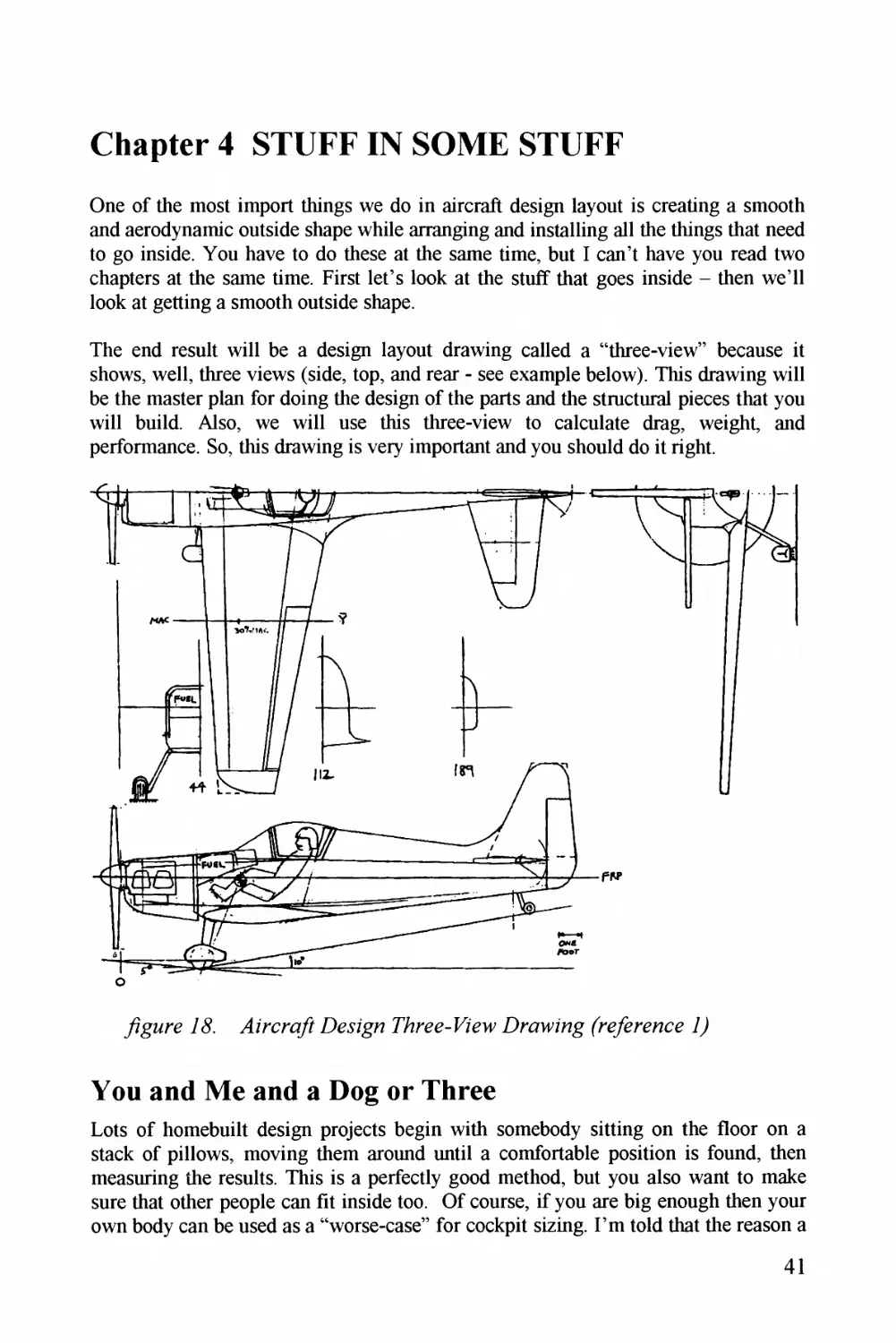
CHAPTER 4 STUFF IN SOME STUFF
41
You AND ME AND A DOG OR THREE
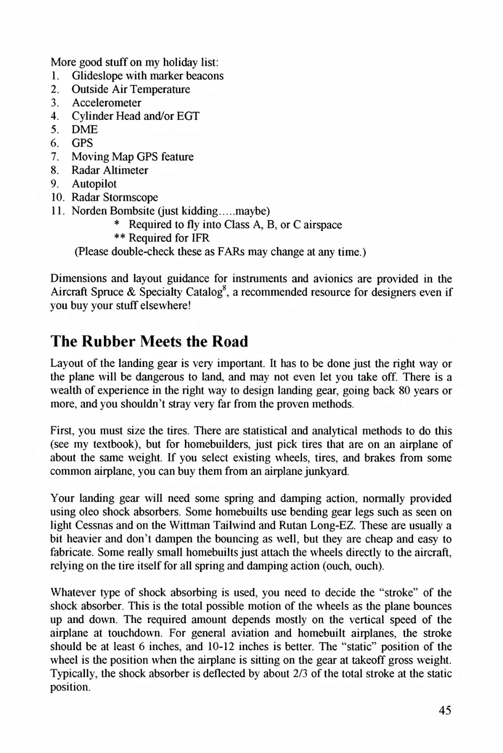
THE RUBBER MEETS THE ROAD
IN GOES THE ENGINE
STUFF SOME STRUCTURE
FUEL TANKS
41
45
51
55
63
vii
CHAPTER 5 DRAW A SMOOTH OUTSIDE
67
CONIC LOFTING
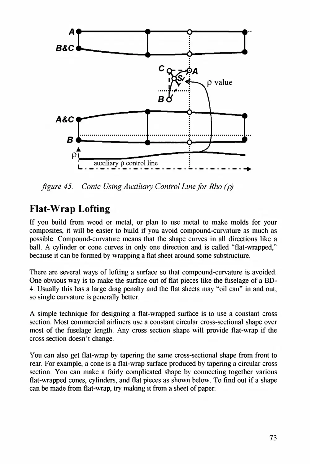
FLAT-WRAP LOFTING
WING/TAIL LOFTING
RAYMERS DR-4 SAFETY TWIN
MEASURE WHAT YOU DREW
67
73
74
79
80
CHAPTER 6 BUCKLE UP FOR SAFETY
83
CRASHWORTHINESS
FLUTTER
83
84
CHAPTER 7 ANALYZE IT
87
AERODYNAMICS
PROPULSION
PRELIMINARY STRUCTURAL SIZING
WEIGHTS ESTIMATION
STABILITY
87
91
97
105
113
CHAPTER 8 RANGE & PERFORMANCE
117
STALL SPEED
TAKEOFF DISTANCE
RATE OF CLIMB
MAXIMUM AND CRUISING SPEED
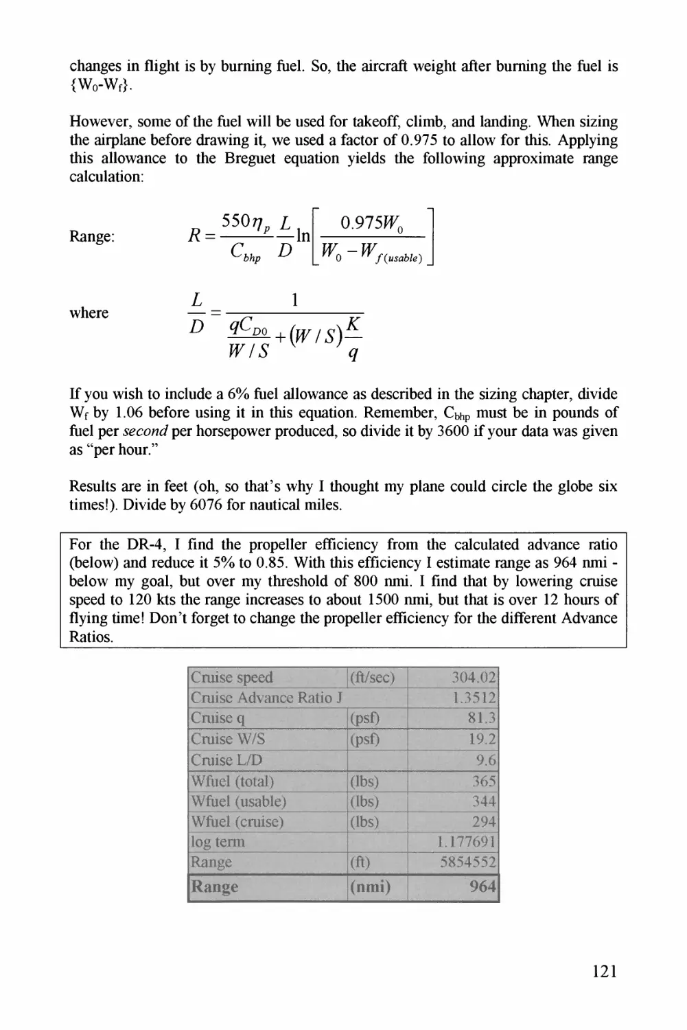
RANGE
HELP - 1 DIDN'T GET THE RANGE/PERFORlMAiCE 1 WANTED!
117
117
118
118
120
122
CHAPTER 9 LET'S MAKE IT BETTER!
123
CHAPTER 10 AND IN CONCLUSION
127
vm
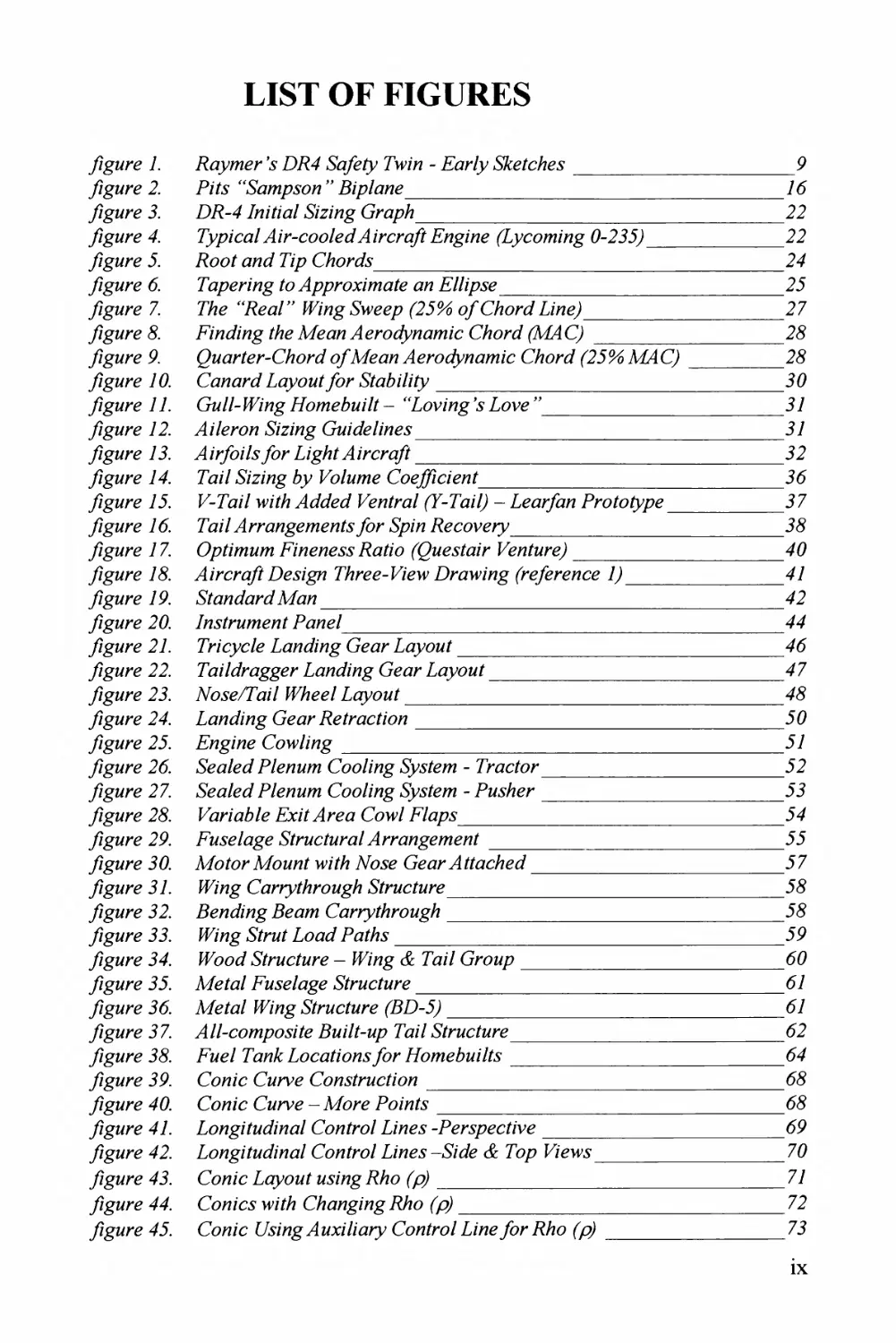
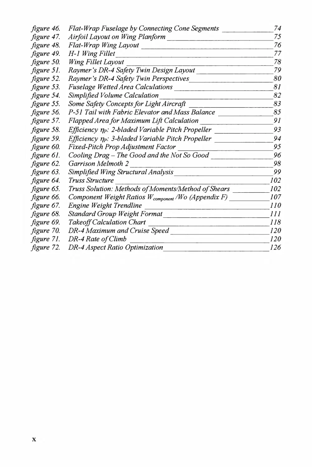
LIST OF FIGURES
/zgMry 7. 7?/z/zyr _ Z^7^4 Sa/y7/_ PHz^za - Ear/- *^a^z^<c/^a^.y
/Zgz^z*y 2. pz/._
jZg^z^/re J. D7--4 TZz^zYza?/ &^z'z^z'z^g G/ap^^/z
/ZgMry 4. TTpp/C^a? / .Z^^Z^zZey pLyco/nz'Hg 0-2333^
y7gZ^/re J. P?c0f a3a/_ PZp C^/^a^Z^aT?
/ZgMry 6. 7Cpe^^^^zz/^gyCo44p/^j^(^.r?z^c7/y pEt/Zp^.^^
/zgMry 7. 7Zz_ ^7^^^a//_ _ WZzg^a'yya- .23.- 6*^C/^^r^j^77JZz)ey_
yZgz^z/y & EZa/Zzag /^Z^y A<y^a^zy .4^a?a^z?//^^/^j2^zZ_ C^Z^a/r/- AP4C_
yZgz^z/y 9^. (aac^J/ey-^-(a^/^z^^Z/*^7/yyz^7?4^aza^z7a^/az7zaM_ CAor^ PP^ C?
yZgz^z/y 76^. Canard jCyyoMf ^rr &0a^z7zzy
/Zg^^y 7 7. G7z//-WZZzg //ozey^zz/f - 'PCwP^g _ p^a-^a?
/zgMry 72. yl^z'Z(?roz &zzzzg GzZ&ZZay.
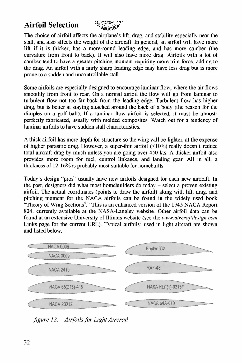
/Zg^z*y 73. Z/yazZEja^r TLzgzzZ .4 z'rcraf
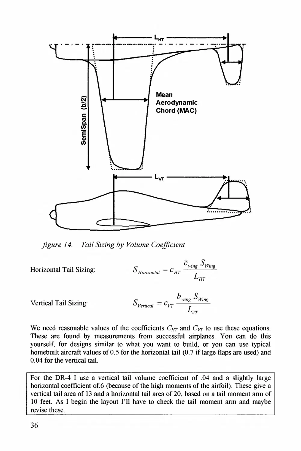
yzg^^y 74. Paz/ Z 5zzZag / Ua/^Zz^az- (Tc^rZC^^^zZ^z/Z
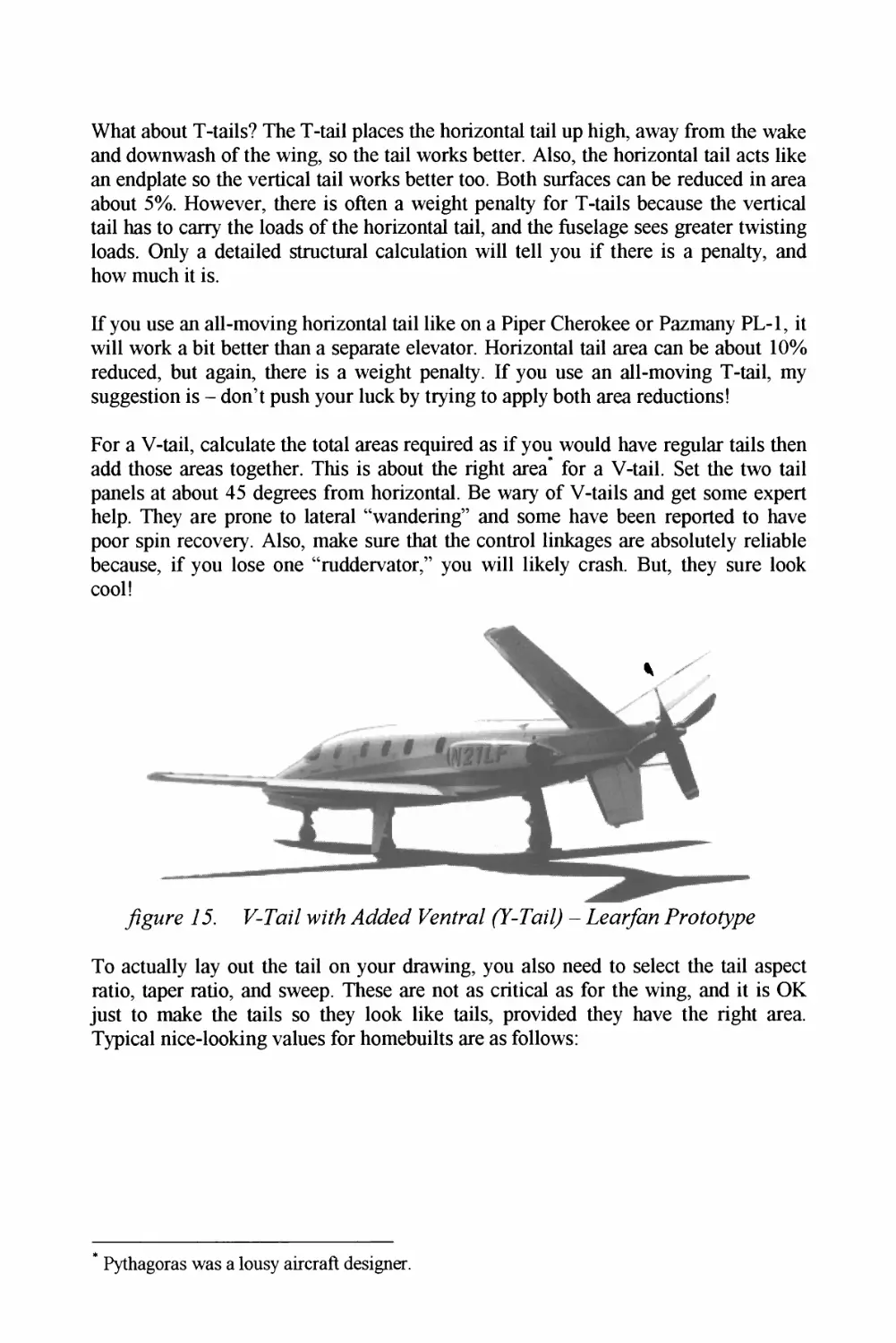
yZgz^z/y 73. jr^^Ca/ Z 'a^z'Z/Zl4azf3^z^^y jyZz^^^^^3yT-P7z^z7Z - .y^c^z^jaZ^zz p/a/^/z^yp^^?
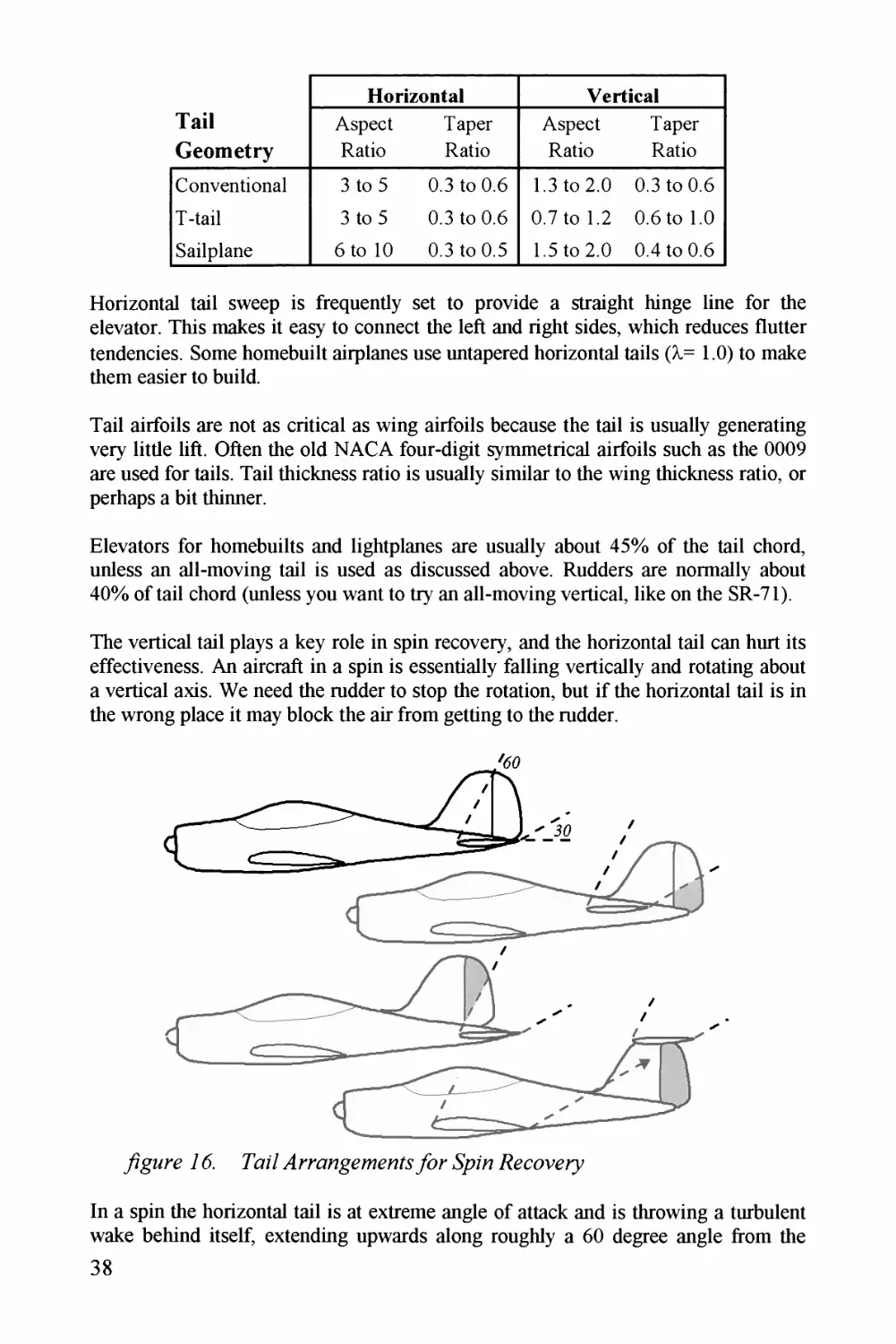
yZgzzry 76. Paz/ Z4t7^c^z^Z7^z^7/^^^zz/.Ja?y3azza2 ./^^^z^a^1^<aa^
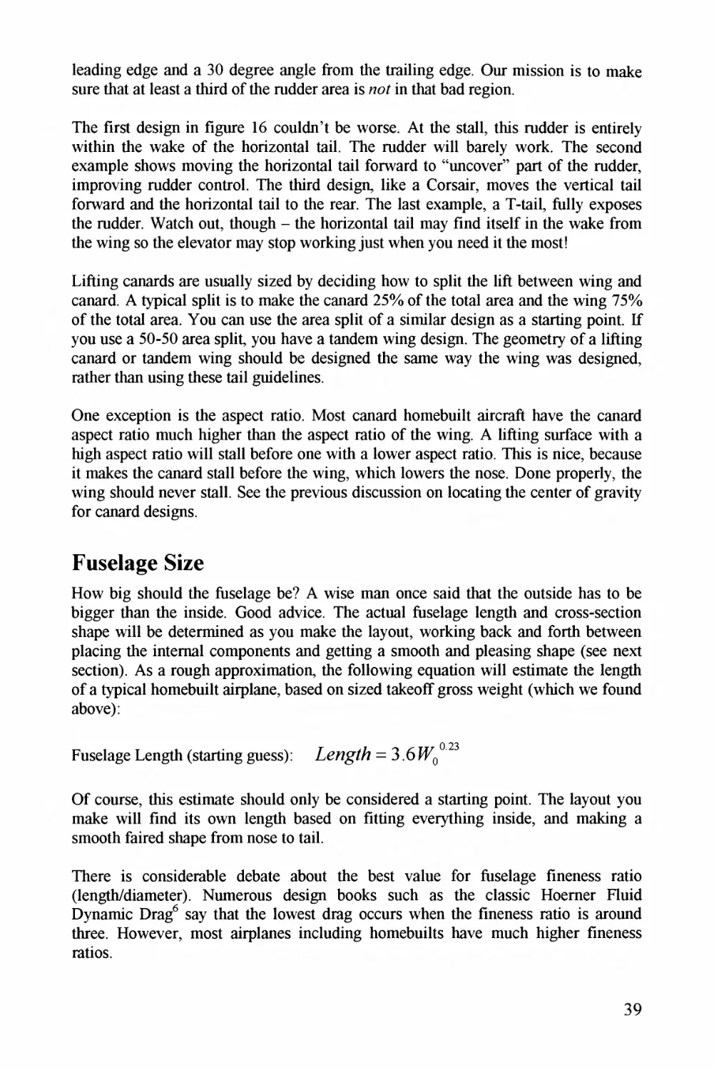
/ZgMry 77. (9/zZz/z^^zn! zaaayaz^e^. 7^</^Za_ .Z^z^(^./azzr pyaazZz/^^r
yZgz^z*y 7& ^zrcza/DDy.yzgzz 77Zryy^-^^a^^^w Er^a^a^^z'z^g Jry/e^J^^aac^^ 7)
yZgMay 79^. ./^z^z^/z/^^7^(^.TCza^
/ZgMry 26^. 7Zr^.^Za^zz/.^^zr^y paaa^zz/
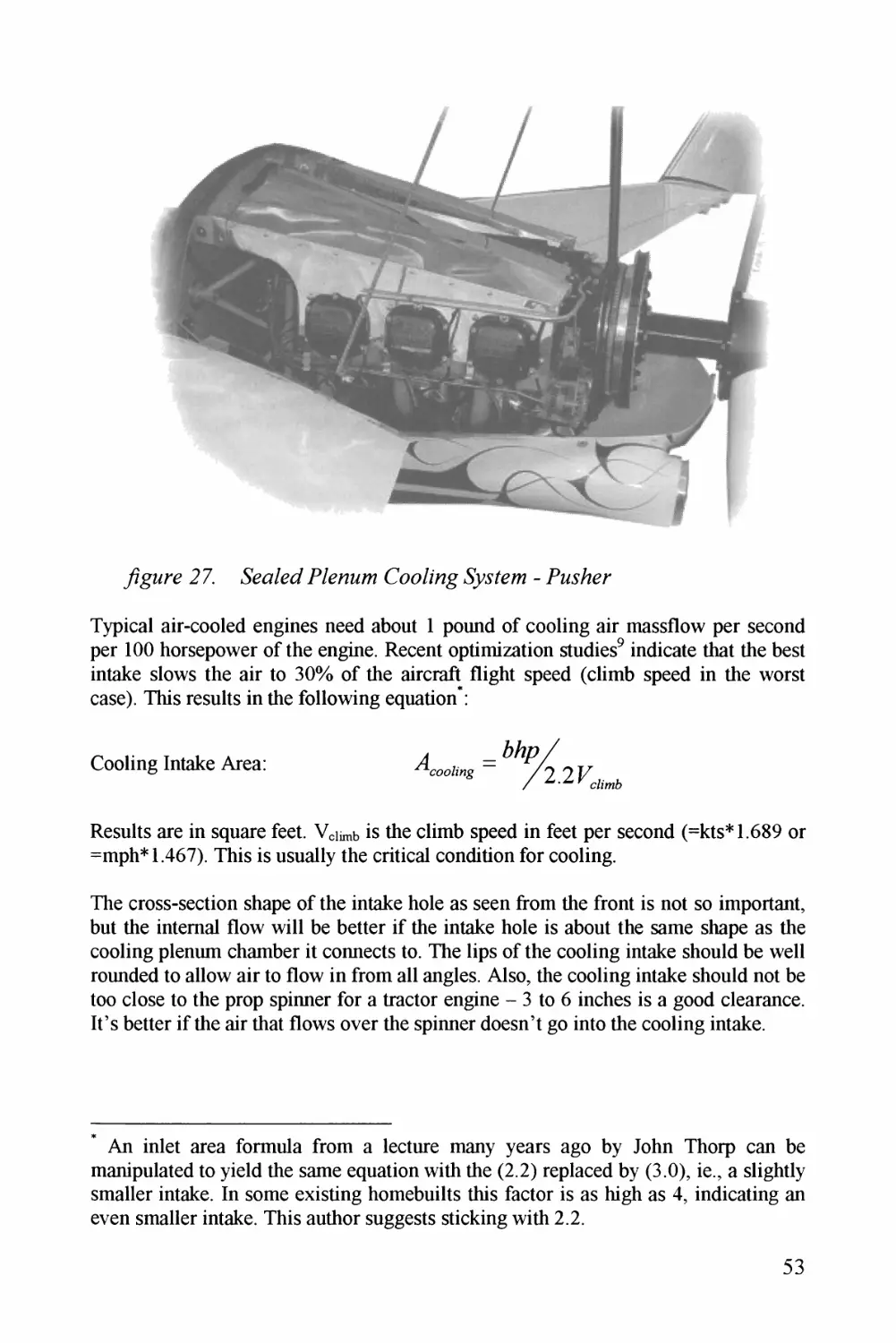
/ZgMry 27. ZZaMa^^Zy PCz^^a(a^z'z^g- (^a^a/y pC/azzz_
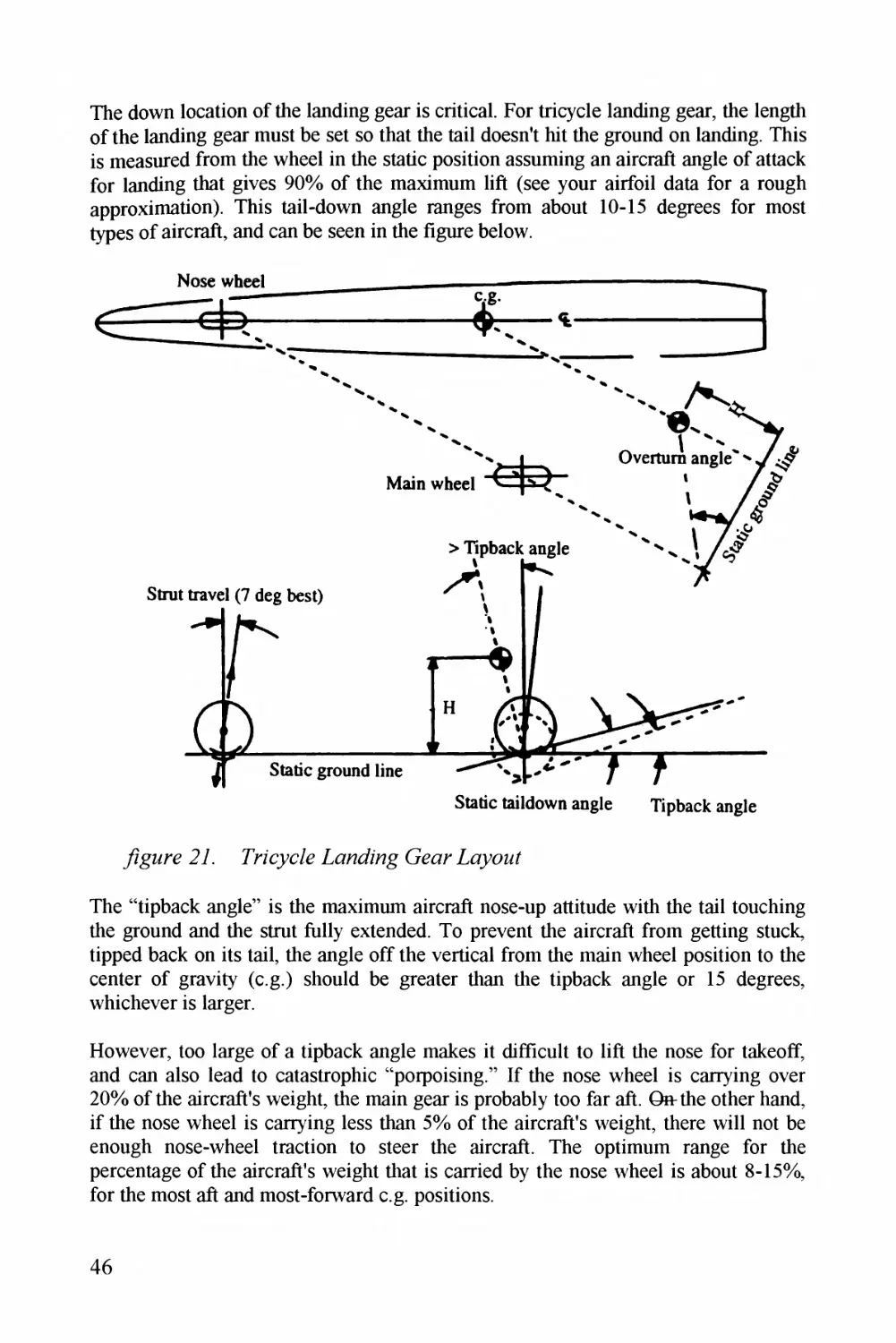
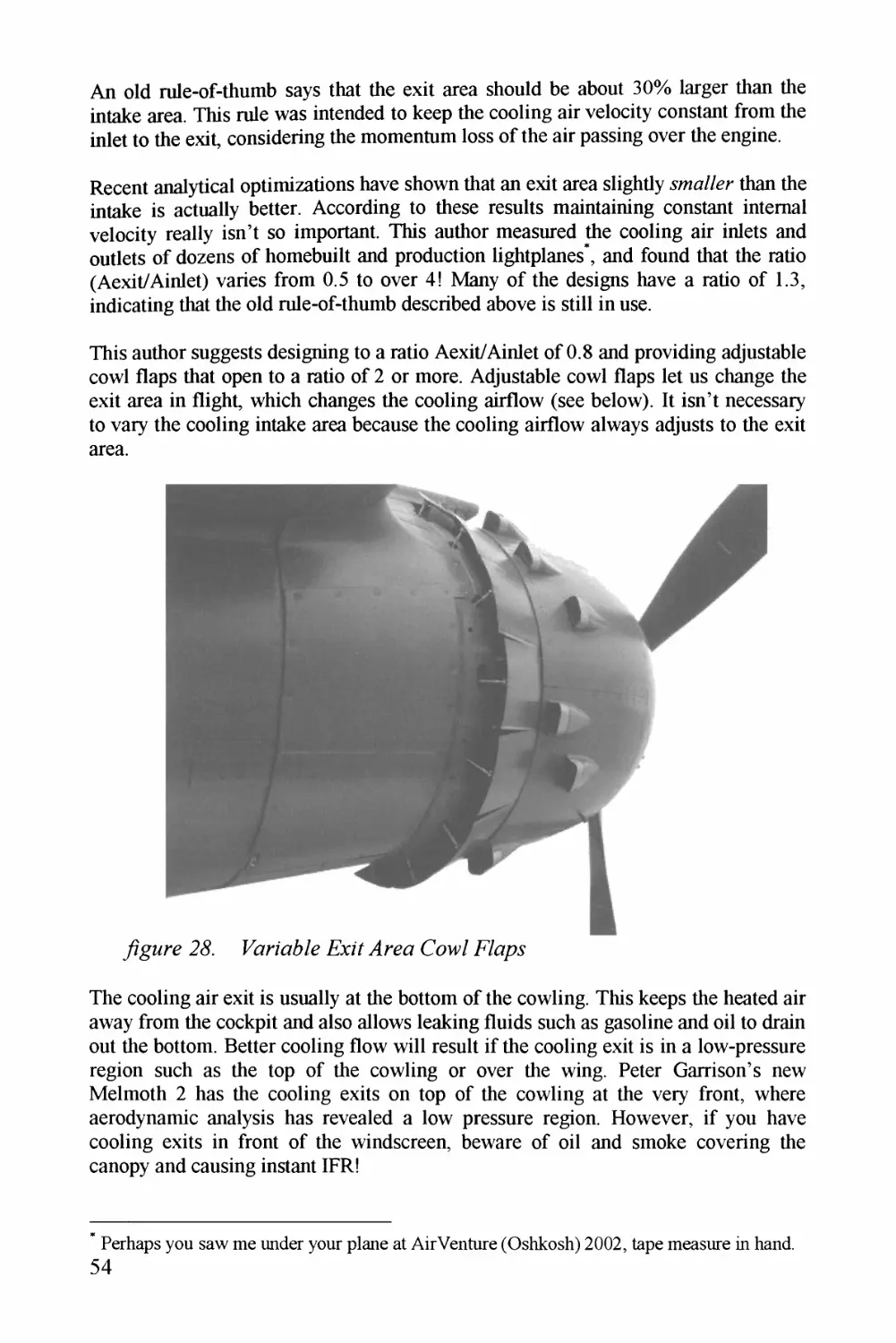
/Zg^^y 22. Eaz76/raggyy^aaaa'ag Gyar A/yzzZ
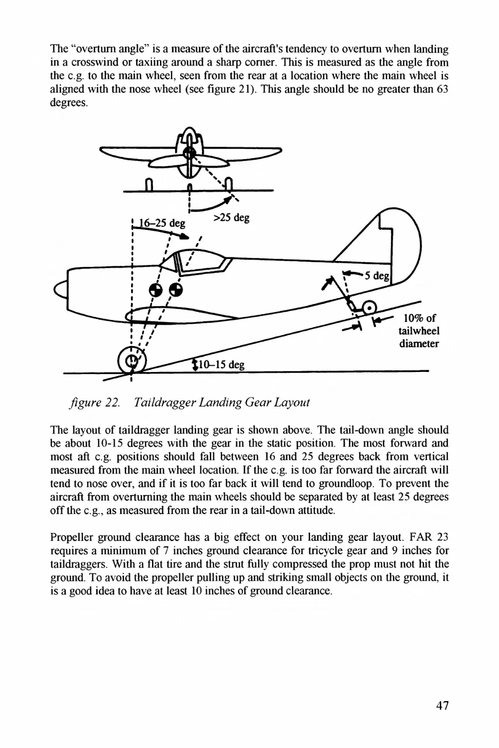
jZg^^^y 23. M9.y/7az7 WZ^y^a?- p^^y^^zz/
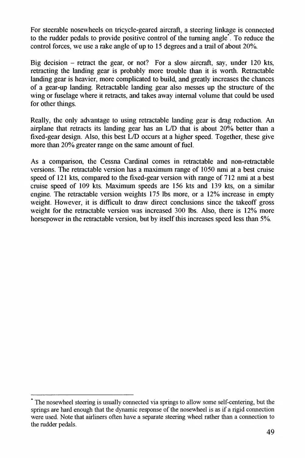
jZg^^z/y 24. Laa/Zzag 7^^/Zra^^aM^j/
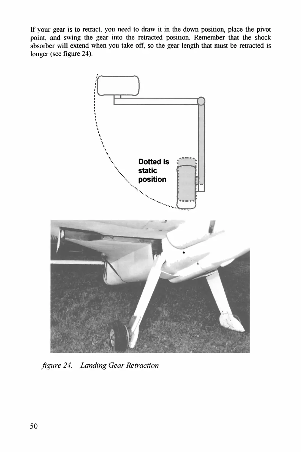
jZg^^z/y 23. Eagz'ay C^c^apaa^zz
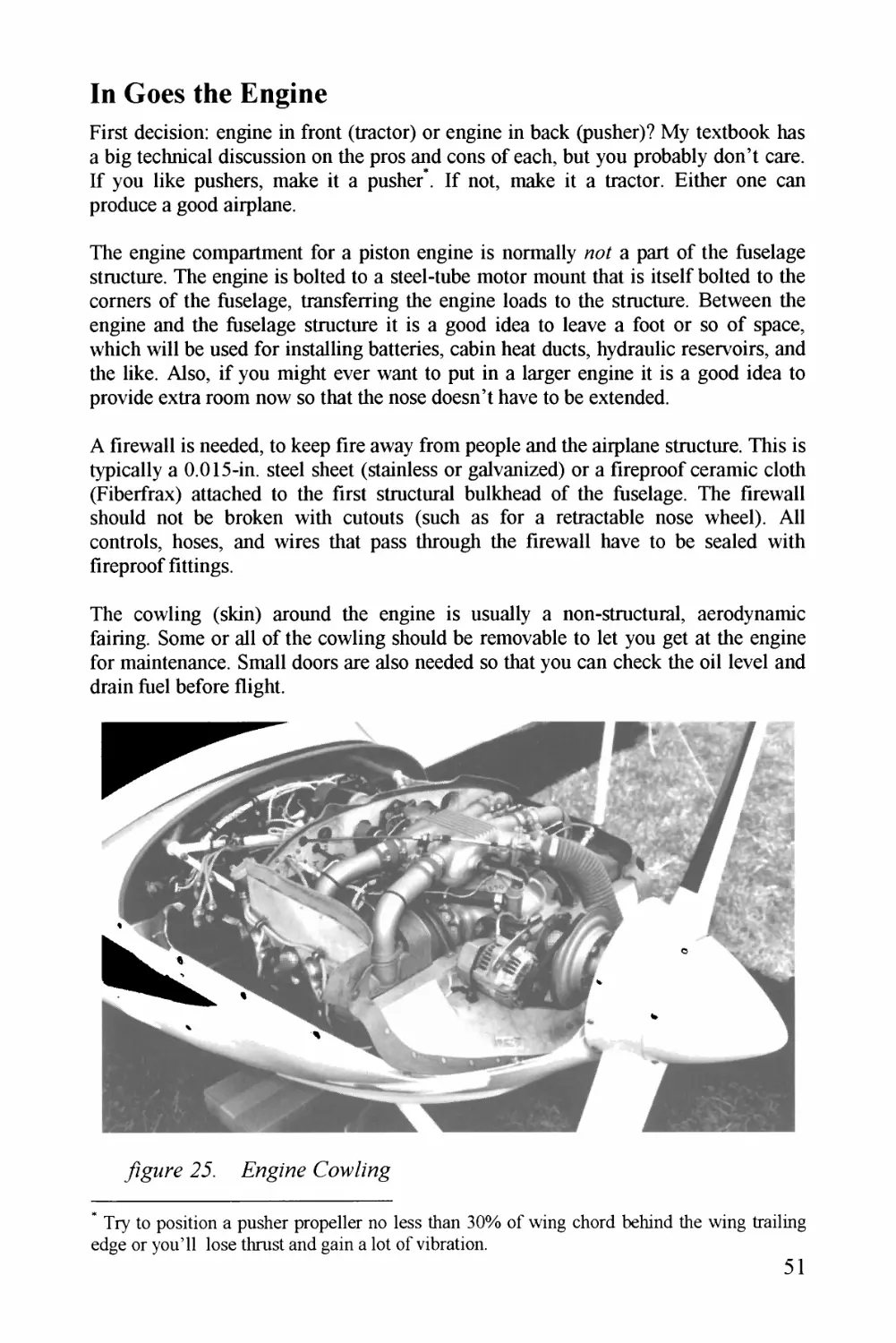
/zg^z^y 26. S'yaZyz?7zZyaMa (ao(zZza^g ,Sy/^i^^^az - 7racZar
yzgzzz/y 27. Syy/^Za^/./yaa^zaz^ia- CaaZzag ^Syz^i^^^a- - pzz./^a^zT
/zgMry 2& Pa/^za^^/Zy .XJ^z7.4z^^^^z (2ay/Z j/7ar_
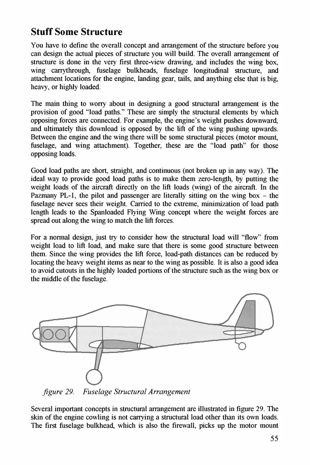
/Zg^z*y 29. Jaas^e^/^c^z^^ *^^/^zacz^zz7'^c^Z.4^jrrz^z^gyzraya^^
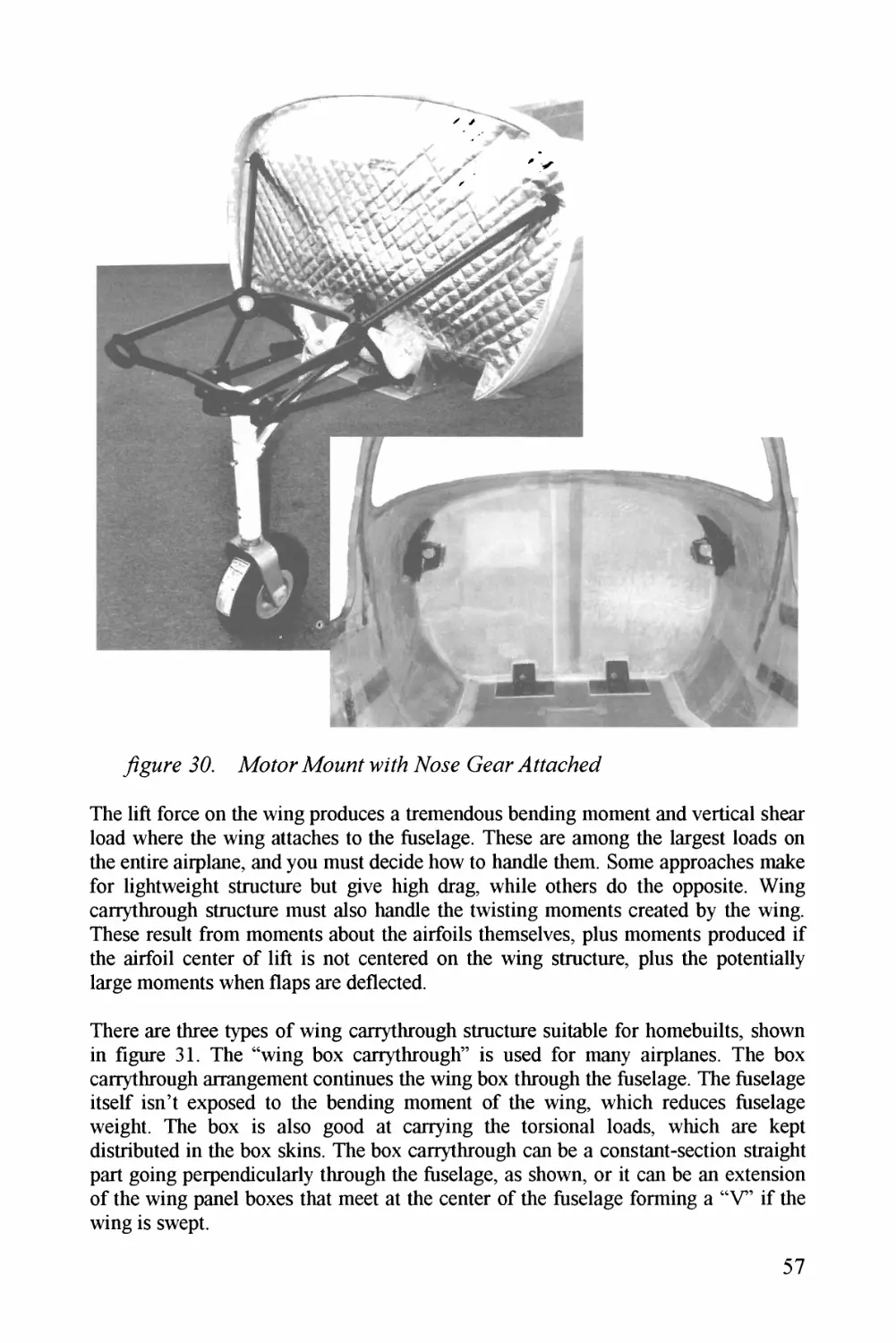
/Zg^z^y 30. A/aZar 7/7a^zaz^Z azZza- TZa^^y Gyar.4#acZzy7
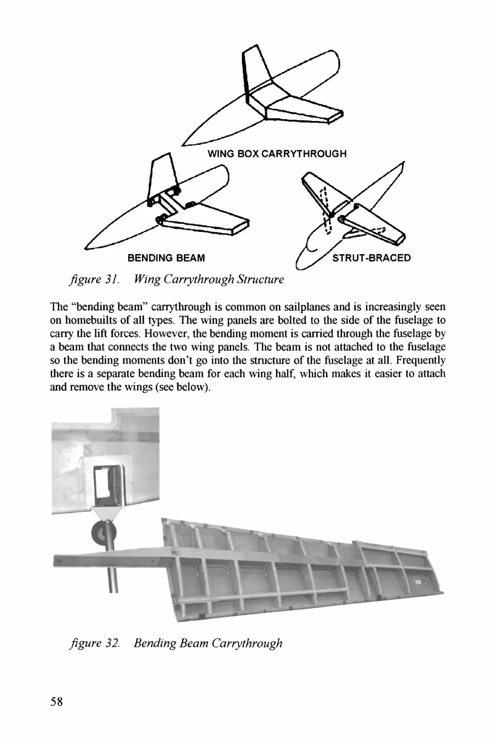
/Zg^z*y 37. ^^a'z^^^ (C/^J^^z^Z^j^(aMEz-*Er^^^zc^^Z^z^jyy
/zgMry 32^. Jy^^^^azaZa^gy J5^^aza- (aa^z^zz/a^/^^aag^^
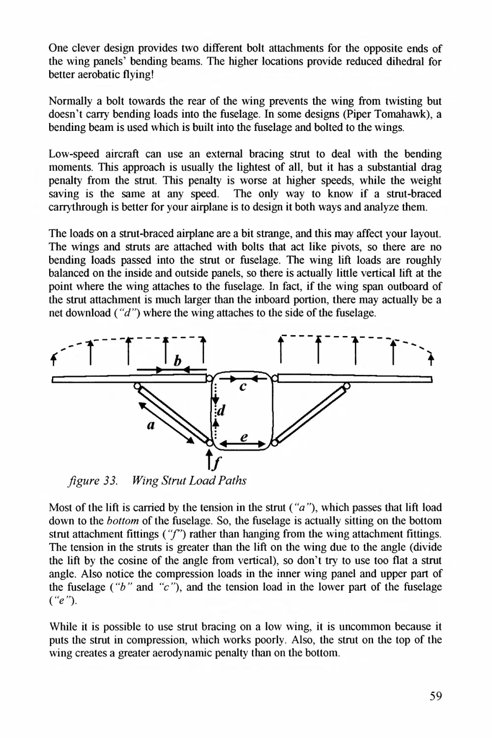
/zgMry 33. ZaZzzg*7Zz^^7 Z .aaz^/7
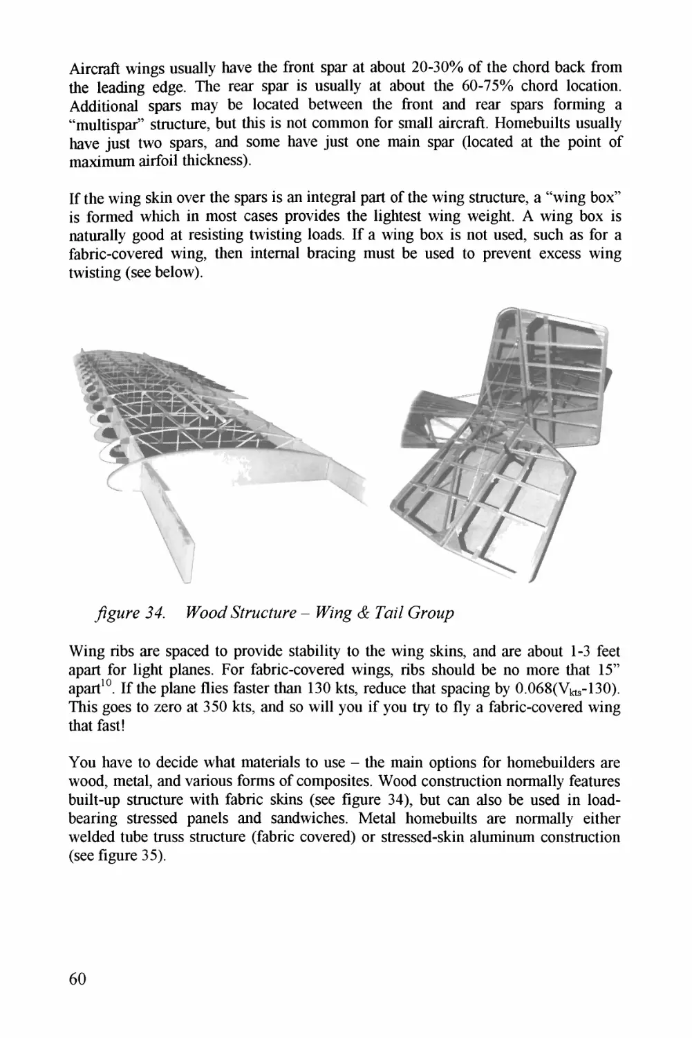
/zgMry 34. Pa9a^Z ^/Z^iM/^z^z/yy -ZZZz^^y &- Paaz Z (jrzzp?
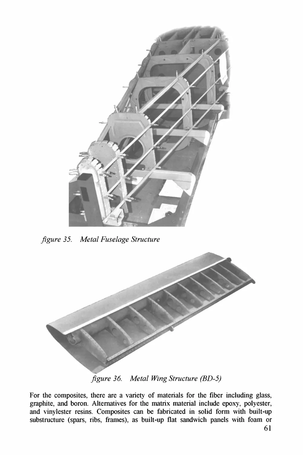
/ZgMry 33. A/yz^a?- Jaary/c^z^^ .S'ZzzcZMry
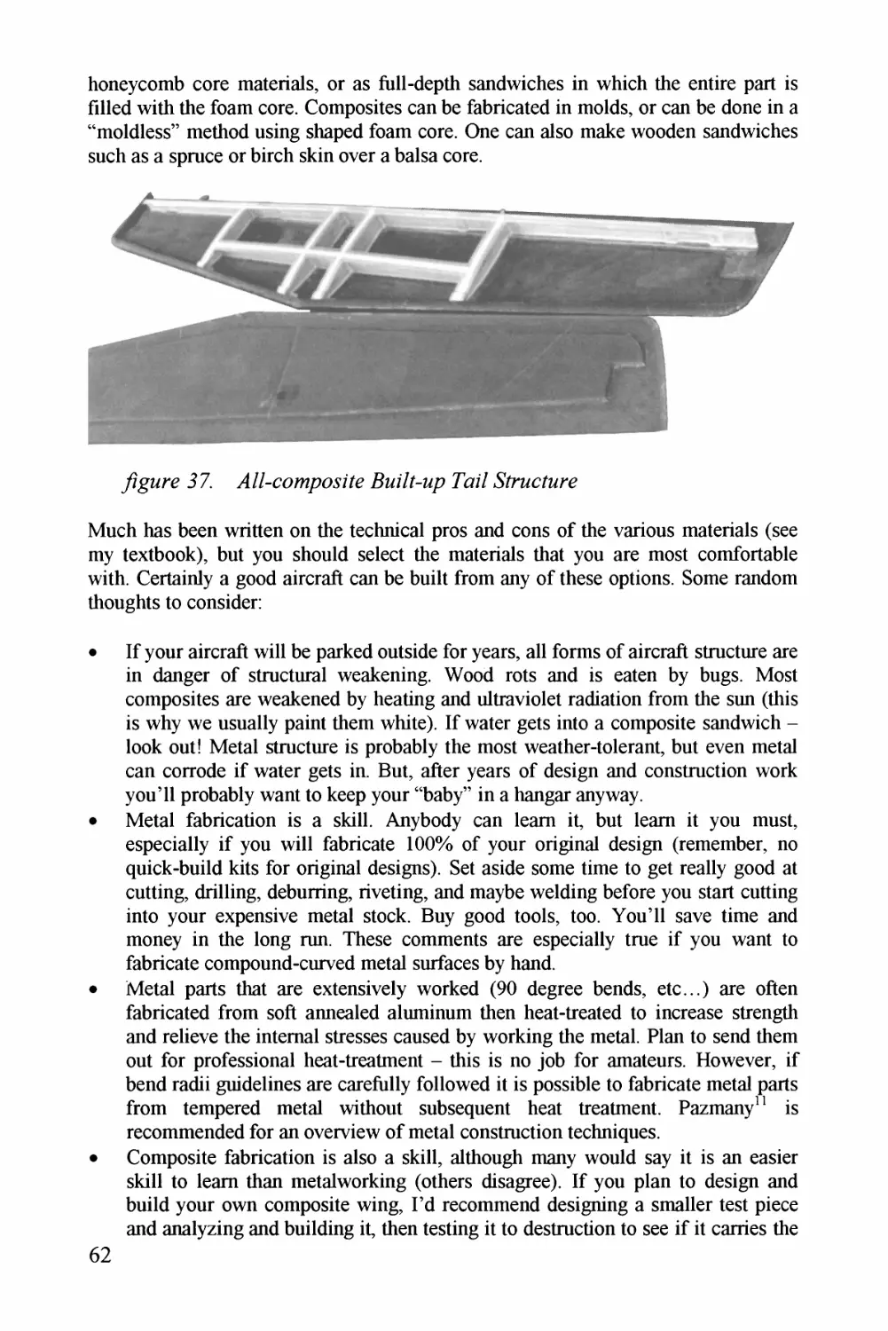
Jaga^7/y 36. A/y?Za/_ ^Zzag &z^z^z^(/Zaz^y
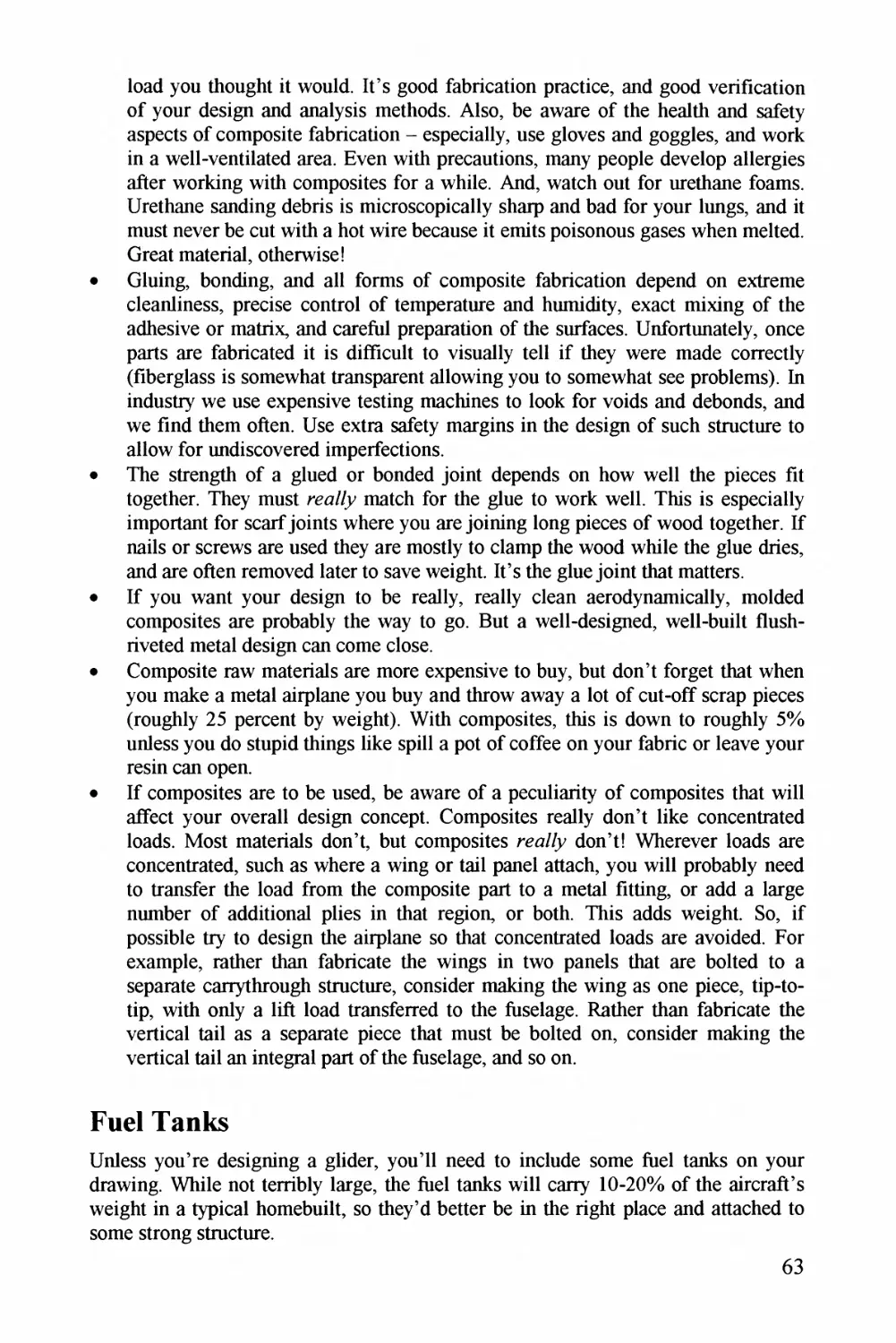
/Zgz^z/y 37. //Z-calap?aaz7y 7Zz^z/^Zaap P^aZZ .^Zaz^z?Z^a7^6?
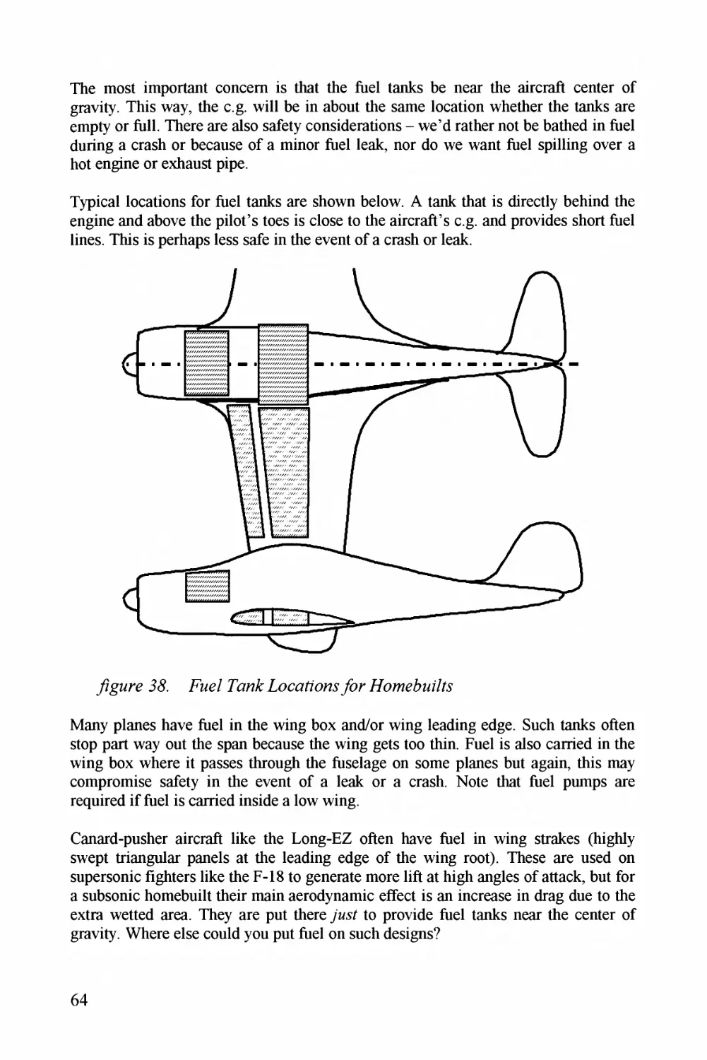
/zgMry 3<S. Jaa^^z- Pao^z^A^ pCaat^z^Zza^r^J7c^a^(^zZaZ/Z.y
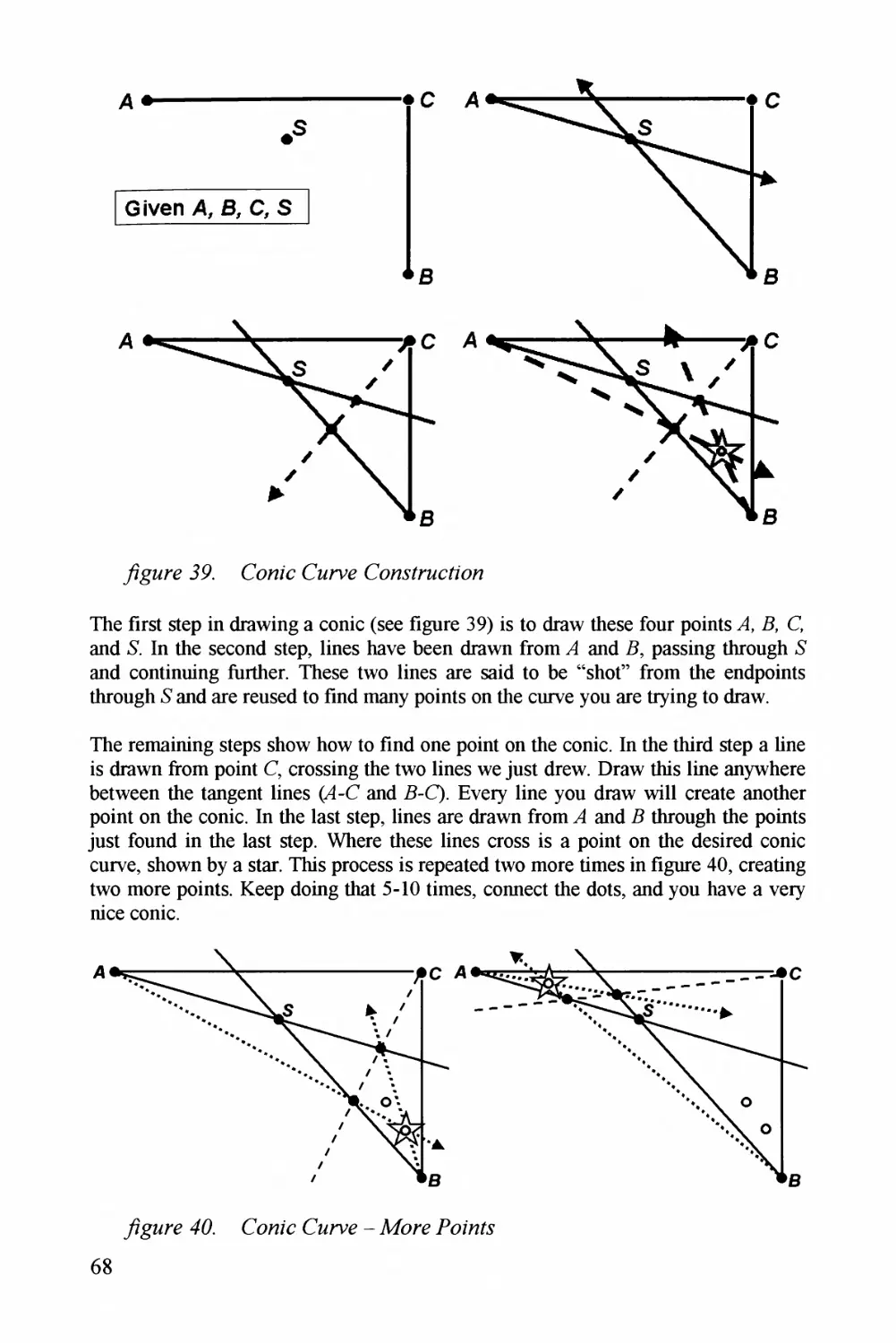
/zgMry 39. CaaZc (Zz^jnyy Caa^yZzacZZaa
/zgzzz*y 46^. (7z^zzZ- CMrvr -ppa?r_ Ezzz/.y
/zgz^//y 47. p^^zzaa^Za<z/aZzc7_ CazZra - .aZz^a^.yP^^?rp^z^(7aVy
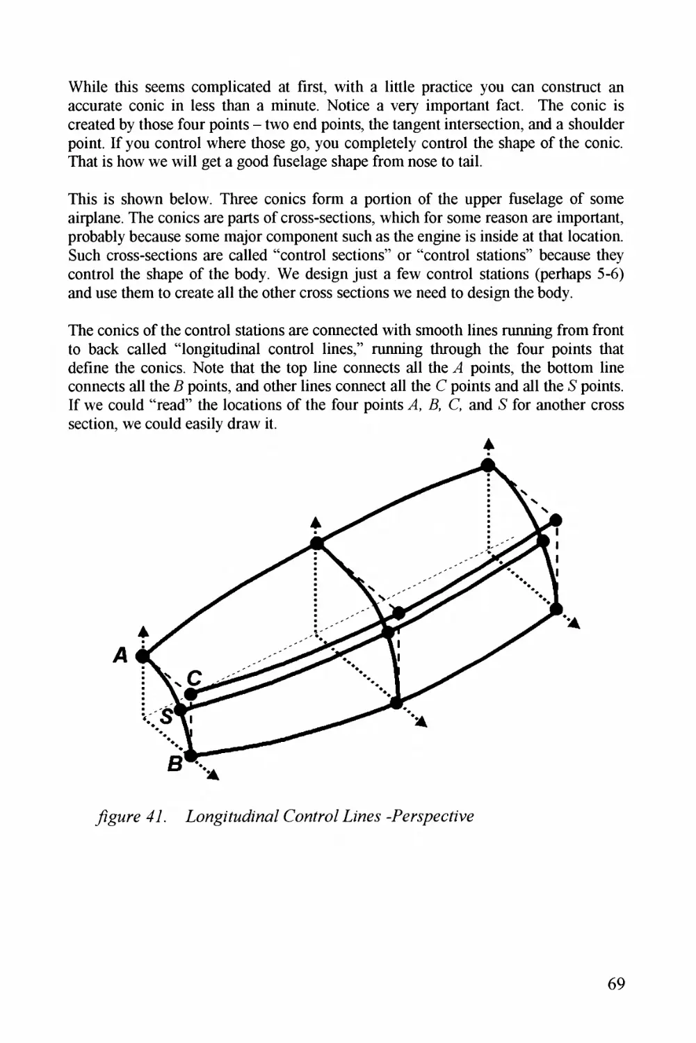
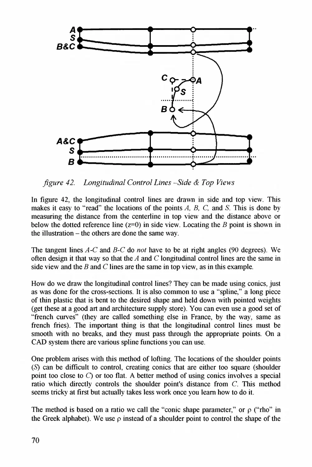
/Zgz^z*y 42^. pCaagaZM/Zaaa- Caaaz^7^^/- .aZay^J--^ZZz^y- &_ Tap- PZyaAy
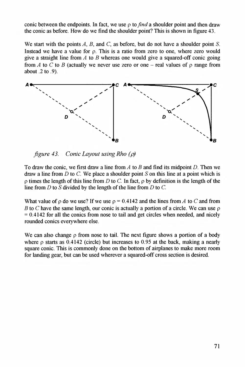
^gz^z/y 43. (7z^zzZy .Laa^z^z/ ZMaZag T^a —
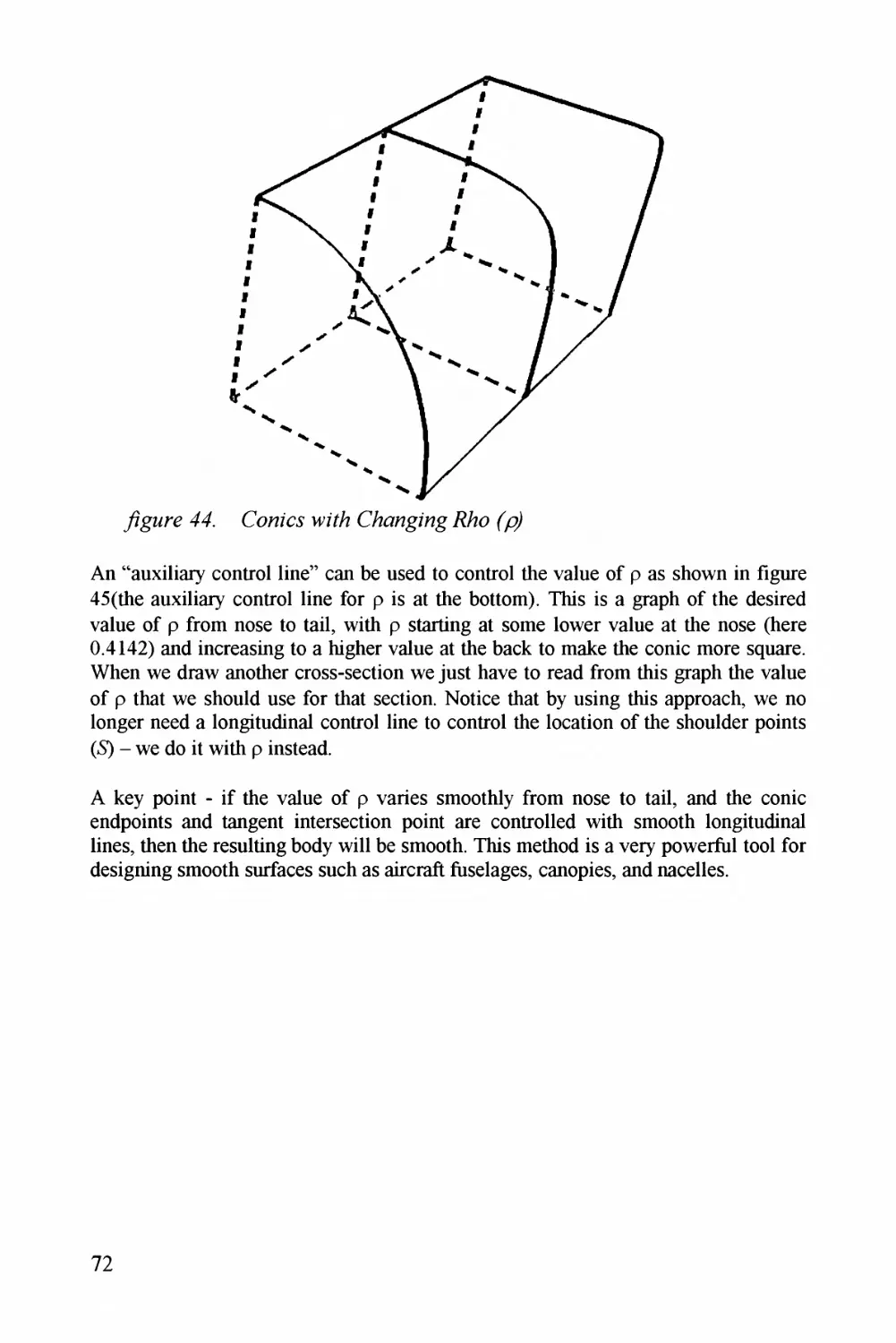
^gz^//y 44. Caaz'cr wzZ/z (/Z^a^jz^^Zz^g^ .7/^a —
^gz^?/y 43. Caaz'y (/azZag.Zz^J^^^^za^^ (^zz^z^^a/ Z.aazyJa/r77a^a
ajo bo ^^Z)QoQo-t^bo^'-^^^Z)OoOo'^L^-^L^bo^^Oo'^0\-^bo^^Qo'^^\bo^^^OoOo'^)L^4^boboO\^)
ix
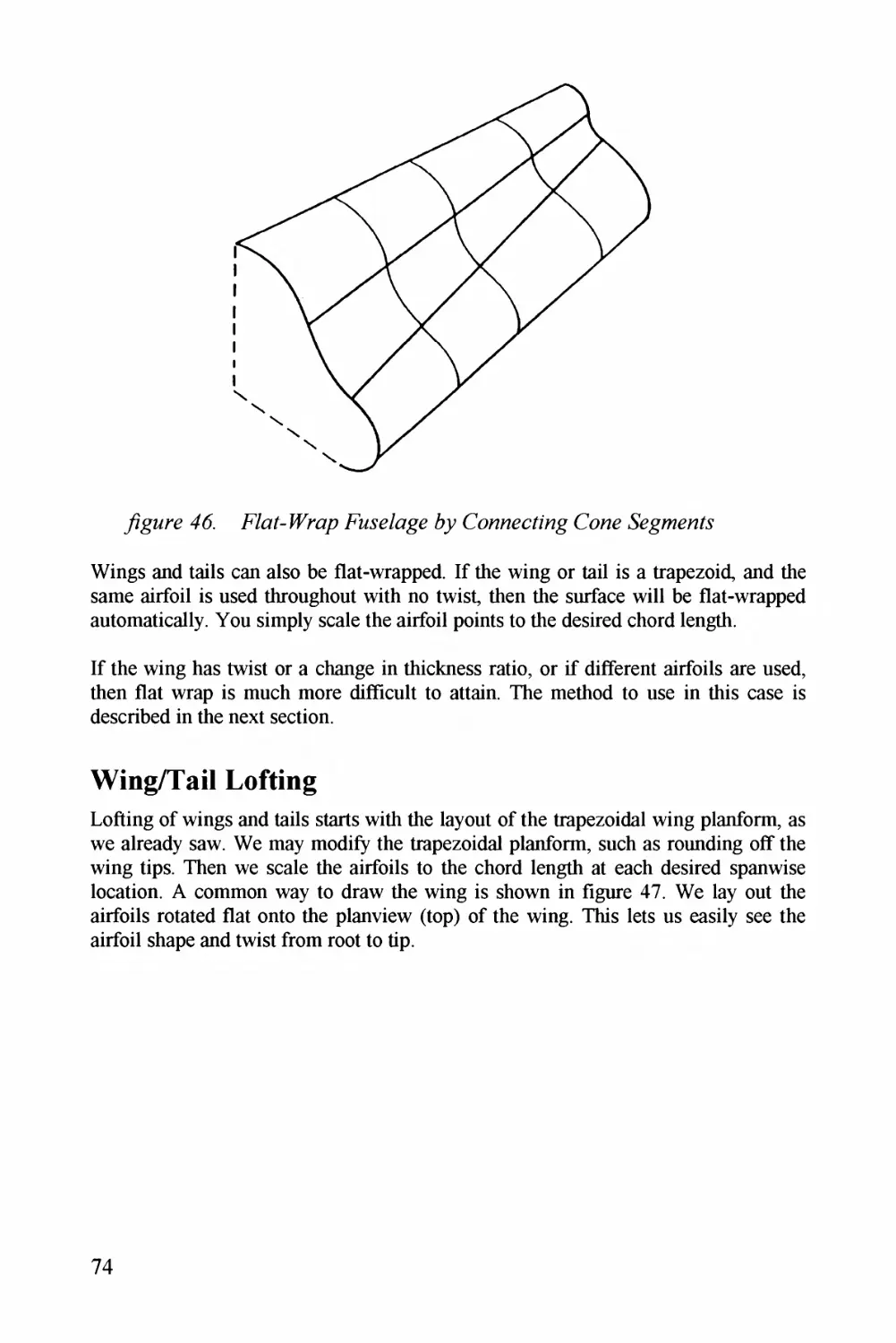
yzgzrz 46. Eoz/E^z^z . CozzzcO'zg 74
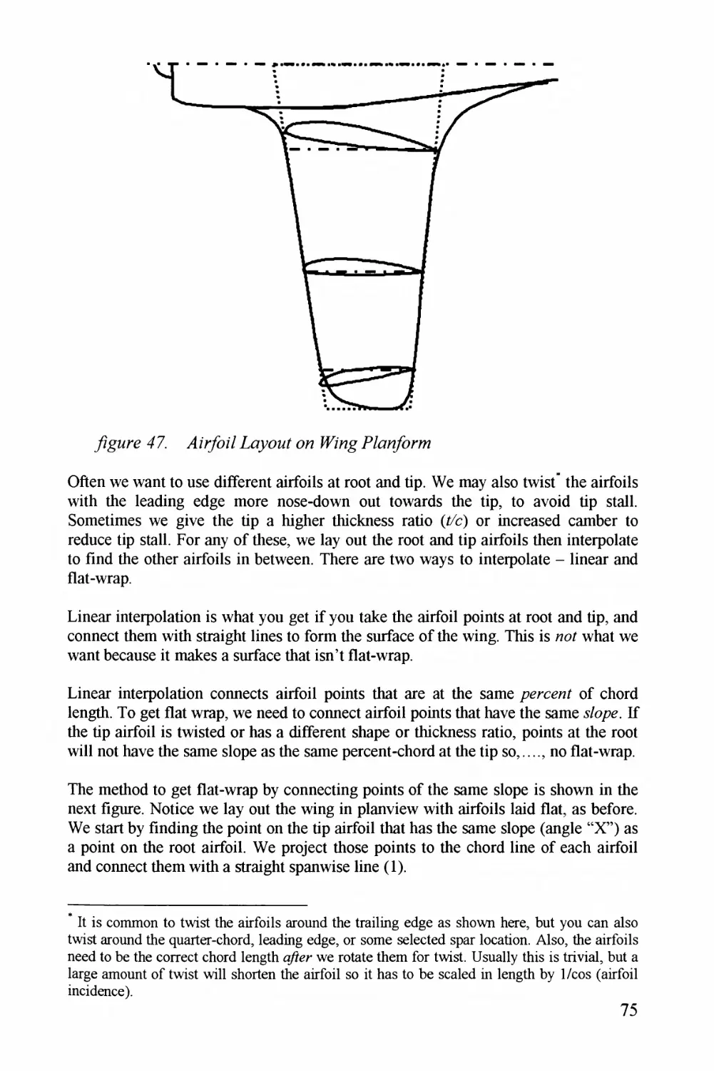
yZgMre 47. yl zryoz/ Zoyoo/ az? Mz'z^^ P^^^o^/Z/orz% 76
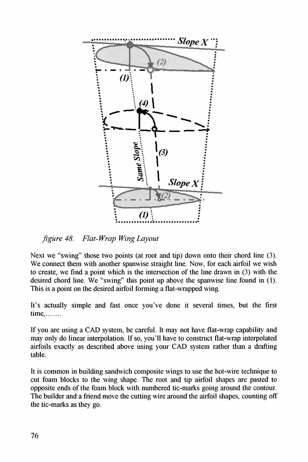
yzgzrz 4& E/o^Z-z^</p zA/og Zo^<^<^j/ 76
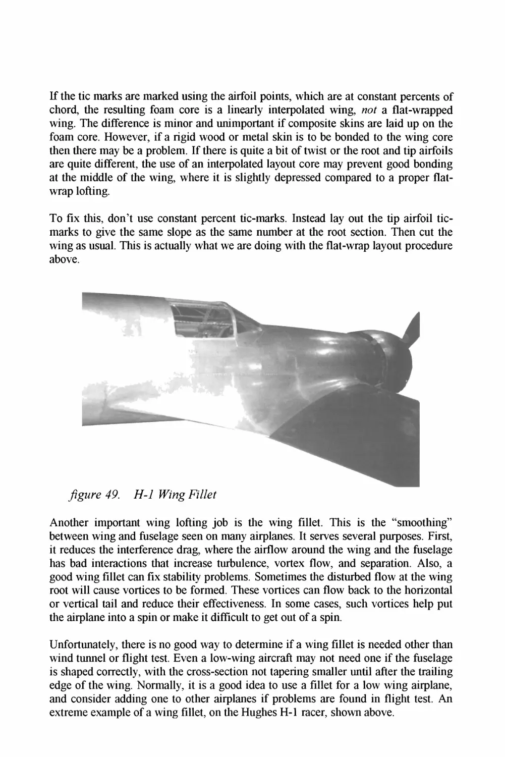
y?gzrz49. 77-^7 77
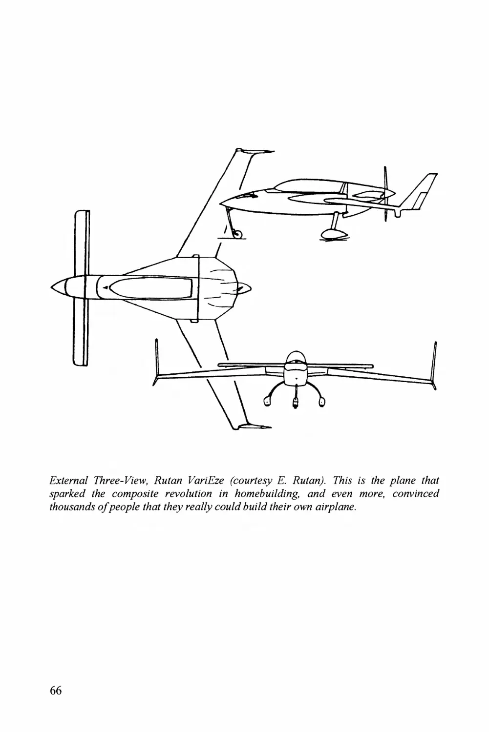
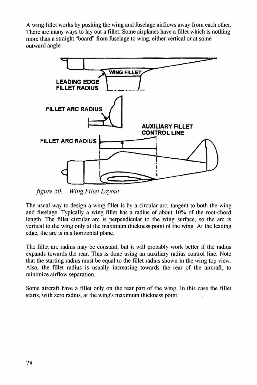
yigorz 66^. ^P/'o^g E7/EE 7P
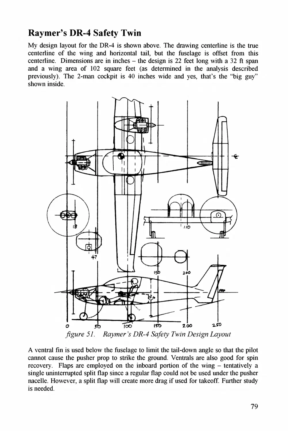
y^^^^orz 67. Eoyzzzr . DZ^-^4 TWo Poyoo/ 79
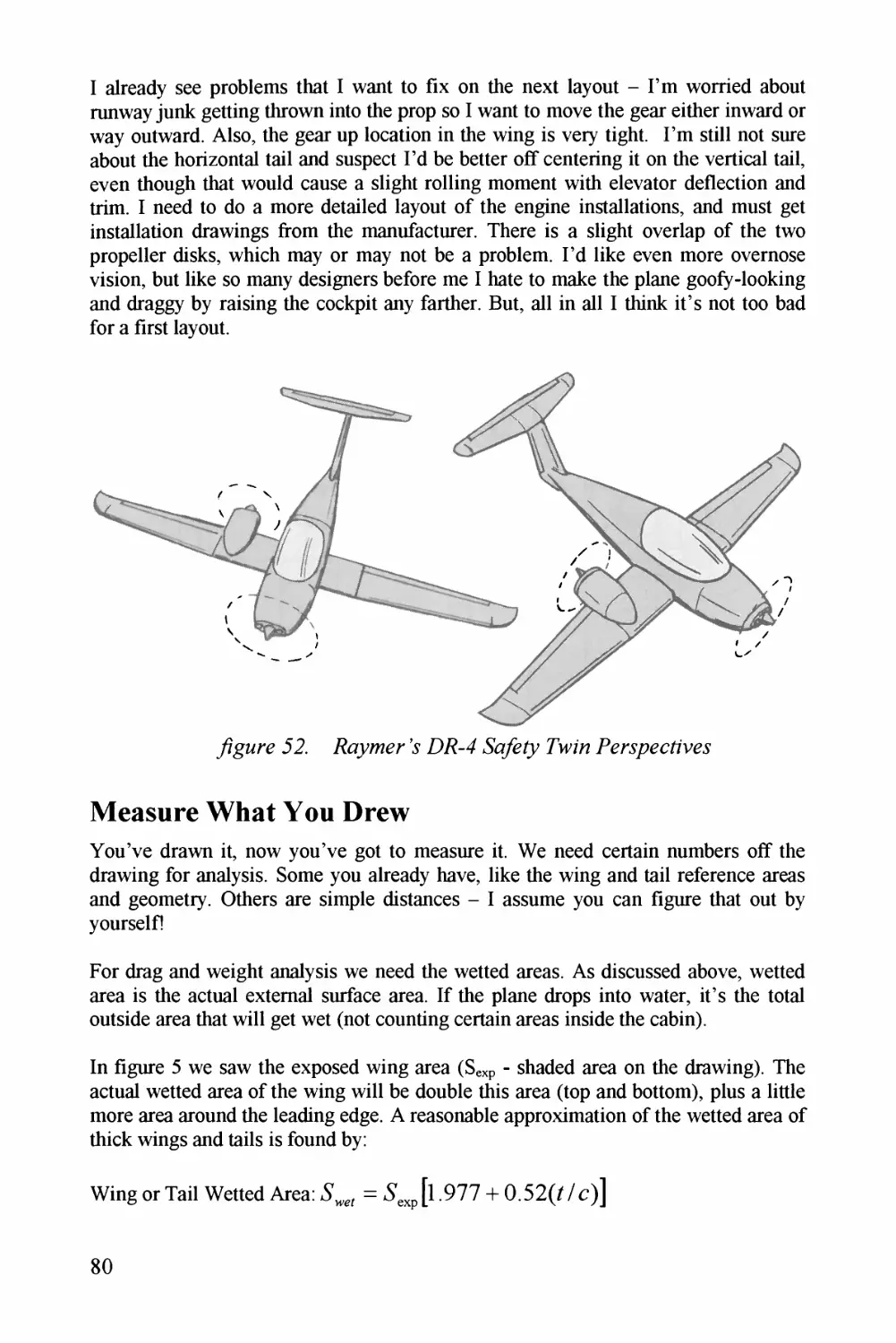
y/gMrz 62^. F^^yyz/zr \ Z^E^-^4 &/&/y 7W^zo P^zr^sp^z^c/z/V^z^z' TO
y/gorz 62. Eoz/E^z^z z/^j^^z^?^.Tz^o Cz^/cz/z^i^7zzz <37
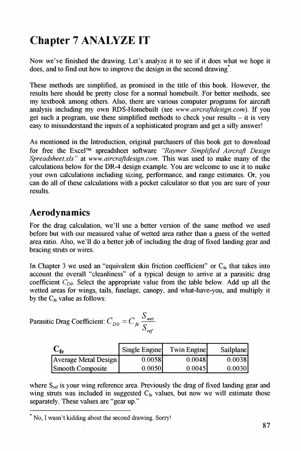
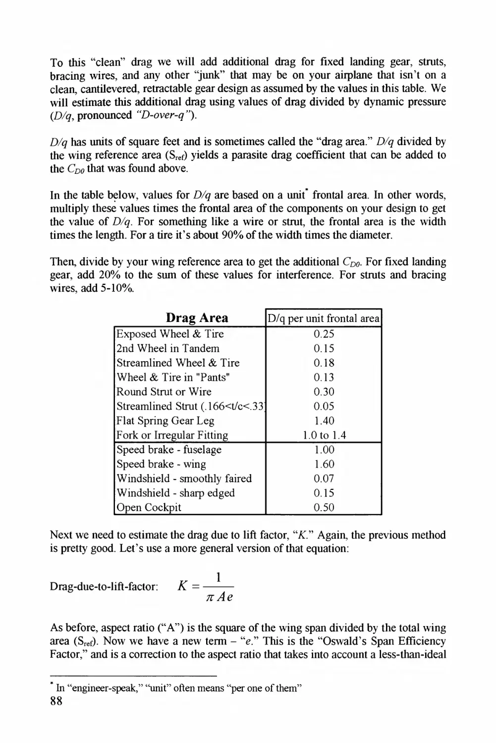
y/gorz 64. P^?7z/9/Z/^(zJ Po/z/nz Cz^/c^a^/z^i^/zz (^.2
y^^^^orz 66. Pozzz Po/ZF C(^/^(^z?^/zyor Z^zgA//4ircrro/ P3
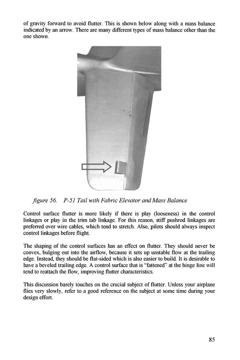
yzgMrz 66. 7^-^6^7 7oz7 w^FZA Fo76r^zc E^^voZor z^^774^J^J P6
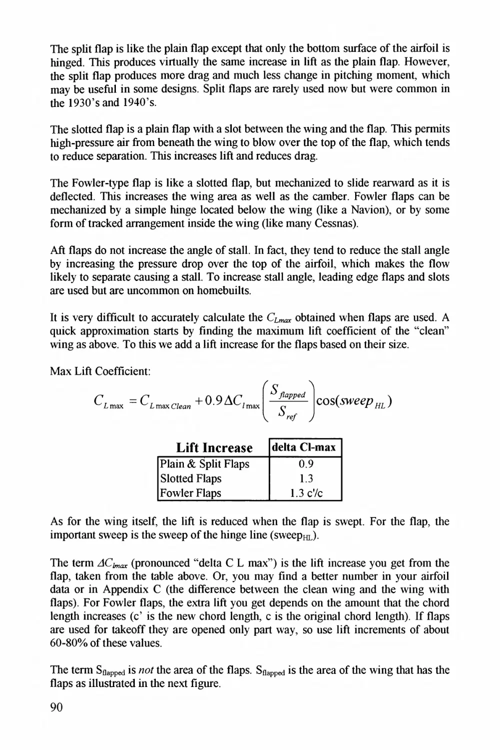
y^z^^^^rz 67. F7zppz4ZZrzz jor APzx^zzzz^/M Z^z/7 Cz^^^^^z//^^Zz^^jo 97
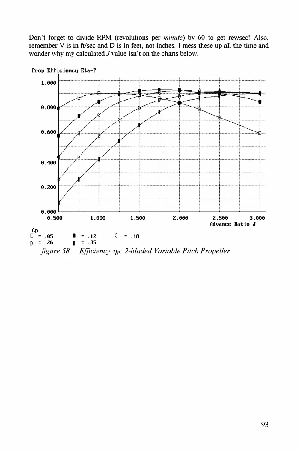
y^goro 63. Z/y^(^zzz^cy ?//..* 2-6E&Z7 ^^J^z'z^7E yzz^c/A Pro^^^o/E* 93
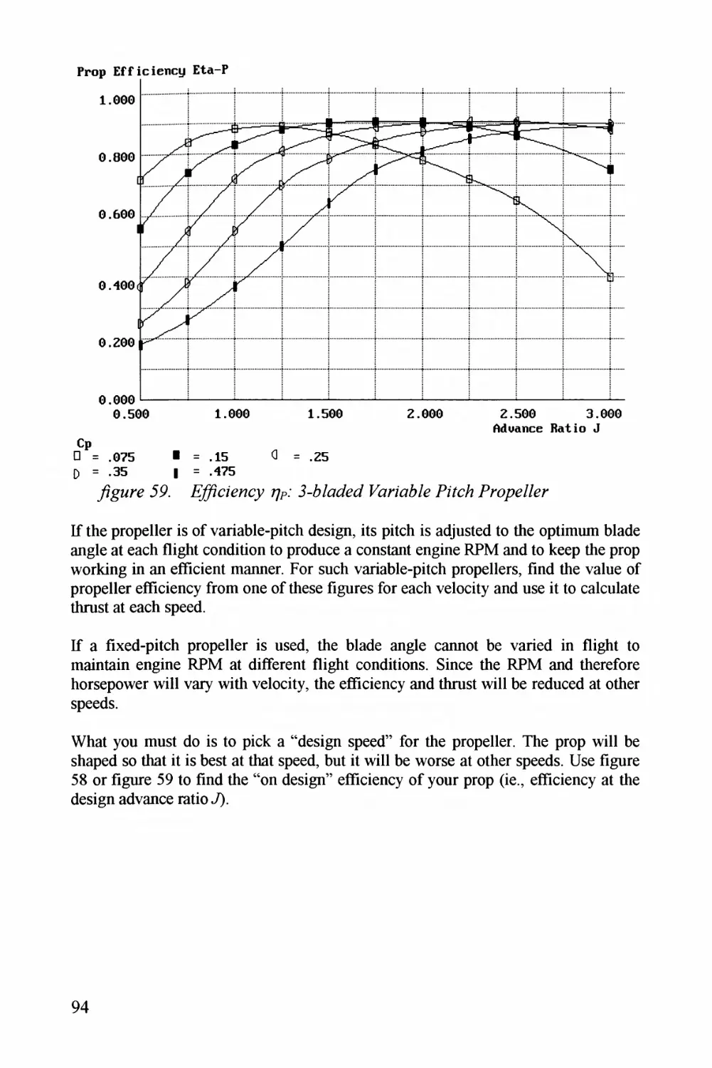
yzgMro 69^. E/yc^E^o^cy 77/?; 3-6/oZzJ PZ^;^zo?/E jzYc?A Pro^^^o/E' 94
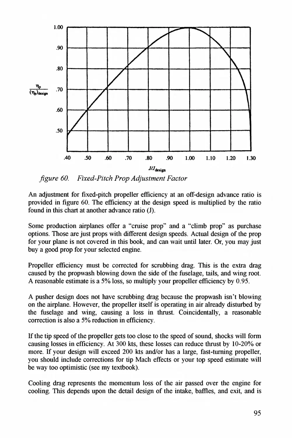
y^z^^oro 66^. Az/X^^(7--jz7^c?A P^r^op Jlz^^^^./Zzzz^Z Eocfpr 96
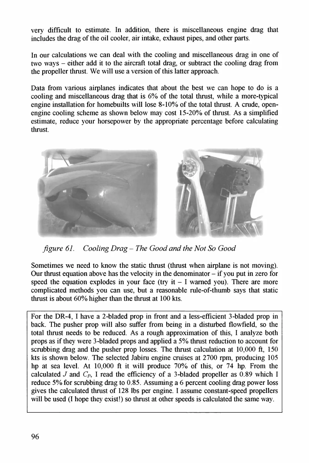
67. Cooz/og E^r^o^g - ^7Az zzZ zz^z Ao^Z 96
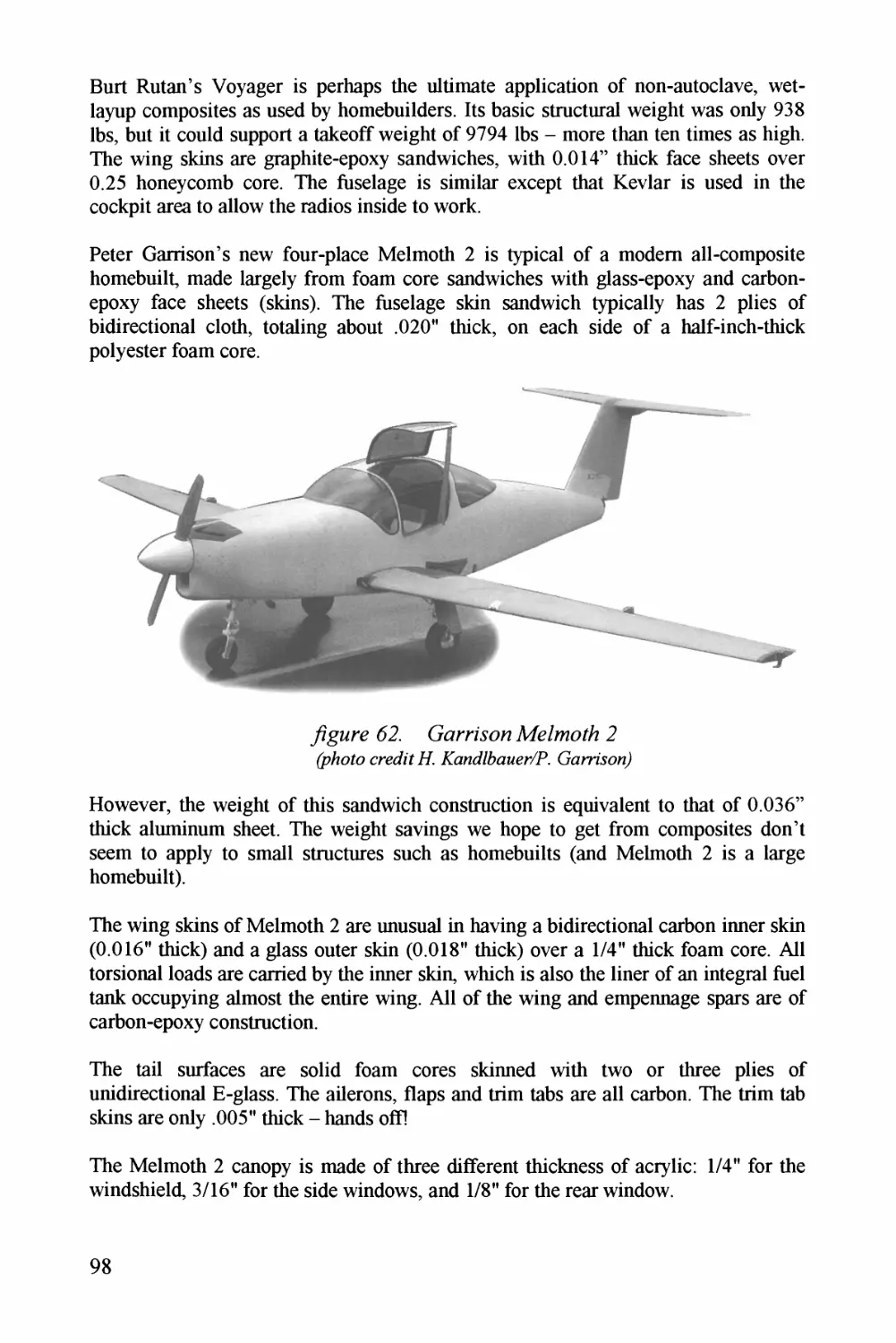
yzgzrz 62^. C^z^rrAz^z AZ?/z!^/ZA 2 9^(2
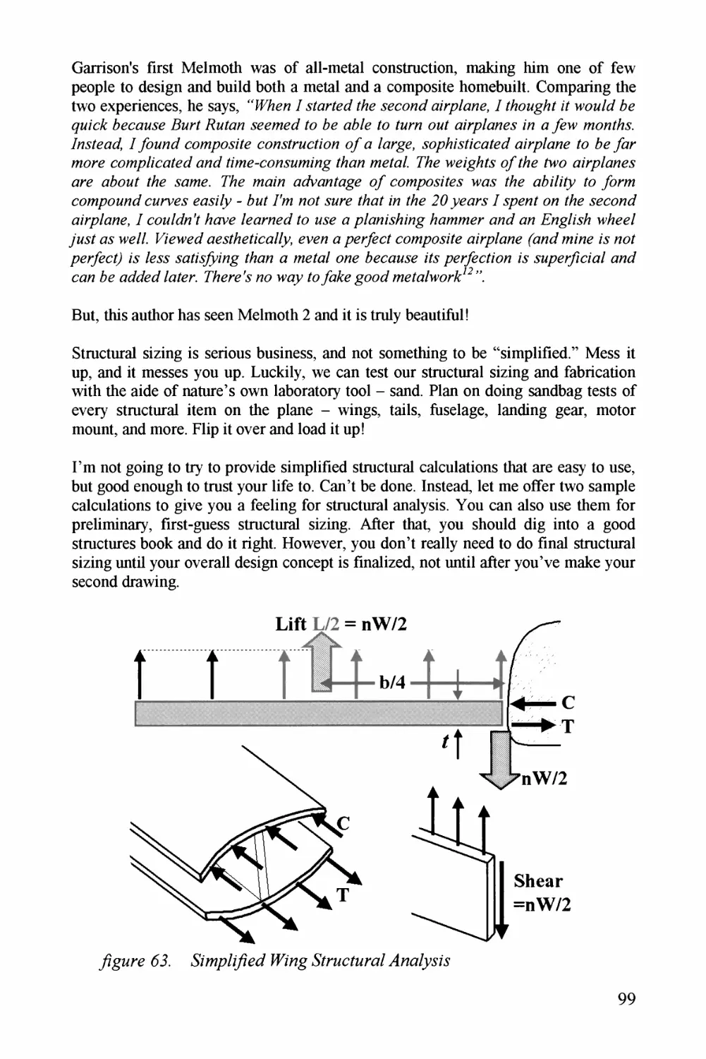
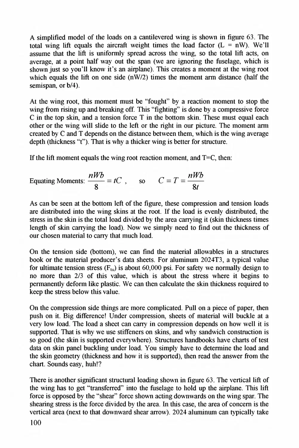
yzg7^7rz 63. Pzzp/(/7z7 ZP^^jog P/^r^T^^/TzroZ J^/^^a^/z/A 99
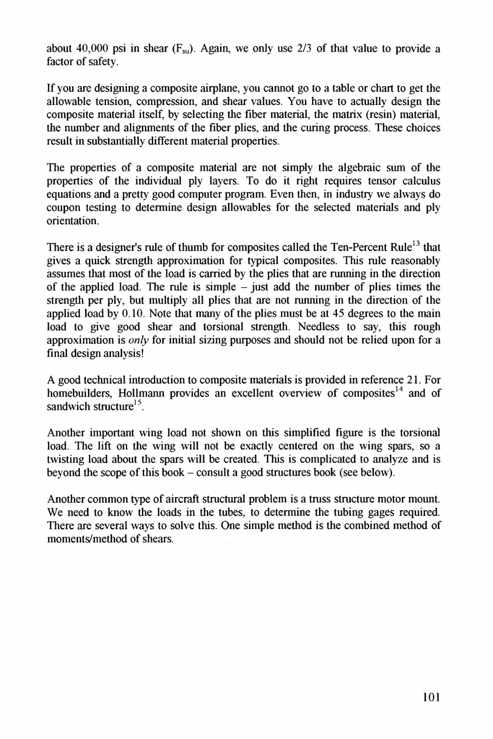
yigMrz 64. 7roz PfrocZorz 7 6^2
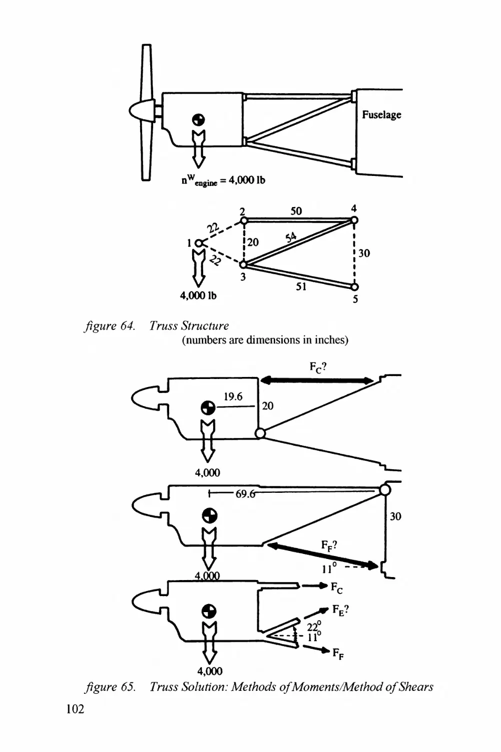
y^T^^^jrz 66. 7roz P^^/Mj^zz^/7 ; AZ/^ZA^^zE' z?^^4^7z^z^z?Z^^.AE?ZAzJ ^Pzors j^Z^2
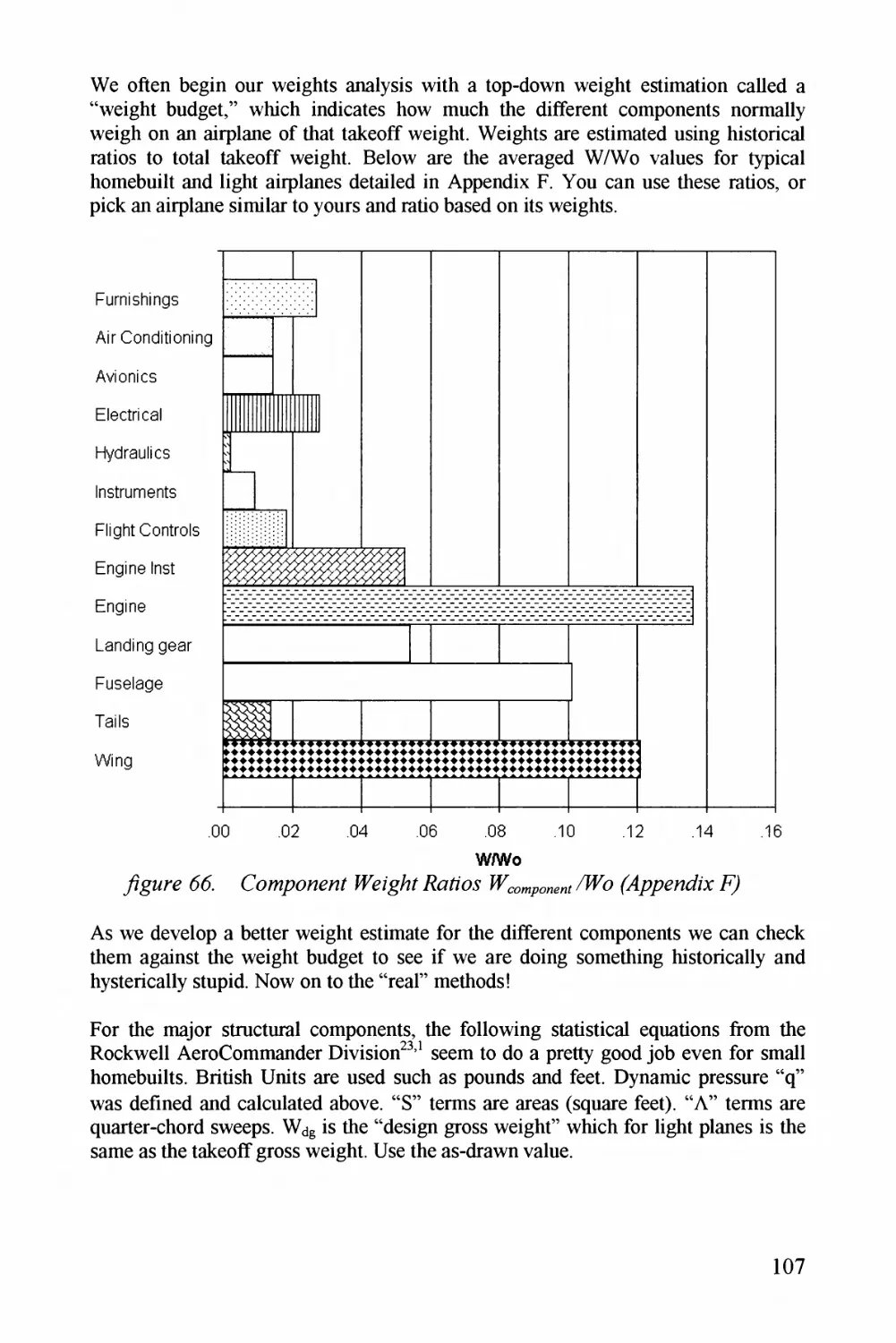
y^^^^orz 66. Co/opoozoZ ZE^g/7/^Z^^/Z'zz (Pj/pzoz^/x 767
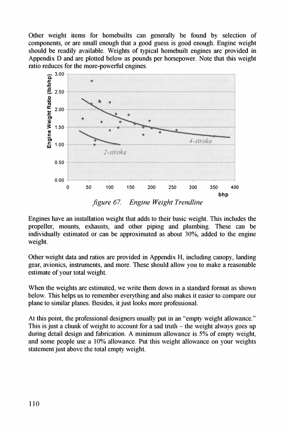
yzgiorz 67. E^o^g^zo^z WEzgAZ Pr^z^o^z^Z/z^z j^.^0
yigorz 63. PEoiZaJ G7^6^zp zfE^zg^^Z E^^7^7zzZ 777
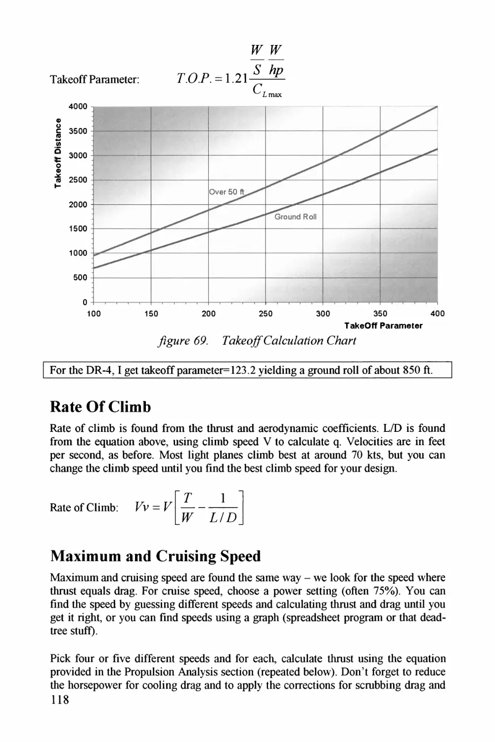
yzgiorz 69^. Tz^P^zo/yC^^^/(^z/Z7/zZ^z CAarZ j^.^3
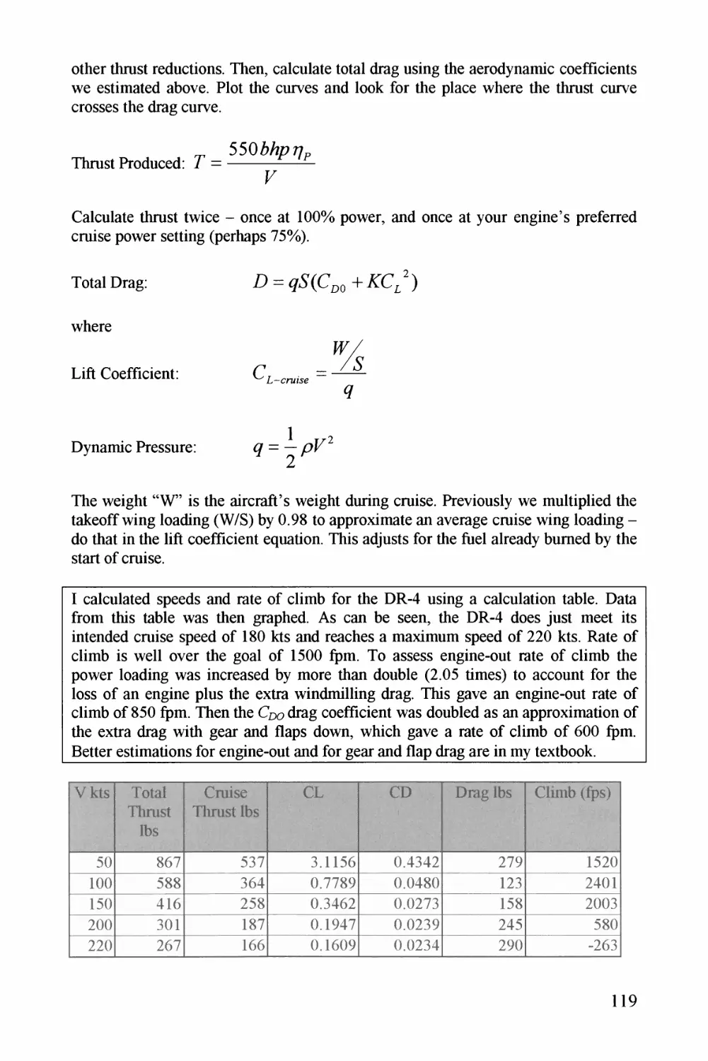
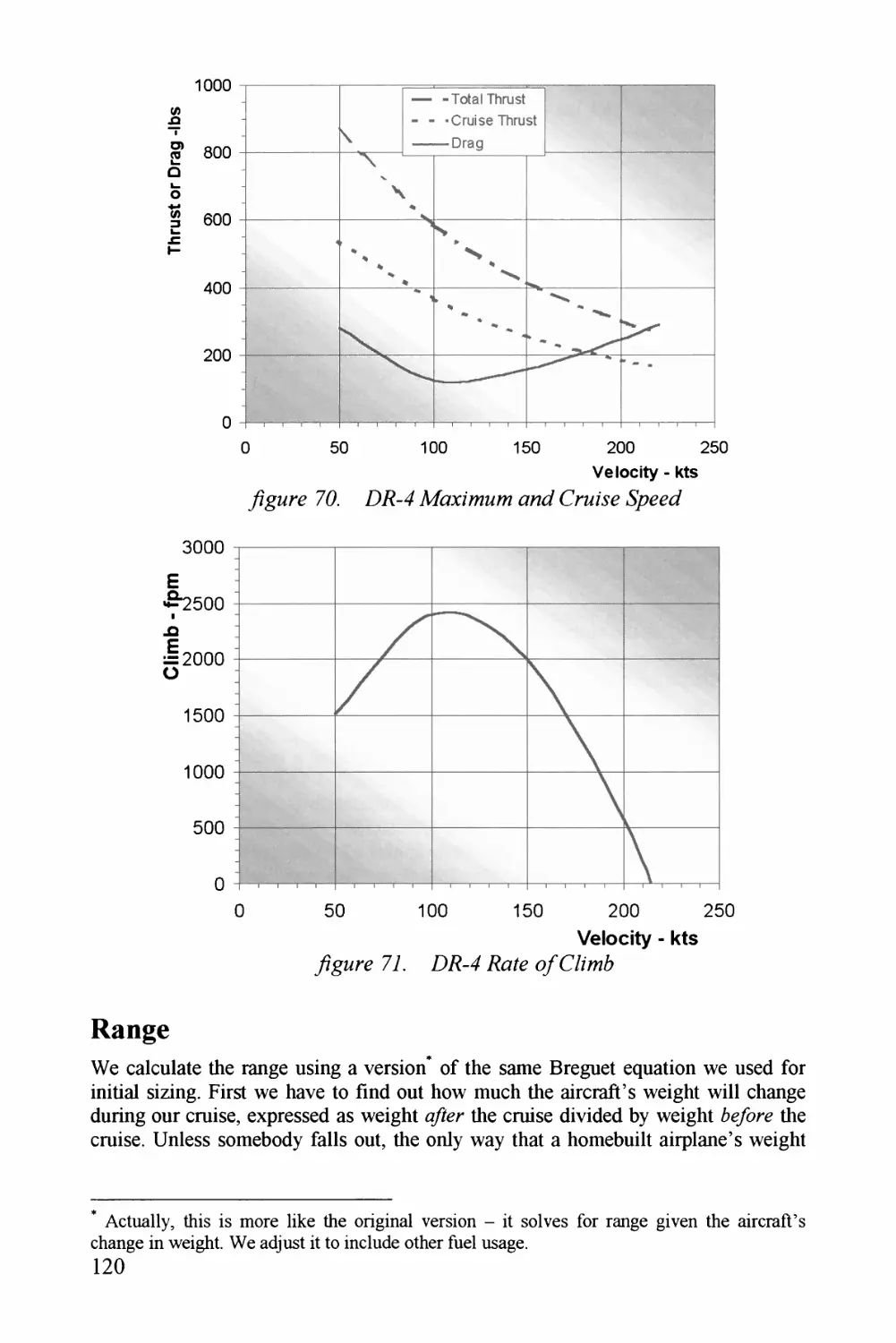
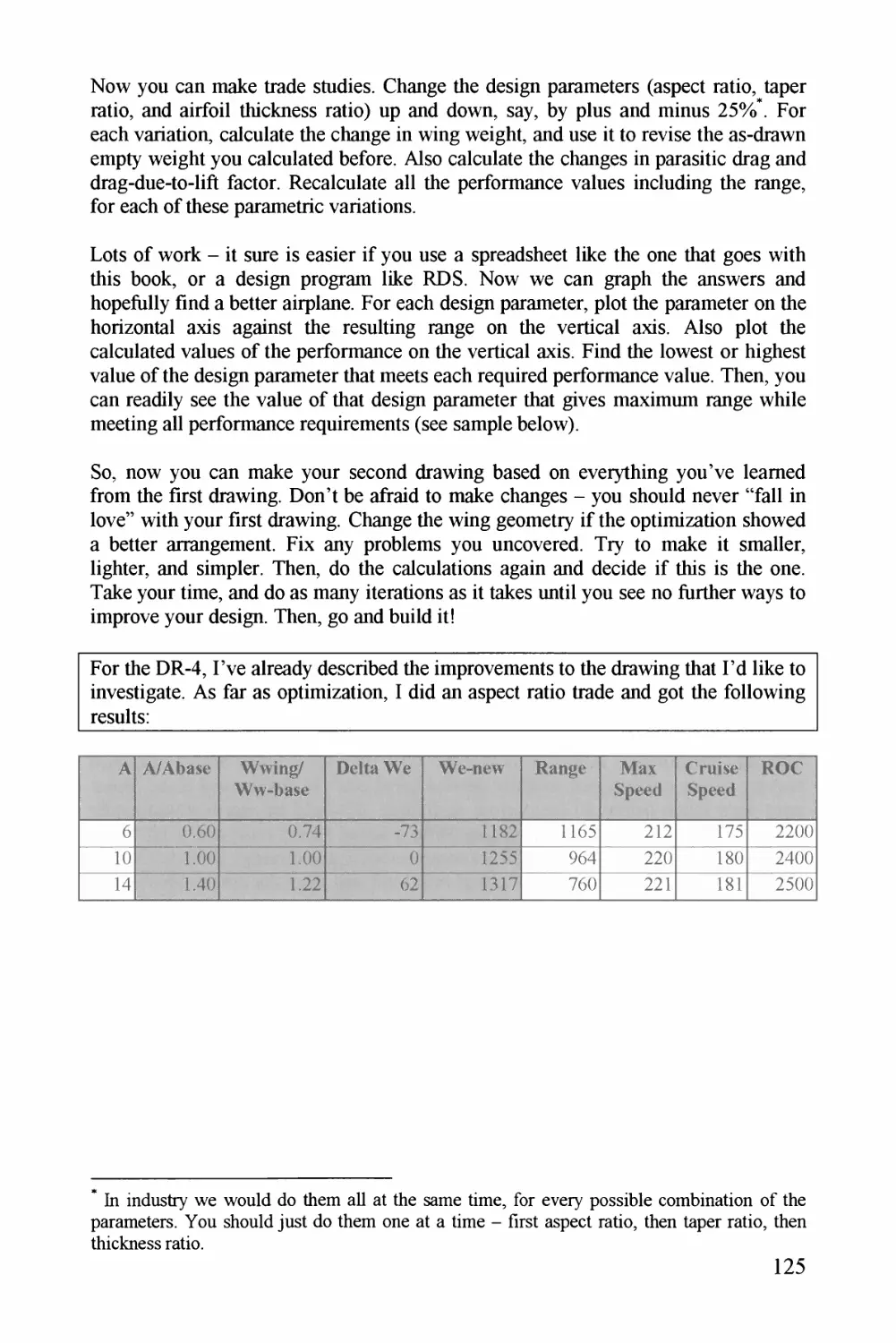
y^^^^orz 76^. E7?-4 APzx^zzzz^/z zzJ Croz^z 720
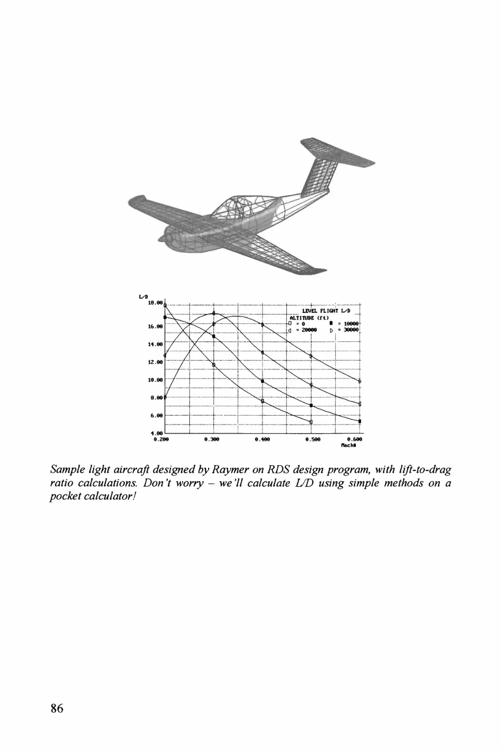
y?gMrz77. E^E^-^4^JZ^^/^^?C/(^/?7^6 726
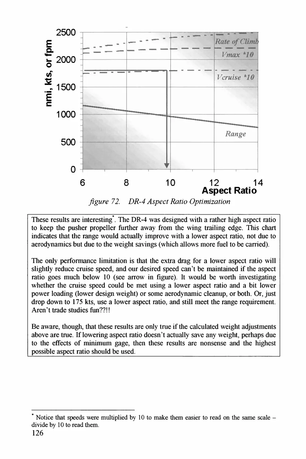
y^T^^^^rz 72. E^E^-^4 . zc/ E^z7Zz (/^z^zzzzzz^/z(Zz^ 7 J^6
x
Chapter 1 INTRODUCTION
Who am I and why did I write this book?
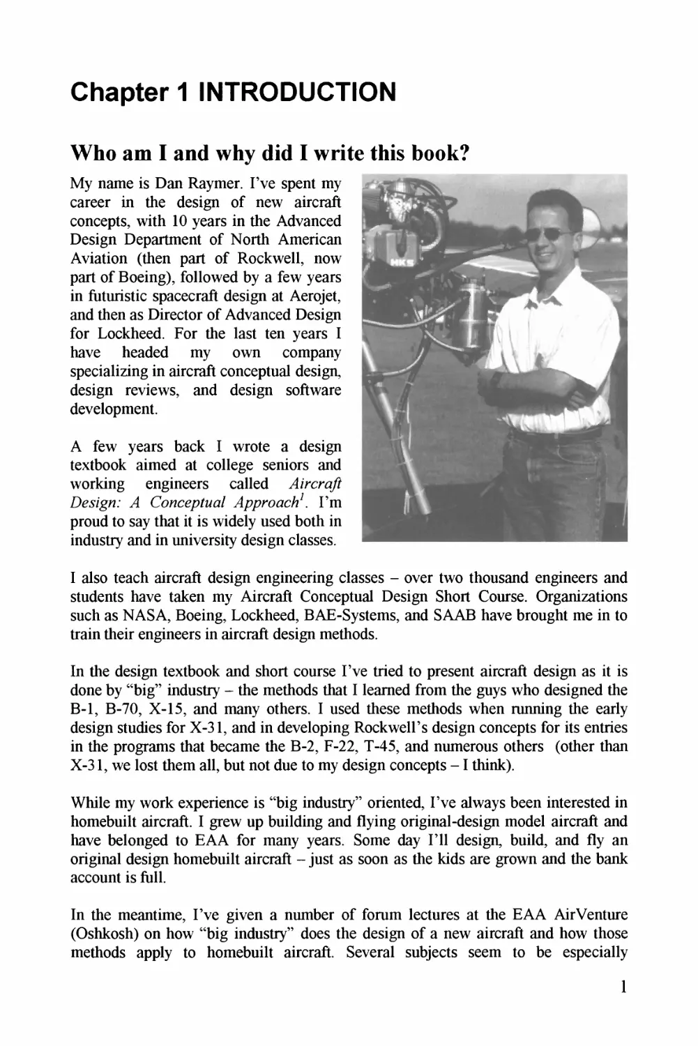
My name is Dan Raymer. I've spent my
career in the design of new aircraft
concepts, with 10 years in the Advanced
Design Department of North American
Aviation (then part of Rockwell, now
part of Boeing), followed by a few years
in futuristic spacecraft design at Aerojet,
and then as Director of Advanced Design
for Lockheed. For the last ten years I
have headed my own company
specializing in aircraft conceptual design,
design reviews, and design software
development.
A few years back I wrote a design
textbook aimed at college seniors and
working engineers called
Denigi.* CowcepMa/ I'm
proud to say that it is widely used both in
industry and in university design classes.
I also teach aircraft design engineering classes - over two thousand engineers and
students have taken my Aircraft Conceptual Design Short Course. Organizations
such as NASA, Boeing, Lockheed, BAE-Systems, and SAAB have brought me in to
train their engineers in aircraft design methods.
In the design textbook and short course I've tried to present aircraft design as it is
done by "big" industry - the methods that I learned from the guys who designed the
B-l, B-70, X-15, and many others. I used these methods when running the early
design studies for X-31, and in developing Rockwell's design concepts for its entries
in the programs that became the B-2, F-22, T-45, and numerous others (other than
X-31, we lost them all, but not due to my design concepts -1 think).
While my work experience is "big industry" oriented, I've always been interested in
homebuilt aircraft. I grew up building and flying original-design model aircraft and
have belonged to EAA for many years. Some day I'll design, build, and fly an
original design homebuilt aircraft - just as soon as the kids are grown and the bank
account is full.
In the meantime, I've given a number of forum lectures at the EAA AirVenture
(Oshkosh) on how "big industry" does the design of a new aircraft and how those
methods apply to homebuilt aircraft. Several subjects seem to be especially
1
interesting to homebuilders - how to develop the actual configuration drawing itself,
and how to quickly analyze the design and then optimize it so that you get the most
range, payload, and speed out of the selected engine.
There are other aircraft design books aimed at non-professionals. They are full of
useful information, but to me they don't seem to cover all the required topics evenly.
One book is mostly structural design, another focuses on performance but doesn't
tell you how to actually the design, another is mostly selection and construction
of a kit, etc... There are also aircraft design books for professionals, including my
own* , but these are full of big equations and they try to provide methods for every
imaginable type of aircraft. Too much for homebuilders!
So, I decided to write a design book for homebuilders, covering these topics and
many others. My goal was to give step-by-step instructions for starting with a dream
and a blank sheet of paper and winding up with a credible design layout that could be
built and flown by a regular person.
In writing this book, I've tried to take the industry methods and distill them down to
their bare essence as applied to homebuilts. Since I'm not trying to turn you into
aeronautical engineers, the theoretical developments are not included. For proof of
the methods and additional information, see my design textbook^
In writing this book, I've made some assumptions and restrictions:
* You are familiar with basic aircraft terminology (wing, tail, aileron, propeller,
lift, etc...)
* You are not afraid of sharp pencils, pocket calculators, data tables, or medium¬
sized equations.
* You are interested in designing a "normal" homebuilt - no flying saucers, exotic
materials or engines, flying cars, supersonic jets, etc....
* You understand that, while this book will get you started, you'll need more
information and should go to other books and seek experienced help in design,
construction, and flight test. Your local EAA chapter is a great place to find
help, and the FAA will work with you before they authorize you to begin flight
test.
What is a Homebuilt?
Almost as soon as the airplane was invented, companies were formed to mass¬
produce them. The Wrights, Bleriot, Curtis, and others built and sold airplanes to the
newly formed military air services of the various nations as well as to wealthy
sportsmen. An instruction manual for an early Curtis tells you how to take it out of
* If you are serious about designing your own plane, you may want to pick up a copy of my
textbook (reference 1). It has better methods for many of the simplified methods in this book,
and has more complete explanations of terms and equations. However, it is written to a
technical audience and has a lot of material that is not relevant to design of propeller-powered
homebuilts. Also, it's not nearly as fun.
2
its packing box, assemble it, and, should you not have an instructor pilot handy,
teach yourself to fly it.
Almost as early, people built and flew their own planes. Brazilian-born Alberto
Santos-Dumont published "homebuilt" plans* worldwide for his 1909 De/noAyeZ/e, in
Popular Mechanics magazine in the USA. Built partly of bamboo, this flew on 20
horsepower and could be called the first ultra-light. Another early article told how to
build and fly a braced biplane hang-glider. I wonder how many aviation careers were
started by the construction and flight of one of those - or prematurely ended.
Typical of pre-WWI homebuilders were two brothers named Loughead who built an
original-design seaplane in a garage in 1913. The plane flew well but nobody could
pronounce their last name correctly, so they changed it to spell like it was
pronounced - "Lockheed."
As time went on, airplanes became more common and safety more important. In
response to numerous crashes, regulations were issued that increasingly restricted the
average citizen's freedom to design, build, and fly an original design, especially in
controlled airspace. Essentially, homebuilts had to be certified by the same expensive
procedures as production aircraft. Homebuilding by amateurs practically died out
until 1946 when the government, with the encouragement of people like George
Borgardus, Paul Poberezny, and Steve Wittman, released new rules permitting
properly-inspected and documented homebuilts to be built and flown virtually
anywhere a similarly-equipped production plane could be flown.
The Experimental Aircraft Association (EAA), founded by Poberezny, continues to
work with the FAA on rules and procedures for experimental aircraft airworthiness
certification. I'm a member, and you should be too.
Today, there are more homebuilt aircraft built per year than production lightplanes.
Homebuilts span the spectrum from under-254 pound ultralights to the 6,800 lb
Grand 51, a turbine-powered P-51 copy available in kit form for a mere $355,000.
Most homebuilts flown today are kit planes, a radical shift from the situation even 25
years ago when plans-built designs like the Wittman Tailwind and the Thorp T-18
were prevalent. However, the rarest of all continues to be the original-design
homebuilt - the subject of this book.
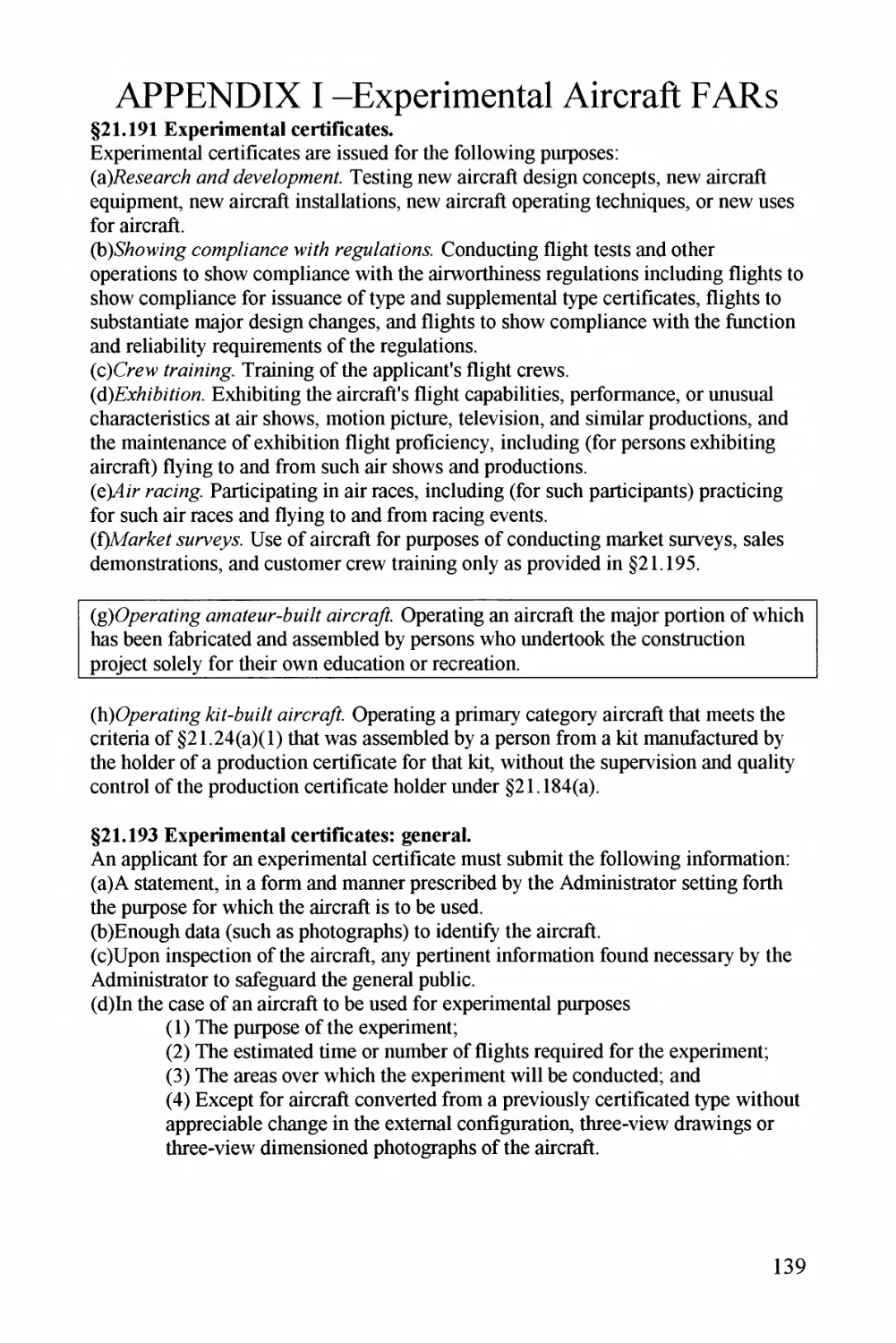
What is a homebuilt? The FAA officially calls them "Experimental-Amateur Buill,"
and defines them as aircraft ' 7/? e /nq/or /?orbon o wbz'cb 7 e been ybbnca^
a^nzb/^^ by wba /be consbMcb'on /yq/ecf so/e/y ybr own
e<Mcaff'on orrecrefon" (FAR 21.191, see Appendix I). The phrase "major portion"
has been interpreted into the so-called "51% Rule." Basically, if you can convince
the FAA that you built 51% of the plane, it can be certified as a homebuilt.
* Santos-Dumont was also an aviation idealist who never tried to patent his technical
contributions, didn't charge for publication of his plans, and donated his prize money to his
mechanics and to the poor.
3
Otherwise there are no special requirements such as use of certified engines and
materials, or certain design practices or analysis methods. You don't even legally
need to get a licensed aircraft mechanic to inspect it, nor a trained engineer to
double-check your calculations (although it's not a bad idea). The FAA may request
that the builder hire (at his own expense) a "Designated Airworthiness
Representative (DAR)" to inspect a homebuilt, and also recommends that
homebuilders call upon the assistance of EAA "Technical Counselors" who will
review the aircraft during construction.
A key part of convincing the FAA that your aircraft is safe to fly is documentation.
Save your calculations in a well-organized notebook. Keep all receipts for the
materials, supplies, and components you purchase. Photograph every step of the
construction, and save sample pieces and test specimens.
There are other requirements you must follow and paperwork you must submit to get
an experimental certificate. The FAA publishes a number of homebuilt-related
Advisory Circulars (AC90-89A, AC20-27E, AC20-139, and AC65-23A). A recent
Sport Aviation magazine article by Lawrence^ summarizes the newest experimental
certification regulations.
A Plain Plan For Piane Planning
This book follows, step-by-step, the design of your aircraft concept. No introductory
lessons in aerodynamics, no math review, and especially, no derivation of equations!
The design steps in this book will work for most concepts, and you should be able to
modify these methods if you have something unusual to consider.
We begin by deciding what you want your homebuilt to do, and how to set your
design requirements. Next, your requirements are used to estimate how big the
aircraft should be, how big the wing should be, and how big an engine you should
buy. If you already have selected an engine, you'll work backwards to determine
what airplane capabilities you can hope to get out of that engine.
Selection of wing geometry comes next, along with airfoil selection and tail
geometry and size.
Following that is a discussion of the things that you must put inside the aircraft.
These include yourself and the passengers and baggage. Landing gear design, engine
installation, propeller sizing, and fuel tank design are then considered.
Then come the methods used to "loft" your airplane. This is the actual creation of the
drawing, and the book explains how to develop smooth external shapes either on a
drafting table or in a CAD system.
Methods are given for analyzing the airplane you just drew, including aerodynamics,
structure, weights, stability, propulsion, and performance. Last comes an
introduction to design optimization - how to change your design concept now to
make it a better airplane when it is built.
4
In my engineering textbook I provided two design examples - a homebuilt aerobatic
single-seater and an advanced supersonic fighter. At the time, I'd hoped to actually
build the homebuilt concept but never got around to it. For this book Fve designed
another homebuilt airplane, and hope to build it someday.
My basic concept for this design (to be called DR-4) is to create a low-cost twin for
training and recreational flying with a design approach that minimizes engine-out
controllability problems. Also, I want to use a fairly inexpensive in-production
engine that can be bought with off-the-shelf components such as propeller and
accessories. I want a lot of range and hopefully a pretty good cruising speed. And,
Fd like a pony while I'm wishing.
Throughout the book you'll see how this overall wish-list was turned into a design
concept, in a series of boxed discussions and drawings. To repeat the warning from
my textbook, DON'T BUILD IT! This is a first-pass conceptual design only. It
would take probably a year of design effort before this concept could be built and
safely flown, and along the way changes to the overall layout may be required.
Hopefully, I'll do that some day and you'll see me in the pattern at Oshkosh.
Step Right Up, Get Your Free Design Software
Really! The Excels spreadsheet software used to make sample design calculations
throughout this book is available on the website as described below. You can use it
to make your own design calculations including sizing, performance, and range
estimates. However, you do not „ , to have the spreadsheet to design and analyze
an airplane - you can do it all with a pocket calculator using the methods in this
book.
Original purchasers of this book are authorized to download the spreadsheet and use
it at no additional charge (must be downloaded within one year of purchase). All
others must send in a registration fee as described on the website. Look for
De.ngK " Please note that the spreadsheet has a
usage and license agreement to protect this litigation-averse author! Also, ExceP"
itself is not included with this offer - you must have your own copy to run the
Simplified Aircraft Design Spreadsheet.
A crass commercial plug:
Please visit my company's website, where you'll find lots
of stuff of interest to aircraft designers including sample design conceptual layouts,
recommended books for aircraft design and analysis, a glossary of aerospace terms
and acronyms, free and not free design software including and the
ybrcra? Dez/g? information about upcoming design short
courses, advice for inventors, and a huge listing of design related links.
5
Piease Read The Following Cautions:
* Airplanes kill, casually and without malice. Nobody, and no book, can guarantee
that an aircraft design is 100% safe. Even if you do "all the right things" in its
design, construction, and flight test, any aircraft can have hidden failure modes
that are only found the hard way. Early Leaijets crashed because water vapor
would freeze inside the elevator, causing flutter. A celebrity (and excellent pilot)
died in a well-proven homebuilt design apparently because a minor change to
the fuel system put the selector valve in an awkward location, causing
distraction during climb-out. Some WWI fighters crashed because nobody
anticipated a forward load on the wings during pull-ups. If you just want to fly, a
production aircraft or a proven homebuilt design is safer than a one-off original
design. But, there are few thrills in life that could compare to the first flight of
an airplane you designed and built yourself.
* Be ve?y careful if you are trying to modify a plans or kit design. Sometimes a
seemingly-innocent change, like reshaping the turtledeck and wing fillet to make
the airplane "cooler" looking, can change the airflow enough to make it
impossible to get out of a spin, or increase loads on the tails enough to cause
fatigue or outright failure under some condition. Even something that would
seem to make the plane stronger, like using thicker skin gages, may actually
make it weaker (by overloading adjacent structure). This book offers some
methods that can help you to calculate the performance effects of your changes,
but no book can guarantee the safety of such changes - only a careful and expert
engineering analysis can do that to a high level of confidence. Don't expect help
from the original designers - they hate it when people try to modify their
designs, and may be legally liable if they even comment on your proposed
changes.
* In what follows, I've tried to present useful and reliable methods for designing a
homebuilt aircraft. I've done my best, but there may be errors due to typos, my
use of information from other sources that is wrong or inappropriate, or my own
ignorance. There may also be errors of omission - some factor that is life-or-
death important for your design may not even be mentioned here. Therefore,
please note the following legal statement:
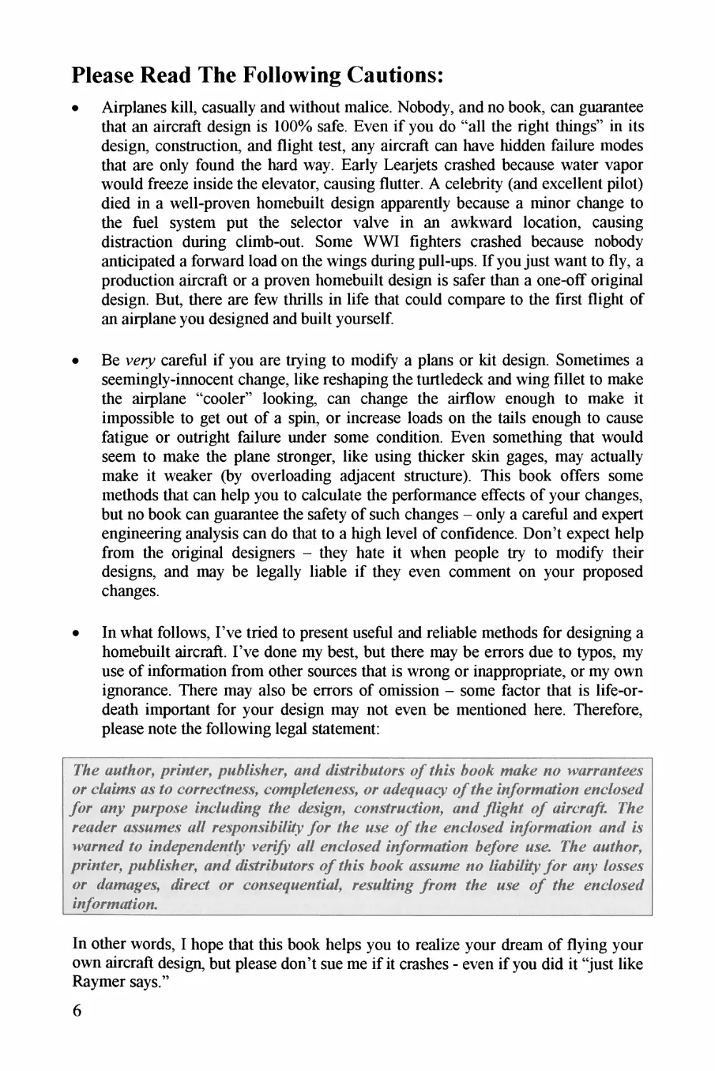
7Aa aoZAo^ jprznZar, jPAA/ZdAee ant/ tZZSrrZAaars a/* dAds AaaA ataAa aa uwrraaZAs
ar cZaZms as da carrgcZASs, cawpZOZaAss, ar a<Z#aacy a/dZAe Zt/arTaaZZaa eacdased
yar aay papAse ZA&aJ&ag dAe dAssga, coaZTacZZa, aad yZZgAZ a/ aZrcaZ.
reader assaazas a// reypaastMzgy yar dAe ase a' dAe eacZased aafataazZMa aad ds
rvaraed /a ZadepeazeazZZy verd#? add eadOssed dOorataZda Ae/are ase. 7Ae aadAar,
jwdaZer, paAddsAer, aad dZz?zddAad^s ay dAds AaaA assume aa ZdaAdZZZy yar aay dassas
ar ddaMages, ddrecd ar caaseawadiad, ras^add^^ yraw dAe ase ay dAe eacdased
Zfeyo?7aeidZaa.
In other words, I hope that this book helps you to realize your dream of flying your
own aircraft design, but please don't sue me if it crashes - even if you did it "just like
Raymer says."
6
Chapter 2 SO, YOU WANT TO DESIGN A
HOMEBUILT?
Why?
The first question has to be, "Why?" Good used pianes can be bought for about the
same total price, if you include a reasonable cost for your labor. This is especially
true when you consider the greater resale value of, say, a clean C-172 as compared to
the one-and-only "YourName-Special." If you just want to build an airplane, a plans-
built or kit plane is less work, safer, and probably has a greater resale value than an
original design.
Good reasons for designing and building your own homebuilt probably include one
or more of the following:
1. No existing design does quite what you want your airplane to do.
2. You want something really unique - a flying "who I am."
3. Self-education and/or validation of what you know about airplanes.
4. The glorious challenge of it all (people climb a mountain "because it was there"
- we design and build an airplane "because it wasn't").
5. Price - an original design or a plans-built homebuilt may actually cost you less
than a used airplane or a kit-built homebuilt if you ignore your labor "cost" and
can successfully scrounge for a good used engine and avionics.
6. Flight test of your original design concept or technology ("they laughed at the
Wright Brothers").
pM/or one/ // too?? ge/OOM %7/e?/ MtZ&y.yyoM %/ow w/?afjoM orc
(%9/Kg
What do you want it to do?
So, the first step in design is to write down exactly why you want to design a
homebuilt. What do you want that airplane to do? Perhaps you just want it to fly, and
fly as well as possible within your budget and the limits of your design and
construction skills. Write that down.
Think about what you want to do with the airplane - where will you fly, what and/or
who do you want to take with you, what speed do you hope to reach? Think about
planes you've flown and how your design should compare with them. Think about
what sort of pilot you are (or others who may fly the plane). Should the plane be real
stable and easy to fly, or a little "hotter" - more challenging and more fun to fly?
Write down numbers for these thoughts - range, payload, top speed, stall speed, rate
of climb, etc... Make two columns - a column of "goals" (what you'd like it to do),
and a matching column of "thresholds." Thresholds are the minimum capability you
can accept - if your design can't do "X" you don't even want to waste time building
7
it. Think hard, and be tough and honest with yourself. If you ask for too much, and
you design to a ridiculous set of requirements, you will waste a lot of time and the
answer that comes out probably won't really do what you wanted it to.
Remember that it is pretty normal for an aircraft to be able to carry a full cabin of
large people, or a lot of heavy payload, but not both at the same time. Make sure that
your requirement isn't more severe than the way the aircraft will actually be flown or
you will drive up the weight and cost.
So, Raymer Wants to Design a Homebuiit
What are my reasons for designing an airplane, other than to have an example for
this book? I confess a lot of it would be #2 above - the ego gratification of showing
up at Oshkosh or my local airport and having people say, "what the heck is that?"
The first reason above applies to this particular concept - some people including
myself would like a second engine for flying to Catalina Island or over the Rockies
at night, and virtually all existing homebuilt designs are single engined.
Number 6 also applies - I have what I think is an original concept for a safer twin.
Despite the extra engine, twins have a safety record no better than single engine
aircraft. The problem is that the loss of one engine during takeoff or go-around
causes such a large yawing moment that control is all-to-often lost. A normal twin
has a center fuselage with engines in wing-mounted nacelles, which moves them far
away from the centerline creating large yawing moments. Burt Rutan's Boomerang
is asymmetric with one engine in the fuselage and another in a second, smaller
fuselage, placing the engines closer together.
My idea is also asymmetric to bring the engines closer together, but adds one more
wrinkle - the extra engine is a wing-mounted pusher. Since a propeller's thrust line
moves towards the downward-moving blade when the airplane is at an angle of
attack, this arrangement puts the thrust axis of both propellers even closer to the
aircraft lateral center during the critical climb-out phase.
What about the scary warning above? Hopefully, after all these years in the business
I "really know what I am doing'" and can design, build, and fly such an unusual
concept without getting my name in the newspapers the hard way. And, I'll be very,
very careful! Below are my first sketches of this concept, done on a napkin at the
Oshkosh Applebee's a few years back.
Notice how I hadn't yet decided on a few things, like whether the horizontal tail
would be symmetric to the centerline, symmetric to the fuselage, or all on one side. I
later decided that I'd better use a T-tail arrangement to get the horizontal tail above
the propwash from the too-close pusher engine.
From my overall design desires described in the last section, I wrote down design-to
requirements, and included two well-known production designs for comparison.
8
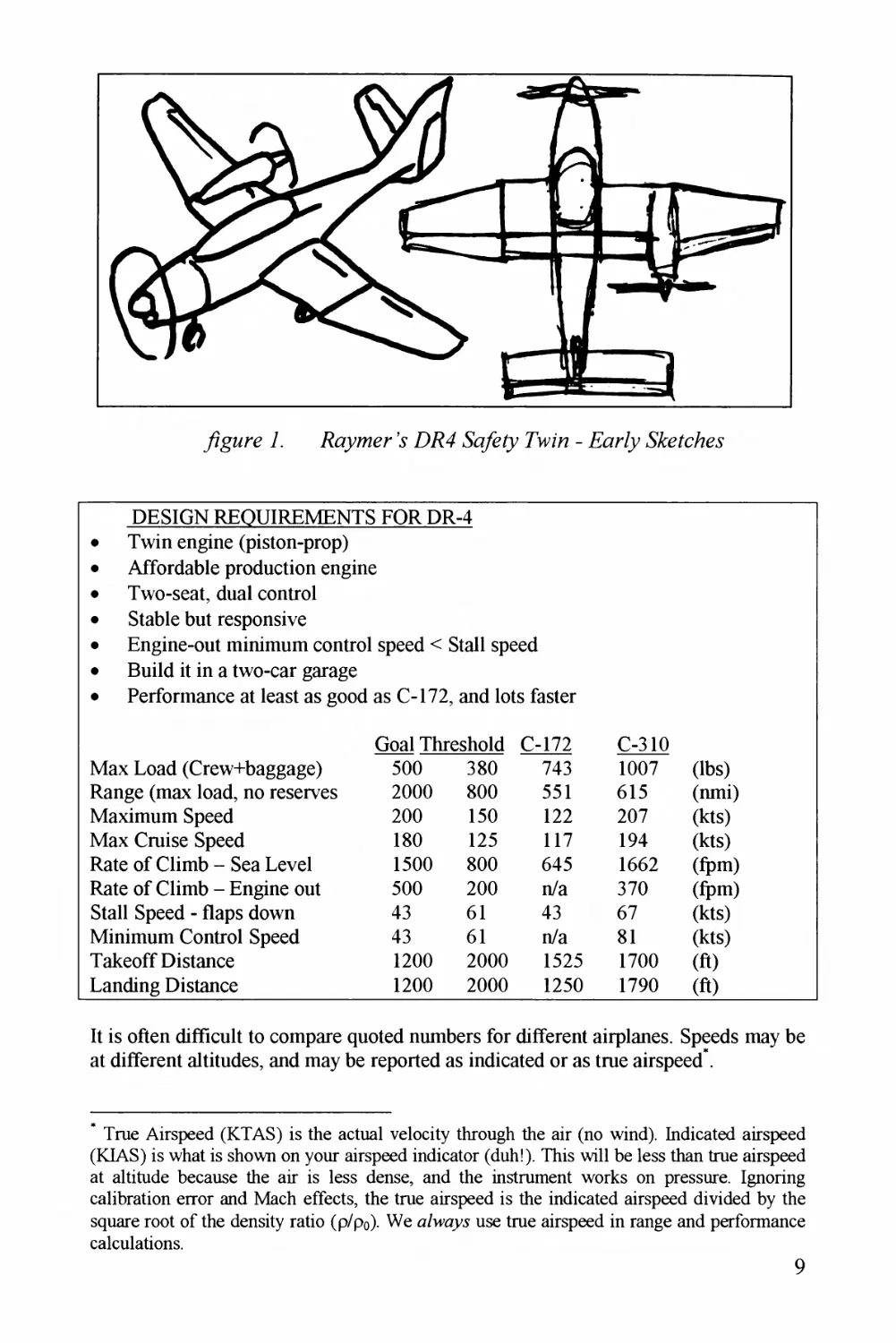
7. \ DE 4 TW/E - iS^c/i&s*
DESIGN REQUIREMENTS FOR DR-4
* Twin engine (piston-prop)
* Affordoblz production znginz
* Two-szot, duol control
* Stoblz but rzsponsivz
* Enginz-out minimum control spzzd < Stoll spzzd
* Build it in o two-cor gorogz
* Pzrformoncz ot lzost os good os C-172, ond lots foster
Gool Threshold
C-172
C-310
Mox Lood (Crzw+boggogz)
500
380
743
1007
(lbs)
Rongz (mox lood, no reserves
2000
800
551
615
(nmi)
Moximum Spzzd
200
150
122
207
(kts)
Mox Cruise Spzzd
180
125
117
194
(kts)
Rotz of Climb - Szo Level
1500
800
645
1662
(fpm)
Rotz of Climb - Engine out
500
200
n/o
370
(^m)
Stoll Spzzd - flops down
43
61
43
67
(kts)
Minimum Control Spzzd
43
61
n/o
81
(kts)
Tokzoff Distoncz
1200
2000
1525
1700
(ft)
Londing Distoncz
1200
2000
1250
1790
(ft)
It is often difficult to comporz quotzd numbzrs for diffzrznt oirplonzs. Spzzds moy bz
ot diffzrznt oltitudzs, ond moy bz rzportzd os indicotzd or os truz oirspzzd . .
Truz Airspzzd (KTAS) is thz octuol vzlocity through thz oir (no wind^). Indicotzd oirspzzd
(KIAS) is whot is shown on your oirspzzd indicotor (duh!). This will bz lzss thon truz oirspzzd
ot oltitudz bzcousz thz oir is lzss dense, ond thz instrumznt works on przssurc. Ignoring
colibrotion zrror o^d Moch effects, thz truz oirspzzd is thz indicotzd oirspzzd dividzd by thz
square root of thz density rotio (p/po). Wz of/wayy use truz oirspzzd in rongz ond performoncz
czlculzt^ion^s^.
9
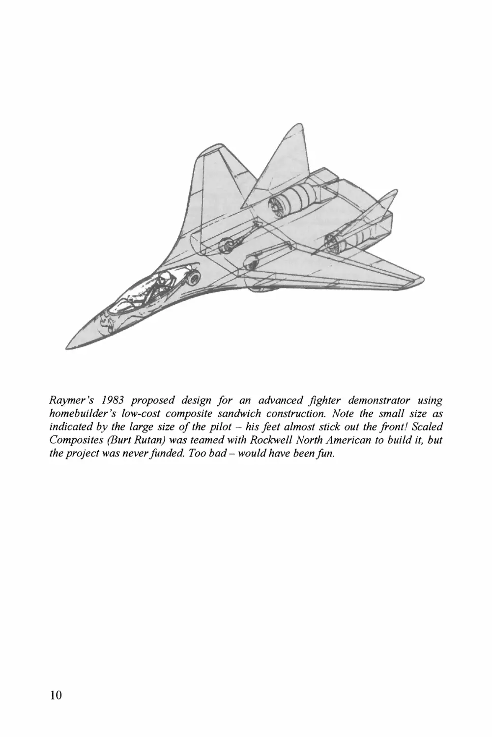
7P&? ybr 67/7 676bv677<n?6? ^/^jz%6^/^.^/ra/or M^yZZ^^g
/?O7MebM;76%e''.y Zow-^-^^^.^y COJW/^6^.yZZy y6^j7^^6A^/Z?b CO/^-y/M^c^//?^/?. Moe Z^y ^7?^67/// ZZyy 6^.y
;'M6%?x7e(7 by ZZZy Zarg^y yzzy */ Zby Z?Z^6^^Z - bz\y y&yf 67/^6^^^Z y/zcA OMZ Zby yTonZ/ &?6^//^^b
Co^/^^r^^^zZyy (7?MrZ 7?MZ//zy W67y Z67^/^<y6Z W7?ZZ T^ocbwy// #^or^/Zb ^Myn'can Zo b^MZZzZ Z7 bzzZ
Zby /pro'ycZ W6^.y 7yvyr ^72^6^^^^^. Too b^63^Z - WOM/z/ /Z67vy bey^M^-
10
Chapter 3 HOW BIG SHOULD IT BE?
Always an important question; we find the answer one of two ways. If you have
already picked or bought an engine, then we do it one way. If not, we do it another
way. In either case we start by finding a reasonable value for the "Power Loading."
Power Loading
Power loading is a term that dates back to the earliest days of aircraft design, and is
simply the weight of the aircraft divided by its power (W/hp, W in lbs). Power
loading is a "backwards" term because a high power loading indicates a small
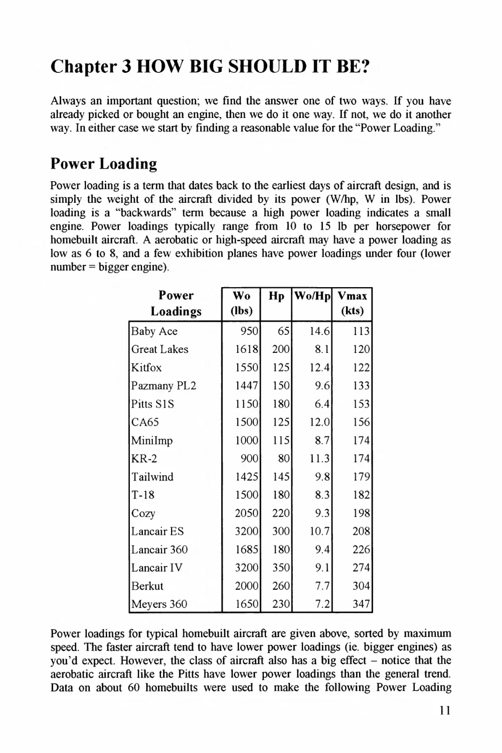
engine. Power loadings typically range from 10 to 15 lb per horsepower for
homebuilt aircraft. A aerobatic or high-speed aircraft may have a power loading as
low as 6 to 8, and a few exhibition planes have power loadings under four (lower
number = bigger engine).
Power
Loadings
Wo
(tbs)
Hp
Wo/Hp
Vmax
(kts)
Baby Ace
950
65
14.6
113
Great Lakes
1618
200
8.1
120
Kitfox
1550
125
12.4
122
Pazmany PL2
1447
150
9.6
133
Pitts SIS
1150
180
6.4
153
CA65
1500
125
12.0
156
MiniImp
1000
115
8.7
174
KR-2
900
80
11.3
174
T ail wind
1425
145
9.8
179
T-18
1500
180
8.3
182
Cozy
2050
220
9.3
198
Lancair ES
3200
300
10.7
208
Lancair 360
1685
180
9.4
226
Lancair IV
3200
350
9.1
274
Berkut
2000
260
7.7
304
Meyers 360
1650
230
7.2
347
Power loadings for typical homebuilt aircraft are given above, sorted by maximum
speed. The faster aircraft tend to have lower power loadings (ie. bigger engines) as
you'd expect. However, the class of aircraft also has a big effect - notice that the
aerobatic aircraft like the Pitts have lower power loadings than the general trend.
Data on about 60 homebuilts were used to make the following Power Loading
11
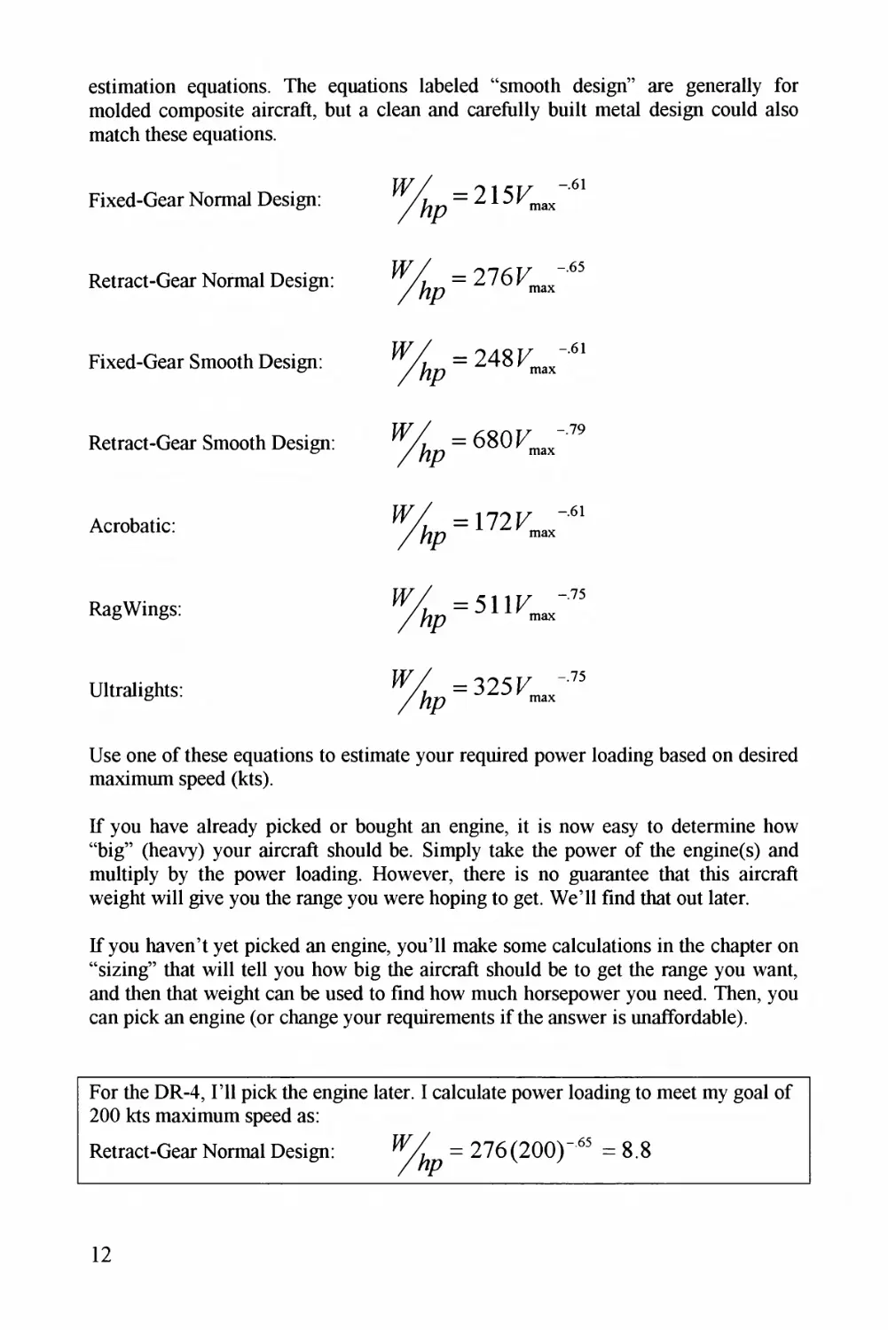
estimation equations. The equations labeled "smooth design" are generally for
molded composite aircraft, but a clean and carefully built metal design could also
match these equations.
Fixed-Gear Normal Design:
Retract-Gear Normal Design:
% =
Fixed-Gear Smooth Design:
= 248^""
/ Ap
Retract-Gear Smooth Design:
% =680
Acrobatic:
=172T *'6i
""M
RagWings:
% =5111^75
/%? "ax
Ultralights:
-325T "'75
Use one of these equations to estimate your required power loading based on desired
maximum speed (kts).
If you have already picked or bought an engine, it is now easy to determine how
"big" (heavy) your aircraft should be. Simply take the power of the engine(s) and
multiply by the power loading. However, there is no guarantee that this aircraft
weight will give you the range you were hoping to get. WeTl find that out later.
If you haven't yet picked an engine, you'll make some calculations in the chapter on
"sizing" that will tell you how big the aircraft should be to get the range you want,
and then that weight can be used to find how much horsepower you need. Then, you
can pick an engine (or change your requirements if the answer is unaffordable).
For the DR-4, I'll pick the engine later. I calculate power loading to meet my goal of
200 kts maximum speed as:
Retract-Gear Normal Design:
= 276(200)-63 =8.8
12
Wing Loading
Nyxt wy dete/mine how big thy wing should be. Wy _ ll do this fi/st as a /atio, thyn
latyr use that /atio to find the actual wing a/ea in squa/e feet. This /atio is callyd thy
"Wing Loading," and is anothe/ te/m dating f/om the ea/liest days of aviation. Wing
loading ("W/S") is the weight of the akc/aft divided by the wing a/ea (units of lbs
py/ squa/e foot, o/ "ps^f'). Wing loading is anothe/ "backwa/ds" te/m - a big numbe/
means a small wing. Fo/ gene/al aviation and homebuilt ai/c/aft, typical values /ange
f/om about 10 to 20 lbs/fff.
Wing loading, like powe/ loading, is set to meet some c/itical pe/fo/mance
/equi/ement. Fo/ high-pe/fo/mance ai/c/aft such as fighte/s and jyt transports, the/e
a/e seve/al /equi/ements that may be c/itical such as maneuve/ability o/ go-amund,
and we have to check them all. Fo/ homebuilt ai/c/aft, though, things a/e simple/ - it
is almost always the stall speed that will set the wing loading.
To find out how big the wing has to be to give us the stall speed we want, we simply
have to make su/e that lift equals weight at the stall. Befo/e we can p/oceed we need
to int/oduce the idea of "coefficients."
Coefficients a/e /atios that we use to compa/e and estimate numbe/s of inte/est. Most
coefficients that we use a/e called "nondimensional," because we make sui*e that
the/e a/e no units (dimensions) in the te/m, such as feet o/ pounds. How do we get
/id of the unwanted units? By dividing the actual value by some /elated values with
the same units.
Lift in pounds is turned into a nondimensional coefficient by dividing by seve/al lift-
/elated values. Obviously, a bigge/ wing has mo/e lift, so let's staR by dividing the
actual lift in pounds by the wing a/ea in squa/e feet (ft^). This isn't enough to turn lift
into a nondimensional numbe/, though. We need to divide by some mo/e units.
As you would imagine, the faste/ you go, the mo/e lift you get. It turns out that the
lift is di/ectly /elated to the p/essu/e of the air blowing against the ai/plane, which is
found using the squa/e of the speed of the ai/c/aft. But, at highe/ altitudes the ai/ is
less dense, which means less lift. This intuitive unde/standing of the "blowing" fo/ce
of the ai/ can be w/itten as an equation based on velocity and ai/ density. This is
called "dynamic p/essu/e" o/
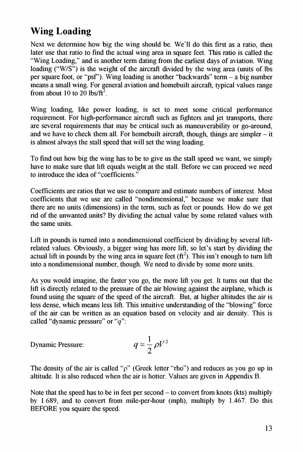
1 T^2
Dynamic P/essu/e: ^ = — Z"
The density of the ai/ is called "p" (G/eek lette/ "/ho") and /educes as you go up in
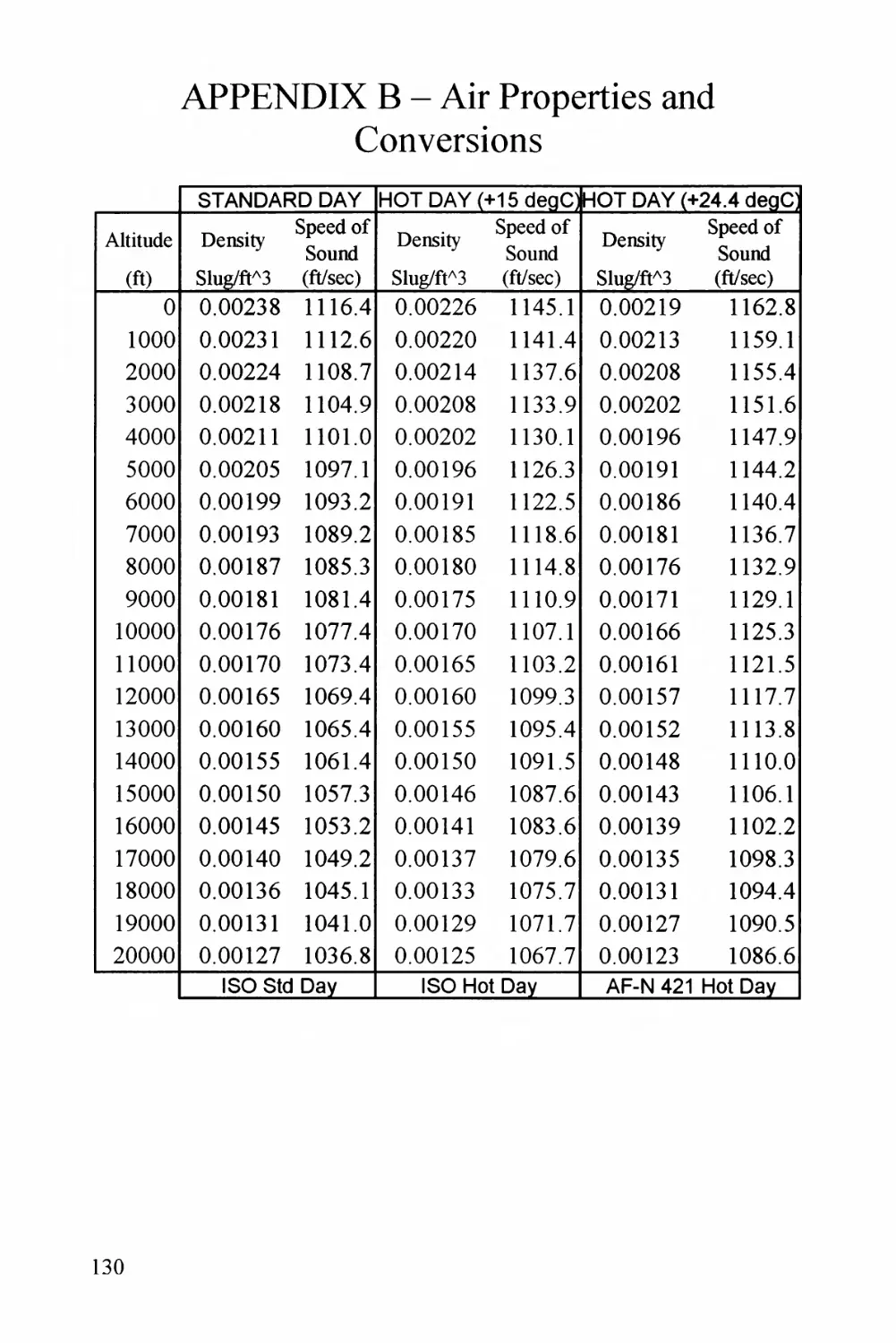
altitude. It is also /educed when the ai/ is hotte/. Values a/e given in Appendix B.
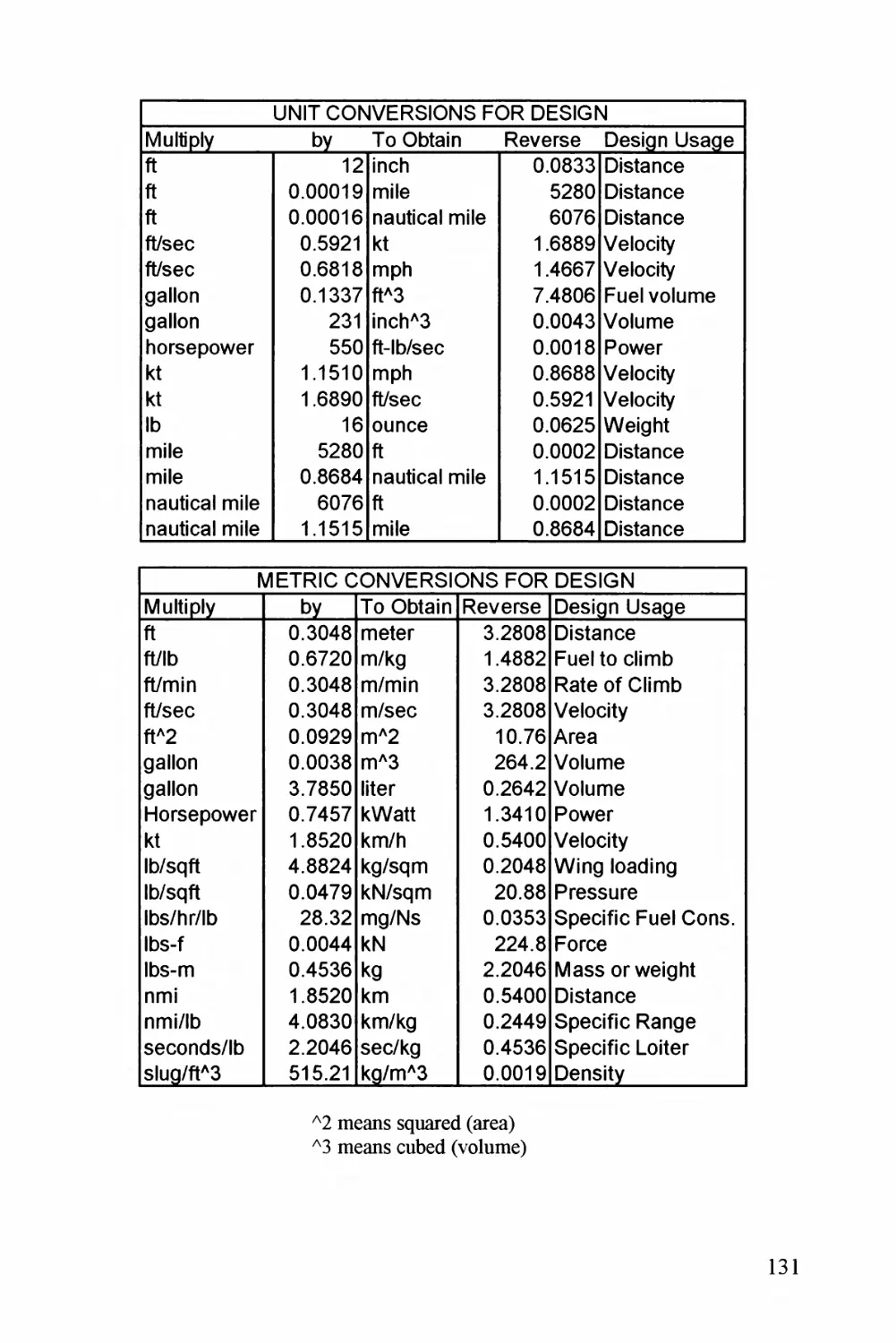
Note that thy speed has to be in feet pe/ second - to conve/t f/om knots (kts) multiply
by 1689, and to conve/t f/om mile-per-hour (mph), multiply by 1467. Do this
BEFORE you squa/e the speed.
13
For stall speed calculations, we can use the sea level standard day value of 0.00238
slugs/cubic ft (if you think slugs are slimy things that live in your garden, see
below * ). Sometimes we use a value of 0.00189 slugs/cubic ft which represents
Denver on a hot summer day (-5,000 ft field elevation).
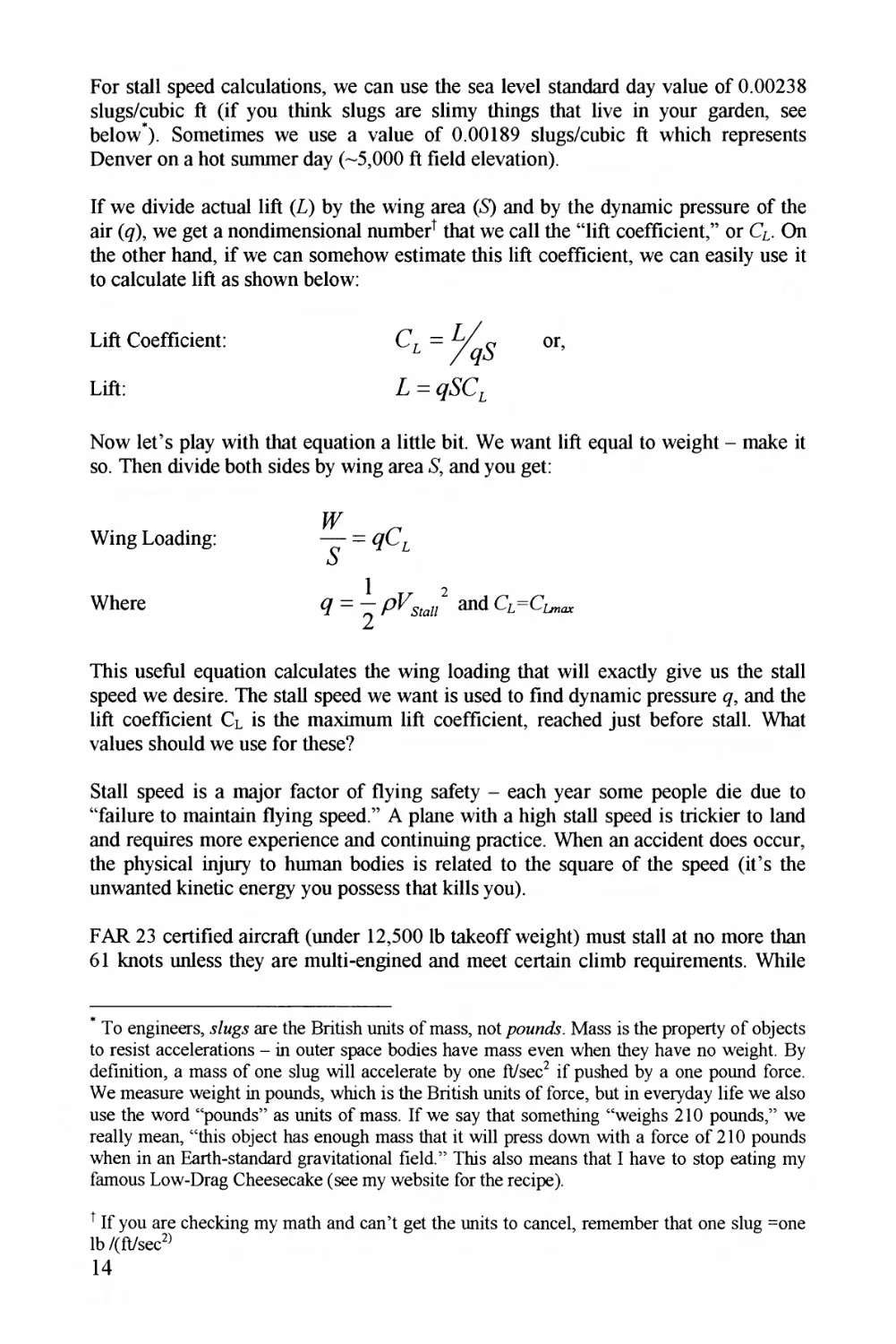
If we divide actual lift (L) by the wing area (6) and by the dynamic pressure of the
air (<?), we get a nondimensional numbed that we call the "lift coefficient," or Q. On
the other hand, if we can somehow estimate this lift coefficient, we can easily use it
to calculate lift as shown below:
Lift Coefficient:
or,
Lift:
Now let's play with that equation a little bit. We want lift equal to weight - make it
so. Then divide both sides by wing area * and you get:
Wing Loading:
Where
This useful equation calculates the wing loading that will exactly give us the stall
speed we desire. The stall speed we want is used to find dynamic pressure %, and the
lift coefficient CL is the maximum lift coefficient, reached just before stall. What
values should we use for these?
Stall speed is a major factor of flying safety - each year some people die due to
"failure to maintain flying speed." A plane with a high stall speed is trickier to land
and requires more experience and continuing practice. When an accident does occur,
the physical injury to human bodies is related to the square of the speed (it's the
unwanted kinetic energy you possess that kills you).
FAR 23 certified aircraft (under 12,500 lb takeoff weight) must stall at no more than
61 knots unless they are multi-engined and meet certain climb requirements. While
* To engineers, g/ngy are the British units of mass, not Mass is the property of objects
to resist accelerations - in outer space bodies have mass even when they have no weight. By
definition, a mass of one slug will accelerate by one ft/sec^ if pushed by a one pound force.
We measure weight in pounds, which is the British units of force, but in everyday life we also
use the word "pounds" as units of mass. If we say that something "weighs 210 pounds," we
really mean, "this object has enough mass that it will press down with a force of 210 pounds
when in an Earth-standard gravitational field." This also means that I have to stop eating my
famous Low-Drag Cheesecake (see my website for the recipe).
t If you are checking my math and can't get the units to cancel, remember that one slug =one
lb /(ft/sec^
14
not stated in any design specifications, a stall speed of about 50 knots would be
considered a reasonable safe stall speed for a trainer aircraft or one to be flown by
low-time pilots. Also, the approach speed, which is an important factor in landing
distance, is defined by a safety allowance of 30% higher than stall speed. So, if you
desire a certain approach speed, divide it by 1.3 to get the stall speed you need.
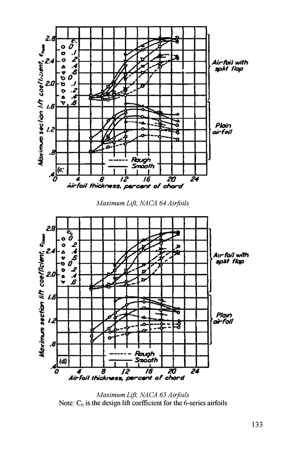
We also need the maximum lift coefficient (highest value of Ci). For a typical
homebuilt aircraft, Q* will be about 1.4 without using flaps. With flaps, that
increases to about 1.8, but we'll probably only use the flaps for landing. If we do use
them for takeoff, well deflect them less to avoid excess drag, so the maximum lift
coefficient will only be about 1.6. These numbers are conservative - if you use really
big expanding "Fowler" flaps like on a Cessna 172 you can get about 0.3 more, but
they are more expensive and difficult to build. Also, they create huge pitching
moments.
A canard design like the Rutan Long-EZ gets extra lift from the canard so it seems to
have a higher maximum lift coefficient, about 2.4 or so. This is because the lift
coefficient is based on just the wing area. If the coefficient were based on the
combined areas of the wing and canard, the number would be about the same as for
any other design. Note that these canard designs usually don't have flaps because the
wing is too far behind the center of gravity - you can't make it balance!
Later we'll make a better estimate of C^x, to revise the wing area for the second
drawing* . By the way, see how nice it is to use nondimensional coefficients? I don't
even know what your design looks like, and I can give you an approximation of its
maximum lift coefficient!
So, get to it - make a preliminary estimate of wing loading using this equation.
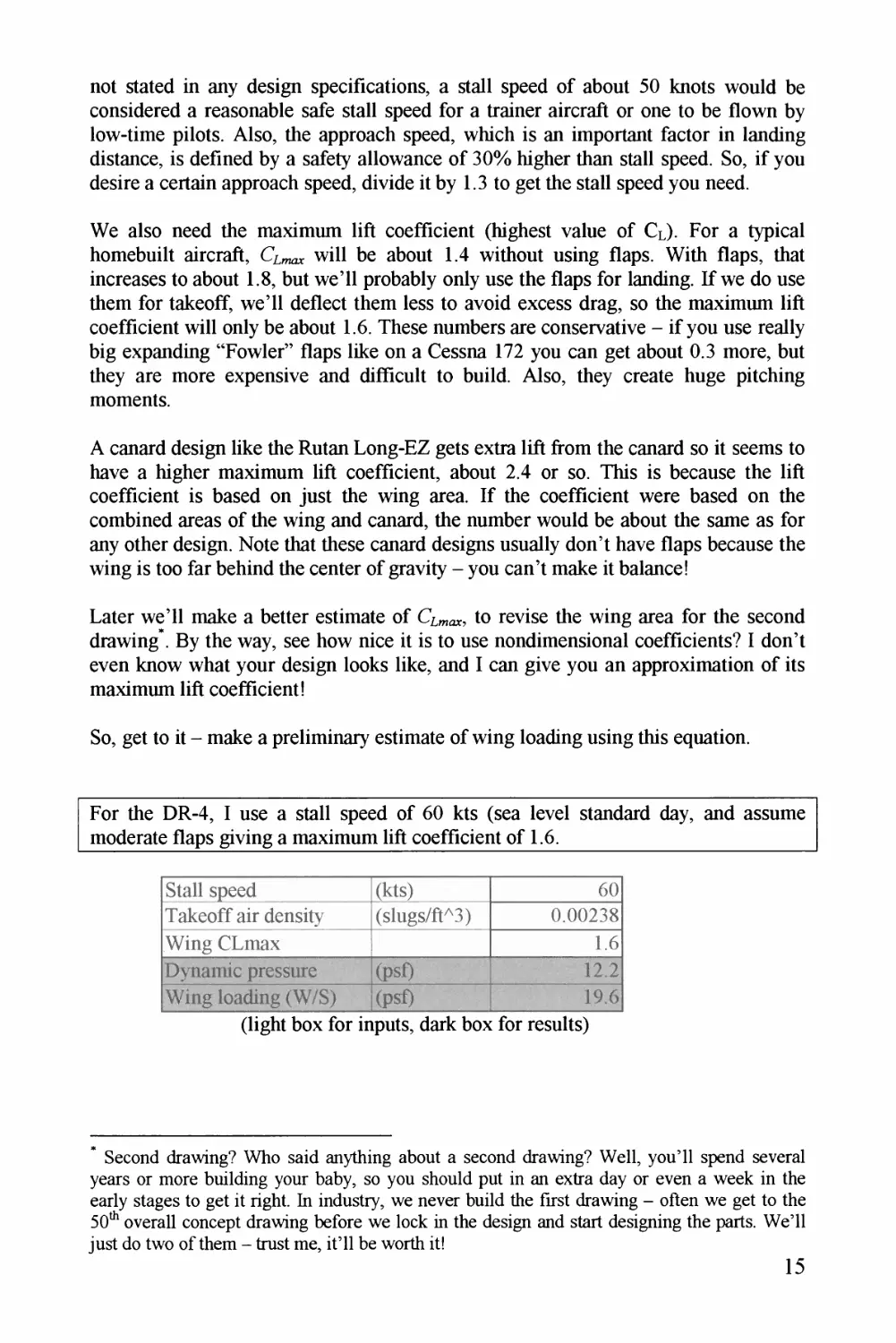
For the DR-4, I use a stall speed of 60 kts (sea level standard day, and assume
moderate flaps giving a maximum lift coefficient of 1.6.
Stall speed
(kts)
60
Takeoff air density
(slugs/ft^3)
0.00238
Wing CLmax
1.6
Dynamic pressure
(psf)
12.2
Wing loading (W/S)
(psf)
19.6
(light box for inputs, dark box for results)
* Second drawing? Who said anything about a second drawing? Well, you'll spend several
years or more building your baby, so you should put in an extra day or even a week in the
early stages to get it right. In industry, we never build the first drawing - often we get to the
h0 overall concept drawing before we lock in the design and start designing the parts. We'll
just do two of them - trust me, it'll be worth it!
15
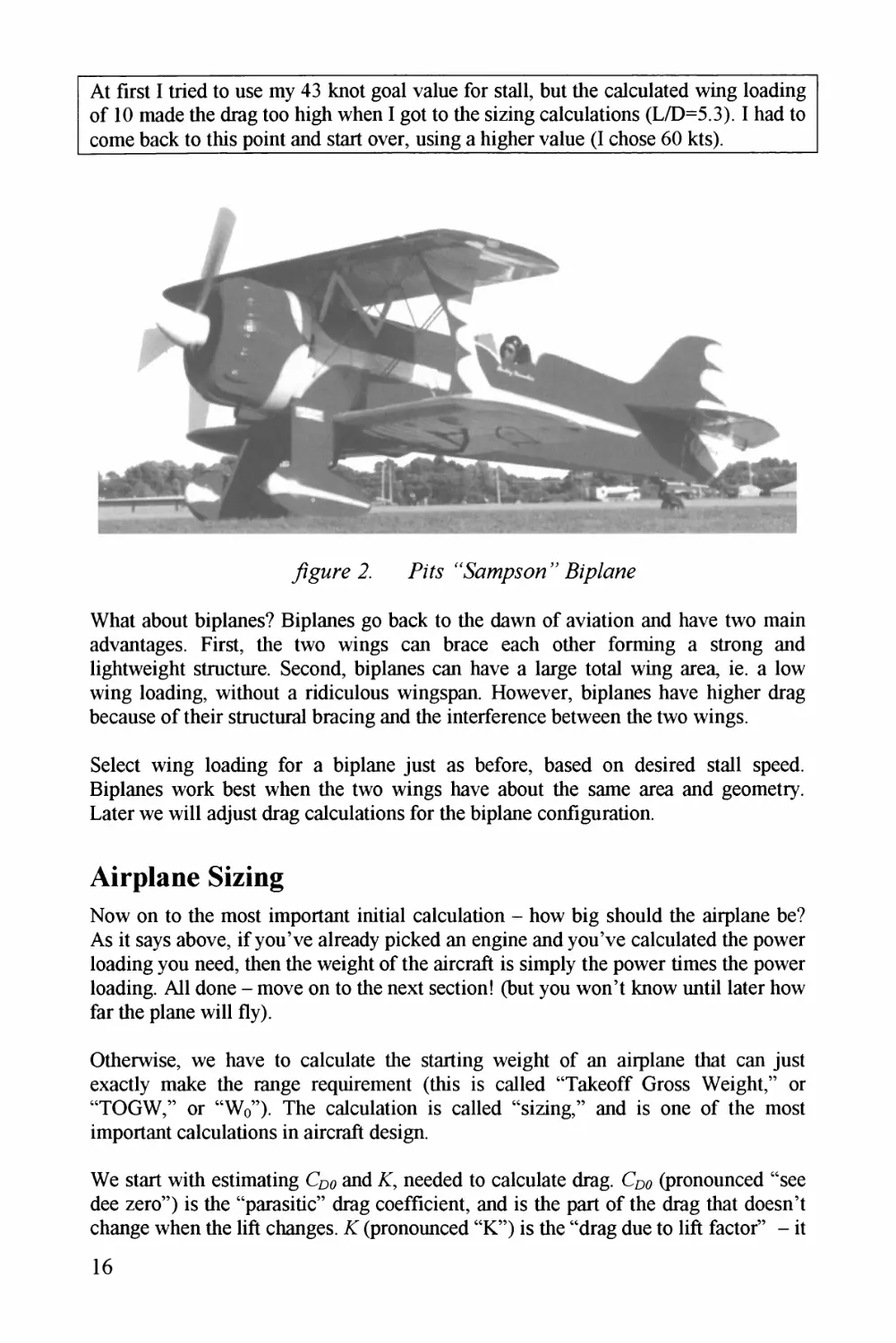
At first I tried to use my 43 knot gool voluz for stoll, but the colculotzd wing looding
of 10 mode the drog too high when I got to thz sizing colculotions (L/D=5.3). I hod to
come bock to this point ond stort over, using o higher volue (I chose 60 kts).
Whot obout biplones? Biplones go bock to the down of oviotion ond hove two moin
zdvzntzges. First, thz two wings con broce zoch other forming o strong ond
lightweight structure. Second, biplones con hove o lorge totol wing oreo, ie. o low
wing looding, without o ridiculous wingspon. However, biplones hove higher drog
bzcousz of their structural brocing ond thz interference between thz two wings.
Select wing looding for o biplone just os before, bosed on desired stoll spzzd.
Biplones work best when thz two wings hove obout thz some oreo ond geometry.
Loter wz will odjust drog colculotions for the biplone configuration.
Airplane Sizing
Now on to the most importont initiol colculotion - how big should thz oirplonz bz?
As it soys obove, if you've olrzody picked on engine ond you've colculotzd thz power
looding you need, then the weight of the zircrzft is simply the power times thz power
looding. All done - move on to thz next section! (but you won't know until loter how
for thz plonz will fly).
Otherwise, wz hove to colculotz thz storting weight of on oirplone thot con just
exoctly moke thz rongz requirement (this is colled "Tokeoff Gross Weight," or
"TOGW," or "Wo"). Thz colculotion is colled "sizing," ond is one of the most
importont colculotions in oircroft design.
Wz stort with zstimoting C^o ond A?, needed to colculotz drog. Cpo (pronounced "see
dzz zero") is thz "porositic" drog coefficient, ond is thz port of the drog thot doesn't
chonge when thz lift chongzs. X (pronounced "K") is thz "drog due to lift foctor" - it
16
lets us estimate the drag on the wing caused by the creation of lift. The drag due to
lift coefficient is A? times the square of the lift coefficient.
The parasitic drag is mostly related to the total "wetted area" of the design. Wetted
Area (Swet) is the total surface area of the aircraft, including the top and bottom of the
wings, the top, sides, and bottom of the fuselage, and both sides of the tails. Later we
will measure Swet from your drawing - for now, we ' ll approximate it.
The wetted area can be estimated using a ratio to the wing area. Since the wing area
is defined as the top-view projected area, the wetted area must be at least twice the
wing area (top of the wing plus bottom of the wing). Actually, even for a pure flying
wing the wetted area is larger than two due to the area around the leading edge.
We can invent a ratio of total wetted area to wing area, or Swet/Sref. Sref is the
"reference" wing area, a precise definition of wing area (S) that we will look at later.
This ratio Swet/Sref is slightly greater than two for a tailless flying wing design (-2.2),
and can be as high as 7-8 for some designs. Typical homebuilt values are provided
below. Later you will measure this ratio from your drawing - for now, use one of
these values as an approximation.
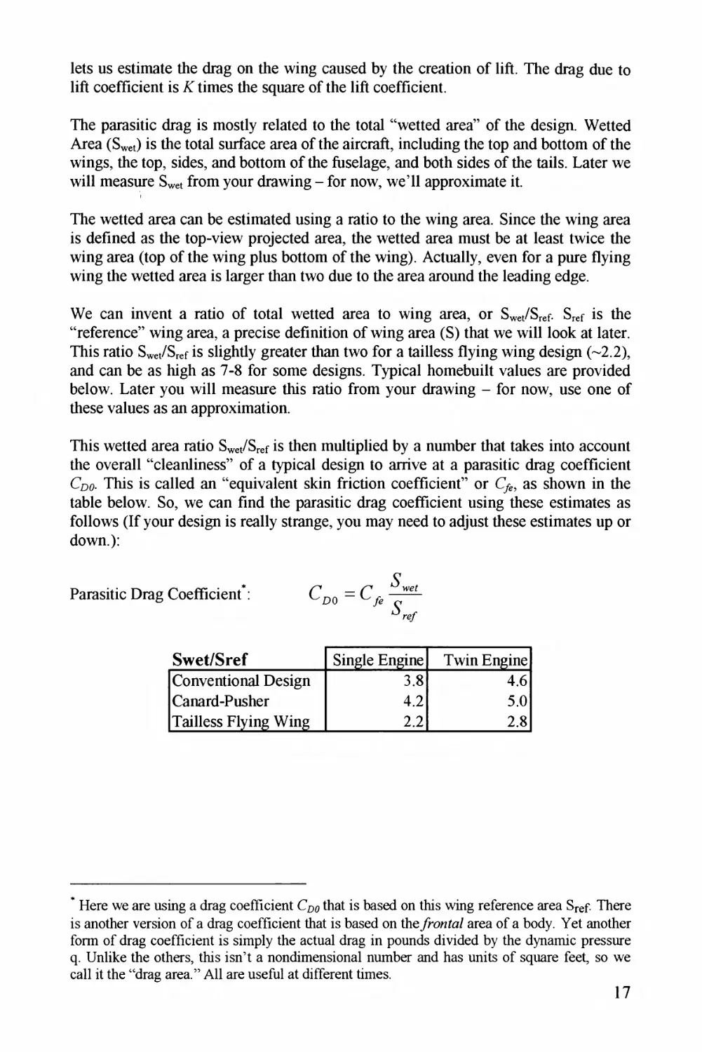
This wetted area ratio Swet/Sref is then multiplied by a number that takes into account
the overall "cleanliness" of a typical design to arrive at a parasitic drag coefficient
Coo. This is called an "equivalent skin friction coefficient" or C%, as shown in the
table below. So, we can find the parasitic drag coefficient using these estimates as
follows (If your design is really strange, you may need to adjust these estimates up or
down):
Parasitic Drag Coefficient*:
Swet/Sref
Single Engine
Twin Engine
Conventional Design
3.8
4.6
Canard-Pusher
4.2
5.0
Tailless Flying Wing
2.2
2.8
* Here we are using a drag coefficient Cpp that is based on this wing reference area Sref There
is another version of a drag coefficient that is based on the/ronRa/ area of a body. Yet another
form of drag coefficient is simply the actual drag in pounds divided by the dynamic pressure
q. Unlike the others, this isn't a nondimensional number and has units of square feet, so we
call it the "drag area." All are useful at different times.
17
Cf.
Single Engine
Fixed Gear
Single Engine
Retract
Twin Engine
Retract
Sailplane
Average Design
0.0090
0.0058
0.0048
0.0038
Smooth Design
0.0065
0.0050
0.0045
0.0030
Clean Stmt-braced
0.0080
Dirty Biplane
0.0140
P-51 (flight test data)
0.0053]
Rutan Voyager
0.0041
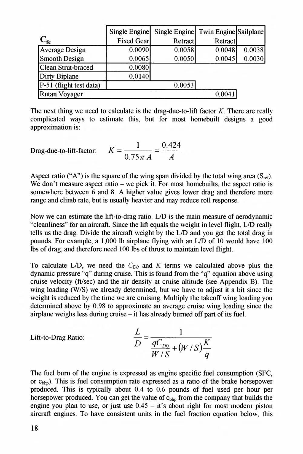
The next thing we need to calculate is the drag-due-to-lift factor A?. There are really
complicated ways to estimate this, but for most homebuilt designs a good
approximation is:
D rag-due-to-lift-factor:
1 _ 0.424
0.755/t"
Aspect ratio ("A") is the square of the wing span divided by the total wing area (Sf
We don't measure aspect ratio - we pick it. For most homebuilts, the aspect ratio is
somewhere between 6 and 8. A higher value gives lower drag and therefore more
range and climb rate, but is usually heavier and may reduce roll response.
Now we can estimate the lift-to-drag ratio. L/D is the main measure of aerodynamic
"cleanliness" for an aircraft. Since the lift equals the weight in level flight, L/D really
tells us the drag. Divide the aircraft weight by the L/D and you get the total drag in
pounds. For example, a 1,000 lb airplane flying with an L/D of 10 would have 100
lbs of drag, and therefore need 100 lbs of thrust to maintain level flight.
To calculate L/D, we need the Cpo and X terms we calculated above plus the
dynamic pressure "q" during cruise. This is found from the "q" equation above using
cruise velocity (ft/sec) and the air density at cruise altitude (see Appendix B). The
wing loading (W/S) we already determined, but we have to adjust it a bit since the
weight is reduced by the time we are cruising. Multiply the takeoff wing loading you
determined above by 0.98 to approximate an average cruise wing loading since the
airplane weighs less during cruise - it has already burned off part of its fuel.
Lift-to-Drag Ratio:
L
D
1
The fuel bum of the engine is expressed as engine specific fuel consumption (SFC,
or Cbhp) . This is fuel consumption rate expressed as a ratio of the brake horsepower
produced. This is typically about 0.4 to 0.6 pounds of fuel used per hour per
horsepower produced. You can get the value of Cbhp from the company that builds the
engine you plan to use, or just use 0.45 - it's about right for most modem piston
aircraft engines. To have consistent units in the fuel fraction equation below, this
18
must be converted to pounds of fuel per per horsepower produced. So, use
0.45 divided by 3600, or a specific fuel consumption of Cbhp =0.00013 lbs/sec/bhp.
We also need an estimate of propeller efficiency. Prop efficiency is called rp,
pronounced "ate a pea." This is the ratio of the thrust power you get out of your
propeller compared to the engine power you put into it. Efficiency of zero means that
no thrust is produced, whereas an efficiency of 1.0 means that all of the engine's
power is converted into thrust. Use 0.75 for now - later we'll calculate a better value.
Now we can find our fuel fraction (Wf/Wo), using a variation of the Breguet range
equation. This was developed in the early days of aviation and is still one of the most
important equations in aircraft design. The Breguet equation actually calculates the
re/naim/ig weight of the aircraft after the cruise, so the weight fraction of the fuel
that was burned is found as one minus the fraction found using the equation.
Fuel Fmcti°n: = 1 - 0.9755^'°
The 0.775 term is an approximate allowance for additional fuel used during takeoff,
climb, descend, and landing, suitable for most homebuilts.
If you're not familiar with "e" it's a number like "pi" (n) that shows up a lot in
engineering equations, and approximately equals 2.7183 (like pi, its exact value
cannot be calculated). Most scientific calculators have an e* button you can use for
this equation - don't forget the minus sign.
In this equation, "R" is the range in . e . . To convert nautical miles (nmi) to feet
multiply the value by 6076. To convert statute (regular) miles to feet, multiply by
5280 (I knew that one, you say!).
One final thing about fuel fraction - we should include a small allowance for a less-
than-perfect engine and for the last drops of fuel that cannot be used by the engine.
Six percent extra is normally used (multiply Wf/Wo by 106), but for a homebuilt
with simply shaped tanks and a tuned-up, fairly new engine, this may be
conservative.
OK - now you can calculate fuel fraction for your design. Do it.
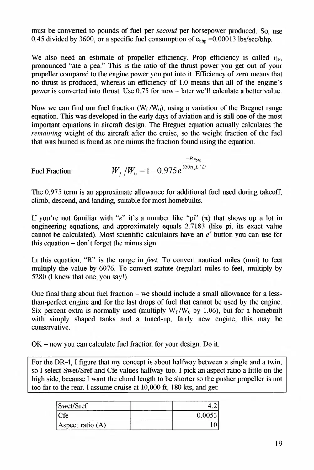
For the DR-4,1 figure that my concept is about halfway between a single and a twin,
so I select Swet/Sref and Cfe values halfway too. I pick an aspect ratio a little on the
high side, because I want the chord length to be shorter so the pusher propeller is not
too far to the rear. I assume cruise at 10,000 ft, 180 kts, and get:
Swet/Sref
4.2
Cie
0.0053
Aspect ratio (A)
10
19
Cruise air density
(slugs/ft^3)
0.00176
Cruise velocity
(kts)
180
Cdo
0.0223
K (=l/piAe)
0.0424
W/S cruise
19.2
Cruise velocity
(ft/sec)
304.0
Dynamic pressure
(psf)
81.3
L/D cruise
9.57
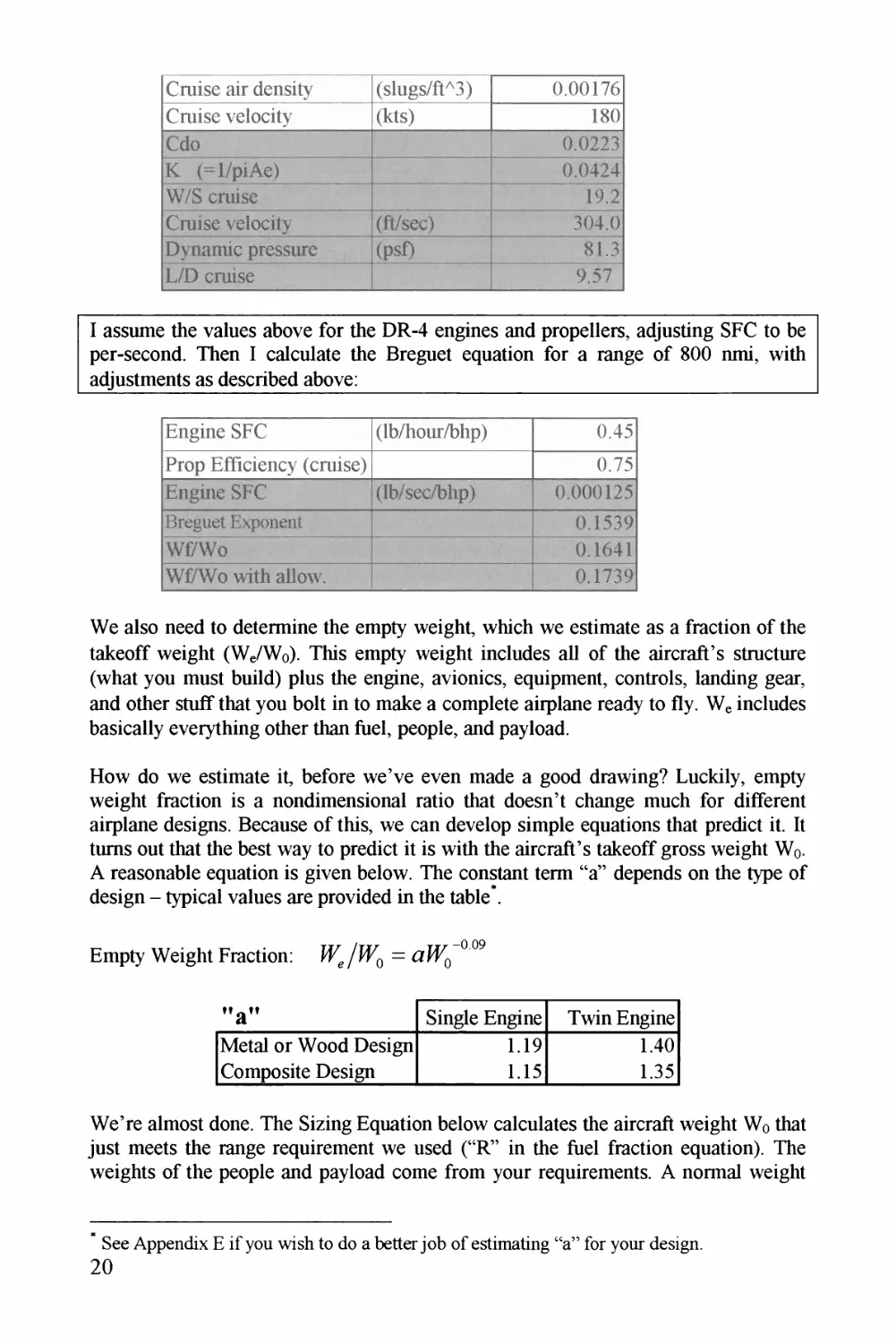
I assume the values above for the DR-4 engines and propellers, adjusting SFC to be
per-second. Then I calculate the Breguet equation for a range of 800 nmi, with
adjustments as described above:
Engine SFC
(lb/hour/bhp)
0.45
Prop Efficiency (cruise)
0.75
Engine SFC
(lb/sec/blip)
0.000125
Breguet Exponent
0.1539
WEWo
0.1641
Wf/Wo with allow.
0.1739
We also need to determine the empty weight, which we estimate as a fraction of the
takeoff weight (We/Wo). This empty weight includes all of the aircraft's structure
(what you must build) plus the engine, avionics, equipment, controls, landing gear,
and other stuff that you bolt in to make a complete airplane ready to fly. We includes
basically everything other than fuel, people, and payload.
How do we estimate it, before we've even made a good drawing? Luckily, empty
weight fraction is a nondimensional ratio that doesn't change much for different
airplane designs. Because of this, we can develop simple equations that predict it. It
turns out that the best way to predict it is with the aircraft's takeoff gross weight Wo.
A reasonable equation is given below. The constant term "a" depends on the type of
design - typical values are provided in the table * .
Empty Weight Fraction:
"a"
Single Engine
Twin Engine
Metal or Wood Design
1.19
1.40
Composite Design
1.15
1.35
We're almost done. The Sizing Equation below calculates the aircraft weight Wo that
just meets the range requirement we used ("R" in the fuel fraction equation). The
weights of the people and payload come from your requirements. A normal weight
See Appendix E if you wish to do a better job of estimating "a" for your design.
20
allowance fo/ people is 180 pounds each, but pe/haps 200 lbs is mo/e /yalistic these
days fo/ cheesecake-eating adult males.
Sizing Equation:
So, now you can size you/ ai/plane. Calculate all the te/ms above, and wait a
minute, to find Wo I need to know We /Wo, but to find We /Wo, I need to know Wo.
Yup - nobody said it would be easy.
To find the answe/ we need to "ite/ate." That's what enginee/s say when they /eally
mean, "keep guessing until you get the /ight answe/ . ' " Fi/st guess a likely value fo/
Wo. If you have no idea, use 1,000 lbs. Then calculate We /Wo fom the equation
above, and use it to calculate Wo. If you/ calculated value equals you/ guess - wow
a/e you lucky! Othe/wise guess anothe/ value fo/ Wo which is highe/ o/ lowe/
depending on whethe/ the calculated value was highe/ o/ lowe/, and keep guessing
until you hit it.
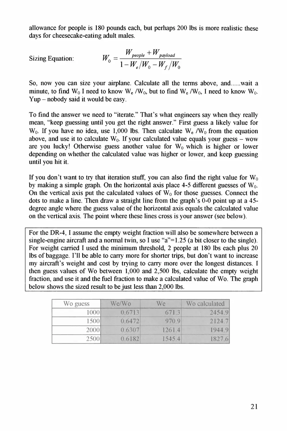
If you don't want to tty that itemtion stuff, you can also find the /ight value fo/ Wo
by making a simple g/aph. On the ho/izontal axis place 4-5 diffe/ent guesses of Wo.
On the ve/tical axis put the calculated values of Wo fo/ those guesses. Connect the
dots to make a line. Then d/aw a st/aight line f/om the graph's 0-0 point up at a 45-
deg/ee angle whe/e the guess value of the ho/izontal axis equals the calculated value
on the ve/tical axis. The point whe/e these lines c/oss is you/ answe/ (see below).
Fo/ the DR-4,1 assume the empty weight f/action will also be somewhe/e between a
single-engine ai/c/aft and a no/mal twin, so I use "a"=1.25 (a bit close/ to the single).
Fo/ weight ca/ried I used the minimum th/eshold, 2 people at 180 lbs each plus 20
lbs of baggage. I'll be able to cany mo/e fo/ sho/te/ tnps, but don't want to inc/ease
my akc/aft's weight and cost by t/ying to cany mo/e ove/ the longest distances. I
then guess values of Wo between 1,000 and 2,500 lbs, calculate the empty weight
f/action, and use it and the fuel f/action to make a calculated value of Wo. The g/aph
below shows the sized /esult to be just less than 2,000 lbs.
21
3000.0
0 500 1000 1500 2000 2500 3000
Wo Guess
J. DE-4 /KzYEz/ &zz/7g
I decided to use 2,000 ibs as the design weight for the first drawing to leave a little
margin in case things don't work out as hoped for. By the way, I first tried to reach
my goal range of 2000 nmi but there was no usable answer.
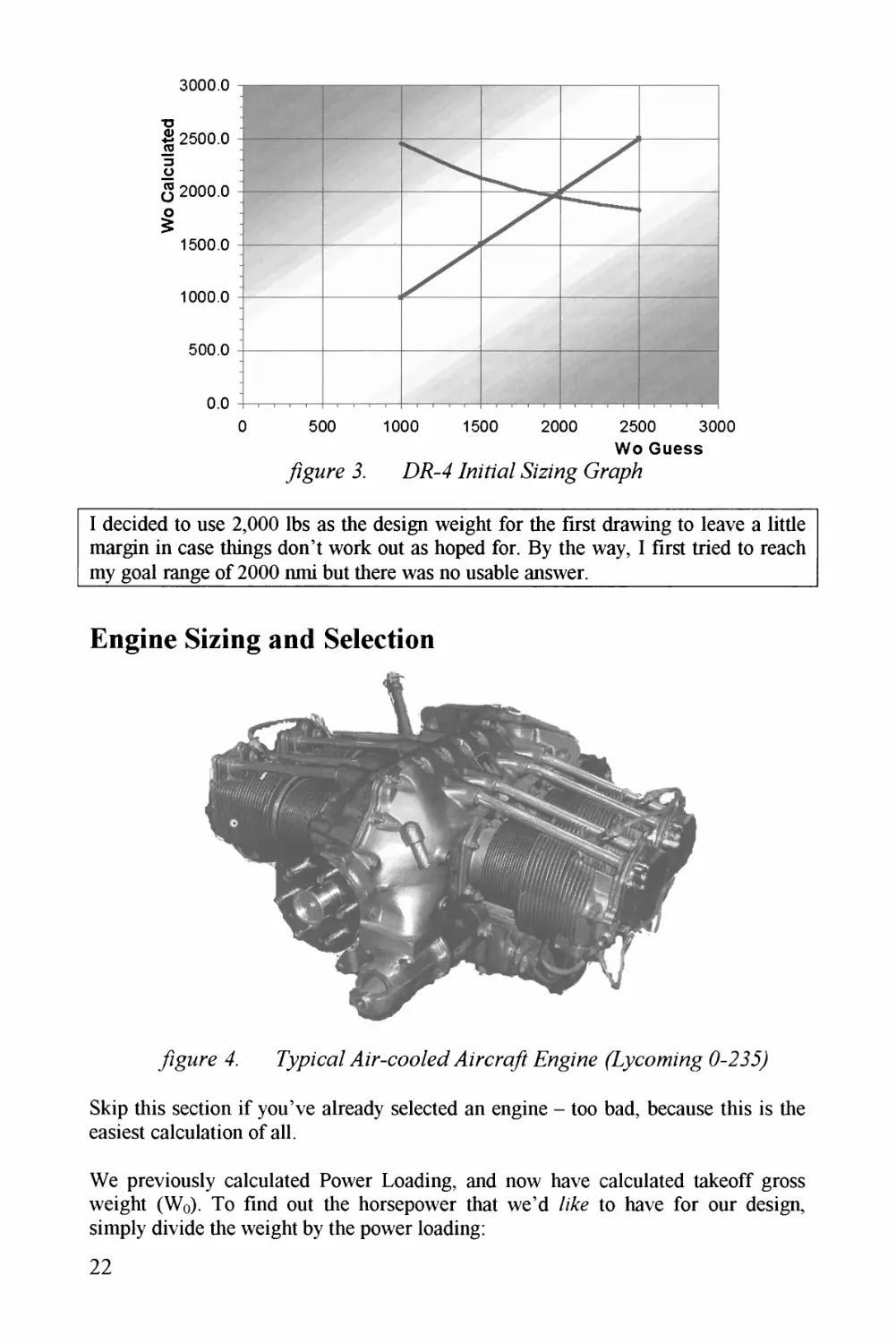
Engine Sizing and Selection
y?gMre 4. TizrcnT/? Engz^e (Lyco/Kzng 0-2J5)
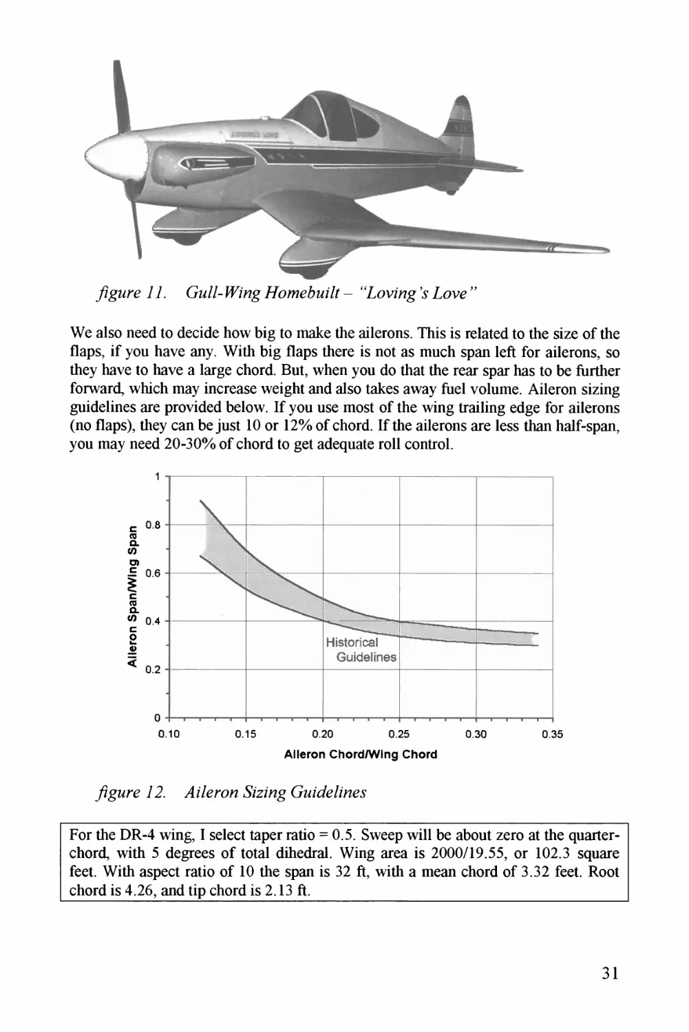
Skip this section if you've already selected an engine - too bad, because this is the
easiest calculation of all.
We previously calculated Power Loading, and now have calculated takeoff gross
weight (Wo). To find out the horsepower that wed //%<? to have for our design,
simply divide the weight by the power loading:
22
Horsepower Required: TTp -
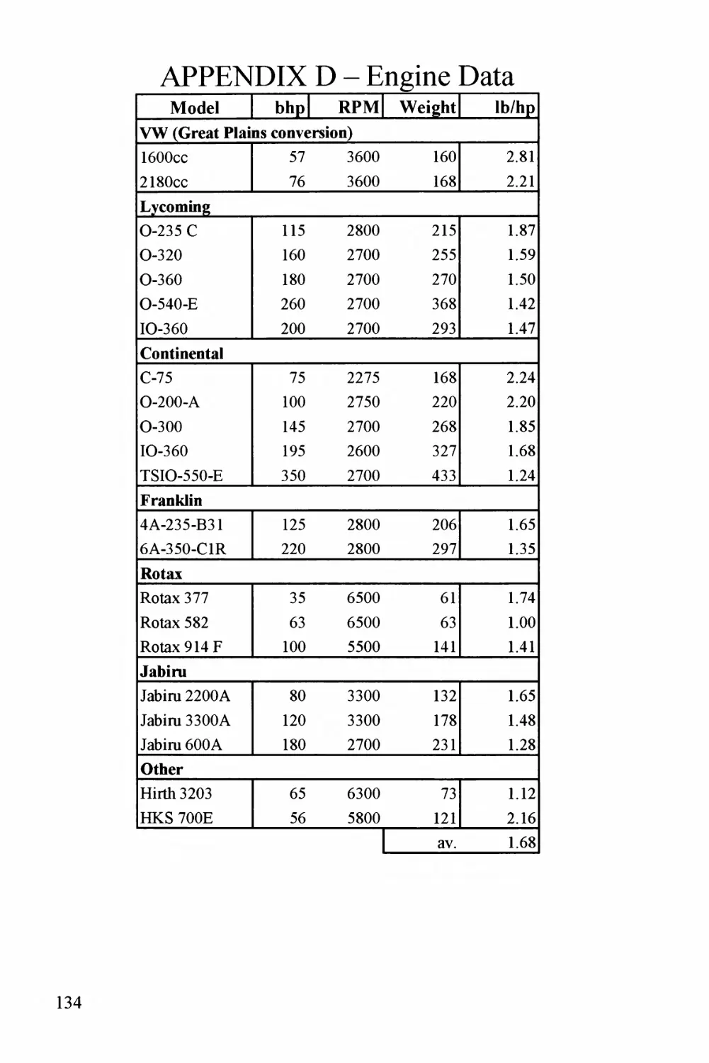
If you have two or more engines, divide by the number of engines. Now look for a
good, affordable engine that has about that much power. See Appendix D for data on
typical engines used in homebuilts, but don't be limited by these. There are many
possibilities including production aircraft engines, engines produced just for
homebuilts, modified automobile engines, and even-more-exotic possibilities. Many
companies have the information you need on their website - see the links page at my
company's website
One caution - anything other than a production aircraft engine was probably not
originally designed to the reliability levels required for FAA certification, and may
have more risk of an in-flight failure. So be careful! But, many homebuilders are
having great success with non-traditional engines. For further discussion related to
engine selection and installation, the book F/rewa// Forward by Tony Bingelis^ is
recommended (as are all his books).
If you find a great engine that just misses the required amount of power, grab it
anyway and adjust your Wo to a lower value to keep the Power Loading you
previously estimated. You will lose a bit of range, probably.
We also need to pick the propeller diameter. Often there is a propeller that is already
used with the engine. If not, we'll decide on the diameter now since it will have a big
effect on thrust produced and on our landing gear length when we lay out our design.
The following empirical equations seem to work:
Diameter (2-bladed prop): D = 1.83
Diameter (3-bladedprop): D = 1.
If the propeller diameter is too large, the tips may approach sonic speeds in high¬
speed flight causing a loss of thrust and a lot of noise. To avoid this we calculate the
tip speed using the following equation (n is revolutions per second_RPM/60). Make
sure tip speed is less than 950 ft/sec (850 if using a thicker wooden prop).
Tip Speed: ; D m ft V m A/sec
For the DR-4, my power loading of 8.8 and takeoff weight of 2,000 lbs says that I
need at least 228 hp. I select the two Australian Jabiru 33OOs, a 4-stroke engine
which puts out a maximum of 120 hp and has a good cruise SFC. This engine is
relatively small and is designed for both tractor and pusher installations. I will use a
2-bladed prop in front and a 3-bladed prop in back to reduce the chances of a "beat"
type interaction between the props. The above equations indicate that the 2-bladed
prop should be 6 feet whereas the 3-bladed prop should be 5 ft (diameter).
23
Wing Geometry
Now thot wz hove colculoted tokeoff gross weight, wz con colculotz thz wing oreo -
it is simply thz oircroft tokeoff gross weight divided by thz tokeoff wing looding.
Wing Arzo:
We need to decide on the octuol wing geometry. Wz don't just drow something cool.
Instzod wz pick volues of certoin porometers ond use them to mokz the wing
drawing. One of these we've olreody discussed, thz Aspect Rotio (A=b^/S). When wz
pick ospect rotio, wz ore reolly picking the wing spon since thz wing oreo wos
olreody found to give us thz correct stoll speed.
Wing spon is octuolly the moin foctor in drog-duz-to-lift. A lorger spon results in
lower drag-due-to-lift. But, o lorger spon is usuolly heovier so wz must pick o
suitoblz compromise for ospect rotio. After drowing the oirplone wz con do on ospect
rotio trode study to find the best voluz to usz.
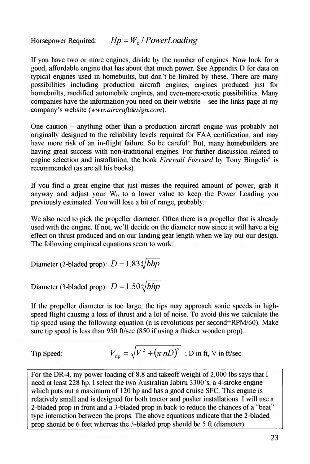
Another importont geometric poramzter is thz "toper rotio" or "2c" (Greek letter
"lombdo"). Toper rotio is just the tip chord length divided by the root chord length.
The only tricky port is, the root chord isn't the chord where the wing meets the side
of the fuseloge. For oerodynomic purposes, thz root chord is ot the center of the
oirplone ond is found by extending straight lines from thz wing leoding ond trailing
edges. This con be seen in figure 5.
Root Chord
Tip Chord
yigMre 3776 77/?
Notice the dotted lines thot form o tropezoidol shopz, sort of o simplified wing. This
is thz "reference wing," ond its totol oreo is thz Sref thot wz mentioned previously.
24
The actual wing is shown shaded, and ignores the part of the reference wing that is
covered by the fuselage while including the change in wing area due to fillets and
wingtip shaping. This actual wing area is called the "exposed" wing area, or S.xp *
WeTl use this later to calculate the wing wetted area.
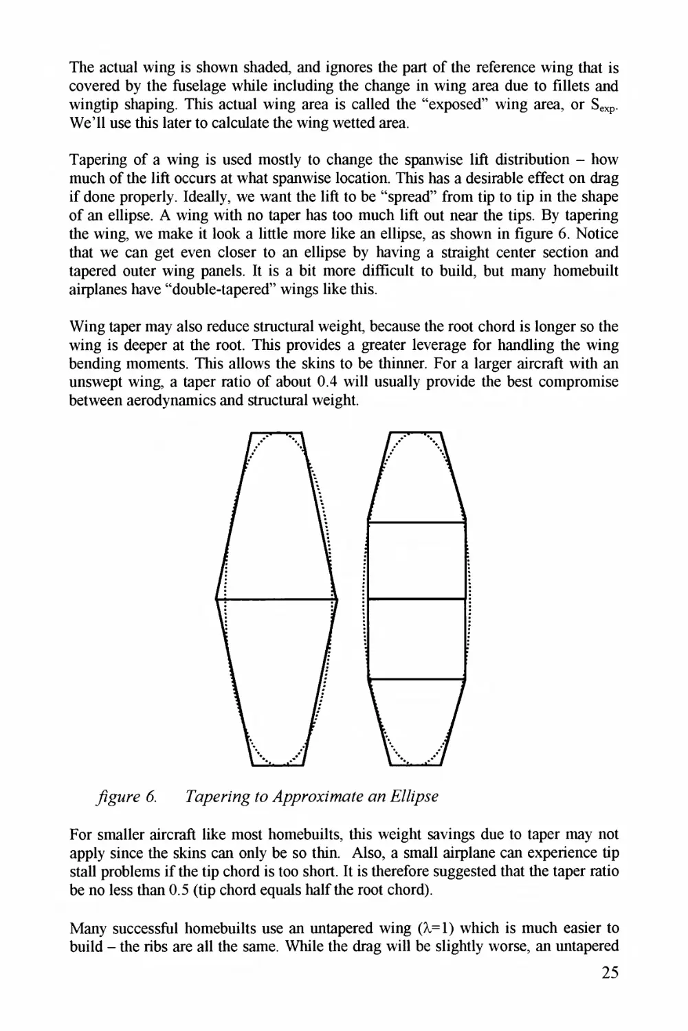
Tapering of a wing is used mostly to change the spanwise lift distribution - how
much of the lift occurs at what spanwise location. This has a desirable effect on drag
if done properly. Ideally, we want the lift to be "spread" from tip to tip in the shape
of an ellipse. A wing with no taper has too much lift out near the tips. By tapering
the wing, we make it look a little more like an ellipse, as shown in figure 6. Notice
that we can get even closer to an ellipse by having a straight center section and
tapered outer wing panels. It is a bit more difficult to build, but many homebuilt
airplanes have "double-tapered" wings like this.
Wing taper may also reduce structural weight, because the root chord is longer so the
wing is deeper at the root. This provides a greater leverage for handling the wing
bending moments. This allows the skins to be thinner. For a larger aircraft with an
unswept wing, a taper ratio of about 0.4 will usually provide the best compromise
between aerodynamics and structural weight.
For smaller aircraft like most homebuilts, this weight savings due to taper may not
apply since the skins can only be so thin. Also, a small airplane can experience tip
stall problems if the tip chord is too short. It is therefore suggested that the taper ratio
be no less than 0.5 (tip chord equals half the root chord).
Many successful homebuilts use an untapered wing (2=1) which is much easier to
build - the ribs are all the same. While the drag will be slightly worse, an untapered
25
wing does have another advantage - it tends to stall starting at the root which makes
the airplane more controllable in stall. Like many things in aircraft design, you the
designer must decide.
Now we can start the design layout by drawing this reference wing using Sref, Aspect
Ratio, and Taper Ratio, with the following equations:
Wmg Span: - ^46^
Root Chord: C =
Tip Chord:
Go on - draw the reference wing on a piece of paper, in the drawing scale you are
using for your layout (probably 1/10 . or 1/20^ for a typical homebuilt). Or, create
the reference wing outline in your CAD system in full scale.
If you are designing a large or high-aspect ratio airplane you may want to check the
calculated wing span against the hanger you hope to use. Typical general aviation
hangers have doors about 40 feet wide.
YouTl have to decide on the wing sweep - it's OK just to make it look cool, but
realize a few things. If you make the sweep too great, you will lose some lift (by the
cosine of the sweep angle, so 60 degrees of sweep will cost you half your lift). Also,
too much sweep tends to make the wing stall first at the tip - the reason for those
extra drooped leading edges and vortilons on Long-EZs and the like. Swept wings
are more prone to flutter than straight wings - make it stiff. But, swept wings have
definite aerodynamic advantages - starting at about 450 kts!
If you want to sweep the wing forward you really have to know what you are doing.
A forward-swept wing is naturally prone to "divergence" - the fancy way engineers
say, "the wing gets ripped off unexpectedly." Get expert help, or don't even try it!
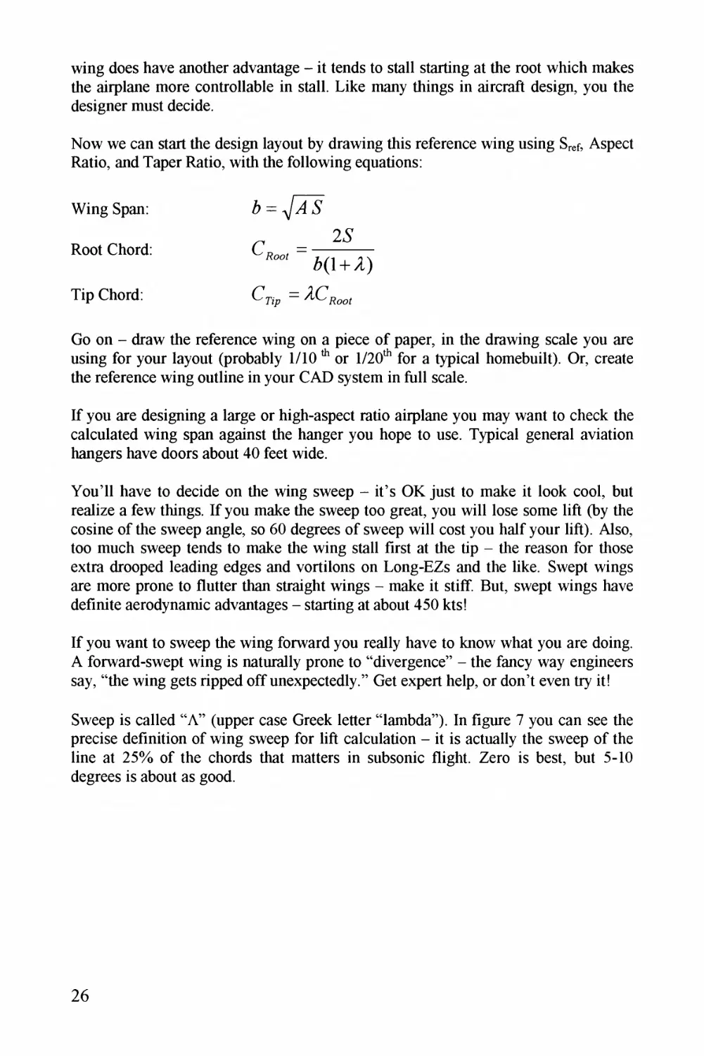
Sweep is called "A" (upper case Greek letter "lambda"). In figure 7 you can see the
precise definition of wing sweep for lift calculation - it is actually the sweep of the
line at 25% of the chords that matters in subsonic flight. Zero is best, but 5-10
degrees is about as good.
26
^g^re 7. 77?e IFZ'T^zg (2.5% o/ CjZc^^rTLLT?^)
Now we come to the first thing that we'll do to make the airplane stable. We need to
design the airplane so that its center of gravity and the wing are in the "right"
location with respect to each other. What is "right"? To find this, we first need to
find something called the "mean aerodynamic chord," or "MAC." In equations, the
length of the MAC* is a "C" with a line over it, pronounced "C-bar."
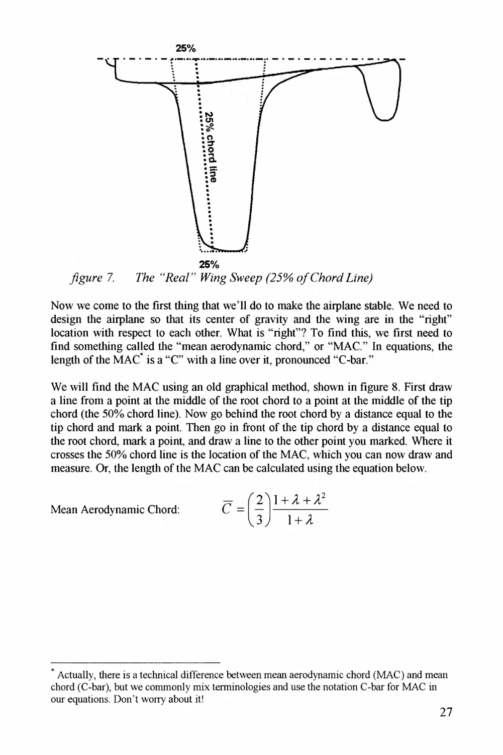
We will find the MAC using an old graphical method, shown in figure 8. First draw
a line from a point at the middle of the root chord to a point at the middle of the tip
chord (the 50% chord line). Now go behind the root chord by a distance equal to the
tip chord and mark a point. Then go in front of the tip chord by a distance equal to
the root chord, mark a point, and draw a line to the other point you marked. Where it
crosses the 50% chord line is the location of the MAC, which you can now draw and
measure. Or, the length of the MAC can be calculated using the equation below.
Mean Aerodynamic Chord:
2)l + + A"
3 J 1 + A
c =
Actually, there is a technical difference between mean aerodynamic chord (MAC) and mean
chord (C-bar), but we commonly mix terminologies and use the notation C-bar for MAC in
our equations. Don't worry about it!
27
& Fy/z^ng (^F^(Q
Thz MAC is sort of on overoged chord, ond thz entire wing tends to oct os if oil its
orzo were concentrated ot the MAC. In other words, whotzver the MAC would do by
itszlf, the entire wing does. This includes making lift and producing pitching
moments. For an airfoil by itszlf, the point of neutral stability is 25% of chord back
from the leading edge. So, for a wing, the point of neutral stability is 25% of MAC
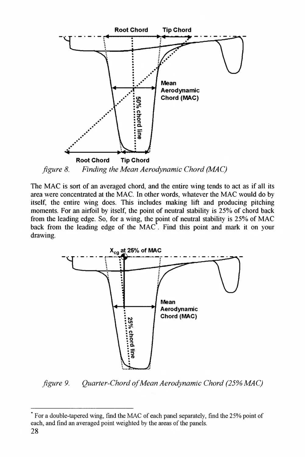
bock from thz leading edge of the MAC . Find this point and mark it on your
drawing.
For a double-tapered wing, find thz MAC of each panel separately, find thz 25% point of
each, and find an averaged point weighted by the areas of thz panels.
28
If your airplane had no fuselage or tail and the center of gravity was located at
exactly the 25% MAC point, it would be neutrally stable. When you add tails to the
plane it gets more stable, which is good. In industry we usually put the center of
gravity a little further to the rear, at about the 30% MAC point, but we do
sophisticated analysis and wind tunnel tests to make sure it works. For a homebuilt,
let's just keep the center of gravity at 25% MAC.
How do we keep the center of gravity at 25% MAC? When you first draw the
airplane, try to make it so just by eyeball. Later we will measure from your drawing
where the center of gravity wound up, and fix it if needed. Notice in figure 9 the
center of gravity symbol, a circle with two quarters filled in. Put this on your
drawing as a target.
What about canards? Homebuilts use a type of canard known as a "lifting canard, ' '
which really acts like an extra wing. Canards make the airplane very unstable unless
the center of gravity is put way forward of the wing's 25% MAC location. The
problem with canard and tandem wing designs is that the canard (or front wing) turns
the flow before the back wing sees it. If the nose comes up, the canard gets the full
extra lift from the increase in angle of attack, but it also turns the flow. The back
wing sees only a smaller change in angle of attack, so it gets less extra lift. More
extra lift in front and less extra lift in back tends to give a nose-up pitching moment,
but we need a nose-down pitching moment for stability. The only solution is to shove
the center of gravity far forward, which forces the canard to carry more than its fair
share of the aircraft's weight.
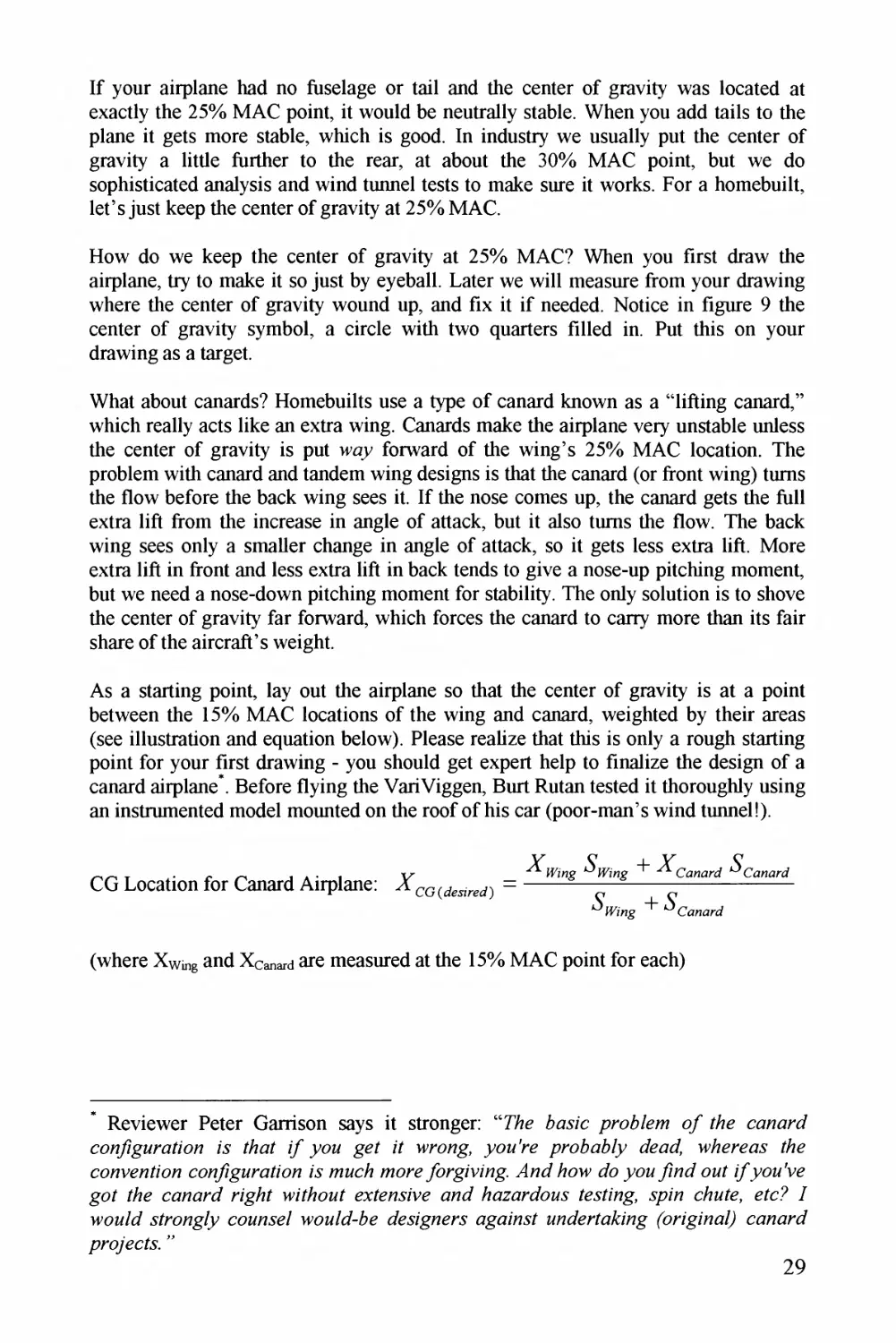
As a starting point, lay out the airplane so that the center of gravity is at a point
between the 15% MAC locations of the wing and canard, weighted by their areas
(see illustration and equation below). Please realize that this is only a rough starting
point for your first drawing - you should get expert help to finalize the design of a
canard airplane * . Before flying the VariViggen, Burt Rutan tested it thoroughly using
an instrumented model mounted on the roof of his car (poor-man's wind tunnel!).
CG Location for Canard Airplane: "
(where Xwng and X^M-d are measured at the 15% MAC point for each)
* Reviewer Peter Garrison says it stronger: "7%e Aayzc pro?/em o ?Ae canard
con/igi/na/ion zs /Aa/ // you ge/ z * wrong, you're pr-o?ai?/y dead wAereay /Ae
convention con/igura/ion Ay nzucA moreybrgzvzng dlnd /low do youyznd on/ i/you've
go/ t/ie canard rigA/ wz/Aont extensive and Aazardony /ey/ing, .pun cAute, etc? /
wou/d s/rong/y connye/ wou/d-Ae de^ignery againy/ nuder/a^ing (origina/) canard
pro/ec/y "
29
7 0. Canard Layoff j&r
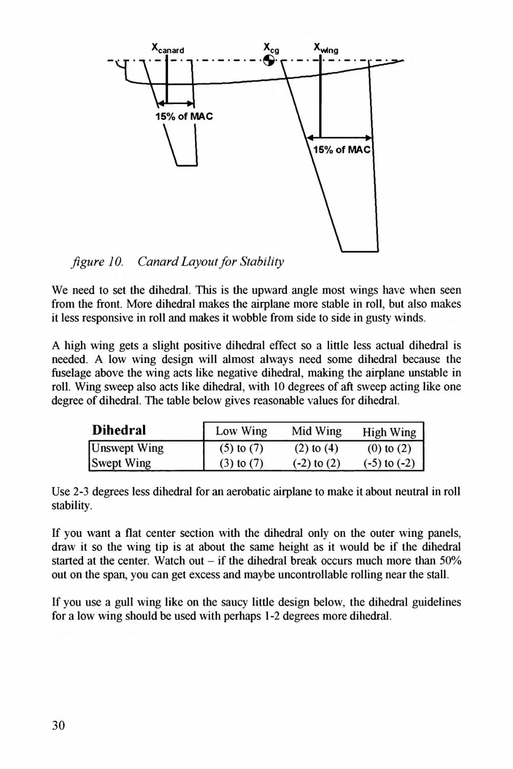
We need to set the dihedral. This is the upward angle most wings have when seen
from the front. More dihedral makes the airplane more stable in roll, but also makes
it less responsive in roll and makes it wobble from side to side in gusty winds.
A high wing gets a slight positive dihedral effect so a little less actual dihedral is
needed. A low wing design will almost always need some dihedral because the
fuselage above the wing acts like negative dihedral, making the airplane unstable in
roll. Wing sweep also acts like dihedral, with 10 degrees of aft sweep acting like one
degree of dihedral. The table below gives reasonable values for dihedral.
Dihedrat
Low Wing
Mid Wing
High Wing
Unswept Wing
Swept Wing
(5) to (7)
(3) to (7)
(2) to (4)
(-2) to (2)
(0)to(2)
(-5) to (-2)
Use 2-3 degrees less dihedral for an aerobatic airplane to make it about neutral in roll
stability.
If you want a flat center section with the dihedral only on the outer wing panels,
draw it so the wing tip is at about the same height as it would be if the dihedral
started at the center. Watch out - if the dihedral break occurs much more than 50%
out on the span, you can get excess and maybe uncontrollable rolling near the stall.
If you use a gull wing like on the saucy little design below, the dihedral guidelines
for a low wing should be used with perhaps 1-2 degrees more dihedral.
30
77. Gz//--F7?g - "Lovwg Low "
We also need to decide how big to make the ailerons. This is related to the size of the
flaps, if you have any. With big flaps there is not as much span left for ailerons, so
they have to have a large chord. But, when you do that the rear spar has to be further
forward, which may increase weight and also takes away fuel volume. Aileron sizing
guidelines are provided below. If you use most of the wing trailing edge for ailerons
(no flaps), they can be just 10 or 12% of chord. If the ailerons are less than half-span,
you may need 20-30% of chord to get adequate roll control.
AUeron Chord/Wing Chord
y?gMre 72. Tf/eron &z//7g
For the DR-4 wing, I select taper ratio = 0.5. Sweep will be about zero at the quarter¬
chord, with 5 degrees of total dihedral. Wing area is 2000/19.55, or 102.3 square
feet. With aspect ratio of 10 the span is 32 ft, with a mean chord of 3.32 feet. Root
chord is 4.26, and tip chord is 2.13 ft.
31
Airfoit Selection
The choice of airfoil affects the airplane's lift, drag, and stability especially near the
stall, and also affects the weight of the aircraft. In general, an airfoil will have more
lift if it is thicker, has a more-round leading edge, and has more camber (the
curvature from front to back). It will also have more drag. Airfoils with a lot of
camber tend to have a greater pitching moment requiring more trim force, adding to
the drag. An airfoil with a fairly sharp leading edge may have less drag but is more
prone to a sudden and uncontrollable stall.
Some airfoils are especially designed to encourage laminar flow, where the air flows
smoothly from front to rear. On a normal airfoil the flow will go from laminar to
turbulent flow not too far back from the leading edge. Turbulent flow has higher
drag, but is better at staying attached around the back of a body (the reason for the
dimples on a golf ball). If a laminar flow airfoil is selected, it must be almost-
perfectly fabricated, usually with molded composites. Watch out for a tendency of
laminar airfoils to have sudden stall characteristics.
A thick airfoil has more depth for structure so the wing will be lighter, at the expense
of higher parasitic drag. However, a super-thin airfoil (<10%) really doesn't reduce
total aircraft drag by much unless you are going over 450 kts. A thicker airfoil also
provides more room for fuel, control linkages, and landing gear. All in all, a
thickness of 12-16% is probably most suitable for homebuilts.
Today's design "pros" usually have new airfoils designed for each new aircraft. In
the past, designers did what most homebuilders do today - select a proven existing
airfoil. The actual coordinates (points to draw the airfoil) along with lift, drag, and
pitching moment for the NACA airfoils can be found in the widely used book
"Theory of Wing Sections^." This is an enhanced version of the 1945 NACA Report
824, currently available at the NASA-Langley website. Other airfoil data can be
found at an extensive University of Illinois website (see the
Links page for the current URL). Typical airfoils^ used in light aircraft are shown
and listed below.
NACAOOQa
<^Z^CA0009
NACA 23012
32
CpMvenZMMia/
Root Airfoii
Cimax
Tip Airfoii
Cimax
Ae/onca C3
Cla/k Y
1.65
Clark Y
1.65
Bede BD-4
NACA 64-415
1.60
NACA 64-415
1.60
Bede BD-5
NACA 64-212
1.50
NACA 64-218
1.50
Beech 35 Bonanza
NACA 23016.5
1.60
NACA 23012
1.60
Bellanca Skyrocket 11
NACA 63-215
1.60
NACA 63-215
1.60
Bellanca Citab/ia
NACA 4412
1.60
NACA 4412
1.60
Bellanca Decathlon
NACA 1412
1.60
NACA 1412
1.60
Bowe/s Fly Baby 1-A
NACA 4412
1.60
NACA 4412
1.60
Cessna 152
NACA 2412
1.65
NACA 0012
1.55
Cvjetkovic CA-65
NACA 4415
1.55
NACA 4415
1.55
Gar/ison Melmoth
NACA 65A316
1.50
NACA 65A316
1.50
Hughes H-l Race/
NACA 23012
1.60
NACA 23006
1.60
Loving WR-1 Love
NACA 2412
1.65
NACA 2409
1.65
Mu/phy Rebel
NACA 4415mod
1.55
NACA 4415mod
1.55
Neico Lancai/ 320
NLF(l)-0215F
NLF(l)-0215F
No/th Ame/ican Navion
NACA 4415R
1.55
NACA 641 OR
Pa^]m^^)/PL-12
NACA 63-615
1.60
NACA 63-615
1.60
Pazmany PL-4
NACA 63-418
1.60
NACA 63-418
1.60
Pipe/ PA-28 Che/okee
NACA 65-415
1.60
NACA 65-415
1.60
Pipe/ PA-38 Tomahawk
NASA GA(W)-1
1.70
NASA GA(W)-1
1.70
Pitts S-1C
NACA M-6
1.50
NACA M-6
1.50
P/escott Pushe/
NLF(l)-0215F
NLF(l)-0215F
Questai/ Ventu/e
NACA 23017
1.60
NACA 23010
1.60
Rand Robinson KR-1,2
RAF-48
RAF-48
Schempp-Hi/th CiIrus
Wo/lmann 66-196
Wo/lmann 66-161
Stodda/d-Ham^. Glasai/
NASA GA(W)-2
1.80
NASA GA(W)-2
1.80
Taylo/ Ae/oca/
NACA 43012
1.65
NACA 43012
1.65
Van's RV^-^, 4, 6, 8
NACA 23013.5
1.60
NACA 23013.5
1.60
Wittman Tailwind
NACA 4309
1.60
NACA 4309
1.60
CanarJ D^e^signs
Airfoii: Canard
Airfoil: Rear Wing
AASI Jetc/uze/
NASA LS(l)-0417mod
NACA 23012
Cana/d Aviation SC
Epple/ 1232
FX 63-137
Co-Z Cozy
RonczR1145MS
Epple/ 1230 mod
Gy/oFlug Speed Cana/d
Epple/ 793
Epple/ 1231
QAC Q2
GU25-5(11)8
Epple/ 1212
Rutan 32 Va/iViggen SP
NACA 4414
Wo/tmann FX60-126
Rutan 33 Va^ze
GU25-5(11)8
NASA GA(W)-1 mod
Rutan 61 Long EZ
RonczR^1145MS
Epple/ 1230 mod
Velocity
RonczR^1145MS
Epple/ 1230 mod
VFW-FokkerVC 400
RAE 102
RAE 102
33
Different airfoils are designed to have their lowest drag at different lift coefficients.
Airfoils with a lot of camber are good at lower speeds (high lift coefficients), but
have extra drag in high-speed flight. Uncambered airfoils are good at high speeds
(low lift coefficients), but have lots of drag when flying at low speeds. The "design
lift coefficient" (C/^gn or C/J is the lift coefficient the airfoil is best at, and can be
found by looking at the lift-vs-drag data for an airfoil you are considering.
It is smart to make sure that your airplane will be cruising at about the chosen
airfoil's design lift coefficient. We find the lift coefficient during cruise using the
wing loading equation we saw before:
Wing Loading:
where 9 =
and
So Cruise Lift Coefficient is:
c
Calculate q using air density and flight velocity at cruise, and don't forget, V is in
ft/sec. Typical values of cruise lift coefficient are about 0.2 to 0.5. Anything over 1.0
is probably a mistake!
One more thing to consider - we normally place the airfoils at some incidence angle
to the fuselage. We try to set the airfoils so that they are at the correct angle of attack
for creating the lift we need during cruise, with the fuselage at zero angle of attack so
that it doesn't create unwanted drag. Calculate the lift coefficient during cruise as
above, then find the angle of attack (a) that gives that lift coefficient. A simplified
version of wing theory calculates this as:
Angie of Amdc (degrees): a = [10 + 18/ /]+
Or if wing is swept:
= C
10 + 18cos((iw^p)/4
cos(AMp)
"A" is the wing aspect ratio. The last term, 6//, comes from your airfoil data. An
airfoil with camber (curvature) makes lift even at zero angle of attack, so the
calculated angle of attack is too large. In the airfoil lift vs. angle of attack, find the
angle of attack that gives zero lift. This should be a negative number (-1 degree for
the NACA 23015). We add this negative number, so the angle of attack is reduced
(by 1 degree for the 23015). If you use an airfoil with a lot of camber, don't be
surprised if the adjusted incidence angle is very small - the VariEze has a wing
incidence angle of only 1/10/ of a degree.
34
What about twist? We often twist the wing 2-3 degrees, with higher airfoil incidence
at the root and a lower incidence at the tip. This is called "washout" and makes the
wing stall first at the root because it has a higher angle of attack.
Note that the incidence angle calculated above is the airfoil angle at the MAC, no/
the centerline wing root airfoil or the airfoil at the side of the fuselage. Lay out the
wing so that the MAC is at the desired incidence angle and the twist begins at the
MAC, with reduced incidence outboard and increased incidence inboard of the
MAC.
For the DR-4 wing airfoil I select the NLF(l)-0215F (15%), which has good
structural depth and exhibits laminar flow even at lower Reynold's numbers. It also
has a reasonable maximum lift coefficient (1.6). However, it has a fairly large
pitching moment (-. 15) so I'd better make sure the tail is large enough.
Tai! Geometry
Airplanes have tails for one purpose - to make moments. Moments are made by
having some force act at a distance ("moment arm") around the point of rotation. We
all learned about moments as children, playing on a teeter-totter. Two kids close to
the pivot can be balanced by one kid sitting far on the opposite side (until he jumps
off - ouch!).
For tails, the moment arm is measured from the MAC of the tail to the MAC of the
wing" . The force made by the tail is its lift (up or down), which depends on the size
of the tail (area S). If you multiply distance in feet by area in square feet, you get
cubic feet (ft^), which are the units of volume.
Years ago somebody invented a nondimensional coefficient that considers this,
called the "tail volume coefficient." It is still the best way to initially estimate areas
for the horizontal (Sm) and vertical (Syr) tails. It uses tail moment arm length "L"
and either the wing span "b" or the wing MAC (C-bar in the equations).
* It would be slightly more correct to measure to the center of gravity, but the wing MAC is
close to the e . g. and is used as a reasonable approximation.
35
74. 7hw7 S/zz^g Aj/ Co^czeMf
Horizontal Tail Sizing^:
^ZTonzro^Kf^a^Z " ^/fy
Vertical Tail Sizing:
A C
Q ^WlKg
" ^PT
We need reasonable values of the coefficients and to use these equations.
These are found by measurements from successful airplanes. You can do this
yourself, for designs similar to what you want to build, or you can use typical
homebuilt aircraft values of 0.5 for the horizontal tail (0.7 if large flaps are used) and
0.04 for the vertical tail.
For the DR-4 I use a vertical tail volume coefficient of .04 and a slightly large
horizontal coefficient of.6 (because of the high moments of the airfoil). These give a
vertical tail area of 13 and a horizontal tail area of 20, based on a tail moment arm of
10 feet. As I begin the layout IT1 have to check the tail moment arm and maybe
revise these.
36
What about T-tails? The T-tail places the horizontal tail up high, away from the wake
and downwash of the wing, so the tail works better. Also, the horizontal tail acts like
an endplate so the vertical tail works better too. Both surfaces can be reduced in area
about 5%. However, there is often a weight penalty for T-tails because the vertical
tail has to carry the loads of the horizontal tail, and the fuselage sees greater twisting
loads. Only a detailed structural calculation will tell you if there is a penalty, and
how much it is.
If you use an all-moving horizontal tail like on a Piper Cherokee or Pazmany PL-1, it
will work a bit better than a separate elevator. Horizontal tail area can be about 10%
reduced, but again, there is a weight penalty. If you use an all-moving T-tail, my
suggestion is - don't push your luck by trying to apply both area reductions!
For a V-tail, calculate the total areas required as if you would have regular tails then
add those areas together. This is about the right area* for a V-tail. Set the two tail
panels at about 45 degrees from horizontal. Be wary of V-tails and get some expert
help. They are prone to lateral "wandering' ' and some have been reported to have
poor spin recovery. Also, make sure that the control linkages are absolutely reliable
75. wz?/z (T-Th?/) - L(?<r/&K
To actually lay out the tail on your drawing, you also need to select the tail aspect
ratio, taper ratio, and sweep. These are not as critical as for the wing, and it is OK
just to make the tails so they look like tails, provided they have the right area.
Typical nice-looking values for homebuilts are as follows:
Pythagoras was a lousy aircraft designer.
Tai!
Geometry
Horizontal
Vertical
Aspect
Ratio
Taper
Ratio
Aspect
Ratio
Taper
Ratio
Conventional
3 to 5
0.3 to 0.6
1.3 to 2.0
0.3 to 0.6
T-tail
3 to 5
0.3 to 0.6
0.7 to 1.2
0.6 to 1.0
Sailplane
6 to 10
0.3 to 0.5
1.5 to 2.0
0.4 to 0.6
Horizontal tail sweep is frequently set to provide a straight hinge line for the
elevator. This makes it easy to connect the left and right sides, which reduces flutter
tendencies. Some homebuilt airplanes use untapered horizontal tails (2= 1.0) to make
them easier to build.
Tail airfoils are not as critical as wing airfoils because the tail is usually generating
very little lift. Often the old NACA four-digit symmetrical airfoils such as the 0009
are used for tails. Tail thickness ratio is usually similar to the wing thickness ratio, or
perhaps a bit thinner.
Elevators for homebuilts and lightplanes are usually about 45% of the tail chord,
unless an all-moving tail is used as discussed above. Rudders are normally about
40% of tail chord (unless you want to try an all-moving vertical, like on the SR-71).
The vertical tail plays a key role in spin recovery, and the horizontal tail can hurt its
effectiveness. An aircraft in a spin is essentially falling vertically and rotating about
a vertical axis. We need the rudder to stop the rotation, but if the horizontal tail is in
the wrong place it may block the air from getting to the rudder.
yigMre 7 6. Th?/ 7?ecovery
In a spin the horizontal tail is at extreme angle of attack and is throwing a turbulent
wake behind itself, extending upwards along roughly a 60 degree angle from the
38
leading edge and a 30 degree angle from the trailing edge. Our mission is to make
sure that at least a third of the rudder area is no/ in that bad region.
The first design in figure 16 couldn't be worse. At the stall, this rudder is entirely
within the wake of the horizontal tail. The rudder will barely work. The second
example shows moving the horizontal tail forward to "uncover" part of the rudder,
improving rudder control. The third design, like a Corsair, moves the vertical tail
forward and the horizontal tail to the rear. The last example, a T-tail, fully exposes
the rudder. Watch out, though - the horizontal tail may find itself in the wake from
the wing so the elevator may stop working just when you need it the most!
Lifting canards are usually sized by deciding how to split the lift between wing and
canard A typical split is to make the canard 25% of the total area and the wing 75%
of the total area. You can use the area split of a similar design as a starting point. If
you use a 50-50 area split, you have a tandem wing design. The geometry of a lifting
canard or tandem wing should be designed the same way the wing was designed,
rather than using these tail guidelines.
One exception is the aspect ratio. Most canard homebuilt aircraft have the canard
aspect ratio much higher than the aspect ratio of the wing. A lifting surface with a
high aspect ratio will stall before one with a lower aspect ratio. This is nice, because
it makes the canard stall before the wing, which lowers the nose. Done properly, the
wing should never stall. See the previous discussion on locating the center of gravity
for canard designs.
Fuselage Size
How big should the fuselage be? A wise man once said that the outside has to be
bigger than the inside. Good advice. The actual fuselage length and cross-section
shape will be determined as you make the layout, working back and forth between
placing the internal components and getting a smooth and pleasing shape (see next
section). As a rough approximation, the following equation will estimate the length
of a typical homebuilt airplane, based on sized takeoff gross weight (which we found
above):
Fuselage Length (starting guess): = 3.6
Of course, this estimate should only be considered a starting point. The layout you
make will find its own length based on fitting everything inside, and making a
smooth faired shape from nose to tail.
There is considerable debate about the best value for fuselage fineness ratio
(length/diameter). Numerous design books such as the classic Hoemer Fluid
Dynamic Drag/ say that the lowest drag occurs when the fineness ratio is around
three. However, most airplanes including homebuilts have much higher fineness
ratios.
39
Analysis indicates^ that the best fineness ratio really is about three if your design
needs to have a pretty large cross-section area, and it is not tight on volume (in other
words, you can make it as short as you want). This is typical for a small airplane,
especially one with side-by-side seating as shown below.
The shortness of such a design requires larger tail areas to get the desired tail volume
coefficient, which increases wetted area. Also, some people just don't like the egg¬
like appearance, or are scared about controllability despite favorable analysis and
flight test. An alternative is to add a tailboom to the back of the fuselage, which can
be smoothly faired to the fuselage forming a tadpole-looking design. This is common
in sailplanes.
If the cross-section area is not so much of a problem, but you need to enclose a
certain amount of volume, then a fineness ratio of around six will have less drag.
This is more typical for larger aircraft or for smaller aircraft with tandem seating.
One more suggestion for fuselage design - don't start the tapering of the back end
until past the trailing edge of the wing (see above design). Otherwise, the wing and
the fuselage will be tapering at the same time, which makes the air more likely to
separate, increasing drag.
40
Chapter 4 STUFF IN SOME STUFF
One of the most import things we do in aircraft design layout is creating a smooth
and aerodynamic outside shape while arranging and installing all the things that need
to go inside. You have to do these at the same time, but I cant have you read two
chapters at the same time. First let's look at the stuff that goes inside - then we ' ll
look at getting a smooth outside shape.
The end result will be a design layout drawing called a "three-view" because it
shows, well, three views (side, top, and rear - see example below). This drawing will
be the master plan for doing the design of the parts and the structural pieces that you
will build. Also, we will use this three-view to calculate drag, weight, and
performance. So, this drawing is very important and you should do it right.
z^gi/re 7& X/rcrq/? Design Drawing (re/erence 7)
You and Me and a Dog or Three
Lots of homebuilt design projects begin with somebody sitting on the floor on a
stack of pillows, moving them around until a comfortable position is found, then
measuring the results. This is a perfectly good method, but you also want to make
sure that other people can fit inside too. Of course, if you are big enough then your
own body can be used as a "worse-case" for cockpit sizing. I'm told that the reason a
41
certain production four-seater has such a generous cockpit is that the chief designer
was a really, really big guy.
The other way to design the cockpit is to use a "standard-man" drawing like the one
below. This guy is about 6'2", but his shoes and helmet add two more inches. Make
a tracing on stiff paper of all the parts separately, in the drawing scale you are using,
then cut them out and attach them using bent over thumbtacks. Then you can move
him around to the desired position and trace him on your drawing.
95th percentile Man
This standard man is about 26 inches wide at the shoulder. Most light planes don't
really have enough room for this big guy. A typical light plane has 18-22 inches of
width per person and 35-40 inches of headroom from the seat cushion to the ceiling.
For this 95^ percentile standard man, a light plane feels more like a tight sweater
than an airplane.
What about when some smaller people want to fly your plane? For production and
some homebuilt airplanes, the seat slides back and forth and/or the rudder pedals
adjust in and out. These mechanisms are rather complicated for no-kit homebuilders,
so maybe a simpler approach can be devised. Perhaps a large cushion can be used by
smaller people, or the seat back can have several snap-in attachment points, or
maybe you can loan the short pilots some 1970's-style platform shoes....
If you have two or more seats, you have to decide how to place them. Many two-
seaters have the seats one behind the other (tandem). This makes the fuselage
narrower, which lowers drag, and even better the pilot can't hear the passenger
42
complaining. If companionship is desi/ed, side-by-side seating is called for You can
somewhat /educe the dmg penalty by having the second seat a little to the /ea/ so that
the two peoples' shoulde/s ove/lap, allowing less side-to-side separation between
seats. Rutan's Boome/ang has all the seats stagge/ed this way.
FAR23 Section 783 sets doo/ /equipments including safety pmvisions, and should
be /eviewed. While it doesn't set a /equipment fo/ light ai/c/aft, fo/ commute/
ai/c/aft it pqui/es that doo/s qualify as eme/gency exits, with "a /ectangular opening
of not less than 24 inches wide by 48 inches high, with come/ /adii not gpate/ than
ony-thi/d the width of the exit." If you have two o/ mo/e seats, FAR 23 Section 807
/equi/es an eme/gency exit on the opposite side f/om the doo/, that is "a clea/ and
unobst/ucted opening la/ge enough to admit a 19-by-26-inch ellipse." Homebuilts
aren't pquipd to follow FAR23, but it is a nice safety suggestion.
Most planes also have a baggage compartment of some so/t. If you hope to sell you/
design to othe/s, the myste/ious connection between flying and golfing should be
conside/ed. At Rockwell, ou/ design compute/ p/og/am had compute/-gene/ated golf
clubs that could be placed into ou/ designs fo/ the milita/y. It always got a good
laugh, but the pilots app/eciated it because, in /eality, it is common fo/ pilots to
thrnw thei/ clubs in when going on an ove/night flight to anothy/ base. Othe/ people
have diffe/ent needs - the Boome/ang has a baggage compartment sized fo/ skis.
A key concern fo/ the ffont of the ai/c/aft is the ovemose vision angle. On you/
layout, d/aw a line f/om the pilot's eye fo/wa/d, at a downwa/d angle just touching
the top of the cowling o/ whateve/ else p/events you f/om seeing fu/the/ down. T/y
to give yourself at least a 10 deg/ee ovemose vision angle - Fo/mula One /ace/s
/equi/e 15 deg/ees ovemose vision. Most fighte/s have a 15-deg/ee ovemose vision
angle and most t^spo/ts have about 20 degpes.
An ideal fo/ebody design would let you see the /unway a few hund/ed feet in font of
the ai/plane, when the nose is up as high as it can go. Many light planes ap not so
good, and fo/ most biplanes you cant see the /unway in ftont of you - the /eason fo/
S-tums.
You must also plan enough space fo/ the instmment panel. You should decide what
instmments and avionics you want to install and get thei/ dimensions, then lay out
the panel to make sup you have enough /oom. While 1/8" is conside/ed the
minimum sepa/ation between instmments, using a %" minimum separation will
make the panel mo/e ngid and will look "cleane/" too. Don't be tempted to extend
the panel so fa/ downwa/d that you/ knees ap t/appyd - you need to be able to get
out of the ai/plane quickly, just in case.
You need plenty of space behind the panel fo/ the depth of the instruments and
avionics, plus extra /oom fo/ wi/ing and hoses, with /oom left ove/ fo/ getting at
eve/ythrng (1 ft is good). Somehow you must p/ovide fo/ getting at the back of the
inst/uments fo/ maintenance when the ai/plane is completed. The ai/c/aft of figu/e
20 has a clea/ nose like a helicopte/, so the instrument panel is on a pedestal.
43
20. Pane/
There are surprisingly few instruments legally required for VFR flight, per FAR 91.
They are:
1. Airspeed Indicator
2. Altimeter
3. Magnetic Compass
4. Tachometer
5. Oil Pressure Gauge
6. Oil Temperature Gage (water temp for liquid-cooled engine)
7. Fuel Quantity Indicator
8. Landing Gear Position Indicator (if retractable)
Most of us would also like to have:
1. Rate of Climb
2. Turn Indicator**
3. Slip-skid Indicator (ball)**
4. Clock
5. Directional Gyro**
6. Artificial Horizon* *
7. Com. Radio *
8. VOR
9. Transponder with altimeter encoding *
10. Ammeter and/or Voltmeter
44
More good stuff on my holiday list:
1. Glideslope with marker beacons
2. Outside Air Temperature
3. Accelerometer
4. Cylinder Head and/or EGT
5. DME
6. GPS
7. Moving Map GPS feature
8. Radar Altimeter
9. Autopilot
10. Radar Stormscope
11. Norden Bombsite (just kidding maybe)
* Required to fly into Class A, B, or C airspace
** Required for IFR
(Please double-check these as FARs may change at any time.)
Dimensions and layout guidance for instruments and avionics are provided in the
Aircraft Spruce & Specialty Catalog^, a recommended resource for designers even if
you buy your stuff elsewhere!
The Rubber Meets the Road
Layout of the landing gear is very important. It has to be done just the right way or
the plane will be dangerous to land, and may not even let you take off. There is a
wealth of experience in the right way to design landing gear, going back 80 years or
more, and you shouldn't stray very far from the proven methods.
First, you must size the tires. There are statistical and analytical methods to do this
(see my textbook), but for homebuilders, just pick tires that are on an airplane of
about the same weight. If you select existing wheels, tires, and brakes from some
common airplane, you can buy them from an airplane junkyard.
Your landing gear will need some spring and damping action, normally provided
using oleo shock absorbers. Some homebuilts use bending gear legs such as seen on
light Cessnas and on the Wittman Tailwind and Rutan Long-EZ. These are usually a
bit heavier and don't dampen the bouncing as well, but they are cheap and easy to
fabricate. Some really small homebuilts just attach the wheels directly to the aircraft,
relying on the tire itself for all spring and damping action (ouch, ouch).
Whatever type of shock absorbing is used, you need to decide the 'stroke' of the
shock absorber. This is the total possible motion of the wheels as the plane bounces
up and down. The required amount depends mostly on the vertical speed of the
airplane at touchdown. For general aviation and homebuilt airplanes, the stroke
should be at least 6 inches, and 10-12 inches is better. The 'static' position of the
wheel is the position when the airplane is sitting on the gear at takeoff gross weight.
Typically, the shock absorber is deflected by about 2/3 of the total stroke at the static
position.
45
The down location of the landing gear is critical. For tricycle landing gear, the length
of the landing gear must be set so that the tail doesn't hit the ground on landing. This
is measured from the wheel in the static position assuming an aircraft angle of attack
for landing that gives 90% of the maximum lift (see your airfoil data for a rough
approximation). This tail-down angle ranges from about 10-15 degrees for most
types of aircraft, and can be seen in the figure below.
27. 7rzcyG Loy—Mg Gar ZqyoW
The "tipback angle" is the maximum aircraft nose-up attitude with the tail touching
the ground and the strut fully extended. To prevent the aircraft from getting stuck,
tipped back on its tail, the angle off the vertical from the main wheel position to the
center of gravity (c . g.) should be greater than the tipback angle or 15 degrees,
whichever is larger.
However, too large of a tipback angle makes it difficult to lift the nose for takeoff,
and can also lead to catastrophic "porpoising." If the nose wheel is carrying over
20% of the aircraft's weight, the main gear is probably too far aft. Qn-the other hand,
if the nose wheel is carrying less than 5% of the aircraft's weight, there will not be
enough nose-wheel traction to steer the aircraft. The optimum range for the
percentage of the aircraft's weight that is carried by the nose wheel is about 8-15%,
for the most aft and most-forward e . g. positions.
46
The "overturn angle" is a measure of the aircraft's tendency to overturn when landing
in a crosswind or taxiing around a sharp comer. This is measured as the angle from
the c . g. to the main wheel, seen from the rear at a location where the main wheel is
aligned with the nose wheel (see figure 21). This angle should be no greater than 63
degrees.
The layout of taildragger landing gear is shown above. The tail-down angle should
be about 10-15 degrees with the gear in the static position. The most forward and
most aft e . g. positions should fall between 16 and 25 degrees back from vertical
measured from the main wheel location. If the e . g. is too far forward the aircraft will
tend to nose over, and if it is too far back it will tend to groundloop. To prevent the
aircraft from overturning the main wheels should be separated by at least 25 degrees
off the e . g., as measured from the rear in a tail-down attitude.
Propeller ground clearance has a big effect on your landing gear layout. FAR 23
requires a minimum of 7 inches ground clearance for tricycle gear and 9 inches for
taildraggers. With a flat tire and the strut fully compressed the prop must not hit the
ground. To avoid the propeller pulling up and striking small objects on the ground, it
is a good idea to have at least 10 inches of ground clearance.
47
Free-swivei
negative rake
Forward
Steerable
positive rake
Trail Trail
2J JVohe/7b777
The nosewheel or tailwheel must be capable of being castored (turned). We use
different geometry if the wheel is free to swivel or is steerable, as shown above.
Nosewheels can be steerable or free to swivel. If the nosewheel - is free to swivel, the
pilot steers the aircraft on the ground using only the brakes. This increases brake
wear and presents a great danger if one brake fails during takeoff or landing.
Tailwheels are always designed as if they are free to swivel. Steerable tailwheels are
connected to the rudder pedals by soft springs that don't affect the wheel dynamics.
High-powered tailwheel aircraft like WWII warbirds may have provisions for
locking the tailwheel during takeoff and landing.
The castoring can cause "wheel shimmy," a rapid side-to-side motion of the wheel
that can tear the landing gear off the airplane. We avoid shimmy by proper selection
of the rake angle and trail as shown above. In some cases a shimmy damper is also
required. This can be a hydraulic plunger or simply a pivot with a lot of friction.
For a wheel that is free to swivel, shimmy tendencies are lessened by using a small
negative angle of rake (4-6 degrees) and a trail equal to 0.2-1.2 times the tire radius.
If the trail is less than the tire radius, a shimmy damper is more likely required.
48
For steerable nosewheels on tricycle-geared aircraft, a steering linkage is connected
to the rudder pedals to provide positive control of the turning angle * . To reduce the
control forces, we use a rake angle of up to 15 degrees and a trail of about 20%.
Big decision - retract the gear, or not? For a slow aircraft, say, under 120 kts,
retracting the landing gear is probably more trouble than it is worth. Retractable
landing gear is heavier, more complicated to build, and greatly increases the chances
of a gear-up landing. Retractable landing gear also messes up the structure of the
wing or fuselage where it retracts, and takes away internal volume that could be used
for other things.
Really, the only advantage to using retractable landing gear is drag reduction. An
airplane that retracts its landing gear has an L/D that is about 20% better than a
fixed-gear design. Also, this best L/D occurs at a higher speed. Together, these give
more than 20% greater range on the same amount of fuel.
As a comparison, the Cessna Cardinal comes in retractable and non-retractable
versions. The retractable version has a maximum range of 1050 nmi at a best cruise
speed of 121 kts, compared to the fixed-gear version with range of 712 nmi at a best
cruise speed of 109 kts. Maximum speeds are 156 kts and 139 kts, on a similar
engine. The retractable version weights 175 lbs more, or a 12% increase in empty
weight. However, it is difficult to draw direct conclusions since the takeoff gross
weight for the retractable version was increased 300 lbs. Also, there is 12% more
horsepower in the retractable version, but by itself this increases speed less than 5%.
* The nosewheel steering is usually connected via springs to allow some self-centering, but the
springs are hard enough that the dynamic response of the nosewheel is as if a rigid connection
were used. Note that airliners often have a separate steering wheel rather than a connection to
the rudder pedals.
49
If your gear is to retract, you need to draw it in the down position, place the pivot
point, and swing the gear into the retracted position. Remember that the shock
absorber will extend when you take oif, so the gear length that must be retracted is
longer (see figure 24).
r
—r
Dotted is
static
position
2-. jRtefraf on
50
In Goes the Engine
First decision: engine in front (tractor) or engine in back (pusher)? My textbook has
a big technical discussion on the pros and cons of each, but you probably don't care.
If you like pushers, make it a pusher" . If not, make it a tractor. Either one can
produce a good airplane.
The engine compartment for a piston engine is normally no/ a part of the fuselage
structure. The engine is bolted to a steel-tube motor mount that is itself bolted to the
corners of the fuselage, transferring the engine loads to the structure. Between the
engine and the fuselage structure it is a good idea to leave a foot or so of space,
which will be used for installing batteries, cabin heat ducts, hydraulic reservoirs, and
the like. Also, if you might ever want to put in a larger engine it is a good idea to
provide extra room now so that the nose doesn't have to be extended.
A firewall is needed, to keep fire away from people and the airplane structure. This is
typically a 0.015-in. steel sheet (stainless or galvanized) or a fireproof ceramic cloth
(Fiberfrax) attached to the first structural bulkhead of the fuselage. The firewall
should not be broken with cutouts (such as for a retractable nose wheel). All
controls, hoses, and wires that pass through the firewall have to be sealed with
fireproof fittings.
The cowling (skin) around the engine is usually a non-structural, aerodynamic
fairing. Some or all of the cowling should be removable to let you get at the engine
for maintenance. Small doors are also needed so that you can check the oil level and
drain fuel before flight.
^Fg^re 25. Engy/ic Cow/Mg
* Try to position a pusher propeller no less than 30% of wing chord behind the wing trailing
edge or you'll lose thrust and gain a lot of vibration.
51
Cooling is a major concern. 10% or more of the engine's horsepower can be wasted
by the drag associated with taking in cooling air, passing it over the engine, and
exiting it. To minimize this cooling drag, the cooling-air mass flow should be as
small as possible and used as efficiently as possible.
For efficient use of cooling air, it should be ducted to a tight compartment above or
below the engine so that it can only escape by flowing through the cooling fins on
the cylinders. Traditional cowlings (see above) use sealing flaps that press against
the cowling skins when they are attached, but this may allow costly leakage. A better
design for cooling has a fully sealed box ("plenum") forcing the air through the
cooling fins - but such a design is heavier and makes maintenance more difficult.
Two examples of sealed plenum systems are shown below - one for a tractor, and
one for a pusher design. For the tractor installation, the top of the box is removed in
the photo. In both designs, the cooling air enters the plenum box from the left, and is
forced down through the cylinders. In the pusher installation, the cooling air exits
through the "tubes" at the bottom-right. Note that the engine exhaust pipes also exit
through these tubes. The exhaust gases going out actually pull the cooling air out as
well, providing a free "pumping" action to improve cooling.
26. P/Mm/K Coo/wig - Prohor
52
27. Coo//pg - P^A^r
Typical air-cooled engines need about 1 pound of cooling air massflow per second
per 100 horsepower of the engine. Recent optimization studies^^ indicate that the best
intake slows the air to 30% of the aircraft flight speed (climb speed in the worst
case). This results in the following equatior
Cooling Intake Area:
Results are in square feet. Vcim is the climb speed in feet per second (=kts* 1.689 or
=mph* 1.467). This is usually the critical condition for cooling.
The cross-section shape of the intake hole as seen from the front is not so important,
but the internal flow will be better if the intake hole is about the same shape as the
cooling plenum chamber it connects to. The lips of the cooling intake should be well
rounded to allow air to flow in from all angles. Also, the cooling intake should not be
too close to the prop spinner for a tractor engine - 3 to 6 inches is a good clearance.
It's better if the air that flows over the spinner doesn't go into the cooling intake.
* An inlet area formula from a lecture many years ago by John Thorp can be
manipulated to yield the same equation with the (2.2) replaced by (3.0), ie., a slightly
smaller intake. In some existing homebuilts this factor is as high as 4, indicating an
even smaller intake. This author suggests sticking with 2.2.
53
An old rule-of-thumb says that the exit area should be about 30% larger than the
intake area. This rule was intended to keep the cooling air velocity constant from the
inlet to the exit, considering the momentum loss of the air passing over the engine.
Recent analytical optimizations have shown that an exit area slightly .wwa/Zer than the
intake is actually better. According to these results maintaining constant internal
velocity really isn't so important. This author measured the cooling air inlets and
outlets of dozens of homebuilt and production lightplanes* , and found that the ratio
(Aexit/Ainlet) varies from 0.5 to over 4! Many of the designs have a ratio of 1.3,
indicating that the old rule-of-thumb described above is still in use.
This author suggests designing to a ratio Aexit/Ainlet of 0.8 and providing adjustable
cowl flaps that open to a ratio of 2 or more. Adjustable cowl flaps let us change the
exit area in flight, which changes the cooling airflow (see below). It isn't necessary
to vary the cooling intake area because the cooling airflow always adjusts to the exit
area.
yZgMe 2& %r/o&/e Ew7 /irea Cow/
The cooling air exit is usually at the bottom of the cowling. This keeps the heated air
away from the cockpit and also allows leaking fluids such as gasoline and oil to drain
out the bottom. Better cooling flow will result if the cooling exit is in a low-pressure
region such as the top of the cowling or over the wing. Peter Garrison's new
Melmoth 2 has the cooling exits on top of the cowling at the very front, where
aerodynamic analysis has revealed a low pressure region. However, if you have
cooling exits in front of the windscreen, beware of oil and smoke covering the
canopy and causing instant IFR!
Perhaps you saw me under your plane at AirVenture (Oshkosh) 2002, tape measure in hand.
54
Stuff Some Structure
You have to define the overall concept and arrangement of the structure before you
can design the actual pieces of structure you will build. The overall arrangement of
structure is done in the very first three-view drawing, and includes the wing box,
wing carrythrough, fuselage bulkheads, fuselage longitudinal structure, and
attachment locations for the engine, landing gear, tails, and anything else that is big,
heavy, or highly loaded.
The main thing to worry about in designing a good structural arrangement is the
provision of good "load paths." These are simply the structural elements by which
opposing forces are connected. For example, the engine's weight pushes downward,
and ultimately this download is opposed by the lift of the wing pushing upwards.
Between the engine and the wing there will be some structural pieces (motor mount,
fuselage, and wing attachment). Together, these are the "load path" for those
opposing loads.
Good load paths are short, straight, and continuous (not broken up in any way). The
ideal way to provide good load paths is to make them zero-length, by putting the
weight loads of the aircraft directly on the lift loads (wing) of the aircraft. In the
Pazmany PL-1, the pilot and passenger are literally sitting on the wing box - the
fuselage never sees their weight. Carried to the extreme, minimization of load path
length leads to the Spanloaded Flying Wing concept where the weight forces are
spread out along the wing to match the lift forces.
For a normal design, just try to consider how the structural load will "flow" from
weight load to lift load, and make sure that there is some good structure between
them. Since the wing provides the lift force, load-path distances can be reduced by
locating the heavy weight items as near to the wing as possible. It is also a good idea
to avoid cutouts in the highly loaded portions of the structure such as the wing box or
the middle of the fuselage.
Several important concepts in structural arrangement are illustrated in figure 29. The
skin of the engine cowling is not carrying a structural load other than its own loads.
The first fuselage bulkhead, which is also the firewall, picks up the motor mount
55
loads. The cockpit a/ea is, unfo/tunately, a la/ge cutout in the fuselage at the wo/se
possible place - the middle, whe/e the bending loads a/e the gfeatest. This /equi/es
ext/a strengthening as shown by the top beam /unning f/om moto/ mount to the end
of the canopy cutout. Quite likely this beam would be extended back to the tail (not
shown).
Bulkheads a/*e p/ovided to t/ansfe/ the wing loads - notice how the bulkhead at the
end of the cockpit cutout is lined up with the back of the wing box. In the tail, a
single bulkhead takes the loads of the ho/izontal tail, ve/tical tail, and tailwheel. This
wasn't an accident! The fuselage will be lighte/ and easie/ to build if the design is
airanged so that the big loads go into just a few bulkheads. In a good conceptual
design, even the locations of the ai/plane components may be adjusted to make this
happen.
In this example, the landing gear loads go into the f/ont spar of the wing, and then
into a small hiselage bulkhead. Alternatively, thy gea/ loads could have gone di/ectly
into the fuselage, pe/haps attaching to the fi/st bulkhead (but make srne the gea/
layout guidelines above a/-e followed).
A moto/ mount fo/ a composite ai/plane is shown below. Note how the nose landing
gea/ is attached di/ectly to the moto/ mount, not to the fuselage structure. This makes
sense, because the load path is sho/te/ f/om engine to nose gear when sitting on the
gwund. The pictu/e on the /ight shows the back of the fi/ewall bulkhead with the
fou/ moto/ mount backing fittings (black) bonded in place. These sp/ead the
concent/ated moto/ mount loads out into the composite skins.
56
The liA force on the wing produces a tremendous bending moment and vertical shear
load where the wing attaches to the fuselage. These are among the largest loads on
the entire airplane, and you must decide how to handle them. Some approaches make
for lightweight structure but give high drag, while others do the opposite. Wing
carrythrough structure must also handle the twisting moments created by the wing.
These result from moments about the airfoils themselves, plus moments produced if
the airfoil center of lift is not centered on the wing structure, plus the potentially
large moments when flaps are deflected.
There are three types of wing carrythrough structure suitable for homebuilts, shown
in figure 31. The "wing box carrythrough" is used for many airplanes. The box
carrythrough arrangement continues the wing box through the fuselage. The fuselage
itself isn't exposed to the bending moment of the wing, which reduces fuselage
weight. The box is also good at carrying the torsional loads, which are kept
distributed in the box skins. The box carrythrough can be a constant-section straight
part going perpendicularly through the fuselage, as shown, or it can be an extension
of the wing panel boxes that meet at the center of the fuselage forming a "V" if the
wing is swept.
57
W)NG BOX CARRYTHROUGH
BEND!NG BEAM
The "bending beam" carrythrough is common on sailplanes and is increasingly seen
on homebuilts of all types. The wing panels are bolted to the side of the fuselage to
carry the lift forces. However, the bending moment is carried through the fuselage by
a beam that connects the two wing panels. The beam is not attached to the fuselage
so the bending moments don't go into the structure of the fuselage at all. Frequently
there is a separate bending beam for each wing half, which makes it easier to attach
and remove the wings (see below).
58
One clever design provides two different bolt attachments for the opposite ends of
the wing panels' bending beams. The higher locations provide reduced dihedral for
better aerobatic flying!
Normally a bolt towards the rear of the wing prevents the wing from twisting but
doesn't carry bending loads into the fuselage. In some designs (Piper Tomahawk), a
bending beam is used which is built into the fuselage and bolted to the wings.
Low-speed aircraft can use an external bracing strut to deal with the bending
moments. This approach is usually the lightest of all, but it has a substantial drag
penalty from the strut. This penalty is worse at higher speeds, while the weight
saving is the same at any speed. The only way to know if a strut-braced
carrythrough is better for your airplane is to design it both ways and analyze them.
The loads on a strut-braced airplane are a bit strange, and this may affect your layout.
The wings and struts are attached with bolts that act like pivots, so there are no
bending loads passed into the strut or fuselage. The wing lift loads are roughly
balanced on the inside and outside panels, so there is actually little vertical lift at the
point where the wing attaches to the fuselage. In fact, if the wing span outboard of
the strut attachment is much larger than the inboard portion, there may actually be a
net download ( "W") where the wing attaches to the side of the fuselage.
S3. PfM*
Most of the lift is carried by the tension in the strut ("a"), which passes that lift load
down to the of the fuselage. So, the fuselage is actually sitting on the bottom
strut attachment fittings (y) rather than hanging from the wing attachment fittings.
The tension in the struts is greater than the lift on the wing due to the angle (divide
the lift by the cosine of the angle from vertical), so don't try to use too flat a strut
angle. Also notice the compression loads in the inner wing panel and upper part of
the fuselage ("7?" and "c"), and the tension load in the lower part of the fuselage
("e").
While it is possible to use strut bracing on a low wing, it is uncommon because it
puts the strut in compression, which works poorly. Also, the strut on the top of the
wing creates a greater aerodynamic penalty than on the bottom.
59
Aircraft wings usually have the front spar at about 20-30% of the chord back from
the leading edge. The rear spar is usually at about the 60-75% chord location.
Additional spars may be located between the front and rear spars forming a
"multispar" structure, but this is not common for small aircraft. Homebuilts usually
have just two spars, and some have just one main spar (located at the point of
maximum airfoil thickness).
If the wing skin over the spars is an integral part of the wing structure, a "wing box"
is formed which in most cases provides the lightest wing weight. A wing box is
naturally good at resisting twisting loads. If a wing box is not used, such as for a
fabric-covered wing, then internal bracing must be used to prevent excess wing
twisting (see below).
3^. iSVrMcfH/re - Wing & 7hw7
Wing ribs are spaced to provide stability to the wing skins, and are about 1-3 feet
apart for light planes. For fabric-covered wings, ribs should be no more that 15"
apart'c. If the plane flies faster than 130 kts, reduce that spacing by 0.068(\kts-130).
This goes to zero at 350 kts, and so will you if you try to fly a fabric-covered wing
that fast!
You have to decide what materials to use - the main options for homebuilders are
wood, metal, and various forms of composites. Wood construction normally features
built-up structure with fabric skins (see figure 34), but can also be used in load¬
bearing stressed panels and sandwiches. Metal homebuilts are normally either
welded tube truss structure (fabric covered) or stressed-skin aluminum construction
(see figure 35).
60
^gv/^ 36. Af^^^/ M^^;?g (BD-3)
Fo/ the composites, Ae/y a/e a variet/ of mate/ials fo/ the fibe/ including glass,
g/aphite, and bo/o^. Alternatives fo/ the mat/ix mate/ial include epoxy, polyeste/,
and vinylester fesins. Composites can be fab/icated in solid fofm with built-up
substructure (spa/s, /ibs, f/ames), as built-up flat sandwich panels with foam o/
61
honeycomb core materials, or as full-depth sandwiches in which the entire part is
filled with the foam core. Composites can be fabricated in molds, or can be done in a
"moldless" method using shaped foam core. One can also make wooden sandwiches
such as a spruce or birch skin over a balsa core.
Much has been written on the technical pros and cons of the various materials (see
my textbook), but you should select the materials that you are most comfortable
with. Certainly a good aircraft can be built from any of these options. Some random
thoughts to consider:
* If your aircraft will be parked outside for years, all forms of aircraft structure are
in danger of structural weakening. Wood rots and is eaten by bugs. Most
composites are weakened by heating and ultraviolet radiation from the sun (this
is why we usually paint them white). If water gets into a composite sandwich -
look out! Metal structure is probably the most weather-tolerant, but even metal
can corrode if water gets in. But, after years of design and construction work
you'll probably want to keep your "baby" in a hangar anyway.
* Metal fabrication is a skill. Anybody can learn it, but learn it you must,
especially if you will fabricate 100% of your original design (remember, no
quick-build kits for original designs). Set aside some time to get really good at
cutting, drilling, deburring, riveting, and maybe welding before you start cutting
into your expensive metal stock. Buy good tools, too. You'll save time and
money in the long run. These comments are especially true if you want to
fabricate compound-curved metal surfaces by hand.
* Metal parts that are extensively worked (90 degree bends, etc...) are often
fabricated from soft annealed aluminum then heat-treated to increase strength
and relieve the internal stresses caused by working the metal. Plan to send them
out for professional heat-treatment - this is no job for amateurs. However, if
bend radii guidelines are carefully followed it is possible to fabricate metal parts
from tempered metal without subsequent heat treatment. Pazmany^ is
recommended for an overview of metal construction techniques.
* Composite fabrication is also a skill, although many would say it is an easier
skill to learn than metalworking (others disagree). If you plan to design and
build your own composite wing, I'd recommend designing a smaller test piece
and analyzing and building it, then testing it to destruction to see if it carries the
62
load you thought it would. It's good fabrication practice, and good verification
of your design and analysis methods. Also, be aware of the health and safety
aspects of composite fabrication - especially, use gloves and goggles, and work
in a well-ventilated area. Even with precautions, many people develop allergies
after working with composites for a while. And, watch out for urethane foams.
Urethane sanding debris is microscopically sharp and bad for your lungs, and it
must never be cut with a hot wire because it emits poisonous gases when melted.
Great material, otherwise!
* Gluing, bonding, and all forms of composite fabrication depend on extreme
cleanliness, precise control of temperature and humidity, exact mixing of the
adhesive or matrix, and careful preparation of the surfaces. Unfortunately, once
parts are fabricated it is difficult to visually tell if they were made correctly
(fiberglass is somewhat transparent allowing you to somewhat see problems). In
industry we use expensive testing machines to look for voids and debonds, and
we find them often. Use extra safety margins in the design of such structure to
allow for undiscovered imperfections.
* The strength of a glued or bonded joint depends on how well the pieces fit
together. They must match for the glue to work well. This is especially
important for scarf joints where you are joining long pieces of wood together. If
nails or screws are used they are mostly to clamp the wood while the glue dries,
and are often removed later to save weight. It's the glue joint that matters.
* If you want your design to be really, really clean aerodynamically, molded
composites are probably the way to go. But a well-designed, well-built flush-
riveted metal design can come close.
* Composite raw materials are more expensive to buy, but don't forget that when
you make a metal airplane you buy and throw away a lot of cut-off scrap pieces
(roughly 25 percent by weight). With composites, this is down to roughly 5%
unless you do stupid things like spill a pot of coffee on your fabric or leave your
resin can open.
* If composites are to be used, be aware of a peculiarity of composites that will
affect your overall design concept. Composites really don't like concentrated
loads. Most materials don't, but composites don't! Wherever loads are
concentrated, such as where a wing or tail panel attach, you will probably need
to transfer the load from the composite part to a metal fitting, or add a large
number of additional plies in that region, or both. This adds weight. So, if
possible try to design the airplane so that concentrated loads are avoided. For
example, rather than fabricate the wings in two panels that are bolted to a
separate carrythrough structure, consider making the wing as one piece, tip-to-
tip, with only a lift load transferred to the fuselage. Rather than fabricate the
vertical tail as a separate piece that must be bolted on, consider making the
vertical tail an integral part of the fuselage, and so on.
Fue! Tanks
Unless you're designing a glider, you'll need to include some fuel tanks on your
drawing. While not terribly large, the fuel tanks will carry 10-20% of the aircraft's
weight in a typical homebuilt, so they'd better be in the right place and attached to
some strong structure.
63
The most important concern is that the fuel tanks be near the aircraft center of
gravity. This way, the c . g. will be in about the same location whether the tanks are
empty or full. There are also safety considerations - wed rather not be bathed in fuel
during a crash or because of a minor fuel leak, nor do we want fuel spilling over a
hot engine or exhaust pipe.
Typical locations for fuel tanks are shown below. A tank that is directly behind the
engine and above the pilot's toes is close to the aircraft's e . g. and provides short fuel
lines. This is perhaps less safe in the event of a crash or leak.
Many planes have fuel in the wing box and/or wing leading edge. Such tanks often
stop part way out the span because the wing gets too thin. Fuel is also carried in the
wing box where it passes through the fuselage on some planes but again, this may
compromise safety in the event of a leak or a crash. Note that fuel pumps are
required if fuel is carried inside a low wing.
Canard-pusher aircraft like the Long-EZ often have fuel in wing strakes (highly
swept triangular panels at the leading edge of the wing root). These are used on
supersonic fighters like the F-18 to generate more lift at high angles of attack, but for
a subsonic homebuilt their main aerodynamic effect is an increase in drag due to the
extra wetted area. They are put there y— to provide fuel tanks near the center of
gravity. Where else could you put fuel on such designs?
64
Fuel tanks for homebuilts are either of discrete construction, or are "integral."
Discrete tanks are separate components that you fabricate and bolt into the airplane.
You can say "look honey - I finished the fuel tank." With integral tanks you never
get to say that because the tank is just an existing part of the aircraft structure which
has been sealed off to hold fuel. Often, we use part of the wing box as an integral
tank.
In our sizing calculation we found the of fuel required (multiply fuel fraction
by sized takeoff gross weight). To determine the size of the tanks we need to divide
fuel weight by fuel density, which is 6 pounds per gallon for aviation gasoline (7.5
for oil). Then we need to divide by 7.5 to convert gallons to cubic feet.
If you are designing a discrete tank you can probably determine the dimensions to
give you the required cubic feet of fuel. Remember to allow for skin thickness and
for any internal structure in the tank.
For an integral tank in the wing or wing box, it is difficult to determine up front how
big to make the tank to hold the required volume of fuel. Basically, you have to draw
something reasonable then measure it, and revise it until the tank volume is adequate.
Methods to estimate volume of tanks are provided in the next chapter .
You should also make an allowance for skin thickness and for internal structure,
which includes wing ribs and spars. A conservative allowance is 15% of volume (so
the usable volume is only 85% of the volume measured to the outside moldline). A
lesser allowance, perhaps 5%, would be suitable if your design has just a few internal
ribs and no spars in the region you've selected to be a fuel tank.
If you skipped the sizing calculation because you had already selected an engine, you
must determine the fuel weight another way. You can't pick fuel weight to give you
the range you want - that's cheating! The problem is, when you add that fuel weight
to the empty weight and the weight of the people and payload you want to carry,
you'll probably get a heavier takeoff gross weight so you'll have a higher power
loading than you wanted (ie., more weight per horsepower equals less performance).
Instead calculate the allowable fuel weight as follows:
where the empty weight fraction We /Wo is found from the equation in the sizing
section. Later we'll estimate empty weight using better methods.
If this amount of fuel doesn't give you the range you were hoping for, you'll need to
increase Wo. If you keep the same engine, you'll wind up with lower performance -
perhaps too low for your needs. The other choice is to find a larger engine, but this
will bum more fuel requiring an even larger airplane (find the right answer by
redoing the sizing calculations). Or, you can change the requirements for weight of
people and payload.
65
EXerna/ TAree-PAw, EM/aA Phr^zEze e^^o//eyy E Ezz/aA^. AT^As As* ^awe z^Aez/
^ar^E //?e revo/Mow /A /zoA^/AMz/EzE,^, a/?E ^v^A /wore, coAV/AceE
Z/zazz.yaAEy ^^^^6y reaEy aazz/E <?//7E Z/^?^^rr o^w/A azTyEaAe.
66
Chapter 5 DRAW A SMOOTH OUTStDE
Now it's time to make ou/ fi/st good design layout d/awing. Sharpen some #2
pencils and tape down a nice piece of d/afting pape/, o/ turn on you/ CAD system if
you have a good one and know how to use it. Undoubtedly you'vy made some
sketches of what you want you/ ai/plane to look like. Pin them to the wall in f/ont of
you and use them fo/ guidance, but don't be su/p/ised if you/ final design layout
looks somewhat diffe/ent.
Lay out the wing t/apezoidal geomet/y, and ditto fo/ the tails when you get fa/
enough along that you know what the tail arm will be (see discussion above). Lay
out the engine, and the cockpit, and the landing gea/, and any othe/ majo/ internal
components. If using pape/, make these layouts on sepa/ate pieces of papy/ so they
can late/ be t/aced onto the final d/awing in the /ight locations. On a CAD system,
you should be able to d/aw them now and move them into place late/.
Conic Lofting
"Lofting" is the p/ocess of defining the exte/nal shape of the ai/plane. Lofting gets
its name f/om shipbuilding. The definition of the hull shape was done using
eno/mous d/awings in the loft ove/ the shipya/d, so they called it "lofting." Ship
lofting was done by measunng and smoothing points f/om doss-section and top
view ("wate/line") d/awings, and the/e was a lot of a/two/k involved. This led to
e/ro/s and mismatches, but these could be fixed du/ing p/oduction using hamme/s
and welding to/ches.
This lofting method wo/ked OK fo/ ai/daft in the ea/ly days, but when ai/planes got
faste/ the lofting e//o/s we/e unacceptable. A new and bette/ method of lofting was
developed at No/th Ame/ican Aviation and used fo/ the fi/st time on the P-51
Mustang. This method, now conside/ed t/aditional, is based upon a mathematical
cu/ve fo/m known as the "conic." The nice thing about the conic cu/ve is that it is
ve/y easy to d/aw a good one, and it is also easy to make conic cu/ves that flow
smoothly f/om nose to tail.
A conic cu/ve is d/awn starting with just fou/ points. Two of these aTe the desi/ed
star! and end points ('^4 " and "2?"). At those end points, the cu/ve sta/ts and ends in
the di/ections of lines (tangent angles) that inte/sect at a point "C. " Between the end
points ^4 and B, the cu/ve goes th/ough anothe/ point called a "shoulde/ point," o/
"B, " which is simply some point on the conic you want to d/aw.
67
y?gure 39. Cowc Curve Co^^rucOo/?
The first step in drawing a conic (see figure 39) is to draw these four points ^4, 7?, C,
and & In the second step, lines have been drawn from ^4 and Z?, passing through 6*
and continuing further. These two lines are said to be "shot" from the endpoints
through 1$ and are reused to find many points on the curve you are trying to draw.
The remaining steps show how to find one point on the conic. In the third step a line
is drawn from point C, crossing the two lines we just drew. Draw this line anywhere
between the tangent lines (4-C and B-C). Every line you draw will create another
point on the conic. In the last step, lines are drawn from ?! and Z? through the points
just found in the last step. Where these lines cross is a point on the desired conic
curve, shown by a star. This process is repeated two more times in figure 40, creating
two more points. Keep doing that 5-10 times, connect the dots, and you have a very
nice conic.
y?gure 40. CtMue Curve - T&re
68
While this seems complicated at first, with a little practice you can construct an
accurate conic in less than a minute. Notice a very important fact. The conic is
created by those four points - two end points, the tangent intersection, and a shoulder
point. If you control where those go, you completely control the shape of the conic.
That is how we will get a good fuselage shape from nose to tail.
This is shown below. Three conics form a portion of the upper fuselage of some
airplane. The conics are parts of cross-sections, which for some reason are important,
probably because some major component such as the engine is inside at that location.
Such cross-sections are called "control sections" or "control stations" because they
control the shape of the body. We design just a few control stations (perhaps 5-6)
and use them to create all the other cross sections we need to design the body.
The conics of the control stations are connected with smooth lines running from front
to back called "longitudinal control lines," running through the four points that
define the conics. Note that the top line connects all the ^4 points, the bottom line
connects all the 2? points, and other lines connect all the C points and all the S points.
If we could "read" the locations of the four points ^1, 2?, C, and S for another cross
section, we could easily draw it.
69
y?gnro 42 Long/SHS/nt?/ Con/ro/ Ls/^7^ -sSMe & To/? FSow^
In figure 42, the longitudinal control lines are drawn in side and top view. This
makes it easy to "read" the locations of the points ^4, 2?, C, and & This is done by
measuring the distance from the centerline in top view and the distance above or
below the dotted reference line (s=0) in side view. Locating the 2? point is shown in
the illustration - the others are done the same way.
The tangent lines ?1-C and 2?-C do no/ have to be at right angles (90 degrees). We
often design it that way so that the .4 and C longitudinal control lines are the same in
side view and the 2? and C lines are the same in top view, as in this example.
How do we draw the longitudinal control lines? They can be made using conics, just
as was done for the cross-sections. It is also common to use a "spline," a long piece
of thin plastic that is bent to the desired shape and held down with pointed weights
(get these at a good art and architecture supply store). You can even use a good set of
"french curves" (they are called something else in France, by the way, same as
french fries). The important thing is that the longitudinal control lines must be
smooth with no breaks, and they must pass through the appropriate points. On a
CAD system there are various spline functions you can use.
One problem arises with this method of lofting. The locations of the shoulder points
(6) can be difficult to control, creating conics that are either too square (shoulder
point too close to Q or too flat. A better method of using conics involves a special
ratio which directly controls the shoulder point's distance from C. This method
seems tricky at first but actually takes less work once you leam how to do it.
The method is based on a ratio we call the "conic shape parameter," or p ("rho" in
the Greek alphabet). We use p instead of a shoulder point to control the shape of the
70
conic between the endpoints. In fact, we use p to 4 4 a shoulder point and then draw
the conic as before. How do we find the shoulder point? This is shown in figure 43.
We start with the points .4 , B, and C, as before, but do not have a shoulder point &
Instead we have a value for p. This is a ratio from zero to one, where zero would
give a straight line from 4 to B whereas one would give a squared-off conic going
from B to C to B (actually we never use zero or one - real values of p range from
about .2 to .9).
To draw the conic, we first draw a line from 4 to B and find its midpoint D. Then we
draw a line from D to C. We place a shoulder point B on this line at a point which is
p times the length of this line from D to C. In fact, p by definition is the length of the
line from D to B divided by the length of the line from D to C.
What value of p do we use? If we use p = 0.4142 and the lines from 4 to C and from
B to C have the same length, our conic is actually a portion of a circle. We can use p
= 0.4142 for all the conics from nose to tail and get circles when needed, and nicely
rounded conics everywhere else.
We can also change p from nose to tail. The next figure shows a portion of a body
where p starts as 0.4142 (circle) but increases to 0.95 at the back, making a nearly
square conic. This is commonly done on the bottom of airplanes to make more room
for landing gear, but can be used wherever a squared-off cross section is desired.
71
yzgwe 4V. Cc^zzzcz w^zVA C/:^z^z^g^zzg 7?Ao (^
An "auxiliary control line" can be used to control the value of p as shown in figure
45(the auxiliary control line for p is at the bottom). This is a graph of the desired
value of p from nose to tail, with p starting at some lower value at the nose (here
0.4142) and increasing to a higher value at the back to make the conic more square.
When we draw another cross-section we just have to read from this graph the value
of p that we should use for that section. Notice that by using this approach, we no
longer need a longitudinal control line to control the location of the shoulder points
(5) - we do it with p instead.
A key point - if the value of p varies smoothly from nose to tail, and the conic
endpoints and tangent intersection point are controlled with smooth longitudinal
lines, then the resulting body will be smooth. This method is a very powerful tool for
designing smooth surfaces such as aircraft fuselages, canopies, and nacelles.
72
V.5. (A/^g Confro/ L ybr 7?7?o
Hat-Wrap Lofting
If you build from wood or metal, or plan to use metal to make molds for your
composites, it will be easier to build if you avoid compound-curvature as much as
possible. Compound-curvature means that the shape curves in all directions like a
ball. A cylinder or cone curves in only one direction and is called "flat-wrapped,"
because it can be formed by wrapping a flat sheet around some substructure.
There are several ways of lofting a surface so that compound-curvature is avoided.
One obvious way is to make the surface out of flat pieces like the fuselage of a BD-
4. Usually this has a large drag penalty and the flat sheets may "oil can" in and out,
so single curvature is generally better.
A simple technique for designing a flat-wrapped surface is to use a constant cross
section. Most commercial airliners use a constant circular cross-sectional shape over
most of the fuselage length. Any cross section shape will provide flat-wrap if the
cross section doesn't change.
You can also get flat-wrap by tapering the same cross-sectional shape from front to
rear. For example, a cone is a flat-wrap surface produced by tapering a circular cross
section. You can make a fairly complicated shape by connecting together various
flat-wrapped cones, cylinders, and flat pieces as shown below. To find out if a shape
can be made from flat-wrap, try making it from a sheet of paper.
73
46. CoKKefng
Wings and tails can also be flat-wrapped. If the wing or tail is a trapezoid, and the
same airfoil is used throughout with no twist, then the surface will be flat-wrapped
automatically. You simply scale the airfoil points to the desired chord length.
If the wing has twist or a change in thickness ratio, or if different airfoils are used,
then flat wrap is much more difficult to attain. The method to use in this case is
described in the next section.
Wing/Tai! Lofting
Lofting of wings and tails starts with the layout of the trapezoidal wing planform, as
we already saw. We may modify the trapezoidal planform, such as rounding off the
wing tips. Then we scale the airfoils to the chord length at each desired spanwise
location. A common way to draw the wing is shown in figure 47. We lay out the
airfoils rotated flat onto the planview (top) of the wing. This lets us easily see the
airfoil shape and twist from root to tip.
74
47. ^/r/b;7 Loyoz// 077 fFz7?g ^/^77/br^
Often we want to use dif^rent airfoils at root and tip. We may also twist* the airfoils
with the leading edge more nose-down out towards the tip, to avoid tip stall.
Sometimes we give the tip a higher thickness ratio (/7c) or increased camber to
reduce tip stall. For any of these, we lay out the root and tip airfoils then interpolate
to find the other airfoils in between. There are two ways to interpolate - linear and
flat-wrap.
Linear interpolation is what you get if you take the airfoil points at root and tip, and
connect them with straight lines to form the surface of the wing. This is no/ what we
want because it makes a surface that isn't flat-wrap.
Linear interpolation connects airfoil points that are at the same ^n^n/ of chord
length. To get flat wrap, we need to connect airfoil points that have the same g/. . If
the tip airfoil is twisted or has a different shape or thickness ratio, points at the root
will not have the same slope as the same percent-chord at the tip so,...., no flat-wrap.
The method to get flat-wrap by connecting points of the same slope is shown in the
next figure. Notice we lay out the wing in planview with airfoils laid flat, as before.
We start by finding the point on the tip airfoil that has the same slope (angle "X") as
a point on the root airfoil. We project those points to the chord line of each airfoil
and connect them with a straight spanwise line (1).
* It is common to twist the airfoils around the trailing edge as shown here, but you can also
twist around the quarter-chord, leading edge, or some selected spar location. Also, the airfoils
need to be the correct chord length .e r we rotate them for twist. Usually this is trivial, but a
large amount of twist will shorten the airfoil so it has to be scaled in length by 1/cos (airfoil
incidence).
75
w.l
Next we "swing" those two points (at root and tip) down onto their chord line (3).
We connect them with another spanwise straight line. Now, for each airfoil we wish
to create, we find a point which is the intersection of the line drawn in (3) with the
desired chord line. We "swing" this point up above the spanwise line found in (1).
This is a point on the desired airfoil forming a flat-wrapped wing.
It's actually simple and fast once you've done it several times, but the first
time,
If you are using a CAD system, be careful. It may not have flat-wrap capability and
may only do linear interpolation. If so, you'll have to construct flat-wrap interpolated
airfoils exactly as described above using your CAD system rather than a drafting
table.
It is common in building sandwich composite wings to use the hot-wire technique to
cut foam blocks to the wing shape. The root and tip airfoil shapes are pasted to
opposite ends of the foam block with numbered tic-marks going around the contour.
The builder and a friend move the cutting wire around the airfoil shapes, counting off
the tic-marks as they go.
76
If the tic marks are marked using the airfoil points, which are at constant percents of
chord, the resulting foam core is a linearly interpolated wing, no/ a flat-wrapped
wing. The difference is minor and unimportant if composite skins are laid up on the
foam core. However, if a rigid wood or metal skin is to be bonded to the wing core
then there may be a problem. If there is quite a bit of twist or the root and tip airfoils
are quite different, the use of an interpolated layout core may prevent good bonding
at the middle of the wing, where it is slightly depressed compared to a proper flat¬
wrap lofting.
To fix this, don't use constant percent tic-marks. Instead lay out the tip airfoil tic-
marks to give the same slope as the same number at the root section. Then cut the
wing as usual. This is actually what we are doing with the flat-wrap layout procedure
above.
49. 74-7 IFzng Ti'/Zef
Another important wing lofting job is the wing fillet. This is the "smoothing"
between wing and fuselage seen on many airplanes. It serves several purposes. First,
it reduces the interference drag, where the airflow around the wing and the fuselage
has bad interactions that increase turbulence, vortex flow, and separation. Also, a
good wing fillet can fix stability problems. Sometimes the disturbed flow at the wing
root will cause vortices to be formed. These vortices can flow back to the horizontal
or vertical tail and reduce their effectiveness. In some cases, such vortices help put
the airplane into a spin or make it difficult to get out of a spin.
Unfortunately, there is no good way to determine if a wing fillet is needed other than
wind tunnel or flight test. Even a low-wing aircraft may not need one if the fuselage
is shaped correctly, with the cross-section not tapering smaller until after the trailing
edge of the wing. Normally, it is a good idea to use a fillet for a low wing airplane,
and consider adding one to other airplanes if problems are found in flight test. An
extreme example of a wing fillet, on the Hughes H-l racer, shown above.
A wing fillet works by pushing the wing and fuselage airflows away from each other.
There are many ways to lay out a fillet. Some airplanes have a fillet which is nothing
more than a straight "board" from fuselage to wing, either vertical or at some
outward angle.
The usual way to design a wing fillet is by a circular arc, tangent to both the wing
and fuselage. Typically a wing fillet has a radius of about 10% of the root-chord
length. The fillet circular arc is perpendicular to the wing surface, so the arc is
vertical to the wing only at the maximum thickness point of the wing. At the leading
edge, the arc is in a horizontal plane.
The fillet arc radius may be constant, but it will probably work better if the radius
expands towards the rear. This is done using an auxiliary radius control line. Note
that the starting radius must be equal to the fillet radius shown in the wing top view.
Also, the fillet radius is usually increasing towards the rear of the aircraft, to
minimise airflow separation.
Some aircraft have a fillet only on the rear part of the wing. In this case the fillet
starts, with sero radius, at the wing's maximum thickness point. .
78
Raymer's DR-4 Safety Twin
My design layout fo/ the DR-4 is shown above. The d/awing cente/line is the t/ue
cente/line of the wing and ho/izontal tail, but the fuselage is offset f/om this
cente/line. Dimensions a/e in inches - the design is 22 feet long with a 32 ft span
and a wing a/ea of 102 squa/e feet (as dete/mined in the analysis desc/ibed
p/eviously). The 2-man cockpit is 40 inches wide and yes, that's the "big guy ' '
shown inside.
.57. T&yy/ey '3 DR-<7 y Tu/M D^ggLayoff
A vent/al fin is used below the fuselage to limit the tail-down angle so that the pilot
cannot cause the pushe/ p/op to strike the g/ound. Vent/als a/*e also good fo/ spin
/ecove/y. Flaps a/e employed on the inboa/d po/tion of the wing - tentatively a
single uninte//upted split flap since a ^gula/* flap could not be used unde/ the pushe/
nacelle. Howeve/, a split flap will c/eate mo/e d/ag if used fo/ takeoff. Fu/lhe/ study
is needed.
79
I already see problems that I want to fix on the next layout - I'm worried about
runway junk getting thrown into the prop so I want to move the gear either inward or
way outward. Also, the gear up location in the wing is very tight. I'm still not sure
about the horizontal tail and suspect I'd be better off centering it on the vertical tail,
even though that would cause a slight rolling moment with elevator deflection and
trim. I need to do a more detailed layout of the engine installations, and must get
installation drawings from the manufacturer. There is a slight overlap of the two
propeller disks, which may or may not be a problem. I'd like even more overnose
vision, but like so many designers before me I hate to make the plane goofy-looking
and draggy by raising the cockpit any farther. But, all in all I think it's not too bad
for a first layout.
Measure What You Drew
You've drawn it, now you've got to measure it. We need certain numbers off the
drawing for analysis. Some you already have, like the wing and tail reference areas
and geometry. Others are simple distances - I assume you can figure that out by
yourself!
For drag and weight analysis we need the wetted areas. As discussed above, wetted
area is the actual external surface area. If the plane drops into water, it's the total
outside area that will get wet (not counting certain areas inside the cabin).
In figure 5 we saw the exposed wing area (Sexp - shaded area on the drawing). The
actual wetted area of the wing will be double this area (top and bottom), plus a little
more area around the leading edge. A reasonable approximation of the wetted area of
thick wings and tails is found by:
Wing or Tail Wetted Area: 5^ = ^exp - 977 + 0.52((/c)]
80
For the fuselage, the proper way to measure wetted area is to measure the perimeters
of all the cross sections then do a graphical integration (see my textbook). A pretty
good approximation can be found by measuring the top view and side view areas of
the fuselage. If the fuselage were a square cross section like a BD-4, the wetted area
would just be double the side view area plus double the top view area, or four times
the average of the side view and top view areas. Since most homebuilts have more
rounded cross sections, a good approximation is:
Fuselage Wetted Area:
If your fuselage is square in cross-section, use 4.0 instead of 3.4. If it is circular or
oval in cross-section, use 7 (=3.142). For most designs, 3.4 is pretty close.
y?g%re -53. 7iye/#ge Tire#
81
Another important measurement is the volume and location of the fuel tanks. The
proper way to do this is by measuring their cross-section area at several locations and
doing a graphical integration. A simpler method is to measure the cross section area
(S) at opposite ends and calculate the volume from:
Volume Approximation:
The length between sections "L" must be measured perpendicular to the end cross¬
sections.
An even simpler approximation is to "guesstimate" averaged values of length, width,
and height, and multiply them together for volume. This is pretty crude, and you'd
better oversise the tanks a bit to allow for measurement error.
82
Chapter 6 Buckie Up for Safety
Crashworthiness
Of course, yoM would never crash your new homebuilt design, but your building
partner you're not so sure about. Just in case, give it some serious thought during the
design process.
To provide some protection in a crash, the aircraft should be designed to act like a
shock absorber. The structure between the ground the plane hits and the people
inside should crush in a controlled fashion over distance and time. The worst thing is
to have extremely hard structure between the ground and the people.
In crashes of 4-seaters it is tragically common that the back-seat passengers survive a
crash, while the pilot and front seat passenger do not. Those in front were sitting on
the hard wing box so the load went immediately into their bodies. In back, the seats
are on legs that collapsed downwards. Good design practiced is to have people
sitting on seats with energy absorbing foam cushions and seat legs that collapse
downward without breaking loose.
For a front-mounted engine, the motor mount can be designed so that it bends
upwards and rearwards under a crash load. This will absorb some of the crash
energy. Also, avoid a sharp edge on the bottom of the firewall. When the cowling
crushes, a sharp edge will dig into the ground causing a rapid deceleration (see figure
29). If that edge is scarfed to the rear the airplane will "skip" and slide rather than
dig in and stop.
Many fatalities occur because the front of the airplane collapses driving the control
wheel backwards just as the pilot is being thrown forward. That is why a good safety
harness, properly attached to some strong structure, is so essential. See the harness
vendor for proper installation geometry. This is also a good argument in favor of a
sidestick controller. Even with a regular centerstick the pilot's head can be thrown
down on the top of the stick with non-aesthetic effects.
83
While we want the structure between the ground and the people to collapse, we do
no/ want any deformation of the passenger compartment itself. Think of an egg - the
growing chick is inside a hard shell that won't deform, but the whole egg is inside a
nice so A straw nest (or a nice soft carton at the store).
Some obvious things - make sure nothing heavy is placed where it will break loose
and strike people. Make sure the battery isn't where it can splash people with acid if
it ruptures. Avoid sharp edges, protruding knobs, and other people-stabbers in the
cockpit, and put padding where heads are likely to hit. Provide good emergency exit
capability, even if the plane flips over. Speaking of which, provide a rollover
structure of some sort. Make sure the fire extinguisher is handy and won't break off,
playing "hide-and-seek" just when you need it most. Ditto for your emergency
flashlight.
Several of these safety concepts are shown above. No, I don't know where the wing
box goes either. But a single bending beam could go right behind the seat, attached
to the rollover bulkhead.
An option being used more and more on homebuilts is the "ballistic" parachute. In an
extreme emergency the pilot hits a button and a parachute shoots out, lowering the
whole airplane safely. Probably the airplane will sustain major damage anyway, but
the people should survive. Contact the vendor for installation instructions.
Ftutter
Flutter is a dynamic interaction between the aerodynamics and the structure of an
aircraft. It occurs when some structural deflection of the aircraft such as wing
bending causes an aerodynamic load that tends to push the structure to more
deflection during each oscillation until structural failure is reached.
There are many possible flutter modes. An aileron with its center of mass well
behind its hinge line will tend to lag when accelerated upwards by oscillating wing
bending. This lagging is similar to a flap deflection, increasing the wing lift and
amplifying the wing bending. On the way back down, the aileron lags upward,
driving the wing down even further.
Similar flutter modes occur in elevators and rudders that have center of masses
behind their hinge lines. Early Learjets were crashing because water was freezing
inside the elevators behind the hinge line, causing flutter. This was difficult to
uncover because the ice melted by the time the accident investigators got to the
scene. Even a trim tab or servo tab may cause flutter if it has its center of mass
behind its hinge line.
The solution to this control surface flutter is obvious: don't allow the center of mass
to be behind the hinge line! Instead, add mass balancing in the form of weight ahead
of the hinge line, and ruthlessly avoid weight behind it. A control surface is said to
be statically balanced if its chordwise center of gravity is on its hinge line. Many
World War 11-vintage planes had fabric-covered control surfaces to keep the center
84
of g/avity fo/wa/d to avoid flutte/. This is shown below along with a mass balance
indicated by an a/row. The/e are many diffe/ent types of mass balance othe/ than the
one shown.
56. P-57 y / wzf^A 7^^/^?^/^ E/e^uxf(^^r <7%/ My
Cont/ol su/face flutte/ is mo/e likely if the/e is play (looseness) in the cont/ol
linkages o/ play in the turn tab linkage. Fo/ this /eason, stiff push/od linkages a/e
p/efe//ed ove/ wi/e cables, which tend to sketch. Also, pilots should always inspect
cont/ol linkages befo/e flight.
The shaping of the cont/ol su/faces has an effect on flutter They should neve/ be
convex, bulging out into the ai/flow, because it sets up unstable flow at the t/ailing
edge. Instead, they should be flat-sided which is also easie/ to build. It is desi/able to
have a beveled t/ailing edge. A cont/ol surface that is "fattened" at the hinge line will
tend to /eattach the flow, imp/oving flutte/ cha/acte/istics.
This discussion ba/ely touches on the c/ucial subject of flutte/. Unless you/ ai/plane
flies ve/y slowly, /efe/ to a good /efe/ence on the subject at some time du/ing you/
design effo/t.
85
n
x2.2^j
L i......
c
X i -
-b -
;7
!
[
P'. '!
t !
1
-....-
[' j
l....Z5l
f {
1 }
So#%?/e J Aoywer 0^/7 ADS *s^7 /^^rogro^w^, wz'Z/z /z/?-/o-(7^rog
ro^z^zo ca/c?M/^^^z(^zzj^. D^a/7 7 worry - 7/ ca^j^(?M/afe ZD Mzng 7^^?y0oZy a
/?ocAe ca^^^c^^^<aZ^zr/
86
Chapter 7 ANALYZE IT
Now we've finished the drawing. Let's analyze it to see if it does what we hope it
does, and to find out how to improve the design in the second drawing*.
These methods are simplified, as promised in the title of this book. However, the
results here should be pretty close for a normal homebuilt. For better methods, see
my textbook among others. Also, there are various computer programs for aircraft
analysis including my own RDS-Homebuilt (see If you
get such a program, use these simplified methods to check your results - it is very
easy to misunderstand the inputs of a sophisticated program and get a silly answer!
As mentioned in the Introduction, original purchasers of this book get to download
for free the Excel^ spreadsheet software yLrcrq?
at This was used to make many of the
calculations below for the DR-4 design example. You are welcome to use it to make
your own calculations including sizing, performance, and range estimates. Or, you
can do all of these calculations with a pocket calculator so that you are sure of your
results.
Aerodynamics
For the drag calculation, we'll use a better version of the same method we used
before but with our measured value of wetted area rather than a guess of the wetted
area ratio. Also, we ' ll do a better job of including the drag of fixed landing gear and
bracing struts or wires.
In Chapter 3 we used an "equivalent skin friction coefficient" or Cf. that takes into
account the overall "cleanliness" of a typical design to arrive at a parasitic drag
coefficient COo. Select the appropriate value from the table below. Add up all the
wetted areas for wings, tails, fuselage, canopy, and what-have-you, and multiply it
by the Of. value as follows:
Parasitic Drag Coefficient: Cpp -
Cf.
Single Engine
Twin Engine
Sailplane
Average Metal Design
0.0058
0.0048
0.0038
Smooth Composite
0.0050
0.0045
0.0030
where Sref is your wing reference area. Previously the drag of fixed landing gear and
wing struts was included in suggested Cf. values, but now we will estimate those
separately. These values are "gear up."
* No, I wasn't kidding about the second drawing. Sorry!
87
To this "clean" drag we will add additional drag for fixed landing gear, struts,
bracing wires, and any other "junk" that may be on your airplane that isn't on a
clean, cantilevered, retractable gear design as assumed by the values in this table. We
will estimate this additional drag using values of drag divided by dynamic pressure
(D/%, pronounced "D-over-%").
DZ? has units of square feet and is sometimes called the "drag area." DZ? divided by
the wing reference area (Sref) yields a parasite drag coefficient that can be added to
the Cpo that was found above.
In the table below, values for DZ? are based on a unit* frontal area. In other words,
multiply these values times the frontal area of the components on your design to get
the value of DZ/. For something like a wire or strut, the frontal area is the width
times the length. For a tire it's about 90% of the width times the diameter.
Then, divide by your wing reference area to get the additional Cp#. For fixed landing
gear, add 20% to the sum of these values for interference. For struts and bracing
wires, add 5-10%.
Drag Area
D/q per unit frontal area
Exposed Wheel & Tire
0.25
2nd Wheel in T andem
0.15
Streamlined Wheel & Tire
0.18
Wheel & Tire in "Pants"
0.13
Round Strut or Wire
0.30
Streamlined Strut (.166<t/c<33
0.05
Flat Spring Gear Leg
1.40
Fork or Irregular Fitting
1.0 to 1.4
Speed brake - fuselage
1.00
Speed brake - wing
1.60
Windshield - smoothly faired
0.07
Windshield - sharp edged
0.15
Open Cockpit
0.50
Next we need to estimate the drag due to lift factor, "'A?. " Again, the previous method
is pretty good. Let's use a more general version of that equation:
I
Drag-due-to-lift-factor: A =
As before, aspect ratio ("A") is the square of the wing span divided by the total wing
area (Sf Now we have a new term - "e." This is the "Oswald's Span Efficiency
Factor," and is a correction to the aspect ratio that takes into account a less-than-ideal
In "engineer-speak," "unit" often means "per one of them'
88
spanwise lift distribution and the effects of flow separation on the wing. Before, we
assumed that e was about 0.75, which is a pretty good estimate for most homebuilts.
A very-well-designed airplane might approach an e of 0.85, if you are lucky.
If you used an untapered wing (2=1), the induced drag factor (A3 will be about 6%
higher since the wing will have a relatively poor spanwise lift distribution.
If your design uses properly shaped winglets you can approximate their benefit by
multiplying your aspect ratio by 1.2 in the A? equation. This lowers the drag.
For biplanes, the aspect ratio is the square of the longer span divided by the total area
of both wings. If both wings have the same area and span, and are separated by a gap
of about 30% of their span, then the span efficiency factor (e) is about 1.4 - a
surprising result since 1.0 would be an ideal monoplane. But, remember that the
effective aspect ratio is very low since the areas of both wings are included. So, the
biplane is still worse than a monoplane where the monoplane's wing has the total
area and the same shape as the biplane's wings. For the drag-due-to-lift of other
biplane geometries see my textbook, or any old aerodynamics book.
The maximum lift coefficient of the wing (C??) determines the stall speed so we
need a better estimate. For high-aspect-ratio wings with moderate sweep and a large
airfoil leading edge radius, the maximum lift depends mostly upon the airfoil
characteristics. The maximum lift coefficient of the "clean" wing (no flaps used) will
be about 90% of the airfoil's maximum lift coefficient. Sweeping the wing reduces
the maximum lift by the cosine of the sweep.
Maximum Lift - Clean: =0.90;^ cos((M??p)
Where C* is the airfoil's maximum lift and "sweep" is the quarter-chord line
sweep. The 0.9 factor is an adjustment for lift losses near the wingtips. For C* see
your airfoil data* .
To get more lift for takeoff and landing, most airplanes use a flap of some sort. A
flap is a part of the wing trailing edge that deflects downwards to increase camber,
which increases lift. There are many types of flaps. A plain flap is simply a hinged
portion of the airfoil, typically with a flap chord of 20-30% of the airfoil chord. For
most airfoils, the maximum lift occurs with a flap deflection angle of about 40-45
deg. Note that ailerons and other control surfaces are a form of plain flap.
* The airfoil data used must be at a similar which at sea level equals 6368
times velocity (ft/sec) times wing MAC (ft). For a homebuilt, Reynolds Number is typically
around 1 to 20 million. You don't need to find data at exactly the same Reynolds Number, but
be suspicious of maximum lift data if it is at a Reynolds Number that is higher than your
design's by a factor of 2 or 3. Also, don't use the "smooth surface" data unless your airplane
looks like perfect, clean polished glass. However, the "standard roughness" data is probably
too rough unless you stuccoed the wing - use a value in between.
89
The split flap is like the plain flap except that only the bottom surface of the airfoil is
hinged. This produces virtually the same increase in lift as the plain flap. However,
the split flap produces more drag and much less change in pitching moment, which
may be useful in some designs. Split flaps are rarely used now but were common in
the 1930'sand 1940 ' s.
The slotted flap is a plain flap with a slot between the wing and the flap. This permits
high-pressure air from beneath the wing to blow over the top of the flap, which tends
to reduce separation. This increases lift and reduces drag.
The Fowler-type flap is like a slotted flap, but mechanized to slide rearward as it is
deflected. This increases the wing area as well as the camber. Fowler flaps can be
mechanized by a simple hinge located below the wing (like a Navion), or by some
form of tracked arrangement inside the wing (like many Cessnas).
Aft flaps do not increase the angle of stall. In fact, they tend to reduce the stall angle
by increasing the pressure drop over the top of the airfoil, which makes the flow
likely to separate causing a stall. To increase stall angle, leading edge flaps and slots
are used but are uncommon on homebuilts.
It is very difficult to accurately calculate the Cf obtained when flaps are used. A
quick approximation starts by finding the maximum lift coefficient of the "clean"
wing as above. To this we add a lift increase for the flaps based on their size.
Max Lift Coefficient:
f = f* Q AT"*
A max L max CVean ' / max
Lift fncrease
delta Cl-max
Plain & Split Flaps
0.9
Slotted Flaps
1.3
Fowler Flaps
1.3 c7c
As for the wing itself, the lift is reduced when the flap is swept. For the flap, the
important sweep is the sweep of the hinge line (sweepm)
The term (pronounced "delta C L max") is the lift increase you get from the
flap, taken from the table above. Or, you may find a better number in your airfoil
data or in Appendix C (the difference between the clean wing and the wing with
flaps). For Fowler flaps, the extra lift you get depends on the amount that the chord
length increases (c' is the new chord length, c is the original chord length). If flaps
are used for takeoff they are opened only part way, so use lift increments of about
60-80% of these values.
The term Snapped is no/ the area of the flaps. Sapped is the area of the wing that has the
flaps as illustrated in the next figure.
90
.5 7. 7^1//? C^/cMt:^^77^
Watch out for big flaps, especially Fowler flaps. They create huge nose-down
pitching moments and can also mess up the flow on the ailerons near the flaps.
Another problem - they make a powerful downwash that can actually stall die
horizontal tail, causing an abrupt nose-down event!
For the DR-4, I measure my as-drawn wetted areas as follows: fuselage & canopy
178, wing 175, horizontal tail 41, vertical tail & ventral 26, and nacelle 12, for a total
of 432. With wing reference area of 102, the measured Swet/Sref comes out to 4.22,
which is almost exacdy my earlier guess (I promise, I didn't cheat!). Using the same
C% value gives us the same ' we calculated before (.0223). For a comparison, I
calculated the drag of this design using RDS-Professional and got .0209 at 10,000 A,
160 kts, so maybe these simplified methods aren't so bad. Also, RDS drag-due-to-lift
results are equivalent to an Oswald's efficiency factor of .81, but I'll continue to use
the more-conservative 0.75 as recommended above.
Propulsion
As mentioned, in this book we are sticking to conventional piston-prop propulsion
systems. Good enough for Wilbur and Orville - good enough for us. If you want to
use a turboprop or turbojet, and can afford one, you'll have to adjust these design
methods accordingly.
To begin with, we need the power and fuel consumption of our selected engine at
different altitudes. If possible, get it all from the engine manufacturer. If not, you can
assume that Cbhp (specific fuel consumption) is about 0.4 to 0.6 pounds of fuel per
hour per horsepower produced. Use 0.45 for a modem engine in good condition, and
0.55 or so for an oldie or not-so-goodie.
You can easily find the sea-level power of your engine, but what about the reduced
power at higher altitudes and hotter days? It's the reduction in air density (p) that
reduces power in both cases. There is an old equation from the Wright Aeronautical
Company (1934) that still does a pretty good job of accounting for the air-density
effect upon power. This equation indicates that at an altitude of 20,000 A, a piston
engine has less than half of its sea-level power (70% at 10,000 A).
91
Density effect on Power: 7 =
JP
7.55
Where P = power, p = air density, and po = air density at sea level
To calculate range and performance weTl need an estimate of the thrust we'll get
from our propeller. In the sizing section we defined the propeller efficiency (r)p) as
the ratio of the thrust power you get out of your propeller compared to the engine
power you put into it. We used 0.75 as a rough guess - it's time to calculate a better
value.
Actually, you may not need to calculate r(p. If you are using a propeller that is
normally used with your engine, you may be able to get a table of propeller
efficiencies or even a table of thrust and fuel consumption at different speeds and
altitudes. If not, read on.
We determine propeller efficiency from two key parameters - the "advance ratio"
and the "power coefficient." The advance ratio ' V ' ' (roughly equivalent to the wing
angle of attack) is related to the distance the aircraft moves with one turn of the
propeller. Advance ratio is sometimes called the "slip function" or "progression
factor." The power coefficient is a nondimensional ratio that expresses how much
power we are putting into our propeller compared to its diameter and rotation rate.
Thrust Produced:
T _ 550%/%?%,
Advance Ratio:
nD
Power Coefficient:
550)/%?
V = velocity (ft/sec)
n = propeller rotation rate (rev/sec)
D = propeller diameter (ft)
p = air density at that altitude (slugs/cubic ft)
bhp = engine brake horsepower at that altitude
Propeller data is available from the manufacturers as well as various NASA/NACA
reports. This data is provided in many different formats. Propeller efficiency data
typical of the props used on homebuilts are provided below as a function of advance
ratio and power coefficient, which you calculate using the equations above for each
flight speed. A thick wooden propeller will have efficiencies about 10% worse than
these values.
92
Don't forget to divide RPM (revolutions per znzKM/e) by 60 to get rev/sec! Also,
remember V is in ft/sec and D is in feet, not inches. I mess these up all the time and
wonder why my calculated 7 value isn't on the charts below.
Prop Efficiency Eta-P
1.000
0.800
0.600
0.400
0.200
0.000
0.500
1.000
1.500
2.000
2.500
3.000
Advance
Ratio J
Cp
0 = .18
0 =
.05
H = .12
D =
.26
] = .35
.5& E^c7<?Hcy .* 2-M<3<3M PhrZhAE PZVcA J*ropE//Er
93
Prop Efficiency Eta-P
1.000
H 1
—1
—
— -
6.806
!
X
t
r y
/p
0.400(
r p
t
0.200
0.000
0.500
1.000 1.500
2.000
2.500 3.000
advance Ratio J
Cp
0 =
.075
H =
.15 <1 = .25
0 =
.35
.475
yigMe ^9^. E^ycyency z^p/ 3-A/^^ Phz^y'^^A/^ P^yVc^/Z Prope/Zer
I^ the propeller is of variable-pitch design, its pitch is adjusted to the optimum blade
angle ot eoch flight condition to produce o constont engine RPM and to keep the prop
working in an efficient manner. For such variable-pitch propellers, find the value of
propeller efficiency from one of these figures for each velocity and use it to calculate
thrust at each speed.
If a fixed-pitch propeller is used, the blade angle cannot be varied in flight to
maintain engine RPM at different flight conditions. Since the RPM and therefore
horsepower will vary with velocity, the efficiency and thrust will be reduced at other
speeds.
What you must do is to pick a "design speed" for the propeller. The prop will be
shaped so that it is best at that speed, but it will be worse at other speeds. Use figure
58 or figure 59 to find the "on design" efficiency of your prop (ie., efficiency at the
design advance ratio J).
94
100
.90
\
70
\
.60
J
.40 .50 .60 .70 .80 .90 1.00 1.10 1 20 1.30
-^design
60. Prep fhc/or
An adjustment for fixed-pitch propeller efficiency at an off-design advance ratio is
provided in figure 60. The efficiency at the design speed is multiplied by the ratio
found in this chart at another advance ratio (J).
Some production airplanes offer a "cruise prop" and a "climb prop" as purchase
options. Those are just props with different design speeds. Actual design of the prop
for your plane is not covered in this book, and can wait until later. Or, you may just
buy a good prop for your selected engine.
Propeller efficiency must be corrected for scrubbing drag. This is the extra drag
caused by the propwash blowing down the side of the fuselage, tails, and wing root.
A reasonable estimate is a 5% loss, so multiply your propeller efficiency by 0.95.
A pusher design does not have scrubbing drag because the propwash isn't blowing
on the airplane. However, the propeller itself is operating in air already disturbed by
the fuselage and wing, causing a loss in thrust. Coincidentally, a reasonable
correction is also a 5% reduction in efficiency.
If the tip speed of the propeller gets too close to the speed of sound, shocks will form
causing losses in efficiency. At 300 kts, these losses can reduce thrust by 10-20% or
more. If your design will exceed 200 kts and/or has a large, fast-turning propeller,
you should include corrections for tip Mach effects or your top speed estimate will
be way too optimistic (see my textbook).
Cooling drag represents the momentum loss of the air passed over the engine for
cooling. This depends upon the detail design of the intake, baffles, and exit, and is
95
very difficult to estimate. In addition, there is miscellaneous engine drag that
includes the drag of the oil cooler, air intake, exhaust pipes, and other parts.
In our calculations we can deal with the cooling and miscellaneous drag in one of
two ways - either add it to the aircraft total drag, or subtract the cooling drag from
the propeller thrust. We will use a version of this latter approach.
Data from various airplanes indicates that about the best we can hope to do is a
cooling and miscellaneous drag that is 6% of the total thrust, while a more-typical
engine installation for homebuilts will lose 8-10% of the total thrust. A crude, open¬
engine cooling scheme as shown below may cost 15-20% of thrust. As a simplified
estimate, reduce your horsepower by the appropriate percentage before calculating
thrust.
67. Coo>?Kg Drag - 7%e a^ JW &
Sometimes we need to know the static thrust (thrust when airplane is not moving).
Our thrust equation above has the velocity in the denominator - if you put in zero for
speed the equation explodes in your face (try it - I warned you). There are more
complicated methods you can use, but a reasonable rule-of-thumb says that static
thrust is about 60% higher than the thrust at 100 kts.
For the DR-4, I have a 2-bladed prop in front and a less-efficient 3-bladed prop in
back. The pusher prop will also suffer from being in a disturbed flowfield, so the
total thrust needs to be reduced. As a rough approximation of this, I analyze both
props as if they were 3-bladed props and applied a 5% thrust reduction to account for
scrubbing drag and the pusher prop losses. The thrust calculation at 10,000 ft, 150
kts is shown below. The selected Jabiru engine cruises at 2700 rpm, producing 105
hp at sea level. At 10,000 ft it will produce 70% of this, or 74 hp. From the
calculated J and Cp, I read the efficiency of a 3-bladed propeller as 0.89 which I
reduce 5% for scrubbing drag to 0.85. Assuming a 6 percent cooling drag power loss
gives the calculated thrust of 128 lbs per engine. I assume constant-speed propellers
will be used (I hope they exist!) so thrust at other speeds is calculated the same way.
96
Advance Rat.o: y = -L_ '5°'' *6,89 =1 J26
nD 2700*5/60
550 Mp 550*74
Power Coefficient:
.00176 *(7700660)3 5'
Thrust Produced:
y,_ 55^(^^/%p)7p
" r
550 *44 * .94 * . 85
150 8=1.689
= 128.4 (lbs)
Preliminary Structural Sizing
Structural sising is the calculation of the thicknesses of the structural parts required
to safely withstand the expected loads, including a factor of safety.
In high-performance aircraft we do structural sising over the whole aircraft and then
taper the material thicknesses to just exactly meet the required strength. This is done
with expensive manufacturing methods such as machining, chem-milling, or
complicated variations in the number of composite plies. For small aircraft including
homebuilts, it is more common to select just a few different skin thicknesses (gages)
and use the same gage over a pretty large region, such as the entire tail.
For example, much of the Piper Tomahawk is made from aluminum 2024-T3 that is
0.020" thick. This is used for aft fuselage sides, wing box skins, and horisontal tail
skins. Very thin skins (0.016") are used for lightly loaded structure such as rudder
and aileron. Skins that are 0.025" thick are used for the aft fuselage top and bottoms
and the side of the fuselage in the cockpit area. The thickest gage, 0.032", is used for
inboard leading edge skins and for the wing box at the root.
The small Sonerai kit plane has wing spars of 0.040" aluminum 2024-T3, and has
ribs, ailerons, and wing skins of 0.025." The fuselage and tails are of 4130 steel
tubing, fabric covered. There is also some 4130 steel sheet metal in the fuselage. The
landing gear is of solid-spring design, made of aluminum 2024-T351 that is 5/8"
thick. The canopy is 1/8" molded Plexiglas. The fuel tank is aluminum, and the
cowling is fiberglass.
The popular RV-6 is also mostly aluminum 2024-T3. Wing skins are 0.032" inboard,
reducing to 0.025" outboard. Spars are built-up of 0.032" to 0.040" thicknesses.
Ailerons are 0.016" with stiffeners. Tails are 0.032" with 0.016" control surfaces.
The fuselage varies from 0.040" up front to 0.025" over the back two-thirds. 0.125"
aluminum extrusions are used for longerons and angle reinforcements, with
bulkheads of 0.025" to 0.032" aluminum.
The RV-6 motor mount is 4130 steel tubing, and landing gear is a steel spring.
Cowling is fiberglass with 0.020" stainless steel firewall.
97
Burt Rutan's Voyager is perhaps the ultimate application of non-autoclave, wet¬
layup composites as used by homebuilders. Its basic structural weight was only 938
lbs, but it could support a takeoff weight of 9794 lbs - more than ten times as high.
The wing skins are graphite-epoxy sandwiches, with 0.014" thick face sheets over
0.25 honeycomb core. The fuselage is similar except that Kevlar is used in the
cockpit area to allow the radios inside to work.
Peter Garrison's new four-place Melmoth 2 is typical of a modem all-composite
homebuilt, made largely from foam core sandwiches with glass-epoxy and carbon¬
epoxy face sheets (skins). The fuselage skin sandwich typically has 2 plies of
bidirectional cloth, totaling about .020" thick, on each side of a half-inch-thick
polyester foam core.
62. GarrMtK 2
However, the weight of this sandwich construction is equivalent to that of 0.036"
thick aluminum sheet. The weight savings we hope to get from composites don't
seem to apply to small structures such as homebuilts (and Melmoth 2 is a large
homebuilt).
The wing skins of Melmoth 2 are unusual in having a bidirectional carbon inner skin
(0.016" thick) and a glass outer skin (0.018" thick) over a 1/4" thick foam core. All
torsional loads are carried by the inner skin, which is also the liner of an integral fuel
tank occupying almost the entire wing. All of the wing and empennage spars are of
carbon-epoxy construction.
The tail surfaces are solid foam cores skinned with two or three plies of
unidirectional E-glass. The ailerons, flaps and trim tabs are all carbon. The trim tab
skins are only .005" thick - hands of
The Melmoth 2 canopy is made of three different thickness of acrylic: 1/4" for the
windshield, 3/16" for the side windows, and 1/8" for the rear window.
98
Garrison's first Melmoth was of all-metai construction, making him one of few
people to design and build both a metal and a composite homebuilt. Comparing the
two experiences, he says, " Wzen 7 y/a?7eZ /7e yeconZ azzp/ane, 7 z7 woM/Z 7e
z/zzzcA E,r/ 7?M^^/z yeenzeZ 7, ,7/, /^o /Mm OM/ azryz^^^/ney Z/z a y,w
7zz.^z^/?a(7 7 yb^M/7,7 coM/?oy;'7e cozy/^r^Mc/^zo^j? o/ yo/?7zyffcafeZ /o 7, y^^r
/wore coz?^/z7a/e7 ,zj/z(7 Mz/z6^-^(7^J?^^^Mznzj/^^g /T^/zzz znefa/. 77^e w,zg7/y a/ /7, /wo azzyz/aney
ar^e a7a^z^^/ /7, ya/we. 77^e w^azz)? aa7^a^z^j^<ag, o/ cawy/ayz/ey way /7, a^7?z/z'7y /a yorw
c?a^w/^^aM77(7 cz^jrv,y ,a^yz/y - 7%/ 7'w yz^zr, /7a/ 7? /7, 26y^ea^r^y 7 ,??(/z^/ an /7e y,c^a?z^(7
azrg/a^a^g^, 7 cazn/Zfz 7 7av, /ea^r^z^^^a, /a Hye a /p/anzy7zz?g 7a?/z/?^(^jr a^^?(7 an Eng/zy7 w7e,/
y'zfy^/ ay we//. P7eweZ aey/7e7'ca^/^/y^, ev^e?7 a ge/yec/ c?a/?2/^(ayz7e a^z7y^^/a/ze (az^^a' //zzz^e zy z^(a/
/zezyec/? zy /eyy yafzy/yzng /7a^j? a z^^^j/a/ a/ze 7ecaMye z/y /^<e/yec/^za^^z zy yMjp^^zzyz^zz^^/ an<7
ca^j? 7e aZZe^/ /a/ez^. 77zere 'y /^^a way /aya^Ae goo (7 we/a/warA^".
But, this author has seen Melmoth 2 and it is truly beautiful!
Structural sizing is serious business, and not something to be "simplified." Mess it
up, and it messes you up. Luckily, we can test our structural sizing and fabrication
with the aide of nature's own laboratory tool - sand. Plan on doing sandbag tests of
every structural item on the plane - wings, tails, fuselage, landing gear, motor
mount, and more. Flip it over and load it up!
I'm not going to try to provide simplified structural calculations that are easy to use,
but good enough to trust your life to. Can't be done. Instead, let me offer two sample
calculations to give you a feeling for structural analysis. You can also use them for
preliminary, first-guess structural sizing. After that, you should dig into a good
structures book and do it right. However, you don't really need to do final structural
sizing until your overall design concept is finalized, not until after you've make your
second drawing.
j?g/zre 63. 5^z'7K9/z^e(7 l%T?g ^^r^Mc/z^z^^/ Tna/yyzy
99
A simplified model of the loads on a cantilevered wing is shown in figure 63. The
total wing lift equals the aircraft weight times the load factor (L = nW). Well
assume that the lift is uniformly spread across the wing, so the total lift acts, on
average, at a point half way out the span (we are ignoring the fuselage, which is
shown just so you'll know it's an airplane). This creates a moment at the wing root
which equals the lift on one side (nW/2) times the moment arm distance (half the
semispan, or b/4).
At the wing root, this moment must be "fought" by a reaction moment to stop the
wing from rising up and breaking off. This "fighting" is done by a compressive force
C in the top skin, and a tension force T in the bottom skin. These must equal each
other or the wing will slide to the left or the right in our picture. The moment arm
created by C and T depends on the distance between them, which is the wing average
depth (thickness "t"). That is why a thicker wing is better for structure.
If the lift moment equals the wing root reaction moment, and T=C, then:
??%%%
Equating Moments: = /C , oo C = T =
8 8/
As can be seen at the bottom left of the figure, these compression and tension loads
are distributed into the wing skins at the root. If the load is evenly distributed, the
stress in the skin is the total load divided by the area carrying it (skin thickness times
length of skin carrying the load). Now we simply need to find out the thickness of
our chosen material to carry that much load.
On the tension side (bottom), we can find the material allowables in a structures
book or the material producer's data sheets. For aluminum 2024T3, a typical value
for ultimate tension stress (Ftu) is about 60,000 psi. For safety we normally design to
no more than 2/3 of this value, which is about the stress where it begins to
permanently deform like plastic. We can then calculate the skin thickness required to
keep the stress below this value.
On the compression side things are more complicated. Pull on a piece of paper, then
push on it. Big difference! Under compression, sheets of material will buckle at a
very low load. The load a sheet can carry in compression depends on how well it is
supported. That is why we use stiffeners on skins, and why sandwich construction is
so good (the skin is supported everywhere). Structures handbooks have charts of test
data on skin panel buckling under load. You simply have to determine the load and
the skin geometry (thickness and how it is supported), then read the answer from the
chart. Sounds easy, huh!?
There is another significant structural loading shown in figure 63. The vertical lift of
the wing has to get "transferred" into the fuselage to hold up the airplane. This lift
force is opposed by the "shear" force shown acting downwards on the wing spar. The
shearing stress is the force divided by the area. In this case, the area of concern is the
vertical area (next to that downward shear arrow). 2024 aluminum can typically take
100
about 40,000 psi in shear (FgJ. Again, we only use 2/3 of that value to provide a
factor of safety.
If you are designing a composite airplane, you cannot go to a table or chart to get the
allowable tension, compression, and shear values. You have to actually design the
composite material itself, by selecting the fiber material, the matrix (resin) material,
the number and alignments of the fiber plies, and the curing process. These choices
result in substantially different material properties.
The properties of a composite material are not simply the algebraic sum of the
properties of the individual ply layers. To do it right requires tensor calculus
equations and a pretty good computer program. Even then, in industry we always do
coupon testing to determine design allowables for the selected materials and ply
orientation.
There is a designer's rule of thumb for composites called the Ten-Percent Rule ' that
gives a quick strength approximation for typical composites. This rule reasonably
assumes that most of the load is carried by the plies that are running in the direction
of the applied load. The rule is simple - just add the number of plies times the
strength per ply, but multiply all plies that are not running in the direction of the
applied load by 0.10. Note that many of the plies must be at 45 degrees to the main
load to give good shear and torsional strength. Needless to say, this rough
approximation is on/y for initial sizing purposes and should not be relied upon for a
final design analysis!
A good technical introduction to composite materials is provided in reference 21. For
homebuilders, Hollmann provides an excellent overview of composites^ and of
sandwich structure^.
Another important wing load not shown on this simplified figure is the torsional
load. The lift on the wing will not be exactly centered on the wing spars, so a
twisting load about the spars will be created. This is complicated to analyze and is
beyond the scope of this book - consult a good structures book (see below).
Another common type of aircraft structural problem is a truss structure motor mount.
We need to know the loads in the tubes, to determine the tubing gages required.
There are several ways to solve this. One simple method is the combined method of
moments/method of shears.
101
64.
(numbers are dimensions in inches)
T/ws A4^i^7/c^Oy ^q)weK^q/o^^SZ?ear.y
yig^Mrg 66.
102
We start by pretending to cut away the top tube. If we did this, the load of the motor
(nWengme) would pivot the motor downward around the bottom weldment. We will
solve for the load in the missing top tube that prevents this from happening. Do this
by equating moments around the bottom weldment as if it were a pivot point (figure
65 top):
Equate moments: (4000)(19.6) = 7^ (20) so Fc= 3919.2
By the way, don't confuse Fc with a notation for a compression force. Here Fc is just
the name of that unknown force -1 could have called it "Ralph." You can see just by
looking that this top tube must be in tension.
Repeat this method for the bottom tube. The calculation is a little more complicated
because we need to include the angle of the bottom tube - its force is acting at an
angle of 11 degrees to the moment arm distance, so the effective force in the
direction perpendicular to the moment arm is reduced (multiply by cosine of 11). We
get:
Equate moments: (4000)(69.6) - 7^ 30 cos(l 1) so Fp = -9463
Fp is a negative number. What is a negative force? One that is in compression. We
would expect this for the bottom tube.
So, we've solved for two of them - how do we get the third answer? Get out that saw
you used to cut the top and bottom tubes, and cut the whole thing off (figure 65
bottom). Now find the missing force that stops the whole thing from floating away.
Add up all the forces in the horizontal direction - their sum must equal zero or off it
goes! Solve for the missing force:
Sum Horizontal Forces: 3919.2 + 7^ cos(22) + (—9463) cos(l 1) - 0
so Fp-5775
We could have done it the other way - add up all the forces in the vertical direction.
They also must add up to zero. Don't forget the engine.
Sum Vertical Forces: - 4000 + 7^. sin(22) - (-9463) sin(l 1) - 0
so Fp=5775
Same answer either way, and a good way to check our result.
Actually, there are probably tubes on both sides of the airplane so these loads are
divided in two. Also, they are probably at some angle when seen from above so the
loads in the tubes will be increased by dividing by the cosine of the angle.
Now that we have the loads in the individual tubes we can find the thicknesses
required. On the tubes under tension, it's the same calculation we used for the wing
103
skins. Calculate the total area of the metal, divide force by area to get stress, and
compare it to the metal's allowable stress including a factor of safety.
On the compression-loaded tubes, we have a similar problem to the skins. Take a
drinking straw and pull on it, then push on it. When you push on it (compression), it
buckles sideways long before the actual material fails. For tubes under compression
we go to charts in structures handbooks that give us the buckling loads for columns
based on thickness and length of column. Pick a tube that won't buckle for the
calculated load.
Often the gages we select for structural parts have nothing to do with the structural
calculations. If a part is lightly loaded, the stress analysis may tell us to use
aluminum foil from the kitchen. Bad idea. Thrown rocks and dropped tools will dent
it, curious kids will bend it, and a bird will go right through it at 200 kts.
To avoid this, we define a "minimum gage" for our design, which means just what it
says. No matter what the stress analysis says, that skin thickness or tubing wall
thickness is the thinnest we will use. The 0.016" aluminum used for lightly loaded
structure on the Tomahawk is probably a realistic minimum gage for homebuilts. For
composite skins the minimum gage is thicker because super-thin composites are
brittle and prone to impact damage. Sandwich structure helps that a bit. In any case,
the allowable minimum gage on your project is your call - and also your problem
later!
The problem of minimum gage has an interesting side effect. A small airplane may
have much of its structure sised by minimum gage, not by stresses. This provides
ample structural margin for increased loads. Because of this, a small airplane may
have no weight penalty for using a T-tail or gull wing or another design approach
that would penalise a larger design, precisely because the skins are already
oversised.
To do the structural sising or the after-construction testing, we need to know what
the loads will be. Again, this is serious business and takes some real effort. For
homebuilt aircraft, the loads approximations in FAR 23 are reasonable and reflect
almost 100 years of design experience.
Plan to study FAR 23 and other books to learn about this subject. My own textbook
has 63 introductory pages on loads and structural calculations including the classical
methods for tension, compression, shear, bending, torsion, column buckling, panel
buckling, truss analysis, shear webs, and more. For an easy-to-read, intuitive
understanding of structural analysis I recommend Rhodes's "Stess Without Tears'?."
A book by Hiscocks*? has a thorough treatment of light aircraft loads. Of course,
everybody involved in aircraft structural design and analysis has a well-worn copy of
Bnum's. I also like the structures books by Peery*? and by Niu^?'. These can be
found in the bookstore on my website.
104
Weights Estimation
Estimation of the weight of the design you've drawn is the next thing to do. It isn't
easy. We haven't fully drawn all the parts yet so we cant simply multiply material
densities times the volumes measured from the drawing. Some parts we haven't even
thought of yet, and we may not make a layout of them until we get to building that
section of the airplane. But, we have to estimate the total empty weight now, to find
out if our airplane will give us the range and performance that we wanted. This
includes the parts we haven't drawn or don't even know we need!
We do this with a combination of historical analogy, statistics, component selection,
and structural analysis. We start with mostly analogy and statistics, and replace our
earlier estimates with better numbers found from selection and analysis as the project
advances.
ana/ogy is simple. I'm designing a canopy a whole lot like a Long-EZ
canopy - I'll bet it will weigh about the same. If it is a bit different in some way, I
scratch my head and make up an adjustment to the weight. Often the adjustment is
based on a ratio - weight divided by some area. If our canopy is smaller than a Long-
EZ canopy we may find the weight per square foot of canopy area and apply it to our
own canopy's area. For other components such as landing gear we may make an
adjustment based on the takeoff gross weight.
methods are similar, but we use more than one existing component to
estimate the weight. For example, we may calculate the weight per square foot of
several different airplanes' canopies and note that they are about the same. Take an
averaged value and you've done a "statistical regression analysis. ' " You can use this
value to predict the weight of your canopy.
Maybe you've spotted some sort of trend in the numbers - perhaps the faster planes
have a higher weight per square foot of canopy area than the slower planes. You can
graph weight per square foot versus maximum speed and, if a trend appears, draw a
line and use it for weight prediction of your airplane. A sample of this is the engine
weight vs. horsepower graph provided below. The Wengim/bhp values calculated for
the engines of Appendix D showed an obvious trend - the higher power engines had
a lower weight ratio, so a graph was prepared showing this.
Often such statistical weight relationships follow an "exponential" equation. This
means that if you plot the data points on a piece of log-log graph paper, you get a
straight line. We can use this line, or make an equation from it of the form Y=aX^.
We saw such an equation in our estimation of empty weight fraction We /Wo . This is
also regression analysis, but the sort you can actually get paid for doing!
One simple and popular form of weight estimation statistic is the "percent of Wo"
method. An example is "most homebuilts have landing gear which is 5% of Wo, so
my design will too." This isn't a bad way to begin looking at weights, and serves as a
useful check on your final estimate. However, this really doesn't "predict" the
weight because it isn't based on your actual design layout. Maybe your landing gear
can land on snow, water, soft dirt, and an active volcano. It is going to weigh more
105
than 5% of Wo, I promise! Component to gross weight ratios for homebuiits are
provided below.
Statistical equations get a lot more complicated. Over the years many weights
engineers have made sophisticated equations for predicting aircraft component
weights. Often these start as a structural analysis of a simplified model of the
component. For example, the wing could be modeled as a simple tapered box with a
tapered lift loading. From this, engineers can develop an equation that gives the skin
and spar thicknesses required to withstand the loads. Then the volume of material
can be found and multiplied times the material density for a weight estimate of this
simplified part.
However, real airplanes have much more complicated geometry and loadings. The
weight engineers take actual data on existing aircraft and adjust the terms of the
simplified equation until its results better match the actual numbers. A few of these
equations are useful to homebuilders and will be provided below.
Cow/wHenf se/ec/Zon refers to actually picking off-the-shelf components for various
things " . Typical examples include engines, propellers, wheels, tires, brakes, avionics,
actuators, batteries, etc... If the part you've selected really does work for your
design, this weight estimate is, of course, very accurate. If you have to modify the
part, look out!
Finally, we can estimate component weights by actual ana/yw-y and
selection of thicknesses and gages. Then, we multiply the total volume of material by
the material densities. This was briefly introduced in the last section, and you'll want
to do such analysis before beginning fabrication. Don't forget to add weight for
fasteners, finishes, and fittings. This method should give the most accurate weights
estimates, but it takes a lot of time. The empirical equations work pretty well for
initial weight estimation and are much easier to calculate.
You must use your own experience and judgement in deciding what methods to use,
and when. Below are some suggested methods for estimating the weights of different
parts of the airplane, suitable for analyzing your first design layout. More data and
methods are available in the Weight Engineers Handbook^, a recommended
resource for designers. Also, the publications of the Society of Allied Weights
Engineers are useful.
No weight analysis method gives the "right" answer. Only you can determine how
each part will actually be built, and therefore what it will weigh. Remember, when
you do a weights estimate early in the design process you aren't really "calculating"
the weight. Instead, you are "promising" the weight. If you don't meet your promises
when you build the plane, it will weigh too much and perform poorly.
I recommend against trying to reuse major structural parts such as existing wings, tails, and
fuselages in your design. It seems that everyone who tries it finds that the cost savings are less
than expected, and the performance penalties are greater than estimated. Besides, such designs
are usually ugly.
106
We often begin our weights analysis with a top-down weight estimation called a
"weight budget," which indicates how much the different components normally
weigh on an airplane of that takeoff weight. Weights are estimated using historical
ratios to total takeoff weight. Below are the averaged W/Wo values for typical
homebuilt and light airplanes detailed in Appendix F. You can use these ratios, or
pick an airplane similar to yours and ratio based on its weights.
WM/o
As we develop a better weight estimate for the different components we can check
them against the weight budget to see if we are doing something historically and
hysterically stupid. Now on to the "real" methods!
For the major structural components, the following statistical equations from the
Rockwell AeroCommander Division^'' seem to do a pretty good job even for small
homebuilts. British Units are used such as pounds and feet. Dynamic pressure "q"
was defined and calculated above. "S" terms are areas (square feet). "A" terms are
quarter-chord sweeps. Wjg is the "design gross weight" which for light planes is the
same as the takeoff gross weight. Use the as-drawn value.
107
Wing:
%% = weight of fuel in wings. If zero, skip this term (=1)
Az = Ultimate load factor (1.5 times limit load factor)
Horizontal Tail:
^Aonzona/ — 0.01
t<21/
-0.12^
x 0 .043
1-0.02
\Cos'A„,y
Vertical Tail:
= 0.073^ 1 + 0.2—
7
^1007/c
aCOSA^y
\-^0.49
^17
4
^c°s A.J
10.039
Zf/% = height of horizontal tail on vertical tail
(0=conventional, l=T-tail)
Fuselage:
5)-= fuselage wetted area (square feet)
L, = tail length, wing quarter-MAC to tail quarter-MAC
L = fuselage structural length (excludes cowling)
D = fuselage structural depth
^r^= weight penalty due to pressurization, if used
These equations assume conventional aluminum construction. If you build your
design from hand layup fiberglass over thick foam cores it will probably be about
10-15% heavier than these values. Fiberglass, designs where the skins and
substructure are molded of thin sandwich construction (vacuum bag-cured) and
bonded together will probably weigh about what the equations predict, or perhaps
5% less mostly because of reduced fasteners and fittings. If unidirectional carbon is
used for the spars, the wing weight may be 10% lighter or more.
If you use graphite (carbon)-epoxy sandwiches the weights should be much less than
the values predicted by these equations. If expertly designed and fabricated, you can
expect about a 10-15% weight savings for wings and tails, and a 5-10% weight
savings for the fuselage. But, the material cost will be very high.
108
The Nemesis Formula One racer was built of non-autoclave carbon epoxy over foam
core sandwiches and attained even better weight reductions^, but the guys who did it
had dayjobs at Scaled Composites and the Lockheed Skunkworks - not exactly your
average homebuilders! Nemesis totally dominated Formula One racing until they got
tired of winning so much and retired it to the Smithsonian.
If your wing is strut-braced it will weigh about 18% less than the weight calculated
by this equation. A biplane's wings weigh roughly 25-50% less than these
calculations would indicate.
A steel tube fuselage will weigh about 80% more, and a wood fuselage will weigh
about 60% more. These adjustments may not apply to a very small design due to the
effect of minimum gages, as discussed above. To get a good weight estimate you'll
probably have to do some structural analysis to size the major skins or tubes, and add
up their weights.
According to Piper's experience, a T-tail PA-28 has a 38% heavier tail group than
the conventional tailed PA-28. That sounds high for a homebuilt, and some argue
that a small homebuilt has no T-tail weight penalty due to the minimum gage effect.
I'd split the difference and assume a 16% penalty until a detailed calculation proved
otherwise. For a small plane it's just a few pounds anyway.
Another way to estimate the weights of these main structural components is the
statistical "pounds-per-square-foot" method. This method may actually give a better
result than the fancy equations if based on data for a similar design. The table below
is based on various homebuilt and light aircraft. For the fuselage, the area to use is
the wetted area. For the wings and tails, the area to use is the exposed planform area,
no/ the wetted area (which is more than double the exposed planform area).
Weight Est.
wing
ib/sq-ft
horiz
ib/sq-ft
vert
ib/sq-ft
fu setage
ib/sq-ft
Metal
1.1 to 2.0
0.9 to 2.0
0.9 to 2.0
1.2 to 1.4
Fiberglass
1.6 to 2.2
0.9 to 2.0
0.9 to 2.0
1.2 to 1.4
Carbon
1.2 to 2.0
0.9 to 2.0
0.9 to 2.0
0.7 to 1.2
Fabric (braced
1.0 to 2.0
0.8 to 1.5
0.8 to 1.5
1.4 to 1.8
For a better estimate find weight data on an aircraft similar in both design and
construction to your own, and find these weight/area ratios.
Best of all - if you can - is to actually do the structural design and analysis, and from
that select the material thicknesses. Then simply multiply volume times density.
Simple, huh?!
Densities of a number of aircraft materials are provided in Appendix G. These
include metals, wood, composites, and miscellaneous materials such as acrylic,
glycol and rubber. Please note that these are just typical values, to use during initial
design. You should verify all data with the material vendors making sure that it is the
material that is appropriate for your application.
109
Other weight items for homebuilts can generally be found by selection of
components, or are small enough that a good guess is good enough. Engine weight
should be readily available. Weights of typical homebuilt engines are provided in
Appendix D and are plotted below as pounds per horsepower. Note that this weight
ratio reduces for the more-powerful engines.
Engines have an installation weight that adds to their basic weight. This includes the
propeller, mounts, exhausts, and other piping and plumbing. These can be
individually estimated or can be approximated as about 30%, added to the engine
weight.
Other weight data and ratios are provided in Appendix H, including canopy, landing
gear, avionics, instruments, and more. These should allow you to make a reasonable
estimate of your total weight.
When the weights are estimated, we write them down in a standard format as shown
below. This helps us to remember everything and also makes it easier to compare our
plane to similar planes. Besides, it just looks more professional.
At this point, the professional designers usually put in an "empty weight allowance."
This is just a chunk of weight to account for a sad truth - the weight always goes up
during detail design and fabrication. A minimum allowance is 5% of empty weight,
and some people use a 10% allowance. Put this weight allowance on your weights
statement just above the total empty weight.
110
STRUCTURES GROUP
EQUIPMENT GROUP
Wing
Horizontai Tait
Verticai Tai!
Ventrai Tai!
Wingiet
Fuseiage
Canopy
Naceiie/cowiing
Motor Mount
Main Landing Gear
Nose Landing Gear
Fiight Controis
instruments
Hydrauiics
Eiectricai
Avionics
Air Conditioning
Anti-icing
Furnishings & Equipment
1 Empty Weight Aiiowance] 1
PROPULSION GROUP
[TOTAL WEIGHT EMPTY 1
rn
Engine
Ar induction
USEFUL LOAD GROUP
Cooiing
Crew
Exhaust
Fuei
Engine Controis
Oii
Misc. Engine instaiiation
Passengers
Propeiier
Payioad
Starter
Fuei System
[TAKEOFF GROSS WEIGHT!
a
y?gare &aA7^ar^/ Gro^//? IT^/gh^ Tor/naf
One important t^ng to remember about the standard group weight format: Kot/
never, ever change fhe /aheo/0gro.xy we/ghf an i7A This should always be the
weight that you used when you drew your airplane (Wodrawn) * That weight was used
to select the sises of the wing, tails, engine, and landing gear. If you change it, you
must change them all and make a new drawing. Also, it is used in the weight
estimating equations and if you change it, your answers are wrong.
Instead, use this sheet to calculate the ^Re/ w?gA as whatever is left from takeoff
gross weight after subtracting the empty weight and the rest of the useful load group.
When you've calculated fuel weight this way, the empty weight plus the useful load
group including fuel adds up to Wo-drawn . Later we'll use this available fuel weight to
calculate the range.
Another thing we have to calculate is the center of gravity. This is easy, once we've
found the weights of the components. First pick a "datum. *" In English, this is the
reference point for measuring lengths. It can be any easy-to-find location, such as the
front of the engine or the front of the firewall. Don't pick the tip of the spinner -
you'll get confused later when you put on a bigger one. Some people use a datum far
in front of the airplane so that all distances are positive, even if the design is
changed.
For each component, measure the distance from the datum to the center of mass of
the component. For wings and tails this is at about 40% of MAC. For the fuselage it
111
is probably at about 40-50% of the structural length. For other components, try to get
correct data, or find the center of volume, or just guess. The errors on the smaller
items will cancel out.
On your group weight statement add another column for moments. For each
component, multiply its weight times its distance from the datum and write that
down. Add them all up, and divide by the takeoff gross weight. That number is your
center of gravity in feet behind the datum. Hopefully this is near the "target" c . g. you
used when drawing the airplane. Don't panic yet, though - save it until after you've
calculated the static pitch stability.
Then, determine what combination of loading would give the most-forward and
most-aft e . g. locations (perhaps a heavy pilot, full fuel tanks, and nobody in back
gives you the most forward e . g. whereas a petite pilot, empty tanks, and a big
passenger in back give the aft-most e . g. ). For each loading condition, calculate the
center of gravity.
The weight reporting format and e . g. calculation is included in the spreadsheet
yhrcrq/? DeygK " available for download at
www. cow.
One final thing - during design and fabrication the center of gravity always seems to
move away from the engine (ie., rearwards for a tractor aircraft). In early analysis,
err on the side away from the engine. It takes very little ballast at the tail to fix it if
the e . g. finally winds up too far forward, but it takes a lot of ballast at the nose if the
opposite is true (anyone know where to buy a solid-lead propeller spinner?).
For the DR-4, I use the above equations for fuselage, wing, and tails without any
adjustments except a 16% penalty on the vertical tail for being a T-tail. Thus, I'm
assuming either a metal structure or a foam/fiberglass construction, not a molded
sandwich construction. I may change my mind on this later. I assume an aerobatic
limit load factor of 6, yielding an ultimate load factor of 9. For other components I
largely rely on ratios from similar airplanes and from actual component weights, and
add a 10% empty weight margin resulting in the following weights. As can be seen,
the fuel weight is just about what the sizing calculation said was needed - what luck!
The center of gravity is at 7.8 ft, a little aft of the target on the drawing.
112
DR-4 Weights
Weight
ibs
Loc
ft
Moment
ft-ibs
Weight
ibs
Loc
ft
Moment
ft-ibs
STRUCTURES
661.0
5600
EQUIPMENT
69.0
429
Wing
276
6.5
1794
Fiight Controis
10
5.5
55
Horizontal Tait
24
21.0
504
instruments
10
5.5
55
Verticai Tai)
18
19.0
342
Hydrauiics
2
6.0
12
Ventrai Tait
8
17.0
136
Eiectricai
12
6.0
72
Fuseiage
155
9.0
1395
Avionics
15
5.0
75
Canopy
15
8.0
120
Air Conditioning
0
Naceiie on wing
50
9.0
450
Anti-icing
0
Naceiie/cowiing
30
7.5
225
Furnishings & Equipment
20
8.0
160
Motor Mount
10
7.5
75
Main Landing Gear
56
9.0
504
(% We Aiiowance)
10
Nose Landing Gear
19
2.9
55
Empty Weight Aiiowance
114.1
7.8
891
PROPULSION
411.0
28771
[TOTAL WEIGHT EMPTY
12551
7.8
9797
Engine
340
7.0
2380
Air induction
3
7.0
21
USEFUL LOAD
744.9
Cooiing
3
7.0
21
Crew
180.0
8.0
1440
Exhaust
8
7.0
56
Fuei
358.9
7.5
2692
Engine Controis
2
7.0
14
Oii
6
5.0
30
Misc. Engine inst
5
7.0
35
Passengers
180
8.0
1440
Propeiier
30
7.0
210
Payioad
20
10.0
200
Starter
10
7.0
70
Fuei System
10
7.0
70
TAKEOFF GROSS WEIGHT
2000.0
7.8
15598
Crew+Pass+Pid, No Fuei
Crew+Pass,No Pid,No Fue)
Crew on)y, No Fue)
Crew on!y, Fuii Fue!
12907
12707
11267
13958
o
tL
1641.1
1621.1
1441.1
1800.0
Stability
The center of gravity we just calculated may or may not match the "target" we used
to draw the airplane. Actually, we don't care. What we really care about is, do we
have the stability we want?
Most people have an intuitive understanding of stability. If disturbed, a stable
airplane will return to its original condition. If pitch is the "condition" being
considered, a stable airplane that suddenly finds itself nose-up will tend to put its
nose back down. An unstable airplane will increase the nose-up condition until stall
occurs. The usual textbook illustration of stability is a marble in a bowr - if
"disturbed" by being moved up one side, the marble will go back down to the lowest
point. Like an airplane, though, the marble will not immediately find the lowest point
but will oscillate back and forth a bit before settling down.
If you've sized the vertical tail correctly and provided a reasonable amount of
dihedral, a normal aircraft configuration should have acceptable roll and yaw
stability. You must check it later with some stability calculations, but it's probably
close enough that you can press on to the second drawing without further ado.
Use your imagination in the absence of a stupid drawing of a marble in a bowl.
113
However, the pitch (longitudinal) stability needs to be checked immediately, and
often the wing must be moved in the second drawing to fix it.
There is no way around it - calculating pitch stability takes some ugly equations.
LeTs start with one that gives us the "Neutral Point" - if your plane had its center of
gravity exactly here, it would have perfectly neutral stability. If the nose comes up, it
just stays there.
fTafe. //ya% yzsV yyzcAea/ M/p /Az\y AaaA ana/ are yzppz'ng AraagA /a yee z/*joatz wan/ /a
/?My I A /p/eaje, Aeey? y7z/??zng/ 77?zj /^<age Aa?L war^L^/^, Mg/zef^Z efM^ZzanL zn /Ae w/^^a/e
/^a?a/T a^j?(/ ?7 pyy^wy 7a^zL ar A7zzry?/ry I revenge /^z^ j^a/ya^^/a /^z^.re/)
Neutral Point:
7L y — y -)- y y
" y -k y
^7aiZ7erm
where:
cosfweep)
10 + 18 cos(swefp) / ,4
A^„g= location of quarter chord of wing MAC
Am? = location of quarter chord of horizontal tail MAC
= (o . 2'25^,,. 0.0675^„„, + 0.011)
If%ejge=naximum fuselage width; Ty^,^/^^^gg^Lf^s^(^l^^age length
L^j = (distance from front of fuselage to 25% of wing root chordd)///^
z ; )
Q
_ or I ?a:7
LTL7i7gn?w '^7^aL7Ld^c^w^n^w^aM^°
The .85 value in the tail term adjusts for the wing wake effect on the dynamic
pressure seen by the tail. If you have a high T-tail, use .95. CLttaii is found with the
same Cm equation used above for the wing, but using the tail aspect ratio.
is the effect of the wing turning the airflow before it reaches the tail. This
reduces the tail's effectiveness, and ranges from approximately 0.3 for a low tail
close to a tapered low aspect ratio wing, to about 0.8 for a T-tail a normal distance
behind a high aspect ratio wing. For most normal designs, =0.6 is probably
reasonable (=0.7 for a T-tail)*.
For a better number, see the downwash derivative estimate in my textbook. Notice how a T-
tail benefits twice - less downwash effect, and less wing wake effect. Too bad they are usually
heavier.
114
The term with the elevator area is an adjustment for the fact that the pilot doesn't
firmly grip the control stick - the plane is flown with a light touch. If the nose comes
up, the air blowing on the bottom of the elevator will lift it slightly and the pilot
won't even notice that the stick has moved back a bit. This slightly reduces the nose¬
down pitching moment we need for stability, so the airplane is a little less stable. As
a first approximation, this term reduces the tail effectiveness by an amount equal to
half of the ratio between elevator and tail areas. Since we are making this
adjustment, we are calculating the "Stick-free Neutral Point."
Now you can calculate the Neutral Point. So what? We rarely want an aircraft that is
neutrally stable, so we try to design it so the center of gravity is forward of the
neutral point. In fact, the distance between the center of gravity and the neutral point
will tell us how stable the airplane is. We divide this distance by the wing mean
aerodynamic chord, which gives us something we call "static margin."
A" - A"
Static Margin: 5W -———
Where:
2) + A + A_
3 J 1 + A
(we measured this on our wing drawing)
c =
What does it mean? The static margin is a simple and direct measure of stability. We
want ours to be about 12 to 20% (ie., 0.12 to 0.20) for a nice-flying, stable design.
For sportier handling, shoot for 8-12%. Anything less than 8% had better be a
serious aerobatic plane for expert pilots.
By the way, these suggested values include an allowance for a propeller in front,
which is destabilizing. If you have a pusher propeller you can reduce these by 3-5%.
After calculating your design's static margin (stability), you may need to move the
wing for the second drawing. Move it to the rear if the static margin is too low, and
to the front if it is too high. You can try a few locations in the equations above to
find the right amount to move the wing * .
PLEASE, do not fly your airplane without doing a better stability calculation than
this simplified estimate. These methods are great for use during design layout, but
get a good stability and control book and do a better calculation before trusting your
life to the answers! And no, building and flying a model airplane is not proof that the
real airplane will fly OK, unless you know how to do a proper dynamic scaling
analysis. Hint - if you do it right, the model is probably too heavy to take off under
its own power!
Also note that I have not attempted to provide a quick method for calculating the
stability of canard and tandem wing designs. You can adjust these methods to
* But Dan - in college I learned to leave the wing where it is and change the size of the tail
until I get the correct amount of stability. Sorry. Wrong.
115
remove the downwash effects on the tail (which is now in front of the wing) and then
add the effect of the canard's downwash on the wing. However, the results will be
pretty crude. I wouldn't trust my life to a new canard design without hiring
somebody to run some aerodynamic analysis on it, and/or testing a pretty good
model. But, such analysis is getting cheaper by the day, so don't let me discourage
you completely.
Stability calculations for the DR-4 found a wing Cm of .0847, a tail Cm of .077
(aspect ratio of 6), a fuselage K term of .031, and a tail K term of .0092. This gives a
neutral point of 8.4 feet. With the calculated center of gravity at 7.8 ft, a stick-free
Static Margin of 19% is obtained. This is stable, more than I'd prefer. As a check I
ran the better calculation in RDS-Professional and found a stick-free Static Margin
of 14%, so I could move the wing forward a bit on the next drawing to make it a
little less stable. Or, I could leave it where it is for safety and as an allowance for the
mysterious tendency of the c.g. to drift to the rear as time goes by!
116
Chapter 8 RANGE & PERFORMANCE
We've made estimates for aerodynamics, weights, and propulsion, and checked the
stability. Now we can do better calculations for stall speed, takeoff distance, rate of
climb, maximum speed, cruise speed, and range. These are the most important
performance parameters for light aircraft - if you want to calculate some other
performance values, please refer to my textbook.
Many of these calculations are also in the spreadsheet "Roy/Mer
Des/gn available at www.a/rcrq/?^;M-<co?w and included in the
original purchase of this book. See details in the introduction.
StaH Speed
Stall speed is calculated just as we did it before, by setting lift equal to weight.
However, we'll take the equations we used to find wing loading and solve them for
the stall speed, based on the wing area we have on our drawing. Also, we can now
use our better estimate of the maximum lift coefficient. For air density (p) we usually
use the sea level standard day value of 0.00238 slugs/cubic ft or the Denver hot day
value of 0.00189.
Stall Speed:
Hopefully this result matches the stall speed we set as our requirement. If not, we
must change the wing loading (and area) for the second drawing.
For the DR-4, the wing maximum lift coefficient will be 90% of the airfoil's value of
1.6, or 144. The split flaps are over about 40% of the wing by area. If used for
takeoff, they add (.9* . 4* . 9=. 194) to the lift, for a total of 1.63. However, I'd expect a
little less due to the interactions with the fuselage and wing nacelle, so I'll assume
1.6, which is the same value used for the initial wing sizing. With this, stall speed
calculates to be 60 kts as desired.
Takeoff Distance
For takeoff distance, the graph below provides a simple estimate from your wing
loading, your power loading, and your maximum lift coefficient. We've already
found all of these. Calculate your value for the "takeoff par^m(^f^t^r^'" using the
equation below, find it on the graph, go up to the desired line, and go left to read off
your takeoff distance. For the Denver hot-day takeoff multiply the T . O . P. by 126
(.00238/.00189) to adjust for reduced air density before using the graph.
117
Takeoff Parameter:
r.CLP. = 1.21
/%?
4000
3500
3000
2500
2000
1500
1000
500
0
Over 50
^Ground Ro!)
100
150 200 250
300 350 400
T akeOff Parameter
For the DR-4,1 get takeoff par<Mneter= 123.2 yielding a ground roll of about 850 ft.
Rate Of CHmb
Rate of climb is found from the thrust and aerodynamic coefficients. L/D is found
from the equation above, using chmb speed V to calculate q. Velocities are in feet
per second, as before. Most light planes climb best at around 70 kts, but you can
change the chmb speed until you find the best climb speed for your design.
Rate of Climb:
r
1
Z/D
Maximum and Cruising Speed
Maximum and cruising speed are found the same way - we look for the speed where
thrust equals drag. For cruise speed, choose a power setting (often 75%). You can
And the speed by guessing different speeds and calculating thrust and drag until you
get it right, or you can find speeds using a graph (spreadsheet program or that dead¬
tree stuff).
Pick four or five different speeds and for each, calculate thrust using the equation
provided in the Propulsion Analysis section (repeated below). Don't forget to reduce
the horsepower for cooling drag and to apply the corrections for scrubbing drag and
118
other thrust reductions. Then, calculate total drag using the aerodynamic coefficients
we estimated above. Plot the curves and look for the place where the thrust curve
crosses the drag curve.
Thrust Produced:
Calculate thrust twice - once at 100% power, and once at your engine's preferred
cruise power setting (perhaps 75%).
Total Drag:
where
Lift Coefficient:
D = <*((C.+XC/)
A
c
%
Dynamic Pressure:
The weight "W" is the aircraft's weight during cruise. Previously we multiplied the
takeoff wing loading (W/S) by 0.98 to approximate an average cruise wing loading -
do that in the lift coefficient equation. This adjusts for the fuel already burned by the
start of cruise.
I calculated speeds and rate of climb for the DR-4 using a calculation table. Data
from this table was then graphed. As can be seen, the DR-4 does just meet its
intended cruise speed of 180 kts and reaches a maximum speed of 220 kts. Rate of
climb is well over the goal of 1500 fpm. To assess engine-out rate of climb the
power loading was increased by more than double (2.05 times) to account for the
loss of an engine plus the extra windmilling drag. This gave an engine-out rate of
climb of 850 fpm. Then the Cpo drag coefficient was doubled as an approximation of
the extra drag with gear and flaps down, which gave a rate of climb of 600 fpm.
Better estimations for engine-out and for gear and flap drag are in my textbook.
Vkts
Total
Thrust
lbs
Cruise
Thrust lbs
CL
CD
Drag lbs
Climb (Ips)
50
867
537
3.1156
0.4342
279
1520
100
588
364
0.7789
0.0480
123
2401
150
416
258
0.3462
0.0273
158
2003
200
301
187
0.1947
0.0239
245
580
220
267
166
0.1609
0.0234
290
-263
119
1000
Vetocity - kts
70. D7!--Z A%2X7/?mw <7M<% Cr^M7.ye S/?e<7
Range
We calculate the range using a version* of the same Breguet equation we used for
initial sizing. First we have to find out how much the aircraft's weight will change
during our cruise, expressed as weight a* the cruise divided by weight the
cruise. Unless somebody falls out, the only way that a homebuilt airplane's weight
Actually, this is more like the original version - it solves for range given the aircraft's
change in weight. We adjust it to include other fuel usage.
120
changes in flight is by burning fuel. So, the aircraft weight after burning the fuel is
{Wo-WJ.
However, some of the fuel will be used for takeoff, climb, and landing. When sizing
the airplane before drawing it, we used a factor of 0.975 to allow for this. Applying
this allowance to the Breguet equation yields the following approximate range
calculation:
Range:
0,, D
0.975)%
^0 —
where
L
D
1
+ (r/3)—
%
If you wish to include a 6% fuel allowance as described in the sizing chapter, divide
Wf by 106 before using it in this equation. Remember, Cbhp must be in pounds of
fuel per second per horsepower produced, so divide it by 3600 if your data was given
as "per hour."
Results are in feet (oh, so that's why I thought my plane could circle the globe six
times!). Divide by 6076 for nautical miles.
For the DR-4, I find the propeller efficiency from the calculated advance ratio
(below) and reduce it 5% to 0.85. With this efficiency I estimate range as 964 nmi -
below my goal, but over my threshold of 800 nmi. I find that by lowering cruise
speed to 120 kts the range increases to about 1500 nmi, but that is over 12 hours of
flying time! Don't forget to change the propeller efficiency for the different Advance
Ratios.
Cruise speed
(ft/sec)
304.02
Cruise Advance Ratio J
13512
Cruise q
(psf)
81.3
Cruise W/S
(psf)
19.2
Cruise L/D
9.6
Wfuei (total)
(lbs)
365
Wfuei (usable)
(lbs)
344
Wfuei (cruise)
(lbs)
294
log term
1 177691
Range
W
5854552
Range
(nmi)
964
121
Hetp -1 didn't get the range/performance I wanted!
If you are way off, you'll need to make the plane bigger, which probably means a
bigger engine. Or, you can reduce the weight carried (throw out those golf clubs, or
put your co-pilot on a diet). In either case, you'll need to redo the sizing calculations
and then revise your design drawing and analyze it again. Luckily, we ' re using
simplified methods so it won't take too long.
If you are not too far off, you may be able to fix things by a bit of optimization. Read
on, young apprentice!
122
Chapter 9 LET'S MAKE !T BETTER!
We are almost ready to do the second design drawing. Hopefully the second one will
be good enough to take into detail design and construction. We've already learned a
lot, and if you want, you can skip this whole section and just do the second drawing.
Before we dive into the next drawing, we can try to improve on some of our early
guesses. We made lots of them. The most important guesses we made were the
power loading, wing loading, aspect ratio, taper ratio, and airfoil thickness. We'd
like to know if the values we picked are good, or if different picks would give us a
better airplane.
We do this with trade studies, called "parametric" because we will vary the design
parameters. We simply change the parameters, recalculate range and performance,
and look for the best combination of parameters for our airplane. For example, we
could just change the aspect ratio. Make it a larger number, and recalculate. Then
make it a smaller number, and recalculate. Then, a simple graph would tell us the
best aspect ratio to use.
In industry we optimize a number of variables* at the same time because the different
parameters "t^k" to each other. The best airplane probably has a different wing
loading %' a different aspect ratio from our initial guesses. You wont find that
"best" airplane if you just change the variables one at a time. However, this sort of
optimization is too much work for most homebuilders, so let's try to reason our way
through some of the variables.
First of all, the wing loading (W/S) will usually be set by stall speed for homebuilts,
so we don't have to optimize that. Just double-check after making the layout that the
stall speed is met, and if not; revise the wing loading (area) for the next drawing.
Power Loading (W/hp) will be set by performance needs - if performance is not met,
revise the power loading until it is (which means resizing your design then finding a
bigger engine). If you change the other design variables the drag will change, so the
required power loading will change. This is especially true for aspect ratio and airfoil
thickness ratio.
Optimizing wing sweep is important for high-speed aircraft, but for homebuilts the
optimum sweep is obvious - it is zero. Sweep for subsonic airplanes only adds
weight and drag, while reducing lift. For homebuilts, sweep is used for other reasons
such as to allow balancing the aircraft (like all those swept-wing canard pushers). So,
we can forget about optimizing sweep.
This leaves three important variables that we can try to optimize - aspect ratio, taper
ratio, and airfoil thickness ratio. To optimize these we want to change our design and
* See my textbook for industry optimization methods.
123
calculate the effects on the plane's performance and range. To do that, we need to
estimate the effects on weight and drag for these changes.
For the weight, you can use the wing weight equation to find the expected changes in
weight, even if you didn't use this equation to estimate the weight of the baseline.
The wing weight equation has each of these parameters raised to a power. Aspect
ratio is raised to the 0.6 power, taper ratio to the 0.04 power, and airfoil thickness
ratio to the (-0.3) power. If we make changes in these parameters, the weight should
change as follows:
\0.6
Aspect Ratio (A):
zz
zz
x 0.04
Taper Ratio (A):
V^3
Airfoil Thickness Ratio (t/c):
These may give incorrect results if the wing structure is mostly minimum gage, or if
the structural concept is unusual, or for some other reason. In such cases only a
detailed design and structural analysis of each trade study change will determine the
weight effects of these changes. This takes too much time, so these equations are
probably the best approximations available.
What about drag? For aspect ratio, simply recalculate the drag-due-to-liff factor (/Q.
For taper ratio, the effect is fairly small unless you go from A=0.5 to A=1.0, in which
case we previously said to increase K by 6%. Parasitic drag is not greatly affected
and can be ignored. Remember, a taper ratio much less than 0.5 can cause dangerous
tip stalling for small aircraft.
The effect of airfoil thickness ratio on drag is mostly a change in parasitic drag, and
is properly found from the airfoil data. If airfoil data at different thicknesses is not
available, an approximation based on NACA airfoils can be used. Also, the parasitic
drag changes only for the part of the drag that is from the wing, so we have to adjust
for the relative wetted area of the wing, as follows:
Drag adjustment for (t/c):
(o.°05 + 0.02('/e.„.,,) ,_ Y
(0.005 + 0.02(/ /
c = c
1 +
The terms {.005+.02(t/c)} are approximations of the airfoil parasitic drag for
different thicknesses, based on NACA airfoils. If you have actual drag data for
different thicknesses of your airfoil, use it instead.
124
Now you can make trade studies. Change the design parameters (aspect ratio, taper
ratio, and airfoil thickness ratio) up and down, say, by plus and minus *5%". For
each variation, calculate the change in wing weight, and use it to revise the as-drawn
empty weight you calculated before. Also calculate the changes in parasitic drag and
drag-due-to-lift factor. Recalculate all the performance values including the range,
for each of these parametric variations.
Lots of work - it sure is easier if you use a spreadsheet like the one that goes with
this book, or a design program like RDS. Now we can graph the answers and
hopefully find a better airplane. For each design parameter, plot the parameter on the
horizontal axis against the resulting range on the vertical axis. Also plot the
calculated values of the performance on the vertical axis. Find the lowest or highest
value of the design parameter that meets each required performance value. Then, you
can readily see the value of that design parameter that gives maximum range while
meeting all performance requirements (see sample below).
So, now you can make your second drawing based on everything you've learned
from the first drawing. Don't be afraid to make changes - you should never "fall in
love" with your first drawing. Change the wing geometry if the optimization showed
a better arrangement. Fix any problems you uncovered. Try to make it smaller,
lighter, and simpler. Then, do the calculations again and decide if this is the one.
Take your time, and do as many iterations as it takes until you see no further ways to
improve your design. Then, go and build it!
For the DR-4, I've already described the improvements to the drawing that I'd like to
investigate. As far as optimization, I did an aspect ratio trade and got the following
results:
A
A/Abase
Wwing/
Ww-base
Deha We
We-new
Range
Max
Speed
Cruise
Speed
ROC
6
0.60
0.74
-73
1182
1165
212
175
2200
10
1.00
LOO
0
1255
964
220
180
2400
14
1.40
1.22
62
1317
760
221
181
2500
* In industry we would do them all at the same time, for every possible combination of the
parameters. You should just do them one at a time - first aspect ratio, then taper ratio, then
thickness ratio.
125
2500
Aspect Ratto
ygHre 72.
These results are interesting*. The DR-4 was designed with a rather high aspect ratio
to keep the pusher propeller further away from the wing trailing edge. This chart
indicates that the range would actually improve with a lower aspect ratio, not due to
aerodynamics but due to the weight savings (which allows more fuel to be carried).
The only performance limitation is that the extra drag for a lower aspect ratio will
slightly reduce cruise speed, and our desired speed can't be maintained if the aspect
ratio goes much below 10 (see arrow in figure). It would be worth investigating
whether the cruise speed could be met using a lower aspect ratio and a bit lower
power loading (lower design weight) or some aerodynamic cleanup, or both. Or, just
drop down to 175 kts, use a lower aspect ratio, and still meet the range requirement.
Aren't trade studies fun??!!
Be aware, though, that these results are only true if the calculated weight adjustments
above are true. If lowering aspect ratio doesn't actually save any weight, perhaps due
to the effects of minimum gage, then these results are nonsense and the highest
possible aspect ratio should be used.
* Notice that speeds were multiplied by 10 to make them easier to read on the same scale -
divide by 10 to read them.
126
Chapter 10 AND IN CONCLUSION
I hope you have enjoyed this book. I enjoyed writing it. May it help you to design
your dream, and may your dream become a reality.
While simplified, the methods presented in this book are real and are not too
different from the methods used by the big companies. As stated before, no book can
guarantee 100% safety. Be careful, be patient, and be alert. Use other resources -
friends who have built planes, your local EAA chapter, and your friendly
neighborhood FAA representative. Buy other books and study them - especially
structures and controls books. This book is about the overall design concept - other
authors have presented the detail design of aircraft including engine installation and
systems. You still have a lot of work to do before you are ready to start "cutting
metal" (or "gluing strings").
When you are done with the design and have built your plane, be even more careful.
Do structural and systems tests before flight. Do a slow and careful flight test
program (and perhaps get an experienced test pilot to do the initial flights). Start with
taxi tests, going faster and faster without trying to take off. On the first flight, just
take it up, check the controls, and bring it down. Gradually expand the flight
envelope, adding stall tests, maximum speed, and (if appropriate) spin tests. Wear a
parachute the whole time, even if you have a ballistic chute. Fly off the required
hours and even more, before taking along a passenger. Be methodical, document
each test you perform, and don't hurry no matter what.
Then, give me a call - I'd love a flight in the "YourName-Special"!
127
(This page intentionally Mank)
128
APPENDIX A - Abbreviations
A
Breguet
C
CAD
Cantilevered
Q)
Cpo
Q
FAR
fineness ratio
JAR
A/D
AE
psf
AW
ED^
SFC
/A?
7E
EOGD
D^IP
IW
a (alpha)
P (beta)
T (gamma)
A (lambda)
A (Lambda)
P (rho)
= Aspect Ratio (span^/reference area of wings and tails)
= Classical range calculation method
= Specific Fuel Consumption
= Computer-Aided Design
= Wing with no bracing struts or wires
= Drag Coefficient
= Zero-lift Drag Coefficient
= Lift Coefficient
= Wing Design Lift Coefficient
= Wing Design Lift Coefficient (NACA terminology)
= Federal Aviation Regulations (USA equivalent of JAR)
-Lengih/diameter (usually of fuselage)
= Joint Aviation Requirements (European equiv. of FAR)
= Lift-to-Drag Ratio
-Leading Edge (wing or tail)
= pounds per square foot
= Power-to-weight ratio of aircraft (engine power/%)
= Aircraft design software \ A)&ngn
= Specific Fuel Consumption
= Airfoil thickness/chord length
-Trailing Edge (wing or tail)
= Aircraft Takeoff Gross Weight
= Thrust-to-weight ratio
= Wing loading (weight/area)
= Aircraft Empty Weight
= Empty Weight Fraction
= Fuel Weight
= Fuel Fraction
= Aircraft Takeoff Gross Weight
= angle of attack
= angle of sideslip
= dihedral
= taper ratio
= sweep
= air density, also conic shape parameter
129
APPENDIX B - Air Properties and
Conversions
STANDARD DAY
HOT DAY (+15 degC)HOT DAY (+24.4 degC
Altitude
Density
Speed of
Sound
Density
Speed of
Sound
Density
Speed of
Sound
(ft)
Slug/fT3
(ft/sec)
siujgftM
(ft/sec)
Sl-ug/tr3
(ft/sec)
0
0.00238
1116.4
0.00226
1145.1
0.00219
1162.8
1000
0.00231
1112.6
0.00220
1141.4
0.00213
1159.1
2000
0.00224
1108.7
0.00214
1137.6
0.00208
1155.4
3000
0.00218
1104.9
0.00208
1133.9
0.00202
1151.6
4000
0.00211
1101.0
0.00202
1130.1
0.00196
1147.9
5000
0.00205
1097.1
0.00196
1126.3
0.00191
1144.2
6000
0.00199
1093.2
0.00191
1122.5
0.00186
1140.4
7000
0.00193
1089.2
0.00185
1118.6
0.00181
1136.7
8000
0.00187
1085.3
0.00180
1114.8
0.00176
1132.9
9000
0.00181
1081.4
0.00175
1110.9
0.00171
1129.1
10000
0.00176
1077.4
0.00170
1107.1
0.00166
1125.3
11000
0.00170
1073.4
0.00165
1103.2
0.00161
1121.5
12000
0.00165
1069.4
0.00160
1099.3
0.00157
1117.7
13000
0.00160
1065.4
0.00155
1095.4
0.00152
1113.8
14000
0.00155
1061.4
0.00150
1091.5
0.00148
1110.0
15000
0.00150
1057.3
0.00146
1087.6
0.00143
1106.1
16000
0.00145
1053.2
0.00141
1083.6
0.00139
1102.2
17000
0.00140
1049.2
0.00137
1079.6
0.00135
1098.3
18000
0.00136
1045.1
0.00133
1075.7
0.00131
1094.4
19000
0.00131
1041.0
0.00129
1071.7
0.00127
1090.5
20000
0.00127
1036.8
0.00125
1067.7
0.00123
1086.6
ISO Std Day
ISO Hot Day
AF-N 421 Hot Day
130
UN)T CONVERSIONS FOR DESiGN
Muitipiy
by
To Obtain
Reverse
Design Usage
ft
12
inch
0.0833
Distance
ft
0.00019
mite
5280
Distance
ft
0.00016
nauticai mite
6076
Distance
ft/sec
0.5921
kt
1.6889
Velocity
ft^^ec
0.6818
mph
1.4667
Velocity
gaiion
0.1337
ft*3
7.4806
Fuei votume
gaHon
231
inch*3
0.0043
Voiume
horsepower
550
ft-tb/sec
0.0018
Power
kt
1.1510
mph
0.8688
Veiocity
kt
1.6890
ft/sec
0.5921
Veiocity
)b
16
ounce
0.0625
Weight
mite
5280
ft
0.0002
Distance
mite
0.8684
nauticai mite
1.1515
Distance
nauticai mite
6076
ft
0.0002
Distance
nauticai mite
1.1515
mite
0.8684
Distance
METRiC CONVERSIONS FOR DESiGN
Muitipiy
by
To Obtain
Reverse
Design Usage
ft
0.3048
meter
3.2808
Distance
ft/ib
0.6720
m/kg
1.4882
Fuei to ciimb
ft/min
0.3048
m/min
3.2808
Rate of Ciimb
ft/sec
0.3048
m/sec
3.2808
Veiocity
ft*2
0.0929
m*2
10.76
Area
gaiion
0.0038
m*3
264.2
Voiume
gaiion
3.7850
ttter
0.2642
Voiume
Horsepower
0.7457
kWatt
1.3410
Power
kt
1.8520
km/h
0.5400
Veiocity
R^^/sqft
4.8824
kg/sqm
0.2048
Wing ioading
ib/sqft
0.0479
kN^fsqm
20.88
Pressure
ib^/hr/ib
28.32
mg/Ns
0.0353
Specific Fuei Cons.
ib!5-f
0.0044
kN
224.8
Force
ibts-m
0.4536
Rg
2.2046
Mass or weight
nmi
1.8520
km
0.5400
Distance
nmi/ib
4.0830
km/kg
0.2449
Specific Range
seconds/ib
2.2046
sec/kg
0.4536
Specific Loiter
siug/ft^3
515.21
kg/m*3
0.0019
Density
^2 means squared (area)
^3 means cubed (volume)
131
APPENDIX C - CLmax - NACA Sections^
ap%y
/SOM
cW*/b<7
4/r*b?f w^?A
/Xqp
^Oh
oWb^f
132
J
ZC
If
AhyMwtw :#c/*&7 Z/!r g<?c/^w7,
—
o F
o
-O
./
F
1
er
A
.4
f/
r
J
Z
* A
V
r—-
Lz
W.
a
X?
(cr
LJ
-
t ! '
PAWa
CW*/iw7
/F /F
<4r-p7 /M-^<ar^ o/ c^a^
4^-Av/ wWy
ATaxMwww L//?, A^iG4 64 i'r/bi/.s
Maxr/)^:^w! A//?, 7^(C4 63^4ir/^fi/s
Note: Cu is the design hft coefficient for the 6-series airfoils
133
APPENDIX D - Engine Data
Model [ bhp] RPM] Weight] lb/hp
VW (Great Piains conversion)
1600cc
2180cc
57 3600 160
76 3600 168
2.01
2.21
Lycoming
0-235 C
0-320
0-360
O-540-E
10-360
115 2200 215
160 2200 255
100 2270 270
260 2270 360
200 2270 293
107
159
150
1.42
1.47
Continental
C-75
0^^200-A
0-300
10-360
TSIO-550-E
75 2227 160
100 2270 220
145 2270 260
195 2200 327
350 2270 433
2.24
2.20
1.05
160
1.24
Franklin
4A-235-B31
6A-350-C1R
125 2877 276
220 2877 292
165
135
Rotax
Rotax 377
Rotax 582
Rotax 914 F
35 6570 61
63 6500 63
100 5500 141
1.74
100
1.41
Jabiru
Jabiru 2200A
Jabiru 33OOA
Jabiru 600A
00 3300 132
120 3300 170
100 2700 231
165
140
1.20
Other
Hirth 3203
HKS 700E
65 6300 33
56 5800 121
1.12
2.16
av. 168
134
APPENDIX E - Empty Weight Fraction
To make a better estimate of empty weight fraction (Wo/ We) before drawing your
aircraft, we can use data from existing aircraft. Find the takeoff gross weight (Wo)
and the empty weight (We) of several airplanes that are similar to what you plan to
design (see Sport Aviation and visit airplane company websites to find these
numbers). Divide to find Wo/ We, then plot each point on the figure below (go ahead
- you paid for the book!). Now read off the value of "a" for the dotted curve that best
passes by your points. For the sample (star) shown below, Fd estimate that "a"=1.3
since a curve halfway between the 12 and 1.4 curves would pass right through the
star.
1^
We/Wo
1000
(dots indicate homebuilt planes, triangles indicate production planes)
's.
*** ** "*** .
* .
A
— A A
v—
A A A
Phpdactran FZanes
$ w
Tfo/rrebaiO P&znes
a;
1.3
1.6
1.4
1.2
1.0
Now go tell your friends you just did a regression analysis.
(Woe Jbr aabanced readers 77rese carves assarne a /-.69y exponent on w/n'cb
rny carve yrt ca/ca/atr'ons /rave rndicated rs reasonab/e ybr /ronrebar'/t ar'rcraf. Foa
con/d do year own carve tbroagb se/ected arrcra/i dafa and yrnd both constant
and exponent Tfowever, nra&e sare /bat /be exponent rs a snna// negative nanrber - r
no/, yoar se/ected arrcra/i sa^rnp/e rs ^7^00%^.^
135
APPENDIX F -Weight Statements
STRUCTURES
225
615
594
286
361
267
554
774
1392
Wing
87
250
210
126
127
107
214
226
572
Horizontai Tail
10
60
45
21
30
13
27
37
63
Vertical Tail
7
25
20
10
12
3
14
20
34
Ventral Tail
8
Winglet
Fuselage
89
210
200
76
95
77
166
353
339
Canopy
15
Nacelle/cowling
15
10
18
11
14
15
124
Motor Mount
10
14
3
12
12
Main Landing Gear
22
60
65
40
54
53
76
79
200
Nose Landing Gear
10
25
3
10
31
32
52
PROPULSION
189
380
402
148
272
240
270
345
703
Engine
146
340
286
140
226
217
199
254
353
Air Induction
3
1
1
16
Cooling
3
6
2
6
Exhaust
12
7
10
14
16
Engine Controls
4
2
2
2
15
Misc. Engine Inst.
13
10
5
1
14
16
Propeller
5
20
58
24
8
20
33
133
Starter
16
10
16
34
Fuel System
25
10
15
8
3
8
20
21
120
EQUIPMENT
26
44
154
9
73
13
129
159
821
Flight Controls
15
7
5
8
31
28
132
Instruments
5
5
10
16
5
6
3
80
Hydraulics
5
4
3
3
Electrical
10
8
49
15
41
38
182
Avionics
1
15
20
18
1
1
123
Air Conditioning
1
4
9
4
1
134
Anti-Icing
1
Furnishings
10
10
52
2
10
43
85
169
WEIGHT EMPTY
440
1039
1150
443
706
520
953
1278
2916
USEFUL LOAD
390
711
1350
210
719
230
547
922.
1358
Crew
180
230
340
170
170
200
340
340
225
Fuel
180
230
300
40
300
30
156
252
876
Oil
2
11
10
11
15
32
Passengers
200
300
170
300
225
Payload
28
40
410
0
69
0
40
15
0
TOGW(Wo)
830
1750
2500
653
1425
750
1500
2200
4274
136
APPENDIX G - Aircraft Material Densities
!b/in*3
Aluminum - 2024
173
0.1000
Aiuminum - 7075
175
0.1010
Aiuminum - cast
160
0.0927
—]
Aiuminum - Lithium
159
0.0920
Stee) -A.!S! a!!oy(4130)
489
0.2830
LU
Stee! - Wrought Cr-Mo-V
486
0.2810
Stee! - AiSi 301 Stainiess
494
0.2860
Magnesium -AZ31B
110
0.0639
Titanium 6A1-4V
276
0.1600
Lead
708
0.41
Ash
42
0.0243
Baisa
9
0.0052
Birch
43
0.0250
Cork
16
0.0090
Q
Q
Mahogany
32
0.0185
o
Oak
45
0.0260
§
Pine
27
0.0156
Spruce (northern)
45
0.0260
Spruce (western)
28
0.0162
Birch P!ywood (.010")
89
0.0514
Birch Ptywood (.100")
49
0.0281
t-
*g
o
§
CL
E-giass/epoxy
131
0.0760
0)
O
E-giass/poiyester
131
0.0760
CL
CL
5
Kevtar/epoxy
90
0.0520
o
UJ
Graphite/epoxy
97
0.0560
o
Boron-epoxy
126
0.0730
X
(D
U)
Urethane foam (fuseiage)
2.0
0.0012
o
>
c
s
(D
Ctark urethane (wings)
4.5
0.0026
>
Q
z
<
LU
g
O
W
c
(D
-D
Styrofoam (wings)
Poiyvinyi
2.0
1.9
0.0012
0.0011
0)
O
Aramid honeycomb (nomex)
3.0
0.0017
High-impact Acryiic
70.8
0.041
Safety Gtass
168.0
0.0972
O
Rubber
94.0
0.0544
(D
Water (pervo)ume)
62.4
0.03613
Giycoi (Ethyiene)
69.6
0.04028
Aicohc^! (methyi)
50.5
0.02922
Fibergtass insuiation
1.5
0.00087
gef cojrr^c/ yrow
137
APPENDIX H - Equipment & Other Weights
Factor (tbs)
Weight Definition
Retractable Landing Gear
.05 to .06
Wgear/Wo
Fixed Landing Gear
.04 to .05
Wgear/Wo
Adjustment for taiidragger gear
0.85
maingear-nosegear spiit
70%-30%
maingear-taiiwheei spiit
80%-20%
Piston Engine instaiiation inci. Propetter
0.3
Winstaii/Wengine
Propeiier
0.15 to 0.25
per horsepower
Spinner
2 to 4
each
Motor Mount
.03 to .05
per horsepower
Fuei system (per hp)
0.05
per horsepower
Aiuminum Fuei tank (ib/ibs-fuei)
0.06
Wtank/Wfuei
Paint - typicai
0.04
per square foot
Wing/fuseiage Fabric -instaiied & doped
0.1
per square foot
Controi Surface Fabric -instaiied & doped
0.07
per square foot
Fiight Controi System
0.01
Wfc/Wo
Pitot's cockpit controis
10
per piiot
Controi Surface Piano Hinge
0.1
per foot
Hydrauiics System
5
typicai totai
Eiectrica! System
0.02
Weiect/Wo
Battery - reguiar
15 to 30
each
Battery - aerobatic
20 to 40
each
Avionics
15 to 20
typicai totai
instruments
10 to 15
typicai totai
Tachometer
1 to 3
each
Other instruments
05to 1.5
each
Com/Nav Radio
1 to 6
each
Transponder, DME, or GPS
2 to 6
each
Emergency Locator Transmitter
4 to 8
each
Autopiiot
10 to 25
each
Canopy
1.5
per square foot
Aircraft Baiiistic Parachute
0.025
Wchute/Wo
Furnishings totai
5 to 20
per person
Seat
15
each
Parachute - seatpack
25
each
Parachute - backpack
18
each
138
APPENDIX I -Experimental Aircraft FARs
§21.191 Experimental certificates.
Experimental certificates are issued for the following purposes:
(a) 7?(e.yea?c? Testing new aircraft design concepts. new aircft
equipment, new aircraft installations, new aircraft operating techniques, or new uses
for aircraft.
(b) S%owM?g regM/af/on.y. Conducting flight tests mid other
operations to show compliance with the airworthiness regulations including flights to
show compliance for issuance of type and supplemental type certificates, flights to
substantiate major design changes, and flights to show compliance with the function
and reliability requirements of the regulations.
(c) Crew ZrazmKg. Training of the applicant's flight crews.
(d) ExH/'M'on. Exhibiting the aircraft's flight capabilities, performance, or unusual
characteristics at air shows, motion picture, television, and similar productions, and
the maintenance of exhibition flight proficiency, including (for persons exhibiting
aircraft) flying to and from such air shows and productions.
(e^4zr raczng Participating in air races, including (for such participants) practicing
for such air races and flying to and from racing events.
(f)Arhr%ef Use of aircraft for purposes of conducting market surveys, sales
demonstrations, and customer crew training only as provided in §21.195.
(g)OjPeragng azrcra/7. Operating an aircraft the major portion of which
has been fabricated and assembled by persons who undertook the construction
project solely for their own education or recreation.
(h)<9per#igMg az'rcra/?. Operating a primary category aircraft that meets the
criteria of §21.24(a)(1) that was assembled by a person from a kit manufactured by
the holder of a production certificate for that kit, without the supervision and quality
control of the production certificate holder under §21.184(a).
§21.193 Experimental certificates: general.
An applicant for an experimental certificate must submit the following information:
(a) A statement, in a form and manner prescribed by the Administrator setting forth
the purpose for which the aircraft is to be used.
(b) Enough data (such as photographs) to identify the aircraft.
(c) Upon inspection of the aircraft, any pertinent information found necessary by the
Administrator to safeguard the general public.
(d) In the case of an aircraft to be used for experimental purposes
(1) The purpose of the experiment;
(2) The estimated time or number of flights required for the experiment;
(3) The areas over which the experiment will be conducted; and
(4) Except for aircraft converted from a previously certificated type without
appreciable change in the external configuration, three-view drawings or
three-view dimensioned photographs of the aircraft.
139
§91.319 Aircraft having experimental certificates: Operating limitations.
(a) No person may operate an aircraft that has an experimental certificate
(1) For other than the purpose for which the certificate was issued; or
(2) Carrying persons or property for compensation or hire.
(b) No person may operate an aircraft that has an experimental certificate outside of
an area assigned by the Administrator until it is shown that
(1) The aircraft is controllable throughout its normal range of speeds and
throughout all the maneuvers to be executed; and
(2) The aircraft has no hazardous operating characteristics or design
features.
(c) Unless otherwise authorized by the Administrator in special operating limitations,
no person may operate an aircraft that has an experimental certificate over a densely
populated area or in a congested airway. The Administrator may issue special
operating limitations for particular aircraft to permit takeoffs and landings to be
conducted over a densely populated area or in a congested airway, in accordance
with terms and conditions specified in the authorization in the interest of safety in air
commerce.
(d) Each person operating an aircraft that has an experimental certificate shall
(1) Advise each person carried of the experimental nature of the aircraft;
(2) Operate under VFR, day only, unless otherwise specifically authorized
by the Administrator; and
(3) Notify the control tower of the experimental nature of the aircraft when
operating the aircraft into or out of airports with operating control towers.
(e) The Administrator may prescribe additional limitations that the Administrator
considers necessary, including limitations on the persons that may be carried in the
aircraft.
140
INDEX
p 13,24
T)P 19
51% Rule 3
advance rado 92
Advisory Circulars 4
ailerons 31
airfoil 4-, 28, 32, 34, 35, 36, 46, 57,
60, 74, 75, 76, 77, 89, 90, 117,123,
124, 125
Airspeed 9 , 44
AirVenttMe 1 ,54
aspect ratio 88
Aspect ratio 18, 19, 124
F
bipllrne 3 , 16 , 89, 109
Breguet 19, 120
C
cambee 34
canards 29, 39
cantilevered wing 100
Cbhp 18
17
center of gravity . . . 15, 27, 29, 35, 39,
46, 64, 84, 111, 112, 113, 114, 115,
116
Q 14
C?MMx 89
cockpii 42
composite materials 101
composites ... , 32, 60, 61, 62, 63, 73,
98, 99, 101, 104, 109
conic 67
Cooling 52, 53,95, 96, 142
crash 83
cruise speed 118
Z)
Designated Airworthiness
Representative 4
dihedral 30
drag due to lift factor 88
drag-due-to-lift factor 18
Dynamic Pressure 13
X
EAA v, 1,2, 3, 4, 127, 142
empty weight . . . ,20, 21, 49, 65, 105,
110, 111, 112, 125, 135
F
FAA 3
FAR 23 14
fineness ratio 40
flap 90
Flutter 84
forward-swept wing 26
fuel fraction 19
fuel tanks 64
G
Garrison in , v, 142
7Z
homebuilt 3
Z
incidence angle 35
instrument panel 43
X
A? 18
L
L/D 16, 18, 20, 49, 118, 121, 129
landing gem- 45
Lift-to-Drag Ratio 18
load paths 55
Lofting 67
M
MAC 27
141
maximum lift coefficient
89
Melmoth
v, 54, 98, 99
Meta!
60
7V
Neutral Poinn
114
o
ovemose vision 43
overturn angle 47
P
Parasitic Drag 87
Parasitic Drag Coefficient 17
Poberezny 3
Power loading 11
Power Loading 22
propeller efficiency ....19, 92, 94, 95,
121
pusher 51
e
% 13
7?
range
120
Rate of climb
118
Rutan
8, 15, 29, 43, 45, 98, 99
S
Sexp 25
SFC 18
shimmy 48
5 , 87 , 112 , 117
Sizing 16
Sizing Equation 21
slugs 14
specific fuel consumption 18
speed 118
spin recovery 38
stability 113
Stall 14
Stall speed 117
Static Margin 115
Stick-free 115
structural arrangement 55
Structural sizing 97
strut-braced 59
T
tail volume coefficient 35
tails 35
takeoff distance 117
Takeoff Gross Weight 16, !29
taper ratio 24
Technical Counselors 4
Ten-Percent Rule 101
Thrust 92
tires 45
tractor 51
trade studies 123
truss 101
T-tails 37
twist 35
r
V-taii 37
W
Wo 16
Weights 105
wetted area 17
wing carrythrough 57
wing fillet 77
Wing Loading 13
Wittman 3, 45
Wood 60
5, 23, 32,
87, 112, 117
142
REFERENCES
1 Raymer, D., DES7GM F Conc^epz/Ma/ yt^proacb, American Institute of
Aeronautics and Astronautics, Washington, D . C., Third Edition 1999
2 Lawrence, E., 'Z4 TV^^w O^z^<^^r. E4F Simpz/i/ies Ro/weba/// C^j^j^zca^^zo^n wz7Z A/ew
G^zZ^^?Z/zne", Sport Aviation, EAA, Dec. 1999
Bingelis, T., Fzrew^a// published by the author, 1983
4 Abbott, I., and von Doenhoff, A., Theory q/ lUng NeeZons, McGraw-Hill, New
York, 1949.
s Lednicer, D., TZe.^va^c^ozn^//c/c G^z^zT/e /oFir/bz7 (Fage (web site)
Hoemer, S., F//Mz,7 ZT^y^n^j/nic Drag, Published by the author, 1958.
Raymer, D., Enhancing ConcepsZza/ E^e^s^zgn a^z^zZ^^g MZ/Z^zz^z\y(^^^/?/zb^n^jry
C/p/Zz^zZ^z^j/zZ^jn, Ph . D. Thesis, Swedish Royal Institute of Technology, Stockholm,
Sweden, 2002
s anon., FYcra/? ^zrzzce & Special Co. (catalog), Corona, CA (yearly)
9 Lednicer, D., DnpMbzisZezZ Engine Coo/ingZ/Mz^ie^s, 2002
10 Becar, N., Sr^a^^^1^ica/7^ZS Design, Sport Aviation, May 1963
11 Pazmany, L., LZ^^/^ZzZ7y^^^^ane Can^zizzc^i^ion ybr F^zna^j^e^z^jr F^z/z7aZ^;rz, published by the
author, 1970
12 Garrison, P., Unpublished personal e-mail communication, 9-11-02
13 Hart-Smith, L., 77i<e Ten Percen/ P^i^i/e/^jr P^r^ezanzzi^^ary Sizing <FZEoazcH.y Co^jn//^o^^^i7e
SZrz^i^i/Mi^rez, Chula Vista, CA, May 1992 (SAWE Paper 2054)
11 Hollmann, M., Co^jn/p^o^^^zYe FireraZ Design, published by Aircraft Designs, Inc.,
Monterey, CA, 1991
13 Hollmann, M., Designing wYZ Core, published by Aircraft Designs, Inc.,
Monterey, CA, 1988
16 Rhodes, T., SYees H77Z<ozY Tea^s, Jacobs Publishing Inc., Indianapolis, IN 1990
13 Hiscocks, R., Design q^Ai'g/i/FYcra/?, Published by Patricia Hiscocks, Vancouver,
BC, Canada, 1995
18 Bruhn, E., Fna/yzz's on (7 Design q/ Fbg/zf Fezaz\c/c S/^^Mc//j/^je^^ Tri - State Offsett,
1973.
19 Peery, D., Fiec^ea^ &/jzMc^/z^z^<es, McGraw-Hill, New York, 1950.
20 Niu, M., Fz'e/r^c^/ze &^e^i^<ciMr^a/ Design, Conmilit, Hong Kong, 1988. (available at
website www.adairfeame.com).
21 Niu, M., Co^jnz^os^/7e Fz/yea/ne Sz^/^azc/^i^Jecs, Conmilit, Hong Kong, 1992. (available
at website www.adairframe.com).
22 Anon., ^Feigaz Engineers EanTbooZ, Society of Allied Weight Engineers, Los
Angeles, CA, 1986
23 Jackson, A., P^r^e^^iizninazy Design IFeig/zi EsZzzaZan Program, AeeoCommandee
Div., Rept. 511-009, 1971.
21 Ericson, S., Sharp, J., and Valentine, J., 77^<e Feznesis slir Pacer, Weight
Engineering Winter 1996, Society of Allied Weight Engineers
25 Abbot, I., von Doenhoff, A., & Stivers, L., SHninzary z^Fir^i/ Da/a, NACA
Report 824, 1945
143