/


Tags: military affairs engineering design handbook
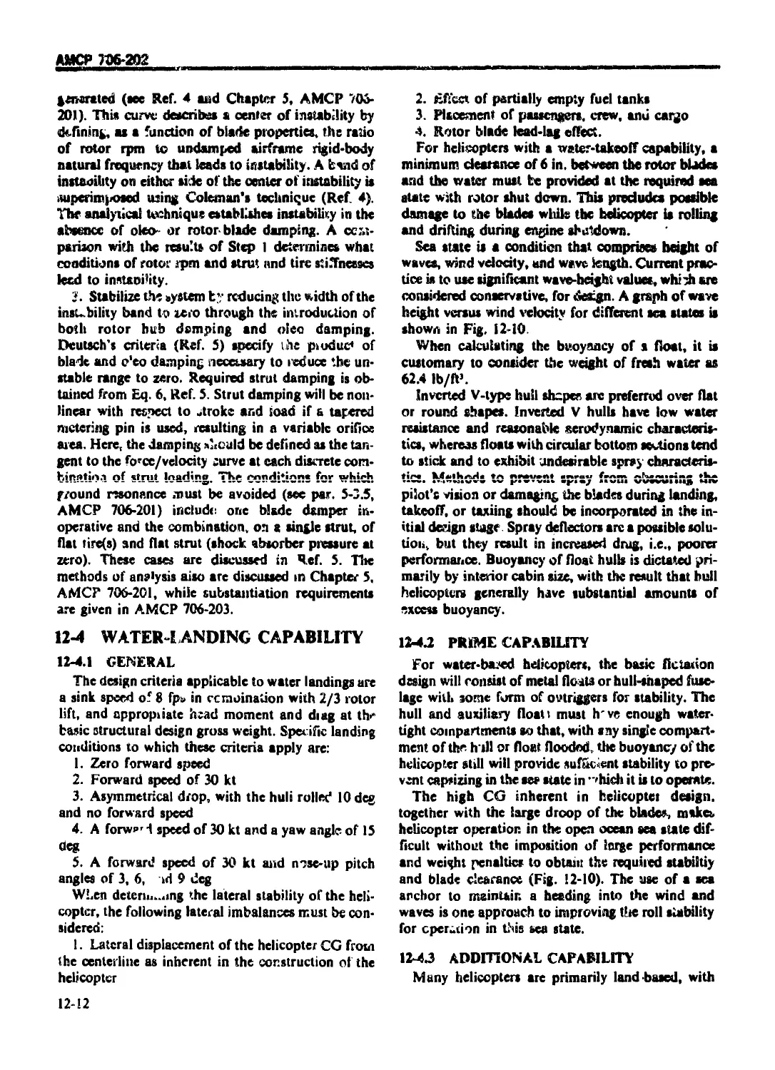
Year: 1976
Similar


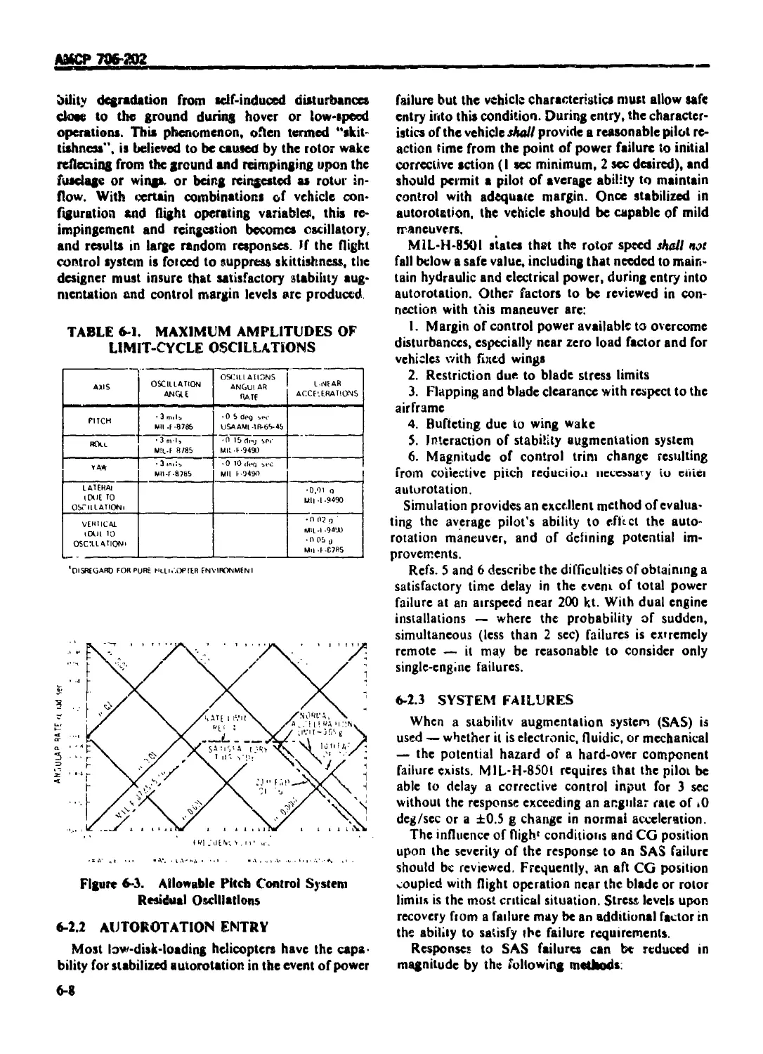
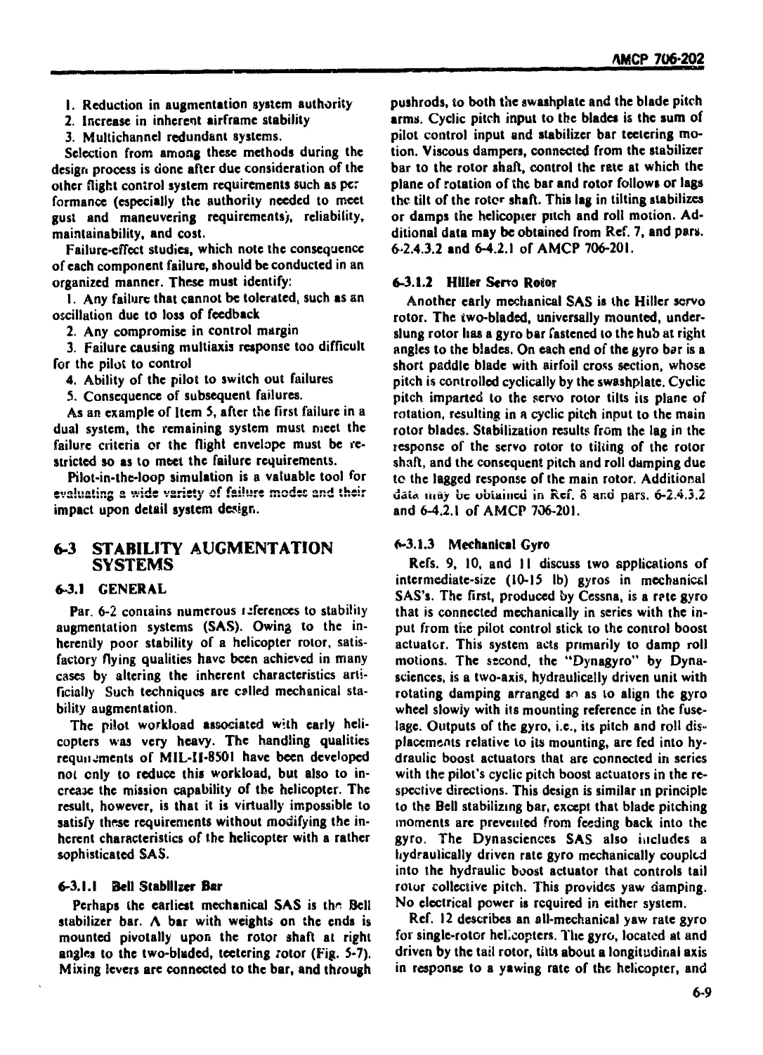
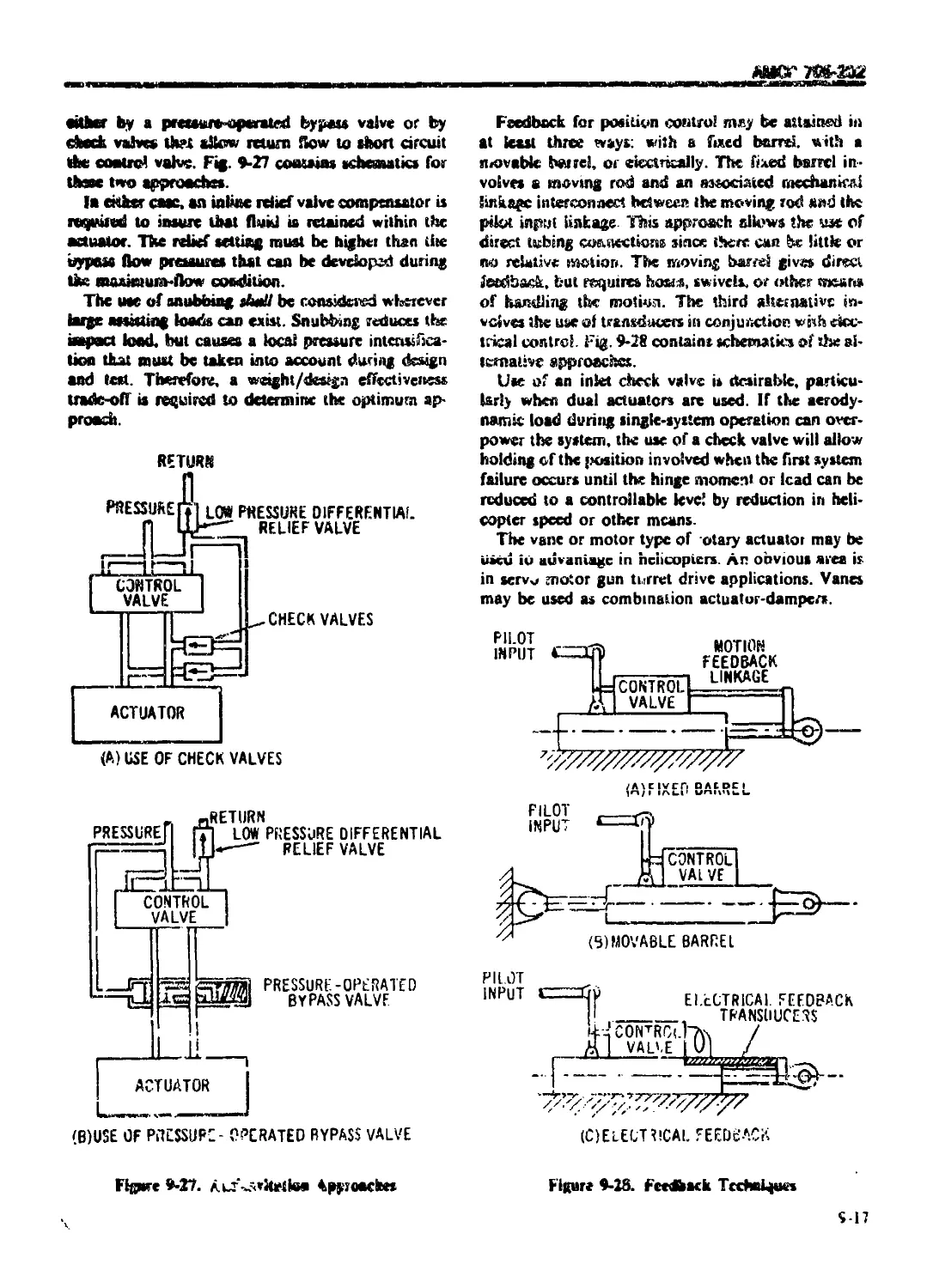
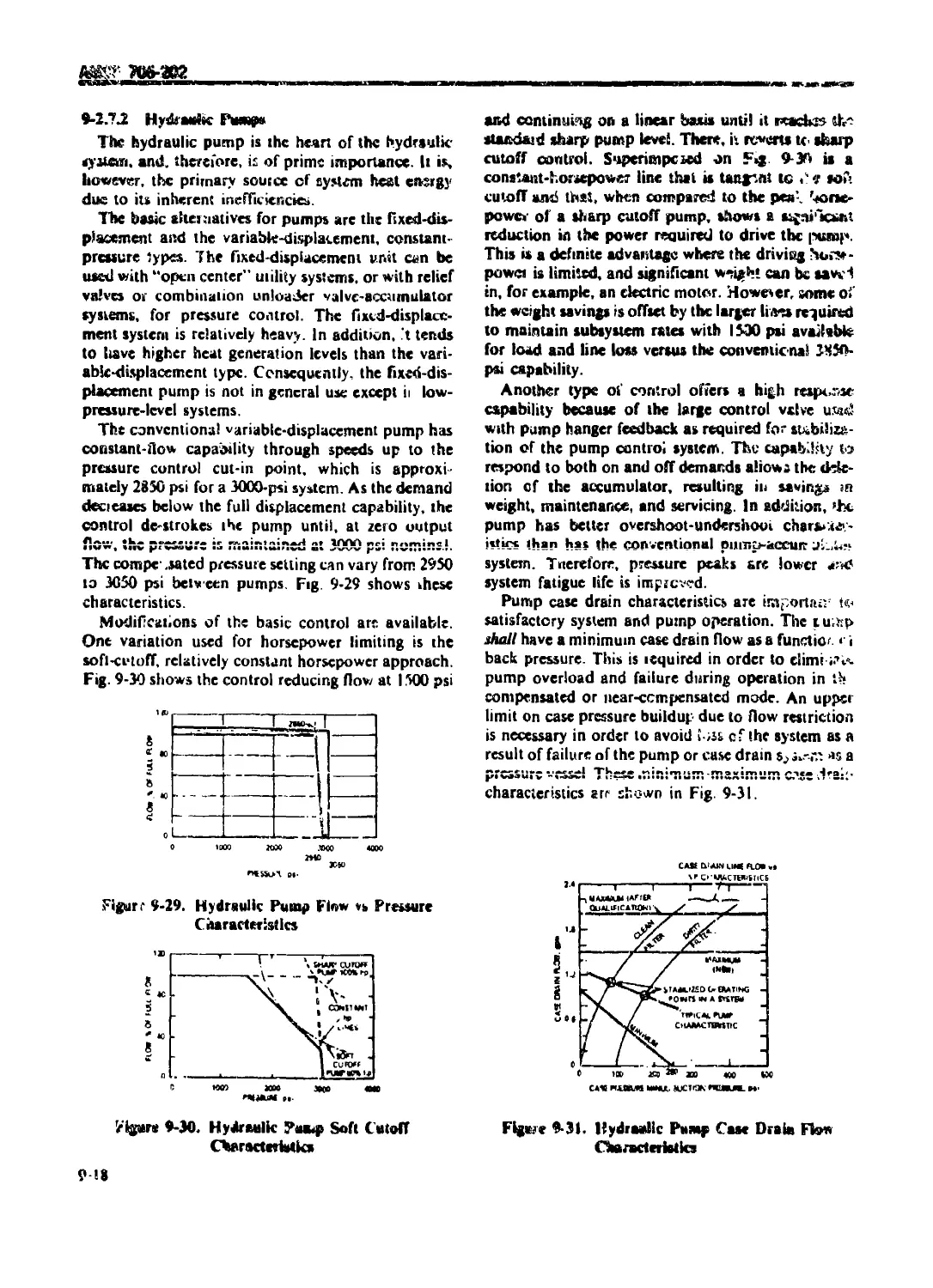
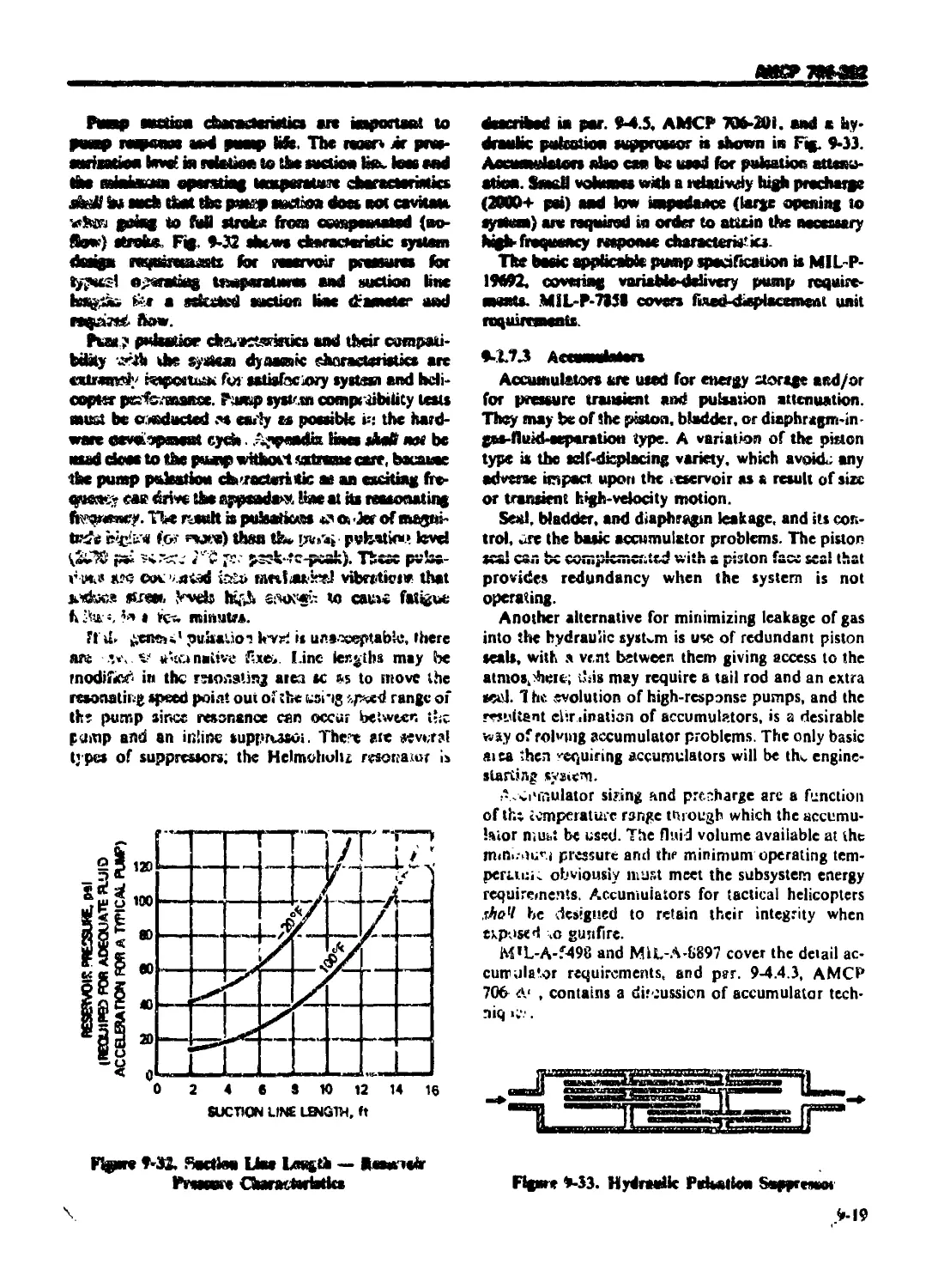
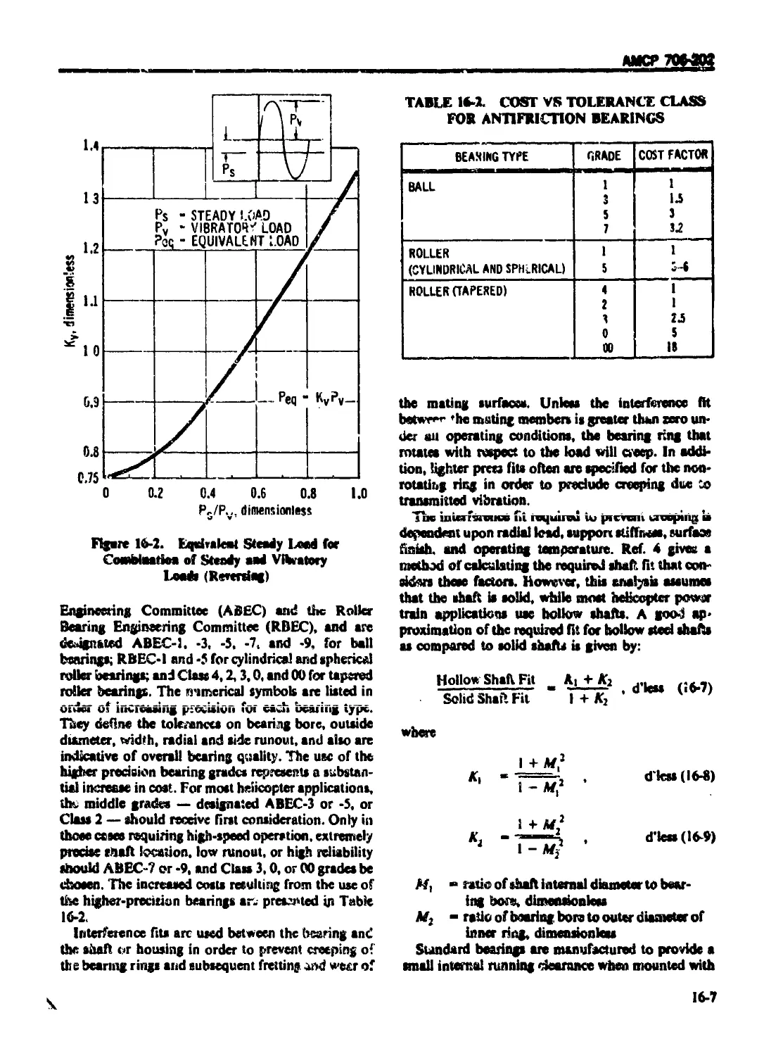
Text
AMC PAMPHLET
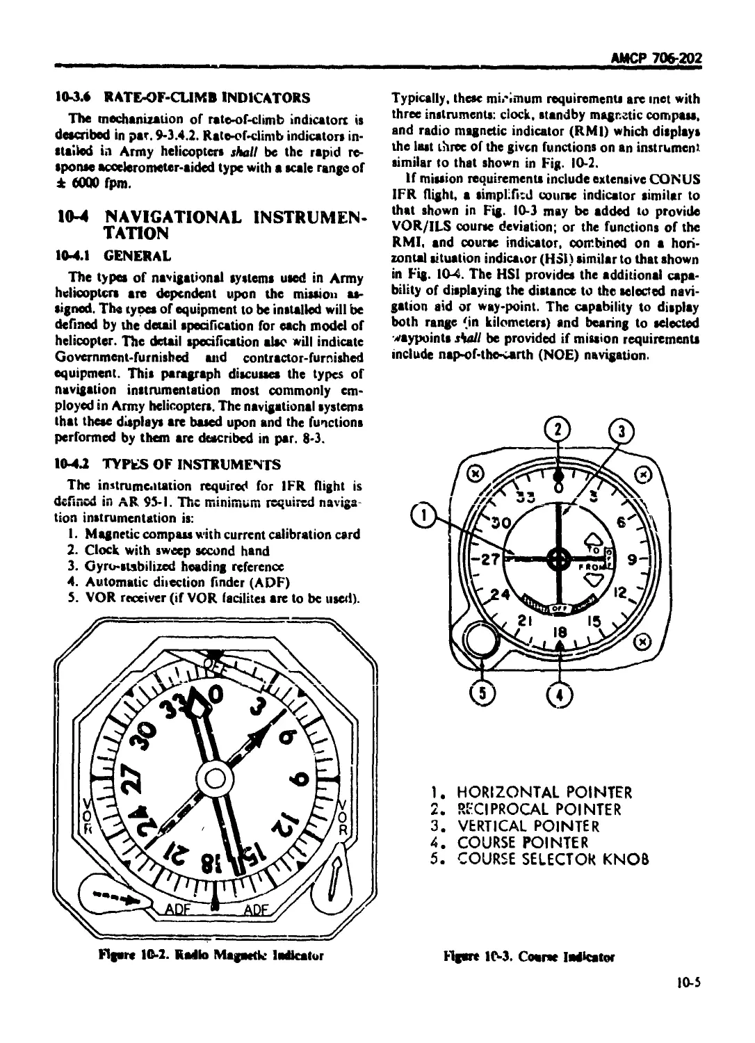
АМСР 706-202
ENGINEERING DESIGN
HANDBOOK
HELICOPTER ENGINEERING
PART TWO
DETAIL DESIGN
HEADQUARTERS, US ARMY MATERIEL COMMAND
JANUARY 1(76
АМОР 706-202
1)1 ГАК I MINI <)l IHI АКАП
IIEADQl AR I F RS I S ARMA M \ l IRIII СОММАМ)
5(Ю I l isinho«cr Me.. Alicandria. A \ 22333
AMC Pamphlet
No. 706-202 20 January 1976
ENGINEERING DESIGN HANDBOOK
HELICOPTER ENGINEERING, PART TWO
DETAIL DESIGN
TABLE Or CONTENTS
Paragraph Pape
LIST OF ILLUSTRATIONS ..................................... xxviii
LIST OF TABLES ............................................. xxxix
FOREWORD ................................................... xxxm
PREFACE ................................................... xxxviii
CHAPTER I
INTRODUCTION
CHAPTER 2
MATERIALS
2-1 INTRODUCTION ............................ ............... 2-1
2-2 METALS .................................................. 2-1
2-2.1 FERROUS METALS ........................................ 2-1
2-2.1.1 General ................................................... 2-1
2-2.1.2 Cai bon Steels ............................................. 2-1
2-2.1.3 Aliov Steels ............................................... 2-2
2-2.1.4 Stainless Steels ........................................... 2-2
2-2.1.5 Precipitation Hardening Steels ............................. 2-2
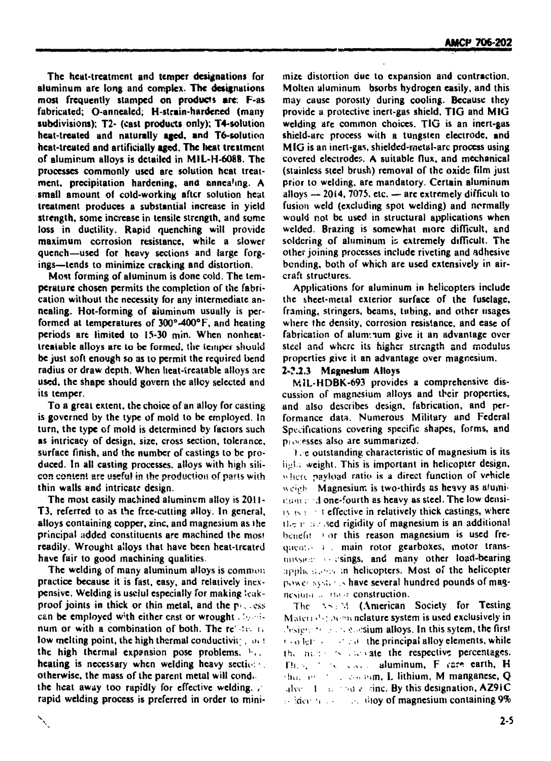
2-2.1.6 Maraging Steels ............................................ 2-3
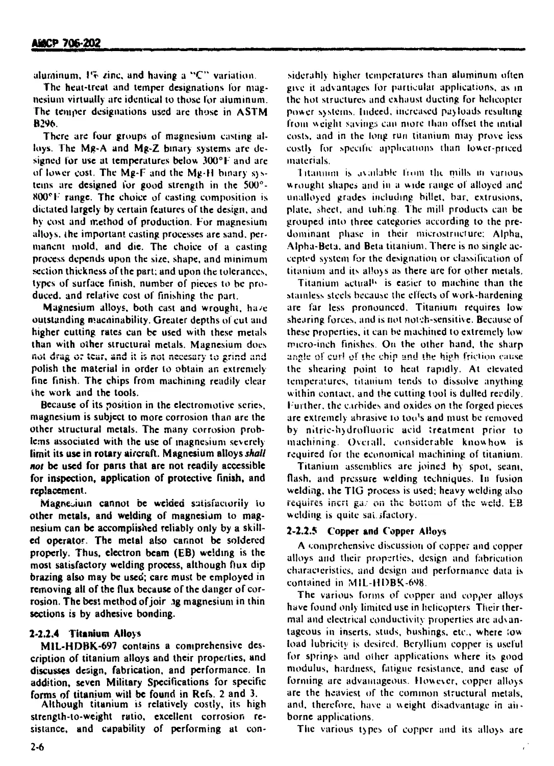
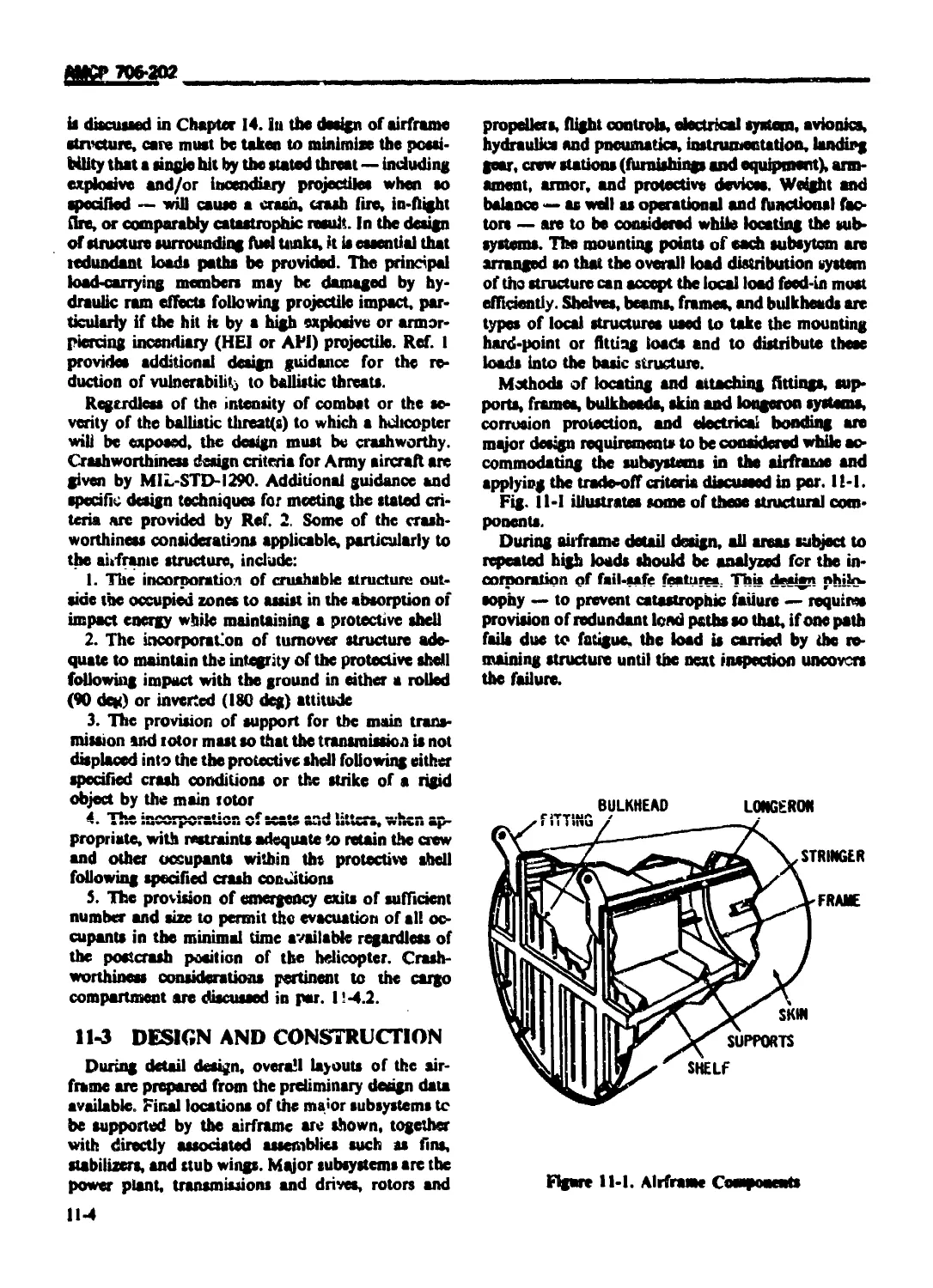
2-2.2 NONFERROUS METALS...................................... 2-4
2-2.2.1 General .................................................... 2-4
2-2.2.2 Aluminum Alloys ............................................ 2-4
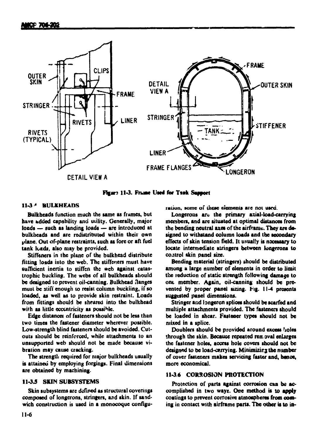
2-2.2.3 Magnesium Alloys ........................................... 2-5
2-2.2.4 Titanium Alloys ............................................ 2-6
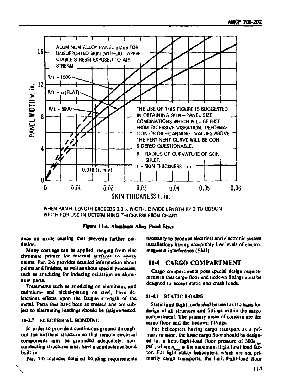
2-2.2.5 Copper and Copper Alloys ................................... 2-6
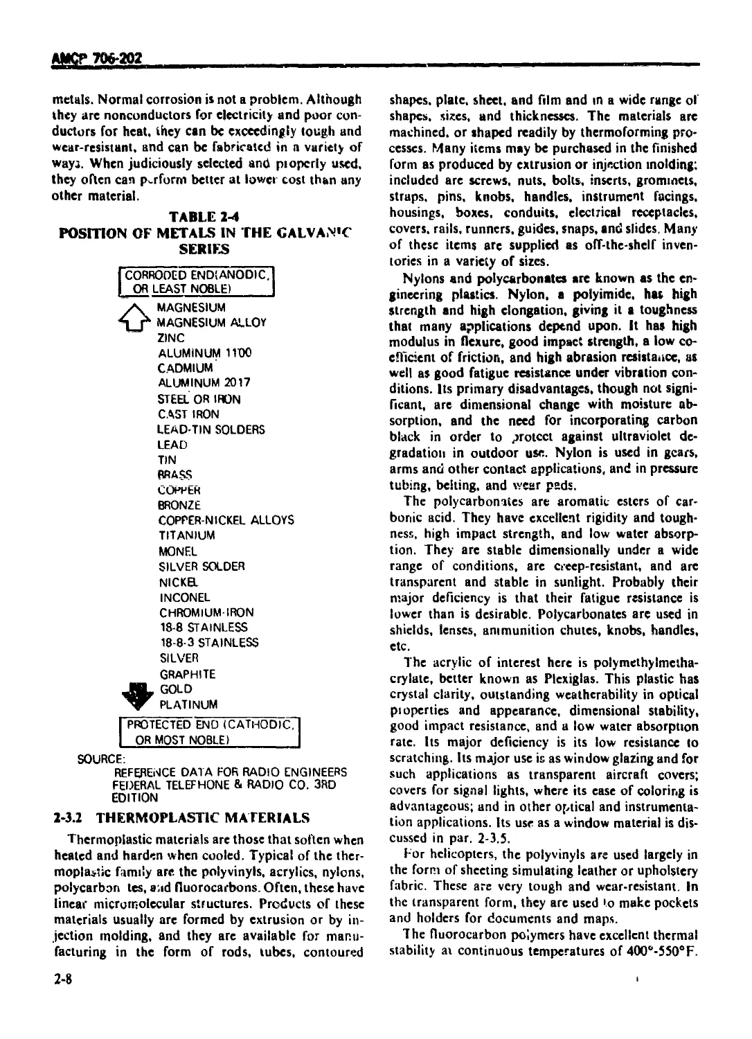
2-2.3 ELECTROLYTIC ACTION OF DISSIMILAR METALS.................... 2-7
2-3 NOMETALLIC MATERIALS .................................... 2-7
2-3.1 GENERAL .................................................... 2-7
2-3.2 THERMOPI ASTIC MATERIALS ................................... 2-8
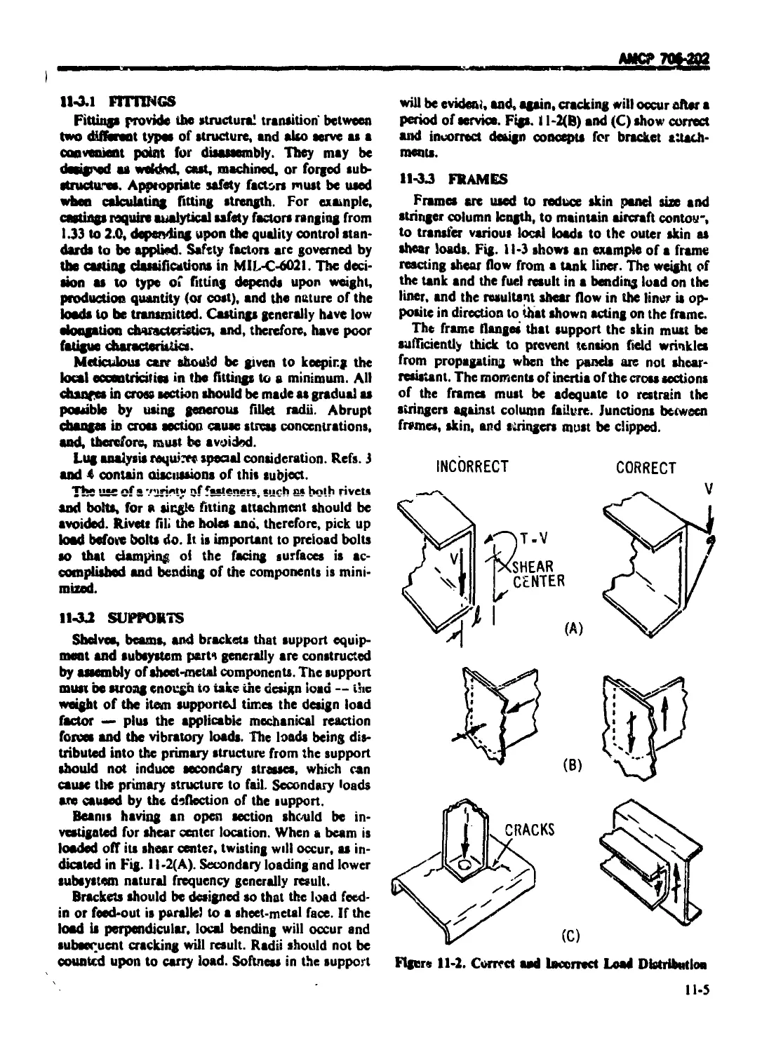
2-3.3 THERMOSETTING MATERIALS .................................... 2-9
2-3.4 ELASTOMERIC MATERIALS ..................................... 2-10
2-3.5 WINDOW MATERIALS .......................................... 2-10
2-4 COMPOSITE STRUCTURES .................................... 2-11
2-4.1 FIBERGLAS LAMINATES ....................................... 2-11
2-4.1.1 Design Considerations ................................. 2-11
2-4.1.2 Resin Systems ......................................... 2-12
2-4.1'. । Polyesters ................................................ 2-12
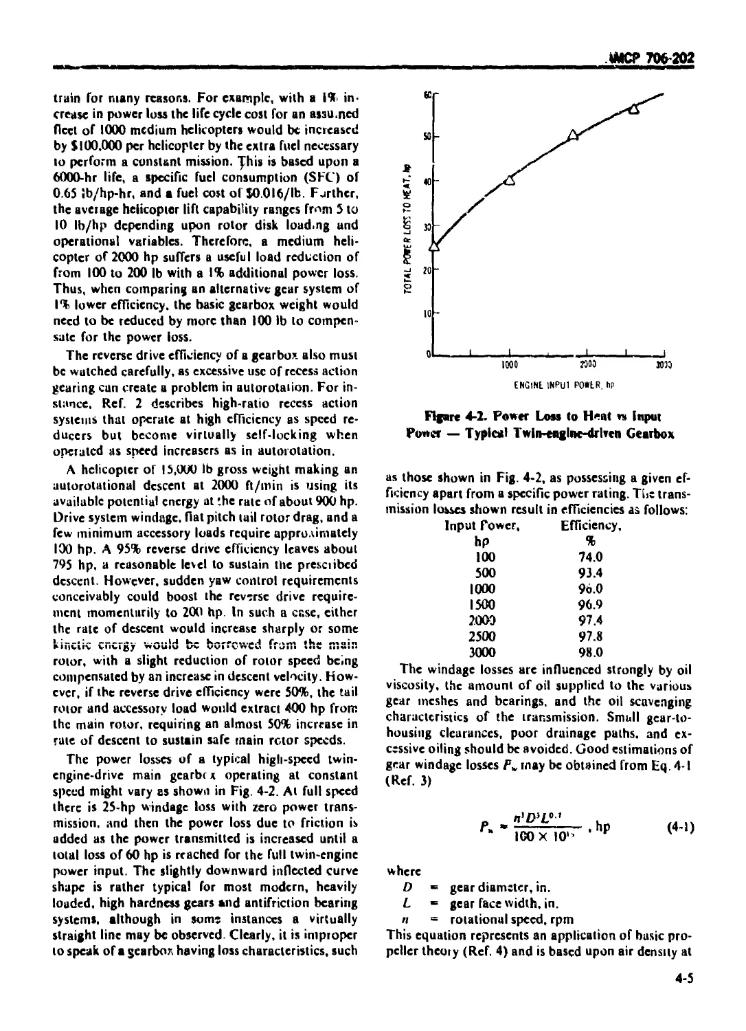
2-4.1.2.2 Epoxies ................................................... 2-12
2-4.1.2.3 Phenolics ................................................. 2-12
АМСР 706-202
TABLE OF CONIENIS (Continued)
Paragraph Pagi
2-4.13 Types of Reinforcement ........................................ 2-12
2-4.1.3.1 Nonwoven Continuous Filaments ................................. 2-13
2-4.1.3,2 Woven Fabric .................................................. 2-13
2-4.1.3.3 Chopped Fiber .............................................. 2-13
2-4.1.4 Fabrication Methods ........................................... 2-13
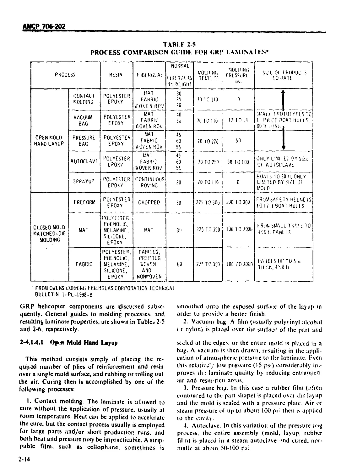
2-4.1.4.1 Open Mold Hand Layup .......................................... 2-14
2-4.1.4.2 Sprayup 2-15
2-4.1.4.3 Matched Die Molding ......................................... 2>15
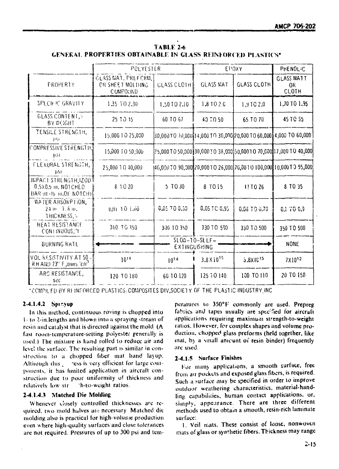
2-4.1.5 Surface Finishes .............................................. 2-15
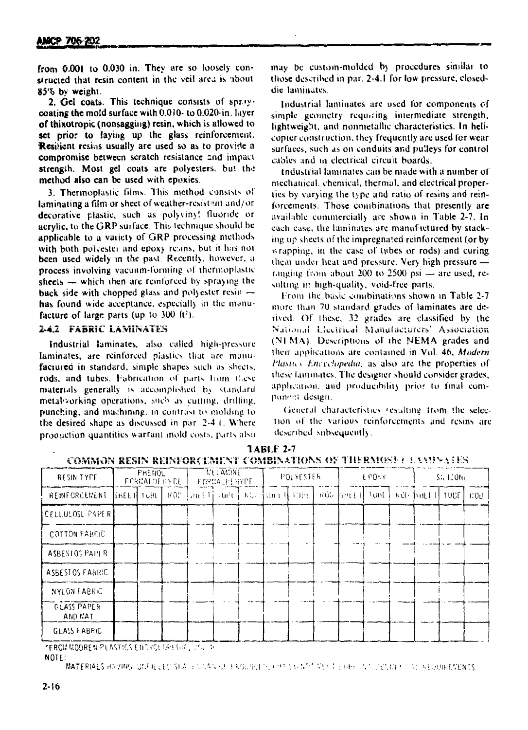
2-4.2 FABRIC LAMINATES ................................................. 2-16
2-4.2.1 Reinforcement Selection ....................................... 2-17
2-4.2.2 Resin Selection ............................................... 2-17
2-4.2.3 Special Types ................................................. 2-17
2-4.2.4 Specifications ................................................ 2-17
2-4.3 FILAMENT COMPOSITION ....................................... 2-17
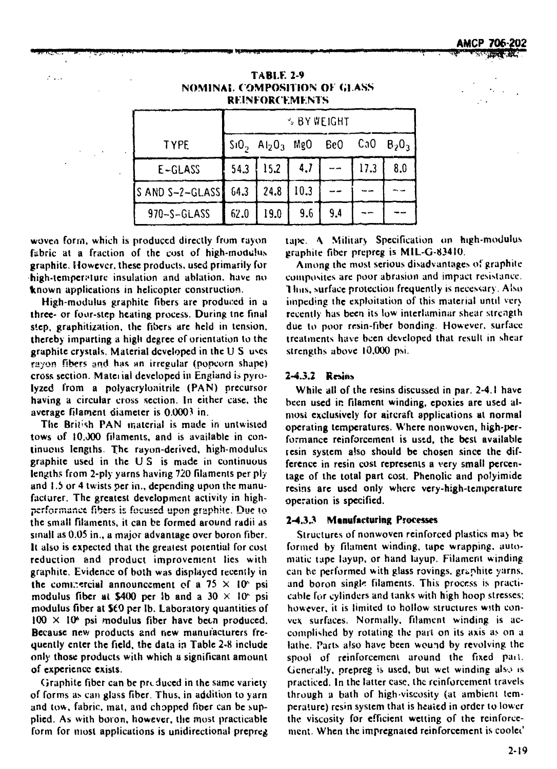
2-4.3.1 Types of Reinforcement ........................................ 2-18
2-4.3.1.1 E-glass ....................................................... 2-18
2-4.3.1.2 S-glass ....................................................... 2-18
2-4.3.13 Boron Filaments ............................................... 2-18
2-4.3.1.4 Graphite ...................................................... 2-18
2-4 3.2 Resins ........................................................ 2-19
2-4.3.3 Manufacturing Processes ....................................... 2-19
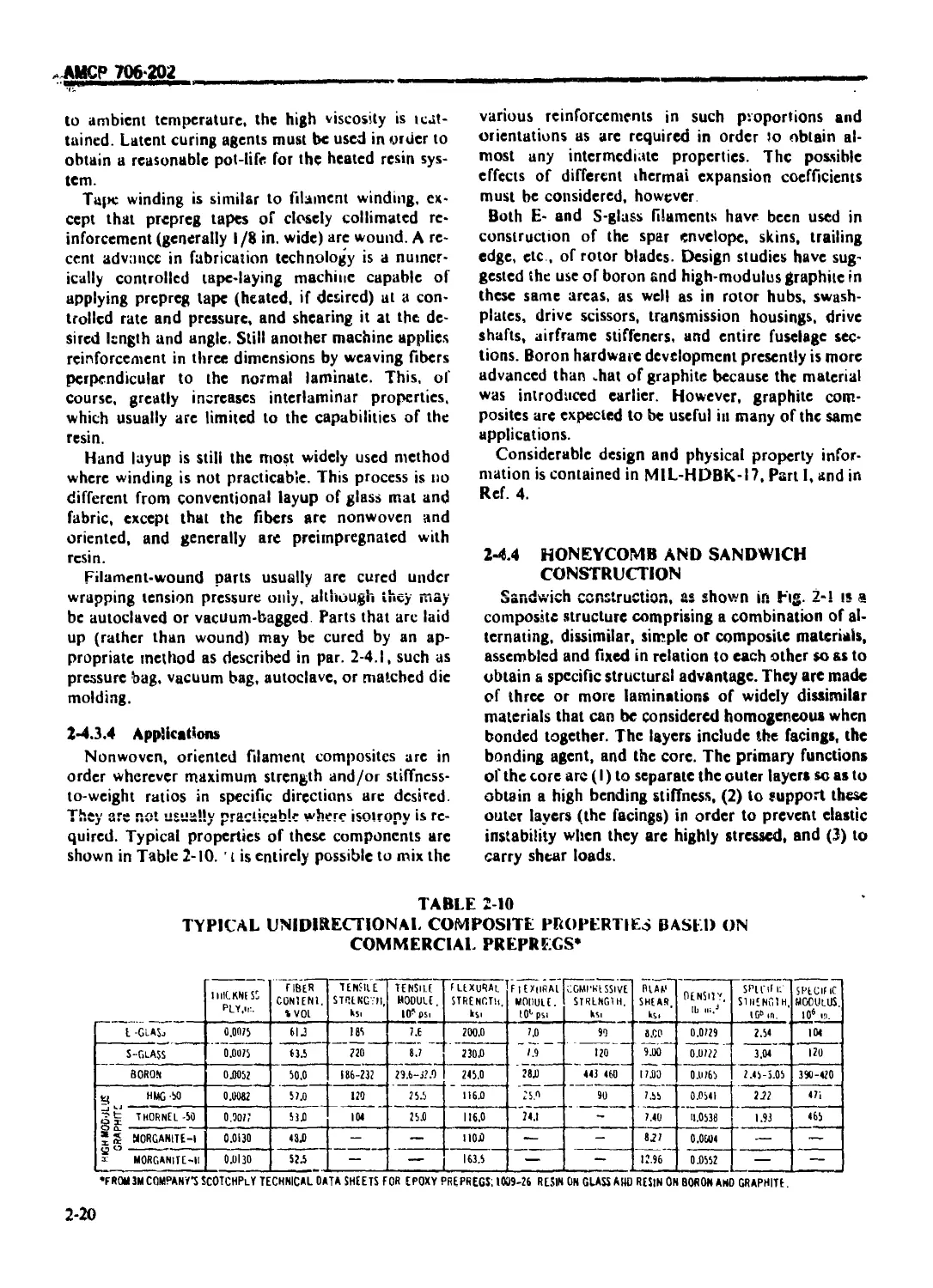
2-4,3.4 Applications .................................................. 2-20
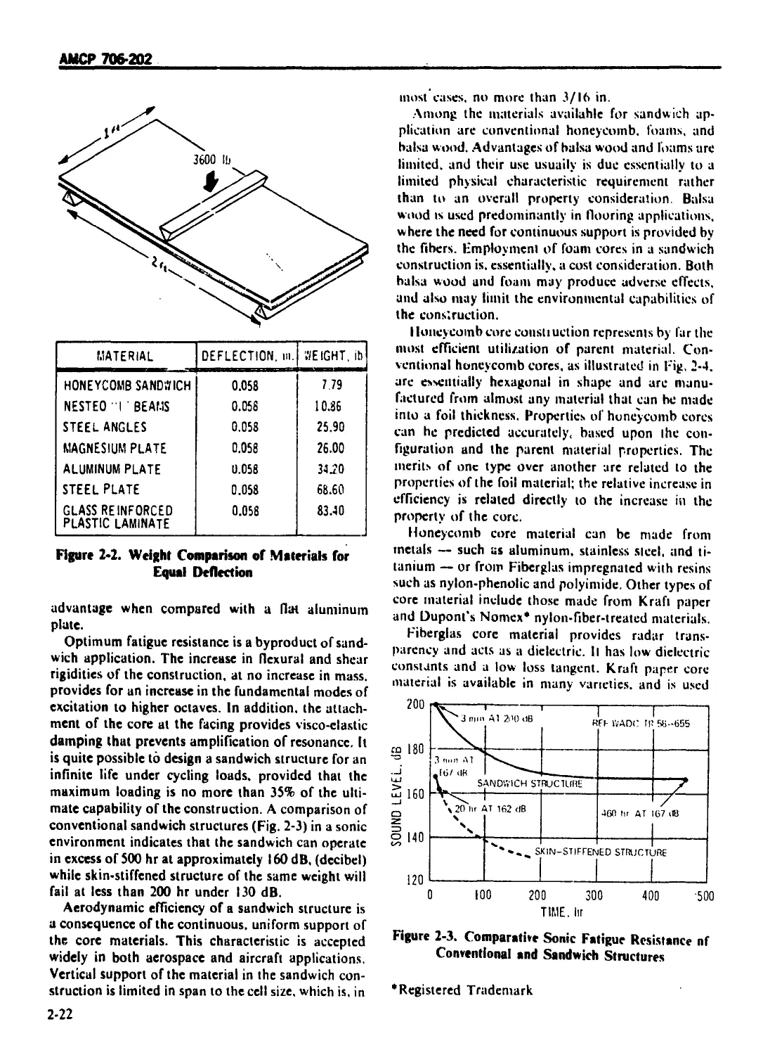
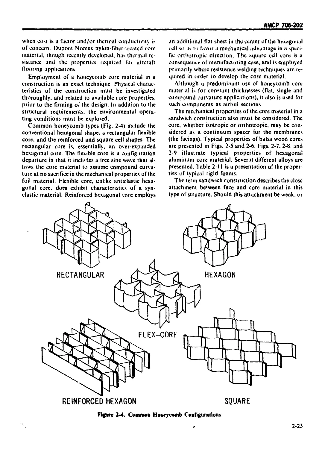
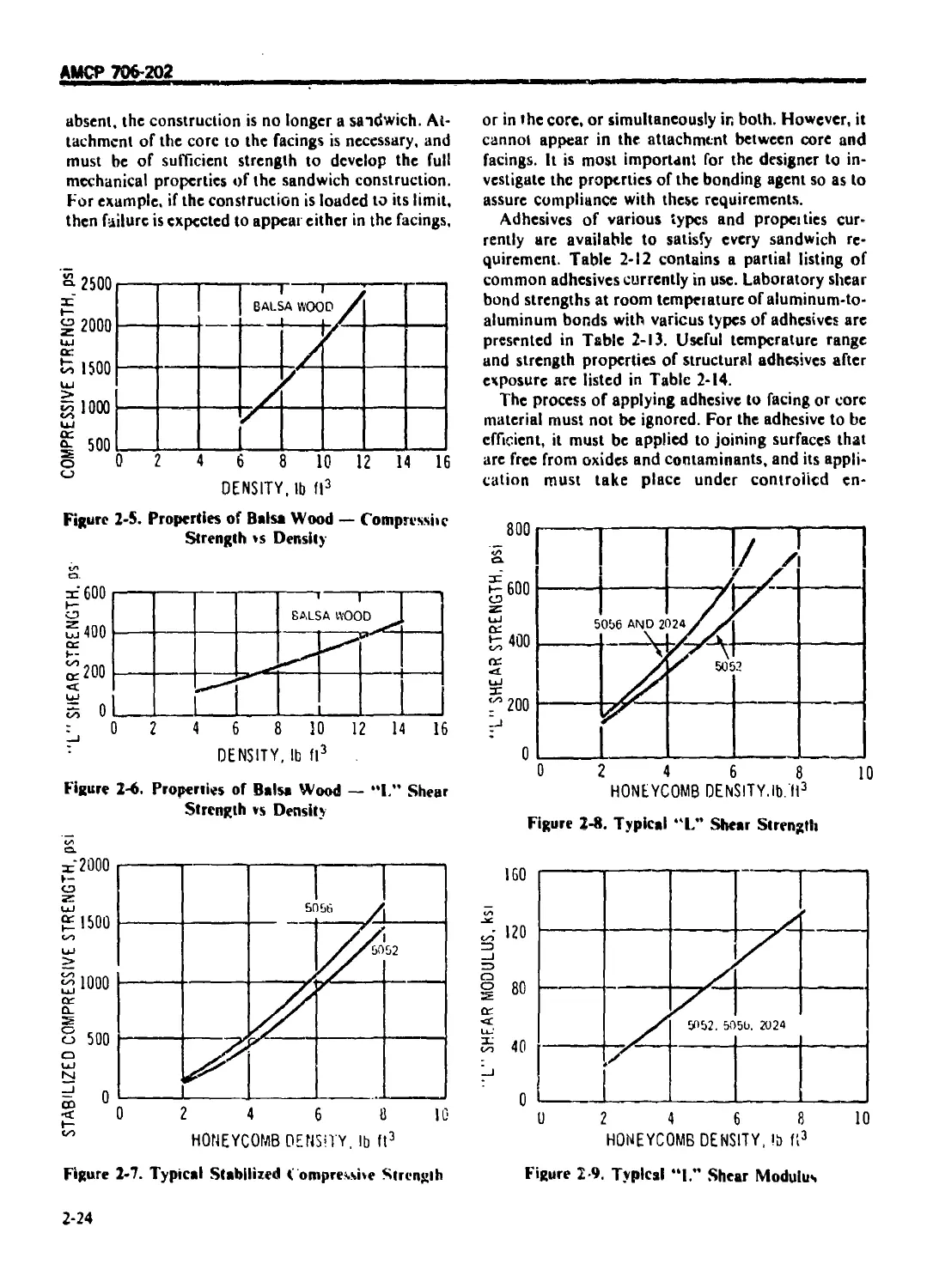
2 4 4 HONEYCOMB AND SANDWICH CONSTRUCTION ........................... 2-20
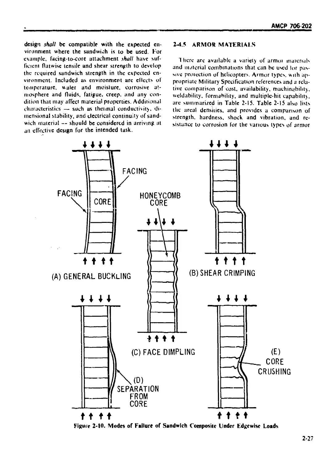
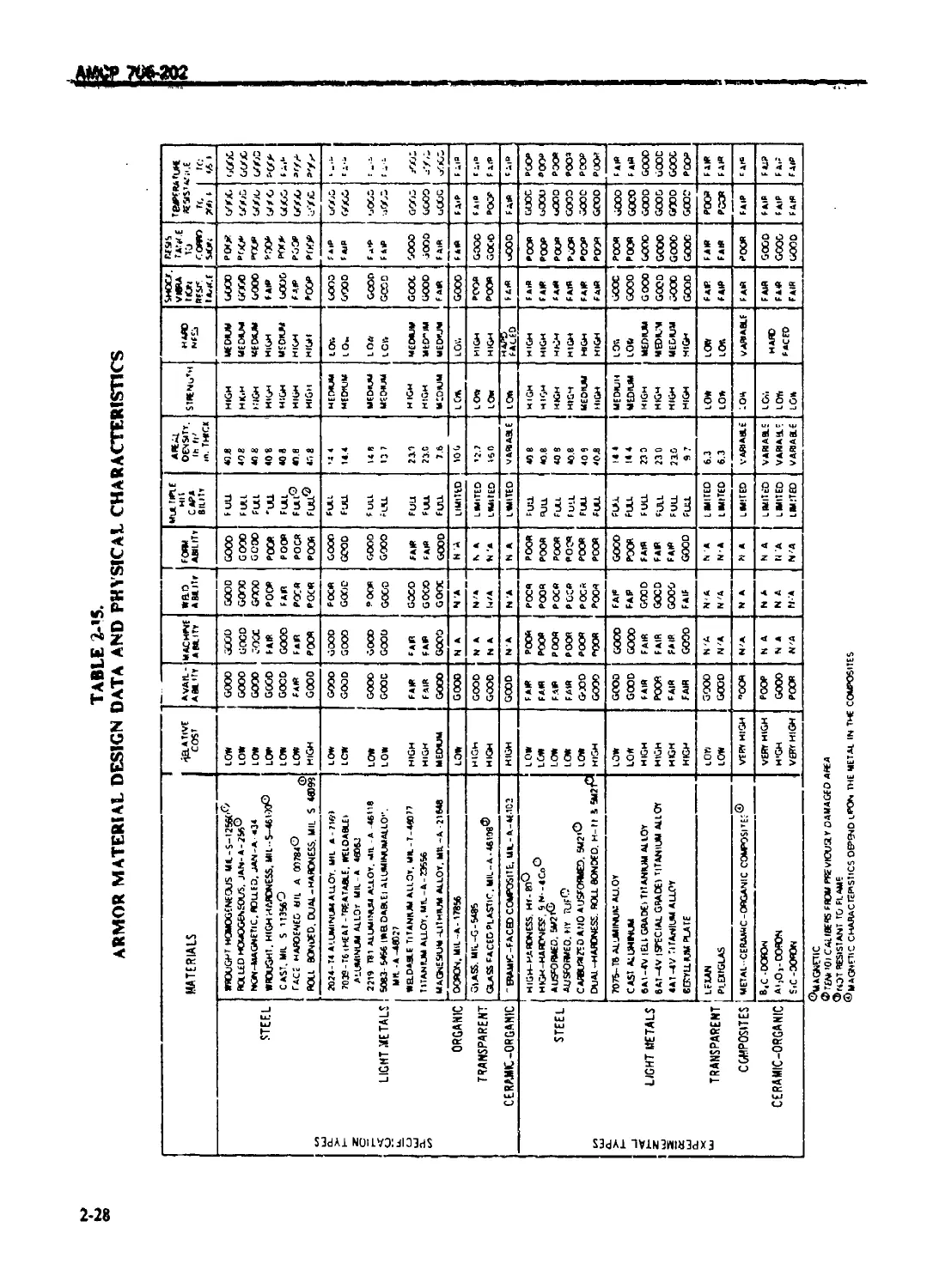
2-4.5 ARMOR MATERIALS ............................................... 2-2/
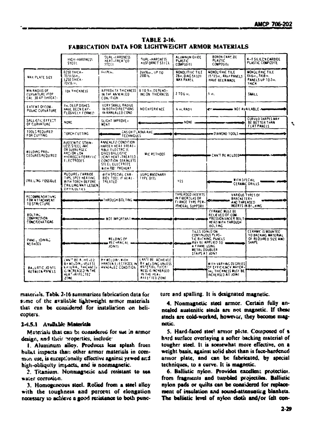
2-4.5.1 Available Materials .......................................... 2-29
2-4 5.2 Design ........................................................ 2-30
2-5 ADHESIVES AND SEALANTS ........................................... 2-30
2-5.1 BONDING AGENTS ................................................ 2-30
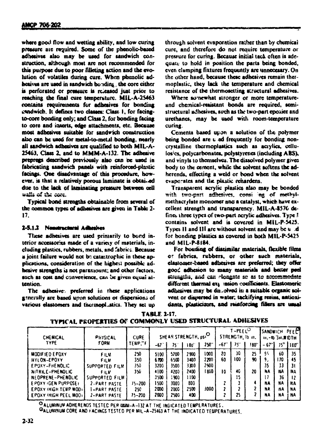
2-5.1.1 Structural Adhesives .......................................... 2-30
2-5.1.2 Nonstructural Adhesives ....................................... 2-32
2-5.1.3 Processing Operations ......................................... 2-33
Z-5.L4 Desigi'i of Bonded Structures 2-33
2-5.2 SEALING COMPOUNDS ............................................. 2-33
2-6 PAINTS AND FINISHES .............................................. 2-34
2-6.1 PAINTS AND COATINGS (ORGANIC) ................................. 2-34
2-6.2 SPECIAL FINISHES .............................................. 2-35
2-6.3 PLATING ....................................................... 2-36
2-6.4 TAPES ........................................................ 2-37
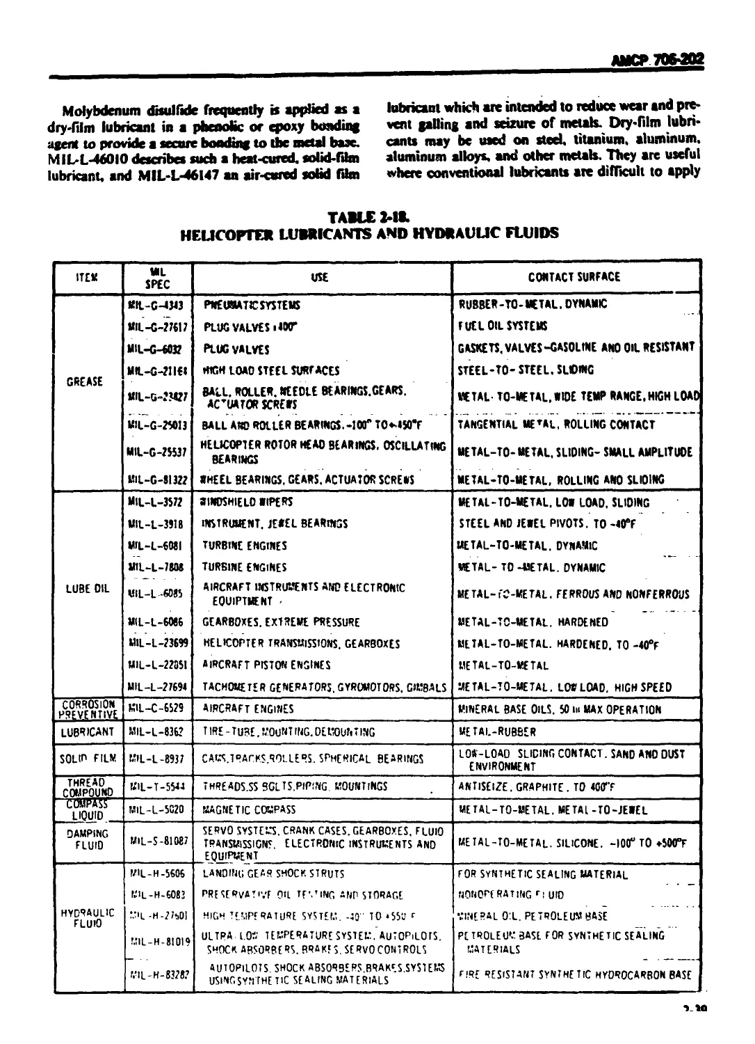
2-7 LUBRICANTS.GREASES. AND HYDRAULIC FLUIDS .................. 2-38
2-7.1 GENERAL ....................................................... 2-38
2-7.2 DESIGN OF LUBRICATION SYSTEMS ............................. 2-38
2-7.3 GREASES ... 2-38
2-7.4 DRY FILM AND PERMANENT LUBRICANTS ............................. 2-38
2-7 5 HYDRAULIC FLUIDS .............................................. 2-40
REFERENCES ...................................................... 2-40
CHAPTER 3
PROPl T.SION SUBSYSTEM DESIGN
3-0 LIST OF SYMBOLS ................................................... 3-1
ii
АМСР 706-202
TABLE ОЕ CONTENTS ((<»ntinued)
Paragraph Page
3-1 INTRODUCTION ................................................ГГТ* 3-1
3-2 ENGINE INSTALLATION .............................................. 3-i
3-2.1 GENERAL ....................................................... 3-1
3-2.1.1 Submerged Installation ........................................ 3-1
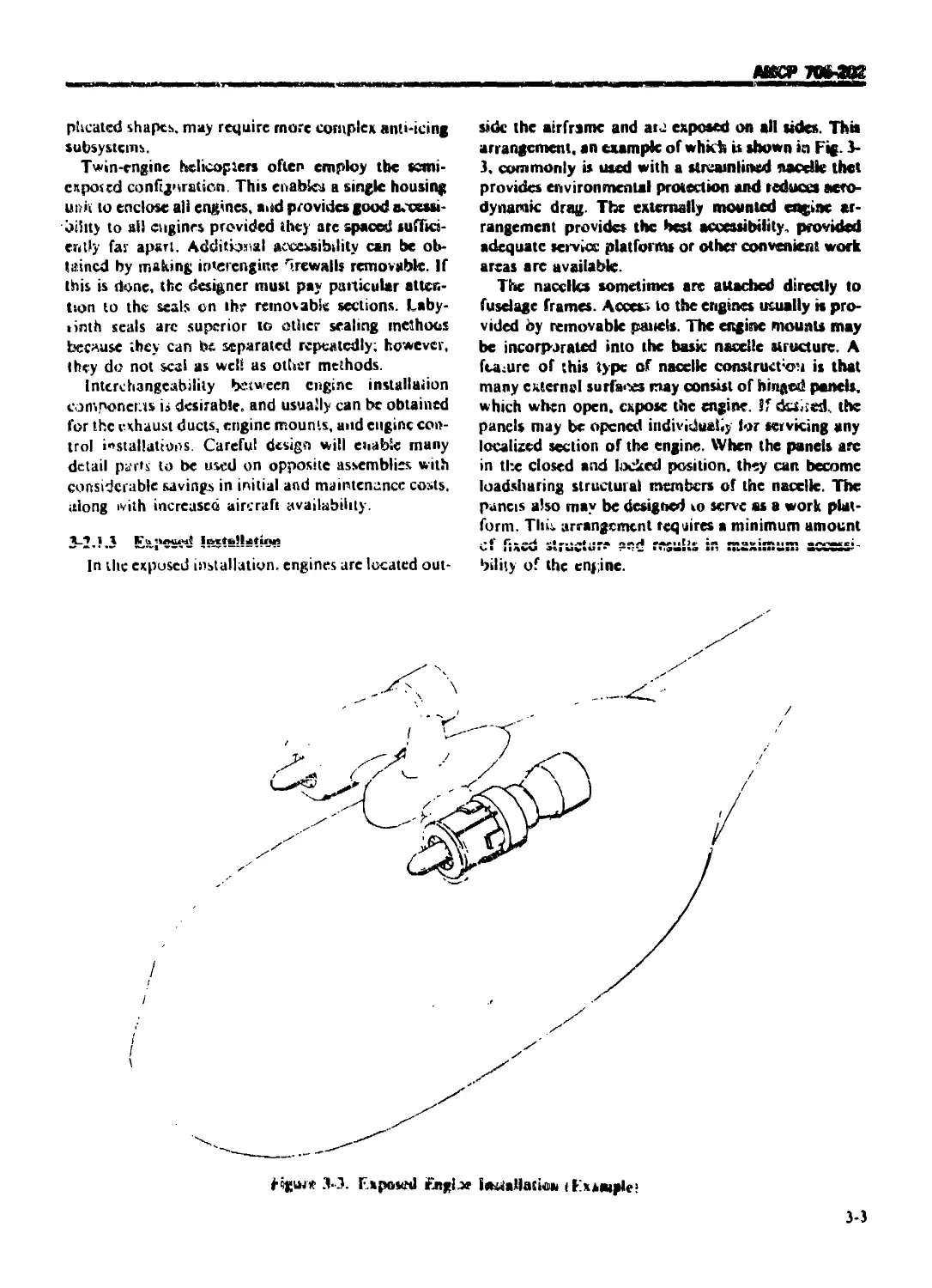
3-2.1.2 Semiexposed Installation ...................................... 3-1
3-2.1.3 Exposed Installation .......................................... 3-3
3-2.1.4 Design Checklist .............................................. 3-4
3-2.2 ENGINE MOUNTING ............................................... 3-4
3-2.3 ENGINE VIBRATION ISOLATION..................................... 3-5
3-2.4 FIREWALLS ..................................................... 3-5
3-2.4.1 Fire Detectors ................................................ 3-5
3-2.4.2 Fire Extinguishing ............................................ 3-6
3-2.5 ENGINE AIR INDUCTION SUBSYSTEM ................................ 3-6
3-2.5.1 Air Induction Subsystem Design ................................ 3-6
3-2.5.2 Inlet Protection ...............................................3-6
3-2.5.3 Anti-icing 3-7
3-2.5.3.1 Electrical Anti-icing ........................................ 3-7
3-2.5.3.2 Bleed Air Anti-icing ........................................ 3-7
3-2.5.3.3 Anti-icing Demonstration ...................................... 3-7
3-2.6 EXHAUST SUBSYSTEM .......................................... 3-7
3-2.6.1 Exhaust Ejectors ............................................. 3-8
3-2.6.2 Infiaicu (IR) Radiation Suppression .......................... '3-8
3-2.6.2.1 IR Suppression Requirements ................................... 3-8
3-2.6.2.2 Exhaust Suppressor ............................................ 3-9
3-3 PROPULSION CONTROLS .............................................. 3-9
3-4 FUEL SUBSYSTEM ................................................... 3-9
3-4.1 GENERAI..................................................... 3-9
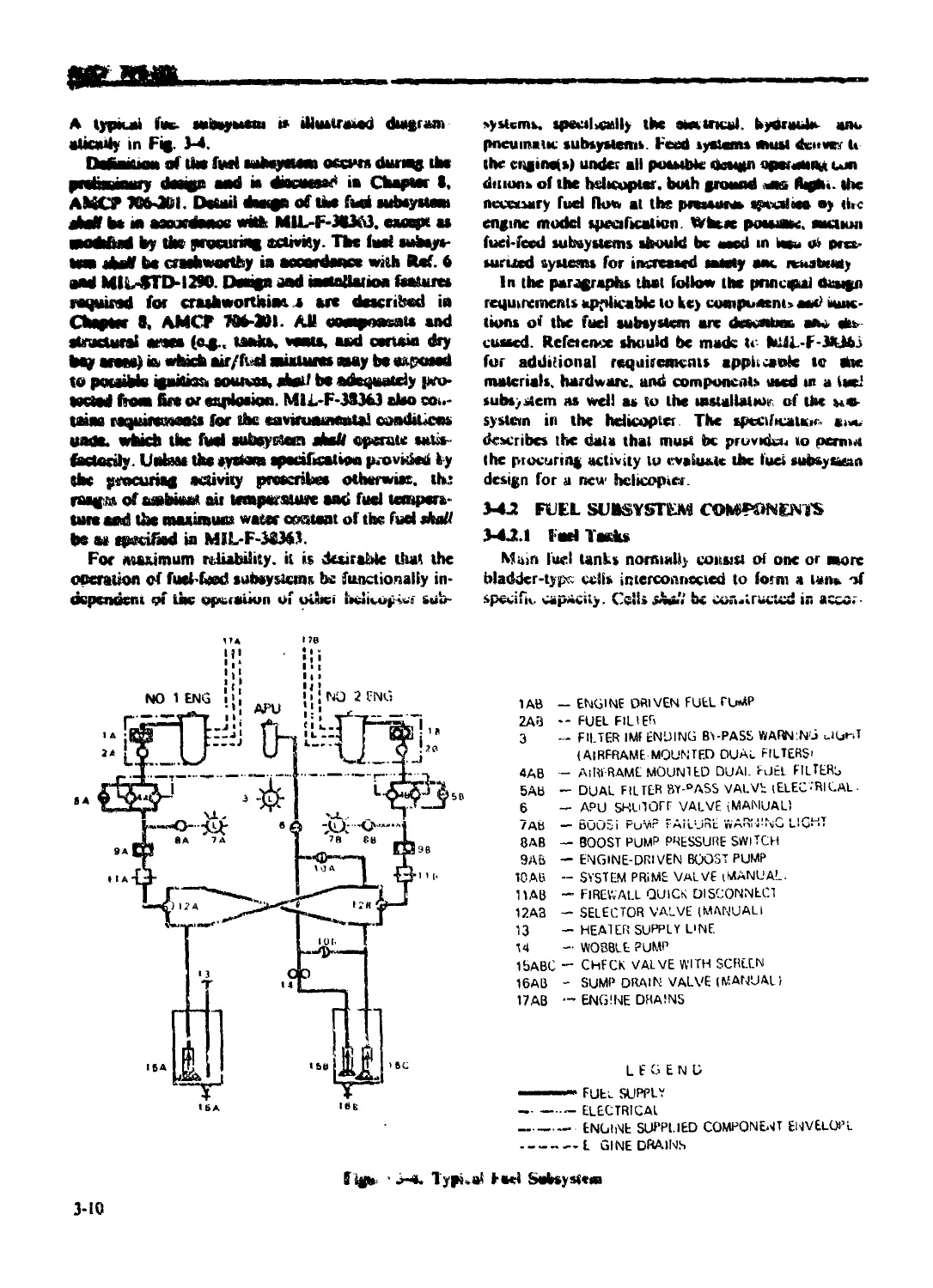
3-4.2 FUEL SUBSYSTEM COMPONENTS .................................... 3-10
3-4.2.1 Fuel Tanks .................................................. 3-10
3-4.2.2 Fuel Tank Vents .............................................. 3-11
3-4.2.3 Fuel Gaging .................................................. 3-11
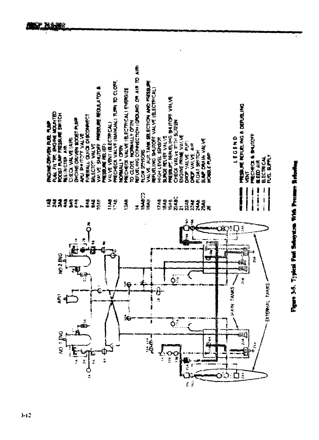
3-4.2.4 Refueling and Defueling ...................................... 3-11
3-4 2.5 Fuel Dumping ................................................. 3-13
3-4 2.6 Engine Feed System ........................................... 3-13
3-4.2.7 Fuel Drains .................................................. 3-13
3-4.2 Controls and Instrumentation ................................. 3-13
3-4.3 TESTING 3-13
3-5 LUBRICATION SUBSYSTEM ......................................... 3 14
3-6 COMPARTMENT COOLING ........................................... 3-14
3-7 ACCESSORIES AND ACCESSORY DRIVES .......................... 3-15
3-8 AUXILIARY POWER UNITS ( APU’s) ................................ 3 15
3-8.1 GENERAL ...................................................... 3-15
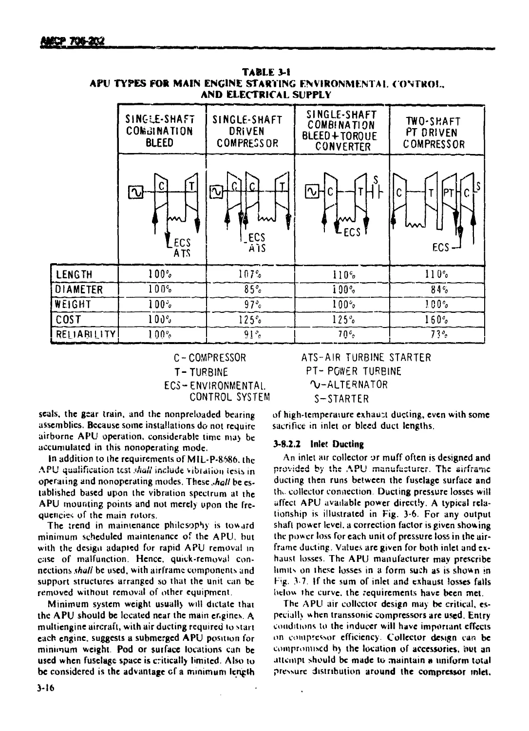
3-8 2 APU INSTALLATION DETAILS ..................................... 3-15
3-8.2.1 Method of Mounting ........................................... 3-15
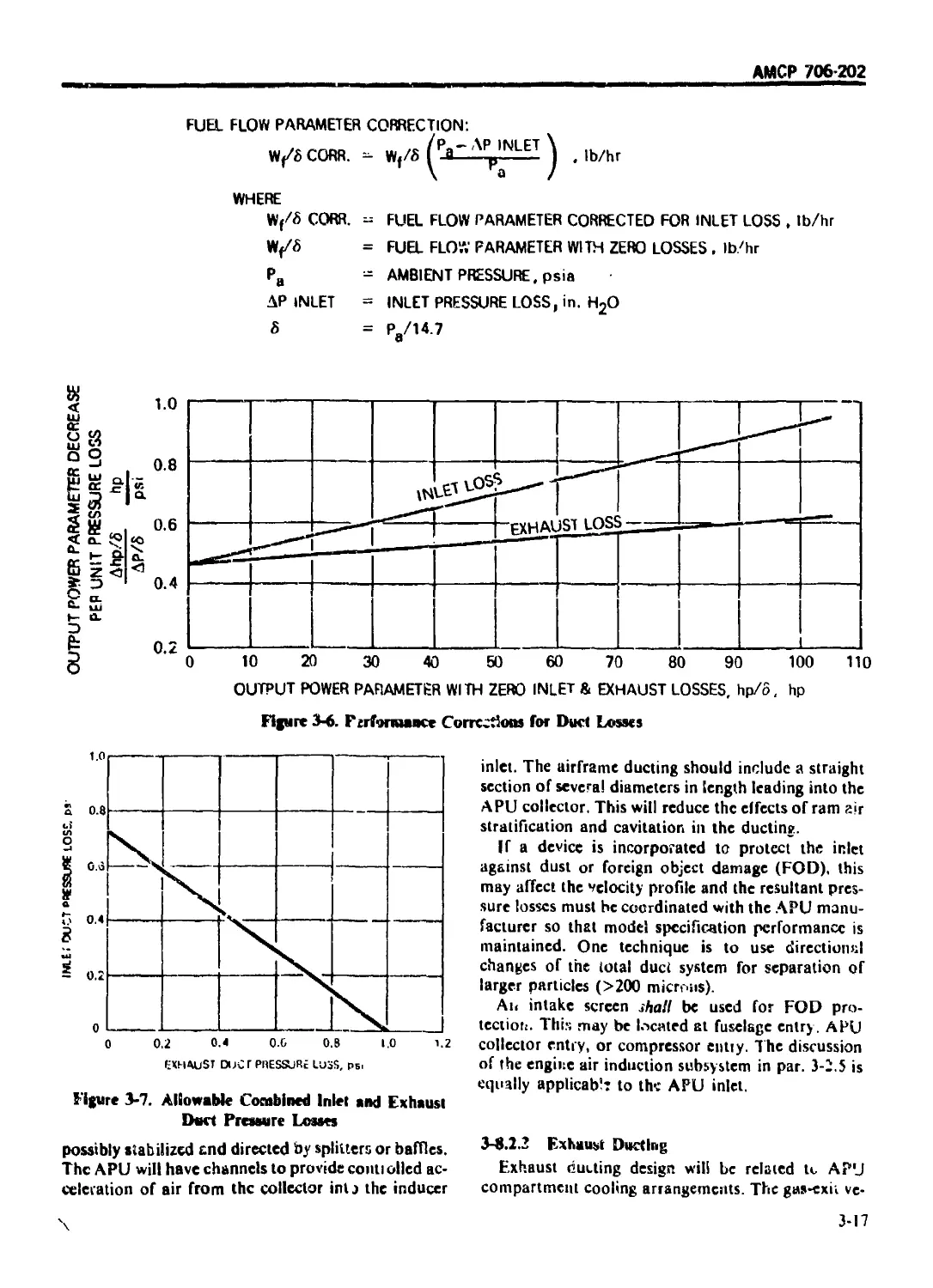
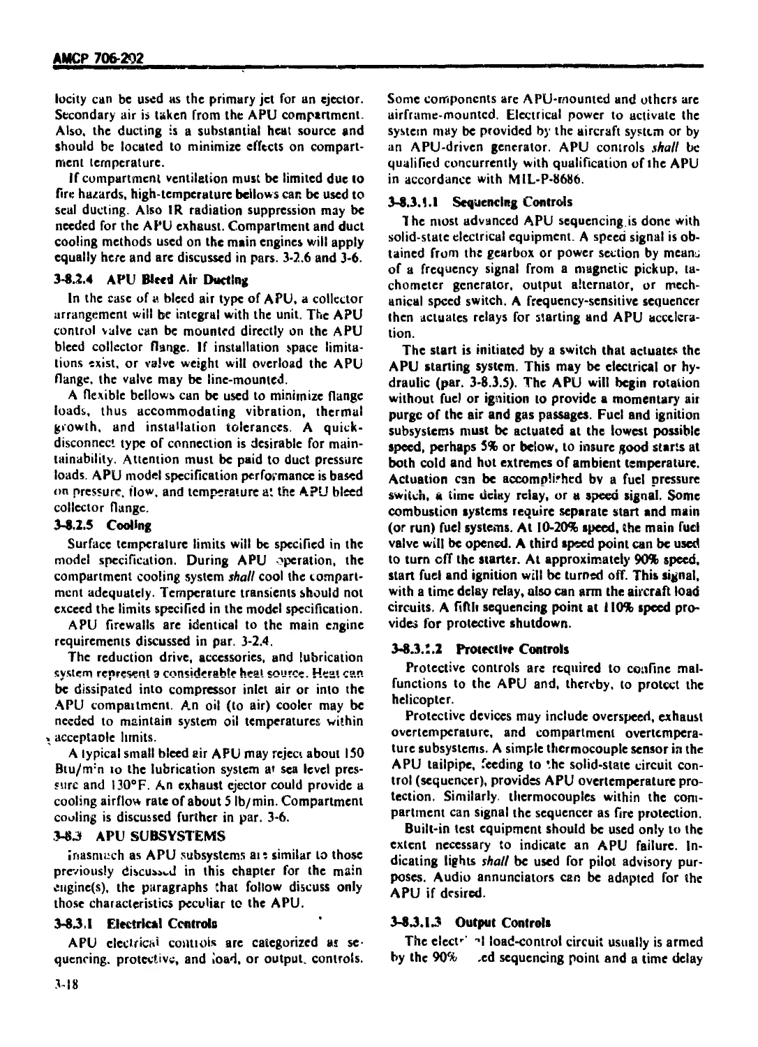
3-8.2.2 Inlet Ducting ................................................ 3-16
3-8.2.3 Exhaust Ducting ............................................ . 3-17
3-8.2.4 ' APU Bleed Air Ducting...................................... 3-18
3-8.2.5 Cooling ...................................................... 3-18
3-8.3 APU SUBSYSTEMS ............................................... 3-18
3-8.3.1 Electrical Controls .......................................... 3-18
iii
АМСР 706-202
TABLE (Ж COM ЕМ S i( ontinuvdi
Paragraph Pugc
3-8.3 1.1 Sequencing Controls ............................................ 3 18
3-8.3.1.2 Protective Controls ............................................... 3-18
3-8.3.13 Output Controls .................................................. 3-18
3-8.3.1.4 Electrical Control Location ....................................... 3-19
3-8.3.1.5 Electrical Power Requirements ..................................... 3-19
3-8.3.2 Fuel System Controls .............................................. 3-19
3-8.3 2.1 Rated Speed Governing ............................................. 3-19
3-8.3.2.2 Filtering Requirements ............................................ 3-19
3-8.3. APU Lubrication Subsystem ......................................... 3-20
3-8.3.4 APU Reduction Drive ............................................... 3-20
3-8.3.5 APU Starting ...................................................... 3-20
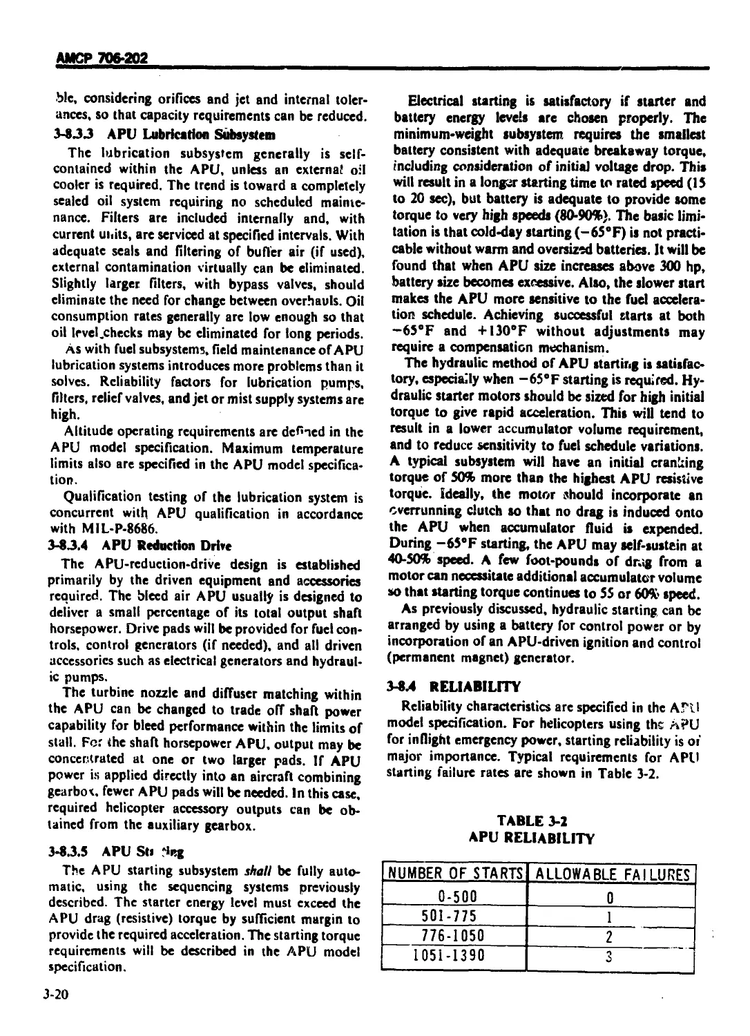
3-8.4 RELIABILITY ....................................................... 3-20
3-8.5 SAFETY PROVISIONS ................................................. 3-2l
REFERENCES ........................................................... 3-22
CHAPTER 4
TRANSMISSION AND DRIVE SUBSYSTEM DESIGN
4-0 LIST OF SYMBOLS ..................................... .............. 4-1
4-1 INTRODUCTION ....................................................... 4 3
4-LI GENERAI............................................................. 4-3
4-1.2 REQUIREMENTS ........................................................ 43
4-1.2.1 General Requirements ............................................... 4-3
4-1.2.1.1 Performance .................................................... 44
4-1.2.1.1.1 Subsystem Weight ............................................... 44
4-1.2.1.1.2 Transmission Efficiency ........................................ 44
4 1,2.1.1.3 SLe ............................................................... 4-11
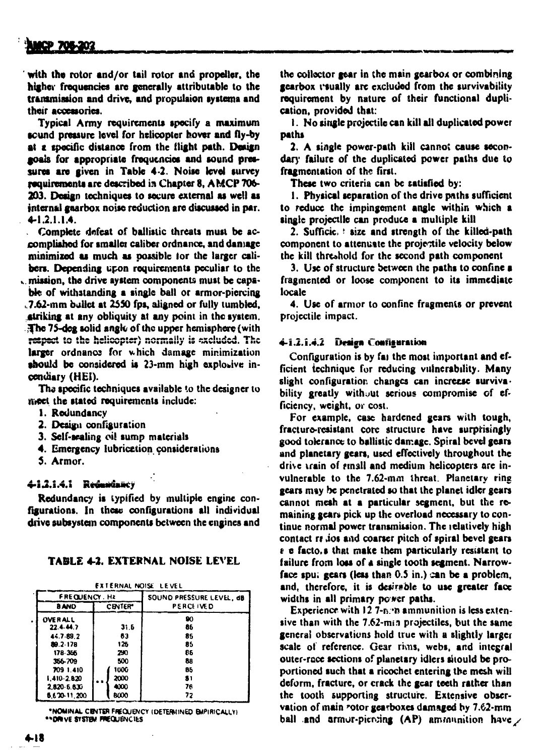
4-1.2.1.1.4 Noise Levels ................................................... 4-11
4-1.2.I.2 Reliability 4-12
4-1.2.1.3 Maintainability ................................................... 4-16
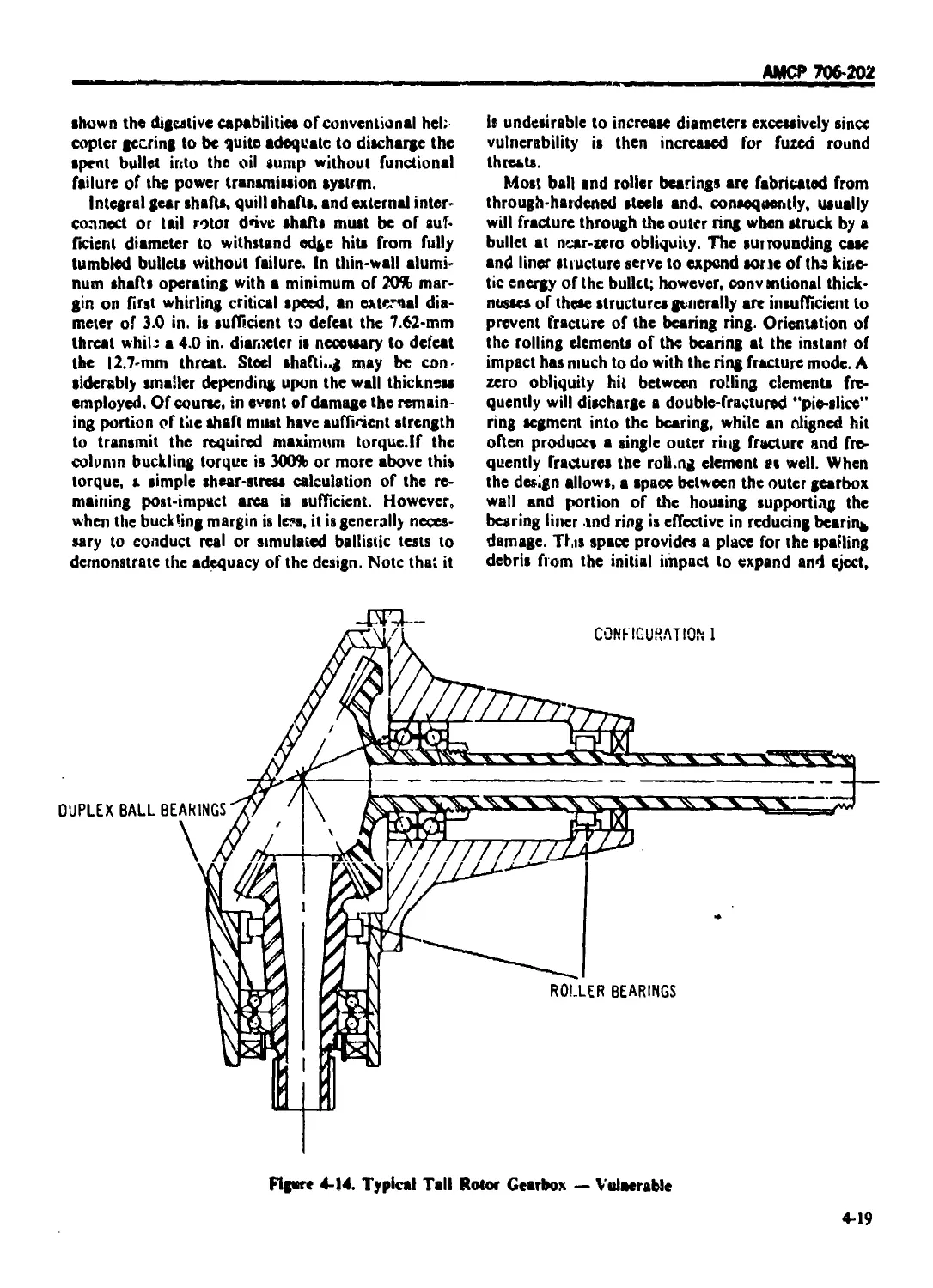
4-1.2.1.4 Survivability .................................................. 4-!7
4-1.2.1.4.1 Redundancy ........................................................ 4-18
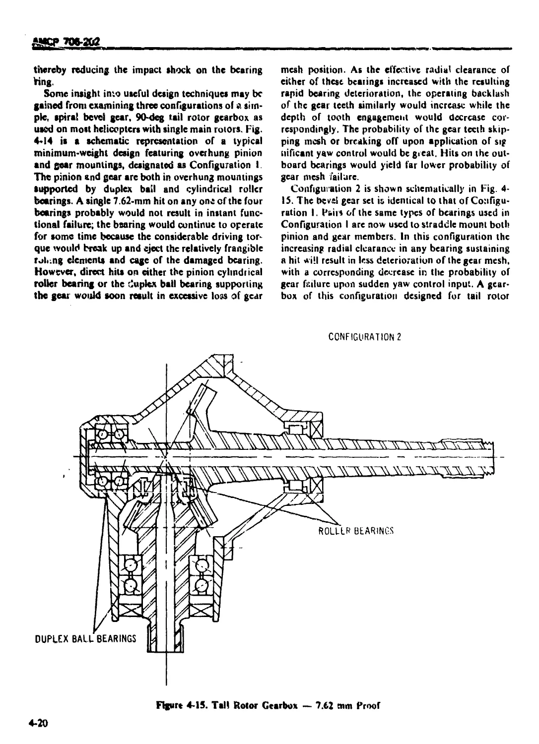
4-1.2.1.4.2 Design Configuration ........................................... 4-18
4-1.2.14.3 Self-sealing Sumps ................................................ 4-22
4-1.2.1.4.4 Emergency Lubrication.............................................. 4-22
4-1.2.1.4.5 Armor ............................................................. 4-23
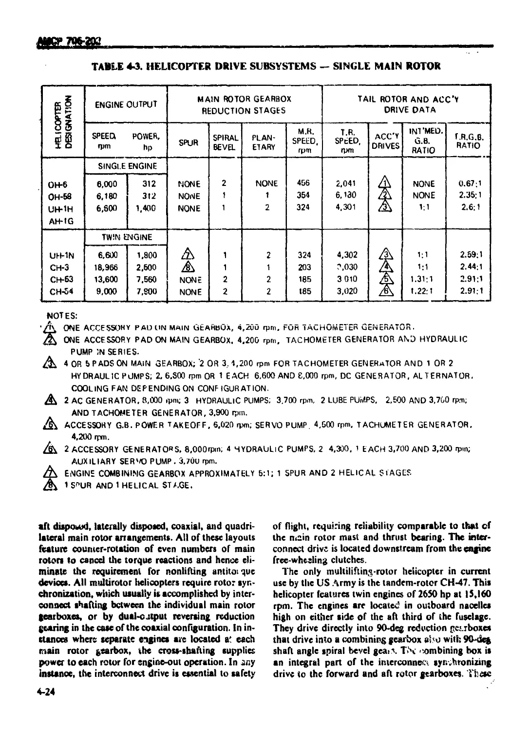
4-1.2.2 Drive System Configurations ....................................... 4-23
4-L2.2.1 Single Main Rotor Drive System .................................... 4-23
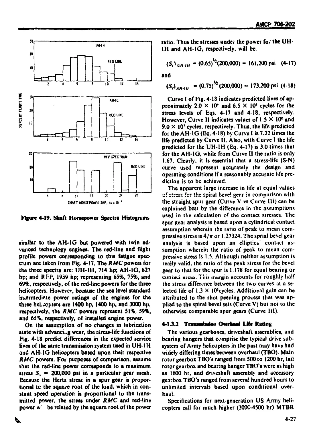
4-1.2.2.2 Multilifting-rotor Drive Systems ................................. 4-23
4-1.2.2.3 Compound Helicopter Drive Systems ................................. 4-25
4-1.3 TRANSMISSION DESIGN AND RATING CHARACTERISTICS.................. 4-25
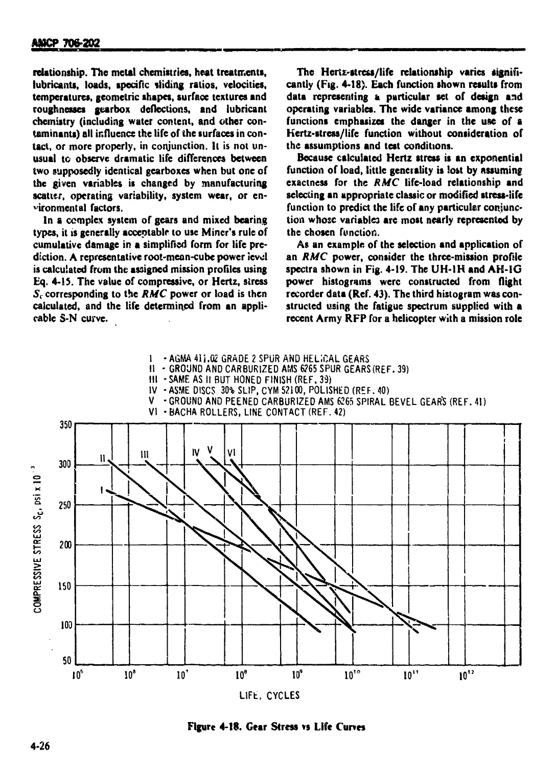
4-1.3.1 Power/Life Interaction ............................................ 4-25
4-1.3.2 Transmission Overhaul Life Rating ................................. 4-27
4-1.3.3 Transmission Standards and Ratings ................................ 4-28
4-1.4 QUALIFICATION REQUIREMENTS ..................................... 4 29
4-1.4.1 Component and Environment ......................................... 4-29
4-1.4.2 Development Testing ............................................... 4-29
4-|.4.2.1 Static Casting Tests............................................... 4-29
4-I.4.2.2 Deflection Tests .................................................. 4-29
4-1.4.2.3 Contact lists ..................................................... 4-30
АМСР 706-202
TABLE Ol ( ОМ ЕМ S (Continued)
Paragraph
Page
4-1.4.2.4 Assembly and Disassembly ......................................... 4-30
4-1.4.2.5 Lubrication System Debugging ........................................ 4-30
4-1.4.2.6 Incremental Loading and Efficiency Tests ............................ 4-30
4-1.4.2.7 Thermal Mapping Tests ............................................ 4-31
4-1.4.3 Overpower Testing ................................................. 4-31
4-1 .4.4 Other Life and Reliability Substantiation Testmg..................... 4-32
4-2 TRANSMISSIONS .......................................................... 4-32
4-2.1. FAILURE MODES 4-32
4-2.1.1 Primary Failure Mooes ............................................... 4-32
4-2.1.2 Secondary Failure Modes ........................................... 4-34
-4-2.1.2.1 Overload Failures 4-34
4-2.1.2.2 Debiis-causcd Failure ............................................... 4-34
4-2.1.2.3 Environmentally Induced Failures .................................... 4-34
4-2.2 DYNAMIC COMPONENTS ................................... 4-34
4-2.2.1 Gears ................................................ 4-34
4-2.2.1.1 Gear Limitations .......................................................... 4-35
4-2.2.I.2
4-2.2.I.2.I
4-2.2.I.2.3
4-2.2.I.2.3.I
Gear Analysis ...........................................................
-Bending Fatigue Strength ...............................................
_____:__
□vui иi aiiui v .........................................................
Pitting Failure .........................................................
Case Failure .........................................................
4-35
4-36
A tl
4-44
4-44
4-2.2.1.2.3.2 Classic or Pitch Line Fatigue..................................... ... 4-45
4-2.2.1.2.3.3 Wear Initiated Failure ................................................ 4-46
4-2.2.1.3 Gear Drawing and Specification ............................................. 4-4?
4-2.2.2 Bearings ................................................................... 4-48
4-2.2.2.I Application Design ......................................................... 4-48
4-2.2.2.1.1 Mounting Practices ......................................................... 4-48
4-2.2.2.1.2 Lubrication Techniques ..................................................... 4-50
4-2.2.2.I.3 Internal Characteristics ................................................... 4-51
4-2.2.2.1.4 Skidding Control............................................................ 4-54
‘4-2222 Life An; lysis ............................................................. 4-55
4-2.2.2.2.1 Assumptions and Limitations ................................................ 4-55
4-2.2.2.2.2 Modification Faclot Approach to Life Prediction ............................ 4-55
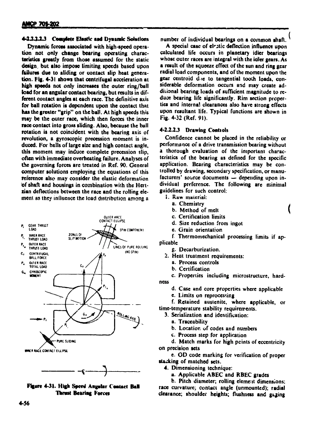
4-2.2.2.2.3 Complete Elastic and Dynamic Solutions ..................................... 4-56
4-2.2.2.3 Drawing Controls ........................................................... 4-56
4-2.2.3 Splines ................................................................... 4-57
4-2.2.3.1 Face Splines ............................................................... 4-58
4-2.2.3.2 Concentric or Longitudinal Splines ......................................... 4-58
4-2.2.3.3 ; Properties of Splines..................................................... 4-58
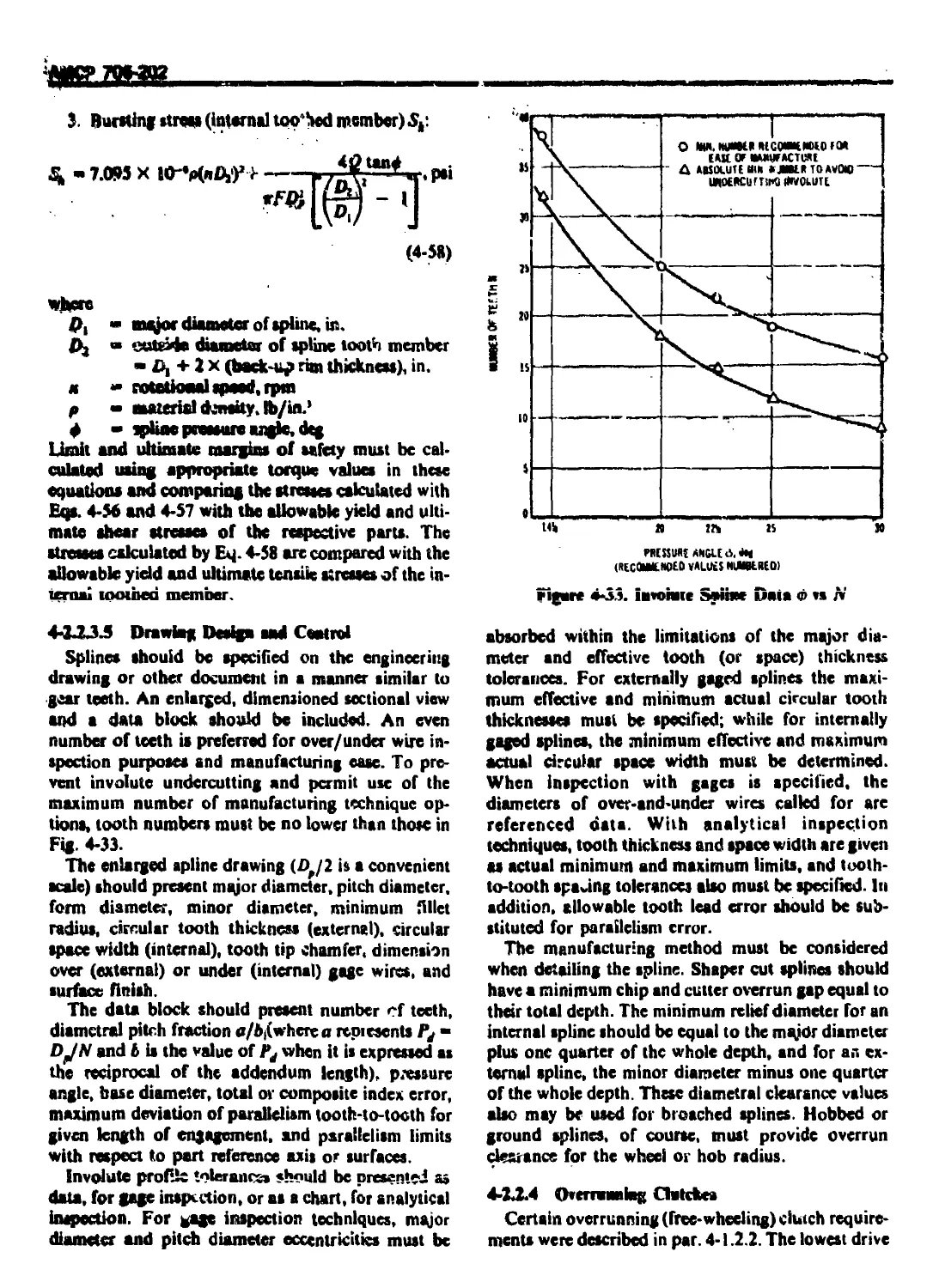
4-2.2.3.4 Spline Strength Analysis ................................................... 4-59
4-2.2.3.5 Drawing Design and Control ................................................. 4-60
4-2.2.4 Overrunning Clutches ....................................................... 4-60
4-2.2.4.1 Sprag Clutches ............................................................. 4-61
4-22.4.2. Ramp and Roller Clutches ................................................... 4-62
4-2.2.4 3 Self-encrgizing Spring Clutches ............................................ 4-62
4-2.2.S Rotor Brakes................................................................ 4-62
4-2.2.5.1 Requirements and Limitations ............................................... 4-62
4-2.2.S.2 Design and Analysis ........................................................ 4-63
4-2.3 STATIC COMPONENTS .............................................................. 4-64
4-2.3.1 Cases and Housings ......................................................... 4-64
АМСР 7Q6-2O2
TABLE О’- CONTENTS tCo»(inutd)
Paragraph Pag'
4-2.3.1.1 Design and Analysis....................................... 4-64
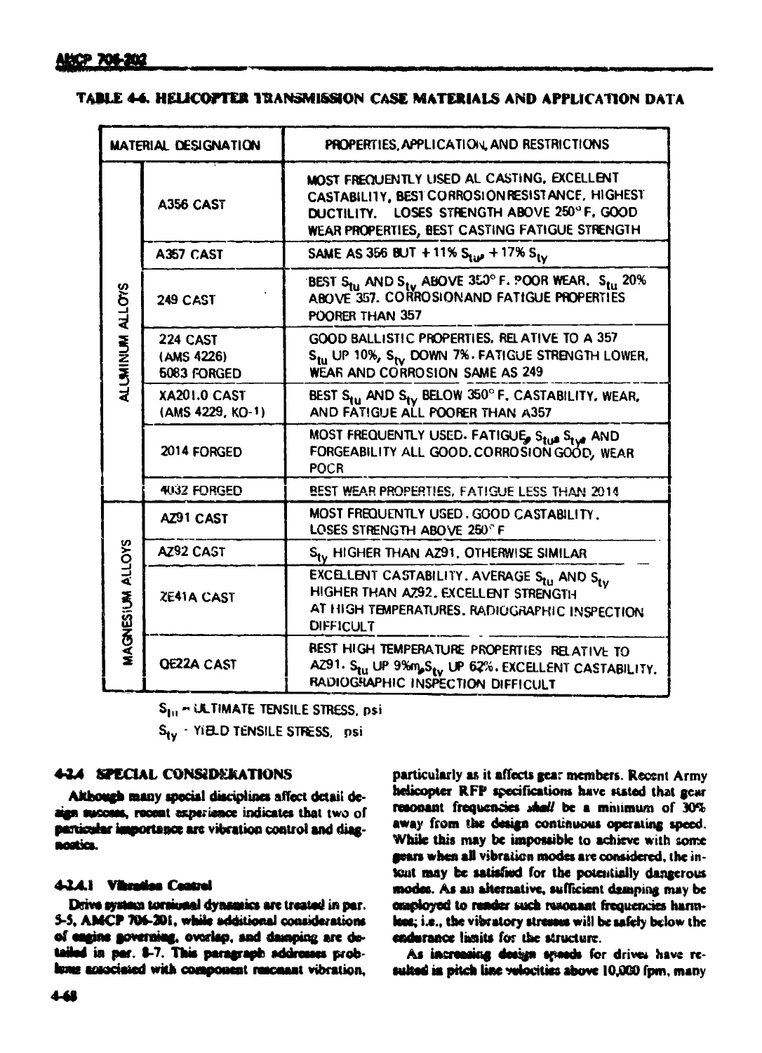
4-2.3.1.2 Materials and Processes .................................... 4-66
4-2.3.2 Quills ..................................................... 4-67
4-2.4 SPECIAL CONSIDERATIONS ...................................... 4-W
4-2.4.1 Vibration Control ......................................... 4-64"
4-2.4.2 Diagnostics ................................................ 4-73
4-3 DRIVE SHAFTING AND 1NTERCO iNECTlON SYSTEMS .................. 4-72
4-3.1 GENERAL REQUIREMENTS ....................................... 4-72
*•3.1.1 Engine-to-Transmission ..................................... 4-72
4-3.1 2 Interconnect Shafting ...................................... 4-73
4-3.1.3 Tail Rotor or Propeller Shafting .......................... 4-73
4-3.1.4 Subcritical Shafting........................................ 4-74
4-3.1.5 Supercritical Shafting .................................... 4-76
4-3.2 COMPONENT DESIGN ........................................... 4-76
4-3.2.1 Couplings 4-76
4-3.2.2 Bearings 4-80
4-3.2.3 Shafting 4-81
4-4 LUBRICATION SYSTEMS ...................................... 4-81
4-4| OILMANAGEMENT ............................................ 4-82
4-4.1.1. Function 4-82
4-4.1.2 Component and Arrangement................................... 4-83
> > J.RS
I . J Ojrvvmi WI1JIUVI ......»................................. — V.’
4-4.2 COOLING REQUIREMENTS ....................................... 4-86
4-4.2.1 Heat Exchanger Sizing ...................................... 4-36
4-4.2.2 Cooling Fan Sizing ......................................... 4-87
4-4.3 EMERGENCY LUBRICATION ...................................... 4-87
4-5 ACCESSORIES .................................................. 4-88
4-5.1 PAD LOCATION AND DESIGN CRITERIA ........................... 4-88
4-5.2 ACCESSORY DRIVE DESIGN REQUIREMENTS ........................ 4-89
4-5.3 SPECIAL REQUIREMENTS ....................................... 4-89
REFERENCES .................................................. 4-89
CHAPTER 5
ROTOR AND PROPELLER SUBSYSTEM DESIGN
5-0 LIST OF SYMBOLS .............................................. 5-1
5-1 INTRODUCTION ................................................. 5-2
5-2 DESIGN PARAMETERS ............................................. 5-3
5-2.1 HOVER 5-3
5-2.1.1 Disk Loading and Induced Power .............................. 5-3
5-2.1.2 Blade Loading ............................................... 5-4
5-7 1.3 Blade Tip Mach Number ....................................... 5-5
5-2.1.4 Number of Blades ............................................ 5-5
5-2.1.5 Twist ....................................................... 5-5
5-2.1.6 Airfoil Sections ............................................ 5-5
5-2.1.7 Hovering Thrust Capability .................................. 5-5
5-2.1.8 Guidelines .................................................. 5-5
5-2.2 HIGH-SPEED LEVEL FLIGHT .................................. 5 6
5-2.3 HIGH-SPEED MANEUVERING FLIGHT ............................... 5-6
5-2.4 INERTIA ..................................................... 5-7
5-3 ROTOR SYSTEM KINEMATICS........................................ 5-7
5-3.1 GENERAL ..................................................... 5-7
vi
AtfCP 706 292
TA BLE 01 (. GM I N I b 1Continued I
Paragraph P“?c
I JO Г **-^“-«*
5-3.2 I If-L1C0H ER CONTROL .......................................... 5 9
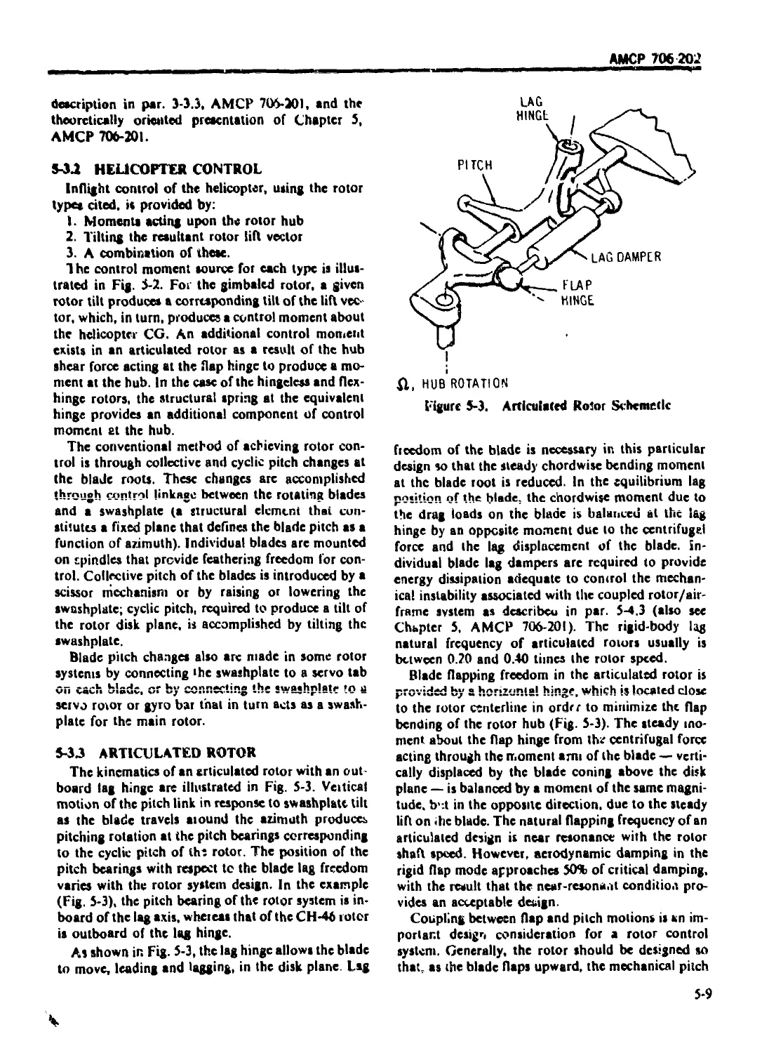
5-3.3 ARTICULATED ROTOR .............................................. 5-9
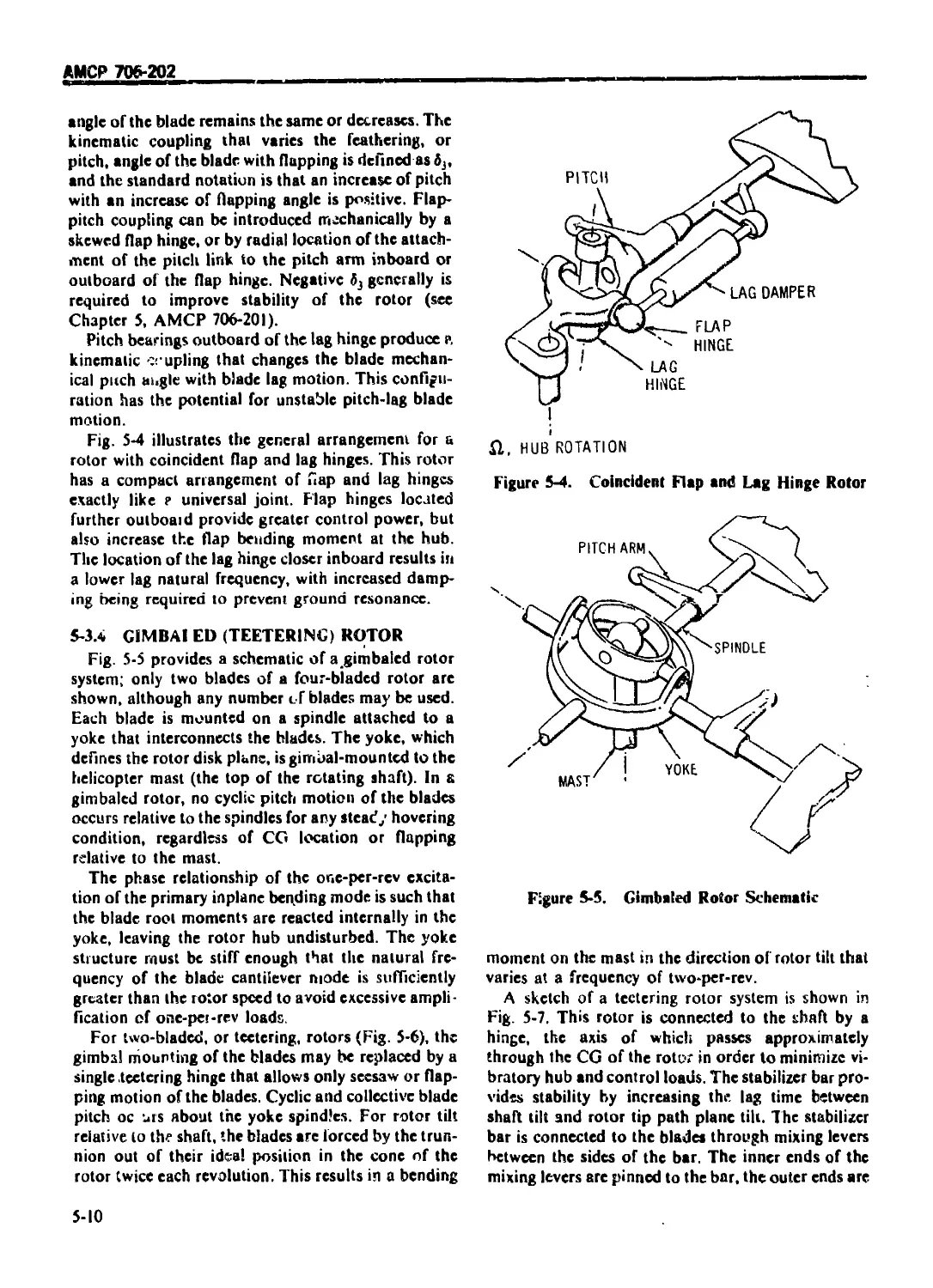
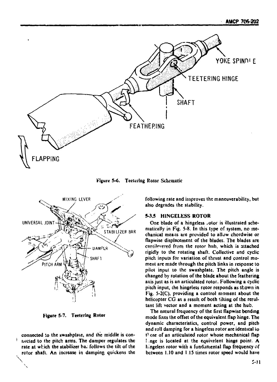
5-3.4 GIMBALED (TEETER! NG) ROTOR ...................................... 5-10
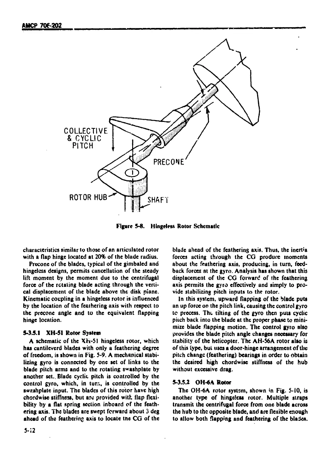
5-3 5 H1NGELFSS ROTOR .................................................. 5-11
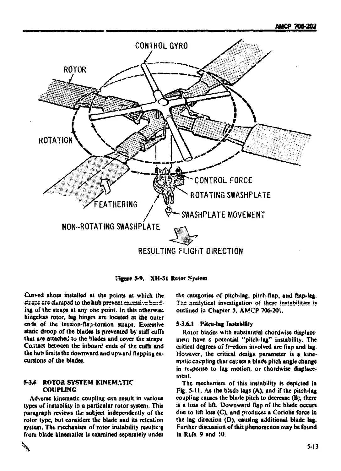
5-3.5.1 XH-51 Rotor System ............................................... 5-12
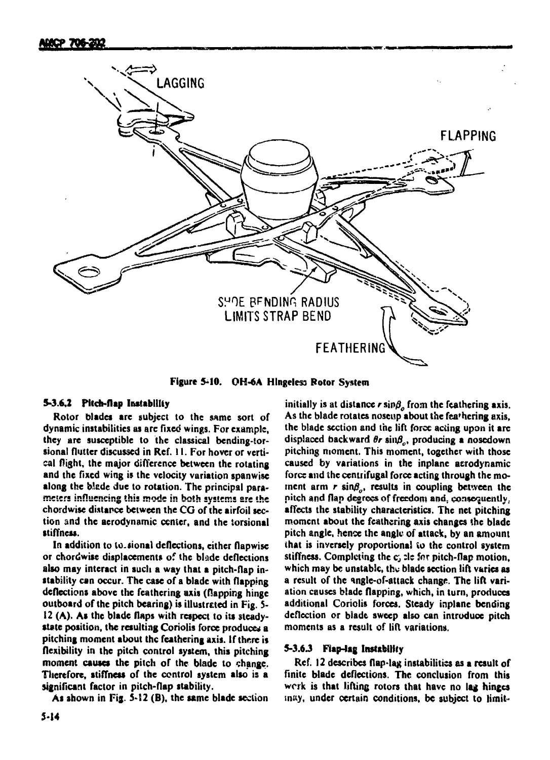
5-3.5.2 OH-6A Rotor .................................................... 5-12
5-3.6 ROTOR SYSTEM KINEMAT1CCOUPL1NG ................................... 5-13
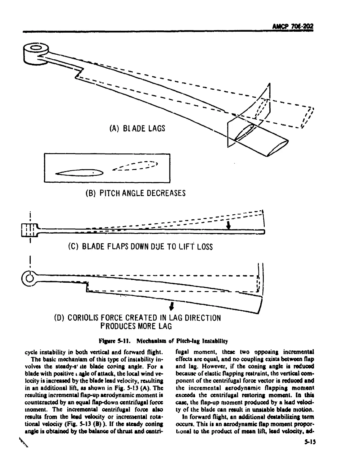
5-3.6.I Pitch-lag Instability ............................................ 5-13
5-3.6.2 Pitch flap Instability ...................................... .. 5-14
5-3.6.3 Flap-lag Instability ............................................. 5-14
5-4 ROTOR SYSTEM DYNAMICS .............................................. 5-16
5-4.1 OSCILLATORY LOADING Or ROTOR BLADES .............................. 5-16
5-4.1.1 Hypothetical Consideration of Rotor Vibratory Loads .............. 5-16
5-4.1.2 Oscillatory Load Design Considerations ........................... 5-1"
5-41.2.1 Rotor Oscillatory Load Calculation ............................... 5-17
5-4.1.2.2 Drawing Board Phase ............................................. 5-17
5-4.1.2.3 Flight Tests ................................................... 5-18
5-4.1.2.4 Fatigue Tests................................................... 5-18
5-4.2 AMPLIFICATION AND NATURAL FREQUENCIES ............................ 5-19
5-4.3 GROUND RESONANCE ............................................ 5-19
5-4.3.1 Two-bladed Rotor With Hinged Blades .............................. 5-21
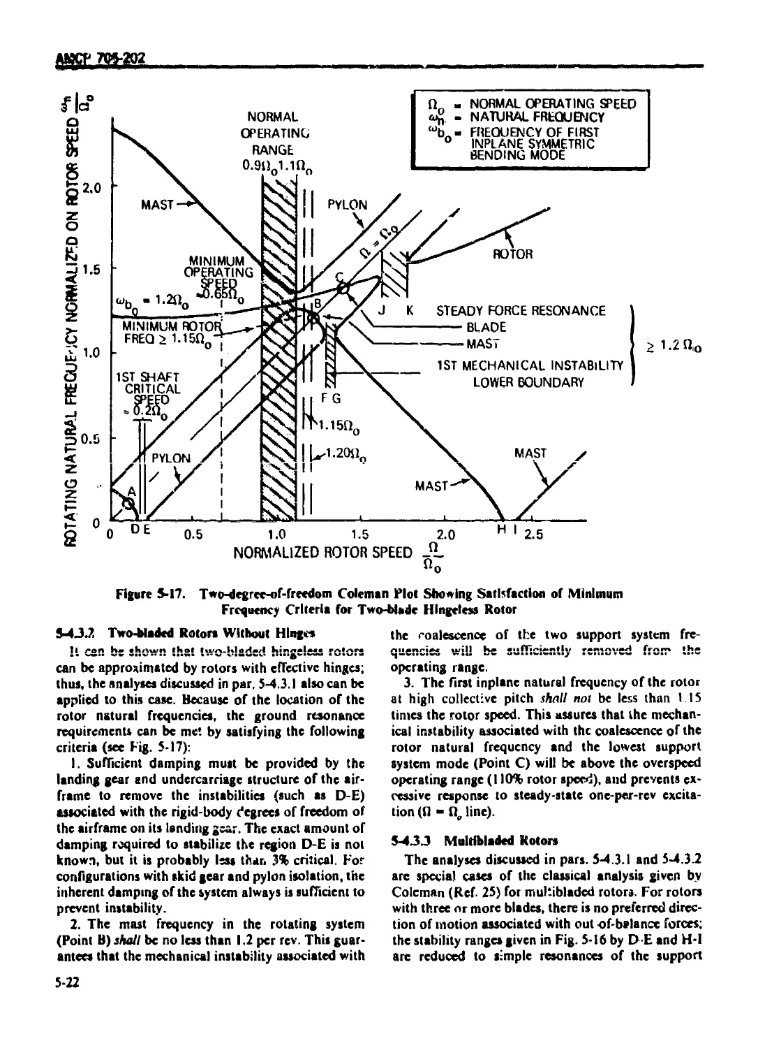
5-4.3.2 Two-bladed Rotors Without Hinges ................................. 5-22
5-4.3.3 MultiLladed Rotors ............................................... 5-22
5-4 4 FLUTTER ASSESSMENT ........'...................................... 5-23
5-4.4.1 Current Criteria ................................................. 5-23
5-4.2.2 Design Considerations ............................................ 5-23
5-4.4.2.1 Helicopter 5-23
5-4.4.2.1.1 Fixed System .................................................. 5-23
5-4.4.2.1.2 Rotating System ............................................... 5-23
5-4.4.2.2 Compound 5-23
5-4.4.2.2. i Fixed System .................................................. 5-23
5-4.4.2.X2 Rotating System ............................................... 5-24
5-4.5 I ACOUSTIC LOADING ................................................. 5-24
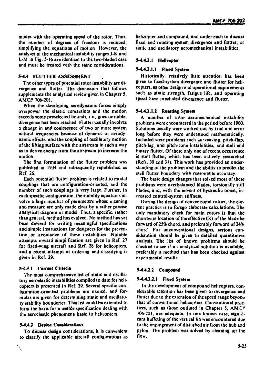
5-4.6 ’ GUST LOADINGS .................................................... 5-24
5 4.6.1 ' Discussion of the Gust Prob; .m .................................. 5-24
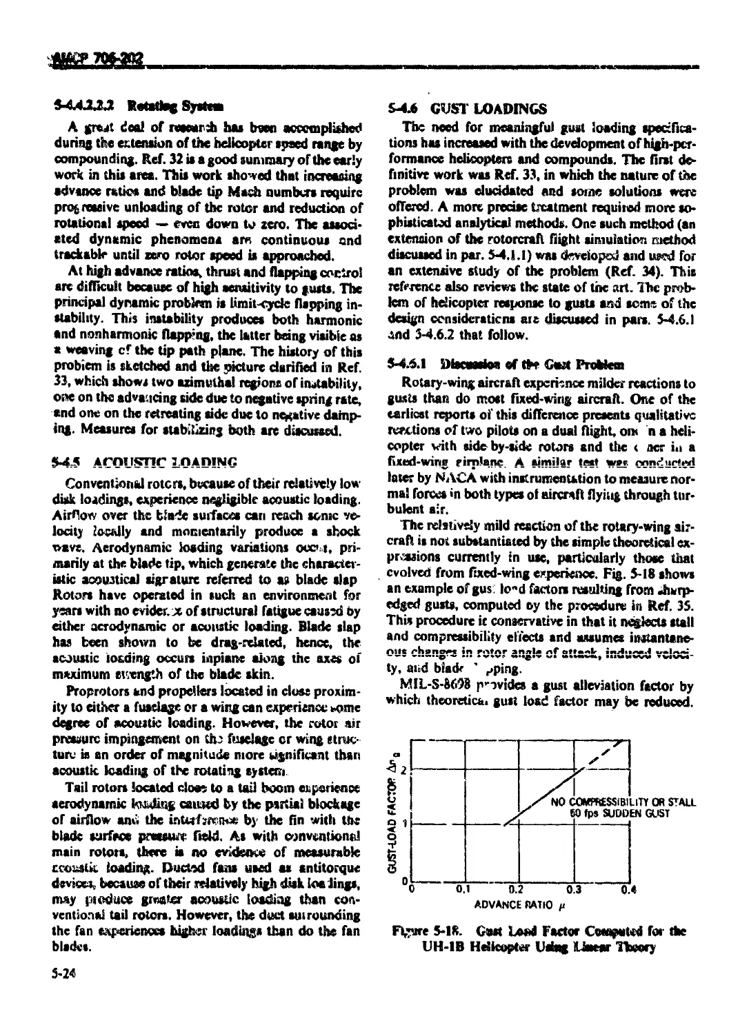
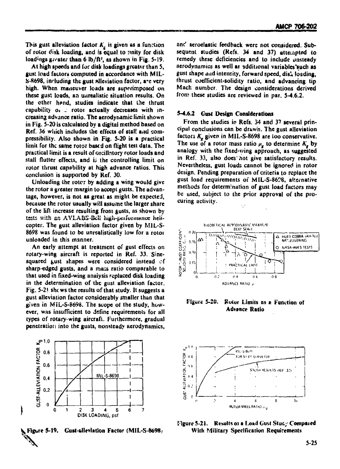
5-4 6.2. Gust Design Considerations ....................................... 5-25
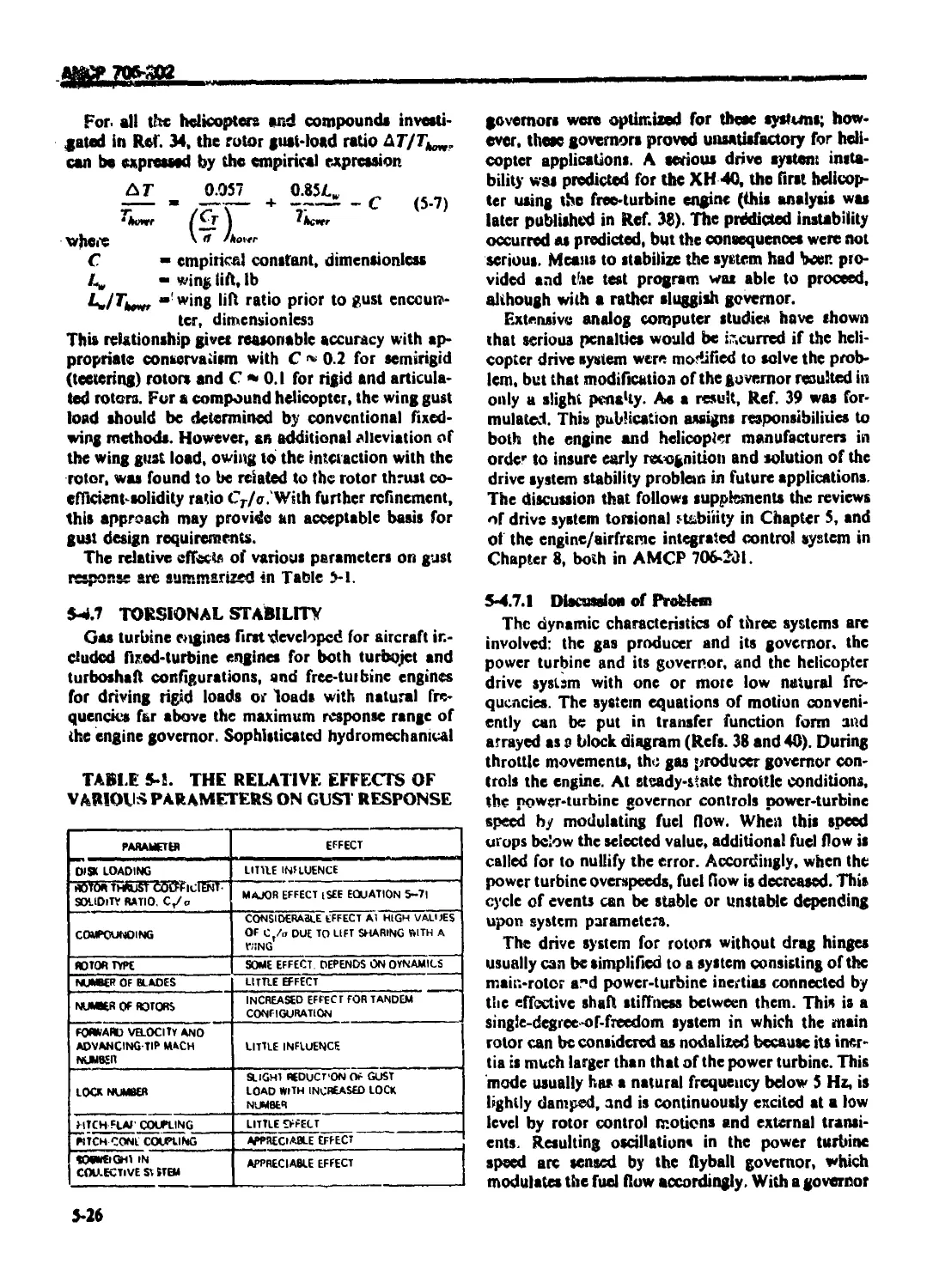
5-4.7 I TORSIONAL STABILITY .............................................. 5-25
5-4.7.1' Discussion of Problem ............................................ 5-26
5-4.7.2 Design Considerations ............................................ 5-2'
5-5 BLADE RETENTION .................................................... 5-27
5-5 1 RETENTION SYSTEM DESIGN CONSIDERATIONS ........................... 5-27
5-5.1.1 Articulated Rotors ............................................... 5-27
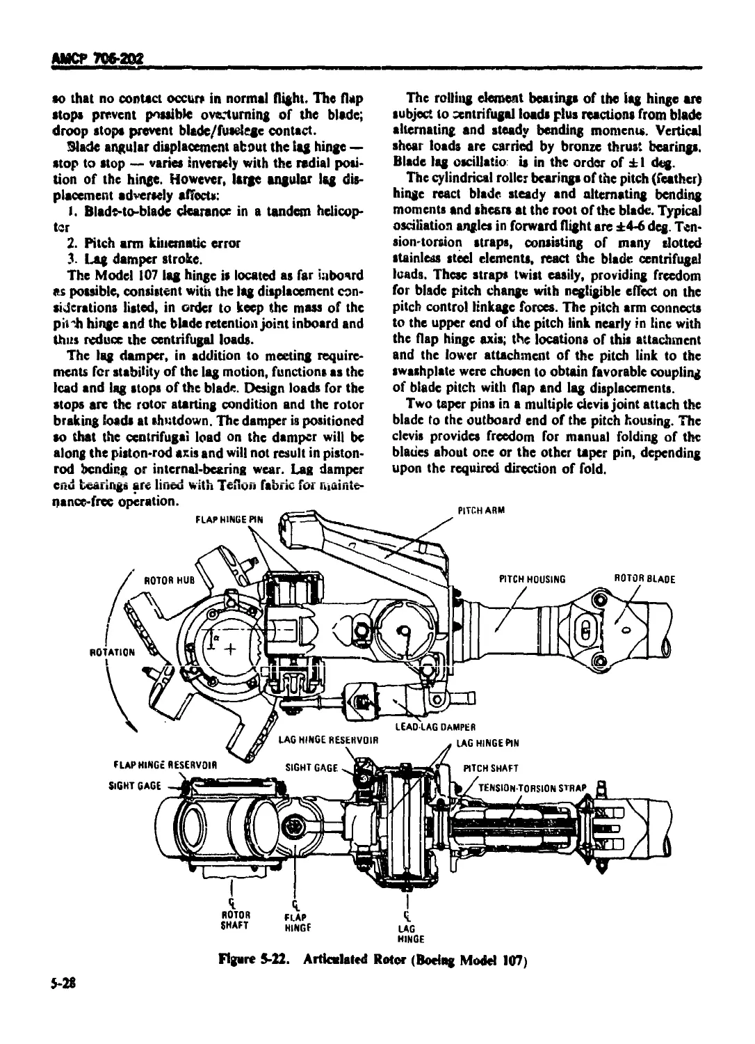
5-5.1.1.1 Typical Articluated Rotor Considerations ......................... 5-27
5-5.1.1.2 Reversed Hinge Articulation .................................. 5-29
5-5.1.2 Gimbaled and Teetering Rotors .................................... 5-29
5-5.1.2.1 Gimbal-mounted Hubs .............................................. 5-29
5-5.1.2.2 Teetering Hubs.................................................... 5-30
5-5.1.3 Rigid Rotor ...................................................... 5-30
5-5.2 COMPONENT DESIGN CONSIDERATIONS .................................. 5-30
5-5.2.1 Rolling Element Bearings ......................................... 5-30
vii
АМСР 706-202
LABI F DI ( DM FVISiC iiiuiiiucd i
Paragraph Page
5-5.2.I.I Cylindrical Roller Bearings ..................................... 5-31
5-5.2.1.2 Tapered Roller Bearings ............................................ 5-31
5-5.2.13 Angular Contact Ball Bearings ...................................... 5-31
5-5.2.2 Teflon f abric Bearings ............................................ 5-31
5-5.2.3 Flexing Elements ................................................... 5-32
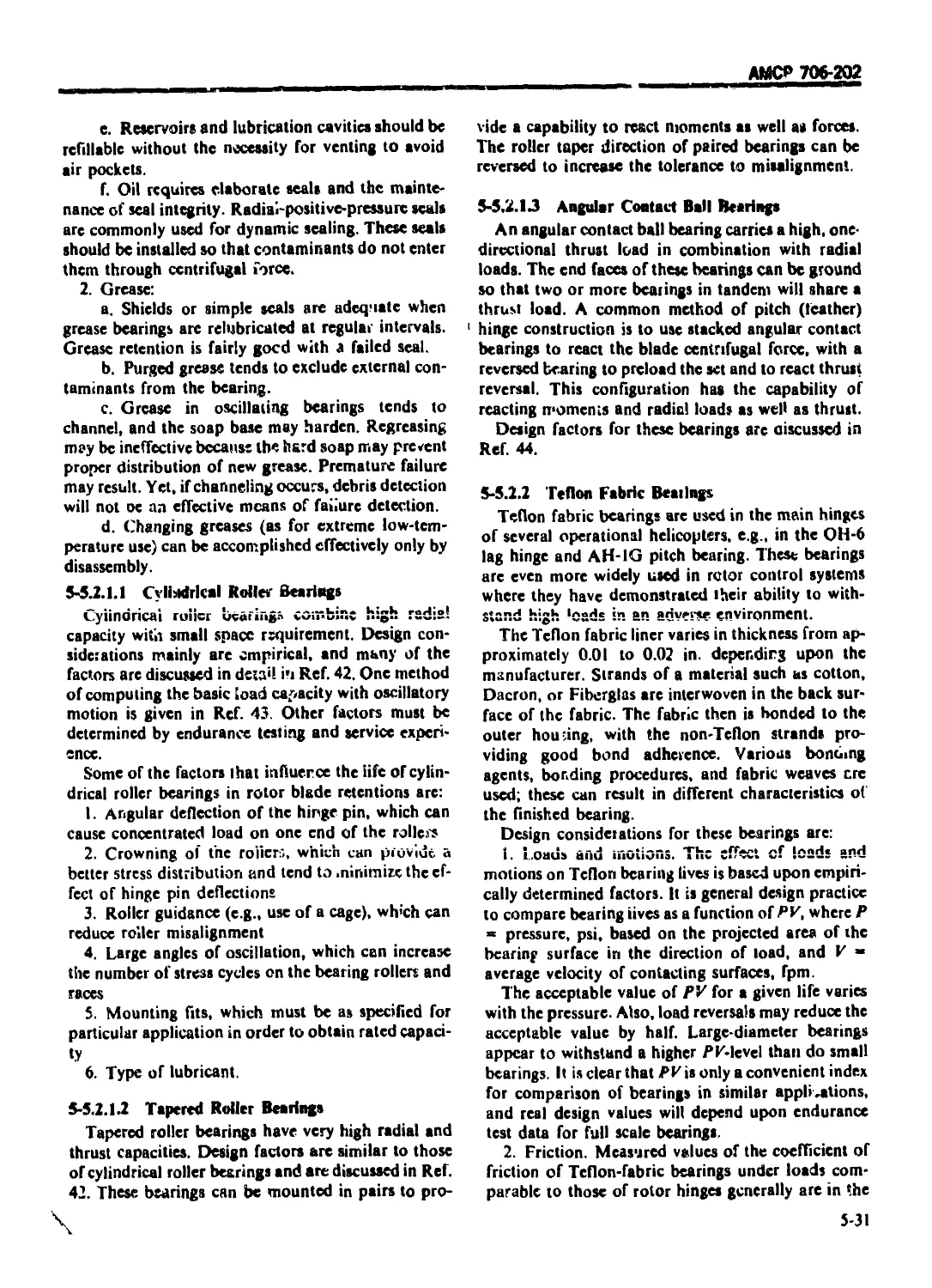
5-5.2.3.1 Tension-torsion Strap Assemblies ................................... 5-32
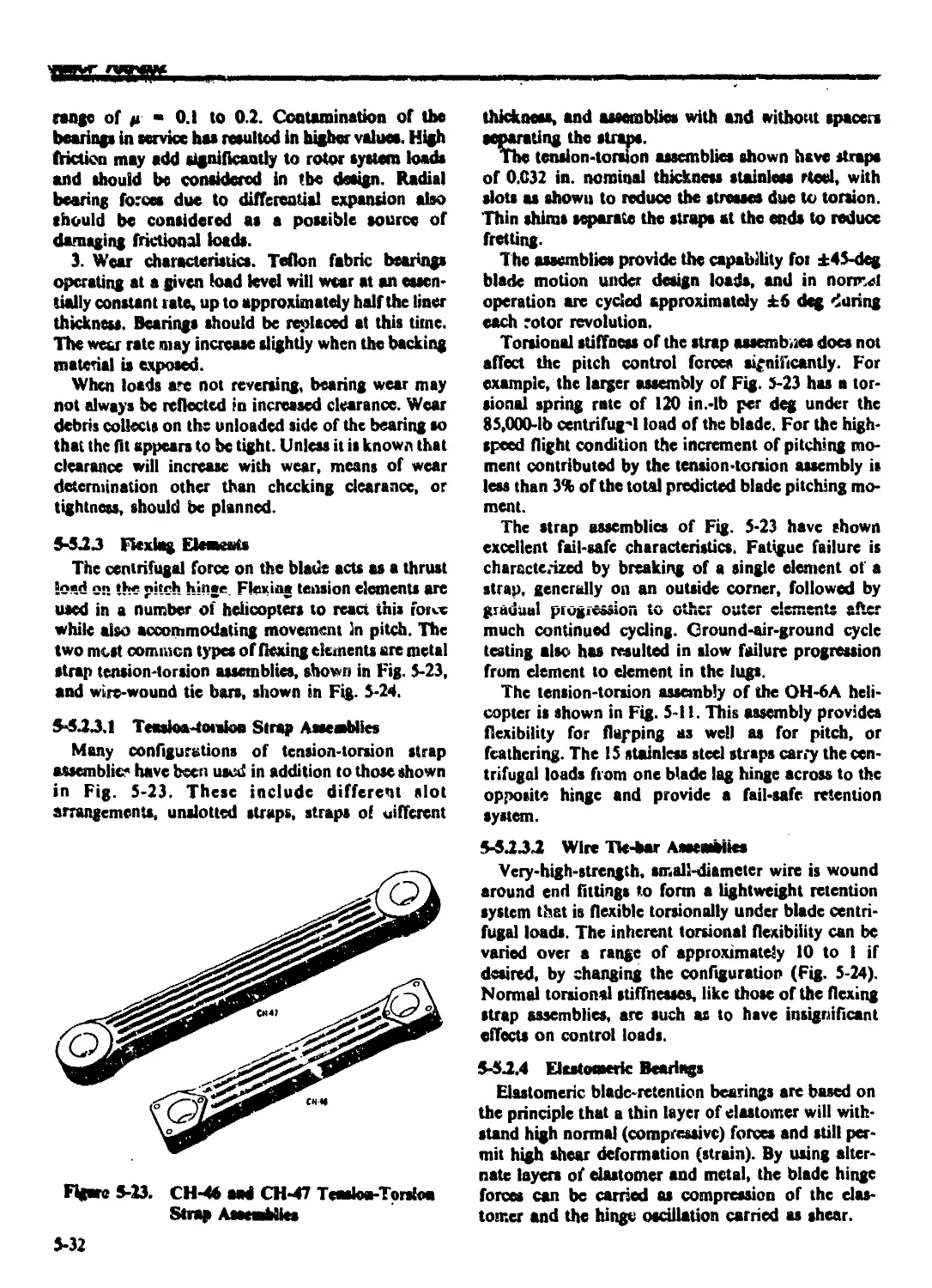
5-5.2.3.2 Wire Tie-bar Assemblies ......................................... 5-32
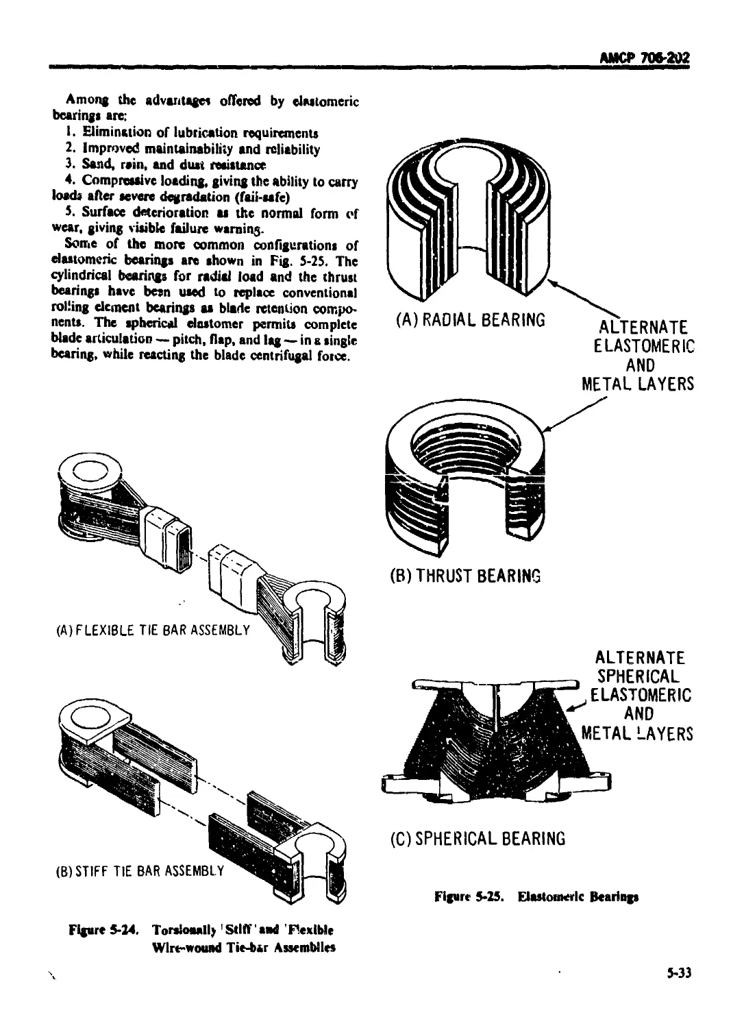
5-5.2.4 Elastomeric Bearings ............................................... 5-32
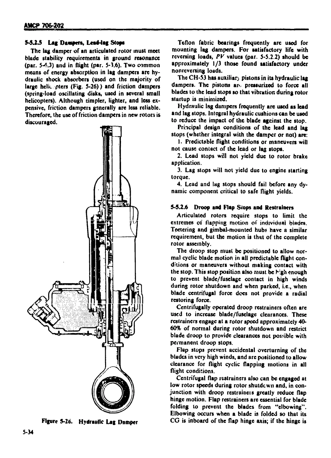
5-5.2 5 Lag Dampers, Lead-lag Stops ........................................ 5-34
5-5.2 6 Droop and Flap Stops and Restrainers ............................... 5-34
5-5.3 CONTROL SYSTEM CONSIDERATIONS .................................. 5-35
5-5.4 BLADE FOLDING ................................................... 5-35
5-5.4.1 Design Requirements .............................................. 5-35
5-5.4.1.1 Manual Biade Folding ........................................... 5-35
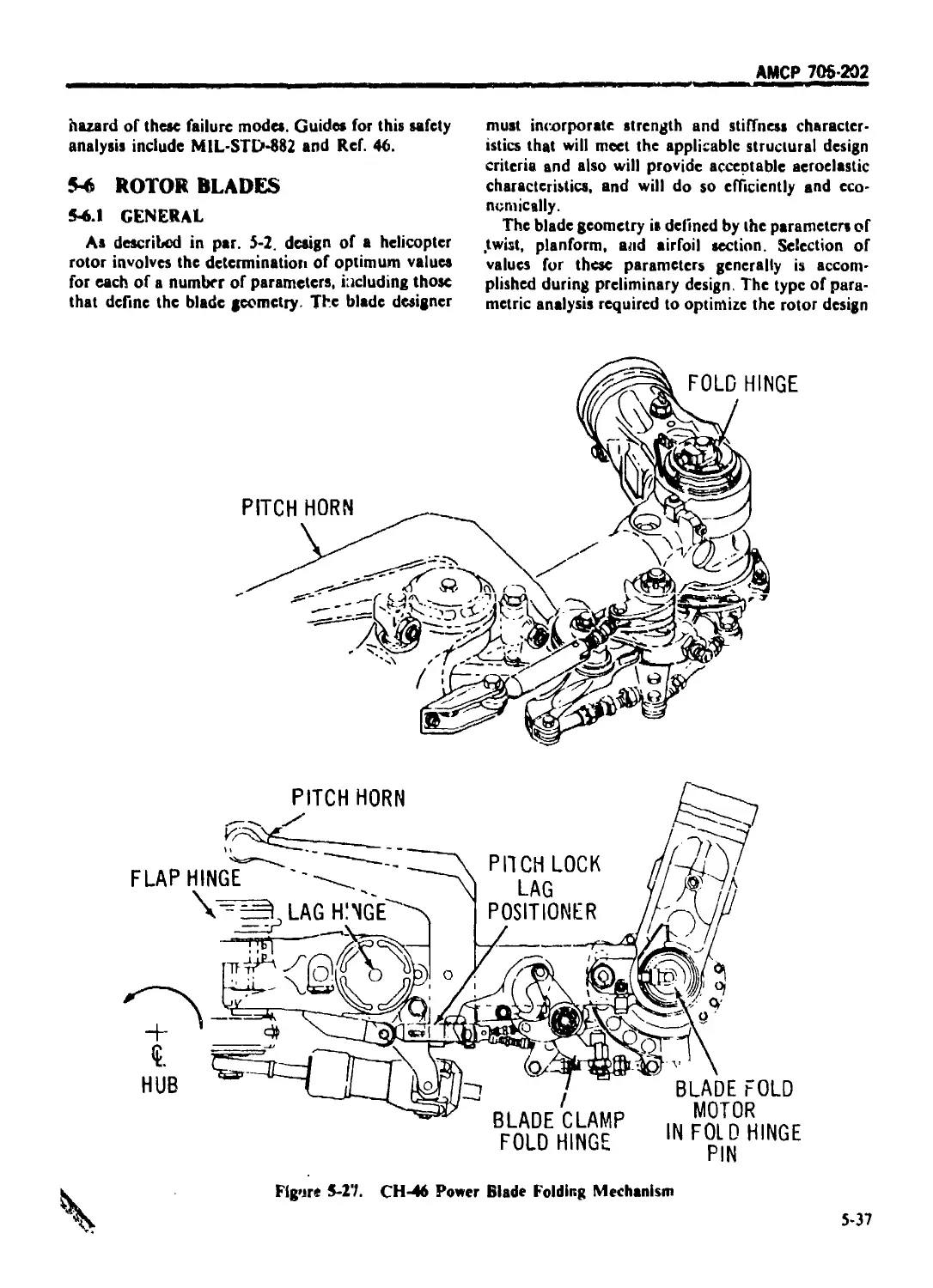
5-5.4.1.2 Power Blade Folding ............................................ 5-36
5-5.4.2 Operational Requirements ........................................... 5-36
5-5.4.3 System Safety Considerations ....................................... 5-36
5-6 ROTOR BLADES ......................................................... 5-37
5-6 I GENERA I ........................................................... 5-37
5-6.1 I Twist .............................................................. 5-3»
5-6.12 Planlorm Taper .................................................... 5-38
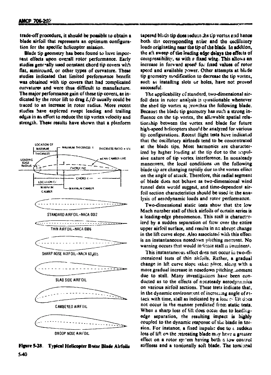
5-6.1.3 Airfoil Cross Section ............................................. 5-39
5-6.2 BLADLCONSTRUCTION .................................................. 5-41
5-6 2.1 Spar ............................................................... 5-41
5-6.2.1 .1 Hollow Extrusion ................................................... 5-41
5-6.2.1.2 Solid Extrusion .................................................... 5-41
5-6.2.1.3 Formed Sheet Metal ................................................. 5-42
5-6.2.1.4 Round Sieel Tube ................................................... 5-42
5-6.2.1.S Formed Metal Tube .................................................. 5-42
5-6.2.1.6 Molded Reinforced Plastic .......................................... 5-42
5-6.2.2 Aft Section ........................................................ ^-43
5-6.2.2.1 Continuous Skins ................................................... 5-43
5-6.2.2.2 Segmented Skins .................................................... 5-43
5-6.2.2.3 Wraparound Skins ................................................... 5-44
5-6.2.3 Root End Retentions ................................................ 5-44
5-6.2.4 Tip Closures and Hardware .......................................... 5-44
5-6.2.5 Trim Tabs .......................................................... 5-44
5-6.2.6 Tuning Weights ................................................... 5-45
5-6.2.7 Design Requirements .............................................. 5-45
5-6.2.Й Tooling and Quality Control Requirements ......................... 5-45
5-6.3 BLADE BALANCE AND TRACK ......................................... 5-46
5-6.3.1 Effect of Design .............................................. 5-46
5-6.3.2 Component Limit Weights ............................................ 5-47
5-6.3.3 Track .............................................................. 5-49
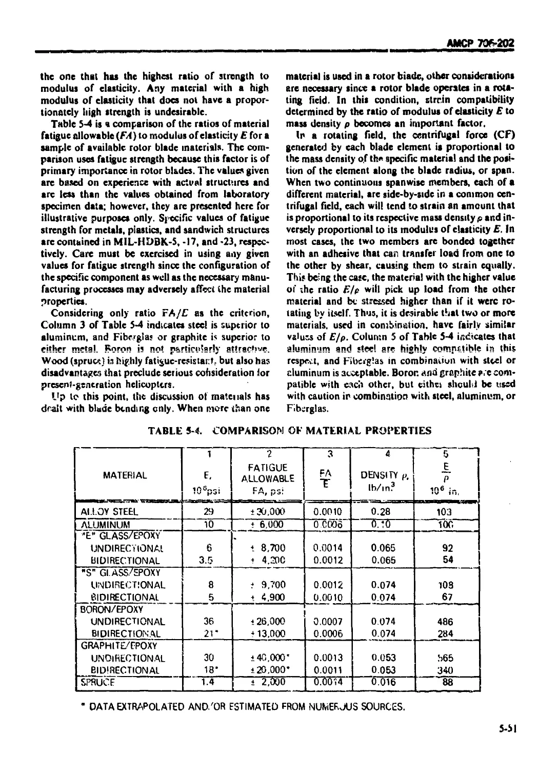
5-6.4 ROTOR BLADE MATERIALS .............................................. 5-50
5-7 ROTOR SYSTEM FATIGDE LIVES ........................................... 5-53
5-7.1 GENERAL ............................................................ 5-53
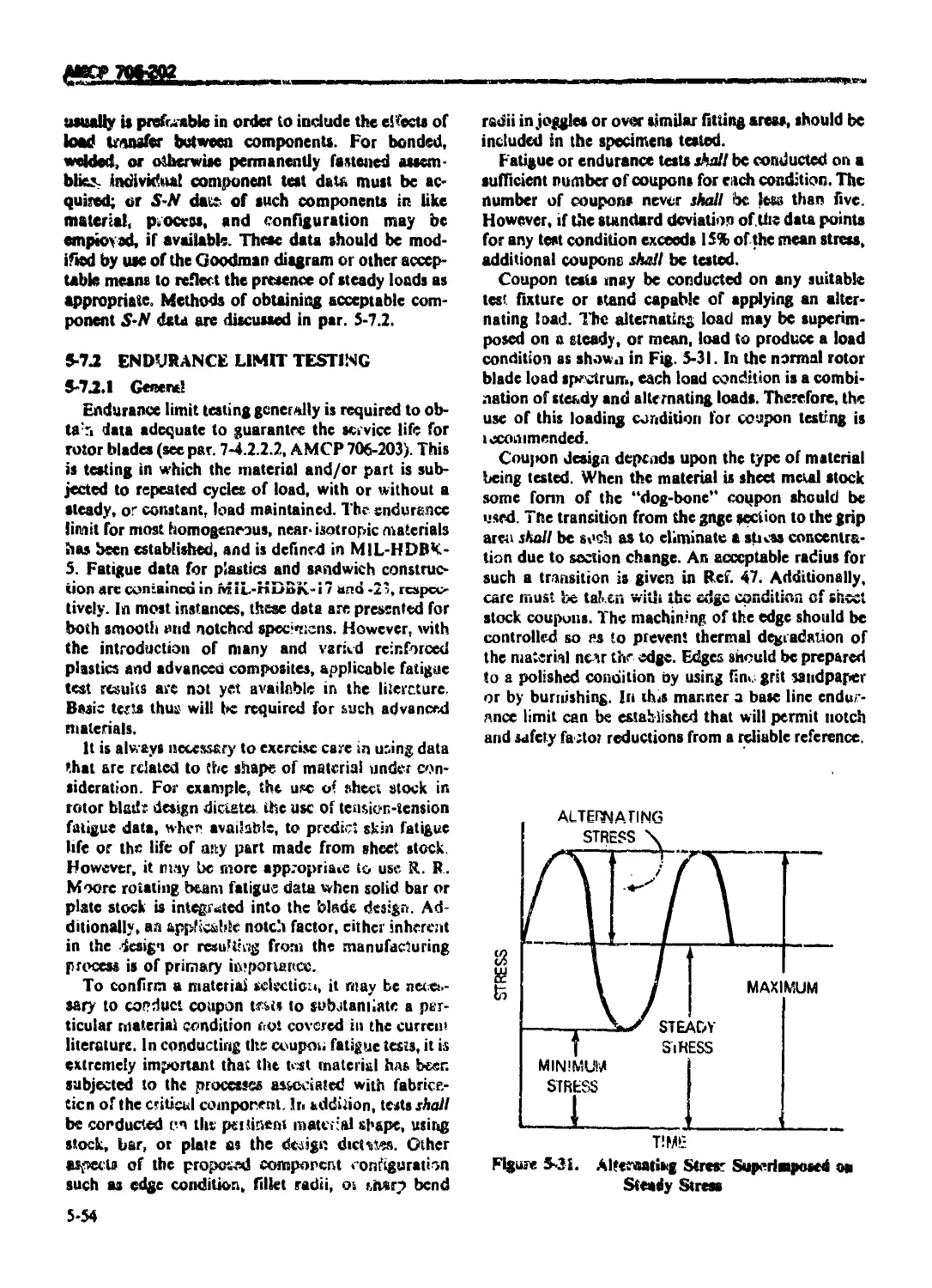
5-7.2 ENDURANCE LIMIT TESTING ............................................ 5-54
5-7.2.1 General ............................................................ 5-54
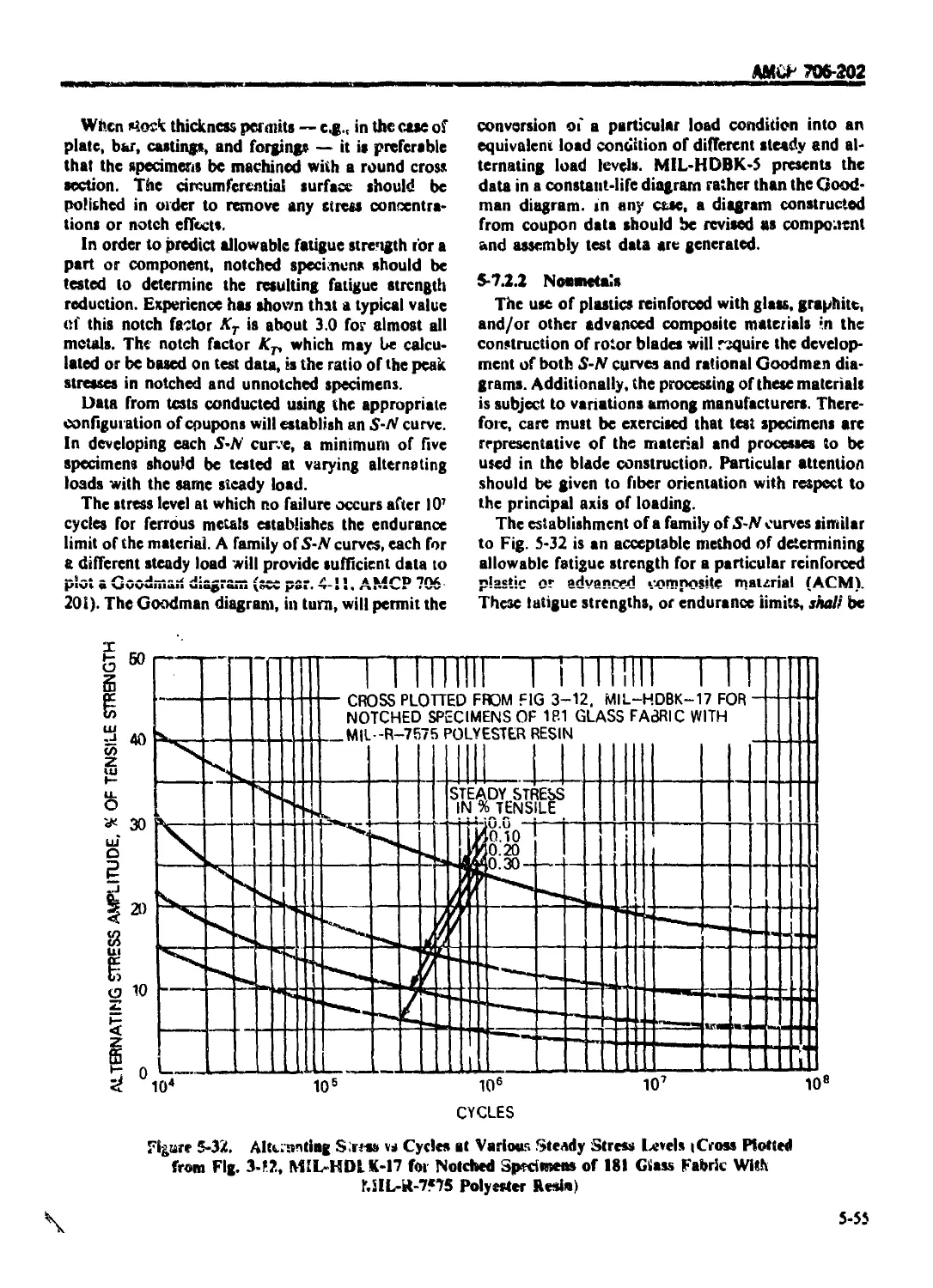
5-7.2.2 Nonmetals .......................................................... 5-55
viii
АМСР 706-202
‘I ABI F (>! ( ON I I N I S i( initinucd।
Paragraph Page
5-7.2.3 Structural Members ................................................. 5-56
5-7.2.4 Determination of Fatigue Life ...................................... 5-56
5-8 PROPELLERS 5-57
5-8.1 GENERAl..................................................... 5-57
5-8.2 PROPELLER SYS I EM DYNAMICS......................................... 5-57
5-8.2.1 Vibratory Loads ... ............................................... 5-57
5-8.2 2 Critical Speeds and Response ....................................... 5-60
5-8.2.3 Gusts and Mancuvets ................................................ 5-62
5-8.2.4 Stall Flutter ...................................................... 5-63
5-8.2.5 Propeller Roughness................................................. 5-64
5-8.3 PROPELLER HUBS, ACTUATORS. AND CONI ROLS ........................... 5-65
5-8.3.1 Propeller Barrel and Blade Retentions ..................... 5 65
5-8.3.1.1 Barrel Loading .................................................... 5-65
5-8.3.1.2 Loading Definition ............................................... 5-66
5-8.3.13 Barrel Structural Tests ........................................... 5-66
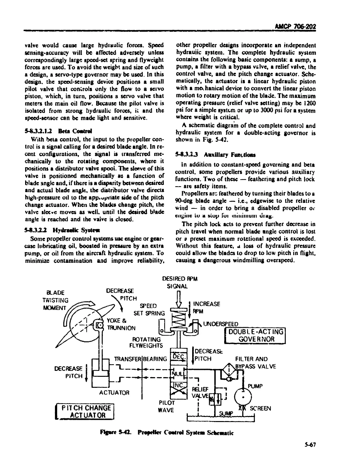
5-8.3.2 Propc'lcr Actuators and Controls ................................... 5-66
5-8.3.2.1 Control Configurations ........................................... 5-66
5-8.3.2.1.1 Constant-speed Governors 5-66
5 8.3.2.1.2 Beta Control.... ................................................ 5-67
5-8.3.2.2 Hydraulic System ................................................... 5-67
5-8.3.2.3 Auxiliary Functions ................................................ 5-67
5-8.3.2.4 Control Performance ................................................ 5-68
5-8.3.2.5 Control Reliability ................................................ 5-68
5-8.4 PROPELLER BLADES ................................................... 5-68
5-8.4,1 Blade Geometry .................................................... 5-68
5-8.4 2 Blade Construction ............................................... 5-70
5-8.4.2.1 Types of Blade Construction ........................................ 5-70
5-8.4.2.2 Manufacturing Processes and Tooling ................................ 5-72
5-8.4.2.3 Quality Control .................................................... 5-73
5-8.4.3 Blade and Propeller Balance........................................ 5-73
5-8.4.4 Blade Materials ................................................... 5-73
5-8.4.4.1 Hollow Blades ...................................................... 5-74
5-8.4.4 2 Composite Materials ................................................ 5-75
5-8.4.4.3 Filler Multrial .................................................... 5-75
5-8.4.4.4 Structural Adhesives ............................................... 5-75
5 8.5 PROPELLER BLADE F ATIGUE LIVES ..................................... 5-75
5-8.5.1 Endurance Limit and Other Structural Testing ...................... 5-76
5-8.5.1.1 Specimen Tests ................................................ 5-76
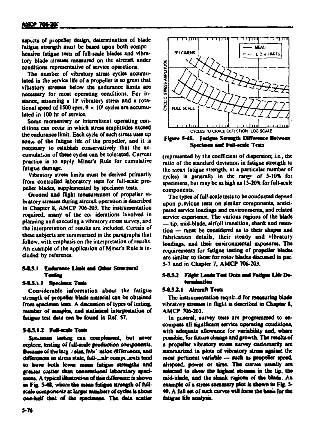
5-8.5.1.2 Full-scale Tests ................................................ 5-76
5-8.5.2 Flight Loads Test Data and Fatigue Life Determination .............. 5-76
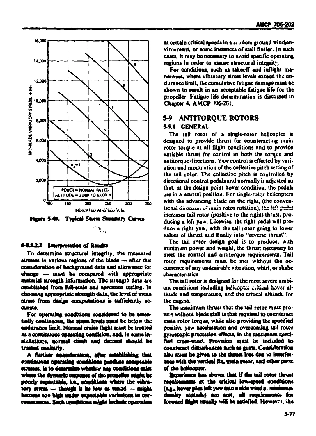
5-8.5.2.1 Aircraft Tests ................................................... 5-76
5-8.5.2.2 Interpretation of Results ........................................ 5-77
5-9 ANTITORQUE ROTORS ...................................................... 5-77
5-9.1 GENERAL ......................................................... 5-77
5-9.2 TYPICAL ANTITORQUE ROTORS .......................................... 5-78
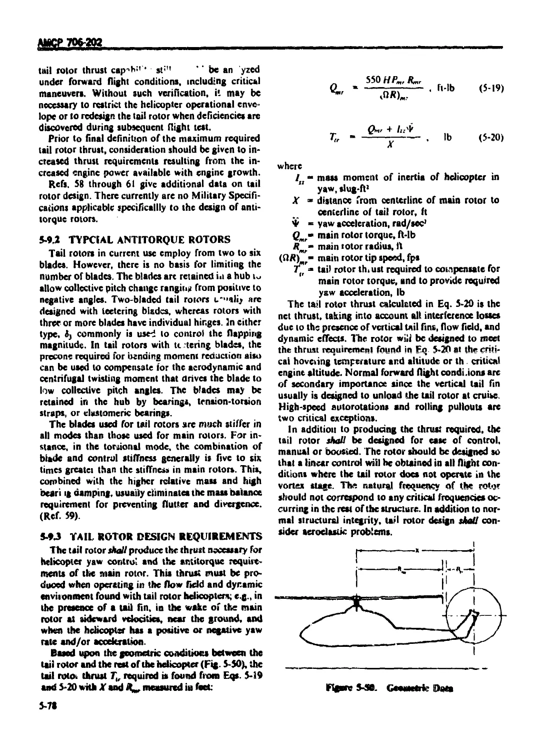
5-9.3 TAIL ROTOR DESIGN REQUIREMENTS .................................. 5-78
5-9.4 INSTALLATION CONSIDERATIONS ..................................... 5 79
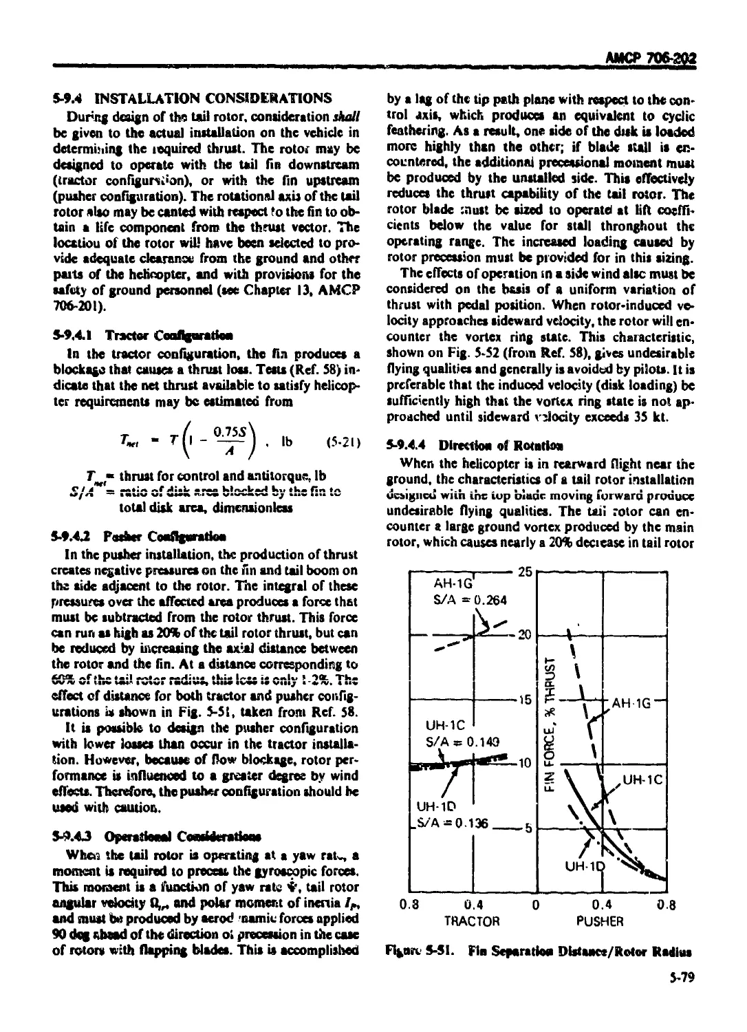
5-9.4.1 Tractor Configuration .............................................. 5-79
5-9.4.2 Pusher Configuration ............................................... 5-79
5-9.4.3 Operational Considerations ......................................... 5-79
5-9.4.4 Direction of Rotation .............................................. 5-79
IX
АМСР 706-202
1ABLE. OF ( ОМ FN1 S i( untlmied)
Paragraph Page
5-9 4.5 Engine Exhaust ................................................ 5-80
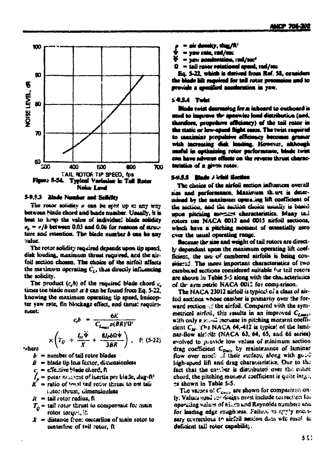
5-9.5 TAIL ROTOR DESIGN PARAMETERS ................................ 5-89
5-9.5.1 Tail Rotor Disk 1 oading...................................... 5-80
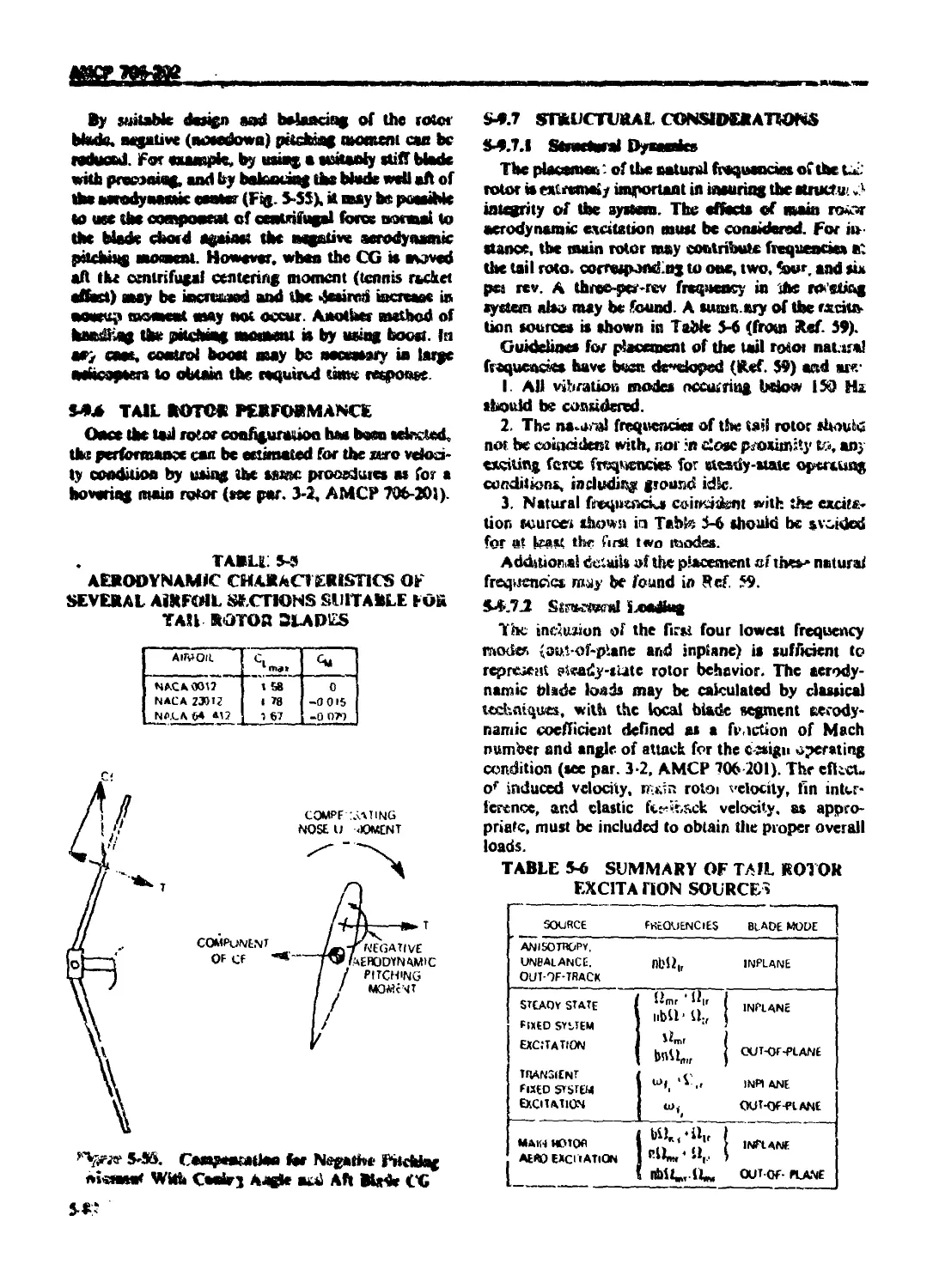
5-9.5.2 Tail Rotor Tip Speed ......................................... 5-80
5-9.5.3 Blade Numocr and Solidity .................................... '5-81
5-9.5.4 Twist ......................................................... 5-8t
5-9.5.5 Slade Airroil Section ......................................... 5-Rl
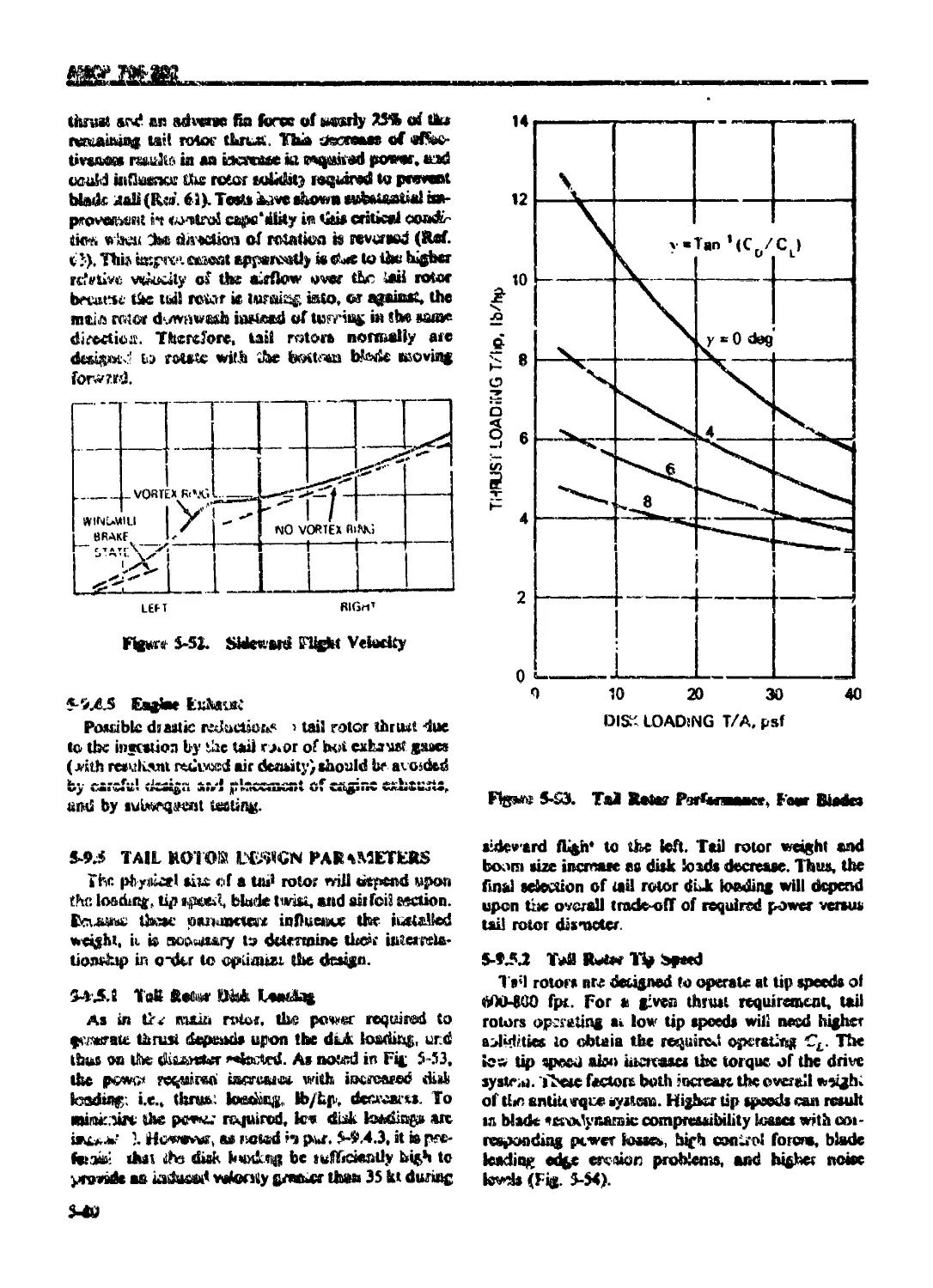
5-9.6 TAIL ROTOR PERFORMANCE ....................................... 5-32
5-9.7 STRUCTURAL CONSIDERATIONS ..................................... 5-82
5-9.7.1 Structural Dynamics............................................ 5-82
5-9.7.2 Structural Loading ............................................ 5-82
5-9.7.3 A Blade Structural Analysis ........ 5-83
5-9.7.4 A Аг-oelasticity ................................................ 5-83
5-9.7.5 Flutter and Divergence ........................................ 5-83
REFERENCES ....................................................... 5-83
CHARIER 6
FLIGHT CONTROL SUBSYSTEM
6-0 LIST OF SYMBOLS ............................................... 6 1
6-1 GENERAL 6-i
6-1.1 DESIGN METHOD .................*................................ 6-1
6-1.1.1 Point of Departure ............................................ 6-1
6-1.1.2 Mission Requirements and Flight Envelop? 6-2
6-1.1 3 Basic Helicopter Data ....................................... 6 ?
6-1.2 ANALYTICAL TOOLS ............................................... 6-2
6-1.3 SIMULATION AND TESTING ...................................... 6 2
6-2 STABILITY SPECIFICATIONS ...................................... 6-2
6-2.1 CRITERIA AND METHODOI АУЛ! YSIS ......................... 6-2
6-2.1.1 Control Power and Damping....................................... 6-3
6-2.1.2 Characteristic Roots ......................................... 6-3
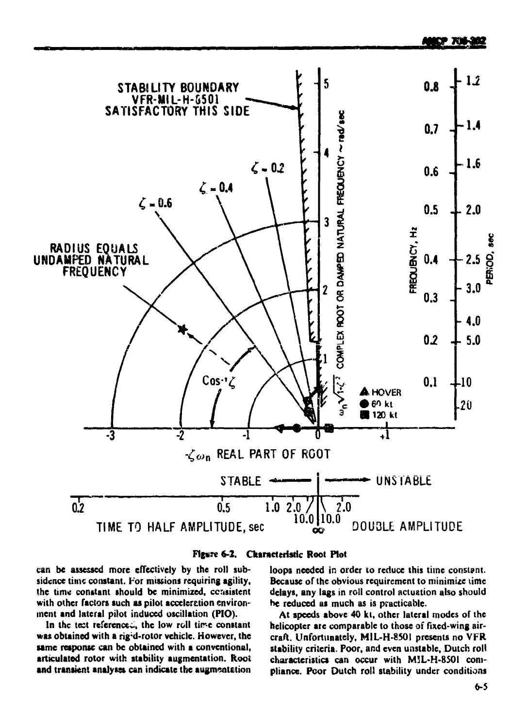
6-2.1.2.1 Roni. Plots .................................................... 6-4
6-2.1.2.2 Modes and Required Damping..................................... 6-4
6-2.1.2.3 Inherent Airframe Stability 6-6
6-2.1.2.4 Variation of Parameters ........................................ 6-6
6-2.1.3 Type of Control ................................................ 6-6
6-2.1.4 Transient Response.............................................. 6-6
6-2.1.5 Other Factors .................................................. 6-7
6-2.2 AUTOROTATION ENTRY ............................................. 6-8
6-2.3 SYSTEM FAILURES ................................................ 6-8
6 3 STABILITY AUGMENTATION SYSTEMS ................................... 6-9
6-3.1 GENERAl....................................................... 6-9
6-3.1.1 Bell Stabilizer Bar ......................................... 6-9
6-3.1.2 Hiller Servo Rotor............................................. 6-9
6-3.1.3 Mechanical Gyro .............................................. 6-9
6-3.1.4 Lockheed Control Gyro ......................................... 6-10
6-3.1.5 Elcctrohydraulic SAS .............. 6 10
6-3.1.6 Fluidic and Hydrofluidic SAS .................................. 6-10
6-3.1.7 Flapping Moment Feedback 6-10
6-3.2 CRITERIA FOR SELECTION ...................................... 6 10
6-3.2.1 Augmentation Requirements ..................................... 6-10
АМСР 706-2С2
TABLE OF CONTENTS (Continued)
Paragraph Pugr
6-3.2.2 Helicopter Size ................................................ 6-10
6-3.2.3 Type of Rotor System ........................................... 6-ti
6-3.2.4 Helicopter Configuration .................................... 6-11
6-3.2.5 Suppression of Structural and Rotor Mode Responses, Vibrations,
or Gusts ................................................... 6-11
6-3.3 SAS RELIABILITY ................................................ 6-12
6-?.'.I Safety ......................................................... 6-12
6-3.3.2 SAS Failures ................................................... 6-12
6-3.3.3 Fail-safe Principles ........................................... 6-13
6-3.3.4 Battle Damage, Vulnerability ................................ 6-13
6-3.4 COST ........................................................... 6-13
6-3.4.1 Development Cost.............................................. 6-13
6-3.4.2 Production Cost ............................................... 6-13
6-3.4.3 Maintenance Cost ............................................. 6-13
6-3.5 TECHNICAL DEVELOPMENT PLAN ................................ 6-1.3
6-4 PILOT EFFORT ..................................................... 6-14
6-4.1 CRITERIA FOR POWER CONTROLS .................................... 6-14
6-4.LI Control Forces ................................................. 6-14
6-4.1.2 Vibration Feedback ............................................. 6-14
6-4.1.3 К muriatic Effects ............................................. 6-14
6-4.1.4 Control Stiffness .......................................... 6-15
6-4.2 HANDLING QUALITY SPECIFICATION ................................. 6-15
6-4.3 HUMAN FACTORS .............................................. 6-17
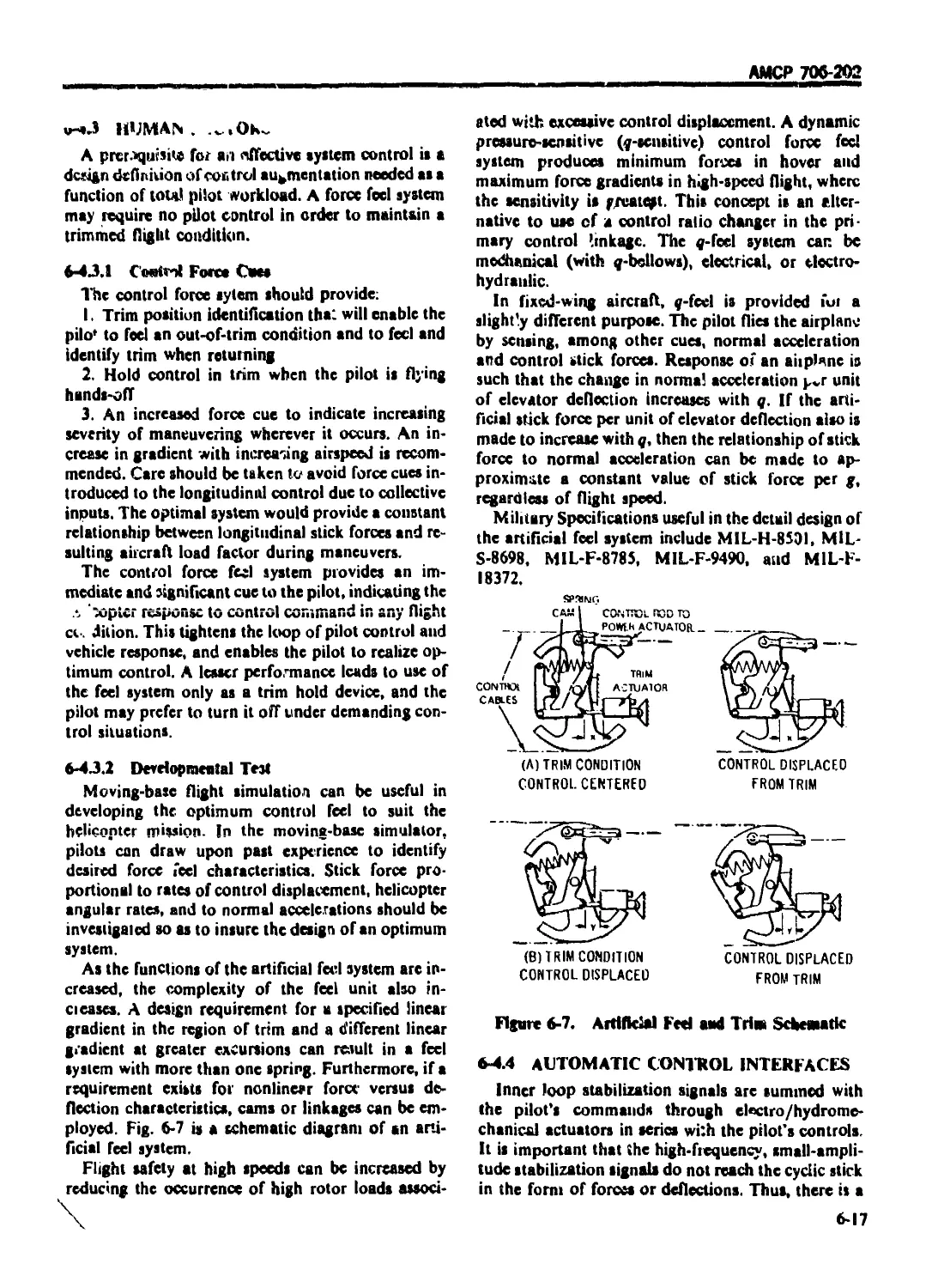
6-4.3.1 Control Force Cues............................................. 6-17
6-4.3.2 Developmental Test ............................................. 6-17
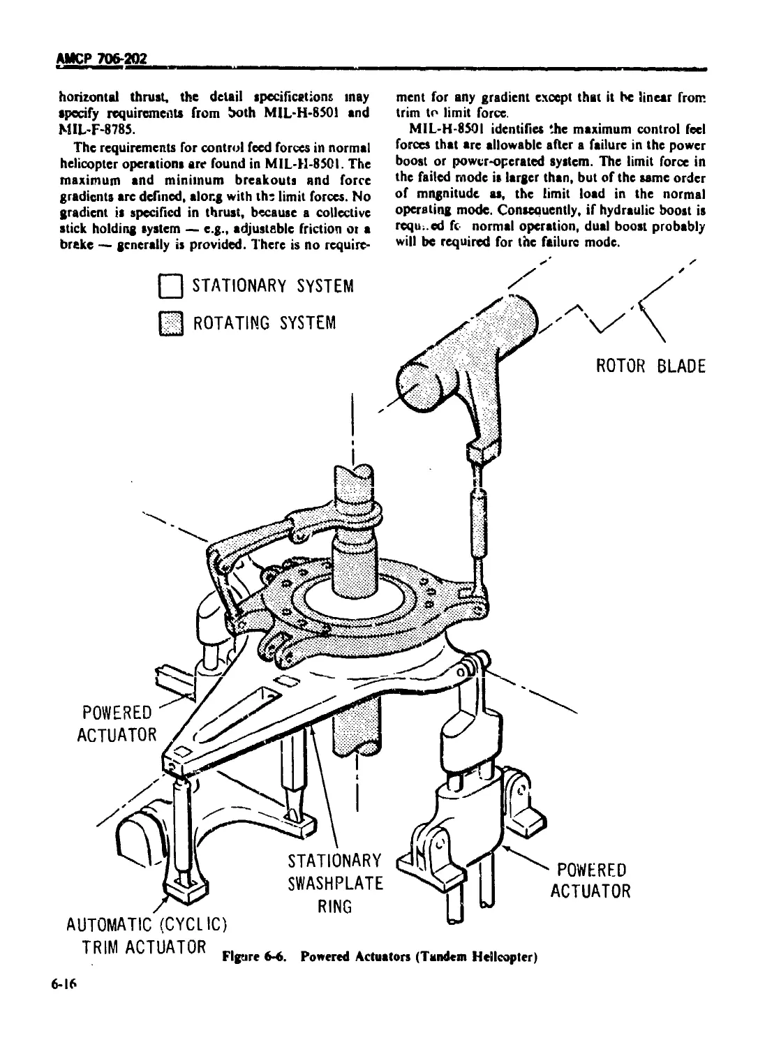
6-4.4 AUTOMATIC CONTROL INTERFACES ............................ 6-17
6-4.5 VULNERABILITY .................................................. 6-18
6-4.6 RELIABILITY .................................................... 6-18
6-5 MECHANISMS ....................................................... 6-18
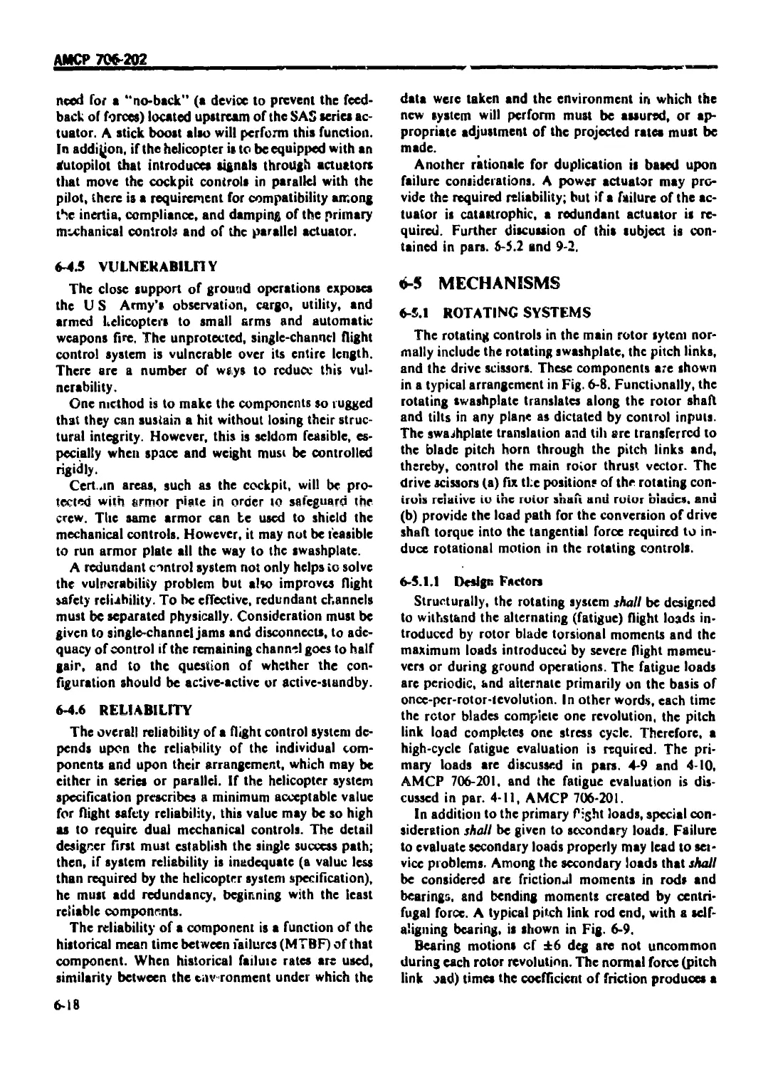
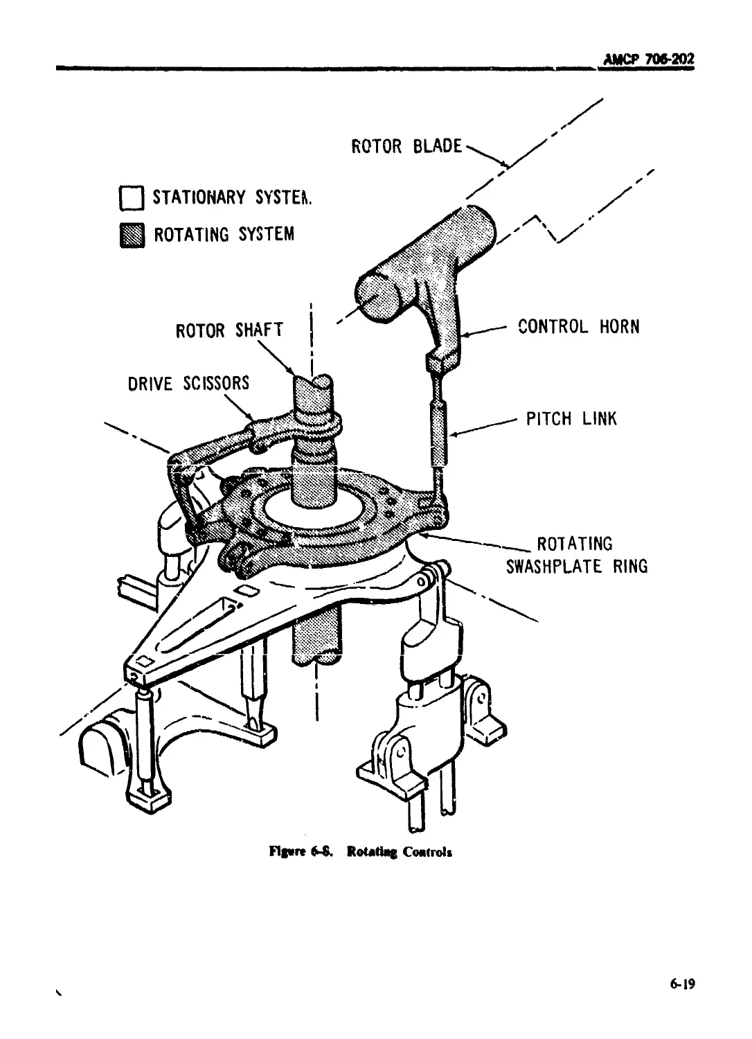
6-5.1 ROTATING SYSTEMS................................................ 6-18
6-5.1.1 Design Factors ................................................. 6-18
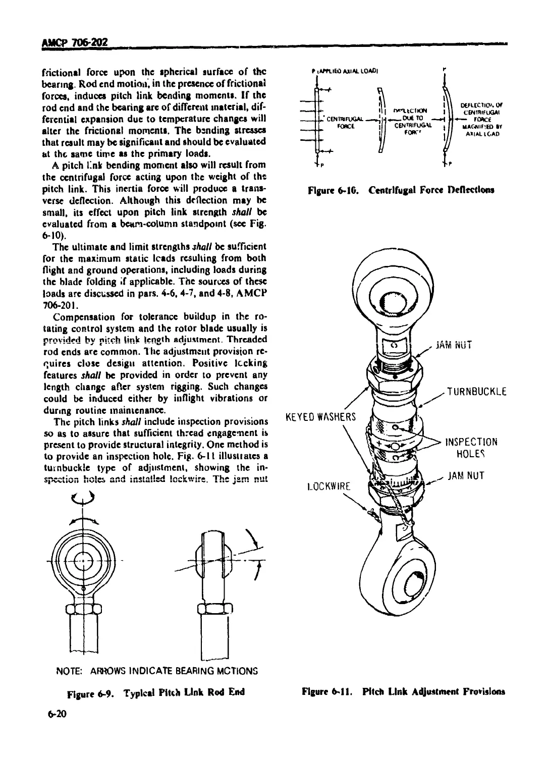
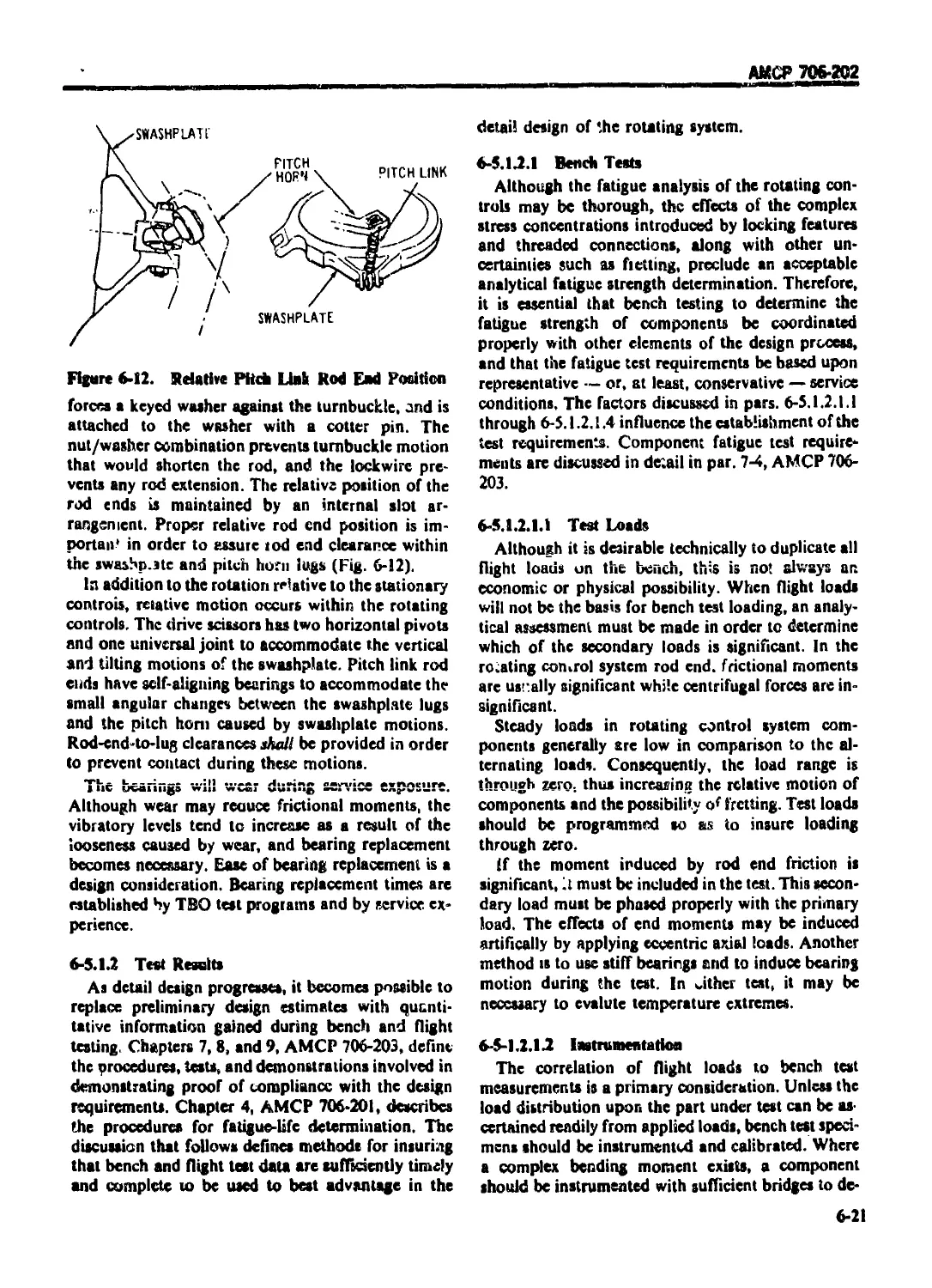
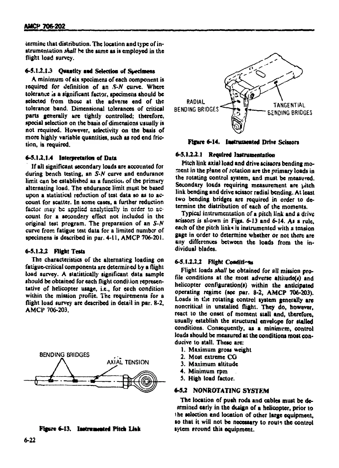
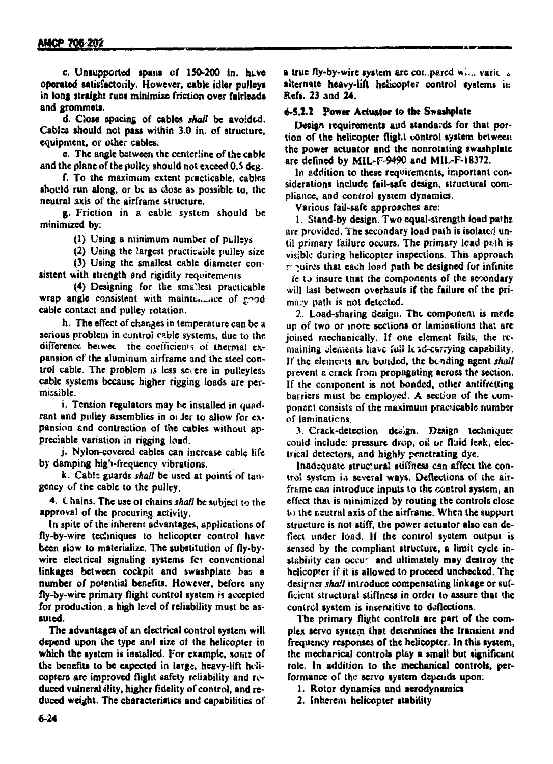
6-5.1.2 Test Results ................................................... 6-2l
6-5.1.2.1 Bench Tests ................................................. 6-21
6-5.1.2.1.1 Test Loads ................................................... 6-21
6-5.1.2.1.2 Instrumentation............................................... 6-21
6-5.1.2.1, j Quantity and Selection of Specimens .......................... 6-22
6-5.1.2.1.4 Interpretation of Data ....................................... 6-22
6-5.1.2.2 Flight Tests ................................................. 6-22
6-5.1.2.2.1 Required Instrumentation ..................................... 6-22
6 5.1.2.2.2 Flight Condi.ions ............................................ 6-22
6-5.2 NONROTATING SYSTEM ............................................. 6-22
6-5.2. i Pilot’s Controls to Power Actuator ............................. 6-23
6-5 2.2 Power Actuator to the Swashplaie ............................... 6-24
6-5.3 . TRIM SYSTEMS ................................................... 6-25
6-5.3.1 Disconnect Ttim ................................................ 6-25
6-5.3.2 ContinuousTrim ................................................. 6-25
6 5.3.3 Parallel and Scries Trim ....................................... 6-26
6-6 SYSTEM DEVELOPMENT ............................................... 6-26
6-6.1 GENERAL......................................................... 6-26
>6.2 MATHEMATICAL MODEL IMPROVEMENT ................................. 6-26
xi
АМСР 706-202
TABJ.E OF CONI 'FN I S (Continued)
Paragraph Page
6-6.2.I Wind Tunnel Test ....................................... -26
6-6.2.2 Hardware Bench Tests .................................. 6-27
6-6.3 GROUND-BASED PILOTED FLIGHT SIMULATION ................ 6-27
6-6.4 FLIGHT TESTS .......................................... 6-2S
6-6.5 DESIGN REVIEW ......................................... 6-28
REFERENCES ............................................. 6-28
CHAPTER?
ELECTRICAL SUBSYSTEM DESIGN
7-0 LIST OF SYMBOLS ....................................... 7-1
7-1 INTRODUCTION ............................................. 7-1
7-1.1 GENERAL ................................................ 7-1
7-1.2 SYSTEM CHARACTERISTICS ................................. 7-1
7-1.3 LOAD ANALYSIS .......................................... 7-2
7-1.4 LOAD ANALYSIS PREPARATION .............................. 7-2
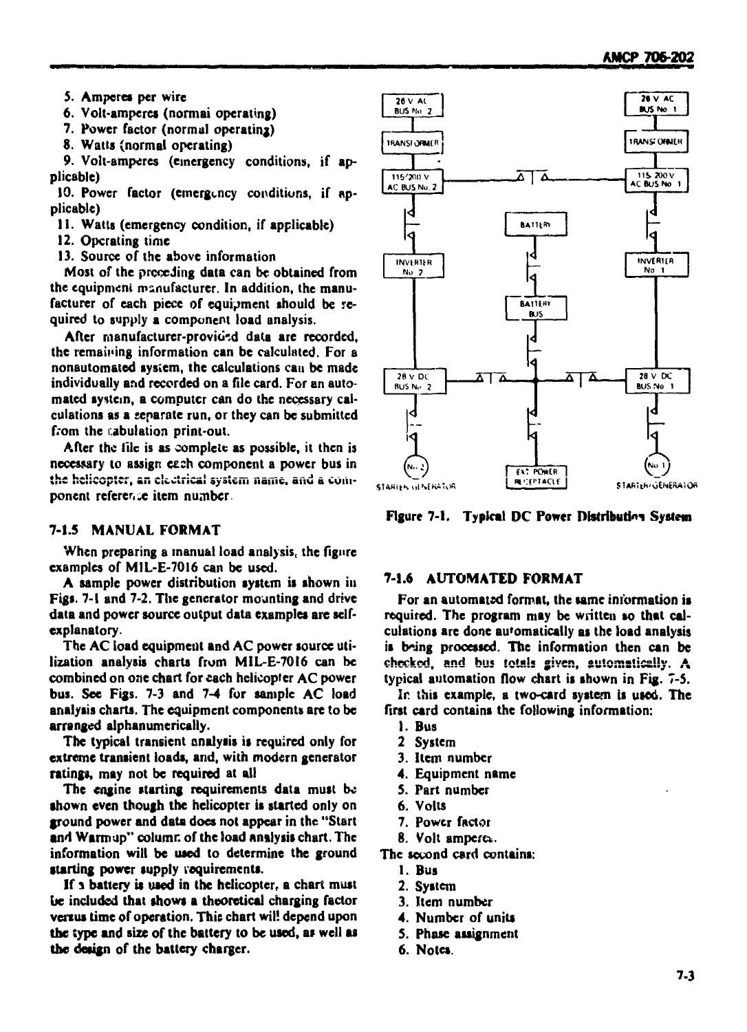
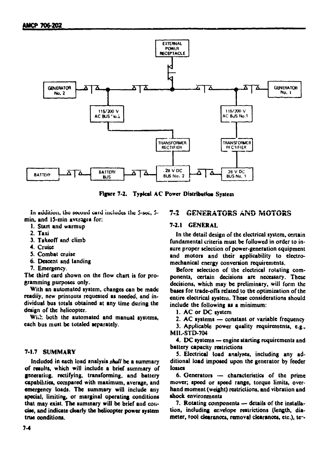
7-1.5 MANUAL FORMAT .......................................... 7-3
7-1.6 AUTOMATED FORMAT ....................................... 7-3
7-1.7 SUMMARY ................................................. 74
7-2 GENERATORS AND MOTORS ..................................... 74
7-2.1 GENERAL ................................................. 74
7-2.2 AC GENERATORS (ALTERNATORS) ............................ 7-6
7-2.2.1 Electrical Design ...................................... 7-6
7-2.2.2 Mechanical Design ...................................... 7-6
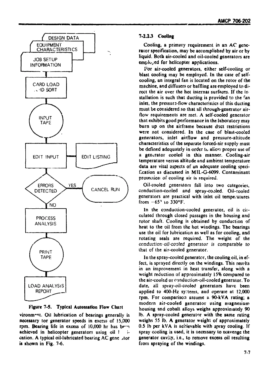
7-2.2.3 Cooling ................................................ 7-7
7-2.2.4 Application Checklist ........................... ... 7-8
7-2.2.S Variable-freqt^ency AC Generators ................... 7-8
7-2.3 STARTER/GENERATORS, DC GENERATORS, AND STARTERS .. 7-9
7-2.3.1 Startcr/Generator ................................... 7-9
7-2.3.2 DC Generators ......................................... 7-10
7-2.3.3 DC Starters ......................................... 7-11
7-2 3.4 Boost Starting System ................................. 7-11
7-2.4 ELECTRICAL MOTORS ..................................... 7-13
7-2 5 ELECTRICAL SYSTEM CONVERSION .......................... 7-14
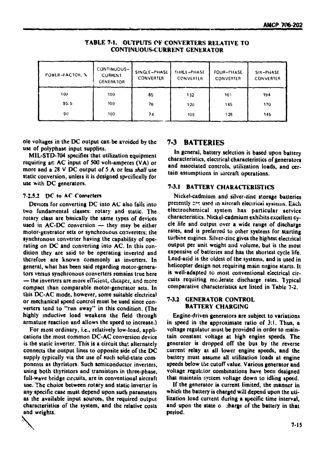
7-2.5.1 AC to DC Converters.................................... 7-14
7.2.5.2 DC to AC Converters ................................. 7-15
7-3 BATTERIES ............................................... 7-15
7-3.1 BAT TERY CHARACTERISTICS .............................. 7-15
7-3.2 GENERATOR CONTROL BATTERY CHARGING .................... 7-15
7-3.3 UTILIZATION LOAD ANALYSIS ........................... 7 56
7-3.4 HEAVY CURENT STARTING REQUIREMENTS .................... 7-17
7-3.5 MAINTENANCE ........................................... 7-18
74 VOLTAGE REGULATION AND REVERSE CURRENT RELAY ............ 7-18
7-4.1 DC VOLTAGE REGULATION ................................. 7-18
74.1.1 Voltage Regulator ............................... ... 7-18
74.12 Reverse Current Relays ................................ 7-19
74.1.3 Overvoltage Relays ................................... 7-19
74.2 AC VOLTAGE REGULATION ................................. 7-19
7-5 OVERLOAD PROTECTION ..................................... 7-19
7-5.1 GENERAL ............................................. 7-',9
7-5.2 OVERLOAD PROTECTION DEVICES ........................... 7-20
xii
АМСР 706202
TABLE ОI (ONI IM S К uitiinuedi
Paragraph Page
7-5.2.1 Circuit Breakers ............................................ 7-20
7-5.2.1.1 Thermal Circuit Breakers .................................... 7-20
7-5.2.1.2 Magnetic Circuit Breakers ................................... 7-20
7-5 2.2 Remote Control Circuit Breakers ............................. 7-20
7-5.2.3 Current Sensors ............................................. 7-22
7-5.2.4 Fuses ....................................................... 7-20
7-5.3 OVERLOAD PROTECTION APPLICATION ............................. 7-2l
7-6 ELECTROMAGNETIC INTERFERENCE (EMI/EMC) ........................ 7-21
7-6.1 GENERAL ..................................................... /-21
7-6.2 ACCEPTABILITY REQUIREMENTS .................................. 7-21
7-6.3 INTERFERENCE SPECIFICATIONS ................................. 7-21
7-6.4 INTERFERENCE SOURCES ...................................... 7-21
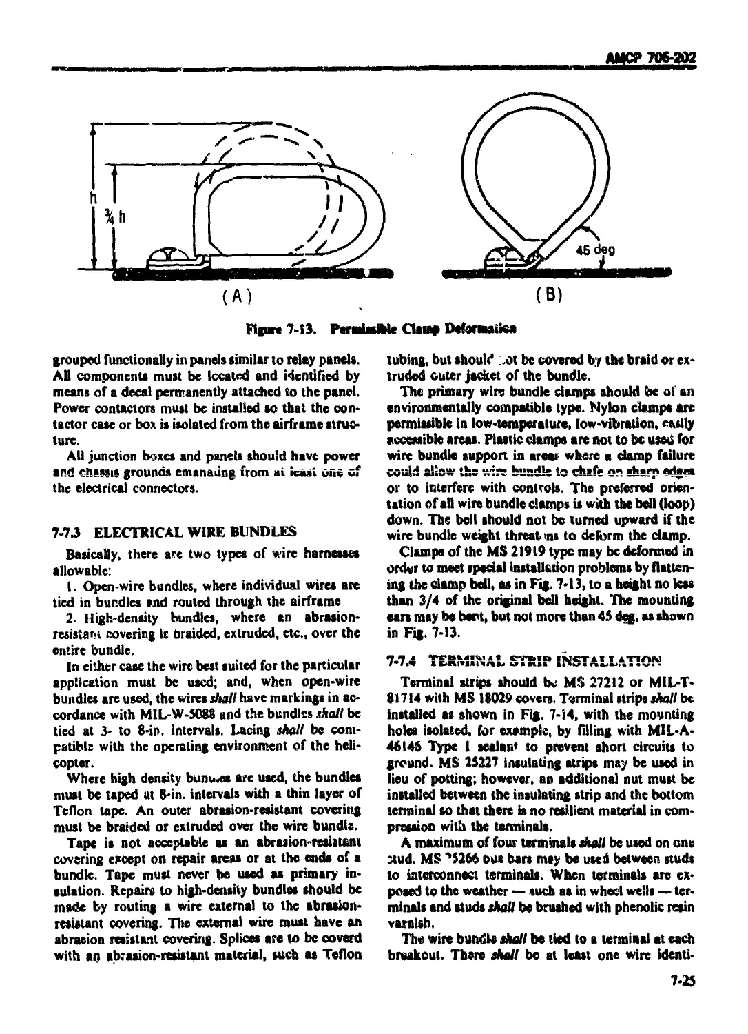
7-6.5 INTERFERENCE SUPPRESSION .................................... 7-22
7-6.5.1 Interference-free Components ................................ 7-22
7-6.S.2 Equipment Isolation and Cable P outing ...................... 7-22
7-6.5.3 Source Suppression and Susceptibility Reduction ............. 7-23
7-6.5.3.1 Grounding and Bonding ....................................... 7-23
7-6.5.3.2 Shielding ................................................... 7-23
-6.5.3.3 Filters ..................................................... 7-24
7-7 ELECTRICAL SYSTEM INSTALLATION ................................ 7-24
7-7. i GENERA!...................................................... 7-24
7-7.2 EQUIPMENT INSTALLATION ...................................... 7-24
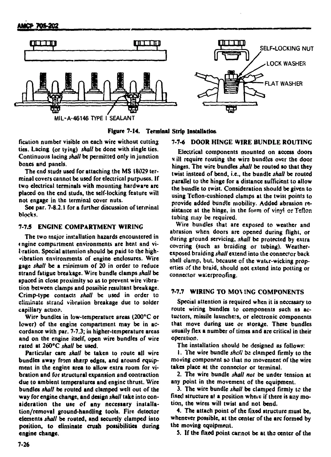
7-7.3 ELECTRICAL WIRE BUNDLES ..................................... 7-25
7-7.4 TERMINAL STRIP INSTALLATION ................................. 7-25
7-7.5 ENGINE COMPARTMENT WIRING ................................... 7-26
7-7.6 DOOR HINGE WIRE BUNDLE P.OUTING ............................. 7-26
7-7.7 WIRING TO MOVING COMPONENTS ................................. 7-26
7-7.8 BATTERY INSTALLATION ........................................ 7-27
7-8 COMPONENTS .................................................... 7-27
7-8.1 WIRE ........................................................ 7-27
7-8.1.1 Wire Insulating Materials ................................... 7-27
7-8.1.1.1 Polyethylene ................................................ 7-27
7-8.1.1.2 Polyvinylchloride............................................ 7-27
7-8.1.1.3 Fluorinated Ethylene Propylene............................... 7-28
7-8.1.1.4 Polychlorotrifluoroethylene ................................. 7-28
7-8.1.1.5 Polyhexamethylene-adipamide ................................. 7-28
7-8.1.1.6 Tetrafluorocthylene ......................................... 7-28
7-8.1.1.7 Dimethyl-siloxanc Polymer 7-28
7-8.1.2 Military Wire Specifications ................................ 7-28
7-8.2 FITTING* 7-29
7-8.2.1 Termi:.al Strips ............................................ 7-29
7-8.2.2 Connectors .................................................. 7-29
7-9 LIGHTNING AND STATIC ELECTRICITY............................... 7-29
7-9.1 GENERAL ..................................................... 7-29
’-9.2 LIGHTNING PROTECTION FOR ELECTRONIC SUBSYSTEMS .... 7 30
7-9.3 STATIC ELECTRICITY .......................................... 7-31
7-9.4 LIGHTNING AND STATIC ELECTRICITY SPECIFICATIONS ....... 7-32
REFERENCE .................................................... 7-32
xiii
АМСР 706-202
TABLE OF CONTENTS (Continued)
Paragraph Page
CHAPTER 8
AVIONIC SUBSYSTEMS DESIGN
8 I INTRODUCTION ......................................... 8-1
8-1.1. GENERAL ............................................. 8-i
8-1.2 ELECTROMAGNETIC COMPATIBILITY PROGRAM ............... £-1
8-1.3 DESIGN CONSIDERATIONS ............................... 8-2
8-1.4 ENVIRONMENTAL ASPECTS ............................... 8-2
8-2 COMMUNICATION EQUIPMENT ............................ 8-3
8-2.1 GENERAL ............................................. 8-3
8-2.2 MICROPHONE-HEADSET .................................. 8-4
8-2.3 INTERCOMMUNICATION SELECTOR BOX ..................... 8-4
8-3 NAVIGATIONAL EQUIPMENT .............................. 8-4
8-3.1 GENERAL ........................................... 8-4
8-3.2 TERMINAL MANEUVERING EQUIPMENT ...................... 8-5
8-3.3 EN ROUTE NAVIGATION EQUIPMENT ......................... M
8-3.3.I 1 Automatic Direction Finder (ADF) .................. 8-5
8-3.3.2 Distance-measuring Equipment (DME) .................. 8-5
8-3.3.3 Tactical Air Navigation (TACAN) ..................... 8-6
8-3.3.4 L ong-range Navigation (LORAN) ...................... 8-6
8-3.3.5 Compasses ........................................... 8-6
8-3.3.6 Doppler Navigation Systems ......................... 8-6
8-3.3.7 Inertial Navigation Systems ......................... S-6
8-3.4 INTERDICTION EQUIPMENT .............................. 8-7
8-3.5 LOW-LIGHT-LEVEL NAVIGATIONAL EQUIPMENT .............. 8-7
8-3.6 STATION-KEEPING EQUIPMENT............................ 8-7
8-4 FIRE CONTROL EQUIPMENT ................................ 3-7
8-4.1 GENERAL ............................................. 8-7
8-4.2 INSTALLATION ........................................ 8-8
8-4.3 SIGHTING STATION .................................... 8-8
8-4.4 SENSORS ............................................. 8-8
8-4 5 COMPUTERS 6-9
8-4.6 FIRE CONTROL ACCURACY ............................... 8-9
8-4.6.1 Inertial Stabilization ............................ 8-9
8-4.6.2 Fire Control Datum Plane .......................... 8-9
8-4.6.3 Harmonization ...................................... 8-10
8-4.7 COMPONENT LOCATION ................................. 8-10
8-5 ANTENNAS.............................................. 8-10
8-5.1 GENERAL ............................................ 8-10
8-5.2 ANTENNA DEVELOPMENT ................................. 8-H
8-5.3 LOCATION AND INSTALLATION OF AN1ENNAS .............. 8-52
8-5.3.1 Communication Antenna Considerations ............... 8-13
8-5.3.2 Low Frequency (LF) ............................... 3-13
8-5.3.3 High Frequency (HF)................................ 8 13
8-5.3.4 Very High Frequency (VHF) .......................... 8-14
8-5.3.5 Ultra High Frequency (UHF) ........................ 8-14
8-5.3.6 Special Purpose .................................... 8-54
REFERENCES ......................................... 8-14
xiv
АЖР 706-20?
TABLE OF CONTENTS (Continued)
Paragraph Page
CHAPTER 9
HYDRAULIC AND PNEUMATIC SUBSYSTEMS DESIGN
9-0 LIST OF SYMBOLS ............................................... 9-i
9-1 INTRODUCTION .................................................. 9-1
9-2 HYDRAULIC SUBSYSTEMS .......................................... 9-1
9 2.1 FLIGHT CONTROL POWER SYSTEMS .................................. 9-1
9-2.1.1 Central Hydrauiic System ...................................... 9-1
9-23.2 Flight Control Subsystems...................................... 9-2
9-2.2 UTILITY HYDRAULIC SYSTEMS ..................................... 9-2
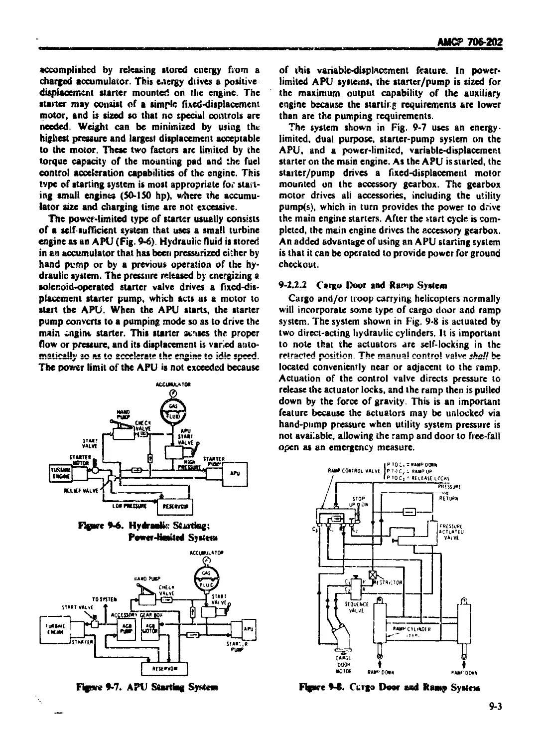
9-2.2.1 Engine-starting Subsystems .................................... 9-2
9- 2.2.2 Cargo Door and Ramp System .................................... 9-3
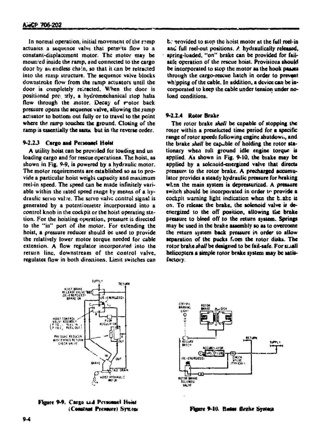
9-2.2.3 Cargo and Personnel Hoist...................................... 9-4
9-2.2.4 Rotor Brake ................................................... 9-4
9-2.2.S Wheel Brakes .................................................. 9-5
9-2.3 HYDRAULIC SYSTEM RELIABILITY .................................. 9-5
,9-23.1 Flight Control Redundancy ..................................... 9-5
9-23.2 Utility System Redundancy ..................................... 9-5
9-2.33 M'SCcIkneous Reliability Aspects .............................. 9-5
9-2.4 HYDRAULIC SYSTEM STRENGTH CONSIDERATIONS ................. 9-6
9-2.5 HYDRAULIC SYSTEM TEMPERATURE CONSIDERATIONS ........ 9-6
9-2.6 HYDRAULIC SYSTEM DESIGN ............................ 9-7
9-2.6.1 Survivability. Reliability, and Safety Trade-offs ............. 9-7
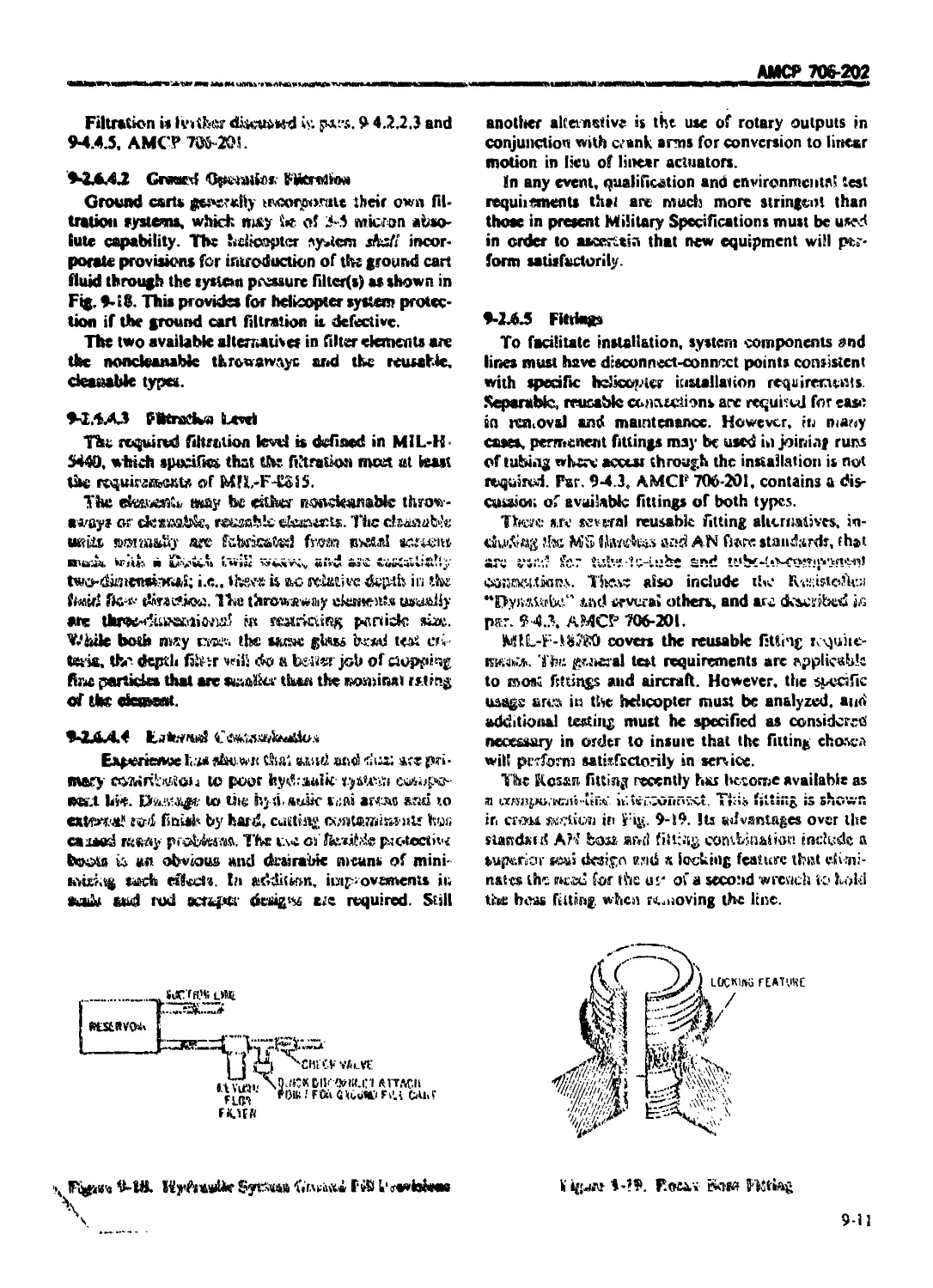
9-2.6.Li ReservoirLeve!Sensing ............................................ 9-8
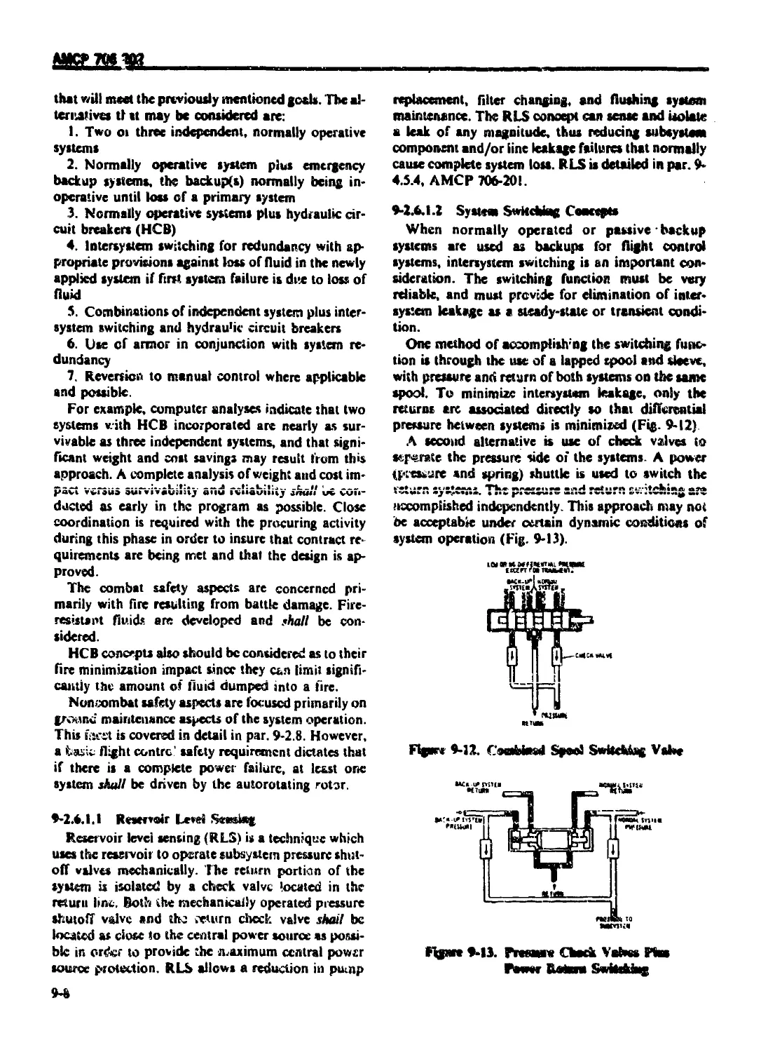
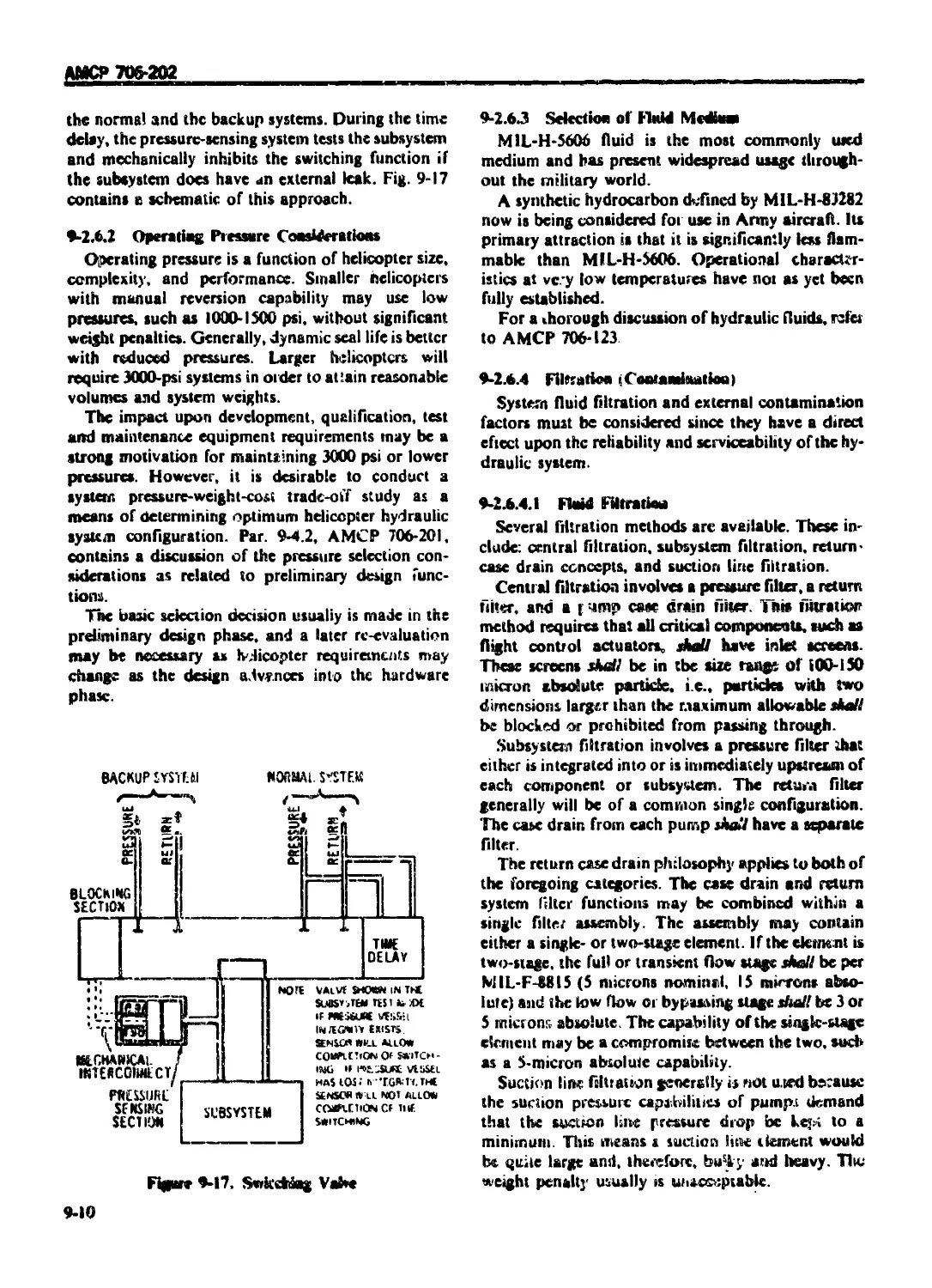
9-2.6.I.2 System Switching Concepts ..................................... J?-8
9-2.6.13 Return Pressure Sensing ...............'....................... 9-9
9-2 6.1.4 Switching and Return Pressure Sensing ......................... 9-9
9-2.6.3 Operating Pressure Considerations ............................. 9-iO
9-2.63 Selection of Fluid Medium ..................................... 9-iO
9-2.6.4 Filtration (Contamination) .................................... 9-10
916.4.1 Fluid Filtration .............................................. 9-10
9-2.6.4.1 Ground Operation Filtration ................................... 9-11
9-2 6.4.3 Filtration Level .............................................. 9-11
9-2.6.4.4 External Contamination ........................................ 9-11
9-2.6.5 Fittings ...................................................... 9-1 i
9-1.6.6 Dynamic Fluid Connections ..................................... 9-12
9-2.6.7 Peak Power Levels............................. ................ 931
9-2.6.8 APU ant* Engine Starting ......................................
9-2.6.0 System Heat Rejection Characteristics ....................... . 9-13
9-2.6.Ю System Analysis ............................................. 9-13
9-2.7 HYDRAULIC COMPONENT DESIGN AND SELECTIO N ..................... 9J?
9-2.7.1 Actuators ..................................................... 9-13
9-2.7.1.1 Rip-stop Protection ........................................... 9-i5
9-2-7 1.2 Endurance Testing Requirements ................................ 9-1*
9-2.7.13 Sea! Alternatives ............................................. 9-1S
9-2.7.1.4 Materials and Stress Considerations ........................... 9-16
9-2.7.1.5 General Requirements .......................................... 936
9-2.7.2 Hydraulic Pumps ......... ..................................... "P-ift
9-2.7.3 Accumulators ............ ...................................... 9-»9
9-2.7.-I Reservoirs .......................... ........................... 9-20
X 9-2.7.5 Pressure Relief .................. ............................ 9-2C
xv
АМСР 706 202
TABLE OF <ОМ 1 M S ।< (Hitinucd।
Paragraph Page
9-2.7.6 Pressure Regulalion ................................................. 9-20
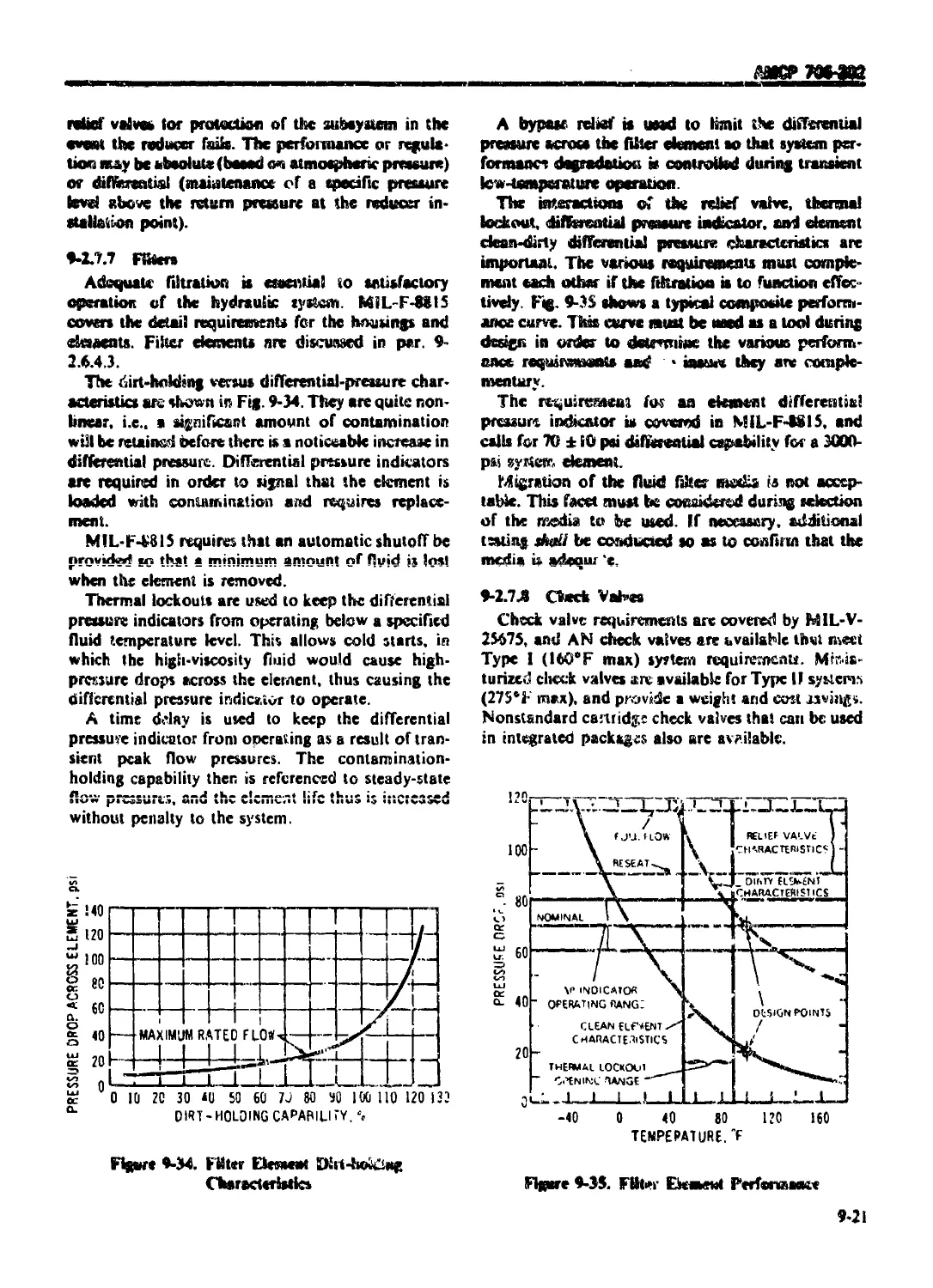
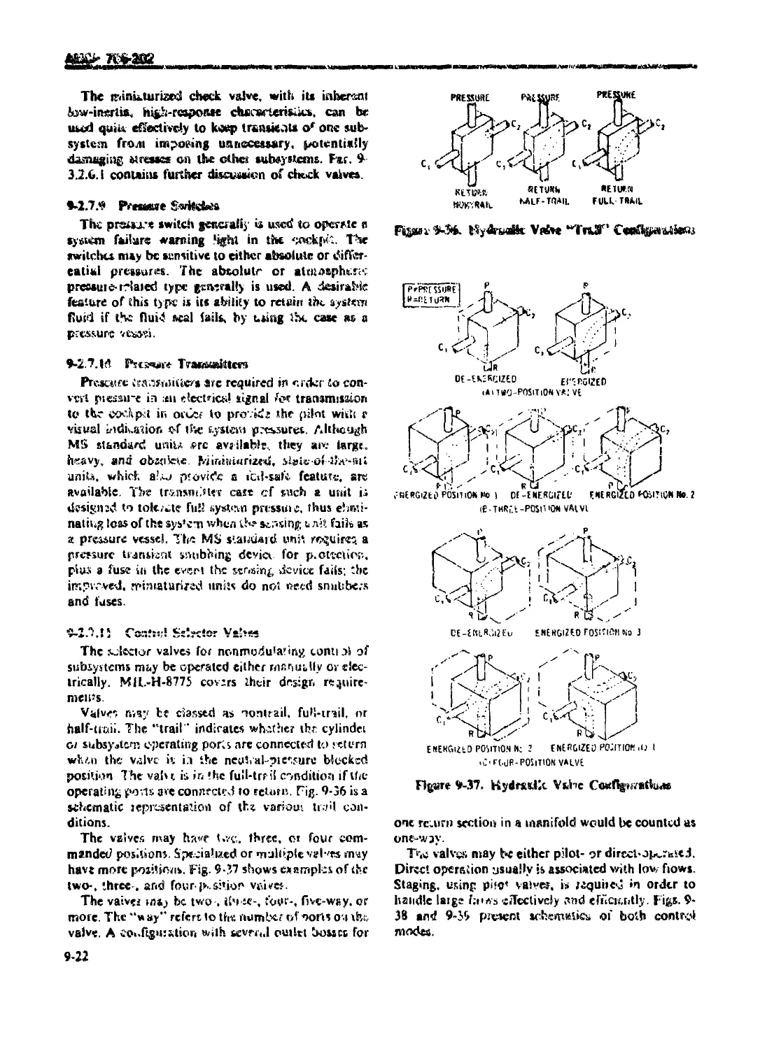
9-2.7.7 Filters ............................................................. 9-21
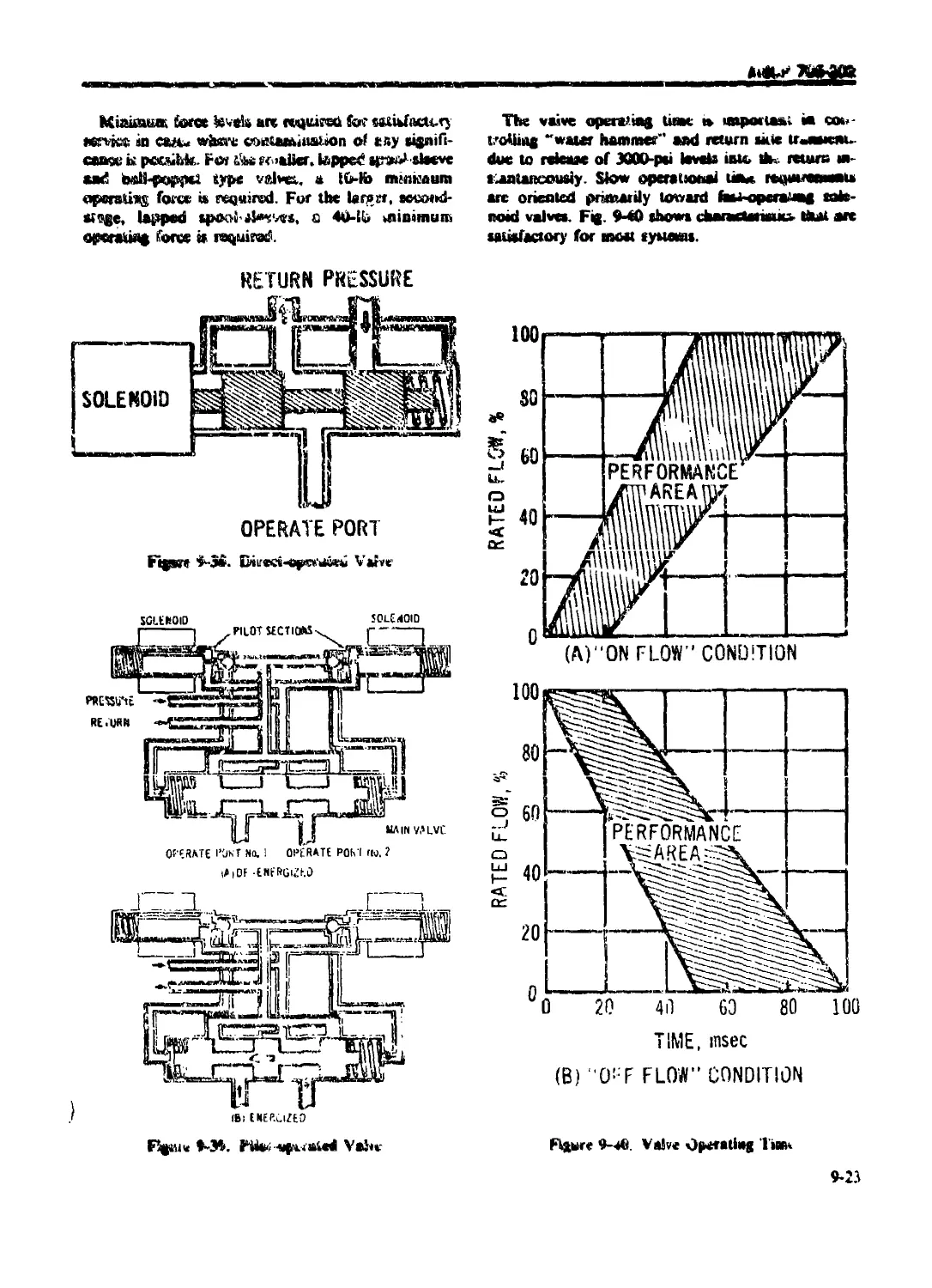
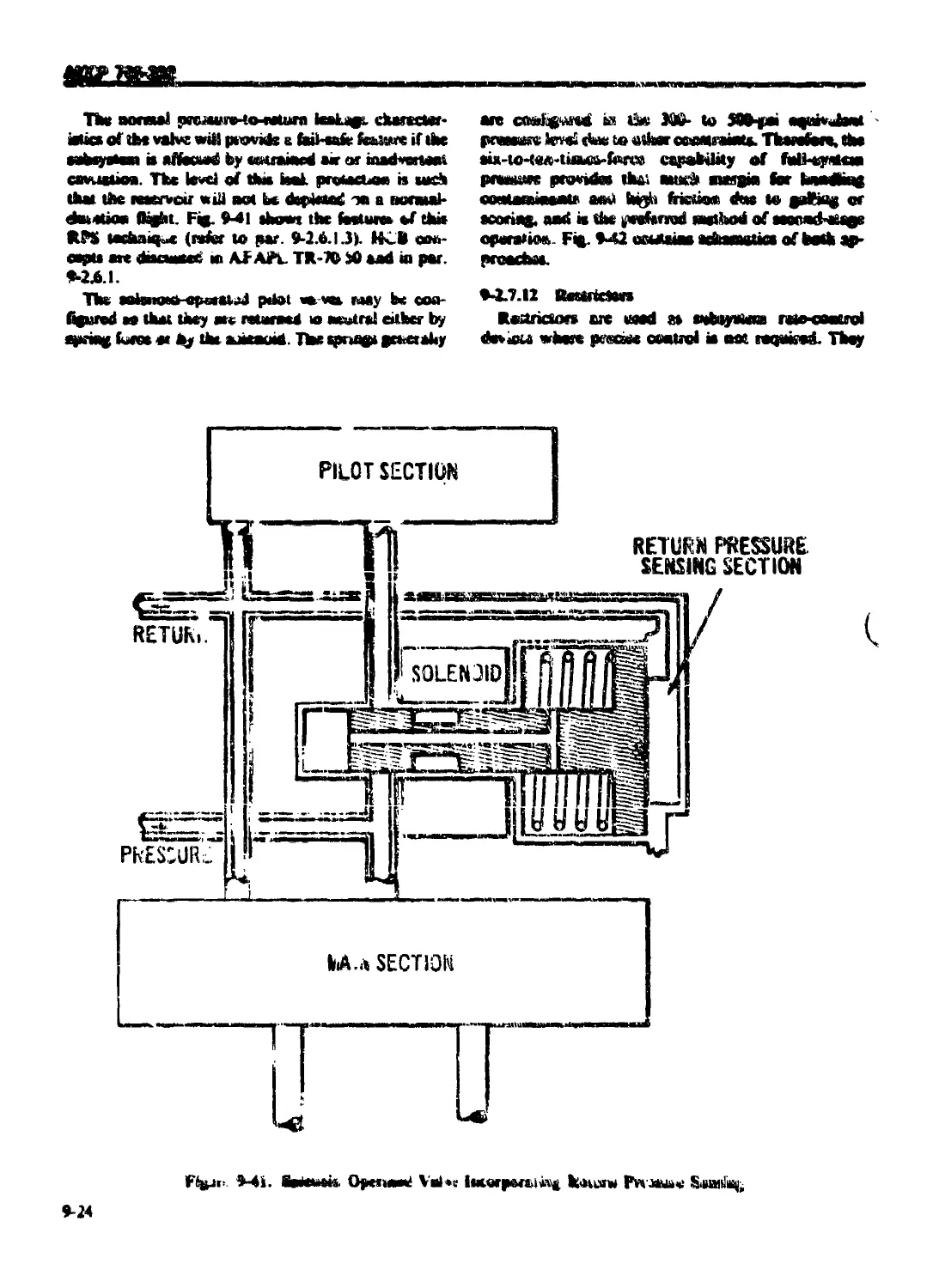
9-2.7.8 Check Valves .......................................................... 9-21
9-2.7.9 Pressure Switches...................................................... 9-22
9-2.7.10 Pressure Transmitters.................................................. 9-22
9-2.7.11 Control Sekuor Valves ................................................. 9-22
9-2.7.12 Restrictors ........................................................... 9-24
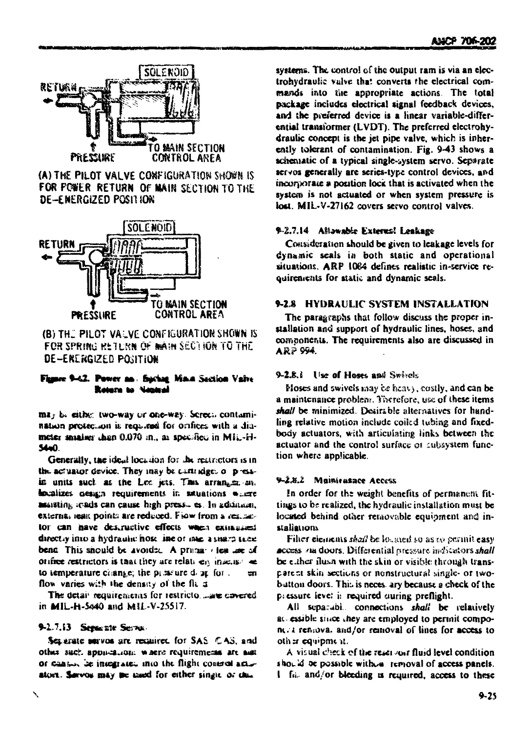
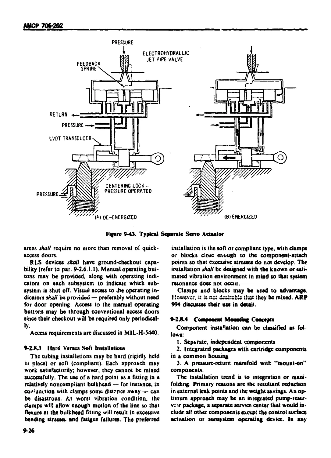
9-2.7.13 Separate Servos ....................................................... 9-25
9-2.7.14 Allowable External Leakage ............................................ 9-25
9-2.8 HYDRAULIC SYSTEM INSTALLATION ..................................... 9 25
9-2.8.I Uscof Hoses and Swivels ............................................... 9-25
9-2.8.2 Maintenance Access .................................................... 9-25
9-2,8.3 Hard Vetsus Soft Installations ........................................ 9-26
9-2.8.4 Component Mounting Concepts ........................................... 9-26
9-2.8.5 Miscellaneous Installation Considerations ............................. 9-27
9-2.9 MISCELLANEOUS DESIGN CRITERIA ......................................... 9-27
9-2.9.1 Actuators and Associated Equipment Design ............................ 9-27
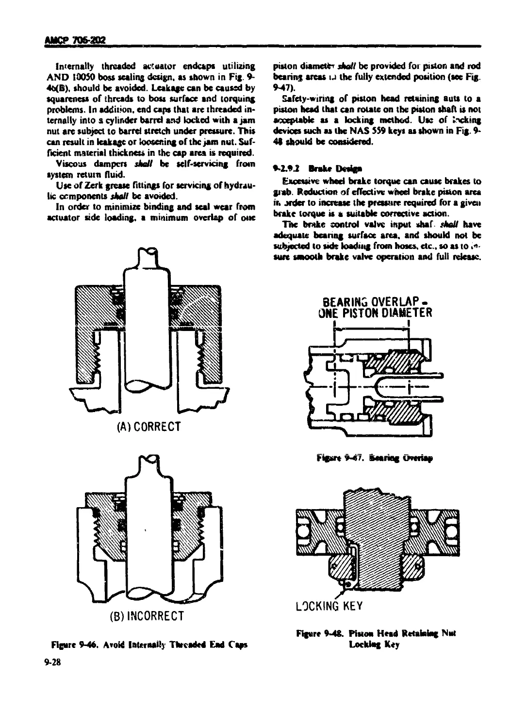
9-29.2 Brake Design ......................................................... 9-2.8
9-2.9.3 Control System Design ................................................. 9-29
9-2.9.4 Electrical Design ................................................... 9-29
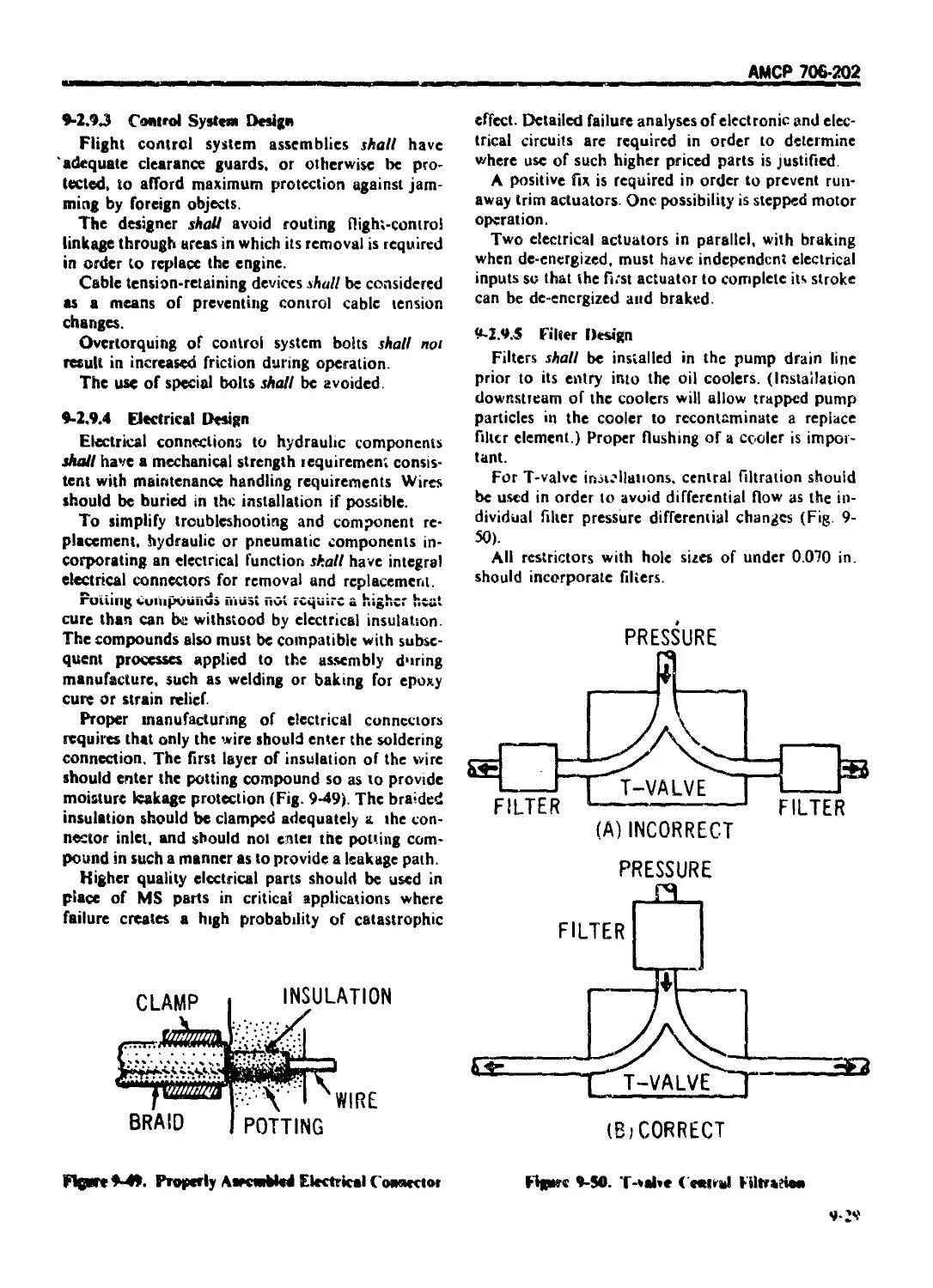
9-2.9.5 Filler Design ......................................................... 9-29
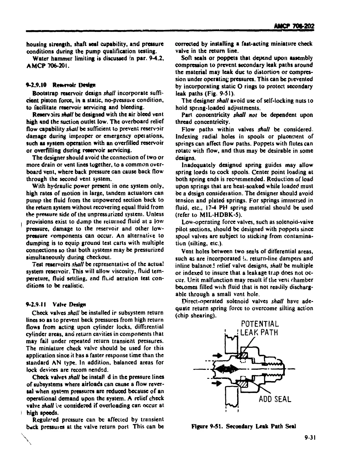
9-2.9.6 Fittings Design ....................................................... 9-30
9-2.9.7 Gage and Indicator Design ............................................. 9-30
9-2 9.8 Hose Design ........................................................... 9-30
9-1.9.9 Pump Design ........................................................... 9-30
9-2.9.10 Reservoir Design ..................................................... 9-31
9-2.9.11 Valve Design .......................................................... 9-31
9-2.9.12 Lubrication ........................................................... 9-32
9-3 PNEUMATIC SYSTEMS ........................................................ 9-32
9-3.1 PNEUMATIC SYSTEM DESIGN .......................................... 9-32
9-3.1.1 System Analysis ....................................................... 9-32
9-3.1.2 System Redundancy ..................................................... 9-33
9-3.2 COMPONENT DESIGN ................................................ 9-33
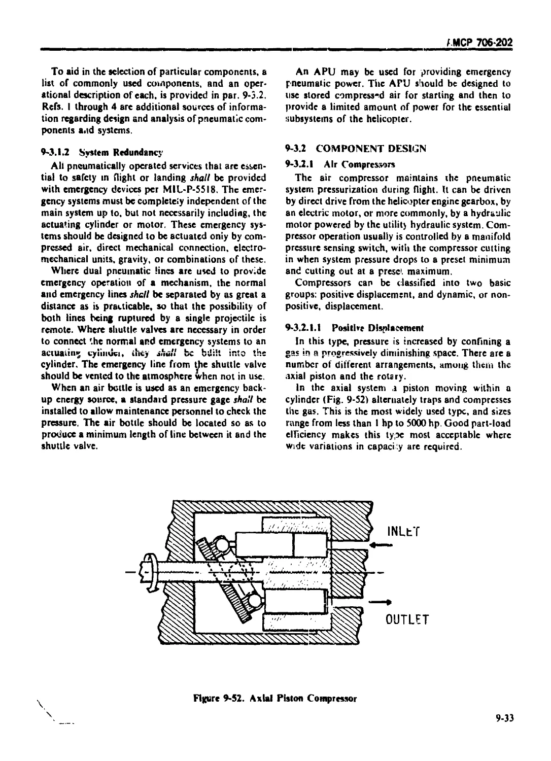
9-3.2.1 Air Compressors ....................................................... 9-33
9-3.2.1.1 Positive Displacement ............................................. 9 33
9-3.2.1.2 Dynamic Displacement .................................................. 9-34
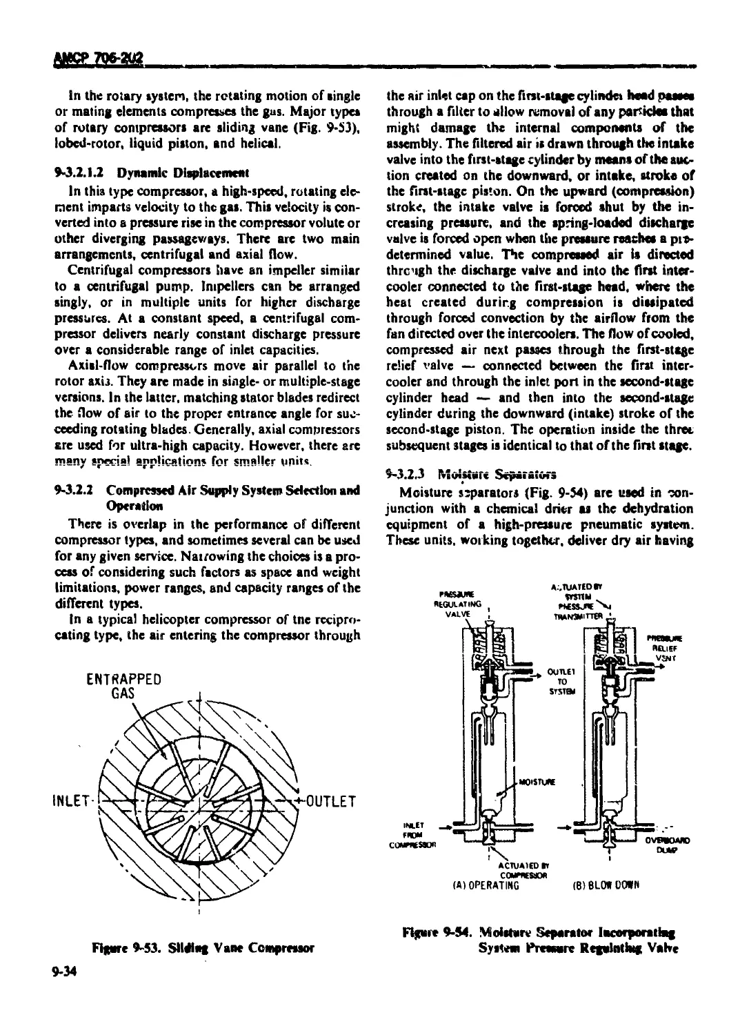
9-3.2.2 Compressed Air Supply System Selection and Operation .................. 9-34
9-3.2.3 Moisture Separators ................................................... 9-34
9-3.2.4 Dehydrators ........................................................... 9-35
9-3.2.5 Filters ............................................................... 9-35
9-3.2.6 Valves ................................................................ 9-36
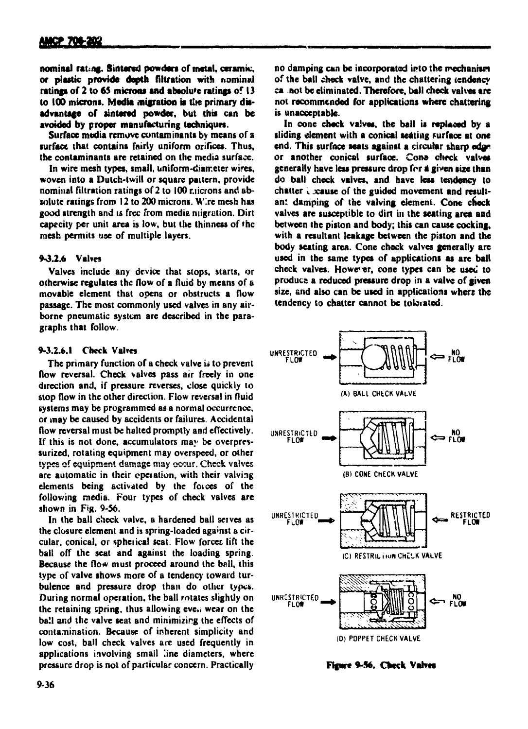
9-3.2.6.I Check Valves .......................................................... 9-36
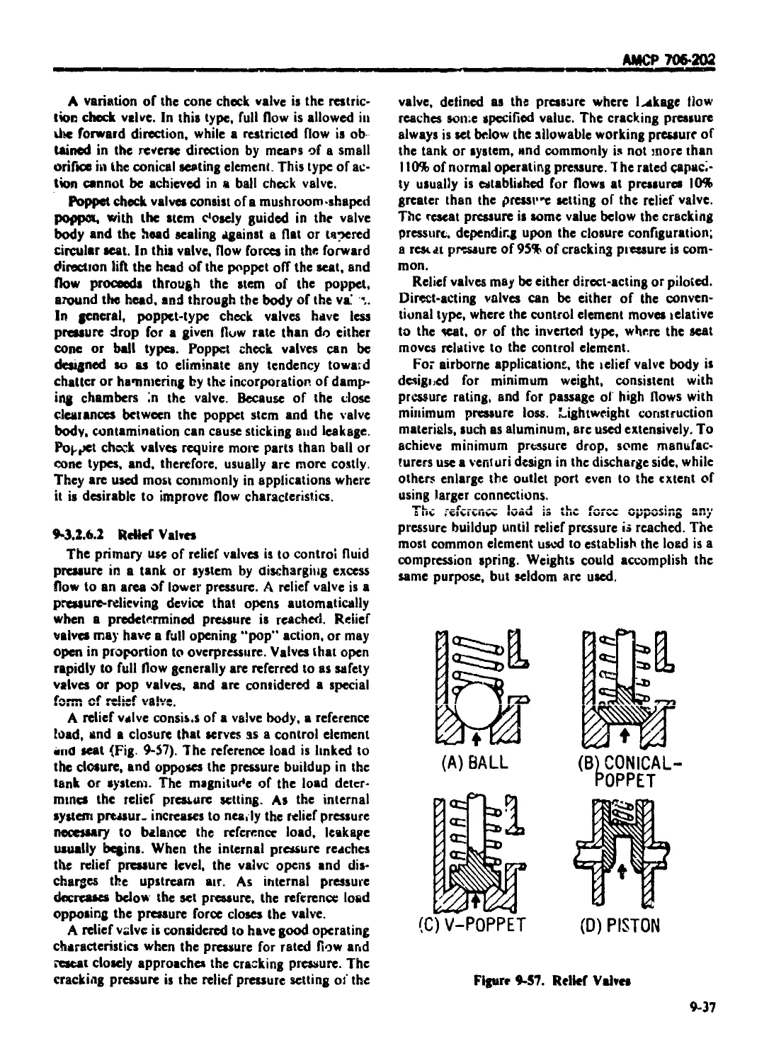
9-3.2.6.2 ReliefValves .......................................................... 9-37
9-3.2.6.3 Pressure-reducing Valves .............................................. 9-38
9-3.2.6.4 Pressure Regulators ................................................... 9-38
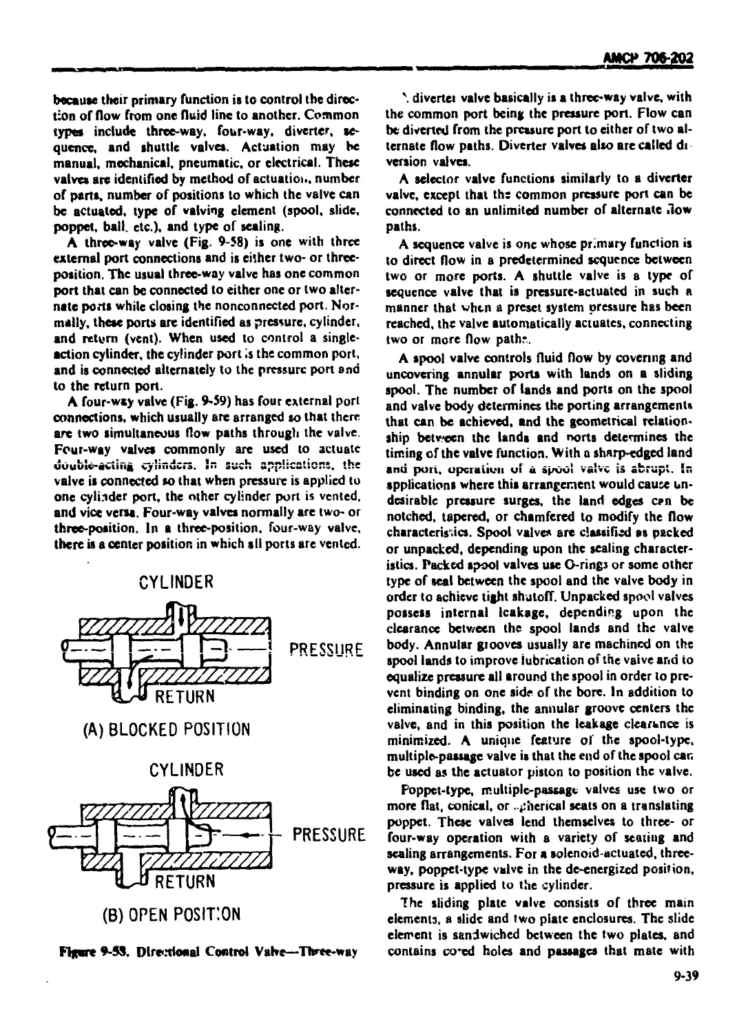
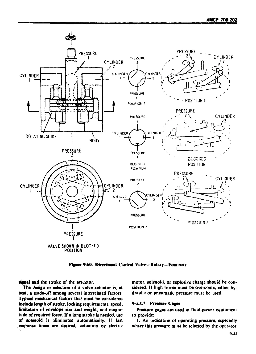
9-3.2.6.5 Directional Control Valves ............................................ 9-38
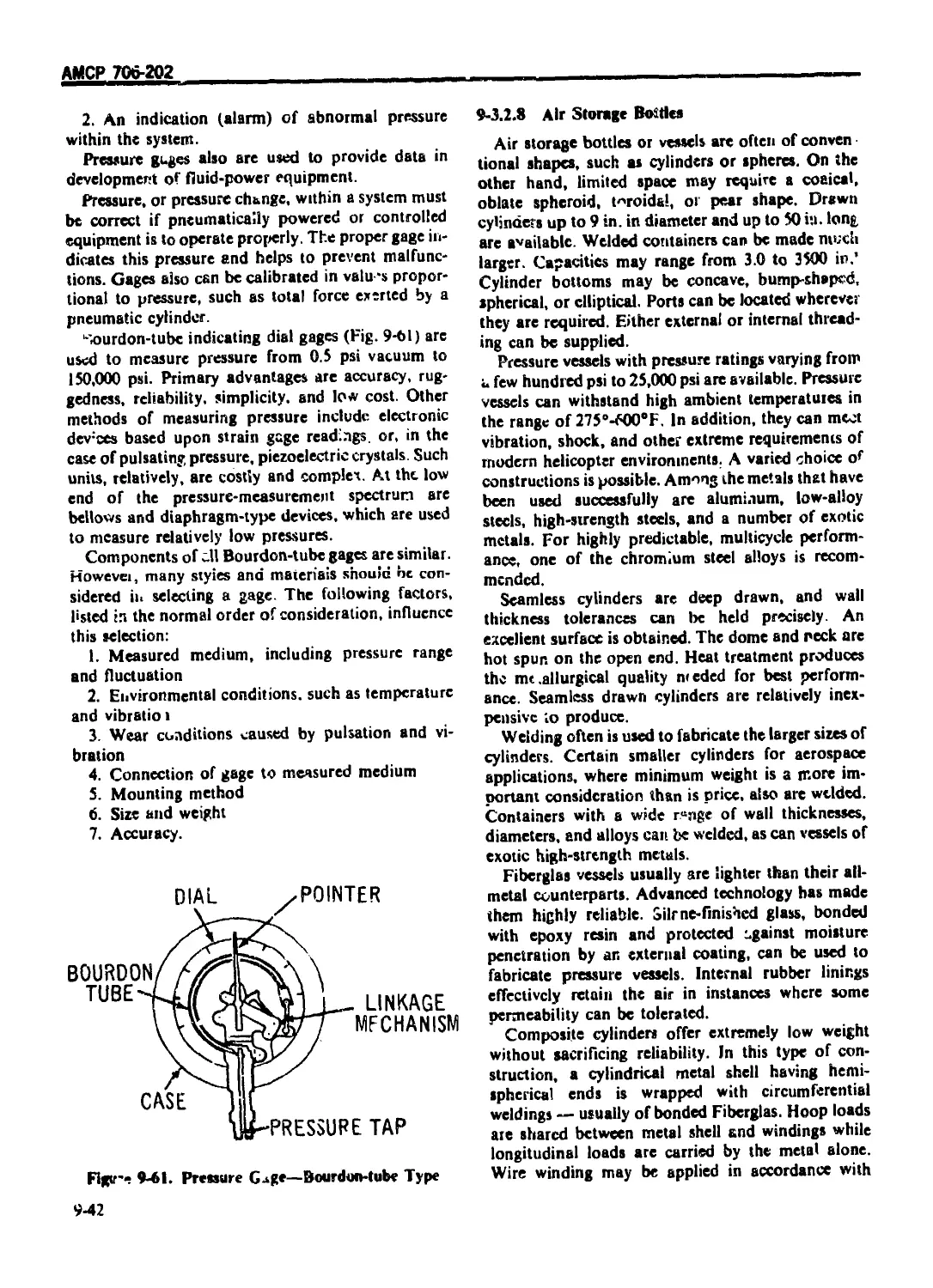
v-3.2.7 Pressure Gages ....................................................... 9-41
9-3.2.8 Air Storage Bottles ................................................... 9-42
9-3.2.9 Subsystem Components .................................................. 9-43
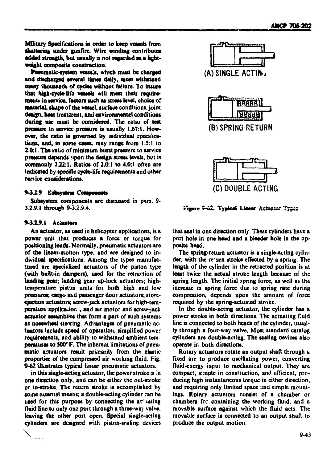
9-3.2.9.1 Actuators ............................................................. 9-43
хм
АМСР 706-202
TABLE OF < ON'IF.VISM onlinuedi
Paragraph
Page
9-12.9.2 Brake Valves ......................................................... 9-44
9-3.2.9,3 Pneumatic Fuses ...................................................... 9-44
9-3.2.9.4 Quick-disconnccc; .................................................... 9-44
9-3.3 PNEUMATIC SYSTEM INSTALLATION AND QUALIFICATION ... 9-44
9-3 4 PITOT-STATIC SUBSYSTEM DESIGN ......................................... 945
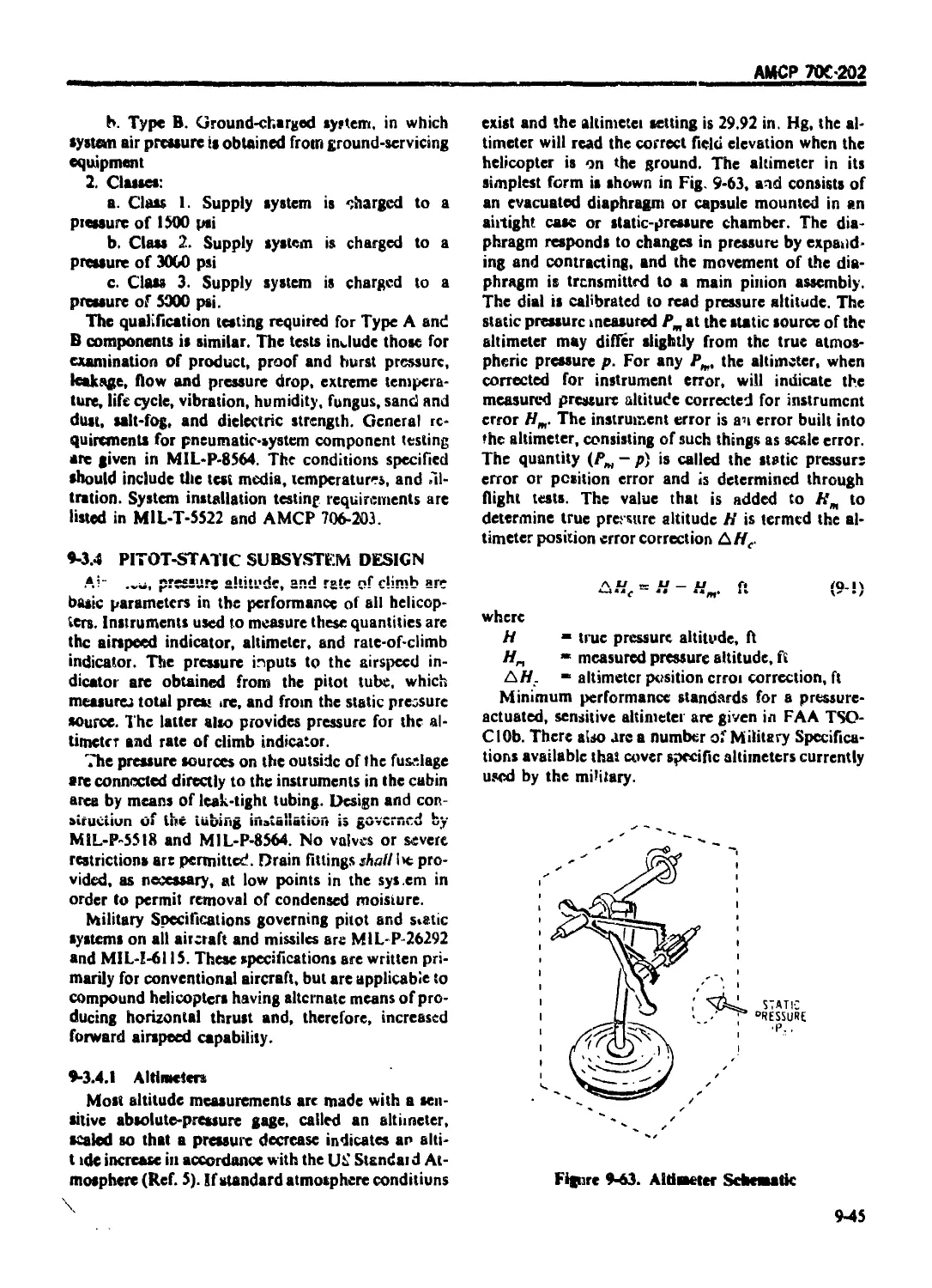
9-3.4.1 Altimeters ........................................................... 9-45
9-3.4.2 Rate-of-climb Indicator .............................................. 9-46
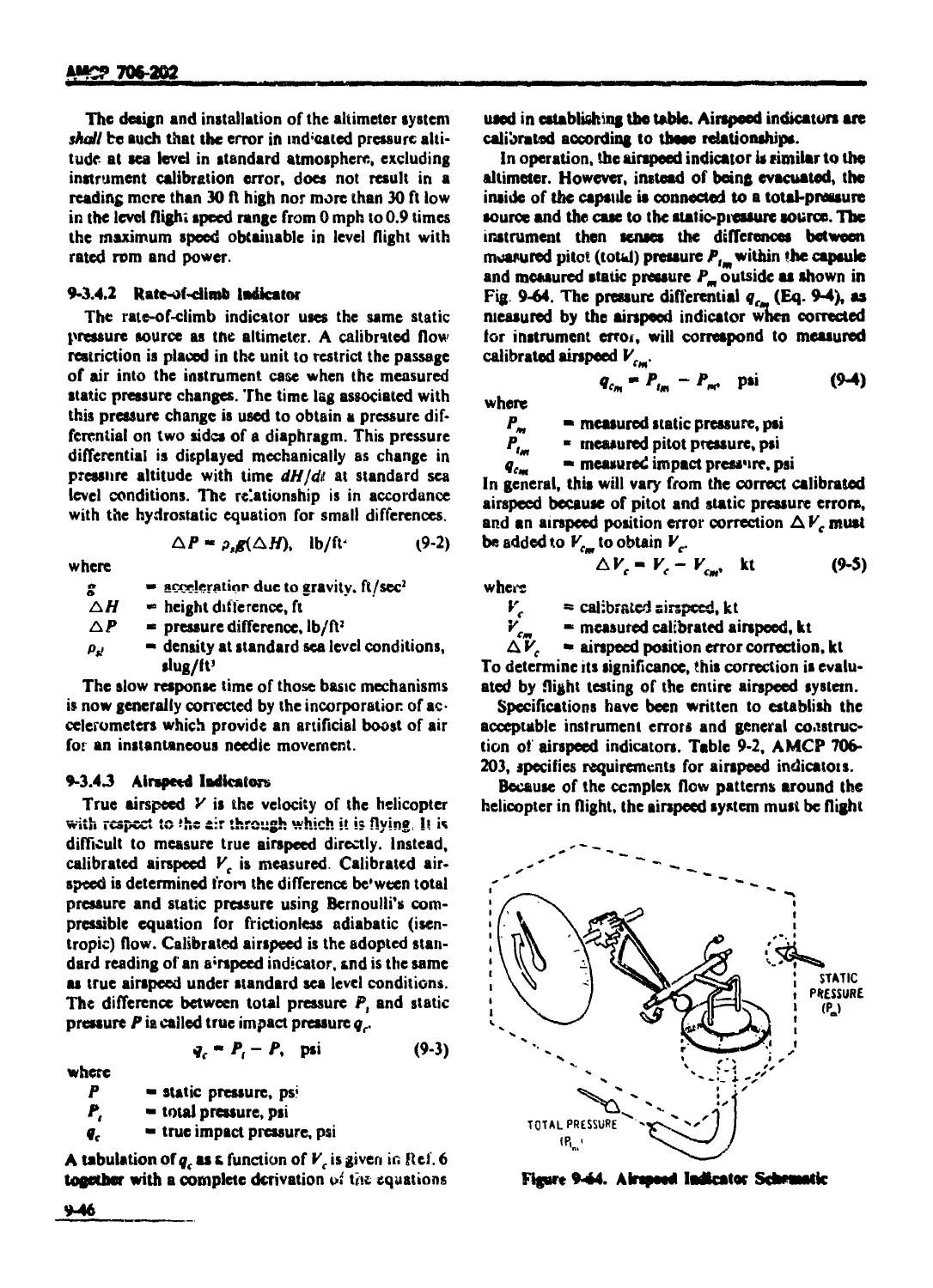
9-3.4.3 Airspeed Indicators................................................... 9-46
9-3.4 4 Total-pressure Sources ............................................... 9-47
9-3.4.5 Static Pressure Sources .............................................. 9-47
9-3.4.6 Pilot-static Tuhes ................................................... 9-48
REFERENCES ............................................................ 9-48
CHAPTER 10
INSTRUMENTATION SUBSYSTEM DESIGN
10-1 INTRODUCTION ............................................ 10-1
10-2 INSTRUMENTATION LIGHTING REQUIREMENTS ................... 10-1
10-2.1 GENERAL ................................................ 10-1
10-2.2 LIGHTING INTENSITY CONTROL ............................. 10-1
10-2.3 LOW INTENSITY READABILITY .............................. 10-2
in.2 л WARNING, CAUTION .AND ADVISORY SIGNALS 10-2
10-2.4.1 Warning Signals ....................................... 10-2
10-2.4.2 Caution Signals ........................................ 10*2
10-2.4,3 Advisory Lights ........................................ 10*3
10-3 FLIGHT INSTRUMENTS ...................................... 10-3
10-3,1 GENERAL 10-3
10-3.2 AIRSPEED INDICATORS .................................... Ю-3
10-3.3 ALTIMETERS ....................................... 10-3
10-3.4 TURN-AND-BANK INDICATORS ......................... 10-3
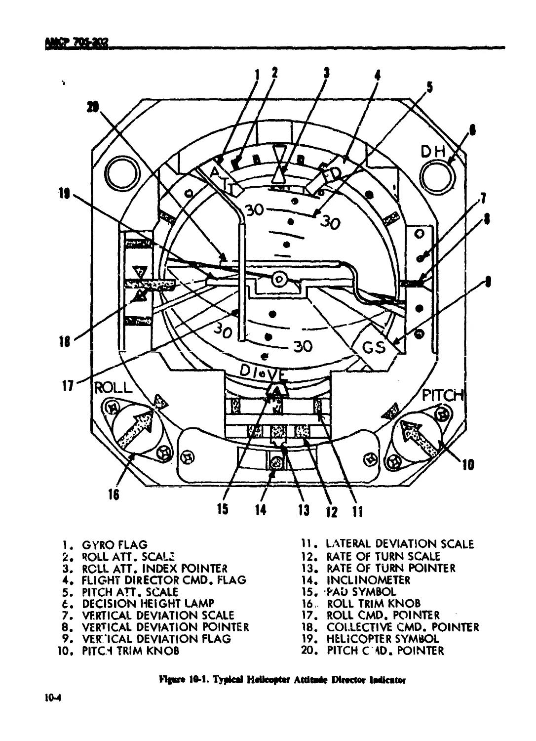
JO-3 5 ATTITUDE INDICATOR ............................... 10-3
10-3.6 RATE-OF-CLIMB INDICATORS ......................... 10-5
10-4 NAVIGATIONAL INSTRUMENTATION ............................. Ю-5
10-4.1 GENERAL .......................................... iu-5
10-4.2 TYPESOF INSTRUMENTS............................... 10-5
10-4.3 MAP DISPLAYS ..................................... 10-7
10 5 HELICOPTER SUBSYSTEM INSTRUMENTATION ........... 10-7
10-5.1 GENERAL .......................................... 10-7
10-5.2 INSTRUMENTATION REQUIRED ......................... 10-7
10-6 WEAPON SYSTEM INSTRUMENTATION ..................... Ю-7
10-6.1 GENERAL 10-7
10-6.2 DESIGN REQUIREMENTS.................... 10-8
10-6.2.1 Arming, Fuzing, and Suspension and Release Control Design . 10-8
10-6.2,2 Human Fa ctors Considerations............... 10-8
10-6.2.3 Indicator Design ..................... 10-8
10-6.3 WEAPON SELECTION CONTROLLER/PROGRAMMER .......... 10-9
10-7 TYPES OF INSTRUMENT ............................... 10-9
10-7.1 INSTALLATION .......................................... 10-10
10-7.2 VIBRATION ............................................. 10-10
10-7.3 ACCESSIBILITY AND MAINTENANCE ......................... 10-10
REFERENCES ............................................. 10-10
xvii
Ш 706-202
TABLE OK CONTENTS t Continued)
Paragt aph Page
CHAPTER li
AIRFRAME STRUCTURAL DESIGN
11-0 LIST OF SYMBOLS ........................................ 11*1
11-1 INTRODUCTION ......................................... 11*1
11-2 DESIGN CONSIDERATIONS ................................ I l-l
11-2.1 WEIGHT ............................................... I l-l
11-2.2 SURFACE SMOOTHNESS ..................................... 11-1
11-2.3 STIFFNESS AND RUGGEDNESS ............................. 1 l-l
11-2.4 FATIGUE SENSITIVITY .................................. 11-2
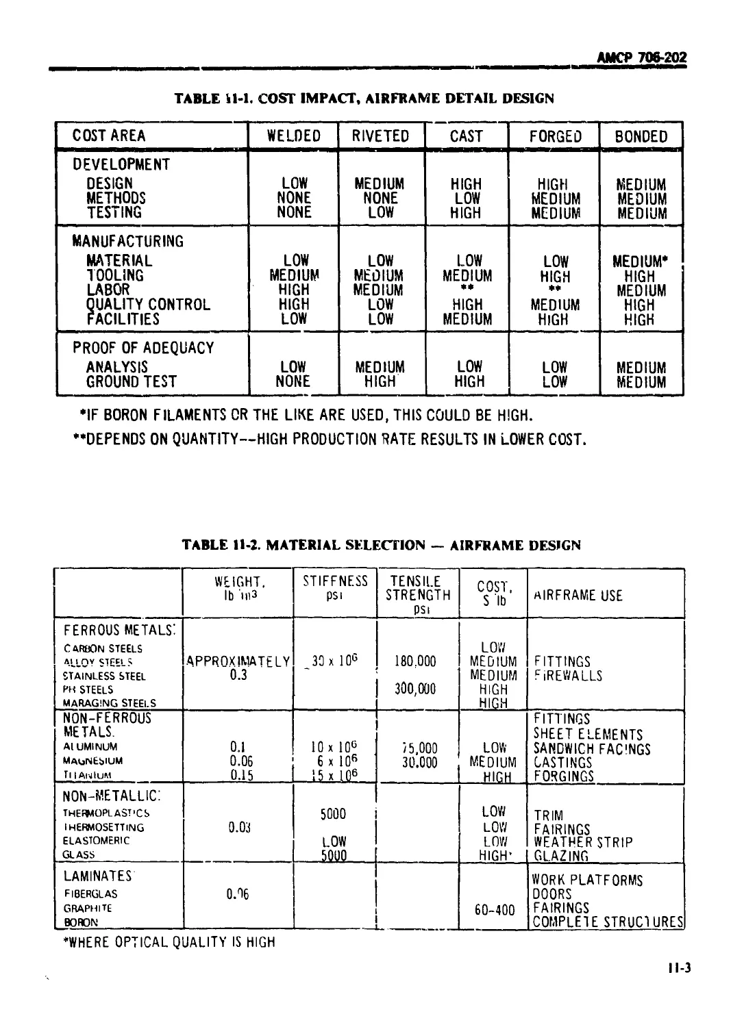
11-2.5 COST.................................................... 11-2
11-2.6 MATERIALS ............................................ 11-2
11-2.7 SURVIVABILITY .......................................... 11-2
11-3 DESIGN AND CONSTRUCTION .............................. 11-4
11-3.1 FITTINGS ............................................... 11-5
11-3.2 SUPPORTS ............................................. I i-5
11-3.3 FRAMES ............................................... 11-5
11-3.4 BULKHEADS ............................................... И-6
11-3.5 SKIN SUBSYSTEMS ........................................ 11-6
11-3.6 CORROSION PROTECTION ................................... 11-6
ii-3.7 ELECTRICAL BONDING ................................... I !-7
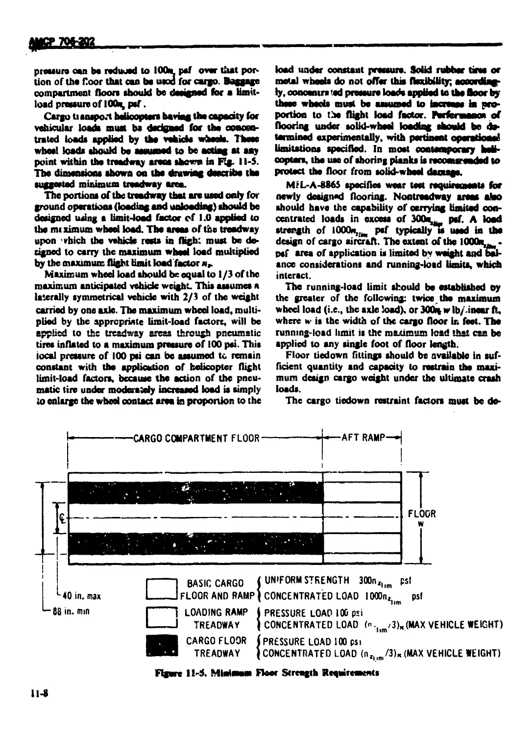
H-4 CARGO COMPARTMENT .................................... 11-7
11-4.1 STATIC LOADS ........................................... 11-7
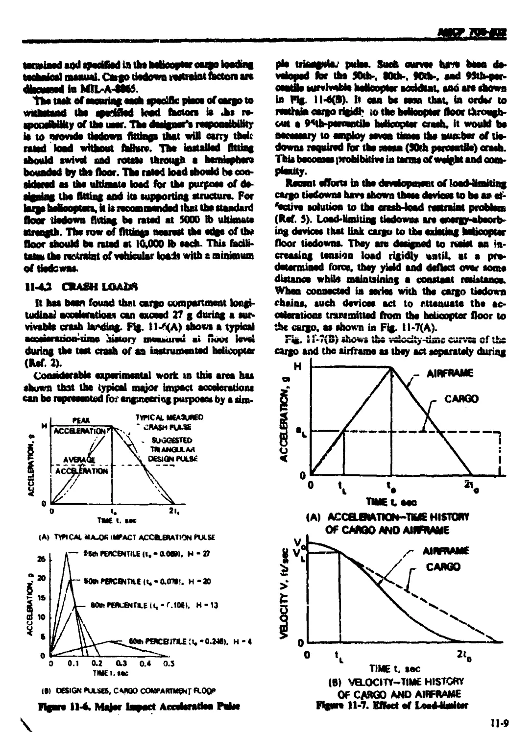
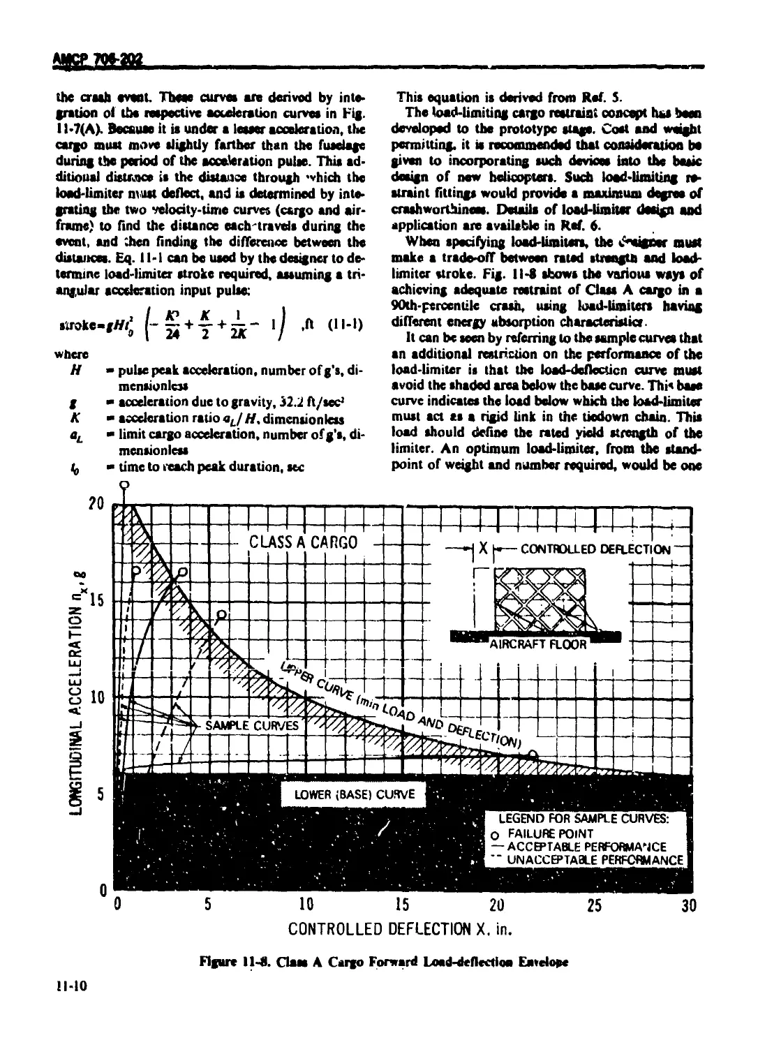
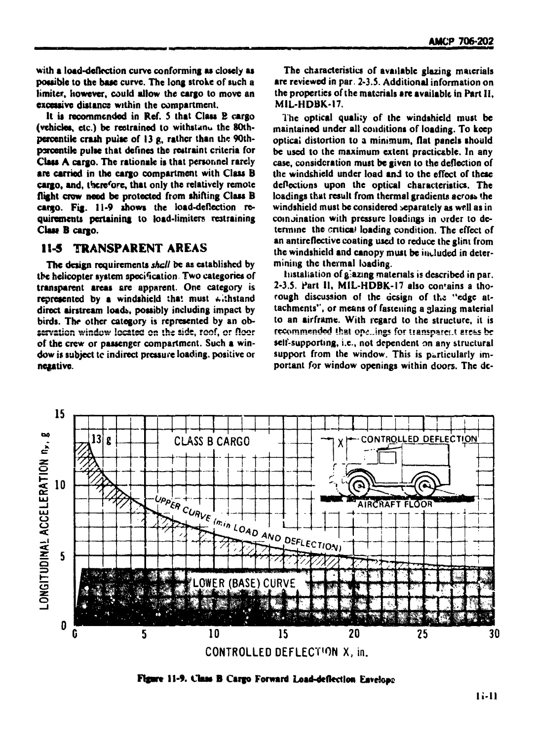
11-4.2 CRASH LOADS ............................................ 11-9
11-5 TRANSPARENT AREAS ..................................... li-II
11-6 DEVELOPMENT ........................................... 11-12
11-7 MANUFACTURE ............................................ H-I2
11-8 SUBSTANTIATION ........................................ li-12
11-8.1 ANALYSIS .............................................. 11-13
H-8.2 TESTING ............................................... 11-13
REFERENCES .............................................. 11-13
CHAPTER 12
LANDING GEAR SUBSYSTEM
12-0 LIST OF SYMBOLS ......................................... 12-1
12-1 GEAR TYPES ............................................. 12-1
12-1.1 WHEELGEAR .............................................. 12-1
12-1.1.1 General'.............................................. 12-1
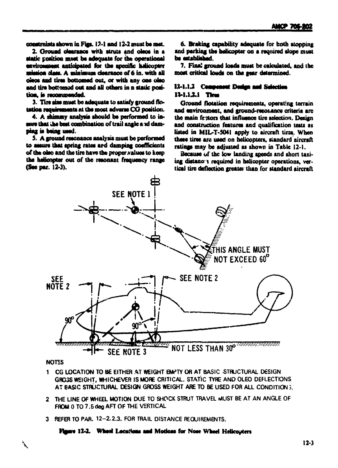
12-1.1.2 Component Design and Selection........................ 12-3
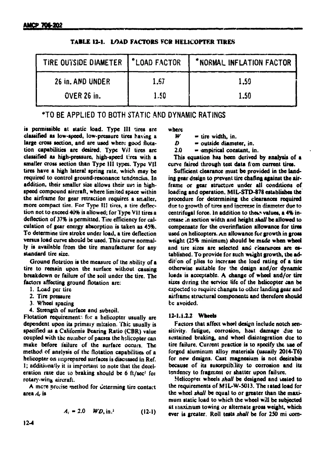
12-1.1.2.1 Tires ................................................. 12-3
12-1.1.2.2 Wheels ................................................ 12-4
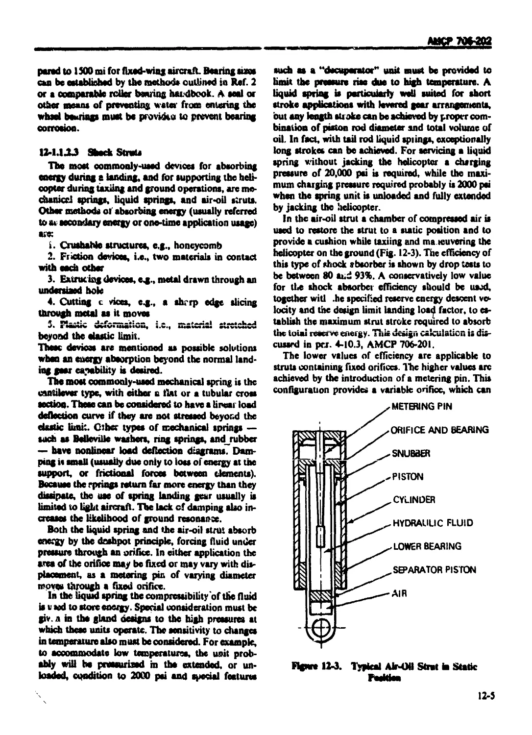
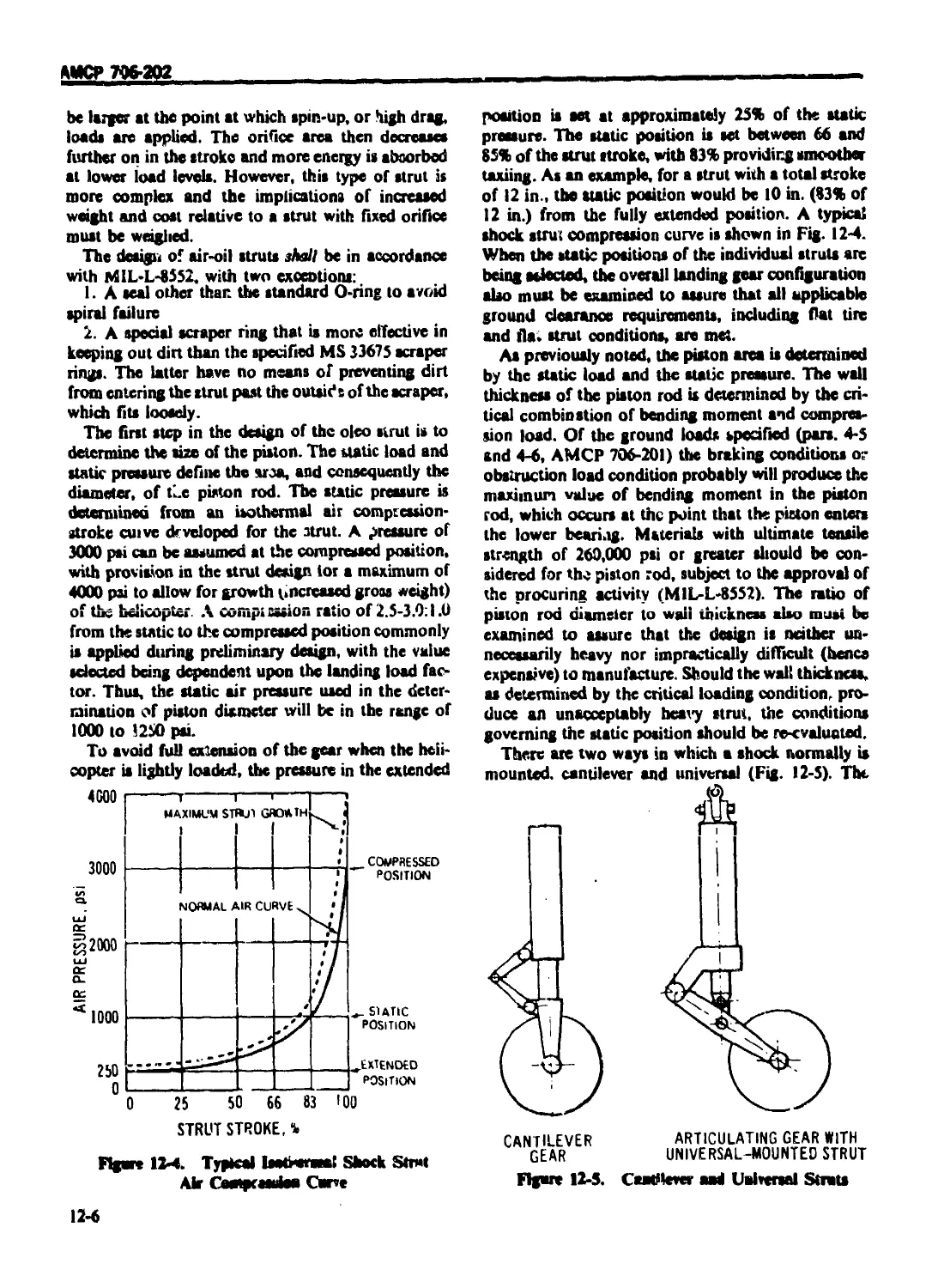
12-1.1.2.3 Shock Struts .......................................... 12-5
12-1.1.2.4 Brakes ................................................ 12-8
12-12 SKIDGEAR ............................................... 12-8
12-1.2.1 General ................................................ 12-8
12-1.2.2 Ground-handling Wheels ................................. 12-8
12-1.2.3 Scuff Plates ........................................... 12-9
12-1 3 RETRACTABLEGEAR ........................................ 12-9
12-1.3.! General ................................................ 12-9
12-1.3.2 Actuation .............................................. 12-9
12-13.3 Emergency Extension .................................... 12-9
xvjii
АЖУ 706-202
TABLE OF CONTENTS (Continued)
Paragraph Page
12-5.4 SKIS AND REAR PAWS .................................... 12-9
12-1.4.1 General ............................................... 12-9
12-1.4.2 Installation ......................................... 12-10
12-2 LANDING LOAD ANALYSIS .................................. ’ 12-11
12-3 AVOIDANCE ОГ GROUND RESONANCE ........................... 12-11
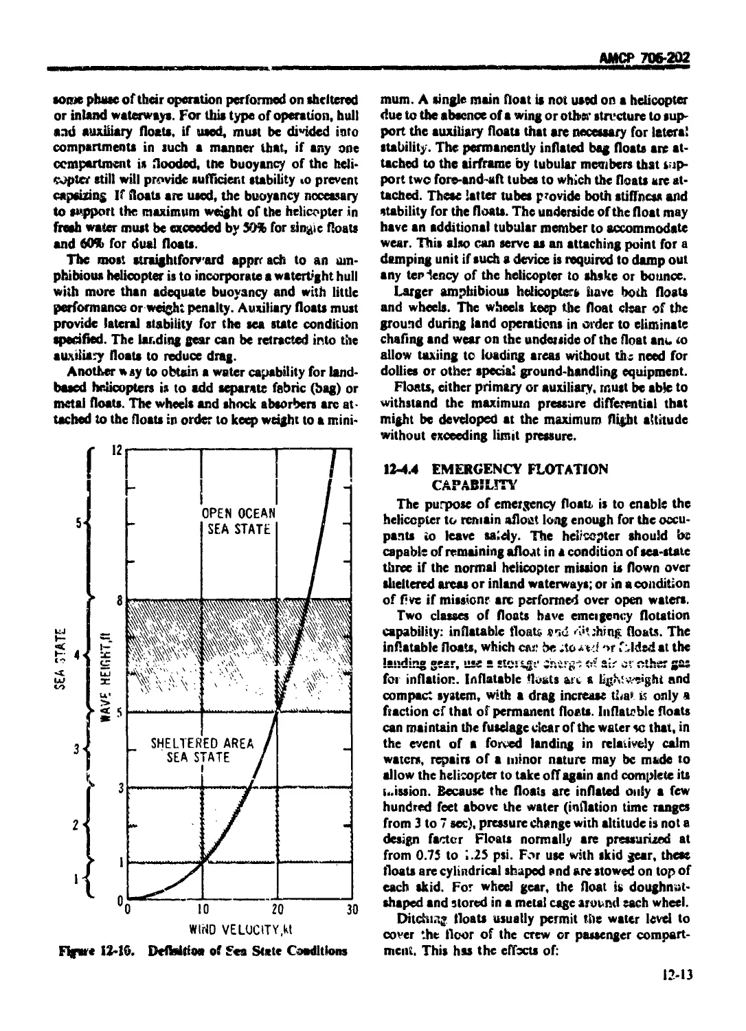
12-4 WATER-LANDING CAPABILITY ............................... 12 12
12-4.1 GENERAL ............................................... 12-12
12-4.2 PRIME CAPABILITY ...................................... 12-12
12-4.3 ADDITIONAL CAPABILITY ................................. 12-12
12-4.4 EMERGENCY FLOTATION CAPABILITY ........................ 12-13
12-4.5 MODEL TESTS ........................................... 12-14
REFERENCES .'............................................ 12-14
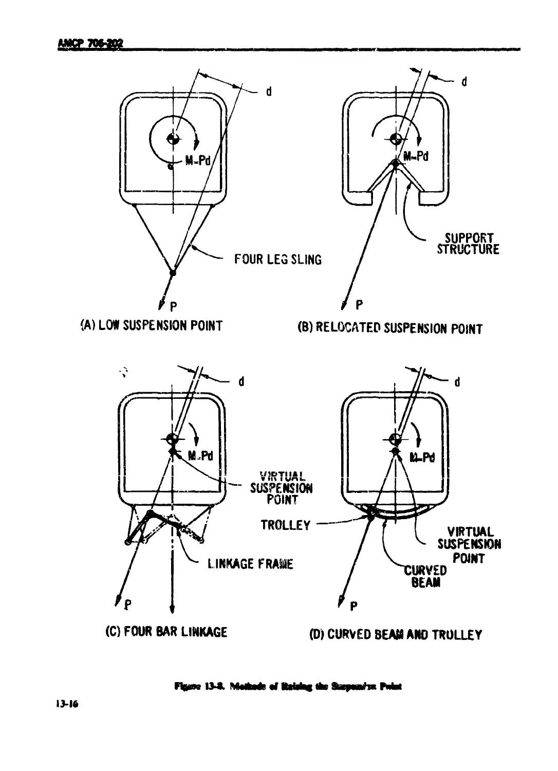
CHAPTER 13
CREW' STATIONS AND CARGO PROVISIONS
13-0 LIST OF SYMBOLS ......... >.................... 13-1
13-1 INTRODUCTION .................................. 13-1
13-2 PERSONNEL ACCOMMODATIONS ....................... 13-1
<3-1
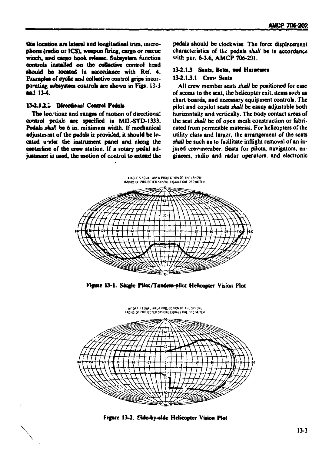
13-2.1.1 General Vision Requirements ........................................... 13-2
13-2.1.2 Controls .............................................................. 13-2
13-2.1.2.1 Pitch Controls ...................................................... 13-2
13-2.1.2.2 Directional Control Pedals .......................................... 13-3
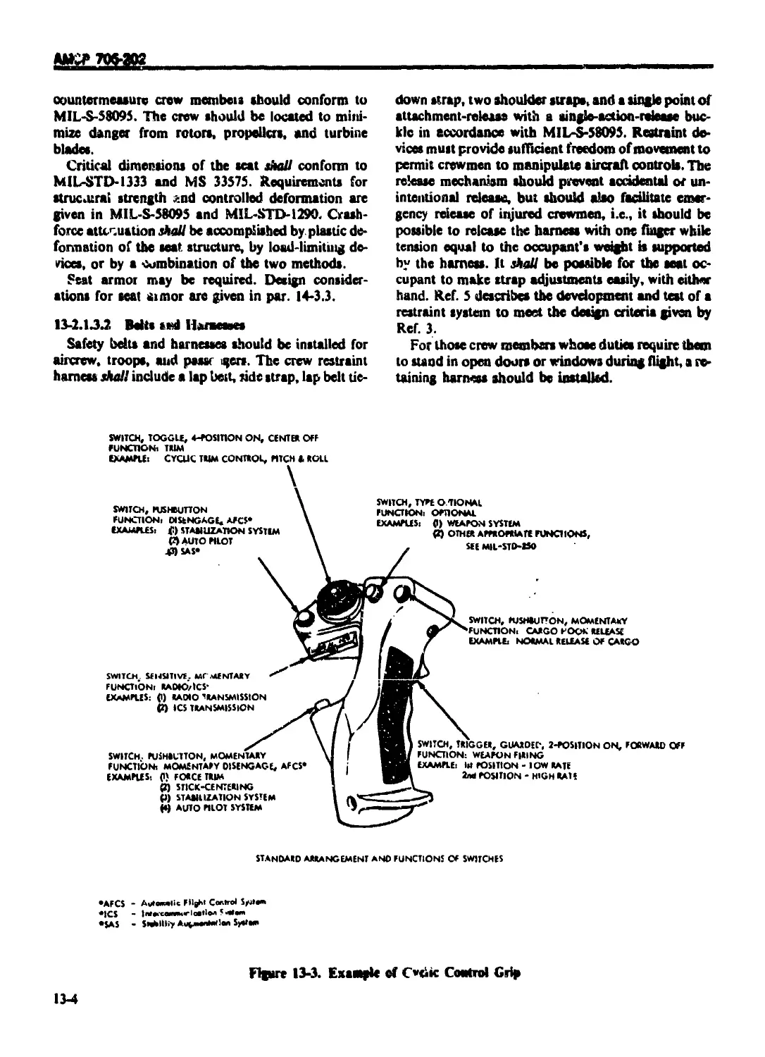
13-2.1.3 Seats, Belts, and Harnesses ........................................... 13-3
13-2.1.3.1 Crew Seats .......................................................... 13-3
13-2.1.3.2 Belts and Harnesses ................................................. 13-4
13-2.1.4 Map and Data Cases ................................................... 13-5
13-2.2 PASSENGER COMPARTMENT ................................................. 13-5
13-2.2.1 Troop and Passcngei Seats ............................................. 13-5
13-2.2.2 Color ................................................................. 13-5
13-2.2.3 Upholstering and Carpeting ............................................ 13-5
13-2.2.4 Smoking Provisions .................................................... 13-5
13-2.2.5 Signal Lights and Alarm Bells ......................................... 13-5
13-2.2.6 Acromedical Evacuation ................................................ 13-5
13-2.3 SURVIVAL EQUIPMENT .................................................... 13-6
13-2.3.1 Inflight Escape and Survival Equipment ................................ 13-6
13-2.3.2 Ground Escape and Ditching Provisions ................................. 13-2
13-2.3.3 Emergency Lighting Provisions ........................................ 13-7
13-2.3 4 Life Rafts ............................................................ 13-7
13-2.3.5 Survival Kits ......................................f................. 13-7
13-2.3.6 First Aid ...........................................'................. 13-7
13-2.3.7 Fire Extinguishing Systems and Axe .................................... 13-7
13-2.4 ENVIRONMENTAL CONTROL ................................................. 13-7
13-2.4.1 Ventilation. Heating, and Cooling ..................................... 13-7
13-2.4.2 Windshield Defogging and Deicing Equipment............................. 13-8
13-2.4.3 Acoustical Environment ................................................ 13-8
13-2.5 SIGHTS AND SIGHTING STATIONS .......................................... 13-8
13-2.5.1 Direct-viewing Sights ................................................. 13-8
13-2.5.2 Helmet Mounted Sight .................................................. 13-9
TABLE DE CDNTEV’SiCiHiiinucdi
Paragraph
Page
13-2.5.3 Indirect Sights ................................................ 13-9
13-2.5.4 Missile Sighting Stations ...................................... 13-9
13-3 LIGHTING SYSTEMS .................................................. 13-9
13-3.1 EXTERIOR LIGHTING SYSTEM .................................... 13-9
13-3.1.1 Anticollision Light System ..................................... 13-9
I 13-3.1.2 Formation Lights ............................................... 13-9
13-3.1.3 Landing/Taxi Light ............................................. 13-10
13-3.1.4 Searchlight .................................................... 13-10
13-3.1.5 Floodlight System .............................................. 13-10
13-3.1.6 Position Lights ................................................ 13-10
13-3.2 INTERIOR LIGHTING SYSTEM .................................... 13-10
13-3.2.1 Cabin and Compartment Lighting ................................. 13-10
13-3.2.2 Cockpit Lighting .............................................. 13-10
13-3.2.2.1 Utility Lights ................................................ 13-10
13-3.2.2.2 Secondary Lighting........................................... 13-10
13-3.2.3 Panel Lightii.g ................................................ 13-10
13-3.2.4 Interior Emergency! :<»his ..................................... 13-10
13-3.2.5 Portable Inspection Lights ..................................... |3-|O
13-3.2.6 Troop Jump Signal Light ........................................ 13-11
13-3.2.7 Warr.ing, Caution, and Advisory Lights ......................... 13-11
13-3.2.8 Instrument 'anel Lighting ...................................... 13-11
13-3.2.9 Cargo Compartment Lighting ..................................... 13-il
13-4 CARGO PROVISIONS .................................................. 13-11
13-4 I INTERNAL CARGO ................................................. 13-11
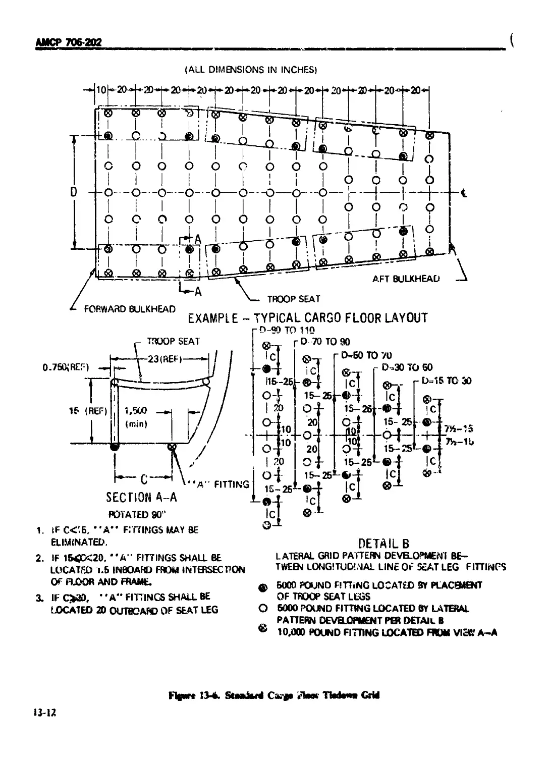
13-4.1.1 Cargc Compartment Layout ....................................... 13-11
13-4.i.2 Detail Design .................................................. 13-11
13-4.1.3 Loading Aids ................................................... 13-13
13-4 2 EXTERNALCARGO .................................................. 13-14
l3-4.2.1 Static Loads......................................................................... 13-18
13-4.2.2 Dynamic Loads ....................................................................... 13-18
13-4.2.3 Winches and Hooks ................................................................... 13-19
13-4.2.4 System Safety .................................................... 13-20
11ГГГПС1ТГГС 11 in
IXL.C LRUl-IVl-O .................................................. '-‘-V
CHAPTER 14
ARMOR. ARMAMENT. AND PROTECTIVE SUBSYSTEMS DESIGN
14-0 LIST OF SYMBOLS ......................................................... 14-1
14-1 INTRODUCTION ............................................................ 14-1
14-2 ARMAMENT SYSTEMS ........................................................ 14-1
14-2.1 GUNS .................................................................. 14-1
14 2.1.1 Types ................................................................. 14-1
14-2.1.2 Location .............................................................. 14-2
14-2.1.2.1 Projectile Flight Path ................................................ 14-3
14-2.1.2.2 Blast Effects ......................................................... 14-3
14-2.1.2.3 Dcbi is Ejection Path ................................................. 14-3
14-2.1.2.4 External Gun Jettisoning .............................................. 14-3
14-2.1.2.5 Accessibility ......................................................... 14-3
14-2.1.2.6 Dynamic Forces ........................................................ 14-4
XX
АМСР 706-302
TABLE OK CONTENTSi(-emtinucHI
Paragraph Page
14-2.1.3 Types of Installations .................................................. 14-4
14 2.1.3.1 Pod Installations ........................................................ 14-4
14-2.1.3 2 Turret Installations ..................................................... 14-4
14-2.1.3.3 Pintle Guns .............................................................. 14-5
14-2.1.4 Ammunition Storage ................................................... 14-5
14-2.1.5 Ammunition Feed ...................................................... 14-6
14-2.1.6 Boresighting and Harmonization ....................................... 14-6
14-2.2 GUIDED MISSILES ...................................................... 14-6
14-2.2.1 Locationof Launcher Installations .................................... 14-6
14-2.2.2 Structural Clearance ................................................. 14-7
14-2.2.3 Blast Protection ..................................................... 14-7
14-2.2.4 Accessibility ........................................................ 14-7
14-2.2.5 Firing Circuit Testing ............................................... 14-7
14-2.2.6 Jettisoning .......................................................... 14-7
14-2.2.7 Effects of Aircraft Maneuvers ........................................ 14-7
14-2.2.8 Types of Installations ............................................... 14-7
14-2.2.9 Loading .............................................................. 14-7
14-2.2. iO Aerodynamic Effects .................................................. 14-7
14-2.2.11 Suspension and Retention ............................................. 14-7
14-2.2.iz Launch initiation .................................................... 14-8
14-2.2.13 Restraining Latch .................................................... 14-8
14-2.2.14 Forced Ejection ...................................................... 14-8
14-2.3 ROCKETS .............................................................. 14-8
14-2.3.1 Rocket Launcher Installations ..... 14-8
14-2.3.2 Launch Tu&e Materials ................................................ 14-9
14-2.3.3 Launcher Mounting .................................................... 14-9
14-2.3.4 Number of Rockets .................................................... 14-9
14-2.3.5 Load Requirements .................................................... 14-9
14-2.3.6 Ground Safety ........................................................ 14-9
14-2.3.7 Restraining Latches .................................................. 14-4
14-2.3.8 Firing Contacts ...................................................... 14-9
14-2.3.9 Intervalometer .......................................................... 14-iu
14-2.3.Ю Launcher Fairing......................................................... 14-10
14-2.4 SAFETY CONSIDERATIONS ................................................... 14-10
14-2.4.1 Safety Criteria.......................................................... 14-10
14-2.4.2 Fire Interrupters ....................................................... 14-10
14-2.4.3 Contour Followers ....................................................... 14-11
14-2.4.4 Burst Limiters ....................................................... 14-11
14-2.4.5 Cockpit Noise ........................................................... 14-11
14-2.4.6 Debris Disposal ......................................................... 14-11
14-2.4.7 Toxic Explosive Gas Protection .......................................... 14-12
14-2.4.8 Turret Master Power Switch .............................................. 14-12
14-3 PROTECTIVE SUBSYSTEMS ...................................................... 14-12
14-3.1 GENERAL ................................................................. 14-12
14-3.2 > DEVELOPMENT OF VULNERABILITY REDUCTION SYSTEMS .. 14-13
14-3.2.1 Vulnerability Analysis .................................................. 14-13
14-3.2.2 Vulnerability Reduction Checklist .................................. . 14-16
14-3.2.3 Vulnerability Data Presentation ......................................... 14-16
14-3.2.4 Aircrew Armor Configuration Development ................................. 14-16
14-3.2.5 Armor Material Selection ................................................ 14-16
xxi
AMCf» 70<r2Q^___________________________________________________________________________________
TABLE OF CONTENTS (Continued I
Paragraph Page
14-3.3 ARMOR INSTALLATION DESIGN CONSIDERATIONS ............ 14-18
14-3.3.1 Aircew Torso Armor .................................. 14-18
14-3.3.2 Interchangeability .................................. 14-18
14-3.3.3 Removability ....................................... 14-18
14-3.3.4 Fiying Qualities .................................... 14-19
14-3.3.5 Immobilization ...................................... 14-19
14-3.3.6 Armor Material Attachmcnt/Installation .............. 14-19
14-3.3.6.1 Mounting of Armor Plate ............................. 14-19
14-3.3.6-2 Installation Design ................................. 14-19
14-3.3.6.3 Bullet Splash and Spall ............................. 14-20
REFERENCES ........................................... 14-20
CHAPTER 15
MAINTENANCE AND GROUND SI PPORT EQUIPMENT |GSF.) INTERFACE.
15-1 INTRODUCTION ......................................... 15-1
15-2 DESIGN CONSIDERATIONS AND REQUIREMENTS ................. 15-1
15-2.1 SAFETY ............................................... (5-1
15-2.2 ACCESSIBILITY ........................................ 15-2
15-2.3 STANDARDIZATION .................................... 15-2
I5-7..4 HUMAN ENGINEERING .................................... 15-3
15 2.5 INSPECTION, TEST, AND DIAGNOSTIC SYSTEM .............. 15-3
15-3 PROPULSION SUBSYSTEM INTERFACES ...................... 15-3
(5-3.1 GENERAL .............................................. 15-3
15-3.2 INTERCHANGEABILITY/QUICK-CHANGE ...................... 15-4
15-3.3 CONNECTORS AND DISCONNECT POINTS ..................... 15-4
15-3.4 INSPECTION AND TEST POINTS ........................... 15-4
15-3.5 OIL, FUEL, AND LUBRICATION ........................... 15-4
15-3.6 GROUNDING ............................................ 15-4
15-3.7 STARTING ............................................. 15-4
15-3.8 GROUND HEATERS ....................................... 15-4
• 15-3.9 ENGINE WASH ........................................ 15-5
15-4 TRANSMISSIONS AND DRIVES................................ 15-5
15-5 ROTORS AND PROPELLERS .................................. 15-5
15-6 FLIGHT CONTROLS ........................................ 15-5
15-6.1 ROTATING SYSTEMS ..................................... 15-5
15-6.2 NONROTATING SYSTEMS .................................. 15-5
15-6.3 TRIM SYSTEMS ......................................... 15-5
15-7 ELECTRICAL SUBSYSTEMS .................................. 15-6
15-8 AVIONIC SUBSYSTEMS ..................................... 15-6
15-8.1 COMMUNICATION SYSTEMS ................................ 15-6
15-8.2 NAVIGATION SYSTEMS ................................... 15-6
15-9 HYDRAULIC AND PNEUMATIC SUBSYSTEMS ..................... 15-6
15-9.1 HYDRAULIC SUBSYSTEM .................................. 15-7
15-9.2 PNEUMATIC SUBSYSTEM .................................. 15-7
15-10 INSTRUMENTATION SUBSYSTEMS ............................. 15-7
15-10.1 FLIGHT INSTRUMENTS.................................... 15-7
I5-1O.2 NAVIGATION INSTRUMENTS ............................... 15-7
15-10.3 AERIAL VEHICLE SUBSYSTEM INSTRUMENTATION ............. 15-7
15-11 AIRFRAMESTRUCTURE ...................................... 15-7
15-12 LANDING GEAR SUBSYSTEM ................................. 15-8
xxii
АМСР 706-20?
TABLE оЕ CONTENTS‘Continued)
Paragraph Page
15-13 CREW STATIONS ........................................... 15-8
15-14 ARMAMENT, ARMOR. AND PROTECTIVE SYSTEMS .................. 15-8
(TIAFI ER lb
STANDARD PARIS
16-0 LIST OF SYMBOLS ..............................................
16-1 INTRODUCTION ....................................r............
16-2 FASTENERS ....................................................
16-2.1 GENERAL ....................................................
16-2.2 THREADED FASTENERS ...................... ..................
16-2.2.1 Screws .....................................................
16-2.2.2 Bolts.......................................................
16-2.2.3 Nuts .......................................................
16-2.2.4 Washers ....................................................
16-2.3 NONTHREADED FASTENERS ......................................
16-2.3.1 Rivets .....................................................
16-2.3.2 Pins .......................................................
16-2.3.3 Quick-release F asteners ...................................
16-2.3.4 Turnbuckles and Tcrininals .................................
16-2.3.5 Retaining Rings ...........
16-2.3.6 Clamps and Grommets ........................................
16-2.3.7 Self-retaining Fasteners ...................................
16-3 BEARINGS .....................................................
16-3.1 GENERAL ....................................................
16-3.2 BALLBEARINGS ...............................................
16-3.2.1 Radial Ball Bearings .......................................
16-3.2.2 Angular Contact Bearings
16-3.2.3 Thrust Bali Bearings .......................................
16-3.3 ROLLER BEARINGS ............................................
16-3.3.1 Cylindrical Roller Bearings ................................
16-3.3.2 Needle Bearings .......
16-3.3.3 Spherical Roller Bearings ..................................
16-3 3.4 Tapered Roller Bearings ....................................
16-3.4 AIRFRAME BEARINGS ..........................................
16-3 5 SLIDING BEARINGS ...........................................
16-3.6 LAMINATED ELASTOMERIC BEARINGS .............................
16-3.7 BEARING SEALS AND RETAINERS ................................
16-3.7.1 Seals ......................................................
16-1
16-1
16-1
16-1
16-1
16-1
16-2
16-2
16-2
16-3
16-3
IC-3
16-3
16-3
16-4
16-4
16-4
16-4
16-4
16-8
16-8
16-9
16-10
16-10
16-10
16-10
16-11
16-11
16-12
16-12
16-14
16-15
16-15
16-3.7.2 Bearing Retention ............................................ 16-15
16-4 ELECTRICAL FITTINGS ............................................. 16-16
16-4.1 GENERAL ...................................................... 16-16
16-4.2 CONNECTORS AND CABLE ADAPTERS ................................ 16-16
16-4.2.1 Connector Selection .......................................... 16-16
16-4.2.2 Circular Connectors .......................................... 16-18
16-4.2.2.1 Termination Seals ............................................ 16-19
16-4.2.2.2 Cable Adapters .............................................. 16-19
16-4.2.2 3 Connector Couplings .......................................... 16-19
16-4.2.3 Rack and Panel Connectors .................................. 16 19
16-4.2.4 Flat Conductor Cable Connectors .............................. 16-19
16-4.2.5 Printed Wiring Board Connectors .............................. 16-19
Xxiii
АМСР 706 202
TABI b O| ( ON'Ii V|Si( oiitimivdi
Paragraph Page
16-4.3 TERMINALS .................................................... 16 И
16-4.4 TERMINAL BOARDS ................................................. 16-19
16-5 ELECTRICAL SWITCHES ............................................... 16-20
16-5.1 GENERAL ......................................................... 16-20
16-5.1.1 Toggle Switches ......................................... 16 20
16-5.1.2 Push-button Switches ............................ 16 20
16-5.1.3 Rotan Switches .......................................... ... 16-22
16-6 PIPE AND TUBE FITTINGS ......................................... 16 22
16-6.1 GENERAL ...................................................... 16 22
16-6.2 TYPES OF FITTINGS ............................................ 16 22
16-6.2.1 Tapered Pipe 1 hreads ........................................ 16 22
16-6.2.2 Straight Thread Fittings ....................................... 16-23
16-6.2.3 Flared Tube Fittings ............................................ 16-23
16-6.2.4 Flareless Tube Fittings......................................... 16-24
16-6.2.5 Thin Wall Tube Connectors .................................... 16-25
16-6 2.6 Quick-disconnect Couplings ...................................... 16-25
16-6.2.7 Permanent Fittings ........................................... 16 25
16-7 CONTROL PUL LEYS ............................................... 16 25
16-7.1 GENERAL ......................................................... 16-25
io-7.2 PULLEY SELECTION 16 26
16-7.2.1 Pulley Diameter .............................................. 16-26
16-7.2 2 Pulley Groove ................................................. 16-26
16-7.2.3 Pulle) Strength ................................................. 16-26
16-7,2.4 Pulley Performance .............................................. 16-26
16-7.2,5 Nonmelallic Pnl’e) s ............................................ 16-26
16-7.3 PULLEY 1NSTA1 I ATION ........................................... 16-26
16-7.4 PULLEY GUARDS ................................................... 16-27
16-8 PUSH-PULL CONTROLS AND Fl.EXLBI.F. SHAFTS ...................... 16 27
16-8.1 GENERAL ......................................................... 16-27
16-8.2 PUSH-PULL CONTROLS ........................................... 16 27
16-8.2.1 Control Travel .................................................. 16-28
16-8.2.2 Control Loads ................................................... 16-28
16-8.2.3 Core Configurations ............................................. 16-28
16-8.2.4 Conduit ........................................................ 16-28
16-8.2.5 End Fittings .................................................... 16-29
16-8.3 FLEXIBLE SHAFTS ................................................. 16-29
16-8.3.1 Torque Capacity 16-30
16-8.3.2 Flexible Power Shafts ........................................... 16-30
16-8.3.3 Flexible Control Shafts ......................................... 16-30
16-9 CABLES AND WIRES (STRUCTURAL ) ................................. 16 31
16-9.1 GENERAL ...................................................... 16-31
16-9.2 PREFORMED WIRE STRAND AND CAB! E ............................. 16-31
16-9.3 TYPES OF CABLE CONSTRUCTION .................................. 16 31
16-9.4 CABLE SELECTION .............................................. 16-31
16-9.4.1 Cable Strength .................................................. 16-32
16-9.4.2 Cable Deflection ................................................ 16-32
16-9.4.3 Operating Characteristics .................................... 16 32
16-9.4.4 Wire Material ................................................... 16-32
16-9.4,5 Cable Construction .............................................. 16-32
16-9.5 SAFETY WIRE ANDCOTTER PINS.................................... 16 32
REFERENCES ....................................................... 16-3.
xxiv
АМСР 706*202
1ABI.I.OI COM ENTS (Continued)
Paragraph Page
< НАГ HR 17
PROCESSES
17-1 INTRODUCTION ............................................ 17-1
17-2 METALWORKING ............................................. 17-1
17-2.1 GENERAL................................................. 17-1
17-2.2 CASTING ................................................ 17-1
17-2.2.1 SandCastings .......................................... 17-2
17-2.2.2 Investment Castings ................................... 17-2
17-2.2.3 Permanent Mold Castings ............................... 17-2
17-2.2.4 Centrifugal Castings .................................. 17-2
17-2.3 FORGING .............................................. 17-2
17-2.4 EXTRUSION 17-2
17-2.5 SHEET-METALFORMING ..................................... 17-3
17-2.5.1 Machine Forming ....................................... 17-3
17-2.5.2 Shop Fabrication .................................... 17-3
17-3 MACHINING ................................................ 17-4
17-3.1 GENERAL ................................................ 17-4
17-3.2 MACHINING OPERATIONS ................................... 17-5
17-3.3 ELEMENTS OF MACHINING DESIGN' .......................... 17-5
17-4 JOINING .................................................. 17-6
17-4.1 GENERAL .............................................. 17-6
17-4 2 WELDING, BRAZING. AND SOLDERING ........................ 17-7
17-4.2.1 Welding ............................................. 17-7
17-4.2.2 Brazing ............................................. 17-8
17-4.2.3 Soldering ............................................ 17-10
17-4.3 mechanical fastening................................... 17-10
17-4.3.1 Rivets ............................................... 17-10
17-4.3.2 Bolts, Nuts, and Washers ............................. 17-11
17-4.3.3 Screws ............................................... 17-11
17-4.4 ADHESIVE BONDING —STRUCTURAL ........................ 17-12
17-4.5 SWAGING AND CABLE SP1 ICING............................ 17-15
17-5 HEAT TREATMENT .......................................... 17-16
17-5.1 GENERAL ............................................... 17-16
17-5.2 HEAT TREATMENT METALLURGY ..................,.......... 17-17
17-5.2.1 Annealing .................................i.......... 17-17
17-5.2.2 Normalizing ..............................I........... 17-17
17-5.2.3 Stress Relief..............................\.......... 17-17
17-5.2.4 Tempering ....................................... 17-17
17-5.2.5 Aging ................................................ 17-17
17-5.3 FERROUS ALLOYS ........................................ 17-17
17-5,4 NONFERROUS ALLOYS ..................................... 17-18
17-5.1.1 Aluminum Alloys ...................................... 17-18
17-5.4.2 Copper Alloys......................................... 17-18
17-5.4.3 Titanium Alloys ........„............................. 17-18
17-5.5 DESIGN ASPECTS OF HEAT TREATING ....................... 17-19
17-6 WORK HARDENING .......................................... 17-19
17-6.1 GENERAL .............................................. 17-19
17-6.2 FORMING ............................................... 17-19
17-6.3 ROLLER BURNISHING ...................................... П-19
17-6.4 SHOT-PEENING .......................................... 17-20
xxv
АМСР 706-202
TABLE OF CONTENTS (Continued)
Paragraph Page
17-7 TOOLING .............................................................. 17-20
17-7.1 GENERAL .............................................................. 17-20
17-7.2 SHOP TOOLING ......................................................... 17-22
17-7.3 AIRF RAME TOOLING .................................................... 17-22
17-7.4 TEST TOOLING ......................................................... 17-23
REFERENCES ...................................................... 17-23
APPENDIX A
EXAMPLE OF A PRELIMINARY HEATING, COOLING, AND VENTILATION ANALYSIS
A-l HEATING AND VENTILATION ANALYSIS ............................ A-l
A-l.l DESIGN REQUIREMENTS.................................................. A-l
A-1.2 DESIGN ASSUMPTIONS ................................................. A-i
A-1.3 HEAT LOSSES ............................................................ A-l
A-L3.I Cockpit .................................................. A-l
A-1.3.1.1 Convection .......................................................... A-l
A-L.i.l.2 Infiltration ........................................................ A-2
A-l.3.1.3 Total Cockpit Heat Loss ...........................'................. A-2
A-1.3.2 Cabin ................................................................ A-2
A-1.3.2.1 Convection ......................................................... A-2
A-l.3.2.2 Infiltration ........................................................ A-2
A-l.3.2.3 Total Cabin Heat Loss................................................ A-2
A-l.4 VENTILATING AIR REQUIRED ............................................... A-2
A-l.4.1 Based on Number of Occupants and Minimum Ventilating Rate .............. A-2
A-l .4.2 Requirement Based on Maximum Allowable Temperature Difference .......... A-3
A-1.4.2.1 Cockpit Requirement .................................................... A-3
A-l.4.2.2 Cabin Requirement ...................................................... A-3
A-1.4.2.3 Total Air Requirement................................................... A-3
A-l.4.3 Total Heat Requirement ................................................. A-3
A-l.5 HEATER REQUIREMENTS .................................................... A-3
A-l.5.1 Heat Gained ............................................................ A-3
A-i.5.2 Nd ikdi Required ....................................................... A-3
A-i.5.3 Heater Size ........................................................... A-4
A-l.6 BLOWER SIZE ............................................................ A-4
A 1.6.1 Volume of Air to be Delivered ............................................ A-4
A-1.6.2 Pressure Drop .................................................... A-4
A-2 COOLING AND VENTILATING ANALYSIS .......................................... A-4
A-2.1 DESIGN REQUIREMENTS................................................. A-4
A-2.2 DESIGN ASSUMPTIONS ................................................. A-4
Л-2.3 DETERMINATION OF EFFECTIVE TEMPER/.TURF
DIFFERENCES ASSOCIATED WITH VARIOUS SURFACES OF
THE HELICOPTER ....................................................... A-4
A-2.3.1 Effective Solar Temperatures ............................................ A-4
A-2.3.2 Effective A Ts ................................................... A-5
A-2.4 COCK PIT HEAT GAINS .................................................... A-5
A-2.' i Zonveclion, Infiltration, and Solar Radiation ....................... A-5
A-2 4.1.1 Convection Gains .................................................... A-5
A-2.4.1.2 Infiltration Gain ................................................... A-6
A-2.4.1.3 Solar Radiation Gait A-6
A-2.4.1.4 Total Heat Gain Due to Convection. Infiltration and Solar Radiation . A-6
A-2.4.2 Occupants .............................................................. A-6
xxvi
АМСР 70&-Ж
TABLE OF CONTENTS I Continued)
Paragraph Page
A-2.4.3 'Electrical System ................................................ A-6
A-2.4.4 Total Cockpit 1-tca. Gain ............ ......................... A-6
A-2.5 AIR CONDITIONER SIZE .............................................. A-6
A -2.5.1 Conditioning of Ventilation Air ................................... A-6
A-2.5.2 Fan Size and Heat ............................................... A-7
A-2.5.3 Tons of Refrigeration Required .................................... A-7
•REFERENCES ........................................................ A-7
INDEX ................................................. .......
xxvii
LIST OF ILLUS^’RATHQ^S
С • Titte = '„А '
f •>Fig. 2-1
r'Eig. 2-2
• - Fig. 2-3
.' f?.
& Fig- 24
•<4$Fig. 2-6
:^F'ig. 2-7
•^.g. 2-8
:TFie. 2-9
'’Fig. 2-10
Fig.3-1
Fig. 3-2
Fip. 3-3
Fig. 3-4
fig. 3-5
Fig. 3-6
Fig. 3-7
Fig. 4-1
;.’Fig.4-2
г;, л i
».'Fig 4-4
iFig. 4-5
/Fig. 4-6
, ig. 4-7
'.£>>. 4-8
‘flFig. 4 9
.
i?-Fig. -i-12
’f&F (g.4-Li
1.W4-M
>'£ ig. 4-15
fa 4-tf
4: .Fig. 4- Г/
i^Fig-4-18
$Hg.4-l9
^;M-20
: Fig. 4-22
: fig. 4-23
^ig 4<;
4-26
< 27
.’•j-Fig. 4-2F
>fg.4-29
''.'Fig. 4-5<j
Fif 4-31
: Fit. 4-J2
Sandwich Structure ......................................................
. Weight Comparison of Materials for Equal Dc‘lecti>ib ....... ...........
Comparative Sonic Fatigue Resistance of tppnvcpiipnai and Sandwich
Structures ..............................................................
Common Honeycomb Configurations .........................................
properties of Bais* Wood — Compressive Strength vi> Density .............
Properties of Balsa Wood — “L” Shear Strength vs Density ................
Typical Stabilized Compressive Strength .................................
Typical**L”Shear Strength................................................
Typicfil **L" Shear Modulus ..............................................
Modes of FeHu.-e of Sandwich Composite Under Edgewise Loads .............
Submerged Engine hsstallation (Example)...................................
Semiexposed Engine Installation (Example) ...............................
Exposed Engine Installation (Example) ...................................
Typical Fuel Subsystem ..................................................
Typical Fuel Subsystem With Pressure Refuet.ng ..........................
Performance Cot regions for Duct Losses .................................
Allowable Combined Ink; and Exhaust Duct Pressure Losses ................
^Helicopter Main Ge*i box Weight vs Takeoff Power .......................
IPower Loss to Heat vs Input Power — Typical Twin-engine-driven Gearbox -.
пкгаРГКлл Rg»ellTV £ ....
л* *• v» ivw»> v» ’ « *w$>‘ .. .......• > . , «
Elastic Body Contact Pressure Distnbu’ion and interface Contour..........
- Friction Coefficient vs EHD Parameters — Regions I and II .............
' Angle of Engagement ...... ............................................
Coefficient of Friction vs Sliding Velocity .............................
•' -.JETect of Surface Texture and Lay on Friction and Scuffing Behavior .
/jMunibei of Failures vs hours Since Overhaul — MTBF^-SOOhr ..............
Number of Failures vs Hours Since Operation — MTBF * 5000 hr ...........
-f^obalility of Survival vs Ratio........................................
j iSpaliinj; Life vs Hertz Stress ..........................................
..'’AVeibull Plot — Spalling Life vs Gear Population Rank ................
ypical 1 ai5 .Rotor Gearbox — Vulnerable .............................
;; •'•Tjit Kotor Ge&rrox — 7.6* mm Frvof ..................................
"atf Rotor Gearbox — 12.? mm Proof ......................................
Typical Speed Power Function.............................................
: Gear Stre*. vs Life Cui'vc' ...........................................
:>4 Shaft Uorsepowci Spectra Histograms ....................................
Graphic Relationship — Failure Modes — Load vs Velocity .................
Graphic Relationship — Failure Modes — Load vs 7 ooth Siw, ..............
.Single ’) oot’» Pulsor Gear Fatigue Test Results ........................
З&ъЬ- I iAtl vs Sliding Velocity — Synchronized and Untynchicnircd Discs
. Scuh t».'^ Lewd vs Lubiicr.Rt — Unsynchronized Duos....................
CiiSi iL ^ith Allowable vt Subsurface Shear..............................
Si't .: Vie*-, v» H&idntss..............................................
t rsep Wear — Inner Ring Fit va Operating Time ..........................
л impmtfjre vs Outer Ring — Liner Fit Redaction ......... ...............
. ring Gt.erstiy Change With inner Ring Expansion .....................
' Г fekiLi Т’жппж! Preload —- DF vs DB ...................................
Hiji?; Sp vv Angular Contaa^nh Thruat Bearing Forces.....................
ClearancevaLw~ElasucandK.i^rdS^jutj^ns ..................................
. 2-21
2-22
2-22
2-23
J2-24
2-24
2-24
1-24
,!2-24
;72-27
3-2
3-2
3-3
3-10
3-12
.3-17
3-17
4-4
4-5
4-7
4-8
4-8
4-9
4-lG
4-10
4 14
4-14
4 15
4-15
4-15
4-19
А- /О
<-21
4-25
4-26
4-27
4-35
4-35
4-41
4-42
4-44
4-45
4-46
449
.Ci
4 52
4-53
.4-56
<5-5?
xxix
Ав£» 706-202
LIST (Л И M SrSATIOSS(C;ii'ii4»i4J)
Fiji. No. Title F^c
Fig.4-33 Involute Spline Data Ф vs N ................................................ 4-60
Fig. 4-34 Radial Mode Resonance Ггесц.'.-псу v> Gear Tooth Meshing Speed .............. 4-70
Fig. 4-35 Typical Spiral Damper Ring Applications ..................................... 4-70
Fig. 4-36 Relative Shaft Speed vs Relative Vibration Amplitude ........................ 4-74
Fig. 4-37 Typical Bearing Hanger Assembly — Subctitical Shaft Assembly ................ 4-75
Fig 4-38 Flexible Diaphragm Coupling ................................................. 4-77
Fig. 4-39 Bossier Coupling............................................................. 4-7g
Fig. 4-40 Elastomeric Coupling......................................................... 4-78
Fig. 4-41 Hooke’s Joint (Universal) ................................................... 4-78
Fig. 4-42 Gear Coupling ............................................................... 4-39
Fig. 4-43 Breakaway Sliding Force vs Misalignment for Various Spline Devices........ 4-79
Fig. 4-44 Oil System Schematic ........................................................ 4-84
Fig .5-1 Vcctoi Diagram of Swirl in Hover ......................................... 5-4
Fig. 5-2 Control Moment for Basic Rotor Types ..................................... 5-8
Fig. 5-3 Articulated Rotor Schematic .............................................. 5-9
Fig. 5-4 Coincident Flap and Lag Hinge Rotor ......................................... 5-10
Fig. 5 5 Gimbaled Rotor Schematic ..................................................... 510
Fig. 5-6 Teetering Rotor Schematic ................................................... 5-11
Fig. 5-7 Teetering Rotor .......................................................... 5-11
Fig. 5-8 Hingciess Rotor Schematic ................................................... 5-12
Fig. 5-9 XH-51 Rotor System .......................................................... 5-13
Fig. 5-10 OH-6A Hingeless Rotor System ................................................ 5-14
Fig. 5-11 Mechanism of Pitch-lag Instability .......................................... 5-15
Fig. 5-12 Pitch-flap Coupling of Rotors ............................................... 5-16
Fig. 5-13 Mechanism of Flap-lag Instability ........................................... 5-16
Fig. 5-14 Typical Plots of Rotor Natural Frequency vs Operating Speed ................. 5-20
Fig. 5-15 Single-degree-of-freedom Coleman Plot ....................................... 5-21
Fig. 5-16 Two-dcgree-of-frcedom Coleman Plot .......................................... 5-21
Fig. 5-17 Two-degree-of-freedom Coleman Plot Showing Satisfaction of Minimum
Frequency Criteria for Two-blade Hingeless Rotor ........................ 5-22
Fig. 5-18 Gust Load Factor Computed for the UH-IB Helicopter Using Linear Theory 5-24
Fig. 5-19 Gust-alleviation Factor(MlL-S-8698) ......................................... 5-25
Fig. 5-20 Rotor Limits as a Function of Advance Ratio ................................. 5-25
Fig. 5-2l Results of a Load Gust Study Compared With Military
Specification Requirements .............................................. 5-25
Fig. 5-22 Articulated Rotor (Boeing Model 107) ........................................ 5-28
Fig. 5-23 CH-46 and CH-47 Tension-Torsion Strap Assemblies ............................ 5-32
Fig. 5-24 Torsionally Stiff and Flexible Wire-wound Tic-bar Assemblies ................ 5-33
Fig. 5-25 Elastomeric Bearings......................................................... 5-33
Fig. 5-26 Hydraulic Lag Damper ........................................................ 5-34
Fig. 5-27 CH-46 Power Blade Folding Mechanism ......................................... 5-37
Fig.5-28 Typical Helicopter Rotor Blade Airfoils ..................................... 5-40
Fig. 5-29 Track With Varying rptn (Zero Collective Pitch) ............................. 5-49
Fig. 5-30 Track With Varying Collective Pitch (Constant Rotor rpm) .................... 5-49
Fig. 5-31 Alternating Stress Superimposed on Steady Stress ........................... 5-54
Fig. 5-32 Alternating Stress vs Cycles at Various Steady Stress Levels (Cross Plotted
from Fig. 3-12, MIL-HDBK-I7 for Notched Specimens of 181 Glass Fabric
With Ml L-R-7575 Polyester Resin) ........................................................ 5-55
Fig. 5-33 Propeller Flow Field for Compound Helicopters ............................... 5-58
Fig. 5-34 Comparison of P-order Excitations ......................................... 5-58
xxx
А&СР 706-202
« Ьи—an-wiiwn*!—и
LIST OF ILLUSTRATIONS (Continued)
Fig. No. Title Page
Fig. 5-35 Propeller IP Loads from Nonaxial Inflow ....................................... 5-58
Fig. 5-36 IP Excitation Diagram for Typical STOL Aircraft ............................ 5-59
Fig. 5-37 IP Excitation Diagram for Helicopter With Pusher Propeller .................... 5-59
Fig. 5-38 Propeller Critical Speed Diagram .............................................. 5-60
Fig. 5-39 Propeller Vibration Modes ................................................. 5-61
Fig. 5-40 Stall Flutter Design Chart .................................................... 5-64
Fig. 5-41 Airfoil Characteristics and Stall Flutter ..................................... 5-64
Fig. 5-42 Propeller Control System Schematic ............................................ 5-67
Fig. 5-43 Simplified Propulsion System Block Diagram .................................... 5-69
Fig. 5-44 Linearized Propeller Control Block Diagram .................................... 5-70
Fig. 5-45 Typical Blade Cross Sections .............................................. 5-71
Fig. 5-46 Typical Spar-sheli Blade....................................................... 5-72
Fig. 5-47 Blade Materials and Weight Reduction .......................................... 5-74
Fig. 5-48 Fatigue Strength Difference Between Specimen and Full-scale Tests ............. 5-76
Fig. 5-49 Typical Stress Summary Curves ................................................. 5-77
Fig. 5-50 Geometric Data ................................................................ 5-78
Fig. 5-51 Fin Separation Distance/Rctor Radius .......................................... 5-79
Fig. 5-52 Sideward Flight Velocity ...................................................... 5-80
Fig. 5-53 Tail Rotor Performance, Four Blades ........................................... 5-80
Fig. 5-54 Typical Variation in Tail Rotor Noise Level ................................... 5-81
Fie. 5-55 Cuinperisaiiori for Negative Pitching Moment With Coning Angle and
Aft Blade CG ............................................................. 5-82
Fig. 6-1 Typical Control Function Scheduling for a Tilt-rotor Aircraft ............. 6-3
Fig. 6-2 Characteristic Root Plot................................................... 6-5
Fig. 6-3 Allowable Pitch Control System Residual Oscillations ...................... 6-8
Fig. 6-4 Control Mixing Schematic....................................................... 6-15
Fig. 6-5 Mechanical Mixing Assembly .................................................... 6-15
Fig. 6-6 Powered Actuators (Tandem Helicopter) ......................................... 6-16
Fig. 6-7 Artificial Feel and Trim Schematic ............................................ 6-17
Fig. 6-8 Rotating Controls ............................................................. 6-19
Fig. 6-9 Typical Pitch Link Rod End .................................................... 6-20
Fig. 6-10 Centrifugal Force Deflections ................................................. 6-20
Fig. 6-11 Pitch Link Adjustment Provisions .............................................. 6-20
Fig. 6-12 Relative Pitch Link Rod End Position .......................................... 6-21
Fig. 6-13 Instiumented Pitch Link ....................................................... 6-22
Fig. 6-14 Instrumented Drive Scissors ................................................... 6-22
Fig. 7-1 Typical DC Power Distribution System ...................................... 7-3
Fig. 7-2 Typical AC Power Distribution System ...................................... 7-4
Fig. 7-3 Example Load Analysis AC Left Hand Main ................................... 7-5
Fig. 7-4 Example AC Load Analysis Format ........................................... 7-6
Fig. 7-5 Typical Automation Flow Chart ............................................. 7-7
Fig. 7-6 Typical AC Generator With Oil-lubricated Bearings ......................... 7-8
Fig. 7-7 DC Starter/Generator .......................................................... 7-10
Fig. 7-8 Elast-cooled DC Generator...................................................... 7-12
Fig. 7-9 DC Starter Motor With Solenoid-operated Switch ............................ 7-12
Fig. 7-10 Prototype Cartridge-boosted Electrical Starter System .. 7-13
Fig. 7-11 Sample Set of! Jtilization Loads .............................................. 7-18
Fig. 7-12 Gases Emitted from Nickcl-Cadmium Sintered Plate Cell During Overcharge
at 7O°-75°F .............................'................................. 7-|9
Fig. 7-13 Permissible Clamp Deformation ...................................................... 7-25
xxxi
АМСР 706-202
LIST OF ILLUSTRATIONS tContinuedi
Fig. No. Title Page
Fig. 7-14 Terminal Strip Installation ................................................. 7-26
Fig. 7-15 Typical Connection to Grounding Pad ......................................... 7-27
Fig. 7-16 Typical Lightning Electrical Circuit Entry Points ....................... 7-31
Fig. 8-1 Block Diagram of Classical Communication System ......................... 8-4
Fig. 8-2 Typical Intercommunication Selector Box ................................. 8-4
Fig. 8-3 Typical Communication Antenna Layout ........................................ 8-13
Fig. 9-1 Central Hydraulic System ................................................ 9-1
Fig. 9-2 Dual System Hydraulic-powered Flight Control Actuators .................. 9-2
Fig. 9-3 Dual-powered Stability Augmentation System .............................. 9-2
Fig. 9-4 Dual-powered Stick Boost Hydraulic System ............................... 9-2
Fig. 9-5 Hydraulic Starting; Energy-limited System ............................... 9-2
Fig. 9-6 Hydraulic Starting; Power-limited System ................................ 9-3
Fig. 9-7 APU Starting System ..................................................... 9-3
Fig. 9-8 Cargo Door and Ramp System .............................................. 9-3
Fig. 9-9 Cargo and Personnel Hoist (Constant Pressure) System .................... 9-4
Fig. 9-10 Rotor Brake System ...................................................... 9-4
Fig. 9-1! Wheel Brake System ...................................................... 9-5
Fig. 9-12 Combined Spool Switching Vaive........................................... 9-8
Fig. 9-13 Pressure Check Valves Pius Power Return Switching ....................... 9-8
Fig. 9-14 Pressure Check Valves Plus Inline Return Relief Valve ................... 9-9
Fig. 9-15 Inline Mechanically Locked-out Keijef valve ............................. 9-9
Fig. 9-16 Cam-operated Poppet Switching Valve ........ 9-9
Fig. 9-17 Switching Valve.............................................................. 9-10
Fig. 9-18 Hydraulic System Ground Fill Provisions ................................. 9-11
Fig. 9-19 Rosan Boss Fitting ...................................................... 9-11
Fig. 9-20 Use of an Articulating Link.................................................. 9-12
Fig. 9-21 Useof Protective Cover on Hoses ............................................. 9-12
Fig. 9-22 Typical Mission Requirement Profile ......................................... 9-12
Fig. 9-23 Examples of Parallel and Series Control Modes ............................... 9-14
Fig. 9-24 Schematic of Jet Pipe Electro-hydraulic Control Valve ....................... 9-15
Fig. 9-25 Schematic of Flapper Electro-hydraulic Control Valve ........................ 9-15
Fig. 9-26 Typical Master Control Valve ................................................ 9-15
Fig. 9-27 Anticavitation Approaches ................................................... 9-17
Fig. 9-28 Feedback Techniques ......................................................... 9-17
Fig. 9-29 Hydraulic Pump Flow vs Pressure Characteristics ............................. 9-18
Fig.9-30 Hydraulic Pump Soft Cutoff Characteristics ........................................ 9-18
Fig. 9-31 Hydraulic Pump Case Drain Flow Characteristics .............................. 9-18
Fig 9-32 Suction Line Length — Reservoir Pressure Characteristics .................... 9-19
Fig. 9-33 Hydraulic Pulsation Suppressor .............................................. 9-19
Fig. 9-34 Filter Element Dirt-holding Characteristics.................................. 9-21
Fig. 9-35 Filter Element Performance .................................................. 9-21
Fig. 9-36 Hydraulic Valve "Trail" Configurations ...................................... 9-22
Fig. 9-37 Hydraulic Valve Configurations .............................................. 9-22
Fig. 9-38 Direct-operated Valve ....................................................... 9-23
Fig. 9-39 Pilot operated Valve ........................................................ 9-23
Fig. 9-40 Valve Operating Time ........................................................ 9-23
Fig. 9-4! Solenoid-operated Valve Incorporating Return Pressure Sensing ............... 9-24
Fig. 9-42 Power and Spring Main Section Valve Return to Neutral ....................... 9-25
Fig. 9-43 Typical Separate Servo Actuator ............................................ 9-26
Fig. 9-44 Dual Seals With Return Vent ................................................. 9-27
xxxii
АМСР 706-202
LIST OF I1I.IS1 RATIONS (Continued)
big No. Title Page
Fig. 9-45 Hydraulic Snubbing for Internal Slops ........................................ 9-27
Fig. 9-46 Avoid Internally Threaded End Caps ........................................... 9-28
Fig 9-47 Bearing Overlap ............................................................. 9-28
Fig. 9-48 Piston Head Retaining Nut Locking Key ........................................ 9-28
Fig. 9-49 Properly Assembled Electrical Connecter ...................................... 9-29
Fig. 9-50 T-Vahe Central Filtration .................................................... 9-29
Fig. 9-51 Secondary Leak Path Seal ................................................. 9-3l
Fig. 9-52 Asia) Piston Compressor ...................................................... 9-33
Fig. 9-53 Sliding Vane Compressor....................................................... 9-34
Fig. 9-54 Moisture Separator Incorporating System Pressure Regulating Valve ............ 9-34
Fig. 9-55 Filter Housing Designs ....................................................... 9-35
Fig. 9-56 CheckValves .................................................................. 9-36
Fig. 9-57 Re.liel Valves ............................................................... 9-37
Fig.9->8 Directional Control Valve — Three-way ........................................ 9-39
Fig. 9-59 Directional Control Valve — Four-way ......................................... 9-40
Fig. 9-60 Directional Control Valve — Rotary — Four-way ............................ 9-41
Fig. 9-61 Pressure Gage — Bourdon-tube Type............................................. 9-42
Fig. 9-62 Typical l inear Actuator Types ................................................ 943
rig. 9-63 Aiiniicter Schematic ......................................................... 9-45
Fig. 9-64 Airspeed Indicator Schematic.................................................. 9-46
Fig. 10-1 Typical Helicopter Attitude Director Indicator ................................ 104
Fig 10-1* Radio Magnetic Indicator ..................................................... 10-5
Fig. 10-3. Cou.se Indicator ............................................................. 10-5
Fig. 10-4 Hori.tontal Situation Indicator (HSI)......................................... 10-6
Fig. 11-1 .Airframe Component ........................................................... I|4
Fig. 11-2 Correct and Incorrect Loud Distribution ...................................... 11-5
Fig. 11-3 Frame Used for Tank Support .................................................. 11-6
Fig. 11-4 Aluminum Alloy Panel Sizes.................................................... 11-7
Fig. 11-5 Minimum Floor Strength Requirements........................................... 11-8
Fig. 11-6 Major Impact Acceleration Pulse .............................................. 11-9
Fig. 11-7 Effect of Load-limiter ....................................................... 11-9
Fig. 11-8 Class A Cargo Forward Load-deflection Envelope ............................... U-lO
Fig. 11-9 Class В Cargo Forward Load-deflection Envelope ............................... U-ll
Fig. 12-1 Wheel Locations and Motions for Tail Wheel Helicopters ....................... 12-2
Fig. 12-2 Wheel Locations and Motions for Nose Wheel Helicopters ....................... 12-3
Fig. 12-3 Typical Air-Oil Strut in Static Position ..................................... 12-5
Fig. 12-4 Typical Isothermal Shock Strut Air Compression Curve.......................... 12-6
Fig. 12-5 Cantilever and Universal Struts .............................................. 12-6
Fig.12-6 Determination of Strut Stroke ................................................ 12-7
Fig. 12-7 Landing Gear Static Load vs Ski Bearing Pressure ............................. 12-9
Fig. 12-8 Snow Depth vs Ski T rack Depth .............................................. 12-10
Fig. 12-9 Ski Configuration ........................................................... 12-10
Fig. 12-10 Definition of Sea State Conditions .......................................... 12-13
Fig. 13-1 Singie Pilot/Tandem-pilot Helicopter Vision Plot ......................... 13-3
Fig. 13-2 Side-by-side Helicopter Vision Plot ...................................... 13-3-
Fig 1.3-3 Example of Cyclic Control Grip ........................................... 134
Fig. 13-4 Example of Collective Control Head ....................................... 13-5
Fig. 13-5 Rigid Pole Litter ........................................................ |3-6
Fig. 13-6 Standard Cargo Floor Tiedown Grid ........................................... 13-12
Fig. 13-7 External Suspension, Basic Configuration .................................... 13-15
xxxiii
АМСР 706-202
LIST OF ILLUSTRATIONS (Continusd)
Fig. No. Title Page
Fig. 13-8 Methods of Raising the Suspension Point ................................... 13-16
Fig. 13-9 Helicopter Load Dynamics Schematic ........................................ 13-18
Fig. 14-1 Study Input Variables ..................................................... 14-17
Fig. 16-1 Equivalent Steady Load for Combination of Steady and Vibratory Loads
(Nonreversing) .......................................................... 16-6
Fig. 16-2 Equivalent Steady Load for Combination of Steady and Vibratory Loads
(Reversing)............................................................................... 16-7
Fig. 16-3 Mounting of Duplexed Ball Bearings .................................... 16-9
Fig. 164 Spherical Aircraft Bearing .............................................. 16-13
Fig. 16-5 Common Types of Connectors ................................................ 16-18
Fig. 16-6 Tapered Pipe Thread Fittings .............................................. 16-22
Fig. 16-7 Straight Thread Fittings .................................................. 16-23
Fig. 16-8 Flared Tube Fittings ...................................................... 16-24
Fig. 16-9 Flareless Tube Fittings ................................................... 16-24
Fig. 16-10 Cable Alignment and Pulley Guaid Location ................................. 16-27
Fig. 16-11 Push-pull Cables and End Fittings ......................................... 16-29
Fig. 16-12 Right-handed Thread Application of Safety Wire ............................ 16-33
Fig. 17-1 Standard Bend Radii Practice —Minimum Bend Radii ...................... 17-5
Fig. 17-2 Weld Contour and Stress Concentration ................................. 17-7
Fig. 17-3 Welding Symbols ....................................................... 17-8
Fig. 174 Representative Butt Joints............................................. 17-8
Fig. 17-5 Representative Corner Joints .......................................... 17-9
~ig. 17-6 Representative Tec Joints ............................................. 17-9
Fig. 17-7 Rivet Spacing ............................................................. 17-10
Fig. 17-8 Types of Loading for Bonded Joints ........................................ 17-12
Fig. 17-9 Lap Shear Joint Deflection U nder Load .................................... 17-13
Fg. 17-10 Typical Rotor Blade Design — Alternate I .................................. 17-13
Fig. 17-11 Typical Rotor Blade Design — Atlernatc2 ................................... 17-13
Fig. 17-12 Honeycomb Sandwich Structure .............................................. 17-14
Fig. 17-13 Addition of Doubler to Honeycomb Structure ................................ 17-14
Fig. 17-14 Balance Bar Design ........................................................ 17-15
Fig. 17-15 Aircraft Wing Rope Fittings ............................................... 17-16
Fig. 17-16 CableSplicing ............................................................. 17-16
xxxiv
LIST OF TABLES
Table No. Title Page
TABLE 2-1 Mechanical Properties of 18 Ni Maraging Steels ........................... 2-4
TABLE 2-2 Comparative Mechanical Properlies for Selected Nonferrous Alloys ......... 2-4
TABLE 2-3 Grouping of Metals and Alloys (MIL-STD-889) .............................. 2-7
TABLE 2-4 Position of Metals in the Galvanic Scries ................................ 2-8
TABLE 2-5 Process Comparison Guide for GRP Laminates ................................... 2-14
TABLE 2-6 General Properties Obtainable in Some Glass Reinforced Plastics............... 2-15
TABLE 2-7 Common Resin Reinforcement Combinations of Thermoset Laminates............ 2-16
TABLE 2-8 Typical Values of Physical and Mechanical Characteristics of
Reinforcement Fibers....... .............................................. 2-18
TABLE 2-9 Nominal Composition of Glass Reinforcements .................................. 2-19
TABLE 2-10 Typical Unidirectional Composite Properties Based on Commercial Prepregs 2-20
TABLE2-II Properties of Rigid Foams..................................................... 2-25
TABLE 2-12 Common Adhesives in Current Use .............................................. 2-26
TABLE 2-l3 Shear Bond Strengths of Adhesives ............................................ 2-26
TABLE 2-14 Useful Temperature Range and Strength Properties of Structural Adhesives .. 2-2u
TABLE 2-15 Armor Material Design Data and Physical Characteristics ...................... 2-28
TABLE 2-16 Fabrication Data for Lightweight Armor Materials ............................. 2-29
TABLE 2-17 Typical Properties of Commonly Used Structural Adhesives ..................... 2-32
TABLE 2-18 Helicopter Lubricants and Hydraulic Fluids .................................. .2-39
FABLE 3-l APU Types for Main Engine Starting Environmental Control, and
Electrical Supply ....................................................... 3-16
TABLE 3-2 APU Reliat.lity .............................................................. 3-20
TABLE4-I U S Army Helicopters — Transmission and Drive System Only —
Maintenance Workload ........................................................................ 4-17
TABLE4-2 External Noise Level ......................................................... 4-18
TABLE 4-3 Helicopter Drive Subsystems — Single Main Rotor .............................. 4-24
TABLE4-4 Life Modification Factors — Surface Durability ............................... 4-33
TABLE 4-5 Shear Stress vs Depth ........................................................ 4-45
TABLE 4-6 Helicopter Transmission Case Materials and Application Data .................. 4-68
TABLES-! The Relative Effects of Various Parameters on Gust Response .................. 5-26
TABLE 5-2 Example of Nominal Weight and CG Locations ................................... 5-48
TABLE5-3 Rotor Blade Balance (Sample) ................................................. 5-48
TABLE 5-4 Comparison of Material Properties ........................................... . 5-51
TABLE 5-5 Aerodynamic Characteristics of Several Airfoil Sections Suitable for
Tail Ruiui' Blades .......................................................................... ?-ez
TABL 15-6 Summary of Tail Rotor Excitation Sources 5-82
TABLE 6-1 Maximum Amplitudes of Limit-Cycle Oscillations ........................... 6-8
TABLE 7-1 Outputs of Converters Relative to Continuous-Current Generator ............... 7-15
TABLE 7-2 Typical Characteristics of 24V. 34 AH Battery Systems......................... 7-16
TABLE 7-3 Alternative Charging Methods ................................................. 7-17
TABLE 11-1 Cost Impact, Airframe Detail Design 11-3
TABLE 11-2 Material Selection — Airframe Design ..................................... 11-3
TABLE 12-1 Load Factors for Helicopter Tires 12-4
TABLE 13-1 Coefficients of Friction .................................................... 13-14
TABLE 13-2 Standard Cargo Tiedown Devices .............................................. 13-15
TABLE 14-1 Typical Helicopter Guns .................................................. 14-2
TABLE 14-2 Vulnerability Damage C riteria Data Summary .. 14-14
TABLE 14-3 Vulnerability Table ......................................................... 14-14
TABLE 16-1 Life I actors for Antifriction Bearing Matcri;.is ........................ 16-6
TABLE 16-2 Cost vs Tolerance Class for Antifriction Bcariags ........................ 16-7
TABLE 16-3 Standards for Airliame Control Annular Ball Bearings ........................ 16-12
XXXV
АМСР 7С6-202
LIS Г OF 'I ABI.I'.S (Continuedi
Tabic No. Title Page
TABLE 16-4 Standards for Airframe Control Rod End Bearings ................................. 16-12
TABLE 16-5 Standards for Sphciical Roller Airframe Bearings ................................ 16-12
TABLE 16-6 Properties ofSIiding Bearing Materials for Airframe Use ......................... 16-13
TABLE 16-7 Specifications and Standards for Self-Lubricating Slide Bearings ................ 16-14
TABLE 16-8 Military Specifications and Standards for Connectors for Ail craft .............. 16-17
TABLE 16-9 Other Military Specifications and Standards for Connectors ...................... 16-18
TABLE 16-10 Military Specifications and Standards for Crimp-Style Terminals ................. 16-20
TABLE 16-11 Military Specifications and Standards for Switches .............................. 16-21
TABLE 16-12 Military Specifications for Cables .............................................. 16-31
TABLE 17-| Bend Characteristics of Selected Metals ..................................... 17-4
TABLE 17-2 Unit Horsepower Values for Representative Metals ............................ 17-6
TABLE 17-3 Representative Surface Finishes Obtained in Machining operations ............ 17-6
TABLE 17-4 Values To Be Added to or Subtracted from Base Dimension for
Holes and ShaftsTo Calculate Tolerance ........................................ 17-7
TABLE 17-5 Representative Heat Treat Temperatures .......................................... 17-jK
TABLE 17-6 The Effect of Shot-peening on the Fatigue Properties of Selected Samples .... 17-21
AMCP 706202
FOREWORD
The Helurpter Engineering Handbook foims a pare of the Engineering Design
Handbook Series which presents engineering data for the design and construction of
A my equipment.
This volume. AMCP 706-202, Detail Design, is Part Two of a three-part
Engineering Design Handbook titled Helicopter Engineering Along with AMCP
706-201, Preliminary Design, and AMCP 706-203, Qualification Assurance, this part
is intended to set forth explicit design standards for Army helicopters, to establish
qualification requirements, and to provide technical guidance to helicopter
designers, both in the industry and within the Army.
This volume, AMCP 706-202, deals with the evolution of the vehicle from an ap-
proved preliminary design configuration. As a result of this phase of the develop-
ment. the design is described in sufficient detail to permit construction and qualifica-
tion of the helicopter as being in compliance with all applicable requirements, in-
cluding the approved system specification. Design requirements for all vehicle sub-
systems arc included. The volume consists of 17 chapters and (he organization is dis-
cussed in Chapter I, the ntroduction to the volume.
AMCP 706-201 deals with the preliminary design of a helicopter. The character-
istics of the vehicle and of the subsystems that musi be considered are described.
Ocsign problems * hut rnuy be encountered during -he helicoplcr design iuc discussed
and possit'* solutions at • suggested. The documentation necessary to describe the
preliminary design in sufficient detail to permit evaluation and approval by the pro-
curing activity also is described.
The third volume of the handbook, AMCP 706-203, defines the requirements for
airworthiness qualification of the helicopter and lot demonstration of contract com-
pliance. The test procedures used by the Army in the performance of those ad-
ditional tests required by the Airworthiness Qualification Program to be performed
by the Army also are described.
xxxvii
АМСР 706-202
PREFACE
This volume, АМСР 706-202, Detail Design, is the second section of a three-part
engineering handbook. Helicopter Engineering, in the Engineering Design Hand-
book series. It was prepared by Forge Aerospace. Inc.. Washington. D.C., under
subcontract to the Engineering Handbook Office, Duke University, Durham, NC.
The Engineering Design Handbooks fall into two basic categories, those approved
foi release and sale, and those classified for security reasons. The US Army Materiel
Command policy is to release these Engineering Design Handbooks in accordance
with current DOD Directive 7230.7. dated 18 September 1973. All unclassified
Handbooks can be obtained from the National Technical Information Service
(NTIS). Procedures for acquiring these Handbooks follow:
a. All Department of Army activities having need for the Handbooks must sub-
mit their request on an official requisition form (DA Form 17, dated Jan 70) directly
to:
Commander
Lctterkenny Army Depot
ATTN. DRXLE-ATD
Chambersburg, PA 17201
(Requests for classified documents must b<_ submitted, with appropriate "Need to
Know" justification, to Lctterkenny Army Depot.) DA activities will not requisition
Handbooks for further free distribution.
b. All other requestors, DOD, Navy, Air Force, Marine Corps, nonmilitary
Government agencies, contractors, private industry, individuals, universities, and
others must purchase these Handbooks from:
National Technical Information Service
Department of Commerce
Springfield, VA 22151
Classified documents may be released on a “Need to Know" basis verified by an of-
ficial Department of Army representative and processed from Defense Documenta-
tion Center (DDC), ATTN: DDC-TSR, Cameron Station, Alexandria, VA 22314.
Users of the handbook are encouraged to contact USAAVSCOM, St. Louis, MO,
System Development and Qualification Division, with their recommendations and
comments concerning the handbook. Comments should be specific and include
recommended text changes and supporting rationale. DA Form 2028,
Recommended Changes to Publications (available through normal publications
supply channels) may be used for this purpose. A copy of the comments should be
sent to:
Commander
US Army Materiel Development
and Readiness Command
Alexandria, VA 22333
Revisions to the handbook will be made on an as-required basis and will be dis-
tributed on a normal basis through the Letterkenny Army Depot.
X X x I
AMCP 706-202
CHAPTER 1
INTRODUCTION
AMCP 706-202, Engineering Design Handbook,
Helicopter Engirt er ring. Part Two. Detail Design, is
the second part of a three-volume helicopter
engineering design handbook. The preliminary
design (covered in AMCP 706-201) is developed
during the proposal phase, at which time all sub-
systems must be defined in sufficient detail to deter-
mine aircraft configuration, weight, and perfor-
mance. The detail design involves a reexamination of
all subsystems in order to define each element
thoroughly with the aims of optimizing the aircraft
with regard to mission capability as well as cost con-
siderations. ,
Detailed subsystem specification requirements are
the basis for in-depth analysis and evaluation of sub-
system characteristics and interfaces. Based upon
complete system descriptions and layouts, perfor-
mance, weight, end cost trade-offs are finalized.
Periodic reviews of the design are conducted to
evaluate maintainability, reliability, safety, product-
biliiy. and conformance with specification require-
ments.
Development testing may be required to peimit
evaluation of alternate solutions to design problems
or to obtain adequate information for trade-off in-
vestigations. Appropriate consideration of human
engineering factors often requires evaluation of infor-
mal mock-ups.
Weight control is an important element of the
detail design phase. Subsystem weight budgets, pre-
pared on the basis of the preliminary design group
weight breakdown, are assigned at the initiation of
the detail design phase. The continuing evaluation of
compliance with the budget as an essential part of the
management of the projeci and the assurance of com-
pliance with weight guarantees of the helicopter de-
tail specification are described in conjunction with
the discussion of the Weight Engineering function in
AMCP 706-201.
The requirements and procedures for airworthi-
ness qualification and proof of contract compliance
for a new model helicopter for the US Army are
defined and discussed in AMCP 706-203. which is the
third volume in this handbook series Qualification is
not time-phased, but is a continuing part of the ac-
quisition program. A number of qualification
requirements are integral parts of the detail design ef-
fort.
Design reviews by the procuring activity arc re-
quired during the definition of subsystem configura-
ons as well as during the final design of assemblies
and installations. Evaluation of a full-scale mock-up
of the complete helicopter is u major part of the de-
sign review process. The requirements for this review
are described in detail in AMCP 706-203; but the
construction and inspection of the mock-up must be
completed at the earliest piactical point of the detail
design phase to permit the contractor to complete the
design and manufacture of helicopters for test and for
operational deployment, with reasonable assurance
that the configuration is responsive to the mission it-
quirements.
Also completed during the detail design chase are a
variety of analyses necessary to substantiate the com-
pliance of the physical, mechanical, and dynamic
characteristics of subsystems and their key com-
ponents with applicable design and performance re-
quirements, including structural integrity. The analy-
sis required during the design, development, and
qualification of a given model helicopter are these
specified by the applicable Contract Data Require-
niciitv Lisi (CDRL).
This volume reviews ihe functions performed by
the major helicopter subsystems and outlines the re-
quirements app'.icaolr to the design and installation
of e ich one. Principal documentation of the detail
design phase is the final drawings of the helicopter in
sufficient detail for procurement, fabrication, as-
sembly. and installation. This volume, therefore, aiso
includes discussion of materials and processes per-
tinent to the manufacture of helicopter components.
This volume is intended to provide designers,
engineers, relatively new to the helicopter tech-
nology, and program managers a general design
guide covering al1 of the helicopter detail design
specialties; however, it is not intended as a source of
detailed design procedures for use by the ex-
perienced design engineer in his specialty.
Throughout this volume the mandatory design
requirements have been identified with the con-
tractual language which makes use of the word
shall '. To assist in the use of the handbook in the
planning or conduct of a helicopter development pro-
gram, the word "shall" has been italicized in the
statement of each such requirement.
Since the mission requirements for individual heli-
copters result in variations be'ween subsystem con-
figurations and performance requirements, the pro-
curing activity will specify in its Request for Proposal
(RFP) the extent to which the design requirements of
this handbook arc applicable to the acquisition of a
given helicopter.
l-l
АМСР 706*202
CHAPTER 2
MATERIALS
2-1 INTRODUCTION
This chapter addresses the properties of the various
materials used in the construction of helicopters.
These materials include ferrous and nonferrous
metals, nonmetaliic materials, composite structures,
adhesives and sealants, paints and finishes, lubri-
cants, greases, and hydraulic fluids. Among the
ferrous metals arc carbon steel, stainless steel, and al-
loy steels. The nonferrous metals include aluminum,
magnesium and titanium alloys, beryllium, copper,
brass, and bronze. Thermoplastic and thermosetting
plastics, elastomers, woods, fabric, and fluoroplas-
tics are reviewed. Composite structures, including
filament laminates, fabric laminates, and filament
wound, and honeycomb and sandwich construction
aqe discussed a? are the adhesives used for bonding of
primary structure, honeycomb and composites,
fabrics, rubber, easterners, glass, and plastics.
Sealing compounds, such as putty and paste, also arc
de.ailed. A discussion of paints and coalings, special
finishes, plating, and >apes is included, as well as a re-
view of thv most commonly used lubricants and their
applications.
The designer will find that a good working re-
lationship with vendors will help him to keep abreast
of new materials and processes with possible appli-
cations to helicopters. New materials are being in-
troduced continually, and new processes alter the
cost and performance relationships among older
Fiiiilv' »*S MvSi Os'thi niulsriiils «irtl t',OwwCCm cO
conform to one or more Government specifications,
and many manufacturers take steps to keep their
products on the qualified-products lists, where such
are require^ Propci regard for and awareness of
these concerns in design callouts will simplify pro-
curement. fabrication, and qualification of hard-
ware.
2-2 METALS
2-2.1 FERROUS METALS
2-2. l.i General
Th'-, discussion provides a brief review of ferrous
metals and their application to the construction of
helicopters, as well as of some of the parameters
governing the choice of a particular ferrous metal for
specific use.
A more comprehensive discussion, as well as detail
design data, will be found in Chapter 9, AMCP 706-
N}0. which describes such items as material selection
factors, standard mill products, and cost data. 1’IL-
HDBK.-5 is a source of mechanical properties data
and provides additional detail design data. For
technical data and information peitainingto wrought
iron, carbon steels, and low-alloy steels, an excellent
source is MIL-HDBK.-723, which covers some of the
more practical aspects of meta! forming and joining.
Finally, for design data and metallurgical details, the
designer should consult the various American Society
of Metals (ASM) Handbooks.
Because of weight considerations, it is desirable to
restrict the heavier ferrous metals to those applica-
tions where very high strength, a high modulus ol
rigidity, high resistance to fatigue, and high modulus
of elasticity arc rcqoired.
The more expensive high-performance steels often
are more economical in terms of weight, cost, and
fabrication processes than are the lower-cost ferrous
products. Applications for these materials include
high-stnss parts such as rotor drive shafts, masts,
hubs, vertical hinges, flapping hinges, tie cables,
trbular frames, and control cams, keys, gears, and
hydraulic cylinders.
2-2,1,2 Carbon Steels
The carbon steels are a broad group of iron-base
alloys having small amounts of carbon as their prin-
cipal alloying element. Commonly, the carbon con-
tent falls between 0.03 and 1.2%. The American Iron
and Steel Institute (aISI) code usually is used for
ucsignaiing steels. This sysieiir ciiiploys a four- or
five-digit number to designate each alloy, with the
first digits referring to the alloy and the last two digits
giving the carbon content in points of carbon, where
one point is equal to 0.01%. Thus, 1045 steel is one of
a scries of nonsulp'nurizcd carbon steels and has
0.45% carbon. Other carbon steel series are the 11XX
series, which are resulpherizcd, the Bl IXX series,
which are acid Bessemer resulphurized, and the
I2XX series, which are rephosphorized. Low-carbon
steels range from 0.05 to 0.30% carbon, medium-
carbon steels range from 0.30 to 0.60% carbon, and
high-carbon steels range from 0.60 to 0.95% carbon.
The machinability of low-carbon steels is poor.
They tend to drag and smear and to build up on the
cutting edges of tools, generating considerable heat
and decreasing cutting efficiency. Medium-carbon
steels machine .better, although the cutting pressures
arc higher. High-carbon steels arc too hard for good
machining, but they are used where fine finish and di-
mensional accuracy arc required. Hot- and cold-
2-1
AMCP 706-202
rolled steels machine better than do annealed steels,
and the machining properties of the low-carbon steels
are improved by the addition of sulphur, phos-
phorus. or lead.
The low-carbon steels have excellent forming
properties, and can be worked readily by any of the
normal shaping processes. Their ready formability is
due to the f<fct that there is less carbon to interfeie
with the planes of slipt^p the same token, the dif-
ficulty ot working increases with increasing carbon
content.
Plain carbon steel is the most readily welded of all
materials. Low-carbon (0.15%) steel presents the least
difficulty; as the carbon content increases to 0.30%,
some martensite may form as a result of r-tpid
cooling, if they arc cooled too rapidly after welding,
medium- and hiph-carbon steels may harden, but pre-
heating to 600CF or post-heating to U00°F will
remove brittle microstructures.
The yield strength of low-carbon steels is on the
order of 46.000 psi, w hile that of high-cat bon steels is
on the order of 150,000 psi. The modulus of elasti-
city in tension remains at 30 miiiion for aii of the cat-
bon steels. Core (Brinell) hardness ranges from 149
for low-carbon to 400 fo, higher carbon.
2-2.1.3 Alloy Steels
Alloy steels are those that contain significant
amounts of such alloying metals as manganese,
molybdenum, chromium, or nickel, which are added
in order to obtain higher mechanical properties with
heat treatment, especially in thick sections. A family
of extra-high-strength, quenched, and tempered al-
loy steels has come into wide use because these
materials have yield strengths c, more than 100,000
psi.
The alloy steels have relatively good resistance to
fracture, or toughness. Weldability is good, and
machinability and castabihty are fair. The alloy steels
generally can be hardened to a greater depth than can
unalloyed steels with the same carbon content. Many
of the alloy steels are available with added sulphur or
lead for improved machinability. However, re-
sulphurized and leaded steels are not recommended
for highly stressed aircraft pa.ts because of drastic re-
ductions in transverse properties. The alloy steels arc
somewhat more difficult to forge than are the cor-
responding plain carbon steels, and the maximum
recommended forging temperatures are about 50%
lower
Cold-forming, il performed, is done in the an-
nealed condition because of the high strength and
limited ductility of heat-treated materials. Notch
toughness of alloys in the heat-treated condition is
much better than that of the carbon steels. Cor-
2-2
rosion resistance is about the same.
1 lie Al SI designation system is used for alloy steels
also. This is illustrated by 4130 steel, which is an alloy
steel containing chromium, molybdenum, and 0.30%
carbon.
2-2.1.4 Stainless Steels
All stainless steels contain at least 10.5% chro-
mium, from which excellent corrosion resistance is
obtained. Apparently, a very thin, transparent, and
tough film of oxide forms upon the chromium sur-
face. 1 his film is inert, or passive, and docs not react
upon exposure to corrosive materials. There are three
broad types of stainless steels, as defined by the
crystal structure; austenitic, ferritic, and martensitic.
Austenitic stainless steels, which have an austeni-
tic structure at room temperature, arc known as the
303 series (A1 SI). These materials have excellent duc-
tility at very lew temperatures, the highest corrosion
resistance of all steels, and the highest scale re-
sistance and strength at elevated temperatures.
Austenitic steels are difficult to machine, but can be
formed when care is given to the rate of work-
liaidcnuig. They are not hardcnable by heat treat-
ment. Welding is done best in an inert atmosphere;
because of the low thermal conductivity, care must be
taken to avoid cracking. Carbide precipitation is
minimized during welding by selecting one of the
stabilized grades, e.g., 321 or 347.
Ferritic stainless steels are magnetic and have good
ductility . Because of the low carbon to-chromium
latio, the effects of thermal transformation are
eliminated and the steels are not liardenable by heat
treatment. They also do not work-harden to any
great extent, are machined easily, and are formed
readily. A general-purpose ferritic stainless is type
430.
Martensitic steels have a higher carbon-to-chro-
miuin ratio and are hardenable by heat treatment.
They are characterized by good ductility, hardness,
and ability to hold an edge. These steels are magnetic
in all conditions, are tough and resistant to impact,
and attain tensile strengths of up to 200,000 psi when
hardened. Martensitic steels machine very well. Type
410 is the most widely used steel in this group.
2-2.1.5 Precipitation Hardening Steels
Precipitation hardening (PH) steels are those that
harden at relatively low temperatures due to the pre-
cipitation of copper, aluminum, or titanium inter-
metallic compounds. They may be nonstainless or
stainless. The best known is 17-4 PH. which is stain-
less by composition and is used for parts requiring
high strength and good resistance to corrosion and
oxidation at temperatures of up to 600° F. 17-4 PH is
AM-i /06 12
martensitic in nature, but other precipitation harden-
ing steels may be austenitic. Forming properties arc
much the same as for stainless steels; forming must be
accomplished before heat treatment, and allowance
must be made for the dimensional changes that oc-
cur during the hardening process. Strength properties
aie lowered by exposure io temperatures above
975° I for longer than 0.5 hr. The heat-treating
procedures are specified in M1L-H-6875.
2-2.1.6 Maraging Steels
The maraging sleds are not treated in the ref-
erences given in par. 2-2.1.1; hence they arc discussed
in somewhat greater detail here.
The term “maraging" is derived from the capabili-
ty of the material for age hardening in the mar-
tensitic condition. The distinguishing features of the
18% nickel maraging steels are that they are designed
to be martensitic upon cooling tc room temperature
after hot-working or annealing, and t*' be age-
hardenable to ultra high strengths in that condition.
The 18% nickel maraging steels essentially are
wrought alloys. The nominal yield strengths of four
well-established grades are 200, 250, 300. and 350 ksi.
The ability of these steels to transform into marten-
site upon cooling from elevated temperatures is im-
parted by their nickel content. The transformation,
which begins at about 3IO°F and ends at about
2IO°F, is of the diffusionless or shearing type. The
formation of martensite in these steels is not dis-
turbed by varying the cooling rate within practicable
limits. Hence, section size is not a factor in the
process of martensite formation, and the concepts of
hardenability that dominate the technology of the
quenched and tempered steels are not applicable with
the maraging steels.
The 18Ni maraging steels may be cut with a saw in
the annealed or hot-worked condition. Alter-
natively, oxyacctylene and plasma arc torches may be
used. Hot-rolled or annealed maraging steels can be
sheared in much the same manner as can the quench-
ed and tempered structural steels that have yield
strengths in the vicinity of 110 ksi. In grinding, these
steels behave in a manner similar to that of stainless
steels, using a heavy-duty, water-soluble grinding
fluid.
The maraging steels can be hot-worked to finished
or semi-finished products by all of the standard
methods of forming that arc used for other steels. To
avoid carburizing or sulfidizing, the metal should be
free ol oil, grease, and shop soil before heating. Fuel
with low sulphur content is preferred. The meta! can
be press- or hammer-forged at temperatures ranging
from 2300° down to I500°F. Forging is completed at
\latively low temperatures. The objective is to refine
the grain struciure. thereby enhancing the strength
and toughness of the steel, A minimum reduction of
25'£. in thickness during the final forging cycle is
recommended to produce optimum mcc]ian<cal
properties in the finished product. Hoi bending, hot
drawing, and hot spinning arc accomplished at
15(ХГ-18(Ю°Е.
Cold-forming operations are performed on the an-
nealed material. Even in the annealed condition, the
18Ni maraging steels have yield strengths of up to 120
ksi. approximately four times those of deep-draw-
body stock The tensile elongations of these steels in
the form of annealed sheet may be as little as 3-4%.
These factors impose limitations upon forming the
sheet metal by tensile stresses. On the other hand,
these steels work-harden very slowly, making them
well suited to forming methods dominated by shear.
They can be cold-reduced by 80% or more, and
shapes are formed readily by rolling or spinning.
Flat-bottom cups can be deep-drawn to considerable
depths. Rounded shapes arc formed mere readily by
means of the flexible die process. Cold-rolled,
solution-annealed material is preferred. Rolling and
welding of sheet, strip, and plate are common meth-
ods of making cylindrical shapes.
In the annealed condition, the l8Ni maraging
steels are machined quite easily. In the age-hardened
condition, machining is difficult because of the hard-
ness imparted by the aging process.
Although these steels have been welded by all of
the common welding processes, the toughest welds
are produced by the gas tungsten arc process or the
electron beam (EB) process. For maximum tough-
ness, the carbon, sulphur, silicon, phosphorus, and
oxygen content must be kept at very low leveis. It is
good practice to avoid prolonged times at elevated
temperatures, not to preheat, to keep interpass tem-
peratures below about 25O°F, to use minimum weld
energy input, and to avoid conditions causing slow
coo'ing rates.
Annealing is accomplished at !500°F with air
cooling. For improved combinations of strength and
toughness, the steel may be double-annealed. The
procedure is to heat the material tc 1600°-1800°F, air
cool to room tcmpeiaturc, reheat to l400”-l500 'F,
and again air cool. Special furnace atmospheres are
required in order to prevent carburization, sullida-
tion, or excessive oxidation.
Age-hardening is accomplished at 900°F, the time
varying from 3 to 6 hr. Air is used commonly as the
heat-treating atmosphere. It is advisable to maintain
the temperature at all part; of the load to within
± 10° of the desired temperature.
The nominal mechanical properties of the age-
hardened 18Ni maraging steels are listed in Table 2-1.
2-3
АМСР
ii jpTii i i и in.
Additional data regaromg htgh-sticngth i\Ni
maraging steels will be found in R1.
2-2.2 NONFERSiOUS MFTALS
2-2.2.1 Сеаетя!
A brief review of nonfenous metals and tlici:
application to the construe.’imi of het.co^w.;. as well
as of some ol the parameters go verning the choice of
one metal among many for n passtciJnr application,
along with detail design data, is fount' in ЛМСР 706-
100 and in MIL-HDHK-5.
Metals such as al-imimu.i, magnesium, or ti-
tanium may be selected because of their relatively
light weights. Other factors in material selection in-
clude corrosion resistance, thermal and electrical
conductivity, lubricity, softness, cost and ease ol
fabrication, hardness, stiffness, and fatigue resis-
tance. Usually, it is the sum of a number of factors
that influences a designer to select the sequence of
materials and fabrication processes that constitute a
design item. This discussion is intended to provide
TABLE 2-S
'MECHANICAL PROPERTIES OF !8Ni
MARAGING STEELS
SERIES 350 300 250 200 !
ULTIMATE TENSILE STRENGTH,psi 365,000 294,000 260,000 210,000 ।
0.2-eYIELD STRENGTH, psi 355,000 290,000 255,000 206,000 |
ELONGATION,» 10.0 11.8 13.0 12.5 | 1
REDUCTION OF AREA.-» 50.0 57.0 61.0 1 62.0
NOTCH TENSILE STRENGTH, (KT.-9.(i’,psi 1 330,(100 42П.ППП 390,000 325.000
CHARFY V-NOTCH,f|-IU 11.0 17.0 19.0 28.0
FAl IGUE ENDURANCE LIMIT (lO" CYCLES), psi 120,000 120,000 115,000 115,000
ROCKWELL"C" HARDNESS 5' 60 52 55 47 51 41 45
COMPRESSIVE YIELD STRENGTH, psi 38S.OOO 272,000 246,000 183.000
TABLE 2-2
COMPARATIVE MECHANICAL PROPERTIES
FOR SELECTED NONFERROUS ALLOYS
PROPERTY MAGNESIUM AZ9IC 14 Al ЦЦЛДО 20S 7 TilANIUM •4A№l V COPPER CART.BRASS
Y<LU STRENGTH. Hi } 32 145 II
1 ENSILE STRENGTH, ki, 34 tr 175 44
ELONGATION. - 7 12 5 66
MODVIUS. 10’ кч 6.5 10.4 15.5 —
HARUNLSS 55 45 200 --
data to assist the designer in formulating the re-
qt.i.ed decision
Comparative mechanical properties for representa-
tive nonfenous alloys arc given in Tabit 2-2
2-3-21 /ilumhmiim Alloys
MiL-UL’iSK-W1* contai-.'. a comprehensive dis-
cussion of idu.-innum alleys, along with design 2ata
end a complete summary of standardization occu-
ments, including military, federal, and industry speci-
fications. These specifications cover most of the uses
of aluminum in detail and should be consulted before
proceeding with design.
With few exceptions, aluminum alloys are de-
signed either for casting or for use in wrought pro
duets, but not for both. Although some general-
purpose alloys are available, compositions normally
arc formulated so as to satisfy specific requirements.
The more widely used and readily available coin-
positions are covered by Government specifications.
Most are adaptable to a variety of applications.
The Aluminum Association has devised a four-
digit system -for wrought alloys in which the first
number designates the major alloying clcincni. Thus.
I is pure aluminum, 2 is copper, 3 is manganese, 4 is
silicon, 5 is magnesium, 6 is magnesium and silicon,
and 9 is zinc. The last two digits are supposed to
designate the aluminum purity, but the exceptions
destroy the rule. However, the more frequently used
alloys become familiar to the designer. The
aluminum casting alloys usually are identified by ar-
bitrarily selected commercial designations of two-
and three-digit numbers
Most aluminum alloys used for wrought products
contain less than 7% of alloying elements. By regula-
tion of the amounts and types of elements added, the
properties of the aluminum can be enhanced and its
working characteristics improved. Special com-
positions have been developed for particular fabrica-
tion processes, such as forging and extrusion.
Wrought alloys are produced in both heat-treatable
and nonheat-lreatable types. The mechanical proper-
ties of the nonhcat-treatable materials may be varied
by strain-hardening or by a combination of strain-
h:irdening and annealing.
t he aluminum alloys specified for casting purposes
contain one or more alloying elements; the maximum
amount of any one element must not exceed 12%.
Some alloys are designed for use in the as-cast con-
dition; others arc designed to be heat-treated in order
to improve their mechanical properties and di-
mensional stability. High strength with good ductility
can be obtained by selecting the appropriate compo-
sition and heat treatment.
2-4
AMCP 706-202
The heat-treatment and temper designations for
aluminum are long and complex. The designations
most frequently stamped on products are: F-as
fabricated; O-annealed; H-strain-hardened (many
subdivisions); T2- (cast products only); T4-solution
heat-treated and naturally aged, and T6-solution
heat-treated and artificially aged. The heat treitment
of aluminum alloys is detailed in MIL-H-6088. The
processes commonly used arc solution heat treat-
ment. precipitation hardening, and anneahng. A
small amount of cold-working after solution heat
treatment produces a substantial increase in yield
strength, some increase in tensile strength, and some
loss in ductility. Rapid quenching will provide
maximum corrosion resistance, while a slower
quench—used for heavy sections and large forg-
ings—tends to minimize cracking and distortion.
Most forming of aluminum is done cold. The tem-
perature chosen permits the completion of the fabri-
cation without the necessity for any intermediate an-
nealing. Hot-forming of aluminum usually is per-
formed at temperatures of 300°-400°F, and healing
periods arc limited to 15-30 min. When nonheat-
treaiabic alloys arc io be formed, the temper should
be just soft enough so as to permit the required bend
radius or draw depth. When heat-treatable alloys are
used, the shape should govern the alloy selected and
its temper.
To a great extent, the choice of an alloy for casting
is governed by the type of mold to be employed. In
turn, the type of mold is determined by factors such
as intricacy of design, size, cross section, tolerance,
surface finish, and the number of castings to be pro-
duced. In all casting processes, alloys with high sili-
con content sre useful in the nroductiou of n8r*s with
thin walls and intricate design.
The most easily machined aluminum alloy is 2011-
T3, referred to as the frcc-cutting alloy. In general,
alloys containing copper, zinc, and magnesium as the
principal added constituents arc machined the most
readily. Wrought alloys that have been heat-treated
have fair to good machining qualities.
The welding of many aluminum alloys is common
practice because it is fast, easy, and relatively inex-
pensive. Welding is useful especially for making leak-
proof joints in thick or thin metal, and the p>. ess
can be employed w'th either cast or wrought
num or with a combination of both. The re' i.
low melting point, the high thermal conductivii; , :
the high thermal expansion pose problems. ’•>.
heating is necessary when welding heavy sectie: •
otherwise, the mass of the parent metal will cond>
the heat away too rapidly for effective welding. /
rapid welding process is preferred in order to mini-
mize distortion due to expansion and contraction.
Molten aluminum bsorbs hydrogen easily, and this
may cause porosity during cooling. Because they
provide a protective inert-gas shield, TIG and MIG
welding arc common choices. TIG is an inert-gas
shield-arc process with a tungsten electrode, and
MIG is an inert-gas, shiclded-metal-arc process using
covered electrodes. A suitable flux, and mechanical
(stainless steel brush) removal of the oxide film just
prior to welding, are mandatory. Certain aluminum
alloys — 2014, 7075, etc. — arc extremely difficult to
fusion weld (excluding spot welding) and normally
would not be used in structural applications when
welded. Brazing is somewhat more difficult, and
soldering of aluminum is extremely difficult. The
other joining processes include riveting and adhesive
bending, both of which are used extensively in air-
craft structures.
Applications for aluminum in helicopters include
the sheet-metal exterior surface of the fuselage,
framing, stringers, beams, tubing, and other usages
where the density, corrosion resistance, and ease of
fabrication of alum*.turn give it an advantage over
steel and where its higher strength and modulus
properties give it an advantage over magnesium.
2-2.2.3 Magnesium Alloys
M1L-HDBK-693 provides a comprehensive dis-
cussion of magnesium alloys and their properties,
and also describes design, fabrication, and per-
formance data. Numerous Military and Federal
Specifications covering specific shapes, forms, and
pi esses also arc summarized.
1 , e outstanding characteristic of magnesium is its
iiglweight. This is important in helicopter design,
"licri payload ratio is a direct function of vehicle
weigh Magnesium is two-thirds as heavy as alumi-
i:u<n ; ,i one-fourth as heavy as steel. The low densi-
ix is । t effective in relatively thick castings, where
il.e г sed rigidity of magnesium is an additional
benefit 1 or this reason magnesium is used fre-
quen’..- i main rotor gearboxes, motor trans-
iiiissh; sings, and many other load-bearing
ippiis ;n helicopters. Most of the helicopter
powe- sss have several hundred pounds of mag-
ncsiiii.i .. 11.-r construction.
The -: Л (American Society for Testing
Maier i л -u nclaturc system is used exclusively in
Л му. • •? ‘sium alloys. In this sytem, the first
I-old . <i the principal alloy elements, while
th, iii. :- - . .. i ate the respective percentages.
Hi... . .... aluminum, F rare earth, H
•liu. i" . .nm, L lithium, M manganese, Q
.live I -.o , :inc. By this designation, AZ91C
; irier i . . ilioy of magnesium containing 9%
2-5
АМСР 706-202
aluminum, 1% zinc, and having a *'C' variation.
The heat-treat and temper designations lor mag-
nesium virtually are identical to those lor aluminum.
The temper designations used are those in ASTM
8296.
There are four groups of magnesium casting al-
loys. The Mg-A and Mg-Z binary systems are de-
signed for use at temperatures below 300°I and are
of lower cost. The Mg-F and the Mg-H binary sys-
tems are designed for good strength in the 500°-
800° F range. The choice of casting composition is
dictated largely by certain features of the design, and
by cost and method of production. For magnesium
alloys, the important casting processes are sand, per-
manent mold, and die. The choice of a casting
process depends upon the size, shape, and minimum
section thickness of the part; and upon the tolerances,
types of surface finish, number of pieces to be pro-
duced. and relative cost of finishing the part.
Magnesium alloys, both cast and wrought, ha/e
outstanding machinability. Greater depths of cut and
higher cutting rates can be used with these metals
than with other structural metals. Magnesium does
>iOi o, , and tl is not necesary to grind and
polish the material in order to obtain an extremely
fine finish. The chips from machining readily clear
the work and the tools.
Because of its position in the electromotive series,
magnesium is subject to more corrosion than are the
other structural metals. The many corrosion prob-
lems associated with the use of magnesium severely
limit its use in rotary aircraft. Magnesium alloys shall
not be used for pans that are not readily accessible
for inspection, application of protective finish, and
replacement.
Magnesium cannot be welded satisfactorily io
other metals, and welding of magnesium to mag-
nesium can be accomplished reliably only by a skill-
ed operator. The metal also cannot be soldered
properly. Thus, electron beam (EB) welding is the
most satisfactory welding process, although flux dip
brazing also may be used; care must be employed in
removing all of the flux because of the danger of cor-
rosion. The best method of joir ig magnesium in thin
sections is by adhesive bonding.
2-2.2.4 Titanium Alloys
M1L-HDBK-697 contains a comprehensive des-
cription of titanium alloys and their properties, and
discusses design, fabrication, and performance. In
addition, seven Military Specifications for specific
forms of titanium will be found in Refs. 2 and 3.
Although titanium is relatively costly, its high
strength-to-weight ratio, excellent corrosion re-
sistance, and capability of performing at con-
2-6
siderahly higher temperatures than aluminum often
give it advantages lor particular applications, as m
the hot structures and exhaust ducting for helicopter
power systems. Indeed, increased payloads resulting
from weight savings can more than offset the initial
costs, and in the long run titanium may prove less
costly for specific applications than lower-priced
materials.
I Itanium is available from the mills in various
wrought shapes and in a wide range of alloyed and
unalloyed grades including billet, bar, extrusions,
plate, sheet, and luh.ng The mill products can be
grouped into three categories according to the pre-
dominant phase in their microstructure: Alpha,
Alpha-Beta, and Beta titanium. There is no single ac-
cepted system for the designation or classification of
titanium and its alloys as there are for other metals.
Titanium actual1' is easier to machine than the
stainless steels because the effects of work-hardening
are far less pronounced. Titanium requires low
shearing forces, and is not notch-sensitive. Because of
these properties, it can be machined to extremely low
micro-inch finishes. On the other hand, the sharp
an'tle of cur! of the ehin and the hinh friction cause
the shearing point to heat rapidly. At elevated
temperatures, titanium tends to dissolve anything
within contact, and the cutting tool is dulled recdily.
Further. the carbides and oxides on the forged pieces
are extremely abrasive to too’s and must be removed
by nitric-hydrofluoric acid treatment prior to
machining. Ovetall. considerable knowhow is
required for the economical machining of titanium.
Titanium assemblies are joined by spot, seam,
flash, and pressure welding techniques. In fusion
welding, the TIG process is used; heavy welding also
requires inert ga.; on the bottom of (he weld. ES
welding is quite sat (factory.
2-2.2.S Copper and Copper Alloys
A comprehensive discussion of copper and copper
alloys and their properties, design and fabrication
characieristics, and design and performance data is
contained in MIL-HDBK-698.
The various forms of copper and copper alloys
have found only limited use in helicopters Their ther-
mal and electrical conductivity properties are advan-
tageous in inserts, studs, bushings, etc., where tow
load lubricity is desired. Beryllium copper is useful
for springs and other applications where its good
modulus, hardness, fatigue resistance, and ease of
forming arc advantageous. However, copper alloys
are the heaviest of the common structural metals,
and, therefore, have a weight disadvantage in aii-
borne applications.
The various types of copper and its alloys are
AMCP 706-202
better known by name than by code number The
term copper is used when the material exceds 99.4'i
purity. *|he principal alloying agent ol brass is zine,
while tin is the principal alloying agem m bronze. The
beryllium coppers have small percentages ol beryl-
lium. producing a remarkably hard, high-modulus,
high-strength, iionsparking material.
The copper and copper alloys are cast readily in all
ol the various casting processes. The alloys arc cold-
funned easily, and are capable ot being rolled, drawn,
spun, and Hanged. In hot-working they are rolled, ex-
truded. pierced, and forged The machinability of
copper alloys is excellent. For sand castings, low
speeds and coarse feeds are used for removing the
scale in order to increase tool life, it is better to re-
move the scale by sand blasting and pickling.
The copper alloys are welded readily by all the
welding, processes, although their high thermal con-
ductivity is a problem. The;, arc adaptable to brazing
and are the easiest of all metals to solder.
2-2.3 ELECTROLYTIC ACTION OF DISSIMI-
LAR METALS
Dissimilar metals, as defined in MIL-STDS89.
should not be used together in helicopter applica-
tions unless the mating surfaces are insulated ade-
quately. When tape is used between two dissimilar
metals, such as in the mounting of a magnesium gear-
box to an aluminum airframe, the contractor must in-
sure that there will be no loss ol mounting torque as a
result of normal usage and vibrations.
Metals can be grouped in four categories, as shown
in Table 2-3
Metals grouped in any one of the categories in
Table 2-3 can re considered similar to one another,
while those metals placed in different groups should
be considered dissimilar to one another. The cate-
gorization docs not apply to fasteners — such as ri-
vets, bolts, nuts, and washers — that are component
parts of assemblies and usually are painted prior to
being used. Instead, the tnetels referred to are surface
metals. For example, zinc covers all zinc parts, in-
cluding castings and zinc-coated parts.
TABLE 2-3
GROUPING OF METALS AND ALLOYS
(MIL-STD-889)
GROUP 1 MAGNHylUM AND ITS Al LOYS A| UMIMUM AHOyS U'Gb WGi AND
GROUP II t.ADMlUM Z'Nf. AND Al IHUNUM ЛГЦ) Ihtf iH A| | t)YS UNC'.UDiNG THf. AIUMINIW All QYS Rl GROUP h
GROUP HI IRON 1 FaU. ANU UN AND TH[IR Al I InS (tXCEP1 5TAINI fSS S1FFISI
GROUP IV COI’ITH. riWMIUM NlCK.Fl SHVFR GOLD. Pl ATINUM TITANIUM V.OBAi 1 ANT'RiiODiUM AND TIlClll A| |()YS SlAfNlLSS SU Г1 S AND t.ilAPnill
Par. 2-2.2.2 derails the use of aluminum alloys in
helicopter construction. Aluminum alloys used in
helicopters may contain copper oi zinc as an es-
sential constituent. In sheet form, these alloysure sus-
ceptible to corrosive action resulting in u loss of
strength of the material, which becomes brittle with-
out evidence of surface change. Aluminum alloys
containing magnesium, magnesium and silicon, and
chtomium as the essential alloying constituents are
much more stable under prolonged weathering con-
ditions than are the aluminum alloys containing
cupper or zinc.
Cadmium behaves similarly to zinc as a coating
metal affording electrochemical piotection of fer-
rous metals against corrosion. Cadmium plating thus
cun be used to put ferrous metals into the same group
as aluminum alloys, giving them a similarity. A de-
tailed discussion of coating processes can be found in
par 2-6. In general, when two dissimilar metal sur-
faces come in contact with one unother, a corrosive
action called galvanic action can take place. Coating
metals are used as thin layers between dissimilar
metals to prevent this type of corrosion.
Table 2-4 illustrates the position of metals with
regard to (heir susceptibility or lack of susceptibility
to galvanic action.
2-3 N0NMETALL1C MATERIALS
2-3.1 GENERAL
This paragraph discusses the applications of the
thermoplastic and thermosetting plastics, elasto-
mers, fabrics, and transparent materials. Other
materials — such as glass in light bulbs or optical
piping, ceramics and mica in electrical insulation, and '
carbon and graphite in lubrication or electrical con-
tacts — also play significant roles in helicopter con-
struction
The noninetallic materials used in composite struc-
tures, reinforced plastics, and other composite
mateiials are treatrd in par. 2-4; plastic materials
used as sealants and adhesives are covered in par. 2-5.
Comprehensive discussions and detailed design data
will be found in existing documents. Among these
are; MIL-HDBK.-700, MIL-HDBK-I7, the Modern
Plastics Encyclopedia, published annually by
McGraw-Hill, and the Materials Selector
published annually by Reinhold Publishing Co.
The major disadvantage of plastics is their low
moduius. which is in the order of a few hundred thou-
sand psi compared to 10 or more million psi for
metals. They also arc more sensitive to heal, soften-
ing markedly at 400° F and below. On the other hand,
plastics can he as strong as steel, be lighter than mag-
nesium, and have better abrasion resistance than
2-7
АМСР 706-202
metals. Normal corrosion is not a problem. Although
they are nonconductors for electricity and poor con-
ductors for heat, they can be exceedingly tough and
wear-resistant, and can be fabricated in a variety of
way3. When judiciously selected and piopcriy used,
they often can perform better at lower cost than any
other material.
TABLE 2M
POSITION OF METALS IN THE CALVAN'C
SERIES
CORRODED END!ANODIC,
OR LEAST NOBLE)
/V MAGNESIUM
MAGNESIUM ALLOY
ZINC
ALUMINUM 1T00
CADMIUM
ALUMINUM 2017
STEEL OR IRON
CAST IRON
LEAD TIN SOLDERS
LEAD
TIN
BRASS
COphEh
BRONZE
COPPER-NICKEL ALLOYS
TITANIUM
MONEL
SILVER SOLDER
NICKEL
INCONEL
CHROMIUM-IRON
18-8 STAINLESS
18-8-3 STAINLESS
SILVER
GRAPHITE
JBL. GOLD
PLATINUM
PROTECTED END (CATHODIC,
OR MOST NOBLE)
SOURCE.
REFERENCE DATA FOR RADIO ENGINEERS
FEDERAL TELEPHONE 8. RADIO CO. 3RD
EDITION
2-3.2 THERMOPLASTIC MATERIALS
Thermoplastic materials arc those that soften when
heated and harden when cooled. Typical of the ther-
mop Iasiic family arc the polyvinyls, acrylics, nylons,
polycarbon tes, aad fluorocarbons. Often, these have
linear micromoiecular structures. Products of these
materials usually arc formed by extrusion or by in-
jection molding, and they arc available for manu-
facturing in the form of rods, tubes, contoured
shapes, plate, sheet, and film and in a wide range of
shapes, sizes, and thicknesses. The materials are
machined, or shaped readily by thermoforming pro-
cesses. Many items may be purchased in the finished
form as produced by extrusion or injection molding;
included arc screws, nuts, bolts, inserts, grommets,
straps, pins, knobs, handles, instrument facings,
housings, boxes, conduits, electrical receptacles,
covers, rails, runners, guides, snaps, and slides. Many
of these items are supplied as off-the-shelf inven-
tories in a variety of sizes.
Nylons and polycarbonates are known as the en-
gineering plastics. Nylon, a polyimide, has high
strength and high elongation, giving it a toughness
that many applications depend upon. It has high
modulus in flexure, good impact strength, a low co-
efficient of friction, and high abrasion resistance, as
well as good fatigue resistance under vibration con-
ditions. Its primary disadvantages, though not signi-
ficant, are dimensional change with moisture ab-
sorption, and the need for incorporating carbon
black in order to protect against ultraviolet de-
gradation in outdoor use. Nylon is used in gears,
arms and other contact applications, and in pressure
tubing, belting, and wear pads.
The polycarbonates are aromatic esters of car-
bonic acid. They have excellent rigidity and tough-
ness, high impact strength, and low water absorp-
tion. They are stable dimensionally under a wide
range of conditions, arc creep-resistant, and are
transparent and stable in sunlight. Probably their
major deficiency is that their fatigue resistance is
lower than is desirable. Polycarbonates are used in
shields, lenses, ammunition chutes, knobs, handles,
etc.
The acrylic of interest here is polymethylmetha-
crylate, better known as Plexiglas. This plastic has
crystal clarity, outstanding weathcrability in optical
piopcrties and appearance, dimensional stability,
good impact resistance, and a low water absorption
rate. Its major deficiency is its low resistance (o
scratching. Its major use is as window glazing and for
such applications as transparent aircraft covers;
covers for signal lights, where its ease of coloring is
advantageous; and in other optical and instrumenta-
tion applications. Its use as a window material is dis-
cussed in par. 2-3.5.
For helicopters, the polyvinyls are used largely in
the form of sheeting simulating leather or upholstery
fabric. These are very tough and wear-resistant. In
the transparent form, they are used to make pockets
and holders for documents and maps.
The fluorocarbon polymers have excellent thermal
stability at continuous temperatures of 4OO°-55OeF.
2-8
АМСР 706-202
They virtually arc inert to chemical attack, have ex-
cellent damping properties, and have outstanding
electrical characteristics, such as high dielectric
strength, low dissipation factor and radio frequency
(RT) transparency They arc used widely in micro-
wave components and high-frequency connectors, as
well as in wire coatings, gaskets, and electrical ter-
minals.
2-3.1 THERMOSETTING MATERIALS
A ithourh there is a great diversity in the chemical
makeup of thermosetting resins, they have one
characteristic in common: once they are cross-linked,
they do not soften undci heat and cannot be formed
by thermoforming processes. With the application of
heat, thermosetting resins undergo a series of changes
that are irreversible. The polymerization reaction
that occurs results in such a high degree of cross-
linking that the cured product essentially is one mole-
cule. In many cases, this results in a highly rigid mole-
cule of good thermal stability. The thermosetting
resins usually arc used with fillers and reinforce-
ment.
Three of the most widely used of these materials
are the epoxy, phenolic, ami polyestei । esins. These
are employed extensively with F'iberglas fabric, with
chopped fiber in laminates, in sprayed forms, in
filament-wound structures, in honeycomb sandwich
structures, and in combinations with balsa wood or
formed shapes.
The epoxy resins ate based upon the reactivity of
the epoxide jroup and generally are produced from
bisphenol-A and epichloiohydrin. Epoxies have a
broad capability for blending properties through
resin systems, fillers, and additives, formulations can
he soft and flexible or rigid and tough. They are avail-
able as prepolymers for final polymerization in the
form of powders and liquids with a wide range of vis-
cosities. Some cure at room temperature, while others
require curng at elevated temperatures. The powders
may be transfcr-^igildcd by machine, and the liquids
may he cast. Mcre.oftcn, the liquid is used to im-
pregnate materials for bonding.
The outstanding characteristic ol epoxies is their
capability to form a strong bond with almost any sur-
face. l or this reason, they are used widely in ad-
hesive formulations. The molded products have high
dimensional stability over a wide range of tempera-
tures and humidities, excellent mechanical and shock
resistance, good retention of properties at 5(Ю”I , and
excellent electrical properties.
The phenolics are the oldest and the least ex-
pensive of the tlierinosctling plastics, lhe basic resin
is manufactured by means of a reaction between
phenol and formaldehyde. This resin is blended with
dye. filler, and curing agents to make the molding
powder, which is called lhe “A" stage powder.
Powders such as these are molded for 2 min at '?5°b
at 1 500 psi pressure. As the granules are warmed by
the hot mold, the resin melts; the material flows and
fills the cavity, further reacting and going thtough a
rubbery “B" stage. With further cross-linking it
reaches the **C" stage, at which it is hard and in-
fusible.
fillers used in typical phenolic molding powders
are fibrous in nature; their interlocking fibers act to
reduce the brittleness of the cured resin. Wood flour
is used most commonly, while asbestos and graphite
fibers form the conventional heat-resistant plastics.
Paper and fabric fillers are used for high impact or
shock-resistant phenolics. When the powders are
used for lamination or in making composite struc-
ture::. a solution of the resin in alcohol is used to im-
pregnate lhe fabric and then “B“ staged. The layers
of impregnated fabric are laid together and then
cured by heat and pressure.
l he advantages of phenolics are their low material
processing costs, dimensional stability, excellent
load-bearing piupcitics, excellent electrical charac-
teristics, and good weathering properties. They are
used in electrical components, receptacles, conduits,
housings, etc.
l he polyesters are plastics lormed of chains pro-
duced by repeating units of a poly acid and a polygly-
col They may be aliphatic or aromatic. Familiar
forms — fibers such as Dacron synthetic fiber or My-
lar film — are the so-called linear polyesters. More
important to applications in helicopters are the ther-
mosetting resins. These are the three-dimensional or
cross-linked polyesters that are formed by bridging
unsaturated polyesters. In this foim. the polyester is
supplied as a syrupy liquid that —when mixed with a
small amount of curing agent, applied to a fabric,
chopped Fiberglas. or filament tow, and laid over a
form — rapidly reacts so as to establish a rigid struc-
ture. Such structures are of paiticular use for ra-
domes because of their RE transmission and excel-
lent wealherability. They have high modulus and im-
pact strength as well as excellent flexural and tensile
properties. The polyesters may be cast in order to
produce glazing materials.
Another highly cross-linked family of polymers
consists of the urethanes. 1 hese are formed by the re-
action ol isocyanates wiih esters and unsaturates. In
the process, carbon dioxide is evolved and forms a
highly porous structure. The stiffness ranges from
soft, flexible foams to highly ligid foams. The flexi-
ble foams are employed for cushioning and padding
2-9
АМСР 706-202
and to reduce noise and shock, as well as for thermal
insulation. The rigid foams are used as light-weight
stiffeners in structures.
2-3.4 ELASTOMERIC MATERIALS
MIL-HDBK.-I49 presents a comprehensive dis-
cussion of the technology of the elastomeric materials
and their applications. From the standpoint of
durability and performance, natural rubber remains
in demand, and substantial quantities are used in
blends with SBR, butyl, and other synthetic rubbers.
Natural rubber is a stcrospecific polymer of iso-
prene.
Its applications in pneumatic tires, bumpers, shock
absorbers, etc., as well as in belting, gaskets, and
seals, are well known. Substantial quantities con-
tinue tc be employed in helicopters. Carbon black
constitutes about 50% of the weight of these com-
positions.
A more advanced synthetic rubber is птпгы.с, a
general-purpose synthetic made by emulsion poly-
merization of chloroprene. A notable characteristic
nf rnhkar ic ile r£«tc1 tA CDcrstin*» liirtri_
eating oils, and other solvents, a id its excellent re-
sistance to weather-oxidations, ozone, and ultra-
violet light. It has gooa tensile strength, tear resis-
tance, abrasion resistance, and rebound characteris-
tics, and excellent adherence to metal and fabrics. It
provides average insulation and has excellent di-
electric strength. In helicopters, it is used to coat
radomes and the leading edges of the rotors for pro-
tection against abrasion by rain and dust. It also is
used in boots on other leading edges and areas where
wear is a factor; and in transmission belts, hoses,
tires, seals, ai'iu clccific.ti applications.
Another important family of elastomeric materials
is the silicones, which are used in many diverse and
seemingly unrelated applications. The silicones are
organo-poly-siloxanes, having alternating silicon and
oxygen atoms in the backbone of the chain. The sili-
cone resins may be cast, extruded, or injection-
molded so as to form shaped products. They are
available in sheet or bulk form; as a range of pastes
and liquids for use as adhesives, sealants, and coat-
ings; and as powders for foaming. They are stable
continuously at temperatures from -140° to
+600°F, and intermittently to 700® F. They are
weather-resistant, have high dielectric strength and a
low dissipation factor, and are bonded easily to
metals, ceramics, and plastics substrates. Aromatic
solvents and chlorocoinpounds swell silicones, and
they have higher gas permeability than do other
rubbers. They are used as foaming agents, encapsu-
lating resins, sealants, and in electrical applications.
2-10
2-3.5 WINDOW MATERIALS
Giazing materials and methods of attachment are
discussed in detail in MIL-HDBK-17. That docu-
ment also lists additional Military Specification/
covering specific glazing materials, resins, cementa,
and processes for the design and fabrication of win-
dow systems. I
The optical properties of greatest significance for
aircraft glazing are surface reflection, index ^f re-
fraction, absorption of light, and transmission of an
undistorted image. The thermal properties of pri-
mary concern are the coefficient of expansion, the
thermal conductivity, and the distortion tempera-
ture. The major physical properties are density and
hardness, or scratch-resistance; the major mechani-
cal properties are tensile and compressive strength
and the modulus of elasticity. The ideal glazing will
be strong enough to withstand structural and
operational (wind and water) loads, ha^d enough to
remain unscratched, optically clear after a life of
operation, unchanged by thermal loads, and unaf-
fected by the weather.
Although no materials possess all of these de-
sirable characteristics, there are several that perform
very well. The three glazing materials that are
employed most often arc glass, cast polyester, and
cast actylic (methylmethacrylate). Polycarbonate, an
otherwise strong contender, has not yet been
produced economically in large sheets with the re-
quired optical properties.
Monolithic glass is used in helicopters only when
use temperatures exceed the performance tempera-
tures of the laminated glasses and the poiymeric
materials. The lamination of glass with plastic im-
proves ths lo thcryrjs! яп—
stresses, and minimize: the possibility of complete
failure of a panel. Splintering of the glass is pre-
vented, although the load-carrying capacity of the
laminated glass is less than that of plate glass. The
plastic interlayer is selected so as to provide the great-
est ability to absorb impact energy. Polyvinyl buty-
ral is the most common interlayer material for both
glass and plastic laminates.
A new thermosetting, polyester-base, transparent
sheet material has been developed under the trade
name "Sierracin 880". It can be used for aircraft en-
closures that operate at suiface temperatures of up to
300°F, and is characterized by its two-stage cure.
After forming and post-cvri.ig, the ultimate physical
properties of this material me obtained. Sierracin 880
generally is used as a laminate with acrylic, and is
described in MIL-P-825'Л
The glazing material used most widely for heli-
copters is cast polymethylmethacrylate. In many air-
craft, it constitutes a major portion of the fuselage
walls, l or window applications, the stretched, modi-
fied acrylic sheet is preferred, per MIL-P-25690. The
modified material has slightly higher heat resistance
than does heat-resistant polymethylmethacrylate,
along with better resistance to crazing and solvents.
When stretched to 60-100% biaxially or multiaxially,
acrylic sheets develop increased resistance to crazing,
higher impact strength, and improved resistance to
crack propagation — without detrimental effects
upon their other properties except for reduced abra-
sion resistance and laminar tensile and shear
strengths. The sheets may be formed thermally to dif-
ferent contours. Laminated plastic glazing materials
are made by bonding two or more layers of acrylic or
polyester plastic sheet to a soft plastic interlayer by
means of an adhesive. This process greatly improves
the impact and structural strengths of the material.
Laminated plastic glazing materials are defined in
MIL-P^!5374.
Differing thermal expansion rates of glazing
materials, edge attachment materials, and metal air-
frames present one <?i the major problems in the
design of window-glazing. For all types of glazing, an
edge wrap is used in order to minimize the propaga-
tion of stresses originating in cracks and chips at the
edges. The preferred wrap is two or more layers of
polyester (Dacron) fabric, sioven from twisted yarns
and impi^gnated and bonded in place with epoxy
resin. Th wrap overlaps sufficiently on the glaze
material and extends sufficiently beyond the edges to
absorb the stresses of attachment closure and at the
same lime :o distribute the load uniformly across the
window. There are many closure designs, but the pre-
ferred enclosure will be designed so as to hold the
glaze securely in a sliding grip in such a manner as to
allow for reciprocal longitudinal motion — as the
glaze expands and contracts — while always applying
a comprehensive load endwise. This may be achieved
by placing a compressible, neoprene-impregnated
tube at the bottom of the closure channel. The
closure will be attached rigidiy to the airframe. The
contacting areas between the closure and the edge
wrap will be sealed with a flexible sealant, preferably
one made of silicone.
2-4 COMPOSITE STRUCTURES
2-4.1 FIBERGLAS LAMINATES
Of all the fibers available for the reinforcement of
plastics, glass is used by far the most widely. Of the
various glass compositions, only two arc important in
aircraft construction: “E” and "S’’ glass. “E" glass is
used extensively; “S” glass provides greater tensile
AMCP 706-3Q2
strength and modulus, but is considerably more ex-
pensive.
The major advantages of glass-reinforced plastic
(GRP) over isotropic structural mateiials (primary
metals) include:
I. Formability and versatility. Large complex
parts and very short production runs are practical.
Because there are few limitations on size, shape, and
number of parts, design freedom is maximized. In ad-
dition, the reinforcement can be oriented as desired in
order to increase properties in specific directions.
2. Chemical stability. GRP is resistant to most
chemicals, and does not rust or corrode.
3. Toughness. Good impact resistance is a feature
of GRP.
4. Strcngth-io-weight ratio. Specific strength of
GRP is very high. For example, unidirectional GRP
has a specific strength about five times that of the
commonly used steel and aluminum alloys.
5. Insulation. GRP is a good thermal and elec-
trical insulator, and therefore, wiil transmit radar and
radio waves.
6. Repairability. Minor damage can he natched
readily and effectively.
On the other hand, GRP has certain disadvan-
tages compared to other construction materials,
namely:
I. Nonuniformity. Variations in material proper-
ties within a part and from part to part are inherent in
most of the fabrication techniques.
2. Low modulus. Stiffness of GRP is relatively
low.
3. Slow fabrication. Production rates are low in
comparison with most metal-forming operations.
Thus, GRP tonsil uciioii is most advantageous for
parts with complex shapes that would be difficult to
form from metal, for parts with anisotropic strength
requirements, or in applications where the con-
ductivity or poor dent or corrosion resistance of
metais present a problem.
Some typical GRP applications in helicopter con-
struction arc in canopies, covers, “nd shrouds (for
formability, specific strength, dent resistance); rotor
blades (for formability, anisotropic strength, and
stiffness); control surfaces (for anisotropic proper-
ties, dent resistance, repairability); and antenna
housings (for radio frequency transparency, forma-
bility). It is conceivable that an entire helicopter air-
frame can be constructed from GRP, as has been
done on several small, fixed-wing aircraft.
2-4.1.1 Design Considerations
Design rules and procedui k . for reinforced plastics
do not differ markedly from those for metals. Stress
strain curves, however, are similar to those for wood
2-11
AMCP 706202__________________________________________
(which also is a fiber-reinforced composite) in that
there is no yield point.
As Part 1 of MiL-HDBK-17 contains con-
siderable property data on specific materials, only
generalities are considered here.
There are two essential ingredients in glass-
reinforced plastics: glass fibers and resin. A finish, or
coupling agent, that enhances adhesion between the
glass and resin usually is used as a coating on the
glass, and may be considered as a third component or
as part of the reinforcement. The resin system
generally has the limiting role :n determining the
chemical, thermal, and electrical properties of a lami-
nate, while the type, amount, and orientation of the
reinforcement predominate in determining the basic
mechanical properties.
2-4.1.2 Resin Systems
Essentially all GRP laminates arc made with ther-
mosetting resins that, when mixed with suitable cata-
lysts or curing agents, arc permanently converted to
the solid state. Reinforced thermoplastics (RTP),
which contain short glass fibers, arc a rapidly
growing element of the injection-molding industry:
such parts, however, arc not considered laminates.
Probably 95% of all GRP laminates are made from
polyester, epoxy, or phenolic resins. Fot very-high-
tcmpcrature service (above 500° F). silicone (MJL-R-
25506 and MIL-P-25518) and polyimide resins are
available. These, however, have no known appli-
cations in current helicopter technology.
2-4.I.2.1 Polyesters
These arc by far the most widely used resins when
lhe cniirc GRP industry is considered. They dre low
in cost, easily processed, and extiemely versatile.
Available types range from rigid to flexible; there arc
also grades that arc fire-retardant, ultraviolet-
resistant, and highly chemical-resistant. The upper
temperature limit foi long-term operation of general-
purpose grades is 200°F, although temperature-resis-
tant resins are available that are useful up to 500° F.
These can be formulated for rapid curing at room
temperature or with long pot-life for curing at ele-
vated temperature. Thus, they commonly are used for
wet layups but prepregs also are used frequently. Pre-
pregs that cure by ultraviolet light also are available.
Disadvantages of polyesters include high shrinkage
during cure, inherently tacky surface if cured in the
presence of air, odor, and Tire hazard in wet layup
fabrication from styrene monomer and peroxide
catalysts.
Requirements for general-purpose polyester lami-
nating resins and laminates arc contained in MIL-R-
7575 and L-P-383, respectively, fire-resistant resins
and lumiiiutes arc detailed in MIL-R-25042 and
MIL-P-25395.
2-4.1.2.2 Epoxies
Epoxics probably arc the resins most frequently
used for aircraft GRP laminates. Although about
twice as costly as polyesters or phenolics, epoxy
resins still qre inexpensive for most applications.
Mechanical, electrical, and chemical-resistant
properties are excellent. Adhesion to most substrates
is very good, and cure shrinkage and moisture ab-
sorption are low. Temperature resistance of general-
purpose types is intermediate between that of poly-
esters and phenohes. Formulation and fabrication
possibilities are extremely versatile. As with poly-
esters, epoxies can be formulated for uses such as wet
layups or prepregs for room-temperature or elevated-
temperature curing, and for iire-retsrdancy. The
choice of curing agent plays a major part in de-
termining curing characteristics, temperature resis-
tance, chemical resistance, flexibility, etc. In addition,
a variety of modifiers and fillers is available to pro-
vide specific qualities.
There are relatively few disadvantages with epoxy
resins. However, because amine curing agents that
arc commonly used in room temperature curing for-
mulations may cause severe dcimntitis, skin contact
must be avoided. MIL-R-9300 contains require-
ments for epoxy laminating resins, while
requirements for epoxy laminates are covered in
MIL-P-25421.
2-4.1.2.3 Phenolics
Phenolic resins are used primarily in GRP appli-
cations where an inexpensive material wiih he:ii re-
sistance up to 500°F and/or nonflammability is re-
quired. Excellent electrical properties also arc ob-
tained. Because water is produced and released in the
curing reaction, relatively high molding pressure is
required in order to prevent porosity in phenolic
laminates. Prepregs nearly always are used.
MIL-R-9299 and MIL-P-25515 cover the require-
ments for phenolic laminating resins and phenolic
laminates, respectively.
2-4.1.3 Types of Reinforcement
Glass reinforcement is available in several basic
forms, and in a wide variety of specific constructions
within these basic categories. Those forms common-
ly used in GRP lamii'ates include woven fabric,
chopped fiber mai, and r.onwuven continuous tapes
or roving. Nearly all of these are derived from con-
tinuous filaments of 0.00023, 0.00028. or 0.00038 in
nominal diameter. Numerous standard yarn ccn
structions arc available, with varying numbers of
2-12
parallel filaments per strand, strands per yard, and
twists per inch of the strands. Likewise, there is a
multiplicity of fabrics woven from these yains that
vary not only in type and amount of yarns but also in
the type of weave. M1L-Y-1I40 is an excellent
reference for definitions and requi ements fur the
various yarns and woven fabrics.
The type of reinforcement selected will depend
upon the mechanical property requirements, part
shape, and applicable fabrication technique as dis-
cussed in the paragraphs that follow.
2-4.13.1 Nonwoven Continuous Filaments
This form of reinforcement offers maximum
mechanical properties, but has minimum fabrication
possibilities due to the difficulty of placing and align-
ing the reinforcement in complex shapes. A big ad-
vantage where this type of construction is practi-
cable is that the fibers can be oriented in proportion
tc the stress in any given direction. Filament winding
is the most widely used fabrication technique with
nonwoven continuous filaments. This construction is
covered more completely in par. 2-4.3.
2-4.1.3.2 Woven Fabric
This consirucuoM provides good
properties and formability and is, therefore, the most
commonly used reinforcement in aircraft fabrica-
tion. When wetted with resin, the cloth has con-
siderable ability to stretch and conform to rather
complex contours. Although intended specifically lor
polyester laminates, MIL-C-9084 fabric usually is
specified for laminates made with all resins. Require-
ments for eleven basic fabrics and six subtypes are de-
fined in the specification. Approximate thickness per
ply ranges from 0.003 in. for 112 fabric to 0.027 in.
lor 184 fabric. (Still heavier fabrics, woven from
rovings rather than yarns, are available in thicknesses
ot up to 0.045 in. per ply; these arc covered in MIL-
C-19663.) Most of these fabrics are balanced weaves,
with nominally equal construction in the warp and
fill directions; 181 fabric at 0.009 in. per ply is the
standard balanced fabric upon which most test lami -
nates and published properties data are based. Repre-
senting the extreme of unbalance is 143 fabric, which
has a warp strength about 10 times as great us its fill
strength. This approaches the nonwoven con-
struction described previously, sacrificing some
mechanical properties for improved drapability.
Most high-strength, glass-fabric-based laminates urc
made from 181 and/or 143 fabrics
As with MIL-C-9084, MIL-Y-1140 originally was
intendco lor polyester laminates. However, its re-
quirements also usually are specified for fabrics con-
taining epoxy compatible finishes.
2-4.1.3.3 Chopped F№ev
The third common form of reinforcement is
chopped fiber mat, as defined by MIL-M-1S6I7.
Because the fibers are short ano their orientation is
completely random, this material is very eom-
formablc. For the same reasons, and also because of
its high bulk — which limits the percentage of glass
obtainable in a laminate — mechanical properties are
lower than with roving or fabric. Continuous (swirl)
strand mat is another variation and is particularly
useful for deep contours. In both types of mat. th«
glass is held in place with a small amount of retin
binder. Both types are available in weights ranging
from 0.75 oz to 3 oz per ft', corresponding to lami-
nated thicknesses of about 0.013 in. to 0.050 in. per
ply. Mat reinfoiccmcnt also is produced preimpreg-
nated with res:n; this is called sheet molding com-
pound (SMC).
Chopped fiber parts can be fabricated by the spray-
up or preform techniques described subsequently.
2-4.1.4 Fabrication Methods
As previously discussed, each of the common
forms of glass reinforcement (roving, fabric, mat) can
be purchased either dry or preimpregnated with the
laminating resin, which is cured or dried partially to a
solid or tacky condition. The latter, called prepregs,
arc advantageous in that they contain a controlled,
uniform, and readily measurable amount of resin.
They are, therefore, easier to lay up. because wet lay-
up operations often are messy and odorous. Pre-
pregs can be obtained with varying degrees of tack so
as to suit the specific operation. And, because com-
plete quality control tests can be made before the part
is fabricated, the problems of incorrect weighing and
mixing of the resin system are eliminated completely.
In order to ob'-sm reasonable shelf life, prepreg* are
formulated with curing agents or catalysts that
require heat to cure (generally 25Oe-35OeF for at least
I hr). Under heat, the resin melts initially, and then
converts chemically to a thermoset solid. Sume
pressure almost always is required in prepreg lami-
nating in order to maintain good contact between
plies of reinforcement. This pressure results in greater
resin flow and, consequently, in higher glass ratios
and better mechanical properties than are obtained
with unpressurized wet-iayup laminates.
Generally, epoxy resins and prepregs of roving,
tape, or fabric are associated with components of
higher quality, cost, and strength, while polyester
resins and wet-layup (or SMC) processing of fabric or
mat arc used where maximum required properties do
I’.jt justilv the increased costs. Those fabrication
methods applicable to construction of laminated
2-13
АМСР 706-202
TABLE 2-5
PROCESS COMPARISON G’ IDE FOR GRP I AMINA I ES*
PROCESS RESIN F IBI RGLAS NORMAL F1BERGLTS BY WEIGHT MOLDING TFET.’f MOLDING PRLS4JRI . lisi Sl.'L Ol I'ROIHJCTS TO DATE
OPEN MOLD HAND LAYUP CONTACT MOLDING POLYESTER EPOXY MAT FABRIC WOVEN RCV 30 45 40 70 10 110 0 !
VACUUM BAG POLYtSIER EPOXY MAT FABRIC WOVENROV 40 70 TC 110 12 TO 14 SMAl.i ( '-01 01 YF’I.S TC 1 Pl! CE BOAT HUH X. SO 1! 1 ONG j
PRESSURE BAG POLYESTER EPOXY MAT FABRIC WOVEN ROV 45 60 55 70 то ж 50 1
AUTOCLAVE POLYESTER EPOXY MAT FABRIC WOVENROV 45 60 55 70 TO 250 70 TO 110 50 10 100 0 100 1 0 300 only lwiied by siZl Or AUlOCLAVL
SPRAYUP POLYESTER EPOXY CONTINUOUS ROV'NG 30 BOAiS TO 30 fl. ONLY LIMITED SY Sk’L Of MOLD
PREFORM POLYESTER EPOXY CHOPPED 30 225 ТОЗОи ER'JVS.AEEIY helmets TO 17 It ЗОА I HUHS
CLOSED MOLD MATCHED-DIE MOLDING MAT POLYESTER, phenolic, MELAMINE, SlLiCONE, EPOXY MAT 3'1 ?25 TO 350 100 TO 3000 1 RON. SMALL TRA1S 10 4XE I! PANH s
FABRIC POLYESTER. PHENOLIC, MELAMINE, silicone, EPOXY FApr.-.CS, PREPREG WOVEN ANO NONWOVEN to 2?' TO 350 100 7 0 3000 PANELS up TO 5 II. THICK, 4X8 fl
• FROM OWENS CORNING FIBERGLAS CORPORATION TECHNICAL
BULLETIN 1-PL-1998-B
GRP helicopter components are ^iscursed subse-
quently. General guides to molding processes, and
resulting laminate properties, are shown in Tables 2-5
and 2-6. respectively.
2-4.1.4.1 OptT Mold Hand Layup
This method consists simply of placing the re-
quired number of plies of reinforcement and resin
over a single mold surface, and rubbing or rolling out
the air. Curing then is accomplished by one of the
following processes:
I. Contact molding. The laminate is allowed to
cure without the application of pressure, usually at
room temperature. Heat can be applied to accelerate
the cure, but the contact process usually is employed
for large parts and/or short production runs, and
both heat and pressure may be impracticable. A strip-
pablc film, such as cellophane, sometimes is
2-14
smoothed onto the exposed surface of the layup in
order to provide a better finish.
2. Vacuum bag. A film (usually polyvinyl alcohol
cr nylon) is placed over the surface of the part and
sealed at the edges, or the entire mold is placed in a
bag. A vacuum is then drawn, resulting in the appli-
cation of atmospheric pressuie to the laminate. Even
this relative!., low piessure (15 psi) considerably im-
proves th? laminate quality by reducing entrapped
air and rcsin-ricii areas.
3. Pressure bag. In this case a rubber film (often
contoured to the part shape) is placed ov;:i the layup
and the mold is sealed with a pressure plate. Air or
steam pressure of up to about 100 psi then is applied
to the cavity.
4. Autoclave. In this variation of the pressure bag
process, the entire assembly (mold, layup, rubber
film) is placed in a steam autoclave "nd cured, nor-
mally at about 50-100 pr.;.
AMCP 706 202
TABLE 2-«
GENERAL PROPF.RTSES OBTAINABLE IN GLASS REINEORt El) PLASTICS*
POLYEST ER EPOXY PHENOLIC
PROPERTY Glass mat. preform, OR SHEET MOLDING COMPOUND GLASS CLOTH GLASS MAT GLASS CLOTH GLASS MATT OR CLOTH
SPf.Clr If GRAVI1 Y 1.35 TO 2.30 1.50 TO 2.10 1.8 TO 2.C 1,9TC 2.0 1.70 TO 1.95
GLASS CONTENl,:- BY WEIGHT 25 TO 15 60 TO 67 40 TO 50 65 TO 70 45 TO S5
TENSiLE STRENGTH, PS. 15.006 1 0 25,000 30.000TO 20,000 14,000 TO 30,000 20,000 TO 60.000 4,000 TO 60.000
COMPRESSIVE STRENGTH, I'il FLEXURAL STRENGTH,] LSI 15,000 Г0 50.000 25,000TO 50,900 30,00010 38,000 50.00010 70,000 17,000 10 40,000
25,000 T 0 40,000 4G,000 TO 90,300 20,000TO 26,000 76,GOTO 100,000 10,00010 95,000
IMPACT STRENGTH,IZOD 0.5X0.5 in. NOTCHED BAR til-lb in.OF NOTCH) 8 TO 20 5 TO 30 8 TO 15 1! TO 26 8 TO 35
WA EER ABSORPTION, ] 24 И1 1. 8 in. _ 1_hiCkness/.-, I HEAT RESISTANCE CONI INUOUS,"! Lt.tl i T и i .60 31.10 TO T50 А А Г T ГХ A ' A U.UJ ’ U U.JJ 300 TO 350 1 0.05 TC 0.35 330 10 599 0.08 TO u./O 330 TO 500 0.1 70 0/3 350 TO 500
BURNING RaTL _| SLOW-TO-SELF- NONE
EXTINGUISHING
VOL RESISTIVITY AT 50 RH AND 13" F.oinns 'em3 10’4 — r io14 • 3.8X10¹⁵ 3.8X1C'5 7X10¹²
ARC RESISTANCE, , 5ec _. .... 120 TO 180 60 10 120 I 125 TO 140 100 TO 110 20 TO 150
*CCMP!LFD BY Rf INFORCED PLAST ICS. COMPOS IT ES DIV,SOCIETY OF THE PLASTIC INDUSTRY.INC
2-4.1.4.2 Spi-yup
In this method, continuous roving is chopped into
1 - to 2-in.lengths and blown into a spraying «-treani of
resin and catalyst that is directed against the mold (A
fast room-temperature-setting polyester generally is
used.) The mixture is hand rolled to reduce air and
level the surface. The resulting part is similar in con-
struction to a chopped fiber mat hand layup.
Although (his . 'ess is very efficient for large com-
ponents. it has limited application in aircraft con-
struction due to poor uniformity of thickness and
relatively low str 'h-to-wcight ratios.
2-4.1.4.3 Matched Die Molding
Whenever closely controlled thicknesses are re-
quired, two mold halves an: necessary Matched die
molding also is practical lor high-volume production
even a here high-quality surfaces and close tolerances
are not required. Pressures of up to 300 psi and tem-
peratures to 35O°F commonly are used. Prepreg
fabrics and tapes usually are spcc:fied for aircraft
applications requiring maximum strength-to-weight
ratios. However, for complex shapesand volume pro-
duction. chopped glass preforms (held together, like
mat, by a small amount of resin binder) frequently
are used.
2-4.1.5 Surface Finishes
For many applications, a smooth surface, free
from au pockets and exposed glass fibers, is required.
Such a surface may be specified in order to improve
outdoor weathering characteristics, material-hand-
ling capabilities, human contact applications, or,
simp'y, appearance. There are three different
methods used to obtain a smooth, resin-rich laminate
surface:
1. Veil mats. These consist of loose, nonwoven
mats of glass or synthetic fibers. Thickness may range
2-15
ДМС? 70НЮ2
from 0.001 to 0.030 in. They are so loosely con-
structed that resin content in the veil area is about
85% by weight.
2. Gel coab. This technique consists of spr.iy-
coating the mold surface with 0.010- to 0.020-in. layer
of thixotropic (nonsaggiug) resin, which is allowed to
set prior to laying up the glass reinforcement.
Resilient resins usually are used so as to provide a
compromise between scratch resistance and impact
strength. Most gel coats are polyesters, but the
method also can be used with epoxics.
3. Thermoplastic films. This method consists ol
laminating a film or sheet of weather-rcsist'.nt and/or
decorative plastic, such as polyvinyl fluoride or
acrylic, to the GRP surface. This technique should be
applicable to a vaiiety of GRP processing methods
with both pokestci and epoxy resins, but it has noi
been used widely in the past. Recently, however, a
process involving vacuum-forming ol thermoplastic
sheets — which then are reinforced by spraying the
back side with chopped glass and polyester resin —
has found wide acceptance, especially in the manu-
facture of large parts (up to 300 It’).
2-4.2 FABRIC LAMINATES
industrial laminates, also called high-pressure
laminates, are reinforced plastics that are manu-
factured in standard, simple shapes such as sheets,
rods, and tubes. Fabrication ol parts bom il.csc
materials generally is accomplished b> standard
metalworking operations, .sue'-’ as culling, drilling,
punching, and machining, in contrast to molding to
the desired shape as discussed in par 2-4 I. Where
proouction quantities warrant mold costs, parts also
may be custom-molded by procedures similar to
those described in par. 2-4.1 for low pressure, closed-
die laminates.
Industrial laminates are used lor components of
simple geometry requiring intermediate strength,
lightweight, and nonmetallic characteristics. In heli-
copter construction, they frequently are used for wear
surfaces, such as on conduits and pulleys for control
cables and in electrical circuit boards.
Industrial laminates can be made with a number of
mechanical, chemical, thermal, and electrical proper-
ties by varying the type and ratio of resins and rein-
forcements. Those combinations that presently are
available commercially arc shown in Table 2-7. In
each case, the laminates jre manufactured by stack-
ing up sheets of the impregnated reinforcement (or by
v,rapping, in the case of tubes or rods) and curing
them under heat and pressure. Very high pressure —
ranging from about 200 to 2500 psi — are used, re-
sulting in high-quality, void-free parts.
From the basic combinations shown in Table 2-7
more than 70 standard grades of laminates are de-
rived Of these, 32 grades are classified by the
Ji i on a i utt/niidi M jiiu i dClui'Crs /лээОСШмиП
(NI M X) Descriptions of the NEMA grades and
then applications are contained in Vol 46, Modern
I'lci.Mits Encedopedui. as also are the properties of
these laminates. The designer should consider grades,
application, and producibiliiy prior to final com-
pomm; design.
General characteristics 'esaltmg iron, the selec-
tion of the various reinforcements and resins arc
described subsequently.
TABLE 2-7
COMMON RESIN REINFORCEMENT COMBINATIONS OF THERMOS’-! '.‘МГ-А-ЕЧ
RESIN TYPE FCh phenol f.TAl :jf!:v Г.Е !.'tAt.’.lNL F C4!.'.A: bl FiYI'F --П "T I’Oi Yf ST к EPO-.r ICON itOiT
RElNFCRCEMENt SHELF 1 uHL кот ,:ii i i 1 ):! mi l I 1 Ut'l 1 KcT- MIL! I TUBE
Jit 1 1 1 Lir-1 r. .;l
CELLULOSE TAPI R
COTTON FABRIC
ASBESFOS PAI'! R
ASBESTOS FABRIC
NYLON FABRIC
glass paper AND MAT
GLASS FABRIC
'FROM WORE N PlAs'tC.S Е!Г. <%• I-1’, .
NOTE:
MATERIALS H'vinr, urn ic.ip ;i: 1 ••• j..i .• 1 1 t-1 л; = уl-i.iи-Г.',’Lnтs
2-16
АМСР 70Б-202
2-4 JZ. I Reinforcement Selection
The common reinforcements used in high-pressure
laminates art paper, cotton, nylon, glass, and as-
bestos. Attributes of these materials are:
I. Paper. 1 he least expensive, and adequate for
many purposes. Kraft paper has relatively long libers
and is the strongest type. Alpha cellulose offers im-
proved electrical properties, machinability, and uni-
formity, while rag paper laminates have the lowest
water absorption and intermediate strength.
2. Cotton. Better impact and compressive
-strengths than paper, and most grades are only slight-
ly more costly than paper. Electrical characteristics,
however, generally arc not as good, lhe heavier
fabrics have the best mechanical properties, while the
fine weaves have good machinability.
3. Nylon. Low moisture absorption and excellent
impact strength and electrical properties, as well a:
good resistance to chemicals and abrasion. Howevei.
nylon laminates have relatively poor creep resistance
at elevated temperatures and are comparatively ex-
pensive.
4. Glass. Highest mechanical strengths by lar.
These materials also have supeiior electrical proper-
ties and heal resistance. Cost is relatively high.
5. Asbestos. Used in the form of paper, mat, ano
fabric. These laminates have excellent heal, flame,
chemical, and abrasion resistance.
Costs range from low fot those with a paper base
to high for a fabric base. The designer should select
the type of material best suited for the application,
considering interface requirements and reliability,
maintainability, producibili'.y, and survivability.
2-4.2.2 Kvsin SelecSten
The resins used in the manufacture of industrial
iarriiridtcs include phenolic, epoxy, polyestei. sil'-
co ic, and melamine. The characteristics ol each are
I. Phe.A he lhe most widely used by lar. These
resins arc inexpensive and have adequate piopcrties
(mcchaiiical, electrical, thermal, and chemical) lor
many design applications.
2. Epoxy Used especially where high resistance to
chemicals and moisture is required. Mechanical
properties and dimensional stability also arc
superior.
3. Polyester Less common, but used l.c mechani-
cal and electrical application». especially whs e Паше
resistance is a rcquiretiictil.
4. Silicone. Used primarily with glass fabric where
iic.it resistance to 5()t)v| is required. Arc icsi'-taiicc is
excellent and moisiiTc absorption is low. 1 lie scry
low dissipation lactor o( these rc.snis .к high lic-
quencies is utilized in radai and radio insulators.
Room tcmpeiature mechanical properties arc com-
paratively low for glass laminates, and cost is high.
5. Melamine. Excellent arc resistance at moderate
cost. Mechanical properties, and heat, flame, and
chemical resistance qualities, also arc good.
2-4.2.3 Special Types
In ddition to the materials listed previously, there
arc two .special types of industrial laminates that de-
serve mention:
>. Postforming grades. Made from resins that,
although thermoset, will soften enough at elevated
temperatures to allow the material to be molded into
intricate shapes. Special paper or fabric reinforce-
ment also is used, permitting considerable stretch-
ing.
2- (.lad laminates. Clad, on one or both surfaces,
with a variety of materials, including aluminum, cop-
per, stainless steel, silver, magnesium, and various
rubbers. The copper-clad laminates (generally
glass/epoxy) are used widely as printed circuit
boards.
2-4.Z.4 Specifications
la addition to lhe NEMA Standards (Pub. No. LI
1-1065). the following Military and Federal Specifi-
cations arc applicable to fabric laminates:
1. L P-509, for sheets, rods, and tubes of various
resins and reinforcements
2. MIL-P-79, tor rods ano tubes of paper/pheno-
lic, coiton/pliet.ohc, and glass/melamine
3. L-P-513. for paper/phenoltc sheet
4. MlL.-P-l5035, for cotton/phcnolic sheet
5. MH.-P-18324. for cotton/phenolic sheet for
water or grease-lubricated bearings
b. MIL-P-15037. for glass/melamine sheet
7. MH-P-I5O47, for nylon/phenolic sheet.
2-4.3 FILAMENT COMPOSITION
Tin.-» paragraph is concerned primarily with high-
pciformance composites, consisting of plastics re-
mlorced with nonwoven filaments of glass, boron,
and high-modulus graphite. Because the fibers are
nonwoven and. usually, untwisted, they can be
packed to high liber loadings. The fibers can be
oriented along lhe axes of stress in proportion to de-
sign requirements, allowing efficient utilization of the
outstanding properties ol this type of reinforcement.
When the specific strength (tensile strcngth-lo-den-
siiy ratio) and specific modulus (Young's modulus-
to - de 11 si i у ratio) of the metal alloy s (aluminum, steel,
tii.iniuip) commonly used in aircraft construction are
compared, it is shown that they are nearly equal to 7
to 9 X 10'tn. and 100 to i It) X 10" in., respectively.
2-17
AMCP 706-202
Although S-glass offers a substantial improvement
in both quantities, more important is the compara-
tively recent introduction of the exotic fibers, with
boron and graphite being of primary commercial in-
terest. Unidirectional composites made from these
fibers have specific moduli in the 600 to 500X10* in.
range. The specific strength of boron composites is
comparable to that of glass, while graphite com-
posites are somewhat lower in this property.
2-43.1 Types of Reiaforcement
A summary of the properties of the previously
mentioned filaments that are used in reinforced com-
posites :.s contained in Table 2-8. The derivations and
characteristics of these fibers are discussed sub-
sequently.
TABLE 2-8
TYPICAL VALUES OF PHYSICAL AND
MECHANICAL CHARACTERISTICS OF
REINFORCEMENT FIBERS
MATERIAL DENSITY, lb up UNS'i l STRENGTH, !0lP5i SPECIFIC STRENGTH, lOl’t-i. TENSll E modulus, IOhfSi SPfCIflC MOOULH’S. 1 t!f' nt
E-CLASS олзг 500 5.» 10.5 114
s—Class с.сзс 665 II.;
970-S-CLASS оси 850 92 153 156
fcORt'N lON TUfIGSTfNi 0.093 500 5.» 60.0 650
GRAPHITE (RAYON) 0.051 300 4.9 50.0 820
'"MWS ' (PaN. TYPE И о/'-;? 300 42 55.0 765
GRAPHJTf IPAN. TYPE ID 0.06 J 400 0.3 40.0 635
2-43.1.1 E-glass
This glass was developed originally for its superior
electrical properties.
Glass roving is manufactured by drawing the mol-
ten glass through resistance-heated platinum bush-
ings at about 2400°F. From 51 to 408 (usually 204)
filaments are gathered .nto a single strand, coated
with a binder, and wound onto a drum st approxi-
mately >0,000 fpm. The coating bonds the filaments
into a strand, protects them from abrading each
other, and also serves as a coupling agent to impiove
the resin-glass bond. For use with epoxy resins, an
801 sizing usually is specified. Requirements for E-
giass roving are contained in M1L-R-60346 under the
Type 1 classification.
Standard continuous roving uses ECG 135 strands
— where E designates the glass composition, C indi-
cates continuous filaments, and G designates a fila-
ment diameter of 0.00037 in. — resulting in 13,500 yd
of strand per lb. ECG 67.5 (408 G filaments per
strand) and EC К 37 (408 К filaments of 0.00052 in.
diameter per strand) rovings also arc available. A
roving package is made by winding a number of
strands (or ends) under each tension onio a cylinder.
The number of ends ranges from 8 to 120, with 60
being the most common quantity. Standard packages
range from 7 to 35 lb nominal weight.
E-glass rovings arc available widely, both dry and
preimpregnaled with a variety of resin systems. Pre-
preg tapes of unidirectional filaments up to 48 in.
wide, having a nominal cured thickness of -ither
0.0075 in. or 0.010 in., also arc available. These can
also be purchased in two-ply bidirectional (0 deg. 90
deg) or three-ply isotropic (-60 deg, 0 deg, + 60 deg)
forms.
2-43.1.2 S-glass
This composition, sometimes called S(994), was
developed under Air Foret contract for its high-
strength properties. S-glass is available in the same
forms (roving, tape, and prepeg) as is E-glass. The
standard roving designation in this case is SCG 150,
indicating that there ere 15.000 yd of strand per lb
due to the lower specific gravity of S-glass. The major
deterrent to its wid_i use has been its cost, which is
about 15 times that of E-giass. A cuunnctciai grade,
S-2, containing most of the S-glass properties at
S' ewhai lower cost, has been introduced.
Another development is 970 S-glass, which has
20% greater modulus and ultimate strength than S-
glass.
The chemical compositions of various glass rein-
forcements are presented in Table 2-9. HTS-901 and
HTS-904 arc the epoxy-compatible sizings for S-
glass, while 470 sizing is used with S-? rovings. S-
glass roving requirements also arc contained in MIL-
R-60346 under the Type 111 classification.
2-43.13 Boron Filaments
These products currently arc made by vapor
deposition of boron on very fine tungsten wire. Work
is under way to develop boron filamen's on glass or
graphite substrates in order to reduce cost and total
density substantially. In order to make handling
practicable, the material usually is supplied in colli-
mated prepreg tapes that are one filament thick and
up to 3 in. wide. A Military Specification on boron
filament prepreg is M1L-B-83369.
2-4.3. >.4 Graphite
A wide vaiiety of filamentary carbon products is
produced by pyrolysis of organic fiber:.. These
products may be divided into two broad categories:
low-modulus and high-modulus materials. Low
modulus carbon and graphite are used frequently in
2-18
AMCP 706 202
W-im... 11 J.11^ !'U' 1 - I .......................
TABLE 2-9
NOMINAL COMPOSITION OK GLASS
REINFORCEMENTS
TYPE BY WEIGHT
StO2 Ai203 MgO BeO CaO B?03
E-GLASS 54.3 15.2 4.7 — 17.3 8.0
S ANO S-2-GLASS 64.3 24.8 10.3 —
970-S-GLASS 62.0 19.0 9.6 9.4 — — —
woven form, which is produced directly from rayon
fabric al a fraction of the cost of high-modulus
graphite. However, these products, used primarily for
high-temper:*lure insulation and ablation, have no
known applications in helicopter construction.
High-modulus graphite fibers are produced in a
three- or four-step heating process. During tnc final
step, graphitization, the fibers are held in tension,
thereby imparting a high degree of orientation to the
graphite crystals. Material developed in the U S uses
rayon fibers and has an irregular (popcorn shape)
cross section. Matci iai developed in England is pyro-
lyzed from a polyacrylonitrile (PAN) precursor
having a circular cross section. In either case, the
average filament diameter is 0.000? in.
The British PAN material is made in untwisted
tows of 10,000 filaments, and is available in con-
tinuous lengths. The rayon-derived, high-modulus
graphite used in the U S is made in continuous
lengths from 2-ply yarns having 720 filaments per ply
and 1.5 or 4 twists per in., depending upon the manu-
facturer. The greatest development activity in high-
рсгГогтммЛСС fibers is focused unon gruphhe. Ouc in
the small filaments, it can be formed around radii as
small as 0.05 in., a major advantage over boron fiber.
It also is expected that the greatest potential for cost
reduction and product improvement lies with
graphite. Evidence of both was displayed recently in
the commercial announcement of a 75 X КУ psi
modulus fiber at $400 per lb and a 30 X 10" psi
modulus fiber at SCO per lb. Laboratory quantities of
100 X IO6 psi modulus fiber have been produced.
Because new products and new manufacturers fre-
quently enter the field, the data in Table 2-8 include
only those products with which a significant amount
of experience exists.
Graphite fiber can be produced in the same variety
of forms as can glass fiber. Thus, in addition to yarn
and tow, fabric, mat, and chopped fiber can be sup-
plied. As with boron, however, the most practicable
form for most applications is unidirectional prepreg
ta|>e. A Military Specification on high-modulus
graphite fiber prepreg is MIL-G-834IO.
Among the most serious disadvantages o! graphite
composites are poor abrasion and impact resistance.
1 hns, surface protection frequently is necessary. Also
impeding the exploitation of this material until very
recently has been its low interlaminar shear strength
due to poor resin-fiber bonding. However, surface
treatments have been developed that result in shear
strengths above 10.000 psi.
2-4.3.2 Resins
While ail of the resins discussed in par. 2-4.1 have
been used in filament winding, epoxics are used al-
most exclusively for aircraft applications al normal
operating temperatures. Where nonwoven, high-per-
formance reinforcement is used, the best available
tesin system also should be chosen since the dif-
ference in resin cost represents a very small percen-
tage of the total part cost. Phenolic and polyimide
resins are used only where very-high-temperaturc
operation is specified.
2-4.3.3 Manufacturing Processes
Structures of nonwoven reinforced plastics may be
formed by filament winding, tape wrapping, auto-
matic tape layup, or hand layup. Filament winding
can be performed with glass rovings, graphite yarns,
and boron single filaments. This process is practi-
cable for cylinders and tanks with high hoop stresses;
however, it is limited to hollow structures wjth con-
vex surfaces. Normally, filament winding is ac-
complished by rotating the part on its axis as on a
lathe. Parts also have been wound by revolving the
spool of reinforcement around the fixed pail.
Generally, prepreg is used, but wet winding also is
practiced. In the latter case, the reinforcement travels
through a bath of high viscosity (at ambient tem-
perature) resin system that is heated in order to lower
the viscosity for efficient wetting of the reinforce-
ment. When the impregnated reinforcement is cooler’
2-19
АМСР 706-202
to ambient temperature, the high viscosity is mat-
tamed. Latent curing agents must be used in order to
obtain a reasonable pot-life for the heated resin sys-
tem.
Tape winding is similar to filament winding, ex-
cept that prepreg tapes of closely collimated re-
inforcement (generally 1/8 in. wide) are wound. A re-
cent advance in fabrication technology is a numer-
ically controlled tape-laying machine capable of
applying prepreg tape (heated, if desired) at a con-
trolled rate and pressure, and shearing it at the de-
sired length and angle. Still another machine applies
reinforcement in three dimensions by weaving fibers
perpendicular to the normal laminate. This, of
course, greatly increases interlaminar properties,
which usually are limited to the capabilities of the
resin.
Hand layup is still the most widely used method
where winding is not practicable. This process is i>o
different from conventional layup of glass mat and
fabric, except that the fibers arc nonwoven and
oriented, and generally are preimpregnated with
resin.
Filament-wound parts usually are cured under
wrapping tension pressure only, although they may
be autoclaved or vacuum-bagged Parts that arc laid
up (rather than wound) may be cured by an ap-
propriate method as described in par. 2-4.1, such as
pressure bag, vacuum bag, autoclave, or matched die
molding.
2-4.3.4 Applications
Nonwoven, oriented filament composites are in
order wherever maximum strength and/or stifTncss-
to-weight ratios in specific directions are desired.
They are not usually practicable where isotropy is re-
quired. Typical properties of these components are
shown in Table 2-10. ' i is entirely possible to mix the
various reinforcements in such proportions and
orientations as are required in order to obtain al-
most any intermediate properties. The possible
effects of different thermal expansion coefficients
must be considered, however
Both E- and S-glass filaments have been used in
construction of the spar envelope, skins, trailing
edge, etc , of rotor blades. Design studies have sug-
gested the use of boron and high-modulus graphite in
these same areas, as well as in rotor hubs, swash-
plates, drive scissors, transmission housings, drive
shafts, airframe stiffeners, and entire fuselage sec-
tions. Boron hardware development presently is more
advanced than -hat of graphite because the material
was introduced earlier. However, graphite com-
posites are expected to be useful in many of the same
applications.
Considerable design and physical property infor-
mation is contained in M1L-HDBK-I7, Part 1, and in
Ref. 4.
2-4.4 HONEYCOMB AND SANDWICH
CONSTRUCTION
Sandwich construction, as shown in Fig. 2-1 is a
composite structure comprising a combination of al-
ternating, dissimilar, simple or composite materials,
assembled and fixed in relation to each other so as to
obtain a specific structural advantage. They are made
of three or more laminations of widely dissimilar
materials that can be considered homogeneous when
bonded together. The layers include the facings, the
bonding agent, and the core. The primary functions
of the core arc (I) to separate the outer layers so as to
obtain a high bending stiffness, (2) to support these
outer layers (the facings) in order to prevent elastic
instability when they are highly stressed, and (3) to
carry shear loads.
TABLE 2-10
TYPICAL UNIDIRECTIONAL COMPOSITE PROPERTIES BASED ON
COMMERCIAL PREPREGS*
1 HlCKNf SS PLYjr. г 1BER C0N1ENI. % VOL IENSUE STHt KC7II, ksi TENSILE MODULE. KF ps. FLtXuRAl STRENGTH, ksi F 1E X(IRAL MODULE. t0€ psi CGMI'h't SSIVE STRENGTH. k$i BIAM SHEAR, k<,( OtNSHY, lb in? SPll il f S1IHNG1H, 10“ in. SPECIFIC MODULUS. l0$ «П.
t -GIAS., 0.0075 6I_3 185 7.6 200.0 7.0 99 B.CO 0.0729 2.54 104
S-GLASS 0.0075 *3.5 720 8.7 23031 1.9 120 9.00 0.0722 3.04 120
BORON 0JK5Z 50.0 186-232 гэ.ь-з?.1) 245.0 ?8JO 443 460 17JJ0 0.0/65 2.46-5.05 390-420
у HMGW 0Ш2 51.0 120 25.5 116.0 25.П 90 7.55 0.0541 2_22 47i
THOR NEL-50 О.Э077 5331 104 253) 116.0 24.1 - 7.40 H.0538 1.93 465
MORGANITE-I 0.0130 433) — •— 1103) — — 821 0.0604 —
X MORGANITE-»! 0.0130 52Л — — 163.5 — — 12.96 0.0552 — —
•FR0M3M COMPANY’S SCOTCHPlY TECHNICAL DATA SHEETS FOR EPOXY PREPREGS; 1009-26 RESIN ON GLASS AHO RESIN ON BORON ANO GRAPHITE.
2-20
AN&P 7Ufr-2UZ
Figure 2-1. Sandwich Structure
Typical applications of sandwich construction in
the airframe industry include access doors, bulk-
heads and partitions, jet engine shiouds, control sur-
faces, spoilers, and helicopter rotor blades.
Properly designed sandwich construction has many
advantages; high strength-to-weight and stiffuess-to-
weight ratios are the most predominant. Secondary
advantages include fatigue resi’iance, impact resis-
tance, and aerodynamic efficiency.
A Comparison of minimum-weight design for
various structural systems and materials on an axially
loaded cylinder proves the superiority of sandwich
construction over monocoque and waffle con-
struction. For a practical range of loading, waffle
construction is approximately five times heavier and
monocoque at least 10 times heavier (Ref. 5).
Honeycomb sandwich is the lightest possible
material that can be used to achieve an optimum
stiffness-to-weight ratio. A comparison of various
materials (Fig. 2-2), based upon an equivalent de-
flection, suggests a 30% weight advantage when com-
pared with a nested I-beam construction and an 80%
2-21
AMCP 706-202
MATERIAL DEFLECTION, in. WEIGHT, ib
HONEYCOMB SANDWICH 0.058 7 79
NESTEO "Г BEAMS 0.056 10.86
STEEL ANGLES 0.058 25.90
MAGNESIUM PLATE 0.058 26.00
ALUMINUM PLATE 0.058 3420
STEEL PLATE 0.058 68.60
GLASS REINFORCED PLASTIC LAMINATE 0.058 83.40
Figure 2*2. Weight Comparison of Materials for
Equal Deflection
advantage when compared with a flat aluminum
plate.
Optimum fatigue resistance is a byproduct of sand-
wich application. The increase in flexural and shear
rigidities of the construction, at no increase in mass,
provides for an increase in the fundamental modes of
excitation to higher octaves. In addition, the attach-
ment of the core at the facing provides visco-clastic
damping that prevents amplification of resonance. It
is quite possible to design a sandwich structure for an
infinite life under cycling loads, provided that the
maximum loading is no more than 35% of the ulti-
mate capability of the construction. A comparison of
conventional sandwich structures (Fig. 2-3) in a sonic
environment indicates that the sandwich can operate
in excess of 500 hr at approximately 160 dB, (decibel)
while skin-stiffened structure of the same weight will
fail at less than 200 hr under 130 dB.
Aerodynamic efficiency of a sandwich structure is
a consequence of the continuous, uniform support of
the core materials. This characteristic is accepted
widely in both aerospace and aircraft applications.
Vertical support of the material in the sandwich con-
struction is limited in span to the cell size, which is, in
2-22
most cases, no more than 3/16 in.
Among the materials available for sandwich ap-
plication are conventional honeycomb, foams, and
balsa wood. Advantages of balsa wood and foams are
limited, and their use usuaily is due essentially to a
limited physical characteristic requirement rather
than to an overall property consideration. Balsa
wood is used predominantly in flooring applications,
where the need for continuous support is provided by
the fibers. Employmenl of foam cores in a sandwich
construction is, essentially, a cost consideration. Both
balsa wood and foam may produce adverse effects,
and also may limit the environmental capabilities of
the construction.
Honeycomb core coustiuction represents by far the
most efficient utilization of parent material. Con-
ventional honeycomb cores, as illustrated in Fig, 2-4.
arc essentially hexagonal in shape and are manu-
factured from almost any material that can he made
into a foil thickness. Properties of honeycomb cores
can he predicted accurately, based upon lhe con-
figuration and the parent material properties. The
merits of one type over another are related to the
properties of the foil material', the relative increase in
efficiency is related directly to the increase in the
property of the core.
Honeycomb core material can be made from
metals — such us aluminum, stainless sieel, and ti-
tanium — or from Fiberglas impregnated with resins
such as nylon-phenolic and polyimide. Other types of
core material include those made from Krafi paper
and Dupont’s Nornex* nylon-fiber-treated materials.
Fiberglas core material provides radar trans-
parency and acts as a dielectric. Il has low dielectric
constants and a low loss tangent. Kraft paper core
material is available in many varieties, and is used
Figure 2-3. Comparative Sonic Fatigue Resistance nf
Conventional and Sandwich Structures
‘Registered Trademark
АМСР 706-202
when cost is a factor and/or thermal conductivity is
of concern. Dupont Nomex nylon-fiber-ireatcd core
material, though recently developed, has thermal re-
sistance and the properties required for aircraft
flooring applications.
Employment of a honeycomb core material in a
construction is an exact technique. Physical charac-
teristics of the construction must be investigated
thoroughly, and related to available core properties,
piior to the firming of the design. In addition to the
structural requirements, the environmental opera-
ting conditions must be explored.
Common honeycomb types (Fig. 2-4) include the
conventional hexagonal shape, a rectangular flexible
core, and the reinforced and square cell shapes. The
rectangular core is. essentially, an over-expanded
hexagonal core. The flexible core is a configuration
departure in that it inch'-ies a free sine wave that al-
lows the core material to assume compound curva-
ture at no sacrifice in the mechanical properties of the
foil material. Flexible core, unlike anticlastic hexa-
gonal core, does exhibit characteristics of a syn-
clastic material. Reinforced hexagonal core employs
an additional flat sheet in the center of the hexagonal
cell so as to favor a mechanical advantage in a speci-
fic orthotropic direction. The square cell core is a
consequence of manufacturing case, and is employed
primarily where resistance welding techniques are re-
quired in order io develop the core material.
Although a predominant use of honeycomb core
materia! is for constant thicknesses (flat, single and
compound curvature applications), it also is used for
such components as airfoil sections.
The mechanical properties of the core material in a
sandwich construction also must be considered. The
core, whether isotropic or orthotropic, may be con-
sidered as a continuum spacer for the membranes
(the facings). Typical properties of balsa wood cores
are presented in Figs. 2-5 and 2-6. Figs. 2-7, 2-8, and
2-9 illustrate typical properties of hexagonal
aluminum core material. Several different alloys are
presented. Table 2-11 is a presentation of the proper-
ties of typical rigid foams.
The term sandwich construction describes the close
attachment between face and core material in this
type of structure. Should this attachment be weak, or
Flgare 2-4. Common Honeycomb Configurations
2-23
АМСР 706-202
absent, the construction is no longer a sandwich. At-
tachment of the core to the facings is necessary, and
must be of sufficient strength to develop the full
mechanical properties of the sandwich construction.
For example, if the construction is loaded to its limit,
then failure is expected to appear either in the facings.
Figure 2-5. Properties of Balsa Wood — Compressiic
Strength »s Density
Figure 2-6. Properties of Balsa Wood — "I." Shear
Strength vs Density
Figure 2-7. Typical Stabilized C ompressive Strength
or in the core, or simultaneously in both. However, it
cannot appear in the attachment between core and
facings. It is most important for the designer to in-
vestigate the properties of the bonding agent so as to
assure compliance with these requirements.
Adhesives of various types and properties cur-
rently are available to satisfy every sandwich re-
quirement. Table 2-12 contains a partial listing of
common adhesives currently in use. Laboratory shear
bond strengths at room tempeiature of aluminum-to-
aluminum bonds with various types of adhesives are
presented in Table 2-13. Useful temperature range
and strength properties of structural adhesives after
exposure are listed in Tabic 2-14.
The process of applying adhesive to facing or core
material must not be ignored. For the adhesive to be
efficient, it must be applied to joining surfaces that
are free from oxides and contaminants, and its appli-
cation must take place under controlled en-
HONEYCOMB DENSITY, lb fl3
Figure 2 9. Typical “|." Shear Modulus
2-24
АМСР 706-202
TABLE 2'11. PROPERTIES OF RIGID FOAMS
DENSITY DENSITY, lb/ft3 COMPRESSIVE STRENGTH. ₽si SHEAR STRENGTH, PSI THERMAL CONDUCTIVITY Gul . MAX TEMP,°F SHORTl FULL
tu-fl3 MIN "F/m.) MAX
MIN MAX MIN MAX MIN MAX TERM TIME
C02 BLOWN 1.0-1., 65.0 1020 18,000 10.15 2,100 021 1.00 600 450
URETHANE FREON BLOWN 13 152 1525 1,500 1020 200 0.11 0.37 .350 250
FRG.tl 13 43 1530 100 1IJD0 65 0.11 0.16 350 250
EXTRUDED 13 425 10.0 140 15.0 95 024 033 115
POLYSTYRENE MOLDED 0.5 103 83 200 13.0 90 0.77 175
SELF EXPANDED 10.0 45.0 120 024
pre-formed 38.0 50 6,000 0.65 500
EPOXY PACK-IN -PLACE 15.0 25.0 600 3,000 024 0.80 600
FOAM-IN-PLACE 23 8.0 13 110 38.0 360 0.11 0.50 450 350
SILICONE HEAT ACTIVATED POWDER ROOM TEMP LIQUID 12.0 3.0 1320 20.0 25.7 8.0 325 115 . . 0.30 0.16 030 650 650
LuwEST DEKSiTV A U*J A .U 1 40 >> J 0 0. LZ.
PHENOLIC LOW DENSITY MEDIUM DENSITY . 23 4.0 25 100 14.0 30.0 020 020 250 7 250
HIGH DENSITY 153 22.0 300 1,100 90.0 030 200
vironmental conditions. The elapsed lime between
preparatory cleaning for bonding and the appli-
cation of adhesive must be held to a minimum.
Process control during application and throughout
the bonding of the construction is vital for the de-
velopment of the specified property for the sand-
wich Adhesive manufacturer recommendations must
be adhered to methodically.
Design considerations for sandwich structural
components are somewhat similar to those for homo-
geneous material. The main difference is the in-
clusion of the effects of the core material. The basic-
design concept requires the spacing of strong, thin
facings far apart in order to achieve a high stiffness-
to-weight ratio. The lightweight core material having
this propeity also will provide the required re-
sistance to shear and the strength to stabilize the
facings to their required configuration. Sandwich is
analogous to an I-beam; the flanges carry direct com-
pression and tension loads in a similar manner as do
the facings of the sandwich, and the web carries the
shear loads as does the core material. The depaiture
from typical procedures for sandwich structural ele-
ments is the inclusion of effects for shear propertie:
on deflection, buckling, and stress. Because the
facings are used to carry loads in a sandwich, pre-
vention of local failure under edgewise, direct, or flat-
wise bending loads is as neccssaiy as is prevention of
local crippling of stringers in the design of sheet-
stringer construction
Structural instability of a sandwich construction
can manifest itself in a number of different modes.
Various possibiliti .lustrated in Fig. 2-10.
Intercellulat buckling (face dimpling) is a local-
ized mode of instability that occurs when the facings
are very thin and the cell size is relatively large. This
effect can cause failure by propagating across ad-
jacent cells, thus inducing face wrinkling. Face
wrinkling is a localized mode of instability that ex-
hibits itself in the form of short wave length in the
facing; it is not confined to individual cells of cellular
type cores, and is associated with a transverse strain-
ing of the core material. A final failure from wrink-
ling usually will result cither from crushing of the
core, tensile rupture of the core, or tensile rupture of
the core-to-facing bond. If proper care is exercised in
selection of the adhesive system, the tensile bond
strength will exceed boih tl e tensile and compressive
strengths of the core failure.
Shear crimping often is referred to as a local mode
2-25
в,»
table 2-12.
COMMON ADHESIVES IN CURRENT USE
ADHESIVE TYPE TYPICAL SY TRADE DESIGNATION STEMS MANUFACTURER
NITRILL PHENOLIC AF 30 METLBONO 402 3M COMPANY NARMCO
ViNYL PHENOLIC FM 47 Al 31 METLBONO 105 AMERICAN CYANAMlD 3M COMPANY NARMCO
EPOXY PHENOLIC AEROBOND 422 HT 424 HYLOC 422 ADHESIVE ENGINEERING AMERICAN CYANAUlD HYSOL
UNMOD'FlED EPOXY HP 304 HYLOC 901 B-3 METLBONO 547 HEXCEL HYSOL NARMCO
MODIFIED EPOXY 250 CURE AFI26 ГМ123 HYSOL 9601 PLASTILOCK 717 RELIADONO 711 & 393 I HP 103 3MCOMPANY AMERICAN CYANAMlD HYSOL BF GOODRICH RELIABLE MFC. HEXCLL
MODIFiEP EPOXY 350 CURL METLBONO 328 AF 120. AFl L RELIABOND 398-420 HP 104 NARMCO 3M COMPANY AlirDirA»! ^V441Allm RELIABLE MFC HEXCEL
EPOXY PDlYAMiDF, EC 2216 HP 316 1 HYLOC 901 B-l 3M COMPANY HEXCEL HYSOL
POLYAMIDE ' FM 34 AMERICAN CYANAMlD HEXCEL
MODIFIED URETHANES HP 300.310.322 URALITE 412 HEXCEL RESOLIN
CORE $PlICING ADHESIVES FM 37 AF 3206 RE I lABOND 370B HP 901 AMERICA!,CYANAMlD 3M COMPANY Reliable mfc HEXCEL
TABLE 2-13.
SHEAR BOND STRENGTH OF ADHESIVES
ADHESIVE TYPE BOND SHEAR STRENGTH, psi*
NITRILE phenolic 3500
VINYL PHENOLIC 4200
EPOXY PHENOLIC 3400
UNMODIFIED EPOXY 3100
MODIFIED EPOXY-250 CURE 4500
MODIFIED EPOXY-350 CURE 3300
EPOXY POLYAMIDE 5500
POLYlMlDt 3300
•AVERAGE VALUES AT ROOM TEMPERATURE.
TEST SPECIMENS ALUMINUM TO ALUMINUM, LAP
JOINTS.
TABLE 2-14.
USEFUL TEMPERATURE RANGE AND
STRENGTH PROPERTIES OF
STRUCTURAL ADHESIVES*
ADHESIVE TYPE USEFUL TEMP RANGE .’F TYPICAL values LAP SHEARjui PEEL STRENGTH
NITRILE phenolic l!>0 1500-4500 3300-1700 GOOD TO EXCELLENT
vinyl PHENOLIC -67 225 2000-3000 100-1800 FAIR TO GOOD
EPOXY PHENOLIC 70 400 1)00-5000 200-1900 POOR TO MEDIUM
UNMODIFIED PHENOLIC -67 SOO 13OO-3OOC KO-KOO POOR TO MEDIUM
MODIFIED EPOXY 250 CURE 250 180 1500-2500 1000-1900 GOOD
MODIFIED EPDXY 350 CURE -6? 306 3000-1500 1590-2500 GOOD
EPOXY POLYAMIDE -67 I8j 4ПОО-50СО 2800 - 33'5 GOOD
P0LMI0E UP TO 600 1100 POOR
• 192 HOU1’ EXPOSURE
of fsiaurc, but it wCtuuBy is * form of
instability for which the buckle wave length is very
short due to a low transverse shear modulus of the
core. The phenomenon of shear crimping occurs
quite suddenly, and usually causes the core to fail in
shear. General instability for configurations having
no supplementary stiffening except at the boundaries
involves overall bending of the composite wall
coupled with transverse shear deformations. Whereas
intercellular buckling and wrinkling arc localized
phenomena, general instability is of a widespread
nature. Premature general buckling normally is
Caused by insufficient sandwich thickness of by in-
sufficient core shear rigidity.
The basic design principles of sandwich construc-
tion can be summarised as follows:
I. Sandwich facingr shall be at least thick enough
to withstand design stress under design loads.
2. The core shall be thick enough and have suffi-
cient shear rigidity and strength so that overall sand-
wich buckling, excessive deflection, and shear failure
will not occur under design loads.
3. The core shall have a high enough modulus of
elasticity, and the sandwich great enough flatwise
tensile and compressive strengths, so that wrinkling
of either facing will not occur under design loads.
4. For cellular honeycomb cores, where dimpling
of the facings is not permissible, the cell size spacing
shall be small enough so that dimpling of either wall
into the core spaces will not occur under design loads.
In addition, selection of materials, methods of
sandwich assembly, and material property used for
2-26
АМСР 706 202
design shall be compatible with lhe expected en-
vironment where the sandwich is to be used. For
example, facing-to-corc attachment shall have suf-
ficient flatwise tensile and shear strength to develop
the required sandwich strength in the expected en-
vironment. Included as environment are eflccts of
temperature, waler and moisiurc, corrosive at-
mosphere and fluids, fatigue, creep, and any con-
dition that may affect material properties. Additional
characteristics — such as theimal conductivity, di-
mensional stability, and electrical continuity of sand-
wich materia! — should be considered in arriving at
an effective design for the intended task.
2-4.5 ARMOR MATERIALS
1 here arc available a variety of armoi materials
and material combinations that can be used lor pas-
sive protection of helicopters. Armor types, wnh ap-
propriate Military Specification references and a rela-
tive comparison of cost, availability, machinability,
weldability, formability, and multiple-hit capability,
are summarized in Table 2-15. Table 2-15 also lists
the areal densities, and provides a comparison of
strength, hardness, shock and vibration, and re-
sistance to corrosion for the various types of armor
Figure 2-10. Modes of Failure of Sandwich Composite Under Edgewise Loads
2-27
TABLE 2-’S.
ARMOR MATERIAL DESIGN DATA AND PHYSICAL CHARACTERISTICS
' — MATERIALS RELATIVE cost AVAIL - ABL’TY MACMPtf A BAITY wao AMITY Fom ABILITY MLt T*lE Mil CAPA BILITY APEX! DENSITY. Ih Yr' m. thick STRENu’H HARD Nf£j shock. VMRA rmri RfST. lA/X.f fjsis TAV.E TO СОРИО MA TgAPFRA YlM
RESIST ГГ, ХА» F Wi-.E rc <A »
WROUGHT HOMOGENEOUS MI-S-I256C® LOW GOOD GOOD GOOD GOOO FULL 4Q6 HIGH MEDIUM GOOD POU* G'JOG исхл
ROE LEO HOMOGENEOUS. JAN- A - 2S6° LOW GOOO GOOD GOOO GOOO FULL 40 e HIGH MEDUM GOOD ₽FK* GT/jD GC/jC
STEEL NUN-MAGNETIC. ROLLED. JAN-A «3* LOW GOOD VOX GOOO GCDO FULL 408 HIGH VEDAJM GOOO ₽nc* GC/jU L/X>D
WROUGHT. HIGHHftRDHESS. MIL -S-ttlM® LO GOOD FAIR РОС* POOR *LU 40 8 И1ЦМ high FA* POOR GTPG PCO
CAST.MIL S 11356® LOW GOOD GOOD FAR POOR FULL 40 8 high M£DlLP4 GOOD PCX* G(X>O FA*
FACE HARDENED «IL A 0078.O ф LOW FA* ТдЛ POCR POCR FUH® 40.в high high FA* POOP GT/X? 31’//'
ROLL BONDED. DUAL-HARDNESS. MIL S 4Ф93 HIGH GOOD POOR POOR POOR FUU® 4G 8 high HIGH *OO₽ РГИ* L-’/Л P*/H
2024-T4 A'.UMINLA4 ALLOY. MIL LOW GOOD GOOO POOR GOOO full *4 4 MEDIUM LO*. GOOD FA|P 6 — .i*
7039-ТЫНЕАГ-’BEATABLE. WELDABLE* LOW GOOD GOOD GOOD GOOD full 14.4 MEDIUM LO« GOOD fair GOOD г
z (3 ALUMINUM ALLOT Mil-A 46063
2219 TRI ALUMINUM ALLOY. MIL -A 46118 LOW GOOD GOOD POOR GOOD F ULL 14 8 MEDIUM LOA GOOD F A*P uOOD : _-
LIGHT METALS 5083-5466 IMSDABLEl ALUMINUMALLO’’. LOW GOOC GOOD GOOO GOOO *IAL 13 1 MEDIUM LCft GOOD F 4* C i-
1. MH. -A-4®2?
weldable titanium alloy. wa-7-460’t HIGH FAIR * A* GOCO FAIR FUU 231 и Юн MEDIUM GOOC GOOD GC/jD ZZjD
K® T1TANRJM ALLOY. МЦ-А-2Э656 HIGH FAIR FAIR GOOO FA* full 23.0 HIGH MED" IM GOOD jOOD GOOD -V/D
MAGNESIUM -LITHIUM ALLOY. MU-А -21648 MEDfJM GOOD GOOD GOOC GOOD full 7.6 MXDiUM MED*JM FA* F AtR uOUC GTiGG
ORGANIC OCAON. MIL -A-17856 LOW GOOD N A N A H A LIMITED TOG L Cl* LCiV. GOOO FA* FAiP f iia
TRANSPARENT GIASS. MIL-C-5486 HIGH GOOD N A N'* N A LWIiTED LOW HIGH POOR GOOC F 4* « i»O
GLASS FACED PLASTIC. MIL-A-LBIOT® high GOOC N A h/A N 'A LIMITED 160 LOW МКН POOR GOCO POOP F xrP
CERAMIC-ORGANIC "BUMtC-FACH) COMPOSITE. UIL-A-M-1C2 HIGH GOOD NA N ’A N A LWlTEO VARIABLE LOW H4PD FACED FA* uOOD fa* Si*
high-hardness, Hf-елФ LOW FAIR POOR POCR POOR FUU 408 high high F A* POOR GOOC. POOP
ИЮН-MARDNESF, 9 N’-ACo^ LOW FAM РОС* POOR POOR RJU 40.8 high HIGH FA* POOP UOOO POOP
STEEL AUSAJWED. 5M21® LOW FAP POOR POCR POOR full 408 и Юн MhjM *A* POL* uOOD POOR
AUSFOWEO. HY TUf® CARBURIZED ANO AUSFOWED. 5M2'® LOW FAIR POOR PCCR POO* full 40.8 HIGH MIGH fair РЦС* GOOO POO»
LOW G-JOO POOR POCR POOR full 40 8 MEDIUM HIGH FA* POO* GOOD POOP
DUAL -HARDNESS. ROLL BONDED. H- If 5 5M2^ HIGH GOOD POOR POOR POOR full N>£ High HIGH FA* POOR GOOO ₽00*
7075-ТВ ALUMINUM AU.OY LOW GOOD GOOD FAF GOOD FLAX 14 4 MEDKJH LOW GOOD POOR GOOO F A*
CAST ALUMHUM LO* GOOD GOOO FAP POOR FULL 14 4 MEDIUM LOW GOOO POOR GOCO F A*
LIGHT METALS BAI-4V (Ell GRADE* TITANIUM ALLOY нюн FAIR FAIR GOOD FAIR FULL 233 miGh MEDIUM GOOO GOOD GOOD GOOD
=, 6AT-4V (SPECIAL GRADE) TITANIUM ALLOY HIGH POOR FAIR GOCD FAP FULL 23 0 HIGH 4HMUM GOOD GOOO GOOD GOOD
2 4AT-4V TITANIUM ALLOY нюн FAIR FAIR GOOD FA* FULL 310 HIGH MEDIUM GOOO GOOO GOOO GOOD
8CPYLLIUM PLATE HIGH FAIR GOOO FAIR GOOD FULL Я 7 HIGH HIGH GOOD GOOC GOOD POO*
TRANSPARENT LEXAN LOW GOOD N-A N'A N ’A LMITED 6.3 LOW LOW fa* FA* POO* fa*
PLEXIGLAS LOW GOOD N'A N 'A N’A LIMITED 6.3 LOW LOW FA* Fa* POOR FA*
COMPOSITES metal-ceramic-ouganic coaposi’e;® VERY HIGH °OOR N'A N A N A LMITED VARIABLE LOR VARIABLE FA* POOR FA* C4fG
B.C -DOON VERY HIGH POOP N A N A N A LIMITED VARIABLE LO,'. FA* GOOD FA* FAIR
CERAMIC-ORGANIC AijOj-OOTON H'GH GOOO N A N A N A LMITED VARIABLE LOW FACED FA* GOOD FA* Fa.;
S.C -DOON VSTY HIGH POOR N'A M-A N'A LM.'TED VARIABLE LOA Fair GOOD FA* FA*
®U»9PIC
® T£M 101 CAUSE'S ЕЯСШ PREVIOUSir DAMAGED АЯЕА
®N3T RESISTANT TO FLAME
®MAGNETIC CHARACTERISTICS OPRlO UPON THE METAL IN THE COMPOSITES
АМСР 706*202
TABLE 2-16.
FABRICATION DATA FOR LIGHTWEIGHT ARMOR MATERIALS
HIGH-HARDNESS STEEL DL-AL-i:ARDNESS KEAT-TR£ATEO STEEI DUAL-HARCNfSS ки5Г0ШГ Sit'd ALUMINUM Qy IDE PLASTIC COMPOSITE BORON CARD.DE PLASTIC COMPOSHt K-t $ILIUCN CARBIDE PLASTIC COMPCS’TE
max Plate size 0’50 THiCK- ЗЗЛХЗ/.п,, 1250 IhiCk- 72X56 4;. FscPEiu. 26X%m.. uP TO ZOOOil MONOLITHIC TILE 28m. DlAG 5X IZH MAX PANEL uonol'Thic tile ISTISiii.. 4X6,f PANELS HAVE BEEN MADE MONOLllNlC TILE 6X6m„ 7X|8'ii. PANELS UP TO 2m. THICK
MIN RADIUS OF curvature(fo₽ CAL .30 AP THREAD > lox THICKNESS APPROX ?X THICKNESS IN TH( ANNEALED C ONt IT iON 8 TO 9-.rr. DEPEND- ING ON THICKNESS 2 TO 6 in. fl Ifl, SMALL
t XT r NT OFCOM - pound Curvature /Ш. DEEP DISHES hAVL BEEN EXP- PLOSiVELY FORMfP VERY SMALL RADIUS IN BOTH DiREC’iONS IN ANNEALED COND NOCxPERIf NCC h in. RAQU I.r nil NOT AV
SALLiSUC EFFECT Of curvature NONE Slight improve- ment honf . — CUftVtO SHAPES MAY BE BETTER THAN rlatpanels
TOOLS REQUIRED FOR CUTTING TORCHCUTTING OASORP.. TECHNiQu ASMA ARC . - ES ’ <" 1
• l LOINS PRO- CEDURES BEQirREC austenitic stain- less STEEL 1M1C OR SUBMERGED ARC10R lOA HVDR0G3I FERRI11C electrodes ANNEALFO CONDITION HAROEX Hf At Г RE Al - ABLI E LECTRC4 GIVES BALLISTIC JCINT HEA1 -TREATED CONDITION STAINLESS STEEL ELECTRCCL • ITH 7QC- PREHEAT Mic METHODS
urii.l:kg possible REQUIRE^ CARBIDE TlPS.SPCT heating With torch before DRILLING WAY LESSEN UHHUUL’itb fliTH special car- BlDl TOOL iF Hl A) - treated using MASCNARY 1 YPE 0115 YES - with $f • CERAMI ECial CORILLS
RECOMMENOATluNS FOR ATTACHMENT to structure i — -T V иППпСм EPl TlkC aJ THREADED INSERTS in FiBERGLAS OR Fl ANGE TYPE PER- IPHERAL Support VARIOUS’TYPES OF В RA c KE T E R v _ ’ "-1 —AND THREADED INSERTS IN BLvKtNG
BOLT INC COMPRESSION СОЮ-ЕШЮМ CFRAMlC MUST BE REGIEVEOOF COM- . PRESSICN UNDER BOLT< HF AD WITH THROUGH BOuliNG
РАНЕ. (OiNiKm Al£ r«O£-S •Elding qp ME ChAni; Al tiles ioi continue 1 С ВлГК «miHitfw |,AV R; 4 MO ON US P1A$- NG. PANELS PPHED 10 ашмшф USING UBLER JOINT СЕКАМЮ IS MOUNTED Ю BACKING MATERIAL of required size and SHAPE
JOINTS A FRAME ME1ALDI STRIPS A
BALLISTIC JO NTS BETAEEN ₽>*1tLS CAN” Ш A.rtlE vEL' OYBfLDrN^ ULllSS b л i tR'Aw THtCfth* Sj G INCREASED Th£ HlA’-Al F[ £TEC ZONE Р* *E LOIN’. Нн HAHCth ElECTROCE IN *4*lC*LCu IkjnyiTiun LAVT BE ACHIEVED BY»fEpipiNG UNLESS NESS IS INCREASED IN TH| HEA । * F F Eг T( 0 ZONE WITH VARYING DEGREES 0е £FF£'EKY MATE»- ial thickness must be INCREASED AT JOIN!
materials. Tabk 2-16 summarizes fabrication data for
s>me of tte avsiiabte lightweight nrmor materials
that can be considered for installation on heli-
copters.
24.5.1 Materials
MKterisifci that can bs- considered for use in armor
design, and their properties, include1
I. Aluminum alloy. Produces lest splash from
bullet impacts than other armor materials in com-
mon esc, is exceptionally effective against yawed and
high-obliquity impacts, end is nonmagnetic.
2, Titanium. Nonmagnetic and rmisiant to sea
water corroaion.
3. Homogeneous steel. RoGed from a steel alloy
with the toughness and percent of elongation
necessary to achieve a good resistance to both punc-
ture and spalling. It is designated magnetic.
4. Nonmagnetic steel armor. Certain fully an-
nealed austenitic sleds are not magnetic. If these
ateds are cold-worked, however, they become mag-
netic.
5. Hard-faced steel armor piste. Composed of 1
bird surface overlaying a softer backing material of
tougher steel. It is somewhat more effective, on a
weight basis, against solid shot than is face-hardened
armor plate, and can be fabricated, by special
techniques, to a curve, it is magnetic.
6. Brilistic nylon. Provides excdlen't protection
from fragments and tumbled projectiles. Ballistic
nylon pads or quilts out be considered for replace-
ment of insulation and sound-atienuaiitg blankets.
The ballistic level of nylon doth and/or left con-
2-29
AMCP 706 202
figured wiih fasteners and/or attachments should be
established and/or verified by gunfire tests for each
configuration.
7. Ceramic. Built up of various materials, each in-
tended to perform a particular function in defeating
the projectile; for example, a glass-fiber-reinforced
plastic to absorb the energy of impact, faced with a
layer of ceramic tile (aluminum oxide, AI,Ot; silicon
carbide, StC; boron carbide. B4C; titanium diboride.
Tie?, etc.) to shatter the projectile. On a weight basis,
some of these composite.. compare favorably with
standard steel armor plate for stopping solid shot.
However, they have poor capabilities for stopping
multiple hits, and produce many secondary frag-
ments when struck. Ceramic is the bulkiest of the ma-
terials listed here, and usually is the most expensive.
8. Ceramic-faced. The ceramic facing may be
applied before or after the armor metal has been
shaped or formed.
9. Transparent. Composed of glass or clear or-
ganic poly mers. either alone or in combination (MIL-
G-5485. MIL-A-7168, M1L-A-46I08).
in general, ceramic armor exhibits the lowest
weight per unit area for protection against armor-
piercing ammunition (cal .30 and .50). Metallic ar-
mor exhibits subsiantially better multihit capability,
although the probability of a small panel of aircraft
armoi taking a multiple bullet hit from a high-firing-
rate gun is remote. Metallic armor for aircrew seats
may become competitive on a weight basis when the
armor is used simultaneously as support or struc-
ture.
2-4.S.2 Resign
I-or design strength and rigidity requirements, refer
to MILA-8860 and AMCP 706-170.
2-5 ADHESIVES AND SEALANTS
2-5.1 BONDINC AGENTS
There arc literally hundieds of proprietary ad-
hesive formulations suitable for various aircraft bon-
ding applications. Some of these may be used in bon-
ding a wide variety of materials, while others are
usable only for highly specialized purposes. Ad-
hesives generally are categorized under the two broad
classifications of struciural and nonstructural types.
2-5.1.1 Structural Adhesives
Thi. category of maieiials is used for bonding pri-
mary structures that are subject to large loads. Typi-
cal ultimate bond shear strengths are several thou-
sand psi. Structural adhesives usually are formulated
from thermosetting resins that, when mixed with a
suitable curing agent, react to form an infusible and
2-30
insoluble solid. Depending upon the type of curing
agent, the conversion may occur within a few minutes
at room temperature, or. at the other extreme, it may
require heating up to about 350°F to effect a cure
within a reasonable time. The latter type of material,
due to its low reactivity at low temperatures, can be
premixed and stored (often, under refrigeration) as a
one-component system until used.
Nearly all applications of structural adhesives re-
quire fixturing in order to hold the components being
bonded in contact during cure; this is because at some
point during the cure cycle the adhesive goes through
a fluid flow stage.
Most structural bonds are made with tape or film
adhesives. These are usually from 0.005 to 0.015 in.
thick, and may be unsupported or supported on thin,
open-weave fabrics (carriers) of glass, nylon, or other
fibers.
Film adhesives have two important advantages:
I. Uniformity. Vacations >n thickness and com-
position are minimal. Because both shear and peel
strengths are sensitive to bondline thickness, control
of this variable is desirable. Although bondline thick-
ness also is affected by curing pressure variations,
fdm adhesives — particularly those having flow re-
stricted by carriers and/or high-melt viscosities —
can reduce thickness varialions appreciably. In ad-
dition, film adhesives eliminate the weighing errors
and inadequate mixing that are possible with iwo-
pari liquid adhesives. Quality control checks can be
made on each toll of film before production parts arc
bonded; this is not practicable to perform on each
batch of most liquid adhesives due to limited pot-
lives.
2. Ease of assembly. Film adhesives are available
in a wide range of tacks, varying from dry to very
sticky. Complicated parts can be assembled simply by
cutting the film to the shape of the desired bondline
and laying it on the first surface. The second surface
then is placed in position, and is held by the adhesive
tack until bonding pressure can be applied. Films
that are not tacky at room temperature are tacked
readily by momentary contact with a hot iron at stra-
tegic locations. Parts of many layers may be laid up in
this manner and bonded at one time. Adhesive waste
also is minimized wlwn films are used because there is
no excess material left to set up in the mixing con-
tainer.
Most film adhesives require curing temperature^ of
25O°-35OUF. and. therefore, have long shelf lives.
Cold storage usually is advised, however, although
some types are stable for many weeks at room
tempeialure. A few types are available that cure at
lower temperatutcs. including room temperature;
these must be stored at temperatures well below 0’F.
;ЧМСР 706-202
The other common physical form for structural ad-
hesives is the two-part liquid mixture. These
materials consist of two components that react, when
mixed, to form a theimosetling solid. Usually, they
are 100% nonvolatile. Many cure at room tempera-
ture in a few hoars or days; others requir*’. heat to
cure Frequently, they are in the form of high-vis-
cosity pastes containing inert fillers and/or thixo-
tropi.’. agents. In contrast to most film adhesives,
however, hese uncured pastes usually become fluid
when healed. Pot-lives, like cure times, depend upon
the rate of chemical reactivity, which is influenced
greatly by temperature. Thus, adhesives that cure
rapidly at room temperature may have only a few
minutes ol pot-life, while those requiring high-
temperature cures have pot-lives varying from hours
to months.
Less common structural adhesive forms include
one-component pastes and powders, and all icquire
elevated-temperature cures.
Essentially all structural adhesives c-f interest for
helicopter applications are based upon either epoxy
or phenolic thermosetting resins. Because these
materials are brittle inherent!*, they usuallv arc made
flexible with elastomers or thermoplastic resins in
order to improve peel strengths. Polyurethane ad-
hesives also show promise, as they can be formulated
with both strength and flexibility. To date, however,
they have not been used widely in structural aircraft
applications.
Epoxies arc the most versatile and widely used
structural adhesives. They have excellent adhe.-ion,
low creep, low shrinkage during cure, and 100% non-
volatilily. The liquid or paste types have either low
peel properties or in.*.;:;'1 '.empc.’Hurc resistance, and
arc 1CSS auapta. > ' io riiOuinCatiuii (for iiTiprOVCiTiCnt
of these particular characteristic) than are the film
types. The latter can be modified with tough thermo-
plastics such as rylo- or polyvinyl acetal resins.
Primers (low-viscosity solutions of adhesive dis-
solved in solvents) are available for use in con-
junction with modified сроху-filtn adhesives. Their
primary function is to protut prepared metal sur
faces from contamination and oxidation since epoxy
films have adequate wetting and adhesive charac-
teristics without primers.
Phenolic adhesive -ased in the aircralt industry
always are modified «".h an elastomer or another
resin Although they can be produced in liquid form,
they now are used predominantly as films. Vinyl (po-
lyvinyl formal or butyral) phenolic adhesives were the
first materials uicO fo aircraft metal bonding.
Rubber-phenolic «4’.^.4ives include those modified
with neoprene or nitrile rubber, the latter presently
being the most widely used type of ela.tomer-
pbeiiohc structural adhesive. Epoxy-phenolics arc
used primarily because of their outstanding tempera-
ture resistance. Being very i igid. they have good shear
strength and creep resistance but poor peel and im-
pact properties. Bccauv; of the poor wetting and flow
characterispes of the elastomer-phenolic films, a
coating of liquid primer on the substrates usually i:>
advised. As with all phenolic condensation re-
actions. gases are evolved during cure, necessitating
relatively high bonding pressures The actual pressure
required to contain these volatiles is a function of the
temperature rise rate; 100 psi is a typical recommen-
dation when the bondline is heated rapidly.
Alt of the adhesive types discussed previously may
be used for metal-to-metal bonding. The selection
will depend upon the relative importance of such fac-
tors as shear strength, peel strength, temperature
resistance, chemical resistance, fatigue and creep
properties, fabrication method, and cost. Generally,
a modified epoxy or nitrile-phenolic film adhesive is
chosen for primary structural applications, while a
paste-type epoxy and simple contact tooling may suf-
fice for secondary structures with ler'.-critical require-
ments. The requirements foi several classes of struc-
tural adhesives are covered completely in '1MM-A-
132 and MMM-A-I34. Although there is some over-
lapping. MMM-A-I32 is concerned mainly with film
adhesives while МММ-A-134generally has less strin-
gent icquircinents which are met by the liquid- and
paste-type epoxies.
Cured, reinforced-plastic composites can be bond-
ed to themselves or to metals with the same ad-
hesives and techniques used for bonding metals. In
addition, adhesive prepregs can be used either for an
entire jp or ак, 2 sir.g!c-p!y bonding isycr between
a conventional riinforced-plastic layup and the sub-
strate. These m ttei ials consist of a structural grade of
reinforcement impregnated at a high resin content
with a resin formulation having good adhesion quali-
ties. Reinforced plastics can be bonded to metals and
other substrates by employing between the substrate
and layup a layer of conventional film adhesive that
is cured simultaneously with the laminate. This pro-
cedure is advantageous in that it precludes any mis
match of titling surfaces, a problem that always
exists to some extent with preformed parts. While this
technique has been found effective with a number of
adhesive and laminating resin combinations, such
materials must be selected carefully for compatibility
with both chemical reactions and curing tempera-
tures and pressures.
Most of the epoxy adhesives also are suitab’e for
bonding facings to honeycomb core in applications
2-31
еюжжа»
where good flow and wetting ability, and low curing
preasure ate required. Some of the phenolic-based
adhesives also may be used for sandwich con-
struction, although most arc not recommended for
thia purpose due to poor filleting action and the evo-
lution of volatiles during cure. When phenolic ad-
hesives are used in sandwich bonding, the core cither
is perforated or pressure is rueased just prior to
reaching the final cure temperature. M1L-A-2M63
contains requirements for adhesives for bonding
sandwich. It defines two classes: Clast I, for facing-
to-core bonding only; and Class 2, for bonding facing
to core and inserts, edge attachments, etc. Because
most adhesives suitable for sandwich construction
abo can be used for metal-to-mcu! bonding, nearly
all sandwich adhesives are qualified to both MIL-A-
25463, Class 2, and to MMM-A-132. The adhesive
prepregs described previously also can be used in
fabricating sandwich panels with rcinforced-plastic
facing*. One disadvantage of this procedure, how-
ever. is that a relatively porous laminate is obtained
due to the lack of laminating pressure between cell
waili Os vvei.
Турка! bond strengths obtainable from several of
the common types of adhesives are given in Table 2-
17.
2-5.11 NamMrectwai Adhtebes
These adhesives are used primarily to bond in-
terior accessories made cf a variety of materials, in-
cluding plastics, rubbers, metals, and fabrics. Because
a joint failure would not be catastrophic in these ap-
plications, consideration of the higher possible ad-
hesive strengths is not paramount; and other factors,
such as cost and convenience, can be given equal at-
tention.
The adhesive-, preferred in these applications
generally are based upon solutions or dispersions of
various elastomers and thcrmopl-aiics. lhey set up
through solvent evaporation rather than by chemical
cure, and therefore do not require temperature or
pressure for curing. Because initial tack often is ade-
quate to hold in position the parts being bonded,
even damping fixtures frequently are unnecesary. On
the other hand, because these adhesives remain ther-
moplastic, they lack the temperature and chemical
resistance of the thermosetting structural adhesives.
Where wnewhat stronger or more temperature-
and chemical-resistant bonds are required, semi-
structural adhesives, such as the two-part epoxies and
urethanes, may be used with room-temperature
curing.
Cements based upon a solution of the polymer
being bonded are c ed frequently for bonding non-
crystallinc thermoplastics such as acrylics, cellu-
loses, polycarbonates, polystyrenes (including AES),
and vinyls to themselves. The dissolved polymer gives
body to the cement, while the solvent softens the ad-
herends, effecting a weld or bond when the solvent
evaporates and tire plastic rehardens.
Transparent acrylic plastics also may be bonded
with twa-p**rt adhesive*, >>e лГ methvi-
methacrylatc monomer nno a catalyst, which have ex-
cellent strength and transparency. MIL-A-857C de-
fines three types of two-part ncrylk adhesives. Type £
contain» solvent and is covered in MiL-P-5425.
Types 11 and III are without solvent and may ben 4
for bonding plastics as covered in both MIL-P-5425
and MIL-P-8184.
For bonding of dissimilar materials, flexible films
or fabrics, rubbers, or other such materials,
elastomer-based adhesives are preferred; they offer
good adhesion to many materials and better peel
strengths, and can -loagate sc as to sccestaodste
different thermal сц insion coetTioenU. Elastomeric
adhesives may be dh.olved in a suitable organic sol-
vent or dispersed in water; tackifying resins, antioxi-
dants, pCastidacrs, and reinforcing fillers are usual
TABLE 2-t7.
TYPICAL PROPERTIES OF COMMONLY USED STRUCTURAL A DI I LSI YES
CHEMICAL TYPE PHYSICAL FORM CURE TEMP,"F SHEAR STRENGTH, ps>° T-PEEL° STRENGTH, lb in. SANDWICH PfE? in.-h’Jin .WIDTH
-67" 75 18u‘ 250" -67" 75" ’80" -67" 75° 18СГ’
MODIFIED EPOXY FILM 250 5100 5200 2900 1000 20 30 25 55 60 35
NYlOX-EPOXY FILM 350 6700 6500 3400 2200 60 100 90 9, 170 45
EPOXY-PHENOLIC SUPPORTED Film 350 320C 3500 3300 2900 35 33 31
NiTRiLC-PHE NOLIC film 350 «100 4200 2400 I860 10 4G 20 NA NA NA
NEOPRENE-PHENDLIC supported film 3500 ;9oo 1100 15 17 36 12
EPOXY ‘GEN PURPOSEi 2-PART PASTE 75-200 1500 3000 800 2 3 4 NA NA NA
EPOXY (HIGH TEMPMODi 1-PART PASTE 250 2000 2000 2500 3000 2 2 2 NA NA NA
EPOXY IHIGH PEELMOOi 2-PART PASTE 75-200 7000 2500 400 2 25 2 NA NA NA
°ALUMlNUM ADHERENDS TESTED PER MMM-A-132 AT THE INDICATED TEMPERATURES .
®ALUB1NUM CORE ANO FACINGS TESTED P£R MIL-A-25463 AT THE INDICATED TEMPERATURES.
2-32
АМСР 706-202
components of the formulation.
MMM-A-1617 covers requirements for adhesives
based upon natural rubber, neoprene, and nitrile
rubber. Adhesives based upon natural or reclaimed
rubber are suitable for bonding such items as rubber
and fabrics to metals in applications where oil and
fuel resistance is not a problem. Neoprene- and
nitrile-based adhesives generally have greater ped
strengths in the same applications, as well as good
resistance to oih and fuels. The neoprene type usually
is best for bonding neoprene and most other rubbers
and rigid plastics, and has the best heat resistance.
Nitrile rubber adhesives are preferred for bonding ni-
trile rubber, vinyls, and other flexible plastics.
Silicone rubbers should be bonded to themselves or
to other substrates with silicone adhesives, such as
those described in MIL-A-46106 or MIL-A-25457.
No heat or pressure is required.
Contact adhesives are a special type of elastomer-
based adhesive having high immediate strength upon
contact of the two coated adherends, but they do not
permit any repositioning. They are covered by
MMM-A-130.
Other speciai-purpose adhesive specifications in-
clude MMM-A-121. MMM-A-122. MMM-A-I89,
MIL-A-24179. and M1L-A-2I366.
2-5.13 Pracesaiag Operations
Process and inspection requirements for structural
adhesive bonding are contained in MIL-A-9067. Fac-
tors to be considered include type of surface prepa-
ration. control limits and methods of surface treat-
ment, solutions, clean-room layup area require-
ments. prefixing of parts, adhesive storage controls,
handling of cleaned parts, application of primer and
adhesive, tooling concepts, temperature and pres-
sure controls, secondary bonding of subassemblies,
rework, and destructive and nondestructive verifi-
cation testing.
Equal in importance to the selection of an op-
timum adhesive system is the selection of the best sur-
face preparation for the adhesives and adherends
being used. Some suggestions are given in MIL-A-
9067. Other recommended sources are ASTM No. D
2561 for metals. ASTM No. D 2093 for plastic sur-
faces. and Ref. 6. With some metals, such as alumi-
num. the surface treatment is practically universal:
while with other metals, such as stainless steel, it is
advisable to evaluate different treatments with each
combination of alloy, condition, and adhesive.
Significant batch-to-batch variations in a given type
of alloy may be noted. For most reinforced plastics, a
wet-sanding treatment is recommended to obtain a
water-break-frcc surface. When nonstructural ad-
hesives are used in bonding, я careful solvent wiping
and/or sanding treatment will suffice for many
materials.
2-5.1.4 Design of Bonded Structures
Adhesive joints should be designed so that they are
stressed in the direction of maximum strength. Thus,
the adhesive should be placed in shear while mini-
mizing peel and cleavage stresses. Maximum bond
area and uniform thickness should be provided for,
and stress concentrations should be avoided where
possible. Scarfing and bevelling arc two methods that
sometimes can be used tc reduce the cleavage-stress
concentrations at the edges of lap joints.
Test methods for sandwich constructions are des-
cribed in MIL-STD-401, while numerous other test
methods for adhesives are contained in FTMS No.
175.
2-53 SEALING COMPOUNDS
There is a degree ^overlapping between sealants
and adhesives; most sealants must adhere in order to
be effective, while.'an adhesive generally seals the
joint that it bonds. In addition, many sealants are for-
mulated from the same basic polymers that are used
in adhesive compositions. Sealants are related par-
ticularly to the elastomeric adhesives, and many of
the qualitative comparisons made in the previous
paragraph apply to sealants as well as adhesives. In
order to form trowelablc pastes, sealants are formu-
lated with higher viscosity and lower tack than arc
the elastomeric adhesives. Lower-viscosity sealants
also are available and are suitable for dipping, brush-
ing, and even spraying. These materials, «vjwevcr. arc
classified more properly as coatings.
Commercial sealants are manufactured from a
variety of polymers, including polysulfide, urethane,
silicone, neoprene, acrylic, butyl rubber, chlorosul-
fonated polyethylene, and polymercaptan. In addi-
tion to the base elastomer, a typical sealant formu-
lation may include curing agents, accelerators, plasti-
cizers. antioxidant', solvent thinners, and inorganic
fillers or reinforcing agents.
Sealants may be one- or two-ccmponent types. All
of the fetter cure into tough, thermoset elastomers.
The one-component sealants are subdivided into
three categories: nonhardening putties that remain
permanently soft; solvent-release types that become
scinihard through evaporation of a volatile in-
gredient. and types that cure by reaction with at-
mospheric moisture. Properties of the latter, after
curing, are similar to those of the cured two-part seal-
ants. (One further form of ‘‘sealant" is the cured
elastomeric tape or extrusion. Because these must be
2-33
АНСР 70В-202_______________________________________
held in place mechanically, (hey more properly might
be called gaskets.)
All effective sealants must have a high ultimate
elongation and a low modulus in order to ac-
commodate expansion and contraction of the joint
being sealed. Most commercial sealants have these
qualities. They vary widely, however, in their degree
of recovery, ranging from near 0% recovery (or 100%
plastic flow) for a permanently soft putty to nearly
100% recovery for a cross-linked (cured) elastomer.
This property is important because a low-recovery
sealant, once compressed, must accommodate subse-
quent joint expansion entirely by its elongation, or it
will fail. A compressed, high-recovery sealant will re-
turn, as the join! expands, to its original dimension
before it begins to elongate in tension.
Of the various chemical types of sealants, only
polysulfidcs, urethanes, and silicones are currently of
importance in the aircraft industry. These are all
high-recovery elastomers when cured.
Polysulfides are most commonly used in heli-
copters. where they act as both sealants and aero-
dynamic fairing compounds. They have excellent ad-
hesion characteristics and resistance to solvents and
fuels, weathering and aging, and temperatures up to
25O’F. MIL-S-7124 and M1L-S-8802 describe the
two-part elastomeric sealing compounds with in-
creasingly severe requirements for adhesion and
resistance to temperature and fuels. MIL-S-8784
compounds arc formulated purposely with very low
adhesion for such uses as fuel tanks access doors. A
grade for scaling electrical components is desetibed in
MIL-S-S516. One-part, noncuring, polysulfide put-
ties also are available. A material of this type is de-
fined by M!L-S! 1030; si is iiJisiMld! for «calinc opli-
cal instruments, but is useful for various purposes.
Silicone sealants have outstanding environmental
resistance because they arc unaffected, relatively, by
temperatures ranging from cryogenic to more than
500° f , and by moisture, ozone, and ultraviolet radia-
tion. However, because they arc the most expensive
sealants, they are used only where these excellent
properties are required. Some types also have very
good electrical characteristics, and arc used to seal
electrical systems. MIL-S-2J5H6 covers silicone
sealants for electrical applications, and M1L-A46106
describes a general-purpose, room-tempcratuie-
curing adliesive-scalant for both mechanical and elec-
trical requirements. As ordinary silicones have rela-
tively poor fuel and oil resistance, fluoro-silicone
sealants should be used where these properties are re-
quired. Both one- and two-component materials ate
in common use. The former cure by absorption of at-
mospheric humidity, and. therefore, cure very slowly
2-34
in confined ureas or in thick sections. Primers usually
are recommended to permit maximum adhesion to
metals.
Although of totally different chemical composi-
tion. polyurethane sealants have many similarities to
the silicones. Both two-component and one-
component moisture-curing types are common
Primers (often silicone-based) are recommended, but,
in this case, primarily for retention of adhesion in
humid or water-immersion situations. These sealants
exhibit complete recovery after extended outdoor ex-
posure. They also are useful in cryogenic appli-
cations where they are surpassed only by the sili-
cones. and in electrical applications. Polyurethanes
also have excellent oil resistance, and greater abra-
sion resistance than any other sealants. One problem
is loss of adhesion upon exposure to ultraviolet light.
An area where sealing compounds frequently are
used is in edge-sealing of honeycomb sandwich pan-
els. because joint expansion and contraction arc not
major considerations in this instance, relatively rigid
sealants usually are employed. These are essentially
the same materials as the epoxy (and occasionally
urethane) paste adhesives discussed previously, ex-
cept that microballoon (hollow microspheres of glass
or plastic) fillers frequently are used to produce a
lightweight, closed-cell structure. Sandwich panels
also may be scaled with an edge wrapping of Fiber-
glas prepreg.
Viscous sealants may be applied with a variety of
equipment, ranging from a putty knife to a com-
pletely automatic mixer-dispenser system. Fluid seal-
ants (coatings) may be brushed or sprayed. Onc-
compcncsit sealants supplied in cartridges can be
gnplinj faun manual, or air-operated guns, or these
sealants can be dispensed directly from pails or
drums by air-powered or hydraulic pumping equip-
ment. Two-part xeal&nts can be weighed and mixed
by hand or by metering-mixing equipment that dis-
penses the components according to preset ratios.
Frozen cartridges of premised sealant also arc
available commercially; these must be stored at
-40е F until just prior to use.
2-4 PAINTS AND FINISHES
2-6.1 PAINTS AND COATINGS (ORGANIC)
M1L-F-7I79 prescribes in detail the manner in
which the external and internal surfaces of a heli-
copter are to be finished. Other helpful documents
are ТВ 746-93 2, M1L-STD-I7I (MR), and AMCF
706-100.
Helicopters require a Type 1 protection, i.e.. pro-
tection against severe deteriorative conditions. For
АМСР TDIi-202
most surfaces, this involves one coat of wash primer
(MIL-C-8514). one coat of primer (MIL-P-23377),
and tv s lop coats of a topcoat foi example, TT-E-
516 or MIL-C-81773. Preparation of the surface for
painting will differ with the type of metal and with
the surface (external or internal).
For this handbook, exterior surfaces are defined as
all visible surfaces of an end-item that is housed
within the helicopter and all visible surfaces of lhe
helicopter, including all portions of the system that
are exposed to lhe airstream. Interior surfaces are lhe
nonvisible surfaces of an end-item that is housed
within the fuselage of the craft.
Prior to painting, aluminum surfaces usually arc
finished with Anodize M1L-A-8625 or Alodine 1200
(M1L-C-554I). and magnesium with Dow 17 or HAE
(MIL-M-45202).
Nonstainless steels are phosphate-treated (MIL-P-
16232), stainless steels are passivated (QQ-P-35), and
Fibei'glas surfaces are sanded and cleaned with naph-
tha (TT-N-95).
The first coal of paint applied is the wash primer.
The term designates a specific material that com-
hinm lh^ nnwrtiAC nf an inhibit ty£ wstch £(>£!, ОГ
metal conditioner, with those of the conveniio;.-d
anticorrosive primer. The essential components o.’
wash primers arc phosphoric acid, chromate pig-
ment. and polyvinyl butyral resin. Wash primers can
be formulated that are effective equally over iron,
steel, aluminum, treated magnesium, copper, zinc,
and a wide variety of other metals. The advantages of
wash primers include ease of application and rapid
drying, useful lange of tempciature and humidity,
application to a variety of metals, effectiveness in pre-
venting underfilm corrosion, and good adhesion as a
fv< Subsequent vuaiiiigs. The iTiOai frequently
used wiuh primer is that defined in MIL-C-8514, a
smooth-finish, spray-type, pretreatment coating fur-
nished in two part >: resin component and acid com-
ponent. The materials must be mixed prior to use.
I he ptisocr, which must conform to MIL-P-23377,
is used over the wash priaset. It is compatible with the
usual acryltc-nilroceliulose lacquer top coat, as well
as with the alkyd top coats (TT-E-516) and urethane
(MIL-C-81,73). The two-ctunpoocnt, epoxy-polya-
mide system has high chemical and solvent resis-
tance and unusual wvatherabiiity. It ia spray-applied.
This specification also provides for an additional
dam of materials suitable for use under air-poilulioa
regulatxvstt. The availability of daaaes of coatings
meeting air-pollution ntgul&uom is becoming in-
creasingly important, and this factor should be kept
in mind by the dssigner.
The top coats meet often spedfiod for Army air-
cruft arc the nitrocellulose and acrylic-nilrocellulosc
lacquers, which contain a wide range of pigmenta-
tion. They arc preferred because of the case in te-
inoving them with solvents when it is necessary to
change camouflage or color schemes or when re-
painting is required- They also are applied with a
spray in volatile solvents (MIL-L-19537). TT-E-516
describes another suitable top coat, and one that also
meets air-pollution regulations. This coating is a
styrenated phthalic alkyd resin combined with the
necessary amounts of driers and volatile solvents.
The mixture contains 50% resin solids, including
small percentages of antioxidants, wetting agents,
and stabilizers. A wide range of coloring pigments is
available, and these are present in amounts of 24-45%
of the total solid content.
There arc special paint formulations for camou-
flage. battery compartments, high-temperature areas,
walkways, and antiglare applications. Rain-crrosion-
resistant coatings (M IL-C-7439) are used on the
leading edges of the rotor and on radomes. There are
special formulations for high visibility, and paints for
lettering and marking. Rubber, both natural and syn-
(Keftn tГйПЬрЗГЗ»»» ur Sj «aitw
plastic windows, arc not painted.
Particular attention must be directed to assemblies
in which dissimilar metals are joined. It generally is
required that each of the mating surfaces shall be
finished with the minimum number of coats required
for interior surfaces. Where magnesium is one of the
metals to be joined to a dissimilar meial, the metals
shall be separated by MIL-T-23I42 tape or MIL-S-
8802 sealant. The tape shall extend not less than 0.25
in. beyond the joint edge in order to prevent mois-
ture from bridging between the dissimilar metals. All
holes and countersinks that attaching pans pass
through should be primed, and all joining bolls,
screws, and inserts should be wet-primed when in-
serted. Preferably, all steel nuts, bolts, screws,
washers, and pins should be cadmium-plated.
242 SPECIAL FINISHES
In addition to the finishing of surfaces with organic
coatings as described in the previous paragraph, there
are a number of special finishes for metal which serve
to provide the desired protection without further ap-
plication of organic coatings, or that are used to pro-
vide a suitable base for the application of organic
finishes. Many of these processes involve the de-
velopment of a durable, corrosion-resistant, oxide
layer on the surface of the metal. Although the de-
velopment of this surface oxide film may or may not
involve the use of an dectncal cun ent, the chemical
effect is similar and the process is called anodizing
2-Зэ
_________
For aluminum, there are many different finishes,
some of which are used to provide a base for paint
and some of which provide protection without
further painting. Tbs ргосеамя all involve chromates
as an oxidizing ingredient, and nil have proprietary
compoaitMNM. The performance of these methods of
treatment is governed by MIL-C-5541. The reagents
may ba applied by spraying, dipping, or swabbing;
generally, the metal is dipped in a sequence of baths
and rmam that create dean, fine-grained oxide —
uniformly distributed over the surface — with no
coarse grains and no untreated areas. Class IA treat-
ments must withstand exposure to salt spray for 168
hr and are uapaintad or followed by wash prime and
prises treatments. Class 3 coatings are similar to
Class IA coatings, except that the electrical re-
sistance is low.
For magnesium, there are two primary anodizing
treatments. One of these is the Dow 7 treatment
(MIL-M-4S2O2) and the other method is the HAE
treatment (M1L-M-43202), both of which involve
electrolytic an- dizing of the metal surface in order to
build up a fairly thick layer of a complex aluminum-
(asnrirwi M •WIMJV’IV Ivi
outdoor exposure without further coatings. The pre-
ferred method involves pretreating, priming, and an
epoxy-polyamide finish.
Parts made of coirosion-resisirnt steel arc passi-
vated in order to develop their corrosion-resistant
qualities. This precess serves to remove the “active"
centers on the surface and to leave a thin, durable,
transparent layer of oxide that prevents further cor-
rosive or oxidative attack on the metal. Passivation is
accomplished by immersing the parts in an aqueous
ruaution vunwacing of niiiit awd and sodium di-
chromatc. The temperature of immersion varies from
70’ to 155 *F, depending upon the alloy involved and
the intended operating temperature. Prior to treat-
ment. it is essential to wash parts carefully in an alka-
line solution in order to remove all of the particles of
iron that may have accumulated c>i the surface, as
these would develop rust stains during the treatment.
The passivation proem is dataued in QQ-F-35.
Ferrous surfaces that are not to be painted usually
are treated with black oxide. The resulting deposit is
a hard, durable, oaide surface that is attractive and is
sousewhet resutaM to covrocion and to wear. The
process is applicable to both nooslainless and stain-
less steels; it involves immersing the previously
cleaned part in an alkaline, or alkalinc-cbromatc. oxi-
dizing solution, followed by warm and then cold
water rinses, a final chromic acid dip, and drying in
warm air. The process is defined in MIL-C-13924.
2-36
Ferrous metals that are to be painted are given a
phosphate coating in accordance with MIL-P-16232.
These coatings are of two types: Type M. which has a
phosphate base; and Type Z. which has a zinc phos-
phate base. Type M coatings are more resistant to
alkaline environments than are Type Z coatings.
When they arc applied properly, the reaction forms a
mixed-metal phosphate coating on the surface of the
ferrous metal that is dose-grained, fine, and free of
powder and coarse grains and that se^ls the surface
well. The treated surface is more resistant to cor-
rosion and provides a firm base upon which to apply
wash prime and prime coatings.
In all of the foregoing treatments, the metals em-
ployed, especially the ferrous metals, are subject to
the absorption of hydrogen from the solutions, and
the hydrogen serves to embrittle the metal. It is
desirable to promote the diffusion of hydrogen from
the metal by heating at 2IO°-225“F for 8 hr in order
to provide hydrogen embrittlement relief.
Still another class of finishes frequently employed
is the flame-sprayed type. In this technique, metals,
silicon dioxide, titanium dioxide, alumina, or other
nviriac unzi rterurttir* motmriitle orn СдЯ ifftlrt s nlncmn <nr
W’V ••• w avaw ~ jrawwaaaw —a
oxyacetylene flame — either as strands or powder —
where they arc vaporized and deposited on any sub-
strate that wilt condense and hold them. By this
means, similar or dissimilar metals can be applied to
metallic or nonmetallic surfaces. Ceramic materials
can be applied in order to provide abrasive surfaces,
wear-resistant surfaces, or flame-resistant coatings.
MIL M-6874 covers the flame-spraying of metals.
Wot i metal surfaces can be built up and subse-
quei.rly machined in order to repair shafts, pistons,
pins, etc. One useful application has been the flame-
spraying of titanium dioxide coatings upon inc mciai
exhaust dr iris of jet engines for oxidation protection.
КЗ PLATING
Another method of applying attractive, durable,
and abrasion- and corrosion-resistant coatings to
metals and plastics is metal plating. The platings of
most interest in helicopter design are copper, nickel,
chromium, and cadmium. Except for electrical com-
ponents, where electrical conductivity is impcctant,
copper plating is used only to provide a bote for the
wear-resistant nickel and chromium platings. Chro-
mium and nickel platings are used to provide hard
and wear-resistani surfaces for such оЦеси as snap
fasteners, strap holders, handles, knobs, seat arms,
instrument parts, and other items where paiutitqt
would not be satisfactory or economical. Cadmium
and zinc plating are employed almost cadusivdy to
provide galvanic protection against corrosion. Cad-
mium is the preferred coating for ferrous metal items
АМСР 706-202
such as null, bolt», screws, inserts, end pins used in
assembly, particularly where dissimilar metals are
employed.
A treatment of m< lai plating can be found in Ref.
7. In this process, fv ur methods are used extensively:
electrolytic, chemical reduction or electroless,
vacuum vapor deposition, and molten metal dip.
In electrolytic plating, the item to be plated is
cleaned so as to provide an oil* and dirt-free surface,
and then is connected as the cathode in an electroly-
tic cell. The anode is n.*de of the plating material,
and when an electrical current is passed through the
electrolyte, the metal is deposited upon the surface of
the item being plated. In some cases, the item first is
coated with a thin layer of copper, which adheres
readily to the base metal and forms a firm surface to
which the plating metal (cither nickel or chromium)
can attach firmly. There are a great many proprie-
tary electrolytic solution formulations and processes.
Considerable skill is required to obtain a uniform,
fine grain and bright coat, and much care must be
unerased to assure cleanliness, avoidance of poisons,
prevention of «raring, biuurina and cracking. and
avoidance of coarswgniacd platings. Applicable
Federal Specifications are QQ-N WO, HQC-320,
and QQ-P416.
Electroless or chemical-reduction plating depends
upon the gencrAtioi of activated atoms of the uietal
to be deposited ac iacent to the activated metal sur-
face upon which tire (Hating w to be deposited. There
are proprietary chunkal composition» s-hi reduc-
tion ргаммеа for metsb used in ptaling, and
also for iwnt metal шмЬ pliuck btsc malcrab. There
is less thttufur of hydrops evibritttanent with tine
process. The eicctiohaK method is citable for
L-calizcd jjfalung, or for: use in the field or shop where
Lboratoty or process line facilities are not available,
ft also is effective for миле of the more difficult jobs,
such as iikkd-plating of magnesium surfaces, where
the nickel coating serves to make the surface more
wotar-remtstt! and fees impact -sensitive. MIL-C-
26074 CQvci'4 the plaua® of declruiess nickel.
Vacuum deposition plating is conducted in a
vacuum chamber. The itawc to be plated are racked
at some optimum dritencc from the sowrcc of the
plating raeiaL and are rotated so as to obtain a uiti-
form coming. Ths source of the plating twetei may be
a hot wire or a aralten pool of the metal. The metal is
heated ekdricaliy to a temperature at which it vapo-
riaoic from lite surface. Under ths influence of ал etec-
trasuiiic field applied between the metal source «nd
the items bring) plated, the atoms of the metal be-
come ionised and are attracted to the surface. This
procani produces aui sacuptionaUy bright, coherent.
and tenacious coating. It is used frequently for rnctal-
izing plastics, and, because the danger of hydrogen
embrittlement is negligible, it also i* used for the
plating of high-strength steel parts for high-stress ap-
plications. It is the preferred method of cadmium-
plating high-strength bolts and nuts and other
fasteners, and MIL-C-8837 details the requirements
for this application.
Galvanised steel products are made by dipping the
cleaned, preheated steel in molten zinc. Cadmium-
plated parts also are made in this manner, and earlier
tin coatings were applied by the dip process. How-
ever, the dip coating of sled with cadmium and tin
has been superseded by the more economical and
more precisely controlled electrolytic processes.
M1L-T-1O727 covers electroplating and hoi dipping
of tin.
In both the electrolytic and electroless processes,
hydrogen embrittlement is a significant hazard. Dif-
fusion of the hydrogen into the metal under the elec-
trolytic forces is greater than in the case of elect ro-
les» deposition. Tnc danger increases with the
strength and modulus of the piaied material. Thus, it
is necessary to program a hydrogen embrittlement re-
lief heating cycle in order to promote the diflurion of
hydroget from the basic metal. The optimum time
and temperature will depend upon the nature of the
coating material and of the base metal, as well at
upon the scheduling requirements for the part.
Generally, the plating aperificaiion wilt require hy-
drogen embrittlement dief. Embrittlement from the
va.-uum plating process and from the molten metal
dip process is minimal.
3-6Л TAPES
Tapes of varying composition, texture, thickness,
and width are used in a variety of ways in helicopter
design. Fabric tapes may be woven or nonwoven, im-
pregnated or nonimpregnsted, and made from many
of the advanced plastic materials. The tapes may or
may not have adhesive on one or both sides
(pressure-sensitive tapes).
One application for tapes is in the m&ikutg of heli-
copters. Decals conforming to the requirements of
MIL-P-38477 my be wed in lieu of paint for aN
temal and interna! muiiings within the siae limits
apoufied. They may be preeeuro-eearittve, adhoivc-
backed, and scored, and are applied over pseviou.Jy
finished surface».
Antislip tiqvei> are used on walkways, steps, and
similar areas, wli.^r h^h'-visibtfay are em-
ployed in wanting fatoigma. CMStion should be aaau
to intzuv that Mtdu&p tape tdpw* мм eapomri to
airllow that can ошм the Оде to peri. Ute imc of
2-37
ALWt' 70?г-ЗД'<?
* m~i wrr‘
Myict and po)ysnide, tapc^ iti electrically driven
motois Ins luutk possible the construction of light,
powerful motors that cool readily. Tapes also are
used for binding wiring sealing access ports,
and sealing critics for fosni-in-place fkli'ng. Teflon
tapes are used to psov.oc, kou-frknb?'. surfaces for
low-load-bcaring ssesx subject to sliding contact.
Finally, masking upcs arc tried in the finishing,
repair, or repainting of surfaces.
2-7 LUBRICANTS, GREASES, AND
HYDRAULIC FLUIDS
2-7.1 GENERAL
Although this chapter is devoted to materials, the
subject of lubricants and fcydtadio cannot be di-
vorced frorr. the total system. The designer cannot
simply choose any oil or hydraulic fluid for a par-
ticular use. A lubrication system is designed for de-
livering oii to the inoclianisnis to be lubricated. Se-
lection of the oii to be used is as much в function of
the filtering. cooling, and pumping properties of the
SvSlC!Z$ Hl !t ES of* ni**'^L5ir“iC5P.£ lO lv
catcd- Simitar сопвмкШгад» are Applicable to Sk-k se-
lection of hydraulic fluids. Even with {родгод.. stiz
matter of service er.d ггмИшда and tlw. prov^iou
of adequate fittings, bushings, arid scats must be con-
sidered in relation to the lubrication sued* and tire
grcijses selected.
Или arc dynamic rathti than static имя of
materials. The wide range of lubricating rnnitiiak
ai*d their a^pticaUows arc indicated in Table 2-18.
Even wtierc the syviatu is not dyramre and main-
tenance is not a pcobikun — &i v Л5, It;.,', use ol scakd
М14ий£ф< Siu tCwiiaju. wZy fiifts liiyic-
сани, aird niartiiaU of h^l lubricity such к» Iclfon
- - tin Ггкйняьа! arid wear of the pr-rts
involved ntuii bt. аг«агугс^ and ЬгЛмихч! as а
raihct tha^ tlmni^h hwittg eoctt contact friction
am tw ait rotated case.
2-7J Ш LUttil'SiATiON SYSTEMS
The: nsqtantjiieitu for design of lubrication syu-
U.vf,s lot turbiur cumenes iftvU.l.W. in helicopters are
in Chapter J; requirements for tians-
nirwrin*.n B^.di t£riw, ilia lubrscaitart arc dircusscj in
Chapu., 4. As ck&Hitwd in ChayAe. 4. the uMiiracioi
aW? prepiiiiC a diu»ik4 tab-ricelioir list fo? approval
prior to iML.k ricri of I'Ach ta&riottrcb. <la(n i:.j uny
techwival cwd.^‘< hci,dl»ook, «w other m-tinlcnanu.
docucuMuft scQasdaiod fcs cwLrery к th* &wi»Mcni.
Lisiuqj o! a tabricwil ttid а eawnrssp^wdarqj liubu-
cation iucicrvul for a givcri ap^slkasmn cunturtutei ел-
sursuM* by tbt cunlractor that Hack equr-pmort will
2-jjg
perform as required for the specified interval when so
lubricated.
2-73 GREASES
A detailed discussion of the many approved
gixrscs is included in MIL-HDBK-275. For pur-
poses of illustration, the applications for four types of
greases are discussed.
I. Helicopter oscillating bearings. A suitable
grease for use in bearings having oscillating motions
of small amplitude — such as helicopter rotor head
bearings — is described in MlL-G-25537, and is ap-
propriate for equipment that must operate at am-
bient temperatures of -65° to 160’F. It also should
be used for ball or roller bearings o^ierating st high
speeds or high temperatures.
2. Bali and roller bearings. These bcaringj may be
lubricated with a grease described in MIL-G-25013.
This grease is intended for use in the temperaliAre
ntr-gr of -103’ to 450* F, and is designed parti-
cularly for those high-temperature ball and roller
bs»mirg applications where soap thickeners may not
&*.>. iij.-ч 4 TT'iv.zv <'ъ,< лг- «foltcn- .-v^tlw-
•»*»’ u.«A». a itv v* ««мш-ч, -w*
may nai acwd 230,006.1 hie grease is not to be used
for riidia^ tii-Mid-on-metal usa. such ил journal
, fij.'-n F.i j'.m, and gear trains
3. G’.-Jii'j and actuators. A genercl-purpou ц.гедм.
fa-.'. requiring a lubricant with hryfli iwd
сарг'сИу is described in MIL-C-81322. TJ?is grew, ia
ikhcful in the temperature range of -65' ;o 356“ F.
and ki ixwttijMtible with rubber.
4. Родшиаас systems. Another frequently re-
quired grease is described by M1L-G-4343. Thh>
grease is intrjtdud for use in poxuraatic systeers as a
iuiiricani iwiwecu rubber scuis and meud ptnis
(under dyiiiiuvii." conditiocu), £K:d has proven satis-
foctAzy in se.:>-vwtt at tv 21ХЮ psi. It is suit-
able for use «'ill’s MJL-P-SJlft lubber, hut AouW not
tee vw.'.d with other tt'pes of rubber without priw
telling for coin^wtibi' -ty.
2-7.4 WXY FILM AND PERMANENT
LUBRICANTS
Bccaus.'. o: the h'£.4 level ol rand and dun con-
frequently encountered in hclk.u>ptej'
oiH'-rabur?. ii iv advaniagtc'ur to use notiu.citing lubri-
cants that du nut с и им: the dc-u in асЬ'лге. Iru'fodod
amung such lubricarr..% a tv. pl susic material» o< high
luurtcity. such ;« TcHun aird nylon, molybdenum di-
sulfide i« h ph’ •••« matrix, n’nd porous c-sO.ifi (usuatlj-
bronscj btarii^/> filbd u.lb a nouvoiatili: lubricant,
such as «ноте. These «sreuliy arc entptoytf! i® low--
kt.-.td application», «wt'. r; ir, inti rumenlatkw. and tn
ki-A-jqn-zd settling itpplMiioi'j'j.
ДМСР706^02
Molybdenum disulfide frequently is applied as a
dry-film lubricant in a phenolic or epoxy bonding
agent to provide a secure bonding to the metal base.
M1L-L-460I0 describes such a heat-cured, solid-film
lubricant, and MIL-L-46I47 an air-cured solid film
lubricant which are intended to reduce wear and pre-
vent galling and seizure of metals. Dry-film lubri-
cants may be used on steel, titanium, aluminum,
aluminum alloys, and other metals. They are useful
where conventional lubricants are difficult to apply
TABLE MB.
HEUCOPTEB LUBRICANTS AND HYDRAULIC FLUIDS
ITEM HL SPEC USE CONTACT SURFACE
GREASE M IL-G-4343 MIL-G-27617 MIL-G-6032 M IL-G-21164 MIL-G-23C7 Ml L-G-25013 MIL-G-2S5J7 MlL-G-81322 PNE USIA ТГ SYSTEMS PLUG VALVES iW PLUG VALVES HIGH LOAD STEEL SURFACES BALL. ROLLER. NEEDLE BEARIRGS.GEARS. AC’UATOR SCREWS BALL ANO ROLLER BEARINGS.-100" TO*.«50’F HELICOPTER ROTOR HEAD BEARINGS. OSCILLATING BEARINGS «HEEL BEARINGS, GEARS. ACTUATOR SCREWS RUBBER-TO-METAL. DYNAMIC FUELOIL SYSTEMS GASKETS. VALVES-GASOLINE ANO OIL RESISTANT STEEL-TO-STEEL. SLOING METAL TO-METAL, WIDE TEMP RANGE,HIGH LOAD TANGENTIAL METAL, ROLLING CONTACT METAL-TO-METAL. SLIDING- SMALL AMPLITUDE METAL-TO-METAL, ROLLING ANO SLIDING
LUBE OIL MIL-L-3S72 MIL-L-3918 MIL-L-6081 M1L-L-78O8 UIL-L -6085 MIL-L-6086 MlL-L-23699 MIL-L-2285I MIL-L-27694 WINDSHIELD WIPERS INSTRUMENT. JEWEL BEARINGS TURBINE ENGINES TURBINE ENGINES AIRCRAFT INSTRUMENTS AND ELECTRONIC EQUIPTMENT GEARBOXES. EXTREME PRESSURE HELICOPTER TRANSMISSIONS. GEARBOXES AIRCRAFT PISTON ENGINES TACHOMETER GENERATORS. GYROMOTORS, GIMBALS METAL-TO-METAL. LOW LOAD. SLIDING STEEL AND JEWEL PIVOTS. TO -40“F METAL-TO-METAL. DYNAMIC METAL- TO -METAL. DYNAMIC ME TAL-fO-METAL. FERROUS AND NONFERROUS METAL-TO-METAL. HARDENED METAL-TO-METAL. HARDENED. TO -40°F UETAL-TO-METAL METAL-TO-METAL. LOW LOAD, HIGHSPEED
CORROSION PREVENTIVE MIL-C-6529 AIRCRAFT ENGINES MINERAL BASE OILS. 50 In MAX OPERATION
lubricant MIL-L-836? т ire - tube . mount ing. dekowiTing metal-rubber
SOLtn FILM l’iL-L-8937 CAW.TRACKS.ROLLERS. SPHERICAL BEARINGS LOW-LOAD SLIDING CONTACT. SAND ANO DUST ENVIRONMENT
THREAD COMPOUND MiL-T-5544 THREADS.SS SCLTS.PIPING MOUNTINGS ANTISEIZE. GRAPHITE . TO 400"F
COMPAJf LIQUID MIL-L-5C20 MAGNETIC COMPASS METAL-TO-METAL. METAL-TO-JEWEL
DAMPING FLUID MiL-S-81087 SERVO SYSTEMS. CRANK CASES. GEARBOXES. FLUIO TRANSMISSIONS. ELECTRONIC INSTRUMENTS ANO EQUIPMENT METAL-TO-METAL. SILICONE. -100“ TO ♦SOOT
HYDRAULIC FLUID I/IL-H -5606 I.Hl-H-6083 "'L -H-2l*>0l MIL-H-8I0I9 VIL-H-8328? LANDING GEAR SHOCK STRUTS PRESERVATIVE oil Tf'.'lNG AND STORAGE HIGH TEMPERATURE SYSTEM. -40" TO «550 r ULTRA l.O?T TEMPERATURE SYSTEM. AuTOPiLOIS. SHOCK ABSORBERS. BRAKES. SERVOCONTROLS AUTOPILOTS. SHOCK ABSORBERS,BRAKES.SYSTEMS USING SYNTHETIC SEALING MATERIALS FOR SYNTHETIC SEALING MATERIAL NONOPf RATING rl UIO MINERAL O:L. PETROLEUM BASE PETROLEUM BASE FOR SYNTHETIC SEALING MATERIALS г IRE RESISTANT SYNTHETIC HYDROCARBON BASE
vid
Ж»_______________—-------------------
or retain, or where other lubricants may be contami-
nated easily with dirt and dust. They generally are
suitable for sliding motion applications, such as in
flap tracks, hinges, and cam surfaces, but may not be
used with oils and greases.
2-73 HYDRAULIC FLUIDS
The design, installation, and data requirements for
hydraulic systems are covered by M1L-K-5440 and
are discussed in detail in Chapter 9. Two types of
systems are defined: Type 1, which is designed for the
-65* to 160°F range; and Type II, which is used in
the -65* to 275*F range. Two classes of systems are
defined: 1500 psi, which has a cutout pressure of 1500
psi at the main pressure con oiling device; and 3000
psi, which has a cutout pressure of 3000 psi. As in the
case of the lubricating oils, selection of the hydraulic
fluid is integral with design of the system. Pumps,
motois, flight control actuators, heat exchangers,
flexible connectors, packings, fittings, filters, ac-
cumulators, and electrical interconnects must be de-
fined carefully and their characteristics shown to be
compatible with the fluid selected.
REFERENCES
I. Defense Metals Information Center (DMIC).
High-Strength Steel — !8Ni Maraging, Battelle
Memorial Institute, Columbus, OH.
2. Defense Metals information Center (DMIC),
Properties of New High-Tempera lure Titanium
Alloys, Memo No. 230, Battelle Memorial
Institute, Columbus, OH.
3. Defense Metals Information Center (DMIC),
Joining of Titanium. Report 240, Battelle
Memorial Institute, Columbus, OH.
4. Structural Design Guide for Advanced Composite
Applications. Advanced Composites Div., AF
Materials Laboratory.
5. L. H. Abraham and L. J. Lows, ShelUnstabiliiy
Problems as Mated to Design, NASA Technical
Note D-I5I0.
6. Charles V. Cagle, Adhesive Bonding Techniques
and Applications. McGraw-Hill Book Co., NY,
196Й.
7. Heat Treating, Cleaning and Finishing. Vol. 2.
American Society of Metals (ASM) Handbook.
240
АЖР 706402
CHAPTER Э
PROPULSION SUBSYSTEM DESIGN
34 LIST OF SYMBOLS
A, area of inlet, insick diameter, in.’
" maximum inlet frontal area, in.’
ft - ambient pressure, psia
Fj*. - maximum velocity dong leading edge sur-
face. Ips
F, « inlet velocity, fps
F« - free stream velocity, fps
•F/ " fuel flow, Ib/hr
Al* “ inlet pressure loss, psi
* * Pal 14.7, dimensionless
3-1 INTRODUCTION
The propulsion system is defined during the pre-
liminary design of the helicopter after the engine or
engines have been sekUed, and their location in the
airframe has been chosen. This chapter is concsrned
with the detail design of the various possible propul-
sion system configurations.
The propulsion system consists of the engine or
engines, air induction subsystem, exhaust subsystem,
fuel and lubrication subsystems, starting subsystem,
controls, transmission subsystem. auxiliary power
unit (if applicable), and infrared radiation suppres-
sion subsystem. It abo shell include cooling and fire
protection subsystems. The air induction subsystem
also shall include inlet protection.
In the paragraphs that follow, engine installation
coftsidcratioas. propulsion control requirements, fuel
and lubrication subsystem requiremenu. compart-
snail coohag. accessories, and APU (auxiliary power
unit) design requireaaenu are discussed. The trans-
mission subsystem is discussed in Chapter 4.
3-2 ENGINE INSTALLATION
34.1 GENERAL
Many different engine inataUalioa arrangements
are posatbfe: front drive, roar dr've. side by side for
multienguic hclicoptsra, etc. Engine locations may be
selected so as to control the overall CG of the heli-
copter to obtain the most effisetiw power train geo-
metry. All the subsystems ahatf function wcU in-
divHuahy and togettar as an integral propulsion
system.
Engine installations usually fall within one of three
rrtegnrim- the compbtely submerged iantaftatioa. the
semi-exposed instahation. and the exposed inataVa-
tMNb,
3-2.1.1 Sabeerged laatallation
The submerged engine installation places the
engine completely within the airframe. This arrange-
ment, an example of which is shown in Fig. 3-Г,
requires careful consideration to insure adequate
accessibility for maintenance.
Removable firewall sections often are used, but
this requires attention to the detail design of seals and
securing devices to insure that the Tire protection of
adjacent components and crew stations will not
diminish with repeated removal of the firewalls.
Although it may be difficult to service submerged
engines because of limited accessibility, their location
often makes it possible for maintenance personnel to
work from ground level or from the cabin floor,
eliminating the need for built-in service platforms,
because the engine may be located deep within the
airframe, engine air induction and exhaust ducts
usually are greater in length and more complex than
for any other configuration. However, inis inherent
inefficiency may be offset by the external cleanliness
of the aircraft.
34.1 2 Sradexpaatd lustaRntim
The remiexposed installation usually nudes the
engine between the main gearbox nnd the top of the
fuselage. The engine is mounted directly on the air-
frame. This method, an example of which is shown in
Fig. 3-2, requires only superficial structure to com-
plete ihe engine enclosure.
The height of the engine in this type of installation
usually requires built-in service platforms. These
platforms often are built into the cowling, so that the
work platform automatically h available when the
cowl к opened. When this is impassible and separate
platforms are provided, the engine cowling can be
much lighter because it need not be structural.
The doeeness of the rotor to the engine installation
requires that careful consideration be given io the
cowl lucking mechanism. .It should be easily operable
by one man and capable of being inspected from
ground level for adequate security.
The semiexpoaed installation lends itaelf well to the
ure of either front- or rear-drive engines berauac the
engine can be located cither forward or aft of the
main gearbox. The rear-drive engine may result in
very short engine air induction subsystems that can
be anti-iosd efficicnlty by nrnet healing systems.
FroM-drivc engines may result in more complex in-
duction subxyuems. nnd. because of their com-
3-1
МКУ 74^-202
Flfar* 3-1. SemkxpaaH Eagtae 1м**11а(км (Example)
1-2
мкутомаг
plicated shapes, may require more complex anti-icing
subsystems.
Twin-engine helicopters often employ the semi-
exposed configuration. This enables a single housing
unit to enclose all engines, and provides good a.'cessi-
dility to all engines provided they are spaced suffici-
ently far apart. Additional accessibility can be ob-
tained by making ioterengiite ^.rewalls removable. If
this is done, the designer must pay particular atten-
tion to the seals on ihr removable sections. Laby-
ilnth seals arc superior to other sealing methods
because they can be. separated repeatedly; however,
they de not seal as well as other methods.
Interchangeability between engine installation
componerus is desirable, and usually can be obtained
for the exhaust ducts, engine mounts, and engine con-
trol installations. Careful design will enable many
detail parts to be used on opposite assemblies with
considerable savings in initial and maintenance costs,
along ivith increased aircraft availability.
1 Л larfbltafanrt
In the exposed installation, engines are located out-
side the airframe and arc exposed on all «ides. This
arrangement, an example of which it shown in Fig. 3*
3. commonly is used with a streamlined nacelle thet
provides environmental protection and reduces aero-
dynamic drag. The externally mounted engine ar-
rangement provides the best accessibility, provided
adequate service platforms or other convenient work
areas arc available.
The nacelles sometimes are attached directly to
fuselage frames. Access to the engines ucually к pro-
vided oy removable panels. The engine mounts may
be incorporated into the basic nacelle structure. A
feature of this type of nacelle construct^?! is that
many external surfaces may consul of hinged panel*,
which when open, expose the engine. If duijed.. the
panels may be opened individually for servicing any
localized section of the engine. When the panels arc
in tlx closed and locked position, they cart become
loadsharing structural members of the nacelle. The
pancis also may be designed io serve as a work plat-
form. Thu arrangement requires a minimum amount
cf fixed structure results in maximum accessi-
bility of the engine.
f-ogwit 3-3. Exposed Engl,» i«j4a<latioa (Example;
3-3
АЖУ 706-202________________________________________
3-2.14 OcaigR Checklist
The following items are applicable to each of the
preceding types of engine installations and. as such,
are basic design objectives:
1. A properly designed engine enclosure shall be:
a. Aerodymanically clean
b. Sized and proportioned to the engine and its
related subsystems
c. Fastened to the airframe, not the engine.
This eliminates problems with metal fatigue
associated with engine vibrations.
d. Arranged in such a fashion that the major
portion may be opened quickly for inspection and
minor repairs, or removed entirely for major
maintenance tasks and cowling repairs
c. Adequately ventilated to prevent accumu-
lations of gases, and designed so that accumulations
of dirt, waste, or fuel may be observed without
removal of cowl sections
f. Properly drained so that no fuel is trapped in
any ground or night attitudes. Any fuel likely to leak
into the engine compartment must be drained clear of
the helicopter through an appropriate drain system.
2. Appropriate firewalls must be provided to con-
tain Tires within the engine cowling or nacelle.
3. Daily maintenance aids should be incorporated
if the configuration will permit them. These include
work platforms, inspection access doors, and sup-
ports to hold cowling or nacelle panels in an open
position to ease maintenance operations and protect
equipment against accidental damage.
4. Maximum interchangeability of parts shall be
incorporated into the design.
5. It should be easy for an observer at ground level
to determine that the cowling is secured properly.
6. The enclosure should have easily-accessible pro-
visions for fire extinguishing, by ground personnel,
during engine starts.
7. All portions of the cowling that might be sub-
jected to exhaust gas impingement and to exhaust
flames in the event of an exhaust subsystem failure.
shall be corrosion-resistant steel, titanium, or other
equivalent temperature-resistant alloy material. The
material selected shall also be determined by the heat
transfer analysis considering the engine heat rejec-
tion.
8. Cowlings shall not interfere with any parts of the
engine, its operation, its accessories, or its installa-
tion.
9. Cowlings shall be designed to provide adequate
cooling of the engines and engine accessories during
flight and ground operations.
3-22 ENGINE MOUNTING
The engine mounts jW be designed to withstand
the loads resulting from the engine torque, thrust,
and gyroscopic couple in combination with all
applicable ground, flight, and inertia loads. In addi-
tion, engine mounts shall withstand transient torque
and crash load conditions. The engine mounts and
supporting structure shall withstand the inertia
torque resulting from sudden stoppage of the turbine
rotors combined with the flight loads for 3.0 g flight.
Torque decay time histories shall be determined by
analysis of the engine characteristics, but in no case
shall stoppage be considered as occurring m more
than 3.0 sec.
Engine mounting requirements are specified in
MIL-E-8593 and shall be followed.
Turboshaft-engine-powered helicopters may
require critical alignment of high-speed shafts. It is
good practice to design a high degree of accuracy into
the mounts and supporting structure, and thus
eliminate the need for adjustment on installation.
This require! more intricate tooling during manu-
facturing, but insures positive shaft alignment.
For muitiengine configurations, interchange-
ability is desirable and can be achieved by deigning
the engine mounts so that common detail parts can
be assembled to result in opposite assemblies.
The various types of engine mountings may be
described briefly as follows:
I. A three-point-suspension type that incorporates
a gimbal or ball joint
2. A mounting that cantilevers the engine from the
gearbox. Few engines can be cantilever-mounted;
consequently, this method will not be discussed.
The front mount of the three-point suspension may
be either a single- or two-point configuration. The
gimbal arrangement likewise may be a single- or two-
point support. The ball joint arrangement, on the
other hand, must use the two-point support to obtain
torsional restraint for the engine. When the three-
point support is used with either the gimbal or ball
joint, it must provide engine freedom for thermal
expansion in all directions. This is accomplished by
providing lateral, axial, and vertical restraint at the
two laterally disposed points, vertical restraint at the
single point, and torsional restraint through the two
laterally disposed points.
Other configurations using the three-point ar-
rangement may place the gimbal or ball joint support
alongside the drive shaft instead of concentrically as
is commonly the case. Because the engine support
and drive shaft no longer are concentric, a simple
"trailer hitch" arrangement may be used advantage-
ously for cost savings and to provide for easier drive
3-4
АМСР70МЮ
shaft and coupling inspection and overall mainte-
nance. With this configuration, it is imperative that at
least one of the drive shaft couplings be capable of
providing adequate axial displacement.
The positive gimbal or ball joint may be replaced
by an elastomeric clement that supplies vibration iso-
lation in addition to the flexibility of mechanical
joints. Isolation mounting systems are discussed in
the paragraph that follows.
3-2-3 ENGINE VIBRATION ISOLATION
Chapter 8. AMCP 706-203. specifies that an engine
vibration survey shall be conducted to determine the
engine vibration environment in the helicopter. In ad-
dition. a test plan shall be prepared, and ground and
flight tests conducted to verify that the engine vibra-
tion environment is satisfactory.
Successful helicopter design will require a flow of
data among the engine manufacturer, the airframe
manufacturer, and the procuring activity. This flow
and the required data arc defined in Chapter 8.
AMCP 706-203.
As pointed out in AFSC DH 2-3. a mounting sub-
system shall be designed so that the natural fre-
quencies of the enginefs), when installed in the heli-
copter. do not exceed a certain limiting frequency in
those modes of motion that may be energized by the
vibratory-forcing functions generated during the
operation of the helicopter. The natural frequencies
shall not exceed 70% of the lowest frequency of the
forcing function.
3-2.4 FIREWALLS
To provide for isolation of fires, zones that contain
both combustible material and a source of ignition
must be defined and shall be separated from the rest
of the aircraft by firewalls. The firewall must with-
stand a 2000°F flame for 15 min. Sources of ignition
may be hot engine surfaces or electrical connections.
High pressure ratios and increased cycle tempera-
tures have made virtually the entire engine surface an
ignition source. Consequently, the practice of
defining the entire engine compartment as a fire zone
has evolved.
Stainless steel, at least 0.015 in. thick, is the most
commonly used firewall material. However, in appli-
cations employing a structural firewall, im-
provements in weight and cost-effectiveness may be
realized by the use of titanium or other suitable
material. In such applications the structural
requirements usually are predominant, and the
material thickness required is easily capable of pro-
viding the necessary fire protection.
Firewalls provide the most effective protection
when they are kept free of sharp protuberances such
as angles, clip*, and brackets. This allows the fire-ex-
tinguishing system to operate more efficiently.
Engine installations incorporating nacelles usually
require that only the interface to the airframe be fire-
proof. This area, therefore, should be kept to a mini-
mum to achieve minimum firewall weights.
Side-by-side engine installations require a common
center firewall, which can be made removable to
enhance engine accessibility. When this * done, care
must be taken to insure a tight-fitting, rugged seal.
All-metal seals appear most attractive for this
application. Pliable seals, cither butted or lapped,
eventually deteriorate, thereby reducing the firewall
integrity. The seal provides the removable section
with a certain amount of inherent support, facili-
tating removal or installation. Side-by-side engine in-
stallations are not desirable due to vulnerability and
survivability considerations.
On each face of firewalls, and immediately adja-
cent thereto, use should be made of materials of a
type that will not ignite as a result of heat transfer
from flame on the opposite side of the firewall. Com-
bustible fluid-carrying lines that traverse a firewall
shall be equipped with shutoff valves.
3-2.4.1 Fire Detectors
Three basic types of detection systems are used: in-
frared. continuous wire, and spot (thermal sensors).
The infrared or surveillance fire-detection system
provides extensive fire zone coverage.
Continuous wire fire-detection systems are of two
types: those in which the resistance across a eutectic
salt filling an annular space between two conductors
is monitored continuously, and those in which in-
creasing pressure of a gas trapped within a sealed line
pneumatically actuates a switch. Each of these types
is routed throughout the fire zone in the areas where
temperature changes caused by fire arc likely to oc-
cur. The continuous-wire element is subject to vibra-
tion and maintenance damage, which can result in
false fire alarms. However, continuous-wire systems
are not vulnerable to false alarms from sunlight.
The spot type of fire detector, or thermal sensor,
actuates a switch to trigger the master fire-warning
circuit. This type inherently is more rugged than
continuous-wire detectors, but has very limited
coverage. As a result, spot detectors in reasonable
numbers can be used only in fire zones of limited
volume, such as combustion heater compartments.
MIL-D-27729 covers volume surveillance types of
flame and smoke detection systems. MIL-F-7872
covers continuous-type fire and overheat warning
systems. MIL-F-23447 covers radiation-sensing (sur-
veillance type) fire warning systems.
АМСР70М02
3-2.42 Flr« ExtiugutaNug
Almost all recent helicopter designs use high*ratc>
discharge Tire-extinguishing systems. Most systems
use vaporous extinguishing agents propelled by a dry
charge of high-pressure nitrogen. More recently,
some extinguishers have used pyrotechnics as the
propellant agent. Inert agents, such as bromctri-
lluoromethane or dibromodinuoromethane. often
are used because of their good extinguishing prop-
erties and low toxicity. Furthermore, the low boiling
point of the agents facilitares vaporization and distri-
bution within the Tire zones.
An effective fire-extinguishing system is one that
will, by test, demonstrate 15% by volume agent con-
centration within the fire zone for a duration of al
least 0.5 sec. r'hc system must meet the requirements
specified in MIL-HDBK-221.
3-23 ENGINE AIR INDUCTION SUBSYSTEM
Two basic tools are useful in the aerodynamic
design of engine air induction subsystems. These are:
I. Analog field plotter, which uses an electrically
conductive paper and is based on the fact that
LaPlace's partial differential equation is identical for
an electrical field and an inviscid fluid. This tech-
nique yields local streamlines, velocity potential lines,
and surface velocities, and is well suited to two-di-
mensional problems.
2. Potential flow digital computer program, which
uses the technique of superposition of sources and
sinks to yield the same results as the analog field
plotter, but with greater accuracy.
Basic criteria for the aerodynamic design of the air
induction subsystem duct, which must satisfy the
requirement of the engine model specification, are:
I. The air induction subsystem shall prevent any
erratic or adverse airflow distribution at all operating
conditions and attitudes.
2. The air induction subsystem shall have minimal
aerodynamic losses. A 0.5-1.0% pressure loss should
be attainable in most air induction system designs.
When a particle separator is installed (see par. 3-
2.5.2), the pressure loss will be higher but should not
exceed 2.0-2.5%. Each 1% of pressure loss results in
1.5-2.0% power loss.
3. The air induction system shall meet the mini-
mum acceptable engine inlet distortion limits as pre-
scribed by the engine specification. The local total
pressure should not differ from the average by more
than 5.0%.
Items 1,2, and 3 arc interrelated and pertain main-
ly to pressure gradients determined by the duct area
distribution, duct wall radii of curvature, and
changes of duct wall curvature. To insure that these
requirements are met. the duct pressure gradient м
made favorable for the flow by decreasing the cross-
sectional area of (he duct along its length and by con-
touring the walls of the duct to polynomial equations.
3-23.1 Air Induction Subsystem Design
The external lip profile is established by fitting an
external cowl contour (usually a NACA Series I or
an elliptical shape) from the lip tangent point to the
inlet envelope boundaries. The inner lip shape usually
has an elliptical contour, and the design parameters
are given in Ref. I. Class A Kuchemann-Weber cir-
cular intakes described in Ref. 2 yield deign para-
meters similar to those given in Ref. I. Ref. 2 also
suggests a desired design range of inlet velocity to free
stream velocity ratio, i.e..
0.4 < F, / K,< 0.65
(3-1)
where
F, = inlet velocity, fps
= free stream velocity, fps
Beyond this range, the possibility of leading-edge ve-
locity peaks, and hence flow breakdown at the nose,
increases greatly.
Ref. 3 shows that a certain minimum frontal area is
needed to keep the external maximum velocity within
limits. This criterion is satisfied when
Л / vj - 1
(3-2)
where
A„ = maximum inlet frontal area, in.1
d, - area of inlet, inside diameter, in?
^mor - maximum velocity along leading edge sur-
face, fps
In addition, pressure measurements should in-
dicate that variations in inlet total pressure, evaluated
in terms of a distortion index, as defined in the engine
model specification, are within the required specified
values.
3-232 Inlet Protection
The engine air induction subsystem should be
designed, to the maximum practicable degree, so that
foreign objects from external sources will not enter
induction subsystems. The level of protection re-
quired for the engine air induction subsystem is de-
fined during preliminary design. Various engine air
particle separators (EAPS) are described in Chapter
8. AMCP 706-201.
An engine air inlet sand and dust protection device,
if installed, shall meet the criteria specified in Chapter
8. AMCP 706 201.
WJJ Anti icH
An induction anti-icing Mibayxlem xAwtf be de*
signed to anti-ice satisfactorily the induction system
when operating in the icing environment* specified in
MlL-E-8593. The anti-icing subeysUMi shell function
from sea level to the helicopter service ceiling.
If an ice detector is installed in the induction
system, the detector shell conform to M1L-D-8I8I.
Any failure of the anti-icing control shall result in
the anti-icing xubaystem remaining in or reverting to
the anti-icing ON mode.
Engine air induction system» can be anti-iced either
electrically or by the use of engine bleed air. The
former (electrically) can use a noninetailic duct in
which thermoelectric heating dements are embedded.
The latter type (bleed air) has used a metallic duct
that is formed into a double-skin heat exchanger
adjacent to the area requiring thermal protection.
These bleed air heat exchangers have been made with
and without Tins.
The decision between electrical and hot air systems
is made for each helicopter on the basis of the
required helicopter mission and results of trade-off
studies in which the airframe/transmission/engine
match is considered to determine the system which
results in the lowest aircraft penalty.
3-2 «3.1 Electrical Anti-Hug
Typically, electrically anti-iced helicopter engine
air induction subsystems require a variation in local
power density from 4.0 to 16.0 W/in.: to account for
local variations in surface velocity and moisture im-
pingement rate. Relatively large amounts of electri-
cal power are necessary, which results in a substan-
tia! investment in generator power and helicopter
weight.
Electrical systems are relatively easy to design and
test. The surface temperature of the air induction
duct normally is held to 40°F (4.4°C) for the atmo-
spheric design condition the anti-icing system is
required to meet. Calculation procedures are con-
tained in Ref. 4.
3-233J Bleed Air Anti-Hag
Hot-air-type anti-icing subsystems use compressor
bleed air, which must be adequate in quantity and
temperature to meet all requirements throughout the
power and environmental spectra. An advantage of
these systems is that the related powci penalty is
applicable only on a cold day, when anti-icing is
required. In most cases, the helicopter will not be
power-limited on a cold day and. thcrclore, will suf-
fer only a fuel consumption penalty from the use of
compressor bleed air.
The bleed air system presents some mechanical
problems, however. Fira, if used, must be brand
properly to the outer skins; otherwise, the local fin
thermal effectiveness will be zero. A double-skin heal
exchanger without tins requires small gap heights
whose tolerances become very important. Manufac-
turing and assembly capabilities also become impor-
tant design considerations.
In a bleed air anti-icing subsystem, engine bleed air
is ducted from the compressor bleed port to a sole-
noid shutoff valve and then into the intake manifold
at the leading edge of the induction subsystem inlet.
The flow then impinges on the inlet leading edge, pro-
viding the greatest heat transfer at the external flow
stagnation point where the thermal load is highest.
The flow then passes through heat exchangers along
the inner and outer lips of the air intake- The gap
height (minimum gap - 0.000 in.) along the induc-
tion system flow passages is tapered so that the ex-
ternal skin temperature is maintained close to 40“F.
The air then is discharged overboard through dis-
charge slots located at the rear of the outer lip. A
thermal switch should be used to monitor duct skin
tempera urc. This switch actuates a warning light it
the skit, temperature drops below 40*F while the
system i. in operation. Actuation of the light in-
dicates either a subsystem failure or icing conditions
more severe than the subsystem capacity
3-2333 Anti-Hag Denranstratiew
The capability of the anti-icing subsystem must be
demonstrated by test. The test requirements are
described in Chapter 9, AMCP 706-203.
3-2.6 EXHAUST SUBSYSTEM
The design of the engine exhaust system she!! meet
the following objectives:
I. Minimize pressure loss to reduce engine power
loss. Losses usually can be held to a pressure loss of
1% or less. A 1% pressure loss generally results in an
approximate I % power loss.
2. Prevent loss of tail rotor efriciency due to hot
exhaust gas flowing through the tail rotor
3. Prevent loss of power due to heating of the inlet
air and/or reingestion
4. Prevent overheating of >he adjacent structure
due to impingement by exhaust gases
5. Provide maximum possible thrust recovery.
Exhaust system assemblies usually are welded or
furnace brazed. The brazed assembly offers high re-
sistance tc metal fatigue because the strength of the
material is not affected appreciably by the brazing
operation. Brazing has both advantages and disad-
vantages. It requires higher initial tooling expendi-
tures. has a potentially tower unit price, and usually is
3-7
г____________________________
мхи diffkuk to rapair. By eoatraat, welds require
tone tooling and ere repaired more ereily. but are
more prone to metal fatigue because of the metallur-
gic change in the weld area.
To reduce ргемиге коме» and thus obtain max-
imum affiaency, the «хМиш system should not make
abrupt croM-sccticnai changes. Duct bends should be
gradual and an adequate diffusion «ugh: must be
maintained, hi muUicnginc helicopters, savings in in-
itial costs and greater availability of spare parts make
imerctangeablc exhaust duct* desirable.
3-1A.I Eshauat Ejertan
Engine compartment/engine component cooling is
discussed in par. 3-6. However, engine installations
requiring positive compartment cooling often use ex-
haust ejectort as air pumping devices. Although
many ejector configurations are possible, two com-
monly are used for this purpose.
The first configuration provides an annulus for
momentum exchange at the downstream end of the
exhaust duct. The nacelle (hat forms the outer surface
of the annulus extends beyond the exhaust duct to
provide an adequate mixing length for this ejector.
Care must be taken iu prevent dwiragc io the FiaCCnc
through exhaust gas impingement. High-tempera-
ture liners often are used in this area. The exhaust
duct is of conventional design, mounted directly onto
the engine.
The second configuration locates the momentum-
exchange annulus at the upstream end of the exhaust
duct, (he engine serving as the inner ring of (he annu-
lus and the duct as the outer ring. This method allows
longer mixing lengths and more precise alignment of
the annulus rings, resulting in higher operating effi-
ciencies. Two basic designs are possible. One sepa-
rates the exhaust duct from the engine, thereby
reducing metal fatigue of the exhaust duct, which is
supported by the nacelle or airframe structure. The
other uses standoffs to mount the exhaust duct on the
engine. The latter must be used when the engine in-
stallation requires a exhaust-ducl-imposed load lo
change engine natural vibration frequencies.
Generally, the selection of a method for providing
the necessary cooling airflow will have been mad.
during preliminary design. As discussed in AMCP
706-201, par. 8-2.4, this selection requires examine.,
tion of the weight penalty and pc>er loss associated
with the alternative means. Design cons.derations
pertinent to the integration of an exhaust cjc.tcr into
the cooling system are reviewed in par..’ 6 Included
are references to design procedures and requirements
for design, documentation, and demonstration
3-2Л-2 Infrared < 162) Radiation Swipp ruloc
If the missions assigned to a helicopter mclur'; the
гшинмрмпгеиан;
possibility of exposure u> IR меклдэд «геариш. an ! R
radiation suppression subsystem m&y be nxy- uM
The extent nnd type of suppression rwjuMod wig have
been defined by the procuring activity and indtoded
in the preliminary design. As ctacusred in Chapter 8,
AMCP 7(06-201, the IR suppression subsystem may
be a part of the helicopter or be a acpcrete kit. In
either care, the suppression of !R radiation requires
reducing ths temperature of tta sources.
The paragraphs that tallow discuw only passive
countermeasures to IR weapons. Active coupler -
measurer also may be required but, at discussed in
Chcpter 8, AMCP 706-203, ti c qualification of мкЛ
systems by US Army Aviation Systems Command
(USAAVSCOM) is limitest to the interface between
the helicopter and the subsystem.
The principal heat sources are the etijsinc hot parts,
exhaust duct, and exhaust plume. However, other
heat sources also may produce significant amounts of
energy in the IR frequency band. Ths. radiation from
other sources (e.g„ heat exchanger outlets and solar
reflection from windshields) also may have to be
reduced to bring the total IR signature of the Iscli-
гчиМяг within f Itmilc
3-2.6,2.1 IR Suppreataa Rcq^ktsueKSii
The IR suppression requirements for a new Army
helicopter will be provided by the Sys’em SpccificE-
tion. Typically, the requ rement will be Mated in the
example that follows.
IR SUPPRESSION REQUIREMENT I
(example» g
fhe maximum total iR radie'ion signature of I
the helicopter shell be suppressed to levels nu
to exceed 3 (2 desired) W/sr in the 3-5 micron
bandwidth. The total IR radiation signature is
comprised of direct (i.e, visible Slot metal
parts), indirect or reflected, and exhaust plui.ie
radiation. Radiation from thr engine and tail-
pipe and from ail secondary sources, sech as
heat exchange) outlets and fuselage areas
washed by exhaust, aie inJuded. The sup-
pressed IR radiatirn signature requirements и
shall be based upon (he Army Hot Day Atmo- 8
sphere (i.e , I25’F al sea к /cl) and shall apply C
wii*-. the engine operating at irdermediatc power I
and with the helicopter at the gross weigh: that S
results in the highest exhaust gas temperature.
The si^natur? shell be evaluated at lower hem s-
phcit, upper hemisphere, and coplana’ viewing
angles u~d the required level of suppression
shall apply to the viewing angk that results in
the maximum signature.
3-8
мЕЯвЯмЩ
RvqtwwmMta for IS1 мфркявмж sufficient to
d*£i<bt jpedfik SkieaU will b* proridad in а dteaifiad
»«p^U»»ac to tbs system apocificntion. I he
maximum acwpUiide sigoulura will be daacribad tn
«от: dated. with ькышшм alowabte lamu bemg
prescribed for the «stergy radiated al awch <rf several
«vavritefths w.Kida the Ий xpnstrum.
A вмкргеЬвйшис мабтам of aaluary IR tech-
nology » »«n by AMCP 7*06-127 and AMCP 7®6-
128 f Mtaary фойма. Aarv One and Тшол
Methods for ehr wtenalioa of IR radurtiua. with or
wvihmH шррмиов. are etwee by tbit two-part hand-
book. Additional rafecenocs pertinent lo IR suppres-
sor design win be p»o*itfod by USAAVSCOM upon
roqumi. However, compiiaace with амррпыим
requirements will be daukoMtrated by a IR stature
auevay (aw per. 84.2. AMCP 786-203$.
J'lAXl ЕмЬоай SuepMeew
As noted (Hwicmaly. the principal sources of IR
radiation from a helicopter arc the vtribte hot parts of
the ceqpne and the еадое exhaust. Therefore, the
tftost important part of the 1R suppression subsys-
te»a аемгаИу is the exhaust tupwaaaor. Depending
on the mterioas asrignad to iiw. hewupicr. ihu sup-
pressor may be an integral pan of the helicopter or it
•шу be da-^/r-vd st a kit to he installed only when the
helicoj- sc iis in a combat rok in which engagement by
!R seeking weapons) is probable. Further, the ex-
haust IR suppressor may be developed by the engine
contractor and provided as an engine accessory, or
the helicopter manufacturer may be responsible for
the development of the suppressor and of the installa-
tion.
Desig.*: of an exhaust IR suppressor is a complex
precess. Ths a’iematives av»!l«|»k are in
Chapter 8, A MC? 706-201, and the trade-offs among
the possible power losses and weight increases also
are discussed. The methodr of cooling a suppressor
arc described and the possible use of low emissiv ity
vjjtmgs also is discussed. Further explanation of the
hrH transfer processes, including pertinent equations
and values for the applicable material properties and
other constants, is given in Ref. 4.
Typically, the first requirement of an exhaust sup-
pressor is to shield the hot engine parts from external
view. The shield in turn is itself heated by impinging
exhaust gas. The effectiveness of the shield as an IR
radiator then must be reduced by cooling or by con-
trol of the emissivity of the surface of the shield, or
both. However, the temperature of the exhaust plume
can be reduced only by cooling and this really can be
accomplished only by dilution; by mixing cooler air
with the plume. Depending on the specific suppres-
sion requirements, the MMMMis of CMtag air may bs
quite large and like power required to provide the
ммавагу airflow ate® ищу камею teips. Ref. 5
describes a study of adsaaoed ааоЁа»/шм1Мшайм/
airframe iMpsiim oaswapts capable of HMteiae a
atriagMt IR •едтимп raquiramsM with яшйкммп
impact upon prcipaisiow ryttem wasght and power
inquired for арезЙЫ omsws« perforate»*.
Whether aa sxhaus! IR reppreaoor » mads an iwte-
gr al part of the engine Mstataion or n rownwbte kit.
the wMtaUaiion muet be sound structurally and nwtet
not affitet adversely the ribratiosi cnrironaMctt of ths
cagfoc or of the Ixslicopter. Further, the тМаМтмт
of an exhaust IR suppressor on a helicopter dteif .«or
result in a reduction of enpine or engine omnpari-
ntent cooling bekr* mtetmutn rsqutted level* under
any normal operating condition. Ahx>. the xwtafic-
tion iMI reduce appreciably the power available
from the engine, or increase appredsbiy either the
power required from the «opine or the RFC bared on
power required. Typically, a power Ims not in вами
of 3% of the power required to hover at the specified
hot-day condition (t.g.. 4000 fU 95*F) is acceptable,
although the 1см allowable in a given esse win de-
pend upon iix tesjupTWisiuii fcrvsl» SpeCmed. In
case, the i.utaUaiion of any device to suppress the IR
signature tMI не: prevent the compliance of the heli-
copter with the performance requirements of the
system specification.
3-3 Fit 7PULSI0N CONTROLS
Control of a helicopter propulsion system requires
consideration of the chv&cteristics of the hdkoptcr
rotor as well as the engine. This control system is
defined during preliminary design, and the
requirements are discussed in dstail in Chapter 8:
AMCP 706-201. The dr tail design engineer must in-
terface the control system design with lhe engine
manufacturer to assure th«t the operation and per-
formance defined in preliminary design are at-
tainable. Accordingly, the continuing relationship
between engine and airframe manufacturers is para-
mount during the detail design phase. Detailed dis-
cussion regarding this interface relationship is pro-
vided in Chapter 8, AMCP 706-203.
34 FUEL SUBSYSTEM
Л-4.1 GENERAL
The fuel subsystem consists of tanks, refueling/
defueling features, fuel feed and vent lines, fuel
pumps, vahex. fuel gaging components, and asso-
ciated items sveh as fuel tank compartment struc-
ture, drainage provisions, and protection materials.
3-9
A typical fas. шЬиуыат » illustrated diagram
aticady in Fig. J-4.
OMfamon of Um fate! tehttyeuai обеим durrng Um
gwi'mimirj dmjgn aad м dtectMtrH io Chapter I,
AMCP К6Л1. Detail damga off the fite aubeystem
etaff be м aaoxbamir with MiL-F-ЖЗбЗ. емцх а»
MiW by tte gwocuriog Шмйу. The fori subays-
MMI dbwlf be cnahwarthy in aaoardance with Raf. 6
aod MIL-STD-I29O. Dewgn aad io* filiation features
required for crashworthim* art described in
Chester 8. AMCP Ж-Ml. AU анярмшПа end
structural twees (о<., tanks, vwau, and certain dry
bap анм) № which air/fesi «faunas nay be aa-posed
to pouibie ignition aoutess, jiei! be adwptatcly улн
•acied from fire or «qdoeion. Mi£-F-3SJfi3 etoo co..-
tafae нфшамеои for the envirumnenU! condilicos
unde, which the fuel subsyEtem shelf operate satis-
factorily. Untat the eystem apedfeatKM provided by
the precurfag activity pratcribea otherwise. the
raagM of шоЬмыш ай temparsUHc and fuel tempera-
ture and the тамйвшю water costant of the fuel shall
be a* specified in MIL-F-J83W.
For твитит reliability. it is desirable that the
operation of fuel-feed subsystems be functionally in-
dependent of the operation of oiSici beiiu»p4bi sub-
»ystems, ipeetltcally the atetncal. bydraufa am*
pneumatic subsystems. Feed systems must deitaeir U
the enginoi») under all poestbte Рвмрп орегтпм им
dtnuns of the hdicofMar. both ground .wts High*, the
necessary fuel flow at the pressures spsxaliea ny tire
engine model specification. Where роняй, auction
fuei-fced subsystems should be used in teu pm-
surued systems for increased lately аж. rettatatey
In the paragraphs that follow the pnticqul dtmgn
requirements applicable to key сотриаспь and iamc-
tions of the fuel subsystem are descHtoos ate rfct
cussed. Reference should be made t< hdli.-F-iM63
fur additional requirements apphtette te ate
materials, hardware, and components used in а 1мг!
subsystem as well as io the mstallalior. of the s*o-
syslein in the helicopter The specil*caiK>r. a.»»,
describes the data that must be pruvicka. to pemiu
the procuring activity to evaluate the fuel subsystem
design for a new helicopter.
Ml FUEL SUBSYSTEM COhDF'ONENffS
MЛ.1 Fuel Tareks
Main fuel tanks normally consist of one or mure
bladder-type cells interconnected to form a tarn* if
spectiiv capacity, (.ell» Ьс coet»tructcd is. acco.
1AB — ENGINE DRIVEN FUEL ГЦ**Р
2AB - FUEL FILI ER
3 — FILTER IMF ENDING BVPASS WARNING ulLH-.T
(AIRFRAME MOUNTED DUAL FILTERS'
4AB — AIRFRAME MOUNTED DUAL FUEL FILTERS
5AB — DUAL FILTER 8V-°ASS VALVE (ELECTRICAL-
6 - APU SHLilOrr VALVE (MANUAL)
/АВ — BuuSi FuviP FAILURE wARN;NG LICFI•
8AB — BOOST PUMP PRESSURE SWITCH
9Aa — ENGINE-DRIVEN BOOST PUMP
10AB -- SYSTEM PRIME VALVE (MANUAL.
DAB — FIREWALL QUICK DISCONNECT
12A3 - SELECTOR VALVE (MANUALI
13 — HEATER SUPPLY LINE
14 - WOBBLE PUMP
1SABC - CHFCK VALVE WITH SCREEN
16AB - SUMP DRAIN VALVE (MANUAL/
17AB — ENGINE DRAINS
LEGEND
"I FUEL SUPPLY
-------ELECTRICAL
------- ENGINE SUPPLIED COMPONENT ENVELOPE
-------E GINE DRAINS
f igu • j—*. Tygi.al Fwri Subsystem
3-lQ
лисгпил
dance with M1L-T-27422. The type, protection level,
and class as defined by the specification shall be ap-
propriate to the application (c.g.. Type I for seif-
sealing. Type 11 for nonself-sealing). The tank con-
figuration and installation shall comply with MIL-F-
38363 and M1L-T-27422. These specifications con-
tain the requirements for liquid-tight structure sur-
rounding self-sealing tanks and the installation of
backing boards to protect flexible self-sealing tanks.
To prevent overflow each tank shall contain expan-
sion space equal to no less than 3% of the total fuel
volume of the tank when the helicopter is in a normal
ground attitude. Gravity filler openings shall be so
located that all tanks can be filled without overfilling
into the expansion space. For pressure refueling
systems the level shutoff valve shall prevent filling of
the expansion space. Each filler opening cap shall be
in accordance with MIL-C-38373. All tanks shall be
provided with a low-point drain for fuel sampling
and defueling purposes.
External fuel can be contained in tanks complying
with M1L-T-7378 or MIL-T-18847. The installed
location should permit service personnel standing on
the ground to inspect visually and service the tanks.
Inflight jettisoning should not affect the helicopter
adversely. To minimize combat turnaround time, all
external tanks should be readily removable and
replaceable without helicopter disassembly.
3-422 Fuel Tank Vents
Each fuel tank shall be vented to the atmosphere
Uirough lines whose capabilities are compatible with
the performance of the helicopter, without pro-
ducing lank pressures detrimental to the helicopter
structure or to the tank.
If a pressure refueling system is required, the vent-
ing capacity of each tank also shall be sufficient .o
discharge the maximum rate of fuel flow, without .л-
cessive tank pressure in the event that the refueling
system shutoff valves fail in an open position. Traps
must be avoided, and the subsystem should be
operable with the helicopter afloat if amphibious
operations are required. If vent valves arc used to
prevent spillage, they .hall, as required by MIL-STD-
1290, close when the helicopter is in a position of
extreme attitude. The vent lines may be designed to
prevent spillage without valves by traversing three
directions, etc. See Ref. 6 for vent line design details.
3-4.23 Fuel Gaging
In accordance with MIL-F-38363. a fuel-gaging
system that meets the requirements of MIL-G-26988
shall be provided. It shall be installed in accordance
with MIL-G-7940. System indication of total fuel
quantity and of the quantity in each main tank jAoff
be continuous. Design of the gaging system and fuel
cell interface must preclude gaging system puncture
of the fuel cell during crash conditions.
Each main tank shall contain a device independent
of the fuel gaging system to provide a low-fuel warn-
ing. The quantity of fuel remaining at the moment of
actuation of the low-fuel warning must be sufficient
to allow the engine to operate for 0.5 hr at maxi-
mum-range power unless otherwise specified.
The refuel/defuel features for any given fuel sub-
system shall be specified by the procuring activity.
However, the design criteria for such features dull be
in accordance with MIL-F-38363.
All helicopters shall be capable of being refueled on
the ground, using a gravity refueling system, without
external power being applied. Unless the lar.xs are
too small for the rate to be practical, or the pro-
curing activity has specified another rate, the fuel
system shall be capable of being refueled at a con-
tinuous rate of 200 gpm without any operations other
than removing the filler cap and connecting the
fueling nozzle bonding plug being required. During
the tank topping portion of the refueling, the flow
rate may be less than 200 gpm.
If the internal fuel capacity is 600 gal or more, a
pressure refueling system shall be required (MIL-F-
38363). In this case, it shall be possible to refuel all
tanks from a single connection, the fuel lines being
such as to allow the fuel level in all tanks theoreti-
cally to reach the full position simultaneously. On the
other hand, the subsystem design must be such that it
is possible to fill selectively any individual tank or to
avoid filling any given tank. Operation of shutoff
valves, plus the precheck system, must not depend
upon the use of external power. To prevent excessive
surge pressure within the refueling system, shutoff
valve closure time may be controlled, or appropriate
pressure relief valves incorporated. Additional sys-
tem requirements are given in MIL-F-38363.
Defueling of tanks shall be possible using the
pressure refueling system when installed. When the
defueling adapter (MIL-A-25896) is not used also for
refueling, positive means, such as a check valve, shall
be installed to prevent refueling through the adapter.
A typical pressure refueling system is illustrated in
Fig. 3-5.
A sump shall be provided in that portion of each
fuel tank which is lowest when the helicopter is in the
normal ground attitude. A drain valve for fuel
sampling and for removal of sediment and water shall
be provided in each tank sump (MIL-F-38363).
t.i i
lAt fNGINE-ORiVSM PUB. «W
2AB FUEL FIl’ER. ENGINE MOUNTS)
ЗА» BOOST PUMP PRESSURE SWITCH
♦AB RES I ft СПЯ АЛ.
SAB CHECK VALVE ! АЛ1
f *« BHCiNs-ofevei eaosr pum*
7 APU SNory? VALVE
BAB FIREWALL OUfCK DISCONNECT
SAB SFLECTtT VALVE
WAP VAI VS SHUTOFF PREMURE REGULATOR A
PRESSURE RELIEF)
HAS VALVE VBtfT IftECTWCAU
I CAR PRECHcCK VALVF (MANUALI TORN TO CLO?₽
NORMAL!* OPEN
13AR РЯЕСНЕСК VALVE (B.ECTKCAL1 ENERGIZE
TO CLOfE NORMALLY OPEN
H «FUELING CCMNECnON I GROUND 0* AIR TO AIR)
16АЙС5 FLOW SENSORS
WAS VALVE. AUX TANK SELECTION ANO PRESSURE
REFUELING SHJTOF' VALVE (bECTWCALI
ПАВ HIGH LEVEL S9iS0P
WAB SURGE PC! । FT VALVE
WAR PPESSUP*: REFUEL IHG SH JTOFF VALVE
ЮА8С CHECK VALVt Г TH SCFr34
21 ENGINE Я51МЕ VALVE
22AB DROP VALVE F,№.
2?AB DROP VALVE. A'R
24A6 P.O AT SWITCH
25AB SUU> OR*.IN VALVE
X ffO№L^PUHe>
LEGEND
Ri aaail PRESSURE REFU&tNG A OEFUS.ING
——— VENT
———РЯЕСНЕСК a SHUTOFF
eEEDAlR
--------ELECTRICAL
—------- FUEL SUPPLY
Figm M. Ty>kd FM Maysh* Ш Praam BHMtayi
UUCP жмю
3-4X5 RnMkmpH
If reflighi furi-dumpipg я required for rapid reduc-
tion of hdicopus grass wnjiit. Uk dadurged fuel
shall not impinge upou ot rc-eau the beiiooptcr. or
be dneharged into edbsr an area of static etectrktiy
discharge or the еадое ежкышм рймм- Unit» the
fad tanks can provide • significant head lor gravity
dumping, pumps «Ы he used to achieve the desired
dumping rate. The teak vent line capacities must be
ramuttd to prevent fud ccH cottepee white dumping.
XI* Kqgte» Fred Synton
The feed system, whereby fad is delivered to the
engsMU), shnN too designed »a accordance with MIL-
F-38363. In general, fvd must be available on an un-
interrupted ba»» witbout continuous attention of the
crew. The feed system must allow normal perfor-
manos of the cagineft) under all attitudes normal for
the helicopter on the ground, aud in both steady and
maneuver flight «t ad altitudes up u> and including
the service ceiling.
Typically, the fttd feed system consists of a main
tank or tanks feeding directly to the engines) and
«m4i (гагнТм1 t««air* « nr* tr» m*M th* Ciu4
capacity requirement* of the helicopter within the
wnght and space limitations of the configuration. On
multienginc helicopters a separate, independent,
main tank and feed system shaU be provided for eacn
engine. These independent systems also must be so
designed that fuel from any tank can be fed-to any or
all engines.
Two independent and isolated methods shall be
provided to move fuel out of each tank, except only
one method need be provided for jcttisonable exter-
nal tanks, tach method of moving the fuel shall meet
the fivw icquiiciiiciii» for the pKitiCiilaf link ul'tdet
all required engine and helicopter operating con-
ditions (altitude and attitude, including maneuvers).
Fuel shall be provided to the engine at conditions
spocified in the engine specification. The suction feed
capability shall be determined for fuel temperatures
specified in MIL-F-38363 of as specified by the pro-
curing activity.
When the system includes transfer tank(s) ar well
as main lank(s). the normal sequencing of intertank
feed must maintain the CG of the fuel system w:thin
acceptable limits throughout the range of foci loads
from full to empty at all required flight conditions.
To insure that the particle sizes of contaminants in
the fuel do not exceed the limits given in MIL-E-
5007, it mi. be necessary for the engine feed
syrtcm(s) to include filters oi strainers. If so, the
strainers shall be in accordance with MIL-S-8710 and
the installation shall be in accordance with MIL F-
38363.
Addition*! requirements and guideline* applicable
to the design aad installation of feed system* that will
be exposed to enemy ground fire and for which «elf-
sealing tanks are required alio arc given by MIL-F-
3*363.
MX? Ftoi Orates
The fnd wtaajnMra design shall teefode adequate
drainage provtetoa* in acoordance with MIL-F-
3*363. Sufficient drain* ere required so that all tow
point* of the «У4**® см be dratetd. Ail иаиИи.
biaddar tank otviti**, dry bays, aad pocket* artel traps
in the structure where fuel may collect shall be
drained to the exterior of the baiicopter. Draia hob*
or drain tube* ЛаК be OJS to. diameter ашмнмм,
except the drams for structure surrouadaRg edf-
•eoluqi teaks that be 0.50 in. diameter aumnrem.
Fuel draia* shall not he iutoroonnectad with dram
lines carrying other liquid*. The iaatbttatkm of fuel
drain* shall be such that under no operating condi-
tion will drainage re-enter th* helicopter or come in
contact with other the engine exhaust ga* wake or
wheel brake*. In those isolated саам when the
ршме of a iim* iree through the оскар*»! pucuuw of
the helicopter cannot be avoided, any joints in the
line within the occupied area shall be shrouded and
drained.
3*4.14 Central* and Inatresnaniatfoa
The controls for the fuel system shall be grouped in
the cockpit in a functional manner. A simplified dia-
gram of the fuel system shall be inscribed on the pan-
el so the function of each switch is indicated clearly.
As a minimum, presentation of the following per-
formance data for the fuel system shall be provided in
the cockpit;
I. Fuel quantity, e^ch main tank and total
2. Low fuel-level warning foi each main tank
3. Bypass warning for each fuel filter
4. Low foel-inlet pressure warning for each engine
5. Indicator lights for electrically operated fuel
shutoff vaives.
As additional auxiliary fuel systems are added, ap-
propriate controls and instrumentation shall be pro-
vided-
3-43 TESIING
Substantiating the capability of the fuel system to
fulfill its functional require,tkt's during all phases of
aircraft operation is required by MIL-F-38363. Such
verification sha!1 occur in three phases:
I. Component testing
2. Fuel system simulator testing
3. Ground and flight testing.
3-13
AMCP 706-202
In addition to testing the complete Fuel subvystcm. all
components must be qualified in accordance with
MIL-F-8615. and must be so qualified ur have passed
safety of flight tests approved by lhe procuring activi-
ty before ground and Flight tests are conducted. Fuel
subsystem demonstration requirements arc described
in Chapter 9. AMCP 706-203.
3-5 LUBRICATION SUBSYSTEM
Engine lubrication subsystems may be an integral
part of the engine, thereby eliminating various con-
nections to the airframe and conditions that may lead
to oil contamination when changing engines. Lubri-
cation oil may be contained in an engine-mounted oil
tank and cooled by a heat exchanger.
Engines lacking an integral lubrication subsystem
require the addition of an oil reservoir, lines, instru-
mentation. and a cooler — if an engine heat ex-
changer is not available — lo cool the oil. Airframe-
mounted oil reservoirs shall not be located in the
engine compartment.
A lubrication subsystem integral to the engine will
have been tested completely during engine qualifica-
tion. Component testing of nonintegral subsystems
will be necessary in accordance with M1L-O-I9838 to
substantiate proper rates of oil flow, pressure, tem-
perature. and deaeration. Engine lubrication sub-
system demonstration requirements arc specified in
Chapter 9, AMCP 706-203.
3-6 COMPARTMENT COOLING
Airflow through the engine compartment is re-
quired lo prevent the engine: engine-mounted acces-
sories: other components, equipment, or fluids within
the compartment: and/or surrounding structure from
exceeding maximum allowable temperature limits.
The maximum allowable temperatures normally will
be given in the applicable engine or equipment speci-
fication but additional limits may be prescribed by
the system specification. Temperatures must be kept
below the allowable limits under all operating condi-
tions, both ground ^nd flight, prescribed for the heli-
copter for all ambient air conditions between the hot
and cold atmospheres (temperature as functions of
attitude) given as limits by the system specification.
Further, the maximum compartment or component
temperature limits shall not be exceeded following
engine shutdown from any operating condition with
ambient air conditions anywhere within the pre-
scribed limits.
Heat rejection requirements for the engine and its
components will be provided by the engine specifica-
tion. The amounts of heat rejected by other acces-
sories or equipment installed within the engine com-
3-14
p.irimeii! may be provided in the applicable equip-
inc-.it '.pecfic.itiuriv In the case of transmissions and
eearhiises. developed by the helicopter manufac-
turer. the heal rejection rate must be calculated,
based on design values for gear-mesh and bearing
efficiencies, and later confirmed by test (see Chapter
4) When the heat rejection rates are known, surface
temperatures of individual heat-producing compo-
nents can be calculated on the basis of free air con-
vection ai the surface. Ref. 4 contains a section which
treats each of ihe fundamental heat transfer mecha-
nisms — i.e.. conduction, convection, and radiation
— in considerable detail. The equations and calcu-
lation procedures for both steady-state and transient
heat transfer problems are given, together with tables
and charts of values oF the physical properties of ma-
terials needed in the calculations. Should the infor-
mation be inadequate for a given problem, an exten-
sive list of references also is provided.
The quantity of cooling airflow required for
adequate cooling of the engine compartment also
must be determined analytically by heat-transfer cal-
culations. This flow usually must be obtained by
forced convection during operation of the engine,
with the residual heat remaining at shutdown being
dissipated by free convection. The calculation of heal
balance within the compartment is complex, with
consideration of all three heat-transfer mechanisms
being required. In the design of the cooling sub-
system. it is necessary to assure that the airflow over
large surfaces such as the engine is such that the
temperatures are approximately uniform. Large
temperature differentials can result in differential ex-
pansion and hence warping of the engine case. Such a
condition, which can cause excessive loads on engine
bearings and hence premature engine failure, must be
avoided.
As mentioned in par. 3-2.6.1, an engine exhaust
ejector is a convenient means for pumping compart-
ment cooling air during operation. The design of an
ejector cooling system shall be coordinated with the
design of the engine exhaust system, with care being
taken that the installation docs not cause excessive
power loss or adversely affect engine operation by
producing an unacceptably high pressure at the
engine exhaust. In any case, the engine exhaust
system shall meet the requirements given in par. 3-2.6
(this handbook) and Chapter 8. AMCP 706-201. Pro-
cedures for the design of an ejector, or jet pump, are
given in Ref. 4. For additional ejector design infor-
mation see "Performance of Low Pressure Ratio
Ejectors for Engine Nacelle Cooling", AIR 1191.
Society of Automotive Engineers, November 1971.
Procedures for design, including determination of the
power roqtttreoteitu for font aiao arc give# in Ref. 4.
Ccmphancc of the cagiuc coopertMOH oooiiag
cubsyttem mutt be damoMlriiiod by trot In addition
to the other temperature itaiiu. all Mtrfacc* ea*
ccadiiv 4QO*t-' jferif be protected front fuel apibapr.
Tint can be ifooatpStberf by ым of drip fence* or by
cooling the surface» to a temperature below 400*F.
The гафйепмпма for a proputoioa ayitani itgnpcra*
turn survey arcjpvro in Chapter 0, AMCP 706-203. A
propuhuon syatene temperature demonairaiioti.
described an Chapter 9 of AMCP >06-203. may
require further tearing » additioa to the temperature
survey.
Э-7 ACCESSORIES AND ACCESSORY
DRIVES
Helicopter design requirements result in minimum
engine accemory drive requirement*. Except for the
engine starter and tachometers, most accessories are
driven directly from the man' gearbox. This is to take
advantage of the ability of the helicopter to autoro-
tate in the event of engine failure. If engine failure oc-
curs, accessory power does not fail because the main
лл«11ок« а**-«м wm^ wtaswblv Anuiir lanelml-
ffWTOltZUA vvr»l»n»*e SV — VI- кигм»
lation of helicopter accessories is discussed in
Chapter 4.
M AUXILIARY POWER UNITS
(APU*e)
34.1 GENERAL
The requirement for an APU will be established
during preliminary design. The paragraph describes
design and installation requirements for APU’» and
refers to pertinent qualification requirements.
Emphasis is placed upon the single-shaft APU con-
figuration becau'x of its wide use. Due to the trend in
helicopter design toward such items as pneumatic
main-engine starting, air conditioning, avionic
cooling, IR radiation suppression, purging of main
engine inlet-protection systems, air supply for anti-
icing. and the availability of air-driven accessory
motors (boost pumps, etc.) additional emphasis is
placed upon the bleed air type of APU. New helicop-
ter designs have favored this type because of lower
overall system weight, despite the lower energy-trans-
mission efficiency of the pneumatic main engine-
starting system. The bleed air type of APU usually in-
corporates an integral gearbox capable of driving
small electrical generators and pumps and, therefore,
provides emergency system power of all types.
Several APU configurations can be selected to
supply pneumatic powei (combined with small
amounts of shaft power). Four configurations are
compared in Table 3-1 as to geometric shape, weight.
UUCP ww
coal, and гокаЬййу. Selection of oottfiguraltoii based
upoa shape will dspead upon hcUcopfor space avail-
able. Weight and volume are comparable; but cost,
niiahifely. maiutaiftabrlity, and bfe cycle costs fava,
the single-shaft combination bleed APU type.
Modem single-stage centrifugal сотргек'ол can
produce 4.0:1 and higher pressure ratios with a wide
range of flow between choke and stall.
Although the driven compressor may product
higher pressures, variable inlet guide vanes or dif-
fuser vanes may be necessary to obtain the required
flow range.
341 APU INSTALLATION DETAILS
In considering the detail design for installation of
the APU. sill interfaces with the hdk jpter staff be
treated. These include APU mounting; inlet. схЬ.пиы
and bleed air ducting; compartment cooling, anc ap-
propriate APU subsystems.
3-41.1 Method st Msantfa*
The APU mounting subsystem sMl be capable of
withstanding all (light maneuver forces, providing for
thermal growth. iwg ytkejli/vn mu Kyat
and being arranged for ease of maintenance (especial-
ly for rapid installation and removal).
Driven equipment usually is APU-mounted, thus
removing the problem of alignment. In some cases,
however, a straight-through external drive shaft is
used to transmit shaft power into an auxiliary or
combining gearbox. In such cases, a flexible coupling
must be provided.
The APU often can be supported rigidly. This is
done conveniently by means of a three-point support
arrangement. Two pin-type mounts on each side of
the APU limit vertical, axial, and horizontal motion,
riut provide lateral freedom for thermal expansion. A
single gimbal then is used to support vertical loads,
while giving thermal freedom radially and axially.
In most helicopter applications, vibration isolation
has not been required because the APU is able to
withstand flight loads and vibrations without shock
mounts. Experience has shown that frequencies up to
500 Hz are significant, but that APU susceptibility is
highest from 5 to 100 Hz. The APU must be capable
of withstanding the complete aircraft vibration spec-
trum in both operating and nonoperating modes.
When the APU is not operating, normal loads are not
available to stabilize parts in position Hence, it is
possible for external vibration to cause unusual mo-
tion of internal parts, thus resulting in excessive wear
and premature failures. APU components of par-
ticular interest in this regard are the combustor liner
assemblies, (he acrodynamically located internal
3-15
TABLE 5-1
APU TYPES FOR MAIN ENGINE STARTING ENVIRONMENTAL CONTROL,
AND ELECTRICAL SUPPLY
SINGLE-SHAFT COMBINATION BLEED SINGLE-SHAFT DRIVEN COMPRESSOR SINGLE-SHAFT COMBINATION BLEED-к TORQUE CONVERTER TWO-SHAFT PT DRIVEN COMPRESSOR
LEGS ATS — -L i 1 К , UvJ 1 I.ECS A'lS г— Г4! И $ 0- C — T-j |- tECSi C T PT c -s ШТр ECS-J
LENGTH 100% 10 7% 110% 110%
DIAMETER 100% 85% 100% 84%
WEIGHT 100% 97% 100% 100%
COST 100% 125% 125% 160%
REI IAR11 1TY L ~ ~ !_1221 91% 7 Г1 % 73% ' . 1
C-COMPRESSOR
T-TURBINE
ECS-ENVIRONMENTAL.
CONTROL SYSTEM
ATS-AIR TURBINE STARTER
PT- POWER TURBINE
'U-ALTERNATOR
S-STARTER
seals, the gear train, and the nonpreloaded bearing
assemblies. Because some installations do not require
airborne APU operation, considerable time may be
accumulated in this nonoperating mode.
In addition to lhe requirements of MIL-P-8586, the
A DI T „....КГ.............. .J- . „• - . ..
^uuni ivonvii .’nun nibium viuidllUII ICMb 1П
operating and nonoperating modes. These.,hall be es-
tablished based upon the vibration spectrum at the
APU mounting points and not merely upon the fre-
quencies of the main rotors.
The trend in maintenance philosophy is toward
minimum scheduled maintenance of the APU, but
with the design adapted for rapid APU removal m
case of malfunction. Hence, quick-removal con-
nections shall be used, with airframe components and
support structures arranged so that the Unit can be
removed without removal of other equipment.
Minimum system weight usually will dictate that
the APU should be located near the main engines. A
multiengine aircraft, with air ducting required to start
each engine, suggests a submerged APU position for
minimum weight. Pod or surface locations can be
used when fuselage space is critically limited. Also to
be considered is the advantage cf a minimum length
3-16
of high-temperature exhaust ducting, even with some
sacrifice in inlet or bleed duct lengths.
3-8.2.2 Inlet Ducting
An inlet air collector or muff often is designed and
ПГЛ1|1г|«Я t kx Л A DI I rt « , ft, 1 • Ткж
piviwvw c; ««*«, . Iiiuuuiuvtuivi . I Iiv auiiaitv
ducting then runs between the fuselage surface and
th,, collector connection Ducting pressure losses will
affect APU available power directly. A typical rela-
tionship is illustrated in Fig. 3-6. For any output
shaft power level, a correction factor is given showing
the power loss for each unit of pressure loss in the air-
frame ducting. Values are given for both inlet and ex-
haust losses. The APU manufacturer may prescribe
limits on these losses in a form such as is shown in
Fig. 3 7. If the sum of inlet and exhaust losses falls
below lhe curve, the requirements have been met.
The APU air collector design may be critical, es-
pecially when transsonic compressors are used. Entry
conditions to the inducer will have important effects
on compressor efficiency. Collector design can be
compromised by the location of accessories, but an
attempt should be made to maintain a uniform total
pressure distribution around the compressor inlet.
AMCP 706-202
FUEL FLOW PARAMETER CORRECTION:
w/scorr. - wf/s (pa\^L!NLEJ ) . ib/hr
\ ra /
WHERE
Wf/Й CORR. - FUEL FLOW PARAMETER CORRECTED FOR INLET LOSS , Ib/hr
W/<5 = FUEL FLOW PARAMETER WITH ZERO LOSSES , lb'hr
PB - AMBIENT PRESSURE, psia
ЛР INLET = INLET PRESSURE LOSS, in. H2O
S = P /14.7
Q
Figure 3-6. Performance Corrections for Duct Losses
EXHAUST DUC Г PRESSURE LUSS, рб.
Figure 3-7. Allowable Combined Inlet and Exhaust
Dart Pressure Losses
possibly stabilized end directed by splitters or baffles.
The APU will have channels to provide conn oiled ac-
celeration of air from the collector ini j the inducer
inlet. The airframe ducting should include a straight
section of several diameters in length leading into the
APU collector, This will reduce the effects of ram air
stratification and cavitation in the ducting.
If a device is incorporated to protect the inlet
against dust or foreign object damage (FOD), this
may affect the velocity profile and the resultant pres-
sure losses must he coordinated with the APU manu-
facturer so that model specification performance is
maintained. One technique is to use directional
changes of the total duct system for separation of
larger particles (>200 microns).
An intake screen shall be used for FOD pro-
tection. This may be located at fuselage entry. APU
collector entry, or compressor entiy. The discussion
of the engine air induction subsystem in par. 3-2.5 is
equally applicable to the APU inlet.
З-в.2.2 Exhaust Ducting
Exhaust ducting design will be related tc AP'J
compartment cooling arrangements. The gas-exit ve-
3-I7
AMCP 706-202
locity can be used as the primary jet for an ejector.
Secondary air is taken from the APU compartment.
Also, the ducting is a substantial heat source and
should be located to minimize effects on compart-
ment temperature.
if compartment ventilation must be limited due io
Tire hazards, high-temperature bellows car: be used to
seal ducting. Also IR radiation suppression may be
needed for the APU exhaust. Compartment and duct
cooling methods used on the main engines will apply
equally here and are discussed in pars. 3-2.6 and 3-6.
3-8.2.4 APU Bleed Air Ducting
In the case of a bleed air type of APU, a collector
arrangement will be integral with the unit. The APU
control valve can be mounted directly on the APU
bleed collector flange. If installation space limita-
tions exist, or valve weight will overload the APU
flange, the valve may be line-mounted.
A flexible bellows can be used to minimize flange
loads, thus accommodating vibration, thermal
growth, and installation tolerances. A quick-
disconnect type of connection is desirable for main-
tainability. Attention must be paid to duct pressure
loads. APU model specification performance is based
on pressure, flow, and temperature at the APU bleed
collector flange.
3-8.2.5 Cooling
Surface temperature limits will be specified in the
model specification. During APU operation, the
compartment cooling system shall cool the compart-
ment adequately. Temperature transients should not
exceed the limits specified in the model specification.
APU firewalls are identical to the main engine
requirements discussed in par. 3-2.4.
The reduction drive, accessories, and lubrication
svstem renresenl я considerable heal source. Heal can
be dissipated into compressor inlet air or into the
APL) compaitment. An oil (to air) cooler may be
needed to maintain system oil temperatures within
> acceptaole limits.
A typical small bleed air APU may rejeci about 150
Btu/nfn io the lubrication system at sea level pres-
sure and 130°F. An exhaust ejector could provide a
cooling airflow rate of about 5 lb/min. Compartment
cooling is discussed further in par. 3-6.
.3-83 APU SUBSYSTEMS
inasmuch as APU subsystems ai: similar lo those
previously discus^J in this chapter for the main
engine(s), the paragraphs that follow discuss only
those characteristics peculiar to the APU.
3-83.1 Electrical Controls
APU electrical contiois are categorized as se-
quencing. protective, and load, or output, controls.
3-18
Some components are APU-mounted and others are
airframe-mounted. Electrical power to activate the
system may be provided by the aircraft system or by
an APU-driven generator. APU controls shall be
qualified concurrently with qualification of lhe APU
in accordance with MIL-P-8686.
3-8.3.1.1 Sequencing Controls
lhe most advanced APU sequencing.is done with
solid-state electrical equipment. A speed signal is ob-
tained from the gearbox or power section by meanj
of a frequency signal from a magnetic pickup, ta-
chometer generator, output alternator, or mech-
anical speed switch. A frequency-sensitive sequencer
(hen actuates relays for starting and APU accelera-
tion.
The start is initiated by a switch that actuates the
APU starting system. This may be electrical or hy-
draulic (par. 3-8.3.5). The APU will begin rotation
without fuel or ignition to provide a momentary air
purge of the air and gas passages. Fuel and ignition
subsystems must be actuated at the lowest possible
speed, perhaps 5% or below, to insure good starts at
both cold and hot extremes of ambient temperature.
Actuation can be accomplished bv a fuel pressure
switch, й time иску relay, or a speed signal. Some
combustion systems require separate start and main
(or run) fuel systems. At 10-20% speed, the main fuel
valve will be opened. A third speed point can be used
to turn off the starter. At approximately 90% speed,
start fuel and ignition will be turned off. This signal,
with a time delay relay, also can arm the aircraft load
circuits, A fifth sequencing point at i 10% speed pro-
vides for protective shutdown.
3-83.1.2 Protective Controls
Protective controls are required to confine mal-
functions to the APU and, thereby, to protect the
helicopter.
Protective devices may include overspeed, exhaust
overtempcrature, and compartment overtempera-
ture subsystems. A simple thermocouple sensor in the
APU tailpipe, feeding to ’.he solid-state circuit con-
trol (sequencer), provides APU overtemperature pro-
tection. Similarly, thermocouples within the com-
partment can signal the sequencer as fire protection.
Built-in test equipment should be used only to the
extent necessary to indicate an APU failure. In-
dicating lights shall be used for pilot advisory pur-
poses. Audio annunciators can be adapted for the
APU if desired.
3-83.13 Output Controls
The electr' nl load-control circuit usually is armed
by the 90% .cd sequencing point and a time delay
AMCP 706 202
relay. Acceleration is rapid from 90 to 100% speed for
most shaft power APU's (I sec or less). The bleed air
APU, however, may have a bypass fuel valve to
reduce the acceleration hie between 90 and 100%
(about 4 sec). The bleed air APU may use a load-
control valve to regulate bleed air as a function of ex-
haust gas temperature. A thermocouple in the APU
tailpipe can signal a solid-state circuit component,
which, in turn, gives a modulating signal to the load-
control valve, lhe valve will open so that maximum
continuous exhaust gas temperature is maintained.
Thus, maximum bleed air available from the engine is
obtained. Large shaft power requirements require
careful examination of transient operation, because a
rapid response may be needed to avoid overtempcra-
ture shutdown. If the compressor is marginal on
stability, lhe load control valve may be scheduled to
bleed small amounts of air during transients to pre-
vent compressor stall.
Output load controls for electrical, hydraulic, or
direct shaft power are regulated by aircraft system
components.
3-833.4 Electrical Control Location
APU-mounted control components include all
driven equipment: sensors for temperature, pressure,
and speed, valves and ignition components, and other
control components capable of withstanding com-
partment temperatures. Solid-stale sequencing con-
trols. power supply, load-control valve controls,
miniaturized relays, and malfunction indicators shall
be airframc-m< unted so as to In tit temperature to
200°I- cr below. If required, some of these compo-
nents can be mounted on the air inkt collector or
other ducting where temperatures can be limited by
heat transfer to incoming air.
3-83.1.5 Electrical Power Requlmneati
If the aircraft can provide small amounts of electri-
cal power, the APU system is simplified. About 4 A,
24 V is adequate to operate most APU relay systems.
Battery systems suffer from ambient temperature
limitations in that the battery must be kept warm
(0°F or above) to permit the -65’F APU starts
required by MIL-P-8686.
If no batteries are available an APU-drivcn igni-
tion and control generator can supply start and run
sequencing power. Such a system requires a stored-
energy APU start, such as hydraulic or pneumatic.
Voltage buildup must be very rapid so that system se-
quencing can begin early (5%) to achieve low self-sus-
taining speed and good cold starting.
3-83.2 Fuel System Controls
The APU fuel system controls must provide for
automatic starting, acceleration, and rated speed
governing throughout the operating envelope defined
in the model specification.
Techniques for scheduling fuel may be mechani-
c< i, electronic, or fluidic. The electronic system is at-
tractive when multiple-sensing inputs ibr precise
speed control, protective circuits, etc., are required.
In most cases, however, lhe APU system require-
ments are simple and are handled best by a mechani-
cal governor with acceleration fuel flow scheduled by
compressor discharge pressure.
The APU fuel system consists of the fuel supply
(common with the main engine(s)), airframe-
mounted boost pump, and fuel lines (with shutoff
and check valves) connected to the APU. An inlet
filter of large capacity, but small micron rating, pro-
vides clern fuel at the APU fuel pump.
3-83.2.1 Rated Speed Governing
The APU speed-regulation requirements generally
are satisfied by droop governing, as explained for the
main engine in Chapter 8, AMCP 706-201. A speed
band (droop) of 2-4% through the load range is
adequate for frequency control at 400 Hz AC power.
Provided bleed airflow and pressure requirements
are met, the speed band is nut critical for a bleed air
APU. Speed recovery and stability will be specified in
the APU model specification. Il required, isochro-
nous governing to hold speed within a narrow band
(±0.25%) can be accomplished by a null system. Top-
ping speed adjustments should be provided to ac-
count for installation differences and deterioration of
the efficiency of the APU or driven equipment
between overhauls.
3-83.2.2 Filtering Requirement'
Filtering has been a problem on some military heli-
copter installations. Combat situations have resulted
in fuel contamination beyond original expectations.
Servicing oi components in the field also can intro-
duce contamination, which must be considered.
To keep required maintenance at a minimum.
APU filters should be of extra-large capacity, or of
seli-purging configuration. A high percentage of fuel
control, valve, and nozzle failures results from con-
tamination damage. Sources of contamination in-
clude line or component contamination during ser-
vicing and wear products generated internally in
pumps and moving parts.
Screens or micronic filters shall be placed at va /e
and nozzle enhances to prevent passage of panicles
left during assembly, installation, or field mainte-
nance. APU fuel pump inlet and outlet filters shall be
standard equipment and of the throwaway type. The
rated micron size of fillers should be as large as possi-
3-19
AMCP 706-202
blc, considering orifices and jet and internal toler-
ances, so that capacity requirements can be reduced.
3-833 APU Lubrication Subsystem
The lubrication subsystem generally is self-
contained within the APU, unless an externa! oil
cooler is required. The trend is toward a completely
sealed oil system requiring no scheduled mainte-
nance. Filters are included internally and, with
current units, are serviced at specified intervals. With
adequate seals and filtering of buffer air (if used),
external contamination virtually can be eliminated.
Slightly larger filters, with bypass valves, should
eliminate the need for change between overhauls. Oil
consumption rates generally are low enough so that
oil level .checks may be eliminated for long periods.
As with fuel subsystems, field maintenance of APU
lubrication systems introduces more problems than it
solves. Reliability factors for lubrication pumps,
filters, relief valves, and jet or mist supply systems are
high.
Altitude operating requirements are defined in the
APU model specification. Maximum temperature
limits also are specified in the APU model specifica-
tion.
Qualification testing of the lubrication system is
concurrent with APU qualification in accordance
with MIL-P-8686.
3-83.4 APU Reduction Drive
The APU-reduction-drive design is established
primarily by the driven equipment and accessories
required. The bleed air APU usually is designed to
deliver a small percentage of its total output shaft
horsepower. Drive pads will be provided for fuel con-
trols, control generators (if needed), and all driven
accessories such as electrical generators and hydraul-
ic pumps.
The turbine nozzle and diffuser matching within
the APU can be changed to trade off shaft power
capability for bleed performance within the limits of
stall. For the shaft horsepower APU, output may be
concentrated at one or two larger pads. If APU
power is applied directly into an aircraft combining
gearbox, fewer APU pads will be needed. In this case,
required helicopter accessory outputs can be ob-
tained from the auxiliary gearbox.
3-83.5 APU Sti .‘«ng
The APU starling subsystem shall be fully auto-
matic, using the sequencing systems previously
described. The starter energy level must exceed the
APU drag (resistive) torque by sufficient margin to
provide the required acceleration. The starting torque
requirements will be described in the APU model
specification.
Electrical starting is satisfactory if starter and
battery energy levels are chosen properly. The
minimum-weight subsystem requires the smallest
battery consistent with adequate breakaway torque,
including consideration of initial voltage drop. This
will result in a longer starting time to rated speed (15
to 20 sec), but battery is adequate to provide some
torque to very high speeds (80-90%). The basic limi-
tation is that cold-day starting (-65°F) is not practi-
cable without warm and oversized batteries. It will be
found that when APU size increases above 300 hp,
battery size becomes excessive. Also, the slower start
makes the APU more sensitive to the fuel accelera-
tion schedule. Achieving successful starts at both
-65°F and +I3O°F without adjustments may
require a compensation mechanism.
The hydraulic method of APU starting is satisfac-
tory, especially when -65°F starting is required. Hy-
draulic starter motors should be sized for high initial
torque to give rapid acceleration. This will tend to
result in a lower accumulator volume requirement,
and to reduce sensitivity to fuel schedule variations.
A typical subsystem will have an initial cranking
torque of 50% more than the highest APU resistive
torque. Ideally, the motor should incorporate an
overrunning clutch so that no drag is induced onto
the APU when accumulator fluid is expended.
During -65°F starting, the APU may self-sustein at
40-50% speed. A few foot-pounds of drug from a
motor can necessitate additional accumulator volume
so that starting torque continues to 55 or 60% speed.
As previously discussed, hydraulic starting, can be
arranged by using a battery for control power or by
incorporation of an APU-driven ignition and control
(permanent magnet) generator.
3-8.4 RELIABILITY
Reliability characteristics are specified in the APU
model specification. For helicopters using the APU
for inflight emergency power, starting reliability is of
major importance. Typical requirements for APU
starting failure rates are shown in Table 3-2.
TABLE 3-2
APU RELIABILITY
NUMBER OF STARTS ALLOWABLE FAILURES
0-500 0
501-775 1
776-1050 2
1051-1390 3
3-20
Ммтмм«ммямяашмат»ампвмиммшм1'ламим
APU operating life maj be demonstrated to iny
given model specification requirement. A lest plan
may be chosen from MIL-SI D-781. Typically, if a
mean time between failures (MTBF) of 1500 hr is
specified, a test with seven APU't, each operated to
300 hr without failure, would be recommended
Othci combinations of run time and number ol
engines may be chosen, e.g., three APU's with each
tunning 750 hr without a relevant failure
High installed reliability can be obtained by sped
fying a time between overhauls (TBO) close to the
specified MTBF. However, this results in a con-
siderably higher life-cycle operating cost. Lc west cost
is obtained by using the remove for failure (RFF)
philosophy, wheK APU’s are repaired or removed
only in event of a malfunction.
A failure mode and effect analysis (FMEA) for the
APU shall be specified to show the consequences ol
each probat.e irilure. This will assist in reliability
prediction, choice of scheduled maintenance inter-
vals, and the determination of RFF versus TBO phi-
losophies.
Several problem areas have been cxperierccd by
operation of the APU in the helicopter. These areas
include vibration, recircuiatjon of exhaust gares,
FOD, etc. They point up the importance of careful
delineation, in the quality assurance provisions of the
APU model specification, of design and tes, con-
ditions that simulate the helicopter environment.
The vibration environment is primary. The profile
of amplitude and frequencies at the APU installation
must be defined. The amplitude and frequencies of
lhe AFU-gencrated vibraiion also should be speci-
fied to anticipate airframe structural problems.
APU air inlet temperature limns arc specified, and
the APU installation must be designed to prevent re-
circulation of main engine or APU exhaust gas.
Careful bttention must be given to thi.« problem
because ii is impractical to attempt to limit hehcop
ter operation in undesirable wind directions. Ir.let
duct locations either mutt be remote fiom exhaust
outlets, or safety shutdown sensors must be pro-
vided.
Similar arguments apply concerning FOD. sued,
or dust ingestion. Genet&lly, high inlet duct locations
are preferable because conceit n ation tf dust in huver
is stratified vertically.
M any APU service problems car. be traced to fuel
system components. Some of these re ult from heli-
copter fuel system contamination. Additional
emphasis should be giv;n to ftkruion, and to pre
veniion of main sank contamination by proper fuel-
handling methods.
A major source of reliability problems arises from
_______________________ AMCP 706-202
мцямшмнммаа*мммаяммш1чгшм>|мммиамкма
maintenance requirements either scheduled or un-
scheduled. For example, more contamination is in-
troduced into oil systems (causing excessive wear and
early bearing failure) through frequent oil level
checks, oil additions, and oil changes than through
seals and vents during normal running. APU design
should stress minimum scheduled maintenance,
throwaway filters and components, sealed systems,
and automatic controls requiring no adjustment. This
approach not only will increase reliability, but also
will decrease net life-cycle APU costs.
3-8 5 SAFETY PROVISIONS
Good APU safety design must inciude provisions
to prevent a failure from causing helicopter damage,
and, if possible, to permit mission completion in
event of a failure. Thus, the APU installation shall be
designed so that fire, APU rotor failure, and crash
damage arc contained within the APU compartment.
APU-rotor containment is an important safety
consideration, and can be handled in several ways.
Structure can be designed to withstand and hold a
rotor tri-hub burst at overspecd trip conditions
(assuming a fuel control failure), but this causes an
undesirable weight penalty. Alternatively, rotor in-
tegrity can be demonstrated by means -;f specialized
tests to measure stress levels under operating con-
ditions. Further, systems can be arranged to
guarantee that blade failures occur lir^t (e.g., stress
grooves), but that smaller mass blade failures can be
contained within the casing structure.
Fuel and ignition sources shall be separated by
means of the compartment design. On<s philosophy is
to put the entire APU into a fireproof compartment.
A second philosophy seel s to prevent fire by con-
futing (ud sources and by segregating the hot section
with a bulkhead. The APU controls and oil sump
should be housed in fireproof containers. Electrical
subsy-lcm ignition sources should be routed or
housed away fiom f.iel lines. APU inlet air should be
dueled from outside the helicopter lo prevent recir-
culation in case ol comvartment fire. Fire detectors
and fire extinguishing equipment shall be ured to pro-
tect against fire within the compartinent (see par. 3-
2.4)
AH APU fuel system components shall be crash-
worthy. Fuel lines shall be made oi flexible hose with
steel-braided outer sheath, with the minimum
number of couplings. At bulkheads, the hose should
be run through uncut, using fungible hose stabilizer
fittings. When lines go through a firewall, self-
sealing. breakaway couplings shall be used. All line
supports should be frangible. Lines shall be 20-30%
longer than necessary to accommodate structural dis-
placements. Routing shall be along the heavy basic
3-21
AMCP 706-202
structure, but away from electrical components
(unless electrical systems arc shrouded).
Drain *ines for combustor, fuel pump, gearbox,
vents, etc., shall be connected with frangible
fasteners, and made of low-strength materials.
Preferred design calls for engine-mounted fuel
boost pumps with suction fuel supply. In the event
that tank-mounted boost pumps are required due to
fuel subsystem configuration, they are acceptable if
mounted with frangible attachments. Electrical lead
wires must be 20-30% longer than necessary, and
shrouded to minimize crash damage.
Self-scaling, btcakaway couplings shall be used at
all c inflections. Fillers and valves shall withstand 30-
g loads applied in any direction. Electrically actuated
valves can'be bulkhead-mounted, with wiring on one
side and the valve and fuel lines on the opposite side.
APU oil tanks and coolers also shall withstand 30-
g loads, and must be mounted away from impact
areas. They shall be located within the compartment,
but away from hot sections and inlet air ducting to
prevent ingestion of spilled oil. Oil fillers shall be
integral with the APU.
Ranches and elecitical accessories shall be located
high enough in the fuselage to remove them from
possible fluid spillage area.». They shall be compart-
mentalized with flexible fire resistant panels. Extra
wire length is needed and shall be supported with
frangible connections. The basic structure shall with-
stand 30-g loads applied in any direction.
REFERENCES
I. C. R- Bryan and F. F. Fleming, Some Internal-
How Characteristics cj Several Axisymmctrical
h'ACA I-Series Nose Air iniets at Zero Flight
Speed. NACA RML54E I9A, July 1954.
2. Kuchcmann and Weber, Aerodynamics of Pro-
pulsion. McGraw-Hill Book Co., NY, I960.
3. J. Seddon, Air Intakes for Aircraft Gas Turbines.
Journal Report, Royal Aeronautical Society. Oc-
tober 1952.
4. SAE Aerospace Applied Thermodynamics
Manual. Society of Automotive Engineers. NY.
October 1969.
5, T. Himka and R. D. Semple, Engine/Transmis-
sion/ Airframe Advanced Integration Techniques.
TR 75-16, USAAMRDL, Fort Eustis. VA. May
1975.
6. N. B. Johnson. Crashworthy Fuel System Design
Criteria and Analysis, TR 71-8. USAAMRDL,
Fort Eustis, VA, March 1971.
3-22
AIWCP 706*202
CHAPTER 4
TRANSMISSION AND DRIVE SUBSYSTEM DESIGN
4-0 LIST OF SYMBOLS
Af “ axial foicc, lb
a « bearing outer ring bore, isi.
At « portion of total, time, %
- life at which 10% of a bearing population
fails, cyJ.es or hr
b ж Hertzian contact banc] semiwidth, in.
b «* bearing OD, in.
C “ capacity of bearing for life of itt4. cycles
with 90% probability of survival. Jb
Ce case convection cooling coefficient, hp/”F
CA ” load inclination factor (helical gait),
dimensionless
Cf “ elastic coefficient, (psi)1 /2
c > liner (steel) OD, in.
r. — specific near of oii, uru/ib-'r
6 gear diameter, in.
D « material factor (bearings), dimensionless
Dec ” bolt circle diameter, in.
Df[) - stud pitch diameter, in.
Db “ involute base circle diameter, in.
D, “ inside diameter, in.
Dml - spline minor diameter, in.
- outside diameter, in.
D, “ pitch diameter, in.
D, - gear root diameter, in.
D, “ major diameter of spline, in.
D2 “ outside diameter of spline tooth member,
in.
d “ pinion pitch diameter, in.
d track of braked wheels, ft
d ж light alloy section OD, in.
E - modulus of elasticity (Young's modulus),
P«
E - processing factor (bearings), dimensionless
Ed - energy dissipation rate, Blu/in.2-min
£' “ combined modulus of elasticity, psi
e “ pitch plane misalignment, in./in.
F « flow rate, gpm
F face width of gear tooth, in.
F lubrication factor (bearings), dimension-
less
Fbi “ breakaway slip force, lb
Ff effective face width, in.
F„ “ average effective face width, in.
f “ coefficient of friction, dimensionless
fb “ frequency of back ward travelling wave, Hz
fr - frequency of forward travelling wave, Hz
/ “ inner race curvature, % of ball diameter
fo “ outer race curvature, % of ball diameter
f0 *• static resonant frequency, Hz
G “ EHD material parameter, dimensionless
G - speed effects factor (bearings), dimension-
less
G “ lengthwise tooth stiffness constant, psi
Gs « specific weight of oil, Ib/gal
H - misalignment factor (batrings), dimension-
less
h *• oil film thickness, pin.
hE • EHD oil film thickness, pin.
1 • stress index modifier, dimensionless
/ « moment of inertia, slug-fT
J “ geometric shape factor, dimensionless
К “ Hertz stress index, psi
Kj - stress conccntration factor, dimensionless
Kt * inertia factor, dimensionless
Kt life factor, dimensionless
Km - misalignment factor, dimensionless
Ke " overload factor, dimensionless
K, - reliability factor, dimensionless
K, — size factor, dimensionless
Kt - temperature factor, dimensionless
K, “ dynamic load factor, dimensionless
к — conversion constant
к “ contact line inclination factor, dimension-
less
к geometry factor, dimensionless
L - gear face width, in.
L « design life or scheduled removal time
(TBO), hr
La - adjusted life, hr
Lff) « gear center distance, in.
L2 • life for 2% failure of a bearing population,
hr
L)0 ~ life for |0% failure of a bearing popula-
tion, hr
M * mechanical advantage, dimensionless
M — moment, in.-lb
m “ profile contact ratio, dimensionless
mf = gear ratio, dimensionless
mn = contact ratio factor, dimensionless
mt, “ modified contact ratio (spiral bevel gy>r),
dimensionless , z
4-1
AMCF 706-2С2
N number of teeth (gear or spline) К
N « number of bolts or studs
number of teeth on gear Tc
number of teeth on pinion c T,
n - number of discrete values T,
n - number of radial nodes Ts
n “ rotational speed, rpm T's
- critical speed, rpm
" normal operating rotational speed, rpm V
nJ - pinion rotational speed, rpm П
P • load, lb
Pl ” power loss, hp
Plc power Iocs to oil cooler, hp
Plc - power loss to oil cooler (cold condition). yT
hp
P - base pitch, in. yT
6 « diametral pitch, in."* v,
Pj « transverse diametral pitch (measured at w
large end of bevel gear), in *1 iv
Pf friction power loss, hp
Pt “ pt ver input to transmission, hp IV
P, power loss, % of transmitted ’♦'d
P. «* mean transverse diametral pitch (bevel
gear), in.'1 и;
Pf - oil pump lost, hp
P. “ fastener tension loading, lb
FK - gear windage power loss, hp w
P “ pump discharge pressure, psig У
Pc - circular pitch, in.
Pn - normal circular pitch (helical gear), in. Ye
V “ torque, Ib-ft or Ib-in.
Qb - brake torque, Ib-ft Yk
Qs - skid torque, Ib-ft
Qf - flange torque capacity, Ib-in. 2
o. « stud torque. Ib-in.
R - mean transverse pitch radius, in. 2/
R - reliability (for 1-hr mission), dimensionless
R, - distance from pitch circle to point of load ft
application, in. a
- radius of curvature of giar tooth, in.
гр - radius of curvature of pinion tooth, in. 0
s » probability of survival, dimensionless у
s - rms surface finish, pin.
• allowable endurance limit stress, psi A
S„r - bearing stress, psi 6
sc - compressive (Hertz) stress, psi t
s<f » compressive (Hertz) stress at failure, psi 4
S>. » hoop stress, psi W
- bursting stress, psi
s. - shear stress, psi
s, - tensile stress, psi
Sn * torsional shear stress, psi X
T temperature, ®F
T< - ambient air temperature, °F X
" ambient air temperature (cold condition)
•F
- critical temperature, *F
- circulai tooth thickness, in.
" initial temperature, *F
- average external surface temperature, *F
average external surface temperature (cold
condition), *F
* EH > speed parameter, dimensionless
- rolling velocity of faster of two bodies in
contact, in./sec or fps
- rolling velocity of slower of two bodies in
contact, in./sec or fpt
total rolling velocity (V, + F2) of two
bodies in contact, in ./sec or fps
(F; + Fj)/2, in./sec or fps
slini *«g veloc;ty, in./sec or fps
- load, lb
helicopter weight carried on braked
wheels, lb
B EHD load parameter, dimensionless
- dynamic load, lb
* * failure load, lb
— gear tooth load, io
effective gear tooth load (KO>F( H'J,
lb
* running load, Ib/in.
- modified Lewis form factor (spur gear), di-
mensionless
« modified Lewis form factor (helical gear),
dimensionless
“ modified Lewis form factor (bevel gear),
dimensionless
• total transverse length of line of action, in.
* c/rtrirte farter HiwvncirtnlAcc
• p w*. • • w • j « «a* * v • * W* • w • w • vww
modified scoring geometry factor (spur
gear), dimensionless
• pressure viscosity coefficient, in.’/lb
linear coefficient of thermal expansion.
in./in.-eF
- contact angle, deg
- fraction of theoretical contact (splines), di-
mensionless
- increment, as A1, deg F or A(Df/2), in.
- mean CLA surface roughness, pin.
incremental growth, in./(in.-°F)
- deflection, compression, or protrusion, in.
« efficiency, dimensionless or %; subscripts c
and y, p. and r denote coarse and fine
pitch, pump, and transmission, respecti-
vely
- ratio of oil film thickness to sur-
face roughness, dimensionless
- failure rate, hr*1
4-2
AMCP 706 202
м, * dynamic viscosity, Ib-sec/in.1
M “ Poisson's ratio, dimensionless
r •• helicxl tooth lead line inclination, deg
t} » EHD parameter, dimensionless
P - density, slug/fl* or lb/in?
в *' standard deviation, dimensionless
Ф » gear tooth pressure angle, deg
ф„ • normal pressure angle (helical gear), deg
Ф, » transverse operating pressure angle, deg
ф gear tooth helix or spiral angle, deg
П “ angular acceleration or deceleration cf ro*
tor, rad/sec1
w *• rotational speed, Hz
4-1 INTRODUCTION
4-1.1 GENERAL
The proper use of this chapter as an aid in the
uchicvcment of satisfactory transmission and drive
system detail design requires a clear understanding of
several basic concepts. The contents reflect the past in
that prior applications are used to generate an ex-
perience and information base. The suggested analy-
tical approaches and techniques for desivn and for
the basic selections of gear, bearing, and shafting
hguratiens represent the present state-of-the-art.
H revet, the technology as discussed docs not
exclude the future in that areas of uncertainly and
limitations of knowledge are emphasized wherever
they appear applicable. The mechanical drive system
designer must practice his skill from a moving or
living technology base.
The use of geared transmission systems predates
recorded history. A relatively sophisticated differen-
tial gear-drive system was employed in lhe Chinese
"South Puiriimg Chariot ’ circa 2500 B.C. (Ref. I),
and geared drives still represent lhe most efficient
method of power transmission. This chapter is in-
tended to encourage rather than to subvert new and
unconventional approaches lo old problems. The sole
limitation upon incorporation of the unconventional
in helicopter drive systems is that the basic rules of
nature (laws of mechanical physics) are relatively in-
violable and should be treated with respect.
There is no perfect or unique design solution to a
given power transmission requirement, and all
known designs have been compromised by the indi-
vidual requirements of the aircraft into which they
must be integrated. Optimization of a design cannot
be viewed within the context of the power tians-
mission task alone; thorough trade-off studies must
consider such factors as suspension, layout, airframe
support structure, rotor control systems, aircraft
weight and balance, space limitations, and locations
of engines. Almost any known drive system could be
made lighter, more efficient, ard less costly if it were
not necessary to conrider interface effects. However,
the design optimization technique;, addressed in this
chapter are limited to the components of the power
transmission subsystems without consideration ofihc
possible overriding effects peculiar to a given aircraft
configuration.
The designer must be aware of the significance of
the total Army environment. Major subsystem com-
ponents such as gearboxes, driveshafts, or hanger
bearing assemblies probably will be subjected to
rough treatment during shipping, handling, and
removal from or installation on the helicopter. The
consistent use of sophisticated or special tools and
torque wrenches simply will not occur, even though
specified by the designer. Extremes in lem)Kruture,
humidity, sunlight, precipitation, and sand and dirt
contamination will occur during both flight opera-
tion and lengthy periods of outdoor parking. Pres-
sure cleaning equipment — employing steam, water-
soap solutions, or other solvents — will be used on
the helicopter and its drive subsystem; thesj cleaning
solutions may be more than 100е F hotter or colder
than the components cicuuiiH the fuithci risk ufiiici-
mal shock. Exposure to such hostile envionments will
occur repeatedly for long periods of time, but must
not compromise the mission availability of the
helicopter. Improper maintenance, tool drops, and
reverse or improper installation where possible also
will occur. Component design must be tolerant and
forgiving of such treatment wherever practicable.
4-1.2 REQUIREMENTS
General requirements arc applicable lo all drive
system configurations. There also arc specific
requirements that vary according to the aircraft con-
figuration and intended mission (par. 7-1.1, AMCP
706-201) and general requirements peculiar to par-
ticular configurations or arrangements of engines and
rotors (par. 4-1.3).
44.2.1 Gewentl Requirements
Certain requirements are common to all Army
helicopters regardless of configuration or intended
usage. The desired level of attainment of these
requirements and their relative importance generally
arc specified in the appropriate prime item develop-
ment specification (PIDS). Because .ne transmission
and drive system represents a significant portion of
the total complexity and cost of the helicopter, these
common requirements must be considered during
4-3
AMCP 706-ЗМ
detail design. Such requirements — without con-
sideration of their relative importance — include per-
foimance, reliability, maintainability, and surviva-
bility.
4-I.2.1.I Perfotmance
The contribution of the drive system to helicopter
performance can be defined in various ways. How-
ever, the following factors predominate:
I. Weight
2. Efficiency
3. Size
4. Noise le- el.
4-1.2.1.1.1 Subsystem Weight
Weight of the transmission and drive system is
minimized by attention to compact size together and
with the use of high-strength materials for dynamic
components that make maximum use of the material
properties available within the limits of permissible
failure rates and reliability requirements Superior
• ’a — л —• * J lk L’tlf 1 Г
quality ч-ОГцГм» in анм %i«v □niiiilii ujv v'
low-density material for forged or cast housings also
are necessary. The latter is important because gear-
box housings comprise from 20 to 60% of total trans-
mission weights in current designs.
Excessively large gear ratios per stage generally
add weight. The pinion size is determined primarily
by the torqrc transmitted and is relatively inde-
pendent of the gear ratio; but lhe weight of 'he gear
member increases roughly as the square of the ratio.
Large ratios per stage usually also are inefficient.
Considering lhe size of support structure and bear-
ings, as weii as of the gears themseives, the gear types
order themselves by increasing weight and power loss
(for approximately equal gear ratios) in the follow-
ing manner:
I. Concentric drives: epicyclic or planetary devices
a. Simple — same input-output rotation
b. Star — reversing rotation.
2. Parallel-axis drives: spur, helical, and herring-
bone
3. lotcrsccting-axis drives: spiral bevel and hypoid.
This ordering reflects lhe effects, in addition to the
intended speed change per stage, of additional tor-
que vector translations and rotations. The con-
centric dri'c does not alter the torque axis; the
parallel drive requires a translation of output vector
with respect to input, and lhe intersecting-axis drive
introduces a new coordinate through the rotation of
the output vector with respect to input.
The selection of drive types should follow the given
ranking, beginning at the ou'.put drive. Also, lhe
largest reductions should be viken clo-e to the final
4-4
output, with smaller amounts of torque being carried
as the distance from the output increases. The weight
of any gear reduction stage is proportional to the se-
cond or third power of the torque. Therefore, worth-
while weight savings can be made by using drives in
the order ranked — concentric drives near the out-
put, parallel-axis types al intermediate or combining
stages, and intersecting-axis types nearest the engine
if drive direction changes arc required.
There are occasional instances where these rules
may not apply; eg., high reduction ratio may be un-
desirable al secondary-level power outputs, such as
tail rotor or auxiliary propellers, because of the long
distance from lhe helicopter CG. Although the total
drive subsystem weight may be less with a lower tor-
que being carried by shafting, it may become dif-
ficult io obtain a satisfactory CG location due to the
larger moment of the extra weigh) of the higher ratio
final reduction stage.
The specifc weights of current helicopter main
gearboxes in range from 0.30 to 0.50 Ib/hp for re-
duction ratio of 15:1 to 74:1 (hig. 4-1). The next
decade Undoubtedly will see this index dropping near
the 0.25 level.
4-1.2.1.1.2 Transmission Efficiency
The requirement for efficient power transmission is
of such importance that gear types other than those
listed in pai. 4-1.2.1.1.1 seldom are considered
sciioujly for application to the main power drive
F gnre 4-1. Helicopter Main Gearbox
Weight vs Takeoff Power
AMCP 706-202
train for many reasons. For example, with a 1% in-
crease in power loss the life cycle cost for an assumed
fleet of 1000 medium helicopters would be increased
by $100,000 per helicopter by the extra fuel necessary
to perform a constant mission. Jhis is based upon a
6000-hr life, a specific fuel consumption (SFC) of
0.65 ib/hp-hr, and a fuel cost of $O.OI6/lb. Further,
the average helicopter lift capability ranges from 5 to
10 Ib/hp depending upon rotor disk load>ng and
operational variables. Therefore, a medium heli-
copter of 2000 hp suffers a useful load reduction of
from 100 to 200 lb with a 1% additional power loss.
Thus, when comparing an alternative gear system of
1% lower efficiency, the basic gearbox weight would
need to be reduced by more than 100 lb to compen-
sate for the power loss.
The reverse drive efficiency of a gearbox also must
be watched carefully, as excessive use of recess action
gearing can create a problem in autorotaiion. For in-
stance, Ref. 2 describes high-ratio recess action
systems that operate at high efficiency as speed re-
ducers but become virtually self-locking when
operated as speed increasers as in autorotation.
A helicopter of 15.0U0 lb gross weight making an
autorotational descent at 2000 ft/min is using its
available potential energy at the rate of about 900 hp.
Drive system windage, flat pitch tail rotor drag, and a
few minimum accessory loads require appruAimately
100 hp. A 95% reverse drive efficiency leaves about
795 hp, a reasonable level to sustain the preset ibed
descent. However, sudden yaw control requirements
conceivably could boost the reverse drive require-
ment momentarily to 200 hp. In such a cr.se, cither
the rate of descent would increase sharply or some
kinetic energy would be borrowed from the main
rotor, with a slight reduction of rotor speed being
compensated by an increase in descent velocity. How-
ever, if the reverse drive efficiency were 50%, the tail
rotor and accessory load would extract 400 hp from
the main rotor, requiring an almost 50% increase in
rate of descent to sustain safe main rotor speeds.
The power losses of a typical high-speed twin-
engine-drive main gearbrx operating at constant
speed might vary as shown in Fig. 4-2. Al full speed
there is 25-hp windage loss with zero power trans-
mission, and then the power loss due to friction is
added as the power transmitted is increased until a
total loss of 60 hp is reached for the full twin-engine
power input. The slightly downward inflected curve
shape is rather typical for most modem, heavily
loaded, high hardness gears and antifriction bearing
systems, although in some instances a virtually
straight line may be observed. Clearly, it is improper
to speak of a gearbox having loss characteristics, such
Figare 4-2. Power Loss to Heat vs Input
Power — Typical Twin-englne-drlven Gearbox
as those shown in Fig. 4-2, as possessing a given ef-
ficiency apart from a specific power rating. The trans-
mission losses shown result in efficiencies as follows:
Input Power, Efficiency,
hp %
100 74.0
500 93.4
1000 96.0
1500 96.9
2009 97.4
2500 97.8
3000 98.0
The windage losses are influenced strongly by oil
viscosity, the amount of oil supplied to the various
gear ineshes and bearings, and the oil scavenging
characteristics of the transmission. Small gear-to-
housing clearances, poor drainage paths, and ex-
cessive oiling should be avoided. Good estimations of
gear windage losses Р» may be obtained from Eq. 4-1
(Ref. 3)
IGOX I01’ * P
(4-1)
where
D « gear diameter, in.
L « gear face width, in.
n = rotational speed, rpm
This equation represents an application of basic pro-
peller theory (Ref. 4) and is based upon air density at
4-5
АЖУ 706-302
standard sea level conditions which is 000238
slug/ft’. However, for MIL-L-7808 cii at normal
operating temperatures p 1.748 slug/fl1. Conse-
quently, if thr. helicopter designer can estimate or
experimentally determine the oiliness of lhe <'„ns-
mission atmosphere, an average p may be employed.
Ref. 4 suggests u 34.25:1 air-oil ratio in which case
Fq. 4-1 can be expressed as
(n’D’L”\
'hp (4’2>
Methods of gear mesh oiling also affect windage
losses Differences of virtually 200% have been re-
ported to exist between in-mesh and out-of-mesh
oiling for u large, single-reduction gear set (Ref. 5).
The torque or load-sensitive contribution of the
transmission to power loss is due almost entirely to
the rolling/sliding loud-carrying bearing and gear ele-
ments.
Good first-order approximations for antifriction
bearing iosses at moderate speeds arc given in Ref. 6
and with a little greater precision in Ref. 7. However,
where very accurate determinations arc required or
where high-speed applications exist, the prediction of
these losses requires an understanding of the more
complex factors involved (Ref. 8). For optimization
studies and examination of the effects of external de-
flections and asymmetrical loading, there is no sub-
stitute for a good digital computer program of the
basic equations such as is presented in Ref. 9.
In general, the significant power losses in bearings
cccui in regions of appreciable contact zone slip.
Consequently, simple, well-guided cylindrical roller
bcamifs arc the most efficient for most applications.
R adidiy loaded ball bearings are lower in efficiency,
while angular contact (thrust loaded) ball bearings
e.-.hib'l signifn.'nliy greater friction losses. When the
latfrr are used in very high-speed operations, their
powei lost characteristics deteriorate sharply as ex-
cessive .'.-.'iiti ifug.il and gy roscopic forces affect ball
kinematics. Standard taper rd roller bearings (coni-
cal lolling tienients) are the hast efficient of these
four types, ih'gdy because cf the heavily loaded cone
rib that i. in riiding contact wiiii the large end cf the
conical roller. A iypc of angulai contact cylin-
drical rcl.er (Ref. iOl may offer advent jges when ful-
ly developed. In '.his type, the cone • ib lo?d is theo-
retically reduced, but mcreasco sliding results a* one
or both of the rjcc-rcllcr contact. Experience is in-
sufficient for tvalueti-.m or it; relative heat Яспг-
lulion, but indication are that it will prove to be
orc efficient than the sUnCard tapcred toiler and
4-6
that its losses will approach Ihosc of the angular co.’-
tad ball bearing. The plain journal bearing is un-
suitable for heavily loaded powvt ttansmission ap-
plications (sec par. 4-2.4.Z), although it may have
satisfactory application in lightly loaded accessory
uses; the power loss with this type of bearing is at
least twice as great as for any of the previously men-
tioned types (Ref. 11). The hybrid boost bearing
(hydrostatic plain thrust bearing in series combi-
nation with the stationary or rotating ring of an an-
gular contact ball thrust bearing) has been evaluated
experimentally (Ref. 12), but no helicopter experience
is known. The experimental work indicated a friction
torque for the hybrid Dearing of roughly twice that
for the simple ball thtust beating.
The accuracy of lite calculated losses for bearings is
dependent upon proper installation and application
design. Excessive preload, due to insinuation and/or
thermally induced, un easily result in doubling the
friction torque and also will have detrimental effects
upon fatigue life and reliability.
The power loss in gearing is quite an involved and
Controversial sijhiect. However, the snecific v/eiohi
rankings listed earlier in this paragraph hold true foi
basic efficiency also. There arc reasonable ranges of
gear ratio for which specific types of gc^r drives are
best suited; when the upper limits are exceeded, lhe
resultant power loss is apt to increase to a level where
superior overall efficiency may be obtained by re-
verting to two stages of lower ratio. The suggested
optimum ratio ranges are:
I. Concentric — epicyclic, 3:1 to 5:1
2. Parallel axes — straight spur, };! to 2.5:1
— single helicals, 1:1 to 3:1
— double helicals, (lici t iligbuiic).
1:1 to 10:1
3. Interacting axes — spiral bevel. 1:1 to 3.5.1.
Л number of assumptions arc included in these
suggested ranges, l he lower limit for the epicyclic
assumes a simple (no ircversing) design. The planet
gears become excessively small so that the sun driver
tend:> to net like a speed-increasing drive with a long,
inefficient arc of approach. At these low ratios the
epicyclic system becomes planct-bcaring-capacity
limited in that it is difficult to fit sufficiently large
bearings to carry the necessary load if the gear teeth
are stressed to satisfactory levels.
The upper limit for the epicyclic represents a
reasonably designed, four-planet idler system whose
weak point is the tendency for pitting of the sun gear.
Because rhe design is sun-pinion-diameter limited (to
acceptable Hertzian stress levels) and the planet gears
arc lour tiir.rs the diameter of the sun, the system is
rapidly becoming inefficient from a weight stand-
AMCP 706-802
П.Л01
point. Th: carrier structure, ring gear, arid ring gear
housing (if usee!) are excessive!; heavy. If used in a
final drive stage, lhe low speed of the plane bearings
(9/4 x rotor speed) is not conducive to the formation
of adequate oil film thicknesses for good per-
formance even though these is virt ally unlimited
space for high-capacity planet bearing designs.
The upper limit of the single helicals is based upon
the assumption that the helix angle will be no
greater than IS deg in order to minimire the thrust
component of the tooth loading. The extended upper
limit given for herringbone designs is based upon the
use of high helix angles (^ « 35 deg); thus, maximum
advania.rr is taken of the thrust component cancella-
tion that permits attainment of very high face con-
tact ratios which in turn permit some reduction in the
profile contact ratio with an attendant reduction in
sliding velocities. The upper limit for the spiral bevel
gear ratio reflects the use of approximately a 90-deg
intersection of axes and is based upon increased
losses due lo excessive sliding velocities in both the
art of approach and the recess. The lower limit for
spiral bevels would be applicable for overhung moun-
..а лл _i__ : — a ___„г ~ --.
uiig> ai 4 7tru^ iiii&iswiiuii vi dA^5. jaiiaiaviuiy
full-straddle-mounted, 90-deg-ax:s systems cannot be
accomplished below an approximate ratio of I 4:1 for
90-aeg axes.
In all cases the lubrication is limited to low-vis-
cosity synthetic turbine oils with no unusual addi-
tives.
The specific efficiencies obtained in gear meshes
are basically considered to be represented by ana-
logy to classic physical concepts. The friction power
loss of Р/ of sliding bodies in contact is given by Eq.
4-3.
the subregime of microclastohydrodynamics (Refs.
13 and 14). Fig. 4-3 represents the salient charac-
teristics and interdependent variables influencing /
throughout the range of specific film thicknesses. The
ratio X is introduced to give physical meaning to these
regimes in terms of the roughness or surface finish of
the active tooth profiles according to
X - , dimensionless (4-4)
0
where
Л “ oil film thickness, дin.
6 « mean centerline average (CLA) surface
roughness,/«in.
Region III of Fig. 4-3 can be neglected for heli-
copter transmission components. The entire region is
defined by classical hydrodynamics; and the proper-
ties of lubricant viscosity, sliding velocity, and load
interact to build a supporting lubricant film that
completely separates the load-carrying mechanisms.
The observed friction is primarily dependent upon
the viscosity of the supporting film.
Region I! actually extends (on a submicroscopic
scale) into Region I, but the true importance of this
region is that it represents a transitional phase that
?nly has become defined with engineering signifi-
cance within the past decade. The pressure dis-
tributions within the loaded gear surfaces are con-
sidered basically Hertzian, but the film thickness is
dependent upon the additional facte rs of elasticity of
metals and the property of greatly increased lubri-
cant viscosity under the Hertzian conjunction pres-
sures. The observed Trim thickness is known to in-
crease with increasing entrainment or sum of rolling
Г,- И%//550. hp (4-3)
where
W • load, lb
V - sliding velocity, ft/sec
f » coefficient of friction, dimensionless
Minimization of power loss would simply seem to re-
quite attention to minimization of and f. However,
the apparent quantity f varies in a very complex
manner with the intensity of load [expressed as a
compressive (Hertz) stress Sr], the sliding velocity,
and factors descriptive of the lubrication regime and
the lubricant itself.
Lubricant regimes are classified loosely (from thin
lubricant dim separation to thick) as boundary,
elastoHdrodynamic (EHD), and hydrodynamic.
There is no abrupt delineation between these regimes,
but the following approximation is useful. In this
system of definition, the boundary regime includes
FllU TtdCKhUS RCU’.HhFSS RATIO A
Figure 4-3. Lubrication Regimes
4-7
AMCP 706202
velocities VT(Pz • Vt + V2, where and V2 are l^c
velocities of the bodies in contact) of the loaded
bodies, the lubricant viscosity at the conjunction in-
let, and the pressure viscosity coefficient of the lubri-
cant, and to decrease slightly with increasing load
and Ps. The largest values of this region represent full
separation of the loaded bodies, while the lower
values permit some meial-to-metal contact of the
asperities of roughness peaks. The most widely ac-
cepted expression in use today for EDH film
thickness ftE(Rcf. 15) is
A£ “ 2 65 ) x '3'‘ • <4-5)
Figure 4-4. Elastic Body Contact Pressure
Distribution and Interface Contour
where the three EHD dimensionless parameters are
G ~ ’.nE' (materials)
V “ (speed)
t, к
W- ~ (load)
£> A
and
F = combined modulus of elasticity, in.
л » mean transverse pitch radius, in.
Pr = mean rolling velocity (^ » V2 )/2, in./sec
w = running load, Ib/in.
« = pressu’e viscosity coefficient, in.’/lb
Mo = dynamic viscosity, lb-sec/in.2
A physical sense for hE is shown in rig. 4-4. Eq. 4-5
is isothermal, in that it docs not treat the effects of
material heating in the conjunction, but is believed to
br rFPsnnahlv nrrsirot* tin trv I/ /I/ 1-Aact
-------------------------Г ’ st ' 7 ’-•*•** ‘*“d‘
0.3.
Figure 4-5. Friction Coefficient vs EHD
Parameters — Region i and i!
The observed friction in the EHD regime is pri-
marily due to viscous shear cf the lubricant in the
high-pressure field of the conjunction.
Much experimental data exists to relate friction
values to certain dimensionless parameters. Most
take the form shown in Fig. 4-5 (Ref. 15). Such rela-
tionships hold for constant values of surface rough-
ness and lay, and for specific lubricant types. The
most important conclusion from these data is simply
that friction is relatively low — on the order of0.u2
to Э.04 — for components operating in Region II. A
пъ re detailed analysis that considers the thermal as-
pects of EHD solutions as applied to simple involute
gears may be found in Ref. 16.
Region I, defined as boundary layer lubrication,
represents conditions that predominate in the lower-
speed components of helicopter gearboxes. In this
region, f may be influenced significantly by inter-
action of asperities in the rubbing load-carrying ele-
ments, be they gears or bearings. The thinnest of
films represented in this region may be monolayers of
lubricant products that either adsorb or adhere to the
exterior molecular surface of the metal. The variables
influencing friction include the chemical compo-
sition and the interaction of the metal and lubricant
combination and the roughness, lay, und texture of
the surfaces with respect to their rubbing directions.
It is at the lower speeds that very noticeable differ-
ences exist in observed friction between the arc of ap-
proach and the arc of recess of involute gearing. Fig.
4-6 depicts a very low speed measurement of this
ph .nomenon involving a spur gear set of minimum
atuinable profile contact ratio (CR) (Ref. 17). The
4-8
АКСР Л&-202
very low CR is employed to study the extremes of
these approach and recess portion effects without in-
troducing the data confusion that normally would oc-
cur in the zones of double tooth pair contact. Fig. 4-6
also illustrates the dramatic improvement in f that
results when the contract ratio is increased. The
torque Q and pitch diameter Dp being held constant,
the higher contact ratio was achieved by changing the
diametral pitch P^ and the number of teeth N.
Although the experiments cited were conducted in
boundary lubrication conditions that yielded much
higher /-values for teeth of coarse pitch, it is in-
teresting to note thut the /-value obtained for gears of
Finer pitch was in the range of values expected for
EHD lubrication. This iliust.ates th* importance of
using gearing of relatively fine pitch to obtain maxi-
mum efficiency. In addition, it should be noted that
the apparent differences in friction between the arcs
ANGLE OF ENGAGEMENT . deg
NOTE: AVERAGE f = 0.081,
©
"0.034
figure 4-6. Angle of Engagement
4-9
AWCF 7064808
of approach and recess are masked completely by the
averaging effect found in the zones of double tooth
pair contact.
The basic bends of friction change in approach
and recess action arc still valid i'j lubrication Region
II. Fig. 4-7 (Ref. 18) represents experimental data
taken at considerably higher values of surface sliding
velocity, load, and lubricant viscosity.
Although the use of a digital computer program to
examine the many instantaneous contact conditions
that occur »is a pair of gear teeth rolls through mesh is
the more precise method of calculating efficiency and
studying detail design variations, excdfeiiCiwriix
may be obtained by using average values for /. The
percent power loss of a gear mesh is expressed
(Ref. 19) as:
P, « ~ X 100 ,% (4-6)
where
M - mechanical advantage, dimensionless
Values of M for various combinations of pinion and
gear tooth members are listed in Ref. 19. For the
COuiac pitch gear (rrf “ 4) of Fig. 4-6, the Fj is:
Pl = x 100 - 1.76% (4-7)
4.6
and for the fine pitch gear sc: (P^ » 10) the Pt is:
Pi “ ПГГ* x 103 ' 0 40%
0*5
Their corresponding efficiencies q are then simply ч
100; -P{ and we find;
ijf - 98.24% /4 9)
4, -99.60% '
where the subscripts c and/indicate coarse and fine
pitch, respectively.
The frictional differences noted for approach and
—recew zones of involute action are characterized, with
respect to the driving member, by the rolling and
sliding contact motions being in opposite directions
to one another in approach but i>t the same direction
during recess motion.
The sensitivity of friction to the lay and textural
features of the mating members in lubrication Region
I is shown clearly in Fig. 4-8 (Ref. 20). These data
represent the results of experiments conducted on a
geared disk test machine with 3.0 in. diameter, 14.0
in. crown radius, case carburized and ground, con-
Cllrtioklw i*l*f*i i-лИа »>« ora** Mrr.akan O3IA
W»V «И Ъ- <r«14*«*VV 4 SIC'S W e V
steel disks. The circular ground data were taken with
disks having a circumferential finish of 8 /«in. and an
axial finish of 16 Min., while the сгом-ground disks
Figure 4-7. Coefficient of Friction »» Sliding Velocity
4-10
Figure 4-8. Effect of Surface Texture and
Lay on Friction sod Scuffing Behavior
АЖУ70Б-202
had a circumferential finish of 16 and wi axial
finish of 8 pin. Conroquei.tiy, both type» had identi-
cal reduced finish number 8-valuea and hence vir-
tually identical X-vnluea, but the croas-ground data
exhibited markedly lower /-value*. The rurface hard-
new was Rc6O-63 in both types, and the cross-ground
disks were prepared using grinding techniques nor-
mally used for spur gear tooth manufacture. A cona-
tant ratio of VJVT « 0.556 was represented, and the
lubrication was jet supplied M1L-L-7808 at I90*F.
Therefore, a particular point on a gear mesh where Vt
”• 53.6% of Fr is represented on this figure as a
linearly increased gear speed (rpm) by moving from
left to right Kith increasing Unfortunately, these
data do not reflect a constant load, but rather the
limit load as defined by scuffing.
The designer should be aware that under fixed
lubricant condition there is little he can do to control
X at low speeds aside from refining the surface finish.
Additional power loss sources of a transmission
system include the accessories and the oil pump. Ac-
cessory power requirements are fixed by the indi-
vidual helicopter requirements, the exact type of ac-
cessory Involved, and the demand or duty cycle re-
ПЦ!ГК1. OftCfniin&lk??! of mnyirn»
menti к diicuosed in Chapters 7 and 9. Oil pump low
Pf is estimated adequately by the simple equation:
Рг - ,hp (4-10)
4/1
where
F “ oil flow rate, gpm
p » discharge pressure at pump outlet, psig
к conversion constant for units, 5.83 X IO 4
ц. efficiency of pump (generally from 0.5
to 0.9), dimensionless
For a 20-gpm system with a regulated discharge of 60
psi, the pump outlet pressure would be 120 psig under
typical conditions. For an assumed pump efficiency
of 0.5, the loss would be:
Pf , <^U20)№X10 <) , 2 7ghp (4.H)
4.1X1.1J Size
Compact gearbox size is important in the achieve-
ment of low subsystem weight because the housing or
casing that encloses the dynamic components con-
tributes a significant proportion of the total aystem
weight. However, compaction should not be empha-
sized to the point of causing excessive oil chum and
windage losaea to the detriment of efficiency. Ref. 21
suggests that ride clearances of 0.5 in. or greater
between gears and casing walls result in negligible
losses due to oil chum. The required clearance
between casing wail and gear outside diameter in-
creases with increasing values for such variables as
arc of conformity, speed of gear rotation, oil vis-
cosity, amount of oil jetted on the gear mesh, and the
amount of run-off or drainage oil in the location at
question. There are no formulas for calculating satis-
factory diametral clearances, but some successful
design applications have employed valuer of ap-
proximately 0.5 in. for 2000-fpm pitch line velocities
and 3.0 in. for 25,OUO-fpm vc'odtics for 180 deg of
conformity and kinematic viscosities below 10 centi-
stokes. Even at these clearances, it frequently
becomes necessary to provide scrapers or aome
means to retard vortex generation and localized re-
circulation of the oil. When wet sump systems are
employed, sufficient vertical space must bi provided
to keep the operating oil Irrel (including lbs. aerated
or foam layer) below the gears and bearings.
4-1XI.1.4 Maine Lerds
The fourth performance criteria of low noise ievri
i__„________________________.гь»,
Iltta snirVi A k*us«X3ffcprfawsa
noise is usually of importance ordy ir relation to crew
and passenger comfort level», while rotor and engine
noise are the principal contributors to ih« aural de-
tectability of the helicopter. The fundamental gear-
meshing frequencies, which range from 40 to 22.000
Hz in present-day gearboxes, arc the primary sources
of noise. Refs. 22 and 23 identify the magnitude of
the problem for two helicopters. The overall heli-
copter configuration and the resulting number and
location of gearboxes dictate the areas affected by
noise; e.g., a tandem-rotor helicopter may have its
forward transmission located above the crew com-
partment, resulting in less favorable noise conditions
in the passenger area, while the reverse may be true
for a single-rotor configuration.
Gear noise may emanate from the gearbox as a
result of forced or resonant vibration of the housing
or cases. It then reaches the iew or passengers either
through direct airborne paths (windows, access pan-
els, or door sexls) or through airframe structural
pathways connected to the gearbox mounting system.
It is far more efficient and desirable to combat such
noise at its source rather than to rely solely upon the
use of insulating and soundproofing coatings or blan-
ket» in the crew or passenger compartments. The
latter measun» generally add more weight than
would be needed to make comparable improvement
in the problem at its source. Sound insulation also in-
cref scs maintenance man-hours due to the need for
4 11
ЙМСРТ^
removal of the material during airframe inspections.
Abo, soundproofing efforts often are defeated when
tom or oil-soaked materials are removed and never
replaced.
The ше of elastomeric isolation mounting devices
at the gearbox and hanger bearing supports is highly
effective in reducing structural noise. Airborne noise
should be minimized by eliminating any housing or
case resonance through use of proper wall thickness,
shape, or internal gear or bearing quill attachment
methods. While it is virtually impossible to calculate
these conditions with sufficient accuracy in the design
stage, they are iclatively easily measured during ini-
tial component testing, and corrective redesign then
can be undertaken. Modifications in the shape of in-
volute profiles so as to change drastically the funda-
mental and harmonic noise content have been in-
vestigated analytically (Ref. 23). However, the slight
variation in profile required to achieve theoretical im-
provements was judged beyond th% present manu-
facturing state of the art Some methods tor ap-
proximate analytical prediction of resonant per-
formance for relatively simple structural housing
кааыы rm 13*f
shv ms»»»»vwv its axva«
It is not certain that the elimination of all interac-
ting vibratory and resonant behavior in the various
gear meshes is entirely beneficial; i.e., some sacrifice
in the efficiency of the lower speed (boundary lubri-
cation regime) meshes may result. The effects of axial
lubrication upon the reduction of tooth-meshing fric-
tion is reported in Ref. 25.
Although the engineering field of gearbox noise
generation b imprecise as yet, there exists con-
siderable general knowledge that can be of practical
benefit to the designer. For example, it is known that
high contact ratio gearing and finer pitch sizes pro-
duce less noise than their opposite counterparts.
Similarly, helical gears are quieter than straight
spurs; spiral bevel gears are quieter than straight
bevel or Zcrol gears because of their greater inherent
contact ratios, reduced dynamic increments or waste
loads, and increased smoothness of operation.
In addition, increased gear tooth backlash and
clearance can help to maintain subsonic air ejection
velocities from bigh-sp^ed meshing teeth (Ref. 26).
Viscous films between Utionary bearing rings and
housings can provide sufficient damping to reduce vi-
bration and noise propagation. Coulomb or dry fric-
tion devices have been successful in damping reson-
ant modes in gear rims and webs, as have high hy-
steresis materials clad or bonded to shafts and webs.
4-1J.U WsfiaMHty
A complete general discussion of reliability con-
4-12
cepts is contained in Chapter 12, AMCP 706-201.
This paragraph, therefore, deals with specifics as re-
lated to mechanical power transmission components
of the transmission system.
Concept definitions and numerical values for
quantitative reliability indices generally are specified
in procurement documents and, with increasing fre-
quency, in P1DS. For transmission and drive system
design there are two types of indices:
I. Values for such characteristics as mission relia-
bility, flight safety reliability, and system reliability
for the entire helicopter (usually for a given mission
and operational environment). Typical values and
methods of expression might be, respectively, 0.90 to
0.99 for one hour of mission time, one failure per 20,-
000 flight hours, and 0.70 to 0,80 probability per mis-
ion hour of no system failures requiring unscheduled
maintenance. Because the reliability of the helicopter
is a composite of the reliabilities of the individual
subsystems, individual reliability levels must be as-
signed as targets for the design effort. As an example,
assume the Request for Proposal (RFP) specified
values of 0.98 and 0.9999 (one failure per 10,000 hr)
fur missis? л unii safety criteria, respectively. The al-
lowable apportionment for the drive system would be
dependent upon the complexity and type of heli-
copter, but typical values for this apportionment
could well be 0.999 and 0.9999. respectively.
Techniques for design to these requirements will be
addressed in par. 4-2.
2. Values for subsystems end components for such
characteristics as reliability after storage and mean
time between removals (MTBR). Typical values area
maximum of 10% degradation in mean time between
failures (MTBF) after storage for six months in ap-
proved environment or containers and 1500 hr
MTBR, including both scheduled and nonscheduled
removals. This type cf index is directly applicable to
individual subsystems, including the transmission
and drive system. The MTBF values subject to the
10% maximum degradation limit are those specified
implicitly or explicitly in Item I, i.e., the 0.90 to 0.99
mission reliability carries the reciprocal meaning of a
10 to 100 hr MTBF, the one failure in 20,000 hr for
flight safety is a statement of 20,000 hr MTBF, and
the 0.70 to 0.80 probability of zero system failures per
hr implies a 3.3 to 5.0 hr MTBF. The MTBF levels
corresponding to the drive subsytem apportionment
in Item I are 1000 hr (0.999) and 10,000 hr (0.9999),
respectively.
it is important that the designer understand that
the MTBR and MTBF criteria discussed previously
interrelate in a unique fashion with the subsystem
design reliability when a finite time between over-
AMCP 70fr3Q2
hauls (TBO) is selected. On the assumption that all
transmission and drive system failures are of suf-
ficient magnitude (and detectability) to force a mis-
sion to be aborted, and further that no TBO
(scheduled removal) requirement is imposed, then it
follows that the MTBF * MTBR. The imposed
requirement of a 1500-hr MTBR would necessitate a
failure rate A £ 0.000<»7 or a onc-hr mission reliability
of 0.99933 for the tra emission and drive system. The
relationships satisfied in the preceding statements
are:
A e , hr'1 |
MTBF
and using Maclaurin's form of Taylor's > (4-12)
formula I
R “ exp (-A() <• 1-A I
where
R = reliability (for a 1 -hr mission), dimen-
sionless
However, if a 25OO-hr TBO level were to be assigned,
the ISOO-hr MTBR could be satisfied only by a higher
reliability number (lower failure rate). The relation-
bOip lliuy vc GApicSScu fui 1500-iir MTBR, aS;
ХцТВЯ « £ ^TBO +Xmtbf
2> = Хмгвй - - 0.00067 (4-13)
Area « —— - 0.00040
2500
Therefore, \^,rBF < ~ ^тво 0.00067
- 0.00040 5 0.0027
Hence, the new MTBF must be i 3704 hr and its cor-
responding reliabilty Л 2: 0.99973.
It is paradoxical that such factors as flight safety
reliability and the increased cost of overhaul of a bad-
ly degraded gearbox (extensive secondary failures)
may fix the TBO interval a) a level that in turn re-
quires a significant increase in the required MTBF to
achieve a specified MTBR.
Relationships defined in this manner are tacitly as-
sumed to fit a simple exponential failure distri-
bution. This not only simplifies the arithmetic in-
volved, but enables the designer to think directly in
terms of the inverse relationships between the
number cf detail components comprising the sub-
system and their intrinsic failure rate requirements.
Although many individual gearbox components are
better represented by other distributions — e.g„
Weibull, gamma, and lognormal — the averaging
effect on the subsystem as a whole is such as to invite
cancellation effects, leaving a net MTBF value de-
fined with sufficient precision to express design relia-
bility requirements.
The “fit" of a given set of gearbox failure data to
the exponential assumption reveals certain charac-
teristics of the system in question. If the operating
time of a group of gearboxes is sufficiently long, a
definite wear-out trend will be observed as a non-
constaut or increasing failure rate. One or more time-
sensitive (wearing) components eventually will begin
to dominate the failure picture as the end of their use-
ful life is approached. Generally, those components
operating in deep boundary layer lubrication regimes
will be the first to influence the picture. In such in-
stances the wear will progress to в state wherein con-
ditions become favorable for the occurrence of a
failure mode indigenous to that new set of operating
conditions established by the particvh.r wear state.
Fig. 4-9 gives an example of a well-developed or de-
bugged gearbox with relatively low TBO that satisfies
the random failure characteristics accurately defined
by the exponential distribution (R;T. 27).
Fig. 4-9 represents a gearbox with a 350-hr
scheduled TBO, an MTBF of 502 hi, arid « 1-hr
reliability of 0.99S0. However, due to the 350-hr
scheduled removal frequency, the resulting MTBR is
204 hr.
Fig. 4-10 front Ref. 28 represents the distribution
evidenced by a well dc-bugged gearbox with rela-
tively high TBO. In thio case the upward inflection or
concavity of the data points reveals the strong in-
fluence of component wear-out as the TBO level is
approached.
Similarly, Fig. 4-10 represents a gearbox with an
1100-hr scheduled TBO, an MTBF of SOI' hr, and a
one-hr reliability of 0.9998. Ir. this case the scheduled
removal frequency results in an MTBR of 904 hr.
Obviously, design MTBR and MTBF values arc
dependent upon the designer's knowledge of repre-
sentative failure modes and his ability to assign
reasonably accurate failure rates. Extensive test and
service experience with analogous components and
subsystem elements is essential in arriving at realistic
predictions. There is little published literature to aid
the designer, but the selection of components with
known lower generic failure rates always ahould be
the objective. It should be recognized that generic
failure rates (indicative of the intrinsic reliability
characteristic of any component) cannot truly exist
apart from the environment in which the component
functions. Some insight into these environmental in-
fluences is given in par. 4-2.1.1.
4-13
ЛШ» MKJQ2
ОСЗмЗмЗмк.
TIME SINCE OVERHAUL, hr
L_J I I I I
О 4 « 12 16 20
OPERATIONAL EXPOSURE TIME, hr x 10"’
Flgm 44. NuAer Ы Failures n Hoar» Sbce
OwriMi - MTBF * 500 hr
I_______I_____J________I______L_______I
4 6 12 16 20
OPERATIONAL EXPOSURE TIME, hr x 10*4
Figure 4-10. Number cf Failures vs Hours Slace
Operatioa MTBF « 5000 hr
Satisfactory failure rate estimates for rolling ele-
ment bearings may be derived by several methods.
One simple but sufficient value is:
A-(I -S)/Z,,hr' (4-14)
where
S " probability of survival, dimensionless
L « design life or scheduled removal time
(TBO), hr
The value for S is nod from the curve in Fig. 4-11
corresponding to tbs ratio of the design life £ to the
life jPto at which 10% of the bearing population will
fail The B10 value for a given bearing is determined
from the bearing manufacturer’s data for the root
mean cube ЛМС load. The applicable RMC load is
4-14
based upon the profile of ‘he design mission; i.e., for
a mission profile of л discrete values of bearing load
P, each occurring for a percentage at of the total
operational time:
RMC
, lb
(4-15)
where
“ ioo
Although in талу instances the life-load exponent
more correctly can be taken as 4, the cube value is
generally recommended for determinations of failure
rate A.
амср торгов
Figure 4-11. Probability of Survival vs L/B^ Ratio
Geai failure ratescan be determined similarly from
design stress levels. Properly designed gears in heli-
copter applications will exhibit pitting as the life-
limiting failure mode (par. 4-2.2.1). The life-strcss re-
lationship for gear teeth is far more complex than for
hearme* Ь*сац*с the specific sliding values generally
are far higher, more types of nictals and heat treat-
ments are prevalent, and the elastohydrodynamic and
chemical effects of the lubricant are known with less
precision.
Available stresa-life curves more often than not are
based upon the mean pitting, or spalling, endurance
of an unknown statistical sample (Ref. 29). Intensive
research is underway by many organizations (ASME
Research Program on the Relationship of Lubrica-
tion and Fatigue in Concentrated Contact, for
example) that should result in the preparation of
more meaningful stress-life pitting enduiariCc charts
that consider lubrication regimes, materials and
metallurgy, and sliding speeds. The AOMA data of
Ref. 29 reflect use of a stress-life exponent of between
9 and 10, whereas values of 5 have been reported
(Ref. 30) for operation in Lubrication Regime I (Fig.
4-3). However, in the absence of well-documented,
statistically-significant, test data, the AOMA data
should be taken as representative of most gear appli-
cations. Use. of the RMC value of the Hertzian or
compressive stress in the contact area to obtain the
mean spalling life from Fig. 4-12 is satisfactory, al-
though the quartic mean level has been shown to of-
fer excellent correlation in Lubrication Regime 1.
There are many suitable techniques for reducing
this life to a value of failure rate X. One rather simple
method uses standard Weibull paper to reduce the
mean life to the level Bl which 2% of population
will have failed by emplo'4rig a dispersion exponent,
or slope of 5.5. This/ether steep slope is represen-
tative of typical helicopter gear performance where
excellent quality control generally results in lower
population dispersion. Very steep slopes frequently
typify Lubrication Regime I. The life value Lj ®°r
98% reliabilly may be read from Fig. 4-13, a Weibull
plot. The resultant failure rate X is then:
X - 0.02/£j (4-16)
The mean value may be taken as the 50% or median
rank for such steep slopes without loss of significant
accuracy in using Fig. 4-13.
Figure 4-12. Spalling Life vs Hertz Stress
Figure 4-13. WeiMI Plot — SpaHlag
Life vs Gear PopMatkNb Rank
4-15
AMCP 706-202
4-1Д.1Л MiiMuhwMIty
A general discussion of maintainability may be
found in Chapter II, AMCP 706-201. This discus-
sion, therefore, treats considerations relating speci-
fically to the transmission and drive system.
The basic concept of maintainability often is
expressed as a requirement for a specific or maximum
number of maintenance man-hours per flight hour
(MMH/FH). Army helicopters of a few decades ago
exhibited values as high as 35 MMH/FH while heli-
copters in the present Army inventory have values
ranging from 0.5 for the OH-58 (Ref. 31) to 6.5
MMH/FH for the CH-54 (Ref. 32). Small heli-
copters as a rule show better maintainability values
than the larger, more complex machines. However,
the values for any given size of helicopter may vary
by 300% depending upon design variables. Current
RFP requirements arc in the range of 5 MMH/FH
for medium-sized, twin-engine helicopter for organi-
zational, direct support (DS), and general support
(GS) maintenance levels combined. A value so stated
must be apportioned in turn (par. 4-1.2.1.2) to the
various subsystems to establish individual design
goals.
Achievement of satisfactory rnainiairiability levels
is dependent upon two factors:
1. High component reliability (par. 4-1.2.1.2)
2. Ease of maintenance.
Maintenance is generally thought cf as comprising
two categories: nonscheduled (due to random failure
or accident), and scheduled (due to time change of
wear-out components, interim servicing, and in-
spections). However, all maintenance concerned with
component change is discussed herein as a group.
The generic failure rates of many external com-
ponents in the drive $vstem ягк such that the com-
ponents may be ranked in order of required fre-
quency of removal or adjustment. Components such
as hydraulic and electrical accessories, rotor brakes,
shaft seals, external hanger bearings, and drive shaft
couplings require relatively frequent inspection or
maintenance and must be designed for ease of
removal and installation. Accessibility is the key cri-
terion Such components must not be located too
close to one another, and adequate wrench clear-
ances must be provided for standard tools.
Subsystem components such as g-arboxes are
generally not maintained at the field or direct support
level and, therefore, they must have simple and ac-
cessible attachments with structural clearances ade-
quate to permit easy removal and replacement. The
use of integral guide pins or tapered dowels is recom-
mended in any case where heavy components must be
aligned for the installation of mounting screws, bolts,
4-16
or clamps, h also should be emphasized that true
leveling of the helicopter is seldom achieved for com-
ponent change at the direct support level. Therefore,
when heavy components necessitate the use of
hoisting devices, extra care must be taken in lhe
design of argument devices and structural clearances
so as to reduce maintenance effort.
External shaft seals always should be assembled in
easily removable housings or holders to permit bench
changing of the seal element. Squareness, alignment,
and cleanliness practices all are critical to the proper
performance of a seal and are difficult to achieve
when the seal element must be changed in place. The
shaft upon which the seal operates also must be easily
removable because good practice requires that the
shaft be slipped into the previously installed seal,
allowing the use of adequate shaft lead chamfers to
minimize the danger cf seal damage. It also is de-
sirable to have the shaft engaged with the driving
spline or some other guiding device prior to making
contact with the seal to prevent excessive side loading
of the seal.
The attachment of all external components should
be such that one man can remove all fasteners and
simiiar items. Two examples of poor design that
require unnecessary manpower are:
I. Bolt-and-nut fasteners through structure where
one man cannot reach wrenches on both element».
Tapped holes on nut plates are proper solutions even
though a larger number of cap screw» may be re-
quired because their rigidity or strength may be lower
than that of a bolt-nut joint.
2. Components that one man must hold while
another installs fasteners. Possible solutions include
the use of guide pins, longer pilot flanges, slotted
clearance holes, rcisiuing pins or сИр», or other frsc-
tian devices to secure the component temporarily.
Components that require a specific orientation to
function correctly should be designed so that they can
be installed only in that position, if possible. When
this is not practicable, as in lhe case of some
Government-furnished electrical accessories, decals
may be used at the pad location to provide in-
stallation instructions. Examples of one-way com-
ponents are seal housings with drain fittings, hy-
draulic pumps that require line connection fitting
orientation, and bearing hangers.
Components that require tight-fitting pilot bores
or similar devices should be provided with jacking
pads for removal. One man can operate two or three
jack screws (tightening each one a little at a time),
whereas their omission might necessitate the use of
two men to pry simultaneously on both sides of a
component (and possibly a third man to catch the
AMCP 706-202
component when it break» free).
Proper performance of scheduled maintenance
tasks such as inspection and servicing it dependent to
some extent upon accessibility and convenience.
Inspection* that are convenient and of a go-no-go
nature are likely to be performed on time and with
accuracy; those that require considerable quantita-
tive judgment may be missed or interpreted incor-
rectly.
For example, the presence of vital fluids in all gear-
boxes, transmissions, and other reservoirs should be
discernible from ground level without opening of
complex cowlings. Min-max oil levels should be used
to eliminate the need for topping ofT, and the
minimum level should be exactly one or two quarts
below the maximum whenever possible lo dis-
courage the practice of saving half a quart of oil in an
open can. The minimum level should be such as to
allow completion of several additional hours of
operation at the maximum likely oil consumption
rate so as to eliminate the need for adding oil when
the level is near minimum.
While accurate values of maintenance times for
transmission and drive system components are not
«*-- -II A____L.—11 —_a______LI1-I..J
avi an tui>vm nniijr nviiwpivi»» puiMiDiivu
data are helpful in identifying present troublesome
areas. Table 4-1 presents maintenance workload fac-
tors relative to drive subsystems (Ref. 33). The
TABLE 4-1, US ARMY HELICOPTERS —
TRANSMISSION AND DRIVE SYSTEM ONLY
— MAINTENANCE WORKLOAD (Ref. 23)
PROBLEM TilLE WORK LOAD RATING |
VERY HIGH HIGH MED. LOW VERY LOW
OH DBA
TAIL ROTOR DRIVE SHAFT X
INPUT DRIVE SHAF T Oh 9 X
TAll ROTOR DRIVE SHAFT X
MAIN GEARBOX UH 1 X
INPUT QUILL OIL SEAL X
INPUT DRIVE SHAFT AH IG INPUT QUILL OIL SEAL CH A? X X
synchronizing drive Shafi On pressure X
TRANSDUCERS CH 51 X
OIL COOLER ASSEMBLY MAIN gearbox X X
INPUT CARBON SEALS ROTOR BRAKE SEAL AHV ROTOR BRAKE SUF PORT X X
AS$f MBIT X
ROTDR BRAKE DISK ROTOR BRAKE PUCKS X X
rankings given relate primarily to other maintenance
factors on the specific helicopter listed, and arc not to
be interpreted as relating the workload on one heli-
copter model to that of another.
4-1.2.1.4 SunhaMIty
Survivability in transmission and drive system
operation may be defined as the capability to sus-
stain damage without forced landing or mission abort
and to continue safe operation for a specified period
of time, usually sufficient to return lo home base or,
as a minimum, to friendly territory. The damage may
occur from either internal component failure due lo
wear, fatigue, or use of a deficient or inferior com-
ponent; or a hit by hostile forces. The current Army
requirements generally define the period of time for
safe operation after damage as a minimum of 30 min
at conditions within the maximum power and load
envelope, except in the case of total loss of the lubri-
cation subsystem; the acceptable maximum power
level for safe operation upon loss of lubrication is
generally reduced to that required for sustained flight
at the maximum range speed at sea level standard
condition.
Survivability tollowing interna! component failure
can be enhanced through such detail design practices
as identification of primary failure modes, and using
configurations and arrangements to assure kindly
failure modes and to limit failure progression rates.
Attention also must be given to the elimination or re-
tardation of secondary failures caused by primary
failure debris, and to providing for positive failure
detection long before a critical condition is reached.
Safe operation with this type of damage normally can
be achieved for durations of 30 to 100 hr. Design
techniques applicable lo this goal are discussed in
pars. 4-2.1, 4-2.4, and 4-4.3.
Survivability in cases of combat hits is considered
coincident with the reduction of vulnerability. Nor-
mal practice is to design a complete helicopter sur-
vivabihty-vulnerubility program plan in accordance
with ADS-11. This plan will include many elements
peculiar to the transmission and drive system. A good
program plan requires the active participation of the
responsible transmission and drive system design ac-
tivity to assure practicable approaches with minimum
penalties in Crive system performance, weight, and
cost.
Reduction of helicopter detectability and the
defeat of specified ballistic threats are important ele-
ments in vulnerability redi -tion. With regard to de-
tectability, the primary area of concern in the case of
the drive system is noise (par. 4-1.2.1.1.4). While the
lower frequency noise levels are basically associated
4-17
_____________________________________
' with the rotor and/or tail rotor and propeller, the
higher frequencies are generally attributable to the
transmission and drive, and propulaion systems and
their accessories.
Typical Army requirements apoci Гу a maximum
sound pressure level for helicopter hover and fly-by
at a specific distance from the Hight path. Design
goals for appropriate frequencies and sound pres-
sures axe given in Table 4-2. Noise level survey
requirements are described in Chapter 8, AMCP 70b-
203. Design techniques to secure external as well as
internal gaarbox noise reduction are discussed in par.
4-1.2.1.I.4.
- Complete defeat of ballistic threats must be ac-
complished for smaller caliber ordnance, and damage
minimised u much as possible lor the larger cali-
bers. Depending upon requirements peculiar to the
к. mission, the drive system components must be capa-
ble of withstanding a single ball or armor-piercing
7.62-mm bullet at 2550 fps, aligned or fully tumbled,
striking at any obliquity at any point in the system.
Jfhe 75-dog solid angle of the upper hemisphere (with
4л tha halirv4Mta*\ hai wi a list • • Th»
*w *uv uwnwv|*»vi) aavasaswssj so *»AViuvtrt*i inv
larger ordnance for which damage minimization
should be considered is 23-mm high explosive in-
cendiary (HEI).
The specific techniques available to the designer to
meet the stated requirements include:
1. Redundancy
2. Design configuration
3. Self-sealing oil sump materials
4. Emergency lubrication considerations
5. Armor.
4>U.1.4.» кёяштасу
Redundancy is typified by multiple engine con-
figurations. In these configurations all individual
drive subsystem components between the engines and
TABLE 4-2. EXTERNAL NOISE LEVEL
EX TERNAL NOISE LEVEL
frequency. h« SOUND PRESSURE LEVEL, dB PERCE IVED
SAND CO4TER*
OVERALL 22.4-44.7 44.7 88.2 88.2 178 178'366 366-709 709 1.410 1.410 2.820 2.820-6.8X S.6TO-11.200 31.6 63 126 290 500 / 1000 ..J 2000 1 400C ( 8000 80 86 85 85 86 88 85 81 76 72
’NOMINAL CENTER FREQUENCY (DETERMINED EMPIRICALLY)
••OMVE SYSTEM FREQUENCIES
the collector gear in the main gearbox or combining
gearbox usually are excluded from the survivability
requirement by nature of their functional dupli-
cation. provided that:
I. No single projectile can kill all duplicated power
paths
2. A single power-path kill cannot cause secon-
dary failure of the duplicated power paths due to
fragmentation of the first.
These two criteria can be satisfied by:
1. Physical separation of the drive paths sufficient
to reduce the impingement angle within which a
single projectile can produce a multiple kill
2. Sulfide. ! size and strength of the killed-path
component to attenuate the projectile velocity below
the kill threshold for the second path component
3. Use of structure between the paths to confine a
fragmented or loose component to its immediate
locale
4. Use of armor to confine fragments or prevent
projectile impact.
4-1.2.i.4.2 Deain Coafiguratioa
Configuration is by fat the most important and ef-
ficient iechnique for reducing vulnerability. Many
slight configuration changes can increase surviva-
bility greatly without serious compromise of ef-
ficiency, weight, or cost.
For example, case hardened gears with tough,
fracture-resistant core structure have surprisingly
good tolerance to ballistic damage. Spiral bevel gears
and planetary gears, used effectively throughout the
drive train of final! and medium helicopters arc in-
vulnerable to the 7.62-mm threat. Planetary ring
gears may be penetrated so that the planet idler gears
cannot mesh at a particular segment, but the re-
maining gears pick up the overload necessary to con-
tinue normal power transmission. The lelatively high
contact rt dos and coarser pitch of spiral bevel gears
« e facto, s that make them particularly resistant to
failure from loss of a single tooth segment. Narrow-
face spu. gears (less than 0.5 in.) can be a problem,
and, therefore, it is desirable to use greater face
widths in all primary power paths.
Experience with 12 7-n.*n ammunition is less exten-
sive than with the 7.62-mi.i projectiles, but the same
general observations hold true with a slightly larger
scale of reference. Gear rims, webs, and integral
outer-race sections of planetsry idlers should be pro-
portioned such that a ricochet entering the mesh will
deform, fracture, or crack the gear teeth rather than
the tooth supporting structure. Extensive obser-
vation of main 'otor gearboxes damaged by 7.62-mm
ball and armor-piercing (AP) ammunition have z-
4-18
AMCP 706-202
shown the digestive capabilities of conventional hel;
copter gearing to be quite adequate to discharge the
pent bullet into the oil sump without functional
failure of the power transmission system.
Integral gear shafts, quill shafts, and external inter-
connect or tail rotor drive shafts must be of suf-
ficient diameter to withstand edge hits from fully
tumbled bullets without failure. In thin-wall alumi-
num shafts operating with a minimum of 20% mar-
gin on first whirling critical speed, an external dia-
meter of Э.0 in. is sufficient to defeat the 7.62-mm
threat whilj a 4.0 in. diameter is necessary to defeat
the 12.7-mm threat. Steel shafii.4 may be con-
siderably smaller depending upon the wall thickness
employed. Of course, in event of damage the remain-
ing portion of the shaft must have sufficient strength
to transmit the required maximum torque.If the
column buckling torque is 300% or more above this
torque, a simple shear-stress calculation of the re-
maining post-impact area is sufficient. However,
when the buckling margin is le?s, it is generally neces-
sary to conduct real or simulated ballistic tests to
demonstrate the adequacy of the design. Note that it
is undesirable to increase diameters excessively since
vulnerability is then increased for fuzed round
threats.
Most ball and roller bearings are fabricated from
through-hardened steels and. consequently, usually
will fracture through the outer ring when struck by a
bullet at near-иго obliquity. The surrounding case
and liner structure serve to expend sone of the kine-
tic energy of the bullet; however, conventional thick-
nesses of these structures generally are insufficient to
prevent fracture of the bearing ring. Orientation of
the rolling elements of the bearing at the instant of
impact has much to do with the ring fracture mode. Л
zero obliquity hit between rolling elements fre-
quently will discharge a double-fractured "pie-slice"
ring segment into the bearing, while an aligned hit
often produces a single outer ring fracture and fre-
quently fractures the roli.ng clement as well. When
the design allows, a space between the outer gearbox
wall and portion of the housing supporting the
bearing liner »nd ring is effective in reducing bearin*
damage. Tf.is space provides a place for the spacing
debris from the initial impact to expand and eject,
Figure 4-14. Typical Tall Rotor Gearbox — Vulnerable
4-19
А8Ю»706-аСД___________________________________
thereby reducing the impact «hock on the bearing
ring.
Some insight into useful design techniques may be
gained from examining three configurations of a sim-
ple, spiral bevel gear, 90~deg tail rotor gearbox as
used on most helicopters with single main rotors. Fig.
4-14 is a schematic representation of a typical
minimum-weight design featuring overhung pinion
and gear mountings, designated as Configuration I.
The pinion and gear are both in overhung mountings
supported by duplex bail and cylindrical roller
bearings. A single 7.62-mm hit on any one of the four
bearings probably would not result in instant func-
tional failure; the bearing would continue to operate
for some time because the considerable driving tor-
que would break up and eject lhe relatively frangible
ruling elements and cage of the damaged bearing.
However, direct hits on cither the pinion cylindrical
roller bearing or the duplex ball bearing supporting
the gear would soon result in excessive loss of gear
mesh position. As the effective radial clearance of
either of these bearings increased with the resulting
rapid bearing deterioration, the operating backlash
of the gear teeth similarly would increase while the
depth of tooth engagement would decrease cor-
respondingly. The probability of the gear teeth skip-
ping mesh or breaking off upon application of sig
tiificant yaw control would be great. Hits on the out-
board bearings would yield far lower probability of
gear mesh failure.
Configuration 2 is shown schematically in Fig. 4-
15. The bevel gear set is identical to that of Configu-
ration I. Pairs of the same types of bearings used in
Configuration I are now used to straddle mount both
pinion and gear members. In this configuration the
increasing radial clearance in any bearing sustaining
a hit will result in less deterioration of the gear mesh,
with a corresponding decrease in the probability of
gear failure upon sudden yaw control input. A gear-
box of this configuration designed for tail rotor
CONFIGURATION 2
Figure 4-15. Tall Rotor Gearbox — 7.62 mm Proof
4-20
AMCP 706-202
steady hover power of more than ISO hp would be
judged capable of the required 30 min operation sub-
sequent to a 7.62-mm bullet impact. However, the
probability of functional failure after receiving a
12.7-mm h<t would be quite high unless the bearing
and gear components were inordinately large.
Configuration 3 is shown schematically in Fig. 4-
16. This configuration has been arranged to defeat
12.7-mm threats with far less weight penalty than
would be incurred by oversizing the elements of Con-
figuration 2. The overhung mounting of Con-
figuration I and the straddle mounting of Con-
figuration 2 have been combined in this redundant or
composite system. Both pinion and gear members arc
supported by two conventional cylindrical roller
bearings and one duplex ball bearing pair. Emergen-
cy thrust shoulders are incorporated on the shafts
adjacent to the integral roller bearing inner race-
ways. Sufficient axial clearance should be provided
between the roller elements and the inner race thrust
shoulders or flanges to preclude contact under nor-
mal operation conditions (including extreme cold
when the light alloy housings have contracted rela-
tive to the steei thafU). However, upon functional
failure of either duplex ball bearing, emergency axial
location is provided by these thrust flanges. Uee ol a
throe-bearing system p. mits total functional low of
any one bearing without seriously compromising the
operating parameters of the gear mesh, however,
bearing alignment becomes more critical. As a result,
one bearing of the three-bearing system must be de-
signed with greater interna! clearance than normal.
The spiral bevel gear set shown in Fig. 4-16 has been
enlarged slightly relative *o the gear set shown in the
prior two configurations to decrease vulnerability to
12.7-mm hits directly in the gear elements.
While numerous other configurations and types of
bearings can be used to accomplish the same ob-
jectives, the logic used to provide inherent surviva-
bility remains unchanged. Similar principles should
govern the design of the entire drive subsystem. Their
application, of course, becomes more involved as the
complexity of the gearbox design increases.
All shaft couplings, joints, hanger bearings or
Figure a.«6. Tall Rotor Gearbox — 12.7 mm Proof
4-21
______________________________
'(pillow block housings. tail rotor «nd intermediate
ftisin geaifeoxee, and input/output quid aaiembiies
must be j »ned, retained, or mounted with a suf-
ficient number of redundant fasteners to preclude
1' less of function from a single projectile. For well
separated attachment points, four fasteners oftstt suf-
'Tice. However, rotating shaft joints and couplings
often require six or more fasteners. Frequent use of
flanges, ribs, and abrupt section changes in castings,
housings, a 4 similar structures provide effective
stoppage of vrack propagation, while enhancing heat
rejection to the atmosphere. Internal ribs in oil sump
areas are desirable because of the possibility of
cracking by hydraulic ram effect in the oil as well as
by projectile impact.
4-12.1.43 Sdf-et-shag Sueuqw
Another design technique involves the use of self-
sealing material? in the gearbox oil sump area. The
3nosx efficient material now available is defined as
Type II in MEL-T-5579. This rubberized seif-sealing
compound originally was developed for fuel cells and
can be fabricated to defeat either the 7.02-mm or the
12.7-mm threat. Another excellent defense material
for 7.62-mm threat is a cast urethane coating ap-
proximately 3/8 in. thick. With the latter material,
lhe design of the sump should be relatively simple, as
tn a casting cope where the drag may withorawn
without use of breakaway core prints The cart
coating contracts after pouring and high residual
compreriive stress results. This prestressed resilient
coat then shrinks to close completely the hole leil by
the piercing bullet. The coating is relatively dense (2.0
Ib/ft1 for the 7.62-mm threat), and also serves as an
excellent heat insulator and noise and vibration
damper. Its density is such that the rurfacc area to be
coated should be kept to a minium to reduce the at-
tendant penalty on sizing of the oil cooling system.
Flat shallow oil pans and srmps often provide the
most efficient configurations.
The various shaft seels must be designed so that a
direct hit cannot cause all the oil to leak from a gear-
box. 1 his may be accomplished by using aonrubbing
labyrinth or slinger seals in series with the con-
ventional contacting face- or lip-type of seal and by
limiting the oil flew rate at the inboard seal face to a
minimum.
Where external oil coolers and lines are used,
current specifications often require the use of
emergency 0» valves to divert the oil directly
back to the transmission lubrication distribution
system in the event of a cooler or line hit, thus pre-
venting total loss of oil. One such device is defined ir
Ref. 34.
4-22
4-14.1.44 Ewergeecy Lubricatfou
ie preferred method of reducing vulnerability is
to assure fail-safe or emergency lubrication in the
event of total 1ои of ths normal lubricant supply
This capability must alhw continued ’safe operation
for 30 min at minimum cruise power at mission gruss
weight. Oil dams, wicks, and other means of re-
taining a minimum oil supply in the critical bearing
areas are simple techniques to employ Ball and roller
bearing cages may be fabricated from sacrifxaally
wearing, self-lubricating composite materials (Ref.
35) such as polyimides, Teflon-filled Fiberglas
matrices, and silver-plated, high-temperature Steel.
The US Army Ballistic Research Laboratories (BRL)
has dcnionstraleo composite idler gears that wear off
on meshing drive gears, thus providing a form of gear
tooth lubrication (Ref. 36).
Ref. 37 reports a successful application of a grease
developed specifically for helicopter gear and bearing
lubrication. However, the normal lubricants (M1L-L-
7808 or M1L-L-23699) serve the equally important
functions of reducing friction and cooling. Ref. 38
describes the requirement that thermal equilibrium
for the new “dry" running condition be established to
achieve 30-min safe operation after loss of the cooling
oil. The equilibrium can be established only by main-
taining adequate ru.ming clearances and backlash in
the bearings and gears in the presence of the therm»)
gradients that exist in the “dry” condition, with its
altered frictional heat sources and modified con-
duction, radiation, and convective heat rejection
paths. The emergency “friction reducing" lubricants
can be of value in sustaining safe operation only in
auch a case. If a gear or bearing loses running
clearance, a rapidly degenerative sequence of events
results in catastrophic failure. Loss of operating
clearance results in abnormally high heat generation
because the gear teeth and bearings operate under in-
terference conditions with attendant overloads. This
heal generation in turn produces an increase in lhe
thermal gradients, resulting in a further increase in
overload and interference until the bearings seize or
the gear teeth g Л so hot that they undergo plastic
failure. Specific methods of preventing such oc-
currences are discussed in par. 4-4.4 3. The general
recommended design procedure (Ref. 38) is as
follows:
1. Design for minimal frictional losses commen-
surate witn available manufacturing ability.
2. Calculate frictional losses for the “dry running"
regime. An average friction coefficient / « 0.16 is
suggested for the first approximation. Use this value
with the mean values for sliding velocity, ar.d load in
the gear meshes and bearing contact areas.
AUCP 705-202
3. Construct a thermal map with probable steady-
state "dry running” tunperature gradients.
4. Redesign all gear ano bearing elements to
provide some clearance under the mapped gradients.
Added clearance should be provided at high-rate fric-
tional heating sources to accommodate transient con-
ditions. For example, relieving clearance will not be
provided by expansion of the gear case until the in-
creased heat generated by dry operation has heated
the cere.
5. Use materials with adequate hot hardness and
friction properties for thermally vulnerable com-
ponents.
6. Provide self-lubrication of bearings where pos-
sible. Methods include the use of suitable cage
materials or the use of appropriately located wick de-
vices.
7. Re-caiculate bearing lives and gear stresses Гог
the increased clearance conditions occurring during
operation in the normal lubrication regime. Adjust
design parameters accordingly; i.e., increase face
widths or pitch of gear members, along with bearing
capacities, as required.
4-1.2.1.4.5 Amor
in some cases it may be appropriate to employ ar-
mor plate to protect the vulnerable component. This
design technique is the least preferred because it adds
weight, increases maintenance task times, and
penalizes the full-time payload.
In such applications, integral armor it preferred
over parasitic or bolt-on armor. Not only is the
weight penalty slightly less with integral armor, but
the pitfalls of increasing pay load at the expense of ar-
mor removal wi|l be eliminated. For most ap-
plications duel-hardness steel armor will be the most
efficient type to integrate because it can be rolled,
welded, bolt-fastened, or integrally cast. Design of ar-
mor installations is discussed in detail in Chapter 14.
4-1.2.2 Drbe System Ccwflgaratinas
The specific requirements for the drive system are
dictated by the detailed configuration layout and
vehicle requirements. AMCP 706-201 sets forth the
evolution of an approved preliminary design con-
figuration, which will include detailed requirements
for transmission subsystem power input and output
drive*; i.e., the speeds, powers, location, and relative
orientation of these drives. Typical configuration
requirements for existing Army helicopters are dis-
cussed further in the paragraphs that follow.
4-1ЛЛ.1 SMgie Mate Rotor Drive System
. The majority of helicopters in current use are of the
single main rotor configuration and are powered by
cither one or two engine*. A shaft-driven, singte-
lifting-rotor helicopter always employs antitorque
reaction and thrust device to counteract main rotor
driving torque and to provide yaw control for heli-
copter maneuverability. A shaft-driven tail rotor lo-
cated at the aft end of the tailboom and arranged as
either a pusher or a tractor propeller is used most
commonly.
The tail rotor shaft is driven through a 90-deg bevel
gear set that ir. turn is driven from the main rotor
gearbox by a long driveshaft or scries of connected
driveshafts. The power takeoff from the main rotor
gearbox for the tail rotor is geared to the main rotor
drive downstream of the output ride of the free-
wheeling or overrunning clutch located between the
engines) and the main rotor gearbox; this ar-
rangement permits full yaw maneuver capability
during auto-rotation or engine-out operation.
Accessory drive requirements vary extensively and
are dependent upon the primary vehicle mission and
helicopter sire. These drives muy be mounted on the
main gearbox or isolated in an accessory gearbox that
is driven by a shaft from the main gearbox. Secon-
dary accessory elements may be driven from the tail
rotor driveshaft. Tabic 4-3 identifies certain con-
figuration characteristics for the single main rotor
helicopters io current Army use.
It should be noted that accessary reqirirenunts in-
crease with the size of the helicopter. Light observa-
tion helicopters (LOH's) have few accessory require -
ments and possibly no drive t?jdundancy. In gr end,
these helicopters may be flown safely without hy-
draulic boost of the flight controls, and the battery
suffices for emeigency electrical supply in the event of
failure of the engine-driven generator.
Utility helicopters (UH) frequently require redun-
dant hydraulic pump and electrical generator drives
due to the magnitude of the rotor control loads and
the increased electrical loads attendant upon the
larger amounts of instrumentation, electronics, and
mission-essential equipment.
Cargo helicopters (CH) often must have auxiliary
power unit (APU) for ground operation and check-
out of electrical and hydraulic subsystems. It is com-
mon practice to employ an independent accessory
gearbox driven through overrunning clutches froni
both APU and main rotor gearbox to permit ac-
cessory operation from either power source.
4-1Л.2Л MaftSlWf-rotn Drive Systems
Multilifting-rctor helicopters have been designed
and tested in many configurations — such л* fere and
4-23
жгаж______________________________________
TABLE 43. HELICOPTER DRIVE SUBSYSTEMS — SINGLE MAIN ROTOR
1 HELICOPTER DESIGNATION ENGINE OUTPUT MAIN ROTOR GEARBOX REDUCTION STAGES TAIL ROTOR AND ACC’Y DRIVE DATA
SPEECH rpm POWER, hp SPUR SPIRAL BEVEL PLAN- ETARY M.R. SPEED, rpm T.R. SPEED, rpm ACC’Y DRIVES INI 'MED. G.B. RATIO f.R.G.B. RATIO
SINGLE ENGINE
OH-6 6,000 312 NONE 2 NONE 456 2,041 A NONE 0.67 ;1
OH-68 6,180 312 NONE 1 1 354 6,130 /2\ NONE 2.35:1
UH-1H 6,600 1,400 NONE 1 2 324 4,301 1:1 2.6:1
AH-IG
TWIN ENGINE
UH-1N 6,600 1,800 1 2 324 4,302 /з\ 1:1 2.59:1
CH-3 18,966 2,500 1 1 203 ?,030 1:1 2.44:1
CH-63 13,600 7.560 NONE 2 2 185 3 010 1.31:1 2.91:1
CH-54 9,000 7,800 NONE 2 2 185 3,020 1.22:1 2.91:1
NOTES:
1 H\ ONE ACCESSORY padcin main GEahbuX, 4,200 rpm. FOR TACHOMETER GENERATOR.
ONE ACCESSORY PAD ON MAIN GEARBOX. 4.200 rpm. TACHOMETER GENERATOR AND HYDRAULIC
pump :n series.
Д 4 OR 5 PADS ON MAIN GEARBOX; '2 OR 3.4,200 rpm FOR TACHOMETER GENERATOR AND 1 OR 2
HYDRAULIC PUMPS; 2. 6.S00 rpm OR 1 EACH 6.600 AND 6,000 rpm, DC GENERATOR, ALTERNATOR,
COOLING FAN DEPENDING ON CONFIGURATION.
A 2 AC GENERATOR, 8,000 tpm; 3 HYDRAULIC PUMPS; 3.700 rpm. 2 LUBE PUMPS, 2,500 AND 3,700 rpm;
AND TACHOMETER GENERATOR, 3,900 rpm.
ACCESSORY G.B. POWER TAKEOFF, 6,020 rpm; SERVO PUMP. 4,600 rpm, TACHOMETER GENERATOR,
4,200 rpm.
/б\ 2 ACCESSORY GENERATORS, 8,000rpin, 4 HYDRAULIC PUMPS, 2 4,300, 1 EACH 3,700 AND 3,200 rpin;
AUXILIARY SERVO PUMP . 3,70u rpm.
A ENGINE COMBINING GEARBOX APPROXIMATELY 6:1; 1 SPUR AND 2 HELICAL STAGES
Ж 1 Sr'UR AND 1 HELICAL STAGE.
aft dupOMMi, laterally disposed, coaxial, and quadri-
lateral main rotor arrangements. All of these layouts
feature counter-rotation of even numbers of main
roton to cancel the torque reactions and hence eli-
minate the requirement for nonlifting antitoique
devices. All multirotor helicopters require rotor syn-
chronization. which usually is accomplished by inter-
connect shafting between the individual main rotor
gearboxes, or by dual-output reversing reduction
gearing in the case of the coaxial configuration, in in-
stances where separate engines are located at each
main rotor gearbox, the cross-shafting supplies
power to each rotor for engine-out operation. In длу
instance, the interconnect drive is essential to safety
of flight, requiring reliability comparable to that cf
the main rotor mast and thrust bearing. The inter-
connect drive is located downstream from the engine
free-wheeling clutches.
The only multiliftin^-rotor helicopter in current
use by the US Army is the tandem-rotor CH-47. This
helicopter features twin engines of 2650 hp at 15,160
rpm. The engines are located in outboard nacelles
high on either side of the aft third of the fuselage.
They drive directly into 90-deg reduction pw rboxes
that drive into a combining gearbox abu with 90-dcg
shaft angle spiral bevel gea>x T>4 -.ombining box is
an integral part of the interconnect synchronizing
drive to the forward and aft rotor gearboxes. Tlicsc
4-24
AMCP 706-202
rotor gearboxes each feature a sii^le spiral bevel and
two planetary reduction stages with final output at
230 rpm. The accessories are all located at the aft
main rotor gearbox and consist of oil cooler Newer,
two electrical generators, and two hydraulic pumps.
4-1X23 Compound Helicopte» Drive Systems
Compound helicopters are those that use auxiliary
propulsion devices other than the main lifting rotors
in the forward flight mode. The majority of such
designs have featured a single main lifting rotor, an
antitorque rotor, and either turbojet engines or shaft-
driven propellers for auxiliary propulsion.
The only compound helicopter to undergo
development test Гог Army use has been the AH-56.
It was powered by a single 3450-hp engine driving
directly into the main rotor gearbox. A spiral bevel
gear stage, a compound planetary, and a simple
planetary provide the reduction gearing for the main
rotor. A spur takeoff located at the engine input to
the main rotor gearbox drove a shaft running along
the top of the tailboom. This shaft drove the pusher
propeller at the end of the tailboom directly; and
through a 90-deg shaft angle spiral bevel gear set also
drove the aniitorque rotor. Accessories were mount-
ed at the mam rotor gearbox «md consisted of two hy-
draulic pumps and a high-speed generator.
4-13 TRANSMISSION DESIGN AND RATING
CHARACTERISTICS
All elements, components, and subassemblies of
the transmission and drive system are subject to
varying degrees of wear, abuse, fatigue, and other en-
vironmental hazards. In many instances, itandard
components will provide acceptable performance for
a given drive system design at a savings in cost, case
лГ t rd»er»*nt and rrtaintAnan/> ли*г
v- r.vw. wa
specially designed components. However, the
designer must have a thorough understanding of the
likely failure modes of standard components (pars. 4-
2.1 and 4-2.2) and the pertinent life-load oi life-
envirooment relationships.
It is customary to specify an input torque limit for
a helicopter main rotor gearbox. Indicated to the
pilot by a torquemeter red-line, this limit may be
lower than the sea-level-standard rating of the
engine(s).
Depending upon such factors as helicopter type
and design mission, the red-line torque usually is
specified as a continuous rating, or, in rare instances,
a 5-min rating. A 5-min limit may be specified for
emergency operation only. A time limit is imposed
because sufficient cooling capacity is not available for
extended operation, lubricants may be degraded, or
simply to achieve longer life of drive system com-
ponents. Sufficient cycles will be accumulated at the
5-min rating during the service life of the drive sub-
system to require the same bending fatigue gear
design, i.e., infinite life, as would be required for a
continuous rat-ng at the same red-line limit.
Although a 5-min drive system rating docs not usual-
ly impair the operational capability of a helicopter
with a typical speed-power relationship (Fig. 4-17),
current Army specifications include a continuous
drive sytem rating. A typical requirement would be a
continuous rating of the main transmission equal
either to 120% of the power required to hover out-of-
ground-effect (HOGE), zero wind, at the density alti-
tude defined by 4000-fi pressure altitude and 95CF, or
to 100% of the intermediate power rating of the
engines) at sea level and 95° F. The effects of power
ratings upon life, overhaul, and selection of standards
are discussed in the paragraphs that follow.
4-13.1 Power/Ufe Interaction
The mechanical failorcs of interest to the drive sub-
system designer usually exhibit a definite relationship
between life and power. The life-limiting failure mode
of primary concern for a developed and serviceable
gearbox is pitting or spalling of the gears and
bearings (par. 4-2.1). However, the life/power re-
lationship for this mode of failure is not reckoned
with easily due to the many factors that govern the
Figure 4-17. Typical Speed-Power Function
4-25
AMCP 70&-2Q2
relationship. The metal chemistries, heat treatments,
lubricants, loads, specific sliding ratios, velocities,
temperatures, geometric shapes, surface textures and
roughnesses gearbox deflections, and lubricant
chemistry (including water content, and other con-
taminants) all influence the life of the surfaces in con-
tact, or more properly, in conjunction. It is not un-
usual to observe dramatic life differences between
two supposedly identical gearboxes when but one of
the given variables is changed by manufacturing
scatter, operating variability, system wear, or en-
vironmental factors.
In a complex system of gears and mixed bearing
types, it is generally acceptable to use Miner’s rule of
cumulative damage in a simplified form for life pre-
diction. A representative root-mean-cube power level
is calculated from the assigned mission profiles using
Eq. 4-13. The value of compressive, or Hertz, stress
5( corresponding to the RMC power or load is then
calculated, and the life determined from an appli-
cable S-N curve.
The Hertz-stress/life relationship varies signifi-
cantly (Fig. 4-18). Each function shown results from
data representing a particular set of design and
operating variables. The wide variance among these
functions emphasizes the danger in the use of a
Hertz-stress/life function without consideration of
the assumptions and test conditions.
Because calculated Hertz stress is an exponential
function of load, little generality is lost by assuming
exactness for the RMC life-load relationship and
selecting an appropriate classic or modified stress-life
function to predict the life of any particular conjunc-
tion whose variables arc most nearly represented by
the chosen function.
As an example of the selection and application of
an RMC power, consider the three-mission profile
spectra shown in Fig. 4-19. The UH-IH and AH-IG
power histograms were constructed from flight
recorder data (Ref. 43). The third histogram was con-
structed using the fatigue spectrum supplied with a
recent Army RFP for a helicopter with a mission role
1 • AGMA 41 i.02 GRADE 2 SPUR AND HELICAL GEARS
11 GROUND AND CARBURIZED AMS 6265 SPUR GEARS (REF. 39)
III - SAME AS II BUT HONED FINISH (REF. 39)
IV -ASME DISCS 30% SLIP, CYM 52 1 00, POLISHED (REF. 40)
V • GROUND AND PEENED CARBURIZED AMS 6265 SPIRAL BEVEL GEARS (REF. 41)
LIFE, CYCLES
Figure 4-18. Gear Stress vs Life Curves
4-26
AMCF 706-202
SHAFT HORSEPOWER SHP, hp 110'*
Figure 4-19. Shaft Horsepower Spectra Histograms
similar to the AH-IG but powered with twin ad-
vanced technology engines. The red-line and flight
profile powers corresponding to this fatigue spec-
trum are taken from Fig. 4-17. The RMC powers for
the three spectra are: UH-IH, 714 hp; AH-IG, 827
hp; and RFP, 1939 hp; representing 65%, 75%, and
69%, respectively, of the red-line powers for the three
helicopters. However, because the sea level standard
intermediate power ratings of the engines for the
three hel.copters are 1400 hp, 1400 hp, and 3000 hp,
respectively, the RMC powers represent 51%, 59%,
and 65%, respectively, of installed engine power.
On the assumption of no changes in lubrication
state with advancing wear, the stress-life functions of
Fig. 4-18 predict differences in the expected service
lives of the same transmission system used in UH-1H
and AH-IG helicopters based upon their respective
RMC powers. For purposes of comparison, assume
that the red-line power corresponds to a maximum
stress Se “ 200,000 psi in a particular gear mesh.
Because the Hertz stress in a spur gear is propor-
tional tc the square root of the load, which in con-
stant speed operation is proportional to the trans-
mitted power, the stress under RMC and red-line
power w'. be related by the square root of the power
ratio. Thus the stresses under the power for the UH-
1H and AH-IG, respectively, will be:
’ (0.65)^(200,000) - 161,200 psi (4-17)
and
“ (0.75)^(200,000) «= 173,200 psi (4-18)
Curve I of Fig. 4-18 indicates predicted lives of ap-
proximately 2.0 X Iff* and 6.5 X 10* cycles for the
stress levels of Eqs. 4-17 and 4-18, respectively.
However, Curve II indicates values of I 5 X 10* and
9.0 X 10’ cycles, respectively. Thus, the life predicted
for the AH-IG (Eq. 4-18) by Curve 1 is 7.22 limes the
life predicted by Curve II. Also, with Curve I the life
predicted for the UH-IH (Eq. 4-17) is 3.0 times that
for the AH-IG, while from Curve II the ratio is only
1.67. Clearly, it is essential that a stress-life (S-N)
curve used represent accurately the design and
operating conditions if a reasonably accurate life pre-
diction is to be achieved.
The apparent large increase in life at equal values
of stress for the spiral bevel in comparison with
the straight spur gear (Curve V vs Curve Hi) can be
explained best by the difference in the assumptions
used in the calculation of the contact stresses. The
spur gear analysis is based upon a cylindrical contact
assumption wherein the ratio cf peak to mean com-
pressive stress is 4/x or 1.27324. The sprial bevel gear
analysis is based upon an elliptic^' contact as-
sumption wherein the ratio of peak to mean com-
pressive stress is 1.5. Although neither assumption is
really valid, the ratio of the peak stress for the bevel
gear to that for the spur is 1.178 for equal bearing or
coniaci aicas. This uiaFgiu accounts for roughly half
the stress difference between the two curves at a se-
lected life of 1.3 X KFcycles. Additional gain can be
attributed to the shot peening process that was ap-
plied to the spiral bevel sets (Curve V) but not to the
otherwise comparable spur gears (Curve HI).
4-1 J.2 ТгааяаЫоп Overtevl Life Rating
The various gearboxes, driveshaft assemblies, and
bearing hangers that comprise the typical drive sub-
system of Army helicopters in the past may have had
widely differing times between overhaul (TBO). Main
rotor gearbox TBO's ranged from 500 to 1200 hr, tail
rotor gearbox and bearing hanger TBO’s were as high
as 1600 hr. and driveshaft assembly and accessory
gearbox TBO's ranged from several hundred hours to
unlimited intervals based upon conditional over-
haul.
Specifications for next-generation US Army heli-
copters call for much higher (3000-4500 hr) MTBR
4-27
AMCP 706-202
without dictating TBO values. However, using the
relationships of par. 4-1.2.1.2, application of a 2000-
hr TBO requires attainment of a 6002-hr MTBF to
achieve the 1500-hr MTBR (par. 4-1.2.1.2). Al-
though this MTBF concerns only failures of suf-
ficient importance to cause gearbox removal, it can-
not be attained easily.
The ultimate design goal is conditional removal
without scheduled TBO levels. Achievement of this
goal requires the use of reliable and thorough diag-
nostic techniques (par. d-2.4.2) and failure modes
with low rates of progression so operation can con-
tinue at least short-term without compromise of safe-
ty of flight.
The question of a cost-effective overnaul time, one
that balances the increased cost of overhaul due to
possible extensive secondary damage and conosion
against the loss of residual useful lire, is beyond the
scope of this document. A cost analysis of TBO based
upon direct and indirect operating cost vf the drive
subsystems of light, medium, and heavy twin-engine
helicopter is reported in Ref. 44.
4-133 TmasmbalM Standards and Ratings
The use of available standards in detail design is
encouraged for many reasons, not the least of «vhich
is cost reduction. Available standards can contribute
to lower costs if it becomes unnecessary to prepare
special specifications; conduct qualification tests;
procure special tooling; and otherwise compound
procurement, storage, and supply activities. The stan-
dards available include military (AN, MS, NAS,
AND, Federal Specifications, MIL Standards, and
AMS) and commercial (AGMA, AFBMA, SAE,
A1S1, and ANSI). However, the limitations and
ratings of standards must be thoroughly understood
to prevent their misapplication.
These following arc some instances in which it is
better to select a nonstandard part:
I. Excess cost or nonavailability (many published
military and commercial standards never have been
manufactured)
2. insufficient strength or inadequate properties
(published standards for parts such as studs may not
provide the required static and fatigue strength or
corrosion resistance)
3. Inadequate quality control for the criticality of
the application (many published standards include an
inspection sampling frequency that is inadequate for
critical applications).
Some recommended uses of commercial standards
are discussed in the paragraphs that follow.
AGMA (American Gear Manufacturers Associa-
4-28
tion) design standards and specifications for gear
tooth bending, scoring risk, case hardening practices,
and gear precision classifications arc excellent design
starting points. However, experience accumulated
through development and field teats will suggest
further sophistications and modifications.
Many useful standards and specifications are
published by the Society of Automotive Engineers
(SAE). The smaller size bearing locknuts and washers
are useful, but for larger bearings the SAE parts
generally arc too heavy. The thread specification
series also is ideal for use with special bearing or
spline locknuts because the series includes sizes com-
pctible with standard bearing bores. The 30-deg
pressure angle involute spline and serration standards
will suffice for most spline applications and lend
themselves well to inspection with simple gages, in
special instances, where greater precision is required
to improve load sharing among the teeth or to im-
prove positioning or location accuracy for the mating
members, a standard spline can be modified by re-
ducing the involute profile, lead, and spacing
tolerances.
Whcucvct possible, bearings should be in ac-
cordance with the standard AFBMA (Anti-Friction
Bearing Manufacturers Association) metric en-
velope dimensions, using the Aircraft Bearing En-
gineers Committee (ABEC) and Roller Bearing
Engineers Committee (RBEC) precision grades. De-
partures from standard envelopes may be necessary
for very light series, large bore bearings; but the com-
mon bore size, width, and outside diameter in-
crements and tolerances should be retained to
facilitate use of standard inspection equipment by the
bearing manufacturer. Cylindrical roller diameters
and lengths will vary among suppliers and may not
follow recommended values. However, individual
rollers with one of two crown radius or drop values
are usually available from all aerospace grade sup-
pliers. All ball bearing suppliers furnish balls in 1/32-
m.-diameter increments and occasionally in 1/64-in.
increments. Standard grade tolerances in microinches
govern sphericity; e.g., grade 5 implies 5 pin. spheri-
city.
Many special steels, frequently called “tool-steels”’,
using consumable electrode vacuum remelt
technology, are finding increasing use in helicopter
gearbox applications. The chemistries of these steels
are identified only by AISI (American Iron and Steel
Institute) specifications. It is frequently necessary to
add special limits on trace elements and inclusions to
these specifications to make them comparable to
some of the commonly used AMS (Aerospace
Material Specifications) grades.
AMCP 736-202
4-1.4 QUALIFICATION REQUIREMENTS
Qualification requirements arc described in AMCP
7G6-2O3. However, there are a number of qualifica-
tion requirements that must be considered integral to
the drive subsystem design process. The confidence
level iur passing qualification tests with a minimum
of redesign and retest is increased significantly by
rigorous attention to these requirements during all
phases of component detail design. This paragraph
treats the requirements for:
1. Component and environ mental performance
2. Development testing
3. Overstress testing
4. Life substantiation testing
as they affect detail design.
4-1.4.1 Component and Enviroomtr.
Many components of the typical drive system must
be qualified initially through individual testing. Such
lubrication system components as scavenge and pres-
sure pumps, filters, pressure switches and trans-
mitters, temperature switches and transmitters, chip
detectors, level transmitters, jets, pressure regu-
lators. and monitors are best defined by specification
control or source control drawings. Qualification
tests are classifier, as functional, structural, or en-
vironmental; and care must be exercised by the
designer in designating applicable qualification and
quality assurance requirements. Structural and en-
durance tests are destructive by nature and therefore
are limitec either to prototype qualification or to ran-
dom sampling in production. Functional and en-
vironments1 test areas may be specified as я quality
assurance requirement, with the sampling rate up to
100%. In addition to obtaining certification of per-
for»Ti3»aC€ *0 Specification frOsTi tuC ouppeiCi, it ГнЗу vv
appropriate to perform functional tests as a part of
receiving inspection. The applicable qualification and
acceptance requiiemci.u must be set forth by the
designer and incorporated into the subject drawing or
specification. The need for completeness and ac-
curacy in creation of the specification control
drawing cannot be overemphasized.
If the designer cannot identify or anticipate the
characteristic failure mode of a component, it will be
necessary to establish thorough environmental test
procedures for conducting the functional or en-
durance qualification. Once the characteristic failure
mode has been established, it is often possible to in-
crease the effectiveness of the quality assurance
tasting by concentrating on a particular index of per-
formance while eliminating those test factors that re-
veal no useful information. For example, the critical
condition for the functional test of an oil pump may
be established by reducing inlet pressure to simulate
limit altitude operation, allowing checks for cavi-
tation as well as volumetric flow efficiency. Similarly,
a hermetically sealed pressure switch might be sub-
jected to a wide range of vibratory frequencies and
amplitudes during functional or endurance testing in
the presence of an environment involving elevated
temperature and 100% relative humidity.
Attention to detail of this nature can save time and
cost during subsequent testing or field evaluation.
4-1.4.2 Devdopmect Testing
In the broad sense, development testing may in-
clude both design support testing and the evaluation
of prototype hardware on bench test rigs. These func-
tions are an extension of detail design whereby early
confirmation of design assumptions or errors is
achieved, and necessary modifications of the initial
design are identified. A thorough initial de-
velopment test program may include:
I. -Static tests of castings
2. Deflection tests
3- Gear contact tests
4. Assembly and disassembly tests
3. Lube nyitcrn debugging
6. Incremental load and efficiency tests
7. Thermal mapping tests.
4-1.4.2.1 S?ailc Casting Tests
The designer and/or structure analyst will predict
critical sections of the castings based upon the as-
sumed load data. A test fixture capable of applying
and reacting these loads in a manner analogous to the
intended helicopter use will be designed and em-
ployed. Stress coating and examination techniques
should be used to pinpoint the Gncutattons and
relative locations of the maximum fiber stresses.
Strain gages with suitable temperature-corrected
bridges or crack wire then should be appiied at the
locations of these maxima, and the casting should be
loaded in increments to failure. Recorded data will
demonstrate compliance with stated requirements
and must be correlated with analytical predictions so
that accurate safely-of*flight decisions can be made
based upon subsequent flight loan survey data or
when material discrepancy and review report action
is required with respect to production hardware.
4-14JJ Deflectioa Tests
Deflection tests often art used to obtain data
relating to hot and cold static torque and external
load deflection. These data are often required in con-
nection with gear tooth contacts and for verification
of spiral bevel gear development. Useful information
4-29
АЖУ 70fr2Q2
«ко may be acquired regarding planetary gear com-
pliance and contact misalignment. Deflection test
data permit accurate determination of planet load
sharing and analysis of cumulative tooth spacing
error; adequacy of bear».^ element and mounting
rigidity and clamp nut torque levels also may be in-
vestigated. Compatibility of input and output shaft
deflections with seal requirements may be evaluated
in addition.
Multiple dial indicator gages customarily are used
with incremental load applications to obtain the re-
quired deflection data. It is generally necessary to
perform extensive housing modifications, usually in
the form of strategically located drilled holes, to per-
mit suitable measurements. Application of red-Icad
paste to gear tooth members, followed by slow ro-
tation of the drive system under the designated tor-
que or braking load, is used to obtain witness con-
tact patterns.
4-1.423 Contact Tests
The red-lead paste technique described in par. 4-
1.4.2.2 supplies information only on gear contacts. A
more sophisticated contact test that also pci mils de-
tailed bearing study and yet does not need extensive
housing rework uses copper plating and gas oxi-
dation. For this test, contacting elements (gear
pinions and inner and outer bearing races) are flash-
copper-plated («0.0001 in. maximum thickness) and
the gearbox then is assembled without oil. The as-
sembled gearbox is mounted in a manner that simu-
lates the helicopter installation and each shaft seal
location is vented to permit air escape. The input
shall is rotated slowly to permit rolling elements to
агенту thfjr prnnfr and then static torque
equivalent to design rating power is applied. A
reducing gas, such as H;S, is slowly bled into the
gearbox, preferably through an orifice near the upper
gearbox surface. All exposed copper surfaces are oxi-
dized to a black tarnish while the Hertzian contacts
remain untarnished. Aller the gearbox is purged
completely with fresh air, the unit may be disas-
sembled for detailed examination and evaluation. All
contacts should be carefully compared with de»ign
assumptions.
4-1.42.4 Assembly and Disassembly
It is essential that the designer evaluate ease of as-
sembly and disassembly of the gearbox, suitability of
standard and special tools, absence of physical inter-
ferences, and opportunities for incorrect assembly.
Special attention should be given to suitability of
torque values specified for nuts, safetying pro-
visions, and absence of thread galling or seizing.
External line, hose, and electrical connections should
be examined for proper fit and location.
4-1.423 Lubricatioa System Debugging
Early in the gearbox bench testing process, atten-
tion must be given to troubleshooting the lubrication
systems. Proper oil jet distribution should be veri-
fied. Use of transparent (acrylic or Plexiglas) win-
dows and covers wherever possible is helpful. Ade-
quate oil scavenging should he verified. Design
changes to incorporate internal baffles, oil scrapers,
and intercompartmental venting are not uncommon.
4-1.42.6 Incremental Loading and Efficiency Tests
Immediately following lubrication system testing it
is generally desirable to proceed with incremental
power step testing, with disassembly and inspection
taking place between each step. Intervals of 23%,
50%, 75%, 100%, and 125% of design power rating are
recommended. Operation for 2 to 5 hr at each step is
desirable to achieve definitive wear-track markings at
thermally stabilized conditions. Visual inspectic i of
the wear patterns cf al! gear meshes should be made
after each rtep paying special note to the rate of
tooth pattern fillout in order to verify use of proper
initial tooth shapes. The use of black oxide on gears
and bearing rings between each load step will assist in
accurate visual inspection.
It may be convenient to schedule efficiency
measurements simultaneously with load incremert
testing. One rather involved but satisfactory method
of accurate efficiency determination requires the ex-
ternal application of insulating material to the entire
gearbox housing and subsequent measurement of the
oil temperature drop and flow rate across the oil
cooler (Ref. 45). Power loss to the cooler PLC is
where
F “ oil flow rate, gpm
Gs “ specific weight of oil. Ib/gal (a function of
temperature and aeration)
cp “ specific heat of oil, Btu/lb-°F (a function
of temperature and aeration)
ДГ « temperature differential between oil out
of transmission and oil out of cooler,
degF
With the assumption that the insulation is effective in
preventing cooling convex m, PLC is the only power
4-30
АМСР70НМ
loss from the transmission. In this case the transmis-
sion efficiency n, is
(p — p \
) x 100 , % (4-20)
“l I
where
Pt “ power input to transmission, hp
Another satisfactory method for determining
power loss is besed upon convection cooling and re-
quires the assumption that gearbox efficiency docs
not change with slight changes in viscosity within the
range of lubricant temperature used. The exterior
surface of the gearbox is gridded into approximately
equal areas with centrally located temperature sen-
sing points. The individual areas should not exceed
5U in1. An oil cooler or heat exchanger with a con-
trollable cooling rate is employed and cir flow con-
ditions about the gearbox are maintained as con-
stant as possible. The test procedure requires stabili-
zed operation at two discrete oil coder heat ex-
traction levels, preferably with temperature levels of
the oil out of the transmission at least 50 deg F apart.
During each of these runs the power loss to the cooler
(Eq. 4-19} is measured and the temperatures of the
designated case monitoring points arc recorded,
along with the ambient air temperature. The increase
in oil cooler heat rejection at the lower stabilized
temperature condition is assumed equal to the de-
crease in convection heat rejection from the housings
into the ambient air, allowing the solution of the
following simple set of equations (the primed sym-
bols indicate cold condition).
Hot:E/>£ - PLC + Cc (Ts - TA) (4-21)
Cold: £PL - P'LC + Cc (Г/ - TA) (4-22)
j^Pl ”• total power loss, hp
PzC " power loss to oil cooler (Eq. 4-19), hp
Cc “ case convection cooling coefficient, hp/*F
Ts ** average of external surface temperature
readings, °F
TA “ ambient air temperature, *F
Because P[c > TS and S/y and Cc are
constant by definition, we have the immediate solu-
tion:
Cc - -& -PrL-[ T, . hp/’F (4-23)
t'i -* Is ~ + ‘A)
Substituting Cc into either of the initial hot oi cold
loss equations (Eq. 4-21 or Eq. 4-22) will y:eld the
total power loss PL. If the necessary temperatures are
measured for each tut condition, the individually
calculated values of Cc may be averaged and a proba-
ble error computed by standard statistical methods.
4-1.4.2.7 Thermal Mapping Tests
Time and instrumentation capability permitting,
final design modifications of the proportioning of
lubrication distribution, along with necessary афим-
tittnt of bearing parameter* such as clearance and in-
ternal preload, may be accomplished by thermal
mapping. Thermocouples embedded in contact with
bearing inner and outer rings and with gear blank
rims or tooth fillets, for example, should be used to
construct a thermd map of the transmtarion. Mea-
surement of rotating component temperatures re-
quires the use of slip rings or similar devioss. The use
of infrared photographs of operating gearboxes also
has been very effective in thermal mapping. Hot spots
or excessive thermal gradients are cause for cor-
rective design measures.
Overpower testing, sometimes referred to as weak
point testing or modified stress probe testing, is in-
tended to yield rapid results to enable the designer to
make timely changes. The purpose of this testing is to
produce failures and define failure modes and fail-
safe features, not to demonstrate reliable extended
operation. However, a 100-hr failure-free overpower
test at from 100 to 125% of maximum continuous
power on two samples certainly would indicate that
the gearbox was ready for life substantiation or quali-
fication testing.
The maximum recommended overpower test ievei
is 120-130% of normal red-line power, although in
some instances 110% is used. For valid test results,
the following conditions described in the paragraphs
that follow should be satisfied:
I. Lubrication states should remain uncht iged for
the main power path components (Fig. 4-3). EHD
film thickness as predicted by the Dowson equation
(Eq. 4-5) is relatively insensitive to load (125% power
should reduce h values by about 4% from their 100%
power levels for an isothermal condition); however,
because the temperature of the conjunction may in-
crease as the 3/4 power of load, which in turn will re-
duce the viscosity of the typical MIL L-7808 oil by
28%, and of the h value by 22%, a cautious evalua-
tion is demanded.
2. Excessive deflection must not occur. If de-
veloped bevel gear patterns degenerate excessively,
their reduced area, coupled with the increased t< 'Oth
load, could result in doubling unit stresses at the
4-31
AMCP 706-202
overpower levels. The “small-culler" and other types
of spiral bevel gears tend to resist pattern shift with
increasing power and are good candidates for suc-
cessful overpower testing. In well designed planetary
gear reductions, it is not uncommon to find a 50% in-
crease in unit stress for a 125% overpower test at con-
stant speed.
3. The mechanical limitation of ball bearing load
path constraints must not be exceeded. There should
be sufficient race shoulder height and bearing mount-
ing rigidity to retain the ball path fully at the over-
power test condition.
4. Cylindrical roller bearings should have suf-
ficient roller crown (or race crown) to preclude severe
end loading due to increased shaft misalignment or
simple Hertzian deflection.
5. The increased thermal gradients present during
overpower testing must not result in excessive bearing
preloading or gear misalignment due to housing dis-
tortions.
Design criteria for successful overpower testing
must preclude gear tooth bending fatigue failure, case
crushings, or scuffing (scoring) failure modes. Ac-
celerated wear without co "promise of he design
function of the gearbox for the specified test interval
is the criterion of success.
4-1.4.4 Other Life and Reliability Substantiation
Testing
A 200-hr qualification test is required by AMCP
706-203, and follows the tests in the preceding para-
graphs. Also required are a 50-hr preflight assurance
test (PFAT) and a 150-hr “must pass" qualification
test in a ground test vehicle (GTV). Beyond these
tests, it is frequently desirable to conduct extended
bench or GTV tests to assist in the determination of
initial TBO levels and to uncover failure modes not
detected in previous tests. AH testing in these cate-
gories is based upon spectrum loading conditions.
The selected spectrum should have an RMC power
level in excess of the anticipated flight spectrum.
Because most lubrication system elements (including
shaft seals) exhibit failure modes that are insensitive
to power level, no meaningful accelerated test
programs exist for the lubrication system, and its
evaluation requires the accumulation of many test
hours. Although the majority of lubrication system
components will have undergone some degree of
evaluation in early tests (par. 4-1.4.1), evaluation of
their performance in the total system environment
must await these extended time or endurance tests.
4-32
4-2 TRANSMISSIONS
4-2.1 FAILURE MODES
Many competing failure modes exist simul-
taneously in any mechanical transmission device. The
modes recognized as dominant are often represen-
tative of the lifc-r de phase in which the observation
is made. Recognition, classification, and definition of
safe operating limits are fundamental to successful
design. Failure modes may be identified as primary
and secondary for ease of analysis. In one study
based on component replacement at overhaul for the
UH-1 and CH-47 gearbox, secondary failures were
shown to exceed primary failures by at least an order
of magnitude (Ref. 46). Although the majority of
design effort is directed toward preventing primary
fail ires, the cost of drive subsystem maintenance and
overhaul reflects the total of both categories. There-
fore, reduction in secondary failure modes is an im-
portant objective for future design.
4-2.1.1 Prfaiary Failure Modes
Primary failure modes are identified as those that
render a component unserviceable because of some
self-generated conditional occurrence other than nor-
mal wear. Cracked, broken, pitted, or spalicd ele-
ments that fail while operating at normal loads,
speeds, and environmental conditions are repre-
sentative of this failure category.
There is a reasonable statistical level of occurrence
for primary failures, perhaps on the order of
0.5%/1000 hr, that typifies the normal dispersion as-
sociated. with acceptable and cost-effective design
practices. Failure rates in excess of this level are con-
sidered a result of design or manufacturing defi-
ciency. Identification and elimination of components
with excessive failure rates arc the objectives of the
qualification assurance testing outlined in AMCP
706-203.
Properly designed and manufactured drive systems
must not exhibit catastrophic primary failure modes.
It is not unreasonable to expect primary modes to be
exclusively noncatastrophic. This criterion may be
satisfied by inherent redundancy in load paths or
load sharing, or by failure progression rates that are
commensurate with available built-in failure de-
tection and diagnostic vices.
Conscientious application of classical structural
anaiysis methods as modified by relevant test and ser-
vice experience, coupled with adequate quality as-
surance methods, effectively will eliminate static and
bending fatigue failures. However, the surface dura-
bility of loaded members such as gear teeth and
AMCP 706-202
roiling element bearings is by no means thoroughly
understood or easily predicted. The interaction of the
effects ol friction, lubrication, and wear (the modern
discipline of Tribology) is the subject of intensive
research (Ref. 47).
Drive design is influenced by variables such as
metals (hardness, microstructure, chemistry, cleanli-
ness, residual stress), finish (roughness, lay, texture),
surface treatments or coatings, lubricants (base oil,
viscosity, additive package), moisture and other con-
taminants, speed, slip, Hertzian stress, contact
geometry, friction, and temperature. These variables,
separately or in combination, may vary observed life
al constant stress by a factor of 500 in conventional
helicopter applications. Their combined effects also
exhibit slope variations from -5 to -12 of log-log S-
N curves. Because it is impossible to consider the
quantitative effects of all pennutations of the per-
tinent parameters described in current literature, the
significance of relevant test experience cannot be
overemphasized. The classical stress-life equations or
published S-N data must be viewed only as starting
points. Table 4-4 presents useful qualitative in-
fluences of some of the variables affecting S-N
characteristic». There are many combination effects
among these variables, but virtually none that result
in contradiction of the indicated trends.
The presence of relatively high slidc/roll ratios and
thin lubricant films is necessary for the surface pitting
life to be sensitive to the additional factors shown in
Table 4-4. Pitting or spalling generally is considered
to be the result of metal fatigue due to cyclic contact
stress. Under idealized conditions, the initiation of
pitting occurs al a considerable distance below the
TABLE 4-4. LIFE MODIFICATION FACTORS — SURFACE DURABILITY
VARI да e INCREASED LIFE reduced life QUALIFICATIONS
METALS
HARDNESS Rc 60 - 63 Re 60 - 64 <Rc 60 DU CARJURtZED AMS 6260 Ai$i 52i0u M-50
retained austenite <10% < 5% > 6% CARBURIZED AMS 6260 AISi 52100
WHITE LAYER REMOVED present AMS 6475
CLEANLINESS CEXW AIR MELT INCI USIONS 4 TRACE ELEMENTS
RESIDUAL STRESS COMPRESSIVE TENSILE SURFACE TO MAXIMUM SHEAR DEPTH
SURE ACE FINISH
TYPE HONED. POLISHED GROUND VERY IMPORTANT AT LOW VISCOSITY
1 AV ft — aa. . ам . a . • . a»
>1 I W JLIUIIYiXJ vi к? iMrjniAwi urvuiMu SUHf ACf
SURFACE TREATMENT BLACK OXIDE LIGHT F.ICH bare AS MACHINED VERY IM°ORTANT THIN lub. film RAPID SURI ACE BREAK IN
LUBRICANT HIGH VISCOSITY MINERAL BASE ADDITIVE & SYNTH HIGH COEFFICIENT LOW ACIDITY LOW VISCOSITY SYNTHETIC BASE ADDITIVE & MINERAL LOW COEFFICIENT HIGH ACIUlTY v,4 V,< 2000 II /пчп TRUE AT NORMAL STRESSES VERY TRUE AT I OW SPEED PRESSURE VISCOSITY COEFFICIENT, a DEGRADATION - TIME AND USE
WATER CONTENT LOW HIGH WATCH DEGRADED SYNTH.
SPEED SLIP FRiCTION HIGH LOW POSITIVE LOW LOW HIGH NEGATIVE HIGH EXCEP I ROUGH SURFACES LOWER REL. SPEED - NEG.
TEMPERATURE LOW HIGH SURFACE CONJUNCTION
Geometry of .• high LOW f -b, a FOR Ell IPSE h= AXIS H TO ROILING V a - AXISXTO ROLLING V
4-33
AMCP 706-202
surface at the level of maximum orthogonal shear
stress, and classical theory has been developed about
these conditions. However, recent studies establish
that the shear stresses tend to be located nearer to the
surface, even in the presence of very Small magni-
tudes of slip (Ref.48). The traction stresses imposed
by sliding can raise the surface shear stresses to
within 40% of the maximum Hertzian stress (Ref. 49).
These conditions lead to surface initiation of pitting
or cracking that ultimately results in the gross pitting
or spalling failures observed in most failed mechani-
cal components. For example, it has been established
that the vast majority of pitting (spalling) failures in
UH-1 and CH-47 helicopter gearboxes are surface-
initiated (Ref. 46).
4-2.1.2 Secondary Failure Modes
Secondary failure modes are all those modes that
are not classified as primary. By definition secondary
failure modes do not contribute directly to com-
ponent MTBR; however, they contribute greatly to
the cost of overhaul, and in some instances they limit
severely tuc SaiC operating time after occurrence of
primary failure.
Secondary failure modes are grouped into three
categories, each with a different design avoidance
technique.
4-2.1.2.1 Overload Failures
Components that are overloaded due to the failure
of a parallel or series connected load carrying mem-
ber frequently result in secondary failure in a short
time. Tandem thrust bearings or multiple planet or
epicyclic gear trains are typical parallel load-path
configurations. Such components limit the pro-
gression rate of a primary failure by an automatic
load reduction resulting from increased deflection or
wear material removal of the failing primary com-
ponent. In such designs, the secondary load-carrying
members should be analyzed under full power to in-
sure adequate life for safe continued operation. Such
analyses should show a minimum life of 100 hr.
Series-connected secondary failures are typified by
transfer of damage from one gear member to another
in a train arrangement or by the upstream overload
of a component due to an advanced downstream
failure such as a “jammed” rolling element bearing
with advanced retainer or ball fractures. The static
yield strength of the primary power path com-
ponents (gears, shafts, bearings, couplings, etc.) must
be sufficient to withstand the maximum red-line
power plus the incremental transient load required to
fracture and bieak dear the relatively frangible pri-
mary failed component.
4-34
4-2.1.2,2 Debrit-caused Failure
Debris from a spalled tooth or bearing often enters
another gear mesh or bearing and results in suf-
ficient denting, embossing, or brinclling to initiate a
secondary failure after relatively few cyclic stressings.
While the damage incurred in gears and cylindrical
roller bearings is less sevete than in ball bearings (due
to the preferential debris entrapment of conformal
contact bodies), the rate of replacement of secondari-
ly damaged parts at overhaul has considerable cost
impact (Ref. 46). Much potential damage can be
avoided by compartmentalized designs or by use of
shields or baffles to protect dynamic components by
deflecting and re-routing debris to catch-trap or
sump areas. The objective is localization of the
damage to the primary failure component.
4-2.1.2.3 Environmentally Indaccd Failures
Oxidation, stress corrosion, galvanic corrosion,
and aging or embrittlement fractures arc examples of
failures that could become significant to future
MTBR data for helicopters with increased TBO in -
tervals. These failures result from inadequate atten-
tion during design or production quality control to
materials, protective plating, or finish coatings. Con-
centric c nodes always should be used during plating
of tubular shaft members to secure adequate pro-
tection of internal surfaces. Special attention must be
given to providing drains to eliminate trappea water
at gearbox slud, boss, and mast seal locations. Ad-
ditional protective practices arc recommended in par.
4-2.3.1.
4-2.2 DYNAMIC COMPONENTS
The dynamic components common to all drive
subsystems are:
I. Toothed power transmission wheels (gears)
that operate over a wide range of rolling or total velo-
cities with moderate to relatively high sliding or slip
velocities, under Hertzian stresses rarely exceeding
250,000 psi
2. Rolling clement support members (bearings)
that operate at similar total velocities, lower slip velo-
cities, but generally higher Heitzian stresses
3. Interconnecting members (shafts and couplings)
that are splined, bolted, or welded together and to
gears, with external forces and moments imposed
while rotating
4. Other miscellaneous elements such as shaft
seals, nuts, and locking devices.
4-2.2.1. Gears
Helicopter gear design will be viewed from three
aspects: limitations, analysis, and the drawing or
AMCF 706-Ж
ЬМКЛШ
specificities). The primary ernphasit is upon power
transmission gearing rather than torque gearing (high
load/low speed, as in actuator or hoist application»)
or accessory gearing. The tatter is discussed briefly in
par. 4-5.
4-2.2Л.1 Gear Liaahn&xw
Successful helicopter gear designs usually have
employed counter-forma! involute spur, helical, and
spiral bevel configurations.
Some «^plications, notably the Westland WG-13,
have used conformal circular arc helical tooth forms.
Although somewhat superior in performance with
respect to surface durability, conformal gears have
numerous configurational limitations, e.g., operating
center distance is very critical, and frequently exhibt*
reduced tooth bending fatigue strength. Analytical
techniques used fot involute tooth strength analysis
are not well-suited for circular arc teeth, although an
excellent analytical finite element approach to betid-
ing stress calculation may be found in Ref. 50. The
need for three-dimensional analysis is described in
Ref. 51- This gear form ia particularly genrjve tn
center distance variation unless consideratih mis-
match of tooth curvature is used between pircun and
gear. The immediate result of this practice is a con-
siderable increase in the marinium Hertzian stress
with an attendant reduction in the theoretical sur-
face durability of the pinion. The deflection inherent
in the clastic reaction of lhe loaded tooth introduces a
small degree of slip that further reduces Ute theo-
retical pitting endurance (par. 4-2,1.1). Confonuai
g^ars are of considerable iutne t from a research and
development viewpoint, but at present, design
/«-.л «„tr,,.:.-* ...
Rtiuwtvu^v atiw ivijvv n«v uvt Miaiivivnb IV pui-
mil a m aningfu! design discussion of this configura-
tion.
The relative efficiencies of the various spur, heli-
cal, and spiral bevel ‘ooth forms were discussed ia
par. 4-1.2.LI. The high sliding mid resultant power
loss and limited load-cany ing capacity of crossed
helical and hypoid gearc operating in synthetic lubri-
cants eliminate their usefulness except in accessory
drive applications.
4-2J.1J Gear Acalysk
Successful detail involute gear design analysis re-
quires an understanding of the relative risks of the
three failure modes (par. 4-2.1.1) under Che par-
ticular operating condfiions for each specific gear
application, initial insight may be obtained by
reviewing the regions of dominant distress as shown
in Fig. 4-20, based upot: Ref. 42. Thie graphic rela-
tionship reflect» the characteristics of case-hardened
precision helicopter geats operating in synthetic tur-
bine lubricants. The relative positions of each zonal
demarcation will vary a a function o> the diametral
pitch Pj, pressure anjk ф, contact ratio, root fillet
form, surface finish, aari material-processing charac-
teristics of each individual design. Fig. 4-20 repre-
sents reasonably accurate estimates for a standard
proportion, Pj « 6.5, 35 X 61 tooth set of full fillet
form, ground flank, carburized AMS 6260 involute
«pur gears.
The variation in the three failure mode relation-
ships when all factors are constant except tor dia-
metral pitch may be seen in Fig 4-21 (Ref. 53).
{‘figure 4-2(1. Giapliic Relationship — Failure Modes
— Load vs Velocity
sr
CONDITIONS'
eft .Distance it i«.
SPEED 10.000 fpm
PRESSURE. ANGIE П.5'
REDUCTION RA1I0 7.2:1
J---L__I—1—1_____I___I___I______I______I
I? 10 9 I 7 6 S « 3 г
OlAKfTRAL Pitch Fa .in.-'
Figure 4-11. Graphic RetatfoMhip — Fatlwe Mode*
— Load v» Tocth Six?
4-35
4ИСР 7W»3Bg
tim
4-2ДЛХ1 Btaritag FatifM Stmgtk
The detenninution of bending fatigue risk involves
three steps: load determination, stress evaluation
technique, and definition of the properties of
Hiaicriali used.
The basic bending stmts equations, generally in ac-
cord with AGM A practice, may be found in Refs. 54
(spur gears), 55 (helical gears), and 56 (bevel gears),
together with computer solutions written in FOR-
TRAN symbology. Because of the increased preci-
sion with which the basic Lxwii equation geometry
factors are treated, the use of these references is
highly recommended. However, for a tetter under-
standing of lhe relative significance of the factors af-
fecting tooth bending fatigue, the general AGMA
equation will be rearranged and discussed term by
term.
The basic equation for tensile stress is due to
tooth bending has been defined (Ref. 57) as
<«<)
\ л, / \r / \ J !
where
F = face width of gear tooth, in.
J ж geometric shape factor, dimensionless
Kn misalignment factor, dimensionless
Ko « overload factor, dimensionless
Ks “ size factor, dimensionless
K, dynamic load factor, dimensionless
Pj ш diametia! pitch, in.-1
Wt « gear tooth load, lb
Both Xst and analysis have confirmed that the
dynamic load fFrf is more correctly expressed as an
independent variable rather than as being accounted
for by Applying the factor Kt to the gear tooth load
Therefore, Eq. 4-24 should be replaced by
(PJC \
S, - (KeW, -I- WJKm psi (4-25)
where
Wj “ dynamic load, lb
Rd. 58 shows that the dynamic load exists as
an incremental load due to tooth errors and gear
drive dynamics at operating speed, and, therefore, is
relatively unaffected by transmitted power. An ac-
ceptable engineering approach to the evaluation of
4-36
W* also is given by Ref. 58. This evaluation is based
upon the tooth spring rate calculation taken frotn
Ref. 59, which in tan, presents an analysis of the ex-
perimental data of Ref. 6C. taken during tests of solid
blank type gears. Inasmuch as helicopter gears have
lighter back-up rim and web configurations than
those used in the referenced tests, the dynamic load
analyses based upon these method* will be conserva-
tive. Greater precision can b: obtained by con-
sidering factors other than tooth deflections by the
methods advanced in Refs. 61 and 62.
Although dynamic load factors and increments
have been studied by numerous investigators for the
past century, the results have led to only slight agree-
ment. Therefore, well correlated test experience is of
great importance. The interaction of profile modifi-
cations, tooth errors, deflection modes, spring cor>-
jlants, and inertias are of such complexity that
generalized solutions arc unlikely to be satisfaciory.
However, certain qualitative observations that find
general acceptance are:
I. The dynamic load increases essentially
Jinearlv with gtnri cnarir.fi *ГГОГ. НсПС? th? !ГП“
portancc of increasing precision with speed is under-
scored.
2. There is г limiting vrlue for that probably
occurs when the duration of the velocity pulse is less
than one quarter the period of natural vibration of
the pinion-gear spring-mass system.
3. The value of is proportional to both spring
rate and gear effective mass. Hence, it is important to
consider total deflection and mass of tooth rim
for helicopter gear designs. Expressions for ap-
proximate values of the deflection at point of mesh
itupcCi for Sviiu Пен aitd hub COflfi£UiaiiOii5 eic givf Г5
by Refs. 61 and 62. For thin-rtm helicopter gears
(back-up rim thickness of approximately one tooth
whole depth) with approximately 40 or more teeth,
the deflection cun be as much as twice the value for a
solid rim. The limiting deflection of a spur tooth at
the moment of mesh impact is approximately 10%
that of a helical tooth, reflecting a spring rate an
order of magnitude higher. As a result, the limiting
dynamic load on the spur gear will be about three
times greater than that on the helical gear. This
analogy also holds for comparing straight and spiral
bevel gears.
4. In most cases the torque capacity of a hardened
precision helicopter gear set will be limited by sur-
face durability rather than by tooth breakage re-
sulting from dynamic loads. Many failures formerly
attributed to dynamic loads have been recognized re-
cently as resulting from resonant or vibratory con-
ditions that may occur at high speeds (par. 4-2.4.1).
AMCP 7> «g
Determination of the gear tooth load IF( is
relatively straightforward. For a first approximation
it is
. >ь и-26)
where
a torque, Ib-in.
D « pitch diameter, in.
N “ number of driven gears in mesh with the
driver, dimensionless
For precise calculations the pitch radius Dp/l should
be replaced by the radius to the highest point of single
tooth loading (HFSTL) as determined by the profile
contact ratio for spur gears or by other con-
siderations for helical and bevel gears. These con-
siderations are discussed further in a subsequent
paragraph in conjunction with discussion of the geo-
metric shape factoi J.
The overload factor Ko is included in Eqs. 4-24 and
4-2S to account for the torque pulsation waveform or
for roughness of the transmitted power, and hence is
a uuiivua j^aaaisavawa ю taaowoi lino luugimwo V4Mi
result from the power source, the driven member, or
the response of the elastic drive subsystem itself.
Because the bending stress S, must be within the
fatigue endurance limit of the material, Ko should not
be used to account for occasional overloads of low
cumulative cyclic duration unless the design life itself
is relatively low; i.e., less than 10* cycles. Some
examples of measured K0 value* arc
Ka - 2.0 — first gear drive from six-cylinder,
reciprocal ig, four-stroke cycle,
horizontally opposed aircraft en-
gine
Ke - 1.25 — gear set adjacent to high angle
Hooke's joint installation
Ko - 1.15 — gear set adjacent to typical tail
rotor drive-shaft
Xo “ 1.2 —third-stage gearing iu six-cylinder
reciprocating engine application
- 1.0 — turbine engine speed teduction
gear drive.
The misalignment factor Km in the tooth bending
stress equations takes into account the lengthwise or
axial load distribution on the face of the loaded gev
mesh. Three primary sources, which generally are ad-
ditive, contribute to misalignment:
1. Initial misalignment due to manufacturing inac-
curacy or deflected axes of rotation due to gcarset
load, external load, or thermal gradient
2. Tooth lead slope deviations due to inaccuracy in
gear manufacture
3. Elastic deflections of shafts, gear webs and rims,
and support bearings.
The generally accepted relationships for the mis-
aligned factor for spur and helical gears «re
, d'less, for FM £ F
(4-27)
" г ’ d’,e“' forF„>F(4-2S)
- (F/2)
where
F n face width of gear tooth, in.
Fm “ average value of effective face width Fc
forgiven loading condition, in.
The average face width Fm in these equations is that
width which can be considered to remain in contact
under cn effective tooth load IF, where, from Eq. 4-25
W; - K0Wt + Wd, lb (4-29)
Empirical expressions for Fn are
for spur gears, and for helical gears
~ T/2 .
eGkZ 11
2
(4-31)
where
e ~ pitch plane misalignment (net), in./in.
G “ lengthwise tooth stiffness constant, pc:
к contact linr indhation factor rRef, 63
dimensionless
Pb = base pitch, in.
Z " total transverse length of line of action,
in.
The value of the tooth stiffness constant G in these
equations usually is 10*^ G £ 2.5 X 10*.
The correct value for for “point-contacts” such
as those in spiral bevel gears may be considerably less
than the values for spur or helical gears due to the
conformal axial curvature and curvature mismatch
used to localize the contact pattern within the tooth
boundaries. It is common practice to use a value of
Km 1.1 for aircraft spiral bevel gears. This low
value is particularly justified for straddle mountings
used in conjunction with so-called "small-cutter
tooth developments”. Use of cutter (and grind-wheel)
diameters equal to the mean соне distance at low
helix angles and equal to less than tv ice the cone dis-
tance at high helix angles is an example that would
УШ2Ш.
meet this criterion. In general, the contact pattern
shifts toward the heel of the tooth as the load in-
creases when too large a cutter is used, while a shift
toward the toe results from use of an excessively
small cutter diameter. The correct diameter will result
in approximately equal pattern spreading toward
both toe and heel.
The stress evaluation portion of Eq. 4-25 consists
of the expression {P^IFjlKjJ).
The diametral pitch divided by face width (PJF)
defines the physical size and hence the basic strength
of the gear tooth. Kt is a size factor to account for the
phenomenon that larger components may not exhibit
fatigue endurance stress levels equal to those for
smaller components. It is grouped with other terms in
the equation foi gear tooth stress S, so that ready
comparison may be made with the basic material
allowable stress.
For spiral bevel gear applications Kef. 56 recom-
mends for Pd S16 the use of
Kt • IFrf-0'”, dimensionless (4-32)
andforP^> 16
K, •» 1.0, dimensionless (4-33)
However, for spur and helical gears for which
6^/^ 12, Ref. 54 suggests Кг “ I because test data
have produced only a slight strength difference at-
tributable io size.
It should be emphasized that the values for
given by Eqs. 4-32 and 4-33 are based upon the
assumptions that the ratio ol case depth to tooth
thickness remains essentially constant for case-
hardened gear teeth, and that the characteristics of
case and core material and residual stress fields are
unaffected by size. Although the letter condition can
be achieved in the practical sense ever a fairly wide
range for case-carburized materials, it cannot be
satisfied for nitrided materials. For materials such as
AISI 4340, AMS 6470, and AMS 6475 that are to be
case-hardened by nitriding, a correction becomes
necessary as the diametral pitch increases. While
there are few published data in this area, reasonable
corrections for nitrided AISI 4340 or AMS 5470 for
various values of pitch diameter Dp are
K,-l for О<> 12
A,«-I2/Pp forl2>D >3
A,-4 forP S 3
(4-34)
while for nitrided AMS 6475 it is appropriate to use
K, • 1 for D, £ 9
K, - 0.5 + 4.5/Df for 9 > D > 3 (4-35)
A.-2 fbrD,£3
The geometric shape factor J is used to account for
the »hape of the cantilevered gc.ar tooth beam; and it
includes the influeticca of stress concentration, load
sharing, and the modified Lewis form factor. The
recommended equations for J are:
for spur gear;
J ” -— , dimensionless (4-3<i)
А/Пя
where
У “ form factor, dimensionless
Ay = stress concentration factor (Ref. 63),
dimeus:onless
= contact ratio factor, dimensionless
for helical gear;
V Л"*
j . , d’less (4-37)
where
Fc » form fsvtor, dimensionless
CA » load inclination factor, dimensionless
ф - helix angle, deg
and for bevel gear;
J - • d’lcss (4-38)
where
Yk ~ form factor, dimensionless
Rt » distance front pitch circle to point of
load application, in.
Ft - effective face width, in.
A( « inertia factor, dimensionless
R * mean transverse pitch radius, in.
Pd « transverse diametral pitch (measured
at large end of bevei gear), in.-'
Pm - mean transverse diametral pitch, in.*1
Eq. 4-38 is taken from a Gleason standard (Ref. 64)
and is pres». ted primarily for discussion of the perti-
nent parameters. As mentioned previously, a more
thorough and accurate evaluation can be obtained
with the computer program of Ref. 56.
The modified Lewis form factor appears as Y, Yc,
and in Eqs. 4-36,4-37, and 4-38, respectively. This
factor is based upon bending stress calculation for a
parabolic cantilever beam inscribed within the in-
volute tooth form with the point of tangency between
4-38
щу тоб-жк?
the parabola and the involute and the point of load
application buiog the significant factors governing
the stress. This form factor reduces the extreme fiber
tensile stress with a compression component of the
tooth normal load. The load application point for the
spur gear factor V always should be taken at the
calculated HPSTL and at the tip of the involute gear
profile for lhe hclieal gear factor Ye. Thi
determination of the load point for the bevel gear fac-
tor I* is based upon certain assumptions concerning
the load contact pattern geometry of the bevel tooth.
The great difference between the assumptions of Ref.
64 and the updated version of Ref. 56 accounts for a
considerable change in the calculated stress. Use of
the modified Lewis form factors in conjunction with
a stress concentration factor Kj has proven to be as
accurate as any method known for involute gear
tooth stress calculation within the range of pnwiure
angles 14.5 deg < d< 25 deg. However, a significant
degree of inaccuracy may occur outside this range as
well as for internal gear tooth forms and for
maximum fillet radius configurations.
The influence of the stress configuration due to the
relative fillet radius and load point location is ac-
ccu.^ted for m JCa wh*ch is derived front the
photostress work of Dolan and Broghamer. It should
be noted that an effective is included in the values
for in Eq. 4-.’S.
The effective bad apportionment due to load-
si- «ring among the xntshing teeth is accounted for in
the cortisci ratio facii; For spur gears for which
the profile contact ratio av < 10.1ц. » I because all
calculations ret based upon the HPSTL. For 2.0 S nt
£ 3.0. л-, *» 7 0 whw el-c highest point of double
tooth contact is игхд tor d;Utmination of ti.v
geometric chape factor J. For helical gears the exi&l
or face contact r.Uio i.j accounted for by
(MS 2'}. 4’ imenstonless (4-39)
where
p„ * no/ir»f .4; ccuIbu pitch (helical gear), in.
Z « fra.it vem Isngth of iinc of есиол. in.
For spi?al Ылс'г geutt. the modified comact rstio mo,
which is a rcot-mean square (nxs) summation of the
effective profile k,od face contact ratio, is used. When
w, S. 2.V,« I, but for ntg > 2.0
<Jg ®
HU- - ---------, d’tew (4-40)
mJ 4- 2 V(mJ - 4У
The CA factor used in Eq. 4-37 accounts for the
inclination of the load contact line and is derived
from cantilever plate bending theory as presented in
Ref. 65.
where
и - helical tooth load line inclination angle “
Tan-1 lin^tan^), deg
4>„ «= normal pressure angle (hclica1 gear), deg
ф gear tooth spiral angle, dqg.
The inertia factor Kf in Eq. 4-38 accounts for a
reduced contact ratio. For «fc> 2.0, Kt • 1.0 and for
^,<2.0,^-2.0/W().
Eqs. 4-36 through 4-38 are of assistance in
evaluating the stress at the location assumed to be the
weak point of gear teeth. Test results often indicate,
however, that failures originate not in the fillet near
the involute flank, but rather deeper toward the root
or higher on the tooth flank.
fn the former case, the crack propagation is fre-
quently downward through the rim rather than in an
arc across the tooth. This type of failure is not an ac-
ceptable failure mode because a large section of the
gear rather than a single tooth tends to break off.
Breakage high on the flank may result from the use
of too thin a tooth on a rigid base with less-lhan-
optimum ble.td between the fillet and the flank. A
low break fi-e^uently arises when the back-up rim is
too tiiir,. ?l.i? case the rim bending stress (due to
tooth l ot-А пн mint about the rim neutral axis) can be
greater the assumed cantilever tooth bending
stress. Because rim curvature and web resistance
enter into this analysis, it is incorrect to consider only
the rim thickness. However, for spur and iow-heiix-
angle helical gears of about 40 teeth, a rim thickness
equal tc the tooth depth Is generally accepted as ade-
quate. Slightly lesser v lucs may be used for gears
with fewer tecth while greater values may be needed
for gesrs wit’, than 40 teeth, lhe existence of
high tlutut lends in helical or bevel gears will com-
plicate the u'.aiyris. Considerable web and rim rein-
foment if. nm.b.$ary to develop full tooth strength
pottiitij ii. nigh-thrust-component spiral bevel
pinions,
Because the preceding analyses arc two-dimen-
sional, tb-'л1 a c not suitable for definition of maxima
for a trie.ual stress field. Computerized methods of
finite element analysis are expected eventually to af-
ford accurate solutions for these conditions
Additional precision of high-speed gearing analy-
ses may >4 obtained by inclusion of the hoop stress
in the geas rim due to the centrifugal acceleration. A
4-39
conservative value for this steady stress (at a con-
stant speed) may be taken as
- 7.095 XI0-‘X"^)’ . pai (4-42)
where
7.095 x IO1 - dimensional constant
p material density, lb/in.’
n - gear speed, rpm
Dr - gear root diameter, tn.
The oscillatory stress due to bending S, may be com-
bined with the hoop stress 5* by use of a modified
Goodman diagram constructed on the basis of the
material properties of the specific gear. The modified
Goodman diagram can be used to account for the re-
duced allowable bending limit for an idler gear ap-
plication in which the calculated stress is fully re-
versing. Use of the diagram is discussed in detail in
Ref 54.
A maximum safe working value of tooth stress
S, due to bending can be determined as
„ SatKi . ..
s'- k£~ <4’43)
where
Sel allowable endurance limit stress, psi
Kt life factor, dimensionless
Kt = temperature factor, dimensionless
Kr * reliability factor, dimensionless
The life factor K, is assumed as unity for all
applications designed for infinite life, i.e., greater
than 10’ cycles. All Army helicopter power gearing
designs must meet this criterion. The temperature
factor K, is taken as unity provided the gear blank
operating temperature is bdow the hardness draw
temperature .he materia! in use; this criterion
must be satisfied by all Army helicopter power
gearing designs. The reliability factor K, effectively is
a factor of safety that is used when the statistical con-
fidence and reliability (test data scatter) are unknown
for a given mean value of the endurance limit stress.
In such cases, a value of 3.0 is recommended for Kr.
When the allowable endurance limit Stl is known for
the specified reliability level, K, » 1.0
Se, always should be chosen to rcilect the desired
reliability for the design application. A generally
recognized safe design practice for helicopter gearing
is to select Sei as the value 3 standard deviations (3o)
below the mean endurance limit demonstrated by
test. The value cf the standard deviation v, as well as
the mean endurance limit, varies greatly with
material, heat treatment practices,/ manufacturing
variability, and the quality control level exercised in
final component acceptance inspection and non-
destructive test and evaluation methods. Endurance
4-40
limit data and an applicable value for c, may be ob-
tained from an R. R. Moore rotating beam specimen
test. Extreme care must be taken to duplicate every
metallurgical and manufacturing characteristic of a
gear itself or the data are useless. However, the value
of c from these tests invariably will be smaller than
that for the more complex production gear.
Refs. 66, 67, and 68 present the results of indepen-
dent test programs conducted to determine an ac-
curate mean endurance limit for carburized AMS
6265 gears. The resultant Se, values vary from
160,000 to 210,000 psi. Relative strength data for
many materials and processes as treated in single
tooth (pulsor) machines over a 15-yr period may be
found in Ref. 69. The variability of a and Set with
material and process is shown in Fig. 4-22, extracted
from Ref. 41. None of the test gears were shot peened
since this process could i.-ve masked the inherent
differences in the materials and processes.
The endurance limit is, of course, merely one of
several factors that must be assessed by the designer
in making his gear material selection. Aside from the
obvious criteria of familiarity, confidence level in
manufacturing and process control, cost, tempera-
ture environment, and size, the crack propagation
characteristics must be satisfactory. Although the
safe design stress for one candidate material may be
far higher than that of another, it also must be
assumed that ballistic damage or secondary damage
will occur in any critical gear mesh of an Army heli-
copter. Such damage could result in an impact-type
overload that could cause a through hardened, high-
tensile-strength material to shatter and fail instantly
The degree of ductility provided by a core structure
of lower hardness (commonly core hardness 20 points
Rockwell C lower than the case) is often sufficient to
provide a safe failure mode with a relatively low rate
of crack propagation. When this technique cannot be
employed, the use of lower hardness gradients
together with geometric crack stoppers rnay suffice.
Ref. 70 is a useful primer on the fracture mechanics
for the gear designer.
The use of properly controlled shot peening in the
gear fillet area often can reduce scatter (smaller <r)
and in some instances can increase the design
allowable 5el by 15 to 25% in carburized AMS 6265
gears. Practices vary widely with regard to peening of
gear tooth faces. Some specifications require masking
the faces during peening, others require removal of
the effects of peening by Hank grinding or honing,
and still others allow peening of the running sur-
faces. Peening requirements are tailored to the gear
application, but certain generalities may be stated:
I. Peen in accordance with M1L-S-13I65.
AMCP 700-202
Figure 4-22. Single Tooth Pulser Gear Fatigue Test Results
2. Use cast iron, steel, or cut steel wire shot of
diameters no larger than one-half the smallest fillet
radius.
3. Use several hundred percent coverage.
4. DcicnTlilic intensity With AliiiCR test strips
positioned to simulate the exact surface location to be
peened.
5. Never exceed 0.0I6A intensities.
6. Do not peen very hard (> Pf 64) or brittle
surfaces such as nitrided AMS 6470, AMS 6475, or
similar materials. However, cleaning and abrasive
grit or glass shot at intensities up to 0.010N is per-
missible.
4-2.2.! ,2.2 Scoring Failure
When two gear teeth slide together under load,
there is considerable heat generation in the localized
conjunction even in the presence of a lubricant. When
the rate of heat buildup exceeds the rate of heat trans-
fer away from the conjunction, the resultant tempera-
ture rise acts to reduce the lubricant viscosity, thus
reducing the thickness of the separating oil film. In
the full EHD lubrication zone, the temperature rise
may serve to reduce the friction; however, as lhe film
thins and conditions change tc the transitional or
boundary lubrication regime, the friction generally
increases. Consequently, the unstable condition may-
be created that eventually will result in harsh metal-
to-meta! contact and a surface energy densitv suf-
ficient to “melt" and smear a tnin layer of the gear
tooth surface. This smearing condition is referred to
as scoring or scuffing. Although the physics of the
phenomenon remains the source of much debate and
intensive research, certain factors are understood suf-
ficiently well to permit engineering design that will
minimize scoring risk for a given set of operating con-
ditions. There are five fundamental approaches the
designer must consider:
I. Selection of the proper diametral pitch, taking
care to balance bending strength against scoring (Fig.
4-21). Higher speeds call for the use of finer pitches.
It always should be possible to select a pitch range in
which putting endurance is the life-limiting failure
mode.
2. Use of a contact ratio sufficient to insure load
sharing by at least two pairs of mating teeth in lhe
higher sliding velocity ranges of the tooth contact.
The profile contact ratio for straight spur gears
4-41
operating in the velocity ranges of scoring sensitivity
never should be leu than 1.65, a value that permits
two-tooth load sharing in the first and last thirds of
meshing contact. The profile contact ratio may be
reduced for helical a id spiral bevel gears when the
face contact ratio is sufficient to assure a total
developed contact ratio of 2.0 or greater. Reliable
achievement of these contact ratios requires ac-
curacy of tooth spacing, profile slope, and lead slope.
3. Selection of tooth numbers to insure hunting
tooth action. In general, this requires that the number
of teeth in any two meshing gears be relatively prime;
i.e„ that there be no common factors. An indication
of the significance cf this requirement is given by Fig.
4-23, which illustrates the difference in scoring load
limit between gear-synchronized and separate motor
driven 4.0 in. diameter test discs operating in MIL-L-
7808 oil (Ref. 71).
4. Modification of the involute profile to compen- -
sate for deflection of the teeth under load-deflected
load so that the loading on the entering and leaving
tooth pair contacts varies siuoothly rather than in a
step-function. This not only minimizes the trans-
mitted bad carried al the sliding velocity extremes,
but reduces the dynamic load increment as well.
5. Provision of adequate, uniformly distributed oil
flow to the entire tooth face width. The dual function
of cooling and lubrication is best served by use of
both in-mesh and out-of-mesh oil jets. When both
jets cannot be employed (either to minimize windage
losses or because of marginal pump supply), it usual-
ly is best to retain the in-mesh jet for high-speed
gearing and the out-of-mesh jet for low-speed
gearing.
The most satisfactory technique currently available
lor calculating gear scoring risk is based upon the
critical temperature hypothesis (Ref. 72). This hypo-
thesis suggests that for every oil-met&i combination,
there exists a critical constant conjunction tempera-
ture at or above which surface scoring occurs. Ap-
plication of the concept requires determination of ap-
propriate values of the critical temperature Tt and the
temperature of the conjunction T( + AT with Tt the
initial temperature of the oil-mesh interface as it
enters mesh and AT being the temperature rise
during the meshing cycle. The critical temperature
hypothesis implies that the limiting or failure load wy
is related to certain design variables. The specific
relationship has been reduced to standard gear termi-
nology and published by AGMA (Ref. 73). Averse :
values for thermal conductivity, specific heat, densi-
ty, and an assumed constant coefficient of friction of
/ * 0.06 have been incorpoictod into the empirical
questions for the temperature rise AT and the
scoring geometry factor 2,
where
Wt' - total effective gear tooth load, lb
Ft « effective face width, in.
5 - rms surface finish, pin.
rt pinion speed, rpm
Zt “ scoring geometry factor, dimensionless
Figure 4-23. Scuffiag Load vs Sliding Velocity —
Synchronized and Unsynchrooized Discs
where
N ~ number of teeth in pinion
Ng - number of teeth in gear
Pj - diametral pitch, in.-1
rt - radius of curvature of gear tooth, in.
r "= radius of curvature of pinion tooth, in.
p, •= transverse operating pressure angle,
deg
In using Eqs. 4-44 and 4-45, Tt is assumed as equal to
the oil inlet temperature. However, considerable
error can be introduced through the actual values off
and Tt because the friction coefficient is often lower
than 0.06 and the pinion-gear surface temperatures
4-42
AMCP 706-202
often are higher than those at the oil inlet. However,
because these two errors are opposite in effect, suf-
ficient cancellation occurs to render the equations
acceptable for estimation purposes.
Ref. 73 defines the critical temperature Tc with
respect to scoring risk, rating Tt • 500°F as a high
risk, 300°F as a medium risk, and lesser tempera-
tures as low risks. Therefore, the value of the con-
junction temperature Tt + A 7' under design load
conditions should be less than the value of Tc
assc lated with an acceptable level of risk.
There is no accepted or inherently accurate method
for calculating T,, although measurements of typical
helicopter pinions have shown values 100°F greater
than oil inlet temperatures. Although it is well known
(Refs. 74 and 75) that above a certain critical speed
the scoring load of a given gear set will increase, the
AGMA equation does not reflect this consideration
since no speed term other than sliding velocity was
used in the development of Eqs. 4-44 and 4-45.
An improved calculation method uses speed-
dependent friction coefficients (Ref. 76) combined
with the effects of tooth load sharing. The method for
digital computer use follows:
I. Subdivide the aetive tooth profile into at least
20 equally spaced points.
2. Calculate r and rg at each point.
3. Calculate Z( at each point.
4. Calculate f at each point by method shown in
Ref. 76 or using suitable empirical data.
5. Replace Zt in Eq. 4-44 with Z;, a modified
scoring geometry factor,
Z, , d ices (4-46)
6. Calculate a value of И'/ adjusted to account for
load sharing at multiple tooth contact points, in-
cluding effects of profile modifications.
7. Calculate A T and conjunction temperature Tt
+ А Г at each point.
Proper load sharing distribution in the two-tooth
contact zone must be provided for by involute profile
modifications. There are many techniques in use for
calculation of these modifications, most of them
based upon the practices recommended by Ref. 77.
Even though the calculated values are slightly low for
thin-rim helicopter gearing, the tooth deflections ob-
tained by the methods of Ref. 78 should be used for
the profile modification technique. The first point of
contact (pinion dedendum with gear tip) is the most
critical with respect to the overload effects of tooth
\spacing errors, and produces the higher absolute
values of the friction coefficient (Figs. 4-6 and 4-7)
Therefore, to achieve the beat profile modification for
scoring risk reduction, the preceding calculations
should be slightly biased to increase the Aiaterial
removal at first point of contact while decreasing the
removal ai lhe last point of contact. A 20-30% bias
shift is generally satisfactory. If practicable reduc-
tions in scoring risk are to be obtained through in-
volute modification, profile slope tolerances must be
held between £ 0.0001 and £ 0.0002 in. for the
modified zones and tooth-to-tooth spacing ac-
curacies of O.OOO2-O.GOO3 in. must be achieved. Ade-
quacy of the calculated design values must be con-
firmed during initial gearbox bench testing. Proper
profile modifications for helicopter applications must
reveal full visual profile contact throughout the range
50-75% of the red- line power; if less than full contact
is achieved, the resultant loss of contact ratio at nor-
mal cruise power may cause excessively rough and
noisy operation with an attendant reduction in pit-
ting life When the level of sophistication described is
used in the calculation of Tt + AT, together with
precision in manufacture, the risk evaluations of T,
should be modified, a value of Tc v- 500“F iciTiains
high risk, but 7C =* 400° F as a medium risk thus
would be a suitable classification for carburized AMS
6265 gears operating in MIL-L-7808 or MIL-L-23699
lubricants.
The preceding analyses do not adequately account
for certain factors that are known io influence the
calculated temperature rise AT and lhe true 7'c for
synthetic lubricants. Among these factors arc:
I. The differences in friction and wear additive ef-
ficiency between MIL-L-7808 and M5L-L-23699 oils
!««*> «* И «4
। uv ihiimvuwo v« owiiwwv
texture
3. The influence of EHD behavior as a function of
temperature and velocity.
When tests are conducted under closely controlled
conditions wherein the friction coefficient /, the in-
itial temperature and the EHD parameters arc
known with accuracy, it has been reported that the
assumption that Tc is constant actually is invalid.
Ref. 20 shows a semi-log correlation between Tc and
a dimensionless EHD parameter which depends
upon the initial viscosity цо; the sliding and total
velocities Vt and respectively; pitch radius R; and
compressive (hertz) stress at failure S(J-. In this cor-
relation the value of Tc for well heat treated, low
retained austenite, case carburized AMS 6265
operating in MIL-L-7808 drops from tbout 600°F to
about 430“F when the value of hincreases by a factor
of I03 (from 10-* to fy “ IO'1’). Values of Tc arc
approximately 100 deg F leu for lower quality (with
4-43
fijgrmM
high retained austenite) case carburized A MS 6265
operating in the Mine lubricant (Ref. 71).
The reduction in Tr with an increase in is due to
the complex interaction of V, and For constant
Tt fall* sharply and then levels off as V, is
increased, while 7.. increases exponentially with VT
when F' is held constant. Because the ratio VtIVr is
constant for a given gear design, these opposite ef-
fects tend to cancel each other over common ranges
of gear operating speeds and loads, producing a rela-
tively constant value of Tc.
When actual friction data for a given lubricant-
metal combination are not available, the trends
shown in Fig. 4-24 (Ref. 71) arc helpful in design
review and evaluation.
From a practical viewpoint, when overpower tests
show that scoring risk is marginal, the problem may
be eliminated by such relatively minor remedial ac-
tions or:
1. Improving the run-in cycle by g longer runs
at increased load and reduced speed to reuiie the
operating surface finishes
2. Reducing the manufactured surface roughness
through belter grinding practice or the list of gear
tooth honing where possible
3. Reducing the value of T, through increased
lubricant flow or cooler lubricant supply.
When such measures prove inadequate, the lubricant
and the metallurgical microstructure should be
evaluated. If neither can be improved, it may be
possible to improve the involute modification or pro-
file and the tooth spacing error.
Figure 4-24. Scuffing Load vs fabricant —
UnayMbroalMd Discs
4-22.1X3 Pitting Failure
There are several pitting failure modes that in their
advanced states produce the same end result: exten-
sive spalling and tooth fracture. Only three of these
modes arc relevant to the type of gearing used in
modern helicopter drive subsystems. They may be
classified as case failure, classic or pitch-line fatigue,
and wear-initiated failure.
4-22.12X1 Case Faillire
This mode results simply from inadequate depth of
case to support the operating load, it may be avoided
by adjustment of either unit load or case depth to ob-
tain a ratio of subsurface shear stress to shear yield
strength in excess of a particular critical value. Ref.
79 recommends that a value of 0.55 for this ratio not
be exceeded; however, for high-quality helicopter
taring transient operations at values between 0.55
and 1.0 should not result in failure. Extended opera-
tion above the critical ratio will cause subsurface
cracks to occur near or in the case-core transition
area as a result of the repetitive subsurface shear
$treMina: These subsurface cracks soon spread to the
tooth profile surface and generally result in numerous
brittle longitudinal fractures in the general area of the
single-tooth contact zone. Total mutilation of the
tooth profile then results from only a few additional
cycles of load application.
The variation of subsurface shear stress with depth
may be calculated in a straightforward manner. The
magnitude of the subsurface shear for a given depth is
a function of $>. and the Hertzian contact band
semiwidth b. The calculation should be made for the
lowest point of single tooth contact (LPSTC) on the
pinion involute surface (unless the gear member is
considerably weaker) because this produces the
maximum value of S(. Se may be calculated in
accordance with the methods shown in par. 4-
2.2.1.2.3.2. The effective tootfl load IF,' and the radii
of curvature should be adjusted for the LPSTC. The
Hertzian semiwidth b is related to in the following
manner:
b » (2.50 X 10-’) (—-V . in. (4-47)
where rf and are, as defined previously, the radius
of curvature ol the pinion and {.ear tooth, respective-
ly-
Table 4-5 next should be used to caktJate values of
shear stress S, at 12 depths. These values then may be
plotted along with the allowable s.rcss as shown in
Fig. 4-25. The allowable values shown are 55% of the
4-44
АМСР 70С-Р0Д
TABLE 4-5. SHEAR STRESS VS DEPTH
DEPTH, in - C, lb SHEAR STRESS - C2 x St
VALUE OF C, VALUE OF C2
0.05 0.090
0.10 0.160
0.25 0.276
0.33 / \ 0.314
0.50 0.293
0.60 0.278
0.75 0.252
1.00 0.211
1.25 0.179
1.50 0.154
2.25 0.107
3.00 0.082
/\maximum value of orthogonal shear
STRESS OCCURS AT DEPTH •. 0.33 b FOR
CYLINDRICAL HERTZIAN CONTACT
shear yield strength, as a function of hardness at the
given depth. An approximate relationship between
hardness to shear yield stress is shown in Fig. 4-26.
The allowable values of shear stress near the sur.acc
are omitted because of the large residual compres-
sive stress field normally in existence there. Because
this residual field will reduce the effects of the im-
posed subsurface shear stresses, this region is not
critical to the analysis; the occurrence of failure in
this region is limited to the high hardness gradient
transitional depths.
4-2.2.1.23.2 Casale or Pitch Line Fatigue
Classic or pitch-line pitting has been treated ex-
tensively in the literature and is related closely to
classic bearing fatigue. Pitting life may be calculated
as a function of Hertzian stress Sr; it is a phenomenon
associated with rolling contact, and the theory is not
applicable if surface traction or shear stresses are of
considerable magnitude. Consequently, valid
analyse are limited to fell EHD lubricant film
Figure 4-25. Case Depth Allowable vs Subsurface Shear
4-45
The stress factor К is defined as
К . * plil). И (4.J0)
dF \ m, /
where
H7 * total effective tooth load (Eq. 4-29), lb
d pinion pitch diameter, in.
F - face width, in.
gear ratio Nt/Nf, a number mf 1.0
In Eq. 4-50 the term (mf + I) is used with counter-
formal teeth and (mf - I) is used with conformal
teeth. The effective tooth load IF/ varies from that
used in Eq. 4-29 in that Wi is taken at the pitch line,
and for most applications - 0 because the pitch
line load is governing while an incremental dynamic
load usually is limited to the initial mesh contact.
The stress index modified / in Eq. 4-48 is defined as
separation as depicted in Regime II of Fig. 4-3.
Operating in this region is not observed often in heli-
copter drive subsystems where low-viscosity syn-
thetic lubricants are used, except in the very high
ttvwd scaring stage* Total velocities V~ — К + V. of
the orde r of 15,000 ft/min or greater are required to
txhicve Regime 11 conditions.
The fundamental AGMA approach to the calcu-
lation of pitting life is given in Ref. 80. For helicopter
use, the following adaptation is suggested for
calculation of the Hertz stress (
- C, ftp psi (4-48)
wher*,
C, “ elastic coefficient, (psi)”
kt “ stress factor, psi
1 < stress index modifier, dimensionless
In Eq. 4-48 the elastic coefficient Cr is given by
(4-49)
where
к “ geometry factor, dimensionless (for
cylindrical contact к » 2.0; for elliptical
contact к “ 3.0)
F “ combined modulus of elasticity, psi
given as
where д, are the Poisson’s ratios.
I - , d’less (4-51)
where
c. . co&siy, (4_5;)
ф1 » transverse operating pressure angle,
deg
and the value for the contact ratio factor m„ also is
calculated us in par. 4-2.2.1.2.1.
The value of Sf calculated using Eq. 4-48 should be
used with the S-N curve shown in Fig. 4-12 to pre-
dict pitting life.
4-2.2.1.233 Wear Initiated Failure
This is the most frequently encountered failure
mode, predominating throughout the transitional
lubrication states between pure boundary layer and
full EHD conditions (Fig. 4-3). Causes and cor-
rective action are discussed in detail in pars. 4-1.2.1.2,
4-1.3.1, and 4-2.1.1.
In the absence of relevant test data or extensive ex-
perience, the best procedure for analyzing this failure
mode is to calculate by Eq. 4-48 and to apply this
value to the applicable S-N curve of Fig. 4-18. More
suitable life equations that take into account many of
the significant variables other than Sc may soon
become available from the many research programs
now under way. One such program, entitled
"Relationship of Lubrication and Fatigue in Concen-
trated Contact", is being conducted by the Research
Committee on Lubrication of the ASME.
4-45
AMCP 706-202
4-2Л.IJ Gear Drawing and Specification
Without a drawing or specification adequate to in-
sure control of the critical variables, tittle confidence
can be placed in the value of gear analyses relative to
expected service performance; reliability goals cannot
be guaranteed and the results of any specific
Airworthiness Qualification Specification (AQS) test
become relatively meaningless. To achieve a
workable logistical, maintenance, safety of flight, and
otherwise cost-effective helicopter program, con-
sistency of product must become a paramount con-
sideration. Consistency or reduction of variability is
of far greater importance at the operational level than
is the achievement of any other criterion of per-
formance such as power-weight ratio, strength, or ef-
ficiency.
The gear drawing must be amplified by numerous
supporting specifications. However, the decision as
to what class of data falls into each category is a
matte.' of individual preference provided the result is
a workable system for procurement, quality control,
and necessary engineering review and change. The
drawing rlrjrnmrnt ffnyrrning definition of the
component, and it must clarify any ambiguities in or
between supporting documents.
The following review list is intended as a minimum
guide for assuring completeness of data, but no stipu-
lation is made whether it be provided by drawing or
by specification:
I. Raw material:
a. Chemistry
b. Certification condition
c. Grain orientation
d. Processing requirement
e. Shape and size rcducliGi, from case mgot
f. Finish
g. Decarb limits.
2. Heat treatment requirements;
a. Process controls
b. Certification
c. Properties, including microstructure
d. Case hardness, surface and gradient, case
depth r.nd tolerance, and core hardness.
f. Quenching and tempering limitations in-
cluding time, temperature, and interval regulations
f. Limits on reprocessing.
3. Serialization:
a. Propet identification and traceability
b. Location of codes and numbers
c. System for transfer during processing
d. Control of marking methods, size, and
pcint(s) during processing for application.
4. Drawing technique:
a. Specifications and Standards (MIL-D-1000),
MIL-STD-10 with dimensioning practices to ANSI
YI4.5
b. Gear reference axis definition with location
tolerance for inspection set-up
c. Specified taper, waviness, roundness, con-
centricity, and finish requirements, assuring com-
patibility for journals
d. Boundaries to ccsed areas.
5. Finishing requirements:
a. Specified methods and limitations on use
b. Specified peening techniques including set-
up, shot, gaging, coverage, and certification frequen-
cy
c. Means to avoid embrittlement and stress cor-
rosion in all electrolytic, acid, or caustic processes.
6. Stock removal:
a. Limits on stock removal (minimum and
maximum if required) during grinding on all cased
areas within tolerances compatible with Item 2 and
with design stress analysis
b. Specified methods of control.
7. Nondestructive testing:
a. Specified requirements and methods for
magnetic panicic, penetrant, and etchant testa
b. Specified frequency and sequence
c. Specified frequency of certification of
processes
d. Specified equipment and precise location of
identification for necessary hardness measurements
on critical areas.
8. Balance requirements:
a. Planes of measurement, limits, and speeds es-
tablished and located, and permissible techniques
specified when dynamic balancing is required
b. Specified location, limits, and malerial
removal methods for meeting balance requirements.
9. Tooth form:
a. Provide clear enlarged detail of tooth form,
graphically specifying tooth thickness, flank and root
finish, over pin (or ball) dimensions, OD root dia-
meter, and minimum fillet radius or equivalent
b. Applicable data listed; i.e., N, Pd. ф, Df,
circular pitch pc, involute base circle diameter A,
and ф.
10. Involute data;
a. Slope and modification zones specified, e.g„
by use of degrees rolled off base circle
b. Critical diameters such as start of true in-
volute, and edge break limits defined.
11. Lead data:
a. If applicable, slope and crown defined
b. End break limits and blend specified.
12. Allowable errors:
a. Specified limits of manufacturing deviation
4-47
from the desired
b. As necessary, equipment or certifiable
equipment capabilities required to measure such
error» specified
c. Repeatability and standardization of proof
check methods and frequency for inspection
equipment check specified
d. Gear mounting within location limits given
in Item 4 or equivalent specified for inspection
c. Tolerances on adjacent and accumulated
tooth spacing, profile slope, lead slope, hollow or
fullness of profile and lead, waviness of profile and
lead, and undercut or cusp specified where appli-
cable.
13. Chart format:
a. Inspection chart for involute profile and lead
required to conform to a predetermined standard for
proper interpretation and consistency
b. A sample chart with explanation of inter-
pretive technique specifying magnification and paper
travel speed provided.
14. Pattern limitations:
a. For spiral bevel gears bearing pattern checks
required in lieu of profile and lead checks
b. Methods and machines by which bearing or
contact checks are performed on production com-
ponents run against “working masters", checked in
turn against “grand masters" specified).
c. Data defining gaging dimensions, pattern
size, shape, and location; and boundary tangencies
through specified V and H and profile settings
specified (See Ref. 81 for further definitions).
4-2Л.2 Beariags
The discussion of bearing application design, life
iiiiiiyais, aliu uiawitig CuiitFuiS tiiat luiiuwS IS liiiiitcu
to radial bail, angular contact ball, and radial cy-
lindrical roller configurations. However, the basic
principles introduced are sufficiently general to serve
well in application design of any rolling element type
bcarin'f. Efficiency, reliability, survivability charac-
teristics. and standards recommendations were
treated previously in pars. 4-1.2.1 and 4-1.3.3.
Army helicopter transmission bearings have
exhibited a primary failure rate two times greater
than that for gears four times higher than that for
all remaining transmission components (Ref. 46).
Also, their replacement rate at overhaul was three
times that of gears and 15 times that of the re-
maining components. The majority of these re-
placements were due to secondary failure such as
debris ingestion and corrosion. Also of importance to
die designer is the finding that ball bearings (pre-
dominantly thrust applications) exhibited ten times
4-8
the primary failure rate of cylindrical roller bearings.
In order to achieve the failure rale reductions
required by modern MTBF goals, it is advisable that,
as a minimum, the designer;
1. Come to agreement with the bearing supplier
with respect to specific application needs.
2. Clearly specify application requirements by per-
tinent drawing or specification.
3. Evaluate the effectiveness of jmtential gains
available with amended specifications in order to un-
derstand what changes in price are justifiable.
4. Inspect bearings for compliance with specifica-
tion.
AMCP 706-201 describes the elements of bearing
type selection and gives many examples of typical
helicopter configurations. The primary function of
helicopter bearings is to provide accurate positioning
of gear and shaft components under wide ranges of
speed while also exhibiting satisfactory life. Means of
achieving this goal are described in the paragraphs
that follow.
4-2.2.2.1 Application Design
Four general areas appear to create ;he major dif-
ficulties in bearing application design. They are:
I. Mounting practices
2. Lubrication techniques
3. Internal characteristics
4. Skidding control.
4-2 2.2.1.1 Mounting Practices
In most helicopter applications of the rolling
element bearing, the loads are relatively large in rela-
tion *o the physical dimensions and weight of the
bearing. Good design requires consideration of the
u.u _r u -
UgiibvIui ui »uvtt a avt^uatv aujzpwi*
for both the rotating and nonrotating rings is
necessary, and the supporting shafts and housings
must have greater rigidity than the bearing rings. This
criterion may be satisfied by use of shaft wall sections
that are at least as large as the bearing inner ring
thickness, and of total housing-lincr-quill cross
sections equal to the total bearing cross section. Use
of thinner sec.ions should be avoided unless careful
stress and deflection analyses prove that they are
feasible.
Fretting wear, creep, and spinning are undesirable
phenomena generally associated with the bearing in-
ner ring-shaft interface (inner ring rotating with
respect to load vector). Proper inner ring interference
fit is the most important parameter for control of
these condition'
Fretting wear is the result of localized rubbing of
very small amplitude at the interface, and is difficult
to control unless the ring cross-sectional thickness is
large enough for the loading conditions involved.
Rkj; creep is the slow rekiive (lagging) motion of
the ring with respect to the shaft and occurs in some
instances as a result of sufficient fretting wear to re-
duce the interference fit. A relative rotational speed
of as little as 10~‘ X shaft speed may result in suf-
ficient wear over several hundred hours to reduce the
design interference. Often, creep occur? initially
because of insufficient design interference.
Spinning is a term used to denote an advanced
state of creep that occurs in cases with loose fit up or
no interference between the shart and the inner ring
of the bearing. With hardened and ground precision
interface surfaces, polishing and advanced wear rates
often result when the relative rotational speeds ap-
proach 10 to 20% of shaft speed under operating con-
ditions not unlike thos-*. in a simple slec'c bearing.
Fig. 4-27 (from Ref. 82) shows a wear vs time func-
tion for a cylindrical roller bearing application.
There are a number of design practices that may be
used to counteract these phenomena. They are
described here in a descending order of preference.
I. The extent of the interferenve «it necessary to
provide sufficient radial force to prevent creep may
be calculated and employed in the design. Two fac-
tors that must be considered are:
a. Circumferential stretch of the bearing ring
under applied rolling element loads which electively
increases the inside diameter (ID) of the ring.
b. The influence of the temperature gradient
from shaft to the bearing ring upon relative thermal
expansion. This gradient is a function of the cooling
paths and of heat generation or friction loss.
Ref. 6 presents a calculation technique suitable for
interference fit determination. However, the
calculations cited assume a solid shaft and generous
Figure 4-27. Creep Wear — Inner Ring
Fit vs Operating Time
....__________________________________AMCP 706-202
ring sections such as are found in 200 or 300 series
bearings. Ther-fore, when dealing wuh application of
this formula to lighter section bearings combined
with hollow shafts, it is nccesscry to compensate for
the reduced radial pleasure per unit interference by
the method of elastic ring theory as defined in Ref.
83. Use of interference fits that produce surface ten-
sile stresses in ‘he circumferential direction above 10,-
000 psi should be approached with caution because
the fatigue life of the race may be reduced.
2. Excessive thermal gradients should be avoided.
Because the circulated lubrication oil acts to modu-
late these gradients through forced convective
cooling, an increase of oil flow to the shaft and
bearing often can be used to alleviate thermal prob-
lems.
3. Very thin ring sections cs used in AFBMA sites
below series “0” for ball-type bearings and series “Г*
for cylindrical roller-type tearings should be avoid-
ed for nigh-load applications. Elimination of the in-
ner ring by use of integral shaft raceways for cy-
lindrical roller applications is an effective means of
avoiding the problem altogether.
4. Hardened (к. 60). ground, or honed journari
(roughness £AAI0) with dimensional tolerances
equal to or closer than the rings of lhe bearing will
assure attainment of desired calculated pressures and
will withstand frequent assembly and disassembly
and long, service with minimal loss of interference.
5. It is desirable to use 2/3-lip-depth shoulders,
spacers, and clamp nuts that are square with the jour-
nal surface and provide rigid axial damping. Positive
nut lock devices always should be used because ring
creep under high axial loading may rotate the nut.
Because bearing ring creep results from a lag of the
ring behind the shaft rotational speed, it is simple to
determine whether such conditions will serve to
tighten or loosen the nut.
6. Copper or silver plating on the shaft interface
has Ьздл used with some beneficial results in re-
ducing or virtually eliminating fretting corrosion and
thus prolonging component service life.
7. Positive nag-shaft interlocking with notched
rings and keys have been employed to prevent creep.
However, satisfactory installations are difficult to
achieve because sufficient fretting corrosion may oc-
cur between the shaft-key-tearing ring surfaces to
precipitate bending fatigue failure in one or inert of
the members.
Outer ring (nonrotating load) diametral clearances
and clamping require somewhat less diligent at-
tention than de the inner rings of bearings. How-
evei, heavily loaded angular contact thrust tearings
must be well clamped and their outside diameters
4-4?
____________________
must be well supported to prevent excessive coning
u-ider the action of the angled rolling element load
srtor. When only radial loads or light thrust loads
кгл invoked, retaining rings or similar devices arc
satisfactory for axial retention. The diametral fit
laterally should be nominally linc-to-line to ap-
proximately 0.0003 in. tight at operating tempera-
ture to reduce ring rotation. Outer ring interference
'a often arc limited by requirements for ease of as-
sembly and disassembly. Higher speeds call for
tighter fits.
Outer ring rotation is normally opposite in direc-
tion to shaft rotation due to the traction forces
exerted by the loaded rolling elements. However, in
the case of lightly loaded, outer-land-guided, cage-
type bearings, the viscous drag may be sufficient to
reverse the norm.
’t is customary to use thcnually fitted and pinned
steel luicn in aluminum or magnesium housings to
reduce wear and the rate of irwreax in outer ring
mounting clearance due to nsing temperature. The
Increased clearance at operating temperature should
be compensated for wher the fit is specified at room
iwnpvrtsiiuc. In the absence of inclflel gradients, the
fit in a massive steel liner having the same coefficient
of thermal expansion as the bearing will remain un-
changed at operating temperature, but the ft in a
light alloy housing without liner will loosen in
proportion with the product of bearing outside
diameter (OD) temperature rise, and the difference in
the thermal expansion coefficients of the alloy and
steel. The change in the outer ring tit in the presence
of a steel liner installed in a housing with con-
siderable diametral interference will lie between these
twn hQiinHsrv conditions, find !S calculated easilv On
&е assumption that liner is fitted to a minimum of
250 deg F interference (line-to-linc contact when the
temperature differential is 250 deg F) at room
temperature (par. 4-2.3.2), there is an appreciable,
uniform pressure at the iiner-housing interface. This
pressure results in an elastic reduction in the dia-
meter of the installed liner bore. As the temperature
is increased, the pressure is reduced and the bore ex-
pands. The initial pressure, and. hence, the expansion
rate, is dependent upon relative section thicknesses
and material properties that may be evaluated by ap-
plication of the elastic cylinder theory (Ref. 83). Fig.
4-28 presents a graphic so(ution to the room tempera-
ture fit correction factor. To illustrate two practi-
cable extreme!!, conditions are represented both for a
140-mm-OD bearing installed in a O.O45-»n.-wall liner
that is in turn fitted (250 deg F shrink fit) into a 0.05-
in.-woll thickness aluminum housing; and for a 60-
mnt-OD bearing, with 0.090-in. wall liner (250 deg F
4-50
shrink fit) and 0.040-in.-v. II aluminum housing. If
the operating temperature is 220®F, the corrections
ere 0.0013 in. for the 60-mm bearing and 0.0038 in.
for the 140-mm bearing in this illustration. However,
when, as Is often the сак, the bearing is the principal
heat source and the housing provides appreciable
heat conduction, these values should be reduced to
compensate for the temperature gradient. A
reasonable correction for most design applications is
60%. Consequently, the room temperature bearing
outer ring ilt-ups should be tightened by ap-
proximately 0.0008 in. for the 60-mm OD bearing
and approximately 0.002 in. for the 140-mm OD
bearing.
Occasionally, due to space limitations or a desire to
eliminate unnecessary detail components, integral ex-
ternal flanges are used on bearing outer rings for
axial retention and prevention of rotation. In this
case, care must be exercised to avoid radial restraint
at the flange holes so as to preclude race distortions
due to thermal or load-induced deflections. Under
the influence of high redial loads, a bearing of this
design always will exhibit greatet stiffness at the
ri-..«. 1 ii .*_ - - 2— b.d
*9ttuf ItlUb burn a«i tvqu nivitaiij
toward the flange. This characteristic can be used to
compensate for bending deflections of the shaft or
housing by appropriate location of the flange side о"
the bearing.
4-2.2Л.1.2 Lubrication Techniques
While theoretically it is true that only a slight
amount of oil is needed to lubricate retainei rubbing
surfaces and to supply fluid to rolling element-race-
way conjunctions, helicopter application.-, □(;»«
quire the use of substantially greater tjuaati '.Н- or oil.
For example, circulating oii may be used to rswwc
retainer wear particles, water condensation and
sludge, and to transport spalling failure debris to chip
detectors or similar diagnostic aids. Increased oil
flows also act to modulate temperature gradients by
forced convective cooling and help to reduce differen-
tial thermal expansion distortions that otherwise
could reduce component life. As speech and loads in-
crease, thermal stability can be attained only through
the rapid rales of cooling provided by high oil flows.
In addition, centrifugal accelerations and windage
barriers al high speeds make it very difficult to get oil
to inner raceway and cage lands, leading to a require-
ment for forced pressure lubrication. Finally, critical
bearings often must be lubricated by redundant
systems so as to increase operational reliability and
permit safe operation should the primary system fail.
Generally, lubricant applications may be grouped
AMCP 706-202
TEMPERATURE TEMPERATURE, ° F
Figure 4*28. Тстреигиге n Outer Ring; — Liner Fit Reduction
by approximate Ds-values (diameter D, mm; mul-
д u.._______eL* л. Г
UpilCU wy apKAAl Л» Iputj ОДА>1Ы1П& W in** lilvlUVU Ui
lubricant supply. The groupings that follow are arbi-
trary and may overlap in specific applications:
I. Low speeds (Dj < 0.3 X 10*):
a. Oil mist by either natural ot forced flow of
oil-laden atmosphere
b. Wick feed to eitlwr ring or retainer
c. Splash or dipping by dammod oil level (ut
least tc center of lower roiling element)
d. Gravity food through drilled or cast passage
from trap located to catch sump i st urn oil
c. Surface tension and/or centrifugal feed from
rotating hollow shaft with oil acquisition froi
pressure jet or other meUwtic«> menns in com-
bination with preceding methods
f. Pressure jet stream impinging on retainer-
ring gap.
2. Moderate speeds (0.3 x 10* < Dr < 1.0 x 10*):
a. Lightly loaded beatings may respond well to
the methods of Item I
b. Heavily loaded bearings require pressure jet
iirspin^SMaSsB* СГ iastejaw! р**?ии“Г£ lhfOUeh Г!Пф
fac. slots er feed holes to retainer lands and/or un-
loaded raceway surfaces.
3. High speeds (Dn > 1.0 X 10*):
a. Lightly loaded bearings with relatively open
faces can be lubricated by high-velocity jet im-
pingement
b. Heavily leaded or restricted configurations
require internal pressure feed tu described in Item 2,
Oil egress must be considered. Outer ring counter-
bored ball-type bearings and lipless outer ring cy-
lindrical frequently are employed.
4-2.2.2.1.3 iaterad Characteristics
Of ell of the internal geometric properties of •
bearing the most important with respect to operating
characteristics ta diametral clearance. Such factors as
control of initial shad displacement to reduce gear
misalignment, load sharing of the roiling elements in
4-51
radial load application*, elimination of thermally in-
duced radial preload, reduction of externally in-
duced deformation loads (such as the pinch effect of
plenet idler gears), and determination of ball bearing
contact angle are basically dependent upon dia-
metral clearance.
A specific operating diametral clearance must be
maintained under all conditions. While radial load
deflection contributes to needed clearances, it is
generally insufficient to compensate for bearing in-
stallation, or fit-up, practices or thermal expansion
effects.
Changes in race diameter due to fit-up and to
temperature differential between inner and outer
rings can be calculated directly from elastic cylinder
theon, as presented in Ref. S3. Whether or not an in-
crease in inner ring temperature will tend to reduce
the raceway enlargement du»- to initial fit-up will de-
pend upon shaft temperature and heat flow con-
ditions. It is nut uncommon to find highly loaded
angular contact bearings operating at moderate to
high speeds with the inner ring temperature 50-100
deg F above the outer ring temperature. Tolerances
selected tor shafts, housing?, and bearings will have a
direct influence upon the success of clearance com-
pensation, The range of variations of bearing de-
flections and lives in a given application and, there-
fore, the life scatter within a lot of ostensibly identi-
cal gearboxes, can be reduced greatly by use of
bearings of the higher precision ABEC and RBEC
classification. When high interference fit-up and
clearance compensation are required, there is a
limiting practicable value for the ratio of ball
diameter to radial cross-sectional thickness of the
bearing. Ratios greater than 0.63 should be ap-
proached with caution unless there is considerable ex-
perience from which to draw.
The successful design of angular contact ball
bearings for use in stacked seU of two or more re-
quires a knowledge of their elastic behavior. DB
(back-to-back; i.e., inner ring thrust faces opposed)
and DF (face-to-face; i.e., inner ring thrust faces ad-
jacent) configurations often are used to provide a
combination of thrust and radial load capability,
while DT (tandem) bearings generally are reserved
fur conditions where the thrust load is less than 40-
50% of the radial load.
Fig. 4-29 represents a single-row, angular contact
bearing. When operating speeds are such that the
centrifugal force on the balls is not significant and the
ball-outer race loads are essentially equal to ball-
inner race loads, the line of contact is established by
the centers of the race curvatures. In Fig. 4-29 the
radii of the races arc denoted f and f0 (inn.r and
4-52
---------------------1---------------------
Figure 4-29. Bearing Geometry Change With
Inner Ring Expansion
outer, respectively). When a radial displacement of
the inner race A (0^/2) occurs due to fit-up or
thermal growth, the radial clearance and contact
angle ure reduced. If the inner ring is allowed to dis-
place axially until ball contact exists with no load, a
ring thrust face protrusion bt. results. If a darnped-
ring DB or DF mounting with a tight housing fit is
employed, the resulting compression produces an in-
ternal preload and a compensating increase in con-
tact angle. This may be eliminated by manufacturing
each bearing with a thrust face intrusion equal to
The initial contact angle also should be reduced by
approximately (^-dj.
If there is a possibility for sizable thermal gradients
and resultant preload, the DB mounting is preferred
to the DF mounting because the load per unit of ther-
mal expansion is considerably less with the DB
mounting. Fif. 4-30 presents a graphic explanation of
this condrtion. The thermal growth of x compensates
for that of у in DB applications while the reverse is
true for DF mountings. The resultant preload is an
exponential function of the relative Hertzian com-
pression,
Load-sharing equalization of DT installation may
AMCP 70M02
Figure 4-30. Relative Thermal Preload — DF n D8
be enhanced significantly by requiring that the faces
be flush (or equally offset) under a relatively henvy
axial gaging load. This load should be at least 25% of
the operating thrust load for maximum benefit.
Raceway groove shoulder heights must be ade-
quate to support the elliptical contact area of the ball-
race. Shaft misalignment and combination radial-
thrust loads can affect a skewed ball path that con-
tributes to this requirement. Most heavily loaded
helicopter angular contact bearings require a
shouk'er height-to-ball diameter ratio of 0.25.
Excessively skewed patiis may require higher
shoulders and increased radii of curvature for at least
the nonrotating race groove. Such conditions also in-
crease the requirement for retainer pocket-ball
clearance to prevent excessive retainer wear or frac-
ture. The balls in the loaded zone of operation will
position themselves as the race-ball traction con-
ditions dictate, including high retainer loads if
clearances arc insufficient.
Single-row angular contact bearings may be
fabricated with two-piece inner rings (J-type bearing).
and, in special instances, with two-piece outer rings.
This eliminates the need for counter-boring and per-
mits the bearing to resist thrust in either direction.
The inner groove generally is ground with shims
between the split halves so that, upon removal of the
shim and assembly of the bearing, a Gothic arch
shape results in the raceway groove. This con-
figuration reduces the axial play of the bearing for a
given contact angle. This fabrication technique
generally enables one additional ball to be assembled
into the complement, thus increasing load-carrying
capacity for the same external envelope. Thrust-to-
rudial load ratios must be approximately 2.0 to
prevent degenerative three-point contact. Mis-
alignment and the resultant ball path skew also must
be considered in avoiding three-point contact. The
shim thickness that may be used in grinding the ring
halves is limited by the need to maintain race
clearance in the absence of a thrust load. Be rause the
loaded inner ring is only half the width of that used in
a conventional counto.*borod ring bearing, total
radial pressure between the loaded ring and the shaft
4-53
ШУ7М-ЗЙ2 ... .............................. ..
b considerably км for the или in ter fet елее fit-up.
Consequently, fretting end ring creep also ere more
difficult to control.
40X2.1.4 SkiiWfag Ceaerri
Lightly loaded high-speed bearing* may operate
with groe» eliding between the rolling element com-
plement and the rotating inner race. Such operation
cm produce uncaring or race surface failure* not un-
like those earned by gear tooth scuffing. The centri-
fugal acceleration present at high «peed create* a con-
siderable rolling element/outcr race load, with
braking traction force# exceeding driving traction
force* at the rolling eJetncnl/inncr race contact. Re-
tainer drag force* and lubricant viscosity also play an
important part in determining load-*pecd-«lip con-
dition*. Historically, thia distress mode ha* been a
greater problem with cylindrical roller bearings than
with ball bearings. Calculation of slip-critical con-
dition* is relatively uncertain, but some useful insight
may be gained from Ref. 8.
One method for preventing gross slip is to main-
tain at the inner race/rolling «dement contact the load
required to obtain sufficient driving traction. This
may be accomplished on DB or iiF angular contact
b «rings with internal preload. A preload spring may
be required with single-row ball angular contact
bearings.
There are several method* for controlling gross slip
with cylindrical roller bearings:
1. Out-of-round outer raceways may be employed
to produce a pinch effect upon installation. Installa-
tion orientation b required such that the external
•ват load* are orthogonal to the pinch load plane
<Rrf. 84).
2. A SSSSl! number of oversized radially tight,
bovlow roUen may be dispersed at even intervals
throughout the complement. The* method requites
careful airing of the hollow rollers to preclude bend-
ing fatigue failures (Ref. 85).
3. When the configuration permits, the roller
bearing may be mounted very slightly off-center with
respect to the shaft axis. If the shaft is positioned by
an additional pair of hearings, sufficient radial pre-
load may be effected to provide tbc necessary traction
load.
4. Out-of-round liners have been employed to pro-
duce the same result as in Item 1. The primary dis-
.advantage to this technique в the increased difficulty
in assembly and disassembly.
To minimize; skidding tendencies in high-speed
tearings, the smallest acceptable diameter* should be
used both for the rolling dement and for the pitch cir-
cle of the complement of rolling dements. Retainer»
4-54
may require balancing to obtain satisfactory opera-
tion. At in dement skidding, a critical speed exists;
the centrifugal acceleration ai this speed will displace
an out-of balance retainer off center until all land
contact occurs in a single local zone of the retainer.
This may, in turn, cause rapid retainer wear at the
pocket* as well as the guiding rails. Once started, the
wear rapidly accelerates until failure occur* — often
in 20 hr or less.
However, a dichotomy often exist* with respect to
clearance requirement*. While controlled reduction
of internal clearance to minimal value* tends to re-
duce the (kidding tendency of lightly loaded bearings,
it comprises their ability to operate without lubrica-
tion, i.c.. fail-safe operation (*ee par. 4-4.3. Emergen-
cy Lubrication). Normal heat distribution within a
bearing with inner ring rotation results in a negative
temperature gradient from inner ring through rolling
element* and outer ring to the housing with the inner
raceway operating broadly from 50 deg to 100 deg F
hotter than the outer raceway. The shaft and inner
ring heat flow path* offer less rejection capability
than the cuter ring and housing paths. This, coupled
with the customarily higher heat generation rate
attendant with inner race sliding vciocirie* and
counterformai contacts, results in the higher inner
race operating temperature*. Under normal opera-
ting conditions, the lubricant removes the bulk of the
heat and maintain* thermal stabilization within this
gradient. However, when the cooling effect and the
friction reducing characteristics of the lubricant arc
absent, temperature stabilization can only occur at
the higher gradients dictated by the increased friction
and reduced heat rejection If internal clearances arc
sufficient to accommodate the expansion attendant
with the new gradient and increased overall tempera-
ture, then stable faii-safe operation is theoretically at-
tainable. However, if inadequate internal clearance
exists, a radially tight condition result*. This in turn
leads to a divergent increase in temperature until
bearing seizure or «haft failure occur*.
A* described previously, the mechanical means of
providing positive rotation for the rolling element* in
order to reduce skidding tendency can be applied in
conjunction with greater intern*! clearance to affect a
design without skidding and with fail-safe operating
capability. Since the skidding tendency i* highest in
lightly loaded high speed bearings, it is possible to in-
stall nonload-carrying hollow roller* in cylindrical
roller bearings without leu of needed capacity. This
offers the driving feature required to defeat skiuding
'• nile providing adequate radial clearance to accom-
modate thermal growth during fail-safe operation.
Bearings with lower speed and higher load* exhibit
AMCP 706-202
progressively less skidding tendency end «re de-
signed with adequate radial clearance for fail-safe
operation without need for auxiliary positive driving
features. Thermal growth due to fail-safe operation in
angular contact duplex ball bearins can be accom-
modated by providing adequate internal clearance
initially (minimvm contact angle of say 30 deg) or, if
initially preloaded, by mounting the bearings back-
to-back (DB). Back-i->-back mounting allows the in-
ner rings to grow radially and axially without
generating additional preload, i.e., radial growth
tends to increase preload while axial growth relaxes
preload.
4-2ДЛ.2 Life Analysis
Modern techniques for calculation or fatigue life of
bearings are based upon the pioneen.iv theoretical
engineering and statistical analyses of Refs. 86 and
87. Certain empirical constants in these analyses were
determined by evaluation of experimental data;
hence, it may be argued that the effects of certain
physical phenomena not specifically addressed in the
theory arc in fact represented in the final equations. If
this is a valid argument, it follows that the bearing life
in an application that di!"?crs substantially from the
laboratory conditions could vary significantly from
the calculated value. Fortunately, the statistical
model used (a modification of the function originally
presented in Ref. 88) is sufficiently genera! to permit
meaningful interpretation of failure modes as diverse
as human mortality, lught bulb filament burnout, or
wear-initiated gear tooth spalling. Consequently,
valid test and field service experience can be used
satisfactorily io add life modification factors with
corrected dispersions to the Weibull distribution for
bearing life prognosis.
4-2 J.2.2.1 Assumptions and Limitations
The basic AFBMA life calculations commonly
used in the U.S. are based upon Refs. 86 and 87 and
hence contain certain key assumptions and
limitations:
I. The failure mode is subsurface-initiated pitting
or spalling. Cracks begin at microscopic weak points,
most probably at the depth of maximum subsurface
orthogonal shear beneath the Hertzian contact. The
developed solution, therefore, is based upon stressed
volume theory. However, it ha* becin indicated (par.
4-2.1.1) that a preponderance of the failures in the
analysis of helicopter bearings at oveth»ul were sur-
face initiated.
2. Hertzian strew theory is based upon the local
compressive deformation of contacting bodies and
hence ignores any possible effects of gross elastic
changes of shape in these bodies.
3. Empirical coefficients used in the AFBMA for-
mulas reflect the characteristics of air-melt AISI
52100 steel of Rc60 nominal hardness operating in
medium-viscosity mineral oils at relatively low
temperatures and moderate speeds and loads.
4. Any effects upon life caused by speed of rota-
tion are omitted.
5. The calculated lives are based upon the number
of cyclic stressings to produce failure in 10% of the
population of a statistically significant sample size.
6. Bearings manufactured by different sources are
assumed to belong to the same statistical population.
4-2.2.2.2.1 Modlflcntlon Factor Approach to Life
Prediction
A useful method hss been advanced (Ref. 89) to ac-
count for many variables common in modern design
applications. An adjusted life LA is calculated as the
product of adjustment, environmental and/or design
factory and the AFBMA calculated life Lio.
LA « DEFGHLlt,hr (4-53)
where
D = material factor (reflecting actual steel
chemistry and purity), dimensionless
E processing factor (accounting for CEVM
and other melting practices, thermo-
mechanical metal working, forging grain
flow orientation, and absolute and cle-
ment differential hardness), dimension-
less
F “ lubrication factor (considering lubricant
EHD film formation and relative surface
roughnesses), dimensionless
G speed effects (considering centrifugal ac-
celeration and slip conditions), dimen-
sionless
H misalignment factor (applicable to crown-
ed and cylindrical roller bearings), di-
mensionless
It is not uncommon in helicopter bearing design for
the value of the multiplicative group of factors to
vary between 0.3 and 18 due to the range of con-
ditions and requirements encountered. Digital com-
puter programs often are used to define factors F. G,
and H; while factors D and E are assigned values
whether the life calculation is by simple AFBMA
equation solution or by computer analysis.
4-55
ое22Ш_________________________________
44X2X3 Complete Elwtk aad Dyaamk Solutions
Dynamic force* associated with high-speed opera-
tion not only change bearing operating charac-
teristics greatly from those assumed for the static
design, but also impose limiting speeds based upon
failures due to sliding or contact slip heat genera-
tion. Fig. 4-31 shows that centrifugal acceleration at
high speeds not only increases the outer ring/ball
load for an angular contact bearing, but results in dif-
ferent contact angles at each race. The definitive axis
for ball rotation is dependent upon the contact that
has the greater “grip’* on the ball. At high speeds this
may be the outer race, which then forces the inner
race contact into gross sliding. Also, because the ball
rotation is not coincident with the bearing axis of
revolution, a gyroscopic precession moment is in-
duced. For balls of large size and high contact angle,
this moment may induce complete precession slip,
often with immediate overheating failure. Analyses of
the governing forces are treated in Ref. 90. General
computer solutions employing the equations of this
reference also may consider the elastic deformation
of shaft and housings in combination with the Hert-
zian deflections between the race and the rolling ele-
ment as they influence the load distribution among a
p,
p7
p,
CF
P,
G.
GEAR THRUST
LOAD
INNER RACE
THRUST LOAD
OUTER RACE
THRUS1 LOAD
Outerhace
contact ellipse
ZONES OF
SLIP MOTION
(NO SPIN)
CENTRIFUGAL
BALL FORCE
OUTER RACE
TOTAL LOAD
GYROSCOPIC
WNK.R RACE CONTACf ELLIPSE
-------------------------------------
Figure 4-31. Speed Angular Coaiact Ball
Thrust Bearing Forces
number of individual bearings on a common shaft.
A special case of elastic deflection influence upon
calculated life occurs in planetary idler bearings
whose outer races are integral with the idler gears. As
a result of the squeeze effect of the sun and ring gear
radial load components, and of the moment upon the
gear centroid d ie to tangential tooth loads, con-
siderable deformation occurs and may create ad-
ditional bearing loads of sufficient magnitude to re-
duce bearing life significantly. Rim section proper-
ties and internal clearances also have strong effects
upon resultant life. Typical functions are shown in
Fig. 4-32 (Ref. 91).
4-2.2.2.3 Drawing Conti ols
Confidence cannot be placed in the reliability or
performance of a drive transmission bearing without
a thorough evaluation of the important charac-
teristics of the bearing as defined for the specific
application. Bearing characteristics may be con-
trolled by drawing, secondary specification, or manu-
facturers’ source documents — depending upon in-
dividual preference. The following are minimal
guidelines for such control:
1. Raw material:
a. Chemistry
b. Method of melt
c. Certification limits
d. Size reduction from ingot
e. Grain orientation
f Thermomechanical processing limits if ap-
plicable
g. Decarburization.
2. Heat treatment requirements:
a. Process controls
b. Certification
c. Properties including microstructure, hard-
ness
d. Case and core properties where applicable
c. Limits on reprocessing
f. Retained austenite, where applicable, or
time-temperature stability requirements.
3. Serialization and identification:
a. Traceability
b. Location of codes and numbers
c. Process step for application
d. Match marks for high points of eccentricity
on precision sets
e. OD code marking for verification of proper
slacking of matched sets.
4. Dimensioning technique:
a. Applicable ABEC and RBEC grades
b. Pitch diameter; rolling element dimensions;
race curvature; contact angle (unmounted); radial
clearance; shoulder heights; flushness and gaging
4-56
Figure 432. Clearance vs £10 — Elastic and Rigid Solatia**»
ivawSi vv> i*v> ЪгсакОы* lintltSi Г€1£!~СГ d.me.!*iO‘~ in-
cluding pocket clearances, surface finishes; and ap*
plicable special dimensions which differ from
ABEC/RBEC standards.
5. Finishing requirements:
a. Methods and limitations on plating, peening,
honing, polishing, and stock removal, when ap-
plicable
b. Protection against embrittlement and stress
corrosion.
6. Nondestructive testing:
a. Requirements for magnetic particle, pene-
trant, and etchant techniques
b. Control frequency and sequence of test or in-
spection
c. Frequency of certification processes.
The use of life modification factors (Eq. 4-53) can-
not be warranted or substantiated unless specifically
controlled by the fabrication and/or procurement
document.
4-2.23 Sallees
Basic introductory and classification information
concerning splines is contained in AMCP 706-201.
Therefore, this discussion is limited to specific design
applications of power-transmitting splines.
The primary failure mode for a properly designed
spline is wear. When relative motion is slight, fretting
corrosion often acoekrates wear. Good design prac-
tice will insure a wear life in excess of the useful com-
ponent life. Galling and pickup (welding) occur only
under excessive compressive stress in the presence of
slight motion. Tooth breakage and fatigue seldom oc-
cur unless shaft bending moments were neglected in
the design analysis. Neglect of proper fillet radius
control or advanced fretting corrosion often con-
tributes to such failures. Bursting of the internally
to.thed member is rare, but results from an ex-
cessively thin tooth backup structure that is insuf-
ficient for the hoop or tensile stresses imposed by the
tooth separating and centrifugal forces.
4-57
AMCP 706-202
Two basic spline types are employed in drive
system design: face splines and concentric splines.
4-223.1 Face Splines
Face splines are typically used to couple two shafts
or a shaft and a gear. Flat-faced, tapered, V, or
square form teeth may be milled, shaper cut, or
ground — depending upon material hardness and ac-
curacy requirements. The fabrication of high-quality,
interchangeable, concentric joints with uniform tooth
contact is relatively difficult expensive; conse-
quently, they are seldom used in drive systems.
The most common face apline is the CurvicP
system (Ref. 92). Curvic* splines are easily fabri-
cated with pressure angles between 10 deg and 30 deg,
although the higher value is predominant. Most de-
sign deficiencies result from inadequate localization
of tooth contact relative to the tooth center or from
inadequate clamping means to resist the tooth sepa-
rating forces and the bending moments on th: joint.
•Registered Trademark — Gleason Works
4-223.2 Coaceatric or Longitudinal Splines
This type of joint has its load-beating surface» es-
sentially parallel to the rotational axes of the coupled
components that comprise the external and internal
mating elements. This discussion is limited to the
commonly used involute tooth form, although other
types are occasionally used.
The involute spline may be manufactured by any
involute gear production method, in addition to
methods not well suited to full-depth, high-strength
gear tooth forma. Depending upon the limitations
imposed by production volume and precision, in-
volute splines may be produced by milling, shaping,
shear cutting, broaching, cylindrical thread rolling,
rack cutting, shaving; by rolling, hobbing. and form
or profile-generating grinding. Relatively trouble-free
applications are limited to misalignments of 0.001 in.-
/in. and are either clamped or floating. Operating
misalignment of the axes of the mating parts of 0.25
deg or greater under load requires the use of flexible
couplings (par. 4-3.2.1). It is very difficult to obtain
satisfactory wear life with floating splines operating
with misalignment.
4-22.33 Properties of Splines
Involute splines are designated as mqjor-diameter
or «defit, depending upon the controlling di-
mensional features. Minor-diauifter-fit splines
should be avoided in all but special applications (such
as with a weaker internal member) due to the ex-
cessive stress concentration caused by the sharp
tooth-root fillet radius on the cxtcrriul member.
4-53
Splines are clamped to prevent relative motion.
Light interference fit dimensioning of mgjor-diameter
or side fit splines may be employed to assist in at-
taining secure clamping. When radial loads domi-
nate the joint design, adjacent mating cylindrical
bores and shoulders with light press fit» frequently
are used to complement the spline; successful ap-
plication requires close control of concentricity
between joint elements.
Floating spline joints primarily are used to ac-
commodate axial motion. Diametral looseness and
backlash must be sufficient to provide clearance un-
der operating conditions. The choice, between major-
diameter and side fit control normally is predicated
upon concentricity and balance requirements. Major-
diameter control is preferable for precision ap-
plications where rotational speeds or alignment are
critical. While side fit splines of 20 deg or greater
pressure angles provide self-centering under torque
loads, their looseness may permit excessive com-
ponent imbalance and eccentric operation under no-
load, high-speed operation.
Conventional involute splines may offer ap-
reeielartiM 1л awial тлЬлп whslf* пиЯ^г
A safe design value axial force Af for oil-lubricated
spline may be taken as:
0.4(2/Dr. lb (4-54)
where
Q “ torque, Ib-in.
Dp - pitch diameter, in.
Reduction in slip force may be achieved by use of
special lubricants, friction-reducing tooth coatings,
platings (silver, etc.) and treatments; with ball splines;
os' by *ssv SsktrOwUctiois of coSiSsdcrab!•
(par. 4-3.2.1). Nylon (Ref. 93) and epoxy-bonded
molybdenum disulfide coatings are often effective.
Floating spline joints also are used to provide a
slight accommodation for radial, axial, and angular
misalignment. Under these operating conditions,
fretting and galling wear modes may prove trouble-
some. Their occurrence is difficult to predict, and de-
termination of secondary effects and solutions fre-
quently must await design development testing.
Depending upon the severity of the problem and the
design restrictions, the following solutions have
found widespread use individually or in combination:
1. Increased hardness and accuracy (generally a
matter of gear tooth grinding precision)
2. Shot peening of one or both members (relatively
high intensities and surface texture modification are
desired)
3. Use of dissimilar materials, types of heat treat-
ment, and hardnesses
AMCP 706-202
4. Crowning of the external member tooth flanks
•nd mnjor diameter
5. Increased oil flow or othei lubrication improve-
ment*.
4-223.4 SgU*e Strength Aaalyib
AMCP 706-201 gives allowable bearing pressures
S* for various classifications of involute splines.
These values reflect app oximate current practice in
the helicopter industry and are defined by
Sbt~2Q/{p^F), psi (4-55)
where
D, “ pitch diameter, in.
F - face width, in.
Q torque, Ib-in.
for standard SAE or ANSI B5.15 tooth proportions
where tooth addenda are one-half those of AGMA
standard 201.02 gears. However, these values do not
represent true bearing pressures because the ac-
curacies, stiffnesses, and geometric proportions of ty-
pical spiines combine io reduce the true contact area
to leu than the 100% tacitly assumed in Eq. 4-55.
The accuracy of splines is determined by the
tolerances as specified and the method of inspection
employed rather than by the method of manufacture.
Splines may be gaged (go-no-go systems), gaged and
partially inspected analytically, or completely in-
spected analytically in the manner of gears. The
following values of the fraction of theoretical contact
4 achieved with splines of the various classifications
•re realistic:
Classification Contact Fraction
Gaged USAS1 Cl.5 < 0 45
(commercial grade)
Gage. 1 and measured 0 45 i у < 0 75
ANSI B5.I5-I95OCI.5
Analytically measured
SAE C1.3 (about 50% 0.75^7^0.95
tolerance of B5.I5 Cl.5)
The variation of у within each classification is de-
pendent upon stiffness, proportions, and, in some in-
stances, the ductility when the design load ap-
proaches limit shear strength.
An external involute spline with face width F -
Do/3 on a solid shaft will exhibit greater shear
strength than the shaft if D„ (outside diameter of the
ahaft) is only slightly smaller than the spline minor
diameter Therefore, excessive spline lengths can
offer little benefit while increasing manufacturing dif-
ficulty and coats. Reasonable proportions for spline
face width F and pitch diameter D, are:
0.4 £ F/Df £ 1.0 for torque-transmitting
applications
0.8 £ F/Df £ 2.0 for location and alignment ap-
plications.
Lengthwise tooth load uniformity can be en-
hanced further by adjusting the shaft diameters and
wall thicknesses to secure matching torsional de-
flections and by avoiding excessive radial stiffness at
either end of the spline joint. Stress concentration
must be avoided by specifying minimum fillet radius
values, chamfering or otherwise blending tooth ends
into the shaft section, and achieving uniform loading.
For most helicopter applications, spline fatigue en-
durance is not the limiting criterion because oscilla-
tory loading due to shaft bending or torque fluctua-
tion is avoided by proper design. If bending fatigue is
a design consideration, recourse to use of the modi-
fied Goodman diagram (par. 4-2.2.I.2) with ap-
propriate stress concentration factors is required.
Static stress analyses must demonstrate a positive
margin of safety boi'n for limit torque compared to
material yield strength and for ultimate torque com-
pared to material ultimate strength. Limit spline
torque is defined as 1.5 X maximum drive system
continuous torque and ultimate torque as 1.5 X limit
torque.
The following spline static stresses should be cal-
culated in addition to the bearing stress values 5^:
1. Spline shear stress 5/
c - 2<?
.V — - - T- net
yD ',r~
where
Q - spline torque, Ib-in.
/V - number of spline teeth
Te “ circular tooth thickness, in.
7 - fraction of theoretical contact, dimension-
less
2. Torsional shear stress (external toothed mem-
bers) ЗцС
(4-57)
where
Dt “ inside diameter of shaft, in.
DM “ minor diameter of spline, in.
4-59
жм________________»_______________________
3. Bursting stress (internal loo’bed member)
- 7.093 X Ю-ЧяАУ +------Г/п^Г^Т1*
Г^Р”]
(4-5в)
where
Pi " mqjor diameter of spline, in.
Dj « outride diameter of spline tooth member
+ 2 x (back-up rim thickness), in.
a - rotcthmal speed, rpm
p • material tknaity. flb/in.’
Ф • ф!ше pressure angle, deg
Limit and ultimate margins of safety must be cal-
culated using appropriate torque values in these
equations and comparing the stresses calculated with
Eqs. 4-56 and 4-57 with the allowable yield and ulti-
mate shear stresses of the respective parts. The
stresses calculated by Eq. 4-58 arc compared with the
allowable yield and ultimate tensile stresses of the in-
ternal looihed member.
4-1X3 J Drawing Design and Cemrol
Splines should be specified on the engineering
drawing or other document in a manner similar to
gear teeth. An enlarged, dimensioned sectional view
and a data block should be included. An even
number of teeth is preferred for over/under wire in-
spection purposes and manufacturing ease. To pre-
vent involute undercutting and permit use of the
maximum number of manufacturing technique op-
tions, tooth numbers must be no lower than those in
Fig. 4-33.
The enlarged spline drawing (Df/2 is a convenient
scale) should present major diameter, pitch diameter,
form diameter, minor diameter, minimum fillet
radius, circular tooth thickness (external), circular
space width (internal), tooth tip chamfer, dimension
over (external) or under (internal) gage wires, and
surface finish.
The data block should present number cf teeth,
diametral pitch fraction a/b|(wherea repiesents Pj “
DJN and fc is the value of P^ when it is expressed as
the reciprocal of the addendum length), pressure
angle, base diameter, total or composite index error,
maximum deviation of parallelism tooth-to-tooth for
given length of engagement, and parallelism limits
with respect to part reference axis or surfaces.
Involute profile tolerance» «hould be present?*
data, for gage inspection, or as a chart, for analytical
inspection. For gage inspection techniques, major
diameter and pitch diameter eccentricities must be
PRESSURE ANGLE <5.
(RECOMMENDED VALUES NUMBERED)
Figure 4-33. iavohiie Sjtime Daia ф vs ft'
absorbed within the limitations of the major dia-
meter and effective tooth (or space) thickness
tolerances. For externally gaged splines the maxi-
mum effective and minimum actual circular tooth
thicknesses must be specified; while for internally
gaged splines, the minimum effective and maximum
actual circular space width must be determined.
When inspection with gages is specified, the
diameters of over-and-under wires called for are
referenced data. With analytical inspection
techniques, tooth thickness and space width are given
as actual minimum and maximum limits, and tooth-
to-tooth sparing tolerances also must be specified. In
addition, allowable tooth lead error should be sub-
stituted for parallelism error.
The manufacturing method must be considered
when detailing the spline. Shaper cut splines should
have a minimum chip and cutter overrun gap equal to
their total depth. The minimum relief diameter for an
internal spline should be equal to the mqjdr diameter
plus one quarter of the whole depth, and for an ex-
ternal spline, the minor diameter minus one quarter
of the whole depth. These diametral clearance values
also may be used for broached splines. Hobbed or
ground splines, of course, must provide overrun
clearance for the wheel or hob radius.
4-2X4 Overnranbg Chstckea
Certain overrunning (free-wheeling) clutch require-
ments were described in par. 4-1.2.2. The lowest drive
AMCP 706-202
system weight will result from placing the clutch in
the location of highest speed; i.e.» between the engine
and the Tint stage of reduction gearing. However,
other considerations in multiengine configurations —
such as vulnerability, safely, and reliability — may
require locating the clutch between the first and
second stage of reduction gearing.
- Operational requirements for clutches vary with
helicopter configuration, mission, and life cycle.
However, current Army clutch requirements for
twin-engine helicopters typically arc..
I. The minimum ultimate torque capacity of the
clutch shall be 2.0 X limit torque (limit torque - 1.5
X maximum continuous drive torque).
2. 2-hr, full-speed continuous overrunning shall be
possible without operational capability impairment.
3. 30-min, full-speed continuous safe operation
shall be possible after total loss of lubricant system,
''hese requirements apply to the entire clutch system,
including support bearings and, often, seals.
In addition to these requirements, there exist other
significant design considerations as evidenced by ob-
served failure modes in existing helicopter clutch ap-
plications;
I. Brinelling due to the presence of oscillatory tor-
que pulsations. Depending upon operating stresses
and configuration, overrunning clutches will safely
tolerate only 10 to 30% continuous oscillatory tor-
que. External shaft bending and radial or moment
loads must be eliminated from the clutches by use of
relatively rigid support bearings that maintain con-
centricity at all times between the driving and over-
running members. When modeling a drive system for
torsional analysis, it is important to consider the
clutch as a relatively soil torsional spring. Stiffness
values typically range from 33,000 to 350,000 in.-
Ib/rad (Ref. 94).
2. Excessive wear at intermediate overrunning
speeds. Maximum wear conditions usually are en-
countered when the output member is operating at
full speed and the engine is at idle speed. Most sprag-
and roller-type clutches evidence their greatest wear
rates when (input speed) / (output speed) * 0.5 due
to the product of centrifugally induced compressive
stresses and sliding velocities.
3. Failure to engage at high speeds. In many in-
stances reported, the second engine has failed to en-
gage after the first has accelerated the system to
ground idle speed. Both sprag and roller clutches re-
quire a critical friction coefficient of about 0.05-0.07
to engage. Hydrodynamic or elastohydrodynamic oil
film formation and/or externally induced vibratory
modes may lower friction coefficients below this level
at the moment of speed synchronization, resulting in
momentary or complete overspeeds. Subsequent ad-
justments of input or output speeds may lead to
abrupt engagement with attendant shock loads suf-
ficient to fail adjacent drive system components.
4. False brinelling of clutch elements or support
bearings. Clutch support bearings operate in a static
mode whenever the clutch is engaged because both
inner and outer bearing rings rotate in unison. Ex-
ternal vibration thus may cause fretting or false
brinelling at the roiling elemcnt/race contacts. The
entrapment of wear particles and sludge in the outer
race often accelerates such wear. Therefore, it is im-
portant to maximize the static capacity of the support
bearings for lhe available envelope and to provide
good oil circulation without stagnation areas.
Design considerations peculiar to particular types
of clutches arc given in the paragraphs that follow.
4-2.2.4.1 Sprag Chrtcbes
Sprag clutches are the most widely used type for
helicopter drive systems. Two variations have been
used with success. Both employ a complement of
equally spaced, full-phasing sprng cams operating
between concentric circular races. A detailed study of
their geometric and operating characteristics is pre-
sented iu Ref. 95. Race cross sections must be suf-
ficiently large to prevent elastic deflection under load
from increasing the sprag space by more than about
0.002 in- Race hardness and case depth must be ade-
quate to support operating Hertzian stresses of 450,-
000 to 500,000 psi at the sprag/inner race contact.
Successful applications of these designs are based
upon between 3 X 10* and I01 cycles of full torque
application without failure.
For moderate to high-speed operation it is pre-
ferable to use outer race power input with inner race
overrunning to reduce the centrifugally induced
sprag/raev contact stress. In such usage the sprng
complement should remain stationary with respect to
the outer race and should slip at the inner race during
overrunning. This arrangement also permits centri-
fugal-feed lubrication through the inner race and re-
duces the race/sprng sliding velocity for a given over-
running speed.
Both clutch types usually employ a degree of cen-
trifugal self-energization by virtue of sprag center of
gravity (CG) offset with respect to their contact
engagement axes. This can cause some problems with
high-speed applications because the drag torque
(power loss) and wear may be excessive.
The two clutch types differ in some characteristics.
For example, one user two concentric cage elements
to separate the sprags, while the other uses a single
outer cage. The double-cage type uses an inner race
4-61
AMCP 706-202
drag spring to react the centrifugal self-energization
during slip conditions, and may product con-
siderably lower overall drag forces at intermediate
slip conditions. The single-cage design frequently em-
ploye an integral rib on the sprag which contacts the
adjacent sprag and thus limits sprag overload rock
angle.
The overload failure modes of the two types also
differ. The double-cage design fails by sprag turn-
over (with resultant permanent loss of drive) while
the design with ribbed sprag and a single cage fails by
slipping. However, both failure modes generally ex-
ceed the 2 X limit torque requirement by com-
fortable margins. The single-cage clutch usually has a
higher torsional spring rate than the double (for
equal envelopes) along with a greater tolerance for
oscillatory loading conditions.
Proper lubrication of either type requires com-
plete oil immersion. This often is accomplished by
use of full-depth circular dams on both sides of the
sprag unit.
4-2Л4.2 Ramp and Roller Clutches
Ramp and roller dutches also have found ex-
tensive successful application in existing helicopters.
Such designs employ a cylindrical outer race as in
sprag clutches, but use cylindrical (hollow or solid)
rollers in lieu of sprats, plus a multiple-cam-surfacc
inoer race to provide a wedging action on the rollers
upon engagement. Overrunning usually produces
roller complement rolli -g contact with the outer race
and sliding with the inner. Consequently, most
moderate- to high-speed applications feature inner
race input with outer race overrunning This design
may require forced feed (pressure) lubrication
through the inner race to obtain satisfactory full-
soeed overrunning.
Spring-loaded cages or individual roller springs are
used to force the rollers into the wedge to secure reli-
able and rapid engagement upon race speed syn-
chronization. A thorough analysis of the design
geometry and speed characteristics of these clutches
is given in Ref. 96.
Due to the reduced radius of curvature in the roller
as compared to the sprag cam, roller clutches have
lower torque capacities than sprag dutches of com-
parable size. Overrunning drag torque also is gteater
at high speeds for the roller clutch. Failure mode of
this clutch type at overtorque is slip, if the cam/itice
components are sufficiently strong to preclude their
fracture, drive capability is not lost. In most instal-
lations, the roller clutch has shown a superior
tolerance to oscillatory torque-induced wear.
4-62
4-2.2.4.3 Self-energizing Spring Clutches
Although there have been no applications of spring
clutches in production helicopter systems, con-
siderable interest has developed in them because they
have the potential advantage of reduced weight and
size for a given torque capacity. The principal de-
terrent to the use of spring clutches in helicopters has
been their poor release characteristics in over-
running. Recent design improvements feature a
tapered-width helical spring of rectangular cross sec-
tion and cylindrical outside diameter (Ref. 97). The
torque transmission is between a cylindrical outer
race and the outside diameter of the spring. The de-
vice may be servo-actuated with an energizing pawl
that contacts the small end of the spring or self-
energized by friction forces between the spring end
and the outer race. Recent development and test ex-
perience is reported in Ref. 98.
4-2.2.5 Rotor Brakes
AMCP 706-201 describes the basic requirements
for rotor brakes, while AMCP 706-203 presents the
minimum qualification test requirements. This dis-
cussion, therefore, is confined to typical detail re-
quirements and limitations and to basic design and
analysis procedures.
While this paragraph treats only hydraulically ac-
tuated disk- and puck-type brakes, the basic analyti-
cal techniques presented are sufficiently general to
aid in the development of design criteria for other
types of rotor brakes. The disk brake has become vir-
tually the standard for helicopters due to its relative
simplicity, esse of inspection and maintenance, and
reliability.
A rotor brake differs significantly from a wheel
brake both in failure modes and in functional
requirements. The catastrophic failure mode for a
wheel brake is failure to engage, or failure to stop the
aircraft. Puck clearances are nil, contact speeds are
moderate, significant cooling may occur during and
after use with disk ventilation assisted by rotation,
and repetitive use with short operating cycles and in-
tervals is common. The catasirophic failure mode for
a rotor brake, on the other hand, is unintentional
operation. Puck clearances must be very large, con-
tact speeds may be very high, the primary cooling is
provided by the disk heat sink, and iepetitivc use in
less than a 5-min time interval is virtually im-
possible.
4-2.2.St Requirements and Limitations
Recent performance specifications lor Army heli-
ДЕДСТ» 706-202
мт
copter rotor brake» have included the following
requirement*:
I. Shall atop rotor from 100% speed in 30 see
2. Shall allow 1000 atop* without part re-
placement
3. Must hold rotor stopped against 45-kt wind
while helicopter is not in use
4. Must hold rotor stopped while engines are at
idle
5. Must not be located on a main driveshaft, or
where lining debris could cause FOD to engines or
APU
6. Activation and control shall be fail-safe.
Safeguards are required to prevent inadvertent acti-
vation. Engine control interlock required with
positive retention in lock and unlock modes.
Development and performance histories of
helicopters also suggest the following guidelines:
1. The best (in simplicity, reliability, and safety)
hydraulic system is a manual hydrostatic type. If
operated from or boosted by pump/accumulator
systems, these system* should be divorced com-
pletely from flight control of sc« vo actuator systems.
2. Autcr»’’ti,‘ self-adjustment is undesirable be-
cause it compromises reliability. Sufficient fluid
should be provided to accommodate the useful wear
life of the linings; manual hydrostatic, dual-level,
mechanical advantage systems have been developed
to accomplish this requirement (Ref- 99).
3. The dick should be stiffly coupled. A short, tor-
sionally stiff takeoff d.ive on the main rotor trans-
mission is often dcsiri bit. Soft mounted disks (such
as on intermediate or tail rotor gearbox drive-shaft
hangers) invariably become a vibration and antinode
at some speed during engagement with resultant os-
cillatory loads on disk and/or puck attachments.
These loads may cause intermittent brake chatter, dy-
namic system overloads, or crew annoyance.
4. The pock or caliper assembly should have a
high spring rate mounting that is stiff in all loading
vector component directions.
From a practical viewpoint, there may be limi-
tations that place two or more of these requirements
into conflict. Often, specification compromise or
multimode brake activation systems are thi result.
For example:
I. Short stop time, high rotor inertia, and landing
gear skid friction limit* may combine lo cause ground
loop.
Braking torque Qt is
&-/Й, lb-ft (4-59)
where
/ - rotor inertia, slug-ft’
ft > rolcr (angular) deceleration, rad/scc’
and skid torque Qs is
- H'/y.lb-ft (4-60)
where
W " helicopter weight carried on each braked
wheei, lb
f - effective coefficient of friction, gear to
ground, dimensionless
d - track of braked wheels, ft
For a stop lime of 15 sec, rotor inenia I " 7500 slug-
fl’ and 0 « 250 rpm rotor speed, QB “ 13,090 lb ft
(ignoring aerodynamic rotor decay). If each of the
braked wheels is loaded to 4000 lb, the whce>-track is
80 in., and / “ 0.4 (rubber sliding on asphalt), the
skid torque Qs « 10,667 Ib-ft, and therefore, a
dangerous ground loop potential would exist. The
minimum stopping time undet such conditions would
be 18.4 sec. A safe limit for the pilot-activated rotor
brake mode would apply about 9800 lb-ft of torque
to the main rotor mast (equivalent to a 20-sec stop).
2. Although the static breakaway friction for the
disk/puck brake may be somewhat higher than that
for dynamic conditions, the severe consequences of
inadvertent rotor rotation during engine idle opera-
tion suggest the need for an additional safety mar-
gin. This can be provided by use of the lower value ol
friction coefficient in design calculations. Thus, a
typical pair of engines might develop the equivalent
main rotor torque of 12,000 lb-ft at gas
generator speeds. If the safe pilot-activated rotor
stopping mode is limited to a main rotor torque of
9800 Ib-ft in accordance with Item I, £ second brake
niode with increased pressure (interlock-protected for
engine start sequence only) would be indicated.
4-2J.SJ Deslgs sad Analysis
Two basic determinations arc required for the cal-
culation of safe brake performance: (I) limit energy
rale per unit area to yield satisfactory wear life and
preclude disk scuffing. and (2) disk heat tink capa-
city.
Surface energy rate varies with such lining and disk
properties as thermal conductivity, diffusivity, con-
vective cooling, and critical temperature. Solid steel
disk* in helicopier applications have been operated
successfully at an energy dissipation rate ED of 25
Btu/in.’-min. The referenced area is the swept area
under the puck. The energy io be dissipated is the
4-63
AMCP 706-202
kinetic energy of the rotor al time of brake applica-
tion less any applicable rotor aerodynamic decay in-
crement. Wear life for common brake puck materials
is dependent upon surface temperature, pressure, and
velocity. Existing rubber-asbestos lining materials
have demonstrated wear rates of approximately
0.0004 in.’/stop at pressures of 240 Ib/in.1 for mean
rubbing velocities of 6000 fpm over 20-sec stop
periods.
The second determination involves the heat sink
capacity of the disk. For stops on the order of 20 to
30 sec, steel disk thicknesses in excess of 0.5 in. offer
little hc'p in reducing peak surface temperatures at
the end of a stop due to the limited thermal con-
ductivity of steel. Current systems operate well with
values of energy/pound- of-disk near 100,000 ft-lb/lb
with peak disk rim temperatures of about 500°-b00
°F.
Other materials such as beryllium and carbon
graphite recently have been employed with relative
success for brake applications. The greatest improve-
ment seems to be available with a configuration
which uses a proprietary low modulus structural
graphite composition for both the disc and puck
liniiig niaiciiui. A beryllium neai shieid is urcti
between the graphite lining and the hydraulic slave
cylinders. The saddle or caliper assembly i. fabri-
cated from aluminum. Such brakes have been suc-
cessfully constructed and tested with disc thicknesses
to 1/5 in., puck diameters of 5 in., and disc dia-
meters of 18 in. Considerable increase in energy
storage, allowable operating temperature, and wear
life has been demonstrated. Safe disc temperatures of
3(XX)OF (incandescent white light) and a thermal
capacity of 300,000 ft-lb/ib of graphite arc
characteristic of the design. Approximately 20% of
the total stopping energy is dissipated in ablaiivc
wear. The puck material also serves as a hr at sink and
may be considered in the thermal design capacity
The advantages due to these characteristics seem to
indicate that weight savings on the order cf 50% and
wear life increases of 800% relative to conventional
steel/ rubber-asbestos systems are obtainable. These
factors are probably sufficient to offset the initial
feiigh cost to the extent that a life cycle cost reduction
can be achieved.
Disadvantages lie in initial costs and structural
limitations cf the graphite material. Although
ballistic impact characteristics are satisfactory and
handling damage susceptibility is relatively low,
graphite cannot compare with steel. Through bolt or
spline attachments cannot be used for the graphite
disc — a high pressure squeeze plate or friction drive
attachment is required. Similarly, the disc cannot be
drilled locally to achieve dynamic balance require-
ments. However, a steel reinforcing ring may be used
for this purpose. The structural graphite material
costs about 5400/lb as of this writing (1975) — future
costs may be significantly less with adequate produc-
tion volume.
4-2.3 STATIC COMPONENTS
Static or nonrotating components of the trans-
mission and drive system include the gearbox
housings, liners, quills, mounts, studs, and dowels
that serve to enclose and support the dynamic com-
ponents. This paragraph addresses only the most
significant components; i.e., cases and housings, and
quills.
4-2 J. 1 Cases and Housings
Helicopter gearbox cases nnd housings are fabri-
cated alttiCsl exclusively from lightweight aluminum
alloys and castings and forgings or from magnesium
sano castings. These materials exhibit excellent ther-
mal condvcti 'ity and ultimate strength-to-weight
ratios, are readily machinable, and in many in-
stances may be salvaged by welding and stress
relieving with little resultant loss о'strength propci-
ties. Although the general approach to casting and
forging design is well covered in available literature,
certain aspects peculiar to Army helicopter ap-
plications are summarized in the paragraphs that
follow.
4-23.1.1 Design Aeriysls
Housings and cases may be classified as primary
shuctuial load paths (rotor masi support or control
sy.vUi.'i reaction member) or simply as gear housings
cant. This distinction is fundamental in the selection
of the design and analysis methods employed. Criti-
cality classifications of castings and forgings are de-
fined in MIL-C-6021 and are interpreted in AMCP
706-203.
In most instances specified crash load factors and
limit maneuver loads will require ultimate and yield
strength levels in primary structural cases and
housings of such magnitude as to permit design def:
nition by static analysis at opposed to fatigue analy-
sis. Fatigue analysis will be used to define only the
rotor control reaction portions of the cases and, oc-
casiotuily, the gearbox support or mounting lugs
when rotor vibratory loads or dynamic reaction loads
from ground resonance or landing conditions are suf-
ficient to cause concern for low-cycle fatigue.
Static and fatigue test requirements are outlined in
AMCP 706-203, which describes basic design load
4-64
ЛМСР Г5-202
requirement* of M1L-S-8698. The critical design cr>-
tenon generally is the satisfaction of the static test
requirements. Because the integrity of a casting or
forging is governed by the type of quality control es-
tablished by applicable drawings and specifications,
it is imperative that required static tests be per-
formed on the least acceptable specimens. The radio-
graphic acceptance standard ASTM El 55, as well as
other inspection criteria, ther may be based upon
these static test results.
Recent Army helicopter RFP requirements have
emphasized inc ased crew safety through more
crashworthy design in accord with the recom-
mendations of Ref. 100. Limit load conditions are
based upon 4-3.5 and - 0.5 maneuver load factors at
the helicopter CG and ultimate load conditions upon
normal load factors of +20/-10, and lateral or
longitudinal load factors of ±21. Combination
loading also must be considered as the simultaneous
occurrence of loadings in accordance with any of the
three conditions that follow:
Longitudinal
vertical
Lateral
±20
+10/-5
±10
Condition
II
±10
+20/-iU
±10
III
±10
+ IV/-5
±20
Where a structural support case is of relatively sim-
ple configuration, forgings are preferred to castings
because of the superior strength-to-weight ratio and
the inherently lower variability in strength of the
former.
The four design deficiencies found most fre-
quently in current Army helicopter housing com-
ponents are:
1. Insufficient attention to corrosion protection.
Success in attainment of cnmnowni life к
highly dependent upon iroidii,^, corrosion. Housing
designs must avoid tr«| s for water from rain, wash-
down, or condensation. Оргп upward-facing traps,
such as stud or boll counterbores or seal enclosure
cavities, must be provided with effective drains. Ex-
ternal size of case joints should be mismatched, with
the upper member being larger so as to eliminate
standing water. Such joint» may be sealed externally
with relative care by nunnardening. fillet-forming
compound*. Sharp edges and surfaces must be
eliminated by chamfering, polishing. or tumble
(slurry) de-buning to avoid inadequate resin or pa.nt
coverage due to surface temi.effects. Cathodic par-
ticles must be removed comp4eu:y from casting sur-
faces by thorough cleaning prior to resin impreg-
nation.
Galvanic corrosion protect) in the form ol resin,
acrylic, or zinc chromate ar^l- a-.sc-n should be used
between all metals except those immediately ad-
jacent in the activity series (MIL-STD-889). Ex-
cessive steady tensile stresses due to assembly clamp
ing 'such as use of bolted clevis lugs without spacers)
should be avoided to reduce the susceptibility to
stress corrosion.
2. Lack of attention to differential thermal ex-
pansion. Steel bearing clamp nuts and simitar de-
vices installed in magnesium or aluminum threaded
bores often lose their entire axial clamping force at
operating temperatures. Such applications either
must have an initial deflection that is greater than the
amount of thermal relaxation or else threaded steel
liners must be inserted in the case bores. Static
bearing and hoop stresses should be checked
throughout the possible ambient temperature range
(normally -65® to +300®F) when steel and light
alloy cases are joined with piloted flanges. Thermally
fit steel liners in alloy vases should have a nominal
300“ F interference and the bore of the light alloy ring
section surrounding the liner also should show a
positive margin on limit stress at -65®F. Where steel
bearings are installed in the liner, their line-to-line fit-
up temperature and outer ring cross section must be
an n* favms* Tk.; Lamm
vwiwwiMLifi^ £•«>* StV Mwp WIS~
sion in the housing bore fiber at —65®F a*s"ming the
bearing nt is line-to-line at a temperature of + 72®F
may be taken as:
where
a " bearing outer ring bore, in.
b bearing OD, in.
c » liner OD(: tee!), in.
d ж light alloy section OD. in.
E Young’s modulus, psi
a - linear coefficient of thermal expansion,
in./in.-®F
д ж Poisson’s ratio, dimensionless
Subscript 1 - sted properties
Subscript 2 “ light alloy properties
4-65
.1. Improper attention to joint end fastener re-
quirements. Sufficient flange thickness must be pro-
vided to distribute loads uniformly among the pre-
loaded tension fasteners (bolts or studs) used on case
flange joints. Fastener preload must hp sufficient to
maintain tension at -65*F, preclude stress reversals
during normal oscillatory loading, and maintain
flange contact under tension loading. For .woperly
designed flanges with compatible fastaxr spacing, a
conservative value for fastener tension loading Pt for
moment-loaded cylindrical joints is given by
where
Af “ moment, in.-lb
DK •* bolt cirde diameter, in.
N • number of bohs or studs (equal spacing
assumed)
The yield and ultimate strengths given ia MIL-
HDitK-5 for standard AN studs represent the
miuumma value* nMaiiud wilh nmmr iaatjUtatigu
However, manufacturing charactoristta often have a
more deleterious effect upon the installed strengths of
smaBer AN studs than upon larger a&es. Even with
maximum practicable perpendicularity for tapped
кок», Озе combined effects of taper and squareness of
joints may induce bending toadt such that 3/B-fo.
write studs danoastrate unrik failure at 90% of
handbook nwtimwn values. The significancir of this
is probably better demonstrated by the fact that
typical 7/16-in. diametar studs usually demonstrate
double the installed tannic strength of comparable
3/v-mb. dsitewv s SaxvS wstb «рраОКмамаС «мы
weight penrdtML of 10% and 25%, respectively.
Blind tapped holm for stud installation must be
vented.
When torque must be transferred through a flange
joint, a orque capacity in the absence of external
wnstoa loads is given by
- 1Д5 , йма.
Н-6Э)
where
Q, * stad torque, ib-fa.
H • nmnber of studs
ж br1* '*>rrfr diameter. *
D,o " stud pitch diameter, in.
Beyond thia value, dowels, код or other mtrtiaaical
tedriag devices should be used to prevent bending
and shear loading of the studs. Although it is com-
mon to consider stud shear strength in determining
ultimate joint strength, this factor should not be
rriied upon for normal design torque analysis.
The joi*i configuration theoretically necessary to
meet the strength requirements having been de-
termined, it becomes imperative to assure com-
patible detail design of the machined surfaces for the
fasteners. Fracture resistance as well as fatigue con-
siderations require careful attention to seemingly less
significant detail. Generous fillet radii must be pro-
vided in spotfaces, counterbora, and keyways. All
shup comen must be chamfered, and feather edges
must be removed to minimia: strew concentration.
Smooth blending of intersections on critical
machined surfaces is also & зеашгу to minimi» stress
concentration. Additionally the counterbore or spot-
face si» must be adequate to provide wrc.>ch dear-
алое for normal maintenance operations.
4. Failure to consider deflection and loading ia
contiguous structure. Many record instances of gear-
box mounting lug failure arc attributable to ex-
ternally induced foadr that were ignored in the design
anahstt. The cast aearbox structure, whi ' often u
suffer than the airframe structure to wnich it is
mounted, may provide a fond path for bending and
for tonioa reactions present in the airframe structure
due to kmdfag gear, rotor thrust, or vibratory re-
sponses. Examples arc the attachment of a four lug
кямеогу gearbox to a deck structure that has verti-
cal beading modes, w the similar mounting of an in-
tan&edfate gearbos o« tail boom structure that uit-
dMgoas torsional deflections with Imgr tail rotor
pitch inputs. Вешне it is dmiraNe to obtain the safe-
ty mherent with mounting redundancy, it is usually a
QPtawl нгьНмн rntfUmr Mrcw:dlm «ounmitv ntiffr~rr1 atr.
g** m'Ovb и v w—vs j m-4rv»ivw «vae
frame etnKture locally or i > introduce adriAkmal
eomphaace at one or inon. gearbox attachment
pusnU by urn of elastomeric members. Beefing up lhe
gumbos ofteu merely modifies the failure mode.
4-1X8 J IdatertelD and Риммам
Magnesium has faUen into disfavor compared to
ahnaiuum for саам and housings because shortening
of service life due lo corrosion has become a
oigaificant maintenance and spares rsptacsmenl ex-
pense to the Army. Because magnesium is ш мйс
with rasped to al! other nstals. failure to employ
adequate design, procan, and preventive main-
tenance measures has caused an ovmmphasts of the
doflcienctes of the material. Bare magmsium ac-
tuary is affected few by exposure to marine at-
aMHphere than м unprotected miMi steel (Ref. 101).
However, corrosion of magnesium alloys can be
AMCP 706-202
avoided successfully only if the designer and fabri-
cates follow the complete sequence of
I. Design
2. Cleaning
3. Chromating or anodic film application
4. Surface sealing or impregnation
S. Painting
6. Assembly
7. Routine preventive maintenance.
The most frequently occurring inadequacies in recent
Army experience involve design and maintenance.
Aluminum alloys should be used in areas of high
susceptibility to corrosion. Ref. 46 reports the
replacement rate for AZ9I magnesium main
transmi ion case at UH-I overhaul as:
Top cam — 16.0%
Main case — 1.7%
Support case — 2.3%
Sump case — 2.$%
Quills — 1.0%
In the case of replacements of the top case, 1/3 were
attributed to improper protection of bare surfaces
during shipment after removal of the main rotor
mast, and 2/3 to in-service corrosion. The relative re-
placement rates suggest that the environment in
which only the top case operates is particularly con-
ducive to corrosion. Aluminum alloys with high
silicon content (6 to 12%) have been found to be su-
perior to other aluminum alloys and magnesium
alloys with respect to wear resistance. Properly
designed splines of these materials will exhibit negli-
gible wear when operating with floating steel mating
spUnes. Magnesium and aluminum alloys commonly
used in helicopter housings and cases are listed in
Table 4-6.
areas can insure the basest allowable strength
propcities. The use of MIL-A-2I1W control speci-
fications rather than those of QQ Л-6С1 generally
will insure 25% higher allowable fatigue strength, al-
though the coat may be 20 to 30% greater. The poten-
tial weight savings may be as high as 40% if sis.
strength defect the design and provided that mini-
mum wall sectioo restrictions are not imposed. The
tensile properties of many aluminum fo>ging alloys
may be improved by odd working or mechanical
stress relief (Ref. 102).
Procurement and process specifications for
castings and forgings arc defined in MIL-C6021. The
detail design drawing must require the following
processing end aondoctructive test (NDT) inspection
procedures as a minimum:
1. Impregnation. Thermosetting polyester mins
psr MIL-STD-276 are recommended for casting im-
pregnation. Vacuum processing is essential to remove
gas bubbles from casting pores and to permit good
resin permeation. Leak checks may be aerostatic or
hydrostatic, although the former is preferred for sen-
sitivity and cleanliness.
2. Radiographic inspection. Radiographic in-
spection is required in accordance with MIL-STD-
452. The detail drawing must call out x-ray views and
should include a stress diagram to assist in de-
termination of techniques and interpretation- to he
employed. The x-ray technique should be able to
resolve 2% of the thickness being examined. Film in-
terpretation is based upon discontinuity gradations
as defined in ASTM E-155.
3. Surface crack inspection. This must be c
complished by fluorescent penetrant techniques as
defined in MIL-I-6866 and MIL-I-25135. Inspection
must be performed after forging, final heat treating
or aging, cold working, stress relieving, grinding,
welding, and machining, but before polishing,
tumbling, shot peening, plating, resin impregnation,
or painting.
4. Hardness inspection. All castings and forging
should he checked for hardness by the standard УЮ
kg Brineii (or equivalent) method to ascertain that
full beat treating and/or solution aging has been av-
compiMhed. Thia inspection must be performed prior
to shot peening, plating, or painting.
44Л2 QeBto
External and internal quills frequently are used to
house a gear/bearing subassembly to facilitate modu-
lar maintenance techniques and reduce the complexi-
ty of the primary gearbox housing. Problems typical-
ly encountered in helicopter applications arc
associated with excessive wear or high temperature
creep of the housing bore that accepts the quill. The
primary саше of wear is the use of material com-
binations that permit differential thermal expansion
with кммемаа becoming excessive at operating
temperatures. Combinations that tighten at elevated
temperatures alleviate this problem while retaining
ease of assembly at room temperatures. However, the
thermal stress effects at -65*F also must he con-
sidered (par. 4-2.3.1.1) to assure that the material
yield strength is not exceeded. Because steel liners fre-
quently are used in light alloy quills, the solution
must be extended to consider the effects of four con-
centric rings with respect to their individual toleran-
ciitg, material strengths, fit-up, and thermal ex-
pansion coefficient». Sealant compounds always
should be used at external quill-housing joints to pre-
vent water entrapment.
4-67
ЖЖ2...............................................
table 44. HELICOPTER ITtANSMlSSfON CASE MATERIALS AND APPLICATION DATA
MATERIAL DESIGNATION PROPERTIES.APPLICATION. AND RESTRICTIONS
ALUMINUM ALLOYS A356 CAST MOST FREQUENTLY USED AL CASTING. EXCELLENT CASTABILI1Y. BESTCORROSIONRESISTANCE, HIGHEST DUCTILITY. LOSES STRENGTH ABOVE 250° F. GOOD WEAR PROPERTIES, BEST CASTING FATIGUE STRENGTH
АЗБ7 CAST SAME AS 356 BUT +11% S^ +17% sty
249 CAST BEST 5(и AN0 Stv AB0VE 3b0° F- ?00R WEAR- stu 20% ABOVE 357. CORROSIONAND FATIGUE PROPERTIES POORER THAN 357
224 CAST (AMS 4226) 5083 FORGED GOOD BALLISTIC PROPERTIES. RELATIVE TO A 357 Stu UP 10%, S^ DOWN 7%. FATIGUE STRENGTH LOWER. WEAR AND CORROSION SAME AS 249
ХА201.0 CAST (AMS 4229, KO-1) BEST S(u AND Sty BELOW 350° F. CASTABILITY. WEAR. AND FATIGUE ALL POORER THAN A357
2014 FORGED MOST FREQUENTLY USED. FATIGU^ Stua S^ AND FORGEABILITY ALL GOOD. CORROSION GOOD, WEAR POCR
W32 FORGED BEST WEAR PROPERTIES, FATIGUE LESS THAN 2014
J MAGNESIUM ALLOYS AZ91 CAST MOST FREQUENTLY USED. GOOD CASTABILITY. LOSES STRENGTH ABOVE 250° F
AZ92 CAST Sty HIGHER THAN AZ91. OTHERWISE SIMILAR
ZE41A CAST EXCELLENT CASTABILITY. AVERAGE S,u AND Stv HIGHER THAN AZ92. EXCELLENT STRENGTH AT HIGH TEMPERATURES. RADIOGRAPHIC INSPECTION DIFFICULT
QE22A CAST BEST HIGH TEMPERATURE PROPERTIES REL ATIVE TO AZ91. S,u UP 9%rq,Stv UP фл. EXCELLENT CASTABILITY. RADIOGRAPHIC INSPECTION DIFFICULT
S|u " ULTIMATE TENSILE STRESS, psi
S(y - YiSLD TENSILE STRESS, psi
4Л4 SPECIAL CONSIDERATIONS
Although many special disciplines affect detail de-
sign швеям, recent oEperieace indicates that two of
panamtar importance are vibration control and diag-
44Л.1 Vgnmdaa Caatnd
Driva n'rtatn toraiuMl dynamics arc treated in par.
3-5, AMCP 7М-ЯМ. while additional considerattom
of engine governing. overlap, and damping arc de-
tailed in par. 1-7. This paragraph addresses prob-
lems aosodemd with component rasenaat vibration,
44*
particularly as it affects gear members. Recent Army
helicopter RFP specifications have ruted that gear
resonant frequencies ЛаН be a minimum of 30%
away from the design continuous operating speed.
While this may be impossible to achieve with some
gears when all vibration modes are considered, the in-
tent may be satisfied for the potentially dangerous
modes. As an alternative, sufficient damping may be
employed to render such teaouant frequencies harm-
het; i.e., the vibratory strerem will be safely below the
endurance limits for the structure.
As iwcroMMig design speeds for drives have re-
sulted m pitch line velocities above 10ДХЮ fpm, many
AMCP 706-202
fatigue failures occurred that initially were attrib-
uted to dynamic tooth loading. However, in-
vestigation revealed that the fatigue nucleations
usually were loca ed in the bottoms of the tooth roots
or on the insides of the back-up rim. The crack
propagation generally was radial rather than across
the tooth base, resulting in the loss of a large seg-
ment of the gear rather than a single tooth. Such
failures are typical of resonant conditions in which
the tooth meshing frequency or one of its harmonics
coincides with a particular natural vibration mode of
the gear.
Lightweight gear designs for helicopter use often
will exhibit various types of vibratory modes, such as
with radial nodes or circular nodes, singly and in
combinations. Typical vibration modes for a thin
web spur gear with integral shaft arc given in Ref.
103. Generally, the mode of concern is that involving
radial nodes that put the gear rim into axial wave-
form vibration. The lower orders (say, up to the fifth
diametral mode) arc more likely to involve higher
amplitudes and, hence, higher oscillatory bending
stresses. However, relative resonant response ampli-
tudes for constant forcing input intensity at various
discrete resonant vary enormously with
gear blank configurations. One gear blank mry
respond meat to a third diametral mode frequency
while another to the fifth. The flange, web, and hub
design, all influence this relationship as well as the
ratio of higher order resonant frequencies to the fun-
damental. The resonant frequencies are best de-
termined by experimental bench test techniques using
only the gear in question. Excitation can be by
rtntchamcal shaker, scouslicai siren, or electro-
magnetically by an induction coil mounted very near
lhe rim surface. Excellent visual determination of
resonant response may be accomplished with sand
pattern techniques if the gear web is of suitable con-
figuration. ?n other instances, nodal and anlinoda!
zones be clearly detects. J by manual probi ig of
the rim an-л ''«b surfaces with a lightly hand held soft
steel ro ’. A’.dibit detect jn is also sufficiently precise
fur resonant frequency identification, although a
microphone feedback coupled with a radially op-
posed input from the exciter into an oscilloscope is
required to produce Lawyou patterns necessary to
distinguish between fundamental and overtone
responses. Magnetic sensors may be used for the
feedback phasing signal with equal ease.
When resonance vibration amplitudes are suf-
ficient to produce significant stress levels, the most
practical quantitative evaluation can be made by at-
taduag strain gages to appropriate antinode regions
of the rim and web. The higher energy level resonance
frequencies readily may be identified. In many in-
stances, designs will exhibit very low vibration due to
the favorable mass and stiffness configurations of the
flange, web, and hub, and therefore will not produce
a detectable strain gage output. Considerable input
energy may be required for a realistic determination.
Although actual operation in the transmission is the
final arbiter the acoustical siren generally will pro-
duce sufficient input to get the job done.
Audible detection also is sufficiently precise, al-
though a microphone feedback coupled with ortho-
gonal axis input from the exciter into ar. oscilloscope
is required to produce Lissgjou patterns in order to
distinguish between fundamental and overtone
responses. The observed standing waves are the
product of a forward and backward traveling (with
respect to rotational velocity) waveset. If the gear is
rotating at a given speed w, two resonant frequencies
are observed for each static fundamental radial vibra-
tion mode:
Forward wave natural frequency
ff • fa + kw/I.Rz (4-64)
Rsck^ard wave natural frequency
/*-/c’W/2,Hz (4-65)
where
fe static resonant frequency, Hz
л » number of radial nodes
и * rotational speed, Hz
A graphic presentation of the phenomenon is con-
tained in Fig. 4-34. The fundamental radial node
static resonant frequencies arc designated on the
ordinate by the number of their radial nodes. The sb-
i< rniatinnal л tO nnrtnej О<*гл-
ting speed e^. The inclined line represents the gear
tooth meshing frequency for a 41-tooth pinion
driving at a normal speed of 20.000 rpm. Note that
lhe forcing function represented by the pinion tooth
mesh intercepts the forward traveling 8 node vi-
bration near ground idle speed, the backward wave
from the 10 node al about 83% speed, the forward 10
node wave at near normal operating speed, and the
backward 12 node wave at ovenpeed. The 8. 10. and
12 node vibrations are all potentially hazardous.
Even if it were demonstrated that the cyclic stresses
were below the material endurance limit, ob-
jectionable acoustical еяегцу radiation would occur
at thsee intercepts. Redesign of the shape and mass of
the gear is not very practicable in this example
bccauK a 25% change in gw rim and web thick-
nessM effects a maximum change of 8% in resonant
frequency fur a specific design (Ref. 1ЭД).
4-69
IFIjmr ДЛА- МаД» BrirTJtrm ВГгавмтту м
Gear Teeth МоЫф Speed
The illuslraUxi situation thus demands the intro-
duction of suffideat damping to reduce the vibration
significantly. The spiral damper ring or snap ring as
shows in Fig. 4-35 has proven to be effective in many
теОмев, producing damping ratios of 0.04 to 9.10
with a resultant reduction of cydic resonant stress to
30-40% of the undamped magnitudes.
AetlaSV iStCwded •• мОшС iw'wCtivn dCVfW*.
other ty, м of damping (viscodaetic) ar>d torsional
absorbers have been evaluated with partial success in
helicopter transmissions. Certain viscoelastic dam-
ping treatments have been shown to reduce some gear
vibration mode amplitudes by 50% (Ref. 105).
4-Х4Л Dtapteotics
Many cockpit indicators, warning Ug&ii*, and gages
fit the general definition of diagnostic aid*. Recent
Army RFP specifications indudc indications far oil
pressure aad temperature, low pressure warning, high
temperature warning, oil quantity, and chip de-
tection. Auditions! ground inspected techniques
routinely indudc impending oil-fiber-bypass warning
flags, oil leakage checks, visual and aurai failure de-
tectLn aad location, and oil sam.fing for spectro-
graphic analysis. However, these a sthods by them-
sehree have proven inadequate to allow the wide-
band me of safe and oast-affective conditional
4-70
Rgme 4-35. Typical Spiral Damper Ring Agftkndcas
maintenanoc on existing Army helicopter drive sub-
systems. To u large extent, the missing ingredient is
thorough and comprehensive consideration of these
techniques in the initial design and development test
phases.
Safe and cost-effective implementation of con-
ditional maintenance methods requires thorough
definition aad accurate use of early failure detection,
diagnosis, and prognosis as defined in Ref. 106.
Мцог efforts underway in Army-sponsored pro-
grams are aimed at reducing the time required for de-
tection aad at improving scheduling. This philosophy
rotate in sebeduhag of unscheduled maintenance
provided that experisnee-baosd judgments arc avail-
able ccncsraiag the severity aad rate of pragrooion
of ths detected failure.
AMCP 706-202
Detection methods may be classified as related to
the internal oii system or external to the oil system,
and include;
1. Oil system dependent:
a. Spectrographic oil analysis
b. Electronic or electro-optical oil monitoring
c. Oil filter differential pressure
d. In-line electrical resistance filter grids
e. Electric chip detectors
f. Magnetic chip collector plugs.
2. Independent of oil system.
a. Noise analysis
b. Vibration monitoring
c. Temperature measurement.
Spectrographic oil analysis has proven expensive
and relatively unreliable because poor correlation
exists between failure severity and detection. Little is
actually known concerning failure, therefore, diag-
nosis and prognosis ore impossible.
Oil monitoring remains ;r. the evaluation stage;
some techniques have proven totally useless while
others show some promise.
Oil filter differential pressure can be correlated
quite well with failure progression rate of bcari.-.gs
when the rate of change of differential pressur is
examined. Usefulness of this system is compromised,
however, by the accumulation of normal wear, dirt,
and contamination parlicha. Visual inspection of the
filter element debris by <e. perienced technicians can
detetmine tbe generic failure mode but not the lo-
cation.
Filter grids are best employed co a fashion aim Par
to use of oil monitoring. The basic difference is ttial
the filter grid ршда u.iaiter conuirtunant particles,
hopefully reta»nift'j, only the larger metal failure
flakes. Tbc p&№/.tags ol grid cuo^rng is detected
and may be converted electrically to a rate-of-change
display.
Chip detections have been used extensively in
Army helicopters for two decedes. The debris par-
tides are captured ft.<neticaWy to bridge electrical
contact pointe, which, in turn, energize a caution
light. The usefulness of this method is dependent
upon the location of the detects and ti.e resulting
crew action. Failure indication often resdts from the
slow accumulation of normal wear debris, and al, too
often the crew fwogixisis results in s lairaion abort to
investigate the cause.
Use of chip collector plugs empiiasiam an attempt
at better гИщздмш in that generally a largt number of
pli«s with greater debris storage capacity and no
decwicol caution panel light are uatd to aid in locali-
zation of a failure to a specific area or module, lit-
epocticui is accomplished at daily oi periodic inter-
vals and sufficient debris collection is usually prcrc.nl
to permit an experienced technician to identify the
failure mode. Good success has been claimed for such
a system on commercial air carrier fleets, but oiccess
in helicopter adaptation is completely dependent
upon well-designed installations that entrap and
localize failure debris, convenient and accessible de-
tector locations, and experienced technicians to cor-
relate findings with other available diagnostics and to
schedule maintenance accurately.
Vibratio.i monitoring and noise analyst diffei only
in the sensing techniques. Accelerometers or other
forms of contacting vibration sensors measure vi-
bration, while microphone sensors measure noise.
Substantial research and development efforts are
being madj on these systems. Rudimentary go-no-go
systems with a warning threshold signal requiring
engine shutdown have long been used in turbine
engine installations. The real challenge lies in the
electronic signal processing and its conversion into an
identification and quantitative assessment of the
failure mode. Signal analysis is being investigated by
such techniques as auto-correlations, Fourier trans-
lUIYll lilRiyiu, pvwii SpVVMal Mwliiljr СХВымимаачмЬ
cross power spectral density, amplitude probability
distribution, and real time classification of wave-
form by convolution of other techniques (Ref. 107).
The operational success of any such system is de-
pendent upon its ability to isolate the faulty com-
ponent signature from the background created by
other internal and external forced and resonant vi-
brations, rid/; bauds, and beat frequencies, at an
earlier time than the chip detector, and to remain on-
line to monitor the rate of progression of failure of
the particular component. Only in this manner can
the remaining useful safe life be predicted, and main-
tenance scheduled wisely. The ultimate goal of these
programs is automatic identification and prognosis
as well as detection. This goal requires compre-
hensive test data on all failure modes, both in-
dividually and in combination, along with improved
sensor reliability and an analysis system having a
minimum reliability an order of magnitude greater
than that of the drive system being monitored.
Temperature measurement ayatcm», limited at
prenent to relatively integrated bulk temperature
measurement, seldom can detect other than very od-
vancud (virtually еими^успсу condition) failures.
Capability improvement require* a multitude of in-
dividual component consort- wni&red with rr<i&-of-
change analysis corrected for bsse line variation in
bulk environment tfetnperauiu.
Rapid improvaauAnts iu di^gnostiu for bdiccpler
4-71
rwwniftMinMMw iQi'WuHMtmvww
drive eubayslemt arc ctep^tdcnt hrgrly upon:
1. Improved initial design:
a. Faiiurc-for^ivtog technique* as
defined in pnr. 4-1.21.2
. b. Integration of пемжмггу dh^mik, aids «nd
acnapr provision» into the ori^innS 4мф<.
2. Redirected development testing effort
a. Seeking out of failure otod&> as discussed in
par. 4-1.4.4
b. Compilautin of progression rate data and
correlation with detection level.
3. Implementation on’firoccdures for effective
prognosis ^**4,
a. Determination of sale rtridaai operating
times for failed components, ba*w>5jCTCrpowa
operation to provide addiifor al safety mhgins
b. Ducrsuination of impact of sewt^jary
failure modes front excessive continued operation:
4-3 DRIVE SHAFTING AND
INTERCONNECT SYSTEMS
In a hdicopcer икаийся rad cltivs wtaymcin..
the ririwa-ihidiiijus i* цжмсугмих? of *??< tfo. ehxfl t™!-
ponaaa sweewary tor tire tritosra tawon c f pewet from
the свдшОД tc а gearbox and from a goiMtejx to a
ream й! propc&u. This гкАлмя drive simfi tub»,
cou^iags bearings, and bewwq; (hniigas).
4-ЗЛ GEh’lEXtAL REQLilSt^.^i’i-ii
Spudiic drive shaft requin.incau are dr.termw«cd by
Ow particular helicopter including the
«шдог4<м aotoctad. itiaft Wit, »рел, haisger
and otl.AU cm^aratifXt teik »±’, detiwd
primarily by the povw t4quireewa(',u of tin. tyxifc;
leant амна mb&Al-лъг*«а*г1 Кь i.nu.i iiu./.«rlL .4а»
kwMMMBSf «*W • saaar vj *<*««*•»'’ «ng»' M»-»-'
Ifoxions to be eaGOvatored, vu2m.vavwty. twaui-
|йш&й4у, tuguticu, mtwuliuUttriug cc*t, w^ijthi.
Gslm,»*’. r»u|uirmcnls for reliifoSaty. tnaiu-
Sttituhfo i'. mud wrv.vabiUty ate dtictosed in par. 4-
1.2 к. 1» asfiMi.'.rtt to ibaw ьН-incfowts requirements
titote exiU gvihunl cfooiwctei'ivlk’Cs focLuret pe-
cu№.’ to tht 1'йлЛ fowai, IsxaEiobi. and opmating
requimttttau to
sporifsc eh aft kviAknii arc ductuscd in iLc paia-
grupfex that к'Мф.’-.
43.1.1 Eag^**So'Tiмлмийыл
Requirwariteis ptoJuh-Ai to t»’A5t<u*-t,c-U'4ut^iw*uun
shafife^ tfejjaKMi един. rhtttm Ьодкгы of iiv; екфшде
аш! and лыки»* awm^ung *умл\,а,
estgiae PHO (power-takeofV) t^..ad and соы-
and PTG iteikrtomw.
Akfiarn. тзди&од ijMw» доиаг&Бу
tiw twisalfe.' iMMitii and dj-iiwti ах&ы motion that the
4-П
shafting must i.cowimoiVsts. These mounting
systems may be grouped conveniently into three
categories:
1. Engincfs) mounted direcMy to main gearbox
2. Engine mounted to airframe with tubular struu,
using rod-end bearings to relieve thermal and load
deflections; with the gearbox bolted directly to the
airframe
3. Engine mounted as in Item 2; gearbox mounted
flexibly. The rotor pylon usually is integral with the
gearbox, that is, airframe mounted with elastomeric
springs and hinged links or struts.
System 1 generally uses an internal splined quill
shaft lubricated with gearbox oil. The splines mi'.) be
hardened and ground, slightly ci us.nsd ci strain: or
medium bard and hobbed, shaped, or roll-formed.
Wear and fretting corrosion may be reduced by shot
peening and/or toft plating or costings such as sil-
ver, nickel, nylon. Teflon, or molybdenum disulfak
dispersed № a bonding vehicle.
lavteJlaikwi rcqforearcuta for System 2 can be me:
witfo енйичШ shafting a.nd couplings with relatively
Irxtf.r 1>*ГЫМ>‘Чв1Псчт‘.-’»/V __ЛП <Ьа* ЛгА."»’ ft Г I К!г’чУ
•’ ЧЧ—ММ—О^Т"» *•'•'•"' «•f-g-.w-s*— • -у • ”• ’ — • * —•'О
ст* км to o!.xxwutcdate airframe structural <k-
flection ead п«>*.«ting tolerances. Thee sdrforn «
need io dynamic axial deflection bti
vat.Jatfoas ba atotic length due to imtallatior.
toi?rA<w& и:й;1 гкл’шгН growth of the engine must tv
cojuirkrMli ia shaft design. Care must be taken to
assure that the structure provides support at
th* eu^ifte and gearbox attach points adequate to
mifiirjuc deflection. It often is possible to comply
with tdtimai,: tued ansJi lo»d sirengtii requirements,
yu XMcc-uMto relatively high, dcftcctk^ ur>du nor-
...-• Г41..Л.Х 1-..^ i !_ ... Л- - J-! ------ Л. _. .I^S
IU«U 1ДОЗД t.’W’UUUKl’hM'. ®«.<4rSAtf4Z,V UftVUIU
be giver, to torqv» and to aitfrutm modes.
Aogtita; detWifoiiffi of i <£«$ or k»s easily arc ac-
coaw-wktcti by fl&ubfe dark (ЪЧадаы type), fejcfo
dMpiK*a$№ (Kctndix t/pu?. ckar auk. teotiors c-te
meni iSnxaiter typc^ <№ crowuvd (..-utb gear «xsuyb'^i.
ТЫЯгй typex- &« preferred Uvsuk
they de furt reAjfo.i'i grrnse ci oil lubrication. (Sec
couplfog dwuMtatt, pec. 4-3.2.1).
System 3 ofter thv gi^usi in
coupling derijf i T'iU
wy with Ю’Ьп sjmsi'h’, rates uifd
tiw: gM'Wt&wk simujuad..: lm^4 »s wii
ш with tfiitf prosiMMljr of tin; S'V<1 to the geur-
bRu М&ЯМ. Tk№ gm>tm the. dtstaaGe tetetn sl-ic two,
th< faw, i\ tlw, ацу.'гЗии- nt-wssi^, .mcai iur a given m-
If®™, а/ШЗД. Fw ft pyfott vyaiww W;u fufid f.4#u
focuria^ o; center, си(...<Ж<. сЛ liu.' dtnianw
from ihwce&u to ifet kv,ai.»if ^1», «•
daces both тйл^и.ши! rw>d axial weifon.
АМСР 706-302
The an aunt of axial motion that must be ac-
commodated usually will determine the type of drive
shaft couplings used. All known drive shaft systems
offer a resistance or damping force opposite to the di-
rection of axial motion while transmitting torque.
The maximum acceptable value for such forces usual-
ly is established by either the rotor vibration iso-
lation system or the engine PTO design specification
limits. Damping force characteristics for various
couplings and spline combinations are discussed in
par. 4-3.2.I.
Other input driveshaft design criteria arc governed
by maintainability, vulnerability, and reliability
requirements and by additional engine PTO design
and specification limits.
Maintainability considerations require that the
engine-to-gcarbox shaft contain “quick-disconnect"
featur a. Ease of accessibility also is required to facili-
tate drive shaft inspection and servicing, and engine
or gearbox replacement. Since these tasks must be
performed at the direct support level, the absolute
minimum of special tools, fixtures, and skills should
be required.
Although vulnerability and reliability have been
«“•C11;”*? previously, i| is important to consitlci the
consequence of drive shaft failure. The large kinetic
energy of the input driv shaft categorizes it as a
potentially hazardous o* lethal object should it
separate at eitba or both of the engines and gearbox
adapters. The use of antiflail devices, i.e.. secondary
components or structure capable of capturing a failed
drive shaft, is highly desirable.
In addition to limits on axial force specification at
the engine PTO pad, allowable moments and steady
and oscillatory radial leads are usually specified.
Since engine-to-gcarbox shaft rotation speeds are in
the range 6000-20,000 rpm, compliance with the os-
cillatory load limits generally require kinematic and
dynamic balancing of the individual dements of the
drive shaft assembly. When positioning or locating
tolerance between mating surfaces of dements such
as couplings, adapters, and shafts cannot be con-
trolled adequately, it may become necessary to
balance the complete assembly to diminalc excessive
vibration.
4-3.L2 Inserter met ShnMag
Aa interconnect shaft syv m for muL pie main (or
lifting) rotor helicopters transmits power between the
•ngine gearbox (or the collector gearbox in multi-
«дос hdicopten) and the main rotor gcarbox(cu)
while aho maintaining phase rdationskip between
rotors. The primary considerations for such an inter
сойма shafa system are reliability and survivabdiiy.
as functional failure of the shafting becomes a catas-
trophic failure almost immediatdy, with a collision of
the intermeshing rotoi blades. Achievement of the
necessary level of reliability requires detailed con-
sideration of operating stresses and margins of safe-
ty, critical speed margins, number and type of dy-
namic components (such as bearings, hangers,
dampers, couplings, and splines), redundancy in
mounti.ig and support structure, and ease of in-
spection. Criticality of the interconnect system allows
little latitude for reliability trade-offs and compro-
mise with weight, coat, and maintainability goals.
Optimization of design, then, must be in the di-
rection of minimum number ci parts, low stress (high
margin of safety), and h*gh tolerance to ballistic
damage. Therefore, the drive shaft tubes will be rela-
tively large diameter, thin wall, and long (within a
safe buckling) length/diameter (L/D) ratio and criti-
cal speed limit. Intermediate bearing hanger design
must permit relubrication, with ready access to the
whole hanger for visual inspection. The selection of
drive shaft tube material can necessitate further con-
siderations of axial motion due to differential ex-
pansion between the aitframe (generally aluminum)
and *he driveshaft (steel, aluminum, titanium, or
composite). Airframe defleaions due to flight
maneuvers or load distribution also can contribute to
the axial deflections of the drive shaft. These de-
flections will necessitate couplings capable of ab-
sorbing the anticipated motion. If axial defleaions
are small, then flexible disk couplings frequently are
the choice; for larger axial deflections, the geared
coupling or ball-spline disk combinations are baler
suited. Under any specific aa of requirements, the
primary design emphasis must be reliability and
ready-access for service and inspection.
44.13 Tai Refer er PrepeRer ShriUng
The drive shaft system №. sd on a single main rotor
helicopter to power the tail or antitorque rotor, spans
between the main gearbox and the tail rotor gear-
box. This system must provide power to the tail rotor
from the main rotor in the event of loss of drive from
the engind*)- In noma! operation, the eagiad*)
drive through a freewheeling dutch to the main gear-
box. During autorotation. when the free-wheeling
unit is overrunning, tail rotor power is extracted from
the main rotor autorotaticaai. or kinetic flywhed. i*i •
estia.
Tail rotor drive shafting will be subjected to severe
transient loads and cydic torsional oedUatioos as
weU м normal steady torque inputs. Torque require-
ments for moat flight conditions are modcra^ in
nature, with maximum steady torque required duriag
4-73
МЙСР 70^302 ____________________
hover at high groat weight. The total power required
to be ver ia main rotor power plus tail rotor power re-
quired to offset the main rotor torque, plus losses.
ТЪс tail rotor atao must counteract the main rotor cy-
clic thrust vector and an aerodynamic drag couple
from the tailboom. Conventional rotor or propeller
theory, including an efficiency factor applicable to
the specific toil rotor can be used to calculate the
steady tail rotor torque. However, experience has
shown that the transient torque requirements can be
from 200-400% of the steady-state design torque.
High levels of transient torque result from sideward
flight in an adverse quartering wind, from yaw ac-
celerations, and from unusual infk < conditions re-
sulting from combinations of main rotor downwash,
tail rotor blanking from aircraft structure, and
adverse winds at hover or low flight speed.
Transient torque inputs also can be introduced to
the tail rotor drive system by engine compressor stall,
violent flight maneuvers, rapid throttle movements
(chops), or abrupt engine power loss. Under such
conditions the abrupt relief of the windup of the tail
r .*tor drive-shaft combines with the flywheel inertia
of the tail rotor and with secondary effects of main
rutoi inertia to cause several cycles of extremely high
amplitude torque oscillations in the drive shafting.
Although occurring infrequently, this low cycle-high
stress phenomenon can cause fatigue damage to the
tail rotor drive system unless the components of this
system are designed for torsional loads well in excess
of the normal steady power requirements. Transient
design criteria for the tail rotor drive stipulated in
MIL-T-S95S and AMCP 706-203 are 300% of the
power required to hover at design gross weight and
density altitude or 150% of the maximum power re-
aiiircd in th* mnjt *сургя maneuver wjihi" ths flight
envelope, whichever is higher.
Such requirements are rather straightforward with
respect to fatigue design of the gear teeth and the can-
tilever rotor shaft in that the need for infinite life cri-
teria due to the high rate of cyclic accumulation
(rotation speed) is evident. However, with respect to
the remainder of the drive system, where start-stop
cycles, throttle chops (T.R. inertia overruns), air-
borne engine restarts, and yaw control pedal ex-
cursions account for the bulk of the high stress cycles,
a far lower frequency of accumulation exists. In such
instances, past experience v>;th the fitting of theo-
retical spectrum analysis to subsequent flight strain
survey results is rather essential in efficient design
work. When fatigue spectra are unknown, a
reasonable approach has been to design static yield
strength kveb to a minimum of 3 times the transient
fatigue stress used for the gear teeth and rotor shaft
infinite life critria. The throttle chop transient re-
sponse is often the greatest oscillatory torque felt in
the T.R. drive system. The system can be modeled for
the computer ining the engine-main rotor decay
curves, the appropriate lumped mass and spring rale
analogues, and ihe coupling discontinuities, with
reasonable accuracy. A preproduction flight strain
survey will provide sufficient information on the tor-
sional characteristics of the tail rotor drivesystem to
enable substantiation of the integrity or revelation of
the unanticipated weak points.
4-3.1.4 Subcriticnl Shafting
Analytical methods for determining critical speeds
of a drive shaft are covered in Chapter 7, AMCP 706-
201. As defined there, the critical speed is that ro-
tational speed at which the elastic forces are over-
come by the unbalanced centrifugal forces and the
“bow” of the shaft increases divergently. Theoretical-
ly, the critical speed of a perfect shaft, i.e., a shaft that
is perfectly balanced, homogeneous, and equally dis-
placed about the rotating axis, will occur as pre-
dicted by ' ‘ analysis. The behavior of such a shaft is
shown *" dashed line in Fig 4-3fi. No vibration
occurs the rotational speed ч approaches the
critical speed where divergence occurs almost
without warning.
Practically any ге I shaft has some initial un-
balance that provides a centrifugal driving force
which increases with increasing rotational speed n.
Such a shaft exhibits vibration/rotation charac-
teristics such as arc shown by the solid iine in Fig. 4-
36. While vibration levels at normal operating speeds
Figure 4-36. Relative Shaft Speed »s Relative
Vlbrattoa Amplitude
4-74
AMCP 706-202
may be acceptable, the unbalanced forces can in-
crease rapidly as q increases above with the possi-
bility of multant damage. This situation can ef-
fectively reduce the critical speed margin to an unac-
ceptably low level. The inference is that simply by
balancing tbe drive shaft an acceptable critical speed
margin easily can be realized. However, the cost of
dynamically balancing the shaft and/or shaft as-
sembly must be included in the tradc-off, together
with a careful assessment of the contributions of the
end conditions and/or mounting compliance to the
vibration/rotation characteristic.
The majority of existing drive system applications
use subcritical shafting, for which the lowest value of
Requirements for balancing can be met with
ordinary balancing techniques and equipment; rela-
tively short shafts minimize production and logistic
problems; and ballistic tolerance design parameters
are known. On the other hand the cost of a sub-
critical shaft installation with several separate spans
may be higher than that of a comparable super-
critical installation. The r manufacturing cost for the
short shafts may not be much different than the cost
of a single long shaft, while the number, an 1 hence
cost, of machined parts probably will be higher for
the subcritical installation.
A single span of the subcritical system consists of a
drive shaft tube with end fittings, drive adapter,
hanger assembly with bearing, splined adapter, and
coupling. A typical example is shown in Fig. 4-37.
Design of the drive shaft requires a determination of
the shaft cross section necessary to accept safely the
steady and transient loads stipulated in the pertinent
design specification, and of a shaft length that will
operate safely within the critical speed limitations.
An efficient design generally consists of the least
number of spans with acceptable critical speed
margins and torsional buckling strength. Large dia-
meter thin-walled tubes, generally of nonferrous
metals; a grease lubricated bearing scaled on one side
Figure 4-37. Typical Bearing Hanger Assembly — Subcritical Shaft Assembly
4-75
Nj/CP 706-202
with a fitting for a periodic relubrication; and a flexi-
ble disk coupling are typical of current design prac-
tice. The end fittings and their attachment represent a
considerable portion of the cost of the manu-
facturing ci such dvi'e shafts. The fittings may be at-
tached by adhesive bonding, riveting, bolting, elec-
tron beam welding, or brazing. Tolerance of mating
pacts must be closely maintained to ensure good
parallelism of end fittings and low vibration charac-
teristics.
The type of couplings selected, their mass, lo-
cation, and friction characteristics, influence critical
whirling modes as well as torsional response modes
of the shafting. A recent investigation of coupling in-
duced whirl phenomena on turboshaft powered heli-
copters is given in Ref. 108.
4-3.1.5 Supercritical Shafting
Supercritical shafting usually opt. '.s at a «"ted
between the first and second critical speeu of ro-
tation, although even high orders are possible. The
main rotor and tail rotor shafts, or masts, often pass
ihrntioh tit* ftref rntirhinn
.....w. ...e
operating speed. However, the critical speed is rela-
tively low, the dwell tirr.. is momentary, and aero-
dynamic damping forces are quite k-.ge. On the other
hand, interconnect drive shafting and tail rotor drive
shafting generally operate at relatively high speed
with very little inherent damping.
The advantages of a supercritical shaft design are
the smaller number of detail parts and bearing hanger
assemblies. The disadvantages arc the need for
dampers, which for reliability should be redundant,
and the physical length of the rhufts, which may im-
a „.и— ^~i c..~
wit ivgntivv гизи, VkitCi eiiou rivuiiat idv
tors n ay determine shaft diameter and wall thick-
ness. Shaft sizes larger than those required by the
power requirements may be necessary to maintain a
LjD ratio sufficient to avoid critical torsional
buckling, or to counter a specific ballistic threat.
Once si.e has been determined, the design require-
ments for shafts in the supercritical speed range
center primarily on damping nnd dynamic balancing.
As shown in Ref. 109, the necessity for balancing to a
very close tolerance over the entire span crthe super-
critical shaft is paramount for successful operation
It is incorrect to assume that a supercritical shaft-
ing system will automatically weigh less than a sub-
critical system. Directly comparable designs for a
given helicopter application have to be made and the
total installed weights determined accurately and
compared. The weight saving apparently achieved by
eliminating the hangers necessary for the subcritical
shafting will be partially or totally offset by the addi-
tion of a dampci or dampers. The elimination of
hangers and the attendant maintenance requirements
also may be offset by the addition of maintenance
requirements for the dampers.
Acceptable tolerance to ballistic strikes requires
hardware testing under simulated service conditions.
Parameters for ballistic-tolerant designs for super-
critical shafting have not been defined and de-
pendence on individual tests is almost complete.
A method for calculation of critical speeds and
bending modes for high-speed shafting is well
presented and explained in Ref. 110.
4-3.2 COMPONENT DESIGN
The basic drive shaft system components, coup-
ags, bearings, and shafts are discussed separately in
ihe paragraphs that follow.
4-3.2.1 Couplings
The primary purpose of the shall coupling is to
nrAi iri* frw*rlzim /7ч«> nnnnlnr mirnlinnment апЯ cax-ial
H1VVIVV 1IWVUV1H IV. U'lgW.M. V.'W
motion between various shafting elements and the
engines and gearboxes. This relieves stresses in the
shafting, bearing, gearbox, and engine components
induced by bending moments and axial forces. The
relative motions between these components may be
due to airframe structural deflections, thermal ex-
pansion. or pylon excursions required by rotor vi-
bration isolation schemes. There are six major types
of couplings that have been used in helicopters, and
the selection of one among them for a given ap-
plication depends greatly upon the required dis-
placements and the loads that can be tolerated in
their supporting elements. The six are:
I. Laminated flexible disk couplings (Thomas
type). This type of coupling, shown in Fig. 4-37, is
probably the simplest design for angular misalign-
ments 5 I deg. Il has been used on the CH-47 syn-
chronizing shaft and on the OH-58 tail rotor drive
system. Lach driving spider may have two or three at-
taching points (four or six equally spaced holes in the
uisk complement). The larger number is preferred
from the viewpoints of vulnerability and sur-
vivability. The laminated disks are generally circular
rings, although square and hexagonal shapes have
been used. One problem that has been encountered is
disk fretting at lhe boll attachment.
This coupling features high torque capacity, light-
weight, simplicity, and constant angular velocity. The
torque capacity can be varied easily by the addition
or deletion of laminates. However, increasing the
4-76
number «f laminate» reduce» i'w angular misalign-
ment capability of the particular design. An ad-
ditional relationship exists between the number of at-
tachment points and ths torque capacity, and mis-
alignment capability. A four-point attachment (two-
bolt shaft adaptet) provides the maximum misalign-
ment capability and also is the least expensive to
manufacture. The flexible disk is capable of smali
axial deflections, and where predicted axial motions
are lew, 'his coupling scrwix well. No lubrication is
required.
T nomas couplings often arc used in scries with a
sliding involute spline to rccominouatr variations in
initial shaft Assembly length due to accumulation of
manufacturing kolcranccr. However, wlien axial de-
ft rclion occurs under operating torque, the slip re-
sistance. of i he spline is so great that appreciable axial
force will be applied to the disk laminates. For splines
of ti is type the breakaway slip force rarely is less
than
»0.4C/D,.lb (4-66)
V? ~ torque, Ib-in.
= pitch diametei, in.
In some special cases where certain dry ftim lubri-
cations are applied to the splines (Ref. 93) break-
away forces of half this value may be realized.
2. Flexible diapv e<u (Bendix tyrx) couplings.
This coupling (^ec Fig. 4-39) has used on the
OH-6 heFcopter. This type / coupling is generally
capable of a maximum vugular misalignment of
about 1 deg per diaphragm pair, but very little axial
dsffactior, capability and theiefore r.<ust be used in
series with a sliding sprnc. Recirculating Kil splines
generally атс picfcnrd for mimmuin breakaway slip
force F63 Also, the diaphragm stack is very sensitive
to fatigue failure due to oscillatory axial deflections
since the weakest member of the stack will often oil-
can ar.d provide nearly all of the axial deflection.
Under Midi condition» it may be necessary to pro-
vide a sdf-aligiiirig monuball (or similar type) bearing
at the intended ftexure center of the stack Io trausicr
axial loads into the supporting adapter and to force
the ball spline to move. Although theoretically it is
possible tr obtain very' low breakaway slip forces
with the ball spline, practical considerations with ic-
spoet to inimrr.um length of the ball track grooves,
tiembei* of balls, and seal provisions usually limit
these forces to a ertinimum of
Fk, -0.1$ ОД. lb (4-67)
DRIVE FLANGE
Figure 4-Л6, rfaxble Diaphragm Coupilitg
All too often, the vibratory forces due to imbalance
and rotor vibrations lead to false brinelling of the bail
track grooves, which results in turn in much higher
axial forces with increasing service time.
Although the flexible diaphragm elements need no
lubrication, the splines and the monoball oc-
casionally require lubrication
3 Axi&i'.y loaded straight element flexible
coupling (Bossier coupling). This coupling (Fig. 4-39)
requires no lubrication and has the ability to accom-
modate combined axial motion, misalignment, and
torque. A series stack of warped rectangular plates
with a ccr.'lraliy located rectangular cutout leaving
slender sides characterize the coupling. Opposed
corners of these plates are bolted to adjacent dements
and to end fittings or adapters. Design characteristics
of this coupling arc defined in Ref. 111.
Applications to date have been largely experi-
mental with some flight time accumulated on the
HH-2 helicopter (Ref. 112) and UH-! helicopter. The
angular misalignment capability appears to be about
0.5 deg per .slate element. However, an increase in the
number of dements used resuiu in a reductiou in first
4-77
whirling critical spaed. A satisfactory lightweight
design for an engioe-to-gcarbcx shaft for moderate
angles (of the order 2.5 deg) and 0.25 io. oedliatory
axial motion probably would be required lo operate
in tbe super-critical range if lhe engine output speed
were above 6000 rpm.
4. Elastomeric couplings. Considerable develop-
ment work culminating with experimental flight
toting on helicopters suc«i as the YH-51 have been
accomplished with this type of coupling (Fig. 4-40).
However, ail successful applications have had low
angular misalignment and ааЫ deflection require-
ments. Efforts to develop higher capabilities (up io
2.5 deg steady misalignment and ±0.25 in. oscil-
latory axial displacement) have met with failure. The
low angle configurations have used simple rubber de-
ments in shear or compression, while for higher
angles very thin, multiple layer, rubber-acetal-rubher
combinations, such as are now common in certain
rotor system bearings lune been used. Ibe principal
development problems have been dastomcr fatigue
d- *o reversed loading (alternating tension/com-
pre-uo ) at high anglc/low torque conditcou.
The basic advantages of eWomeric couplings are
higu CurupilfenCC (low SitOCk fetid iauwv ti'fetiMuiiSiuii),
«ЛЯП0 RECTANGULAR PLATIS
Figure 4-39. Bossier Craftliag
no lubrication required, net susceptibility to fretting
corrosion, and potential savings of cost and
maintenance. Inherit disadvantages are deteriora-
tion in an oily environment and aging, and reduced
critical speed doe lo high compliance.
5. Hooke's joint. The Hooke’s or Cardan type of
universal joint coupling (Fig. 4-4!) is capable of rela-
tively Aigh angular misaliguincnt, of the order of 30
deg at .noderate speeds and 15 deg at high speeds.
However, unlike all other couplings discussed in this
paragraph, the output is not a constant angular velo-
city, and significant bending moments are induced in
the attaching adapter; and supporting structurci.
Consequently, this type of coupling generally is em-
ployed as phase-matched pairs to cancel the oscilla-
tory angular velocity or singularly with systems that
are very soft torsionally and hence can absorb the
angular velocity oscillation. The H-13 tail rotor drive
system is an example of lhe latter type of ap-
plication.
These couplings have no axial motion capability
and normally arc used in scries with either a sliding
(involute or square tooth) or a recrculaiing ball
spline. The input and output yokes of the coupling
riviinsliy fefC attached iO the CbOSS With cupped nCi’.d'c
bearings. When these vo!r.t>oncnts arc sized properly
for a given torque and angular velocity oscillation,
the breakaway sliding force of the adjacent spline
usually is well within the axial load capacity of the
coupling. Common failure modes -ire spalling of the
cup «nd needle bearing, and fatigue fracture of the
yekets. The needle bearings require lubrication.
b. Gear coup'ingx. Gear couplings (Fig. 4-42) with
highly crowned external involute gear teeth ;..4ling
with straight loomed internal gcai teetl have been
used on heiiccpti rj far more extensively than all
other coupling types combined. 1 l.cse couplings arc
capable of providir^ moderately high angular mis-
alignment and axial motion during operation at high
spred and torque S'-'f very low weight. Common
operating rondituxs «re 3 deg continuous and 6 deg
Figure 4-40. Elastomeric Conpling
Figure 4-41. Hooke's Jdat (Untierva’i
4-78
ADAPTER COUNTING
BOLT CIRCLE
Figure 4-42. Gear Coupling
transient and ±0.75 in. oscillatory axial motion at
frequencies in the range of 10 Hz. Unlike straight
splines or recirculating ball splines, the breakaway
kliding force Л. can be very low; actually Л. reduces
as the misalignment angle increases. A comparison of
thw force .’о.- a typical gear coupling shown in Fig.
4->'3. This pnenomenon is due to i'-.г fact that the
contact between loaded teeth is at r.. high sliding velo-
city rJuc t> the angular misalignments. Conse
quen ly, a superimposed axial motion is resisted only
by the rela >vely low dynamic friction coefficient
rather than a static value.
Gc:'r coupling operating limits are thermal rather
than i'al^ue, which is the limiting consideration for
the Л *** coupling typej previously discussed. Specially
developed grease lubricants have provided the best
load carrying (least friction) capability for gear
couplings. However, the operating environment (high
centrifugal Held, high mechanical stroking fre-
quency, ad elevated temperature) combine to make
the rest ni.tjority of greases unsuitable for this ap-
plkition.
Figure 4-43. Breakarny Sliding Force и
М1м11рнкеяС for VarioiM Spline Detlsea
4-79
AMCP 706-202
Aside from the need for periodic relubrication
(600-hr intervals ate common) the greatest difficulty
with gear couplings is providing adequate sealing for
the grease. Guillotine slider seals and elastomeric
boots are most often found in high angle ap-
plications while modified lip-type shafts seals can be
used for low angle (<l deg) operation. Shaft speeds
of 20,000 rpm, which are now common, offer a dis-
tinct challenge to the designer since few seal designs
can tolerate the high centrifugal field. Overheating
due tc less of lubricant, followed by plastic shear of
the hot teeth, is the predominant failure mode for this
type of coupling.
Fully hardened, ground, and properly modified
gear coupling teeth operate well with tooth loads in
the range of 50,000-70,000 psi at sliding velocities
well over 100 in./sec. Operation out-side of these
boundaries, use of improper tooth materials, and use
of inferior lubricants can result in contact melting,
smearing, and welding of the teeth.
A method of determining the tooth load dis-
tributions for varying combinations of tooth crown
curvature, profile modification, misalignment angle,
and torque is given in Ref. 113. These loads may then
be used to calculate root fillet bending stress, Hert-
zian contact stress, and flash temperature indices as
shown in par. 4-2.2.1.2.
4-32.2 Searings
The criteria for design of hanger bearings for drive
shaking differ considerably from the normal power
loaded bearings used in gearboxes. The loads P to
which the hanger bearings are subjected are very light
(C/P << 10 where C is the capacity of the bearing for
a life of 10* cycles with 90% probability survival) and
sizes are determined by the torque requirement of the
shaft through the bearing. With high tensile strength
heavy wall shafts used to reduce shaft outside
diameter, a relatively small bore (light) series bearing
can be used in the hanger.
Bearing mounting on the shaft should be closely
controlled to assure true running and that internal
clearances are adequate to prevent radial preloading
under operating temperature differentials. Grease
lubrication normally is used, and sealed nonrelubri-
catable as well as relubricatable bearings may be
used. The lack of adequate internal clearance is a
common design error found in many existing hanger
bearing designs.
Considerable effort has been expended, as des-
cribed in Ref. 114, to evaluate greases for hanger
bearings. The grease most commonly used is M1L-G-
81322.
After loss of the lubricating oil in the grease by
evaporation or migration, the common failure mode
exhibited by grease lubricated hanger bearings is
overheating, failure and expulsion of the cage, and
finally, expulsion of balls. Severe shaft vibration, due
to loss of centering provided by the bearing, or shaft
failure may follow loss of balls.
Degradation of the lubricant also is caused by en-
try of water or debris into the bearing. The means of
sealing bearings provided by bearing manufacturers
are generally inadequate to preclude a significant
failure rate in the Army environment unless ad-
ditional protection is provided. One such means is to
enclose the drive shaft with a cover to exclude the
bearing areas from the contaminating environment.
Another simpler, but less effective, means is to in-
stall rotating slingers on each side of the bearings
with closely controlled clearances at the slinger OD.
This provide' shie.d against the entry of water,
debris, or cleaning fluids during helicopter wash-
down. Although an effective seal may be designed
that will reliably assure reasonable bearing life (1000-
2000 hr), a hanger that is designed to permit re-
lubrication can greatly reduce hanger bearing re-
placement. Frequent introduction of a fresh charge of
lubricant can revitalize and/or purge the old charge
of contaminated and thickened grease. However, re-
lubrication adds to the maintenance burden and the
risk of servicing with an incorrect and unsuitable
lubricant is everpresent, but most lubricants will pro-
vide satisfactory operation of the bearing for at least
a short period. The selection of nonserviceable
replaceable bearings or relubricatable designs is a
trade-off involving many factors such as bearing cost,
maintenance man-hours, reliability, and survivabili-
ty-
The design of the hanger assembly must be such as
to prevent inadvertent bearing overloads. Nominal
bearing loads are limited to shaft weight and ro-
tating unbalanced loads, neither of which should be
detrimental. However, misinstallation of the hanger
can introduce static angular misalignment between
inner and outer rings (shaft to housing) causing a
moment load to be imposed on the bearing. Al-
though system compliance (hanger, shaft, and air-
frame) may preclude loads of sufficient magnitude to
cause spalling fatigue, the bearing balls will skid as a
result of contact angle reversal due to these moment
loads. Such operation will cause cage distress and
overheating with abbreviated service life. Adequate
relief from angular misalignment, in the form of
proper internal clearances and/or self-aligning outer
ring mounting, must be provided in the hanger
design.
4-80
AMCP 706-202
4-3JJ Shafttag
Design of the drive shaft itself is concerned pri-
marily with material, size, and end fitting selections.
For high torque applications, where tube wall thick-
ness permits, a spline or similar drive mechanism may
be used to adapt the shaft to couplings or other drive
components. With thin wall tubes, an adapter with a
thicker section must be attached to the tube to per-
mit use of a bolted or splined attachment to the
coupling.
Adapters may be adhesively bonded to thin wall
tubes. The adapter joint must be proportioned
properly to avoid excessive stress concentration al the
bond interface. This can be done by machining the
end Titting bore and shaft OD in a tapered or para-
bolic shape so that the angle of twist is constant. If
the section modulus is constant over the length of the
bonded joint, the distribution of shear stress in the
bond material will beeven. If the joint were not so de-
signed and an abrupt change in section modulus were
encountered at the end of the fitting, a differential
angle of twist would occur causing a severe shear
stress concentration in the bond material. The
strength of such a joint would be considerably lower
than intended.
The Fittings can be riveted effectively to the larger
diameter drive shaft tubes with adequate margins of
safety. The stress concentration effects normally as-
sociated with riveted joints must be taken into ac-
count in the design of this type of assembly. Bolted
joint designs are similar to the riveted joints.
Welded joints can be made effectively when ferrous
materials are used both for tube and adapter. Normal
efficiency factors for welds must be used when sizing
the joint for steady torsional load and the effects of a
metallurgical "notch” or stress concentration must
be included in the fatigue analysis. Brazed joints also
are effective for some designs. Induction brazing is
developed easily and is a cost-effective method. The
heat affected zone in the brazed joint normally is
tempered, and the torsional strength of the joint must
be based on the minimum allowable strength of the
tube or adapter in the tempered zones.
Machining may be necessary subsequent to the at-
tachment of the end Fitting lo provide parallel and
concentric mounting surfaces so that the drive shaf-
ting runs true.
Materials used for drive shafting include steel,
aluminum, titanium, and nonmetallic composite
structures. Steel shafting is used for engine-to-
transmissioh applications and other areas defined as
fire-zones. Aluminum, titanium, and composite shaf-
ting are suitable for interconnect shafting and tail
rotor drive shafting. Mill run tube stock can be used
in low-speed applications where oalancc require-
ments are not stringent. Tube stock and bar stock,
bored and completely maeb'ned, arc used for higher
speed application where straightness and true run-
ning are necessary to meet close tolerance balancing
requirements. Composite materials usually are fabri-
cated by laminating epoxy preimpregnated carbon or
boron filament al zero, 45 deg and 90 deg lay to the
shaft axis and curing in an autoclave. The composite
shaft has a very high strength to weight ratio but the
cost is considerably higher than for other materials.
Balancing requirements arc less stringent for the
composite shaft due to the lower specific weight
material, but machinable material should be added at
approximately one third span positions to facilitate
dynamic balancing when required. Large diameter
(3.0 in.OD) thin-walled aluminum tubes have demon-
strated excellent ballistic tolerance to iow and high
velocity, and tumbled 7.62-mni bullets. Torque trans-
mitting capability is somewhat reduced following a
hit by this type of projectile, but he vibration charac-
teristics are not affected adversely for subcriticai
shafting. Composite shafting exhibits ballistic
tolerance to 7.62-mm bullets similar to that of alumi-
num shafting although the tolerance to lower velocity
projectilei, impact of a dropped tool, or handling
damage is considerably reduced.
4-4 LUBRICATION SYSTEMS
A helicopter gearbox can be designed to meet load
and speed requirements but the useful life of the gear-
box is a direct function of the lubrication and cooling
system. The amount of power loss as heat is governed
by the design of the heat generating elements in the
gearbox. The lubrication system assures attainment
and maintenance of a minimum value of heal loss as
well as minimum wear. The concurrent function of
the lubrication system is to carry away heat.
Heat transfer occurs between bearing outer rings
and housings by conduction and from housings to at-
mosphere by convection. This mode of heat transfer
is minimal compared to the heat transferred directly
to the inside walls of the housings by the cascading
oil, with convection again taking place. The third
means of heat rejection is by direct transfer to forced
air in an air/oil or, in rare cases, fuel/oil heat
exchangers (oil coolers).
During stabilized operation a balance is main-
tained between heat transfer by conduction/convec-
tion/radiation from the gearbox cases and the heat
exchanger, if one is provided. Some gearboxes are de-
signed for continuous operation without an external
heat exchanger. In this case the surface area (external
4411
AMCP 706-202
wetted area) provides adequate cooling margin, es-
pecially if forced air is directed across the gearbox.
A somewhat different mode of heat transfer oc-
curs in gearboxes thnt are grease lubricated. Gear-
boxes that are f,"ease lubricated depend almost en-
tirely upon the transfer of neat from the gears elong
the shaft to the bearings, through the bearings, and to
the housings. A secondary flow of heat is provided by
slowly migrating grease as agitation occurs but this is
minimal compared to the direct conduction of heat to
external gearbox walls through the shafts and
bearings. Tests conducted on grease lubricated gear-
boxes using USAF MCG 68-83 grease (Refs. 37 and
11.5) indicate that grease migration is not significant.
The lack of migration can be an advantage in meeting
fail-safe operational requirements since little or no
grease loss would be anticipated in the event of a
ballistic strike in the housing.
4-4.1 OIL MANAGEMENT
The delivery of oil from pump to filter to manifold
and then to load points must be systematic and de-
liberate to assure proper lubrication and cooling.
Placement of the oil must be specific to prevent sur-
ging, foaming, and cavitation. As the used oil leaves
the gear mesh and/or bearings, a natural gravi-
tational flow path must be provided. Traps around
rotating components can cause excessive churning
and heat buildup, thus adding to the cooling burden.
High speed gears can create vortices that will sus-
pend large amounts of oil against the housing around
the gear. Excessive oil flow to gears and bearings can
cause heat generation and buildup greater than the
amount of heat coming from the loaded con-
junctions. Therefore, controlled movement of the oil
after egress from the rotating elements and heat
generating points must be provided to allow the oil to
find its way uninterrupted back to the sump. Close
fitting shrouds around gears, and return lines from
cavities between bearings and shaft seals provide ef-
fective means of preventing oil entrapment and ex-
cessive churning. Judicious placement of ribs and
webs in the gearbox housings and ample provision
for oil flow beneath or around the structure will help
assure proper oil return.
The pump inlet placement and arrangement must
be considered carefully in the design of the pump,
housing, and sump. Maintenance of a sufficient oil
supply at altitude is directly affected by the volume
and depth of oil at the oil pump inlet and the effect of
flow constrictions into the inlet. If the return oil is
hampered in getting to or through the oil inlet, cavi-
tation and loss of oil pressure can ensue.
in splash lubricated gearboxes oil flow is more dif-
ficult to attain. However, because the primary func-
tion of the lubricant in this type of gearbox is to lubri-
cate the gears and bearings sufficiently to Minimize
the heat generation, the amount of oil required at the
friction points is minimal. Nevertheless, management
of the oil is still critical to the adequacy of lubri-
cating and cooling; provision must be made for oil to
be delivered to each bearing, gear, and seal. Natural
laws are employed tc accomplish this; centrifugal
head, gravity feed, and dynamic pressure dif-
ferentials can impart sufficient impetus to the oil to
attain directed flows. Oil splashed to the inside of a
rotating shah can be caused to flow continuously
through the shaft by tapering the bore from the oil
“inlet” end to the outlet. The outlet can be at the end
of the shaft where return is accomplished by gravity
flow through bearings or it can be through radial
holes in the shaft, with centrifugal head forcing the
oil into lhe bearings. Cooling (though minimal) also
is provided by this How by ultimate impingement of
the warm oil onto gearbox interior wails. Agitation of
this cil is primarily by gear members dipping into the
oil sump and splashing the oil to the housing walls,
bearings and gears, or to the inside of shafts.
Auxiliary splashing can be accomplished by pro-
viding rotating dippers or slingers. Maximum cooling
of the oil can be accomplished by the agitation and
slinging action, but care must be exercised to de-
termine the maximum oil level that car, be tolerated
before churning losses override the cooling effect of
the agitated oil.
Grease lubricated gearboxes have a different set of
operating characteristics. Although the high vis-
cosity of grease provides good lubricating qualities,
this high viscosity also prevents free migration inside
the gearbox. As a result, the grease must be forced to
remain in the bearing anri gear cavities, usually by
means of shrouds and beffles. The grease is thereby
“captured" around er^h bearing, and the grease
quantity must be such as to assure an adequate sup-
ply around gears. The percent ‘Till" in the gearbox is
critical, as it is with lhe oil lubricated gearbox, es-
pecially the minimum level inasmuch as successful
lubrication of the gears is predicated on grease quan-
tity as well as location.
4-4.1.1 Function
The satisfactory fulfillment of the dual functions of
cooling and lubricating requires that lhe design be
approached systematically. Oil flow requirements
should be determined and followed from pump out-
let through the system and back to the pump outlet.
4-82
амер яклав
мНСшЯВЯВ
Ok OMNI be for Ыношм of al! 1и&1
ымкя мм2 to мкк a way as to ba рыш ef-
fective by реем* * jefe, ail wtot, acsd/or totcnaal pm-
mssfs paiwiagmi to haariitg* aad peer*. Tba акимма of
«3 ragnind to fabricate a содияс&ж. la., io pro-
vaai ямодЗ to анка! coated, ж very аниН. However, if
Ifc» MetiaaaS beat giMratod is Ute cosyuaclfon is
tigh. * reach greater ажошл of oil mad ba supplied
to absorb the beat aad ctaiy И away from the cau-
ju*ictfoa. Local heal buildup caa саам aeorfay in
делг tooth with ааЬмдиииг watofag and tooth
bsuakaga possible, aad atao км of fatenul clearance
ia bearings that can cause epullfag failed or seizure.
Aa adequate «apply of oil serve to reduce the fric-
tion lewis to а яйайммп level aad to Maintain stable
OfMtntfag temperature «masteot with the power and
cpect. The cooling oil tequireflicnt ia a loaded con-
fect is a dfcuu function of the bad intensity o- J the
qfeod. A lightly lotadod gear mesh operate!,, with
thick film Ubicaiioa will generate vary little fric-
tkuud bdU aad will require very Huie cooling oil.
Suck a mesh can fee fabricated adequately by air/oil
u&t or by splash. Conversely, a highly loaded gev
meek will generate ccwstderabh beat and require a
copknif flor/ sf directed si! for CvGlir«. TU »»«i*
true for both light!) loaded and heavily loaded
bearings.
Canpuattti cud Arraogwueat
An oil system, as it minimum, will consist of a
supply of oil tn a gearbox and ». means of gagging oil
quantity, e.g., right glass, dip stick. The sump must
be &o located that oil circulation will be ac-
complished by a gear or routing clemeut dipping into
the sump and splashing the oil to the gear and
bearing dements. This snangvmar.t for rpiash lubri-
cation can be Uxied effectively :i> gurbous with single
meshes normsllj operating at light toad where the
wetted p«lw arsa provides ₽<kquate convective
coo!iii£. I'm! и. tor drive and accessory drive gear-
box» л fell in (hit category. Although the power trans-
mitted by the ikii ro'or gearbox occa^ionaliy is high,
tth condition ;c trsnseat and bulk heat buildup is
gene idly negligible. Gearbox he^t loss at hover
power can be tu^.'skircd effectively from the gear
box how tings to the airflow caused by the rotor
downwash. Less power is requited during cruise cor>-
dilioits, and tnoie airflow is available. Large welted
areas at c KU'tiwr, for accessory drive gearboxes, and
power requi-’ei'znts are predictable and constant.
The splash system it an inherently we: suinp system.
On th', other end of the spectrum arc oil systems
consisting of oil pump, oil lines and pttuages. relttf
valve, filter, rittr.ifold, register, oii cooler thermal
рммааавмымтаввзп
Ьурам, flow byX'ffiM, tentff tow aeasor and gags,
рммшаенмос atari gaga, tight plaaa, aad andtipfaoi
fate. A eebnaatic of such a syotom b abown in Fig 4-
44. Fewer for the mi puasp can ba provided by aa no-
здадегу d; л» gear wi.h power takeoff from the main
dries Urie. (Ml b pwnpnd front the ampp through the
fifes?, me coofar, and tba Manifold to the internal
passages uad Jcte and fismfiy to baerfags and gear
aashas.
This b typical at both wet svtep and dry sump
pressure tahrkatioib systems. The dry atmp system
попвайу wiH haw a scavenge pump to ratnovc oil
from the "fnt" sump area and to bed the pressure
nuotp inlet cavity with a contiguous supply of lubri-
cation oil. The dry sump system finds wide uee where
the Hkeiibocd of oil starvation exists, as fa violent
flight maneuvers,, or in gaarboMs that are subject to
different functional requirement* in a single flight, a*
with a compound helicopter or convertiplane.
Another use for the dry tump system b with a system
of gearboxes utilizing a single lubrication system. The
oil must be scavenged from al! remote gearboxes and
deposited in the pressure pump sump arcs.
Tile (Mcaeufv рылир in general will be of inc con-
stant displacement type, sized for the pressure and
flow rate determined by cooling requirements and
system pressure losses. Pumps can be designed to
meet widely varying flow requirements with single
«foment pumps possible with flows in the range of 70
gpm and speeds up tc 12,000 rpm. The pump drive
nay be required to ha. - a shear section to satisfy the
requirement that no catastrophic damage be done to
the raaia drive train in the event of accessory failure.
The filter systeRt should consist of a pump inlet
icrecn to prevent ingestion nf large particles snd,
downstream of the pump, finer filtration. A primary
disposable filter element of required fineness in a
housing with full flow bypass capacity, snd possibly
with bypass indicator, should be provided. Re-
placement of this filter element will be part of the
periodic maintenance requirements. Additional
filters may be required in the system to meet fil-
tration requirements of full bypass flow, if stipulated
by the RFP or P1DS. In this case a secondary filler
sytem will be installed in the bypass syiem to assure
continued clean oil delivery to the gears and bearings
subsequent to complete dogging of the primary filter.
The secondary filtration requirements generally arc
les* stringent than primary filtration. Filter clement*
of the order of 40 microns suitable for secondary fil-
tration can be of porous bronze, steel mesh, or paper
eknwnt types. Ihc bronze and sled filter* are dean-
able ano reusable while the paper element generally is
4-83
«ишь
MANIFOLD
Figure 4-44. Oil System Schematic
disposable. The paper ektncnu a e used more fre-
quently in the primary system where absolute fii-
trttior’ down tc 3-5 microns can be arUined and
maiitta.iicd with less than 15 pt. p'essure drop acioss
lite filter (Ref. 116). However, ansoluie filtration of
IS-mnion particles with Л® efficiency ol filtering 5-
micron size pattidca or larger hu. bc«.n shown to be
coaiHif.ectivfc eno advquutc (f.J 117), whale finer
ftitratUMi printed filter doggi ft* piubleni- that af-
fectod aervioc intervals and reliability.
Tiie oil cooler system normally will consist of an
air/oil heal exchanger with thermal bypass Гог cold
weather starting, and forced air cooling. Oil cooler
design requirements and procedures arc presented in
Chapter 8, AMCP 706-201, and are amplified in par.
4-C.2. Forced air can be from shaft driven blowers or
bheo air turbines. O l cooler fan design procedure
a*v i« described in Chap. *r 8, AMCP 706-21)1.
Cook, kr ration shouk be cuaswtent with ap
pkcab.e ballistic threat survivability requirements.
444
AMCP 706-202
Coolers integral with the gearbox or, if separate, sur-
rounded by protective components or structure are
possibilities. The use of either auxiliary systems or ar-
mor plating should be considered only as a last
resort. The integral oil cooler has been shown to be
effective (Ref. I IS). It virtually eliminates the need
for external plumbing and minimizes the ballistic
threat to the gearbox oil system, and the inherent
protection of the surrounding airframe structure is
enhanced by proximity of cooler to gearbox. A
pressure bypass has been used to divert full oil flow to
the gearbox oil system to circumvent oil flow to lhe
cooler in case of ballistic strike on the cooler.
The manifold is an oil distribution mechanism that
normally houses the oil pressure regulator, lempera-
ture sensor, pressure sensor, and distribution
passages. Oil is carried from the manifold through
gearcase internal passages to oil jets for pressure
lubrication of gears and bearings with direct im-
pinging streams of high velocity oil. Internal passages
also can be provided to direct oil to bearings encap-
sulated in housings and liners.
Externally mounted oil system components such as
pumps and filter housings often present scaling prob-
lems and service problems associated with the seals.
Gaskets and О-rings normally arc used for sealing be-
tween the mating parts. Components requiring fre-
quent removal can more effectively be sealed with ta-
rings then gaskets. The compressed gasket material
adheres to both the sealed surfaces, and mechanical
removal of the gasket residue often is required. This
becomes more difficult around studs'. Each gasket ap-
plication generally is unique and hence maintenance
support requires stocking of unique parts, while O-
rings are stocked for multiple applications and are
supplied from a common stock. Gaskets possibly
have a cost advantage by virtue of the elimination of
the О-ring groove. Provisions for О-rings also can
result in slightly higher weight than for gaskets.
Some system protection is provided by gaskets by
their inherent ability to “blow out” in case of over-
pressure surges. Where close tolerances must be held
between locations within the mating parts, the use of
a gasket becomes impractical. The gasket material
can compress and generally is not consistent from
one gasket to another. In this case an О-ring should
be used.
4-4.1.3 Special Considerations
High flow oil systems may require multiple ele-
ment pumps. Constriction free inlet design, high ro-
tational speed, and high flow rate may not be at-
tainable with a single element pump. Multiple ele-
ment pumps (or more than one pump) also may be
necessary in a dry sump design, when a scavenge
pump is required. The scavenge pump extracts oil
from the sump area and feeds it directly to the pres-
sure pump or to an oil inlet sump for the pressure
pump. Oil return requirements, sump capacity, and
turn-around time must be compatible. A 20-gprn flow
requirement with an 8-qt sump capacity results in
complete turn-around of the oil ten times a minute. If
the height of the gearbox is appreciable, with ex-
tensive baffling, there is a danger of pump cavitation
and interrupted lubrication. Even without the danger
of interrupted lubrication the oil has insufficient
dwell time for deaeration. Therefore, excessive
foaming and inadequate lubrication or cooling are
possible. Turnaround frequencies greater than 3.5-4
'imes per minute become questionable with respect to
proper deaeration and attendant cooling charac-
teristics. Adequate film thickness is difficult to
achieve relative to surface finish in loaded contacts
when low viscosity synthetic oils are used for gear
and bearing lubrication. Boundary lubrication states,
often characteristic with low viscosity oil, can still
provide adequate wear life in gear teeth and bearings
but the surface roughness must be low enough to pre-
vent progressive metal-to-metal contact (sec par. 4-
1.2.1).
Synthetic oil, especially MIL-L-23699, has a
moisture absorption capability and its lubricating
ability is diminished by moisture content. Hence, ex-
treme care should be exercised in the design and lo-
cation of gearbox vents to prevent water ingestion.
Areas where atmospheric air can impinge directly on
shaft seals also should be avoided. Positioning ro-
tating shields in front of shaft seals is a very effective
means of preventing dust, dirt, and moisture-laden
air from being ingested into the gearbox.
Secondary effects of moisture absorption are in-
ternal corrosion. Synthetic lubricant that is con-
taminated with moisture becomes highly corrosive to
the bare steel parts inside the transmission, with the
lower roughness surface finishes being particularly
susceptible. It should be noted that once contami-
nated with water, MIL-L-23699 does not release that
water when heated to normal operating temperature
(>2I2°F). Therefore, both the poor lubricating
quality and adverse corrosive tendency are present,
and every effort should be made to prevent moisture
absorption.
The most consistent problem facing the designer of
oil lubricated gearboxes is proper sealing. Leaking
seals represent the single largest replacement item or
cause for removal of gearboxes in the military heli-
copter (Ref. 33). Although it is infrequent that a seal
leak rate is sufficient ior depletion of the gearbox
4-85
лмсрж-ам
lubricating oil lo occur in a single mission, that ap-
pearance is presented nevertheless. The oil residue
from a leaking shaft seal accumulated on the sur-
rounding components is so extensive that a minor
leak manifests itself as a major problem. Certainly ef-
fective seal designs are laboriously, if ever, achieved.
Carbon face and circumferential scab required for
high-speed and high-temperature applications
generally require an extensive test and development
program. Elastomeric shaft seals for lower speed
applications are designed more easily but successful
sealing often is equallyIBdifncuit to attain,
investigations are being conducted continuously by
seal manufacturers and users to develop a uni-
versally acceptable and effective seal design. Based on
the premise that no seal is completely effective, one
design approach that can be taken to minimize the
leakage problem is multiple seals. A shaft seal of con-
ventional design, either elastomeric lip seal or carbon
face seal, can be used in conjunction with other types
of scab to affect seal staging. One suitable method is
to use an inner lip seal with an outer labyrinth seal.
The oil lubricates the lip seal, which assures ade-
quate seal life, while the labyrinth provides secondary
sealing from both directions. The shielding effect of
the labyrinth precludes atmospheric debris that
would normally accelerate elastomer and shaft wear
from collecting on the lip seal. A rotating slinger in
close proximity to the housing on the outside will
produce further baffling and increase the sealing
effectiveness and seal life. Oil that weeps past the lip
seal in normal operation can be removed through an
overboard drain.
Research with various lip contact configurations
for rotating shaft lip seals has shown promise during
testing but no striking improvement has been ob-
served in service. A ribbed lip was observed to pro-
duce a pumping action that prevented oil flow from
the oil aide of the test gearbox. Another lip design, a
waved contact lip, produces a similar wiping action
and retains some lubricant on the seal-shaft contact
that provides good sealing and coincident lubri-
cation. A radially segmented carbon seal has been ex-
tensively tested and evaluated at NASA for high-
speed shaft sealing. This seal consists of several semi-
circular segments fitted together and spring-loaded to
contact the shaft. In operation the seal lifts oft slight-
ly and virtually frictionless contact results.
441 COOLING REQUIREMENTS
Determination of the power loss in bearings and
gears as described in pars. 4-2.2.1 and 4-2.2.2 pro-
vides the basis for determination of minimum heat re-
jection requirements. The gearbox frictional losses
4-86
and windage losses, having been determined, an esti-
mate of the oil flow requirements can be made.
44X2 Heat Exchanger Sizing
The maximum size required for a heat exchanger,
or oil cooler, would be that size necessary to reject all
the heat losses from tbe transmission. On the other
end of tbe spectrum, considering forced air con-
vection around the gearbox, no oil cooler may be
required. This would occur if the surface area were
sufficiently large, heat generation low, and internal
oil flow distribution such that transfer of heat to lhe
housing inside walls were adequate. Characteristic
heat transfer rates from aluminum and magnesium
gearbox housings are in the range of 0.001 Btu/in.--
min-*F (Ref. 4). Hence, when the friction and win-
dage loss has been determined and the surface area
has been established, it easily can be decided whether
an oil cooler will be necessary. Tail rotor drive gear-
boxes and accessory gearboxes generally fall into this
category. However, in the interest of compact design
it is rare that no cooler it required for a main rotor
gearbox. A general design requirement for the cooler
is to reject 67% of the heat generated from the gear-
box during critical operating conditions. Critical
operation generally occurs during hover at design
gross weight in hot-day conditions (35eC. 4000 ft),
when maximum main rotor power is required and
forced air convection is minimal. As the gearbox
power-to-weight ratio increases with improvements
in design and material technology, larger size coolers
will be required to reject the increased amount of heat
that will result from higher specific gear and bearing
loads and decreased wetted areas of housings.
The physical size and configuration of the oil
cooler, together with oil and air flow rates and
pressure drops, can be determined with the help of
the cooler manufacturer. The cooler core size and
density are determined by the heat rejection require-
ments and the available airflow. The procedural ap-
proach to cooler size determination consists of the
following:
1. Determine heat generated in the gearbox in gear
teeth, bearings, and by windage loss (par. 4-2.2.2).
2. Determine effective external wetted area of
gearbox. Effective area is exclusive of appendages.
3. Apply heat transfer factor, 0.001 Btu/in.-'-min-
°F for hot-day performance and power condition,
and take algebraic difference between heat generated
and heat transferred.
4. If heat generated exceeds heat transferred, then
a cooler will Ы* required to reject the excess generated
heat.
шанжан
5. Datermiac location for coding fan and. baaed
on required heat reaction rate of the cooler, choose a
fan that will onm the airflow rcquircsaenu of the
cooler. Cooter specifications to be met are;
* Rated oil flow fpm
Rated air flow Ib/min
* Rated heat rqpctioa Btu/min
• Oil intel temperature *F
* Oil out! M temperature ®F
* Oil intel preaaurc pwg
• Oil praaaurc drop psi
Air static pressure drop in. H jC
(•There values will be established by the system
design and the heat injection requirements.)
Any number of actual combinations of airflow and
cooler rizet can meet the established heat rejection
requirements. However, the final choice will be based
upon the system interfaces, i.e., available fan drive
power; location of fan and ducting required; fan size
limitations impseed by surrounding airframe or other
hardware; and resulting limi ations on airflow cooler
loc&tioa, and size limitations. The nccessaiy cal-
culations for a cooler and fan design are presented
fully in Ref. i 18.
4-422 Couiteg Faa Siring
Sizing of the cooling fan can be accomplished by
the method described in Chapter 8, AMCP 706-201.
The airflow requirements (volume, pressure, and
velocity) will br determined by the heat rejection
required of the cooler, the oil flow rate, and cooler
core parameters. Based on the required airflow, a fan
that will interface with the available drive and space
can be designed to meet the requirements. Both axial
and centrifugal flow fans are used in cooler blowers.
Choice of the type of fan is dependent upon airflow
volume and pressure requirements. The axial fan
generally is used where higher shaft speeds are avail-
able, and pressure head at the cooler is high. The cen-
trifugal flow fan generally is used where high volume
flow at lower pressures is required. An adverse side-
effect possible with the axial flow fan is a high pitch
noise.
4-4 3 EMERGENCY LUBRICATION
Design of a power transmission system to meet
specific emergency operation requirements entails a
comprehensive evaluation of each and every dy-
namic component that car. influence the loss of drive
continuity as a result of interruption or loss of lubri-
cation. Redundancy of power paths, dormant auxil-
iary lubricants, secondary cooling systems, and
specific design tolerances are considerations directly
pertinent to emergency lubrication or operation
without benefit of primary lubrication and cooliag
systems. Much work has been acoompiwbed in es-
tablieLiag anti evaluating design parameters as-
sociated with emergency operation, i.c., fail-safe
design (Refs. 35. 37. and 38). The basic criterion that
has been established is safe contiouatica of (light far
a minimum of 30 min subsequent to total loss of
lubricant As a minimum, the continuing flight ribatf
be at the power level required to maintain the speed
for maximum range at sea level standard conditions.
Loss of lubricant initially is synonymous with loss
of cooling and is followed immediately by an in-
crease in the coefficient of friction with attendant in-
crease in beat generation, due to the change to dry
operation. As the primary beat transfer medium of
oil is lost, an immediate beat buildup occurs at the
heat-gencrating points; and the secondary heat
transfer paths become paramount. If unstabilized
healing is to be averted, the heat generating clement
must maintain a balance of heat generated to heat
transferred through the secondary medium at a
maximum temperature that is safe. Heat sources
(gears and bearings) must be designed to minimize
uij ifivuvii iviiti, aiiv iw gvitciatw hcai be
transferred away by the most efficient means avail-
able.
Gears designed for fail-safe operation must have
sufficient clearance to prevent interference at the
higher stabilized temperature. The clearance neces-
sary is determined by calculating the differential ex-
pansion between steel gear centers and the same dis-
tance in the housing, which is usually nonferrous
material. For instance, a gear set consisting of
straight spurs operating at a center distance Lco of
6.0 in. and a normal operating temperature of 200 “F
may attain a temperature of 900“F while the alumi-
num housing containing the gears (and bearings) only
rises to 400°F. The rate of expansion of the steel Sjt is
6.5 X IO-* in./in.-°F and the aluminum expansion
rate 5y, is 12 X IO_‘ in./in.-eF. The differential
amount of expansion would then be
- [(Г, - - (7: - TJM
X Lc D
- [(900 - 200) (6.5)1 o-* -(400 - 200)
(12)10"*] X6.0
- [(700Ц6.5Х 10-)~(200)(l2)(l0-,)j
X 6.0
» 1(45.5)IO"* - (24)10 *] X 6.0 (4-6")
* 0.013 in.
The significance of the preceding calculation is that
the gears expand in a radial direction toward each
4-87
"ЛИ
•Шаг to гейма гамм* «йапнкс more than tbe
Ьмямф exgaadi to мрогаМ the gour*. 1я tbe скат-
pk, to altow йг врагайоа at th* aaswsad сошМмм*
•Maat iatufrawa eke iaatk would have to be cut
Шараг (malar root dnaretan) aed/cr the outside
dhaaaton damatad, aquivataart to spreading the g*.-iw
«tan by a total of 013 n.
The tame type of calculatioa ca.. re made for ball
and tolar bearing* oa a radial daaraace basis and for
Шрк* Ьай bearing*, considering contact augon a
radial and axial baste. Radial growth characteristics
in bearings and gear* and the effects of dry running
an ptenmed in Ref. 38. Optimum design for mini-
mum friction loot ia gears and bearings is covered in
par. 4-2.2.
To operate a gear or bearing at temperature* of
fOO*F and above; d is аеовмагу that the component
ba fabricated from aaaterial(i) that exhibit a
пееоааЫе tolerance to high temperature. Material*
sa Ji ar AMS «473 (Nitndfo- N) and AMS 6490 (M-
50) are well suited to the purpose. AMS 6490 ex-
hibit* cxositaat bot hardens characteristic* and ha*
provea to he one of the most fatigue reusiant bearing
аммиак available. AMS 6475 is a precipitation
пи и Лam few!—i^ir-i* — г
u*oi*n*t whsmj «тенге» aw H%*rwjr»w э"Чк
which also exhibit* high hot hardness charade* sues.
The more comason gear and bearing materials, AMS
4265 and AMS 6444, respectively, do not have high
hot hardness characteristics, but they can withstand
moderate load* for a short period. Fail-safe opera-
tion for 30 min can be obtained using AMS 1265 and
AMS 6444 gears and bearing», but the application*
are limited to moderate power level* and speeds.
Bearing cages are also critical to Inc design of fail-
safe bearing*. Bronze and plastic material* >re not ac-
ceptable for fail-safe operation. The characteristic
failure mode tor a bearing with a bronze cage is me-
chanical plating of the bronze onto the rolling ele-
ments with immediate lou of running clearance and
temperature instability, followed by seizure. Plastics
such as nylon. Teflon (teirafluoroethylene) and
fiberglass offer little resistance to failure at elevated
temperature*. Carbon graphite is an excellent cage
material for dry operation, but its tensile strength is
too low for normal use. Manufacturing problems and
scrap rates are significant; carbon cages can be ar-
mored with steel reinforcing rings and side plates but
the cost i* quite high. The most adaptable cage
material at the present time appears to be mild steel
with silver-plated pockets. Dry friction between the
rolling elements and the silver-plated cage is
moderate, and the steel retains adequate strength for
this application. Clearances are necessarily a very im-
portant part of the cage design. Outcr-land-riding
cages offer the risk of entrapping dag-type debris
between ths cage and the outer land, with fracture or
seizure рашЫс. while inner-land-riding cage* risk
Icias of deer&scc due to thermal differentials between
the cage and the inner ring of the bearing Tbe most
difficult cage design “ seen in high speed bearings. It
is desirable, especially in roller bearing*, to provide
ismer-land-riding cages with inner ring through-
lubrication to make maximum advantage of the trac-
tion force vectors. Also, it i* desirable to minimize
guiding-laad-locagc clearance from a dynamic
balance standpoint. Therefore, if normal high speed
design parameter* are followed, risk of seizure or
“burn-out" of the bearing increase* for dry opera-
two.
Several mean* of augmenting lubrication or sup-
plying lubricant after (os* of the primary oil system
that may be developed are:
1. Inclusion inside rotating shafts of high melting
point lubricant that melts and flows into bearing* and
onto gears after dry running commences
2. Providing oil traps with metering holes
3. Wicking oil into bearings from oil absorbing
materials
4. Encapsulating lubricant in containers with heat
activated drain plugs
5. Providing auxiliary (idler) gears of oil ab-
sorbing or dry lubricant material to mesh with power
gear*.
4-5 ACCESSORIES
4-5.1 PAD LOCATION AND DESIGN
CRITERIA
On small helicopters the accessories may consist
only of an oi| pump, hydraulic pump, tach generator,
and cooier fan. A simple co-axiai arrangement of oii
pump, tach generator, and hydraulic pump as on the
OH-58A may be the most effective means of ar-
ranging an accessory drive. The accessories arc driven
by a concentrated contact spiral bevel pinion
powered by the input bevel gear.
On medium weight helicopters, where system re-
dundancy may be required, multiple accessory pads
usually can be provided on the main gearbox. Hy-
draulic pumps for primary control actuation must be
located at widely displaced locations to thwart loss of
both systems to a single small arms bullet. The size of
the main gearbox normally will be adequate to «How
such displacement while Etill providing pads for
generators, tach drive, etc. Accessibility for main-
tenance must still be a prime criterion for location.
On large helicopters the most effective mean* of
providing accessory drives normally is from a gear-
4-38
AMCP 706-202
box remote from the main rotor gearbox. Multiple
•умели with redundancy become imperative, and the
complaxity and power required for ground checkout
eatablishas the need for an auxiliary power unit
(APU). With multiple drive pada and high con-
tinuous power requirement the remote accessory
drive gearbox must have a recirculating oil system,
complete with oil pump and filter. For emergency
lubrication considerations, the gearbox must be self-
contained to prevent oil depletion from the main
transmission in the event of the accessory gearbox
being hit by small arms. The location for the ac-
cessory gearbox must not introduce unacceptable
noise levels in crew compartments.
4-5J ACCESSORY DRIVE DESIGN
REQUIREMENTS
Accessory gearbox design and configuration fac-
tors must be compatible with the main gearbox
power takeoff, airframe and cowling, work platform
provisions, CG. and minimization of gear-induced
noise. Particular drive pad power requirements arc
determined by the accessory (hydraulic pump,
generator, alternator. eic Y and the proper MS,
AND, or QAD pad must be provided to meet the
continuous power rating and seizure torque level.
The accessory drive shall normally is provided with a
shear section that must fail in the event of seizure of
the accessory rather than permit damage to the ac-
cessory gearbox. Coincidentally the accessory drive
gearbox must be provided with a connecting drive
shaft system that will isolate effects of accessory gear-
box seizure from the main rotor gearbox. Multiple
dutch arrangements are required to provide isolation
of the APU during normal helicopter operation and
overr*»s..««g ssowtioa. of the gearbox f, o,,, tftv тап,
rotor gearbox during APU drive (ground checkout,
etc.), APU shaft mounted centrifugal clutches are
well suited to the former application and one-way
sprag dutches are wdl suited to the latter. Func-
tionally. the APU must power the accessory gearbox
by driving through the APU input clutch while the
main gearbox drive is disengaged by means of the
one-way sprag dutch in the accessory gearbox. Con-
versely, tui the main rotorfs) become operative, the
APU is shut down and disengaged while the main
rotor gearbox drives into the accessory gearbox
through the one-way clutch. Additional clutches may
be required to limit the number of accessory drives
that operate during ground operation.
Ш SPECIAL REQUIREMENTS
As mentioned previously, the noise generated by
the accaaaoties must be considered in the choice of
gearbox location. The hydraulic pumps are especially
severe noise generators and dose proximity to a crew
compartment can cause intolerable high-pitch sound
levels. Elastomeric mounts can be an effective noise
isolation means. APU exhaust ducting must be ade-
quate to prevent noxious gas and heat from invading
the personnel compartments. As with other gear-
boxes accessibility must be provided to oil level in-
dicators for preflight maintenanve. One man should
be able to change accessories without assistance.
REFERENCES
1. Darle W. Dudley, lhe Evolution of the Gear A rt,
circa 1966, AGMA 990.14,50th Annual Meeting
cf the American Gear Manufacturers Associa-
tion. June 1966.
2. D. W. Dudley. Ed.. Gear Handbook. McGraw-
Hill Book Co.. NY, 1962, Chapter 5, p. 20.
3. Ibid. Chapter 14, p. 20.
4. huiabeiioe of High-Reductioa-Ratio Transmis-
sion in the UH-l Helicopter. USAAVLABS TR
ГЛГА
17V7.
5. F. A. Thoma, Written commentary on paper.
Thermal Behavior of High-Speed Gears by Luigi
Martinaglia. ASME Symposium on Trans-
missions Л Gears, San Francisco, CA., October
1972.
6. Arvid Palmgrcn, Bali and Roller Bearing
Engineering, S. V. Burbank A Co., Inc.,
Philadelphia. PA., 1954, pp. 3641.
7. Donald F. Wilcox, and E. R. Booaer. Bearing
Design and Application. McGraw-Hill Book
Co.. Inc., NY. 1957. p. £3.
Й. Tedriwk A. Harris, Rothng Bearing Analysis.
John Wiley A Sons, Inc., New York, 1966,
Chapter 14 and 15.
9. A. B. Jones, “Rail Motion and Sliding in Bull
Bearings", ASME Journal of Basic Engineering.
1-12 (March 1959).
10. P. D. Waehlcr, The Rollway Conical Bearing.
RE-0012-01. Rollway Bearing Co., inc..
Syracuse, NY, November 1972.
II. Dudley, op. cif.. Chapter 14, p. 19.
12. Predicted Characteristics of cm Optimised Series-
Hybrid Conical Hydrostatic Ball Bearing.
NASA TN D-6607, December 1971.
13. “Lubrication and Wear". Lubrication, Texaco,
Inc., NY 51. No. 6(1965).
14. R. S. Fein and K. L. Kreuz, Discussion on Boun-
dary Lubrication, NASA Symposium
Proceedings Preprint Supplement. San Antonio.
TX. November 1967. pp 6.2.1-6.2.25
4-K9
AMCP 706-202
IS. D. Dowscn, Elastchydvodynamic Lubrication,
NASA SP-237, Symposium on Interdisciplinary
Approach to the Lubrication of Concentrated
Contacts, Troy, NY, July 1969.
16. A. Gu, Elastohydrodynamic Lubrication of In-
volute Gears. ASME Paper 72-PTG-34,
Mechanisms Conference d International Sym-
posium on Gearing and Transmissions. San Fran-
cisco. CA. October 1972.
17. E. 1. Radrimovsky, A. Mirareli. and W. E.
Broom, Instantaneous Efficiency and Cotfficient
of Friction of an Involute Gear Drive, ASME
Paper 72-FTG-13, Mechanisms Conference d
International Symposium on Gearing and
Transmissions, San Francisco, CA, October
1972.
18. L. U. Tso and R. W. Prowell, A Study of Fric-
tion Loss for Spur Gear Teeth, ASME No. 61-
WA-85, October 1962.
19. Dudley, op. cit.. Chapter 14, p. 5.
20. H. E. Staph, P. M. Ku, and H. J. Caper, Effect
of Surface Roughness and Surface Texture on
Scuffing, ASME-AGMA-IFTMM Symposium
on Gearing and Transmissions, San Francisco,
CA., October 1972.
21. Heat Generated in High Power Reduction
Gearing. Report No. PWA-3718 prepared under
Contract No. N000I9-68-C-O422, Naval Air
Systems Command, June 1969.
22. Analysis of Noise Generated by UHl Helicopter
Transmission. USAAVLABS TR 68-41. June
1968.
23. Program for Helicopter Gearbox Noise Predic-
tion and Reduction, USAAVLABS TR 70-12.
March 1970.
24. Thomas Chiang and R. H. Badgley. Reduction
of Vibration and Noise Generated by Planetary
Ring Gears in Helicopter Aircraft Transmissions.
ASME Paper 72-PTG-ll, Mechanisms
Conference d International Symposium on
Gearing and Transmissions. San Francisco, CA,
October 1972.
25. E. I. Radzimovsky and W. E. Broom, Efficiency
of Gear Transmissions with Flexibility Connected
Gears Subjected to Axial Vibrations. ASME
Paper 72-PTG-1O, Mechanisms Conference d
International Symposium on Gearing and
Transmissions, San Ffancisco, CA, October
1972.
26. R G. Schlegel, R. J. King, and H. R. Mull,
"Gear Noise”, Machine Design, February 1964.
27. Study of Helicopter Transmission System
Development Testing. USAAVSCOM TR 69-3.
June 1968.
28. C. W. Bowen, Analysis of Transmission Failure
Modes. SAE Paper 710454, Atlanta, GA, May
10-13, 1971.
29. Design Contact Stress Limit Recommendations
for Aerospace Gearing. AGMA Specification
411.02, September 1966.
30. Bowen, op. cit., p 5.
31. J. A. Gean and J. H. Tinggold, Results of the
Reliability and Maintainability Demonstration of
the OH-58A Light Observation Helicopter, AHS
28th National Forum. Washington, DC. May
1972.
32. CH-54 Reliability and Maintainability. U.A.C.
Report 64276, USAAVSCOM Contract No.
DAAJOI-68C0512(31)P008. November 1972.
33. Identification and Analysis of Army Helicopter
Reliability and Maintainability Problems and
Deficiencies, USAAMRDL TR 72-11 A. Vol. I.
April 1972.
34. "Automatic Control for Hydraulic Systems",
U. S. Patent No. 3,474,819, October 1969.
35. Solid Lubricants for Helicopter Tail Rotor Gear-
boxes, Final Report, Contract DAA-J02, 67C-
0058, US Army Aviation Material Labora-
tories.
36. Vulnerability Study of the VH-l Helicopter
Power Train System to Small Arms Fire. (U)
BLR Memorandum Report No. 1821 (C)
February 1967.
37. Grease Development and Evaluation for
Helicopter Transmissions and Servo Mecha-
nisms, USAF Technical Report AFML-TR-68-
338, Parts I and il, November 1970.
38. Fail-Safe Bearing and Gear Lubrication System.
Final Report, Contract Now-65-0592-ci,
Bureau of Naval Weapons. Washington. DC.
March 1969.
39. C. W. Bowen. Pitting Endurance of Carburized
Spur Gears in Synthetic Lubricants. AGMA
Technical Meeting. Chicago, IL, November
1967.
40. M. A. H. Howes, Relationship oj Lubrication
and Fatigue in Concentrated Contacts. ASME
Report No. HTRI-B8135-5. NY, December
1971.
41. C. W. Bowen, Strength of Gears — New
Materials Investigation. AGMA Aerospace
Gearing Committee Meeting. Milwaukee. WL
September 1970.
42. F. G. Rounds. "Some Effects of Additives on
Rolling Contact Fatigue", ASLL Transactions
10, 243-255 (1967).
43. G. L Graham, Combat Operational Flight
Profiles on the UH-IC. AH-IG. and CH-IH
4-90
AMCP 706-202
Helicopters. AHS. 26th National Forum, Wash-
ington, DC, June 1970.
44. Trade-off Study for Extended-Ltfe Helicopter
Transmissions, USAAVLABS TR-72-40,
November 1972.
45. Dudley, op. cit.. Chapter 14, p. 56.
46. Mode of Failure Investigations of Helicopter
Transmissions. USAAVLABS TR 70-66,
November 1972.
47. •‘Tribo»”, Tribology Abstracts. The British
Hydromechanics Research Association, Cran-
ficld, Bedford England, published monthly.
48. J. O. Smith and С. K. Liv, “Stresses Due tn
Tangential and Normal Loads on Elastic Solids
With Application to Some Contact Stress
Problems”, Journal of Applied Mechanics, 20,2
(June 1953).
49. B. W. Kelley, “The Importance of Surface
Temperature to Surface Damage”, Handbook of
Mechanical Wear, University of Michigan
Press, 1961.
50. B. A. Shotter, A New Approach to Gear Tooth
Root Stresses. ASME Paper 72-PTG-42, Oc-
tober 1972.
51. A. Y. Attia, Bending Moment Distribution on
Gear Teeth of Circular-arc Profiles. ASMt
Paper 72-PTG-46, October 1972.
52. Dudley, op. cit., Chapter 14, p. 43.
53. J. R. Miller, Fillet and Root Design Con-
siderations. AGMA Paper 109.26, February
1971.
54. Advancement of Spur Gear Design Technology,
USAAVLABS TR 66-85, December 1966.
55. Advancement of Helical Gear Design Tech-
nology. USAAVLABS TR 68-47, July 1968.
56. Advancement of Straight and Spiral Bevel Gear
Technology. USAAVLABS TR 69-75, October
1969.
57. A. J. .-emanski, Gear Design, SAE 680381, Fifth
Southern New England Seminar, April 1968.
58. A. 1. Tucker, Dynamic Loads on Gear Teeth,
Design Applications. ASME, Design Engineering
Conference and Show, NY, April 1971.
59. A. Seirig and D. R. Houser, Evaluation of
Dynamic Factors for Spi'r and Helical Gears,
ASME Paper 69-WA/DE-4, November 1969.
60. D. R. Houser and A. Seirig, An Experimental
investigation of Dynamic Factors in Spur and
Helical Gears, ASME Paper 69-WA/DE-5,
November 1969.
61. A. Y. Attia, Deflection of Spur Gear Teeth Cut
in Thin Rims, ASME Paper 63-WA-14,
November 1963.
62. C. Weber, the Deformation of Loaded Gears and
The Effect on Their Load Carrying Capacity, N.
Report No. 102 (Part No. 3), Department of
Scientific and Industrial Research, Sponsored
Research (Germany), 1947.
63. Strength of Spur, Helical. Herringbone and Bevel
Gear Teeth, AGMA Information Sheet 225.01,
December 1967.
64. “Bending Stresses in Bevel Gear Teeth”,
Gleason Works Gear Engineering Standard,
Rochester, NY, 1965.
65. E. J. Wellauer and A. Seirig, “Bending Strength
of Gear Teeth by Cantilever-Plate Theory",
Journal of Engineering for Industry, 82, No. 3
(August I960).
66. W. L. McIntire, et. al., Bending Strength of Spur
and Helical Gear Teeth, AGMA Paper 229.11,
October 1967.
67. W. Coleman, A New Perspective on the Strength
of Bevel Geer Teeth, AGMA Paper 229.13, Oc-
tober 1969.
68. Evaluation of Advanced Gear Materials far Gear-
boxes and Transmissions, Final Report, Con-
tract N00156-69-C-1965, Department of the
Navy, NAPTC (AED), Philadelphia, PA,
September 1961.
o9. J. B. Seabrook and D. W. Dudley, Resuits of a
Fifteen Year Program of Flexural Fatigue
Testing of Gear Teeth, ASME Paper 63-WA-
199, November 1963.
70. E. J. Ripling and J. E. O'Donnell, How Fracture
Mechanics Can Help the Designer, SAE Paper
710153, January 1971.
71. H. J. Caiper, P. M. Ku, and E. L. Anderson,
Effect of Some Material and Operating Variables
on Scuffing. ASME-AGMA-IFTMM Sym-
posium on Gearing and Transmissions, San Fran-
cisco, CA, October 1972.
72. H. Block, Les temperatures des surface dans des
condition de graissage sous pression extreme.
Congr. Modial Petrole, 2me Congr., Vol. 3,
Paris, 1937.
73. Gear Scoring Design Guide for Aerospace Spur
and Helical Power Gears, AGMA Information
Sheet 217.01, October 1965.
74. V. N. Borsoff, "On the Mechanism of Gear
Lubrication”, ASME Journal of Basic
Engineering, 81D (1959).
75. P. M. Ku and В. B. Baber, “The Effect of
Lubricants on Gear Tooth Scuffing”, ASLE
Transactions, 2 (1959).
76. B. W. Kelley and A. J. Lcmanski, Lubrication of
Involute Gearing, Conference on Lubrication and
Wear, Institute of Mechanical Engineering. Lon-
don, September 1967.
4-91
AMCP 706-202
77. D. W. Dudley, “Modification of Gear Tooth”,
Product Engineering, September 1949.
78. H. Walker, “Gear Tooth Deflection and Profile
Modifications", The Engineer, London, 3 Paris,
October 14, 1938/October 21, 1938/August 16,
1940.
79. R. Pedersen and S. Rice, “Case Crushing of
Carburized and Hardened Gears", SaE Tran-
sactions. 370-380 (1961).
80. Surface Durability (Pilling) of Spur, Helical,
Herringbone, ard Bevel Gear Teeth, AGMA In-
formation Sheet 215.01, September 1966.
81. How To Test Bevel Gears, Gleason Works,
Rochester, NY, 1955.
82. C. W. Bowen, Helicopter Transmission Design,
presented to Texas SAE Region, 1961.
83. A. B. Jones, “Analysis of Stresses and Deflec-
tions", New Departure Engineering Data, 1,16!
(1946).
84. T. Harris, An Analytical Method to Predict
Skidding in High Speed Roller Bearings, ASLE
Paper 65-LC-I4, Park Ridge. IL, October 1965.
85. “Anti-Skid Bearing", U. S. Patent No. 3,410,-
618, November 1968.
86. G. Lundberg and A. Paimgren, Dynamic
Capacity of Rolling Bearings, Acta Poly-
technica, Stockholm, Sweden, 1947.
87. G. Lundberg and A. Paimgren, Dynamic
Capacity of Rolling Bearings, Acta Poly-
tcdtnica, Stockholm, Sweden, 1952.
88. W. Weibull, “A Statistical Theory of the
Strength of Materials", Proceedings of the
Royal Swedish Institute for Engineering
Research, 151 (1939).
89. Bamberger, et al., “Life Adjustment Factors for
Ball and Roller Bearings", Engineering Design
Guide, ASME, NY, September 1971.
90. A. B. Jones, “A General Theory for Elastically
Constiained Ball and Radial Roller Bearings
under Arbitrary Load and Speed Conditions”,
ASME Journal of Basic Engineering, 309-320
(June I960).
91. A. B. Jones and T. A. Harris, “Analysis ol a
Rolling Element Idler Gear Bearing Having a
Deformable Outer Race Structure", ASME
Journal of Basic Engineering, 273-277 (June
1963).
92. Charles Wilson, Curvic Couplii g Design.
Gleason Works Design Guide, Rochester, NY,
February 1964.
93. John Kayser and Wilson Groves, A New
Concept in Drive-line Slip Splines, SAE paper
680) 18, January I9t8.
94, E. A Ferris, Automotive Sprag Clutches —
4-92
Design and Application, SAE paper 208A,
January 1961.
95. Sprag Overriding Aircrqft Clutch, USAAMRDL
TR 72-49, July 1972.
96. Aircraft Clutch Assemblies, Ramp Roller.
USAAMRDL TR 72-31, July 1972.
97. Spring Clutch Applications, Engineering Report
No. PD-462A, Curtiss-Wright Corp., Caldwell,
NJ, February 1964.
98. Spring Overriding Aircraft Clutch,
USAAMRDL TR 72-17, May 1973.
99. “Hydraulic Brake”, US Patent No. 3,228, 195,
January 1964.
100. Crash Survival Design Guide, Revised,
USAAVLABS TR 71-22, October 1971.
101. “Surface Sealing”, This is Magnesium, 16,
Heathcote and Coleman, Birmingham,
England, August 1968.
102. J. H. Hull and S. J. Erwin, The Effect of
Mechanical Deformation on the Tensile Proper-
ties and Residual Stresses in Aluminum Forgings,
ASME Paper W72-53.I, Western Metal and
Tool Exposition and Conference, Los Angeles,
CA, March 1972.
103. Darle W. Dudley, Successes and Failures in
Space Gearing. SAE AbME Paper No. 87IB,
presented at lhe Air Transport and Space
Meeting, NY, April 1964.
104. Wayne L. McIntire, How to Reduce Gear Vibra-
tion Failures, AGMA Paper, presented ai lhe
AGMA Aerospace Gearing Technical Com-
mittee Meeting, Orlando, FL, February 1964.
105. An Investigation of Helicopter Noise Reduction
by Vibration Absorbers and Damping.
USAAMRDL TR 72-34, August 1972.
106. Rudolph Hohenbcrg, Characterization of
Deflection, Diagnosis, and Prognosis in Failure
Prediction, Proceedings of the Tenth Meeting of
the Mechanical Failures Prevention Croup, Of-
fice of Naval Research, January 1970.
107. Donald Davis, Time Series Analysis Techniques.
Proceedings of the Tenth Meeting of the
Mechanical Failure Prevention Group, Office of
Naval Resea. ch, January 1970.
108, J. M. Vance, Influence of Coupling Properties on
the Dynamics of High Speed Power Transmission
Shafis, ASME no 72-PTG-36, Mechanisms
Conference and international Symposium on
Gearing and Transmissions. San Francisco, CA,
October 1972.
109. Flight Test Evaluation of a Supercritical-Speed
Shaft. USAAMRDL TR 70-50, September
1970.
110. Design Criteria for High-Speed Power Transmis-
AMCP 706-202
лол Shafis. ASD-TDR-62-728, AFAPL,
Wright-Patterson A; Force Base, OH,
December 1964.
III. The Bossier Coupling, NASA CR 1241,
National Aeronautics and Space Administra-
tion, Washington, DC, January 1969.
112. The Bossier Coupling Experimental Flight Test.
Final Report, Contract No. 0156-69-C-I3I6,
Department of the Navy, Naval Air Propulsion
Test Center, Washington, DC, March 1972.
113. C. W. Bowen, Gear Couplings, AGMA Paper,
Aerospace Gear Committee Meeting, Seattle,
WA, September 1962.
114. Comparative Lubrication Studies of OH-5BA
Tail Rotor Driveshaft Bearings, NASA TMX-
68118, NASA Technical Memorandum,
Cleveland, OH, July 1972.
115. An Extreme Pressure, Anti-wear Grease for
Transmission Lubrication. AFML-TR-72-282,
USAF Technical Report, December 1972.
116. R. Cooper, Development of a Three Micron Ab-
solute Main Oil Filter For the T-53 Gas Turbine,
ASME Joint Fluids Engineering. Heal Transfer,
and Lubrication Conference, NY, September
1970.
117. OH-6A Product improvement Program —
Upgrade Transmission to a Longer Life Con-
figuration, Final Report, Contract DAAJ0I-68-
C-l 123, p. 20, US Army, AVSCOM. St. Louis,
MO. May 1973.
118. Investigation of an Experimental A nnular-Shaped
integrated Transmission Oil Cooler Design.
USAAVLABS TR 70-41, September 1970.
4-93
AMCP 706-302
CHAPTER 5
ROTOR AND PROPELLER SUBSYSTEM DESIGN
5-0 LIST OF SYMBOLS
A a =" propeller inflow angle, deg “ speed of sound, fps = coefficient dependent upon mass distribu- tion and the mode of vibration, dimension-
Д» " coefficient which is dependent upon mass less
and stiffness distribution and has a differ- KE •» kinetic energy, ft-lb
ent value for each mode of vibration, di- KEK ** rotational kinetic energy, ft-lb
mensionless wing lift, lb
В = tip loss factor, dimensionless 1 = length, in.
BL ~ blade loading, Ib/ft2 M ** bending moment, in.-lb or ft-lb
b “ number of blades M Mach lumber, dimensionless
b, *- blade semichord, ft tip = advancing tip Mach number, dimension-
c ~ empirical constant, dimensionless less
cD ~ mean rotor blade profile drag coefficient. tri “ mass per unit length of the beam, slug/in.
dimensionless тя « mass of spanwise increment at outboard
Cl - coefficient of lift, dimensionless end of blade (K), slug
^L = mean rotor blade lift coefficient, dimen- sionless me “ mass of span wise increment at inboard end of blade (c). slug
CM “ coefficient of pitching moment, dimension- = load factor, dimensionless
less n ” the number of vibratory stress cycles ac-
Z* * pOwci CuCfTiCiCriL, uiiFtcHSiCTtiCSS nt g "Qfticulsr stress level or al я
CT = thrust coefficient, dimensionless particular operating condition
c = distance from beam neutral axis to outer n » tail rotor rotational speed, rev/sec
fiber, in. Ъ - gust load factor, dimensionless
" airfoil section drag coefficient, dimension- P = actual powet required, hp
less P = pressure, psi
9 ” airfoil section lift coefficient, dimension- Ql s engine torque, units as required
less Qp = propeller torque, ib-ft
^max - maximum section lift coefficient, dimen- Qntr ~ main rotor torque, Ib-ft
sionless c = dynamic pressure, Ib/ft2
D “ propeller diameter, ft R - propeller tip radius, ft
E “ modulus of elasticity,' psi R к rotor radius, units as required
tt- = excitation factor, dimensionless n ixntr main rotor blade radius, fl
El =* stiffness, ib-in? R„ = tail rotor radius, ft
e “ location of flapping hinge from the center R" « outside blade radius, in.
of rotation, in. r » radius, ft
F ж force, lb r - radius of curvature, in.
g = acceleration due to gravity, ft/sec2 S ® Laplace operator, sec-1
HP. ~ profile power requited, hp SFP. = stall Gutter parameter, dimensionless
I “ mass moment of inertia, slug-fl2 .S/A = ratio of blocked disk area to total disk area,
Г = moment of inertia, in? dimensionless
” polar moment of inertia (per blade for a T « thrust, lb
tail rotor), slug-ft2 AT “ change in thrust, lb
« propeller mass moment of inertia, slug-ft2 T/A = tail rotor disk or thrust loading, psf
h - mass moment of inertia of the rotor, slug-ft1 Tv « tail rotor thi ust required to compensate for main rotor torque, lb
/„ » helicopter yaw mass moment of inertia. К ~ total tail rotor thrust required, 1b
slug-ft2 к ~ total tail rotor thrust minus the fin force,
К “ ratio of total tail rotor thrust to net tail lb
rotor thrust, dimensionless I = propeller axis downtilt from wing zero-lift-
KT - notch factor, dimensionless line, deg
Л gust alleviation factor, dimensionless У « true airspeed, kt
5-1
AMCP 706-202
V » average velocity of contacting surfaces,
fpm
V, " indicated airspeed, kt
V, = induced velocity, fps
К - vertical airspeed, fps
W = gross weight, lb
И' - aft adjustable weight, lb
Wf => forward adjustable weight, lb
Hj, = propeller weight, lb
W = maximum allowable weight for abrasion
strip, lb
= minimum allowable weight for abrasion
strip, lb
w = disk loading, b/ft1
X = distance between center of main rotor and
__ tail rotor-antitorque moment arm, ft
X = dynamic axis, in.
ДА' = clearance between main rotor and tail
rotor blade tips, ft
x = chordwise distance from blade leading
edge to centroid of mass increment, in.
У = spanwise distance from flapping hinge to
centroid of mass increment, in.
n = rotor angle of attack, deg
d - rotor blade coning angle, deg
3 = propeller blade angle, deg
7 = Tan-1 (CP/CL)
<5, = pitch-flap coupling angle, positive if pitch
is decreased when the blade flaps up, deg
6 « rotor blade angle, deg
u = advance ratio, dimensionless
ц = coefficient of friction, dimensionless
= rotor mass ratio
p = air density, slug/fl’
<r = standard deviation, defined as the root-
m* a 11 a r* valll* I He^iatinnc k*.
• '«••mV V* » »•«* «*v
tween individual data points and the mean
<r = rotor solidity, dimensionless
<rB « blade bending stress, psi
<rh = rotor blade solidity, dimensionless
= propeller inflow angle, deg
= yaw rate, rad/sec
= yaw acceleration, rad/scc!
9 = rotor angular velocity, rad/sec
Цг = tail rotor angular velocity, rad/sec
(1Л = rotor tip speed, fps
9) - precession velocity, rad/sec
w = propeller speed, rad/sec
w, - natural torsional frequency, rad/sec
u<K|| “ natural frequency of a rotating beam,
rad/scc
5-1 INTRODUCTION
In general, all rotors and propellers arc mechani-
cal devices used to produce thrust by accelerating a
fluid mass. They range in sophistication from simple
two-bladed, fixed-pitch configurations to coaxial
counterrotation systems with individual rotor collec-
tive and cyclic pitch control The analytical tech-
niques for all types are very similar. However, there
arc minor variations in the definition of rotor-pro-
peller nondimensional parameters which prove to be
unimportant once it is realized that data can be
transposed readily from one format to another.
The overall performance of a rotor or propeller
may be described by its tip speed, airfoil character-
istics, solidity ratio, and disk loading. Rotational in-
ertia also is important to rotor design because i1.
affects helicopter autorotational performance. Based
upon selected values for these parameters, the detail
design of the rotor is largely a task of optimizing the
configuration in terms of the number of blades, flap-
ping and inplane freedoms, dynamic response to
externally applied cyclic forces, and the assurance
that the hardware can be built with a fatigue or ser-
vice life compatible with the design requirements.
The paragraph addressing design parameters re-
views those preliminary design factors which will be
converted to useful hardware in the design of the
rotor system.
The paragraph on rctor system kinematics dis
cusses the blade motions to be accommodated in the
detail design; in particular, the flapping, leading, and
blade-feathering motions. Typical rotor systems ac-
commodate these metions by means of teetering, ful-
ly articulated, or hingeless hubs. The paragraph also
describes a number of methods that provide for both
cyclic and collective feathering of individual blades.
The paragraph on rotor system dynamics addresses
the internal stiffness and mass distributions of the
rotor blades, and the relative effects of these factors
on aeroelastic stability, vibration response, flutter,
ground resonance, and other phenomena related to
system damping and periodic forcing functions. Also
covered in this paragraph are rotor responses to such
transient excitations as gusts and acoustic loadings.
The discussion of blade retentions includes the
various means of attaching the blades to the rotor
hub. Among these are elastomeric bearings, tension-
torsion straps, and antifriction bearings. Also de-
scribed are auxihaiy devices used al the hub to alle-
viate blade forces associated with blade pitch, and the
lag hinge dampers used to dissipate the excess energy
of the inplane motion of the blades. Blade-folding
provisions, both manual and powered, arc discussed
as well.
5-2
AMCP 706-202
The paragraph on rotor blade* discusses trade-offs
in blade geometry, such as airfoil section and root-to-
tip taper and twist, and their relationship to the cor-
responding parametric analyses discussed in AMCP
706-201. Design considerations that provide for
manufacturing simplicity, inservice adjustments of
blade balance and track, and the blade materials and
joining techniques needed to position masses and
stiffnesses properly, are addressed. Also discussed arc
rotor system fatigue lives.
Th? paragraph on propellers deals generally with
the design requirements for propellers and develops
design considerations in the same manner as do prior
paragraphs for rotors.
The paragraph on antitorque rotors reviews the
knowledge gained in recent years concerning the
desirable direction of rotation, the flapping freedom
required, the merits of pusher versus tractor con-
figurations, etc. The advent of “flat-rated" engine-
transmission systems with high-altitude capability
has placed additional demands on tail rotor conti ol
power. Additionally, the airspeeds encountered in
normal operation have increased markedly, creating
adverse environmental conditions for tail rotors.
These, end other problems, are discussed in light of
the lastest knowledge.
5-2 DESIGN PARAMETERS
The selection of rotor parameters is quite complex,
as each major variable interrelates with all other vari-
ables. The basic analytical procedure for determining
rotor performance arc outlined in Chapter 3, AMCP
706-201. Included is a discussion of the type of para-
metric analysis required to optimize a rotor L” **
given group of performance requirements. The dis-
cussion herein supplements that description of pre-
liminary design procedures, with emphasis upon the
considerations pertinent to the detail design phase.
The paran iters that are considered in connection
with rotvr performance include:
I. Disk loading
2. Blade loading
3. Blade tip Mach number and advance ratio
4. Number of blades
5. Blade twist
6. Airfoil section(s).
For an Army helicopter that will be required to
operate in the nap-of-the-earth and in combat, com-
pliance only with specified performance requirements
will not produce an acceptable design. Additional
design criteria that may or may not be defined quan-
titatively for a particular helicopter rotor include:
1. Maneuverability
2. Noise
3. Radar cross section
4. Damage tolerance against
a. Striking a solid object such as tree limb
b. Being struck by weapon fire, cither solid or
HE
5. Repairability
6. Fatigue life
7. Weight
8. Cost
Specific values of the performance parameters prob-
ably will have been selected during preliminary
design. Compliance, with the operational criteria is
dependent largely upon the materials and method of
manufacture, which will be selected during detail
design.
The design problem initially is broken down into
the requirements for hover, high-speed level flight,
and high-speed maneuvering and each is discussed in-
dependently. The total problem then is considered
and some approaches are offered.
5-2.1 HOVER
Selection of the optimum hovering rotor involves
all the performance related parameters listed previ-
ously. with the exception of advance ratio. Hover
power is divided into “induced power” (that charge-
able to providing lift) and “profile power” (that
chargeable to blade profile drag).
5-2.1,1 Disk Loading and Induced Power
The relationship between induced power and disk
loading is described in Chapter 3, AMCP 706-201. A
more extensive discussion can be found in Ref. I.
Disk loading frequently is determined by factors
other than performance. For example, a requirement
for air transportability may dictate a fuselage length
limitation that, in turn, will limit the rotor diameter.
Rotor downv. ash and wake effects also are involved
because induced velocity is pioprotional to the
square root cf the disk loading. Thus, the higher the
disk loading, the higher the induced — or hovering
downwash — velocity, which will result in increased
ground erosion and greater difficulty for personnel
and cargo operations in rotor wake areas.
Another effect of disk loading on performance
concerns vertical drag, or download. Vertical drag
results from the impingement of the wake upon the
fuselage, horizontal tail, and wings (if any). The effect
of vertical drag appears as an increment of rotor
thrust required over and above the vehicle weight.
However, evaluation of vertical drag is not precise.
One of the methods described in par. 3-2.1.1.9,
AMCP 706-201, employs wake velocity distribu-
tions, such as those given in Ref. 2, to obtain dy-
5-3
AMCP 706-202
namic preuure distributions. Drag coefficients arc es-
tablished consistent with the body shapes in the
wake, and th? vertical drag is calculated by a strip
analysis. One weakness of this method is lhe relative
inaccuracy of the wake geometry described in Ref. 2.
Improved accuracy of vertical drag calculations is
desirable although this may require extensive devel-
opment of more refined wake analyses. Model tests
can be performed with scaled rotor and airframe
models. However, Reynolds number effects on data
from these tests can be significant. For conventional
helicopter shapes (without wings) and values of disk
loading, download is normally about 4-6% of the
vehicle gross weight.
Hovering induced power also is affected by blade
twist. Tiru effect is due primarily to alterations in
spanwise load distribution as a result of twist. Ref. 1
details twist effects for the "ideal" rotor. Twist selec-
tion for the actual rotor is covered in par. J-2.1.5.
The “swirl", or inplane component of induced ve-
locity is another factor that affects induced power.
This inplane component frequently is omitted in the
determination of the induced power of the rotor in
hover or axial flight. Fig. 5-1, based on work reported
in Ref. 3, shows that the swirl velocity effectively
reduces the magnitude of the rotational velocity seen
by the blade element. For lightly loaded rotors, this
swirl component can be considered insignificant, but
it can be substantial in the more heavily loaded rotors
used today. In general, swirl effects should be in-
cluded in hovering-power-requircd computations un-
less disk loading н> < 3.5.
5-2.1.2 Blade Loading
The thrust produced by a rotor per unit of blade
area is the blade loading BL. This parameter can be
defined most simply in terms of the disk loading w
and the rotor solidity a.
BL - — . lb/fl’ (5-1)
(J
where
w “ disk loading, lb/fl2
a rotor solidity, blade area/disk area, di-
mensionless
More meaningful than this parameter is the mrf.ri
blade lift coefficient <?L. This coefficient can be ur«d
to define the aerodynamic operating point lor the
rotor blade airfoil sections and, therefore, to deter-
mine the drag coefficient. The profile power required
HP0 is proportional to the mean drag coefficient CD,
and can be expressed as
“ —uoo~ • hp
(5-2)
INDUCED
VELOCITY
INPLANE C0M°0'IENT
OF INDUCED VELOCITY
(SWIRL)
VELOCITY SEEN BY
ELAOL ELEMENT
AXIAL
COMPONENT
Of INDUCED
VELOCITY
(DOWNWASH)
EFFECTIVE
rOtahonal
VELOCITY
J-
Figure 5-1. Vector Diagram of Swirl in Hover
where
“ mean rotor profile drag coefficient, di-
mensionless
R rotor radius, 11
p “ air density, slug/ft-
f) " rotor angular velocity, rad/sec
The mean rotor profile drag coefficient-Гр is a
function of the mean Hade lift coefficient CL. In the
"ideal" case (Ref. I) CL = bCTjo
0 0*R;p(SlRY
and
CT _ w
rr np(UR):
where
Cr - thrust coefficient, dimensionless
T » thrust, lb
HR = rotor tip speed, fps
For the more realistic case, where tip losses and
other effects are considered, Гл can be described
more accurately as 1CT/a (see par. 3-2, AMCP 706-
201). Also, a single curve of airfoil section lift and
drag coefficients c, and cd characteristic of the section
is not representative of the actual rotor case, where
Reynolds number and compressibility effects are
significant. When there are spanwise variations in
blade plan form and/or airfoil the actual
values of these characteristic coefficients deviate even
further from the ideal.
The relationship between and VD can be
developed from flight tests of rotor configurations
similar to the one being designed (i.e., similar in
Mach number, twist, and airfoil sectic-is); or it may
be developed from detailed power-required calcu-
lations that include the spanwisc variation of all para-
meters.
The optimum value of mean blade lift coefficient
5-4
AMCP 706-202
7, generally is that value corresponding to
(Q/CpJ^JRef. 4). Further, it is preferable to obtain
a blade configuration (planform, twist, and airfoil
section(s)) such that the ratio of section lift 2nd drag
coefficients c,/crf is maximum simultaneously all
along the blade span.
5-2.13 Blade Tip Macb Number
Performance and weight considerations generally
arc in conflict when efforts are made to optimize
rotor tip speed. High tip Mach numbers (greater than
0.63) can be attractive from the points of view of both
transmission and blade weight, but they have detri-
mental effects upon both power required and noise
propagation. If higher tip Mach numbers are
employed, tip airfoil selection becomes more critical
*.u hover performance; thin airfoils (thickness less
than 10% of chord length) arc desirable, and the twist
must be selected so as to maintain relatively low tip
lift coefficients.
5-2.1.4 Number of Blades
Upon selection of vnl’jr* for disk loedin®, п?слп
blade lift coefficient, and blade tip Mach number,
rotor solidity has been defined uniquely. With any
significant variation from a rectangular planform for
the rotor blades, the effective rotor solidity at should
be evaluated using the method of Ref. I.
Blade area is defined by the product of rotor solidi-
ty and disk area and can be divided among any
number of blades. Propeller design experience in-
dicates that efficiency increases with increasing
numbers of blades. However, recent analytical ad-
vances, confirmed by flight and whirl test data, show
that this is not true necessarily for the hovering rotor.
Apparently, interblade interference can reduce the
hovering efficiency of mnltibladed rotors (Ref. 5).
The selection of the number of blades, therefore, is
dependent more upon considerations of overall rotor
system weight than upon aerodynamic efficiency (see
par. 3-4.1, AMCP 706-201).
5-2.1.5 Twist
Selection of blade twist for the “ideal" rotor is
covered in Ref. I In current helicopters, twist
generally is linear in order to simplify manufac-
turing. If stretch-formed spars are used, nonlinear
twist is obtained quite easily. In any event, twist selec-
tion is a function of disk loading and blade tip Mach
number. The higher the disk loading, the greater the
optimum twist; and the higher the tip Mach number,
the greater the required twist. Twist optimization is
achieved by systematic variations using detailed
analytical methods.
5-2.1.6 Airfoil Sections
Rotor blade airfoil sections preferred for Xheir
aerodynamic characteristics frequently are incom-
patible with structural design requirements, and a
compromise must be made. In general, for the
hovering rotor the inboard airfoil should be of a low-
drng type (at least with extensive lower-surface lami-
nar flow). Outboard of 70% radius, compressibility
effects i ust I c considered, and the lifl-to-drag ratio
L/D for the airfoil section should occur at the local
Mach number and angle of attack. These conditions
suggest a spenwise variation in airfoil contour. If a
constant airfoil is employed, its selection should be
weighted toward complying with the angle of attack
and Mach number conditions at or near the blade tip
(outboard of 80% radius).
5-2.1.7 Hovering Thrust Capability
The capability of a hovering rotor to produce
thrust can be expressed by a simple relationship.
However, the agreement between the calculated and
measured values of thrust produced for a given
amount of power applied to rotors of practical con-
figuration is not good. Several improvements are
available and are reviewed in par. 3-2.1.1, AMCP
706-201. The method most appropriate for calcu-
lating the capability of a new rotor possibly is depen-
dent upon the similarity to rotors for which analyti-
cal and experimental results are available. The limita-
tions of the available methods for prediction of the
performance of hovering rotors also is discussed in
Ref. 5.
5-2.1.8 Guidelines
Fvfllufttinn '"'Г th* **irl»al** hnv*»rino rnlnr iiurflm.
eters requires systematic pa'dmetiic variation in-
volving all of the major variables given previously.
This analysis is discussed in detail in par. 3-4 I,
AMCP 706-201. Generalized results arc given in the
paragraphs that follow.
In current helicopter designs, disk loading general-
ly does not exceed 10 Ib/ft1. Light helicopters (less
than 5000 lb gross weight), tend to have disk loadings
of 3-5 Ib/ft1. The medi im-size helicopter, 5000-
15,000 lb tends to be in the 6-9 Ib/ft2 class, and for
larger helicopters disk loading is of the order of 10
Ib/ft2. SiT.e and weight effects bias the disk loadings
higher as gross weight increases.
The current emphasis on high-altitude, high-tem-
perature design conditions results in values of mean
blude lift coefficient values of the order of 0.44 to
0.54 for sea level standard day conditions at primary
mission gross weight.
Current helicopters have hovering blade tip Mach
5-5
AMCP 706-202
number» ranging from 0.50 to 0.75. Weight and struc-
tural considerations suggest higher minimum values,
and noise considerations suggest lower maximum
values — resulting in a comprvnise design range
between Mach 0.6 and 0.7.
5-2.2 HIGH-SPEED LEVEL FLIGHT
To maximize high-speed level flight performance,
the same parameters are considered as in optimizing
hover performance. In addition, the ratio of flight
speed to rotational tip speed, or advance ratio я, is in-
troduced.
In high-speed design, the basic compromise is
between advancing blade tip Mach number and ad-
vance ratio. The advancing tip Mach number llf
can be defined cs
where
a - speed of sound, fps
V - true airspeed, fps
Al a given forward speed, decreasing tip speed
decreases the amount of blade that ij providing useful
lift and propulsive force, because more and more of
th. : is in reversed flow. This effect is accom-
panies, necessarily, by increased lift coefficients over
the “working” part of the disk, which eventually can
lead to significant amounts of stall.
The alternative approach is to increase rotor lip
speed. This leads to increasingly higher advancing
Made Mach numbers. Eventually, drag divergence is
attained over a significant portion of the advancing
blade, with increased power requirements аз a result.
Increasing blade area with a given value of rotor
tip speed will lower the mean blade lift coefficient
and, therefore, allow operation at higher advance
ratios.
Increasing twist tends to alleviate the retreating
blade stall problem up to a point, but also can result
in negative lift on the advancing blade tip. The latter
is disadvantageous because higher lift coefficients
must be achieved over the positive-lift portions of the
disk in order to compensate for the negative lift on
the advancing blade tip. Also, with large amounts of
blade twist, drag divergence — with an accom-
panying increase in power required — may occur due
to high negative angles of attack on the advancing
blade.
It is necessary to determine the combination of tip
speed, solidity, and twist that results in the minimum
power required for a given speed, or the maximum
speed for a given amount of power available.
Normally, the high-speed performance problem
5-6
cannot be divorced from the hover and maneuver
requirements. However, it is discussed as a separate
problem here, where for a given amount of power
available, airspeed is to be maximized. Initially, a
source such as Ref. 6 cr.n be used to determine an in-
itial set of values for twist, solidity, and tip speed.
This source requires that values for gross weight and
vehicle parasite drag area first be assumed. Ref. 6
also assumes a particular airfoil section and a linear
twist distribution. From this starting point, modifi-
cationt of blade tip airfoil section, planform shape,
and twist can be made in order to achieve speed in-
creases up to the limits of the power available.
To increase the advancing blade tip Mach number
at which drag divergence becomes critical, airfoil
thickness can be reduced. For symmetrical airfoils,
reduction of thickness to vaiues of less than 12% nor-
mally results in a reduction of maximum lift coeffi-
cient. This is detrimental for the. lifting capability of
the retreating bhide. This effect can be altered by in-
troducing camber into the airfoil section of reduced
thickness in order to maintain an acceptable value for
CLmax while also attaining an increased drag diver-
Msch niimijCr. WoWfVCr 2XCC2S1VC amount® nF
camber will result in undesirable blade pitching
moments at high level-flight Mach numbers.
Sweep of the Маас tip can be employed to decrease
the effective Mach number, thus allowing higher
values of ectual advancing tip Mach number (И +
£lR)/a before the drag rise due to compiessibility
becomes unacceptably high. However, care must be
exercised to avoid the loss of effective area and,
therefore, of retreating-blade lift capability.
Nonlinear twist distributions may assist in opti-
mizing speed for a given amount of power available.
TL. .ГГ. ___* U _ ?. - J-* ?».! л
i нс сиочлэ inuai uc tiivusiqiaicu in a uciaiicu fuiur
analysis by consideration of radial and azimuthal
variations of anglc-of-attack and Mach number. No
r< les can be offered; lris>l-and-error is the only ap-
proach currently available.
5-23 HIGH-SPEED MANEUVERING FLIGHT
Achievement of the desired maneuver capability at
a given airspeed also may affect the selection of final
values for the basic rotor design parameters. Because
of increasing amounts of retreating blade stall, the
higher the forward speed (for a given tip speed) the
more difficult it is to achieve high maneuvering load
factors.
To begin with, a static analysis is not satisfactory
for determination of maneuvering fligh* capability.
As discussed in Ref. 7, rotor pitch and roll rates are
involved in both symmetrical and turning maneu-
vers, and can affect load factor capability tignifl-
AMCP 706-202
cantly. These maneuvei rates alter the anglo-of-attack
distribution obtained during steady-state flight at a
given speed and rotor thrust level.
In general, to achieve high maneuver capability,
biadc loading in trimmed steady-state flight, i e., nor-
mal load factor nz *• 1.0, must be low. Load factor,
or maneuver, capability can be related to (Cr/e)^/-
(Cr/ir)n2 “ 1.0. Thus, for a given rotor design with
known [Cj-fobu' the lower the trim thrust coeffi-
cient (or Made loading), the greater the load factor
capability. The other term under design control is
The mqjor variables for maneuver capa-
bility are advance ratio, airfoil section, and twist Гог a
given solidity ratio.
As advance ratio increases, (Cr/e)^. decreases
(Ref. 8). Therefore, for a given flight speed, an in-
crease in rotor tip speed increases How-
ever, as for level flight, a maximum value of advan-
cing blade tip Mach number must not be exceeded.
Advancing blade shock stall can be encountered if the
Mach number is too high.
The magnitude of (Сг/<тХ*ыл f°r a given advance
ratio is a strong function of the maximum section lift
coefficient near lhe blade tip. This is not nevessarily a
direct function Of the section, ОГ InO-uiiucuSiOnUl,
maximum section lift coefficient cllHax, because of
complicating factors such as spanwise flow and oscil-
lating airfoil effects. However, it is a good general
rule that an increase in of the tip section will
improve the rotor maneuvering thrust capability.
Because retreating blade stall generally occurs first,
the magnitude of at the retreating blade tip
Mach number also is quite important. New airfoil
design developments (Ref. 4) allow a tailoring of the
section profile to obtain the peak value of c/wu at a
desired Mach number.
Blade twist also affects maximum thrust capability
by controlling the lift distribution at the retreating
blade tip. Optimum twist is determined only by
detailed analyses of the maneuvers including major
effects such as pitch and roll rates. However, opti-
mization of twist for the maneuver case usually is
detrimental to level-flight performance, so a compro-
mise often it required. Computation of helicopter
maneuvering flight performance is discussed in more
detail in par. 3-5.2, AMCP 706-201.
5-2.4 INERTIA
Rotor inertia is a miyor parameter in autorotative
landing characteristics. Rotor angulai velocity and
inertia uniquely define the rotational kinetic energy
of the rotor that can be used in the development of a
decelerating force to arrest descent velocity in a zero-
power or partial-power landing. The amount of ro-
tational kinetic energy КЕЙ is defined as
KE„ - , fl.|b (5.6)
where
/л “ mass moment of inertia of the rotor,
slug-ft’
The symbols and represent the rotor
angular velocities at the beginning and end of lhe
flare maneuver, respectively. However, the deter-
mination of an acceptable value for Qflnal for a new
rotor is largely judgmental, with little mere than the
designer's experience available lo assure that the
rotor remains controllable throughout the flare.
Computation of helicopter autorotative perfor-
mance is discussed in further detail in par. 3-5.1,
AMCP 706-201, In par. 3-5.3, AMCP 706-201 an
autorotative index Al is developed. Acceptable values
of this index, and hence of the rotor inertia, also are
discussed.
5-3 ROTOR SYSTEM KINEMATICS
5-3.1 GENERAL
Rotor systems can be described as articulated, gim-
baled (or teetering), hingeless (sometimes referred to
as “rigid"), and flex-hinge.
The blades of an articulated rotor system are at-
tached to the hub with mechanical hinges, allowing
the blade freedom to flap up and down, and swing
back and forth (lead and lag) in lhe disk plane. The
blades of the hingeless rotor arc attached to the hub
without mechanical hinges for flapping or lead-lag
motion. The flex-hinge, or strap-hinge, rotor employs
a flexible structural attachment of the blade to the
hub and thereby achieves a compromise between the
high stiffness of the hingeless rotor and the low stiff-
ness of the articulated or gimbaled system.
Generally, the type of rotor system will have been
selected during preliminary design. In par. 3-3.3,
AMCP 706-201, each of the types of rotor system is
described, together with the methods by which each is
controlled and in turn is used to provide control of
the helicopter. The discussion includes a simplified
summary of the flapping motions of a flapping (fully
articulated) rotor, while the dynamics of rotor
systems are described in detail in Chapter 5, AMCP
**06-201. The descriptions of the several types of
rotors in par. 3-3.3, AMCP 706-201, include dis-
cussions of the advantages and disadvantages of
each, together with a review of the helicopter sizes for
which each may oe most appropriate.
The discussion of rotor systems kinematics and
control which follows supplements the introductory
5-7
AMCP 706-202
TYPE
MOMENT SOURCE
LIFT
1. THRUST VECTOR TILT
2. HUB MOMENTS DUE TO SHEAR
FORCE AT HINGE
LIFT
I------------------------
1. THRUST VECTOR TILT
LIFT
VECTOR
1. SMALL THRUST VECTOR TILT
2. HUB MOMENT DUE TO SHEAR FORCE
AT EQUIVALENT HINGE
3. HUB MOMENT DUE TO BLADE
STRUCTURAL STIFFNESS
(C) HINGELESS OR FLEX-HINGE ROTORS
Figure 5-2. Control Moment for Bask Rotor Types
5-8
AMCP 706 202
description in par. 3-3.3, AMCP 706*201, and the
theoretically oriented presentation of Chapter 5,
AMCP 706-201.
5-ЗД HELICOPTER CONTROL
Inflight control of the helicopter, using the rotor
type* cited, is provided by:
I. Moments acting upon the rotor hub
2. Tilting the resultant rotor lift vector
3. A combination of these.
1 he control moment source for each type is illus-
trated in Fig. 5-2. For the gimbaled rotor, a given
rotor tilt produces a corresponding tilt of the lift vec-
tor, which, in turn, produces a control moment about
the helicopter CG. An additional control moment
exists in an articulated rotor as a result of the hub
shear force acting at the flap hinge to produce a mo-
ment at the hub. In the case of the hingcless and flex-
hinge rotors, the structural spring at the equivalent
hinge provides an additional component of control
moment at the hub.
The conventional method of achieving rotor con-
trol is through collective and cyclic pitch changes at
the blade roots. These changes arc accomplished
through control linkage between the rotating blades
and a swashplate (a structural element that con-
stitutes a fixed plane that defines the blade pitch as a
function of azimuth). Individual blades are mounted
on spindles that provide feathering freedom for con-
trol. Collective pitch of the blades is introduced by a
scissor mechanism or by raising or lowering the
sw&shplate; cyclic pitch, required to produce a tilt of
the rotor disk plane, is accomplished by tilting the
swashplate.
Blade pitch changes also are made in some rotor
systems by connecting >he swashplate to a servo tab
on each blade, or by connecting the swashplate to a
servo rotor or gyro bar that in turn acts as a swash-
plate for the main rotor.
$33 ARTICULATED ROTOR
The kinematics of an articulated rotor with an out-
board lag hinge are illustrated in Fig. 5-3. Veitical
motion of the pitch link in response to swashplate tilt
as the blade travels aiound the azimuth producer
pitching rotation at the pitch bearings corresponding
to the cyclic pitch of th; rotor. The position of the
pitch bearings with respect tc the blade lag freedom
varies with the rotor system design. In the example
(Fig. 5-3), the pitch bearing of the rotor system is in-
board of the lag axis, whereas that of the CH-46 rotor
is outboard of the lag hinge.
As shown in Fig. 5-3, the lag hinge allows the blade
to move, leading and lagging, in the disk plane. Lag
LAG
I
П, HUB ROTATION
Figure 5-3. Articulated Rotor Schcmetk
freedom of the blade is necessary in this particular
design so that the steady chordwise bending moment
at the blade root is reduced. In the equilibrium lag
position of the blade, the chordwise moment due to
the drag loads on the blade is balanced at the lag
hinge by an opposite moment due to the centrifuge!
force and lhe lag displacement of the blade, in-
dividual blade lag dampers are required to provide
energy dissipation adequate to conrrol the mechan-
ical instability associated with the coupled rotor/air-
fratne system as dcscribeu in par. 5-4.3 (also see
Chapter 5, AMCP 706-201). The rigid-body lag
natural frequency of articulated rotors usually is
between 0.20 and 0.40 times lhe rotor speed.
Blade flapping freedom in the articulated rotor is
provided by a horizontal hinge, which is located close
to the rotor centerline in order to minimize the flap
bending of the rotor hub (Fig. 5-3). The steady mo-
ment about the flap hinge from th? centrifugal force
acting through the moment ami of lhe blade — verti-
cally displaced by the blade coning above the disk
plane — is balanced by a moment of the same magni-
tude, b':t in the opposite direction, due to the steady
lift on ihe blade. The natural flapping frequency of an
articulated design is near resonance with the rotor
shaft speed. However, aerodynamic damping in the
rigid flap mode approaches 50% of critical damping,
with the result that the near-resonant condition pro-
vides an acceptable design.
Coupling between flap and pilch motions is an im-
portant design consideration for a rotor control
system. Generally, the rotor should be designed so
that, as the blade flaps upward, the mechanical pitch
5-9
AMCP 706-202______________________________________________
angle of the blade remains the same or decreases. The
kinematic coupling that varies the feathering, or
pitch, angle of the blade with flapping is defined as 6Jt
and the standard notation is that an increase of pitch
with an increase of flapping angle is positive. Flap-
pitch coupling can be introduced mechanically by a
skewed flap hinge, or by radial location of the attach-
ment of the pilch link to the pitch arm inboard or
outboard of the flap hinge. Negative generally is
required to improve stability of the rotor (see
Chapter 5, AMCP 706-201).
Pitch bearings outboard of the lag hinge produce t>
kinematic coupling that changes the blade mechan-
ical pitch angle with blade lag motion. This configu-
ration has the potential for unstable pitch-lag blade
motion.
Fig. 5-4 illustrates the general arrangement for a
rotor with coincident flap and lag hinges. This rotor
has a compact arrangement of Пар and lag hinges
exactly like p universal joint. Flap hinges located
further ouiboaid provide greater control power, but
also increase the flap bending moment at the hub.
The location of the lag hinge closer inboard results in
a lower lag natural frequency, with increased damp-
ing being required to prevent ground resonance.
5-3.4 GiMBAI ED (TEETERING) ROTOR
Fig. 5-5 provides a schematic of a gimbaled rotor
system; only two blades of a four-bladed rotor are
shown, although any number cf blades may be used.
Each blade is mounted on a spindle attached to a
yoke that interconnects the blades. The yoke, which
defines the rotor disk plane, is gimbal-mounted to the
helicopter mast (the top of the rotating shaft). In £
gimbaled rotor, no cyclic pitch motion of the blades
occurs relative to the spindles for any steady hovering
condition, regardless of CG location or flapping
relative to the mast.
The phase relationship of the or.e-per-rev excita-
tion of the primary inplane bending mode is such that
the blade root moments are reacted internally in the
yoke, leaving the rotor hub undisturbed. The yoke
structure must be stiff enough that the natural fre-
quency of the blade cantilever mode is sufficiently
greater than lhe rotor speed to avoid excessive ampli-
fication cf one-pei-rev loads.
For two-bladed, or teetering, rotors (Fig. 5-6), the
gimbal mounting of the blades may be replaced by a
single teetering hinge that allows only seesaw or flap-
ping motion of the blades. Cyclic and collective blade
pitch oc uis about the yoke spindles. For rotor tilt
relative to the shaft, the blades arc forced by the trun-
nion out of their idea! position in the cone of the
rotor twice each revolution. This results in a bending
П, HUB*ROTATION
Figure 5-4. Coincident Flap and Lag Hinge Rotor
Figure 5-5. Gimbaled Rotor Schematic
moment on the mast in the direction of rotor tilt that
varies at a frequency of two-per-rev.
A sketch of a teetering rotor system is shown in
Fig. 5-7. This rotor is connected to the shaft by a
hinge, the axis of which passes approximately
through the CG of the rotor in order to minimize vi-
bratory hub and control loads. The stabilizer bar pro-
vides stability by increasing the lag time between
shaft tilt and rotor tip path plane tilt. The stabilizer
bar is connected to the blades through mixing levers
between the sides of the bar. The inner ends of the
mixing levers are pinned to the bar, the outer ends are
5-10
AMCP 706-202
Figure 5-6. Teetering Rotor Schematic
Figure 5-7. Teetering Rotor
connected to the swashplate, and lhe middle is con-
* keeled to the pitch arms. The damper regulates the
rate at which the stabilizer ba. hollows the tilt of the
rotor shaft. An increase in damping quickens the
following rate and improves the maneuverability, but
also degrades the stability.
5-3.5 HINGELESS ROTOR
One blade of a hingeless .otor is illustrated sche-
matically in Fig. 5-8. In this type of system, no me-
chanical means are provided to allow chordwise or
flapwise displacement of the blades. The blades are
caniili-vertd from, the rotor hub, which is attached
rigidly to the rotating shaft. Collective and cyclic
pilch inputs for variation of thrust and control mo-
ment are made through the pitch links in response to
pilot input to the swashplate. The pitch angle is
changed by rotation of the blade about the feathering
axis just as is an articulated rotor. Following a cyclic
pitch input, the hingeless rotor responds as shown in
Fig. 5-2(C), providing a control moment about the
helicopter CG as a result of both tilling of the resul-
tant lift vector and a moment acting at the hub.
The natural frequency of the first flapwise bending
mode fixes the offset of the equivalent flap hinge. The
dynamic characteristics, control power, and pitch
and roll damping for a hingeless rotor are identical to
Cose of an articulated rotor whose mechanical flap
i ngc is located at the equivalent hinge point. A
hingeless rotor with a fundamental flap frequency of
between 1.10 and 1.15 times rotor speed would have
Ml
AMCP 706-302
Figure 5-8. Hingeless Rotor Schematic
characteristics similar to those of an articulated rotor
with а Пар hinge located at 20% of the blade radius.
Prccone of the blades, typical of the gimbaled and
hingelcss designs, permits cancellation of the steady
lift moment by the moment due to the centrifugal
force of the relating blade acting through the verti-
cal displacement of the blade above the disk plane.
Kinematic coupling in a hingeless rotor is influenced
by the location of the feathering axis with respect to
the precone angle and to the equivalent flapping
hinge location.
5-3 J. 1 XH-51 Rotor System
A schematic of the Xh-51 hingcless rotor, which
has cantileverd blades with only a feathering degree
of freedom, is shown in Fig. 5-9. A mechanical stabi-
lizing gyro is connected by one set of links to the
blade pitch arms and to the rotating swashplate by
another set.. Blade cyclic pitch is controlled by the
control gyro, which, in turn, is controlled by the
swrshplate input. The blades of this rotor have high
chordwise stiffness, but are provided with flap flexi-
bility by a flat spring section inboard of the feath-
ering axis. The blades are swept forward about 3 deg
ahead of the feathering axis to locate tne CG of the
5-12
blade ahead of the feathering axis. Thus, the inertia
forces acting through the CG produce moments
about the feathering axis, producing, in turn, feed-
back forces at the gyro. Analysis has shown that this
displacement of the CG forward of the feathering
axis permits the gyro effectively and simply to pro-
vide stabilizing pitch inputs to the rotor.
In this system, upward flapping of the blade puts
an up force on the pitch link, causing the control gyro
tc precess. The tilting of the gyro then puts cyclic
pitch back into the blade at the proper phase to mini-
mize blade flapping motion. The control gyro nlso
provides the blade pitch angle changes necessary for
stability of the helicopter. The AH-56A rotor also is
of this type, but uses a door-hinge arrangement of the
pitch change (feathering) bearings in order to obtain
the desired high chordwise stiffness of the hub
without excessive drag.
5-3.5.2 OH-6A Rotor
The OH-6A rotor system, shown in Fig. 5-10, is
another type of hingelcss rotor. Multiple straps
transmit the centrifugal force from one blade across
the hub to the opposite blade, and are flexible enough
to allow both flapping and feathering of the blades.
AMCP706-202
RESULTING FLIGHT DIRECTION
Figure 5-9. XH-51 Rotor System
Curved shoes installed at the points at which the
********* * »* ala* hiah Mmmaemml BV.VMeiu*
•11 «рт »tv Whlll|>W »V M«V a»HV wjwwwaVZ wwhu
ing of the «traps at any one point. In this otherwise
hingetess rotor, lag hinges are located at the outer
ends of the tension-flap-torsion straps. Excessive
static droop of the blades is prevented by stiff cuffs
that are attached to the blades and cover the straps.
Contact between the inboard ends of the cuffs and
the hub limits the downward and upward flapping ex-
cursions of the blades.
5-ЗЛ ROTOR SYSTEM KINEMATIC
COUPLING
Adverse kinematic coupling can result in various
types of instability in a particular rotor system. This
paragraph reviews the subject independently of the
rotor type, but considers the blade and its retention
system. The mechanism of rotor instability resultin g
from blade kinematics is examined separately undet
the categories of pitch-lag, pitch-flap, and flap-lag.
Th* analytinol invggt jggtign ryf inStfibsU*•€$ t*
outlined in Chapter 5, AMCP 706-201.
J -3.6.1 Pitc&dag Instability
Kotor blades with substantial chordwisc displace-
ment have a potential “pitch-lag” instability. The
critical degrees cf freedom involved arc Пар and lag.
However, the critical design parameter is a kine-
matic coupling that causes a blade pitch angle change
in rx^ponse to lag motion, or chordwise displace-
ment.
The mechanism of this instability is depicted in
Fig. 5-11. As the blade lags (A), and if the pitch-lag
coupling causes the blade pitch to decrease (B), there
is a loss of lift. Downward Лар of the blade occurs
due to lift loss (C), and produces a Coriolis force in
the lag direction (D), causing additional blade lag.
Further discussion of this phenomenon may be found
in Rtfs, 9 and 90.
5-13
&S£JS£SL
Figure 5-10. OH-6A Hingeless Rotor System
9-Э.6.2 Pitch-flap Instability
Rotor blades are subject to the same sort of
dynamic instabilities as arc fixed wings. For example,
they are susceptible to the classical bending-tor-
sional flutter discussed in Ref. 11. For hover or verti-
cal flight, the m^jor difference between the rotating
and the fixed wing is the velocity variation spanwise
along the blade due to rotation. The principal para-
tion and the aerodynamic center, and the torsional
stiffness.
In addition to to.sional deflections, either flapwise
or chordwise displacements of the blade deflections
also may interact in such a way that a pitch-flap in-
stability can occur. The case of a blade with flapping
deflections above the feathering axis (flapping hinge
outboard of the pitch bearing) is illustrated in Fig. 5-
12 (A). As the blade flaps with respect to its steady-
state position, the resulting Coriolis force produces a
pitching moment about the feathering axis. If there is
flexibility in the pitch control system, this pitching
moment causes the pitch of the blade to change.
Therefore, stiffness of the control system also is a
significant factor in pitch-flap stability.
As shown in Fig. 5*12 (B), the same blade section
initially is at distance r sin^ from the feathering axis.
As the blade rotates noseup about the feathering axis,
the blade section and the lift force acting upon it are
displaced backward Br siiVJ0, producing a nosedown
pitching moment. This moment, together with those
caused by variations in the inplane aerodynamic
force and the centrifugal force acting through the mo-
ment arm r sin/?o, results in coupling between the
pitch and flap degrees of freedom and. consequently.,
affects the stability characteristics. The net pitching
moment about the feathering axis changes the blade
pitch angle, hence the angle of attack, by an amount
that is inversely proportional to the control system
stiffness. Completing the cj :le for pitch-flap motion,
which may be unstable, the blade section lift varies as
a result of the angle-of-attack change. The lift vari-
ation causes blade flapping, which, in turn, produces
additional Coriolis forces. Steady inplanc bending
deflection or blade sweep also can introduce pitch
moments as a result of lift variations.
5-3.63 Flap-lag Instability
Ref. 12 describes flap-lag instabilities as a result of
finite blade deflections. The conclusion from this
werk is that lifting rotors that have no lag hinges
may, under certain conditions, be subject to limit-
5-14
AMCP 706-2Q2
(В) PITCH ANGLE DECREASES
PRODUCES MORE LAG
Figure 5-11. Mechanism of Pitch-lag Instability
cycle instability in both vertical and forward flight.
The basic mechanism of this type of instability in-
volves the steady-s' de blade coning angle. For a
blade with positive i agio of attack, the local wind ve-
locity is increased by the blade lead velocity, resulting
in an additional lift, as shown in Fig. 5-13 (Л). The
resulting incremental flap-up aerodynamic moment is
counteracted by an equal flap-down centrifugal force
moment. The incremental centrifugal force also
results from the lead velocity or incremental rota-
tional velocity (Fig. 5-13 (B)). If the steady coning
angle is obtained by the balance of thrust and centri-
fugal moment, these two opposing incremental
effects are equal, and no coupling exists between flap
and lag. However, if the coning angle is reduced
because of elastic flapping restraint, the vertical com-
ponent of the centrifugal force vector is reduced and
the incremental aerodynamic flapping moment
exceeds the centrifugal restoring moment. In this
case, the flap-up moment produced by a lead veloci-
ty of the blade can result in unstable blade motion.
In forward flight, an additional destabilising term
occurs. This is an aerodynamic flap moment propor-
tional to the product of moan lift, lead velocity, ad-
5-15
SSSZJBeSL
(A) CORIOLIS MOMENT FROM BLADE FLAP
Figure 5-12. Pitch-flnp Coupling of Rotors
vance ratio, and the sine of the azimuth anole. A sub-
harmonic instability of blade motion can occur at
moderate advance ratio, e.g., ц - 0.4. This type of in-
stability can be suppressed by an adequate amount of
inplane damping. Ref. 13 suggests that, if the blades
arc sufficiently flexible in torsion, pitch-lag coupling
can be used as an additional means of suppressing lag
motion instability.
5-4 ROTOR SYSTEM DYNAMICS
M.l OSCILLATORY LOADINC OF ROTOR
BLADES
The oscillatory loading of rotor blades is important
for both vibration and fatigue.
Rotors usually are designed by extrapolation from
previously successful designs. This can be expensive
because many rotors have been designed, buiit, and
flight tested without significantly extending the useful
envelope of existing rotors in relation to loads and vi-
5*16
(A) ADDITIONAL LIFT DUE TO BLADE LEAD VELOCITY
(B) INCREMENTAL CENTRIFUGAL FORCE DUE TO BLADE
LEAD VELOCITY
Figure 5*13. Mechanism of Flap-lag Instability
brations. Rotor design considerations — such as
fatigue spectra (based on mission profiles and ma-
neuver frequencies), details of bearing stress, peak
stress, and stiffness of complex shapes — remain dif-
ficult. However, other considerations, e.g., static de-
flection and gross vibratory response, are becoming
fairly well defined and calculation procedures are
available.
5-4.1.1 Hypothetical Consideration of Rotor
Vibratory Loads
The procedure for development of preliminary
rotor design into a detail design requires continuous
iterations by aerodynamics, dynamics, stress, and
fatigue specialists. The integration of computed vi-
bratory rotor loads into the detail design is described
best by a generalized method toward which the in-
dustry is moving.
Ideally, the following program, which hinges on
the existence of a complete aeroelastic flight-vehicle
analysis, could be used to link the preliminary and
detail designs:
1. A maneuver spectrum should be defined, based
upon previous helicopter experience and the mission
requirements of tl>e new helicopter.
2. The maneuver spectrum should be “flown'* ana-
lytically with the preiiminnry design helicopter, and
loads and vibrations should be computed at the
AMCP 706-202
locations where flight test instrumentation will be
placed. These calculations should cover the complete
ground-air-ground cycle, including landing, taxiing,
and towing. In such a sequence, all of the static, tran-
sient, and oscillatory stresses and vibrations should
be computed.
3. The stress and vibration calculations should be
reviewed to determine where design optimization
should start. If the performance, stresses, vibrations,
handling qualities, and other rotor characteristics
meet but do not exceed the specification require-
ments, then the preliminary design may represent an
optimum configuration. If the helicopter greatly
exceeds requirements in one or more of these areas, a
weight penalty generally results. Design changes
should be made and at least a portion of the analysis
based upon the maneuver spectrum should be recom-
puted. If the design fails to meet the specifications in
certain arerthe design must be improved und a por-
tion of the maneuver spectrum analysis should be
recomputed to demonstrate compliance.
At the end of the iteration, the detail design should
start with a set of loads for static and dynamic stress
calculation, and a reasonable assessment of vibra-
tion.
The detail design of the rotor system should be in-
itiated by making dimensional drawings of all parts.
The designer should follow the preliminary design as
closely as possible. However, compromises often may
be required, some of which can alter the dynamic
characteristics significantly. As the design pro-
gresses, section properties, weights, inertias, and
stresses should be computed for the detail parts. As
soon as the first design iteration is completed, the
rotor natural frequencies, loads, and stresses should
be recomputed. These stresses should be used as the
'basis for a fatigue analysis, which should be guided
additionally by experience from the test histories of
Similar pans and idealized material samples. Depen-
ding upon the outcome of this first design iteration,
the design should be accepted or another iteration
started.
Significant advances have been made with heli-
copter flight simulations. For example, Ref. 14
describes a recently developed analytical tool for
computer “flight testing” of VTOL designs. Steady-
staie flight, maneuvers, and gust response effects arc
included so that required configuration changes can
be made readily during the preliminary and detail
design stages. This objective is achieved by detailed
representation of the aircraft, including rotors, wings,
auxiliary propulsion, and control systems. Complete
blade clement analysis of the main rotor(s), tail rotor,
and propeller(s), as applicable, are performed
through a maneuver, and are based upon the in-
stantaneous aerodynamic and dynamic environ-
ments. Time histories of rotor blade loads and bend-
ing moments are calculated. The basic equations and
programming procedures are presented and discussed
in Ref. 14. The representation of airframe end rotor
parameters, the types of maneuver inputs, and the
available output formats also are discussed in detail.
Typical case studies are given. This analysis is
capable of evolving into a generalized procedure with
the addition of details such as clastic pylon and fuse-
lage, and a fully aeroclastic rotor. Complete docu-
mentation of this particular method can be found in
Ref. 15. Comparable met’ods have been developed
by other contractors.
5-4.1.2 Oscillatory Load Design Considerations
Oscillatory loads are a major factor in rotor design;
but the calculation of oscillatory loads is not yet suf-
ficiently accurate for life prediction and design
assurance. Therefore, rotor design is guided by cal-
culated natural frequencies, static loads, and factored
oscillatory loads. The final demonstration of design
adequacy comes from flight and fatigue testing.
5-4.1.2.1 Rotor Oscillatory Load Calculation
Most current procedures for computing rotor
natural frequencies and loads are based on Mykle-
stad’s development of the dynamics of a rotating
beam (Ref. 16) and on simplified, two-dimensional
aerodynamics (Ref. I). Typically, such analyses can
be used to compute natural frequencies and airloads
separately; then the two analyses are combined to
compute the forced steady-state response. Many ver-
sions of this procedure have been developed. A
detailed description of one adaptation, which has
been used for designing two-bladed rotors for nearly
a decade, is given in Ref. 17.
5-4.1.2.2 Drawing Board Phase
As noted previously, the drawing board phase of
the rotor detail design is an iterative procedure and
typically involves several groups of engineering speci-
alists. The procedure is best explained by briefly
describing the functions of several elements:
1. The areodynamics group sizes the rotor,
develops the blade contours, and helps determine the
static load spectrum during the preliminary design
phase. Often this work carries over, with little
change, into the first step of detail design.
2. The rotor design group starts the design itera-
tion by laying out the preliminary rotor design and
developing dimensional drawings for the detail parts.
The designers must be cognizant of the stresses and
5-17
AMCP 706-202
vibrations resulting from rotor oscillatory loading.
Other considerations requiring attention include dy-
namic stability, weight control, bearing applications,
mechanical function, value analysis, materials, bon-
ding, and manufacturing processes, and the designer
must rely upon specialists in many of these fields
3. The rotor stress group begins preliminary
design with the development of section properties.
These properties, in turn, are used for determination
of the nominal stresses that result from the highest
combinations of centiifugal force (CF) and maneu-
ver thrust conditions. The bending moments for these
conditions arc computed in the steady-load portion
of the rotor-load analysis (par. 5-4.1.2.1).
Fatigue may be considered by an empirical method
that provides a simple and reliable account of load
spectrum shape and severity tn relation lo compo-
nent fatigue strength in the initial stages of rotor
component design (Ref. 18). This method uses the
flight loads calculated for maximum level flight
speed, the condition that usually produces the highest
continuous (nontransient) alternating loading. A fac-
tor is applied to the calculated loads to obtain design
loads that will produce a satisfacury fatigue-life
structure. This factor is a function of the material S-
N curve, the maneuver spectrum severity, the loading
frequency, and lhe fatigue life required by the heli-
copter system specification. The design curves for this
factor are based on an analysis of several flight load
surveys.
Natural frequencies also are calculated for the
rotor as defined at this stage of the design. Changes in
section properties and/or concentrated weights are
used to produce a frequency distribution that avoids
principal resonances.
F>iiein* fka
«zwain^ **sv uviuii uvcifii IVWI
natural frequency placement insures the lowest possi-
ble oscillatory rotor loads; and rotor and fuselage fre-
quency placement, isolation, and superposition in-
sure the lowest possible fuselage vibration. The rotor
characteristics must be such that low-frequency vi-
brations of the fuselage are avoided. High-frequency
vibrations generally are not so critical and may be
corrected during the flight test phase.
The aim of this continuous iteration is a design
optimized, or balanced, with regard to performance,
function, strength, life, weight, and vibration. When
an acceptable balance has been achieved, the design is
considered to be adequate, the drawings are com-
pleted, and rotor components are manufactured.
However, further changes usually result from the
flight and fatigue tests.
541X3 Flight Teats
The design calculations made during the drawing
5-18
board phase insure that a rotor meets the static
strength criteria and has an infinite life for the low-
cycl^ high-stress variations associated with the
ground-air-ground cycle. However, because of the
superimposed high-cycle, low-stress oscillations,
meny rotor and control system parts will have finite
fatigue lives. Design changes often are required to in-
sure that the adequate component fatigue lives of all
components are adequate. Flight and fatigue testing
is required to determine these lives.
Prior to the flight test phase, the strain gage in-
strumentation, the flight load survey tests, and the
data reduction format shall be specified. The
measured loads are used, along with the approved
maneuver and frequency-of-ocurrence spectra, to
determine the fatigue lives of all fatigue-critical com-
ponents. The required flight load survey tests are out-
lined in Chapter 8, AMCP 706-203.
The calculations made during the drawing board
phase are effective in guiding the design so as to avoid
excessive loads and vibrations at the lower fre-
quencies; however, additional tailoring of the rotor
and fuselage usually is required during flight lest to
minimize high-frequency loads and vibrations.
Measures taken include optimizing the amount and
location of the concentrated blade weights; changing
blade stiffness, such as through use of trailing edge
stiffeners; optimizing the pylon suspension рал-
meters, and detuning the fuselage by varying stiffness
and the location of certain concentrated weights, e.g.,
the battery.
5-4. t.2.4 Fatigue Tests
The determination of fatigue lives of components is
discussed in Chapter 4, AMCP 706-20). The
requirements for fatigue testing of critical compo-
nents are given in Chapter 7, AMCP 706-203. The
parts to be tested, the number of samples, and the
method of loading shall be specified. The samples arc
cycled to failure, or for a prescribed number of cycles
at several stress levels. The results usually are plotted
as an S-N diagram. Basic information on the need,
methods, and interpretation of fatigue testing in the
helicopter industry is presented in Refs. 18, 19, and
20. By use of the fatigue test data and the frequency-
of-ocurrence spectrum, the fatigue lives of the criti-
cal parts shall be determined by a method acceptable
to the procuring activity (Chapter 4, AMCP 706-
201). If one or more parts have lives shorter than
required, the flight envelope may be restricted or the
parts may have to be redesigned and requalified.
Failure to comply with the fatigue-life requirement of
the helicopter system specification usually will result
in a penalty being applied to the contractor.
MJ AMPLIFICATION AND NATURAL
FREQUENCES
A summary of the field of rotor vibration* it con-
tained in Ref. 21. Although highly mathematical, this
is a valuable reference for those socking both general
and specific information on rotor load* and vibra-
tion. The paragraphs that follow discuss specific am-
plification and natural frequency information.
Fig. 3-14 presents natural frequency information
for a t vo-bladed, teetering rotor, but the method of
presentation and the design information are general
enough to warrant a detailed discussion. Two graphs
are made — one labeled collective mode and the
other cyclic mode. These names stem from the types
of forces and motions caused by the collective and
cyclic controls. For the two-bladed rotor, collective
modes are excited by even harmonic airloads while
cyclic modes are excited by odd harmonics.
The ordinates are natural frequencies; die abscissas
are rotor speeds; the vertical lines mark the normal
rotor speed range, and the radial lines r.re harmonic
excitation lines. Coupled and uncoupled natural ffe-
quendes are indicated by cuives with and without
coding symbols. The applicable mode shapes are
shown schematically. Flapwise is normal to the plane
of rotation; inplanc is in the plane of rotation. Un-
coupled means without blade torsion and feathering;
coupled modes include these degrees cf freedom. The
collective plot contains even harmonic excitation
lines, while the «cyclic plot contains odd harmonic
lines.
The circled numbers identify three coflectivc and
four cyclic modes. Al! natural frequencies increase
with rpm, but the flapwise frequencies increase much
FS*t*r мама* ««* Sts* ^SssCas SS iasw *ев1ам
cyclic mode) because the centrifugal stiffness it a
larger percentage of the total stiffness in the flapwise
direction. The collective modes show very little inter-
modal coupling with (wist and pitch, while the cyclic
modes show strong coupling.
These fan plots are the primary design guide for
rotor dynamics. Myklestad’s development (Ref. 16)
made it possible to compute the variation of the un-
coupled frequencies with rpm. Finally, the method of
Ref. 17 made it possible to compute the intermodal
coupling due to twist and collective pitch. Accurate
computation is necessary because of the fine tuning
required to avoid resonance through the eighth har-
monic of excitation, especially for compound and
composite aircraft rotors having wide ranges of
operating rpm.
Transient resonances such as Points A, B, and C in
the collective mode plot (Fig. 5-14) cannot be
avoided, but they cause no significant load or vibra-
tion problems. Such points are used for test verifica-
tion of calculated natural frequencies. Without
such verification to confirm or adjust the fan plots
during the first ground runs of a new rotor, several
variations of tuning weights might be required to es-
tablish correct trends nt operating rpm, resulting in
considerable cost and loss of time.
14 main objective of calculating rotor natural fre-
quencies is to prevent coincidences (resonances) such
as Point A from occurring in or near the normal
operating rotor speed band. Such steady-state reso-
nances are not catastrophic, but often produce
stresses high enough to reduce fatigue life signifi-
cantly, as well as fuselage vibration* that may require
restriction of the flight envelope for comfortable
operation.
Generally, resonant amplification factors cannot
be computed with sufficient accuracy for design pur-
poses. Once amplification factors have been deter-
mined for an existing rotor, fairly accurate predic-
tions of loads can be made for variations of para-
meters; however, extrapolating these value* to a new
rotor involves considerable risk. The damping factor*
ueeu in the typical rutur-iuau computing program arc
empirical and the value of the predicted loads
necessarily is low.
Progress in evaluating damping mechanisms has
had to wait for improvements in both dynamic and
aerodynamic computing method* because an
observed level of response at resonance may be due
either to a low level of force or to a high level of dam-
ping. Some? damping concept* associated with the fan
plots of Fig. 5-14 are:
1. All modes contain structural damping on the
order of 0.50-1.00% of critical, which is relatively in-
significant.
2. Flapwise mode* such as the ones shown in the
collective mode plot are strongly damped aerody-
namically, while inplanc modes are not.
3. Modes with strong intermodal coupling, such as
those shown in the cyclic mode plot, have fre-
quencies that vary significantly with blade pitch;
thus, they benefit from an effective damping me-
chanism referred to as cyclic detuning. The cyclic
variation in pitch limits the resonance to a few
degrees of azimuth, preventing steady-state resonant
amplification. This damping source is at least as
significant as the flapwise aerodynamic damping.
MJ GROUND RESONANCE
The helicopter jAo// be free of mechanical insta-
bility at all rotor speeds and operating condition*
(takeoff, flight, landing, anti taxi) regardless of the
type of landing gear; under the entire range of gross
O COUPLED FLAPWISE NATURAL FREQUENCY
О COUPLED INPLANE NATURAL FREQUENCY
—UNCOUPLED NATURAL FREQUENCY
3RD FLAPWISE
NATURAL FREQUENCY, cptn
ROTOR SPEED, rpm
Ftgm 5-14. Typical Ptotu of Rotor Natoral »» Operettas Speed
5-20
AMCP 7QB-302
О A. В STEADY-FORCE RESONANCES
О C SHAH CRITICAL FREQUENCY (COUPLH))
H D SHAH CRITICAL FREQUiNCV (UNCOUPLED)
ROTOR SPEED D.ipm
Figure 5-15. Siagle-dcgroof-fretdoiH Cotaun Plot
weight conditions, and throughout the extreme tem-
perature range specified by inc cuniraci. An extensive
series of tests is specified by Chapter 9, AMCP 706-
203. These tests can be relaxed, or eliminated, pro-
vided that it can be demonstrated to the satisfaction
of the procuring activity that the helicopter is free of
mechanical instability.
Occurrence of the instability problem usually is a
result of a primary failure in the system. Additional
information is contained in Refs. 22, 23, and 24. The
discussion that follows supplements the analytical
review given in Chapter 5, AMCP 706-201.
5-4.3.J Twu-bienid Rviui n'lui rSaagnd Blmicr
The analysis of the mechanical instability of two-
bladed, hinged roton differs from that of rotors with
three or more blades. In the original analysis (Ref.
22) it was assumed that the support system below the
rotor — including the fuselage, pylon, and landing
gear — could be resolved into a single-dcgree-of-
freedom support in each of two perpendicular (fore-
and-aft and lateral) directions. This necessitates the
computation of the effective там and effective
lateral and fore-and-aft hub springs in the rotor plane
for each mode of vibration of the support. It was
further assum. d that each support system mode can
be treated independently.
The analysis is used to compute the coupled
natural frequencies of the model, which has elements
of both fixed and rotating systems; thus, the fre-
quencies can be calculated and plotted in either
о A.B.C STEAOT-FORCE RESONANCES
□ D, H • SHAFT CRITICAL FREQUENCIES (COUPLED)
s E. I SHAFT CRITICAL FREQUENCIES (UNCOtPLED)
DE. HI - SHAF1 CRITICAL INSTABILITY REGIONS
Figure 5-16. Two-degree-of-freedoai Coiinsaa Plot
system. Such graphs (Coleman plots) present both
frequency and stability information according to con-
ventions detailed in Ref. 22.
Potential instabilities — A through E — indicated
in the frequency plot in Fig. 5-15 are classified in
three categories in accordance with the mode of exci-
tation:
1. Poi.ru A and B: ordinary reaonarccs (reso-
nance with steady force) that occur at one-half the
support system coupled natural frequency for any
support mode (Point A) and at the coupled rotor-
pylon natural frequency (Point B)
2. Points C and D: shaft-critical speeds (excita-
tion by an out-of-balance force) that occur at the
coupled (Point C) and uncoupled (Point D) support
system frequencies
3. Points E and F: coalescence of pylon and blade
frequencies, marking boundaries of the mechanical
instability range (self-excited modes due to negative
damping forces). These points always occur at rotor
speeds greater than the firnt inplane rotor natural fre-
quency (Point Б).
The analysis of Ref. includes two degrees of
freedom of the support system in each direction. The
rotational system frequency plot generated by this
analysis is given in Fig. 5-16. It shows nn additional
steady force resonance B, an additional shaft critical
range H-I, and two additional instability ranges F-G
and L-M.
5-21
f |a
’О
PYLON
1.5
FREQ > 1.150
1.0
IXI
XiZ о
0.5
1ST SHAFT
CRITICAL
П - NORMAL OPERATING SPEED
a# . NATURAL FREQUENCY
wb. FREQUENCY OF FIRST
° INPLANE SYMMETRIC
BENDING MODE
NORMAL
OPERATING
RANGE
0.9П 1.1 Ц
F G
DE
H 1 2.5
0.5
a
STEADY FORCE RESONANCE
---BLADE
---MAST
1ST MECHANICAL INSTABILITY
LOWER BOUNDARY
1.0 1.5 2.0
NORMALIZED ROTOR SPEED
«о
Figure 5-17. Two-degree-of-freedom Coleman Plot Showing Satisfaction of Minimum
Frequency Criteria for Two-blade Hingefess Rotor
Ki
2.0
MAST
MINIMUM
OPERATING
ROTOR
PYLON
1.15%
11^1.20%
MAST
£
£
§
2
2
2 1 -2 %
S-4J.2 Two-bladed Roton Without Hinges
ji С&П v* shown »*Stj rotors
can be approximated by rotors with effective hinges;
thus, the analyses discussed in par. 5-4.3.1 also can be
applied to this case. Because of the location of the
rotor natural frequencies, the ground resonance
requirements can be me! by satisfying the following
criteria (see Fig. 5-17):
I. Sufficient damping must be provided by the
landing gear and undercarriage structure of the air-
frame to remove the instabilities (such as D-E)
associated with the rigid-body degrees of freedom of
the airframe on its landing gear. The exact amount of
damping required to stabilize the region D-E is not
known, but it is probably less than 3% critical. For
configurations with skid gear and pylon isolation, the
inherent damping of the system always is sufficient to
prevent instability.
2. The mast frequency in the rotating system
(Point B) shall be no less than 1.2 per rev. This guar-
antees that the mechanical instability associated with
the coalescence of the two support system fre-
д||жиагм*»«р vus 1! be suffiCiwaat.y itniuVCw frOaT*
operating range.
3. The first inplane natural frequency of the rotor
at high collective pitch shall not be less than 1 15
times the rotor speed. This assures that the mechan-
ical instability associated with the coalescence of the
rotor natural frequency and the lowest support
system mode (Point C) will be above the overspecd
operating range (110% rotor speed), and prevents ex-
cessive response to steady-state one-per-rev excita-
tion (Я » Ц, line).
5-4.3.3 Muldbladed Rotors
The analyses discussed in pars. 5-4.3.1 and 5-4.3.2
arc special cases of the classical analysis given by
Coleman (Ref. 25) for multibladcd rotors. For rotors
with three or more blades, there is no preferred direc-
tion of motion associated with out of-b₽lance forces;
the stability ranges given in Fig. 5-16 by DE and H-I
arc reduced to simple resonances of the support
5-22
AMCP 706-202
modes with the operating speed of the rotor. Thus,
the number of degrees of freedom is reduced,
simplifying the equations of motion However, the
analyses of the mechanical instability ranges J-K and
L-M in Tig. 5-16 arc identical to the two-bladed ease
and must be treated with the same considerations.
5-4.4 FLUTTER ASSESSMENT
The other types of potential rotor instability are di-
vergence and flutter. The discussion that follows
supplements the analytical review given in Chapter 5,
AMCP 706-201.
When the developing aerodynamic forces simply
overpower the elastic constraints and the motion
exceeds some preselected bounds, i.e., goes unstable,
divergence has been reached. Flutter usually involves
з change in and coalescence of two or more system
natural frequencies because of dynamic or aerody-
namic effects, and the coupling of oscillatory motion
of the lifting surface with the airstream in such a way
as to derive energy rrom the airstream to increase the
motion.
lhe first formulation of the flutter problem was
published in 1934 and subsequently republished as
Ref. 26.
Each potential flutter problem is related to modal
couplings that are configuration-oriented, and the
number of such couplings is very large. Further, in
each specific configuration, the stability equations in-
volve a large number of parameters whose meaning
and measure are only made clear by a rather precise
analytical diagram or model. Thus, a specific, rather
than general, method has evolved. No method has yet
been devised for writing meaningful specifications
and simple instructions for designers for the preven-
tion or avoidance of these instabilities. Notable
attempts toward simplification are given in Ref. 27
for fixed-wing aircraft and Ref. 28 for helicopters,
and a recent attempt at ordering and classifying is
given in Ref. 29.
5-4.4.1 Curreat Criteria
The most comprehensive list of static and oscilla-
tory aeroclastic instabilities compiled to date for heli-
copter? is presented in Ref. 29. Several specific con-
figuration-oriented problems are named, and for-
mulas arc given for determining static and oscillato-
ry stability boundaries. This list could be extended to
form the basis for a usable specification dealing with
the acroclsstic phenomena basic to helicopters.
3-4.4.2 Desire Couaideratiotu
To discuss design considerations, it is convenient
to classify the applicable aircraft configurations as
helicopter and compound; and under each to discuss
fixed and rotating system divergence and flutter, or
static and oscillatory aeromochanical instabilities.
5-4.4.2.1 Helicopter
5-4.4.2.I.1 Fixed System
Historically, relatively little attention has been
given to fixed-system divergence and flutter for heli-
copters, as other design end operational requirements
such as static strength, fatigue life, and operating
speed have precluded divergence and flutter.
5-4.4.2.1.2 Rotating System
A number of rotor aeromechanical instability
problems were encountered in the period before 1960.
Solutions usually were worked out by trial and error
long before they were understood mathematically.
Included were problems such as weaving, pitch-flap,
pitch-lag. and pitch-cone instabilities, and stall and
binary flutter. Of these only one of recent occurrence
is stall flutter, which has been actively researched
(Refs. 30 and 31). This work has provided an under-
standing of the problem and the ability to predict the
staii flutter boundary with reasonable accuracy.
The basic design changes that solved most of these
problems were overbalanced blades, torsionally stiff
b lades, and, with the advent of hydraulic boost, in-
creased control-system stiffness.
During the design of conventional rotors, the cur-
rent practice is to forego elaborate calculations. The
only mandatory check for main rotors is that the
chordwise location of the effective CG of the blade be
forward of 25% chord, and preferably forward of 24%
chord For unconventional designs, serious con-
sideration should be given to detailed quantitative
analysis. The list of known problems should be
checked to sec if an analytical solution is available,
preferably a method that has been checked against
experimental results.
5-4.4.2.1 Compound
5-4.4.2.2.1 Fixed System
In the development of compound helicopters, con-
siderable attention has been given to divergence and
flutter due to the extension of the speed range beyonv
that of conventional helicopters. Conventional prac-
tices, such as those outlined in Chapter 5, AMC7
706-201, are adequate. In one known case, signifi-
cant buffeting of the vertical fin was encountered due
to the impingement of disturbed air from the hub and
pylon. The problem was solved by cleaning up the
flow.
WCP70M02
S4A12JI Retafbg Sjratm
A grcjt deal of пяигЛ has been acccmplifched
during the extension of the helicopter spaed range by
compounding. Ref. 32 is a good summary of the early
work in this area. This work showed that increasing
advance ratios and blade tip Mach numbers require
progressive unloading of the rotor and reduction of
rotational speed — even down to zero. The associ-
ated dynamic phenomena am continuous end
trackablr until zero rotor speed is approached.
At high advance ratios, thrust and flapping control
arc difficult because of high sensitivity to gusts. The
principal dynamic problem is limit-eyde flapping in-
stability. This instability produces both harmonic
and nonharmonic flapping, the latter being visible as
a weaving cf the tip path plane. The history of this
probiem is sketched and the picture clarified in Ref.
33, which shows two azimuthal regions of instability,
one on the advancing side due to negative spring rate,
and one on the retreating side due to negative damp-
ing. Measures for stabilizing both arc discussed.
M5 ACOUSTIC LOADING
Conventional rotors, because of their relatively low
disk loadings, experience negligible acoustic loading.
Airflow over the blade surfaces can reach sonic ve-
locity locally and momentarily produce a shock
wave. Aerodynamic loading variations occ.t, pri-
marily at the blade tip, which generate the character-
istic acoustical signature referred to a» blade slap
Roton have operated in such an environment for
years with no evider. x of structural fatigue caused by
either aerodynamic or acoustic loading. Blade slap
has been shown to be drag-related, hence, the
acoustic loading occurs inpiane along the axes oi
maximum strength of the blade skin.
Proprotors and propellers located in dose proxim-
ity to either a fuselage or a wing can experience юте
degree of acoustic loading. However, the rotor air
pressure impingement on СПз fuselage or wing struc-
ture » an order of magnitude more Munificent than
acoustic leading of the rotating system
Tail rotors located do»» to a tail boom experience
aerodynamic k№ding cauud by the partial blockage
of airflow and the intwfjren** by the fin with the
blade surface prsumrc field. As with conventional
main rotors, there ш no evidence of measurable
zrouslk loading. Ducted fans used as antitorque
devices, because of their relatively high disk loadings,
may produce greater acoustic loading than con-
ventional tail rotors. However, the duct sut rounding
the fan experiences higher loadings than do the fan
blades.
5-24
S-4A GUST LOADINGS
The need for meaningful gust loading specifica-
tions has increased with the development of high-per-
formance helicopters and compounds. The first de-
finitive work was Ref. 33, in which the nature of the
problem was elucidated and some solutions were
off cred. A more precise treatment required more so-
phisticated analytical methods. One such method (an
extension of the rotorcraft flight simulation method
discussed in par. 5-4.1.1) was developed and used for
an extensive study of the problem (Ref. 34). This
reference also reviews the state of the art. lhe prob-
lem of helicopter response to gusts and semt of the
design considerations are discussed in pars. 5-4.6J
and 3-4.6.2 that follow.
S-4.6.1 DlacuMian of the Gurt Probiem
Rotary-wing aircraft experience milder reactions to
gusts than do most fixed-wing aircraft. One of the
earliest reports of this difference presents qualitative
reactions of two pilots on a dual flight, от h a heli-
copter with sideby-side rotors and the < acr i» a
fixed-wing pirnlane A similar test conducted
later by NACA with instrumentation to measure nor-
mal forces in both types of aircraft flying through tur-
bulent air.
The relatively mild reaction of the rotary-wing air-
craft is not substantiated by the simple theoretical ex-
pressions currently in use, particularly those that
evolved from fixed-wing experience. Fig. 5-18 shows
an example of gus; lo"d factors resulting from «harp-
edged gusts, computed oy the procedure in Ref. 35.
This procedure it conservative in that it neglects stall
and compressibility effects and assumes instantane-
M1L-S-8698 provides a gust alleviation factor by
which theoretics, gust load factor may be reduced.
Figure 5-18. Gast Load Factor Computed for the
UH-1B Helicopter Using Linear Theory
AMCP 706-302
This gust alleviation factor Ag is given as a function
of rotor disk loading, and is equal to :mity for disk
loadings greater than 6 Ib/ft’, as shown in Fig. $-19.
At high speeds and for disk loadings greater than 5,
gust load factors computed in accordance with M1L-
S-8698, including the gust Alleviation factor, a-e very
high. When maneuver loads are superimposed on
these gust loads, an unrealistic situation results. On
the ether hand, studies indicate that the thrust
capability o< _ rotor actually decreases with in-
creasing advance ratio. The aerodynamic limit shown
in Fig. $-20 is calculated by a digital method based on
Ref. 36 which includes the effects of stall and com-
pressibility. Also shown in Fig. $-20 is a practical
limit for the same rotor based on flight test data. The
practical limit is a result of oscillatory rotor loads and
stall flutter effects, and is the controlling limit on
rotor thrust capability at high advance ratios. This
conclusion is supported by Ref. 30.
Unloading the rotor by adding a wing would give
the rotor a greater margin to accept gusts. The advan-
tage, however, is not as great as might be expected,
because the rotor usually will assume the larger share
of the lift increase resulting from gusts, as shown by
tests with an AVLAuS-ScIl high-pciГигпшпсс heli-
copter. The gust alleviation factor given by M1L-S-
8698 was found to be unrealistically low for a rotoi
unloaded in this manner.
An early attempt at treatment of gust effects on
rotary-wing aircraft is reported in Ref. 33. Sine-
squared gust shapes were considered instead cf
sharp-edged gusts, and a mass ratio comparable to
that used in fixed-wing analysis replaced disk loading
in the determination of the gust alleviation factor.
Fig. $-2* she ws the results of that study. It suggests a
gust alleviation factor considerably smaller than that
given in MiL-S-8698. The scope oi the study, how-
ever, was insufficient to define requirements for all
types of rotary-wing aircraft. Furthermore, gradual
penetration into the gusts, nonsteady aerodynamics,
and aeroclastic feedback were not considered. Sub-
sequent studies (Refs. 34 and 37) attempted to
remedy these deficiencies and to include unsteady
aerodynamics as well as additional variablcs’such as
gust shape and intensity, forward speed, disk loading,
thrust coefficient-solidity ratio, and advancing tip
Mach number. The design considerations derived
from these studies are reviewed in par. $-4.6.2.
$-4.6.2 Gust Design Considerations
From the studies in Refs. 34 and 37 several prin-
cipal conclusions can be drawn. The gust alleviation
factors Kg given in MIL-S-8698 are too conservative.
The use of a rotor mass ratio ng to determine A'f by
analogy with the fixed-wing approach, as suggested
in Ref. 33, also does'hot give satisfactory results.
Nevertheless, gust loads cannot be ignored in rotor
design. Pending preparation of criteria to replace the
gust load requirements of MIL-S-8698, alternative
methods for determination of gust load factors may
be used, subject to the prior approval of the pro-
curing activity.
0 2u
0Л5
0.1t)
0 05
0
THEORF TlCAl AmntNAVlC MAXIVJV.
0 6 0 8
ADVANCE HAH0 p
Figure 5-20. Ruiur Limits as a function of
Advance Ratio
DISK LOADING, psf
Gust-alleviation Factor (MIL-S-8698/
Figure $-21. Results oi a Load Gust Stuay Complied
With Military Specification Requirements
$-25
Ж1&Ж
For. all the helicopters and compounds investi-
gated in Ref. 34, the rotor guat-load ratio АТ/Г*^,,
can bo expressed by the empirical expression
А Г 0.057 QML„
-— я уТГГ— + ~ - с (5-7)
7*<w /£г ) ?*cw
where ' '*ow
C * empirical constant, dimensionless
- wing lift, lb
L^JTksKr -'wing lift ratio prior to gust encoun-
ter, dimensionless
This relationship gives reasonable accuracy with ap-
propriate conservatism with C * 0.2 for semirigid
(teetering) rotors and C * 0.1 for rigid and articula-
ted rotors. For a compound helicopter, the wing gust
load should be determined by conventional fixed-
wing methods. However, an additional alleviation of
the wing gust load, owing to the interaction with the
rotor, was found to be related to the rotor thrust co-
efficient-solidity ratio CT[a .'With further refinement,
this approach may provide an acceptable basis for
gust design requirements.
The relative effects of various parameters on gust
response are summarized in Table 5-1.
5-4.7 TORSIONAL STABILITY
Gas turbine engines first developed for aircraft in-
cluded fixed-turbine engines for both turbojet and
turboshaft configurations, and free-tuibine engines
for driving rigid loads or loads with natural fre-
quencies far above the maximum response range of
the engine governor. Sophisticated hydromechanical
TABLE 54. THE RELATIVE EFFECTS OF
VARIOUS PARAMETERS ON GUST RESPONSE
PARAMETER EFFECT
DISK LOADING LITRE INFLUENCE
яоМж thAjSY СЙЙ* ici^nt- solidity ratio, c/o MAJOR EFFECT (SEE EQUATION 5-71
COMPOUNDING CONSIDERABLE effect Al HIGH values OF Cj/tr DUE TQ LIFT SHARING WTH A r;:NG
ROTOR TYPE SOME EFFECT DEPENDS ON OVNAMICS
NUMBER OF BLADES LITTLE EFFECT
NUMBER OF ROTORS INCREASED EFFECT FOR TANDEM CONFIGURATION
FONVARD VH-OCITy ano advancing tip MACH NUMBER LITTLE INFLUENCE
LOCK NUMBER SLIGHT REDUCT’ON OF- GUST LOAD WITH INCREASED LOCK NUMBER
FITCH FLAP COUPLING LITTLE EFFECT
PITCH CONI COUPLING APPRECIABLE EFFECT
SOWEiGHl IN COLLECTIVE ST STEM APPRECIABLE EFFECT
governors were optimized for these systems; how-
ever, these governors proved unsatisfactory for heli-
copter applications. A serious drive system insta-
bility was predicted for the XH 40, the first helicop-
ter using the free-turbine engine (this analysis was
later published in Ref. 38). The prddicted instability
occurred as predicted, but the consequences were not
serious. Means to stabilize the system had beer, pro-
vided and the test program was able to proceed,
although with a rather sluggish governor.
Extensive analog computer studies have shown
that serious penalties would be incurred if the heli-
copter drive system were modified to solve the prob-
lem, but that modification of the governor resulted in
only a slight penahy. As a result, Ref. 39 was for-
mulated. This publication assigns responsibilities to
both the engine and helicopter manufacturers in
order to insure early recognition and solution of the
drive system stability problem in future applications.
The discussion that follows supplements the reviews
of drive system torsional .«t&biiity in Chapter 5, and
of the engine/airframc integrated control system in
Chapter 8, both in AMCP 706-201.
5-4.7.1 Discussion of Problem
The dynamic characteristics of three systems arc
involved: the gas producer and its governor, the
power turbine and its governor, and the helicopter
drive syslsm with one or mote low natural fre-
quencies. The system equations of motion conveni-
ently can be put in transfer function form and
arrayed as s block diagram (Refs. 38 and 40). During
throttle movements, the gas producer governor con-
trols the engine. At steady-state throttle conditions,
the power-turbine governor controls power-turbine
speed by modulating fuel flow. When this speed
urops below the selected value, additional fuel flow is
called for to nullify the error. Accordingly, when the
power turbine overspeeds, fuel (low is decreased. This
cycle of events can be stable or unstable depending
upon system parameters.
The drive system for rotors without drag hinges
usually can be simplified to a system consisting of the
mair.-rotor a"d power-turbine inertias connected by
the effective shaft stiffness between them. This is a
single-degree-of-freedom system in which the main
rotor can be considered as nodalized because its iner-
tia is much larger than that of the power turbine. This
mode usually has a natural frequency below 5 Hz, is
lightly damped, and is continuously excited at a low
level by rotor control motions and external transi-
ents. Resulting oscillations in the power turbine
speed arc sensed by the flyball governor, which
modulates the fuel flow accordingly. With a governor
5-26
AMCP 706-202
optimized for a system with a high natural fre-
quency, the oscillation of the torque at the turbine
wheel that follow* will be so phased that it reinforces
the original, lew-frequency, drive system oscillation.
Unstable torsional motion results.
It is not feasible to stabilize the system either by in-
cluding mechanical dampers in the drive shaft or by
stiffening the shafting sufficiently to move the natural
frequency out of the response range of the governor.
Furthermore, the gains and time constants of the
engine and governor can be varied only within
narrow limits One effective solution is to use a small
amount of valve overlap, which allows the tiyball
governor to oscillate the fuel valve a small amount
without modulating fuel flow.
5-4.7.I Design CocsMerstions
Ref. 39 establishes an effective, three-phase proce-
dure that adequately deals with the problem. Briefly,
the steps include:
I. The engine .designer provides as much flexi-
bility as possible in.fhe engine governor parameters.
2. Early in the preliminary design, the engine and
helicopter designers ewchenge system parameters and
each designer conducts an analysis of the system.
3. The helicopter designer selects the optimum
solution determined by the analyses.
Several efficient computer methods of analysis now
exist, including analog, digital, and hybrid. The ana-
lysis can be complete, including the nonlinear para-
meters for the full range of engine operation, or a per-
turbation analysis can be performed in which an
operating point is selected about which oscillatory
stability is determined. The complete analysis is much
more complex, but it determines transient response
ОпЯ ЯглАЛ в* ъа>а*1( ЛИ «tnkillili ’T'U-o. •• лм — м. и-
«им uiw^ «с wvn at oicavnssj. I uv }SVI 11ДВМОММП вив”
lysis usually is adequate for determining stability
alone.
5-5 BLADE RETENTION
5-5.1 RETENTION SYSTEM DESIGN
CONSIDERATIONS
The fully articulated, gimbaled (teetering), and
rigid (hingcless) rotors are described in par. 5-3. The
blade retention requirements for each are different,
and are discussed in the paragraphs that fellow.
5-5.1.1 Articulated Rotors
The fully-articulated rotor system provides free-
dom of blade movement about flap and lag hinges in
response to aerodynamic forces resulting from pitch
change and/or flight conditions. This flap and lag
freedom reduces the flap and la,; moments to zero at
the respective hinges. The lag dampers (shock ab-
sorbers) prevent unstable blade oscillations about the
lag hinges. Dampers usually arc not required for flap
hinges because of the amount of aerodynamic dam-
ping provided by flapwisc Hade motion.
The design considerations for a typical articulated
rotor, the motions and loads for each hinge, and their
effect on the helicopter are discussed in par. 5-5.1.1.1.
This rotor has the flap hinge inboard, then the lag
hinge, and then the pitch axis hinge outboard. The
effects of reversing the hinge arrangement arc con-
sidered in par. 5-5.1.1.2.
5-5.1.1.1 Typical Articulated Rotor Considerations
The Boeing-Vertol Model 107 rotor is shown in
Fig. 5-22. The hinge arrangement of this rotor also is
typical of the ’’ikorsjey S-51, the Bristol Model 171,
the Alouette II, and (he Russian Mil 6, 8, and 10 air-
craft, among others.
The fiap, lag, and pitch hinges on the Model 107
rqtor have oil lub> icqted, cylindrical roller bearings.
The three flap hinges have a common, centrally
located reservoir, while each of the other hinges has
its own reservoir. Each reservoir has one or more
sight glasses to indicate oil level. Radial, positive-
contact seals retain the lubricant in the bearings.
The flap hinge is .offset both radially and in the
direction of rotation. The radial offset of the flap
hinge axis is small, approximately 1.7% of the blade
radjus, and is as close to the rotor center as shaft and
hinge sizes permit. Because of the small radial offset
cf the flap hinge, the control forces generated by this
rotor come primarily from thrust vector tilt, with a
small contribution from the vertical component or
the flap hinge forces (see Fig. 5-2 (B)),
The offs t of the flap hinge >n the direction of rota-
tion (also known as the torque offset, and shown as
dimension “a” in the plan view, Fig. 5-22) is chosen
to satisfy two requirements:
I. To equalize loads on the flap-hinge bearings
when the blade is in the lag position, corresponding
to normal flight torque
2. To avoid reversing axial motion of the flap
hinge bearings due to blade lead-lag motion in nor-
mal flight.
The flap hinge cylindrical roller bearings with-
stand blade centriftiga. force, alternating loads due to
blade lag oscillation, and blade vertical shear forces,
and experience one-per-rev flapping oscillations of
±4-6 deg. Thrust loads are carried by a bronze thiust
bearing.
Permanent stops prevent excessive blade droop or
flap motion due to winds while the helicopter is
parked or during rotor shutdown. These stops are set
5-27
AMCP 706-202
so that no contact occur» in normal flight. The Пар
atop* prevent possible overturning of the blade;
droop stop» prevent blade/fuselege contact.
Blade angular displacement about the lag hinge —
stop to stop — varies inversely with the radial posi-
tion of the hinge. However, large angular lag dis-
placement adversely affects:
1. Blade-to-blade clearance in a tandem helicop-
ter
2. Pitch arm kinematic error
3. Lag damper stroke.
The Model 107 lag hinge is located as far inboard
as possible, consistent with the lag displacement con-
siderations listed, in order to keep the mass of the
pirh hinge and the blade retention joint inboard and
thus reduce the centrifugal loads.
The lag damper, in addition to meeting require-
ments for stability of the lag motion, functions as the
lead and lag stops of the blade. Design loads for the
stops are the rotor starting condition and the rotor
braking loads at shutdown. The damper is positioned
so that the centrifugal load on the damper will be
along the piston-rod axis and will not result in piston-
The rolling element boatings of the lag hinge are
subject to centrifugal loads plus reactions from blade
alternating and steady bending moment*. Vertical
shear loads are carried by bronze thrust bearings.
Blade lag oscillatio: is in the order of ± 1 deg.
The cylindrical roller bearings of the pitch (feather)
hinge react blade steady and alternating bending
moments and shears at the root of the blade. Typical
oscillation angles in forward night are ±4-6 deg Ten-
sion-torsion straps, consisting of many slotted
stainless steel elements, react the blade centrifugal
leads. These straps twist easily, providing freedom
for blade pitch change with negligible effect on the
pitch control linkage forces. The pitch arm connects
to the upper end of the pitch link nearly in line with
the Пар hinge axis; the locations of this attachment
and the lower attachment of the pitch link to the
swashplate were chosen to obtain favorable coupling
of blade pitch with Пар and lag displacements.
Two taper pins in a multiple clevis joint attach the
blade to the outboard end of the pitch housing. The
clevis provides freedom for manual folding of the
blades about one or the other taper pin, depending
rod bending or internal-bearing wear. Lag damper
upon the required direction of fold.
end healing» are lined with ТеПип fabric for ruainte-
HINGE
Figure 5-22. Articulated Rotor (Boeing Model 107)
5-28
AMCP 706-202
5-5.1.1 Л Reversed Hinge Artkalatioa
The coincident lag and flap hinge arrangement
shown schematically in Fig. 5-4 is used on all pro-
duction Sikorsky helicopters from the S-55 through
the S-65. The radial location of these coincident
hinges is roughly 5% of the blade radius. Good con-
trol power results, permitting liberal CG travel in
these single-rotor helicopters. The loads and motions
resulting from thjs hinge arrangement and the reten-
tion methods use&in a typical coincident-hinge rotor
(Sikorsky S-61) at^discussed in the paragraphs that
follow.
As the S-61 lag hinge bearings arc mounted in the
star-shaped hub, normal blade coning and cyclic flap-
ping result in sizable vertical thrust loads along the
lag hinge axis.
A pair of conical roller bearings transfers both
radial and vertical thrust loads of the Ing hinge to the
upper plate of the hub, while a cylindrical roller
bearing transfers radial loads to the lower plate.
With this coincident-hinge arrangement, the flap
hinge leads and lags with the blade. Loads on the lead
and lag bearings of the flap hinge are equalized by a
symmetric*»! !wCStion ebou! the к*по<* a«ic Aniwl
thrust along the flap hinge axis is due to blade chord-
wise shear forces. These forces are low and are
carried by thrust faces.
The pitch (feather) hinge is just outboard of the co-
incident hinge, and blade moments and shears arc of
low magnitude, with the primary reaction for this
hinge being the centrifugal force on the blade. A
stack of angular contact ball bearings arranged in
tandem carries the centrifugal forces in a very com-
pact arrangement. A radial bearing pre-loads the
angular contact set and assists in carrying moments
and shears.
At least one helicopter (CH-47) has the pitch hinge
inboard cf the lag hinge. In this configuration the lag
axis rotates with blade pitch changes und is perpen-
dicular to the flap hinge axis at only one blade pitch.
The weight of the rotor head is thus reduced, as the
blade can be removed or folded at the lag hinge and
an additional attachment joint is not required. Hinge
loads and motions for this configuration are similar
io those of the typical rotor arrangement first dis-
cussed, with differences resulting mainly from the
moments and shears at the different radial locations
of the pitch and lag hinges. Control system loads do
not differ significantly.
This rotor configuration, with the pitch axis hinge
inboard of the lag hinge, results in two mqjor charac-
teristics:
1. There is no kinematic coupling of pitch with lag.
2. The “parked” helicopter has reduced blade/fu-
4.
adage dearances in that the weight of the blade in a
lead or lag position results in moment about the pitch
hinge, causing the controls to “drift” and the blade to
droop below the normal position.
5-5.1.2 Gimbaled and Teetering Rotors
The gimbal-mounted rotor and the two-bladed
teetering, or see-saw, rotor have blade pitch-change
hinges rigidly mounted to the central hub. This hub
assembly in turn is free to pivot with respect tc the
mounting structure in response to one-per-rev blade
forces, thus minimizing loads in the blade root and
the hub due to first harmonic flapping. Coriolis
forces in the lag direction similarly are reduced. Alle-
viation of these two types of load has a significant
effect on rotor-head strength requirements and
therefore on the weight of the components. Elimina-
tion of the lag hinge and lag damper reduces mainte-
nance requirements but at the expense of providing
strength for lead-lag moments that do nut go to zero.
Also, controllability is somewhat lower with these
hubs because it results from thrust vector tilt alone.
5-5.1.2.1 Gimbai-mouated Hubs
Two-bladed hubs, fully gimbal-mounted on the
rotor shaft, see-saw about one axis for cyclic flapping
and arc tilted about an orthogonal axis for cyclic
pitch control. Collective pitch is input by individual
links to each blade. The OH-13 and the OH-23 are
examples of helicopters that use this hub.
The gimbal pivot bearings react the rotor lift forces
and also transmit the drive system torque. When the
rotor plane is tilted, the Cardan joint characteristics
of the gimbal cause oscillating speed- torque charac-
teristics in the drive system that must be considered in
tuC dCSigii Of tuC retention SyatCiai, av£v Caps*
bility in the gimbal hinges is required to react the in-
plane rotor forces.
The pivot bearings on the gimbal axis parallel to
the blade span oscillate with cyclic feathering cf the
blades while the bearings on the axis normal to the
blade span oscillate with flapping of the rotor. Thus,
the bearings on the pitch axis are required to accom-
modate only the collective pitch motions of the
blades.
The pitch axes arc preconed to reduce the steady
bkdc flap bending moments on these hinges and on
the hub structure. The hub structure containing the
hinges is underslung below the gimbal pivot so that
the vertical location of the CG of the blade assembly
in the normal flight position is close to that of the
gimbal pivot point. This reduces the chordwise oscil-
lation of the blade CG when pitch changes are made
without flapping, as discussed in Ref. 41.
5-29
ШУЛНИ____________________________________________
Moment* and shear force* for the pitch bearings
are higher than those of an equivalent fully articu-
lated rotor. Motion* arc of the same order of magni-
tude but, as noted previously, do not indude the os-
cillations due to cydic pitch. Retention methods are
the мте as those previously described for the pitch
axis of the fully articulated hub.
5-5.13.2 Teetering Hubs
Another common two-bladed rotor hub configu-
ration, used on the OH-58A and the Fairchild-Hiller
FH-1100, is 9 hub free to teeter about nn axis normal
to both the blade span and the rotor shaft for cydic
flapping. Control linkages to each blade change col-
lective and cydic pitch. This type of hub has
preconed pitch axes underslung below the teetering
hinge, and, in general, the loads and motions arc
similar to those of the two-bladed, gimbal-mounted
hub. However, larger chordwise moment* are caused
by the lack of full gimbal provisions, and the pitch
axis bearings must accommodate the oscillatory
motions of cyclic pitch as well as collect?. a motions.
5-5.13 Rigid Rotor
The "rigid,” or hingeless, rotor blade retention
configuration attaches the rotor blades firmly to the
hvb, which, in turn, b attached rigidly to the rotor
mast. The blade retention system must be capable of
transferring forces and moments in both flnpwise and
lead-lag directions. The blade centrifugal force may
be reacted by uny of the conventional methods (a ten-
sion-torsion strap, an elastomeric bearing, or a stack
of antifriction bearings). The retention must provide
a pitch change capability (both cyclic and collective),
and the centrifugal force must be reacted across the
gwaawas vsr~iii^Y| va a*«waawa*B^|f ааа**фъ>»
No hinges are provided for flapwise or lead-leg
motion and the only flap or lag movement of the
blades relative to the fixed support structure is due to
structural deflection. The specific layout of the hub
and the retention determines the manner and extent
to which these deflections couple with and affect the
pitch motion of the blades.
As with other systems that do not incorporate a
flapping hinge, a precone angle usually is built into
the blade retention for a hingeless rotor. This built-in
angle help* to alleviate the flapping moment that the
retention must react. The geometry of the retention
also may include sweep and/or droop of the span-
wise axis of the blade relative to the feathering hinge
axis. The direction and amount of these alignments,
together with the specific geometry of the blade pitch
control input, define the feedback coupling between
blade nr tion and pitch control input. The necessity
5-30
for and significance of these coupling effects upon the
stability of the rotor system arc discussed in detail in
Chapter 5, AMCP 706-201.
The advantages of the hingeleu rotor system in-
clude the high level of control provided by the trans-
fer of moments. The system may be physically simple,
but the strength required to transmit the forces and
moments across the blade retention system can cause
the retention to be heavier than is true for other types
of rotors.
5-5.2 COMPONENT DESIGN
CONSIDERATIONS
The design considerations applicable to the use of
rolling element bearings in rotor blade retention
systems are reviewed in this parngraph. Additional
discussion of bearings, for blade retentions and for
other applications, is found in par. 16-3.
Other components associated with the blade reten-
tion system that also are discussed in this paragraph
are: lag dampers, lead and lag stops, droop and flap
stops, and drvop and flap retainers.
5-5.2.1 Rolling Element Bearing*
Rolling clement bearings are widely used in rotor
hinges. Experience with them has been good and the
technology, which is based upon both analytical
methods and empirical data, has been verified by
extensive service experience. Gene ally, these bear-
ings are compact. Bearing friction л low and has a
negligible effect on hub load* However, the effect of
pitch axi* bearing friction on control system loads
should be evaluated; on large helicopters this friction
usually is low compared with the aerodynamic and
dynamic loads, but on smaller helicopters the effect
Hi ay uv ajgiiinCaiit.
The failure mode of oscillating rolling element
bearings most generally encountered is gradually pro-
gressive spalling that results tn looseness, heat
generation, and aircraft vibration. These factor* have
some incipient failure warning characteristics.
Both grease- and oil-lubricated bearing* have been
used in rotor hinge*. The use of oil is favored for the
majority of current helicopters. Some characteristics
of the two system* are:
1. Oil Lubrication:
a. Oil is satisfactory over a broad temperature
range and is changed easily in response to environ-
mental changes.
b. Oil sight gages provide positive indication of
lubricant presence.
c. Oil permits “on condition” maintenance.
d. Reservoir* should be located so that centri-
fugal force drives oil into the bearings.
AMCP 706-202
e. Reservoirs and lubrication cavities should be
refillable without the necessity for venting to avoid
air pockets.
f. Oil requires elaborate seals and the mainte-
nance of seal integrity. RadiaLpositive-pressurc seals
are commonly used for dynamic sealing. These seals
should be installed so that contaminants do not enter
them through centrifugal force.
2. Grease:
a. Shields or simple seals are adequate when
grease bearings are rehjbricated at regular intervals.
Grease retention is fairly goed with a failed seal.
b. Purged grease tends to exclude external con-
taminants from the bearing.
c. Grease in oscillating bearings tends to
channel, and the soap base may harden. Regreasing
may be ineffective because the hard soap may prevent
proper distribution of new grease. Premature failure
may result. Yet, if channeling occurs, debris detection
will not oe aa effective means of failure detection.
d. Changing greases (as for extreme low-tem-
perature use) can be accomplished effectively only by
disassembly.
5-5.2.1.1 Cylindrical Roller Bearings
Cylindrical roller ucafirign combine high radial
capacity with small space requirement. Design con-
siderations mainly are empirical, and many of the
factors are discussed in dets'l i*i Ref. 42. One method
of computing the basic load capacity with oscillatory
motion is given in Ref. 43. Other factors must be
determined by endurance testing and service experi-
ence.
Some of the factors that influence the life of cylin-
drical roller bearings in rotor blade retentions are:
I. Angular deflection of the hinge pin, which can
cause concentrated load on one end of the rollers
2. Crowning of the rollers, which can provide a
better stress distribution and tend to minimize the ef-
fect of hinge pin deflections
3. Roller guidance (c.g., use of a cage), wh;ch can
reduce roller misalignment
4. Large angles of oscillation, which can increase
the number of stress cycles on the bearing rollers and
races
5. Mounting fits, which must be as specified for
particular application in order to obtain rated capaci-
ty
6. Type of lubricant.
5-5.2.1.2 Tapered Roller Bearings
Tapered roller bearings have very high radial and
thrust capacities. Design factors are similar to those
of cylindrical roller bearings and are discussed in Ref.
42. These bearings can be mounted in pairs to pro-
vide a capability to react moments as well as forces.
The roller taper direction of paired bearings can be
reversed to increase the tolerance to misalignment.
5-5,2.13 Angular Contact Ball Bearings
An angular contact ball bearing carries a high, one-
directional thrust load in combination with radial
loads. The end faces of these bearings can be ground
so that two or more beatings in tandem will share a
thrust load. A common method of pitch (leather)
1 hinge construction is to use stacked angular contact
bearings to react the blade centrifugal force, with a
reversed bearing to preload the set and to react thrust
reversal. This configuration has the capability of
reacting moments and radial loads as well as thrust.
Design factors for these bearings are discussed in
Ref. 44.
S-5.2.2 Teflon Fabric Beatings
Teflon fabric bearings are used in the main hinges
of several operational helicopters, e.g., in the OH-6
lag hinge and AH-1G pitch bearing. These bearings
are even more widely used in rotor control systems
where they have demonstrated their ability to with-
stand high 'oads in an adverse environment.
The Teflon fabric liner varies in thickness from ap-
proximately 0.01 to 0.02 in. depending upon the
manufacturer. Strands of a material such as cotton,
Dacron, or Fiberglas are interwoven in the back sur-
face of the fabric. The fabric then is bonded to the
outer housing, with the non-Teflon strands pro-
viding good bond adherence. Various bonding
agents, bonding procedures, and fabric weaves ere
used; these can result in different characteristics of
the finished bearing.
Design considerations for these bearings arc:
1. Loads and iiiotions. The effect cf loads and
motions on Teflon bearing lives is based upon empiri-
cally determined factors. It is general design practice
to compare bearing lives as a function of PV, where P
pressure, psi, based on the projected area of the
bearing surface in the direction of load, and V »
average velocity of contacting surfaces, fpm.
The acceptable value of PV for a given life varies
with the pressure. Also, load reversals may reduce the
acceptable value by half. Large-diameter bearings
appear to withstand a higher PF-level than do small
bearings. It is clear that PF is only a convenient index
for comparison of bearings in similar appli,ations,
and real design values will depend upon endurance
test data for full scale bearings.
2. Friction. Measured values of the coefficient of
friction of Teflon-fabric bearings under loads com-
parable to those of rotor hinges generally are in the
5-31
WYiFiTTir, ц. -----------------------------------
range of д • 0.1 to 0.2. Contamination of the
bearings in service has resulted in higher values. High
friction may add significantly to rotor system loads
and should be considered in tbe design. Radial
bearing forces due to differential expansion also
should be considered as a possible source of
damaging frictional loads.
3. Wear characteristics. Teflon fabric bearings
operating at a given load level will wear at an essen-
tially constant rate, up to approximately half the liner
thickness. Bearings should be replaced at this time.
The wear rate may increase slightly when the backing
material is exposed.
When loads are not reversing, bearing wear may
not always be reflected in increased clearance. Wear
debris collects on the unloaded side of the bearing so
that the fit appears to be tight. Unless it is known that
clearance will increase with wear, means of wear
determination other than checking clearance, or
tightness, should be planned.
5*51.3 Fiexiag Elements
The centrifugal force on the blade acts as a thrust
taad »n tM pitch hinge. Flexing tension elements are
used in a number of helicopters to react thia ibr«x
while also accommodating movement In pitch. The
two mest common types of flexing elements are metal
strap tension-torsion assemblies, shown in Fig. 5-23,
and wire-wound tie bars, shown in Fig. 5-24.
5-5ЛЛ.1 Teasfoa-tOHfou Strap Assemblies
Many configurations of tension-torsion strap
assemblies have been used in addition to those shown
in Fig. 5-23. These include different slot
arrangements, unslotted straps, straps o! different
Figure 5-23. CH-44 and CH-47 Tcnsloa-Tpntai
Strap Assemblies
thickness, and assemblies with and without spacers
separating the straps.
The tension-torsion assemblies shown have straps
of O.C32 in. nominal thickness stainless Heel, with
slots as shown to reduce the stresses due to tonion.
Thin shims separate the straps at the ends to reduce
fretting.
The assemblies provide the capability for ±45-deg
blade motion under design loads, and in norrcd
operation are cycled approximately £6 deg daring
each rotor revolution.
Torsional stiffness of the strap assembles does not
affect the pitch control forces significantly. For
example, the larger assembly of Fig. 5-23 has a tor-
sional spring rate of 120 in.-lb per deg under the
85,000-lb centrifug-l load of the blade. For the high-
speed flight condition the increment of pitching mo-
ment contributed by the tension-torsion assembly is
less than 3% of the total predicted blade pitching mo-
ment.
The strap assemblies of Fig. 5-23 have shown
excellent fail-safe characteristics. Fatigue failure is
characterized by breaking of a single element of a
strap, generally on an outside corner, followed by
gradual progression to other outer elements after
much continued cycling. Ground-air-ground cycle
testing also has resulted in slow failure progression
from element to element in the lugs.
The tension-torsion assembly of the OH-6A heli-
copter is shown in Fig. 5-11. This assembly provides
flexibility for flapping аз well as for pitch, or
feathering. The 15 stainless steel straps carry the cen-
trifugal loads from one blade lag hinge across to the
opposite hinge and provide a fail-safe retention
system.
5423Л Wire Tic-bar Asaeatbiies
Very-high-strength, small-diameter wire is wound
around end fittings to form a lightweight retention
system that is flexible torsionally under blade centri-
fugal loads. The inherent torsional flexibility can be
varied over a range of approximately 10 to 1 if
desired, by changing the configuration (Fig. 5-24).
Normal torsional stiffnesses, like those of the flexing
strap assemblies, are such as to have insignificant
effects on control loads.
5-32,4 Elastomeric Bearings
Elastomeric blade-retention bearings are based on
the principle that a thin layer of elastomer will with-
stand high normal (compressive) forces and still per-
mit high shear deformation (strain). By using alter-
nate layers of elastomer and metal, the blade hinge
forces can be carried as compression of the elas-
tomer and the hinge oscillation carried as shear.
5-32
AMCP 706-202
Among the advantages offered by elastomeric
bearings are;
1. Elimination of lubrication requirements
2. Improved maintainability and reliability
3. Sand, rain, and dust resistance
4. Compressive loading, giving the ability to carry
loads after severe degradation (fail-safe)
5. Surface deterioration as the normal form of
wear, giving visible failure warning.
Some of the more common configurations of
elastomeric bearings are shown in Fig. 5-25. The
cylindrical bearings for radial load and the thrust
bearings have besn used to replace conventional
rolling element bearings as blade retention compo-
nents. The spherical elastomer permits complete
blade articulation — pitch, flap, and lag — in a single
bearing, while reacting the blade centrifugal force.
ELASTOMERIC
AND
METAL LAYERS
(B) THRUST BEARING
ALTERNATE
Figure 5-24, Torsionally ' Stiff' and ' Flexible
Wire-wound Tie-bar Assemblies
(C) SPHERICAL BEARING
Figure 5-25. Elastomeric Bearings
5-33
АМСЯ 70&-202
5-5.23 Lag Dawpera, Lead-lag Stop*
The lag damper of an articulated rotor must meet
blade stability requirements in ground resonance
(par. 5-4.3) and in flight (par. 5-3.6). Two common
means of energy absorption in lag dampers are hy-
draulic shock absorbers (used on the majority of
large helio pters (Fig. 5-26)) and friction dampers
(spring-load oscillating disks, used in several small
helicopters). Although simpler, lighter, and less ex-
pensive, friction dampers generally are less reliable.
Therefore, the use of friction dampers in new roton is
discouraged.
Figure 5-26. Hydraulic Lag Dnmper
Teflon fabric bearings frequently arc used for
mounting lag dampers. For satisfactory life with
reversing loads, PV values (par. 5-S.2.2) should be
approximately 1/3 those found satisfactory under
non reversing loads.
The CH-53 has auxiliary pistons in its hydraulic lag
dampers. The pistons ar>, pressurized to force all
blades to the lead stops so that vibration during rotor
startup is minimized.
Hydraulic lag dampers frequently are used as lead
and lag stops. Integral hydraulic cushions can be used
to reduce the impact of the blade ageinst the stop.
Principal design conditions of the lead and lag
stops (whether integral with the damper or not) are:
1. Predictable flight conditions or maneuvers will
not cause contact of the lead or lag stops.
2. Lead stops will not yield due to rotor brake
application.
3. Lag stops will not yield due to engine starting
torque.
4. Lead and lag stops should fail before any dy-
namic component critical to safe flight yields.
S-5.2.6 Droop and Flap Stops and Restrainers
Articulated rotors require stops to limit the
extremes ol flapping motion of individual blades.
Teetering and gimbal-mounted hubs have a similar
requirement, but the motion is that of the complete
rotor assembly.
The droop stop must be positioned to allow nor-
mal cyclic blade motion in all predictable flight con-
ditions or maneuvers without making contact with
the stop. This stop position also must be high enough
to prevent blade/fuselage contact in high winds
during rotor shutdown and when parked, i.e., when
blade centrifugal force docs not provide a radial
restoring force.
Centrifugally operated droop restrainers often are
used to increase blade/fuselage clearances. These
restrainers engage at a rotor speed approximately 40-
60% of normal during rotor shutdown and restrict
blade droop to provide clearances not possible with
permanent droop stops.
Flap stops prevent accidental overturning of the
blades in very high winds, and are positioned to allow
clearance for flight cydic flapping motions in all
flight conditions.
Centrifugal flap restrainers also can be engaged at
low rotor speeds during rotor shutdown and, in con-
junction with droop restrained greatly reduce flap
hinge motion. Flap restrainers are essential for blade
folding to prevent the blades from “elbowing”.
Elbowing occurs when a blade is folded so that its
CG is inboard of the flap hinge axis; if the hinge is
5-34
AMCP 706-202
free to Пар, the blade tip will droop unoer the blade
weight. Flap restrainers can be ground support
equipment if blade folding is accomplished only oc-
casionally.
Two common types of centrifugal droop and Пар
restrainer mechanisms arc overcenter linkages and in-
terposcr blocks. Both of these use weights to release
the mechanism as the rotor speed increases, and
springs to re-engage during shutdown.
Another droop restrainer mechanism is a floating
(gimbaled) ring below the hub, with projections on
the flapping portion of each blade. Cyclic motion of
individual blades displaces the ring to permit flapping
without restraint, while the ring supports all the
blades against collective droop.
5-53 CONTROL SYSTEM CONSIDERATIONS
In the selection and design of the blade retention
system, consideration must be given to the charac-
teristics of those elements which aft'cct the loads on
the rotor control system. Displacement of the blade
about the pitch axis is opposed by a friction torque of
essentially constant value if angular contact ball
bearings are used io react tuc centrifugal urce of inc
blade. On the other hand, both elastomeric bearings
and flexing elements (tensu n-torsion straps and wire
tie-bar assemblies) have the characteristics of tor-
sional springs. When the elements of this type are
used to react the blade centrifugal force, the torque
opposing angular motion of the blade is propor-
tional to the displacement.
In addition to torques resisting motion about the
pitch axis that originate in the blade retention system,
there also are torques that depend upon the inertia
characteristics of the blades. The first of these, known
variously as the propeller moment and the centri-
fugal feathering moment, is a torque that opposes
displacement of the chordwise principal axis of the
cross section of the blade out of the plane of rotation.
This torque is directly proportional to the difference
between the moments of inertia with respect to the
principal axes of the cross section and also varies
directly with fl1. The presence of the torque also has
been referred to as "the tennis racket effect”. For tail
rotors and for main rotors of small helicopters for
which the rotational speed is high, it may be desirable
to nullify this torque by equalizing the moments of
inertia. This may be accomplished by the addition of
appropriate balance weights at the root of the blade.
The second torque that depends on the character-
istics of the blade is the conventional inertia reaction,
proportional to the polar moment of inertia with
respect to the pitch axis. This inertial torque varies
with, but is opposite in direction to, the pitching
(feathering) acceleration. If balance weights arc used
to reduce or nullify the centrifugal centering moment,
the increased polar moment of inertia will result in
higher loads in the control system to obtain a given
change of blade _>itch.
For those rotors in which cyclic pitch is obtained
,by oscillation of the blade about the pitch axis, c.g.,
fully articulated and hingcless systems, the dynamic
characteristics of the system may be important. The
selection of a blade retention system should include
the investigation of the response of the blade to the
oscillating control force. Systems such as tension-tor-
sion straps or wire tie-bar assemblies that have
known torsional spring characteristics may be
required to obtain an acceptable relationship between
the natural frequency of the feathering motion and
the rotational speed.
Control system design considerations are discussed
in detail in Chapter 6. Further discussions of both
nullification of the centrifugal centering moment and
optimization of the natural frequency of the
feathering motion are provided by Ref. 45.
oLAwL rOLOaNG
For shipboard operation, or for compact stowage,
it is desirable to bring the rotor blades within the fu-
selage envelope. When the blades are stowed in this
manner, there is much less possibility of blade
damage when moving the helicopter, or when other
helicopters or vehicles are moved in the vicinity.
Blade folding is preferable to removing blades; there
is less chance of handling damage, and retracking can
be avoided. Either manual or powered blade folding
systems can be used, depending upon operational
requirements.
Consideration should be given to blade folding in
the initial design of a rotor system, even if the basic
helicopter criteria do not include this as a require-
ment. Appropriate decisions as to the method of
blade attachment, radial location, and clevis
clearances of the blade attachment joint will simplify
incorporation of folding at a later date.
5-5.4.1 Design Requirements
5-5.4.1.1 Manual Blade Folding
The following provisions arc required:
1. Rotor brakes, rotor locks, or means of securing
tne blades to the fuselage to retain hub azimuth posi-
tion
2. Pitch locks, locking pins, or fixtures to restrict
blade motion about the pitch axis, preventing load
feedback into the pitch control system from a folded
blade
3. Flap restrainers (articulated, gimbal-mounted,
5-35
•nd teetering hub»). Centrifugally-operated droop
•.id flap restrainers arc desired; if not self-contained,
special ground support equipment is needed to
restrain blade droop.
4. Blade fold hinge, with quick, simple means of
locking and unlocking blade motion about thio hinge
5 Clamps to restiict lag hinge motion (articulated
rotora)
6. Quick-disconnect fittings for attaching handling
lines to blade tips (optional)
7. Acces- to the rotor head (steps, handholds,
toeholds, or rungs) and u work platform for per-
forming rotor-head folding operations.
Major steps in a typical manual blade-folding
operation of a single-rotor helicopter are:
1. The rotor should be rotated to the proper azi-
muth position for folding.
2. Rotor brake or rotor lock should be applied, or
one blade should be secured to the fuselage to retain
rotor hub azimuth position.
3. With an articulated hub it may be necessary or
desirable to move some cr all blades to a predeter-
mined position about the lag hinge and to lock out
any further motion about this hinge.
л лл..ы к»
-T. vvyw^/n «JVIIV aasaw wiiwsitv waasiv*» jhuwim w
positioned to the proper setting for folding.
5. Pitch locks should be installed on all blades to
be folded.
6. Flap restrainers:
a. For articulated hubs without automatic flap
restrainers, a (lap restrainer should be installed on all
blades folded 90 deg or more.
b. For teetering or gimbsl-mounted hubs, flap
hinge motion should be locked out.
7. Racks should be installed to secure the folded
blades to fuselage or other structure, if required.
8. A biade-suppuriing pole and steadying lines, as
required by blade size and accessibility, should be at-
tached. The blade-fold joint should be unlocked, and
each blade folded and secured. Blades may be secured
in racks, by lines to helicopter structure, or about the
fold hirige.
9. If the tail assembly is to be folded, it may be
necessary to fold it before the main blades or at an in-
termediate point in the fold cycle.
5-5 4.1.1 Power Blade Feldhtg
For flight safety it is mandatory that a power blade
folding system be properly interlocked to prevent any
malfunction from occurring in flight. Interlocks also
are necessary to prevent damage to helicopter com-
ponents due to improper sequencing of the power
blade-folding system. It also must be apparent to the
flight crew that the blade unfolding sequence is com-
plete and the aircraft is safe for flight.
5-36
The following component requirements arc
necessary for a power blnde-folding system:
I. Power rotor orientation mechanism
2. Rotor lock to maintain azimuth position
3. Automatic droop and flap restrainers (articu-
lated, teetering, or gimbal-mounted hub)
4. Control position indicating devices for pilot
5. Power pitch locking device
6. Bl. !e lag hinge positioning device (articulated
hubs)
7. Blade fold hinge unlocking device
8. Blade fold actuators.
The power blade-folding mechanism for a typical
blade of the CH-46 is shown in Fig. 5-27. An electro-
mechanical actuator housed within each rotor blade
folding hinge pin operates a linkage that sequentially
inserts pitch lock pins, positions the blade about the
lag hinge, releases the blade fold hinge lock, and
rotates the blade to the proper fold position.
5-S.4.2 Operational Requirements
Blnde folding frequently must be accomplished in
an adverse environment with poor lighting, winds,
rain, and possible helicopter motion.
Manual blade fo!d>na under these conditions can
result readily in crew injury and human error. In view
of this, dci-ign of folding components should con-
sider:
I. Minimizing loose components
2. Minimizing large or special tools
3. Attaching flags to all fixtures (pitch lock pins,
etc.) so that it is apparent the helicopter is unsafe for
flight
4. Providing adequate access and working areas
on the helicopter for performing the folding opera-
tions.
r'lworofi,'* k^fuvMtn К1оЛ«в end
blades and helicopter structure should be adequate to
allow for blade, hub, and drive system deflections un-
der wind loads or due to motions of the helicopter. If
the blade-to-fuselage or blade-to-bladc clearances arc
inadequate provisions for biade recks or blade se-
curing lines should be made.
5-5.43 System Safety Considerations
In addition to the specific safety consideration dis-
cussed in relation to design and operational
requirements, the entire blade-folding operation
should be reviewed from the system safety viewpoint.
The identification of potentially hazardous con-
ditions should be made from the viewpoint of
material failure/malfunction, environmental con-
ditions, personnel error, supervisory influence, or any
combination of these factors. Maximum effort
should be made during the design phase to reduce the
AMCP 706-202
hazard of these failure modes. Guides for this safety
analysis include M1L-STD-882 and Ref. 46.
5-6 ROTOR BLADES
5-6.1 GENERAL
As described in par. 5-2. design of a helicopter
rotor involves the determination of optimum values
for each of a number of parameters, including those
that define the blade geometry. The blade designer
must incorporate strength and stiffness character-
istics that will meet the applicable structural design
criteria and also will provide acceptable aeroelastic
characteristics, and will do so efficiently and eco-
nomically.
The blade geometry is defined by the parameters of
twist, planform, and airfoil section. Selection of
values for these parameters generally is accom-
plished during preliminary design. The type of para-
metric analysis required to optimize the rotor design
Figure 5-27. CH-46 Power Blade Folding Mechanism
5-37
АМСР 706-202
is described in per. 3-4.1, AMCP 706-201. The con-
siderations pertinent to the three principal flight con-
ditions — hover, high-speed lift, and maneuvering —
are reviewed in par. 5-2. Ir the paragraphs that
follow, the significance of the two types of design
parameters — aerodynamic and structural — is
reviewed, with emphasis on the detail design and
manufactuie of rotor blades that will satisfy these
requirements.
5-6. ’Ll Twist
Gcnerai'y, rotor blades have a linear twist on the
order of 4 to 8 deg, and the blade tip angle of attack is
less than that at the root (washout). The primary con-
siderations leading to selection of the design value of
twist occur in the trade-offs between hover efficiency
and the delay of high-speed, retreating blade stall.
Thus, for a particular aircraft mission profile that
combines both hover and cruise, an optimum twist
must be determined that will allow both high hover
gross weight and good cruise efficiency.
The effect of twist in the hover mode is to create a
more uniform inllow distribution trom the b’ane tip
to the root. The so-cailed “ideal twist" (which results
in unrealistic values of twist near the bladv root) the-
oretically would result in a uniform inflow distri-
bution across the rotor. Large amounts of twist, up to
12 deg, approximate this distribution over at least the
outboard half of the blade. Twist has the effect of
reducing both the induced and profile drag losses of
the rotor so that the hover efficiency, generally
referred to as Figure cf Merit, is increased (see par. 3-
2, AMCP 706-201).
The theoretical maximum value for Figure of
Merit value is unity. This value can occur only if the
rotor has no tip losses and also possesses no profile
drag. These conditions cannot occur, so an actual
rotor Figure of Merit value always will be less than
unity.
The effect of twist in the forward flight mode of
rotor blades is to lower the pitch at the tip while
maintaining a larger angle near the root. This reduc-
tion of tip angle of attack gives a corresponding
decrease in the rotor profile drag power, which, in
turn, allows a higher forward speed to be obtained.
Aerodynamic parametric studies used to optimize
design twist for a particular aircraft also must include
torsional deflection in obtaining the section angle-of-
atiack and the corresponding aerodynamic loading.
Effects of drag loads and centiifugal twisting also
should be included ::i the elastic twist angle deter-
mination. The forward flight angle-of-attack deter-
mination also should include the effect of blade pitch
r."te (tennis racket effect) on the instantaneous twist
6-38
angle as it varies around the azimuth. Commonly the
inertia contribution — i.'., centrifugal twisting due to
blade pitch and pitch rate — will be greater than the
aerodynamic twisting moments, and the net tor-
sional deflection is in the nosedown direction.
A further requirement is that at high forward-flight
speeds, the advancing blade tip has zero, or near zero,
lift load in order that the corresponding high Mach
number drag be minimized. For a given amount of
twist and a given forward speed, this minimum drag
can be n.ct only at one specific gross weight. For
operations at gross weights above this value the in-
crease in required collective pitch results in increased
blade-tip iift and drag loadings Also, at gross
weights below this minimum, a highly twisted blade
lip operates at high forward speed with negative lift
on part of the advancing side of the disk. This causes
a nosedown control-load pulse, and the aircraft flight
envelope may be limited because the resultant vibra-
tion exceeds prescribed limits.
The amount of twist that is optimum for forward
flight power requirements also is restricted by the
relatively linear increase in oscillatory flanwise ben-
ding moment with increased twist. In general, the
power consumption and blade torsional moments
due to compressibility effects can be minimized if, at
the design condition, the blade is twisted to produce
zero lift on the advancing tip.
5-6 1.2 Planform Taper
As with twist, the effect of planform taper is to give
a more uniform inflow distribution across the disk
during hover and thus to increase the Fig те of
Merit. The local induced velocity is proportional to
the square root of the blade section lift, which, in
turn, is directly proportional to the local blade chord.
Thus, by increasing the root chord over that at the
tip, the induced velocity over the inboard portion of
the disk can be increased, simultaneously increasing
the thrust over the inboard portion of the disk. Ex-
perimental results have shown, however, that the os-
cillatory bending moments are increased as the plan-
form taper is .ncreased (i.e., tip chord is mucn less
than root chord).
The higher cost of producing planform-tapered
blades has ruled out their general use. In addition, a
blade with planform tapei requires a thickness taper
in order to retain a uniform airfoil section with
known characteristics. Also, significant planform
taper results in a smaller blade tip cross-scctional
area available for tip balance weight placement. Also,
excessive amounts of root chord — as dictated from
Figure of Merit optimization studies — can cause a
premature power limit on forward speed due to an in-
crease in profile power.
AMCP 706-202
5-6.1.3 Airfoil ms Se< ion
In addition to the usual need for high lift-to-drag
ratios, stall angles, and critical Mach numbers, rotor
blade airfoils require low pitching moments. Airfoil
pitching moment coefficients that vaiy appreciably
with angle of attack give periodic pitch link inputs
that are undesirable and that, in turn, can lead to
periodic forces and vibrations. Thus, although in
forward flight the angle of attack varies with azi-
muth, it is desirable that the blade pitching moment
coefficient not vary. Usually, it is preferred that the
pitching moment coefficient be zero so the corre-
sponding loads do not vary with the variations of
iocal airspeed.
The usual starting point in airfoil selection is the
minimization of rotor power requirements for the
design cruise and hover conditions. Two-dimen-
sional airfoil drag data at the design lift coefficient
arc used in this determination. The static variation of
drag coefficient with Mach number, along with the
change in the drag divergence boundary, also i« used.
The drag reduction potential of thin airfoils is well
known, and has the greatest effect near the blade tip
due to the higher Mach number environment there.
For ease and economy of manufacturing, a thin air-
foil al the blade tip usually is achieved with a uniform
root-to-tip thickness taper.
On the other hand, the reti fating blade stall and
drag divergence characteristics of thick sections are
superior to those of thin sections in several series of
airfoils. In the low Mach number region of lhe disk,
the thick sections allow a higher lift coefficient to be
obtained before the onset of drag divergence. How-
ever, the advantage of these 'hick sections is reversed
in the high Mach number environment. Tnus, the air-
foil section characteristics for the advancing and
retreating blades are in conflict.
The addition of airfoil camber ano increased
leading edge raduis tends to improve the lew-speed-
stall characteristics of the symmetrical airfoil sections
commonly ”.sed for rotor blades. At high Mach
numbe's, the effect of camber is to decrease the
maximum obtainable lilt coefficient. However, this
effect is not too significant because low lift coeffi-
cir its are desk-J in the advancing blade, high Mach
number region. Camber generally is applied to the
forward portion of the rotor blade airfoil cross sec-
tion in order to retain low pitching moment cocffi
cients. This leads to the “droop snoot*’ terminology
used by at least one contractor. In some instances, the
trailing edge is reflexcd slightly to counteract an
otherwise unavoidable amount of pitching moment
and the corresponding cyclic control loads. This
^method of eliminating undesirable pitching moments
may have undesirable effects on blade profile power.
At the same time, cambered airfoils extend the low
Mach number, retreating blade drag divergence
boundary to regions corresponding to greater lift co-
efficients. However, this beneficial effect disappears
as Mach number is increased.
A further benefit of the delay of compressibility
effect? due to the use of thin, cambered airfoils is that
noise levels due to these effects arc, in general,
decreased for a given flight condition. The noise
generated by a blade intersecting a tip vortex is
affected only to the extent that the strength of the
vortex is affected. This particular form of noise is
caused by a .railed tip vortex being intersected by the
following blade, with a resultant rapid change of
angle of attack. The corresponding pressure change
causes the slapping noise that is characteristic of heli-
copters. At a given flight speed, a lower lift-to-drag
(L/D) ratio will reduce the vortex strength and hence
lower the noise.
Several airfoil sections that ;re used or could be
used in helicopter blades ate shown in Fig. 5-28. The
main geometric properties of these ait foils — such as
thickness ratio, leading edge radius, and camber —
are identified in this ligure.
Is* addition to tbe characteristics shown, some
blades possess a thin, trailing edge extension strip
that extends beyond tne “irue" airfoil trailing edge.
In the usual blade, this strip is used as a base to which
the upper and lower skins are bunded. The strip can
be tailored in length and thickness, or number uf
laminates, to obtain the desired edgewise stiffness
and fatigue properties. Airfoil characteristics shown
in F;g. 5-28 also can be used jointly so that the
desiiaole properties of seven*! characteristics can be
incorporated into one airfoil. For example, a blade
design could be based on a thin airfoil with a droop
nose. This would combine the benefits of reduced
drag on the hi^h Mach number advancing blade tip
v i'.h increased maximum lift coefficient on the
retreating biade. This hypothetical blade could be
modified further with a large leading edge radius, and
could have its aft section produced with straight
“slcb” sides. These changes would improve, respec-
tively, the abruptness of the blade stall character-
istics and the ease of manufacturing ihe blade aft sec-
tion honeycomb er web structure. Further, the
machining of the main bonding molds for a slab-
sided blade will be easier, hence, less expensive. The
decrease in blade flapwise, edgewise, and torsional
stiffnesses caused by this particular geometric shape
could be restored with the proper selection and
layups of advanced materials such as boron or graph-
ite composites, but the slab-sided airfoil may r.ot pro-
vide as high a value of L/D. By use of this type of
5-39
МКР 706-W
trade-off procedure, it should be possible to obtain a
blsde airfoil that represents an optimum configura-
tion for the specific helicopter mission.
Blade tip geometry has been found to have impor-
tant effects upon overall rotor performance. Early
studies genr-ally used constant chord tip covers with
flat, semirourtd, or other types of curvature. These
studies indicated that limited performance benefit
was obtained with tip covers that had complicated
curvatures and were thus difficult to manufacture.
The major performance gain of these tip covers, as in-
dicated by the rotor lift to drag L/D usually could be
traced to an increase in rotor radius. More recent
studies have explored ewept leading and trailing
edges in an effort to reduce the tip vortex velocity and
strength. These results have shown that a planform
LOCATION OF
MAXIMUM t~ THICKNESS t THICKNESS RATIO • t/c
THICKNESS___________
Клинк
--MAXIMUM CAMBER
CAMBER
STANDARD AIRFOIL-NACA 0012
THIN AlRFOIL-NACA 0006
SHARP NOSE AIRFOIL-NACA 63^011
SLAB SIDE AIRFOIL
CAMBERED AIRFOIL
DROOP NOSE AIRFOIL
Figure 5-28. Typical Helicopter Rotor Blade Airfoils
5-40
tapered bkda tip dees iddu'.c. Jia tip vortw (rid hence
both tlw corresponding notes and the owiihtory
loads originating near the tip of the blade In addtlon,
the aft sweep of the leading edge delays the effects of
compressibility, «s with s fixed wing. This allows an
increase in forward speed fo> fixed values of rotor
speed and available power. Other attempts at bhde
tip geometry modification to decrease the tip vortex,
such ay installing slots or holes, have not proved
successful.
The applicability cl standard,. two-dimensional air-
foil data in rotor analysis is questionable whenever
the shed tip vortex «iproftches the following blade.
Because the blade tip geometry has nuch a strong in-
fluence cn the tip vortex, the allowable spatial rela-
tionship between the vortex and blade for future
high-speed helicopters shou’d be analyzed for various
tip configurations. Recent flight tests have indicated
that the oscillatory airloads tend to be concentrated
at the blade tips. Most harmonics arc character-
ized by higher loading at the tip due to the impul-
sive nature of tip vortex interference. In nonstcady
maneuvers, the local conditions on the following
biade tip are changing ranidiy due to the vortex effect
on the angle of attack. Therefore, this radial segment
of blade does not behave as two-dimensional wind
tunnel data would suggest, and time-dependent air-
foil section characteristics should be used in the ana-
lysis of aerodynamic loads and rotor performance.
Two-dimensional static tests show that tfte low
Mach number stall of thick airfoils of certain series is
a leading-edge phenomenon. This stall is character-
ized by a sudden separation of flow over the entire
upper airfoil surface, and results in ar> abrupt change
in the lift curve slope. Also associated with this effeci
is an instantaneous nosed.>wn pitching moment. No
warning occurs that would indicate stall is imminent.
This instantaneous effect does not occur hi two-di-
mensional tests of thin airfoils. Rather, a gradual
change in lift curve slope takec pipce, along with a
more gradual increase in nosedown pitching moment
due to stall. Many investigations have been con-
ducted as to the effects of nonsteady acrodyr.vH.ics
on various airfoil sections. These tests indicate that,
in the dynamic environment of inenttimg angle of at-
tack with time, stall as indicated by a icnii Un Gr/cs
not occur in the manner predicted from static teats.
When a sharp loss of lift does occui due to kad;<<£-
edge separation, the resulting impact is highly
coupled to the dynamic response of the biade in tor-
sion. For instance, a fixed impute: due to t sudden
loss of lift on the retreating blade m.uy hr.vt u greater
effect on a rotor sy; 'em having both a low control
stiffness and a torsionally soil blade. The tonionxl
AMCP У06-202
stiffness of an airfoil erou section is approximately
proportional to the square of its area for a given type
of cell construction. Thus, a thick airfoil can be
manufactured with higher torsional stiffness. There-
fore, for the airfoil series with which the thick section
receives a sharp impulse due to sudden stall, the tor-
sional response of the blade may be less for a given
amount of control system stiffness than when a thin
section is used.
Dynamic pitch te4ts of various airfoils have shown
clearly that the increase in the maximum lift coeffi-
cient is large for low Mach numbers and decreases as
Mach number is increased. Thus, as the retreating
blade increases pitch, it can reach a greater angle of
attack before stall occurs than that predicted by two-
dimensional airfoil tests. The amount of this increase
is dependent upon the airfo:l geometry, particularly
the amount and location of camber and the leading
edge radius. The lift coefficient that corresponds to
the drag divergence angle of attack obtained from
two-dimensional tests, however, remains an adequate
indicator for oscillating drag divergence. The more
gradual increase in pitching moment due to the
bailing edge acpuiXkiiuii <>' uiiii auiOiii, niiiiiiariy
could result in large losses of lift if these torsionally
softer blades untwist sufficiently to precipitate a loss
of lift. Sharp increases in torsional loads then occur
and can result in the same net effect as leading-edge
separation of thick airfoils. It has been found from
several experimental sources that cambered airfoils
with a slightly increased leading-edge radius possess
superior pitching moment delaying characteristics. Л
large leading-edge radium also helps keep the blade
section CG forward, which delays the onset cf both
pitching moment stall and classical bending-torsion
and stall flutter. For airfoils with sharp leading edges
and with their maximum thickness further aft, the
overall blade CG can be moved forward with a large
tip-over balance weight. This is not as desirable as
obtaining a more uniform forward CG position from
root to tip, since individual olade radial segments
may still be acted upon by undesirable moments.
A form of negative damping can occur when the
blade twist rate and ihe loading due to the aerody-
namic pitching moment are in the same direction.
This may lead to excessive torsional response and to
subsequent loss of lift on the retreating blade, char-
acterized by excessive flapwise bending amplitudes.
As with iorsional stiffness, a thicker blade obviously
possesses more flapwise stiffness, for a given type of
construction and hsnee will respond less to a fixed
amount of flapwise lift input.
Determination of blatie geometry should consider
the effects of nontteady aerodynamics along with
blade tip vortex strength and trajectory in conjunc-
tion with the objectives of obtaining a high hover
Figure of Merit and a low value of cruise power
required. Blade twist, chord, and thickness, and the
corresponding physical properties of the blade,
should be chosen to minimize the responses due to
vortex action and aerodynamic hysteresis effects, in
addition to resonant conditions. These types of ana-
lyses should include the effects on the blade of the en-
tire control system, as well as possible shcf> or pylon
bending. Dynamic blade stall effects at the first tor-
sions) natural frequency and at the once-per-rev
rotational frequency of the blade should be included
in the blade response analysis.
МЛ BLADE CONSTRUCTION
Rotor blade structures may be broken down into
three mqjor elements: the spar, the aft section
(sometimes referred to as the fairing), and the root
end retention. Secondary elements are tip closures
and hardware, trim tabs, and tuning weights. While
wooden rotor blsdes still are in use and probably will
be used to a limited extent for many years, they are
iiOt a lavtui iii vuiTviit Oi iuiui« uvuvup*
ter development and, therefore, are not addressed in
this handbook.
5-6.2.1 Spar
The mqjor load-carrying member of any rotor
blade is the main spar, whether it be designed for
structure only or also as a part of the aerodynamic
shape of the blade. It may he of monolithic construc-
tion or may be assembled from two or more compo-
nents. The predominant types of spars arc described
in subsequent paragraphs.
5-6X1.1 Hollow Extrasloa
This extrusion may be a “D” spar, usually con-
sisting of a single cell, or it may be of an essentially
trapezoidal shape. The "D" shape conforms to the
forward portion of the airfoil shape, with the vertical
part of the "D” serving ss a shear member. The
hollow trapezoidal spar, sometimes referred to as a
box beam, may be made to conform to the upper and
lower sides of the airfoil surface but requires the addi-
tion ot a shaped component on the forward side to
provide the nose rudius of the airfoil. This shaped
component usually serves also tc provide chordwise
balancing of the blade end therefore is made of. brass
or some other relatively dense material.
5-6X1.2 Solid Extrusion!
This extrusion is solid in the sense that its cross-
sectional outline may be tinned without lifting the
AMCP 706-202
tracing stylus. It may be referred to as a *'C” section,
opening toward the trailing edge. As with the "D”
section, it conforms to the forward portion of the
airfoil shape. Commonly the wall is thickened a con-
siderable amount at the nose to provide chordwise
balance and resistance to impact damage. The “C"
section may or may not be closed at its aft end with a
separately extruded or formed shear web.
The principal advantage of extruded aluminum
spars is relatively low cost in production. The “D"
and box beam configurations lend themselves to in-
ternal pressurization as an in-service inspection
system for cracks. The advantage of the “C” section
is that its internal, surface may be inspected during
manufacture. A major disadvantage is that the use of
extruded spars is confined to constant-section blades.
An added disadvantage is the poor resistance of
aluminum to erosion. In low-performance helicop-
ters, where changes in airfoil nose radius are not criti-
cal, this problem can be ignored; however, it usually
is necessary to cover the aluminum with an erosion-
resistant shield at the leading edge of the blade. From
the standpoint of efficient design, the fatigue
strength-to-weight ratio for aluminum is not attrac-
tive.
5-6.2.13 Formed Sheet Metal
This type of spar is fabricated from multiple com-
ponents, the minimum being a “C” section and a
shear web. The sheer web may be the web of a
channel section, with the flanges providing surface
area with which to bond or braze the channel into the
“C” section to form a “D” shape. Additional webs
may be added to made a multiceli structure. In most
instances, a continuous or segmented balance weight
is carried in or near the nose radius of th? and
may contribute to the overall structure, particularly
for chordwisc stiffness. There is a wise choice of
materials for firmed sheet-metal spars, ranging from
low alloy steels to any of several types of stainless
steels or nonferrous alloys such as beryllium copper.
Among the advantages of this type of construction
is lhe ability to taper the spar in almost any manner
desired. Another is the ability to tailor the gages of
the different components to achieve a given set of
stiffness and strength requirements with greater pre-
cision. Perhaps lhe greatest advantage is the redun-
dancy of the structure. The bondlincs between the
components are effective crackstoppers so that, even
if the “C” spar should fail, the remaining structure
can be designed to carry the loads and prevent a cata-
stiophic failure of the blade. Finally, depending upon
the alloy and the configuration, the spar can provide
adequate erosion protection without ?n extra shield.
5-42
Reliability is enhanced in that the quality of the
raw material can be closely controlled end inspected
prior to spar fabrication. The raw material docs not
undergo any fundamental change during the fabrica-
tion process.
5-5.2.1.4 Round Steel Tube
One of the earliest types of spars for rotor blades
was a round steel tube, and certain advantages still
exist. Obviously, a found tube cannot be used to con-
stitute a part of the airfoil shape, but must be buried
within an enclosing structure or envelope. Inherent in
the various processes for producing such spars is the
ability to taper both diameter and wall thickness —
continuously or in smooth steps — providing con-
siderable latitude in stiffness, mass, and -aerody-
namic taper of the rotor blade. The heaviest portion
of the tube protrudes from the root end of the blade
envelope, and may have integral attachment lugs or
may simply be a cylinder that accepts a socket type of
retention fitting.
Generally, excellent material properties are ob-
tained in tubular spars due to the nature of the cold-
working process employed in their fabrication. When
this process is accomplished with sufficient prevision
to avoid stress raisers, high fatigue strength can be
obtained. Further, with proper blade design, the
material surrounding lhe spar tube can have suffi-
cient independent strength to make the structure
highly redundant. A disadvantage of the completely
enclosed spar is the difficulty of access for inspec-
tion,
5-6.2.1.5 Formed Metal Tube
An alternative to the round tube is the formed
metal tube. Generally, this starts with a round tube
which subsequently is formed to either a *’D’* or an
oval shape within the blade envelope. In the former
case, the “D" is the forward portion of the airfoil
contour. In the latter case, the oval tube is encased
within the envelope of the airfoil, much as with the
round tube. The oval shape permits a thin airfoil
compared to the original tube diameter. In either
case, taper of the airfoil is quite difficult to achieve,
although the wall thickness can taper so as to give the
desired mass and stiffness distribution. The root
retention alternati.es aic identical to those for the
round tube. Most of the advantages and disad-
vantages are the same as for round tubes.
5-63.1.6 Molded Reinforced Plastic
Molded reinforced plastic lends itself to aluicst any
geometric spar configuration. High-sirength fibers —
which may be of various types of glass, graphite, or
boron — are imbedded in a matrix, usually of epoxy.
AMCP 706-202
Orientation of the fibers along the length of the spar
gives a composite construction that is very strong in
axial tension and is light in v'eight. Ore successful
configuration ia much like the solid aluminum extru-
sion. Others may be *T* beams or variants thereof.
The large number of configurations possible include
a multicell section with complete shear webs molded
integrally inside an airfoil-shaped shell.
One of the greatest attractions of molded plastic is
the ability to achieve any desired degree of taper and
virtually any desired shape. Another is the ability to
wrap each fiber, or filament, around t’.e principal at-
tachment member at the root end so that there arc no
discontinuities in the load-carrying material. Still
another is the relatively wide selection of stiffness/
strength/weight ratios that arc available through the
choice of fibcr-reinforcing material and the orienta-
tion of the fibers.
A disadvantage of molded reinforced plastic is the
difficulty of repealing with precision the properties
(density, strength, stiffness) from one unit to another.
This problem is being overcome through improve-
ments in the molding process.
An Secriea
The aft section, or fairing, of a rotor blade is the aft
70-80% of the airfoil. It consists of upper and lower
skins, some type of contour-stabilizing internal
member (usually a structural trailing edge strip), and
a means of attachment to the spar. This section may
make a significant contribution to the beam stiffness
and strength of the blade, or, in some cases, it may
serve only as a fairing and to transmit the airloads to
the spar. There are many different types and varia-
tions. The most common are described in succeeding
paragraphs.
5-6.2.2.1 Coudauous Skins
Continuous skins of sheet metal or fiber-rein-
forceo plastic may extend from the root of the blade
to the tip. Regardless of the internal members, con-
tinuous skins normally carry a significant amount of
the centrifugal loading and a lar* : share of the chord-
wise bending ant* torsional stiffness. These contribu-
tions can be controlled closely in the case of plastic
skins by the selection of the fiber orientation. In this
way, a blade can be designed to be torsionally soft
and yet very stiff in the flapwise or chordwise direc-
tion, or vice versa.
The internal members that tie the upper and lower
skins together and maintain the blade contour may
be metallic or nonmetallic “I” beams or channels,
honeycomb core, foam core, or a series of individual
ribs. Blades with a chord of less than 8.0 in. or blades
with unusually heavy skins may not require any inter-
nal members in the aft section. Very large blades may
be constructed with individual sandwich skins both
top and bottom, in which case no further reinforce-
ment or stabilization may be necessary.
Spanwise “I" beams or channels in the aft section
generally contribute significantly to blade chordwise
and torsional stiffness and thus are found more often
in the blades of semirigid rotor systems. Channels are
adaptable as spanwise members in tapered blades
since thay can be stretch-formed to the required
shape. If they are brake- or roll-formed in a constant
shape, they can be placed in a skewed position within
the aft section so that they follow a spanwise line of
constant blade thickness. However, the use of such
internal members often has the disadvantage of com-
plicated internal too'ing required for proper
positioning, and to supply adequate pressure during
adhesive bonding of ihe assembly.
Honeycomb core as a filler between the top and
bottom skins of the aft section is extremely effective
in maintaining a stable airfoil contour. Although
aluminum alloy honeycomb core is the most com-
mon, there is a growing tendency toward the use of
nonmetallic honeycomb. The latter has the advan-
tages of being less susceptible to corrosion, relatively
resistant to impact, and — where nonmetallic skins
also are employed — less suuxptible to lightning
strikes. Whenever honeycomb is used, careful atten-
tion must be given to scaling a blade completely
against the entry of moisture, because any water that
enters the blade has a tendency to migrate and
become entrapped, leading to corrosion and blade
unbalance.
Foam core also has been used successfully in blade
aft sections. The lightweight foams required in this
application are somewhat more susceptible to de-
lamination between skin and core than arc the honey-
combs, and to failures occurring within the foam
itself. Generally, foam cores are pre-cured before
blade assembly. Foaming in place is to be dis-
couraged since it is difficult to obtain uniform quality
and density.
Individual ribs commonly were used with wooden
rotor blades, but seldom are employed with metal or
reinforced plastic blades with continuous aft sections.
In the latter case, the tooling for installation of the
ribs becomes quite complex, and contour stability is
difficult to maintain within the weight and balance
limitations.
3-6.2.22 Segmented Skins
Blades used in fully articulated rotor systems often
are constructed with segmented aft sections,
М3
sometimes referred to aa boxes, pockets, or fairings.
Obviously, this type of construction provides for no
centrifugal load-carrying ability, and makes little
contribution to chordwise stiffness unless each seg-
ment is connected by a continuous, structural,
trailing edge strip. The skins of the aft section
segments may be of metal or reinforced plastic and
are subi'ized much the same as are the skins in blades
with continuous aft sections.
Among the advantages of segmented skins is the
ability to replace individual segments in the event of
local damage. Because the skins are, in a sense, non-
structural, considerable damage can be sustained
without destroying the basic structural integrity of
the rotor blade. Also, with* this configuration it is
easier to achieve blade bending stiffnesses of the
values required for the natural frequencies desired in
an articulated system. One of the greatest disadvan-
tages in segmented aft sections is the increased dif-
ficulty in preventing water from entering the rotor
blade. The number of segments may vary from 8 to
20 or more, and each joint between segments must be
scaled.
5-6223 Wraparound Skins
A special form of continuous aft section is that in
which the skin of the rotor blade wraps completely
around the nose radius, providing both the upper and
lower i lirfoil surfaces in one piece. This method of
constriction may be used with any of the previously
described internal stabilizing or strengthening
members, although genera*ly it is used with a solid
extruded spar or a formed-section tubular spar. Such
a skin usually is made of aluminum, although the use
of other light alloys or fiber-reinforced plastic is not
precluded. The method of manufacture normally is to
form only the nose radius in the center of the skin
material, and to depend upon the spar and/or other
internal members to control the remainder of the ail-
foil contour. A disadvantage of wraparound skins is
the difficulty of maintaining dose contour toler-
ances, particularly in nonsymmetrical airfoils. Also,
in order to maintain the required weight and balance,
the skin normally is too thin to afford protection
against erosion of the nose and, therefore, an ad-
ditional erosion shield is required.
5423 Root End ReteudoM
Root end retentions vary considerably from one
blade design to another, depending upon the type of
rotor system and the type of blade construction. The
main retention bolts or pin(s) provide the interface
between the rotor blade and the hub. Because of the
high bending and centrifugal loads at this interface, it
is necessary to increase the blade thickness to achieve
sufficiently high section modulus and bearing are*.
Commonly, this is accomplished by bonding metal
laminates external to the upper and lower surfaces of
the blade, and then adding a relatively heavy reten-
tion or grip plate external to the stack of laminates.
The retention plate contains the main hole(s), which
may pass through the blade envelope or through top
and bottom lugs that are extensions of the retention
plates. Where the bolts pass through the blade enve-
lope, it is reinforced with internal, metal filler blocks
that effectively create a solid airfoil section in that
region. When a tubular steel spar is used, it may be
extended inboard of the blade envelope and be fitted
with a socket, or cuff, which is either clamped or
threaded onto the heavy root end of the spar. The
socket may contain a single retention hole or two
holes, depending upon the location and configura-
tion of the lead-lag hinge of the hub. Here, again, the
holes are through lugs that are an integral part of the
socket and mate with similar lugs on the hub.
5-62.4 Tip Closures and Hardware
11_«..* _I1 ______________________
сытим an iwiwi utauw плтс dviiiv typv ui havu
and adjustable weights within the envelope at the tip
end. Fixed weights arc employed to provide adequate
rotor inertia, to control flapwise bending fre-
quencies, and to place the static chcrdwise CG and
the nominal dynamic axis in the proper location.
Generally, adjustable weights are installed in pairs,
displaced equally forward and aft of the design dy-
namic axis of the blade. These are used to equalize
the spanwif'; mass moment of one blade against
another or against a master, correcting for manufac-
turing tolerances in weight, and also ,o provide a
forward or aft adjustment of ti : dynamic axis to
achieve equal pitching moments from one blade to
another. With adequate precision in the tooling and
methods of manufacture, the need for cither or both
of there adjustments may be eliminated.
Tip closures may be simple fiat plates or telatively
complicated hollow, airfoil-shaped, monocoque
shells, usually screwed or riveted to the blade enve-
lope. Various shapes are in use: some simply rounded
at the end, some made in the shape of a wedge, and
some with very unconventional planforms. Most tip
plates or caps have a small protuberance at the
extreme tip to facilitate flag tracking of the rotor.
5-62.5 Trim Taha
Rotor blades generally are fitted with ground-ad-
justable trim tabs. The tab may be an extension of the
skin or of the trailing edge filler strip beyoud the
nominal trailing edge of the airfoil, and may extend
5-44
for «У or part of the npaa of the biade. A more com-
mon type to a retotivaty short tab located to the vi-
cinity of 75Я spaa. For blade tradktog, trim tabs an
adjusted by ben&ng them upward or duwnmrd м
necessaty to aquaUre the pitching mqmest cIute-
teriatics of the todh.dual Medea.
54X6 Tmtog Weights
Many forms of tuning weights an used internally
at various locations along the span of the Made. They
an referred to as “antinode” weights because they
an placed at the point of maximum deflection ampli-
tude of the blade as it vibrates in various harmonic
modes. The purpose is to change the natural fre-
quency of the blade to avoid resonance with any
possible forcing frequencies, particularly rotational
speed. The weights may be bonded, riveted, or bolted
to internal structur J members of the blade, or may
be suspended at the end of a cable, strap, or rod that
is retained at the root end. The latter method of
retention precludes high local stresses in the basic
blade structure due either i holes, or to centrifugal
force because of the concentrated mass. It also pro-
k:«.u tk-
wuumi мфаа ouvaava ssa wav wwgui *tawt «swiag HIMUMM
bending, and permits the weight to be made of high-
density, nonstructural metal.
54X7 Design Ksguiremints
Regardless of the method of construction of a
rotor blade, the detail design and the selection and
distribution of material must satisfy a number of in-
dependent and interrelated requiiemcnts. The blade
geometry having been established, as discussed in
par. 54.1, additional mqor considerations are
strength, vibration, weight, mass moment of inertia,
serviceability, and cost.
As a rule, a rotor blade that is designed to have a
reasonable life under the applicable fatigue loading
conditions will be structurally adequate for any static
conditions. Therefore, major emphasis must be
placed on design features that reduce the alternating
stresses and make the structure as insensitive as possi-
ble to those stresses. Alternating stresses are induced
by response of the blades to the periodic airloads,
which, in turn, are effected by the blade motion. The
blade response is dependent almost entirely upon the
mass and stiffness distributions. It is extremely im-
portant that these distributions be such as to avoid
any bending or t rrrional natural frequencies that are
near resonance ' th any forcing functions (see par. 5-
4.2).
The Made vibration frequencies may be broken
□own into flapwise, chordwise, -and torsional fre-
quencies; these may couple together unfavorably to
cause high aaapUoatioas of motion and stress. To
•void such unfevwabto oonpiing.it to deairabte lobs
abto to oha^s the these stiffhesett todtpee4sntiy.
Similarly, to to deskabto that alteratioa of Iho spon»
wise mess distribution be pontibto without affecting
the chordwtoe CG. For example, a spnawiee anti-
node weight, if improperly located to the blade, nsey
correct a flapping natural frequency, but may change
a torsional frequency so as to cause it to couple
strongly with a chordwtoe bending frequency. Such
coupling often results in high-frequency stress ampli-
fications that can seriously limit the life of the rotor
blade; but if the vibrations are not transmitted to ths
aircraft, the condition may not be apparent to the
occupants.
This control of natural frequencies is equally in-
portaat in avoiding excessive vibration of the aircraft
and high loads in the control system. Whether or not
the rotor blade vibrations will be transmitted to the
fixed system is dependent upon the mode of vibra-
tion relative to the nun her of blades in the rotor.
Thus, it is necessary to consider the entire system
when designing a rotor blade for optimum natural
fremiency
In spite of all efforts to avoid amplifications of
bending moments by control of natural frequencies,
alternating stresses always will exist. It is of prime im-
portance, therefore, that the detail design maximize
the tolerance of a rotor blade to these stresses.
Materials selected, whether metallic or nonmctallic,
must be capable of providing high fatigue strength.
To this end, any form of stress raiser — e.g., notch,
hole, or sudden change of section — must be avoided
in areas of even relatively low alternating stress.
Techniques have been developed that now make
welding a viable method for fabrication of roior
blades. However, care must be exercised in the place-
ment of the weld, and adequate quality control over
the process must be assured. Holes in areas of high
stress also can be avoided through the use of adhesive
bonding. When the joints are designed with care,
stress concentrations virtually can be eliminnted.
Bonded joints also act as a barrier to the propaga-
tion of a crack from one structural member to
another. In all of the blade configurations discussed
in the earlier parts of this paragraph, adhesive bon-
ding generally is the principal method of joining.
54X8 Toeitog sad Quality Control Requirement
Two principal categories of tooiing for the con-
struction of rotor blades are the tools for fabricating
the main components and those for assembling the
blade. In the case of molded flber-rcinforced-plastic
blades, these may bo combined, and the spar, skins.
545
\tc., also may be ma.'. ... .□entbJy .ool.
Diet for tbe manufacture of extruded aluminum
span are relatively inexpensive; however, the ma-
chining and other operations involved are likely to
offset this cost advantage if the spar is tapered in any
way. Frequently, it is difficult to maintain the
required tolerances in aluminum extrusions.
* Formed sheet-metal spars and shear webs, or
longitudinal stiffeners, usually arc made in a multi-
stage roll forming mill if the blade is of constant sec-
tion. T -oling is more expensive than extrusion dies,
but is more durable and produces parts to very dore
tolerances. For taprred blades, it is necessary to
stretch-fonn the parts. Tools and capital equipment
for this operation can be quite costly, but very dose
tolerances can be held.
Tubular metal spars may be made by any of several
methods, all of which are some form of swaging
Tooling costs generally are quite high. Quality
hazards associated with these process. include man-
drel pickup and the enlargement of otherwise negli-
gible or easily removable metal defects.
Adhesive bonding requires large, specialized tools
capable of applying accurately controlled heal and
pressure while maintaining dose dimensional toler-
ances. These tools may bw “unitized"; i.e., they may
contain built-in sources of heat and pressure. Heat
may come from the electrical resistance “cakod” type
of inserts or heating blankets, or may be provided by
steam or hot oil passages. Pressure sometimes is
applied through pneumatic ceils contained in the
fixture. Unitized tools have the advantages of being
semiportable and of being capable of providing
different values of temperature and pressure in
different ?лпеж як гелнмлН Гл r the rnauj nf njBtCri?.!
and the type of joint in each particular zone. A dis-
advantage is that each rotor blade type or sub-
assembly requires a completely new tool with heat,
pressure, and cooling provisions and relatively com-
plex controls.
The other principal assembly method is the auto-
clave. Both heat and pressure are provided by this
piece of capital equipment, and the tools that hold
the blade components and maintain dimensions
during bonding are relatively less expensive than
comparable unitized tools. However, unless special
provisions are made, all areas of the blade receive the
same heat and pressure. This can be a distinct disad-
vantage since more heat input is desirable in a region
such as at the root end, where there is considerably
more mass, than in a light section of the blade.
A hybrid method of assembly employs a tool that
contains its own pressure source, such as pneumatic
cells, but that is placed in an oven for heating.
5-46
Regardless of the type of too.ing, precise conti ols
are required to assure that proper heat and pressure
have been applied. Printed chart records are
desirable, fnd provisions should be made for the pro-
cessing of samples representative of each individual
blade assembly that can be tested to destruction.
Even after having maintained such control, it is
desirable that some form of nondestructive testing
(NDT) be applied to the final assembly. The most
prevalent NDT method is the ultrasonic scan, which
reveals unbonded or poorly bonded joints.
5-63 BLADE BALANCE AND TRACK
Individual production rotor blades must have both
dynamically and acrodynamically similar character-
istics. Dynamic similarity is achieved through
maintenance of a specific mass balance by the addi-
t m or removal of weights on the blade. Aerody-
namic similarity is achieved by maintaining close air-
foil and geometric control, or by adjustments, such as
with a trim tab. Determination and confirmation of
dynamic and aerodynamic similarity are accom-
hv nhveirjillv hfllnnrintir finH tfBCklHS £HCh
blade against a master blade or set of master blades.
5-63.1 Effect of Design
Considerations in obtaining dynamically and aeio-
dynamically similar blades must begin with the
design. The selection of materials and the construc-
tion of the blade should be made with interchangea-
bility as an ultimate objective. In making material
selections, trade-off such as sheet stock versus
extruded or forged material must be made. General-
ly, a weight advantage can be realized by the use of
Sheet Stuck. However, the luiijiiiig Ol tlic sheet slOCK
may not produce a dose-tolerance airfoil shape. This
type of trade-off procedure should be followed for all
major components of the blade to insure acceptable
balance and track and ultimately, the interchangea-
bility of each blade with other blades of that specific
configuration.
Bc;ausc the control of the weight of individual
parts within a dose tolerance could result in extreme-
ly high costs, some adjustment of the weight of the
blade must be provided. This adjustment should per-
mit the addition or removal of weight at the blade tip
and, possibly, at the blade root as well. In many blade
designs, the adjustable tip weights are installed on at
least two separate chordwise attachment points (par.
S-6.2.4). The location of the adjustable weights at the
tip takes advantage of the large balance ’rm about
the reference datum, which usually is the center of
rotation. Spanwise balance is achieved by adjusting
the total weight at both attachments, whereas the
AMCP 706-202
chordwisc CG is corrected by transferring weights
between the chordwise positions. The limits of ad-
justment are reached when either attachment is com-
pletely empty or is completely filled with weights.
Tc establish individual dynamic balance, both the
spanwise and product moments must be controlled to
maintain a common dynamic axis for all blades of a
particular model. P>e dynamic axis X is expressed as
follows:
j*xydm
X -------------,in. (5-8)
increment of blade mass, slug
location of flapping hinge from the center
of rotation, in.
mass, of spanwisc increment at inboard
end of blade (e). slug
mass of spanwisc increment at outboard
end of blade (A), slug
blade radius, in.
chordwise distance from blade leading
edge to centroid of mass increment, in.
spanwisc distance front Happing hinge to
centroid of mass increment, in.
where
dm ”
e =
mt =
mk °
R =
x =
У “
Eq. 5-8 implies that the weight of each element or
component must be rigidly controlled. However, in
practice this is not necessary because a system can be
established to match relatively heavy parts with those
that are on the light side of the tolerance scale.
Because it would be quite cumbersome to match or
select each and every part of the blade assembly, only
those components that make up the bulk of the
weight need be considered. This method of selective
assembly divides the rotor blade into four main com-
ponents or groups: the spar or spar assembly; the
leading edge material, including ballast; the aft sec-
tion skins and stabilizing material; <md the trailing
edge reinforcement. These four подог components
are selected because they comprise the basic structure
of a blade and extend the full length of the blade
span. Variations in the weights of the remaining parts
have little significance in the total weight and balance
of the complete blade.
543 2 CoMpoaeat Limit Weights
By selecting the подог components on the basis of
their respective weights and moments lelativc to the
available weight adjustments, virtually all blades can
be balanced to a master balance blade. The weight
variation in each part shail be determined by the
available capacity of the attachments for adjustable
weight. Weight limits for each part may be calculat-
ed by assuming that all other parts are of nominal
weight and that one of the weight attachments is
completely empty or full. When two tip weight at-
tachments aiv used, the acceptable weight tolerance
on forward components (e.g., spar and abrasion
strip) is limited by the forward tip weight capacity,
whereas the weight tolerance on all components (e.g„
trailing edge and skins) is limited by the aft tip weight
capacity.
When this method of weight adjustment is used,
the limit weight for each component may be obtained
by the solution of simple pairs cf simultaneous
equations. The equations are set up in terms of span-
wise and chordwise (or product) moments where the
sums of the moments of empty or full attachments
and the two unknown weights are equated to tlsc
sums of the nominal moments on the same compo-
nents, as shown in Table 5-2.
The steps that follow (using data from Table 5-2)
show the solution for the minimum and maximum
weight for one part (an abrasion strip):
1. Minimum allowable weight (forward attach-
ment assumed full):
a. Spanwisc moment is:
0 19(155.50) + 82.6. 4- 155.50»; •» 459.30 4-
15.55 + 15.55
b. Product moment is:
0.19(155.50) (0.75) + (82.61)(O.558)HZ1„U1 4-
(155.50) (2.35)»; = 256.30 4- 11.66 + 36.54
c. Solving these two equations will give »/.Tuin.
the minimum allowable weight for the abrasion strip,
lb, if all other components remain at nominal weight
2. Maximum nlkwable weight (forward attach-
ment assumed empty):
a. Spanwise moment is:
nruicc «лч x tn xi w x ice ел uz — дел in x
15.55 4- 15.55
b. Product moment is:
0.0(155.50) (0.75) + (82.61) (О.558)»,,тм + (155.5)
(2.35 И^) - 256.30 4- |?.66 4- 36.54
c. Solving these two equations will give И^,
the maximum allowable weight for the abrasion strip,
if all other components remain al nominal weight. In
both the solutions the valwts and the aft and
forward adjustable weight*, respectively, must be
£0.19 lb, the maximum capacity of the adjustable
weight attachment. A similar set of simultaneous
equations is solved for each of the other three critical
components.
Nomograms can be prepared for convenience in
the selection of the four oi more critical weight com-
ponents. These nomograms combine into a single
graphical format all the minimum and maximum
component weights determined by the procedure
stated previously. Similarly, these results can be com-
AyCP 7Q&-202
TABLE 5-2. EXAMPLE OF NOMINAL WEIGHT ANO CG LOCATIONS
PART WEIGHT, lb A CG LOCATIONS MOMENT
SPANWISE, in. В CHORDWiSE, in. C SPANWISE, Ib-in.'A x В cD PRODUCT, Ib-in.’C x D=£
ABRASION STRIP 5.56 82.61 0.558 469.30 256.30
’ADJUSTABLE FORWARD1 0.10 1Б5.5О 0.750 15.55 11.66
TIP . , WEIGHTS AFT 0.10 155.50 2.350 15.55 36.54
’ MAXIMUM CAP AC 1П 0.19 lb
PART WEIGHT, lb A SPANWISE MOMENT COEFFICIENT, in. В SPANWISE MOMENT, Ib-in. A x В C PRODUCT MOMENT COEFFICIENT in.2 D PRODUCT MOMENT, lb-in.2 A x D E
SUB-TOTAL COMPLETED BLADE UNBALANCED Я 2156.9 3599.6 •.
ADJUSTABLE TIP WEIGHTS ADDED FORWARD 0.084 155.50 13.1 116.60 9.8
AFT 0.169 26.3 365.40 61.8
SUB-TOTAL PRELIMINARY
BALANCE BLADE 1ЙЙ111 2196.3 3671.2
PRELIMINARY DYNAMIC AXIS (CHECK) SUB-TOTAL COLUMN E SUB-TOTAL COLUMN C 3671.2 = 2196.3 =® 1.67 2 in.
ADJUSTABLE FORWARD -<Ц).005 155.50 -0.8 116.60 -0.6
TIP WEIGHTS AFT - 0.005 155.50 -0.8 365.40 -1.8
TOTAL FOR TEETER 2194.7
BALANCED BLADE 4 X \ 3668.8
FINAL DYNAMIC AXIS TOTAL OF COLUMN E 3668.8 = ®1.672 in.
(CHECK) TOTAL OF COLUMN C 2194.7
NOTES: ф THIS WE:GHT ADJUSTMENT IS MADE WHEN THE BLADE IS TEETER BALANCED.
THE NEGATIVE SIGN INDICATES WEIGHT WAS REMOVED.
(?) DYNAMIC AXIS AS MEASURED FROM THE LEADING EDGE.
5-48
AMCP 7OS-aO2
billed into a system employing a digital computer to
provide rapid component selection from a number of
random-weight parts.
For Final balance the spanwise and product
moments of all of the blade components, including
the paint and adhesive, are obtained for the un-
balanced blade. Again, two simultaneous equations
can be written. The unbalanced spanwise moment
and the forward and aft tip weight moments should
be equated to the rr quired spanwise moment of the
master blade. The unbalanced product moment along
with the forward and aft tip weight moments should
be equated to the desired product moment. Solving
these equations simultaneously will yield the ad-
ditional weight required at each location for dy-
namic balance. A summary of the balance procedure
is shown in Table 5-3.
By establishing a weight tolerance for each of the
major selective components and using a consistent
method of part selection, the blade assembly will, in
nearly all cases, balance within the capacity of ad-
justable weight attachments. Upon final assembly of
the blade, it shall be balance-checked against a master
blade. The tolerance on the actual balance depends
Oil boiu iiic Oi lOtui, c.g., luiiy afucuiuicu ur
hingeless, and the size of the blade. Tolerances of the
order of 10 in.-oz arc not uncommon. This physical
balance of the blade must be performed on a balance
stand capable of registering the blade spanwise mo-
ment to within the specified tolerance. Weight should
be added or removed as required to balance the new
blade. The balance master shall be established as that
blade to which all other blades of a particular part
number or series shall be balanced. This demonstra-
tion shall be accomplished by balancing each blade
cither directly against the master balance blade or
against a calibrated mass balance for which the
master blade was the calibration standaid.
The spanwise teeter balance discussed previously
demonstrates only that the blade will be in flywheel
balance; however, the dynamic chordwise balance
still may be out of tolerance. Dynamic chordwise
balance, therefore, must be checked by tracking the
blades at various rpm and collective pitch settings. If
the selection of parts was controlled during the fabri-
cation of the blades, a minor adjustment, such as
moving adjustable tip weights forward or aft, will
correct any dynamic chordwise deviation,
54ЛЛ Track
To confirm interchangeability, each blade should
be tracked prior to its release for installation. How-
ever, tracking of hingeless blades is difficult because
the deflections at the tip arc small. Interchange-
ability of these blades can be confirmed by using a
closely controlled weight and balance system during
manufacture. The prerelease tracking of all other
blades will be made against master tracking blades.
The master bladcfs) are blade(s) that have been fabri-
cated as closely as possible to design specifications
and to as precise tolerances. These master tracking
blades are produced so that, when they are installed,
the controls arc adjusted to the nominal position. It
then can be ascertained how much deviation or toler-
ance may be allowed on production blades. Consider-
ation of allowable tolerances shall include the crew
comfort levels defined in MIL-H-8S0I.
Interchangeability with master blades must be
determined cither on a liedown aircraft or on a
suitable tower prior to release for random installa-
tion. At least one master blade must be tracked with
each group of production blades. The blades should
be tracked at several rotor speed settings typical of
those that will be- encountered during operation and
at several values of collective pitch, with rotor speed
held constant. Track readings shall be taken for each
blade at each speed and pitch setting. Typical data
are shown in Figs. 5-29 and 5-30.
HU1OH SPEED, rpm
Figure 5-29. Track With Varying rpm
Figure 5-30. Track With Varying Collective Pitch
(Constant Rotor rpm)
5-49
A typical plot (Fig. 5-29) cf the tracking data
recorded by any one of several tracking methods
during an rpm sweep of an articulated rotor indicates
that blade (A) is aerodynnmicaily similar to the
master; however, an incidence or pitch adjustment is
required to correct the blade track to aero. Blades (B)
and (C) can be corrected by downward trim tab ad-
justment. The appropriate adjustments should be
made to bring all blade tracks within the tolerance
level compatible with crew comfort levels previously
established. This tolerance will depend on rotor size
but commonly will be equivalent to differential blade
coning angles of the order of 5 min.
A typical plot (Fig. 5-30) of track data during a
collective pitch swoep with the same articulated rotor
depicts blades (A) and (C) out of track due to dy-
namic unbalance. This condition is corrected by
moving a portion of the adjustable weight of blade
(A) forward while that of blade (C) is moved aft.
Blade (B) is seen to be dynamically similar to the
master blade without adjustment. Weight adjust-
ments and/or trim tab or trailing edge adjustments
will provide blades that are dynamically and aerody-
namically alike, permitting interchangeability with all
other blades of that configuration. In both Figs. 5-29
and 5-30, the reference master blade is shown as a
horizontal straight line through zero without slope.
Several methods of tracking blades may be
employed; the accuracy, safety, and reliability of the
electronic trackers provide excellent results.
In addition to tnc flat and collective tracking data,
the blade pitching moments should be determined
with a suitable calibrated load cell. Pitch link forces
should match the master blade pitching moment
within ar. acceptable tolerance for which it can be
demonstrated that vibratory levels do not exceed the
limits of MIL-H-8501 and that life-limiting oscilla-
tory stresses ore not induced.
54.4 ROTOR BLADE MATERIALS
As discussed in par. 5-6.2, a relatively broad varie-
ty of materials may be used in rotor blade construc-
tion. This paragraph considers the major factors that
lead io the selection of specific materials, based upon
the inherent properties of the materials and irre-
spective of the details of construction.
Helicopter rotor blades are unique in that many
conditions that must be met depend upon various
combinations of material properties. A rotor blade
must be designed as an integrated part of the com-
plete rotor system. One specific requirement is that
the mass moment of inertia of the rotor system must
be of at least a minimum value to provide satis-
factory autorotational characteristics. This require-
5-50
meat has much influence in the establishment of the
minimum mass distribution for the rotor blade. No
weight savings can be realized beyond the limit im-
peded by this requirement; thus, a point exists beyond
which an increase in the strength-to-weight ratio of
the material cannot reduce blade weight. Although a
high strength-to-weight ratio is desirable, more im-
portant factors are the ratios of both the fatigue
strength and density to the modulus of elasticity of
the material.
The total loads on a rotor blade cannot be pre-
dicted by a straight forward examination of rotor
thrust and centrifugal forcc.TUe loads depend upon
the response of the blades to the periodic airloads
which themselves arc affected by the blade motion.
The blade response also depends heavily upon the
mass distribution. A change in stiffness affects the
bending moments, deflection, and radii of curvature
of the blade to the extent that the response is
changed. It is impossible to predict — without a re-
evaluation of the blade response — whether a change
in stiffness will increase, decrease, or have no effect
on the radius of curvature of the blade. In other
words, the radius of curvature of a rotor blade docs
not have the simple proportional relationship to
stiffness that exists in a static structure because the
bending moment is a dependent variable. Neverthe-
less, the following equation from simple beam theory
for the radius of curvature r is applicable:
and bending stress ал in a particular material with
modulus E is
Mi-E
<5I°)
Substituting Eq. 5-9 in Eq. 5-10,
cB " ~~ • Psi t5'11)
where
c - distance from beam neutral axis to outer
fiber, in.
E modulus of elasticity, psi
/ moment of inertia, in.*
M * bending moment, in.-lb
If a stiffness change is made in such a way that the
distribution of mass and stiffness is unchanged, the
blade response, and thus the radius of curvature, also
will be substantially unchanged. Then, as in Eq. 5-11,
the blad; bending stress will increase in direct pro-
portion to the material modulus of elasticity E. It
follows that the most desirable rotor blade material is
AMCP 706-202
the one that has the highest ratio of strength to
modulus of elasticity. Any material with a high
modulus of elasticity that docs not have a propor-
tionately high strength is undesirable.
Table 5-4 is a comparison of the ratios of material
fatigue allowable (FA) to modulus of elasticity £ for a
sample of available rotor blade materials. The com-
parison uses fatigue strength because this factor is of
primary importance in rotor blades. The values given
are based on experience with actual structures and
arc les* than the values obtained from laboratory
specimen data; however, they arc presented here for
illustrative purpose* only. Specific values of fatigue
strength for metals, plastics, and sandwich structures
arc contained in MIL-HDBK-S, -17, and -23, respec-
tively. Care must be exercised in using any given
values for fatigue strength since the configuration of
the specific component as well as the necessary manu-
facturing processes may adversely affect the material
properties.
Considering only ratio FA/E as the criterion,
Column 3 of Table 5-4 indicates steel is superior to
aluminum, and Fiberglas or graphite is superior to
either met^L i? not nEr?icij?9rlv sttrsch^e.
Wood (spruce} is highly fati^uc-resistaid. but also has
disadvantages that preclude serious consideration for
present-generation helicopters.
Up to this point, the discussion of mateuals has
dealt with blade bending only. When more than one
materia) is used in a rotor biade, other considerations
are necessary since a rotor blade operates in a rota-
ting field. In this condition, strrin compatibility
determined by the ratio of modulus of elasticity £ to
mass density p becomes an important factor.
In a rotating field, the centrifugal force (CF)
generated by each blade clement ia proportional to
the mass density of the specific material and the posi-
tion of the element along the blade radius, or span.
When two continuous spanwise members, each of a
different material, are side-by-side in a common cen-
trifugal field, each will tend to strain an amount that
is proportional to its respective mass density p and in-
versely proportional to its modulus of elasticity £. In
most cases, the two members are bonded together
with an adhesive that can transfer load from one to
the other by shear, causing them to strain equally.
This being the cate, the material with the higher value
of the ratio E/p will pick up load from the other
material and be stressed higher than if it were ro-
tating by itself. Thus, it is desirable that two or more
materials, used in combination, have fairly similar
values of E/p. Column 5 of Table 5-4 indicates that
aluminum and «ter! grn highly cnmnrtihle in this
respect, and Fiberglas in combination with steel or
aluminum is acceptable. Boron and graphite ?. e com-
patible with each other, but cithei should be used
with caution in combination with steel, aluminum, or
Fibcrglas.
TABLE 5-4. COMPARISON OF MATERIAL PROPERTIES
MATERIAL ALLOY STEEL 1 I 2 3 FA T 4 DENSITY p. Ib/m.3 c & =- 7 V“
E, lOsPsi FATIGUE ALLOWABLE СЛ rt, po. + 30.000
29 0.0010 0.28 103
ALUMINUM 10 + 6,000 0 C006 0.10 100
’E" GLASS/EPOXY UNDIREC'flONAl 6 + 8.700 0.0014 0.065 92
BIDIRECTIONAL 3.5 + 4.200 0.0012 0.065 54
"S" gi.ass/epoxy UNDIRECTIONAL 8 + 9,700 0.0012 0.074 103
BIDIRECTIONAL 5 + 4,900 0.0010 0.074 67
BORON/EPOXY UNDIRECHONAL 36 + 26,000 0.0007 0.074 486
BIDIRECTIONAL 21- + 13,000 0.0006 0.074 284
GRAPHITE/EPOXY UNDIRECTIONAL 30 + 40,000’ 0.0013 0.053 565
BIDIRECTIONAL 18’ + 20.000’ 0.0011 0.053 340
SPRUCE 1.4 + 2,000 0.0014 0.016 88
’ DATA EXTRAPOLATED AND/OR ESTIMATED FROM NUMEROUS SOURCES.
5-51
In view of growing pressure» to use advanced com
poaites in aircraft structures, it is appropriate to
examine the benefits, if any, to be derive,! from their
application to rotor blades. The outstanding attrac-
tions of such materials are very high stiffness, high
strength, end low weight. It has been shown that the
ratios of these properties — rather than the absolute
value» — arc of prime importance. From the stand-
point of fatigue resistance (Column 2, Tabic 5-4),
these materrJs appear to be very compatible with
more conventional materials for use in rotor blades.
The question, then, becomes whet'’*i there are over-
riding advantages to be gained from other character-
istics, such as ballastic tolerance, or the high value of
the ratio E/p.
Th* rotor blade dynamic response is high'y depen-
dent upon the rotating natural frequencies of the
blade, and it is necessary that the blade be designed to
avoid frequencies that arc in resonance with any for-
cing functions. The expression for natural frequency
of a rotating beam шЛп is
! / Ei\
Л Or («/*)
+ ДлЙ; , rad/'sec
0-12)
where
ц, “ coefficient which is dependent upon mass
and stiffness distribution and has a d.rfcr-
ent value for each mode of vibration, di-
mensionless
El = stiffness. lb-in?
К* “ coefficient dependent upon mass distribu-
tion and the mode of vibration, dimension-
less
.*?! = mas? per ui»'t length of beam, slug/in.
/ " length, in.
fl ” rotational speed, rad/sec
For hinged beams, the values a„ and K„ icr the first
three modes are:
e, «= IS.-Soj = 50.0. о J = 105.0
A; ” 6.38, A2 = 17.65. = 3.50
To examine the effect of stiffness El on natural fre-
quency, an example *s presented: a constant-cross-
section blade of 25-ft radius with a weight of 4.0 b/ft
and a flapwise El of 20 x " >b-in.} A tip speed of
680 fps is assumed, giving a rotational speed (I of 27.2
rad/sec; hence
_____20 X
4 X (25 X 12)*
12 X (32.2 X 12)
+ 6.38(27.2)’
“V695T 4720 -x/5415
- 73.6 rad/sec
which is
«?• . 2i.6_ . 2.72
П 27.1
or
ыЛ1 = 2.72Q
Now, assuming that 'he stiffness El is increased to 40
x 10* lb-in.?,
= v^l 390 -t" 4720 ’v^Ub
“ 78.2 rad/sec
Thus, for the first flapwise bending mode on a typical
hilled rotor blade, a 100% stiffness change tesults in
a change in rotating frequency ZL шД1 = 4.6 rad/sec,
cr 6%. This mode of vibration is critical in an articu-
lated rotor, and the only effective way to control it is
by varying the mass distribution, because little can be
done by changing the stiffness.
Further examination would show that the first
choidwise mode of vibration, as well as the higher
modes in boih planes, is affected significantly by
blade stiffness. For hingeless or semirigid rotors, ail
modes are affected significantly by blade stiffness. In
these types of rotors, the higher modes of vibration
are manifest primarily in blade stress levels, as op-
posed to vehicle vibrations. For multibladed rotors,
the higher vibration modes also can contribute signi-
ficantly to vibrations.
Material selection also can be very important in
rotor blade fabrication. It now is possible to produce
nonuniform blade cross sections in any of the
available materials, although it geneially is easier
with composites, which can be molded. As in in-
stances where rioncompatihlc values of E/p can cause
high stresses in flight, it also is important to avoid
material combinations with greatly differing coeffi-
cients of thermal expansion. Such assemblies can
develop high residual stresses as a result of adhesive
bonding operations.
Ideally, a rotor blade should be made of materials
that are highly resistant to both corrosion and ero-
sion. Corrosion resistance of the nonmetallic com-
posites is highly attractive and ж be influential in
material selection. In a monolithic composite blade,
it is necessary to protect the forward portion against
erosion. The most effective materials for this purpose
are stainless steel, nickel, cr cobalt abrasion shield».
Of the elastomeric materials, the urethanes are
superior and are very durable when subjected to
sand, but generally have been found to have short
lives when rain is a significant part of the environ
ment.
5-52
AMCP 706-302
It has been determined that rotor blades are
vulnerable especially to I'ghtning. To avoid damage
to blades subject to lightning strikes, provision must
be made for low-resistance paths for the high currents
that are characteristic of lightning. The basic light-
ning protection requirements for all aerospace
systems are given by MIL-B-5087. For blades con-
structed cf composite materials — inherently poor
conductors — or even those of all-metal bonded con-
struction, adequate protection against lightning
damage shall be demonstrated by test (see par. 8-9.4,
AMCP 706-203.) Valuable preventive design guide-
lines are given in Chapter 7, AFSC DH 1-4.
5-7 ROTOR SYSTEM FATIGUE LIVES
5-7.1 GENERAL
Critical helicopter components are subject to a
load spectrum characterized by a relatively high-fre-
quency oscillating load content. Characteristically,
the rotor system — particularly the main rotoi —
produces and endures the highest cyclic loading. A
fundamental design requirement is long life of rotor
system components. Resonant conditions that pro-
duce high or uuniaging Cyclic stress levels within a
component must be avoided. However, compliance
with these requirements can be verified only through
the correlation of flight test and component fatigue
test data. The discussion that follows supplements the
description of fatigue life determination given in par.
4-11, AMCP 706-201.
Corrosion has a rapidly degrading effect or the
fatigue strength, and related life, of a particular com-
ponent end this effect is difficult to predict in an ac-
curate quantitative manner. Corrosion-resistant ma-
terials and/or proven corrosion profit ion methods
thus should be used to obviate the necessity of con-
sidering corrosion in the determination of rotor
system component fatigue life.
Fretting is the erosive failure cf the metal surface
as the result of small displacements of heavily loaded
mating parts. All preventive methods practicable
should be employed in the design and development
phase to preclude the occurrence of fretting between
components, particularly critical, highly stressed
bladc/hub retention areas. Fretting occurs common-
ly in areas such as tension torsion strep packs,
bearings, (particularly low-angle oscillating applica-
tions), I mention hole bushings, and blade/hub at-
tachment fittings. The degree of success in pre-
venting the occurrence of fretting is determined
through careful inspection of various components
that have been subjected to fatigue tests that simulate
actual installations and loads.
Rotor system components with long lives can be
attained by implementing a combination of tech-
niques in the initial design. Preliminary calculations
of rotor system natural frequencies and loads can be
made with a reasonable degree of accuracy for a pre-
scribed number of representative vehicle flight con-
ditions. The mission profile specified for the vehicle,
coupled with load calculations for specific flight con-
ditions, can define a preliminary load spectrum, con-
sisting of load magnitude and frequency, as well as
frequency of occurrence. Thc&c data, when combined
with section property and therociical stress concen-
tration factor* for a component design, can be con-
verted to steady and oscillatory S-Л (stress versus
number of cycles) data. Therefore, preliminary com-
ponent life can be determined based upon cumula-
tive damage and notched and unnotched material or
similar fatigue test data. Coupon fatigue test data
must be used with care since these data usually will
not reflect accurately the effects of manufacturing
processes that aie peculiar to a specific component
design. S-Л' test data for components of similar
design and manufacturing process are more useful in
the preliminary determination of component life (see
par. 4-11, AMCP 706-201).
Although the previously described method can be
employed in the preliminary design phase to predict
component life, a more rige/ous analysis of compo-
nent fatigue and flight test data must be performed to
determine the final life of the component. In the lab-
oratory fatigue tejit it is necessary to simulate the ac-
tual combined loading conditions, particularly in
areas of local attachment or where actual load paths
may be in question. For example, i.t № . w/rr blade
root-to-hub attachment, a meaningf:^ .eprscrna-
tion of the flight condition incfo’ks слттплй ey-Jic
flap and chordwise moments and shears pt «tr torsion
superimposed on the centrifugal force. Because, il is
not feasible in many cases to include all associated
influencing components in the fatigue test, it often is
important to simulate local flexibilities offered by
flexures, bearings, etc., or to simulate local force in-
puts to the test article such as those offered by pivot
point friction or lead-lag dampers.
The failure data acquired for an assembly quite
often will involve the failure of only one component
of that assembly | This component then becomes the
limiting factor in the life of the assembly. If such a
component is a replaceable item, it can Ik replaced
periodically during testing, as failures occur, in order
to acquire failure data for the longer-life compo-
nents. Although the individual components of the
assembly can be tested separately under simulated
loading conditions, testing of t‘".e complete assembly
5-53
usually is ргаГмяЫс in order to include the effects of
load transfer between components. For bonded,
welded, or otherwise permanently fastened assem-
blies individual component test data must be ac-
quired; or S-N date of such components in like
material, process, and configuration may be
empiovad, if available. These data should be mod-
ified by use of the Goodman diagram or other accep-
table means to reflect the presence of steady loads as
appropriate. Methods of obtaining acceptable com-
ponent S-N data are discussed in par. 5-7.2.
5-72 ENDURANCE LIMIT TESTING
5-72.1 Genend
Endurance limit testing generally is required to ob-
tar. data adequate to guarantee the service life for
rotor blades (sec par. 7-42.2.2, AMCP 706-203). This
is testing in which the material and/or part is sub-
jected to repeated cycles of load, with or without a
steady, or constant, load maintained. The endurance
limit for most homogeneous, near-isotropic materials
has been established, and is defined in M1L-HDBK-
5. Fatigue data for plastics and sandwich construc-
tion arc contained in MiL-HDRK-i7 and -2’, respec-
tively. In most instances, these data are presented for
both smooth and notched specimens. However, with
the introduction of many and varied reinforced
plastics and advanced composites, applicable fatigue
test results are not yet available in the literature.
Basic torts thus will be required for such advanced
materials.
It is always necessary to exercise care in using data
that are related to the shape of material under con-
sideration. For example, the use of sheet stock in
rotor bled? design diclatei the use of tension-tension
fatigue data, wher available, to predict skin fatigue
life or the life of any part made from sheet stock.
However, it may be more appropriate io use R. R.
Moore rotating beam fatigue data when solid bar or
plate stock is integrated into the blade design. Ad-
ditionally, an applicable notch factor, cither inherent
in the design or resuming from the manufacturing
process is of primary importance.
To confirm a material scisctiou, it may be neces-
sary to conduct coupon tntt to substamiate a par-
ticular material condition oot covered in the current
literature. In conducting the coupon fatigue tests, it is
extremely important that the n-rst material has beer,
subjected to the processes astcciRted with fabrice-
ticn of the critical component. In addition, tests shall
be conducted t.*n the ptHisem mattiial shape, using
stock, bar, or plate as the design dicUMs. Other
aspect» of the proposed component configuration
such as edge condition, fillet radii, oi f.iwrp bend
5-54
radii in joggles or over similair fitting ares», should be
included in the specimens tested.
Fatigue or endurance tests shall be conducted on a
sufficient number of coupons for each condition. The
number of coupons never shall be less than five.
However, if the standard deviation oftiie data points
for any teat condition exceeds 15% of the mean stress,
additional coupons shall be tested.
Coupon tests may be conducted on any suitable
test fixture or stand capable of applying an alter-
nating load, lhe alternating load may be superim-
posed on a steady, or mean, load to produce a load
condition as shown in Fig. 5-31. In the normal rotor
blade load spectrum, each load condition is a combi-
nation of steady and alternating loads. Therefore, the
use of this loading condition for coupon testing is
iccooimended.
Cou}>on design depends upon the type of material
being tested. When the material is sheet metal stock
some form of the “dog-bone" coupon should be
used. The transition from the gnge section to the grip
area shall be soch as to eliminate a stress concentra-
tion due to section change. An acceptable radius for
such a transition is given in Ref. 47. Additionally,
care must be taken with the edge condition cf sheet
stock coupons. The machining of the edge should be
controlled so ns to prevent thermal degradation of
the material neir fur edge. Edges should be prepared
to a polished condition oy using f;n< grit sandpaper
or by burnishing. In thas manner a base line endur-
ance limit can be established that will permit notch
and safety factor reductions from a reliable reference.
Figure 5-31. Alteraattog Stresr Superimposed on
Steady Stress
AM CF 706-202
When stock thickness permits — c,g., in the case of
plate, bar, castings, and forgings — it is preferable
that the specimens be machined with a round cross
section. The circumferential surface should be
polished in order to remove any stress concentra-
tions or notch effects.
In order to predict allowable fatigue strength for a
part or component, notched specimens should be
tested to determine the resulting fatigue strength
reduction. Experience has shown that a typical value
cf this notch factor KT is about 3.0 for almost all
metals. The notch factor which may be calcu-
lated or be based on test data, is the ratio of the peak
stresses in notched and unnotched specimens.
Data from tests conducted using the appropriate
configuration of coupons will establish an S-/V curve.
In developing each 5-Л' curve, a minimum of five
specimens should be tested at varying alternating
loads with the same steady load.
The stress level at which no failure occurs after IO1
cycles for ferrous metals establishes the endurance
limit of the material. A family of S-N curves, each for
a different steady load will provide sufficient data to
Л. Л. J —. „ /Палка.* «л» /11 A ТЛ4
pIVl «I WVUIIIUII UlO^LtUU pets. T-* I,
201). The Goodman diagram, in turn, will permit the
conversion of a particular load condition into an
equivalent load condition of different steady and al-
ternating load levels. MIL-HDBK-5 presents the
data in a constant-life diagram rather than the Good-
man diagram, in any case, a diagram constructed
from coupon data should be revised as component
and assembly test data are generated.
S-7.2.2 Noe metals
The use of plastics reinforced with glass, graphite,
and/or other advanced composite materials in the
construction of rotor blades will require the develop-
ment of both S-N curves and rational Goodman dia-
grams. Additionally, the processing of these materials
is subject to variations among manufacturers. There-
fore, care must be exercised that test specimens arc
representative of the material and processes to be
used in the blade construction. Particular attention
should be given to fiber orientation with respect to
the principal axis of loading.
The establishment of a family of S-N curves similar
to Fig. 5-32 is an acceptable method of determining
allowable fatigue strength for a particular reinforced
plastic or advanced composite maizrial (ACM).
These fatigue strengths, or endurance iimits, shali be
Figure 5-32. Altc.sMing S.rrss vs Cycles at Various Steady Stress Levels (Cross Plotted
from Fig. 3-’?., MIL-HDL K-17 for Notched Specimens of 181 Gliass Fabric With
h5IL-R-7<75 Polyester Resin)
5-55
established for a particular steady load at a minimum
3 x 10’ cycle* without failure.
The obj^iive of the coupon teat it to establish or
verify the endurance limit of a material for several
combinations of steady and alternating load*.
Because it would be unconscrvstive to extrapolate an
equivalent alternating stress from a combined steady
and alternating strew for reinforced plastics, a family
of curves similar to those shown in Fig. 5-32 will be
required to evaluate fatigue damnge.
5-7ЛЛ Structural Member*
Following the establishment of material endurance
limits from coupon test data, those parts that carry
primary and secondary oscillatory loads should be
tested. Component* such as the blade apar, which
may be one continuous member or a built-up section,
should be tested thoroughly prior to their incorpora-
tion into the complete assembly. Testing of such parts
and subassemblies will provide test data valuable for
further adjustment and refinement of the stress dia-
grams obtained from coupon tests. Additionally,
testing of critical structural members such as the spar
reduces the cost of testing full-size blades or biade
sections. The discussion that foiiows suppiemenu rhe
test requirements delineated in Chapter 7, AMCP
706-203.
In many blade configurations, a full-length mem-
ber such as the apt - lends itself to electromechanical
vibratory testing or other simple loading methods in-
volving minimum fixtures. The extreme fiber stress
due to flap bending often is experienced directly by
the spar, while because of a location dose to the
neutral axis in the chordwise bending plane — the
effect of loading in this plane may not be significant.
To obtain usable data, the part or nuba&scmbly must
be instrumented and calibrated to known load con-
ditions prior to conducting the fatigue test.
A minimum of three specimens of each significant
structural member should be tested to ascertain the
fatigue strength »n the manufactured condition. It is
extremely important that the processing of these
specimens be identical to that of the final production
unit.
The data generated from part or subassembly tests
will compare with coupon data discussed previously.
The shape of the S-N curve for most metals is shown
in MIL-HDBK-5. A rational method of curve fitting
such as is described in Chapter 9, MJL-HDBK-5,
shall be used when ro reference curves are available.
The data obtained by using an electromechanical teat
machine would be simple alternating stress (zero
steady strew). These data can be used to refine the
Goodman diagram* in a manner similar to that
5-56
shown in Ref. 48. Additional data from tests of other
parts of the same material may be used to define
further the allowable fatigue envelope.
In many instances the retention hole* of the root
blade fitting receive special processing. Test data to
substantiate the endurance limit of the root retention
fitting can be obtained by testing the individual fit-
ting rather than the entire blade or root section. The
effect of bearingizing, (a special rolling treating of the
bearing surface of a hole) shot peening, or other such
treatment to improve the fatigue life should be
evaluated at this time. Component tests of specimens
selected as beyond normal tolerance also can be used
to provide data to assist in the establishment of limits
of allowable defects and of overhaul and repair
criteria. To the maximum extent possible, test loads
shall simulate the condition(s) experienced in flight
test and be considered in the analysis. However,
where well-defined stress diagrams exist, a combina-
tion of steady and alternating loads that may be con-
verted to an equivalent alternating stress condition
should be selected.
Testing of the extreme aft section member, whether
or not it includes a trailing edge strip or other rein-
forcement at the aft terminus of the skin, likewise will
piovide valuable data for service life prediction.
Because this member experiences the maximum fiber
stress in the chordwise bending plane, tension tension
fatigue loading will provide acceptable data. Due to
the relatively sharp contour presented by the trailing
edge, failure may be precipitated at a relatively low
stress level by a small nick or scratch. Although the
principal stress is due to bending, the critical stress
may tx*. simulated as a tensile stress due to the small
gradient. If practicable, it is advantageous for the test
loads to duplicate the predicted stress combination in
the trailing edge.
Additional parts or subassemblies peculiar to a
specific design may warrant special endurance limit
testing Among such parts are the tip and/or inertia
weight attachment fittings. These parts may be sub-
jected to high-amplitude, low-cycle fatigue resulting
from the start/stop centrifugal force and the atten-
dant secondary moment and/or shear loads. The en-
durance limit for the fittings ana attachments may be
confirmed by duplicating the load conditions experi-
enced in service. Other components and/or subas-
semblies should be tested whenever the construction
of the blade does not permit accurate or reliable
analysis.
5-7.2.4 Determination of Fatigue Life
Endurance limit testing shall provide the fatigue
data necessary lb permit the determination of a aer-
АЙКУ 706-202
vice life. Service life determination jAo// consider, as a
minimum, the flight maneuvers and loading con-
ditions of a realistic mission profile and the resulting
frequency of occurrence of damaging stress cycle»
(see par. 4-11. AMCP 706-201).
5-8 PROPELLERS
f-8.1 GENERAL
The essential dements of propeller design are
described in the pantgraphs that follow. Included are
a discussion of propeller dynamic behavior and how
it is handled in design; information on the detail
design of hubs, actuators, controls, and blades; and a
description of how test data are used to verify that the
propeller has a satisfactory fatigue life.
In many respects, the propeller design process is
much the same as the design of a helicopter rotor.
However, because of differences in the technology
and therefore in various details of the process, this
discussion for the most part is independent of the
description in prior paragraphs of the rotor design
process. Also, the design requirements specific to
propellers generally are beyond the scope of inis
handbook. Therefore, the paragraphs that follow ate
only descriptive of the process and are provided for
assistance in the integration of propellers into the
design of compound helicopters.
Almost all propeller technology has developed
from design work and experience with conventional
aircraft applications. However, the information pre-
sented here is applicable to propellers for helicopters
as well. Where appropriate, there are special com-
ments relative to helicopter applications. Propellers
of metal or composite material, with hydraulic means
for controlling blade angle, are emphasized. Informa-
tion on other kinds of propellers, such as fixed-pitch
wooden versions or those with electrical blade angle
actuation, may be found in ANC-9.
The preliminary design procedure for choosing a
propeller ix described in considerable detail in par. 3-
3, AMCP 706-201. The generalized performance and
weight methods given therein allow an examination
of all pertinent variables so that the best configura-
tion can be selected. The best configuration is usually
a compromise that depends upon the relative impor-
tance of cruise performance, takeoff thrust, and other
characteristics. This systematic method of propeller
selection has proven successful for fixed-wing air-
craft and can be expected to provide the basis for the
proper choice of propellers for helicopters.
Besides the fundamental performance parameters,
noise frequently plays a mqjor role in the selection of
a propeller configuration. If noise is an important
design criterion, some further compromise may have
to be made in both performance and weight as quiet
propellers generally require low disk lending and tip
speed.
During preliminary design, the propeller diameter,
number of blades, activity factor, integrated design
lift coefficiceit, and rotational speed will be selected.
The planform and twist distribution also will be
selected, snd the airfoil type and camber distribution
defined. The significant performance parameters and
the aerodynamic loads under important openrimg
conditions then are computed for use in the me-
chanical design of the propeller.
5-8.2 PROPELLER SYSTEM DYNAMICS
5-X2.1 Vibratory Loads
The structural design of a propeller is determined
primarily by its aerodynamic configuration require-
ments, and by the structural capacity required to han-
dle the aerodynamic loads. Although the centrifugal
and steady aerodynamic loads must be taken into ac-
count, usually it is the vibratory loads that dominate
-the structural design. Basic vibratory loads originate
from several sources, primarily the following:
I. Acivuynaniic
2. Engine (These excitations, which generally arc
experienced with piston engines, are essentially of no
aignificancc with turbine engines and are not dis-
cussed here. The subject is treated briefly in Ref. 49.)
3. Gyroscopic and inertial
4. Stall flutter.
Vibratory aerodynamic blade loeds are a result of
the propeller operating in a nonuniform flow field,
which causes the aerodynamic lift on each blade sec-
tion to vary as the blade rotates. For conventional
aircraft, the nonuniform flow field is primarily an
angular inflow into the propeller disk resulting from
the attitude of the aircraft, which varies with flight
speed and gross weight. For helicopters, some of the
factors that can cause propeller flow aberrations in
direction, velocity, and density are listed in Fig. 5-33.
For normal flight operating conditions, the non-
uniform propeller flow field is steady, and the varia-
tion in aerodynamic blade forces as the blade rotates
is periodic. The blade forces at each azimuthal and
radial position may be calculated by standard aero-
dynamic techniques such as are used for propeller
performance computation. The harmonic compo-
nents of the loading may be evaluated by Fourier
analysis of the periodic loading. These harmonics are
the P-order aerodynamic excitations — 1P, 2P, 3P,
etc. — where P is the propeller rotational frequency.
Although all of these excitations cause blade stress,
the strongest and me U important is that due to IF
(see Fig. 3-34) provided the dynamic design of the
propeller system is handled properly.
5-57
1. FUSELAGE
2. MA‘N WING
3. HORIZONTAL STABILIZER
4. VERTICAL STABILIZER
5. JET EXHAUST
6. MAIN ROTOR SLIPSTREAM
7. ANTITORQUE ROTOR-SLIPSTREAM
8. MAIN ROTOR PYLON
Figure 5-33. Propeller Flow Field for Compound Helicopters
r-ORDER EXCITATION
v, . flight vaocin
UR - ROTATIONAL VELOCITY
V, - 8LA0E RELATIVE VELOCITY
Figure 5-35. Propeller IP Loads from Nonaxlal Inflow
Figure 534. Conqmrlson of P-orde. Excitations
The development of IP-blade loads from angular
inflow is depicted in Fig. 5-35, where blade #1 is in
the retreating position relative to the inflow with
reduced angle of attack and relative velocity and
blade 03 is in tf e advancing position, with increased
angle and velocity. This figure shows that although
the resulting loads on the blades and propeller shaft
vary at a frequency of IP, the moment and side force
loads on the airframe are always in the same direc-
tion. These airframe loads are steady if there are three
or more blades. The variation in lift experienced by a
blade section rotating around a propeller centerline
inclined to the airflow is proportional to «be product
of the inflow angle A and the square cf t?.e aircraft in-
dicated airspeed Vt, i.c., IP-blade excitation, is pro-
5-5»
portional to AV,1. The dimensionless excitation
factot EF is defined as
ЕГ ~ A (“Пт) • d’lcss (5-13)
у J
where
A " propeller inflow angle, deg
- indicated airspeed, kt
An alternative expression used to indicate the severity
of IP aerodynamic excitation is Aq. The relationship
between the two expressions is
Aq = 409 EF (5-14)
where
q » dynamic pressure, Ib/ft1
AMCP 706-202
Figure 5-36. IP Excitation Diagram for Typical STOL Aircraft
<P EXCITATION FACTOR
Figure 5-37. IP Excitation Diagram for Helicopter
With Pusher Propeller
In a fixed-wing aircraft, the effective angular in-
flow into the propeller is a function not only of the
aircraft attitude, but also of the wash effects of the
wings, fuselage, nacelles, stores, jets, etc. In general,
these inflows vary approximately as the square of the
aircraft velocity, so that the variation of the blade ex-
citation EF can be depicted as shown in Fig. 5-36 for
a fixed-wing STOL aircraft. Thi ordinate intercept is
determined by the gross weight and the wing area,
and the slope of the EF line is a function of the tilt of
the propeller axis relative to the wing zero-lift line.
(As indicated, wing flaps shift the zero-lift line and
therefore the slope of the EF line.) It is customary in
aircraft design to consider the IP excitation factor
when the nacelle alignment is being chosen. With an
advantageous nacelle tilt, the excitation factor at high
speed may be no higher than at low speed. For a
pusher propeller on a helicopter, the EF diagram may
5-59
АМСР 706-202
take a form such as is shown in Fig. 5-37. In this case,
it would be possible to reduce the IP excitation by
tilting the propeller axis so as to obtain virtually no
angular flow into the propeller over the entire
operating range for a given load factor level. The or-
dinate intercept is zero because the propeller is not
affected by the wing, a: d the main rotor is the lifting
levies at low speeds.
Although Figs. 5-36 and 5-37 — which consider
only the IP excitation caused by angular inflow in the
pilch direction — indicate speeds at which the 1P ex-
citations arc .wero, this, in fact, seldom occurs because
of the presence of yaw washes in addition to the pitch
washes considered previously. In addition, if the
mounting of the propeller is flexible, variation in the
nacelle alignment must be included in the propeller
load analysis as an aeroelsstic effect.
Once the aerodynamic environment at the propel-
ler plane has been defined, the aerodynamic blade
loads can be calculated for various azimuthal and
radial positions as indicated. However, because the
blade deflects somewhat in the presence of these
loads and thereby changes its angle of attack, the ac-
tual loads aic ilighiiy different from those for a rigid
blade. The computation of the actual loads must take
into account the derivative of blade load with blade
angle changes.
5-8.2.2 Critical Speeds and Response
The response of the propeller blades to the vibra-
tory aerodynamic excitation loads described in the
preceding paragraph is determined by the structural
and dynamic characteristics of the propeller system.
The response, in turn, determines the stresses in the
blades and the loads and stresses in the barrel, pro-
peller shaft, and the aircraft itself. The dynamic char-
acteristics of the propeller are described best by
defining its critical speeds for the various aerody-
namic excitation orders i.e., the rotational speeds at
which the frequency of the aerodynamic excitation
coincides with a natural propeller blade frequency.
The relationship of P-order excitation and propeller
blade frequency commonly is shown in a critical
speed diagram si ;h as that of Fig. 5-38. Ai propellei
critical speeds, there may be high dynamic magnifi-
cation of the aerodynamic loads. Therefore, the pro-
peller system should be designed so that the lower,
stronger, critical speeds do not fall within the
operating speed range of the propeller. The operating
range in the typical diagram of Fig. 5-38 may be seen
to be free of critical speeds up to 8P.
The dynamic characteristics of the propeller system
depend upon the number of blades and the mode of
vibration associated with the aerodynamic order of
5-60
excitation. The three basic modes for a four-bladed
propeller — whirl, symmetrical, and rcactionlcss —
arc illustrated in Fig. 5-39, which also shows how the
engine can participate in the system response. For
propellers with three or more blades, response to the
IP aerodynamic excitation docs not involve the na-
celle or the aircraft, because the resulting loads on the
aircraft are steady. Hence, a conventional forced
blade response (assuming a fixed hub) can be used
(Refs. 50 and 51). Such a program must include the
effects of the blade torsional dynamics and blade
retention stiffness, and determines not only the 1P-
bladc loads and stresses, but also the resultant steady
loads on the nacelle-aircraft structure. In order to
avoid IP-magnification, the blades should have a
high first mode frequency and be torsionally stiff.
For four-bladed propeller, the 2P-, 6P-, etc., aero-
dynamic loads excite blade modes that are reaction-
less witn tesptet to the aircraft, as shown in Fig. 5-39.
Thus, the dynamic characteristics and response of the
propeller blades to these excitations do not involve
the nacelle-aircraft system and can be analyzed using
the same analysis as used for the I P-cxcitetions.
However, because of the low damping associated
with these reactionless modes, it is important to place
their critical speeds, particularly the 2P, outside of
OPERATING
Figure 5 38. Propeller Critical Speed Diagram
ЛИСУ 70»»?
the operating speed range with at least a 10% aairgin.
Because th* value» of critical «peed charge with
blade angle due to the blade twist and centrifugal
effect», blade angle should be considered in the evalu-
ation of roaptionless mode critical «peed relative to
the operating range. Abo, the effective retention
stiffness differ* for the three kind» of propeller mode»
shown in Fig. $-39 because of structural coupling
within the hub. This effect must be included in dy-
namic and response calculations for the blade. In
general, the retention sdo^sa is lowest for the re-
actionleu modes and highest for the symmetrical
modes.
Propeller aerodynamic excitations with a frequen-
cy order of one greater or one leu than integer mul-
tiples of the number of propeller blades combine at
the propeller hub to produce backward or forward
whirl modes of the propeller, respectively. Because of
this whirling action and the rotation of the propeller,
these aerodynamic excitations appear on the gear-
box-aircraft system as rotating shear and moment
loads at frequencies corresponding to multiples of the
number of binder. For example, in e three-bladed
propeller, excitations at frequencies of 2P and 4P are
feit by inc gearbox ш a Зг-whiri.
This interaction of the propeller dynamic system
with the aircraft system must be taken into account in
calculating the propeller blade whirl mode critical
Figure 5-39. Propeller Vttsatiee Modes
speeds. This can be done by a compiota coupled ana-
lysis of a routing, flexible propeller attached to a
stationary aircraft dynamic system. It also can be cal-
culated by first determining the variation with fre-
quency of aircraft system whirl Impedance, eg.,
angular and radial deflection of the propeller shaft
for unit shear and moment whirl loads, and then in-
cluding the aircraft impedances in the propeller
critical speed analysis.
Aerodynamic excitations at frequences that are
multiples of the number of blades excite the propel-
ler in a symmetrical mode, producing vibratory fore-
and-aft and torque loads at the same frequency on
the gearbox-airmaft system. Just и with the whirl
modes, dynamic characteristics of the aircraft and
transmission system must be included when sym-
metrical mode propeller critical speeds are computed.
Again, this can be done with a coupled analysis, or by
the impedance technique discussed previously.
Because the torsional impedance of a transmission
system usually is low, symmetrical blade modes that
are primarily inplanc (putting vibratory torques on
the shaft) will have considerably higher critical speeds
than would be calculated for a fixed hub.
decease of the ceutri&ga! stiffening effect and the
twist of the blade, propeller critical speeds will vary
with blade angle. This effect must be considered in
placing the critical speeds properly. In general, it is
customary io place the lower order whirl and sym-
metrical critical speeds at least 5% out of the normal
operating range. Less margin is needed for these
critical speeds than for the reactionism modrs
because of the much greater damping supplied by
structural interaction with the aircraft system.
Once the dynamic characteristics of the propeller
system have been determined, the magnitude of the
response to the various propeller aerodynamic exci-
tations can be determined. For modes that are being
excited well below their critical speeds, a real-vari-
able response analysis may be used (ANC-9). This
always is possible for IP-aerodynamic excitation and
sometimes for 2P.
System response of the higher order aerodynamic
excitations may tc determined by an energy method,
using the calculated normal modes of the propelhr
and assuming the structural and aerodynamic damp-
ing from experience. Another method is to use
response analysis, such as given in Refs. 50 and 51,
with complex variable» so as to include structural and
aerodynamic damping. The former (energy) method
uses the normal modes and natural frequencies ob-
tained from dynamic analysis of the propeller system,
and determines the tesponse of the blade to a parti-
cular aerodynamic excitation order by equating the
$-61
AMCP 706-202
energy dissipated through damping with the energy
introduced by the excitation. Experience showi that
the effective overall damping, aerodynamic plus
structural, varies with the type of vibration mode,
being about 0.02 to 0.04 of critical for reactionless
modes, and about 0.04 to 0.06 for whirl and sym-
metrical modes.
From the response of the blades to the various
aerodynamic excitations, one can determine the blade
stresses, retention and s'lafl loads, and, finally, the
loads applied to the gearbox and aircraft. Certain ex-
citation orders put vibratory torque, but not vibra-
tory bending moment, on the gearbox; others do the
opposite. Also, 2P-excitation on a four-way (four-
blade) propeller puts no load at all on the gearbox, as
this is a reactionless mode, i.c., all the loads are
reacted within the hub.
A propeller must have the structural capacity to
withstand the combined loading from its response to
all of the aerodynamic excitation orders super-
imposed.
5-8,2.3 Gusts and Maneuvers
Gu.$t$ and maneuvers can heve significant effects
upon propeller vibratory loads. The more obvious
effects arc caused by changes in the aerodynamic flow
fields and the consequent excitations to whic' the
blades are subjected. Secondary effects are the result
of gyroscopic motion and inertia forces. Because the
basic frequency of the vibratory loads is the propel-
ler rotational speed, many stress cycles can be ac-
cumulated on the propeller during a gust or maneu-
ver. This is in contrast to nonrotating airframe com-
ponents, which are subjected to only one major load
cycle during a gust or maneuver.
A gust can have velocity components in three
directions: longitudinal, lateral, and vertical. The
longitudinal, or fore-and-aft, component essentially
is parallel to the flight path of the aircraft, and, there-
fore, subjects the propeller and airframe to a change
in dynamic pressure. The steady torque and thrust on
the blades change with a suddenness that depends
upon the rise time of the gust. These changes in load
can be relatively high for the large propellers used in
V/STOL aircraft because the blades of these propel-
lers are operated at relatively low angles of attack.
The change in dynamic pressure also has a direct
effect on the IP excitation factor, and the I P-stresses
are affected accordingly. A longitudinal gust changes
the lift on the aircraft, thus imparting vertical accel-
erations and changing the wing circulation, which, in
turn, has an effect on the flow field.
The lateral component of a gust can be treated as a
change in yaw inflow to the propeller. The yaw inflow
5-62
is added vectorially at right angles to the normally
considered pitch inflow. Hence, the total lP-inflow
angle is affected. Likewise, the dynamic pressure is
changed by the cross-flow component, but for the
same gust velocity the wing lift is affected less by a
lateral gust than by a longitudinal or vertical gust.
Vertical gusts have direct effects upon the pitch
component of the inflow angle, the dynamic pressure,
and the wing lift. Each of these factors influences the
flow field and, consequently, the excitations and
loads. As in Che case of a lateral gust, the vertical
component is added vectorially to the forward air-
speed. This changes the magnitude and direction of
the velocity inflow.
The current method for determining propeller vi-
bratory loads during gusts uses a quasi-steady-state
analysis to evaluate the flow field and aerodynamic
excitations. Although the propeller speed and blade
angle may change, depending upon the rise time of
the gust, it is expedient and conservative to assume a
step change in the inflow to the propeller. In other
words, the propeller is assumed to be placed suddenly
in a different aerodynamic environment without any
change in blade angle or propeller rotational speed,
o<iu inv fJiGpCalcr loads and responses are determined
in the manner discussed in the preceding paragraphs.
Propeller vibratory loads incurred during maneu-
vers arc determined by using essentially the same pro-
cedures as for gusts, with the exception that the ma-
neuvers analyzed generally are limited to those in-
volving vertical load factors.
Aircraft design specifications (M1L-A-8860 scries)
do not include the time duration of each maneuver
nor a breakdown of the maneuvers as functions of
airspeed. The maneuver spectrum (see par. 4-11,
AMCP 706-201) must be available to the propeller
designer so that he can a- *' -- ‘iai the fatigue lives of
the propeller component be satisfactory.
In the design analysis, blade vibratory loads for
maneuvers involving vertical load factors are calcu-
lated using the procedures given in the preceding
paragraphs and considering that the effective gross
weight of the vehicle is its actual gross weight mul-
tiplied by the vertical load factor.
Maneuvers influence blade vibratory loads not
only by changing the aeiodynamic flow fields but
also by the resulting effects cf gyroscopic motion and
inertia forces In a pullout or pushover maneuver, the
angular velocity of precession fl, is equal to
(nz- l)g
th = --r—- . rad/sec (5-15)
where
пг ж load Гас* or, dimensionless
F =• flight speed, fps
AMCP 706-202
The resulting blade loads can be calculated using a
procedure like that used for calculating the response
due to IP-aerodynamic excitation. For this analysis,
the load is a function of the mass distribution of the
blade and is applied perpendicular to the plane of lhe
propeller (out-of-plane). Like IP aerodynamic exci-
tation, gyroscopic motion induces a 1 P-momcnt on
ihc propeller shaft, which, for blades having three or
more blades, exerts a steady bending moment M on
the aircraft as expressed in
M = ,ft-lb (5-16)
where
lp * propeller mass, mass moment of inertia,
slug-fl1
ы = propeller speed, rad/sec
Inertia loads result from the vertical load factor
applied to the propeller. As in the gyroscopic analy-
sis, the load is a function of the mass distribution of
the bladv, but in this case it is applied inplane. The 1P
shear force F on the shaft is simply
F = nzlFp,lb (5-17)
where
Wp weight of the propeller biades and hub, lb
There may be other special occasions where loads
due to maneuvers should be considered. For instance,
a tail propeller of a helicopter may be subjected to
large precession rates in yaw while hovering.
5-Я.2.4 Stall Flutter
Propeller blades must be designed not only to han-
dle the applied aerodynamic excitation loads and to
have the appropriate dynamic characteristics, as dis-
cussed in the preceding paragraph, but they also must
be designed to be free of flutter. Classical bending-
torsion flutter is not of concern because of the large
separation between the fundamental bending and tor-
sional frequencies of propeller blades (Ref. 52). How-
ever, stall flutter is a major concern because of its po-
tentially destructive torsional vibration. There arc
two apparent causes of high torsional .blade vibra-
tion: aerodynamic hysteresis and Karman vortices
(Ref. 53). Aerodynamic hysteresis can cause diver-
gent, self-excited torsional vibration and is, therefore,
true flutter. The Karman vortex excitation, however,
is not true flutter but a forced excitation. It neverthe-
less is similar to hysteresis stall flutter and can cause
large amplitudes of structural response and possible
failure.
Torsional dynamic divergence due to stall flutter
occurs because of the phase lag in the aerodynamic
circulation variation with airfoil torsional motion.
Because the vortex formation must travel to infinity
before full circulation develops, the airfoil angular
motion tends to lead the aerodynamic change in mo-
ment about the elastic axis. When the airfoil motion
and phase lag combine appropriately, aerodynamic
energy is fed into the structural system and self-
excited divergent torsional blade oscillation occurs at
the fundamental torsional frequency of the blade.
Although methods have been developed for
analytically predicting stall flutter (Ref. 54), experi-
ence shows that a general understanding of stall
flutter and empirical relationships usually is suffi-
cient to evaluate whether a given blade design will be
subject to this phenomenon. Tests and analyses have
shown that stall flutter is dependent primarily upon
three factors: the reduced frequency, the blade angle,
and the airfoil Mach number (Ref. 55). The effects of
Mach number can be combined with the reduced
frequency to give the stall flutter parameter SFP.
SFP = ----------- , d'less (5-18)
where
w = natural torsional frequency, iad/sec
M •* local Mach number, dimensionless
bs = blade semichord, ft
a = speed of sound, fps
When full-scale and model blade stall flutter test
results for many propellers under static conditions
are combined in a plot of SFP versus blade angle,
points indicating the onset of flutter form a general
trend, as shown in Fig. 5-40. 1 he envelope of these
flutter points may be used as a design basis. Although
Ref. 55 shows that a blade whose SFP is greater than
1.0 will not flutter regardless of blade angle or power.
Fig. 5-40 shows that, for low blade angles, a blade
may have an SFP of less than 1.0 without being
susceptible to stall flutter.
Because the design line in Fig. 5-40 is drawn
without regard to such secondary effects as camber,
thickness, planform, sweep, and center of twist, it is,
in general, conservative; i.e., although the SFP of a
blade lies under the curve, lhe blade will not
necessarily flutter. In general, increasing the camber
and thickness and shifting the center of twist forward
will increase the blade angle at which flutter occurs.
The effects of planform and sweep are more difficult
to assess, because the stability of the blade involves
the integrated effects over the entire blade. Thus,
although some blade sections аге stalled, the blade
itself will be stable unless the integrated energy fed
into the blade is greater than the structural damping
present.
5-63
AMCP 706-202
Figure 5-40. Stall Flutter Design Chart
Figure 5-41. Airfoil Characteristics aad Stall Hutter
A blade also may be evaluated for stall flutter by
analysis of the characteristics of the moment coeffi-
cient CM of the airfoil. As shown in Fig. 5-41, the
onset of stall flutter usually occurs when the airfoil is
operating near the peak of the CM curve with respect
to the torsional elastic axis, and not the lift coeffi-
cient CL curve. Thus, stall flutter occurs only at high
thrusting or blade load conditions — both forward
and reverse. Because, for a given blade angle, airfoil
camber increases the thrust or CL without changing
CM, increasing the ait foil camber is one way of in-
creasing the forward thrust or power at which a blade
will be subject to stall flutter. However, in all cases, if
the SFP is greater than 1.0, the blade will not be
susceptible to true stall flutter regardless of blade
angle or loading.
The other possible cause of high torsional blade
response, and also bending response, is Karman vor-
tex excitation. When the vortex excitation frequency,
which is proportional to (aM -/1-ЛГ ) /Ьг coincides
with the torsional or bending natural frequency of the
blade, significant blade response may result. The
frequency expression is the reciprocal of the SFP
divided by the torsional frequency, i.e., (SFP/ы,)-'.
Although the coincidence of the natural blade tor-
sional or bending frequencies with the Karman
vortex excitation frequency can result in significant
blade response, particularly at very high blade anglec
of attack or blade stall, the response is not divergent.
This type of response can be experienced at high
blade angles even by blades whose SFP is greater
than 1.0.
Annp;ent from ihi$ discussion is lhe dcsirabilitv of
designing propeller blades with high torsional
frequencies so that their SFP is greater than 1.0. If
this is done, divergent stall flutter is avoided. Also,
the higher the SFP, the less likelihood that Karman
vorlex excitations will be a problem at very high
blade loads. In general, solid propeller blade con-
struction, e.g., using aluminum, gives relatively low
torsional natural frequencies and SFP values below
1.0, so care must be exercised that these blades are
not operated in the stall flutter zone of Fig. 5-46.
Although composite monocoque blade construction
rV <• ♦ *- •* 1-J н м
uuo t/\ttvt tvoiviiat vitalavtvisaiavj niaii avitu Wil*
struction, It frequently gives SFP values below 1.0. In
general, propeller blades consisting of a structural
spar and a thin composite airfoil shell have SFP
values of muuh greater than 1.0 and are not suscepti-
ble to stall flutter.
5-8.2.3 Propeller Roughness
A propeller can apply loads to the aircraft with
resulting vibration or roughness that is unacceptable
to the aircraft structure or the occupants. These vi-
bratory excititions stem primarily from two sources:
excessive mass and aerodynamic unbalance of the
propeller, and an undesirable combination of non-
uniform flow field ano propeller dynamic character-
istics. The former shakes the aircraft at a frequency
order of IP, whereas the latter shakes the aircraft at
frequencies that are multiples of the number of the
blades — e.g., 4P, 8P for a four-bladed propeller.
Through proper design, manufacture, and assembly
5-64
AMCP 705-202
of the propeller, the detrimental effects cf propeller
roughness can be minimized. The importance of pro-
peller balance and higher order excitation to aircraft
roughness is dependent upon the propeller mount
design and its integration with the overall aircraft dy-
namic system, which determines the damping and
transmissibility of these excitation loads to the air-
frame.
5-83 PROPELLER HUBS, ACTUATORS, AND
CONTROLS
The design methods described in this paragraph
relate primarily to the propellers of one manufac-
turer. In these propellers, pitch change actuation is
hydraulic, but many of the design aspects apply to
almost any configuration. The discussion is limited in
scope inasmuch as propeller design, development,
and manufacture usually are performed under sub-
contract, or under separate prime contract, and pro-
vided as Government-furnished equipment (GFE)
5-8.3.1 Propeller Barrel and Blad* Retentions
The shape of the propeller bat re! is determined by
tne oiaocs. A Split, or two-piece, barrel is :rscd for
high power p'opcEc.rs with solid aluminum blades; a
one-picce barrel witii a single integral blade retention
race is used for low power propellers with solid alu-
minum blades; a on*-piece barrel with multiple inte-
gral гасл is used fcr propelkiS whose blades are
made with a steel core and a Fiberglas shell. The last
type generally is used >or helicopter installation and is
the type that is discussed.
The barrel assembly consists of the barrel, blade
retention balls, seals, and clamp.-. 1 he barr?l itself is a
one-piece, vacuum-melted steel forging incorpora-
ting the bearing race tor biade retention. The tail-
shaft of the barrel extends into the gearcase and is
driven directly through a splined joint, l he tailshaft
ir supported cn two radial roilci bearings — front
and rear — sc that propeller momen's arc reacted
directly into the gearcasv Housing. Propeller thrust
loads are reacted through an angular contact bearing
at the front of the tailshaft.
5-83.1.1 Bane! Loading
The following loads are comidircd when designing
a propeller barrel:
I. Centrifugal force. Blade centrifugal force is
transmitted to the retention, barrel arm, and iront
and rear rings, where it is reacted elastically within
the barrel. For purposes of analysis, the barrel is con-
sidered to contain a front and a rear structural ring.
2. Steady bending moment. Steady bending mo-
ment is due to aerodynamic loading on the blade, or
to the blade being offset from a radial line. Trie mo-
ment is transmitted from the blade to the retention,
to the barrel arm, to the front and rear rings, and into
the tailshaft. The inplanc component is reacted by the
spimed joint, and the out-of-plauc component is
reacted elastically within the barrel.
3. Propeller thrust. Thrust is transmitted from
the blade to the retention, to the blade arm, to the
front and rear rings, and to the tailshaft where it is
reacted by the tailshaft thrust bearing.
4. Propeller torque. Torque is transmitted from
lhe blade through the retention to the blade arms and
into the tailshaft, where it is reacted through the drive
spline.
5. 1 P-aerodynamic bending moment. The inplanc
component of IF-vibratory loading is transmitted
from the blade to the retention, to the barrel arm, and
into the front and rear rings. There, because of the
unsymmetrical load phasing among the blades, it is
reacted elastically within the barrel. Tire out-of-plane
component contributes to a combined bending mo-
ment on the tailshaft, reacted by front end rear redial
bearings.
0. 1 P-aerodynamic side force. This furce is tr«lis-
mitted like 1P out-of-plane moment end is reacted by
the tailshaft radial bearings.
7. Higher-order vibratory loads. Moments and
forces at higher orders (2P. 3P, 4P, etc.) combine in
various patterns depending upon the load phasing
among the bl-idcs. According to their patterns, these
loads may be reacted elastically within the barrel or
transmitted to lhe tailshaft bearings cr.d as a
bending moment or a fort-tn.d-aft ur side force. They
also combine in a vibrator/ torque.
8, Gyioscopic moment. Bending moment from
gyrcscopic action affects the barrel like IP-aerody-
namic moment.
9. Propeller effective weight. The ride force from
propeller weight, multiplied by the aircraft vertical
load factr.r, affects the barrel like IP-areodynamic
side force.
10. Bearing prcssi.t loads. The tailshaft bearings
are pressfit onto the tuilshcft and impose a compres-
sive load locally.
11. Axial preload. Tensile load is imposed on the
tailshaft by axial prelouding of the shaft bearing
against a shaft shoulder.
12. Blade twk ting moment. A combination oi cen-
trifugal, frictional, and aerodynamic effects, pro-
duces a twisting moment eround the blade pitch
change axis. This is transferred indirectly to the
barrel as a couple between the biade retention and the
pitch change actuator.
5-65
AMCP 706-202
543.12 UadH DeflaWen
In designing the barrel for a specific configura-
tion, the various loads described in tbe preceding
paragraph must be defined for the applicable aircraft
mission profile. Loadings involved in demonstration
and qualification tests also must be 'onsidered.
Applicable specifications shall be defined by the pro-
peller procurement specification.
From the analysis of propeller design parameters
and dynamics, a summary of significant loads is
prepared for selected conditions. These loads are the
basis for the structural analysis of tbe barrel.
5-8-3.13 Barrel Seractaral Tests
After the barrel has been manufactured, the
stresses at critical locations are measured under
various load conditions to assure structural integrity.
The barrel, is strain-gaged, and an experimental stress
analysis is performed with axial loads applied to
simulate centrifugal loads and bending moments,
both static and vibratory.
An assembly with cytinderic&i test bars instead of
r- -rA - J- —. —- * — — . a ж m ж т— — 8
ингуш a» nw чттгп ssrssrh Bia umuiaa
frequency, so that the retention spring rate can be
deduced. This is compared with the calculated values.
The barrel aho is fatigue tested to determine its ac-
tual margin of safety under the design loads.
5-932 Pira^d9tr Aeteatm and Ceatarab
Fropciter pitch chr^tge actuators and control
systems adjust and maintain blade angle according to
one of several control modes, ns required by aircraft
and engine operating conditions. One control mode
commonly used is constant-spued governing, in
wl>K.h a selected propebcr rotational speed is held
«мыаш by a governor that raises or lowers blade
angle in response to changes in forward speed or
applied power. This is the control mode used almost
umvctully in flight operation of conventional air-
craft. wtxrj it allows the pilot to seiect the most effi-
aettt cctnbination of propeller and engine operating
conditions. Tbe other common control mode is bets
control, in which 'he cohiiol sete a selected blade
angle d, in response to direct pilot control cr to the
output of a coordinated engine or aircraft flight con-
trol system. Beta control o.ten is used for propeller
reversal during landing, in low-thrust ground opera-
tion. and for propellers umd as primary aircraft flight
controls, such as in VTOL aircraft. Many propellers
hare a combination control system that uses either
constant-speed governing or beta control as required.
The pi-ch control system has two bask com-
ponents; the control and the actuator. The control
receives usuals from the pilot or another control
Me
system or from the propeller itself, and transmits a
signal to the actuator to change blade angle aS
necessary. The actuator converts this signal into a
mechanical action to move and maintain the blade
angle.
5-832.1 Castrol CcaflgaraticMB
Several arrangements are used for control compo-
nents. In one common configuration, the control
assembly ir nonrotating and mounted near the pro-
peller on the gearcase or surrounding the barrel tail-
shaft. The output of the control is a hydraulic flow
that is transferred to the pitch change actuator in the
barrel assembly through transfer bearings. The rate
of flow controls the rate of blade angle motion. In
another configuration, the stationary portions of the
control produce a mechanical signal directly related
to the desired blade angle. This signal is transferred
to the barrel assembly through a mechanical bearing
or a differential gear train, and the rotating assembly
contains the hydraulic valves and pumps required to
drive the pitch change actuator.
5-832.1.1 CoMtOBt-upeed Governors
The input to a constant-speed governor is a signal
calling for a desired propeller speed. This signal may
come directly from the pilot or from another control
system, such as a synchronizer or a coordinated
power management control. The desired speed is
compared with the actual speed by a device such as a
speed-set spring balanced against a set of rotating fly-
weights driven by lhe propeller or engine. If an off-
speed condition occurs, tire device puts out an error
signal, commonly in the form of a pilot valve dis-
placement. The valve displacement, in turn, meters
oil to the pitch change actuator, raising or lowering
the blade angle to slow down or speed up the pro-
peller to correct the off-speed.
In forward-thrust operation, blade (writing mo-
ment alwrtys is toward low pitch, and the actuator
leads always are in one direction. The governor, then,
noeos to meta high-pressure oil only to one side of
the actuator piston to raise the Made angle; letting oil
drain back to the sump permits the twisting moment
to lower the blade angle. A governor with only this
function is called a single-acting governor.
A double-acting governor can direct high-pressure
oil to atbsr aide of tbe actuator piston. This cap»-
bility is required if the Modes are to be controlled in
reverse thnui operation or to be unfeathered.
In many constant-epeed governors, the pilot vaivt
positioned by the speed-sensing device nutere ac-
tuator oil flow directly. For some designs. however,
large oii flows are required and use of a simple pilot
AMCP 706-202
valve would cause large hydraulic forces. Speed
sensing-accuracy will be affected adversely unless
correspondingly large speed-set spring and flyweight
forces are used. To avoid the weight and size of such
a design, a servo-type governor may be used. In this
design, the speed-sensing device positions a small
pilot valve that controls only the flow to a servo
piston, which, in turn, positions a servo valve that
meters the main oil flow. Because the pilot valve is
isolated from strong hydraulic forces, it and the
speed-sensor can be made light and sensitive.
5-B3J.1J Beta Coutrol
With beta control, the input to the propeller con-
trol is a signal calling for a desired blade angle. In re-
cent configurations, the signal is transferred me-
chanically to the rotating components, where it
positions a distributor valve spool. The sleeve of this
valve is positioned mechanically as a function of
blade angle and, if there is a disparity between desired
and actual blade angle, the distributor valve directs
high-pressure oil to the a pp. up л ate side of the pitch
change actuator. When the blades change pitch, the
valve sleeve moves as well, until the desired blade
angle is reached and the valve is closed.
5-83.2.2 Hydraulic System
Some propeller control systems use engine or gear-
case lubricating oil, boosted in pressure by an extra
pump, or oil from the aircraft hydraulic system. To
minimize contamination and improve reliability.
other propeller designs incorporate an independent
hydraulic system. The complete hydraulic system
contains the following basic components: a sump, a
pump, a filter with a bypass viilve, a relief valve, the
control valve, and the pitch change actuator. Sche-
matically, the actuator is a linear hydraulic piston
with a mechanical device to convert the linear piston
motion to rotary motion of the blade. The maximum
operating pressure (relief valve setting) may be 1200
psi for a simple system or up to 3000 psi for a system
where weight is critical.
A schematic diagram of the complete control and
hydraulic system for a double-acting governor is
shown in Fig. 5-42.
5-83.23 Auxiliary Functions
In addition to constant-speed governing and beta
control, some propellers provide various auxiliary
functions. Two of these — feathering and pitch lock
— are safety items.
Propellers arc feathered by turning their blades to a
90-deg blade angle — i.e., edgewise to the relative
wind — in order to bring a disabled propeller o.
engine io a stop loi «niiiiinuiii diag.
The pitch lock acts to prevent further decrease in
pitch travel when normal blade angle control is lost
or a preset maximum rotational speed is exceeded.
Without this feature, a loss of hydraulic pressure
could allow the blades to drop to lew pitch in flight,
causing a dangerous windmilling overspeed.
BLADE
DECREASE
MOMENT
DECREASE
PITCH
DESIRED RPM
SIGNAL
UNDERSPEED
INCREASE
RPM
DOUBLE-ACTING
GOVERNOR
BEARING
TRANSFER
ROTATING
FLYWEIGHTS
SET SPRING
YOKE &
TRUNNION
ACTUATOR
DECREASE
PITCH FILTER AND
T\BYPASS VALVE
PITCH CHANGE
ACTUATOR
PILOT
WAVE
RELIEF
VALVE
«
t
I
-SUMP
PUMP
SCRE&N
Figure 5-42. Propeller Control System Schematic
5-67
ЖДО? ____________ ______________________________-
$-®.ЭЛ.4 Control Perfa маете
A propeller control, in combination with the
engine control, must set and maintaia the optrnting
conditions directed by the pilot. It must respond
quickly and accurately to pilot commands and be un-
affected by undesirable disturbances. Control pcr-
formanx i$ summarized in three parameters: ac-
curacy, stability, and transient response. In order to
define lhex characteristics, it is necessary to study
the behavior о the entire propulsion system over its
complete operating range, using various analytical
techniques.
The overall transient performance of an aircraft
propulsion system generally is analyzed by using a
nonlinear dynamic simvlstion of the overall system.
This involves detailed nonlinear dynamic equations
for the engine and the engine control, as well as for
the propeller control. This simulator» requires input»
that define the ambient conditioui. surrounding the
engine and propeller — such as pressure, tempera-
ture, and flight speed — and the pilot-initiated inputs
that specify the desired operating point. This type of
program provides estimates cf thrust, propeller
SpSSd, CngilaC SpvCd» fasw! flvwt »*iv uieiiy Othvi ¥•**•
ables as a function of time for various types of pilot
command signals or external disturbances.
Fig. 5-43 shows a simplified block diagram of a
turboprop propulsion system and indicates some of
the typical input parameters to the engine and pro-
peller controls. Each of the blocks contains a matrix
of nonlinear differential equations that are used to
define the steady-state and transient behavior of that
component.
A simpler analysis, providing a good insight into
the basic control requi, япы.^:, can be made by line-
arising inc important „ystem parameters at various
discrete operating conditions and examining the
system behavior for small disturbances around these
operating points. This permits the application of
classical servomechanism theory to the design of the
control system.
Fig. 5-44 shows a <yptc-l linearized block diagram
for constant-speed control of a tunane-driven pro-
peller system. This integral control system will mo*
the blade angle until the speed error goes to aero, thus
assuring that sensed speed w equal to desired speed
under steady-state conditk'The governor shown
in Fig. 5-42 is such a conUu.
Whenever rapid transient response is important,
the control designer may provide lead comptmeation
to improve the speed of response and ibt stability
characteristics of the system. 'iTar- lead characteristic
compensates for the kg fir,-, constant between Made
angle change and speed change, la effect, it provides
5-41
ur anticipatory signal for control that helps to mini-
'Tit-e overshoots and provides good rysteni stability.
5ОЛЗ Central RetfebHity
Because control melfunctions can cause serious
trouble, reliability is a vita! part of propeller control
design. There arc two different philosophies involved
in design for reliability: safe-life and fail-safe.
Tt safe-life theory requires that the probability of
a catastrophic malfunction be exceedingly remote.
The design muse, have n sufficient margin of safety for
ail operating conditions, both normal and abnormal.
Proof that a system eqjoys this level of reliability
requires extensive testing and thorough analysis of
service experience.
The second method, fail-safe, requires that no
reasonably probable single malfunction be allowed to
cause unsatisfactory operation. The design must in-
clude safety devices and redundant components in
order to tolerate single failures. Some propellers have
dual hydraulic systems, both controls and actuators,
to provide fail-safety. This is the case especially for
propellers used for primary aircraft control as well as
Глг MvjXMBslac***-
An important part of design for reliability is the
Failure Mode and Effect Analysis (FMEA). Such on
analysis will help to reveal areas needing better osfety
features. It also will provide an improved under-
standing of possible malfunctions so that their con-
sequences on aircraft operation can be appraised
jointly by the airframe designer and the propeller
manufacturer.
M.4 PROPELLER BLADES
5-4.4.1 Made Ceeatetry
м explained in per $-8.1, the aerodynamic si» of
a propeller is chosen initially with the hdp of para-
metric performance in which the trends of
performance and weight are evaluated for various
combinations of characteristics. For the parametric
studies, a number of important but secondary aero-
dynamic design details are assumed to be in a “stan-
dard" condition, to be evaluated later.
For the complete bbdc design, the secondary awo-
dynam ; details — s.c., thinkocss, planform, twist,
airfoil type, and cam rer — are chorea first from past
experience. Mqjor consideration is given to the an-
ticipated severity of structural loading and the type of
blade material and conslruciica planned. Then — for
the specified operating conditions — aerodynamic
performance and loading, and the Made structural
response to the loads, are computed. With these
results, changes are modern the design details and the
analyses ara repeated until the desired levels of aero-
<л
m
•—COMPRESSOR DISCHARGE PRESSURE —
•—TOTAL ТЕИ*. I СМГ1ЫС im irr
odccc ( ENGINE INLET
m
2
Q
। » STATOR VANE ANGLE
» I—I ! Rja. FLOW —
m
*
♦
T
3 *
z b
m !
PROPELLER rpm
•—FLIGHT SPEED
BLADE ANGLE—>
S
•—STATIC TEMP.
•— STATIC PRESS.
FREE STREAM
AWCF 706-202
---- > CHANGE IN PROPELLER TORQUE WiTH N,
BN, '
do.
—L - CHANGE IN ENGINE TORQUE WITH N.
JN, *
ao,
---E „ CHANGE Hi PROPELLER TORQUE WITH BLADE ANGLE
<i/T
S " LAPLACE OPERATOR
Figure M4. Lfeearired Propeller Control Block
Diagram
dynamic performance and blade stress are achieved.
For efficiency and speed, these analyses are per-
formed with the hdp of a high-sp«*d digital com-
puter.
Of the secondary details, thickness and planform
are the moat important to propeller strength and
weight. The choice of biade thickness and its distri-
bution along the blade is affected by structure.)
capacity requirements and also by considerations of
vibration-critical speed location. The aerodynamic
requirement to minimize profile drag losses puts a
constraint on blade thickness, and special problems
such as tip compressibility also may affect the design.
Tk* of t* efSer&Aff hv the
choice of Made material and construction; with spar-
und-sheII Fibcrglas blades, a tapered planfonm (wider
inboard) tends itsdf to both minimum weight and
reduced noise. The selected activity factor usu.*v«
limits tile amount of taper — the higher the activity
factor, the less the taper. For solid aluminum blades,
a planform with an elliptical or round tip often is
used for reduced noise.
5-В.4Л Blade CeeetractiM
Viewed as a structure, a propeller biade is a ro-
tating, cantikver beam subjected tc two major dasaes
of loading: inertia! forces and aerodynamic forces.
The inertial forces consist of steady centrifugal loads
and vibratory reactions; the aercdynantic forces are
both steady and periodically varying. Steady loads
are important to the Made design, but vibratory
loading usually is the dominant istfiuencc. Even
5-70
without dynamic mzg^iu-^iioti, vibratory loading at
one cycle per revolution (1P) can be very significant.
In addition, if The frequency of aerodynamic load
variation approaches one of the natural frequencies
of the propeller, considerable magnification of the
cyclic loading in the blade can result. Much effort is
spent in blade structural design to limit this dynamic
magnification by properly positioning the bending
and torsional frequencies.
In general, there arc six major structural aspects
that must be considered in designing propeller blades:
I. Axial load capacity
2. Bending capacity
3. Bending stiffness
4. Bending frequencies
5. Torsional stiffness
6. Torsional frequency.
The objective of the structural designer is to obtain,
by judicious use of various materials and configura-
tions, the lightest and best structure possible within
the geometric constraints defined by aerodynamic
requirements.
5-MX1 Types srf Made Cmvuuctiaw
The simpkai Cvnnauustion is the Solid bkide, a*
shown in Fig. MS(A). With the proper choice of
material, this coostrrjuion has provided an aoxp-
table balance of we^ht and structure for many yean
o»i conventional aircraft- Its advantages arc simplici-
ty and low cost. Sts disadvantages arc inciTicien' use
of material in the center ol the cross section, particu-
larly in bending, and the fact that the primary struc-
ture is exposed to service-inflicted foreign object
damage (FOD). Unfortunately, proptiter Nads*
often are subjected to the impact of various objects,
ranjini fmm unn and du** to ainnea and birds.
Many of thtae impacts ate capable cf inflicting sur-
face damage that propagates as fatigue cracks
because of the cyclic stresses caused by the unsteady
loadings. Recognizing the potential of FOD has been
shown repeatedly to be essential to acceptable service
performance. With solid construction, the designer
must select materials with low notch sensitivity and
low crack propagation rates, and must observe con-
servative stress limits.
The simplest form of hollo>.-blade construction is
shown in Fig. 5-43(B). This is a fully attested skin of
moaocoque construction in which the central
material of the blade section, which contribute» litite
to beam strength or stiffness, is absent. The simple
hollow blade construction has Che potential for sub-
stantial weight reduction, but two significant prob-
lems have interfered with realizing this potential.
First, foreign objects that only gouge the surface of
solid blade» can bvih gouge and dent the hollow sec-
tion». The dent саше» an additional concentration of
stress in the same area as the gouge. Therefore, the
minimum wall thickness is determined not by gross
structural considerations but rather by the required
resistance to FOD. Because impact velocities are
greatest at the lip, thick walls are required there; from
the standpoints of centrifugal load and frequency
piaewnent, this is an undesirable region for added
weight. The second problem cf simple hollow blades
occurs at the leading and trailing edges, which form
the only shear toad path between the thrust and
cambc faces. Because the faces intersect at a sharp
angle; th«. bend radius is small. The resulting geome-
tric stress concentration often i» unsatisfoctoiy, and
additional material must be added at tbe edges to in-
crease tbe radius and reduce the local stress. This
added material not only increases the weight, but also
reduces the blade natural frequences, particularly in
torsion.
Some of the problems of simple hollow blade sec-
tion» are alleviated by a modified monocoque con-
struction. such as the ribbed section shown in Fi. 5-
45(C). One or more ribs are added to supply ad-
ditional shear к ad paths and to reduce denting. The
exact proportioning of sheet and rib thickness and
spacing along the length of tbe blade is a combma-
(A) SOLID
(B) MONOCOQUE
(C) MODIFIED MONOCOQUE
(D) SPAR-SHELL
ПргеМА Typical ВЫе Cross Sections
tion of analysis and experimentation. Once perfected,
the resulting blade generally is much lighter than a
solid version. The primary structure, however, still is
exposed to FOD, and cracks caused by such damage
can propagate across the entire action.
One way to solve this remaining deficiency is to
build what is in principle a modified monocoque sec-
tion in two pieces. Fig. 5-45(D) illustrates the cross
section of such a blade .xxtstruettoo. In this ap-
proach, the central tubular member, or spar, u made
as a tapered-wall, varying-diameter tube and then is
flattened and twisted to shape. The outer aerody-
namic contour cr shell then is bonded to the spar.
This construction allows considerable design flexi-
bility. The spar and shell wall thicknesses can be
varied independently to achieve the required mass
and stiffness distribution, and tbe spar position
within the shell can be varied as well. Additional
refinements, such as chordwise wall thickness vari-
ations in both shell and spar, also can be achieved.
Most important, with the separation of the aerody-
namic shell and structural spar, different materials
may be considered for each item. With the proper
choice of material, damage isolation can b? achieved;
i.c., the effects of service inflicted damage can be
limited to the shell, allowing adequate time for detec-
tion and repair.
A typical spar-shdl Node is shown in Fig. M6.
Because the spur is formed from a tube, the transi-
tion from the airfoil contour to the round retention
section is natural and convenient. The spar is con-
tinuous from retention to tip. with no joints of any
sort, and the shell is bonded to the фа» over the en-
tire blade length. With the large joint area and the
continuous transfer of load from the shell to the spar,
the bonded joint is loaded lightly. A filler material
often is used ia the cavities of the blade. This type of
blade construction has been very satisfactory, with
substantially lower weight than solid Hades.
The use of hollow blades to achieve these im-
provement», however, introduces a number of special
structural considerations in addition to the six major
aspects mentioned previously. These are:
1. Secondary structural action in the transition
region between shank and airfoil, where local bend-
ing of the spar and .ihail watt» can occur since the
gross bending tends to straighten or deform the tongi-
tudinal profile of the watts.
2. Panel vibration of local areas of the spar or
shell, especially if they are unsupported
3. Shear flow, from the inability of the mqjor shorn
load» in a hollow Hade to pass directly across the
Hade thicfcntes. Imtend, throe loads mute fallow the
structural material around the cavities.
5-71
дмсрж-ао?
LOW-DENSITY FOAM
Праге Mfc. Typical Spar rhrll BSade
4. Filler stressing. from carrying some of the shear
loading across the blade thickness and from reactions
to crow section deformation
5. Shear lag effects, in which горюш of the surface
distant from a rib tend to duck the bending load
6. Chordwisc deformation and stress from
рлл-и»гс and inertia loads on the airfoil, a» well as
from няепт lag effects
1. Structural stabik.у— the avoidance of buckling
I. Joint stressing, especially at the inboard end of
the shell.
These possible problems must be considered
carefully in design, and require judicious choke of
configuration, filler, and joint design.
Additional information on types of propeller blade
construction, including both wood and metal blades,
may be found in ANC-9.
54L4X2 htandhWuctag Precesses and Toeflng
More so than wish пишу structures, the derign of
ilghi, strong propeller blades has been affected by the
Manufacturing ргосемш available. For hollow
5-72
blades, especially, detail blade design must represent
an intimate combination of functional requirement
and manufacturing capability.
Monocoque blades are made by manufacturing
procedures that fall into two general categories:
flattening and twisting tubes into shape, and joining a
number of individual pieces.
In the tube-flattening process, a round tube is
drawn, extruded, or reduced in some manner from
the billet so that its wall thickness tapers as required
and its perimeter is compatible with the desired air-
foil sections. The shank region is swaged down to the
proper size, and then the tube is pressed and twisted
into shape in dies. If the blade is to be tapered, the
trailing edge of the pressed tube is trimmed and
welded.
Some hollow blades are made from only two
pieces, one containing the shank region and one sur-
face of the blade, the other the second surface. The
two pieces are welded together at the leading and
trailing edges, and a brazed fillet added to strengthen
lhe edges. The pieces to be assembled are milled,
ground, and press-formed into the proper thickness
shape before joining. Other blades have been
v^ddod rrom smaller segments, with both cbordwise
and longitudinal welds.
Hollow blades with ribs arc made essentially the
same as the blades just described. In this case, one or
more of the pieces to be welded or brazed is milled to
contain the central ribs.
The manufacture of spar-shell blades varies ac-
cording to the material used. These Made» have been
produced both in all-metal configurations and in con-
figurations with steel spars and Fiberglas shells.
Current development work is demonstrating the pro-
mise of new composite materials for the spar or the
shell or both.
Metal span are manufactured by processes similar
to those used for flaltened-tube monocoque blades.
Internal and external peening with metal shot or
glass beads are used for strength improvement. The
retention bearing raceways then are machined on the
root of lhe spar. These raceways are integral with the
spar material, and must be hardened locally by
carefully controlled flame or induction methods.
Finally, the finished spar tuay be plated for corro-
sion protection.
Metal shells are formed from polish-ground sheets,
which are folded arcusd the leading edge and eeam-
wddad at the trailing edge and the tip. As with the
span, the final shape is obtained by hot-forming.
Fiberglas shells normally are laid up on metal man-
drels, either by a wet tayup process or by using pro-
imp.^gnated fabrku. Scum Fiberglas shells are made
AMCP 706-202
in ne piece, folded around the leading edge and open
al the trailing edge, which is joined when the spar and
shell are joined. Others arc made in two pieces, with
bonded joints at both the leading and trailing edges.
The spar and shell are joined by brazing, for all*
metal blades, or by adhesive bonding, for the Fiber-
glas shells. Brazing is performed in dies in a brazing
ftirnace, with pressure in the spar to hold the joint in
intimate contact. Adhesive bonding of Fiberglu
shells may be accomplished with heat and pressure in
a pair of dice, but the more common practice is to use
a die only for the camber faces of ths blade and to
apply pressure by vacuum bag or autoclave.
The assembly of a spar-shell blade also requires the
insinuation of lightweight filler material. Some filter
pieces are precast to shape or cut from balsa wood or
honeycomb, there are installed as parts of the
assembly when the spur and shell are joined. Cast-in-
place filter also is used; this is poured into the blade
cavities and cured after the spar-shdl joint is made.
Spars and shells of advance composite materials, in
the present state of he art, usually are laid up by
hand in tape form on „ mandrel. When the composite
ffiiuix i> гешц им иинти в vaircu wtib uw шймш w
as a die and autoclave pressure, or with an outside die
and inflatable bladders inside. When the matrix is
metal, the material is compacted and diffusion-
bonded in matched metal dtes.
With advanced composites, selected materials and
fiber orientations can be used in the various layers of
the spar and shell. Numerically controlled tape-
laying machines arc being used in current develop-
ment progiams to facilitate the efficient manufacture
of these new blades.
**4J Э Quality Control
The production quality of a propeller blade has a
considerable effect on allowable stress levels, because
fatigue stream are critical. Therefore, it is important
that blades be inspected carefully for material quali-
ty, surface condition, and — in the care of spar-shell
blades — quality of bonded or bramd joints. In addi-
tion to verifying those attributes affisctii* strongtit,
inspection must штаге that the Undos arc correct
dimeasfonally. Airfoil dimensions are wed to assure
that each blade will produce its design thrust perfor-
mance; an individual performance tew is both ио-
practicauie and uanacaseary. Airfoil daueosione of
indsvidnsi blades also are need to check aerody-
namic balance among a sot of blades.
Material quality к verified by certification of each
lot of fosgik^a, iadudfog Senaite nd chemical tests of
sample tabs, asnl by hardewu tans on each piece. Pro-
cesses affecting strength, each m cold rolling and
ahot-peening, are subjected to thorough process con-
trol. This includes frequent inspection of the
machines and techniques involved, as well as periodic
destructive examination of sample blades.
The surface condition of propeller blades should be
subjected to careful visual scrutiny. In addition, spar-
to-shcll joint qual ty is assured by process control and
by nondestructive testing techniques such as x-ray,
ultrasonic scanning, and tap testing. These non-
destructive methods also assure the quality of the
blade filler material.
541.4 J Blade and Propeller Balxace
Propeller roughncri due to unbalance is caused pri-
marily by deviations from tolerances in the three
main propdlei components: blades, hub assembly,
and spinner. The moat important source of propeller
unbalance is the blades, because of their large radius
and mass, and their aerodynamic characteristics.
Four factors affect Lhe amount of blade unbalance:
mass force, mass moment, aerodynamic forces, and
aerodynamic moment.
To obtain realistic estimate» of probable un-
balances tor a particular propeller design, the effevis
of the various independent dimensional tolerances
must be cv Justed statistically for each of the three
major components and then combined statistically
for the overall propeller. Analytical techniques and
computer programs have been developed for es-
timating and assessing unbalance for numerous pro-
peller installations with good success. A discussion of
the varkH , aspects of propeller balance is giver in
Ref. 56. A dditioaal comments appear in ANC-9.
In general, blade balance is achieved in manufac-
IMCIBflg BMW MMMViy SJ шС aCnaO^aeqg SSpZ.
I. Mass force unbalance is controlled by hori-
zontally bak.xting the blades against a master blade
within 0.002 in. timet the blade weight with a
minimum tolerance of 0.10 ia.-lb.
2. Maas moment unbalance is controlled by verti-
cally balancing the Nadra gainst a master Made
within 0.004 in. times the blade weight with a
minimum tolerance of 0J0 ia.-lb (КЛ.-Р-26366).
The vertical balance should be accompliahed for two
orthogonal Made angular poritioas. To achieve mass
balance, small weights are added, uausLy ia the Made
root region
Aerodynamic balaace of propeller batence usually
is controlted by holding propeller airfoil shape and by
irartsflaag the biadm with their reference etatiom
within 02 dag of each other. In many mctaUatioM,
however, adequate сомгЫ cannot be adueved
without selective ammnbiy. In them cases, the
5-7Э
weighted average blade angle error mutt be com-
pared to a specification maximum. The weighting
factors for the angle errors along the blade are based
on the aerodynamic loading for a specific operating
condition for cither force or moment unbalance.
Usually, correcting aerodynamic force unbalance
also will correct moment unbalance satisfactorily.
The weighted average blade angle error may be ob-
tained by manually averaging the weighted blade
angle errors at various stations along the blade, or by
using an automatice blade aerodynamic balancing
machine.
Hub and spinner unbalances also can influence the
overall propeller balance. Even though the hub is
stctically balanced about its axis to 0.00 j5 in. times
its weight, and the spinner is both statically force
balanced about its axis to 0.0005 in. times its weight
and dynamically moment balanced, скис dimen-
sional control and indexing must be maintained to
achieve good propeller balance. Critical factors in-
clude out-of-plane and inplanc blade retention
squareness, axial positioning of the blade, eccentri-
city and squareness of the hub retention on the pro-
peller shaft, and spinner mounting runout and tih.
The balance rcqjifMi'iuiii o' the hub and sjunm
usually are met by removing materia! or addin.,
balance weights.
After the parts of a propeller are balanced
separately, the assembled propeller is baliured
statically in either the horixo>M*d or verticil position
to 0.0005 in. limes the propeller weight by adding
balance weights to the hub. Tbs blades should be at
cruise flight angle during thia fiol balance to obtair*
the smoothest operation in flight.
If additional balancing is required, it may be per-
formed on the я-ircraft dynxmival’y by
systematic trial weight methods or special instru-
mentation, such at the pulse tynchronuer unbalance
indicating (PSUI) unit or a vibration analyser.
Because of differences in blade angular position and
loading, and possibly in nscelk system response in
flight, it may be noccuary to supplement ground
dynamic baiandi'ig of the propeller with inflight dy-
namic balancing.
544.4 Made Materials
The continuing development of new tAatcrials and
construction techniques Г;м propdlti blades has per-
mitted substantial weight rvduUious, as suimnatired
in Fig. 5-47. Advanced CMOtparite blade conatnactioa
has the potential for even more improvement.
The paragraphs that follow deal with various kinds,
of blade materiel*. Additional information h con-
tained in ANC-9.
5-74
54.4.4.1 Hsilow Blades
Steel suitable for one-piece hollow blades, or for
the spar of spar-shell blades, arc low-alloy steels
equivalent to AISI 4350, vacuum melted, in both the
36-40 Re hardness and the 40-44 hardness ranges.
These steels must be protected from corrosive envir-
onments. The leading edge or the entire airfoil may
be protected with erosion-resistant coatings or
plating) with less-durable paint coatings on the inter-
na! surface.
Impact detnage is a serious problem for n one-piece
hollow sled blade. Wall thickness that may be
adequate for carrying structural loads may be thin
enough to dent locally. The strength reduction for
local impact damage b the combined effect of the
gouge stress concentration, the local plastically
deformed material, and the stress-raising action of
the dent. Frequent inspection and local removal of
gouges and their plastically deformed surrounding
materia! can be used to protect against the effects of
this type of damage. Another method is to protect the
blade with a hard, damage-resistant plate such as
nickel or chrome. However, the strength-reducing
гЛегЧ» of the hfcX? nlatinir nn the etgri n-ust
be considered in the initial design.
RELATIVE
I WEIGHT
—----------------------------50%
STEEL SPAR AND FIBERGLAS SHELL
TITANIUM SPAR AND FIBERGLAS SHELL
Figure 547. Mods Material nnd W«g|ri ReAscttea
7С»Ж
1Ждптмяммим1
When spar-alM^I coEutfrui'ljoft is uwJ, with the spar
a* the пмуг* loid-caiTj'sng nnxv.S/ti end a surround-
inf shell of a diftacut material, th* sp*f is protected
from erosion and ыарш (buiMtgc bj tiw «hdt. Inter-
nal surfaces of the яр»г be protottsd, however.
Glass doth or fibw-PKalwwi piawis mtwuis can
be used for the acrody&amis sJieJ! wk* bceui’j to the
spar with adhesives. The alxstis and mochcbicd prop-
erties of the shell can be tailored by selected orienta-
tion of the lay-up.
Hollow titanium load-carrying sr»ars arc being
developed, using 4AI-4V ahoy. Because of the
excellent corrosion resistance of titanium alloy» in
general. no corrosion protection м required. An air-
foil envelope adhesively boao;d to the spar provides
both erosion and impact de/паде protection. There-
fore, no protective p&atings that am degrade the
fatigue sindgth of titanium need be considered in this
type of construction.
S-lA4Jt Cniufadiu IWttoWc
GUu> fiJners in ruin matriox rifer filaBiscr.t-
wound oc in etosh lay-ups, have been u#od widely for
various sii'wctuiw. Gkw i« &u дому ич-Шчл и
used as tfac acrodyumw. kiaiii ш ttutw» spru-i'-aUi
bkvM with mci.si »;жг. AUh&u$!'i to Uy-uj>a do
fcvH odubii high they six fate iroa» corro-
rioa and are rctotiveiy iiua^th® to the effasu of та-
рам damage. A&^uate fcoro ОД*' jMinicte
erosion can be provided by a moul sheath bondsd
adhesively to the leuilr^ edji tad e&ua$ng o«w
pcsttons of the face and sides.
Berea and carf-yjir. ttt »£< ецлму mvra
and borok in i№ atawsitira alias smtsu iu c & t&c
dwelqpnwQtai Mag.. Tojf^i^v with Fiberglas, tikws,
advssxJ сс^ж^й tii* ^i-?i а» еч-
anstiahy eV rss» кмш-iak fat модо
eeque or Ь1иЖ
Tkt dsru>'.4»i^Md of fibrous cotta-
рск&м пмке i'ateu tah речзйаййа® nod trouMosotn*.
Thoy M»®i be muteAwud as substitutes for
ЮСЫ^-АС №Ш'вМ&. Titf &*ОД|Ж Kivu'S Ukc ndvuo-
to Mtiicfc in. ^'лшЬ&ч of tSw? dmctienel piop-
Ыы cf tik' сиинг'^и to-лмб (to great gains in
HniduuctisMii aad stifiRssas №№ гибком! if the
afewiW'.. Bimos cxrT' n№).4idi№weidi fond». Maxi-
mfaaa® ниги-ли^ Йгжу at reqjku.
tiet. the кШодвимм» Ы п-тадайш.' feu! ptvj.wtio»sJ
а<кш«*а1у пай иими^.жл1у to suuitks tU Ж(.^ь
foade. ТЫ toj-uwwA datitjlul both
fitiUre ifeodet' and омыпйьи
With №«Ы mAU«i соод4№..;«, 1&ш шяьшгымг&ж
w а Бок паи Ьодизд of tiu. «лчб^мк-в^.- g.ad
tmuiwurtc nS tbs ш« nuteiul. Tata prob-
lem is finding satisfactory techniques for fabricating
individual components from the tapes. Brazing and
diffusion bonding aux two processes with great poten-
tial that poa»u* due capability of being developed
into highly reproducible and economical manufac-
turing -Yooeaaes. Dramatic increases in stra^th-to-
weight and stiffmss-to-wdght ratios over either civil
or titanium are pomibte with the new advanced com-
posites.
When loading is essentially unidirectional with the
reinforcing fibers and the matrix material h not
highly stressed, an epoxy matrix appears preferable
because of its lighter weight. However, a metal matrix
offers higher ilrength and stiffness, where Handed.
Aho, the allowable and design modulus of
material with an opoxy matrix norwaliy rntut b; ad-
justed downward to allow for moisture аЬгогрлкл it.
aervicc end for the gradual modulus doersam иы!и
continuous cydic stressing.
M.A4J ГШгМШыЫ
Rigid tKeihnuc foam materials with a dauity ia the
of S-!2 lb/li’ currently ate used as the sriiw-
№.nsl f&t Ik Ugfttwsq^i Th,' тлляЫч
Vb i$i.wb‘4Cw, к tteAe CStigway £ iJrv.Jy
ск.‘,'д- iuii; arc of the potn-ib-j iAU tnx,
btawsi vc itli CQ,. YJscygh anisotropic in uature, thnw
o.«afes low thermal conductivity aud
ratios with adequate ru.wxiuv
геалйтож, Kwdimi adhesion, and satisfactory tou-
par&ture »1;;;э5Ыу. Of particular importance is blade
fabrication is ability of these foams to be installed
in-pl&№ in spite oi' сойфЬх cavity configuration.
S-4fo$A4 Sta№h№*.' WfaAvu
Modified е$»му4шш1 adfoaiwii are the «labuials
Suiiul й-nJw L'U.c. fa? i.r- sssttis is Fibes--
g3ru-w№№i№C лЫй lid» lv.r tux fc<№di«g 4^4.,A
is Fib«:’a?.w-t5>-sMtoi Mid «бйЬйчкнймЛ»! ЬхмЫ
j-rissu. ТЬш xui the BMMt verasUk swd ^4-
vkfe ГЫ tat teirtsc® of к jfr’ties foe adrieum' *х«н£-
ing. Fur р."«£я№№ ^adfog a£/jrii&^iu«£> lituus
«fe.tkvas ar» ii»i in аиодч-чед! film fiwiu. ta tto
fai-w, proo№i^ ii шад&ЁЫ. bead thkktMt й peo-
dkxi.ok аэдзиож^у. km ebrinJuqge is «dub-
itad, tstiel еда s«j’ ty\:iu of акл?.asiids--
is atfeswW, wtai a fcug^a k№&<Huyia$ fe
provided.
f&S Filtoesiuxfi; Шм&М FATISSW иm
РЧ'Шрь&в- OWycgWU^WW tK&t4 Ы № "V”
i»rx?.wy aSxV'sMura «;» Miwm iHu: forigw ЖййфЬ. of fet
роти. №*ОД|(Ш G, !&•. Ш$ГОГШ1<М ol' tfoui-
ema! iaiicBrity' to th» «.-&& of am! Inmwm до«з-
pelfer takfevtor w w№№^ Cw chftiwrii
5-УЗ
aspects of propeller design, determination of blade
fatigue strength must be based upon both compr
hensive fatigue tests of full-scale blades and vibra-
tory blade stresses measured on the aircraft under
conditions representative of service operations.
The number of vibratory stress cycles accumu-
lated in the service life of a propeller is so great that
vibratory stresses below the endurance limits are
necessary for most operating conditions. For in-
stance, assuming a IP vibratory strrss and a rota-
tional speed of 1500 rpm, 9 x 10* cycles are accumu-
lated in 100 hr of service.
Some momentary or intermittent operating con-
ditions can occur in which stress amplitudes exceed
the endurance limit. Each cycle of such stress uses up
some of the fatigue life of the propeller, and it is
necessary to establish conservatively that the ac-
cumulation of these cycles can be tolerated. Current
practice is to apply Miner's Rule for cumulative
fatigue damage.
Vibratory stress limits must be derived primarily
from controlled laboratory tests for full-scale pro-
peller blades, supplemented by specimen tests.
Ground and flight measurement of propeller vi-
bratory stresses during aircraft operation is described
in Chapter 8, AMCP 706-203. The instrumentation
required, many of the co. «deration» involved in
planning and executing a vibratory stress survey, and
the interpretation of results are included. Certain of
these subjects are summarized in the paragraphs that
follow, with emphasis on the interpretation of results.
An example of the application of Miner's Rule is in-
cluded by reference.
5-8S.1 Eadsswnee Utah and Other Structural
Testing
5-SS.k.l Spectams Tests
Considerable information about the fatigue
strength of propeller blade material can be obtained
from specimen teats. A discussion of types of testing,
number of samples, and statistical interpretation of
fatigue test data can be found in Ref. 57.
М5.1Л FuHwcnto Tests
Specimen tasting can comptamcnt, but never
replace, tasting of full-ocaie production components.
trcauMof the hug ; нас, fabi ‘ stkxt diftenssoca. and
differences in stress state, fulkjale compc jents tend
to have both lowar mean fatigue strengths and
geeatar ficattar than conventional laboratory spad-
ямм. A typical ihcMtantma of this diftcrcttce b shown
in Fig. 5-48, where ths mean fatigue strength of fish-
scale components at larger number? of cycle» is about
owe half that of ths tperimsnt The data scatter
5-76
Figure 5-48. fatigue Strength Difference Between
Specimen end FuU-ecnle Testa
(represented by the coefficient of dispersion; i.e., the
ratio of the standard deviation in fatigue strength to
the mean fatigue strength, at a particular number of
cycles) is generally in the rang*, of 5-10% for
specimens, but may be as high as 15-20% for full-scale
components.
Ткл SajM^a full «Aula Ia bum ~ l ni wrl АаЛмЯ
a arv wjj/vm vi awao-mwrenav wets w v* whw«^*vm
upon p.evious tests on similar components, antici-
pated service loadings and environments, and related
service experience. The various regions of the blade
— tip, mid-blade, airfoil transition, shank and reten-
tion — mint be considered as to their shapes and
fabrication details, their steady and vibratory
loadings, and their environmental exposures. The
requirements for fatigue testing of propeller blades
arc similar to those for rotor blades discussed in par.
5-7 and in Chapter 7, AMCP 706-203.
«-«<’ !^!ле±>Test Ones e^FedgseLU» De-
termination
S83J.1 Aircraft Teats
The instrumentation requirul for measuring blade
vibratory stresses in flight is described in Chapter 8,
AMCP 706-203.
In general, survey tests are programmed to en-
compass all significant service operating conditions,
with adequate allowance for variability and, where
possible, for future change and growth. The results of
a propeller vibratory stress survey customarily are
summarized in plots of vibratory stress against the
most pertinent variable — such as propeller speed,
airspeed, power or time. The curves usually are
retorted to show the highest stresses in the tip, the
mid-blade, and the shank tvqpoas of the blade. An
example of a strem summary plot is shown in Fig. 5-
49. A full set of such curves will form the basis for the
fatigue life analysis.
АДКУ 706-2Q2
Flger» 5-49. Typical Stves* Smmnary Carves
5-MJSJL2 laSerprstatien of Remit*
To determine structural integrity, the measured
atreram in various region* of the blade — after due
cooridcratioa of background data and allowance for
change — must be compared with appropriate
material strength information. The strength date are
cetabbthod from fUU-ecaie ami specimen testing, in
choosing appropriate strength data, the level of mean
stress from derign computation* i* suffideutly ac-
curate.
For operating condition* considered to be esaen-
tially cootinuoua, ths stive* level* must be below the
endurance limit. Normal cruise flight must be treated
a* a continuous operating condition, and, in some in-
eteUatioca, normal chmb and descent should be
treated simitariy.
A farther MNMideratioa, after ertablishh^ that
oMthntoue operetta* conditiMa produce Mosptnbl*
stranea, ia to determine whethw any condition* exist
where the dyManir empemes of ths prapribr aright be
poorly repeatable, 1л, сопШом where the vibro-
tory «teres — thoqh it be low as tested — might
become too high mt dr expectable variations in car-
cometaaese. Such ооойкммм mj^n inched* operation
at certain critical speeds in t r^idom ground winefcen-
vironment, or some instance* of stall flutter. In such
cases, it may be necemary to avoid specific operating
regions in order to assure structural integrity
For conditions, such a* takeoff and inflight ma-
neuvers, where vibratory sires* levels exceed the en-
durance limit, tbe cumulative fatigue damage must be
shown to result in an acceptable fatigue life for the
propeller. Fatigue life determination is discussed in
Chapter 4, AMCP 706-201.
5-9 ANTTTORQUE ROTORS
5-9.1 GENERAL
The tail rotor of a single-rotor helicopter is
designed to provide thrust for counteracting main
rotor torque at all flight conditions and to provide
variable thrust for control in both the torque and
antitorque directions. Yaw control is effected by vari-
ation and modulation of the collective pitch setting of
the tail rotor. The collective pitch is controlled by
directional control pedals and normally is adjusted so
that, at the design point hover condition, the pedals
are in a neutral position. For single-rotor helicopters
with the advancing blade on the right, (the conven-
tion*: dirovuuu q' iTiain гоюг rotstior.), the left pedal
increases tail rotor (positive to the right) thrust, pro-
ducing a left yaw. Likewise, the right pedal will pro-
duce a right yaw, with the tail rotor going to lower
values of thrust and finally into '‘reverse thrust”.
The tail rotor design goal is tc produce, with
minimum power and weight, the thrust necessary to
meet the control and antitorque requirements. Tail
rotor requirements must be met without the oc-
currence of any undesirable vibration, whirl, or shake
characteristics.
The tail rotor is designed for the most severe ambi-
ent condition* including heltCuptw critical hover al-
titude and temperature, and the critical altitude for
the engine.
The maximum thrust that the tail rotor must pro-
vide without blade stall is that required to counteract
main rotor torque, while also providing the specified
positive yaw acceleration and overcoming tail rotor
gyroscopic precession effect», in the maximum apoci-
fled croaa-wind. Provision must be included to
counteract disturbances such a* gusts. Consideration
also mnai be ghrnn to th* thrust lorn du* to interfer-
ence with th* vertical fla, main rotor, and other part*
of the hritaoptor.
Experience has shown that if the tail rotor thrust
requirements at tbe critical tow-epeed rendition*
(*4„ hover pMs left yew into a ride wind a asiahsum
density latitude) are sret, all requirsmeafr far
forward flight нападу wHi be satisfied. However, th*
5-77
tail rotor thrust cap,,h:' * st;" be an yzed
under forward flight conditions, including critical
maneuvers. Without such verification, it may be
necessary to restrict the helicopter operational enve-
lope or to redesign the tail rotor when deficiencies are
discovered during subsequent flight test.
Prior to final definition of the maximum required
tail rotor thrust, consideration should be given to in*
creased thrust requirements resulting from the in-
creased engine power available with engine growth.
Refs. SB through 61 give additional data on tail
rotor design. There currently are no Military Specifi-
cations applicable specificallly to the design of anti-
torque rotors.
МД TYPCIAL ANTITORQUE ROTORS
Tail rotors in current use employ from two to six
blades. However, there is no basis for limiting the
number of blades. The blades are retained in a hub io
allow collective pitch change ranging from positive to
negative angles. Two-bladed tail rotors f'slij are
designed with teetering blades, whereas rotors with
three or more blades have individual hinges. In either
type, Aj commonly is used io control the flapping
magnitude. In tail rotors with tt-tering blades, the
precone required for bending moment reduction aiso
can be used to compensate for the aerodynamic and
centrifugal twisting moment that drives the blade to
hw collective pitch angles. The blades may be
retained in the hub by bearings, tension-torsion
straps, or elastomeric bearings.
The blades used for tail rotors are much stiffer in
al) modes than those used for main rotors. For in-
stance, in the torsional mode, the combination of
blade and control stiffness generally is five to six
times great» than the stiffness in main roton. This,
combined with the higher relative mass and high
beari ig damping, usually eliminates the mass balance
requirement for preventing flutter and divergence.
(Ref. 59).
5-9J TAIL ROTOR DESIGN REQUIREMENTS
The tail rotor shall produce the thrust necessary for
helicopter yaw control and the antitorque require-
ments of the main rotor. This thrust must be pro-
duced when operating in the flow field and dynamic
environment found with tail rotor helicopters, e.g., in
the presence of a tail fin, in the wake of the main
rotor al sideward velocities, near the ground, and
when the helicopter has a positive or negative yaw
rate and/or accekralion.
Baaed upon the geometric conditions between the
tail rotor and the rest of the helicopter (Fig. 5-50), the
tail roUh thrust Tlr required is found from Eqs. 5-19
and 5-20 with X and measured in feet
550 HP„, R„r
ft-lb
(5-19)
Qm, + /.-.'I'
T„ - -----------------------. lb (5-20)
д
where
ltt ~ mass moment of inertia of helicopter in
yaw, slug-ft’
X distance from centerline of main rotor to
centerline of tail rotor, ft
♦ - yaw acceleration, rad/sec’
main rotor torque, ft-lb
Rn- main rotor radius, ft
(QR) » main rotor tip speed, fps
Tft - tai) rotor th, ust required to compensate for
main rotor torque, and to provide required
yaw acceleration, lb
The tail rotor thrust calculated in Eq. 5-20 is the
net thrust, taking into account all interference losses
due io the presence of vertical tail fins, flow field, and
dynamic effects. The rotor will be designed to meet
the thrust requirement found in Eq. 5-20 at the criti-
cal hovering temperature and altitude or th. critical
engine altitude. Norma) forward flight condi.ions are
of secondary importance since the vertical tail fin
usually is designed to unload the tail rotor at cruise.
High-speed autorotations and rolling pullouts are
two critical exceptions.
In addition to producing the thrust required, the
tail rotor shall be designed for ease of control,
manual or boosted. The rotor should be designed so
that a linear control will he obtained in all flight con-
ditions where the tail rotor docs not operate in the
vortex stage. The natural frequency of the rotor
should not correspond to any critical frequencies oc-
curring in the rest of the structure. In addition to nor-
mal structural integrity, tail rotor design sAetf con-
sider aeroelastic problems.
Flgarv 5-38. Geometric Data
5-71
AMCP 706-202
S-9.4 INSTALLATION CONSIDERATIONS
During design of the tail rotor, consideration shall
be given to the actual installation on the vehicle in
determining the required thrust. The rotor may be
designed to operate with the tail fin downstream
(tractor configuration), or with the fin upstream
(pusher configuration). The rotational axis of the tail
rotor also may be canted with respect ‘o the fin to ob-
tain a life component from the thrust vector. The
locatiou of the rotor will have been selected to pro-
vide adequate clearance from the ground and other
parts of the helicopter, and with provisions for the
safety of ground personnel (see Chapter 13, AMCP
706-201).
M.4.1 Tractor Conflgnration
In the tractor configuration, the fin produces a
blockage that causes a thrust loss. Tests (Ref. 58) in-
dicate that the net thrust available to satisfy helicop-
ter requirements may be estimated from
Г*' " • lb (5-21)
T » thrust for control and antitorque, lb
С / A “ лГ e vsAJi Baas tkaas Лп 1л
ssyn ““ muv wa wamaa njvw
total disk area, dimensionleu
MA2 Pusher CoaflgvratkNi
In the pusher installation, the production of thrust
creates negative pressures on the fin and tail boom on
the aide adjacent to the rotor. The integral of these
pressures over the affected area produces a force that
must be subtracted from the rotor thrust. This force
can run as high as 20% of the tail rotor thrust, but can
be reduced by increasing the axial distance between
the rotor and the fin. At a distance corresponding to
ЛАЯ. tail Aftlu 9 Tha
w/v vt til* «мл ivtvi saws*»** miw ivw >• vsasj а-ur/v» a as-w
effect cf distance for both tractor and pusher config-
urations is shown in Fig. 5-51, taken from Ref. 58.
It is possible to design the pusher configuration
with lower losses than occur in the tractor installa-
tion. However, because of Dow blockage, rotor per-
formance is influenced to a greater degree by wind
effects. Therefore, the pusher configuration should he
used with caution.
M.43 Operadonel СешИегаЦми
Whcii the tail rotor is operating at a yaw raU, a
moment is required to precess the gyroscopic forces.
This moment is a function of yaw rate ♦, tail rotor
angular velocity 0,^ and polar moment of inertia Ip,
and must be produced by aerod namic forces applied
90 deg abaad of the direction ol precession in the case
of rotors with flapping blades. This is accomplished
by a lag of the tip path plane with respect to the con-
trol axis, which produces an equivalent to cyclic
feathering. As a result, one side of the disk is loaded
more highly than the other; if blade stall is en-
countered, the additional preceasional moment must
be produced by the unstalled side. This effectively
reduces the thrust capability of the tail rotor. The
rotor blade must be sized to operate at lift coeffi-
cients below the value for stall thronghout the
operating range. The increased loading caused by
rotor precession must be provided for in this sizing.
The effects of operation in a side wind alsc must be
considered on the basis of a uniform variation of
thrust with pedal position. When rotor-induced ve-
locity approaches sideward velocity, the rotor will en-
counter the vortex ring state. This characteristic,
shown on Fig. 5-52 (from Ref. 58), gives undesirable
flying qualities and generally is avoided by pilots. It is
preferable that the induced velocity (disk loading) be
sufficiently high that the vortex ring state is not ap-
proached until sideward velocity exceeds 35 kt.
M.4.4 Direction of RMntioa
When the helicopter is in rearward flight near the
ground, the characteristics of a tail rotor installation
designed with inc iop blade moving forward produce
undesirable flying qualities. The tail rotor can en-
counter a large ground vortex produced by the main
rotor, which causes nearly a 20% deciease in tail rotor
Figure 5-51. Fin Separation Distauce/Rotor Radius
5-79
threat агч£ ап toiwie fin force of wsriy' 2ЭД of th*
retraining tail rotoc thruat, Thto лта« of effbc*
tivsao» rautfe in aa bcratae ia enquired power. aud
cauM inflwKXtf ths rotor soUdity required to prereet
binds лаИ (Rw. 61). ТеШ a^ve shown aubsiaatia! tsn-
provewwrt i*t <№ttnd CA$№*6iity in tatto critic»! coa£n
ti<wi what Ле dhedioa of relation is reversed (Ref.
C). This ie;fw.№i®at apparently istfee to the higher
Ktvtiw; wciucily of the airflow MW the lail rotor
Ьчшзд tic ttdl rotor ir luiasj. into, or against, the
имид rotor downwash instead of tw^'iii^ in the same
directica. Therefore, tail rotors normally are
dcsiftM'.:' to route with the (кличи btade moving
forward.
Figwrr S-5J. Shfattiid BTigJrt Velocity
5-*>A5 Engine Euhaut;
Posciblc drastic гЫшЯюь« > tail rotor thrust due
to the ingestion by the tail rj.or of hoi exhaust gases
(jesth rerdtont redmrd air density) should hr avoided
fee • « <»bl^ й|< ум*! **r «Wk* atoX- 1»4 Л
алввмиоаы ПАШКИН лег л д» NtvMuvm Us CS^ainr
ami by lutarqitent testing.
5-93 TAIL НОТОЙ №'O PARAMETERS
The. pbyiitorl *i« df a tnit rotor will depend upon
the loading, tip blade twist, and air foil section.
Вшлш; liw*£ parumctcir* influence the installed
weight, ii к во&ыиагу to dUertnine their interred*
tiowhip in о "dvr to opdauA!. the design.
i-15.1 ToK Refer Utok LeM&v
As in Os nwn rotor, tbs power required to
fcr*i?ate thrust depends upon the diuk loading, urd
thus on the diweter ’"«taAcd. As noted in Fig 5 -53,
the required ггмзгещмя. with iocrwed didi
Icedias: i.e., thrw krading,. H>/Lp, dccx'OU'U. To
иигамс.ул. the pemts required, kt> duh )эд&од» arc
]. Howavw, as nefed iu pu*. Mb4.3, it to pre-
fatato' that dhs disk ЬчмЬпд be reHiehtolly high to
>>Hmdc aa iateu< vatooty grefecr than 35 kt during
MU
Ffffw>j 5-S3. Tai Rater Ртгг1г—-- Fear Fie4*"
sideward fligh* to the left. Tail rotor weight and
boom size increase as disk lotos decrease. Thus, the
final seJwxion of tai! rotor duk feeding will depend
upon the overall trade-off of required power versus
tail rotor dis*nctcr.
5-Т.5Д T»R Rwtw Tig bpaed
Tri rotors nfe designed to operate at tip speeds of
бЛО-ДОО fpt. For a given thrust requirement, tail
rotors operating at low tip speeds will need higher
solidities to obtain the require.! operating The
to- tip speed also шсншсс the torque of the drive
system. TNmc factors both increase the overall weight
of tlao antiUvqce system. Higher tip speeds can result
in blade Aerodynamic compressibility teases with coi-
rcaponding pvwcr кшсь, high conJol forona, blade
leading ed^e ercuon problems, and higher notoe
lewd* (Fig. J-54).
МЛ3 Stole Number ми! SsMty
The rotor аовдну * can ?ч ap es му way
between N®dc chord aad bode number. Ucso^y, & b
beet to ксчр tbe value of iadividsd blade solidity
«* ” e/4 between ОЛЗ and 0.06 fur reaeoas of struc-
ture and retention. Tbe blade number 6 can bo any
value.
Tbe rotor solidity required depends upon tip spend,
disk loading, nuumnum thrust required, and the sir-
foil section choeea. The choice of the airfoil affects
the maximum operating CL, thus directly iufluwing
the solidity.
The product (e,b) of the required blade chord ct
times the Made пшпГег 6 can be found froo} Eq. 5-22,
knowing the maximum operating tip speed, helicop-
ter yaw rate, fan blockage effect, and thrust require
naent:
/ /„♦ tlfMW \ „
XV° “й*7' p < 1
ere '
b *" number of tail rotor blades
В - blade tip loa fccior, diioeiuionleM
c •* effective blade chord, ft
I? = polar .n> of inertia pci blade, jlug-ft2
К » ratio of *n, ,i tail rotor thrust to net tab
utor, thrust. uimenbioakss
A - tail rotor radius, ft
TQ •* tai! rotor thrust to compensate for main
rotor torqtuv,-.b
X •* distance free; csuteriinc of main rotor to
centerline of tail rotor, ft
л » ewduashy.steg/ft’
v « yaw rate, sad/ак
¥ « yaw aeedtesadon, rad/asc*
0 - tail rotor rotational speed, rad/sec
Eq. 5-22. which is derived tram Kef. SS. cewdere
the binds i№ required Str tad rotor precereiaa and to
prowitto a spndfiM asoshratiM io yaw.
Twite
Hade twist tereeoiag fire* inboard to outboard io
ttud to iatprevt the speawire load dfotributiut (and,
thmfcre, prapnbiw efficiaacy) of the tail rotor ia
the datis or tow-epeed flight саам. The twist required
to maxiatias prepuhsw efficiency becomes greater
whh toemsieg disk loadtog. Hcwcvrj, ahhough
aeoM ia optiaiafeg rotor purfornseute, Made twist
m have adverse effects oa the revom thrust charac-
teristics of a рйч» rotor.
MJJ Ctode >ИЫ вмЛвл
The choice of the airfoil aoction influences overall
sis» sad performance. Maximum lk. at is dcser-
sniaed by the геахвнии оркаиив lift coefficient of
the wfuvii. Sod &£ ййюй dwiw ишмЦу t> Ьйййи
upon pitching uw»ss?t characteristics. Many
roton use NACA 0012 and 0015 airfoil sections,
whech have a pitching mcncnt of essentially aero
ever the usual operating range-
Because the nee and weight of tail roton are direct-
ly dependent upon the maximum operating lift cocf-
Лсйа«, the we of cambered airfoils is being ссм-
rider~ Tbe more important characteristics of two
cambered sections considered suitable tra tail rotors
are shown in Table 5-5 along with the cha>acteristics
of tbr symmetric NACA 0012 for comparison.
The NACA 25012 airfoil is typied ci a class of air-
foil Kjctiocs wtoee camber is primarily over the for-
ward section .£ the airfoil. Compssrx! with the sym-
metrical airfoil, this results in an improved
with only s increase in pitching morststt coeffi-
cient CM. The NACA 64,-412 is typical of tbe lami-
nar-flow air.’ ?U£ (NACA 63, 64, 65, and 66 scries)
evolved to jhoride low values of minimum section
drag coefficient C^,- by ntaintcwice of laminar
flow over muc’- f their mfacn, along with go>i
high-speed lift and diag characteristics, Due to tbe
fact that the ca-'.^er if distabuteo over th; entire
chord, the pitching тог,к»Л coefficient is qdte inr^i,
*s shown in Tabic $-5.
Ti.c vsitsw oJ C^x are shown for comparison on
ly. Valuct) *.,wd ,o>' piujl include coirccvor- fo>
opening v<shi ж of und Reynolds number ano
for leading edge roughness. Faftu.x to £pr‘y
мгу сс'ггесиош to airfoil section wiV it<
deTbcitnt tail rotor capability.
5 V.
By suitable design sod babukdag of the rotor
btade. negative (noeodowa) ptictaag moment can be
reduoui. For example, by using а шйаЫу stiff Made
with pracooiug. and by Ьвкмкмф ths bhufe well aft of
tbs мгобушшме cento? (Fig. 5-55), it may be pomiNe
to use ths compoweat cf centrifugal force nonnai to
the blade chord agaiost ths negmtire aerodynamic
pdchmg moment. However, when the CG is moved
aft the centrifugal centering moment (tennis racket
effect) may be йюпжмм! and lhe desired mcreaac in
миоф orament «му not occur. Another method of
hMtdEttg the pitching амшмп! » by using boost. In
aa; cast, control boost may be necessary in large
aeiicgpten to obtain the required time response.
MA TAIL ROTO* PERFORMANCE
Once the tad rotor oonfiguratoa has been selected,
the performance can be estimated for the маге veloci-
ty condition by using the млвс procedures at for a
hovering mein rotor (tee par. 3-2, AMCP 706-201)
tabu: m
AERODYNAMIC CHARACTERISTICS OF
SEVERAL AIRFOIL SECTIONS SUITABLE FOR
TAIL ROTOR SLADlbS
AlJUQU * ITl^S
NACAOOU 1 SB 0
NACA 2JD12 1 78 -0 0 >5
NflCA 0* 41? 1 67 -0 DM
MS. Cmnptnretfoo for Negative fMdtfay
пкям* With Cmriry Aagle acd Aft BUfo CG
5.g;
M.7 STRUCTURAL CONSIDERATIONS
M.7.1 Structural Dynamics
The placemen', of the natural frequencies of the ui.'
rotor is tatremaiy important in insuring the atructui J-
integrity of the system. The effects of main гоалг
aerodynamic excitation must be considered. For in-
stance, the main rotor may contribute frequencun a:
the tail rote, corrwpaMLng to one, two, four, and six
per rev. A throc-pcr-rev frequency in Ac rostiexg
system atoa may be found. A sumn.ary of the r&ato
ton sources is shown in Table 5-6 (from Ref. 59).
Guidelines for placement of the tail rotor natara!
frequencies have been developed (Ref. 59) and are-
I. AU vibration modes occurring below ISO №
should be considered.
2 The natural frequencies of the tail rotor should
nor be coincident with, nor n close proximity to, any
exciting force froqwsncics for elcsdy-Mate operating
conditions, including ground idle.
3. Natural frequeocLs coinchtent with the excita-
tion sourcci shown in Tah^ 5-6 should be avoided
for at bait the first two modes.
Additions! details of the placement sf thes-* natural
frequencies may be found in Ref. 59.
M.7J Stnuswrul ixoadiug
The tnduwon of the first four lowest frequency
moder, (out-of-ptane and inplanc) is sufficient to
represent pieady-iiutc rotor behavior. The aerody-
namic blade loads may be calculated by classical
techniques, with the local biade segment aerody-
namic coefficient defined as a function of Mach
number and angle of attack for the cssigu operating
condition (see par. 3-2, AMCP 706 201). The cfkcu
or induced velocity, roloi velocity, tin inter-
ference, and clastic for-илек velocity, as appro-
priate, must be included to obtain the proper overall
loads.
TABLE 5-6 SUMMARY OF TAIL ROTOR
EXC1TA HON SOURCE v
SOURCE FREQUENCIES BLADE MODE
ANISOTROPY. UNBALANCE, OUTDF-TRACK nbll|, INPLANE
STEADY STATE fixed system t lU'll,, I | llbti'ti;, | inPlane
excitation j ^mr ( | j out-of-plane
TRANSIENT Fixed system 1 ui '5 ,, INPI ANE
EXCITATION | OUT-OF-PLANE
MAKI НОТОЙ AERO EXCITATION I bik,rillr { JplU’ii,.. 1 INFlANE
* ihfU-IU CXJT OF- PLANE
5-1.7J State Stevctarai Aaaiyni»
When blade section*, stiffness, and там distribu-
tions have been selected and the externally distribu-
ted leads calculated, the next task is to establish the
structural integrity of the blade. The internal strain
fstreu) distribution among the elements of the bladt
is computed: the resultant stress levels are compared
with allowable icvels that test and/or experience have
shown will preclude failure during the life of the sys-
tem.
There u*r two genet ai •cUgoncs of design loading
conditions c ?asidcrcd in Nrzle design; ultimate con-
ditions and ,'rligue coodiitons. fhc blade must have
an ultimate strength :'<0% greater tian the highest
peak load ar&ki^ctcd during the lifetime of the
system. The hhde also muse have fatigue *xreAgth
sufficient tc prevent a fail ire to alternating loads,
f лрепеосе has shown that fatigue uusily is the more
critical design condition.
In fatigue analysis, a spectrum cf fatigue loads and
the"': expected nusnbe. of occurrence* it the lifetime
of the h-lkojj'.'X is dev,;loped. Thir it (h^ved from a
mia»:5u aiioiycrt 'Ь- for all >T.sneuvers. tv?-
buleur-c, climbs, <1v*ms, t-'vi loads, sad ground-sit-
grcunl cycles (k.i Chapter 4, AMCP 706-20! and
Chapu* >’- AMCP 06 203).
The f«%- \ strath of the cv.4ppor.int generally is
given ir, •>' b‘?.- !<*. cf a S-N curve derived from lest
data. The magnitude and shape, of the :urve ate a
function of material, sties* conc?a(ra<i0'.is, en .'iron-
mental conditions, and magnitude of concurrent
stead) stress.
The influence of steady stress on frU.us sttenplu
may tw considerable: and must be considered in
fatigue analysis. In tail rotor bls5es, the steady si;?«i
generally is equal to the aiterrutirg sirese, a .e.
reduces the allowable alternating stress by ai f roxi-
mately 20%. depending on the nuu.ia'.
As with main rotors, tail rotor blad< design i.* r?r
iterative process of developing a blade with adeque e
aerodynamic, physical, and dynamic chaiacteristies,
and fatigue integrity. If, at any «tape in the design
process, an inadequacy is deleted, the design pro-
cess begins once again until all required character-
istics are achieved.
S-9.7.4 Aeroeiastizity
Problems due io aeroelasticity have been en
countered in the installation of tail rotors. These
problems have resulted in undesirable flying qualities
at hiph speeds. An example, of such a problem,
termed “tail wagging”, was encountered on an ex-
perimental helicopter. The rotor was mounted on a
fin that projected above the tail boom. A natural fre-
quaacy of the Loom ia torsion was ooupted to the
change in rotor tkruot due to lateral vaiodty (inflow)
so that negative dumping was oacowataral. Th»
change ia tail rotor threat due to the motion ia pro-
portional to lateral flapping 6, aad to the phdsdlap
coupling tan It was fbwsd in this case that Mga-
tiveij was the best way to (temp the system. This type
of problem can be avoided mdy through eyeful con-
sideration of the dynamic characteristics of all com-
ponents of the hchcopter.
5-9.7 J Rutter and Dhesqaace
Tail rotors are not ssated-dowa main rotors. There-
fore, Hitter and divergence problems guMtally are
not u severe as for the main roton. Usually. the tail
rotor blades are much stiffer than those in main
rotors due to the operating environment. Also, the
relative inertia, as expressed by Lock number, is of
the order of 2.5 times that of the main rotor. Finally,
aspect ratios of tail rotor bktes arc much tower.
Although these factors reduce the tendency toward
flutter and divergence, problems with tail rotors have
occurred, so the proper combination of i, nnd pitch
link stiffness must be mud. The methods discussed
for the main rotor (par. 5-4) and the data in Ref. 59
may be used to determine the design details necessary
to eliminate this problem
REFERENCES
1. A. Ge>.4nv a>;d C. G. Myers, Jr., Areodynewucs
of the he’icopter. MacMillan Co.. NY, 1952.
2. H. K. Ijcyio^ and S. Katzoff, Normal Ситро-
next of InAuttl Velocity of a Lifting Rotor И7(Л A
Notuaijo.nt Disk Loading. NACA TN 3690,
April 1956.
3. R . I Licittcn, “Some Aspects of Convertible
Aircreri DesignJournal of the Aeronautical
Sciences {April 1956).
4. E. X Worttnann usd J. M. Drees, Design of Air-
foils fj- Rotors, presented al CAL/AVLABS
Symposium on Aerodynamics of Rotary-Wing
and VIOL Aircraft, 1969.
5. O. S J';nnc. J. R. Olson, and 4 J. Landg.ebe, A
Rtnsscfsment of Rotor Horerteg Performance
Prettain Methods, presented at the 23rd An-
nual I. aional Meeting of the American Heli-
cop it Society, Мау 19'э7.
6. W. r; Tanner, Charts for Estimating Rotary-
Performance in Hover and at High ForwcrtS
Sf-fts, NASA Contractor Report CR-114,
November 1964.
7 E. L. Brown and P. S. Schmidt, “The Effect of
Rotor-Pitching Velocity on Rotor-Lift Capa-
bility". Journal of the American Helicopter
Society, S, No. 4 (October 1963).
М3
в. С. L. Lirinptoa and М. R. Murphy. “f iytag
Qti&№»6 Ссэдыктгайом in &с Рицм aad
Devwiopetm of Use НиауСйЫ»'*, Jouraal с/ th»
American Kiticcptes Tocisfiji M, No. 1 (Замшу
1969).
9. № Chi Chou, "Pitch-leg leatahiHty of Hslasap-
tor Rotors", Jourtwl off the Awerican Hebcopta
Sccsdy, 3, No. 3 (July 1958)
10. В. В. Blahe, fc. E. Buskham, aad R. G. Loewy,
"Roarnt Studies of tbe Pfch-Leg каКаЫШм of
Articulated Roters", Journal of ttes Amsicaa
Helicopter Soocty. 6, No. 3 (July 19W).
It. R. L. StsptinghftfT, H. Adtky, R, L. Htltaan,
Aerodastidty. Addison*W«da$ РиЭДЫед Co..
Reading, MA, 1933.
12. Mi. I. Young, “А Theory cf Rotor Dlade Motion
Stability In Powered FJtghl", Journal of the
American Helicopter Society, SB, No. 3 (July-
1965).
13. K J. Hotancmstr and P. W. Heaton, Jr., "Aero-
elastic Instability of Tontoaslly Rigid Helicop-
ter Blades”, Journal of lhe American Ediscopfcr
Society, 12, No. 2 (April 1967).
is. j. M. Duhon, K. w. Hervey, and в. L.
Blankenship, "Computer Flight Testing of
Rotorcraft", Journal of the American Hdiccp-
U? Society, 10, No. 4 (October 1965).
15. Charles L. Livingston, Billy J. Bird, and Гусе T.
McLarty, A Stability etui Control Prediclian
Method for Helicoptert and Stoppable Rotor Air-
craft, AADDL-TR-69-123 (in four Volumes).
16. N. O, Mykleslad, А Tabular Method of Calcu-
lating Helicopter blade Deflections and Moments.
paper presented at the ASME Aviation Division
Conference, Lof Angeles, CA. May 1947.
11, ft. L. Blankenship and K. W. Harvey, "A Digital
Analysis for Helicopter Performance and Rotor
Blade Bending Moments”, Journal of the
American Helicopter Society, 7, No. 4 (October
1962).
18. G. L. Graham and M. J. McGuigan, ”A
Simplified Empirical Method for Rotor Compo-
nent Fatigue Design”, Juufua! of the American
Helicopter Society, 15, No. 2 (April 1970).
19. Angel F. Madayag Ed., Metal Fatigue: Theory
and Design, John Wiley and Sons, NY, 1969.
20. Carl E. Nord, Estimating the Reliability of
Fatigue Loaded RoiorcKfft Structures. Proceed-
ings of the 23rd Annual National Meeting of the
American Helicopter Society, Washington, DC,
May 1967
21. M. L. Mil, ct al, Helicopters — Cclctdaiioft and
Design. Volume II. Vibration and Dynamic Sta-
bility. NASA-TT-F-519, May 1961.
22. Robert P. Coleman and Arnold M. Faingtrid,
5-84
Theory ofSdfi-Exctod МосМяЛя1 Osii^ati&ne gf
Helicopter Reion HiKgod Rtafar. NACA
TN 3844, Wsritiagtioe, DC, Fateuasy 1957.
23. WilBura IS. Gervartet, Fftjufcef httaeprettabso gf
Hatit&pur Chotdtriae Vibntleu, Proceedings of
the 13th Annual Msticnri Moving al Che
Americ»a HeKceptor Soriaiy, Wcahiagtoe, DC,
May 1957.
24. George W. Bronka, 71кг AferikMtatf Instability
and ForcetJ Reepmtee gf Jtabm cut ММЦрМ
Dagiwe-gf-Fmedaai Skppretr, Prinoton Uriws-
rity Doctoral DMtwiatioo, 1962.
25. Robert F. Cotaaaa, ТЪмгу <»f SeffaxHted Ft-
cksndad OrdHeticns cf Hinged Kotor Modes.
NACA Advanced Rmirictod Report 3G29,1943.
RepuMuihed м NACA Report 1351.
26. T. TModonea ami 1. E. Garrick, Medtaaisut of
Flutter: A Theoretical and ExperiMonted Imestb
ffxtien of Ле Flutter Probicnt, NACA TR 685,
Weshiagtoe, DC, 193S.
27. SaanMd Pines, Ля Elementory Explenattan cf Ле
Flutter Mtchonixm. Proceedings of the IAS
Nations! Specialists Meeting on Dynamics and
Awvtieeiticstj, Forth Worth, TX, NvVwMber
1938.
28. Jan M. D ms, Acroelastic Rotor Phatomens and
Ncn-Suai. Aerodynamics. International Con-
gress of Subsonic Aeronautics, NY, April 1967.
29. Robert G. Locwy, "Review of Rotary-Wing
V/STOL Dynamic and Aeroelastic Problems”,
Journal of the American Helicopter Society, 14,
No. 3 (July 1969).
30. Norman D. Ham and Maurice I. Young, “Tor-
sional ChciUation of Helicopter Blades Due to
Stall”, Journal of Aircraft, 3, No. 3 (May-June
1966).
31. F. O. Carta, “An Analysis of Stall Flutter Insta-
bility of Helicopter Rotor Blades**, Journal of the
American Helicopter Society, 12, No. 4 (October
1967).
32. Evan A. Fratfcsiburgh and Richttd M. Segal,
Model and Full-Scale Compound HHiccpter Re-
search, Proceedings of the 21st Annual National
Meeting of the American Helicopter Society,
Washmgton, DC, May 1965.
33. J. M. Drees and M. J. McGuigan, Highspeed
Helicopters and Compounds in Мапеюегз and
Gluts, Proceedings of tbe 21st Annual National
Meeting of the American Helicopter Society,
Washingtos, DC, May 1965.
34, K. W. Haivey, B. L. Blankenship, and J. M.
Drees, Analytical Study of Helicopter Gui
Respeu» ol Hi^i Ferwwd fyem&. TR 59*1, US
Army Aviation Material Laboratories, Fort
Eustis, VA, September 196R
35. К. В. Amer «nd F. В. GuMataa, Ctaru/farErf*
Motion of f uyinuBnHf Stability DoiKJbii for в
Helicopter Rotor io Ferwad Ftighi. NACA 114
230», Waahington, DC, Much 1951.
36. A. Geaaow, E^mutaiu and Procedures for
NtanericoUy Coladoting the Areedynnmic Char-
жи/Ша of Ufting Rotors. NACA TN 3747,
WaehmgtoM, DC, October 1956.
37. RumU ft. Banguiot, Heiitxpeer Gru UtsfMsti
lorittdiMg Unsteady Aerodynamic Stell Effects.
TR ?2-63, US Amy Air Mobility Ruaearch usd
Development Laboratories. EuptM Directorate,
Fort Erutis, VA, May 1973.
38. John C. Keeling and David L. Kidd, A Sealy of
Turbine-Powered Helicopter Drive Srilui Insut-
bHity, Proceedings of the 14th Annual NalicKisi
Herting of the American Hdk»pt*r Society,
Washington, DC, April 1958.
39. SAE ARP-704, Helicopter Ещм/Яал' System
Compatibility. Society of Automotive Engineer*.
NY, June 1962.
40. Joseph L. Peczkowtki, Atuorxatic Control of'Free
TurbineEnjirtt, ASME Winter Annual Meeting,
Phihidilphi", PA, Dectsber 1963.
41. J. Shapiro, Principles of Helicopter Engineering.
McGraw-HtB Book Company, lwc.r NY, 1936.
42. AFBMA Standard*. Stscrion No. 11. Methods cf
Evaluating Load Raxutgs for Rolte Bearings.
Anti-Friction Bearing Manufacturers Associa-
tion, Inc., NY.
43. Engineering Макиа! SF-90, Roller Bearing Com-
pany of America, West Trenton. NJ.
44. AFBMA Standards. Section No. 9, Methods of
Evaluating Load Ratings for Ball Bearings. Anti-
Friction Bearing Manufacturer» Associatioi;,
KJV
a a A .
45. P. R. Payne, Helicopter Dynamics and Aerody
narnics. Sir Isaac pitman and Sons, Ltd., Lon-
don, 1959, pp. 361-367.
46. SAE ARP-926, Aerospace Recommended Prac-
tice Design Analysis Procedure for Failure Mode,
Effects and Criticality Analysis {FMECA}, Socie-
ty of Automotive Engineers, NY.
47. R. E. Petersen, Stress Concentration Design Fac-
tors. John Wiley and Sons, NY.
48. CAM 6, Rotorcraft Airwotthiness; Normal Cate
gory. Appendix A, Main Rotor Life Deternm’
tion, Federal Aviation Agency, Washington, DC,
Revised January 15, 1962.
49. J. P Den Hartog, Mezhcnica! VibratEms, third
Edition, McGraw-Hill Sock Co., 1947, pp. 331-
336
_________________ ЛИСР TOMBS
50. J- C. Houhoti and G. Brooks, РфегсыиЫfy»
lines of Motion Jar llcsdrinl HttvtK Chuad-
wise tending, and Torsion ofTvristed Naaurdfonn
Rotor Blades. NACA TN 1346. Washington.
DC, February 195?.
51. J. C. Houbolt, Caqplod tending and Toniettal
Ptfimscian of Tvittni Rotating Blades under
Arbitrary Landing. IAS Preprint Nc. 539,
January 1955.
52. J. B. DuStc and M. J. Turner, “Propeller
Flutter”, Jou-aw of the Aeronautical Sctancm,
И. No. 6 (June 1949).
53. li, A "iheonttiesl Approach to a Surf, cf Stoll
Flutter ЕйШпз, Cornell Graduate School of
Acronatnifju Engiaeerins. AFOSSi 899 Juns
1961.
54. F. {?. Carta sad C. Niebuxh. Prediction cf Rotor
Instability at High Fcrnwrf Speeds, Volume Hl
Stall Flutter, TR 64-1 SC. US Army Avintiun
Materia! Laborator;, Fori Ечг&, VA, Е Лгилгу
1969.
55. J. E. Baker, rfer Effects of РЬлети FereeMtm.
Including M'aft Number, on Prwpell*t Blade
61/ -JL r*_ ГТ WAth
Г1М189Г* r*l»n W*» tan <rr-« shhii..1,
TN 3357, Wa»hi;<ion, DC, 1955.
56. S. G. Best, “Propeller balancing Probtenis1',
SAE Journal, S3, No. il (November 1945).
57. STPA1A. A Guide for Fctigue Testing and the
Sia'isticu! Analysis of Fatigue Data. Second ?idi-
ticn, American Society for Jesting Materials,
1963.
58. R. R. Lynn, ct ai., “Tail Rotor Design, Part I —
Areodyoamics”, Journal of the American Heli-
copter Society, IS, No. 4 (October 1970,.
59. P. W. Rrdke, ct al., “Tait Rotor Design, Part fi
— Structural Dynamic", Journal of the
American Helicopter Society, 15, No. 4 (October
1970).
60. F. Robinson, “Current Premia in Tai! Rotor
Design", Journal of the American Helicopier
SoJety, IS, No. 4 (October 1970).
6L R. J. Houston and С. E. К. Mo.tJs, "A Note on
a Phenomenon Afl xling Heiicopici Directional
Control in Resrward Flight", Journal ol Amer
can Helicopter Society 15, No. 4 lOclobe;’ 197C).
c<2. W. Weisnsr and G. Mohler, Tai tloior Design
Guide, TR /3-99, US Army Air Mobility
Research and Development Laborr.tories,
January 1974.
63. N. N. JiAirs, “RuuUs of a Tati Rotor Diccction-
pf-RcDtior Test”, Journal of the American Heli-
copter bocie*y, 16, No. 2 (April 197!,'.
5-85
CHAFFER *
FLIGHT CONTROL SUBSYSTEM
6-9 LIST OF SYMBOLS
L* •* roll «Ьярод; dusivuliw of roUing mooMvt
with гоцж! to roil dsu; ft-lb/rod-aoc
I* “ dihedral stebUaty; derivative of roliiag mo-
®«t with reepuct to yaw angle, ft-lb/rod
1, " roll awitml «smilivity; derivative of ratling
емяймас whs raspect to «mtrol input,
ft-Sb/i».
Af, “ pitch damping, derivative of ptui,iag mo
nssat with respect to pitch filfr/
ГМЙНС
“ ap«ed stability; derivative of psu-hiag tao-
taent wish reefwet to ferwsni velocity;
ft-iib/fiK
Ma “ pitch stability; dsrivetire of pitting, mo-
Rvtai with respect ’o pitcit anglt, ii-lb/rad
A(| ® taw!* coaridmauviiy; derivative of
phehing momi^t vrith reject to conuol
input, fl-fe/in.
Ne “ ya» danpisp; derivative of yawing mo-
fk№Etf w^lh v2* ft*!b^rSoi,*£€
A^ « yaw stability; derivative cf yis wiag moment
with impact to yaw angk, ft-lb/rad
“ y&w cstntTOa sensitivity; derivative of yaw-
ing moment with respect to control input,
ft-lb/in.
я * number of pitch huts, dictcnsionless
Л| ~ nai.thei of nonrerf.undant components
having the. failure rate Ft
я\ * nunrber of redundant components having
th. failure rate Pt
«2 ш number of nonredundant сомкнете
be»“iig tlic ГвиыГС late Fj
o'] ж nuinur of redundant components having
the failure rate
Pt 1 fcilure rate of aggregate of component,
hr1
g ” dynamic pressure, ps»i
Z* •» vertical drraping; derivative of vertical
force with respect to vertical velocity,
ib/fp*
Zt “ vertical control sensitivity; derivative of
vertical force wait respect to control input,
(b/in.
f * damping retie, dimensionless
0 generalised rotation about a\y axis, rnd
0 m rotational speed, rad/scc
ы, » undamped i mural frequency, rad/scc
«у -• ualurri frequency of inpUnc (Icad-hg) mo-
tion of rotor blade, rsd/asc
6-1 GENERAL
Flight control ayateoi detail daugn invoivae traaa-
feiiflg a helicopter prrdiminary design, which has teen
shown to satisfy the gsmnd stability roquiraneeits
ctated in Chapter S AMCP 706-201, into a refiapd
conQgvntsoa that meats the miasioe flying-quality
requirements. Th* paragraph* that follow dwcuas the
influence of helicopter stability requirements upon
tte dated design of the flight control system.
6-1.1 DESKrN METHOD
The airframe manufacturer — acting aa the system
integrator of airframe, controls, and stability aug-
mentation subsystem — should conduct iterative
and/or competitive trade-off studies ТЬсьз studies
will evaluate the performance, cost, safety, ratability,
and maintenance characteristics of one or several
eohl ol systems as they relate to the mitsicK require-
ments aod flight path stability specifications nderrod
to within this chapter.
4-1Л.1 Paint ef Dapartnre
Туj kaliy, the preliminary design results in a &&si-
tion of the flight controls and a first esURtetrof
stability augmentauo^ subsystem charasteristiss that
arc believed to be sufficient to permit сошркавдс of
the helicopter wi'h the stability end control specs-
ficatioru. These pt uimiaary design data include; coo-
trd kinematics as limits on rotor Ышк ar acro-
dynatnic control «arfar? travel, geuerri «rrangement
of controls, and mechanical ao-nuiages. The pst-
limiiitry design scrv» as a base point front which
dcr<&n aitci sthjits arc proposed tor the purpose of im-
povtng system capability, reliability, raamtainabili-
ty, and cost. There design alternatives then art sub-
yxud to a detail: design tradc-оЯ study ioi assess-
ment. Typical considerations to Ik reviewed arc:
’. The. level of helicopter stability required, with or
without augmentation
2. The parameters that should be controlled, and
ti e charactcriri'ics of these control loops
3. The automated tauks or autopilot (pilot relief)
functions that should be provided
4. The need fcr maneuver augmentation to pro-
vide satisfaefory helicopter response to pilot control
inputs as well as to external disturbances
5. The use of single-, dual-, or multichuntir:! *c-
dundaui systems; augmentation actuator location,
and whether aiigmth.iriion inputs should L., in scries
with or parallel to the pilot's inputs
6-1
4. Caotroi qMn tiafletic satorasm* to гаОДиай
А gyMpato of mtn—hr m*nI attest rapsiro-
ЛКМ to presented to МШХМИШ.
4-a.lJ Mirth* ВцШиии.1 asto BRgfa tewfap»
MiL-H-foOl dm»i*tiii оммШмм far which th*
•ttbflRy cf th* tattoopMr anal h* «vateasad. Th*
faiawitig are addhioael pt—ton fa be hsehtotod
far **ch wfiywutNm appteahie tol wu*dguad *ms-
ateae:
I. CG 1ий* ia th* vertical, lateral, *ad км*
tadtoto dtoaetiou sad their tofawabi* variatiea ia
cootperwou with otter рвгакяМга (03 Itonaat* ar* a
faactioa ef gross weight far corvuMmmmI haii*
«opt*»)
2. ASowahto rotor speed variatittes
3. Exlaraal load coafifuratiaa.
Because stability » w dependent upon the factor*
cited, tteir efiacu should be evaluated throughout
ths devalopoMat phase, aad dura* analysis and
tertfae. Cotnpliaaos whk stability яроегГкаЬот
should ba evaluated, aetd all the factor* weighed as to
Muawun n»{uwtnm>ia.
4-1.13 Bask HeMcapti* Data
During analysis and flight testing, data on the
stability characteristic* of the basic, itaaiymeated
•ййаяве should be esublisted. The helicopter system
is likely to undergo rwwiy changes in its automatic
conirota, but only limited airframe changes, during
its life cycle.
tot J ANALYTICAL TOOLS
There are two basic form* of mathematical rep-
resentation for assessing vehicle trim and stability:
wnall-penurbation equation* and total-force equa-
tions.
The typical sinsii-perturbation equations noted in
par. 6-2, AMC? 7rHj-20l, expedite the asacssmcni of
stability at one flight condition, and can incorporate
nonlinear control loops readily. These equations also
are adaptable to parametric studies using analog or
digital computers.
Total-force equations completely describe the ab-
solute forces acting upo<- the helicopter. However,
they require * rather k<ge complement of either
analog or digital computer equipment for their solu-
tion. This type of solution is пдоыагу whe* in-
vestigating large variations in fligh, conditions <i.e.,
speed, attitude, arj lwg<- Uak sag s)
Wind iuwmI testing should b- conoucto. in order
to refine the malte««*ikcal m<xk>. Inroatnalion con-
cerning asrudyaseic characteristic* Oj tte fuMnir -
6-2
atency-eUM rotor cutneartariMii, tub ratu dtraw-
wfah sflfato* an ebkataahhi fraai «as tiatipg.
«J MVLATION AND IttSHNG
tfedMI МВВ11МЯМвЙйв1 WVkfi
tiMMal iswatoigatiea. leqy took is tte te—atee
-Д—_ЬаАшавйвя Аавл лмаякимь
are pihH ia tte bap flight ateiilafHU. tenah Mating,
bafatear* ia th* loop sfamlatiaa. uc psana^pe
fligte tasting. Tteto to* provide tea from tea tea
GsotoNMMMd. piloted flight staiutatioa jtrevatiB
an ovataaLaa <rf atast/asMbiw toassfaa* piataams
•nd an estMtinte of tte flying «выип рпк to ttss
flight of the prototype. It atoo «how* aiMhuanal lano
time for praparatioa of aoteuea* to any poroatte
problems iatteitod by ateuhstina. А аммйпйоп
capable of evaluating aaapy a*pa«ts of flight ooetrot«
disguised in Ref. 1.
6-2 STAB4JJTY SMX1FKAT1ONS
IfacMNe much effort to spent ««мммж tte
iuuMMfag фммимв о* г. ввакирш, k ia амлааку to
attempt to define “good banobag''. fauMy three в
no single definition, but telicupte dynamic stability
certainly influence* tte pilot** ability to coatiul tte
vehicle aad kw acceptance of iu characteristic
response* to eatenud dtoturteacos. Of цк.оа! ianuam
are the magnitude of the ttapoerc, the rapidity with
which a steady attitude or trim is regained, and tte
спившее of any oscillations or lightly damped re-
actions. Engineer* work to quantify tte rating of
handling qualities and dynamic stability so that they
arc &b!c to provide futur^j vehicle with ttettrahk
stability and to make predictions or comparisou* for
existing hclicoptetk. The latter includes prediction
with sufficient accuracy to supplement flight testing
activities and to expand the engineer’s uiKter-
standing of tafety-pMlight topic*.
toll CRITERIA AND METHOD OF ANALY^S
The following list presents the more significtuik
topics relating to helicopter handling qualities:
1. Control powr., sensitivity, and intaraxis coup-
ling
2. Inherent or augmented static stability and
damping
3. Characteristic rovte
4. Type of automatic control kyitam and vaiiabiee
'xmtroUed
5. Faroe fad
6. hkagnitude of response
7. IntiuwKe of control eatopOtaMitc upon Hability.
.зам
provides шогквййг двЫймш for aw
tabliihng haedlrag qMuUtto*. Ceuqd|Mg with the
рсоГкайим, Ьо*о«. dsns not моамлв) pro-
duce the dynamic stability took that гамак in the beat
handling qnalviM, пег 6ms it iasnun abate* suc-
ces.
CoMtdsrataMe panbaM to bapcvviag hah cep >a
тдеэа aflactriw^A, afo> 4 with asaibeds vf aa*ly-
ah, are revtewad in thn p*uag.aphe that foflon.
4-2.L1 Centre* Fewer sod Dim plug
Par. 6-i.l, AJdCf 7Qt»20i. ptM4 JutTU thus
aratiag cualnx >»wt ana dawpwg ’Mrtee it for
opcraaoen hmm ас*- шмлиыге ft*at ruin (Г St)
and visual flip'.i rule» (VFR). Denag pieii ёьагу
dutign apvaficLuaB caapiiaax it obtained by pro
vaLdg values «Ими tac boundaries shown on then;
ch***». It is conven»c.*t to astinuktc the nufsoeated
rtMntainp, du* to stansL*y augrocnutioL syttta* ano
to plot these csuina* 0» tte charts.
The aununum aagsuar dnp acemcnt response for
t^-j**- J$stro‘ !"r“ 5*-* Le a* tgMcififd in MIL-H-
850? for VFR or li ft сиосмЬэвк as appt ллс Thu
гацшгамеа( places a aw-mnit upon the nuxiiuam
augmentation loop gs «, including any pdot
maneuvering compensation, because a high gun re-
duces cugniiu. rate, and, therefore. ang-i*: di*
placemen* M a give. time These cansria an. con-
structee *» control sensitivity and damping cut »cs fo
the one .-oil. ano yaw control axe» in par. 6*3.1,
AM 300*201. Alth jagh gt».n setting by these
criteria » not sufficient, and req foes otuei anajici,,
this method docs sc. vc as a fir it estimate 1'01 rate xn-
irui пиар setting. Thu ‘У[*ь of rat ag s nc ippkcti
for at.xudt jontroi loops wLc. mas be. ev=alua;fo
for their spuuiicatior, coh.piiunct ay ssstsg umnsieat
analyst*
Vertical control sensitivity Zt ease verucai jump-
ing Zw IcKe-risc ure rated m per. 6-.53 AlVlCii 4X>
2fi> These parai iCtcn arc fixes; by pcscnnantx con-
sidcrauoiib unic-i- the; arc altera.. by atgneuauon
controls. Use of vert 1.4.i au^iicn.^io^ is prcuably
due to the preset. tieno to iucorporuiit hove nold
systems wtnen so cuntrol loops that reg ums ver-
tical vekicity and posi лк In hover, the thrust levc
commands -ei .ical velocity wn .1 a fitst-orjc; .him a^
equa> w she reciprocal jf the *crl.iuu dan. pi ng Тли
lug for a ca ge helicopter is ubou' 5 sec (ZW»Q2
sec '). Th*. .» lor^r em,-H|L I'o. pio) op ioi anc
woikloab to be influenced h.aiuccny by a ar
greater irxiuclion *> ийг сошаи.
For cerUiu hcHCupte* types liil-rotct va
hades), tne гоил* и not m. cffoctivi лкыгес cf rolin.g
aiumcn thiougitout the fl*gu cn vetopa. Thmdomt, и
b SMMHMMy to «дорку шЬгом, or smn othsr roS
«ОМЫ dswsca, ia cnswicf Right, where the sotar
skaA щм ммяйайу b ptfi&i to the flight path, la
prauioe — afocc this typ*. of
МОвАйШМ
froai hover to crabs — the rotor ctowty bpbaMdoat
as a raU-coet?ol source, with iA« raitantrol hiactsoa
of ths ailerons prog.«rively iarroraing with ainfiaed
and/or vnhidc смЦвипкмт variatiou. A ebnilar
btuatioa eabta with reaped to the pilch, yaw, and
altitude cont.ols. Fig. 6-1 b ao iUtotraiirm of typical
control fuuctioa scheduling for the roll axis.
No coudM Hying quality sporificalraa exists for
eonhdicoptw rotorcraft. Therefore, the procuring
activity generally specifies book composite ap-
plication of М1Ы1-85О1 and M1L-F4735 as a fua®-
tx>d ol airspeed or load distribution аоимш the lift
produoMs.
6-2.12 Charactorietk Roots
Any mode of response detectable and/or directly
controllable by the pilot shatf exhibit a level of dy-
namic stability st least eq-al to that specified in M1L-
H450I. Thb specification primarily addresses the
longitudinal «*л foi VFR. but it should be cca-
siden.d a muiiiwffi requirement for any axis.
There also are rcquireuxmts for stabilizing such
парой», modes as are not under the direct control of
the p lot, or are controlled by him only indirectly
such as by charging flight conditions or system set-
tings. Examples include modes influenced by stability
augmentation control loop coupling, potential acro-
mech^ni^a! resonance, and external sling load dy-
namic: These modes should meet the MIL-H-6501
cr.jtnx for applicable VFR or IFR conditions, except
ihw MIL-К 8501 allows divergence cr docs
not HHirify a criterion, some minimum acceptable
damping should be designated (e.g., 0.03 damping
ratio, which is the minimum for flutter in MIL-A-
8870).
6-3
s«quara&*uta шш фк*1«й ia torws- <rt
Utt ttatt намапну ic* Um nurture tc cM№ Je на аяфЬ-
tads or to sciwv< half empforate, ав» ttarosore are
adaptable пшйЫу te syatow Mafyaa techniques.
Ый^мм to tte fasariwu vehicle «q^atitwa of reo-
tioa Mhibit both frequsacy w»d rate Ы dtocuy chaiac-
tartttira ta&ptoMai of the ошимг in wh«& the vehi-
cle it disturbed. СЬйцдаяз the type of dssuuritocc
ctaagea only the magnitude of the геирэме; the fst-
quancy and rate of decay (пгаешкв of ttobskiy) re-
main utuufoctad. The characteristic roots of the
equations of motion arc a measure of tbit stability,
and may be plotted on the compkx plaiu. These plots
have the saute format st Jo root locus plots used by
servo system analysis.
64.1.2.1 Boat Нем
A cttarastcrurtic root p*ct fc; an unaugmented heli-
copter is shown in Fig 6-2. Yte venical scale is the
damped natural frcquctK-y or complex pun of the
пхх, tbs left half (negative abacus») deeignatrs the
stable real pan of the root with the time to half
ampbuKic as scaled, and the righ. half (positive
tactaa) dsaigisaua as utauvic iw., iuvauMKi with
time to ooubie ampkuuto as indtutud.
The VFR criterion boundary given in MIL-H-85OI
also is piutted in thus figure. Root iouticus .0 the left
of ths boundary fane, satisfy me speafkalot. criteria.
Ths seuxAurter system damping г»лк., auc cither
the undantiMd dr dampcc. natural frequencies of die
ptoitcd roou, ate obtainable. The undaiapcd natural
frequency is tiu ntagnitud. of the ramus vectoi.
Experm.en*! aa* or comp-le: soilicn» of UH
equations of motion may be 1 toiled c ..r©..tly it. this
forma- sc as to indicate system proxira у ю a spe 4-
fisauou limit. Experimental data art esinaaicd either
by uweg a step response and extracting Joe damping
and frequenc. iby assuming a second-oi^cr system^,
er by a.iulot jomputcr matching.
Typical piou are shown in Fit. 6-2 lei a range of
airspeeds iron, uover to cruising . ignt. Ir. «> « tnc
heucopte; exnioiu an unsuUile otc.lalory raoue of ®
ttc to oouhie amplitude, ana a single converge;..
а^епоСг, root. As th'., airspeed iu-icases. Jhc sing -
root moves to the right and become. a divci4 sb . . rur.
wMe the other oscillatory root becomes si*»«s im
drereaue. in frequency.
6-2.1.2.2 Moto oac Rjqiured Damping
The tUruping tcquire»ie>i for eitner VFR or LFk
frequent!у may be <&ceudcc w.ri. only minoi snm-
plication «с increase in uos. Thia dumping map be
йюгашей foi inree reucex
I. Generally, wdi-daoapec roots arc less likely to
couple with othar suucte oC napoato or to rawxsd
to periodic бшамкаввав, than are ИркЦу damped
roots.
2. Good damping raduMS pitot workload.
3. Augmoatauoa ауамам having good damping
ans toes prone to tonawcycte onriliatioes with re-
вдДцдаЗ auboc subeystMO dstarioraiicNL
Dnmpmg requirements acualty are —ocittod with
а рагёздЬг том of rrapoma, aad there for heb-
oopuw me almost identical to thorn for fixed-wuqt
aircraft, except for the hover conditio*.
A helicopter with stability амрзжяШкю exhibits
in hover а кмэдйшкиа!. short-period mode, which is
pcwtowinaraJy a pitching response. The mode should
be artoquatufy damped since it is Uk pitons prime
cosuol mode both ia hover and ia forward flight.
The pitot rarely will rate ths vehicle aa aatieiactocy
(Cooper Ralirsj of 3 5) tmfoM the medal damping is
greater than 0.3, and will accept a value of 0.3 only
when the frequency is the moat favorable for a given
flight teat experiment.
There w no target value for the short-period
natural frequency; this might be established beat in
aiinuuucvii #u*u piwwijr’pe imb*1* tv>>t. Tbm«
limits, however, because increarisg the frequency
tends to aggravate any cxisiutg control crcos-
coupiing or coupling into otfew modici.
There staff be no objccJiof.atk characteristic
attributable to poor speed subility (p&ugaid mode).
Any long aperiodic or long-period (greater than 10
sec) oscillatory divergences, as allow:? i* 1 the present
MIL-H-8501, compromise speed stability awd thus
p.acc ai. added workload on the pilot. Sac&-fixcd
s| wi stability demands that all roots exhilril stable
di pping Helicopter lateral-directional flight cly-
пл viiaj generally exhibit roll subridenx itpiiai, and
Dt. ch roll modes similar to those of fixed-wing aii-
cri. a The spiral i>nd Dutch roll modes may cccut at
two or more frcqutncii* in helicopters with lateral
axii liability aagmentation.
R. il subsiOencc is an aperiodic r&tponsA, with lite
fcme constant set primarily by the amount roll
<fomp ng The higher the damping, the shorter the
tu.x cons Ant. Tiic requirement for ininimtmi damp-
ing is hi by MIL-H4501, e.g for a typical, light
(25,0-Ij) vehicle uncer IFR conditions, the require-
met.. ii> a C 3-se. time constant. For cargo heli-
0 pt Яв. the IFR ipcuficatior shows time constants
it. u «so of 1 sec. Test results Iron, a napof-the-carth
Rm1* typical of a weapon <u reconnaissance heli-
eopte rh sw a distinct advun.^^ >a reducing the roll
sonu< I и,-at constan; from C 3 <0 0.12 sec. This test
and s«. pplumcntal data on гоь. control response are
taiaJe. in Refs. 2 and 3. The valu. of roll damping
<<yn REAL part of root
STABLE *
UNSTABLE
-r~------------------1------1—r-TTi—s—
0.2 0.5 1.0 2.0 / \ 2.0
TIME TO HALF AMPLITUDE,sec 10,0J0‘° DOUBLE AMPLITUDE
Flgere 6-2. Characteristic Root Plot
can be assessed more effectively by the roll sub-
sidence time constant. For missions requiring agility,
the time constant should be minimized, consistent
with other factors such as pilot acceleration environ-
ment and lateral pilot induced oscillation (PIO).
in the test referenced, the low roll tir e constant
was obtained with a rig'd-rotor vehicle. However, the
same response can be obtained with a conventional,
articulated rotor with stability augmentation. Root
and transient analyses can indicate the augmentation
loops needed in order to reduce this time constant.
Because of the obvious requirement to minimize time
delays, any lags in roll control actuation also should
be reduced as much as is practicable.
At speeds above 40 kt, other lateral modes of the
helicopter are comparable to those of fixed-wing air-
craft. Unfortunately, M1L-H-85O1 presents no VFR
stability criteria. Poor, and even unstable, Dutch roll
characteristics can occur with MIL-H-85OI com-
pliance. Poor Dutch roll stability under conditions
6-5
reqtririag оммнм)! hamfaig омйго1 рми м манате
bardan мрм the pilot The require» ewii far %-r>J
aad Dtctcb rad МОЙ io рога. 3.7.4.4 aad 3.7.4.5 of
Raf. 4 siboald Im road iaateasf. These ok sar&ar lo
ftad-wMtg tyadficatfaae, aad caa be owt with ntd»-
амаигу Mobility aggwiwitatina Aay ooupiiag of the
tataraf roll iiiibiideoiM and ’Sral mode* (ooaasaaaly
refanad to а а нцша1-к or “lateral рЬгфомГ
node) should not be detectable by tbe pilot
6-2.1ХЭ fahenat АИгаам StabtSty
The HiiatvMDted (inherent) stability of the heli-
copter adatf ba considered fistfy with raapect to vehicle
coaflgaratiaa and flight envelope fansts, even though
афмошюо b planned This ia aaresary Ьесшде
айамюаа сза arw it? which augmasiaticu system
failures require the pilot to fly only with the inherent
vehicle stability. A OMt-eflactivaMat aad perfcret
anoo-effectivencss design trade-off exists between the
degree of flight eowtroi system aophiaticaiioo and tbe
degree of inherent stability provided the haste beb-
coptcr ocMfipurabon. la effecting such a trade-off
study, the level of stability required under failure con-
ditions ЛЛ be defined since it may be subject to
variation with the flight control system concept used.
For coasder the fallvwi^ tt’.x relatiui*-
shipe between augmentation sophistication and in-
herent stability:
I. A reliable, multiredundant augmentation
system can tolerate a significant degree of inherent in-
stability. A vehicle so equipped, however, тяу not be
capable of flight with all augmentation switched off.
2. A single-channel augmen’Uon system will
require inherent vehicle stah'Uy suitable for com-
pliance with the VFR requiremenis of MIL-H-&30I
under augmentation system failure conditions.
3. A dual-channel system will require an inherent
stability level somewhere between the first two cases.
A hardover failure of one channel (while operating in
the normal dual mode) can produce a vehicle
response that causes the remaining operating channel
to experience a saturation in opposition to the failure.
Such a failure, with inherent airframe instability,
results in a rapid divergent vehicle response, whereas
the vehicle response with increased positive inherent
stability becomes slower and more easily con-
trollable by the pilot.
A method for improving the inherent longitudinai
stability of single- or tilt-rotor vehicles is the ad-
dition of a horizontal tail; "differential delta three"
(rotor blade flap-pitch coupling on the forward rotor)
can be used with tandem-rotor vehicles. Lateral-
directional stability improvement is afforded by the
tail rotor and a vertical tail surface on single- or tilt-
64
row; machines, whereas fasriayi asrodyaaurire
(taKkidMg the aft pylon) is the principal source of iw-
prvisnowt for taadam-irotor rehiche.
6-2.1X4 Varirefaa uf Forsan stirs
The effect of added stability angrewnstira upoa
the characteristic roots should be reviewed thor-
oughly on the root plots. офам>Лу with regard to
changes ia mtgBaaaUtica gains, tiauc msstasns. air-,
speed, aad other flight ooeditioae. This iafanaatioa
will help save rinse and cost by indicating ragicae af
critics! stability aad regions whose stability is too sen-
sitive to ccrtaia parametric var ^tiooa.
The root plot formats anpoctaat to design are:
I. Basic hefcepter versus ainpeod. at critical grans
weights and at both extremis of the CG range
2. Basic helicopter versus airspeed, as ia Item I.
but at the upper limit detigaated far the авйааоа
3. Helicopter with stability ai^awatatioa for the
conditions in Items 1 ahd 2.
6-2.1 J Type ef Ceurvi
The types of stability augmentation applicable io a
given design vary in the parameters they control and,
therefore, in how they aid tbe pilot.
СОштОб aiigiiKufatiuM CCnitiul type* &№
I. Rate
2. Attitude and trim
3. Altitude and/or airspeed bold
4. Heading
5. Hover position
6. Special augmentation.
Rate controls provide improved damping of all
augmented degrees of freedom (potentially six, in-
cluding three linear and three angular). This type of
augmentation aids the pilot in coping with the short-
period responses, but does not prevent long-term roll
drift and possibly a sluggish or unstable speed hold,
even with a stable stick gradient.
The addition of attitude loops and trim functions
(such as lateral accelerometers asid speed-hold loops)
aids the pilot by providing long-term trim-speed hold
and strong sideslip roll attitude and pitch control.
The pilot then must provide only the power setting,
altitude, and heading control. Finally, the use of
altitude-hold and heading-hold removes the need for
pilot input to the controls. Hover-position hold
loops, and controls designed to impart stability to ex-
ternal sling loads in forward flight, arc examples of
special augmentation controls.
6-2.1.4 Transient Response
The characteristic root analysis only partially des-
cribes the handling qualities of a helicopter. The mag-
дмср ямю
sotta* of v*htd* пиром* to Л«я pita utpMU or ex-
toroal taturbMc** «too ним! be dasantooed.
For pita ooatfol mptoa, ib* cootral aroreuvuy
roquiratota* ««* green by MIL-H-UOI fat all but Uw
vertical мп. Smm ootopiicatiM апм* with th* taro-
duetto* of stability augtooatoifo* loofn, which nuty
wta to Гойю* th* aretrol aea*tovity. Tito «tact caa
be огегомю by th* taorponttioa of cottlrol input
feed-forward аггаярмкм*. This approach aot ooly
altowa in* of hjph pain Bapi—tatinn fat аммвммк
паром* to «Uatraal tatabsawe, but also provide*
the desired sensitivity to pita iapvu.
la addition to speoficatioa* fair tonpitudiaa! con-
trol scstotivity. MlL-H-BSOi promt* a criterion for
meaeuvar stability. It stalos that, foilowi*g a
qpocifiod step input, the accslcv&tioa and pitch rate
response* sMt be concave downward and con-
verge*: is not mors than 2 sac after tha curt of the in-
put. A shorter time is desired for attaining * stabi-
taed value of accderation. especially where maneu-
vering capability is essential to the mission. Analysis
can indicate method* of maximizing thia per-
Сто* **«***» kw nr*jm«iAro-iftm wnriruia of
feed-forward and loop closures. Such analysis should
include any significant structural dynamics. For
example, elasticity of the rotor mounting causes a
major increase in the time required for the response
to become concave downward (Ref. 2).
Tt also is desirable to analyze the transient response
to pulse impute. This response will indicate the heli-
copter beliavior in turbulent air. An assessment of the
attitude time histories, and the lime interval required
to reacquire the initial trim Hight condition with
alternate stability augmentation schemes, is
«..«.ом.»
• wwihehviivw, a ui •W£i**^>jsvmMvii w/wxvsiiw v*iijz»vj~
ing some form of pilot control feed-forward, the
pulse should be inserted downstream cf the aug-
mentation system so as to simulate a turbulence en-
counter L.nce pilot pulse imput into such a system is
not equivalent to an atmospheric pulse.
In addition to the transient response analyses
noted, transients associated with the following
maneuvers should be assessed with respect to SAS
authority, control margins, and vehicle capability:
1. Jump takeoff
2. Rapid acceleration from hover to maximum
level speed
3. Quick stop
4. Autorotation entry and recovery
5. Hovering turns
6. Pedal-fixed turn entries and recoveries
7. Fixed collective, constant speed turn entry and
recovery.
The characteristics of residual, limit-cycle oa-
riltaioM staff be mtaetaid witaa acroplabto
hwri». T»biab-1 preronts • **t of attawabto Into* far
a* by th* dtagaer.
Fig- b-3 й a graphical реемошю* of allowable
fata* for th* pilch axis. Th* «etaorono* require-
mant «Mbtataa th* high4requMcy taut, aoggto?
roe* ortebtah** the middfo-froqueocy raaga, at»d an-
gular dieptacaaMot aetabhetac th* tow-freqweaqr
limit.
6-2.1 J Otar Factor*
Th* stability and control roqtarorowit* specified or
derived for the helicopter repmeat the design ob-
jectives for th* flight control system. Therefore, each
potential flight control system design mutt be in-
vestigated to insure that it does not violau three
operational requirements. Often, a stability aug-
mentation system will exhibit satisfactory per-
formance for *m*U-perturfa*tion maneuvers or dis-
turbances, but will impair vehicle stability severely
during large disturbances and atmospheric tur-
bulence because of its rate-limiting or saturation
fskmwm nJ jeamtLwn i* too,
tablish the operational limits of the flight control
system through analysis and experiment. If the
system limits vehicle stability, it must be re-
configured appropriately in order to assure speci-
fication compliance. Flight conditions for which such
studies must be made include high-rate vehicle
motions, regions where stability may be sensitive or
highly nonlinear, and turbulent air.
The influence of flight control system sensor out-
puts upon vehicle stability also must be considered
and monitored in order to assure proper design and
OpCFatiOii. f:Or vXaiupiv, Я VCiti-Hu «УГО CiiipiOycd •*
a pitch angle sensor in a body axis coordinate system
will introduce significant inter-axis coupling at large
bank angles, because the gyro operates in an earth-
axis coordinate system.
The effect of atmospheric or self-induced tur-
bulence upon helicopter stability and control requires
significant attention. A vehicle that has satisfactory
handling qualities in calm air may exhibit large at-
titude and rate responses, including poor speed hold,
in gusty air due to poor modal damping or to control
loop nonlinearities. Response to atmospheric tur-
bulence shall be evaluated over the entire flight en-
velope. MIL-F-8785 provides criteria suitab1? for
gust analyses in cruising flight. Attention also shall be
given to special operating requirements, such as an
external cargo hookup, where gusts or wind shifts
often increase the demand upon the position sta-
bility augmentation system.
Many nonhelicopter rotorcraft are subject to sta-
&-7
АЖУ 706-292
bility degradation from acif-induced disturbances
dote to the ground during hover or low-speed
operations. This phenomenon, often termed “skit-
tishness”, is believed to be caused by the rotor wake
reflecting from the ground and reimpinging upon the
fuselage or wings, or being reingested as rotor in-
flow. With certain combinations of vehicle con-
figuration and flight operating variables, this re-
impingement and reingestion becomes oscillatory,,
and results in large random responses. И the flight
control system is foiced to suppress skittishness, the
designer must insure that satisfactory stability aug-
mentation and control margin levels arc produced
TABLE 6-1. MAXIMUM AMPLITUDES OF
LIMIT-CYCLE OSCILLATIONS
AXIS OSCILLATION ANGLE OSCILLATIONS ANGUl AR RATE LNf AR ACCELERATIONS
FITCH - 3 mi l> Mil 4-8786 • 0 S deg w USAAMl -lR-65-45
RCKl 3 m-l j MIL-F 8/85 0 15 (1ну spr MlL-F-9490
TAW • 3 mi! ь Mlt-f-87b5 •0 10 <|pq M-c MU 1--949П
LATEHAl (DUE TO OSTHLATIONi •0.01 Q MU 1-9490
VERTICAL lOUl Ю OSCILLATION' ♦ П 02 q MIL-I -94‘JU •0 05 о Mil 4-C7R5
’DISREGARD FOR PUR£ NlLi.’-OFIER FNVIRONMENI
Figure 6-3. Allowable Pitch Control System
Residual Oscillations
6-2.2 AUTOROTATION ENTRY
Most low-disk-loading helicopters have the capa-
bility for stabilized autorotation in the event of power
6-8
failure but the vehicle characteristics must allow safe
entry into this condition. During entry, the character-
istics of the vehicle shall provide a reasonable pilot re-
action time from the point of power failure to initial
corrective setion (I see minimum, 2 sec desired), and
should permit a pilot of average ability to maintain
control with adequate margin. Once stabilized in
autorotation, the vehicle should be capable of mild
maneuvers.
MiL-H-8501 states that the rotor speed shall not
fall below a safe value, including that needed to main-
tain hydraulic and electrical power, during entry into
autorotation. Other factors to be reviewed in con-
nection with this maneuver are:
1. Margin of control power available to overcome
disturbances, especially near zero load factor and for
vehicles with fixed wings
2. Restriction due to blade stress limits
3. Flapping and blade clearance with respect to the
airframe
4. Buffeting due to wing wake
5. Interaction of stability augmentation system
6. Magnitude of control trim change resulting
from collective pitch reduciio.i necessary iu eiiici
autorotation.
Simulation provides an excellent method of evalua-
ting the average pilot's ability to eflict the auto-
rotation maneuver, and of defining potential im-
provements.
Refs. 5 and 6 describe the difficulties of obtaining a
satisfactory time delay in the evem of total power
failure at an airspeed near 200 kt. With dual engine
installations — where the probability of sudden,
simultaneous (less than 2 sec) failures is extremely
remote — it may be reasonable to consider only
single-engine failures.
6-2.3 SYSTEM FAILURES
When a siabilitv augmentation system (SAS) is
used — whether it is electronic, fluidic, or mechanical
— the potential hazard of a hard-over component
failure exists. MIL-H-8501 requires that the pilot be
able to delay a corrective control input for 3 sec
without the response exceeding an angular rate of *0
deg/sec or a ±0.5 g change in normal acceleration.
The influence of fligh' conditions and CG position
upon the severity of the response to an SAS failure
should be reviewed. Frequently, an aft CG position
coupled with flight operation near the blade or rotor
limits is the most critical situation. Stress levels upon
recovery from a failure may be an additional factor in
the ability to satisfy the failure requirements.
Responses to SAS failures can be reduced in
magnitude by the following methods:
AMCP 706 202
I. Reduction in augmentation system authority
2. Increase in inherent airframe stability
3. Multichannel redundant systems.
Selection from among these methods during the
design process is done after due consideration of the
other flight control system requirements such as per
formance (especially the authority needed to meet
gust and maneuvering requirements), reliability,
maintainability, and cost.
Failure-effect studies, which note the consequence
of each component failure, should be conducted in an
organized manner. These must identify:
1. Any failure that cannot be tolerated, such as an
oscillation due to loss of feedback
2. Any compromise in control margin
3. Failure causing multiaxis response too difficult
for the pilot to control
4. Ability of the pilot to switch out failures
5. Consequence of subsequent failures.
As an example of Item 5, after the first failure in a
dual system, the remaining system must meet the
failure criteria or the flight envelope must be re-
stricted so as to meet the failure requirements.
Pilot-in-the-loop simulation is a valuable tool for
fttrrslnatinrv a ur««4* uarttfv j\C fasllir* mariar onrl tlaasiw
*’ • —• — ’ W..W >..W.
impact upon detail system design.
6-3 STABILITY AUGMENTATION
SYSTEMS
6-3.1 GENERAL
Par. 6-2 contains numerous inferences to stability
augmentation systems (SAS). Owing to the in-
herently poor stability of a helicopter rotor, satis-
factory flying qualities have been achieved in many
cases by altering the inherent characteristics arti-
ficially Such techniques are called mechanical sta-
bility augmentation.
The pilot workload associated with early heli-
copters was very heavy. The handling qualities
requnements of MIL-II-8501 have been developed
not only to reduce this workload, but also to in-
crease the mission capability of the helicopter. The
result, however, is that it is virtually impossible to
satisfy these requirements without modifying the in-
herent characteristics of the helicopter with a rather
sophisticated SAS.
6-3.1.1 Bell Stabilizer Bar
Perhaps the earliest mechanical SAS is the Bell
stabilizer bar. A bar with weights on the ends is
mounted pivotally upon the rotor shaft at right
angles to the two-bladed, teetering rotor (Fig. $-7).
Mixing levers are connected to the bar, and through
pushrods, to both the swashplate and the blade pitch
arms. Cyclic pitch input to the blades is the sum of
pilot control input and stabilizer bar teetering mo-
tion. Viscous dampers, connected from the stabilizer
bar to the rotor shaft, control the rate at which the
plane of rotation of the bar and rotor follows or lags
the tilt of the rotor shaft. This lag in tilting stabilizes
or damps the helicopter pitch and roll motion. Ad-
ditional data may be obtained from Ref. 7, and pars.
6-2.4.3.2 and 6-4.2.1 of AMCP 706-201.
6-3.1.2 Hiller Servo Rotor
Another early mechanical SAS is the Hiller servo
rotor. The two-bladed, universally mounted, under-
slung rotor has a gyro bar fastened io the hub at right
angles to the blades. On each end of the gyro bar is a
short paddle blade with airfoil cross section, whose
pitch is controlled cyclically by the swashplate. Cyclic
pitch imparted to the servo rotor tilts its plane of
rotation, resulting in я cyclic pitch input to the main
rotor blades. Stabilization results from the lag in the
response of the servo rotor to tilting of the rotor
shaft, and the consequent pitch and roll damping due
to the lagged response of the main rotor. Additional
data may be obtained in Ref. 8 and pars. 6-2.4.3.2
and 6-4,2,1 of AMCP 706-201.
6-3.1.3 Mechanical Gyro
Refs. 9, 10, and 11 discuss two applications of
intermediate-size (10-15 lb) gyros in mechanical
SAS’s. The first, produced by Cessna, is a rate gyro
that is connected mechanically in series with the in-
put from the pilot control stick to the control boost
actuator. This system acts primarily to damp roll
motions. The second, the “Dynagyro” by Dyna-
sciences, is a two-axis, hydraulically driven unit with
rotating damping arranged so as lo align the gyro
wheel slowly with its mounting reference in the fuse-
lage. Outputs of the gyro, i.e., its pitch and roll dis-
placements relative lo its mounting, are fed into hy-
draulic boost actuators that are connected in series
with the pilot’s cyclic pitch boost actuators in the re-
spective directions. This design is similar in principle
to the Bell stabilizing bar, except that blade pitching
moments are prevented from feeding back into the
gyro. The Dynasciences SAS also includes a
hydraulically driven rate gyro mechanically coupled
into the hydraulic boost actuator that controls tail
rotor collective pitch. This provides yaw damping.
No electrical power is required in either system.
Ref. 12 describes an all-mechanical yaw rate gyro
for single-rotor helicopters. The gyro, located at and
driven by the tail rotor, tilts about a longitudinal axis
in response to a yawing rate of the helicopter, and
6-9
AMCP 706-202
mechanically changes tail rotor collective. Rudder
pedal displacement moves the reference point of the
gyro centering spring, biasing the system for turns.
6-3.1.4 Lockheed Control Gyro
In later versions of the Lockheed control gyro, a
gyro bar, consisting of as many arms as the rotor has
blades, is mounted universally upon the rotor shaft
above the rotor hub. Pitch links connect each arm to
a pilch arm cn the following blade. Push rods also
connect each arm to a point directly below on the
swashplate. Spring capsules in the linkage between
the swashplate and the control stick enable the pilot
to exert a moment upon the swashplate. This moment
is proportional to stick displacement, and is trans-
ferred to the control gyro, which precesses in the ap-
propriate direction 90 deg of rotor rotation later. The
tilt of the gyro results in an input of cyclic pitch to the
main rotor blades. Rotor tilt and fuselage tilt follow
because of the relatively high flapping natural fre-
quency of the hingdess blades. Additional data about
this system may be obtained in Ref. 13 and in par. 6-
2.4.3.2, AMCP 706-201.
6-3.1.5 Electrohydraullc SAS
In order to achieve acceptable handling qualities,
many helicopters use electrically driven and sensed
rate gyros to measure rates of pitch, roll, and yaw
(Ref. 14). These rate signals are amplified, shaped,
cross-coupled where appropriate, and fed into elec-
trohydraulic servo actuators in scries with the con-
ventional control boost actuators.
6-3.1.6 Fluidic and Hydrofluidic SAS
The fluidic SAS, which is operated by air or liquid,
is analogous to the clectrohydraulic SAS and may be
substituted for it (Refs. 15 and 16). The fluidic SAS,
with specially developed angular rate sensors having
no moving parts and with integrated circuits having
no external plumbing, offers advances in reliability
and significant savings in cost and weight. However,
it represents an advanced state-of-the-art, and it still
may suffer from problems such as leakage, tempera-
ture sensitivity, and null shift of the sensors.
6-3.1.7 FlapplHg Moment Feedback
Rigid-rotor helicopters exhibit strong noseup
pitching moments with an increase in speed or in up-
ward gust encounters. One method of counteracting
this tendency is to sense the pylon bending moment
and to apply cyclic pitch in such a direction as to
reduce the moment. If the pylon is flexible, its de-
flection due to rotor moment can be connected
mechanically into the cyclic pitch loop at the proper
6-10
phase to reduce the deflection (Ref. 17). This concept
has not yet been developed fully.
6-3.2 CRITERIA FOR SELECTION
5-3.2.1 Augmentation Requirements
It is virtually impossible for a helicopter to comply
with the handling quality requirements of MIL-H-
8501 without some type of SAS. Selection of the type
of system to be installed requires evaluation of the de-
ficiencies of the unaugmented, or inherenr, charac-
teristics. The evaluation criteria include both the
specification requirements and the requirements im-
posed by the missions assigned to the helicopter.
Refs. 18 and 19 discuss the tailoring of helicopter
handling qualities to mission requirements exceeding
those set forth in MIL-H-8501. Par. 6-3.1, AMCP
706-201, presents recommendations for control
power and damping.
High-performance attack and troop support heli-
copters require high control power in order to
achieve the necessary maneuverability. Good damp-
ing in roll, pitch, and yaw also is required in order to
prevent the helicopter from being oversensitive and
difficult to hoid in a given attitude. Furthermore,
helicopters become more divergent at very high
speeds, with the result that speed compensation of the
stabilization system may be required. By means of
simulation studies with alternate helicupter/SAS
combinations, it is possible to determine a range of
gains for the SAS that will cover the extremes of
operational requirements. During flight test of SAS
prototypes, adjustment capability can be provided by
means of calibrated potentiometers or resistors
(decade boxes). Final values for system gains should
be based upon adjustments made under actual flight
conditions duplicating those of the required mission.
The test program also will establish whether or not
the gains can be constant, or if they must vary with
flight speed, gross weight, or any other parameter.
For a small obseivation helicopter, the require-
ments of MIL-H-8501 generally are adequate, and
the simplest mechanical SAS may be sufficient to
meet them.
6-3.2.2 Helicopter Size
The general category of SAS, mechanical or
power-assisted, to be used is determined by heli-
copter size. Only the smallest helicopters can use all-
mechanical systems, because the rotor feedback
forces that the SAS must overcome are correspond-
ingly small. In helicopters with power-operated con-
trols (par. 6-4), the SAS need not operate directly
upon the rotor but can operate at a much lower force
level in the control system below the power actuator?
AMCP 706-202
(between the pilot’* stick and the actuators). In prac-
tice, if both hydraulic ; ,id electrical power are
available, the SAS gyros arc made as small as possi-
ble and their output signals are amplified (electrically
and/or hydraulically) to the power level required to
provide inputs to the control actuators. Dual or triple
electrical SAS’s can be provided below the final rotor
control actuator with leas weight than a single
mechanical system.
63.23 Type of Rotor System
It is possible to use the Bell stabilizer bar or the
Hiller servo rotor with rotor systems having more
than two blades (Ref. 20). However, some of the ob-
scure refinements or kinematic relationships nec-
essary for the success of the system may be over-
looked. For example, the orientation of the gimbal
pivots on the Bell rotor is critical in order to prevent
driving torque from acting about the feathering axis.
In the Hiller system, the amplitude and phase of the
feedback of blade flapping into the cyclic pitch con-
trol of the servo rotor paddles are very important to
the effectiveness of the system.
The Lockheed control gyro, which is precessed by
forces applied through springs, is applicable only to
hingeless rotors or those with an equally high flap-
ping natural frequency, in order for a flapping or
teetering rotor to exert a moment upon the fuselage,
it would have tc tilt relative to the rotor shaft. To sus-
tain this tilt, the control gyro would have to be tilted
by an equal or greater amount, depending upon the
linkage ratio. This control gyro tilt, 90 deg out of
phase with the swuhplate tilt, would alter the phase
of the maximum spring-applied force upon the con-
trol gyro, causing it to nutate toward the swashplate
ti|i. and eventually to line up parallel to the swash-
plate. In the case of hingeless rotors, with their high
control power, the required amplitude and/or dura-
tion of control gyro tilt are too small to permit any
noticeable gyro precession.
In general, whenever a rotor-mounted SAS is
modified from its original form, an extensive pro-
grim of developmental and qualification testing is
necessary. The internally mounted electronic, hy-
draulic, or fluidic SAS’s, which are more flexible and
less dependent upon rotor dynamics, are more adap-
table to any rotor system. The electronic SAS gains
are adjustable individually in pitch, roll, and yaw
directions; can be made variable with airspeed; and
can be cross-coupled if desired to compensate for
adverse airframe cross-coupling.
63.2.4 Helicopter Coaffgurattai
Single-rotor helicopters can be equipped with any
type of SAS that is compatible with helicopter size
and the type of rotor used. This is because pitch and
roll attitudes both are controlled by cyclic pitch in-
puts to the main rotor. The yaw SAS, if used,
operates by controlling the collective pitch of the tail
rotor. Thus, each SAS input to the helicopter control
system is independent.
On lhe other hand, tandem-rotor helicopters ob-
tain longitudinal control by use of differential collec-
tive pitch of the two rotors. Obviously, any longi-
tudinal SAS will be required to change the thrust of
one or both rotors. Rotor-located, mechanical SAS’s
— such as those that are used by Bell, Hiller, and
Lockheed and that affect only cyclic pitch — are not
adaptable readily to tandem-rotor helicopters. The
necessity for mixing all controls from the cockpit of a
tandem helicopter before they are impressed upon the
rotor makes it more straight-forward to introduce
SAS control inputs in scries with the cockpit con-
trols before mixing. However, in large helicopters
that contain many linkages in the control system,
even normal amounts of play in these linkages may
detract from SAS performance. Therefore, lhe SAS
output signals for the respective axes should be mixed
eicctricaiiy in inc srnne manner йпм pfcyortivii «s «гс
the mechanical controls. Then the SAS control in-
puts may be introduced at the input to the upper
rotor control actuators.
6-3,2.5 Suppression of Structural and Rotor Mode
Responses, Vibrations, or Gusts
Helicopters whose blades have an inplanc natural
frequency below the rotor speed consequently have
high response to horizontal pylon forces at fre-
quencies of rotor speed plus lag frequency (fl m If
any of the airframe modes of vibration, either flexible
or rigid body, has a natural frequency that is near the
aforementioned sum or difference, there will be a
tendency for annoying, large, transient responses to
gusts or sudden lateral control motions. In lhe case of
resonance at the difference frequency (fl a self-
excited destructive oscillations can occur in the uir or
on the ground. In some cases, the SAS rol1 axis has
coupled with the resonance and aggravated it. Thus,
steps shall be taken either to eliminate SAS response
to the mode or to make use of the SAS in si >
pressing it Unless a special design effort is madt, the
total lag of SAL sensors, signal shaping, and ac-
tuators at the high frequencies of the transient os-
cillations is liable to shift phase response into a region
that caufts divergence rather than attenuation of the
mode. It may be necessary to install separate sensors,
filtered to respond only to the pertinent frequency
and then phase-adjusted so that the final SAS output
6-11
AMCP 706-202
is at the proper phase. Both the SAS and the entire
control system must respond to this frequency.
Ref. 21 discusses the theory that л-per-rev vi-
brations may be reduced considerably by suitably
phased control inputs of the same frequency. This
type of vibration suppression requires large amounts
of power, and shortens the life of the control system
considerably. If such suppression is to be used, the
control system and SAS frequency responses must be
approximately 15-20 Hz.
When dual SAS actuators are inserted in vertical
linkage, the mass of the actuators may induce small
control motions in response to vertical accelerations.
In a specific case involving the collective pitch lever
with friction lock disengaged, the weight of the pilot’s
arm coupled with the vertical motion of the heli-
copter produced a sustained oscillation. Mass balan-
cing of the control linkage and/or the use cf viscous
dampers are methods of curing these oscillations.
Gust alleviation by means of control inputs re-
sponsive to gust-sensing instruments still is un-
developed. Closely allied to gust alleviation is air-
frame load limitation by control velocity restriction.
However, the control requirements of the two tend to
conflict because gust aiievibtion requires rapid con-
trol response. Because both programs have as their
objective the reduction of airframe loads, the gust
alleviation system should perform the duties of both.
Ultimately, the SAS will include the functions of gust
alleviation and load limiting in addition to flying-
quality improvement.
6-33 SAS RELIABILITY
The expression for the failure rate Px of the
aggregate of components in a system, as shown in
Ref. 22, is
Л “ "lZ‘l +^/P|3 + n2P2 +(y) ll • hr"' (6-1)
where
n, number of nonicdundant a nponents
having the failure rate P,
л', » number of redundant components having
the failure rate P,
n2 " number of nonredundant components
having the failure rate P2
n'2 « number of redundant components having
the failure rate P2
A mechanical SAS having fewer than a dozen pans,
all of which have a very low failure rate, is ultf ’-
reliable compared with an electro-hydraulic SAS with
hundreds of parts. On the othci hanu, the weight
penalty of providing redundancy in critical parts of
the clectrohydraulic system is not great. As seen in
6-12
Eq. 6-1, the aggregate failure rate is highly de-
pendent largely upon the ar.iount of redundancy,
given that the design insures that failure of one re-
dundant component does not affect the operation of
the other.
6-33.1 Safety
The designer must be cognizant of the influences of
the inherent stability level of the helicopter and its
SAS performance upon flight safety. Added stability
margins can improve safety during night flying, or
during limited-visibility situations caused by the
presence of dust or snow clouds. During such
operation?, the provision of improved stability levels
allows the oilot to concentrate les» upon flying the
helicopter and more upon other pilot duties.
The flight control sy«*cm should be designed to
allow the pilot to detect or diagnose a failure, disarm
the failed system, and effect corrective action. This
requirement may involve some for' i of online status-
monitoring for the various control system elements.
Design compliance with the current Military Speci-
fications does not preclude the possibility of inad-
vertent flight operation? with one channel of a dual-
channel augmentation system inoperative. In this
type of failure, the difference in flying qualities is
small enough to be undetectable by the pilot. Thus,
the pilot may enter a flight condition in which failure
of the remaining SAS channel cannot be correc ted
within a eascnablc reaction time.
For certain critical situations, a need exists for
automatic control activation. For example, electro-
mechanical SAS links should revert automatically to
a mechanical lock if hydraulic pressure is lost. This
eliminates the possibility that a sloppy extensible link
will create control difficulties while the pilot is at-
tempting to cut off the failed system. Another exam-
ple involves external cargo-handling or -towing
operations, where it may be necessary for the load to
release automatically if the applied moments cxc.«d
safe levels of controllability.
The results of the failure effect analysis (see par. 6-
23 of this volume and Chapter 3. AMCP 706-203),
including any supporting piloted simulations, should
be reviewed and verified by flight test. These results
then should be incorporated into flight handbooks in
the form of warning notes or flight restrictions for
various failure conditions.
6-33.2 SAS Fallarea
A discussion of SAS failure modes, limitation of
authority, and time delay criteria may be found in
par. 6-4.4, AMCP 706 201, and in par. 6-23 of this
volume. Failures of rotor-mounted, gyroscopic SAS’s
АМСР 706-202
are not discussed. These systems shall be designed so
as to be at least u reliable as are lhe rotorcraft pri-
mary flight controls.
6-ЗЛЛ Falbufe Principles
Fail-safe design, redundancy, and self- monitoring
principles also are discussed in par. C-4.3, AMCP
706-201.
6-ЗЛ.4 Battle Damage, VnineruMllty
Steps shall be taken to reduce SAS vulnerability in
cases where loss of all stability augmentation would
abort a mission Duplication or triplication of ac-
tuators and hydraulic systems is a valid approach.
SAS actuators should be designed so that it is possi-
ble to lock them in a centered position in the event of
loss of hydraulic pressure. Duplication or tripli-
cation of hydraulic lines docs not reduce vulncra
bility unless provision is made for automatically cut-
ting off the oil supply to severed lines. Levers, bell
cranks, and pushrods can be made large in size and of
light-gage, low-stressed material in order to r duce
vulnerability to small arms fire. Critical components
not readily duplicated shouid be grouped and pro-
tected with armor (sec par. 14-3).
6-3.4 COST
6-3.4.i Devdopmeat Coat
The cost of developing a new SAS generally is in
proportion to the advance in the state-of-the-art rep-
resented by the development program. A conven-
tional SAS for a conventional airframe can be ob-
tained from off-the-shelf components, whereas a new
concept for a rotor-located SAS, or for sensors based
upon new technology, may require a iarge ex-
penditure in order to bring it to production status.
The new concept must promise a suffici-nt increase in
cost-effectiveness in future production to com-
pensate for the high cost of development.
6-3.4.2 Production Cost
SAS production cost can be reduced by adhering to
the following:
I. Simplicity of design
2. Use of integrated and printed circuits
3. Commonality of circuit moddes
4. Extensive use of value engineering principles.
Production cost increases may be expected with an
increase in:
I. Number of system components
2. Quality or precision of components
3. Number of nonstandard parts
4. Number of parts that can be assembled in-
correctly
5. Number and interdependency of adjustments to
be made in final assembly
6. Number of parts that can be damaged easily in
assembly
7. Degree of cleanliness required during assembly
8. Unrealistic requirements, or overemphasis on
singular disciplines, such as in:
a. Weight reduction
b. Compactness
c. Functional complexity
d. Reliability
c. Maintainability
f. Structural integrity.
6-3.4Л Maintenance Cost
A simple, mechanical SAS composed of infinite-
life parts (as in the Bell stabilizer bar) requires main-
tenance only in the form of regular inspection and
lubrication. In the event of battle damage or other
failure, repairs can be performed by a qualified
mechanic. An electrohydraulic SAS, on the other
hand, may require the sei vices of an instrument
specialist, an electronic technician, and a qualified
helicopter mechanic. Thus, the self-test circuiU
should be devised so аз to indicate exactly which sec-
tion is defective. Removal and replacement of plug-in
modules represent field maintenance at lowest cost.
Added to this cost, however, is the cost of main-
taining adequate spares.
6-3.5 TECHNICAL DEVELOPMENT PLAN
For the development of a conventional (electro-
hydraulic) SAS, the plan outlined in MIL-C-18244
should be followed. In addition, the airframe and
rotor dynamic and aerodynamic properties eventual-
ly should be included in the initial system analysis
(MIL-C-18244) in order to show the possible exis-
tence of airframe cross-coupling and the need for
anticross-coupling in the SAS, as well as to show the
overall behavior of the SAS/airframe combination.
Six degrees of freedom of the airframe, and quasi-
ncrmal modes of the rotor (inplanc as well as flap-
ping motion of the blades), should be used. The
resulting equations are used later in the simulation
studies required by MIL-C-18244. The simulation
not only will allow the pilot to evalutc the system, but
also will permit demonstration of the several types of
failure of the SAS, and will indicate time delays per-
missible oetore starting corrective action.
In the development of unconventional SAS's, es-
pecially those involving modified rotor dynamics,
several changes from the procedure in MIL-C-18244
are recommended. Unconventional systems require
more initial system synthesis, or concept selection,
6-13
AMCP 705-202
than do conventional systems; and model studies
should be undertaken as an aid. The models can
range in complexity from simple mock-ups of gyro
and linkage arrangements, through dynamically
scaled wind tunnel models, lo remote controlled
flying models.
Tne paragraph of MIL-C-18244 dealing with
model studies notes that experimental models may
take the form of full-scale, engine-driven rotor and
SAS assemblies, suitably mounted upon a truck bed
for measurement and observation of dynamic
behavior under forward-flight conditions. The maxi-
mum possible experience with and knowledge of the
system should be gained before the start of testing of
a man-carrying flight article.
Full-scale wind tunnel tsats, although expensive,
• an be used to test the flight article progressively to
conditions beyond the extremes of the projected
flight envelope.
Further substantiation of the airworthiness of an
unconventional SAS and rotor system can be ob-
tained by operating an identical system on a tieJown
test, where a given number of hours is require i for
each hour of actual flighi testing.
The documentation and data required to establish
the satisfactory fulfillment of the technical devel-
opment plan are described in MIL-C-18244, sub-
stituting SAS for automatic flight control system
(AFCS).
6-4 PILOT EFFORT
The helicopter designer must consider pilot effort,
or control system loads, from two points ot view. The
first concern is the significance of control feel with re-
gard to flying qualities. Pi'iois normally fly by the
physical association of applied force and the
maneuvering response of the aircraft. Therefore, the
coni.ol feel in maneuvers plays an important role in
the assessment of handling qualities. Stick position-
ing also is a fundamental characteristic, because it
holds lhe helicopter in the selected tnm attitude when
the controls are released. MIL-H-8501 provides for
stick position trim and hold by specifying breakout
forces and force gradients.
The other design consideration is related to the
structural integrity of the components. The com-
ponents shall achieve specified factors of safety when
subjected to loads due to pilot and copilot effort, arti-
ficial feel devices, power actuators, etc. MIL-S-8698
coven this aspect of pilot effort.
6-4.1 CRITERIA FOR POWER CONTROLS
Whenever the magnitude and line.rity of control
6-14
loads permit, direct mechanical control shall be used
unless there is a valid requirement for power controls.
Direct mechanical control is the simplest and most
foolpioof control system. However, power-operated
systems may be required wh*n the control system en-
vironment contains high control forces, feedback of
vibratory forces, or mixing of control forces. The
control system designer must verify a need for power-
operated systems before adding their cost, weight,
and complexity to the helicopter design.
6-4.1.1 Control Forces
Not all helicopters require power actuatots. For
cxarrp'e, on small, single-lifting-rotor vehicles, a
system of weights may be installed in the antitorque-
rotor controls. Centrifugal force acting upon the
weights balances the pitch link loads, and the system
is adjusted on the ground lo compensate for the con-
trol forces in cruise. The pilot cannot trim the system
in flight, and accepts the unbalanced forces in the
pedals in hover and flight modes other than cruise.
However, this is a small disadvantage in comparison
with the simplicity of mechanical design. Also, it may
be feasible to design a bungee spying iiiai win
counteract the steady download in collective pitch.
Medium- and heavy-lifl helicopters generally
require power actuators due to the magnitude of their
pitch link loads. Pitch link loads arc sensitive to rotor
blade design parameters, both aerodynamic and in-
ertial.
6-4.1.2 Vibration Feedback
The control moment of a lifting rotor blade is a
steady pitching moment with various alternating har-
monic components superimposed. In the non-
rotating control system, these components appear as
n-per-rev forces due to the n number of pitch links
passing over the attachment point where the non-
rotating controls support the swashplate. The
presence of these vibrations in the cyclic stick
generally is intolerable to the pilot. Vibration ab-
sorbers can be used to reduce the amplitude of the vi-
bration transmitted by means of a simple mechanical
system.
6-4.1 J Kinematic Effects
The generation of control forces and moments
along and about the various axes of the helicopter is
accomplished by combinations of collective and
cyclic pitch on the rotor(s), as discussed in par. 3-
3.3.1.3, AMCP 706-201. The motions of the cyclic
stick and thrust lev^r (and, on some helicopters, the
motion of the pedals) are transmitted through the
swashplate to the rotorfs). In some installations, the
AMCP 706-202
control inputs are transmitted to control-mixing
assemblies, «here they arc combined before reaching
the swashplate. The degrees of rotor blade angle
change in collective or cyclic pitch, per inch oF con-
trol travel in the cockpit, arc the dominant con-
sideration in establishing the mechanical ratios in the
mixing. Even if control forces arc low and the vi-
bratory components insignificant, there is a cross-
talk of forces from one control axis to another
because of the mixing. It is unlikely that the mixing
assemblies, whk' contain components sized for
stroke or travel relationships, will produce satis-
factory force relationships. MIL-H-8501 sets limits
upon control force cross-talk. Fig. 6-4 is a schematic
diagram that illustrates the mechanical mixing of
control signals. Fig. 6-5 shows a mechanical mixing
assembly.
(В) POSITIVE VALUE Of INPUT В FROM TRIM
(C) POSITIVE VALUE OF INPUT A FROM TRIM
Flgare 6-4. Control Mixing Schematic
Figure 6-5. Mechanical Mixing Assembly
6-4.1.4 Control Stiffness
At high airspeeds and disk loadings, the onset of
rotor stall flutter can limit the flight envelope. One of
the many parameters to be considered is the com-
pliance (stiffness) of the contrc! *y«»rr., particularly
of the swashplate and its support. Hence, another
justification for power actuators is based upon rotor
performance. Fig. 6-6 illustrates the installation of
power actuators for tandem helicopters.
6-4.2 HANDLING QUALITY SPECIFICATION
The handling quality requirements of MIL-H-8501
shall be specified in the detail specification if the
rotorcraft under design is a pure helicopter. How-
ever, if the rotorcraft is a high performance vehicle
with fixed wings and alternate means of producing
6-15
AMCP 706-202
horizontal thrust, the detail specification!; may
specify requirements from both M1L-H-8501 and
MIL-F-8785.
The requirements for control feed forces in normal
helicopter operations are found in MIL-H-8S0I. The
maximum and minimum breakouts and force
gradients arc defined, along with th? limit forces. No
gradient is specified in thrust, because a collective
stick holding system — e.g., adjustable friction or a
brake — generally is provided. There is no require-
ment for any gradient except that it be linear from
trim to limit force.
MIL-H-85OI identifies the maximum control feel
forces that are allowable after a failure in the power
boost or power-operated system. The limit force in
the failed mode is larger than, but of the same order
of mngnitudc as, the limit load in the normal
operating mode. Consequently, if hydraulic boost is
req u. cd fc normal operation, dual boost probably
will be required for the failure mode.
TRIM ACTUATOR rl _ o , /T . ы .. , 4
Figure 6-6. Powered Actuators (Tandem Helicopter)
6-16
AMCP 706-202
v-U HUMAN. v.Ob.
A prcr-X]uisiU Гог ait directive system control is a
design definition of control augmentation needed as a
function of total pilot workload. A force feel system
may require no pilot control in order to maintain a
trimmed flight condition.
MJ.l Cowirnl Fore* Cues
The control force sytem should provide:
I. Trim position identification that will enable the
pilo* to feel an out-of-trim condition and to feci and
identify trim when returning
2. Hold control in trim when the pilot is flying
hands-off
3. An increased force cue to indicate increasing
severity of maneuvering wherever it occurs. An in-
crease in gradient with increasing airspeed is recom-
mended. Care should be taken to avoid force cues in-
troduced to the longitudinal control due to collective
inputs. The optimal system would provide a constant
relationship between longitudinal stick forces and re-
sulting aircraft load factor during maneuvers.
The control force feel system provides an im-
mediate and significant cue to the pilot, indicating the
л copter response to control conimand in any flight
co. dilion. This tightens the loop of pilot control and
vehicle response, and enables the pilot to realize op-
timum control. A lesser performance leads to use of
the feel system only as a trim hold device, and the
pilot may prefer to turn it off under demanding con-
trol situations.
6-4.3.2 Developmental Tert
Moving-base flight simulation can be useful in
developing the optimum control feel to suit the
helicopter mission. In the moving-base simulator,
pilots can draw upon past experience to identify
desired force Гее! characteristics. Stick force pro-
portional to rates of control displacement, helicopter
angular rates, and to normal accelerations should be
invesiigaicd so as to insure the design of an optimum
system.
As the functions of the artificial fed system arc in-
creased, the complexity of the feel unit also in-
ci eases. A design requirement for a specified linear
gradient in the region of trim and a different linear
gradient at greater excursions can result in a feel
system with more than one spring. Furthermore, if a
requirement exists for nonlinear force versus de-
flection characteristics, cams or linkages can be em-
ployed. Fig. 6-7 is a schematic diagram of an arti-
ficial feel system.
Flight safety at high speeds can be increased by
reducing the occurrence of high rotor loads associ-
ated with excessive control displacement. A dynamic
pressure-sensitive (g-ecnsitive) control force feel
system produces minimum forces in hover and
maximum force gradients in high-speed flight, where
the sensitivity is yrcategt. This concept is an alter-
native to use cf a control ratio changer in the pri-
mary control linkage. The q-feel system car. be
modhanical (with q-bellows), electrical, or electro-
hydraulic.
In fixed-wing aircraft, g-feel is provided iui a
slightly different purpose. The pilot flies the airplane
by sensing, among other cues, normal acceleration
and control stick forces. Response of an airplane is
such that the change in norma! acceleration p«r unit
of elevator deflection increases with q. If the arti-
ficial stick force per unit of elevator deflection also is
made to increase with q, then the relationship of stick
force to normal acceleration can be made to ap-
proximate a constant value of stick force per g,
regardless of flight speed.
Military Specifications useful in the detail design of
the artificial feel system include MIL-H-85dl, M1L-
S-8698. MIL-F-8785, MIL-F-9490, and M1L-F-
18372.
(Л) TRIM CONDITION
CONTROL. CENTERED
CONTROL DISPLACED
FROM TRIM
(B) TRIM CONDITION CONTROL DISPLACED
CONTROL DISPLACED FROM TRIM
Figure 6-7. Artificial Fed and Trim Schematic
6-4.4 AUTOMATIC CONTROL INTERFACES
Inner loop stabilization signals are summed with
the pilot's commands through electro/hydrome-
chanics! actuators in series with the pilot's controls.
It is important that the high-frequency, small-ampli-
tude stabilization signals do not reach the cyclic stick
in the form of forces or deflections. Thus, there is a
6-17
AMCP 706-202
need Гог a “no-back” (a device to prevent the feed-
back of forces) located upstream of the SAS series ac-
tuator. A stick boost also will perform this function.
In addi^jon, if the helicopter is to be equipped with an
Autopilot that introduces signals through actuators
that move the cockpit controls in parallel with the
pilot, there is a requirement for compatibility among
the inertia, compliance, and damping of the primary
mechanical controls and of the parallel actuator.
6-4.5 VULNERABILITY
The close support of ground operations exposes
the U S Army's observation, cargo, utility, and
armed helicopters to small arms and automatic
weapons fire, The unprotected, single-channel flight
control system is vulnerable over its entire length.
There are a number of ways to reduce this vul-
nerability.
One method is to make the components so rugged
that they can sustain a hit without losing their struc-
tural integrity. However, this is seldom feasible, es-
pecially when space and weight must be controlled
rigidly.
Cert.in areas, such as the cockpit, will be pro-
tected with armor piate in order io safeguard the
crew. The same armor can te used to shield the
mechanical controls. However, it may not be feasible
to run armor plate all the way to the swashplate.
A redundant control system not only helps to solve
the vulnerability problem but also improves flight
safety reliability. To be effective, redundant channels
must be separated physically. Consideration must be
given to single-channel jams and disconnects, to ade-
quacy of control if the remaining channel goes to half
gain, and to the question of whether the con-
figuration should be active-active or active-standby.
6-4.6 RELIABILITY
The overall reliability of a flight control system de-
pends upon the reliability of the individual com-
ponents and upon their arrangement, which may be
either in series or parallel. If the helicopter system
specification prescribes a minimum acceptable value
for flight safety reliability, this value may be so high
as to require dual mechanical controls. The detail
designer first must establish the single success path;
then, if system reliability is inadequate (a value less
than required by the helicopter system specification),
he must add redundancy, beginning with the least
reliable components.
The reliability of a component is a function of the
historical mean time between failures (MTBF) of that
component. When historical failuie rates are used,
similarity between the env ronment under which the
data were taken and the environment in which the
new system will perform must be assured, or ap-
propriate adjustment of the projected rates must be
made.
Another rationale for duplication is based upon
failure considerations. A power actuator may pro-
vide the required reliability; but if a failure of the ac-
tuator is catastrophic, a redundant actuator is re-
quired. Further discussion of this subject is con-
tained in pars. 6-5.2 and 9-2.
6-5 MECHANISMS
6-5.1 ROTATING SYSTEMS
The rotating controls in the main rotor sytem nor-
mally include the rotating swashplate, the pitch links,
and the drive scissors. These components are shown
in a typical arrangement in Fig. 6-8. Functionally, the
rotating swashplate translates along the rotor shaft
and tilts in any plane as dictated by control inputs.
The swajhplate translation and till are transferred to
the blade pitch horn through the pitch links and,
thereby, control the main rotor thrust vector. The
drive scissors (a) fix the positions of the rotating con-
trols relative to the rotor shaft ami rotor blades, and
(b) provide the load path for the conversion of drive
shaft torque into the tangential force required to in-
duce rotational motion in the rotating controls.
6-5.1.1 Design Factors
Structurally, the rotating system shall be designed
to withstand the alternating (fatigue) flight loads in-
troduced by rotor blade torsional moments and the
maximum loads introduced by severe flight mameu-
vers or during ground operations. The fatigue loads
are periodic, and alternate primarily on the basis of
oncc-pcr-rotor-tevolution. In other words, each time
the rotor blades complete one revolution, the pitch
link load completes one stress cycle. Therefore, a
high-cycle fatigue evaluation is required. The pri-
mary loads are discussed in pars. 4-9 and 4-10,
AMCP 706-201, and the fatigue evaluation is dis-
cussed in par. 4-11, AMCP 706-201.
In addition to the primary fight loads, special con-
sideration shall be given to secondary loads. Failure
to evaluate secondary loads properly may lead to sei-
vice problems. Among the secondary loads that shall
be considered are frictional moments in rods and
bearings, and bending moments created by centri-
fugal force. A typical pitch link rod end, with 8 self-
aligning bearing, is shown in Fig. 6-9,
Bearing motions cf ±6 deg are not uncommon
during each rotor revolution. The normal force (pitch
link oad) times the coefficient of friction produces a
6-18
AMCP 706-202
ROTOR BLADE
Figure 6-S. Rotating Controls
6-19
AMCP 706-202
frictional force upon the ipherieal surface of the
bearing. Rod end motion, in the presence of frictional
forces, induces pitch link bending moments. If the
rod end and the bearing arc of different material, dif-
ferential expansion due to temperature changes will
alter the frictional moments. The bending stresses
that result may be significant and should be evaluated
at the same time as the primary loads.
A pitch link bending moment also will result from
the centrifugal force acting upon the weight of the
pitch link. This inertia force will produce a trans-
verse deflection. Although this deflection may be
small, its effect upon pitch link strength shall be
evaluated from a beam-column standpoint (sec Fig.
6-10).
The ultimate and limit strengths shall be sufficient
for the maximum static leads resulting from both
flight and ground operations, including loads during
the blade folding If applicable. The sources of these
loads arc discussed in pars. 4-6, 4-7, and 4-8, AMCP
706-201.
Compensation for tolerance buildup in the ro-
tating control system and the rotor blade usually is
provided by pitch link length adjustment. Threaded
rod ends are common. The adjustment provision re-
quires close design attention. Positive locking
features shall be provided in order to prevent any
length change after system rigging. Such changes
could be induced cither by inflight vibrations or
during routine maintenance.
The pitch links shall include inspection provisions
so as to assure that sufficient thread engagement is
present to provide structural integrity. One method is
to provide an inspection hole. Fig. 6-11 illustrates a
turnbuckle type of adjustment, showing the in-
spection holes and installed lockwire. The jam nut
r (AFtlltO AXIAL LOAD)
Figure 6-10. Centrifugal Force Deflections
IWICUON
__out TO
CENTRIFUGAL
fOOC'
DEFLECTION Of
CENffllFUGAI
*— force
MAGNIFIED IT
AXIAL ICAO
NOTE: ARROWS INDICATE BEARING MOTIONS
Figure 6-9. Typical Pitch Link Rod End
Figure 6-11. Pitch Link Adjustment Provisions
6-20
AMCP 706-202
Figure 6-12. Relative Pitch Ltak Rod End Position
forces a keyed washer against the turnbuckle, and is
attached to the washer with a cotter pin. The
nut/washer combination prevents turnbuckle motion
that would shorten the rod, and the lockwire pre-
vents any rod extension. The relative position of the
rod ends is maintained by an internal slot ar-
rangement. Proper relative rod end position is im-
portaii' in order to assure tod end clearance within
the swa&hp.ste and pitch horn lugs (Fig. 6-12).
In addition to the rotation relative to the stationary
controis, relative motion occurs within the rotating
controls. The drive scissors has two horizontal pivots
and one universal joint to accommodate the vertical
and tilting motions of the swashplatc. Pitch link rod
ends have self-aligning bearings to accommodate the
small angular changes between the swashplate lugs
and the pitch horn caused by swashplate motions.
Rod-end-to-lug clearances з/udl be provided in order
to prevent contact during these motions.
The bearings will wear during service exposure.
Although wear may reouce frictional moments, the
vibratory levels tend to increase as a result of the
looseness caused by wear, and bearing replacement
becomes necessary. Ease of bearing replacement is a
design consideration. Bearing replacement times are
established hy TBO test programs and by service ex-
perience.
6-5.1.2 Test Resells
As detail design progresses, it becomes possible to
replace preliminary design estimates with quanti-
tative information gained during bench and flight
testing. Chapters 7,8, and 9, AMCP 706-203, define
the procedures, tests, and demonstrations involved in
demonstrating proof of compliance with the design
requirements. Chapter 4, AMCP 706-201, describes
the procedures for fatigue-life determination. The
discussion that follows defines methods for insuring
that bench and flight test data are sufficiently timely
and complete to be used to best advantage in the
detail design of the rotating system.
6-5.12.1 Bench Tests
Although the fatigue analysis of the rotating con-
trols may be thorough, the effects of the complex
stress concentrations introduced by locking features
and threaded connections, along with other un-
certainties such as fretting, preclude an acceptable
analytical fatigue strength determination. Therefore,
it is essential that bench testing to determine the
fatigue strength of components be coordinated
properly with other elements of the design process,
and that the fatigue test requirements be based upon
representative — or, at least, conservative — service
conditions. The factors discussed in pars. 6-5.1.2.1.1
through 6-5.1.2.1.4 influence the establishment of the
test requirements. Component fatigue test require-
ments are discussed in detail in par. 7-4, AMCP 706-
203.
6-5.1.2.1Л Test Loads
Although it is desirable technically to duplicate all
flight loads on the bench, this is not always an
economic or physical possibility. When flight loads
will not be the basis for bench test loading, an analy-
tical assessment must be made in order to determine
which of the secondary loads is significant. In the
rotating con,rol system rod end. frictional moments
are usually significant while centrifugal forces are in-
significant.
Steady loads in rotating control system com-
ponents generally are low in comparison to the al-
ternating loads. Consequently, the load range is
through zero, thus increasing the relative motion of
components and the possibility of fretting. Test loads
should be programmed so as to insure loading
through zero.
if the moment induced by rod end friction is
significant, It must be included in the test. This secon-
dary load must be phased properly with the primary
load. The effects of end moments may be induced
artifically by applying eccentric axial loads. Another
method is to use stiff bearings and to induce bearing
motion during the test. In either test, it may be
necessary to evalute temperature extremes.
6-5-1.2.12 iMtrumentation
The correlation of flight loads to bench test
measurements is a primary consideration. Unless the
load distribution upon the part under test can be as-
certained readily from applied loads, bench test speci-
mens should be instrumented and calibrated. Where
a complex bending moment exists, a component
should be instrumented with sufficient bridges to de-
6-21
AMCP 706-202
terming that distribution. The location and type of in-
strumentation shall be the same as is employed in the
flight load survey.
6-5.12.0 Quantity aad Selection of Specimens
A minimum of six specimens of each component is
required for definition of an S-N curve. Where
tolerance is a significant factor, specimens should be
selected from those at the adverse end of the
tolerance band. Dimensional tolerances of critical
parts generally are tightly controlled; therefore,
special selection on the basis of dimensions usually is
not required. However, selectivity on the basis of
more highly variable quantities, such as rod end fric-
tion, is required.
6-S.12.1.4 Interpretation of Data
If all significant secondary loads are accounted for
during bench testing, an S-N curve and endurance
limit can be established as a function of the primary
alternating load. The endurance limit must be based
upon a statistical reduction of test data so as to ac-
count for scatter. In some cases, a further reduction
u- nr*,
lavtut itiuj W appilVW *S« VIUVI IV MW
count for a secondary effect not included in the
original test program. The preparation of an S-N
curve from fatigue test data for a limited number of
specimens is described in par. 4-11, AMCP 706-201.
6-5.122 Right Tests
The characteristics of the alternating loading on
fatigue-critical components are deternured by a flight
load survey. A statistically significant data sample
should be obtained for each flight condition represen-
tative of helicopter usage, i.e., for each condition
within the mission profile. The requirements for a
flight load survey are described in detail in par. 8-2,
AMCP 706-203.
BENDING BRIDGES
Figure 6-13. laatnmeated Pitch U*k
6-22
6-5.1,22.1 Required lastnieentatiou
Pitch link axial load and drive scissors bending mo-
ment in the plane of rotation are the primary loads in
the rotating control system, and must be measured.
Secondary loads requiring measurement are pitch
link bending and drive scissor radial bending. At least
two bending bridges are required in order to de-
termine the distribution of each of the moments.
Typical instrumentation of a pitch link and a drive
scissors is shown in Figs. 6-13 and 6-14. As a rule,
each of the pitch link * is instrumented with я tension
gage in order to determine whether or not there are
any differences between the loads from the in-
dividual blades.
6-S, 1.22,2 Right Coaditi-as
Flight loads shall be obtained for all mission pro-
file conditions at the most adverse altitudefs) and
helicopter conflguration(s) within the anticipated
operating regime (see par. 8-2, AMCP 706-203).
Loads in the rotating control system generally are
noncritical in unstalled flight. They do, however,
react to the onset of moment stall and, therefore,
usually establish the structural envelope for stalled
conditions. Consequently, as a minimum, control
loads should be measured at the conditions most con-
ducive to stall. These are:
1. Maximum gross weight
2. Most extreme CG
3. Maximum altitude
4. Minimum rpm
5. High load factor.
6-52 NONROTATING SYSTEM
The location of push rods and cables must be de-
srmined early in the design of a helicopter, prior to
the selection and location of other large equipment,
so that it will not be necessary to route the control
sytem around this equipment.
АМСР706-2С2
The control runs must be coordinated with each
other and with the entire airframe in scaled layouts.
Direct, straight-line routing improves the control
system response, reduces friction and weight, and in-
creases reliability. Other factors that must be con-
sidered during control system layout are vulnerability
to small arms and automatic weapon fire, jamming
by foreign objects, rigidity, strength, accessibility for
inspection and service, and techniques to prevent in-
co. rect assembly. All pertinent information should be
shown clearly ot, the small-scale layouts in order to*
verify the design feasibility.
as various design options are developed, the al-
ternative configurations should be evaluated by
means of a trade-off study. The parameters in the
study may include — but are not limited to — per-
formance, reliability, cost, safety, weight, use of stan-
dard parts, logistics, maintainability, and vulnerabili-
ty. In such a study, weighting factors may be assigned
to the various parameters. However, because the
weighting factors affect the outcome of the study,
th*,; must be assigned judiciously.
The results of the trade-off study upon the selected
configuration should be evaluated i^icfuily during a
design review. The purpose of the review is to insure
that the selected configurations and the applicable
specifications, mock-up, and test requirements are in
accordance with objectives established during the
preliminary design, and that program and contract
requirements for performance, reliability, cost, safe-
ty, maintainability, standardization, and ease of in-
spection are or will be met.
6-5.2.1 Pilot's Controls to Pov _r Actuator
A comprehensive discussion of design standards
and requirements for that portion of the helicopter
flight control system between the pilot's controls and
the power actuator is found in MIL-F-9490 and
MIL-F-18372. Although there are minor conflicts
between these specifications, the helicopter system
specification generally will define the extent of their
applicability.
The loads in the nonrolating control system con-
sist of those loads present in the system at ell times,
operational loads due to pilot forces, and any flight
loads fed back from the rotor blades. Constant loads
include system preloads or rigging loads, and loads
due to component weight.
The values of the control system loada required for
design are given in par. 4-9.8.3, AMCP 706-201.
Included are the pilot effort loads applied at each
control input, together with their reaction points.
Criteria are provided for dual control systems, dupli-
cate systems, distribution of loads within a system,
and power control syicms.
In addition to tte requirements of the Military
Specification and of Chapter 4, AMCP 706-201, the
following iist of requirements and general design
practices are applicable to the design of helicopter
control systems:
I. Push-pull rods, bcllcranks, and levers:
a. Each bolt, screw, nut, pin, or other fastener
whose loss could jeopardize the safe operation of the
helicopter shall incorporate two separate locking
devices. The fastener and its locking devices should
not be affected adversely by environmental con-
ditions.
b. Impedance bolts shall be used where loss of a
bolt can cause a catastrophic failure.
c. Rod assemblies should be designed with only
one adjustable end fitting. The adjustable rod end
check nut should be lock-wired where the rods are
subject to vibration or to hiph-frequency load re-
versals.
d. The natural frequencies of push-pull rods
should be checked against the forcing frequencies of
the rotorfs) in order to assure that the system is free
ffnm
e. The largest diameter and longest tube con-
sistent with weight and strength consideratio.ts
should be used in order to provide reduced ’ul-
nerabikty.
f, Maximum clearance in the clevis joints of the
push-pull tubes shall be provided so as to allow for
overtravel when the controls are disconnected.
2. Torque tubes and universals:
a. The natural frequencies of torque tubes
should be checked against the forcing frequencies of
the rotor(s) to assure that the system is free from
iv^wiauuvv.
b. Universal joints should be used where mis-
alignment exists between torque tubes.
c. A double universal joint assembly may be
used to obtain constant angular velocity, provided
that:
(I) The driving yoke of one of the joints is 90
deg offset from the driving yoke of the other.
(2) Each joint is operated at the same angle.
(3) All shafts are in the same plane.
3. Cables, pulleys, and quadrants:
a. Cables and pulleys should be used only when
distinct advantages can be shown over a system using
push-pull rods.
b. Cables tend to twist over each pulley. If the
twist from one pulley rides onto another pulley, cable
wear will result. Pulleys thus should be spaced far
enough apart so that no segment of cable runs over
more than one pulley during full travel.
6-23
АМСР 706Ж____________________________________________
c, Unsupported spans of 150-200 in. huve
operated satisfactorily. However, cable idler pulleys
in long straight runs minimize friction over fairleads
and grommets,
d. Close spacing of cables shall be avoided.
Cables should not pass within 3.0 in. of structure,
equipment, or other cables.
e. The angle between the centerline of the cable
and the plane of the pulley should not exceed 0.5 deg.
f. To the maximum extent practicable, cables
should run along, or be as dose as possible lo, the
neutral axis of the airframe structure.
g. Friction in a cable system should be
minimized by:
(I) Using a minimum number of pulleys
(2) Using the largest practicable pulley size
(3) Using the smallest cable diameter con-
sistent with strength and rigidity requirements
(4) Designing for the smallest practicable
wrap angle consistent with maintu._.icc of ^od
cable contact and pulley rotation.
h. The effect of changes in temperature can be a
serious problem in control cable systems, due to the
difference beiwee the coefficients of thermal ex-
pansion of the aluminum airframe and the steel con-
trol cable. The problem is less severe in pulleyless
cable systems because higher rigging loads arc per-
missible.
i. Tension regulators may be installed in quad-
rant and pulley assemblies in oi Jer to allow for ex-
pansion and contraction of the cables without ap-
preciable variation in rigging load.
j. Nylon-covered cables can increase cable life
by damping high-frequency vibrations.
k. Cable guards shall be used at points of tan-
gency of the cable to the pulley.
4. C hains. The use ol chains shall be subject to the
approval of the procuring activity.
In spite of the inherent advantages, applications of
fly-by-wire techniques to helicopter control have
been slow to materialize. The substitution of fly-by-
wire electrical signaling systems for conventional
linkages between cockpit and swashplate has a
number of potential benefits. However, before any
fly-by-wire primary flight control system is accepted
for production, a high level of reliability must be as-
suied.
The advantages of an electrical control system will
depend upon the type and size ol the helicopter in
which the system is installed. For example, some of
the benefits to be expected in large, heavy-lift heli-
copters are improved flight safety reliability and re-
duced vulneral ility, higher fidelity of control, and re-
duced weight. The characteristics and capabilities of
6-24
a true fly-by-wire system are compared w..,. vark л
alternate heavy-lift helicopter control systems in
Refs. 23 and 24.
6-5.2.2 Power Actuator to tbe Swashplate
Design requirements and standards for that por-
tion of the helicopter flight control system between
the power actuator and the nonrotating swashplate
are defined by MIL-F 9490 and MIL-F-18372.
In addition to these requirements, important con-
siderations include fail-safe design, structural com-
pliance, and control system dynamics.
Various fail-safe approaches are:
1. Stand-by design. Two equal-strength toad paths
arc provided. The secondary load path is isolated un-
til primary failure occurs. The primary lead prih is
visible during helicopter inspections. This approach
" quires that each load path be designed for infinite
fe t J insure that the components of the secondary
will last between overhauls if the failure of the pri-
mary path is not detected.
2. Load-sharing design. The component is mr.de
up of two or more sections or laminations that are
joined mechanically. If one element fails, the re-
maining elements have full к ad-carrying capability.
If the elements arc bonded, the bending agent shall
prevent a crack from propagating across the section.
If the component is not bonded, other antifrctling
barriers must be employed. A section of the com-
ponent consists of the maximum practicable number
of laminations.
3. Crack-detection design. Design technique;
could include: pressure drop, oil or fluid leak, elec-
trical detectors, and highly penetrating dye.
Inadequate structural stiffness can affect the con-
trol system i.t several ways. Deflections of the air-
frame can introduce inputs to the control system, an
effect that is minimized by routing the controls close
ti > the neutral axis of the airframe. When the support
structure is not stiff, the power actuator also can de-
flect under load. If the control system output is
sensed by the compliant structure, a limit cycle in-
stability can occu' and ultimately may destroy the
helicopter if it is allowed to proceed unchecked. The
designer shall introduce compensating linkage or suf-
ficient structural stiffness in order to assure that the
control system is insensitive to deflections.
l he primary flight controls are part of the com-
plex servo system that determines the transient and
frequency responses of the helicopter. In this system,
the mechanical controls play a small but significant
role. In addition to the mechanical controls, per-
formance of the servo system depends upon:
1. Rotor dynamics and aerodynamics
2. Inherent helicopter stability
AMCP 706-202
3. Power actuator dynamic*
4. Automatic flight control*:
(a) Stability augmentation system
(b) Outer loop stabilization
(c) Automatic trim systems.
5. Pilot t’d the feedback loop.
- Frequently, the mechanical controls and the power
actuator arc analyzed together as a subsystem.
Characteristic* of the mechanical controls that have
an effect upon the responses of the servo system are:
1. Inertia and balance of control system com-
ponents
2. Damping at control stick, actuator valve,
and/or control surface
3. Friction at control system joints
4. Looseness of control system joints.
Friction can cause control system hysteresis, which
prevents the control stick from returning to the trim
position once it is displaced. The provision of posi-
tive centering requires a preload force larger than the
value of the friction force. However, excessive con-
trol breakout force around the neutral or trim posi-
tion is undesirable because it results in a tendency for
the pilot to overcontrol the helicopter.
Looseness, the result of excessive buildup of
tolerances and wear at bearings and joints, causes
backlash in the control system. The effects of back-
lash can range from sloppy and unsatisfactory con-
trol characteristics to pilot-induced oscillations.
Dynamic analysis conducted with high-speed digi-
tal or analog computers not only identifies required
characteristics of the automatic systems, but also
identifies design requirements for the mechanical
system, such as:
1. Balancing of certain control components, par
iicumrly the cyclic stick and collective lever
2. Stiffening of control elements and backup struc-
ture
3. Installation of antibackhsh springs to eliminate
looseness
4. Additional damping at stick, actuator valves,
and/or control surfaces
5. Establishment of the allowable upper limit for
control system friction.
Major accidents can result from improper or in-
adequate maintenance of flight control systems.
Specific design guideline* for maintainability of con-
trol systems include:
I. Understand the skill level of the maintenance
personnel, their operating environment, and the type
of error* they are likely to make
2. Replace routine maintenance with on-condition
maintenance accompanied by adequate failure warn-
ing
3. Incorporate physical barriers against incorrect
assembly and installation of generally similar parts.
The design shall insure that the omission of critical
fasteners either is obvious during ground runup or
cannot result in catastrophic failure in flight.
4. Realize that the same maintenance error may be
repeated in all paths of a redundant system
5. Human factors engineering should be applied to
design for maintainability to minimize human error.
6-5.3 TRIM SYSTEMS
The force trim system is provided in order to allow
the pilot to reduce the control force to zero when the
helicopter is trimmed along a stabilized flight path.
MIL-H-8501 requires that, for all conditions and
speeds specified, it shall be possible in steady-state
flight to trim steady longitudinal, lateral, and di-
rectional control forces to zero. At all trim con-
ditions, the controls shall exhibit positive self-
centering characteristics. Stick "jump” when trim is
actuated is undesirable.
Several types of control force trim systems are des-
cribed in the paragraphs that follow.
6-5.3.1 Disconnect Trim
The handling quality requirements can be satisfied
by a prcloading spring in combination with a mag-
netic brake. The principal advantage of this method
is simplicity. However, the magnitude of the spring
force and the kinematics of the system may combine
to produce an objectionable kick when the magnetic
brake is released. A damper in parallel with the mag-
netic brake will reduce this undesirable charactci istic;
whenever the trim button is held, the magnetic brake
is disengaged from the control linkage, and, there-
fore, the trim, or force feci, springs also arc disen-
gaged. In a well-designed system, this can be an ad-
vantage, as it simplifies the input of small control dis-
placements such as those required for precise
hovering control.
6-5.Э.2 Continuous Trim
An alternative tc the on-off system is a system in
which the trim is continuous. Upon activation of the
trim switch, the control forces are trimmed slowly to
zero. In this system, the magnetic brake* are re-
placed by electromechanical actuators. This type of
trim can be provided readily in helicopters that are
equipped with parallel actuators for outer loop stabi-
lization. However, the two-axis (Chinese hat) elec-
trical trim switch on the cyclic stick grip can activate
only longitudinal and lateral trim; the directional
trim switch must be located elsewhere.
10 avoid the trim switch limitation, it is possible to
6-25
AMCP 70620k
design the trim circuit tc that when the pilot de-
presses the trim button, the trim force for any control
axis that is out of trim is trimmed to zero force. If
more than one control axis is out of trim, all axes
would be trimmed simultaneously to zero. A detent
arrangement disengages the actuator when the zero
spring force has been reached.
both the rate at which the actuator operates and
the authority, or maximum value, of the feel force
provided by the continuous trim system are sig-
nificant in determining the acceptability of the
system No specific requirements are given by MIL-
H85O1.
6-5.3Л. Parallel and Series Trim
Artificial feel forces may be trimmed to zero with
both parallel and series trim. Parallel trim involves
the repositioning of the neutral (zero force) point of
the unit; thus, a new trim position for the entire con-
trol system is created. Both the magnetic brake and
the continuous trim systems are parallel. Fig. 6-7
shows the parallel trim actuator in the schematic of
an artificial feel system.
Series trim involves the insertion of an extendable
link in the control system between the fee! unit and
the power actuator, and produces control surface
motion with no stick motion.
Helicopters with fixed wings and alternate means
of producing thrust may require trimming of un-
bocsted aerodynamic control surfaces. Elevators,
ailerons, and rudders may be trimmed by driving a
geared trim tab through electrical trim motors with
mechanical override provided. In addition, the pitch
control may be trimmed by adjusting the incidence
angx of the stabilizer and the elevator.
Trim is provided in order to balance, or reduce to
zero, the steady-state control forces that arise from
changes in helicopter configuration and flight con-
ditions. The vehicle is flown normally by the primary
flight controls from one flight condition to another;
after allowing time for stabilization, it is trimmed to
fly hands-off. To use the trim control to change from
one flight condition to another is a misuse of the trim
system. Trimming the 'ehicle into maneuvers results
in loss of the capability to return to the normal flight
attitude if the controls are released, as weli as in loss
of the feel for the particular maneuver being ac-
complished.
Constant use of the trim system when it is not
required will lower the system MTBF. Failures may
occur at extremes of control travel or in an un-
comfortable helicopter attitude. An inoperative trim
system can create unusual stick forces. Runaway
parallel trim produces abnormal control forces, and
6-26
runaway scries trim causes a change in both the con-
trol position and the force necessary to maintain
trimmed flight. The magnitudes depend upon the au-
thority of th- trim system.
In addition to trimming steady-state control forces
to zero, a trim system may be used for trimming of
aerodynamic forces and moments (series trim). Trim
at the incidence of the horizontal stabilize! may be
used in single-rotor helicopters, trim of the longi-
tudinal cyclic pitch in tandem-rotor helicopter, and
trim of the wing incidence angle in rotorcraft
equipped with wings. This aerodynamic trim may be
programmed automatically or operated manually
Fig. 6-6 shows the installation of an automatic cyclic
pitch trim actuator
6-6 SYSTEM DEVELOPMENT
6-6Л GENERAL
Design and development of the helicopter flight
control system should include several forms of
testing. Objectives of this testing are to improve the
validity and accuracy of analytical mathematical
models, to insure proper consideration of the human
pilot as a controller, and to pcifnit refined develop
ment under a full-scale environment.
6-6.2 MATHEMATICAL MODEL
IMPROVEMENT
In general, the mathematical model used for analy-
zing the helicopter during the preliminary design
phase considers first-order effects or characteristics
and incorporates data or approximations based upon
prior experience with similar systems, subsystems, or
devices. A margin of tolerance, again based upon
available experience, is applied to these results prior
to their assessment with respect to specification com-
pliance. During detail design, it is necessary to im-
prove the accuracy and validity of the mathematical
model in order to insure credible and cost-effective
compliance with specifications. In this regard, wind
tunnel and hardware bench tests are proper tools for
engineering application.
6-6.2.1 Wind Tunnel Test
The aerodynamic forces and moments of the total
helicopter and its components parts, together with
their derivatives with respect to many of the variables
required for stability and control studies (e.g., at-
titude, control deflection, and rotor thrust), can be
obtained in the wind tunnel. Primary interest should
focus upon the static stability derivatives Ma, Nfi, and
Lg; the damping derivatives Nr, Lf, and Zv; the
control derivatives Mt, Lt, Nt, and Z(; the speed
stability derivative Mu; and the flow field character-
AMCP 706-202
istics affecting the helicopter. These data should be
gathered over the full range of helicopter con-
figurations and for the complete flight envelope.
Wind tunnel testing also can provide important in-
formation on interaxis cross-coupling effects.
Measuring the damping derivatives directly in the
wind tunnel generally requires complex procedures
and techniques. However, the time constants as-
sociated with the changing aerodynamic forces and
momenta often ’.re small compared with vehicle
response, allowing steady-state wind tunnel results to
be used with sufficient accuracy in dynamic analyses.
For example, wind tunnel measurements of the hori-
zontal tail lift characteristics and the downwash
existing at the *ail location can be used to calculate
the pitch-damping contribution of that surface,
knowing the tail am..
64.2.2 Hardware Beach Tests
At hardware components cf the flight control
system become available, they should be subjected to
laboratory bench tests in order to describe ac-
curately their performance characteristics. These
results then may be used to update the data pre-
viously employed in the mathematical models. The
bench testing can define items such as stiffness, fre-
quency response, threshold level, and rate limits.
6-6J GROUND-BASED PILOTED FLIGHT
SIMULATION
The helicopter flight control system design not
only should result in compliance with the minimum
requirements of the handling quality specification,
but also should maximize th; handling quality po-
tential from the pilot’s viewpoint with regard to the
mission requirements. Therefore, detail design of
complex flight control systems requires that the
human pilot be inserted into the simulation by using
either fixed-base or moving-base piloted flight simu-
lators. Fixed-base simulation, however, doea not pro-
vide the pilot with a realistic environment for his
body sensors, and forces him to respond un-
realistically or,' sometimes, falsely. Ths correct en-
vironment consists of a proper representation of the
helicopter equations of motion and a proper pilot en-
vironment, including vision, sound, touch or feel, and
motion.
Use of a high-fidelity, moving-base, piloted flight
simulator is a cost-effective approach to the en-
gineering development of helicopters. The flight
simulator is an engineering tool that can provide high
confidence in design decision-making regarding now
systems. Application of moving-base flight simu-
lation early in the helicopter definition and develop-
mental cycle identifies pitfalls and potential prob-
lems, and provides a means of generating good flight
vehicle characteristics.
During the past few years, heavy emphasis has
been placed upon efforts to identify and understand
the fundamental technological and phyriological fac-
tors involved in the man/machine interface, par-
ticularly with regard to nonhelicopter rotorcraft
systems, where the basic vehicle configuration often
is dictated by the pilot’s control ability. These efforts
already have produced a quantum increase in the
knowledge of control system theory and criteria, sta-
bility, human factors, handling and flying qualities,
end hardware design. Because nonhelicopter rotor-
craft are advanced systems, their ability to comply
with specifications must be substantiated prior to any
significant financial expenditure. Piloted flight simu-
lation provides the means for assessing and demon-
strating *the adequacy of the pilot/vehicle system
prior to hardware procurement.
Piloted flight simulation should be employed in the
development of any system when the pilot is in-
volved directly in the control loop. A partial list of
flight control design and development studies that
can be used in piloted simulation includes:
i. Susceptibility to piiot-induccd osciliaiion (FIG)
2. Analyses of failure mode effects
3. Definition of control harmony requirements
4. Height-velocity capability, with emphasis on
human factors
5. Handling qualities in turbulent air
6. Design trade-off studies
7. Scheduling and mixing of flight control compo-
nent functions
8. Optimization of stability augmentation system
configuration ano flight control system forces
9. Weapon delivery suitability
10. Conversion mode characteristics and re-
quirements (for non-helicopter rotorcraft)
11. Flight test supplement (pilot familiarization,
test planning, test support)
12. Autorotation entry and recovery.
Piloted simulation is effective particularly in failure
mode studies. All types and combinations of failures
can be presented for evaluation of transient response
characteristics, profile of pilot reaction, allowable
time delay prior to corrective pilot action, the need
for fully automatic protection, and the resultant limi-
tations on mission capability. Initially, such studies
are conducted using a fully mathematical rep-
resentation of the helicopter. As hardware com-
ponents become available, they can be substituted for
their corresponding mathematical models, thereby
enabling refinement of the previous estimates made
for items such as friction and hysteresis.
6-27
AMCP 706-202
6-6.4 FLIGHT TESTS
The detail design phase oi a flight control system
generally extends into the early stages of helicopter
High* testing. Flight testing particularly is warranted
for the detail design of new flight control system con-
cepts, or for novel applications of a given system.
Flight testing associated with the detail design ef-
fort requires that the flight control system be
mechanized so that its characteristics may be altered
or adjusted over a limited range. After establishing
the helicopter handling qualities with the flight con-
trol system set to its nominal configuration, the
engineer can vary the system configuration in an at-
tempt to improve vehicle handling qualities. His as-
sessment of change is based upon pilot commentary
and upon recorded time histories of the important ve-
hicle and flight control system response parameters.
Such eva1 nations should consider the total require-
ments of the system over the entire flight envelope.
Specific flight test requirements arc discussed in
Chapters 8 and 9, AMCP 706-203.
6-6.5 DESIGN REVIEW
When the configuration has been selected and the
design requirements have been identified, the detail
design proceeds from the one-half and full-size lay-
outs. Stress and weight analyses are conducted simul-
taneously with the preparation of full-size layouts
and detail, assembly, and installation drawings.
Long-lead items and material are ordered in advance
of the drawing release.
Detailing of the components requires a knowledge
of materials, processes, and standard parts. The
reader is referred to Chapters 2, 16, and 17 for
guidance. Detail requirements applicable to the inter-
faces between the flight control system and the hy-
draulic system are described in Chapter 9.
A hazard analysis shall be performed in order to
determine the design potential for incurring equip-
ment failures or human errors that can cause ac-
cidents. Chapter 3, AMCP 706-203, details this de-
sign evaluation technique.
The critical design review, a formal technical
review of the detail design, is conducted when the en-
gineering drawings arc ready for release for fabri-
cation or procurement. The purpose of the review is
io determine the total acceptability of the design, i.e.,
that the detail design satisfies the design require-
ments, and satisfies the design solution sei forth in
prior reviews.
Review team members representing product sup-
port engineering, flight test, reliability, maintainabili-
ty, safety, human factors, stress, aerodynamics,
materials, and process-engineering shall evaluate the
design as it pertains to their specialized fields.
6-28
REFERENCES
1. В. B. Blake, N. Albion, and R. C. Radford,
Flight Simulation of the CH-4(i Helicopter, Pro-
ceedings, 25th Annual National Forum,
American Helicopter Society, May 1969.
2. R. J. Huston, An Exploratory investigation of
Factors Affecting the Handling Qualities of a
Rudimentary Hingeless Rotor Helicopter, NASA
TN D-3418, May 1966.
3. H. L. Kelley, R. J. Pegg, and R. A. Chainpine,
Flying Qualities Factors Currently Limiting
Helicopter Nap of the Earth Maneuverability as
Identified by Flight Investigation, NASA TN D-
4931.
4. Major P. R. Curry and J. T. Matthews. Jr.,
Suggested Requirements for V/STOL Flying
Qualities, US Army Aviation Materiel
Laboratories, TR 65-45, June 1965.
5. D. Cooper, K. Hansen, and T. Kaplita, Single-
Rotor Helicopter Dynamics Following Power
Failure at High Speeds, US Army Aviation
Materiel Laboratories, TR 66-30, June 1966.
6. J. Davis, H. McCaiTcriy, J. Kaiuiuii, anu r.
Leone, A Study of Tandem-Rotor Helicopter
Dy: amics Following Power f ailure at High Speed.
US Army Aviation Materiel Laboratories, TR
65-72, Nov. 1965.
7. b. Kelley, "Helicopter Stability with Young’s
Lifting Rotor", Society of Automotive Engineers
Journal, December 1945.
8. Joseph Stewart III, The Helicopter Control Rotor,
presented at the 16th Annual Meeting of the
Institute of Aeronautical Sciences (IAS), January
1948.
9. M. Vague, and С. M. Seibel, Helicopter Sta-
bilization and Handling Characteristics Improve-
ment by Mechanical Means, IAS Report No. 59-
27, IAS 27th Annual Meeting, New York, NY,
January 1959.
10. M. George, E. Kisielowski, and A. A.
Perlmutter, Dynagyro. A Mechanical Stability
Augmentation System for Helicopters,
USAAVLABS Technical Report 67-10, March
1967.
11. M. George, E. Kisielowski, and E. FraundorL
Reliability Evaluation of a Mechanical Stability
Augmentation System for Helicopters,
USAAVLABS Technical Report 69-17, June
1969.
12. 1. Culver, and D. Walters, Tait Rotor for
Helicopter. U S Patent No. 3,004.736, Octobet
1961.
AMCP 706 202
13. G. Sissingh, "Response Chsracteristics of the
Gyto-controlled Lockheed Rotor System", Jour-
nal of the American Helicopter Society 12, No. 4,
October 1967.
14. B. Blake, J. Clifford, R. Kaczynski, and P.
Sheridan, Recent Advances in Flying Qualities of
Tandem Helicopters, Proceedings, 14th Annual
National Foium, American Helicopter Society,
April 1958.
15. E. Ebscn, D. Ogran, and H. Sotanaki, Three-
Axi: Fluidic Stability Augmentation System Flight
Test Report, USAAMRDL TR 71-34, September
1971.
16. W. Bedhun, Fiuidic Three-Axis Stability Aug-
mentation System for the CH-46 Helicopter.
Honeywell Document 20725-FR, Contract
N62269-67-C-0086, January 1969.
17, W. Cresap, "Development and Tests of Multi-
bladed Semi-rigid Rotor Systems”, Journal of
the American Helicopter Society 5, No. 2, April
1960.
18. H. Edenborough, and K. Wernecke, Control and
Maneuver Requirements for Armed Helicopters,
Proceedings, 2viil Aunutu National Forum,
American Helicopter Society, May 1964.
19. H. Harper, W. Sardanosky, and R. Scharpf,
"Development of VTOL Flying and Handling
Qualities Requirements Based on Mission-Task
Performance”, Journal of the American Heli-
copter Society 15, No. 3, July 1970.
20. G. Dausman, D. Gebhard, and L. Geland,
Development, Flight Test and Evaluation of a
Mechanical Stabilizer for Single-rotor Heli-
copters. 26th Annual Meeting, Institute of the
Aeronautical Sciences, Preprint No. 821, January
1958.
21. H. Daughaday, and H. McIntyre, Suppression of
Transmitted Harmonic Rotor Loads by Blade
Pitch Control, Proceedings, 23rd Annual
National Forum, American Helicopter Society,
Paper No. 129, May 1967.
22. H. Hecht, and L. Kaufman, Reliability Require-
ments for Helicopter Flight Controls. 25th Annual
Meeting Institvte of the Aeronautical Sciences,
Preprint No. 682, January 1957.
23. D. S. Jenney, and L. S. Szvstak, Control of Large
Crane Helicopters, Proceedings, 26th Annual
National Forum, American Helicopter Society,
Pap r No. 441, June 1970.
24. R. W. Sanford, P. R. Venuti, and D. Wood,
LTf Lf
stLtis s rtrrswy t мдч* w»ss*v»
Proceedings, 27th Annual National Forum,
American Helicopter Society, Paper No. 503,
May 1971.
6-29
AMCP 706-202
CHAPTER 7
ELECTRICAL SUBSYSTEM DESIGN
7-0 LIST OF SYMBOLS
Jc ** charging current, A
k * charging time, min
V\RS - volt-amperes, reactive
/V •• increase in battery capacity, A-hr
7-1 INTRODUCTION
7-1Л GENERAL
The basic determinants of overall electrical system
design and layout arc the demands of the equipment
on the helicopter for electrical power, and the
physical and operational constraints ir posed by the
helicopter and its mission(s). The latter will include
such aspects as the availability of space in the air-
craft, the safety requirements imposed by the system,
and the weight penalty imposed by the chosen sub-
system.
Tka «nanifio rlafailc лГ «I лг>4 rino 1 c SI vef
* SSV if'WHiv -- v«.
characteristics and utilization arc determined by
MIL-STD-704. In general, however, helicopters
require 28 V DC for both normal and emergency
operation of such items as fuel pumps, flight instru-
ments, panel lighting, most avionic equipment, and
electrically-driven weapons; constent frequency 400-
Hz AC power for some avionic equipment; and often
variable-frequency AC for some heating (deicing)
and frequency-insensitive loads. Thus, with suitable
conversion components, the basic helicopter elec-
trical system can be DC, variable-frequency AC (vf
AC), or constant-frequency AC (cf AC).
New helicopter design trends are toward increased
electrical power in general, as well as increased
amounts of constant-frequency power. Many
helicopter system designs provide an input speed to
the generator that varies by more than ±5%.
In addition, a m^jor consideration in electrical
system selection is engine starting. If the maximum
engine starting torque is less than 90 Ib-ft, a 400-A,
28-V DC starter-generator powered by two CA-5, or
CA-9 nickel-cadmium batteries will provide the
simplest self-contained start system. However, this 90
Ib-ft limit defines a small engine, and, therefore, a
small helicopter.
The actual choice of electrical systems will depend
upon the relative demand for DC, cf AC, or vf AC
and a weight analysis of the necessary components.
This system selection generally will include the deci-
sion on the existence (or not) of an on-board
auxiliary power unit (APU). Above a certain total
requirement for cf AC, for example, a considerable
weight saving can be realized by using a OSD
(constant-speed drive) input to the electrical system
instead of an inverter system; or the presence of an
APU may provide hydraulic or pneumatic starting
and thus decrease overall electrical system weight by
eliminating the need for a DC stortei-gcnerator. A
transformer-rectifier would be used in this case for
other DC power needs.
The electrical power system on the helicopter may
thus be based upon such power sources or conversion
devices as:
I. AC or DC generators driven by:
a. The main rotor power transmission system
b. Engine accessory drives
c. Constant speed drives (speed controlled by
hydraulic or mechanical torque converter)
d. Constant-speed turbines (speed controlled
by air or gas turbines)
2. Inverters
3. Transformer-rectifiers
4. Batteries.
The selection of the type of system es well as char-
acteristics of the components of the electrical system
are discussed further in the paragraphs that follow-
7-1Д SYSTEM CHARACTERISTICS
The type of electrical power source generally will
have been selected during preliminary design (sec
Chapter 7, AMCP 706-201). During the detail design
phase, it is necessary to confirm this selection and to
define the distribution and utilization systems.
Detail design begins with the specifications for the
particular helicopter, which typically spell out:
I. The design gross weight (i.e., the weight cf the
primary mission payload plus the empty weight, in-
cluding mission-essential equipment)
2. The maximum performance capabilities of the
aircraft at its design gross weight
3. The specific primary power sourcc(s) and the
power conversion methods
4. The specific utilization equipment, which will
include lights, displays, communication equipment,
avionics, fire control, and additional electrically
powered equipment such as hoists.
While the set of utilization equipment components
is typically defined in the specifications, numerous
options may still be exercised. For example, it may be
left to the discretion of the designer as to whether ar.
7-1
AMCP 706-202
auxiliary power unit it to be included. The trade-off
analytes involved in system selection are discussed in
Chapter 7. AMCP 706-201. Approximate weights of
the various electrical system components or typical
weights per unit output are presented with that dis-
cussion. Only upon analysis of all secondary power
requirements and systems will it be possible to de-
termine whether or not the requirements for engine-
starting, and other secondary power, would be better
served by an APU or by an electrical source.
In general, duplicate primary electrical power
sources will be required. The electrical utilization
load will be split between the sources, being dis-
tributed on two busses such that the total load will
r.c 1 be more than hnlf the capacity of the total source.
Thus, in the event of failure of one source, automatic
pund'.eling will enable the remaining source to supply
all the electrical power required.
in addition, an ''essential’* bus must be provided.
All components vital to the safe operation of the heli-
copter under night and instrument conditions must
be connected to this bus. In the event of the complete
failure of the primary source, the emergency source
(battery) must provide power to this bus typically for
20 min of operation with a 10% reserve, such a speci-
fication for the oattcry powered emergency bus
typically will require the installation of a battery
charger/snalyzer in the system. This unit is designed
to insure that the charge is maintained and moni-
tored and that the power from the primary source is
distributed properly during normal operation
between the utilization load and battery charging.
To illustrate the level of input detail given to the
designer at the outset, the system specification may
delineate the electrical system for a particuSr
helicopter — i.e., the primary AC power source shall
be two 400-cycle, three-phase 120- to 208-V AC
generators mounted on the accessory gearbox, that
primary DC shall be supplied by two transformer-
rectifisrs, and that emergency power shall be
provided by a nickcl-cadmium battery with svf-
ficient capacity to supply power for 20 min of flight
with a 10% reserve. This battery load includes an in-
verter to provide essential AC needs. Also specified
are the requirements for lighting, communications,
navigation equipment, and other utilization equip-
ment components.
Even with such characteristics predetermined, it
remains for the designer to select components that
meet the applicab’e specification and to insure that
the electrical characteristics of the overall system con-
form to the requirements of MIL-STD-704. Substan-
tiation of the system design shall include a load
analysis in accordance with M1L-E-70I6.
7-2
7-13 LOAD ANALYSIS
The information and general format required for
electrical load analysis are given in MIL-E-7016;
however, the requirements may be modified slightly
(particularly for automated systems) to fit each pro-
gram. For instance, the specification requires that the
form be as indicated, but this can be modified to fit
the format for automated equipment. One page can
comprise the equipment list, equipment description,
parts designation, and electrical ratings, while the
next sheets can obtain the acutal calculations, with
the pages folded such that the columns match the pre-
ceding sheet when unfolded. The paragraph that per-
tains to operating times can he revised to match more
closely the modern generator overload times; i.e., 5
sec, 5 min, and continuous instead of 5 sec, 2 min,
and 15 min. MIL-E-7OI6 requires that phase-to-
ground identification be A-N, B-N, C-N, etc., and
this can be modified to А, В, C, and b, with D being
the neutral leg of a three-phase four (4) wire system.
However, an explanatory note must be included; and,
because delta-connected loads are rare in modern
helicopters, a code also can be established for this
situation and explained. MIL-E-7016 gives the for-
mula for power factor. Usually, this information is
obtained from the equipment manufacturer or by ac-
tual measurement; however, the formula in M1L-E-
7016 may be used. The formula for determining
single-phase and three-phase power factors PF is;
connected watts
/*/’ м - _ . - — \7sI)
(connected watts)1 + (connected VARS)1
where
VARS « volt-amperes, reactive
The time intervals for the analysis can be modi-
s’Елг evorttnl# tims» e%*rindc nf Cat in
tenths of a second increments, 5 min ir. hundieths of
a minute, and 15 min in hundredths of a minute may
be used.
7-1.4 LOAD ANALYSIS PREPARATION
The load analysis, as defined by MIL-E-7016, can
be written, typed, or presented as an automated
printout.
From the beginning of a new helicopter design, a
complete electrical load file must be kept for each
piece of equipment. Ideally, a printed file card should
be made, allowing space for the following informa-
tion:
1. Name of equipment
2. Equipment part number
3. Rated voltage (normal operating)
4. Type of voltage (DC, AC, single- or three-
phase)
AMCP 706-202
5. Ampere* per wire
6. Volt-ampere* (normai operating)
7. Power factor (normal operating)
8. Watts (normal operating)
9. Volt-amperes (emergency conditions, if ap-
plicable)
10. Power factor (emergency conditions, if ap-
plicable)
11. Watts (emergency condition, if applicable)
12. Operating time
13. Source of the above information
Most of the preceding data can be obtained from
the equipment manufacturer. In addition, the manu-
facturer of each piece of equipment should be re-
quired to supply a component load analysis.
After manufacturer-provided data are recorded,
the remaining information can be calculated. For a
nonautomated system, the calculations can be made
individually and recorded on a file card. For an auto-
mated system, a computer can do the necessary cal-
culations as a separate run, or they can be submitted
from the tabulation print-out.
After the tile is as complete as possible, it then is
necessary to assign each component a power bus in
the helicopter, electrical systcrri natne. and a com-
ponent referer.x item number
7-1.5 MANUAL FORMAT
When preparing a manual load analysis, the figure
examples of M1L-E-7016 can be used.
A sample power distribution system is shown in
Fig*. 7-1 and 7-2. Tire generator mounting and drive
data and power source output data example* are self-
explanatory.
The AC load equipment and AC power source uti-
lization analysis charts from MIL-E-7016 can be
combined on one chart for each helicopter AC power
bus. See Figs. 7-3 and 7-4 for sample AC load
analysis charts. The equipment components are to be
arranged alphanumerically.
The typical transient analysis is required only for
extreme transient loads, and, with modern generator
ratings, may not be required at all
The engine starting requirements data must be
shown even though the helicopter is started only on
ground power and data does not appear in the “Start
and Warmup” column of the load analysis chart. The
information will be used to determine the ground
starting power supply requirements.
If a battery is used in the helicopter, a chart must
be included that show* a theoretical charging factor
versus time of operation. This chart will depend upon
the type and size of the battery to be used, as well as
the design of the battery charger.
Figure 7-1. Typical DC Power Distributing System
7-1.6 AUTOMATED FORMAT
For an automated format, the same information is
required. The program may be written so that cal-
culations are done automatically as the load analysis
is bring processed. The information then can be
checked, end bus totsls given* gwton*stiC£Uy. A
typical automation flow chart is shown in Fig. 7-5.
Ir this example, a two-card system is used. The
first card contain* the following information:
1. Bus
2 System
3. Item number
4. Equipment name
5. Part number
6. Volts
7. Power factor
8. Volt amperu.
The second card contains:
1. Bus
2. System
3. Item number
4. Number of unit*
5. Phase assignment
6. Note*.
7-3
АМСЯ 706-202
Flgwe 7-2. Typical AC Power Distributioa System
Ill auuiiiuii» inv jwjiiu wiiu liiviud^» the 5-э^С» 5-
min. and 15-min averages for;
1. Start and warmup
2. Taxi
3. Takeoff and climb
4. Cruise
5. Combat cruise
6. Descent and landing
7. Emergency.
The third card shown on the flow chart is for pro-
gramming purposes only.
With an automated system, changes can be made
rcadiiy, new printouts requested as needed, and in-
dividual bus totals obtained at any time during the
design of the helicopter.
With both the automated and manual systems,
each bus must be totaled separately.
7-1.7 SUMMARY
Included in each load analysis shall be a summary
of results, which will include a brief summary of
generating, rectifying, transforming, and battery
capabilities, compared with maximum, average, and
emergency loads. The summary will include any
special, limiting, or marginal operating conditions
that may exist. The summary will be brief and con-
cise, and indicate dearly the helicopter power system
true conditions.
7-4
f* * лг'ип"!»* а лгллп * wtr\ * л ЛН'Лvur*
hi UmrSKAlVKO A U [Y1U1UK3
7-2.1 GENERAL
In the detail design of the electrical system, certain
fundamental criteria must be followed in order to in-
sure proper selection of power-generation equipment
and motors and their applicability to electro-
mechanical energy conversion requirements.
Before selection of the electrical rotating com-
ponents, certain decisions are necessary. These
decisions, which may be preliminary, will form the
bases for trade-offs related to the optimization of the
entire electrical system. These considerations should
include the following as a minimum:
1. AC or DC system
2. AC systems — constant or variable frequency
3. Applicable power quality requirements, e.g.,
MIL-STD-704
4. DC systems — engine starting requirements and
battery capacity restrictions
5. Electrical load analyses, including any ad-
ditional load imposed upon the generator by feeder
losses
6. Generators — characteristics of the prime
mover; speed or speed range, torque limits, over-
hand moment (weight) restrictions, and vibration and
shock environments
7. Rotating components — details of the installa-
tion, including envelope restrictions (length, dia-
meter, fool clearances, removal clearances, etc.), te“-
ДД6СР 706-202
A SEL SUPPltMtNUftY DATA
Q P l Я A I I N li CONDITIONS
2 1 l()\D O₽ ANCHOR START AND WARM UP 1AXI
»*rrsj AVG WATTS I AVj VA°S SUVA AVG UR'; 1 PSJIVJI AVG WATTS s > AVG VARS
r i AVG WAITS
5S EM 16M 5$ SM 16M 6$ 6M I5M 6$ SM 15M 5S SM 15M 65 6*4 ’S*f
A132 \
0102 1 2 1 2 1 2 1 2 6 Э 89 59 69 1 2 1 2 1 2 1 2 5 9 59 5 9 5 9 1 2 1 2 1 2 1 2 5 9 5? V 9 69
0182 158 158 15 6 15 8 15 8 166 15 8 15 8 15 8 15 8 IA 8 15 8 15 6 15 8 15 b 16 5 15 8 15 8 158 168 15 8 16 у 15 8 158
F174 97 6 97 5 97 5 97 5 У'6 50 6 60 6 606 97 5 97 5 9/ 6 97 6 50 5 506 Xl 6 60 6 97 5 9/ 5 97 5 97 6 60S »♦ 50 6 506
Mia 1
► 622
Midi 6X1 6X) 63 0 8 4 172 472 47 2 6 3 6Xi 8X1 83 0 В 4 472 472 47 2 6 3 63U 6X' 63 0 8 4 472 4 72 47 2 63
IOTAL
С О N L' 1 I О N S
£
a
77Г
t
ТАКТОВ ANO CUMB
AVG WAITS
IP
AVG VARS
AVG WATTS
CKjISI
CRUlSi-COMBAI
A1J2
0Ю2
0182
Г 324
F4IB
F622
МЮI
IOTAL
JL
§
AVG VARS
r
a.
6 9
6.9
ь.а
S 9
5 9
69
5 9
l*.8
16.8
168
15 R
168
16.8
166
15.R
8
158
16 8
16 8
15 8
15 8
158
15 c
15 8
97.5
97.5
97 5
97 5
60.6
50 b
60 a
60. J
97 5
97 5
97 5
97 5
50 6
60 6
60 6
50 8197 6
600
63U
500
5X>
600
5Л0
6СЮ
500
600
312
63 0
8 4
472
AVG WAITS
bsTsm
ISM
s
81
159
97 5
600
312
JO 3
15 8
16.6
USE FOL DO Л RAGE OR МОЧЕ &<FTS FOR OTHER OPERATING CONOiiiOKS
97.6
97.6
500
317
500
AVU VARS
ss
69
15.8
60.6
234
6 9
»5.C
15 8
15 6
60 6
60.6
506
234
234
234
FifMrc 7-3. Exa»plc Lo«4 Analytb AC Left Hand Main
7-5
EQUIPMENT РДЯ1 DESIGNATION | Sl*№ i UTOA a LOAD OR ANCHOR START AND WARNKf
2 3 I 8 £ g i UAYTS VARS WATTS VAftS
£ % 2 s i t 65 sm ISM 5S 1EM 6S fiM 16M 55 SM 1БМ
3 A 132 GUN SVSTtM G0G2K»3 1 1 116 0Л6- 8G.0 8
1 D 102 PNEU. PRESS INC. 2906-22 2 116 о.л> 10 C 1,2 1.2 i.2 6.9 6.9 6-9 1.2 1-2 1.2 6.9 6.9 6.9
1 D 182 Pitt. OTY. INDICATOR A0WO 64*4001 2 115 0.71- 11-1 A 163 168 16.8 16.8 16 8 18 8 16.8 15-8 16.8 15.8 16.8 16.Й
2 c 324 NaV. compuieh •712-23 1 tl& O.Bb •0-3 C 97.6 976 97.6 60.6 50.6 Ю.0 97.6 976 97.5 60.6 50.9 60.6
2 F 418 VENTURI HEATER 29ОЭ6-32-5 1 116 1.0 600 A
3 F 522 LEAD COMPUTING SET AN/ASG-33 1 200 0.80- ж D
2 M >01 SEAT ADJUST CMU 606155 I 2 115 G80- 393 C 630 63 0.4 472 47.2 6.3 630 63 e« «72 47.2 6.3
1 TQ1ALS
2 TOTALS
3 TOTALS
Figure 7<4. Example AC Load Aaalysia Format
mine! block* and/or connector restrictions,
temperature-altitude environment, availability, and
characteristics of air or liquid cooling
8. Adequate system growth — designer must con-
sider future growth when selecting a power scurce.
7-2.2 AC GENERATORS (ALTERNATORS)
An AC power source capable of insuring a power
quality equal to, or better than, that specified by
MIL-STD-7CH can be ochieved best by utilizing the
attributes of the conventional salient-pole, synchron-
ous alternator.
The helicopter AC generator is comprised of the
main generator, an exciter, and, in the majority of
cases, a permanent-magnet pilot exciter sharing a
common housing and shaft. Modern-day alternators
are brushloss; i.e., no brushes, slip rings, or commu-
tators are ««ployed.
7-22.1 Electrical Design
The main generator consists of a stator and a rotor.
The stator is built of steel laminations that are uni-
formly slotted on the inner periphery and contain the
output windings. These windings are connected in a
normal three-phase, four-wire manner, and arc dis-
placed so as to minimize distortion of the output
voltage waveform. The rotor or field consists of lami-
nations punched so as to form "poles", and the
number of poles end the rpm fix the output fre-
quency. The main field winding is wound on the rotor
poles and is excited with DC. This provides tiie
magnetomotive force necessary to provide sufficient
lines of force (flux) In the magnet circuit of the main
generator for adequate, all-load-condition, voltage
generation.
7-6
The exciter functions so a* to supply DC to the
main field winding. The poles are on the rtator and
on a disturbed winding in riots on the r or. Both
members are laminated, as in the main ^snerator.
1 TIG GAG4WT 13 Wl АО ДОЙ€)СНйГ> uiiu piGviuvS OO tv
the main field through a bridge of rotating rectifiers.
In order to achieve a self-sufficient generator —
one not dependent upon any external power source
for excitation power — a permanent-magnet pilot ex-
citer completes the electrical portion of the AC
generator. This generates either polyphase or single-
phase AC power, which is rectified either within the
generator (stationary rectifiers mounted within the
generator case) cr in the voltage regulator (par.7-4) to
provide DC excitation power to the exciter. De-
pending upon system requirements, the magnetic
pilot exciter may provide control power, protective
circuitry, or operational power necessary for proper
functioning of the distribution system.
7-2.22 Mechanical Design
AC generators are housed in either aluminum or
magnesium housings. The selection of housing
material is dictated by weight and/or vibration
requirements. Lamination steel for the magnetic cir-
cuit is either a silicon or cobalt alloy. The latter con-
struction results in a relatively expensive generate,,
but provides a weight advantage o' almost 30% over a
system using silicon steU punchings.
PrarJcal generator speeds range from 6000 to 12,-
000 rpm for 400-Hz output. Variable-frequency
machines in ratings to 120 kVA are practical to
speeds of 20,000 rpm. Applications of 6000 to 12,000
rpm require grease-lubricated ball bearings with
bearing lives of 5000 hr in an average helicopter en-
AMCP 706 202
Figure 7-5. Typical Automation Flow Chart
vironm*p»t. Oil lubrication of bearings generally is
necessary tor generator speeds in excess of 15,000
rpm. Bearing life in excess of 10,000 hr has be-n
achieved in helicopter generators using oil I i-
cation. A typical oil-lubricated bearing AC gene Лог
is shown in Fig. 7-6.
7-2.23 Cooling
Cooling, a primary requirement in an AC gene-
rator specification, may be accomplished by air or by
liquid. Both air-cooled and oil-cooled generators are
employed for helicopter applications.
For air-cooled generators, either self-cooling or
blast cooling may be employed. In the case of self-
cooling, an integral fan is located on the rotor of the
machine, and diffusers or baffling are employed to di-
rect the air over the hot internal surfaces. If the in
stallation is such that ducting is provided to the fan
inlet, the pressure-flow characteristics of this ducting
must be considered so that all through-generator air-
flow requirements are met. A self-cooled generator
that exhibits good performance in the laboratory may
burn up on the airframe because duct restrictions
were not considered. In the case of blast-cooled
generators, inlet airflow and pressure-altitude
characteristics of the separate forced-air supply must
be defined adequately in order tv allow proper use of
a generator cooled in this manner. Cooling-air
temperature versus altitude and ambient temperature
data are vital aspects of an adequate cooling speci-
f.cation as discussed in M1L-G-6099. Contaminant
protection of cooling air is required.
Oil-cooled generators fall into two categories,
conduction-cooled and spray-cooled. Oil-cooled
generators are practical with inlet oil temperatures
from -65’ to 330°F.
In the conduction-cooled generator, oil is cir-
culated through closed passages in the housing and
rotor shaft. Cooling is obtained by conduction of
heat to the oil from the hot windings. The bearings
use the oil for lubrication as well as for cooling, and
rotating seals are required. The weight of the
cottduclion-oil’coolcd gcncrsior is conin3rsfe!c to
that of the air-cooled generator.
In the spray-cooled generator, the cooling oil, in ef-
fect, is sprayed directly on the windings. This results
in an improvement in heat transfer, along with a
weight reduction of approximately 15% compared to
the air-cooled or conduction-oil-coolcd generator. To
date, all spray-oil-cooled generators have been
applied to 400-Hz sy.'terns, and operate at 12,000
rpm. For comparison assume a 90-kVA rating; a
modern air-cooled generator using magnesium
housing and cobalt alloys weighs approximately 90
lb. A spray-cooled generator with the same rating
weighs 55 lb. A generator weight of approximately
0.5 lb per kVA is achievable with spray cooling. If
spray cooling is used, it is necessary to scavenge the
generator cavity, i.e., to remove excess oil resulting
from spraying of the windings.
7-7
АМсртоб-гог
Figure 7-6. Typical AC Generator with Oil-lubricated Bettings
7-2J.4 Application Checklist
The criteria that follow should be considered in the
design of all AC generators. This is a minimum list of
characteristics that must be defined and adapted to a
given application:
1. Rating:
a. kVA at required power factors
b. Voltage at terminals
c. Phases
d. Frequency
2. Speed, rf-m
3. Maximum weight
4. Envelope, diameter, and length
5. Mounting details
6. Cooling requirements x
7. Applicable Military Specifications regarding
generator and/or system performance, electromag-
netic interfetnee, vibration, etc.
8. Minimum efficiency
9. Overloads and time at each overload
10. Short-circuit current capacity and time at short-
circuit
7-8
11. Waveform
12. Performance requirements under unbalanced
load conditions.
7-2.2.5 Variable-frequency AC Generators
Variable-frequency generators are practical in
ratings to 120 kVA at speeds to 20,000 rpm. The
previous discussions relative to mechamc-il design,
cooling, and application checklist generally are ap-
plicable also to the variable-frequency generator.
There are twe significant performance character-
istics peculiar to the variable-frequency generator
that should be considered prior to its application:
1. Voltage transient performance at high speed
2. Voltage regulation problems over a wide speed
range.
Voltage transient performance at high speed for a
wide-speed-range generator (e.g., 1.5:1) can result in
severe system problems. This is because the
maximum voltage attainable from the generator at
the high speed is the speed range times the voltage at-
tainable at the low speed. Upon application of load,
AMCP 706-202
•evert dip* in system voltage could be experienced.
With regard to voltage regulation, when a speed
range approaches or exceeds approximately 2.5:1,
high-spew! instability can result. Because the regu-
lator is called upon to adjust from an overload at low
speed to no load or leading power factor loads at high
speeds, exciter Odd current variation may be ex-
treme. Such a field current variation could be in the
order of 15:1.
7-23 STARTER/GENERATORS, DC
GENERATORS AND STARTERS
State-of-the art DC systemr for helicopter ap-
plications are designed for operation at a nominal 28
V, with power quality defined in accordance with the
requirements of MIL-STD-704. For the majority of
applications, advantage is taken of the volumetric ef-
ficiency and lightweight properties cf the DC
starter/generator. Nevertheless, there exist many
applications that, for various reasons, employ both a
DC generator and DC. starter;
7-23Л Souier/Genminfs
The construction of the DC starter/generator is
comprised of a rotating armature and stationary
field. The armature is constructed of a stack of steel
laminations uniformly slotted on the outer peri-
phery; the power winding? arc connected to the com-
mutator and are placed into the slots. The stationary
field consists of laminated main po'es, interpoles, and
a solid steel field ring to which the poles arc attached
on the inner periphery.
On the main poles are wound the main field win-
dings, connected either in parallel (shunt) or in scries
with the armature winding. The interpole coils arc
conn* cted in scries with the armature. A fourth win-
ding — distributed in slots, placed in the pole faces,
and connected in series to the armature — serves to
support the main field and to overcome the de-
magnetizing effects of an armature reaction to the
magnetic field set up by load currents flowing in the
armature winding. This winding is termed the com-
pensating winding, and generally is employed with
generator ratings of 200 A or more.
The starter/generator normally requires a fifth
winding consisting of a single turn in series with the
armature and wound oa the main poles. This win-
ding, during starter operation, aids in increasing the
torque output per ampere of input current. Some
manufacturers leave this winding connected during
generator operation as a differential compound win-
ding that aids in tbe regulation over the load and
speed range.
The discussion of the mechanical construction of
the AC generator is applicable generally to the DC
starter/generator also. In order to achieve the lightest
possible weight without sacrificing mechanical in-
tegrity, both aluminum und magnesium are used for
housing materials, the choice being related directly to
the mechanical environment requirements.
As in the AC generator, cobalt alloy laminations
are employed where weight is of significant im-
portance. The weight advantage of a DC starter/
generator employing this high-permeability material,
compared to a unit employing silicon steel punchings,
is of the order of 29%.
The starter/generator normally operates from
stand-still to speeds of 6000 rpm in relation to starter
mode operating speeds. For generator operation, it
ordinarily <x>vers a speed range of approximately 2:1,
with 3000 r^i.i the usual minimum speed, and seldom
is applied where maximum speeds exceed 12,000 rpm.
State-of-the-art DC etarter/gencrators generally
employ grease-lubricated ball bearings. For heli-
copter usage, the bearing life generally falls between
1000 and 3000 hr.
The brushes that ride on the commutator and con-
duct the cunent from the power source — in the case
of the starter — and to the load — in the case of the
generator — are made normally of carbon and
copper. Because of altitude requirements, the brushes
are treated with a compound (such as molybdenum
disulfide) in order to provide the necessary filming
characteristics under c jnd:»ions of low oxygen and
moisture. For starter/generators, brush life is limited
to 500-1000 hr, depending upon the severity of the
start. For those applications requiring generrtor
operation only, brush lives of up to 2000 hr are po. ui-
ble.
Air cooling of the DC starter/generator and
generator is standard practice. Contan.inam pro-
tection of this cooling air ir required. This cooling
may be accomplished by integral fan (self-cooling),
by blast cooling, or by a combination of the two. Pre-
cautions are necessary in order to define the cooling
conditions adequately. Because of the problem of
providing adequate heat transfer from the'brushes
and commutator to the oii, oil cooling seldom is em-
ployed.
Following is a checklist of minimum informatic i
necessary in order to define adequately a starter/
generator for a given application:
I. Engine type and manufacturer
2. Intended installation
3. Envelope requirements (diameter and length)
4. Maximum allowable weight
5. Maximum allowable overhand moment
6. Engine mounting pad details
7*9
AMCP 706-202
7. Applicable specifications, if any
8. Type of cooling — blest, self, or other
a. If blast cooling, pressure available
b. Temperature of air
9. Ambient temperature range
10. Altitude requirements*
11. Direction of rotation facing engine pad
12. Engine to starter/generotor pad gear ratio
13. Power supply for starting:
a. Battery, type and voltage
b. Giound power unit, type and voltage
14. Engine torque versus speed curves for standard
conditions and -65°F (or the lowest applicable
temperature), plus a notation cf whether or not these
curves include accessories and gearing
15. Engine light-off speed if not shown on curves
16. Starter cutoff speed if not shown on curves
17. Maximum allowable time to light-off speed
18. Maximum allowable time to cutoff speed
19. Starter/generator pad rpm at engine idle
20. Starter/generator pad rpm at minimum cruising
speed
21. Starter/generator pad rpm at maximum engine
speed
22. Required generator output and voltage under
all speeds in range of regulation
23. Percentage of maximum generator output used
at engine cruising speed
24. Voltage regulator type and applicable speci-
fication.
For engine starting, cither a ground power supply
or aircraft battery is used. Ground power supplies
generally are of the constant-current type, and pro-
vide the best power source available for engine start-
ing. In the majority of helicopter applications, where
siartcr/gencrators are used, aircraft batteries are em-
ployed for starting. The batteries are rated 24 V and
are cither silver-zinc cr nickel-cadmium (par. 7-3). If
multiple batteries are used, they may be connected
parallel or in series to provide the desired starting
characteristics, but consideration must be given to
the applied torque vs generator shaft shear section
and the engine gearing limitations.
A typical starter/generator used in helicopter ap-
plications is shown in Fig. 7-7.
7-2.3.2 DC Generators
The helicopter DC generator is identical electrical-
ly and mechanically to the DC starter/generator,
with the exception that, generally, no series turn is
employed uii die inuiu field winding.
The preceding discussion relative to mechanical
i
'1
Figure 7-7. DC Starter/Generator
7-10
AMCP 706-202
design, speed range, bearings, brush*», and cooling
also arc applicable here. It is suggested that reference
be made to MIL-G-6162 as a guide for specification
preparation.
A typical blast-cooled DC generator is shown in
Fig. 7-8.
7-22.3 DC Starters
With the advent of the DC starter/generator, the
DC starter now has limited application. In the past,
the majority of applications were found on heli-
copters employing reciprocating engines, and, there-
fore, these starters were designed for cranking ser-
vice rather than for the type of starting service re-
quired by the turbine engine. For cranking, the
starter operates at a nearly fixed speed until engine
light-off. Present-day starters are designed for star-
ting the turbine engine, and the starter operates over
a speed range of 0-20,000 rpm.
The DC starter/motor is quite similar, electro-
mechanically, to both the DC generator and the DC
starter/generator. Ordinarily, often three windings
are used, as opposed to the five windings often
employee in generators. The senes connection of ttif.
main field with the armature and interpole winding
provides the highest torque per ampere of current,
and lends itself to use with battery power supplies.
As in the starter/generator and generator,
starter/motors employ grease-lubricated ball bear-
ings. Brushes usually arc of the low-contact drop
type, and contain a high percentage of metal so as to
minimize voltage drop at the high currents required
by the starting cycle. Because of the short duty cycle
requirements, an integral fan provides required
cooling.
The DC starter/motor serves no function after
starting the engine; therefore, design provisions to
disconnect it from lhe engine accessory drive must be
made. This usually is accomplished by a mechanically
or electrically operated jaw engaging and dis-
engaging mechanism.
A turbine engine starter is shown in Fig. 7-9.
7-22.4 Boost Starting System
Modern military practices dictate the use of
turbine-powered helicopters for a variety of reasons,
one of which is their ability to use completely unpre-
pared terrain for takeoff and landing. Therefore, de-
ployment of helicopters away from airfield support
functions is common. Deployment in het or cold
temperature environments having no APU or ground
power facilities requires that batteries not lose their
gas turbine engine-start capabilities.
The effect of cold temperature on the energy re-
lease rate of storage batteries is a matter of common
practical knowledge. The engine -starting capability
of a fully charged battery in a 70s F environment is re-
duced to 27% after the battery has been stabilized in a
commonly experienced -25®F environment.
Experience has shown that the probability of a
successful 0®F start capability decreases rapidly as
the level of the battery charge decreases.
Gas turbine starting problems are not restricted
solely to the low end of the temperature spectrum. A
leu obvious, but very real, problem is encountered at
the high end of ths temperature range. The hot start,
in which the temperature within the turbine exceeds
the safe operating range for turbine materials, is en-
countered al! too frequently in high ambient tempera-
tures during the starting sequence of gas turbine-
powered helicopters. The hot start can be caused by a
number of conditions. A battery that is not charged
sufficiently and improper fuel control adjustments
are two conditions that can lead to critical hot-start
problems. Another cause of hot starts is the time-
lapse needed to accelerate the engine from light-off to
idle speed. The net result of hot starts, whatever the
cause, is premature engine failure. Even though a hot
start might not result in an immediate and catas-
trophic engine failure, it will shorten the times
between engine overhauls, thereby increasing heli-
copter operating costs.
The characteristics of electrical starting systems
(and starter/generator systems) for turbine engines
generally are such that maximum torque is delivered
from the starter/motor to the turbine upon the initia-
tion of the starting sequence. Starter/motor output
torque decreases approximately as a straight-line
function at increased turbine speeds, with the
starter/motor torque reaching a very low value at
starter/motor cutoff. The starter/motor is designed
to have a stall torque capability exceeding the torque
limit of the engine accessory drive system.
Adding a boost feature to the electrical starting
system provides an additional supply of starting
energy for extraordinary starting situations. Con-
ceptually, the boost power is obtained from a com-
bination of gas generator and gas motor, and by
coupling the gas motor with the electrical starter/
motor. This boost feature is a supplement to, and in
no way is intended as an alternative for, the electrical
starting system. Even though the added feature is
used only occasionally, the components added to the
electrical starter, or starter/generator system, never-
theless must be taken into account, and their effect
must be established upon such elements as overhand
moment, vibration characteristics, operation of the
system in a generating mode, and the overall physical
7-11
Figure 7-8. Blast-cooled DC Generator
Ftgara 7-5. DC Starter Motor With Solenoid-operated Switch
7-12
Figure 7-10. Prototype Cartridge-boosted Electrical Starter System
constraints of specific engine installation. Prototype
hardware is shown in Fig. 7-10.
7-2.4 ELECTRICAL MOTORS
Electrical motors for use in helicopter electrical
systems may be either AC or DC, depending upon
the primary power source selected. AC motors in use
are almost universally of the squirrel-cage induction
type. They may be three-phase or single-phase, with
the number of phases to be used being governed prin-
cipally by motor size and by the characteristic? of
typical load requirements.
The squirrel-cage induction motor comprises a
laminated stator — identical in configuration to that
employed in the AC generator — and a laminated
rotor. The rotor has slots on the outer periphery con-
taining either copper or cast aluminum bars — short-
circuited on both ends — with end rings of the same
material so as to form, ultimately, what resembles a
squirrel cage. The input winding is contained in the
stator slots and may be wound three-phase or two-
phase.
Housing materials mayjbe either aluminum or
magnesium, depending 'upon weight and en-
vironmental considerations; and bearings are almost
universally of the grease-hibricated ball variety. For
the specification of ti.e AC motor, the best guide is
contained in M’L-M-7969.
The factors involved in construction of the DC
generator generally apply also to the DC motor, with
the exception that seldom, if ever, are pole face com-
pensating windings employed. Depending upon the
load, the DC motors may be used in series, shunt, or
compound winding configurations. For very small
motors, permanent-magnet fields are employed in
place of the shunt or series field windings. MIL-M-
8609 is recommended as a guide for specification
preparation.
In general, the electrical motor may be termed a
torque device, inasmuch as a certain volume of iron
and copper is required to produce a given torque. The
size of the motor is dictated by the torque require-
ments. For helicopter applications, where size and
weight are at a premium, it is normal to operate
7-13
AMCP 706-202
motor* at high speed* in order to obtain a high power
output (power equal* the product of torque and
speed) per unit volume. This, fundamentally, is why
the majority of aircraft AC power systems operate on
400 Hz rather than th J 60-Hz power usually em-
ployed for industrial and commercial uses. High-
speed operation poses certain problems in bearing
and/or brush life, which, when coupled with the fact
that the airframe itself ha* a relatively short life, re-
sult in overhaul rate* measured in hundreds of hours,
rather than in the 10-20-year life rates considered
normal in industrial and commercial ground ap-
plications.
High-speed, high-power-per-unit-volume opera-
tion points up the design parameter that usually de-
termines the size of the helicopter electrical motor.
Increased losses follow increased power output, and
the size of the motor must be adequate to dissipate
these losses without exceeding motor material
temperature limits. It follows that the avaUability of
effective cooling directly affect* motor size. High alti-
tudes, with low air density, will decrease the cooling
available from a fan. High ambient temperatures re-
duce the he . transfer and add to the motor total
temperature. Also, there is a significant amount of
heat generated in the rotating member of the motor
during acceleration from standstill; and if repeated
starts are msde, motor temperatures rise significant-
ly. /mother significant item is the effect of voltage
and/or frequency variation on motor life and size.
These items must be accounted for in the design so
that, under the worst conditions, the motor continues
to produce the required speed at the spe» Tied torque.
This means that, for all other conditions, the motor
will be operating at high-speed, high-power output
With higiici iuSSgS, In brief» tuv ^rCatCi* the V&r*utlO**
of input power, the larger the motor that is required.
The electrical motor also is i torque device in the
sense that speed and power input, etc., are direct
results of the torque imposed by the load. This leads
to use of motor speed torque curves. These curves
are, simply, the equilibrium opeiating points for the
motor. The speed, current, power input, etc,, are
those values that occur when the motor operates at n
given torque.
7-2.5 ELECTRICAL SYSTEM CONVERSION
The typical helicopter lequirc* both AC and DC
power. Therefore, the ability to convert one to the
other as needed also is required. Various types of de-
vice* are available by which this conversion can be
effected.
7-2.5.1 AC to DC Converters
Devices for converting AC into DC arc of two
basic types: rotary and static. Rotary systems may be
cither AC-driven motor-generator* or synchronous
converters. The latter arc essentially DC generators
in which slip rings have been connected to the arma-
ture winding by equidistant taps. The synchronous
converter, in effect, combines the functions of an AC
drive motor input with those of a DC-generetor out-
put, although with less flexibility in voltage and
power-factor control than the motor-generator com-
bination. Converter* typically are cheaper, more ef-
ficient, and more compact than coi responding
motor-generat 'r*. It is important, however, that they
operate as near tc unity power-factor as possible
since their “rating", i.e., relative output, decreases
rapidly with decrease in power-factor. Table 7-1 dis-
plays this relative output relationship for various
power factors and number of phases. Converters also
must be synchronized with the input AC supply.
The relationships between the AC and DC voltages
and currents arc functions both of the power-factor
and the number of phases (hence, number of slip
rings). Converters may pc single-phase, in which case
there are two slip-rings and two slip-ring taps per
pole pair; three phase, in which there are three slip-
rings and three taps per pole-pair; and so on.
However, because of the sensitivity of the output to
the total number of phases, converters usually are
operated with six phases. With a sine-wave input vol-
tage. the DC voltage is the peak of the diametrical
AC voltage, the latter being tbe voltage between any
two diametrically opposed taps.
At unity power factor and a typical 95% efficiency,
the DC and AC currents are equal with three slip
rings; with six slip rings, the DC current is twice the
AC current.
Static conversion from AC lo DC is accomplished
by transformer-rectifier units (TRU). The rectifier
concept essentially acts to block conduction during
one-half of the reversing alternating current. Thus,
current is unidirectional, but only during one-half of
the sine-wave cycle. combinityg two units and a
center tap from a transformer, rectification through-
out the full sine-wave can be achieved. A smoothing
inductance connected in scries with the load in such a
device effectively smooth* out the wave peaks to a
relatively small pulsating ripple.
In practice, most rectifiers employ bridge circuits
to achieve such full-wave rectification; however, the
active components of which may be diodes or
thyristors (siliconc-controllcd rectifiers). The output
results are a series of square current pulse*, which
together produce a continuous current output. Rip-
7-14
AMCP 706-202
TABLE 7-1. OUTPUTS OF CONVERTERS RELATIVE TO
CONTINUOUS-CURRENT GENERATOR
POWER-FACTOR, % CONTINUOUS- CURRENT GENERATOR single-phase CONVERTER THREE—PHASE CONVER1ER FOUR-PHASE converter SIX-PHASE CONVERTER
100 WO 85 132 161 194
9b. 5 100 78 120 145 170
90 100 74 109 128 145
pie voltages in the DC output can be avoided by the
use of polyphase input supplies.
MIL-STD-704 specifies that utilization equipment
requiring ar. AC input of 500 volt-amperes (VA) or
more and a 28 V DC output of 5 A or less shall use
static conversion, unless it is designed specifically for
use with DC generators.
7-2.5.2 DC to AC Converters
Devices for converting DC into AC also fails into
two fundamental classes: rotary and static. The
rotary class are basically the same types of devices
used in AC-DC conversion — they may be either
motor-generator sets or synchronous converters; the
synchronous converter having the capability of ope-
rating on DC and converting into AC. In this con-
dition they are said to be operating inverted and
therefore are known commonly as inverters. In
general, what has been said regarding motor-genera-
tors versus synchronous converters remains true here
— the inverters are more efficient, cheaper, and more
compact than comparable motor-generator sets. In
this DC-AC mode, however, some suitable electrical
or mechanical speed control must be used since con-
verters tend to “run away” in this condition. (The
highly inductive load weakens the field through
armature reaction and allows the speed to increase.)
For most ordinary, i.e., relatively low-load, appli-
cations the most common DC-AC conversion device
is the static inverter. This is a circuit that alternately
connects the output lines to opposite side of the DC
supply typically via the use of such solid-state com-
ponents as thyristors. Such semiconductor inverters,
using both thyristors and transistors in three-phase,
full-wave bridge circuits, are in conventional aircraft
use. The choice between rotary and static inverter in
any specific case must depend upon such parameters
as the available input sources, the required output
characteristics or the system, and the relative costs
and weights.
7-3 BATTERIES
In general, battery selection is based upon battery
characteristics, electrical characteristics of generators
and associated controls, utilization loads, and cer-
tain assumptions in aircraft operations.
7-3.1 BATTERY CHARACTERISTICS
Nickel-cadmium and silver-zinc storage batteries
presently zr' used in aircraft electrical systems. Each
electrochemical system has particular service
characteristics. Nickel-cadmium exhibits excellent cy-
cle life and output over a wide range of discharge
rates, and is preferred to other systems for starting
turbine engines. Silver-zinc gives the highest electrical
output per unit weight and volume, but is the most
expensive of batteries and has the shortest cycle life.
Lead-acid is the oldest of the systems, and is used in
helicopter design not requiring main engine starts. It
is well-adapted to most conventional electrical cir-
cuits requiring moderate discharge rates. Typical
comparative characteristics are listed in Tabic 7-2.
7-3.2 GENERATOR CONTROL
BATTERY CHARGING
Engine-driven generators are subject to variations
in speed in the approximate ratio of 3:1. Thus, a
voltage regulator must be provided in order to main-
tain constant voltage at high engine speeds. The
generator is dropped off the bus by the reverse
current relay at all lower engine speeds, and the
battery must assume all utilization loads at engine
speeds below the cutoff value. Various generator and
voltage regulator combinations have been designed
that maintain system voltage down to idling speed.
If the generator is current limited, the manner in
which the battery is charged will depend upon the uti-
lization load current during a specific time interval,
and upon the state о ;harge of the battery in that
period.
7-15
Ж.70^
TABLE 7-2. TYPICAL CHARACTERISTICS OF 24 V, 34 AH BATTERY SYSTEMS
“ T Y P E WEIGHT, lb W-h'/lb AT 2 hr RATE CURRBMT CAPABILITY W-hr/lb AT 200 A, 80°F W-hr/lb AT 200 A, 0°F RETBMTION OF CHARGE 14 DAYS at ao°F No. OF CELLS AVERAGE CEIL ’ VOLTAGE
NICKEL-CADMIUM 75 10-13 50 x CAPACITY 9 7 93% 19 .1 ..25
lead-acid 78 10-13 20 x CAPACITY 5 3 90% 12 1.9
SILVER-ZINC 34 2530 6 x CAPACITY 17 16 88% 17 1.4
When the generator output current does not reach
the current-regulator limit, the battery will charge at
constant voltage. The charging current will be deter-
mined by the state of charge of the battery during the
time intervals considered. When the generator out-
put current tends to exceed the current-regulation
limit, the regulator automatically reduces the
generator voltage so as to lirr.’t the current to the
regulated value. Under these conditions, the battery
win be charged at a constant current equal tc the dif-
ference between the regulated current and the
utilization-load current. The increase in battery state-
of-citarge Zk in this case can be computed by the
following formula:
, A-hr (7-2)
where
Ic * charging current, A
le •* charging time, min
0.8 » charging efficiency
When total system loading — including battery
1 charging — exceeds the continuous rating of the
generator, a current regulator limits the output
current to a safe value. This means that the battery
must supply the difference between the utilization
load current and the maximum generator current.
in any case, when the system is operating, the
battefy is always cither charging or discharging at
some rate determined by the demands of the overall
utilization system and the output of the generator.
The actual conditions of the charging state at any
time are controlled by the generator voltage and
ebrrent regulator.
Battery temperature, especially in nickel-cadmium
batteries, should be monitored to prevent over-
heating, which reduces capacity. Л combination of
high battery temperature (i.e., in er cess of 150° F) and
7-16
overcharging at constant voltage can result in a con:
dition called "thermal runaway". This is an un-
controllable rise in battery temperature that ulti-
mately will destroy the battery. As the temperature
increases, the effective internal resistance decreases,
permitting ever-higher currents to be drawn from the
constant-voltage source. This in turn decreases the re-
sistance still further, in an ever-increasing spiral.
In general, the over-all condition of the battery
should be monitors! during charging. Some instal-
lations incorporate control systems (battery con-
ditioner/analyzers) which monitor temperature and
state-of-charge, constantly analyze the general bat-
tery status, and cut the charging process on and off ar
conditions dictate.
Such systems typically use other approaches to
battery-charging, some of which are itemized in
Tabic 7-3, along with tneir principal operational
characteristics.
7-3.3 UTILIZATION LOAD ANALYSIS
1 he utilization load assignments should be based
upon the most demanding conditions likely to be en-
countered during operation. For example, it should
be assumed that the aircraft is open ting at night,
with landing lights used during takeoff, climb, and
landing. Approximate data concerning the duration
of each load should be known or assumed. To obtain
conservative results from the load analysis, the inter-
mittent load peaks usually are considered to occur
concurrently. Despite the short duration^ heavy
loading, such as during engine starting, can reduce
the battery capacity sharply and should be con-
sidered.
The load analysis is prepared for an arbitrary set of
operating conditions. Too severe a set of conditions
would overburden the power system during pipst
operations. An overly optimistic choice of condi-
tions would limit the usefulness of the aircraft. The
AMCP 70^202
TABLE 7-3. ALTERNATIVE CHARGING METHODS
method PRINCIPLE OF OPERAliON EFFECT ON BA’TFRr PERFORMANCE СНАЯСЕН CONSIDERATIONS iYSTEM CONSIDERATIONS
maintenance operational CAPABILITY
TRUE CONSTANT POTENTIAL BATTERY CHARGED AT CONSTANT VOLTAGE. INITIAL Charge CURRENT LIMITED only by SOURCE ANO LINE IMPEDANCE MAX ELECTROLYTE LOSS EACH CYCLE FAST RfCHARGE POSSIBLE Simple design DOES NOT REQUIRE Ct'IS MATCHED CLO’ELT
CONSIANT POTEN’IAL/ CONSTANT current BATTERY CHARGED AT TEMPER- ATijRE-COMPENSATED VOLTAGE, CURRENT LIMITED IMTALLY BY BATTERY CONSIDERATIONS ELECTROLYTE LOSS each CYCLl FACU ITATES QUICK RECHARGE REQUIRES BATU.RY TEMPERATURE SENSOR REQUIRES WOE RANGE OF POWER HANDLING CAPABILITIES REQUIRES GOOD MATCHING OF charger voltage то b/iiery characteristics to avoid thermal runaway of nickel Cadmium cells DOES NOT REQUIRE CElLS MATCHED CLOSELY
MULTl-LEVfcL CONSTANT CURRENT COTTER; CHARGE RfDUCLO Al STATE-Of--<"HARG£ INCREASES ELECTROLYTE LOSS EACH CYCLE REQUIRES lONGEP RECHARGE TIME THAN CONSTANT POTENTIAL REQUIRES BATTERY TEMPERATURE sensor MDUCED PUWCR CAPABILITY AS OPPOSED TO CONSTANT POTENTIAL METHOD Difficult to determine OPtiMuM CHARGE TLRMINATiON CONDITION REQUIRES CELLS MATCHED CLOSELY FOR CAPACITY
PROGRAMMED PEAK CHARGE iPPCl Charging controlled or PROGRAMMED SO -HAT BATTERY RETURNS TO FULL* CHARGED CONDITION ONLY PERlODiL A'.LY FREQUENCY DETERMINEDRY AC- CURACY DF STATE-Of-CHARGE SENSING DEVICE, WhiCh MUST BE RESET PERIODICALLY TO null Out errors fl ECTROlYTL LOSS ONLY WHEN Battery RfiuANS TO FULLY CHARGED CONDITION 1 AST RECHARGE CYCLE POSSIBLE WHEN BATTERY NOT ftj|L* CHARGED REQUIRES BATTERY TEMPERATURE’ SENSOR REQUIRES INTEGRATING DEVICr FOR А-hr INPUT- ОиТЧЛ MONITORING REQUIRES COMPENSATION FQR CHARGE EFFICIENCY AND POSSIBLY STANDBY LOSSES REQUIRES CELLS MATCHED closely for capacity
PULSE charging CHARGER PROVIDES REVERSE current pulse after each Charging pulse to Cause DEPOLARIZATION Of BATTERY PLATES to ALLOW BETTER AB- SORPTION OF CHARGING CURRENT ELECTROLYTE LOSS EACH CYCLE Should reduce chargf time SINCE HIGHER Charge Rates Can BE USED AS COMPARED TO CONSTANT PQ — REQUIRES HIGH POWER CAPABILITY requires cats matched closely FOR CAPACITY POSSIBLE EMI PROBLEM POSSIS.T REQUIRES BATTERY REDESIGN FQR MOST EFFEC- TIUF ijYn IZATlON
PULSED constant CHARGE CONSISTS OF CURRENT PULSES WHOSE PEAK VALUES MAY BE AS HIGH AS 600 A . WHILE CONTROLLING The Duty CYCLE 10 OBTAIN THE DESIRED AVER- AGE value of current LLfCTAOLYTE LOSS EACH CyClE SHOULD REDUCE CHARGE TIME AS COMPARED TQ CONSTANT POTENTIAL REQUIRES high POWER CAPABILITY REQUIRES CELLS MATCHED CLOSELY FOR CAPACITY POSSIBLE EMI PROBLEM
choice is, necessarily, a compromise. For most air-
craft, the following is suggested:
I. Battery operating temperature, 0°F
2. Duration of flight
3. Night operation.
See Fig. 7-11 for a sample set of utilization loads
based on a typical mission profile.
7-3.4 HEAVY CURRENT STARTING
REQUIREMENTS
Some aircraft engines have starting characteristics
that place severe loads upon batteries, particularly in
extreme low-temperature environments, or where the
battery is not used for long periods. Under ^uch con-
d ions, not only is it more difficult to start the
engine, but the battery itself is less active electro-
chemically, causing the internal resistance to in-
crease greatly.
Additional energy must be incorporated in order to
insure a reliable system. This can be accomplished by
the use of parallel-series connected batteries, so as to
provide a marked increase in the available voltage
7-17
AMCP 706202
EOUlPMENT
5
6
4
cruise
TAXIING
ТАКЕСИ E AND
CL1MU
CURRENT . A
&
8a
0.5
150
0, 7
0.7
0.7
0.7
0.7
0.7
0.7
0.7
0.7
0.5
0.5
0.5
0.5
0.5
0.5
0.5
0.5
landing
m E
STARTER
150
RELAT-3ATTER1
INDICATOR LIGHTS
INSTRUMENTS
POSITION LIGHTS
3
0. 7
0.5
0.5
C
C
0.7
0.5
0.7
0.5
0.5
0.7
0.5
0.5
0.5
0.5
0.5
0.5
0.5
0. 5
0.5
0.5
0.5
0.5
0.5
0.5
5.0
5.0
5.0
5.0
5.0
5.0
5.0
5.0
5.0
5.0
5.0
5.0
INSTRUMENT LIGHTS
LANDING LIGHTS
MISC. ELECTRICAL
CHECK OUT
RADIO RECEIVER
RADIO TRANSMITTER
TOTAL UTILIZATION
LOAD. IL
10
0.2
8.4
5.0
2U.0
4.5
Ю. 5
2.0
“CSIGMTILS CONTINUOUS
0.2
0.2
8.4
8. 4
0.2
8. 4
20.0
10. 5
50. 3
4.5
10.5
30.3
4.5
19.6
0.2
4.5
11.4
0.2
8.4
20.0
4.5
10.5
50.3
0.2
8.4
4.5
30.3
0.2
4.5
0.2
20.0
4.5
10. 5
41.9
0.2
4.5
10, 5
21.9
0.2
0.2
8. 4
20.0
4. 51
10.5
50. 3
0.2
8.4
10. 5
30.3
0.2
8.4
19,8
Figure 7-11. Semple Set cf Utilization Leads
and current, resulting in a higher power output and
greater torque at the starter. The batteries are con-
nected initially in parallel and then switched to series
after a predetermined time delay for completion of
the start.
7-3.5 MAINTENANCE
Battery maintenance can pose a serious ope-
rational problem. Because of the necessity for
periodic addition of water to the cell electrolyte, the
battery generally is removed from the aircraft on a
scheduled basis, and operational delays thus are en-
countered.
Operating water loss results from the two natural
functions of evaporation and electrolytic dissocia-
tion. Except at extremely high temperatures, water
loss by evaporation can be considered unimportant.
Dissociation occurs at a relatively constant rate, and
is a function of voltage, current, and temperature.
Higher voltage will increase the overcharge current
and gassing rate (Fig. 7-12). Higher temperatures will
increase losses by evaporation and will lower the po-
tential at which electrolysis occurs. Higher tempera-
tures also will increase the overcharge current when
Charging at a constant voltage.
The requirements for battery maintenance must be
considered in locating the battery compartment. The
location should provide for easy access to remove
and install batteries under operational conditions.
Battery installation is described in par. 7-7.8.
7-4 VOLTAGE REGULATION AND
REVERSE CURRENT RELAY
7-4.1 DC VOLTAGE REGULATION
DC generating systems in most he!iconters consist
of a starter/genei aior with a series-field starter, vol-
tage regulator, reverse-current relay, overvoltage
relay, field relay, starter relay, and start-control relay.
One or more of these components may be supplied to
the contractor as Government-furnished equipment
(GFE), and thus will establish some areas of the
design.
Military Specifications for a generating system —
using carbon pile regulators and reverse current
relays— include MIL-C-5026, MIL-R-6106, M1L-G-
6162, MIL-R-6809, M1L-R-9221, MiL-R-25078, and
M1L-R-26126.
7-4.1.1 Voltage Regulator
A voltage regulator designed to incorporate all but
the line contactor functions, and having additional
functions such as feeder fault protection and field
weakening for shunt starters, is available. The
Military Specification for voltage regulators of the
7-18
AMCP 706 202
GA$. мгОЯЭСЭ* & OrrGBt. ** I
Figure 7-12. Gases Emitted from Nlckel-Cadmlum
Sintered Plate Cell During Overcharge at
70°-75eF
static type is M1L-R-23761. However, as this speci-
fication deals only with voltage regulation and
paralleling, the system designer must consider the
functioning of voltage regulation, generator parallel
ing, field weakening tor shunt staring, line contac-
tor control, engine start control, and protection
against reverse current, overvoltage, ovcrc.sciiation,
startup into shorted bus, and feeder fault.
It is recommended that, whenever possible, the
static type voltage regulator be used The regulator
procurement specification should include all of the
foregoing functions. This will economize on weight
and installation time since separate components will
not be required.
The switching action of some static voltage regu-
lators has cai'sed application problems. Switching
frequencies that are kept constant, and at values
above 1(00 Hz, generally will be above any engine or
generator resonant frequencies. This switching action
also can produce some radio frequency noise; but if
proper switching speeds and filtering are used, radio
noise can be held to a minimum. Locating the regu-
lators close to the generator also will serve in keeping
down radiated and conducted interferences.
The use of shunt starters with field weakening is a
recent approach to turbine engine starting. The
regulators sense the voltage on the starter/generator
at the equalizer terminal, and use this variable-
current voltage by varying the shurt field current in
the starter/generator so as to provide a prede-
termined armature current. Startcr/gcnerators with
interpole windings can develop a shunt field current
that can result in no-loao, overspeed self-destruction.
In case of shaft failure, a means must be provided to
limit the no-load speed. Some manufacturers pro-
vide, as an integral part of the starter/generator, a
tachometer generator that enables the icgulator to
sense speed, thereby terminating the start at a pre-
determined speed. The primary advantage of shfnt
starting is weight economy.
A line contactor, designed in accordance with
MIL-R-6106 and with the proper rating, can be used
to connect the ge .orator to the bus. This contactor
also would be used fcr the starter armature current
during starting, and by the reverse current overvol-
tage, overexcilation, startup into short, and feeder
fault functions in disconnecting the generator from
the bus.
A relay in the regulator should be used to de-excite
the generator in the event of overvoltage, overexcita-
tion. startup into short, and feeder fault conditions.
7-4.1.2 Reverse Current P.elays
The reverse current (cutout) relay is designed to
connect and disconnect a generator automatically
from the bus in a 28 V DC system. The reverse
current relay will close when the generator is pro-
ducing 18 to 28 V and is a* least 0.5 V above the bus
potential. Depending upon the unit-rating, when the
generator voltage drops below bus voltage, the relay
wiB open w ith a given reverse current. These units are
available in I00-, 300-. and 600-A continuous ratings.
Depending upon generator rapacity, reverse current
relays shall be sized to match the maximum con-
tinuous generator output.
7-4.1.3 O»er»olt»«»e Relays
Overvoltage relays are used to remove the
generator from the bus by tripping the field relay if
the generator voltage exceeds a specified limit.
7-4.2 AC VOLTAGE REGULATION
M1L-G-21480 is a lepresentative Military Specifi-
cation for AC systems. Highly reliable control units
— which provide voltage regulation, field relay con-
trol, contactor control, and overvoltage, under-
voltage, feeder fault, and underfrequency protection
— are available in solid-state versions.
AC generator manufacturers design and build
static AC voltage regulators to match their genera-
tors. The designer must consider the electromagnetic
interference requirement, regulator operation en-
vironmental conditions, and the qualification data
before choosing a regulator.
7-5 OVERLOAD PROTECTION
7-5.1 GENERAL
The primary objectives of overload protection are
7-19
АИСР 706-202
to limit malfunction automaticaily to a single circuit,
and to minimize the danger cf smoke and fire not
only in the components, but also in the wiring.
Overload protection of the equipment should be
considered separately from circuit overload protec-
tion. In order to obtain maximum safe use of the
equipment, any protection required shall be integral.
If the equipment is not required in order to maintain
controlled flight, and maximum equipment use is not
necessary, the equipment and circuit protection may
be accomplished by the same device, provided that
this dual function does not conflict with the basic
requirement cf protecting the wiring bringing power
to the equipment.
The primary intent of circuit protection is to pro-
tect the interconnect wiring and the equipment. All
wires measuring more than t ft from the bus to the
load shall be provided with some form of circuit pro-
tection. Proper selection of the protective device
should result in the lowest rating that will not open
the circuit inadvertently.
A circuit-protection device should be ured at any
point in the circuit where the wire size cb’r.gas, un-
lc?s the ipstrcsim nrotcction provides for thv srrisllwt
wire. Where more than one rirevit is fed from a single
circuit-protection device, the protection should be
sized to provide adequate protection for the in-
dividual circuit. The circuit protection should be lo-
cated as close to the power source as is practicable in
ord .r to minimize unprotected wiring.
7-SJ OVERLOAD PROTECTION DEVICES
Overload protection devices fall into three cate-
gories circuit breakers, including remote circuit
breakers; current sensors; and fuses.
7-5.2.1 Circuit Breakers
Circuit breakers may be actuated either thermally
or magnetically. Both types are covered by MIL-C-
580$.
7-5.2.11 Thermal Circuit Breakers
The actuation of thermal Jrcuil breakers is de-
pendent upon a temperature increase in the sensing
dement which is produced principally from the load
current heating. The thermal element will be affected
by externd heating or cooling, and must be derated
or uprated from calibration temperature to allow for
fluctuations in ambient temperature. Th: majority of
the circuit breakers used at tire present ti-ne are of the
thermal type.
7-5J.1J Circuit Breakers
Magridic circuit breakers use a trip mechanism
7-20
that responds to a mrgnetic effect rather than to the
heating effect of the current carried by the breaker.
Magnetic circuit breakers normally incorporate time
delay so as to avoid nuisance tripping from current
surges of abort duration. Although the magnetic cir-
cuit breakers are less affected by adverse environ-
ment, they are not used to the extent that thermal cir-
cuit breakers are because the trip characteristics of
magnetic circuit breakers may be affected by their
mounting position and vibration.
7-S.2.2 кецкме Control Circuit Breakers
A remote control circuit breaker consists of a con-
tactor whose solenoid circuit is controlled by a
current-sensitive element, plus a manual-switching
and trip-indicating device. The latter unit often con-
sists of a men tally operated circuit breaker arranged
so as to trip whenever the remote sensor trips. The re-
mote circuit breaker can be utilized best for bus
feeders and wiring connected to a single load.
Although an approved remote control circuit breaker
is not available, Military Specification MIL-C-83383
is being developed for a family of remote control cir-
cuit breakers.
7-5.23 Current Season
A current sensor is used in conjunction with a con-
tactor and a manual-switching or trip-indicating de-
vice in order to obtain the actuation of a remote con-
trol circuit breaker. The sensor current-sensitive ele-
ment controls the solenoid of the contactor. The trip-
indicating device often consists of a manually
operated circuit breaker areanged so as to trip when-
ever the current limit of the sensor is exceeded. When
a /*se*/4»it so псвЛ wifrh о mrerenf елпелг ae о
W V» vwnvt MlTVW П.Л»! M was VIS* WtliJV» MW «А
trip-indicating device, the lowest possible rating
should be used in order to obtain an immediate indi-
cation of when the sensor has tripped, lhe current
sensor can be utilized best when there is я need to
control a high-current load, such as in i. motor with a
low-current control circuit, and to keep the high-
current loads to a minimum length.
7-S.2.4 Faaes
A fuse relies upon the melting of the current-
carrying element in order to open the circuit when an
overload occurs. The four basic fuse types arc: nor-
mal, time delay, very fast-acting, and current-
limiting.
Each type of fuse ic available in a variety of
characteristics so as to meet various circuit require-
ments. For a complete listing of characteristics, refer
to MIL-F-23419 end MlL-F-5372.
AMCP 706*202
7-5.3 OVERLOAD PROTECTION
APPLICATION
Circ.*.it breakers are preferred to fuses. A fuse must
be replaced once its current limit has been exceeded,
and replacement with an improper size or type is
possible. Circuit breakers should be grouped in order
of function or usage, and should be labeled by func-
tion for rapid identification. They should be located
in a protective panel, or covered so as to eliminate the
possibility of hazard to personnel or contamination
by foreign objects. The placement of circuit breakers
in the crew area should be avoided. Only those
necessary in ordet to maintain safe flight should be
accessible to the flight crew, as any malfunction must
be corrected prior to reinstating the circuit.
The instaliation requirements for fuses and circuit
breakers are detailed in M1LE-7O8O.
7-6 ELECTROMAGNETIC
INTERFERENCE (EMI/EMC)
7-6.1 GENERAL
Electromagnetic compatibility (EMC) describes
the ability of aircraft electronic/electrical equipment
to perform in its intended operational environments
without suffering or causing unacceptable degrada-
tion as a result of unintentional electromagnetic
radiation or response, i.e., electromagnetic inter-
ference (EMI).
EMI is generated by a varying electrical or mag-
netic field. As a result, almost any device carrying
electrical current is a possible source of interference.
Likewise, within a weapon system, each subsystem is
a potential victim of a generated interference. In the
course of EMC qualification of a weapon system,
electrical equipment victim response to interference
sources is defined and evaluated. The solution is to
control the EMI by reducing the magnitude of inter-
ference, isolating the source, or designing the re-
ceptor to be ’.ess susceptible lo the EMI.
To achieve a compatible weapon system, the entire
environment, from intcrcircuit and intersystem to in-
trasystem, must be considered by following inter-
ference specifications and state-of-the-art engineer-
ing designs. The same results can be achieved by
several means; and the best solution depends upon
the judgment of the cognizant engineer, and upon the
budget and time allowance of the particular ap-
plication.
This paragraph outlines the design procedures for
the determination of acceptable EMI levels. In addi-
tion, lhe identification of sources of interference and
4.
possible methods of compatibility correction or al-
leviation are discussed.
7-6.2 ACCEPTABILITY REQUIREMENTS
Unacceptable equipment responses to EMI levels
are exhibited as aural, video, or equipment mal-
functions. In some cases, negative aural response can
be acceptable if testing indicates that it does not af-
fect overall mission capability or Slight safety.
EMC tests are required to demonstrate control of
the electronic intei ference environment. The detailed
requirements for these tests shall be specified in the
contracto. s control and test plan. Sec par. 9-11,
AMCf 706-203, for a discussion of the helicopter
system EMC demonstration requirements.
In testing certain equipment — for example, ord-
nance — for undesirable response, it is necessary to
itismc that the system functions within a wide safety
ть');,1п. Military requirements stale that an inter-
ference signr.i impressed upon the most critical point
of a subsystem must be at least 6 dB (20 dB for
explosives) below the level that would cause an un-
desirable response. Items of equipment that directly
affec* flight safety, or that cause or lead to a mission
abort or to failure tc accomplish a mission, are de-
termining factci's for the safety margin tests as in-
dicated in MIL-E-6051.
7-63 INTERFERENCE SPECIFICATIONS
Military Specifications require that sufficient tests
be made of equipment or weapon systems io insure
that they are compatible
Specifications and standards applicable to the
design requirements and test procedures necessary to
CGutroi the electronic interference environment of ?
helicopter are MIL-B-5087, MIL-E-6051, MIL-I-
16165, MIL-STD-454, MIL-STD-461, and MIL-
ST D-462. In general, the most current specification
in force will be the controlling factor for EMC quali-
fication.
7-6.4 INTERFERENCE SOURCES
Electromagnetic interference originates from either
natural or manmade sources. Natural sources include
atmospheric, precipitation, corona, and lightning dis-
charge noise. Natural EMI varies randomly with
time, geographical area of operations, and seasonal
conditions. This type of interference generally affects
a broad frequency range in the low-frequency band.
Manmade sources of EMI are either broadband or
narrowband generators, and they must be evaluated
and handled separately.
Broadband interference distributes energy over a
wide frequency spectrum, and can be either random
7-21
AMCP 706-202
or constant in time and amplitude. Typical broad-
band generators of EMI are motors, switches, power
distribution lines, ground currents, pulse circuits,
transistors, and capacitors.
Narrowband interference is produced by an oscil-
latory circuit that contains energy only at the fre-
quency of oscillation or its multiples. The output har-
monics of a communication transmitter or its internal
oscillators are typical of narrowband EMI. Spurious
outputs of a transmitter or receiver can cover a wide
range of frequencies and exhibit the characteristics of
broadband noise; however, the energy distribution is
defined sharply.
Inherent interferences unique to the helicopter can
arise from sources such as the rotating members of
the engine, drive shaft, and main and tail rotors.
In small- and medium-sized helicopters, radio/
radar operation frequently is hampered seriously by a
phenomenon called rotor modulation which creates
problems especially in VOR/1LS, ADF, and some
communication systems. Rotor modulation inter-
ferences arise due to the chopping or reflection of the
RF signal by the main rotor. The rotor speed and the
number of rotor blades combine to pass a given point
resulting in the modulation of the arriving RF sig-
na! These distortion perturbauer.s (amplitudes,
cancellations, or harmonics) can set up interference
patterns that create navigation system noise, error,
and needle oscillation. The interference can become
critical when integrated flight control systems are
used, resulting in helicopter oscillation.
The expanding use of helicopters in a variety of en-
vironments has resulted in interference sources not
considered previously. These interference effects can
downgrade seriously, or even ptevent, a particular
mission capability. Some interference problems arise
from atmospheric field charging potentials, precipi-
tation charging, corona discharge phenomenon (elec-
trons accelerated by a strong electrical field around a
sharp point), or triboelectric charging potentials (fric-
tional charging as a result of dissimilar material con-
tact).
Of these sources, probably the most noticeable
effect for EMC qualification will be produced by the
triboelectric charging of helicopter rotating members
(engine, transmission, drive shaft, and rotors).
7-6.5 INTERFERENCE SUPPRESSION
EMI within a subsystem may be divided into four
categories:
I. Device signal interference emissions
2. Device susceptibility to such signals
3. Transmission path of interfering signals (solid
or wave)
7-22
4. Interference time coincidence, i.e., signal pre-
sentation during times of receptor susceptibility.
The complexity of the subsystem, and the number
and magnitude of the internal interference sources,
determine the choice of protective design ap-
proaches. Bask approaches to interference reduction
within tnc helicopter or subsystem include:
I. Design of inherently interference-free com-
ponents
2. Equipment isolation
3. Cable routing
4. Source suppression
5. Signal point containment ai^d suppression.
7-6.5.1 Interference-free Components
All electrical systems shall meet the limits imposed
by the applicable equipment specification, such as
MIL-STD-461. These specifications primarily are
concerned with radiation, and with susceptibility to
radiation- or conduction-propagated broadband and
narrowband interference. Compliance with these
specifications represents maximum state-of-the-art
interference control. However, the specifications are
broad and do not necessarily soive the iiue.i'ercncc
problems arising in all systems. If individual border-
line component interference sources are not elimi-
nated, compliance with specification limits does not
insure that EMC problems will not develop when the
total system degrades from specification limits.
7-6.5.,2 Equipment Isolation and Cable Routing
Many EMC problems arc solved by positioning
electronic equipment or routing cables such that they
pick up or radiate minimal inierfcrence. Location
and orientation are two important parameters in pre-
ventive iSviatsuii. uCCausC viCCtruiTiugiictiC rauiarivii
attenuates with distance, antenna location and orien-
tation can prevent or reduce EMI.
Simple shielding of cables is not always effective,
due to the magnitude of interfering signals. In such
instances, isolation of equipment cables is necessary.
Separation of high-level from low-level cables may be
required, depending upon design and space allow-
ances. Signal wires and primary power cables may re-
quire separate routing even when terminating at a
single connector.
И interference is a result of equipment location or
cable routing, the following areas should be investi-
gated:
1. Power and control wiring run separately from
signal-carrying wires
2. Audio frequency wins run separately from
wires of higher frequency
3. Provisions made for the right-angle crossing of
sensitive circuit cables
AMCP 706-202
MTd
4 Pro.*:, wire types used
3. Max'wura spatial separation of antennas or in-
terference-producing cables
6. Grouping of noninterfering equipment away
from known interference sources.
7-C.5.3 Source Suppression aad Susceptibl'lty Reduc-
tion
After using physical isolation and cable routing to
the maximum extent, additional techniques for EMI
source and susceptibility reduction include:
1. Grounding and bonding
2. Cable and equipment shielding
3. Filtering.
Source suppression is the application of ap-
propriate bypassing, decoupling, or filtering at the
source of interference or at a point of maximum sus-
ceptibility.
7-6.53.1 Groundlog and Bonding
A fundamental requirement for helicopters is the
establishment of a well-bonded, low-impedance
ground plant extending to al! extremities. A uni
potential ground plane prevents EMC problems re-
sulting from unequal ground potentials and ground
loop currents, and reduces the possibility of equip-
ment transmitting or receiving undesired energy
while insuring that shield and filler applications are
effective.
Bonding refers to the method in which various sub-
systems or structures are connected or integrated
electrically and mechanically. Bonding avoids the de-
velopment of electrical potentials between adjacent
metallic parts, and provides homogenous flow of
radio frequency currents between subsystems and
structures. MIL-B-5087 provides detail requirements
for all bonding aspects of airborne systems.
7-6.5.33 Shielding
A major area of practical EM! suppression in-
volves the application of component or cable
shielding. Effective use of shielding requires investi-
gation of the interference signals, and of the nature of
metallic shielding. The question of whether the
source or receptor is prevented from radiating or re-
ceiving undesited signals deserves equal attention.
Metallic shielding Is dependent upon the inter-
fering signal component, e.g., the electrical or mag-
netic Reid. The lowest frequency for which a desired
shielding is required normally determines the type of
shielding material.
High-permeability materials can be used to im-
prove shielding effectiveness for low-frequency, low-
impedance magnetic Fields. Aluminum, copper, or
ferrous materials will provide shielding above audio
frequencies (electrical Fields).
Shielding used to contain interference is de-
pendent primarily upon the attenuation (absorption)
properties of the shield. Reflection loss becomes an
important consideration for exclusion of interfering
signals.
Discontinuities in a shielded enclosure can pro-
vide an entry/exit path for EMI radiation. Venti-
lation openings, panel meters, access covers, dial
shahs, or switches are possible EMI containment
problem areas.
Interference coupling of electronic subsystems can
be reduced by careful selection of interconnecting
cables. Types of interconnecting cables available to
the designer include unshielded wire, twisted pair,
shielded wire (single or double), twisted shielded pair,
and coaxial (single or multiple shield).
The selection of interconnecting cables to reduce
interference coupling and audio crosstalk will be de-
pendent upon physical isolation of the operating fre-
quency range, and the power and susceptibility levels.
In general, a shielded wire provides protection
against electrical Fields, while the twisted pair re-
duces susceptibility to magnetic Fields.
To achieve maximum EMI shielding from en-
closures and shielded cables, it is necessary to termi-
nate them effectively to the helicopter unipotential
ground plane. Both multipoint and single-point
ground systems provide certain design features.
Single-point grounding (floating shield) may pro-
vide the best approach where the possibility of inter-
ference coupling with sensitive low-frequency cir-
cuits is a matter of concern. When a shielded cable, in
a sensitive circuit, is grounded at both ends for the
return circuits, power frequencies in the ground plane
can induce audio frequency interference in the signal
wires.
When electronic and electrical equipment is dis-
tributed over large areas, experience has shown that
multipoint grounding is superior for RF frequencies.
Multipoint grounding involves shield grounding at
both ends of all cables, and at al! immediate points
where the cable runs through equipment.
A 'plication of proper shielding techniques for in-
terference alleviation should be performed in the
following areas:
1. The radiation source or sensitive component
should be installed in a properly bonded metallic
housing with limited openings.
2. The magnetic Field should be directed away
from sensitive components or wiring by use of low-
reluctance, high-permeability material.
3. Twisted, shielded, or shielded and twisted cable
7-23
AMCP 706-202 .......
should be used for AC and DC power circuits in
order to prevent coupling of super-imposed EMI
noise and transients.
4. Two conductor-twisted and -shielded cables
should be used for DC signal, control, and audio cir-
cuits. Single-point grounding is required.
5. Single- or mustiple-shield coaxial cable should
be used for RF circuits. Multipoint grounding is re-
quired.
6. Continuity of shielded enclosures is necessary.
7. Shields should be routed through connectors.
8. Minimum-length ground returns should be •
used, and shield insulation from structural members
should be insured.
7-6.5.33 Filteis
Filters are used at the outputs of EMI generating
sources in order to prevent EMI signal (broadband or
narrowband) interference coupling paths. Types of
niters utilized for EMI containment and attenuation
include low-pass, high-pass, and band-pass filters, as
well as bypass and feedthrough capacitors.
Basic filter paiameters include capacitance, induc-
tance, and icsiSiaiivc. Each parnincici uvcuiiipiiSiicS
filtering action by a different method; i.e., capaci-
tance by short-circuiting, inductance by open-
circuiting, and resistance by dissipation. Filters
should suppress only the interfering signals/ How-
ever, the filter may have an effect upon desired cur-
rents necessary to the operation of the equipment.
Therefore, an understanding of insertion loss is im-
portant to filter applications.
In the application of bypass capacitors, the lead
length from the capacitor to ground becomes an im-
portant factor. Self resonance nullifies the effective-
ness of the filter for signals at frequencies equally, or
greater than, the resonant frequency.
Filter containment of EMI can be effective only if
the source can be shielded and isolated from other in-
ternal circuitry, thus preventing the interference from
being coupled into other wiring or circuitry within a
subsystem. Such coupling may conduct spurious
energy to external wiring, or radiate directly from
other parts of the unit. Proper bonding must be used
in order to prevent interference currents in the
ground circuit from shunting the filter element.
7-7 ELECTRICAL SYSTEM
INSTALLATION
7-7.1 GENERAL
Electrical system installation, refers to the installa-
tion of electrical and electronic equipment (equip-
ment installation) and wire bundles (electrical in-
7-24
stallation) in the airframe. This includes electronic
components, electrical relays, electrical power
generators, wires, coaxial cables, junction boxes, test
connectors, etc., but does not include aircrew control
panels and instrument panels. Electrical system in-
stallation should be in accordance with MIL-E-
25499, M1L-E-7080, and as described subsequently.
7-7.2 EQUIPMENT INSTALLATION
During the design of equipment installations,
maintainability, re'iability, and producibility must be
considered from design concept to the production
hardware phase. Close attention should be given to
the servicing problems that might arise with each par-
ticular installation. It is not likely that all electronic
components can be made immediately accessible. The
service reliability of each must be considered during
design of the installation. Factors such as electronic
alignment after installation and acccsibility to test
points must be considered. If equipment is installed
in rows, front row components must be capable of
baing removed quickly to. provide accessibility tc rear
mounted components.
Equipment-mounting hardware should consist of
not less ‘han Number 10 screws, except where vi-
bration isolators arc used, in which case the box
mounting screws should be no smaller than Number
10, with the isolator multiple mounting screws no
smaller than Number 8. Care must be taken to in-
sure that mounting screws are not hidden behind
flanges and protruding portions of neighboring
boxes. For easy accessibility, the straight-in approach
should be provided for all mounting hardware.
Equipment installations involving the placement of
electrical receptacles facing bulkheads or other ob-
structions must allow sufficient room for installation
of the wire bundle with a bend radius in accordance
with M1L-W-5088. as well as room tc engage and dis-
engage electrical connectors without damaging the
wires. If possible, electrical terminals cn boxes should
permit the use of a ratchet-drive socket wrench for
wiring installation and removal.
Junction boxes must be designed so as to facilitate
maintenance and troubleshooting, Access to internal
components must be such as to permit easy replace-
ment. The locations of internal components must be
.idcr.tified by permanently attached decals. Foreign-
object protective covers must be provided on all junc-
tion boxes. On all nonsealed boxes, drain Lot's must
be incorporated at the lowest point. Wiring must be
installed neatly, and numbered or color-coded for
ease of maintenance.
Relays, resistors, small transformers, etc., must be
AMCP 706-302
Figure 7-13. РсгяОмМе Clan* Deformation
grouped functionally in panels similar to relay panels.
All components must be located and identified by
means of a decal permanently attached to the panel.
Power contactors must be installed so that the con-
tactor case or box is isolated from the airframe struc-
ture.
All junction boxes and panels should have power
and chassis grounds emanating from ai icaat one of
the electrical connectors.
7-73 ELECTRICAL WIRE BUNDLES
Basically, there are two types of wire harnesses
allowable:
I. Open-wire bundles, where individual wires are
tied in bundles and routed through the airframe
2. High-density bundles, where an abrasion-
resistant covering ic braided, extruded, etc., over the
entire bundle.
In either case the wire best suited for the particular
application must be used; and, when open-wire
bundles are used, the wires shall have markings in ac-
cordance with MIL-W-5088 and the bundles shall be
tied at 3- to 8-in. intervals. Lacing shall be com-
patible with the operating environment of the heli-
copter.
Where high density bunu.es are used, the bundles
must be taped at 8-in. intervals with a thin layer of
Teflon tape. An outer abrasion-resistant covering
must be braided or extruded over the wire bundle.
Tape is not acceptable as an abrasion-resistant
covering except on repair areas or at the ends of a
bundle. Tape must never be used as primary in-
sulation. Repairs to high-densily bundles should be
made by routing a wire external to the abrasion-
resistant covering. The external wire must have an
abrasion resistant covering. Splices are to be coverd
with an abrasion-resistant material, such as Teflon
tubing, but should ot be covered by the braid or ex-
truded cuter jacket of the bundle.
The primary wire bundle damps should be of an
environmentally compatible type. Nylon clamps arc
permissible in low-temperature, low-vibration, easily
accessible areas. Plastic clamps are not to be used for
wire bundle support in arear where a damp failure
could allow the wire bundle to chef* on eher** erfe*»
or to interfere with controls. The preferred orien-
tation of all wire bundle clamps is with the bdl (loop)
down. The bell should not be turned upward if the
wire bundle weight threat ns to deform the clamp.
Clamps of the MS 21919 type may be deformed in
order to meet special installation problems by flatten-
ing the clamp bdl, as in Fig. 7-13, to a height no less
than 3/4 of the original bdl height. The mounting
cars may be bent, but not more than 45 deg, as shown
in Fig. 7-13.
7-7.4 TERMINAL STRIP INSTALLATION
Terminal strips should bv MS 27212 or M1L-T-
81714 with MS 18029 covers. Terminal strips shall be
installed as shown in Fig. 7-14, with the mounting
holes isolated, for example, by filling with MIL-A-
46148 Type I sealant to prevent short circuits to
ground. MS 25227 insulating strips may be used in
lieu of potting; however, an additional nut must be
installed between the insulating strip and the bottom
terminal so that there is no resilient material in com-
pression with the terminals.
A maximum of four terminals shall be used on one
stud. MS '‘5266 bus bars may be used between studs
to interconnect terminals. When terminals are ex-
posed to the weather — such as in wheel wells — ter-
minals and studs shall be brushed with phenolic resin
varnish.
The wire bundle she// be tied to a terminal at each
breakout. There she// be at least one wire identi-
7-25
M1L-A-46146 TYPE I SEALANT
Figure 7-14. Terminal Strip Installation
fication number visible on each wire without cutting
ties. Lacing (or tying) shall be done with single ties.
Continuous lacing shall be permitted only injunction
boxes and panels.
The end studs used for attaching the MS 18029 ter-
minal covers cannot be used for electrical purpuses. If
two electrical terminals with mounting hardware arc
placed on the end studs, the self-locking feature will
not engage in the terminal cover nuts.
See par. 7-8.2.1 for a further discussion of terminal
blocks.
7-7.5 ENGINE COMPARTMENT WIRING
The two major installation hazards encountered in
< ngine compartment environments are heat and vi-
bration. Special attention should be paid to the high-
vibration environments of engine enclosures. Wire
gage shall be a minimum of 20 in order to reduce
strand fatigue breakage. Wire bundle clamps shall be
spaced in close proximity so as to prevent wire vibra-
tion between clamps and possible resultant breakage.
Crimp-type contacts shall be used in order tc
eliminate strand vibration breakage due to solder
capillary action.
Wire bundles in low-temperature areas (200°C or
lower) of the engine compartment may be in ac-
cordance with par. 7-7.3; in higher-temperature areas
and on the engine itself, open wire bundles of wire
rated at 26O°C shall be used.
Particular care shall be taken to route all wire
bundles away from sharp edges, and around equip-
ment in the engine area to allow extra room for vi-
bration and for structural expansion and contraction
due to ambient temperatures and engine thrust. Wire
bundles shall be routed and clamped well out of the
way for engine change, and design shall take into con-
sideration the use of any necessary installa-
tion/remova! ground-handling tools. Fire detector
elements shall be routed, and securely clamped into
position, to eliminate crush possibilities during
engine change.
7-26
7-7-6 DOOR HINGE WIRE BUNDLE ROUTING
Electrical components mounted on access doors
к ill require routing the wire bundles over the door
hinges. The wire bundles shall be routed so that they
twist instead of bend, i.e., the bundle shall be routed
parallel to the hinge for a distance sufficient to allow
the bundle to twist. Consideration should be given to
using Teflon-cushioned clamps at the twist points to
provide added bundle mobility. Added abrasion re-
sistance at the hinge, in the form of vinyl or Teller,
tubing may be required.
Wire bundles that are exposed to weather and
abrasion when doors are opened during flight, or
during ground servicing, shall be protected by extra
covering (such as braiding or tubing). Weather-
exposed braiding shall extend into the connector back
shell clamp, but, because of the watcr-wicking prop-
erties of the braid, should not extend into potting or
connector waterproofing.
7-7.7 WIRING TO MOMNG COMPONENTS
Special attention is required when it is necessary to
route wiring bundles to components such as ac-
tuators, missile launchers, or electronic components
that move during use or storage. These bundles
usually flex a number of times and are critical in their
operation.
The installation should be designed as follows:
I. The wire bundle shell be clamped firmly to the
moving component so that no movement of the wire
takes place at the connector or terminal.
2. The wire bundle shall not be under tension at
any point in the movement of the equipment.
3. The wire bundle shall be clamped firmly to the
fixed structure at a position where if there is any mo-
tion, the wires will twist and not bend.
4. The attach point of the fixed structure must be,
whenever possible, at the center of the arc formed by
the moving equipment.
5. If the fixed point cannot be at the center of the
AMCP 706-202
Figure 7-15. Typical Connection tc Groundlag Pad
moving arc, a loop must be made to lake up the slack
in the wiring. This loop must be of sufficient length to
insure that the wire bundle is never under noticeable
tension. This loop must be self-supporting and self-
forming. The self-supporting feature can be assisted
by a preformed spring steel wire woven in, or at-
tached to. the wire bundle.
6. Attention shall be paid to chafing of the wiring.
Added protection, such as vinyl or Teflon tubing,
may be required on the slack wire bundle. Vinyl
sleeving is not to be used as a substitute for good en-
gineering. Protecfve tubing should not ride on sharp
edges of structure.
7-7.8 BATTERY INSTALLATION
Batteries shall be installed so that they are readily
accessible from the outside of the helicopter. The air-
craft connector shall be of lhe quick-disconnect М2
25182 type in accordance with MIL-C-18148, and
shall be accessible without moving any equipment or
reaching around any obstruction.
The battery compartment must be located in such
an area that battery gas and fumes will not enter the
cockpit or cabin. The battery compartment shall be
painted with a material resistant to the electrolyte
used in the battery. There shall be no oxygen, hy-
draulic, or flammable lines in the battery compart-
ment.
The batter, cables shall be clamped and protected
against chafing during installation and removal of the
battery. The battery ground cable shall be attached to
primary structure that is heavy enough to carry short-
circuit current without damage. A grounding pad, as
shown in Fig. 7-15, may be used to increase electrical
current capacity.
7-8 C0MP0NE1 TS
7-8.1 WIRE
The choice of wire should take into consideration
пл* лл!1г iha •1лл1''1(чл1 rtf tka uii^a Iwnt
irvi VS1SJ VilV viws.ivui VI inTaaCf
also the environment in which the wire must operate.
The electrical requirements cap be satisfied by the
wire current capability; however, the environmental
requirement may be compatible with the wire de-
fined in only one appropriate specification. Environ-
mental compatibility will vary depending upon the
type of insulating material used. The designer shall
assure that the finished diameter of the wire selected
is compatible with the wire sealing ranges of the con-
nector used and compatible with the connector inser-
tion/extraction tool.
7-8.1.1 Wire Insulating Materials
7-8.1.1.1 polyethyienc
Polyethylene is a commonly used dielectrical
material. It is excellent for high-frequency ap-
plications. However, because of its physical proper-
ties, it has definite limitations as an insulating
material. Polyethylene possesses low abrasion re-
sistance; the maximum safe operating temperature is
only 80°C, and it will burn freely in the presence of
an open flame.
7-8.1.1.2 Polyvinylchloride
Polyvinylchloride (PVC) has physical properties
that surpass thor? of the basic polyethylene. It
possesses greater abrasion resistance, higher ope-
rating temperature limitations, and increased resis-
tance to flame. However, the molecular imbalance of
PVC precludes its use at high frequencies, although it
7-27
AMCP 706-2Q2
is excellent in low-frequency applications where re-
sistance to moisture, flame, oil, and many adds and
alkalines is important
7-8,1.1J Flaorlnatad ЕЛуйп* Propylene
Fluorinated ethylene propylene (FEP) demon-
strates excellent electrical stability over a temperature
range of -65е to +200eC, and is suitable for ultra-
high-frequency applications.
7-8.1.1.4 Polychloroirifluoroefhykae
/olychloiotrifluoroethyiene, more commonly
known as KEL-F, combines many of the advantages
of Teflon with a superior resistance to abrasion, thus
enabling it to be used as a thin-walled insulation
without any outer covering or mechanical pro-
tection. This material is rated for continuous opera-
tion through the temperature range of -65е to
+ 150°C.
7-8.1.1.5 Polyhexamethyiene-adipamlde
Poly hexamethylene-adipamide is a readily extru-
dable polyimide, better known as by its family name
of nylon. Because of its relatively poor electrical
characteristics, it rarely is used as a primary in-
sulation on wire. However, it makes an excellent out-
er coverings when applied over vinyl insulation. Ex-
truded nylon jackets are tough end resistant to abra-
sion and oil, and have a tendency to increase the
temperature stability of the primary insulation.
7-8.1.1.6 TetrafluorocthylefK
Tetrafluoroethylene (TFE), better known as
Teflon, is an excellent electrical balance and,
therefore, is well suited for high-frequency
applications. TFE offers exceptional electrical,
chemical, and thermal properties not available in any
other wire insulation material. TFE insulation is
rated for continuous operation at 200eC, but remains
flexible at cryogenic temperatures.
7-8.1.1.7 Dlmethyl-slloxane Polymer
Better known as silicone rubber, dimethyl-siloxane
polymer is finding widespread application as a wire
insulation because of its good high-temperature char-
acteristics and low-temperature flexibility. It will
withstand 200°C continuously, and can withstand as
much as 300’C for short intervals. However, in the
presence cf flame, silicone rubber will burn to a non-
conductive ash, which, if held in place, could function
as an emergency insulator. Its abrasion resistance is
improved greatly by the addition of a saturated glass
braid. Unlike vinyls, polyethylene, and nylon, sili-
cone rubber is a thermosetting plastic.
7-8.1Д Military Wire Specfficatioea
The Military Specifications for aircraft wire are too
numerous to cover in detail. However, a brief de-
scription of some of the more commonly used types
of wire and of the specifications defining them is
given to assist in selecting the specification that satis-
fies the general requirements.
M1L-W-5086 covers PVC-insulated, single-
conductor hookup and interconnecting electrical
wires made with tin-coated or silver-coated con-
ductors of copper or copper alloy. PVC insulation
may be used alone or in combination with outer in-
sulating or protective materials. It is a good general
purpose wire, and is available in voltage ratings from
600 to 3000 V and a temperature rsnge of -55е to
+110еС. The wire construction of this specification
contains nylon jackets foi increased mechanical
toughness and resistance to fuels, solvents, and hy-
draulic fluids.
MIL-C-7078 covers single-conductor and multi-
conductor shielded wire. The basic wire in this speci-
fication is M1L-W-5O86 and MIL-W-81381.
MlL-W-ioS/a covers wir$ designed tor interna!
wiring of meters, panels, and electrical and electronic
equipment, and requires that such wire.have mini-
mum size and weight consistent with service require-
ments. The temperature rating of wire included in
this specification ranges to 260°C, with potential
ratings of 250 to 3000 V. This wire is primarily a
hookup wire, hut it may be used for wiring electronic
equipment in protected areas of the aircraft.
MIL-C-22759 covers fluorocarbon-insulated,
single-conductor electric wire made with tin-coated,
silver-coated, or nickel-coated conductors of copper
or copper alloy. The fluorocarbon insulation of these
wires may be polytetrafluoroethylene, fluorinated
ethylene propylene (FEP), or polyvinylidene fluoride.
The fluorocarbon may be used alone, on in com-
bination with other insulation materials. This wire is
available in a temperature range of 200“C to 260eC,
and voltage ratings of 600 to 1000 V.
M1L-W-7072 covers low-tension, insulated, single-
conductor, aluminum wire for aircraft electrical
power distribution systems. Aluminum wire usually
is used where an appreciable weight saving can be
realized.
MIL-W-81044 covers a variety of construction
suitable for airframe and electronic hook-up wire, in-
cluding light, medium, and heavy wall insulation
thickness and tin- and silverphted-copper con-
ductors. These wires are rated to 500 V over a
temperature range of -55е to + 150*C. The insula-
tion consists of crosslinked polyvinylidene fluoride.
Improved thermal stability is realized through mole-
7-28
AMCP 706-202
cular crosslinking of both materials by the high-
energy electronic beam process. These constructions
provide significant space and weight savings while re-
taining excellent abrasion resistance.
MIL-W-25038 covers single wire for electrical use
under short-time emergency conditions involving ex-
posure to flame and temperatures of up to 2000’ F.
This wire is intended for use in circuits where it is
। necessary to maintain the electrical integrity of the in-
sulated conductor for 5 min in a 2000’F flame with
the operating potential not exceeding 125 V,
7-82 FITTINGS
Fittings cover a broad area, and include any fix-
ture attaching to a wire. Two basic fittings are termi-
nal strips and connectors.
7-8.2.1 Terminal Strips
Terminal strips are used where there is a require-
ment for a junction of two or more wires. Terminal
strips also may be used as disconnects in ap-
plications where it is impractical to use a connector,
or to simplify assembly and maintenance pro-
The standard terminal «trip is the MS 27212 cr
MIL-T-81714 which consists of a series of threaded
studs retained in a plastic insulating strip. Each ter-
minal stud will accommodate a maximum of four ter-
minals; however, a bus bar may be used between
studs in order to allow for more than four wiies
having a common junction.
The new NAS standard terminal strip, which con-
sists of series of modules retained between mounting
rails, offers many advantages over the old style MS
terminal strip. MIL-T-81714 covers environmental
feedthrough and nonfccuihrough tefiiiinal strips. For
new designs qualified parts shall be in accordance
with MIL-T-81714. This type of unit is similar to an
electrical connector in concept in that it uses a crimp
pin, and an insertion-extraction tool for installing the
wires.
Each terminal strip requirement must be evaluated
individually in order to determine which of the types
can be used best.
7-82.2 Connectors
The ideal situation, as far as reliability is con-
cerned, is to have continuous conductors throughout
the entire circuit. However, this usually is not pos-
sit!': interconnects must be added to facilitate
assembly and maintenance. The designer must select
the connector that best combines high-performance
factors with capabilities for meeting environmental
requirements. Thus, the selection of a connector for a
specific application will involve a compromise.
MIL-C-5015 covers circular electrical connectors
with solder or removable crimp contacts, and ac-
cessories such as protective covers, storage re-
ceptacles, strain relief clamps, and potting molds.
These connectors are for use in electronic, electrical
power, and control circuits. They have threaded
couplings, and may require safety wiring in order to
eliminate inadvertent decoupling in high-vibration
areas.
MIL-C-26482 covers environmental-resistance,
quick-disconnect, miniature electrical connectors
with solder or removable crimp contacts and ac-
cessories. These connectors hate bayonet couplings
and do not require safety wire.
MIL-C-83723 covers an environmental-resisting
family of miniature, circular, electrical connectors.
These connectors may have threaded or bayonet
couplings.
MIL-C-28748 covers rectangular rack and panel
and electrical connectors with nonremovable solder
contacts and removable crimp contacts.
MIL-C-39012 covers the general requirements for
radio frequency connectors used with flexible co-
axial RF cable.
The designer shall make every effort to select only
connectors that provide common termination
methods; i.e., common contacts, common back hard-
ware, and common assembly methods and tools —
using MIL-STD-1353 as a guide.
7-9 LIGHTNING AND STATIC
ELECTRICITY
7-9.1 GENERAL
The proper functioning of electronic systems is
taking on increased Importance in mission effective-
ness and flight safety with the development of elec-
tronically controlled, automatic flight and engine
controls. Thus, the common occurrence of total elec-
trical system failure Lorn lightning strikes is no
longer acceptable and a higher degree of static elec-
tricity and lightning protection must be provided for
the helicopter in order to assure reliable, safe, and ef-
fective operation over its operational lifetime.
One lightning strike can De expected to occur on a
helicopter approximately e ery 2500 flight hr (Ref.l),
depending upon aircraft zone of operation, mission,
normal flight altitudes, susceptibility, etc. Minor to
serious structural damage cat’ result in cases where
protection is not provided.
New materials, such as polyurethane paints, have
many advantages relative to corrosion protection;
7-29
AMCP 706-202
but their excellent dielectric characteristics also can
introduce serious static electricity problems. The high
dielectric strength of the painted surface permits the
buildup of 5000 to 50,000 V from friction charging of
the surface, which may be followed by puncture of
the base metal and accompanied by an energy re-
lease in tens of joules. This can cause precipitation
static or streamer radio interference, and — if the
paint is covering an electrical component, such as an
engine inlet heating grid — also can result in a short
circuit of the element. This often is followed by burn-
up, as a result of energizing of the initial spark by the
power system, with resultant mtyor damage.
Possible internal problems with high-quality di-
electrics include the charging of fluid lines from the
liquid flow and the charging of painted internal fuel
tank walls from spray electrification or sloshing.
7-92 LIGHTNING F OTECTION FOR
ELECTRONIC SUBSYSTEMS
The designer of lightning protection for helicopter
electronic subsystems should make maximum use of
the metallic frame and skin for shielding purposes.
Specific lightning protection, or lightning-resistant
designs, should be provided at the major lightning en-
try points. These include main rotor and tail rotor
blades, antennas, navigation lights, pitot-static tubes,
active electrical discharger probe heads, and any
other electrical components exposed on the exterior
of the helicopter. In addition, because of the general-
ly reduced shielding of helicopter frames and skins
(compared with fixed-wing aircraft), greater con-
siderations must be given to magnetic and electrical
field penetrations into the vehicle interior.
Where all other factors are roughly equal, it i’< ad-
visable to use mechanical primary flight controls as
engine and rotor controls and to use the electronic
systems primarily for trim or management controls.
Electronic surge suppressors of various types, such as
gas or zener diodes and simple capacitors, may be
used on critical circuits for suppressing the residual
voltage suigc (which can penetrate despite the ex-
ternal lightning protection design), particularly if the
electronic systems require very-low-voltage pro-
tection.
In summary, the preventive design approaches are:
I. Principal lightning protection efforts should be
directed toward blocking electromagnetic energy en-
trance through electromagnetic windows such as
navigation lights and antennas.
2. Use of electronic systems for primary flight con-
trols should be avoided. Use should extend only to
trim or management.
3. Surge suppressors should be used where
required, eithc r because of large surge voltages that
cannot be reduced at the entry point or for low-
signal-level circuits that require low-level protective
devices.
4. Simple lightning test facilities should be used to
permit quick evaluation of component performance.
Untested lightning protection designs often have
proved to be not only ineffective, but sometimes
more dangerous than the components they were in-
tended to protect.
Lightning protection through geometrical con-
figuration control of external components, such as
antennas and navigation lights, has proven to be one
of the most effective methods of preventing lightning
penetration into the aircraft. For example, tests of
navigation and collision light designs have shown
that a 1-in.change in a cover screw position can re-
duce the resultant lightning damage from total de-
struction of the element, with major energy pene-
trations into the vehicle interior, to negligible physi-
cal damage resulting in voltage pulse amplitude re-
ductions to a few hundred volts. Thus, geometrical
control of all external components for lightning pro-
tection purposes generally is the most economical ap-
proach, in terms of weight and cost. Typical entry
points requiring protection design effort are shown in
Fig. 7-16.
Earlier HF and UHF antennas of the voltage-fed
type constituted one of the principal electromagnet
windows through which lightning energy could enter
the vehicle interior. To offse' a possible total electri-
cal system loss, these units often can be replaced with
shunt-fed antennas, which are inherently grounded
designs in which the lightning energy essentially is
channeled into the external vehicle skin, with only re-
sidual high-voltage, low-energy pulses entering the
electronic systems. HF lightning arresters are avail-
able commercially for HF antennas, and their ef-
fectiveness in preventing bo’h structural and radio
equipment damage has been demonstrated in their
use on commercial jet airliners during millions of
flight hours.
Other external components, such as pitot-static
heads and active discharger probe heads, require
typical electronic system protection approaches. The
pitot-static heads can be protected effectively by con-
ventional electrical system protective devices such as
zener diodes or gas diodes; however, the high-voltage
active discharge probe heads require more extensive
protection development because of high operating
voltage levels.
For electrical surge suppressi n, macy types of de-
vices are available commercially — including zener
diodes, gas tubes, simple capacitors, spark gaps, and
7-30
AMCP 706-202
Figure 7-16. Typical Lightning Electrical Circuit Entry Points
silicon controlled rectifiers (SCR). The principal
problem in their application is the selection of the
right device, or combination of devices, for the par-
ticular equipment being protected. As an example,
for antenna front ends, semiconductor devices have a
mgjot shortcoming, they introduce cross-modulation
through their inherently nonlinear transfer character-
istics. Simple gas tubes present only e light ad-
ditional capacitive load on the front end, and thus
provide more suitable protection for this ap-
plication. For other types of components — such as
electronic control systems, where nonlinearity may
not be as important as is obtaining sufficient low-
voltage protec'ion levels — zener diode protection
devices may be more suitable.
7-frJ STATIC ELECTRICITY
The requirements for control precipitation
charging are much mere severe for helicopters than
for fixed-wing aircraft because of the cargo-handling
requirements. Potentials that would be acceptable on
fixed-wing aircraft — 20,000 to 30,000 V, which is
well below the radio noise threshold of the vehicle —
can represent a serious shock hazard to ground per-
sonnel unloading cargo from helicopters, and pos-
sibly can cause ignition of ordnance or fuels. Several
general approaches have been suggested and carried
to various degrees of development, including use of
active dischargers in which the electrical field from
the aircraft is measured and an opposite charge is ap-
plied to the vehicle, the use of passive wick-type dis-
charge devices at the blade tips, and the use of con-
ductors hanging ii'om the helicopter to the ground to
discharge the vehicle before the ground crew con-
tacts the load.
The active dischargers suffer from several dis-
advantages, including indicating a charge in external
electrical crossfieids when using single-head field
meters when no charge actually is present on the heli-
copter and thereby charging the vehicle with the pro-
tection device. This can be prevented by using dual
field meters, one above and one below the vehicle.
However, space-charge shielding of the field meter
sensing head can occur from a recirculating charge
during hover. It generally is acknowledged that the
use of active dischargers, in spite of the short-
comings, is advisable, particularly when ground
handling is frequent.
The passive wick dischargers located on the blade
tips have the advantage of simplicity, but suffer from
the fact that substantial potential is required on the
vehicle before they begin discharging, i.e., they do not
7-31
AMCP 706-202__________________________________________
bring the vehicle potential down to zero. This still
permits sufficient potential to give shocks to the
ground-handling crew. The technique of using a con-
ducting cord from the vehicle tc the ground, and per-
mitting it to contact the ground before the ground
crew handles the load, has the disadvantage of the
cord being whipped by helicopter downwash, and
will not necessarily hold the vehicle potential down
continuously while the ground crew is in contact with
the load.
The other major problem with externa! static elec-
tricity on helicopters is radio interference. The com-
plexity of the problem is caused by: the variety of
charge-generating mechanisms, of noise-generating
mechanisms, and of coupling modes into the com-
munication systems; the difficulty in separating the
effects from internally generated equipment inter-
ference; and the differences of effects upon different
types of equipment.
The basic method of controlling radio interference
includes:
1. Avoidance of all electrically floating external
sections on the airctaft
2. Use of some type of active or passive dis-
chargers in order to reduce the potentials on the vehi-
cle under friction electrification conditions
3. Location of antennas in areas where the DC
electricci fields are minimized under thunderstorm
crossfield conditions
4. Use of radio-interfckfrico-resL tant antennas
5. Coating of all external dteirctric surfaces sub-
ject to particle impingement with resistive paints so as
to prevent streamer interference, particularly over
plastic sections where the interference coupling is
most severe.
In addition io the externa! problem, which is com-
plicated by the difficulty of proper identification of
the interference source, internal static electricity
problems involve the fact that helicopters often are
engineered by designers who possess little knowledge
of the hazards posed by electrical interference of fuel
systems. As an example, plastic tubing often is con-
sidered for fuel jettison tubes. Friction electrification
of the plastic surfaces of these tubes can ignite the
fuel vapors, particularly when the fuel tanks and jetti-
son tubes are nearly empty. As a solution to this
problem. it has been suggested that all dielectrics with
a resistivity of higher than 10’ ohm-cm be carefully
considered for aircraft use. Thus, the use of such
materials would be permitted, but freedom from
static electricity hazards would have to be assured for
each specific installation.
7-9.4 LIGHTNING AND STATIC ELECTRICITY
SPECIFICATIONS
There arc a number of Military Specifications con-
taining references to surges and protections. MIL-
STD-704 defines the acceptable limits of transients
on electrical power systems. MlL-A-9094 specifies
the requirements for aircraft lightning arresters for
HF' antennas, and it probably will be extended to in-
clude all surge penetration into vehicles. MIL-E-6051
is the electromagnetic compatibility specification,
and refers to permissible EM pulse limits. MiL-B-
5087 is the standard military bonding specification
and coveis test current waveforms, bonding jumper
sizes, protection of canopies, and lightning-induced
surge penetration limits. There are other speci-
fications with reference to lightning, but those listed
herein are the principal ones with specific data on
waveforms, test arrangements, and requirements.
REFERENCE
1. Rotary Wing Aircraft Susceptibility, DN 74A,
AFSC DH 1-4, 10 January 1972.
7-32
AMCP 706-202
CHAPTER 8
AVIONIC SUBSYSTEMS DESIGN
8-1 INTRODUCTION
8-1 1 GENERAL
Avionic* (aviation electronics) ii defined a* the ap-
plication of eler’ronic techniques io accomplish such
function* as communication, navigation, flight >n-
trol, identification, sensing, surveillance, and target
designation. The avionic subsystems will be defined
by the detail specification. This chapter will discuss
design requirements to interface these subsystems
with the heliujpter.
From an operational viewpoint, the helicopter
avionic complement can be subdivided into (1) the
basic helicopter configuration, and (2) the special-
mission equipment.
The basic helicopter configuration as discussed in
thic handbook is limited to the space, weight, and
power require-nents of the minimum electronics
necessary in order to provide the basic mission capa-
bility for a specific ciass of neiiconier. The helicopter
classes include light observation, utility, tactical,
medium and heavy transport, and external heavy lift
transport.
Special-mission equipment is defined as the ad-
ditional electronics — beyond the basic commun-
cation, navigation, and identification functions — re-
quired to accomplish specific missions such as IFR
flight, night operation under reduced visibility con-
ditions, target detection and recognition, target desig-
nation, and integrated fire control, such as is found in
gunships and tactical aircraft weapon systems.
Avionic procurement, installation, and qualifi-
cation, along with bench, pteflight and flight test
requirements, are defined by Military Specifications
such as MIL-STD-454, MIL-STD-461, M1L-STD-
462, MIL-STD-704, MIL-B-5087, MIL-W-5088,
M1L-E-54OO, MIL-E-6051, and MIL-I-8700.
The first step in avionic system design is to de-
termine the proper location for each individual
system. Because avionic systems are made up of
several subsystems and components, it is mandatory
that the total helicopter system and its environ-
mental capability be known. Every avionic system
component has temperature and vibration limi-
tations. Before any placement or location is de-
termined, the inter/intra-system compatibility of the
location must be determined to insure that heat and
vibration will not have a detrimental effect upon the
performance of the equipment. In addition, electro-
magnetic compaiibility/interference (EMC/EMI)
must be considered.
In general, the lollowing design sequencing must
occur.
1. Determine the avionic requirements.
2. Determine the avionic characteristics.
3. Construct a block diagram of ’he interface to
the electrical system.
4. Develop a basic layout of the system in the air-
craft for mock-up purposes.
5. Develop a schematic wiring diagram for the
system.
6. Develop an interconnect diagram.
7. Develop a parts list.
8. Develop a wire list.
9. Develop an electrical load analysis.
10. Complete a preliminary EMC/EMI analysis
plan for the system.
«-l.i ELECTROMAGNETIC
COMPATIBILITY PROGRAM
Interference generated by items of electrical/elec-
tronic equipment installed in close proximity, as in a
typical helicopter system, easily can result in an in-
tolerable interference level that could reduce serious-
ly the usefulness of airborne equipment, or might
even render it inoperative. As defined in par. 9-11.2,
AMCP 706-203, the prime contractor shail establish
an overall integrated EMI compatibility program for
the helicopter.
EMC is achieved by application of an optimum
combination of 2nd technics! resources
from the earliest design stage through the final
product or operational feasibility demonstration
stage. Accordingly, an EMC program shall be es-
tablished that will;
i. Insure the efficient integration of engineering,
management, and q. .lity assurance tasks as they
relate to EMC.
2. 'isure the efficient integration of EMC with all
other systems ar.d subsystems.
The first requirement for achieving EMC in an
avionic system is that all major components and sub-
systems be designed, constructed, snd tested in com-
pliance with MIL-STD-461.
The second requirement is compliance with MIL-
E-6051 as an operating helicopter system, with all
avionics and other equipment installed and per-
forming their normal functions.
8-1
AMCP 706 202
8-13 DESIGN CONSIDERATIONS
The design considerations that follow are appli-
cable to EMI and should be used to assist in keeping
EMI to a minimum.
The first design consideration involves the creation
of a good, basic ground plane. This is normally the
avionic component chassis or the airframe structure
for the avionic system installation. An ideal ground
plane will provide a zero-potential, zero-impedance
reference base for all circuits, and a sink or trap for
all undcsired signals that can oecomc interference
sources.
A second design consideration, particularly at the
lower communication frequencies, is the require-
ment for single-point grounding so as to avoid
ground loops. The hige, circulating currents in
ground loops are potential causes of interference.
A third design consideration concerns shielding
practices for major components ard for the total air-
craft installation.
A fourth design consideration calls for isolating, as
fur as possible, the power-carrying ’vires and cables
from the high-impedance, low-level signal wiring.
The baUc principle is to categorize conductors on the
qC twunu*** {ibid СОГ*'
portents are magnetic or clcctrosiatic. Ail conductors
carrying power or signal energy have associated with
them ar external or leakage field that can induce un-
wanted signals or noise in nearby conductors by in-
ductive or capacitive coupling. To minimize these un-
desirable field components, various techniques are
used — such as electrostatic and magnetic shielding,
space separation, twisting of wire pairs, crossover
wiring methods, use of field-absorbing materials, and
sophisticated neutralization methods.
A fifth design consideration is to provide adequate
heading find grounding for all elect ical and cicc-
troniv equipment, and for pans of the vehicle struc-
ture that can contribute to the generation of electri
cai noise. All electrical and avionic equipment, sub-
systems, and systems that produce electromagnetic
energy shall be irstalled to provide a continuous low-
impcdancc path from the equipment enclosure to lhe
aircraft structure. The designer must demonstrate
that the proposed bon^; 'g methods result in a DC
resistance as specified ft.. ..ie various classes of bond-
ing in MIL-B-5087. The design shall minimize the
long-term effects of opera'' uial vibration, the effects
of corrosion between adj«..nt surfaces and of gal-
vanic action, the dielectric breakdown of insulating
finishes, and the undesirable effects of intermittent
electrical contact. Bonding shall be accomplished by
direct mUal-to-meial contact wherever practicable. A
bonding jumper shall be used where direct meta!-to-
S-2
metal contact is impracticable. Such jumpers shall be
of lhe standard types as specified in MIL-D-5087, or
other appropriate types, and shall be kept as short
and direct as possible. Where practicable, lhe jumper
shall not exceed 3 in. in length. Surface preparation
for bonds and grounds shall be accomplished by
removing all anodic film, grease, paint and lacquer,
or other high-resistance materials from the im-
mediate area of contact. Direct-to-basic structure
bonding shall used wherever possible. For vehicles
with metallic skin, the skin shall be designer so that a
unifonn, low-impedance skin is produced through in-
herent RF bonding during construction. RF bonding
must oe accomplished between al! structural com-
ponents. Hatches, access doors, and similar com-
ponents not in proximity to interference sources or
wiring shall be either bonded to or permanently in-
sulated from the vehicle skin except for the pro-
tective static drain band. И is highly desirable, during
the design phase, to confer regularly with airframe
designers so as to resolve compatibility problems.
For guidelines to analysis and design, the design en-
gineer should consult MIL-B-5087, AFSC DH 1-4,
Ref. 1, and the NAVSHJPS documents referenced in
M1L-STD-46I.
A sixth design consideration for niinimizing EMI is
to separate .’nd isolate pulse devices and equipment
from other devices that are highly susceptible to
EMI. This is accomplished by attempting «о separate
sucn items as pulsed radars, interrogators, trans-
ponders, an 1 HF transmitters from computers, data
processors, and susceptible receivers. This is not
always possible, masmuch as the physical locations cf
some devices are dictated by Mission requirements.
However, the designer should sirive to achieve as
much physical and electrical isolation as is practi-
cable.
A final design consideration involves the use of
double-shielded coaxial cables. Other cables or wires
requiting shields shall have a minimum of 90%
coverage. Connectors used with shield cables shall be
provided with black shells foi fastening cable shields.
8-1.4 ENVIRONMENTAL ASPECTS
Environmental considerations arc pertinem lo the
design of the bisic avionic system, and to the
airframe-system interface. Susceptibility to rotor
modulation must be cons.deied. The very high fre-
quency omni-d>rcctional range (VOR), instrument
landing system (ILS) localizer and glidescopc, VHF-
FM homer, and other equipment have been affected
adversely by near-frcquency rotor modulation. As
rotor blades pass over the aircraft, a modulation of
the incoming wavefront is set up, with pronounced
AMCP 706-202
results. In addition, the modulation is in a nonsinu-
soidal manner and the harmonic content is high. The
variable and reference modulation in a VOR is 30 Hz
and the localizer and glidescope frequencies are 90
and 150 Hz; these are all convenient harmonics. This,
coupled with the fact that helicopter rotor speed
often is such as to give harmonics of 30, 90, and 150
Hz creates problems for avionic system designers.
Techniques have been developed, as discussed in par.
8-3.2, for phase inversion and cancellation of the
modulation. This technique shows promise of solving
the problem. However, the characteristics of certain
existing ground facilities are such that when this
technique is used one error simply is exchanged for
another. In any case, it is essential that manu-
facturers of equipment for helicopters incorporate
very narrow bano filters into their equipment, and
procurement should be based upon this criterion. In
addition, antennas must be decoupled from the main
rotor insofar as is possible.
In general, helicopter avionics do not have to be
designed to withstand the altitude extremes that
fixed- wing avionic systems do.
Dust and sand are more of a problem to helicopter
avionic equipment than to fixed-wing equipment.
Diit can pack up in voltage regulators, lotating
equipment, relays, switches, and othet critical de-
vices and cause malfunctions. If these components
cannot be hermetically scaled, they must have
shrouds or other protective covering, and they will re-
quire additional maintenance.
Helicopter vibration must be considered bas'xi
upon the installation of all equipment. The addition
of equipment, particularly in the instrument panel,
affects the frequencies and amplitudes of vibration.
With the aJvcnt of solid-state components, vibration
problems have been reduced, but most internal com-
ponents r.tiil arc vulnerable to vibration fatigue.
While avionic manufacturers qualify their products
to a specification, the applicable specification cannot
duplica'c absolutely the situations encountered in the
actual installation. Therefore, it is desirable to de-
sign for a minimu m level of vibration.
Temperature ranges may be severe, depending
upon ambient conditions. Because of the large areas
of transparent windshield or canopy, solar heat can
become a problem when the doors are closed and the
helicopter is on the groiind. Avionic packages are
good licr.t sinks; they will absorb a great deal of heat
and will kiot dissipate it for some ,imc after be-
coming airborne. Some ground temperature con-
ditions are worse than conditions in flight.
A temperature survey is an important design con-
sideration foi avionic equipment installation. Data
based upon heat rise can be developed for various
critical ambient temperature situations. It must be re-
membered that ram air is not available on the ground
or when the helicopter is hovering; therefore, either
auxiliary air from outside the aircraft or engine bleed
air must be used to meet cooling requirements.
If a particular helicopter is to be a multiuse air-
craft, requirements applicable to the various uses
must be considered. If a single airframe is to be used
for two or more different types of missions, the
avionic configuration design must accomplish all
requirements economically.
Environmental test requirements should be formu-
lated during the initial helicopter planning phase and
should consider all environmental conditions to be
encountered.
8-2 COMMUNICATION EQUIPMENT
8-2.1 GENERAL
Army helicopters coutain many combinations of
communication equipment. Because of the rapid de-
velopment of new devices and the changes in nomen-
clature, no specific radios are referenced in this
cheprer.
The types of communication equipment currently
in use include high frequency, HF (3-311 MHz) very
high frequency, VHF (FM) (30-75.9 MHz); VHF
(AM) (118-150 MHz); ultra high frequency, UHF
(AM) (225-400 MHz); and millimetei wave. A typical
communication block diagram is shown in Fig 8-1.
Guidelines for the radio installation include:
1. The transmitter should be mounted in dose
proximity to the antenna in arder to preclude line
losses.
2. The control head should oc rrt Ш1 to pro-
vide ease of access for the flight crew.
3. Routing of audio wires should be such as tv pre-
vent crosstalk and feedback.
4. Power leads should be of sufficient size to per-
mit full gencrator/battery voltage to appear at the
radio under transmit conditions.
5. Components should be mounted in an area
where sufficient cooling will be available.
6. A low-vibration area should be provided for
mounting. The vibration limitations for communica-
tion equipment are identified normally in the ap-
plicable equipment installation specification (SCL-I-
OOXX).
Each of these guidelines contributes to the re-
liability of the overall system, and, therefore, is es-
sential tor helicopter mission accomplishment.
Transmission lines, usually coaxial cables, are used
to cairy the transmitted signal to the antenna and the
8-3
AMCP 706-202
received signal from the antenna to the receiver. Low-
loss cable, such at RG-214/U, should be considered
for lengthy runs where excessive loss could occur.
Newer cables are being developed, and appear
promising. Commercial cables, even if not yet ap-
proved by Army qualification tests, should be pro-
posed by the contractor if their use assists in main-
taining efficiency and low cost. AMCP 706 125 (Ref.
2) should be consulted for further information on
transmission lines.
Antenna considerations for communication equip-
ment are presented in par. 8-5.
8-2.2 MICROPHONE-HEADSET
A helicopter microphone must be of the noise-
cancelling type; Army and civilian experience has
shown that a dynamic microphone is the most ef-
fective. In the noise-cancelling microphone, ambient
acoustic noise enters both sides of the microphone
with equal intensity and at the same phase re-
lationship. Unfortunately, the face, lips, teeth, and
protective helmet have a major effect upon the noise-
cancelling characteristics. In the case of a helicopter
with a high ambient acoustic noise level, it may be
necessary to conduct a power spectral density
measurement of the noise level in the microphone
area, using standard microphones, and then to de-
velop a filter that attenuates unwanted noise while
permitting a voice to pas. through the microphone
amplifier.
The headset also must be of a dynamic type, and i:
is highly durable that it have minimum high-level
distortion. The ear muffs should be large enough to
exclude extraneous noise, while providing operator
comfort on long flights.
1 be microphone-headse t, if included as part of rhe
helmet, also should possess the foregoing character-
istics.
Figure 8-1. Bicrk Krieg/aw of Classical
CeiAmmicatlow Sy. «и
i a s 4 s n*v
6 6
NAV NAV
Flgu^ 8-2. Typical IixercoauMaicadoa
Selector Box
8-23 INTERCOMMUNICATION SELECTOR
BOX
The microphone-headset plugs into an inter-
communication selector box (ICS), which will have a
number of microphone and headset selector switches.
Usually, the selector unit has an integral volume con-
trol and a “hot" microphone twitch. A typical unit is
shown in Fig. 8-2.
The ICS control unit srlecJ-s — for each crew
member — the radio for which the headset is selected,
the intercom functions, and the emergency radio.
(Thv emergency radio function normally is un-
switched audio which cannot be disabled.) Often,
other functi ?ns are routed through the ICS control
box — such as engine failure warning, landing gear
warning, rotor brake-on warning, and other audio
warning signals, '. he ICS control box is the main
switchboard for the flight crew. It usually is ar-
ranged in a standard configuration so that a crew
member can transfer from one type of aircraft to
another without confusion.
It is imperative that each crew member hr.ve ready
access to his ICS control unit. Cockpit and crew sta-
tion arrangement is described in par. 13-2.1.
8-3 NAVIGATIONAL EQUIPMENT
8-3.5 GENERAL
The categories of navigational equipment are;
I. Terminal maneuvering
2. En route navigation
3. Interdiction
4. Low-light-level navigation
5. Station-keeping.
Because the usefulness of VFR aircraft has been
limited in recent combat operations, future heli-
copter requirements will include all-weather opera-
tion with stability augmentation systems.
The location and installation of the antennas
required for the navigational equipment discussed are
further defined in par. 8-5.
Navigation displays arc discussed, along with other
flight instruments, in Chapter 10.
8-4
----------—------------------------------------
/
8-3J terminal maneuvering
EQUIPMENT
In addition to the basic flight instruments, a
helicopter may have VOR, ILS, marker beacon, and,
preferably, a radar altimeter.
The helicopter VOR Antenna Array is mounted
for horizontal polarization in an area that provides
maximum performance and minimum rotor modu-
lation. The basic ground signal is both frequency-
and amplitude-modulated at 30 Hz, and the aircraft
VOR receiver measures the phase difference between
these two signals in order to obtain the angular dis-
placement to the station; accuracy of the VOR is
about ±2 deg. Because the main rotor blade often ro
tide» at an angular rate that is seme subharmonic .of
3Q Hz, helicopter manufacturers have experienced a
great deal of difficulty with rotor modulation of the
VOR. Usually the .rotor modulation can be seen in
the oscillation of the course needle. In extreme pfr$es,
the course information will become unusable. ;
There are some experimental techniques available
by which this rotor modulation can be eliminated.
Essentially, these depend upon detecting the rotor
। amplitude-modulation on the subcarrier, inverting it,
and summing'it .with the modulation on the VOR
receiver variable phase channel — in effect, can-
celling it out. While this principle has been demon-
strated, it also has been found.to introduce an ad-
ditional error into the system. The small variation in
wheel-tooth symmetry in the' spinning tone wheel
typically used to generage the subcarriers in VOR
systems results in an amplitude modulation of the
subcarrier. When the modulation of the subcarrier is
summed with the variable phase signal, the rotor
component is cancelled but these asymmetries im-
pose a new AM component on the tone. Thus, the
principle cannot yet be applied to operational equip-
ment (Ref. 3).
An instrument landing system (ILS) is used to
guide the aircraft to the ground. The ILS is composed
of a localizer, which operates between 108 and-112
MHz and uses the same antenna as the VOR, and a
glidescope, which operates between 329 and 335
MHz. When a localizer frequency is dialed, the glide-
scope is channeled automatically to the proper fre-
quency. Both the localizer and the glidescopc use 90
and 150 Hz to provide right-left or up-dewn signals.
Again, rotor modulation has been « major problem
in both these devices.
। An additional radio for use with the VOR and ILS
is the marker beacon receiver. The receiver operates
at 75 MHz and is used to locate points along the ILS
path.
_____________________________AHCPTOffi
М3 EN ROUTE NAVIGATION EQUIPMENT
Navigational equipment used in en route flying
may include ADF, DME, TACAN, LORAN, cosi-
pass, Doppler radar, and inertial navigation systems.
The mission requirements dictate the fajnx of
sophistication required.
B-3J.1 Automatic Direction Ftasder (ADF)
This is a refinement of the old radio direction
finder, and employs both a sense antenna and a loop
antenna on board the aircraft. The signals from these
two antennas are added vectorially and a cardioid
pattern results. By means, of circuitry within the
radio, the sy stem always seeks the null of the cardioid
and, by means of proper calibration and instru-
mentation, a pointer shows the relative bearing to the
station to which the radio is tuned.
The equipment designer must be certain that the
receiver antbnnas are selective, so that extraneous
signals will not affect the operation of the unit. At-
tempts have been made to install wideband ampli-
fiers in the loop and sense antenna circuits in order to
try to improve the efficiency of a short antenna or a
Inng rnhlr run from ЯП1СППЗ to radin’ however such
attempts usually have resulted in additional design
problems.
' The sense antenna should be as far from the main
rotor As possible in order to prevent interference from
tribdelectric noise, and should be close to the elec-
trical CG of the helicopter for good reversal
characteristics. The location of the sense antenna de-
termines the reversal characteristics of the system.
Empirically, it has been Shown that if the sense anten-
na is located forward on the aircraft belly, an early
reversal (and, possibly, multiples) will occur; if it is
лж. n Inta лг ллет.е*|/агсп) itisll
llivvunvu Mil MIM M V» w«st
result. If it is mounted forward on the top, a later
reversal will occur; and if mounted aft on the top, an
early reversal will result.
The loop antenna should be mounted so that it is
symmetrical in the longitudinal axis for symmetry in
calibration. Because the loop is affected by large
masses, consideration should be given to the location
of deployable or disposable stores when placing the
loop.
The ADF never is to be considered as precision
equipment. It is versatile, and its angular error varies
inversely with distance and increases with at-
mospheric noise level. It is vulnerable lo counter-
measures.
8-3.3Л Distance-measuring Equipment (DME)
Distance-measuring equipment has been in use for
some years and is very accurate. It consists of an air-
borne transponder that sends out a signal that
8-5
АУУУУГЖ
triggers t ground transponder into «ending beck
another signal to the aircraft on a slightly different
frequency. The airborne transponder measures the
total siapsod time, divides by two, and conve:ts this
figure into miles. The distance then is presented to the
pilot by means of a dial instrument or a digital dis-
play. The antenna should be isolated from other an-
tennas u much as possible due to the pulsed
Characteristic of the output.
•JJ3 Tactical Air Navigation (TACAN)
TACAN (Tactical Air Navigation) is e military
system that combines DME and a form of VOR (Sta-
tion Bearing) so as to give the pilot a continuous posi-
tion fix with respect to a single station, in terms of
distance and bearing to the station. Each ground
TACAN beacon consists of a transmitter and an an-
tenna. The transmitter operates in the UHF band,
between 962 and 1213 MHz. The airborne receiver-
transmitter sends out a chain of interrogation pulses
and decodes the reply from the ground nation
TACAN is a lino-of-sight system, and there is
almost no chance of interference from stations be-
yond the radio horizon.
•GJm LoM-rtwj Navigation (Lu к AN)
Hyperbolic navigation is achieved when synchro-
nized signals having a known velocity cf propa-
gation are trai emitted from at least three known
points, and the relative times of arrival cf these
signals are measured and interpreted. Standard
LORAN is a hyperbolic navigation system that was
developed primarily for long-range navigation over
water. It operates on one of several frequencies
between 1700 and 2000 Hz, and its propagation
characteristics are determined primarily by soil con-
ductivity and ionospheric conditions.
The long pulse length requires the use of careful
matching techniques in order to achieve reasonable
precision The chief disadvantages of LORz'N in-
clude the impossibility of instantaneous fixing with-
out dual insulations, the presence at night of long
tra ns of pulses reflected from the ionosphere, and the
fact that ionospheric transmission is not homo-
genous, so that the shapes of the sky-wave pulses
often are distorted and difficult to match.
LORAN C/D is the latest model of this type of air-
borne equipment. The accuracy is extremely good
when the set is operating within the range of highest
accuracy of the transmitting stations. The LORAN
equipment operates in the HF region, so a relatively
long, wire antenna is desirable. Except for reversal
characteristics, the same considerations should be
used in the placement of this antenna as arc used for
the ADF sense antenna.
8-6
8-333 Compasses
There usually are two types of compose systems
abroad a helicopter. The most precise is the slaved di-
rectional gyro (DG), that has two modes of opera-
tion — free directional gyro and slaved compass. In
the free mode, it acts only as a directional gyro; In the
slaved mode, signals from a flux valve slave it to mag-
netic north. Particular care must be used in the lo-
cation of the flux valve; it must be as far as prac-
ticable from any ferrous material, and any DC wiring
in dose proximity must be two-wire twisted.
The stand-by magnetic compass usually is located
above the instrument panel. Compensation is inte-
gral to the unit. If light wires are installed for thia
compass, they must be two-wire twisted.
Intermittent fields should be avoided for all cou-
pass systems.
8-33,6 Doppler Navigation Systems
Doppler systems measure velocity only, by the
well-known Doppler effect in which radiation from a
source in motion relative to the viewer is displaced in
frequency. In practice, this means comparing the fre-
quency of the returned echo with a stable reference
frequency; rhe difference between inc two is a direct
measure of the relative velocity. Accuracy thus de-
pends upon the echo quality. Echo quality from
water, for example, often is poor.
Doppler systems determine location relative to the
point of flight origin by integration of measured velo-
city vectors. Doppler accuracy represents an im-
provement over airspoed-clock-compass dead rec-
koning because the velocity vectors measured arc
relative to the ground. Generally, the vectors in the
direction of flight and normal to it (* and y) are
measured. The system accuracy is expressed as a per-
centage of the distance travelled, as opposed to in-
ertial systems whose accuracy is relative to the time of
flight.
Typical performance accuracy of Doppler systems
for ground speed is 0,11 % (rms) over 10 nmi, and 0.06
deg (rms) for aveiage drift. Rdiability of actual in-
stallations has typically been 1000 to 1200 hr MTBF.
Further information on Doppler systems can be
found in Ref. 4.
8-33.7 Inertial Navigation Systems
Inertial navigation systems (INS) have been de-
veloped primarily for use on fixed-wirg military and
commercial aircraft. Because of the requirement that
an inertial platform be precise without ground nation
correction, this device is a valuable navigational stan-
dard in forward areas. Countermeasures arc vir-
tually nonexistent.
AMCP 706-202
INS operation is governed by two basic physical
principle* — the gravitational pull of the earth and
the gyroacopic principle. Essentially, the INS is made
up of a stable platform, a computer, a memory, and a
presentation. Many outputs can be derived from such
a unit — e.g., true north, velocity and direction, ~rab
angle, and al! autopilot signals necessary to pre-
determine flight track.
The only requirement necessary for installation of
inertial navigation equipment is the provision of a
precise longitudinal axis for reference. Normal
EMI/EMC precautions also must be taken.
8-3.4 INTERDICTION EQUIPMENT
Because of security considerations, this discussion
necessarily is limited. Generally, a specific electronic
countermeasure (ECM) device will give quadrature
information (general location of the equipment under
surveillance), frequency, pulse width (if pulsed), duty
cycle, peak and average power, and repetition rate.
The ECM also is designed to provide other types of
information if required. ECM is desirable as interdic-
tion equipment, not only to provide the helicopter
crew with information, but to telemeter the informa-
tion back to secondary forward analysis areas.
In addition to ECM, it may be desirable to include
optical or laser rangefinders, ranging gunlaying
radar, or othsr devices to aid the interdiction aircraft
in performing its mission and to pinpoint targets for
forward ground artillery. Communications, usually
secure, will form a part of the system.
While not actually a part of the interdiction equip-
ment, the electrical characteristics of the helicopter
must be considered to be a part of the mission.
Acoustic noise, radar reflectivity, and infrared (IR)
gienghirp main* Rr minimitwd In (It*
craft mission will specify radio frequency transmis-
sion usage.
*33 LOW-LIGHT-LEVEL NAVIGATIONAL
EQUIPMENT
This equipment is unique, and is required only for
specific missions. There are three basic types of such
equipment. The first type is low-light-leve! televi-
sion. In is simplest form it is nothing more than a
closed-circuit TV employing a camera that is sensi-
tive particularly to low light levels. 1
The second type is an adaptation of the photo-
multiplier or “snooperscope" device used during
World War 11. Optical stabilization and intensi-
fication techniques have bean refined, and the im-
proved system has some unique advantages.
The third, and most promising, system is the in-
frared (IR) detection type. Il consist* of a sensor-
scanner, a signal conditioner, a power supply, and a
video display. The sensor respond* to a selected spec-
trum in the IR region, and operates in total dark-
ness. It is extremely sensitive and can discriminate
between slight temperature differences. The system
can he designed to include very accurate definition,
and the resultant display on a dark night can dupli-
cate a daylight TV picture.
These low-light-lcvel devices are used in activities
that call for radio silence, acoustic silence, low radar
reflectivity, and low IR signature. Flight techniques
also are important.
6-3.6 STATION-KEEPING EQUIPMENT
This equipment generally is used for maintaining a
position directly ,ver a point on the earth and for for-
mation flying. The systems usually are employed on
larger, load-carrying helicopters requiring precision
positioning for pickups and drops.
In applications requiring loading and unloading
from a hover, Doppler radar is the moat readily
available and precise type of station-keeping equip-
ment. Most conventional Doppler navigational
SVUlfimR fifft li&rri ж яп eHiiinrt tn *»n rmitp novteofi. »n»
the frequencies are relatively high and accurate. At
zero velocity, the Doppler shift will be zero, and
determination of movement is difficult; however, re-
cent developments by avionic manufacturers effec-
tively have permitted zero error during hover. This
type of system is recommended for station-keeping
for loading situations.
Doppler systems require specific antenna
location*. Generally, three- or four-beam patterns are
used. Some manufacturers incorporate all functions
into one antenna. Certain type* of equipment require
that the aiitcfiiia be gimbaled for stabilization pur-
poses. Provisions for antenna location must be made
during the early design phase in order to maximize ef-
ficient use of the area in the fuselage belly.
For station-keeping during formation flying, many
techniques have been used in the past and are
satisfactory under both VFR and 1FR conditions.
Cost-effectiveness decision* will determine equip-
ment selection. Radar, together with beacons,
LORAN, or special IR, may be considered.
8-4 FIRE CONTROL EQUIPMENT
8-4.1 GENERAL
The airborne fire control system selectively per-
form* the task* of (1) establishing that the weapon is
aligned properly to trit the target, and (2) driving and
holding the weapon platform to a commanded posi-
tion.
8-7
AMCP7J6-aO2
The major element* of any Tire control system con-
sist of sight, sensors, and computet. The weapon
control» are a part of the fire control equipment, and
their functions are to activate the gun or missile,
regulate gun firing rate, select the weapon, regulate
the ammunition feed system, inventory the am-
munition supply, etc.
The complexity and sophistication of an avionic
fire control system will vary according to the degree
of accuracy required, and the type and flexibility of
the armament subsysten,. The armament subsystem
may be an integral subsystem of the helicopter, or it
may be a modular component that can be snapped on
or off to suit the particular mission requirements.
Thus, the designer must establish fire control design
requirements commensurate with required aircraft
missions.
Because the kinds of missions to be performed are
likely to be broad in scope (ranging, perhaps, from
close tactical support to rescue), the fire control re-
quirements likewise will be varied. Mission analysis
will determine the fire control functions to be per-
formed, and a careful selection of multiuse arma-
ment subsystem equipment will reduce weight and
esrtQzxe A e*vM<asn»rtt ciikiutfame avtttlttXlse
for helicopters include flexible turreted guns, fixed
guns, rockets, and missiles. The interface character-
istics of their supporting functions are as different as
the armament systems themselves. Consequently, de-
tailed integration design specifications for each type
of armament subsytem shall be issued so as to insure
effective weapon delivery.
8-4.2 INSTALLATION
Adequate provisions for installation of the
elements cf the respective fire control systems should
be incorporated into the helicopter to insure proper
matching or harmonization of such systems with ar-
mament. The fire control system should be installed
as specified in the helicopter specification governing
control of guns, rockets, and guided missiles. The
helicopter manufacturer is responsible for the shock
mounting of all fire control equipment installed.
Vibration-isolating mounts should be incorporated
so that equipment will not be affected adversely by vi-
brations in the helicopter. Testing shall be in ac-
cordance with MIL-STD-810.
8-43 SIGHTING STATION
The sighting station provides the means by which
the weapon operator establishes the azimuth and de-
pression coordinates of the target relative to the air-
craft position. For flexible weapons, lhe sighting sta-
tion includes the operating controls by which the
8-8
weapon is aimed and fired. An optical sight, either
direct-viewing or periscopic, generally is used for
daylight operations, and may provide selectable de-
grees of optical magnification.
The sighting station also may provide target range
and image intensification sensors. Target range
equipment can include lasers, radar, or stadiametric
ranging devices. Image intensifiers include low-light-
level television, electronic image amplifiers, and op-
tical telescopes.
Direct viewing weapon sights have been a major
source of fatal and serious head trauma during
crashes in US military aircraft during World War II,
Korea, and Vietnam. It is essential that all sighting
devices be designed to eliminate their potential as in-
jury producers. Factors to be taken into con
sideration in order to delethalize sighting devises are:
1. Ability to instantly remove, jettison, or stow
during emergency
2. Not to create additional hazard(s) to other crew
personnel in the event of emergency
3. Adequate stowed tiedown strength to prevent
sight from rebounding during impact
4. Not to represent lethal missile hazard in the
event crQ*^
5. Review of Ref. 5.
8-4.4 SENSORS
Fire control system sensors provide the in-
formation necessary for solving the fire control prob-
lem and directing the weapon(s) at the target. Sensor
types include those that measure target and aircraft
motion or position, and those that assist in target de-
tection. Externally mounted sensors should be
housed in aerodynamic fairings wherever possible,
and protection should be provided against such en-
vironmental conditions as handling and accidental
ground maintenance damage. Sensors that produce
electro-optical or electromagnetic energy should be
located so that neither direct nor reflected energy
enters the crew compartment. Furthermore, the
mounting provisions for such sensors should permit
attachment of ground operation warning devices to
alert ground crews to potential radiation hazards.
The mechanical interface between the sensor aud
the helicopter should be designed tor adequate
strength, ease of maintenance, and accurate align-
ment with the helicopter datum plane. Sensors pro-
jecting from helicopter mold lines should be located
so that they will not interfere with aircrew entry and
exit. Aerodynamic sensors include those tor the pitot
tube, angle-cf-altack indicator, and air data com-
puter. They should be located as tar forward on the
aircraft, and as far from the fuselage or appendages,
/UUCP 706-202
as й pvMtieaWe to minimise aerodynamic iniw-
fereno* and local flow variation* duo to the influence
of the main rokxfs). Smoot accuracy lavsla should be
•elected for compatibility with fire control accuracy
requirements.
Season located internal to the helicopter shell be
protected against the vibration shock and power load
oaviroaassate associated with the specific helicopter
dteipn. In psaerai, any ceasing equipment located
within the crew compartment must be capable of
withstanding crash load factors without detaching
from its mountings. Vibration isolation should be
provided in accordance with MIL-E-54QQ and MIL*
STD-810. Power requirement* (including number
and sice of electrical wires), the necessity for
shielding, and/or the use of nonstandard electrical
connectors should be considered in the design of the
internal mounting structure. Mounting provisions for
all sensor units should provide for easy removal of
fasteners and connectors, and for structural clearance
adequate to permit rapid removal and/or repair
during maintenance operation*.
Sensors using electro-optical or electromagnetic
energy should be located in region* where they will
minimum electrical interference from
other aircraft equipment. This principle applies to
both the internal and the external (transmitting) por-
tions of the equipment. The electrical power require-
ments of these equipment types can be significant. In
order to minimis* transmigsion losses and electrical
interference, it is necessary to: (1) locate the sensor
unit power supply in dose proximity to the heli-
copter power source, and/or (2) minimize the sepa-
ration between the sensor unit and the point of air-
craft transmission. In addition, care should be taken
to avoid potential hazards to the aircrew during
a« и natiA» аГ glare демклтап!
V» wag*
8-45 COMPUTERS
The airborne fire control computer is a special-
purpose device that accepts quantitative in-
formation, arranges it, performs a mathematical cal-
culation, and provides qualitative output in-
formation. This definition describes a simple elec-
trical computing circuit as well as a digital computer.
The specific requirements for the computer are es-
tablished by the degree of fire control accuracy de-
sired. In addition to supporting fire control compu-
tation, the airborne computer may be employed to
assist in flight control, navigation, and communi-
cation tasks.
The specific design requirements of the computer
system shall be in accordance with the governing
design requirements of the fire control system for
sharing helicopter na- Ration-avionic computation
function*.
Power requirement, shall be as specified by com-
puter design requirements. Computer vibration iso-
lation will be required as specified ia the design re-
quirements. In meeting computer access require-
ments, consideration must be givun to removal, safe-
ty, repincement, and component inspection,
8-4,6 FIRE CONTROL ACCURACY
Guns and rockets should have adequate structural
support in order to minimize helicopter structural de-
flections during firing or launching. Optical sights
should be located so as to avoid the sighting
aberrations of canopy distortions. Sights should be
installed upon rigid mounts, but without inducing
undue sight-line vibrational distortion. Locations of
sights and armament should be such as to avoid the
probability of excessive parallax errors in the fire
control computation. The sight and armament sub-
system* should be installed with suitable adjustment
and lock device* for proper boresighting and har-
monization Electronic equipment should be pro-
t xted from the noise generated by helicopter power
wissipfttgnt yfMid by £ну ether compOHcnts lihc«y to
generate electronic noise). Data sensors and ballistic
computer: should be chosen so as to provide com-
ponent accuiacy characteristics consistent with the
system accuracy requirements of the governing heli-
copter specification.
84Ж1 huttial StabflizatiM
For some applications, stabilization of the sight
recicte is used in order to remove helicopter motion
dynamics as a source of sighting error. Stabilization
is also incorporated in automatic target tracking
equipment. This equipment typically is designed as
part of the sighting station, but remote auxiliary com-
ponent location may be required. Auxiliary com-
ponents should be installed in accordance with design
practices specified by the sight supplier.
8-4.62 Fire Control Datum Plane
A physical reference surface should be established
so as to relate sight and armament equipment for
basic alignment and harmonization of the fire control
system with the aircraft structure.
In a fixed weapon system installation, the weapon
firing line generally is aligned so as to be parallel to
the aircraft datum line. The designer should consider
weapon characteristics, such a* tangential projectile
throw and/or barrel cant, during the alignment
process. If the system is radar-directed, the radar line
must be aligned parallel to aircraft datum.
8-9
AMCP 706-202
For flexible Tire control system» — either radar- or
optically-directed — provisions shall be made to align
and test the line of sight, the tracking line (turret
minus weapon), and the weapon firing line parallel to
the aircraft datum line. Provisions must be included
for testing and harmonizing the fire control co-
ordinate system with the aircraft coordinate system.
The precision of measurement is dependent upon the
overall fire control system requirements and the as-
sociated error allocation.
8-4.63 Harasoalzatioa
In order to provide the greatest firing accuracy, the
major components must be adjusted carefully. This is
true especially of the sight and its accessories, the
projectile-launching equipment, and the aircraft it-
self. This harmonization involves the orientation of
three reference lines in the aii craft; the aircraft datum
line (P.ight path), the sight line, and the armament
line. Lugs aligned with the aircraft longitudinal axis
should be installed to provide a surface for leveling
the equipment and for establishing reference lines.
Harmonization of fixed weapon installations
generally can be accomplished by mechanical ad-
justment of the weapon. For flexible installations,
mechanical and electrical adjustments arc required in
order to assure coincidence and alignment of sight
line and weapon line.
Harmonization techniques can be parallel, point,
or pattern; and the technique best suited to the
specific weapon type should be selected.
In parallel harmonizetioii all armaments, plus the
sight line, are aligned parallel to the Armament datum
plane. Point harmonization typically is used when the
armament is installed well outboard from the center-
line of the aircraft or the sight location. In this case,
all armament is adjusted so that the firing lines inter-
sect at a point ahead of the aircraft, thus con-
centrating the fire of the weapons upon a single, small
area at a selected range. Pattern harmonization is
similar to parallel harmonization, except that the
parallel armament line is elevated above the sight line
by gravity drop or velocity hump corrections. All
harmonizath n techniques require lhe use of a special
target (or harmonization board) as support equip-
ment.
8-4.7 COMPONENT LOCATION
The major points to be considered in fire control
component installation include vibration and shock
isolation, cooling and heating, radio noise inter-
ference, accessibility, electrical shock hazards, and
crash safety. All weapon system components should
be mounter so that the entire travel of the shock
mounts is possible in all directions without inler-
8-10
ference between components. For small com-
ponents, the shock mounts should be adequate to
support the weight of both the component and its
cable connections. The components shall be located
where they will receive an ample supply of cir-
culating air, particularly when airborne.
Heating may be necessary for some components of
the fire control system under extremely low-
temperature conditions.
Radio noise interference should be reduced by
groundittg the cases of all components securely and
filtering power supplies, and by using shielded cables
for pulse-carrying applications.
Electrical shock hazards will be reduced greatly by
secure grounding of all components.
Ease of installation, alignment, and trouble-
shooting should be considered during equipment
design so that connectors can be disconnected readi-
ly, even under advene conditions. Components
should not block access io other components. Ser-
viceability of equipment should be enhanced by lo-
cating adjustments and test points on a single, ac-
cessible surface. Where this is impossible, the use of
slideout racks to permit removal of equipment from
«hock mount* should be considered. Ii the com-
ponent must be removed from the aircraft for ad-
justment, sufficient cable length should be available
to allow the component to be removed and placed on
a service rack without disconnecting its cables.
Great care should be taken to insure that avionic
subsystem components cannot enter crew spaces as
lethal missiles in the event of a crash. Crashworthy
component tiedown strength and/or crashworthy
barriers should be provided in order to overcome the
lethal potential of avionic components.
Я-S ANTENNAS
8-5.1 GENERAL
The communication and navigation equipment dis-
cussed in pars. 8-2 and 8-3 requires a variety of an-
tennas, ranging from those in the low-to-microwave
frequency spectrum to those having horizontal and
vertical polarization and those with different radia-
tion patterns. Antennas are susceptible to rotor-
induced modulation, triboelectric cb«'ging, and noise
generated by corona discharge. The combination of
electrical requirements and problems created by the
platform presents the antenna designer with difficult
design requirements. Safety problems arc important.
It is essential that antennas capable of emitting po-
tentially harmful or fatal radiations be marked with
appropriate warning labels to preclude fatal or
serious injury to aircrew or maintenance personnel
during normal operation or routine maintenance.
AMCP 706-202
8-5Д ANTENNA DEVELOPMENT
The development of a helicopter antenna is based
upon the requirements of the associated equipment
and the mission for which the helicopter is intended.
Some of the considerations arc;
I. Frequency range
2. Radiation characteristics
3. Polarization
4. Efficiency
5. Voltage standing wave ti’io (VSWR)
6. Noise
7. Environment
8. Structure.
The frequency range of the antenna determines its
basic dimensions. Army helicopters use frequencies
from 150 kHz up to the visible range. Without con-
rideration of power output, the high-frequency
region extends to 30 MHz. Depending upon the time
of day, the time of year, the sunspot cycle, and the
vagaries of the ionosphere and its various layers, the
HF band is considered to be the best for long-
distance communication.
With the pcnsuiiun vf Suliu-itats, Biiiglb-Sidwaiiu
(SSB) equipment, high-frequency communication is
becoming more prevalent. However, mission re-
quirements will establish unage criteria.
For VHF, 30-300 MHz and up is considered to be
linc-of-sight communication or propagation, de-
pending upon radiated power and receiver sensi-
tivity, and upon the points of radiation and re-
ception. For example, a reasonably clear area pro-
vides true line-of-sight communication, while multi-
ple layers of vegetation, such as are encountered in
Southeast Asia, require much more power in order to
effect through-vegetation transmission of electro-
magnetic impulses.
For operation at frequencies in the LF and HF
ranges, antennas are quite long—c,g.. one-quarter
wavelength at 1 MHz is 246 ft. Because the di-
mensions are so large, it is standard practice to have
the antenna system include an antenna tuner as a
coupler. Ine coupler automatically matches the im-
pedance of the electrically short antenna to that of
the transmission line. This method of loading wire
antennas becomes less efficient as the ratio of anten-
na length to the wavelength of operation becomes
smaller.
For frequencies at or above VHF, the size of the
antenna is less of a problem. As the ciectrical length
increases, the instantaneous bandwidth of the an-
tenna also increases, and the result is operation over a
wider bandwidth without tuning. Whereas the wire
antenna must be tuned each time the frequncy is
changed, the VHF and UHF antennas are fixed-
tuned, and are capable of efficient operation, with
low VSWR, over a band of frequencies. Because of
the wide instantaneous bandwidth, the antenna also
can be used simultaneously by different equipments
tuned to different frequencies. Diplexers and hybrid
devices are used to provide isolation between
equipments using the same antenna.
Radiation patterns of the antenna indicate where
energy is being radiated, or, conversely, from which
direction it can be received. Communication and
direction-finding equipment generally requires omni-
directional radiation in the azimuthal plane, with the
maximum amount on the horizon in the vertical
plane. Navigational equipment requires radiation in
specific directions. (Because of the physical geo-
metry of the airframe, truly omnidirectional patterns
never are obtained.)
The airframe directly influences the radiation by its
shadowing and re-radiation effects. The airframe can
radiate energy coupled to it at frequencies where its
dimensions arc an appreciable part of a wavelength.
At higher frequencies, the airframe blocks and sha-
dows radiation in certain directions.
The relative positions of the antenna and the rotor
also affect the radiation patterns. The effect of the
rotor is to modulate the radiation pattern at a fre-
quency determined by the number of blade passages
per second over the antenna location. The carrier fre-
quency, along with each sideband, will be modulated
by this frequency. As discussed in par. 8-1.4, this
modulation interferes with the performance of equip-
ment that makes use of information contained in
modulation components close to the same frequency.
Rotor passage near an antenna also can affect the :m-
pvvauw vi thl^CiCiigCut, Which iCoultS in A mOuUl«tCd
signal.
From empirical data, it appears that an antenna
can have a peak-to-valley variation of about 6 dB and
sharp nulls of 30 dB without experiencing overall de-
gradation of performance. For the sake of economy
and practicality, it is imperative that the best an-
tenna possible be provided. Mission requirements
will determine the selection and use of radio typc(s)
and associated antennas. For instance, the VOR
pattern is optimum in a forward direction, while tac-
tical communications, IFF, and other primary radio
aids should be as omnidirectional as practicable.
The polarization of the helicopter antenna must
correspond to that of the antenna al the other end of
the communication link. This requirement does not
apply to HF antennas because of rotation of polari-
zation by the ionosphere. Cross-polarized signals can
be radiated from linear antenna elements as a result
8-11
___________________________
of reflection* end current* in the airframe. The cross-
polarized component represents an inefficiency or a
power leu, and it a consideration when selecting the
antenna location.
. The effects of triboclectric (friction) charging in-
fluence the selection of antenna location. The heli-
copter airframe and nearby antennas are cha ged
electrostatically by the rotor downwash, and voltages
high enough io produce corona can result. The cor-
ona will occur on sbai p points, or on points of high
electrical stress concentration. If these area* are on
antennas, 01 are electromagnetically coupled to
antennas, the broadband noise generated by the cor-
one will be introduced into the receiver.
Antenna location must insure that the antenna* are
decoupled from each other; this is practicable for an-
tennas operating in the same frequency range.
Mutual coupling between antennas affects their im-
pedance and the radiation patterns of individual ele-
ments. High voltages can be introduced in passive cir-
cuits if excessive mutual coupling exist* between
transmitting and receiving antennas.
Development of helicopter antenna* depend* upon
th* result* of g* coctsirivd in
MIL-A-25730. When employed with discretion, the
use of scale models for antenna development pro-
vides the ability to predict the suitability oi unsuit-
ability of an antenna location. Usually, the model
technique is used on large prototype aircraft with the
model scaled down to l/2Oth to facilitate manipu-
lation. The scale factor is variable, and any scale fac-
tor may be used provided that the resultant fre-
quencies (which must be scaled upward by the same
scale factor) are easily obtainable.
Frequencies in the gigahertz region are not easily
scaled. In addition, frequencies in the HF region
often are not scaled. On a 1/20-scale model at 15
MHz, for example, the model frequency must be 300
MHz and these two frequencies inherently propa-
gate differently. Theory is quite logical for scale
models, but care must be taken to scale every detail
affecting antenna performance. For example, scaling
wire size in order to maintain identical current dis-
tributions must be considered. The model must be
isolated from its surroundings, and consideration
must be given to ground reflections and to radiation
from connecting cable*.
The model measurements are made in the scaled
dimensions and for orthogonal polarization. The
radiation patterns are measured over the scaled fre-
quency range of operation, for varying position* of
the rotor and for different antenna locations. The op-
timum location of the antenna with respect to radia-
tion patterns will result from these measurements.
Measurement of impedance and mutual im-
pedance is accomplished moat easily on the heli-
copter although a full-scale mock-up, containing
those portion* of the helicopter within severe! wave-
lengths of the antenna, gives accurate results. Ail
model measurements must bo verified on fuli-scak
aircraft. This technique is analogous to aerodynamic
model testing in a wind tunnel.
The present range requirement for VHF-FM com-
munication having a 10-W power output to * non-
matching antenna is 40 mi. This it a reasonable range
when tested in the optimum condition.
When an antenna is tc be used over a wide frequen-
cy range, i.e., VHF-FM 30-76 MHz, it must bo
broadband if efficient operation is to result. If the
transmitter/receivcr mismatch is not too great,
reasonable efficiency will result. VSWR, the Voltage
Standing Wave Retio, is the criterion for acceptance
of antenna matching; it is determined by tbe ratio of
forward to reflected power. The Radio Technical
Commission for Aeronautics (RTCA) has choeeu a
VSWR of 5:1 a* an applicable standard. However, a
more stringent ratio is required in many cases. Com-
hould have * VSWR of 2.6:1
o. less. TACAN and transponder antenna* should
have a VSWR of 2,5:1 or less. VSWR is a complex
ratio of incident power to reflected power as given by
Eq. 8-1.
VSWR 2: 5
+ Reflected Power
Forward Power
। „ Reflected Power
Forward Power
(8-1)
8-53 LOCATION AND INSTALLATION OF
ANTENNAS
In most cases, the» veral type* of inUnau
that can be used for any given item of communication
or navigational equipment, and the final choice is de-
pendent upon the requirement* of the specific in-
stallation. For additional information governing an-
tenna installation and location, see MIL-STIM77.
During the initial design phase, incorporation of
system zero-drag or flush-mounted antenna* must be
considered. It is extremely important to submerge the
antennas, not only for increased flight efficiency, but
also to minimize maintenance problem*.
In moi t cases space limitation* prevent the location
of antenna* far away from one another.
Specifications usually require a three-eighth* wave-
length separation, but thi* i' unrealistic; therefore,
separation to the greatest decree possible should be
made. An alternative solution is the multiusage of a
single antenna, with passive device* added to aid in
multiplexing. An excellent example of thi* usage is a
8-12
ШСР 706-303
dprydrag, wide-band antenna for both UHF and
VHF frequencies. With the assistance of a diplexer
thia single, simple antenna is used to receive and
transmit simultaneously in the UHF and VHF com-
munication bands. The same philosophy could be
used for lower frequency VHF (30-75) and ADF
sense antennas.
S-SJ.1 СошмнкаОм Anteana
CoaridsratiMs
Together with EMI/EMC. .considerations, an-
tennas pose the most difficult problem for the heli-
copter avionic engineer. A typical helicopter with
standard communication antennas is shown in Fig. 8-
3, which depicts a simple, operational combat scout
or observation helicopter (none cf the navigational
antennas are shown).
Antenna functions are affected by antenna loca-
tion, aad the helicopter in Fig. 8-3 illustrates typical
problems. For example, due to the HF antenna lo-
cation, a hard landing could affect operational
characteristics. This antenna also is beaten by the
main rotor down wash, and breakage could cause the
Suwuaa to become wrapped up in the tail rotor. In
addition, an electrical impedance problem results
from the main rotor blades passing over the antenna
and causing rotor modulation. The VHF-FM #1
antenna, used for tactical communications, is in the
exhaust, which could cause physical degradation, and
the bulk of the helicopter is forward of the antenna,
resulting in partial antenna shadowing. The VHF
antenna, shown in the belly, may be relatively dear of
many problems, but the landing gear would give re-
flective properties and consequent nulls in the an-
tenna pattern. The UHF antenna, shown forward
and above the cab top, is vulnerable to triboelectric
noise and to rotor modulation. The VHF-FM Jfl
antenna is in front of the aircraft and in the field of
view of the flight crew, which could be distracting. It
also may be vulnerable to rotor modulation and
triboelectric noise.
Mgarv 8-3. Typical Coaumakatioc
Aatsaaa Layoat
Effects of rotor modulation can be controlled ef-
fectively by installing notch filter equipment in the
primary area of interest. In the case of com-
munication receivers, band stop filters are used to eli-
minate unwanted modulation frequencies in the
audio band.
8-5ЛД Low Frequency (LF)
The primary use of the low-frequency spxtnun is
for automatic direction-finding. The ADF system
uses a loop antenna having a figuro-of-light radiation
pattern, plus an omnidirectional whip (sense) an-
tenna. The sense antenna output is combined with
that of the loop antenna to produce a cardioid
pattern, thereby eliminating the directional am-
biguity of the loop. The location of the loop antenna
is restricted by two considerations:
1. The cable between the loop and the receiver in-
put is part of the receiver input circuitry and is of
fixed length.
2. The loop must be located in a position of mini-
mum pattern distortion.
The magnetic field lines that induce a current in the
loop arc distorted by the airframe, thereby causing an
apparent bearing error. Although sms!! errors can be
compensated in the equipment, the design engineer
must determine the best location for each in-
stallation. The sense antenna should be positioned in
an aica of minimum electrical field distortion to
maintain accurate ADF performance as the heli-
copter flies over or near the ground station in what is
called the “confusion'* zone. The size of the con-
fusion zone, in which the ADF indication can vary as
much as 180 deg, depends upon the characteristics of
the sense antenna and upon maintaining a minimum
signal input level to the receiver.
8-533 High Frequency (HF)
HF, employed for long-range communication, uses
wire antennas. The wire can be fixed between two
points on the helicopter, or a trailing wire can be
used. The use of antenna couplers is required with
this type of antenna. A major problem with wire an-
tennas is the possibility that they will become tangled
in the rotors.
Radiation patterns, which, ideally, would be omni-
directional, are dependent upon location. They can
be shadowed by the airframe, which itself can radiate
and cause distortion. The wire antenna usually will
have nulls at its end directions. The antenna wire is
coated with polyethylene in order to prevent corona,
and the supports must be designed to withstand
transmitting level voltages.
LORAN also utilizes the wire antenna. Corona
and voltage breakdowns are not problems, but omni-
directional coverage still is a requirement.
8-13
AMCP 708-302____________________________________
8-53.4 Very High Frequency (VHF)
The marker beacon receiver operate* at 75 MHz.
The antenna radiation pattern must be downward-
looking, and must be polarized parallel to the axis of
the helicopter. There are several antennas that will
meet the radiation requirements. One is a balanced
antenna mounted under the airframe. Other suitable
designs are loaded half loops and flush-mounted
cavity elements mounted in the same location.
The glidescope receiver operates in the frequency
range of 329-335 MHz. The glidescope antenna must
be designed for reception of horizontal polarized
signals with minimum reception of vertically
polarized signals. The antenna must be located for-
ward on the aircraft for proper glideslope reception.
The VOR operates in the frequency range of 112-
118 MHz and requires a horizontally polarized,
omnidirectional antenna. The ILS receiver operates
in the frequency range of 108-112 MHz and use* the
same antenna a* does the VOR. The location of the
VOR antenna is critical due to rotor modulation ef-
fects. The VOR determines the phase difference
between two received signals modulated with 30 Hz,
which is about the third harmonic of rotor-induced
modulation; if iriltrfcrence is too great, the VOR is
inoperable. A loop mounted on the underside of the
airframe and configured with a vertical axis is
suitable for the VOR antenna. Location of any an-
tenna on the underside can result in airframe shadow-
ing in some direction. The ram’s horn (a modified
dipole), stacked dipoles, folded dipoles, and flush-
mounted cavities also all are suitable designs.
Communication equipment operates in the
frequency ranges of 30-76 MHz and 118-150 MHz.
Some fonn of monopole is used most often for com-
munication. The position of these antennas is de-
termined by the necessity of obtaining omni-
directional radiation patterns. The antennas must be
designed to prevent corona discharge, and should be
decoupled from triboelectric discharges that would
introduce noise into the receiver. The difficulty of ob-
taining omnidirectional coverage sometimes can be
overcome by using two antenna*. If the radiation
patterns of the two antenna* are complementary and
the antennas are isolated from each other, they can be
driven in parallel with appropriate impedence
matching.
8-533 Ultra High Fraqmney (UHF) /
UHF communications operate in the frequency
range of 225-400 MHz. Monopole-derived con-
figuration* are used a* both UHF and flush-mounted
type*, such a* the annular slot. The general require-
ments for VHF location and installation pertain to
UHF as well.
8-53.6 Special Ршрим
There are other type* of equipment that require an-
tennas, but these are limited in use. The con-
sideration* for location and installation of these an-
tennas depend upon individual system requirement*.
Doppler radar antennas, for example, always are
mounted flat in lhe bottom of the aircraft. In general,
the same restriction* discussed heretofore apply to all
types of antenna*.
REFERENCES
1. USAECOM Manual, Interference Reduction
Guide for Design Engineers, Vol*. I and II, AD
619 666.
2. AMCP 706-125, Engineering Design Handbook,
Electrical H'irt and Cable.
3. John G. Mast, Elimination of VOR Signal Rotor
Modulation, Paper 924, 31st Annual National
Forum of the American Helicopter Society. May
1955.
4. Myron Kaylon and Walter Fry, Avionics Naviga-
tion Systems, John Wiley and Sons, NY, 1969.
5. Turnbow et al., Crash Survival Design Guide, TR
71-22, USAAMRDL Fort Eustis, VA, Revised
October 1971.
8-14
МКР 706-202
CHAPTER 9
HYDRAULIC AND PNEUMATIC SUBSYSTEMS DESIGN
9-0 LIST OF SYMBOLS
g - acceleration due to gravity, fl/sec-
H - true pressure altitude, ft
HM “ measured pressure altitude, ft
dH/dt “ change in pressure altitude with time at
standard sea level conditions, ft/sec
A# “ height difference, ft
AH( altimeter position error correction, ft
P « static pressure, psi
“ measured static pressure, psi
P, total pressure, psi
Р1я1 - measured pitot pressure, psi
ДР - pressure difference, psi
p “ true atmospheric pressure, psi
qe true impact pressure, psi
- measure impact pressure, psi
f-z к true airspeed, ninh
« calibrated airspeed, kt
measured calibrated airspeed, kt
A Kr airspeed position error correction, kt
density at standard sea level conditions,
slug/fl'
9-1 INTRODUCTION
Chapter 9, AMCP 706-201, describes the many
design trade-offs necessi'y in the final selection of
secondary power subsystems. This chapter deals with
Xafnil лГ nr.*4 risk.
• ••*» Mwwasaa %ra r.»-x wa ыып« wiiv |/»iUWHIHUk,
systems.
Hydraulic applications primarily include flight
control and utility functions. Flight control func-
tions include servo control of cyclic pitch, collective
pitch, and directional surfaces. Utility functions may
include part or all of the following:
I. Personnel/cargo hoists
2. Cargo hooks
3. Loading ramps
4. Doors
5. Landing gear
6. Gun turrets and drives
7. Rotor braking
8. Wheel braking and steering
9. Engine starting
10. Fluid dampers.
Pneumatic applications, while not as widely used in
helicopters a* are hydraulics, may include such func-
\
tions as engine starting, auxiliary utility systems, and
emergency backups. Pneumatic power also may be
used for auxiliary power unit (APU) starting.
9 2 HYDRAULIC SUBSYSTEMS
9-2.1 FLIGHT CONTROL POWER SYSTEMS
Helicopter flight control systems may vary in com-
plexity from the relatively simple power boost system
with manual reversion to nsultiredundant systems
where each system is designed to provide the full
power required to operate tne flight control func-
tions throughout the vehicle performance envelope.
The n.ultirediipdant system is discussed in this
chaplet because it contains the basic elements of all
types of systems. This typr system shall be employed
unless ihe aircraft can be controlled without boost. A
ez*kMimotis* ч tyvv^ol pjotroj liyHrouljp cygl£fYl >c
presented in Fig. 9-1. The system shown contains its
own fluid power generation, fluid transmission, and
fluid supply components.
9-2.1.1 Central Hydraulic System
Hydraulic power is generated by variable-dis-
placement pumps that ate compensated for a
nominal system design pressure. Fluid may be
supplied to the pumps from gat-pressurued cr boot-
strap reservoirs. The pumps ere driven by an
accessory gearbox, which, in turn, is driven by the
transmission when the roioi(s) is ioming and by an
Figure 9-1. Central Hydraulic System
9-1
AMCP 706-202
APU during ground checkout. Central system com-
ponents include:
1. System manifold, a package containing system
fitters, pressure transmitters (with associated snubber
and fuse), system relief valves, ground test connec-
tions, and return line check valves
2. System accumulator, a gss ^-echarged, piston
unit with associated servicing valve and pressure gage
3. System reservoir, including return and pump
suction line fittings, bleed and fill provisions, over-
board vent, and level indicator. The reservoir also in-
corporates reservoir level-sensing, with associated
subsystem isolation valves.
9-2.1.2 Flight Control Subsystems
A typical flight control subsystem consists of (I) a
boost-actuating system, (2) a stability augmentation
system (SAS), and (3) a stick boost hydraulic system.
The pilot’s control movements, transmitted through
a system of bell cranks, rods, and levers, arc mixed to
provide the correct lateral, cyclic, and pitch motions
through hydraulically powered actuators as shown in
Fig. 9-2. If dual actuators are used, each half of the
actuator is powered by a separate system.
A typical duJ reversed SAS ia ivustrated in F.g. 9-
3. The SAS actuator inputs to the boost actuators
affect the movement of the rotor blades without feed-
back forces to the pilot control». The SAS actuators
must be capable of being engaged or disengaged by
the pilot, and musi incorporate an automatic lockout
feature that operates in the event of hydraulic power
failure.
Figure 9-2. Fhuil System Hyd'Mdk-powercd
Flight Control Actuators
The stick boost system provides the pilot with low-
force stick movement capability- As shown in Fig.-9-
4, an actuator is provided in each axis to overcome
friction and inertia loads. Thcve actuators function to
react inputs from the SAS so that they cannot be felt
through the pilot controls.
9-2.2 UTILITY HYDRAULIC SYSTEMS
The utility rystem may be powered in essentially
the same manner as is the flight control system, using
accessory gcarbox-dr:, -:n pumps when the rotor is
turning or the APU for ground operation. The cen-
tral portion of the system will contain basically the
same components as does the flight control system. If
system demand during peak load phases is relatively
high, additional pumps in parallel may be necessary.
To minimize the weight and size of subsystem circuits
that do not have high pressure and flow require-
ments, pressure reducers should be considered.
9-2.2.1 Eaglm-startiag Subsysteuis
There are two basic types of hydraulic engine-
starting systems. One uses a limited amount of stored
energy that is available in an accumulator, while the
Other CvuSiuCis the niaAiniuil’ puwci output nvlliiaPK
from an auxiliary power supply.
Because energy is limited in tie first type of system,
the design goal is to complete the start in the shortest
possible time. As shown in Fig. 9-5, engine starting is
Figure 9-4. Daal-powercd Stick Boom
Hydraulic System
Ffgurv 9-3. Dual-powered Stability
AMgm«btatioa System
Figs^e 9“5 Hydraelk Starting;
EMNgy-Hasited System
AMCP 706-202
accomplished by releasing stored energy from a
charged accumulator. This energy diives a positive-
displacement starter mounted on the engine. The
starter may consist cf a simple fixed-displacement
motor, and is sized so that no special controls arc
needed. Weight can be minimized by using the
highest pressure and largest displacement acceptable
to the motor. These two factors are limited by the
torque capacity of the mounting pad and the fuel
control acceleration capabilities of the engine. This
tvpe of starting system is most appropriate for stall-
ing small engines (50-150 hp), where the accumu-
lator size and charging time are not excessive.
The power-limited type of starter usually consists
of a self sufficient system that uses a small turbine
engine as an APU (Fig. 94). Hydraulic fluid is stored
in an accumulator that has been pressurized cither by
hand pump or by a previous operation of the hy-
draulic system. The pressure released by energizing a
solenoid-operated starter valve drives a fixed-dis-
placement starter pump, which acts as a motor to
start the APU. When the APU starts, the starter
pump converts to a pumping mode so as to drive the
main engine starter. This starter senses the proper
flow or pressure, and its displacement is varied auto-
in « 1л th? !O idle Sr*C?d.
The power limit of the APU >s not exceeded because
Flpwe 94. Hydraelk- Starting;
Fnwer-HmUed System
Flgnre 9-7. APU Starting System
of this variable-displacement feature. In power-
limited APU systems, the startcr/pump is sized for
the maximum output capability of the auxiliary
engine because the startirg requirements are lower
than are the pumping requirements.
The system shown in Fig. 9-7 uses an energy-
limited, dual purpose, starter-pump system on the
APU, and a power-limited, variable-displacement
starter on the main engine. As the APU is started, the
staiter/pump drives a fixed-displacement motor
mounted on the accessory gearbox. The gearbox
motor drives all accessories, including the utility
pump(s), which in turn provides the power to drive
the main engine starters. After the start cycle is com-
pleted, the mein engine drives the accessory gearbox.
An added advantage of using an APU starting system
is that it can be operated to provide power for ground
checkout.
9-2.Z.2 Cargo Door and Ramp System
Cargo and/or troop carrying helicopters normally
will incorporate some type of cargo door and ramp
system. The system shown in Fig. 9-8 is actuated by
two direct-acting hydraulic cylinders. It is important
to note that the actuators are self-locking in the
rclfsictcd position. The rnnnu^l control vslve *hs!! be
located conveniently near or adjacent to the ramp.
Actuation of the control valve directs pressure to
release the actuator locks, and the ramp then is pulled
down by the force of gravity. This is an important
feature because the actuators may be unlocked via
hand-pump pressure when utility system pressure is
not available, allowing the ramp and door to free-fall
open as an emergency measure.
Figace 9-8. Ctrgo Door sad Ramp System
9-3
А*СР 706-202.
In normal operation, initial movement of the r?mp
actuates a sequence valve that pernrts flow to a
constant-displacement motor. The motor may be
mouit'cd inside the ramp, and connected to the cargo
door by an endless chain, so that it can be retracted
into the ramp structure. The sequence valve blocks
downstroke flow from the ramp actuators until the
door is completely retracted. When the door is
positioned pre. trly, a hydromechanical stop halts
flow through the motor. Decay of rotor back
pressure opens the sequence valve, allowing the jump
actuator to bottom out fully or to travel to the point
where the ramp touches the ground. Closing of the
ramp is essentially the sum but in the reverse order.
9-2.23 Cargo aud Personnel Hoist
A utility hoist can be provided for loading and un
loading cargo and for rescue operations. The hoist, as
shown in Fig. 9-9, is powered by a hydraulic motor.
The motor requirements are established so as to pro-
vide a particular hoist weight capacity and maximum
recl-in speed. The speed can be made infinitely vari-
able within the rated speed range by means of a hy-
draulic servo val /e. The servo valve control signal is
generated by a potentiometer incorporated into a
control knob in the cockpit or the hoist operating sta-
tion. For the hoisting operation, pressure is directed
to the “in” port of the motor. For extending the
hoist, a pressure reducer should be used to provide
the relatively lower motor torque needed for cable
extension. A flow regulator incorporated into the
return line, downstream of the control valve,
regulates flow in both directions. Limit switches can
be provided to stop the hoist motor at the full rod-in
and full reel-out positions. Л hydraulically released,
spring-loaded, "on” brake can be provided for fail-
safe operation of the rescue hoist. Provisions should
be incorporated to stop the motor as the hook passes
through the cargo-rescue hatch in order to prevent
whipping of the cable. In addition, a device can be in-
corporated to keep the cable under tension under no-
load conditions.
9-2.1.4 Rotor Brake
The rotor brake shell be capable of stopping the
rotor within a preselected time period for a specific
range of rotor speeds following engine shutdown, and
the brake shall be capable of holding the rotor sta-
tionary when lull ground idle engine torque is
applied. As sitown in Fig. 9-10, the brake may be
applied by a solenoid-energized valve that directs
pressure, to the rotor brake. A precharged accumu-
lator provides a steady hydraulic pressure for braking
when the main system is depressurised. A pressure
switch should be incorporated in order tr provide a
cockpit warning light indication when the b.ake is
on. To release the brake, the solenoid valve is de-
energized to the off position, allowing the brake
pressure to bleed off to the return system. Springs
may be used in the brake assembly so as to overcome
the return system back pressure in order to allow
separation of the pucks Lorn the rotor disks. The
rotor brake shell be designed to be fail-safe. For «.tail
helicopters a simple rotor brake system may be satis-
factory.
Figure 9-9. Cargo m.4 Pnncaeel Hoist
(Constant Pressure) Syutei
94
Figure 9-10, R«*tm Brake Syeeoas
AMCri 706-202
3-2ЛЛ Wheel Brakes
Hydraulically powered wheel brakes shall be
designed in accordance with MIL-P-8585. The circuit
shown in Fig. 9-11 represents a braking system with
differential control. Each brake pedal provides a
direct input to a master brake cylinde . Hydraulic
pressure may be reduced as necessary for brake
operation. Parking brake capability also should be
incorporated A warning indicator shall be provided
to signify when the parking brakes are "ON”.
9-23 HYDRAULIC SYSTEM RELIABILITY
Good hydraulic system reliability can be obtained
best by recognizing the probable we. 4 links during
the initial design. Because the system must be
designed within the constraints of weight and cost,
and must meet appropriate Military Specifications,
reliability aspects of the design must be optimized.
9-2J. 1 Flight Coatroi Redundancy
The most critical hydraulic failures arc those that
ultimately cause loss of the capability to operate the
primary flight controls. MIL-H-5440 requires that,
whercvet hydraulic power is used for the primary
flight controls, a completely separate system shall be
provided for that purpose. Further, it is required that
if direct mechanical control is not sufficient to allow
controllability as defined in MEL-F-8785 in event of a
hydraulic failure, an emergency power source shall be
provided in order to supply the necessary con-
trollability.
As a ucans of meeting the redundancy require-
ments, several design techniques may be considered:
I. A sit gle primary flight control system with me-
chanical reversion. This method is simple and
relatively lightweight, and can be used if operating
loads are .tot above pilot and/or structural cap-
abilities.
Flgaae *-H- Wheel Brake System
2. A single primary flight control system with inte-
grated, electrically powered hydraulic backup. The
survivability characteristics of this design are good
but may result in a heavier and costly installation. It
also may present heat rejection problems.
3. Dual flight controls. This may be the best ap-
proach if high power must be delivered to the flight
control actuators. Dual or tandem actuators can be
used to enhance reliability further. However, this
type of system involves more weight, more compo-
nents, and, therefore, higher cost than other ap-
proaches.
4. A single flight control system with active utility
system backup. This is an approach which should be
considered if the utility system can supply power suf-
ficient for the normal utility functions, as well as ap-
proximately two-thirds of the hinge moment required
for the flight control functions. Use of priority valves
in the utility system should be considered in order to
insure that priority is given to the flight controls in
the event of loss of the independent flight control hy-
draulic system.
9-232 Utility System Redundancy
In general, utility functions are not critical in-
dividually to the control of the helicopter; therefore,
total system redundancy need not be considered.
However, specific functions within the utility system
may be critical during emergency conditions. If so,
emergency or alternate modes of operation should be
considered. Usually, the least reliable component
within the system is the hydraulic pump, due to its
relative complexity, high operating loads, and con-
tinuous operation. The use of two utility system
pumps can provide add tional reliability. Each pump
can be sized to provid one-half of the maximum
system power demand, thereby providing a good
weight and cost trade-off in comparison with a single,
large system pump. If one of the two pumps fails,
system performance is reduced, but only the failure of
both pumps can cause total system loss.
9-233 MisceNaeMw Reliability Aspects
The key to high system reliability is reduction of
the effects of single-point failures or elimination of
their cause. Major types of recurring failures are:
I. External component leaks, causing loss of
system fluid
2. Leakage of precharged accumulator gas into the
hydraulic fluid, causing pump cavitation or dumping
of fluid overboard.
The effects o’ component leakage can be alle-
viated significantly by use of a leakage isolation
device in each flight control system branch circuit.
The various types of such devices arc discussed in
par. 9-4.54, AMCP 704-201.
9-5
АЖУ 706-202
Loss of systems due to accumulator precharge gas
leakage can be reduced to a great extent by elimi-
nating the need for a main system accumulator. One
method is to design a system relief valve having the
response capability necessary to dump high-pressure
fluid to the low-pressure return side of the system
quickly enough to reduce the amplitude of pressure
spikes.
If a variable-delivery, pressure-compensated pump
is used, pressure surges can he reduced by designing
the pump with a derivative compensator. The com-
pensator anticipates pressure surges by sensing the
rate of rescure rise, and thus acts to reduce the
magnituoc of that rise before it reaches a critical
value.
The design approaches discussed in this paragraph
represent the latest state-of-the-art developments
and, therefore, may not prove to be the best methods.
However, their considered usage couid be worth-
while in increasing system reliability.
«-2.4 HYDRAULIC SYSTEM STRENGTH CON-
S?£?E®AT’ONS
Hydraulic system components and attaching
linkages start be designed so as to meet tbe most cri-
tical loads or combination of loads. Load factors or
design faclois shall be established for systems in
order to insure adequate safety and life of the com-
ponents. Where applicable, load factors must comply
with Military Specification requirements. When no
Military Specification requirement exists, these fac-
tors must be determined aid assigned ia accordance
with good design practice. The following basic cri-
teria shall be considered in establishing these factors;
I. The structure must not suiter fatigue wht.< sub-
jected to normal working loads. The unit stress under
normal working loads must be limited so as not to
exceed the fatigue strength of the material, under
repeated loading, for the anticipated life of the st>.
ture. with stress concentration factors taken into con-
sideration.
2. The structure must not yield when subjected lo
maximum expected loads. The unit stress at the limit
load must not exceed the yield strength of the
material. It should be recognized that test loads may
be imposed upon the structure that may exceed the
maximum limit load encountered after installation.
No part of the structure should taka any permanent
set or experience any damage when subjected to
applicable test loads.
5 The structure must not fail at the ultimate load.
Where applicable, ultimate strength of materiel
should be determined by bending or torsional
modulus of rupture.
«-b
4. Deflection of components must not cause mal-
function. Deflection, rather than strength, is often the
major criterion for design of hydraulic system com-
ponents and associated structural elements, When
this is the situation, the design shall be based upon
limit loads rather than ultimate loads.
5. Temperature variations must not cause msl-
functioning or excessive stress. Consideration must
be given to expected temperature variations so that
no binding, sticking, or malfunctioning of compo-
nents will result. Internal stresses, such as those
resulting from the use of dissimilar materials in com-
bination, slMHild not exceed allowable stresses und
the most adverse temperature conditions. Where
components are expected to operate at extremely
high temperatures, allowable unit stresses may he
reduced.
Hydraulic system design pressures (operating,
proof test, and burst) shall be determined in accor-
dance with Table I of MIL-H-5440. The design
should be based upon the most critical condition. In
addition, MIL-H-5440 tequires that all hydraulic
systems and components that are subjected, during
operation of the aircraft, io structural or other нмкю
not of hydraulic origin shall withstand such loads
when they are applied simultaneously with appro-
priate proof pleasure as specified in Table I, without
exceeding the yield point at the maximum operating
temperature. MIL-H-5440 also requires that actu-
ating cylinders and other components, and their at-
taching line* and fittings, if subject to accelerated
loads, shall be designed and tested on the basis of a
pressure equal to the maximum pressure that will be
developed, without exceeding the yield point at the
maximum operating temperature.
«-2Л HYDRAULIC SYSTEM TEMPERATURE
CONSIDERATIONS
Hydraulic fluid selection criteria include th*
expected range of operating temperatures, time at
ealrente temperatures compared to available means
of temperature control, and fluid physical properties
at expected temperature levek. Where ambient and
structural temperatures are above the hydraulic fluid
flash and/or fire points in a compartment, the po-
tential fire hazard must be considered. Fluid stability
is affected by thermal stress, which can result in
changes, its viscosity and formation of volatile com-
ponents, imoIuNc material, and corrosive deposits.
Hydraulic system efficiencies are raducsd by iigh
fluid viscosity at lower temperatures, which results in
inlet problem» with pumps, sluggish response of criti-
cal actuators, power Iocs in transmission. and weight
penalties due lo line. size. At high temperatures, low
AMCP 706-202
fluid viscosity can cause internal leakage and slippage
in pumps, actuators, and valves. Compressibility of a
fluid increases with pressure and temperature, and
the resultant loss of volume output of pumps is a
significant design consideration. In control systems,
compression of fluid provides a mass-spring condi-
tion that can limit system response. Successful opera-
tion of the hydraulic system throughout the design
temperature range depends upon the interaction of
the hydraulic fluid with all other components of the
system.
The designer shall consider the temperature distri-
bution within the helicopter in order to achieve
judicious placement of hydraulic system plumbing
and components in the cocier regions. However, it
may be necessary to locate portions of the hydraulic
system in high-temperature regions of the airframe.
Radiation shielding and proper ducting for air
cooling may be necessary for such equipment. The
design of actuators located in extreme-temperature
areas should be such as to provide for continuous
exchange of fluid to assist in controlling tempera-
ture. This may be accomplished by controlled inter-
na! leakage, which likely will be inherent in flight
control actuators, but special coriiideration also must
be given to utility actuators, which may be subjected
to extreme thermal environments for extended
periods of time when in a static or nonoperating con-
dition.
Although intermittent-actuating systems must be
designed to operate with cold hydraulic fluid,
continuous-power-transmission systems will r^ach
their normal operating temperatures rapidly regard-
less of original ambient temperature. Heat ex-
changer and viscosity considerations favor vac of the
highest vpeiatinj temperature: that are possible
without encountering fluid breakdown atid excessive
wear of moving parts. For MIL-H-83282 fluid, the
normal upper limit it 275*F maximum (Class II
system). However, high-temperature design tends to
impose a cost penalty due to the attendant require-
ment for special materials, along with a reduction in
system life because of the reduced lubricating prop-
erties of the fluid. In many applications, normal heat
losses from lines and components are adequate to
maintain hydraulic system temperatures within
design limits; thus, use of heat exchangers is un-
йссомгу.
For analytical purposes, the assumption of uni-
form temperature throughout a hydraulic circuit
usually is quite accurate. When a pressure drop oc-
curs without external work resulting — i.e., losses
through orifices and tubing — the hydraulic fluid
temperature riser by 7°F per 1000 psi drop for each
circuit. However, this rise normally it dissipated as
the fluid passes through the system.
9-2.* HYDRAULIC SYSTEM DESIGN
Hydraulic system design begins with an evaluation
of the system as it evolved in the preliminary design
phase. The production configuration requirements
are compared with the preliminary design, and the
necessary changes are incorporated. In addition, a
final examination of the system shall be made in
order to ascertain not only that it meets the procure-
ment specification, but that it is optimum with regard
to weight, cost, and performance. MIL-H-M40 and
its associated specifications will be p’trt of the pro-
curement specification.
The subsequent discussion covers the major system
design areas, including number and type of systems,
operating pressure selection, fluid media selection,
filtration, fittings, power levels and transmission
system optimization, and heat rejection require-
ments. The starting system is discussed, as are system
analysis, including failure mode and effect analysis
(FMEA), and reports required for meeting the heli-
Mpici plutuiutHuit SpCCificativnS.
The component selection and design requirements
also are discussed, as arc system installation design
and areas of good design practice with general
application to components or installation.
The hydraulic system is influenced by the size and
complexity of the helicopter and by the procurement
specifications. Following is a discussion of the critical
elements of hydraulic system design.
9-2.*. 1 SurrivuMMty, Reliability, aad Safety Trade-
off*
The problems of designing for combat surviva-
bility and for system reliability are simitar. Redun-
dancy of systems and components may be required in
either case. For survivability, the requirement may be
a tolerance of two hits anywhere in the flight control
system without lou of the capability of returning
safely to base. The elimination or reduction of the
possibility of hydraulic system fires associated with
incendiaries also may be я requirement. Reliability
aspects involve losses due to equipment failures. The
low requirement may be Mated in terms of “no more
than и" losses per |0),000 noncombat missions. The
component and/or subsystem reliability require-
ments may be stated as mean time between failures
(MTBF), which must be demonstrated by analyse,
test, and service.
Trade-ofl/optimization studies are required in
order to establish the basic system configurations
9-7
Ж»
that will meet the previously mentioned goals. The al-
ternatives tl st may be considered are:
1. Two oi three independent, normally operative
systems
2. Normally operative system plus emergency
backup systems, the backupU) normally being in-
operative until loss of a primary system
3. Normally operative systems plus hydraulic cir-
cuit breakers (HCB)
4. Intersystem switching for redundancy with ap-
propriate provisions against loss of fluid in the newly
applied system if first system failure is due to loss of
fluid
5. Combinations of independent system plus inter-
system switching and hydrau'ic circuit breakers
6. Use of armor in conjunction with system re-
dundancy
7. Reversion to manual control where applicable
and possible.
For example, computer analyses indicate that two
systems with HCB incorporated are nearly as sur-
vivable as three independent systems, and that signi-
ficant weight and cost savings may result from this
approach. A complete analysis of weight and cost im-
W » лля я л a - A k* I. A a к a " 1 *. J . . — C— — f t 1 a a
pan vwua мм vivgtvsatgj auu ivuaMiuij inwi vuir
ducted as early in the program as possible. Close
coordination is required with the procuring activity
during this phase in order to insure that contract re-
quirements are being met and that the design is ap-
proved.
The combat safety aspects are concerned pri-
marily with fire resulting from battle damage. Fire-
resistant fluids are developed and shall be con-
sidered.
HCB concepts also should be considered as to their
fire minimization impact since they can limit signifi-
cantly the amount of fluid dumped into a fire.
Noncombat safety aspects arc focused primarily on
ground maintenance aspects of the system operation.
This №-t is covered in detail in par. 9-2.8. However,
a fcasit flight centre safety requirement dictates that
if there is a complete power failure, at least one
system shall be driven by lhe autorotating rotor.
9-2.9.1.1 Reservoir Level Sesstatg
Reservoir level sensing (RLS) is a technique which
uses the reservoir to operate subsystem pressure shut-
off valves mechanically. The return portion of the
system is isolated by a check valve located in the
return line. Both the mechanically operated pressure
shutoff valve and the return check valve shall be
located as close to lhe central power source as possi-
ble in order to provide the n^aximum central power
source protection. RLS allows a reduction in pump
replacement, filter changing, and flushing system
maintenance. The RLS concept can sense and isolate
a leak of any magnitude, thus reducing subsystem
component and/or line leakage failures that normally
cause complete system lore. RLS is detailed in par. 9-
4.5.4, AMCP 706-201.
9-2.6.1.2 System Switching Concepts
When normally operated or passive - backup
systems arc used as backups for flight control
systems, intersystem switching is an important con-
sideration. The switching function must be very
reliable, and must provide for elimination of inter-
system leakage as a steady-state or transient condi-
tion.
One method of accomplish;ng the switching func-
tion is through the use of a lapped spool and sleeve,
with pressure and return of both systems on the same
spool. To minimize intersystem leakage, only the
returns are associated directly so that differential
pressure between systems is minimized (Fig. 9-12)
A second alternative is use of check valves to
separate the pressure side of the systems. A power
(pressure and spring) shuttle is used to switch the
k-atusn etisfAMAj Th* нелаепм алЯ MdnPH г
Awwvti •] | |iv g^s*«anaa w wtiw • ’wawv
uccomplished independently. This approach may not
be acceptable under certain dynamic conditions of
system operation (Fig. 9-13).
Figure 9-12. СмМЫ Spool Switchbg Valve
Figure 9-13. Ггмамге Chock Valve* Ptao
Power Rotas* flwRrtrils^
AMCP 706-202
A third alternative is the use of check valves to
sepatate the pressure side of the systems, in conjunc-
tion with an inline relief valve in a common return
line. The relief valve represents an energy loss in the
normal system, and acts to keep the backup system
fully serviced as a part of the normal mode of opera-
tion (Fig 9-14). Upon reversion to the emergency
(backup) mode, the relief valve setting is high enough
so that maximum generated return pressures will not
operate it. Where this concept is used as a part of a
dual system actuator, anticavitation valves are
required in order to keep the relief valve setting at a
reasonable level.
A variation of Alternative 3 is the use of a me-
chanical loeked-out relief valve to eliminate energy
loss during the normal mode of operation. This is ac-
complished by using the last portion of the backup
system reservoir stroke on Tilling to hold the relief
valve off its seat mechanically. The initial stroke of
the reservoir allows the valve to reseat and preserve
the system integrity upon reversion to the backup
system (Fig. 9-1 J '.
A variation of Alternative I involves use of poppet
valves and a mechanically operated cam in lieu of the
lapped spool and sleeve (Fig. 9-16).
Pyrotechnically operated valves also may be used
tc provide switching. This approach generally is irre-
versible, and replacement of the valves is required
after operation.
9-2.6.1.3 Retum Pressure Scusing
Return pressure sensing (RPS) is most appro-
priate for use with full-trail solenoid selector valves.
The cylinder port(s) is connected to the return when
the valve is in the de-energized position. A spring-
opposed, pressure-operated shutoff valve is located in
the system return at the valve return port or down-
stream. Normal system return pressures, by design,
overpower the RPS piston and allow normal valve
operation. Combat damage, or component or line
failure resulting in external leakage, causes reduced
subsystem pressure because the return check valve
prevents reverse flow. The spring then operates the
RPS valve, thus inhibiting operation of the solenoids
and, in effect, preventing use of the damaged sub-
system and loss of the complete system.
Fifare 9-H. Preaanre Check Valve» Plat laliat
Return Rdief Valve
5ГСТ1»
SWUrSUII
9-2.6.1.4 Swiiraoen Sad RvtwM Firiimc ScMwig
The pressure-sensing concept can be used in con-
junction with switching functions as a means to pre-
vent switching a good backup system into a sub-
system that has lost its pressure vessel integrity. A
time delay of several seconds is integrated into the
switch: ig function, i.e., the initial motion blocks both
BACKUP BACKUP
SUBSYSTEM SUBSYSTEM
PRESSURE RETURN
Figaro 9-S5 laMtx MechanricaHy Ledutd^na
VaSe
Figure 9-16. Cpm egeratad Pepper SwhcMag Vabe
9-9
AMCP 706-202
the norma! and the backup systems. During the time
delay, the pressure-sensing system tests the subsystem
and mechanically inhibits the switching function if
the subsystem does have an external leak. Fig. 9-17
contains a schematic of this approach.
*-2.6.2 Operating Pressure CoasWeratioM
Operating pressure is a function of helicopter size,
complexity, and performance. Smaller nelicoptcrs
with manual revenion capability may use low
pressures, such as 1000-1500 psi, without significant
weight penalties. Generally, dynamic seal life is better
with reduced pressures. Larger helicopters will
require 3000-psi systems in order to attain reasonable
volumes and system weights.
The impact upon development, qualification, test
and maintenance equipment requirements may be a
strong motivation for maintaining 3000 psi or lower
pressures. However, it is desirable to conduct a
system pressure-weight-cost trade-off study as a
means of determining optimum helicopter hydraulic
system configuration. Par. 9-4.2, AMCP 706-201,
contains a discussion of the pressure selection con-
siderations as related to preliminary design func-
tions.
Tne basic selection decision usually is made in the
preliminary design phase, and a later rc-evaluation
may be necessary as hdicopter requirements may
change as the design advances into the hardware
phase.
NORMAL S-’STF.ki
BACKUP S VS Yf.bl
SUBSYSTEM
PRESSURE
SENSING
SECTION
TIME
DELAY
MECHAWICAi.
IKTERCOliHECT
M I
VAlVf X** IN THE
Suas’.TW rtsi
IF ЯКШЙЕ ЛЛ1
INIEOWVT EXISTS
SENSE» WILL ALLOW
С0ИЛГТ10М Of SWITCH -
ING IF ntLSLAX VtSStL
has ios; ivroiLTT.THt
SENSC* I» LL NOT ALLOW
CWtfLCIlONCf Tilf.
SWITCHING
BLOCKING
SECTION
Figure 9-17, Swkettog VaSre
9-2.63 Selectron of fluid Medium
M1L-H-56O6 fluid is the most commonly used
medium and has present widespread usage through-
out the military world.
A synthetic hydrocarbon defined by M1L-H-8J282
now is being considered for use in Army aircraft, Its
primary attraction is that it is significantly less flam-
mable than MIL-H-5606. Operational character-
istics at vc.-y low temperatures have not as yet been
fully established.
For a thorough discussion of hydraulic fluids, refer
to AMCP 706-123
9-2Л.4 FilsratiM iCtrotamfoiaitaa)
System fluid filtration and external contamination
factors must be considered since they have a direct
eficct upon the reliability and serviceability of the hy-
draulic system.
9-2.6.4.1 FlaW Ffttradw
Several filtration methods are available. These in-
clude; central filtration, subsystem filtration, return-
case drain concepts, and suction line filtration.
Central filtration involves a pressure filter, a return
niter, and a t ump cate drain niter. This nitratioF
method requires that all critical components, such as
flight control actuators, shall have inlet screens.
These screens shall be in tbe size rartgi of 100-150
micron absolute particle, i.e., particks with two
dimensions larger than the maximum allowable shall
be blocked or prohibited from passing through.
Subsystem filtration involves a pressure filter that
either is integrated into or is immediately upstream of
each component or subsystem. The return filter
generally will be of a common single configuration.
The case drain from each pump shall have a separate
filter.
The return case drain philosophy applies to both of
the foregoing categories. The case drain and return
system filter functions may be combined within a
single filter assembly. The assembly may contain
either a single- or two-stage element. If the element is
two-stage, the full or transient flow stage shall be per
MIL-F-8815 (5 microns nominal, 15 microns abso-
lute) and the low flow or bypassing stage shall be 3 or
5 micronr, absolute. The capability of the singk-stage
element may be a compromise between the two. such
as a 5-micron absolute capability.
Suction line fsliracron generally is not u.tcd because
the suction pressure capabilities of pump.t demand
that the suetton line pressure drop be kepi to a
minimum. This means i suction line itemtmt would
be quite large and, therefore, busly and heavy. Tlic
weight penalty usually is witco-.ptablc.
9-10
г» aw а*»мвлгтлНйуммЛй*л««»
AMCP 706-202
Filtration н Iv»tfeer discuawd iy. № 4.2.2.3 and
94.4.5, AMCP 7©6-20S.
9*2A4Л Gratacd <J$matlr>r.- Fitaraafow
Ground carts gewsrsdly «мхиммиаи their own Til*
tratkni rystema, which пику J»t of 3-5 micron abso-
lute capability. Ths helicopter ixyUcm stefi incor-
porate provisions for introduction of the ground cart
fluid through the system pressure filterfs) as shown in
Fig. 9-18. This provides for helicopter system protec-
tion if the ground cart filtration is defective.
The two available alternatives in filter dements arc
the nondcanablc throwawayc and the reusable,
deauabk types.
9-1ЛАЛ PBtra&a Level
Thu required filtration level is defined in MIL-H
S44D, which specifies that the fiZtration meet itt least
the requirement# of MIL-F-C&SS.
The etaiSttU may Ьс csthiw nondcanablc throw-
ашуг o-f скжум.Ыгч reusable йипеки. The clsiiwb’c
uttiib twsmadiy are fabricated from пхд<п! stfiMJitt
H4U!. Й >."*»,« Wl'.d «а'С J>'
tw^diflteftsvHuiS; i.e.. there it ac rc.iat.ivc depth in tW
fofltd ffc-f-' tUrartKw. The throwawaiy element.» u»u.dly
are three*/iiWKiiio wsf нх rcMricriR# pen ide size.
V.'Jtile both msy ths same glass b-c*d t<Ai cri-
teria, the depth fi&tr vrii'; do a better job of stopping
fine particles that are siiaailicr than the nominal rsling
of the dement.
9-2Л4.4 Lztemw?
Ехрепемеlew sise wjt tSsai wid and Tiux: are pri-
mary седпНЬАои to poor hydraulic yy&u^i
жегА Li*. IM/v-Jig® to the hyd.suik i<;m аг«лс and to
extw.'M* ечг<£ finish by hard, cuttin£ ix.’ntamins'ntr bus
caiaed гладу ргоЫжю. The гл-с os' tbmi№e рк-toctivc
boots ii на obvious and desirable means of mini-
tou?.tg twwh «facts. In addition, improvements fa
sods and rod acrapci' design e>e required. Still
another alternative is the use of rotary outputs in
conjunction with crank arms for conversion to linear
motion in lieu of linear actuators.
In any event, qualification and environmental test
requiiemcnts that are much more stringent than
those in present Military Specifications must be used
in order to asceretin that new equipment will per-
form satisfactorily.
9-2Ж5 Fittings
To facilitate installation, system components and
lines must have disconnect-conncct points consistent
with specific helicopter installation requirements.
Separable, reusable conctMaionv are required for ease
in removal and maintenance. However, tu many
cases, permanent fittings may be used in joining runs
of tubing where acccsr through the installation is not
required. Far. 94.3. AMCF 706-201, contains a dis-
cuoiot; of available fittings of both types.
Ttee ».re several reusable fitting alternatives, in-
civuSiqg ?hc MS ftatfte and AN fiftre standard:, that
•Tw fc«7 Sind
OOBtw-iXinns. The-w also include ific R«;istofhr.;i
"Pyiwtobe” and wvurai others, and are described ifi
par. 94.3. AMCP 706-201.
MltL-F-.ris?i£O covers the reusable fitting requite-
К№№Ж i hu £<r.neral test requirements arc npplicebk
to most fittings and aircraft. However, the specific
u&ags nro in fixe helicopter must be analyzed, and
additional testing must he specified as considered
necessary in order to insure that the fitting сколсл
wilt pi-rfbrm satisfactorily in service.
The Kosan. fitting recently has Income available as
a П. ИЙ.-ДИИЧМ. к Ш» i|L««iif, ,S S'lvw"
in стой M.-vfion in !ri&. 9-19. Its advantages over lhe
siartdsid A?'* boss awl combination include a
superior KMii design в,fid к locking feature tbnt elimi-
nates lh<t вдас for the u‘* of a second wrench i-:> told
toe hcas fitting when removing the line.
WCW L»Mi
«staves
"V
I I О 'Ci1i <v
• DIVOBW-CI А1ТЛС.11
FLin ’ ' F0" ikbu,tl F''-i ьи,!"
ГК.Ш1
К Roca,» Boss FMflag
\ F£gti»'4 ^-Wi. HyftayUif 'игл^л* FiS l'i**ksl*«s
9-11
AMCP 7< 6-202
The use of titanium is being initiated in lii :s and
fittings with significant weight savings. Techniques
for eliminating galling between fittings have been per-
fected. A weight-cost trade-olf covering the use of ti-
tanium may be performed in the final design config-
uration commitment phase.
9-2.6.6 Dynaadc Fluid Conntctioas
Swivels, hoses, and coiled or torsion tubing arc al-
ternatives to be considered where relative motion
between an actuator and a structure must be allowed.
Because these types of fittings may impose weight
and cost penalties, other means of solving the relative
motion problem must be considered seriously. The
use of an articulating link between the structurally
mounted and immobilized actuator and the moving
coi.trol surface or other subsystem is an alternative
that has been used frequently. Fig. 9-20 is an example
of such an installation. Par. 9-4.3, AMCP 706-201,
presents information covering dynamic fluid connec-
tions.
If hoses are the only alternative, c’osc attention
must be given to design of the installation, The
minimum allowable bend radius of the hose must not
be exceeded during motion of the actuator. The hose
position relative to str- -lure and areas on the actu-
ator during motion must be analyzed in a layout
drawing in order to determine that interference does
not exist. In addition, a protective cover must be in-
stalled to protect the hose from abrasion damage due
to vibration and g's, which can cause the hose to de-
flect outside its normal path during motion (Fig. 9-
21).
Flgr re 9-20. Use of aa Articulating Lkk
Figaro 9-21. Use of Protective Cover on Hoses
Swivels may be used in conjunction with hoses, or
as scissor assemblies, to resolve relative motion prob-
lems. The swivel assembly rigidity minimizes vibra-
tion and acceleration problems. However, the joints
involve the use of dynamic seals, which can result in
nuisance or catastrophic leaks.
Tl e use of coiled or torsional tubing or articu-
lating links is the preferred method.
9-X.6.7 Peak Power Levels
The determination of peak power levels, and,
therefore, of hydraulic pump and li.ie size, is detailed
in par. 9-4.6, AMCP 706-201. it is desirable to
develop a precise knowledge of the parallel-series
operation of the subsystems so that adequate perfor-
mance is attained at minimum weight and cost. Un-
due conservatism in hydraulic system design will
penalize helicopter performance, insofar as weight
and power extraction are concerned.
The same techniques of power system analysis that
are discussed in par. 9-4.6. AMCP 706-201, shall be
used m establishing system peak power require-
rrientt In addition a mitcirin nrrtfil? analv«i« с&л// hr
-------— —.....- --, —--------r------------------- - -
co -ducted to determine total energy requirements
and the system heat load. Fig. 9-22 is a typical exam-
ple of a mission profile requirement.
9-2.6.» APU and Eagine Starting
It is customary to use hydraulics for starting
APU*s and turbine engines, since the hydraulic star-
ting system is self-contained and provides a capa-
bility for multiple starts. No external electrical or
ground hydraulic carts are required, and a hand
pump allows recharging of the accumulators for sub-
SCQwwfit 'n ts«* vVvsat tsafit *a»C JI fet «ttvsrijjt aS UM*
successful. The basic hydraulic starting system con-
sists of air- or nitrogen-charged accumulators that
are discharged through a hydraulic motor that is con-
nected mechanically to the turbine engine or APU via
Figure 9-22. Typical Miaaloa R. jd-tiKtf Profile
9-12
AMCP 706-202
a manually operated selector valve. Self-displacing
accumulators can be used to injure that the asso-
ciated hydraulic system reservoir is kept to a
minimum size and weight.
The cold start is a primary design point due to high
line-loss characteristics with -65°F fluid tempera-
tures. The motor requirements for equivalent warm
oil output torques are not increased appreciably by
-65*F fluids: however, flow rate will be greatly
reduced until fluid temperature has increased.
Instantaneous or fast opening of the manual con-
trol valve can cause hydraulic motor shaft shearing or
other damage due to the high-p assure shock wave.
The control vaive design should include features to
provide for slow buildup of pressure (0.5 to 1.0 sec is
reasonable). At high temperatures, the extra fluid
energy available as a result of decreased line losses
may require control if the APU or turbine engine is
acceleration-limit^ due to a characteristic of a com-
ponent or the basic gear train.
System Heat Rejection Characteristics
Lew-pswer!eve! system: (low premurc of 1000 ps;
or less, and low flow of 5 gpm or less) generally do
not require any special cooling equipment. Large,
high-powcr-levcl systems operating in relatively
warm ambient temperature regions may require heat
exchangers in order to maintain fluid temperatures
below the Type II upper limits of 275’F.
The performance specification for the heat ex-
changer includes the following requirements:
I. Media maximum inlet and outlet temperatures
allowed
2. Media minimum and maximum mass-flow rates
3. Hydraulic fluid maximum inlet and outlet
allowable temperatures
4. Hydrauiic fluid minimum and maximum mass-
flow rates
5. Allowable pressure drops in both the media and
hydraulic sections.
The heat exchanger qualification test dull specify
the following basic requirements in addition to a
demonstration of performance:
I. Realistic impulse testing as a pressure vessel so
as to insure adequate fatigue life
2. Environmental tests, including vibration, shock,
and corrosion testing.
9-2.6.10 System Analysis
The system performance analysis necessitates
definition of the requirements of each of the sub-
systems in terms of output requirements and resulting
input needs. Flight control subsystems and utility
^subsystems arc the basic divisions. Par. 9-4.6, AMCP
706-201, discusses the analysis or determination of
power requirements for both types of subsystems.
Where there are several subsystems, the maximum
simultaneous need must be dete; mined in order to
define the peak output capability. As a part of the
performance analysis, line-sizing criteria based upon
maximum allowable transients must be used to insure
that MIL-H-5440 and practical limits are met.
In order to insure that performance goals — in-
cluding combat-damage tolerance and single- and
dual-failure tolerances — are met, a failure mode and
effect analysis (FMEA) must be conducted. ThissAatf
be conducted in as much detail as is practicable. Thia
analysis shall be prepared in accordance with the
system safety program plan of Chapter 3, AMCP
706-203.
MIL-H-5440 defines the hydraulic system data and
reports that are required, including:
I. System requirement studies data
2. Design selection data
3. Developmental data
4. Production data
5. Schematic diagram
6. Hydraulic system design report
7. Hydraulic system nonstandard component
cross-sectional assembly drawings.
The requirements of the helicopter detail specifica-
tion, together with the MIL-H-5440 requirements,
shall constitute the basic hydraulic system report re-
quirement.
9-2.7 HYDRAULIC COMPONENT DESIGN
AND SELECTION
The detail requirements for the various compo-
nents needed to complete the hydraulic system are
discussed in the paragraphs that follow.
92.7.1 Actuators
Actuators may be separated into two basic classes:
flight control and utility. These two classes may be
divided into rotary and linear output types. The flight
control actuators may be dual- or single-system types
with manual, mechanical, pilot control input signals.
In addition, some units include an integrated control
augmentation system (CAS), a stability augmenta-
tion system (SAS), and/or an autopilot system. The
controls — manual and electronic — generally are
combined with the electrical control mode, either in
series or in parallel with the manual mode (Fig. 9-23).
The series mode provides limited authority and
flight control surface motion without motion feed-
back to the pilot’s control stick. The parallel mode of
operation provides unlimited authority: in effect.
9-13
ШСР 706-202
ELECTRICAL CONTROL INPUT
INPUT
(A) SERIES MODE OF OPERATION
Figure 9-23. Example* Paralet aad Sarles Ceutrol Medes
dragging the stick along with the surface during mo-
tion. The augmentation and autopilot modes of
operation use electrohydraulic valves, which receive
electrical signals generally in proportion to the
magnitude of the desired surface position change and
then translate the signal into a hydraulic command to
the actuator. The electrical feedback signal cancels
out the electrical command signal when the control
surface reaches the commanded position. Flapper
and nozzle or jet pipe electrohydraulic control valves
are used. Figs 9-24 and 9-25 present schematics of
the valves. The jet pipe is preferred because it has an
inherently greater tolerance to contamination; how-
ever, this type valve has a higher leakage rate than the
flapper and nozzle type which increases the hydrau-
lic system heat load. This contribution to the heat
9-14
load requires consideration in the decision on type of
valve to be employed.
The master control valve that accepts the manual,
electrical, or combined signal is a four-way. closed-
cenler valve (Fig 9 -26). For balanced-area cylinders
in the neutral position, the cylinder port pressures are
generally established at one-half the system pressure
at the no-load position. In unbalanced actuators, the
cylinder port neutral pressures are unbalanced in pro-
portion to the area unbalance as required to obtain
the necessary force balance. The spool of this servo is
subject to jamming, particularly by thread-shaped
particle which may have been scraped from surfaces
of components by abrasives (predominately sand)
which arc introduced from the environment. Beside
scrupulous care during maintenance and servicing »o
AMCP 706-202
Figure 9-24. Schematic of Jet Pipe Electro-hydraulic
Csatrcl Vahe
Figarc 9*25. Schematic of Flapper Electro-hydraulk
CoaCrol Valve
Figure 9-26. Typical Master Coatrol Valve
preclude entry of contaminants, the obvious pre-
ventive measures are boots and effective scrapers and
use of depth type filters which trap these thread-
shaped panicles far better than screen type filters can
Where the electrical and manual signals are mixed,
a linkage mechanism is used to combine the signals at
the master control valvt. The manual signal comes
directly to the valve through an appropriate linkage.
The clectrohydraulic valve output flow is directed to
a small auxiliary ram that, through an appropriate
linkage, can move the master control valve as
directed by the electrical signal.
The utility cylinders generally are relatively simple
and do not include the control function of the sub-
system.
9-2.7.1.1 Rip-stop Protecdca
When dual actuators are employed, or two in-
dependent systems are used simultaneously in a flight
control actuator, experience indicates that a fatigue
failure may originate in one system and propagate
into the other, resulting in loss of both. If control
cannot revert to manual mode in such a situation, the
helicopter can be lost. This potential problem can be
eliminated by use of the rip-stop technique, which
requires the use of separate pressure vessels. The
vessels can be joined by fasteners, brazing, or other
techniques, and the discontinuity will preclude the
possibility of a fatigue failure causing both systems to
be lost. The present state of the art allows use of this
technique without significant weight penalty. There-
fore, it shall be used where possible.
9-2.7.I.2 Endurance Testing Requirements
Adequate endurance tests are essential if the nctu-
aivi Hl’ivv iitvuiiiv ta tv uv outtjiuytvij. > »»v iiupui
tant design considerations are the dynamic seals and
the integrity of the actuator as a pressure vessel. The
endurance test program shall provide for a rigorous
test of the basic and detail design concepts Toward
this end, the usage must be defined in depth; where
test requirements in addition to those specified in the
applicable Military Specification are desirable, they
shall be specified. The additional test may include en-
vironmental, operational cycle, and/or pressure ves-
sel impulse testing.
9-2.7.1Л Seal Alternatives
Military Standard (MIL-G-5514. etc.) О rings,
backup rings, and glands are used in dynamic seal
applications. The backup ring is lequired for
pressures above 1000-1 SOO psi, depending upon the
specific application. Frequently, seal life require-
ments are such that special, nonstandard seals are
9 IS
AKir-F Ж-Ж2
w irin ii sri—iwwii—nfim н а miwi> ати ~г цтгпг г— тчмлиаи i
used. Ilf various types of nonstandard к'л)$ arc dis-
cus;>cd in p«r. 9-4.4.S, AMCF 7ЯЪ-2О1,
A useful technique involves ihe tee of dual seals
with ihe section bctwe«’« the ecals vented to the return
side <if the system. The first st.ige is then the high-
pressure -va), and the s econd stage must seal only the
lower return pressures Restrictors may be used in the
vented section in order tc inh bit large, short-circuit
leakage flows.
Use of truly raitisidatv seals is a new technique.
This involves use of two seals in "cries without vent-
ing iit between. The designer should, lx we ver. insure
thu fluid canrot be trapped between seals or that
'herm.'.t effects will not cause faiure.
Backups fur standard U ring seals may be either
standard scarfed or unscarfed (solid) The unscarfed
backup shall be used whenever possible in lieu of the
standard scarfed types.
.surface finish is important to seal life, and should
bt kept belo-a 8 utn. A Ibuiri. finish may be accep-
table for short-life applications,
Static seal" generally in use are lhe MS standard О
rings with MS standard scarfed backups. As with the
dynamic seals, unscarfed (solid) backups are pre-
ferred where the diameter is large enough so that they
can be installed without damage. A lb- to 32-д!п.
finish is required f- ..<e O-riug glares.
The types of seals currentlv m use are discussed in
par. 9-4 Т6, AMCP 706-20
9-2.7.1.4 Materials and Stress Considerations
Actuator stress considerations include control ui
stress raise's and use or appropriate ra jterials with
proven stress coriosion resistance and precictable
farigue l.-fe. Use of adequate internal and external
radius is highly desirable. i’he finish must be kept in
the range of ’’Z rms or belcw. A significantly rougher
finish can oftec generous radii by introducing many
r.u-radius s .css raisers.
Steels generally have bcltct, more co.isislc.’it
fatigue-life characteristics than decs aluminum, an<.„
li^refore. jh.iil be used where long life is mandatory
and flight safety important. MZL-C-5503 is applica-
ble in Chis c?.w., and contuiiis detail requirements in.
'Ju-fing envi'onr.tental and life tests.
The lapocd spool-sleeve control valve mattr-ais
may be either SAE 52100 series steel, or corrosion-
rcsis'.tnl ste-ls such as Type 44% stainless. Tnese
m .T’: bt have p'O'^cn su'.ufaciory in service usage,
bm C stainlcM must Ise cold stabilized to insure
dimension'd stab.uty in erder lo avert subsequent
jamming.
M6
9-2.7.1.5 Geaenl Re^arirewews
This discussion applies primarily to flight control
actuators with integrated CAS. SAS. or autopilot
modes of operation. For satisfactory service usage, it
is desirable that the necessary control linkage be im-
mersed in fluid inside the actuator. Jamming, corro-
sion. high friction, and unacceptable control system
slop due to wear are problems that arc eliminated
and/or minimized by this method. It also allows the
use of a rotary low-pressure dynamic seal as the
access from the external manual control system to the
actuator internal linkage. Such a seal is considered
superior to a linear seal because more efficient sealing
minimizes introduction of contaminants io the acai.
Mechanical override of s. jammed servo requires an
appropriate margin of y*e)d/failure strength in the
control linkage. Reliability of override success
depends upon the severity of the jam, which, in tuin.
vsries in some manner with size, shape. and material
ol the jamming particle. Dependence on mechanical
override (as the sole back-up for a jammed servo) is
not an acceptable techr.iqje except for small (light
control force) helicopters. Hydraulic redundancy is
the prescribed method for larger helicopter
The linkage and the 'crcc input capability rhall be
designed so thut chips that may get to the control
vslve can be sheared, thus a; oiding catastrophic jam-
ming of the actuator control. Generally, a 1000-lb
force at the valve spool centerline is used to define the
ultimai: load-carrying capability of the control
system linkage between the pilot input point and the
valve spool. This is conservative, but usually deflec-
tion and other criteria are such that no weight penalty
is involved.
For stable control system operation, both with
power on and with power off, actuator stiffness can
be important. The fluid spring rate capability of lhe
actuator is a prim - factor, because it is generally the
softest portion of the total actuator spring rate capa-
bility . Adequate stiffness may be attained in several
ways. The actuator area may be increased beyond
that required for aerodynamic purposes so af to in-
crease the fluid spring rale. Another alternative is to
use hydraulic damper in conjunction with actuator
capability. Power off dumping may require the use of
separate dampers in an; event.
Dual actuator operation on a single system may re-
quin- c hydraulic bypass or anticavitatton featrre.
Chis prevc nts the pumping of fluid back to the sy stem
reservoir, a.'d a resulting requirement for a larger,
heavier rcse>v<ir. Another benefit is a significant
reduction in the energy required fiom the remaining
operative system tn order to circulate, fluid in the
failed syrtem. Anticavitation can be accomplished
Аасгж-ааа
«ttter by a pressure^opcrated bypass valve or by
check valve* lh?x allow return {low to abort circuit
the control valve. Fig. 9-27 cotMaias schrautics for
these two approaches.
la сйкег сак. ал inline relief valve compensator is
required to insure that fluid is retained within the
actuator. The relief retting must be higher than tire
bypass flow pressure* that can be developed during
tike auuMuum-flow condition.
The use of snubbing sAatf be considered wherever
large assisting loads can exist. Snubbing reduces the
inspect load, but causes a local pressure intensifica-
tion that must be taken into account during design
and tret. Therefore, a weight/design effectiveness
trade-off is required to determine the optimum ap-
proach.
(RETURN
1 LOW PRESSURE DIFFERENTIAL
RELIEF VALVE
PRESSUREf
CONTROL
VALVE
Feedback for position control тяу be attained in
at least three ways: with a fixed barrel. with a
n«ovablc barrel, or eiectrually. The fixed barrel in-
volves a moving rod and an aatoriated mechanical
linkage interconnect between the moving rod and the
pilot input linkage This approach shows the use of
direct tubing connections since there can be little or
no relative motion. The moving barrel gives direct
feedback, but requires hows, swivels, or other mean»
of handling the motion. The third alternative in-
volves the use of transducers in conjunction with elec-
trical control. Fig. 9-28 contains schematics of she al-
ternative approaches.
Use of an inlet check valve is desirable, particu-
larly when dual actuators are used. If the aerody-
namic load during single-system operation can over-
power the system, the use of a check valve will allow
holding of the ;>osition involved when the first system
failure occurs until the hinge moment or lead can be
reduced to a controllable level by reduction in heli-
copter speed or other means.
The vane or motor type of otary actuator may be
used iu advantage in helicopters. An obvious area is
in servv motor gun turret drive applications. Vanes
may be used as combination actuator-dampers.
PRESSURE-OPERATED
BYPASS VALVE
PILOT
INPUT
ACTUATOR
(C)ElEUTf'CAL FEEDcACrt
Figure 9-28. Feedback Techniques
(B)USE OF POLSSUFE- OPERATED BYPASS VALVE
Ffypure 9-27. Auf-^vltalfoa Approaches
9-17
АЖГ Ж-Ж2
•ШЯЯКВДНмаянпвам
•'.****«»
9-2.72 Ну&амКс Пиф*
The hydraulic pump is the heart of the hydraulic
ryitcm. and. therefore, is of prime importance. It is,
however, the primary source of system heat energy
due to iu inherent inefficiencies.
The basic alternatives for pumps arc the fixed-dis-
placement and the variable-displacement, constant-
pressure types. The fixed-displacement unit can be
used with “open center” utility systems, or with relief
valves or combination unloader valve-accumulator
systems, for pressure control. The fixed-displace-
ment system is relatively heavy. In addition, t tends
to liave higher heat generation levels than the vari-
able-displacement type. Consequently, the fixed-dis-
placement pump is not in general use except ii low-
pressure-level systems.
The conventional variable-displacement pump has
constant-flow capability through speeds up to the
pressure control cut-in point, which is approxi-
mately 2850 psi for a 3000-psi system. As the demand
decieases below the full displacement capability, the
control de-strokes ihc pump until, at zero output
low, the pressure is maintained st 3000 psi nominal.
The compc .sated pressure setting can vary from. 2950
to 3050 psi between pumps. Fig. 9-29 shows ihese
characteristics.
Modifications of the basic control are available.
One variation used for horsepower limiting is the
soft-cutoff, relatively constant horsepower approach.
Fig. 9-30 shows the control reducing flow at 1500 psi
Pl-
Figure 9-29. Hydraulic Pump Flow »s Pressure
Characteristics
Figure 9-30. Hydraulic Pmup Soft Cutoff
Ctaractertaks
and continues on a linear basis until it readers th"
stand*!d sharp pump level. There, it reverts tc sharp
cutoff control. Superimpcud on F«g 9-ЗП is a
constant-horsepower line that is tangent tc - ’ <r wh
cutoff and that, when compared to the pea'-, '«one-
power of a sharp cutoff pump, shows a tijni ’iw.’.
reduction in the power required to drive the pump.
This is a definite advantage where the driving horw-
powet is limited, and significant weigh* can be savvi
in, for example, an electric motor. However, some oi
the weight savings is offset by the larger lines required
to maintain subsystem rates with 1530 psi available
for load and line lorn versus the conventional ЗД5О-
psi capability.
Another type oi' control offers a high гезрегде
capability because of the large control valve um^-
with pump hanger feedback as required for subihzft-
tion of the pump control system. The capability
respond to both on and off demands aliows the dete-
tion cf the accumulator, resulting in savings in
weight, maintenance, and servicing. In addition, ’he
pump has better overshoot-undershoot charauev-
iitirc than has the conventional pnmp-accurt
system. Therefore, pressure peaks are lower «;•«<?
system fatigue life is imprewd.
Pump case drain characteristics are impoiwv u-
satisfactory system and pump operation. The t u^p
shall have a minimum case drain flow as a function •' i
back pressure. This is icquired in order to elimi i.n-c
pump overload and failure during operation in th
compensated or near-cempensated mode. An upper
limit on case pressure buildup due to flow restriction
is necessary in order to avoid i-ts cf lhe system as a
result of failure of the pump or case drain i.-r.t as a
pressure -esse! These .r.inimum maximum c?se .i'a:?
characteristics arr shown in Fig. 9-31.
CA« RXSAM МИШ- JuCfrOK НМЛ И-
Flgare 9-31. Hydraulic Pump Сам Drain Flow
Characteristics
9-18
РШцр mctisa сЬмаеШМа «га iaqmtaat to
punp гагой rad рнмр Me, The пмп ж p»w-
mriratiea l*ve£ in ratetira to thcwctira tis*. tee* rad
th* нМввжа opwstMf мицгаммз* cheracteriatics
jfedf te aacb tiet the рак> «ratio* don мн cavitra
vSwj goi«g to Alli stroke from «егарганЫ (eo-
ffow) strait* Fig. 9-32 shew* ckMacMristic system
drag* raspararattt* for fosnw ргемига* for
o^aratfog UwfMratisnts and suction line
fee * sdcste^l seactr^j^s h^ie tflr a^teet^tc and
raiga?*6 ft»w.
Katpsthatior dtaratjtsristic* and their compati-
bility с-'Л the яуЛып dynamic characteristic* arc
sxtrenW'/ &tpcitx&i for satisTaciory systesi and heli-
copter ptK'fc.'anaitse. Fnmp syst'.tn cwnprtibiiity test*
must be c risdiKted « erniy as possible the hard-
ware ctv«.’>paw&$ cych. £jtpmda trees dfoff ira be
nsad do** to the pump within! utfrene care, because
the pump puhatiou cbtraeteritic ae an ocitrag fte-
tpratt* car drive th* appended line at its nasotMting
Ь’давяе;». The rradt is putentiuts «за>3ег of magni-
*я£е f.№ F*jee) than th» [>v<4 pvteatw*» level
psi Z'C p:.- -pcsk). These pvlsa-
гя» w cot 4i^d rmljukrJ vibratictw that
bvdws ftrra, Web hq-^ ггчкфл to cauu fatigue
h itu.- s, M * K- minutes.
Ft d> ^erwhs.1 puhsuo*! kvrl it una-^ceptabhr, there
arc ’<, v U’tu native fixe;. Line lengths may be
modified in the rsior.aling area sc &s to move the
resonating speed point out o< the usi'ig i/4cd range of
th? pump since resonance can occur between ;:;с
pump and an inline supprusoi. There are >wvt,r?!
types of suppressors; the Helmohuhz resonator is
Flgar* 9-32. Roctira Uaa Length — Bawnoir
Praacora Ctaracterirtlcs
described ia par. 9-4.5. AMCP 709-201. and a hy-
draulic putaotioa SKppraeaor is shown in Fig. 9-33.
Aacwmidaton abo can be used for pulsation attaro-
atioa. Small votaam* with a nthuivriy high pracharpr
(2000+ psi) aad low impedance (large opening to
system) are required ia order to attain the necessary
Mgb frequency меромс characteristics.
The basic applicable pump цмаГюайоп is M1L-P-
19992. covering variable-delivery pump require-
ments. MIL-P-7151 covers fucd-dtapteccment unit
raquiraateats.
К17Д Aecmmdaten
Accumulators are used for energy storage and/or
for pressure transient and pulsation attenuation.
They may be of the piston, bladder, or diaphragm-in'
gte-fluid-aeperation type. A variation of the piston
type is the self-displacing variety, which avoids any
advene impact upon the reservoir as a result of size
or transient high-velocity motion.
Seal, bladder, and diaphragm leakage, and its con-
trol, uft the bask accumulator problems. The piston
seal сал Ъс сотрк^мсг.ted with a piston face ses! that
provides redundancy when the system is not
operating.
Another alternative for minimizing leakage of gas
into the hydraulic syskm is use of redundant piston
seals, with я vent between them giving access to the
atnioSi'heie; ibis may require a tail rod and an extra
scd. 1 he evolution of high-response pumps, and the
wJtant ehr lination of accumulators, is a desirable
way of foknig accumulator problems. The only basic
aica then requiring accumulators will be thv engine-
starting system.
Л viTr.ulator siring and precharge are a function
of the temperature range through which the accumu-
lator niui,: be used. The fluid volume available at the
m<n>.>rur i pressure and thr minimum operating tem-
решик obviously must meet the subsystem energy
requirements. Accumulators for tactical helicopters
.tAoV he designed to retain their integrity when
exposed .o gunfire.
M’L-A-f498 and MiL-A-8897 cover the detail ac-
cumulator requirements, and par. 9-4.4.3, AMCP
706 A1 , contains a ditcussicn of accumulator tech-
niq >;..
Figure 9-33. Hydraulic Priutio* Seppreww
9-19
Steusncin
Жвигиа*.** fvovfo* ршар suction Км ргамш-яа-
ikmj, store ЛкЙ from аиЬдоюп differential volwnes,
provide for tteeruo&J ехредейа «nd cooiractioie, «nd
provide for acsapubte exiemaJ leakage st dynamic
•rah during «усаста operation. There are several types
of traervoira, indsdiag bootstrap, saparated-air
lrt<MKursj9£d, end bwncepfsiwd-eir pressurised. There
types are decaned in more detail in per. 5-4,4.2.
AMCP 704-201, Тле various design requirements
and fraturss of the reservoirs are dtacuosod in MIL-
Й-55Х ano MIL-R-ЭДИ.
The reservoir pressure level essentially is defined by
the pump auction requirements. These requirements
involve both fluid acceleration and the pressure
required to eliminate cavitation at the matimiun
speed, numimutfe flow, and minimum operating tem-
perature points. The pump characteristics must be
defined before the reservoir and pump suction line
can be analyzed and dsatg'ied. M1L-H-544C defines
ge>xral suction requirements; however, tlx specific
pump requirements may override these.
The seals in the Madder and diaphragm isservorK
an not considered dynamic in the sense of a piston
seal. The diaphragm and bladder do have relative
motion between themselves and the rerervoir. The
bootstrap reservoir doss incorporate piston seals.
Where the weight penalty is acceptable, bellows are
preferred to dynamic scak for the low-pressure side.
Where dynamic seals crc used, friction and life ex-
pectancy are primary considerations. The friction
level shell be estimated conservatively and is to be
uxed in designing the reservoir to meet the accelera-
tion and anticavitation requinnienu.
The reservoir shall include, as an integrated cr
septate element, a relief valve for protection against
overfill, in conjunction with accepting the maximum
flow back to the reservoir as a result c f system differ-
ential during operation.
Fill provisions shall be in accordance with Mll.-R-
5520. Filling is a function primarily of the type of
reservoir. The open or air-pressurized reservoir may
live filled by hand with fluid poured froin a can. How-
ever, this method has obvious disadvantages in that
ccnuuninatcd fluid easily could be poured into the
system. Separate uir-fluid reservoirs and bootstrap
reservoirs cannot be filled conveniently and easily b>
pit *ing. They require fill carts, cr equipment such as
'and pumps that can generic positive flow at low
pressure This type of filling normally is ac-
complished through the system return filter. This is
desirable because contaminated fluid will be filtered
prior to reaching the pump inlet.
Ths ига of НСШ todHuquss twefe as RLS afSsrta the
reurvoir гаргтямш (refer to pars. 9 2.6.1 med 9-
Z6.I.9). Mechamcaily. ihe RL5 unit must be inte-
grated brio the design iit the optimum mas®»:
minimum external dynamic seals, lightwell. rriia-
Ые operation, etc. Functionally, voi^^te must be
added, depending upon the specific subsystem char-
acteristics, to allow for the search and fatd.' isolation
prcecsaeti.
The suction outlet should bs at the bottom of, or
no higher than the middle of, the reservoir, relative to
normal full levels. In the case of nonaeparated reser-
voirs, provis№3$ for negative g-transient operation
afeau he marfe.
Fluid level ind№.tfion shall bs in accordance with
M1L-K-532C and detail specifications.
For bootstrap reservoirs, the high-pressure side
passages shall be large enough to nuwtain the transi-
ents due to reservoir high-volume change rate from
exceeding 3750 psi.
Provisions shell be included for an air bleed at the
highest point of the reservoir as it is installer in the
helkeptcr. Manual-operation capability is required.
Coiiriun tiuii ini" be given to tuC possibility of
autornati bleed on startup in addition to the manual
bleed.
•2.7.5 Pressure RoLWC
System relief valves ere required to provide for
possible pump control failure. The requirements are
covered in MIL-V-8813, and a Military Standard
(MS) series of qualified valves is available. However,
MS valves are in separate housings; where integrated
modules and service renters arc chosen, the func-
tional parts of the MS valve m?y be integrated into
the package. Consideration should be given to
routing the relief flow through the hydraulic system
cooler. This could prevent system overheat under
conditions where the relief valve on the pump com-
pensator malfunctions. The standard system relief
valve rarely operates, and therefore can be quite sim-
ple in design.
Where high response, frequent operation, and/or
narrow rescat-full-flow requirements dictate a non-
standard design, consideration must be given to the
dynamic performance characteristics. This will in-
clude damping provisions, such as a hydraulic
dashpot.
9-2.7.6 Pleasure Regulation
Pressure regulators or reducers generally are used
to step the system pressure down for use in a specific
subsystem. The detail requirements for these units ar,
covered by M1L-V-8549. The reducers may include
9-20
ralid valves tor protection of Use subaysicm in the
«rent the reducer fails. The performance or regula-
tion may be abeoluta (baaed we atmospheric prneure)
or differentfal (maintenance of a specific pressure
level above the return pressure at the reducer in-
stallation point).
9-2.7.T Fitters
Adequate filtration is cmcntial to satisfactory
operation of the hydraulic system. MiL-F-8%15
coven the detail requirements for the housings and
dements. Filter elements are discussed in par. 9-
24.4.3.
The dirt-holding versus differential-pressure char-
acteristic* are shown in Fig. 9-34. They are quite non-
linear, i.e., a significant amount of contamination
will be retained before there is a noticeable increase in
differential pressure. Differential pressure indicators
are required in order to signal that the element is
loaded with contamination and requires replace-
ment.
MIL-F4815 requires that an automatic shutoff be
nrnyided «л that s minimum amount nf fluid jj lost
when the element is removed.
Thermal lockouts are used to keep the differential
pressure indicators from operating below a specified
fluid temperature level. This allows cold starts, in
which the high-viscosity fluid would cause high-
pressure drops across the element, thus causing the
differential pressure indicator to operate.
A time delay is used to keep the differential
pressure indicator front operating as a result of tran-
sient peak flow pressures. The contamination-
holding capability then is referenced to steady-state
л„...__________ .ь- i;r- »u... ...j
вачлее mum niv vsvinvtis iiiv uiua invivuavu
without penalty to the system.
Figure 9-34. hitter EhmcM Dht-hctong
Characteristics
А Ьурш relief is ured to limit the differential
pressure «crocs the filter element so that system per-
formance degradation « controltod during transient
low-temperature operation.
The interaction* о» the relief vahe, thermal
lockout, differeatial pressure indicator, and element
dean-dirty differential pressure characteristics are
important. The various raquiraneau must comple-
ment each other if the filtration is to function effec
tivdy Ftg. 9-3$ shows a typical composite perform-
ance curve. This curve must be used as a tool during
design in order to detrnniue the various perform-
ance requirements and * insure they are comple-
mentary.
The requirement км an efement differential
pressure indicator is covered in MIL-F-1815, and
calls for 70 ± iO psi differential capability for a 3000-
pni syrtem element.
Migration of the fluid filler media is not accep-
table. This facet must be considered during refection
of the media to be used. If necessary, additional
listing shell be conducted so as to солГнкл that the
media is. adequr *e,
9-2.7Л Check Vahes
Check valve requirements arc covered by M1L-V-
25675, and AN check valves are uvailahle tbvt meet
Type 1 (ItO'F max) syrtem requirement*. Mois-
turized check valves are available for Type II system
(275‘F max), and provide a weight and cost livings.
Nonstandard cartridge check valves that can be used
in integrated packages also are available.
Figure 9-3$. FUttr Ebaueut РгНегамке
9-21
The miniaturised check valve, with its inhcmi
low-irwrlia. high-rcsponae duirarterisiics, can be
uud quia effectively to k<*p transient o* one sub-
system from imposing unnecessary, potentially
damaging Mitsscs on the ether subsystems. Hr. 9
3.2.G. i contains further discussion of chock valves.
•2.7.9 Ргммше Switches
The prsisj/e switch generally is used to opesrte я
system failure warning ‘ighl in the 'rodtpit. The
swilclict may be sensitive to either absolute or diHer-
eatial pressures. The absolute or atmosphere*;
preuuie-Haied type gmtrally is used. A desirable
feature of this ty pe is its ability to retain the system
fluid if the fiui-J seal fails, by using ihe case as a
pressure vesaei.
9-2.7.1Л Ргсзчагс Trafiwsiltcm
Preset!re craiwrititicni arc required in erdef to con-
vert piessu-e in tn electrics! signal for transmission
lo the eocApd in order lo provide the pilot with г
visual indkalior. r-f the system pressures. Although
MS standard units s>rc available, they aix- large,
heavy, and ob«iiete. Miniaturized, il»U-vt iJA’-fiil
units, which a’.cj provide a icd-safe feature, are
available. The transmitter cast cf such a unit is
designed to tolc.ue full syevnn prcssuie, thus elmti-
natiug loss of the sys’ett when th-* sensing; u л?, faik as
a pressure vessel. The MS s‘.ai«wid unit requires, a
pressure trunsknt snubbing device for p.ouclirv-,
plus a fuse in lhe evert the strain^ device fails; the
impirved. miniaturized units do not ftecd snubbers
and fuses.
»-2.7.!5 CosJsr;! Selector Va’rss
The elector valves for nonmoduiatiny, conn ol of
subsys tems may be operated either rnr.nublly or elec-
trically. MR.-H-8775 covers lheir design require-
ments.
Valves may be classed as oonirail, ful>-tnil, or
half-traii. The "trail ‘ indicates whither thr cylinder
or subsystem operating ports are connected to ret cm
wh/.n the valve it i.i the neuVal-piesjure blocked
position T he vaht is in the fuil-trrii condition if tbe
operating ports are connected to return. Tig. 9-36 is a
schematic lepraentation of the variout tr.j'l con-
ditions.
The valves may have t.vc. three, cr four com-
manded positions. Specialized or multiple val-'ts rn-ry
have more positions. Fig. 9-37 shows examples of the
two-, three . and four-p.. «’.ion voir».
The valves ra&y be two-, tin sc-, tour-, five-way. cr
more. The "way" refers lo the number of noris o'.i list-,
valve. A co>.figuration wilh scvro.l cutlet bosses for
9-22
Р1щиv 9-M t-fydraaBi; Vnfve “TraS” €«й1|£Н4Л5еад
OE-tk-RCIZED
iA>i«o-POSiTiOHve:vt
(e-THR,-.t-POsn'ON vaivi
CE-ttnA’.ltEu E.NEHGIZE.0 FOSiTlOfl Wo J
ENEKGiZlD POSITION N: 2
>C'rWR-P0SlTI0N V*LVE
Figure 9-37. Hydradk Vahe CaufignvatWe
one rc.uru section in a manifold would be counted as
one-way.
T»w valves may be either pilot- or direct* OK'uicd.
Direct operation usually is associated with low fiows.
Staging, using pi‘o* valvej, ь jzquitcsJ »n order to
handle large f;t।лs effectively nnd efficiently. Figs. 9-
38 and 9-J9 present schematics of both control
modes.
ЮТ0
Мйштык force leveis аге required for satiafacu-ry
seme® in сод» whsa-i contamination at сву signifi-
cance к pot&hta. for foalicr. lapped spWstocve
sad tosll-poppcl type valves,, a t&-K> minHAum
operatic force is required. For the larprr, setorxi-
s»r«ge, lapped sponl’ sWzrs, a 4d-it minimum
operating force is required.
The valve operating time » important м cos,
voliuig ‘'water hammer" aad return sale tr.micau
due to release of 3000-psi levels into dk. mure *•
ivaatancousiy. Slow operaixanai им* reqaammau
are oriented primarily toward fast opera1 mg tote-
read valves. Fig. MO shows charactansucv that are
satisfactory for meet systoeu.
RETURN PRESSURE
OPERATE PORT
Ftgsre ^3£. Еч1г«с»ч»рс».'«Лй*4< Varve
I# I OF -INFRG^F.O
(A)"ON FLOW CONuiTION
IB: EHEP.C.I/EO
Flgtuv Fifo; uguaied Vabv
TIME, msec
(B) 'O' F FLOW” CONDITION
Figure 9-аб. Valve Operating '1’ianv
9-23
The normal praMvre-to-Nturn IcaMp. character-
istics of the valve will prowls & faii-nfe fea&ire if lhe
whiyataM h aftbcaad by «Mramcd air or madvotiMi
cavuctioa. The lave! of th* hal. protacuoa is inch
that the raaervoir wiii not I* depleted та a normal*
dmatioa flaght. Fig. Ml sho** the festim» of th»
RPS tachai$»c (refer to par. 9*2.6.13). HCB con-
cepts are dwnwtw № Mr API TR-Л) M) and io par.
ЧА1.
The aafenota-epetaud pdot < <* may be coa-
figured м that they ate rataraad to aeutral cither by
spring ferae at ths ajteaoid. The фпгцр gntcrahy
ага amtigwred ш 1ж ДО- to SObgm agtdvjaot
ргамш« feve£ «fee to other ««Mrahtta. Tharafera, the
su-UHe^titM^farc» capability of foli-tsjwacta
praauwe provides thm ausdi maspm for haadhtt
«oettaeuaeots anti high frictiM do# to *dhcg or
aooriag. aad * the prafemd method of Mccarf**age
operteioa- Fig. 9-42 oGMataa асВавшма of both op-
proachaa.
9-17.12 BMteteteaa
RcktncUM* arc uted as wbuyvieta raie^eouoi
dmioui where precast cmtral is not taqntrad. They
PILOT SECTION
Мл SECTIQhi
Mi. Bai tv nib OpetmMi V'ai*e iworpa«>iw< koioiw pin-яше
9-24
АШ> 706-202
(A) THE PILOT VALVE CONFIGURATION SHO»H IS
FOR POWER RETURN Of MAIN SECTION TO THE
DE-ENERGIZED POSH ION
(B) th: pilot valve configuration shown is
FCS SPRING KETLRN OF SECT Юн TO THE
OE-EKLRGIZED POSITION
R^em 9-t2. Fewer ** 6*etag Иже Sactioe Vah*
lM«n to Чамп!
mij Ь «tbt: two-way ur one-way. Scree- contami-
nation prccccuoii it requited for orifices with a dia-
meter ммЬю Juui 0.070 in., ai sptviico in MiL-H-
340.
Generally, tee ideal loctuon for Jk rcunctors is in
Uw. actuator device. They may be esnt idgcc a p tsr,
in units suet at the Lex. jets. Tan arrange. in.
localizes oesign requirements ir. «nations •_nxe
misiin^ reads can cause high press» es. In ad&uusi.
externa^ icait point; are reduced. Flow from a rea.^u:-
lor can have destructive effects wWcxi cxiibsi*^
directly into a hydraulic: hose ine or ituc. a snars uee
bene This should be avoids. A prune- < lea uec af
ounce restrictors is tnai they arc relau ec itiac.is <e
to temperature ctan^c; the pi .ж иге d. ap for . en
По* varies with ifc density of the fit a
The detar requirements for restricto —anc covered
in MIL-H-5440 and Mli-V-25517.
♦-1.7.13 Septasle Ser*»-
Separate Mrvas art reuuirec for SAS CAo, and
other such apoucauaic waere requiremcass art lua;
or caaw, Lc integrates into the flight contaroi actu-
ators. Servos may Be used for either single or du*
systems. The control of the output ram is via an elec-
trohydraulic vulvc that converts the electrical com-
mands into the appropriate actions The total
package includes electrical signal feedback devices,
and the preferred device is a linear variable-differ-
ential transformer (LVDT). The preferred electrohy-
draulk concept is the jet pipe valve, which is inher-
ently tolerant of contamination. Fig. 9-43 shows a
schematic of a typical single-system servo. Separate
servos generally are series-type control devices, and
incorporate a poution lock that is activated when the
system is not actuated or when system pressure is
lost. MIL-V-27162 covers servo control valves.
♦2.7.14 AKawabfe Extents! Leakage
Consideration should be given to leakage levels for
dynamic seals ia both static and operational
situations. ARP 1064 defines realistic in-service re-
quirements for static and dynamic seals.
9-2J8 HYDRAULIC SYSTEM INSTALLATION
The paragraphs that follow discuss the proper in-
stallation and support of hydraulic lines, hoses, and
components. The requirements also are discussed in
ARP 99*.
9-2.8.1 Use of Hoses and Switch.
Hoses and swivels may ce hcavj. costly, and can be
a maintenance problem. Therefore, of these items
shall be minimized. Desiribls alternatives for hand-
ling relative motion include coikd tubing and fixed-
body actuators, with articulating links between the
actuator and the control surface oi subsystem func-
tion where applicable.
9-tM.Z Maim*«пасе Access
In order for the weight benefits of pernistnvtu fit-
tings to be realized, the hydraulic installation must be
located behind other removable equipment and in-
stallations
Fiber elciiicins shall be. fo.-aed so as r.v permit easy
access oa doors. Differential pressure indicators shall
be e.ihcr ilu.sn with the skin or visible through trans-
parent skin sections or nonstructurai single- or two-
button doors. This is ncces. ary because a check of the
pressure level i: required during preflight.
All sepa.abi. connections shall be relatively
at. csstble since they are employed to pennit compo-
ih. t rencova. and/or removal of lines for access to
othxr cq<i>pmt it.
A visual check of tic resei >uir fluid level condition
should oc possible withoe removal of access panels.
I fii. and/or bleeding is required, access to these
9-25
AMCP 706-202
Figure 9-43. Typical Separate Seno Actuator
areas shall require no more than removal of quick-
access doors.
RLS devices shall have ground-checkout capa-
bility (refer to par. 9-2.6.1.1). Manual operating but-
tons may be provided, along with operating indi-
cators on each subsystem to indicate which sub-
system is shut off. Visual access to <he operating in-
dicators shaii be provided — preferably without necu
for door opening. Access to the manual operating
buttons may be through conventional access doors
since their checkout will be required only periodical-
ly.
Access requirements are discussed in M1L-H-544O.
9-2.8.3 Hard Versus Soft Installations
The tubing installations may be hard (rigidly held
in place) or soft (compliant). Each approach may
work satisfactorily; however, they cannot be mixed
successfully. The use of a hard point as a fitting in a
relatively noncompliant bulkhead — for instance, in
conjunction with clamps some distance away — can
be disastrous. At worst vibration condition, the
clamps will allow enough motion of the line so that
flexure at the bulkhead fitting will result in excessive
bending stresses and fatigue failures. The preferred
9-26
installation is the soft or compliant type, with damps
or blocks close enough to the component-attach
points so that excessive stresses do not develop. The
installation shall be designed with the known or esti-
mated vibration environment in mind so that system
resonance docs not occur.
Clamps and blocks may be used to advantage.
However, it is not desirable that they be mixed. ARP
994 discusses their use in detail.
9-2.S.4 Coaspoueirt Mounting Coacrpt*
Component installation can be classified as fol-
lows:
1. Separate, independent components
2. Integrated packages with cartridge components
in a common housing
3. A pressure-return manifold with "mount-on"
components.
The installation trend is to integration or mani-
folding. Primary reasons are the resultant reduction
in external leak points and the weight savings. An op-
timum approach may be an integrated pump-ieser-
v< ir package, a separate service center that would in-
clude al' other components except the control surface
actuation or suMyslem operating device. In any
«vent, each helicopter design must be assessed indi-
vidually in conducting the system installation trade-
off.
9-2JL5 MbceHamoes * uahatka СшмИегаНош
Components requiri frequent maintenance shall
be accessible. Such unite as fluid-driven air compres-
sors, pumps, and filters must have unusually good
access in order to allow adequate servicing.
Components that require frequent maintenance,
such as filters and pneumatic chemical driers, shall be
mounted rigidly in order to avoid damage during ser-
vicing.
Natural dirt-collecting areas, such as brake valves
under the cockpit floor, shall be considered in plan-
ning system installation.
A typical example of improper installation is
routing of lines through a wheel-well area, where
leaking air can cause strumming of both normal and
emergency lines. Attachment of lines to a panel that
may vibrate will have a similar effect. Proximity to a
common fire hazard also must be avoided. Separa-
tion of lines shall be accomplished after consideration
of al! environmental hazards.
The designer shall avoid installations in which an
engine mount failure can drop the engine on critic-.l
lines or components and thereby increase the
poaribility of losing the helicopter.
9-1Л MISCELLANEOUS DESIGN CRITERIA
Industry experience vith previous hydraulic
systems and components has revealed many miscel-
laneous design aspects that shall be considered. The
paragraphs that follow present some of these con-
siderations.
**2-9.1 Actuator* and Associated Equipment Design
For protection against dynamic shaft seal failures,
the designer should consider use of dual seals, with a
return vent incorporated between the seals (Fig. 9-
44).
The design of the electrical system with regard to
electrohydraulic servo valves shall avoid dither
signals that cause valve oscillation and actuator dy-
namic seal wear. Protection against electromagnetic
interference susceptibility shall be required.
Linkage pivots on flight control actuators, con-
sisting of friction-held journal bushings with loose
tolerances, require critical shimming in order to ob-
tain the alignment necessary for free operation. Ball-
bearing pivots, with provisions to prevent overtor-
quing and operating in system return fluid, are
preferred in order to prevent binding of control-valve
linkage.
The design of actuator valving should include pro-
visions to prevent fluids being trapped at the ends of
the main control-valve spool.
Actuator pistons shall net bottom against internal
actuator stops during autopilot (stability augmenta-
tion) input, coupled with the extremes of manual in-
put and rigging and manufacturing tolerances.
Erratic stability augmentation inputs during taxiing
can cause excessive loads due to hammering against
stop-. This condition shall be taken into account
during testing, as well as in design.
Internal hydraulic stops in cylinders shall incorpo-
rate snubbing, or shall be strengthened sufficiently to
prevent fatigue loading failures (Fig. 9-45). Rigging
alone should not be considered in order to prevent
fatigue loading. However, the designer should
emphasize the rigging of controls to stick-stcp limits
to avoid actuator bottoming.
To prevent blow-by. Teflon piston seals should be
avoided in an actuator that also must operate pneu-
matically. Piston rings shall be used on piston head*.
Appropriate seals should be considered for long-
stroke, large-bore actuator cylinder applications to
alleviate chances of roiling and subsequent damage to
seals.
VENTED
TO RETURN
Figure 9-44. Dual Seals With Reiara V«at
9-27
AMCP 7OS-2O2
Internally threaded actuator endcaps utilizing
AND 10050 bos* sealing design, as shown in Fig. 9-
4o(B), should be avoided. Leakage can be caused by
squareness of threads to boss surface and torquing
problems. In addition, end caps that are threaded in*
temally into a cylinder barrel and locked with a jam
nut arc subject to barrel stretch under pressure. This
can result in leakage or loosening of the jam nut. Suf-
ficient material thickness in the cap area is required.
Viscous dampen shall be self-servicing from
system return fluid.
Use of Zerk grease fittings for servicing of hydrau-
lic components shall be avoided.
In order to minimize binding and seal wear from
actuator side loading, a minimum overlap of one
(A) CORRECT
(B) INCORRECT
Figure 9-46. Avoid Internally Threaded End Caps
piston diameter shall be provided for piston and rod
bearing areas и the fully extended position (see Fig.
9-47).
Safety-wiring of piston head retaining auts to a
piston head that can rotate on the piston shaft is not
acceptable as a locking method. Use of Icking
devices such as the NAS 559 keys as shown in Fig. 9-
41 should be considered.
9-2.91 Brake Design
Excessive wheel brake torque can cause brakes to
grab. Reduction of effective wheel brake piston area
ir, order to increase the pressure required for a given
brake torque is a suitable corrective action.
The brake control valve input shaf. shall have
adequate bearing surface area, and should not be
subjected lo side loading from hoses, etc., so as to
sure smooth brake valve operation and full release.
Figart 9-«7. Bearing uveriap
LOCKING KEY
Figure 9-48. Piston Head Retaining Nut
Locking Key
9-28
AMCP 706-202
*2.93 Control System Design
Flight control system assemblies shall have
adequate clearance guards, or otherwise be pro-
tected, to afford maximum protection against jam-
ming by foreign objects.
The designer shall avoid routing flight-control
linkage through areas in which its removal is required
in order lo replace the engine.
Cable tension-retaining devices shall be considered
as a means of preventing control cable tension
changes.
Overtorquing of control system bolts shall not
result in increased friction during operation.
The use of special bolts shall be avoided.
d-2.9.4 Electrical Design
Electrical connections to hydraulic components
shall have a mechanical strength requirement consis-
tent with maintenance handling requirements Wires
should be buried in the installation if possible.
To simplify troubleshooting and component re-
placement, hydraulic or pneumatic components in-
corporating an electrical function shall have integral
electrical connectors for removal and replacement.
rotting Cuiiipvuiiuj iiiust not require a higher heal
cure than can be withstood by electrical insulation.
The compounds also must be compatible with subse-
quent processes applied to the assembly during
manufacture, such as welding or baking for epoxy
cure or strain relief.
Proper manufacturing of electrical connectors
requires that only the wire should enter the soldering
connection. The first layer of insulation of the wire
should enter the potting compound so as to provide
moisture leakage protection (Fig. 9-49). The braided
insulation should be clamped adequately z the con-
nector inlet, and should not enter the potting com-
pound in such a manner as to provide a leakage path.
Higher quality electrical parts should be used in
place of MS parts in critical applications where
failure creates a high probability of catastrophic
effect. Detailed failure analyses of electronic and elec-
trical circuits arc required in order to determine
where use of such higher priced parts is justified.
A positive fix is required in order to prevent run-
away trim actuators. One possibility is stepped motor
operation.
Two electrical actuators in parallel, with braking
when de-energized, must have independent electrical
inputs so that (he first actuator to complete its stroke
can be de-energized and braked.
9-2.93 Filter Design
Filters shall be installed in the pump drain line
prior to its entry into the oil coolers. (Installation
downstream of the coolers will allow trapped pump
particles in the cooler to recontaminate a replace
filter clement.) Proper flushing of a cooler is impor-
tant.
For T-valve iniicllauons. central filtration should
be used in order to avoid differential flow as the in-
dividual filter pressure differential changes (Fig. 9-
50).
All restrictors with hole sizes of under 0.070 in.
should incorporate fillers.
PRESSURE
(A) INCORRECT
Пдме *49. Property AwcoMed Electrical (owacctot
Figarc 9-50. T-*abe ( eoi.a! Filtratieo
9>'
AMCP 706-202
Test filtration should not exceed that of the com-
ponent in actual use.
9-2.9,6 Fittings Design
Hydraulic fittings, such as AN 833 universal bulk-
head types, when installed in a valve port, can result
in internal valve interference or restricted fluid flow.
Component port design and fitting selection shall be
such that interference cannot occur.
Pump fittings — and suppressors, if incorporated
— shall be torqued to maximum allowable values in
order to prevent loosening and subsequent loss of
fluid. Use of an acceptable locking device is advisable
for any large fitting in high-pressure application.
The use of pipe plugs for external sealing of drilled
passages can lead to internal stresses in component
housings, resulting in cracks. The Lee plug produces
less stress concentration and should be considered.
9-Z.9.7 Gage and Indicator Design
It generally is good design to include fuses as well
as snubbers at the upstream ends of the lines leading
to gages and indicators. An alternative is to install the
pressure sensors into fittings in the system line in-
stead of in an appendant line. Heliccil sensing
elements arc recommended instead of bourdon tube
types.
Gages with Bourdon tube or rack and pinion
gearing shall be avoided for use as pressure indi-
cators. The transmitter should be connected to the
system with fiexible hose or with a tube having suf-
ficient bend to absorb vibrations.
Gage cases shall incorporate a vent hole to prevent
buildup of case pressure if the sensing element leaks.
The vent hole should be covered with tape to prevent
corrosion.
9-2.9.B Hose Design
Realistic design and testing of devices such as
brake control vaives must take hose side loads into
dvCOUnt.
Hose routing or sizing shall prevent cross-con-
nection at actuators. However, deviations from nor-
mal hydraulic practices, such as use of return hoses
that яге smaller than pressure hoses, shall be avoided
because such deviations can have an adverse effect.
9-2.9.9 Pump Design
insuring compatibility of the pump with the system
requires determination of the effects of low inlet
pressure, high case drain (or bypass) back pressure,
and the interaction of the two on the internal balance
of the pump. Back pressute also can cause reduced
cooling flow, leading to shortened pump life. Com-
patibility determination includes analysis of the
nature of the contamination generation properties of
the pump; sufficient filters must be used to keep back
pressure low within a reasonable cleaning schedule
while maintaining a clean fluid supply for the pump.
Two-pump system design shall consider large, non-
bypass filters in the drain line of each pump. Should
bypass-type filters be used to insure low pump case
pressures, the flow shall be routed through a second,
larger return filter.
Pulsations resulting from pump ripple, which may
be intensified by system resonance, can be deter-
mined by oscilliscope scanning of the pressure
through the range of operation. Peak pulsations shall
be kept below ±150 psi (300 psi total). Pressure
pickups must be in the line (not on appendages), and
shall be located at the pump and, at least, at the first
downstream component. The optimum design fur-
nishes some elasticity to the system at the pump out-
let port. Short, dead-ended lines near the pump
require particularly close scrutiny, and should be
avoided.
Pump caviiation will result if reservoir pressuriza-
tion is not sufficient to accelerate the fluid in the suc-
tion line to a flow rate compatible with pump dis-
placement. This condition is likely to be a more cri-
tical design condition than is the steady-state flow re-
quirement. Qualification testing of pumps, particu-
larly those for use in power-control systems, should
include suction and demand requirements based
upon the condition of the application.
Connecting two or more pump systems from a
common routing can result in priming problems, with
a momentary interruption of inlet flow resulting if
reservoir pressurization is low.
if inc normal sysiem pump is pumping air and
cavitating a bootstrap reservoir, the auxiliary pump
can be affected adversely by the low bootstrap supply
pressure, and may not prime. A check-off accumu-
lator may be required in order to maintain bootstrap
pressure with loss of normal system pressure.
Centrifugal pump operation with an outlet flow
blockage can result in overheat, thus causing seal or
case (structural) failures. Therefore, bypass flow for
cooling shall be provided.
Pump testing shall include realistic case drain
system characteristics. The internal leakage of a hy-
draulic pump is necessary for lubrication and cooling
of the pump mechanisms. However, the subsystems
into which the flow is discharged vary among heli-
copter designs. The designer shall specify the case
drain system characteristics to insure adequate
9-30
AMCP 706-202
housing strength, shaft seal capability, and pressure
conditions during the pump qualification testing.
Water hammer limiting is discussed in par. 9-4.2,
AMCP 706-201.
9-2.9.10 Reservoir Desigit
Bootstrap reservoir design shall incorporate suffi-
cient piston force, in a static, no-pressure condition,
to facilitate reservoir servicing and bleeding.
Reservoirs shall be designed with the air bleed vent
high and the suction outlet low. The overboard relief
flow capability shall be sufficient to prevent reservoir
damage during improper or emergency opeiations,
such as system operation with an overfilled reservoir
or overfilling during reservoir servicing.
The designer should avoid the connection of two or
more drain or vent lines together, to a common over-
board vent, where back pressure can cause back flow
through the second vent system.
With hydraulic power present in one system only,
high rates of motion in large, tandem actuators can
pump the fluid from the unpowered section back to
the return system without recovering equal fluid from
th? pressure side of the unpressurized system. Unless
। provisions exist to dump the returned fluid at a low
pressure, damage to the reservoir and other low-
pressure «’ornponents can occur. An alternative to
dumping is to equip ground test carts with multiple
connections so that both systems may be pressurized
simultaneously during checkout.
Test reservoirs shall be representative of the actual
system rcseivoir. This will allow viscosity, fluid tem-
perature, fluid settling, and fluid aeration test con-
ditions to be realistic.
9-2.9.11 Valve Design
Check valves shall be installed ir subsystem return
lines so as to prevent back pressures from high return
flows from acting upon cylinder locks, differential
cylinder areas, and return cavities in components that
may fail under repeated return transient pressures.
The miniature check valve should be used for this
application since it has a faster response time than the
standard AN type. In addition, balanced areas for
lock devices are recom nended.
Check valves shall be install d in the pressure lines
of subsystems where airloads can cause a flow rever-
sal when system pressures are reduced because of an
operational demand upon the system. A relief check
valve shall be considered if overloading can occur at
I high speeds.
Regule'ed pressure can be affected by transient
back pressures at the valve return port This can be
corrected by installing a fast-acting miniature check
valve in the return line.
Soft seals or poppets that depend upon assembly
compression to prevent secondary leak paths around
the material may leak due to distortion or compres-
sion under operating pressures. This can be prevented
by incorporating static О rings to protect secondary
leak paths (Fig. 9-51).
The designer shall avoid use of self-locking nuts to
hold spring-loaded adjustments.
Part concentricity shall not be dependent upon
thread concentricity.
Flow paths within valves shall be considered.
Indexing radial holes in spools or placement of
springs can affect flow paths. Poppets with flutescan
rotate with flow, and thus may be desirable in some
designs.
Inadequately designed spring guides may allow
spring loads to cock spools. Center point loading at
both spring ends is recommended. Reduction of load
upon springs that are heat-soaked while loaded must
be a design consideration. The designer should avoid
tension and plated springs. For springs immersed in
fluid, etc., 17-4 PH spring material should be used
(refer to M1L-HDBK-5).
Low-operating force valves, such as soienoid-vaive
pilot sections, should be designed with poppets since
spool valves are subject to sticking from contamina-
tion (silting, etc.).
Vent holes between two seals of differential areas,
such as are incorporated i>. return-line dampers and
inline balance* relief valve designs, shall be multiple
or indexed to insure that a leakage trap does not oc-
cur. Unit malfunction may result if the vent chamber
becomes filled wuh fluid that is not readily discharg-
able through a small vent hole.
Direct-operated solenoid valves shall have ade-
quate return spring force to overcome silting action
(chip shearing).
Figure 9-51. Secondary Leak Path Seal
9-31
____________
Split-coil (holding) solenoids should be avoided in
valve design. Unreliable operation, caused by
starting-coii switch settings and malfunctions, results
in overheated solenoids. This problem usually over*
rides such desirable features as the lower weight of
split-coil designs.
Servo-valve-cover deflections or shocks can cause
valve malfunctions if the cover is mounted upon the
servo valve motor instead of the main valve body.
Adequate clearance between cover and motor should
be provided in order to minimize effects of minor
dents. Covers should be of rugged design.
Hydraulic pressure surges du: to valve spool shift
may be prevented by the use of slow valving (ade-
quate dead band) or electric time delay.
In the case of electrically operated valves, con-
sideration shall be given to valve positioning, and to
the effect upon the system should electrical power be
applied inadvertently to two electrical inputs due to
shorting, etc. Relays can insure predictable operation
in this abnormal situation.
Hydraulic emergency overboard dump vaives shall
have sufficient flow capacity to avoid back pressure
buildup that, in some system designs, can divert fluid
to the reservoir through selector valves and check
valves. Directing fluid to the reservoir may result in
reservoir overpressurization and failures under cer-
tain conditions.
Differential area vent scvl wear and leakage can oc-
cur frotA plunger motion during normal system
pressure fluctuations. Long-life seals, or valve designs
incorporating little or no plunger motion during nor-
mal system pressure fluctuation, are desirable.
In the case of half-trail valves, internal leakage
when in the neutral half-trail position should be
evaluated for its effects upon subsystem operation.
When leakage from pressure to blocked cylinder port
is greater than leakage from block cylinder port to
return, pressure buildup in the hlocked.circuit can oc-
cur, resulting in unwanted motion or loads in the
blocked circuit. Excessive leakage from the blocked
cylinder port to return can result in unwanted motion
from external loads.
High-pressure tests with return ports capped can
result in overpressurization of components. The
return proof pressure requirement should be com-
patible with system operating pressure.
9-2.9.12 Lubrication
Experience indicates that graphite-loaded grease
tends to dry up in high-temperature antifriction
bearing applications, leaving a residue of hard graph-
ite that interferes with proper bearing function.
9-32
All critical joints shall be lubricated and protected.
The lubricant must be compatible with oiling.
Lubrication of mechanisms that лге located in a
high-temperature area can result in jamming as a
result of burned oil carbon.
Left- and right-hand component lubrication Tit-
tings shall be multiple, or shall be located so as to be
accessible.
Long lubrication paths result in frozen grease and
blocked fittings.
Unclamped monoball bearings must have two
grease fittings in order to insure proper lubrication
on both ID and OD.
9-3 PNEUMATIC SYSTEMS
9-3.1 PNEUMATIC SYSTEM DESIGN
The decision to use a compressed gas rather than a
pressurized liquid as a working medium in a fluid
power control system is made during the preliminary
design phase. The various trade-offs to be considered
in making the choice are presented in Chapter 9,
AMCP 7Q6-2OI, The paragraphs that follow describe
the detail design considerations for a pneumatic
system.
9-3.1.1 Systei i Analysis
The design and analysis of a pneumatic system
become considerably involved when nonlinearities
are considered. The derivation of a mathematical
model describing the physical phenomena of com-
pressible fluid through a system — where the fluid
passes through restriction* expansions, changes in
direction, etc. — proves difficult and results in cum-
bersome, complicated equation*.
For example, the flow within the system, or the
pressure drop, will vary betwxn the extremes of adia-
batic flow (no heat transfer) and isothermal flow. The
basic formulas for adiabatic and isothermal flow are
given in par. 9-5.5, AMCP 706-201. The formula for
calculating the maximum muss flow of air within a
system is presented in the same paragraph.
The calculation of flow through nozzles, orifices,
^piping, valves, and fittings may be simplified by use
of charts and graphs for expansion factors, orifice
coefficients, critical pressure ratios for rozzles, and
relative roughness and friction factors *bi p ping and
tubing. Familiarity with the simplified equations of
Refs. 2 and 4, and use cf the tablet, graphs, and
charts contained therein, will allow a good analysis of
an entire system or component to be made.
fhe verification of the design through actual
operational test of the system or component per-
formance is the designer's ultimate goal.
ЛМСР 706*202
То aid in the selection of particular components, a
list of commonly used components, and an oper-
ational description of each, is provided in par. 9-3.2.
Refs. I through 4 are additional sources of informa-
tion regarding design and analysis of pneumatic com-
ponents a.id systems.
9-3. i,2 System Redundancy
All pneumatically operated services that are essen-
tial to safety in flight or landing shall be provided
with emergency devices per MIL-P-5518. The emer-
gency systems must be completely independent of the
main system up to, but not necessarily including, the
actuating cylinder or motor. These emergency sys-
tems should be designed to be actuated oniy by com-
pressed air, direct mechanical connection, electro-
mechanical units, gravity, or combinations of these.
Where dual pneumatic lines are used to provide
emergency operation of a mechanism, the normal
and emergency lines shall be separated by as great a
distance as is practicable, so that the possibility of
both lines being ruptured by a single projectile is
remote. Where shuttle valves are necessary in order
to connect '.he normal and emergency systems to an
actuating cylinuvi, they shall be bililt into the
cylinder. The emergency line from the shuttle valve
should be vented to the atmosphere when not in use.
When an air bottle is used as an emergency back-
up energy source, a standard pressure gage shall be
installed to allow maintenance personnel to check the
pressure. The air bottle should be located so as to
produce a minimum length of line between it and the
shuttle valve.
An APU may be used for providing emergency
pneumatic power. Tiic APU should be designed to
use stored compressed air for starting and then to
provide a limited amount of power for the essential
subsystems of the helicopter.
9-3.2 COMPONENT DESIGN
9-3.2.i Air Compressors
The air compressor maintains the pneumatic
system pressurization during flight. It can be driven
by direct drive from the helicopter engine gearbox, by
an electric motor, or more commonly, by a hydraulic
motor powered by the utility hydraulic system. Com-
pressor operation usually is controlled by a manifold
pressure sensing switch, with the compressor cutting
in when system pressure drops to a preset minimum
and cutting out at a preset maximum.
Compressors can be classified into two basic
groups: positive displacement, and dynamic, or non-
positive, displacement.
9-3.2.I.1 Positive Displacement
In this type, pressure is increased by confining a
gas in a progressively diminishing space. There are a
number of different arrangements, among them the
axial piston and the rotary.
In the axial system a piston moving within a
cylinder (Fig. 9-52) alternately traps and compresses
the gas. This is the most widely used type, and sizes
range from less than 1 hp to 5000 hp. Good part-load
efficiency makes this ty.ne most acceptable where
wide variations in capacity are required.
Figure 9-52. Axial Piston Compressor
9-33
AMCP 706-202
in the rotary system, the rotating motion of single
or mating elements compresses the gus. Major types
of rotary compressors are sliding vane (Fig. 9-53),
lobcd-rotor, liquid piston, and helical.
9-3.2.1.2 Dynamic Displacement
in this type compressor, a high-speed, rotating ele-
ment imparts velocity to the gas. This velocity is con-
verted into a pressure rise in the compressor volute or
other diverging passageways. There are two main
arrangements, centrifugal and axial flow.
Centrifugal compressors have an impeller similar
to a centrifugal pump. Impellers can be arranged
singly, or in multiple units for higher discharge
pressures. At a constant speed, a centrifugal com-
pressor delivers nearly constant discharge pressure
over a considerable range of inlet capacities.
Axisl-flow compressors move air parallel to the
rotor axis. They are made in single- or multiple-stage
versions, in the latter, matching stator blades redirect
the flow of air to the proper entrance angle for suc-
ceeding rotating blades. Generally, axial compressors
are used for ultra-high capacity. However, there are
many annlicgtinn* for smaller units.
9-3.2.2 Compressed Air Supply System Selection and
Operation
There is overlap in the performance of different
compressor types, and sometimes several can be used
for any given service. Narrowing the choices is a pro-
cess of considering such factors as space and weight
limitations, power ranges, and capacity ranges of the
different types.
In a typical helicopter compressor of tne recipro-
cating type, the air entering the compressor through
Figlire 9-53. Sliding Vane Compressor
9-34
the air inlet cap on the first-stage cylinder head paisas
through a filter to allow removal of any particles that
might damage the internal components of the
assembly. The filtered air is drawn through the intake
valve into the first-stage cylinder by means of the auc-
tion created on the downward, or intake, stroke of
the first-stage piston. On the upward (compression)
stroke, the intake valve is forced shut by the in-
creasing pressure, and the spring-loaded discharge
valve is forced open when the pressure reaches a pi>
determined value. The compressed air is directed
through the discharge valve and into the first inter-
cooler connected to the first-stage head, where the
heat created during compression is dissipated
through forced convection by the airflow from the
fan directed over the intercoolers. The flow of cooled,
compressed air next passes through the first-stage
relief valve — connected between the first inter-
cooler and through the inlet port in the second-stage
cylinder head — and then into the second-stage
cylinder during the downward (intake) stroke of the
second-stage piston. The operation inside the three
subsequent stages is identical to that of the fmt stage.
9-3.2.3 MviMitrc ScpainivtS
Moisture separators (Fig. 9-34) are used in con-
junction with a chemical drier as the dehydration
equipment of a high-pressure pneumatic system.
These units, working together, deliver dry air having
coMHcsaoR
(A) OPERATING (B) BLOW DOWN
Figure 9-54. Moisture Separator Incorporating
System Pressure Regulntlng Vabe
AMCPTOMte
a free air dewpoint of -65’F by trapping and collec-
ting droplets of moisture that literally have been
squeezed out of the air during compression. In a
system pressure of 200 atmosphere», the separator
reduces the free air dewpoint to - 15*F. Collected
moisture is drained from the separator either by a
dump mechanism that operates automatically when
system pressure drops upstream of the separator, or
by a mechanism that discharges the moisture at fre-
quent intervals while the compressor is supplying air
to the system.
Th; air compressor incorporates » bleed valve that
•llows the separator to blow down automati-jlly
when the compressor stops running. During this
operation, the compressor and the interconnrcling
lines to the separator also are blown down. The
moisture separator includes a heating unit that
prevents the accumulated water from freezing. Also
included is a safety disk that protects the separator
from the effects of overpressurization. A back-
pressure valve is used directly after the moisture
separator in order to build up pressure in the
moisture-separation chamber before it car. build up
in downstream components. This valve injure» im-
mediate moisture separation when the compressor
starts running. The vxlve either is integral to the
separator or is installed separately. Valves arc
available with various back-pressure settings.
*<3.2.4 Dehydrators
The basic types of vapor-removal equipment are
mechanical and chemical.
Mechanical dehydration usually * 'des a refrig-
eration cooling process that lowers the air tempera-
ture vc'vw the required dewpoint. The condensed
water then is collected and eliminated. The limiting
factor is the temperature to which the air can be
towered. This type usually is not found on airborne
svstems due to the weight penalty of the refrigeration
equipment.
Chemical dehydration normally is used in con-
junction with a moisture separator in order to pro-
vide maximum efficiency. The chemical drier is
placed immediately after the moisture separator
(refer to par. 9-3.2.3). The pneumatic system beyond
this dehydration equipment thus operates with dry-
air, reducing the possibility of freezing in lines or
components. Although they are called chemical
driers, these units reduce moisture content by the
process of absorption, and no chemical change takes
place. Each unit consists of two parts: (I) a metal
housing that acts as the pressure container, and (2) a
replaceable cartridge containing the drying agent.
.The life of a cartridge will depe. d not only upon the
rate of airflow, but also upon the ambient and inlet
air temperatures and the moisture con.ent.
If the chemical drier is to be serviced manually, a
filter sA<m7 be included at the outlet port to as to pre-
vent downstream m.gration of particles of the re-
placement compound. Some means of indicating
when the compound is no longer removing water
vapoi effectively thaU be included. In the manually
reactivated types, ease of compound removal for re-
placement or icactivation should be considered. The
compound should he in cartridge or capsule form to
prevent spilling.
9-3.23 Filters
For tong life and trouble-free performance of
system components, the air should be kept as clean as
possible. Fig. 9-55 shows some filter configurations.
There are many sources of contamination: the air
itself may be contaminated by dirt from the atmos*
phere, or trom system hose connections and other
transfer devices. Pa.ticles from worn system compo-
nents are significant sources of contamination.
All filter media act to varying degrees as both
UVpua iriw muffoyC aaatvs». HOWCVCf, th?" S!*C
classified on the basis of the predominant type of ni-
tration provided.
Depth media depend upon long, tortuous flow
paths to remove contaminants. Examples of these
media include paper, cellulose, felt, glass fiber, wood
pulp, and sintered powder. In fiber filters, variations
in thickness, density, and fiber diameter are com-
bined to produce nominal filtration of 0.5 to 100
microns. Absolute ratings vary from 2 to 50 times the
(C) INLINE- TYPE
Figure 9-55. Filter Housing Designs
9-35
nominal rating. Sintered powder* of metal, ceramic,
or plastic provide depth filtration with nominal
rating* of 2 to 65 microns and absolute ratings of 13
to 100 microns. Media migration te tire primary dis-
advantage of sintered powder, but this can be
avoided by proper manufacturing techniques.
Surface media remove contaminants by means of a
surface that contains fairly uniform orifices. Thus,
the contaminants are retained on the media surface.
In wire mesh types, small, uniform-diameter wires,
woven into a Dutch-twill or square pattern, provide
nominal filtration ratings of 2 to 100 r.iicrons and ab-
solute ratings from 12 to 200 microns. W;rc mesh has
good strength and is free from media migration. Dirt
capacity per unit area is low, but the thinness of the
mesh permits use of multiple layers.
9-3.2.6 Valves
Valves include any device that stops, starts, or
otherwise regulates the flow of a fluid by means of a
movable element that opens or obstructs a flow
passage. The most commonly used valves in any air-
borne pneumatic system are described in the para-
graphs that follow.
9-3.2.6.I Check Valves
The primary function of a check valve is to prevent
flow reversal. Check valves pass air freely in one
direction and, if pressure reverses, close quickly to
stop flow in the other direction. Flow reversal in fluid
systems may be programmed as a normal occurrence,
or may be caused by accidents or failures. Accidental
flow reversal must be halted promptly and effectively.
If this is not done, accumulators may be overpres-
surized, rotating equipment may overspeed, or other
tvtvc gf п«зу occur (ZKcck valves
are automatic in their epeiation, with their valving
elements being activated by the foices of the
following media. Four types of check valves are
shown in Fig. 9-56.
In the ball check valve, a hardened ball selves as
the closure element and is spring-loaded against a cir-
cular, conical, or spherical scat. Flow forces lift the
ball off the scat and against the loading spring.
Because the flow must proceed around the ball, this
type of valve shows more of a tendency toward tur-
bulence and pressure drop than do other types.
During normal operation, the ball rotates slightly on
the retaining spring, thus allowing eve,, wear on the
ball and the valve seat and minimizing the effects of
contamination. Because of inherent simplicity and
low cost, ball check valves are used frequently in
applications involving small line diameters, where
pressure drop is not of particular concern. Practically
no damping can be incorporated into the mechanism
of the ball check valve, and the chattering tendency
ca not be eliminated. Therefore, ball check valves are
not recommended for applications where chattering
is unacceptable.
In cone chock valves, the ball is replaced by a
sliding element with a conical seating surface at one
end. This surface scats against a circular sharp edgr
or another conical surface. Cone dtrck valve*
generally have les* pressure drop for a given size than
do ball check valves, and have less tendency to
chatter t xause of the guided movement and result-
ant damping of the valving element. Cone cfteck
valves are susceptible to din in the seating area and
between the piston and body; this can cause cocking,
with a resultant leakage between the piston and the
body seating area. Cone check valves generally are
used in the same types of applications a* are ball
check valves. Howe'er, cone type* can be used to
produce a reduced pressure drop in a valve of given
size, and also can be used in applications where the
tendency to chatter cannot be tolerated.
(B) CONE CHECK VALVE
(C) RESTRILiiuN CHECK VALVE
(0) POPPET CHECK VALVE
Figure 9-56. Check Vahee
9-36
AMCP 706*202
A variation of the cone check valve is the restric-
tion check valve. In this type, full flow is allowed in
rite forward direction, while a restricted flow is ob
tained in the reverse direction by means of a small
orifice in ihe conical seating element. This type of ac-
tion cannot be achieved in a ball check valve.
Poppet check valves consist of a mush room-shaped
poppot, with the stem c'osely guided in the valve
body and the head sealing Against a flat or tapered
circular seat. In this valve, flow forces in the forward
direction lift the head of the poppet off the seat, and
flow proceeds through the stem of the poppet,
around the head, and through the body of the va.'
In general, poppet-type check valves have less
pressure drop for a given flow rate than do either
cone or ball types. Poppet check valves can be
designed so as to eliminate any tendency toward
chatter or hammering by the incorporation of damp-
ing chambers in the valve. Because of the dose
clearances between the poppet stem and the valve
body, contamination can cause sticking and leakage.
Poppet check valves require more parts than ball or
cone types, and, therefore, usually are more costly.
They are used most commonly in applications where
it is desirable to improve flow characteristics.
9-3.2.6.2 Relief Valves
The primary use of relief valves is to control fluid
pressure in a tank or system by discharging excess
flow to an area of lower pressure. A relief valve is a
pressure-relieving device that opens automatically
when a predetermined pressure is reached. Relief
valves may have a full opening “pop” action, or may
open in proportion to overpressure. Valves that open
rapidly to full flow generally arc referred to as safety
valves or pop valves, and are considered a special
form of sx!scf vb!ys.
A relief valve consists of a valve body, a reference
load, and a closure that serves as a control element
nd seat (Fig. 9-57). The reference load is linked to
the closure, and opposes the pressure buildup in the
tank or system. The magnitude of the load deter-
mines the relief pressure setting. As the internal
system preasur. increases to nearly the relief pressure
necessary to balance the reference load, leakage
usually begins. When the internal pressure reaches
the relief pressure level, the valve opens and dis-
charges the upstream air. As internal pressure
decreases below the set pressure, the reference load
opposing the pressure force closes the valve.
A relief vdvc is considered to have good operating
characteristics when the pressure for rated flow and
reseat closely approaches the cracking pressure. The
cracking pressure is the relief pressure setting of the
valve, defined as the pressure where leakage flow
reaches son.e specified value. The cracking pressure
always is set below the allowable working pressure of
the tank or system, and commonly is not more than
110% of normal operating pressure. The rated capaci-
ty usually is established for flows at pressures 10%
greater than the pressvre setting of the relief valve.
The reseat pressure is some value below the cracking
pressure, depending upon the closure configuration;
a reseat pressure of 95% of cracking pressure is com-
mon.
Relief valves may be either direct-acting or piloted.
Direct-acting valves can be either of the conven-
tional type, where the control element moves relative
to the seat, or of the inverted type, where the seat
moves relative to the control element.
For airborne applications, the relief valve body is
designed for minimum weight, consistent with
pressure rating, and for passage of high Hows with
minimum pressure loss. Lightweight construction
materials, such as aluminum, arc used extensively. To
achieve minimum pressure drop, some manufac-
turers use a venturi design in the discharge side, while
others enlarge the outlet port even to the extent of
using larger connections.
& i*v »vivi*vuv4' Ivau iS tuC fGFCC Opposing йПу
pressure buildup until relief pressure is reached. The
most common element used to establish the load is a
compression spring. Weights could accomplish the
same purpose, but seldom are used.
(C) V-POPPET (D) PISTON
Figure 9-57. Relief Valves
9-37
№№№№* __________________________________________
The valving unit is competed of a seat and a con-
trol deme.it. The seat may be Hat, spherical, or con-
ical in shape, wifh iti configuration determining the
sealing and opening characteristics of the relief valve
to a large degree. There aie four commonly used con-
trol element dcragnr: ball, conical-poppet, V-poppet,
and piston.
The ball control clement is used extensively in both
quick-opening and proportional relief valves because
of its simplicity, low manufacturing cost, and in-
herent self-aligning capability as it reseats. When
used in a quick-opening relief velvc (safety valve), the
bail tends to chatter when discharging fluid. It is
limited to small valve sizes, and has a short life cycle.
Like the ball control, the conical-poppet may be
used in both quick-opening and proportional relief
valves. Conical-poppets lend themselves to larger
port sizes, but require closer tolerances on the scaling
surfaces of the poppet and scat. The control element
stem must be guided in order to obtain alignment
between the poppet and seat. When the valve is open,
however, the inside surface of the guide is exposed to
the fluid. If gas is discharged, cooling during expan-
sion may result in an ice buildup on the guide that
will prevent the valve from closing. This type is
quieter in operation than the ball, due to frictional
damping induced by the guide.
The V-poppet element is used only in safety valves.
As soon as the valve starts to open,* the fluid — by
changing momentum due to the V-dcsign — exerts a
greater force against the poppet, causing it to pop
open for full flow. The poppet uses only its inner cone
for a scaling surface. Like the conical plug, the pop-
pet stem is guided. Precision machining is required in
order to obtain accurate poppet-sesl concentricity
and alignment.
A piston sometimes is used in relief valves for
closed air systems. The piston offers no positive
seating surface to prevent leakage, depending pri-
marily upon dose tolerances. Valve opening is pro-
portional to the overpressure. Pistons are used com-
monly as the second stage in pilot-operated relief
valves, rather than in singte-Uage valves.
9-3.2.6J Preemre-redudag Valves
The most practical components for maintaining
secondary lower pressures in a pneumatic system are
pressure-reducing valves. These arc normally open,
two-way valves that sznsc downstream pressure in
order to close. There are two types, direct-acting and
pilot-operated.
Direct-acting valves are usually of sliding spool
design. Air flows from the high-pressure inlet to the
low-pressure outlet. An adjustable spring holds the
9-38
poppet or spool open, and reduced pressure acts to
dose the. valve. When the valve is closed, a small
quantity of air bleeds from the low-pressure side of
the vs Че through the spring chamber to the atmos-
phere, usually through a fixed or adjustable orifice in
the '.pool or body. The bleedoff prevents downstream
pressure from increasing above the valve setting
because of spool leakage when the valvt doses. The
spring chamber always is drained to ‘he atmosphere
in order to prevent fluid pressure from building up
and holding the valve open. Direct-acting valves
require a large envelope to provide space for the
spring and adjustment. Also, spring ranges usually
are narrow. As in relief valves, a small pilot section
may be added to control the main valve.
In a pilot-operated, pressure-reducing valve, the
spool or poppet is balanced pneumatically by down-
stream pressure at both ends. A light spring holds the
valve open. A small pilot relief valve, usually built
into the main valve body, bleeds air to the atmos-
phere when reduced pressure reaches the pilot valve
spring setting causing a pressure drop across the
spool or poppet. Pressure differential &«i fiwn» ii
toward its closed position against the force of the
light spring. The pilot valve relieves only enough fluid
to position the main valve spool or poppet so that
flow through the main valve equals the flow require-
ments of the reduced-pressure circuit, if no flow is
required in the low-pressure circuit during a portion
of the cycle, the main valve doom. High-pressure air
leaking into the reduced-pressure section of the valve
then returns to the atmosphere through the pilot
relief valve. Pilot-operated, pressure-reducing valves
generally have a wider range of spring a<$uMneat
than do direct-atalug valves, and provide more
repetitive accuracy. However, contamination can
block flow to the pilot valve, causing the main valve
to fail to open properly.
9-3.2.6.4 Preesnre ReguiaCon
The pressure compensator bypass flow regulator
and moisture separator usually is a part of the air
compressor, and controls flow by diverting excess
compressor output overboard. In a typical example,
flow-pressure drop across a metering orifice is used to
shift a balanced spool against a control spring. This
spool movement is used to maintain a constant pres-
sure drop across the orifice, diverting or bypassing
excess supply flow. The pressure drop, which is deter-
mined by spool area and spring force, is relatively
low.
9-3.2.6.5 [Hrecrieeal Control Valves
This term describes all multiple-passage valves,
AMCP 706- 203
because their primary function is to control the direc*
t:on of flow from one fluid line to another. Common
types include three-way, four-way, diverter, se-
quence, and shuttle valves. Actuation may be
manual, mechanical, pneumatic, or electrical. These
valves are identified by method of actuation, number
of pans, number of positions to which the valve can
be actuated, type of valving element (spool, slide,
poppet, ball, etc.), and type of sealing.
A three-way valve (Fig. 9-58) is one with three
external port connections and is either two- or three-
position. The usual three-way valve has one common
port that can be connected to either one or two alter-
nate ports while closing the nonconnected port. Nor-
mally, these ports are identified as pressure, cylinder,
and return (vent). When used to control a single-
action cylinder, the cylinder port 1$ the common port,
and is connected alternately to the pressure port and
to the return port.
A four-way valve (Fig. 9-59) has four external port
connections, which usually are arranged so that there
are two simultaneous flow paths through the valve.
Four-way valves commonly are used to actuate
uOubic-aciiug cylinders. such applications, the
valve is connected so that when pressure is applied to
one cylinder port, the other cylinder port is vented,
and vice versa. Four-way valves normally are two- or
three-position. In a three-position, four-way valve,
there is a center position in which all ports are vented.
CYLINDER
PRESSURE
(A) BLOCKED POSITION
CYLINDER
(B) open posit:on
Figare 9-58. Directional Control Valve—Three-way
divertei valve basically is a three-way valve, with
the common port being the pressure port. Flow can
be diverted from the pressure port to either of two al-
ternate flow paths. Diverter valves also are called di
version valves.
A selector valve functions similarly to a diverter
valve, except that th: common pressure port can be
connected to an unlimited number of alternate «low
paths.
A sequence valve is one whose primary function is
to direct flow in a predetermined sequence between
two or more ports. A shuttle valve is a type of
sequence valve that is pressure-actuated in such a
manner that when a preset system pressure has been
reached, the valve automatically actuates, connecting
two or more flow path?..
A spool valve controls fluid flow by covering and
uncovering annular ports with lands on a sliding
spool. The number of lands and ports on the spool
and valve body determines the porting arrangements
that can be achieved, and the geometrical relation-
ship between the lands and norts determines the
timing of the valve function. With a sharp-edged land
and port, operation of a spool valve is abrupt. In
applications where this arrangement would cause un-
desirable pressure surges, the land edges can be
notched, tapered, or chamfered to modify the flow
characteristics. Spool valves are classified as packed
or unpacked, depending upon the sealing character-
istics. Packed spool valves use О-rings or some other
type of seal between the spool and the valve body in
order to achieve tight shutoff. Unpacked spool valves
possess internal leakage, depending upon the
clearance between the spool lands and the valve
body. Annular giooves usually are machined on the
spool lands to improve lubrication of the vaive and io
equalize pressure all around the spool in order to pre-
vent binding on one side of the bore. In addition to
eliminating binding, the annular groove centers the
valve, and in this position the leakage clearance is
minimized. A unique feature of the spool-type,
multiple-passage valve is that the end of the spool car.
be used as the actuator piston to position the valve.
Poppet-type, multiple-passage valves use two or
more flat, conical, or piierical seats on a translating
poppet. These valves lend themselves to three- or
four-way operation with a variety of seating and
scaling arrangements. For a solenoid-actuated, three-
way, poppet-type valve in the de-energized position,
pressure is applied to the cylinder.
The sliding plate valve consists of three main
elements, a slide and two plate enclosures. The slide
element is sandwiched between the two plates, and
contains co’cd holes and passages that mate with
9-39
CYLINfiER CYLINDER
1 2
(A) POSITION 1
(8) BLOCKED POSITION
(C) POSITION 2
Figure 9-59. Directional Control Valve—Four-way
9-40
ports in the plates. Many porting arrangements arc
available, and thiee- and Гоиг-way mulitple-pruagc
valves can be achieved easily. One advantage of a
sliding plate valve is that it can be reworked and
lapped to compeniate for wear.
A ball valve can be adapted readily to operate as a
multiple-passage valve by the addition of outlets on
the body and additional porting in the ball valving
element. With three outlet connections on the body,
the ball valve can be made into a variety of three-way
valves, depending upon the porting utilized in the
ball.
A rotary slide valve is used more commonly as a
multiple-passage valve than as a two-way shutoff
valve. Rotary slide, multiple-passage valves consist,
essentially, of two parts, i.e., the body and a rotating
plate (Fig- 9-60). The body contains either three or
four outlets to provide a three- or four-way valve
configuration, and the rotary plate contains various
porting arrangements so as to achieve a multiplicity
of three- or four-way valve types.
A valve actuator is a power unit that provides a
mechanical operating force for positioning a valving
element. The actuator may be either direct-acting cr
piloted. The direct-acting valve actuators include
paaiOia Svrefiuiuis *HU К5Г"
vo torque motors, each used independently. Piloting,
involving the use of a small power input to control a
larger power source, is common with such piston-
cylinder actuators as the electro-pneumatic, pneu-
matic-hydraulic, or pneumatic-pneumatic combina-
tions. Most aerospace valves are powered by remote-
control, or automatic, actuators Linear actuators
used in aerospace valves include solenoids, piston-
cylinders, bellows, and diaphragms. Rotary actu-
ators also can be used to impart linear motion, for
example, through a rack and pinion. Linear actu-
ators aiso can be used to impart rotary motion by
driving an internally threaded valve stem attachment
with a threaded rotating shaft. The actuator may be
either an integral part of the valve, or a separate
device linked mechanically to the valve. Solenoids,
diaphragms, bellows, piston-cylinders, and servo
torque motors are ususUy in. :gral parts of the valve.
Electric motors commonly are linked to the valve
through a gear train, screw drive, etc. Valve actuator
positioning requirements can be divided into two
groups:
1. Two-position, or nonmodulating, actuators for
“on-off" control valves and shutoff valves
2. Modulating actuators for positioning control
valves; pneumatic and hydraulic piston-cylinder ac-
tuators commonly are used with valve positioners,
and provide a feedback loop between the control
AMCP 706-202
PRESSURE
1
VALVE SHOWN IN BLOCKED
POSITION
Figure 9-60, Directional Control Vahe—Rotary—Four-way
signal aud tire stroke of the actuator.
The design or selection of a valve actuator is, at
best, a liade-ofT among several interrelated factors
Typical mechanical factors that must be considered
include length of stroke, locking requirements, speed,
limitation of envelope size and weight, and magni-
tude of required force. If a long stroke is needed, use
of solenoid is eliminated automatically. If fast
response times are desired, actuation by electric
motor, solenoid, or explosive charge should he con-
sidered. If high forces must be overcome, either hy-
draulic or pneumatic pressure must be used.
9-3.2.7 Pressure Gages
Pressure gages are used in fluid-power equipment
to provide:
I. An indication of operating pressure, especially
where this pressure must be selected by the operator
0-41
AMCP 706-202
2. An indication (alarm) of abnormal pressure
within the system.
Pressure guges also are used to provide data in
development of fluid-power equipment.
Pressure, or pressure change, within a system must
be correct if pneumatically powered or controlled
equipment is to operate properly. The proper gage in-
dicates this pressure and helps to prevent malfunc-
tions. Gages also can be calibrated in valu *s propor-
tional to pressure, such as total force exerted by a
pneumatic cylinder.
Sourdon-tubc indicating dial gages (Fig. 9-Ы) are
used to measure pressure from 0.5 psi vacuum to
150,000 psi. Primary advantages are accuracy, rug-
gedness, reliability, simplicity, and low cost. Other
methods of measuring pressure include electronic
dev:ces based upon strain gage readings, or, in the
case of pulsating pressure, piezoelectric crystals. Such
units, relatively, are costly and complex. At the low
end of the pressure-measurement spectrum are
bellows and diaphragm-type devices, which are used
to measure relatively low pressures.
Components of -ll Bourdon-tube gages are similar.
Howevei, many styies and materials should he con-
sidered ii> selecting a gage. The following factors,
listed in the normal order of consideration, influence
this selection:
1. Measured medium, including pressure range
and fluctuation
2. Environmental conditions, such as temperature
and vibratiot
3. Wear conditions caused by pulsation and vi-
bration
4. Connection of gage to measured medium
5. Mounting method
6. Size and weight
7. Accuracy.
Flgir- 9-6 i. Pressure G-ige—Bourdon-tube Type
9-3.2.8 Air Storage Bottles
Air storage bottles or vessels are often of conven
tional shapes, such as cylinders or spheres. On the
other hand, limited space may require a coaical,
oblate spheroid, toroidal, or pear shape. Drawn
cylinders up to 9 in. in diameter and up to 50 iu. long,
are available. Welded containers can be made much
larger. Capacities may range from 3.0 to 3500 in.’
Cylinder bottoms may be concave, bump-shaped,
spherical, or elliptical. Ports can be located wherever
they are required. Either external or internal thread-
ing can be supplied.
Pressure vessels with pressure ratings varying from
<. few hundred psi to 25,000 psi are available. Pressure
vessels can withstand high ambient temperatures in
the range of 275°-600°F. In addition, they can meet
vibration, shock, and other extreme requirements of
modem helicopter environments. A varied choice of
constructions is possible. Among the metals that have
been used successfully are aluminum, low-alloy
steels, high-strength steels, and a number of exotic
metals. For highly predictable, multicycle perform-
ance, one of the chromium steel alloys is recom-
mended.
Seamless cylinders are deep drawn, and wall
thickness tolerances can be held precisely. An
excellent surface is obtained. The dome and neck are
hot spur, on the open end. Heat treatment produces
the mt .allurgical quality meded for best perform-
ance. Seamless drawn cylinders are relatively inex-
pensive to produce.
Welding often is used to fabricate the larger sizes of
cylinders. Certain smaller cylinders for aerospace
applications, where minimum weight is a more im-
portant consideration than is price, also are welded.
Containers with a wide runge of wall thicknesses,
diameters, and alloys can be welded, as can vessels of
exotic high-strength metals.
Fibcrglas vessels usually are lighter than their all-
metal counterparts. Advanced technology has made
them highly reliable, oilrne-finished glass, bonded
with epoxy resin and protected against moisture
penetration by an external coating, can be used to
fabricate pressure vessels. Internal rubber linings
effectively retain the air in instances where some
permeability can be tolerated.
Composite cylinders offer extremely low weight
without sacrificing reliability. Jn this type of con-
struction, a cylindrical metal shell having hemi-
spherical ends is wrapped with circumferential
weldings — usually of bonded Fibcrglas. Hoop loads
are shared between metal shell and windings while
longitudinal loads are carried by the metal alone.
Wire winding may be applied in accordance with
9-42
AMCP 70002
Military Specifications in order to keep vessels from
shattering under gunfire. Wire winding contribute*
added strength, but usually is not regarded м a light-
weight composite construction.
Pnsumatic-eystem v«***j, which must be charged
and discharged several times daily, must withstand
many thousands of cycles without failure. To insure
that lugh-cyde life vessels will meet their require-
ments in service, factors such as stress level, choice of
material, shape of the vessel, surface conditions, joint
design, heat treatment, and environmental conditions
during use must be contidered. The ratio of test
pressure to service pressure is usually 1.67:1. How-
ever, the ratio is governed by individual sperinca-
ticoa, and, in some case*, may range from 1.5:1 to
2.0:1. The ratio of minimum burst pressure to service
pressure depends upon the design stress levels, but is
commonly 2.22:1. Ratio* of 2.0:1 to 4.0:1 often arc
indicated by specific cycle-life requirements and other
reniee consideration*.
9-3.29 Subsystem Componesrts
Subsystem component* are discussed in par*. 9-
3.2.9.1 through 9-3.2.У.4.
9-3X9.1 Actuators
An actuator, as used in helicopter applications, is a
power unit that produces a force or torque for
positioning load*. Normally, pneumatic actuators are
of the linear-motion type, and are designed to in-
dividual specifications. Among the types manufac-
tured are specialized actuators of the piston type
(with built-in dampers), used for the retraction of
landing gear; landing gear up-lock actuators; high-
temperature piston units for both high and low
pressure*; cargo and passenger door actuators; storc-
epction actuators; screw-jack actuators for high-tem-
perature application •, and air motor and screw-jack
actuator assemblies that form a part of such systems
as noscwheel stewing. Advantages of pneumatic ac-
tuator* include speed of operation, simplified power
requirements, and ability to withstand ambient tem-
perature* to 500° F. The inherent limitations of pneu-
matic actuators result primarily from the elastic
properties of the compressed air woikmg fluid. Fig.
9-62 'illustrates typical linear pneumatic actuators.
in this single-acting actuator, the power stroke is in
one direction only, and can be either the out-stroke
or in-stroke. The return stroke is accomplished by
some external means; a double-acting cylinder ran be
used for this purpose by connecting the aC rating
fluid line to only one port through a three-way valve,
leaving the other port open. Special single-acting
cylinders are designed with piston-sealing devices
(A) SINGLE ACTIN',
(B) SPRING RETURN
(C) DOUBLE ACTING
Г8 урайш ActSwwvT a
that seal in one direction only. These cylinders have a
port hole in one head and a bleeder hole in the op-
posite head.
The spring-return actuator is a single-acting cylin-
der, with the return stroke effected by a spring. The
length of the cylinder in the retracted position is at
least twice the actual stroke length because of the
spring length. The initial spring force, as well as the
increase in spring force due to spring rate during
compression, depends upon the amount of force
required by the spring-actuated stroke.
In the double-acting actuator, the cylinder has a
power stroke in both directions. The actuating fluid
line is connected to both head* of the cylinder, usual-
ly through a four-way valve. Most standard catalog
cylinders are double-acting. The sealing oevices also
operate in both directions.
Rotary actuator* rotate an output shaft through ь
fixed arc to produce oscillating power, converting
fluid-energy input to mechanical output. They are
compact, simple in construction, and efficient, pro-
ducing high instantaneous torque in either direction,
and requiring only limited space ^nd simple mount-
ing*. Rotary actuators consist of a chamber or
chambers for containing the working fluid, and a
movable surface against which the fluid acts. The
movable surface is connected io an output shaft to
produce the output motion.
9-43
Tbe basic type* of rotary reciprocating actuators
an vane and piston. Basically, the vane actuator con*
lists of a cylindrical chamber, a stationary barrier, a
central shaft with a fixed vane, and end caps through
which the shaft projects and which support the shaft-
and-vane assembly. Fluid energy on one side of the
vane produces an unbalanced force on the shaft. The
shaft extension can protrude from cither or both
ends, and has key-ways, splines, or squared ends юг
mechanical connection of tbe load. Vane actuators
usually have one or two vanes, but may have three or
more. The orc of rotation for singlovant units is
about 2Я0 deg; for double-vane units, about 10Q deg.
Maximum arc varies with the size and const uction of
the unit. Besides the torque, there ia a radial force on
the vane shaft, and this side load tends to deflect the
shaft. Thus, the output shaft must be large enough to
withstand maximum torque and side load withoit
excessive deflection, and bearing areas must he large
enough to support these loads with minimum wear
and friction. Efficiency of single-vane units varies
rrom to 95%, depending upon such items as
bearings and bearing length-to-diameter ratio.
Double-vane units contain opposing vanes and op-
posing stationary barriers. Fluid enters one compart-
ment from an external port and flows through inter-
nal passages to the opposite compartment. A force is
exerted on each vane, and the force that tends to dis-
place tbe shaft is balanced transversely. Because pure
torque is the only load on the shaft, efficiency of the
double-vane unit is high; torque output is double that
of a single-vane unit of comparable dimensions.
Vaue-type actuators are available in a variety of stan-
dard sizes and mountings, with torque outputs
ranging from 3 Ib-in. at 50 psi to more than 700,000
ib-in. at 3000 psi.
Piston actuators are available in several types. In a
helical spline actuator, fluid is applied to one side of
tbe piston which is kept from routing by guide rods.
The actuator can be stopped at any point in its
stroke. The helix angle on the shaft end piston is self-
locking, preventing rotation of the actuator under
external torque loads. Sealing is by ring seals around
the piston, the fluid rods, and the helical screw. Stan-
dard units are available for a wide range of torque
outputs and pressures. Tbe arc of roution can be
larger than 360 deg. Adjustable cushions arc
available io reduce shock at each end of the stroke.
A variation of this type of actuator uses two
pistons in the same cylinder. The shaft has a right-
ha id helix on half of its length and a left.- hand helix
on the other half. Fluid is introduced into the area
between the pistons and causes linear movement of
the pistons, thereby imparting roUry motion to the
9-44
center shaft. Tbe pistotz-rack actuator may have a
cylinder with two pistons, each integral with a rack,
or two cylinders with four pistons. In each case, the
racks engage a pinion in the Tenter of tbe cylinder
and, as the pistons move tbe racks, the pinion is ro-
uted. Equal torque thus is produced in each direction
of rotation. Pfotons usually are seated by standard O-
ring seals. Unite are available with high tor]ue
ratings and for preuurw to 300C psi.
93.2.94 Brake Valree
Pneumatic brake valves provide a means of
supplying operating pressure to hclitopter wheel
brakes. The pressure applied to the pedals (or hand
levsr, depending upon valve design) deliver» ь
regulated, proportionate pressure to the valve outlet
port, thus allowing air to flow to the brakes.
Releasing of the brake pedal (or handle) vents the
pressurized air on the brakes. Pedal or handle travel
is proportional to brake valve outlet pressure, i.e., to
the pressure applied to the wheel brake. The design of
brake valves should feature minimum hysteresis char-
acteristics. For increased release response, rapid-
exhaust valve* are located between the brake valves
and the brakes.
9-3.2.93 Pbcamatic Feats
A fuse is used to protect a pneumatic system while
permitting full, efficient operation of components in
the remainder of the system. Essentially, the fuse
operates on a rate of flow that if sensed by a pressure
drop through the fuse itself. Once closed, the fuse
resets automatically as scon as the pressure differ-
ential is removed by venting the upstream com-
pressed air.
9-34.9.4 Qaick-dtocoamcte
Quick-disconnects provide easy, instant coupling
and uncoupling of pneumatic systems and system
components without loss of supply pressure. Their
use greatly facilitates aircraft overhauls and service
replacements. In order to meet varying require-
ments, two types of quick-disconnects are available: a
lever type and a rotating type.
9-33 PNEUMATIC SYSTEM INSTALLATION
AND QUALIFICATION
Pneumatic systems are classified into types and
classes as follows:
1. Types:
a. Type A. Airborne compressor-charged
system, in whicn system air pressure is maintained by
a compressor mounted in the helicopter
АМСР 70С-202
b. Type В. Ground-charged system, in which
system air pressure is obtained from ground-servicing
equipment
2. Classes:
a. Class 1. Supply system is charged to a
pressure of 1500 psi
b. Class 2. Supply system is charged to a
pressure of 30Ы) psi
c. Class 3. Supply system is charged to a
pressure of 5000 psi.
The qualification testing required for Type A and
В components is similar. The tests include those for
examination of product, proof and burst pressure,
leakage, flow and pressure drop, extreme tempera-
ture, life cycle, vibration, humidity, fungus, sand and
dust, salt-fog, and dielectric strength. General re-
quirements for pneumatic-system component testing
are given in MIL-P-8564. The conditions specified
should include the test media, temperatures, and ni-
tration. System installation testing requirements are
listed in M1L-T-5522 and AMCP 706-203.
*3.4 PITOT-STATIC SUBSYSTEM DESIGN
pressure fiHitL'dc, and rate of climb ?rc
basic parameters in the performance of all helicop-
ters. Instruments used to measure these quantities are
the airspeed indicator, altimeter, and rate-of-climb
indicator. The pressure inputs to the airspeed in-
dicator are obtained from the pitot tube, which
measures total prest >re, and from the static pressure
source. The latter also provides pressure for the al-
timeter and rate of climb indicator.
The pressure sources on the outside of the fuselage
are connected directly to the instruments in the cabin
area by means of leak-tight tubing. Design and con-
struction of the tubing installation is governed by
MIL-P-5518 and MIL-P-8564. No valves or severe
restrictions are permitted. Drain fittings shall I* pro-
vided, as necessary, at low points in the sys.em in
order to permit removal of condensed moisture.
Military Specifications governing pitot and static
systems on all aircraft and missiles are M1L-P-26292
and MIL-I-6115. These specifications are written pri-
marily for conventional aircraft, but are applicable to
compound helicopters having alternate means of pro-
ducing horizontal thrust and, therefore, increased
forward airspeed capability.
*3.4.1 Altimeters
Most altitude measurements are made with a sen-
sitive absolute-pressure gage, called an altimeter,
scaled so that a pressure decrease indicates an alti-
t ide increase in accordance with the Uh' Standaid At-
mosphere (Ref. 5). If standard atmosphere conditions
exist and the altimetei setting is 29.92 in. Hg, the al-
timeter will read the correct field elevation when the
helicopter is on the ground. The altimeter in its
simplest form is shown in Fig. 9-63, aad consists of
an evacuated diaphragm or capsule mounted in an
airtight case or static-pressure chamber. The dia-
phragm responds to changes in pressure by expand-
ing and contracting, and the movement of the dia-
phragm is trensmittrd to a main pinion assembly.
The dial is calibrated to read pressure altitude. The
static pressure measured P„ at the static source of the
altimeter may differ slightly from the true atmos-
pheric pressure p. For any the altimeter, when
corrected for instrument error, will indicate the
measured pressure altitude corrected for instrument
error The instrument error is an error built into
the altimeter, consisting of such things as scale error.
The quantity (Ры - p) is called the static pressure
error or position error and is determined through
flight tests. The value that is added to Hn to
determine true pressure altitude ti is termed the al-
timeter position error correction &HC.
A U s U _ U ft
SI **
iQ. l\
• /
where
H - true pressure altitude, ft
Hn x measured pressure altitude, ft
/\H. “ altimeter position crroi correction, ft
Minimum performance standards for a pressure-
actuated, sensitive altimeter are given in FAA TSO-
IS 10b. There also are a number of Military Specifica-
tions available that cover specific altimeters currently
used by the military.
Figure 9-63. AitiaMter Schematic
9-45
АМС? 706-202
The design and installation of the altimeter system
shall be such that the error in indicated pressure alti-
tude at sea level in standard atmosphere, excluding
instrument calibration error, does not result in a
reading mere than 30 ft high nor more than 30 ft low
in the level flight speed range from 0 mph to 0.9 times
the maximum speed obtainable in level flight with
rated rom and power.
9-3.4.2 Rate-of-dimb Indicator
The rate-of-climb indicator uses the same static
pressure source as the altimeter. A calibrated flow
restriction is placed in the unit to restrict the passage
of air into the instrument case when the measured
static pressure changes. The time lag associated with
this pressure change is used to obtain a pressure dif-
ferential on two sides of a diaphragm. This pressure
differential is displayed mechanically as change in
pressure altitude with time dHjdt at standard sea
level conditions. The relationship is in accordance
with the hydrostatic equation for small differences.
ДР - Ib/ft- (9-2)
where
» w «ccrlftratinr due to gravity, ft/sec2
ДЯ "° height difference, ft
ЛР > pressure difference. Ib/ft2
- density at standard sea level conditions,
slug/ft’
The slow response time of those basic mechanisms
is now generally corrected by the incorporation of ac-
celerometers which provide an artificial boost of air
for an instantaneous needle movement.
9-3.4Л Airspeed Indicators
True airspeed V is the velocity of the helicopter
with respect to ihe sir through which it is flying. It is
difficult to measure true airspeed directly. Instead,
calibrated airspeed Ve is measured. Calibrated air-
speed is determined from the difference be'ween total
pressure and static pressure using Bernoulli’s com-
pressible equation for frictionless adiabatic (isen-
tropic) flow. Calibrated airspeed is the adopted stan-
dard reading of an a*rspeed indicator, and is the same
as true airspeed under standard sea level conditions.
The difference between total pressure P, and static
pressure P is called true impact pressure qr
Ъ" P,~ P, P»i (9-3)
where
P static pressure, ps*
P, total pressure, psi
qt “ true impact pressure, psi
A tabulation of q( as a function of Vc is given in Ref. 6
together with a complete derivation of the equations
9-46
used in establishing the table. Airspeed indicators are
calibrated according to these relationships.
In operation, the airspeed indicator is similar to the
altimeter. However, instead of being evacuated, the
inside of the capsule is connected to a total-pressure
source and the case to the static-pressure source. The
instrument then senses the differences between
measured pitot (total) pressure Pt within the capsule
and measured static pressure outside as shown in
Fig. 9-64. The pressure differential qe (Eq. 9-4), as
measured by the airspeed indicator when corrected
for instrument error, will correspond to measured
calibrated airspeed ИГн|.
Ясп-p« (M)
where
P„ “ measured static pressure, psi
Ptm * measured pitot pressure, psi
qCm measured impact pressure, psi
In general, this will vary from the correct calibrated
airspeed because of pitot and static pressure errors,
and an airspeed position error correction A Ve must
be added to Kf((r to obtain
kt (9-5)
where
l'f = calibrated airspeed, kt
Ve “ measured calibrated airspeed, kt
» airspeed position error correction, kt
To determine its significance, this correction is evalu-
ated by flight testing of the entire airspeed system.
Specifications have been written to establish the
acceptable instrument errors and general construc-
tion of airspeed indicators. Table 9-2, AMCP 706-
203, specifies requirements for airspeed indicators.
Because of the complex flow patterns around the
helicopter in flight, the airspeed system must be flight
Figure 9-64. Airspeed Indicator Sdsmatic
АМСР70Б-202
tested in order to evaluate performance. The flight
teat for airspeed calibration is described in par. 9-5.2,
AMCP 706-203. This flight testing must be accom-
plished over the fail range of flight capabilities of the
helicopter, including climbout, cruise over the entire
speed range, autorotation, and tideslip. Flight test
techniques, established primarily for conventional
aircraft, are described in Refs. 7, 8, and 9. Some
specific flight test instrumentation for V/STOL air-
craft is described in Ref. 10.
9-3A4 Total gussart Sources
Pitot or pitot-static tubes are used to determine
total or pitot pressure, which is defined as the
pressure of the air when it is brought to rest isen-
tropically. True total pressure is measured by a
sharp-lipped pitot opening that is faced directly into
the airflow. Pitot pressure errors can develop when
the airflow impinges the tube at an angle of attack or
incidence. A wind tunnel investigation of a number of
total-pressure tubes at high angles of attack is
described in Ref. 11. Results indicate that a sharp-
lipped opening with shallow or no internal and exter-
nal tapers has the least sensitivity to angle of attack.
The nitnt nnpnine i« verv susceptible to water in-
gestion. Therefore, it usually is desirable to place a
watercollection chamber and drain hole in the pitot
tube. The small amount of airflow that passes
through the pitot tube and out the drain hole also
causes a pitot pressure error, and should be investi-
gated for each design.
Helicopters can and do operate in atmospheric
conditions that are conducive to producing ice, e.g.,
from supercooled water droplets in the air or from
freezing rain. The tip of the pitot opening, because it
is in a stagnant-flow region, is susceptible to blocking
by ice, and can become completely plugged and in-
operative even before an appreciable accumulation of
ice has developed on the rotors and other parts of the
vehicle. It, therefore, is important to use electricially
heated pitot tubes that are capable of deicing and
anti-icing under the most severe atmospheric con-
ditions that are likely to occur in flight.
Pitot tubre normally arc placed in the forward area
of tbe heli opter, outside of the airflow boundary
layer. Loca ions high on the fuselage are desirable in
order to avoid ground damage. The pitot tube shall
be pointed into the nominal flow direction, and
should not be placed behind any protrusion that
could cause flow separation ahead of the tube. It also
should not be located aft of windows or openings that
could exhaust airflow into the pitot opening. It shall
be located where the downwash from the rotors does
nol cause large-flow angles of attack and excessive
flow pulsations. Locations on the forward top of the
canopy or above the rotor on a stationary rotor hub
have been found satisfactory.
Rotor downwash can cause pressure pulsation in a
pitot tube. Ref. 12 evaluates the effect of these pulsa-
tions on total pressure. Proper design of the pitot
tube and connecting lines for pressuire-iag response,
together with a favorable mounting location out of
severe dot/nwash, can eliminate the pulsation prob-
lem. Flight test investigation of preuure-lag prob-
lems is documented in Ref. 7.
Although oie pitot tube is sufficient for obtaining
total pressure, it is recommended that, if there are
two sets of instruments (i.e., two airspeed indicators),
separate pitot jourccs be used for each indicator. This
redundancy permits detection of a faulty pitot
pressure reading caused by a plugged or iced-ovc.
pitot opening or a pressure leak in the system.
9-3.4.5 Sriitk Pressure Sources
A number of helicopters arc designed with flush
static pressure vents located on the fuselage. These
static vents or ports shall be located such that vehicle
speed, the opening or closing of windows, airflow
variation, and iiiuiiiuiv ur viher foreign matter wlii
not affect their accuracy seriously. Each altimeter,
airspeed indicator, and rate-of-climb indicator shall
be connected into the system in an airtight manner,
except for the static vents.
Two static vents normally comprise the static
pressure system. They are located symmetrically on
the right and left sides of the fuselage, and are inter-
connected to the flight instruments by a single tube
containing a T-fitting located halfway between the
two vents. This right- and left-hand installation is
used in order to reduce sideslip errors in the system,
and also provides a partial redundancy if one of the
vents becomes plugged or damaged, or if a leak
develops. For helicopters with advanced speed and
altitude capabilities, a leak to a pressurized cabin
area could cause a serious static pressure error. In
this case, two completely separate static systems with
separate right and left vents should be used if there
are two sets of flight instruments.
Common locations for static vents are on the sides
of the fuselage aft of the cabin or on the tail boom. A
location shall be selected that is not sensitive to rotor
downwash or forward speed, and that is away from
windows, doors, or air vents that could produce a
variable airflow geometry in the vicinity of the vents.
A flight test program is necessary in order to deter-
mine the pressure influence of all vat tables, in addi-
tion to the calibration under conditions of climbout,
cruise over the speed range, and autorotation.
9-47
АСКУ 70*202
Static vents shall be located so that no moisture can
enter tiie openings under any service conditions. The
static vent plate should be heated if there ia a prob-
ability that ice could aeal over the static vent. Other
pertinent design information for flush static vents can
be obtained Гч>т MIL-I-6115 and MIL-P-26292.
9-3.4.6 Htot-Madc Tabes
On recent helicopters, the pitot and static pressure
sources have been combined into a pitot-static tube.
This tube cm be straight for boom mounting, or L-
ahaped f эг mounting directly to the fuaelage. Accep-
table mounting locations are on a short boom ahead
of the nose of the helicopter on a stationary hub on
the top of the rotor, and on the top of the cabin —
toward the front, yet near the rotor hub. Locations
on the forward sides of the fuselage also arc accep-
table. However, low locations on the bottom of the
fuselage usually are susceptible to ground damage. If
the tube is located at the rear of the fuselage, right-
and left-mounted units should bv used in order to
reduce the influence of sideslip on the static pressure
measurement. For redundancy, t wo pitot-static tubes
aiv recommended for aii helicopters having iwo sets
of flight instruments. Pitot-static tubes also ran be
designed with two sets of static ports if additional
static sources are required.
Minimum requirements for pitot-static tubes are
specified in MIL-P-3; 136. It is recommended that all
pitot-static tubes be capable of completely deicing
and anti-icing under the most severe environmental
conditions likely to be encountered in flight. Place-
ment of the static ports on a pitot-static tube also
assures adequate deicing of the static vents.
Pitot-static tubes offer the possibility of aerody-
namic compensation for static-pressure errors. This is
accomplished by selectively designing the shape of
the tube and the location of the static pressure ports.
A general description of aerodynamic compensation
is given in Ref. 13. The concept is used extensively for
conventional aircraft, both commercial and military.
MIL-P-8320'7 applies lor straight-boom-mounted,
aerodynamically compensated pitct-static tubes; and
MIL-P-83206, covers L-shaped, compensated tubes.
Placement of the static ports on the pitot-static
tube and away from the fuselage skin also can reduce
errors caused by iocal skin irregularities in the vicini-
ty of flush static vents. An extensive investigation of
surface irregularities and nonreproducibility has been
peifonned for conventional aircraft (Ref. 9).
REFERENCES
1. Blackhum, Reethoff and Shearer, Eds., Fluid
Power Control. The M. I. T. Press.
2. B. W. Anderson, The Analysis and Design of
Pneumatic Systems, John Wiley and Sons, Inc.,
NY, 1967.
3. Machine Design. Fluid Power Reference Isaue,
Sept. 22, 1966.
4. Flow of Fluids Through Valves, Fittings and Pipe.
Engineer Division of Crane Co., Chicago, IL,
1957.
5. (J. S. Standard Atmosphere. Prepared Under
Sponsorship of National Aeronautics and Space
Administration, United States Air Force, United
States Weather Bureau, Washington, DC,
December 1962.
6. Sadie P. Livingston and William Gracey, Tables
of Airspeed, Altitude, and Mach Number Based on
Latest International Values for A tmospheric Prop-
erties and Physical Constants. NASA Technical
Note D-822, August 1961.
7. Russel M. Herrington, et al.. Flight Test Engi-
neering Handbook, AF Technical Report No.
6273, Air Force Flight Test Center, Edwards Air
Force Base, CA (AD-636 392), January 1966.
8- Richard V. DsLeo, Peter J. Cannon, and Floyd
W. Hagen, Evaluation of New Methods fvr Flight
Calibration of Aircraft Instrument Systems, Part
I: Analysis of Altimeter. Airspeed, and Free-Air-
Temperature Systems, Wright Air Development
Center Technical Report 59-295 (Rosemount En-
gineering Company Report 6591), June 1959.
9. Richard V. DeLeo, Floyd W. Hagen, Robert R.
Kooiman, and Donald I. Thompson, Evaluation
of Factors Affecting the Calibration Accuracy of
Aircraft Static Pressure Systems, USAF Tech-
nical Report SEG-TR-65-35, Air Force Systems
Command. WPAFB, OH. (Rosemount
Engineering Company Report 66227), June 1962.
10. Floyd W. Hagen and Richard V. DeLco, Flight
Calibration of Aircraft Static Pressure Systems,
Federal Aviation Agency, SRDS Report No.
RD-*>6-3, (Rosemount Engineering Company
Report 76431) February 1966.
II. William Gracey, William Letko, and Walter R.
Russell, Wind-Tunnel Investigation of a Number
of Total-Pressure Tubes at High A ngles of A Hack,
Subsonic Speeds, National Advisory Committee
for Aeronautics Technical Note 2331, April 1951.
12. R. C. Johnson, Averaging of Periodic Pressure
Pulsations by a Total-Pressure Probe. National
Advisory Committee for Aeronautics Technical
Note 3568, October 1955.
13. Richard V. DeLeo and Floyd W. Hagen, The Use
of Aerodynamically Compensated Pitot-Static
Tubes on Aircraft. Rosemount Engineering Com-
pany Report 2686C, Minneapolis, MI.
9-48
AMCP 706-202
CHAPTER 10
INSTRUMENTATION SUBSYSTEM DESIGN
10-1 INTRODUCTION
The chapter discusses the instrumentation neces-
sary in the helicopter cockpit to permit assigned mis-
sion* to be performed. Became mission* must be con-
ducted at night, or under IFR conditions, the require-
ments for lighting of th* instrument and control pan-
els азе included.
The instruments required in order to provide the
pilot with the information necessary to conduct as-
signed missions normally should be grouped by func-
tional categories. Included are flight, navigation, heli-
copter subsystem, and weapon system instruments.
Installation requirements for instrumentation are dis-
cussed separately. Because of the h;gh vibration en-
vironment in which helicopter instruments operate,
they she// be designed and qualified to survive curve
M (5G’s) of method 514 of M1L-STD-8I0B.
The deflnition of the total helicopter instrumen-
tation package shall include the arrangement of all
displays Situ control» in the cockpit. Aiivrew station
instruments and displays shall be located in ac-
cordance with MIL-STD-250, unless unique mission
requirements and supporting human factors en-
gineering (HFE) analysis dictate otherwise. Displays
for other crew stations shall be arranged to provide
good control/display compatibility, along with mini-
mum workload and minimum opportunity for
human error. The most satisfactory method of as-
suring that these goals are achieved is by a systematic
HFE analysis which should be accomplished as early
in the design phase as possible. it is discussed in more
detail in par. 13-3, AMCP 706-201. Formal mock-up
review and evaluation are discussed in Chapter 5,
AMCP 706-203. The formal function of the aircraft
mock-up is not limited to the evaluation of the in-
strument subsystem.
10-2 INSTRUMENTATION LIGHTING
REQUIREMENTS
10-2.1 GENERAL
The lighting concept* in use today vary from red to
white in the color spectrum, and from direct lighting
to diffused indirect lighting techniques. A number of
solid-state, light-emitting instruments recently have
been developed, and these may be appropriate for use
in helicopter cockpits. Such app'ications have used
electroluminescent (EL) lighting, liquid crystals, and
light-emitting diodes (LED).
4
The lighting concept shall consider the total cock-
pit instrumentation requirements rather than in-
dividual needs. The necessity to consider all require-
ments cannot be overemphasized. Also, because the
airframe developer usually procures cockpit in-
strumentation from many different sources, he must
recognize his role as the cockpit lighting integrator
early in the detail design process or the resulting
cockpit lighting will suffer from problems of varying
colors, imbalance, and unevenness even though all
vendors are designing to the same requirements. Con-
trol of cockpit glare and reflections also must be ad-
dressed by the airframe developer.
Except for the primary instrument lighting, the
cockpit lighting for all helicopters shall be designed in
accordance with the applicable provisions of MIL-L-
6503. Integrally lighted instruments having a white
lighting system shall be designed according to MIL-
L-27160. MIL-L-25467 shall be used if operator re-
quiremenu dictate the use of red lighting. Aii
switches, radio controls, auxiliary controls, and cir-
cuit breaker panels shall be illuminated by plastic-
plate, edge-lighted panels, as specified in MIL-P-7788
and MIL-L-81774 for red lighting or MIL-P-83335
for white lighting. The secondary instrument panel
lighting system shall provide a minimum of 10 ft-
candles of either red or white illumination on the sur-
face of the main instrument panel.
10-2.2 LIGHTING INTENSITY CONTROL
Unless otherwise specified by the procuring ac-
tivity, the instruments shall be grouped on con-
tinuously variable lighting intensity controls as
fellows:
I. Side-by-side:
a. Pilot's basic flight and navigation displays on
main instrument panel
b. Co-pilot's besic flight and navigation dis-
plays on main instrument panel
c. Propulsion and other subsystem displays on
main instrument panel
d. Center console
e. Overhead console
f. Secondary panel lighting
2. Tandem:
a. Pilot’s basic flight and navigation displays on
main instrument panel
b. Pilot’s propulsion and other subsystem dis-
plays on main instrument panel
10-1
fijstzsaaa
c. Pilei’» aide consoles
d. Pik t't secondary panel lighting
e. Co-pilot/gunner's main instrument panel
f. Co-pilot gunner's side consoles
g. Co-pilot/xunner’s secondary panel lighting.
Lighting rheostat» shall be capable of continuous
adjustment from FULL “ON” to FULL “OFF" to
provide the low settings required for use with light
amplification devices such u night vision goggle*. A
single switch to control all cockpit lighting shall be
provided if night vision goggles will be used ex-
tensively.
LOW INTENSITY READABILITY
Particular attention must be directed toward opti-
mizing the primary instrument lighting and edge-lit
panels for readability at low intensity settings. All
pointer, scale markings, and nomenclature shall be
readable at 30% rated voltage when viewed from a
distance of 32 in. under fully dark adapted con-
ditions. This can best be accomplished by main-
taining uniformity in scale design, and letter size and
font. Two instruments may differ significantly in the
total aivai of the dis! face markings ~“d lhe instru-
ment with the greater total marking area wiil appear
brighter. Careful attention to balancing the area
between instruments will reduce the differences. In
some cases a resistor may be added in the lighting cir-
cuit of the instrument with greater apparent bright-
ness if matching the area of the dial face markings is
not practical. Additional design guidance in instru-
ment lighting design may be found in Refs. 4 and S.
IB-14 WARNING, CAUTION, AND ADVISORY
«МП/МЛ»
All warning, caution, and advisory signals shall be
designed, displayed, and operated in accordance with
MIL-STD-411. A warning signal is a signal assembly
indicating the existence of a hazardous condition
requiring immediate corrective action. A caution
signal is a signal assembly indicating the existence of
an impending dangerous condition requiring at-
tention but not necessarily immediate action. An ad-
visory signal is a signal assembly indicating safe or
normal configuration, condition of performance,
operation of essential equipment, or to attract at-
tention and impart information for routine action
purposes. Special consideration Ml be given to
minimizMig erroneous signals, and to combining
several input parameters through logic networks in
order to provide a more credible signal for such com-
plex and critical situations as an engine-out con-
10-2
dition. The use of a void warning system (VWS) also
should be considered. VWS is advantageous par-
ticularly during mission phases when the crew's task
loading is high and their attention is directed outrids
the cockpit. Under such conditions, s light signal fre-
quently may go undetected for long periods of time.
In addition when a problem is detected via a reastar
caution or warning light, ths specific смиса or
warning light then must be located and read, and cor-
rective action initiated or deferred, depending upon
the criticality of the problem. With VWS, the craw to
made aware immediately of the exact nature of the
proolem and can decide whether to initiate or defer
corrective action without diverting nttentioa from
primary tasks. However, as with a visual overhead,
noise and auditory load may not provide an environ-
ment conducive to the detection and recognition cf
aural caution or-warning signals The final mix cf
visual and auditory caution/waming signals shall be
based on a human factors analysis of (1) criticality,
i.e., time available to respond to each caution war-
ning signal; and (2) the visual and audio workload of
each mission segment for which a caution/waming
signal is critical. The lists of warning, caution, and
advisory signals that follows are provided as a
suggested baseline. The final vunnguiauus must be
determined from the subsystem failure modes and
effects analysis, and the previously mentioned HFE
analysis.
10-2X1 Warning Signals
Warning signals should include, but not be limited
to, the following information:
I. Engine out (identify engine if multiengine)
2. Engine fire (identify engine if multiengine)
3. Landing gear up (if retractable gear installed)
4. APU fire (if applicable)
5. Other fire xones (as appropriate)
6. Low/hlgh rotor/eugine RPM.
10-2X2 Caution Slgsals
Caution signals should include, but not be limited
to, the following information:
1. Low transmission oil
2. Low engine oil pressure (identify engine if mul-
tiengine)
3. Low hydraulic fluid pressure (identify system)
4. High engine oil temperature (identify engine if
multiengine)
5, Low engine fuel pressure (identify engine if
multiengine)
6. Engine fuel pump inoperative (identify engine
if multiengine)
AMCP 706-202
7. Low fuel quantity (20-min warning)
8 Fuel filter курам operating (for each filter)
9. Oil filter bypass operating (for each filter)
10. Chip detector (engine)
11. Chip detector (accessory section)
12. Chip detector (tranamiaaion)
13. Chip detector (tail rotor gearbox)
14. Engine inlet icing (if applicable)
IS. Other icing detector* ** (where appropriate)
16. Electrical system failure (both AC and DC)
17. Essential AC but OFF
18. Main transmission oil pleasure
19. Main tranamiaaion oil temperature
20. APU low oil preaaurc (if applicable)
21. APU high oil temperature (if applicable)
22. APU rotor speed (low/high) (if applicable)
23. SAS failure
24. Oil coo*er bypass operating
25. Low oil level for each independent oil sub-
sytem.
26. Drive system overtorque (if engine rating is
significantly higher than drive system).
J0-L4J Advisory Lights
Advisory lights should include, but not be limited
to, the following information:
I. AFCS disengage
2. Pilot heat ON
3. Parking brake ON
4. Anti-ice ON (if applicable)
5. External power ON
6 Starter ON
7. Rotor brake (if applicable)
8. APU ON (if applicable).
*Л_1 V» IPVT IMCTTDl IMK'NJTS;
** B-an sb* at vas ч w
16-3.1 GENERAL
Helicopter flight instruments are basically similar
to those of fixed-wing aircraft although frequently
they are optimized or provided with additional
features to make them more suitable for helicopters.
This paragraph discusses preferred arrangements
and other characteristics for the selection of heli-
copter fiignt instruments. The detail specifications
will define when multiple installations are required.
IMJ AIR SPEED INDICATORS
In view of the ability of the helicopter to fly at very
low airspeeds, including hover, airspeed indicators
suitable for use in fixed-wing aircraft are not ac-
ceptable for installation in helicopters. Instruments
having increased accuracy in the low-airspeed range
have been qualified, and shall be specified for heli-
copter installation. Airspeed systems that are capable
of measuring and displaying both the magnitude: and
direction of the relative wind should be considered
when accurate relative wind data are required to im-
prove weapon or navigation system accuracy, or
when relative wind limitation* during hover are
critical.
10-33 altimeters
Barometric altimeter* installed in Army heli-
copters shall be of the countei-drum-pointer con-
figuration. A maximum altitude reading of 30,000 fl
is adequate for use in helicopters. One of the alti-
meters in each helicopter shall provide encoded alti-
tude information to the transponder compatible with
thi CONUS air traffic control system.
Some mission applications may require an altitude
display that provide* an accurate and direct in-
dication of relative altitude or height above the
terrain. In these cases, radio or radar altimeter» will
be specified in addition to barometric altimeter.
KL3.6 TURN-AND-BANK indicators
The turn-and-bank indicator provides rate of turn,
an<Vor needle and bad sideslip information, in some
cases, the turn-and-bank indicator should be com-
bined with the attitude indicator. However, the turn
rate gyro and the attitude gyro shall be provided with
independent power sources.
10-3.5 ATTITUDE INDICATOR
The attitude indicator provides the pilot with a
substitute for the real horizon as a rderence for main-
taining desired aircraft pitch and roll attitude under
all flight conditions. A typical attitude indicator is the
IND-A5-UH1. This device is an electrically driven
(400 Hz) gyro that is housed in a standard 5-in. in-
strument case, a size that is preferred for case and ac-
curacy of reading and interpretation. Because of the
magnitude of instrumentation required in Army
helicopters, the basic attitude indicator generally is
replaced with a mo.e highly integrated display such
as a vertical situation indicator (VSI). The VSI, if
specified, shall provide the following as a minimum:
attitude (pitch and roll), rate of turn, inclinometer in-
formation (slip and skid), FM homing and station
passage, glide slope, pitch and roll trim, and weak
signal flag alarm. When a flight director system is
provided, command bars are added to the above re-
sulting in an instrument referred to as an attitude
director indicator (ADI). An example of an ADI
which has been optimized for helicopter application,
including a collective pitch command, is shown in
Fig. 10-1.
10-3
1. GYRO FLAG
2. ROLL ATT. SCAL2
3. ROLL ATT. INDEX POINTER
4. FLIGHT DIRECTOR CMD. FLAG
5. PITCH ATT. SCALE
6. DECISION HEIGHT LAMP
7. VERTICAL DEVIATION SCALE
8. VERTICAL DEVIATION POINTER
9. VERTICAL DEVIATION FLAG
10, PITCH TRIM KNOB
11. LATERAL DEVIATION SCALE
12. RATE OF TURN SCALE
13. RATE OF TURN POINTER
14. INCLINOMETER
15. PAU SYMBOL
16. ROLL TRIM KNOB
17. ROLL CMD. POINTER
18. COLLECTIVE CMD. POINTER
19. HELICOPTER SYMBOL
20. PITCH C AD. POINTER
Fife* 10-1. Typical HaUcoptMr Attitafe Director Wkator
10-4
AMCP 706-202
l(k34 RATE-OF-CUMB INDICATORS
The mechanization of rate-of-climb indicator! is
described in par. 9-3.4.2. Rate-of-climb indicators in-
stalled in Army helicopters shall be the rapid re-
sponse accelerometer-aided type with a scale range of
dt 6000 fpm.
10-4 NAVIGATIONAL INSTRUMEN-
TATION
104.1 GENERAL
The types of navigational systems used in Army
helicopters are dependent upon the mission as-
signed. The types of equipment to be installed will be
defined by the detail specification for each model of
helicopter. The detail specification also will indicate
Government-furnished and contractor-furnished
equipment. This paragraph discusses the types of
navigation instrumentation most commonly em-
ployed in Army helicopters. The navigational systems
that these displays are based upon and the functions
performed by them are described in par. 8-3.
1042 TYPES OF INSTRUMENTS
The instrumentation required for 1FR flight is
defined in AR 95-1. The minimum required naviga-
tion instrumentation is:
1. Magnetic compass with current calibration card
2. Clock with sweep second hand
3. Gyro-stabilized heading reference
4. Automatic diiection finder (ADF)
5. VOR receiver (if VOR fadlites are to be used).
Figure 10-2. Radio Magoetk Indicator
Typically, these miSmum requirements are met with
three instruments: clock, standby magnetic compass,
and radio magnetic indicator (RM1) which displays
the last three of the given functions on an instrument
similar to that shown in Fig. 10-2.
If mission requirements include extensive CONUS
IFR flight, a simplified course indicator similar to
that shown in Fig. 10-3 may be added to provide
VOR/ILS course deviation; or the functions of the
RMI, and course indicator, combined on a hori-
zontal situation indicator (HSI) similar to that shown
in Fig. 10-4. The HSI provides the additional capa-
bility of displaying the distance to the selected navi-
gation aid or way-point. The capability to display
both range (in kilometers) and bearing to selected
waypoints shall be provided if mission requirements
include nap-of-the-iarth (NOE) navigation.
1. HORIZONTAL POINTER
2. RECIPROCAL POINTER
3. VERTICAL POINTER
4. COURSE POINTER
5. COURSE SELECTOR KNOB
Figare IM. Coarse Mkator
10-5
1. DISTANCE READOUT
2. COURSE ARROW
3. HEADING BUG
4. LUBBER LINE
5. HEADING FLAG
6. LATERAL DEVIATION BAR
7. DIGITAL COURSE
b. BEARING POINTER NO. 1
9. NAV FLAG
10. LONGITUDINAL DEVIATION BAR
11. HELICOPTER SYMBOL
12. BEARING PONTER NO. 2
Hpre IM. HoriMMal SKaatiM fa4kator (HSI)
10-6
AMCP 706-202
10-4.3 Map Displays (
Because controlling the helicopter and main-
taining geographical orientation are both very de-
i landing tasks in NOE flight, a map display may be
considered to reduce crew workload. The capability
to display present position continuously is parti-
cularly valuble when terrain obstacles require fre-
quent heading changes. Map displays are generally
either of the projected film or paper roller type. The
primary advantages of each of these types are:
I. Projected Map Display Advantages;
a. Simpler map preparation for a specific mis-
sion
b. Larger map storage capability
c. Display can be oriented either track-up or
north up
d. Simple in flight scale change
2. Roller Map Display Advantages.
a. Lower initial cost
b- Easier prefiight and inflight annotation
10-5 HELICOPTER SUBSYSTEM IN-
STRUMENTATION
10-9.1 GENERAL
Subsystem instrumentation provides cockpit
references that describe the condition oi* engines,
secondary power systems, and ancillary equipment.
When pilot and copilot are seated side-by-side, the
most common instrument panel arrangement groups
the subsystem instruments in the center of the panel.
When the pilots are seated in tandem, it is necessary
to duplicate some of the subsystem instruments and
to place them on each pilot's panel. Preferred lo-
cations are given in MIL-STD-250.
10-5,2 INSTRUMENTATION REQUIRED
The number and complexity of the instruments are
limited to the minimum required for safe and ef-
ficient operation of the individual subsystems.
The amount of instrumentation required depends
upon the size of the helicopter and the complexity of
its subsystems. A single-engine, light helicopter ob-
viously requires less instrumentation than a multi-
engine, transport helicopter. Cost, weight, and panel
space savings frequently can be realized by having
several similar parameters share the same display.
Since many subsystem parameters are of concern
only in event of a malfunction, the appropriate para-
meter can be selected manually or automatically for
display when a caution light illuminates. Rapid ad-
vances in electronics may result in the cost-effective
replacement of many individual instruments with a
CRT display, symbol generator, and digital proces-
sor. This approach becomes particularly attractive in
the event sufficient onboard computer capacity
exists. Unless otherwise specified in the detail speci-
fication, the following subsystem parameters shall be
displayed:
1. Gss generator rotor speed, calibrated in per-
cent, for each engine, and for the APU (if applicable)
2. Turbine gas temperature, calibrated in °C, for
each engine, and for the APU (if applicable)
3. Output shaft speed, calibrated in percent, for
each engine
4. Output shaft torque, calibrated in percent, for
each engine
5. Total torque, calibrated in percent for all
engines, if multicngine
6. Rotor speed, calibrated in percent, for the
main rotor
7. Oil temperature, calibrated in °C, for each
engine
8. Oil pressure calibrated in pounds per square
inch (gage), for each engine
9. Fuel quantity, calibrated in pounds, for each
fuel tank
1G. Total fuel quantity, calibrated in pounds, for
all fuel tanks
11. Oil pressure, calibrated tn pounds per square
inch (ояое) for each nre$«ure lubricated gearbox
12. Oil temferature, calibrated in *C, for each
drive subsystem gearbox.
Electrical, hydraulic, and pneumatic subsystem in-
strumentation should be based on subsys'em capaci-
ty, redundancy, and failure modes. When redundant
hydraulic systems or redundant generators — either
of which is capable of carrying the entire electrical
load — are provided, caution lights indicating
generator failure or loss of hydraulic pressuie may
prove sufficient.
10-6 WEAPON SYSTEM
INSTRUMENTATION
10-6.1 GENERAL
This paragraph describes the required design stan-
dards for controls and instruments for the helicopter
armament subsystem. Contrary to flight and navi-
gation displays, which frequently can be selected off-
the-shelf with little or no modification, weapon
system instrumentation is generally uniqi:. о the
weapons mix on a specific airframe. Carcf' n-
tion to mission requirements and estat iis.
ci pie; of human engineering are required tc ;
an optimized man/machine weapon system. -,e
armament controls and instruments should provide
the operator wi*h rapid armament subsystem status
10-7
AMCP 70*202
indication, and with rapid control of the particular
systems and selection of various available options.
Shape coded controls should be considered to allow
the operator to select the various sight inodes, and
types and quantifier of ordnance with a minimum di-
version from his search or tracking tasks. The design
shill provide the operator with up-to-the-minute
store inventory information in order to insure the in-
telligent choice of ordnance for firing. Design con-
sideration also shall be given to preclude inadvertent
activation of The weapon systems.
10-62 DESIGN REQUIREMENTS
For all weapon control systems, the following
design requirements shall be applied:
1. Multiple, and preferably sequential, actions are
’equi.'ed from the initial control operation to the nor-
mal firing or release of the ordnance. All weapon
controls and circuits shall be fail-safe so as to prevent
firing or release of ordnance in the event of improper
control operations or sequences. Where practicable,
the design should make it either mechanically or elec-
IriceUv impossible to actuate control circuits m &?!
improper sequence. The operator shall be provided
with feedback to indicate improper sequencing. If
deemed necessary, it is permissible to have controls
serving dual functions; however, in no case should
safety be compromised. Controls used for prearm or
release shall be made unique to that operation.
2. Where practicable, all armament controls and
indicators with the exception of the firing switch shall
be grouped together. The group should be outlined
by a 3/16-in red border (Color 3116. "TED-S7D-595).
Orange-yellow (Color 23538* FED-^TD-595) and
black (Color 27038, г ED-STD-595) striped borders
shall be used to outline armament groups when red
compartment lighting is used. Placaro abbreviations
shall be made for each indicator and control in ac-
cordance with MIL-STD-783 and ANA BUL 261.
Preferred locations arc shown in MIL-STD-259.
3. A complete failure mode and effect analysis
(FMEA) during the design stage is desirable in order
to preclude the inadvertent design of unsafe failure
modes into the system.
10-6.2.1 Armlug, Fuzing, and Suspension and
Release Control Design
Requirements for the helicopter arming, fuzing,
and suspension and release control systems include:
I. The helicopter commander shall be provided
with the capability to permit and/or to prohibit pre-
arming and arming of the weapons.
10-8
2. Two activa- ions are required, preferably by two
separate controls which should be separated so that
they cannot be actuated by one movement. For
example, most turrets require that both an “Action"
о* “Deadman" switch and a trigger be depressed
before the weapon will fire. Lever-lock and/or hood-
ed configurations shall be used for all master arming
switches. These controls shall be designed so that ir>
advertent activation is prevented. A will-to-use con-
trol caoability should he provided. Both the design
and the crew responsibility for this control should be
developed based upon human factor studies of the
particular system.
3. Reversible, inflight capability of arming and re-
turning to an unarmed, or safe condition shall be
provided for weapons and/or suspension and release
mechanisms. The ARMED state shall be designed to
return automatically to SAFE, and the SAFE state
should remain unchanged in the event of an aircraft
power failure.
4. The wiring shall be designed to preclude any in-
teraction between power and critical armament cir-
cuits. Control power shall not be applied to the
weapon unless it is turned on tentionally by the
operator of the system.
5. Jettisoning of ordnance may be effected indi-
vidually or in multiples, provided that the warheads
are in an unarmed state. Depending upon the arma-
ment system design, missiles may be jettisoned either
by free fail or by being fired from their launchers.
10-622 H«em Fcctem CMrideratieaa
In ч11 dose-proximity control groups, the in-
dividual control* .ЛаИ be arraugnd so that those
operated in jequence ere in line and in their normal
order of operation progressing from left-to right or
from iop-io-botiom. waen two or more switches
mu c activated rim, .auuoiwly or in a rapid se-
quent- they should be located so that they can be
reachco simultaneously from a fixed position. Each
control should be placed so that it does no’ hinde” the
operation of another control m the seqiuice, with
adequate clearance for a 95th percentile gloved hand.
10-623 ledfcater Desi^i
The following are weapon system indicator design
objectives:
1. indicators shall have high reliability.
2. A minimum number of indicators shall be
provided in the crew compartment to show the con-
dition (armed or safe) of critical weapon com-
ponents.
3. Indicator systems shall be current-limited so as
AMCP 706-202
to preclude indicator current from activating ar*/
weapon or suspension and release component. If wa-
bwd continuity monitoring is required, the moni-
toring currents shall be limited to a value below that
which will activate lhe most sensitive component. In-
dicator circuits that are integral to control circuits
cannc. meet this requirement, and thus, should be
avoided.
4. Indicator systems shall be designed so that in-
dk. к or power is not available to any part of the
weapon system unless it is turned on intentionally by
the operator.
5. Indicator tests shall be possible in flight, in-
dependent of ti.t“- indicator-related components.
6. The operator shall be provided with visual in-
dication of a "hot" trigger condition. This indication
should be in the operator’s direct line of sight. The
moat common indication is the use of an amber light,
which alerts the operator to use caution when the
weapons ue armed.
7. The operator shall be provided with a visual or
aural missile condition indication (missile launched
or being launched) signal.
8. Immediate visual indication of hangfires or mis-
fire* sisaii bu provided.
9. Identical visual indications arc to be employed
whether live or training missiles are aboard the heli-
copter. This will insure that the crew acts at all times
as though live missiles were- aboard.
10. Arming and fuzing indicators shall be fully
automatic. Except for the-power-on function, and the
press-to-test feature of the monitor testing function,
no manual operation should be required. For multi-
ple carriage, each weapon should be monitored in-
dividually. This may be accomplished either se-
lectively or continuously.
11. Weapon malfunction, if ii occurs during the
prearm cycle, shall be indicated.
10-63 WEAPON SELECTION
CONTROLLER/PROGRAMMER
A weapon selection controller and programmer
shall be required for helicopters canying a variety of
ordnance. This unit also is required for con-
figurations incorporating selective or automatic in-
terval sequence launching of i.iistiies and rockets
from alternate sides of the helicopter.
T4* controller provides the operator with a choice
of type and quantity of ordnance. If necessary, the
controller also can provide controls for lissile
guidance operations. The programmer port эГ this
unit stores basic information about store s* ailability
and ammunition depletion status, in addition to per-
forming weapon selection sequencing at the com-
mand of the controller.
The controller/programmer unit(s) must be
mounted in a readily accessible area, but not
i jxsaarily in die control pant I area. However in the
case of a guidance control system for missiles, lo-
cation in the panel area may be required. The con-
trollcr/programmer function may be divided between
any reasonable number of subunits. The subunits
may be mounted in functionally convenient
locations, e.g., one per store location; or the entire
function mav be handled at one or two units mounted
in a central area. In ah cases, the programmer por-
tion^) must be easily accessible during ordnance
loading. The programmer porion(s) of the unit(s)
shall provide some means of programming into the
unit the type of ordnance loaded into the various
stores locations. This input may be provided by
switches, keypunch, patchboard, or any other
suitable means. Based upon the information pro-
vided by the programmer unii(s), the controller por-
tions) shall provide the function or ordnance selec-
tion, firing, and guidance (when required), and the
rate of ordnance delivery as selected by the operator.
In order lo simplify wiring requirements, portions
ol the controller which need not be accessible duiLg
normal usage of the system may be located wherever
convenient on the aircraft. The controller shall
provide an effective ground of all electrically fired
ordnance. This ground shall be lifted only during
firing. Pails of the controller/programmer that must
be accessible on a regular basis — e.g., rocket on stub
wing of the helicopter — may be mounted inside the
leading edge of the stub wing. This would require box
sizes limited to approximately 3 X 4 X 10 in. at each
location.
10-7 TYPES OF INSTRUMENTS
The type of instrument to be used depends upon
the condition that the instrument is recording and the
required ease of interpretation on the part of the
crewmember monitoring it. The designer shall con-
sider: the best type of display for the information to
be provided (qualitative, quantitative rate, trend,
etc.); proper scale design to cover the required range,
yet provide adequate discrimination in critical
ranges; proper alphanumeric design to assure icad-
ability under low-level illumination and in a typical
helicopter vibration environment and the reliability/
maintainability features of potential designs. In addi-
tion to MIL-STD-1472 and AFSC fDH 1-3, Refs. I.
2. and J should be reviewed for additional in-
formation.
10-9
ашзш_______
The two types of instrument actuation are direct
and remote indicating.
10-7.1 INSTALLATION
MIL-J-5997 covers the general requirements for
the installation of aircraft instruments and in-
strument panels. However the vibration mounting
specifications are inappropriate for most helicopter
installations and generally arc waived for the rigid
mounting described in par. 10-7.2.
10-7.2 VIBRATION
The installation of instruments requires that
pedal attention be given to the vibration of the com-
plete instrument panel. Because each instrument has
its own set of vibration requirements as set forth in its
specification, the designer must review the ap-
plicable procurement specification for each instru-
ment. He must determine the maximum frequency
and double amplitude permissible, and must select a
set of instruments that is compatible in this regard.
Ideally, the method of establishing the vibration
and test criteria for a new helicopter should be based
upon я thorough vibration analysis that defines the
anticipated vibration conditions. Reference to MIL-
STD-810 will assist in this analysis.
In general, and specifically for new designs, the
normal procedure is to make the instrument panel as
rigid as possible in order to avoid any resonances that
may be excited by rotor fundamental frequencies.
(This conflicts with the vibration requirements of
MIL-I-5997, which usually is waived.) Should the vi-
bration characteristics of an individual instrument be
incompatible with the environment provided by the
rigid panel, vibration isolators may be used in the
mounting of the critical instrument.
10-73 ACCESSIBILITY AND MAINTENANCE
All panel-mounted instruments shall be mounted
with the case lugs or mounting ring against the front
of the panel so that the instrument may be installed
and removed from the front. Each instrument shall be
installed with enough electrical wiring or conducting
tubing to permit the instrument to be pulled out of
the panel to expose its connections. Where necessary,
suitable means should be provided to prevent fouling
or objections! interference of slack wiring or tubing
when the instrument is installed in the panel. Each
connection should be well identified so as to pre-
clude its being hooked up to another instrument in-
advertently.
REFERENCES
I. E. J. McCormick, Натал Factors Engineering,
McGraw-Hill. NY. 1970.
2. Morgan, Cook, Chaphis, and Lund, Human
Engineering Guide to Equipment Design.
McGraw-Hill, NY, 1963.
3. Semple, Негру, Conway, and Burnette, Analysis
of Human Factors Data for Electronic Flight
Display Systems. Technical Report AFFDL-
TR740-174, Air Force Flight Dynamics Labora-
tory, Wright-Patterson Air Force Base, OH
45433, April 1971.
4. G. W. Godfrey, Principles of Display Illumination
Techniques for Aerospace Vehicle Crew Stations.
Aerospace Lighting Institute, P. Q. Box 19122,
Columbus OH 43/1$.
5. Handbook of !lie Illuminating Engineering Socie-
ty. NY. 1966.
10-10
MtCP 706-202
CHAPTER 11
AIRFRAME STRUCTURAL DESIGN
IM UST OF SYMBOLS
- limit cargo acceleration, number of g's, d>-
meusionkM
f “ acceleration due to gravity. 32.2 ft/мс1
H » peak acceleration, number of g's, dimen-
siotdoM
K. - acceleration ralks, at/ft. dimensionless
ц, “ longitudinal acceleration, number of g’s,
diraenaioalcM
%, ~ limit flight load factor, dinKnuionless
tL “ time for acceleration to reach limit cargo
acceleration, sec
lo « time to roach peak acceleration, sec
Ид - velocity at time tL, ft/мс
Ио - iaitial velocity, ft/sec
w » width of the cargo floor, ft
X “ controlled deflection, in.
!M INTRODUCTION
Structural oonaidcratioas for helicopter major
component design were discussed in Chapter I. Thit
chapter is concerned with the detail structural design
of the airframe only; i.t., fuselage, tail boom, stabi-
lizers, fins, and auxiliary lifting wings. Secondary
structure, such as doors, cowlings, and fairings, is in-
cluded. Detail design of transparent are*u also is dis-
cussed.
The base helicopter configuration is chosen and
the external loads me developed during the pre-
liminary design of the helicopter. Fundamental air-
frame decisions, such as whether to use monocoque
or Msnimouccoquc construction, also art made du-
ring preliminary deaign. The task in detail design it to
confirm thet the airframe structure designed in pre-
liminary design meets the mission performance and
curvivability requirements, and that it can be de-
veloped and produced within tbe budget cost es-
tablished for it.
The bases for detail design are the helicopter detail
specifications, M1L-S-8698 and MIL-A-8860 through
-8871, and the design criteria defined by or developed
from time documents.
The detail design involves selection between al-
ternative types of local structure by application of
certain trade-off criteria. Material properties, method
of fabrication, weight, and strength limitations are all
important considerations in the design confirmation.
The determination of how a particular portion of the
airframe is to be fabricated — i.e., by welding,
forging, steel metal buildup (riveted or bonded), or
from composite materials — is the principal decision
to be made in detail design. The trade-off criteria to
be used during tbe investigation of fabrication
techniques include weight, surface finish, stiffness
and ruggedness, fatigue scusitivity, cost, and proper-
ties of materials.
112 DESIGN CONSIDERATIONS
11-2.1 WEIGHT
Л* the beginning of the detail design effort, the
weight group provides the weight budget to the
design group. The weight budget is based on sta-
tistical analyses and estimates of the preliminary de-
sign. A state-of-the-art design, therefore, normally
would meet the weight allowance, while advanced
design techniques and new materials should produce
a structure weighing less than the allotment, incor-
poration of new design techniques in order to save
weight must be considered in conjunction with the
other requirements since, for instance, advanced
designs may increase the airframe cost. In any case, a
strict accounting of weight with respect to the budget
must be maintained throughout detail design.
11-2.2 SURFACE SMOOTHNESS
Surface smoothness is sm.ther structural quality
that affect* aircraft performance. Criteria that limit
the use of protruding fasteners, stipulate 1 'ired areas,
and dictate external contours arc provided by the
aerodynamic group. The extent to which '.nese cri-
teria are applied depends upon the impact upon
manufacturing cost. It may be possible to trade off
the additional costs of meeting these criteria through
simplification (therefore, lower costs) of the structure
itself.
A curved surface often will be more costly, but it
will be stiffer, more rugged, lighter, and less fatigue-
sensitive than the simpler alternative. Limiting flush
fasteners to the forward 25% of the airframe aero-
dynamic length may be an acceptable compromise
that will yield the required drag reduction.
11-23 STIFFNESS AND RUGGEDNESS
Airframe components must have adequate stiff-
ness to meet s'ated vibration criteria. There must be
adequate separation between the natural frequencies
of prime modes end the exciting frequencies. This
frequency separation will reduce the internal stresses
11-1
UUCP 706-202
Гт*’ -... —............
caused by amplification (a phenomenon experienced
when operating near resonance). Vibration levels at
the pilot and crew positions often are excessive (un-
comfortable and distracting) 4,:e to poor airframe
design; rotor vibration has been amplified by struc-
tural elements whose natural frequency is too close to
the operating frequencies or to muliiples thereof.
Vibration of structural components can cause
audible noise or pilot fatigue. In addition to crew dis-
comfort, vibration can cause structural fatigue and
possible catastrophic failure.
Ruggedness is a quality that prevents denting or
puncturing of structure by rotor-induced debris,
ground.handling, erosion, or brush. It is difficult to
prescribe physical characteristics that would prevent
these types of damage. Flight testing of a prototype
should include simulated operational conditions so
that ruggedness can be checked. These tests will show
those areas that must be strengthened, resulting in the
minimum weight increment to obtain the required
capability.
11-2.4 FATIGUE SENSITIVITY
Statically ati Ong, lightweight designs may be fa-
tigue-sensitive. Attention must be paid to the detail
of the airframe structure to prevent fatigue sensi-
tivity. For example, designers would like to eli-
minate the clips attaching the stringers to frames in
the fuselage, thus saving both weight and cost. How-
ever, experience has shown that skin and bulkhead
flange cracks occur when the clips are omitted.
A highly loaded airframe fitting may have suf-
ficient static strength because a high heat treatment is
provided, but, as a result, the material may be notch-
sensitive and prone to fatigue failure.
Grain orientation in highly loaded fittings is im-
portant. The most efficient structural design is ob-
tained by orienting the longitudinal grain in the di
rection of the primary load. A fitting may be fatigue-
sensitive if the transverse grain is oriented in the
primary load direction.
11-2Л COST
In the design of the airframe, three cost areas
should be considered: cost to develop, cost to manu-
facture, and cost to operate.
The cost of development includes that of design,
development of new methods, and testing required to
prove the design. Development testing is a very im-
portant design tool. A number of design alternatives
can be tested under identical conditions to find the
best design. The costs involved may be high, par-
ticularly where fatigue testing is involved
Manufacturing costs must be estimated during the
11-2
design stage. Materials, tooling, labor, quality con-
trol, and facility coats are involved. MaV>or-buy de-
cisions may influence detail design of components.
For example, a fairing might be manufactured in
house if molded from Fiberglas; but if pressed from
aluminum, it might have to be developed outside. In
such an instance, weight, stiffness, etc., also must be
considered when the method of manufacture is bring
selected. Table I l-l indicates the coat impact of
various detail design alternatives.
Each manufacturer can prepare such a table during
preliminary design and update it during detail design
using specific cost data. The table b a particularly
useful design tool if it is stated on a cost-per-air-
frame-pound basis.
Operating costs for airframe structures consist of
repair, maintenance, and replacement parts costs.
The design objective should be s maintenance-free
life equal to the anticipated service life of the heli-
copter.
11-2.6 MATERIALS
In preliminary design, material selection has been
comphted. A most important detail design con-
sideration is material verification. A wide variety of
ferrous metals, nonferrous metals, and nonmetallic
materials is available. Characteristics of these metals
and materials are described in Chapter 2. Addi-
tionally, Table 11-2 summarizes materials, charac-
teristics, and their uses in helicopter airframe con-
struction.
11-2.7 SURVIVABILITY
The survivability characteristics of an Army heli-
copter design include:
I. Detectability
2. Vulnerability to enemy ballistic threats
3. Crashwor hiness.
Detection methods to be considered are radar, in-
frared (IR) radiation, acoustics, and visual. In the
design of the airframe structure, the greatest con-
tribution to reducing the detectability can be made by
reducing the radar cross-section of the helicopter
fuselage. The techniques available include the use of
radar-transparent materials and/or nonreflective
coatings. Reflectivity characteristics of the key as-
pects of the helicopter also may be reduced, at least
for selected radar frequencies, by careful attention to
the shape cf the target presented to the transmitted
beam.
The specific ballistic threats to which the helicopter
will be exposed and the desired levels of protection
will be stated by the helicopter system specification.
The use of armor materials to defeat ballistic threats
AMCP 706-202
TABLE 41-1. COST IMPACT, AIRFRAME DETAIL DESIGN
COST AREA WELDED RIVETED CAST FORGED BONDED
DEVELOPMENT
DESIGN LOW MEDIUM HIGH HIGH MEDIUM
METHODS NONE NONE LOW MEDIUM MEDIUM
TESTING NONE LOW HIGH MEDIUM MEDIUM
MANUFACTURING
MATERIAL LOW LOW LOW LOW MEDIUM*
TOOLING MEDIUM MEDIUM MEDIUM HIGH HIGH
LABOR HIGH MEDIUM ** MEDIUM
QUALITY CONTROL HIGH LOW HIGH MEDIUM HIGH
FACILITIES LOW LOW MEDIUM HIGH HIGH
PROOF OF ADEQUACY
ANALYSIS LOW MEDIUM LOW LOW MEDIUM
GROUND TEST NONE HIGH HIGH LOW MEDIUM
*IF BORON FILAMENTS OR THE LIKE ARE USED, THIS COULD BE HIGH.
"DEPENDS ON QUANTITY—HIGH PRODUCTION RATE RESULTS IN LOWER COST.
TABLE 11-2. MATERIAL SELECTION — AIRFRAME DESIGN
WEIGHT, lb in3 STIFFNESS PSI TENSILE STRENGTH PSI COST, S lb AIRFRAME USE
FERROUS METALS: Carbon steels winy STEELS STAINLESS STEEL PH STEELS MARAGING STEELS APPROXIMATELY 6.3 JO x 10G 180.000 300,000 LOW MEDIUM MEDIUM HIGH HIGH FITTINGS Firewalls
NON-FERROUS METALS. AlUMINUM MauNESIUM Tl lAhllUM 0.1 0.06 0.15 10 x 10G 6 x 10е __ 15 x IQ6 _| ‘/5,000 30.000 LOW MEDIUM HIGH FITTINGS SHEET ELEMENTS SANDWICH FACINGS CASTINGS FORGINGS
NON-METALLIC: THERMOPLAST'CS IHERMOSETTING ELASTOMERIC GLASS 0.03 5000 LOW 5000 LOW LOW LOW HIGH' TRIM FAIRINGS WEATHER STRIP GLAZING
LAMINATES FIBERGLAS GRAPHITE BORON 0.06 — 60-400 WORK PLATFORMS DOORS FAIRINGS COMPLETE STRUCTURES
♦WHERE OPTICAL QUALITY IS HIGH
11-3
м«****а_________
is discussed in Chapter 14. in the design of airframe
structure, care must be taken to minimise the possi-
bility that а single hit by the stated threat — including
explocive and/or incendiary projectile» when so
specified — will cause a crash, crash fire, in-ftight
Пге, or comparably catastrophic result. In the design
of structure surrounding ftiel tanks, it ia essential that
redundant loads paths be provided. The principal
load-carrying members may be damaged by hy-
draulic ram effects following projectile impact, par-
ticularly if the hit it by a high explosive or armor-
piercing incendiary (HEI or API) projectile. Ref. 1
provides additional design guidance for the re-
duction of vulnerability to ballistic threats.
Regardless of the intensity of combat or the se-
verity of the ballistic threat(s) to which a hdicopter
will be exposed, the design must be crashworthy.
Crashworthiness design criteria for Army aircraft are
given by MIL-STD-1290. Additional guidance and
specific design techniques for meeting the stated cri-
teria arc provided by Ref. 2. Some of the crash-
worthiness considerations applicable, particularly to
the aitframe structure, include:
1. The incorporation of crushable structure out-
side the occupied zones to assist in the absorption of
impact energy while maintaining a protective shell
2. The incorporation of turnover structure ade-
quate to maintain the integrity of the protective shell
following impact with the ground in either a rolled
(90 deg) or inverted (180 deg) attitude
3. The provision of support for the main trans-
mission mid rotor mast so that the transmission is not
displaced into the the protective shell following either
specified crash conditions or the strike of a rigid
object by the main rotor
* aav аааСОа^О^иемОаа vf w^aes? nitU Wlivil
propriate, with restraints adequate to retain the crew
and other occupants within ths protective shell
following specified crash conditions
5. The provision of emergency exits of sufficient
number and size to permit the evacuation of all oc-
cupants in the minimal time available regardless of
the poetcrash position of the helicopter. Crash-
worthiness considerations pertinent tc the cargo
compartment are discussed in par. 1 '-4.2.
11-3 DESIGN AND CONSTRUCTION
During detail design, overall layouts of the air-
frame are prepared from the preliminary design data
available. Final locations of the major subsystems tc
be supported by the airframe are shown, together
with directly associated assemblies such as fins,
stabilizers, and stub wings. Mqjor subsystems are the
power plant, transmissions and drives, rotors and
11-4
propellers, flight controls, electrical system, avionics,
hydraulics and pneumatics, instrumentation, landing
gear, crew stations (furnishings and equipment), arm-
ament, armor, and protective devices. Weight and
balance — as well as operational and ftinctioosl fac-
tors — are to be considered while locating the sub-
systems. The mounting points of each subsytem are
arranged so that the overall load distribution system
of the structure can accept the local load feed-in must
efficiently. Shelves, beams, frames, and bulkheads are
types of local structures used to take the mounting
hard-point or fitting loads and to distribute these
loads into the basic structure.
Methods of locating and attaching fittings, sup-
ports, frames, bulkheads, skin and longeron systems,
corrosion protection, and electrical bonding are
mqjor design requirements to be considered while ac-
commodating the subsystems in the airframe and
applying the trade-off criteria discussed in par. 11-1.
Fig. 11-1 illustrates some of there structural com-
ponents.
During airframe detail design, all areas subject to
repeated high loads should be analyzed for the in-
corporation of fail-safe features. This philo-
sophy — to prevent catastrophic failure — requires
provision of redundant lend paths so that, if one path
fails due to fatigue, the load is carried by the re-
maining structure until the next inspection uncovers
the failure.
Figure 11-1. AlrfrauM Comp о unite
11*3.1 FITTINGS
Fittings provide the structural transition between
two diftsrsot types of structure, and also serve as a
convenient point for disassembly. They may be
designed as welded, cast, machined, or forged sub-
structures. Appropriate safety factors must be used
when calculating Titting strength. For example,
castings require analytical safety factors ranging from
1.33 to 2.0, depending upon the quality control stan-
dards to be applied. Safety factors are governed by
the casting classifications in MIL-C-6021. The deci-
sion as to type of Titting depends upon weight,
production quantity (or cost), and the nature of the
loads io be transmitted. Castings generally have low
eioogation characteristics, and, therefore, have poor
fatigue characteristics.
Meticulous canr should be given to keeping the
local eccentricirica in the fittings to a minimum. All
changes in cross section should be made as gradual as
possible by using generous fillet radii. Abrupt
changes in cross section cause stress concentrations,
and, therefore, must be avoided.
Lug analysis requires special consideration. Refs. 3
and 4 contain oisenssions of this subject.
The use of a ’.'arirt* of fasteners, such as both riven
and bolts, for a single fitting attachment should be
avoided. Rivets fill the holes and. therefore, pick up
load before bolts do. It is important to preload bolts
so that damping oi the facing surfaces is ac-
complished and bending of the components is mini-
mized.
11*34 SUPPORTS
Shelves, beams, and brackets that support equip-
ment and subsystem parti generally are constructed
by assembly of sheet-metal components. The support
must be strong enough to take the design load — inc
weight of the item supported times the design load
factor — plus the applicable mechanical reaction
forces and the vibratory loads. The loads being dis-
tributed into the primary structure from the support
should not induce secondary strasses, which can
cause the primary structure to fail. Secondary loads
are caused by the deflection of the support.
Beams having an open section should be in-
vestigated for shear center location. When a beam is
loaded off its shear center, twisting will occur, as in-
dicated in Fig. 11-2(A). Secondary loading and lower
subsystem natural frequency generally result.
Brackets should be designed so that the load feed-
in or feed-out is parallel to a sheet-metal face. If the
load is perpendicular, local bending will occur and
subsequent cracking will result. Radii should not be
counted upon to carry load. Softness in the support
will be evident, and, again, cracking will occur after a
period of service. Figs. 11 -2(B) and (C) show correct
and incorrect design concepts for bracket attach-
ments.
11-33 FRAMES
Frames are used to reduce skin panel size and
stringer column length, to maintain aircraft contoir,
to transfer various local loads to the outer skin as
shear loads. Fig. 11-3 shows an example of a frame
reacting shear flow from a tank liner. The weight of
the tank and the fuel result in a bending load on the
liner, and the resultant shear flow in the liner is op-
posite in direction to that shown acting on the frame.
The frame flanges that support the skin must be
sufficiently thick to prevent tension field wrinkles
from propagating when the panels are not shear-
resistant. The moments of inertia of the cross sections
of the frames must be adequate to restrain the
stringers against column failure. Junctions between
frames, skin, and stringers must be clipped.
Figure 11-2. Correct aad Incorrect Load Distribution
11-5
Rgarr 11-3. Fnasse Used for Tank Support
IM 4 BULKHEADS
Bulkheads function much the same as frames, but
have added capability and utility. Generally, major
loads — such as landing loads — are introduced at
bulkheads and are redistributed within their own
plane, Out of-plane restraints, such as fore or aft fuel
tank loads, also may be provided.
Stiffeners in the plane of the bulkhead distribute
fitting loads into the web. The stiffeners must have
sufficient inertia to stiffen the *cb against catas-
trophic buckling. The webs of all bulkheads should
be designed to prevent oil-canning. Bulkhead flanges
must be stiff enough io resist coiumn buckiing, if so
loaded, as well as to provide skin restraint. Loads
from fittings should be sheared into the bulkhead
with as little eccentricity as possible.
Edge distances of fasteners should not be less than
two times the fastener diameter wherever possible.
Low-strength blind fasteners should be avoided. Cut-
outs should be reinforced, while attachments to an
unsupported web should not be made because vi-
bration may cause cracking.
The strength required for major bulkheads usually
is attained by employing forgings. Final dimensions
arc obtained by machining.
11-3.3 SKIN SUBSYSTEMS
Skin subsystems are defined as structural coverings
composed of longerons, stringers, and skin. If sand-
wich construction is used in a monocoque configu-
ration, some of these dements are not used.
Longerons art the primary axial-load-carrying
members, and are situated at optimal distances from
lhe bending neutral axes of the airframe. They are de-
signed lo withstand column loads and the secondary
effects of skin tension field. It usually is necessary to
locate intermediate airingers between longerons to
control skin panel size.
Bending material (stringers) should be distributed
among a large number of elements in order to limit
the induction of static strength following damage to
one member. Again, oil-canning should be pre-
vented by proper panel suing. Fig. 11-4 presents
suggested panel dimensions.
Stringer and longeron splices should be scarfed and
multiple attachments provided. The fasteners should
be loaded in shear. Fastener types should not be
mixed in a splice.
Doublers should be provided around excess holes
through the skin. Because repeated ren oval enUrges
the fastener holes, access hole covers should not be
designed to be load-carrying. Minimizing the number
of cover fasteners makes servicing faster and, hence,
more economical.
11-36 CORROSION PROTECTION
Protection of parts against corrosion can be ac-
complished in two ways. One method is to apply
coatings to prevent corrosive atmospheres from com-
ing in contact with airframe parts. The other is to in-
11-6
AMCP 706-202
Т
16
ALUMINUM Z.LLOY PANEL SIZES FOR
UNSUPPORTED SKIN (WITHOUT A°PRE-
CI ABLE STRESS) EXPOSED TO AIR
STREAM _____,__________1/
R/t - 1506^
-----1-----b
R/t = oc(FLAT)
R/t= -------
0.016 (t, min)
THE USE OF THIS FIGURE IS SUGGESTED
IN OBTAINING SKIN-PANEL SIZE
COMBINATIONS WHICH WILL BE FREE
FROM EXCESSIVE VIBRATION, DEFORMA-
TION OR OIL-CANNING .VALUES ABOVE
THE PERTINENT CURVE WILL BE CON-
SIDERED QUESTIONABLE.
R = RADIUS OF CURVATURE OF SKIN
SHEET.
t = SKlN THICKNESS , in. '-------
0 0.01
0.06
SKIN THICKNESS t, in.
WHEN PANEL LENGTH EXCEEDS 3.0 x WIDTH, DIVIDE LENGTH BY 3 TO OBTAIN
WIDTH FOR USE IN DETERMINING THICKNESS FROM CHART.
F1f«rc 11-4. AImmIunb Alley Pxati Sixes
duce an oxide coating that prevents further oxi-
dation.
Many coatings can be applied, ranging from zinc
chromate nrimer for intern®! si’.rf—ces to cxtxy
paints. Par. 2-6 provides detailed information about
paints ano finishes, as well as about special processes,
such as anodizing for inducing oxidation on alumi-
num parts.
Treatments such as anodizing on aluminum, and
cadmium- and nickel-plating on steel, have de-
leterious effects upon the fatigue strength of the
metal. Parts that have been so treated and are sub-
ject to alternating loadings should be fatigue-tested.
11-3.7 ELECTRICAL BONDING
In order to provide a continuous ground through-
out the airframe structure so that remote electrical
components may be grounded adequately, non-
conducting structures must have a conductance bond
built in.
Par. 7-6 includes detailed bonding requirements
necessary to produce electrics! and electronic system
installations having acceptably low levels of electro-
magnetic interference (EMI).
11*4 CARGO COMPARTMENT
Cargo compartments pose special design require-
ments in that cargo floor and tiedown fittings must be
designed to accept static and crash loads.
11-4.1 STATIC LOADS
Static limit flight loads AaU be used as tt г basis for
design of all structure and fittings within the cargo
compartment. The primary areas of concern are the
cargo floor and the tiedown fittings.
For helicopters having cargo transport as a pri-
mary nrssion, the basic cargo floor should be design-
ed for a limit-flight-load floor pressure of 30QnI/un
psf, where пг1кн is the maximum flight limit load fa”
tor. For light utility helicopters, which are not pri-
marily cargo transports, the limit-fFght-load floor
11-7
preuura сад be reduced to lOOta p*f over that por-
tion of the floor that can be woo for cargo. Baggage
compartment floors should be deeigned for a Unit-
load pressure of 100», psf.
Cargo transport helicopter* having the capacity for
vehicular load* nil* b* dedgned for the acaceo-
trated load* applied by the vehicle «he**. Then
wheel toad* should be anurned to be acting at any
point within the treadway area* shown in Fig. 11-5.
The dimenatoa* shown on the drawing describe th*
suggested minimum treadway area.
The portions of the treadway that are used only for
ground operation* (loading and unloading) should be
designed using • Unit-load factor cf 1.0 applied to
the mt ximum wheel load. The ana* of the treadway
upon 'vhich the vehicle rests in flight mu* be de-
signed to carry the maximum who* load multiplied
by the maximum flight limit toad factor я».
Maximum wheel load should be equal to 1/3 of the
maximum anticipated vehicle weight. This assumes a
laterally symmetric* vehicle with 2/3 of the weight
carried by one axle. The maximum wheel load, multi-
plied by the appropriate limit-load factors, will be
applied to the treadway areas through pneumatic
tire* inflated to a maximum pressure of 100 psi. This
local pressure of 100 psi can be assumed tc remain
constant with the application of helicopter flight
limit-load factors, because the action of the pneu-
matic tire under moderately increased toed is simply
lo enlarge the whe* contact area in proportion to the
load under constant pressure. Solid rubber tin* or
m*al who** do not offer this flexibility; according*
ly, concentrated pressure toad* applied tc the floor by
these wheels mu* be assumed to fascraaae to pro-
portion to th* flight load factor. Nrfcraianca of
flooring under solid-whs* loading should be de-
termined experimentally, with pertinent operation*
limitation* specified. In mo* contemporary heli-
copter*, the use of shoring plank* is recoaurended to
protect the floor from solid-whe* damage.
MiL-A-8865 specifies wear to* requiraosent* for
newly designed flooring. Nootreadway anas also
should have the capability of carrying limited con-
centrated loads in excess of 300*.^ p*f. A toad
strength of lOOOw,^ psf typically м used in the
design of cargo aircraft. The extent of the lOOQsr^ .
psf area of application is limited by weight and bal-
ance considerations and running-load limits, which
interact.
The running-load limit should be established oy
the greater of the following: twice the maximum
wheel load (i.e., the axle toad), or 300q w lb/.incur ft.
where н is the width of the cargo floor ir. feet. The
running-load (unit it the maximum load that can be
applied to any single foot of floor length.
Floor tiedown fittings should be available in suf-
ficient quantity and capacity to restrain the maxi-
mum design cargo weight under the ultimate crash
load*.
The cargo tiedown restraint factor* mu* be de-
•CARGO COMPARTMENT FLOOR
AFT RAMP—
L40 in. max
I- 88 in. mm
BASIC CARGO (UNIFORM STRENGTH 300ni|im psf
FLOOR AND RAMP I CONCENTRATED LOAD lOOOn, psf
' I Ifll
LOADING RAMP I PRESSURE LOAD 100 psi
TREADWAY I CONCENTRATED LOAD («., /3)K(MAX VEHICLE WEIGHT)
1 llffl
CARGO FLOOR
TREADWAY
PRESSURE LOAD 100 psi
CONCENTRATED LOAD (пж,im/3)« (MAX VEHICLE WEIGHT)
Figure П-5. ММямм Heer Strength Requirement*
11-8
WJgjg
tornsined and specified in tin heliooptar camo loading
tachafoal manual. Cmgo tiedown restraint baton ar*
dhwaaed ia MIL-A4BI5.
The task of securing eadi specific piece of cargo to
withstand th* spenifiod lead baton I» Jn »
роойЬИку of th* user. The designer's napoaaMHty
ia to nrovsde tiedown fittings that will carry their
rated load withoot Mhuc. Th* iastalled fitting
should ewivol «ad rotato through a hemisphere
bounded by the floor. The rated load should be coo-
siderad as the ultimate load for the purpose of de-
signing the fitting and its supporting structure. For
laigahallooplan, it is recommended that lhe standard
floor tiedown fitting be rated at 5000 lb ultimata
strength. The row of fittings Merest the edge of the
floor should be rated at 10,000 R> each- This fadli*
tatm the restraint of vehicular foods with a minimum
of tiedowns.
11-4Д CRASH LOAM
It haa been found that cargo compartment fongi-
todinai accaiaratfoas can «weed 27 g during a sur-
vivable crash landing. Fig. HAA) shows a typical
acraiararinn rime history meuMinu el ittun level
during the test crash of an instrumented helicopter
(Ref. 2).
Comnderabte experimental work in this area has
shown that the typical пмцог impact accelerations
can bo represented for engutecring purposes by a sim-
(A) TOPICAL МАДЖ IMPACT ACCELERATION PULSE
(8) CNESIGN PULSES, CARQO COMPARTMENT R.0QP
Figure 11-4, Major Impact Aecehratiea Pulae
pl* triangular pulse. Such curves hrre been da-
vefoped for ths 90th-, 00th-, 00th-, aad 9Stb-per-
osatib survivable heMcoptor aoddsat, and are shown
in Hg. 114(B). It can be **» that, ia order to
reetiain cargo rigidb io the beNoopter floor through-
out a O^tb-percentib helicopter crash, it would be
necessary to employ seven times th* number of tin-
downs requited for the mean (90th percentile) crash.
Thi* becomes prohibitive in terms of weight and com-
piaaily.
Recent efforts in the devetopmem of loed-timiting
cargo tiedowns have shown these devices to be an ef-
fective solution to the crash-load restraint problem
(Ref. 9). I nod-limiting tiedowns are energy-absorb-
ing devices that link cargo to the existing hetiooptar
floor tiedowns. They are designed to resist an in-
creasing tension load rigidly until, at a pre-
determined force, they yield and deflect over some
distance while maintaining a constant resistance.
When connected in series with the cargo tiedown
chains, such devices act to attenuate the ac-
celerations trantmittad from the taiiooptor floor to
the cargo, as shown in Fig. I1-7(A).
Fig. 11*7(2) iuvw* tbw TrSevCity-uMiC curve; cf tuS
cargo and tbe airframe as they act separately during
(А) АССаВЛТЮН-ШЕ HISTORY
(B) VB-OCITY—TIME HISTORY
OF CARGO AND AIRFRAME
Ftgers Ц.7. Effect of Uad-Umitar
11-9
the crash event. These curvet are derived by inte-
gration of the respective acceleration curve» in Fig.
11-7(A). Because it ia under a leaner acceleration, the
cargo must move slightly farther than the fuselage
during the period of the acceleration pulse. Thia ad-
ditional distr&ce ia the distance through 'vhich the
load-limiter muat deflect, and is determined by inte-
grating the two velocity-time curves (cargo and air-
frame) to find the distance each'travel» during the
event, and then finding the difference between the
distances. Eq. 11-1 can be used by the designer to de-
termine load-limiter stroke required, assuming a tri-
angular acceleration input pulse:
slroke-g/ft’ + T + l) ,ft (,И)
where
Zf * pulse peak acceleration, number of g's, di-
mensionless
g “ acceleration due to gravity, 32.2 ft/sec1
К - acceleration ratio qJH. dimensionless
aL •" limit cargo acceleration, number of g's, di-
mensionless
Iq “ time to reach peak duration, sec
This equation is derived from Ref. 5.
The load-limiting cargo restraint concept has been
developed to the prototype stage. Cost and weight
permitting, it is recommended that consideration be
given to incorporating such devices into the basic
design of new helicopters. Such load-limiting re-
straint fittings would provide a maximum degree of
crashworthiness. Details of load-limiter design and
application are available in Ref. 6.
When specifying load-limiters, the «^signer must
make a trade-off between rated strength and load-
limiter stroke. Fig. 11-8 shows the various ways of
achieving adequate restraint of Class A cargo in a
90th-percentile crash, using bad-limiters having
different energy absorption characteristics.
It can be seen by referring to the sample curves that
an additional restriction on the performance of the
load-limiter is that the load-deflecticn curve must
avoid the shaded area below the base curve. This base
curve indicates the load below which the load-limiter
must act as a rigid link in the tiedown chain. This
load should define the rated yield strength of the
limiter. An optimum load-limiter, from the stand-
point of weight and number required, would be one
Q
CONTROLLED DEFLECTION X. in.
Figure 11-8. Class A Cargo Forward Load-deflection Envelope
11-10
AMCP 706-202
with a load-deflection curve conforming as closely as
possible to the bate curve. The long stroke of such a
limiter, however, could allow the cargo to move an
excessive distance within the compartment.
It is recommended in Ref. 5 that Clau В cargo
(vehicles, etc.) be restrained to withstand the 80th-
pcraentile crash puisc of 13 g, rather than the 90th-
pacentile pulse that defines the restraint criteria for
Clau A cargo. The rationale is that personnel rarely
an carried in the cargo compartment with Clau В
cargo, and, thcrc'orc, that only the relatively remote
flight craw need be protected from shifting Clau В
cargo. Fig. 11-9 shows the load-deflection re-
quirements pertaining to load-limiters restraining
Clau В cargo.
11-5 TRANSPARENT AREAS
The design requirements shall be as established by
the helicopter system specification Two categories of
transparent areas are apparent. One category is
represented by a windshield that must withstand
direct airstream loads, possibly including impact by
birds. The other category is represented by an ob-
suin/Luu ли th>* eiHu гллГ r\r
of the crew or passenger compartment. Such a win-
dow is subject tc indirect pressure loading, positive or
negative.
The characteristics of available glazing materials
are reviewed in par. 2-3.5. Additional information on
the properties of the materials are available in Part II,
M1L-HDBK-I7.
The optical quality of the windshield must be
maintained under all conditions of loading. To keep
optical distortion to a minimum, flat panels should
be used to the maximum extent practicable. In any
case, consideration must be given to the deflection of
the windshield under load and to the effect of these
deflections upon the optical characteristics. The
loadings that result from thermal gradients across the
windshield must be considered separately as well as in
combination with pressure loadings in order to de-
termine the critical loading condition. The effect of
an antireflective coating used to reduce the glint from
the windshield and canopy must be included in deter-
mining the thermal loading.
Installation of grazing materials is described in par.
2-3.5. Part 11, MIL-HDBK-17 also con'ains a tho-
rough discussion of the design of the “edge at-
tachments”, or means of fastening a glazing material
to an airframe. With regard to the structure, it is
recommended Ibal opj..ing« for t!ansn»rc!_t grf*S he
self-supporting, i.e., not dependent on any structural
support from the window. This is particularly im-
portant for window openings within doors. The dc-
CONTROLLED DEFLECT'ON X, in.
Flgar* 11-9. Скм В Cargo Forward Load-deflection Envelope
11-11
AMCP 705-202
flection* of the 0(«cning should not be large enough to
caiue failuit of the glaze-supporting system.
Thickn^s of the glaze — determined by analysis or
test — should be adequate to support the pressure
and impact loadings. In addition, the glaze material
must satisfy any ballistic-resistance requirements
contained in the system specification.
11-6 DEVELOPMENT
The iterative process of design, build, test, and re-
dcJgu is called development. Several different ver-
sions of the same airframe component may be de-
signed, built, and tested to determine trade-off para-
meters such u weight, strength, and cost. With these
data available, a decision can be made as to which
structure best fits the requirements.
Development, including testing of alternative
manufacturing methods, is a costly process. It should
be used only for redundant structures, where analysis
is either more costly or is impossible to accomplish
within the alloted schedule, or for new construction
techniques in which experimental manufacture is re-
quired to prove feasibility and to determine costs.
For purposes of this discussion, development does
not include the testing of oarts to determine points of
local failure and the changes necessary to obtain ade-
quate strength. This testing, rework, and meeting is
considered a part of the demonstration of structural
adequacy and is discussed in par. 11-8.
11-7 MANUFACTURE
The designer has the responsibility to provide an
airframe requiring as low a manufacturing cost as is
possible. Generally, the must easily manufactured
Jrframe also is the least costly one. A reasonable
number of subassemblies should be planned to allow
ease of manufacture.
Accessibility to all areas of the structure usually re-
sults ia lower cost, because more workers can be ap-
plied during a given period of construction.
The structure should be designed to permit use of
automated machines (e g., riveters) and numerically
controlled machine tools during manufacture in
order to minimize production costs.
In Chapter 4, AMCP 706-201, the consideration
for practical production tolerances is discussed. The
preliminary design will have considered the
tolerances that can be achieved during manufacture
and will have been the basis for design selection. The
example used in Chapter 4, AMCP 706-201, is the
preliminary design oi the doors and hatenes.
During detail design the exact production
tolerances required must be established. The
11-12
tolerance* chosen will bt. the result of many con-
siderations. Ttese include:
I. Number of units. The total number of heli-
copters to be produced influences the type and ex-
tent of the tooling that can be used. A large pro-
duction run will permit intricate tooling with cu..ts
that can be spread over many units.
2. Fabrication method. The way the helicopter will
be fabricated on the production line influences the
tolerances. If the helicopter is fabricated from many
components that have been subcontracted to many
different vendors, there is a need for closer tolerances
than if the helicopter is entirely fabricated on one
production line.
3. Assembly method. There are various methods
of assembly that have different tolerance re-
quirements. Close tolerances will permit complete in-
terchangeability of parts without additional work.
Selective assembly will permit less strict tolerances. A
large production run v, ill make parts available for se-
lective matching with adjacent pare If assembly
methods and production time is available, the saw to
suit, file to fit, approach may be the best.
4. Performance. The need for flushneas and gap
tolerances to тссг pcrfui'iuaiicc bcquiiciudiis will be
an influence on production tolerances.
$. Interchangeability and replaccability. The ex-
tent that pans end components should be inter-
changeable and how they should be replaceable have
a direct influence on production tolerances. Re-
placrr.ent requirements at the lower maintenance
echelons will require tolerances that will permit re-
placement with a minimum amount ef match fitting.
6. Cost. Cost production tolerances where they arc
not required resu’t in added expense. Loose
tolerances that pivsent assembly problems also may
result in added expense.
Careful consideration must be given to production
tolerances. The final tolerances used will be the result
of coordination between the procuring activity,
engineering, manufacturing, and purchasing.
See Chapter 11, AMCP 706-201, for preliminary
design treatment of acces|ibility/interchange-
abilily/replaceability.
IM SUBSTANTIATION
In addition to design, development, and manu-
facture of an airframe, it is necessary to demonstrate
that the structural subsystem meets the design
requirements. Two methods are used to demonstrate
the structural adequacy of the airframe: analysis and
testing. Generally, it is acceptable to use one or the
other method to prove that strength and de-
formation, utility, dynamics, and weight and CG are
AMCP 706-202
within the required limit*. In special cases — e.g.,
structures that are redundant or subject to fatigue —
it may be necessary to employ both methods.
114.1 ANALYSIS
As the development progresses, substantiating data
are prepared in accoi dance with the contract data re-
quirements list (CDRL). Specific data requirements
are coordinated with the Airworthiness Quali-
fication Specification (AQS) prepared and approved
for an individual helicopter program. The possible
scope of these requirements is discussed in Chapter 4
of AMCP 706-203. Chapter 9, AMCP 706-203, pre-
sents a comprehensive discussion of the final quali-
fication of the airframe. The analysis and testing per-
formed during the design phase are disevued in this
paragraph
At the start of the detail design effort, design para-
meters established during the preliminary design arc
confirmed or amended. The bads applicable to ail
airframe components unde? design flight and gronr.d
loading conditions must be established and *he
critical design conditions determined. In Chapter 4,
AMCP 706-201, the desij;<> loading conditions are
described and procedures for il.< determination oi‘•
temal load distributions are discussed. !,'* of a com-
prehensive computer program such as NASTRAN
(Ref. 7) is recommended.
Following determination of the loadings ftial arc
critical for individual parts, in many cases structural
adequacy can be substantiated by stress analysis
alone. Examples are parte th*»t involve either a single
load path or simple redundancy, for which therefore
the stress and analysis it both simple and accurat
Other parts for which analysis alone is adeouate are
simple fittings for which dynamic (fatigue) loadings
are not significant, and secondary structure and com-
ponents that are classified as nonstruciural. How-
ever, because the airframe structure generally in-
cludes multiple load paths for which even the most
sophisticated stress analysis methods often provide
unreliable results, substantiation it based largely
upon the results of structural tests.
1142 TESTING
Portions of the structure will be tested after brief
preliminary analysis. These include fatigue-loaded
primary structure, redundant structures, components
manufactured using new processes or materials, and
castirgs with low safety factors.
Other portions of the structure will require de-
tailed analysis and backup testing. Where expensive
proc sees and/oi large, costly structures are in-
volved, extensive analysis is necessary in order to pro-
duce an optimum design that will be proven ade-
quate by test.
When both analysis and testing are used, signifi-
cant savings in weight can be obtained with designs
for which the analysis indicates a small negative or
zero margin. During testing, the areas in which
failures occur can be strengthened. Some of these
areas will have sufficient strength as it. In this way,
the minimum weight can be achieved.
Some portions of the airframe are designed with
multiple load paths. In the event that one path fails,
the others will continue to carry expected leads. It
will be necessary to test these areas with selected load
paths failed, and with the applicable fatigue spectrum
applied, to demonstrate that the structure will con-
tinue to support all loads ur.ti* the next mandatory in-
spection. It also is necessary that inspection of these
areas be possible, and particularly that portions of
structure that are designed as fail-safe not be ob-
scured. Chapters 7, 8, and 9, AMCP 706-203, des-
cribe component tests, surveys, and demonstrations
that nre applicable.
Fatigue testing may be generalized in that only
bay.<. data (such as S-N) are collected. Statistical
analyses that consider operating load frequency will
insure adequate structural reliability. The number of
i«is conducted will determine the confidence level
for tht design. Fatigue life determination is dis-
cussed in detail in Chapter 4, AMCP 706-201, and the
r-xjuirtii tests are outlined in Chapters 7 and 8,
AMCP 706-201.
After the helicopter prototype is manufactured,
flight vest loads will be gathered as basic data to be
u&d for structural qualification analysis and testing.
It may be necessary to redesign locally before quali-
fication if the flight loads are in excess of those pre-
dicted by analysis.
REFERENCES
1. W. D. Dotseth, Survivability Design Guide for US
Army Aircraft. (U), USAAMRDL TR 71-
41A(U) and TR 71-4!B(C), Eustis Directorate,
VA, November 1971.
2. J. W. Turbow, et al, Crash Survival Design Guide,
USAAVLABS TR 71-72, US Army Aviation
Matei'kl Laboratories, Fort Eustis, VA, October
1971 (Revised).
3. E. F. Bruhn et al, Analysis and Design of Flight
Vehicle Structures, Tri-State Offset Co., Cincin-
nati, OH, 1965.
4. G. E. Maddox, et al. Stress Analysis Manual,
AFFDL-TR-69-42, Air Force Systems Com-
mand, WPAFB, OH, February 1970.
11-13
6Ш&23Ш.
S. J. A. VichneM «nd T. L. House, “Helicopter
Cargo Restraint", journal of the American
Helicopter Society, 10, No. 3,41*47, July 1967.
6. J. A. Vichnesi. /nlitral Helicopter Cargo
Restraint Systems, USAAVLAFS TR 69-68, US
Army Aviation Materiel. Laboratories, Fort
Eustis, Va. 1969.
7. R. H. MacNeal aad C. W. McCormick, ?йг
NA STR AN Computer Program for Stnsenurai
Analysis, SAE Paper No. ДО612, Nanumd
Aeroaoealc aad Space tjtginrrrittg ei^-' МелцЯк •
taring Motdati. Los Ar—les, CA, October 1ОД.
11*14
МКУГОМ02
CHAPTER 12
LANDING GEAR SUBSYSTEM
12-0 UST OF SYMBOLS
Ac " tire contact area, in.’
D outside diameter, in.
” tire width, in.
12-1 GEAR TYPES
Conventional helicopter landing gear configura-
tions indude wheel, skid, and float. Normally, the
desired configuration will have been selected during
preliminary design. The detail designer’s objective is
to verify a type, or combination of types, that pro*
vide the beat performance for the least weight, cost,
and maintenance. The system specification and mis-
sion requirements will influence the selection by
specifying the following:
1. The environmental and operational landing
conditions, which will indicate the roughness of
operating terrain and th* requirements for snow or
water landing capability
2. Descent velocities, allowable load factors, and
ground clearance, which together with weight and
CG location, will dictate gear location, size, and axle
vertical travel
3. Performance, which may require low-drag or re-
tractable landing gear, thus requiring a compact gear
configuration
4. Overload conditions and growth factors, which
wo zid require a gear with increased capacity.
As a rule, the skid gear is lighter in weight, is less
apensivv to nianufactiuc and replace, and requires
Irss maintenance than other types. One disadvantage
of the skid gear is the necessity for special ground-
handling wheels or dollies for moving the inoperative
helicopter. In addition, a method of raising the heli-
copter to permit installation of these wheels must be
provided. Some vehicles carry this equipment along
and thereby suffer the additional weight and drag
penalties.
The wheel gear provides the capability and direc-
tional control песемагу to maneuver the hdicoptc
on the ground, as well as during landing and takeoff.
In addition, this type of gear allows a running take-
off, which provides additional lift and thus permits
an increase in allowable payload in the event of an
overload condition. The jiras can absorb part of the
impact energy during landing, and also car act as a
cushion over obstacles during taxi operations.
Where the primary mission of the helicopter in-
volves flight over waterways or areas with a number
of lakes, the use of some type of water-landing gear is
required. Depending upon the mission requirements,
one of the following options could be selected:
1. A type with full seaplane capability (either
floats or a boat hull) and having little or no land
capability
2. An amphibious type, with either floats or boat
hull plus land gear
3. A type with primary water capability, using
fabric (inflatable) floats that also are capable of being
used for land operations
4. A type with secondary water capability, using
packaged floats that can be inflated for water land-
ings if desired. With this option, the helicopter still
maintains its laud gear. Depending upon the sea
state, it may or may not be possible to take off from
the water.
5. A ditching capability, which keeps the helicop-
ter upright (although it may be partially submerged)
long enough for personnel to evacuate. Common
practice here is to make provisions on the helicopter
to attach the flotation gear and then to piovide the
major portion as a kit; thus, if the helicopter mission
is not over water, only a small weight penalty is in-
curred.
Skis are required for operation from snow- or ice-
covered areas. Current practice is to maintain the
normal landing gear and to adapt the ski to it. This
gives the helicopter a greater versatility and also im-
proves ski life by preventing the skis from scraping
when encountering areas bare of snow. Bear paws are
smaller than skis and are used in marsh or bog areas,
where normal wheels or skid gear would not be
capable of supporting the helicopter weight.
12-1.1 WHEEL GEAR
12-1.1.1 General
There are four types of wheel gear in present use:
I. The conventional or tail wheel type
2. The tricycle or nose gear type, with and without
tail bumper
3. The quadricycle arrangement
4. l he bicycle type gear with outrigger wheels.
The recommended location and rollover angles for
the tail wheel amd nose gear types are shown in Figs.
12-1 and 12-2, respectively. Because of the require-
ment for Army helicopters to operate on or from sur-
faces with as much as 15 deg slope, the turnover angle
in any direction should be at least 30 deg (par. 13-
12-1
AMCP 706-202
1.1.8, AMCP 706-201). Other than turnover angles,
there are no specific requirements Гог or limitations
on the location of the individual gear fore and aft of
the CG. The quadricycle and bicycle arrangement;
may fall into either nose or tail category; thus, the
same guidelines shown in Figs. 12-! and 12-2 apply.
The tail gear arrangement automatically, with no in-
crease in weight, provides protection to the. tail rotor
during tail-down landings, whereas the nose gear
arrangement! usually requires a tail bumper, or, in es-
sence, a fourth gear. However, no one arrangement
inherently is superior or preferable. Many design
criteria and operational requirements — such as safe-
ty, ground handling, and transportability — must be
considered during selection of the landing gear
arrangement for a new helicopter.
Because the pertinent trade-off studies will have
been made and the optimum type of gear selected in
the preliminary design phase, the following items
should be required at the inception of the detail
design phase:
1. Gear and location, rollover angles, and other
LINE OF WHEEL MOTION
DUE TO SHOCK STRUT TRAVEL
NOTES
1 CG LOCATION TO BE EITHER AT WEIGHT EMPTY OR ATBASIC STRUCTURAL DESIGN
GROSS WEIGHT. WHICHEVER IS MORE CRITICAL. STATIC TIRE AND OLEO DF.FLECuON^.
AT BASIC STRUCTURAL DESIGN GROSS WEIGHT ARE TO BE USED FOR ALL CONDITIONS. .
2 THE LINE OF MAIN WHEEL MOTION DUE TO SHOCK STRUT TRaVEL MUST BE AT AN
ANGLE OF FROM 0 TO 5 deg AFT OF THE VERTICAL
3 THE TAIL WHEEL SPINDLE AXIS MUST BE INCLINED FORWARD AT AN ANGLE OF Б deg.
4 THE LINE OF WHEEL MOTION DUE TO SHOCK STRUT TRAVEL CAN RANGE FROM 45 to
90 deg. ABOVE THE HORIZONTAL THE OPTIMUM VALUE IS 60 deg.
5 TAIL WHEEL TRAIL DISTANCE MUST BE GREATER THAN 10% OF THE TAIL WHEEL DIAMETER.
Figure 12-1. Wheel Location* and Motion for Tall Wheel Helicopters
12-2
АМСРЯЕ-ЙЙ
couttrainto shown in Fig». 12-1 and 12-2 mutt be met
2. Ground (Йима with struts and oboe in a
static positioa must be adequate for the operational
environment anticipated for the specific habcoptcr
вам» dans. A miaiaiuai cbaraaco of 6 in. with all
oboe and tiros bottomed out, or with any one obo
and tiro bottomed out and all others in n static posi-
tion, b recommended.
3. Tiro abs must be adequate to satisfy ground flo-
tation roqmramenta at the moat advene CG petition.
4. A shimmy analysis should be performed to in-
sure that *bs best combination of trail angle aid dam-
ping is being used.
5. A ground resonance analysis must be performed
to assure that spring rates and damping coefficient»
of the obo and the tiro have the proper xaluos to keep
the helicopter out of the resonant frequency range
(See par. 12-3).
6. Braking capability adequate for both stopping
and parking tiro helicopter on a required slope must
be established.
7. Final ground lends must be calculated, and the
most critical loads on the gear determined.
12*1.1 J Csmpesroot DeeigB and Sebctiea
12-1.1X1 Thro
Ground flotation requirements, operating terrain
and environment, and ground-roeoMnce criteria are
the main frUon that influence tire selection. Design
and construction features and qualification tests as
listed in M1L-T-5O4I apply to aircraft tires. When
those tiros are used on helicopters, standard aircraft
ratings may be adjusted as shown in Table 12-1.
Because of the tow landing speeds and short taxi-
ing distance required in helicopter operations, ver-
tical tire deflection greater than for standard aircraft
NOTES
1 CG LOCATION TO BE EITHER AT WEIGHT EMPTY OR AT BASIC -STRUCTURAL DESIGN
GROSS WEIGHT, WHICHEVER IS MORE CRITICAL. STATIC TYRE ANDOLEO DEFLECTIONS
AT BASIC STRUCTURAL DESIGN GROSS WEIGHT ARE TO BE USED FOR ALL CONDITION S.
2 THE LINE OF WHEEL MOTION DUE TO SHOCK STRUT TRAVEL MUST BE AT AN ANGLE OF
FROM 0 TO 7.5 deg AFT OF THE VERTICAL
3 REFER TO PAR. 12-2.2.3. FOR TRAIL DISTANCE REQUIREMENTS.
Figaro 124. Wheel Locations and Motions for Nose Wheel Helicopters
12-3
ШШ__________________—__________—
TABLE 12-1. LOAD FACTORS FOR HELICOPTER TIRES
TIRE OUTSIDE DIAMETER "LOAD FACTOR * NORMAL INFLATION FACTOR
26 in. AND UNDER 1.67 1.59
OVER 26 in. 1Л-0 1.50
*T0 BE APPLIED TO BOTH STATIC AND DYNAMIC RATINGS
i> permissible at italic load. Type III tires are
clasufied as low-speed, low-pressure tires having a
large cross section, and are used when: good flota-
tion capabilities are desired. Type VII tires arc
classified as high-pressure, high-speed tires with a
smaller cross section than Type HI types. Type VI!
tires have a high lateral spring rate, which may be
required to control ground-resonance tendencies. In
addition, their smeller size allows their use in high-
speed compound aircraft, where limited space within
the airframe for gear retraction requires a smaller,
more compact tire. For Tyne II3 tires, a lire deflec-
tion not to exceed 40% is allowed; for Type VII tires a
deflection of 37% is permitted. Tire efficiency for cal-
culation of gear energy absorption is taken as 45%.
To determine tire stroke under load, a tire deflection
versus load curve should be used. This curve normal-
ly is available from the tire manufacturer for any
standard tire size.
Ground flotation is tbe measure of the ability of a
tire to remain upon the surface without causing
breakdown or failure of the soil under the tire. The
factors affecting ground flotation arc:
1 t______i___
i. RHjau pci uic
2. Tire pressure
3. Wheel spacing
4. Strength of surface and subsoil.
Flotation requirement' for a helicopter usually are
dependent upon its primary miction. Thic usually is
specified as a California Bearing Ratio (CBR) value
coupled with the number of passes the helicopter can
make before failure of the surface occurs. The
method of analysis of the flotation capabilities of a
helicopter on unprepared surfaces is discussed in Ref.
1; additionally it is important to note that the decel-
eration rate due to braking should be 6 ft/sec2 foi
rotary-wing aircraft.
A mere precise method for determing tire contact
area Д. is
/L-2.0 WD, in.2 (12-1)
where
W « tire width, in.
D » outside diameter, in.
2. 0 - empirical constant, in.
This equation has been derived by analysis of a
curve faired through test data from current tires.
Sufficient clearance must be provided in the land-
ing gear design to prevent tire chafing against the air-
frame or gear structure under all conditions of
loading and operation. MIL-STD-878 establishes the
procedure for determining the clearances required
due to erowth of tires and increase in diameter due to
centrifugal force. In addition to thev' values, a 4% in-
crease ,n section width and height shall be allowed to
compensate for the overinflation allowance for liras
used on helicopters. An allowance for growth in gross
weight (25% minimum) should be made when wheel
and tire sizes are selected and clearances are es-
tablished. To provide for such weight growth, the ad-
dition of plies to increase the load rating of a tire
otherwise suitable for the design and/or dynamic
loads is acceptable. A change of wheel and/or tire
sizes during the service life of the helicopter can be
vApvCtvd tO ivijuirv tv OuiCi liTiuing gvai aDu
airframe structural components and therefore should
be avoided.
12-1.1.2.2 Wheels
Factors that affect whorl design include notch sen-
sitivity. fatigue, corrosion, heat damage due to
sustained broking, and wheel disintegration due to
tire failure. Current practice is to specify the use of
forged aluminum alloy materials (usually 20I4-T6)
for new designs. Cast magnesium is not desirable
because of its susceptib.lity to corrosion and its
tendency to fragment or shatter upon failure.
Helicopter wheels shall be designed and tested to
the requirements of M1L-W-5OI3. The rated load for
the wheel shall be equal to or greater than the maxi-
mum static load to which the wheel will be subjected
at maximum towing or alternate gross weight, which
ever is greater. Roll teats shall be for 250 mi eom-
12-4
pared to 1500 mi for fixed-wing aircraft. Bearing um
can be established by the method* outlined io Ref. 2
or a comparable roller bearing handbook. A seal or
other meant of preventing water from entering the
whsei beurings mutt be provide to prevent bearing
corroeiou.
12-1.1ЛЗ Shock Strata
The moot commonly-used device* for absorbing
energy during a landing, and for tupporting the heli-
copter during taxiing and ground operations, are me-
chanics! springs, liquid springs, and air-oil strut*.
Other method* of absorbing energy (usually referred
to № secondary energy or one-time application usage)
are:
i. Cruahahle structures, e.g., honeycomb
2. Friction devices, i.e., two materials in contact
with each other
3. Extrac ing devices, 04., metal drawn through an
undeninod hole
4. Cutting c vices, e.g., a shrrp edge slicing
through metal a* it moves
•Zs гмжъ VHvmMttivit, a.w., ишнмш SwCICmCC
beyond the elastic limit.
These devices are mentioned a* possible solutions
when an energy absorption beyond the normal land-
ing gear capability is desired.
The most commonly-used mechanical spring is the
cantilever type, with either в flat or a tubular cross
section. Them can be considered to have a linear load
deflection curve if they are not stressed beyond the
elastic limit. Other type* of mechanical springs —
such a* Belleville washers, ring springs, andrubber
— have nonlinear load deflection diagram*. Dam-
ping is small (usually due oniy to loss of energy at the
support, or frictional forces between elements).
Because the rprings return far more energy than they
dissipate, the use of spring landing gear usually is
limited to light aircraft. The lack of damping also in-
creases the likelihood of ground resonance.
Both the liquid spring and the air-oil strut absorb
energy by the dashpot principle, forcing fluid under
pressure through an orifice. In either application the
area of the orifice may be fixed or may vary with dis-
placement, as a metering pin of varying diameter
moves through a fixed orifice.
In the liquid spring the compressibility of the fluid
is i' led to store energy. Special consideration must be
giv. л in the gland designs to the high pressures at
which these units operate. The sensitivity to changes
in temperature also mutt be considered. For example,
to accommodate low temperatures, the unit prob-
ably will be pressurised m the extended, or un-
loaded, condition to 2000 pai and special features
such a* a “decuperalor” unit mutt be provided to
limit the pressure rise due to high temperature. A
liquid spring b particularly well suited for short
stroke applications with levered gear arrangements,
but ацу length stroke can be achieved by proper com-
bination of piston rod diameter and total volume of
oil. In fact, with tail rod liquid spiings, exceptionally
long strokes can be achiered. For servicing a liquid
spring without jacking the helicopter a charging
pressure of 20,000 psi is required, while the maxi-
mum charging pressure required probably is 2000 psi
when the spring unit is unloaded and fully extended
by jacking the helicopter.
In the air-oil strut a chamber of compressed air b
used to restore the strut to a static position and to
provide a cushion while taxiing and ma.ieuvcring the
helicopter on the ground (Fig. 12-3). The efficiency of
this type of shock absorber is shown by drop tests to
be between 80 aud 93%. A conservatively low value
for tLe shock absorber efficiency should be uajd,
together witl .he specified reserve energy descent vo-
lodty and inc design limit landing lost) factor, to es-
tablish the maximum strut stroke required to absorb
the total reserve energy. Th» design calculation is dis-
cussed in prr. 4-10.3, AMCP 706-201.
The lower values of efficiency are applicable to
struts containing fixed orifices, lhe higher values arc
achieved by the introduction of a metering pin. This
configuration provides a variable orifice, which can
Figure 12-3. Typical AIMNI Start in Static
-ЛлЛ-
FWIMB
12-5
AMCP 706-202
be larger at the point at which spin-up, or high drag,
load* are applied. The orifice area then decrease*
further on in the stroke and more energy is absorbed
at lower load levels. However, this type of strut is
more complex and the implications of increased
weight and cost relative to a strut with fixed orifice
must be weighed.
The design of air-oil struts shall be in accordance
with MIL-L-8552. with two cxceotions:
1. A seal other than the standard О-ring to avoid
spiral failure
1. A special scraper ring that is more effective in
keeping out dirt than the specified MS 33675 scraper
rings. The latter have no means of preventing dirt
from entering the strut past the outsit1 s of the scraper,
which fits loosely.
The first step in the design of the oleo strut is to
determine the size of the piston. The static load and
static pressure define the sna, and consequently the
diameter, of tLe piston rod. The static pressure is
determined from an isothermal air compression-
stroke cuive developed for the atrut. A pressure of
3000 psi can be assumed at the compressed position,
with provision in the strut design tor a maximum of
4000 pai to allow for growth increased gross weight)
of the helicopter. Л cofiipi Ewioti ratio of 2.5-3.0J .0
from the static to the compressed position commonly
is applied during preliminary design, with the value
selected being dependent upon the landing load fac-
tor. Thus, the static air pressure used in the deter-
mination of piston diameter will be in the range of
1000 to 1250 pai.
To avoid full extension of the gear when the heli-
copter is lightly loaded, the pressure in the extended
Figure 124. Typical laefrersMt Shock Strut
Air Comprswiiaa Cone
position is net at approximately 25% of the static
pressure. The static position is set between 66 and
85% of the strut stroke, with 83% providing smoother
taxiing. As an example, for a strut with a total stroke
of 12 in., the static position would be 10 in. (83% of
12 in.) from the fully extended position. A typical
shock strut compression curve is shown in Fig. 12-4.
When the static position* of the individual struts are
being selected, the overall landing gear configuration
also must be examined to assure that all applicable
ground clearance requirements, including fiat tire
and fla. strut conditions, are met.
Aa previously noted, the piston area is determined
by the static load and the static pressure. The wall
thickness of the piston rod is determined by the cri-
tical combination of bending moment and compres-
sion load. Of the ground load* specified (pars. 4-5
and 4-6, AMCP 706-201) the braking conditions or
obstruction load condition probably will produce the
maximum value of bending moment in the piston
rod, which occurs at the point that the piston enters
the lower bearing. Materials with ultimate tensile
strength of 260,000 psi or greater should be con-
sidered for tho piston rod, subject to the approval of
the procuring activity (M1L-L-8552). The ratio of
piston rod diameter to wail thickness also musi be
examined to assure that the design is neither un-
necessarily heavy nor impractically difficult (hence
expensive) to manufacture. Should the wall thickness,
as determined by the critical loading condition, pro-
duce an unacceptably heavy strut, the condition*
governing the static position should be reevaluated.
There are two way* in which a shock normally is
mounted, cantilever and universal (Fig. 12-5). The
CANTILEVER ARTICULATING GEAR WITH
GEAR UNIVERSAL-MOUNTED STRUT
Figure 12-5. Cantilever aad Universal Struts
12-6
cmtdtovsr design to used more commonly ЬесаимН »
lighter ia weight, even though large bending momenti
may be iaduosd under loodiac oondWoiw that in-
duds ride load*, or oonspoMsts other than along the
axto of the strut ТЪмп bending mosmau an detri-
awnttl not only front the standpoint of the resultant
stress, but aiao became they increase the possibility of
toakage through the etrut bearing and increase strut
Motina. This Motion can cause erratic strut opera*
that during landing and taxiing operation». How-
ever, uoe of proper bearing materials, proper location
of seals in the bearing, and low bearing pressures arc
eatable prsvntatfas.
For cantilever-mounted struts, the bearings should
bespocedao that bearing toss does not exceed 6000
psi under the desigc ride load. Tbs distance between
the outermost ends of the upper and tower bearing
with tbe strut tally extended should be at least 2.75
taws the piston diameter. For universal (pin ended)
struts, which have tittle tendency to bind, this dis-
tance to only 1-25 times the piston dianwMr. With
these parameters known, the length of the strut can
be determined. The length of a cantilever etrut ia the
extended position to equal to (Fig. 12-6):
I
EXTENDED
SWT
LENGTH
Шраге 124. DeSsnaiaatioa of Strut Stroke
2.75 x (piston diameter) + 2x (stroke)
+ (allowance for upper cap and lower axis
dennmoe)
This allowance, shown in Fig. 12-6 as approximately
4j0 in., will vary with strut she. For universal-
mounted struts, the length to calculated in the same
manner u for the cantilever strut, except that the
tower value of minimum bearing spacing to used. The
elimination of bending loads by a levered suspension
thus results in a shorter strut The use of this config-
uration to rscommended for tali gear where long trail
arms are derirnblo to reduce shimmy tendencies.
A snubber or rebound ring to provided to reduce
the impact forces upon the gear during sudden exten-
sions, such as those encountered on takeoff and land-
ing rebound. The strut in the tally extended position
aad not touching the ground must be capeMe of reac-
ting to a rebound load factor of 20 times the un-
sprung weight of the landing gear, or three times the
load induced by air pressure within the gear, which-
ever fc greater.
Mixkg of air and oil iu the oko can cause toss of
strut efficiency as the hydraulic fluid becomes
aerated Alan, foaming of the fluid takes place during
servicing, inueasing the poeribiiity of having the in-
correct amount of fluid in the otoo and thus reducing
some of the energy-absorption capability of the strut.
Currant praejee to to install s separator piston, which
creates two separate chambers; thus, no mixing of air
and oil to possible. The housing or outer cylinder to
usually of forged aluminum construction and consists
of bosses or lugs to provide the method of attachment
to the airframe. A set of torque arms to necessary to
react the torque louts on the gear due to pivoting,
and to maintain wheel alignment by joining the
«м»йл«* ам4 la4*«swsmw> aS wamosossi sumIv
~***raiS0 |/s*W»a »U»V аамегае asvaowaaa^ W wo w jrvauiiv woaa^
an axial degree of freedom. Main gear torque arms
usually are constructed of forged aluminum, with the
angle betwccu the arms limited to 135 deg. Nose gear
torque arms, being susceptible to shimmy, may be of
steel construction with a leaser angle, and may use a
knuckle design (multiple lugs) at the apex rod.
The design of nose and tail wheels must include
centering sprites to insure proper alignment of the
wheels during landing and sufficient damping of
angular motion to prevent shimmy during run-on
landing and uu'tog. Shimmy is a self-excited, rapid
oscillation of the landing gear that occurs at or above
critical landing Bfxods. Basically, shimmy is the result
of a lateral misaLgnmcn: between the helicopter CG
and the center of contact of the tire with the ground.
The gear to deflected to one side, but a restoring force
due to the elasticity of the gear and iu supporting
structure causes tie wheel to move back. It then over-
12-7
медкга____________________________________________
boot! the center, with a subsequent lateral misalign-
ment on the other side.
An analysis of shimmy is quite complicated if an
attempt is made to incorporate all of the variables;
however, a simplified approach that calculates the
speed at which shimmy starts to occur has proven
acceptable for landing speeds below 100 kt. This
method uses Moreland’s stability criteria (Ref. 3),
which express the equations of shimmy in a nondi-
mcnsional form containing all of the major aircraft
parameters, A digital computer program has been
developed to indicate the stable and unstable regions
for any given aircraft configuration.
To reduce the possibility of shimmy, several design
practices baaed upon experimental work should be
observed for helicopters equipped with nose gcai»:
1. The trail distance (Fig. 12-2) should be less than
8% or greater than 50% of the tire diameter.
2. Dampen mounted at the wheels or at the strut
are acceptable. For dual wheels, a damper connecting
the two wheels is preferred because the amount of
play iu the system thereby is minimized. Duel wheels
are preferred for dynamic loads above 20,000 lb.
3. A short trail distance usually requires more
dgmtfMne than s long trail arm. Therefore, sr, articu-
lating or xemiarticulsting gear with a long trail arm is
probaoly lighter than a gear with a short trail arm.
4. Hydraulic viscous damping is preferred. Fric-
tion damping is not desirable due to the large vari-
ations encountered.
5. Torqi . arms should be os stiff as possible. The
apex should be a knuckle design to avoid any offset in
the line of action of the two members. The use of steel
instead of aluminum should be considered.
In the case of single-rotor configurations, the tail
rotor provides excellent control of the helicopter
duiiitg l^iiuuig, takeoff, and taxiing; therefore,
steering of the no:* or tail wheel is not necessary. A
device should be provided, controllable by the pilot,
to lock the tail wheel in a trail position during land-
ing and takeoff to assist in directional controi. Nose
gear helicopters are inherently stable and, therefore,
usually require no lock. Both nose and tail gears
should contain cams or other centering devices to
maintain the gear in a trail position prior to landing.
As a rule, antiskid devices are not required for
vehicles with landing speeds below 100 kt.
12-1.1.2.4 Brakes
Braking system requirements are governed by the
system specification, and by MIL-B-8384 and MIL-
W-5013. Current cargo and crane helicopters ure
Type IV systems because the energy-absorption re-
quirements dictate a power-operated system. This
12-8
type of system must operate from cither set of pedals,
and must permit parking of a 10-dag slope without
application of external power.
Main gear wheel braking usually is sufficient to
achieve the specified deceleration; however, each heli-
copter must be analyzed individually to determine
brake adequacy.
A parking brake handle accessible to both pilot
and copilot must actuate a parking brake with
pressure sufficient to hold the helicopter on the
specified slope with the power off.
Sizing of brakes is dictated by prior constraints in
addition to the applicable Military Specification. The
size of the wheel and tire, previously selected, defines
the volume available for the brake assembly, and
hence the area of the friction pads and the number of
actuating cylinders.
Master brake cylinder sizing and detail design are
dependent upon the brake pressure and actuation
volume requirement, the speed of response, the
linkage ratio to the pedals, and the available pressure
supply.
12-12 SKID GEAR
2-1.2. i Geawrri
The mqjor advantages of skid gear are lightweight,
low cost, and simplicity. The initial cost of skid gear
is less than that of a conventional oleo gear. The
elimination of wheels, tires, brakes, and braking
system alto results in reduced maintena.icr. The dis-
advantages are the need for support wheels or dollies
to handle the helicoptei on the ground, a limited
running-landing capability, the inability to perform
running takeoffs and to thereby increace payload
with the resultant increased lift, and the high rate of
wear of the bottom of the skids.
Skid gear is ustd on many lightweight helicopters
where the normal landing energy is stored in tubular
or rectangular spring members. For harder landings,
the landing energy is absorbed by pennr nent de-
formation of the spring members.
Th; static deflections of the skid gear usual!) are
less than those of olco gear. The efficiency of skid
gear is approximately 50% until the load in the spring
member exceeds the elastic limit. When the load is
above the yield strength of the member, the effi-
ciency of the skid gear is comparable to that of the
conventional gear.
Ground clearances of structure, control surfaces,
or external items for skid gear shall nol be less than 6
in. wit'.i skids flat on the ground in a static position.
12-1.22 Growd-haadiing Wheels
Location and number of wheels are dependent
AMCP 706-202
upon helicopter weight and CO location. Unite
shcuM have the capability of being removed easily
and quickly.
Wheel* should be capable of roiling over a 4-in.
obstacle. A braking device is not required.
11-123 Scuff Platea
Factor* that affect skid wear arc speed of landing,
bearing pram -re, raiwtancc of skid material to abra-
sion, and type of landing surface. Removable wear
plates should be located at critical wear points along
the bottom of the skid to prevent permanent damage
to the skid and supporting structure when a lauding is
made on a hard surface tt a speed of 35 kt. These
wear plates must be designed to prevent excessive
digging into the pavement surface as a result of the
scuffing action rerulting from gear motion. Steel wear
stripe seem to give the best remits.
12-13 RETRACTABLE GEAR
12-13.1 General
Extenaion and retraction requirements for the
tending actuation *y«tem are given by the helicopter
system, or detail specification.
The gear actuation system must include a mechan-
ical lock at either extreme of travel; must provide an
indication of gear status — i.e., up, down, or in tran-
sit — and must provide a method for emergency ac-
tuation. Retraction can be accomplished by folding
toward, aft, or laterally, or by telescoping the gear
along a fixed olco axis. Forward retraction is favored
for the main gear in order to pennit the airstream to
assist in emergency extension. The telescopic retrac-
tion method may be employed on the nose gear,
autw because structural considerations preclude a
large, open wheel well in the nose, or because the
nose gear strut length must be controllable in order to
tilt the fuselage for cargo loading.
A typical retraction system, wherein the gear pivots
up into a wheel well, contains the following:
I. An actuating cylinder on each gear, which either
acts as a drag strut or drives the drag strut linkage,
which in turn actuates the gear
2. Mechanical up and down locks
3 Mechanical lock limit switches
4. limit switches on each gear scissors, or on the
oleo itself, which are deactivated when the helicopter
weight is on the gear.
The down lock limit twitch, the landing gear con-
trol handle, the scissors switches, and the hydraulic
control valve up coil are wired in series so that raising
can commence only with gear unload. Similarity, the
up lock limit switch and the control valve down coil
are wired in series through the control hand,e.
The design of the actuating systems shall be in ac-
cordance with MIL-C-5503 and MIL-H-8775. How-
ever, the specified seal* (MS 28775) and scraper ring*
(MS 28776) should be replaced where possible. Co-
ring shaft scab are prone to spiral failure because the
seal works on an unlubricated shaft. Improved ser-
vice life ha* beer achieved by u*ing a seal consisting
of a T-shaped elastomer supported by two Teflon
backup rings. MS »crapers allow entrance of sand
and dirt because the sealing surface is discontinuous.
A filled Teflon jeraper, preloaded with an O-ring,
provide* longer seal life.
12-133 Actuation
Indication usually is provided for three modes on
each gear. Engagement of the mechanical up and
down lock* actuates the gear up and down in-
dications, respectively, in the cockpit.
Disengagement of both up and down lock* in-
dicates an in-transit condition by illuminating the
gear control handle from within and/or by un-
covering a striped "barber pole" indicator.
iS-13-7 ErwigwiCj Extesslcw
Emergency extension of the gear should be
manual. An air bottle may provide the energy
necessary to assist in lowering the gear and to over-
come air load* on the gear door. Provision* shall be
made for emergency extension in the event of loss of
hydraulic pressure or of failure of the landing gear
directional conti ol valve.
12-1.4 SKIS AND BEAR PAWS
12-1.4.1 General
Skis and bear news are similar. Bear paws are used
primarily on snow or soft terrain for nearly vertical
descents. Ski* are used primarily for landings with
some forward speed in snow-covered areas. Ski* are
Figure 12-7. Landtag Gear Static Load »» Ski
Beartag Preaaare
12-9
АЖР 706-302
larger than bear paws, and have a lower bearing
pressure, a longer nose section, and a greater length-
to-width ratio. Landing gear static load versus accep-
table ski-bearing pressure data are shown in Fig. 12-
7.
Note that the main gear has a higher allowable
hearing pressure than do the nose or tail gears. The
tendency of pilots is to feel for the ground, or land
tail down, when operating tail wheel helicopters. This
increases the effective tail ski load. As a result,
relative to the main gear static load, a lower bearing
pressure is required to stay above the snow surface.
The nose gear must react the dynamic loads caused
by drag and faction forces at the main gear, and thus
a lower bearing pressure is necessary to keep the nose
ski from submerging in the snow. A comparison of
typical missions indicates that lighted vehicles require
a greater mobility than does a heavy cargo helicop-
ter. This is evidenced by the lower bearing pressures
found to be acceptable for helicopters with lower gear
static loads.
Limited available experience indicates that above a
bearing pressure of approximately 350 psf, ski
opefauofi bccviiiw while a reasonable
bearing pressure for besr paws for seft-soil operation
should not exceed 1500 psf (approximately 10 psi).
The length-to-width ratio of skis is not of great im-
portance at the low forward speeds encountered in
helicopter operations. A ratio of 2.5:1 c rrentiy is in
use for helicopters. On snow-covered terrain, a run-
SKI TRACK DEPTH, ft
Figure 124. Snow Depth re aikl Track Depth
ning landing speed of at least 15 kt is required to
enable the pilot to maintain a dear Пек! of vision by
keeping the helicopter in front of the blizzard created
by the rotor downwash.
Ski friction is due to compacting of the snow
(which can vary greatly with the moisture content or
density of the snow) and sliding >riction. A coeffi-
cient of friction of 0.25 shall apply for landing con-
ditions and a coefficient of 0.40 shall apply for
ground-handling conditions (MIL-A-8862).
The relation between snow depth and ski track
depth is presented in Fig. 12-8.
12-1.4Д Installation
Current practice is to adapt skis to the standard
wheel arrangement. The lire is allowed to protrude
through an opening in the ski in order to permit land-
ing on hard-packed anow and i<t. This permits the
tire to absorb some of the landing energy that other-
wise would be transmitted through the ski. This
design also permits ground maneuvering of the heli-
copter to work areas that normally are cleared ol soft
snow.
TssC mi* ssmsemily лГ лт FthmwlM
lion with a honeycomb or balsa wood core. A long
planing nose (Fig. 12-9) keeps the ski from digging
into the snow during landings involving toward
speed. The aft portion also is raised upward,
although to a lesser degree, to pennit rearward move-
ment over snow or other obstacles without digging in
or snagging. Replaceable chafing stripe may be at-
tached to the bottom of the ski to protect it from
being scraped and damaged if it contacts the ground
while landing or taxiing on snow-cleared surfaces.
The ski is attached to the extended wheel sxle by
pedestal fittings that position »iic ski in rdiilufi to tuv
wheel and permit pivoting of the ski above or below
its normal horizontal position, thus allowing it to
follow the terrain without imposing high loads on the
ski or gear structure. Fore and aft cables with
adjusters position the ski in flight to minimize drag at
cruising speed. Cables are attached above the shock
strut and become slack as tbe oleo compresses upon
Figure 1Z-9. Ski Coaflguratioa
12-10
AMCP 706-202
landing, allowing the ski freedom to кек its own
position on the snow. A spring or bungee cord wme-
tinws is used to keep the ski dear of the ground on
snow-free runways, although some designs favor a
caster wheel at the aft end.
12-2 LANDING LOAD ANALYSIS
The operational environment to which Army heli-
copters are exposed is sufficiently severe that it has
been found necessary to increase the sinking speed re-
quirements specified in MIL-S-8698. The applicable
design criteria are given in Chapter 4, AMCP 706-
201. The requirements fot both symmetrical and
asymmetrical landing conditions are discussed
therein, inasmuch as a comprehensive design analy-
sis of the landing gear subsystem is required curing
the preliminary design of a new model of helicopter.
Landing loads jMI be determined by a rational
analytical procedure that has been approved by the
procuring activity. One such procedure is outlined in
M1L-A-8862. The adequacy of the landing gear sub-
sequently will be demonstrated by drop test. The
qualification requirements, including the drop test,
sre in Chester 9 AMCP 706-203.
In addition to the landing loads, the loacu created
by taxiing over obstructions, turning, braking,
towing and backing also must be determined using
the design criteria of Chapter 4, AMCP 706-201. The
landing and ground-handling loads then are distri-
buted as shear loads, and bending a>'.d torsion
moments at selected points on the helicopter. The
shear loads and moments resulting from flight loads
are distributed similarly, and the critical loads at each
point are determined.
Normally, the energy-absorbing capability oi the
lending gear i® designed so that the lending and
ground-hanging loads ач: critical only for the land-
ing gear attachment and support points. Should the
specified landing or ground-handling loads exceed
tix> flight loads, it usually is appropriate to revise the
landing gear energy-absorbing system to reduce the
load factor at the CG. and/or the local loads. The
airframe is overweight and structurally inefficient if
the landing loads are critical. As with other charac-
teristics, it is necessary to examine the trade-off
between energy-absorbing-system weight and air-
frame structural weight.
124 AVOIDANCE OF GROUND
RESONANCE
Ground resonance occurs due to coupling between
the main rotor blades oscillating about their lag
hinges and the airframe excited at its rigid-body
natural frequency in the roll, lateral, and/or pitching
modes. Instability can result in oscUhtionx which
buildup sufficiently to destroy the helicopter in a
matter of seconds. Because the theory is understood
(Refs. 5 and 6), the problem can be approached ana-
lytically during detail design.
The factors governing stability are a combination
of rotor and landing gear parameters. Several of the
pa>smeten are fixed by basic constraints beyond the
control of the landing gear designer. The critical pa-
rameters are:
1. Blade mass, offer*, and moment of inertia
2. Number of blades
3. Blade damping about the lag hinge
4. Rotor rpm
5. Fuselage mass
6. Fuselage polar mass moment of inertia about
the lateral and longitudinal ши»
7. Landing gear geometry
8. Tire vertical and lateral spring rate
9. Oleo strut damping
10. Structural spring rate of gear.
Items 3, 7, 8, 9, and 10 offer the most flexibility in
assessing and resolving ground resonance.
The problem is further complicated by the
following factors:
1. Nonlinear variation of the tire end oleo spring
rates caused by changes in helicopter gross weight or
CG
2. The percentage of gross weight supported by the
rotor
3. The effect of improper servicing on the spring
rates of the struts and tires
4. The effect of a flat or soft tire on the spring rate.
A detail design approach for assessing stability and
determining the parameter changes required to
resolve the problem includes the following proce-
dures:
1. Determine the lateral, roll, snd longitudinal
rigid-body natural frequencies of the airframe, con-
sidering Items 5 through 10 plus the aforementioned
non'inearities. Operational considerations will deter-
mine the range of available parameters in some casci.
A range of oleo spring rates is est.biithcd by the de-
ce!eru‘ion loads imposed upo.i the airframe and by
the ratio among static, extended, and compressed
lengths. Tire selection is dictated by terrain, load, and
CBR, leaving some latitude in tire vertical and lateral
spring rates. The гапо» of oleo-s?rut damping is es-
tablished by the necessity for an efficient energy-ab-
sorpticn curve. The possible rigid-body natuial fre-
quencies, and the extremes of the ratio of rotor rpm
io rigid-body natural frequency, should be tabulated.
2. A ground resonance stability plot should be
12-11
AMCP 706-202
generated (tee Ref. 4 and Chapter 5, AMCP 705-
201). This curve describes a center of instability by
defining, as a function of blade properties, the ratio
of rotor rpm to undamped airframe rigid-body
natural frequency that leads to instability. A band of
instability on either side of the center of instability is
wperimposed using Coleman's technique (Ref. 4).
The analytical technique establishes instability in the
absence of oleo- or roton blade damping. A cct.t-
pariion with the results of Step 1 determines what
conditions of rotor rpm and strut nnd tire stiffnesses
lead to instaoihty.
3. Stabilize the system by reducing the width of the
instability band to zero through the introduction of
both rotor bub damping and oleo damping.
Deutsch's criteria (Ref. 5) specify the product of
blade and o'eo damping necetsary to reduce the un-
stable range to zero. Required strut damping is ob-
tained from Eq. 6, Ref. 5. Strut damping will be non-
linear with respect to stroke and load if a tapered
metering pin is used, resulting in a variable orifice
area. Here, the damping »Lculd be defined as the tan-
gent to the force/velocity curve at each discrete com-
hindtio-i of strut lo&dtng. The conditions for which
ground resonance «uust be avoided (see par. 5-3.5,
AMCP 706-201) include one blade damper in-
operative and the combination, on a single strut, of
flat rire(s) and flat strut (shock absorber pressure at
zero). These cases are discussed in Ref. 5. The
methods of analysis also are discussed in Chapter 5,
AMCP 706-201, while substantiation requirements
are given in AMCP 706-203.
12-4 WATER-LANDING CAPABILITY
12-4.1 GENERAL
The design criteria applicable to water landings are
a sink speed of 8 fp» in ccmoination with 2/3 rotor
lift, and appropriate head moment and diag at tlx
basic structural design gross weight. Spec ific landing
conditions to which these criteria apply are:
1. Zero forward speed
2. Forward speed of 30 kt
3. Asymmetrical drop, with the hula roller* 10 deg
and no forward speed
4. A forw»' 1 speed of 30 kt and a yaw angle of 15
deg
5. A forward speed of 30 kt and n?se-up pitch
angles of 3, 6, id 9 deg
When detenu...>ng the lateral stability of the heli-
copter, the following lateral imbalances must be con-
sidered:
1. Lateral displacement of the helicopter CG from
the centerline as inherent in the construction of the
helicopter
12-12
2. Effect of partially empty fuel tanks
3. Placement of passengers, crew, ami cargo
4. Rotor blade lead-lag effect.
For helicopters with a water-takeoff capability, a
minimum clearance of 6 in. between the rotor blades
and the water must tc provided at the required sea
alate with rotor shut down. This preclude* possible
damage to the blades while the helicopter ia rolling
and drifting during engine shutdown.
Sea state is a condition that comprises height of
waves, wind velocity, and wave length. Current prac-
tice is to use significant wave-height values, whidi are
considered conservative, for design. A graph of wave
height versus wind velocity for different sea states is
shown in Fig. 12-10.
When calculating the buoyancy of a float, it is
customary to consider the weight of fresh water as
62.4 Ib/ft’.
Inverted V-type hull shapes arc preferred over flat
or round shape*. Inverted V hulls have low water
resistance and reasonable aerodynamic characteris-
tics, whereas floats with circular bottom sections tend
to stick and to exhibit undesirable spray character!*-
fin* tft finevertl snrau /мт
г-W"».» w frewe» "И*/ uvui VVewwilll^ MIV
pilot’s vision or damaging the blades during landing,
takeoff, or taxiing should be incorporated in the in-
itial deign stage Spray deflectors arc a possible solu-
tion, but they result in increased drug, i.e., poorer
performance. Buoyancy of float hulls is dictated pri-
marily by interior cabin size, with the result that bull
helicopters generally have substantial amounts of
excess buoyancy.
12-4.2 PRIME CAPABILITY
For water-ba^ed helicopters, the basic ficiarion
design will consist of metal floats or hull-shaped fuse-
lage with some form of outriggers for stability. The
hull and auxiliary float i must h've enough water-
tight compartments so that, with *ny single compart-
ment of the. h ill or float flooded, the buoyancy of the
helicopter still will provide sufficient stability to pre-
vent capsizing in the see state in • 'hidi it is to operate.
The high CG inherent in helicoptet design,
together with the large droop of the blades, makes
helicopter operation in the open ocean sea state dif-
ficult without the imposition of targe performance
and weight penalties to obtain the requited stabiitiy
and blade clearance (Fig. 12-10). The use of a sea
anchor to maintain a heading into the wind and
waves is one approach to improving tire roll stability
for operation in this sea state.
12-43 ADDITIONAL CAPABILITY
Many helicopters are primarily land based, with
AMCP 706-202
some phase of their operation performed on sheltered
or intend waterways- For this type of operation, hull
and auxiliary floats, if used, must be divided into
compartments in such a manner that, if any one
compartment is Hooded, the buoyancy of the heli-
copter still will provide suffiderit stability «о prevent
capsizing If floats are used, the buoyancy necessary
to support the maximum weight of the helicopter in
fresh water must be exceeded by ЯНЬ for single floats
and 60% for dual floats.
The most straightforward apprr ach to an am-
phibious helicopter is to incorporate a watertight hull
with more than adequate buoyancy and with little
performance or weight penalty. Auxiliary floats must
provide lateral stability for the sea state condition
specified. The tending gear can be retracted into the
auxiliary floats to reduce drag.
Another way to obtain a water capability for land-
based helicopters is to add separate fabric (bag) or
metal floats. The wheels and shock absorbers arc at-
tached to the floats in order to keep weight to a mini-
WlriD VELOCITY,kt
Figure 12-16. DeftritlM of Fea State Conditions
mum. A single main float is not used on a helicopter
due to the absence of a wing or other structure to sup-
port the auxiliary floats that are necessary for lateral
stability. The permanently inflated bag floats are at-
tached to the airframe by tubular members that sup-
port two fore-and-aft tubes to which the floats arc at-
tached. These tetter tubes provide both stiffness and
stability for the floats. The underside of the float may
have an additional tubular member to accommodate
wear. This also can serve as an attaching point for a
damping unit if such a device is required to damp out
any leniency of the helicopter to shake or bounce.
Larger amphibious helicopters have both floats
and wheels. The wheels keep the float clear of the
ground during tend operations in order to eliminate
chafing and wear on the underside of the float anu to
allow taxiing tc loading areas without th; need for
dollies or other special ground-handling equipment.
Floats, either primary or auxiliary, must be able to
withstand the maximum pressure differential that
might be developed at the maximum flight altitude
without exceeding limit pressure.
12-4.4 EMERGENCY FLOTATION
CAPABILITY
The purpose of emergency floaU is to enable the
helicopter to remain afloat long enough for the occu-
pants io leave saldy. The helicopter should be
capable of remaining afloat in a condition of sea-state
three if the normal helicopter mission is flown over
sheltered areas or inland waterways; or in a condition
of five if mission? arc performed over open waters.
Two classes of floats have emeigency flotation
capability: inflatable floats end riifehing floats. The
inflatable floats, which car be *>r folded at the
landing gear, use a stciigs’ cr.trg" air or other gas
for inflation. Inflatable floats ar c a lighiweight and
compact system, with a drag increase that is only a
fraction cf that of permanent floats. Inflatable floats
can maintain the fuselage clear of the water sc that, in
the event of a forced landing in relatively calm
waters, repairs of a minor nature may be made to
allow the helicopter to take off again and complete its
i.-ission. Because the floats are inflated only a few
hundred feet above the water (inflation time ranges
from 3 to 7 sec), pressure change with altitude is not a
design factor Floats normally are pressurised at
from 0.75 to '>.25 psi. For use with skid gear, these
floats are cylindrical shaped and are stowed on top of
each skid. For wheel gear, the float is doughnut-
shaped and stored in a metal cage around each wheel.
Ditching floats usually permit the water level to
cover the floor of the crew or passenger compart-
ment. This has the effects of:
12-13
AHCF 7*06-202
1. Lowering the CG, thereby improving lateral
stability
2. Reducing the weight of the submerged portion
of the helicopter by the buoyant force of the dis-
placed water, thereby requiring less buoyant» from
the flotation bags
3. Keeping the helicopter intact so that the crew
can be rescued and a salvage operation can be under-
taken.
Normally, two main ditching floats are forward of
the CG and are powered by a cool-gas generator or
other method to give rapid inflation, usually in under
3 sec. Inflation may be activated by the pilot or by
submenible valves that automatically trigger the
generating unit when it is immersed in water. A third
float, permanently inflated, is mounted in the tail
cone to provide fore-and-aft stability.
1243 MODEL TESTS
To substantiate the analytical data for any type of
float system, a hydrodynamically complete scale
model is tested in a model basin capable of generating
Глтиа TSa am maath
rotors and ballast weights to permit varying helicop-
ter weight, CG, and moments of inertia. Stability, roil
response, and landing impact load data then are
recorded and compared with analytical data. On
models tested to dale, excellent conflation between
analytical and model test dfcta has been noted. With
the model in the tank, wave forms san be gmucratal
and model teruhmeies such as heading, rolling, and
pitching can be observed. Methods of eliminating tad
rotor submergence or other undenirabte charactori»-
tka, if they exist, also can be evaluated.
REFERENCES
1. D. H. Gray and D. E. Williams, £ий»Ьоя р/"Л1г-
crq/i Landing Gw Ground Flotation Otamctarb-
tics far Operation from Unnufaced Soil Airfields,
SEFL Report No. 167, Air Force Systems Com-
mand. Wright-Patterson Air Force Base, OH,
Marcn 1967.
2. 7he TImiUh Engineering Journal. The Timken
Rolla Bearing Co., 1963.
3. W. J. Moreland, Landing Goar Vibration. Air
Fcice Technical Report No. 6590, Wright-
Pattarson Air Force Base, Of I. October 1951.
4. R. P. Coleman, Theory of Sdtf-exotaed Idedbmdcrd
Oscillations of Hinged Rotor Blades. NACA
Report ARR No. 3029,1 ugley Memorial Aero-
nautical Laboratory, Langley Field, VA, July
1943. Republished as NACA Report 1351.
5. M. L. O**lt*€h, VihratirtMg of Mgjywwv.
ter»”. Journal of the Aeronautical Science». 5,223-
228, (May 1946).
6. С. E. Hammond, “An Application cf Floquet
Theory to Predictior. of Mechanical Instability",
Paper No. 15, Rotorcnfi Dytandcs, NASA SP-
352, Proceedings of AHS/NASA Ames Specia-
lists Meeting, Moffett Field, CA, February 13-15,
1974.
12-14
|«Я)
CHAPTER 13
CREW STATIONS AND CARGO PROVISIONS
134 LIST OF SYMBOLS
К spring rate of suspension, Ib/ft
К « total spring rate of two-spring system,
Ib/ft
Ki • spring rate of first spring, Ib/ft
K} • spring rate of second spring, Ib/ft
L length of suspension, ft
MH там of helicopter, slug
ML “ таи of external load, slug
N • yaw restoring moment, ft lb/dcc
FK «• weight of external load, lb
x - distance between suspension attach points,
ft
x “ longitudinal distance in case of four-point
suspension, ft
J> — lateral uiBUiHve uviwSsii SuapCwiivii attach
points, ft
у “ four-point suspension, ft
w " natural frequency of suspension system, Hz
13-1 INTRODUCTION
Thia chapter addressee the requirements for per-
sonnel accommodatiocs and cargo provisions to t
incorporated in the detail design of helicopters. The
discussion of the cockpit indudes the pertinent re-
quirement* for crew station geometry, passenger
compartment arrangements, seats and restraint sys-
tems, control/dispiay arrangements, map and data
cases, etc. Also included is a discussion of the intet-
face criteria pertinent to the installation and employ-
ment of cargo handling and survival equipment.
Design requirements for environmental control sys-
tems and lighting guidelines arc included.
The basic design of personnel and cargo ac-
commodations is determined during preliminary de-
sign. The detail designer should adopt an integrated
systems approach to optimizing provisions for per-
sonnel and cargo in such a way as to obtain maxi-
mum mission effectiveness. To accomplish this goal,
the detail designer will consider parameters such as
the exact location of displays, controls, mission
equipment, and emergency equipment nnd must opti -
mise on the basis of anthropometric data and a
human factors engineering analyst of crew taielu. He
most recognize existing design boundaries as speci-
fied by the preliminary dr gn and the appropriate
Military Specifications. Pertinent Military Specifi-
cations are listed within the chapter where ap-
plicable.
13-2 PERSONNEL
ACCOMMODATIONS
13-2.1 COCKPIT
There is a growing body of literature, methods, and
practices which provide guidance in the application
of system engineering to the development of cock-
pits. Ho wever, there are few perrianent, specific, ab-
solute requirements. The mission profile, the vehicle
constraints, function analysis, time-line analysis, link
analysis, and the development of new materials and
components must be considered in determining cock-
pit design.
In addition to design handbooks and manuals —
e.g., Refs. 1 and 2 —. reference should be made to
MIL-STD-250, MIL-STD-850, MIL-STD-1333,
MIL-STD-1472, Ref. 3, AFSC DH 2-2, and pars. 13-
3 ai d 4-5 of AMCP 706-201.
The general cockpit dimensions, seating arrange-
ments and external vision envelope will have been de-
termined during preliminary design. The trade-offs
available to the detail designer include standardiza-
tion of dimensions and controls versus opportunities
for improvement resulting from a particular aero-
dynamic shape. The goal of maximum vision in all di-
rections may compete with instrument panel lo-
cation, airframe weight, comfort, armor protection,
and aerodynamic shape.
The detail designer must consider the entire
anthropometric range of user population for which
the crew station is d'signed. The reach and body
clearance envelopes must consider the heaviest
clothing, survival, and protective equipment likely tc
b worn or used. Guidance for the application of
anthropometric factors is contained in Chapter 13,
AMCP 706-201.
Crew station arrangement and geometry shall be in
ao.crdance with MIL-STD-250 and MIL-STD-1333
uniw)i otherwise specified by the procuring activity.
Deviation from these specifications, or the location
fiaisp томя
ЯМЫХЕЯСЬ
of controla or equipment not covered by these spad-
fications, stall be based on • human factors en-
gineering analyUa of crew tasks. Controls, switches,
and levers that require frequent actuation in flight
should be conveniently accessible to the pilot's left
hand to minimise removal of his right hand from the
cyclic pitch stick during normal flight.
13-2.1.1 General Vision RequimeMats
MIL-STD-8S0 defines tbe requirements for air-
crew external vision. Figs. 13-1 and 13-2 illustrate the
AitofTs equal area projection of the sphere showing
single-pilot/tandem-pilot and side-by-side helicopter
vision plots.
The problems associated with designing for op-
timum vision include reflections, glare, distortion,
light transmission, and angle of vision. Asitireflective
coatings shoulo be applied as necessary to minimize
reflections and glare from instrument faces, wind-
screen, and windows. Analyses of crew stations under
all parts of expected mission profiles should be con-
ducted to determine that transparent areas are ade-
quate for all mission requirements. Light trans-
miajiu.’: iiuuiigu iiuupkiaii areas jnu" be maxi-
mized, consistent with mission requirements. Tinted
windows or other design features whid: reduce light
transm' .4ion are not acceptable because of their ad-
verse cf. 'Ct upon external night vision.
Maximum obstruction due to transparency fr. fnc
members is specified in M1L-STD-85O. In heli-
copters where there arc broad expanses of trans-
parent areas that are used by more than one crew
member, vertical obstructions should be no more
than 2.5 in. wide projected on a phute normal to the
line of sight. Thia will permit binocular vision to, in
etlect, see around the obstruction. Such obstructions
should be located to avoid critical vision areas and to
provide maximum distance between the crew
member’s eye and the nearest obctructHins. Struc-
tural design and material selection guiocnce for
transparent areas is discussed in Chapter 11. When
necessary, a rear-vision mirror (see MIL-M-575S)
should be positioned inside the windshield to give
maximum visibility to the rear without obstructing
forward vision.
13-2.1.2 Controls
Requirements for size, shape, location, range and
direction of motion, and foroo-versus-displacement
characteristics for helicopter controls are defined in
the following documents: MIL-STD-250, M1L-STD-
1333, M1L-STD-1472, M1L-O-5H87, MS 87017, and
AFSC DH 1-3.
The pilot-operated lighting and emergency con-
13-2
trots should bo shaped and located so that an aircm
member reasonably familiar with their arrangement
is able to operate them without visual reference—the
so-called ’’blind position reaction”.
All controls of like function should be grouped to-
gether, and normal operating and emergency con-
trols should have priority of position.
Conformity to established custom or standards
must be carefully reviewed in cases where unique mis-
sion requirements or helicopter design possibilities
present an opportunity for a more nearly optimum
cockpit arrangement through deviation from stan-
dards. Standards, in general, represent minimum re-
quirements and the result of experience, but arc not
intended to obstruct progress nor to stifle initiative.
However, the possibility of improvement through
deviation from standard should be subjected to
thorough analysis before approval is requested, and
the designer should make full use of human factors
engineering techniques in order to determine the
value of any deviation from standard practice.
Human factors engineering principles also stall be
used io determine the locations of any controls not
Control panels, control knobs, handles, or levers
other than emergency controls and integrally illumi-
nated controls should be black to minimize re-
flections. Control panels ihall be designed in ac-
cordance with M1L-C-8S774. All emergency
switches, buttons, handies, knobs, and levan which
require immodla'z corrective action by the operator
in the event of an emergency should bo identified with
alternate orange-yellow and black stripes in ac-
cordance with MIL-M-180I2.
The edges of adjacent circular nondetaot knobs
Suvtilu be st least 1 is. apart. Hwv daus*»*» мйиш/'
are determined by torque and netting requirements.
Knobs of less than 0.5-in. diameter should be used
for low torque application only. Knobs with dia-
meters of more than 0.5 in. may somewhat reduce
chances of error, but iucreaae the demand for control
panel area.
134,1X1 Pitch Controls
Separate collective and cyclic pitch controls should
be provided for pilot and copilot. The characteristics
of force vs displacement for these controls stall be in
accordance with par. 6-3.6, AMCP 706-201. An ad-
justable friction device or irreversible mochaoiam
should be incorporated in the pilot’s collective pitch
control.
Subsystem functions controlled from the cy hc
Mick shatt be in accordance with MS 37917 and MIL-
G-58087. Among the functions to be controlled from
AMCP 706-202
thia location are lateral and longitudinal trim, micro-
phone (radio or ICS), weapon firing, cargo or rescue
winch, and cargo hook rviease. Subsystem function
control! installed on the collective control head
should bo located in accordance with Ref. 4.
Examples of cyclic and collective control gripe incor-
porating subsystem controls are shown in Fig*. 13-3
and 13-4.
134.1X2 DtacttemA Control Pedeta
The Iccu'tiom and ranges of motion of directional
control pod&ln are specified in MIL-STD-1333.
Pedab sWf be 6 in. minimum width. If mechanical
ad|jwMrtumt of the podale it provided, it should be lo-
cated uider the instrument panel and along the
centerline of the crew station. If a rotary pedal ad-
justment м used, the motion of ccntiol to extoad the
pedals should be clockwire The force displacement
characteristics of the pedals shall be in accordance
with par. 6-3.6, AMCP 706-201.
13-2.13 Seats, Belts, and Harnesses
134.13.1 Crew Seats
AB crew member seats shall be positioned for ease
of access to the seat, the helicopter exit, items such as
chart boards, and necessary equipment controls. The
pilot and copilot seats shall be easily adjustable both
horizontally and vertically. The body contact areas of
the seat shall be of open mesh construction or fabri-
cated from permeable material. For helicopters of the
utility class and larger, the arrangement of lhe scats
shall be such as to facilitate inflight removal of an in-
juied crevmember. Seats for pilots, navigators, en-
gineers, radio and radar operators, and electronic
AITOFF SEQUAL AK'A РЯОЛС’Ю»Of THE SPHERE
RADIUS Of PROJECTED SPHERE EQuAlSOHE DECIMETER
Figart 13-1. Single PUoC/Tandem-pHot Helicopter Vision Plot
AiTOFF 5 EQUAL ARIA PROJECTION Of Tut
RADIUS Of PROJECTED SPHERE EQUALS ONE ЛГС>КТ[н
Figure 13-2. Side-by-«Ue Helicopter Vision Plot
13-3
МШ2ИВ.
countermeasure crew membeu should conform to
MIL-S-S809S. The crew should be located to mini-
mize danger from rotors, propellers, and turbine
blades.
Critical dimensions of the seat shall conform to
MIL-STD-1333 and MS 33575. Requirements for
structural strength z.nd controlled deformation are
given in MIL-S-58093 and MIL-STD-1290. Crash-
force attenuation shall be accomplished by plastic de-
formation of the seat structure, by load-limiting de-
vices, or by a combination of the two methods.
Seat armor may be required. Design consider-
ations for scat atmor are given in par. 14-3.3.
13-2.13.2 Beits and Нмаееме
Safety belts and harnesses should be installed for
aircrew, troops, and passe igers. The crew restraint
harness shall include a lap best, side strap, lap belt tie-
down strap, two shoulder straps, and a single point of
attachment-release with a ainglo-action-release buc-
kle in accordance with MIL-S-58095. Restraint de-
vices must provide sufficient freedom of movement to
permit crewmen to manipulate aircraft controls. The
release mechanism should prevent accidental or un-
intentional release, but should also facilitate emer-
gency release of injured crewmen, i.e., it should be
possible to release the harness with one finger while
tension equal to the occupant's weight is supported
by the harness. It shall be possible for the seat oc-
cupant to make strap adjustments easily, with either
hand. Ref. 5 describes the development and test of a
restraint system to meet the design criteria given by
Ref. 3.
For those crew members whose duties require them
to stand in open doors or windows during flight, a re-
taining harness should be installed.
SWITCH, TOGGLE, ^-POSITION ON, CENTER OFF
FUNCTION: TRIM
EXAMPLE: CYCLIC TRIM CONTROL, PITCH * ROLL
SWITCH. PUSHBUTTON, MOMENTARY
FUNCTION: MOMENTARY DISENGAGE, AFCS-
EXAMPLES: (I) FORCE TRIM
P) STICK-CENTERING
P) STABILIZATION SYSTEM
(•) AUTO PILOT SYSTEM
SWITCH, SENSITIVE, MCMENTARY
FUNCTION: RADKvICS-
EXAMPLES: (1) RADIO TRANSMISSION
P) ICS TRANSMISSION
SWITCH, PUSHBUTTON
FUNCTION: DISENGAGE, AFCS*
EXAMPLES: f) STABILIZATION SYSTEM
(2) AUTO PHOT
-P)SAS«
switch, pushbutton, momentary
function, cargo hook release
EXAMPLE: NORMAL RELEASE OF CARGO
STANDARD ARRANGEMENT AND FUNCTIONS Cf SWITCHES
SWITCH, TYPE OTIONAL
FUNCTION: OPTIONAL
EXAMPLES: (I) WEAPON SYSTEM
(2) OTHER APPROPRIATE FUNCTIONS,
SEE MIL-STO-SSO
SWITCH, TRIGGER, GUARDED, 2-POSlIlON ON, FORWARD CVF
FUNCTION: WEAPON FIRING
EXAMPLE: IH POSITION - IOW RATE
2nd POSITION - HIGH RATE
•AFCS - Ave«l‘< FH(hr Conlrol SjMlw»
•ICS - |»«ханна-1о(1>»л Swlam
•SAS - SnAlllry Au^mMwIm S)«tM>
Figure 13-3. Exaaylc of Cvdk Control Grip
13-4
шср томи
В4.М Мер and Dote <taa
Мар aad data сома rited bi located in acooedanco
with MIL-STD-250 to that the «raw macaber см
reach and locate Um caste wfchout having to dtart
Mt attention titan Mt displays and «oatrote.
IMJ FAKKNGDI С0МРЛШМ1МГ
Tht requirements cf tho cniorion inAnsnco ta
dotegn roqniranoida. HistortaaRy, troops have boon
transpeeted titan point to point wMt Mate oow-
tedontica gtaa to their comfort or protattoa. Lera
thaa мажйпшп ccinbnt>«0taivonoB «Aon reoritod,
at wdl at tarar tcrv&al peobaMtam Mr the paea-
eagsre in «tat of а стой or гсай fading. Thors-
6cno, iatpntrtRtd tochalqtsoo udtech doflusr troops or
омро in condftfou to porfoe* their opodfled aritaton
aaM he в oMBaat —I "Whaa Mawhut
troops oro to bo trnMpartsd, eoinpartutesN thing and
апафнгапг enact ho adequate to acconaaodate al
par and oqttepmont.
1МЛ1 Tboop and Пмогарг fleate
The bsric dajpo erbtrio for troop aad prattnptr
caais ore tahtv. aoariott. and onto of foorem/aerem.
^a^m^tan^ra cuMrada mnwfl АмтМав^гш
С 59K^^^H>S6 EStwCtk^ €*«5SwsS CSS ^ЯЯЗСЗВЯ»
the Mtaopter мШм Md cMflpmtkMi are neo**
aa^y to ^Вв4оаявйва Met oafiaaaatiQMp СмгчаатЛ or
rearward facing «ante. Bare of ingress and ogress un-
<kr al sitaetfono te atriattd by йцй, reteabte re-
straint ayotano «nd flush stowage of the restrsint
system to praraat itanghmatu TU design mutt
ooacidtr the requtannri for own of fastening and ro
bating Um restraint system.
Suqpseted ooaflguraifoat for troop seats are pro-
vided by Ref. 6. Dodge requironNnte for crash-
аолМмм and for raotrriat system design is given by
MIL4TD-1290. Troop star should fold and be
Pgr-" *M. Exaaspte of Coflocttee Central Hoad
capable of being Mowed in a minimum volume, so as
not to interfere with the transport of cargo.
Troop амта ere to bo equipped with lap botes and
ooaeideniiou ohould be gJvon alto to providing
tanridar haraooeos for the occupants of all forward
or sideward fodag seats. The lap botes shotted retract
outomaJcaily to improve the ease of (agrees and
qgreoe. The belts thotxK adjust auwmstfcalty to tor-
so teas without need for additional fittings, and
foddag aad uatocking of the lap bolt should be pos-
sible using only one hand.
134X3 Cater
Interior color schemes staff be in accordance with
IV 74M3-2.
154X3 Ufjtateterfag and Carpeting
The choice of upholstering and carpeting is, to
soma extent, mission-dependent. Consideration
should be given to availability, weight, resislance to
combustion, wear, sunlight, oils and greases, and
other degrading influences and stresses. Coated and
simulated leather fabrics are suitable materials. Foam
rubber per MIL-R-50Q1 and polyurethane foam per
M5L-P-2S514 are exsptibte for L'S Army testing ap-
plicitions.
Seat cushions should minimise occupant sub-
marining and dynamic overshoot. Net-type scat
cushions may be used if they prevent contact be-
tween the occupant and the scat pan under design
vertical loads, and if their rebound characteristics
limit occupant return movement from the point of
maximum deformation to 1.5 in. or len. Cushions
should bo so contoured so as to avoid constrictions or
focalized pressures that reduce comfort or inhibit
body circulatory functions. Body contact portions of
the scat back and seat cushion shouki be permeable.
13-2X4 Sarokteg Frericteue
in an area in which smoking is permitted, re-
movabte adf-coctaiaed ash trays are necessary. The
flight compartment aeh trays must be flush-mounted
and preferably accoooibte to the crewman’s left hand.
CmnpmtHmnte whero emoUag is act permitted dull
bo deettnated by aa appropriate placard.
BUS Atari L|0te aad Atam Ms
Crow stashrn tegnafe are govereod by M1L-STD-
411. Смбеа asri warning sigaMi are discussed in
par. 10-Z2.
134X6 AaecnmHta snemrion
When required, the htetaflatica of the aluminum
pate VP* ®f tam stated и provided. A minimum
13-5
vertical separation between litters of 18 in. is re-
quired. The entire installation ahould conform to the
strength requirements of M1L-S-8698. MIL-STD-
1290 provides design guidance for providing ade-
quate crashworthiness in the Utter installation. Litters
maj' be installed either longitudinally or laterally.
Care must be taken to provide adequate crash-
worthiness snd unless the litter configuration is capa-
ble of providing restraint, the litter straps must be
capable of restraining the patient against the sur-
vivable crash loads. A lateral orientation of the litters
is indicated as preferable. Ease of litter loading and
in-flight accaasibility by medical attendants are im-
portant considerations. A litter lift device is generally
preferable to adjustable litter support strap as-
semblies if comhat evacuation of litter patients is re-
quired. Fixed litter support strap assemblies should
be used only wher. .equired by the procuring activity.
The maximum dimensional requirements fo;
aluminum pole Utters are shown in Fig. 13-5. All -
other pole litters used by the services have the same
length of pole, distance between poles, and length of
canvas.
Oxygon lines о» storage for portable oxygen units
— for the ше of all Utter patients, medical personnel,
and other personnel — ahould be provided.
Electrical outlets should be provided in order to
operate electrical medical equipment and provide
sockets for traveling leads.
As specified by the procuring activity, foldaway
deck, medical chest and equipment storage space, in-
tercom equipment for two-way communication
between pUot and medic, and a loudspeaker system
for giving emergency instructions to evacuees also
should be provided.
1313 SURVIVAL EQUIPMENT
13X3.1 Inflight Eacaps and Survival Equipment
Provisions for inflight escape and survival depend
on the performance capability of the helicopter, the
nature of the mission, configuration of the heli-
copter, crew training, and equipment provided. For
moat helicopters, the autorotative characteristic* of
the helicopter and the low altitude at which moat mis*
sionr arc flown make inflight escape undesirable if
not impossible. Therefore parachute provisions are
Figure 135. Rigid Pole Litter
13-6
AMCP 706-202
not required unless specified by the procuring activi-
ty. If feasible, the role of inflight emergency escape
systems is to deliver the crewmen and passengers —
with necessary survival equipment — to the earth’s
surface in such physical condition that they can per-
form the actions required to survive, evade capture,
and take action necessary (such as the establishment
of signals) to aid in rescue operations. Although in-
flight escape systems are not now operational, re-
search and experimentation have been undertaken
toward the development of such systems. An example
of such an effoTt is the HEPS program of the US
Navy. In this program a pyrotechnic device permits
separation of the canopy and rotor system from the
helicopter and extraction of the crew if autorotation
is impossible.
13-234 Groand Escape and Ditching Piovbiom
Because of the variety of emergency situations that
can occur, the design of emergency egress facilities
and ditching capabilitiea is a difficult problem.
Among the primary design parameters are the
number, size, strength, and location of emergency
doors; the use of slide ropes, slide poles, and ground
ayimnrttiQM th* prtyaihililu rtf pinLvjiypIv
created exits; and performance features that maxi-
mize chances for successful ditching.
The scope of appropriate ground and ditching pro-
visions will have been defined during preliminary de-
sign (see par. 13-3.2.1, AMCP 706-201). Mission re-
quirements largely dictate the size and shape of the
helicopter, as well as its basic performance character-
istics. These in turn help to establish the natuie and
likelihood of the possible emergency environments.
An analysis of the characteristics of the helicopter
and the emergency environments can be used to
create a weighted vucCkliSt of required ditching ««id
emergency-egress provisions. Detail design requires
that these provisions be continuously reviewed and
re-optimized as adjustments or improvements in sub-
systems are made. Detail considerations include
design of doors or escape hatches to minimize possi-
bilities of jamming due to crash deformation of crew
or passenger compartments. Design guidance is pro-
vided by Ref. 3. Included are recommendations re-
garding operation of emergency exit closures and re-
quired markings for emergency exits.
13-2 J 3. Emergency Lighting ProristaMs
Emergency lighting provisions should be installed
independent of the craft electrical system in the pas-
senger or cargo compartments. IWeience should be
given to an emergency lighting system that is seif-
ouutaincd, axptooiouproof, waterproof, and operable
by a combination manual/inertia type switch. One
emergency lighting unit should be provided at or near
each emergency exit. Additional criteria and design
guidance are provided by Ref. 3.
1MJ.4 Life Rafts
The type and number of life rafts, if required, will
be specified by the procuring activity. Design
guidance for life raft installation directions is given in
MIL-R-9131 and MIL-L-5567.
13-233 Survival Kits
Army aviators usually wear survival vests, which
are personal equipment and for which the designer
has to insure weight allowance, restraint capability,
and absence of control or reach interferences. In ad-
dition to this, space provisions for survival kits shall
be provided.
13-23.6 First Aid
The type of first aid kit will be specified by the pro-
curing activity. Selection of the location of the first
aid kit should be based upon the requirements of in-
flight access as well as easy access in case of emer-
gency egress.
13-23.7 Fire Extinguishing System and Axe
The differences in size and configuration of heli-
copters preclude specifying a standard location for
portable fire extinguishers. The portable fire ex-
tinguishers should be located in such a way that they
are readily accessible to the crew members at their
normal duty stations. Hand fire extinguishers may be
mounted either vertically or horizontally. The ex-
tinguishers must not be mounted over or behind the
heads of crew members when they are positioned in
their norma! or emergency stations. Each cargo or
litter compartment should be provided with a mini-
mum of two extinguishers at each end of the com-
partment and near entrance doors if it is practicable.
Fire extinguishers for use in occupied areas shall use
nontoxic agents. Hand emergency fire axes shall be
provided as specified by the procuring agency.
13-2.4 ENVIRONMENTAL CONTROL
13-2.4.1 Ventilation, Heating, and Cooling
Ventilation, heating, and cooling requirements are
defined in par. 13-3.23.2, AMCP 706-201. During
detail design the specific environmental control unit
must be selected, air duct routing defined, and the
type and location of the air discharge ports defined.
The location aud controllability of the air outlets
shall be adequate to meet the 10-dcg maximum
temperature spread in both ths besting and cooling
13-7
AMCP 706-202
mode*. At least one outlet for each crewman shall be
located to provide variable airflow over the head and
cheat. Thia feature significantly increases comfort in
the ventilating and cooling modes. Detail design
guidance on environmental control and air dis-
tribution systems can be found in Refs. 19 and 20. An
example analysis of heating and ventilation require-
ments is presented in Appendix A.
There should be a comprehensive investigation of
the possible toxic elements from all of the materials
that go imo the construction of the aircraft. Con-
sideration must be given to the removal and the de-
tection of any toxic element* which may enter into or
be generated within the crew compartments or the
cockpit. As new materials are developed for use in the
construction of the aircraft, they must be tested to de-
termine possible toxicity. Since it is impossible to pre-
sent a comprehensive, up-to date list of toxic agents
which may find their way into the cockpit, it is neces-
sary that each design program consider toxic hazards.
13-2.4.2 Windshield Defoggtag aad
DeMag Equipment
The windshield defoggiug and deicing equipment
should be piuviucd io meet inc m|uircnicnis of the
altitude, thermal, and weather conditions required by
the mission profile of the helicopter. Detail require-
ments are given by MIL-T-5842. Automatic and
manual override controls should be provided as ap-
propriate. In the case of anti-icing through chemicals
such a* alcohol or other toxic substances, the design
should be such that the fumes or liquid will not enter
the cockpit or passenger compartments and thus
adversely affect the crew or passengers.
13-2.4J AccMstical Eaviromnast
The noise within occupied compartmenu shall no!
be in excess of the maximum allowable levels
prescribed in MIbSTD-1474, MIL-STD 740, or
MIL-A-8806, as applicable. MIL-S-6144 provides the
general specifications for the soundproofing of air-
craft.
Special attention must be paid to techniques for
reducing noise level at iu source, and to the use of
special materials and techniques for insulating
against acoustical n 5*e. Reference should be made to
par. 13-3.2.2, AMCP 706-201, for information on
maintaining noise levels within acceptable levels.
Auxiliary systems that normally operate for longer
than 5 min should not produce an increase in noise
levels in occupied compartments above that specified
in MIL-A-8806.
Special missions which may require noise levels
lower than those required by the general Military
Specifications should have the requirements so stated
in the detailed procurement specification and special
care should be taken to insure that these levels are not
exceeded.
13-23 SIGHTS AND SIGHTING STATIONS
Provisions must be made for safe, efficient
positioning of sight* and sighting stations required
for direction of helicopter weapon system*. Design
guidance for both direct and indirect sight* follows.
13-2.5.1 Direct-viewing Sights
Direct-viewing sights may be fixed or slewable.
Fixed sights generally are provided to permit pilot
operation of fixed weapons, flexible weapons in the
stow position, and rocket*.
Fixed sight* should not restrict pilot movement or
field of view during normal flight condition*.
Furthermore, the fixed sight must not interfere with
emergency exit crew movement*. The sight may be
folded out of the operator’s field of view until
required. Sufficient clearance must be provided to
permit the pilot (with gloves) to place the sight into
its operating position and to perform any required
hand-operated reticle adjustments.
A direct-viewing flexible pantograph sight may
also be provided at the gunner’s station. It generally
is supported from the aircraft structure and is hand
directed by the gunner. Alternately, the sight may be
fixed to, and rotate with, the gunner's seat during
target tracking and firing operations. The helicopter
designer must insure that adequate clearance is
provided for the gunner’s head. hands, and other
extremities to permit unrestricted movement of the
lighting station installation.
Airframe and cockpit surface* within the
operator’s f lew should have dull (antiglare)
finishes to prevent reflection and eye strain. The
canopy enclosure (windshield) within the lino-of-eight
envelope should contain as few area* of curvature
and thickness variation* as possible to minimize opti-
cal refraction and distortion. That portion of the
windshield within the sight-aiming envelope should
have adequate defogging and deicing provision*.
Direct viewing sights have been a major source of
serious or fatal head traumas in crashes in US
military aircraft during World War II, Korea, and
Vietnam. It is essential that all sighting devices be
designed to minimize the potential for injury. Safety
factors to be considered are:
1. Capability for instant removal, jettisoning, or
storage during ei urgency period* should be
provided.
2. Stowed sight positions should not create ad-
13-8
dkfoaal haaarda to olbar eraw panoniwi in tbe event
оГммяому.
3. Adequate (towed tiedown strength should be
provided to prevent the right from raboundbg during
faapnst.
4- Jettieoocd or removed rights should not repre-
sent lethal miacite haaard in the event of a crash.
5. The guidance contained in Ref. 3 (Chapter 6)
should bo followed.
1ХЛ 44 " -I
Tbe helmet mounted right is another type of direct-
viewfag optical right currently used for helicopter
applications. The same clearance considerations app-
ly to this iaataDatioo as to the aircraft-mounted flexi-
ble sight. Adequate head clearance must be provided
between helmet projections and the aircraft structure
for normal flight operation and for weapon control
within the required azimuth and elevation flexibility
ranges. Quicx-dtaconnect provision must to made to
aBow dislodging of the helmet from its electrical or
mechanical counection with the aircraft; provisions
also must be made enabling such disconnection to bo
a ~W4j*O^i*nd ‘ operation.
One type of brimet sight incorporates a mechani-
cal linkage to detect bead motions and sum the
aiming information. Other types of beimet rights use
light маеога, sonic season, and electromagnetic
fields to perform the same function.
Another type of direct sight is the periscopic sight
which views the target through a mirror arrange-
msot and permits the sight head to be located ex-
ternally and in locations that allow unobstructed line
of right within a large envelope of azimuth and de-
pression angle limits. The optical equipment may bo
supported from tbe aircraft structure, or may consti-
tute tn integral part of rotating gunner’s station.
Rsriacope installations of either type are sizable and
require adequate airframe support structure. Power
requirement* for a flexible gunner’s tight station may
be significant and may require early consideration of
sighting station cable or hydraulic line sizing and
routing.
1МЛЗ Infract Sights
Indirect sights receive tbe target image from elec-
tronic sensors and project it to the observer by means
of a panel-mounted or helmet-mounted display. The
ability of the observer to detect and identify targets
with an indirect right b dependent on display resolu-
tion, contrast, number of shades of grey, display size,
and еуочо-panel distance. Detail design guidance for
indirect view sights and other CRT displays is
available in Rrf. 21.
_____________________
1МЛ4 Mbrih flighting Stadeos
Sighting stations for miarito installation generally
will employ the sight iMtallaiion uand for guns and
rockets. Provisions may bo required for installation
of ratroctabto optical fitters (in the gunnsr’a line of
sight) for им when the missile exluust light intensity
is sufficient to cause temporary blindness or a blurred
view of either the target or the guidance references.
Sight alignment with ths aircraft datum plane may be
obtained electrically or mechanically, and generally
requires provisions for adjustment.
13-3 LIGHTING SYSTEMS
1M.1 EXTERIOR LIGHTING SYSTEM
The exterior lighting system design may include an
anticollirion light system, formation lights, landing/
taxi lights, searchlights, floodlights, and position
lights. These are discussed subsequently. MIL-L-6503
provides specific design requirements foi exterior
lighting.
1M.1.1 AotkoiHrioa Light System
Unless otherwise specihM, the Army developed
day/night anticoliision light system sftotf be provided.
This system is identified as Light Set, Navigation
(AABSH1L) and provides a white daytime strobe of
3500 effective candle-power and a red night time
strobe of ISO effective candle-power. This system is
available in the following two types:
I. Type 1 (28 V) NSN 6620-00-361-0644
2. Type II (115 V) NSN 6620-00-361-0614
Field of coverage shall be as specified in MIL-L-
6503.
13-3.1 J FonuHM UgMs
For helicopters, formation flying lights usually fall
into two categories: fuselage formation flying lights
and rotor tip lights.
Fuselage formation flying lights shall be so
arranged that adjacent aircraft can fly in either
stepped-up trail formation or vee formation by align-
ment of lights. Durable electroluminescent panels
easily can be adapted for fuselage lighting. Refer to
the specific aircraft system specification for detail re-
quirement*. A test installation is required to verify
optimum system design.
Rotor tip formation flying lights should be con-
sidered on helicopters because the rotor blade usually
extende beyond the fuselage, and movement of the
rotor diac provides an indication of an impending
maneuver. Due to the high centrifugal loads of rotor
tips, multiple white lamps should be used mini-
mizing filament and vibratory angle. Some type of
13-9
slip ring normally will be required, as well as wiring
in the rotor blade itself. Five different light intensity
levels have been found satisfactory. Formation lights
must not be visible from the ground, and should be
further shielded when practical to be visible only
from behind and at the same altitude and slightly
above the lead aircraf..
133.13 Landtag/Taxl Light
A 600-W or 1000-W retractable landing light
(1000-W preferred) shall be installed. For small
helicopters with limited power systems, lights of less
wattage may be acceptable. MIL-L-6503 requires
that this light be slewable from 20 deg above to 60
deg below the normal level flight position of the air
craft. For those helicopters having limited lower nose
space available, the 20-deg light above normal level
flight position may be difficult to meet, and a devia-
tion should be requested.
133.1.4 Searchlight
A 450-W controllable searchlight, in accoiaance
with MIL-L-6503, shall be provided unless the detail
specification requires a larger searchlight, i.e., 600-W
or 1000-W.
133.13 Floodhght System
Some detail specifications for rescue helicopters
may require a floodlight system in addition to the
landing lights and searchlights. The ground area to be
illuminated and the helicopter altitude when using
the floodlight system should be determined prior to
the design or during a lighting mock-up.
133.1.6 Position Lights
All helicopters shall be equipped with fuselage side
position and tail lights as defined in MIL-L-6503.
133.2 INTERIOR LIGHTING SYSTEM
The interior lighting system design may include
cabin and compartment lighting, cockpit lighting,
panel lighting, interior emergency lighting, portable
inspection lights, troop jump signal lights, worktable
light, warning, caution, and advisory ligh*s, and in-
strument panel lighting. The applicable Military
Specifications for the interior lighting system are
MIL-L-6503, MIL-P-7788. MlL-L-5667, MIL-L-
27160, and M1L-L-25467.
133.2.1 Cable and Compartment Lighting
Cabins and compartments shall be provided with
suitable i.xhting for passengers and crew. These lights
shall be insu'Ued so that their direct rays are shielded
13-10
from the pilot’s eyca, and so no objectionable re-
flections are visible to the pilots. In aircraft where
dark adaption is required, these lights shall be capa-
ble of providing both red and white illuminatiun with
separate dim controls in the cabin area. The required
levels of illumination are tabulated in MIL-L-6503.
133JJ Cockpit Lighting
Cockpit lighting shall provide illumination suffi-
cient to enable crew members to ascertain readily in-
dicators and switch positions. A cockpit dome light,
with controls accessible ,o both pilot and copilot, will
normally meet this requirement. The dome light shall
be dimmable and provide either red or white lighting.
133.2.2.1 Utility Llghtt
MIL-L-6503 gives applicable design requirements
foi cockpit utility lights. For most helicopters, one
light is installed for each pilot.
133Л.2Л Secondary Lighting
Socondaiy lights shall be installed in the instrument
glare shield to provide diinmablc red and white il-
lumination for supplementary and thunderstorm
lighting. These lights, connected to the essentia! bus,
shall be in accordance with MIL-L-18276. Utility
lights may suffice as a secondary light source in cer-
tain cockpits if they can be located to illuminate es-
sential instruments while remaining readily ac-
cessible to be used as utility lights.
133.23 Panel Lighting
Control panels shall be sufficiently lighted to per-
mit easy and accurate reading of the information con-
tained thereon. Integrally illuminated panels shall be
provided in accordance with MIL-P-7788 when a red
lighted cockpit is specified, or in accordance with
MIL-P-8333S when Air Force blue-white light is
specified.
133.2.4 Interior Emergency Lights
An interior emergency lighting system when
required shall be in accordance with MIL-L-6503.
Design innovation radioactive luminous lighting pan-
els may fulfill some of the requirements of MIL-L-
6503 for emergency lighting.
133.23 Pertable laepectica Lights
MIL-L-6503 requires that each helicopter be
equipped with a hand-held scanning light. The light
covered by MIL-L-7569 is approved for this ap-
plication. Outlets shall be provided in the cockpit and
crew compartment to permit the required in-
spections during hours of darkness.
AMCP 706-202
13-3.Z.6 Tree* Джи* Stgaal Llg£t
As defined in MIL-L-6503, when required by the
procuring activity, a troop jur'p signal light shall be
provided.
1342.7 Wamtog, Caudoa, aad Advisory Lights
The warning, caution, and advisory lighting system
is discussed in par. 10-2.2.
1342Л lastnusMt Pead Lighting
Instrument panel lighting is discussed in par. ! 0-2.
13-32.9 Cargo Coasparaani LigMhis
Cargo compartment lighting should consist of, at
the minimum, two rows of flush-monnted ceiling
floodlights located along the nuges of the ceiling. It
also is advisable to provide external ligntiitg m the
general area of the ramp and other doorways, to
facilitate night loading and enhance safety. A row of
lights along the base of the side walls provides the il-
lumination required for the rigging of tiedowns on
vehicle frames and undercarriage.
IM CARGO PROVISIONS
134.1 INTERNAL CARGO
The provisions of this paragraph are applicable to
helicopten having an all-cargo or combined
cargo/рам* nger-carrying mission, with the cargo
carried wit! tin a fuselage compartment or within a
pod separate from the basic helicopter airframe.
Baggage comparu^*"»». incidental cargo provisions,
and equipment stowage bins should conform to the
Cargo COoTipajtiiMMit wSigfi СГНСПй wherever pos-
sible.
Army cargo can be grouped into two classes. Class
A cargo includes unpacked items and loose boxes
smaller than a 3-ft cube which can be restrained by з
net or similar device. Class В cargo includes largei,
single-unit loads such as vehicles, artillery, and fuel
barrels, which are secured individually within the
cargo compartment. Incidental cargo, which fails
into neither class, includes items such as spare parts,
flight bags, or mission-oriented equipment carried
onboard by passengers — e.g., tool kits, ammunition
boxes, and weapons.
134.1.1 Cargo CoDgartmcot layout
The basic envelope dimensions of the cargo com-
partment are established early in the preliminary
design process. The detail designer must keep the
various helicopter structural and mechanical com-
. ponente from intruding into this envelope u the
^mign develops. Compartment walls and ceilings
must remain unobstructed; even a minor protrusion
can decrease the usable cargo volume considerably.
Any structures or components which project un-
avoidably into the compartment must be marked
conspicuously. In all cares, the protruding com-
ponent must be suitably protected against impact
from cargo and vehicles.
With the ovcrdl dimensions of the cargo floor de-
termined by preliminary design, the cargo tiedown
points can be located. These points must be arranged
in a basic 20-in. grid pattern. Such a grid pattern has
been standardized internationally (AFSC DH 2-1)
and is shown in Tig. 13-6.
The requirement that cargo tiedown fittings be
located on 20-in. centers must be considered early in
the struct ural design process, since this is a major fac-
tor in the location of fuselage frames (see Chapter
11).
Helicopters which have the capability of hauling
vehicles should have rtrengthened treadway areas on
the floor, located to coincide with the wheel locations
of all Army vehicles which might oe transported by
tne helicopter. This suujOct » uibcumCu in Chapter
11.
The main cargo door should have rn aperture
equal to the size of the cargo compartment, with the
door sill on the same plane as the floor. Forward or
aft doors should open clear of the extended wall and
ceiling planes, to permit straight-in loading of the
highest load which will fit into the compartment. In
addition to the main door, at least one smaller, secon-
dary door should be located at the upporite end of
the cargo compartment, го allow access when the
compartment is filled with cargo. If the secondary
door i’ on the side of the fuselage, it should be
located on the right-hand side of the helicopter to
facilitate the pilot's surveillance of loading
operations.
If required for a cargo hoist (Chapter 11), a hatch
at least DO in. squaie should be located on the center-
line of the floor, at the approximate location of the
helicopter CG.
134.12 Detail Dsaiga
The cargo floor should be sufficiently flat and
smooth to insure that boxes and fabric containers can
be slid across the floor without being snagged or
damaged. Tiedown fittings, floor panel fasteners, and
seat/litter anchor studs must be flush with or recessed
below floor level. Tiedown rings which cannot be in-
stalled flush with the floor must be made removable
when in use. Since they present a storage problem
and <>’ z gvi№al inconvenience, removable tiedown
rings should be coruidc^d only as a last resort.
AMCP 706-202
(ALL DIMENSIONS IN INCHES)
EXAMPLE - TYPICAL CARGO FLOOR LAYOUT
r- D-qQ ТП 11П
| 20
| 20
rD 70 TO 90
®-T
iC
115-25.-ф-
110
10
г 0=50 TO 70
- D-.30 TO 60
D---15 TO 30
SECTION A-A
ROTATED 80“
IS—2b;
o4
15- 26
®~r
|C
O-r
CH
20
CH
20
O-|
15- 25s- &
15-26i-®4 l(
»4 lc ®
Ic ®L
15—25’
7)4-15
жч ’ть-1ь
-Ф-
1. IF СС'.Б, ”A" FITTINGS MAY BE
ELIMiNATED.
2. IF 16<C<20. “A" FITTINGS SHALL BE
LOCATED 1.5 INBOARD FROM INTERSECTION
OF FLOOR AND FRAME. _
X 1FC>2O, ’* A** FITTINGS SHALL BE
LOCATED 20 OUTBOARD OF SEAT LEG О
DETAILS
LATERAL GRID PATTERN DEVELOPMENT! BE—
TWEBM LONGITUDINAL LINE OF SEAT LEG FITTINGS
6000 POUND UTT .NG LOCATED BY PLACEMENT
OF TROOP SEAT LEGS
6000 POUND FITTING LOCATED BY LATERAL
PATTERN DEVELOPMENT PER DETAIL В
10.000 POUND FITTING LOCATED FROM VIEW A-A
Flgwre 13-6. StM&uri А» Ttahant Grid
IM2
Provision mutt be made for the inevitable damage
which will occur occasionally to the Root during
loading operations. The floor should be divided into
panels that can be replaced readily during organi-
rational maintenance. If it is not possible tc> make the
load-bearing floor structure removable, then it
should be protected from minor damage by replace-
able cover*. Tbe floor should be tn&dc at stiff and
puncture-resistant at possible, consistent with weight
limitations. Material selection should oe based on
considerations of weight, stiffness, and resistance to
corrosion, fire, moisture, and abrasion. Because of
the reintiveiy frequent replacement of floor panels,
cost also is significant.
Because of the abrasive wear artel severe en-
vironment to which the floor is subjected, the
derignsr should pay particular attention to tbe poten -
Lal effects of corrorioo. Dissimilar metal joint* in the
vicinity of the tiedown fittings should be designed
carufully, especially when the faying surf чаи arc sub-
ject to relative mowmeat. The use of magnoium is
no< roconuneaded for cs^gо floor cTsnpcrtt^ of tac-
tic-*! If u-vd, ,,|‘сДмД^w.\\ parts mus. Ье
tiiitably protected, and shielded from any abrasion
) which could destroy the protective coating. If com-
poa.te psneb are used fur tbe flooring, the core
material must be highly resiusnt to water migration
and fuofiM attack.
Tbe floor should be covenxl with a nonslip
material, eueh as the Type IH matting described in
MIL-W-50M, to provide good footing far pertonnei
and good traction for vehicles. The содрэ com-
partment wall» and ceiling should be lined with pro-
tective panchbg. This materia! should be a* light as
роьчЫе and should serve to protect the fuselage
structure from minor damage and wear, ftrneh so®,
thermal and sound insulation, end provide a smooth,
snag-free wsli. A commercially available Fibcrgla*-
reiuforcod laminated start lAaterial к ured widely a*
a cargo compartment liner. The thin material is con-
stnuteu of paralhi glam fibers bonded together it a
cross-ply construction with spoty resin. For ad-
ditional insulation, Fiberglas baiting material can be
installed between the inner compartment finer and
the helicopter skin.
Al! materials used for constructing and lining the.
ca<go compartment must be fire-resistant. Any cargo
опирайте»! which is not accemibh in flight must
have a fire detector and remotely controlled fire ex-
tinguishing equipment. Ir. any case, a means should
\ be provided to seal off the cockpit from smoke and
' fumes originating iu the cargo compartment.
Flight controls, critical mechanical components,
ond critical wiring and plumbing must not enter the
AMCP 706-202
cargo compartment. Any such component* locate''
immediately adjacent to the wall of the cargo com-
partment must be shielded properly to guard against
the possibility that shifting cargo could deform the
wall locally and jam the controls or damage the com-
ponent*.
13-4.13 Leading Aids
The detail design of the cargo compartment must
include provision* for the handling of cargo during
loading and (towage. The utility value of the
helicopter will be affected greatly by the attention this
atea receives from the detail designer.
If cargo transport is one of the prime mission* of
the helicopter, an integral loading ramp ir a necessity.
This ramp should be at least equal in width to the
cargo compartment floor, and should provide a con-
tinuovw, smooth surface over this width, although it
may be Mgmcntsd into left rnd right halves for better
conformance to rough terrain. It should havr the
capability of being adjusted to and locked at any
bright within the wide*. possible limit*. Measured
from il? poritkn when deployed on level ground, a
minimum range of travel of -10 in. to +S0 in. is
recommended- The slope of the ramp when deployed
on level ground should not exceed 13 deg. Allowance
should be made for changer m helicopter floor height
during loading- Jacks supporting the helicopter
weight will eliminate such sterling, but at the cost of
considerable weight. Alternatively, a ioatf limiter (see
Chapter 11) should be incorporated into the ramp ac-
tuating mechanists, to allow the ramp to move up-
ward a* required when the helicopter settles under
load. W ithout such a load Ihnitrv installed, tbe ramp
actuator and it. supporting structure must be
designed to support tbe weight of the loaded heli-
copter.
Cargo helicopter* must have power-operated
ramps. Power for operating tbe ramp and associated
do"** must he of a type available from ground power'
unit*. Light observation and utility helicopter* may
use manually positioned ramps that can be remotely
stored within th» cargo compartment. Rear entrance
ramps muet be deployable in flight. Any doors
operating in conjunction whh these ramps must be
capable of being opened in flight; alternatively, such
door* may be removable on the ground, with their
abeeuce having no effect on structural integrity or
flight characteristics.
The ramp* should be strong enough to permit
loading of the heaviest anticipated vehicular load,
with only one corner of the ramp contacting the
ground. The ramp muy be «trengthened locally to
provide treadway area* at least equal in width and
13-13
«ДЖ
strength to the treadway» within the cargo compart-
ment. It h desirable, however, that the entire ran.p
have a uniform bearing atrengEh, equal to that of the
contpar*«nent treadway». Ramp edge* and doer till»
must be designed to withstaod the acvere localized
impact loading» encountered in cargo operation*. E .i
the absence of more specific design criteria, the romp
edges, door dlis, and vertical door frames should be
<fc*qp*d to sustain without damage a single random-
ly toe. -fid load equal tc the weight cf the heaviest
single item to be loaded, the toa# being applied to the
structure through a 1-in. radius sphere.
Ramp extensions, if necessary, should conform to
the strength requirements of the integral ramp and
compartment treadway. Extensions should have a
continuous width equal to that of the ramp. If this is
not possible, the more narrow individual rsmp erteu-
sionx should be made reversible, with a sr.iooth sur-
face on one side for cargo loading and side flanges on
the opposite side for guidance of wheeled vehicles.
A winch should be provided for the purpose of
loading and unloading cargo from cargo helicopters.
Although the winch should be located at the forward
end of the ca^s compartment, it may be located
elsewhere provided tliat a suitable combination of
blocks and pulleys can be arranged to guide the
winch cable. As a minimum requirement, the winch
should be capable of both pulling cargo cn board and
extracting cargo from the compartment to the ramp.
Reversal of direction of pull can be accomplished by
rerigging the winch cable over snatch block» located
on the ramp. Snatch block» that can be attached to
cargo tiedown fitting» will greatly improve the flexi-
bility and utility г» un winch in shifting cargo w.xhin
the comp*?0 «cat. A[! necessary blocks and pulleys
must be pre vxfed u part of the bu&c equipment of
the helicopter, and provisions for their mounting and
storage must be included.
A (knirabk, but ncneseentiil, sccorvf?ry mode of
operation for the winch is as a hoist within the cargo
compartment, with the cable rigged over a ceiling-
mounted pulley. If a floor bstch is available, the
cargo winch can t*> used to a limited degree as an
eataiaal toad hoist, riowevm, the designer should
consider the rouflicung requirements which this
application impels» upon the cargo л*пск. A winch
used only for «.< handling need ло‘. have high-
speed capability. Thus, although farce levels are quite
high, the tow cable speed tends u« minimise power
requirements, size, and weight. (k> tbe other hand, an
externa! toed hou:, tc he of any value, required
reel-in rate undu ;-ujO, as well as к rapid deptoynvi №.
rate and such features as a high-capacity brake «
pyrotechnic cable cutters.
13-14
The minimum uaabto cable length must be that
required to retrieve a toad which is 20 ft beyond the
aft-most part of the helicopter (the tail rotor disk, or,
in lhe cate of the tandon-rotor (Mdtonpter, the aft
main rotor tip). The winch system should have suf-
ficient capability to haul a flat-bottomed packags of a
weight equal to the maximum paytoad up to the
loading ramp wid into the cargo compartment. On
the assumption that the package is co metal skids,
and the ramp is deployed on level ground, the use of
watch blocks and multiple purchase cable ar-
rangements is recommended to achieve this maxi-
mum toad capability, since a winch with a straight-
pull capacity of such magnitude would be prohibi-
tively large. The coefficients of friction shown in
Table 13-1 should be used when determining winch
capacity.
The selection of a power rouree far the cargo winch
should take into consideration the fact that loading
operations usually are conducted with the heiicoptM
main power plant shut down, and power is supplied
by either the onboard auxiliary power unit or a
ground electrical power cart. Control of the winch
should be by a remeb: pcadcs. cc; tre! with s cable
long enough to permit the wind: operator to move
throughout the cargo compartment a>~l ramp.
Table 13-2 fate the various tiedown devices which
may be used to secure cargo within Army heC-
copters. Floor tiedown fittings must be compatible
with all these devices. Provisions must be made for
the storage of an appropriate number oi these de-
vices within the cargo compartment.
13-4Д EXTERNAL CARGO
Tb onc&-nove! practice of CbiTyfag cargo toedc ex-
terna ;y from «iwiiuopws han vvviVuw sinv
a standard oiwrnt’ng procedure, cepsrially in com-
bat oprm.'w. In many caste, the vugo n sliwg-
TABLE 13-1. C-OSFi'lCI'ENTS OF FRICTION
MATERIAL COEFFtciENT Of FRICTKWI
SCOT. SKIDS CX ANTI-SKID FLOORING ОлО
KOU: Ofc ИМИ (L2i TO 0.S0
WOOD ОМ ML TA L 0.20 70 (150
METAL ON METAL 0.I5TO0J0
TRACKED VEHICLES O.M
GREASED SURFACES 0.03 TO (kM
WHEELED VEHICLES 0.02
AMCP 706-202
TABLE IM. STANDARD CARGO
TIEDOWN DEVICES
DEVICE SIZE, fl TYPE RATING, lb SPECIFICATION
NET, STEEL CABLE 9X9 A-2 10,000 HIL-T-9166
NE7.Wff.BlNG 15X15 МЛ-2 10,000 II
MET, WEBBING 1SA20 МА-3 10,000 II
CHAIN, TIEDOWN 9 C-2 10,009 НН. -Т-Ы80
CHAIN, 1IEDOWN 9 MB~i 10,000 HIL-T-25959
SiRA°, TIEDOWN 15 ИС-1 5,000 MIL-Y-86V
strap, tiedown 15 A-1A 5,000 MlL-T-7141
strap . TIEDOWN 20 GCU-i/B 5,000 MlL-T-27260
loaded from a helicopter even though it could easily
fit imide the cargo compartment of the s*.ne heli-
copter. Numerous advwr<uig* to this method:
I. The helicopter need not land, either to pick up
or to release its cags.
2. Loading time is minimized for the hookup, and
unloading is nearly instantaneous. This reduces ex-
posure to hostile fire.
3. Oversize cargo can be carried.
4. When wing single-point вицраикчп, loading
and unloading have little or no effect on longitudinal
CG position, and therefore recompuu^vn of CG
location u not required.
5. Cargo can be jettisoned to lighten the beii-
copt r lout prior to an esnagancy luxiing.
GutTOraliy, externa] cargo suspension configtnu-
tiom cm be classified by the number of points
through which the loed n attwh»^ to the helicopter,
ringto-ps'^s two-point, and four-point suspor'-xas
comprise the lar^e majority of лмПв’Ь/дии (see Fig.
63-7) While thrae-poim mpKrifc» ofSer some ad-
vantages, they have u&om been used because of the.
imcvailabitity of centerline hard points on existing
helicopters, atul because few loads, with the notnVie
exception of artillery pwsoes, are fat three-
point pickup.
Li addition to the diwuisioa thet follows, derign
guidance for extcruusl kutd вумеаи is proved by
Ref. 7.
Siaglo-pomt swpwiras are by far the simplest
means of carrying csig s. Loose cargo «n be carried
in a net or on a pellet, with a tninimtun of prepa-
ration. There is no need to pack and secure tic cargo
carefully using high rertmat factors as in the сод
with loads curried vithin the emge compartment.
(П) FOUH-POINT
Fi^er* 13-7 EKteraall Sospcnriw, Bask:
Coofigaratiea
Most light bebcoptm and curtain early cugo
models achieve sMigku-puiat capability by using a
short four-member ding, the кцп of which are
anchored to aa apex briu* the CG oil the talieoptcr.
The cargo is tuspeudMi from this epew. While this ar-
rangement tun* to the ImJ tate the aL-
framc, allowing гждsisd rtruottiral wexjlrt, it has toe
undesirable side idlec:; of wig the suspension
point too far bekrw rhw CG, with the rnault shown in
Fig. 1M<A).
As the kvbd owingb kvtaally and llongitudinaly, the
vaster pivots aLw.t the еш^тшоп point at
tii apes, imposing suLiaantinl upsettiiaf. moments
upttc tiw hebooptur as it diiwgsi widely frwa the
1.M5
AMSUSfcffiL
(A) LOW SUSPENSION POINT
(B) RELOCATED SUSPENSION POINT
(C) FOUR BAR LINKAGE
(D) CURVED BEAM AND TROLLEY
FlfitfM IU МШШв Шц the АиршеНк Petal
13-16
АЖУ
location of the СО (Ref. t). The aohttioci to thii un-
stable situation te to raiar the ммреткм point to a
location м does a* possible to the CG of the empty
heltoopter. This con bo done by physically ro-
ammgiag the structure as shown in Fig. 134(B).
For most caeca, inchidibg Misting hehcopteta, it is
mors foasMe to creels a virtual suspension point by
anchoring the cargo hook or pendant upon a linkage
(Fig. 134(C)) or a trolley running on a curved track,
which allows ths pendant to move as though it were
pivoting about a point near the CG (Fig. 134(D)).
The mqjor difficulties with single-point suspen-
sions cries front the fact that the suspension can pro-
vide only simple pendular stability to tbe load, and
cannot provide any rertroitu or stability in yaw or
pitch. An auxiliary Unc connecting tbe load to tbe
helicopter would provide pitch and yaw restraint;
however, this second line cannot be used because it
would comprise tbe emergency release capability and
possibly impose uncontrollable moments upon the
helicopter (Ref. 9). Thus, the only moans of pro-
viding stability to a single-point load is by using the
aerodynamic forces generated by forward flight A
dramte narachule attached to the tfailm* «И лГ
cargo toad can provide the necessary restoring mo-
ment to hasp an other «tee unstable load aligned with
the direction of flight. However, the drogue worn it*
effect at very low speeds ®nd in hovering flight where
rotor downwash can apply coasiderabte rotational
forms on certain types of foods.
There u one type of tingfe-point suspension which
effort a limited amount of iacidantel yaw restraint. If
a hook is rigidly mounted to the airframe at tbe sue-
pension point, and if the toad to suspended by a short
multileg sling with в ring at its apex, the ring inter-
fowCS wnk taiS hGwk to provide гймкапн* to iweiiug.
Lend yawing moments tend to wind up the shag,
which resists thie windup with a torque proportional
to yaw angle. The hock and its supporting structure
must be ads quern to carry this sting windup torque.
Syaundriscl high density toodc can be allowed to
rotate if sack rotation has oa|y a minor effect on hdi-
toptar flyfejg qualities. Froviefoo must be made for
this rotatiun; a swivel must be mmsnted between the
hook end the pendent to protect the pendant from
dsmsgs due to enMseivo twisting.
Ths twe-poiot smpnsetoa prortdas the yaw and
pitch stabilator which single point mnpsMum lacks.
Ths directional (yew) raaicring moment H of a two-
point Mopension, as a frmctioa of cable length, is
eapseeosd as
m . ---t- ,Mt/deg (13-D
where
IF “ weight of external toad, lb
x “ distance between suapeinfon attach points,
ft
L - length of suspension, ft
It can be seen that shorter suspension cables
generate a greater restoring moment and result in a
more stable toad and higher allowable airspeeds.
Pitch restraint is provided by the tandem type of two-
point suspensions, with the distance between the heli-
copter attachment points detenninmg whether the
load pitches up, remains level, or pitches down as
aerodynamic drag swings it aft during flight. To
avoid having a low-density load “fly” up into tbe
helicopter due to a drag-induced pitchup, it is de-
sirable to have the load attachment points spaced
farther apart than the helicopter attachment points.
Laterally disposed two-point suspensions do not
provide any pitch restraint, but do offer sonic roll
restraint as well as yaw restraining torque.
Four-point suspensions provide simultaneous re-
straint in pitch and roU, and provide a slightly mere
effective yaw. restoring moment N, as expressed by
Eq 13-2 (ȣ IP).
w* L>
where
x »longitudinal distance between cable attach
points, ft
у - lateral distance between cable attach
points, ft
A four-point suspension и compatible with most
vehicular and containerized loads, and permits
relatively high-speed flight with such toads slung
done to the fuselage. The four-point suspension lay-
out, however, has a number of inherent problem
areas, some of which are unique and some of which
are shared to a fearor degree by the two-point suspen-
sion.
Emergent’ release of multipoint ашрепмош re-
quires simultaneous jettison of all cables with a high
degree of .ehabality. If hoists are taoorpurated at the
suspension points, thess hoists must be syn-
chronhod. The presence of two or more attachment
points, white providing stability to the cargo, pro-
vidcc a toad path through which potentially uacon-
tradable moments could be applied to tb* heticupter.
Hooking up multipoint suspensions to a hovering
helicopter can be difficult. The operation is dan-
gerous because of tbe poscibiEty of picking up « par-
tially unhooked toad and moding the hafcopter out
of control The problem of indeterminate struoural
eeuLsm
performance ia unique to the four-point suspension.
Prof r analysis of this redundant structure requires
consideration of both payload and hetioopter struc-
tural stiffness, &s well as ding member elasticity (Ref.
11).
In the practical application of a four-point suspen-
sion. it has bean found neussary to incorporate a load
trimming syatom to equalise forcca in the four ctbtes.
Without such a system, flexing of the fuselage and the
payload in flight is Hkety to load some cables while
causing others to go slack. An automatic takeup de-
vice designed to alleviate thia problem u likely to be
complex and oxpenaive, but may be a nocresity in
future bdiooptcra wring four-point suspensions.
Tc determine the location and capacity of the sus-
pension pointe for any new helicopter, the designer
must have some knowledge of the type of loads to be
carried. Refs. 9,10, and 12 list, among :hem, meet of
the Army eqwpmcnt and vchidrn which can be sling-
loaded. Wefchts and dimensions are provided. Army
aircraft are included in the listed loads because of the
frequent use of helicopten for aerial recovery of air-
craft from otherwise inacctmibk forced landb^ rites
1341! Static Leeds
The rated capacity of tbc external load suapemifon
system is estabhshed by preliminary design and flight
tests. All components of the suspension system
should be designed uniformly for this rated load. The
rated load must be multiplied by a limit flight load
factor of 2.5, with a safety factor of 1.5 applied to
give an ultimate design load factor of 3.75. Tbc at-
taching structure must be capable of sustaining this
tension load applied in any direction within 30 deg of
vertical. Relief wn the 3!Mcg requirement can be
nhtaiiwt if i' s he «hnwa that with the limit fliaht
load applied at «мае leaser angle, the limits of control
capability are reached. If groan ' vehicle towing
.'stability is desired, the пирса ricin must be analysed
for the nuuimum towieg force times the ultimate
safety factor of 1.5, applied at the extreme aftward
toeing angle, as estabihlMd by preliminary design.
Maximum towing force will be determined by pitch
angle ant1 control power hmits, when the location of
the cable attachment point is known.
13-4X2 Dynamic Leads
A phenoasenoa known as vertical bounce can oc-
cur when a helicopter is carrying an extoraa! load sus-
pended from a shag or a pendant, it to a dtvergem
vortical osdSoticoi of the airframc/orgo system
caused by гмеопаасе of the coupled airframe/fiargo
natural frequency with the one pw-rev (IP) vi-
bration frequency of the heUcopur. Due is shown
i via
schsvMticaily ia Fig. 13-9.
This simplified diagram makes no attempt io
represent the sncemal bending inodm^ both
the helicopter and the cargo are treated as rigid
mmees, aad the suspeosiM shag to shown as a spring.
The natural frequencyw of this mrengmsent is
3r w MuMt
where
К • spring rate of suepeasioa, fo/ft
Mu - mamofheltoopcaF.ehig
ML - mam of external load, stag
Experience has shown that, when this natural
frequency reaches does proximity to the IF mate
rotor frequency, vertical bounce wih occur. The
lower practical threshold of vertical bounce has boon
defined as approximately 0.6 fates the IF frequency
(Ref. 9).
With presently used shag materials aad typical
load weight», vertical bounce has been encountered in
drgreea ranging from mild craw discomfort to po-
tentially destructive diverge* airframe первом. The
milder cases usually are ths result cf essesdiag the
lower threshold frequency with the coasbteetioa of c
stiff Fling aad a rebfady dgtot food. The more suricut
divergent саам occur when the natural frequency is
taken too don to the 1F frsqusaqr with a suspended
load weighing doM to the empty weigh*- of the heli-
copter.
IP FORCING FUNCTION
HELICOPTER 1
К
SUSPENSION
STIFFNESS
LOAD
MASS
C
LOAD ISOLATOR
DAMPING
Flgsre 13-9. Heticapter/Load Dywawrics Schsumtte
On the assumption that helicopter empty weight
and main rotor speed mt invariable, and that the
helicopter b capable of carrying ite rated payload ex
tero&Uy, the only way that divergent vertical o*-
dlaticHM can be avoided ia by controlling the stiffneas
К to keep the suspension system frequency below
both the IP frequency and the fuaelagc first bending
mode.
If the characteristics of individual cargo load* are
known, it ia possible to control the stiffness K. by
tailoring the sling design to load, by manipu-
lating aling geometry (length), material, and cross-
sectional area. Thia has been done for some existing
helicopter load combinations by preparing curves of
mfaiaium ding length versus lord for varvnis sue-
Fenaion ganmotries and sling webbing thicknesses
(Ref. 13). Where suspension length is variable in
flight by the use of a winch, the stiffness of the system
can bo decreased by reeling out more cable whenever
the onset of vertical bounce is detected.
A more satisfactory solution to the problem of di-
vergent erticai oedliatioo is available to the de-
signer (Ref. 14). This solution ia to control the stiff-
ness by inscribe into tbe suspension system a lend
isolator having a soft spring rate; taking advantage of
the fact that, when two springs are connected in
series, the total spring rata К of the combination is
always lass than the stiffhan of either spring, in the
propOftHNS
'-тут-£%•*/* (,w>
where
Kt - spring rate of tat spring. Ib/ft
<2 ~ - spring rate of second spring. Ib/ft
Thus, iff the load isotator by itself has a stiffaree such
that the external load frequency is always below the
04 x IP threshold frequency, resonance with IP fre-
quency aad coupling with tat fuselage bending
sods always wflj be avoided, regardkM of the sus-
pensiea sling stiffness.
If a dangle spring is employed as a load nalmer, the
spring гаи (stiffness) num Ire soft enough to handle
the flghtost toad ешоЬймС with the atififaet chug. A
spring-type ioaietor deojpwig to meat this requtre-
MSt pratebty wig eahtbit mwereivc deflection when
tended with the smsmutx cargo land (tiaset the limit
lend factor). The more scphutscared types of load
inelsior* ate dreipm I to have a varfable stiffness that
iaoamos with load, *o such a preportion м to mam-
tab a nearly oonctout амромйп qsrem natural fre-
qnuuty.
These nonlinear load isolators can be baaed on air
springs or liquid springs, although studies have
shown hydropneumatic load isolators to be generally
superior (Ref. II). Such an isolator usually is de-
signed as an air-oil cylinder, with a volume of coas-
pressed air providing the spring rate, and the oil pro-
viding damping and sl-o a means of varying the air
volume to change stiffness. When the applied load b
increased, an increased quantity of hydraulic fluid is
metered into the cylinder by a servo valve. Pro-
visions should be incorporated to absorb the recoil
shock resulting from an inflight load rebase. The
load limiter also provides a convenient mount for the
placement of a cargo-weighing load ceil.
13-4X3 Winches and Hooks
While light helicopters may be abb to ccnduct ex-
ternal load operations satisfactorily with a simple
fixed hook and pendant or multibg sling, any cargo
helicopter should have the capability of howting its
maximum rated external load white in a hover. This
capability makes it possible to retrieve loads frees
tight snots where dose hovering would he unsafe, and
also enables the pilot to reel in loads in flight to mini-
mize the kind of pendulum load csdUations which
threaten controllability fRef. IS).
The detail design of winches has many unique as-
pects which are beyond the realm of the helicopter
designer. However, the designer should be familiar
with the general characteristics required so that in-
telligent specifications may be written. Military hdi-
ccpters used for combat transport must have a high-
speed winch capable of hoisting the maximum ex-
ternal load at a rate of at hast 60 fpm. With lighter
1йкш, Speeds in «мжйв in lw> fjSs ш® Vvsy dSiiebn?
A no-load deployment rate of 300 fpm or more would
be useful in a combat situation. The winch speed
should be smoothly variable over its entire range un-
der load. Adequate braking capacity must be pro-
vided, as welll as an automatic load holder to lock the
wimh in case of power failure. Hydraulic power
generally is used far high-capacity aircraft winches
because aircraft drctrical noion have imuffidaat
power, froth drum aad capstan winches are auhabte
for helicopter application. Studies have shown no
dear advantage for either type, when afl aspects of
their appheation are coassdcsud (Rafa. 10. 11. and
16).
The same studeta have concluded unamewously
that, with the present state of the art, steel wire rape
is the optimum temaicw member. Cable maun
fosterers* recoasmendatimie should be fottowad with
reapect to aunimum alowabte dnaa aad eheave dia-
EMten (400 times wire strand diameter or aa avenge
13-It
of II team nabla dbamtar). Manufeeturors' госот-
мвЫ wmftiag load* are conservative, on ihe other
haad. aad the duster should eetabfah high allow-
ebb lends, by Mat if poeriMa. Contemporary, dec-
tabafty operated 1» & require a number of cbctri-
eai OMdurtoto to be laid withia the core of tbe wire
вара, to be wed for powering tjg hook-operating
ШмИ aad coaductiat various indicator s^nak. it
b Mgpttsd that the dmtgMr incorporate several
фаге v^tn white tte cable co that tiwee spare wires
cm be «omactod as rrobnsmenb for condurton
toeten during nee.
Смро hooka arast be capabb of rebasing by elec-
trical conunaad, aad oho steukf be aote to bo re-
bnrod by a bodcap manual nuAianical system. A
ground coatart rdtem feature, which орем the hook
whoa the toad b rdraaed, abo b dcsirabb. On singb-
pcfa* Mapeaduna, a swivel must be provided to ho-
tel» the hobt cabb from food rotation. If an cbctri-
cadh' operated book b used, ebctrical continuity must
be maintained through tide swivel joint, using well-
roahd dip rings.
The roquiramentB for winches and hooks generally
are timiar — whether siagto-, two-, or four-point
tesfSBatets are used. Hooks used essh.--:«iy for
mdtipoiat suopsnsione do not require t tvel iso-
lators. Four-point suepoarioe books must not heve
suicimecic rebase under rvlaxatioo. Winctai cm mul-
tipoint auepeneiuns must be synchronte/d, either toy
direct тмкмвеа! шичоямимскои or tterjugh tte use
of smupmator servo ugmtrah. Midtipb winchu abu
should be indhidudly wotroiltete to permit in-
dependent use as riegto-ro^t Swett and to provide a
омыв of triwimitiig tte raultipmm load in flight.
— —* —'jf —<*.W|>4>V(7
A fesdt fine taalysh eteuid te made early in tte
dtegu of tte udoreal cargo system to isolate po-
tential tawek. Cwrtarn features must be premcad on
•Й omevffial мцмемЬа uyasean. Tte normal rebase
coMroU which may be. ebctrical, must bo located on
bath piiute' cydte adds. In addition, an aB-
ssecbumcRi means of load nbeue should be pro-
vided «в a teckup to tte nxmol rubmi dev»». An
еянфвдеу гаЬаье control nmet be provided for tte
pdtt. Thb swteK Mparato from ths and
тмма! ooatrob must emm ыемдомекям jetti-
tiMMflg of tte cebb and book, «tear by eevwhtg tte
«МОД or ky reih^ty dedtedriag ths winch dram eo
that 4м fidfatg bed «trips Aw eaten; frees tte <кшп.
Twa-pofat oaepeaetoas sbotod iansrporate a
fitihms motor white detects the porting of one cable
amt iastaaCMmvNly mbnesa tte Mirvivhg cabb.
Four point вшрмсЬм, b ardor to team-ratod for
IJ-JC
pueeager pod opet .itioas, mutt have a means of posi-
tively locking the pod in place after hoisting, or of
pbcing tte emergency jettison system чз a positively
safe configuration.
Safety of ground-handbag рогамим! sbouMbe en-
hanced by providing some means of attenuating
static electricity discharge. The static ebctrical charge
developed by a cargo helicopter hovering ia dry and
dusty conditions has enough eawgy to tacapeciteto
an individual coming in contact with tte suspended
hook. Thb energy, arcing to ground, b sufficient to
ignite fuel vapor or initiate egploeivm (Ref. 17). Two
techniques are avaibbb for the eibniaatioo of static
teargas: active dbcharge (Ref. 18),'^>bhuomahigb-
rottaps generator tc null any teteoptcr potential d*-
tectsd by an onboard sesisnr, and passive discharge,
which drains tte capacitive easEgy to ground throogh
a highly rosbtive hek, at a current bvel white b not
iiyurious and usually not dttcctabb. Tte resistive
link can bo incorporated in a ground handler's gaff
hook, or can be connected ia swim with tte sus-
pension sling. See pur. 7-9 J for additional mfaram-
tton.
memrvs
— nro
I. H. P. VanColt and J. W. Ahman, PtecsterorA’
АкМИу Мимом Ibthmstev Farters b ter
vofopmeiu ef Wteptw SysMM». WADCTR 56-
481, Wright Air DcvolopuMtrl Coater, Wrjght-
Pttteroon Air Form Base, OK, October 1934 (FB
U1914).
2. Mok t'fMd Свмп/ Ditfby Str^(U), ASDTR
6191(C), Aircraft System Divtec, Wrighl-
Patiertoo Air Force Bern, OH (AD 246340(C)).
3. Crate SunM Design GtsUe USAaMRDL TR
71-22, Eiiatie Directorate, Fori Euetis, VA, vc-
tober 1971.
4. SumJartUxed Collective Control Stttdy. HEL M-
24-73 US Army Human Eaginearing Letewa*
tory, Aberdeen Proving Ground, MD.
5. O. Kouroukte, i. J. Gteeey, and S. P. Deb*-
ditte. The Design. Dedsfomi, nd Testing gfen
Aircrew geiuulnt System fee Atnty Ainunfi,
USAAMRDLTR 72-76, Euatb DbecGmate, Fan
Eustis, VA, June 1972.
6. Petfeoeijim Лшпеоя! ее I'tnml 4toanl Otefe
SapparMd (fterf Ltmixedf Tracp Saw fee
UTTAS. USARRAR Memo Report 72-K U
Army Ag»»cy for Aviation Maty, Fort Raster,
AL.
7. W. E. Huebanr, £bs|p! fhdrlr fiss Lead Thimnrr
«ton Patistt. end Atongft Pniaa.
USAAMRDLTR 72- M, Ewte Dwec&orota, Fort
EuMis. VA. July 1972
АКО* 706-202
ЦВОДКЖЧЫМЖЩВЯЧММВ мил* «а
S. 1 Е. Едашоав «-Hsi К J. Stetfc, “Dyaaatic Sta-
hSo$ А«}Й <jt«. №)<mriag IlaMeopter with а
S9tag Lootf‘, Jmjx-ujJ <4 tte Americaa Haticoplar
Sottog?» №. №. X (A^ii 1945).
9. W. Si. K^M“4, Aerto? Hwswwy KM. Coocnpt
FaMa&'ta SMr. AWX№ IK 4S-2, US Алву
Aviation Materia Cowniand, St. Louis, MO,
June !^,'„
10. L. JLBaToagh»amiH. B. Rahlaa,Den^aSta^'
gf ЛГдюду Hfi iitSmtl 1лж1 НяЛ^
System, USAAVLABS TR 67-44. US Army
Aviwtioa Material Labonatoriaa, Poet Butrin,
VA, Novaatbw 1967.
11. T. LaMMkira aad R. ОДрм, Nttr^LI/l
Hottoepier 40,0ft>-P<WMf сЦрпску Exicntai
Carfa Haadiimg System. Design Stttdy.
USAAVLABS TR 47-51, US Алву Aviffticn
Material Laboratorieo, Fort Eucta. VA, October
1947.
12. US Array Ccsabet Dtevefopwats CoouafiBd,
EsHutitd EkoaeMt of Anafyah to Street QMR
fev № Неону Lyi Stady, EEA No. 6,
Адада A, Sqrttse&w 1965.
11 St (3&Ы cad G. J. Wita’jw, <иТш As^’-ex^fc^fawcsii to
ЕммлчяЛ «мЬачдо kwuiw 1Лк|м<тпкшй»'><< VWU4io№?i LufC
Armfffcswe Hrihxspte' ?»uci*ty, 14, Ku. 1, 1V-27
(Jau'iii^y l$f^
14. G. M. <LXusi«fsMB5. МеЗмрНгг EiKWiM.1 JWw
«9/мгй> £ш«. USA1LA ftepml
49-14, US Array 'Гяиачинайзк Eo&imaw^
Agwacy, Fwt Uaatu, VA, Dcoaa^Ltx 1969.
15. G. R. Heffaw. LTC, Квуопвм! Atefab of СИ-
МА fftetf Ltft HeUcoyitr Oytreilma txJ
JtfathCMMVK*. Dapt. of tlw Army, 273d Awidt
Support Hdiooptar Ccmpaay (Hovy), APO San
Fraacteco, Jww 194S.
16. К. V. Parionon, at al., AOjOOii Hotsni Qsfwky
Htery-Ltfl HAcifiur Extontai Carps HihtA/iHg
Sytasv; DeHgit SttiAy. USAAVLABS TR 6S-16.
US Array Aviation Material LaboratoricE, Fort
EwUk, VA, April 1949.
17. G.Bora, г* al., “The Ebctroetatic Charging and
Diachargiaj Phenomena of Helicopter» in
Flight, la AFAL-TR-6S-290, Part II.
PhNwrih^i, Ltgtenbig and Stock Eitctrkity
Co^fertM». Decemhvj 1965, Air Force Avionics
Laboratuty, Air For% SytuviiA, Сопшшым!.
Wright-PaJicnon AFb, OH, May 1969.
IS. M C. Bocbm, /atosrfgivtiav of CH-SfA Ekciro-
static Chotfiag and of Active Eleanntotic Dfo-
ebaegw Co^ah^itit*. USAAVLABS TR 69-90,
US Army Aviation Material Laboratories, Fort
EuAiis, VA.
19. S>4E7 Awwp&ct' Appitod Ttemwt^rAvua Mm-
..P to......_.K ЯУ-liAl-..» ZA—f|Vf»
fcAW. Елмамчш* g ?Ч. 4’.
2Й». ASvlVE, Htadag. Venlikxkv. Atr C'o/tdjli&Hfag
G^idt, Vol 37. BaltiisiOK Waverly Риш. inc.
1959
21. AFFDL-TR-70-174, Analysis of ffftriKilt Ftti'iOrj
Bsmt for Elect tonic Flighs bkpkiy
WPAFK. OH 45433.
АДКУ 706-202
CHAPTER 14
ARMOR, ARMAMENT, AND
PROTECTIVE SUBSYSTEMS DESIGN
144 LIST OF SYMBOLS
- presented area
Av • vulaerablearea
A ,,t singly vulnerable area of component i of a
system
A„r « singly vulnerable ana of a system
FK\H " conditional kill probability
(P* |W)r conditional kill probability of component i
of a system
14-1 INTRODUCTION
A* deathbed in Chapter 2, AMCP 706-201, and
ADS-ll, the concept of hehooptcr aurvivabiiity u
broad and complex. However, the effects of ortna-
msQt and protective Estsriils can be evaluated in
term* of three basic means of coping with a hcetue
environment ( vhetber the hostility is man-made or
natural):
I. Avoiding it
2 Neutralizing it
3. Enduring it
Avoidance places emphasis upon vehidr perform-
ance. To avoid a specific environment, a helicopter
requires the ability to fly above it, or around it. or to
outrun it. Armor and armament have a negative
effect. upon this aspect of survivability, because they
add weight and aerodynamic drag.
From a military standpoint, neutralizing the en-
vironment requires destroying the source of hostility
or hazard, or otherwise rendering it harmless. This
may bo aocompiiahed by strategies or tactics that do
not involve the system being protected. However, a
capability to correct a hostile euviroomeut may be
designed into the system itself by the inclusion of
standoff weapons (armaaumt) or countermeasures.
Enduring the hostile environment places emphasis
upc < such areas as redundancy and separation,
shielding of m sion-critici' components with struc-
ture or components that are km critical, concentra-
tion of critical components in a single place within
the vehtcie core in ordur to decrease the total ana
prmentad to the hazard, and addition of deadweight
protauxm such aa armor.
Armor and armament, sapeciaSy the latter, must
bo evaluated in contexts other than survivability. For
attack helicopters, the ability to survive в hostile en-
vironment, although essential for mission com-
pletion, is not in itself a true measure of the worth of
the vehidcc’ armament. Ip rebcr words, the possible
trade-off’s among performance, armor, and arma-
ment always affxt survivability, but also may involva
direstly such other primary mhsioa variables m per-
formance (see Chapter 2, AMCP 706-201).
The mqjor trade-off* will have been performed
prior to the start of detail design. APbough those
tradeoffs should be updated continuously through-
out the design process as more complete and precise
data become available, a discussion of their nature
and description is beyond the scope of this chapter.
However, it is essential that the designer retain a con-
latcat, balanced approach io the overaii cneos «n
detail design deocioe* regarding location, inetaUs-
tion, selection, and use of armament. These relctioo-
shipe are subtle and, in many iswtanoss, are difficult
to quantify. As a result, much of the material con-
tained in this chapter is qualitative, with specific re-
lationships being included only in instances in which
general physical relationships are known.
14-2 ARMAMENT SYSTEMS
Helicopter armament systems typically are in-
dividual installations of guns, guided vussUe*. or nun-
flight rockets. The ntunber and type of instsdlmioaa,
and the mix of gum, miaailte, or rockets, are
described by the governing helicopter detail specifi-
cation. This chapter contains ths bux helicopter
design guidelines, cooridcratiom^and requireaerats
that apply to the installation of armament systems.
144.1 GUNS
Gum of the number and caliber described by the
governing helicopter detail specification shall be in-
stalled in the required position*. An ammunition
supply of the quantity and type dictated by the detail
specification shall be provided.
144.1.1 Types
Several type* of gum are available for bdicopter
use. They include air-cooled, gas-operatod 7.62 mm
14-1
вйЕДИК - _____________________
weapons; air-cooled, automatic 20 mm weapons; air-
cooled electrically-operated and controlled 30 mm
automatic cannons, and air-cooled weapons for firing
40 mm grenade ammunition Typical guns are listed
in Table 14-1.
Operational and maintenance details are contained
in the applicable specification. US Army Armament
Command (ARMCOM), Rock Island, 11!.. can pro-
vide information about guns not listed in Table 14-1
and also can provide operation temperatures, lubri-
cation requirements, power requirements, peak and
steady-stats recoil foroee, life of gun and critical
parts, and similar pertinent details on all guns
available for helicopter use.
For some appbeetio s, the gun b installed on
tecoil adapters. This installation minimizes the effect
of gun recoil forces upon the helicopter structure. In
sntecting and designing recoil adapters, careful con-
siderotion should bs given to gun muzzle energy; gun
weight, including attaching feeder and drive motor,
and the response dynamics of the helicopter struc-
ture. ARMCOM can provide the latest information
on those requirements.
Feed mechanisms for those weapons vary, and each
type presents a special set of design problems. In
some instances, the emmu-iition feed must start from
rest and must reach the peak rate c f fire within the
time required for the firing of one round. This im-
poses high acceleration forces upon the feed train and
the storage containers.
In other applications, a feed mechanism is used
that extracts cartridges from a recycling conveyor
ML The integral feeder is adapted for this purpose
by replacing the feeder cover with special link guides.
Ths high acceleration forces imposed upon the belt,
and cyclical deviations of the gun from a nominal
rate of fire, require careful design of the ammunition
feed train to insure equivalent belt tension on both
sides of the gun feeder.
in other cases, the feed action introduces repeti-
tive accelerations upon the ammunition belt by
requiring the belt to start, move one cartridge pitch
distance, then return to rest in the process of firing
each shot. Sharp turns in the vicinity of the feeder,
and belt drag conditions that will cause link stretch
under these conditions, must be avoided.
In some systems an ammunition booster will need
to be added at an appropriate location in the ammu-
nition path r that the belt pull forces are alleviated.
The booster commonly is driven by a fractional HP
motor and must be controlled by various means to
sense ammunition demand. Starting and stopping ac-
celerations must be controlled so that feeding will be
compatible with gun demand for ammunition. Care
must be taken to prevent obstructions from falling
between flexible chute elements.
14-2.1.2 Location
Gun location is part of the overall helicopter opti-
mization as discussed in Chapter 2, AMCP 706-201.
lhere are minimum requirements imposed by the
nature of tits weapon. The location must pru-iuc
accessibility, unimpeded projectile flight paths and
debris Section paths, and the ability to jettison
externally mounted gun pods; and it must be such
that the vehicle can withstand gun muzzic blast
effects.
Beyond these minimum requirements, the degree
of optimization must be related to the overall effec-
tiveness criteria used in evaluating the vehicle. The
trade-offs will involve structural and geometrical
limitations arising from the desire to optimize cost
and flight perfornuuice veraua the ontimiiin IncatifM)
TABLE 14-1. TYPICAL HELICOPTER CVNS
GUN DESIGNATION CALIBER RATE OF PRE. «pm METHOD OF OPERATION METHOD OF FIRING REFEItNCE
M80C MACHINE GUN 7.62 <m 800 SELF-POWERED GAS OPERATED ELECTRIC SOLENOID TM >1090-201-12
M134 AUTOMATIC GUN 7.62 mm 790-8000 EXTEMAL MOTOR PERCUSSION 1 SELF-CONTAINED) TM >1005-285-15
MSI AUTOMATIC GUN 20 mm 4000-7200 EXTERNAL MOTOR ELECTRIC TO IIRI-12-4-32
Mil? AUTOMATIC GUN 20 mm 400-1500 EXTERNAL MOTOR ELECTRIC NAVAIR 11-994197-1
Ш140 AUTOMATIC CANNON 30 mm 405 SELF-CONTAINED ELECTRIC MOTOR PERCUSSION 1 SELF-ACTUATED) POMM 1005-2*5-1b
XM12B AUTOMATIC GRENADE LAUNCHER 40 wn 400 EXTERNAL MOTOR PERCUSSION (SELF-CONTAINED) TM 1090-203-12
14 2
AMCP 706-202
to provide weapon system performance and main-
tainability.
Parameters relating weapon system performance to
location are discussed individually in the paragraphs
that follow.
14X1X1 Prcjectik Flight Path
Gun location must be such as to avoid intersection
of the extremes of the projectile flight path envelope
with the helicopter structure, including the main
rotor and axtcmally-carried stores. The projectile
flight path envelope ia described by a circular disper-
sion of the fired projctile. with the circle center being
coincident with the gun barrel centerline. Factors to
ccnsider in determining the dispersion envelope in-
dude gun and ammunition dispersion, aerodynamic
forces acting upon the projectile, and deflections of
the gun mount and helicopter structure. ARMCOM
can provide details of gun and ammunition disper-
sion, and aerodynamic test data.
14X1X2 Mast Effects
MUDt JWSM W «• ia* aS *3 pOSiiuif ifOtu igC«b
copter structure to minimize the effects of muzzle
blast. Tbc aircraft skin near the mi'zzle and adjacent
aircraft structure must be strong enough to prevent
gun blast damage. Reinforcement requirements of
the aircraft skin and structure are determined by the
distance between gun and skin, the thickness of the
skin, and the density of frames and stringers. The gun
muzzle ЛвИ never bo located near enough to cano-
pies, radar antennas, or door frames to cause or
create a hazardous condition.
For some guns, a muzzle brake can be incorpo-
rated to reshape the biast pressure field. This device
distorts the blast field so that peak pressures and im-
pulses are rotated and displaced from their normal
positions relative to the gun barrel and thereby
reduce recoil forcer ARMCOM should be consulted
for details regarding availability of muzzle brakes
and flash suppressors for particular weapons, design
couredention* for fitting a particular gun. and defini-
tion of muzzle pressure fields. AMCP 7CP-251 pro-
vides information on the design and application of
maria brakes. Conridsratioa also should be given to
the reletinnehip of different weapon systems to each
other, such as machine gum vs rockets or missiles,
both from rtstioasry firing position (of machine
gum) and during the trajectory (of rockets, etc.).
14X1X3 Debris E>cdn Path
Fjsctsd ammuaitKM cases and links shall nor im-
pinge upon hebcoptsr structure, control surfaces.
rotors, or externally-carried equipments. Tbc trajec-
tories o ' the ejected debris can be determined from
gun ejection velocities and the local aerodynamic
conditions about the helicopter. In general, the debris
ejection velocity is equivalent to or higher than am-
munition feed velocity.
Debris ejection velocities can be inci cased by the
use of accelerator mechanisms. Some accelerators use
rotating brushes to capture and kccdcrcte the debris;
others use sprockets. The selection of the design tech-
nique must consider the available space, and the at-
titude, kinematics, and shape of the ejected debris.
The accelerator must be designed for positive capture
and retention or rejection of the debris, and must ba
located as dose to the gun ejection port as is possible.
Deflector plates can be placed strategically to redirect
the caselink ejection path properly, particularly
where cases can strike a surface perpendicular to ths
ejection path and bounce back into the gun mech-
anism.
For some applications, an ammunition feed system
is used that returns gun debris to an internal storafie
compartment. This design is suited best for system
th£t 6?!!n!cy rwryrlmw rnnyp'/nti nr ciwrrwltrta rafhar
than a linked belt, to tran port ammunition. The
return conveyance path da’, accommodate positive
guidance of an occasional misfired cartridge as well
as fired cases. The strength of the storage compart-
ment must be sufficient to protect personnel and the
vehicle from hazards caused by misfired cartridges. A
ventilating system in the storage container shall be
provided to remove residual gases in the fired caeca.
14X1X4 External Gan Jettlreriag
In general, for installation! requiring jettison, ths
gun and ammunition should be located in externaliy-
mounted pods. The locations oi the gun and pod and
the angle of ejection shall be such as to insure
clearance from the helicopter, landing gier, and ad-
jacent stores. Pod and helicopter structure shelf be
designed for compatibility with power jettison mg par
MIL-A-8591.
14X1X9 AcceeriMHty
Location of the gun must provide suffkiaat
clearance and accessibility to allow performance of
maintenance — including servicing, removal, and re-
placement of the gun and related accessories; and
loading and unloading of ammunition. The weapon
ako must be accessible enough to permit such ac-
tivities as diagnosis of malfunctions and the dsartsg
of stoppages or jams, partial disassembly while in
piece, performance of all standard adjustments with
appropriate tools, and viewing and reading of ah
14-3
ШСР 706-202
dials and gagas.
An unobstructed view from the gun barrel must be
provided for boresight alignment. Electrical саЫег,
tubing, and equipment that must be placed in the
vicinity cf the gun should be located to prevent
damage during the removal and replacement of the
gun. Minimum maintenance and turnaround times
are a primary coneidcralion.
Cables and equipment should be restrained an that
they cannot bo proximate to hot gun barrels or other
moving parts of a weapon or system. Provisions
should to made for removing hot weapons (gun
barrels and adjoining componcats) without burning
crewman's hands. Appropriate “NO STEP*’ mark-
ings wih be provided on the weapon turret, feed
chuting, ammunition caps, and other materiel not
designed to withstand stepping forces.
144.134 Dynamic Forces
Dynamic forces may best be determined from in-
strumented tests of the actual weapon turret on a
mount that simulates the flexibility profile of the heli-
copter. Weapon systems contain a series of shock ab-
axbers that operate at different natufrl frequencies,
thus alternately changing the load profile during the
firing bsmt These shock absorbers arc characterized
as:
1. Weapon internal mechanism
2. Buffer (spring or hydraulic package)
3. Turret structure
4. Connecting struts between turret and helicop-
tor
5. Helicopter framework or structure.
Sum» the weapon firm at various attitudes of ele-
vation and azimuth, the torques and loads vary. The
true load nroflfe » statically indeterminate and
should be obtained from ARMCOM in the form of
iootnuneutal firing data with ail test conditions dear-
ly identifiod as to:
1. Ammunition Lot No.
2. Weapon weight
3. Firing schedule
4. Weapon eiwatioa/azimuth angle for each test
5. Stiffness of mount base
6. Other special toot coodition» (temper urt, etc.).
Moderate overdesign in the weapon system moun-
ting interface shcvJd he considered in new or
dtMtiopaseatai designs to allow for normal “growth"
or increase ia impulse as an evolutionary factoi in a
system life cycle. А Гас sr of 50% is recommended
Additionally, this consjcwralion will provide an in-
creased ииешге of capability to accommodate un-
predictable adverse coodittou or necessary stiffening
14-4
of the shock absorbing elements in the weapon
system.
14-2.13 Types of Instaltatlosn
Guns normally are installed in the fixed, forward
position in pods, or are mounted flexibly in remote-
controlled turrets or upon manually-operated pintles.
Guns also may be installed in the fixed, forward posi-
tion without pods. The configuration that best suits
the detail helicopter mission requirements should be
determined and employed.
14-2.13.1 Pod InstalUtioa»
Gun pod installations usually contain the gun, the
ammunition storage and feed system, and the
operating mechanisms within an acrodynamically-
shaped enclosure. Size and contour of the pod enve-
lope are selected for minimum aerodynamic drag.
Construction and suspension features of the pod ihall
conform to MIL-A-8591 structural design standards
for jcttisonable stores. Pods normally are designed
for installation on cither 14- or 30-in. spaced bomb
rack mounting hooks. The design of the supporting
structure also should consider:
1. Location of the pod so as to permit normal ser-
vicing and maintenance of the gun, ammunition, and
operating mechanisms without removal of the pod.
These actions will include, as a minimum, ammuni-
tion loading and unloading, boresighting, compo-
nent checkout, and normal removal/replacement of
components.
2. Design of the supporting structure so as to with-
stand forces imposed by gun recoil and aerodynamic
pressures. The structure should provide proper rigidi-
ty in order to minimize gun firing errors as a result of
structural deflections.
3. Location and design of the pod to avoid aero-
dynamic interference among control surfaces, sen-
sors, and adjacent stores.
4. Asymmetrical firings occurring due to failure of
a matching gun pod.
14-2.13.2 Turret Installations
Turret-mounted guns arc aimed and positioned
remotely by means of a sight or a fire control system.
Such guns normally require remote location of am-
munition supplies, which are connected to the gun by
means of flexible or rigid chutes that guide the am-
munition. Turrets normally are placed just beyond
the helicopter skin line, and require an aerodynamic
fairing in order to reduce aerodynamic drag. The
fairing design must provide clearance foi the turret
internal mechanisms, and must minimize aerody-
namic torques against the turret drives. The fairing,
аляр» ЭВЫМ*
Ута»
or а pm оон of к, mini be quickly Noaomabte to that
<wsnx"*3 сал de&'siic tte “safe” condition of tte
weapoc; ao&fat take nrisaediato actio» to venter tte
weapon safe.
The location of tbs turret Adi pewit unob-
struewd firing throughout tte turret limits of
coverage. Positive Mnrctura! кяш eteps Ml be pro-
vided ir. order to pwai tte turret from moving
teyrcd the ndxted haul* and to maintain a projec-
tile trajectory whiU> does net endanger tte aircraft
atu! its «ton*
Tte typs oT power «йгеШ to cpa«ate ite turret
dipend* upon tte available total power, aaJ upon
total bdicoj.Uv wwg?.i &./d scat factor*. Quick-
oiiMHurect coupling* th iidd be used for attacteneat
of tte powa amice to tte turret.
Tte dct< w must piovidc а Штеншнипюс sur-
face that tea a definite pKnnar relatiomltip to tte
Weapon SjKlet j Datum Plane (see par. 14-2.1.6). Tte
Weapon S'kMcm Datum Plane № a surface or
refcicnce plane in the helicopter to which all алия-
meet, sight*, and fire coat» o’ *у*идаш are rderenond.
ite rupporting structure murt provide tte rigidity
iiivcatiuy tc m«t tte c^curacj- requirements
«faceted in tbe helicopter system specification and
to witlistand tte Mechanical foi^cs and moment* im-
poiMi by tte gu.'i and turret Tte principal mechan-
ical loads will result from tte following conditions,
applied indi ^dually or in unison:
1. ’ । usi loads imnC ad by tte maneuvering ol
the teliccpter
2. Cyclical : eoil forev* imposed by tte /’ .ins o',
tte gun
?. 'J erques applied w> acoshrute the gun to its
maximum argular velocity, or to bring tte pivoting
gun to rest from it* maximum angular velocity of ro-
tation
4. Er.Vnni’i form such a* those created by dis-
regard lo. the “NO ST EP” marking.
Acausibility of the tunei must be adequate to per-
mit main лпапсс and inspection of the weapon.
Turret drsign should permit the cowling to be
removed ’.vithout requiring tte ivnr.l to be slewed
fiorn tte stowed position. Tte cowling should not
pa?.u through the line of fi? white being removed.
14-2.1 S.3 Ftofc (Л
Typically imulled in helicopter doorways, pintle
gun* a . aimed and fired manually. Aniiaunitlon
containers usually arc located remotely and are co»i
netted to tte gun with flexible chutes. Some qucs can
be installed with integral ainiuunitiou containers,
provided that tte weight of ite full ammunition con-
tainers u low.
Onus are installed oa plate имей an that tte
««toitiae of tte firing taml to емкИсм wM tte
рёмй eeater of tte out Hvot eaetsn ateuM be w-
ieddsnt with tte CG of tte pan aad aB atesMog
hardware. If it to Mi ooaneatowt to рге*Ие a ester
dent CG/phte Mda, oomtatatoto esectaatauoM
be 1мШЫ to tesp attest tte iwrtfal fares* ireperad
upea tte gtutaar w*£e pvateg tte gpt- IfadMteal
stope steVte provided in os&r to matatetaufsqiw-
tite tnyeetory which does nos eadMQV tte itacraft.
Ctoarwce must be provided arovte tte pistole tocr>-
tioa to allow Sth through fifth psKsutiis ata*рчпшге
to operate the gun aad №oont throughout the fat
range of gun trsvd. A gwaaar safstj te&toSMurette
gunner steB be provided.
144.1.4 Arendta Swags
Ammunition Ml be instated fa ooManssn with
capixcttiee as deacrited by tbe goveraieg teitooptor
specification. Xmmuriliou rmwfaiawt» auset be lo-
cated as dose to tte gm as possible vtohto tte teh-
ccp&r nod wepn and
balance restricdoi». Tte dfl^gner must provide tte
scosesibility and tearaure neewswry to:
1. Lead nd unload tte coacafoer without removal
frot. . the fadicopter
2. Hcmove and replace tte cootdfKr (The dcsigaar
must consider repktoemeut of a damapul hill coo-
taincr.)
3. Fennit normal aervidag as required by tte
tfcdfk container design, including lubrication, <!»-
nsserably of attaching hardware, and reptoraesnent of
container subaseetnblte.
For some application*, ammunition coniainen have
power drives. Tte designer sfrad provide the poww
service a* needed. Power service should be attached
using quick-disconnect couphug*.
The use of prdoadod container*, which signifi-
cantly reduce turnaround titre, should be considered.
Containers should contain sufficient accesses to fa-
cilitate remedial action in event of hangup*, and
snould be secured appropriately to tie points or
mounting fixture*. When using linked ammunition,
helicopter vibration should be taken into account
because feed problems have been traced to this cause.
Vibration cause* a settling of vrwupf orted linked am-
munition, making layers of lelta difficult to pull
apart. Use of spacer shelves or hargiag loops should
he considered; aho note that drum or linkieu feed
eliminate* this problem. Stake testa of the storagr-
5nd feed system therefore should be made during
development.
14-5
MtCP 706-202
14-2.13 Ammunition Feed
The chutes that carry the ammunition from the
container to the gun feed mechanisms may be of
either rigid or flexible design, bet should be frx of in-
aide surface projections and independent of other
accessories. Chula must be attached to the feed
mechanism by a quickly detachable means. When
locked in place, the chutes must remain in alignment
with the ammunition boxes and the gun feed mech-
anism throughout all adjustments of the gun. Feed
chute design must accommodate the aliowable twist,
bend, and fan radii of the ammunition belt.
The detail design shall provide accessibility to the
sminunition belt within the chute to permit threading
the belt through the chute and inserting it into the
gun feed mechanism. The feed chutes shall be of light
weight, low friction, and long wearing materials and
of a gage that will insure maintenance of original in-
side dimensions un-J:r ordinary operating conditions.
If flexible chuting is used, an approved design must
be employed.
Where the ammunition belt contacts lhe feed
chute, the design shall provide relief so that the am-
munition links will not drag on the chute. This can be
accomplished with tracks added to the chute beads
rolled into the chute, or with a clearance slot cut from
the chute co that the ammunition will be supported
by the case and projectile and not by the links.
14-2.1.6 Boresighting and Harmonlration
The armament installation shall be designed for
compatibility with the rights and/or sighting station
equipment described by the helicopter system speci-
fication. A means shall be provided to boresight the
gun to an accurate coincident relationship with the
sight. For pivoting guns, a means must be provided
to check the gun pointing angles in reference to the
sight command angles.
The helicopter design must include a definite rela-
tionship between armament installations and the
sighC and fire control references. This is accomplish-
ed by establishment of a Weapon System Datum
Plane. The installation and tri verse of each weapon,
and the sighting and Lre control equipment shall be
referenced to this datum. Accuracy of the relation-
ship between the references shall be in accordance
with the governing system specification.
Gun mounts shall be adjustable, and shall be
capable of being locked in the transverse and vertical
planes to provide for a minimum of ±0.25-deg gun
adjustment in addition to any adjustment required to
overcome aircraft manufacturing tolerances. The
detail design shall provide for the use of standard
boresight telescopes for performing the boresight
14-6
operation with the guns in place. For turrets, provi-
sions shall be made for checking alignment of axes to
the aircraft datum planes (vertical and horizontal)
through the use of the standard boresight telescope,
with the turret aligned to three azimuth angles as a
minimum.
14-2.2 GUIDED MISSILES
Guided missile launchers and guidance control
equipment of the number and type described by the
governing helicopter system specification shall be in-
stalled. Currently being used for helicopter applica-
tions is the TOW, a tube-launched, optically aimed,
wire-guided missile. Details regarding this missile are
classified and, with required justification, are avail-
able f.om the US Army Missile Command
(MICC'M). This paragraph pro’/ides helicopter
design standards that can be applied to the TOW
weapon system or to any other missile installation.
14-2.2.1 Location of Launcher Installations
The primary function of the launcher installation is
to release the missile from the helicopter without
damnging either the missile components or the heli-
copter. The launch mechanism should be designed so
that the missile flight path (during launch) will be
directed to position the missile within (1) the capture
envelope required for initiation of guidance by the
gunner, or (2) the flight path limitations required for
target acquisition and lock-on when using a homing
missile.
Helicopter missile launchers generally will be in-
stalled offset from the helicopter centerline on arma-
ment pylons or stub wings to protect tlie tail control
surfaces and rotor system from possible immersion in
the exhaust wake of the missile. Good design prac-
tices include location of the launcher on the helicop-
ter to prevent
1. Engine compressor stall or flameout as a result
of exhaust gases entering the engine intake ducts
2. Exhaust gas impingement upon, or ignition
debris collision with, the airframe and all rotor
systems
3. Harmful corrosion effects as a result of deposits
of missile exhaust residue within the ergine or upon
other components that arc not accessible readily for
prompt cleaning
4. Impairment of pilot’s or gunner s vision by flash
during firing
5. Excessive acoustic noise in the crew compart-
ment during firing
6. Pitting or coating of the canopy by exhaust gas
and debris
7. Aerodynamic interference between launchers
AMCP 706-202
and control surfaces, sensors, and adjacent 'tores
The design and location of the launcher installation
should be such as to minimize corrosive effects
resulting from the exhaust particles inherent to solid
propellant missiles. Proper consideration of pre-
ventive or corrective methods, including cleansing of
affected parts, can reduce significantly the possibility
of structural corrosion or surface damage caused by
motor exhaust. In general, missile launchers should
be located as far as possible from other parts of the
aircraft.
14-2.2 Л Structural Clearanre
Adequate structural clearance sha4 be provided tc
prevent interference of the missile (including fins)
with any part of the helicopter (including adjacent
stores) during launch of the missile. A clearance cone
of 3 deg half angle, measured from the missile longi-
tudinal centcr'ine at the exit port, is an example.
Definition of clearance should include considera-
tion of the aerodynamic forces acting upon the mis-
sile at launch. These forces can cause significant vari-
ations in the missile pitch and yaw motion, and in the
iincar displacement, during the launch phase. Suffi-
cient ground clearance shall be provided to prevent
launcher ground contact during normal takeoffs and
landings, and during hard landings at maximum
gross weight.
14-2.23 Blast Protect^
The helicopter designer shall preside strength
and/or surface protection for helicopter structure
and exposed subsystems that is adequate to protect
them from missile exhaust effects. These effects in-
clude overpressure, heat, recoil or reaction loads, ero-
sion, and corrosion resulting from normal repetitive
firing. Details of these characteristics will be available
in tfie weapon specification
14-2J.4 Accessibility
Maximum accessibility shall be provided to the
launching mechanisms, tubes, detente, firing con-
tacts, and electrical connections to facilitate loading,
unloading, circuit checking, diagnosis of malfunc-
tions, clearing of stoppages, partial disassembly while
in place, viewing of all dials and gage marks, accom-
plishment of all adjustments with the appropriate
took, cleaning, and replacement. Minimum mainte-
nance and turnaround times are a primary considera-
tion. Other guidelines pertinent to this topic are con-
tained in Chapters II and 13, AMCP 706-201.
14-2.2.5 Firing Circuit Testing
The designer should provide a self-contained firing
circuit tester, or a single-point electrical quick-
disconnect in the individual missile contact circuit
which is suitable r ‘.we with an e ternal circuit
tester.
14-2X6 Jettisoning
Tje launcher installation shall include provisions
for jettisoning the unit from the aircraft under all
normal flight conditions, including undetected side-
slips. Launch structure should be designed for com-
patibility with power jettisoning per MIL-A-8591.
The angle at which the launcher is ejected shall be
selected to provide clearance with the airframe, land-
ing gear, and adjacent stores.
14-2X7 Effects of Aircraft Mssanwi
Structural design of the missile launcher installa-
tion shall consider the effects of loads imposed by
maneuvers of both the missile and ths aircraft.
14-2X8 Types of Installations
The launcher installation should provide for effec-
tive missile deployment in specified tactical situations
associated with a particular missile configury'ion.
Factors affecting selection of the launcher configura-
tion are launcher size and weight, hehcopter speed
and altitude environment, and ground-handling and
loading requirements. For helicopter applications,
the launcher generally will be a fixed installation
located on a wing or armament pylon, and may in-
clude either a zero or a finite launch length depending
upon the missile characteristics.
14-2X9 Loading
The missile launcher should be designed to facili-
tate fast loading during ground operations. The
loading process should require a minimum number of
precise locating and positioning operations by the
armament mechanics.
14-2.2.10 Aerodynamic Effects
Effects of local airflow conditions upon the initial
missile flight path can be significant, and shall be con-
sidered during the launcher derign task. Immediately
upon release from the launcher, the missile is exposed
to aerodynamic forces that tend to displace it from its
intended flight path. Missile response is affected by
launch velocity, guidance system operation during
the launch phase, and control surface effectiveness at
the launch speed.
14-2X11 Suspension and Retention
Suspension and retention components include the
equipment used to attach the launcher to the air-
‘.4-7
AMCP 706-202
craft. MlL-A-8591 contains a detailed method for
calculation of suspension system interface loads. This
specification is applicable to bombs and other
externally-mounted stores on fixed-wing aircraft, and
may be used for a helicopter missile launcher
wbcnr.'er the launcher is compatible with the lug and
sway brace criteria contained therein. Missile launch
fixtures and suspension hardware generally should be
as simple, lightweight, and small as possible, com-
patible with maximum reliability and with minimum
effects upon missile and aircraft performance. A safe-
ty lock or retention mechanism is required in the
launcher to prevent inadvertent launch and to retain
the missile under severe load conditions (i.e., crash
loads). The retention device should be designed to in-
terrupt the launch initiation system, as well as to
rorirah the missile mechanically.
14-2X12 Lanacb InHation
The missile system should include a means of
transmitting a launch initiation signal from the air-
craft to the missile. The nature and complexity of this
system will depend upon the type of missile to be
launched. Some missiles require only the ignition of a
rocket motor, while others require in-flight pre-
launch checkout, initial condition inputs to the
guidance unit, and multistage launch sequencing. The
design should be as simple as possible, consistent
with a reliable and safe launch.
14-2X13 Restraining Latch
A restraining latch mechanism sometimes is
required to retain the missile just prior to launch.
This is similar to the rocket restraining latch dis-
cussed in par. 14 2.3.7. The latch is designed to retain
the missile under normal maneuver loads, but to
release at a predetermined load created by the motor
thrust. The mechanism may be designed as pare of the
suspension and retention system (par. 14-2.2.11). The
restraining latch should be releasable easily by arma-
ment mechanics during ground loading and un-
loading operations. The latch design should contain
provisions for adjusting the release load in order to
compensate for wear in the mechanical components.
Locking devices should be provided to prevent post-
loading variations in the missile-restraining force.
14-2X14 Forced Ejection
Some missile systems may require a means of ejec-
ting the missile from the launcher in such a manner as
to provide separation of helicopter and missile prior
to ignition of the boost motor. The necessity and
mechanism for forced ejection must be determined by
14-8
a dynamic and aerodynamic evaluation of the mis-
sile/belicopter system. Sourcss of ejection force that
have been used successfully indude compressed gas,
mechanical springs, and explosive or propellant
devices. Provision shall be made to prevent inad-
vertent operation of the ejection system, either in
flight or on the ground.
14-2 J ROCKETS
Rocket launchers of the number and type
described by the governing helicopter systevt specifi-
cation shall be installed The current rocket type
qualified for use on helicopters is the 2.75-*r*. folding
fin aircraft rocket (FFAR). This rocLet и available in
a variety of warhead/fuze combinations to suit
specific helicopter mission requirements. It is carried
in and launched from the helicopter by means of
tubular bunchers. The rocket and some of its
available launcher types are described in ТВ 9-1340-
201. ARMCOM should bi consulted for details
regarding launch recoil forces, exhaust blast enve-
lope, firing power, and other pertinent items.
14-2X1 Rocket Launcher Installations
The primary function of the rocket launcher is to
release the rocket safely from the helicopter without
disturbing the rocket from its intended fl;ght path.
The initial flight direction of unguided rockets direct-
ly influences delivery accuracy. Therefore, the
launcher design should provide for accurate align-
ment of the launcher borcline with the helicopter
aiming reference under all tactical deployment con-
ditions. The effectiveness, safety, and maintain-
ability requirements and considerations of pars. 14-
2.2.1 through 14-2.2.7 are relevant to both rocket and
missile installations. Additional interface design con-
siderations related only to free-fligi. t rockets are con-
tained within this paragraph.
The current 2.75-in. FFAR launchers for helicop-
ters consist of a fixed, forward-firing, rearward-
venting, onen-breech tube cluster. The individual
tubes may bs reusable or replaceable, or the cluster
may be expendable. The launchers normally are in-
stalled with the launcher axis (boreline) parallel to the
line cf flight under specified flight conditions.
Other types of launcher installations have been
used successfully in fixed-wing aircraft, but have not
been applied to helicopters to date. They are listed
here because of possible applications to helicopters of
the future, and include:
1. Open-tube pod, retractable into the fuselage
and extended for firing
2. Restricted-breech, rearward-venting, with con-
stricted or deflected exhaust
1 ОмМакй, tamri —-^д
4. Таайа* ШЬж, aid* vrutigg tiwuegfi doflastor
doos* «г мм wsmiag 1квмй мВ-Nesd, tagw*
Веке*»
ТЬв wb of otoM^taeMh 1ммквя( $мк*в пфмю
fee ^^вфмвв fafwtf вдкмф» Tk*
fine of tba 2.7S-M. FFAB mb а№дм* to daaags or
Mun fraai reraaiw йммЬюд tube prareura, or
firao* dstoaatiaa of tba forward waiedashiMict gore*
at the hMMtohar май as the raehet laaws the haacSi
tuba.
1MJJ Laoacb Tribo Matodab
iMMKhar tehee capabte of withstand^ rapeseed
firing of the 2.75-ie. FFAR haw beta coaetractod of
aluansHm, «aantere eteel, titaifwai, rerin iayrap
aated Fibr/glaa, aad pltonnibn iaipriigsielsd fabric-
bare material. Expeadabbe or cae-ehot leundtiag
tufare hnw bate coaetractod of ahanfaaa, Meei, aad
plastic-anprugnatod or coated popor-brec antarial.
Аяу auuriab that haw beea fully bated aad fated
suitable for the purpose may be used for rocket
Iruach tubes, provided due accouat a taken of
£¥?ымшм»*аУ' €uS*v Susm CvGiptoiitoaaity «ни Ошы'ш'
stallatson requirements.
14-233 Lauachar Merating
Forward-firing launcher* should be mounted with
the launch tube* at the optimum angle for highest
system accuracy for tactics to be employed. The cor-
responding aircraft pitch angle also should be
evaluated for one-half fuel load and maximum am-
munition load at the mean combat altitude. Provi-
sion for adjustment of the launcher elevation may be
required so a* to account for variations in the flight
attitude of the helicopter between level and diving
flight. Adequate structural clearance shall be pro-
vided to prevent interference of the rocket (including
fins) with ьпу part of the helicopter (including adja-
cent stores) during rocket launch. A clearance cone of
7 deg half angle measured from the rocket longitu-
dinal centerline of the exit port is an example.
14-23.4 Number ot Rockets
The applicable helicopter system specification will
define the number of rockets to be carried and the se-
quence in which they are filed. Lateral spacing of
succcssively-.lred rockets should be selected to pre-
vent the mutual interference effect* of rocket bleats,
fin opening, and jostling of adjacent rockets fired
from closely spaced tube*. Rockets usually can be
ripple- fired with relatively abort firing interval* if
successive round* are fired from tuber with adequate
nrntoriirn ecpanttiaa dtotaaas. Smm hofiaaftor oew-
figuration* ueiag win^wreaafeid квиикоЕВ at oot-
taotwUl feocBiioMi мяу гофмве мнмкмнювв вмймс
firing* (pskr Bring) вмт each atoa af tbs tase^R* in
coder to ptawnt шы satire гемвйп baaqpea about the
britageer dbretfo«l «мЫкт/ tab.
М4Л9 Land BaqptosaMrie
Th* rocket 1ммк*г hssuithtitti itot be
to wistota^ witkrest рммвмпк drifeiwetioa, tire
aMderataaa and anrodynoseie leads Mooriotad with
ths ашжммт hriiooptor mnacrwriig load facton, in
«мЬвАмАвма Mwc&wft hficrid. THBQgl *
lands. The iaatafiatioa also ribatf wUntond agpimobte
ctwh loads without fafiarc (Raf. 1).
И2Л6 Graaod Safety
Th* rocket hwceMctioQ iecittd* a ground rotn
ty cutout twitch in order to prevent anridwital rocket
firing during ground operations. The firing circuit
may bo mtemaptod by landing gear txteasiaa by
landing skid compcaretoa under the heiscoptre empty
weight, or by insertion of an interlock pin at meh
launcher by the ground craw.
A manually-operated override switch idMlii be pro-
\ ded to permit ground checkout of the firing circuit.
*1 ie grounding path for each rocket ignition circuit
shall be located physically a* dose as possible to the
actual rocket firing contact Grounding shell con-
tinue until the rockets are loaded or until the firing
circuit is energized. The firing circuitry rise must
contain provisions for preventing inadvertent rocket
motor ignition due to radio frequency energy.
14-23.7 Restraining Latches
rOvkei* will be fcsiiaiiicu puaii-Wsiy iii Cuvh
launching tube' by means of tn appropriate mecha-
nism. The restraining mechanism must enguge auto-
matically when the rocket is loaded into the launcher,
and must remain engaged if the rocket is rotated
within the launcher during the loading procedures.
The latch will prevent aft movement cf the rocket,
and wii! restrain the rocket from forward movement
with a force equivalent to that imposed by longitu-
dinal crash load factor*. If a blast-operated detent is
used, the mechanism will prevent both fore and aft
movement of the nonburcing rocket, and will contain
a means for manual release of the individual rocket
latches in order to permit rapid loading arid removal
of unfired rockets.
14-233 Firing Contacts
The e'cctrical contacts will be designed to provide a
low-reaistance path for the electrical cumnt flow
24-9
finm the MfeepSre QriagctararitetoeMh roekat. The
ceakNte aad aapparttaQ Лилии ЛяЛ ba designed to
fire а мйймиа ctf SO rodMt* wittaal repair or re-
pfoesmeai of pasta. The стекай* staff ba darignad to
prorida пйаомап taimri btockage of the teach
tube, io (tad debris te the racket lateam, aad to
he astaesite raedfy foe chaning *** teteawatt.
*4X3.9 hterateate
Tta rocket system Ml inched* Method* to allow
both automatic end manai firing of racket* ia a pre*
detenated gueatity, mqacac*, aad taring tatarval.
The изфйлмма** for racket miactioa aad firing aw
guenra wtt tea defined by the bare: hafcoptar eystem
apestfteatMM. At- * srintauin, the operator coatrai
penri staff allow retete of ths numbar of rocket* to
be fired su^Jy. ia poire, or in ripple fit a preset tisee
ime’vaJ, Tta tinting aracteriae staff be tarignsd far
ish'obdity «and accuracy миЬг afi firing coadktes.
144At* LauMhar Faring
И frangibteйк bnatawny Material it uncd to cover
burncte opening* or to «гамака* the rocket in*
stfitatioa. tta dariga iraKW WnaStfiw» П£скй blast sad
air ted* at triropMids up to th* rassimum aircraft ve-
locity. The cover» ako staff provide protection
адецзд* «tin, dust, aad other severe onriromecatai
coadettoHs to which the aircraft nay be subjected.
The danga of the fririag лкей insure that the fran-
gible material will break !sto sagtecau small enough
to prevent damags to irdomes, windshield* aad
clastic dceurcs, engine cunpooenta, aircraft struc-
ture or skin, and control surfacer. The fragment*
ЛяИ лм be permitted to enter the engine intake
duct*. Some fiannibte materials that have been used
*«K»et8fuUy are:
1. Polyester resins with inert fiB-tnaiarial tucn a*
chopped (xUophane, short jute fibm, and short glare
fiber*
2. Plastic-impregnated papers
3. Foamed plastic plug* and plater
I4-X4 SAFETY СХЭМГОЕЗДТКЖв
This paragraph spcrifksUy cow* lhe interface of
fixed and movable weapon system* with other taH
copter стает».
Proper system safety design tnret incorporate tb«
applicable data and tectaiqus* related to iwuring
safe man-machine relMteahip*, yo eotat awid
placing unrealistic or солиу шцмм<ым» upon hard-
ware draign. To ta cfifestiwi, таздшкЬми refatioa-
rhipe must be teugrafed with systesr rrie’y us pre-
side a togieaJ aud coantaeel «k-»tinv«. t»rougtau;
the fife span of the weapon syataet. Ttas are a that
1410
system safety engineering prteipiw anat be apptad
throughout the tariga aad davefeparent — ia tta
ooaoepteri рЬша, design ацрймагк^, fobrtetiMi,
tret, tetaffaefon, checkout, epeeatteas, wwdaraae-
tha, aad retrofit phases of the program.
14X4.1 Staaty Criteria
Safety criteria for weapon фйеам яммз be ones-
pttible vriih both condtot ffivircanrena and paace-
thae coodkioee. Uta ratpriremeat prereal* bread
eaguMeriag dss^n unpUcatiowi aiaee маммааМ
*yntemg are Moatataiad in the first pteca by content
operations. While every «fort вам be ate* to
achieve the maximum level of safety urn teat with
unanent system design and operation tmdur ай con-
ditkNu, this objective also must be coarifinnd with
respect to the attaiaaaect of ааажмим tactical effoo-
tiwMNM. Where rigorous safety criteria impose atpjor
daajga comptasitiwi that asay raotK bi decraired tac-
tical rificioacy, an acceptable bvcl of tdsAf may have
to be «taMsslwid. This level mwet be based upon a
thorough esyiaaeriag safety analysis and an avafea-
tte of the o^traU integrated wsapao systems.
A №l‘?rs mode and «nect заму»
(FMHEA) should be conducted for the gun sys-
teoffi/vrinde interface date- Thi* analysis cosuiidsn
tb: 'rifecS of both subsystem fathers aad репкюм!
слог during bote operational u*f and maintenance.
DOa from other rritabihiy, Kuuxtsinabitiiy, system
safety, and human factors analyses can be uredwten
applicable. Safety hazards arc defined in MIL-STD-
SS2 a* CUs* I, Negligible; Class !1, Marginal, Cia~»
III, Critical; and Clare IV Catastrophic. The effect
analysis should identify foihue декМ), their reev.bain
effect upon the hUicopter and personnel, compen-
sating provisions, and the tarard classification.
When Class HI ?r С1аи IV hazards arc identified,
immediate actios must b& tiken to eliminate Class IV
items and to smites Clare III item*, consistent vilb
d«te objectives. System safety requiremeut* are dis-
cussed further in Chapter 3, AMCF 7O&-293.
14-XA2 Ftce latenvptere
Fire-interrupting dmos arc requiret* on gen
lufrc'! for the foK&wiag reax»»;
1. To protstt agairut firing at some part of the air-
craft structure, roton, loading gear, external store*,
etc.
2. To protect agaiaat firiug into tile patii of other
firing or^dauoc, such a* other guns, mcktj, or
smoke grenades
.1. To interrupt the iveapon firuj when the enor
•ignni briwsro th* fir* coated r. stem sight Use and
ths g»« bus » outside sperifiad tasks
4. To tatomtpt th» wropeg firing wten му otter
peteouratioed мммШом ore oomiterad to te texar-
doua to personae! or to tte rebsria.
Fire iaearruptm guaeraBy are risrtramt, and мм
servo cyatM logic to determine дм peritioa aad te
Ntacioiiahip to a potentially teurdteta sstiMtion. Fte
interrupt ia cootrated by «гайку heated on specific
lag* tirant cards. Bkmm fire tetamaptsn are ete-
tronic, they say not рсаам tte pootevn control
fottod in such мескашсо! devices at coafottr follow-
ers. Ia tba regard, for safety, particMta aonpharia
must be placed upon failure analysis of fire жмтцн
dsvtes. Fire tatan-jptsn ому te employed акмд
with positive turret traveMhniting devicn for added
sefay.
W-0A3 Caterer fdtem
Tte contour follower ia a potitiv» мосЬамяй
ntewMiaflutetegttu «traveliathenaraaeinwhtch
uaeofo ofttratioo otterwim would mult It UMndy ia
a cam tad!* into tte turret » order to prevent firing at
a trice «tore. Cor mempit. at tte gun barrel is stewed,
with tte cast allowing tte turret to contour follow a
pmh Mv««d th-s sisrs. Tte cssa cm.tour aeft te
poebfoMti ao tte* tte gwn travel, м tinted with tte
pun diapsosM inprewparert. is at a safe dtsuacc
Ним tte ipeohibted area. Tte dreign of tte support-
ing structore ante te such aa to avoid unsafe detec-
tion if tte gun strikes tte ocotour at амшомив rota-
tional velocity.
M&44 tentUnten
Gwrteauid gua bands on teed er turreted
weapons can amste hasardou* steatioM. Firing oi
machine gunt for <!«*sadsd can cause
1. Damage to tte weapon
2. Weapon malfunction, with the attendant pot-
ability of misfire or of exploding ammunition, which
could result in damage tr tte helicopter or injury to
personnel
3. Inability to re-fire tte weapon until after a con-
siderable ccol-off period.
Bunt-limiting tfevicM generally arc ЫавшГюг* cs
cither temperature-limiting or ifae-lirn'ting. A tem-
peraiure-acnsing device normally и located on the
gun barrel. A timo-limiting device can be located
remotely in tte weapon control circuitry. ARMCOM
should be consulted for information about bunt-
limiting requirements for specific guns ano for detaik
about current burst-limiting devicM.
14-143 СыДО Notes
'Note resulting from weapon firing can affect
testing, produce annoyance and diacoesfart rtdvce
tte level of rirfihd piwfmmwnw. and «Mtdteto to
teasM error. Тморсмгу tearing bases can Metre as
a fowctiM of Mina tank dnodiaa et едокам,
and tte atea of tte bandwidth white eM teoaggr
is coskocwtraAed.
Tte haws ear can wteteaad есдопф teen
sounds, MKh as gunfire, bite «toads trittete
testing effete, but pMiaggsd «доем» to iatenritiaa
of 8М8» dfi ®r above eaa entree damags to tte ear aut
ямкам tearing lees. Tte iff was at гонгом ace
cvmuhtiva. A tari of 95 dB is the teak fir aa SUfc
euporem, white 136 dB ем te totentod for cafe Ю
esc. Design atteattew ante te gtero to naotatiM ef
мпм problems in ordhr to oditowi safe «раздет.
Tte tiuritiag of note to safe terete «re te аокшо-
plated by.
I. Direct rodactiM of note at tte дораш,
through the use of а arorote device
2. Спадов through rotates nouatiag pewsfe
siom
3. AttenuationorreAscticnoftteK»mdbyгомш
of teutation, taffies, or еагдоМоЦда dvritos.
Weapons stated te osMtead to proven* direct stere
кймиш *i< ^i opssiagt b tte sfesrsfi.
Tte appiicahb mtifany spsdficetiM for o®w oom-
psjtmMt note level is MIL-A-UW. Abo. MiL-
STD-1472 states that equipment staff nei дшм»а*е
none in схеме of tte maxinuac allowable fates
proscribed by HEL-STD-S-143, AFR 1ЗД-3,
BuShips Sp«ific»!»e S-l-IO. BuMedW бЖАА.
MlL-ST^VeQ, or MIbA-88f№, as apptitnb&s. Tte
itnpect of note ирод tte safety and вй»схЬодь..в of
personnel is dt.scribed in par. 13-2.2, АМСР7О6-Э31.
Acoustical noise deU-oabnHty is covered in par. В4Д
AMCP 706-203.
14ЗД6 Debris Dlspete
Effective diapoeai of fi.*ol amrtuftstiMt caece, tter
fired rounds, ат! links fioa a firing weipon must te
considered from a safety design Bisatfooint. Dc£rit
emitted from a fixed or turreted gun can L «:
1. Blown into the telicopler structure with dama-
ging result/
2. Be deflected into antennas, lights, exwnsl
stores, etc.
3. Be diverted by air currents into the main or tail
rotors or engine inku, causing potaiNc cataatrophic
failure
4. Cause gun jams, rendering tte weapon system
inoperable
5. Be deflected onto cockpit etes areas, causing
personnel injury.
Certain weapons provide sufficient debris «jecticu
velocity to preclude debris diapered probteas «tea
14-11
Им мм* • iartaetad оя certain tatoeftara. Each
tastabatoM амба be aaatoatd todwtawatty. Hihcnp
tar wtaftuy, giaa фо*йя wAwicy. atr амМяммь
pratamity of tartnta to the Мкаодиг, «с., шма U
«ашШаяй tawtafty to Hatarauat rtebro tapasi
idatagn aaalyew ttaw «tot be смйлмй wtfi, ritfcar
«tad taiMMi or Mpb* taritag.
Dabrift atap baMMad «Шаз tbe wbtata taker firing.
Thb tatariaaftK dapatta ргаЫаак. tart ймлмЫм
«bar ймЬчайц» aaab а» ламой» of ммйа»
шефе M*d MMtarirabta ьма дм ta apart saaec. Atao.
ataMb» ’take* мдйнм that a debris шма be
darigaad tato tbe vshkta. thank? Mtta* vriuabte
qp«*
М&4Л Teede EAptaatao Gee ftraMtataa
The аррЬееЬк criteria 5or task ₽►' cinccntia-
ttam ан t»w«i in MSL-STD-kOO. Thratorid limit
vahmfor panoanri прими» art cooteuw^ ;n ftri.2.
Gai дом can have iotas affects о» personnel if
attt^nd to »U№ the crew eoeapHtnmt. Adequate
aariiae* р*”УЧГ. iw»d ventitaiKin should be con-
toured in order to avoid tint hiawd. Accumulation
Gfg-iS jkiss; ia reduture with titr prop's: pretporUGt1- of
air »Jeo can hmhU in exptosioa and catastrophic
taihue. Gun bay or twjul trtr must have adequate
natural or forced air <W«w) votutatitM to maintain
да. levels brio* their explorivc bmits ConcMiuatiou
of genes above 75% of the lower erpktave limit, thi
proportwe at whiefc. burning can occur, ii con-
riderud hamdous. Deaign of a pwgiiig system must
consider hover and ground firing conditions when air
in ihe proximity of the gn bay may virtually be stag-
nant. Rotor downwash umy be considered as a means
of c&s diapered. Tbe purge system -<W/1>& designed
to пжши operation! for some time after cessation cf
gunfire to avoid inapping gases. Ventihtion or ram
ш purging systems should be dzaigned so that air in
takes arc located away from thj gun muzzle in order
to prevent intake cl gun gates along with purging air.
Care must be taken not to locate any possible elec-
trical a’.dng sources in the area cf gun дсш. Final
competition of ga« levels, atu'. proof of purging de-
sign. must be determined by actual linngs monitored
by proper detecuon equipment.
14-2.44 Twwi Master Power Switch
To prevent inadvuteiu. eperatien of г remote con-
trol turret white it it being act viced, a master jowct
switeft that is acaasibie from tl*c turret sc dicing area
rikril b, provided.
из rtvnnm&mrnk
MAI GKNCSUL
Нскмфйг uniwntay is rttafeMi« ta* abMv «f
taa vahtata to «taw* or wtstanaa а мнаМв
haattia мяпмииаш »tba «ямкрИаШаат «f tat aria-
atosu Ли-гйоЫЖу eats ммЬамяй by «MMbag tba
«rtarior а^микмж of tbs aevraft fomta an Ж nw
tat* sad aotn) by SMarpnaattag «и* aad aotaw
«мганмгоммма to rtsppufi аоднаями.. амй»
asrf firn ocntral (амЬ as narin jmemmw} by miartpr
rating porrtaHSMoa and sgtav anta, ttnta^, bp
tbe миегаМ to wtotaMrtd gaunt»».
Tbe appropriate аш дамга&у * brtataaned by tax
Amy baaed on tba ршрааа of tio aworaft uS postu-
lated tluoiA. Ttaic the ашхжаЛ terwgawr s jet лашарй-
Aod since he b Mippbrrt with the aircraft лгмм-
tafaty features aad ейегаааггшлек wtaris tie маш
ewhn to atxtac. VanoMt tastariqaaa for site» mg
thee* gcitas are dwctMssd aa appropriate регадпмш
Тм ability of aa ataendt to wrthrtaart g»tam’
•merrily b tanned ‘"Vntaoratalriy тЬдейогГ er *%>-
brtk hardening”.
Vtdnanbimy H'.uwctou tong» tepees» upon a,
taut ttawe йИЯсгс (1) tbe throat rhaTartanarics. mki>
as caliber aad tyna of prawtote. impact votodty. *°
aagte of cWMjuity, (2) tk. югдм (мпсирм «а«ц*>-
Mot) rimnetcrisbca, such aa material, thbduaesa am
operating rtmtes; and OJ the toaiMNUbip between
the britaviot of the las'ge-i compuoeat and that of the
remainder of the helicopter. VuiMrabiiity reduction
during nc»' design gmxxidly am be aamnpteted
more efficiently by proper robeystem design tech-
nique than tbe use of amor. An optimum design is
characterized by armor tcing limited to the uw sta-
tion. Methods used to achieve vulnerability reduction
c&n be dutified as burial, concentration, auplic?
tier., separstiftn, ballistic resistance. bidlisiH- toler-
aiioe,, and, as a last rracn, armor.
Duplication, as an example, is the optimal method
for protection of flight control systems. Associated
problems are the need io separate to be effccuv. and
how tar to extend the redundancy. Duplicate controls
running side by side would not reduce overall vul-
nerability significantly, since a singk. nit might rup-
ture troth sets. Moreover, if both seta terminate at a
common actuate!, that actuator becomes the vulner
aole element.
Shielding and concentration of components
generally go together. The numbers of heat у struc-
ture! memoers and components and subsystems that
can be regarded as not mission-critical are veiy
limited in a properly designed helicopter. The prac-
tice of ' incinerating critical components within a
small vciume, and then shielding them with 1см
14-12
AMCP 706-202
critical systems and structural members, reduces the
statistical probability that any single projectile will
hit them, but it also may increase the vulnerability of
the helicopter to any projectile that does penetrate
the critical core.
A design that buries concentrations of sensitive
components mside the helicopter core, or even hides
them behind a single layer of structural protection,
may affect maintenance and serviceability. Analy-
tical procedures for evaluating these tradeoffs are
well known, but the importance that should be
assigned to the various values in the analysis is not so
firmly established.
Ballistic resistance is the construction of critical
components such that they are massive enough to
defeat the stated threat; for example, a control rod
constructed out of steel armor material. As opposed
to this, ballistic tolerance is the construction of a
component such that the projectile passes through
but the item still functions; for example, a multipivot
point belkrank of a nonshattering composite materi-
al.
Since vulnerability reduction by inherent design is
discussed under the appropriate subsystems, par. 14-
Э generally concentrates on the armoring method.
14-3.2 DEVELOPMENT OF VULNERABILITY
REDUCTION SYSTEMS
Designing for vulnerability reduction, irrespective
of environment, involves an analytical procedure that
begins with a study of effects of enemy weapons. The
designer then determines how the existing or pro-
posed helicopter system couples into, or responds
when exposed to, these effects. The uncertainties in
the first group of data are minor since weapon effects
are usually well documented; but in the area of
system coupling, they are very great, especially for
systems in the early stages of design.
A ballistic vulnerability reduction program shall be
conducted with the development program to assess
effects of design concepts, and provide analysis and
guidance for controlling and reducing vulnerability
by the most effective means. A vulnerability analysis
of the complete aircraft is conducted as outlined. The
definitions, criteria, and general methodology have
been standardized by triservice agreement.
14-3.2.1 Vulnerability Analysis
The vulnerability analysis is presented in the form
of vulnerable area as a function of striking velocity
for each threat and each category of kill. The key
threats to be considered in this study area are general-
ly 7.62 mm API, and 23 mm HEI, (low and mid-
inteesity threats). The striking velocities to be con-
sidered are muzzle velocity, velocity at expected en-
gagement range, and velocity at maximum effective
range unless otherwise stated.
The categories of kill which are mutually exclusive
are attrition, forcud landing, and mission abort. Each
is defined:
1. Attrition. Damage to the helicopter which
causes the helicopter to crash and become a complete
loss after the terminal ballistic damage occurs.
2. Forced Landing. Damage to the helicopter
which causes the pilot to land (powered or un-
powered) because he receives some indication of
damage (a red light, low fuel level warning, difficulty
in operating controls, loss or* power, etc.). The extent
of damage may be such that very little repair would
be required to fly the helicopter back to base; but, if
the pilot continued to fly, the aircraft would be
destroyed. The forced landing kill category includes a
forced landing at any time after damage occurs
(within specified design mission duration).
3. Mission Abort. Damage to the aircraft which
causes the aircraft to be unable to complete its
defined mission.
The following procedure and methodology are
used in the vulnerability analysis.
1. Target Technical Description. Detailed infor-
mation on the construction and operation of all the
systems, subsystems, and components form the major
portion of the target technical description. The
description includes a tabulation of all critical com-
ponents, listing their title and function along with the
failure mode; and the cause and the effect of a failure
on the components, subsystem, and system (see Table
14-2). All potential damage mechanisms are con-
sidered as well as secondary damage effects such as
fires, explosions, and leaking fluids. Scale drawings
with dimensions of the aircraft configuration with
locations of its major systems and their components
are used to determine the presented areas of these
components for up to eighteen (18) attack directions
(i.e., azimuth, elevation 0,0; 45,0; 90,0; 135,0; 180,0;
225,0; 270,0; 315,0; 0, -45; 45, -45; 90, -45; 35,
-45; 180, -45; 225, -45; 270, -45; 315, -45; 0
+90; and 0, -90). Normally, the number of aspects
used are restricted to the cardinal views (front, rear,
left side, right side, and bottom); more views are used
where required for improved accuracy. If a computer
is used, these drawings can be used to determine lhe
input data for the computer. The drawings also
should provide data concerning the shielding offered
to individual target components by other portions of
the vehicle. Additional detailed drawings may be re-
quired for critical components. Examples of critical
14-13
АМСР7РММ
TABLE 14-2. VULNERABILITY DAMAGE CRITERIA DATA SUMMARY
CRITICAL COMPONENT
FAILURE MODE A CAUSE
EFFECT OF FAILUREON
COM PON ENT SU BSYSTEM
AND SYSTEM
TITLE* FUNCTION
TABLE 14-3. VULNERABILITY TABLE
PRESENTED
SYSTEM COMPONENT AREA (Л^, ft1)
FORWARD FLIGHT
HOVER MODE
Singly Multiply
Vulnerable Vulnerable
Singly Multiply
Vulnerable Vulnerable
Attrition Forced Attrition
Landing
Forced Attrition Forced Attrition Forced
Landing Landing Landing
14-14
шсг warn
components may include:
a. Engine compraaeor
b. Fuel control
c. Engine oil-cooler
d. Transmission oil-cooler
c. Hydraulic module and reservoir
f. Fuel cross-over valve
g. Fuel cell sumps
h. Control linkage and bell cranks
i. Actuatorr
j. Crew
k. Drive shafts.
2. Kill Definition. Attrition, Forced Landing,
Mission Abort.
3. Kill Criteria. For convenience of analysis, the
helicopter generally is divided into distinct systems
(i.e., crew, propulsion, fuel, flight controls, rotor,
power train, etc.). Each system contains components
that arc vital to the successful operation of the
system. Damage to a single component is said to be
singly vulnerable. Components of a set are said to be
multiply vulnerable in a given kill category if damage
Ю leas than (я-1) members of the set does not result
is a helicopter kill, but damage tc at least я members
of the set does result in a helicopter kill. Although the
primary vulnerability analysis is conducted for the
aircraft in forward flight, the list of vital components
ЛЫ1 show the level of kill for damage when the heli-
copter is in a hover mode of flight (see Table 14-3).
4. Probability of a Kill Given a Hit (Рк | Я) lor
Each Component. The designer assigns the PK\H's
to all the components and submits the list for ap-
proval to Ballistic Research Laboratories (BRL) at
Aberdeen Proving Ground, Maryland. |H’s are
based on experimental firings on subject item, or like
items.
3. Presented Area (ЛД Once the conditional kill
probabilities for each component have been ascer-
tained, it is necessary to reconsider the target tech-
nical description to determine component presented
areas. One of the least complex and most frequently
used means of obtaining presented areas of helicop-
ter components employs a planimeter to measure
them from scale drawings made for each of lhe prin-
cipal views to be considered. Several computer pro-
grams, notably the MAGIC (used at BRL) Program
and the SHOTGUN program, have been developed
for obtaining presented areas, as well as shielding for
the components. During this precess of obtaining
presented area', it is necessary to consider the space
orientation of the individual components and evalu-
ate the masking or shielding provided to each com-
ponent by the test of the helicopter, 'n general, any
studding provided to a particular compvwnl by the
rest of the aircraft will be rdtlecied м a indnstioa м
the conditional kill probnbditim for that сотрем*
for all or some of the vefocitim for a pariiaitar view
or views. This reduction of coaditimMl kill prafca-
Ышм applies for that compmsmt for ah or sosae of
the velocities for a particular view or views. Thu
reduction of соамШмта1 мм probability is not ar-
bitrary but is hosed on the raridnal weight and veloc-
ity of the threat after it has perforated the abaidiag
inaterial. А потртпаш may be rnrnpisMy shielded
for some or ail of Ms prcMwMd araa for one or atom
of the views coaaidmd. If the cooura, the praasafod
araa of the потримай for thaao views mast be
reduced oorraspowdiagly. Whoa amor ia employed
to protect aircraft nmprjaumts, the effect of the ar-
mor is analyzed as masking. When the armor is per-
forated, behiad-piate effects wiU be accounted for,
i.e.. number, weight, velocity, aad dinctiM of piacea.
(For some new types of armor, aew firing data will be
required.) Data on malarial ehioidtag properties an
contained in the damiSed data on темпа! “Thor"
series of reports. Consult BRL concerning this sub-
ject
6. Vulserabls Araa (,4r). After th* r—kill
probabilities have been estimated for the compo-
nents of the heUcoptor and the prasenfad агам of
these components have bean dauminod, vulnerable
атом of these components are generated. For a given
threat, striking velocity, and view, the vulnerable area
of a component is obtained from Eq. 14-1.
PK\H (14-1)
where
A у • vulnerable area of component
Af. » presentee area of cusupuucm
PKIH " component conditional kill probability
Vulnerable areas generally are classified as one of
two types, singly vulnerable araa or multiply vulner-
able area for singly and multiply vulnerable compo-
nents. lhe singly vulnerable am A vr of the system is
the sum of the singly vulnerable areas An of lbs com-
ponents of the system.
AvT “ Av = X A • (f\| H), (14-2)
j- i i- ।
Only a limited amount of subto'aling may be ac-
complished in a system of multiply vulnerable com-
ponents. If, for example, vulnerable areas were com-
puted for a multiply vulnerable net of components
forming a propulsion system which contained two
engines, two engine IranamiasMMU and two drive
14-15
skuRa Muktag the ogiaa tnmaaohsiou to воам otaor
tfautariarioa, tkM tba wtanbh rm fu tto ri’Au
eughto eagiae Спмййж aad right dri?«
teaft wuhH ba амЬсмаЫ and tba vuhwnkte алии
fer tba M eapac traasaobriow and left drive drnft
аямЫ ba aabtr ad. Tba raattftiag subtotals would
q vaaaat the * aanMa мам of twu iadapendant
httriMfta whicfc tadiM ШЛ А мДшмЗм1
^в^мое^в^^^^к a^^^a^a^p *^w ^^a^^w а ^^bb^^h^^oo^^uw ^и^в а
subsystem (L&. waltiply «wlnarabH.
1АШ ViiiMbMMIj Ratet&a OricMbt
Tba panhl aback Mat that (Mows may be waful far
Ьшмpfatf ttat Immi mi Mh мв4аокмС Dmm^
baa cf tfcaoa Lana are located tho^gboot thia head-
w№.
I. HtoKft
a. Sast armor
b. Hataat
c. T®dy amor
d. Cockpit anaor
1 Fuel Cote
a SeNrisalaat
b. Internal foam
^M^Ltawro
d. External Гоем
a. Fira detactfou/axtiuguishisig
f. Hydraulic ran
g. Meat loads
h. MuMpte tanka
3. Fuel Mass:
a. Satf-sealant
b. Shutoff/s‘ixation valves
c. DupUst^on/separation
d. Routing behind rtruciure
4. Engine and Power Train:
0. Siiwvn 'v«i pump
b. Self-aealing oil raoarvoira
c. Engine and transmission operation without
lubrication
d. Damage tolerant shafting
e. Damage tolerant gearboxes and transmis-
sions
f. Fire detcction/extinguishing
g. Shielded fuel control
5. Finish:
a. Insignia or symbols that could be used
as aim points absent or subdued.
b. Matte/camouflaged paint scheme
6. Flight and Engine Controls:
a. Redundant mechanical controls
b. Redundant hydraulic systems
c. Fite resistant hydraulic fluid
d. boost actuators jam proof and redundant
7. Shatterproof high pressure containers
I. Structure:
a. No singly vubtenbb nractsn
b. Mast (telaraal/mereal)
iMtvwBMt Pfceoie» Ooo^oio ftftd мв£пшим|*
бмАмлв( шИйрв! сЬвпк1впйМ|
10. Canopy/Windows/Doorx
а. ТгамрагаГ. material that dose not pro-
Лш* мооиЛму
b. Flat phto canopy md window for control
of suagHet
11. Rotor Medes Redundant Spare
12. Electrical Syi teas Fntwniiiis^
14-3JL3 VteaarabMty Date Frineatutioa
Total aircraft vuhwrability for ah throats —
striking veiocitiaa, duoctfosn. kilk, etc. •— should he
CQUssderad and ptoeeated in а лмаамг that wil facili-
tate evaluation of the net effects obtained hy tubes
quart changes in compoaaut sine, location, or kill
probabilities and protection additions.
14-1X4 Aircrew Агаме ConDpuradcn DevstapotM
The objectors of the armor designer io to minimise
th« ама nf the rww imaaiatow aknnaad tO th* ttanaat
ExtesMve armoring, however, adversely impacts
other eamtiai crew station requiretnetrts, such as vi-
sion and emergency egress. Therefore, several alter-
nate armor configuration concepts should be
developed in accordance with MIL-STD-i2tt and
the effects of each upon aircrew helicopter perform-
ance should be evaluated similar to methodology
shown in Fig. 14-1. The configuration that best
satisfies the protection need by producing the
smallest changes in system weight, crew virion, and
crew motion envelopes while also providing the
ims'ramad »nr*naea in rbww aw«4Sz*B» л«п be*
нм^мг» HiVivw* ess аваав** ул wwwvivu а^ма w gas w|rvm^ wap
an optimum integrated armor system. Surveys of
experienced Army aviators should not be over-
looked ш a possibility in achieving a balanced con-
figuration.
The armor configuration that is most widely
accepted consists of an armored seat bucket, in-
dividually worn chest protector, and supplemental
airframe mounted plates.
14-3.2.5 Armor Material Selection
Testing and evaluation of armor materials are
generally unnecessary for the selection of optimum
armor with the lowest possible weight. Refer to
Chapter 2 for guidance on selection. All at mor
materials shall be qualified in accordance with
USAAVSCOM specification IM0-MULT1-C01, Pro-
cwvwat Specification for Lightweight Aircraft Ar-
mor.
14-16
HUMAN l№UT VARIABLES
REQUIREMENTS • PERFORMANCE • VISION
ANTHROPOMETRIC OIMBNSIONS OF AIRCREWMEN (5TH A 95TH PERCENTILES)
BODY HINGE POINTS • LOCATION • EXCURSION • REFERENCE POINTS
STUDY PACKAGE
AIRCRAFT
PERFORMANCE MATRIX
AIRCREW
"PROTECTION NEED-
MATRIX
AIRCRAFT INPUT VARIABLES
BASIC AIRCRAFT:
REQU IREMENTS/LIMI TATIONS • TYPE • MISSION • PERFORMANCE
COMPONENTS:
AIRCRAFT SHiaDING COMPONENTS • INSTALLATION • DIMENSIONS • BALLISTIC CHARACTERISTICS
CREW STATION:
CREW STATION VOLUME • INSTALLATION • DIMENSIONS
REFERENCE POINTS • SEAT * nrn a > e * • LVfYLJ • CONTROLS
DISPLAYS • INSTALLATION • DIMENSIONS
CONTROLS • INSTALLATION • DIRECTION • SHAPE • LIMITS
FIXTURES • WINDSCREEN • STRUCTURE • SEATS • EXITS • HARNESS SYSTEMS
AIRCRAFT CONFIGURATION
CREW STATION GEOMETRY
CREW MOTION HWaOPE
J
Fl₽r* 14-1. Shriy lafvt Variable»
14-17
МЛЗ ARMOR INSTALLATION DESIGN
CONSIDERATIONS
Tte teak approactes to tte armor type protection
of teHcoptm from ground tire consist of:
1. Placement of armor in very close proximity to
tte component for which protection is required.
2. Incorporation of armor into the vehicle struc-
ture or into tte component structure
3 Consideration of benefits gained (if any) from
tte ahfolding (masking) effect* of helicopter structure
and/or components.
Tteac bask approaches have teen divided into three
principal passive protection concepts — integral ar*
mor, psrasiik armor, and indigenous armcr.
Integral armor consists of armor incorporated into
tte aircraft as a replacement for component structure
(e.g., hydraulic actuator housings, which are
fabricated from armor) or for existing loud-carrying
structure. The most obvious use of the integral armor
concept is in tte floor of an aircraft having relatively
small crew stations and/or areas of vulnerable com-
ponents. Integral armor can be expected to be heavy,
and thus is limited generally to smaller installations.
Tte far the inherently higher wcivht of inte-
gral armor is that it is generally metallic. The ceramic
composites and otter nonmetallic materials are not
well suited for use as load-cartying members because
of their lack of strength or low ductility. Also,
because integral armor is by definition a permanent
installation, material* having poor multiple-hit-pro-
section capability are not suitable. Permanent or inte-
gral armor should be made from materials that have
tte capability to withstand multiple hits, and that can
be repaired in some manner without the necessity for
removing structure or component*
Parasitic armor it attached in some manner to the
teikopter structure. It provides only ballistic protec-
tion, and does not function as a load-carrying
member. This concept pro. ides more flexibility in the
selection of material* than do tte integral and in-
digenous armor concept*. There are, however, po-
tential drawbacks, including the need for sufficient
structural hard-points for adequate attachment of ar-
mor, tte necessity for strengthening of backup struc-
ture; interference with access doors and other items
essential to the proper use of the helicopter; and the
establishment of realistic toteranoes to allow armor
panel interchangeability in the field between helicop-
ters of tte same type. When parasitic armor is in-
stalled on the exterior of the helicopter, crashworthi-
ness is not affected particularly. However, if the ar-
mor panels are located in tte interior of tte helicop-
ter, design of tte bnsetetry and attachments is dic-
tated by a crash-load criterion. Convertibility to
14-18
peace-time operation is an attractive feature of a
parasitic armor installation.
Indigenous armor refers to the benefits, if any, that
may result from shielding of the critical component
by aircraft equipment or structure that normally is
located, or possibly may be relocated, between the
projectile and the component which require* protec-
tion.
The suggested technique is to take maximum ad-
vantage of the structure and equipment of the heli-
copter in providing ballistic protection for the item.
Thb involves accounting for the indigenous protec-
tion that is inherent io the original helicopter config-
uration, as well a* relocating equipment to improve
the protection. Consideration is best given to ballis-
tic protection in the preliminary configuration design
stage. Under the impact of a projectile, certain items
cf equipment and structure will create fragments and
splinters that, while they are not lethal individually,
will form a pattern covering a large area, thus greatly
increasing the probability of a personnel hit. Other
item* will arrest the projectile energy completely and
give, thereby, 100% ballistic protection. The fact that
the net effect of indigenous materials may be either
positive or negative indicate* inc uiuiculiy of devising
a method for employing indigenous armor. Consult
ERL concerning data relative to tbe ballistic prop-
erties of various structural materials. Refer to
Volume II, Ref. 3 for the behavior of fuel cells as
masking.
1433.1 Alrcvew Tonu Armor
Service experience with seat mounted torso armor
(chest protection) ha* been unsatisfactory and
resuited in the development of the individually worn
armored vest. Armored seat* and restraints shall be
designed to interface with these vests and use them as
the forward protection. US Army Natick Develop-
ment Center, Natick, MA, i* responsible for this
equipment and details may be obtained from there.
1433.2 Interchangeability
Armor of identical location shall be interchange-
able between helicopters of tte same model. If armor
for more than one level of protection is provided,
both should be interchangeable (see MIL-1-8SU0).
14333 Removability
Except for tte integral armor, each component of
the armor system should be capable of being removed
by a maximum of two men, using tools normally
found in line maintenance areas.
Parasitic armor should be removable in order to
permit inspection, repair, and maintenance and to
AMCP 706-202
provide «сеем to masked components. Consideration
should be given to the tenioval problems associated
with combat operations. The design of armor should
take maximum advantage of the modular concept
with respect to size and contour.
The maximum weight of a single piece of armor
should not exceed 80 lb. Where the working area is
restricted by existing structure and/or equipment, the
weight should be reduced accordingly.
Transparent armor should be readily replaceable
and cleanable. Removal should be possible without
disturbing the fire-control system.
Each component of the armor system which
requires three or more hours for removal should be
considered as structural or integral. Such armor
should be evaluated as part of the helicopter struc-
ture with respect to load-transmission characteristics
and fatigue life.
14-33.4 Flying Qualities
The removal of armor, partial or total, should not
adversely affect the flying qualities of the helicopter.
The use of ballast should be avoided.
14-33.5 ImBauouixauva
Immobilization, as related to armor, is defined as
rendering any moving part of a structure immovable
following ballistic attack. The three most common
types of immobilization are burring, keying, and
deformation.
The edges of pieces of armor may become cracked
or torn as a result of projectile impacts. When two ar-
mor surfaces are very close together their tom edges
may come in contact with one another. The resultant
burring often causes immobilization, because the
raised edges prevent er restrict movement. Keying
occurs when a projectile or fragment becomes
wedged between two surfaces, or when a projectile
penetrates one surface and partially penetrates the
other surface so as to lock or “pin” the two movable
parts together. Deformation results when projectile
impacts swell the metal or push it out of shape, thus
jamming moving surfaces together or otherwise
preventing normal operations.
Protection against, or insensitiveness to, these
types of immobilization always must be considered in
designing moving parts. In some cases, the use cf pro-
jectile deflector strips prevents immobilization. A
large clearance between moving parts also offers pro-
tection against immobilization.
14-33.6 Armor Material Attachmeat/lnstaliation
14-33.6.1 Moserttog of Armor Plate
\ Armor plate shall be mounted on strong, rigid
structural members or on energy attenuating
members that are designed to reduce the peak impact
loads thereby reducing the structural requirements
and hence the weight of local airframe structure. De-
flection of the armor dial! be considered in deter-
mining space allowances. Wherever possible, moun-
tings should be on the rear side of the armor plate
(remote from the anticipated direction of attack).
This arrangement, which is advantageous from the
strength viewpoint, also prevents damage to the
mountings from gunfire.
Refer to Figs. 19 and 20, Ref. 5, for armor attach-
ment methods.
The structure and brackets for armor support
should exhibit sufficient strength to withstand the
normal loads of flight, gust, blast, and landing, as
well as crash, loade. The strength of hinges, locks, and
fasteners on doors and/or removable inspection pan-
els should be maintained at the design level. The
added weight of the armor should not stretch springs,
damage hinges, or warp doors or panels to which ar-
mor is attached. The attachments should retain suffi-
cient strength after the limit load imposed by ballis-
Lc impact to withstand flight loads without breaking
loose or incurring additional deformation that would
cause interference with any critical component. The
bracketry may be designed to yield under limit load.
When armor such as hard-faced steel must be
oriented in a particular manner, uttachmentt should
be positioned to preclude improper installation. The
sizing of fasteners is determined most conveniently by
gunfire teste.
When practicable, the armor attachments should
be designed to take the impact loads in compression
or shear, but not in tension.
Armor should be attached at three or more points
having sufficient strength to support the armor and
to withstand normal operational loads in the event
one attachment pcint is shot away.
lhe standoff space provided by the armor attach-
ments should be such that any deformation and/or
deflection of bracketry and armor will not cause in-
terference with the functioning of the armor-critka)
component.
14-33.6.2 Isetallatloa Design
The installation of armor shall not preclude the
rapid egress of the crew in emergency situations.
Metallic armor should have no discontinuities or
rough edges that might set up stress raisers. All edges
should be broken or deburred in order to prevent
delayed cracking.
Ceramic composite armor should not be used for
primary aircraft structure.
14-19
AMCP 706-202
Shock-susosplible components should not be
mounted on armor panels. After ballistic acceptance
testing, no thermal processing is permissible without
reverification of conformance with the ballistic
acceptance limiu. Deviation from this requirement
shall be subject to review and approval by the pro-
curing activity.
Armor should not be attached by methods that
transmit the impact shock from the armor to the
critical component.
In general, the following detailed installation re-
quirements should be met:
I. Use flat plates except where a simple curved or
bent shape is advantageous in gaining angular pro-
tection or weight savings.
2. All armor installations should provide space for
a possible future increase of 50% in armor thickness.
3. Avoid the use of cutouts or holes in any portion
of the plate for supporting or clearing miscellaneous
apparatus.
4. Do not allow any cutting or burring after the
final delivery from the armor manufacturer's plant
since this may locally degrade the ballistic capability.
14-ЗЗЖЗ Met Splash ami Spall
Bullet splash is defined as particles of the projec-
tile formed from the impact against armor. With steel
armor the splash tends to travel along the surface of
the armor, much like the flow of a fluid. Bullet splash
is dangerous to the eyee and bodies of the crew, and,
when sizable particles are included, can cause damage
to equipment. The effective methods of providing
protection against bullet splash are to deflect it away,
to trap it, or tc turn it back along its original course
bar anrt
j «|rv4rs«*aaj wwigiiw vwttnvw*
Any steel armor in such a position that it could
direct secondary or bullet splash fragments into vital
components shall be provided with flanges, spall
shields, or splash stripe (peripheral fences) to deflect
these particles.
Spall is the fragmentation of the am-.or, either on
the impact side or on the reverse, with or without
complete penetration of the armor. The armor
materials listed in Chapter 2 feature adequate spall
resistance, with the exception of the ceramic com-
posites. The remedial action is to overlay the exposed
ceramic facing with a bonded layer of ballistic nylon
doth and, where required, to curl the backing up
beside the tile at panel edges.
The splash or spall produced on ceramic compos-
ite armor tends to form a rather narrow cone
centered about the projectile flight path.
REFERENCES
I. 156O-MULT1-OOI, Procurement Specification for
Lightweight Aircraft Armor. USAAVSCOM, St.
Louis, MO, 17 Oct 66.
2. MiL-STD-1288, Aircrew Protection Requirements.
Nonnuclear Weapons Threat, 29 Sep 1972.
3. American Conferene of Government Industrial
Hygienists. Committee on Threshold Limit Values,
Cincinnati, OH, Revised 1966.
4. ADS-11, Survivability/Vulnerability Program
Requirements, USAAVSCOM St. Louis, MO, 7
Sep 1972.
5. TR 7-41, Survivability Design Guide for US A rmy
Aircraft, Vol f (U), Vol. II (C) USAARDL (now
USAAMRDL), Eustis Directorate, Ft. Eustis,
VA, Hov 1971.
14-20
AMCP 706402
CHAPTER 15
MAINTENANCE AND GROUND SUPPORT
EQUIPMENT (GSE) INTERFACE
15-1 INTRODUCTION
This chapter contains basic guidelines, considera-
tions, and requirements that must be followed by the
design engineer to insure satisfactory interfaces be-
tween the helicopter and its required maintenance
ground support equipment (GSE). The design guide-
lines presented herein arc baaed upon Army circu-
lars, regulations, and policy manuals related to
operation and maintcnenace support of supplies and
equipment.
GSE interface design must consider standard items
of GSE and the maintenance personnel capabilities
available within the Army’s system, and must be in
consonance with tbe Army’s maintenance support
policy. Specific maintenance and GSE interface
design provisions should use built-in-test equipment
(BITE), where feasible, and must improve efficiency
in the use of GSE at each maintenance level. When
incorporated, these interface design considerations
Mna requirement* will minimize the time required fur
turn-around servicing, maintenance, and repair; thus,
maintainability of the helicopter will be improved.
As used in this chapter, the term GSE includes all
equipment neec*sd to service, inspect, lest, adjust,
calibrate, fault isolate, measure, assemble, disas-
semble, handle, transport, safeguard, store, repair,
overhaul, maintain, and operate the helicopter and its
installed subsystems but excludes personnel equip-
ment, office furniture and equipment, and common
production tools and tooling.
15-2 DESIGN CONSIDERATIONS AND
REQUIREMENTS
The requirements for GSE interfaces must be con-
sidered from the inception of the helicopter design.
Reliability, maintainability, serviceability and self-
test features must be designed into the helicopter and
its installed subsystems to minimize the costs of
maintenance facilities and manpower.
Human factors considerations, safety, and accessi-
bility must be included in the initial design. Simi-
larly, standardization of equipment parts must be
emphasized, beginning with design inception.
Designs should conform to the human engineering
principles and criteria of MIL-STD-1472.
Equipment arrangements shouid minimize the
need for removing equipment when servicing is per-
formed. Design considerations should include analy-
sis of the operational deployment requirements.
along with related climatic and environmental fac-
tors. Helicopter and subsystem installations should
be designed to permit personnel wearing heavy gloves
and clothing to perform maintenance in cold cli-
mates. Instruction markings should be legible and
placed so that they are viewed easily. The design
should permit ground servicing by maintenance per-
sonnel with a maximum of safety and a minimum of
skill. The design must assure that personnel with
minimum training and average mechanical abilities
can perform the required servicing, maintenance, and
repair of the helicopter and installed equipment.
Sharp projections that may injure personnel during
operation or servicing must be eliminated. Vital com-
ponents must be proterted to prevent damage during
servicing.
15-2.1 SAFETY
Safety is a principal consideration in the design of
ficc sseemrfita/qmw OSE inter*
face design shall conform to system safety criteria,
principles, and techni jues as defined in M1L-STD-
882 and Chapter 3, AMCP 706-203. The objectives
are maximum safety consistent with military opera-
tional requirements; control of hazards to protect
personnel and equipment; and identification, elimi-
nation, or control of hazards associated with each
system, assembly, er subassembly. These con-
siderations shouid include, but not be limited to, the
following:
1. Human factors
2. Levei of training required for safe servicing and
maintenance
3. Characteristics of fuels and hydraulic fluids,
and their hazard levels during storage, transporta-
tion, and handling
4. Containment of electrical and radio frequency
energy and appropriate warnings
5. Protection of pressure vessels and associated
piping
6. Classification cf hazards resulting from es-
sential use of explosives.
Particular attention must be given to possible ital-
functions that could create hazards, and appropriate
design features must be incorporated to eliminate or
control these hazards.
General rules to be followed in safety design are:
I. Clearances must be provided to permit the in-
terconnection of fuel and/or oil fill Ines, along with
electrical connections.
15-1
AMCP 706-202
2. Appropriate valve* mu*t be provided to permit
safe servicing in case* where pleasure is maintained,
a* in pneumatic and hydraulic system*.
3. Electrical connector* must be keyed to pre-
clude incorrect interconnection, and the installation
must prevent arcing and exposure of hot pin*.
4. Ground receptacles must be provided to insure
a common ground and to eliminate any electrical po-
tential difference between the helicopter and GSE.
S. Guards and warnings must be provided in situa-
tions where explosive devices are installed or where
high electrical potential* are present or for other po-
tentially sudden and serious hazards.
6. Interlock switches and devices must be pro-
vided as necessary.
7. Connections should be quick d:sconnect type,
vibration proof, and not require safetywire.
15-23 ACCESSIBILITY
The designer should emphasize ease of servicing,
testing, removal, and replacement of all equipment.
Inaccessible and complex structural arrangements
must be avoided. Moreover, the designer should con-
sider sectioning the helicopter structure for ease of
Nsa jaeliitas» анй mrvleiMment in ih*
fidT"
Except where weight, structural integrity, or stiff-
ness are overriding consideration*, assemblies sub-
ject to periodic removal should be attached with
quick-disconnect fasteners of an approved type
rather than with bolts or screws. Tool clearance must
be provided for installing and removing lines, nuts,
bolts, and other fasteners. Where the use of tools is
restricted because of remote location, temperature, or
other factors, fastener* such a* self-locking plate nut*
or anchor nuts should be used to allow single sided
wrenvuirig.
If lubrication is required, fittings must be located
where access is possible using standard Army GSE
without the need for special adapters. If positional
adjustments are needed, the design should permit un-
obstructed adjustment over the complete range of
component movement.
Accessibility for the Sth to 95th maintenance per-
sonnel should be provided for items subject to pre-
flight inspections and servicing. Similarly, emphesis
ahould be placed upon accessibility of all com-
ponents subject to normal maintenance. Such items
include fill and drain plugs, filter elements, valves,
switches, and other field-replaceable assemblies.
Large, quick-opening access doors and ample
space should be provided for servicing of engine ac-
cessories and replacement of components. The de-
signer also should provide for quick removal and in-
stallation of engines*), transmission(s), rotorfs), and
propellers).
To the extent practicable, the helicopter design
should permit complete preflight inspection without
the use of special stands or ladders. Integral nonskid
steps, handholds, and work platforms should be in-
corporated to facilitate maintenance. Similarly, utili-
ty systems should have quick-access provisions so
that they cun be serviced without special GSE, pre-
ferably from ground level.
Arrangements that require special tools or re-
moval of other equipment to accomplish an aviation
unit level interchange (removal and replocen.cnt)
should be avoided. If it is necessary to place ere unit
behind another, the unit requiring hsa-frequent
access should be located to the rear. Except for pro
tection, or other valid reasons, equipment requiring
periodic inspection, service, or replacement should
not be placed behind or under structural members or
other item* that are difficult to remove or that can be
damaged readily. Equipment should be isolated from
sources of fluids or dir*.
The designer should provide built-in check points
to simplify the connection of fault-isolating test
service and maintenance personnel to accomplish
their tasks without working in awkward positions.
Maintenance at the intermediate support and de-
pot levels will involve the use of automatic test equip-
ment (ATE) when this is feasible and cost-effective.
The helicopter system equipment and components
must contain the necessary test point* to interface
with ATE. End items of equipment should be de-
signed to have the test points required to permit per-
formance evaluation and diagnostic tests — con-
sistent with the policy of returning the helicopter to
operational status by means of maximum re-
placement of modules — limited piece-part replace-
ment, and repair of designated direct exchange (DX)
modules by replacement of external parts or use of
authorized repair kit*. In turn, module* should have
sufficient test points to permit performance evalua-
tion and diagnostic tests itt accordance with Army
policies and practice* for depot repairs.
15-23 STANDARDIZATION
Ground sup} ort equipment interface designs
should consider two levels of standardization;
I. Equipment level. Sundr rd GSE Items (MIL-
HDBK-300 and DA Pamphlet 700-20).
2. Parts and Materials level, Military Standard
(MS, AN, AND, etc.), Military Specification
Qualified Products List* (QPL).
Such standards should be used in preference to
15-2
А «У 706-202
special commercial part* or design* serving the same
or basically the same function. To the extent that per-
formance is not compromised, helicopter design
should permit servicing and maintenance at all levels
with equipment standardized for Army use. Electrical
connectors, fill plugs, fittings, and other interfacing
items should permit connection of standard GSE
without the use of special adapters.
Where items require modification in order to per-
form the required function, the designer should speci-
fy tools and tooling that will comply with Govern-
mental specifications and documents relating to
materials, processes, equivalent tolerances, and size.
The designer should eliminate, where possible, the
requirements tor new or special tools for use on new
helicopter system*.
Th: designer should reflect decisions cf Optimum
Repair LevJ Analysis, based on Army main-
tenance/support policy in the maintenance and GSE
interface design. Equipment should be designed for
testing at the indicated levels, giving consideration to
the interface with standardized Army test equip-
ment.
The design of individual black boxes should per-
mit their serviceability on the helicopter to be de-
termined by means of seli-containeu, gu/no-go test
circuitry. The circuit loop* of multi black-box sub-
systems should be contained in a single box. Thi* will
eliminate the need for calibration adjustments at the
helicopter level and will permit the use of simple,
light weight, go/no-gu circuits.
15-2.4 HUMAN ENGINEERING
Maintenance personnel having a minimum of
training and relatively low skill levels, and some-
times working under adverse climatic and environ
mental conditions, are employed to provide the
needed service, maintenance, and repar of the heli-
copter and installed systems. Therefore, designs must
be based upon the proper allocation of rasa-
equipment performance for system operation, main-
tenance, and control. Thus, design* should allocate
functions to optimize performance, minimize
operational constraints, and minimize operating and
maintenance costs. Human Factors Engineering
(HFE) design criteria principles and practices may be
found in MiL-STD-1472 and MIL-H-46855. Goals
to achieve include:
1. Achieve satisfactory performance by operator,
control, and maintenance personnel.
2. Reduce skill requirements and training time.
3. Increase the reliability of personnel-equipment
combination*.
4. Foster design standardization within and a-
mong system*.
Human engineering specialists should interpret the
design to define HFE problem areas and provide
solutions.
Population* for deaign should be specified. During
the iterative process of design, existing critical main-
tenance task* dull be defined and, when possible, eli-
minated.
AFSC Personnel Subsystem* 1-3 provide specific
criteria for human engineering design requirement*.
15-2.5 INSPECTION, TEST, AND DIAGNOSTIC
SYSTEM
The need for increased tactical mobility require* ef-
ficient methods for inspection, test, diagnosis, and
prognosis in the tactical operating environment. A
design objective, when requested by the procuring ac-
tivity, is to provide an automatic inspection, test, and
diagnostic system capable of diagnosing malfunc-
tions automatically, warning of impending
mechanical failures, minimizing manual inspections,
and permitting helicopter component* to be changed
on the basis of condition rather than of time. This
objective may be modified by state-of-the-art, mis-
sion, and weight/volume restriction*.
The automatic inspection, test. and diagnostic
system should serve the following dements:
1. Enginefs) and accessori^
2. Fuel subsystem
3. Oil subsystem
4. Rotor group, including main and tvil rotor
transmissions, propellers
5. Flight control subsystem
6. Electrical subsystem
7. Essential avionic*
8. Hydraulic subsystem
9. Airframe (critical stress area)
1Л A л хм •»«» * ••еВщ*ем*аь««а
iVi r>ast-^osssv**» awvujetvuii
Appropriate seniors should be installed per-
manently in the helicopter and in mqjor system com-
ponents, a* applicable. Sensor media may include,
but are not limited to, temperature, pressure, vi-
bialien, acceleration forces, liquid flow, electrical
continuity, electronic characteristics, and vapor de-
tection. Sensor outputs should terminate in a quick-
disconnect outlet in the vicinity of the ground power
connector terminal. The sensor outlet will interface
with GSF capable of processing sensor data outputs
automatically.
15-3 PROPULSION SUBSYSTEM IN-
TERFACES
15-3.1 GENERAL
A pre cision system consists of the engine or
15-3
--------------------------------
о^Йим» ай induction subsystem, exhaust nbaystam.
An! and lubrication subsystems, starting subsystem,
oontrob, tnuMiaaioa subsystem. and APU (if ap-
pboabiaX Intarteoa derign conrideratioos outlined in
par. 15-2 staff apply. Specific design attention must
ba phen to maintainability objectives and muat in-
clude quick-change capabilitice and accessibility for
visual inspections, maintenance, and servicing. Ad-
ditional propuirioa system design criteria are avail-
able in Chapter 3 and in Chapter 8, AMCP 706-201.
153J INTERCHANGEABIUTY/QUICK-
CHANGE
Only engine components and accesaorim Лв11 bo
mounted on the engine. Design objective include
component and accessory arrangements that facili-
tate interchangeability. Engine components and ac-
cessories chat vary with installations will be re-
movable in kit form to achieve interchangeability at
minimum maintenance coat. Interchangeability re-
quirements are outlined in MIL-1-8500.
Helicopter operational availability is sensitive to
engine change requirements. Therefore, engine ai -
ceeeory pecks or modules should be designed for at
tachment to the engine to form a complete engine as
Swibly. Thv dvMgu vf tuv hSwCvpwT must allow fo>
installation and removal of the engine assembly as a
single unit. To reduce lifb-cyde rnsintenance coats,
case of removal and reinstallation of the engine as-
sembly from the propulsion system must be a princi-
pal design objective. Quick-change capability should
be achieved with a minimum of special tools.
15-3J CONNECTORS AND DISCONNECT
POINTS
Approved, standard, quick-disconnect mechanical
and riacuicai couplings мм be used as required.
Automatic shutoff couplings in accordance with
MIL-C-"413 ЛвВ be employed with fluid Hoes to re-
duce spLjgB and contamination during ргорийхю-
vstom mahteciance. For ease of alignment and nu-ti-
тжж quick-change times, MS 28741 flexible hose, or
the equivalent, should bo used for fluid lines betwudt
the propulsion system and the firewall. MIL-11-25579
applies to hoses for high-temperature locations. The
number of connector and coupling types staff be
mirdmimil Selection of electrical connector* к des-
cribed in MIL-STD-1353.
INSPECTION AND TEST POINTS
Sensors incorporated within the propulsion sys-
tem will provide for real-time readout of enginefs)
and subqystsnKs) condition, performance, and ef-
ficiency. Seneors staff be provided at additional
15-4
points as required to accomplish diagnostic testing
compatible with the overall helicopter toot and diag-
nostic system (par. 15-2.5).
1MJ OIL, FUEL, AND LUBRICATION
Oil system drain valves staff allow gravity drain-
age dear of the helicopter. In addition, the valves will
be eelf-locking to preclude accidental loss of fluid.
The design of fbel-rervidng area* staff permit easy
and thorough cleaning. Areas shall be marked dear-
ly “for fuel only" and designated as to type or types
of Aid as appropriate. Filler connection designs will
produde the accidental connection of water hoecs
with those carrying other fluids. All fuel tanks must
be capable of being drained completely and purged
while on the ground.
Permanently lubricated hardware will be used
wherever possible. Required grease fittings should be
designed in accordance with MIL-F-354I, MS 15000,
15001, and 15002.
15-3.6 GROUNDING
A static electricity discharge path to ground must
vC pivViwd thivugu ure teiiuifi* доас ui\ f'jg wireww
landing gear, an external ground wire. An MS 33645
receptacle for grounding the refueling nozzle should
be installed not more than 42 in. nor less than 12 in.
from the filler opening for gravity fueling systems on-
ly. Provisions must be made to ground the airframe
through skids or other means prior to any servicing,
refireling/roarming, etc.
15-3.7 STARTING
A self-contained engine-starting system is required
for most Army helicopters.
External electrical power tor ground starting will
be furnished through connectors and receptacles in
accordance with MIL-C-7974. The turbine jet-
starting receptacle, if installed, will comply with MS
25018 if a split bus system is used. The standard con-
nection for DC is MS 3506; for AC, 400 Hz 120/208
V 3-pbase, MS 9СЭ62 will be used.
1Ш GROUND HEATERS
The designer staff provide a 12-in. opening for a
ground heater duct (a 6-in. opening may be used on
engines below 350 hp) in the accessory section, for-
ward of the firewall and close tc high-temperature-
demanding units such as gearboxes and oil-system
components. A heater duct opening behind the fire-
wall also is desirable to facilitate cold-weather main-
tenance and servicing.
Hot air should not be directed onto electrical bar-
АЙКУ 706-2Q2
ncaacs or other equipment that could be affected ad-
versely by high temperatures. Openings should be
marked “Ground Heater Duct".
15-3.9 ENGINE WASH
The designer shall provide access for connecting a
ground cart to the engine water wash system.
IM TRANSMISSIONS AND DRIVES
General requirements for transmissions and drives
are presented in Chapter 4 and M1L-T-5955. In-
stallation design should provide for ease of replace-
ment, repair, and servicing, and should avoid re-
quirements for special tools and fittings. Standard
eyelet fittings should be provided for attachment of
slings for hoisting components such as gearboxes and
transmissions.
Easy-to-read indices, keys, or other markers
should be included on gears and shafts that require
radial alignment during assembly and installation.
Мцог components and assemblies should be inter-
changeable in accordance with MIL-I-8500.
Accessories and accessory drives shall be located
for ease of removal and replacement. The design en-
gineer should make maximum use of standard fit-
tings, avoiding adapters to the maximum possible ex-
tent.
Sensors compatible with the helicopter inspection,
test, and diagnostic system shall be incorporated (see
par. 15-2.5).
Oil systems shall be provided with a pimple, visual
method of verifying oil level from tbe ground. Sumps
should be equipped with self-locking drain va'ves and
an adequate oil drain path dear of the helicopter
structure. The oil filler cap should have positive-lock
fcslurcs, iiid should be in fl servicing Atrys. Con-
sideration should be given to installation of a chain
or cable to prevent loss of filler caps following re-
moval. Required grease fittings shall be designed in
accordance with MIL-F-3541.
15-5 ROTORS AND PROPELLERS
Quick-removal features should be provided on the
cowling, spinners, and protective housings. Rotor
and propeller controls should be designed with quick-
disconnects to facilitate connection of control-circuit
testers.
Each helicopter rotor blade shall be identified by
serial number and marked in accordance with Army
Technical Bulletin ТВ 746-93-2 and shall be inter-
changeable within the rotor system. Rotor blade tip
markings or equivalent shall be provided in order to
provide for ground-checking of blade alignments.
The designer shall provide for sling lift of individual
rotor blades and tbe rotor hub.
Blade trai -ing and balancing techniques should be
simple so as to eliminate the need for a maintenance
test fliaht after tracking and balancing.
The propeller assembly design shall provide for the
use of standard tools and tool types. Also, at-
tachment points shall be provided for use of the com-
bination propeller wrench and lifting device for hoist-
ing the complete assembly. Blades will be numbered
serially and wiil be individually interchangeable. The
design should pent ' blade removal, lifting, handling,
and installation to be accomplished with the indi-
vidual blade ii: a horizontal plane.
IM FLIGHT CONTROLS
The flight control subsystem as defined herein in-
cludes the primary and secondary flight control
systems (if applicable), the rotating systems, the non-
rotating systems, and the trim systems.
15-6.1 ROTATING SYSTEMS
Tbe components of the rotating portion of the
flight control system should be capable of being re-
placed without disturbing the rigging. A plain or
tapped hole in a relatively rigid member, such aa a
structural beam, should be provided so that control
surface rigging gages can be attached by a bolt or
screw. The location must be accessible readily so that
maintenauce/support personnel can perform the
neccsr.ary inspections and adjustments. Care must be
taken to provide the work space necessary for tbe ad-
justment of pivot shafts, push-pull tubes, and bell
cranks. When hydraulic or electrical boost devices
are used, sufficient access must be provided to allow
for inspection, servicing, and maintenance.
If autopilots and/or stability augmentation sys-
tems are used, self-testing provisions must be in-
cluded to the extent feasible. Where self-test is not
feasible, test connectors for isolating faults of a failed
component should be provided so that test equip-
ment can be attached externally.
15-6.2 NONROTATING SYSTEMS
Par. 15-6.1 applies equally to nonrotating systems.
When cables and pulleys are used in lieu of bell
cranks and push-pull tubes, a means of checking and
setting the cable tensions to specified values must be
provided. In all cases, wear points, such as beli-crank
bearings must have access for inspection and cor-
rection.
15-6.3 TRIM SYSTEMS
Interfaces for cable and pulley, or bell crank and
15-5
шиш
pu*h pul tub*, ж^шимои must be provided so that
trim surface five play can be maintained within speci-
fied Merit*.
1S-7 ELECTRICAL SUBSYSTEMS
External power reooptadm ЛЛ be provided fcr
the electrical subeystem. Time reocptadee Aall con-
form to MIL-C-7974 standards for crouod power un-
fa. Hnovirions for grounding the helicopter and ex-
ternal power unit will be inducted in the design.
A ninimum variety of eiectical connectors ahould
be used. Connector aeiection will follow matruction*
contained in MIL-STD-1353. Proviaiona must be
mark to prevent incorrect connections.
Provision* for lubricating and coo”ng generator*
and electric motor* will be included in the design. Ac-
ctoribility to lubricating pointe, aa wdl at for the in-
terchange, of generator and motor brushes will be
provided.
The battery should be accessible easily with no
special G E required for it* removal and in-
strilation. If r.kkol-cadmiuin batterice are ueed, the
designer shall insure that water cannot be added to
the battery without first removing the battery from
mW wdkvpwi, \ pv vwuiuv авйигёв шаъ waira wiu
be added only after it has been ascertained that the
battery is fully charged.)
The voltage regulator should be accmdbte to allow
for interconnecting the required teat equipment and
•Rusting the regulator to the proscribed voftago level.
All Ann aad circuit breaker* ribatf be visible and
readily ccaaaiNe.
The internal and external lighting installation
should provide easy всеем for installation of bulbs or
tubes.
Wiring rune must bo designed to allow easy весам
for the пмшпешиюе of wir-'g. Similar wiring con-
nections to identical types of equipment on a given
helicopter should be mad to avoid error* in wiring
during installation, rephmmsnt, and maintenance If
there is a possibility of connecting a GSE cable con-
nector to th* incorrect cable, the cable connector
keying should produde such httercoonrction. Com-
mon bonding poets or connector* should be pro-
vided for connections between She helicopter wiring
and the GSE.
The basic design considerations for the electrical
subsystem an described in Chapter 7.
15-3 AVIONIC SUBSYSTEMS
Design consideration* and requirements for
avionic subsystems an described in Chapter 8. Only
essential VFR night commwtication/navigation
avionics an considered in this paragraph.
15-6
15-S.l COMMUNICATION SYSTEMS
Installation* for the intercornnv.licMion sei. com-
munication radios, signal light, and flan launcher
must permit ready removal and replacement of com-
ponents
When self-test provision* an included, teat result*
must be visible to maintenance personnel. Ad-
justmc t cortrols must be readily accesaible.
For equipment that doea not include aelf-tmt
features, the design should permit external test equip-
ment to be connected readily. Plug-in connectors
should be used throughout the installation in order to
avoid breaking circuits for test and adjustment pur-
poses.
Break point* should be provided dose to the trans-
mitter and antenna equipment. The designer should
consider the use of directional couplers tv simplify
maintenance. When the directional couplers are used,
calibration indicator* should be visible without
removal of the unit*.
Chassis slide*, runners, and tilting mechanism*
may be used to facilitate accessibility of avionic
equipment When used, these mechanisms should be
equipped with devices for positive locking in both ex-
tended and retracted petition. Handles should be
provided in order to simplify handling and removal.
Withdrawal should be in the direction of available
space. Cable lengths should be adequate to permit
slide operation. Adequate space must be available for
the installation and removal of mounting unit* and
screws. Screws and bolt* requiring access for main-
tenance should not be buried under cables.
Installation and test requirements for inter-
communication systems and communication radio
set* are contained in the applicable commodity speci-
fications and data.
14J NAVIGATION SYSTEMS
The GSE interface considerations and require-
ment* applicable to the communication system also
apply to the navigation system. In addition, con-
sideration* must be given to the necessity for align-
ing the direction finder antenna* and indicator*
during maintenance. Sim arly, ths gyrosyn сотрем
system alignment requirements must be considered in
the installation design.
Specific iiutaUation and test requirements for the
navigation systems are contained in individual com-
modity specifications and data.
IM HYDRAULIC AND PNEUMATIC
SUBSYSTEMS
The hydraulic and pneumatic subsystem dcaign
requirement* arc discussed in Chapter 9.
АЙКУ 706-202
15-9.1 HYDRAULIC SUBSYSTEM
The hydraulic subsystem requires checkout con-
nections for interfacing with ground test stands !n ac-
cordance with MIL-A-5.40 and MIL-C-25427. The
system design should include a means for bleeding
and replenishing hydraulic fluid.
The hydraulic system relates more closely to GSE
than any other helicopter system in that the hy-
draulic fluid is transposed between the two in the ac-
complishment of the basic functions of filling,
blooding, and filtering.
*5-9.2 PNEUMATIC SUBSYSTEM
Pneumatic subsystem ducting and coupling must
be adequate for ground test purposes. The ground
coupling should be included and appropriately
marked. Where ram air turbines are used, an inter-
face should be provided for driving the turbine by
means of a pneumatic power source during ground
testing. MS 28889 high-pressure valves should be
provided to interface the high-pressure pneumatic
systems with the GSE.
The designer should consider using engine pneu-
matic starters, it the helicopter is so equipped, aa the
source oi* compressed air for the actuation of air-
borne components. By tapping into the starter duct,
the number of ground couplings can be minimized.
15-10 INSTRUMENTATION
SUBSYSTEMS
The mounting of instruments and subsystem com-
ponents shall permit rapid and easy inspection, ad-
justment, removal, installation, and diagnostic test-
ing. Sufficient clearance should be provided for re-
moval of covers, inspectio:: plates, and removable
modules. Items requiring more frequent adjustments
or inspections should be more accessible than th. sc
requiring less frequent servicing.
The design considerations and requirements foi the
helicopter instrumentation subsystem are described
in Chapter 10.
15-19.1 FUGH1 INSTRUMENTS
Pressure-actuated flight instruments shall be in-
stalled in accordance with MIL-P-26292, and thu
specified provision? for calibration shall b~ included.
An ammeter correction card must be provided
when the combined italic pressure system error and
altimeter instrument error exceeds & 15) ft.
When servo-operated ins rum», nts are used, neces-
sary interlaces for electrics' iwt equipment should be
included.
15-10.2 NAVIGATION INSTRUMENTS
The pilot's compass installation must indude pro-
visions for swinging the compass in accordance with
MIL-STD-765. Compass correction cards for each
indicator in tie helicopter will be provided. Radio
navigation instruments are discussed In Chapter 8.
15-10.3 AERIAL VEHICLE SUBSYSTEM
INSTRUMENTATION
The design requirements for the interf«ct of the
serial vehicle subsystem instrumentation with the
helicopter and the GSE are described In Chapter 10.
15-11 AIRFRAME STRUCTURE
The structural design engineer must indude design
provisions for jacking, mooring, lifting, loading, and
transporting the helicopter by all modes of transport
to include helicopter external airlift.
Lift points or sling positions for lifting of tbe com-
plete crash/battle-damaged helicopter should be pro-
vided. Lift pointe must be designed to meet the g-
loads specified in AR 70-9 and MIL-A-842IF.
Sectioning should be employed to separate the
body and empennage, the body and wings, or the
body itself into constituent sections. Each section
should include clearly identified pointe for lifting and
load bearing. Hoisting eyelets must be provided if
hoisting is the prescribed method of lifting.
Floor obstructions of any kind chould be avoided.
If these are unavoidable, however, removable
flooring — of sufficient strength to preclude de-
formation in normal use — must be provided to per-
mit inspection, repair, and replacement of under-
lying structure or equipment not otherwise ac-
cessible.
All transparent areas should consist of easily-
replaceable panels. Removal and replacement should
be possible without the removal of other equipment.
Bearings and universal joint;» must be equipped
with the appropriate provisions for lubrication, in-
spection, and replacement. Cowlings will be de-
signed for ease of opening or removal.
Fittings as required for matin} with towban and
towing vehicles must be provided. Lugs and rings
suitable for coupling with hooks used on towlines,
and standard methods of towing, also should be pro-
vided. Jig points for treasuring and leveling in ac-
cordance with MIL-M-6756 shall be included in the
airframe design.
Jacking facilities conforming to MIL-STD-809
shall be included. The desigshall assure that each
landing gear can be jacked separately w^hout inter-
ference between the jack and the landing gear sys-
15-7
AMCP 706-302_____________________________________
tern. The wbecli muat be removable without requi-
ring the removal of Units or any part of the landing
gear structure.
Towing proviaions will be in accordance with MIL-
STD-805.
The airframe structure must include mooring pro-
visions consisting of lugs or rings for attachment of
mooring ropes, cables, or lines. Where the fittings are
reosaood, they must have sufficient clearance space
for easy extension from the recessed position. The
word “moor” ’ yill appear on adjacent exterior sur-
faces. If detachable fitting* are used, the design
should provide for their storage in the baggage or
tool compartment. If the landing gear is not used for
restraint during runup of the engines), fittings to
withstand the maximum load imposed during this
ground operation shall be provided. When installed,
these fittings will be marked with the statement: “At-
tach restraining harness here during ground runup of
engine(s)”.
Design requirements for airframe structural design
are discussed in Chapter 11.
15-12 LANDING GEAR SUBSYSTEM
AU units Ol the landing gear should be accessible
for inspection, servicing, lubrication, and replace-
ment. All air valves should permit easy servicing
When retractable gear is used, easily removable
covers should be installed on all exposed equipment
within the wells. Mud guards and scrapers should be
deanabk easily without removal, and readily re-
movable for tire servicing.
The attachme it points for the landing gear must be
designed to permit easy installation and removal. Re-
tractable systems should include locks that require no
adjustment, and are accessible for inspection with-
out requiring disassembly of the actuating members
of the retracting system.
Each gear in a retractable system should have a
manually installed, lightweight, quick-release,
ground-safety lock or pin The design of this device
should eliminate the possibility of incorrect in-
stallation. The gear should be designed so л» not to
retract or be damaged if manual unlocking is not ac-
complished before flight. A red warning streamer
should be included with the lock pin to indicate wlien
the lock is in place.
A tiedoxn lug should be provided on rach main
landing gear leg. There lugs should pwmit com-
pression of the shock absorber to a position beyond
the normal static deflection point when the heli-
copter is moored.
Tbe landing gear design should minimize the
requirement for special servicing tools, equipment, or
fittings. Jack pads should be marked appropriately.
If the landing gear is not to be used as a re-
straining member during ground runup of onginefs),
it shall be marked conspicuously, in accordance with
MIL-M-25047, with the statement: “Do not use for
restraining helicopter during ground runup of
enginefs)”.
Landing gear design considerations are discussed
in Chapter 12.
15-13 CREW STATIONS
In general, all design provisions included for air-
crew actuation of controls also are necessary for
ground secvicing. Additionally, sufficient clearances
are required for operation and maintenance. In-
ternal cargo compartments should have all pro-
trusions marked conspicuously io avoid possible
damage during loading and unloading. Cargo com-
partment doors should open easily, have a positive
means of remaining open, and provide minimum in-
terference with loading and unloading operations.
Where external cargo-carrying provisions are in-
cluded, their design should facilitate loading and un-
loading operations. Designs for internal and external
cargo-handling capabilities should permit standard
material-handling equipment to be used.
The design requirements for helicopter crew
stations, furnishings, and equipment are discussed in
Chapter 13.
15-14 ARMAMENT, ARMOR, AND
PROTECTIVE SYSTEMS
Interface design requirements for these mission-
esacntial systems are contained in Chapter 14. GSE
considerations are included in the specific com-
modity specifications and requirements, and are not
included herein.
15-8
AMCP 706-202
CHAPTER 16
STANDARD PARTS
16-0 LIST OF SYMBOLS
В “ laminate length, in
C * basic dynamic capacity, lb
(?i " load rating for life £( and speed Nt, lb
e - life exponent, 3 for ball bearings and 10/3
for roller bearings
Д/С * change in interior clearance, dimensionless
“ nonreversing load factor, dimensionless
K, ~ reversing load factor, dimensionless
L “ total bearing life, hr
L|O -B-IOlife.hr
L'1O “ B-10 life, revolutions
Lt - calculated bearing life at load P, and speed
N,. hr
Lr “ laminate width, in.
£ ! “ life, hr
M j “ ratio ol* shaft internal diameter to bearing
bore, dimensionless
M2 “ ratio of bearing bore to outer diameter of
inner ring, dimensionless
M3 “ ratio of inner diameter of bearing outer
ring to bearing outer ring,
dimensionless
M4 “ ratio of bearing outer diameter to the
housing outer diameter, dimensionless
N “ rotational speed, rpm
Nt «- speed imposed on bearing for fraction of
limn r rnm
................ "I »• r*”
“ rotational speed at which the capacity or
equivalent radial load is determined, rpm
P ~ equivalent radial load, lb
PK • equivalent steady load, lb
Pt “ load imposed on bearing for traction of
time £, lb
P/v “ prorated load fcr speed Af(, lb
Ps “ steady load, lb
P1 “ vibratory load, lb
R “ radial load, lb
SF “ shape factor, dimensionless
T » thrust load, lb
t - laminate thickness, in.
I, “ fraction of time, dimensionless
V - rotation factor, dimensionless
X " radial factor, dimensionless
Y • thrust factor, dimensionless
164 INTRODUCTION
Standard parts, for the purposes of this handbook,
are defined as those items normally used as pur-
chased with no change or modifications; and
manufactured to meet industry, association, or
Governmental specifications as to size, materials,
mechanical properties, performance, etc.
The standard parts discussed in thia chapter are
fasteners, bearings, electrical fittings, pipe and tube
fittings, control pulleys, push-pull controls, flexible
shafts, cables, and wires. The applications for and 0*з
limitations applicable to each ol these are discussed.
Further discussion of standard parts is found in
AMCP 706-100.
16-2 FASTENERS
iv-s.i general
Fasteners arc available in many types and sizes;
however, fasteners for use in the design and construc-
tion of aerospace mechanical systems shall be selected
in accordance with MIL-STD-15IS. Generally,
fasteners can be classified as either threaded or non-
threaded, and further as either reusable or non-
reusable. Threaded fasteners include screws, bolts,
and related hardware such as nuts and washers. Non-
threaded fasteners include rivets, pins, quick-release
fasteners, retaining rings, clamps, and grommets.
16-Z.Z THREADED FASTENERS
16-2.2.1 Screws
M1L-HDBK.-5 contains allowable design loads for
all structural screws. Installation of structural screws
should be performed in accordance with Chapter 4,
AFSC DH 1-2. Screws should be torqued to the
maximum practicable preload, compatible with the
applicable torquing method.
Screw threads for structural fasteners should con-
form to MIL-S-7742 or M1L-S-6879. MIL-S-8879
threads shall be used on all materials with a minimum
ultimate tensile strength in excess of 150 ksi or with a
minimum hardness greater than Rockwell C32 or
equivalent. These threads also shall be used in
applications where the operational temperatures will
exceed 450° F; in applications that require the con-
sideration of fatigue strength; for all bolts and screws
16-1
of 0.164-in. diameter and larger; for high-temper-
ature internal threads in excess of 900е F; and for
threaded holes (other than nuts). MIL-S-7742
threads, both interna) and external, may be used for
fasteners smaller than 0.164 in. diameter, and for
electrical connectors.
Screws used on helicopters should be restricted to
two types of screw heads: pan or countersunk. In
countersunk applications, a head angle of 100 deg
should be used wherever possible; otherwise, a head
angle of 82 deg should be used. Seif-tapping screws
should not be used in the primary structure. They
may be employed, primarily in nonstructural
applications, when the use of bolts or rivets is not
practical. The installation and usage of tapping
screws shall comply with the requirements cf MS
33749.
Screws normally are reusable, and are replaced
only when either the receas in the head or the threads
have been damaged.
16-23Л Rohs
The installation or removal of bolts normally is a
two-handed operation. Therefore, it is slower and
more difficult than is an assembly using screws.
Another disadvantage is the many loose parts — such
as nuts, washers, and cotter pins — required in con-
junction with this type ol installation. Special care
must be taken that parts are not dropped, later to
find their way into the engine inlet or to jam a moving
assembly.
In general, bolts should be no longer than
necessary. When tightened, the bolt should extend at
least two threads beyond the nut. Hexagonal head
bdtn are preferred, and left-hand threads should be
avoided when possible. Self-locking bolts may be
used in tapped boles when one surface is inaccessible,
or when there is a requirement that one surface be
smooth, and when temperatures do not exceed
25O*F. Bolts are more readily replaceable than studs.
Allowable design bolt loads should comply with
M1L-HDBK-5. Installation and preload torqr;
requirements are described in Chapter 4, AFSC DH
1-2. Specifications covering approved standard bolts
are included in MIL-STD-1515.
Bolts shall be installed in such t way as to minimize
the possibility of tau of the bolt due to lose of the
nut. In control eystetns, and other applications
(primarily in dynamic system i) where loss of a bolt
could cause a catastrophic failure, self-retaining bolts
shall be utod, or tvo independent means of locking or
safetying shall be required. Bolts shall be installed
with heads forward or uppermost, taking into con-
sideration ease of maintenance and replaceability.
Bolts normally are reusable, being replaced only
when the head or the thread has been damaged
during removal or replacement.
16-2-23 Nata
Nuts can be subdivided' into such general
categories as locking or nonlocking, and fixed or
nonfixed. Nuts shall be selected in accordance with
MIL-STD-1515.
Self-locking nuts can be used independently or in
conjunction with 3uch devices as cotter pins, safety
wiring, lock washers, locking compound, or self-
locking bolts, as a means of keeping the nut light on
the bolt. Self-locking nuts should meet the require-
ments of MIL-N-25027 and shall be subject to the
design and usage limitations of MS 33588.
Fixed nuts are affixed rigidly to the helicopter
chassis by riveting, welding, clinching, or staking;
and are used specifically in case? where the thinness
of the metal prohibits tapping, or where limited space
results in inaccessibility. Fixed nuts also have an ad-
vantage over nonfixed in that assembly and repair
become one-handed operations.
Nonfixed nuts preferably should be of the
hexagonal-head type. Wing or knurled nuts, which
require no tools, shall be used only for low-tension,
nonstructural applications; wing nuts are the easier to
install. Nonfixed nuts, unless safetied, must net be
used where fallen nuts can damage equipment. Self-
wrenching nuts may be used in areas where insuf-
ficient space is provided for maintenance and use of
tools. Self-sealing nuts are required for fastening
equipment to fluid tanks in order to prevent leakage.
Nuts are reusable until the threads, or, when appli-
cable, the locking provisions, arc damaged during
removal and reinstallation.
16-2.2.4 Wasben
In general, washers arc used under nuts to prevent
injury to surfaces upon tightening the fastener, and to
reduce the stress on the joint by increasing the
bearing area. Spacer washers may be required in
order to prevent loading of bolt threads in bearing.
The intended use and the temperature limitation
should be considered when choosing a washer.
Washers shall be selected in accordance with M1L-
S7D-15I5. Dissimilar metals should not be used
together (e.g., steel washer with aluminum bolt) when
normal methods of protection against corrosion,
such as primer, may be damaged during ibe assembly
of the joint.
Lock washers can be used to prevent rotation of
the bolt and nut in nonstructural application*, but
are not preferred. Preload-indicating washers may be
16-2
AMCP 70Ь-202
used to gage bolt preloads, but mutt be replaced each
time the bolt or nut is reinstalled.
16-23 NONTHREADED FASTENERS
1643.1 Rivets
Allowable design loads for rivets are given in MIL-
HDBK.-5. Solid rivets cf specific type: and materials
arc covered by MS 20426, MS 20427, MS 20470, MS
20613, and MS 20615. Additional rivet standards,
applicable to solid, tubular, and blind rivets (both
structural and nonstructural) are listed in Chapter 4,
AK J DH 1-2.
Rivets are a permanent type of fastener: they must
be destroyed in the process of their removal, and
often they cannot be replaced by another of the same
size. Therefore, rivets shall not be used in any applica-
tion where disassembly is expected to be necessary
during the normal life of the helicopter.
Rivets shall be used in applications where they are
subjected primarily to shear. To prevent ripping, the
diameters of the heads of countersunk rivets shall be
larger than the thickness of the thinnest of the pieces
they fasten. Requirements for countersinking arc-
contained in Chapter 4, AFSC DH 1-2.
In a case where it it impossible or impracticable to
teach the back of the joint to buck solid rivets, blind
rivets may be used. Blind rivets may be structural or
nonstructural. Mechanical expansion generally is ac-
complished by withdrawal of an appropriately
shaped spindle through the hollow center of the rivet.
Standards for structural and nonstructural blind
rivets are given in MIL-STD-1515.
In installation of rivets, the distance from the
center of the rivet hole to the edge of the sheet
depends largely upoi, the stress analysis of the joint.
Rivets shall be located so that the edge distance is not
less than 1.5 times the rivet shank diameter, or
greater than 2.5 times the rivet shank diameter on a
lap joint. The design allowable load data for counter-
sunk joints in MIL-HDBK-5 is based upon an edge
distance of two diameters. If lesser edge distances arc
used, the allowable loads shall be substantiated by
test data. The head angle of countersunk rivets shall
be 100 ±1 dig.
16-233 Pins
In tie rods and on secondary controls that are not
subjected to continuous operation, clevis pins may be
used. In these usages, the reversal of stresses and the
chances of loosening are slight. Clevis pins shall not
be used where tight joints are required.
Taper pins should be used in all permanent con-
nections where the absence of play is essential. They
can be locked safely with castellated or self-locking
nuts.
Spring pins should conform to MS 16562, and they
may be used within the design limitations given in
MS 33547.
The use of swaged, collar-headed straight pins
should conform to MS 25420, and that of flathead
pins to MS 20392. The standards for positive-locking,
quick-release pins arc given in MS 17984 through
17990.
16-233 Qukk-vclease Fasteners
Quick-release fasteners are clarified as rotary-
operated, lever-activated, slide action, or push-
button.
These types of fasteners are relatively easy and fast
to use, do not always require special tooling, and are
recommended for securing plug-in components,
along with small components and covers. Quick-
release fasteners also are known as cowl or panel
fasteners.
Specific requirements for low-strength, quick-
release panel fasteners are given in M1L-F-5S91. The
disadvantages of these fasteners are that their holding
power is limited and many types cannot be used
where a smooth surface is required. Their advantage
is that they can be attached and released easily, with a
maximum of one complete turn, and usually without
the use c f hand tools.
High-strength, qukk-opcoiug rosary fasteners, in
accordance with MS 17731 (countersunk) and MS
17732 (protruding head), may be used as structural
panel fasteners.
16-23.4 Tarabacklea aad Terminals
In helicopter application. turnbuckles are used
primarily in control cabie iirsrauations, and their use
should be in accordance with the system specification
for the specific helicopter mo "el. In most cases, the
desired end fitting (except a threaded end fitting) is
swaged onto the cable. Swaging is discussed in par.
17-4.
Turnbuckle terminals may be of either fork, eye, or
swaged configuration. Following installation and
adjustment of cable tension, turnbuckles must be
safetied to prevent loss of tension. MIL-T-5685
describes one type of turnbuckle for aircraft applica-
tion, while a positive-safetying type of turnbuckle is
described by MIL-T-8878. General-purpose turn-
buckle bodies (MS 27954) shall be safety-wired in ac-
cordance with MS 33591. Clip-lock turnbuckle
bodies (MS 21251) shall be locked in accordance
with MS 33736.
16-3
ама,шк
IMIS RetahriagR^
Retaining ringr-ormap ring» — (elected in accor-
dance with MIL-STD-1515 — may be used to retain
bearing, oi seals, and, in limited application», to re-
tain pit* or bohs. The application of retaining ring»
to boaimgs and mb b discussed further in par. 16-
3.12.
Beth externul and internal retaining rings are
available aa tapered or reduced стой section types.
The reduced crcas section type ha» a lower load
capability and, therefore, h used only in locations
where the load is not critical and where the retaining
ring i* not required to maintain a tight installation.
When a tapered cross section retaining ring is used to
maintain a tight joint, both the location and the
width of the map ring groove are critical.
The external ring is installed in an appropriately
located groove in the shaft or pin. Interna) retaining
rings require that a groove be cut in the housing bore.
The primary types and configurations of external
and internal retaining rings are described in MIL-
STD-1515. External retaining rings used as primary
fasteners shall be safety-wired in accordance with MS
33540.
16-234 Clamps aad Groesawts
Clamps should be used for holding wires, tubing,
or hoses that are to be removed frequently. Hinge
damps are preferred for mounting tubing or wiring
on the face of a panel, thus facilitating maintenance
by supporting the weight of die tubing or wiring. For
large, plug-in assemblies, positive-locking clamps
should be used.
Grommets shall be used wherever necessary to
protect cables, tubes, hose, and wiring from chafing
ngsinst the ed(,es of holes in bulkheads, frames, pan-
els, or other structure through which they must run.
Grommets are available in a variety of materials,
making it possible to select the correct material for
each application. Grommets are covered by MIL-G-
3036, -1649’, -17594, ane. -22329.
16-23.7 Seif-retefadag Fasteners
Self-retaining fasteners are used as в safety lock in
areas where a serious hazard would exist should a
bolt be lost, or should a joint be broken following
loss or failure of the threaded connection. Their use
in helicopters it applicable particularly to control
systems and dynamic systems.
Self-retaining fasteners are not to be confuted with
eelf-locking bolts. When the self-retaining fastener is
inserted into the holes of two surfaces to be joined,
mechanical safetying prevents it from being removed
readily. Thus, a semipermanent joint, which can be
164
opened through a specific action on the part of the
user, is obtained even before the nut is attached to the
bolt. Vibration, for example, is not suffeicitt force to
allow this type of fastener to fall free.
Self-retaining fasteners of the impedaa - type are
covered it! MIL-B-83050, and self-retaining, positive-
locking bolts ire described in M1L-B-23964.
86-3 BEARINGS
163.1 GENERAL
Design and selection of bearing» for helicopter ap-
plications demand the consideration of several fac-
tors; life requirements, loads and speeds imposed
upon the bearing, available space envelope, and en-
vironmental conditions.
Determination of the allowable space envelope
logically is the first step in the design of a bearing
system. Maximum and minimum values should be
obtained for the outer diameter and width, together
with the preferred values within these ranges.
Tne ne?.t, and most significant, design considera-
tion is the required operating life of the bearing, "he
life requirements arc dependent upon the projcctuu
component service life, the time between overhauls
(TBO), and the level of reliability that must be main-
tained Because bearing failures, and, hence, bearing
lives, follow a definite statistical distribution, bearing
lives are calculated for a given survival rate. The
bearing design life usually is given in tcm.s of B-IO
life, which represents the operating time that will be
exceeded by 90% of the bearings under given con-
ditions of load and speed. In helicopter applications,
critical bearings are designed for я 3000-hr minimum
life, with the actual value depending upon the
helicopter system specification requirements. in
determining the required B-10 life, the designer must
realize that the equations uoed for life calculations are
baaed largely on data from fatigue tests of bearings
run under controlled and nearly ideal conditions.
These equations do not take into account such
adverse operating conditions as severe thermal or
contaminating environments, lubricant deterioration,
or shaft misalignment. Where the potential for such
conditions exists, the use of a higher calculpted
bearing life ir appropriate.
The loads and speed imposed upon a bearing are
mqjor considerations in determining the type and size
of bearing to be used. Purely radial load* may be
carried by cylindrical roller bearings. Combiner)
radial and thrust loads require the use of ball
bearings or tapered or spherical roller bearings, each
of which may be used either alone or in combination
with cylindrical roller bearings. For ippiications in
AMCP 706*202
which only thrust loads an preocnt, spacial thrust
hearings an available in both bull and roller types.
For high-speed applications, ball beatings or cylin-
drical roller bearings should be given first considera-
tion since their speed capability an significantly
greater than those of tapered or spherical roller
bearings. When the motion between two members is
oedlletory rather than rotary, consideration should
be given to sliding spherical or journal bearings or to
laminated elastomeric bearings.
Environmental conditions that must be considered
include operating temperature, possibility of con-
tamination, and corrosive atmosphere. Knowledge of
the operating temperatures to be encountered will aid
in the definition of tbe bearing materials to be used.
Bearing steels usually am be stabilized thermally for
a particular range of operating temperatures. En-
vironments that can cause contamination or corro-
sion may require that special sealing devices be incor-
porated into the bearing. Operation in highly cor-
rosive atmospheres may require the use of corrosion-
resistant bearing steels.
unce the design requirements are defined and the
possible bearing configurations selected, tbe designer
should perform the necessary bearing life calcula-
tions. For rotating, rolling-element bearings, the
basic B-iO life equation is;
, 16,667 /eV . ... ..
Lio - —~ I pJ .hr (1G1/
or
L'io - ’С4 .rev (16-2)
where
Ll0 = Б-10 life, hr
L'm = B-10 life, revolutions
C - basic dynamic capacity, lb
P ** equivalent radial load, lb
N “ rotational speed, rpm
e - life exponent, 3 for ball bearings and 10/3
for roller bearings
The basic dynamic capacity C is defined as the
radial load that a bearing will endure for a B-10 life of
one million revolutions of the inner ring, with the
outer ring stationary. This capacity can be defined
equivalently as the radial load that will yield a B-10
life of 500 hr at a shaft speed of 33-1/3 rpm. The basic
dynamic capacities of their standard bearings are
available from the bearing manufacturers. For new
designs, the Anti-Friction Bearing Manufacturers
Association (AFBMA) has established procedures
for calculating the capacity based upon internal
bearing geometry (Refs. 1 and 2). When comparing
catalog capacities q- oted by different manufacturers,
the designer must make certain that each capacity is
defined similarly in terms of life and speed. Load
ratings baaed upon lives and speeds other than 5C? hr
and 33-1/3 rpm can be converted to basic dynamic
capacity C by:
. №
C C,
,16,667/
(16-3)
where
C, - load rating for life Lt and speed JV|, lb
L, « life, hr
tV, ~ speed, rpm
The equivalent radial load P is defined as that
radial load that yields a bearing life equal so the Hfe
resulting from the combination of radial and thrust
loads actually imposed upon the bearing. It is
calculated by the relation:
P - XVR + YT , lb (16-4)
where
R • radial load, lb
T “ thrust load, lb
X.Y “ radial and thrust factors, respectively,
dimensionless
V “ rotation factor, dimenJontas
The radial and thrust factors X and Y are baaed
upon internal bearing geometry and are given in
Refs. I and 2. The rotation factor V is equal to 1.0 if
the inner ring of the bearing is rotating with respect
to the radial load, and 1.2 if lhe outer ring is rotating
with respect to the radial load.
In most helicopter applications, lire loads and
speeds vary over a predictable spectrum. In such in-
stances, the equivalent radial load P can be expressed
as a prorated load for a given speed and is
detei mined by: ’
, lb (16-5)
where
PN} " prorated load for speed Nt, lb
“ rotational speed at which the equivalent
radial loa ! is determined, rpm
Pt = load imposed on bearing for fraction of
time rp lb
W • speed imposed on bearing for fraction of
timet,, rpm
” fraction cf time, dimensionless (the sum of
fractions must be exactly В
16-5
An friternate method of calculation ia to dete.minc
the bearing life for each condition of load and speed
by using Eq. 16-1, and then to calculate a total
bearing life by:
where
[. « total bearing life, hr
Lt » calculated bearing life a: load
Pi and speed Af(, hr
Bearing life at high speed may be reduced
significantly by the effect of centrifuge] loads im-
posed by the rolling dements against the outer race.
The calculation of the internal bearing stresses and
bearing life is a lengthy procedure that is covered
adequately in Ref. 3. However, for the vast majority
of applications, the centrifugal effects can be
neglected, and. therefore, Eqs. 16-1 through 16*6 are
valid. The effect of centrifugal force, however, must
be taken into account in ths case of higher rotational
speeds, such as those found in some engine reduction
gearbox bearings.
Usually, the life of a particular bearing can be in-
creasou by a significant factor rimply by using
bearing materials that offer greeter uniformity and
better fatigue life than docs »' ndard steel. Table 16-1
shows approximate life adjustment factors for several
superior bearing steels. Consult Ref. 13 for a com-
plete discussion of hearing life. The calculated B-10
Hfe should be multiplied by these factors in order to
determine the actual B-10 life to bo expected from
ntat.^aia. Although SAE. 52100 air-melt steel is
used as the basis for the AFBMA ratings, vacuun-
degasaod material now is considered to be the stand-
ard steel throughout the bearing industry.
TABLE 16-1. LIFE FACTORS FOR
ANTIFRICTION BEARING MATERIALS
— MATERIAL LIFE FACTOR
BALL BEARINGS ROLLER BEARINGS
SAE 52100 AIR MELT STEEL 1 1
SAE 52100 VACUUM-OEGASSED STEFL 3 2
SAE 52100 CVM 4 3
M-50CVM >5 >5
In папу helicopter bearing applications, the load
imposed upon the bearing is vibratory or is a com-
bination of steady and vibratory load*.. Such con-
ditions of ioading may be converted to an equivalent
steady load for the purpose of bearing life
calculations. For conditions in which the steady load
is greater than the amplitude of the vibratory load,
the method illustrated in Fig. 16-1 is used. The ratio
of vibratory to steady load is calculated, and the cor-
respoadins nonreversing load factor K,from Fig. 16-
1 is multiplied by the actual steady load to yield the
equivalent steady load. A similar procedure is used
for the case of a reversing load condition (amplitude
of the vibratory load greater than the steady load).
The reversing load factor Kr from Fig. «6-2 then is
multiplied by the imposed vibratory load to yield the
equivalent steady load used in the life calculation.
Antifriction bearings are manufactured in various
tolerance ranges or classes of precision. These classes
huve been standardized by the Annular Bearing
Pv/Ps, dimensionless
Figure 16-1. Equivalent Stendy Load for
Comblnatioa of Steady aad Vibratory
Loads (Noartvenlag)
16-6
AMCP 70fr3P$
Figure 16-2. Equivalent Steady lx«d for
ComUnatioa of Steady aad Vibratory
Lends (Reversiag)
Engineering Committee (ABEC) and the Roller
Bearing Engineering Committee (RBEC), and are
designated ABEC-1, -3, -5. -7, and -9, for ball
bearings; RBEC-I and -5 for cylindrical and spherical
roller bearings; and Class 4,2,3,0, and 00 for tapered
roller bearings. The 'rimcrical symbols are listed in
order of inciseaing provision ioi each bearing type.
They define the tolerances on bearing bore, outside
diameter, width, radial and side runout, and also are
indicative of overall bearing quality. The use of the
higher precision bearing grades represents a substan-
tial increase in cost. For most helicopter applications,
the middle grades — designated ABEC-3 or -5, or
Class 2 — should receive first consideration. Only in
thoee ccses requiring high-speed operation, extremely
precise shaft location, low runout, or high reliability
should ABEC-7 er -9, and Clan 3,0, or 00 grades be
chosen. The increased costs resulting from the use of
the higher-precirion bearings ar. presented in Table
16-2.
Interference fits arc used between the bearing and
the shaft or housing in order to prevent creeping of
the bearing rings and subsequent fretting we&r of
TABLE 16-1 COST VS TOLERANCE CLASS
FOR ANTIFRICTION BEARINGS
BEARING TYPE GRADE COST FACTOR
BALL 1 1
3 13
5 3
7 32
ROLLER 1 1
(CYLINDRICAL AND SPHiRICAL) 5 74
ROLLER (TAPERED) 4 1
2 1
3 23
0 $
00 18
the mating surfaces. Unless the interference fit
betwv**- ’he mating members is greater than zero un-
der au operating conditions, the bearing ring that
routes with respect to tbe load will creep- In nddi-
tion, lighter press fits often arc specified for the non-
rotating ring in order to predude creeping due to
transmitted vibration.
The шиятвгоиот ni rcquiiw iu prevent vrcepirig в
dependent upon radial lead, support stiffness, surface
finish, and operating temperature. Ref. 4 gives a
method of calculating the required shaft fit that con-
siders these factors. However, this enalyau assumes
that the shaft is solid, while most helicopter power
train applications use hollow shafts. A good ap-
proximation of the required fit for hollow sted shafts
as compared to solid shafts is given by:
Hollow Shaft Fit ш A| + Ki ,.
Solid Shaft Fit I + K2 ’ V '
where
A, *"=72 . dless(l6-8)
1 + M2
K. --«—4, , d'less (16-9)
2 1 -
Mj “ ratio of shaft internal diameter to bear-
ing bore, dimensionless
Мг - ratio of bearing, bore to outer diameter of
inner ring, dimensionlcu
Standard bearings are manufactured to provide a
small internal running dearance when mounted with
16-7
the fits recommended in the manufacturer*! catalog.
When heavier fits (1ем clearance, or greater in-
terference) are needed to prevent creeping, a bearing
with increased internal clearance must be used in
order to avoid preloading the bearing radially. The
change in internal clearance due to interference fits
for both ball and roller bearing» can be calculated for
steel riiafU or housing» by the following equations:
Д/С
Shaft Fit
Д/С
Housing Fit
K2 - I
A/2(K> + '
- I)
*j+*4 ’
d’less (16-10)
d’less (16-11)
where Кг, A/,, and are as previously defined,
and Д/С “ change in interior clearance, dimen-
sionless, and:
I + My
Ki - ---------2 . d’less (16-12)
I - At/
I + M?
Кл - ---------, d’less (10-13)
i -
where
M} • ratio of inner diameter of bearing outer
ring to bearing outer diameter,
dimensionless
M4 “ ratio of bearing outer diameter ю the
housing outer diameter, dimensionless
The changes in internal clearance due to shaft and
housing fits are added. The lowest range of initial
clearances that will give a positive running clearance
ЫМЧ8 ShvwW be SCeCCtCdr
Additional information on the selection, design,
and installation of both rolling element and sliding
bearings can be found in Ref. 5.
Bettings subjected to high loads or speeds must be
provided with sufficient quantities of lubricant to
maintain a satisfactory heat balance and avoid ther-
mal damage to the contact surfaces. Grease lubrica-
tion or splash-type oil lubrication is satisfactory for
bearings operating <t moderate speeds in areas where
the heat rejection characteristics of the bearing
housing are favorable. For higher speeds — or in
potentially high-temperature areas — jet, splash, or
mist oil lubrication usually is necessary, often with
the incorporation of an oil cooler.
For heavy loads, the use of high-viscosity
lubricants, or of lubriants formulated with extreme
pressure additives, often is necessary. High-tempera-
ture applications, such as in engines or in high-speed
16-8
engine reduction gearboxes, may require the use of
synthetic-base lubricants of the ester type. There syn-
thetic lubricants also provide the advantage of good
low-temperature performance. The characteristics of
many types of applicable lubricants, as well as
descriptions of lubrication systems, are given in Ref.
6.
16-3.2 BALLBEARINGS
The type of bearing most widely used in aircraft
applications is the ball bearing. Ball bearings can be
classified in three categories: ladial, angular contact,
and thrust.
16-3.2.1 Radial Ball Bearings
The most common configuration is the single-row,
deep-groove ball bearing. It is capable of supporting
both radial loads and light thrust loads in either
direction while operating at high speeds. While most
radial ball bearings are produced to ABEC-1 tolei-
ances, higher precision bearings, such as ABF.C-3, -5,
-7, or .-9, are available foi very high-speed
applications in those areas where shaft location and
runout are criiicaL The hearinos in the l.icher arades
usually contain better-quality retainers, typically of
machined bronze. In addition, these retainers are
guided by one of the bearing races, rather than being
positioned by the balls, thus further improving the
high-speed performance of the bearings. Pre-
lubricated radial ball gearings equipped with shields
or seals arc available for grease-lubricated
applications.
Because the radial ball bearing is assembled by
radially displacing the inner and outer rings and then
packing lhe balls into the resulting annular space, the
мЦПаЪсГ О» ЪмНо ia* £ £!V*P, Haagrsnre sc |**П!*См Th*
number of balls in the bearing, and hence the load
capacity, can be increased by the use of a filling
notch, a counterbored inner or outer ring, a circum-
ferentially split inner or outer ring, or a fractured out-
er ring. These features yield bearings having
calculated capacities that are substantially greater
than those of normal, deep-groove bearings of the
same size. However, each of these techniques has its
limitations. A filling notch limits the ability of a
bearing to support thrust loads, because the balls
contact the notch. Counterboring a bearing ring
results in a bearing that can support thrust loads only
in one direction; therefore, such bearings generally
are used in pairs (see par. 16-3.2.2). Bearings with a
circumferentially split ring should be used only in ap-
plications having a thrust load sufficient to prevent
the balls from riding on the split. Lastly, bearings
with a fractured outer ring should not be used to sup-
AMCP 706-202
pert thrust load since this type of loading tends to
spread the outer ring apart at the fracture.
Double-row bearings are available for applications
requiring higher radial-load capacity within a limited
space envelope. Two rows of balls are held between
single-piece, double-grooved inner and outer rings.
This configura’ion provides approximately a 50% in-
crease in radial load capacity over the single-row
bearing, and is available in both decp-gioove and
maximum-capacity types.
For applications where misalignment is a factor,
self-aligning bearings are available in two types. In
one type, the outer race is ground as a spherical sur-
face, yielding a standard space envelope, but with
reduced capacity. The other type employs a separate
spherical outer ring While the capacity of this design
is not reduced significantly, it has a larger outside
diameter for a given basic size.
16-3.2.2 Angular Contact Bearings
Angular contact bearings provide increased radial
and thrust capacity, but limit the supportable thrust
load to only one direction. In this type of bearing,
one shoulder of the outer ring is removed rimosi
completely. The remaining small shoulder serves to
hold the bearing together, but cannot support thrust
loads. The bearing is ass mbled by heating the cuter
ring and then installing the inner ring, balls, and
retainer as a preassembled unit. This construction
permits the use of a maximum ball complement and a
one-piece, machined retainer, thus yielding both high
capacity and good high-speed capability.
Angular contact bearings can be made with a wide
range of contact angles. As the contact angle in-
creases, thrust load capacity increases and radial load
capacity decreases. At high speeds, a bearing having a
high contact angle will experience a large amount of
ball spinning, with resultant heat generation. There-
fore, tor high-speed angular contact ball bearings, the
contact angle should be kept as low as possible.
For applications in which thrust loads must be
carried in both directions, angular contact bearings
often arc mounted in duplexed pairs. When a pair of
these bearings is mounted with like faces together,
they become preloaded. Two bearings are preloaded
if all of their internal looseness is removed when their
inner and outer rings are clamped together. Preload
usually is built into a ball bearing by grinding the
outer-ring thrust face flush with the inner ring while
the bearing is loaded axially with a given gage load.
The thrust face ol the outer ring is marked with an
identifying symbol.
When two such angular contact bearings are
mounted with their outer-ring thrust faces togethei.
as shown in Fig. 16-3(A), the beating set is known ns
a duplexed pair mounted back-to-back with a
preload equal to the gage load. Higher preloads are
used to ensure that the nonthrust-carrying bearing
does not become unloaded completely, which car.
result in call skidding. Back-to-back duplex moun-
tings are capable of carrying combhed radial and
thrust loads, reversing thrust loads, and moment
loading. They provide a rigid mount for the shaft
because the lines of contact intersect the bearing axis
outside the bearing envelope. They also provide
precise location of the shaft since all internal
looseness is removed.
If a pair of angular contact bearings is mounted
with the r.onthrust faces of their outer rings together,
as shown in Fig. 16-3(Г<ь the bearing set is known as
a duplexed pair mounted face-to-face. This type of
mounting also can take combined radial and thrust
loads, along with reversing thrust loads. It does not
provide the rigidity and moment-carrying ability of
the back-to-back mounting, but will tolerate small
amounts of misalignment.
If a pair of angular contact bearings is mounted
with the outer-ring thrust face of one bearing against
the non th rust face of the outer ring of Luc other
bearing, the bearing set is known as a tandem pair, as
illustrated in Fig. 16-XC). This type of mounting is
(A) BACK-TO-BACK
(В) FACE-TO-FACE
(C) TANDEM
Figure 16-3. Mounting of Duplexed Ball Bearings
16-9
fflEWE__________________________________________
uaad to carry heavy threat loads in one direction, with
the bearings sharing the load equally. However,
tandem mounting does not remove alt of the internal
кмеепша from the bearings, and, therefore, permit»
some shaft float.
ОДХЭ Thrust Ball Bearfop
Thrust bail bearings are available for applications
in which pure thrust loade are to be supported at
moderate speeds. These bearings afford a very high
thrust capacity, but provide no radial support for the
shaft. Thrust ball bearings arc quite limited in speed
capability due to spinning in the ball-to-race con-
tacts, and they also are sensitive to misalignment.
Because even small amounts of misalignment can
mult in hb>h internal contact stresses, a high degree
of perpendicularity must be maintained between the
bearing frees and the axis of the shaft.
Thrust ball bearings are made for applications
requiring thrust-supporting capabilities in one or two
directions. The various configurations available are
shown in such catalogs of manufacturers as Ref. 7.
163Л ROLLER BEARINGS
Roller bearings are used most frequently in appli-
cations requiring high load capacity for a given space
envelope. The various types of roller bearings indude
cylindrical, needle, spherical, and tapered roller con-
figurations. Needle roller bearings have • rolling
element length-to-diameter ratio significantly greater
than that encountered in typical cylindrical roller
bearings. Spherical roller bearings use concave or
convex rolling dements in order to permit operation
with misalignment between the shaft and the housing.
Both spherical and tapeied roller bearings can sup-
port combined radial and thrust loads Their limiting
speeds ere lower than those of cylindrical roller
bearings because of sliding between the rollers and
the guiding ribs.
1Ш1 Cylindrical Roller Bearings
Cylindrical roller bearings are used typically in
applications in which a purely radial load is to be
supported. In most cases, the rollers are crowned in
order to prevent end loading and to compensate for
small amounts of misalignment.
Cylindrical roller bearings are manufactured in a
standard grade designated RBEC-I for most com-
mercial applications. Precision-grade RBEC-5
bearings are used for critical helicopter applications
where high-speed capabilities, and very precise loca-
tion and alignment of the shaft are essential.
Cylindrical roller bearings are constructed with the
16-10
rollers running between two flanges on either the in-
ner or the outer ring. In some cases, one or two ad-
ditional shoulders are used in order to limit axial mo-
tion and to allow the bearing to support light thrust
loads. Such configurations are known as locating
types of bearings and are designated as one- or two-
directional, depending upon whether one or two
shoulders are used. One-directional locating bearings
have separable rings, and incorporate a single
shoulder to prevent axial movement of the shaft in
one direction. Two-direct io ns I locating bearings use
two race shoulden, to provide shaft location and light
thrust load capability in both axial directions.
Locating roller bearings have design capabilities
similar to those for non-locating bearings, except for
a slightly lower limiting speed due to sliding of the
roller ends on the face of the shoulder.
Cylindrical rolh r bearings afford the highest speed
capabilities of ill roller bearing types. In utilizing
these capabilities, the designer must be aware of the
special problems associated with high-speed opera-
tion. Operation at very high speeds, usually while
carrying rather low radial loads, can result in roller
skldwaSig, COiatfibutiiag, in tUTii, tv Carly beaiiaig
failure. In order to prevent skidding, several tech-
i iques can be employed. The simplest and most
reliable method is to insure that a radial load suf-
ficient to maintain rolling contact always is present.
Because this is not always possible, particularly when
the only load imposed upon the shaft is torque,
specialized design features — such as reduced inter-
nal clearance, out-of-round outer races, or the incor-
poration of two or more prcloadcd hollow rollers —
have been introduced to help maintain rolling contact
and a constant retainer speed. However, bearings in-
corporating such features usually require extensive
development and testing.
With high-speed roller bearings, in which the
retainer is guided by a shoulder on the outer ring, the
radial growth of the retainer due to increased
temperature must be considered. In order to avoid in-
terference between the retainer and the outer ring, the
initial retainer clearance must be large enough to in-
sure a running clearance at the maximum operating
temperature of the bearing.
16-3.3.2 Needle Bearings
Needle bearings comprise a special class of cylin-
drical roller bearings in which the rolling dements are
long in relation to their diameter. Such a design has
the advantage of a very high load capacity for a given
radial section. Needle bearings are manufactured in
both full-complement and retainer types. The full-
complement types provide high radial capacity since
the maximum number of rolling dements is used.
Retainer type» sacrifice some load capacity, but have
the highest speed capabilities of any of the needle
bearing types due to the roller guidance and spacing
provided by the retainer. Because of the high length*
to-diameter ratio of the rollers, these bearings are
susceptible to roller skewing end roller end loading.
Therefore, they are limited to lower speeds than are
standard cylindrical roller bearings. Limiting speeds,
as well as load capacities for the various types of nee-
dle bearings, are given in such manufacturer’s
catalogs as Ref. 8.
Needle roller bearings are produced in several con-
figurations for different applications. The most com-
mon type is the drawn-cup bearing, which consists of
a drawn, case-hardened eup surrounding hardened
and ground rollers. The cup acts as the bearing outer
race and incorporates a lip at each end to provide
roller retention. The shaft, when properly hardened
and finished, may serve as the inner race, or a
separate inner race may be provided. Drawn-cup
bearings are manufactured in both full-complement
and retainer types.
Caged roller assemblies, consisting of = comple-
ment of hardened, crowned needle rollers and a steel
retainer, also are available. The inner and outer races
are designed separately, using clearances and finishes
recommended by the bearing manufacturer. The
crowned rollers provide fairly even stress distribution
along the roller length, and.increase the misalignment
capability of the bearing.
Needle thrust bearings use cylindrical rollers
arranged with their axes positioned radially with
respect to the axis of the bearing and held in a flat,
machined retainer. The rollers run on flat races thet
are hardened and ground. Care must be taker, tc
locate the race surfaces perpendicular to the axis of
rotation in order to prevent end loading of the rollers.
Because the rolling elements of needle thrust bearings
arc cylindrical rather than tapered, some sliding
always occurs between the rollers end the races.
Because of this condition, a generous lubrication film
should be provided in order to prevent excessive heat
generation.
16333 Spherical Roller Beariage
Spherical roller bearings are used to accommodate
shaft misalignment. They are made with either con-
cave or convex spherical rollers in both single- and
double-row configurations. One raceway is machined
and gtound to conform to the roller. In the case of
convex rollers, guide flanges are provided on this
race. The other raceway, typically the outer, is
ground with a continuous spherical surface. Single-
AMCP 706-302
row spherical bearings can carry high radial loads
while supporting only very light throat loads.
Double-row spherical bearings also have high radial
load capacities and can support thrust loads much
higher than those permitted by single-row designs. In
addition, double-row bearings can be made with
asymmetric rollers, which reduce the roller skewing
tendency, and thus permit the bearing to operate at
higher speeds. Speed limitations and load capacities
for typical spherical roller bearings arc presented in
Ref. 9.
In addition to the usual single- and double-row
designs, spherical roller bearings are available in a
special thrust bearing configuration. This type of
bearing has a high thrust-load capacity and can bo
manufactured with either symmetric or asymmetric
rolling elements.
Although spherical roller bearings do not ромеоа
the high-speed capabilities of cylindrical roller
bearings or bail bearings, they afford a combination
of high load and misalignment capacity that cannot
be equaled by any other bearing type. These unique
attributes are useful in many helicopter applications.
163.3.4 Tapered RoUet Btartags
In helicopter applications in which both radial and
thrust loads are high, as on a bevel gear shaft, tapered
roller bearings should receive first considenuion. Of
all antifriction bearings, tapered roller boariags offer
the best combination of radial and thrust capacities.
The raceways and rollers of a tapered roller bearing
are conical in shape. If the lines of contact between
the rollers and each race are extended, they meet at a
common point on the axis of the bearing. This
geometry results in virtually pure rolling at all points
of contact. Because ihe loads imposed upon «ach
roller by the inner and outer races (referred to as the
cone and cup, respectively) are normal to the line of
contact, the roller experiences a net thrust load
toward its larger-diameter end. This load is reacted
by a shoulder on the inner ring (or cone) called the
cone back lib. Sliding always is present between the
roller and the cone back rib, resulting in the signifi-
cant disadvantage of tapered roller bearings — their
limited speed capability. At the present state of
technology, tapered roller bearings should not be
operated with a relative velocity greater than 7000
fpm between the roller and the cone back rib.
However, this figure is arbitrary and will be increased
as more-advanced taper bearing designs are pro-
duced.
Tapered roller bearings often are mounted in pairs
or in a double-row configuration with either a one-
piece dual cup or a cone. Either the pair-mounted or
16-11
Um (touble-row design can be adjusted during in-
staBation to prsioad the bearing* axially. This
pnsioad is used to insure positive axial location of
the shMt, and to prevent roller skidding. In beticoptor
power trantmMon appiicetioo*, preload usually is
adjusted by moan* cf a hardened steel spacer
mounted between the two bearing ooms. This spacer
is-ground to a thsckncus that reauhs in a pre-
determined rotational drag on the bearing assembly.
Beuuse of bearing manufacturing toleraacea, the
final grinding of the preload spacer is a trial-and-
error procedure, and an overaiasd epaeer should be
provided with the assembly in order to insure that the
proper preload can be achieved.
I6<M AIBFBAME BEARINGS
Several aeries of ball and roller bearing* are
manufactured specifically for airframe control
applications. These bearings possess high static-load
capacity, high tolerance to miaaUgnment. and typical-
ly include integral shields or stub suitable for grease
lubrication. These bearing* are tailored for control
applications in which they must support heavy com-
binations of steady and vibratory load* under con-
Of vmr4m41m /amrdllmtaarw mAfiAs*.
Ball bearings for airframe control applications are
of the full-complement type which provide high-loed
capacity within a limited space envelope. Retainer*
are not required since high speed* are net a factor.
These airframe bearing* are produced in both an-
nular and rod end configurations in accordance with
applicable Military Specification*. Annular ball
bearing* for use in control applications are covered
by MIL-B-7949, and the applicable standard* under
the specification are presented in Table 16-3. The
requirements for ball bearing rod ends are defined in
MIL-B-6Q39 and the applicable tifckdard* for this
typo cf bearing are shown In Table 164.
In addition, two groups of rod ends referred to as
the Balanced Design Series are produced to most the
requirement* of NAS661. The аррМоаЫе standard*
pertaining to this specification are NAS659 and
NAS660.
Spherical roller bearings also are used for airframe
applications where eepsciaily heavy load* must be
carried. They provide good self-aligning capabilities
aad may be used for rotating shafts a* well as in oa-
dfiatory application*. Such bearings arc doccribed in
MIL-B-8914. The standard* applicable to that
pacification are presented In Table 16-5.
16-3J SLIDING BEARINGS
Various type* of sliding bearing* are used in
helicopter application*. The control system* of
several current aircraft employ spherical bearing* of
both the grease-lubricated and the self hskricetirj
types. A typical spherical bearing is shown я Fig. 16-
4. Spherical bearings also are avi ЛаЫе in rod end*
TABLE 164. STANDARDS FOR AIRFRAME
CONTROL ROD END BEARINGS
STANDARD TYPE
MS 21150 SOLID SHANK
MS 21151 EXTERNAL THREAD
MS 21152 HOLLOW SHANK
MS 21153 INTERNAL THREAD
TABLE 16-3. STANDARDS FOR AIRFRAME
CONTROL ANNULAR BALL BEARINGS
STANDARD TYPE (PREVIOUSLY)
MS 27640 hP SERIES (MS 2(K?00)
MS 27641 KP-A SERIES (MS 20201)
MS 27642 ' KP-B SERIES (MS 20202)
MS 27643 DSP SERIES (MS 20206)
MS 27644 DPP SERIES (MS 20207)
MS 27645 KSP SERIFS (MS 28261)
MS 27646 B500DD SERIES
MS 27647 DW, GDW SERIES
MS 27643 KP-BS SERIES
MS 27649 AW-AK SERIES
TABLE 16-5. STANDARDS FOR SPHERICAL
ROLLER AIRFRAME BEARINGS
STANDARD TYPE
MS 28912 ANNULAR, SINGLE ROW
MS 28913 ANNULAR,DOUBLE ROW
MS 28914 ANNULAR, DOUBLE ROW, WIDE INNER RACE
MS 28915 TORQUE TUBE
16-12
AMCP 706-202
for installation in control rod assemblies. Journal
bearings are used in areas, such as rotor head scissor
assemblies, where the loads and speeds do not require
antifriction bearings. Sliding bearings arc not subject
to fatigue failures of the type that occur in rolling-
element bearings, and thus they afford an increased
degree of reliability. However, sliding bearings
exhibit wear characteristics that are dependent upon
materials, lubrication, load, speed, and environment.
STAKING
RING
Figure 16-4. Spherics' Aircraft Bearing
Grease-lubricated sliding bearings employ either
steel-on-steel members or sintered bronm running on
steel. Both material combinations are highly resistant
to wear if they are lubricated properly and frequently.
In many helicopter applications (oscillating motions),
however, daily lubrication of such bearings is
required in order to insure satisfactory operation.
Several self-lubricating materials are used currently
as liners of inserts on the sliding surfaces of these
bearings. The most commonly used liner materials
are Teflon fabric and carbon-graphite.
Teflon fabric is relatively easy to manufacture and
can be bonded in both spherical and journal bearings.
Teflon-lined bearings are relatively low in cost and, if
properly protected, can provide very good service
However, the liner material is subject to deterioration
as a result of exposure to water, dust, and oil en-
vironments. Teflon-lined bearings also are limited by
the pressures and velocities that can be imposed upon
them. Tabic 16-6 gives limiting values of pressure and
velocity for Teflon fabric, as weil ns for other com-
monly used bearing materials. A PV factor (the
product of pressure and velocity) also is given in the
table; this factor frequently is used as a parameter for
initial design. It should be emphasized that the values
given in Table 16-6 are approximate and should be
used only as a guide. The use of any self-lubricating
sliding bearing in a critical component requires that
carefully controlled qualification testing be per-
formed. Unlike life calculations for antifriction
bearings, those for Teflon-lined bearings, as given in
most manufacturers’ catalogs, can serve only as a
rough approximation and must be modified by the
results of qualification testing and service experience.
TABLE 16-6. PROPERTIES OF SLIDING BEARING MATERIALS
FOR AIRFRAME USE
MATERIAL LIMIT STATIC PRESSURE OVER PROJECTED AREA P, psi LIMIT SPEED V, fpm LIMIT PV (PRODUCTOF STRESS AND SPEED) psi x fpm
SINTERED BRONZE 8500 1200 25,000
TEFLON FABRIC 60,000 200 5000-15,000
CARBON-GRAPHITE: PLAIN RESIN-IMPREGNATED 200-500 500-1000 200-500 500-1500 15,000 12,000
16-13
ажутм-яй
Carbon-graphite alao has been used for self-
lubricating bearing!. This material combines the
lubricity and low friction cf graphite with the good
compressive-strength characteristics of carbon. It is
slightly more resistant to adverse environments than
is Teflon and has demonstrated a wear life equivalent
to that of a good Teflon fabric. Its disadvantages in-
clude brittleness, which may be a factor if shock loads
are present, and the relatively high cost of finished
bearings, which is related to the poor machinability
of the material.
The Military Specifications and Standards that
define the requirements for sliding bearings for air-
frame use are presented in Table 16-7.
IW.6 LAMINATED ELASTOMERIC
BEARINGS
The rotor heads in most helicopters employ bail,
tapered roller, and needle bearings operating with os-
cillatory motion. Such bearings represent a substan-
tial proportion of the rotor system weight, and
require lubrication and sealing. Laminated elastomer
bearings, on the other hand, require no lubrication
nnd are lighter than conventional antifriction bear-
ings for a given load capacity. They also permit the
type of oscillatory motion and loading present in
most rotor applications.
These bearings consist of thin, metal laminates
alternated with thin sheets of natural rubber. The
rubber is bonded to the metal by a process simitar to
that employed in the manufacture of lip seals.
Four basic types of laminated elastomeric bearings
arc made. Radial bearings are able to support a radial
load only, and permit Oscillation about one axis.
Similarly, thrust bearings support only thrust load.
and also permit motion about one axis. Conical
elastoirsric bearings are analogous to tapered roller
bearings; they are capable of supporting both radial
and thrust loads, and permit single-axis oscillation.
Spherical elastomeric bearings are the most suitable
for rotor systems. These bearings employ spherically
shaped laminates, are able to support combined
loads, and permit oscillatory motion in any plane.
The laminated construction greatly increases the
stiffness of the elastomeric structure in the direction
normal to the laminations, while maintaining virtual-
ly the same deflection characteristics in the plane of
the laminates as would te found in a solid block of
rubber. ТЬл permits laminated elastomeric bearings
to support high loads while permitting the degree of
motion necessary in rotor system components.
In the design of u Isminated bearing, the most im-
portant parameter is known as the shape factor. This
factor determines the load and deflection capabilities
of the laminated structure, and is defined aa the
loaded area divided by the force-free area. For a
single rectangular rubber laminate, the shape factor
SF is given by:
SF
L.B
2r(U + B) '
d’less
(16-14)
where
Lw - laminate width, in.
В - laminate length, in.
t “ laminate thickness, in.
The shape factor for a laminated elastomeric
bearing is calculated as the shape factor for a single
rubber laminate multiplied by the number of
TABLE 16-7. SPECIFICATIONS AND STANDARDS FOR
SELF-LUBRICATING SLIDE BEARINGS
SPECIFICATION STANDARD SPECIFICATION STANDARD TYPE
MIL-B-S942 MS 21230 MIL-B-81820 MS 14103 WIDE ANNULAR, GROOVED
MIL-B-8942 MS 21231 M1L-B-81820 MS 14102 WIDE ANNULAR, NONGROOVED
MIL-B -3942 MS 21232 MIL-B-81820 MS 14101 NARROW ANNULAR, GROOVED
MIL-B-8942 MS 21233 MIL-B-81820 MS 14104 NARROW ANNULAR, NONGROOVEO
MIL-8-8943 MS 21240 MIL-B-81934 MS 21240 SLEEVE (JOURNAL), PLAIN
MIL—B—8943 MS 21241 MIL-B-81934 MS 21241 SLEEVE (JOURNAL), FLANGED
MIL-B-8948 MS 21242 MIL-B-81935 MS 21242 ROD END - MALE
MIL-B-8948 MS 21243 MIL-B-81935 MS 21243 ROD END - FEMALE
16-14
АЖУ 706-202
laminates used. For helicopter applications, shape
factors of 30 to 40 have been found lo yield the beat
results. Additional information on the design of this
type of bearing can be found in Ref. 10.
16-3.7 BEARING SEALS AND RETAINERS
16-3.7.1 Seals
Seveial types of scaling devices are employed in
helicopter power trains and rotor systems. The most
commonly used type is the radiai iip seal. In this con-
figuration, a V-shaped sealing lip, which contacts the
rotating or oscillating shaft, is held within or bonded
to an outer case, which in turn is pressed into the
component housing. The scaling lip typically is
fabricated from either natural or synthetic rubber.
For oil-lubricated applications, the sealing lip is
forced against the shaft by means of a circum-
ferential grrter spring. In grcase-lubricated com-
ponents, this spring usually is omitted.
Radisl lip seals are fairly inexpensive to manufac-
ture, and provide reliable operation at surface speeds
up to approximately 3500 fpm. For higher speeds, a
hvdrodvnan?ic !in **! should rocoivc first considers*
tion. In this type of seal, the interface pressure
between the shaft and the seal is low, and a hydro-
dynamic oil film is maintained at the interface.
Helical grooves, indentations, or ribs are molded into
the air side of the scaling Up and are effective in
directing the oil flow back into the area to be scaled.
Hydrodynamic lip seals can be operated at surface
speeds of up to 10,000 fpm because of the reduced
contact force and the maintenance of an oil film that
lubricates the sealing lip.
For all lip seals, the compatibility of the seal
______1-1 e^ К. к* ««Ъма 1Л»А
Tlimvi »«1 пн tiav siuiu tv w bvsiivu uiuei w sn»v
account. Many of the current lubricants, particularly
those of the synthetic ester type, have a detriment d
effect on certain seal materials. Materials such as
nitrile rubber and fluoroclastomers are available for
use with this class of lubricants. Their use results in
increased seal cost, but often is necessary in order to
prevent deterioration of the seal lip and resultant
leakage.
For applications involving high operating tem-
peratures or shaft speeds, carbon-face seals generally
are used. These seals consist of a carbon sealing face,
called a nosepiece, bearing against hardened steel
mating rings, which must be extremely Rat. Such
seals have been used successfully at speeds and
temperatures typical of turbine engine operation.
Because of the very precise tolerances required in the
manufacture of all parts of carbon-face seals, their
cost is many times that of a similarly sized lip ml.
Therefore, face seals should be restricted to applica-
tions where surface speeds or temperatures prohibit
operation with a lip seal.
Clearance seals — such as labyrinth and ring aeab
— also are used for high-speed operation. They
provide satisfactory sealing when the shaft is
rotating, but permit leakage under static conditions.
Therefore, these seals should be used only in ap-
plications >n which a static head of oil is not present
in the seal area when the component is not in opera-
tion.
For applications in which small oscillatory
motions are present, such as in rotor bead hinges,
diaphragm seals have been used successfully. These
seals employ an elastomeric membrane that spans the
gap between the os illating and stationary mem-
branes of the seal. The membrane undergoes tor-
sional deflection under the oscillatory motion. As
long as the elastomer and the mctal-U>eladOder
bonds remain intact, the diaphragm ml is able to
operate without leakage.
Additional information on various available
sealing devices can be found in Ref. 11.
16-3.7.2 Bearing ReieaiMMi
Several methods are used to retain bearing rings on
shafts or in housings. They indude lock nuts, snap
rings, retention dips, and staking. A lock nut is used
to retain the inner ring of a bearing on a shaft.
Together with the diametral interference fit, the lock
nut prevents the bearing from creeping under load,
and also provides axial location for the bearing. The
lock nut may be secured with a tab washer. Tabs in-
serted into slots on the nut lock the washer to the nut,
while serrations on the bore of the washer fit Into
similar serrations on the thread ares cf the shaft, thus
preventing the assembly from turning.
For lightly loaded applications, in which creeping
is not a factor, a bearing outer ring may be retained
by a snap ring. The snap ring is installed in a groove
in the bearing housing, and bean against the face of
the bearing outer ring. However, snap rings provide
no circumferential retention for the bearing and,
therefore, should not be used where the outer ring ia
rotating 'with reaped to the radial load. For such
applications, retention dipt normally are employed.
These clips are bolted to the bearing housing, and fit
into slots that are machined into the face of the
bearing outer ring. The dips thus can provide both
axial and circumferential retention. However,
bearing clips should not be used as the primary
method for prevention of creeping. Proper selection
of the interference fit will insure that the bearing doea
not turn ir. the housing under loud.
16-15
Spherical control bearing* commonly are retained
in a control rod by staking their outer ring*. Thb
method ums a circumferential, V-ahaped groove
machined into the bearing outer ring, aa shown in the
detail of Fig. 16-4. After the bearing b pressed into
the housing, a special tool ia used to roll the portion
of the outer ring outboard of the groove over a
chamber in the base of the housing. Thb provides
positive axial retention of the bearing, and permits
the bearing to be removed from the assembly by
applying a heavy axial load. Because loading of thcec
bearings b primarily radial in direction, the staking
procedure has been found to be satisfactory fot moot
helicopter applications of spherical control bearings.
164 ELECTRICAL FITTINGS
16-4.1 GENERAL
The design of electrical systems b discussed in
Chapter 7. This paragraph discusses the fittings used
in these electrical systems.
Bkctrical fittings should be selected for reliability
and ease of maintenance. Therefore, several design
principles should be observed:
I. Mounting hardware should be connected per-
manwitly to the part be*ng mouittcu.
2. Features should be provided to prevent in-
correct assembly.
3. Right- and left-hand part* either *hould be iden-
tical or should be incapable of being interchanged.
4. Components should be protected against in-
correct use of attachment*.
5. Universal mounting feature* should be incor-
porated where possible.
6. The use of dissimilar metals in intimate contact
shall be avoided (see MIL-STD-889 and MIL-STD-
454, Requirement 16, for definitions of dissimilar
metab). An interposing compatible material shall be
used if combinations must be assembled.
7. The number of wire and cable junction* shouid
be minimized, and only approved device? shall be
used where junctions are required.
8. The use of identical connectors in adjacent
location* should be avoided.
9. Junctions should be accessible for inspection
and maintenance.
10. Terminals and junction* should be spaced a suf-
ficient distance apart to prevent arcing and detri-
mental current leakage between circuits.
Because of the number and variety of switches, ter-
minal blocks, connectors, terminals, and insulating
materials available, manufacturers' data and the
referenced Military Specification* should be con-
sulted for additional information not presented in
thb chapter.
Marking requirements of selected electrical and
electronic part* are defined in MJL-STD-1285. MIL-
E-7000 contain* the general requirements for air-
borne electrical equipment.
164.2 CONNECTORS AND CABLE ADAPTERS
Connector* are used for joining a cable to other
cablet or for joining sables to equipment in case*
where frequent disconnect is required. The most com-
monly used connector* have been the circular and the
rack-and-panel type*. M1L-W-5088 does not state a
requirement for a specific type of connector, bitt
require* that selection and use shall be in accordance
with MIL-STD-1353. Although there are more than
30 Military Specifications dealing with connectors,
the designer should reduce the quantity of connector
variation* snd limit the selection to those which lend
themselves to common termination methods; i.e.,
common contacts, common bad. hardware, and
common assembly toob. Thu discussion is limited to
those connectors most commonly used in heli-
copters. Table 16-8 provide* a ready reference to
these type*, along with their general descriptions.
Table 16-9 list* additional specifications to be used
where special requirements exist.
Connector is a generic term used to denote both an
electrical plug and a receptacle. A plug is a con-
nector that normally is attached to a free-swinging
electrical cable. A receptacle is a connector that nor-
mally is attached rigidly to, or u an integral part of, a
supporting surface. Each connect м shall be selected
to make the “live” or “hot" side of lhe connector the
soefet member to minimize possible shorting when
the junction is disconnected. The dead side of the cir-
cuit i* the pin member. Therefore, depending upon
the individual circuit я pliju m»v contain either pin!
or sockets. The mating receptacle, of course, will con-
tain the opposite.
164.2.1 Connector Selection
A multitude of connector designs, with specific
capabilities, are available. Moreover, many of the
features of these designs overlap. Therefore, the re-
quirements pertinent to the task for which the con-
nector is intended should be identified and then com-
pared with the features of those available.
Information necessary for the selection of tl'.'
proper connector includes the following:
I. Specific types of connectors, if any, designated
in the contract
2. Applicable enviionmental conditions
3. Maximum voltage and current for each circuit
4. Number of circuits to be accommodated plus
spare contacts
16-16
ЛИСЯ 706-202
TABLE 164. MILITARY SPECIFICATIONS AND STANDARDS FOR CONNECTORS
FOR AIRCRAFT
SPECIFICATIONS MIL-C-5015 TYPE CIRCULAR STANDARDS SEE SPEC. SUPPS. DESCRIPTION
CONNECTORS, ELECTRICAL, "AN”TYPE
MIL-C-26500 CIRCULAR SEE SPEC. SUPPS. CONNECTORS. GENERAL PURPOSE, ELECTRICAL, MINIATURE, CIRCULAR. ENVIRONMENT RESISTING, ESTABLISHED RELIABILITY
MIL-C-38999 CIRCULAR SEE SPEC. SUPPS. CONNECTORS, ELECTRICAL, CIRCULAR. MINIATURE, HIGH DENSITY, QUICK DISCONNECT, ENVIRONMENTAL RESISTING, REMOVABLE CRIMP TYPE CONTACT, RELIABILITY ASSURANCE PROGRAM
MIL-C-83723 Circular SEE SPEC. SUPPS. CONNECTORS, ELECTRICAL, CIRCULAR, ENVIRONMENT RESISTING, GENERAL SPECIFICATION FOR
MIL-C-24308 ... . NACK ANU KAfJtL itt 5KtC. SUrri. CunnECTuRS, ELECTRiCAL, RECTANGULAR, MINIATURE POLARIZED SHELL, RACK AND panel, general Specifi- cation FOR
MIL-C-26518 RACK AND PANEL SEE SPEC.SUPPS. connectors, electrical, MINIATURERACK ANO PANEL, ENVIRONMENT RESISTING, 200-С AMBIENT TEMPERATURE
MIL-C-28748 RACK AND PANEL SEE SPEC. SUPPS. CONNECTORS, ELECTRICAL, RECTANGULAR, RACK AND PANEL, SOLDER TYPE AND CRIMP TYPE CONTACTS. Г» СИГ DAI ecrnir 1ГЛТ1ЛЧ rno UUlimtnu QI evil ivn 1 ivrl 1 Wit
MIL-C-55544 FLAT FLEX CABLE SEE SPEC.SUPPS. CONNECTORS, ELECTRICAL, ENVIRONMENT RESISTING. FOR USE WITH FLEXIBLE, FLAT CONDUCTOR CABLE, GENER.4I SPECIFICATION FOR SEE MIL-C-55543
MIL-C-55302 PRINTED CIRCUIT SEE SPEC. SUPPS. CONNECTOR,SOCKET, STRAIGHT THROUGH. FDR MULTILAYERED PRINTED WIRING BOARDS
5. T,pe of attachment required
6. Wire jize, material, construction, and other
characteristics
7. Type of coupling required
8. Special mounting provisions required.
The requirements of M1L-W-5O88 also should be
considered. These cover safety-wiring of coupling
nuts, use cf noninterchangcable connectors in adja-
cent locations, drainage provisions, insulation,
adapters, and scaling requirements. When con-
ditions permit a choice, the crimp style of attachment
cf wire terminations is preferred. The use of identical
connectors in adjacent locations shall be avoided.
Difference in size or insert arrangement is preferred.
16-17
АМСР706-???
TABLE 16-9. OTHER MILITARY
SPECIFICATIONS AND STANDARDS
FOR CONNECTORS
SPECIFICATIONS TYPE
MIL—C—10544 CIRCULAR
MIL-C-12520 CIRCULAR
MIL-C-22249 CIRCULAR
MiL-C-22539 CIRCULAR
MIL-C-22992 CIRCULAR
MIL-C-24217 CIRCULAR
MIL-C-26482 CIRCULAR
MIL-C-27599 CIRCULAR
MIL-C-27699 CIRCULAR
MIL-C-55116 CIRCULAR
MIL-C-55181 CIRCULAR
MIL-C-55243 CIRCULAR
MIL-C-8151 i CIRCULAR
MIL-C-81582 CIRCULAR
MIL-C-81703 CIRCULAR
MIL-C-21617 RACK AND PANEL
Whetx identical connectors are used in adjacent
locations, wires and cables shall be so routed and sup-
ported that improper connections cannot be made.
Adjacent connectors using the same insert arrange-
ment shall be selected to take advantage of alternate
insert portions or alternate shell keying positions. If
this requirement cannot be met, color coded sleeves
having the identification of the associated receptacles
shall be attached to the wires or cables near the plugs.
The receptacles shall be color coded by a colored
band on mounting structure.
16-4.2.2 Circular Coaswctors
Circular connectors are the most popular st:
used for general aircraft wiring. This type of conn» л
tor is shown in Fig. I6-5(A), and Table 16-8 contains
a listing of these connectors and their descriptions.
PLUG RECEPTACLE
(A) CIRCULAR
Figure 16-5. Common Types of Connectors
Standard MS connectors are available with from 1
to more than 100 contacts, and in 15 different insert
diameters ranging from 0.250 to 2.550 in. Connector
sizes are based on the diameter of the receptacle shell,
stated in sixteenths of an inch. Standard contact sizes
available range from 0 through 22. Either solder- or
crimp-style terminations may be obtained; however,
unless otherwise approved by the procuring activity,
crimp-style terminations should be used. Standard
pin arrangements for cylindrical connectors con-
forming to MIL-C-5015 are contained in MS 33680
through MS 33690. Pin arrangements of other types
of connectors can be found in pertinent MS stan-
dards.
16-18
АЩУ ХЮ-ЭМ
16-422.1 Tnrmbation Seals
Environment resistant connector* having wire
eating grommet* Juil be ueed whenever posrible;
however, potting may be ueed when no connector
having a sealing grommet i* suitable for the applica-
tion. Sealing material* should meet the applicable en-
vironmental requirement* and ahould be selected
from either MIL-S-8516 or MIL-S-23586.
16422.2 Cable Adapter*
A cable damp often i* used at the end of the cir-
cular connector to support the cable or wire* and to
prevent twisting and pulling of the contact termi-
nation*. Avoiding this motion also helps to reduce
the transmission of moisture along the wire. For
applicable cable clamps and other aerssoory hard-
ware, consult the supplement to th^ connector speci-
fication.
164223 Ceaaector Couplings
Three basic styles of circular connector coupling?
are used; threaded, bayonet, and push-pull. The
bayonet and push-pull styles offer quick-disconnect
features. Other features, or a combination of fea-
tures, are sometimes used. For example, a pull to
breakaway action may be incorporated with the basic
coupling.
16423 Rack and Panel Connectors
Rack and panel connector* arc used tc connect
cable to a fixed receptacle, a cable to a cable, or a
module to a backplate. The common configuration is
rectangular or some variation of a rectangular shape
(see Fig. I6-5(B)). These connector* are available in
many sites and shapes conforming to Military Sped-
fivniiu^Si «*н* *lso in
Refer to Tables 16-8 and 16-9 for listing* of the mili-
tary types, and to the manufacturers' am/ dis
tributen* catalogs for the commercial types.
1642.4 Flat Ceadactor Cable Сом»ctors
Where flexible, flat conductor cable is used, con-
nectors of the MIL-C-55544 type (Fig. 16-5(0)
should be considered. Theaq connectors an suitable
for connecting flat cable to flat cable, to round wires,
or io printed circuit boards.
16425 Printed Wiring Beard Снимемте
Printed wiring boaa- or printed circuit connectors
(Fig. 16- 5(D)) normally arc not encountered i i air-
craft wiring. They arc used for connecting printed
wiring /oaids to conventional wiring, printed wiring
bonrds U> each other, or printed wiring boards to *
backplate. Connectors in accordance with M1L-C-
55302 are preferred for printed wiring bonrd ap-
plications.
1643 TERMINALS
Common types of terminals currently in use in-
clude lug, eyelet, and notched. Their installation may
be of the dip-solder, solderieas wrap, taper tab, taper
socket, or crimp style. Unlere otherwise specified in
the contractual documents or approved by the pro-
curing activity, wire and cable terminals should Ire of
the crimp style
Crimp terminals- allow diu-ct contact of wire and
terminal to be accomplished by deformation. They
can te installed quickly with uniform and reliable
quality, even by newly trained personnel. The crimp
can be accomplished with hand toob or with auto-
matic equipment and can be inspected easily. The
crimp terminal m»y be used in high-temperature ap-
plications where other types would oe unocceptabie.
The connection if electrically sound and mechanical-
ly strong. However, reuse of crimp joint* is almost
impossible. A common practice b to provide extra
wire length in new harness assemblies so that a
terminal £agy X* fWbWrjedf h®
cutting off the oid one and crimping on a new one.
AMCP 706-125 provides a detailed discussion of the
requirement* and characteristics of various types of
terminations. MIL-STD-195 define* the marking of
connection# for electrical aseemblies.
For copper wire, MS 25036 terminals (Type II. in-
flated) should be used — except in applications re-
quiring conductor temperatures above I05*C. For
such applications, uninsulated tmninab (Type I),
conforming to MS 20659 and to the requirements of
MIL-T-792S, should be used. For aluminum cable,
terminah conforming iu MiL-T-7u99 впиши Ira uasd.
Table 16-10 contains additional standards.
164.4 TERMINAL BOARDS
Where wire or cabk junctions require infrequent
disconnection, or where it b necessary to join two or
more wires or cables to a common point, terminal
bomds shouM be used.
Terminal .boards should conform to MS 2'1212.
and cover* conforming to MS 18G29 should be used
with them. These board* have molded barrier* and
molded-in studs. They may be purchased in standard
length* and cut to the length (number of studs) re-
quired for each installation. Terminal board iden-
tification should be in accordance with the para-
graph titled “Junctions” in MIL-W-5088.
Busses connecting the terminal studs should con-
form tc biS 25126.
16-19
14MJC l«*Nc MILITARY SPECIFICATIONS AND STANDARDS FOR CRIMP-STYIE
TERMINALS
SPECIFICATIONS TYPE CLASS STANDARDS WIRE
MIL-T-7928 1 1 MS20659, MS21003, 4.5.6,18.9,10, li. 12,11 /4, ANb 15 COPPER
MIL-T-7928 MIL-T-7099 II 1 1 MS17143, MS25O36 MS25435, 6, 7, 8 AND 9 COPPER ALUMINUM
MIL-T-21608 FERRULE 1 MS18121, MS21980, MS 21981 SHiELDED CABLE
MIL-T-38732 1 SPLICE MS27429 COPPER
ELECFRSCAL SWITCHES
16-5.1 GENERAL
Military switches mta be designed to obtain
maximum power capacity within a limited rise and
apace. Electrically, the m<wt ir.i^rta.it con-
siderations involve contact iocd rating and arrange-
ment. These factor* dw rr?> dictate the type o7
switch to tbe iK«d in u gfinw application. Other сол-
sidsrationa ir.dwte derirod Etching sequence, in*
Bullion rsetacnoe, radio interference, environ*
menu aspects, and way astay ieatur^s that might be
reqtwed.
The !oad<«» tying requinxftonls for each twitch
must be wialyxed thoroughly. Sud> factors as vol-
tage, ctaidy ctuiroat, surge current, frequency, con-
tact bust «$taipx!k№, types of loads, and life require-
ments» bust be considered.
The most commonly used switches are toggle,
push-button, shds, and rotary. Each one has par-
tkadar advantages, which must be weighed for the
dnsign task under consideration. MIL-STIM132
ooruiins aekctkMi and Installation requirements for
switches.
Where inadvertent actuation of u switch might pro-
duce serious аиммрдомбс, a switch guard &i»’i be in-
stalled. Ths awcptiNe types of guard generally fall
into either the fixed or the hinged category .
Fiand guards are dienneksbaped, metal members
that require a finger to be inserted into tbs ansa
bctwwri the chfiSiiad legs to actuate the switch. Sw
MS 24417 and MS 2S221 for this configuration.
Hinged guards have a cover that swings down over
the switch. This sever must be raised and rotated out
of tire way before the switch can be actuated. Two
typo of hinged guards specified in M1L-G-77O3 are
Type A switch guards, which n«ve more than one
maintained position, and Type В cwitch guards,
which are spring loaded to the closed position.
Military Standards describing switch guards <nclu*ie
MS250’4,-25214, 25223, 25224,-25225, and-25452.
Table 16*11 lists specifications and standards ap-
plicable to the several typer of switcher.
16-5.1.1 Toggle Switches
Two types of toggle switch action are common:
momentary and maintained. These switches generally
are actuated by a toggle lever (often shaped in the
form of a bat), and have a snap type of action. They
usually have either two or three positions: either side
of the center and the center position. Other ar-
rangements are available as special configurations.
The twitching action may be one cf many standard
tyn-wi, such as rocker-contact, positive-action toggle
link, or others. Toggle switches are relatively low in
cost, and arc used widely.
16-5X2 Pwh-buttua Switches
Push-button switches are clumified as momentary-
action. maintained-action, and sequential-action
16-20
AMCP 708-302
TABLE 1*4 1. MILITARY SPECIF1CAT IONS AND STANDARDS FOR SWITCHES
SPECIFICATION TYPE STANDARDS DESCRIPTION
MIL-S-3786 ROTARY SEE SPECIFICATION SUPPLEMENTS SWITCH, ROTARY, GENERAL SPECIFICATION LOW POWER. AC,DC,FOR ELECTRONIC Alfo COMMUNICA- TION EQUIPMENT
MIL-S-3J50 TOGGLE SEE SPEC.SUPPS. SWITCH, TOGGLE, GENERAL SPECIFICATION SEALED AND UNSEALED, AC AND DC
MlL-S-6743 PUSH BUTTON AND LIMIT REPLACED BY MIL-S-8805
MIL-S-6744 PUSH BUTTON AND LIMIT REPLACED BY MIL-S-8805
MIL-S-6745 TOGGLE
MIL-S-6746 ROTARY AN3212, AN3213, • aiAAt 4 SWITCHES, ROTARY, SHIELDED AIRCRAFT IGNITION SINGLE, TWO AND FOUR ENGINE
MIL-S-6807 ROTARY MS21994 AND 5 MS25002, MS90547 SWITCH, ROTARY, SELECTOR POWER FOR USE IN POWER CIRCUITS
MIL-S-8805 SENSITIVE AM) PUSH SEE SPEC. SI PPS SWITCHES AND SWITCH ASSEM. SENSITIVE AND PUSH (SNAP ACTION), GENERAL SPEC!- FICAHON SINGLE PHASE, AC, DC
MIL-S-8834 TOGGLE MS21026 AND 7, MS24S12,13, AND 14, 55 AND 6, MS25305, 7, AND 8,10 AND 11 SWITCHES, TOGGLE, POSITIVE BREAK, AIRCRAFT, GENERAL SPECIFICATION FOR SEALED,AC,DC
WIL-S-S419 TOGGLE MS28939, SEE PAR. 3 OF THE SPECI- FICATION SWITCH. TOGGLE, MOMENTARY, FOUR-POSITION bN, CENTER OFF MINIMUM ENVELOPE, FREE RETURN
MIL-S-55433 DRY-REED SEE SPLC.SUITS. SWITCH CAPSULES, DRY-REED TYPE HERMETICALLY SEALED 1 IN GLASS MAY BE MAGNETICALLY OPERATED, FOR USE IN COMMUNICATION, ELECTRICAL, ELECTRONIC EQUIPMENT |
16-21
type*. A pushing motion in line with the button nor-
mally it required; however, a modification of the
maintaincd-action type require* a puD-to-operate
motion.
Military push-button switch requirement* are de-
fined in MIL-S-8803. The switches described an
available in five enclosure designs, four temperature
d«aracterbtic*, two shock types, end three vibration
grades. The specification coven both sensitive and
push-type switches. Sensitive switches are intended
for a nonhand-operated mode, while manual (push)
switches an intended for hand operation. The
Supplement to MIL-S-8805 contain a list cf speci-
fication sheets by switch title and a list of superseded
documents (MS, AN, and JAN standards and
specifications).
164.1.3 Rotary Switch**
Rotary switches an uted to control a number of
circuits in consecutive steps. These switches an
available in single or multiple wafers, allowing a large
variation in the configuration* and making the
switches adaptable to many task*.
Detents an provi&d on these switches by thb use
of steel ball* carried in a detent plate. The detent*
cause a requirement for a relatively high torque to
tum the knob, and the switching takes place with a
snap action at maximum force and velocity. Thi* ac-
tion reduces the arcing time between contacts and
promote* longer contact life.
Most rotary selector switches are used in electronic
circuitry where currents are low. The use of the
sliding type of contacts on tnese switches provides the
necessary self-cleaning required for low contact re-
sistance. Rotary switches should be installed with the
extreme counterclockwise position as the OFF posi-
tion. MIL-S-3786, MIL-S4746, and MIL-G 7090 de-
fine the requirements for rotary switches.
16-6 PIPE AND TUBING FITTINGS
164.1 GENERAL
Aircraft hydraulic systems aMl be designed and in-
stalled in accordance with MIL-H-5440 union other-
wise directed by the procuring activity. Hydrauhc
system requirements ore discussed in Chapter 9 and
the requirements for fuel and lubrication systems are
described in Chapter 3. This paragraph discusses the
fittings used in the installation of hydraulic system*
and in the installation of fud and lubrication system*.
Since each joint represent* a possible leakage and
trouble spot, the installation of piping system* must
be accomplished careftdly. The number of con-
nection* used should be reduced to a minimum in
order to assure maximum safety and system ef-
ficiency with minimum installation and maintenance
costs.
164J TYPES OF FITTINGS
Many types of pipe and tube fitting* are available.
For aircraft systems, those generally used are tapered
pipe thread, straight thread using a gasket seal, flared
tuba, flarebss tube, thm-wali tube, quick disconnect,
and permanent. Solder-type tube fitting* conforming
to MIL-F4001 arc inactive for new design, except for
oxygen systems and engine primer line*.
1640.1 Tapered Pipe Thread*
Tapered pipe thread fittings provide reasonably
leakproof connection*, but should be used only for
permanent attachment* or closures. Fsg. 164 illus-
trates thi* type of fitting and the related specifications
and standard*. High-quality workmanship and
machining to dose totaance* will insure a rood seal
with tab type of fitting. However, it cannot be used
for directional adjustment because it must be
tightened properly to prevent leak*, and there is a
Figure 164. Tapered Pipe Thread Fitting*
16-22
ашу тоиж»
danger of damaging the component hooting if the fit-
ting h overtightened. Thia type of fitting it inactive
for new aircraft design, except for oxygen systems,
and should be avoided where possible
I64JJ Straight "(bread Fittings
Straight thread types are preferred for installation
of fittings into the boss of a component, as illus-
trated in Fig. 16-7. Standard internal thread di-
mensions for bosses are shown in MS 33649. The
tubing end fittings should conform to MS 33314 and
MS 33515 (flaretas tube style); or MS 33656 and MS
33657 (flared tube style); or MS 4385 and MS 24386
(flared tube precision style). Installation instructions
are given in MS 33566 and AND 10064.
Straight thread fitting installations am usable for
nominal operating pressures up to and including 3000
psi but are inactive for hydraulic systems in new air-
craft design. For the universal elbow fitting installa-
tion, refer to AND 10080.
MS 28778 or MS 29512 gaskets should be used re-
producing the aeal between straight thread fittings
and components. As the pressure increases, the gas-
ket inavasa the scaling effect-
This style of fitting requires fees torque to insure a
good Mai than is recceaary for pipe threads, and it
may be disassembled and reassembled without de-
terioration of the joint quality. Choice of the proper
thread style (MS 33366 and AND 10064) allows the
fitting to be positioned without impairing the sealing
properties.
Installations of this type of fitting should be made
carefully in order to minimize service problems. Ex-
treme caution ahould be uoed whan a gasket is in-
stalled on the fitting. The gasket should not be
pushed over the threads or other areas that might
nick the gasket surface. A plastic or metal thread-
protector or “thimble” should be used during in-
stallation of the gasket.
Specifications for installation, gasket setoction and
lubrication, fitting torque, and positioning should be
in accordance with MS 33566 and AND 10064,
164.2.3 Flared Tube Fittings
Flared tube fittings are of the expanding type. The
end of the tube is flared to an angle of 37 deg in the
mating sleeve. The sleeve and flared tube end then are
damped between the fitting and the nut to form the
fluid seal. Fittings of this type are shown in Fig. 16-8
and should conform to MIL-F-5509. The styles of fit-
tings available are listed in AND 10059.
The external male fitting end should conform to
the dimensions listed in MS 3365G or MS 33657 for
flared tube connections, or to MS 24385 o- MS243S6
for the precision type of flared tube connections. For
3000-psi systems, components smstier than 0.5-in.
iura; size ihuulu us iiiadv uf mvvI in alwMutUSt &Usy.
Aluminum alloy fittings should be used with caution
in installations where repeated disassembly and re-
assembly could damage the threaded fitting end.
The tubing end should be flared in accordance with
MS 33584, except for aluminum a toy tubing ofOJCS
in. or less (outside diameter); this, instead, should be
double flared in accordance with MS 33583.
These fittings are intended for use in aircraft hy-
draulic and pneumatic systems. This type of fitting is
INSTALLATION
10064
UNIVERSAL
a BOW
AND10080
GASKETS
M $28778
MS29512
Figure 16-7, Straight Thread Fittings
16-23
NKT WHS?
inactive for kfifftuJR № nvw Aircraft deaign.
If a flarad bilw? fiuhig connection vz wade improperly,
the joint wi‘h hak. J k'wevw, iim- pressure ia not likely
to came tba tube t> blow out of the joint. For in-
stailattan information concerning flared tube fittings,
see AND 10064.
Tm tubing layout and routing should be designed
ж accordance with MIL-H-5440 or MIL-P-3518. The
tubing should be formed so that no strain ia placed
upon the Atting when the connection is tightened.
Sufficient straight length should be allowed between
the end of a bend and tbe flared portion of the tube
for installation of the nut and sleeve. Tube cutoff
must be square, and all bum must be removed before
the nut and skevw are paced on the tube and the flare
is made. The finished flare tkall be inspected for pock
marks, splits, inadequate squareness or concentri-
city, and other defects. AND 10064 (Mines ac-
ceptable values for nut torque for assembly of the
joint.
164X4 Flandeas Take FktingB
Flare*ess tube fittings are of the compression type,
as shown in Fig. 16-9. The tube does not require a
flaring operation. As the nut is tightened, the sleeve is
compressed by the fitting body and deflects into the
outer surface of the tubing wall to create an inter-
ference seal between sleeve and fitting and stecye and
tube.
THREADS
MIL-S-7742
FITTINGS
FLARED TUBE
MIL—F—Б609
ZZEZ
FITTING ENDS
Msaaess
MS336F>7 ’
MS24385
MS24386
FLARED TUBE
FLARED TUBE
PRECIS'ON
INSTALLATION
AND10064
Figure 16-8. Flared Tube Fittings
Figure 16-9. Flarekss Tube Fittings
16-24
Fitting* of this type are intended for use in aero-
nautical fluid systems in accordance with MIL-H-
5440 and MIL-P-5518. They should conform to MIL-
F-18280, and the installation instructions of MS
33566 should be follow'd.
Tbc externa! male fitting end for flaretess tubing
should conform to the dimensions of MS 33514 or
MS 33513. For ЭООО-psi systems, tubing smaller than
0.5-in. used on the pressure or actuating parts at the
circuit should be made of steel. Aluminum or stcd
may be used for return lines. Tubes measuring more
than 0.5-in. may be of steel or aluminum alloy.
Where repeated disassembly and reassembly could
damage the threaded fitting and, caution must be
used if the fitting is of aluminum.
The tubing layout and installation should be de-
signed so that no bending or springing of the tube is
required for alignment with the fitting.
For flareless tube fittings, a tube of tess-ductik
material -- such as high-strength, thin-wall tubing—
may be used.
When flareless fittings are uaed, an improperly
constructed joint may cauee the tube to be blown out
of the fitting when pressure is applied to the line. This
couici resuh <n the compseia fam as ifae faywrautc
fluid.
The tube should be cut square, and internal and ex-
ternal bum should be removed. Ths nut and sleeve
must be slippod oo the tube and the tubing then hdd
against the shoulder of the feting white the nut and
sleeve are being tightened. Tte nut should be tor-
qued in accordance with ths inetructioM of MS
33565.
164.2J Ihta Wai Thhe Cmmecten
Installations involving large volumes of fluid, such
as pneumatic systems or power plant fuel systems,
should use relatively large, thin-wr.ll tubing; standard
tubes and tube fittings could result in unacceptably
high weights and pressure losses. Fuel systems shall
be designed to the requirements of MIL-F-38363.
For fuel systems where operating pressures to 125
psi are present, couplings conforming to MIL-C-
22263 should be considered. Type I couplings con-
nect two tubes with MS 33660 Type A rolled bead
ends; Type II couplings connect two tubes with MS
33658 machined fitting ends, two MS 33660 Type A
rolled bead ends, or one MS 33658 machined and one
MS 33660 Type A rolled bead; and Type III
couplings connect two straight end tubes. Standard
coupling sizes are from 1.00 to 8.00 in. This type of
coupling allows expansion and contraction, small
angular and radial misalignments, and smooth flow.
MIO 7MUQ2
-мммшмшамжктаммЯжкХХк
Fuel hoee coupling requiremauts are given in MIL-H-
7061 and MIL-H-58089.
16-6Л6 Quirk disc a onset Gnyffags
For fuel and oil lines, automatic shutoff, quick-
disconnect couplings should be used and should meet
the requirements of MIL-C-7413 for Type I foci line
couplings or Type II oil line couplings. Reference
should be made to the specification for dasarn and
other data.
For the hydraulic, self-sealing, quick-disconnect
couplings used in Type I and Type II hydraulic
systems, detail requirements are covered by MIL-C-
25427. Two classes of couplings are designated: Class
600 with a rated pressure of600 psi, furnished only in
1.25-in. tube size; and Class 3000 with a rated
pressure of 3000 psi, furnished in 0.25- through I XL
in. sizes.
For protection against post-crash fires, all flam-
mable fluid systems shall include automatio-sLutoff,
breakaway fittings. These fittings shall be designed to
break away at the specified crash load factor, and to
shut off and thus prevent spillage of flammable
fluids. Such components а-’ё uaCuinu in Cufiptw 8,
AMCP 706-201, and in Ref. 12, and in MIL-STD-
1290.
16-6.2.7 Penuoacat Fktiuga
MIL-H-5440 requires the use of permanently
joined tube fittings except for production breaks and
component removal. Permanent connections pro-
vide a higher degree of reliability than either flare or
ftereless fittings and can result in substantial weight
savings for the system. The four methods in current
use are swaging, brazing. welding, and cryogenic.
However, standards do not exist for these com-
ponents. Uragc, installation, procedures, and test
requirements are proprietaQ.
16-7 CONTROL PULLEYS
14-7.1 GENERAL
Selection of the proper pulley for a cable system is
important in achieving long cable life. Some of the
earliest control systems for aircraft were of the cable
type, using pulleys when a directional change wan
required. These systems gave long, trouble-free ser-
vice when properly installed.
MIL-F-9490 requires that approved Military
Standard pulleys in accordance with MIL-P-7034 be
16-25
мкг теми
ueed in flight control systems. The latter speci-
fication cover» the requirement* for single-groove,
antUHmion-boaring pulleys of two types and three
ciaaasi: Type I-NonmetalHc and Type Il-Metallic;
and Class i-Seoondary control. Clast 2-Flight con-
trol, and Class 3-Heavy-duty control. For standard
configurations, tee MS 20219, MS 20220, MS 20221,
and MS 24566. Performance and strength require-
ments and other data one given by MIL-P-7034.
М-7Л PULLEY SELECTION
The selection or design of the proper pulley for
achieving optimum performance should be baaed
upon several guidelines. A pulley of the largest feasi-
ble diameter should be used, and the groove radius
and the pulley strength shotf be appropriate for the
ths of cable being used.
16-7X1 Pritey Diameter
The diameter of the pulley has a primary influence
upon cable life. An increase in cable life of 10-15
times can be achieved by doubling the size of a pulley
from an initial pulley-to-cable-diuncter ratio of less
than eight. Smaller, but still significant, im-
provements are available as the diameter ratio in-
creases. However, increasing the pulley diameter re-
sults in increased weight and space requirements, so
the improved cable life must be evaluated against
these factors. Nevertheless, pulleys of less than 30
times the cable diameter should not be used under
normal circumstances; those with a larger diameter
ratio should be used where possible.
16-7X2 Pedtey Groove
The radius of the pulhy groove also is important.
Using a cable in a pulley where the groove radius is
too small causes a wedging action, possibly resulting
in distortion of the cable. When the groove radius is
too large, insufficient contact exists, resulting in de-
formation of the groove tread and distortion of the
cable, and, hence, the possibility of premature failure.
The radius of the pulley should equal one-half the
cable diameter plus approximately 0.015 to 0.030 in.
for cable diameters to 0.388 in., and 0.060 in. for
cable diameters to 0.5 in. The contact between the
cable and the pulley groove should be equal to ap-
proximately one-third the cable circumference.
16-7X3 Pofioy StrougSS
The rtrsngth of a pulley may be limited in several
ways, depending upon the material from which it fe
made. Consideration must be given to .'he buckling or
splitting strength of the sheave, the checking and
shearing strength of the flange, and the strength of
16-26
the bond between the pulley and its bearing. MIL-P-
7034 and the MS standards provide additional infor-
mation on the strengths of standard pulleys.
16-7X4 Pulley Porfcramnce
Sufficient wrap angle of the cable on the sheave
should be provided to overcome the static friction
torque of the bearing. Very small wrap angles should
be avoided in order to prevent sliding between the
cable and the pulley instead of pulley rotation.
Standard pulleys use ball bearings that are grease-
lubricated and sealed. The seals are capable of with-
standing temperatures of -55* to 12I*C. The
bearings are installed in the pulley, and the assembly
then is chocked for wobble and eccentricity within the
limits specified in MIL-P-7034. The design of
brackets and the placement of guards should allow
clearance for these wobble variations to avoid rub-
bing or other interference with the pulley mounting
bracket.
16-7X3 NeaawtaUc Pufieys
NonmetalHc pulleys (Type I per b IL-P-7034)
should be fabricated of a material that meets the non-
aftsr Нот/ requirements of the sperfficetinn. In addi-
tion, this material should meet the requirements for
fungous resistance, should be noncorroeivc to tin- or
zino-coated carbon steel cables, and should meet the
other qualification tests of the specification.
16-73 PULLEY INSTALLATION
Pulley installations shall be designed to insure that
the cable alignment (the angk. of direction of change
with the plane of the pulley) does not exceed 2 deg. as
shown in Fig. 16-10(A). The effect of cable sagging,
where long runs are used, should be concidcrod when
determining the cable position. If necesaary, fair-
leads and rubstripe should be used near the policy to
limit this misalignment. Ths design of the pulley
mounting bracket should be such that the deflection
of the pulley under loud does not result in a mis-
alignment angle in excess of the 2-dcg maximum. The
slack-cable aide of a system under load should be
considered to insure that sagging, binding, and ex-
cessive misalignment do not occur.
The design of the pulley brackets ahould be such
that there и room to thread the cable ends without
the removal of the pulley. Spacars that may be re-
quired between the pulley, and the mounting boss
should be made integral with the bracket wherever
possible. To the maximum possible extent, the use of
thin shims or washers between the pulley and the
sides of the brackets ahould be avoided. These items
are difficult to in dl and are lost or omitted easily
AMCP 70*402
(A) MAXIMUM MISALIGNMENT KlWffii CAKE ANO KANE OF KALEV
(M GUARD PINS AT CAKE (Cl GUARD PINS FOR SMALL
TANGENCY POINTS CAKE WRAP ANGLES
(Di cake ouards offset
FROM TANGENCY POINT
Figure 16*10. Cable AUpaeeat and
Pulley Gwi Location
ONE INTBWEDIATE
(E) CAKE GUARDS FOR LARGE
MAP ANOLES
during routine maintenance; their omission could
csu*e th* pulley to be misaligned. or induce un-
desirable stresses on tbe bracket which would result
in premature failure.
Eccentric loading of flat sheets, tension in welds,
and the bending of mounting flanges should be
avoided. Moreover, adequate back-up structure
should be used to provide a rigid support of the
bracket base.
For long cable life, pulleys in the same cable run
should not be installed doser together than the maxi-
mum cable travel. In thb way, no portion of the cable
wilt pass over more than one pulley. In any case, the
pulley should be arranged and located so that no por-
tion of the cable b made to reverse direction in bend-
ing when passing over two or more pulleys.
16-74 PULLEY GUARDS
Guards or guard pine should be installed at the ap-
proximate point of tangency of the cable to tbe
pulleys (Fig. I6-IO(B)). For very small wrap angles,
where the use of two guard pins is impractical, one
pin may be used <Fig 16- 10(C)). When two or more
pins are used, they r. <ay be offset from the point of
tangency in order to obtain the space necessary for
their installation (Fig. I6-IO(D)). Where the wrap
angle is more than 90 deg, intermediate guard pins
should be installed (Fig. 16-10(E)).
To avoid possible binding due to relative de-
flections, the support for guard pins should come
from the same bracket that supports tbe pulley. Tbe
gap between the guard and the pulley should be as
small as possible, yet sufficient to allow for the
tolerance variations, including wobble and eccentri-
cities. The gap should not be so large as to permit the
cable to become wedged between the pulley flange
and the guard. The recommended maximum gap b
ono-half the cable diameter.
Spring guards should not be used in primary flight
control systems. If used in secondary control systems,
some method of retention in addition to their own
spring effect should be considered. If used, spring
pins should be installed in accordance with Mb
33547.
16-8 PUSH-PULL CONTROLS AND
FLEXIBLE SHAFTS
164.1 GENERAL
Although push-pull controb and ftexibte shafts are
similar in appearance, they differ considerably in
construction and application. Basically, both devices
consist of a flexible core that operates inside a casing.
The casing supports and acts as a bearing surface for
the core. The push-pull control b used to transmit
linear motion by tension or compression of the core.
The flexible shaft b used to transmit power or rotary
motion, usually along a curved path, between two
components. These two devices are designed
specifically to perform their individual functions, and
they should not be interchanged.
164Л PUSH-PULL CONTROLS
The basic components of the push-pull control are
the inner core (usually flexible), the outer tubular
casing or conduit (rigid or flexible), and the end fit-
tings, as required.
The requirements for thb type of control are
defined in MIL-C-7958. Push-pull controb are
designated by grades. Grade A controb are made of
specially selected components that are individually
tested in order to insure that backlash and operating
forces are reduced to the minimum value. Grade В
16-27
МШ5Ш_________________________—-------------------
controls are made to high-quality commercial stand-
ards for applications not requiring Grade A controls.
Many i/pas of Опий В controls are available, with a
variety of characteristics and styles of end fittings to
meet special requirements. Applicable data are pro*
vided in manufacturers’ catalogs.
The advantages of the push-pull type of controls
indude:
I. Ease of design aad installation because they are
readily routed around obstructions
2. Lower weight and space requirements than
pulleys, bell cranks, and brackets
3. Corrosion-resistance and permanently lubri-
cated construction, resulting in case of maintenance
4. A variety of end fittings that adapt readily to de-
sired control configurations
5. Ready accommodation of motion between the
input and output anchor points
6. Low cost.
However, for a satisfactory design using push-pull
controls, the limitations of this type of system must
be evaluated and determined to be acceptable. Such
consideration should include:
I. Lost motion
louremsnmmaaj4 «uridreeUX
3. D assembly required to inspect the sliding core
4. Temperature limitations, particularly for as-
semblies using nonmotalHc seals
S. The necessity for the outer housing to be
anchored rigidly not only at the end fittings but at
regular intervals along its length (to control friction
lost Motion)
6. RsesMe weight dieadvantage for long control
spsiems wkh acceptable eflldeocy.
ВМЛ1 Cs^riTnwd
The eeunrai nwrien avnuabie (stroke) from a par-
tiuriar paab-fnl ceatrol depends upon its design and
theoMr^iniugB used. If no end fittings are attached
Йо suueriNs cere, the stroke is dependent simply
upon dm amount of eeee that extends past the fixed
ournr bearing. Many styles of end fittings are
агаЙаЫе in standard configurations that will ac-
cxNMUodoM control strokes of from I to 9 in., and
may be custom tailored.
164X2 Control Leeds
The allowable push load that may be imposed
upon a push-pull control is dependent upon the
maximum stroke of the control. As the stroke in-
creases, the column length of the unsupported end
abo increases, and a corresponding reduction in com-
pression loading is required. The allowable pull load
usually is equal to the maximum rated capacity of the
16-28
control, and is independent of the stroke.
As the number and sharpness of the bends and the
length of the control Increase, so will the internal fric-
tion. To achieve the desired output load, the input
load must increase accordingly to compensate for
these friction >osaee. This factor must be considered
when selecting a type of control. The possible in-
crease in load, due to an increase in friction, that may
occur during tha life of the equipment also should be
considered to insure continued satisfactory opera-
tion.
164.2.3 Core Ceaflgeradflus
The inner core sliding member may have a number
of configurations. The simplest form is a single
member of high-tensile-strength spring wire. This
type of control generally is used for light loads, and in
installations having a small number of bends of
generous radii (Fig. 16-11(A)).
Cores of more sophisticated construction should
be used for controls requiring higher load capa-
bilities, more flexibility, and minimum backlash.
These may be single or multiple strands of wire
wrapped with outer armor to provide strong but
ЛмаЫге mamhora (р!й. 16“ 1 1(B) ). Oth?TS !HSV С0П*!*1
of components that include an action element, such
as a thin, flexible member supported by balb that roll
or slide in raceways inside the conduit (Fig. 16-
11(C)). These units may be custom-assembled for
minimum friction losses and backlash, and high load-
carrying capabilities.
164.2.4 Conduit
The outer tubular casing or conduit of a push-pull
control may be either flexible or rigid and generally is
damped to the basic structure at frequent intervals. It
must be anchored firmly at the ends in order io
achieve the desired control motion. Complete as-
semblies may consist of sections of both rigid and
flexible conduit.
The flexible outer casing usually is a built-up
member. Typical flexible construction contains an in-
ner liner of hard steel or plastic to provide a good
bearing surface for the core. Around this liner is a
structure of outer windings to provide longitudinal
compressive and tensile strength, and to maintain the
fesired flexibility of the control. This outer member
is sealed in order to prevent moisture and other
foreign matter from entering. This seal may be in the
form of a plastic or rubber outer jacket, or of packing
between the windings.
Rigid conduit may be built up in a manner similar
to the flexible conduit, except that it uses rigid-metal
tubing as the structural member. This tubing is bent
AMCP 706-202
SPRING WIRE SLIDING MB1BER
\
(A) SPRING WIRE CORE
BALL
SUPPORT
(B) ARMORED CORE
(C) FLEXIBLE RIBBON ACTION ELBMBlT
SLIDING WIRE
SLIDING WIRE
(GROOVED TERMINAL! SLIDING WIRE
(flanged bracket»
fahmibi
SLIDING МШВеГ
(BULKHEAD)
_ - i STATIONARY MEMBER
-JBaQao
~ _ • "^SLIDING MEMBER
POINT
(D) TYPICAL STANDARD TYPE END FITTINGS
Figare 16-11. Push-pull Cables and End Fittings
carefully to the desired shape and Fitted to the in-
stallation.
16-8.2.5 End Fittings
End fittings for push-pull controls are available in
a multitude of styles and sizes. Many configurations
have a self-aligning capability, either by flexing the
outer casing or by using a slider mounted in a swivel.
A seal is incorporated into the end fitting to retain
lubricants and to exclude foreign matter. Fig. 16-
11(D) illustrates some typical types of ends.
16-8.3 FLEXIBLE SHAFTS
There are two bssic types of flexible shafts. One is
used tc transmit power, and the other is used for con-
trol of equipment. The construction of these two
types is quite different, and they should not be inter-
changed.
Power-drive shafts are constructed to transmit the
maximum feasible torque. They generally are con-
structed to rotate only in one direction, and in small
sizes that can be driven at continuous speeds of up to
20,000 rpm. The casing generally docs not fit closely
on the shaft, and therefore the unit can be dis-
assembled for lubrication and inspection.
Remote-control shafts can be rotated in either
direction. They are built to provide maximum ac-
curacy and genetally are operated at low speeds.
16-29
AMCP 706-3»
Since they normally do not require periodic lubrica-
tion or inspection, the contraction does not allow
ready disassembly.
The main elements of к flexible shaft are casing,
end fittings, and shaft end fittings.
164.3.1 Torqae Capacity
The torque capacity of a flexible shaft is reduced as
the minimum bend radius of the shaft ia reduced. The
flexible shaft undergoes the most severe type of flexu-
ral stress when it operates while it is bent — two
phase reversals occur during each revolution. As the
bend radius decreases, the cable strands also under-
go more rubbing against each other. The minimum
bond radius for a given shaft is dependent upon shaft
size, number of layers, types of material, desired life,
and the required torque output.
164ЛЛ FlexMe Power Shafts
Flexible power shafts are designed to rotate in one
direction only. The torque capacity of a power-drive
core in the unwind direction may be only 50% of that
in the windup direction.
Flexible shaft cores of the same diameter may have
significantly different characteristics. The core usual-
ly is made up of a single straight wire wrapped with
additional layers of wire, each of which u wound on
the preceding layer. Successive layers alternate in
pitch direction. Cores may vary according to the
number of wires per layer, the number of layers of
wire, the diameter of wires, th. wire material, the
spacing between the wires, and the type of con-
struction. These variables, in turn, affect such core
characteristics as torque capacity, trap tverse stiff-
ness, minimum radius of curvature, efficiency, de-
fiwMvti factor, core life, and cost.
When selecting a power-drive shaft, the following
factors must be considered:
I. Maximum torque that the shaft must transmit
2. Operating speed ranges:
a. Normal, 1750 to 3600 rpm
b. Special, to 10,000 rpm
c. Special small size, to 20,000 rpm (gearing or
other means should be used to increase the shaft
speed and reduce the torque)
3. Maximum torque capacity of a possible shaft
configuration and effect of operating radius
4. Direction of rotation, preferably such that the
outer layer of wires tends to tighten
5. Normal design for 100 million cycles at rated
speed and torque capacity
6. Standard rating conditions, and environmental
conditions such as elevated temperature and cor-
16-30
rosivc atmosphere for special material considera-
tions
7. Required safety factor, possibility of shock
loading, and starting overloads.
Some of the advantages of flexible power shafts
over other types of torque-transmitting devices in-
clude:
1. Power to equipment can be transmitted at odd
angles relative to the drive shaft.
2. Insinuation misalignments are accommodated
eesily, allowing more flexibility in the location of
equipment.
3. Driven equipment need not remain in the same
relative position to the driver during operation.
4. Torsional fluctuations can be absorbed.
5. Cost is relatively low.
6. Rotating elements зге enclosed, thereby elimi-
nating a ssfety hazard.
16-8 3.3 Flexible Control Shafts
Flexible control shafts are designed to minimize
the overall deflection and thereby provide the
required accuracy. They usually can be rotated in
either direction at speeds of leu than |00 rpm. Inter-
mittent operation to 3000 rpm, with a low (less than 5
min) duty cycle followed by adequate rest periods,
may be accommodated.
These control assemblies usually ere designed with
a casing that closely fits the core. The end fittings
may be attached permanently. They usually do not
require lubrication. If required, cores can be de-
signed so that there is nearly equal deflection in either
direction of rotation.
When selecting a flexible control, the following fac-
tors should be considered:
1. Maximum torque to be transmitted
3. Shaft length, in.
4. Radius of smallest bend, in.
5. End connections for both shaft and casing
6. Size of core diameter.
Requirements for remote-control flexible shafts
with a steel core snd casing arc presented in MIL-S-
3857. Units built to conform to this specification art
intended for use in either clockwise or counterclock-
wise directions. The load capacity and deflection
characteristics differ, however, depending upon
whether the operation is in the winding or un-
winding direction for the outer layer of the core. The
requirements of this specification should be reviewed
for applicability to the requirement at hand. For in-
stallations and configured}!» requiring special
chvacteristics, manufacturers’ data should be con-
sulted.
AMCP 706-202
16-9 CABLES AND WIRES
(STRUCTURAL)
16-9.1 GENERAL
Cabin may be used as structural members in
special applications. They are of light weight, and
they may be made flexible for ease of stowing and
handling. Their use as tension members — for
operating controls, slings, and hoists, and as part of
machinery — has resulted in a number of types of
construction. Data concerning the design and use of
electrical cables and wires can be found in AMCP
706-125.
16-9.2 PREFORMED WIRE STRAND
AND CABLE
When & wire is preformed, it is hePcally formed
into the shape that it will assume in the finished cable.
This relieves the internal stresses of the w re and in-
creases the useful life of cable tha^ is subjected to
repeated bendings. The total stress, which ia the sum
of the internal stresses and the bendbig stresses, is
reduced by the amount of the internal stresses. Other
advantages of preformed wire cables aie:
E can be cut without seizing.
2. It is easier to handle, has less tendency to loop
or kink, and is more tractable.
3. !t can be used with swaged terminals.
4. It has little or no tendency to rotate, and will
run true over pulleys, helping to reduce wear of the
pulleys.
16-9.3 TYPES CF CABLE CONSTRUCTION
Cable is made by stranding many fine wires, which
can be of vinous materials. However, for aircraft
applications, corrosion-resistant material, as toeci-
fied in MIL-W-5424 or MIL-W-5693, should be u«d
These specifications cover wire strand and cables of
many types, as described in Tabic 16-12. Coated
cab!*» per MIL-W-83M3 also may be used.
The most popular type of aiicraft ccble is the
seven-slrand construction. Each strand consists of a
number of individual wires. It has been determined
empirically that this type of construction, with six
outer strands, supplies sufficient roundness to con-
tact sheave grooves with enough cuter surface to af-
ford all of the bearing surface required, and provides
enough contact points to prr ent abrasion from
being concentrated on too few exposed surfaces.
MIL-W-5424 rpecifises other properties of the
different types of cable construction.
46-9Л CABLE SELECTION
When «dotting the cable for a specific application,
all pertinent factors must he considered. The require-
rneins must be matched curcfuiiy wiiik the puruduiar
cable p 'opertiej. A typical compsrisoi that might be
made would balance lhe following:
1. Cable strength and maximum load
2. Cable stretch and allowable deflection
3. Operating chars^riatics and system friction (if
applicable)
4. Wire material and environment
5. Cable conatructijK. life, and ab'wion.
TABLE 16-12. MILITARY SPECIFICATIONS FOR CARLES
SPECIFICATION TYPE
MIL-W-5693 TYPE 1 1x7 - WITH WIRE CENTER -NONFLEXIBLE
MIL-W-5693 TYPE II 1x19-WITH WIRE CENTER - -NONFLEXIBLE
MIL-W-5424 3x7 - WITHOUT A CORE -FLEXIBLE
MIL-W-5424 7x7 - SIX OUTER STRANDS OF SEVEN WIRES AROUND A CORE STRAND OF SEVEN WIRES FLEXIBLE 7x19-SIX OUTER STRANDS OF 19 WIRES AROUND A CORE STRAND OF 19 WIRES FLEXIBLE
MIL-W-5424 6xl9-(IWRC) SIX OUTER STRANDS OF 19 WIRES AROUND A 7x7 INDE PENDENT WIRE ROPE CORE- FLEXIBLE
16-31
aiSSUSfcag______________:;__________________________
16-9.4.1 Cable Strength
The breaking strength of a cable ia determined by
the net metallic crosa-Sectional area and its material
pmpetries. The net metallic cros*-eectjonal area
equate the sum of the croes-eectionsi anas of all of
the individual wires. end, therefore, varies, for a
given nominal cable.
164Л2 Cable Deflection
The total cable deflection may result from either
constructional stretch or elastic stretch. The maxi-
mum stretch allowed by M1L-W-5624 is 2% v/hen the
cable is loaded to 63% of its breaking strength.
Constructional stretch varies from cable to cable,
and results from the small spaces preotnt between the
wires and the strands, and between the strands ar d
the cere after fabrication. Cables used in conto!
systems, and where large initial deflections cannot be
tolerated, are proof-loaded to remove this stretch.
The cable shouid be loaded to a minimum of 60% of
its breaking strength in accordance with MIL-C-
5688. This procedure also is used for proof-testing
cable assemblies.
Elastic stretch results from the elongation of the in-
diviouai wires as the ioad is applied. As the K/sd is
released, the wires return to their original length,
provided the elastic limit of t ie material has r.oi been
exceeded. The elastic stretch is determined from the
product of the load times the cable length divided by
the product of lhe metallic cross-sectional area and
the modulus of elasticity.
16-9.43 Operating Characteristics
The operating characteristics of a cable are de-
pendent upon the type of construction and the »ri-
stallation. A friction-preventive compound mey be
applied during fabrication to reduce the friction of
the cable when it is bent. The number ct bends, the
radius around which the cable is bent, and the pulley
configuration in which the cable operates all affect
the opc>ating characteristics.
16-9.4.4 Wire Material
The composition of wire used in the fabrication of
corrosion-resitiant steel wire rope it given in M1L-W-
5424 and MIL-W-5693. The physical properties are
determined by the manufacturer in order to meet the
requirements ef the Military Specification. Many
other types of materials are available, but their use
should be considered only with the approval of the
procuring activity. Other types of cable include gal-
vanized carbcn steel (MIL-W-6940 and MIL-W-
1511) and no? magnetic corrosion-resisting cables
(MIL-C-18375).
16-9.4.5 Cable Ceastractiee
The construction of the cable can take many forms
to obtain the results desiizd, as discussed in par.
16-8-3. The type of construction used should be
matched with the operating requirements for the
cable. A system might be designed using segment» of
cables with different construction. Aircraft cable
measuring 7 by 19 (7 strands of 19 wires each) is pre-
ferred for aircraft controls because of its high
strength, good flexibility, and bending fatigue re-
sistance — which allows it to be operated over rela-
tively small sheaves.
The 7 by 7 (7 lit ends of 7 wires) aircraft cable is not
as flexible as the ’ by 19. Since each strand is made up
of only seven wires, each wire is larger in diameter.
Therefore this type of construction has more ability
to withstand abrasion tnan does 7 by 19.
The 1 by 19 aircraft strand is considered non
flexible. It should be used only as a straight run sec-
tion because its minimum stretch results in increased
rigidity in control systems. It also is used for bracing,
etc., where its compact structure, high strength, and
minimum stretch all provide added benefits.
Other aircraft and commercial cable types are
avaiiabie. Some arc designed for high energy ab-
sorption — as in launching and arresting systems,
towing, etc. Other configurations include plastic-
coated cable, particularly desirable for use as a hand-
hold or guard rail; and as complex assemblies used
for communications, where electrical conductors
with insulation are provided inside the loau-canytng
outer members.
16-9,5 SAFETY WIRE AND
CO i i ER riNS
Pins always should be made safe. In main struc-
tural members, safety can be achieved by drilling a
hole and using a cotter pin or safety wire. As an ad-
ditional safety measure, bolts and pins should be in-
serted with their large end, or head, uppermost in
order to reduce the possibility of their falling out
should they not be properly safetied.
In general, safety wire should be used only where
self-locking fasteners or cotter pins are not adequate
to withstand the expected vibration or stress. Safety
wire should be attached so that it can be removed in
accordance with MS 20995. Inconel (uncoatcd) and
Monel (uncoated) wire should be used far all general
lock-v.iring purposes. Copper wire that hrs bee?<
cadmium-plated and dyed yellow should be used for
shear and seal wiring in order to allow operation or
actuation of emergency devices. Aluminum alloy
16-32
AMCF7- -Л
ALCLAD 3056, ancdted and dyed blue in sc~
cotdanos with FfiD-STD*995, ahould be used №
dusivety for safety wiring of magnesium parts. AU of
these materiab can be identified vitality by their
color.
The wire ahould measure 0.032 in. in diameter aa a
minimum for general purpoee». The doublotwist
method of safety-wiring ahould be considered aa
standard. The singlo-wire method may be ueed in a
dogety spaced, dosed geometrical pattern, on parte in
electrical tyUcmt, and in other applications that
make the single-wire method more sizable.
Peru staff be safety-wired in such a manner that
the lode wire is put in tension when the part loosens.
The lode wire always should be tHatrd so that the
loop around the head stays down and does not come
up over the bolt head, leaving a sbek loop. A pigtail
of 0.23 toO.S in., or about 3 to 6 twists, ahould be left
at the end of the wiring. The p^dail ahould be bent
backward or under to prevent snagging. Fig. 16-12 il-
lustrates various lock wire application». The tae cf
safety wire and cotter pins staff be in accordance with
MS 33540.
REFERENCES
I. aFBMA Siandards, Section No. 9 — Method of
Evaluating Load Batings for Ball Bearings. The
Anti-Friction Bearing Manufacturers Associa-
tion, New York, NY.
2. AFBMA Standards, Section No. Il - Method of
Evaluating Load Bating, for Koller bearings. The
Anti-Friction Bearing Manufacturers Associa-
tion. New York, NY.
3. T. A. Harris, Bolling Bearing Analysis, John
Wiley and Sons, Inc., NY, 1966, pp. 221-241.
4. A. Pahngren, Ball and Boiler Bearing
Engineering. Third Edition, SKF Industries Inc..
Philadelphia, PA, 1959, pp. 115-134.
5. “Bearings Reference Issue", Machine Design, 42,
No. 15, June 20, 1974.
6. Lubrication Guide, the Fr.fnir Bearing Company,
New Britain, CT, 1964.
Figure 16-12. RigM-taadsd Thread
AppUcatfou of Safety Wire
7. Aetna G^xnu Catalog srl Engineering Manual,
Aetna Ball and Roller Bearing Company,
Chicago, IL, I960.
8. Torrington Bearings, Catalog 567, The
Torrington Company, Torrington, CT, 1967.
9. SKF Spherical Boiler Bearings, SKF Industries,
Inc., Philadelphia, PA, 1966.
10. P. B. Lindley, Engineering Design with Natural
Rubber. Тле Natural Rubber Producers*
Research Association, London, 1966.
11. “Seals Reference Issue", Machine Design. 45,
No. 22, September 13. 1973.
12. USAAVLABS Technics', Report 71-8, Crash-
worthy Fuel System Design Criteria and Analyses,
March 1971.
13. ASTM Engineering Design Gude, Life Adjust-
ment Factors for Bail and Roller Bearings.
16-33
AMCF 706-202
CHAPTER t?
PROCESSES
17-1 INTRODUCTION
Thb chapter dbcuMM tbs ргсвсмм used in tbe
manufooturiug and ммшЫу phases of helicopter
conetruction. It Indudes tbe basic metalworking
procseres — casting, forging, extrusion, and sheet-
metal forming. Machine shop practices and bank
types» of machine tools abc are dbcuaeed. Tbe
methods of joining — such as woldins, brazing, and
soldering — ere dinumed, as are tbe processes of
mnchanical fastening, bonding, swaging, and cable
splicing. Various typos of beat treatment arc
deasxibed, including stress relieving, conventional
quenching and tempering, aging, and surface
hardening. Work hardening techniques, such as shot*
peening and burnishing, am addressed, together with
the types cf materials and parts whose faliguc-
rcristascc improves as a result of processing. The
tooling requirements needed to produce a given type
of helicopter structure or part are reviewed.
Vendors should be used aa additional information
sources because of the continuing development of
new materials and new processes that alter tbe coat
and performance relationships between alternative
manufacturing processes.
17-2 METALWORKING
17-11 GENERAL
Thb paragraph discusses metal-forming processes
and their applications to the construction of heli-
copters, as well as some of the parameters governing
the choice of car ргоэем among many for tbe pro-
duction of a particular part. More comprehensive
discussions, as well as demited design data, are found
in other documents such as AMCP 706-100, MIL-
HDBK-5. -693, -694, -697, -696, and -723. Abo, Ref.
1 b an important source for design data and
metaUusgicai details.
Ths primary metal fabrication processes are
casting, forging, extrusion, and sbert-metal forming.
The choice of the appropriate process depends upon
tbe site and complexity of tbe part, tbe nature and
magnitude of the strasses to which it will be sub-
jected, the material from which it will be made, and
the relative costs of fabrication. In general, large,
fairly comptex parts — which require high rigidity,
«re not subject to exoeesi'.-s stress or impact, and for
which somewhat greater weight can be tolerated —•
can be produced more economically by casting. A
part that will be subject to high strai and in which
toughness also b required — and where high
strength, lighter weight and better finish also are
necessary — might be formed better by forging. Ex-
trusion forming may be preferable where high-
strength, cfoeo-tolerance pans having a continuous
contour — e.g., rails, tubing, and beams --are
required. Large-area, thin-wall, deep-draw con-
figurations more often will be formed from sheet
metal. In most cases, some machining, joining, and
finiuhing will be involved. Only a detailed Analysis,
with a careful evaluation of the several process and
material costs, will provide a sound basis for selecting
tbe metal-forraing process for a particular part.
Forging;, castings, extrusions, and sheet-metal
parts will constitute the major portion of any
helicopter. The parts produced by these processes
range from the smallest and most precise instrumen-
tation to tbe largest castings for gearbox housings.
The materials employed in these processes include
iron, steels, high-performance alloys, copper, mag-
nesium, aluminum, and titanium.
17-X2 CASTING
Metal castings are formed by pouring molten metal
into a prepared cavity and allowing it tc solidify. The
casting processes most commor.iy used in the manu-
facture of helicopter components are sand, in-
vestment, permanent mold, and centrifugal. Casting
is selected over alternative methods primarily on the
basis of cost. The strength of castings generally is
lower than that of wrought alloys. However, lhe
structural properties of castings are the same in all di-
rections, and, therefore, in case of symmetrical
loadings a casting may be the most efficient design.
Castings should not be employed when the pre-
о minent loadings are not steady, i.e., when the loads
either are alternating or involve impact, because
castings do not have tbe toughness of wrought alloys.
The possibility of tbe inclusion of sand or ether im-
purities, blow holes, or other invisible flaws results in
tbe need for careful quality control of those castings
used in critical applications. MIL-C-6021 provides
the standards for classification of castings on the
basis of the hazard following their failure, and also
к
17-1
AMCP7QS-202
specifics applicable quality control requirement.
Allowable strength of castings is discussed in Chapter
4, AMCP 706-201, and test and demonstration re-
quirements ere given in Chapter 9, AMCP 706-/03.
17-2.2.1 Saad Castings
Sand casting consists of forming a mold from sand
cotnpi eased around a suitable pattern of the part t j
be made, removing the pattern, and pouring in
molten metal to replace the pattern. The advantages
of this process are: almost any metal may he used,
there is almost no limitation to the size or shape of
the part, and the process is relatively low in cost. In
addition, extreme complexity is possible, tool costs
are low, and the process provides the most direct
route from pattern to mold. There are also disadvan-
tages:
1. Sand castings have rough surfaces.
2. Close tolerances are quite difficult to achieve.
3. Some alloys develop defects.
4. Long, thin projections are not practicable.
5. Some machining usually is necessary.
17-ZJJ Imrestawut Castings
Investment casting uses patterns of wax made in a
split mold These patterns can be combined into com-
plex assemblies. The assembly then is “invested” by
coating, first with a fine slurry of refractory powder
and binder material and then with progressively
coarser layers of sand. When the resulting mold is
baked, the wax is melted out (lost), leaving a smooth
wailed cavity into which the metal is cast.
This process has the advantages of high di-
mensional accuracy, excellent surface finish, and
nearly uniimiicu iiiifiCiiCy. Moreover, aliiiuot any
metal may be used. However, the size of the part that
can be formed is limited, the labor cost is high, and
expensive patterns and molds are required.
17-2J3 Permanent МоИ Castings
In the sand and investment casting processes, the
mold it destroyed during the removal of each casting.
In permanent mold casting, the molds are made of
metal, usually cast iron, die steels, graphite, copper,
oi aluminum. The permanent mold is machined for
dimensional tolerance and draft angle*. Vent plugs
are inserted into lhe cavity to allow gases to escape
when the molten metal is poured. The process is
readily automated, with many molds on a turntable
using a fixed pouring, cooling, and ejection cycle.
The procras has the advantages cf good surface
finwii and grain structure, high dimensional ac-
curacy, rapid production* rate, low scrap rate, and
low porosity. Dir^dvaviuges include high initial mold
17.2
cost; limitations on the 'hape. size and intricacy of
castings; tmd process limitations for metals with low
melting points.
17-2.1.4 CMJb'Kagai Castings
In sand and nt vestment casting, the mold is filled
with tncial simply by the force of cavity. In centri-
fugal Mid centrifu&: a ccntrtfygal force 60-75
time* force of gtuvity exerts prek:-ura on the metal
by spinning tW mchi tlr, moltan incus is
charged to it. The mold even may be rotated stout
two axes. CetUrifugtrl fwee helps fill the iftdd com-
pletely. Gases and impe Sties are conyenuatet! near
the center of rotation, and gwas end r ices* are kept to
a minimum.
This method is particularly adaptable to small, in-
tricate castings that otherwise would be difficult to
gate. A good surface finish is obtained. However,
tocling costs for centrifugal ca sing wt high and the
castings must be symmetrical. Alloys of separable
metals may not be distributed evenly.
17-23 FORGING
The forging o- a metal part iuVL-lve« nsatiug •
metal blank to a plastic state and hammering it into
shape. In this process, great strength is imparted be-
cause of the beneficial grain flow that takes place as a
result of the kneading action on the metal. The grain
flow is changed to follow the contour of the pan, re-
sulting in a tough, fibrous structure. Usually, the
shaping takes place between closed dies thst de-
termine the contour of the forged part. Forgings have
high strength, high impact strength, and great re-
sistance to fatigue, and are used for applications in
shafts, axles, springs, geurs, rotor hubs, end similar
moving parts, in the deign of forgings, it is neces-
sary to consider the lower level of strength normal to
the grain flow. This consideration may affect the
orientation of the grain flow as well м the crciu sec-
tion of the part. The cost of forgings is substantially
higher than that of castings.
17-24 EXTRUSIONS
Extruding is a process in which & billet or slug of
metal is pressed by a ram until the pressure inside the
work piece reaches the flow state of the material. The
material then it squeezed through a die that contains
an orifice of the desired shape. Because ui the high re-
duction ratio, the metal has excellent transverse flow
lines. This provides greater «trength in the longi-
tudinal direction and lower strength in the transverse
direction. The nonferrous alloys of aluminum, mag-
nesium, and copper are used most commonly for ex-
trusions, bu some steel alloys are extrudable.
Very complex shapes are possible at a cost much
АМСР 706202
Ssm than that of tiiachining. Extruded shapes often
can raphra u^ldawute nnd parte previously ma-
dhiood fro» bar tto<&. The cost of extrusion dies is
mtativriy to*v, making rhort runs practicable. Ex*
truded tracks and ntli, teams, bars and tubas, and
stringers find ready application in helicopter struc-
tures.
17-13 SHEET-METAL FORMING
In addition to isig^ surface areas, such as fuselage
shells and skins, a multitude of smaller parte are
made by sheet-metal fanning. These include straps,
brackets, clamps, cup®,. pressure housings, headers,
inserts, grommets, stringers, and conduits. Sheet
thickneec normally к 0.013 to 0.141 in., but thicker
blanks may be used for various draw-farming opera-
tions. Sheet materials from which metal parte for
helicopters arc formed include aluminum, titanium,
and stainlev steel.
17-23Л MacMae Ferathg
Many sheet-metal parte are made by machine-
far.ning epsrstions tk«t start with sheet-metal
blanks. The operations take place within dies, which
are mounted on various machines designed to supply
the forces I о shape the materials in the dies. There are
dies for cutting, bending, squeezing, and drawing.
The material may be subjected to a combination of
several, or all, of these operations in я single die or in
a succession of dies. Certain operations are named
far the manner in which the force is applied.
By far the largest amount of cutting, bending,
squeezing, and shallow drawing is done with the drop
huijiucr. In this machine, a falling or powered weight
produces the force required tc perform the necessary
function.
In hydrofarming, hydraulic pressure is furnished
by a fluid to one side of a rubber diaphragm. This
diaphragm presses sgainst the metal blank and forms
it around a punch that moves up into the forming
mold cavity. The pressure causes the metal to flow
evenly around the puneb with little thinning or Slip-
ping. Hydroforming usually can achieve in one or
two operations the same resuiu that would require
four or five draws in a normal press method. It usual-
ly is employed with higher strength alloys.
In stretch-forming, the sheet metal is pulled ovt.- a
form block. The material is stretched beyond its elas-
tic limit, causing it to take a permanent Kt in the de-
sired contour. There is no spring-bock, but allow-
ance must be made for dimensional changes in the
metal, large parte with compound curvatures —
such м the external surfaces of fuselages, cowlings,
and fairings — may be made in this manner.
Spinning is when cold forming circular, sym-
metrical sheet metal parte such as pans, covers,
shields, and bullet now shapes. In spinning, a flat cir-
cular blank is damped on a die or chuck in a lathe
type machine. The blank is revolved or spun and the
metal is formed over the chuck, using hand held for-
ming tools. Parts with return flanges nay b* formed
by using hand held forming tools, or by using collap-
sible or take-apsrt spinning chucks. Parts cxn be
trimmed to size on the machine, using conventional
lathe cut-off tools. Wooden chucks can be made
economically for prototype and short run parts
whereas aluminum and steel chucks are suitable for
high production.
In explosive, or high-energy, forming, shock waves
are generated by explosives such as dynamite,
exploding gases x ait electrical discharge. The shock
waves are transmitted through a liqu'd medium,
usually water, to the work piece, fanning out in all
directions and forcing the metal into a preformed die
cavity. Materials of very high strength can be formed
in this manner. The same materials formed by other
methods would have excessive spring-back, but, due
to the high energy rate and the uniformity of distri-
bution, very little spring-back occur: after explosive
forming.
17-2.5.2 Shop Fabrication
Although the machine-forming processes pre-
viously discussed are used in the fabrication of a large
number of parts, the majority of the sheet-metal work
involved in the manufacture of helicopters is per-
formed in a sheet-metal shop. Here, sheet metal is cut
into various flatwork patterns; punched, drilled,
folded, seamed, crimped, beaded, grooved, turned,
rolled, and burred; and then joined by clinching,
soldering, brazing, welding, riveting, or adhesive
bonding.
Many design and fabrication techniques are avail-
able to add strength and rigidity to simple sheet-
metal parts. For example, strength can be incorpo-
rated into the structure by means of flanges, ribs, cor-
rugations, beads, etc. These and similar metal-
working operations can be performed either hot or
cold. Hot-working may involve little or no strain
hardening, whereas in cold-working, considerable
dislocation and strain hardening can occur. Wotk
hardening can produce beneficial effects, such as in-
creases in tensile and yield strength, but accompany-
ing decreases in ductility and toughness also may
result.
Regardless of whether the sheet metal is machine-
formed or worked in the shop wit’s press brakes or by
hand, the metal will be subjected to bending in many
17-3
way». The мм with which a nhul сан be bent is de-
pendant on many factor*. The rtsost important are the
nature of the metal itself, ita hardness, tamper, «nd
prior working, and the orientation of the bend rela-
tive to the direction in which tlbc cheat waa roiled. In
Table 17-1 data are presented to illustrate the wide
variety of characteristics available from working
abut mctah. Minimum radii are listed for repre-
sentative metals. In Fig. 17-1 common flange ano
curling operation», and their recommended bend
radii are illustrated.
17-3 MACHINING
17-3.1 GENERAL
Thia paragraph diacuaaea machining practice» and
tbe relationship between the decagner and the
machine ahop in the construction of helicopter parts.
More comprehensive discussion, aa well as detail
deaign data, will be found ta Chapter 10, AMCP
706-100. and MIL-HDBK-5, 493,494, 497,49g,
and-723.
As distinguished from the forming operations dis-
cussed in the precoding paragraph, machining in-
volves tbe removal of material from the work piece.
Thus, proper design, dimcntiontag, and eequcnctag
of operations are important because an error, otee
made, is not easily corrected. Props, deaign of the
part is essential for a quality machining operation,
and the design must be complete ta every detail
before any material enters tbe machine shop.
TABLE 17-1. BEND CHARACTEBISTICS OF SELECTED METALS
STEEL: TEMPER AND CONDITION BEND CHARACTERISTICS
No, i-HARu-Rg 84 min ПГА1ГЧ ПкН V AkJ 1 АВЛГ ОАП11 DLI1V VtlLI VII UnitUh HnVl»
No. 2-1/2 HARD-Rb 70 to 85 r -1 PERPENDICULAR TQ ROLL
No. 3-1/4 HARD-Rb 90 deg PARALLEL TO ROLL 180 deg PERPENDICULAR TO ROLL
No. 4- RB 65 No. 5- FB 55 180 deg FLAT ON ITSELF IN ANY DIRECTION
CARBON % 0.015 OR LESS 180 deg FLAT ANY DIRECTION
CARBON t 0.150 TO (125 180deg f-t
THICKNESS t, in. 4. MINIMUM BEND RADIUS r FOR STEEL OF MINIMUM YIELD STRENGTH psi
45,000 50,000
TO 1/16 t/Z It
1/16 to 1/4 It 2t
1/4 to 1/2 2t 3t
ALUMINUM C.016 MINIMUM BEND RADIUS Ih 1/32 in. FOR THICKNESS t,in.
ALLOY TEMPER 0.025 0.032 0.040 0.050 0.063 0.090 0.125 0.250
3004 . 5151 0 0 0 0 0 0 0 0 2 8
ALCLAD 3004 H32 0 0 0 1 1 2 3 4 18
5254 AND H34 1 1 1 2 2 3 5 6 24
5254 AT TEMP. H36 1 1 1 2 3 4 6 9 24
H38 1 1 2 3 4 6 9 И 40
17-4
ORABN SHELLS TUBING
• «*W25d
•X* I I*— *
(A)FLANGES
R = 3 TO 5 TIMES
MINIMUM BEND RADIUS
FOR THE METAL
(B) IDLING
Figaro 17*1. Standard Bead Radii Practice—
—J DaJU
1Ш MACHINING OPERATIONS
The machine referred to in thb dbcuasion are cut-
ting tod type*. Qlher types of machine», which arc
ueed to a leeoer degree, include electrical discharge,
electrochemical, chemical, ukraaoaic, abrasive jet,
and plasma arc. AU can be programmed from
Material control by tape or by computer to that
only nominal supervbton b required. Thb results in
substantial cost reductions for quantity aad quality
Among the operations performed wish cutting tool
machiMB are turning, trepanning, planing, shaping,
brcodting, drilling and thread milling, counter*
sinking, couaurborfog, and db threading. A tool
that cuts with owe point or edge b referred to as a
singfopoint tool. Drills, raamen, and milling cutter*
have more than one cutting edge.
During machining operations, meta! removal takes
piece through three distinct typ« of cutting action,
drpoadfatg upon the typo cf material being cut.
Medium-hard materials, with a low coefficbat of
friction,; meate a coatiatMXM chip that tends to foul
the wort bee, whib soft and ductile materials with a
high coefficient of friction give a continuous chip
with a built-up edge. This action contributes to ehort
tool life, requiring optimum tool geometry, proper
cutting speed, and proper cutting fluid to remove
hast and reduce friction. Brittb materials are
removed by a combination of shear and fracture.
causing chips to come off in segment*. Thb makes the
attainment of a fine finish difficult.
Important factors in the overall cost of machtatag
are the tool material, the tool geometry, and the cut-
ting fluid employed. A secondary factor it the ma-
chittability of the metal being machined. Methods of
measuring the machinability of a given material are
baaed upon cutting ratio, shear angle, horsepower,
surface finish, tool temperature, and tool life. A
mqior parameter b horsepower. Tabb 17*2 lists the
relative values of horsepower required for turning,
drilling, and milling representative ntetab. Horse-
power, surface finish, and tool life may be used as a
measure of machinability by comparing the results
obtained for each with the results obtained u tder the
same conditions with SAE Bl 112 steel, rated 100%
machinable.
The three major murirne shop operation* arc turn-
ing, milling, and drilling. All other operations are
derived from the* three. In turning operations, the
work piece b turned against a cutting tool. In milling
operations, the work piece remains at a fixed height
and is moved back and forth under an arbor or spin-
dle boldine the muhihladad cuttiuj tael. The tanl ro-
tates on an axis parallel to the plane of the work
table, and food to the work piece b made by vertical
adjustment of the tool. Drilling operation* are con-
ducted by means of a drill bring turned into the work
piece.
17-33 ELEMENTS OF MACHINING DESIGN
The smoothness of the surface produced by ma-
chine-cutting or motal-finishiiig operations is ex-
pressed in RMS microinches. Measurement stand-
ards for these surface textures are given by ANSI
ЙСА.I-IQA*. Пimrw,-nl»t> w v«Iiim far Mveral cyttin»
operations are given in Table 17-3.
The tolerance* and limits applied to-a dimension
on the drawing of a part will dotermir.e the kind of
machining process that should be used. Thus, for a
dimension requiring a tolerance of 0.002 in., it is ap-
propriate to use a grinder rather than a lathe or
milting machine since the time spent trying to hold
thb tolerance on a lathe would prove expensive. On
the other band, a part that carries a tolerance of 0.015
in. probably h more appropriately machined on e
lathe or milling machine rather than precision
ground.
The established dasM of tolerance include run-
ning or sliding clearance (RC), location clearance
(LC), location transition (LT), location interference
(LN), and force or shrink (FN). In RC, one part
mom inside the other. LC, LT, and LN are used
mainly for the eseembiy of stationary parts. FN
yields constant boro pressure. The relationship
17-5
AMCP 706-202
TABLE 17-2. UNIT HORSEPOWER VALUES FOR REPRESENTATIVE METALS
1 MATERIAL HARDNESS UNIT H0RSEP0WER/IN.3/MIN FOR:
TURNING DRILLING MILLING
MAGNESIUM ALLOYS 40-90 Br 02 0.2 0.2
ALUMINUM ALLOYS 30-150 Br 0.3 0.2 0.4
COPPER ALLOYS 20-80 Re 0.8 0.6 0.8
80-100 RB 1.2 1.0 1.2
Titanium 250-375 Br 1.0 1.0 1.2
PH STEELS 170-450 Br 1.5 1.4 1.7
CARBON STEELS | 35-40 Rc 1.6 1.4 1.5
ALLOY STEELS 40-50 Rc 2.0 1.7 2.0
TOOL STEELS 5G-55 Rc 22 2.0 2.2
TUNQSTEN 321 Br 3.5 3.3 3.6
TABLE 17-3. REPRESENTATIVE SURFACE between the limit* and allowances for holes and
П 1SHES OBTAINED IN MACHINING
OPERATIONS
OPERATION RMS FINISH, micro in.
BURNISHING 2-4
LAPPING 2-8
HONING 2-10
POLISHING 2-10
REAMING 8-50
GRINDING 5-150
BROACHING 15-60
DRILLING 75-200
MILLING 20-300
TURNING 20-300
SHAPING 20-300
SAWING 250-1000
shafts for a Class 2 fit are illustrated in Table 17-4.
Among the more frequently encountered elements
of design arc cams and gears, keyways, splines, and
serrations. Each gear type performs a specific role in
power transmission. Gears may be cut on a milling
machine or by hobbing, but more frequently are pro-
duced by a shaper-cutter working on a preformed,
forged gear blank. The types of gear* employed are
discussed in detail in Chapter 4.
Splines, serrations, and keys are device* for at-
taching item* such as gears, cams, pulleys, and torque
bars to the power shaft in such a manner that there
will be no interfacial slip caused by the torque im-
posed. Spline* and serrations often are cut with a
spline roller, keyway* with a mill or shaper. There are
many kinds of keys, such as feathered, gibhead, plain
flat, plain square, round, saddle, tangential, and
Woodruff.
17-4 JOINING
174.1 GENERAL
Joining operations include welding; brazing;
soldering; mechanical fastening, including rivets,
bolts, .'tuts, washer* and screws; adhesive bonding;
swaging; and cable splicing.
17-6
AMCP ,06-202
TABLE 17-4. VALUES TO BE ADDED TO OR
SUBTRACTED FROM BASE DIMENSION FOR
HOLES AND SHAFTS TO CALCULATE
TOLERANCE
CLASS AND FIT (In thousandths of an inch)
RC LC LT LN FN
HOLE -0.9 -0.0 +1.4 -0.0 •2.2 -0.0 •1.4 -0.0 +1.4 -0.0
SHAFT -0.5 -1.1 0.0 -0.9 +0.8 -0.6 +2.5 -1.6 +3.9 <3.0
ALLOWANCE -0.5 +0.0 -0.8 -0.2 -1.6
+2.0 •2.3 -2.8 -2.5 -3.9
17-L2 WELDING, BRAZING, AND
SOLDERING
17-4X1 Weldlag
Welding u lhe proceas in which pieces are joined or
fused together, with or without a filler material, so
that a cohesive bond is formed. There are two pri-
mely types of welding: fusion welding, in which
molten metal is formed between the pieces to be
joined; and forge welding, in which pressure is
applied to cause tbe plasticized surfaces to diffuse.
A more recently developed fusion welding tech-
nique is electron beam (EB) welding. In this process,
a stream of electrons emitted by a hot cathode is
focused to a fine beam by an electrostatic or magne-
tic lens. Extreme!’' hieh densities are nossible. and
welds of high depth-width ratio, with consequent lack
of distortion, can be obtained. The operation must be
conducted in a vacuum, and consequently is expen-
sive and time-consuming. The process is used mainly
where high heat input, precise placing of the beam,
and cleanliness of vacuum welding can be exploited.
The proceu is useful on reactive, vacuum-melted
materials such as titanium, zirconium, hafnium, and
beryllium. It gives the same control of impurities as in
the original material. This technique has been suc-
cessful in welding titanium forgings for the main
rotor hub.
Ref. 2 provides a more detailed discussion of
welding practices. In addition, MIL-STD-22 dis-
cusses welded joint designs for manual and semi-
automatic arc and gas welding processes, although it
docs not apply as a standard to aeronautical equip-
ment. Additional information is found in AMCP
TOo-lOO, M1L-HDBK-5, -693. -694, -697. -72 L M1L-
STD-20, and ANSI Y 32.3-1969.
Wherever possible, vndded joints should 1 <- made
with smooth-flowing lines that blend gradually with
the parmt metal. Any abrupt change in the surface
contour causes a stress concentration at the point of
change. Many parts fail in service because of stress
concentrations, which tend to cause failure by fatigue
— even when the regions of stress concentre, ion are
small — and are almost always traceable to impro-
per design or fabrication. The effect of joint d^ign on
stress concentration is illustrated in Fig. 17-2.
Joint design must take into consideration ihe prior
histoiy of the pans being joined and the particular
characteristics of the metal or metah. Thus highly
cold-worked materials have locked-up streses that
are relieved by the heat of welding, and t;i>s may
result in distortion or a decrease in strength. The
rapid heating and cooling of the weld can produce
thermal stresses from expansion and contraction that
are quite large. Heat cracks are more apt to occur in
weld metal than in the base metal because the weld
metal cools last and essentially is cast met.il with
columnar grains. Corrocion properties also may be
affected. For example, although Type 304 stainless
steel is corrosion-resistant, chromium carbid< s form
in the grain boundaries in welded areas, leading the
rest of the grain unprotected. Compensation for such
alloy changes may be provided by the filler n .iterial.
т
STRESS
----------CONCENTRATION
v"7/
Figure 17-2. Weld Contocc and Stress Concc -ration
17-7
ter whw_________________________________________
Joint* should be located so that the entire weld
groove is visible to the welder and no obstructions
unpaid the accessibility for welding. On all joints
welded from both sides, the root of the first weld
should be ground to sound metal before welding the
second side. Commonly used welding symbols are
given in Fig. 17-3. Representative butt joint* ar*
shown in Fig. 17-4, representative comer joints in
Fig. 17-3, and representative tee joint* in Fig. 17-6.
The welding procedure to be followed in the fabri<
cation of a pert will be determined by the design and
will be defined by the contractor as a process specifi-
cation. The cost and effectiveness of a welded con-
struction will be determined by the prescribed pro-
cedure. Prior to welding, the welding procedure and
the welding operator must be qualified in ac-
cordance with MIL-STD-248. Qualification as-
surance requirement* for weld* are discussed in
Chapter 6, AMCP 706-203.
HSnjSOriQh uctot
iA> ELEMENTS OF A WELDING SYMBOL
nfSVaM-E- *Ui5»AMCt- 0“
snot *ojtc’<ON sfaw uosri
Ж X xxx i
<c> BASIC RtSGT«NCt WtLDS’KBOlS
•40
(O' SuPfLltKHURV HELD SVUBOlS
17-4X2 Bnulng
The joining of two parts by brazing requires the use
of nonferrous fill rod. film, or powder. The pieces to
be joined and the filler material are brought to a
temperature that is below the melting point of the
material* to be joined but above the melting point of
the brazing material. The brazing material wet* the
surfaces of the pieces to be joined, and through capiU
laiy action then draws the melt into the space
between the part*. The optimum strength occurs
when adhesion is present between the molecules of
the brazing materials and the molecules of the base
material*. Under these conditions, some alloying,
take* place.
(A) SINGLE-V BUTT JOINT, WELDED BOTH SIDES
(B) SINGLE-V BUTT JOINT. WELDED ON BACKING
(C) DOUBLE-V BUTT JOINT, WELDED BOTH SIDES
JOINT NUMBER ANGLE X min, deg Y ROOT OPENING (min), in.' WELDING POSITIONS
B—14 60 1/8 ALL
B-101 60 1/8 ALL
B-ll 45 1/4 ALL
B-41 20 1/2 FLAT, VERT., OVER
B-46 12 1/2 FLAT
B-31 60 1/8 ALL
1B-10 MAXIMUM PLATE THICKNESS - 1/8 in.
NOTE: REINFORCEMENT OF GROOVE WELDS SHALL
BE 1/32TO 1/8 In. AS WELDED.
Figure 17-3. Welding Symbols
Figure 17-4. Repreeentatir* Batt Joint»
17-8
AMCP 706-202
C-2
(SEE NOTES 1 AND 3)
(SEE NOTES 1 AND 2) _T mjn
(A) OPEN SQUARE CORNER JOINT,
WELDED ONE SIDE
3/16” max
min
(9) OPEN SQUARE CORNER JOINT,
WELDED BOTH SIDES
(A)
C-20
(SEE NOTES 1 AND 2)
(C) OUTSIDE SINGLE-FILLET-WELDED
ППОИСО 1Л1МТ
T—12 (SEE NDTES 1, 2. AND 3)
SINGLE-BEVELED TEE JOINT, WELDED,
ONE SIDE, FILLET REINFORCED
T-14 (SEE NOTES 1 AND 3)
(B) SINGLE-BEVELED TEE JOINT, WELDED
BOTH SIDES, FILLET REINFORCED
T-32 (SEE NOTES 1 AND 3) к
(C) DOUBLE-BEVELED TEE JOINT,
FILET REINFORCED
(D) DOUBLE-FILLET-WELDED CORNER JOINT
NOTES:
1. REINFORCEMENT OF WELD SHALL BE
1/32 TD 1/8 m. ASWtLDtU.
2. JOINT SHALL NOT BE USED WHEN ROOT
OF WELD IS SUBJECT TO BENDING TENSION.
3. SIZE OF FILLET "S" SHALL BE AS GOVERNED
BY DESIGN REQUIREMENTS.
NOTES;
1. REINFORCEMENT OF GROOVE WELDS SHALL
BE 1/32 TO 1/8 in. AS WELDED.
2. JOINT SHALL NOT BE USED WHEN ROOT OF
WELD IS SUBJECT TO BENDING TENSION.
3. SIZE OF FILLET “S" SHALL BE AS GOVERNED
BY DESIGN REQUIREMENTS.
Figare 17*5. Representative Coracr Joints
Flgare 17-4. Representative Tee Joints
Brazing has the advantage that it can be used to
join dissimilar metals. The mating point of brazing
materials is above 800" F. Brazing materials include
silver, copper and aluminum alloys; nickel-chrome;
and sitver-mangancsc. Brazing techniques include
torch, resistance, induction, furnace, and dip brazing.
A variety of fluxes is used.
Fits and tolerances arc of particular importance in
brazing. Lap joints are necessary whenever strength is
a consideration. The only allowable loading of
brarnd joints is in shear. An overlap of three times the
thickness of the thinnest member gives the greatest ef-
ficiency. Butt joints provide a smooth joint of mini-
mum thickness, but are more difficult to Gt. Scarf
joints maintain the smooth contour of the butt joint,
and at the same lime provide the large area of the lap
joint.
Joint clearance is the distance between the sur-
faces of the joint into which the brazing material
must flow. For any given combination of base «nd
17-9
AMCP 703-202
filler metal», there ia a beat joint clearance. Valuta
below the minimum clearance are weak because the
alloy does not flow into the joint. Clearance» beyond
the maximum alio result in joint» with lower
strength. The normal rnnge of clearance it 0.002 to
0.010 in.
Brazing material» and processes, with approved
specifications, are liated in MIL.-B-7883.
17-4.23 SoHeriag
The principle* and technique* for soldering are
much the tame a* for brazing, except that soldering
alloy* are primarily tin-lead base alloy* that melt
below 800* F. Soldering i* restricted primarily to
joining sheet-metal surfaces and wiring for electrical
connections. Copper and steel surfaces, and surfaces
coated with copper, tin, zinc, or other compatible
materials, may be soldered. Aluminum and stainless
steel are example* of metal* which are difficult to
solder. Cleanliness and proper selection of the solder
and the flux in relation to the surfaces to be joined are
of utmost importance. No porosity can be tolerated
in soldered joints. Electrical continuity and complete
leafing against fluids are normal requirement*.
17-43 MECHANICAL FASTENING
Because of the convenience of mechanical
fastening, parts that need never be disawembled often
are joined mechanically, with resultant poor distri-
bution of stresses and increased weight. Such parts
well may be joined more effectively by welding,
brazing, or adhesive bonding
There also is the quertion of which of the hundreds
of types of mechanical fasteners to use. The result
often is overdesign, with poor strength balance
between the fasteners and the parts joined. More
over, there is little in the literature to guide the de-
signer in making broad choices in mechanical
fastening. However, there arc more than 20 Military
Specifications on specific fasteners, and M1L-F-
’<9700 ard MS-17855 contain general specifications
and standards for screw threaded fasteners. Follow-
ing is a discussion of various methods of mechanical
fastening.
17-43.1 Rivets
For U1 aircraft applications, particularly where dis-
similar metals are involved, rivets shall be set with
primer. Often an adhesive is placed between the parts
being riveted in order to dampen vibrations and to
minimize failure due to fatigue.
Important items of rivet joint design are pitch, the
spacing between rivet centers; back or transverse
pilch, the spacing between centerlines of rows of
rivets; diagonal pitch, the spacing between the nearest
rivet center* of adjacent rows; and margin, the
spacing between the edge of a port and the centerline
of the nearest row of rivet*.
For structural and machine member joint», the
pitch should be such that the tensile strength of the
plate in the distance between rivet* in the outer row b
equal to the shear strength of the reposting sections
of rivet*. The rivet diameter d is selected so that d -
1.1 y/Гto d ” 1.4vTwhere l is the thickness of the
plate. Good dsrtign practice calk for placing the
center of the first row of rivets a minimum of one and
one-hnlf rivet diametei* away from the edge of the
plate. For multiple rows, the transverse pitch b 1.73 d
(see Fig. 17-7). It is also required thet
I. Bearing stress of rivet and plate be uniformly
distributed over the projected area of the rivet
2. Tensile strew be uniform in the metal between
rivets
3. Shearing stress be uniform across tbc rivet
4. Accumulation of stresses on rivets be mini-
mized.
Rivet hole* usually are made several thousandths
of an inrh larger than the nominrl diameter of the
fivci. Oil OurnpfvSeiOfi, the rivet expand» to fill the
hole while also forming the driven head. Punching
operations may cause dsgradaton in the strength of
the plate surrounding the hole. An annealing opera-
tion may be desirable to restore strength in these
area*. Structural aqd machine monber rivets usually
are made of wrought iron cr soft steel; but copper,
aluminum alloy, Mond, and Imoncl rivets mny be
Figure 17-7. Rivet Spacing
17-10
АМСР 706-202
required where weight or resistance to corrosion are
important.
Although there are no general Military Speci-
fications on riveting, there are more than 50 Military
Specifications covering particular types of rivets. A
general Vestment for riveted joints ir. steel, alumi-
num, magnesium, and titanium is given in Chapter 8,
MILHDBK.-5.
17-43.2 2o!to, Nats, and Wasben
Bolts and nuts often arc wed when the joint will
not be permanent and disassembly can be anticipated.
Maximum strength of bolted joints can be attained
only when the grip length of the boll is at least equal
to the thickness of the parte being joined. No threads
are to be in bearing in the holes through the parts.
Washers are added as required to permit tightening
the bolt sufficiently to develop the load-carrying
capability of the joint.
All bolted joints must be locked or safetied, and
bolts in critical locations, such as in control linkages,
shall have two separate locking provisions. Self-
locking provisions include nylon inserts in the bolt or
nyt Lnrlnno end Bfifpivtno яг£ !П СЬ.9П1СГ
16.
If failure of a threaded assembly should occur, it is
preferable for the bolt to break rather than far either
the external or the internal thread to strip. Thus, the
length of the mating threads should be sufficient to
carry the full load necessary to break the bolt without
stripping. The critical areas of mating threads are.
I. Effective cross-sectional or tensile stress area of
the external thread
2. Shear area of the external thread (dependent
upon the minor diameter of the tupped hole)
*1 Chet r ar*a intaenol (Кл-.пЯ
*/« w>im a «1*4» va »аа»мваааа Iiiiw'Am
upon the major diameter of the external thread).
When bolts are used tc join disrimilar metals, or to
join materials dissimilar1 froi’i the bolt material,
difference,! in the coefficients of thermal expansion
and in the temperature extremes specified for the heli-
copter must be considered in calculating the maxi-
mum stresses. Provisions also must be made for cor-
rosion protection in such installat'ons.
Box wrench clearances are given in Ref. 3. For
wrench access, bolt centeis should be placed at a
minimum distance from obstruction of two times the
wrench clearance.
Plain washers are defined by ANSI B27.2-I965.
These washers are available in narrow, regular, and
wide series with proportions designed to distribute
loads over larger areas of Icwer-stiength materials.
Plain washeis are made of ferrous, nonferrous,
plastic, or other materials. ANSI B27.1-1965 defines
heiical-spring-lock and tooth-lock washers. Helicd-
spring-lock washers have a dual function. F.zst, they
compensate for looseness that may be developed
during the use of a bolt or screw fastener, preventing
loss of tension between component parts of the
assembly. Secondly, they act as hardened thrust
bearings to facilitate assembly and disassembly of
bolted fasteners by decreasing the frictional
resistance between the bolted surface and the bearing
surface of the head or nut. Tooth-lock washers bite
into the bearing surfaces and increase frictional
resistance to motion. These washers are made of car-
bon steel, corrosion-resistant steel, alumtnum-zinc
alloy, phosphor bronze, and К Monel of various
series.
17-433 Screws
Screws, particularly machine screws, may be con-
fused with bolts. Actually, the equations for strength
and the precautions on thread bearing are the same
for both. ANS* Bl8.6.3-1962 covers both slotted and
recessed-head machine screws. Threads on machine
screws may be either unified coarse (UNC) or fine
(UNF). Head height of countersunk screws is
the distance, parallel to the axis, from the bearing
surface al the diameter of the screw to the largest
diameter of the bearing surface. For screws less than
2 in. long, the threads will run to within two turns of
the head. For longer screws, the minimum thread
length is 1-3/4 in. The body is the unthreaded cylin-
der portion of the shank. The designation of a screw
thread consists of nominal size (inches or number),
number of threads per inch, letters of the thread
series, and class cl tolerance. On drawings, the desig-
nation may be followed by the pitch diameter toler-
А 1мГе kntvfl iftaa^l La, • L .*
miiw, Д ItUllU liuvou l\JVI 1XItIV44 MJ 4114. IVUlId
LH following the class designation. The formulas for
tolerances and allowances for the several series and
classes of threads are given by ANSI B!.1-1960.
The heads of machine screws may be recessed, hex,
slotted, round, countersunk, pan, cheese, or mush-
room. Tapping and metallic drive screw types include
round head, flat head, flat and oval trim head, under-
cut, f’llister, Struess, pan, and hex head.
Sheet-metal screws are defined in ANSI BI8.6.4-
1966. Some of these, when turned into a hole of the
proper size, form a thread by displacing the sheet
metal, while others form a thread by cutting action.
There are 12 types, each having preferred applica-
tions with sheet metal, plywood, nonferrous castings,
plastics, etc.
Set screws arc used for preventing a pulley, gear, or
other part from turning relative to a shaft. Generally
speaking, 1/4-in.-diameter screws will hold against a
17-11
AMCP 706'202
force of iOO lb; 3/8-in., 250 lb; 1/2-in., SOT lb; and 1-
in., 25OT lb.
Self-tapping screw thread insert* arc herd bushings
with internal and externa! threads. They often are
used in nonferous castings. Helical, diamond-shaped
coih of stainless steel with phosphor bronze inserts
often are used to repair old, threaded holes.
There art many Military Specifications dealing
with ps-titular typ-а of serrvs, including MIL-STD-
9 and M5L-S-7742. Additional data will be found in
Chapter 8, MIL-HDBK-5.
Pins, such as cotter pins are used to secure nut*
upon bolts, nr upon other pins and far'erKTS. Cotter
piru may be obtained for hole eixes of 3/64 to 3/4 in.
The extended-prong type is secured in place most
easily. Clevis pins (ANSI B5J2G-19S8) frequently are
used ,-л lock bolts and may be secured with a cotter
pin, Dowel pins (ANSI B5.2O 1958) are used either to
retain part* in a fixed position or to preserve align-
ment. They normally are subject to shearing »Uain
only at the junction of the two parts being held, and
•wo usually ere sufficient. For parts that frequently
are disassembled, the taper dowei is preferred. This
type also is preferred for joint* of close tolerance.
Pins kv.vi.ig imnrtsurs cf i/R to 3/16 Ip. мг? teti*-
factor; in most cases.
When soft parts are to be joined, the hole should be
about 0.001 in. smaller chan the pin. For, locking fit,
a longitudinally grooved pin is preferred.
П-4.4 ADHESIVE BONDING — STRUCTURAL
In eider to realize the maximum benefits of adhe-
sive bonding, a structure must be designed initially
with this method of joining in mind. The first requi-
site is an understanding of the basic loading con-
Hstsfxne tr* w4inh о irbini mav K* In
•.he pas*, structural applications of adhesives were
based on tension, shear, cleavage, and peel (as illu-
stiated in Fig. 17-8). These criteria resulted i.i the
development of adhesives that met purely structural
applications based on design loads. Today, adhe-
sives not only must meet these requirements but else
must include resistance to environmental conditions
experienced in current adhesive specifications for
resistance to moistm , enetration under load (en-
vironmental cyclic creep) and under dynamic loacL
(fracture mechanics and ^.tigue). These include ten
sion, shear, cleavage, a. ^cel, as illustrated in Fig.
17-8.
An ideal structure! joint is c>ic in whkh the load it
oisttibuied as uniformly as is possible over the entir.
bonded area. This condition most nearly is яр-
pi cached when the basic stress is tension or shear
(Figs. 17-8(A; and 1?-8(B)). While the stresses that
17-12
Figure 17-8. Typv> of Loading for Beaded Johte
cause failure in the cleavage or pod situation (Figs.
I7-8(C) and I7-S(D)) may be deasribed as tensile
stresses, they are concentrated heavily in local regions
of the joint; thus, the load capability of die joint is
unrelated to ti e total bonded area. Therefore, ped
and cleavage situations should be avoided.
AMCP 705-202
The designer must examine carefully even the ten-
sion and shear joints to minimize any eccentricities or
deflections that would cause an unfavorable redistri-
bution of stresses in the joint. For example, a simple
lap shear joint under load, if rot restrained, will un-
dergo a deflection that causes high concentrations of
stress at Points I and 2 as illustrated in Fig. 179.
The designer should keep in mind that joints with
uniformly distributed shear or tension joints arc a
design goal, and then should apply common sense to
achieve thia goal. Such a commbn-sense approach to
(A) UNLOADED
Figvre 17-9. Lap Shear Joint Deflection
Under Load
a joint design problem is illustr ated in Fig. 17-10. The
spar of the rotor blade might be considered to be a
riyid member. Air loads acting upon the aft section
create a bending moment that tends to pry, or peel,
the lightweight skins away from the inside of the spar
at Point A. Therefore, a "keeper" channel that great-
ly rigidizes this portion of the structure is iijcorpo-
rated, permitting the joint between the. skin and spar
to react the hending moment through a shear couple.
Another typical rotor blade design is shown in Fig.
17-11. Again, there is a tendency for the skin to peel
from the spar. In this case, the skin deflections that
would aggravate the peel situation are prevented by
the incorporation of a simple angle (A).
The design of adhesive-bonded joints Oemands the
proper mating of parts with regard to dimension and
tolerance. It is imperative that aahesive-joined com-
ponents fit each other without relying upon the ad-
hesive to hold them in the proper shape. Where
overall external dimensions are critical, it is necessary
to account for the thickness of the cured bond lines in
the fina> assembly. A reasonable thickness allowance
per bond line is U.005 in., although this value should
be determined specifically in each case for the par-
ticular adhesive and method of manufacture.
In the case of honeycomb-sandwich structures, no
allowance is made for adhesive between the honey-
comb core and the face sheets. The cells of the honey-
comb cut through the Film of adhesive completely.
SPAR
Figure 17-11. Typical Rotor Blade Design — Alternate 2
17-13
AMCP 706-202
DETAIL A
Figure 17-2. Honeycomb Sandwich Structure
ADHESIVE
and actually contact the face skin. (Fig. 17-12, Detail
A). The bond of face-to-core is achieved by the fillet
of adhesive between the face and the cell wall, which
ia another example of a shear joint. In Fig. 17-12, the
insert might be an extrusion or any other form that
results in a metal-to-metal joint, as opposed to a face-
to-core joint. Thus, if thedesired overall dimension is
1.00 in. and.the face skins are each 0.020 in. thick, the
tiiaciw wuulu uv 0.95 iii. iiiivk, iucicby allowing iui
two 0.020-in. skins and two 0.005-in. bond line*. The
core, on the other hand. would have to be 0.96 in.
thick, allowing only for the skins. An exception to
this rule is the case of the adhesive that incorporates a
carrier, or scrim, which is composed of woven or tan-
demly oriented libers. In such a case, the thickness of
the carrier should be allowed for between core and
faces.
Fig. 17-12 actually is oversimplified in that the
abrupt change in section between the honeycomb
sandwich and toe ligid insert or adjoining member
shouid, in moat cases, be made more gradual either
by shaping the noiid member as shown in Fig. 17-
13(A), by the addition of ooublers as in Fig. 17-
13(B)- In cither case, the rules for adhesive thickness
allowance still apply. If a construction like that
shown in Fig. 17-13(A) ;s employed, a foaming type
of adhesive may be used on the portion of the core
that fits against surface Л of the closure. Such an ad-
hesive can be preyed into the core cells prior to
assenbly and thereby permit fitting of the parts.
Another example of a design technique that i surer
a fit of parts and, thus, a uniform, unstrained bond
line is that employed for the balance bar shown in
Fig. 17-10. The bar is bonded into the nose radius of
the C spar. Because the spar ia very stiff in this highly
curved poition, while the balance bar is solid, me
required bonding pressure ir achieved best by
applying s force against the back -»f the bar. It will be
noted that the nose radius of the Ь.^г is larger than lhe
(A)
Figure 17-13. Addition of Doublers to
Нмеусмй Structure
inside nose radius of the C spar. This assures that the
bar will never bottom out and, therefore, pressure
always will be applied at the side of the bar. This
technique is not restricted to rotor blades, but can be
employed in any situation where the bonding
pressure is provided by a component of force that is
applied in a direction other than normal to tbc bond
line.
While it was stated previously that parts usually
should be formed to fit each other without the aid of
the adhesive bond, the degree to which this rule
should Ы* imposed is dependent upon the stiffness of
the member* being joined and nature of the assembly.
Generally, sheet-mete! parts should not be so closely
toleranccd in th«.r free state that tbsrs is no
allowance for clearances when assembling them.
There also must be space for 0.010 in. or more of un-
cured adhesive between the components during
17-14
•МмпЫу. This can be achieved by an over-bend or
under-bend allowance, but this allowance never
should be so great is to prevent hand pressure from
bringing tbe part into the final form that is desired in
the flniahad assembly. The residual strains caused by
such a condition are negligibie.
Bonded structures usually are assembled in
tooling. This precludes a visual examination of the
relative locations of components during the curing
stage. Because tbe adhesive becomes fluid at some
point during tbe cure, and thermal expansions are
taking place, some shifting of one part relative to
another usually must be anticipated. Thus, adjoining
parts must be dimensioned and toleranced to accom-
modate such movement. Fig. 17-14 illustrates such a
case. Tbe bottom of the figure shows s gap where two
members butt together.' This gsp must be pro-
grammed in the design and usually should be from
0.020 to 0.060 in., depending upon the size of the
structure. In the example shown at the top of Fig. 17-
|4, insufficient allowance was provided and the
resulting joint either will have a void or, at best, will
be subject to peel. Usually, the small gap in the pro-
perty designed joint will fill with adhesive squeeze-out
or rosy be filled later with a fairing-sealing com-
pound.
Currently, all structural bonds require pressure
during their curing This pressure must be reacted in
some way. Either one of the members being joined
must be stiff enough so that it will not deflect signifi-
cantly under the pressure requited to bond the other
members to it, o** provisions must be made for
tooling that will provide the reaction force. Wl n
such tooling is required, the detail design must pro-
vide space for the tooling and a means of removing it
after the cure cycle is completed.
IMPROPER DESIGN
0.020 in. min INCLUDING
ACCUMULATED TOLERANCES
When dissimilar metals are bonded, serious dis-
tortions can occur due to differential expansions, be-
cause the bonds are being cured at temperatures
ranging from 225° to 35O*F. Such distortions of the
structure can be minimized if the member with the
lowest coefficient of expansion is stretched or
otherwise strained by the application if external
force white undergoing cure. This often iteans that
some extra length must b* provided to permit grip-
ping the member or pinning it to the bond.. ; fixture.
This extra materiel can be removed after the bonding
is completed.
It often is impractical to complete an entire as-
sembly in a single bonding operation. This creates tL?
necessity for secondary bonding, in which a part of
the assembly is reheated to bonding temperature
while additional parts are bonded to it. The most
commonly used adhesives are quite weak at the
temperature at which they were cured and, thus, there
is a risk of destroying the original bond during a
secondary bonding operation if proper precautions
are not taken. One such precaution is the use of a
lower-temperature curing adhesive for the secondary
bond. Another, more reliable 'echniquc is to reapply
pressure to any of the primarily Ьопбс.1 joints ihui
will be subjected to the heat of secondary bonding.
Provisions must be made in the design to assure that
reapplication cf pressure is possible in such cases.
Finally, the designer always should consider pro-
viding. for physical testing, some kind of extension of
the basic structure that can be removed after bond-
ing. Nondestructive testing techniques are being im-
proved constantly, but there is no substitute for de-
structive teste of joints that ere built alone with, and
duplicate, the actual structure.
i7-4Л SWAGING AND CABLE SPLiCsNG
Wire rope and cable may be used in helicopter con-
trol mechanisms, although push rods are preferred.
Aircraft cable made of high-carbon steel wire, elec-
trolytically galvanized and drawn to size, has the
highest strength and greatest resistance to fatigue of
any cable.
Representative wire rope fittings are illustrated in
Fig. 17-15. For aircraft, the more commonly used
types range in size from 1/16 to 5/8 in.
Swaged fittings on wire rope have a strength rating
equivalent to the strength of the wire rope. These fit-
tings are applied to the end or the body of wire rope
by the application of high pressure, causing the steel
to flow around the wires and strands of the wire rope
to form a union as strong as ihe rope itself. The
necessary high pressure and flow are accomplished by
means of special dies. Machines for this purpose are
described in M1L-S-6180 and MIL-S-80035.
Figure 17.14. Boiamce Bar Deaign
17-15
н*»л
Kgare S l-№. Aircraft Wiag Rape Fittiags
Another elective method of attaching fitting* it by
means of pjurod we. A spacial high giade of pure
line is used tc' fu! the socket. (Babbitt and other
alloy*» will not hold properly.} When properly pre-
pared, the joini strength approaches that of the wire
rope
tor te/upviary cenftetciofis, U-bolt clips mr.y be
employed, V.'r^.r f iling a loop with a U-bolt clip, a
wfr«r rope thimMe shou’J be placed in the loop to pre-
vent kinking, "л is csa^iid that the saddle or base of
the dip bear ayai/st the longer ci live end of the rope,
whtV the U-boh bears against the shorter or dead
end. The end of the wi.e rope should be seized
properly. The strength of a dip fastening is than
80% of the strength of the cable.
A seldom-used me/ ‘<1 cf joining, cables and makk?
endloops is cable earing. The method may be usee
in the field for repair when equipment or fittings are
unavailable. To join two uibles, each of the free end
strands is worked over and under a strand in tie
other cable, working against the lay. A total of four
turi s for елс.1 strand is adequate for most purposes.
An eye splioe can be made м n loop of any size, or
light around a thinuble. The ends arc tucked under
Ук town etmidfl against the lay and around the
17-lfr
cable. Normally, threw tucls for each strand are all
that can be managed. Splicing «illustreted in Fig. 17-
16. Field-spliced cables never should be exposed to
mure thnn 50% of ths normal break mg had for the
cable.
Heavy ahr«<jncjr ovirlcstfing, ®«{j bending; around
sheaves or drums Aat sre too small in diam:uci- are
the principal reason» for deterioration of wire rope. A
kinked, bent, or flattened ые& cannot be tolerated in
a control cable. Th; rope or cable should Ik kept well
Rubricated, using Ле hbneant supplied by the manu-
facturer. Normally, the* lubrpant must be heated to
2C0’F it» ог‘?чг to penetrate. Nylon or vinyl coating»
are effective for reeling in lubricant and for pro-
tecting wirs. rope from dirt and con сзton.
S7-5 HEAT TREATMENT
17-5.1 GENERAL
H ?at treatment is defined as the application of
tinta tempcrature-cooling cycle relationships in order
to cause atomic, molecular, or crystalline trans-
formations in materials. These transformations are
selected to impart desirable properties fur particular
end-uses. Although such transformations occur in
plastics, coramke, and other ncmmetaliic materials,
the term boat treatment usually is applied exclusively
to metals. The engineering metals include ferrous
aBoys, copper alloys, aluminum, titanium, and mag-
nestum.
Heat treatment is applied to all forms of metals, in-
cluding castings, forgings, machined parts, ban,
pkts», and sheets. The heating cyde may be con-
ducted in various types of furnaces with a variety of
atmospheres, in liquid media such as molten salt or
molten lead, or by some other means. The holding
and cooling cydm may involve vacuum, controlled
inert atmoepherai, oil both quenching, air cooling, or
water quenching.
The futilities, equipment, processes, controls, and
acceptance standards for the heat treating of metal
parts have been deflnedin numerous Military Sped-
fleations including MIL-H-6083, -6875,-7199, and
-81200.
17-вЛ HEAT TREATMENT
METALLURGY
There are many kinds of heat treatment, with time-
temperature cycles designed to develop the crystalline
Bud ffiiiii StivCMMV CflMiflMwaStiCi vf the раГиСПк,
material. Those characteristics indude strength,
toughness, hardness, machinability, freedom from
residual stress, or any other property necessary for
tite part to perform its design function. Each metal
and inetal alloy hu hi own heat treatment character-
istics that an determined by its chemical constitu-
tion.
The more commonly employed heat treat opera-
tions are annealing, nonnaliriag. ятем relief, teanper-
ku. and aaisa.
MS •» • A
Most heat processes are variations of annealing. A
“fuH” anneal consists of heating the metal to a
temperature that allows the grains to recrystallize in a
daafcud pattern. This proems is described inter-
changeably as rotation heat treatment, to indicate
that the metal is heated to a temperature at which the
alloying otaasants are dbsolvod and placed ia solid
notation. Then the metal is cooled in order to pre-
cipitate the desired structure.
ГМЛЛ Nwntirig
This annealing step often is accomplished after
forging or machining in order to restore uniform
grain structure. The metal is heated to just above the
solution temperature — in no case long enough or
hot «tough to cause the graine to grow to any ap-
preciable extent — and then is cooled in still air to
room temperature. The effect is to restore uniform
AMCP 70М02
мнтвмитаммкШа«»ммв«1^ма«машантмсмп^Вб||ма1яшле&ав
cutting conditions in the previously dntoried crystal».
17-5ЛЭ Strew ReUrf
Thb process is conducted at considerably lower
temperatures than those for the other heat treatment
pro семи. Stresses imposed by forming or machining
arc relieved by allowing the diffusion of boundaries,
or the diffusion of hydrogen from a part where
hydrogen embrittlement is a hazard.
17-5X4 Teatperta«
Thb b the process of reheating a normalized or
quench-hardened alloy to a temperature just below
the transformation range and then cooling it at a suit-
able rate. Tempering b used to obtain desired proper-
ties of strength and toughness.
17-5X5 Aging
Aging b n tempering process in which certain
alloys are hold at a constant, relatively low tempera-
ture long enough to permit the precipitation of par-
ticles and grain structure transformations that
develop the desired properties of strength. tough-
ness, hardness, or formability. In some alloys, М'"»
пшу be acccmplbhed st room temperature.
The data in Table 17-5 are indicative of the
temperatures at which beat treatment operations arc
conducted for each of the engineering metab.
17-5J FERROUS ALLOYS
The conditions for annealing, hardening, and
tempering individual fcnous alloys are given in the
applicable Military Specification or Aerospace
Material Spedficauon (AMS), of in the jnodav»'?
literature. Air, combusted gases, protective at-
mospheres, inert atmospheres, vacuum, fused salts,
and molten metal are acceptable heating media.
Temperature control must allow the entire lot of
heat-treated material to achieve its desired proper-
ties. Corrosion, contamination, and embrittlement of
the metab being treated dull нм be permitted.
Processes such as induction heating, flame harden-
ing, carburiring, nitriding, austempering, and mar-
tempering are recognized processes but are beyond
the ссору of thb dirmsrion.
The equipment for heat treating muat provide for
adequate handling and uniform treatment of the
charge» •» “ for precise control of the time-
temperature-cooling program, to achieve the desired
results. The quenching process» involving oil, water,
and air must be controUed to function with adequa:<$
sperd
17-17
urtHW K*ON**I
ТАМЕ 17-5. REPRESENTATIVE HMT TREAT TEMPERATURES
METAL TEMPERATURE 1 SOLUTION H T ANNEALING FURNACE COOL N°F FOR: NORMALIZE AIR COOL 1600-1 ж HARDEN QUENCH TEMPER QUENCH STRESS RELIEF AIR COOL
STEEL-4? ^0 1525-1575 1525-1600 1075 1600-1700
TITANIUM J 4A1-3MO-1V J 1620-1700 900-975 900-1100
COPPER-Be ALLOY no 175 1700 90t)
ALUMINUM 2024 900-93' 370-380
MAGNESIUM AZ91C 775-799 400-425
The follow;^ limitations and controb are im-
p&ud upon tbe treating praeesLac
1. Trsniici'.r^uou -hardening sleek tiiail h?
Q.^’Khi.xl to not lies than 93% rncrteiiute or 93%
icwtr bainite, at spmfied by design documcntetion.
Mixed fU'uctum are not acceptable.
2. Cooling oi eutsiest steel* froia lie anneali»^
range must not exceed SO deg F/hr duwrs to iiUT
3. Transformtijon-btrdetiing steels *W be ocofed
to or below qucm.o:ag-bath temperature before tem-
ping
4. Th-- maximum permissible iiscre&se in depth o>
any rotw: of dc^arburixicig shall net exceed 0003 in.
„ j»:l «tr.e frh**. »r>na wall bw> С kv
«.мм- »> m« ч»-г wj
meckiuing or grinding.
17-S.4 NONFbRKQUS ALLOYS
17л5Л.З АкмаЭДм* Alley*
Air. ftaidizod beds, combusted gases, protective at-
. '.eapbsrtt, мы! molten salt baths are acceptable
media for the beat treating of aluminum alleys, pro-
vided that no damage ы done to the materia!. Item»
processed in air chamber furnaces must be shown by
ttsM to be free from high-temperature oxidation. Salt
baths mutt be of the pr oper type and grade; nitrate
baths will attack aluminum magnesium alloys, for
jMjt.x Time-tctnpcraturv-coodng cycle controls
must provide the desired properties. Parts must be
«utauntfaUy fa* f.oen lubricants s’*! other foreign
nrfttar, which could barm the mat-'aiai being heart
toctud. Quenching normally is conducted by total
17 18
immeniou in water of 100’F for wr« <ht alloy* wk;
ISO* to 2i2*F for caAtincts asui fanruutt. мллМ that
certain alloy* may be cii-qucnched or air-quenched.
17-5A2 Copper Alloys
Furnace* having vacuum or controUad ataao-
apfecrc frequently are used for capper. Air at-
mosphere may be used when tbe кмв of materiel due
to oxidation and scaling ю not detrimental to the
finished part. Bright hardening requires a canirollod,
nonoxidiang and noncombustible gas atnospbar* in
a chamber furnace. Molten salt bst..s ski' ши be
used for solution heat treatment becauss of tbe sua-
uopumuiy uf «Ходж fe&jys io wnwns aunts, by
molten salu at solution heat treatment testperature*.
Time-tempersture-oooling cycle* must be adequately
controlled uai the parts adequately deamd before
charging. Cleaning may involve vapor degrease, acid
pickling, or bright dipping. Neutral salt baths may be
employed for age hardening, but mud be rwwved
carefully end ncutru&md. Quenchii< к in water.
Copper-bcryliiunt mill product* and nx-
mally are supplied in a condition suttel-U fa,' pt .^ipi-
tation beat irearisg. benve. »Oruric« heat imttng b
performed only when w<ndio£ or cold working ha* re-
quired a softening ttetuaent.
>7-5.43 Titaalaa! Altoys
Furnaces having a slightly oxidizing or inert at-
HKKphcre are employed fur beat treating of titanium
alley*. Reducing or anckthermic atmospheres such a*
hydrogen or cracked ammonia jW ям be used.
Hydrogen embrittlement presents a major problem
because hydrogen is absorbed readily from baths and
gases. Quandting is in water, and quench delay time»
must be minimal, except that the product ata// be air
cooled after strw-rebeving operations. The treat-
ment of titanium at temperatures above 1100’F un-
der oxidising condition may result in sewn scaling
and oxygon diffusion to form a hard, brittle surface
layer. Titanium alloys are susceptible to stress cor-
rosion by halides at temperatures above 55O*F.
174J DESIGN ASPECTS OF
HEAT TREATING
The heat treating processes to which a particular
part may be subjected in the oouras of its fabrication
and азаетЫу arc an integral part of its design. The
hau treat requirements must be defined dearly on the
drawings and in the process specifications for the
pari. The heat treatment must be performed in the
proper sequence to achieve the required end-item
properties. Because the end-Ист properties serve to
qualify the entire process, the design must be such
that the properties realistically can be achieved. As-
NMuKv iii thv ueot ымашф SSpCCtS Cf the dSS^S of
metal parts can be found in a number of military
documents, including MIL-HDBK-S. -693, -694,
•697, -698, and -723. Additional information will be
found in Ref. 4 and in Chapter II, AMCP 706-100.
17-Й WORK HARDENING
17-46.1 GKNKRaL
When a strum ia hngoeed upon a metal, some or all
of the atom» ia its grata nm moved from their equi-
librius pcritkma, »lti»w in crystalline de-
formation. If enough strem is apphad to deform the
lattice punnanondy, the atoam will not return to their
form* positions; the rnetal has undergone plastic de-
formation. W’wn this occurs below the recrystal-
biatiou tcmpe.ature, the metal b said to be “cold
worked”; i.e., the grains have been distorted, elon-
gated, and fragmented. As stress b increased, the dis-
locations in the crystab move to grain boundaries or
other imperfections, where they are stalled and pre-
sent fncreasing resistance to further plastic de-
formation. The metal then b work hardened.
Work hardening has some distinct disadvantages.
It can cause cracking in sheet-metal forming, or it can
require intermediate annealing steps during shaping
operatives. In machining, the metal chip may be-
come severely deformed before breaking away from
the work piece. Austenitic steeb arc difficult to
machine because of their high rate of work
hardening. And, tS a consequence of their high duc-
tility, much work hardening occurs before rupture of
the chip. Thu results in increased power con-
sumption and tool wear.
On the other hand, work hardening can be bene-
ficial. Ltctvascs in tensile and yield strengths can be
obtained, as can resistance to bending and buckling,
along with increased fatigue resistance. Judiciously
employed, the phenomenon can be used to provide
lighter, stronger parts, thereby eliminating the need
for subsequent, expensive heat treating equipment
and processes. The designer must be careful to select
material that will work harden to the proper degree
during fabrication in order to produce a part having
the required hardness or rigidity without excess
we ght. Knowledge of which gage and condition of
material to select can produce significant savings. For
instance, many materials can be purchased with
varying degrees of cold working; aluminum, stain-
less steel, and brass may be purchased fully annealed,
1/4 hardened, I /2 hardened, 3/4 hardened, and fuliy
hardened by cold working.
17-6.2 FORMING
Furnung upeieiiviu i»pr«SCi>t the major StCS
where savings can be obtained by judicious use of the
process of work hardening. AU operations that in-
corporate bending, stretching, or upset of metab, and
result in plastic deformation below the crystal-
lization temperature, involve work hardening. The ef-
fect may be advantageous or disadvantageous, de-
pending upon the selection of the starting material
and the rate and degree of deformation. For instance,
stainless steel has high ductility but wrinkles easily
with compression. A strong, light muffler header
having increued rigidity and increased resistance to
laugue can oe made by acidCtiug the proper hardness
of stainless steel and then designing the blanking and
forming dies to proride the required degree of de-
formation in the proper places. In this case, an inner
stretch and an outer compressive deformation would
be required.
Similar considerations also may be appropriate for
dished and flanged parts such as wheels, pulleys, and
fairings; and in the shaping of bars and tubes, inte-
gral stiffeners, and large, stretch-formed shapes such
az cowlings.
17-63 ROLLER BURNISHING
Roller burnishing is a method of improving finish
and dimensional accuracy, and results in work
hardening a surface without the removal of metal.
The operation is employed primarily with internal
bores. Bore diameter can be increased by 0.002 to
17-19
АЖУ 706-203
0.005 in., although this is not normally a primary ob-
jective. The operation frequently is designated for
phoephor bronze and sintered bronze bushings. The
depth of burnishing normally is limited to three times
the diameter of the hole, but the insides of tubes 10 to
20 ft long have been roller burnished. Wall thickness
is limited to no к 4 than 1/16 in., unless the wall is
supported properly by a backing material. Metals
that work harden rapidly must be at a lower hard -
ness.
Roller burnishing is a machine operation in which
a set of steel rollers is caused by cam action to im-
pact a surface at a rate of, perhaps, 2,000,000 blows
per min. This produces a smooth surface, improves
roundness or straightness, and increases surface
hardness to a depth of 0.005 to 0.015 in. The surface
may be finished to a tol rsnce of ±0.0301 in The
kneading action tends to reduce the stresses im-
parted by prior operations, such as welding and
machining, and also introduces a compression stress
to the surface. Greatly improved fatigue and impact
resistance can be given to parts in this manner.
Roller burnishing has a limited amount of appli-
cation to external surfaces. A special operation using
а Г£а1|£Г лГ tj** rysiMirgjj окарл eomehmar
employed for rolling fillets. In this case, the objective
is an increased resistance to fatigue. Relatively small
forces are employed — 100 psi or less. A plain roller
of oil-hardened tool steel at Rockwell C-62 to C-65
may be used to burnish a fillet of 1/32-in. radius in
about 10 passes. The rolling and pressing causes a
combined rolling and sliding action on the metal in
the fillet to relieve the stresses and to work harden the
material locally to higher hardness and fatigue re-
sistance.
17-6.4 SHOT-PEENING
Shot-peening is a process used on many helicopter
components to increase fatigue strength. Com-
pressive stresses are induced in the exposed surface
layers of metallic objects by the impingement of a
stream of shot, directed at the metal surface at high
velocity an’ under controlled conditions. When the
individual particles of shot contact the metal surface,
they produce slight, rounded depressions in the sur-
face, thus stretching h radially and causing plastic
flow of surface material at the instant of contact. The
layer of metal thus affected is 0 005 to 0.010 in. thick.
The surface inetal is in compression parallel to the
surface, while the underlying metal is in tension. The
compressive stress may be several times greater than
the tensile strew, and therefore offsets an imposed
tensile stress such as is encountered in bending. The
fatigue life of the parts in service is improved marked-
17-20
ly. The stress-concentration effects of notches, fillets,
forging pits, surface defects, and decarburization are
redu-ed greatly. Shot-peening can change to bene-
ficial compressive stresses the residual tensile stresses
that grinding usually imposes upon a metal surface.
A higher residual stress, approaching the full-yield
strength, can be obtained by strain peening. This con-
sists of peening the surface while it is being strained in
tension. The surface tensile stresses that give rise to
stress corrosion also can be overcome by the com-
pression stresses induced by shot-peening. The brittle
failure of a ductile material due to stress corrosion
has been associated with brats, stainless steel,
aluminum, zinc, magnesium, and titanium. The com-
pressive stresses due to peening are stable in low-alloy
steels to 55O°F and in high-temperature steeb to
800°F. The effectiveness of peening in improving
fatigue resistance is illwtrated in Table 17-6.
Shot size has been standardized by SAE J444, and
the shot numbers range from S70 to S1320. The shot
number is approximately the same as the diameter of
the individual pellets expressed in ten thousandths of
an inch. Cast steel shot is the meet widely used
peening medium. It has a useful life many times that
a v /4 | — — — — a J a it. -
V» vw» uvil, BUM veueve iVM whu «liu IWU VII ЫВФ
components of peening machines. Cast iron shot is
used in peening operations requiring low initial cost.
Where contamination with iron is not desirable — as
in the peening of stainless steel, titanium, aluminum,
anr* magnesium — glass beads are employed.
17-7 TOOLING
17-7.1 GENERAL
Tooling for helicopter manufacture is the responsi -
bility o! the manufacturer and, except as may be de-
fined in the contract with regard to Government-
furnished tools, is unique to the manufacturing facili-
ties of the manufacturer. In any event, configuration
control will be in accordance with MIL-STD-480.
Tooling is a significant element of helicopter
manufacturing cost, and the more stringent lhe
manufacturing tolerances, the more costly the
tooling. Consequently, it is imperative that the
tolerances specified by the designer be kept in per-
spective.
In modern production work, where mating parts
arc manufactured in different departments or by dif-
ferent contractors, some method is necessary fur pro-
ducing these parts sc that they will fit correctly in the
final assembly. Appropriate standards include MIL-
STD-100, ANSI 34.1-1967, and ANSI Y 14.5-1966.
As with airframe design, tooling design must be
performed in accordance with standard practices and
AMCP 706-202
TABLE 17-4. THE EFFECT OF SHOT PEENING ON THE
FATIGUE PROPERTIES OF SELECTED SAMPLES
SAMPLE STRENGTH GAIN BY PEENING Д
PLAIN ALUMINUM Z014 - T6 ROUND BAR 23
PLAIN ALUidiNUM 2024 - T4 ROUND BAR 34
PLAIN ALUMINUM 7079 - T6 ROUND BAR 30
SPRING STEEL 5160 FLAT LEAF 51
PLAIN STEEL 1045 POLISHED 10
SINGLE GEAR TOOTH 4118 Rc60 29
S-ll STEEL - GROOVED 54
0.54 % C STEEL - V NOTCHED 73
pm кмрп round rar “S V T v V • | • VkalW •WV' livwtvv W • « 1 150
procedures. Tool design standards, prepared by the
manufacturer, should include design drafting prac-
tices, design and shop techniques, standardized tool
specifications, types of materials, standards of
material strength and dimensions, and tool pro-
duction and qualification processes.
For most projects, tooling will fall into two stages:
prgtQtypg tngljno gnH production trwilino Ц/Коп tbc
design of a helicopter is released for manufacture,
drawings nnd specifications for all of the parts and
assemblies are used for tool planning and tool design.
Tool engineers consider the number of units to be
produced, the required rate of production, the equip-
ment and resources of the plant, and contractual limi-
tations, if any, on tool costs. When all factors have
been weighed, the tooling plan will be defined. The
production planners then can break down the manu-
facturing processes for each part into individual
operations.
The helicopter will have been designed by en-
gineers who are concerned primarily with the proper
functioning of each part, although they will have kept
in mind the factors of produdbility and economy.
The tool engineer, familiar with the manufacturing
facUitics and the tool stockpile. first will consider re-
design of the pert for easier or more economical
manufacture. New material compositions or con-
figurations, new manufacturing processes, and new
tooling sequences are possible. For instance, a casting
might be replaced by stamped sheet metal, requiring
a forming die. Often, a suitable tool can eftiect
economy in manufacture by reducing the amount of
material scrapped.
When the machine aenuence hp» been determined,
the individual operations are listed. An operation
consists of all of the work that can be dene at one set-
up, or station. The operations are planned in an order
that will reduce the number of special tools to a mini-
mum. Thus, it is better to design dies for multiple
operation on a single press than to require individual
operations on a number of punch presses. The same
multiple-use capability is desirable for jigs and fix-
tures.
Once an operation is listed, the tool to be designed
is determined from the description of the given opera-
tion, the machine to be employed, and a set of de-
tailed drawings of the part to be made. This tool —
complete with assembly drawings, subassemblies,
part details, and specifications — becomes an ele-
ment of configuration control for the helicopter.
For both prototype construction and production,
there are three broad categories of tooling: shop
17-21
AMCP 706-202
tooling, airframe tooling, and teat tooling. The latter
two categories may, in turn, require shop tooling.
17-7,2 SHOP TOOLING
Cutting operations in the shop are performed, for
the most part, with standard tools or with ex-
pendable tools that do not become part of contract
inventory. On occasion, however, special bar tools
may be required fo boring, reaming, recessing,
grooving, undercutting, and similar operations. Most
of the specie tools for shop use are jigs and fixtures
for holding the work piece and guiding the work per-
formance.
17-73 AIRFRAME TOOLING
Fabrication of helicopters requires the transfer of
numerous dimensions from an engineering drawing
or prototype to the item being built. Where the
number of items to be built is small, and the per-
formance requirements not too great, the structure
can be produced economically by extracting di-
mensions directly from a blueprint. However, for the
________I---____________
pl WWW VII VI UWlltWI* Ul *Uil«UIICMa lllglilj jJIV-
cise tools have been developed for transferring the
configurations of nondimensional, lofted, full-size
drawings to the actual structure, even though por-
tions of that structure are manufactured by many dif-
ferent manufacturers. The five primary types of tools
employed are:
1. Master tools, designed so that dimensions for
the entire helicopter can be referenced to several
master tools. Each tool is the three-dimensional
representation of a key portion of the system.
2. Templates, a thin plate of metal or other suit-
able material that may be used as a guide or pattern.
A template generally defines the profile, contour, or
layout of holes; the bead lines of a part, or an as-
sembly layout of several parts.
3. Optical tooling, a system of tools constructed
with alignment telescopes at one end and targets at
the other end. With the use of such line-of-sight tools
— together with master gages, tooling bars, incre-
ment ban, optical micrometers, and a transit — the
configuration of a system can be controlled front a
single datum line in six degrees of freedom.
4. Jigs and fixtures, coordinated to the master
tools, position and hold the detail parts in their rela-
tionship for drilling and fastening. Smaller or sub-
assembly component» arc fabricated in fixtures that
are coordinated to larger or main assembly fixtures.
The large components then are loaded into joining or
final assembly fixtures to complete the assembly of
the airframe.
S. Plastic Tooling. The number of parts to be
П-22
made and the material the parts are made from are
determining factors in the type of tooling to be used.
There are three common elements used in plastic
tooling:
a. Mock-ups.
(1) wooden
(2) plaster filled grids
b. Molds:
(1) high temperature epoxy
(2) low temperature wood
(3) matched
(4) aluminum shell
c. Trim tools.
Special tools in those classification» may be de-
signed for inspection, or for the application to testing
of fabricated parts or systems using the test tools des-
cribed subsequently.
Basic decisions as to tooling design must be made
concurrently with design of the airframe. Tooling
drawings will be initiated as soon as a flow chart and
production breakdown are possible; the basic tool
philosophy and procedures must be established at
thi* Unit. Tfc ivuliuji ijxicui Jnli uc UGBigiicu iO
allow maximum latitude for airframe design changes
while minimizing the need for redesign of tooling.
Continuity of datum points and coordinate reference
lines and planes must be retained at ail times.
In most cases, the tooling processes employed will
involve all five types of tooling discussed, but will re-
ly more heavily upon one type for configuration con-
trol and quality assurance. The quality assurance
program will be determined almost completely by the
processes selected since the same systems are em-
ployed for inspection as for production.
Considerable variar— i be introduced when
numerical control lot-.., .. employed. In this case,
the engineering data are transmitted in mathematical
form. Automatically programmed tools are possible,
with a computer working from, or producing,
numerical-control drawings.
Provision must be made for special situations. For
example, because of the small cross sections end the
extremely close tolerances required in ths manu-
facture of rotor blade components, normal lofting
practice may not be followed. Those components may
be fabricated in closely dimensioned detail. Rib and
other blade components may be lofted actual size and
provided with appropriately tolcranced dimensions
for inspection purposes.
When justified by the nur bcr of units and the
number of subcontractors, the manufacturing and as-
sembly processes may be built around the use of
master tools. In this case, quality assurance can be
improved and simplified because master tools elimi-
Анкухж-ад
natn individual interpretations of engineering value*
and permit duplication of do*» tolerance». Further,
by having a control matter u the dimensional au-
thority, duplicate masters can be built for imc by sub-
contractors. Protection also is provided against the
lorn of dim twional control should master tools be
damaged.
17-7.4 TEST TOOLING
Meet phya^al, mechanical, thermal, and electrical
testing will be accompliahad with standard input and
readout equipaeut, and by им of expendable appa-
ratus such as strain gagm and resistance strips.
However, some of the qualification requirements for
a helicopcar, and its assemblies or subassemblies, re-
quire testing in a configuration or in an environ-
mental or fatigue condition that is not attainable with
standard test equipment. Such tests, for example,
may become noceeeary to design and fabricate test
fixtures, test stands, load input equipment, and read-
out equipment peculiar to the helicopter system that
is to be manufactured. Such special testing might in-
volve the twisting loads on the helicopter fuselage, vi-
bration inputs in specified attitudes and types of sus-
pension, fatigue of assemblies, and determination of
rotor stability characteristic».
Design and construction of special test tooling
must be initiated as soon as the final configuration
and the qualification specification have been de-
fined. Verification of the test tools and test tool pro-
cedure» must precede their application to the evalua-
tion and qualification of the helicopter and its subas-
semblies and assemblies.
REFERENCES
1. Mt tai Forming. aSM Handbook. Vol. 5,
American Society for Metals, Cleveland, OH.
2. Voiding Handbook. American Welding Society.
NY.
3. SAE Drawing Standard Manual. Society of
Automotive Engineers, NY, 1970.
4. Heat Treatment, ASM Handbook. Vol. 2,
American Society for Metals, Cleveland, OH.
17-23
AMCP 706-202
APPENDIX A
EXAMPLE OF A PRELIMINARY HEATING, COOLING,
AND VENTILATION ANALYSIS
A-l HEATING AND VENTILATION
ANALYSIS
The following is an example of a heating and venti-
lating system.
A-1.1 DESIGN REQUIREMENTS
1. The heating system shall be capable of main-
taining a temperature of 60*F in occupied spaces
where the outside air temperature is -65°F or above.
2. The ventilating system shall be capable of de-
livering no leu than 2.25 lb of fresh air per min to
each occupant.
3. The surface temperature of the ducts within
180’F.
А-1Л DESIGN ASSUMPTIONS
I. The number of occupants in the aircraft is 33: 3
in the cockpit and 30 in the cabin. Metabolic heat
rate for a seated person (writing) is 400 Btu/hr per
occupant.
2. Heat gain due to solar radiation at -65°F is
negligible.
3. Outside air infiltration rates are: cockpit, 100
cfm: and cabin. 300 cfm.
4. Humidity effect at -65°F is negligible.
5. The heating system heat loss is equivalent to 20
deg F.
6. The blower volume flow rate is a constant.
7. Mechanical heat sources and fan work are negli-
gible.
8. The cabin ceiling and upper 3.5 ft of the side
walls are covered with 3 in. of insulation. The ther-
mal coefficient U of the insulation is 0.G7 Btu/hr-0 F-
ft’.
9. Heat transfer coefficients:
Surface U, Btu/hr-0F-ft1
Transparent areas 1.69
Floor 0.7
Uninsulated wall 1.85
Insulated wall 0.07
10. Electrical equipment uses 0.225 kVA
II. Air: о - v 10 Ib/ft1, c, - 0.24 Btu/lb-’F
12. Heat transfer are*»:
J&lftfiL. Ara, IV
Cockpit windshield SOX)
Cockpit skin SOX)
Cockpit floor 50.0
Cabin rear tamp (uninsulated) 60.0
Cabin windows 26.7
Cabin floor 225.0
Cabin walls (uninsulated) 180.0
Cabin walk (insulated) 259.0
Cabin ceiling (uninsulated) 105.0
Cabin ceiling (insulated) 225.0
A-13 HEAT LOSSES
A-l 3.1 Cockpit
The heat losses result from convection and infil-
tration, i.e.,
" Qnmtctlan QhJVtrtHfii (A-l)
A-13.1.1 Coevectioa
The heat losses are through the transparencies, un-
insulated skin, and floor, i.e.,
where
f l - UA&T (A-3)
- (Btu/hr-’F-ft1)• (ft1)» (°F) - Btu/hr
Я1ГЛирвтг, “ (169X50)[60 - (-65)] - 10.560
Btu/hr
Я^^ыГ (1 -85450)160 - (-65)] - 11,560
Btu/hr
- (0.7X50)[60 - (-65)] « 4,380
Btu/hr
By Eq. A-2, the cockpit total convection heat loss
is:
w ,0-560 + 11.560 + 4.380 - 26.500
Btu/hr
A-l
A-12.12 EaRtrate
ТЫ heat lorn svsulting from infiltration is:
C*^ * <№Г (A-4)
- (Btu/ib-'F) • (ib/hr) • (*F) - Btu/hr
Based on the given infiltration rati of IOC cfm into
the cockpit, the resulting pounds of air IP are:
»' - (ft*/min) • (lb/ft*) • (min/hr) - Ib/hr
- (100X0.1M60) - 600 Ib/hr
Therefore, by Eq. A-4:
- (0.24'X600)(60 - (-65)] - 18,000
Btu/hr
А-1Л.1Л Total Cockpit Heat Lore
By Eq. A-l, the total heat loss is
Qc^m! - 26,500 t- 18,000 - 44,500 Btu/hr
А-1Л2 CaNa
Tbe losses result from convection snd infiltra-
tion, i.e.,
** f?sse>«rUM "f" QkfUlrM'a* (A'S)
А-1Л11 Coervetba
The heat losaes .'re through the ramp, transparen-
cies, floor, walls, sod ceiling, i.e.,
QmmcUm gratr.'w?(nnuai««S; + qi/nnftnocy
4" qfltiee *> ч
+ gtiMhtarfwatf (A-6)
* фнаймЫамГМЦфвиг, n»nf
+ {tuUaMt4<*y
Therefore, by Eq. A-3
UwM " (l.85M60)(60 - (-65)]
- 13,900 Btu/hr
“ (169X26.7)[60 - (-65)]
» 5,640 Btu/hr
«ju^ - (0.7X225)(60 - (-65)]
- 19,690 Btu/hr
- (I.85X180M60 - (-65)]
- 41,630 Btu/hr
- (0.07X259)160 - (-65)1
- 2,270 Btu/hr
fmtaadMiSeriMvакггааф “ (1.85XI05)[60 — (—65)]
- 24,280 Btu/hr
- (0.07X225)[60 - (-65)]
- 1,970 Btu/hr
A-2
By Eq. A-6, the cabin total convection heat loss is
Qcenwcita - 13,900 1 3,640 + 19,690 + 41,630
4- 2,270 + 24.280 + 1,970
- 109,380 Btu/hr
A-13.Z.X lafUtratioa
The heat loss resulting from infiltration is by Eq.
A-4.
Qh^UtiaiOK — c'pW^ZXT*
Since the infiltration rate is given as 300 cfm into
the cabin, the resulting pounds of air are:
W - (ft’/min) • (lb/ft*) • (rnin/hr) « Ib/hr
- (300X0.1X60) - i.800Ib/hr
Therefore, by Eq. A-4
Qwknu.» - (0.24X1,800)[60 - (-65)]
- 54,000 Btu/hr
A-13.2.3 Total Cabin Heat Loss
By Eq. A-5, the total heat loss is
Qm,ioui - 109,380 + 54,030 - 163,380 Btu/hr
A-1.4 VENTILATING AIR REQUIRED
A-l.4.1 Baaed en Number of <Wnwuta aad
Minimum Ventilating Rate
The ventilating air requirements are:
+ И'-™**, (A-7)
The weight We of the air required is determined by:
IP, - (Ib/min-occupant) • (occupant) (A-8)
- Ib/min
Therefore, b&red on the given conditions of 3 cockpit
and 30 cabin occupants each requiring 2.25 lb of fresh
air per min:
"(2.25X3)- 6.75 Ib/min
- (2.25X30) « 67.5 Ib/min
By Eq. A-7, the total minimum ventilation require-
ment is:
^в1ви1 - 6.75 + 67.5 - 74.25 Ib/min
AMCP 706-202
A-1.4.2 Eequlrevenl Baaed on Maximum Allowstat
Temperature Difference
Since the surface temperature of the du4s cannot
exxed 180'F, the maximum allowable temperature
difference A T in occupied areas ;s:
AT» 180 - 60 = 120aegF
Thus it is necessary to determine if this allowable ДГ
ir sufficient to satisfy the cockpit and cabin heat losses
based oi. ? circulation demanded by minimum ventila-
tion requirements.
А-1.4.2Л Cockpit Requireusevi
The required ccckpit A T is
“ deg F
(A-9)
Use the heat loss of 44,500 Btu/hr from par. A-i .3.
1.3.
“ <*.500/1(0.24X6.75X60): = 458
degF
Sines the 458-dcg F temperature difference exceeds
the allowable AT = 180 deg F, the airflow to the
cockpit must exceed the minimum required for venti-
lation. The required amount of cockpit air based on
the allowable A T “ 120 deg F ir.
• Q*»cipii/(,ci>&T') “ Ib/hr (A-10)
- 44.500/KOJ4X120))
“ 1,545 lb/hr » 25.81b/min
А-1ЛХ2 Cshl s XeqktaHMMt
Similarly, use the beat Iom of 163,380 Btu/hr from
par. A-i .3.2.3.
AT^^ " 163380/1(0.24X67.5X60)1 • 168
dcgF
Since the 168-dcg F temperature difference also ex-
ceeds the allowable limit, the airflow to the cabin
must exceed the mil. mum required for ventilation.
The required amount of cabin air based on the allow-
able AT ” 180 deg F is
“ I63,38O/[(O.24XI2O)]
= 5,670 Btu/hr = 94.5 Ib/ntiic
A-l.4.23 Total Air Requirement
By Eq. A-7, the total ventilation requirement based
or. the a'lowable AT ” 120 d.g F is
lF.(eto/ - 25.8 + 94.5 - 12C.3 ib/min
A-i.4.3 Total Heat Rertaremeta
Since the system heating loss is given as 20 deg F,
the total temperature difference between the outside
air (~65°F) and the heating ducts (180’F) is:
ATW(az - 180 - (-65) + 20 - 265 deg F
Accordingly, the total heat required is:
Qlaui = (0.24)[(120.3X60)K265)
- 459,100 Btu/hr
A-1.5 HEATER REQUIREMENTS
The net heat requirement to be supplied by the
heater is the difference between that required and
that gained from the occupants and electrical equip
ment, i.e.,
G«“G—"Gr* (A-ll)
A-1.5.1 HeatGakred
The occupants and the electrical equipment are re-
sponsible for the heat gain, i.e..
Grate ” QocaiftKU + Qthrtrial (A-12)
The heat generated by the 33 occupants bated on
thi given metabolic heat nite of 400 Btu/hr is:
Q^, “ (Btu/hr-occupant) • (occupant)
- Btu/m*
- (33X400) - 13300 Btu/hr
Since the electrical system power consumption is
0.225 kVA. the equivalent heat is:
“ (kVA) • (Btu/hr - kVA) - Btu/hr
- (0.225X3,413) - 768 Btu/hr
By Eq. A-12, the total heat gained is:
= 13,200 4- 768 - 13368 Btu/hr
A-1A2 Net H*M Reqairtai
Since tbc total heat required by par. A-I.4.3 was
459,100 Btu/hr, by Eq. A-l I the net heat required is
- 459.100 - 13.968 - 445,132 Btu/hr
A-3
A-I5J Heater Sira •
The магам available heater size to satisfy the heat-
ing requirement of 445,132 Bfj/hr is a 600,000-Btu/
hr heater.
A-14 BLOWER SIZE
The blower must provids air for both ventilation
and combustion of fuel to heat the air, i.e.,
МИ«им; *’ ^*см«кшйя (A-13)
A-S.6.1 Vol—l of Air te be DsUvered
The weight of ventilating air from par. A-l.4.2.3 is
120.2 Ib/min.
To determine the combustion airflow, assume:
1. Heat transfer efficiency i; » 0.65
2. Fuel with higher heating value HHV • 18,400
Btu/lb
3. Fuel-air ratio Wf/W.. - 1/15.
Пип the airflow required for the 445,13? Btu/hr out-
put is:
- (A-14)
- (Btu/hr)/[(Btu/lb)* (W,/^h] »
Ib/hr
- (445,132)/E(18,400X!/15X0.65)]
- 558 Ib/hr - 9.3 Ib/min
By Eq. A-13, ‘he total airflow required is:
H'omw - 120-3 + 9.3 - 129.6 Ib/min
or in terms of cfm
- 129.6/p - 129.6/0.1
- 1Д96 cfm
А-1Ж2 Pre—re Drag
Assume the following ргеяшге losses:
1. Per foot of straight duct: 0.05-in. of watci
2. Per 90-deg elbow; |.0-in. of water
3. Fresh air inlet: 2.O-in. of water
4. Across the heater 2.0-in. of water.
A blower with a pressure Др rise of 13-in. of water is
required, applying these unit losses.
A-2 COOLING AND VENTILATING
ANALYSIS
The following is an esample of a cooling and ven-
tilation analysis.
A-4
А-2Л DESIGN REQUIREMENTS
The design condition is to maintain 90*F, 40%
relative humidity (RH) maximum during a MIL-
STD-210 hot day (IO3*F and 95% RH) in the cockpit
only.
A-22 DESIGN ASSUMPTIONS
For solar radiation effects it is assumed that the
helicopter is heading due south at 1400 hours in the
afternoon of August I. Other considerations remain
the si me as for the healing analysis. No heat effect
due to mechanical sources will be considered.
A-L3 DETERMINATION Ol- EFFECTIVE
TEMPERATURE DIFFERENCES
ASSOCIATED WITH VARIOUS
SURFACES OF THE HELICOPTER
A-23.1 .Effective Solar Teaiperatms
The outx.de surface temperature is dependent upon
the outside heat transfer film coefficient Д the
portion a ai solar radiation I which is absorbed, and
the outsioe ambient temperature To. The relation-
ship for this effective surface temperature t, (solar
temperature) as given in Ref. A-i is:
h - To + al/fo, *F (A-15)
where
о “ fraction of solar radiation absorbed, dimen-
sionless
/« « heat transfer coefficient (film), Btu/hr-ft’-T
I “ solar radiation, Btu/hr-ft’
For this case, fe « 13, To • 103, and a “ 0.8; there-
fore, from Eq. A-l5:
h - 103 + 0.8//13 - 103 4- 0.06!/.eF (A-16)
The temperature for each surface of the helicopter
depends upon thehun angle, which affects I. The fol-
lowing values of Л are taken from Ref. A-2 for the
conditions of this example:
Surface A Btu/hr-ft1
lEatt. Vmitul 25
IwkiI. Vtrticti 160
iNtrth. Vinltul 16
/Sash. ytnfail 105
Tty 250
16
Ж2Ш
From lbw fa, the fbliowiag ^aroohtainwl ftw
Eq.A-16;
64
'«r
*4s
{»н
*чам
10*5
123
104
1093
IBB
104
A-23J Effective АГ»
The A 7*» to be used for calculation» are deter-
mined from Eq. A-17.
ДГ-г,,.-T^deeF (A-17)
ornnee Tn-^ “ 90*F,
AT - !t — on, Aj* F
The faulting Д lz follow:
ДТ, Temperature Difference, deg F
*TS 14.5
23
АГм 14
ДТ, 193
28
ЬТъ 14
A-2A COCKPIT HKAT GAINS
The principal source» of baas gain considered are.
1. Convection, infihrution, anu eolar radiation
2. Occupant»
3. Electrical system.
A-X4.1 Ceerartia Iidbi a I in, and BeW BaflMta
The heat gain » exprvmod ак
VokU* “ 0«emeetoa Came—
+ (A-ll)
- ЬА(\У, + с,ГйГ ♦ A/„Bta/hr
where 4(ia the projected araa facing «мА of the AT,
direction».
Аммюю uohntaatad "waE" araa» of the foMowiag
At Am, ft*
At 20
Ar 30
A// 0
A, 20
A^ 1
A*. 40
Аеешм traaapamt ama of the folowtag dtawn-
BOOK
Aj Araa, ft*
A'f 17.»
A'r 17.9
A'g 16.0
A’^, 111
Calculation of the bant gain» baaed on the given
data follow.
А-2АЛ.1 CeumChn Gate
The best gain» are through the wake (aba), floor,
and tnaaparam ama, i*..
(A-19)
wiwrc
f Mb " fl + f» + f It + f» + f«w
•” f«M
fMUMNM«!» * f'ft-f'W'-i-ff+ frfar
By Eq. A-3, where </ <> 1<{$ for anbraiMed waih.
f к - (1.15X20X14.5) - 537 Bta/hr
f w « (1K5M2UK23) - 151 Bta/hr
fM - (1Л5ХРХМ) - 0
«г - (1Л5Х20Х193) » 721 Bta/hr
few >(I.35)(B)(2I)>» 414 Bta/hr
- 537 +15* +721 т 414
-2Д23 Bta/hr
Abo by Eq. A-3, when V » 0.7 for Boon,
«дм - (0.7ХОД14) - SK Bta/hr
Abo by Bq. A4> *b*e I/ * 1Л9 for trouaparant
МММ,
- (1.ОД7ОД4.5) “ 43» Btu/hr
Г r - (1^X17.9X23) - 696 Bm/hr
- (I.«XliXIS S) - 527 Bt ./hr
<-*, - (1^9)123X2» - 40o Btu/hr
«могошот-439+096+ 527+606-2369
Btu/hr
Thmfon total heat gnfafed by ccowaioa (Eq. A*
19) b
G-m-w. - 2ДВ + 599 + 2361
-5379 Btu/hr
A44.13 WsMtmtiM Gaia
By Eq. A-4, aad tbe deaign tacumpticfii and re-
of pan. A-13 aad A-23,
Cmm - (0J4XWCXO.1M60XIC3 - 90)
m j^ero Bta/br
A-&4.L3 Safer Radtatioa (Шив
The hoot gab from ootar radiation b detenuiaod
By Eq. А-Э0.
Qna^Afli, Btu/hr (AX)
The mduea far tbe tnaapanat агам Al an gfan ia
par. А-2Л.1; tbe vahaae fw aotar radiation Z* ia par.
A-23.1
VmMw " Mu» + qr.hr +
+ ««*>+«МгмЬг (A-21)
сд-г • (17.9X25) - 449 Btu/hr
угы» - (17<9)(!60) - 2364 Btu/hr
CArir • (HMIB5) - ДО Btu/hr
“ (123X230) » IMO Btu/hr
ThantaScby Bq. A-21 tbe total aotar radiation ta
frtaM - 449 + 2JN4 + IJM 4 3J90
- 9,192 Bln/ta
Л4ДСЛ Total Hout Gain By taCemataien.i«B-
By Eq. A-16 the total teat pin ta
(Ufea“ ДО + 1372 + 6.192
- 1ДОЗ Btu/hr
Л4
А4Л2 Qee^mda
The teat generate! by the 3 cockpit occupanta
baaed on tbe ghwn metabolic beat rate of 400 Btu/hr
ta
- (3X400) - 1300 Btu/hr
A-X43 Uectrlod Syetam
The фймо, fron par. A-l .5.1, b 769 Btu/hr.
А-2Л4 Total СескрИ Haot Goh
The total heat gain by Bq. А-IB b.
е«Ф*м, - 15,443 -» 1300 + 7G4 - 17.-481
Btu/hr
A-23 ASR CONDITIONER SIZE
In thb paragraph oouditioahg of the air for venti-
lation. fan bent aiad siae. and praaure agninat which
the faa must oparue m ocoabbred in order to deter-
mine the aiae of the ab rnrditioniag t4aipmont Ге-
тммН
•fe--
A-23.1 СаЫИжЛц of VintBidia Ab
In the example chosen fetch ab b at 103’F, 95%
RK. Since vaatibrino Com cool by waagaabbnt air
ody. the deaign ragubeawnt of 90"F, 40% RH, can-
not be neat Hence, ab сомЙВоаЬф b ямаасагу.
CondMioabig numt provide for removal of the «aui-
bb hnt cf tbe ab and the beet of ctiadanantian of the
The aendNe heat raaaeved from the ab baaed oa
tbe2J5fo/aain-occopM* vanintioorataaadЗосго-
-...- (235X3) - 675 fo/min
Qttttalr “ СрЖАТ
»(OJ4M(6.7$)(«^(ta-90)
- 1^64 Btu/hr
The amouat of wafer reaacwad from the ab by re-
ducing the RH from 95% to 40% nay be determined
from n paychroumtric chart. Le4
wafer in 1O3*F, 95% RH ab - 0jM5 fc-wnh r/&-ab
wafer ta 9TF. 40% RH ab - СЛ12 fo^afer/lb«tf
water nanoved - ОиОЗЗ fowjtar/R’-rir
Since tte heat of condeaoatioa of wafer b 1Д37 Stu/
fc wafer, tte total htat of ocndawMtion ta
Qm*v*• -.1- .m
X (hMtqfnandnBMtfen) (A-22)
- Кб.7ятдовэх1 дат)
- !3JNBBta/hr
АЫСР 706-202
The heat removed in cooling the water vapor or
water from 103* to 90°Fia very until and can be neg-
lected.
A-XSJ Fan She and Heat
Ventilation fam and any other fam moving air into
the occupied space cool their own motor» with the air
they are moving. Many time*, ventilation fam are in-
stalled in an exhaust mode. When this occur», no heat
u gained by the occupied space and fan heat is neg-
lected. Air conditioners may be d. .ven by compres-
sor bleed air from cither the engine or an APU and
no >' tact heat is added to the occupied apace. If the
air conditioner ia driven electrically, beat will in
general have to be added to the system. For the exam-
ple case, assume that
I. Ventilation fam arc on the input aide, bringing
frosh air into the cockpit at a rate of 6.7S Ib/min.
2. Ventilation fam вге moving the rest of the
cooled air at a speed v - 30 ft/min.
3. Cross sectional area A for the cockpit is 32 ft?
The volume K«cf air to be moved is:
- Av (A-23)
- (ft’) ° [(ft/min) • (min/hr)] “ ft’/hr
- (32MO0X60)] - 57,600 ft’/hr
In addition, the following amount of fresh air b in-
troduced for veatdaticn (the demit? p of air at IO3*F,
95» RH, is 0Л64 Ib/ft1):
r; - (A-24)
- [(Ib/min) « (min/hr)]»[1/(Ib/ft1)]
-ft’/hr
- K6.75XM)](1/0.064) - 6,328 ft’/hr
The total vohrnsa of air to be circulated by the fan
b
- 57.600 4-6326-63,92» ft’/u
Assume the (Mowing praams 1оаеак
1. Rar loot of straight duet: QjOS-m. of water
2. Pei 90-dcg cibow: 1-in. of water
3. Across fresh air inlet: 2-in. of water
4. Across air conditioner: 2-in. of water.
Assume further that these unit loaaes result in a total
loss in pressure Др - 13-in. of water, also, the fan
motor efficiency w - 0.8. The fan motor horsepower
P b then
P ” ^(ЛП/[(33.«Ю)е1 (A-25)
- (ft1/min) • (lb/ft’)/(ft-lb/hp-ta) - hp
- (63,928/ЮЖ13X5.2)]/
[(33,000X0.8)] - 2.7 hp
since 1-in. of water - 53 Ib/ft’.
The equivalent haat of the fan motor h
- (2.7X2,545) - 6,872 Btu/hr
since 1 hp - 2,545 Btu/hr.
A-23J Tern of
The total heat loan to be removed from the cockpit
to satisfy the design requirement — see pars. A-2.4.4,
A-2.5.i, and a-2.5,2 — b:
- 17,411 + 1,264 4- I3M0 4- 6,872
- 39.407 Btu/hr
- 39,407/lWOO - 3.3 tom refrigera-
tion
Siam 12ДОО Btu/hr • I ton of refrigeration.
REFERENCES
A-l. W. H. Seram aad J. R. FeUras. Heettog and
Aadaemasafs. John Wilcv and
Sons, lac.. New York, NY. 1954.
A-2. АЕКЛАЕ ЯвиЛввк vf МяняНвЬ. Ameri-
cas Society of Heating. Refrigeration, and Air-
CMtdbionfav Eagfamera, Inc., New York. NY,
1972.
АЖУ 706-202
INDEX
А
Accessibility
in engine maintenance, 3-1
of gun installation, 14-3
of missile installation, 14-7
Accessories
APU. drives, 4-89
engine, drive requirement!, 3-15
transmission and drive systems, 4-88, 4-89
Accumulators, hydraulic, 9-19
Acoustic loading Set. Loading, acoustic
Actuators
flight control, hydraulic, additional requirements
and criteria, 9-16, 9-17, 9-27, 9-28
hydraulic, 9-13 to 9-17
pneumatic, 9-43, 9-44
propeller, 5-66
valve, pneumatic, 940
Adhesive bonding, 7-12 to 7-15
proem inspection requirements, 2-33
Adhesives
epoxy, 2-31
film, 2-30
nonstructural, 2-32
phenolic. 2-3 i
properties of, 2-26
structural, 2-30 to 2-32
Advisory lights, instrument, 10-3
Aeroclasticity, total flight vehicle, 5-83
Aging, of metals, 17-17
Air conditioning, cockpit, example analysis.
Appendix A
Airfoil sections
antitorque rotor blade, 5-81
main rotor blade, 5-39 to 5-41
propeller blade. 5-68
Airframe structure
analysis. 11-13
bulkheads, 51-6
cargo compartn4nt, 11-17
corrosion protection, 11-6
cost, 11-2
crash loadr, 11-9
design and construction, 114 to ! 1-7
design considerstions, 11-1 to 114
development, 1112
electrical bonding, 11-7
fatigue sensitivity. 11-2
fittings H-5
frames. 11-5
maintainability considerations, 15-7
manufacturing, 11-12
materials, II-2
skin systems, 11-6
static loads, 11-7
stiffness and rigidity. 11-1
substantiation, 11-12, SI-13
supports, 11-5
surface smoothness, 11-1
survivability, 11-2, 114
testing, 11-13
transparent areas, 11-11
weight, 11-1
Air induction subsystem
APU, 3-16, 3-17
engine, 3-6, 3-7
Airspeed indicator. 10-3
position error, 946
Alloys
aluminum, 24
heat treatment of, 2-5, 17-18
copper, 2-6
heat treatment of, 17-18
magnesium, 2-5
steel, 2-2
heat treatment of, 17-17
titanium, *2-6
heat treatment of, 17-18
Alternators, design of, 7-6
Altimeters
barometric, 10-3
encoding, 10-3
position error, criteria, 945
Aluminum alloys See: Alloys, aluminum
Aluminum Association, alloy designation system, 24
American Iron and Steel Institute (A1SI) codes. 2-1
American Society for Testing and Materials (ASTM)
nomenclature, 2-5
Ammunition
ejection of debris, 14-3, 14-11
feed. 14-6
onboard storage, 14-5
Analysis
example; heating, cooling, and ventilation.
Appendix A
gear designs, 4-35 to 446
ge&ibox housings and cases. 4-64
rotor brake, 4-63
spline, strength of. 4-39
II
МЕХ (CttttaMtf)
AMCF 706-202
Analysis (Cont’d)
vulnerability, 14*13
Annealing, description, 17*17
Anodizing, 2*35
Antennas
avionic (general), 8-10
communication, 8-13
high-frequency. 8-13
i ns talk t ion of, 8-12
low-frequerxy, 8*13
UHF, 8 14
VHF, 8-14
Anthropometric iltita, in cockpit design, 93-1
Anticollision ligi’U, 13-9
Anti-ici>ig
of engine si,- induci on system, 3-7
of pkol-static system, 9-4?, 948
Anhlorque rotor See: Rotor system, «Atitorque
Arniamen'
boresighting, 14-6
controls (arming, fuzing, suspension, гскз»Д 10-S
system, design guideHare, 14-1 to 14-7
Armor
aircrew torse. 14-lt
attachment of, 14-19
devetop nent of ccofigurafion for, K-16
immobilization of moving ports by damage to,
14-19
icd:igcnoui, 14-18
init«lkti <ir design considcraiMru, 14-18 to 14-30
integral, 14-18
materials, 2-27 to 2-30
s-bition of, 14-16
parasitic, 14-18
protection of transmission and drive system com-
ponents, 4-23
removability of, 14-18
Articulated rotors
blade retail, ons for, $-27 to $-29
See aba: Rotor system, antitorque. Rotor system,
main, types and kiaeumViz
Assembly, rotor blades, selective, $-46 to 5-50
Automatic diruction finder (ADF), 8-S
Automatic teat equipment, f®, maintenance, 15-2,
15-3
Autorotation
entry, stability requiretioeat, 6-8
simulation of, 6-8
Auxiliary power unit (A?U)
accessory drives, 4-89
bleed rir type, 3-18
controls, 3-18
cooling requirements, 3-18
design and installation requirements, 3-15 to 3-22
1-2
engine starting by, 9-3
exhaust ducting, 3-17, 3-18
failure mode and effect analysis (FMEA), 3-21
fi»si system, 3-19
irlet air ducthg, 3-16
lubrication system, 3-20
maintenance reqidmaaeau, 3-21
mounting system, 3-1$
pneumatic powe? source, ec^sgsttcy, 9-33
protective devices, 3-18
rdirbiHty, 3-21
safety provisions, 3-21
starting. 3-20, 9-3
Avioiic subsystem
anteuMs, 8-10 W 8-(4
cubAiiunicatisffi, 8-S, 8-4
design cocwidcrathMU, 8-*
effect of rotor modoktion, 8-2, 8-10
dcctrac'iiagnetic compe tibibvy, 6-;>, 8-2
environmental сопвгЛ-/п4<ла, 8-2, 8-3
Гг л control, 87 to 8-10
geaera! leguirceaeeta, 8-1
«rLgi’vt-loabilitw comnkkratiiMML 15-6
nav^atioa, 8-4 to 6-7
В
Balance
and track, eotor blade, $-46 to 5-50
antitorque rotor bhuk, 5-82
drive shafting, 4-75
propeller, .5-73
Ball bwrii^j
radix! design of, It S
1ЛЛ81, 16-10
types, 16-8
ъг-i in roi;r. blade ravA\tious, 5-31
BiJlutic tokiance, supercrictica* shafting, 4-76
Katas wood, prcjxriies of, 2-24
Batteries
characteristics, 7-15, 7-16
chtuging, 7-15. 7-57
irctalktion, 7-27
lead-acid, 7-1$, 7-16
maintenance, 7-18
nkkd-csdtnium, 7-15, 7-lb
silver-zine, 7-15, 7-16
utilizatic.v facds, 7-16, 7-18
Bearing life, cafeulation nf, 4-55.4-36, 164 to 16-6
lUariij seek, typoi, 16-15
Bearings
airframe, 16-12
angular contact, 16-9
antifriction, daanficstiou of, 16-6, 16-7
bull, types of, 16-8
INDEX (СмИмЫ)
Bearings (Coat’d)
cakutariou of toad» on, Id-6
disiga, scfoctioa. nd im, 164 to 16-16
drive shaft. 440
elMtoroenc. taasiastod. 16-14
ia rotor Made ratoBtfoao, $42, $-33
ggorboK. 448 to 657
drawings, 4-56
Мпм Wo. 4-53,4-36
internal chetactorictfcs, 4-51 to 4-54
iwoaaiiapu 448 to 4-56
operating withotM tobrieattoa, 4-88
AiddH control, 654,4-55
мвгжшов пи» iw* »
Ufa, 164 to 164
bbricution ra^^eearonta, 164
roonobaK rad-ted, tabsicnkfon of, 9-32
aeodfo. 1610. 16-1!
pitch Как. 6-21
power low doe to Irictfoa. 44
rotaatioa of. 16-15
roller, type» of. 6-10 to 16-12
rcBiag etaneat, in rotor blade roteatioae. ^^30,
5-31
didtog. 14-12. 16-13
Tdtoe fabric, to rotor blade retentions, $-31
Bro. pews, (audits pear, !24
Belta, safety, 134
teetto^
flight control доках, 6*27
татарам» and drive aysSaaa. 4-29 to 4-32
Маск oanto, for coating farroro suefecsa, 2-36
Ma&r batouM* and track, rotor. 546 to $-50
Made ooMtrockfoa
dt iga amaidaratMac, 54$
(£.jtar»4 n*4ii*»r»tiiin« S-S2
propeitor, $-70 to $-7$
rotor, 541 to 546
Made foldh«. 5-33 to $-37
Made peoroetry, pcepeflar, 548
Binds ntotortela
propdtor, 5-74, $-75
nzor, 5-56 to $-53
Mode pkafonn, rotor, $-31
Made rateatfoae
ргоиМег. 5-45, 546
rforw. 5-27 to $-35
Bisito twin
«ndtatopie rotor, $41
propdtor, 548
rotor. 3-38
Ibiir
ммймг* fix pwwpeftec Ыйьсмв* 5-73
for rotor balance and brack, $46 to $-50
propeller, $48 to 5-75
rotor, 5-37 to 5-53
Blast, protection, 14-3, 14-7
Balta
{Retaliation, 16-2
uses, 162, ’7-11
Bonded structure
амекМу. 17-1$
design, 2-33
Bonding adhesive
design coeeideratioaa, 2-31, 17 12 to 17-15
electrical, 11-7
honcycoub structures, 17*13, 17-14
Boost, atick-forae. 614, 62
Boron filaaronts, 2-18
Broke
rotor, hydraulic, 442 to 444, 9-2
wheel. 65, 628, 124
Braang, 174, 17-9
Вий ia test aqnipanut (BITE). 15-1
BnMrbeedi, (14
Bullet spall aad splash, 1620
Buret linriters, gun, 1611
Bns, aeeantiel. 7-2
C
Cablet
ia flight control system 623
joiauv. 17-15, 17-16
structural, 1631 to 1633
Cedmiu a plating. 2-7, 2-36
Cargo c wriapc
eatem.il. 13-14 to 13-20
hnernai, 13-11 .
safety coaeiduntaiana. 13-20
design ot iMideratiorM, 11-17, 13-11
floor. 114, 1611. 13-13
Cargo aad ramp
deevn. 1611
hydraulic aubeyttees. 9-3
Cargo, eataraai. ешрепЬм суПавм. 13-15 to 1618
Cargo loading, provisone for, 1613
Cargo tiedowns
load-iiwMting,, 11-9
structural proviatoas. 1611, 13-12
Cmtmgs
alurainiuui afloys in. 24
types of, !7-l, 17-2
Cauelon oignahu 162
ChraroliMn pfesdng, 2-36
Circuit braokere
electrical. 7-20
hydraulic. 94
1-3
CUuap*, иш of, IM
HOP 706-202
INDEX (Continued)
D
Dacron. 2-9
ОмфСГО, leg Й4?Ж M4
Duaqriug. flight vehkte
mhrfuiro аямртШ, 6-3
ipeciftcatioa reqr*b>«u*sata. 6-3 to **-<»
Debris dhposal, мзшшйша, 14*11
Defcggiag/detciag. windshield, i.34
Defusing syiMtn, raquiroments for, 3-11
Deaign prrwetaj, rotor blade, 5-37 to 5-41
Dnign review», 1-1, 6-28
Detectability, drive system noise. contribution to,
4-17
Dugnoaitc techniques, transmission and drive sys-
tem. 4-70
Diractioual coatroh, 13-3
DiMunilar metals
bonding of, 2-32
brazing of. 17-9
definition of, 2-7
use of bolt* in, 17-1)
Distance maturing ®quspu<ent (DME), 8-5
Doppler radar system, 8-6
Dawbiwa, structural, 11-6
T^yrqyH)
AMJ, 3-22
fuel, 3-13
hydraulic pump cm, 9-18
Drawings
gearbox bearings, 4-56
gearbox houJngs arid cm, 4-67
gears, 4-47, Ф4Я
splines, 4-40
Drive puds, gearbox, acc«JcuiGi, 4-00
Drive sluJung, 4-72 to 4-8)
Drive «/turn, general nquirwatir, 43
Droop 5m. Sivp»
Dutch roil, 6-4, 6-6
Dyuutibic loads
external cargo, 13-18
gun installatkMw, 144
Dynamics
«UiSior^uf. гйт; 5-82
p.’Opel’iW 5-57 to 5-65
rotor яуЖли, 5-!t to 5-27
E
E-gia#», 2-18
Efficiency
effect of a^ear piic’s on, 4'/
gearbox, Ейвеашеглваг of, 4-30. 4-31
transnussion and drive syuem, 4-4
Ejector, exhaust, ertgme cooliicg by. 38, 3-14
EHaatatnutk bearings Btamigi,, elastomeric
Elastomers coupling, drive shaft, 4-78
Elastomeric materials, 2-40
Electrical cumncctfcua, to hydraulic components,
9-29
Electrical equipment, tmuiiation. 7-24
Electrical power
external, 15-4
selection of stwxa, 7-1
Electrical subsystem
bettcriea, 7-15 to 7-18
electromagnetic interference, 7-21 to 7-24
fittings, 7-29
general requirements, 7-1 to 7-4
generators and motors, 7-4 to 7-15
installation, 7-24 to 7-27
lightning and static eiuciricity, 7-29 to 7-32
maintainability considerations, 15-6
overload protection, 7-19 to 7-21
voltage regulation and reverse current relay, 7-18.
7-19
wire, 7-27 to 7-29
Elwtrcniagnstw compatibility (EMC), in avionic syt-
teva d«*iign, 8-1
intc.&weaoe (EMI)
in decimal syatom design, 7-21
ptotvAiwT. c-i dojtohvds&ulic serve valve Iron»,
9-27
sources u.r, 7-21
suppression of, 7-22
Electron beam welding (EBW). 17-7
Electronic countermeasures (ECM) devices, 8-7
Emergency devices, preumatk components, 9-33
Emergency lighting, passenger compartment, 13-7
EttHTftcncy lubrication
gearbox, 487
transrsiiraion tiad diiw syitesn, 4-22
End f'lti'.ti’i. nuxli-puU c4SHt:nfci, 16-29
Endui'ance limit
gerr teeth, 4-46
nonmeuhic ndudiug advanced ccwj-
решод 5-55
testing
propdUr blades, 5-76
rotor Ыздч*, 5-54 to 5-57
Engine ассеяшгу drive rajuireowut, 3-15
Engine air induction яиЬиушгя, 3-6, 37
Engine edutusi eubsyMam, 3-7 to 3-9
Еп&ич. system, 3-13
Eng:«® instoilaitcns
dwign checkiiri, 3-4
distufranta^u, 3*5
type» of, 3-1 to J-4
Engi.ie lubrication sub*y*Wi, 3-H
Engine moubto. 3-4
Engine vibration, isolation of, 3-5
Engine wash system, 15-5
Engineering p*—*1"». 24
Environmental control system, cockpit and cabin,
example analysis, Appendix A
Epoxics
aa structural adhesives, 2-31
description, 2-12
Equations of motion, in stability analysis, 6-4
Erosion protection, rotor blade, 5-44 to 5-52
Exhaust electors, 3-8, 3-14
Exhaust subsystem
APU, 3-17, 3-11
engine, 3-7 to 3-9
Exhaust suppressors, 3-9
Explosive forming, metals, 17-3
External cargo, carriage of, 13-14 to 13-20
Extrusions, metal, 17-2
F
Fabrication, shop processes, 17-3
Failure mode and effect analysis (FMEA)
flight control system, 6-27
а.
sj«Mmu«aw ojmnw* ^~aw
propeller, 5-68
stability augmentation system, 6-12
weapon systems, 14-10
Failure modes
overrunning dutch. 4-61
rotor brake, 4-62
t——-
primary, 4-32 to 4-34
secondary, 4-34
Failure rates, traawniarioa system, 4-13 to 4-15
Failures, pear tooth
pitting, 4-44 to 446
scoring, 4-41 to 4-44
Failures, reduction of sources, to iacrauMg relia-
bility (hydraulic system), 9-5
Fan
cockpit coding and ventilation, siring and rating.
Appendix A
traasuriteioa oil coating, 447
Fasteners
noathreaded, appticotiokse and limitations, 16-3
qtick-r tones, 16-3
setf-raumiag. 16-
threadod, appheatiuns, 16-1, 16-2
types of, 17-10 to 17-12
Fatigue analyse
gsarbnx featuring» and cnees, 4-64
gam, bending. 4-36 to 4-41
Fatigue life detcrnuMtiou
ргореМнх. 5-77
rsfcnuce to methods, 5-56
1-6
INDEX (CooCteeed)
Fatigue live*
antitorque rotor, М3
composite material*, 5-55
gearbox bearings, 4-55
propeller blades, $-75 to $-77
rotor system components, 5-18, $-53 to 3-57
Fatigue sensitivity, in airframe design, 11-2
Fatigue testing, structural mimbsss, rotor system,
5 56
Feedback, for actuator petition control, 9-17
Ferrous metals
applicatioas and attritostae, to 2-4
heat treatment, 17-17
Fiberglass laminates, 2-11
filler caps, fttd. 3-11
fitters
APU. 3-17
etoctronic, for EMI protection, 7-24
engine fried system, 3-13
gearbox lubrication system, 443
hydraulic system, 9-21,9-25, 9-29
pneumatic system, 9-35
Filtration, hydraulic eyetim. 9-10» 9-11
Fimtoee
apptications, 2-34 to 2-36
flame sprayed, 2-36
Fire control syetam. 8-7 to 84
Fire detectors
APU, 3-21
types of, 3-5
Fire extinguishing subsystem
APU, 3-21
engine ncmpertmit. 34, 13-7
Firewalls
APU, 3-18
engine, 3-5
Fire ton, engine, datiaitioe of, 3-5
First aid equipment, nquiranem far, 13-7
Fittings
airframe, 11-5
electrical, 7-29, 16-16 to 16-22
hydraulic, 9-11, 9-25, 16-220 16-25
Flight control
by types of rotors, $-9 to 5-13
conrideratious in stisetiun and design of Made rt
tiatnas, 5-35
Flight control system
actuators (hydraulic), 9-13 to 917
desiga trads-ofls. 6-6
devdofmatat and tiefag, 6-26 to 6-2*
estimate at opcrsriowil Maaiti, 6-7
general NqutranxmtM, 6-1, 6-2
hydraulic ehheyatim (typical), 92
6-23,929
АШУ 706-202
Flight control system (Coat’d)
intersystem switching (hydraulic), 9-8
kinematic effects, 6-14
maintainability considerations, 6-25, 15-5
mechanisms (rotating and nonrotating), 6-18 to
6-26
nonrotating, requirements and design standards,
6-22 to 6-25
pilot effort requirements and considerations, 6-14
to 6-18
redundant hydraulic power sources required, 6-1,
6-18. 9-1, 9-5
reliability consideration! 6-18
stability and control requiraments and specifica-
tions, 6-2 to 6-9
stability augmentation system (SAS), 6-9 to 6-14
structural stiffheso, 6-24, 9-16
tasting. 6-26, 6-27
vibration feedback, 6-14
vulnerability consideraticas, 6-18
Flight instruments, 10-3
Flight load survey
drive shafting. 4-74
flight contra! system, 6-22
propeGer, 5-76
mtor, 5-18
Flight testing. in dovskpinsul of flight control
syriem, 6-28
Flnodtigbtt, 13-10
Flotation
emergency capability, 12-Ю
in tiro design. 12-4
Flutter aad divorgenn
aotitocqiM rotor, 543
maar. 5-23
Hotter, propsher biade Sat: StaB flutter
Fly-by-wira, ia (fight control, 6-24
Hying quahtias
duvetapasmt of, 6-2
rignifleent parameters, 6-2
Fomas, rigid, properties of, 2-25
Foldh* An aircraft rack* (FFAft), 14-8
FsMm. rotor hinds Ma^s faidiM
• чмамговфо верпам ^^gonv a^»m, owt^m m^nmaro
Forgmg, roetalr, 17-2
Formation lights, 13-9
Forming, metals
• methode at, 17-3
work herdomug during. 17-19
Frame, airframe structwai, 11-5
Frequency
natural. rotor systern, 5-19 to 5-24
esperatioa, in airftume design, 11-1
Friction, comribnticn to gsurbox effttiascy, 4-5,4-7
INDEX (Continued)
Fuel controli
APU, 3-19
cockpit, 3-13
Fud drain valve requirements, 3-11, 3-13
Futd dumping provisions, requirements, 3-13
Fuel gaging systems, 3-11
Fud subsystem
components of, 3-10 tc 3-13
crashworthiness criteria, 3-10
definition, 3-9, 3-10
diagram required, 3-13
drains, 3-13
testing, 3-13
Fud tanks
expansion space, 3-11
external, 3-11
integral, 3-10
refueling and defiteHag, 3-11
vents, 3-11
Fuses
electrical. 7-20
pneumatic, 9-44
Galvanic action, susceptibility of metah to, 2-7
Gages, pressure
hydraulic, 9-30
pneumatic, 9-41
GearbonM, lubrication and coding. 441
Gear couplings, 4-78
Gear losses
friction, 4-5,4-7 to 4-11
windage, 4-5,4-6
Gear systems
KaaitatioM, 4-35
types, 44, 4-6
Gear teeth
analysis of bmefaag fatigue strength, 4-36 to 441
pitting faihee. 4-44 to 446
scoring fefluro, 441 to 444
Gears
design and aualyria, 4-34 to 448
drivings and rperifliiutioae, 447, 448
Generators
AC, characteristics of, 74
DC. characteristics of, 7-9.7-Ю
speeds at. 74
variable frequency , chasacteriatim, 74
Geometry, rater Weds parameeera, 5-37 to 541
Gimbaled rotor, binds retention fc , 5-29, 5-50
Giaas-rainforesd plastic (GRF)
fabrication methods, 2-13
Gtess rriaforoemanta. types, 2-12 to 2-16
Gteahqt amteriala. 2-i0
1-7
AMCP 706-202
INDEX (Continued)
Governors, propeller, 5*66
Graphite, 2*18
Greases, application for, 2-38
Grommets, uses, 16-4
Ground resonance
avoidance of, 12*11
landing gear design criteria, 12-11
rotor design criteria, 5-19 to 5-23
Ground support equipment (GSE)
design considerations, 15-1
standardization of interface, 15-2
Grounding, electrical, provisions for, 15-4
Guided missiles
design considerations for
installations, 14-6 to 14-12
See also: Missiles
Gun
accessibility, 14-3
burst limiters, 14-1!
feed mechanisms. 14-2
fire interrupters required, 14-10
locations, design considerations, 14-2 to 14*4
pintle-mounted, 14-5
pod-mounted, 14 4
turret-mounted, 14-4
types of, 14-1, 14-2
Gust loads
effect on propeller vibration, 5-62
rotor system, 5-24 to 5-26
H
Handling qualities
evaluation of, 6-2
methods of analysts, 6-3
requinemanls. 6-15, 6-16
See also: Flying qualities
Hangers, drive shaft, 4-75
Harnesses, safety, design of, 13-4
Heat exchanger
tiring. 446
See also: Cooler
Heat treatment, metab
dmcription. 17-16 to 17-19
design considerations, 17-19
Heaters, ground, 15-4
Heating, cockpit aad cabin. 13-7
example analyses, Appendix A
Hi^abm rotor, blade rotentioa, 5-30
Hiagw
articulated rotor, 5-9
gimbaled (teetering) rotor, 5-10
Hoist
hydraulic subeyatam far, 9-4
internal, cargo loading, 13-14
1-8
Honeycomb struct’ree
composite materials, 2-20, 2-2!
use of adhesive bonding, 17-13, 17-14
Hook, external cargo, 13-19
Hoses, use in hydraulic system, 9-12, 9-25, 9-30
Human factors
in armament controls, 10-8
in cockpit design, 13-2
in maintenance, 15-3
Hydraulic circuit breakers
uk to improve survivability, 9-8
Hydraulic components
electrical connection to, 9-29
See also: Hydraulic subsystem, components
Hydraulic fittings See; Hydraulic subsystem,
Fittings
Hydraulic fluid
indication of level, 9*26
location of level indicator, 9-25
selection of, 9-6, 9-10
uks of, 2-39, 2-40
Hydraulic pumpa, 9-18, 9-19, 9-30
Hydraulic reservoir
additiOual СП1сП«, 9-31
design requirements, 9-20
Hydraulic subsystem
accommodation of relative motion, 9-12
analysis required (heat load, mission profile.
peak power, and total energy), 9-12
APU and/or engine starting, 9-12
cargo and/or personnel hoist, 9-4
cargo ramp and door operation, 9-3
components
access for removal, 9-25
rteaian and selection, 9-13 to 9-25
control selector valves. 9-22
design and development data and reports, 9-13
design considerations, 9-7 to 913
design praasum. 94
filtration, 9-10, 9-11
fittings, 9-11. 9-30
flight control power, 9-1, 9-2
fluid level indicator, 9-20
hot 9-13
installation considerations, 9-25 to 9-27
maintainability cnnridnratxw, 15 7
nuaccflaneous «кода critariu, 9-27 9-32
operating pmmuie coaridmaticNtc, 9* 10
pressure rs^uhMioa, 9-20
propdler control, 54?
p'dsation attenuation, 9-19
rv.iability. 9-5, 94
rotor brake, 9-4
strength criteria. 94
AMCP 706-202
INDEX
Hydraulic subsystem (Cont'd)
temperature considerations. 9-6, 9-7
utility system, 9-2 to 9-5
whed brake*, 9-5
Hydroformtag, metals, 17-3
Hydrogen embrittlement, methods for
relief of, 2-36, 2-37
I
Indicators
advisory, transmission and drive system, 4-70
attitude, 10-3
attitude director, 10-3, 10-4
course, 10-5
differential pressure, hydraulic filter, 9-21, 9-25
effectiveness, pneumatic system dehydrator, 9-35
fluid level, hydraulic reservoir, 9-25
horizontal situation, 10-5, 10-6
pressure
emergency air bottle, 9-33
hydraulic system, 9-22, 9-30
pneumatic system. 9-41
r.tdio magnetic (RMI), 10-5
rate of climb. gu-5
static pressure source, 9-46
turn and bank. 10-3
vertical situation. 10-3
warning, parking brake, 9-5
weapon systems, 104, 10-9
Inertial navigation systems, 8-6
Infrared (IR) suppraraicn
APU exhaust, 3-18
engiie exhaust, 34, 3-9
requirement (example), 34
Inlet air ducting, APU, 3-16, 3-17
Inlet, angtae, protection of, 3-6
Invention sad teat
in field maintenance, 15-3
trutamtauon aad drive system, 4-10
instability
awomeebaaicai, 5-23
antitorque rotor, 543
flap-lag, 5-14
tuestauiLal See. Ground resonance
pitch-flap, 5-14
piteb-bg, 5-13
tentaati, 5-26, 5-27
iMtrument landtag system (ILS), d 5
InetrumcMation subsystem
accessibility of components, 10-19
gaeeral raquiraetente, 10-1
taetnflaltoft considerations, 10-10
Nghttag requiremsats, 10-1
maintainability considerations 15-7
(Continued)
vibration, 10-10
warning, caution, and advisory signals, 9-2. 9-3
Instruments
flight, 10-3 to 10-7
helicopter subsystem, 10-7
light emitting, 10-1
navigation, 10-3 to 10-7
types, 10-9
weapon system, 10-7 io 10-9
Insulation
of electrical wire, 7-27
sound proofing, transmission and drive system,4-11
Intake screen, APU, 3-17
Interchangeability requirement, blade balance and
track, 5-46 to 5-50
Intercommunication selector, system, 8-4
Interfaces, ground support equipment, 15-1
Investment casting, 17-2
Isolation, vibration
avionic equipment, 8-3
engine, 3-5
gearbox and drive system components, 4-12
instrument panel, 10-10
J
Jettisoning
gun and ammunition, 14 3
gun ped, 14-4
missile launcher, 14-7
Joining, metab, methods of, 17-6 to 17-11
К
Kinematics, rotor system, 5-7 to 5-16
L
Lacquers, 2-35
Laminates
fabric, 2-16
high pressure, 2-17
industrial, 2-16
Landing gear
avoidance of ground and resonance, 12-11
bear paw, 12-9
components, 12-3
load analysis, 12-11
maintainability considerations, 15-8
retractable, 12-9
ski, 12-9
skid-type, 12-8
water landing. 12-1, 12-12
wheel, 12-1
Landing loads, analysis of, 12-11
Landing/taxi lights, 13-10
Launchers
missile, 14-6 to 14-8
rocket, 14-8 to 14-12
1-9
АЙЮРЖ202
INDEX (Coetieuedi
Life
gearbox bearing*, 4-55, 4-So
trsnsmisMon and drive system, testing, 4-32
Life rafts. requirements for, 13-7
Lighting
exterior, 139
instrument, intensity control, 10-1, ?0-2
instrumentation, SO-1
interior, 13-10
Lightning protection
ciwtricd.1 system, 7-29, 7-30
rotor blades, 5-53
Light’
advisory, caution, and warning, 10-2, 10-3
antkoHiiion, 13-9
cabin and passenger compartment, 13-10
cargo compartment, 13-11
cockpit, 13-10
emergency, ?3-10
formaticn, 13-9
landing/tPM, 13-10
panel, i0-i, 13-10
portable inspection, 13-10
position, 13-10
troop jump signal, 13-11
Lirntl-cyc'e oscillations, 6-7
Litters, installatio" "ovisions, 13-5, 13-6
Load analysis
battery utilization, 7-h
electrical, 7-2 to 7-4
lending, 12-11
Load fr.rtors
ctabii, 11-7
gust, 5-24 to 5-27
tires, 12-4
Load-limits s, cargo tiedown. 11-9
Loading
8co*istic rotor, 5-24
anti'.orque rotor, 5-S2, 5 83
propeller hub and blade retention, 5-65, 5-66
Loading ramp, cargo, 13-13
Loads
gearbox housings and cases, design, 4-64 to 4-66
gust See: Gust loads
wheel, cn citgo compartment floor, 11-8
Longerons, И-6
Long-range navigation (LORAN) equipment, 8-6
Louer, transmission power, 4-5
Low-fue’ warning 3-h, 10-3
' o'wants
*.ry-fi’.nt, 2-39
film, thickness of, 4-7
nonwcltini,, 2-38
Lubrication
boundary layer, 4-8
data list required. 2-38
drive shaft bearings, 4-80
emergency, uaiwniasion and drive system. 4-87
gearbox bearings, 4-50. 4-51
hydraulic system componctitt, 9-32
regimes of, 4-7 to 4-11
rolling element bearings in
blade retentions, 5-30, 5-31
Lubrication subsystem
APU, 3-.2O
engine, 3-14
transmission and drives, 4-81 to 4-88
M
Machining
toierancea, 17-5
types of, 17-4 to 17-6
Magnesium alloys
casting, 2-6
des<ripiiu>3, 2-5
limitations, 2-6
machinability, 2-6
Maintenance, design considerations
accessibility, 15-2
baman engineering, 15-3
inspection, test, and diagnosis, 15-3
safety, 15-1
standardization, 15-2
Maintenance and GSE interfaces
airframe structure, 15-7
ЗГП.0Г) £nd nfOtOCt!VC Kvatema. |5»Я
avionic subsystems, 15-6
crew stations,.15-8
electrics! subsystems, 15-6
flight controls, 15-5
hydraulic and pneumatic subsystems, 15-6
instrumentation subsystems, 15-7
landing gear subsystem, 15-8
propulsion subsystem, 15-3
rotors and propellerr, 15-5
transmissions and drives, 15-5
Maneuver stability- criterion, 6-7
Maneuvers, effect on propeller vibratory loads, 5-62
Manufacturing, considerations in
□irframe design, 11-12
Map rases, location, 13-5
Map d>piay
projected, 10-7
roller, IC з
Marking and painting, helicopter, 2-37
1-iO
дмсрж-аог
SNDEX (CoHrimed)
Master blades
for propeller balance, 5-73
for rotor balance and track, 5-46 to 5-50
Matched die molding, GRP, 2-14
Materials
airframe structure, 11-2, 11-3
armor, 2-27 to 2-30
composite, 2-11 to 2-27
drive shafting, 441
elastomeric, 2-10
gear, effect on fatigue strength, 4-38
gearbox cases and housings, 4-66. 4-67
glazing, 2-i0
hydraulic actuators, 9~!6
main rotor blades, 5-50 to 5-53
metallic, 2-1 to 2-6
nonmctallic, 2-7
propeller blades, 5-74
rotor brakes, 444
rotor system, fatigue life conaiderations in
selection of, 5-54
thcrjiaOplasttc, 2-8
thermosetting, 2-9
Mechanical instability See: Ground resonance
Mechanical properties, sources, 2-1
Metals
casting of, 17-1, 17-2
dissimilar, 2-7
extrusion of, 17-2
fabrication of. 17-3
ferrous, 2-1 to 2-4
forging of, 17-2
fnrniina nf
joining of, 17-6 to 17-16
machining of, 17-4 to 17-6
nonferrous, 2-4 to 2-7
parameters pertinent to selection of, 2-1, 2-4
plating of, 2-36, 2-37
work hardening of. 17-19, 17-20
Metalworking, description of processes, 17-1 to 17-4
Microphone-headset, design requirements. 8-4
Missile launchers, 14-6, 14-7
Missiles, guided, installation, 14-6 to 14-12
Mcck-up, review und jvaluaiiofl, l-l
Molybdncium disulfide, as lubricant, 2-39
Motors, electrical, 7-13
Mounting cysu,;-* j
engine, 3-4
traromiraum and drives, 4-72
Muzzle blast, minimoation of effects of. 14-3
Mylar, 2-9
N
Natural frequencies
antitorque rotor, 5-82
propeller, 5-60
rotor, 5-19
Navigational equipment
installation considerations, 8-4
maintainability considerations, 15-6
Needle roller bearings, use of, 16- J
Nickel plating, 2-36
Noise
analysis for diagnosis, 4-74
gearbox, effect of gear type and tooth piich, 4-12
gun installations, 14-11
transmission and drive system, 4-1',
Nonferrous metals
description, 2-4 to 2-7
heat treatment of alloys, 17-18
Nonmetallic materials, 2-7
Nonrotating flight controls, design. 6-22 to 6-25
Normalizing, in heat trea.ment, 17-17
Notch factors, applied during endurance
limit testins. 5 55
Nuts
fixed, 16-2
nonfixed, 16-2
self-locking, 16-2
uses of. 16-2. 17-11
О
Oil
spectrographic analysis of 4-71
trarii-nission system lubricating. 4-85
Oil tank and cooler, APU, 3-22
Open r aid hand layup, GRP, 2 14
Oscillatory loads See: Vibratory loads
Outp"’ load controls, APU, 3-18
Overleaf protection, electrical systems, 7-19 to 7-21
Overpower testing, gearboxes, 4-31
P
Paints, 2-34 to 2-38
Parameters, rotor blade drsign, 5-37 to 5-41
Passenger compartment, design of, 13-5
Performance
antitorque rotor, 5-82
hriicopier, system parameters
pertir'flt is, 4-4
prcpel'>sr fef.uu. 5-68
Performance anahsis
hydraulic system, 9-13
rotor brake, 4-63
Permanent mold castings, metal, 17-2
i->l
тжж_______________________________________________
IW»EX
P»n*
coder, им» of, 16-32, 16-33
type» and иыа af, 16-3, 17-12
Pt*& controls, design of, 13-2
Pitch linki, dmign ar4 tatting of, 6-11 to
Pitot-sU'k subsystem, design ar.
ir taxation, 94J to 94^
Pitot-staric f Jbca, 948
?tto< tube*. 947
Flanform, propeller biak, 5-68
PUutks
appii ulions for, 2-7
disadvantages c 'r 2-7
eng.urceri'jfc, 2-8
gJaat-reiwforced, 2-11, 2-12
reinforcxl, design coostdcratow, 2-i! to 2-It
Plating
ekctrcA»*, 2-37
electrolytic, 2-37
metal, ?-36, 2-37
molten metab dip, 2-3 *
vaarom ctap^tion, 2-37
P«S*i£ltu, 2-F
Pneumatic auGiysta;'
analyeis of тыл ilow, 9-32
component design criteria, 9-33 to 941
design re juiramfctaU, 9-32, 9-33
filtt^re, 9-35
>ntudlat4 -i and qudifica<o:i, 94$
maintainability V'nsidera’ion*, 15-7
moisture separntors and dehydrate», 9-34, 9-35
p>?oi-4 4tiv system, 945 to 948
pre&rars redu^it-u end regulation., 9 38
...„—I,, * - - - - -X л •» s
аЛУ'ргУ V4o9W>MVfl «Л.АМ Ug/V«KiUn«
tenting, ccmponeuts and Instal'.tion, 9-45
typo; *u'.a classes, 9-44
fMyettera, 2-5, 2-12
F >sition lights. 13-10
Pi.;»er controls, criteria for, 6-14
Power/lifa relationship, transmission and
drive sjttcm components, 4-25
Power losses, transmission, due to accessories, 4-11
Pc. aw source, electrical, selection of, 7-1
Prt^fi*. GRP, 2-B, 2-19
Ргел ге ga»es
hydraulic, 930
pneumatic, 9-41
Pressure regulation
hydraulic uyi .cm, 920
pneumatic system, 938
Pi «sure tensing, return line, hydraulic system, 9-9
Frasurv, vessel*, pneumatic system, 942
м*имкммми*и»маинвг«амаво1яимваммнммвм»акм«т«мША»
(ОкЙвваЙ)
Pressures
hydraulic raeervoer, мошму for nttfofoc* ’vy
pump operation, 919
L/imiJuc tyctam rlasign. 96
hyd aulk system nperathsg, wwtght/cott
trado-oHf. 910
Primes, 2-35
PnyenJle flight paths, 14-3
Propeller
blades, 5-68 to 5-75 Л* afax- Madee, propcflbr
coa^ooents (hubs, actuators,
co itiols). $-65 to 5-68
dynamic', 5-57 to 5-65
fatigue lives, 575 to $-77
jjfcowf ; frcqi’irements, 5-5?
maintainability considerations, 15-5
shafting, 473
Propt/b'.on subtytietn
definition of, 3-1
interface with GSE, 15-3
quick-change capability in, 15-4
Pfe»~rtjen, rip tisp, ia dual acv&UM. 915
Policy gururf*, use of, 16-27
Pulleys, c^n.jol system
criteria for selection, 16-26
installation of, 16-26
урш and uses, 16-25 to 16-27
Pumps
gearbox lubricating oil, 4-83
hydraulic, 918, 919, 930
rush -puli control*
advantages of, 16-28
component* of, 16-28
types and use<i, u 23. 1&-Л7 to 16-30
Q
q-feel system, definition of, 6-14
Qualification
APU, 3-16
transmission and drive system, ‘<-29 to 4-32
Quality control
propeller blades, 5-73
rotor blade construction, 545
Quick-disconnects
APU, 3-16
drive system, 4-73
GSE interfaces, 154
pneumatic system, 944
Quill*, gearbox. 4-67
R
Kate control*, description, 6-6
Ratings, transmission, 4-25 to 4-28
Reduction drives, APU, 3-20
t-Г.
INDEX (Cmtiwrf)
Rarimrion гас», tranaurierion aysieuk,
wrigRt еаЫпмЫр, 44
kydnuttic, м фркдеЬ to ч»а« adtaMiqr. М
£аамийс црМм, МЭ
total and Matic рамам Аяагам, *47, Mt
trad»*cff tdadha, SAS, 4-1
trim—йгйла and drive syetam,
»>,* Mr«*ivab®4y, 4-11
JUfmUaf а^амнм, M^ubeuMnts, 3-1!
Relays
cwAjsaip, ?-№
ravam "«neat, '-19
Raiiabiltty
APU. 3-19
* flight ccsteol systcat, «юям>$г».'й4й, 6-14
hydnudx; systarn, 9-5
trada-offr, 9-7
prapdler control, 546
SAS. 6-12, 6-13
trfrxKtL’.vm and drive eytfui'^ <17 io «i-iS
йк :*», r»x»> i'.'-iwUiw.
J-Jlhy by&*OU- 'I^.Tistn, 9-5
L^ujrwaants
oocvmkj cii-.'M, 4-89
a’S-’t xTtiun». 4-72
gc 'S - c©».-'X> 4-86
Reservoir, hydra^ik. 9-20
Reaervoir level uiising 9-£
pround chock out, 9-26
Rcauis
epoxy, 2-9, 2-12
tn filament (xwapoaice, 2-19
phenolic, 2-9. 2-12
polyester, 2-9, 2-12
thermoaettifig, 2-9, 2-12
Resonance, ground Set: Gicvtid w-otj.uc
Restraining tetchse
missile, 14-8
rockets, 14-9
Restrictors, for hydnulic systMi rate сшс.;оН, 9
Retaining rings, uses of, '(J-4
Retentions
propclier blade, 5-65
rotor blade
construction of biMs? root, 5-44
types and deaign conaide>atwM, 3-27 to 5- JO
Rigid rotor Snr; Rotor, hurguieas
Rivets, ым of, 17-10
Rocket launchers
deaign requirabbenta, !4-8 to 16-12
mounting of, 14-9
types of instalistinn, E4-I
RiMketo
firing provksana. 14-10
ground safety coarideraticAs 14-©
Rod ends
bench Mating oC 6-21
dattnaiaetioa of ю^^ию» Кяйв for, 6-22
Roll цю4ы„ daatj ^g гоцдоламна, 9-4
Rottar Ьшода
«aged u*td*Ki, 16 11
d^jjj'^riiiki un£ им*. K.-1C5 to 16-12
cyliadriod. 141®
t,jfeurka\ 16-It
tapnod, 16-11
UKsci in Made глепгЬаа, 3-31
Rutter bumishfitg. work 1м>нШп£ of
nwta surfaces, 17-19
Rco‘. finxs, if subtly studies, 6-4, 6-6
RoUiiiflg Cjuitota
design factors, 6-11
tmtinj of, 6-21, 6-22
Rotor brake
М&ЯГЭДЫ MlBMdj'teadis Wa И/ v**vw’
g^de^nes, *'-63
hydraulic subeyr'^m, 9-4
Rotor, hingcle»
blade retention for, >•*)
kiftrmativ» of, 5-11
Rotor oyster.;. Mtitorque
wwigh ['.iHramcters, 5-80 to 5-82
«Serign nx'|uiren№»ts, 5-78
S-NtcriU retirements, 5-37
!osl4lte::&,-. co^aikri/joi-ji, 5*79
iKrforaun?^, 5-82
stn»c»4it,! considen-ikios, 5 -S'.!
F,oun s'ntci»;, msiA
ЬЫ< глепис nr 5-27 iu 5-37
5-3? to; <3
dc1^ ра.' едлк.-тг, 5-3 to 5-7
dyt.Mmtci of, 5-Ю to 5-27
fatigue !i*5-53 to 5-57
i;wkitai'wMHty сс.лзкл1«,с;сг:з, 15-5
t- pet ant kinematic, 5-7 to 5-16
Ru№>KL.m4, airfrdme UtiXiun:, 11-2
S
&gh<, 2-ill
Sai'ji; №te r?id haiiientxca, design of, 13-4
Sal. t xeonsidnaiions
a.euament inatallatiai, 1*-16 u 14-12
QSE interim xs, !3-l
hydraufx; pv'.ver for fiighk cor.trc i during
RLilorC lUk'.n, 9-1
_________________________________________
INPEX (Cniptf—fl)
Sefrty win
ь длму ШЫ$ far w ^JiSrqg mst^^ hpdseultc a^stsctae
piatne JvW, $<liJ
»'.., of, Itf-u 5 ч-33
Sued <uhuaetwbtioi aad psupestaaa, 17-2
Sandwich сомгй'мсйов
с^л^жи мшч/.ais. 2-30
deign pmcipia*, 2-24
&СШЛЧ
W&xUMMU rad famtabOM, 16*1. 16*2, 17-11
cxn»ntnrste/;i, 16-2
St^laots
apf йлЬопе aad types, 2-33, 2-34
palj'suiAdte, 2*34
sri'wrse, 2-34
urorimne, 2-34
Saak
Ikai,-mx;- types of, 16-15
face, 14-15
hydraulic, actuators, 9-IS
Ckbyriath, 35-15
lubrication, (earbox, 4-85
radial Up, 16-1?
fcilistic tankage rates in service, 9-25
Scarch!<hts, '3-10
Scats
oniorod, *4-16
crew. 13-3
pesaa< r, 13-5
Season, f’•«-control system, 8-8
S^uencinc, APU, 3-18
Servos
fligli: contr.il system, 9-24
SAS, hydraulic subsystem, 9-25
Shafting
interconnect, 4-73
subcritical, 4-74
supercritical. 4-76
Uril rotor or propelh,-, 4-73
tr.tnsmir.ion and drive system, 4-81
Shafts, flexible
cc.iirol, 15-30
power, 16-30
tyr u, characteristics, and
ronstniction, H-29, 16-30
Shalt, use of, 1-1
Sheet metal .'urming, description of, 17-3
Shielding, eketrieal, 7-23
3<ii..niy, wheel, analysis of, 12-8
Shock struts, landing gear, 12-5 to 12-8
Shot iHcsiin^
gear teet*-, 440
wo k barttesiin/ of metal surfaces, 17-20
Sighting su tiona, weapon system, 134
1-14
SVna
dtect-viewsag. 134
hatasal-mMated, 134
iadhert viewdpg, 139
StgMla, wemdac, rsmina, and aduieasy» W-2
SfamdattM
acmiaatk ttght vehsda, 5-14, 5-17
fMt laadhg, 5*24
aaoving bate, 6-17
pilot b the loop, 64. 6-17
SAS dewiopamte 6-13
tearing of flight eoterol system, 6-27
Skid landing gear, 124
Skin, airframe, 114
Skis, landing gear
dehgn, |24
installation, 12-10
Smoking, provisions for. 13-5
Smoothness, airframe surfaces, 11-1
Soldering, description of, 17-10
Soundproofing, crew and
passenger compartments, 4-1 i. 134
Specrficari m
gears, 4 17, 4-48
subsystei , l-l
Spectrogiapaic oil analysis, 4-71
Speed governing, APU, 3-19
Speed stability, requirements for, 6*4
Speeds, critical See: Critical speeds
Spinning, metal-forming, 17-3
Spiral roll, 64, 6-6
Splicing, cable, 17-15, 17-16
Splines, power transmission, 4-57 to 440
analysis of strength. 4-59
drawings, 4-60
properties, 4-58
types, 4-58
Sprayup, GRP, 2-15
Stability
degradation of, 64
derivatives, wind tunnel testing for, 6-2, 6-26
inherent, 6-6
maneuver, criteria for, 6-7
measures of, 64
requirements for, 6-2
rotor blade motions See: Instability
torsional rotor and drive system, 5-26
Stability augmentation system (SAS)
cost consichrations, 6-13
criteria for selection of, 6-10
design considcraiMMM. 6-1 to 64
effect of helicopter siac, 6-10
ebctrohydnudic, 6-10
failurm and лмрмнеа, 64. 64, 6-1*
хммежвм
INDO (OMtiwdh
ЯМЬЙНу мфамшйм aysfnm (Crat’d)
fimfefrlO
gutt aSMatira by. 6-12
Шшйм of, 6-li
asadw&ai, 6-9
rdaetiM at tian cmurtuat by. 6-5
HikMfay rapifMMfl№. 6-12
мцмАмр^оввВу 6-12
rmutetira iradhe ia lisnalapaaeat at. 6-Ю
атфргаыияг of vftratira aradm by. 6-11
kcehuiseil dcvelopMtcas ytaa fee. 6-13
types at, 6-9 to 6-W
tyjtei dual waned, 9-2
Stag ftuttor. prcpete btodM, 5-43. 5-64
taadmda, ia шицавШга rad drive system Jauge
rad аомшЬаши. 4-21
Starter. DC. 7-it
StartK/gsaorator. DC. 7-9
Starting subsystem
APU, 3-Ж 9-3
AMI cod «я0аа. 9-12
boost type (electrical), 7-1!
DC, 7-5, 7-11
hydraulic subsystem (br, 9-2
юф|!гамвм ^friicsbte to ttodrissi
system design. 7-17
stored energy, 9-3
Static electricity, ptrotortioii of electrical system
tcmit, 7-2», 7-3 i
Static toed*
cargo cotapartateou 11-7
external сядо, 13-15
Statioo-kespmg syateini, 9-7
St*s^
alloy. 2-2
carbon, 2-1
corrosion resistant (MainhusX 2-2. 2-36
maraging, 2-3
precipitation hardening. 2-2
Stiffeners. 11-6
Stiffness
airframe structure, 11-1
flight control system, 6-24, 9-16
StiflncBMo-weight ratio, hraeycomb uni^ures. 2-21
Stop*, rotor blade. bad-lag. droop, and flap, 5-34
Storage bottle*, pneumatic system. 9-12
Strainer», engiue feed system, 3-13
Stress relief, in heal treatment, 17-17
Stretchforming. metal ь-erts, 17 3
Stringers, wfratne structure, 11-6
Struts, air-oil, design of, 12-5 to 12-6
Sumps
fuel edi. 3-11
gearbox, geif eeeiing, 4-22
SuMmrta. aerfraowt stractara. 11-5
Surface ffarrti, GRP. 2-15
Surface eutoottatess, airframe, 11-1
Survivability
airframe design, coassdesaticaa, 11-2
enhanceuMut at, 14-12
hydraulic system, considerations, 9-7
tramsaiasioa aad drive syssan,
coairibution to. 4-17, 4-1S
Survival/sacape equipeaust
ground, 13-7
iafl^ht, 1^6
Survival kits, roquireinests far, 13-7
SuspoMiou systems
external cargo, 13-15 to 13-18
mimife, 14-3
Swsging, cables, 17-15, 17-16
Switches
pressure, hydraulic system, 9-22
push button, 16-20 to 16-22
rotary, 16-22
toggle, 16-20
types aad uses, 16-20 tc 1622
System safety
APU, 3-21, 3-22
armament cystcm, 14-10
blade folding considerMions, 5-36
flight control. 6-12
T
Tactical air navigation (TACAN) systems, 8-6
Tail rotor shafting, 4-73
Tai! rotors Set: Rotor system, antitorque
Tape*
antislip, 2-37
high-visibility, 2-37
marking, 2-37
types and шга, 2-37, 7.-3L
Teetering rotor Set: Gimbaled rotor
ТсПэп, in bearings, It-13
Tampering, 17-17
Toniion-torsion straps, rotor blade retentions, 5-32
Terminal maneuvering equipment 8-5
T«:ifiiinal '.trip* or boa.'ds, 7-25, “’-29, <6-19
Terminals, electrical, 16-19
Test points, propulsion syctern, 15-4
Testing
development, SAS, 6-13
trai»missi<.n and drive system, 4-29
endurance limit, 5-54 to 5-76, 6-22
fuel system, 3-13
pneumatic cysUm, 9-45
structv.al, 11-13
1-15
яшвш_____,_________«___—______
INDO (Cwlfawd)
Tests
airspeed calibration. 9-47
caatinga, trar.imisBioa anti drive lyUan, 4-29,441
deflection, gear nyatuns, 4-29
endurance, hydraulic actuator, S-15
flight toed survey, 4-74, 5 18, 5-76, 6-22
gearbox asMOTibiy and сЬеесйллЫу, 4 30
feat box efficiency nMuirenanta, 4-ЭЭ, 4-31
hydraulic pump compatibility, 9-19
lubfication. transmission md
drive subsystem. 4-Э0
model, water Luring, 12-14
overpower, gearbox, 4-31
praftight acceptance (PF AT), off round test vtuucte
(GTV), 4-32
therm»! mapping, gearbox, 4-31
Thermoplastic nuictials, 2-Й
Thermosetting resins, 2-9
Tie ban Site; Tcmon-torsioa strep*
Tiedown donees, cargo, 13-15
Ti»^-buw(№>-ovcr«4ii.^ (W), U'anmiwoo and
drive ryrtens. 4«2?
Tires, landittK Fear. 12-3
TiiMtuiuii aiioys
characteristics, 2-6
machining, 2-6
Tolerances, machining, 17-5
Tooling
airfram structure, 17-2?
design tequiiements, 17-20 to 17-23
optical. 17-22
plastic, 17-3?
piopdlcr blade, 5-72
rotor blade, 5-43
input (redlinc) limit, tranurisswn and
drive t/stoiv., 4-2>
tail-rotor shafting, transient criteria, 4-74
Toxic gasfss, рты;.!»;, fron.,
weapon installations, 14-12
Transient responses
dvscti^lion and damping requirements, 6-6, 6-7
maneuvers, 6-7
pulse inputs, 6-7
Tranr,mic ;ion
maintkru.bilit;; considerations, 15-3
rtanawds, 4-28
thermal mapping, 4-31
See also: Gearboxes
Tranamiision and drive subsystem
xcoweon.^ included in, 4-83, 449
vemponent*
dynamk, 4-34 to 4-64
static, 4-64 to 4-72
i->6
configurarionr, 4-23 tc 4-25
deb n config uratioM for survivability, 4-18 to 4-22
drive shafting aad
iruercos&met systems 4-72 to 441
eJridei'.cy, 44 to 4-11
failure modes, 4-32 to 4-34
fsittvjJ requireakata, 4-3 to 4-23
lubrication, 441 to 448
noise levels. 4-11
qualification requirements, 4-29 to 4-32
ratings, 4-25 to 4-26
reliability, 4-12 to 4-17
size, 4-h
survivability, 4-17 to 4-23
weight. 4-4
Transmitter, pressure, hydraulic ay«aea, 9-22
Transpaitndea, cockpit and cabin, 11-11
Trim systems
continuous, 6-26
maintainability coosidcratioos, 15-5
parallel, 6-26
requirements and types. 6-25
Tiling, hydraulic, insiaimuou, 9-26
Turbulence, effect on wtahiiity and control, 6-7
Tcrnbuckha, uses of, 16-3
U
Urethanes, 2-9
V
Valves
bleed and back pressure, air compressor, 9-35
лл»»<*л1 л*'ГАЛ Йапг пч»»а 8лла*1АА aF О 3
vxaasaaszst wwvi «ss-s.v sSMSB^t awettaues Vl>
control, v/hwl brake, 9-28
hydraulic, check, 9-21
control selector, 9-22
design criteria (additional), 9-3 t
pressure relief, 9-20
master control, hydraulic actuator, pneumatic,
9-36 to 9-41
directional control, 9-38 to 9-41
wheel brake, 9-44
Ventilation, cockpit and cabin, example analysis
Appendir A
VenU
fuel tank, 3-11
static pressure, syi'em, 947
Very high frequency onui. ange (YOH) Syrians, li-5
Vibration isolation
APU installation, 3-15
engine insuLution, 3-5
instrur.wd installation, 10-10
INIMX (CMtari)
VibratiM UMNdtoriag. шамйамв aad
drive syetou, 4-71
VhradmM
at «MridwatiMi ca aMraaw darin»
rater. 5-19
toraieaat. drive «удое. aoatrai of, 441 ta 4-70
Vibratory ioada
ш&мфм rater, 5-12
prapdier, 5-57 to S4d
th* to аиш aad asrodyaaaric iaabahan, 544
rotor, dadfa ooaridcratioca. 5-14
Visibility raguhcHmats, cockpit, dmign, 13-2
Vokaga, ragnhtioa of
AC, 7-19
DC, 1-13
Vulnerability
darign considerations
flight comrcto, MS
SAS, 6-11
transmieaion aad drive system, 4*17 to 4-23
method of analysis, 14-13 to 14-14
reduction of, 14*12 to 14-20
checklist for, 14-16
W
Warning
light, hydraulic system failure, 9-22, 10-2
sigtials, 10-2
transmission and drive system, 4-70
voice, IO2
Washer»
lock, 16-2
(wirtgd itang* 1^2, !?-l1
Water landing cn.pabiisty
design and development for. 12-12
Weapon Installations
glided missiles, 14-4 to 144
guns, K-l iu 14-4
rockcO, 14-tJ to 14-10
aelaty ooaridcrab m, 14- Id to 1<M2
Weapon saherioa ооаагаВаг/ргааааашмг. KM
Weapon Ryuhra Datum than, MM, 144
Wear ptotas, leading gear. 124
WefcU
control, detail design pbam. 1-1
dssign roaridsrariong, oirihaao atnranea, 11-1
tranaaiari iB aad drive syataa», 44, 4-11
Weights, rotor bhde marag and Ьаяме. 3-*4
Weighty, types aad daatja nainidinriieaa, 13-7
WfceeL leading M
design ги^шгеанои, 13-4
kwtioe», 12-2, 12-3
Wheels, ground headliNg, 12-8
Winch», cargo
external, 13-19
inter&J, 13-14
Windri^kM
dchgguig/deicing. 134
derign of, I £-11
vk on requinbLrula, 13-2
Wind-tuanci tmUr^f, 6-2, 6-14, 6-26
Wire, rioCuKn*
bundles, 7-25
insulating m aterial», 7-27
spectficaUMis, 7-28
type*, characteritaica, and appiicatiow, 7-27
Wire»
pmumwd, 16-11
safety, 16-32, 16-25
stnhctursl 16-31 to 16-33
Wiring, electrical'
its door hirigcu, 7-26
ip KfMtiite gnmnagtgteeni. 7-26
to moving components. 7-26
Work hardening, metals, 17-19, 17-20
Wrought products, alt'Minum alloy, 2-c
£
Zinc plating, 2-36
1-17
(DRCDE.LO)
AMCP 706-202
FOR THE COWANDER:
LTC, Si
Adjutant General
D'ST-’IBUTIOI»:
Special
ROBERT L. KIRWAN
Briaadier General» USA
Chief of Staff
C.S GOVEKNMKWT СГПСХ иг'-ЖЬТТ». «ts
»
ENGINEERING DESIGN HANDBOOKS
toftxtoi <® м ardtMti** (м кммйш to*» toK. iPtot totol-M*. «toMMtMto. * **k <tow ~|_-------
•to. to^>, <M* tom*. tort» c**w. ttoJHttor* tottow cMtttrtmn. **i**ri 1Л«г». to..«uwU*. riHtortiim.
toA мН» rt* ton ml tontoaui I** гчмм torn*. to/*t*iiii «< to<MfteM. to toll»,
to* rtirtu to* to**»* tout'* «to «К *rtto« •*>, . * •* rbwifM tonMM.