/


Tags: military affairs engineering design handbook
Year: 1966
Similar


Text
AMC HARRIET
АМСР 70S-242
ENGINEERING DESIGN
HANDBOOK
DESIGN FOR CONTROL OF
PROJECTILE FLIGHT
CHARACTERISTICS
Kuminu, ix шт шппн chiui
KFTEIKI INI
HEADQUARTERS
UNITED STATES ARMY MATERIEL COMMAND
WASHINGTON. О. C. 20315
AMC PAMPHLET
NUMBER 706-242*
26 September 1966
AMCP 706-242, Design for Control of Projectile Flight Characteristics,
forming part of the Amy Materiel Coamand Engineering Design Handbook Series,
Is published for the information and guidance of all concerned.
(AMCRD)
FDR THE COMANDER:
OFFICIAL:
Colonel, ф
Chief, Administrative Office
SELMYN D. SMITH. JR.
Major General. USA
Chief of Staff
DISTRIBUTION:
Special
•Thia pamphlet aupereedae OtDP 20-246, Nay 1957, redealgnetwd 4NCF 706-246
ЛМСР 7W-942
PREFACE
The Bugiuoenag Deaign Handbook of the
Amy Materiel Command it a enordinatod aerie*
of handbook* joutaining braie inforaMtion and
fundrmeatai data ’rnefut in the dceign and develop-
ment of Алау vatanel and ayateaaa, The Hand-
bent* are wthoritatiro refetwnee book* of practical
information and quantitative facta helpful io the
datig* a ad devetopaacut of materiel that wilt meet
th* мот of th* Araaed Force*.
Tbi* handbook, oar of a aerie* on аашншйоа,
proarr.t* a goner*) eorvry of the principal factor*
offering th* flight of projectile*, and deaerihe* the
method* commonly need for predicting and in-
flneaemg the flight performance.
The eoeAeianta which ebaraetenm th* aero-
dynamic forom and momenta on a moving bodv
an identified, method* for determining the eoefll-
cientn applicable to a projectile having a given
ahap* and «enter of gravity location are daaeribed,
and the eaetteiente of a nomber *f projectile* and
paojaetU* ahapaa *r* given.
The mm of aerodynamic ee*ttti<ate in pradirtiag
atabihty, rang* and aeeuracy it dmtribed. Th*
effect* of variatioM ia projectile ahap* and center
of gravity location *n range, aeeoraey and lethality
are dtaenaaad. Soaa* material on prototype tatting
and th* «ffbet* of rvnnri to mood variatioan ia
prodnetioa lota ia proaauted.
It ia no longer peaaibie, if it ever waa, to eram
into a few hundred pagan all of th* information
required to intelligently daaign every type of con-
ventional projectile. The author mutt ebocne bo-
tween eonatrneting a digeat of available infoma-
tion, or directing the daaigner to tie aourcea perti-
nent to hie problem, together ’ri-h enough back-
ground aaaterial to make it pavable for him to uae
th* data in the original report*. The aaeoad ap-
proach haa bean ehoeen in th;a handbook; th* ma-
terial praaanted ia intended to place the daaigner
ia a pomtian to пае new information a* it ia pro-
duced by the variona reneareh farilitie*
Thia text waa prepared by K. L. K«arier, aaaiated
by D. Vipeberg, both of th* ataff of The Budd
Company. Much of the material and many helpful
eoaamenta were anpplied by the U.S. Amy Ballinti*
Hmm reh Leboratoriee and by the Picotiony and
Frankford Aracnab. Final editing and arranging
wer* by the Kngineering Handbook Otte* of Dake
Univermty, prime contractor to the Army Bmmreh
OfltamDurham.
tthmante of the U.S. Army Materielг’-—-
boring need for handbeaka may aobmit rrqai*rti*wa
or attdal raqwato directly to tb* Pnblienticaa and
Bepeaductiaa Agency, Lattorkoany Army Depot,
Cbaaabcnbarg; PaMuyivaaia 17901. Cantraatar*
ahoald aahmit aaeh regowitiaae er ragteate to their
«ontraetiag offlmn.
CesflNeto wd ш tbi* b**dbook wt
wricome and abojald b* addremad to Amy Be-
atareh Ottm-Dorbam, Box CM, Dak* Btatiw ,
Dnrham, North Carolina ТИЧА
ЛМСРЖЗа
TABLE OF COXTEXTS
rvrv^rvpe *W*
PREFACE................................. i
LIKT OF ILLUSTRATIONS .................viH
LIST OF TABLES......................... ix
LIST OF APPENDIXES ..................... X
LIST OF SYMBOLS ....................... xi
CHAPTER 1
INTRODUCTION
1-L Gamal .................................. 14
1-2. Maaaarw af Perferauner ..................14
1-4. Lqpctieal CcssdraatMos................ 14
CHAPTERS
TRADE-OFFS
ЕЙК»? t Ц щ
Gamal
Ismaaat Easts va Wariest Vtm.........................
UtiBty st Staadard Prajastila Ахмат! Basal to
•m far Siaadard Easts.........................
instar 9t ЬааЛыЛ PnjKitib Aasmed Staal to
Uaity tar Saaadart Вам».......................
Caaaaariaaa st Emits tar Utility Eras! to Ears asd
Utility Eqaal to Unity........................
Tabslettos af Psasibli Tiaih aft.......................
24
M
M
24
CHAPTERS
AERODYNAMIC COEFFICIENTS
Gsaaaal...............................................
Bstjr Aafadysaaica..................................
Castriiaats ttystaaa............................
Taw ............................................
2-1
Castor at Piiasaia...................................
Asratystaria Pearse sat Meeaasto ***•«•**»«••••••••••••
Gaesrai..............................................
Lift aat Dtm .........................................
АМСР 706-342
TABUS OF CONTENTS (crat'd)
/’ereffrupk Pegt
ХЗЗ Magnus Furer’.................... ....................
3 3.4 Static Moment.........................................
3-3.5 . Damping Moment..........................................
3-3.6 Мартов Moment.........................................
3-3.7 Roll Damping Moment ................................
3-4. Foree and Moment Coefficient*................ .............
3-4.1 ' Aerodynamic Force Coefficient* ... л....................
3-4Л . Moment Coefficient* and Moment*.........................
3-4.21 Moment Coefficient*..............................
3-4.22 Jfn Moment About Horizontal Ай»..................
3-4.22 3tt. Moment About Vertical Axia..................
3-4.24 Moment About Longitudinal Axia...............
3-4X5 Relationship Between Balliotie and Aerodynamic
System* of Coefficient*....... ...............
3-42 Complex Yaw ..........................................
3-44 .Марти* Moment .Sign Convention.......................
34. Method» of Measuring the Coefficient* .............................
3-5.1 Дм»—1 .......................................... .....
3-5.2 Method* of Measurement .................. ............
3-52 Factors To Be Considered in Selection of Method.......
3-52.1 Free Flight (Balliatie Range) ......................
3-52.2 Wind Tunel ......................................
3-5.4 Data Resulting from Balliatie Range Teats.............
3-52 Data Resulting from Wind Tunnel Testa.................
3-5.4 Test Facilities ......................................
3-6. Methods of Estimating the Coefficient*............................
CHAPTER 4
TRAJECTORY CALCULATIONS
General .................................................
Dtfirratial Cocffiuants er Sensitivity Pastors..........
Digital Csmputor Pragiaam for Trajectory Calculations ...
Simple Particle Trajectory .........................
Six-bcgrce-ef-Fraedam Partieie Trajectory ..........
Example of Simple Paztirk Trajectory Cake latten
(FORTBAN Program)...................................
Desk Computer Method ter Trajectory Caleulatioa.........
Method of Calculating Direction of Tangent to Trajectory ..
Effect of Projectile Mam on Trajectory ... .............
.Horieoatal Trajectory..............................
Vetoeity ......................................
Time of Flight.................................
TerminalVeiaeity ..............................
Curved Trajectory. Antiaircraft Fire ...............
Efeet of Drag on Trajectory.............................
General ....... ....................................
ttttt 888888888888
4-722
4-722
6-724
Axial Drag ......................................
' Effect of Moeh Number.............................
Swbeeuk Ragiou. 0 < If < 02 to...............
Tiraeuaii Regia*, 26 * < M. < U to...........
duparuani* Regie*, 1 * < M <i................
Hypmeai* Regiaa. N > i.............. ........
ЛМСР TOMtt
Paragraph
<-7.10.2
4-710.3
4-710.4
4-7.11
4-7111
4-7112
4-712
TABU OF СОКТКГГв (eeat*4)
Bffeet of Reynolda Number oa Drag Coefllcitut.......
Subaonie Drag....................... ...............
Surfaoe Bougtoneaa and Irregularities..........
Bloat Noae ........................... .....
Bofttiftiling ..... ............................
' Pin-Stabilized ProjeetileB ............. ........
Traaaooie Drag ..................................
SpiaAtabiliaed Projectile............ ..........
Pin-Stabiliced Projectile .....................
Supamaie Drag.......................................
Deeroaae of С», with Kadi Number ..............
Meet of None Shtpe oa ..........................
Meet of Boattailiag on ........................
Dual Plow...........................................
8pike-Noaed Projettika ........................
Undercut Projeetilea...........................
Hoaakpharieal or Sharply Cooieal Baae Projeetilea
Drag Venation with Yaw .............................
Muazk Bloat.....................................
Yawing Velocity Due to Tnaareroe Vibration of
Mode ...........................................
. Tranworw Preacure Gradieata....................
Pialkabiliaed Projeetilea ia Brrnnad Plow......
Otemooa....................... ................
СпшяпаА .......................'...............
Wind Seoaitirity...............................
Lateral Deflection ............................
VahMBofCe, та Mach Number.................... ......
CHAPTERS
CHOICE OF METHOD OF STABILIZATION
RtabQiantioa .......................,..........
5-121 Agaiatt......................................
5-122 For .........................................
5-2 Bpio^taMHaed Projeetilea ....................................
5-21 Gyrooropie Stability............. ................
5-211 Qyraacopie Stability Faeter..... ............
5-212 Caaditiona oa Value of ц far Stability.......
5-22 Taw of Пересе ....................................
5-221 General .....................................
5-222
5-223
5-224
5-225
5-23
Formula for Angie of Bepoee ...................
Trailing ......................................
Projectile Aaymmitrim..........................
Method of Computation of Projectile Spin.......
5-24
5-241
5-242
Dynamic Stability of SpiaAtaMWI ProjeetSm....
Mttpttuii of Modal Vortma................
Dynamic Stability Factor, *..............
£ зззззззз3552 3255533 33555555 ззз ззззззззззззззззз
▲MCP 71)6-242
vi
TABLE OF COMTEMTS (cant*d)
/•ray rep*
5-2.42.1
5-2.422
5-2.4.3
5-2.5
5-24.1
5-2.52
5-243
5-24.4
5-244
5-2.56
5-24.6.1
5-2.5.62
5-33
5-3.3
5-33.1
5-332
5-34
3-3.5.1
3-342
5-3.8
5-3.6.1
5-3.62
5-3.63
5-3.63.1
5-3.633
5-3.633
5-3.63.4
5-3.6.4
5-3.6.4.1
5-3.6.43
5-8.6.44
5-3.7
5-3.7.1
5-3.72
5-3.72.1
5-3.722
5-3.733
5-33
5-8.10
Peg*
54
54
Stability for X .............................
Stability for 1 = 0.........................
Further Discussion of Magnitude of Modal Vectors
and Stability ...................................
Aerodynamic Jump of Spin-Stabilised Projectiles ....
General...............................................
- Aerodynamic Jum? ....................
Magnitude of Ae .. asrfeJamp........................
Orientation cf Aeroc.углск Jump...................
Distribution cf A rr-iv .w jac Jump...............
Relationship Aerod? <tmic Jump and QJs. Ml
------------ 5-11
5-12
5-12
5-12
5-12
5-12
5-13
.5-13
5-13
5-13
5-13
5-13
5-14
5-14
5-14
5-14
5-14
5-14
5-15
5-15
5-15
5-15
5-15
536
5-16
5-16
Variation of Magnitude of Taw with Asymssetry 5-16
----------------- 5-17
5-17
5-17
5-17
5-17
5-18
5-18
Vertical ( ja7«..;ent................
Horisontul Cci-pone>.t ..............
Fin-Stabilised Projectiles .......................
General ......................................
C.P.-C.G. Separation .........................
Fin Type............. ...... .................
Fixed Fine...............................
Folding Fins ............................
Obturation ...................................
Arrow (Subealiber) Projectiles................
General .................................
Sabot .......................... ........
Aeroelastieity ..........................
Dynamic Stability of Fin-Stabilised Projectiles
General......................................
Zero Spin................................
Equilibrium Roll Rate....................
Equilibrium Spin.....................
Torque ..............................
Computation of Equilibrium Roll Rate
Sample Calculation ..................
Computation of Dynamic Stability.........
General..............................
Sample Calculation ..................
Magnus Moment CcefieientB............
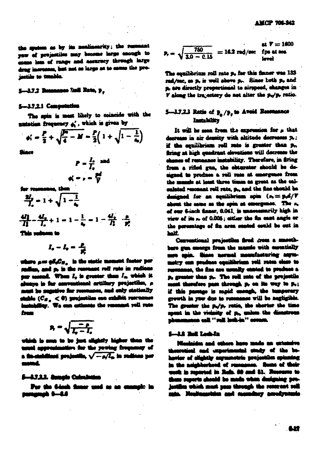
Resonance Roll Rote, p, .......................
Computation ....................................
Sample Calculation .........................
Ratio of p,/p, to Avoid Raaonaaea Instability
Roll Loeh-in.........................................
Aerodynamic Jump of Fiu-Stabiliaod Projectiles.......
Fin EEeetiranMB at Supersonic Speeds.................
CHAPTER 6
ROCKET-ASSISTED PROJECTILES
54
54
54
54
54
5-11
5-11
6-1. General .................................................6-1
4 8-2 Momentum Limited Situation .............................. 6-1
6-21 Variation of Massie Energy, Chaarter Pnasun
and Propellant with Weight of Projectile.............................. 6-1
ЛМСР 706-342
TABLE OF C0X7EKTS (cMt*4)
Psrsgrepk Pepe
6-24 Variation of Setback Acceleration................... 6-2
6-2.3 . Effect of Roeket Addition* on Projectile
Design Parameters ................................ <4
6-24 Effect of Rocket Addition* on Accuracy.............. 6-2
CHAPTER 7
LIQUID-FILLED PROJECTILES
7"*1 7-1
7-2 Effect of Sloshing of Liquid Filler ................... 7-1
7-3. Computation of Design Parameter* .......................7-1
7-3.1 Oyroeeopie Stability Factor........................7-1
7-32 Dynamic Stability Factor......................... 7-2
7-44 Spin Bate....................................-.....7-2
7-4. Rigid Body Theory.......................................... 7-2
CHAPTER 8
RANGE TESTING OF PROTOTYPE PROJECTILES
XL General ..............................................8-1
8-2 Data........................................ 8-1
8-3. Teatinc ...............................................84
8-3.1 Static Testing......................................M
8-32 Flight Testing .................................. 8-2
8-3X1 Vertical Target Accuracy.................... 8-2
8-3.21.1 Measurement of Accuracy................... 84
8-3.21.2 Temperature Range......................... 84
8-3X1.3 Data Recorded ............................ 84
8-3X2 Range (Distance) Accuracy..................... 84
8-3X21 Measurement of Accuracy................... 84
8-3X22 Dau Recorded ...........................84
8-8X24 Instrumentation ...........................84
CHAPTER 9
MANUFACTURING TOLERANCES
XU
xu
Analysis
XI
XI
ЛМС? 7O»i-*A42
TABU 07 С0ГГЖМТ8 (смРА)
9-Z Predicted Probable Bang» Error..................................9-1
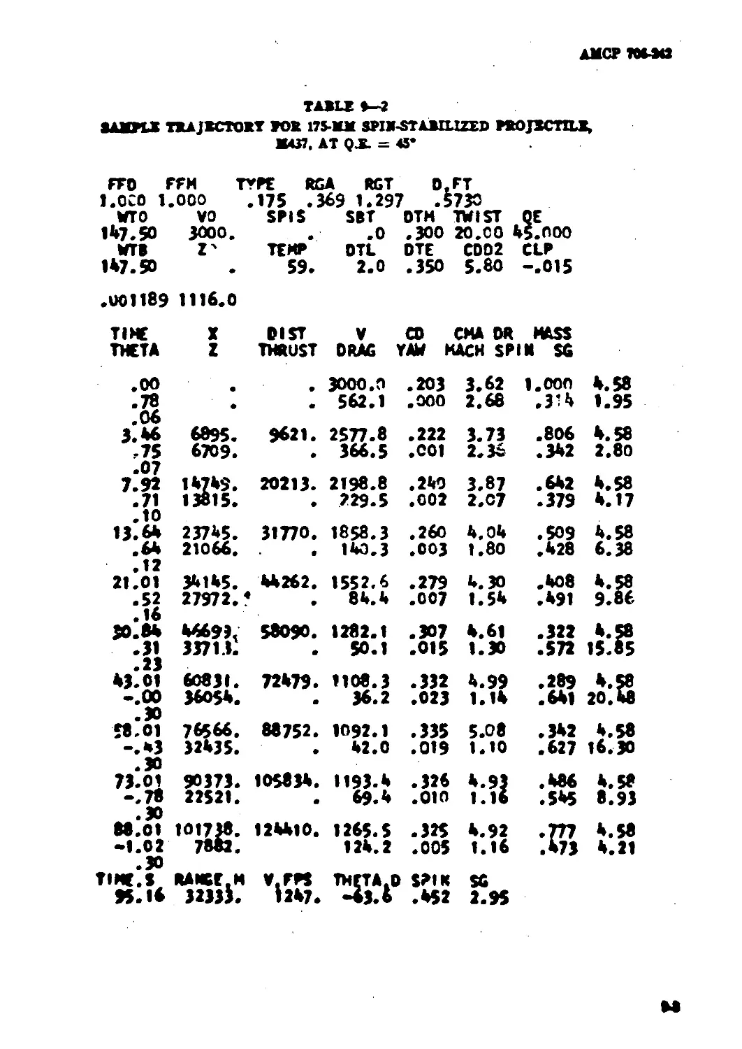
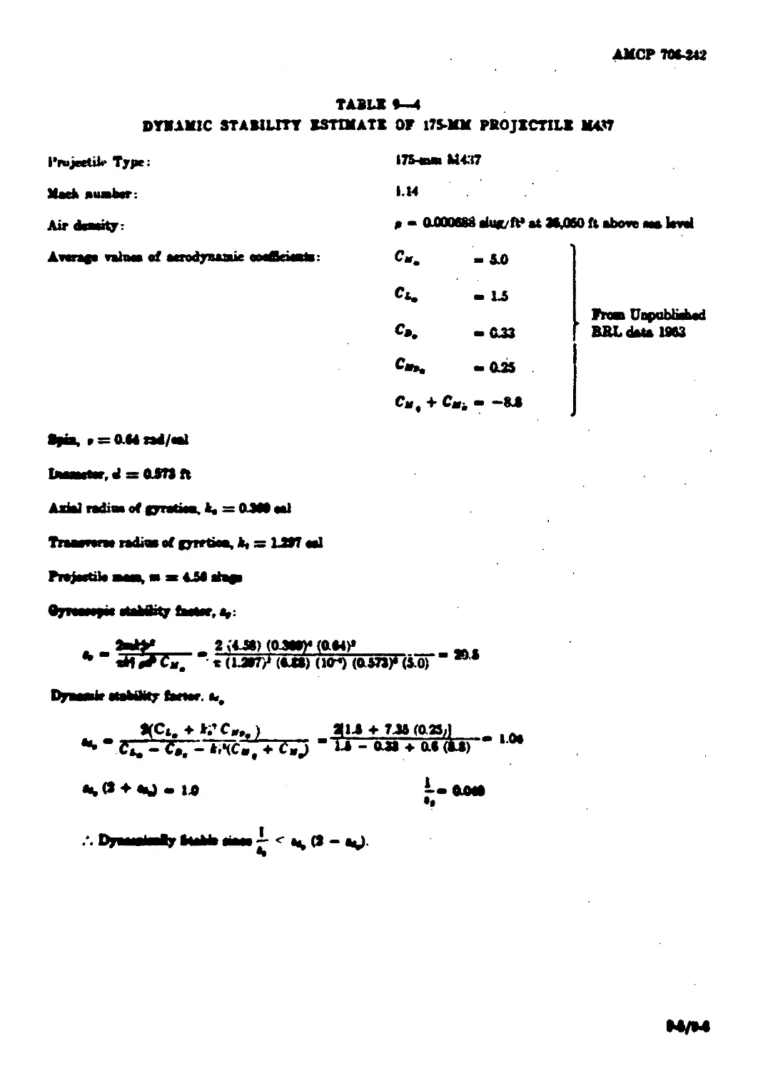
9-3. Dynamic Stability of 175-mm Projectile, M437 .................. 9-2
GLOSSARY ......................... G-l
APPKNDIXB8 ...................... A-l
RRFBRBNCES ........................ B4
BIBLIOGRAPHY ..................... B-l
LIST OF ILLUSTRATIONS
Fipwv go, ftft
S-l Coordinate System ......................... ................3-1
4-1 Diagram of Gravity Force oa Projectile................... 44
4-2 Flow Pattena on Varying Length. Cooatant Caliber 43
Diameter Spike Noam at Snpenonie VeloeitiM .............4-11
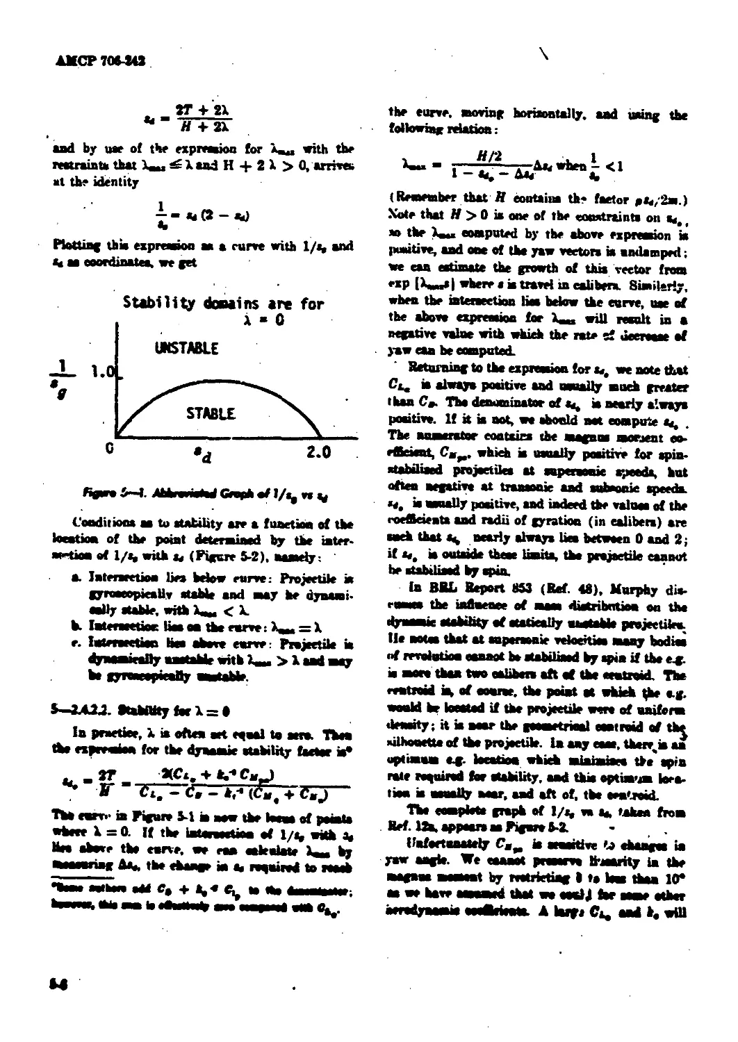
S-l Abbreviated Graph of 1/», va «« ............................54
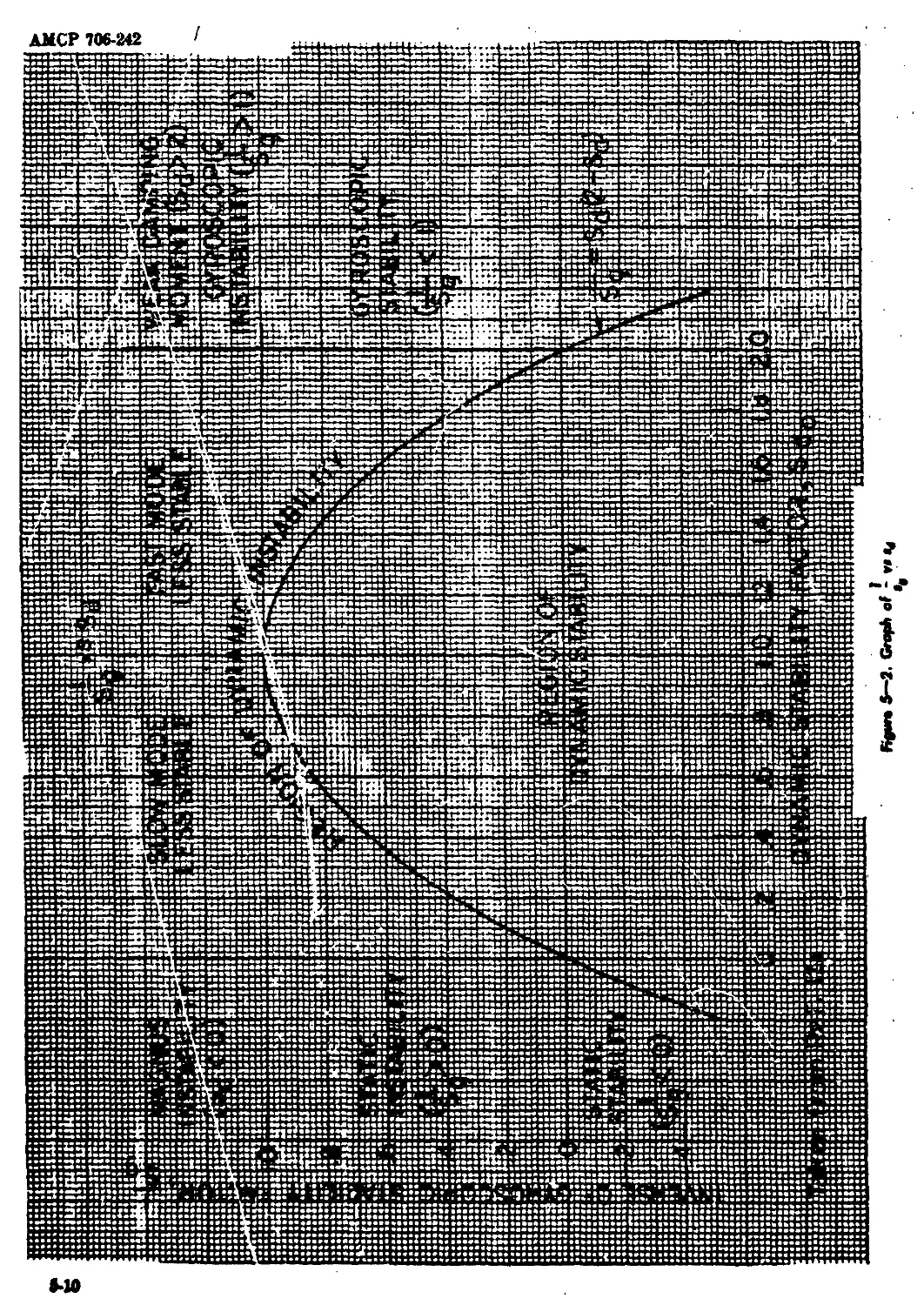
5-2 Graph of 1/a, vo g........ ............. MO
AMCP 70042
LIST OF TABLSS
Fable No.
Pajje
3-1 Eatimrted Accuracy of Aerodynamic Coefflej^ats Obtained by
Ballistic Range and Wind Tunnel Teat*...................................
3-3 GoeAciait* of Typical Projectile» Measured in Free Flight
. and Batimated .......................................................
3-3 Partial List of Ballistic Tert Ranges in North America..............
3-4 Partial Liat of Wind Tunnels in North America.......................
3-5 List of Reports Containing Methods of Ratimsting CoefBdenta ..
4-1 Typical Output of FORTRAN Simple Particle Trajectory
Program ............,.
4-3 Sample Trajectory Oleulatrd on Desk Computer
(Seineh Sample Projectile) .............................................
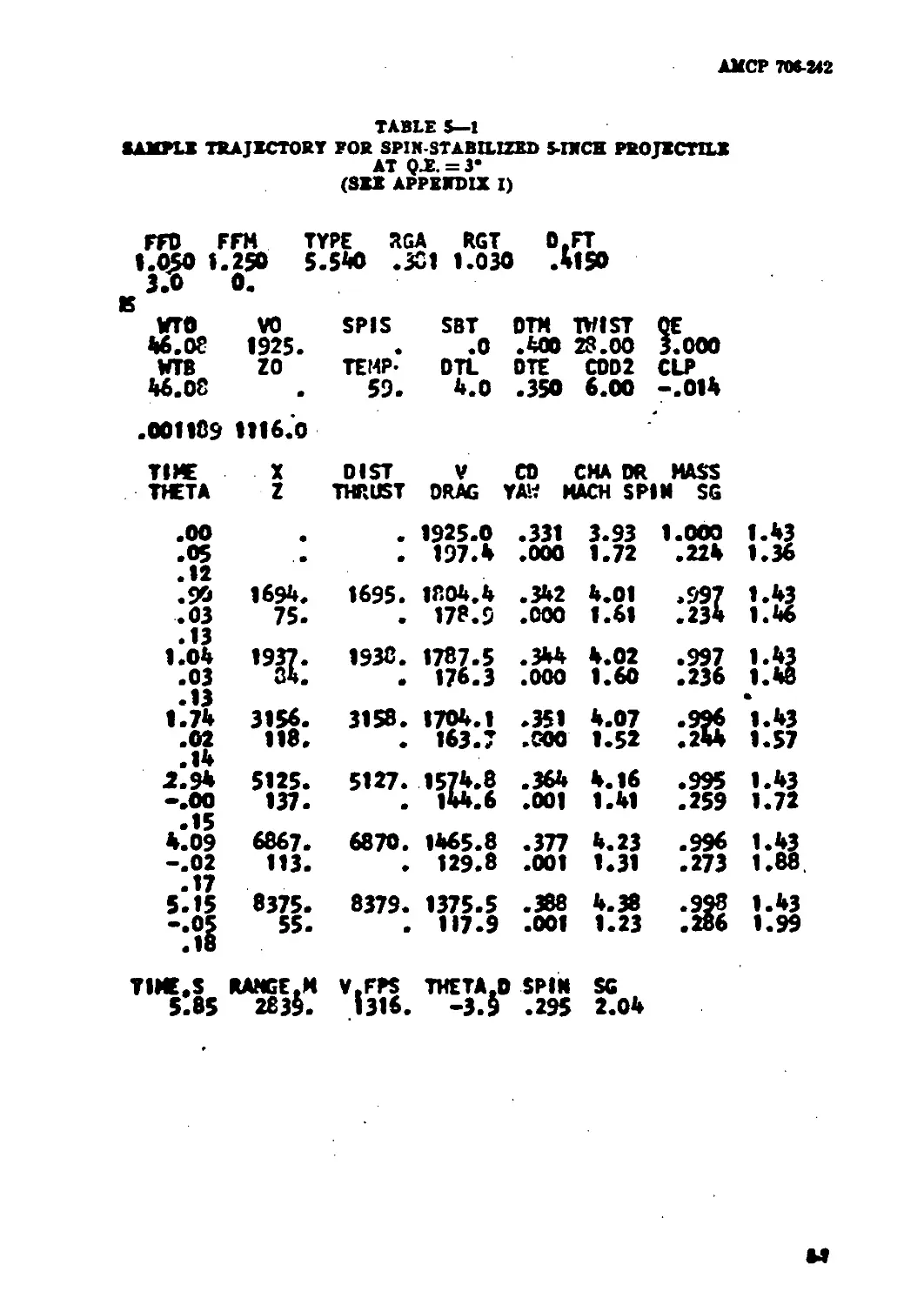
3-1 Sample Trajectory for Spin-Stabilised 5-ineh
Project at Q.E. = 3* ...................................................
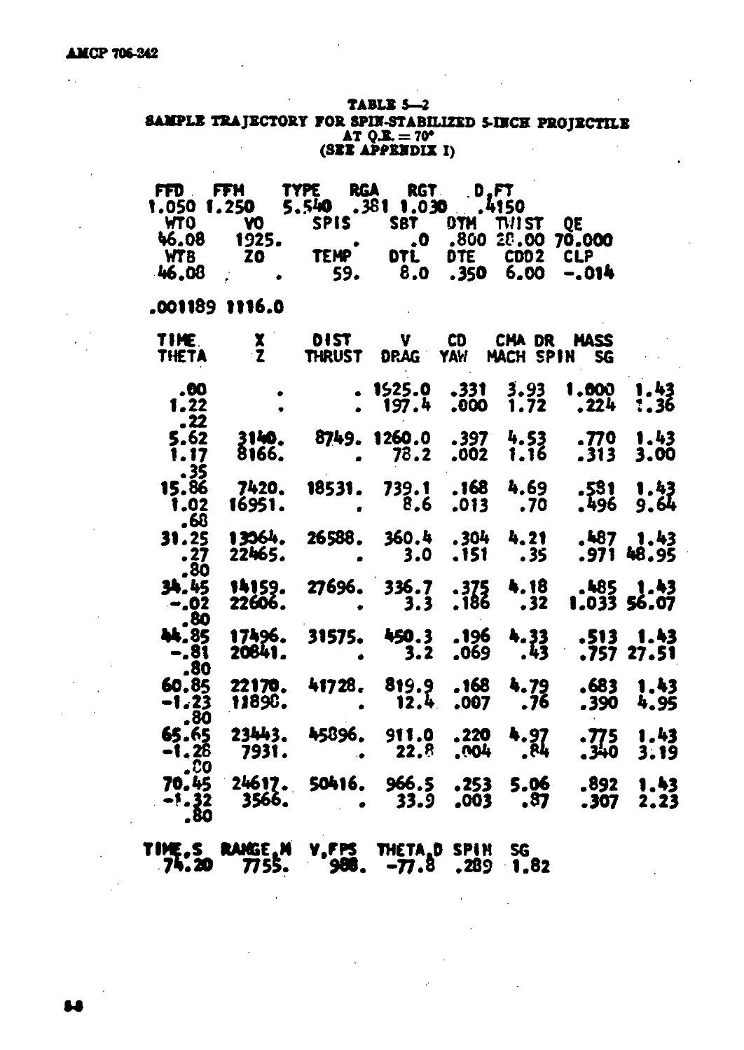
5-3 Sample Trajectory for Spin-Stabilised 5-ineh
Projectile at Q.E. 70* .................................................
5-1 Probable Variability af Rorket-Aanstad Projectile Characteristic*
and Sensitivity Factor* Which Affect Range................... ..........
5-3 Sample Trajectory for 175-mm Spin-Stabilised Projectile,
M437, at Q.E. = 46* ....................................................
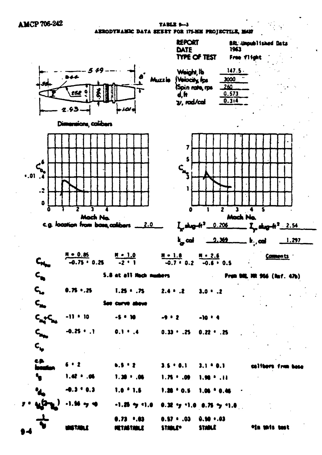
»-f Aerodynamic Date Sheet for 175-еии Projectile, 1(437 ........
•-4 Dynaau* Stability Estimate of 175-mm Projectile. M437...............
П St t 2SU S
АМСР 706-342
Appendix No.
LIST OF APPENDIXES
Ряде
I Sample Spin-Stabilized Projectile....................................A-l
II Calculation of C.O. and Radius of Gyration..........................A-2
III Gyroscopic Stability Estimates
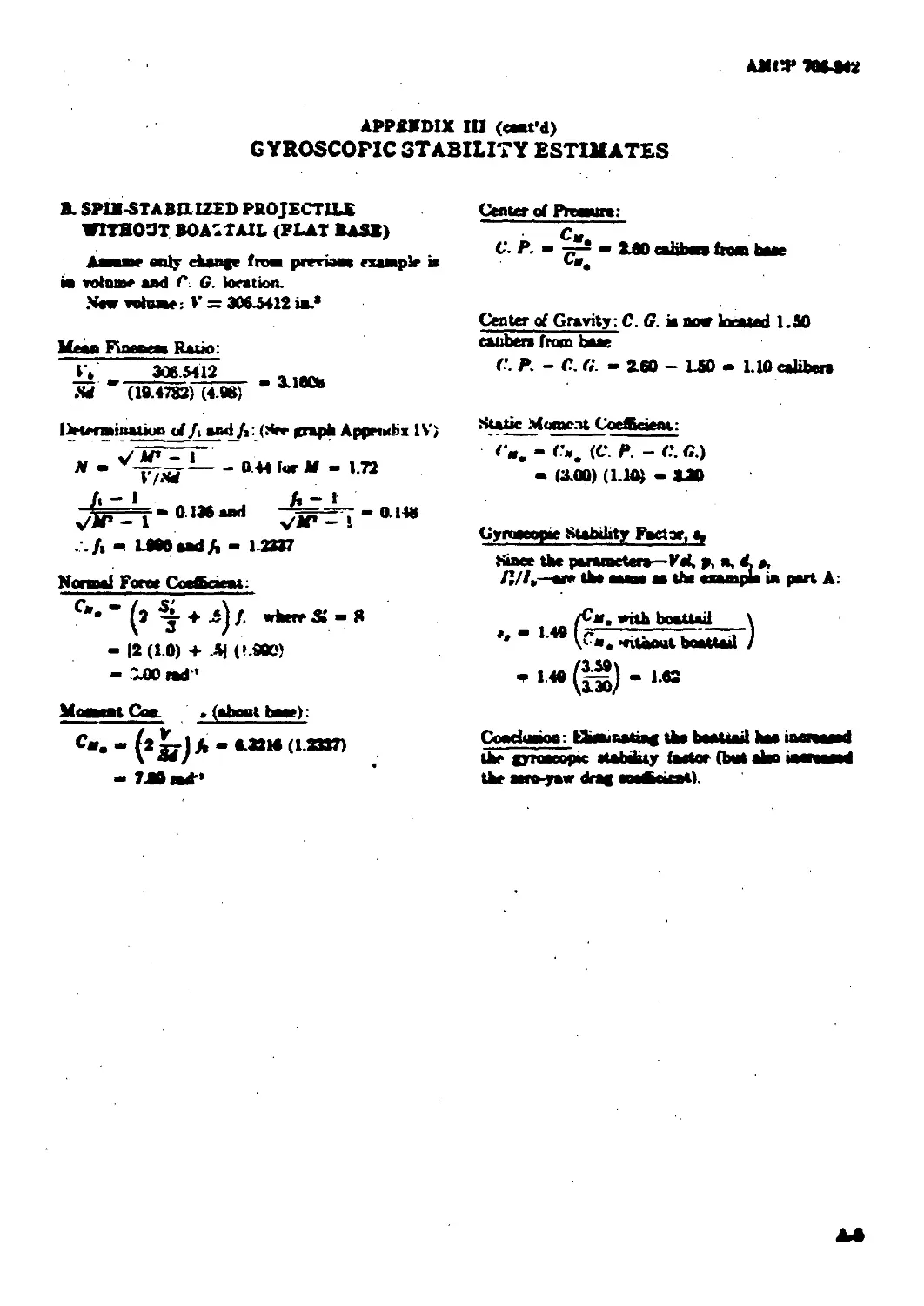
A. Spin-Stabilized Projectile With Boattail ................... A-3
B. Spin-Stabilized Projectile Without Boattaii (Flat Baae).... A-S
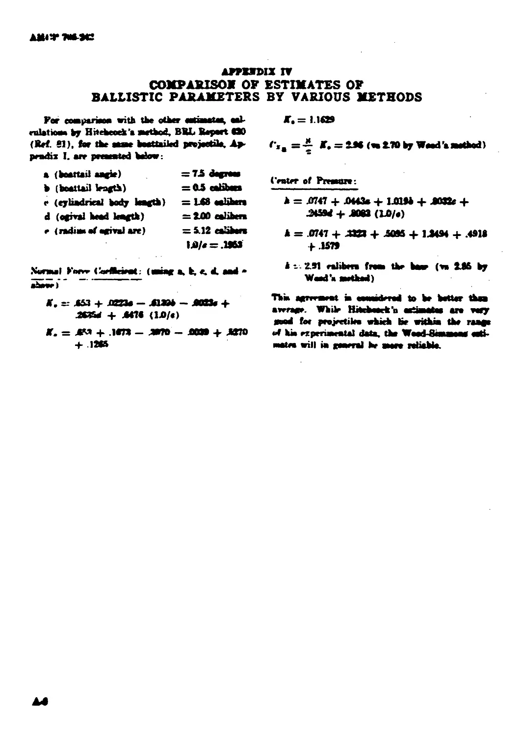
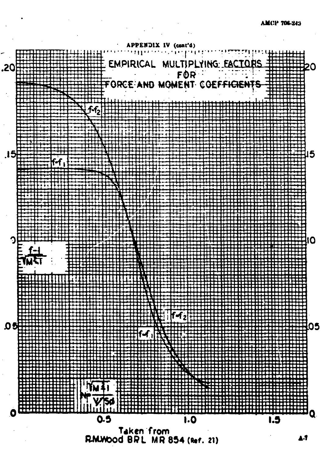
IV Comparison of Estimates of Ballistic Parameter!
By Various Methode ........................................A-6
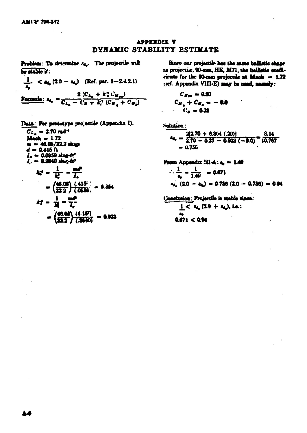
V Dynamic Stability Estimate.................. ..................A-S
VI . Static Stability Estimate of a 5-ineh Fin-Stabilized Projectile'.. A-9
VII Projectile Geometry.........................................A-10
VIII Aerodynamic Data Sheetz
A. 30-mm HEl Projectile, T306E10............................... A-ll
B. 20-mm HEI Projectile, T282E1 ............................ A-12
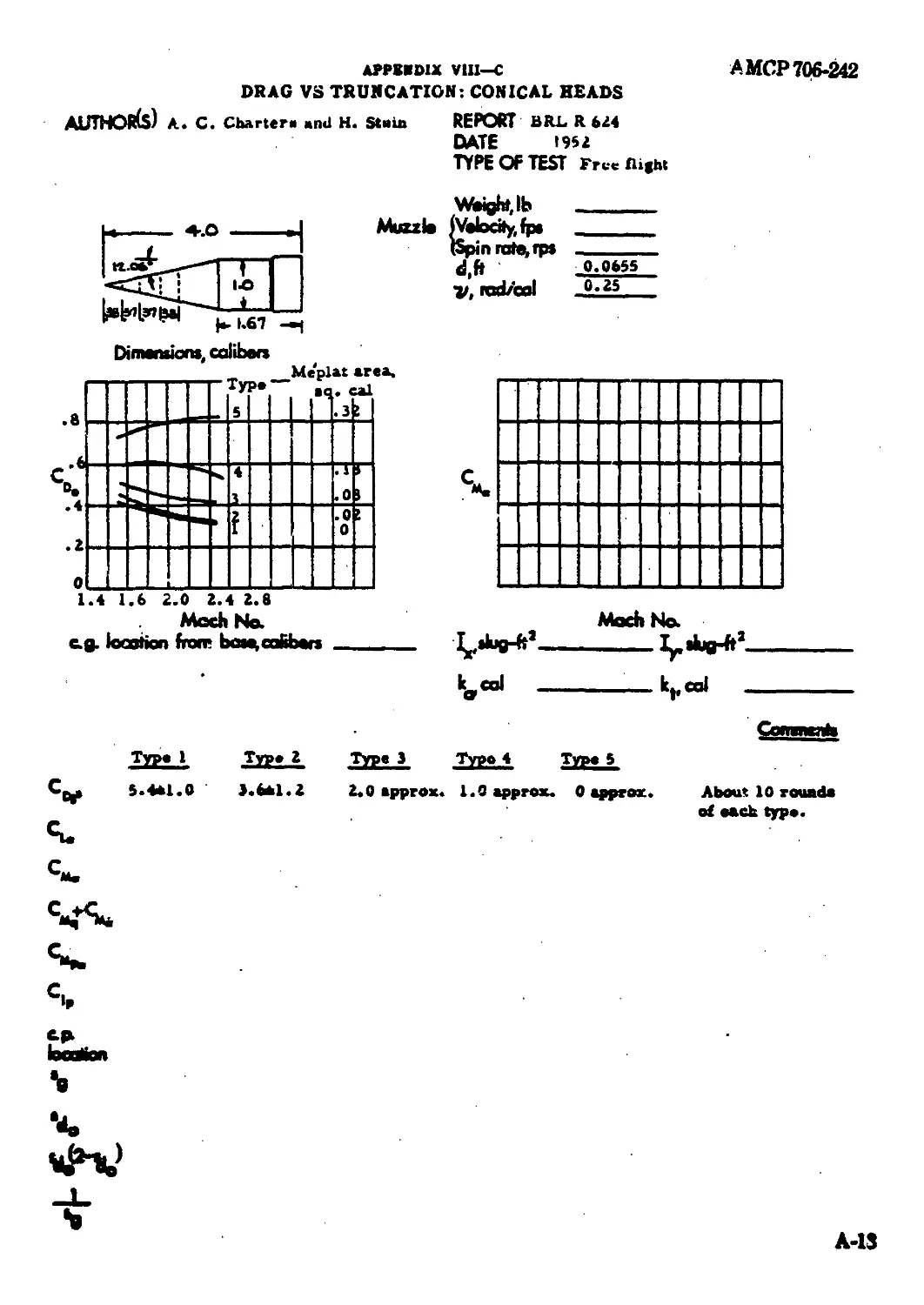
C. Drag re Truncation: Conical Heada........................... A-13
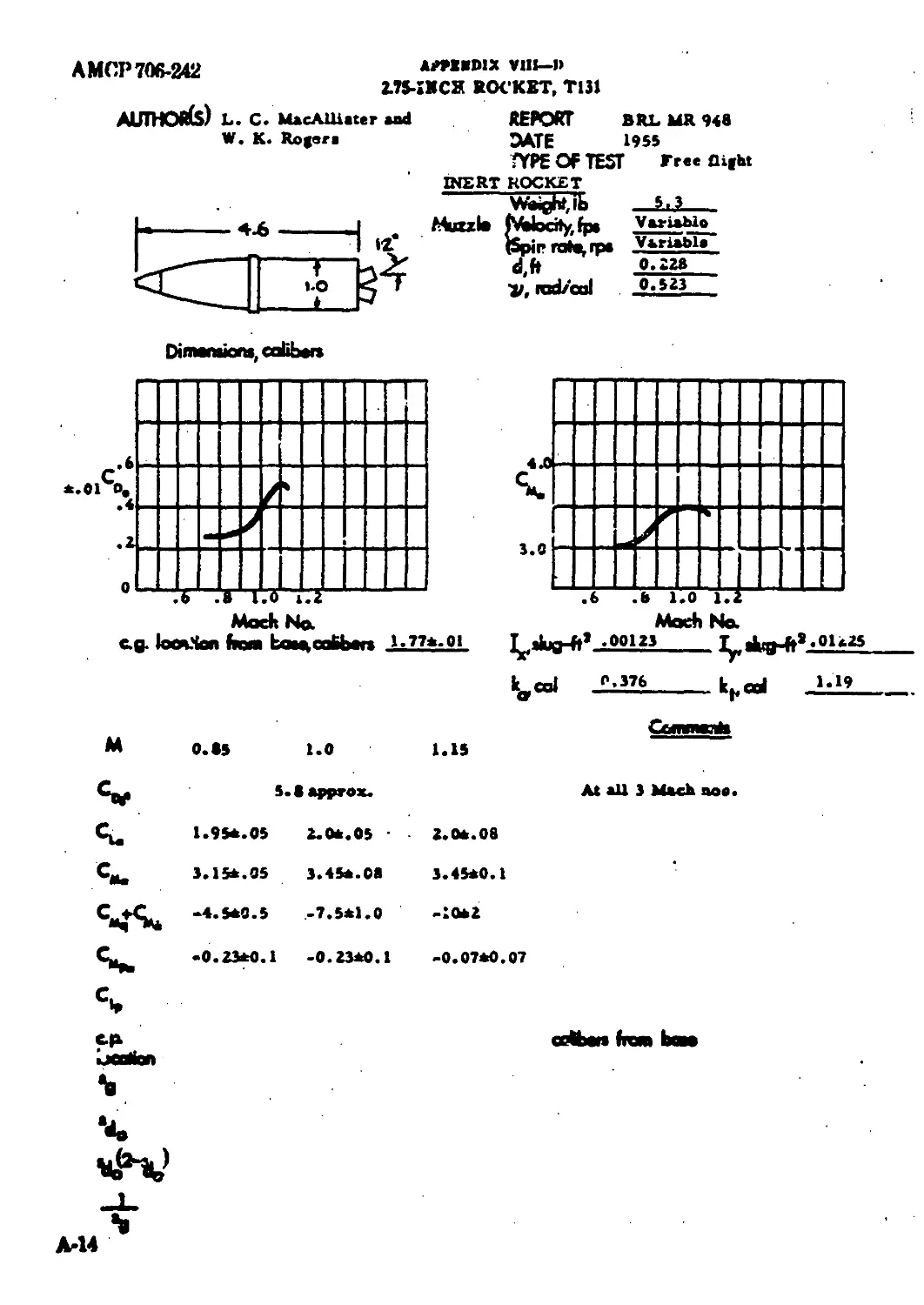
D. 2.75-inch Roeket, Tl?l ......................................A-14
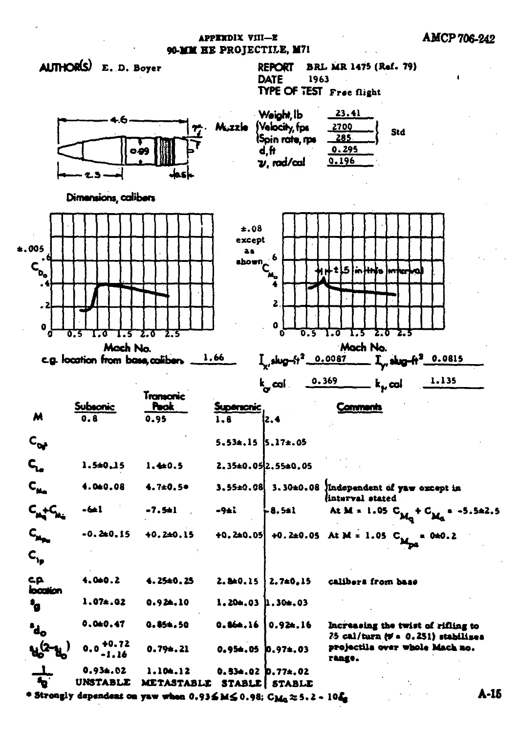
E. 90-mm HE Projectile, M71................................... A-15
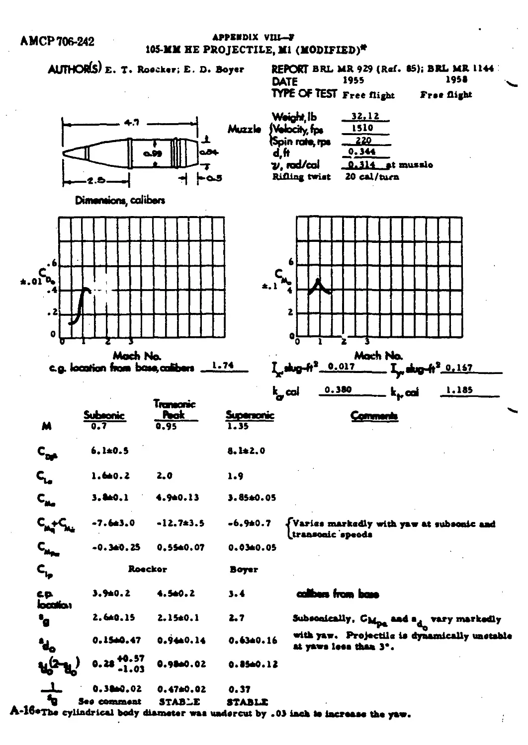
F. 105-mm HE Projectile, Ml (Modified) .........................A-16
G. 4.9-ealiber Projectile at Transonic Speeds.................. A-17
H.
L
J.
L.
M.
N.
0.
P.
0-
R.
8.
T.
U.
V.
w.
X.
T.
z.
90-mm HE Projectile, T91 ............................. ........
Effects of Head Shape Variation................................
120-mm HE Projectile, M73.......................................
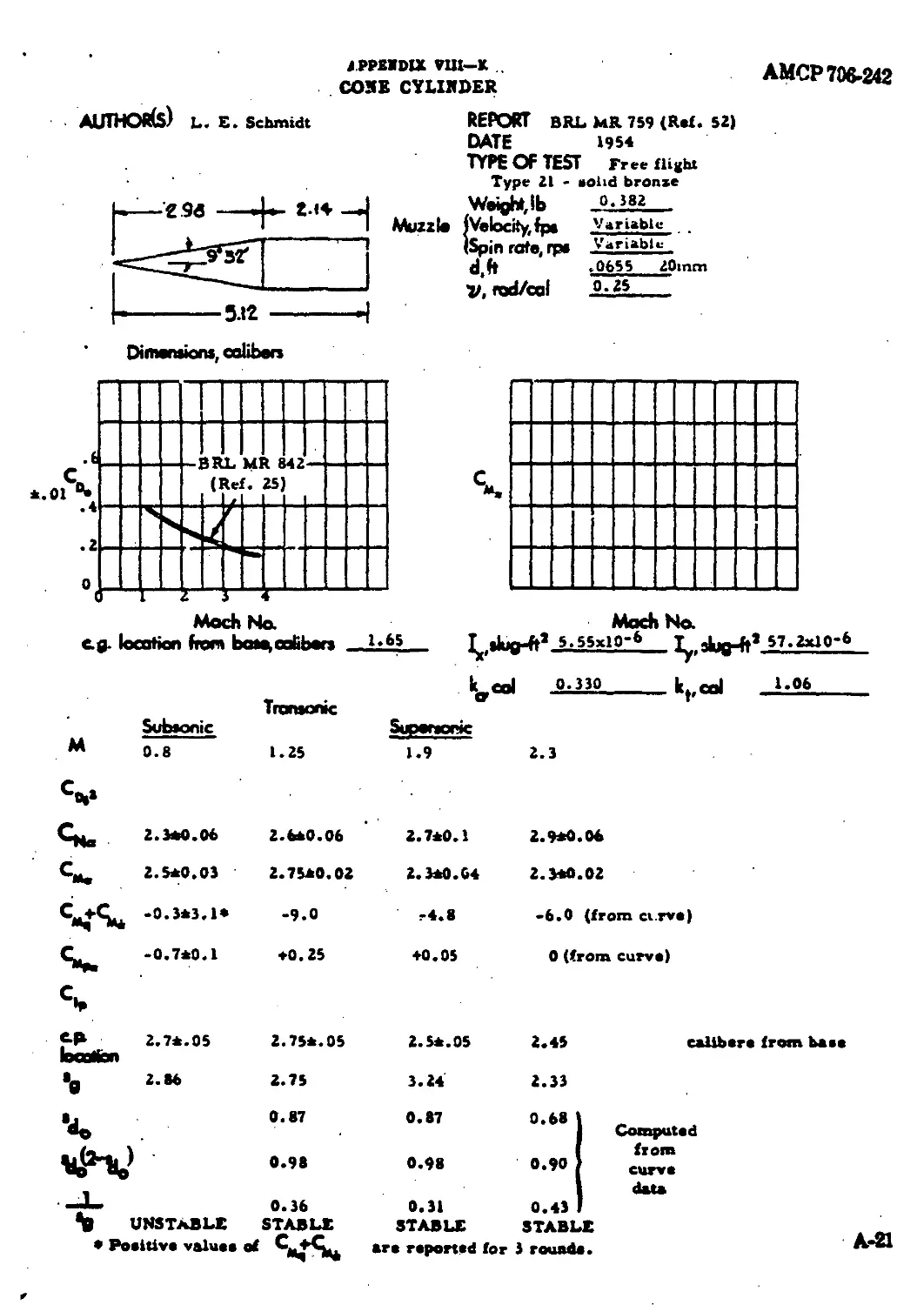
Com Cylinder ..................................... ..........
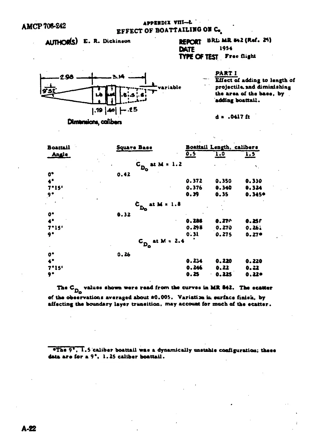
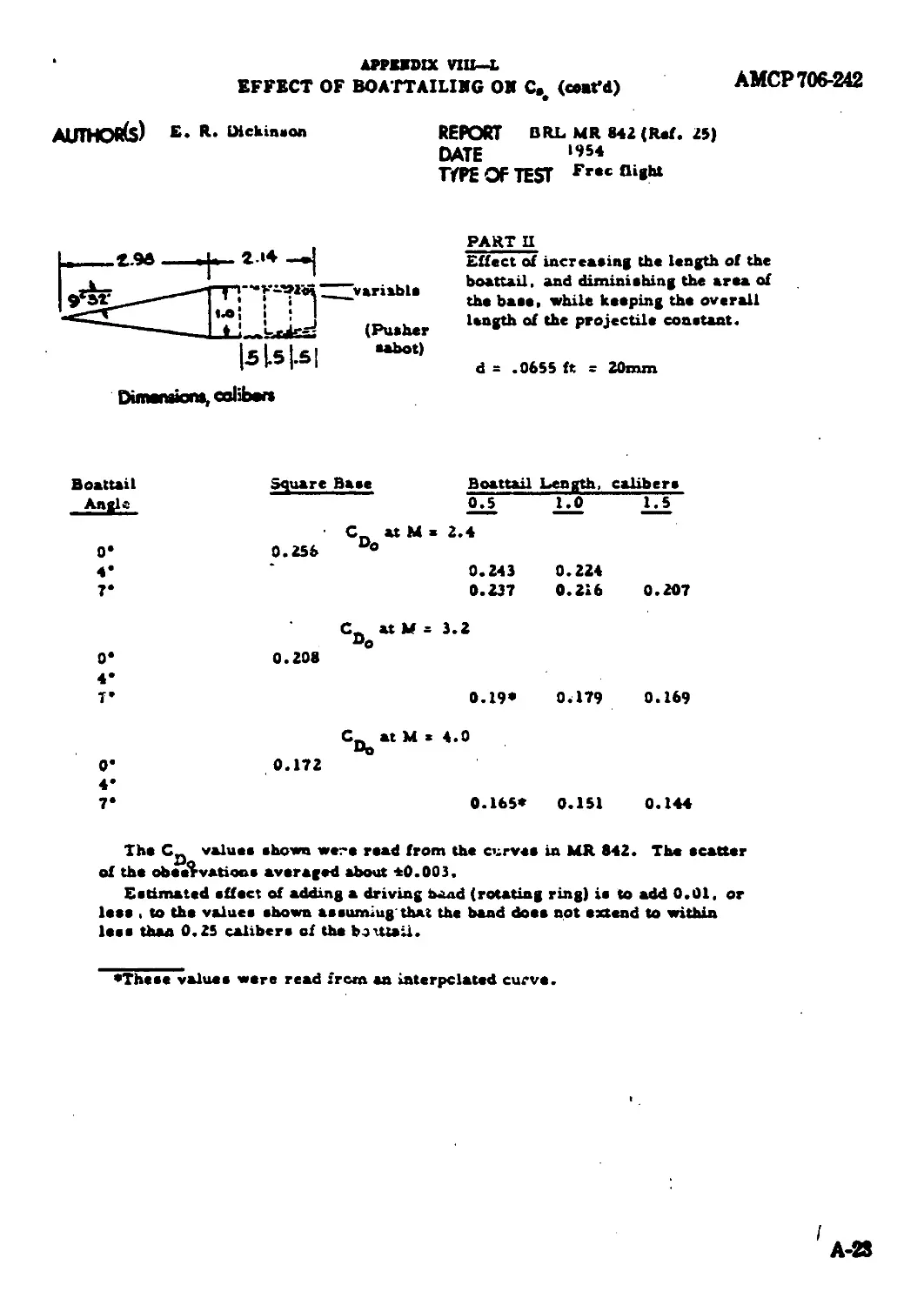
Effect of Boattailing on Co, ..................................
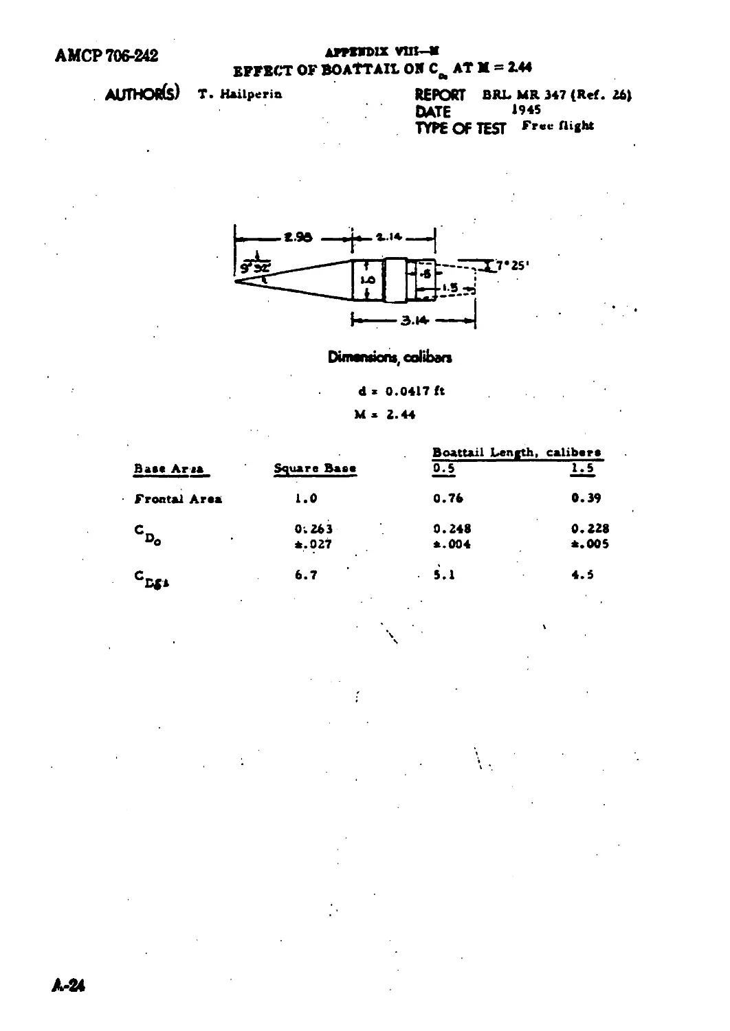
Effect of Boattailing on Co, at M = 2.44........................
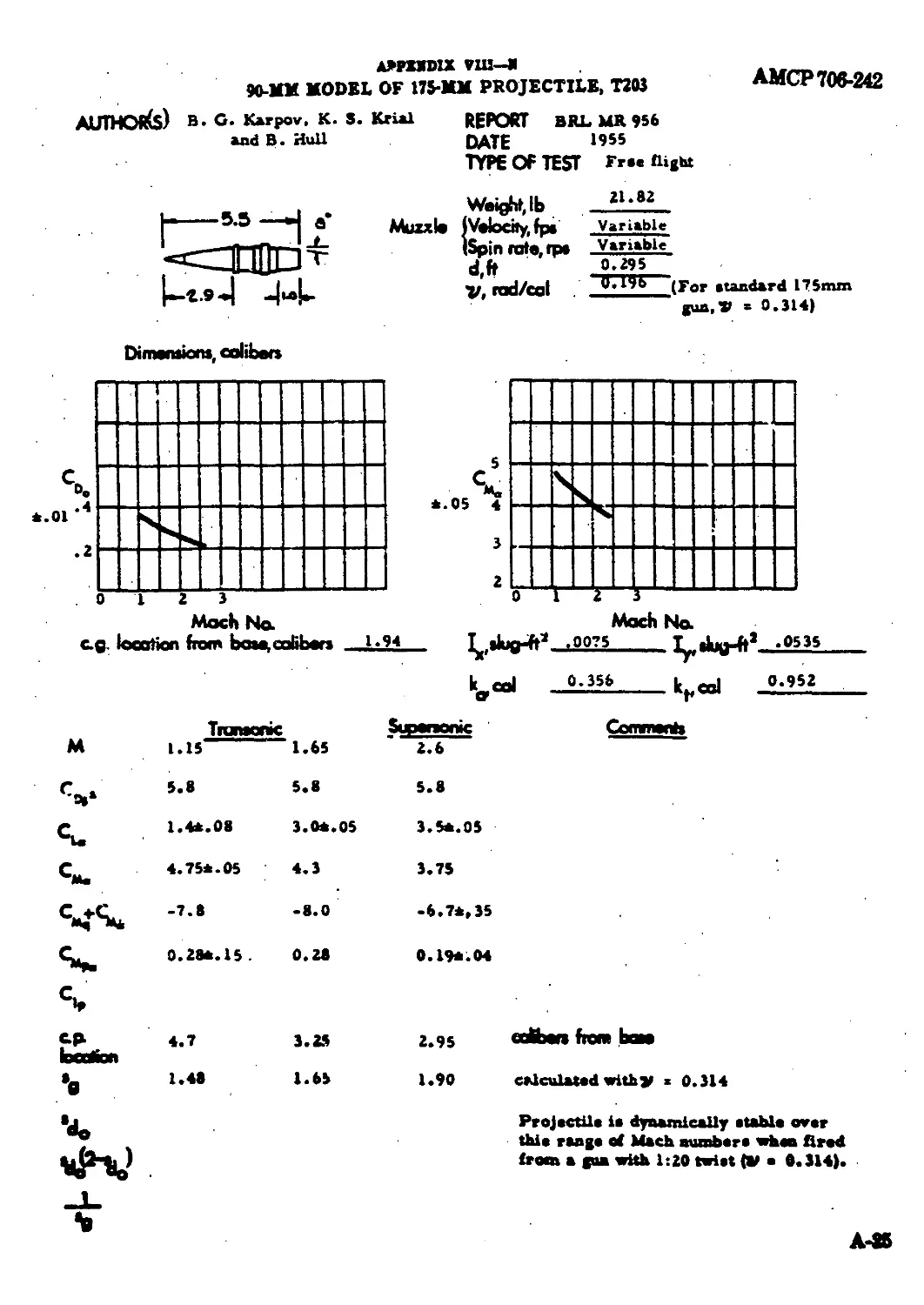
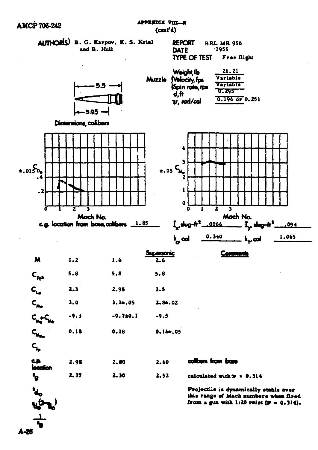
90-mm Model of l?5-mm Projectile, T203 ........................
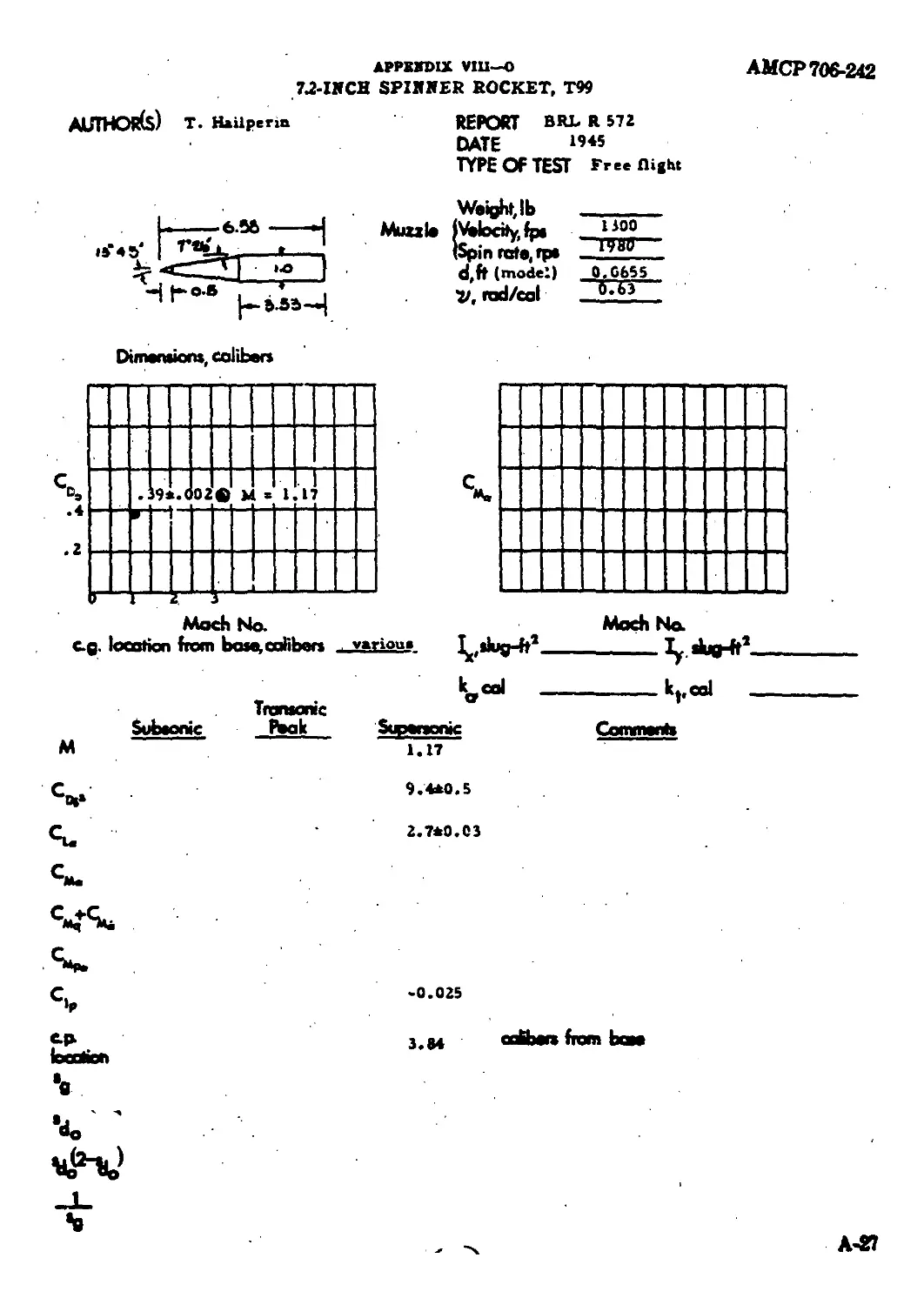
7.2-ineh Spinner Roeket, T99...................................
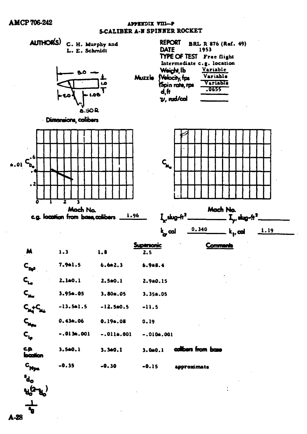
5-ealiber A-N Spinner Roeket...................................
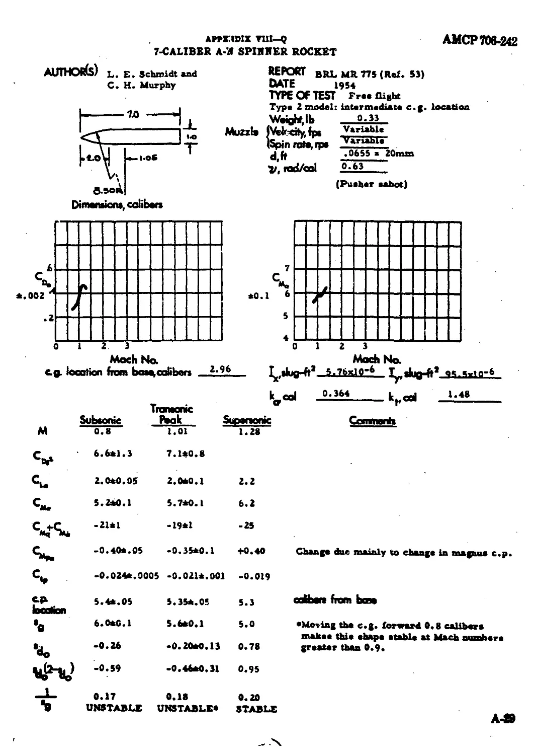
7-caliber A-N Spinner Roeket...................................
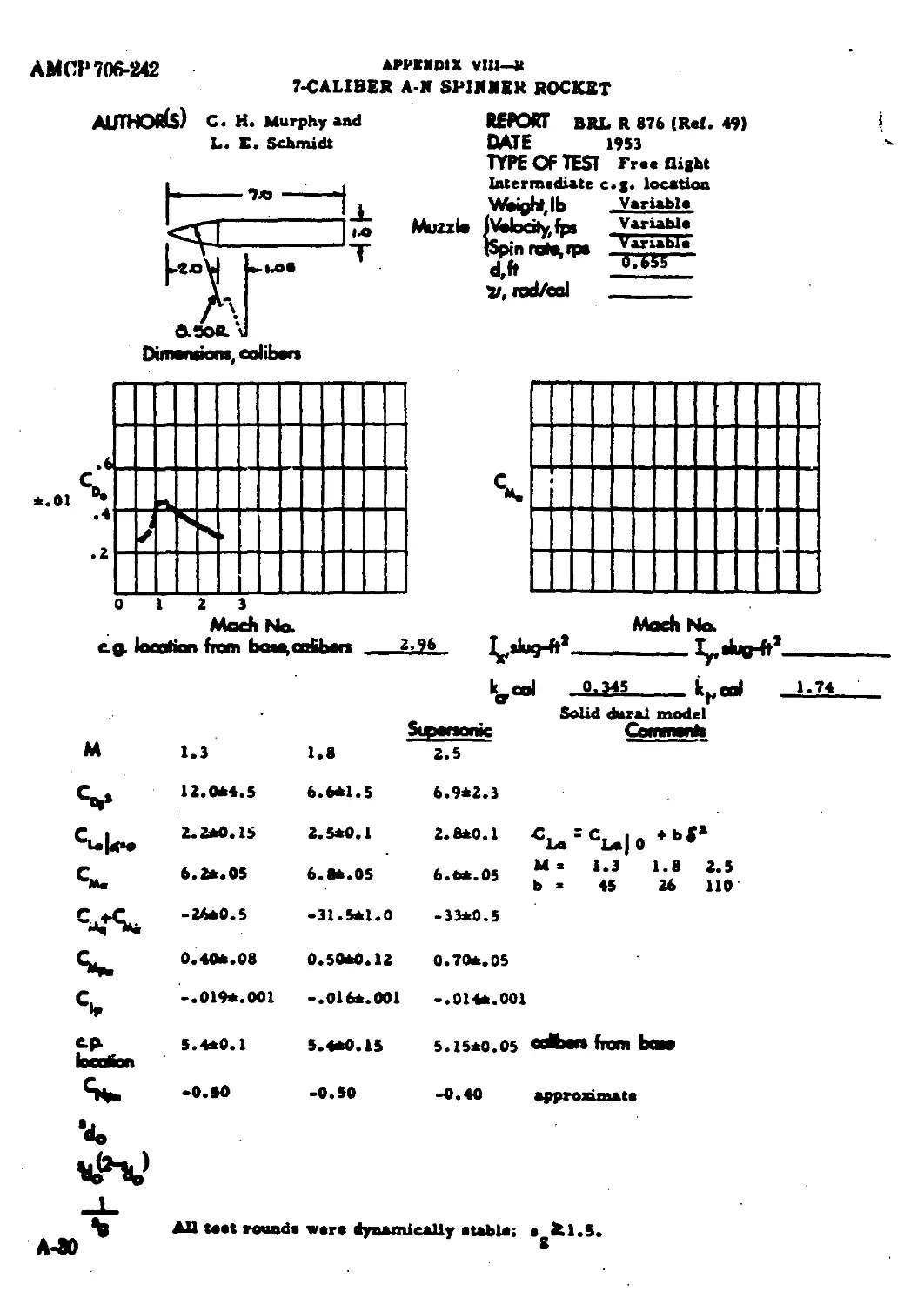
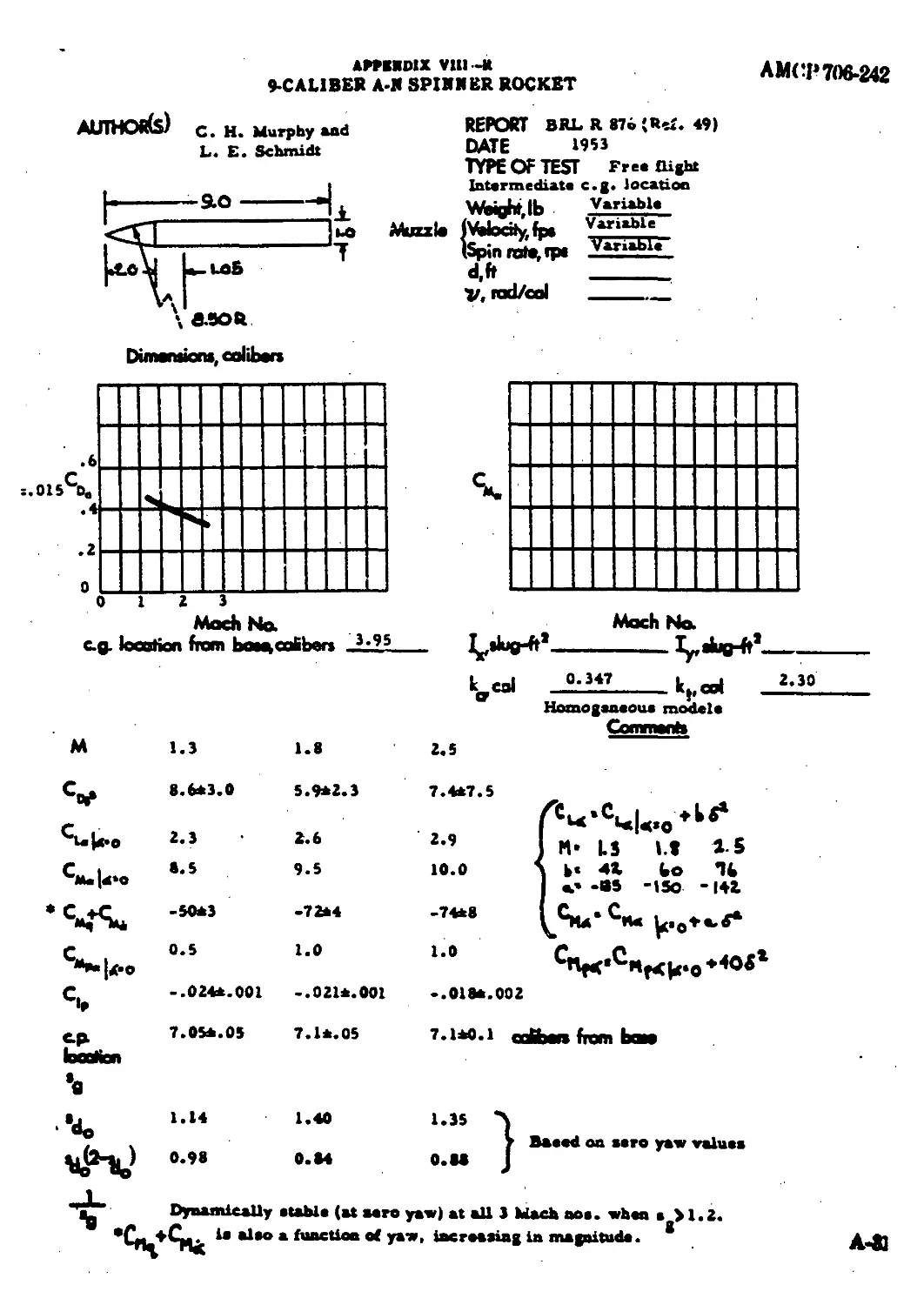
7-ealiber A-N Spinner Roeket and 9-ealiber
A-N Spinner pocket .......................................
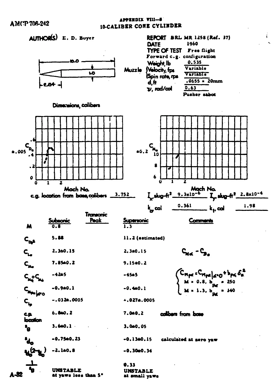
10-ealiber Cot e Cylinder .....................................
105-mm HEAT Projectile, T171 (Modified) .......................
60-mm Mortar Projectile, T24...................................
105-mm Mortar Projectile, T53............... ............
57-mm HEAT Projectile, T188E18.................................
90-mm HEAT Projectile, T108....................................
90-mm HEAT Projectile, T108....................................
10-ealiber Arrow Projectile ...................................
А-Э0
A-32
A-33
A-34
A-35
A-36
A-37
A-38
A-S9
IX Trajectory Program in FORTRAN Language........................ A-40
AMCF 706-242
LIST OF SYMBOLS
A
A
a
b
c
e-P-
CD
cal
C,.
Ct.
Ch,
C"t.
Ct,
С*, +
C*»
Ct» .
A conatant deecribing the kind and degree of aaymmetry of a projectile, radiana D d
Bore area, ft* e
Setback acceleration, ft/aec* 0»
Conatant in Q function в
Fin epan, tip4o-tlp, ft к
Conatant in Q function I.
Fin chord, ft 11
Conatant in Q function л9
Center of gravity t
Center of preaaure Dreg coefficient Ki
Caliber k.
Drag coefficient at aero yaw Yaw-drag coefficient, per rad* k,
lift coefficient, per radian L
Normal force coefficient, per radian Zu
(Cm, С*., + С» for email yaw) M
Mangua force coefficient, per rad/aec, per radian at
Static moment coefficient, per radian N
Mag".ua moment coeftcient, per rad/ n
вес, per radian N,
Damping moment coefficient, per rad/sce P.
Rolling dariping moment coefficient, P
perrad/aec
Roll moment coefficient due to fin
cant (at aero epin), per radian О
Drag, lb
Maximum body diameter, ft
Baae of natural logarithm!
Feet per ascend
Acceleration of gravity, ft/aec*
Altitude above aea level, ft
Axial moment of inertia, alug-ft*
Tranavene moment of inertia, alug-
ft*
V-l; in complex notation indicateo
rotation by 90*
Modal vector, radian»
Axial radiuc of gyration, caliber*
Tranavene radiua of gyration,
mlibera
Lift, lb
Bore travel, ft
Natural logarithm
Mach number
Maae, aluga
Normal force, lb
Twiat of rifling, cal/turn
Magnua force, lb
Chamber preaaure, Ib/ft*
Roll rate, rad/aec
Equilibrium roll rate, rad/aeo
- - o + Mf
AMtT 706 242
LIST 0Г SYMBOLS (cant'd)
Dynamic prrenurr, &,'?•?
(f - **V»)
Angular velocity at a noorolling
nuamle-fixed coordinate rynem about
a boriaootal axia, rad/aec (in
damping moment expreaaion)
Radian»
Frontal ana ft*
Trawl at projectile, caliber»
Dynamic (tabibty factor
Dynaamc XabOity factor for
U. S 0
Gyrcaoopie atabihty factor
Temperature, *F
Tune of flight, aee
Time, aac
Utility
Velocity or aimpeed, fpa
Volume of projectile (indudiag
bauadary layer over the boattail,
if ряапы). ft*
Weight, a>
D*aare along trajectory, ft
Vertaeai oorepanant of yaw, rad
Beriauntal eoreponeot of yaw. tad
Yamaatfo,nd
Samfa maaaoat factor, ib-fl/radiaa
CaaAaiaataf naeaatty
Spin (aomSmaaakaual) » » pd/F
Acute >mgfa between a horiaoMnl
pinna and the tiaynt to the trajec-
tory nt the eg. of the project de
Angle of roi
Aagb af anewtatien of a modal
wet ar, re liana
Danaity, thg.'ft*
Pertain» to nutation vector
Periaine to pre г ramen vector
Pertain* to aaymmetry vector
Maximum value
Standard value
Dummy index: to be replneed by a
aaqoance of apedfic indioea when
the «aJjc-ripted quantity uaed in
t computation
Sama definition an auhacript •
Aerodynamic jump
Damping exponent, par caliber of
trawl
Repone
Rwoaaat
Derivative with reaped to angle of
sttftck
Aoouatie (V. - apeed of aound)
Body
Bum
RSaetiw
Equilibrium
Fin
Initial eoadfticn»
Stanza* vahm
Dnriuatiw with reaped toapia
Derivative with reapaat tn time
Derivative with reapaat to antihare
trawled, Kg., • p, ЦТ
АМСРЖЭС1
СМАЯЛ* 1
IMTRODUCTIOM
J—L GMMSKAL Thia handbook м гоомниД with
th» doaign of projection flrod free guan. The pro-
jeetihn aoModerad m of greater мм and weight
than sea пеемаИу be And fnm a hand-held
weapon, aad they are wot equipped with guidaoce
ya fa It win be aaouawd that they an bodice
of rivfhuiie, aoaaetiaoee equippod with flno, aad
fly ia the gawara! direction of the Inwgifniliaal axis.
J—X MBASCU8 ОТ ПЖГОКМАМСЖ
The pemcipol an Mateo of the perferManti of
а pnjeetile art:
b. Lethality
e. Aeeuruoy
d. Tineoffligh.
The eohtea taben on by tbeae neaaune arban a
reend. ar group of twaada, io trod are detenaiaed
by atMeopberte eeudxiooa, maaaie velocity, gun
orieatatiau, tarpot ar barot riot elite relative to gaa,
aad by flight ehorneteriotMO draagnod aad boUt iate
the projMlilo,
The рпамгу flight 'horaeterietka which dinetly
inAoaaee tbe trnjoeteey are:
a. Drug
b. АогоАуаамй jaa^
bat both drag, which rhwfly adret» range aad tiaae
of flight, aad jenp, which ehiepy afloete aaewraey.
an tboanarivaa detonemed by a aaatber of prejeetik
aharaatariattea wbaab we will aoM enoadwy flgbt
a. Stro-yaw drag ooaAeiant
b. Taw-drag MiMriant
e. Serfianal deaaity
A Lift eoeflkieat
a. Stability
t Aqyaaaetry effects
g. Wiad eenortnity
h. Meade bleat MMiiivity
The lift aad dra* eaodfeieate are funrtioao of
projectile ohape aad airop nd. Stability ia primarily
a fwartioo of chape, airepoad, air deaaity, aad opin
rate, aad of the Meaner ia whieh the мам of tbe
projectile ia distributed. Mank biaot araeitivrty
depeadi on enoeatially the aame paraaeteH aa
atability. Vind Moatirity deponde on tbe lift aad
drag eoeflfeienta, *• atability, and, ia tbe сам of
rocket aeaioted projeetihn, on the ratio of throat
to drag. Practically all projectile bodiea (aad
flat) an deaigaed with rotational ayaaotey; tbair
MjnMitry ariaa ia tbe aMoofaetaring peooaaa.
Рама, boweeor, an aeaally aaysaaetrie iateraaQy;
the eenter of gravity of tbe faae dan sot be ia
tbe praj(ctik axis.
AS of tbe above aaeaadary flight abaaaater-
iatiaa, aad therefore the priaary flight ahem-
terietMo. an controllable by tbe daaigner to withia
a narrow range; roead to naad oariatieaa ariaa
owing to Monofaetariag toteroaea aad to obaaga
ia aaaaia nleeity. air deaaity and wiad pattea».
Striageat aaaatetariag aienni: m aaay ba Mo-
poaed by the daaigner if the аопгму йпреоеемпК
obtained eaa jaatify the iaaeeawd aaet of anao-
faetan.
1-4. LOOtSTSCAL СОЯГОПАПОЖа
hgiattak The fl edge re май еаааМаЦу bear th
14
AMCPTOd-242
Kind the dement* of eoat, atorability, and trans-
portability. He should avoid, where роиШе, the
we of material» likely to be in «bort «apply during
wartime. He will often be limited by the facilities
for loading the projectile into the gun, and by the
design of the gun chamber. Moat of thane eon-
aiderationa are beyond the aeope of thia particular
handbook, bat ate eocered ia other draign hand-
books of this aeries.
It is not difficult to deaigu a projectile having
long range, a relatively abort time of flight, and
л «mail round-to-roand diapetmon. However, the
projectile might, and probably would, have aueh a
mill Jeatnietive value, or lethality, that it would
be ttsrieas *» a weapon. THE PRIME FUNCTION
OF THE PROJECTILE DESIGNER IS TO
FIND THAT COMPROMISE AMONG RANGE,
ACCURACY AND LETHALITY WHICH WILL
BEST SUPPORT THE MISSION OF THE
WEAPON SYSTEM UNDER CONSIDERA-
TION.
Foe eaample, maiiHhatita of an eaiating pro-
jectile by increasing the length of ita ogive, while
preserving the overall length cf the projectile,
should decrease its drag coefficient and, therefore,
increase it* range. However, the stability of the
round will be altered, with some effect on accuracy;
the volume of the projectile will be decreased, with
resulting decrease in lethality (or other measure of
usefulnem, as in the ease of ansoke or illuminating
projectiles). These trade-offs are disenssed in de-
tail in the body of thia handbook.
' In most of the discussion* in this handbook it
will be tacitly assumed that the designer i* given
the projectile disaster and the characteristics of
the gun from which it m to be flred, i.e4 upper
limit*, on chamber pressure, muasie energy and
murnie momentum have been established by the
gun designer. Occasionally, but not often, the pro-
jectile designer may be able to apaeify the twist of
the rifling. If the deeagner i* equipped to make
correct design decision* for any one ealiber, he will
be аЫе to cope with the problem of eboosiug an
optimum ealiber far a given miasma, should that
problem arise.
АК<ЖЖ4Н2
СНАРТХЛ 2
TRADE-OFFS
3—L GBVXKAL
If th* eolutioa of * tradeoff pro&Hm to ex-
pmeed in ввааЬеп, an intelligent eompramtoe be-
tween eoufbeting geek eon only be roeeted when
the eont of falling abort of each geal ana be ex-
prvmed in number*. Furthermore, them penalty
number* mum b* in the aame eyetem, Le_, they
maat be capable of being added or multiplied to>
gMh*r t* grv* a eigniheant number.
One nerful concept, borrowed from ceoneauca,
ie that of •‘utility", enpiemtd at a number which
lie* between aero, etoadiug for naeBw, and unity,
ataading for am visum uarfulnem attainable ia the
given aituatioa. If the utility of each element of a
aituatiou can be computed, the utility of the over-
all aituatioa ean be touad by muitiplyiag, ar.
ia tome aaom, adding, tbe utilitiee of the element*.
(The earn atay be divided by the washer of ceat-
poaenta if the teaviatiea that Utility leaner trend
unity ia to be r Hamid.)
In order la oeaetnmt the enrauo which expram
the utilitiee of tbe rnriom etemmne of projeetito
perfaramaaw, tbe durigaer meat obtain, from the
agency rmposaibie far dednine the military rugate*-
meat, atatemento about tbe roUtrvo value* of war-
head* of diliriut valamm dor the purpaoaa, and at
to nsgaa, pertinent to the mtoetos of the pea-
(йвйвмммш weNi Ъ* obvM
the uerfulaem of increaoed rang*, dmmneod toe
of tight, and improved accuracy While the otate-
meate obtained may be mainly gnalitetivo, anob a*
“•eeon toad a tola mduottom warhead veto**,
but a 90% ntoetton would be aaowaptabto," •*
‘‘anything 'Mt thou tom tbe proem* range to
ooaaHemd to be b^end to «Шив of Me pew-
joetto’* toy to b» trastotod tom immiHiil
utility eurree. Tbe deeigner ahouU dtoeum th*
utility eurm with the esmtomer befor* proceed-
ing with the daaign; oom* elariSeation of dmign
objective* ia likelyt* reauit. Ixamplm of trade-
off ar* given below.
3—3. DICRXASXD KA10F VS WAMRAD
vouna
3-ЗД Utility of Sttndaxd Fiojectite toe moi
Xgaal to Zare far Standard Bang*
A* an totopia, onppom that the peobiam to tto>
deeign of a rorhat eentotel projectile to be dr*
from an «xietiag gun. Range to iaeroaaed by th*
addition of roehat fori; howavnr, th* overall length
of tbe projectile to limited by etability or handling
eoaeidcratioaa, m that an the amount al rochet fuel
to iaeraaeed, the volume of the warhead, and tor**
fere toa lethality, to dm ream it Tfea deaigne* can
compute the tradeoff «uro* of rang* vo warhead
valame, and dt thia earm with a eimpla algabmi*
iipuwim. Foe mempto, to our** might ba m
лмсртсвш
Неге Хм cad FoIm repeoeent the raage cad
warhead volume, reopoetivdy, of the ataadard pro-
jeetile toed from the given gua. The deaign prob-
lem ia to inereaae the raage above X«m withost
ааогШм “too maeh" warhead volume. The
equattoa for the enrve abowa would be:
of range uaefulnem approaebm aero aa the raage
approaebee the upper limit.
replacing the fnetieaa by mnnboto-.
Tbto naatiaa might M the carve wall only over
the raage Ц < 1, bat it wffl ten oat that in
thia еамарй we ate act iatoroated ia mlutmaa out-
todt of thia raaga.
Wa aww that the utaity of the warhead
MW W w* WHB ОТСЯМММф wnM)
thru paeeiptoooaty, and «not votaaam torn thaw 0-3
Ac atondtod vehmm are werthloea, Le4 P>»0.
Ito Mtowtog cam abeam that any raage lying
oonga it of hrtaaen^ and that the ante of inmnaa
we aan tap tom Ot ia term» of 2,
«'—ft-y-Sf-
On the aaaumptton that the utility of the rem pre
mtoe eolation ia proportional to the product of the
ntUitiea of range and warbead volume, wa have
Й?*
;*i.5 .
Tbere to an teteroot Wbw » = M aad the boot
iimpromtoc Um at В = O.K where U = BM, and
X = LM X<o Ttoe aatattoa may bo reached by
orthm graphiaal er aaalyttoal matbada Note that
the rmaitawt utiMiy of the ataadard projmtUe to
ano by thto artoartoa.
h-U Vtttty af htmtoard Frtjirtito ЛшшЛ
Bgaal to Baity tor htaated Жа^а
It it ahoeM ba thought more naltotto to give
the ttoadard paadaotUa a raaaitoat utiMty at ana,
raauitoat. la thto earn
M
AMCP 708-242
a>>d the bo* ecmpromioe Un at ff = 0.80, where
F = 138, and X - 1-67 Х~ Tbe reouHant utility
of the atandard-projectile being 1.0 by the cri-
terion, we hare an rotimate of the iaemer ш пае-
fulnea gained by going to the roehet-aaeiated pro-
jectile, ria, 58%.
3-U Comparioea of Beechs tor Utility Bgnal to
Zero and Utility Kgnal to Unity
In car example* it don not sake mueh dif-
ference which criterion we war, however, thia will
not ahrayi be the cane. In general, it eaa be «aid
that tbe nee of the additive criterion plaem the
optimum ti the point where tbe eaa of tbe olopeo
of the utility curve* ia aero. In tbe muhiplieetive
method tach aiope i muhiplird by tbe peodnet of
the other etilitiee before being anaimed to am.
After beating tbe area of optimum miutMaa, the
flaal aototiaa win be pinpointed only by coa-
aidaratiouo of accuracy, timi if flight, and bgbtica.
2—3. TABULATIOB OF FOSSIBU TRADE-
OFFS
Deaign change* whieh inervaae accuracy aoaw-
timea decnwee range; range and accuracy aught
both be improved by inereaaing the coat of manu-
facturing the round. Tbe trade-off method out-
lined above can be uaeful in them and mauler atten-
tion*.
Many different trade off aituationa are men-
tioned in the баепипоаа in thia handbook. For ex-
ampl*:
a. CocLputiag time to* accuracy of anaulatioa
in trajectory calculation*.
h. Warhead vohnne tor abort time-of-flight by
me of a «nbealiber projectile.
e. Bange or time-of-flight for accuracy where
improved atability aaay be obtained by em-
ploying a high drag rouflguraiiou.
d. Warhead voluaae for range or tim*-of-flight
by boattailing. er by lengthening the ogive.
Unfortunately, inereaaing range uaually di-
nin i*h re tbe nrwfubim* of even an undimin-
iahed warhead by ineraaaiag the diapenaan
(in meter») и the target.
* Drag for manufacturing eeat in the ihoirn at
flapoaflie.
f. Bange or tme of flight rodneed ataengo
aad handling apaae in the oaae of a W*e-
naaad round.
g. Bimpiirity tor warhead volume by uaiag feid-
gflna,
М/Ы
АМСР70МС1
chapter з
AERODYNAMIC COEFFICIENTS
3—1. GEXEEAL
A large part of thia handbook ia concerned with
the interactions between a projectile and the air
through which it Hies Frequent use ia made of the
fact that many aspects of thia interaction are in-
dependent of which of the two, projectile or air, ia
actually moving; their relative velocity is the
signi&eant quantity. The basic characteristics of
the How of a fluid, sueb as air, around a body are
described in Posndorioss of Aerodyncmaes by
Knethe and Scbetaer, and in Physical PrindpUf
of .Vcehcsies and Aeoerttca by Pohl, which pre-
sent many interesting drawings and photbgnuha
of the flow of flsnda, using dye or reflecting ~-rti-
eiaa to aaake the motion visible. The Bibliography
at the end of thia handbook lists those and other
hooka on aeredynamae theory.
3—J. BODY ABB0DYBAMIC8
A projectile flying through the ai.' mates
vertexes, turhalrnia and, if its speed is ufllciently
gnat, shock wares in the air. Both the air and the
projectile are heated. The energy content of these
motiuna is supplied by the kinetic energy of the
projectile, end thia transfer of energy implies &
force, or foree system, between the air and the
projectile. This force system may be analysed into
components which produce changes in the linear
and angular velocities asroeiated with each of the
throe orthogonal axes which ему be efaoaen as a
eootalineto system for the description of the asoticn
of the projectile.
3—XI CoordinMe Byatea
The Meediaate t>seom employed in this hand-
book. Figure S4. for deeerihiag the leeoso and
momenta acting on a projectile has its origin at the
eenter af gravity (eg.) of the projectile, its X-axie
pointing in the direction of the tangent to the
trajectory (note that thia direction changes as the
projsetile moves along the trajectory) and its Y-
and Z-axes in a plane normal to the X-axis. The
Y-uia is horiaontal; the Z-axia ia normal to the
other two.
Many diFerent coordinate ay ate am are employed
by writers on projectile osrodynaaaiaa, the aheiee
of a ayotem being iaflneased by earn of derctep
meat of the mathematics involved. However, nearly
all of those eystema ^tvee in having the origin at
the raster of gravity of the projectile arose the
motion of • body ean always be rseeivod into
AMCKTUS-M2
translation cf. and rotation about, its center of
gravity.
3-23 Taw
Tbe aerodynamic forces nrc functions of the
attitude of the projectile with respect to the di-
rection of motion of the e.g. rdatire to the sur-
rounding air. If there i* no wind, thia direction of
relative motion is along the tangent to the tra-
jectory. (Since wind velocities arc small compared
with projectile velocities, wind effects are usually
introduced as corrections.) Yaw to defined as the
angle between the tangent to the trajectory and
the direction of the longitudinal axis of tbe pro-
ject ile. Thix angle varies continuously throughout
the Hight, rapidly at first, but, in a well behaved
peejectilr, less rapidly an time goes on; apin-
stabiliard projectiles should quirt down to a nearly
rv actant yaw, called the yaw of repose, while
tbe yaw of fin-stabilised projectiles should damp
to very small values. In mathematical analyses, the
position of the projectile axis is usually projected
onto the Y, Z-plane. giving a horisontal and a
“vertical” component of yaw. These components
are related to the yaw by the eosine and sine of the
yaw orientation angle, and are usually handled
matbemstirally by the use of complex numbers.
3—13 Cantar of hmsn ,
Tbe aerodynamic forces on a projectile are de-
termined by the pressure distributee'Which exists
•ver tbe whole exterior surface, but in order to
simplify the miasurrmrnt end mathematical ma-
mpulatioM of these forrrs, we «leal only with a
(Verified set of the resultants of the distributed
foeees. These resultants have a amgniinde and
direction, and also point of application on tbe
body, ie., a point through which the resultant seta.
This point, called the eeater of pressure (e.p.) of
the force in question, is assessed to lie in tbe longi-
tudinal axis of tbe projectile, but its position on
that axis depends on the shape Л the prajsetile, hs
sir opwd (Mach amnber), axial spin rate, and,
ttefoeHnateiy, аапийама on tbe magnitude ef tbe
Я*.
In this handbook, the center of pteanme Л the
fidt foeoes io aoouased to be bsdopeerfeat at yaw
angle; thia ia made psooMe by considering moly
"linear” projectile behavior in whieh I he yaw
seldom exceeds 10*. (hie pnr]Mss- of good design is
to keep the yaw well below thia figure; not greater
than 5*. However, the center of pressure of the
magnux forces can move an appreciable distance
when the yaw angle changes as jiueh aa 10*. and
some attempt to describe tbe effects of thia e.p.
movement will be made.
3-^3. AERODYlfAMICS FORCES ATO
MOMENTS
3—3.1 General
The (resultant) forces and momenta whieh are
significant for projectile design are:
a. Normal fores
b. Lift
c. Dreg
d. Magnus force
e. Static moment
f. Damping moment
g. Magnus moment
h. Roll damping moment
3—33 Lift and Drag
Tbe resultant of the pressure forms on a sym-
aaetrfeal nouspaming projectile lies in tbe plane
ooataiaing the tangent to the trajectory and tbe
longitudinal axis of tbe projectile, called the “yaw
plane”; the point on the projectile axis through
whieh this nsultant paassa ia called the center of
prnsuirr of the lift er normal force, einoe the re-
sultant may be resolved either into lift and drag
components, or into norma) force and nxial drag.
Lift is parallel to the Y, Z-plane, drag is parallel
to tbe X-axis; norma) force is perpendicular to,
and axial drag ia in line with, the axis of the
projectile. Rack possible psir of components lies,
of course, in the yaw plane.
3—33. Kagans Vens
When в projectile is spanning about its longi-
tudinal axis, tbe pressure distribution over its sur-
face to altered so that the resuhast force na longer
lies tn the plane of yaw. Tbe asvodynamietet tabes
earn of this stonstiea by tartrsdusiag a terse oom-
poaent normal to tbe yew plasm, together with Ms
ЛМСР 700-242
aeeoriatni moment. Thia foree, called the “magnus
force”, ia alao perpendicular to the longitudinal
axb of the projectile, and paaaea through it* own
eenter of preasure. Vector aubtraction of the
magnus foree from the total foree on the projectile
leavm a force in the yaw plane, which ean he re-
solved into lift and drag.
3—J.4 Static Moment
The static moment ia the product of the normal
foree and the distance between ita e.p. and the eg.
of the projectile, which ia considered positive when
the e.p. b forward of the eg. as it practically al-
ways i* for apin-stabilixed projectile*. The axis of
thia moment is a transverse axia through the e.g.,
normal to the yaw plane. Fin-stabilised projectile*
have the e.p. aft of the eg., so that the static
moment opposes an increase in yaw (in normal
flight), and ean be called a “restoring moment”.
3—3J Damping Moment
When the yaw of the projectile b ehanging,
the swinging of the projectile about its eg. change*
the pressure distribution so as to produce a eouple
about an axb through tbe eg. normal to the plane
of tbe yawing velocity (which b not necessarily the
plane of yaw). Thb eouple, called tbe “damping
moment”, usually oppoem the yawing velocity.
3-34 Xagami Memaut
The magnus forte produces a aaoeaent about an
axb through the eg. parallel to tbe normal foree.
Thb aaagnua moanent changes the yawing velocity
in a way which depends ou the location of the center
of pressure of tbe amgnue force, aad on its direc-
tion. The magnus foree and moment are a result of
spinning the projectile, and are shot nt on a non-
rotating projectile; however, even flnotabiliaed
projectiles шау have spin.
3—ЗЛ ЯЛ Damping Moment
Tbe roll damping moment b a couple about tbe
longitudinal axb of the projeetib; thb aaoeacnt
on a spinning body b related to tbe friction be-
tween projectile and air. Fins produce large roll
damping moments owing to the angle of attack
induced by spin.
3—4, FORCX AMD MOMXMT CORFFICttMTS
It has been found that the aerodynaaue forces
and the static moment are proportional to the
dimension* of the projectile, to the dynamic pres-
sure of the air, and to the yaw of tbe projectile.
The three moments arising from rotatiora are also
proportional to their appropriate angular veloci-
ties. The factors of proportionality are known as
“aerodynamic coefficient*1’. They are not constant
for a given projectile, but an themselves funetioca
of Mach number, Reynolds number, spin rate, aad
yaw. A brief dbcnaebn of tbe foree and moment
coefficient* follows. For a more complete ilierue
sion of the aerodynamic forces and aaoownto am
Murphy, The Free PtigU Uotoe* of Sgaaaairie
MittOu, Ref. 12*.
3—4.1 Aerodynamic Form Ceoffidenta
The moat significant of the aerodynamic foree
coefficient* are defined aa follows; when
is the dynamic pressure, 8 = - d1 is the frontal
arm of the projectile, aad a b the yaw in raitiana;
r N_ a = air density, alug/ff
F ~ apoed of peojeeUe ral-
д stive to air, ft/am
p = roll rate, rad/ом
_ d = maximum body diaaa-
C* - -s etar of projectile, ft
If = normal force, lb
c,_______If» 4 = lif,lb
D=dreg,lb
If» = magnua fore*
All of thane eoaffieianta an expected to be func-
tions of the yaw angle, o. For assail angles (e <
0.17 radian), all, except C>, ean be aaoumed to vary
linearly with ynw; thb leads to the no* of the alepe
of the ma of coefficient venue yaw angb m a
more eouvonbnt deoeriptioe of the ehwactartatim
of the projeetib. Using th* subscript e, to denote
a derivative with raped to e, we san write:
АМСР 705-242
N-^gSe-Cs.gSa
L - ^gSs - Ct,p8«
M
Drag varies with the square of the yaw, ao we
write
D « (C*. + «8
where С», ia the drag coefficient at aero yaw aad
C»,» ia the rate of change of Ca with a*.
3—42 Meanest CaeSdeata aad If ascents
The momente produced by the aerodynaaaie
forces an referred to the eenter of gravity of the
projectile, uateaa othenriae stated. The moment
eoeflejenta, ia the terminology of thia handbook,
an derivatn-ea with respect to yaw, or with mpeet
to appropriate angular veloeities.
3—42.1 Momsnt Cosffideuto
Than* eoeffitients an defined aa follows:
“ = C*, = static anaaent coefficient
damping aaoaaent eoeffieiewt
-----Cw_ = magnus non ent coefficient
de
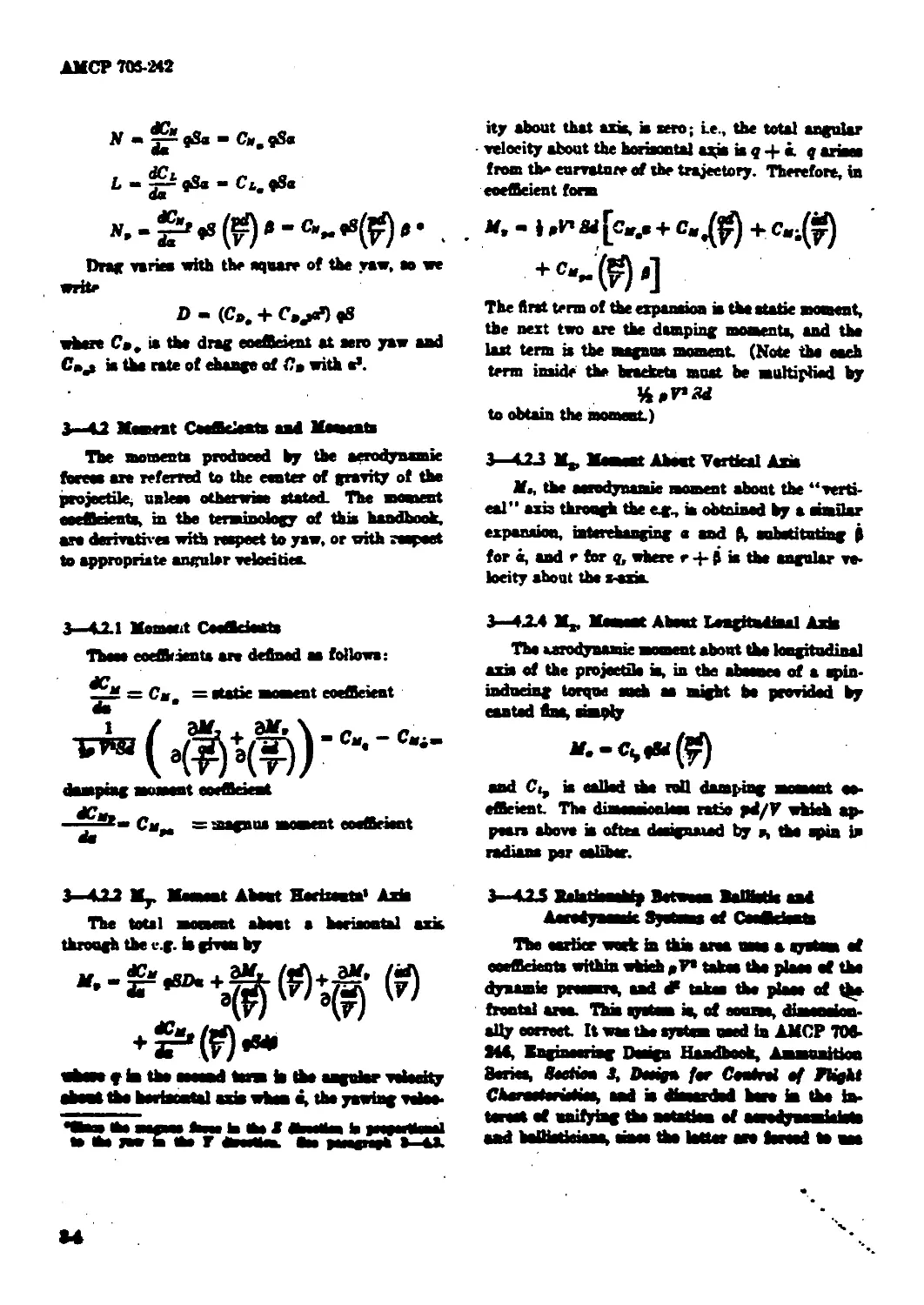
3 4.22 My. Mem eat Abent Hocizonin' Ata
The total mocaest about a heriaontal ata
through the eg. b given by
abase p in the aaoand tom b the angular velocity
abont the bertasrtal ata when e, the yawing velaa
•«tew tea swmms teem total dbeeMen b peegeriteaal
to ta Я» b ta Г awmUm. Cm pmagne* •—40.
ity about that axis, ia aero; i.e., the total angular
velocity about the horiaontal aqb ia q 4- i. f ariaes
from th» curvature of the trajectory. Therefore, in
coefficient form
M, - Ы M [cr.a + C.jffi + CWi(^)
+ M$']
The first term of the expansion b the static moment,
the next two an the damping momenta, and the
last term is the magnua moment (Note the eaeh
term inside the brackets must be multiplied by
4nF*ad
to obtain the moment)
3 423 1Ц, Mament Abent Vertical Ata
M., the aerodynamic moment about the “verti-
cal” axis through the e<, ia obtained by a similar
expansion, interchanging a and 3, substituting 0
for «, and r for q, where r 4- 3 is the angular ve-
locity about the z-ata
3—4X4 M., Маем* About tengtadinal Ante
The aerodynamic moment about the longitudinal
axis of the projectile ia, in the abaanee of a apin-
indueing torque seek as might be provided by
canted Ina, simply
and Ci^ is called the toil damping moaaent co-
efficient. The diseeneionlem ratio pd/V which ap-
pears above ia often designated by a, the spin in
radians per ealiber.
3-423 >ahfbnta| Betam BaHtotis and
ЛмшКумнбс СмАсЬвШ
The earlier work in this am uaae a system at
coeffieiects within which дРе mfcm toe place at the
dynamic proaaure, aad dF taken the plane of
frontal am. Thb system is, of course, dimanainn
ally correct. It was the system used in AMCP 704
Md, Knginseriag Design Handbook, Aaamunition
Benes, Boctwu 3, Design fer Cental Plight
ChamterMoA aad b dbaardad bare in the in-
ternet at unifying the natatbn of aaredywaaaiabto
teUtatitttMb мм* th® letter on israd to wm
M
AKOP 704-242
* Urge amount of wind tnnnel data obtniiml by
aertMlynnmirUU.
The ballwtie notation will lie around for a long
time, an it ix iiewssacy Io know that rorfllriruLs
in the balimtie system (which are usually denoted
by the capita! letter К with a subscript) ean be
converted into the corresponding aerodynamic
coefficient slopes (or directly into those coefficient*
which are not function» of yaw) by multiplying the
ballistic system coefficient by 8/x, e.g, C»a - .
For example,
N " C". 0pV» I <₽) a - лЦрР <₽ j Ш a
When ain a * a, C»a * | Ku by cancellation,
h should be noted that for Ci^ + C<; ,
»“d the multiplier ia - (Some authors
пае - aa a multiplier, since they use 2 V as the
denominator of their spin terms, e.g^ pd/2F in-
stead of pd/V.)
3—43 Complex Yaw
In the foregoing discussion, for the sake of
simplicity, the symbol u was used for yaw angle.
In the notation of Ref. 12a, a is the component of
the yaw angle in the “vertical” direction; the com-
ponent in the horiiontal direction ia 5, and the
total yaw angle, 8, ia given by
» = » + *•
where the orientation of the yaw is tan-' 9.
The aerodynamic coefficient slopes, or “aero-
dynamic derivatives", ean be defined in terms of a
because of the rotational symmetry of a projectile;
their values ean be derived from measurements
made on a model whieh is given a ya* in one plane,
identified as the о-plane. (See MeShane, Kelley and
Reno, tzteriar BaUirtiet, Ref. 7.)
3—4.4 Magnus Mem eat Sign Coaveutieu
If the projectile m viewed from the front, 0
is positive to tbe right and в ia positive upward.
A project?!* with righthand spin (eounter-eloek-
wie» rihen looking from the front) experiences a
magnus force downward when 0 is positive. If the
neuter of pressure of this maguus force is aft of the
e.g. of the projectile, then the magnus moment is
positive since it add» to the static moment produoed
by positive e and (*na. In the study of the effect
of e.g. position on the aerodynamic properties of the
A-N spinner (Ref. 49), it will be seen that CMpa
increases as the eg. moves forward.
3—5. METHODS OF MEASVRIMG TH.*
COEFFICIENTS
3—5.1 General
la order to be able to predict the performance
of a proposed design, a good bit must be known
about the probable pattern of the air flow over the
projectile in flight. Thia air flow is mathematically
described by the aerodynamic coefficients, as these
must be measured or estimated. Estimation, by
methods referred to below, is adequate in tbe pre-
liminary design stages; however, if the coefficients
are not well established before prototype rounds
are manufactured, the designer runs a great risk
of a totally unacceptable performance when the
first test firings are made. Furthermore, the proeeea
of maximising one desirable characteristic, such
as lethality, which involves reducing other per-
formance characteristics, sueh as stability, to their
minimum acceptable values ean not be intriligently
carried out if the principal aerodynamic eoaffiriente
are not known to a dose approximation.
3-12 Methods of Mease rsmeat
Two methods are in common use for the measure-
ment of coefficients, both of whieh yield values
whieh are adequate to permit eonfldent design
compromises. That is, they yield not only sufficient-
ly accurate values of tbe coefficients of the design
being tasted, but also good estimates of the changes
in those coefficients whieh would result from small
changes in the design. Tbe two methods are:
a. Ballistic range tasting
b. Wind tunnel tasting
Tbs method ehornn in a particular ease stay
depend on tbe technical eonsidarationa listed be-
ЛМСГ 7(MU242
low; if not, it depend* on factor* of time snd co*t.
Major considerations are tbe availability of the
range or the tnnnel, and the «peed with which the
necessary data reduction ean be performed at tbe
available facility because costa are usually not
widely different
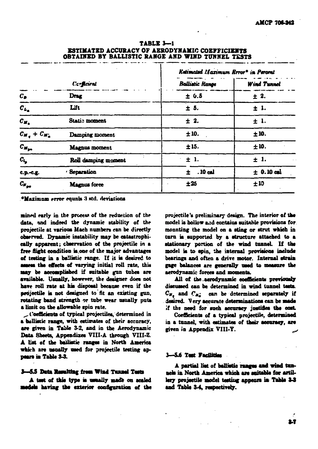
Estimated accuracy of aerodynamic coefficients
obtained by ballistic range and wind tunnel tecta
ia abown in Table 3—1.
3—S3 Factor* to ba Cansidsred 1* Selscttea of
Method
The condition* and objective* of tbe teat should
be thoroughly discussed with personnel of the
facility ehoeen before any work ia started on test
models or prototype*. However, to assist the de-
signer in the preliminary djsenasion, significant
difference* between the two method* of testing are
dearrihed below.
3—53.1 Free Flight (BtlHotic Bange)
a. Good control of Maeb number, velocity,
temperature, and premure*.
b. Little control of modtl attitude.
e. Medel must be statically or gyroacopieally
яСяЫв,
d. No strut to interfere with baa* flow.
a. One teat cover* a range of Maeh number*.
t Data obtained from shadowgraph*, photo-
graphs, and yaw cards, with the poaobility of
telemetering асам data.
g. Data reduction i* eompHeated.
h. Models usually full aeale.
L Baynolds number ean be varied by varying
sire.
3-433 Wiad Tunnel
a. BxceUent control of Mach number, -velocity,
temperature, and proaouie*.
b. Excellent control of model attitude.
a. Can obtain data on both stable and i natalil г
couflgarstioM.
d. Model anpport may interfere with baaa flow,
o. Only ом Maeh number per toot.
f. Data obtained from fore* and moment hal-
амаа, maars tape, aohVoren photograph* or
shadowgraph*.
g. Data reduction ia simple.
h. Models usually reduced in aiae.
i. Bcynold* number ean be varied by varying
tunnel premure (it may not be possible to teat
at free-flight Reynold* number).
3—53 Data Basnlriag tram Ballistic Baage Teats
For a test of thia type a projectile is manu-
factured in accordance with the preliminary design
drawings; if length or diameter is too great, a
geometrically sealed model with a proper mam
distribution may be made. The projectile is fired
along a nearly flat trajectory in a suitably instru-
mented building. For a description of sueh a range,
it* instrumentation and method of operation, see
Ballistic Research Laboratories Beport 1044 (Ref.
13). (The U.8. Army Ballistic Research Labora-
tories at Aberdeen Proving Ground, Maryland, will
be hereinafter referred to by the initial* BRL.)
The designer should be familiar with the capabili-
ties of BRL, aa this installation ean be of major
assistance to him ia any design problem.
A* the projectile flies along the instrumented
range, a number of parameter* of ita motion are
very carefully measured at successive stations along
the range. They ar*
a. Velocity
b. Roll rate
e. Ta* angle
d. Taw orientation
e. Swerving motion
From the position versus time (velocity) data,
the deceleration of th* projectile can be inferred.
Knowing the ант and diameter of the projectile,
and having observed the current value* of baro-
metric preaeure, tea^onture, and humidity; wo an
able to compute the drag and drag eoeAsient, C*.
Befaat brings at the mm* velocity eaa give tbe
variation of С» with ya* angle (equated), end sate
of flring* at different mnarte velniitieo will gh*
the variation of C* with Maeh number. If the pro-
jectile ia rofkot sestets 1, teat flrings with rceket
ignition wil! gh* not thraat.
All of the eseAsteete hated above aun be de-
termined in a baMatb rang*, anopt that C»f
and Cai » hhrnya determined aa a ana. Tbe
yawing fiequMotm aad the damping ан deter-
лМСР 708-242
TABLE 3—1
ESTIMATED ACCURACY OF AERODYNAMIC COEFFICIENTS
OBTAINED BY BALLISTIC RAMGE AMD WIND TUNNEL TESTS
Ccrfident EeitmaUd Maximum Error" in Percent
BaUuHc Наяде Wind Tunnel
C, Drag ± 0.5 ± 2.
Co. Lift ± 5. ± 1.
Cm. Static moment ± 2. ± 1.
Cm, + Cm; Damping moment ±10. ±10.
C“>. Magnus moment ±15. ±10.
Roil damping moment ±1. ± 1.
e.p.-c.g. ' Separation ± .10 cal ± 0.10 cal
Magnus force ±25 ±10
"Maximum error equnb 3 std. deviation*
mined early in the procev of the reduetion of the
data, and indeed the dynamic stability of the
projectile at various Mach numbers can be directly
observed. Dynamic instability may be catastrophi-
cally apparent; cbeervation of the projectile in a
free flight condition ia.one of the major advantages
of testing in a ballistic range. If it is desired to
assess the effects of varying initial roll rate, this
may be accomplished if suitable gun tubes are
available. Usually, however, the designer does not
have roll rate at hia disposal because even if the
projectile is not designed to’fit an existing gun,
rotating band strength or tube wear usually puts
a limit on the allowable spin rate.
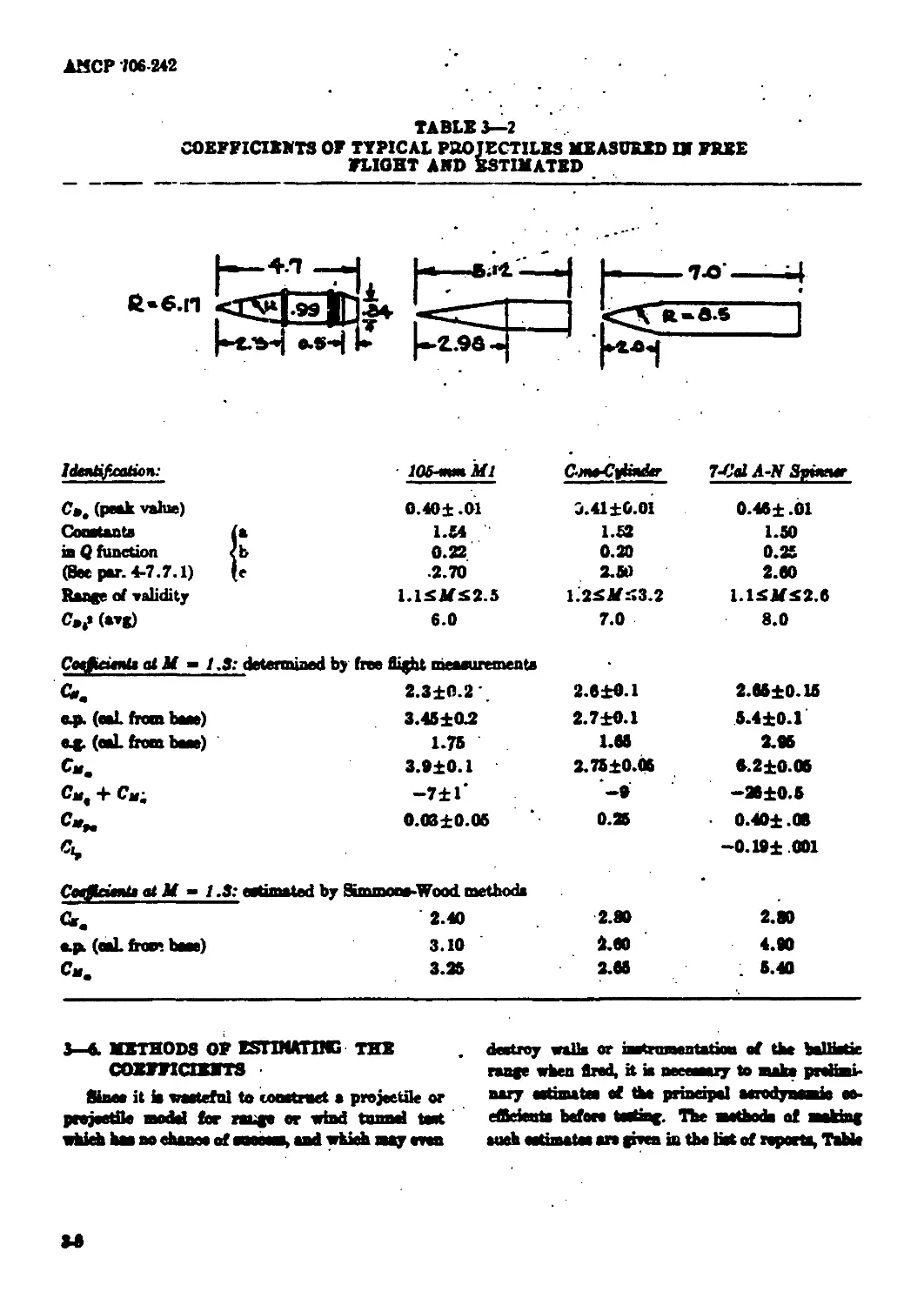
Coefficients of typical projeetilea, determined in
a ballistic range, with estimates of their accuracy,
are given in Table 3-2, and in the Aerodynamic
Data Sheets, Appendixes VIII-A through VIII-Z.
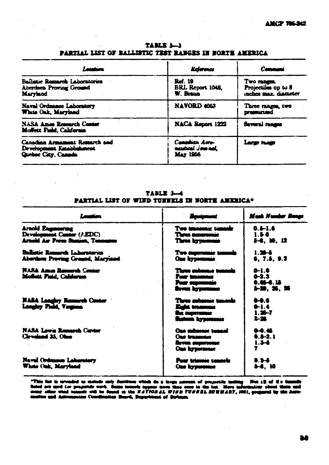
A list of the ballistic ranges in North America
which are uaually used for projectile testing ap-
pears ia Table 3-3.
3—&S Data Easultiag from Vlad Tunnel Testa
A test of thio type is usually madb on sealed
medeb having the exterior configuration of the
projectile’s preliminary design. The interior of the
model is hollow and contains suitable provisions for
mounting the model on a sting or strut which in
turn is supported by a structure attached to a
stationary portion of the wind tunnel If the
model is to spin, the internal provisions inelude
bearings and often a drive motor. Internal strain
gage balances are generally used to measure the
aerodynamic forces and momenta.
All of the .aerodynamic coefficients previously
diseuaaed can be determined in wind tunnel testa
C«( and Cs; can be determined separately if
deaired. Very accurate determinations can be aaade
if the need for sueh accuracy justifies the eost
Coefficients of a typical projectile, determined
in a tunnel, with estimates of their aeeuraey, are
given in Appendix VI1I-Y.
3—5A Tact FadUtbs
A partial liat of ballistie ranges and wind tun-
neb in North America vhid are suitable for artil-
lery projectile model testing appears in Tabb 3-3
and Table 3-4, respectively.
АМСР 706-242
TABLE 3 I
COEFFICIENTS OF TYPICAL PROJECTILES MEASURED Uf FREE
PLIGHT AMD ESTIMATED
Identification:
С», (peak value)
Constants
ia Q function
(See par. 4-7.7.1)
Range of validity
C»f (avg)
• 105 mm Ml
0.401 .01
1.54
0.22
.2.70
1.13MS2.5
6.0
Cm^Cpfadr
j. 41 ±0.01
1.62
0.20
2.»
1.2SM^3.2
7.0
7-Cal A-У Spwcwr
0.46± .01
1.50
0.25
2.60
1.1SMS2.6
8.0
Свфейп1» of Jf - 1.3: determined by free flight measurements
Gre 2.310.2', 2.010.1 2.0510.15
сф. (eaL from base) 3.4510.2 2.7Ю.1 5.410.1
eg. (eaL from base) 1.75 1.05 2.95
Cm. 3.910.1 2.7510.06 5.210.06
Gw. + Cm; -71Г —9 —2010.5
C-w 0.0310.05 0.25 0.401.08
4 -0.191 001
CoffiatnUaiM - / .3: estimated by Simmons-Wood methods
<i. 2.40 2.80 2.80
о.рь (eaL from base) 3.10 2.00 4.90
3.25 2.05 . 5.40
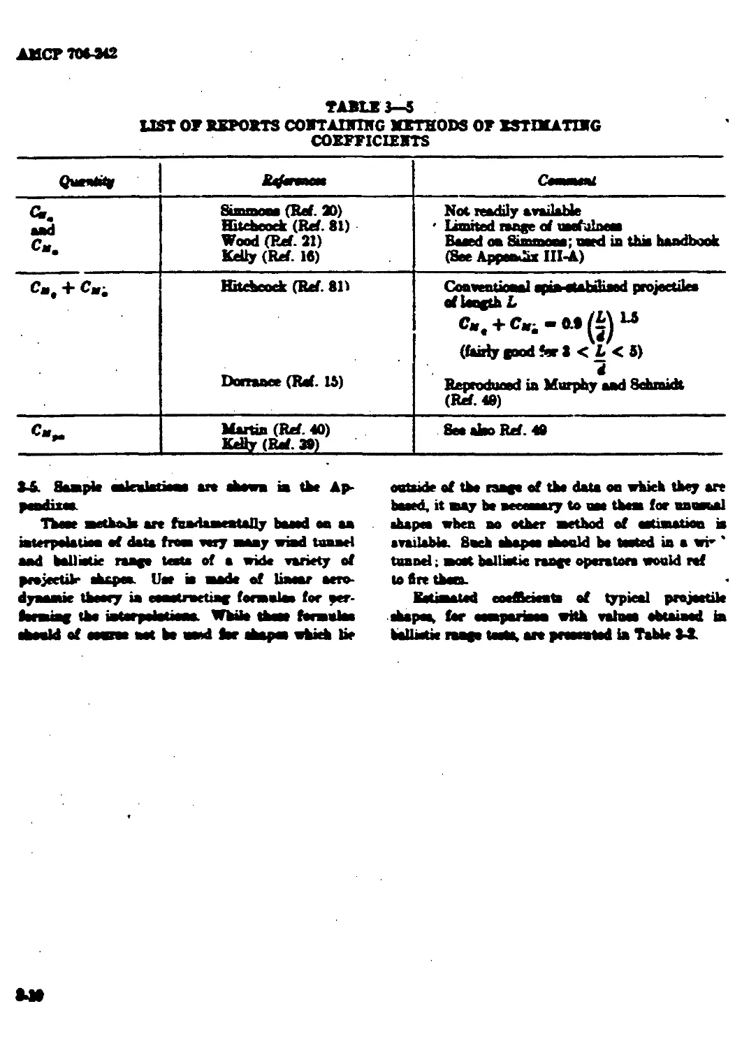
3—6. METHODS OF ESrUUTIMG THE
COEFFIOEMTS
Sines it is waatefnl to constmet a projectile or
projectile model for range or wind tnnnd test
whieh has no rhanno of вместе, and which aty even
destroy walls or fasti ostentation of the V11****»
range when fired, it is neeereary to make prelimi-
nary astimatea of the principal eerndynemiu eo-
ef&eients before tasting. The methode of making
such eetmatao an given in the list of reports, Table
▲MCF7K3C2
TABU 3-3
PARTIAL LIST OF BALLISTIC TXST RABGXS U SORTR AMXRXCA
Ифпм» CMMNMt
ВаДаяй йммгеЬ Laboratoriea Aberdeen Proving Growti Maryland Ref I# BRL Report 1048, W. fhaua Two tang* Projectile up to 8 inehea max. diameter
Na val Ordnance Laboratory White Oak, Maryland NAVORD4069 Three range, two praaanrimid
NASA Лама Reaearch Cwtar Motet №, Caldera* NACARapcnISS Several range
Canada* A**et Rerarrh aad Devrinpewt Embhhant Qoetee Gty, Canada Caaadua A«ra- aaatMal jMnaai, May IBM Large rang»
AJSCP ТО-342
TABU 3—5
UST 07 REPORTS CORTADTTHG METHODS OF BSTDKATIBG
COEFFICIENTS
Quentty J^wwnaaa CeawMal
Or. aad C„a Simmon* (Ref. X) Hitchcock (Ref. 81) Wood (Ref. 21) Kelly (Ref. Ifi) Not readily available ' limited range of uoefalnem Raced oa Simmon*; nerd ia thia haadbook (See Appendia III-A)
C„, + См; Hitchcock (Ref. 81) Domace (Raf. 15) Conventional apia-eUbiliaed projeetilea af length L (fairly good for 3 < L < 5) d Reproduced ia Murphy aad Schmidt (Ref. 40)
C»e- Martin (Ref. 40) Kelly (Raf. 3») See ateo Ref. 48
34. Sample mlniteticae ar» ahewa ia the Ap-
peodixM.
Three methode ar* faadaaMBtally baaed oa aa
iaterpetetioa ef data from wry maay wind tuaael
aad baUietie raage tecta of a erid* variety of
prejeetih* ahapee. Uae ia made of linear aero-
dyaaaeie theory ia eeaotrartiag formula* for per-
forming the intarpetetieaa Wbtte theac fermutee
heald of ooaree act be and ter Aapea which lie
outaide of th* raage of the data on which they an
baaed, it may be a re emery to am them for aammal
•hapee when no other method of eotiwiation ia
available. Such abapm ahonld be tooted ia a vr ’
tuand; moot balliotic raage operator* would ref
to fire thaw
hetimated eoeAeieata of typical projectile
ahapaa, for eempartean with vahrne obtained ia
ballietie raage toot*, an pnoeatod ia Table 34.
АМСР 706-342
CHAPTER 4
TRAJECTORY CALCULATIOMS
4—L gxyxral
The parpm of a calculation of a trajectory,
the rarve ia opaee traced by tbe eeater of gravity
of the projectile, ia ooualiy the prediction of the ex-
pected pent of import of the projectile, «he* fired
at a give* mandr eeteoty and qnadnat elevation,
along with the prediction af nmorirtrd gaaathire
aaeh oa time of flight, aagte of fall, aad reloeity at
impact. Bemetimes the raage ia stated, aad the
pnrp-.se of the eoienlatiaa ia to find the eerriopooj-
iag marie vrieeity and/or gaadraat ilmtioo; the
three eriistaral eaantitioe are still of iateTNt Or
the trajectory may he a groaad-teair type, oa
for aa satiaireraft projeetile, for which ainaer
aititade, tim to raaeh a given attitwie, aad tra-
jectory earvntnrv are impertast roonEa.
4-2. ытштт сотквт аж
ЖЖПГПТТТТ FACTORS
•tee m*. by varying tbe enpata to tbe trajectory
aaicalotoea by авий aaeaata, ear at a time, rom-
pnte the ebangr in asported raaga, time of flight, or
ether gmmtity of ia to rad, canard by a email ehaagv
ia raeb mpnt pnraasoter. The percent ehaage ia
taagn (or other oatpat quantity) predated by a
1% cbaapr ia aa mpat parameter m ended by came
writers a ••didorootad rorifieirot", by others a
"seuritivity factor.” Tbe feeters are d^crvnt foe
oath deriga. ш weU as for rldhrsot internals of tbe
valrn of tbe input pn-nmcters. whieh in why they
mast be dotermmod by aamll pertarbatieae aad the
partiroiar aoe of oaadrttona for which they arc
valid mat be stated. A aneapto ad of oraritrvrty
Inelm for a Mchstmdotod projectile fired Isr
ав1амаа mage m pwa in Tbbto fi-L
4-3. DIGITAL COMPUTZR PROGRAMS FOR
TRAJRCTORT CALCULATIONS
MleeAstMdB Ъмв
erode. aad are stiU bring mode, for the prodaction
of firing tables. Up to tbe advent aad general
adopti~n of the high speed digital oompater, those
mini latinos were performed by approximate math
eda wbiih employed overage or odhetive calm of
the drag roeCrient. The varioas methode were
named for their developers, the Garre n—imiari—.
Siaed, and Mayevoba among others. These smtheda
are still naefnl for roped aetiarotiena of the effecto of
variations in projectile shape, амв1е velocity and
quadrant elevation on range and tiase of flight. The
neeoesary charts aad tables with directions for
their one, are give* ia AMCP 704-140 (Ref. 97).
Digital comptiter programs fall into two dasroe,
particle trajectories aad six degrii rf-freedom tra-
JtslMiMp вмЬ * 4йяиЫ tabw.
4—3.1 gtmpte Particle Trajectory
The rriotivriy eimpie particle trajectory pro-
gram amnaroe that the only forma an tbe pro-
jectile are gravity, drag, and, if present, thraot.
The herieeatal and wrtieal aeerieratioas dwe to
these foevm are computed at eueeoarivs potato ia
tian, aad tbe rvoatting herisoatal ami vertical
eompeneato of tbe projectile's veledty aad petition
are competed for roeh time point If tbe time in-
terval a aamll eaoagh. the titon lotion of the tra-
jectory eaa be very good. With a time interval
of O.JS oeeend, the time repaired to eimalate a
typical trajectory on aa IBM 1490 eompater mat
abent ten time» tbe time of flight of the projectile
bring rimtoted. This foealted in an aaenengy of
AMCF 7116-242
simulation better than 1%, assuming that the drag
eoefieien' ewe used averaged within 2% ot the
true C* at all Mach numbers travened. If no com-
putation of yaw ia made, C*t, the axilc drag eo>
efloent, ia the eocffeient uaed. Since projectile
velocity and altitude are known at саек time point,
Maeh number ia ahwaya available for entering a
stored table of С», vs Maeh number.
Tbe particle trajectory ia very naefnl in com-
puting trade-offs of range, time of flight, aad
lethality, particularly in eaae of a rocket easiitrd
projectile. Bxtenawan of tbe program to com-
pete muzzle vehnity under tbe limitations on
muzste energy and musrie momentum, aad then the
merinos set beet aeeeteration, ем further aato-
mrie the donga proeom.
4 । U fix Degree of У reed ms Particle Trajwnocy
Tbe stx-degree-ef-frmdam system ia seldom
coded fee anything smaller than tbe «inivaMut of
an IBM 704. Thio program computes tbe position
and velocity of the projectile relative to all thiyv
asm of the coordinate system(s) chasms, aa wen as
the portinent aagtee aad angular veioeitAe. All of
the aerodynamic tsrffriiets ru be mod (although
many meind order tones are usually left out), aad
the rmuttisg eimnbtieu of the trajectory is earn-
plots, down to ysw angle, yaw ersoMataen, and
sen list ambon. dt redye am к jump to on unto-
emtio by-prodnet of this system. Wmd ean be
intendawd ma variable.
If nil rata, and the vortolion of Ca, with
Math sombre were iaeludid ia the particle tra-
jectory program, thou either program could esn-
tlaaoueiy cheek the gyroscopic stability of the
projectile and calculate the jaw of repose, Tbessx-
degrooW-frvedem cyst ms ossdd ahs riatinwousiy
chock the dynamic etahiiMv of the projectile.
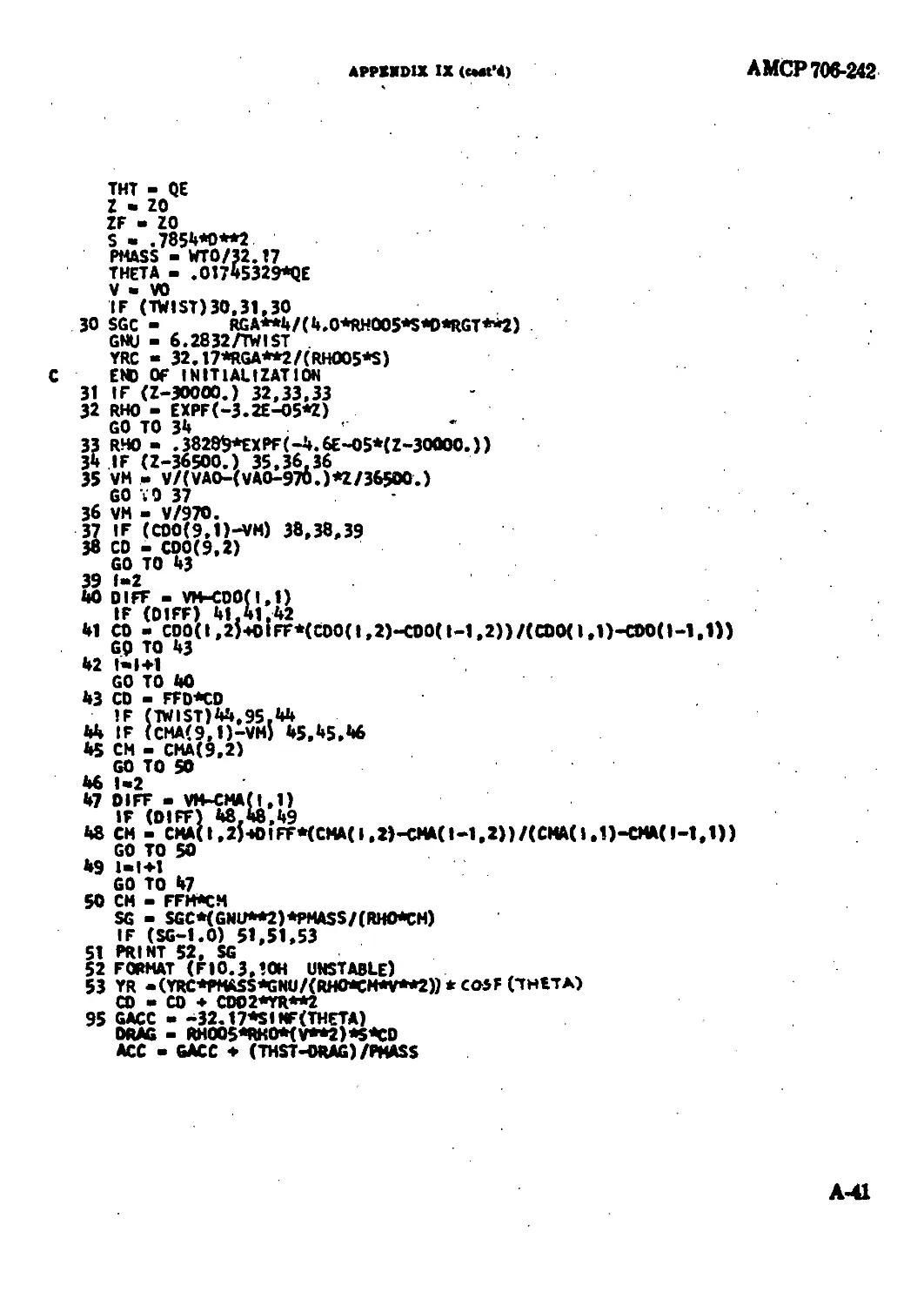
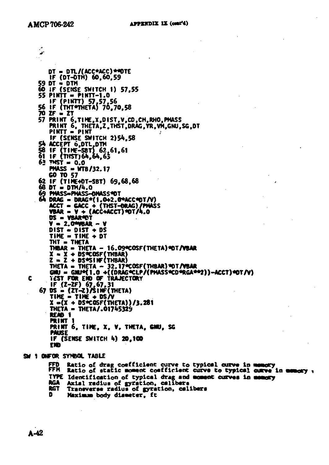
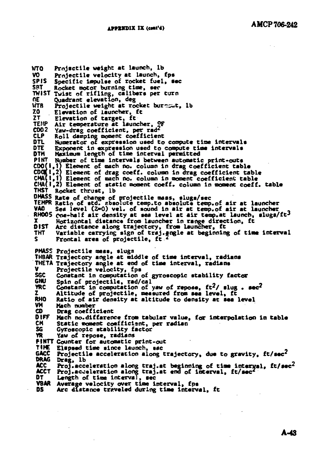
4—3J Banmpto of Nmpio httkh Trajectory
Catentettoa (УОЖТЖАВ Pngna)
The FOBTBAX particle tmjistory avogram
pomoatml belew wes written fee м IBM 1O0 com-
puter with ЖЦКМ unite of aw miry. it will oem
rocket-asaisted projectiles, either spin- or fln-
htabilized. and single-stage roekete. The spin, yaw
>f repose, and gyraeeopic stability computations do
uot allow for the presence of fin eant or nocxle
«•ant.
The limited memory available nude it aeeeesery
to read the headings for the output (see Table 4-1
for a sample output) from cards. Appendix IX
dewribn the input cards forming the data deck;
the numbers on the iuput eardc describe tbe pro-
jectile and its launching environment. Heading
cards are a part of the data deed and follow tbe
numerical data, except that the first eard of the
data deck identifies the projectile heiny pro com rd.
An experienced programmer, or one having
scrim to s computer having a larger rm згу, will
be able to make many improvemeuts in and ex-
tensions to the program, presented here. For ex-
ample, this program isterpolatm haeariy ia find-
ing C>, or C«, from the tables provided by the
data deed; it nmy be iiffenlty to represent a given
curve eufliriistly wed with only nine data pointe.
Furthermore, while the computer will print out
CNSTABLA whoa 8, is lem than unity, dynamic
stability must bo computed by hand.
A typical output produced by the program
given bri.'W is presented ia Table 4-1. Projectile
data an for the sample peojeetites uaed to illustrate
the methide of mtimetisg gyromspie atability
(Appmdiim I-VI1).
The form farter relating tbe drag of the oample
projectile to that of the fi-ineh/M Navy projectile
stored in the eoosputer mesmey was mtimafied to be
106 since the only significant difference in chape
is the shorter oom of tbe cample projectile. The
form farter relating tbe static moment eoeffeieat
of the sample projectile to the С», table stored in
memory wm mtimeted to be 1.142, booed on tbe
Wood-BioMconestimate oik з 1.72.
The loot Uno of the computer output givee the
time of flight ia amoate, the range in meters, the
vrierity at impact, angle of toE, aad the ф!п and
gyroimp is stability faster at hapmet. Ths target to
at the come etovwtioa ш the gun (ma level) in
thio example, bat му dwirsd target itovotiis ем
be M with the data.
АМСР 706-242
The. fundamental equatione undeiying the com-
puter program preeentod below are:
дг -
дв.^^вдх
AX - (F eo* 0) At
AX - (Ужав) At
Averaging technique are uaad to imptv*» the ac-
curacy of the aimuiatinn
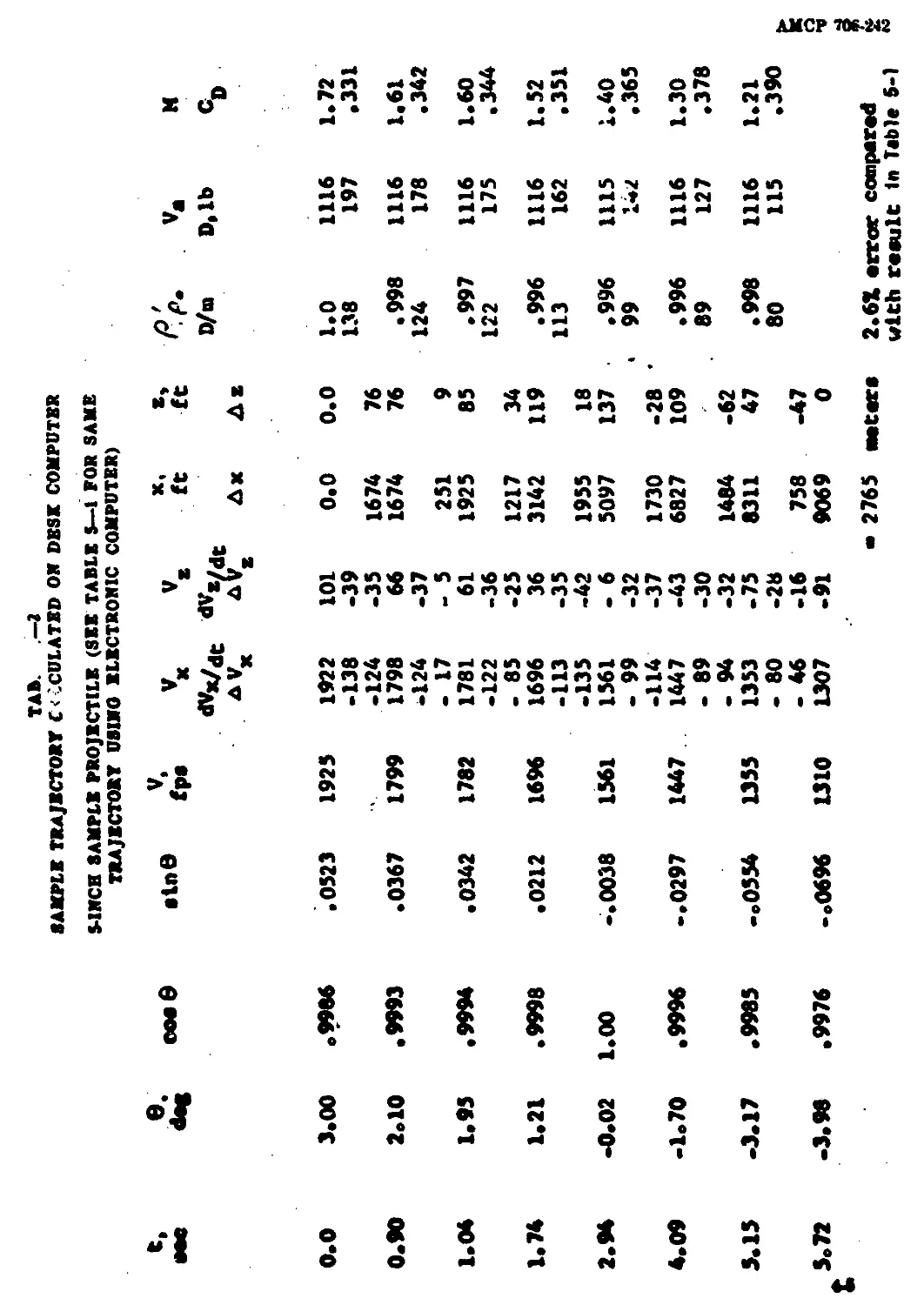
4—4. DESK COIMTH METHOD FOR
TRAJECTORY CALCULATIOR
Reference io made io Tahie 4-2 for the format
of the drok eomputaiioo. Note that the eoeditioae,
в. and appear ia column* 2 and 5 in tba dnt
row. Starting with thane initial eraditicno, we now
proceed with the rempntatina aa ItUowa:
a. Compete the lemaininet ertriee in Ant row.
b. Proceed to neat row: locate С» oa the drag
curve of the projectile; calculate the drag, D,
reelerotica, D/ue, where m ia the projectile
aMaeiaaia^.
e. Compute:
(1) dF, _ _ Deeeft
(2) <У, Dam 8
Л “ m " ’
d. Multiply the above darivativon, dF,/dl aad
d1\/dt, by the earrewtly ahaeea time interval.
The nonIto aee AF, and AV, in the third row.
*. Compute V, aad V, at the tad of the time
interval (they appear in the fourth row),
aad am avenpt veloeitim over the Ant tim*
interval to rrmpwte Ax and At (third row)
and the new g aad a (fourth row).
t. Compute th* new V from V = >/77T7?
determine в from в = tan -» V./V,; fad oo*
8 aad aia •; aad romplrtr the fourth row,
uatag np |—SI x 10-‘r| and V.»
in«-aoote.
g Continue aa above far remaining entrim to
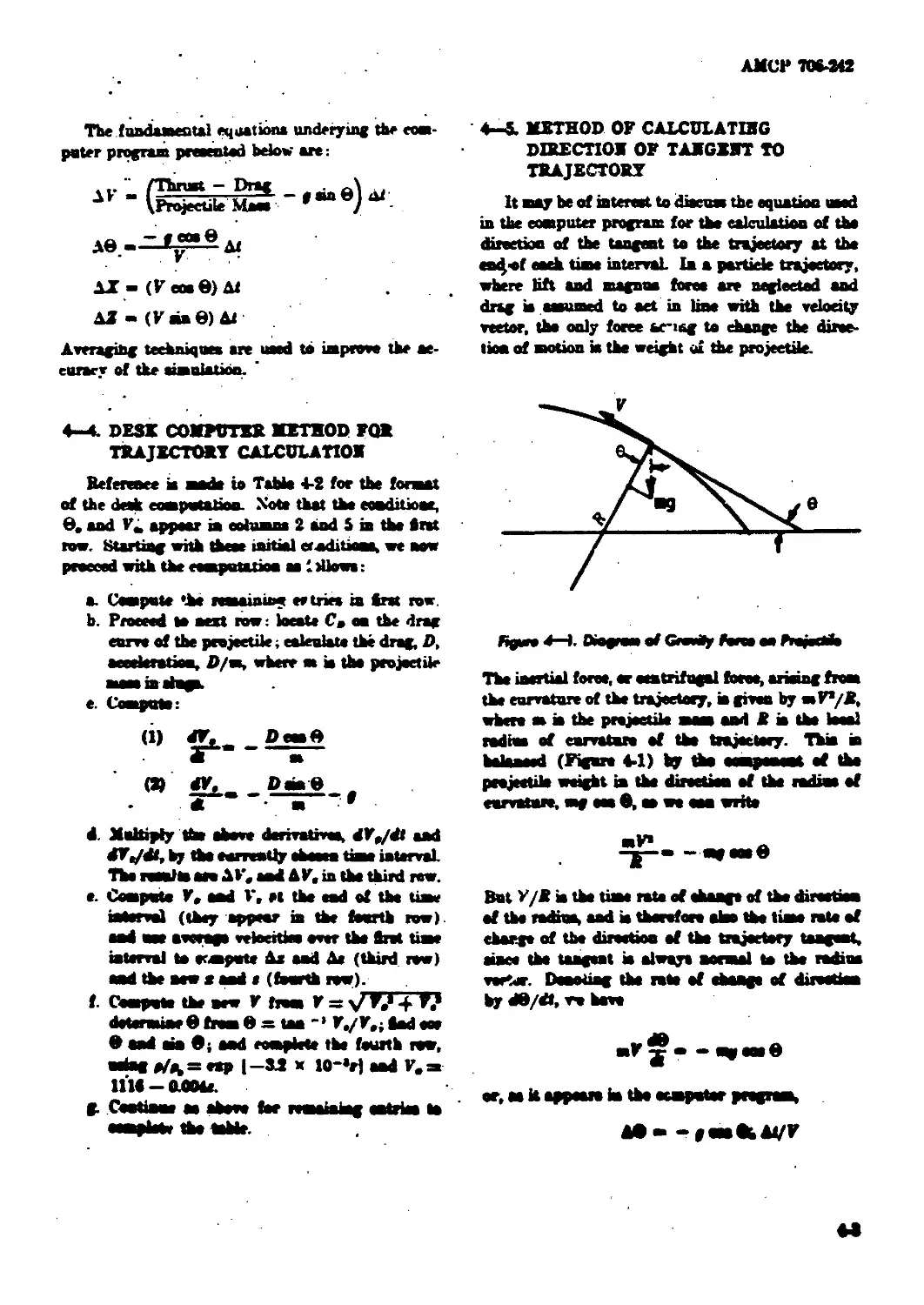
4—5. METHOD OF CALCULATIHG
DIRECTION OF TAMGXMT TO
TRAJECTORY
It may be of internet to diacum the equation uaed
in the computer program for the calculation of the
direction of the tangent to the trajectory at the
en^of each time interval la a partide trajectory,
where lift and magnon force are negieetod and
drag io aoeumed to aet in line with the velocity
vector, the only force ье-iag to change the direc-
tion of motion ia the weight o£ the projectile.
figoro 4—1. Diograw of Gravhy Ferae oa Prajeddo
The inertial force, or centrifugal force, arieiag from
th* curvature of th* trajectory, m given by a»V*/Jf,
where m m the projectile maaa and i a th teeal
rodbm of enrvataro of the trajectory. Thia m
balanced (Figure 4-1) by the eoaopenawt of the
projectile weight in the diroetien of the rediuo of
earvaturo, mg am •, aa we ana write
But F/R i* the time rate of change of the diraetiea
of the radraa, aad i* therefore ateo the liaoe rote of
charge of the direction of the trajectory tangent,
tone* the tangent i* alwayt normal to the rodiua
rorter. Dena ting the rote of change of direction
by dB/dt, w have
AD--poaaiLAVV
АМСВ ФЖ. ДО
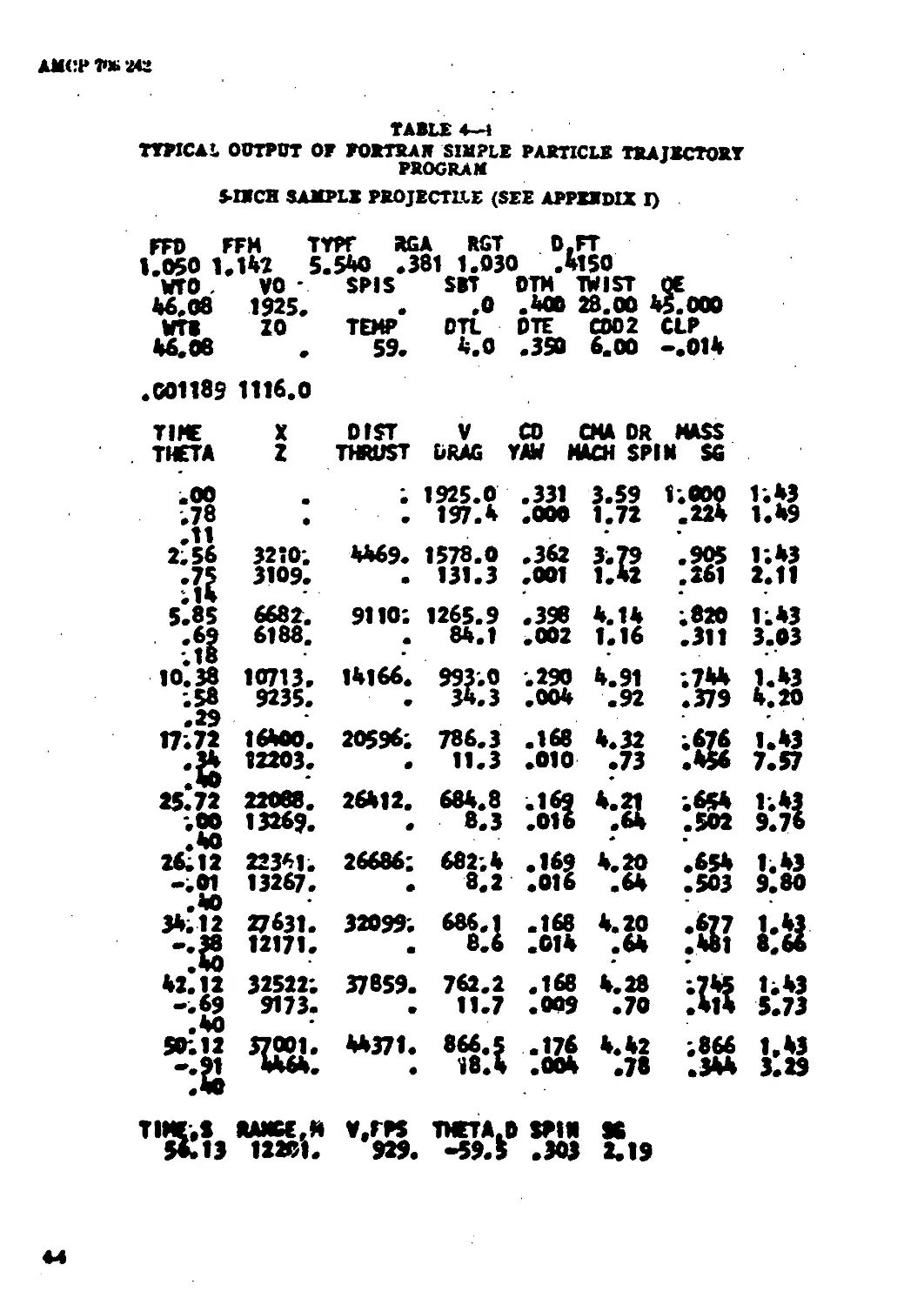
TABLE 4—J
TYPICAL OUTPUT OF PORTRAIT SIMPLE PARTICLE TRAJECTORY
PROGRAM
5-IECH SAMPLE PROJECTLIE (SEE APPERDIX I)
FFD FFM TYPf AGA RGT D.FT
1.050 1.142 5.540 .381 1.030 .4150
WTO , vo • 46.08 1925. WTB ZO 46.06 .001189 1116.0 SPIS SBT DTM TWIST QE .0 .400 28.00 45.000 TEMP DTL DTE CDD2 CLP 59. 4.0 .350 6.00 -.014
TIME X DIST V CO CHA DR MASS
THETA Z THRUST DRAG YAW MACH SPIN SG
50*. 11
*:й
6682.
6188,
3210.
3109.
• 1925.0 .331 197.4 .000 3.59 1.000
1.72 224
4469. 1578.0 .362 3.79 905
131.3 .001 1.42 261
9110*. 1265.9 .398 4.14 820
84.1 .002 1.16 311
14166. 993.0 .290 34.3 .004 4.91 .92 744 379
20596; 786.3 .168 4.32 676
11.3 .010 .73 456
26412. 684.8 .169 8.3 .016 *:a 654 502
26686; 682;4 .169 4.20 654
8.2 .016 .64 503
32099. 686.1 .168 8.6 .014 4.20 .64
37859. 762.2 .168 4.28 w
11.7 .009 •70 414
44371. 866.5 .176 4.42 866
18.4 .004 .78 .344
9.80
1.43
TIMERS RAMGE,M V.TPS THETA.D SPIN SO
Mils 12281. 929. -59.$ .303 2.19
44
TA*. —I
ПЯТИ TRAJECTORY C'-CULATBD 01» DBSK COMPUTER
S-1XCH SAMPLE PROJECTILE (SEE TABLE 5—1 FOR SAKE
TRAJECTORY USIBO BLBCTR0N1C COMPUTER)
t. •ее e. ooe8
0.0 3.00 о9986
0.90 2.10 .9993
1.04 1.95 .9994
1*74 1.21 .9998
2.94 -0.02 1.00
4.09 -1.70 ААЛ/ • WtQ
5.15 -3.17 •9985
5.72 -3.98 •9976
•tn 8 V, fp« Vx ^x/dc AVx
.0523 1925 1922
-138
-124
.0367 1799 1798
-124
- 17
.0342 1782 1781
-122 - 85
•0212 1696 1696
-113
1561 -135
-.0038 1561
- 99
-114
-.0297 1447 1447
- 89
- 94
-0554 1555 1353
- 80
- 46
-.0696 1310 1307
x,
V. dv«/dt ft ft
A Ax Ae
101 -39 0.0 0.0
-35 1674 76
66 -37 1674 76
- 5 251 9
61 -36 1925 85
-25 1217 34
36 -35 3142 119
-42 1955 18
- 6 -32 5097 137
-37 1730 -28 '
-43 6827 109
-30
-32 1484 -62
-75 -28 8311 47
-16 758 -47
-91 9069 0
2765 eaters
P.p. v* M
D/n D,lb CD
1.0 1116 1.72
138 197 .331
.998 1116 1.61
124 178 .342
.997 1116 1.60
122 175 .344
.996 1116 1.52
113 162 .351
•996 1115 1.40
99 1<*Z .365
• 996 1116 1.30
89 127 .378
• 998 1116 1.21
80 115 .390
2.61 error compered
with result In Table 5-1
AMCP 706-242
Ткж —utia—hip ш also need in derma* the oqna-
taan tar p/7 whieh to presented ia paragraph
ЛЛЛЛ.
4-4- EFFECT OF PROJECTILE MASS OB
TRAJECTORY
BiaeeCa, dote not vary greatly with inereeaing
length to iiiameter ratio, a tony, and therefore heavy
ronnd will experience a tower drag deceleration
thaa a lighter round of the same ealiber aad
general shape. Thia ia the reaaon for the пае of
anbealiber or "inw" peojoetilm for antitank
or antiaircraft Are, where a abort rime of flight
to a givea target ia at great importance. The man-
ner in which the паза of the round aT'eta the
velocity, time of flight, range, and terminal velocity
io shown in the treatment whieh foltowe.
4—4Л Hoeiaontal Trajectory
la thia ease С» ia aoauaaed to be a constant, and
the gravity curvature of the trajectory in aaauawd
to be negligible
dF d7 dt DI Cao PS
U”1 S’’ “ a"v" SsF
80 ^-dhsF -
InOegmtiag ghno
bsF C (4-1)
4—AU Yotodty
If we onbotitnte the iniriai eenditioaa, 7 = 7.
when X, = 0, into Bganba* 4-1;
C-toF.
F-F.e«p[-^a] (<4)
whieh chows the importance of a aasall С» aad a
large там if a high velocity ia to be maintained aa
X, the range, inmeaes. Replacing the frontal area
S by (*/4)d* and m by W/g, we have
F - 7.exp[ --
The ratio W/d* ia called “sectional density”, and
in moat of the older publications ia written an
ж/d1, using ж as a symbol for weight.
4-6.1 J Time of Fligjtt
The time of flight to a given range ean bo
obtained by eohsririrting dz/dt tar 7 and re-
arranging Equation 4-3
Integrating
and substituting intial eonditiook, a « 0 at i “ 0
If T ia the time of flight to a given range X,
then
(♦4)
where Fr = terminal votoeity, or votoeity at« = X.
Bines Г = X/7M aad 7W > 7n tho gmmtity in
the parontbaem of Equation 44 io negative and the
time of flight to a give* target deeroaom in pro-
poetion to the relative in erases in the mono or
weight of the projectile, Aas/ns, providing that
7. ie independent of projectile weight
However, when designing a reend to *t an
ototiag gen, muaoto votoeity 4 ep— de in a very
direct manner on projectile weight If it to decirod
to make the mam of the projectile greater than the
AMCP 706-242
mass, M.M, of tbe standard projectile fired from
that iron, then 1’. will be Im than the mutzle
velocity, <>f the x'auilunl projectile. Thix м
due to the шчччыНу of ktx-piug tile inunde nioinen-
tuiu, and therefore the load mi the recoil xyxteiu.
at or below the rapacity of the xystetu. We can
write
Г. _ *•**••*{& at 2 Ч1.Ы
and substituting this in the Equation 4-4 for time
of flight we get
2ж» i
1 * "w V-CawS I “P
. гт vr x____
gm ” at mVr
-*(£- /,)
Since tbe average velocity is usually not much dif-
ferent from the terminal velocity for the flat
trajectories of interest to the designer (and indeed
cannot he if tbe assumption of constant C* is to be
be valid), we can conclude that increasing the
projectile weight in a momentum limited situation
will usually increase tbe time of flight. If the
projectile mam is less than ацм, then V. is limited
by chamber prmnra (a constant energy constraint,
mF*. = atue^iw) and ЭТ/Э m = 1/m (3T/2 —
X/l'r). Here there in more likelihood of decreased
tiam of flight.
4—4.13 Ttrmfasl Vetodty
Increased projectile weight ean, however, im-
prove tbe terminal velocity. If we substitute F, =
ацм Pmin tbs velocity equation, 4-2,
m
we get
avr
9b
So г- -|- decreases with increased projectile
weight for ranges which are shorter than 2m/
(f'opX), and increases for longer ranges. For a
typienl 20-mm projectile weighing 0.22 lb, C&B
might be (1.4 X .IMK37H x s/4 (0.066)»= 4.1
x 10 * and the range beyond which inereuaed
projectile weight will give increased terminal ve-
locity will be about 1000 meten. At thia range
Г/V. will be e~‘, which makes the assumption of
constant Co questionable. The accuracy of the
estimate of tbe eroes-over range eould be improved
by performing the calculation in steps. Since pro-
jectile weight generally increases faster than
frontal area with increasing diameter (m = Ы»,
approximately), tbe cross-over range generally in-
creases with projectile caliber; for a 105-mm pro-
jectile weighing 32 lbs, 2m/(Cep 8) would be about
7000 meters on tbe assumption of a constant C* of
0.40.
4- 82 Curved Trajectory, Antiaircraft Fire
The analysis of antiaircraft Are is complicated
by the ehanging air deaaity aad tbe inability to
neglect gravity and trajectory curvature; it will
not be attempted here.
4—7. EFFECT OF DEAO ОЖ TRAJECTORY
4-7.1 General
Tbe drag of a projectile has a direct effect on
its range, time of flight, and wind sensitivity; and
leas directly affects both static and dynamic sta-
bility. In order to obtain long range, abort time
of flight, aad minimum lateral defleetion due to side
winds; the drag of tbe projectile should be as amall
as possible. Sometimes stability eocsids-ntions will
lead to the acceptance of a high вето-yaw drag. A
reduction in yaw, obtained by improving atability
deereaem the yew drag aad may improve aeeuraey
by decreasing asrodynaaue jump.
The material on drag which follows is eoaflned
to tbe drag of a projectile flying ia line with the
tangent to tbe trajectory of its e.gM La., at aero yaw.
The drag eoeflkient at aero yaw, C\ , san in thb
situation ba sailed the axial drag eoeflhient. Tbe
increase in drag with yaw, and its ooaflteient,
win be dbemosd h рал«тарЬ 473. For a won
behaved projectile the initial yew damps rapidly to
АМСР1Ш442
a ff"*” value, «о that by fnr tbe prater component
of С» ia С», . The minimisation of Co, is, there-
fore, of primary importance in nearly all cases.
The designer most seek a projectile shape whieh
will have a «mall axial drag coefkient, Co,, and
yet h/ve anfleient internal volume to carry the re-
a-'ired lethal charge, lie must also avoid, as far as
possible, surface irregularities such as alota, de-
pressions or protrusions. The effect of general
surface loughntm varies with the velocity regime
of the projectile; thia will be diaruewd later.
the carfare of the model in a way whieh depends
<hi its ahape.
4—73.1 Subssak Bagion, 0 < M < 03 ±
The aerodynamic eoefleiente of a conventional
projectile are fairly constant when the projectile io
flying (or being tested in a wind tunnel) at Ma< h
numbers lean than some critical number, whieh ia
usually in the vicinity of 0.8. This is the model or
"free stream" Mach number at which the flow
over some port of the model reaches Jf= 1.0.
4—73 Axial Drag
The axia) drag at aero yaw may be divided into
three components: wave drag, friction drag, and
Ьме drag. The relative importance of the various
components depends strikingly on the Maeh num-
ber regime. For example, wave drag is absent in
subsonic flight. For this reeaou the designer will
ehoose different shapes for rounds whieh fly pre-
dosainantly in different regimes; however, many
artillery projectile fly in all throe regimes and a
trajectory calculation of some sort must be made
if the optimum drag ahape is to be found.
Wind tunnel testing with pressure surveys will
provide a division of Ca, into its components;
ballistic range testing gives only the overall value.
The designer is urged to refer to Hoeraer, Flvid-
Dys cetin Drug (Bet 27) in all matters relating to
drag.
4-73 Meet of Mach lumber
The mmplaot way to dineum drag is from the
point of view of a paraoa observing a peojeetile
flxad ia a wind tunnel, with air flowing around it
The aanpeed of tbe peojeetile is then dearly the
voteaity of the tunnel air far enough upstream of
the model aot to be mgnifaaatly altered by tbe
peossnee of the model. Tbe speed of sound, in
the tunnel air at the point at whieh the air velocity
is measured then gms the Meet number, V/V„
at whieh the toot is being conducted. At points in
tbe neighborhood of the model the air vskieity is
altered in magnitude aad direction but the speed
ef мшЫ1 to mmmmA to ta w thto
total M*ta wntocF wto* tras petal to peel ew
4—733 Transonic Bogies, M л < M < 1.1 ±
At a free stream Maeh number slightly above
the critical value, the eoefteients such so or
<’/>, begin to increase rapidly and the projectile is
said to have passed from tbe subsonic to the
transonic regime.
4—733 Supermaic Bagtea, 1 < M < S
At some free stream Maeh number greeter than
1.0 the wave system characteristic of compressive
flow is fully established, and the projectile is said
to be in the supenonie regime.
4—73.4 Hypersonic Bagioa, M > 5
Above M=5 the flight is tensed hypersonic.
This regime will not be diocnsssd so very flaw con-
ventional artillery projectiles fly at such high
epMck
4—7.4 Xfcct st Bsyaolds Member on Drag
Caodktent
Drag eosfleients are also influenced by Boyuolda
number; geoasrtrieally similar projoetilas of dif-
ferent calibers win bare slightly different Ca, vu
Maeh number curves.
4—73 Subeaate Drag
la the subsonic range (0 < Jf < 03 ±) wa
would like to have a rounded, but nut noeoemrily
pointed, мое and so aaull a base diameter as san
be ja-t-vieed in view of the ашу eonsiderationa
whieh afftrt projectile shape, sash as required in-
ternal vshsam, weD strength, propulsive method.
44
АМСР 706-242
type of stabilization, fuzing, etc. The eSect of pro-
jectile shape is discussed below.
4—7.S.1 Surface Roughness asd Irregularities
Surface roughnem corresponding to ordinary
industrial practice wilt have little effeet on the drag
coefficient. Surface irregularities, ouch aa dots,
shallow holes, and protuberances may increase the
drag very greatly, depending on their location and
orientation. Fuzes are often poorly designed in
thia respect nnd consideration may be given to
covering them by a windshield.
4—7X2 Bloat Item
Blunting the none of a projectile will, in the
subsonic regime, have little effect on overall drag.
The important effeet of blunting (short of a com-
pletely flat face) is to lower the critical Mach num-
ber. Small flat faces, such aa appear at the nose in
many point-detonating fazes, have little effect on
drag. The integral of the dynamic pressure forces
over a properly shaped head will be dose to zero,
and the forebody drag will accordingly be dose to
aero. The base drag is thus the result of a pressure
deficiency over the base of the projectile; the
existence of this sub-static (less than atmospheric)
pressure ia evident in everyday life in the wake of
trains and automobile*.
4—7X3 BeettaiBag
Reducing the diaaseter of the base below that
of the cylindrical body, called “boattailing*’, is a
very effective way of reducing base drag in the
subeonie regime. Boattailing also reduces the lift
coeflteiont and changes the position of the eenter of
pressure of the normal force, moving it forward.
This reduces the stability of the projectile, placing
another limit on the amount of boattailing that ean
be tolerated.
The extent to whieh thia ean be done on a spin-
stabilized projectile is limited by the necessity of
applying a rotating band, which moat be supported
by s relatively thick wall, and by the fact that the
projectile walk aft of the rotating band are ordi-
narily exposed to the full chamber peemure so that
they must aloe be thick. These considerations limit
the length of the boattail aad may also limit the
amount of reduction in bees area. Um of a hollow
boattaii avoids these limitations, bnt sacrifices in-
terna! volume.
Г sc of a large bouttai! angle (greater than about
16°), without a rounded transition from the
cylindrical body, ean cause the air flow to separate
at the junction, cancelling all of tiie drag reduction.
4—75.4 Fin-Stabilized. Projectiles
The zero-yaw drag of fine ia. of course, related
to their shape and siae, but these arc dictated
primarily. by stability considerations. While it is
true that some fin profiles have less drag than a
simple flat plate, the extra cost of manufacturing
the double wedge or streamline profile fins must be
weighed.
4—75 Transonic Drag
4—7X1 Spin-Stabilized Projectile
The transition from the subeonie to the super-
sonic drag regimes is clearly illustrated, for a typi-
cal low-drag spin stabilized projectile, in K. D.
Boyer, Aerodynamic Properims о/ the 90-mm HX
M71 Shell (Ref. 79). The ogive of this projectile ex-
tends over about half its length, the boattail is
half a caliber long and the boattail angle ia 7*.
Its subsonic Cd, is 0.15, even though the rotating
band area has four circumferential slots.
Shadowgraphs at M = 0.88, M = 0.97, and
If. = 1.05 show the initiation of the shock waves
at the points of abrupt ehenge in diameter and
their growth to fully developed wave*. <’», ram
from 0.15 to 0.39 in thia Mach number interval,
as ean be seen from the drag curve in Appendix
VHI-B. No shock wave appears over the nose of
the projectile before photograph at If = 1.05,
when a separated bow wave is present 8o we ean
eay that for this projectile the transonic regime
rovers the Mach number range from approJasatriy
0.88 to 1.05. Note thia is only one example; the
numbers would be different for a different pro-
jectile. The development of the oboek waves on
the body and fins of an arrow projectile is shown
by the shadowgraphs in BRL Report 934 (Ref.
89).
The greatest pert of the increase in drag in the
tranao. ie regime eaa be attributed to the proaenee
of the ahoek waves aad b called “wave drag**.
The bane drag peaks at about if = 1.0; the friction
44
AMCP 706-242
drag becomes relatively amah ax the total C„t in*
ereaar*.
4—7.A2 Fla-Stabilbod ProjectUe
The draff of ty| й-al 'ui-xtabilised projectile in
the tranaonb regime incresam in about the name
•ay ax d«terihed nbovr, aa may be noeti from the
drag curves presented in Appendixes VII1-T
through VII1-Z. The designer should obtain aad
study a number of shadowgraphs or Schlieren
photographs of projectiles of varying shapes in
conjunction with their drag curves.
4—7.7 Saparaaak Drag
4—7.7.1 Decrease of Cq* with Mach Bumbar
After tbe shock wave system is fully developed,
which usually oeeun at a free stream Maeh number
batwean 1.1 and 1Д wa £nd that С», decreases
with inerescing Maeh number.
In faet, wa ean use Q = y/e-f-C», iP — a 4- Mf
aa aa interpolation formula; a typical set of values
of the constants might he a = 1.4, b = 0.2, e = 2.7.
4—7X2 Effect of Kass Shape on Cq*
The aba of Cs, in the supersonic regime de-
pends largely on the shape of the мае. By the
Tayior-MaceoU formula (BaL Э0) wa have-.
Cs, - (ли +
where C*r is the forebody pressure drag (wave
and drag) component of C*,, • b half of the cone
angle, in degrees, and Jf is Maeh number.
While by thb formula the lowest drag shape
tor the глее would be a вопя, an ogival nose hav-
ing a large ogival radius will have slightly lower
drag (and abo afford a greater warhead volume).
В. B. Diekiaaon (Bef. 24) found from ballistic
range drugs at M = 2.44 that the minimum drag
head shape at a caliber £0 projectile (d = 0.0417
ft) wm a secant ogive having a radius twice that
af the tangent ogive af the sasse length and maxi-
mam diameter (ratba between 1.7 and 2J5 were
asarty as goad).
The presmn of a araaD flat (or rounded) sur-
face at the front of the мое, called the mfplat, has
only a small effect on Co, , and indeed, if not top
large, may reduce Си, slightly below that for a
|M>iutn! iw of the same ie.igth.
4—7.73 Effect of Beattailing ea Сщ
Boaitailing reduces the drag *>f м|м*лмшЬ pro-
jectiles as long sa the airflow b abb to follow the
contour of the body. For each projectile shape
there b a critical angle (generally stout 8*) and
a critical boattail length (about 1 caliber at ths
critical angle, longer for smaller angles) beyond
which the flow win separate from the projectile
forward of the base, reulting in a Co, which b
greater than the minimum attainable, and which
varies from round-to-round with consequent deg-
radation of aeeuncy. Bee Beta. 25 and 24.
4—7 A Dual Flow
As a general rule, we assume that projectiles
having the same shape and eqj. location will have
the same set of aerodynamic eoefleianta when tired
at the same Maeh number (and Reynolds number),
and that small differences in shape and surface
finish will produce only small differences in the
euefficienta. The few outstanding exceptions to
these rules are diseased below.
4—7.8.1 Spflm-ltaed PrajoctBm
It waa found some time ago that replacing the
ogival bead of a projectile by a slender cylinder
protruding from the flat forward foee of the body
would stove the e.p. of the normal foree rearward,
reducing and reducing tbe spin nue required
to stabilise a spin-stabilised round, or reducing the
length of the tail required on a tin-etabilixed round.
These spike-noeed projectiles had higher drag co-
efficients than the corresponding projectiles with
ogival heads. Aho, for some designs, projectiles
from tbe seme lot, tired under the asase conditions,
exhibited drag eoeOeients which fell in ом or the
other of two groups, with tte aversgm of the two
groups as much as 30% apart.
Examination of spark photographs showed that
the low drag coeMeients were associated with
rounds on which the airflow separated from ths
spike at its tip, whib oa tbe high-drag rounds
the flow separated at a point about half-way down
ths spike. Thb phenomenon wm called “dual
4-10
АМСР 706-242
М = 1.73
M=2.75
M-3.80
L=I.O CALIBER
L'1.0 CALIBER
L-I.O CALIBER
L« 1.5 CALIBERS
L=l,5 CALIBERS
L-1.5 CALIBERS
L-2.0 CALIBERS
L-2.0 CALIBERS
L-2.0 CALIBERS
The pitiurea, taken ia the ERL мрегаоак wind taaael. ahow that the character of the low orer a apiko мае depeada «• Mach
auarber aad near length. The tow aepantioa ia delayed, with ronaeqoeat inereaac ia drag, on the three photographa at the
loner right hand eornerf-t. Thieher apikea ahonod delayed reparation at nhorter lengtha (Ref. Mb).
Figaro 4—2. How ЯвИегт on Varying lengUi, Coaetant CaUbtr .33
Droaietar Spika Noaoa of Svpartonk Voiocffioa
4-11
АМСР 704-242
How”; it* rxmti'im* wax a function of tin* geometry
of the spike. In order to avoid the oecnrrewe of
dual flow, with it» Mcrionx effect on neenracy,
modern apike-iKxed round* an* fnrnixlo-d with a
maall ring near tbe tip of the mw whieh insure»
the early ae|>aratio«i of the flow.
Figure 4*2 ahowa the rffiwl of Maeh number
and nose length on the .flow pattern prnditred by a
spike-nosed projectile.
4—7Л2 Uadercut Prsjectilee
Another example of dual flow was found in
ballistic range firing» of projectile» haring the
central part of the body deeply undercut; drag
and moment coefficient» «tried from round-to-round
by aa much as 50%. The flow pattern, whether
high- or low-drag, was stable; i.e., onee established,
it persisted throughout the observed flight of the
projectile. The possibility of dual flow may some-
times be detected by wind-tunnel tests when bal-
listic range flrings do not reveal its existence.
4 7.8.3 Hemispherical er Sharply Conical Base
Pnject&aa
The point of separation of the airflow from
the base of a projectile having a hemispherical
or sharply conical base will also vary from round-
to-round, but in a continuously distributed manner,
ao that thia behavior й wot classified as '‘dual flow”.
The hemispherical shape allows the wall of the base
to be thinner, ao that more HE ean be earned,
but extra care must be taken to insure dynamic
stability (see Appendix VHI-H).
4—7.9 Drag Variation with Taw
The increase in drag when the attitude of tbe
projectile changes from sero yaw to a yawed posi-
tion is called by some writers “induced drag.”
This term is borrowed from airplane terminology,
and is equivalent to "drag doe to lift.” For small
yaws, the axial drag is very nearly unchanged from
its aero-yaw value, and its component parallel to
toe trajectory is also very little changed, since cos 8
=: 1 when 8 =: 0. Tbe normal force is inclined
rearward at an angle 8, so it has a component in the
drag direction which ia given by Cx, VqS when
8 = sin 8. The expression for the drag coefficient
then becomes
С. - С., + С», I»
However, the nbservt*<i coefficient of variation of
drag with yaw squared. <'„?, й usually about
twin* as large as Ctt, .
While the induced drag may be reduced some-
what by rhutMtng a body shad's having a small
dynamic stability may be impaired so that the act
effect on drag may be unfavorable.
The above observations apply to fine as well as
to bodies. It will be seen that over-atabiliaing a
finned projectile by means of a large fin lift may
result in a C> penalty aa well aa increased muzzle
blast sensitivity.
4—7.10 Muzzle Blast
4—7.10.1 Tawing Velocity Due to Transverse
Vibration of Muzzle
Nearly all projectiles emerge from a gun with
essentially zero yaw. Even mortar projectiles,
which have large bore clearance to facilitate drop
flring, ean lie in the tube no more than 0J* out of
line with the tube axia Tbe possibility exists
thnt transverse vibrations of the muzzle may move
the rear end of the projectile after the eg. has
passed the muzzle; thin action, as well as any over-
all motion of the gun tube, can impart yawing
velocity, to the projectile*, but no significant exit
yaw.
Equations for aerodynamic jump, whieh is one
of the two primary flight characteristics, will b>-
presented later in this handbook. It is noted here
that jump is primarily a function of initial yawing
velocity, and not of initial yaw.
4—7.102 Transverse Prassure Gradteta
TrSnsvent pressure gradients in the muzzle
blast elnunpart some yawing velocity to the pro-
jectile if the eg. of the projectile does not coincide
with the center of pressure of the transverm fores.
This effect is most prominent when firing with a
worn gun tube. These transverse рпыше gradients
are probably related to the bon yaw of the pro-
jectile. Good obturation reduces the pt t mere dif-
ferences in the blast aud shortens the effective blast
zone, thus reducing initial yawing velocity, aero-
dynamic jump, and dispersion at the target An
improvement in accuracy of hot rounds over cold
*For a ttiiivtiiil m4 azparimaata) sta«y af the atsrt» at
gaa амСйа, aee >£. L
4-12
ЛМСР 704-242
rounds of the mum projectile* arises drit£r from
their better fit in tbr tube, partly because bin-
yaw is reduced and partly because obturation is
unproved.
4—7.103 Fin-Stabilised Projectiles ш Bcwraed
Flow
Pm-atabiliard projectile* arc affected by the
saiuxle biaet ш yet another way. For n abort lime
after eaergrwer from the nusxlr the blast gases are
flowing forward orer the fin surfaces, resulting in
a large demobilising seoaseat which ean impart a
significant yawing veioeity ron though the time
of action is abort. it ia of great importance that the
aerodynaanie moon rut rveSeirat of the fins ia re-
amed flow be hept aa small as possible.
Many photograph* of the Buazie blast are
available in firing test nporta of the Devriopomt
and Proof Services, Aberdeen Prosing Ground.
Maryland.
Sines the camera nasally takes thousands of
pietarm per served. the imrrgram of the pro-
jectile frees the smoke flood caa be eboerred, and
the tiane spent ia reversed fiow estimated. The
data frees the photographs ean be correlated with
the dieperoioa of hits on the target; these correla-
tion* Hearty shew the importance of ebtnratian for
finntabilieed rounde
4—7.MM Obtnewtian
Мшимо» of the rotating bond sterol into
the groom of the riffiag aaualiy eesmideved to
furan* odegMte eb.aratiea foe apinwtabrbaed
rounds However, aeaae recent prajoetde designs
here inciwdrd special obturating ring* or dines-
miler to the drum remeieuty need an fin-
stabilised rounds, these desires are deembed in
paragraph 5-34.
♦—7.H Cramubad
4—741.1 WM fliaawidty
While too projectile drsigwee cannot de any-
thing about the wind, be ran de eomething about
the eran№vity of baa project de to the effeet at wind.
A etnde proysetde win am into the wind. Le, the
tlw вжШ W
trifle V0
ba Ш hue wt*b the mnltani of prajeotite votoeity
and wind velocity. The net drag force (drag minus
rorket thrust) will then have a component at right
angto* to the projectile velocity. In the absence
of rocket thrust, or ir drag exceed* thrust, the pro-
jectile will acquire a downwind lateral velocity and
displacement; if thrwrt exceed* drag, the projectile
will aaove upwind.
4—7.1 14 Lateral Dodhrtira
With no rocket thrust, a conatant eromwind, and
making the usual assumption that the projectile
aligus itself with the rmultant air-stream a* soon
aa it leaves the muazle of the gun. we can write
a very aim|>)e exprrmion for the deflection of a
flu* trajectory by a t torn wind (асе II. P. Hitch-
eoek. The Motion of ? Verj Stable 8MI at Short
Beafct, BBL Report 1047, April 1958. p. 19).
r-f.(T-p-)
where
T= lateral deflection at
impart, ft
F< = crosswind velocity, fpa
T = time of flight, see
X — raage, ft
V, = mtusie velocity, fps
The only variable in the above exprtmion ia the
time of flight. Kubatitutiag for T ita equivalent, as
given in paragraph 4-4-1Д we have
From thia eqaatiaa we caa find that the lateral de-
flect iea m mils deerraaaa with inirraaail projectile
weight er snail vetaeity, aad iaoeawo with ia-
ervaee ia C*.
Theos relatmaa taramb the desigwr with addi-
tions! rsaaoas for arebiag toe* drag and high
aertiraal draaity (nairas bin projectile contains a
rochet aaetar, when the trade-off aituatioa besnaaea
mare eaatpbm).
4—7.1J VataaaotC^ so Mach Rumbee
Corvee of C*, ve Mach number for typical
prajeetitoe are diawn ia Appaadiara VUI-A
through Vtlt-Ж. The raatgnfgtiea ef the pre.
jaetUr ia Aewa an rar* pagr la seder in raobie
ths drainer to iMrrpilaii between ahapae
4-И/4-И
AMCP 70С-М2
CHAPTER 5
CHOICE OF METHOD OF
STABILIZATION
5—1. STABILITY
5-1.1 GemI
In order tn have a «mall induced drat, a pev-
jaetile niuat be иаЫе, i r„ the yaw of tbe projectile
moot damp to a «mail equilibrium aagie mrty in
ita Hight. if not atatieatly М>Ыг MT gynwwpi-
enlly ataMe, tbe projectile will entnawnev to tuaMr
an anon aa it leaven the retuxlr of the gon; if not
dynaairally atable. tbe yaw of the projectile will
grow eocrtinnomiy with tune, ou that the project tie
will taa.bie nr go into a bat «pin mile- the eipeeted
tune of flight ia very abort.
5—1Л Static aad Gyrwecapic Stability
Static atabatty b related to the pout мп af
the ।enter tt aiemari of tbe патам! fnrre with
reopect ta tbe eg. of the proyretile. If tbe e p b
aft a( tbe eg.. tbe projectile -tatieaUy Mabie, re.
any yew of tbe prejnetde produre* о maaarnt abaart
the eg. «hath tend* to ret am the aria of the
prajectiie tn tbe arm-yaw pamtion. if tbe e.p.
ahead of tbe eg., the aneowl faevr prmtueco an
overt new tag aaaorent lending to ineimv the yaw.
However, if tbe projectile ► «running rapidly
reoufh ah tot гл owe mX the yaw will net grow
rapidly bat oowmly eflange direction; tbe projectile
b Mtd to be rrmomptenlly i table. even though
atat trolly nawtable.
Stare the e p. of a cylindrical body of remla-
that b woolly throe of an eentroed. a typml pee-
>etlh ahope b aaolobb nahna:
a. Mare of tbe prejeetde u м «oamntrawd at
tbo fattened ^^ad no bo aaove tbe e t • ahead
of the e.p. (thia b rarely a practical eola-
tion >. or
b. Projectile b provided with a flaring rear
end or with flat eurfaceo (flaw) at the rear
of the body which move tbe e.p. rearward
of the eg., er
e. l*rojevtilr in nanih* gyraaevpiraHy atable by
pin.
5—U Factor» to ba Caabdarai ia Cbaaco of
Fia-Suhduatiae
5—1.11 flpiwa
Fixed flat take no length without adding to
tbe payload volume of the .projectile, exrapt ia
the ipectai caae at an arrow, er aubealiber, pro-
jectile Foldiag flan either add to the length ar
rrdnre tbe volume, departing on the daoiga
adopted, bat b any eaae add to tbe rerepJenity of
tbe projectile. Since tbe naafolaaao of a pro-
jectile of a given maxiaiaaa diaaaatar aad ornar-
all length b re dm id when ba payload rotaaM
m reduced. and. м general, agio atabllbsl pro-
jectile» are cheaper than and aa arcaretr м tbe
reempomlmg KoMobtliaod projectile haring agnal
peyl«ia*l. pmpvtrbw are alabiherrl by apin aalnm
their are oveereduig reman* to the contrary.
5-1.12 Far
three af the reooam fae ehioa ng flnotahilim
tie* are:
o. A tn-wtabdiaMi prajeHile roa he larger in
pwpnrtian to d* diameter (hare a greater
flaretrea Mtbi than oae which b flphre
M
ЛМ4Т иж-м:
stabilised. If thr logixlic limitation* on
length («toeing, handling, loading into tbe
gnn > are not exceeded, the fin-«tabilivd pro-
jectile may be long enough to nave an interna!
volume greater than that of the correspond-
ing «pin-stabilised round.
b. The lethality or other terminal umfulnem
of the round at; be impaired by spin. An
example in thia category n the «hoped charge
round.
r. Tbe Hussion of thr projectile nay require
that it he fired al high quadrant elevation*.
Coo rent tonal «pia-otabilisrd round* suffer
severe degradation in arenne-y when fired
at quadrant deration» greater than about
fH*. fin-stahilianl rounds du M
d Tbe internal structure .af thr projectile siay
be ым-Ь that the round become i dynamically
unstable when spun, er even su.-h that .t can-
not he spun rapidly enough foe gyroscopic
stability by the gua available.
e. Thr projectile may be designed 10 be fired
from a smooth-bore gun.
f. Pia-stabiliaed projectiles ean be fired from
a rifled кчр without peeking up enough spin
to lose seCuracy Thu is done by tbe use of
aa obtutator whieh engages tbe rifling but
slip* aa tbe pcojsetile.
S—2. Sraf-«TA*aiZBB nOJBCTXLBS
The first requirement we place on a projectile
at that it be staMr *t must be sial wall у or gyro-
srepirnMy stable, it mtme aha be dynamically stable
OSlein it* expected trajectory is very short. ГЪе
stability »f iq>«a-siab«liaed pr»jrvtile« at treated ia
the paragraphs which follow.
5—X! Oyrmciyk flcnbOtty
I—3.1.1 Oyroacopte BtaMMy Factor
Tbe gyroscopic wabUrty of a ipm stabilised
peojoetile van be maesaed by computing s*. tbe
gyrsmeepir stability Carter.
whew
I, — axial moment of inertia, *lug-ft:
I, — traaswnr moment of inertia,
slug-ft1
p — axial angular velocity, ead/arv
# = static moment factor. Ib-ft/radian
i bi the атшпрйоа that the static moment varan
linearly with yaw, the ezpevmiou for the static
. moment per radian of yaw ia
О
ц — air density, slug/ft1
d — maximum body diameter, ft
F — airspeed, ft/sev
— static moment eweflk-irat.
pec radian
t’lme attention must he paid to the units used in
these nprvwuoim, a* some of them are not tor units
customarily employed ia reportisqr mi1 asurrments
»f the quaatMaa.
5—2.L2 СоекШам on Value of sg for Stability
if 0 —s»^l the projectile ia unetabi* and
will "tumble” within a few hundred feet of the
guu.
If ц is greater than one. the projectile m gyro-
scopically stable, aad we then investignu >*•
dynamic stability, aa deaeribod later. Sines », is
inversely proportional to the density of the air,
projertdm whieh are stable at standard simas
l«herie csmditisen amy be umstablt «hen fired under
arrtie er other noswtaadard iwaditiem of tempera-
ture and premmre. hsmnMe mvironmewto mtsd be
i shea into account in computing «,. thin fart,
wepW with the uacrrlaiatie* ia the ether factors
entering into *a ha* fed some designers to set 1.3 aa
a tosrrr limit oa *, ia th* preliminary deesgn stage,
nig standard air density in tbe somputaUoa.
Nate that at tbe muasie we can write
vrherr Ci sb »и nets st
hot p/F = fls/mf, where a w th* twist sf tbe riflw*
st thr muasie. in calibers per tom. Ilwsoow tbe
miiiol stability of tbe projectile dipt ads oa tbe
rdhag twist and only indirectly on mnmle vobrity.
If this wow not am aaued fire. Lt, fins* with re>
M
AMCH7MUM3
«liwnl propelling ebargc, wuuhl I» impmctica). The
indirect influence of muzzle vclucity arises from the
depcndroev of »n Mach number; this de-
prudencr ran rsuse instability at гн'ит! muzzle
velocities.
t'onvrutiuual projectile» ka<r airspeed much
more rapidly than they kw spin Tbe value of *,
thus nearly always increase» aa tbe projectile file»
liowii range.
Tbe atability factors of projectile» fired at high
quadrant elevation* ran. unless projectile velocity
ia ataintained by roeket thrust. rroeh quite large
value» at tbr summit of tbe trajectory. ourirg to
drvrraer» ia both vet wit у and air density. Throe
larye vnlue» are not detrimental in themselves, but
tbe rouditbun which produce them abu bring about
lance inrrraara ia tbe equilibrium ya* of the pro-
jeetile.
S-2J YrwofBopeM
$-2,2.1 GmtjI
Tbe gravity mrvatere of tbe trajretocy five»
rise to aa angle of ya* large enough to rotate a
premauoa rate whieh will permit tbe azh of the
projectile to follow tbe taagent to tbe trajectory.
Thia equilibrium requirement ranees tbe projectile
to porat to the right of it» flight path (right-hand
ya* of repcor) when tbe spin of tbe projectile м
ehehwhe aa viewed from tbe rear, which ia tbe eaae
with nearly аП I'aitod Htatro artillery ammuaitba
The lift force associated with thm angle canoe» a
drift to tbe right, aad an rolimate of tbe magnitude
of thb drift io gma ia the flriag tabtao for tbe
projectile. The demgner ia iatoroHad ia beeping
tba> drift email aad a* .uniform, from round t*
roand, as реайЫе.
The ya* of repose proport maul to Р/П
If it beeomrs Urge, the projretib may become
dynamieaUy амСаЫг with matting Um ia nagr
aai seewrucy. •
5—2X2 Bormob lor Aagb of Вором
Aa appmimote rxprtmuu for the aoual right-
hand ya* of гор roe b
Thb equation shows that at tbe imasmit uf a high
aitgir trajectory. where иш W a: 1 and д b con-
siderably Ina than its sea level value, if Г is anal]
the ya* may be very Urge; it may eveu shift over
to tbe left-hand equilibrium angle with disastrous
result* for the trajectory predietion. Hee Bef. flfl,
p.392.
5—2-2.? Traihag
An analysis of the flrat (and most aigniflraat)
term of the expmaioa for ya* af гора* may 4hed
Mine- light on tbr mechanism by which n spinning
projectile “traih” as it нагого along it* trajectory.
Keamnging tbe abnrr equation gives
ipPSdC^fc - I*1—?
On tbe left aide of tbe aquation wv have the static
aerodynamic moment, a* the right aide me have
the axial angular momentum, Z,p. multiplied by
the rate of change of direction of the tangent to the
trajectory, g roe в/К (aee paragraph 44). The
product b a rote of change of angular omaoentum,
earned by the aerodynamic meanest; Mavsrsrty,
the aerodynamie moment orbing from the ya* of
rap mi b just eu£eie*t to «bangs the angular
momentum of the peojectib at the rote required
for the asm of tbe peojeetib io remain langoat to
tbe trajectory (in the vertical piano tbe ya* b ia
a plane мета! t* the trajectory phar and tbe
static onmrwt b af right a ng Im t* tbe rotatimt, er
'регомма*, af the projretib axb. *hbb b tbe
well knows gyramepii brim rise).
$2.2.4 Projoetib teywmilrbs
Aaymamtrim of a projeetib, aribag from tbo
Maufaatariag proevaa, «Ш add (vrotoiieity) a
small eoaolaM ya* to the ya* of ropnro, iaeroaaiag
tbepwnibilityof troobb at the ешммС. Aaymmotry
aba introdMso a forcing function *kbh ran bad
to rvseaaaee; the rvwultiqg ya* M* be large lor
fla etobilbwl projevtiba, aad tbr onhjeet will be
dbeMoad further in paeagroph 14.
AJCCH 706-242
S—2ЛЛ ММЫ of Cesnpatatiea »f PnjKtite Spin
Th* gyroscopic «Utility factor is calculated at
♦к» muzzle and и often eaienlated at the summit
of high angle trajectories aa an index of summital
bdsavior. It ia recommended that the designer com-
pote the yaw at repose at the summit of sueh
trajectories. and compute the stability factor at
the muzzle and at impact. If his computer pro-
gram does not inelude a running calculation of spin
rate, he must estimate as well as he ran what the
spin rate of the projectile will be at summit and
impart, uaing the expieaaiiMi (in the absence of
racket thrust}
where the subscript a refer» to conditions at the
btginning of the interval over which the change in
р/Г in bring competed, z i* distance measured
along the trajectory, and k. •’ = arit/l,. Thia ex-
p from an aesuams that p. Clf and CD are eonataats,
whieh is not likely. Average values of these
parameters moat be used, and it will be seen that
the appraximatiou far p/F may be poor. Designers
of spin sterilised projectile* have been willing to
sesame that the projectile* retained enough spin
to be stable at impart and ta aeeept whatever limi-
tottoe oa quadrant etovatiaa was found to be
aeemaary ia test Mage of the round.
While C, ia args tire. C„ is usually at stobr net
magnitade that p/F iacremw* as the projectile
Ham to the summit. On the draeendiag limb the
eosine at the trajectory angle is decreasing, aad
p/F will deereem, cnee obviously Г is iaeriaaing
white p, ia the absence of some spia-prodneiag
meehonimn such aa a canted fin. continue* to de-
Mown in Table 5-1 and Table 5-2 are sample
trajortortes far a lypiml 5-iaeh projectile, with
initial esadittene dtfbriag oerty ia quadrant eteva-
tson. The trajectory with Q.K. — 2* ofera aa
ippertuniiy far a steeple cheek so the (p/F)/
(P/F), equation pevsewted above. ,1'siag average
«stars of g aad Ca, wo have, for p, Г al Impact
P
£ 2 ”»( ~ 3-У) / (-001186) (0.1355)
/p\”e. * йпЗ5 Mpl 1.435
U7.
(6.88 ( - .014) + 0.365) 0330 j
.9977 * , _
”.9986* “132S
The trajectory calculation give* »/», = .295/224
= 1.32, so the approximate formnla is very good
for flat fire.
For the trajectory with Q.E. = 70*, the rough
estimate* of * and Г• obtained by taking simple
means values would be .ОООЙЯ foe g ami 3M5 for
•_ ”* < ~ 11 m H-WM8) (0.1355)
cos 70* ”₽ | 1.435
(6.89 ( - .014) + 0285) 54100 }
.2113 «•
” .3420 * “ 145
The trajectory calculation gives »/», = 289/224
= 1.29, so the approximation is only fair. The
uae of values of С» weighted hy the are distance
traversed, in calculating the moans, would make
;he approximation for »/». very good.
The high angle trajectory io presented princi-
pally to show the ssagnitade reached by the yaw
of repose at the summit. The actual yaw might be
much greeter bocsjse dynaaue instability, owing
to nonlinearity of tbs aerodynamic eosflteisuta, is
likely to occur at yaws of this magnitade.
Conventional prajeetite* attain their maximum
range when bred at a quadrant deration of about
43*. For rocket ornate 4 projectiles the Q.K. for
maximum range is greater than 46*, rwaniag ap to
•0* or 70* when using а losv-barafa* racket wit*
a high ratio of fuel weight to total prajoetL
weight. Reagan shorter than the smximam may bo
obtained by ehanging the Q.E., reducing the etse-
tire racket thrust, er reducing the muazle veioeity.
Reduction of the mmate votoeity in a series of stope,
hy reducing the charge of gun propellent, is salted
“aontog**; raeh level of musste veiomty ia sailed
a “sene”, aad variations of raage within eagh им
are obtained by varying the quadrant eievuttea.
A peajratiie whose raage te ssattailed bp asaaato
ЛМСР 7W-MS
velocity variation muxt be stable over a wide range
of Naeh number*, which will ainxwt certainly in-
clude tranaouie speed* st sea level air drasitiro
Sitter f'j, usually peaks in the trawaniie regime
aad the gyruaropie stability factor m inversely pro-
portional to CWa , stability may be at a auaimiun
in the tromsmie regime. If dau are not avail-
able for the full range of speeds, estimates may be
amde by use of the shapes of tbe va Mack
number curves of projectiles aiarilar to the one in
question. Use of aa estimated С», requires a
greeter margin of safety on the gytooeopis stability
factor toinsurs that it does not beams leas than
unity. However, if trajectory ealeulatioM show
that the projectile will spend only a abort time in
the transonic regime, it easy he possible to aeeept
a certain rnnouat of instability for that short time.
The gytoseopie stability factor of a esnven-
tioaal spiaatabilimd projectile usually has its
mealiest value at the aausale. fforbrt assisted pro-
jeetiles, on the other hand, are more likely to be-
come gyroecopieally unstable on the descending
limb of tbe trajectory, near impact. This insta-
bility ean be avoided by •
a. Distributing tbe mass of tbe projectile •?
that its eg. to forward of tbe usual location in
a projectile of the given aerodynaade shape.
h. Increasing tbe rifting twiat of the gun.
e. Casting tbe roehet aieshs. or providing in-
ternal meaaa of rotating tbe jet from a tii gh
Baade.
S-X4 Dynamic Stobttty ef •yte-fttabMrod
nVJKaHi
S—2A1 Magnttuii of Hadal Vectors
Tbe yaw of a tymasetrie projectile acted oa by
a Unoar flseoo and moment gtou is giroa by
* - Х«,Л*е** ♦ Ж|,Л»о* _ i
X< = precession damping ei-
ponent, per caliber
s .= travel of projectile, eabbers
4t — phase angles of the model
vectors (j = 15)
i. - equilibrium yaw
We are concerned here with the magnitudes and
signs of X| and Xt. It will be seen that the magni-
tude of a modal vector win increase if its associated
X is positive; the larger the value of X the more
rapid is the increase in the magnitude of the vector.
The term Л ia, of course, simply a sinusoidal
oseillariou between +1 and — 1, aad between +♦
and —i. If neither of the two modal vectors, Xi
or Xb grows in magnitude so the projectile Aim
down range, the projectile is said to be dynes»jolly
stable. For dynamic stability, therefore, both X,
and X» must be equal to, or lew than aero.
From Bef. 12a we have
Х.--1/5Г,-
L VI - l/ч J
and %e differs only in having a + sign between the
two terms inside tbe braeketa.
и _ c*. - c. - ы (Cm, + Cw,)J
r.«[c^ + Ke„]
So, since i, is a function of Св. and (indirectly)
of Ci,, we see that all of the major aerodynamic
eoeflfeiento enter into the dotirminatuin of the
dsnptag вфммвЖ
S-XU Dynamic Stability Factor, Og
Murphy (Bef. 12a) rooemminde that instead
of simply requiring that the X, be noapoaitive, we
should set an upper limit oa ths greater of the two
whieh moat not bo eseeoded if the projectile to to
fulfil ito mtooioa. This liasit, represented by
uaenbeoriptod X, may be greater than osro be-
come souse growth of initial yaw may be tolerable,
oopeeiatty ia towrt flights.
I—2Л2.1 Stabfitty lscXM.^X
Murphy then introduces the . «ability
fbotar, ч *bors
АМСР 70*442
27 + 21
* " И + 21
aad by uae of the exprmion for with the
reatraintk that )wi — land H + 2 1 > 0, arrive;
at the identity
^-a*(2-ad
Hotting thia exprawion aa a curve with 1/*» and
a« aa coordinatea, we get
Figaro 5—4. nbbrwaaotad Graph of 1/t* va
Cooditiona aa to atability are a function of the
locution of the point determined by the inter-
mrtioa of l/t, with it (Figure 5-2), naaody:
a. Intmeetioa liea below curve: Projectile ia
gyroaeopiealiv «table and aaay he dynami-
cally atable, with !*« < 1.
b. latenettioe liaa aa the curve: !* = 1
e. Iwtecmetien Km above ewe: Projectile ia
dynamically anatabif with > 1 aad may
be ругааеерйаПу uaatahh.
S—2Л2Х Stability far 1 = •
la practice, 1 ia often art egeal ta aero Then
the exprnwioa for the dynamic viability factor ia*
_2Г SCCi. + MCw^)____________________________
®* Ci, — C* — *<* (См, + CkJ
The earn- in Figure 5-1 h new the leeua of potato
where 1=0. И the iutaroactioa of \/t, with a*
Bro above the eurve, we ran oeleaiate by
ataaroring Да», the change ia a* required to roach
the eurve. moving horixontaJly. and uoing the
following relation:
l-ж - Да» when <1
I — hi, ~ A** **
(Reuwmber that H eontaina th« factor p<«/2ai.)
Note that H > 0 ia one of the eoaatrtinta on a»,,
*o the l«x computed by the above expreenion in
(Maitive, and one of the yaw veetora ia undamped;
we can eatimate the growth of thia vector from
exp |l«m*l where a ia travel in ealiber*. Similsriy,
when the iateraeetion lice below the curve, uae of
the above expreeaion for !«, will reault in a
negative value with whieh the rate ef dceraam of
yaw ean be computed.
lieturning to the expremion for it, we note that
Ci. й alwaya pooirive and ианаЦу much greater
than С» The denominator of % io nearly alwaya
poaitive. If it ia not, we aboeld not compute a*, .
The numerator contain* the amgnua moment eo-
rfieient, С>и. which ia uaually poaitive for cpin-
xtabiliaed projeetilea at aaperuouie apeeda, hut
often negative at traaaenie aad auboonie apeeda.
»», ia wmally poaitive, and indeed the value* of the
coeffcient* and radii of gyration (in ealiber*) are
aueh that ««, nearly alwaya Um between 0 and 2;
if it, ia ouioide them liauta, the projectile eannot
be atabiliaed by apin.
In BBL Beport 853 (Baf. 48), Murphy dia-
rmnm the indneace of aaam diotribntioa on the
dynamic otabibty of otatieaUy unatable projeetilea.
lie notm that at auperaoaie veloeitim many bodim
of rrvotatioa cannot be atabiliaed by apin if the e<.
io more than two caliber* aft of the centroid. The
centroid ia, of courm, the point at whieh {he eg.
would be located if the projectile were of uniform
dewoity; it ia none the gooaaetriaal centroid of thj
Mlhourtte of the projectile, in any cam, therrja an
optimum eg- Ieeatioa whieh minhaiww th* apin
rote required foe debility, aad thia optim>jm loca-
tion ia aeaally near, aad aft of, the eca'roid.
The complete graph of 1/^ va c* tahen from
Kef. 12a, appear* m Figure 5-2
Unfectuaately C«w to arooitive to ehangm ia
yaw angle. We eaaaot proaarve B’jaarity in the
amgnua memant by rvotrietiag 11* lorn thaa 10*
aa we have maaawd that wo oenlj far aaaae other
tredynamw oeadtoiewta. A tap* Ci, aad b« will
AMCP 7M-242
TABLE S—l
SAMPLE TRAJECTORY FOR SPIN-STABILIZED 5-ПГСН PROJECTILE
ATQX = 3*
(SEE APPENDIX I)
FTD FFM TYPE RGA RGT D.FT
1.050 1 .250 5.540 .301 1.030 Д 450
3.0 0.
К
WTO VO SPIS SBT DTM WIST qe
46.oe 1925. • .0 .400 28.00 3.000
WTB ZO TEMP- DTL DTE CDD2 CLP
46.08 • 59. 4.0 .350 6.00 -.014
.001189 1116.0
TIME X DIST V CO CHA DR MASS
THETA z THRUST DRAG WM > IACH SPIN SG
.00 • • 1925.0 .331 3.93 1.000 1.43
.05 . • • 197.4 .000 1.72 .224 1.36
.12
.90 1694. 1695. 1804.4 .342 4.01 .997 1.43
.03 75. • 178.9 .000 1.61 .234 1.46
.13
1.04 1937. 1938. 1787.5 .344 4.02 •997 1.43
.03 34. • 176.3 .000 1.60 .236 1.48
.13 •
1.74 3156. 3158. 1704.1 .351 4.07 .996 1.43
.02 .14 118. • 163.7 .000 1.52 .244 1.57
2.94 5125. 5127. 1574.8 .364 4.16 .995 1.43
*.00 137. • 1*4.6 .001 1.41 .259 1.72
• 15
4.09 6867. 6870. 1465.8 .377 4.23 .996 1.43
-.02 113. • 129.8 .001 1.31 .273 1.88
.17
5.15 8375. 8379. 1375.5 .388 4.38 .998 1.43
-.05 .18 55. • 117.9 .001 1.23 .286 1.99
TINE.S RANGE.N V.FPS THETA.0 SPIN SG
5.85 2839. hie. -3.9 .295 2.04
•4
АМСР 706-242
TABU 5-2
SAMPLE TRAJECTORY FOR SPIV-STABILIZED 5-ПСН PROJECTILE
ATQJL = 70*
(SBB APPEMDIX I)
FFD 1 TH TYPE RGA RGT 0. FT
1.050 1 .250 5.560 .381 1.031 i .4 150
WTO VO SPIS SBT DTM TWIST QE
№.08 1925. .0 .800 2Г.00 70.000
WTB ZO TEMP DTL DTE CD02 CLP
66.08 59. 8.0 .350 6.00 -.016
.001189 1116.0
TIME X DIST V CD CMA DR MASS
THETA Z THRUST DRAG YAW MACH SPIN SG
.00 • • 1525.0 .331 3.93 1.000 1.63
1.22 9 • 197.6 .000 1.72 .226 :.36
.22
5.62 3160. 8769. 1260.0 .397 6.53 .770 1.63
1.17 8166. 78.2 .002 1.16 .313 3.00
.35
15.86 7620. 18531. 739.1 .168 6.69 .581 1.63
1.02 16951. 8.6 .013 .70 .696 9.66
.68
31.25 13366. 26588. 360.6 .306 6.21 .687 1.63
•F 22665. 3.0 .151 .35 .971 68.95
.80
36.65 16159. 27696. 336.7 6.18 .685 1.63
-.02 22606. 3.3 .32 1.033 56.07
.80
66.85 17696. 31575. 650.3 .196 6.33 .513 1.63
-.81 20861. 3.2 .069 .63 .757 27.51
.80
60.85 22170. 61728. 819.9 .168 6.79 .683 1.63
-1.23 11898. 12.6 .007 .76 .390 6.95
.80
65.65 23663. 65896. 911.0 .220 6.97 .775 1.63
-1.28 7931. 22.8 .006 .86 •360 3.19
.co
70.65 26617. 50616. 966.5 .253 5.06 .892 1.63
-’:й 3566. 33.9 .003 .87 .307 2.23
TIMERS RANGE.M V.FPS THETA.D SPIN SG
76. 20 775$. 988. -n.S .289 1.82
ЛМСР 706-142
reduce tbe effect of change* in ('л^ > and a email
and nearly eonmant yaw angle will reduce the aiae
of the change in magnna moment. We aee im-
mediately the value of good obturation in keeping
the initial yaw email, and the value of high pro-
jectile velocity in keeping the equilibrium yaw
aaaalL
S—2.4-3 Further Diacuacioa of Msgnitud* *f M*dsl
Factors aad Stability
The following paragraph is taken from Murphy
(Kef. 12a):
Tbe requirement that the exponential eo-
efik-ient* be negative throughout the flight ia much
utronger than necemary in a number of applica-
tion*. This ean be aeen by the following example.
Conaider the earn of a specific projectile whose ex-
ponential eodfleienta are strongly negative for
It ^2.0 except for tbe Maeh number interval
(0.9, 1.]) where both exporunta are positiv*. Ex-
act numerical integration showed that an initial
maximum angle of attack of four degree* for the
launch Mach number of two will decay to a tenth
of a degree before the Maeh number decrease* to
1.1. The dynamic instability aaaoeiated with the
transonic veloeitie* then will cause tbe maximum
angle to grow to approximately one degree and then
deereaee a aeeond time when aubaonie atability ia
eatabtiabed. Thue the “dynamically unteabte”
projectile ha* maintained a smell angle of attack
over th* entire trajectory.
S—2J Aarsdyasari* Jump ef SpMtahUaad
ProjortHaa
5—2A.1 General
Th* path taken by a projectile after leaving the
muola of the gun ia determined principally by
wind, gravity, drift, aerodynamic jump, and, of
eoune, by the direction in which th* gun ia point-
ing when th* pv*jee*ile emirgm from th* senate
Th* designer can reduce the aenmtivity of tbe
projectile to wind by reducing С*, er balancing
drag by rocket threat; be ean redoes th* round-to-
roond dieperaion dn* to varying gravity drop by
good obturation which red**** rvund-to-round
variations in aanmie velocity. Drift absald Mt
vary maeh tram rawed to round If the projectile
yaw i* kept aeaall. Ia thia diaewaaie* w* win simply
art wind, gravity, aad drift eqaal to ano, aanams
that th* teaaoveaas ooaapaaaat of the velocity
imparted to tbe projectile by the gun ia negligible,
and conaider bow the designer may reduce the re-
maining source of inaeerraey, aerodynamic jump.
5 2.5.2 Aaredyaamic Jump Dadaad
In the abeenee of wind, gravity, and drift, an
average line drawn through the swerving path of
the projectile, sueh that the projectile spend* equal
time* on eoeh aide (or all aid**) of the line, ean be
visualised a* a straight line which intersects the
muole of the gun. At tbe mantle thia mean tra-
jectory line will make an angle with the line de-
fining the direction of the bore of tbe gun; thia
angle ia called the “aerodyanmie jump."
Note that tbe plane of the aerodynamic jump
angle ean lie in any orientation; jump ean be up,
down or aidewia*. At a vertical target the effect of
jump appear* a* a deviation from the theoretical
point of impact, which is computed from tbe bore
eight line, corrected for drift aad gravity drop,
(in flat firing wiad correction* are seldom made;
round* ar* fired aa rapidly as is practical, and tbe
wind effect ia assumed to be the asms for all
round»).
5—iSJ Magnitude *f Aerodynamic Jump
The aerodynamic jump of a agnametria pro-
jectile, in radian*, m givan (to a eime appi prime
tian) by
в/(Н».-й:рЛ)
where
V, = projectile
valecity, fps
j, = yawing velocity,
nd/bae
p. = spin rate,
rad/aee
g, =y*w, radian*
aad th* imaginary multiplier,«, ahoam that the earn-
tribation of initial yaw to jump is at right angle*
to the dbartte of th* yaw. I*ymeatery st th*
papjastfle adds another tern to th* axpraaabn far
•a a term wfaiah depend* <m th* *s aad initial
ariantatian < the aqymmetty; am Morphy, Ceao
ампйапЛге^мМе Jwnp>*at. FT. It in impovtaa*
* «• - Iе l—f •*вМ
•>10
АМСР 706-242
that projectile asymmetries be kept as small aa ia
economically feaaible.
2, ia usually ao email that the second term in tbe
jump rquction ia about an order of magnitude
smaller than tbe tint. However, if the bore clear-
num* in ununuaily largi*, ur if there ia a strong eroaa
wind at the gun, the ynw may be. large ami the
aeeond term cannot be neglected.
8. varies from round to round. Good obtura- .
tion will reduce ita magnitude.and the magnitude
of the variation. For a low drag projectile.
C»e /Ct. ia approximately equal to the distance, in
calibers, between the c.g. of the projectile and the
e.p. of the normal force. Increasing thia distance
will reduce в/ for a given 8, but the design changes
which increase the e.p.-c<. separation, such as an
increase in tbe length of the projectile, often also
increase kJ. Boatteiling will decrease Cto and
increase , increasing the e.p.-e^. separation
without much change in kJ. Since drag ia also
decreased, boattailing has a very beneficial effeet
on performance unless the stability of the design
ia impaired; thia must be checked (see paragraph
5-2.4.). This dieenmion of aerodynamic jump
applies only to dynanucelly stable projectiles.
5—45.4 Orientation ef AeNdynaaslc Jump
The orientation of the aerodynamic jump angle
also varies from round to round, because 8, ia a
vector. Tbe dirmtiim of 8, depends «m the pattern
of tbe gas flow in the munle blast, whieh in turn
drpen de on the born yaw of the projectile. Since
projectiles loaded in the gun in the same manner
probably ride the lands of the rifling in the same
manner (see Bef. 56), the orientation of the hlast
pressor* field, and therefore" of K. is probably
biased in one particular direction. Hence the distri-
bution of jump orientation angles, when a group
of rounds is fired, is probably sharply peaked in
one quadrant
5-45J Distribution ef Aerodynamic Jump
Tbe dietrftotion of impact pointe oa the target
is really a eireahr (or elliptical) distribution about
the thoerrtieal point of impart of all the rounds,
summing no change in gun direction. The Mao
described in tbe preceding paragraph produces a
hit pattern whieh appears to be a rectangular dis-
tribution about a mean point of impact whieh ia
the “renter of gravity*' of the pattern. Artillery
targets arc always analysed so though this were
tin* true situation, ainee tbe center of. impact and
the vertical and borixontal probable errutn arvvery
easy to compute from the coordinates of the'hita.
The location of the theoretical point of impact ia
very difficult to obtain from the coordinates of the
hits and eannot be computed from the boresight line
with any certainty, which makes the derivation
of the true Sj distribution impractical.
The above diornarinn is presented because of
its implications for design dmeisiniw baaed oa the
results of firing testa. Sines the P.B.v aad P.K.W
method commonly used is theoretically inappro-
priate, design changes should not be baaed on small
srmplea, ix, groups of fewer than 15 rounds.
Furthermore, ainee moot design changes are aimed
at reducing only the magnitude of в; and not at
reducing ita directional dispersion, the statistically
indefensible procedure of eliminating “maverick"
rounds from the error calculations may be justified
by the eont>mtion that their pointe of impact on
the target were the result of unusual orientations
of the jump angle, not large changes in ita magni-
tude.
5 454 Betatiesskip Between Aerodynamic Jump
aad QX
5—454.1. Vertical Component
In firing for range, tbe importance of the verti-
cal component of depends on the quadrant
elevation of the gun. Differentiating tbe expression
for range in a vacuum gives an approximation of
the effeet of changes in angle of departure on range.
When ». = 45*, the change in raage ie negligible.
At в» = 15* «be change in range, in mils, is shout
5-11
AMCP70fi-242
3J> Нтр— as great м the change in departure angle
(in milliradians) due to aerodynamic jump, ao at
tow quadrant elevations jump is an important
factor in range accuracy.
5—23.63 Horizontal Component
The horizontal component of produces a
horizontal deviation at the point of fall of the
projectile, which is proportional to the are length
of the actual trajectory. Since the deflection die-
pennon of rounds fired for range is usually re-
ported in mils based on the mean range, the effect
of a given horiaontal jump ia multiplied by the
ratio of the are length of the trajectory to its
horiaontal projection. Again we can estimate this
ratio from the vacuum condition, giving
Лге _1Г 1 .__________1 u ( oos в. \1
7* 2Lcos0. tan 0. \1— ain0jj
and at®. = 45*, 4^ =1.15, while at ®. = 15*.
X
£=1.01. H— <-««. ы woifa.1
in estimating deflection P.E.’s from aerodynaaue
jump, when 0. > 40*.
5—3. FIR-STABILIZED PROJECTILES
5—3.1 General
The inconvenient fact that the eenter of pressure
of the aerodynamic forces on a projectile body is
abnoot invariably forward of the e.g. of the body
can be counteracted by placing lifting surfaces
(fins) rearward of the eg.. If, when the projectile
is yawed, the moment produced by the lift forces
on the fins is greater than that produced by the
forces on the body, the net moment will oppose the
yaw and the projectile will be statically stable.
In symbolic notation, we have
Gra —
Cm, ” Gva> (Xe^.y — 'Xe.e.) +
Gr^ (Xe^.r — Xc.sJ
CJ. - C.O.
where the subscript В refers to the body and the
subscript T refers to the tail. Unauboeripted
quantities apply to tbe whole projectile. The X’s
are distances in calibers, measured from the base
of the whole projectile, which ia usually the base
of the tail. The tail comprises all of the fins and
the (usually) cylindrical boom os whieh they are
mounted. Arrow or subealiber projectiles have the
fins mounted directly on the body, so the base of
body, base of tail, and base of whole projectile
may coincide. Folding fins may require an arbi-
trary definition of their base location, depending
on the design.
5—12 CP.-C.G. Separation
It will be noticed in the above equations that
Xor.r —Xco. is negative, and C«a will be negative
if the projectile is statically stable. О J*.-C.G. is
then also negative, but this quantity is often re-
ferred to simply as “e.p.-eg. separation,” in cali-
bers, aad treated aa though it were unsigned.
The optimum magnitude of the c.p.-eg. separa-
tion is not well defined. For minimum sensitivity
to muzzle blast the tail moment coefficient,
^"•T —ХОл.)
should be small; to minimize the yaw angle
due to projectile asymmetries, the total static
moment coefficient, СКл, should be large. The
writer believes that the design value of the
e.p.<g. separation should be far enough above 0.5
caliber that inaccuracies in estimation of and
С»,, including the effects of amnufaeiuring varia-
bility, will not reduce tbe e.p.-eg. separation of
any round hzlow 0.5 ealibor. On tbe other hand,
e.p.-eg. separations greater than one caliber have
been found to be accompanied by meroamd disper-
siou at the target.
5—33 Fin Type
The eboiee of fin type is obviously a trade-off
problem, involving the utilities of projectile volume,
range, accuracy and eoct Establishing trade-off
curves for each design, determining optimum points
for each design, end then comparing the optima
would be a long proosoa. It is doubtful that the
eboiee win ever be made explicitly in this way, but
tbe intuitive narrowing of ehoaoas Burnt follow
Ml
▲МСР 706-242
them lines. Д hrief discussion of the type» of fins
follows.
5—33.1 Fixed Fina
Fixed fina of one caliber span are easy to make,
and —у to make uniformly; thia promotea ac-
curacy. However, «расе m required between the
leading edge of the fina and the location of the
full body diameter in order to reduce fin-body
interference and allow the fina to develop their
expected lift. This reduces the projectile volume-to-
langth ratio. If low drag ia important, the long
boattail required further reduces tbe netful pro-
jectile volume.
5—332 Folding Fina
Folding fina which are bunched behind the
projectile when in the gun tube and fanned out to
more than one caliber span by aome mechanism
after the projectile has left the muxxle blast ean
produce large e.p.-eg. separations without large
mnzxle blaat effect». They are expensive and con-
ducive to large projectile asymmetry. They need
not reduce the volume-toJength ratio of the pro-
jectile aa much aa do fixed fina.
Folding fina which are wrapped around the
projectile near ita baae when in the gun tube and
spring out after the projectile leave the muxxle,
ean produce the required atability with reduced
sensitivity to music blaat and very little reduction
in projectile volume. They are not cheap; the
asymmetry they produce ean be effect by a large
5-3.4 Obtnratien
Good obturation ia important for both spin-
and fin-atahilised projeetilea, especially so for the
fin-stabilised rounds. It haa been achieved by the
use of rubber or plastic ring» on or near the cylin-
drical portion of the body, or by the use of a к
of suitable material placed behind the projectile
(puaher obturator). The obturator ia sometimes
given the added function of holding folding fine in
the doaed position; the obturator must then break
up <m sMtgenee from tbe muxale, usually no prob-
lem with rubber or plaatie obturators which can be
notched or, if nesamry, segmented. Obturator» on
mortar projeetilea moot break-up into assail non-
lethal fragment» on emergence; thia behavior may
be required for other weapon «yatema. Obviously,
retailing the obturator in flight increases the drag.
, Fin-atahilired projectile» are often fired from
rifled guna. The obturator muat be designed to fill
the groove» of the rifling, but it muat not impart
a high «pin to the projectile. Friction between
obturator and projectile will impart a alow spin
which ia usually remarkably uniform from round
to round, and which can to some extent be con-
trolled by the designer by varying the material of
the obturator and the area of ita surface of con-
tact with the projectile.
5—33 Arrow (Subcaliber) Projectiles
5—35.1 General
The large muxale energy obtainable with large
caliber guna offers the possibility of launching a
light projectile at very high velocity. If the light
projectile is reduced in caliber, ita weight per unit
deceleration due to drag would be so great aa to
aoon reduce it» velocity below that of a heavy pro-
jectile fired from the same gun. But if the light
projectile is reduced in caliber ita weight per unit
of frontal area (sectional density) can be in-
creased up to the point at which it becomes a use-
ful item for employment against armor, owing to
ita high striking velocity. Since these subealiber
projeetilea are usually very long in proportion to
their diameters, they must be dnutabilixad; they
are referred to aa “arrow” projeetilea.
5-332 Sabot
The space between the subealiber projectile
and the gun barrel ia filled by an annular device
called a “sabot.” The fina, attached to the body
near its base, have a span equal to the gun caliber
ao that they and the aabot, which ia usually plaeed
near the eg. of the projectile, form two riding
surface» which keep the bore yaw of the projectile
malL
If the projectile is propelled by a puaher
obturator, the aabot has only a centering function
and can be relatively light and lightly attached to
the projectile. However, the aabot must often pro-
vide the obturation and transmit most’^of ths
aeoeisrating fora to to the projectile since the aabot
MS
АМСР TOfi-242
аге» often greater than the bate area of the
projectile. The xabot it then heavy, aad attached
to the projectile by ore nt of groove* around the
projectile body. Tbeee groove» naturally give roe
to abode wave» whieh inrreaw th.* drag. If fired
from a rifled tube', provnioa sta*. be Made for
rotational ilippagr between obturator aad pro-
jectile. Tbe eabot meat leave the projectile by
break-up or aegnwntatMn ehortly after leaving
tbe muaxie beeaaac » drag would be intolerable.
Fragwente ef «be eabot ay atrike the Аац an the
fin met be rtrcwg For thia reaaon, aad to improve
the ridii< of the fin» oa the interior «efface of tbe
gun tube, the fine are often end-plated While
tbe traaeverae piatee on the Up» of th* fine Mtereaee
tbe drag, they abw in veer the lift of tbe fiat,
penaituag a redaction in fia area whieh largely
eCeeto the drag of th* platen Socw mtiroerrig
eabot dawgna are deaenbed by AQna w BSL Вере
ММ» Pan 1 (Baf. fill.
MacAibater and Bwbfri (Bet O) riwpdif
and onaljaid tbe drag data obtained ia wvural
Hl1—*" mage firsage of anww projection. They
found tbar the addifiaa of four ooreahber aquarv
а.- м ж t«n lebibtr coat ryhntev body in-
rreaeed tbe drag to about of tbe drag ef tbe
body atone, when the fia tbwhw woe of the
fin eord When the fin thwfrn»* waa 1<%. tike
dreg atereaaed to about 230“% of the bedy alone
vane. When thear fine wee* canted t* the drag
~ by an addatnaai ДО ef the body ptoe
tad valor. Ttoto torn» f», vtonv are wade triatn-
hb by Ito tort that they aw band on the Ammeter
of the den to, bed?
f- f <» Aaouatentteaey
Beeaaar of the togh «etorrty of the am*
made, the amdynam* Сосем and епкм to
*hwh they at* euhjeriad earn tovnm* «о terp» aa to
eaaar a tong «tender ywjartri* to drfoe* «о Bqfb*
mao a dighT be* tower the to*» «hnape duvotmn
nr the yowi aad eufl» rtrvb. the bowoeg
defertwo town* «• ианйаьв* wtert Unde to tbe
M*fa4
are art kbefy to gm tenable bee. w tbe evuat that
adgwiflaaot pevbaa of «he body a iteteeM. the
antenl tooqnewrlm of the hidy ribnewg aa a tad
apgfid be entoedehne and eetepneafi wdb the
frequency — e/^v ie radiaat per er rend Large
deformatioae inereaae the drag of the projectile
wen if they do not threaten ita integrity.
5—ЗА Dynamic Stability af Fia-StahiliMt
Projeetilea
S-3A1 C to oral
Aa dirmeri (at greater length) ia the aub-
Mvtioa toi eptn etebiliwd projeetilea, a projectile
t» aaid to be dynamically atabie if ita trenrieat yaw
does not iaervaae during flight. Statically atabie
fin-rtabiliaed projectile* having aero apin are alwaya
dynamically atabie; the yaw whieh ia plauar, do-
—гад».according to the expreaeton
• - Ao1* +1? “
where
C* — t'! ♦ Cwj J
e it tbe travel in rolihirv. and A, a the eauataat
ya* doe to projecute aajnwitrj, er "trim eagto ”
Yhe addit.oaal ya* whieh anew from th* cunenure
of th* trajectory * nagtigtlto Car neraal trajoe-
torim
S-3jU Zee* Span
A inn ditto* ef an* open ateaart moor exart»
wner wie»factoring toteeuneaa pmnb eatoe abght
*wo< of the han roenitmg in a epin prodnamg
tooqer 1» fart, an* apin ia very undenmbie. be*
nuw the* th* Uft prndneod by the trine nagle.
will alm the peojevuto away fme йп peodtetod
trajectory, th* defiertw* doe to naywitotry on*
to- catebrably gnnt if the reB rate of the prajmie
n near am ewer math *i tbe trajoetory
Ifil BqefiMbnato Bag Bate
$-ААЛЛ BqnMbrtoto Byte
Naariy *3 fiaotetohoad prajirtitei an do-
«wed to eeqawv о ooetarn «ndibrvu* epen* ealterl
a •*»• «pen to-kj» it * etwab ownlte* than the nil
nuotoid tor ^wwn dwotw* The «pin «мфее a
АМСН 704-342
|«мг»Пг prodneed by "caaUay’’ tbe inn, or, if the
projectile » reefrrt «girted, «*y be produced by
eaatiny Aa rochet ina
5 -3.4.1J Torqne
Whea the terqne ia predated by twiabay ar
aunberiny the daa. er by eaatiny, Le, bendiay ap
a portion of aaeh da, the spin tarqae ia produced
by the lift e* tbe dm, whieh seta ia eppotote di-
гмЬеаа aa ippierti ade* ot the peoyeeOie ахж
The apple at which the air tew aver the projectile
etnhaa the tea tepee dt aa the apta rate; aa the
epia rate mcreaaos, tbe aapie of attach of the coated
port ton of the ds deemara and the ара» terqee
deewaeta anti] it jael balances the deederatiny
torque pMdneed by «bin frietiea.
5—ЗЛ1Х Caanpatatiea of lyilrtrt— BaB Bate
Th» aqaiNbrwMi rail rate ia given by
where f, — eqsabbriow roll rate, md/aee
C»( = rail »t»mt eoeflkieat doe to da
cent (at aero spin)
= roO daapuay nwaeent eoedbeient
= da not anyie, radians
Ct, to a fanetiea of tbe pirmtepe of fat area
whirb to canted, C»t ia ateayc aayatiaa. Ttaa aa-
рамс tonactei «Ban C,t baa been drtaemiaed in
a wind teaaei teat. Ibwtru, C,t /C^ may be
aettawtad teas the appreeiwat ia, valid only far
Baa with a tip radiao at kaat these tiaras as ymt
aa tbe wet radtea
- il®
i
«bare C*. to tee te Mt eoedbeeat toepc baaed
on la am, Ct* to the reO daeeptey aeewewt
enedMoM of tbe body atone, F* to the total la am
(act tea wetted am wteeb to twice aa ymt) aad
<a» to tee tetai aaated am Вааса tbe ntte
4m/4e» to tee peapaetiaa tt la am white to
aaated. * to baatal am, * to ia ypyp aad d to
aataaa dtaartav ef tee body
5—1Ш Samph Calcalatiaa
Per exaaple, a < meh projectile with one*
caliber das (b = d) nuyht have the feitowiay
Ci^ - 2.0 per radian
- — 0.02
s - am ft*
&--Uft*
3», - 0.1 ft*
U • 4* « 0i073 radian
Г - IdOOfpo
c«. 3 /0Л\ 0.6
ш - 0.57
•1 л - 057 (ОЛ73) - 133 rad/aee
-21 rnv/aee
Thia ini rale tim to net very aeaaitive to C^,
whieh can be ti—trd by tbe rzpreaaiea
C, - С», £
*y te
where b = span of daa, aad e = avaraye da dteed.
If the das have more than 44* nwnephnak, the
nbnwt irprmna dor C»( /С^ ему ant yrve a
5—XM CitepatetoM at Ttjuaii ttellfty
S—ЗЛ4.1 Caaneal
It in importaat te have a yaad oatimate of the
oqaitibriaw epia toare tbe bhebhoed at dyaaatit
instability iaenaaw with ineraatmy ipia rate. Tbto
to often rape»4 by myiay "the epia ma aaat
ba tept tow eninyh te sveid toaqnoa edtecta**
Marphyto dyaatnie stability teeter, к vn d»
earned ia paeayraph d-d.4. This atotbed at die-
piaytey tee tycrmii atability at a pvoyoetite eaa
be aataadad, wtobent ebaaye* te atytieaay atabto
penjrotilee, tee aaaptote earn a< 1/t^ w te to
teewn ia Plyan К Fw taai^iUard репуаКйм,
tear*** opomate hi oat to^Mo^wawetnsM^eeato
AMCF70*-W
t, » negative taarr CWa ia BnpUi* Hr mnall
wlura of apia, t, approoebau aero aad 1/*, beeoawa
a large negative number. Hence, the pomibility of
dynamic mutability ia «mall when the apia ia email.
S—ЗДА2 Sample Cakubte
Our d-ineh gamer need an aa example in the
diaeuaaioa of apia due to tn. eaat ia. preceding
paragraphs aaight alae haw the following char-
aetariotian:
J. - OiUriurft*
I. - 1Л ah*ft'
Cm. “ - Xlparmdma
Then we haw
1 tfjy* «См.
s, " V
(4) <2.0) (.001 It) (ИЮУ (ft Ito) (<U) (—2-5)
“ (ftuy (iw
- -.22.5
fa any eaae, the magnua аммаеп! corftciacta of
fin-atobiluad projeetilea are lem predictable than
tboae of apin-aiebiiiied projeetilea. kor thm reaeon
it it wiee to allow as great a margin of dynamic
atability aa ean be secured without falling into
r.mniaei batability, which ie itieewsid in the next
paragraph.
S—17 Вааомпее Instability
While spin Mebiliaod projeetilea can thooreti-
еаЦу experience coincidence of epin and yaw fro-
q-мпема, thb phenomenon ia aa much mere fitdy
to occur with in efabitiaed projeetilea that it in
diaewaed here.
S-3X1 Variate ef Magnitude of Taw with
Aapaneetry
Murphy (Bef. 12a), in hia dbewmien af the
angular mote of a slightly uaaymmetrie teaile,
abowa that the augnitade of the yaw due to wym-
nmtry ia usually well approximated by
и- "Л + M
where
Dcipg Murphy 'a ententes
|--4a-4)hrh
- he <•
we tad that tbe peojaciite ef thia enamyto ie
tyaimiielly etaMe if a^ lien between -U and
+«Л к terid wee be dMiu.l ta deafen a •*-
aad degree ef aaynwoatry.
otohihoad pcwjactihi with a sqtoe of % lying bo-
tween thane bmito.
If tbe doMteatar b aat equal to Ш» and
aaiwd ter a, the ruauit b
S-4jMJ Hague Моим Ceetoteto
but thb b peoebely the мргеааюа for fie fro-
queweiae tt the two amda) wetace of yaw (Bef.
12a). 8o if either tbe mtateol froqvancy or the
preaaeeieaal fraquaocy b nearly equal te the apia
frequency, the magnitude ef the yaw due ta Офап*
matry can baaome wry large The ebbbrity to a
cpring-aaae <etom subjected to an евМгм! ohsr-
fae yaw inenaaa. The inareaee to year, ante toe
growth ef toe aanpiitade af an ocdkanry qpringwaw
bbte M bounded net w much by toe dmaping to
AMCP 7004*2
th* и by ita аваПамгйу; th* aaanaat
yaw *f pnjaatitai any Ъ*мп* la*** *anngh to
«ан tan of reap* а*Л anaiaey ttawogh taqe
d*w iNKto bat art a* tarp* a* to *aaa* th* pn>
jaatite totnabte.
5-4X2 BmaaoaoM Bat*» pr
$-3.7X1 CiByetktiM
Th* apia ia nart likely to eaiaeida with th*
to-dX2X ВвпрйСМпйШв
Pa* the gdaab tear ari a* aa aoanpte la
PRWll-U
________ at 7 = MOO
p, ш . /-—— = 1C2 nd/«« fpa at aaa
' \ ЦО - C.15 ' JL
Th* aaaffihriaai *oU nt* to far thia fianar aaa 133
rad/aae, a* to й w*U abao* to Biaa* both to aad
to an dineQy pnpwtiaaal to ainpoad, «haaga* ia
V aiaaf th* t*K,o*ta*y d* art altar tba 9^9, ratio.
5 3 7.7J Batto of fe/>rto A*wid Вамамас*
laatatahty
It wiin b* aaaa fnn th* аараоавма far * that
dBenan ia air deaaity with aititod* damn 9,;
if tba agailibrian nU «at* it greater thaa to
ftriag at high gndraat «tontiaa* will doeraan th*
•haa** of гаамаам iaatahiltoy. Tbn*fan, ia triag
Iran a nfled gaa, th* ebtantar ahooid ba do-
aigaad to prods** a rail nt* at anargawe* boa
th* aaaaate at taart thn* ttarta a* gnat a* the eai-
oototad **aoa*at toil rata, y^aad thadnaahoald bo
daigwad for aa agoilihnan apto (». = p^/7
abaat th* mb* aa the apia at оавацуаам. Th* *.
of oar <4aeh daaar, 0.0*1. to аааомааагЦу high ia
aw* of й» r, of (МШ; atthar th* ta oaat aagto ar
th* panaaiag* of ia araa oaatad ««aid bo oat ia
half.
Caaaaatinaal projiititoa trod fnaa a naortb-
ban gaa aaaaga fraat the Mart* with aaarttiaRy
aan tpia. Kaaa M**ai aaaaBfaatanag *•***
mU sBftM gAaga ton
ваваааааа, the taa an аоаайу aaatod to peadan a
to gpaator thaa to- Th* nt nto at th* pnjaetito
art thaaaton pao* thnagh to •>/ to toi
if thto paaaag* to aapid aaaagK the twaperary
growth te yww do* to паааам will b* aagtigibli
Th* gnator th* p^to lb* ahertor th* tiaa*
apart te th* TMteity af to ah* th* dtoartnaa
pbaaaaenaa aaB "nO totete" oeaaaa,
f -ya gafilaBtola
MfaaiaMrt aad tehan han aade ав «tantea
VMM WK ton
AM СР 706-242
momenta not considered in tbe dhenaaioao in thia
handbook ean offiet the fln torque, causing the spin
to naii' at the reetmant frequency long enough
for the yaw due to asymmetry to grow eataatrophi-
caily. Giving tbe pro.ieetife a epia at emsrgcnee—
and at equilibrium greater than >„ the Method
roeemmended ia thia handbook for avoiding roll
loek-in.
S—3.9 Aerodynamic Jump of Fin-StaMHiod
Frojoctilee
All of the Material oa the aerodyaaaaie jump of
«pia^nabiltaed projectiles (paragraph 5—25) ap-
plies erithoot change to flaotabiliaed ammunition,
with tbe eseeptioa that the drift of a destabilised
projectile in kept tad! by railing the projectile
slowly. However, it requires very good design and
manufacture to keep tbe aerodynamic jump (aad
therefore the dispersoe) of ftn-otabiliaed ronada to
ы low a level so that of standard opin-otabiliaed
rauads flrod from the same gun. This hoc been
observed aaaay times ia test fringe of da-etobiliaed
teak rounds, where spin-stabilised rounds were
need as control raundo.
The aerodynamic jump aagie Gz, ’• rodweed by
increasing the e.p.-eg separation, so is веса m tbe
oquatioa ia paragraph 5-2ЛХ (e.p.-eg. — C«. /
Ci, for assail yaw). Unfortunately, if this in-
oroam ia achieved by meroaoiag tbe momewC cm
eflbioat of the teal, aa by greater da area er a loafer
boom, then the rffwtivvasm of the fas ia the re-
wound dew rsintia* m the Meet aenr is iaoroaood.
with nnuftiag iniranw la teitial yawing wfeeity.
If thin mereane it I, > greater than the йаегааае in
r.p.ug. separation, and it may well be, then tbe
aeredynamie jump is iaeraaosd, not reduced, by the
change ia ep.-eg. mparatisa.
Tbe e.p. tt the normal force oa the body alone
can be awved rearward by changing the ahape of
the body: thio can increase tbe ep -eg. oeporetioa
of tbe whois projectile with Mttie or no eboagr ia
tbe tail moment If thio body eha^e h made by
oabstitatiag a apibe fee tbe often, tbe deaf b la-
Fte-otobilmsd rounds are probabiy mere ooaoi-
ties to taaaoee^oe peecaaore geedba^e in the Moot
tadteote that Лв «fleet of feme рампе* grodfento
on aerodynamic jump minimised if the raoultant
of the transverse pressures oa tbe projectile passes
through the normal flight c.p. of tee round. How-
ever, since little is knewn about the dbtribmioa of
muscle blast pressure in either space or timt, the
best way to reduce mumle blast efleet io to reduce
I be magnitude and duration of the blast pressures
on the projectile by good obturation.
It will be noticed that aerodynamic jump has
been di te nosed only for dynamically stable pro-
jectiles where initial yawing velocity sad e.p.-cg.
separation are tbe quantities of interest. Fin-
>uabiliied projectiles whieh are statically stable are
also dynamically stable unless they have an un-
usually high roll rate.
5—3.10 Fin Effoctivoum at Supsnenic Spoofs
(Kef. 12b)
With low aspect ratio* fas of tbe ardor of 10
or loss, the span io the predominant factor for
producing high normal fores oooflfeieata. However,
when spans are limited to no greeter than ano full
body diameter, the optimum chord length must be
determined. For a flsod span there is a dedaite
limit to the chord length that still giro the boot
combination of normal foree and swot rearward
C.P. The normal foree baaed oa body frontal
area derrrams with iaereaeing Maeh aaasber for
ft Mwtftftt фвя ftftd ftMHtftet chevdg ftsd it dMNMM
more rapidly aa the chord is shartaaad. Thio means
that as aspect retie inereaem, the «fleet of Maeh
number h greeter oa the fla normal fence, Tbe
must Hhrwat chord tragth appears te be between
calibers .70 aad 1.0, dep indent oa Maeh number.
Thr larger chord should bo weed for the hi***»
Maeh numbers.
The effect of leodiag-odge swoopback io negligi-
ble m far es normal ferae eoaeeeaod if oeaotant
am and aeport ratio is held. From tbe wing
theory tbe lift within the tip Moab ooarn b appreai-
amiely И af the twmdiaMaabaal value.*• Tbb ia
eaaaed by a permute leakage arouad the tips from
gfefllfe te m^nmmn^a^k
АМСРТММ
tbe tower to tbenpper aurfaew. If met ef the 1*
wrfiet a affected by tbe tip Mach сома, the tower
the total normal foeor will he and the further for-
ward the C.H. will aarw. if by типе method wr
could prevent thia pnurr leakage around the
lipa, wr would be аЫе to two-dimruniaaaltor a
thru1 dimmwinaal aurfaee. Bad plating the tea waa
attempted. By thia method it waa found that the
fa normal force could be inrrmerd aa much aa 4O5<
depending upon the aaeount of fa area afaetod by
the end platee and the amount of end plate width.
Tbe end plated fa m agoinot tbe plain tail oa the
TWK triage had notoring momenta 31% greater
aad much better accuracy. The damping enefaienta
were alee larger far tbe end-plated taih aa agaiaat
the plain tail, and thia t enerd the more atabie round
todaatp to % amptirodr in fewer cyetea.
A complete end piate width would be etenated
ш a ehrouded or ring tail Bxperimental evidence
at lew Meeh mmbem ebowed that tbe ehroud had
a otroug tendency to ehohe er Uock the air few
over the fa eurfawe, thereby enuring poor faw
ever them eurfaem. Th» in turn canoed poor
lifting rooulte. However, mace the Sight veieritim
bare been reieed to high Maeb number*, the ten-
dency for tbe faw to choke between the fae and
ahroud ia eiimioeted, aad fa normal foreeo are
iaervaced aad C.P.’a moved rearward.
The number of fae neeeaeary for optimum
normal force appear* to be ux. Theoretically eia
flee. acting independently ef each other, ahould gi**
1 'A timn> the force of four fan. however, experi-
mentally they MuaUy produce only 10% to S0%
more, dependent upon Meeh number. If autre than
nix fae are employed, tbe fae interfere with ем
another m far m the faw faida are eaneernid, aad
the normal force aufen
In order to obtain татпаме tail rffutiumm.
ом would want the tail to be m a uaifocu faw
region, ix, outaide of nay body wake infaeneee.
Thia, however, ie only p Baribin when wing folding
faa whom oweep aagim are relatively entail For
faod fa ooudguratioM (except in the earn ef arrow
projeetilm) the fae an epent-ag mainly ia the
boundary layer faw from tbe body. Maaaa of giv.
iag the fa the moot effective lifting eurtaec an to
make the cupporung body m email aa practical, La.,
beep the epsa to auppert body diameter aa large aa
poaaible aa that a greater portion of the fa in mat-
aide of the body boundary layer, aad boattail the
ntoin body m that emieth uniform faw io pre-
rented to the aurfooe.
ЫДОВ
АМСР Т06-М2
CHAPTER 6
ROCKET-ASSISTED PROJECTILES
6—1. GENERAL
The kinetic energy whieh a gun ean impart
to a projectile to limited by the diameter of the
bore, tbe length of travel of the projectile in the
tube, and by the curve of chamber preecure vo
travel The aunle energy ean be increaeed
by aaing a bigger, longer or thither gun tube,
thue increaaing the coot of the weapon and, more
important, decreaaing ita mobility. Bet raage ia
liauted by the kinetic inirgy «applied to the pro-
jectile ainee each foot of trajectory aubtraeta
from the kinetic energy an aamunt equal in
magnitude ta tbe drag foeee.
To inrrami raage, or to inmem the pay-
load earned io the came range, or to inereoae
the votoeity at target impact, without det tearing
the mobility of the gun, the tat «top to io rodwee
the drag ooeft-tat of the projectile to m tow a
value aa to compatible with the projectile votane
required by the projectile *a mtorina Tbe next
atop to to add kinetic energy to the projectile in
fight
By i a creeping the length of tbe projectile,
or by aaerifleing воем of the warhead volume,
a rocket motor ean bo ineluded in the projectile.
The rocket thruet adde kinetic energy to the pro-
jectile ia flight. The rocuHing projectile to called
a "roeket amietid projectile,'* or, equivalently,
a"gun-booetod racket" Tbe burning of tbe rocket
fuel can be controlled, or "progromaeed,’’ to bo
lorn than tbe drag force, anptoxtoutoly equal to
drag, or very much greater for a abort ported.
Tbe addition ef a reeket motor iaenmaee the
eart of tbe paojeetito aad iacreoapa tbe etonge
apace required ta a givea daatrurtivo capability.
Aa added ttoeHattoaea aeaaeie energy to Ktoodweod
by the maximum aet-beck acceleration whieh the
propellant can tolerate without eruahing, but thio
limiting acceleration to aurpriaingiy high.
6—2. MOMENTUM LIMITED 31ТПАТ1ЭЖ
6—2.1 Variation of Muzzle Energy, Chamber Pm-
euro and PropeUaat with Weight of Pro-
jectile
Became of the aet-baek aeealention limit,
tecket-aariated projeetilea are rnually made heavier
than the conventional ammunition flrod from the
юте gun. The muxale velocity ia then limited by
the capacity of the resoil ayrteaa, and deeroaam in
proportion to the inrroam in projectile weight.
If we uae the aubeeript “ftd" to identify the
•tymboto relating to a projectile whieh to launched
at tbe mmole moauntum limit, then
mV “ m«M (oeuotant momentum)
aquaring, rearranging, and dividing both ridm
by two givm
| .1» . (Sto),
\ ш / мегаж).
Equating muxale energy to the integral of the
work done on the projectito by geo preoowe in tho
guu givm
where
P, m chamber pronmro
A shore area
A a bore travel
Ы
AMCP 706-242
timing th* preesure-travel curves have the tame
shape, P,=.kP.* and P,= then
muxxle energy and chamber pressure, and conse-
quently tbe weight of gun propellant, are inversely
proportional to the weight of the projectile, in a
aaomentum limited situation.
I—12 Variation of Setback Acceleration
The setback acceleration, а, ы given by
as the setback acceleration ia inversely propor-
tional to the square of the mans ratio.
•—2J Effect ef Rocket Additions on Projectile
Design PusBctsen
The ndnetioa in weight, and volume, of gnn
propellant allows aoane at the extra length occu-
pied by the rocket motor to be inserted in the space
previously occupied by gun propellant Whether,
aad how, thia io done depends on the characteristics
of the gun tube aad loading system involved.
Largo inert asm in range require, if warhead
watuaw is net to be severely rodwecd, as intrasas in
projectile laswtth. lips пенсе has shown that spin-
stabiliaed projeetilea laager thaa • calibers usually
require a high open rase fee gyroscopic stability;
in the ahseuM of rochet thrust tbeae prejeetileo
slew down so maeh on a high angle trajectory that
their equilibrium yaw baseman daagvrouety large.
However, whsu tbe projectile velocity is asainteiaod
by a koebot which buran nearly to the summit of
the fnjoMsey, opts etabilbwtinn may be used far
projectile* a* long as 8 calibers, or possibly longer*.
At 10 calibers, fin-stabiiixatioa is almost certainly
required.
6—2.4 Effect of Rocket Additions on Accuracy
Long-burning rockets, sometimes called “sua-
taiuer” rockets, with thrust approximately equal
l<> drag, ran have a proving ground accuracy (no
wind) very little worse than a conventional round
fired from the same gun. Thrust malalignment,
which contributes heavily to the dispersion of fast-
burning rockets, is a minor factor in the tow-thrust
rocket. Variation in racket fuel specific impulse
contributes to racket dispersion and accounts for
tbe slightly inferior accuracy ef long-burning
rockets compared with conventional projectiles
when both are fired in the absence of wind. How-
ever, a long-burning roehet is lam affected by wind
than a conventional projectile, ao that eoasbet»
euraey of the racket emitted round might well be
better thaa the eenventional.
Accuracy analyses of racket assisted projec-
tiles, both spin- and fin stabilised, era prmentad
in Bullock and Harrington, Sasnswry Eaporf on
6'tsdy ef the Gsa-Boostod Rockst Spates», Ref. I*.
These analyses, with supporting experimental date,
are very useful for design; an ext assies bibliog-
raphy is also included. Initial yawing ulssitj-,
ilynasrie uabalanee, and wind era identified as the
major sources of dhpensen ef spin stabilised
roeheta; thrust saalalignsseut earn be significant
in east* af high thrust and stow spin. Dynamic
unbalance ie net significant fir finneru but fin
asymmetry and thrust malalignment ean be if the
roll rata ie too tow; wind b alee a asajor aonrae
of dbperaion here. Tbe naaono for tbe mall wind-
setmitivity of ouotainer raehste are abe discussed.
•eosrtal taUmfag ef the eg. bsMtae nap be mwM
is *s4w te saOsm tysani» IsstaMUw st th* anssl* sat
saat in m st
АМСР 706-342
СВАРТКК 7
LIQUID-FILLED PROJECTILES
7—LOKJTXJUL
Projectiles having an inner eavity whieh ia
partially or completely filled with liquid are a
special сам of tbe data of projectiles having a
nourigid internal structure. The yawing motion
st a projectile has anally «“eh a low energy eon-
teat that small transfers of energy between the
internal parts and tbe wall of the projectile can
тгтеем the yaw significantly. When tbe mass of
the nonrigid part large relative to tbe имев
of tbe projectile, aa it is in the сам of aome bqnid-
fiilod projectilea, the yaw may in инеем very
rapidly.
The inotahiti*y of liquid-filled projeetilm hm
Ымв stodiedp thoMratta&Uy *Bd czperiflMstsUy,
by Karpov, Scott, Milne, Ota war tarn and others.
Boom of thio week in reported in Refs 71 to 73.
The iasaetigatioa in not complete*, the statements
made in the following paragraphs represent ear-
rent (19*4) eeneepta and opiaioaa.
7-4. ДОХСТ ОГ SLOSMIKO ОГ LIQUID
ГПШ
Difereueec in the thermal eoeSeiento of a-
рамаоа of projectile body and liquid make it im-
practical to completely fill a projectile cavity with
liquid. Meehanim! deviem for allowing the cavity
votams to ebaage with tbe change ia liquid volume
are peaeible, but not much need. ГШе of
are ееамвеа; came projeotibe may be fitted to M*.
It Ъав been found that the «Inching about of
the Ml ia a ftawtabilbed projectile Som net ia-
' arouse tbe yaw. So a ample notation of the prob-
lem of liquid fin b to we fimotabUbatiea. Thb
b net alwaga babble) HmbutbuB on projectile
length may reduce the volume of a flnnor below
acceptable limits, or spin-stabilisation may be
desirable for terminal affeeta.
7—3 COMPUTATION ОГ DN8I0N
PASAMXTXBS
The dbetmaion whieh folloaa apptito only to
spin stabilised projectiles.
7—3.1 Gyreocepfc Stability Pnctar
The gyroeeopie stability factor of a liquid-filled
projectile is given (approximately) by
*“4(/,, + c?,J7
when
/.y = axial mniamt of inertia
of rigid parts, stag-ft*
= traaoverM moment of
inertia of rigid parts,
etag-ft*
с = a constant related to the
viaeMity of the liquid;
for water, о = OJ
/»4 = traacvecM amment of
inertia of liquid parta,
stag-ft*
д s |Цй BMMt tMtotg
ib-ft/ndbu
Tbe rigid parte inetade bath metal parts aad
high exptasivo; the traewvorao meannto of inertia
are computed about tbe total «4- at the projectile,
with the liquid fin distributed м a heDvw eon-
АМСР 706-242
centric cylinder occupying the full length of the
eavity.
7—<! J Dynamic Stability Factor
The dynamic stability factor—computed in the
usual way from aerodynamic eorfirienta, except
that hi ia given by Л(,/(’ив*) and M by
(I, + c7,t)/[(me + mJ #| — mw<t be such that
the projectile would be dynamically atabie over
ita trajectory if there wen no interaction between
the liquid fill and the projectile wall.
7—33 Spin Bata
In the transieut period, during whieh the liquid
fill b acquiring a spin rate equal to that of the
projectile wall, tbe traufer of angular momentum
from wall to liquid will reduce the «pin rate 'Л the
walk Thu redaction in apin rate may be very rapid
if the liquid fill has a high vbeosity, or if Ъавеа tied
to the projectile wall are placed in the liquid. On tbe
theory of paragraph 7-33, above, that the angular
mom rntarn of the liquid dose not contribute to a*
the projeetib may become unstable. However, the
transient period b then so abort that bafibe (or
high viscosity) may actually improve the flight.
Hafirs ean be designed simply on the boob of the
torque exerted on tho liquid in g’ ring it angular
velocity and on the shear, due to setback, at the
roots of the baffles.
7—4. BIGID BODY THBOBT
When all of the liquid b rotating with the name
angular vebsity aa the projectile wall, the pro-
jectile in said to be rotating aa a “rigid body.**
If the liquid were not al! of the same density, the
heaviest fraction would be eloeast to the projeetib
wall aa a result of the centrifugal field, whieh re-
sembles * gravitation*! field. The air space, then,
is as far away bom the projeetib wail as possible,
surrounding the axis of the projeetib or any solid
eore, sueh ss a burster tube, which may be posi-
tioned along the projeetib axis.
Stewartaon’a theory b concerned with the in-
stability of liquid-filled projectiles rotating aa a
“rigid body.** It was derived for cylindrical eavi-
ties completely or partially filed with liquid of
uniform density and low vbeoaity; the behavior
of test groups of rounds of varying geometry
and percentage of cavity filled han been имеем
fully predieted by the urn of thb theory. The pro-
jectile eavity need not be precisely cylindrical
near its ends. The necemery formulae and tables
for applying Stewartaon’a criterion of instability
are contained in Karpov, DynssuM of Legtrid-FBied
XheU. BBL Maemruadum Boport 1477 (Bef. 72).
AMCP 708-242
\
CHAPTER S
RANGE TESTING OF
PROTOTYPE PROJECTILES
8—L GENERAL
Very few projectile* an completely satisfac-
tory aa fint designed. Metal part* failure is ran,
but the fint teat firing* usually show that either
пце or accuracy is not a* good a* waa demnd
or expected. In instance* when the fint group of
tea or fifteen teat rounds find gave excellent result*,
a aeeond group ha* often failed to confirm the good
mult* of the fint Conduaion* an drawn from
the behavior of the test round*; design change* an
made on tbe basis of then conclusions; and new
prototype round* an made and find. Thia teat
and change aequence may go ou through many
eyele* before an acceptable design i* reached.
The difficulty that a designer may encounter in
translating a round from the drawing board into
a useful weapon is deaeribed in the following ex*
eerpt from tbe report of E. R. Diekineou, The £f-
ftete of Uttltr Sngt mi Qroooot, and о/ Body
fadareatf e* th* Aerodynamic Properties of a
Coa*-Cyl*ud*r Projtetilo of M = 132 (Ref. 80):
Often, in a projectile’s progress from ths de*
signer's drafting board to the assembly line, then
an many changee made in the detail* of tbe pro-
jectile** contour. A* a result, tbe actual aerody-
namic performance of the projectile may differ
fNm that of the deaigner’s prediction.
Almost all of the baaie deaign data on projec-
tile* concern* itself with smooth contour* and
stmpl* geometric shapes. When practical eonaidrra-
tfoM enter the pietan aad fuses haw to be at*
tech cd, relief* han to be machined, rotating band*
hen to ba added, a projectile which may han been,
originally, aa optimum one, often fall* abort of ex-
pMtatioML
По engineer, who tranalatea the boUstieiaa'a
deaign data into a practical piece of ammunition,
should be cognisant of tbe differential correction*
that have to be made to the predicted behavior of
the projectile. The purpose of thia report (Ref. 80)
is to show the effect, on drag, lift, and pitdung
moment, of depremion* and protrusions on the
surface of a body of revolution. Unfortunately,
there were insufficient data to determine effect* op_
the damping and msgnua momenta and foree*.
Obviously important to the designer is the
soundness of the conclusion* on which th* design
change* are based. This soundness is directly re-
lated to the care taken in preparing for, firing,
and analysing the firing tart.
8—2. PRE-FIRE DATA
It is important that the designer know exactly
what waa fired and bow it waa fired. He must
know what equipment waa uaed for measuring the
test parameter*, «neb aa velocity, time-of-flight,
aad target impact, in order to aa*em the accuracy
of the number* presented to him. Each round fired
must be precisely identified ao that ita performance
can be tied to its physical characteristics a* deter-
mined before firing.
For each round, the following phyrieal charac-
teristics must be determined and reoordod before
firing:
a. Individual weight* and dimensions of all of
th* significant eoesponenta of the round.
b. Weight and center of gravity location of the
projectile, iaeladiag it* simulated lethal
e. Amount of seeenSrieity ef specific compe-
nsate relatiw to a sbeesn raforeaee axis,
▲MCI* 706-241
when atwemhled into lh- complete projectile.
<1. Axial and tranaverw momenta of inertia.
(Moment of Inertia data may be omitted if
the projectile ia fin-atabilixed and it ia known
from a previous test that dynamic stability
ia not a problem.)
e. Surface irregularities whieh could cause dis-
ruption of proper boundary layer flow.
f. Bound number or other identification, whieh
should be permanently marked on the pro-
jectile.
Spam experiences in the manufacture of proto-
Ay^e projectiles indicates that there should he no
difficulty in meeting the following tolerances:
a. Projectile weight: ±0.6% design value
b. Center of gravity location: ± 0.C5 inch
e. Eccentricity: ±0.006 inch
d. Moments of inertia: ±2.0% of design value
Practical methode of measurement of projectile
characteristics are described in В. R. гна;»»»
Phycioel Мммггееиай of PnjodilM (Bef. 74).
of the projectile tact 1л-
and unbiased test re-
The primary
cility is to acquire
suits. Engineering
unsound; aeeord-
76). It is the
usually employed are:
responsibility of the tooting овеет to
dition whieh will make completion impractical
The two types of tecta, static tasting and flight tast-
ing, are described below.
h. Fragmentation studies
c. Smoke tests: chemical type, shape, volume,
density, ete.
d. Socket motor performance
e. Propellant and high explosive ignition sys-
tems
- Many of there static tacts involve design fac-
tors whieh contribute to the mam and maaa distri-
bution, and directly or indirectly affect flight
characteristics.
8—3.2 Flight Testing
The mission of the projectile determiner the
type of flight test conducted. The two moat com-
mon tacts are to determine vertical target accuracy
and range (distance), each of whieh fa diacomud
below.
8--32.1 Vertical Target Accuracy
For vertical targets, the accuracy is exprsreod
in terms of two probable errors, PJB.a and РА».
These indicate the distribution, both boriaoctaUy
and vertically, about a center of impact
8—32.12 Temperature Mango
Test requests generally specify temperature con-
ditioning of the test projectiles, for a Sri-hoar
a. Hot:
b. Standard: 70*P
e. Cold: —40*F
1-3.1 atatie Testing
Static testing fa an intermediate design tool,
whieh fa particularly netful in determination of the
followiag:
a. Whaped charge pen strati no
(1) stand-off dfatanee
(fl) User design: thickness, cone angle, etc.
(» high expletive charge: type, volume,
density, ®Ь|фе» ate.
(4) dBret of чИв
8—32.1 J Data Retarded
In vertical target accuracy testa the projeetilm
are fired on a flat trajectory and the following data
are reeorded:
a. Projectile identification; round identification
b. Gun identification aad condition
c. Chaagte in gun elevation « atimnth (if
any) between rounds
d. Target dfataaee from gun
a. Maatie vtiesity
44
АМСР 706-242
f. Coordinate* of point* of impact
g. Ground level meteorological conditions
h. Terminal velocity \
i. Time of flight ( Not always
j. Chamber premare / observed
k. Barty yaw )
8—3X2 Range (Distance) Accuracy
8—3X2.1 Measurement of Accuracy
When testing projectile* for distance, the ac-
curacy i* measured in these two way*:
a Probable error of range; indicating the dis-
tribution forward and aft of a calculated
mean range.
b. Probable erne of deflection: indicating dis-
tribution to the right and left of the eenter of
impact Deflection P.B. is generally ex-
prams d in mils, tweed on the mean range.
8—3.2X2 Data Recorded
Those projectiles are generally tested through a
range df quadrant elevations and the following
data are recorded:
a. Gun and projectile identification* a* in flat
fire
b. Quadrant elevation and aaimnth of gun
e. Munla velocity
d. Coordinates of points of impact or bunt
e. Meteorological data at ground level aad
aloft
f. Time of flight
g. Chamber pressure 1 Not always
h. Barty yaw J observed
8—3.2X3 Instrumentation
Subsequent field tests may be conducted uadei
localised weather conditions, sueh as at the Arctic
Test Branch, Big Delta, Alaska. Instrumentation
available for recording flight data are:
a. Photography: Picture* taken at muscle show
growth of smoke eloud whieh is related t<>
adequacy of obturation. Sequence photo*
record discarding sabots or record spin ac-
tivity.
b. Taw Cards: The projectile is fired through
a series of strategically located softeard-
board panels to record the attitude of the
projectile relative, to its line of flight
e. Radiosondes: A small radio transmitter
built into the projectile m actuated upon
firing. An on-ground receiver, being sensi-
tive to the roll orientation of the transmitter
antenna, is able to record th* apin history
of the projectile.
d. Radar: Radar tracking ean provide position
and velocity data throughout the flight.
ЛМСР 704-342
CHAPTER 9
MANUFACTURING TOLERANCES
9—1. DIMENSIONAL CHANGES
Cort factor* neceaaitate that tolerance* on part*
being produced in large quantity be lea* stringent
than prototype manufacturing tolerance*. Dimen-
sional change*, to facilitate production, may be
made only when the Sight results will not be sig-
nificantly impaired by the change; thia implie* that
standard* for high production run* can be estab-
lished only after statistical analysis of prototype
firing tert data. A brief example of the type of
analysis considered is presented below. Reference
should be made to the Engineering Deaign Hand-
books, Ezperimewtal Statistics, AMCP 706-110
through AMCP 706-114, for a thorough treatment
of thia important phase of data analysis.
9—LI Problem
Fin misalignment relative to the longitudinal
axh of the projectile ia recorded during preflight
inspection. The assemblies accepted t'. thia time
must meet the requirement* of prototype manu-
facturing. After tert firing the accepted pro-
jeetilea, the impact dispersion at target ia re-
corded.
9— 1Л Aaatyrt*
A aimpie r*gre*sinn analysis of fin misalignment
versus distance of hit from center of impact will
produce number* indicating the effect of "»•**4g"-
ment. If the analysis indicates insignificant cor-
relation, the tolerance* on th* fin dimension* which
control alignment may be relaxed.
9—2. PREDICTED PROBABLE RANGE
ERROR
Table 9-1 presents estimates of the probable
variability of those projectile characteristic* which
most significantly affect range. Theae estimates
were gathered from balliatieiana at Picatinny Ar-
senal, Aberdeen Proving Ground, and the Naval
Ordnance Test Station. The last column in the table
presents sensitivity factors for a particular rocket-
assisted projectile when fired for maximum range.
These sensitivity factor*, which represent the per-
cent change in range caused by a one percent
change in the associated round variable, were ob-
tained by trajectory computations as deambed in
paragraph 4-2.
Tbe predicted probable error in .range, in per-
cent, due to each variable is therefore the product
of the probable error of the variable and its as-
sociated sensitivity factor. Under the usual as-
sumption that the error* an independent of each
other, the resulting rang* probable error of the
projectile, in percent, is tbe square root of the sum
of the equate* of the individual products. Vector
sum* of this type can be significantly reduced only
by reducing their large components. Obviously, a
significant improvement in the range dispersion of
rocket-assisted projectile* could be obtained by
reducing the round-to-round variation in specific
impulse. In th* absence of rocket thrust, variations
in drag coefficient become moat significant; dis-
persion might be improved by closer control of the
external contour of the projectile.
The foregoing paragraph* apply to high angle
indirect fire. As the quadrant elevation ia de-
creased, the relative importane* of th* various
factor* change* ao that in dinet fin th* most im-
portant items an quadrant elevation and aerody-
namic jump.
M
TABU 9—1
FBOBABU VABIABIUTT OF BOCUT-ASSISTED PROJECTILE
CKARACTXB1STICS AMD SEMSITIVITY FACTORS WHICH
AFFECT RAXGX
Jtoaad FrawMc PtoheMe Error et % ef Ммл ef VerieNe e araa. raage
Projectile Weight AS At
Morale Veioczty AS Л
Feel Weight SO Л
Fad Spaetoe laipube u® AT
Feci Buniac Beat AO AB
Dreg CectocMct y. .П
Boltietie Deraity of eb AO .П
Qaedwat Bhratba <* Л
♦—A DTMAMIC УГАВП.ПУ OF 17S-MM
pbojecttu, «и?
Пе trajectory еаЬоМЬош га ТаЫв M toe*
that toe M4J7 And at 44' qeadroat
ebvataoa aad MX® fpe raaato vehiity, vtO if at
a Mach aaraher «baa la 1.1S over the catin de*
oeaodiag taah ef rte tnjetterj. Bateriag to the
terertyevii date ia Totoe *4. aa aw that ia thia
Mach aaraher ▼warty the eapeeted ccUac of 4, «
ebae to 1®, » that a roead haria* veto* cd the
«верам tocaeeat aad daraprag шевем исВмвШ
acar to the everape raiara ceoare 4 for the iceato
toBtod ia Шс face Bight raage ail he dyacatiraBy
ehtob ewe ito vheie tntfectwy.
Bewrw, the aapertoMatoi data heat tho паре
▼eaae of the eraaB си» of the ya* beeL Aaaoaa-
eeaacaat •< thio watt*. BVj acatapiad the
ceaaitmty of the Nttoirty of the peejertili to
▼ariatieaB ia the швата sent aad dawptag
treat bt-toJet voriataara b рсефаввЬ chape ее
«eater ef gravity hatae
The neaMt of raeeat (1M4) ctaAagroaef-boa-
<k>« eeapator гам at BBL the* that the MeMT
pro jeetile hcheeed property crith eerie tiara of tear
foer eUadard deeiataoaB heat toe carve httod to
the eeyeriateotal vahtaa hat rartottoaB of tee
itaadaed tonebtra predaejd iaatohtttiaa Thera
rarapatotbac, Tahh hd, faaMaato toot ether thaa
auaer btdabl vwtatiira to chape or e< baaiim
eaa had to traahb ewe ahaa the haob draipt ef a
p.-ajeatih b <aito ctohto.
▲мер теме
TABLE ♦—2
SAMPLE TEAJECTOET POE 175-JUf SPIE-STAEILIZED PEOJXCTXLE,
M437, AT Qi. = 45*
FFD FFM TYPE RGA RGT D.FT
1.0C0 1.000 .175 .369 1.297 .573
WTO VO SPIS SBT OTH TWIST QE
1*7.50 3000. .0 .300 20.00 1 !»5.nOO
НТВ Z' TEMP DTL DTE C002 CLP
1*7.50 .001189 59. 1116.0 2.0 .350 5.80 -.015
TIME X 01 ST V CO CMA DR MASS
THETA Z THRUST DRAG YAW MACH SPIN SG
.00 • • 3000.0 .203 3.62 l.oon *.58
.78 • • 562.1 .000 2.68 .3:* 1.95
.06
3.*6 6895. 9621. 2577.8 .222 3.73 .806 *.58
-75 6709. 366.5 .001 2.36 .3*2 2.80
.07
7.92 16769. 20213. 2198.8 .2*0 3.87 .6*2 *.58
.71 13815. 229.5 .002 2.C7 .379 *.17
.10
13.6* 237*5. 31770. 1858.3 .260 *,0* .509 *.58
.66 21066. . 1*0.3 .003 1.80 .628 6.38
.12
21.01 3*165. 66262. 1552.6 .279 *.30 .608 6.58
.52 27972.4 86.6 .007 1.5* .691 9.86
.16
30.8* *6693, 58090. 1282.1 .307 6.61 .322 6.58
.31 3371.1. 50.1 .015 1.30 .572 15.85
.23
*3.01 60831. 72*79. 1108.3 .332 *.99 .289 *.58
-.00 3605*. 36.2 .023 1.1* .6*1 20.68
.30
$8.01 76566. 88752. Ю92.1 .335 5.08 .362 6.58
-.*»3 32635. 62.0 .019 1.10 .627 16.ЗО
.30
73.01 90373. 105836. 1193.6 .326 6.93 .686 6.58
-.78 22521. 69.6 .010 1.16 .565 8.93
.30
88.01 101738. 126610. 7882. 1265.5 .32$ *.92 .777 *.58 .673 *.21
-1.02 126.2 .005 1.16
.30
ИМЕЛ 85.16 RANCE, M V.FPS 3233). h*7. ТНГТА.0 spin -63.1 .*52 SG 2.95
M
AMCP 706-242
»>u »-з
АВЖООТВАИЗС BATA 8ЕХГТ FOB ITSJOI FBOJACTtLl, ЯШ
«epost
DATE
TYPE OF TEST
BRL-UmklitMO Oat*
1903
Free flfflfct
3000
23Q_____
0.573
0.3i4
147.5
k^eol _Д.Ж __ it. cri 1.207
Я * 0.85 я « 1.0 Я • 1.0 Я • 2.0 o' Cements -
4%. -0.75 • 0.25 -2 • 1 -0.7 • 0.2 •0.0 • 0.5
cw 5.0 *t all йкя мот Рг» ML HR MO (Mf. 470)
C^, 9.П «.25 1.2$ * .П 2.4 » .2 3.0 ' .2
-1» * W too carw Mm -» • W -0 • 2 -W • 4 •
-о.» • .1 0.1 • .4 0.33 • .25 0.22 • .25
4 f-r «.2 •.» *2 3 t • 0.1 3.1 • 0.1 «•110m frm кем
Rg 1.02 * .00 1.30 • .00 l.n • .03 I.M * .11
-0.3 • 0.3 1.0 * 1.0 1.20 • 0.0 1.00 * 0.40 •
/ • *’*• ** * «1.30 *f «1.0 0.32 «у «1.0 0.75 «у «1.0
ж л МВШЦ 0.73 «.03 0.07 • .03 жшгтс зттх« о.и ».оз 5ТЖ2 •to Ml» tMt
АМСР 70А242
TABLX •—4
DYFAM1C STABILITY BSTIMATB OF 175-MM PROJXCTILB М4П
Prujeetilr Type: !7S«nai М4.Ч7
Им4ь ишвЬсг: l.M
Air daaaitgr: D > А0Ш88 aiuc/ft* at ЭАО6О ft above aaa leva!
Avarafa «окна of aaodjnuaue омвемМв: См. - AO C*, _ U From Uopubliahad
C>. -033 - A2S См, + Сш, - -AS BBLdatalM3
Spfa, « = AUnd/«al
Inamatar.d sAFTSft
Axial radiai of ajialim, i, = A3W «al
Traaovan* radial of pirtioa, A = U9T «al
Prafaatib maaa, at m AM aiau
Oyvaaaapaa atabAity faataa,
2 (AM) (AW (AMP_________
т (1Л7? (AU) (10*) (АМЗЯАО) "
tlyaaaiir ataMNty farter. •<,
ч О + 4) . Ifl
м/м
ЛМСР 706-242
GLOSSARY
accuracy. Tbe quality of eomctaem or freedom
from error. С*, precision.
accuracy of fire. ТЪе eonectncm of firs as judged
by tbe distance uf the center of impact from tbe
eenter of tbe target.
acoustic aoteiity. Toe Priority of sound wave*, or
tiaular waves, in a given medium. For variation
with altitude. in air, •< <Standard Atmosphere.
eeeifjaiciir jump. Tbe avenge defleetion of the
trajectory whieh anas from the alternating lift
forem on a yawing projectile. Drift, whieh
arisen from a non-aerv equilibrium angle, in not
included in aerodynamic jump.
inpmd. The speed of a projectile relative ta *br
air ia whieh it is imawreet1
AMC fabhrj. Army Materiel < naviaad.
angle •! jump. The aagic bet». ti 4 line of ele-
vation aad the hne of dv.iertur-
angle of yew. The angle between t'> dunelion of
motion of a projectile a->c di.-v-tios. of ifc
aria. In computing secv<fi.-tic Чгое* m the
presence <f a InMral wind > tv angle is baaed
oa tbe directmu of tbe relative »i»d, mtber thaa
the ditvrtion nt wetioa of the iл
atmospheric eaadltieea. #«v: mofe^ «logical data,
aahd drag. Tbe component of thi aerodynamic
foree oa a body ia tbe dmetioa of U« toagitud-
iaal axis of symmetry.
ante Vnlem otherwme specified, the lacqpuu’nal
us vf symmetry
baBtetic oaoAdaaL A numerical measure at A-
ability of a projectile te evocomao aar rmioterv
It ш в^в® tM* AiMMtw ям!
teem tarter, aad mm widely med ia tmjeeteey
^^В^^^ВпЯЖпВ^^в >Wv OV emu w^Bmw^^®®®^
ballistic range. A suitably instrumented area or
enclosure in whieh projectile trajectories ean be
closely observed, aa by park photography; anal-
ysis of the observations ean yield good estimates
of the aerodynamic cnefBewnta of tbe projectile.
blast man. The sone of turbulent air and propel-
laut gases through whieh a projectile must fly
as it leaves the mussie of the gun. The blast
sone ends where, aad when, the projectile entom
undisturbed air.
beattail. The bene of a projectile when shaped like
the frootum of a eone (к like a reversed ogive).
< if: agnate bnm>
boom. The central stalk or sleeve to whieh the fins
nf a fin-stabilised projectile are attached.
bore. The interior of a gun barrel or tube.
boundary layer. A thia layer of air (or other
fluid) next to a body, distinguishable from the
mala flow by ebamstcriatier of its own, aat up
by trietiou The layer within whieh tbe major
efforts of viasemty are ssmeeatrabed.
bourrelet Tbe eyiiadrieal surface of a projectile
ea whieh the projectile beam white in tbe been
of the weapon. Conventionally the bourrelet b
located jwet aft of tbe egive aad baa a slightly
larger diameter thaa the main body. Ia асам
caem tbe bourrelet exteexte the full length of
tbe cylindrical body. Ia aocae designs a middle
bourrelet ia provided juat forward of the rotating
bead. In aeaee other deeigm a rear bourrelet is
provided behind the rotating bend, aad ia tn-
etahiliaed designs a ahmad or end plalm oa the
fine provide a rear bourrelet.
Murrslot diameter. The maxtiama diameter of
the projectile. Tbe frontal am med ia the
computation of aerodynamic oeedteientB is baaed
vu An diameter.
04
AMIT 7WMM2
GLOSSARY (coat’d)
bew wave. A shock wave caused by the ronpmuon
of air ahead of a projectile Li (light. When thia
wave touches the tip of the nose of the projectile,
it is called an “attached bow wave” or “attached
shock.*'
IU (tibrj. UK Amy Ballistic Research Lab-
oratories.
turaiag rata. Eor «Jut nn>|wl!ani furl», tbr rate
of motion of the burning surface (nonaal to
itself).
burnout. Tbe teminatzon of eooBbuttion ia a roeket
sector owing to ev ha nation of the propellant sup-
ply
caliber. The diameter of a projectile or the di-
ameter of the bore of a gun. In ririnl anas, the
caliber й meonnd from the surface of one land
io the surface of the land directly opposite
Often the caliber designation й booed on а мев-
inal diameter aad repnaents a close appresima-
tioa rather than aa exact mtmurement.
Caliber may be aaed aa a unit of length; for
example, a 6-ineh S&ealiber gun (6*750) would
hare a bore diameter if • inches and s tube
length of SO calibers ее 25 feet, measured from
the breech face to the muzzle.
catotto. See: twpist.
aemtoc of (aspect. Center of the dispenses pattern.
Calculated at though it wen the ten ter af gravity
ef a qpatem at diaente mut maaom placed at the
peieta of impjet of the individual rounds of tbe
group.
oaotor of ргсавам. The point on the ахй of a
projectile (er on the the rd of a tn) through
wtueh the me heat of a given set of eat r dynamic
Свеет paaaea
chamber pram to. The решаете existent wtthia
the gun chamber ot nay time ao a mult of the
burning of the pnpeDant charge. Thm pmeurv
мепмПу varies from atmaepbme pressure to a
paak preueerv whseh b attained when the pen*
jectilc non traveled a abort distunes, thus de-
esoesm steadily until the yrojeetih nairgm hem
the atusaie. In thm handbook F, й identided
irtth ths pnaaan exirtieg ot too baas ot the pro-
jeodit, akhnegh the two paoaaarm an not exact-
ly oyael. the bon pcaonan being pethaps fi%
smaller than after tbe projectile haa aequired
a large fraction of its (Inal velocity.
complete round. AU of the components of am-
tunnitiou nevessary to fire a given gun onee.
control rounds. Set: ntmat» rounds.
damping exponent. A numerical measure of the
rate of rhantre of the amplitude of an uaei(iatiug
motion.
defiection probable error. The directional error,
rawuvl by linpenion. which will be exceeded aa
often a» not. iu a large number of rounds final
at a siujrt- gun setting. It й approximately one-
eighth tbe greatest width of the dapenioa pat-
tern (far large samples).
density ef air. The maar ef a unit volume of air.
ft varies with altitude, generally decreasing as
the altitude inert ааи, since it varies with the
rurrent temperature and baranetrie pmsnrv.
When > й altitude in feet (h < 90,000) above
sea level. It ,) — 3.2 X Ю~* A a. the stan-
dard deiiaity of dry air at 5#*P and 14.7 psi,
й 0002378 slug/ft* (KACA W42).
derivative. The rate change of one variable with
respect to another. In projectile mrodynaatiea,
the rate of change of aa aerodynamic coefficient
with mpeet to a change in the aeagaitude of the
yaw angle. r-g- tbr stope of the C« vs о curve
give» the static atoment derivative, C*,.
dileraattol esadMant Ле.- aaarttMty fatter.
didermttol eBecta. The edeeta upon the elements
of the trajectory due to variattoam fram standard
ruuditioaa.
, dtoponiea. The scattering of abets feed on a target
by the оси gmi (or group ef gnus).
dtoperetoa ocroc. Chen ее varieties in a aeries of
shots even though firing eoadittoua are kept so
constant as possible. Far practical purpoaaa tbe
«liapentoa mor of a particular shot in eomndond
the distance from the point of impost or bunt
ef that «hot to tbe center of impact er bunt
diepentoa pattern. The distribution of the points
of totoort of a series ef shots obtained under
rooditieae aa nearly identical aa poaaibto.
diatributiaa. Pattern of pnjeetitoa about a point.
Tbe art of vahma tabea on by a rundem variable
ia auemrtw triab.
04
лмсртоедо
GLOSSARY (coat’d)
dhorgiag yaw. In thr Hight of a projectile, if the
angir of yaw iuereaws from the initial yaw, the
ynw ia mid tu hr diverj-iug.
«rag. < '<impuMa4il of air rnuxtauvr in the direc-
tion opposite to that of the motion of the renter
of graviiy of n projectile.
drag ceefeoeat. A iiunilirr relating drag forre
to the dynamic prroaurv of the air stream ard
to the frontal area of the projectile.
grift The lateral deviation of the trajectory of
a spin<tabilised projectile, die to the equilib-
rant yaw.
dynamic prmsure. The premure exerted by a fluid
aolely by virtue of ita relative motion when it
«trike* an object. Proportional to density and
the square of relative velocity [q= (Ц)е V’i.
it ia obviously related to the kinetic energy poo-
seeaed by, er imparted to, the fluid. Sometime»
called "velocity head."
end plate. A narrow rectangular plate integral
with tbe tip of a fln, forming a T when viewed
in the chordwiac direction. The other surfai>
ef the plate ia curved to conform to the radius'
of th* gun bore, as the end plate »uppiies a rid-
ing surface for the fln in the barrel, as well as
increasing the lift of the fln by preventing tbe
flew of air around the fln tip from the lower to
the upper surface.
equilibrium yew. The yaw angle to whieh the
yaw of a dynamically stable projectile decays.
Part af this angle is due to asymmetry of the pro-
jectile, part to the effect of gravity.
tmr. 1. The differ» ace between an observed or
calculated value aad the true value. 2. In gun-
nery. the divergence of a point ef import from
tbe eenter of impart.
flaeaam ratio. Ratio ef length to diameter (l/d) of
a projectile.
fln ata hili tod Of a projectile, made statically stable
by the aerodynamic asoerent arising from the
presence of lifting surfaces aft of the eg.
flring tahto. Table er ehart giving tbe data needed
fer flring • ff*” aeeurote’y on a target under
——* conditions and also tbe correetioos that
nit be made tor special conditions, sueh as
winds er voriotieue ef temperature.
flat boon. Deeeriprim of a projeetiW with a tylin-
drival bs*e section, an opposed to a beattail, which
Sometime rallnl “square hone.*'
form factor. Factor introduced into the denomi-
uator of the ballistic ruelBeient (q.v.), hued on
lhr xliapr of the projectile.
free stream. The flow of air or other fluid audio,
‘urbed by the premier of a (relatively) moving
lady; specifically the relative flow of air ahead of
s shock wave.
fringing groove. A groove eut into a rotating band
to collect metal from the band while it travels
through the bore. Exeom metal so colleetad io
prevented from forming a fringe behind the
rotating band. Fringe formation has been a
cause of exeem dispersion and short range.
frontal area. The ana of the greatest circular
cross-section of tbe body of a projectile
j S = (a4)<P1; used as the reference area ia de*
fining tbe aerodynamic eooeeienta.
gravity drop. lu ballistics, the vertical drop due
to gravity; equal to one-half the acceleration due
to gravity multiplied by the aquare of the time
of flight.
HEAT (ebbr). High explosive antitank. A term
used to designate high explosive ammunition
.ontainiag a shaped charge.
hit. An impart on a target by a projectile.
bit probability. The expected ratio of number of
hits to Lumber of projectiles flred at tbe target.
HVAF fobRj. Hyperveieeity armorpicreiag.
hypersonic. Of or pertaining to tho speed at ob-
jects moving at Modi 4 or greater.
impact velocity. The velocity of a projectile at the
instant of impact on the target or target area.
Also ealled "striking velocity.*’
impulea, total, la rocketry, tbe product of tbe av-
erage thrust (in pounds) dcvetopod by the motor,
tiasm tbe burning time (ia seconds).
iacreamaL An amount of propellant added to, or
taken away from, a propeUiag charge of aami-
flood or separate boding ammunition to allow
for differences in raage.
direct Are, Gunflre delivered at a target which
cannot be aeon from tbe gun parities.
iahibitae. A material applied to aurfaaaa of pro-
peilaat graiao to prevent burning on tho seated
aurtacca
G4
АМСГ 7U6-2<2
GLOSSARY (coat’d)
initial M* Thr mam sf » rorkrt-amiMted pn>
jretilr a.J. the Mart of burning nf the rorkrt pro
pellant.
вШ yaw. The yaw of a projectile «a it (carve the
muscle htet sone.
initial yawing vs io city. Tbe rate of change of
the yaw ol a projectile aa it leaves tbe muscle
blast coos.
jump. 1. Mowment of a gun tube when the gun ia
fired. X Angle of jump (q.v.). Sm: aerodynamic
jwap.
кШ ^rehabstity. Probability (/*<) that, given a hit,
a single projectile will hill (ie, destroy) the
target against whieh it is fired. The overall hill
probability of a single shot is tbe product P«P<,
where Pa iu the hit probability, amumrd to be
indepeudrat of P«.
teriaar lew. A OMtneMent airflow.
lead. One of the rained ridgeu ia Che bore of a
rifled gun barrel.
bmaal i eristics. Horiaontal distance (normal to
the line of Are) between tbe point of impact of a
single round and the center of impact of the
group.
Utt. The eompoacat of the total aerodynamic force
perpendicular to the relative wind, aad acting
ia the plane of yaw.
Hee of departure. The path of the projectile aa
it leaves the maarie; tbe direction of the pro>
jwtite st Um iMtMt it *4^^ Um mms!> the
gun, providing it ban no swerving Motion.
tee of rievaten. The penteugatioa of tbe bore
when tbe gun is out hi ire
logarithm, natural. Mned by * = «*', where
t— 2'1828 . . .
let. Ouaatity of str riel, the units of which were
amaafaetarod under identical conditions.
II fabbrj. 1. Maeh nuasber. x In aueh usage as
М2*, designates a ctandardiaed (teas.
Hoch. (Named for Bract Maeh. 1838-1*16, Aus-
trian physicist.) Pwgnoetly used for Math
number, whieh ace.
Mash angle. Tbe acute angle between a Mach tea
aad the tee of flight of a snoring body.
•« > tar* 1
*4^ - 1
Mach effect. Ai> rrauhing from the feet that
an object ш moving al transonic or supersonic
speed; ж cotnprvmibility effect. Maeh effort may
be eviuudered in terms of (a) The changes in the
air brought on by a aboek wave, La, changes in
рггмшге. velocity, density and temperature and
(u) Changes in aerodynamic confidents, each an
drag, lift, and moment coefficients.
Mach tee. A theoretical line representing the back-
»weep of a eone-shaped aboek wave made by aa
assumed infinitely small particle moving at the
same speed and along the same flight path as aa
actual body or projectile. This tee, ao repro-
aented on any plane bieroting the shock-wave
«ми-, forma an angle with the flight path usually
wimewhat wore acute than tbe angle formed by
the aboek wave of the actual body, whieh depends
among other thingi upon the shape of the body.
Mach somber. Tbe ratio of the velocity of a body
to that of sound in the modivm being eoasid-
i-red Thus, at ace level in the UM Standard
Atmosphere, a body moving at a Maeh number
of one (M = 1) would have a velocity of 1116.2
fpe (the speed of sound ia air under those oon-
ditions).
Mach number, critical. The free stream Maeh num-
ber at whieh ths relative speed of air aad pro-
jectile attains aoaie velocity at some point oa the
projectile.
Mach Masher, bee stream. The Mash number com-
peted on tbe basis of the velocity of the pro-
jectile relative te air which in undisturbed by
the psveenee of the projectile.
magnas force. The lateral thrust on a rotating
body whan acted on by an airstream having a
velocity component normal te the body’s aate
of rotation.
magnus meaesnt The moment about the body eg-
produced by the magnus foree.
mesa. The в on stent of proportionality between the
fens oa a body aad the roaultiag aaeelerotion.
m m W/p. Date Miaately, in previous refer-
ernes, “mesa** is eemetimm need as syueaymnno
with “weight.*'
materioL la a roetrieted осмо, these things used
la oombet or legmtie support operations, each as
АМСР 706-242
GLOSSARY (coat’d)
Mi raage. Average distance reached by a group
of shots fired with the same firing data.
stoplt* The flat nose formed by truncation of thr
ogival portion of a projectile or point fuxe.
Sometimrx the meplat ia convex, and auty h*
railed a “calotte.”
mttrmlflgi-i* data. Peeta pertaining Io the nt
moapherr, raperially wind, temperature* and air
denaity, whieh nrv used in determining correct-
ing* to basic firing data. Often ahortened to
“metro data.”
medal vectors. A pair of. rotating arm*, called the
precession vector and the nutati an vector, which
when added together give the magnitude and
orientation of the variable part of the yaw of the
projectile at any inatant. Adding the equilib-
rium yaw to the variable part gives the total
yaw. The preremion vector ia often visualised
aa originating on the tangent to the trajectory,
and rotating alowly. The outer end of thia pre-
cession vector ia taken as the origin of the nuta-
tion vector, whieh rotates more гарЗДу, and tbe
resulting epieyelie motion of the outer end pf
tbe nutation vector represent* the motion of the
nose uf the projectile (neglecting the equilib-
rium yaw).
mauls blast. Sudden gas pressure exerted nt thr
muule of a weapon by the noth of hot gases and
air on firing. Muxrie blast precedes tbe emer-
gence of the projectile, and forma a soar of tur-
bulent air, gas, and smoke through whieh the
projectile must fly. The length of the projectile**
path in the blast «one varies from about 20 feet
to 200 feet, depending on the aim of the gun
aad tbe aasouat of gas leakage post the pro-
jectile while ia the lore.
made energy. Kinetic energy of the projectile
as it tmergm from the muxxle (plus a small
amount of energy picked up in tbe muxxle blast,
where for a abort distance the muxxle gases out
raa the projectile). Thio io a measure of the
power of the weapon
SMsafo measentum. Tbe momentum of the projec-
tile (ue., product of mam and velocity) aa it
loaves tbe arassie. Limited by the capacity of the
resell system built into the gun meet
амшй velocity. The projectile velocity at tbe
moment that the projectile ceases to be r.»3d
upon by propelling foiee* (other ths» the thrust
uf a rocket motor). It ia obtained •< measuring
the velocity over a dixtanee forr .rtl of the gun,
anil correcting back to t’zi 'puxxle for the re-
tardation iu flight.
KBS (abbr). National <iureau of Htandarda.
MOL (abbr). Naval Ordinance ’laboratory.
normal force. The component of the total aero-
dynamic fur-- |>erpendieular to the longitudinal
axis of the projectile, and acting in tbe plane of
yaw.
MOTS {вЪЪт). Naval Ordnance Test Station.
nutation. The oscillation of the axis of a rotating
body such as a spinning projectile. This oscil-
lation is superimposed on the slower motion of
the projectile axis whieh is known aa procasriea,
which see.
obturation. Tbe act of, or sseana for, preventing
the escape of gases.
obturator. 1. A device (usually a ring or pad) in-
corporated in a projectile to make the tube or a
weapon gas-tight. 2. A device incorporated in a
rocket motor to prevent unwanted gas leakage.
ogive. The curved or tapered front of a projectile.
Tbe fuse may or may not be included as a part
»f tbe ogive
ogive, secant. An ogive generated hy an are not
tangent to, but intersecting at a small angle, the
cylindrical surface of the body. A secant ogive
may have any radius of curvature greater than
that of a tangent ogive for the same projectile,
np to an infinite radius of curvature (Le., a
xireight, eonieal ogive); a radius twice that of
the tangent ogive is common
ogive, tangent An ogive generated by aa arc
tangent to the generator of the cylindrical sur-
face. Called “true ogive" bf the British.
erieatatioe ef yaw. Tbe direction of the plane of
yaw (q.v.) relative to scam reference direction
sueh as a vertical plane containing tbe tangent
to the trajectory.
overturning moment Aa aerodynamic moment
tending to ineroam th* yaw of the projeetde.
particle trajectory. The trajectory determined by
gravity aad mro-lift drag which would be de-
scribed by a projectile which maintained sere
04
АКС? 706-242
GLOSSARY (coat’d)
atiglt* чГ yaw. A., useful approxinuitlull tu the
trajectory <>Г an actual projectile.
piezeatotrk oflkiency. The ratio nt I hr work ilutie
on the projectile hy the propellant gases io the
work that eoukl have breu iloiie if the maximum
chamber pmoutre barf acted on the projectile
base for the full travel in the bore; i.e.. tbe ratio
of average ргиЛипе to peak pressure.
plaae of yaw. The plane containing both the longi-
tudinal axis of the projectile and* the tangent
to the trajectory. / '
procession. A eirariar motion, of the axis of rota-
tion of a spinning body which ia brought about
by tbe application of a constant torque about an
axis perpendicular to the axia.of rotation. A
noneonstant torque produce» a noncireular pre-
cession.
pradsiea. The property of having small dispersion
about tbe mean. Cf: Accuracy.
pressure treat. Ям,- shock treat.
preamro-travel curve. Curve showing chamber
pressure plotted against the travel .of the pro-
jectile within the bore of the weapon.
probable error. In general, a value that any given
error aril! aa likely fall under as exceed. In gun-
nery, a measure of the dispersion pattern around
the eenter of impact; half of the observed im-
pacts will within a band two probable errors
wide and centered on the eenter of impact.
quadraat elevation. Vertical angle between a
horiaontal plane and axis of bore of gun, just
prior to firing.
radius of gyration. Tbe distance from the axis of
rotation at which the total maos of a body might
be concentrated without ehanging ita moment of
inertia about that axia. In this handbook radii
of gyration are usually expremed in calibers.
rang* correction. Changes of firing data nreceaary
to allow for deviations in range due to weather,
material, or ammunition
range deviation. Distance by which a projectile
strikes beyond, or abort of, the target measured
along a line parallel to the gua-target line.
range error. Difimaee between the range to the
point of impest of a particular projectile им!
the raago to tbo mater of impact af the group
of «hots died with the eaaae data.
range probable errar. I. Error in range that n кип
>r ntln-r wrafion may lw rx|M*etai tn exeecil as
often пн iu>L Itiuigr probable error given in the
firing tables fur a gun niny be taken as an index
of tin* accuracy of the piece. 2. in describing the
dispersion (tattern of a group of shots, the prob-
able error in the range direction.
range wind. Horizontal component of true wind in
the direction of the line of fire.
reference rounds. Ammunition rounds of known
performance which are fired during ballistic
tests of ammunition for comparative purposes.
Also called “control rounds.”
relative velocity. The velocity of relative motion,
especially in respect to a projectile and the air-
stream.
relative wind. The velocity of the air with refer-
ence to a body in it. Usually determined from
measurements made st sueh a distance from
the body that the disturbing effect of the body
upon the air is negligible. Equal and opposite to
the relative velocity of a projectile.
restoring mefueat. A static moment (q.v.) which
ie negative when the angle of attack is positive,
and vice vena.
reversed flow. Flow of the airstream from the base
toward ths nose of tbe projectile, sueh as exists
in the mnsxis blast where the blast gases are mov-
ing faster than tbe projectile.
Reynolds number. (Named after Osborne Reyn-
olds, 1842-1912, a British physicist aad engi-
neer.) Aa index of similarity used ia the analysis
of tbe fluid flow about seals andda in wind tun-
nel testa to determine the results to be expected
of the flow about full-seals models. The Reynolds
number ie expressed in a fraction, the numerator
consisting of the density of the fluid multiplied
by its velocity aad by a linear dimension of the
body (aa for example ita diaamter), the de-
nominator nonsisting of the eoefleienta of vis-
cosity of the fluid (R* = *П/a).
RMS error. A*.* standard error.
rochet motor. A nonairbrrathing reaction propul-
sion device that oouaiota вгамНаПу of a fuel
ehambor(s) aad exhaust ueado(a), aad that car-
ries its own solid oxidiser-fuel ooabiaatisa from
which hot gaam are generated by eemhmtioa aad
G4
АМСР 706*242
GLOSSARY (coat’d)
expanded through a nozzle (a). (If the fnei is
liquid the device ix called a ’‘rocket engine.")
rolL An angular displacement about the longi-
tudinal axis of a projectile.
nil rata. The tine rate of projectile rotation about
ita longitudinal axis.
nil rate, nonditneiisieaaL The product of roll nte
and a reference length, for example a di-
ameter, divided hy the airspeed (» = pd/V).
Usually called “spin.”
rolling moment. An aerodynamic moment about
the longitudinal axis of a projectile, tending to
ehange the roll nte*.
rolling velocity. Angular velocity; roll nte.
net moan aquare. The square root of tbe arith-
metical mean of the squares of a set of numerical
values.
rotating band. Soft metal band around a projectile
near ita base. The rotating band centers the
projectile and makes it fit tightly in the bore,
thus preventing the escape of gas, and hy en-
gaging tbe rifling gives tbe projectile its spin.
round (af ammuaitioa). 1. Short for complete
round, whieh see. 2. A shot fired from a weapon.
scale effect. An effeet in fluid flow that resales
from changing tbe aeale but not tbe shape of a
body around whieh tbe flow parses Reynolds
number is useful in the amt mm ent of aeale effeet.
achHerea. 1. Gradients or variations in gas density,
from tbe German word. 2. An optical system
whieh either euts off or pannes a large ehange in
light intensity, owing to the slight refraction of
the light panting through the gas. This phe-
nomenon ix often used to make turbulence awl
shock waves visible by photographic means:
hence, ‘‘achlieren photographs.'’
aectioaal density. The ratio of the weight of a pro-
jectile to tbe aquare of its diameter. A measure
of the maaa per unit of frontal area, and there-
fore of tbe deceleration due to drag.
sensitivity factor. The percent change ia range (or
defleetion) produced by a one percent ehange in a
parameter affecting range (or deflection), sueh
aa mussle velocity or initial yawing velocity.
Aho called “differential eoeflkieaL” flee.* dif-
farartial affects;
aaparation. i. The phenomenomin whieh tbe bound-
ary layer of the fiow over a body placed in a mov-
ing stream of fluid (or moving through the fluid)
separates from the surface of the body. 2. The
point on the body at which tbe separation be-
gins. Aho called “separation point.*’
aetback acceleration. The peak acceleration ex-
l>erieneed by the projectile during launching.
I'sually expressed in terms of the acceleration
due to gravity, e.g., “the aetback acceleration
was 40000 g’x’’ or about 1,286,40 ft/oee*.
shock front. The outer aide of a shock wave, at
which the prexxure rises from aero up to its peak
value. Also called a “preaaure front.’*
shock wave. 1. A boundary surface or line across
which a flow of air or other fluid, relative to a
l»dy or projectile passing through the air or
fluid, changes discontinuously in premure, ve-
locity, density, temperature and entropy within
an infinitesimal period of time. 2. Such a bound-
ary surface or line that comes into being when an
object moves at transonic or supersonic speeds.
1. 8ueh a surface or line produced hy the ex-
pansion of gases away from *n explosion (or
through a nozzle).
shroud. A tubular section encircling the tips of the
fins, and usually integral with the fins. The
shroud often forma a rear riding surface for the
projectile in the bore of the gun.
slug. The engineering unit of mass, chosen such
that n force of one pound acting on a unit mam
will produce au acceleration of one foot per
second )s*r second. Since the weight of a body is
equal to the product of its mam and the accelera-
tion of gravity, the weight of a body having a
mam of one slug is 32.17 lbs (at sea level at 45*
latitude).
spaa. Tbe maximum dimension of an airfoil (e.g„
a coplanar pair of fins) from tip to tip.
spark raage. A flring raage in whieh projectiles
in free flight ean bo photographed by tha light
from an electric spark whieh is triggered by
passage of the projectile, flee: baUotic raage.
spodfle taapnlae. Tbe total impulse produced by
burning a pound of rocket fuel. At constant
thrust and авам burning nto, the threat pro-
AMCP 706-242
GLOSSARY (coat’d)
dueed per unit of mass bunting rate, i.e., pound»
per Ib/see.
specific weight WeighJ^per unit volume.
spike. A subeajjbef'eylinder, often slightly tap-
ered. whieifreplaces the ogive of a projectile,
increasing the drag but moving the eenter of
pressure of the lift force nenrer the 1шж nf the
projectile.
spin. Mee: roll rate, i—dfmsnsional
spin rata. Mee: roll rato.
spia stabilization । Method of stabilizing n projec-
tile during flight by causing it Io rotnle about ita
own longitudinal axis.
spotting charge. A small charge such aa black
powder, in a projectile under test, to show the
location of its point of functioning (usually ita
point of impact).
square base. Descriptive of a projectile with a
cylindrical base section, as opposed to a beattail,
which see. Abo called “flat base.”
stability. A characteristic of a projectile that
causes it, if disturbed from ita condition of
equilibrium or steady flight, to rrtum'to that
condition.
stability factor, dynamic. A number related to the
ynw damping characteristics of n projectile.
Stability factor, gyroscopic. A number relating the
angular BMimentum of a projectile to the slope
uf ita aerodynamic overturning moment. Loug
used as a sole criterion of projectile stability and
called simply the “stability factor.*’ ». A neves,
мгу, but not sufficient, condition for atability b
that thb factor be greater than unity,'or nega-
tive.
stability, static. Stability in tbe absence of spin.
In general, a meebanims b statically stable if
any dbplacement from a rest position creates a
foree or moment opposing tbe displacement.
Standard Atmssphsr*. Tbe standard atmosphere
for the United States Armed Services b the
U.S. Standard Atmosphere which b that of
tbe International Civil Aviation Organisation
(ICAO). Thb standard atmosphere aasumm a
ground pressure of 760 mm of mercury (14.69
psi) and a ground temperature of 15*C (56*F).
Tbe temperature throughout the troposphere ex-
tending up to 11 kilometers (approx. 36,000 ft)
b given by:
T(*F) = 59 - QJtic56 *
where * b the heigh&^bove sea level measured
in feet. In the stratoaftberv, extending from 11
kilometer* to 25 kilometers (npprox. 82ДЮ0 ft)
tbr tei(i|ierature b SMuimed to be a constant
21<>.6(>"K (—69.7aP). Above the stratosphere
other laws are assumed. Temperature b signifi-
cant IsTaust* the aeoustie velocity iu feet per
«croud b given by
V. - 49.1 V 460 + T T in *F
standard deviation^ In the field of testing, a mea-
sure of the deviation of the individual values of
a serie* from their mean value. Tbe standard
deviation of a sample b expressed algebraically
by the formula.
. - J«» - " X
’ я
the sum of N individual squared differeneas, the
Si are the individual values, * b the mean
(i—X r</M), and N b the number of individuals
in the sample. The best estimate of «, the stan-
dard deviation of the lot from which the sample
was drawn, b obtained by multiplying the sample
value, *, by vW/(M-l).
standard error. The square root of tba average of
the squares of all the errors. When error b
identified as the difference between an observed
point and the means of the observations, standard
error becomes identical with the sample standard
deviation. It might also he called the “BM8
error.’’
standard muzzle velocity. Velocity at which a given
projectile b supposed to leave the muzzle of a
gun. The velocity b calculated on the basb of
the particular gua, the propelling charge used,
and the type of projectile. Firing tables are
based on standard muzzle velocity.
standard projectile. That projectile which a given
gun was primarily liorignod to fire.
static moment An aerodynamic moment related
only to angle of yaw.
static pnanre. The pressure which b snorts it by
<M
GLOSSARY (coat'd)
n fluid al real, or which would be indicMl-ri by
n gage placed in the Htream and. moving with
the name velocity их the Htreani. It ia thr prwwun-
arming irom the random motions of the mole
rules of the fluid, rather than their organised
suit ion in the direction of the flow.
steady state. The condition of a system whieh is
essentially constant ifter damping out initial
transients or fluctuations.
sting. A rod or type of mounting attached to, aad
extending backward from, a model, for conven-
ience of mounting when testing in a wind tunnel
subsonic. Pertaining to relative motion between a
body and a surrounding fluid at a speed iem than
the speed of sound in the same fluid.
summit of trajectory. Highest point that a pro-
jectile reaches in its flight.
swerving motion. In flight, the motion of the cen-
ter of gravity of a projectile perpendicular to its
particle, or zero-lift, trajectory.
r;etem reliability. The probability that a system
will perforin its specified task under stated tac-
;‘-eal and environmental conditions. This will in-
clude accuracy.
T (subscript). In aerodynamic data, relating to
tail alone configuration.
terminal velocity. I. The constant velocity of a
falling body attained wben the resistance of air
or other ambient fluid has become equal to the
foree of gravity acting on the body. Sometimes
called “limiting velocity.'’ 2. Velocity at end
of trajectory, Le., impact velocity.
time of flight. Elapsed time in seconds from the
instant a projectile leaves the gun until the
instant it strikes or bursts.
tolerance. The permissible difference between the
two extremes in dimension, weight, strength or
other quality whieh will not cause rejection of
an item.
trajectory. The curve in space traced by the eenter
of gravity of the projectile.
traaaitiea flew. A flow of fluid, about a body, that
is ehanging from laminar flow to turbuient flow.
traaaeaic raage. The range of speeds between the
speed at whieh one point on a body reaches su-
personic speed (relative to the airflow in tbe
vicinity of that point) and the speed at which the
shock wave system is fully developed.
transonic speed. A speed within the transonic
range.
transverse axis. In a projectile, any axia normal
to the longitudinal axia and paaaing through the
eeater of gravity.
trim. Tbe equilibrium attitude of the longitudinal
axis of the projectile relative to the tangent to
the trajectory; equilibrium yaw.
turbnleat flow. An unsteady flow characterised by
the super-poaition of rapidly varying velocities
on the main velocity of flow, in contrast to the
smooth, steady laminar flow in whieh velocity
varies with distance but only slowly with time.
twist (of rifling). Inclination of the spiral grooves
of the rifling to the axia of the bore of the
weapon. It ia expressed as the number of calibers
of length in whieh the rifling (and therefore the
projectile) makes one complete turn. A right
hand twist is such as to impart a right hand
(clockwise) rotation to the projectile whan
viewed from the rear. Most U.8. guns have right
hand twist
utility. A numerical scale for comparing prefer-
ences between alternatives. Usually defined on
tbe interval 0, 1 because of its relation to prob-
ability.
vacuum trajectory. The path of a projectile sub-
ject only to gravity. A first approximation to tbe
trajectory of an actual projectile.
vector. 1. An entity whieh has both magnitude and
direction, sueh a* a foree or velocity. 2. In con-
nection with the yawing oscillations of projec-
tiles, the rotating arms whieh can be used to rep-
resent the components of the yaw are termed
modal vectors, whieh see.
velocity. Speed, or rate of motion, in a given di-
rection and in a given frame of reference. In
many contexts no distinction in meaning is made
between speed and velocity, tbe symbol V often
being used in equations in whieh the magnitude
of the velocity, i.e., tbe speed, is the only attri-
bute of velocity whieh is beiag considered.
velocity head. 8м; dynamic pressure.
viscosity, ceeflciaat uL The ratio of the shearing
strem to the velocity gradient in a boundary
G4
АМСР 706-242
GLOSSARY (coat’d)
layer. Dependent on the fluid and on ita tem-
perature.
м ы, at 59* F = 3.72 X 10" » Ib-sec/ft»
«aka. The xone of turbulent flow liehind the baae
of projectile.
wash. The «urge of disturbed air or other fluid
resulting from the paaaage of something through
the fluid. Include» the wake and bow and aide
waves.
wave, expansive. An oblique wave or tone set up
ia supersonic flow when the ehange in direction
of the airflow is such that the air tends to leave
the new surface, sueh as flow around the juncture
of a cylinder and a eone (e^., at the forward
end of a boattail). Thia condition is called "flow
around a corner. ” The air after pasaing through
an expansive wave or none has a lower density,
static presure, and freestream temperature and
has higher velocity and Mach number. Visible
cs a darkened sone in aehlieren photographs,
these waves are often called "expansion fans."
wave length. 1. The distance traveled in one period
or cycle by a periodic disturbance. Z Of yaw
of a projectile, the distance traveled by the pro-
jectile during One eyele of yaw.
yaw. 1. Thr angle between the direction of motion
of a projectile uud tbe direction of the longi-
tudinal axis of the projectile, Z The oscillation
uf the direction of the longitudinal axis (aa in
' wnvelength of yaw”). .7. To acquire an angle
of ynw; to oscillate iu ynw.
yaw of repose. That part of the equilibrium yaw
which is due to gravity.
yaw drag. Drag due to yaw.
yawing moment due to yawing. Term sometimes
itsed for the damping moment.
yawing vslodty. Time rate of ehange of yaw; the
change may be a ehange in magnitude or direc-
tion, or both.
zone charge. The number of increments of propel-
lant in a propellant charge of semifixed rounds,
corresponding to the intended sone of firs.
zone of fire. The raage interval whieh ean be cov-
ered by a round containing a given number of in-
crement. of propellant, Le., the eovenge obtain-
able by changing quadrant elevation at a constant
muzzle velocity.
zoned ammunition. Semifixed or separate loading
ammunition in which provision is made for add-
ing or removing propellant increments.
G-10
AFPBJTOIX I
SAMPLE SPIN-STABILIZED PROJECTILE
ашт Ms-эа
лтяпях и
CALCULATION OF С. G. AND RADIUS OF GYRATION
Apprexuutr forwalao for high expicarve pro-
jectile* ore prevented by Hitebeoek ia BBL Bopart.
«20 (Ref. 81).
i
0375^
k». = 0140
к», =OOTO+ 0l0M4^)
where Xrl. ia the riwtianr free the tear of tbe
projectile to ita «enter of gravity, ia aolihcea, aad
1/d m tbe in>»a ratio at tbe projectile.
a. A!trr»eu MtM:
For tbe вамрАе projectile ia Appendix I, the
panMoeten eatatiated by aae at tbe "Altanaie
Method” 'we Appeadix VII) are:
Хел = L5.
P. = 0145
H, = LOT .
A MildUecb Method.
By HitHMark n fonaalat, we weald got
Jre 0XK x Ala -= 1.Ы
h*. = 0140
IF, = OOTO + OOhM (4.3?)’ = 1Л
AMCP 706-242
АРРХКЫХ Ш
GYROSCOPIC STABILITY ESTIMATES
A. SPIH-STABaiZRD PROJECTOR WTTE
ВОАТТАП.
. Tbe fallowing * sample calculation for a
epin-etabiliaed projectile with boattail, uaing the
awthoda of Wood (Ref 21) and Siaaoune (Ref.
20) to eutiaute the nonaal fore* aad static ao
eat eoeAcienta The geometric and там eharae-
tericties ot the projectile are given in Appendix I.
Effective Base Diameter:
where d - Rear body chain. « 4.88" (0.416 ft)
d» - Baae diaaa. - 442"
4. - у/ 21.7314 - 4.66"
Effective Baae
Si - .7854 £
- .7854 (4M? - 17.0664 in*
Frontal Area:
X - .7854*
- .7854 (446)» - 16.4783 ia*
Baae Area Ratio:
Xi . 17.0554
X ”18.4782
- 04756
Volume of Projectile (iacAiitag boattail bouadary
Myer):
V» - 30X5412 * (aee mlnriitina below)
1 Я1Я '4125) |(3CO)» 4- (SOO) (56) > (.SA)*] 11.8*76
2 Prato Harvard Table Caten'atioaa* ЛМ40
8 7864 (8.382) (4.88)»= 188,2660
4 2618 (280) |(4.M)* 4- (4.M) (4.66) > (AM)*) 46.6826
V, Total Bouadary Layer VehtaM « 308.5412
* Мегмае Appendix Tit.
АМСР7ММ2
лтпа ш (сме<>
<Jeulrr <d < «rarity (faaa App aifa I);
C. (,'. - 1.Л2 oJihrfli (гим her
C. /•. (!. t:. » XN5 - tJS • IJB мКЬма
DrtrrwM—йов «/ /, nd fc
фве graph Appradn IV)
At аиргпм*е taead:
X - VM’-l - 04» far X - 1.П
VjSd
Static Muaxat Cotgcirat:
С», - CK, (С. A - C. 0.)
- (2.TO) (14» ш IM
* ~ 1 - 0142 aad
VX» - I
J* 7™1 - aits
VSTZi
..J, - 1.1007 aadX - 1.2300
Ncnaal Fcrca CnrOrirol.
- I 2 (ATM) 4- A 1(1.1007)
- 270 rad •
Moanmt Coeftqeat (abcat baae):
C«. - ](1 2300)
Gyroaeopic Siabtfcty Factor,
Velocity: Vel - 1Я25 (pa
Twiat: a - Я eahbaaa par tan
Airdaaaity: * - 000072 аЦДО
/.*//, - OOOMA«4t*
,-t^PC,,
i
- IM tat*
_______(LOOM X >T)
*“ i^cooncb (J0U) (зЗомм X (X0j
- LM
лмсгжде
АРРДОЫХ Ш (eaat’d)
GYROSCOPIC STABILITY ESTIMATES
A SPLM-STA BQ. IZED PRO JECTILE WITHOUT BOA* TAIL (FLAT BASS) Aaaaaae only change from previoat exaatple » м volume aad C. G. location. New volume: К = Э0&5412 ia.» Mena Finenem Ratio: V. r 306.5412 .Sd (19.4782) (4.96) “ llrtrnntnation of /i and/«: (Ser graph Appendix IV) N - 044 fur M - 172 - 1 A - 1 vm* — i L & I* Bn^ VX* — i ” ® *** ../> - LOWaadA - 12337 Normal Fore* Coeftciaat: C"‘ " (’ * *)1 ***"S " Я - (2 (1.0) +• .14 (».990) - Х0О rad ’ Moawat Coe . (about bear): C*e ” (* S’) h ~ <ЛИ (l аяп - 7-Miad-* Center of Pbeawre; • L*. P. ” •• X60 caliben from baae Center of Gravity: C. G. ia nov located 1.50 eaubero from baae P. - C. G. - X60 - 1J0 - 1.10 ealiben Static Momc.it Cocggeat: < a. - О. (С. P. - в.) - (xoo) (i.io) - xao Gyroeeopie Stability Fbctor, a» Suter the parametera V*L, p, a, d. a, /J//»—are the ааш aa the example ia part A: Z^a. with boattail \ ** “ I’4® Wa. *aithout boattail / • ла an ’ l *(xao) “ , e= ConduMOtt: thB boMtMl httB UMNMBd the gyroaeopic atabduy ItMt (bwt aho iaanaaaad the aaro-yaw drag Modheicat).
AMWNe-МЗ
Ш1Ю1Х nr
COMPARISON OF ESTIMATES OF
BALLISTIC PARAMETERS BY VARIOUS METHODS
For eompanaoa with the other eariMttee, oeJ- ndotkMM by Hrteheoek’a awtbod, BBL Report OO (Ref. 81), far At мте boattailed projeetile. A*- prndiz I. are preamted Wo»: X. = lies r «, =4 *. = 2-M (wXTOby Weed’a method)
a (beetle il eagle) = 75 degree* b (boattail Vogth) =05 мКЫн <• (eyliadrieal body liagth) = L58 oalihera d (opnl heed leagth) =100 ealihere r (radia*atogival ore) = 5-12 eaSbero IjO/« = .1» Crater of Ргнвог»: h = .0747 + 4443e 4- 1JHM 4- MUt 4- JMSOd 4- AOOS (LO/o) h = .0747 4- ЛКЛ 4- JSO№ 4-14494 4 .4910 4 .157»
Хашм! ('urMeieat: (мм* a. h, e. d. aad • shove) * 2.91 ralibm from the bar (ea 18& by Woad’a aMthed)
K. ~ 453 + AS3o — 4UM — ЯВП» 4 ЖЫ 4- Ml* <L0/«) r. = ЛМ + .im _ дт - ооа» + xno 4- IMS This agrreowat ia camadrrad to be better thaa average- While Hitabcack’n aril atm are very mod for peojretihe whieh lie withia the reage •>< bio ezperuaeata] data, the Weed-SmaaoM eoti- matea will >a goaera) he atom reliable.
A4
ЛМСВ ТООДЭ
АШТ 704-242
APPEVDIX V
DYNAMIC STABILITY ESTIMATE
РгаЫмм: То drtenniae v,. Tbe projectile will beatable if: _L <a4,(20-s4) (Ref. par. 5-24 21) . • a (Cl. 4- «•" ex. - u л- * (с. Д c.j Snee nur projectile has the hum baBbtk shape as projectile, 90-mm, HE, M71, ths baffistio coett- rieato for the 9(Xmm projectile at Mach “ L72 iief. Appendix VIII-E) any ba naad, namely: - 020 См, + Cm, --AO C. - 042
Ihta: For pratutype projectile (Appendix I). Cl, - 270 rad-» Mach - 1.72 * - 4АМПЛЛЛч* d - 01415 ft J. - 00350 shuH^ 2,, - 04040 sh<-ft7 *-5--T7 . (**\1*^. им 1»2 ) (.0Ы4, **"£“77 /МО<\(4ЛУ)_ \324 ) (4040) Solution: 2(2.70 4- 54M (40)1 114 4 " 270 - 043 - 0933 (-10) "10707 - 0736 Eram Appendix Ш4:4 “ L40 < (20 - - O7M (20 - 0754) - 004 Ccochмйа: Projectile is stable am: _1_< 4^ (29 ¥ i&: 0471 <004
АМОР 706462
АРРКХЫХ VI
STATIC STABILITY ESTIMATE OF A 5-IKCH
FIN-STABILIZED PROJECTILE
l*n>bli-a>: I Jrb-nniw normal f«m* atul n-nti-r of
imtwun* of the Ixuly alow. and normal fora* and
renter of 1И1КШЛ* of the tail alone in onlrr Io
solve for statir «lability:
; P- — С. 4. ; > 0.5 caliber
Solution:
(1) Body alone coeffictents at sufasomc muxzlc
velocities
Data; The effective base are г. 31, and total
boundary layer volume are determined in a
manner similar to that shown ia Appendix Ш-Л.
4, - 2.672" and о - 5"
SI - .7854 4
- .7854 (2.672)’ » 5.6074 in1
X - .7854*
- .7854 (5>* - 19.635
S3 - 19.635 3 - 19.635 (5)
- 98175
V» - 487.0151 №>
Solving by Simmons' Equations НИ. 20:
См, “ 2
+ 0.5
’(Sb—-
’® -’(та1)
9.9212
C»t> 9.9212
• ~ C„“ 1.071
- 9.26 calibers from base of fins
(2) Tail alone eoelbarut» at subsonic velocities:
Data:
effective tail length: / “ 3.0’'
In span: X “ 5.0"
effective base diameter: d, * 2.67"
j- 0.6 and y- 0.53
Solving by Simmons’ Tables :
f’i.T — *2.20 (for 6 rectangular fins)
- <’tp (0.74) 1.628 (body interference
factor « 0.74)
Gr - Ci (1.80) - 2.9304 (allowance for end
plates and shroud - 1.80)
C. P- u.i “ 0.61) caliber from base of fins
(3) Static Stability | С. P. - C. G. | > 0,5
caliber (Ref, par. 5-3.2):
Data: From parts (1) A (2):
Ся, - 1.0710 at a С. P. located 9.26 calibers
from base of fins
f 'vr - *2.9304 at a С. P. located 0.60 caliber
from base of fine
< v. - Си, + С„т - 4.0014 rad*»
C. fl. * Ж68 calibers from bane of 6na
«'. P.„ - C. (! ) - 9.2h - 3.68 - 5.58 cali x*n«
P.r - C.«.) - 0.60 - 3.68 - - 3.08
calibers
Solving (ref, pir. 5—XI):
См. - См, (С. P., - C. (?.) 4-
C,T (C. P.T - C. ff.)
(1.071) (5.58) + (2.9304) (- 3 08)
4.0014
X0494 n„
-4Л61Г- ~°n
P. - C. G. | - 0.76 caliber
Condumoo: Static stability seems adequate sinoe
| C. P. - C. 0. | > Л5, iA,
a78 > as
AMCPTCIMt
лтпих vn
PBOJECTUB GXOMETBY
Th* deeiga parameter* rotated only to th*
Material* aad geenMtry of th* projiotiie an:
Weight
Crater of gravity location
Axial aad traaawrar momenta of .nertia
Method* of Ccmpetation:
I. Mechanical Integrator (Ref. 95):
*. A aeale drawing ia Made of the part or aa-
ata^ty.
(1) Th'miaeinae ia the z dirratioe av not
attend
(X) Птепемпа ia the у duration are al-
tered hy letting ih = y*/S
h. The drawing ia travomd by the mo-
ehaaieal inti grot nr (a fam af planieo-
eter).
r. Dial iadiratore provide nambera, relative
to the transformed plane arena
d. Bquatioaa convert dial readinga to
weight, center of gravity, aad eoomrate
of inertia of aalide of iw station.
2. Harvard Tebin Btaadard Method (Hot
«21
a. Analyte wortei from dimraeioned ahetehee,
or drawian, to evahtato weight, eg, and
MMste of iMvtifc»
h. Table* provide expedient method to aap>
piement etandard egnation* for aolida'of
revelation.
X. Alternate Method: Aaotyat nma venation*
of form]** for limited xaaeber of аоШ
ohapro, aad waiplibm ammary ef parte and
aaembty.
A Competer (Ref. 98): The weight, heatira
of frntOT of |iniitj~TnlaoM. polar moment
of inertia, tranever** moment of inertia aad
total momeat of inertia eon be obtained
throogh пае ef a digital ilietrnrir eompeter.
AMCP 706-242
АРРКЖС1Х УШ—A
30-MM HEX PROJECTILE, T306E10
AUTHO₽(s) E. T. Roeckar and E. D. Boyar REPORT BRL MR 1098
DATE 1957
TYPE OF TEST Free Bight
Weight, lb Q.,56
Muzzle fVolodtyfpe Vari ahi,
(Spin rate, rpe Yana bl it
d.ft . 0.098
y, rad/col - °-38
eg. location fra* bot%cafiber* 1.33
M Subtonic fQ.6 Tranaonic Pbofc 0.9 к col 0.372 t «1 0.845
Superaonic 2.0 CowwiHHfci
c«t* 1.7 2. l<0.2 2.4*0.2
^Ma 1.9 2.3*.05 1.50.05
^a|..O 4 C.P 2.3 2.350.05 «3.501.0 «0.13О0.10 1.850.05 Without arming ball rotor |4-aC**.|«o tM « 2.0 b « 90 -- - f. — 8-
(noAm » 5.4*0 1 Computed for itaadard 1:25 twiet ( 0.25)
ч£“К? • 0.500.« Vithout arndag ball voter aad at mail yaw STABLE at mull yaw* ar/o armlag ball
rotor. UaaaUy UNSTABLE with arming ball rotor A«H
АМСР 706-242
author(s) Е. О. Boyar
АГГКМШХ VIII—8
20-МЖ НЕ1 PROJECTILE, T282S1
REPORT BRL MR 813 (Raf. 78); BRL MR 916
DATE 1954 1955
TYPE OF TEST Free flight
Mexlo
0.216
Variable
Variable"
0.0655
0.209 or 0.251
Mosh No.
C.Q- locoHon faora bomvcofibora -L)L
kecd ♦ 370 kfCd -1-015
M Subocnie 0.98 . 1.15 Supononic 2.4 tow»
CBA 6.6 (oetimated) 5.3*1.0 1.4£M£3.6
1.9*0.1 2.0*0.1 2.6*0.2 cn. - %
c* Vk -4.8*0.6 . -0.20*0.04 aoa curve -7.5*0.6 -3.8*1.1 0.07*0.04 0.16*0.07 Г-0.7*0.3© M> l-4.3*0.3©M« 3.5 3.5 w/o arming ball rotor
4 Not maaeu-i Bd; aesumad to be -0.01 ia computatioaa
•e 2.85*.05 1.75*.06 2.70*. 05 1.85*.07 2.25*.05 oa 2.6*. 12 Ihm tram born 1
0.15*. 12 0.58*. 10 1.25*. 10
Whu’ *-1» 11 0.26*.20 0.57*.02 UNSTABLE 0.82*.08 0.54*. 02 STABLE 0.93*.05 0.38*. 02 STABLE Far large yav (/£43*) flrlaga at M* 2.3 aoo E.T. Roe char, BBL MR 888. 1955.
A MCP 706-242
APPKND1X VIII—С
DRAG VS TRUK CATION: CONICAL HEADS
AUTHOR^) A. C. Charter» and H. Stain REPORT BRL R Ы4
DATE 1952
TYPE OF TEST Free Hight
0.0655
0.25
&0. location from Ьс^сойжг»
----------1^, dur*’--------
k-Cal __________________k.,cd _________________
<r г
Commmti
5.4*1.0 >.6*1.2
2.0 approx. 1.0 approx. 0 approx.
About 10 rounds
of each typo.
A-1S
A МСР 706-242
A/PIND1X VIII—1>
2.7S-IXC8 ROCKET, T13J
AUTHOR^) L. С. MacAlliater aad
W. K. Roger»
REPORT BRL MR 948
DATE 1955
TYPE OF TEST Free flifht
INERT ROCKET
Weight, ib 5.3
Muzzle (Velocity, fpa Variable
(Spit? rata tpa Variable
d,ft 0.228
1/, rad/col 0.523
Modi Na
Mach Na
eg. looCian Ikm baaacafiben 1.77*. 01
>>.01225
kecd JLHL-— кь«1
M 0.85 1.0
Cewmate
1.15
1.95*.05 2.04.05 2.04.08
^Me 3.15*.05 3.454.08 3.45*0.1
-4.5*0.5 -7.5*1.0 • 1042
•0.23*0.1 -0.23*0.1 -0.07*0.07
ijcoHun
*0
Ы - •-i--
wvon vram вявв
hS2^?
4"
Л-14
appxxdix vin-E AMCP706-242
90-MM HE PROJECTILE, M71
AUTHOR^) E. D. Boyer REPORT BRL. MR 1475 (Ref. 79)
DATE 1963
TYPE OF TEST Free flight
Dimensions, calibers
Meeh No. Mach No.
eg. location from basecofibors _ I^slug-f»8 Q.QQ87 skig-ft8 0.0815
к _col °- 369 k^cd »•*«
Transonic 7
Subsonic fbak Supersonic
M 0.8 0.95 1.8 2.4
c<* 5.53*.15 5.17*.05
1.5*035 1.4*0.5 2.35*0.05 2.55*0.05
с*. 4.0O0.08 4.7*0.5* 3.55*0.08 3.30*0.08 Jindependent of yaw oxcept in (interval stated
-tel -7.5*1 -9*1 -8.5*1 At M * 1.05 Cu + Cu • -5.5*2.5
-0.2t0.I5 40.2*0.15 40.2*0.05 40.2*0.05 At M x 1.05 Cj^* 0*0.2
4
ЮС0МЗН 4.000.2 4.25*0.25 2.8*0.15 2.7*0.15 calibers from base
1.07*.02 0.93А.Ю 1.20*. 03 1.30*.03
‘Ho 0.0*0.47 0.85*.50 0.86*. 16 0.924.16 Increasing ths twist of rifling to ?5 cal/turn (Г » 0.251) stabilises
uS*“k? o.o+o-n -1.16 0.79*.21 0.954.05 D.97*.03 projectila over whole Mach ao. range.
0.93*.02 1.104.12 0.53*. 02 0.77*. 02
V UNSTABLE METASTAB LX STABLE STABLE 10^ A«15
* Strongly dependent on yew whin 0.938» M£ 0.98; CM* *5.2-
АМСР 706-242
APPSMD1X VIU—У
105-MM HE PROJECTILE. Ml (MODIFIED)*
autho«(s)e. T. Roecker; E. D. Boyer
REPORT BRL MR 929 (Ref. 85): BRL MR 1144
DATE >«55 1958
TYPE OF TEST Free flight Free flight
Dimenticrts, caliben
Wiohtjb
(Velocity, fpt
(Spin ratal qpa
d.ft
V, rad/cal
Rifling twist
32,12
1510
220
0.344
0.314 nt mussle
20 cni/tum
M Subeonie оЛ Ticmcnie fbok 0.95 a Supemcnic 1.35 "" 1»— Ccmmatda
c* 6.1*0.5 1.4*0.2 2.0 8.1*2.0 1.9
^Mn 3.0*0.1 4.9*0.13 3.85*0.05
-7.4*3.0 • 12.7*3.5 -4.9*0.7 , fVarias markedly with yaw at aubecuic and
^^4 c»s- «0.3*0.25 0.55*0.07 0.03*0.05 (Jraaaenic speeds
Roeckor Boyer
3.9*0.2 4.5*0.2 3.4 соНмп from Ьсм
ЬаМои 'в 2.4*0.15 2.15*0.1 2.7 Subeooically, СМр* ** vary markedly
• > 0.15*0.47 0.94*0.14 0.43*0.14 with yaw. Projectile ie dynamically uaotahle
o.is^*57 ”•“-1.03 0.90*0.02 0.85*0.12 at yaws leea than 3*.
_1 0.30*0.02 0.47*0.02 0.37
See comment STABLE STABLE
A*16*The cylindrical body diameter waa undercut by .03 iach ie increase the yaw.
AMCP 706-242
APPSMDIX VIII—G
4.9-CALIBER PROJECTILE AT TRAESOXIC SPEEDS
литнояк) L. E. Schmidt REPORT BRL MR 824
DATE И54
TYPE OF TEST Free flight
42.5
Variable
Variable
0.341
0.314
Dimensions' calibers
Mach Na Mach Na
cq. location from baset calibers *-23 ^sluQ-ft’Iy,slug-ftl
к cal 0--34S k.,cal °-’7S
Subsonic Transonic Pbok O’ Supersonic Comments
M 0.83 1.03 1.3
с«г b. 1 (estimated) Used over whole Maeh no. range
2.3*0.! 2.1*0.1
4.4*.04 4.7*.04 4.7*.04
-1.8*0.8 -5.0*1.2 -3.5
-0.4*.05 -0.1*0.! -0.05
c.₽
c.q location 3.0*0.1 3.0*0.! 3.o*o.l cdbers hoe bow
*8 3.1*0.! 3.0*0.1 3.0*0.!
‘do -0.83*0.4 Ю 0.42*0.30 0.71
-1.7*1.4 o w*®-46 0,6*-0.43 0.92
0.32*.01 0.33*.01 0.33*.01
• UNSTABLE METASTABLE STABLE A-17
AMCP 706-242
AFPUDUl VXU—M
90-MM HE PROJECTILE, T91
AUTHORCs) L. C. MuAWlUr REPORT BRL UR 990 (Ref. 13)
DATE 1956
TYPE OF TEST Free flight
IB,64
Variable
Variable
___0.292
0.25
cq. locotian haa boM^cafibcrs I-?5
Modi Na
JL2®*L_ ly. Ajb-**
0.0645
M Suboomc 0.7 Transonic 0.95 k®e°* SupSflOCMC 1.8 _°L3.70 kb Cd Ь14 Comnmds
сог 2.1O0.1 2.7*0.2 2.1*0.1 Valuee shewn ar* for tracer aot i^ited. With tracer ignited, C_, eo ie reduced about 6%; Cwt ia not
См. № 18*1.1 0*1.5 -6.5*1.0 changed very much; dynamic stability ia improved.
-1.0*0.15 -0.9*0.3 •0.2*0.15
cv 3.65*.05 3.35*.15 3.55*.05 « яя bom Ьом
loccAort *8 4» 4" - Coefficiente vary with yaw. See BRL TN 1119 (Ref. 84) for data on variation. Tracer off—UNSTABLE at all Mach nos. tested (0.6 A M « 2.0) Tracer on—UNSTABLE 0.6<MA1.6 STABLE above M • 1.6.
A-18
AMCP 706-242
лтшых viii—।
EFFECTS OF HEAD SHAPE VARIATION
AUTHOR^) E. R. Dickinson
M = 2.44
REPORT BRL MR 838 (Ref. 24)
DATE 1954
TYPE OF TEST Free flight
Weigh», lb _____________
(Wlodty.fpe 2720
(Spin rate, rpe --------
d,ft
eg. loooticn hem Ьом^соСЬеге various
R 9.47 14.20 18.94 37.88 « edben
«Ат 1.0 1.5 2.0 4.0 «(cone)
.235*.007 .210*.006 .205*.005 .210*.005 .217*.005 C0»»x Ю.0 for all types
2.8*0.1 2.7*0.1 2.65*0.1 2.55*0.1 2.5*0.1 All values are at M s 2.44
«•A - ОыЯОП 3.05*.05 2.93*.05 2.82*.03 2.71*.03 2.57*.05 --»« — • - 1 GDHDwV IWm DKBB
R^ is the radius of a tangent ogive, in calibers.
For this projectile R^ * 9.47 calibers.
A-19
АМСР 706-242 лижжвхх тш-j
120-ММ НЕ PROJECTILE, М73
AUTHOftls) Н. Р. Hitchcock REPORT BRL R 569
DATE 1945
TYPE OF TEST Fro* Flight
Woiphr.lb
Muzzle (Meloeityfpe
(Spin rato.rpe
d,ft
4/, rad/cal
. M.T. M61 Fuse
50 (approx.)
-3010
—Й4______
0.392
0.209
eg. location from bca%oa№ors .
Subsonic
Transonic
Psok
M
-0.0125s. 0008 Determined by averaging over
time intervale ao long ao 60 oec
cdbm from beat
^(2Tlo)
AMCP 706-242
JPPEIDIX VUI— К .
COME CYLINDER
AUTHOfifc) L. E. Schmidt
Muzzle
REPORT BRL MR 759 (Ref. 52)
DATE
TYPE OF TEST
Type 21 -
Weight, lb
(Velocity, fpe
(Spin rate, rps
d.ft
V, rod/cal
1954
Free flight
«olid bronze
0.582
Variable
Variable
.0655 20mm
0.25
Dimensions, calibers
Mach Na
eg- location from ЬамьаЬЬеп -1,65
Mach Na
5.55x10⁻⁶ Ty «IvQ-ft* 57.2x10⁻⁶
kaed 0.330 к», Col 1.06
Transonic Subsonic Supersonic ** 0.8 1.25 1.9 C0|« 2.3O0.06 2.6*0.06 2.7*0.1 2.3 2.9*0.06
2.5*0.03 2.75*0.02 2.3*0.64 -0.3*3,1* -9.0 -4.8 -0.7*0.1 *0.25 40.05 4 2.3*0.02 -6.0 (from ci.rve) 0 (from curve)
C-P 2.7*.05 2.75*.05 2.5*.05 2.45 I .Г wQDROn •g 2.86 2.75 3.24 2.33 0.87 0.87 0.68 ^2^) 0.98 0.98 0.90 -J- 0.36 0.31 0.43 ТВ UNSTABLE STABLE STABLE STABLE • Positive values of *re reported for 3 rounds. calibers from base Computed from curve data A-a
АМСР 706*242
APPIUDtX УП1—t ‘
EFFECT OF BOATTAILIEO 01 Cos
AUTHOflfc) E* R* »*ckin.<»n
BRL MR М2 (Ref. 24)
ЭД7Е 1944
TYPE OF TEST Free flight
variable
| .19 |4o| |—15
DtaMmicft», coliben
PART I
Effect of adding to length of
projectile, and diminishing
the area of the baee. by
adding boattaU.
d« .0417 ft
Boattail Square Baee Boattail Length, calibers
Лпд1е 0.5 1.0 1.5
C_ at M * 1.2
»o
0* 0.42
4* 0.372 0.350 0.330
7*15’ 0.376 0.340 0.324
9* 0.39 0.35 0.345*
at M * 1.8
bo
0* 0.32
4* 0.288 0.27P 0.25 Г
7*15' 0.298 0.270 0.261
9* 0.31 0.275 0.27*
C_ at M » 2.4
0* 0.26
4* 0.254 0.220 0.220
7*15’ 0.246 0.22 0.22
9* 0.25 0.225 0,22*
The C_ values ebown were read from the curves ia MR 842. The ecattar
ua
of the observation» averaged about *0.005. Variatiaa ia surface finish, by
affecting th* boundary layer transition, may account for much of the scatter.
•The 9*. i.5 caliber boattail was a dynamically unstable configuration; these
data ar* for a 9*. 1.25 caliber boattail.
A-22
AMCP 706-242
АРРВИНХ VIII—L
EFFECT OF BOATTAILIMG OM (crat’d)
AUTHOR^) e- *• Bick.nson
Dimension», caliber»
REPORT BRL MR 842 (Raf. Z5)
DATE
TYPE OF TEST Free night
PART Ц
Effect af increasing the length of the
boattail, and diminishing the area of
the base, while keeping the overall
length of the projectile constant.
d = .0655 ft = 20mm
Boattail Square J3as£ Boattail Length, calibers
Angle 0.5 1.0 1.5
C atM« 2.4
0* 0.256 »o
4* 0.243 0.224
7* 0.237 0.216 0.207
C_, at M - 3.2
»o
0* 0.208
4’
T* 0.19* 0.179 0.169
C_ at M x 4.0
»• ...72 “°
4*
7* 0.165* 0.151 0.144
The Cjj valuee shown were read from the curves in MR 842. The scatter
of the obee^vabons averaged about ±0.003.
Estimated effect of adding a driving band (rotating ring) is to add 0.01, or
lees , to the valuee shown assuming'that the band does not extend to within
less than 0.25 calibers ai the bjtttaii.
•These valuee were read frem aa interpolated curve.
АМСР 706-242
AUTHOR^)
лтятх vin—м
EFFECT OF BOATTAIL ОН С* AT М = 2.44
T. Hailperia REPORT BRL MR 347 (Ref. 26)
DATE 1945
TYPE OF TEST Fr«‘i n***
M> 2.44
Boattail Length, caliber*
Baee Area Square Base 0.5 1.5
1
Frontal Area 1.0 0.76 0.39
c_ 0.263 0.248 0.228
Do *.027 *.004 *.005
CD«i 6.7 5.1 4.5
A-24
AMCP 706-242
АРРХЖШХ УШ—Я
90-MM MODEL OF 175-ММ PROJECTILE, Т203
AUTHORtS) В. О. Karpov, к. s. Krial
and В. Hull
REPORT BRL MR 956
DATE 1955
TYPE OF TEST Free flight
Weight, lb 21.82
Muzxle (Velocity, fpe (Spin rate, rpe Variable Variable
d,ft 0.295
1/, rad/cal d.tVb (For etandard 175mm
gun,V ® 0*314)
Mach Na
eg. location from Ьсм,саСЬ*га 1.94
»00?S -0535
k Cd k cd 0.952
QF f*
Tranacric Supenonic Comment*
M 1.15 1.65 2.6
5.8 5.8 5.8
1.4*.08 3.0*.05 3.5*.05
4.75*.05 4.3 3.7S
-7.8 *8.0 -6.7*,35
0.28*.15 . 0.28 0.19*.04
4
ioection 4.7 3.25 2.95 M. - . £ 1 GQRWl TTOlW DQiv
’« 1.48 1.65 1.90 calculated withy ж 0.314
ЧН? Projectile ie dynamically etable over thie range of Mach numbere when fired from a gua with 1:20 twiet (V • 0.314).
*
A-25
АМСР 706-242
шипи vin—ж
(coat'd)
AUTHOR(s) В. G. Karpov, К. S. Krial
«ad B. Hull
REPORT BRL MR 956
DATE И55
TYPE OF TEST Free Hight
Muzzle
Weight, lb
|spinrat«,rp»
d.ft
V, radZoal
21.21
Variable
Variable"
"07295----
~В.Ш or 0.251
eg. location from biweontfaau 1 •85
^dug-ft’—______________Iyrdug-ft* .094
kacol 0-™ kf.el 1-065
M 1.2 1.6 Sm&ereonie 2.6 Coenmonh
5.8 5.8 5.8
2.3 2.95 3.5
Cm. 3.0 3.1a.05 2.8*.02
-9.4 -9-7*0.1 -9.5
0.18 0.18 0.16*.05
4
«•P ОыЯОП 2.98 2.80 2.60 cdbot* from boro
2.37 2.30 2.52 calculated with* » 0.314
*d© W4? Projectile ie dynamically stable over thio raage of Mach numbers when fired from a gua with 1:20 twist (9 a 0.314).
А-И
APPKKDIX УШ—О
7J-IMCK SPIRRER ROCKET, T99
АМСР 706-242
AUTHOR^) T. Hailpenn
REPORT BRL R 572
DATE 1945
TYPE OF TEST Free night
Weight, lb .
Muzzle IVelocity, foe 1500
KiT.Sejp.
d,ft (model) 0,0655
V, rod/cal Z0<t>3
Mach No.
eg. location from base, calibers . various
Mach Na
^slug-ft1-----------ly.dug-ft’^________
_ kaCal -----------------kt««> ------------
Transorac
Subsonic Peak Supersonic Comments
M 1.17
9.4*0.5
2.7*0.03
>0.025
3>M others from base
4, '
А4П
АМСР 706-242
ЛРРПГЭ1Х VIII—F
5-CALIBER A-И SPIHMER ROCKET
AUTHOSCS) с. H. Murphy and
L. E. Schmidt
Muzzle
REPORT BRL R 876 (Ref. 49)
DATE 1953
TYPE OF TEST Free flight
Intermediate c.g. location
WMQht.lb Variable
(Vblodlvfm Variable
dft пятг
V, rad/eol
Mach Na Mach Na
cq. location from bae<ediben 1,96 ^dug-ft1 I^dug-ft1
kacal °-340 bt,«d -1.19
Supcnonie Commenti
M 1.3 1.8 2.5
COH 7.9*1.5 6.642.3 6.948.4
2.140.1 2.540.1 2.940.15
Cm. 3.954.05 3.804.05 3.354.05
-13.5*1.5 -12.540.5 -11.5
0.434.06 0.194.08 0.19
4 -.0134.001 -.011*.001 -.0104.001
f-»- DQDHOn 3.540.1 3.340.1 3.040.1 adban from bam
CNp* -0.35 -0.30 -0.15 approximate
4"
A-28
AMCP 706-242
APPBTIDIX Till—Q
7-CALIBER А-'Л SPINNER ROCKET
AUTHOR^) L. E. Schmidt «ad
С. H. Murphy
REPORT BRL MR 775 (ReX. 53)
date 1954
TYPE OF TEST Free flight
Type 2 model: intermediate e.g. location
Waioht.lb 0.33
Muzzb |VUf-dty,fpe X>rUble
(Spin rata,rpe v*r^«
d ft .0655 » 20mm
1/, rad/col °-63
(Pucher aabot)
к cd °-364 к к cd 1.48
Traneonic O' Г
Subcode Peak Si upanonic Ccmmotdi
M 0.8 1.01 1.28
cm* 6.6*1.3 7.1*0.8
2.0*0.05 2.0*0.1 2.2
5.2*0.1 5.7*0.1 6.2
c +C -21*1 -19*1 -25
Me4** -0.40*.05 -0.35*0.1 +0.40 Chang* due mainly to change in magno* e.p.
4 -0.024*.0005 -0.021*.001 -0.019
e-p location 5.4*.05 5.35*.05 5.3 M t 1 QOBDW ТТОП1 ООЯ
•e 6.0*C.l 5.6*0.1 5.0 •Moviag th* e.g. forward 0.8 caliber*
makee thie ehape etable at Mach sumbere
•«io -0.26 -0.20*0.13 0.78 greater thaa 0.9.
vS’Ho’ -0.59 -0.46*0.31 0.95
1 0.17 0.18 0.20
UNSTABLE UNSTABLE* STABLE А-»
АМСР 706-242
APPKMDIX viu—X
7-CALIBER A-N SPIKIER ROCKET
AUTHOR^) С. H. Murphy aad
L. E. Schmidt
Dimnaiom, caliber»
REPORT BRL R 876 (Ref. 49)
DATE 19S3
TYPE OF TEST Free flight
Intermediate c.g. location
Wight, lb .Variable
Muzzl* jYalocitu fas Variable
<ир<ппяяФ> т.н; - ~
V, rad/col -
Mach No.
eg. location from Ьом,cafibors 2.96
Mach No.
kacol 0.M5 kf.cd
M 1.3 1.8 2.5 Solid dural model СошпвиЫ
cm 12.0*4.5 6.6*1.5 6.9*2.3
e|d*O 2.2*0.15 2.5*0.1 2.8*0.1 с. = с. IA ♦ ь C* Ln La|0
Cm. 6.2*.05 6.8*.O5 6.6*.05 M> 1.3 1.8 2.5 b « 45 26 110
-26*0.5 -31.5*1.0 -33*0.5
4 0.40*.08 -.019*.001 0.50*0.12 -.016*.001 0.70*.05 -.014*.001
«•* - 5.4*0.1 5.4*0.15 5.15*0.05 edbars from Ьом
4> -0.50 -0.50 -0.40 approximate
A40 All teet round* were dynamically etable;
АМСР 706*242
лтяшх vin-к
9-CALIBER А-Л SPIBBER ROCKET
AUTHOUfe) С. Н. Murphy aad
L. Е. Schmidt
REPORT BRL R 876 (R«f. 49)
DATE 1953
TYPE OF TEST
Intermediate
Weight, lb
(Velocity, fps
(Spin rata, rpe
d,ft
V, rad/col
Free flight
c.g. location
Variable
Variable
Variable"
Mach No.
^,elu8-ft’----------------------------------
M 1.3 1.8 k col 2.5 °-34.7 k},cd 2-30 Homogeneous modele Commants
c* Cu|ce 8.6*3.0 2.3 5.9*2.3 2.6 7.4*7.5 2.9 M* LS l.t 15
См«|а*О 8.5 9.5 10.0 b' <4% bo Th •Л -85 -I5O -142
-50*3 -72*4 -74*8 Л**0"*
C.. **|*O 0.5 1.0 1.0
% c-p -.024*.001 7.05*.05 -.021*.001 7.1*.05 -.018*.002 7.1*o.l catbars from boss
loocfiun •« •do Mo^ 1.14 0.98 1.40 0.84 1.35 *\ 0.88 J Based on aero yaw values
Dynamically stable (at aero yaw) at all 3 Mach not. when a >1.2
♦CL. ia also a function of yaw, increasing in magnitude. 8
A-a
ЛМ(Т 706-242
лррных vin-s
10-CAL1BER CORK CYUMDER
AUTHOflts) E. D. Buyer
REPORT BRL MR 1258 (Ял1. 57)
Muzzle
DATE WW
TYPE OF TEST Free flight
Forward c.g. configuratioa
0.535
Variable
Variable"
.0655 * 20mm
0.63
Pucher sabot
DiiMmicn*, eoliben
Mach No.
C.Q. location from boe^oafiber» 3.752
Mach No.
. 9.3xlO~” 2.8x10-*
к cal °-ul Comment» Cnm-C.. 1.98
▼ & iranmc Subsonic Peak Supereonic M 0.8 1.3 5.88 11.2 (estimated) 2.3*0.15 2.3*0.15 Г 7.85*0.2 9.15*0.2 '"Me C +C -42*5 .45*5
8 2 M s 0.8, b « C . -0.4*0.1 [ и . U, b* . *1*0 L M £ -.032*.0005 *.027*.0005 •e c.p 6.8*0.2 7.0*0.2 crfben from bate ОыЯОП •_ 3.6*0.1 3.0*0.05 0 *j -0.75*0.23 -0.13*0.15 calculated at sero yaw 250 340
-2.1*0.8 -0.30*0.34 —L- 8.33 д __ TR UNSTABLE UNSTABLE A-iK at yaws lees than 5* at email yawe
appixdix vni—т AMCP 706-242 105-MM BEAT PROJECTILE, T171 (MODIFIED) *
AUTHOflts) M. J. Fiddington REPORT BRL MR 1215 (Ref. 41) DATE »»» TYPE OF TEST Free flight
Weight lb 17.54
Muzzle |Wlocity,fps (Spin rate.rps Variable variaoie
d,ft 0.344
1/, rad/col
Six-finned, end-plated tail
ср. location from Ьом^соБЬоп - 3,22 0,0072 Iy,A»p-fta 0,088
к col °-341 kbcol
Transonic ° h
Subsonic _____ Supersonic Cowwnenls
2.5*0.2
-28*7.5
No significant
variation
with
Mach
number
5 rounds
14 rounds
colbm from bone
Static instability (C^_> 0) is to bo
expected at about M*« 2.
Mo(2%)
The else of the yaw for the rounds tested ranged from about 0.5* to 4*.
•Modified by eliminating the wrench slots ia the forward section of tba i
A48
AMCP 706-242
AFTUDXX УШ—о
М*ММ MORT ЛЯ PROJECTILE, Т24
AUTHO«(s) Ж. D. Boyer
REPORT BRL MR 1020 (Ref. 07)
DATE 1956
TYPE OF TEST Free flight
Afazzb
Wright, lb
IVriod^fpa
(Spin rato,rpa
d.ft
y, radZooi
4.05
500
Vartable^leaa thaa 1 rpe)
0.197
5.3*1.0
2. 3*0.1
*2.1*0.05
-20 (approx.)
0^.45*13
CMf ' -» ‘ 5
edban from boa*
B*ao4 a* 5 rooada with ao fia caat, aa* 7 rouada with the aft eectioaa af th*
Haa «acted. No appareat effect of caat (op to 4*) oa drag, lift or pitchiag mcauat.
AMCP 706-242
AFFXXDU УШ-V
IOS-ММ MORTAR PROJECTILE, T53
author(s) m. J. Pidctington
REFORT BRL MR 1354
DATE 1961
TYPE OF TEST Free flight
Weight, lb 23-35
Muzzle (VWocity,fp. • 925
(Spin fate, rpe variable
. d,ft 0.344
V, rad/cal C 0,08
| 0.13
lo-lb
eg. location from baeetcaSber» . 4.87
Mach No.
.OU 0.253
kecal °-345 fct,cal
Tramcnic
Subionic Reofc Supenonic - Comment»
M 0.82
7*2
C.
-3.5 * 0.1
at »«ro «pin
- 4.2V
C.. » C
-55 4 5
-1.4* 0.3
смижСм^|.-25х'*зв5*’
t-P
fl
в 0.08
-0.0454.001
» 0.16
-0.1654.005
’<*o
-3.70Й.57
1
For etability at nearly aero yaw,
V ebould not exceed 0.11 (45 rpe at
V в 900 fpe)
-9.7542.8
-22.2*0.3
STABLE
(Computed from coefficient*
tabulated above)
-6.0540.2
UNSTABLE (but STABLE at about 4^ в .094 rad
A-85
AMCP 706-242
ШПО1Х Till—W
57-MM HEAT PROJECTILE, T188E18
Weight, lb
Muzzle (Vblodty.fpt
(Spin rote,rpe
d.ft
"V, rad/eol
REPORT BRL MR 1112 (Ref. 35)
DATE 1957
TYPE OF TEST Free flight
2.75
1200
6 * 1
0.187
Mach No.
c.g. locoKon fccn boa^cofibera - 4,95
Tramonic
Subeonk _____________
M 0.8 ~ 0.95
Led Led _
Cr Г
Trcnaonk Comment»
1.06
0.54 Mil.07
2.80 0.8 3.6 0 1.2 3.1 о 0.3
€au -6.4*0.3 -8.501.5 -6.0O0.3
-7OO10 -6209 -7508
The Urge rarUtion U may be due to
yaw aad to dual flow.
locrti»
-0.05O0.05 Computed from cur re; fin aaymmetry caa
nullify ekia friction,
cofem hem bow
W4?
•Cylindrical body undercut 0.22 inch to lacroaee yaw level (to about >•).
AMCP 706-242
AWJWB1X УШ—X
M-MM HEAT PROJECTILE, TIM
ДЦТНОЙЬ) В. G. K*rpcv REPORT bRL MR 4% (RM. 47)
DATE 1953
TYPE OF TEST Free flight
Subeonie Suoononie Couvnontt
M ------------- oT? ---- --------------------
1.2<M<1.8
Cu 2.7 3.0* 0.5
-A. 5 See curve
C.p - c.g.. caliber* - -2.0 -1.1*0.4
baton
*8
MR
1
4МСР 706-242
APPXFDIX VUJ-T
90-MM HEAT PROJECTILE, TIM
AL*THO₽fr0L- J- lbd *• H‘ Krl*8er:
R. Pisiali and L. C. MacAUiater
Lfint
Muzzle
nrn_-T BRL MR 763 (Ref. 93)1
RErORT BRL MR 1076 (RM. 41)
DATE 1956; 1957
TYPE OF TEST Wind tuaael; Free Right
d, It (w-t modal) 0.118
Dimenuons, caliber»
Mach Na 7.13 (w-t)
с.®, lasaticn fccm Ьом^соМж* 6,г*
M 1.72 I.72
2.45
Body aloM Body + tail
Cu^*C*<\1*3
2.8
+5.6 -3.2
Wiad tunnel
3.0
41.5 + 75(Л)
-75 (approx.)
-8.3 (approx.)
Fran flight
V * roll rata la rad/cal
Рт-'/actile becomes dywamlcrlly uaatabla above
16' .*pe (» - 0.11).
Raductica of boom leaf th
by 1.5 calibers cut
ia holf (when ueiag shrouded
tail), c.pre.g. eeparatioa was
also halved. This relatioa
Mould hold for the six-fia
uaahroaded tail aa well.
Л-88
APPixDix vin^z AMCP 706-242
10-CALIBER ARROW PROJECTILE
AUTHOR(s) L. C. MacABieter REPORT BRL R 934 (Ref. 89)
DATE 1955
TYPE OF TEST Free flight
Variable
Variable
” IA
.066
Cruciform tail
kacd _Oifi-----k^cri ____
M Tmcnic Supersonic «sSSSSS^L
1.1 1.8 2.4
C«H 12*1 9*1
Cu 21*3 12*1 8.5*0.5
Cm. -42*0.5 -21*0.5 -12*0.5
-220*50 -290*50 -270*50
S
t-A baton ъ 2.1 2.1 2.6 CGHDwl ПСП® DCBO
Ч"
A-39
АМСР 706-242
лтятх ix
TRAJECTORY PROGRAM IM FORTRAM LANGUAGE
C
L_____
1 FORMAT
6 FORMAT
, BBSS’ W*'9-2’- eH“&2.ms
6 format п.г.гб.о.гв.о.гт.т.гб.з.гб.г.п.з.гб.г)
9 FORMAT F6.3,F6.3.F8.3,F6.3,F6.3,F8.Aj
10 FORMAT i F8.6-F7.1)
“ FORMAT (2Я )
READ 1
READ 6,D,ZT,WT0,WTB.SPIS,S8T,QE.V0
READ 6, FFD,FFM,CD02,TWIST,CLP,PINT,RCA,RCT,DTE,DTL,DTK,20,TEMP
DO 11 1-1,9
READ 9. COO(I,1),CDO(1,2),X,CMA(I,1),CHA(I,2)
PRINT 1
PRINT 7
READ 1 --------a,
PRINT 1 .-----------------
PRINT 9,FF0,FFM,X,RtiA,RGT,D
PAUSE
IF (SENSE SWITCH 1) 21,22
ACCEPT 6, QE. SBT
IF (SENSE SWITCH 2) 23,26
: ACCEPT 6, FFD, VO,DTL,DTM
i READ 1 ---------1
PRINT 1 ~----------------------
PRINT 6,WT0,V0,SPIS,SBT,DTM,1WIST,QE
READ -----------v
PRINT 1 -------JL----------t>----
PRINT 6,WTB,ZO,TEMP,DTL,DTE,CQ2,CLP
PRINT 7
THST - 0.0
IF (WTO-WTB)29.29,96
96 THST-(WT0-WTB)*SPIS/S8T
DMASS-THST/f32.17*SPIS)
29 TEMPR - 5l8./(A59.*TEMP)
VAO • 1116./(TEMPR**O.5)
RHOOS - .OO1189*TEMPR
PRINT 10, RH005, VAO
PRINT 7
PAUSE
IF (SENSE SWITCH 6) 20,97
97 READ 1
PRINT 1
READ 1
PRINT 1
PRINT 7
PI МП
TIME > 0.0
X - 0.0
DIST > 0.0
7
100
11
20
21
22
23
26
0.0
Di»t V CO сил OR мам
A-40
АРРВЮ1Х IX (CMt*4)
АМСР 706-242
тнт
z -
- QE
ZO
ZF - ZO
S « .7854*O**2
PMASS - WTO/32.17
THETA - .01745329*QE
V » VO
IF (TWIST)30,31,30
30 SGC - RGA**4/(4.O*RHOO5*S*O*RGT**2)
GNU - 6.2832/TWIST .
YRC - 32.17*RGA**2/(RHOO5*S)
C EH) OF INITIALIZATION
31
32
IF (Z-30000.) 32,33,33
RHO - EXPF(-3.2£-O5*Z)
GO TO 34
RHO - .3828WXPF(-4.6E-O5*(Z-3OOOO.))
„ IF (Z-365OO.) 35,36,36
35 VM . V/(VAO-(VA0-970.)*Z/36500.)
GO i'O 37
36 VM - V/970.
37 IF (COO(9,1)-VM) 38,38,39
38 CO - CD0(9,2)
GO TO 43
IF (OIFF) 41.41,42
41 CO - C00(I,2)*0IFF*(C00(I,2)-C00(1-1,2))/(C00(I,1)-CDO(I-1,1))
GO TO 43
42 l« 1+1
43
44
45
46
47
48
49
50
GO TO 40
CD - FFD*CD
IF (WIST)44,95,44
IF (CMA(9,1)-VM) 45,45,46
CM - CMA(9,2)
GO TO 50
51
52
53
95
I «2
OIFF - VM-CMA(I.I)
IF (OIFF) 48,48,49
CH - CMA(I ,2)-*OI FF*(CMA( I,2)-CMA(l-1,2))/(CMA(l,!)-CMA( 1-1,1))
GO TO 50
l»l+1
GO TO 47
CM FFH*CM
SG - SGC*(GNU**2)*PMASS/(RH0*CM)
IF (SG-1.0) 51,51,53
PRINT 52, SG
FORMAT (FI0.3.10H UNSTABLE)
YR -(YRC*PMASS*GNU/(RHO*CM*V**2)) *
CO - CO + CD02*YR**2
GACC • -32.17*SINF(THETA)
DRAG - RH0O5*RKO*(V**2)*S*CD
ACC - GACC ♦ (THST-ORAG)/PMASS
CO5F (THETA)
A-41
AMCP 706-242
APPRKDIX IX (CMf *)
59
60
55
56
70
57
58
61
63
62
%
DT - DTL/(ACC*ACC)**OTE
IF (DT-OTM) 60,60,59
DT « DTM
IF (SENSE SWITCH 1) 57,55
PI NTT - PI NTT-1.0
IF (PINTT) 57.57.56
IF (THT*THETA) 70,70,58
ZF - ZT
PRINT 6,TIME,X,DIST,V,CD,CM,RH0,PMASS
PRINT 6, THETA,Z.THST,DRAG,YR,VM,GNU,SG.DT
PINTT - PINT
IF (SENSE SWITCH 2)54,58
54 ACCEPT b,DTL,DTM
IF (TIMF-S8T) 62,61,61
IF (THST)64,64,6i
TMST - 0.0
PMASS - WTB/32.17
GO TO 57
IF (TIME40T-SBT) 69,68,68
OT - DTM/6.0
PMASS- PMASS-OMASS«OT
DRAG - DRAG*(1.0s2.0*ACC<DT/V)
ACCT - GACC ♦ (THST-ORAG)/PMASS
VBAR - V ♦ (ACC*ACCT)«0T/4.0
OS - VBAR«OT
2.0*VBAR - V
- DIST ♦ DS
- TIME ♦ DT
- THETA
- THETA - 16.O9*COSF(THETA)«OT/VBAR
♦ DS*COSF(THBAR)
♦ 0S*SINF(THBAR)
- THETA - 32.17*COSF(THBAR)-*OT/VBAR
GNU*(1.0 4((DRAG*CLP/(PMASS*CD*RGA**2))-ACCT)*0T/V)
DIST >
TIME >
THT -
THBAR
X « X
Z - Z
THETA
GNU ”
VEST FOR END OF TRAJECTORY
x IF (Z-ZF) 67.67,31
67 OS - (ZT-Z)/SINF(THETA)
TIME - TIME ♦ DS/V
X -(X 4 0S*C0SF(THETA))/3.28l
THETA - THETA/.01765329
REAO 1
PRINT 1
PRINT 6, TIME, X, V, THETA, GNU, SG
PAUSE
IF (SENSE SWITCH 6) 20,100
END
SW 1 ONFOR SYMBOL TABLE
FED Ratio of drag coefficient curve to typical curve in eeeory
FFM Ratio of static aoeent coefficient curve te typical curve in
TYPE Identification of typical drag and none nr. curves in епакту
RGA Axial radius of gyration, calibers
RGT Transverse radius of gyration, calibers
D Maxinun body diaeeter, ft
A-42
АМСР 706-242
АРПЖО1Х IX (cMt'4)
WTO Projectile «Might at launch, lb
VO Projectile velocity at launch, fps
SPfS Specific impulse of rocket fuel, вес
SBT Rocket motor burning time, sec
TWIST Twist of rifling, calibers per turn
ПЕ Quadrant elevation, deg
WTB Projectile weight at rocket burr^t, lb
ZO Elevation of launcher, ft
ZT Elevation of target, ft
TEMP Air temperature at launcher, 9F
COO 2 Yaw-drag coefficient, per rad2
CLP Roll damping moment coefficient
DTL Numerator of expression used to compute time intervals
DTE Exponent in expression used to compute time intervals
DTH Maximum length of time interval permitted
PINT Number of time intervals between automatic print-outs
CDO(1,1) Element of mach no. column in drag coefficient table
COOK 1,2) Element nf drag coeff. column in drag coefficient table
CMA(l,1) Element of mach no. column in moment coefficient table
CMA(l,2) Element of static moment coeff. column in moment coeff. table
THST Rocket thrust, lb
®HASS Rate of change of projectile mass, slugs/sec
TEMPR Ratio of std. absolute temp.to absolute temp.of air at launcher
VAO Sea level (Z»0) vel. of sound in air at temp.of air at launcher
RH005 one-half air density at sea level at air temp.at launch, slugs/ft^
X Horizontal distance from launcher in range direction, ft
DIST Arc distance along trajectory, from launcher, ft
THT Variable carrying sign of traj.angle at beginning of time interval
S Frontal area of projectile, ft 2
PMASS Projectile mess, slugs
THBAR Trajectory angle at middle of time interval, radians
THETA Trajectory angle at end of time interval, radians
V Projectile velocity, fps
SGC Constant in computation of gyroscopic stability factor
GNU Spin of projectile, rad/cal . _
YRC Constant in computation of yaw of repose, ft2/ slug . sec2
Z Altitude of projectile, measured from sea level, ft
RHO Ratio of air density at altitude to density at sea level
VM Mach number
CD Drag coefficient
DIFF Mach no.diffarence from tabular value, for interpolation in table
CH Static moment coefficient, per radian
SG Gyroscopic stability factor
YR Yaw of repose, radians
FINTT Counter for automatic print-out
TIME Elapsed time since launch, sac .
GACC Projectile acceleration along trajectory, due to gravity, ft/sec2
DRAG Drag, lb
ACC Proj.acceleration along traj.at beginning of time interval, ft/sec2
ACCT Proj.acceleration along traj.at end of interval, ft/secz
DT Length of time interval, sec
VBAR Average velocity over time interval, fps
DS Arc distance traveled during time interval, ft
A-43
АМСР 706-242
REFERENCES
General
1. R. fl. Fowler, E. G. Gallop, C. N. H. Lock and
11. W. Richmond, ‘.‘The Aerodynamic* of a
Spinning Shell,” Phil. Trana. Roy. Soc. (Lon-
don) (A), 221, 295-387 (1920).
2. H. P. Gay, Note» on the Weight» of Cunt,
Morten, BecoUlett Weapon» and Their Am-
munition, ERL Memorandum Report 1360,
Aberdeen Proving Ground, M<1, 1961.
3. H. P. Gay and A. 8. Elder, The Lateral Motion
of a Tank Gan and It» Sftd on the Accuracy
of Fire, BBL Report 1070, Aberdeen Proving
Ground, Mil, 1959.
4. J. L. Kelley and E. J. McShane, On the Motion
of a Projectile With Small or Chang-
ing Yaw, BBL Report 446, Aberdeen Proving
Ground, Md., .1944.
5. B. H. Kent and E. J. McShane, An Blementary
Treatment ef the Motion of a Spinning Pro-
jectile About It» Center of Gravity, BBL Re-
port 459, Aberdeen Proving Ground, Md., 1944.
6. C. G. Maple and J., к Synge, “Aerodynamic
Symmetry of Projectiles," Quart. App. Meeh.,
Vol. VI, No. 4 (1949).
7. E. J. MeShane, J. L. Kelley and F. Beno, Ex-
terior BaUittica, Univerrity of Denver Preet,
Denver, CoJon 1953.
8. J. von Neumann and O. Morgenatern, Theory
of Gem re and Xeonomie Behavior, Princeton
University Prine Princeton, N. 1953.
9. J. D. Nieolaidea and L. C. MaeAUiater, “A Re-
view of Aerobelliatic Bange Reeeareh on
Winged and/or Finned Mimilee,” 3rd Havy
Bympoeium on AerobaUiitiu, Applied Phyaics
Laboratory, Silver Spring, MiL, NAVOBD Bo-
port 5338, 1954.
10. Ordnance Technical Terminology. June 1962.
Special Tert ST 9-152, UJ. Army Ordnance
School, Aberdeen Proving Ground, Md. Alao
available from CJearingbouee for Federal Sci-
entific and Technical Information, Springfield,
Va. aa PB 181465.
11. R. W. Pohl, Phytical Principle» of Mechanic»
and Acoustics. Translated by W. M. Doana,
Blaekie A Son-Ltd, London, 1932.
12. a. С. H. Murphy, The free Flight Motion of
Symmetric MittHu, BBL Report 1216, Aber-
deen Proving Ground, M«L, 1968.
b. R. H. Kreiger, Addrett Delivered Before the
Commute» on FimStabUiaed Ammunition at
Picatmny Anenal on 15 September 1954, BBL
Technical Note 962, Aberdeen Proving Ground,
McL,1954.
Estimatien and Measurement of Aerodynamic Co-
cAcisnts
13. E. Bluestone, Flexible Hoetl» Tunnel Ho. 3,
Model Detign Criteria and Tunnel Operating
Condition» (BBL Supertoaie Wind Tunnel),
BBL Memorandum Report 711, Aberdeen Prov-
ing Ground, McL, 1958.
14. W. E. Buford and 8. Shatnuoff, The Xfeete
of fineneu Batio and Mach number on the
Normal Pore» and Center of Preuvn of
Conical and Ogival Head Bodin, BBL Memo-
random Report 760, Aberdeen Proving Ground,
Mil, 1954.
IS. W. H. Dorrance, “Non-oteady Superaonie Flow
*-1
AMCP 706-242
REFERENCES (cant’d)
About Pointed Bodies of Revolution,” J.
Aeronaut. Sei. 18, 505 (1951).
16. H. R. Kelley, The Esiimation of Normal Farce
end Pitching Moment Coefficients for Blunt
Bate Bodies of Revolution at Large Angles of
Attach, Naval Ordnance Test Station Technical
Memorandum 998, China Lake, California,
1953.
17. J. C. McMullen, Wind Tunnel Testing Facili-
ties at the Ballistic Research Laboratories,
BRL Memorandum Report 1292, Aberdeen
Proving Ground, Md., 1960.
18. С. II. Murphy, The Measurement of Nonlinear
Forces end Moments by Means of Free Plight
Tests, BRL Report 974, Aberdeen Proving
Ground, Md., 1956.
19. W. K. Rogers, Jr., The Transonic Free Flight
Bangs, BRL Report 1044, Aberdeen Proving
Ground, Mil, 1958.
20. N. Simmoca, Bimplifnd Methods for Estimat-
ing Static Stability of Air end Underwater
Projectiles, AD.E. Project Note 21, Fort Hal-
stead, 1952. See also: AD.E. Technical Report
3-54, 1954.
21. R. M. Wood, Quick Methods for Estimating the
Static Aerodynamic Coefficients of Shell, BRL
Memorandum Report 854, Aberdeen Proving
Ground, Md., 1954.
Drag
22. Л. C. Charters and R. II. Kent, The Relation
Between The Skin Friction Drag and the Spin
Reducing Torque, BRL Report 287, Aberdeen
Proving Ground, M<L, 1942.
23. A. C. Charters and R. A. Turetsky, Determina-
tion of Base Pressure from Pree-Flight Data,
BRL Report 653, Aberdeen Proving Ground,
Md., 1948.
24. E. R. Dickinson, Some Aerodynamic Effects of
Bead Shape Variation at Mach Number 3.44,
BRL Memorandum Report 838, Aberdeen
Proving Ground, Md., 1954.
25. E. R. Dickinson, The Effect pf BoattaHimg on
the Drag Coefficient of Cone-Cylinder Projec-
tiles at Supersonic Velocities, BBL Memoron-
dum Report 842, Aberdeen Proving Ground,
Md., 1954
26. T. liailperin, Comparison of Boat-tail and
Square Base: Part 1, BRL Memorandum Re-
port 347, Aberdeen Proving Ground, Md.,
1945.
27. S. F. Hoerner, Fluid-Dynamic Drag, Published
by the author, 48 Busteed Dr., Midland Park,
N.J., 1958.
' 28. L. C. MaeAlliater, The Drag of a % Scale Model
of the 3000-lb. Bomb M118 from e Meeh R«m-
ber of 0.7 to 1-2 as Obtained from Free Flight
Firings, BRL Report 927, Aberdeen Proving
' Ground, Md., 1955.
29. С. T. Odom, A Drag Coefficient of HE Shell
for the New Series of Field Artillery Weapons,
BRL Memorandum Report 1013, Aberdeen
Proving Ground, Md., 1956.
30. G. I. Taylor and J. W. Maeeoll, “The Air Pres-
sure on a Cone Moving at High Speeds,” Proc.
Roy. Soe. (London) 139, 278 (1933).
31. N. Tetervin, Approximate Analysis of Effect
on Drag of Truncating the Conical Nose of a
Body of Revolution in Supersonic Flow, NOL
Technical Report 62-111, Naval Ordnance Lab-
oratory, White Oak, Md, 1962.
32. R. N. Thomas, Some Comments on the Form of
the Drag Coefficient at Supersonic Velocity,
BRL Report 542, Aberdeen Proving Ground,
Md., 1942.
Dual Flo*
33. B. G. Karpov and M. J. Piddington, E/ect on
Drag of Twa Stable Flow Ceuffguraiione Over
the Nose Spike of the 90-mm T316 Projectile,
BRL Technical Note 955, Aberdeen Proving
Ground, M<L, 1954.
34. A. S. Platou, Body Nose Shapes for Obtaining
High Static Stability, BRL Memorandum Re-
port 592, Aberdeen Proving Ground, McL, 1952.
35. a. С. P. Babin, The Aerodynamic Properties
of • Spike-Nosed Shell at Transonic Velocities,
BRL Memorandum Report 1112, Aberdeen
Proving Ground, MdL, 1957.
h. R. H. Krisger, paper pnasntsd at the Fin-
R-2
▲МСР 706-242
REFERENCES (coat'd)
Nlabilistil Ammunition Nyru|xauitm, Picatinny
Arxcnaf, 19-20 October 1955.
Magnus Farce aat Manat
36. E R. Benton, "Supersonic Magnus Effects on
a Finned Missile,’’ Al A A Journal, January
1964.
37. E. D. Boyer, Free Flight Range Tests of a 10-
eeliber Cone Cylinder, BRL Memorandum Re-
port 1258, Aberdeen Proving Ground, Md.,
1960.
38. W. E. Buford, Magnne Efectc tn the Сале of
Rotating Cylinder» and Shell, ERL Memoran-
dum Report 821, Aberdeen Proving Ground,
Md., 1954.
39. 11. R. Kelley, An Analytical Method for Pre-
dieting the Magnue Poreea and Momenta on
Spinning Projeetilea, Naval Ordnance Test Sta-
tion Technical Memorandum 1634, China Lake,
California, 1954.
40. J. (3. Martin, On Magmu Efectc Canoed hy the
Boundary Layer Dicpleeemeni Thiekneaa on
Bodice of Revolution at Small Angela of At-
tack, BRL Report 870 (Reviaed), Aberdeen
Proving Ground, Md., 1955.
41. R. Piziali and L. C. MaeAUister, Efect of
Magnue Torque oa ths Erne Damping of the
90-mm T108E45 Shell, BRL Memorandum Re-
port 1076, Aberdeen Proving Ground, Md.,
1957.
42. A. 8. Platou and J. Sternberg, The Magnue
. Characterictiee of a 30-mm Aircraft Ballet,
BRL Report 994, Aberdeen Proving Ground,
Md, 1956.
43. A. S. Platon, The Magnne Poree on a Short
Body at Bupenonie Speedo, BRL Report 1062,
Aberdeen Proving Ground, Md, 1969.
44. A. 8. Platon, The Magnne Poree on t Rotating
Cylinder in Trmmonie Croce Plain, BRL Re-
port 1150, Aberdeen Proving Ground, Md.,
1961.
45. A. 8. Platon, The Magmu Poree on a Piemed
Body, BRL Report 1193, Aberdeen Proving
Ground, Md, 1968.
Dynamic Stability
46. R. E. Bols and J. D. Nicolaides, A Method of
Determining Some Aerodynamic CoefftTiente
from Supenonic Pree Plight Tecta of a Roll-
ing Miacile, BRL Report 711, Aberdeen Prov-
ing Ground, Mil, 1949.
47. a. B. G. Karpov, Aerodynamic and Flight Char-
acterictics of the 90-mm FmStabiliecd Shell,
HEAT, T108, BRL Memorandum Report 696,
Aberdeen Proving Gronnd, Md, 1953.
b. B. G. Karpov, S. Krial and B. Hull, Aero-
dynamic Characteriatiea of the 175-mm ТЯ03
Shell aid the 175-mm Sqnare-Bate Shell With
Puce M51A5, BRL Memorandum Report 956,
Aberdeen Proving Ground, Md., 1955.
48. С. H. Murphy, On Stability Criteria of the Kel-
ley-McShane Linearieed Theory of Taming Mo-
tion, BRL Report 853, Aberdeen Proving
Ground, Md, 1953.
49. С. H. Murphy and L. E. Schmidt, The Efeet of
Length on the Aerodynamic Cheracterwttes of
Bodice ef Revolution in Superconic Flight,
BRL Report 876, Aberdeen Proving Ground,
Md., 1953.
50. J. D. Nicolaides and T. F. Gridin, On a Fluid
Mcehamcm for Boll Lockin end Bolling Speed-
up Due to Angle of Attack of Cruciform Con-
figurations, Navy BuOrd Technical Note 16,
Washington, D.C., 1955.
51. J. A. M. Schmidt, A Study of the Recounting
Taming Motion of Asymmetrical Missiles By
Meanc ef Analog Computer Simulation, BRL
Report 922, Aberdeen Proving Ground, Md.,
1954.
52. L. E Schmidt, The Dynamic Properties of Pure
Canas and Cano Cylinders, BRL Memoran-
dum Report 759, Aberdeen Proving Gronnd,
Md, 1954.
53. L. E Schmidt and С. H. Murphy, The Aero-
dynamic Properties of the 7-oeEber Army-
Navy Spinner Socket ш Transonic Plight, BRL
Messorandum Report 775, Aberdeen Proving
Ground, Md, 1954.
54. W. E Soott, The Efeet ef a Rotating Band
Upon Some Aerodynamic Caeflmenta ef Che
7 ealiber Army-Navy Spiamor Rocket at Mach
AMCP 706-242
REFERENCES (coat’d)
/.8, BRL Memorandum Report 1302, Aber-
deen Proving Ground, Md., 1960.
55. R. A. Turetsky, Dynamic Stability of Spinner
Roeket Models Fired in the Free Flight Aero-
dynamic Range, BRL Memorandum Report
526, Aberdeen Proving Ground, Md., 1950.
Aerodynamic Jump
56. J. G. Darpas, Transverse Forces on Projectiles
IVhich Rotate in the Barrel, translated by
H. P. Hitchcock, BRL Memorandum Report
1208, Aberdeen Proving Ground, Md., 1959.
57. С. H. Murphey, Comments on Projectile Jamp,
BRL Memorandum Report 1071, Aberdeen
Proving Ground, Md., 1957.
58. С. H. Murphey and J. W. Bradley, Jump Due
to Aerodynamic Arymmetry of a Missile With
Varying Roll Rate, BRL Report 1077, Aber-
deen Proving Ground, Md., 1959.
59. \V. E. Simon, Investigation of the Causes of
High Dispersion of the Production 90-mm Fin-
Stabilised Snell, ИВАТ, T108E40, BRL Mem-
orandum Report 967, Aberdeen Proving
Ground, Md., 1956.
60. S. J. Zaroodny, On Jump Due to Musslc Dis-
turbances, BRL Report 703, Aberdeen Proving
Ground, Md., 1949.
Arrow Projectile
61. W. II. Allan, "Sabots Used at the Thompson
Aeroballiatiea Laboratory,'’ Proceedings of the
Aerodynamic Bangs Symposium, January
1957, BRL Report 1005, Part I, Aberdeen
Proving Ground, Md., 1957.
62. L. C. MacAllister, Drag Properties and Gun
Launching Long Arrow Projectiles, BRL Mem-
orandum Report 600, Aberdeen Proving
Ground, Md., 1952.
63. L. C. MacAllister and R. J. Roaehke, The Drag
Properties of Several Winged and Filmed
Cone-Cylinder Models, BRL Memorandum Re-
port 849, Aberdeen Proving Ground, Md.,
1954.
64. S. T. Marks, L. C. MaeAllister, J. W. Gehring,
H D. Vitagiiaao and В. T. Bentley, PeaaAOity
Test of an Upper Atmosphere Gun Probe Sys-
tem, BRL Memo, idum Report 1368, Aber-
deen Proving Ground, Md., 1961.
<»'»_ G. Taylor, Sabot-Launching Systems for Ex-
penmental Penetrators, BRL Memorandum Re-
port 1505, Aberdeen Proving Ground, Md,
1963.
Rocket-Assisted Projeetilea
66. L. Davis, J. W. Follin and L. Blitser, The
Exterior Ballistics of Rockets, D. Van Noe-
trand N. Y, 1958.
67. С. H. Murphey, Advances in the Dynamic
Analysis of Range Data, BRL Memorandum
Report 1270, Aberdeen Proving Ground, Md,
1960.
68. S. J. Zaroodny, Ok the Scaling of Rockets,
BRL Memorandum Report 1421, Aberdeen
Proving Ground, Md., 1962.
69. R. C. Bulloek and W. J. Harrington, Summary
Report on Study of the Gun-Boosted Rocket
System, PSR-9/8, North Carolina State Col-
lege, Raleigh, N. C, 1962.
70. S. J. Zaroodny, Accuracy of Ungmdad Finned
Rockets, BRL Report 1232, Aberdeen Proving
Ground, Mil, 1964.
Liq aid-Filled Projeetilea
71. B. G. Karpov, Experimental Observations of
the Dynamic Behavior of Liquid-FUlod Shell,
BRL Report 1171, Aberdeen Proving Ground,
Md, 1962.
72. B. G. Karpov, Dynamics of Liquid-FUhd Shell,
Aids for Designers: e) Milner’s Graph, b)
Stewarison’s Tobies, BRL Memorandum Re-
port 1477, Aberdeen Proving Ground, Md,
1963.
73. K. Stewartaon, "On the Stability of a Spin-
ning Tep Containing Liquid," «. Fluid Maeh.
5, Part 4 (1959).
Prototype Testing
74. E. R. Dwftinaon, Physical Measurements of
Projectiles, BRL Technical Note 374, Aber-
deen Proving Ground, Md, 1954.
АМСР 706-242
REFERENCES (coned)
75. АМСР 706-110, Engineering Design Hand-
book, Experimental Statistics, Section 1, Basic
Concept» end Analysis of Measurement Data.
Iе AMCP 706-112, Engineering Design Hand-
. book, experimental Statistic», Section 3, Plan-
ning end Analgtis of Comparative Experi-
ment».
77. Tut and Evaluation Command Materiel Test
Procedures, TECP 700-700, Aberdeen Proving
Ground, Md.
Aerodynamic Data-Spinners
78. E. D. Boyer, Aerodynamic Characteristics of
20-mm Shell, HEI, T2S2E1, BRL Memorandum
Report 813, Aberdeen Proving Ground, Md.,
195-.:
79. E. D. Boyer, Aerodynamic Properties of the
90-mm HE M71 Shell, BRL Memorandum
Report 1475, Aberdeen Proving Ground, Md.,
1963.
80. E. R. Dickinson, The Effects of Annular Rings
end Grooves, and of Body Undercuts on the
Aerodynamic Properties of a Cone-Cylinder
Projectile at M = 1.72, BRL Memorandum
Report 1284, Aberdeen Proving Ground, Md.,
1960.
81. H. P. Hitchcock, Aerodynamic Data for Spin-
ning Projectiles, BRL Report 620 (1947), with
Errata Sheet (1952), Aberdeen Proving
Ground, Md.
82. II. K. Kelly, The Subsonic Aerodynamic Char-
acteristic» of Several Spin-Stabilised Rochet
Models, I. Static Coefficients. Naval Ordnance
Test Station Technical Memorandum 375.
China Lake, California, 1953. II. Magnut
Coefficients, Naval Ordnance Test Station Tech-
nical Memorandum 376, China Lake, Califor-
nia, 1953.
83. L. C. MaeAUiater, The Aerodynamic Proper-
ties and Related Dispersion Characterittiu of
a Hemiepherieal-Bue Shell, 90-mm, HE, T91,
With and Without Tracer Element, BRL Mem-
orandum Report 990, Aberdeen Proving
Ground, MxL, 1958.
84. L. (.*. MaeAUiater, Comments on the Effect of
Punched and Plain Fuse Covers on Йо Aero-
dynamic Properties of the 90-mm T91E1 Shell
at M = Id, BRL Technic d Note 1119, Aber-
deen Proving Ground, Kd., 1957.
85. E. T. Roeeker, The Aerodynamic Properties
of the 105-mm HE Shell, Ml, in Subsonic and
Transonic Plight, BRL Memorandum Report
929, Aberdeen Proving Ground, Md., 1955.
86. L. E- Schmidt and С. H. Murphey, Effect ef
Spin on Aerodynamic Propertiu of Bodies of
Revolution, BRL Memorandum Report 715,
Aberdeen Proving Ground, Md., 1953.
Aerodynamic Data-Finners
87. E. D. Boyer, Aerodynamic Propertiu of 60-
mm Mortar Shell, T24, BRL Memorandum
Report 1020, Aberdeen Proving Ground, Md.,
1956.
88. R. H. Krieger and J. M. Hughes, Wind Tunnel
Tuts on the Budd Company T153, 120-mm
HEAT Spike Nose, folding Pin Projectile,
BRL Memorandum Report 738, Aberdeen
Proving Ground, Md., 1953.
89. L. C. MaeAUiater, The Aerodynamic Propertiu
of a Simple Non-Rolling Pinned Cone-Cylinder
Configuration Between Mach Humbert 1.0 and
2A, BRL Report 934, Aberdeen Proving
Ground, Md., 1955.
90. L. C. MaeAUiater and В. T. Roeeb*«, ^ero-
dynamic Properties, Spies, and Launching Char-
acterittiu of 105-mm Mortar Shell T53E1
With Two Types of Piss», BRL Memorandum
Report 618, Aberdeen Proving Ground, Md4
1952.
91. M. J. Piddington, Some Aerodynamic Proper-
tiu of a Typical Pin-8tabilis»d Ordnance Shell,
BRL Memorandum Report 1215, Aberdeen
Proving Ground, Md., 1959.
92. A. 8. Platou, The Effect of High Stability
Notu on Finned Configurations, BRL Tech-
nical Note 707, Aberdeen Proving Ground,
Md., 1952.
93. L. J. Rose end R. H. Krieger, Wind Tunnel
Tests of the TlOd, 90-mm HEAT Projectile at
Mach Number 1.72, BRL Memorandum Report
763, Aberdeen Proving Ground, Md., 1954.
АМСР 706.242
REFERENCES (cont’d)
Projectile Geometry
!M. Tublri for thr Drniiii of Uunln, Klaff, <Ioiu-
pntation Ijaboratory, Harvard University.
Cambridge, Майн., 194#.
9Я. Mc.ehanical Integration for Solid* of Revolu-
tion, Development Engineering Division, Ar-
tillery Ammunition Department. Frankford
Araenal, Philadelphia, Pa.
96. АМСГ 706-^47, Engineering Design Hand-
book, Ammunition Series, Section 4, Design for
Projection.
!(?. AM(‘1‘ 706-140, Engineering Denign Hand-
book, liallixlies Sa*ri<*H, Trojeetorie», Differen-
tial Кficr.lt, and Dote for I‘rojeetilc4.
llx. JMy b. Politser, “Shell” A Computer Program
for Determining the Phytieal Propertiu of
Artillery SMI end Related Исаи, Technical
Memorandum lieport No. ORDBB-DR1-14
(SAAS No. 36). Pieatinny Arsenal, Dover,
N.J.. 1962.
АМСР 706-242
BIBLIOGRAPHY
General
1. H. J. Coon, Evaluation of Shell, HE, 81-mm,
M362, Modified, BRL Technical Note 1288,
Aberdeen Proving Ground, Md, 1959. (Con*
fidential)
2. E. R. Dickinson, Design of a Ductile Cast Iron
Shell for the 155-mm Howiiser, BRL Technical
Note 1196, Aberdeen Proving Ground, Md.,
1958. (Confidential)
X B. G. Karpov and J. W. Bradley, A Study of
Causes ef Short Ranges of the Mach T317
Shell, BRL Report. 1049, Aberdeen Proving
Ground, Md, 1958. (Secret-Restricted Data)
4. L. C. MacAlliater, Comparative Firings of 105-
uun Shell T131E31 and 105-mm Shell Ml from
Unmodified and Counterbored M2A1 Howitzer
Tubes, BRL Technical Note 739, Aberdeen
Proving Ground, Md, 1952. (Confidential)
5. L. C. MaeAllister, “Some Problems Associated
with the Determination, from Range Firings,
of Dynamic Stability of Ballistic Mismle Re-
entry Shapes,” Proceedings of the Aerody-
namic Range Symposium, January 1957, BRL
Report 1005, Part II, Aberdeen Proving
Ground, Md, 1957. (Confidential)
A R. Sedney, Aerodynamic Healing of the Pro-
jectile 20-mm, HEl, M56A1, Past M505, BRL
Memorandum Report 1037, Aberdeen Proving
Ground, Md, 1956.
7. R. Sedney, Aerodynamic Heating Problems in
Shell Design, BRL Report 1043, Aberdeen
Proving Ground, Md, 19M.
Rodmatiea and Measurement of Aerodynamic Co*
ofldenta
8. F. DeMeritto aad A. May, "A Comparison ef
fiorodynamio Data from Wind Tunnell and
Free Flight Ranges,' * 3rd Navy Symposium on
Aeroballistics, Applied Physics Laboratory, Sil-
ver Spring, Md, NAVORD Report 5338, Paper
22,1954.
9. G. E. Hanson, A Method for Estimating Pereas,
Moments and Drag Due to lift Ailing on
Blender Bodies and Piss-Stabilised Bodies at
Supersonic Speeds (Includes IBM 1620 pro-
gram.) Report No. R8-TR-63-2, UB. Army
Missile Command, Redstone Arsenal, Ala, 1963.
DDC No. AD 335484. (Confidential)
10. R. H. Krieger, Ths Aerodynamic Design of
Pin-StabiHcsd Ammunition, BRL Memorandum
Report 971, Aberdeen Proving Ground, Md,
1956. (Confidential)
11. A. S. Platou, Body Nose Shapes for Obtaining
High Static Stability, BRL Memorandum Re-
port 592, Aberdeen Proving Ground, Md,
1952.
12. W. E. Scott, Sems Aerodynamic Properties of
a 105-mm Modal of the 155-mm T358 Shell
BRL Memorandum Report 1369, Aberdeen
Proving Ground, Md, 1961.
IX a. R. H. Whyte and H. E. Hudgins, Bfoots of
Nose Shape and Boattail Angle on Static Aero-
dynamic Characteristics of a 105-mm Shall at
Meeh 4Д 4Л and 59, Pieatinny Armnal Tech-
nical Memor**^dum 1248, Dover, NJ. 1964.
b. Elisabeth &. Dickinson, Some Aerodynamic
Egsets of Varying the Body Length and Hoed
Length of a Spinning Projectile, BRL Memo-
randum Report 1664, Aberdeen Proving
Ground, Md, 1966.
Arrow FrojsctSm
14. R. C. Huystt, “Aerodynamic Characteristics
of Fin-Boattail Combinations at M s= XOO,”
AMCP 706-242
BIBLIOGRAPHY (confd)
3rd Navy Symposium on Acroballutics, Ap-
plied Phyxiot Laboratory, Silver Spring, Md.,
NAVORD Report 5338, Paper 14, 1954. (Con-
fidential )
15. F. G. King and R. U. Kent, Kill Probability
of the 127/60 Gun for Two Drag Estimate!,
and Comparison with the Loki Rocket, BBL
Memorandum 721, Aberdeen Proving Ground,
Md., 1954. (Confidential)
16. A. R. Krenkel and J. F. Mello, “High Angle of
Attaek Aerodynamic Rolling Momenta and
Stability Phenomena for Cruciform Wing-
Body Combination», * * 3rd Navy Яутрммиа on
Aeroballistics, Applied Physics Laboratory,
Silver Spring, Md., NAVORD Report 5338,
Paper 13, 1954. (Confidential)
17. M. J. Piddington, Retardation and Velocity
Histories of an 8-grain Plechette, BRL Memo-
randum Report 1140, Aberdeen Proving
Ground, Md., 1958. (Confidential)
18. M. J. Piddington, The Drag Characteristics
of а 10.2-grain Plechette (ХМ110), BRL Mem-
orandum Report 1501, Aberdeen Proving
Ground, Md., 1963. (Confidential)
19. M. A. Sylvester, Wind Tunnel Tests of Myper-
•seloaty Cone Cylinder Finned Projectiles at
Mach Rambert 4M, 4A3 and 4JB9, BRL Mem-
orandum Report 1166, Aberdeen Proving
Ground, Mo., 1968.
Dug
20. R. R. Dickinson, Design Data for a Series of
MR Projectile Shapes at Mach Number ЗЛ,
BRL Memorandum Report 920, Aberdeen Prov-
ing Ground, Md., 1956.
21. E. R. Dickinaou, The Efcctioencu of Base-
Bleed m Reducing Drag of Boattailed Bodies
at Supersonic Velocities, BRL Memorandum
Report 1244, Aberdeen Proving Ground, Md.,
1960.
22. G. D. Kahl, Supersonic Dreg and Base Pres-
sure of e 70* Соы Cylinder, BRL Memoran-
dum Report 1178, Aberdeen Proving Ground,
McL, 1958.
28. M. J. Piddington, Berne Brief Comments on the
Dreg aad Stability of the 37mm Spotting Pro-
jectilr, BRL Technical Note 1416, Aberdeen
Proving Ground, Md., 1961. (Confidential)
24. E. J. Roechke and M. J. Piddington, Drag end
Dispersion of Banded Spheres With and With-
out Strings, BRL Memorandum Report 995,
Aberdeen Proving Ground, Md., 1956.
25. M. A. Sylvester and R. H. Krieger, Wtnd
Tunnel Tests of the T340E11, 90-mm ME Pro-
jectile With Varying Spike Nou and Spool-
Type-Body Parameters, BRL Memorandum
Report 1146, Aberdeen Proving Ground, Md.,
1958.
Dual Flow
26. E. D. Boyer, Drug and Stability Properties of
the AVCO 52 Nou Cone Model, BRL Tech-
nical Note 1145, Aberdeen Proving Ground,
Md., 1957. (Confidential)
27. E. D. Boyer, Drag and Stability Propertiu of
the AVCO 13 Nou Cone Model, BRL Tech-
nical Note 1147, Aberdeen Proving Ground,
Md., 1957. (Confidential)
28. H. H. Album, Spiked Blunt Bodies in Super-
sonic Flow, Air Force (Mee ot Scientific Re-
search Report 307, w—hington D. Cn 1961.
Dynamic Stability
29. B. G. Karpov and 8. Krial, Aerodynamic Char-
acteristics Of the UOmm ME, T194 Shell and
Its Modifications, with Fuse M51AA, BRL
Memorandum Report 1057, Aberdeen Proving
Ground, Md., 1957. (Confidential)
30. L. C. MacAllister, Some Instability Problems
With Re-entry Shapes, BRL Memorandum
Report 1224, Aberdeen Proving Ground, McL,
1959. (Confidential)
31. M. J. Piddington, The Efieets of Spin and
Magnus Torque on a Spike-Nose, Fin-Sta-
bdiud, MEAT Projectile, 76mm T180B23,
BRL Memorandum Report 1310, Aberdeen
Proving Ground, Md., I960. (Confidential)
FeWag Fin Characteristics
32. В H. Krieger, Wind Tunnel Tests of the T84
75mm HEAT Projectile, BRL Memorandum
BIBLIOGRAPHY (cost’d)
'Keport 518, Aberdeen Proving Ground, Md.,
ftSO. (Confidential)
:B. K. JI. Krieger «nd J. M. Hughes, Wind Тамме!
Tecta of the Chamberlain Corporation 7G-mm
T310 EEAT Projectile, BBL
Memorandum Beport 790, Aberdeen Proving
Ground, Md, 1954. (Confidential)
34. R. H. Krieger, W*rd Tunnel Tecta of a 76-mm
EEAT Projectile With Thin Folding Fine,
BBL Memorandum Beport 8i6, Aberdeen Prov-
ing Ground, Md, 1954. (Confidential)
Liquid-Filled Projectflea
35. a. G. Sokol, Some Ecperimenta ВОД the
Liquid-Filled, Impulawely Started, Spinning
Cylinder, BBL Technical Note 1473, Aberdeen
Proving Ground, Md, 1962.
b. B- G. Karpov, Dynamize of a Liquid-Filled
Shell: Inatabiliiy During Spin-up, BBL Mem-
orandum Beport 1629, Aberdeen Proving
Ground, Md., 1965.
36. H. M. Stoller, Apparatus for Study of Fluid
Motion tn a Spinning Cylinder, BBL Tech-
nical Note 1355, Aberdeen Proving Ground,
Md, 1960.
37. В. H. Wedemeyer, The Unsteady Plate Within
a Spinning Cylinder, BBL Beport 1225, Aber-
deen Proving Ground, Md, 1963.
Magnaa Force aad Moment
38. 8. Fagin, “Magnus Charaeteriatica of Typical
Projectile Configurations (12.75-ineh A8 Roc-
ket; Called ‘Weapon A* and 7-ealiber A-N
Spinner Rocket),” 3rd Navy Sympoemm on
AerobeUictier, Applied Physiee Laboratory,
Spring, Md, NAVOBD Beport 5338, Paper 2.
1954. (Confidential)
39. H. R. Kelly and G. R. Thaeker, The Effect of
High Spin on the Надпив Force on a Cylinder
at Smail Angler of Attach, NAVOBD Beport
5036, 1956.
40. W. Lnehuck aad W. Sparta, Wind Tunnel
Magnate Charaetendiee of the 7 oaUbti A-N
Spinner Backet, NAVOBD Beport 3813, 1964.
Beckot-Aaabtod Projeetilm
41. B. D. Boyer, Comparioon of Aerodynamic
Charaeterielice of Live and Inert 70-mm T331
Gun-Booctcd Rockcta, BBL Memorandum Be-
port 1086, Aberdeen Proving Ground, Md,
1957.
42. S. J. Harnet and S. Waaaarman, Second Statue
Report, Reaearek and Development of Booeted
Artillery Projectilee, Picatinny Arsenal Tech-
nical Memorandum Beport 1183, Dover, NJ,
1963. DDC No. AD 339982. (Confidential)
43. F. H. McIntosh, The Theory and the Calcula-
tion! of the Behavior of Self-Aligning Rockett,
BRL Beport 1228, Aberdeen Proving Ground,
Md., 1963.
44. G. J. Pietrangeli, I. Faro and W. Amoa, “Ram-
jet Bngine Design Optimisation and the Com-
parative Performance Evaluation of Super-
sonic Diffusers for Long Range Triton Mis-
sile, ” 3rd Navy Sympoaium on AerobaUietice,
Applied Physics Laboratory, Silver Spring,
Md, NAVOBD Beport 5338, Paper 7, 1954.
45. Deaign Studiea on a 105-mm GumBooated
Pocket. Final Beport, A D. Little, Ine, Cam-
bridge, Maas, prepared for Picatinny Arsenal,
Dover, NJ, 25 January 1963. DDC No. AD
336539. (Confidential)
46. 5-ineh 38-ealiber Socket Buctainod Projectilu,
The Budd Company,. Philadelphia, Pa, pre-
pared for Bureau of Naval Weapons, Study
Project RM-2061, November 1961. (Confi-
dential)
Spin ef Fin-Stabilized Projeetilm
47. B. D. Boyer, and M. R. Yeager, Aerodynamic
Fropertiea of 30-mm, EE-T, T34O Shall, BRL
Technical Note 1094, Aberdeen Proving
Ground, MA, 1956. (Confidential)
48. J. W. Bradley, A Comparioon of Hectored
Spin Hietoriea of 105-mm Mortar Shell T53E1
With Solutiona of Liaenrioed Roll Equation,
BRL Memorandum Report 1074, Aberdeen
Proving Ground, Md, 1967.
49. J. W. Bradley, A
B4
АМСР 708-242
BIBLIOGRAPHY (crat'd)
Ярй» Hiotoriot of 81-mm Mortar 8hM T28XS
Wilk SoMioiu of Lmoaritod Boll Eqpatim,
BBL Technical Note 1234, Aberdeen Proving
Ground, Md., 1958. (Confidential)
50. B. G. Karpov and W. R. Sinton, Egectwoout
of Booonl Simple Methode of Aorodpawme
Control of Bpm of the 90^mm, MEAT, T108.H0
8heU, BRL Memorandum Report 879, Aber-
deen Proving Ground, Md., 1955.
51. M. J. Piddingtoa, Borno Aerodynamic Prop-
ertier of Two 90-mm Bpmod-Kata Shell,
T300E53 aad T316E0, BBL Memorandum Re-
port 1082, Aberdeen Proving Ground, MA,
1957. (Confidential)
52. A. 8. Platou, Beil Chaeueieriehee of Of-amt
Pm Coafigmvtioa, BRL Memorandtns Report
938, Aberdeen Proving Ground, Md^ 1Э55.
(Confidential)
ENGINEERING DESIGN HANDBOOK SERIES
lilted below are Uh HeniPi—ti which haw be— published or are currently bring printed. HandbookI alt* p—licet!—
dote* prior u I Aug—t 1*2 — p—Hiked и 20-carle* Ordnance Corp* pm—1*1'. NC Circular 310-M. It July 1443.
redesignated the— publication* at Юк-teri— АИС panpklrtt (I.a.. OAOP W-IM wa* rod—Igreted АИС? 2M-I3B). All a—,
reprinted. or reviled Haadbooki or» —lag pHIlihed и 2114-tarlat —C pan—let*.
.Anu—/ «ап/ Via.u I tew-uwe Pubjorte
Sb. Title
UM Ele—at* of Aw—cut Engineering. Port 0—.
Source* of Energy
107 Elaneet* of Ana—ent Eaginoerieg. Port Tuo,
Mllittic*
100 Elonert* of Аиаа—nt Engineering. Port Thm*.
Wup— Sy* ten* Md Co—on—t*
И0 Eaperi—aul Statistic*. Section I. tosfc tea-
cept* and f ly*1* of Maatur——t Dau
III Eaperin—ul '.u iitlc*. Secti— 2. Analyli*
of fm—rLti i aad Cl—ilficatory Dau
III Eeporla—ul Sutiitlc*. Section 3, Planning
and Mwlyii* of Con—rati— Experin—t*
113 Expert annul Sutiitlc*. Section ♦, Special
Topic*
II* Experin—ul sutiitlc*. Sect!— S. Такl*>
III Packaging and Peek Cn*ine*r1ng
IM Maintain—llity Sul de for te*I—
13S In—ntlon*. Pat—U. and Delated Matter*
(A—11*4)
13* Sr—ech—I—a. Sect!— I. Thagry
137 oer—neckMl—*. Sect!— 2. Moetur——t and
Signal ten—rten
13* Ser—neck—i*m. Section 3. J—pliflcatio*
134 Sor—neck—l—o. Section 4, Onur Elen—
and Sy*un 0—iga
170(C) Amor and Iti Appltuti— te «chicle* (U)
270 Propel Imt Actuated Device*
230(C) Иаг—a—-General (U)
331 C—I mating Cl——t* (Fire Centre 1 Serie*',
——Ctiow —4 1—Coot—e Sweden
IPS Solid pre—II—t*. Pert Ono
170(C) Solid Pro—II—ti. Part Ten (U)
177 Preportle* of Upl—(vol of in 11 Ury Inter—t.
Section I
170(C) Prop*rtle* Of Expl—iv— of —11 Ury In—it.
Sectl— 2 (U)
IT* Ca*l—1— Train*
210 Fun*. Cenc—I and Mach—teal
211(C) tea—. Pr—laity. electrical. Part 0— (0)
212(5) Fea—. Pro» laity. electrical. Port Two (U)
213(5) Faw*. Pr—laity, electrical. Part The— (U)
214(5) Fu**. Proxtoity. electrical. Part Four (U)
213(C) Fun*. Pro* laity, electrical. Port Ft— (U)
242 0—1— for C— trel of Projectile Fit—t
□Mrocuriitlcl
2*4 See lion I, Artillery Anu—Iti — —ml.
with Takle of tent—. SI—aery and
fer S*W*t
245(C) Section 2. 0—1— for Tomi—I Effect* (u)
24* Section 3, о—I— for tentrel of *M—t
Characteristics lawk ef pHoaf
2*7 Section 4. 0—<— for Prayut tier.
2*1 Seet’co 5. ,Mpectl— A—ecu of Artillery
Zba—Itlon o—iga
240 Section *. —factum of Meullic С—репам*
of Artillery AnaaltIon
iMs*!fntac<si
The Au—<i— АеииРly
Me —< о Saape—lan*
MldaCdn an'—(te Serf— ZaeU/aadZ
Ml. Title
2*3 Aerodynaericl
284(C) Trajectories (U)
2M Structure*
BoIIcartee terUa
140 Trajectori—. Oiffer—tial Effect*, and 0*U
for Projectl I—
150 Interior Balletic* of Gu—
130(5) El——u of Terniaal Belliltici, Part (be.
Introductt—, Kilt Mock—io—. end
Vulnerability 'U)
I4I(S) Ela—fit* of Temi—I BalUltlcl, Part Two,
Collect!— and A— ly*1* of 0ou Concerning
Tar—t* (U)
I32(S-AO) El a—nti of Tomi—I Balliitlct. Port Three,
A—licatlon tn Midi Io and Spec* Tar—U (U)
Пп п ине md — KarCwe
340 Carriag— a— Mo—t*- Co—I
Ml Cradle*
3*2 Aecoil Sy*U—
М3 T— Carriage*
3*4 Aotten Carriage*
45 Equilibrator*
34* Elevating —c—a1—*
Ml Tro—r*lag HeckMi—*
Cww Strict
250 Cun—Ceneml
252 Sun Tn—*
—‘I*— ArroUi—r*m Sertee
IM Part T—. Safety. Pre co du mi and Al—oary
IB7 Part niroo. p—perti— of Material* Ikod io
Pyrotechnic c—ilttvna
IM Pert Fi—. Itkllofraphy
3to^bap-ae-4<r HitrlU Suit»
Ml Part 0—. Syitan Integration
232 Part Too. heap— tentrel
М3 Part Thro*, tea—ter*
234TS) Part Four, M1**1lo Amaeeot (U)
235(S) Port Fi—. Co—oaaum* (0)
2M Part Six, Structum* and Power Source*
M7(S) Pert So—n. Sa—Io Pmblm (U)
—rioto *onue*
143 Mber and A—Air like Material*
212 Baiket Material* (hornetalllet
431 Adh—1—*
332 let— to Selection of h—or 0-Din—
ИЗ Mega— 1— and Mega—1— Allay*
444 Al—in— and At—in— Allay*
И1 Tlteat— and Tlteni— All—*
3M C—r aad Capper Allay*
BM laid* te Spar 1 fleet Ion* for Fl— Iklo tebker
Product*
ЛЮ Plattic*
721 Carr—I— aad terr— 1— Prokecti— of Natal*
m «le-
201(5-*) Moip— S—teo Effect!—am* <V)
Ж Pm— ill— —d Pro—II—to
ant мага—— пап— о—ага. —о о • a—o— Omani