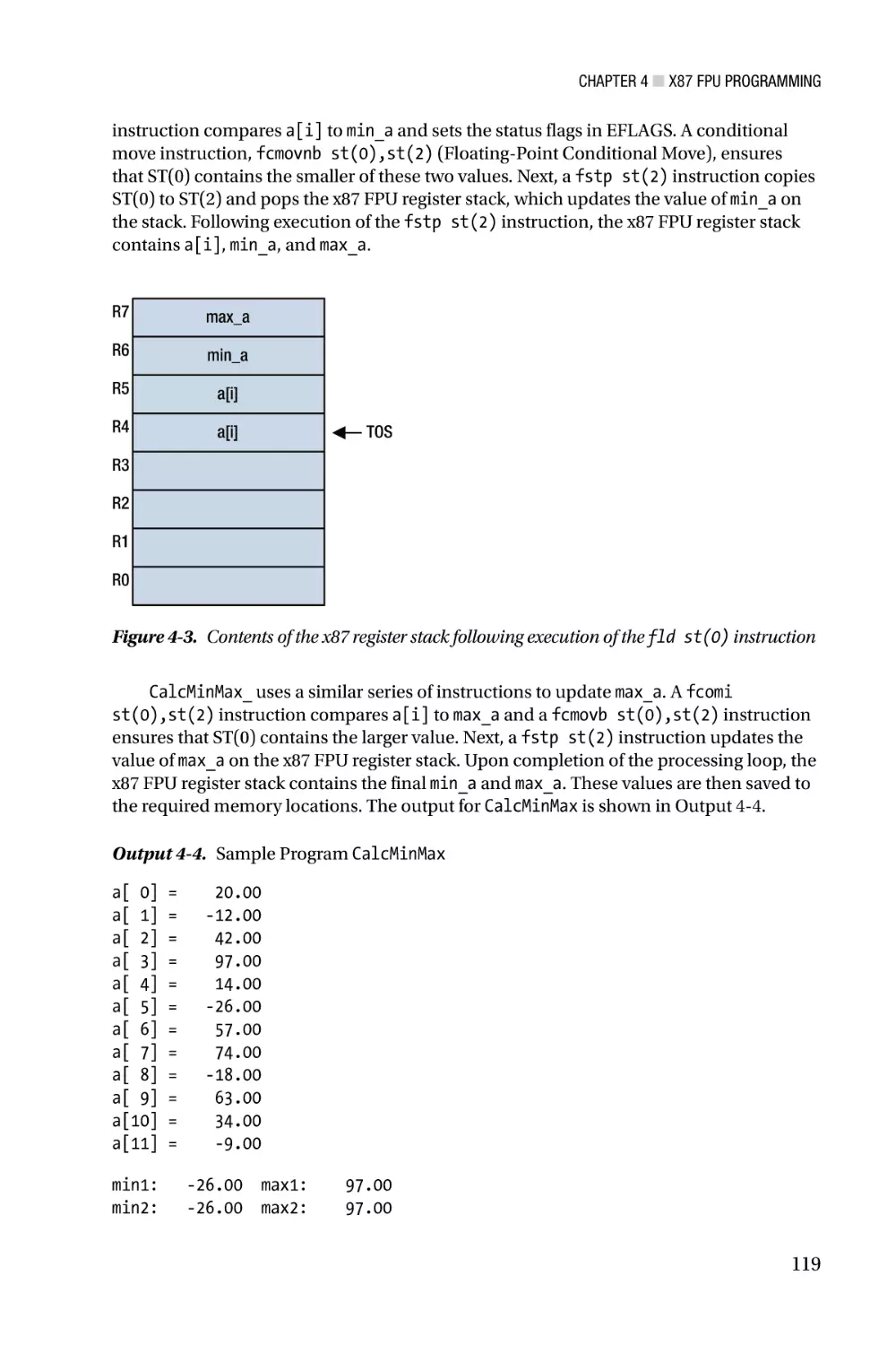
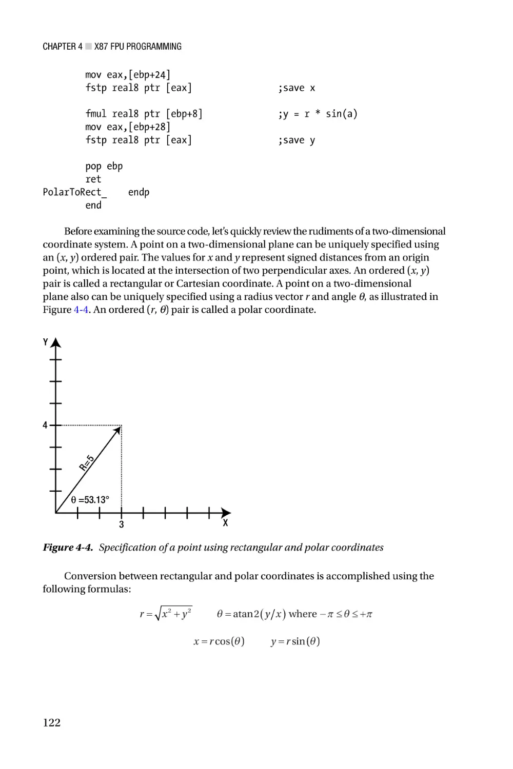
/


Author: Kusswurm D.


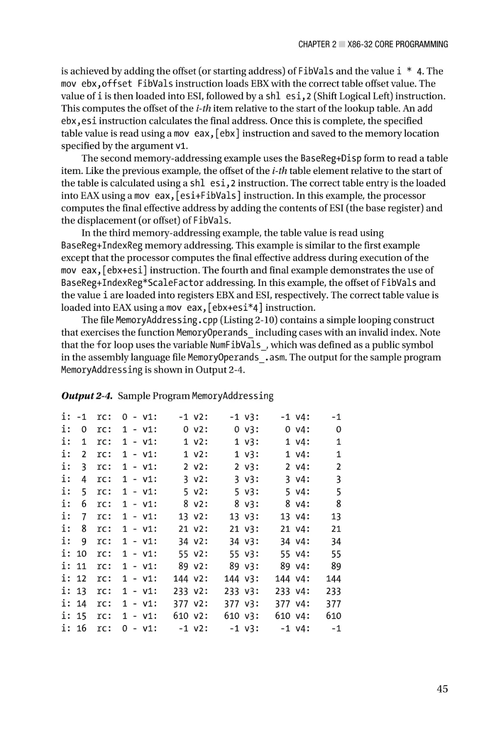
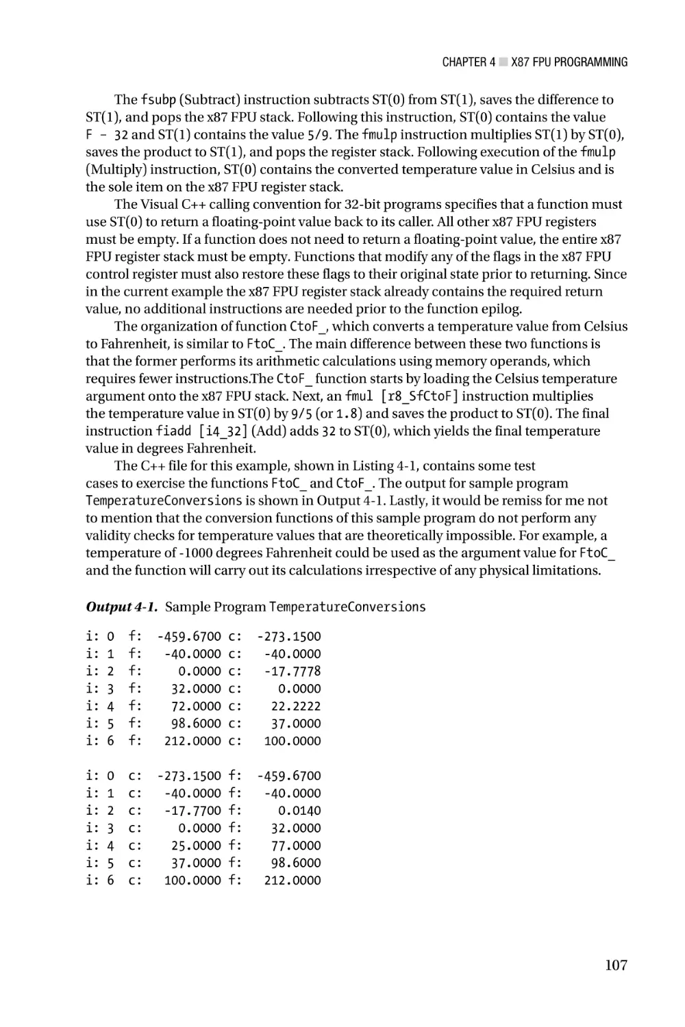
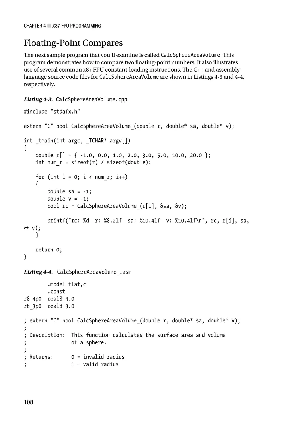
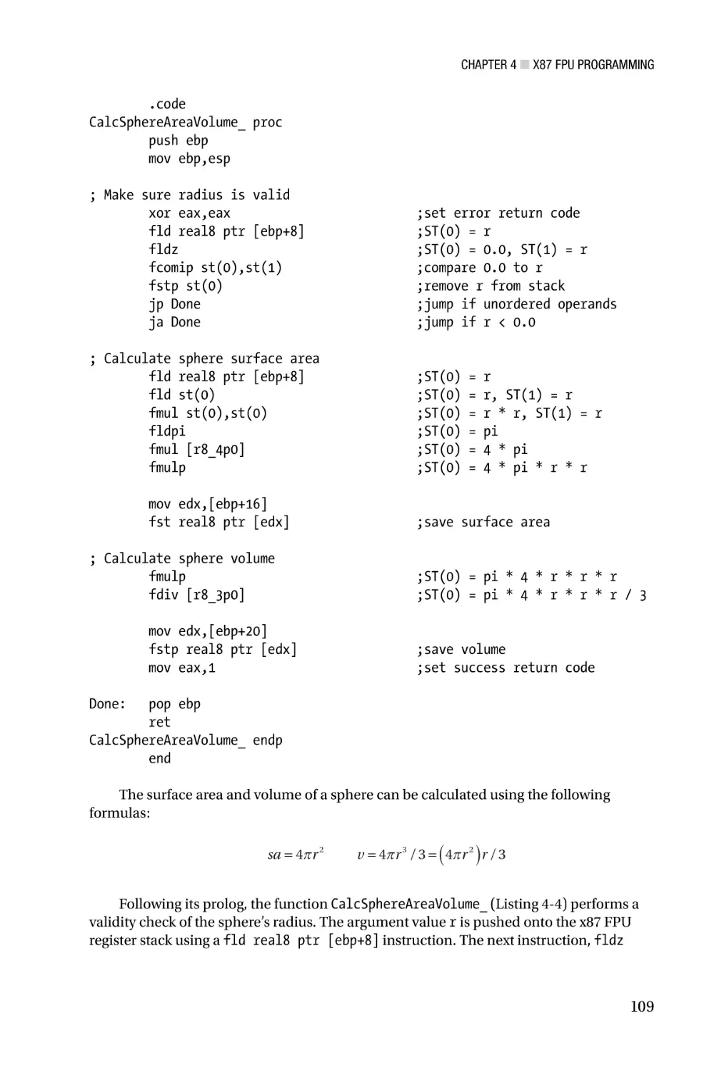
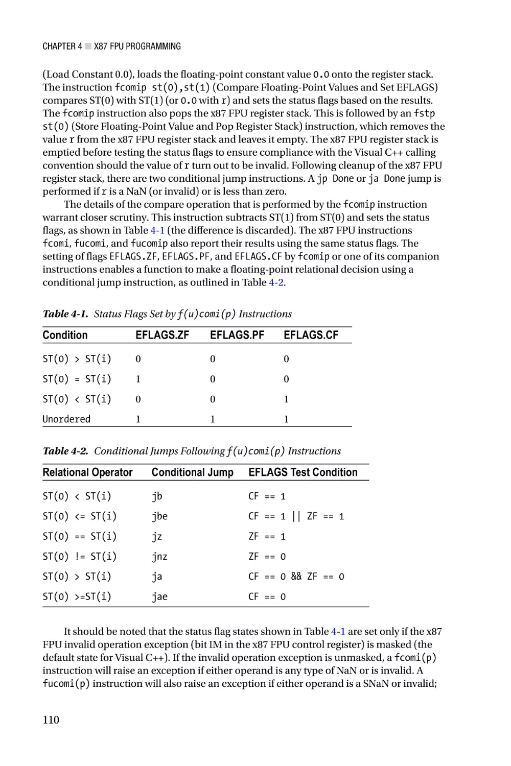
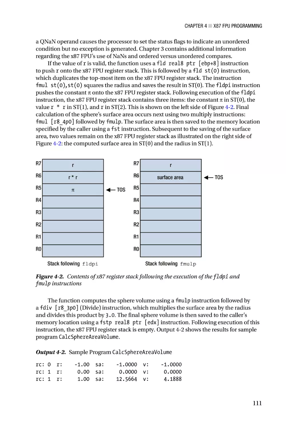
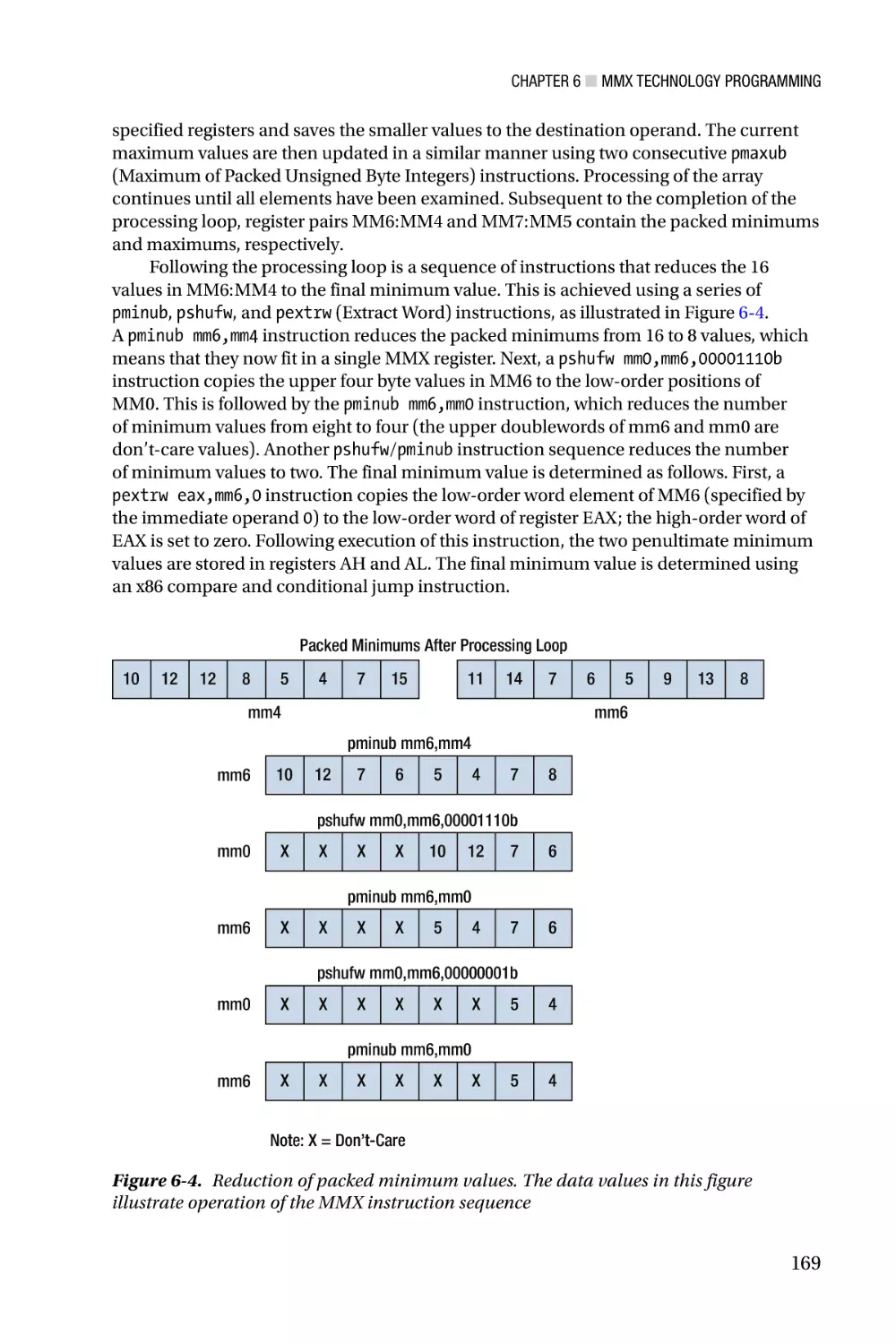
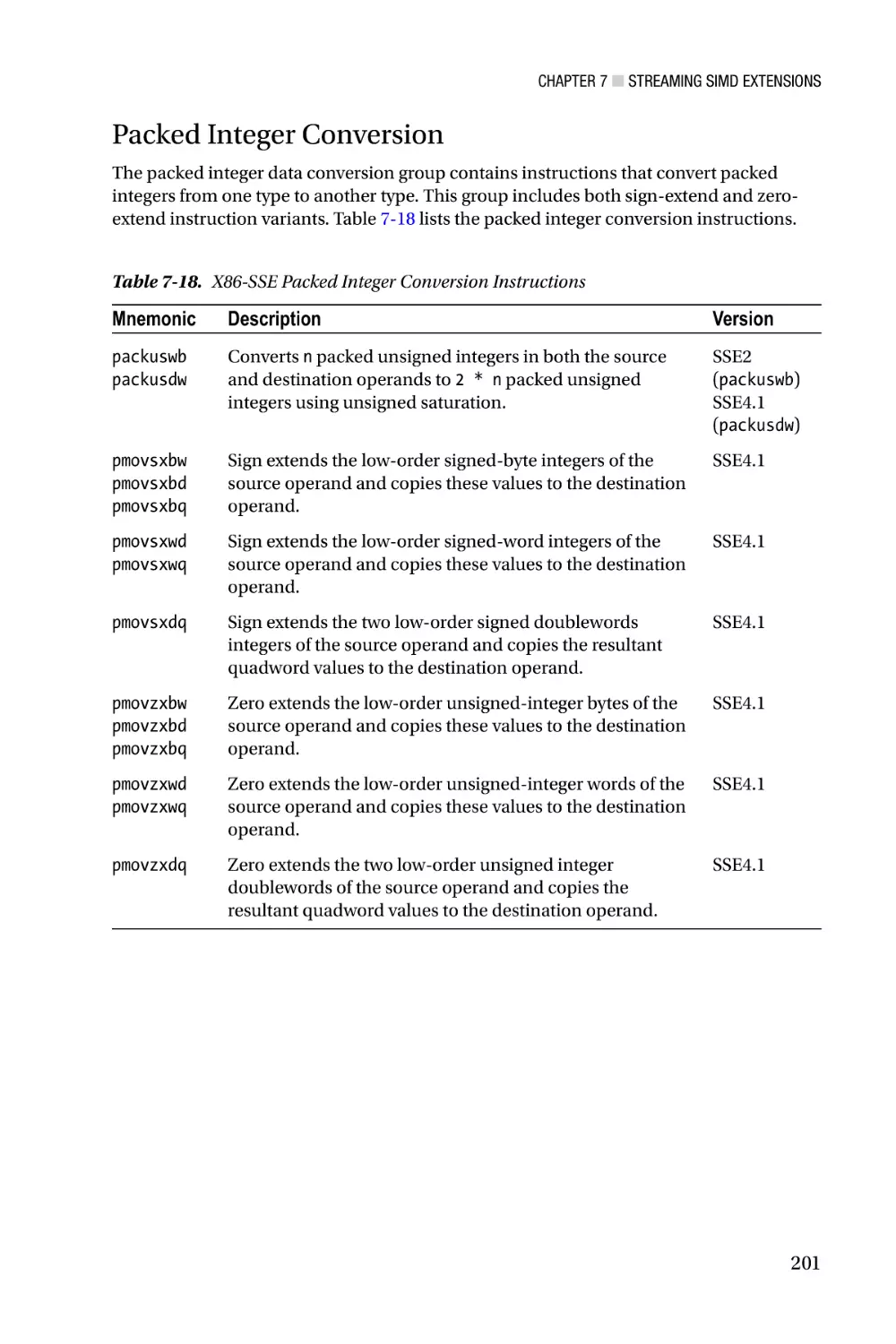
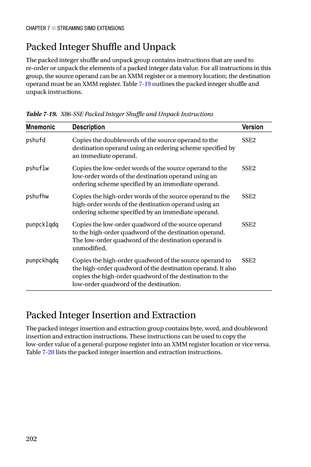
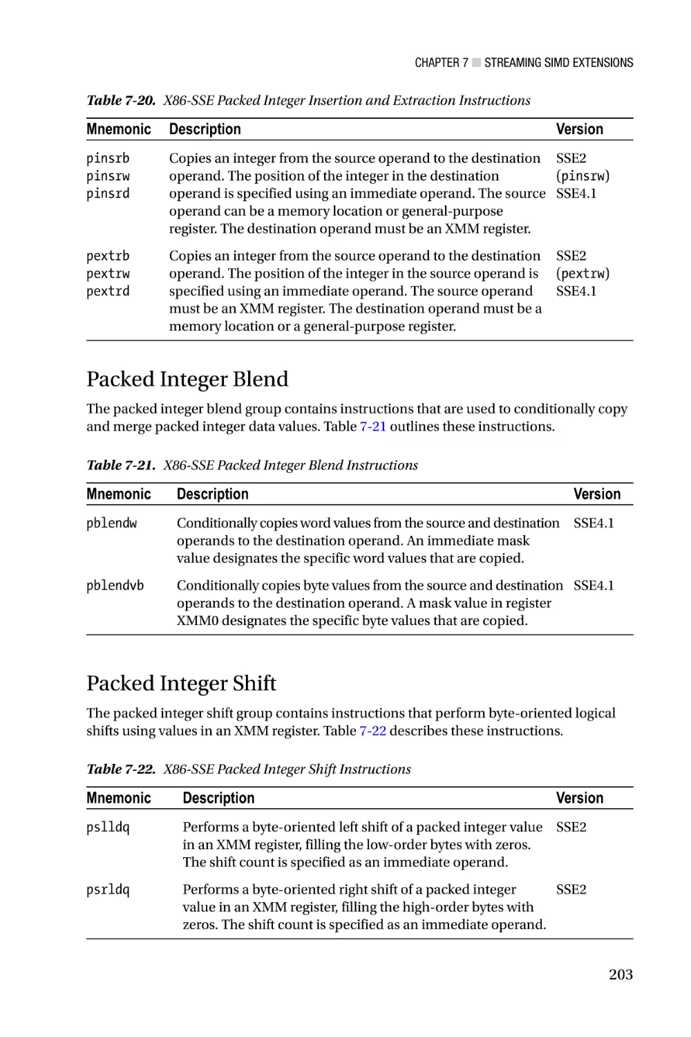
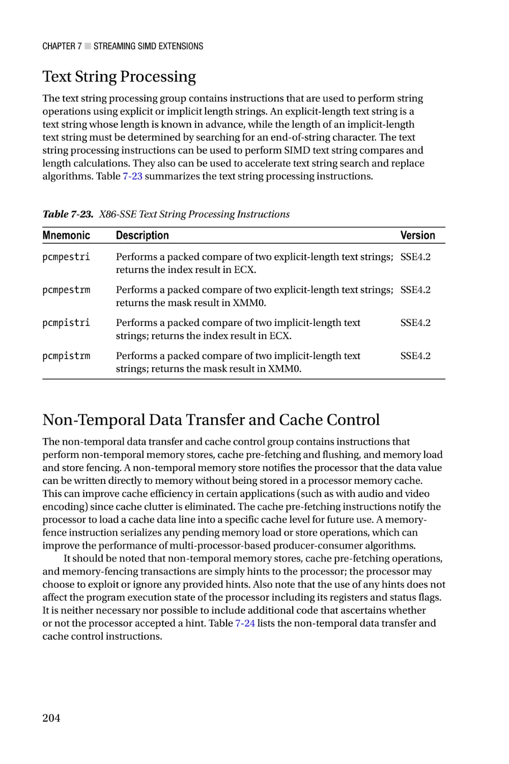
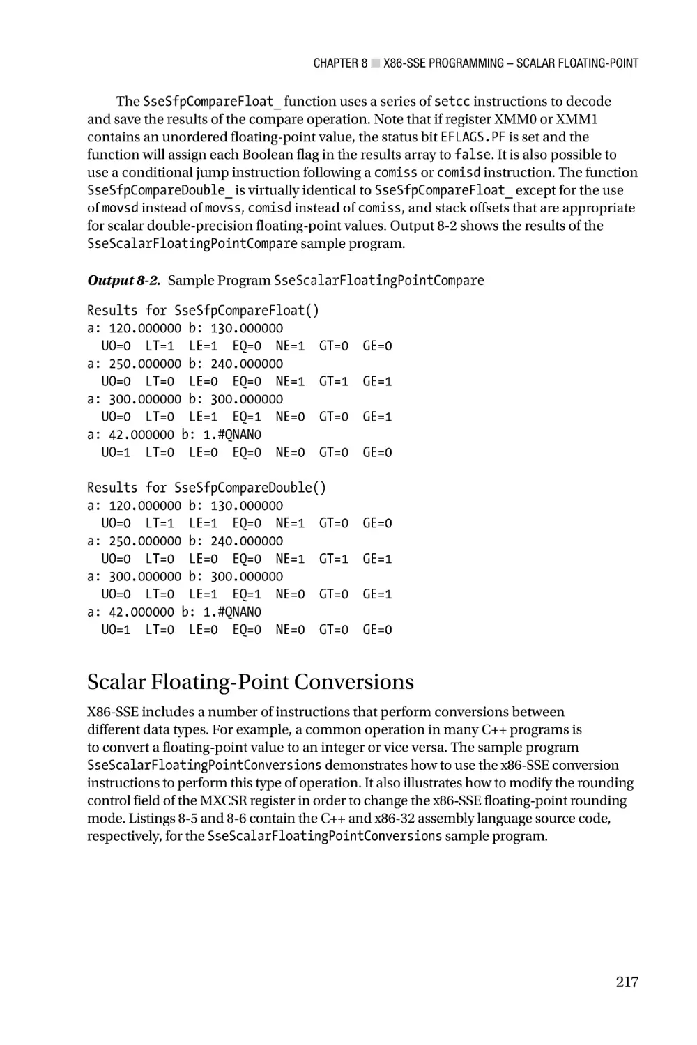
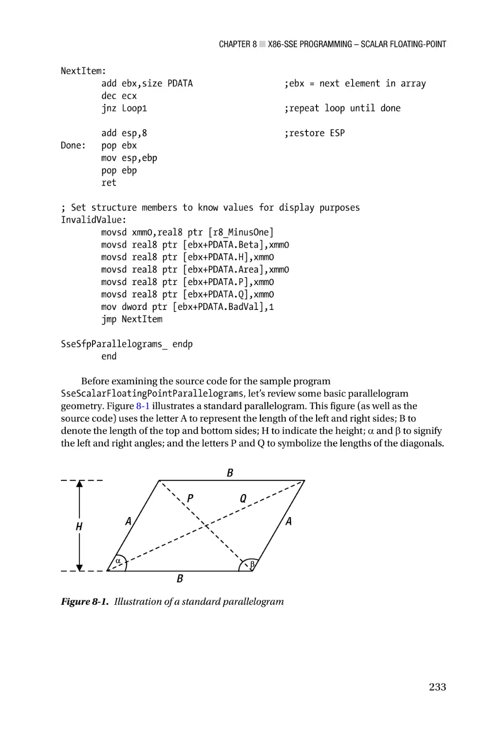
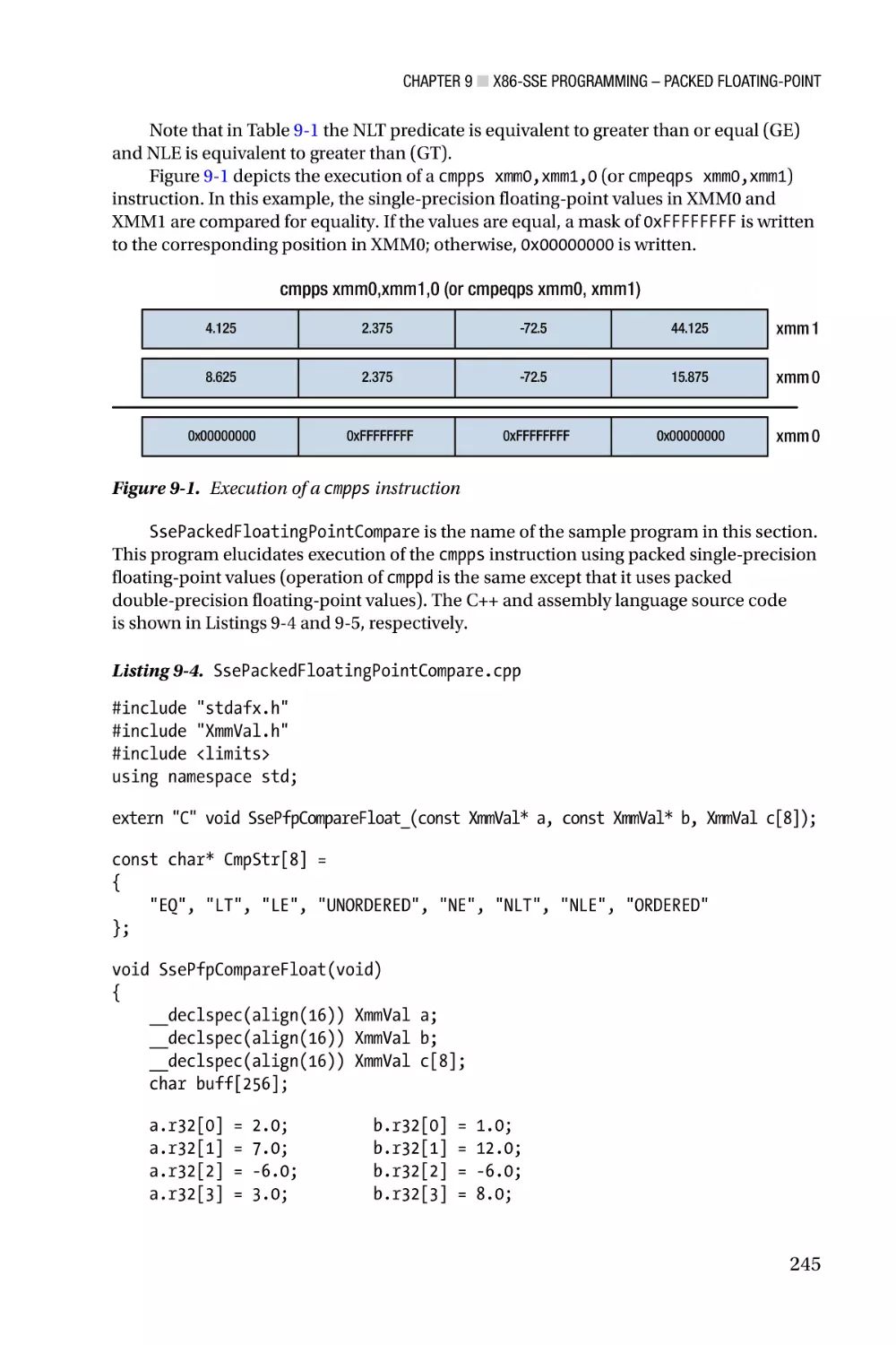
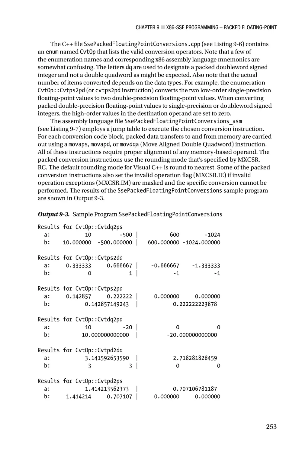
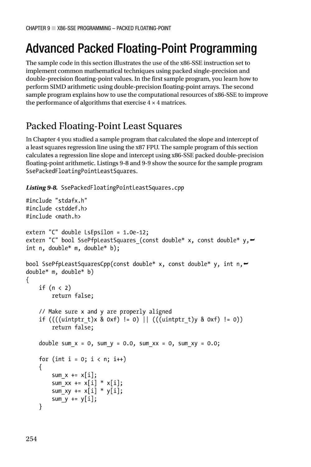
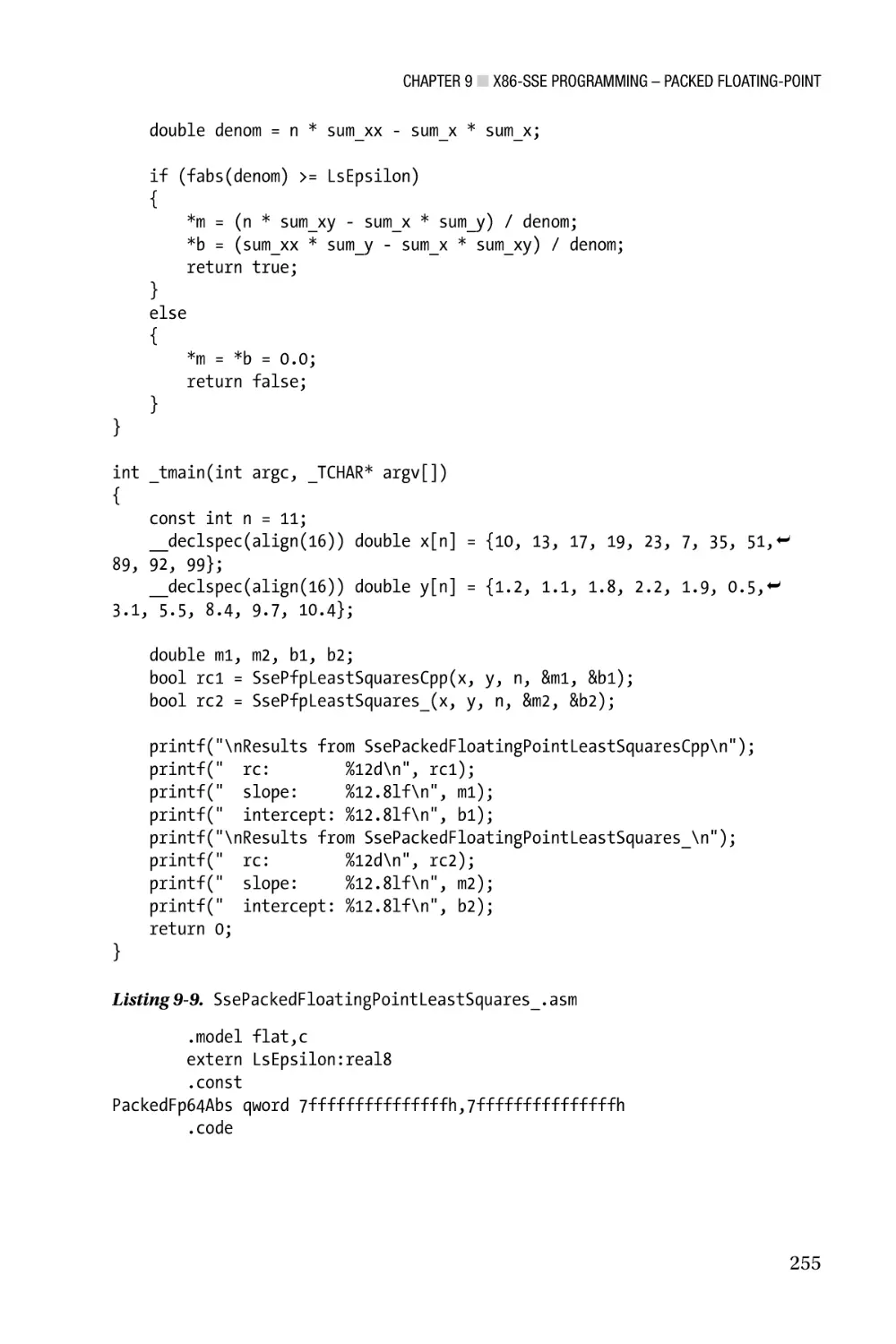
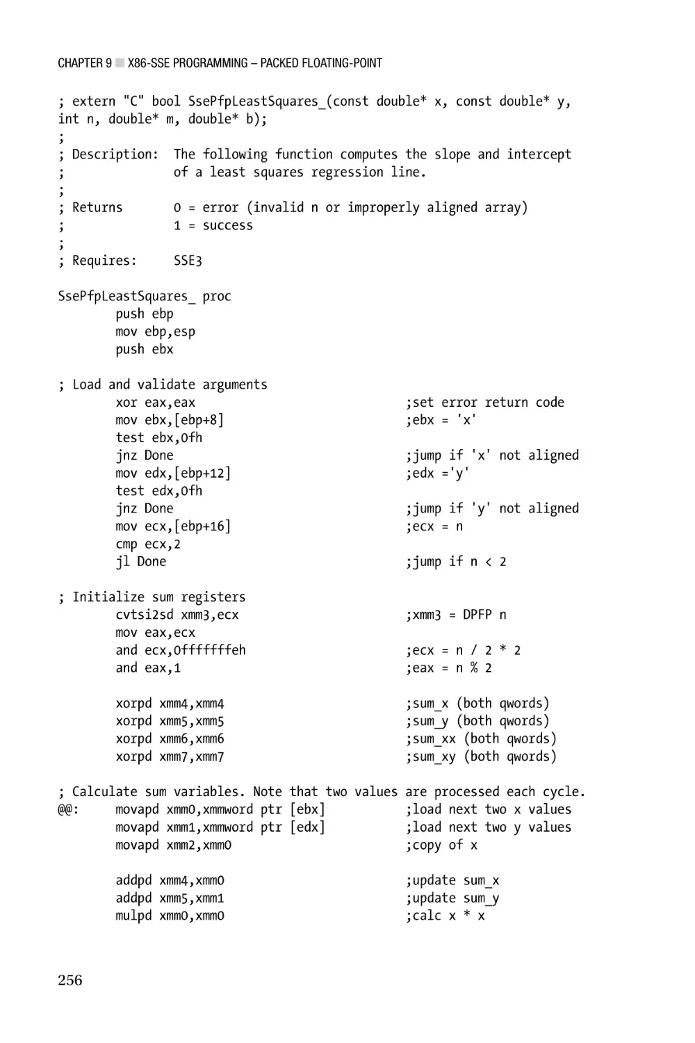
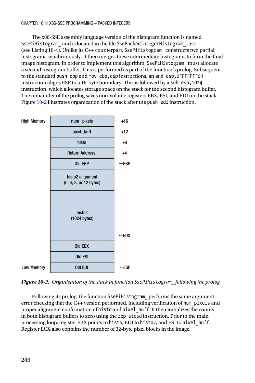
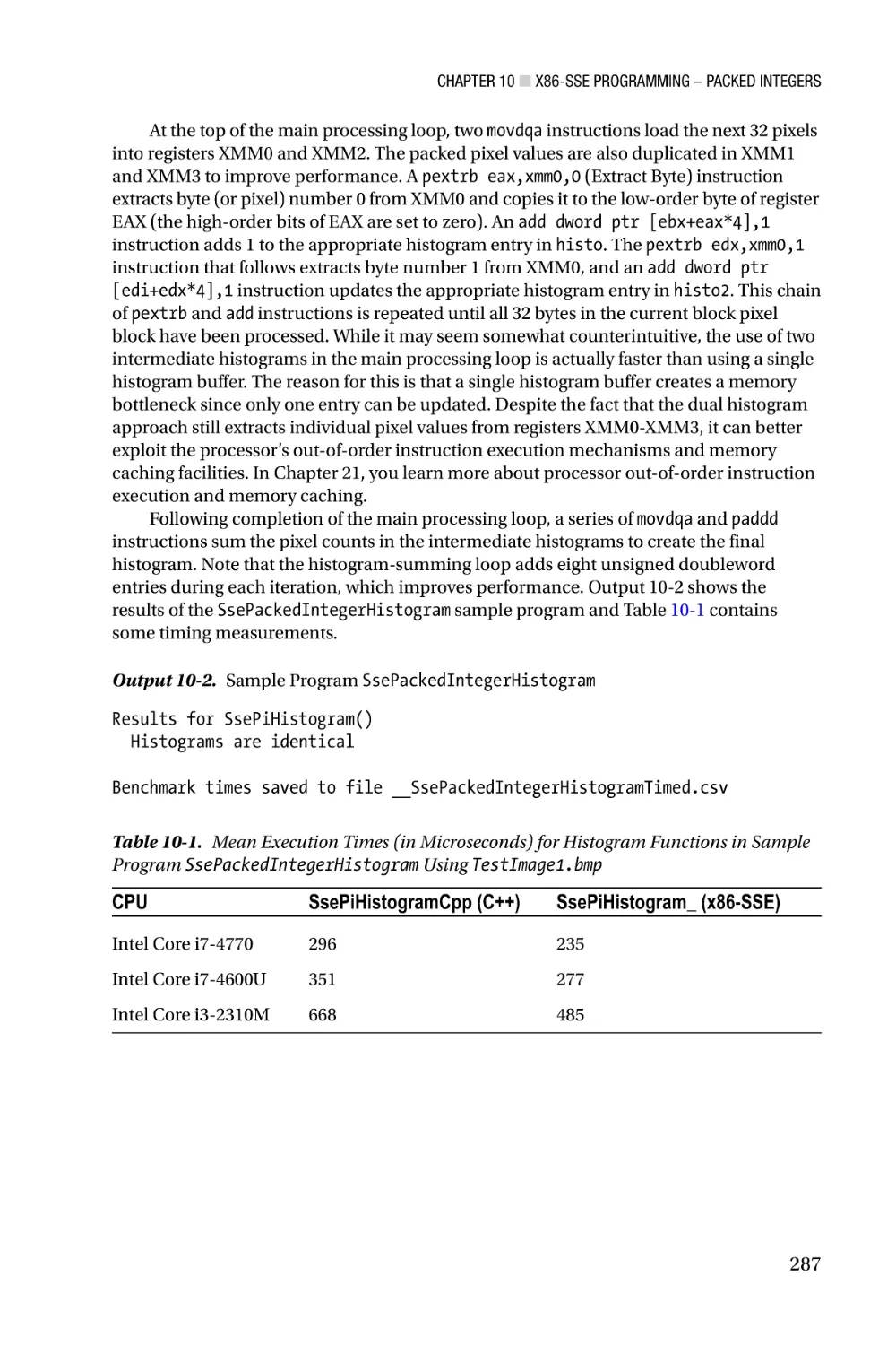
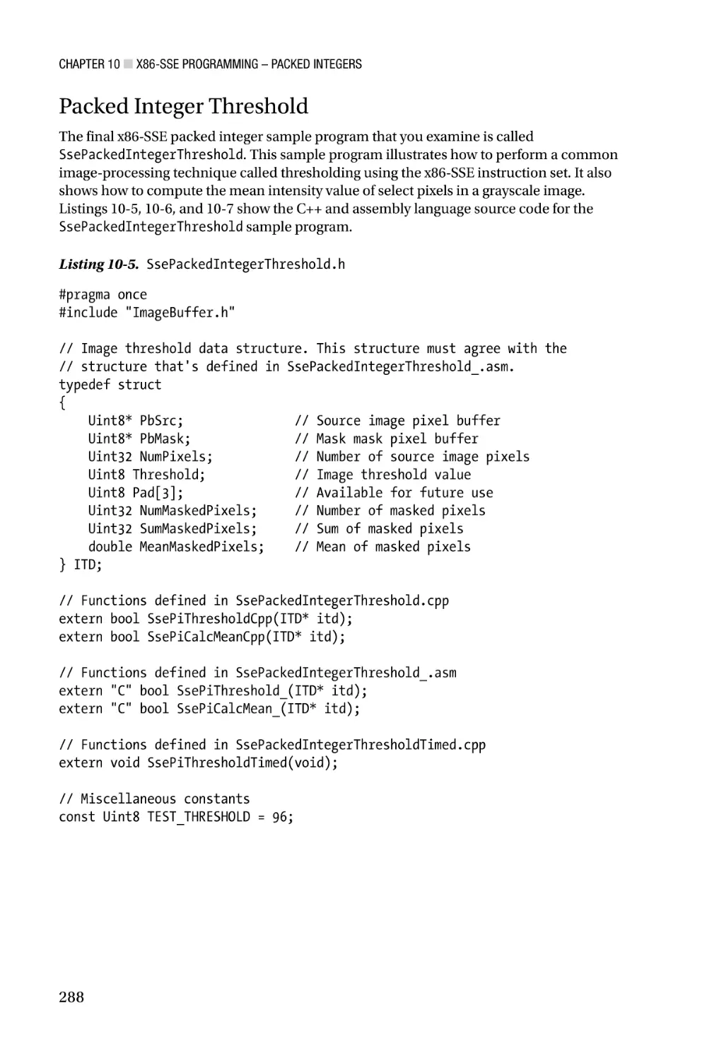
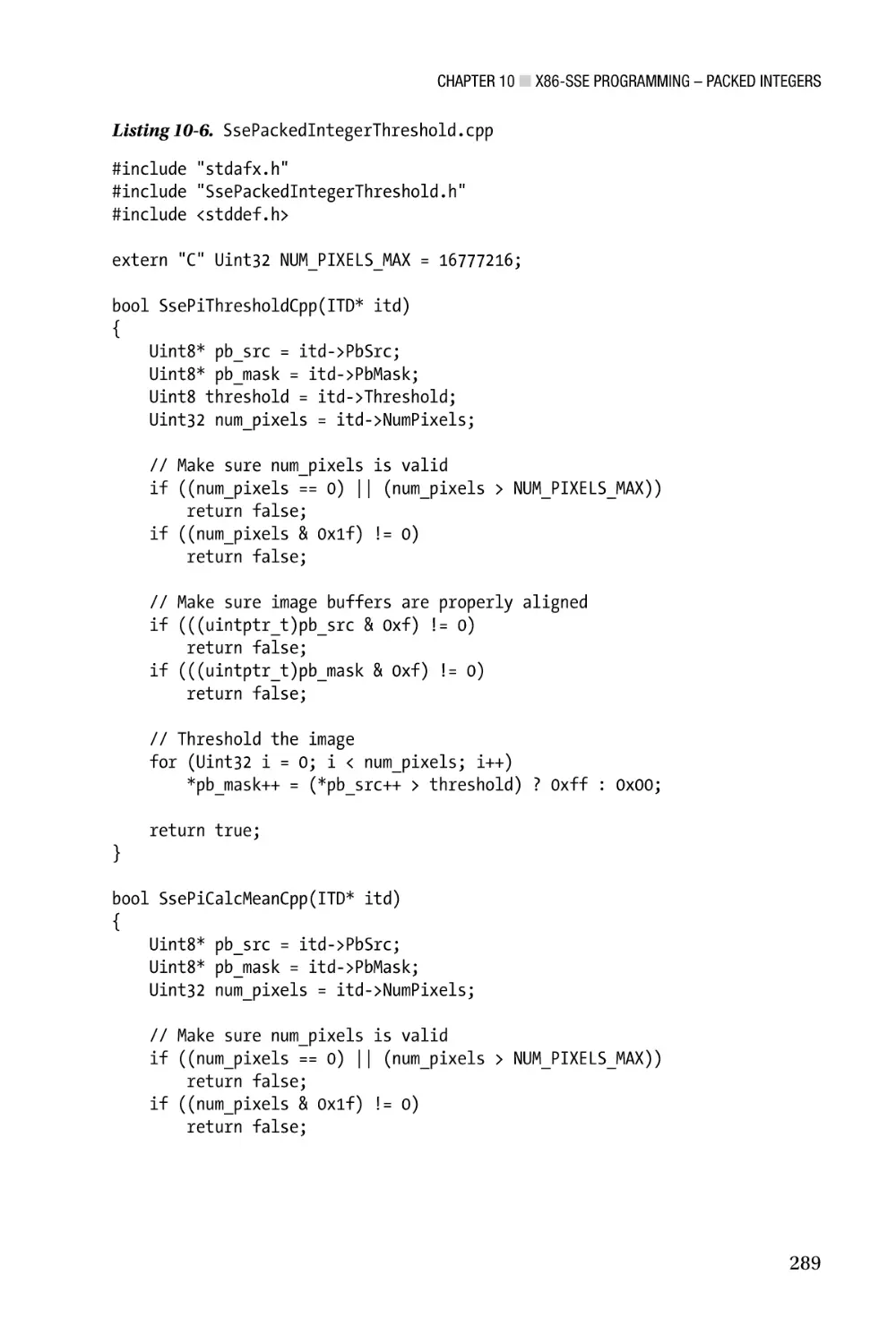
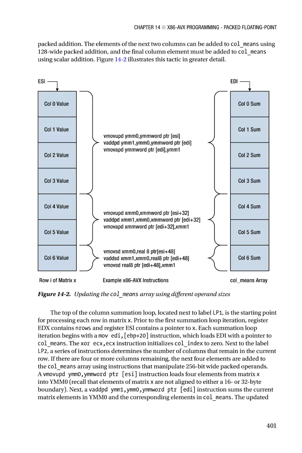
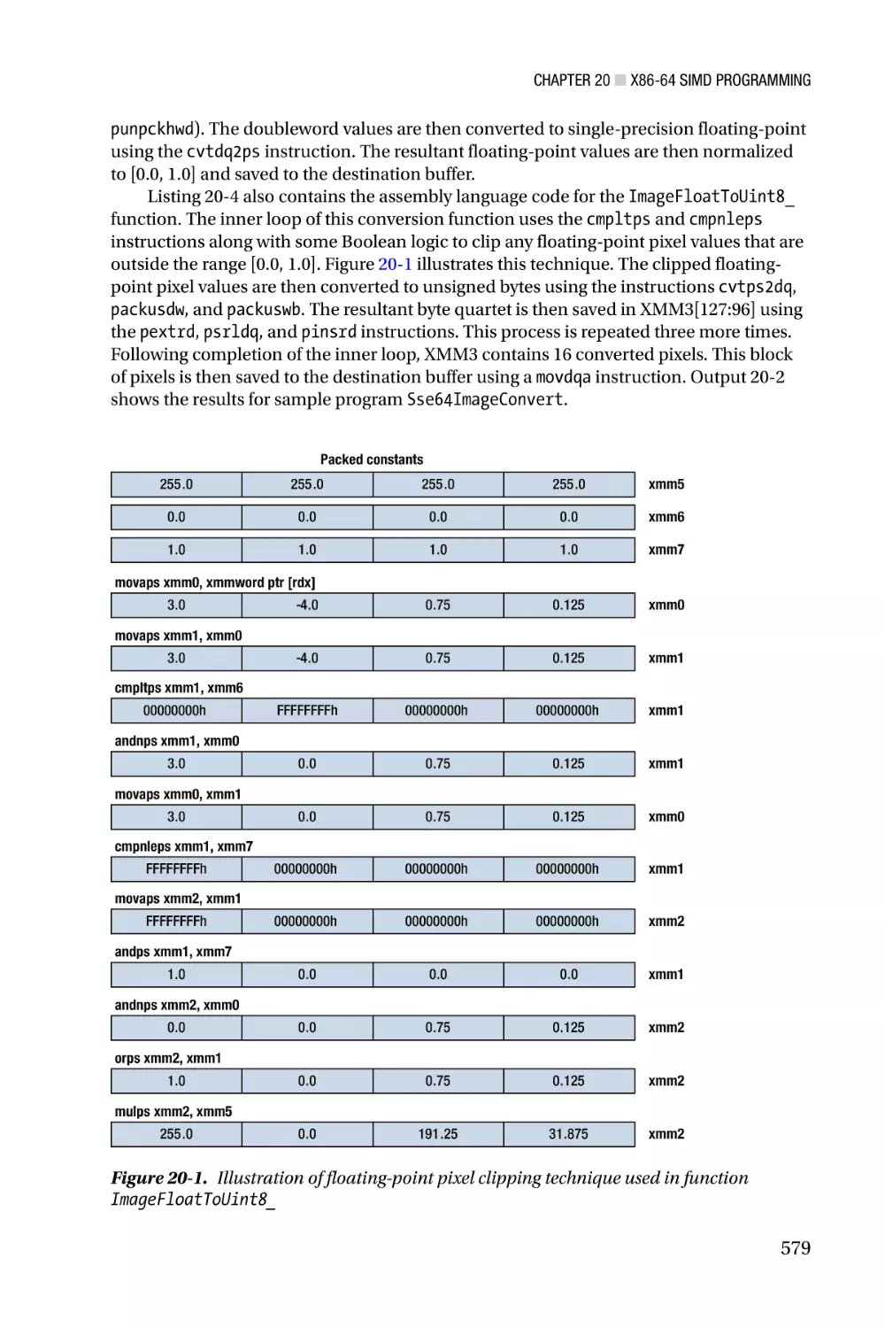
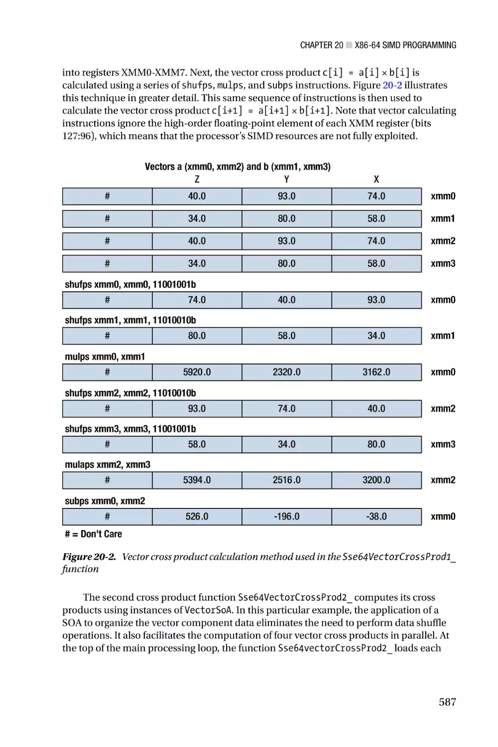
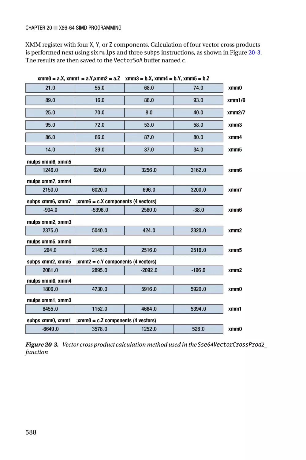
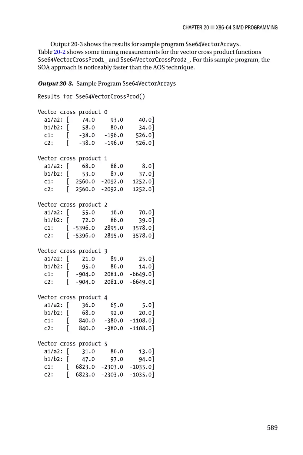
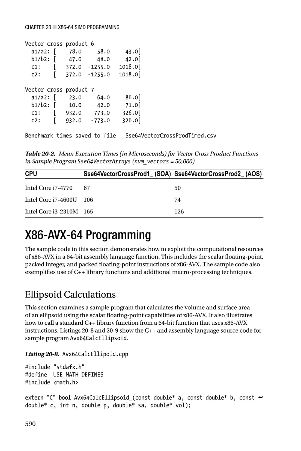
Text
For your convenience Apress has placed some of the front
matter material after the index. Please use the Bookmarks
and Contents at a Glance links to access them.
Contents at a Glance
About the Author���������������������������������������������������������������������������� xix
About the Technical Reviewer�������������������������������������������������������� xxi
Acknowledgments������������������������������������������������������������������������ xxiii
Introduction������������������������������������������������������������������������������������xxv
■■Chapter 1: X86-32 Core Architecture��������������������������������������������� 1
■■Chapter 2: X86-32 Core Programming����������������������������������������� 27
■■Chapter 3: X87 Floating-Point Unit����������������������������������������������� 87
■■Chapter 4: X87 FPU Programming���������������������������������������������� 103
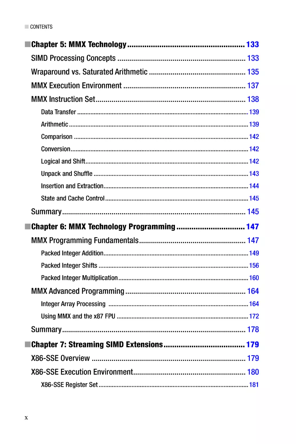
■■Chapter 5: MMX Technology������������������������������������������������������� 133
■■Chapter 6: MMX Technology Programming�������������������������������� 147
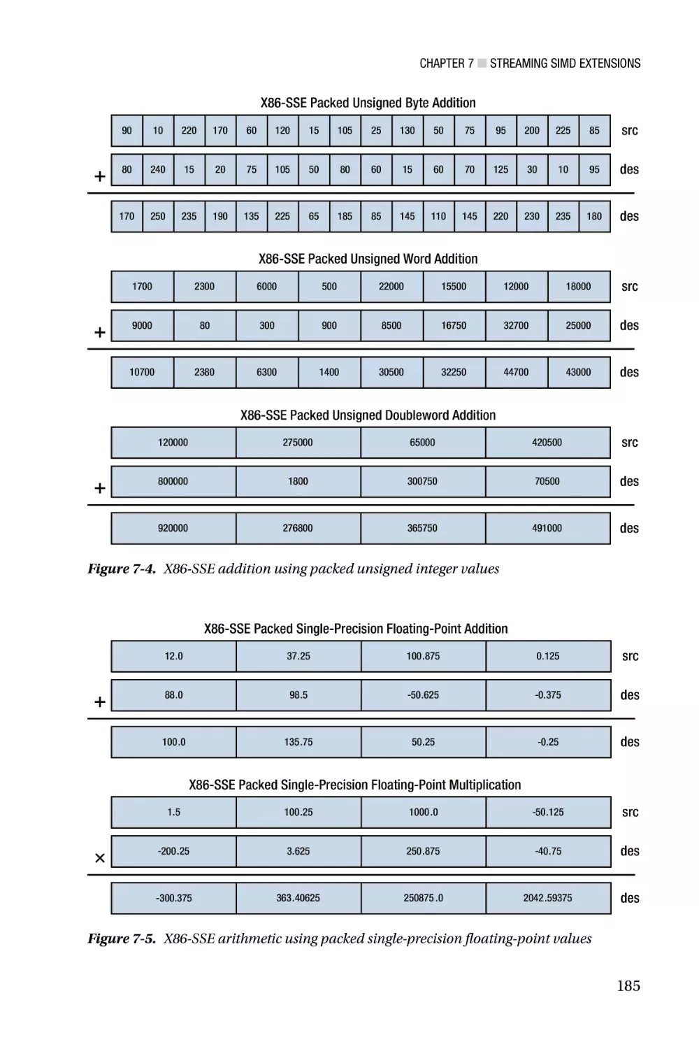
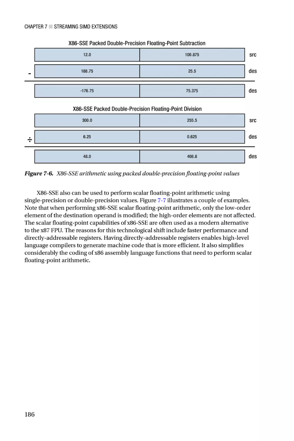
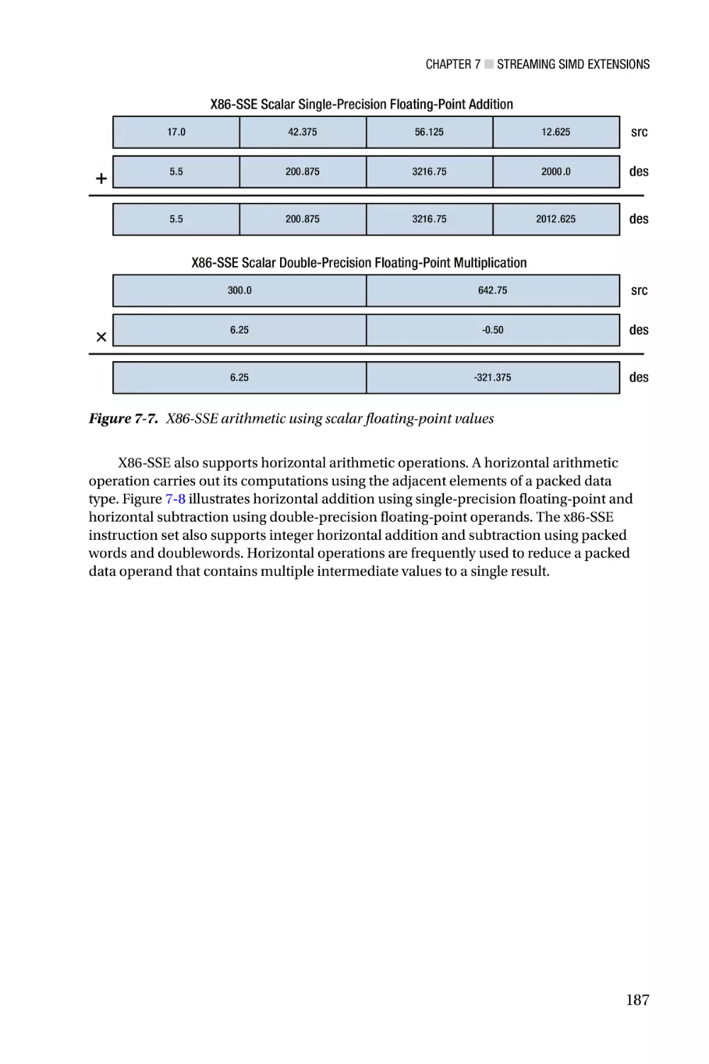
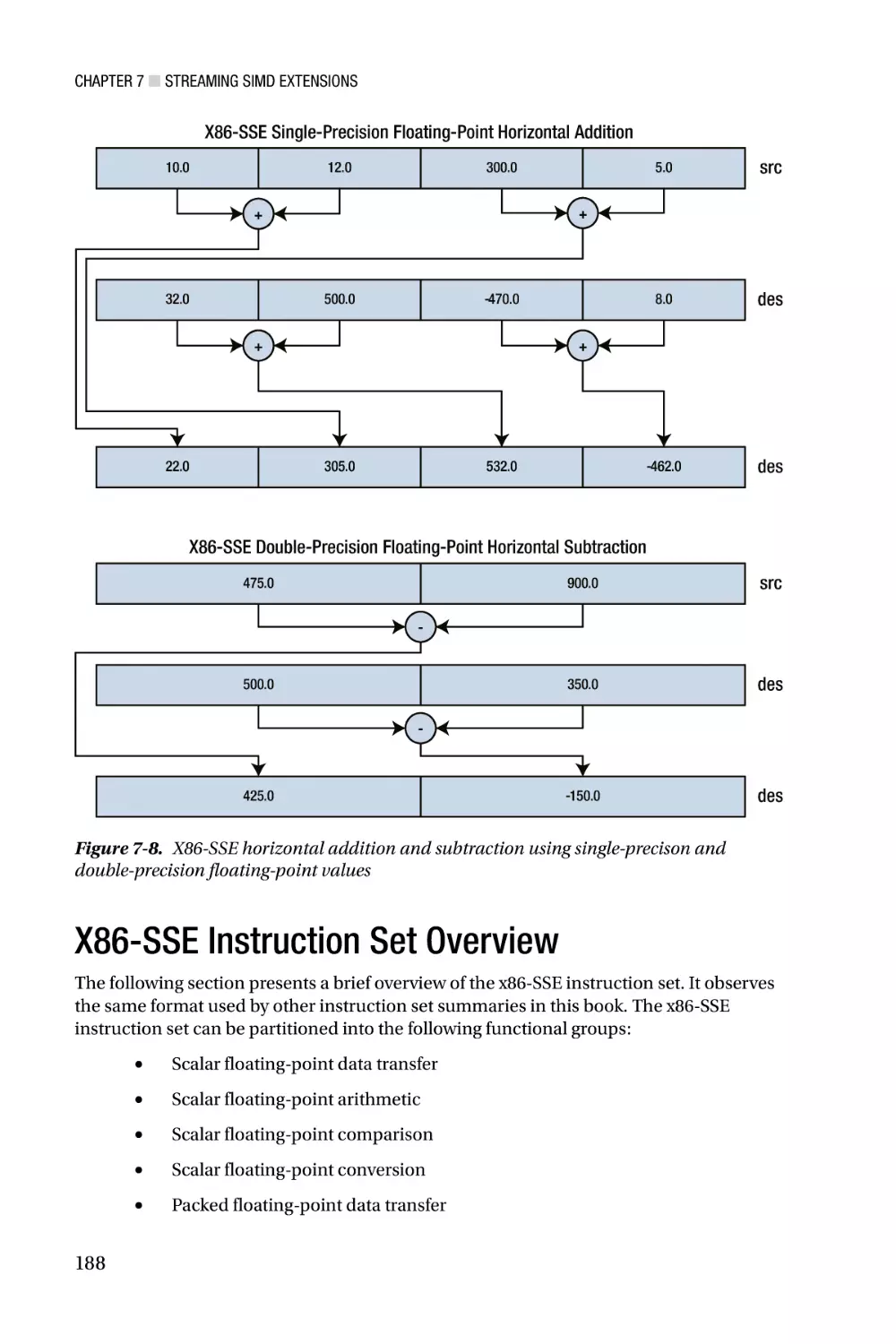
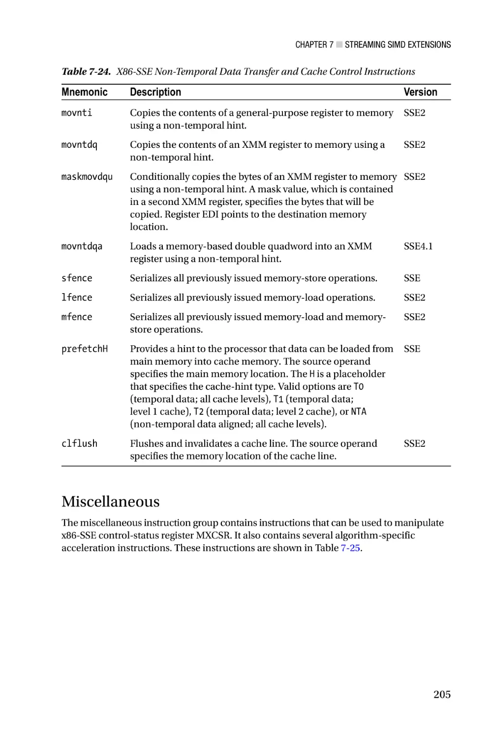
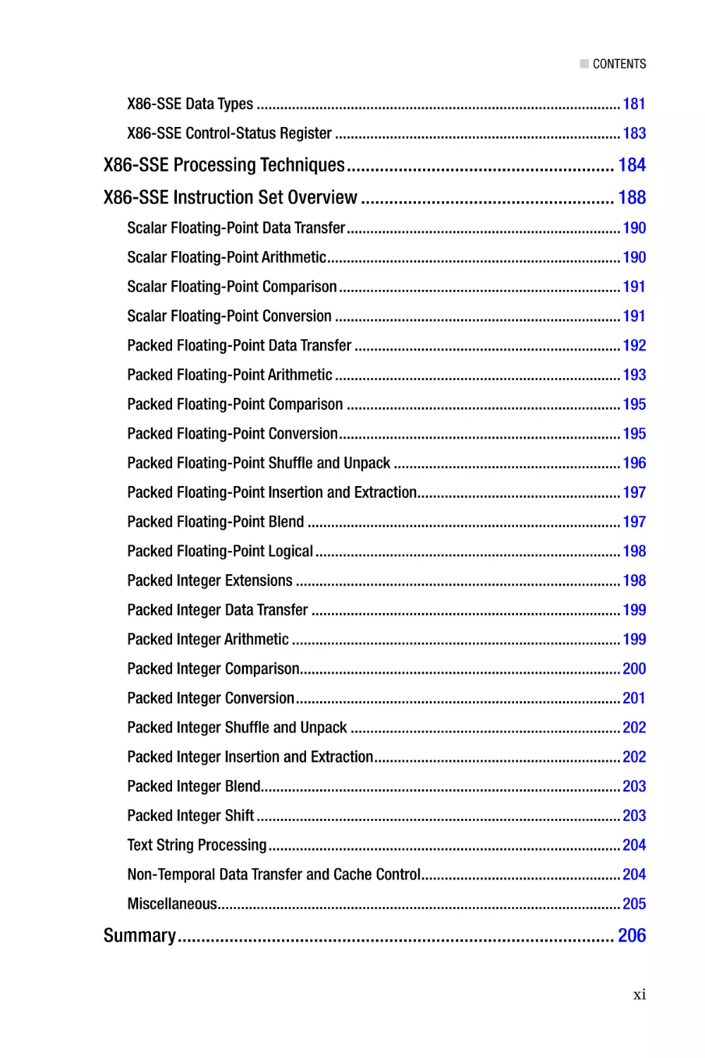
■■Chapter 7: Streaming SIMD Extensions�������������������������������������� 179
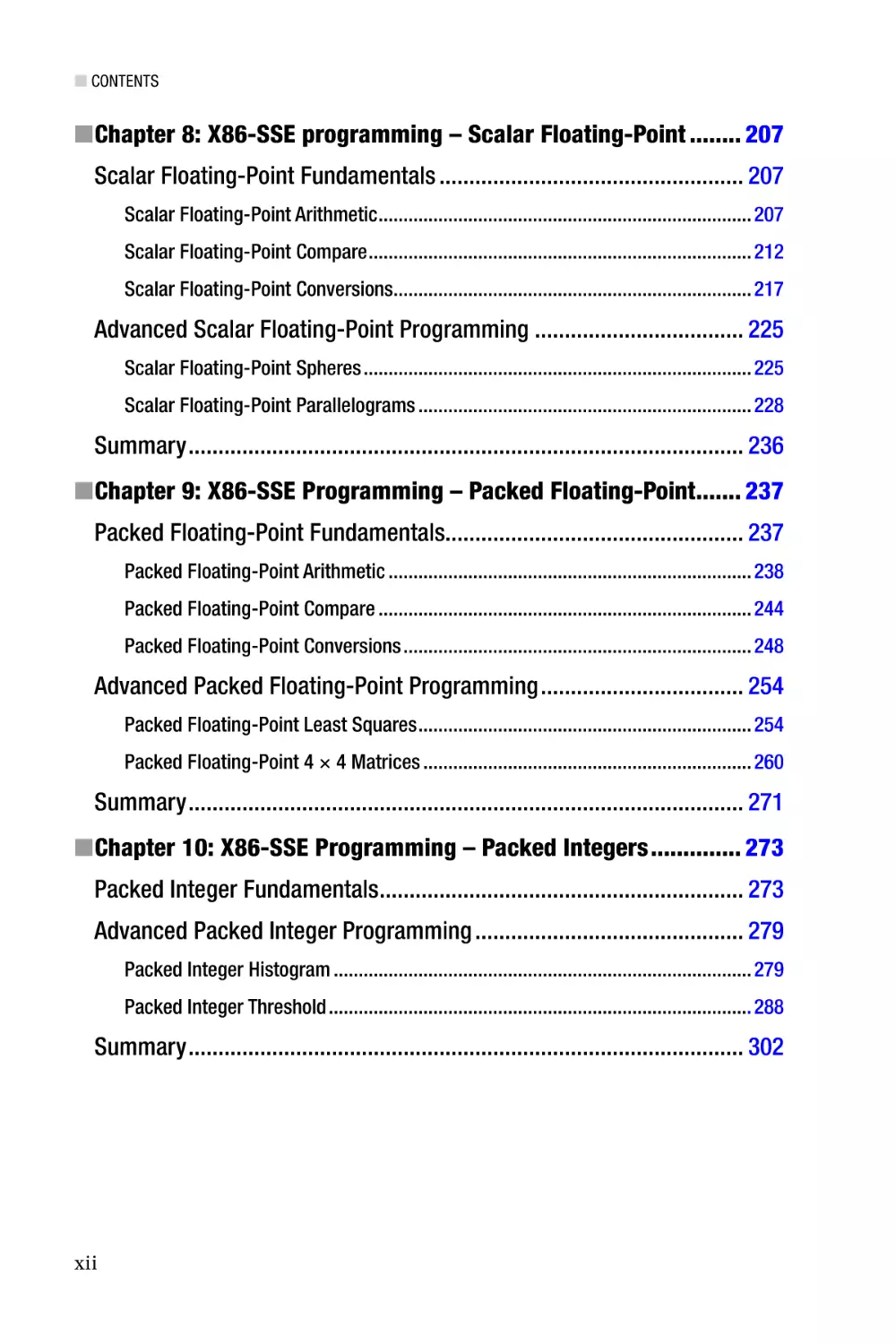
■■Chapter 8: X86-SSE programming – Scalar Floating-Point�������� 207
■■Chapter 9: X86-SSE Programming – Packed Floating-Point������� 237
■■Chapter 10: X86-SSE Programming – Packed Integers�������������� 273
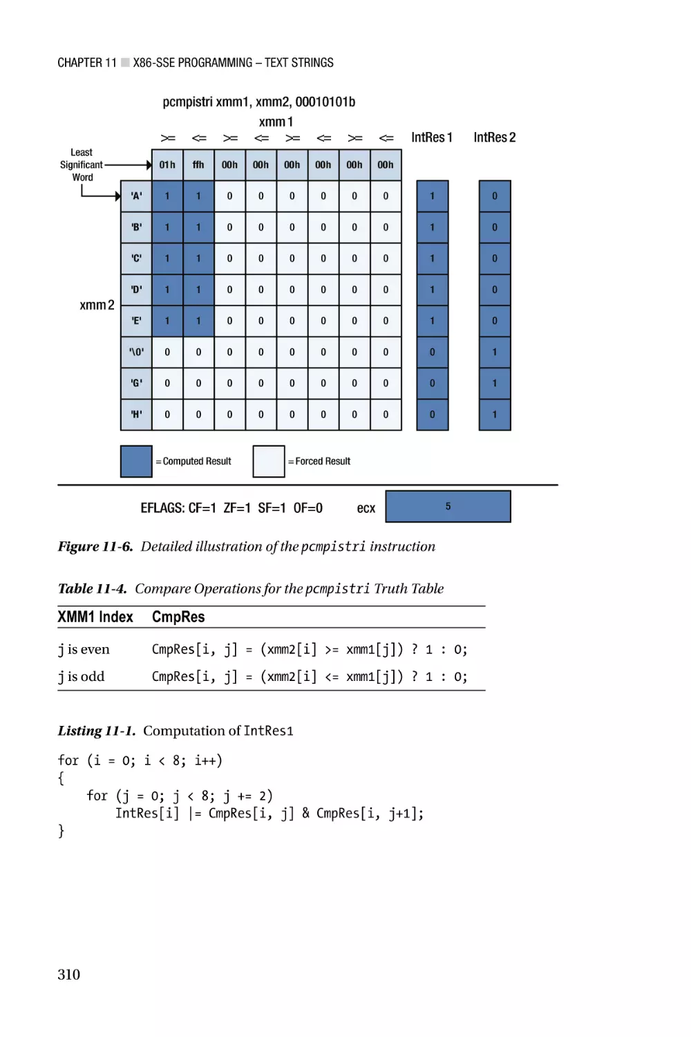
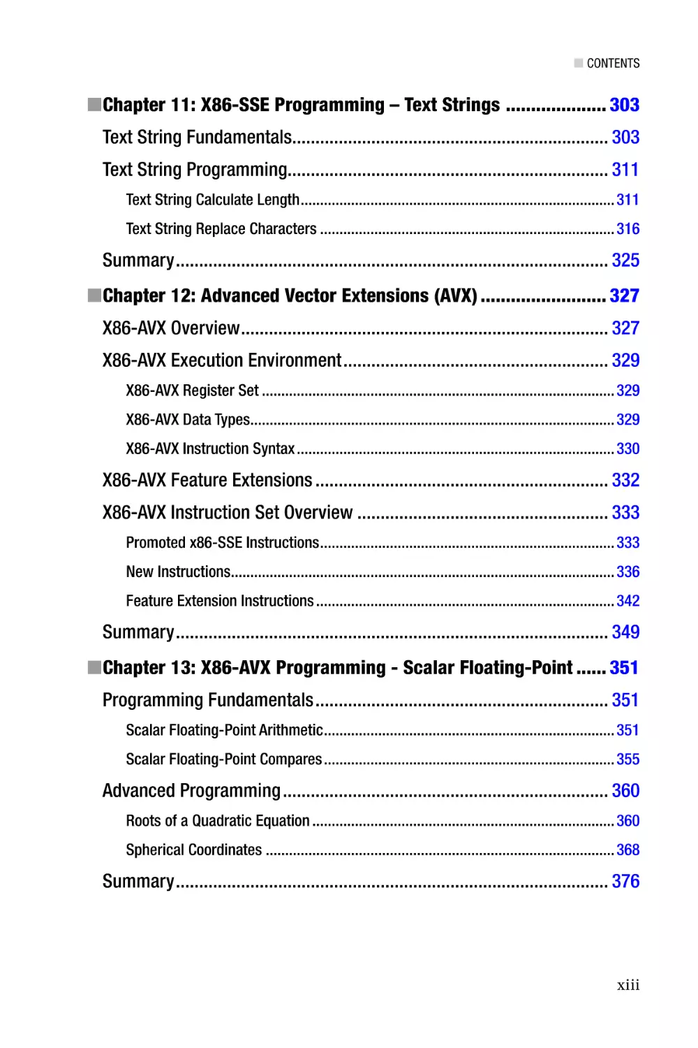
■■Chapter 11: X86-SSE Programming – Text Strings �������������������� 303
■■Chapter 12: Advanced Vector Extensions (AVX)������������������������� 327
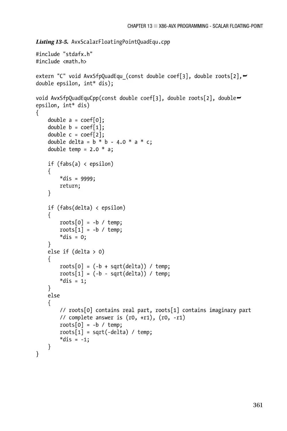
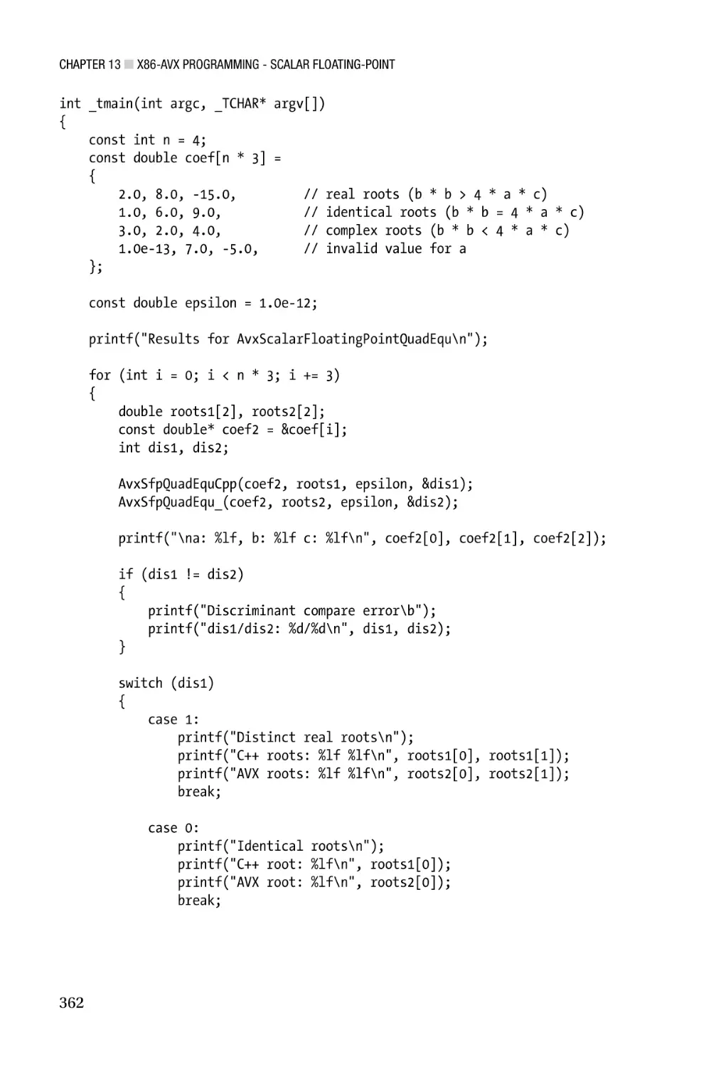
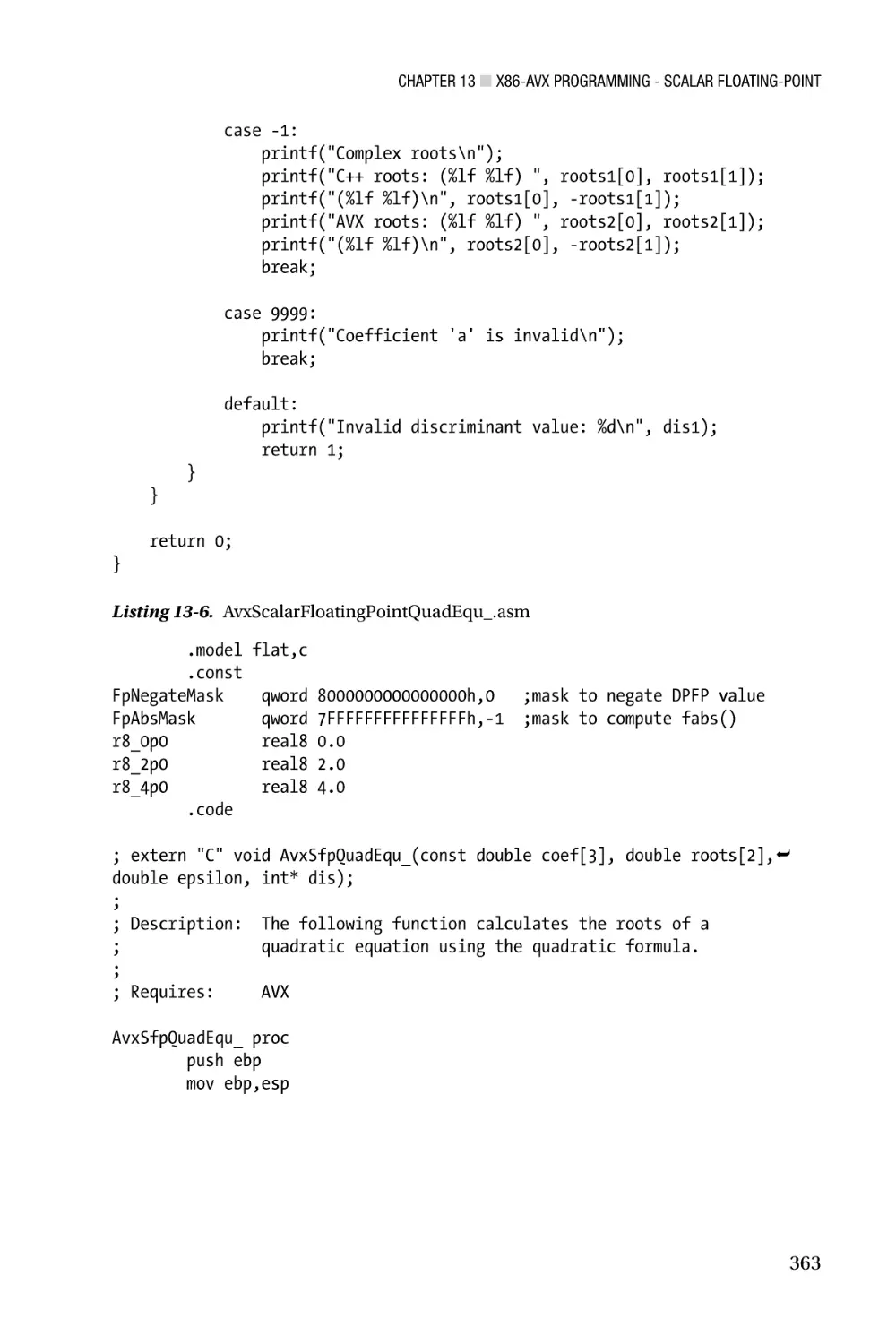
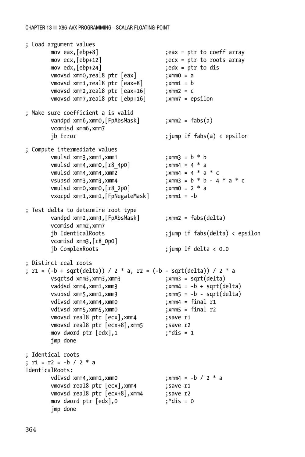
■■Chapter 13: X86-AVX Programming - Scalar Floating-Point������ 351
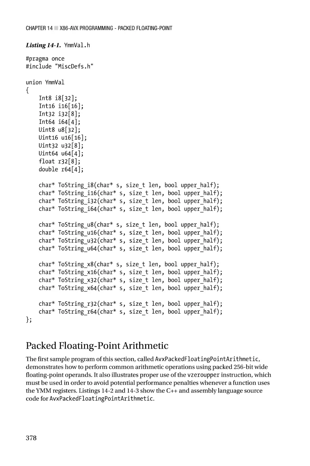
■■Chapter 14: X86-AVX Programming - Packed Floating-Point������������377
■■Chapter 15: X86-AVX Programming - Packed Integers�������������� 405
v
■ Contents at a Glance
■■Chapter 16: X86-AVX Programming - New Instructions������������� 439
■■Chapter 17: X86-64 Core Architecture��������������������������������������� 491
■■Chapter 18: X86-64 Core Programming������������������������������������� 503
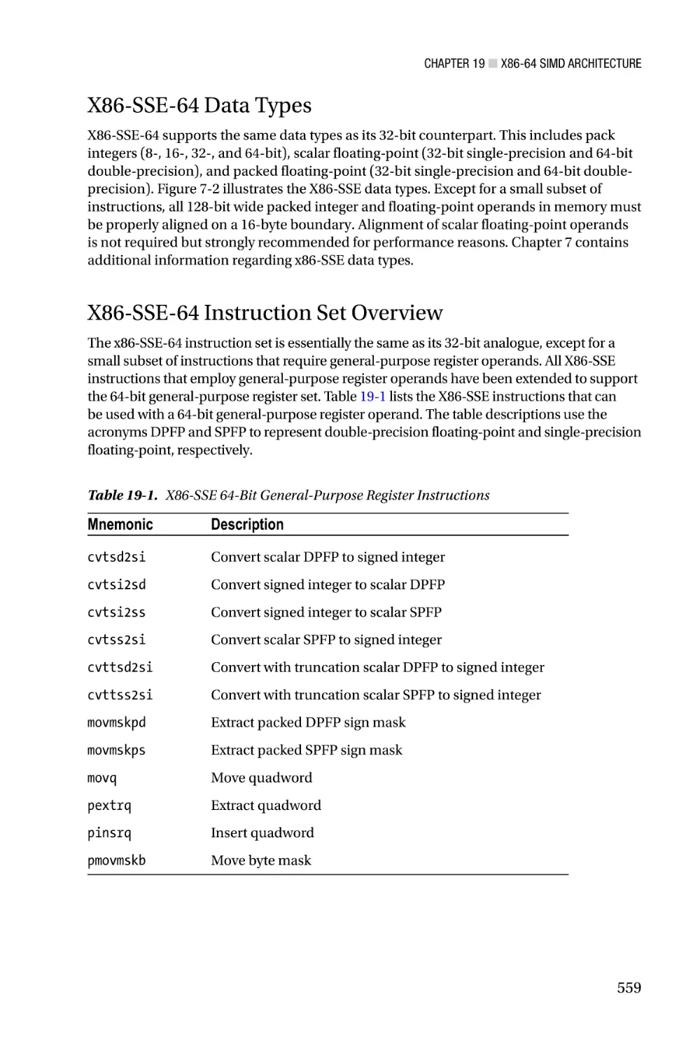
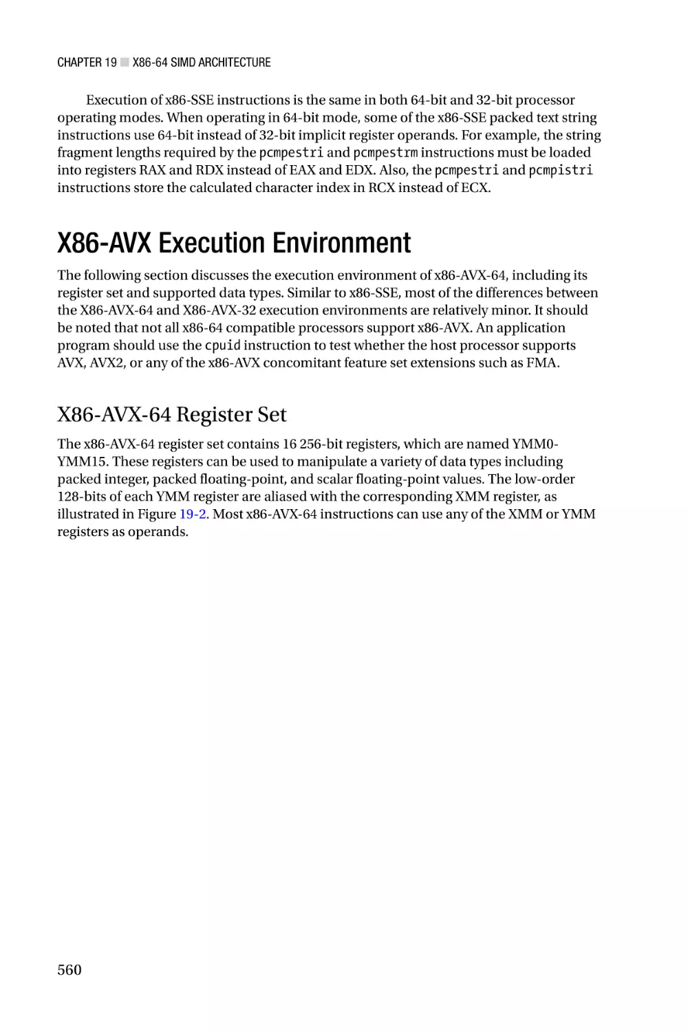
■■Chapter 19: X86-64 SIMD Architecture�������������������������������������� 557
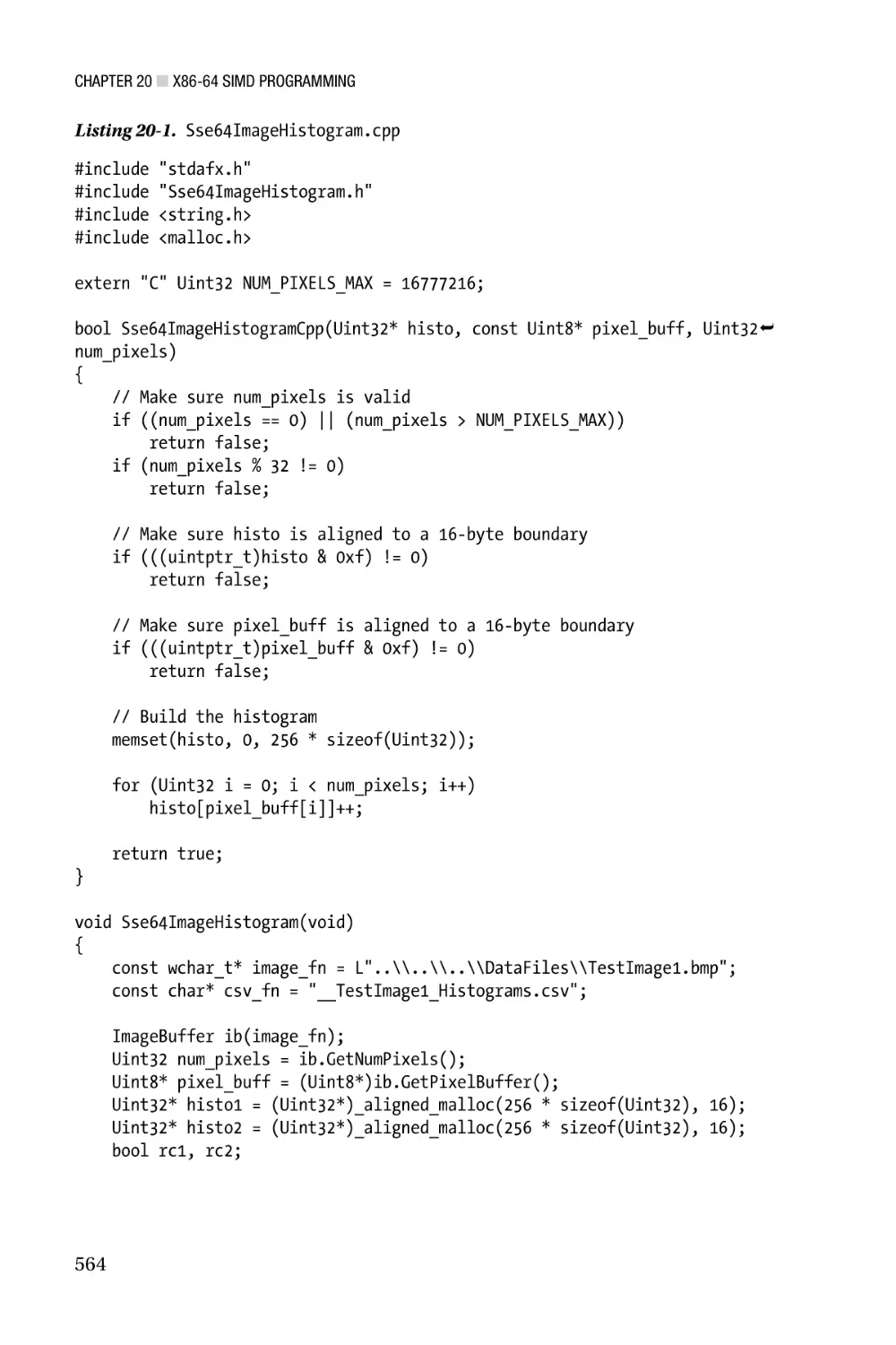
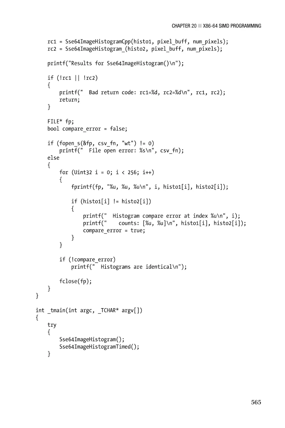
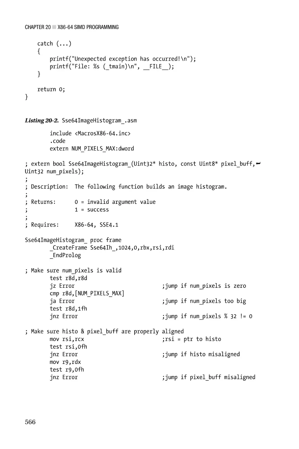
■■Chapter 20: X86-64 SIMD Programming������������������������������������ 563
■■Chapter 21: Advanced Topics and Optimization Techniques������ 623
■■Chapter 22: Advanced Topics Programming������������������������������ 637
Index���������������������������������������������������������������������������������������������� 657
vi
Introduction
Since the invention of the personal computer, software developers have used assembly
language to create innovative solutions for a wide variety of algorithmic challenges.
During the early days of the PC era, it was common practice to code large portions of
a program or complete applications using x86 assembly language. Even as the use of
high-level languages such as C, C++, and C# became more prevalent, many software
developers continued to employ assembly language to code performance-critical
sections of their programs. And while compilers have improved remarkably over the
years in terms of generating machine code that is both spatially and temporally efficient,
situations still exist where it makes sense for software developers to exploit the benefits of
assembly language programming.
The inclusion of single-instruction multiple-data (SIMD) architectures in modern
x86 processors provides another reason for the continued interest in assembly language
programming. A SIMD-capable processor includes computational resources that
facilitate concurrent calculations using multiple data values, which can significantly
improve the performance of applications that must deliver real-time responsiveness.
SIMD architectures are also well-suited for computationally-intense problem domains
such as image processing, audio and video encoding, computer-aided design, computer
graphics, and data mining. Unfortunately, many high-level languages and development
tools are unable to fully (or even partially) exploit the SIMD capabilities of a modern x86
processor. Assembly language, on the other hand, enables the software developer to take
full advantage of a processor’s entire computational resource suite.
Modern X86 Assembly Language Programming
Modern X86 Assembly Language Programming is an edifying text on the subject of x86
assembly language programming. Its primary purpose is to teach you how to code
functions using x86 assembly language that can be invoked from a high-level language.
The book includes informative material that explains the internal architecture of an x86
processor as viewed from the perspective of an application program. It also contains
an abundance of sample code that is structured to help you quickly understand x86
assembly language programming and the computational resources of the x86 platform.
Major topics of the book include the following:
•
X86 32-bit core architecture, data types, internal registers,
memory addressing modes, and the basic instruction set
•
X87 core architecture, register stack, special purpose registers,
floating-point encodings, and instruction set
xxv
■ Introduction
•
MMX technology and the fundamentals of packed integer
arithmetic
•
Streaming SIMD extensions (SSE) and Advanced Vector
Extensions (AVX), including internal registers, packed integer and
floating-point arithmetic, and associated instruction sets
•
X86 64-bit core architecture, data types, internal registers,
memory addressing modes, and the basic instruction set
•
64-bit extensions to SSE and AVX technologies
•
X86 microarchitecture and assembly language optimization
techniques
Before proceeding I should also explicitly mention some of the topics that are
not covered. This book does not examine legacy aspects of x86 assembly language
programming such as 16-bit real-mode applications or segmented memory models.
Except for a few historical observations and comparisons, all of the discussions and
sample code emphasize x86 protected-mode programming using a flat linear memory
model. This book does not discuss x86 instructions or architectural features that are
managed by operating systems or require elevated privileges. It also doesn’t explore how
to use x86 assembly language to develop software that is intended for operating systems
or device drivers. However, if your ultimate goal is to use x86 assembly language to create
software for one of these environments, you will need to thoroughly understand the
material presented in this book.
While it is still theoretically possible to write an entire application program using
assembly language, the demanding requirements of contemporary software development
make such an approach impractical and ill advised. Instead, this book concentrates on
creating x86 assembly language modules and functions that are callable from C++. All of
the sample code and programing examples presented in this book use Microsoft Visual
C++ and Microsoft Macro Assembler. Both of these tools are included with Microsoft’s
Visual Studio development tool.
Target Audience
The target audience for this book is software developers, including:
xxvi
•
Software developers who are creating application programs
for Windows-based platforms and want to learn how to write
performance-enhancing algorithms and functions using x86
assembly language.
•
Software developers who are creating application programs for
non-Windows environments and want to learn x86 assembly
language programming.
■ Introduction
•
Software developers who have a basic understanding of x86
assembly language programming and want to learn how to use
the x86’s SSE and AVX instruction sets.
•
Software developers and computer science students who want or
need to gain a better understanding of the x86 platform, including
its internal architecture and instruction sets.
The principal audience for Modern X86 Assembly Language Programming is Windows
software developers since the sample code uses Visual C++ and Microsoft Macro Assembler.
It is important to note, however, that this is not a book on how to use the Microsoft
development tools. Software developers who are targeting non-Windows platforms also can
learn from the book since most of the informative content is organized and communicated
independent of any specific operating system. In order to understand the book’s subject
material and sample code, a background that includes some programming experience
using C or C++ will be helpful. Prior experience with Visual Studio or knowledge of a
particular Windows API is not a prerequisite to benefit from the book.
Outline of Book
The primary objective of this book is to help you learn x86 assembly language
programming. In order to achieve this goal, you must also thoroughly understand the
internal architecture and execution environment of an x86 processor. The book’s chapters
and content are organized with this in mind. The following paragraphs summarize the
book’s major topics and each chapter’s content.
X86-32 Core Architecture—Chapter 1 covers the core architecture of the x86-32
platform. It includes a discussion of the platform’s fundamental data types, internal
architecture, instruction operands, and memory addressing modes. This chapter
also presents an overview of the core x86-32 instruction set. Chapter 2 explains the
fundamentals of x86-32 assembly language programming using the core x86-32
instruction set and common programming constructs. All of the sample code discussed
in Chapter 2 (and subsequent chapters) is packaged as working programs, which means
that you can run, modify, or otherwise experiment with the code in order to enhance your
learning experience.
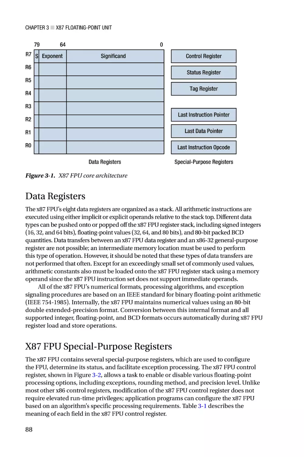
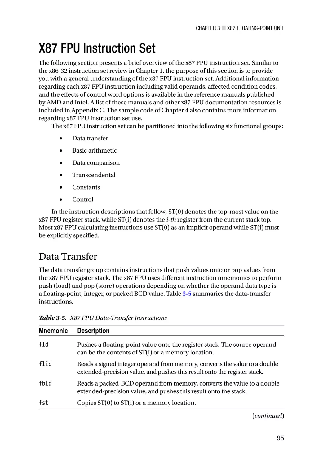
X87 Floating-Point Unit—Chapter 3 surveys the architecture of the x87 floatingpoint unit (FPU) and includes operational descriptions of the x87 FPU’s register stack,
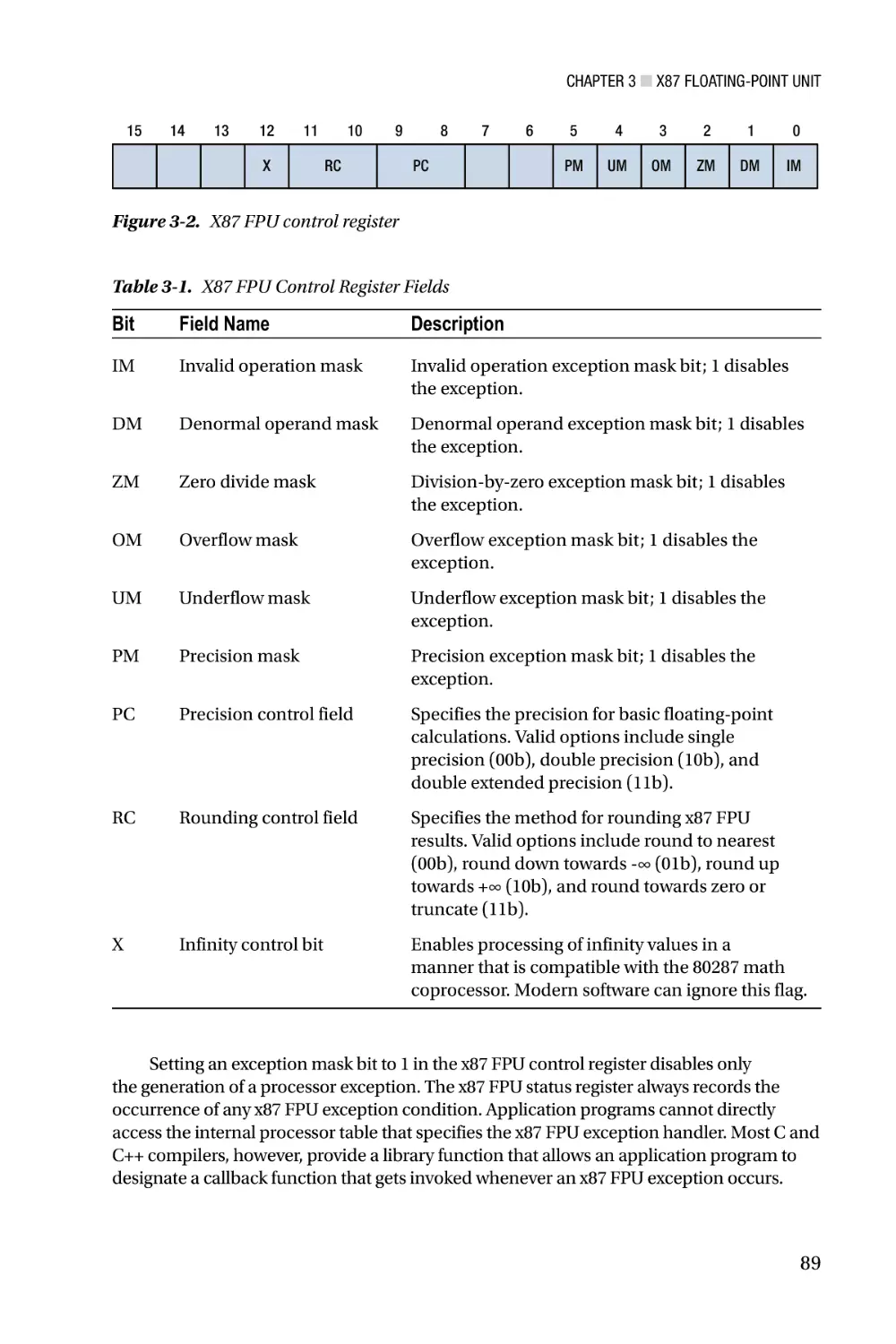
control word register, status word register, and instruction set. This chapter also delves
into the binary encodings that are used to represent floating-point numbers and certain
special values. Chapter 4 contains an assortment of sample code that demonstrates how
to perform floating-point calculations using the x87 FPU instruction set. Readers who
need to maintain an existing x87 FPU code base or are targeting processors that lack the
scalar floating-point capabilities of x86-SSE and x86-AVX (e.g., Intel’s Quark) will benefit
the most from this chapter.
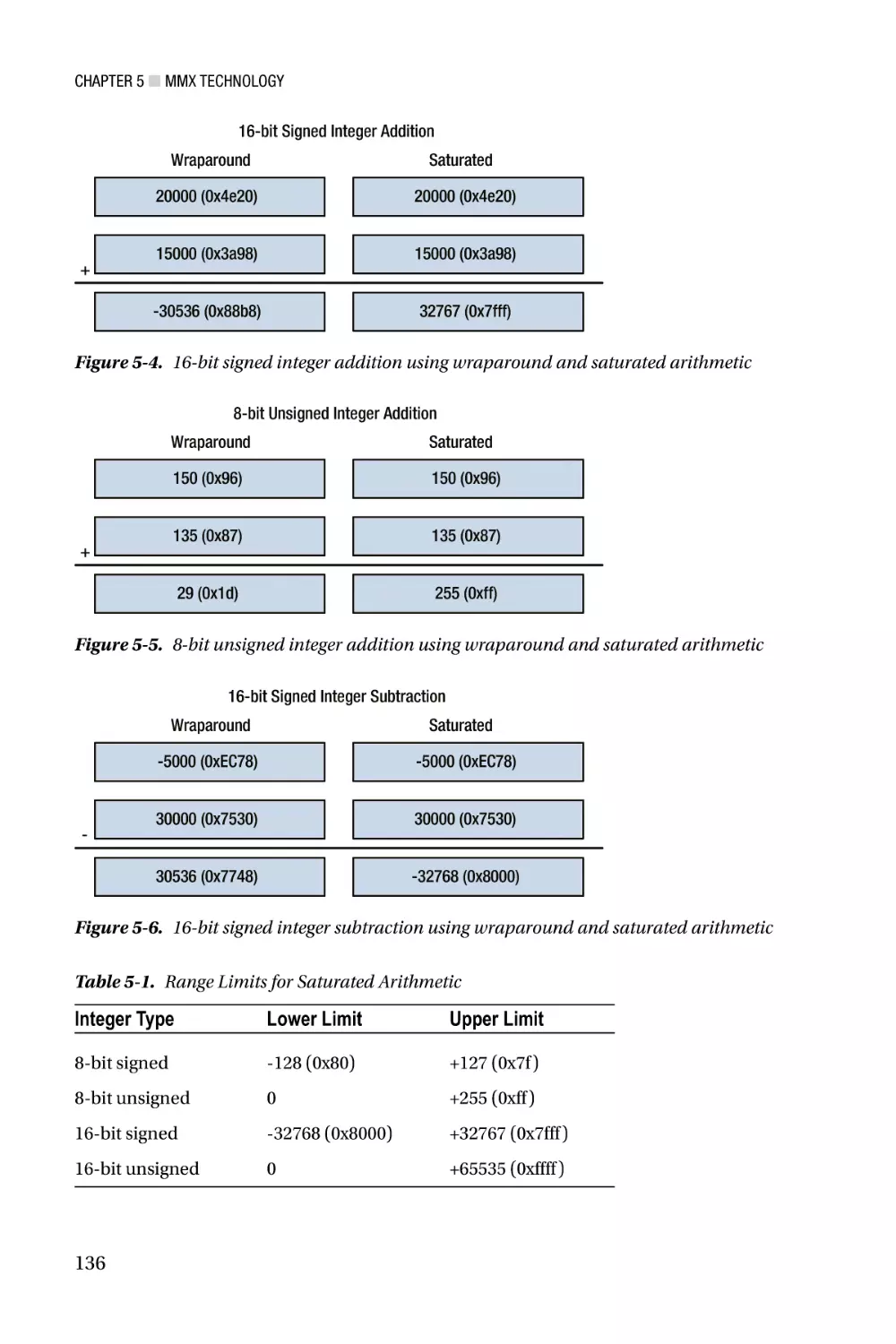
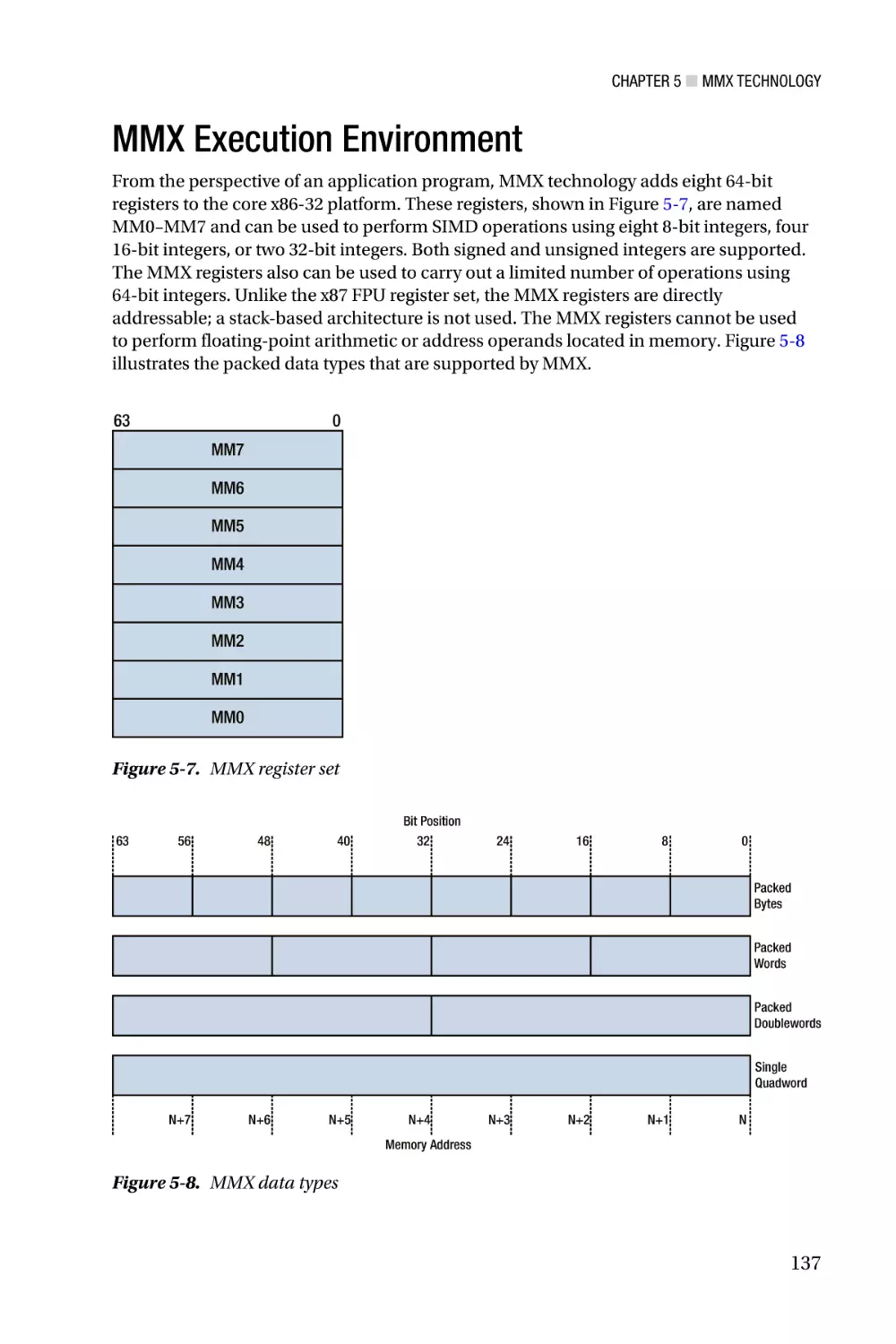
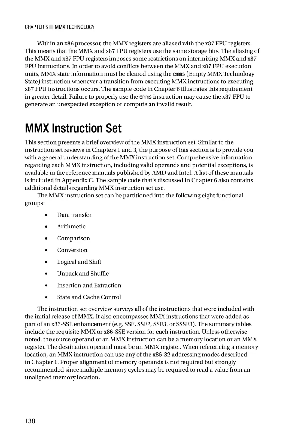
MMX Technology—Chapter 5 describes the x86’s first SIMD extension, which is
called MMX technology. It examines the architecture of MMX technology including its
register set, operand types, and instruction set. This chapter also discusses a number
of related topics, including SIMD processing concepts and the mechanics of packed-
xxvii
■ Introduction
integer arithmetic. Chapter 6 includes sample code that illustrates basic MMX operations,
including packed-integer arithmetic (both wraparound and saturated), integer array
processing, and how to properly handle transitions between MMX and x87 FPU code.
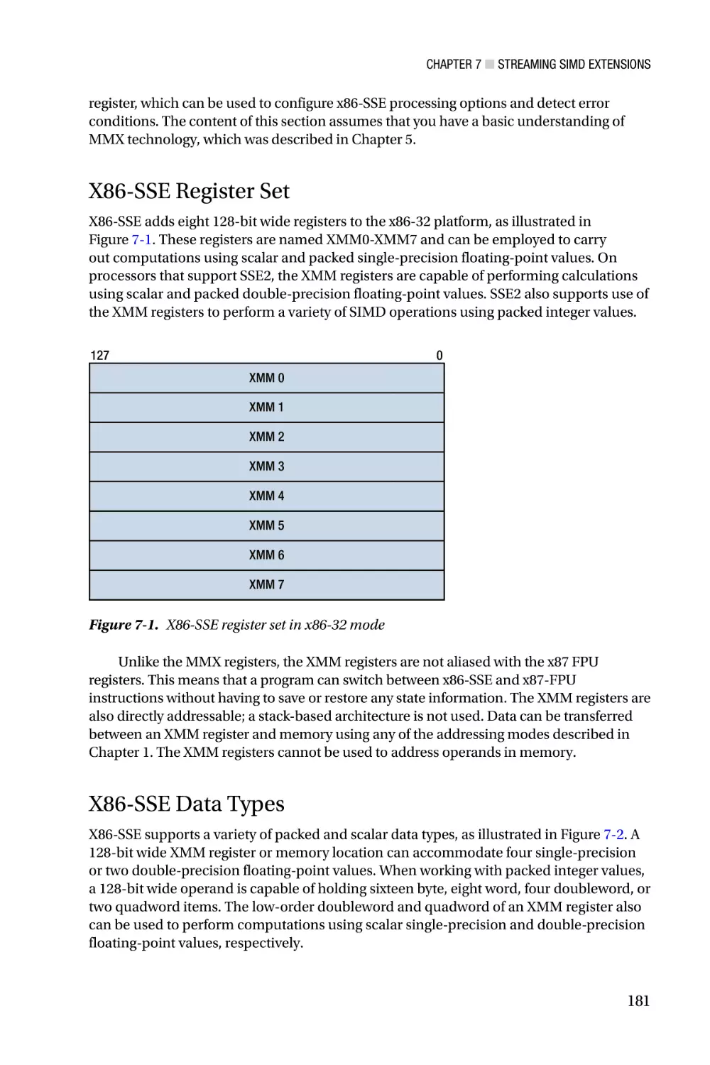
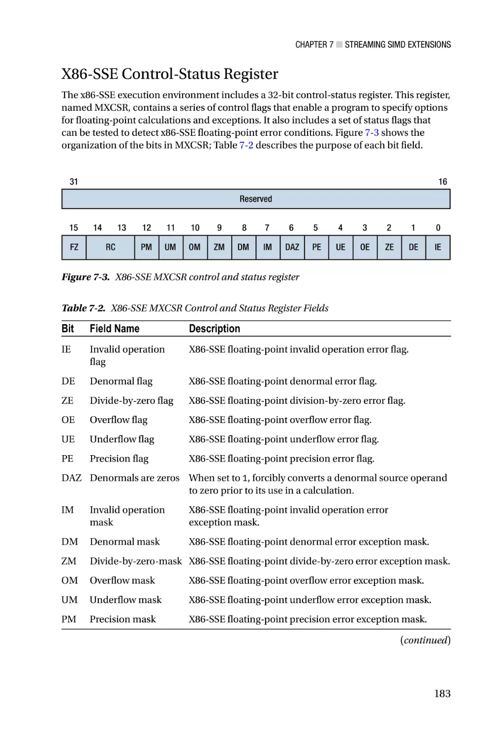
Streaming SIMD Extensions—Chapter 7 focuses on the architecture of Streaming
SIMD Extensions (SSE). X86-SSE adds a new set of 128-bit wide registers to the x86
platform and incorporates several instruction set additions that support computations
using packed integers, packed floating-point (both single and double precision), and text
strings. Chapter 7 also discusses the scalar floating-point capabilities of x86-SSE, which
can be used to both simplify and improve the performance of algorithms that require
scalar floating-point arithmetic. Chapters 8 - 11 contain an extensive collection of sample
code that highlights use of the x86-SSE instruction set. Included in this chapter are several
examples that demonstrate using the packed-integer capabilities of x86-SSE to perform
common image-processing tasks, such as histogram construction and pixel thresholding.
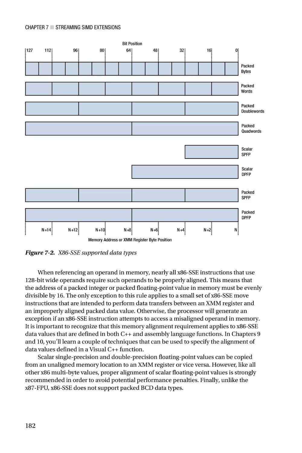
These chapters also include sample code that illustrates how to use the packed floatingpoint, scalar floating-point, and text string-processing instructions of x86-SSE.
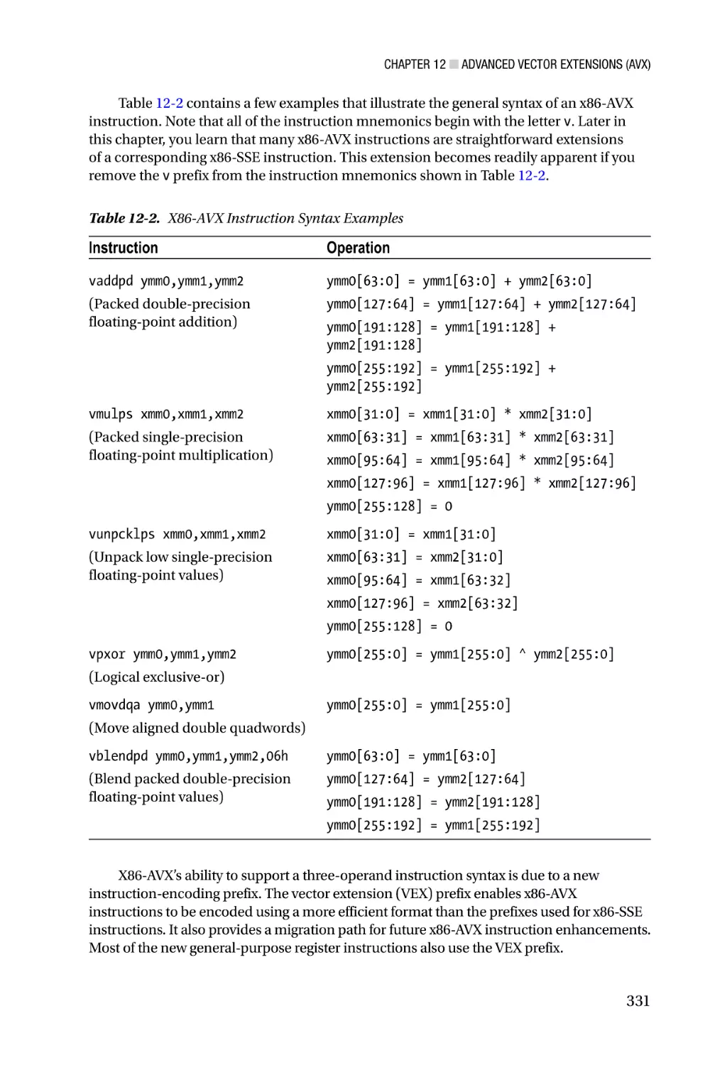
Advanced Vector Extensions—Chapter 12 explores the x86’s most recent SIMD
extension, which is called Advanced Vector Extensions (AVX). This chapter explains the
x86-AVX execution environment, its data types and register sets, and the new threeoperand instruction syntax. It also discusses the data broadcast, gather, and permute
capabilities of x86-AVX along with several x86-AVX concomitant extensions, including
fused-multiply-add (FMA), half-precision floating-point, and new general-purpose
register instructions. Chapters 13 - 16 contain sample code that depicts use of the various
x86-AVX computational resources. Examples include using the x86-AVX instruction set
with packed integers, packed floating-point, and scalar floating-point operands. These
chapters also contain sample code that explicates use of the data broadcast, gather,
permute, and FMA instructions.
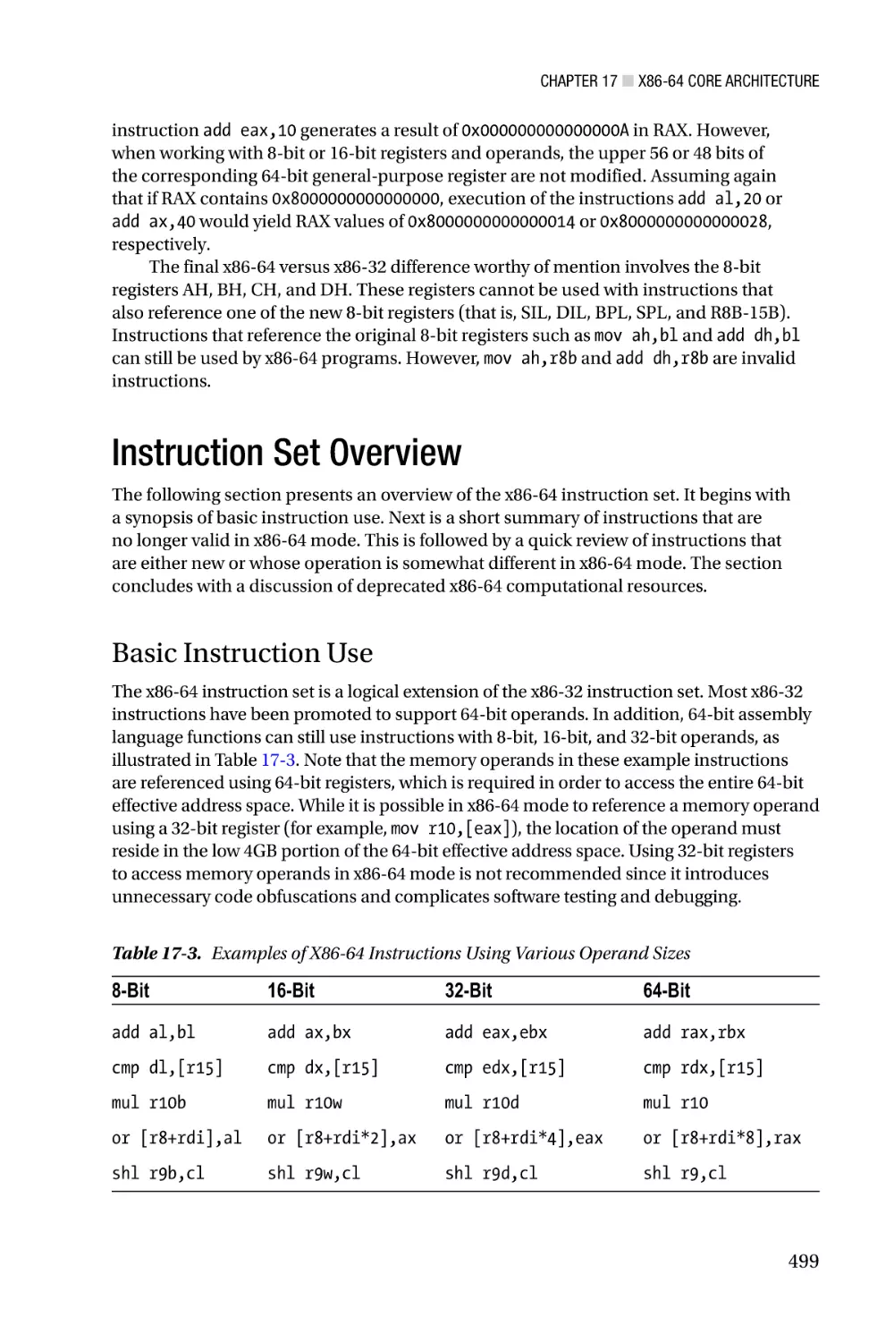
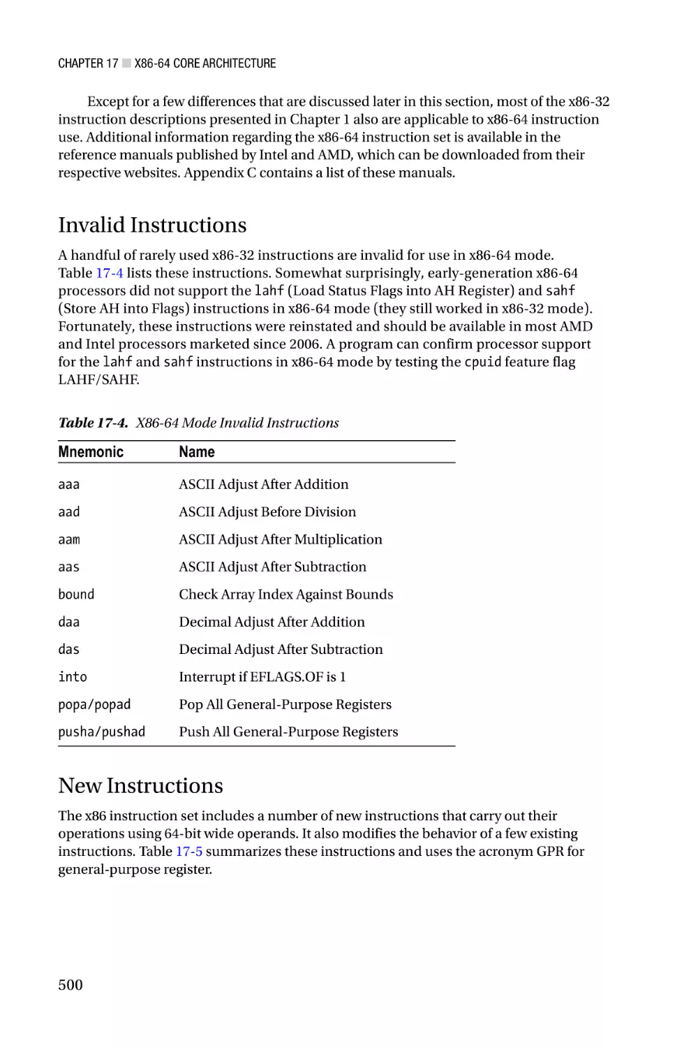
X86-64 Core Architecture—Chapter 17 peruses the x86-64 platform and includes
a discussion of the platform’s core architecture, supported data types, general purpose
registers, and status flags. It also explains the enhancements made to the x86-32 platform
in order to support 64-bit operands and memory addressing. The chapter concludes with
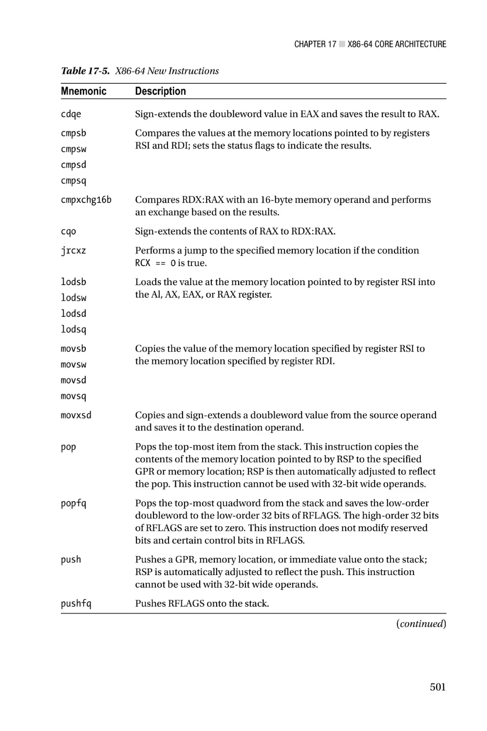
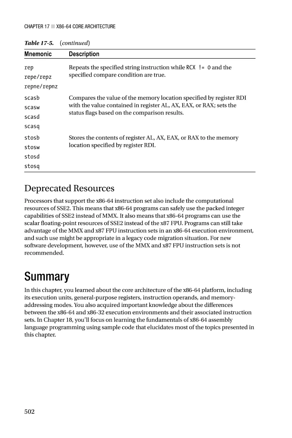
a discussion of the x86-64 instruction set, including those instructions that have been
deprecated or are no longer available. Chapter 18 explores the fundamentals x86-64
assembly language programming using a variety of sample code. Examples include how
to perform integer calculations using operands of various sizes, memory addressing
modes, scalar floating-point arithmetic, and common programming constructs. Chapter
18 also explains the calling convention that must be observed in order to invoke an x86-64
assembly language function from C++.
X86-64 SSE and AVX—Chapter 19 describes the enhancements to x86-SSE and x86AVX that are available on the x86-64 platform. This includes a discussion of the respective
execution environments and extended data register sets. Chapter 20 contains sample
code that highlights use of the x86-SSE and x86-AVX instruction sets with the x86-64 core
architecture.
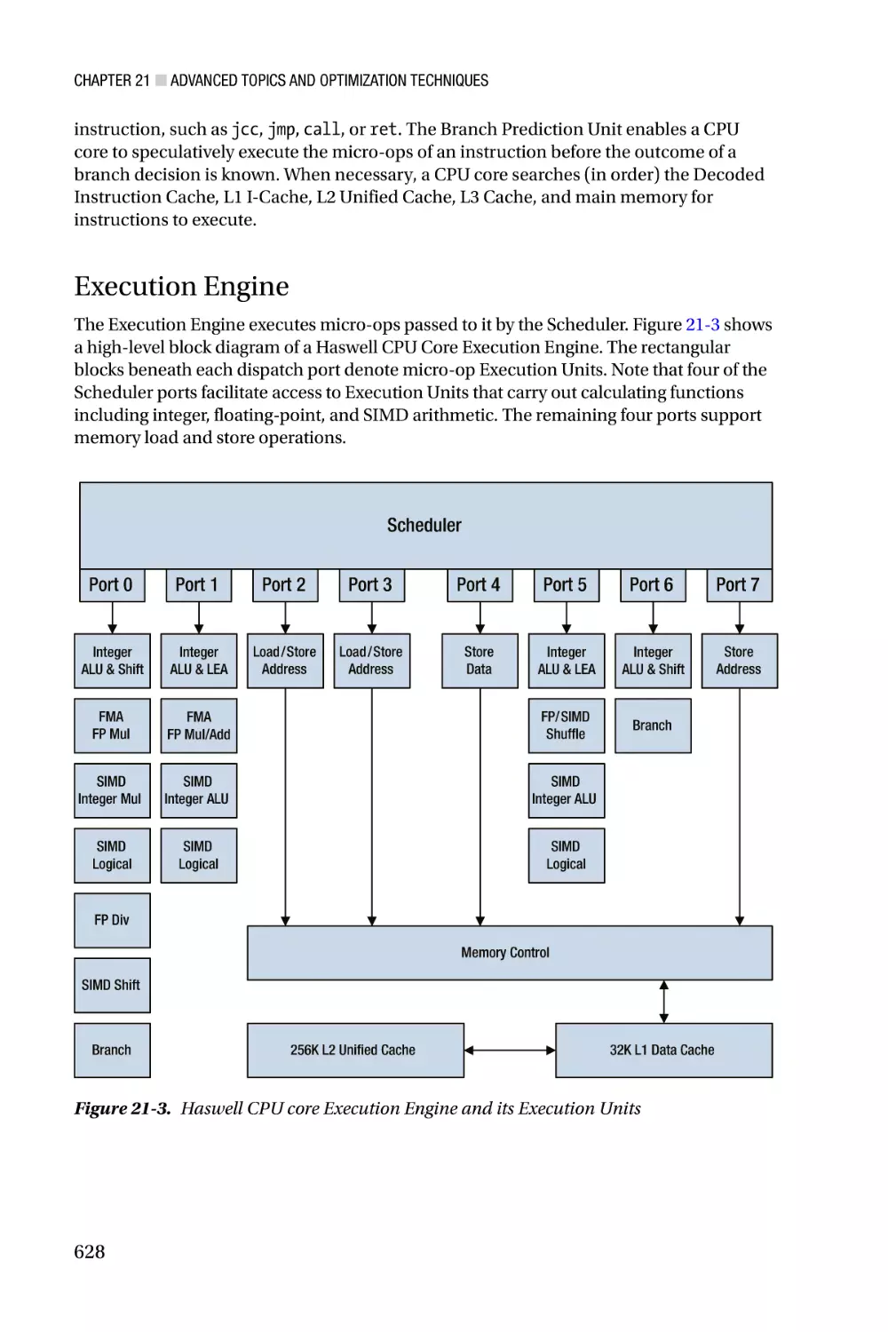
Advanced Topics—The last two chapters of this book consider advanced topics and
optimization techniques related to x86 assembly language programming. Chapter 21
examines key elements of an x86 processor’s microarchitecture, including its front-end
pipelines, out-of-order execution model, and internal execution units. It also includes
a discussion of programming techniques that you can employ to write x86 assembly
xxviii
■ Introduction
language code that is both spatially and temporally efficient. Chapter 22 contains sample
code that illustrates several advanced assembly language programming techniques.
Appendices—The final section of the book includes several appendices. Appendix
A contains a brief tutorial on how to use Microsoft’s Visual C++ and Macro Assembler.
Appendix B summarizes the x86-32 and x86-64 calling conventions that assembly
language functions must observe in order to be invoked from a Visual C++ function.
Appendix C contains a list of references and resources that you can consult for more
information about x86 assembly language programming.
Sample Code Requirements
You can download the sample code for this book from the Apress website at
http://www.apress.com/9781484200650. The following hardware and software is required to
build and run the sample code:
•
A PC with an x86 processor that is based on a recent
microarchitecture. All of the x86-32, x87 FPU, MMX, and
x86-SSE sample code can be executed using a processor based
on the Nehalem (or later) microarchitecture. PCs with processors
based on earlier microarchitectures also can be used to run
many of the sample code programs. The AVX and AXV2 sample
code requires a processor based on the Sandy Bridge or Haswell
microarchitecture, respectively.
•
Microsoft Windows 8.x or Windows 7 with Service Pack 1. A 64-bit
version of Windows is required to run the x86-64 sample code.
•
Visual Studio Professional 2013 or Visual Studio Express
2013 for Windows Desktop. The Express edition can be freely
downloaded from the following Microsoft website: http://msdn.
microsoft.com/en-us/vstudio. Update 3 is recommended for both
Visual Studio editions.
■■Caution The primary purpose of the sample code is to elucidate the topics and
technologies presented in this book. Minimal attention is given to important software
engineering concerns such as robust error handling, security risks, numerical stability,
rounding errors, or ill-conditioned functions. You are responsible for addressing these issues
should you decide to use any of the sample code in your own programs.
xxix
■ Introduction
Terminology and Conventions
The following paragraphs define the meaning of common terms and expressions used
throughout this book. A function, subroutine, or procedure is a self-contained unit of
executable code that accepts zero or more arguments, performs an operation, and
optionally returns a value. Functions are typically invoked using the processor’s call
instruction. A thread is the smallest unit of execution that is managed and scheduled by
an operating system. A task or process is a collection of one or more threads that share the
same logical memory space. An application or program is a complete software package
that contains at least one task.
The terms x86-32 and x86-64 are used respectively to describe 32-bit and 64-bit
aspects, resources, or capabilities of a processor; x86 is employed for features that are
common to both 32-bit and 64-bit architectures. The expressions x86-32 mode and
x86-64 mode denote a specific processor execution environment with the primary
difference being the latter mode’s support of 64-bit registers, operands, and memory
addressing. Common capabilities of the x86’s SIMD extensions are described using
the terms x86-SSE for Streaming SIMD Extensions or x86-AVX for Advanced Vector
Extensions. When discussing aspects or instructions of a specific SIMD enhancement, the
original acronyms (e.g., SSE, SSE2, SSE3, SSSE3, SSE4, AVX, and AVX2) are used.
Additional Resources
An extensive set of x86-related documentation is available from both Intel and AMD.
Appendix C lists a number of resources that both aspiring and experienced x86 assembly
language programmers will find useful. Of all the resources listed Appendix C, the
most important tome is Volume 2 of the reference manual entitled Intel 64 and IA-32
Architectures Software Developer’s Manual—Combined Volumes: 1, 2A, 2B, 2C, 3A, 3B and
3C (Order Number: 325462). This volume contains comprehensive information for each
processor instruction, including detailed operational descriptions, lists of valid operands,
affected status flags, and potential exceptions. You are strongly encouraged to consult this
documentation when developing your own x86 assembly language functions in order to
verify correct instruction usage.
xxx
Chapter 1
X86-32 Core Architecture
This chapter examines the x86-32 core architecture from the perspective of an application
program. I begin with a brief historical overview of the x86 platform in order to provide
a frame of reference for subsequent discussions. This is followed by a review of the x86’s
data types, including fundamental, numeric, and packed types. Next, I delve into the
details of the x86-32’s internal architecture, including its execution units, general-purpose
registers, status flags, instruction operands, and memory addressing modes. The chapter
concludes with an overview of the x86-32 instruction set.
Unlike high-level languages such as C and C++, assembly language programming
requires the software developer to comprehend certain architectural aspects of the target
processor before attempting to write any code. The topics discussed in this chapter will
help fulfill this requirement and serve as a foundation for understanding the sample code
presented in Chapter 2. This chapter also provides the base material that is necessary to
understand the x86-64 core architecture, which is discussed in Chapter 17.
Historical Overview
Before you examine the technical details of the core x86-32 platform, a brief history
lesson might be helpful in understanding how the architecture has evolved over the
years. In the review that follows, I focus on the noteworthy processors and architectural
enhancements that have affected how software developers use x86 assembly language.
Readers who are interested in a more comprehensive chronicle of the x86’s lineage
should consult the resources listed in Appendix C.
The original embodiment of the x86-32 platform was the Intel 80386 microprocessor,
which was introduced in 1985. The 80386 extended the architecture of its 16-bit
predecessors to include 32-bit wide registers and data types, flat memory model options,
a 4 GB logical address space, and paged virtual memory. The 80486 processor improved
the performance of the 80386 with the inclusion of on-chip memory caches and optimized
instructions. Unlike the 80386 with its separate 80387 floating-point unit (FPU), most
versions of the 80486 CPU also included an integrated x87 FPU.
Expansion of the x86-32 microarchitectures continued with the introduction of the
first Pentium brand processor in 1993. Known as the P5 microarchitecture, performance
enhancements included a dual-instruction execution pipeline, 64-bit external data
bus, and separate on-chip code and data caches. (A microarchitecture defines the
organization of a processor’s internal components, including its register files, execution
1
Chapter 1 ■ X86-32 Core Architecture
units, instruction pipelines, data buses, and memory caches. Microarchitectures are often
used by multiple processor product lines as described in this section.) Later versions
of the P5 microarchitecture incorporated a new computational resource called MMX
technology, which supports single-instruction multiple-data (SIMD) operations on
packed integers using 64-bit wide registers (1997).
The P6 microarchitecture, first used on the Pentium Pro (1995) and later on
the Pentium II (1997), extended the x86-32 platform using a three-way superscalar
design. This means that the processor is able (on average) to decode, dispatch, and
execute three distinct instructions during each clock cycle. Other P6 augmentations
included support for out-of-order instruction executions, improved branch-prediction
algorithms, and speculative instruction executions. The Pentium III, also based on
the P6 microarchitecture, was launched in 1999 and included a new SIMD technology
called streaming SIMD extensions (SSE). SSE added eight 128-bit wide registers to the
x86-32 platform and instructions that support packed single-precision (32-bit)
floating-point arithmetic.
In 2000 Intel introduced a new microarchitecture called Netburst that included
SSE2, which extended the floating-point capabilities of SSE to cover packed doubleprecision (64-bit) values. SSE2 also incorporated additional instructions that enabled the
128-bit SSE registers to be used for packed integer calculations and scalar floating-point
operations. Processors based on the Netburst architecture included several variations
of the Pentium 4. In 2004 the Netburst microarchitecture was upgraded to include SSE3
and hyper-threading technology. SSE3 adds packed integer and packed floating-point
instructions to the x86 platform while hyper-threading technology parallelizes the
processor’s front-end instruction pipelines in order to improve performance. SSE3-capable
processors include 90 nm (and smaller) versions of the Pentium 4 and the server-oriented
Xeon product lines.
In 2006 Intel launched a new microarchitecture called Core. The Core
microarchitecture included redesigns of many Netburst front-end pipelines and
execution units in order to improve performance and reduce power consumption. It
also incorporated a number of x86-SSE enhancements, including SSSE3 and SSE4.1.
These extensions added new packed integer and packed floating-point instructions
to the platform but no new registers or data types. Processors based on the Core
microarchitecture include CPUs from the Core 2 Duo and Core 2 Quad series and the
Xeon 3000/5000 series.
A microarchitecture called Nehalem followed Core in late 2008. The Nehalem
microarchitecture re-introduced hyper-threading to the x86 platform, which had been
excluded from the Core microarchitecture. It also incorporates SSE4.2. This final x86-SSE
enhancement adds several application-specific accelerator instructions to the x86-SSE
instruction set. SSE4.2 also includes four new instructions that facilitate text-string
processing using the 128-bit wide x86-SSE registers. Processors based on the Nehalem
microarchitecture include first generation Core i3, i5, and i7 CPUs. It also includes CPUs
from the Xeon 3000, 5000, and 7000 series.
In 2011 Intel launched a new microarchitecture called Sandy Bridge. The Sandy
Bridge microarchitecture introduced a new x86 SIMD technology called Advanced Vector
Extensions (AVX). AVX adds packed floating-point operations (both single-precision and
double-precision) using 256-bit wide registers. AVX also supports a new three-operand
instruction syntax, which helps reduce the number of register-to-register data transfers
2
Chapter 1 ■ X86-32 Core Architecture
that a function must perform. Processors based on the Sandy Bridge microarchitecture
include second- and third-generation Core i3, i5, and i7 CPUs along with Xeon series E3,
E5, and E7 CPUs.
In 2013 Intel unveiled its Haswell microarchitecture. Haswell includes AVX2, which
extends AVX to support packed-integer operations using its 256-bit wide registers.
AVX2 also supports enhanced data transfer capabilities with its new set of broadcast,
gather, and permute instructions. Another feature of the Haswell microarchitecture is
its inclusion of fused-multiply-add (FMA) operations. FMA enables software to perform
successive product-sum calculations using a single floating-point rounding operation.
The Haswell microarchitecture also encompasses several new general-purpose register
instructions. Processors based on the Haswell microarchitecture include fourthgeneration Core i3, i5, and i7 CPUs and Xeon E3 (v3) series CPUs.
X86 platform extensions over the past several years have not been limited to SIMD
enhancements. In 2003 AMD introduced its Opteron processor, which extended the x86’s
core architecture from 32 bits to 64 bits. Intel followed suit in 2004 by adding essentially
the same 64-bit extensions to its processors, starting with certain versions of the
Pentium 4. All Intel processors based on the Core, Nehalem, Sandy Bridge, and Haswell
microarchitectures support the x86-64 execution environment.
Intel has also introduced several specialized microarchitectures that have been
optimized for specific applications. The first of these is called Bonnell and was the basis
for the original Atom processor in 2008. Atom processors built on this microarchitecture
included support for SSSE3. In 2013 Intel introduced its Silvermont System on a Chip
(SoC) microarchitecture, which is optimized for portable devices such as smartphones
and tablet PCs. The Silvermont microarchitecture is also used in processors that are
tailored for small servers, storage devices, network communications equipment, and
embedded systems. Processors based on the Silvermont microarchitecture include
SSE4.2 but lack x86-AVX. In 2013 Intel also introduced an ultra-low power SoC
microarchitecture called Quark, which targets Internet-of-Things (IoT) and wearable
computing devices. Processors based on the Quark microarchitecture only support
the core x86-32 and x87 FPU instruction sets; they do not include x86-64 processing
capabilities or any of the SIMD resources provided by MMX, x86-SSE, and x86-AVX.
Processors from AMD have also evolved over the past few years. In 2003 AMD
introduced a series of processors based on its K8 microarchitecture. Original versions
of the K8 included support for MMX, SSE, and SSE2, while later versions added SSE3.
In 2007 the K10 microarchitecture was launched and included a SIMD enhancement
called SSE4a. SSE4a contains several mask shift and streaming store instructions
that are not available on processors from Intel. Following the K10, AMD introduced
a new microarchitecture called Bulldozer in 2011. The Bulldozer microarchitecture
includes SSSE3, SSE4.1, SSE4.2, SSE4a, and AVX. It also adds FMA4, which is a fouroperand version of fused-multiply-add. Like SSE4a, FMA4 is not available on Intel from
processors. A 2012 update to the Bulldozer microarchitecture called Piledriver includes
support for both FMA4 and the three-operand version of FMA, which is called FMA3 by
some CPU feature-detection utilities and third-party documentation sources.
3
Chapter 1 ■ X86-32 Core Architecture
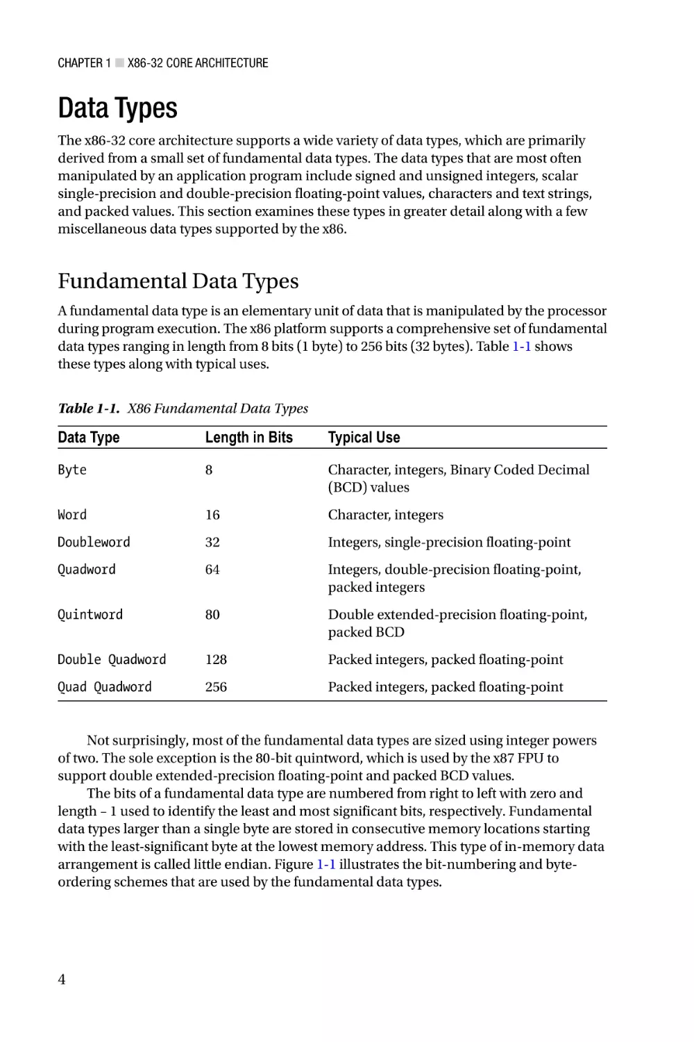
Data Types
The x86-32 core architecture supports a wide variety of data types, which are primarily
derived from a small set of fundamental data types. The data types that are most often
manipulated by an application program include signed and unsigned integers, scalar
single-precision and double-precision floating-point values, characters and text strings,
and packed values. This section examines these types in greater detail along with a few
miscellaneous data types supported by the x86.
Fundamental Data Types
A fundamental data type is an elementary unit of data that is manipulated by the processor
during program execution. The x86 platform supports a comprehensive set of fundamental
data types ranging in length from 8 bits (1 byte) to 256 bits (32 bytes). Table 1-1 shows
these types along with typical uses.
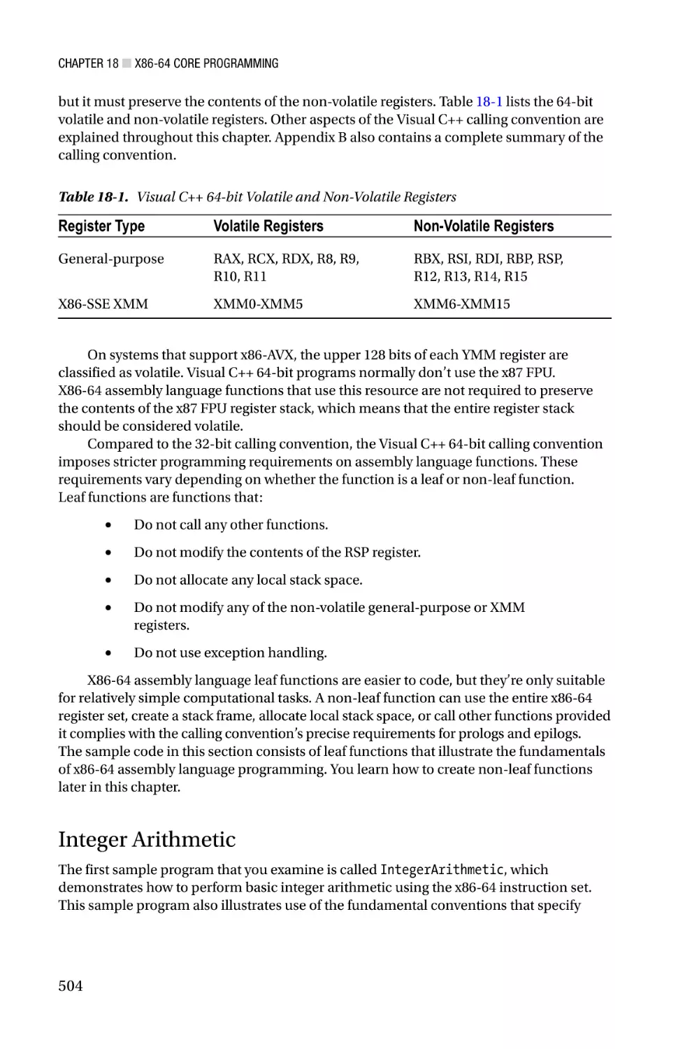
Table 1-1. X86 Fundamental Data Types
Data Type
Length in Bits
Typical Use
Byte
8
Character, integers, Binary Coded Decimal
(BCD) values
Word
16
Character, integers
Doubleword
32
Integers, single-precision floating-point
Quadword
64
Integers, double-precision floating-point,
packed integers
Quintword
80
Double extended-precision floating-point,
packed BCD
Double Quadword
128
Packed integers, packed floating-point
Quad Quadword
256
Packed integers, packed floating-point
Not surprisingly, most of the fundamental data types are sized using integer powers
of two. The sole exception is the 80-bit quintword, which is used by the x87 FPU to
support double extended-precision floating-point and packed BCD values.
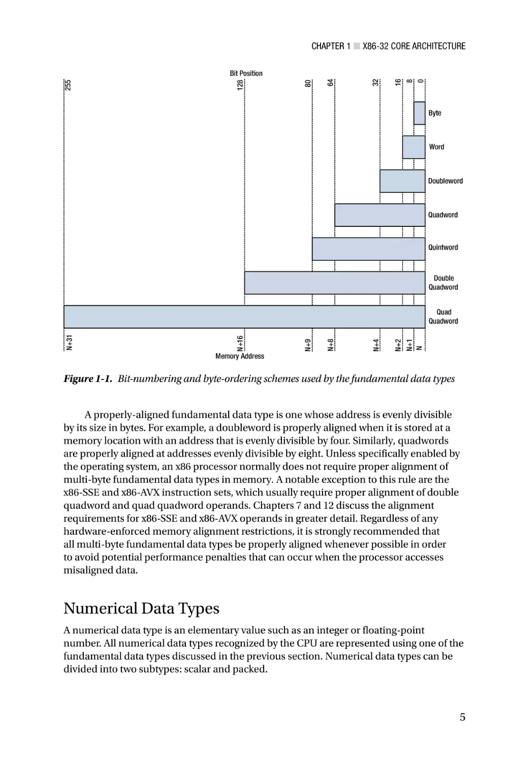
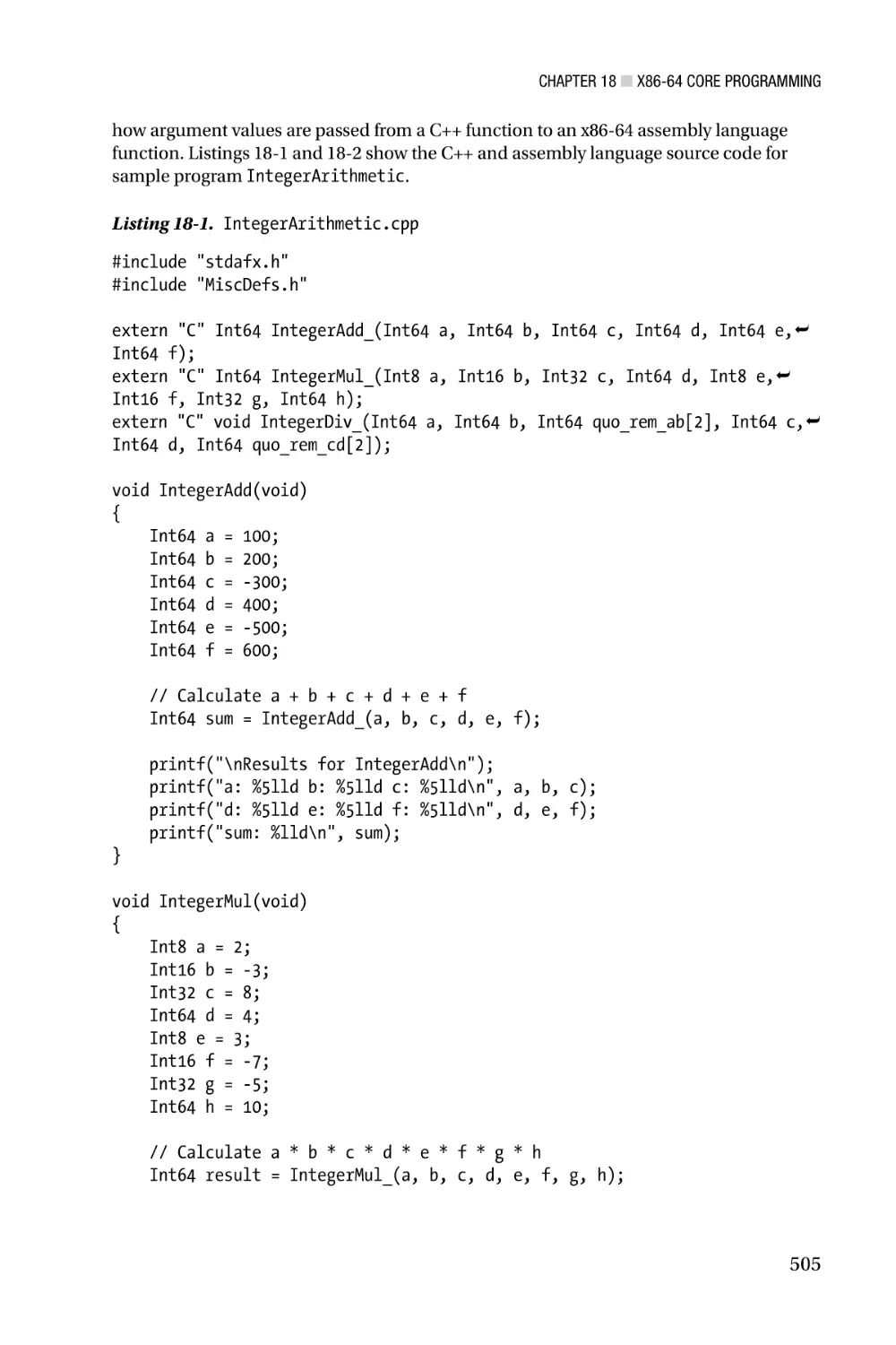
The bits of a fundamental data type are numbered from right to left with zero and
length – 1 used to identify the least and most significant bits, respectively. Fundamental
data types larger than a single byte are stored in consecutive memory locations starting
with the least-significant byte at the lowest memory address. This type of in-memory data
arrangement is called little endian. Figure 1-1 illustrates the bit-numbering and byteordering schemes that are used by the fundamental data types.
4
Chapter 1 ■ X86-32 Core Architecture
8
0
16
32
64
80
128
255
Bit Position
Byte
Word
Doubleword
Quadword
Quintword
Double
Quadword
N+1
N
N+2
N+8
N+4
Memory Address
N+9
N+16
N+31
Quad
Quadword
Figure 1-1. Bit-numbering and byte-ordering schemes used by the fundamental data types
A properly-aligned fundamental data type is one whose address is evenly divisible
by its size in bytes. For example, a doubleword is properly aligned when it is stored at a
memory location with an address that is evenly divisible by four. Similarly, quadwords
are properly aligned at addresses evenly divisible by eight. Unless specifically enabled by
the operating system, an x86 processor normally does not require proper alignment of
multi-byte fundamental data types in memory. A notable exception to this rule are the
x86-SSE and x86-AVX instruction sets, which usually require proper alignment of double
quadword and quad quadword operands. Chapters 7 and 12 discuss the alignment
requirements for x86-SSE and x86-AVX operands in greater detail. Regardless of any
hardware-enforced memory alignment restrictions, it is strongly recommended that
all multi-byte fundamental data types be properly aligned whenever possible in order
to avoid potential performance penalties that can occur when the processor accesses
misaligned data.
Numerical Data Types
A numerical data type is an elementary value such as an integer or floating-point
number. All numerical data types recognized by the CPU are represented using one of the
fundamental data types discussed in the previous section. Numerical data types can be
divided into two subtypes: scalar and packed.
5
Chapter 1 ■ X86-32 Core Architecture
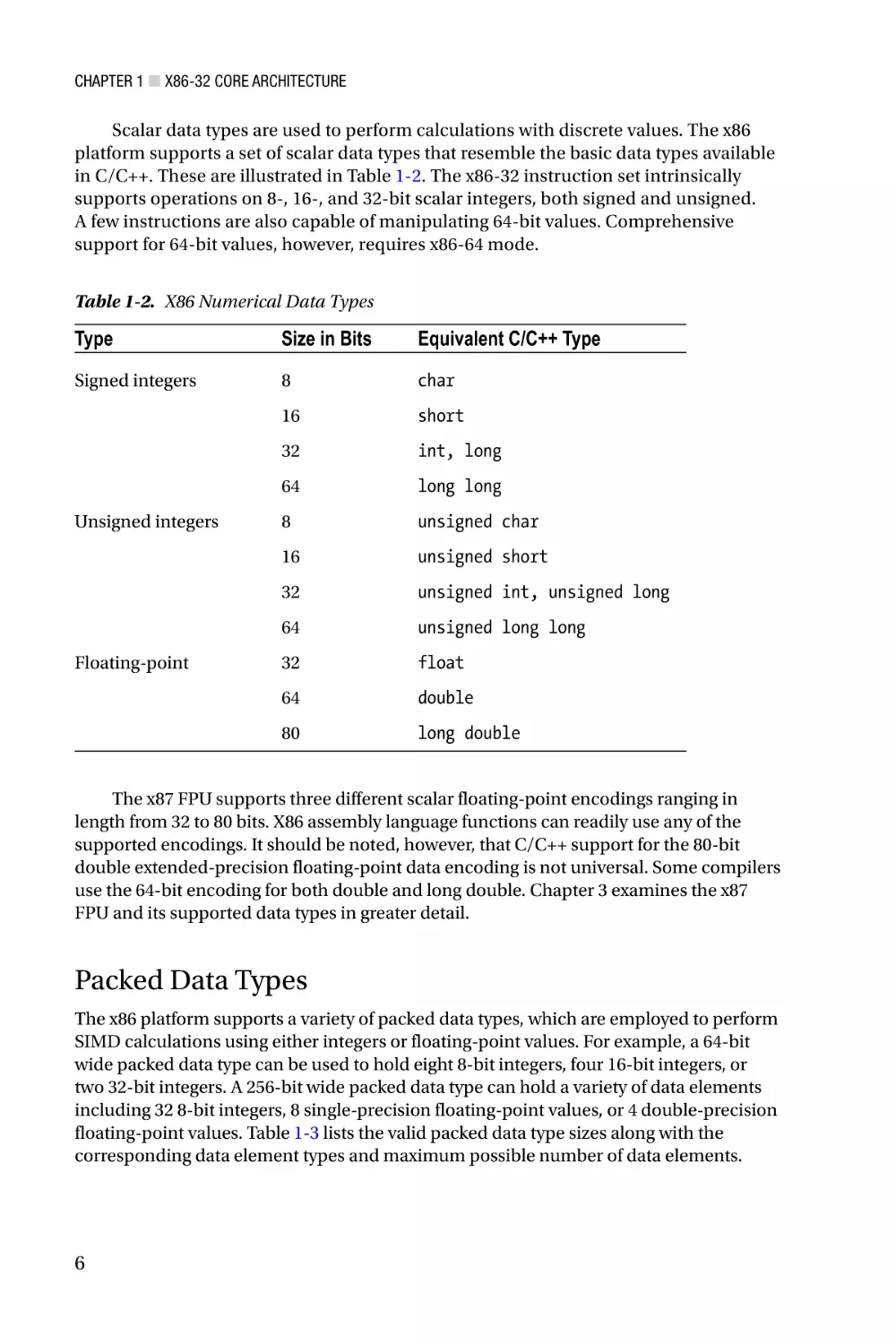
Scalar data types are used to perform calculations with discrete values. The x86
platform supports a set of scalar data types that resemble the basic data types available
in C/C++. These are illustrated in Table 1-2. The x86-32 instruction set intrinsically
supports operations on 8-, 16-, and 32-bit scalar integers, both signed and unsigned.
A few instructions are also capable of manipulating 64-bit values. Comprehensive
support for 64-bit values, however, requires x86-64 mode.
Table 1-2. X86 Numerical Data Types
Type
Size in Bits
Equivalent C/C++ Type
Signed integers
8
char
16
short
32
int, long
64
long long
8
unsigned char
16
unsigned short
32
unsigned int, unsigned long
64
unsigned long long
32
float
64
double
80
long double
Unsigned integers
Floating-point
The x87 FPU supports three different scalar floating-point encodings ranging in
length from 32 to 80 bits. X86 assembly language functions can readily use any of the
supported encodings. It should be noted, however, that C/C++ support for the 80-bit
double extended-precision floating-point data encoding is not universal. Some compilers
use the 64-bit encoding for both double and long double. Chapter 3 examines the x87
FPU and its supported data types in greater detail.
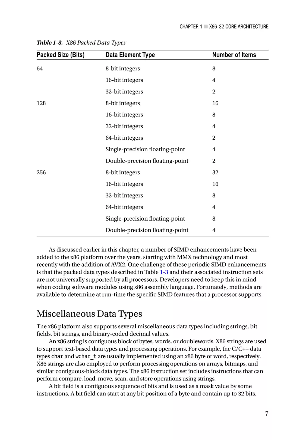
Packed Data Types
The x86 platform supports a variety of packed data types, which are employed to perform
SIMD calculations using either integers or floating-point values. For example, a 64-bit
wide packed data type can be used to hold eight 8-bit integers, four 16-bit integers, or
two 32-bit integers. A 256-bit wide packed data type can hold a variety of data elements
including 32 8-bit integers, 8 single-precision floating-point values, or 4 double-precision
floating-point values. Table 1-3 lists the valid packed data type sizes along with the
corresponding data element types and maximum possible number of data elements.
6
Chapter 1 ■ X86-32 Core Architecture
Table 1-3. X86 Packed Data Types
Packed Size (Bits)
Data Element Type
Number of Items
64
8-bit integers
8
16-bit integers
4
32-bit integers
2
8-bit integers
16
16-bit integers
8
32-bit integers
4
64-bit integers
2
Single-precision floating-point
4
Double-precision floating-point
2
8-bit integers
32
16-bit integers
16
32-bit integers
8
64-bit integers
4
Single-precision floating-point
8
Double-precision floating-point
4
128
256
As discussed earlier in this chapter, a number of SIMD enhancements have been
added to the x86 platform over the years, starting with MMX technology and most
recently with the addition of AVX2. One challenge of these periodic SIMD enhancements
is that the packed data types described in Table 1-3 and their associated instruction sets
are not universally supported by all processors. Developers need to keep this in mind
when coding software modules using x86 assembly language. Fortunately, methods are
available to determine at run-time the specific SIMD features that a processor supports.
Miscellaneous Data Types
The x86 platform also supports several miscellaneous data types including strings, bit
fields, bit strings, and binary-coded decimal values.
An x86 string is contiguous block of bytes, words, or doublewords. X86 strings are used
to support text-based data types and processing operations. For example, the C/C++ data
types char and wchar_t are usually implemented using an x86 byte or word, respectively.
X86 strings are also employed to perform processing operations on arrays, bitmaps, and
similar contiguous-block data types. The x86 instruction set includes instructions that can
perform compare, load, move, scan, and store operations using strings.
A bit field is a contiguous sequence of bits and is used as a mask value by some
instructions. A bit field can start at any bit position of a byte and contain up to 32 bits.
7
Chapter 1 ■ X86-32 Core Architecture
A bit string is a contiguous sequence of bits containing up to 2^32 – 1 bits. The x86
instruction set includes instructions that can clear, set, scan, and test individual bits
within a bit string.
Finally, a binary-coded-decimal (BCD) type is a representation of a decimal digit
(0 – 9) using a 4-bit unsigned integer. The x86-32 instruction set includes instructions
that perform basic arithmetic using packed (two BCD digits per byte) and unpacked
(one BCD digit per byte) BCD values. The x87 FPU is also capable of loading and storing
80-bit packed BCD values to and from memory.
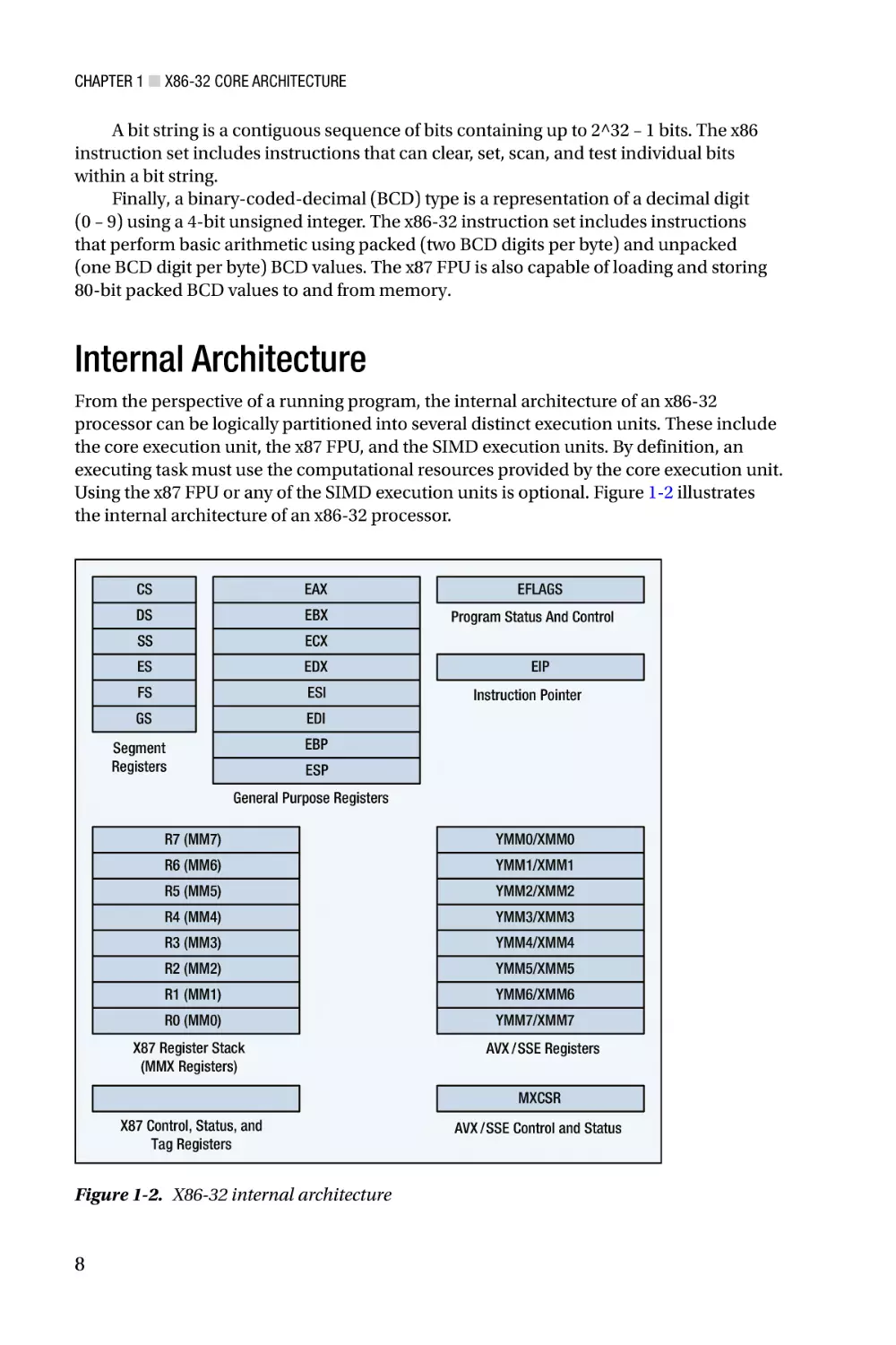
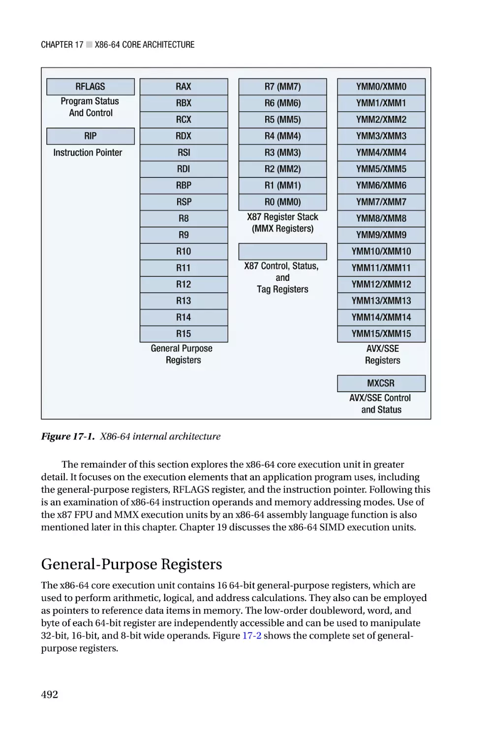
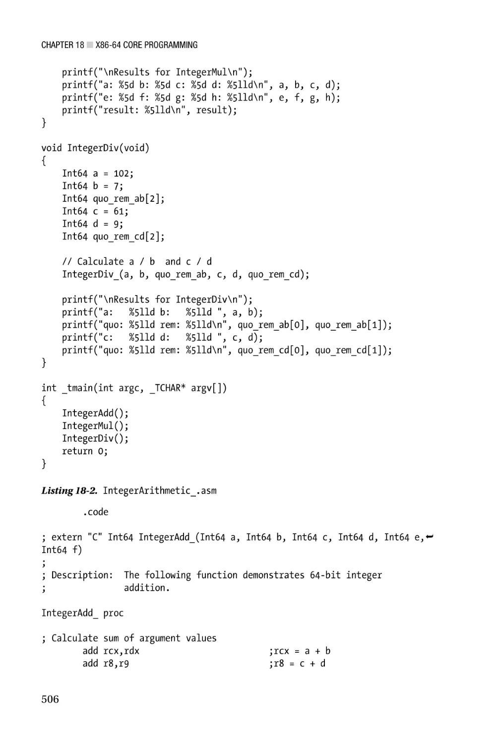
Internal Architecture
From the perspective of a running program, the internal architecture of an x86-32
processor can be logically partitioned into several distinct execution units. These include
the core execution unit, the x87 FPU, and the SIMD execution units. By definition, an
executing task must use the computational resources provided by the core execution unit.
Using the x87 FPU or any of the SIMD execution units is optional. Figure 1-2 illustrates
the internal architecture of an x86-32 processor.
CS
EAX
DS
EBX
SS
ECX
ES
EDX
FS
ESI
GS
EDI
EFLAGS
Program Status And Control
EIP
Instruction Pointer
EBP
Segment
Registers
ESP
General Purpose Registers
R7 (MM7)
YMM0/XMM0
R6 (MM6)
YMM1/XMM1
R5 (MM5)
YMM2/XMM2
R4 (MM4)
YMM3/XMM3
R3 (MM3)
YMM4/XMM4
R2 (MM2)
YMM5/XMM5
R1 (MM1)
YMM6/XMM6
R0 (MM0)
X87 Register Stack
(MMX Registers)
YMM7/XMM7
AVX /SSE Registers
MXCSR
X87 Control, Status, and
Tag Registers
Figure 1-2. X86-32 internal architecture
8
AVX /SSE Control and Status
Chapter 1 ■ X86-32 Core Architecture
The remainder of this section examines the x86-32 core execution unit in greater
detail. It starts an exploration of the unit’s register sets, including its segment registers,
general-purpose registers, status flags register, and instruction pointer. This is followed
by a discussion of instruction operands and memory addressing modes. The remaining
execution units are examined later in this book. Chapter 3 explores the internal
architecture of the x87 FPU, while Chapters 5, 7, and 12 delve into the architectural
intricacies of MMX, x86-SSE, and x86-AVX, respectively.
Segment Registers
The x86-32 core execution unit uses segment registers to define a logical memory model
for program execution and data storage. An x86 processor contains six segment registers
that designate blocks of memory for code, data, and stack space. When operating in
x86-32 protected mode, a segment register contains a segment selector, which is used
as an index into a segment descriptor table that defines the segment’s operational
characteristics. A segment’s operational characteristics include its size, type (code or
data), and access rights (read or write). Segment register initialization and management
is normally handled by the operating system. Most x86-32 application programs are
written without any direct knowledge of how the segment registers are programmed.
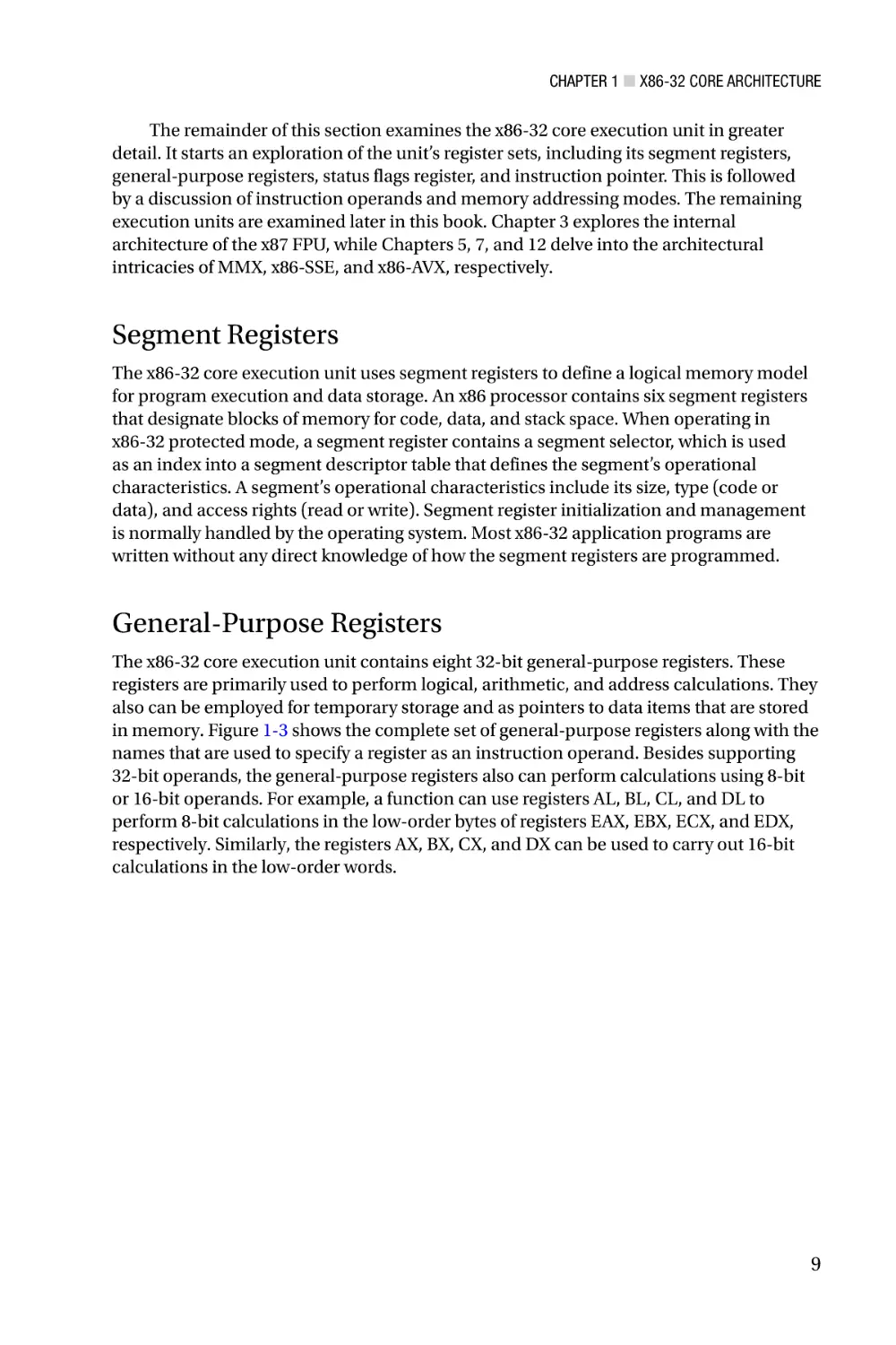
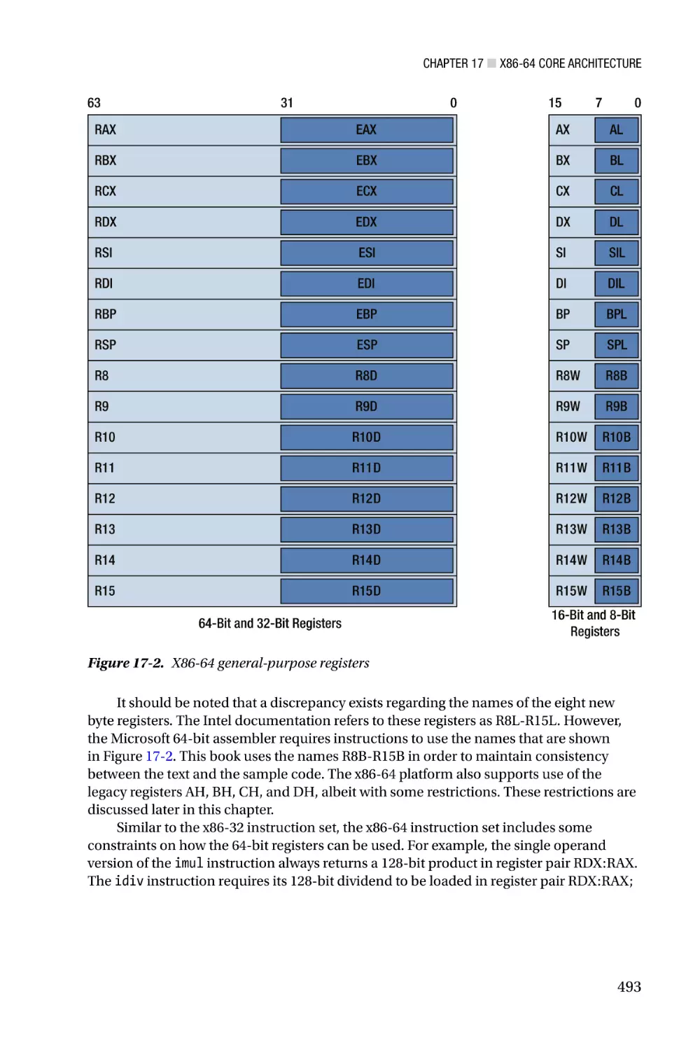
General-Purpose Registers
The x86-32 core execution unit contains eight 32-bit general-purpose registers. These
registers are primarily used to perform logical, arithmetic, and address calculations. They
also can be employed for temporary storage and as pointers to data items that are stored
in memory. Figure 1-3 shows the complete set of general-purpose registers along with the
names that are used to specify a register as an instruction operand. Besides supporting
32-bit operands, the general-purpose registers also can perform calculations using 8-bit
or 16-bit operands. For example, a function can use registers AL, BL, CL, and DL to
perform 8-bit calculations in the low-order bytes of registers EAX, EBX, ECX, and EDX,
respectively. Similarly, the registers AX, BX, CX, and DX can be used to carry out 16-bit
calculations in the low-order words.
9
Chapter 1 ■ X86-32 Core Architecture
31
0
15
EAX
AH
EBX
BH
ECX
CH
EDX
DH
8 7
AX
BX
CX
DX
0
AL
BL
CL
DL
ESI
SI
EDI
DI
EBP
BP
ESP
SP
32-Bit Registers
8-Bit and 16-Bit
Registers
Figure 1-3. X86-32 general-purpose registers
Despite their designation as general-purpose registers, the x86-32 instruction set
imposes some noteworthy restrictions on how they can be used. Many instructions either
require or implicitly use specific registers as operands. For example, some variations of
the imul (Signed Multiply) and idiv (Signed Divide) instructions use the EDX register to
hold the high-order doubleword of a product or dividend. The string instructions require
that the addresses of the source and destination operands be placed in the ESI and EDI
registers, respectively. String instructions that include a repeat prefix must use ECX as
the count register, while variable bit shift and rotate instructions must load the bit count
value into the CL register.
The processor uses the ESP register to support stack-related operations such as
function calls and returns. The stack itself is simply a contiguous block of memory that
is assigned to a process or thread by the operating system. Application programs can
also use the stack to pass function arguments and store temporary data. Register ESP
always points to the stack’s top-most item. While it is possible to use the ESP register as a
general-purpose register, such use is impractical and strongly discouraged. Register EBP
is typically used as a base pointer to access data items that are stored on the stack (ESP
can also be used as a base pointer to access data items on the stack). When not employed
as a base pointer, EBP can be used as a general-purpose register.
The mandatory or implicit use of specific registers by some instructions is a legacy
design pattern that dates back to the 8086, ostensibly to improve code density. What this
means from a modern programing perspective is that certain register usage conventions
tend be observed when writing x86-32 assembly code. Table 1-4 lists the general-purpose
registers and their conventional uses.
10
Chapter 1 ■ X86-32 Core Architecture
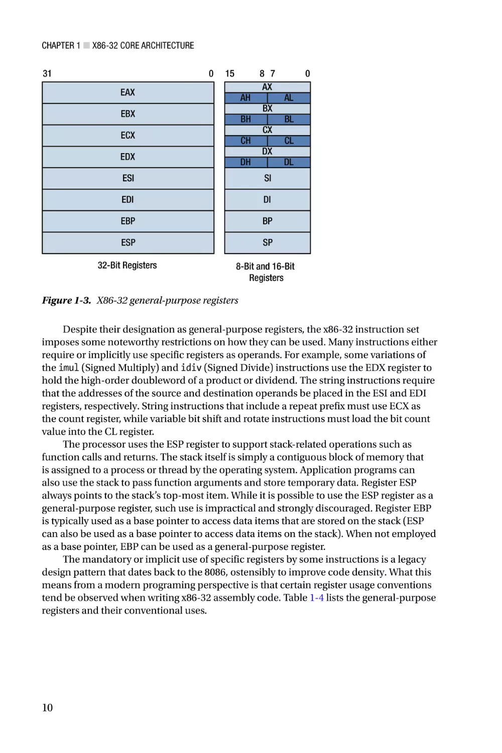
Table 1-4. Conventional Uses for General-Purpose Registers
Register
Conventional Use
EAX
Accumulator
EBX
Memory pointer, base register
ECX
Loop control, counter
EDX
Integer multiplication, integer division
ESI
String instruction source pointer, index register
EDI
String instruction destination pointer, index register
ESP
Stack pointer
EBP
Stack frame base pointer
A couple of items to note: The usage conventions shown in Table 1-4 are common
practices, but are not compulsory. The x86-32 instruction set does not, for example,
prevent an executing task from using the ECX register as a memory pointer despite
its conventional use as a counter. Also, x86 assemblers do not enforce these usage
conventions. Given the limited number general-purpose registers available in x86-32
mode, it is frequently necessary to use a general-purpose register in a non-conventional
manner. Finally, it should be noted that the usage conventions outlined in Table 1-4
are not the same as a calling convention defined by a high-level language such as C++.
Calling conventions must be observed and are discussed further in Chapter 2.
EFLAGS Register
The EFLAGS register contains a series of status bits that the processor uses to indicate the
results of logical and arithmetic operations. It also contains a collection of system control
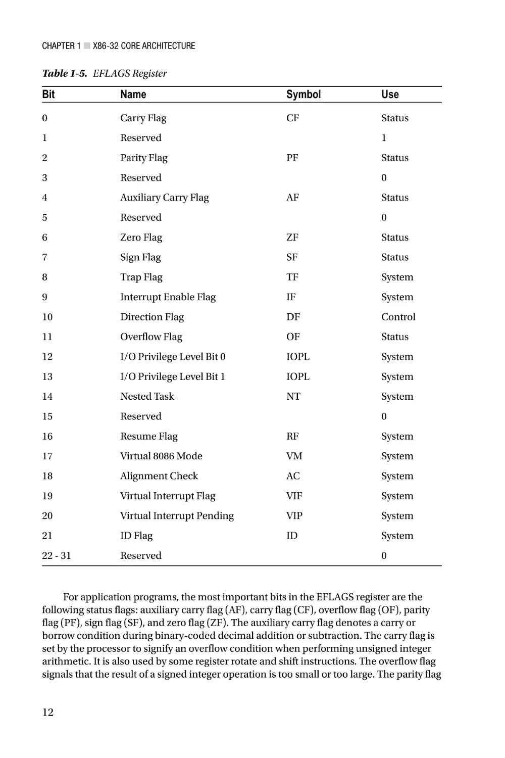
bits that are primarily used by operating systems. Table 1-5 shows the organization of the
bits in the EFLAGS register.
11
Chapter 1 ■ X86-32 Core Architecture
Table 1-5. EFLAGS Register
Bit
Name
Symbol
Use
0
Carry Flag
CF
Status
1
Reserved
2
Parity Flag
3
Reserved
4
Auxiliary Carry Flag
5
Reserved
6
Zero Flag
ZF
Status
7
Sign Flag
SF
Status
8
Trap Flag
TF
System
9
Interrupt Enable Flag
IF
System
10
Direction Flag
DF
Control
11
Overflow Flag
OF
Status
12
I/O Privilege Level Bit 0
IOPL
System
13
I/O Privilege Level Bit 1
IOPL
System
14
Nested Task
NT
System
15
Reserved
16
Resume Flag
RF
System
17
Virtual 8086 Mode
VM
System
18
Alignment Check
AC
System
19
Virtual Interrupt Flag
VIF
System
20
Virtual Interrupt Pending
VIP
System
21
ID Flag
ID
System
22 - 31
Reserved
1
PF
Status
0
AF
Status
0
0
0
For application programs, the most important bits in the EFLAGS register are the
following status flags: auxiliary carry flag (AF), carry flag (CF), overflow flag (OF), parity
flag (PF), sign flag (SF), and zero flag (ZF). The auxiliary carry flag denotes a carry or
borrow condition during binary-coded decimal addition or subtraction. The carry flag is
set by the processor to signify an overflow condition when performing unsigned integer
arithmetic. It is also used by some register rotate and shift instructions. The overflow flag
signals that the result of a signed integer operation is too small or too large. The parity flag
12
Chapter 1 ■ X86-32 Core Architecture
indicates whether the least-significant byte of a result contains an even number of 1 bits.
The sign and zero flags are set by logical and arithmetic instructions to signify a negative,
zero, or positive result.
The EFLAGS register also contains a control bit called the direction flag (DF). An
application program can set or reset the direction flag, which defines the auto increment
direction (0 = low-to-high addresses, 1 = high-to-low addresses) of the EDI and ESI
registers during execution of the string instructions. The remaining bits in the EFLAGS
register are used exclusively by the operating system to manage interrupts, restrict I/O
operations, and support program debugging. They should never be modified by an
application program. Reserved bits should also never be modified and no assumptions
should ever be made regarding the state of any reserved bit.
Instruction Pointer
The instruction pointer register (EIP) contains the offset of the next instruction to be
executed. The EIP register is implicitly manipulated by control-transfer instructions.
For example, the call (Call Procedure) instruction pushes the contents of the EIP register
onto the stack and transfers program control to the address designated by the specified
operand. The ret (Return from Procedure) instruction transfers program control by
popping the top-most item off the stack into the EIP register.
The jmp (Jump) and jcc (Jump if Condition is Met) instructions also transfer program
control by modifying the contents of the EIP register. Unlike the call and ret instructions,
all x86-32 jump instructions are executed independent of the stack. It should also be noted
that it is not possible for an executing task to directly access the EIP register.
Instruction Operands
Most x86-32 instructions use operands, which designate the specific values that an
instruction will act upon. Nearly all instructions require one or more source operands
along with a single destination operand. Most instructions also require the programmer
to explicitly specify the source and destination operands. There are, however, a number of
instructions where the operands are either implicitly specified or forced by the instruction.
There are three basic types of operands: immediate, register, and memory. An
immediate operand is a constant value that is encoded as part of the instruction. These
are typically used to specify constant arithmetic, logical, or offset values. Only source
operands can be used as immediate operands. Register operands are contained in a
general-purpose register. A memory operand specifies a location in memory, which can
contain any of the data types described earlier in this chapter. An instruction can specify
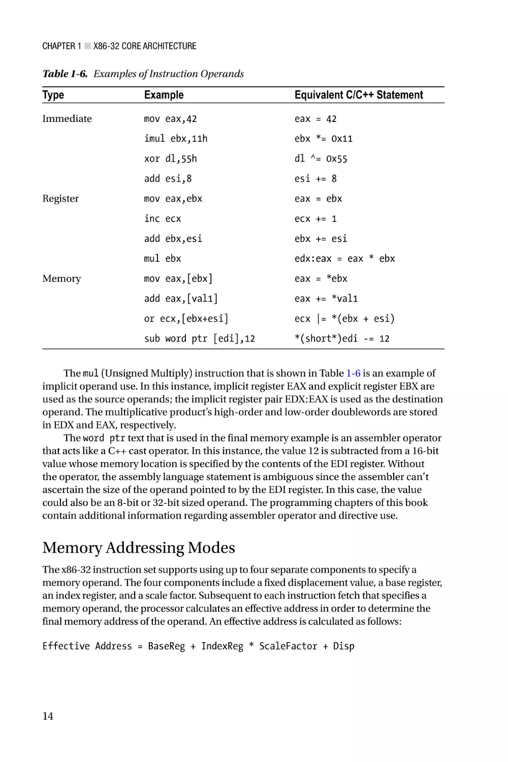
either the source or destination operand as a memory operand, but not both. Table 1-6
contains several examples of instructions that employ the various operand types.
13
Chapter 1 ■ X86-32 Core Architecture
Table 1-6. Examples of Instruction Operands
Type
Example
Equivalent C/C++ Statement
Immediate
mov eax,42
eax = 42
imul ebx,11h
ebx *= 0x11
xor dl,55h
dl ^= 0x55
add esi,8
esi += 8
mov eax,ebx
eax = ebx
inc ecx
ecx += 1
add ebx,esi
ebx += esi
mul ebx
edx:eax = eax * ebx
mov eax,[ebx]
eax = *ebx
add eax,[val1]
eax += *val1
or ecx,[ebx+esi]
ecx |= *(ebx + esi)
sub word ptr [edi],12
*(short*)edi -= 12
Register
Memory
The mul (Unsigned Multiply) instruction that is shown in Table 1-6 is an example of
implicit operand use. In this instance, implicit register EAX and explicit register EBX are
used as the source operands; the implicit register pair EDX:EAX is used as the destination
operand. The multiplicative product’s high-order and low-order doublewords are stored
in EDX and EAX, respectively.
The word ptr text that is used in the final memory example is an assembler operator
that acts like a C++ cast operator. In this instance, the value 12 is subtracted from a 16-bit
value whose memory location is specified by the contents of the EDI register. Without
the operator, the assembly language statement is ambiguous since the assembler can’t
ascertain the size of the operand pointed to by the EDI register. In this case, the value
could also be an 8-bit or 32-bit sized operand. The programming chapters of this book
contain additional information regarding assembler operator and directive use.
Memory Addressing Modes
The x86-32 instruction set supports using up to four separate components to specify a
memory operand. The four components include a fixed displacement value, a base register,
an index register, and a scale factor. Subsequent to each instruction fetch that specifies a
memory operand, the processor calculates an effective address in order to determine the
final memory address of the operand. An effective address is calculated as follows:
Effective Address = BaseReg + IndexReg * ScaleFactor + Disp
14
Chapter 1 ■ X86-32 Core Architecture
The base register (BaseReg) can be any general-purpose register; the index register
(IndexReg) can be any general-purpose register except ESP; displacement (Disp) values are
constant offsets that are encoded within the instruction; valid scale factors (ScaleFactor)
include 1, 2, 4, and 8. The size of the final effective address (EffectiveAddress) is always 32
bits. It is not necessary for an instruction to explicitly specify all of the components that the
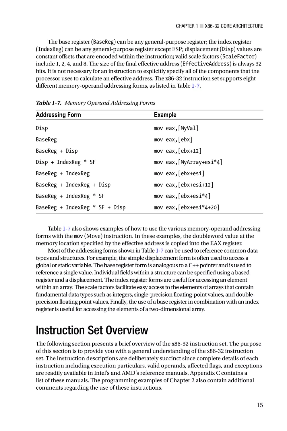
processor uses to calculate an effective address. The x86-32 instruction set supports eight
different memory-operand addressing forms, as listed in Table 1-7.
Table 1-7. Memory Operand Addressing Forms
Addressing Form
Example
Disp
mov eax,[MyVal]
BaseReg
mov eax,[ebx]
BaseReg + Disp
mov eax,[ebx+12]
Disp + IndexReg * SF
mov eax,[MyArray+esi*4]
BaseReg + IndexReg
mov eax,[ebx+esi]
BaseReg + IndexReg + Disp
mov eax,[ebx+esi+12]
BaseReg + IndexReg * SF
mov eax,[ebx+esi*4]
BaseReg + IndexReg * SF + Disp
mov eax,[ebx+esi*4+20]
Table 1-7 also shows examples of how to use the various memory-operand addressing
forms with the mov (Move) instruction. In these examples, the doubleword value at the
memory location specified by the effective address is copied into the EAX register.
Most of the addressing forms shown in Table 1-7 can be used to reference common data
types and structures. For example, the simple displacement form is often used to access a
global or static variable. The base register form is analogous to a C++ pointer and is used to
reference a single value. Individual fields within a structure can be specified using a based
register and a displacement. The index register forms are useful for accessing an element
within an array. The scale factors facilitate easy access to the elements of arrays that contain
fundamental data types such as integers, single-precision floating-point values, and doubleprecision floating point values. Finally, the use of a base register in combination with an index
register is useful for accessing the elements of a two-dimensional array.
Instruction Set Overview
The following section presents a brief overview of the x86-32 instruction set. The purpose
of this section is to provide you with a general understanding of the x86-32 instruction
set. The instruction descriptions are deliberately succinct since complete details of each
instruction including execution particulars, valid operands, affected flags, and exceptions
are readily available in Intel’s and AMD’s reference manuals. Appendix C contains a
list of these manuals. The programming examples of Chapter 2 also contain additional
comments regarding the use of these instructions.
15
Chapter 1 ■ X86-32 Core Architecture
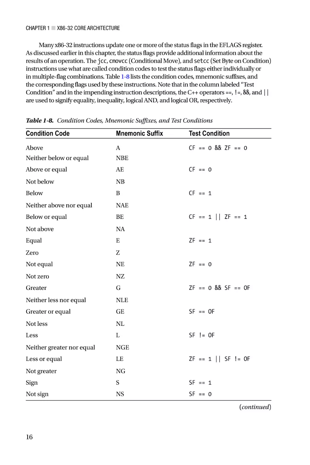
Many x86-32 instructions update one or more of the status flags in the EFLAGS register.
As discussed earlier in this chapter, the status flags provide additional information about the
results of an operation. The jcc, cmovcc (Conditional Move), and setcc (Set Byte on Condition)
instructions use what are called condition codes to test the status flags either individually or
in multiple-flag combinations. Table 1-8 lists the condition codes, mnemonic suffixes, and
the corresponding flags used by these instructions. Note that in the column labeled “Test
Condition” and in the impending instruction descriptions, the C++ operators ==, !=, &&, and ||
are used to signify equality, inequality, logical AND, and logical OR, respectively.
Table 1-8. Condition Codes, Mnemonic Suffixes, and Test Conditions
Condition Code
Mnemonic Suffix
Test Condition
Above
A
CF == 0 && ZF == 0
Neither below or equal
NBE
Above or equal
AE
Not below
NB
Below
B
Neither above nor equal
NAE
Below or equal
BE
Not above
NA
Equal
E
Zero
Z
Not equal
NE
Not zero
NZ
Greater
G
Neither less nor equal
NLE
Greater or equal
GE
Not less
NL
Less
L
Neither greater nor equal
NGE
Less or equal
LE
Not greater
NG
Sign
S
SF == 1
Not sign
NS
SF == 0
CF == 0
CF == 1
CF == 1 || ZF == 1
ZF == 1
ZF == 0
ZF == 0 && SF == OF
SF == OF
SF != OF
ZF == 1 || SF != OF
(continued)
16
Chapter 1 ■ X86-32 Core Architecture
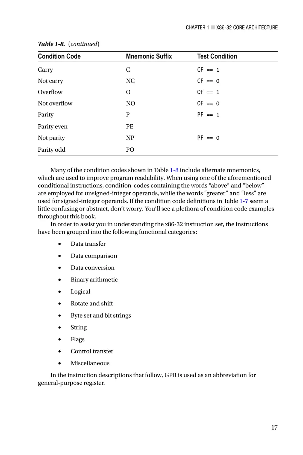
Table 1-8. (continued)
Condition Code
Mnemonic Suffix
Test Condition
Carry
C
CF == 1
Not carry
NC
CF == 0
Overflow
O
OF == 1
Not overflow
NO
OF == 0
Parity
P
PF == 1
Parity even
PE
Not parity
NP
Parity odd
PO
PF == 0
Many of the condition codes shown in Table 1-8 include alternate mnemonics,
which are used to improve program readability. When using one of the aforementioned
conditional instructions, condition-codes containing the words “above” and “below”
are employed for unsigned-integer operands, while the words “greater” and “less” are
used for signed-integer operands. If the condition code definitions in Table 1-7 seem a
little confusing or abstract, don’t worry. You’ll see a plethora of condition code examples
throughout this book.
In order to assist you in understanding the x86-32 instruction set, the instructions
have been grouped into the following functional categories:
•
Data transfer
•
Data comparison
•
Data conversion
•
Binary arithmetic
•
Logical
•
Rotate and shift
•
Byte set and bit strings
•
String
•
Flags
•
Control transfer
•
Miscellaneous
In the instruction descriptions that follow, GPR is used as an abbreviation for
general-purpose register.
17
Chapter 1 ■ X86-32 Core Architecture
Data Transfer
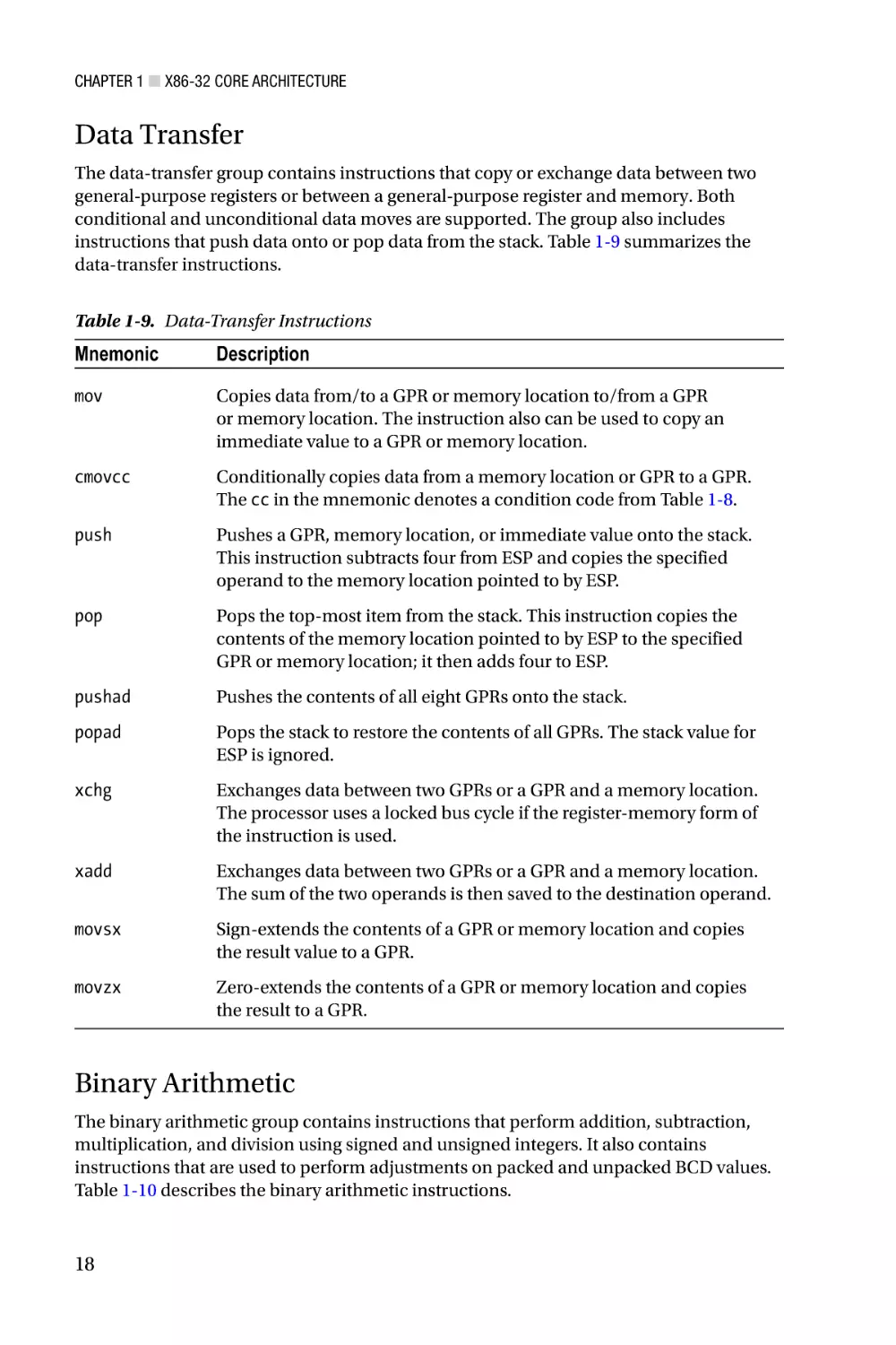
The data-transfer group contains instructions that copy or exchange data between two
general-purpose registers or between a general-purpose register and memory. Both
conditional and unconditional data moves are supported. The group also includes
instructions that push data onto or pop data from the stack. Table 1-9 summarizes the
data-transfer instructions.
Table 1-9. Data-Transfer Instructions
Mnemonic
Description
mov
Copies data from/to a GPR or memory location to/from a GPR
or memory location. The instruction also can be used to copy an
immediate value to a GPR or memory location.
cmovcc
Conditionally copies data from a memory location or GPR to a GPR.
The cc in the mnemonic denotes a condition code from Table 1-8.
push
Pushes a GPR, memory location, or immediate value onto the stack.
This instruction subtracts four from ESP and copies the specified
operand to the memory location pointed to by ESP.
pop
Pops the top-most item from the stack. This instruction copies the
contents of the memory location pointed to by ESP to the specified
GPR or memory location; it then adds four to ESP.
pushad
Pushes the contents of all eight GPRs onto the stack.
popad
Pops the stack to restore the contents of all GPRs. The stack value for
ESP is ignored.
xchg
Exchanges data between two GPRs or a GPR and a memory location.
The processor uses a locked bus cycle if the register-memory form of
the instruction is used.
xadd
Exchanges data between two GPRs or a GPR and a memory location.
The sum of the two operands is then saved to the destination operand.
movsx
Sign-extends the contents of a GPR or memory location and copies
the result value to a GPR.
movzx
Zero-extends the contents of a GPR or memory location and copies
the result to a GPR.
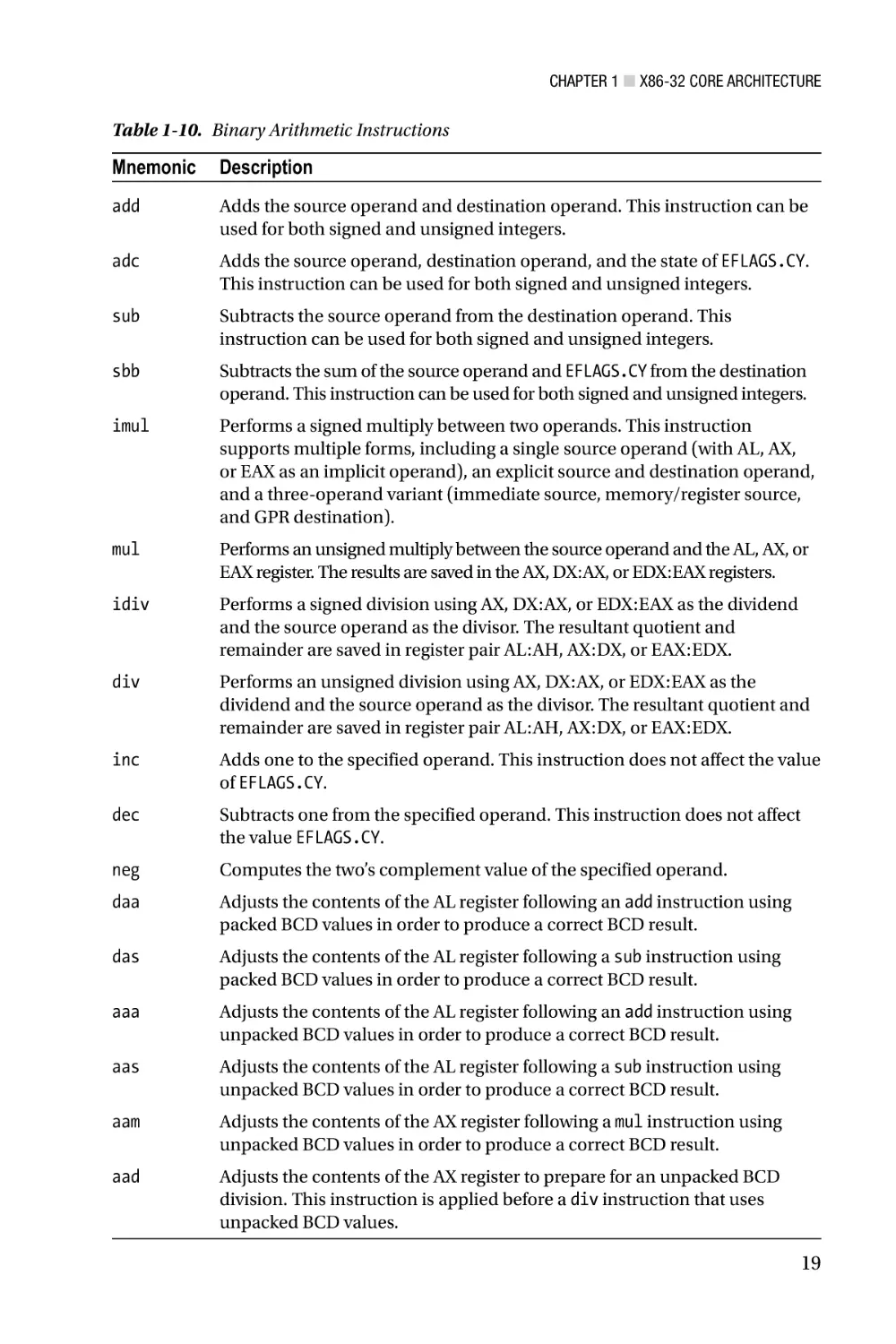
Binary Arithmetic
The binary arithmetic group contains instructions that perform addition, subtraction,
multiplication, and division using signed and unsigned integers. It also contains
instructions that are used to perform adjustments on packed and unpacked BCD values.
Table 1-10 describes the binary arithmetic instructions.
18
Chapter 1 ■ X86-32 Core Architecture
Table 1-10. Binary Arithmetic Instructions
Mnemonic
Description
add
Adds the source operand and destination operand. This instruction can be
used for both signed and unsigned integers.
adc
Adds the source operand, destination operand, and the state of EFLAGS.CY.
This instruction can be used for both signed and unsigned integers.
sub
Subtracts the source operand from the destination operand. This
instruction can be used for both signed and unsigned integers.
sbb
Subtracts the sum of the source operand and EFLAGS.CY from the destination
operand. This instruction can be used for both signed and unsigned integers.
imul
Performs a signed multiply between two operands. This instruction
supports multiple forms, including a single source operand (with AL, AX,
or EAX as an implicit operand), an explicit source and destination operand,
and a three-operand variant (immediate source, memory/register source,
and GPR destination).
mul
Performs an unsigned multiply between the source operand and the AL, AX, or
EAX register. The results are saved in the AX, DX:AX, or EDX:EAX registers.
idiv
Performs a signed division using AX, DX:AX, or EDX:EAX as the dividend
and the source operand as the divisor. The resultant quotient and
remainder are saved in register pair AL:AH, AX:DX, or EAX:EDX.
div
Performs an unsigned division using AX, DX:AX, or EDX:EAX as the
dividend and the source operand as the divisor. The resultant quotient and
remainder are saved in register pair AL:AH, AX:DX, or EAX:EDX.
inc
Adds one to the specified operand. This instruction does not affect the value
of EFLAGS.CY.
dec
Subtracts one from the specified operand. This instruction does not affect
the value EFLAGS.CY.
neg
Computes the two’s complement value of the specified operand.
daa
Adjusts the contents of the AL register following an add instruction using
packed BCD values in order to produce a correct BCD result.
das
Adjusts the contents of the AL register following a sub instruction using
packed BCD values in order to produce a correct BCD result.
aaa
Adjusts the contents of the AL register following an add instruction using
unpacked BCD values in order to produce a correct BCD result.
aas
Adjusts the contents of the AL register following a sub instruction using
unpacked BCD values in order to produce a correct BCD result.
aam
Adjusts the contents of the AX register following a mul instruction using
unpacked BCD values in order to produce a correct BCD result.
aad
Adjusts the contents of the AX register to prepare for an unpacked BCD
division. This instruction is applied before a div instruction that uses
unpacked BCD values.
19
Chapter 1 ■ X86-32 Core Architecture
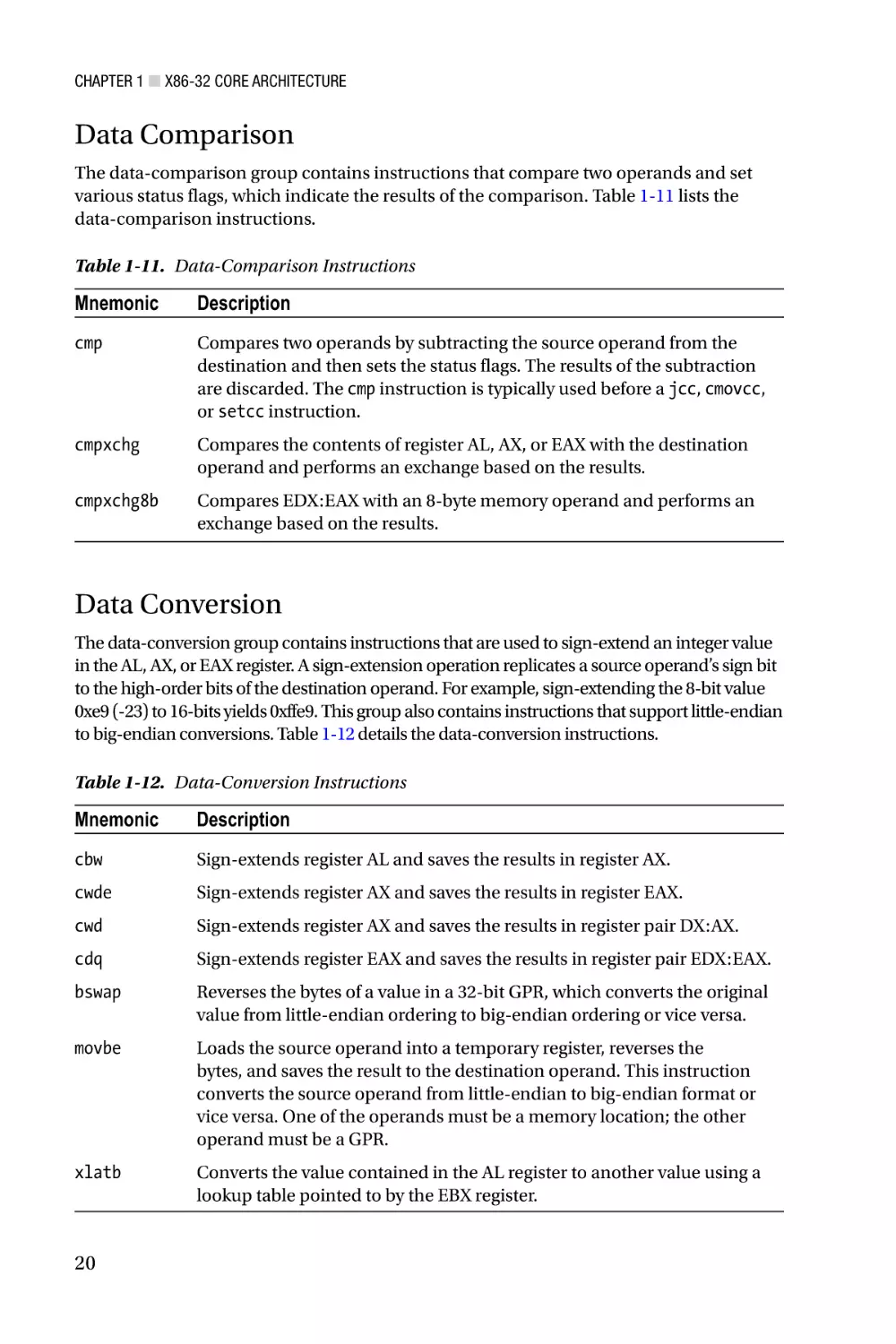
Data Comparison
The data-comparison group contains instructions that compare two operands and set
various status flags, which indicate the results of the comparison. Table 1-11 lists the
data-comparison instructions.
Table 1-11. Data-Comparison Instructions
Mnemonic
Description
cmp
Compares two operands by subtracting the source operand from the
destination and then sets the status flags. The results of the subtraction
are discarded. The cmp instruction is typically used before a jcc, cmovcc,
or setcc instruction.
cmpxchg
Compares the contents of register AL, AX, or EAX with the destination
operand and performs an exchange based on the results.
cmpxchg8b
Compares EDX:EAX with an 8-byte memory operand and performs an
exchange based on the results.
Data Conversion
The data-conversion group contains instructions that are used to sign-extend an integer value
in the AL, AX, or EAX register. A sign-extension operation replicates a source operand’s sign bit
to the high-order bits of the destination operand. For example, sign-extending the 8-bit value
0xe9 (-23) to 16-bits yields 0xffe9. This group also contains instructions that support little-endian
to big-endian conversions. Table 1-12 details the data-conversion instructions.
Table 1-12. Data-Conversion Instructions
Mnemonic
Description
cbw
Sign-extends register AL and saves the results in register AX.
cwde
Sign-extends register AX and saves the results in register EAX.
cwd
Sign-extends register AX and saves the results in register pair DX:AX.
cdq
Sign-extends register EAX and saves the results in register pair EDX:EAX.
bswap
Reverses the bytes of a value in a 32-bit GPR, which converts the original
value from little-endian ordering to big-endian ordering or vice versa.
movbe
Loads the source operand into a temporary register, reverses the
bytes, and saves the result to the destination operand. This instruction
converts the source operand from little-endian to big-endian format or
vice versa. One of the operands must be a memory location; the other
operand must be a GPR.
xlatb
Converts the value contained in the AL register to another value using a
lookup table pointed to by the EBX register.
20
Chapter 1 ■ X86-32 Core Architecture
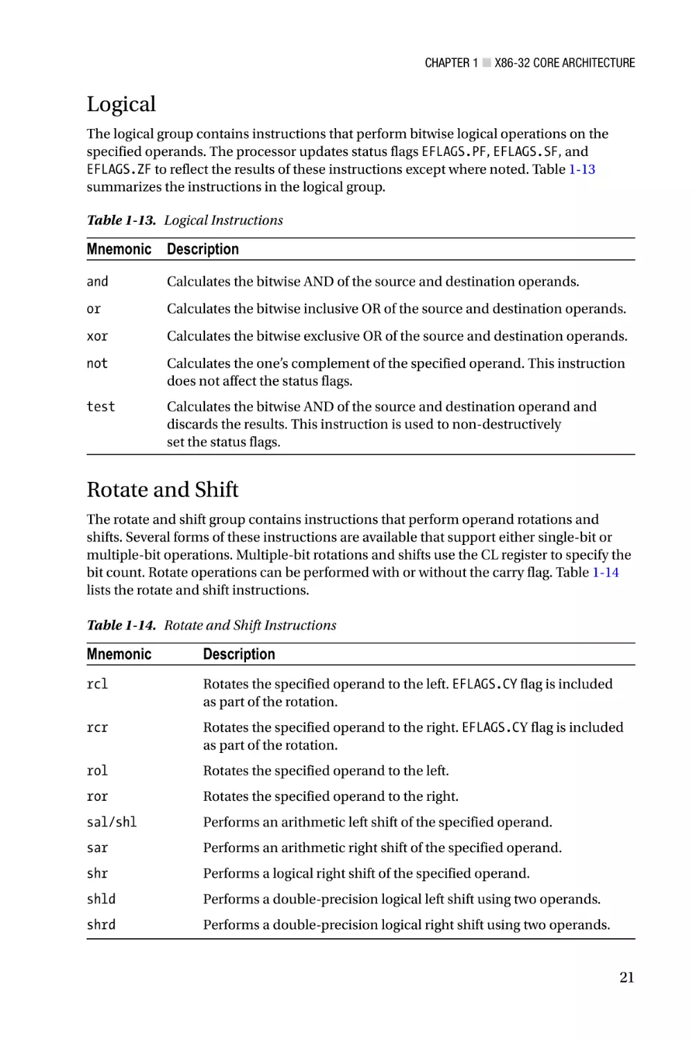
Logical
The logical group contains instructions that perform bitwise logical operations on the
specified operands. The processor updates status flags EFLAGS.PF, EFLAGS.SF, and
EFLAGS.ZF to reflect the results of these instructions except where noted. Table 1-13
summarizes the instructions in the logical group.
Table 1-13. Logical Instructions
Mnemonic Description
and
Calculates the bitwise AND of the source and destination operands.
or
Calculates the bitwise inclusive OR of the source and destination operands.
xor
Calculates the bitwise exclusive OR of the source and destination operands.
not
Calculates the one’s complement of the specified operand. This instruction
does not affect the status flags.
test
Calculates the bitwise AND of the source and destination operand and
discards the results. This instruction is used to non-destructively
set the status flags.
Rotate and Shift
The rotate and shift group contains instructions that perform operand rotations and
shifts. Several forms of these instructions are available that support either single-bit or
multiple-bit operations. Multiple-bit rotations and shifts use the CL register to specify the
bit count. Rotate operations can be performed with or without the carry flag. Table 1-14
lists the rotate and shift instructions.
Table 1-14. Rotate and Shift Instructions
Mnemonic
Description
rcl
Rotates the specified operand to the left. EFLAGS.CY flag is included
as part of the rotation.
rcr
Rotates the specified operand to the right. EFLAGS.CY flag is included
as part of the rotation.
rol
Rotates the specified operand to the left.
ror
Rotates the specified operand to the right.
sal/shl
Performs an arithmetic left shift of the specified operand.
sar
Performs an arithmetic right shift of the specified operand.
shr
Performs a logical right shift of the specified operand.
shld
Performs a double-precision logical left shift using two operands.
shrd
Performs a double-precision logical right shift using two operands.
21
Chapter 1 ■ X86-32 Core Architecture
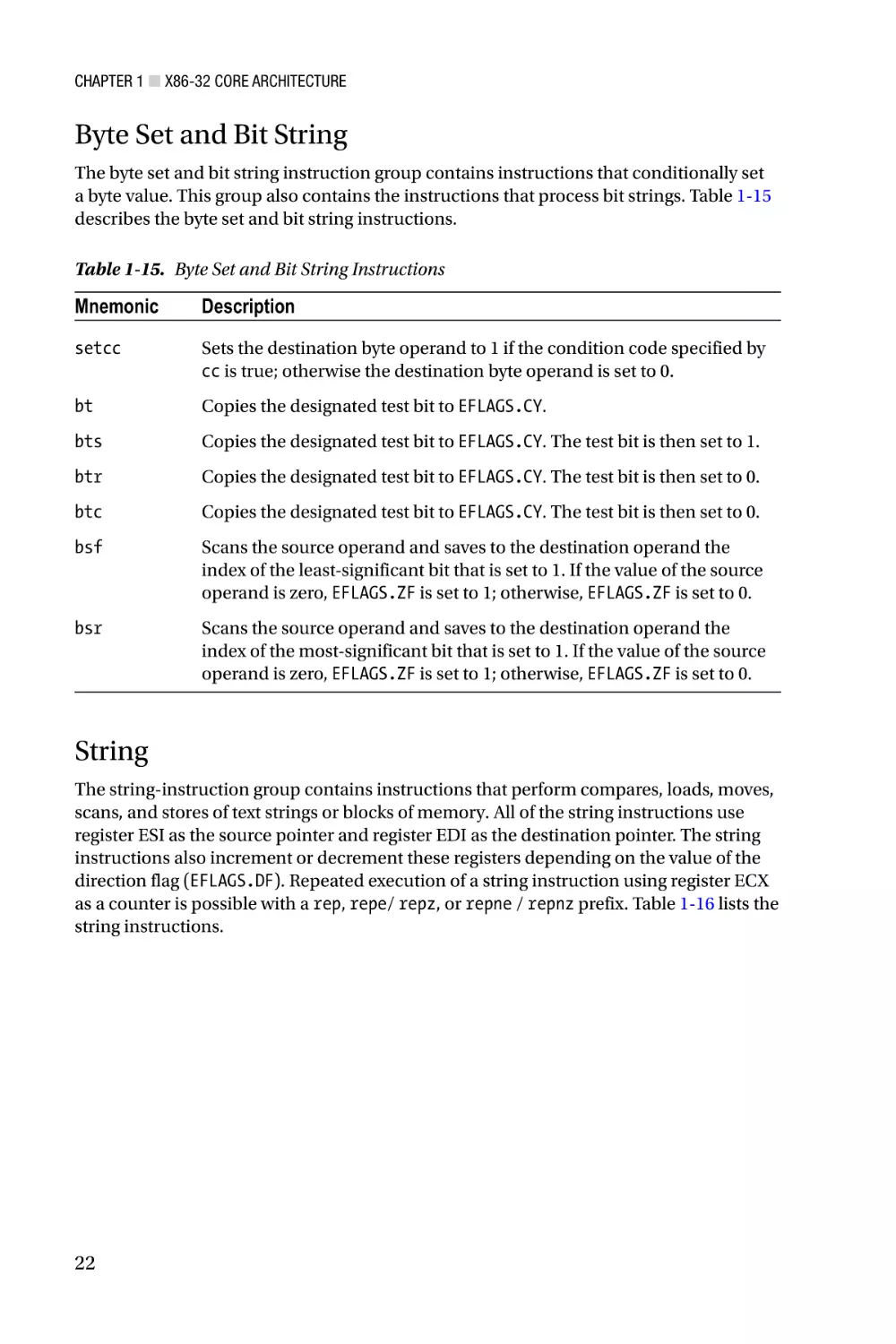
Byte Set and Bit String
The byte set and bit string instruction group contains instructions that conditionally set
a byte value. This group also contains the instructions that process bit strings. Table 1-15
describes the byte set and bit string instructions.
Table 1-15. Byte Set and Bit String Instructions
Mnemonic
Description
setcc
Sets the destination byte operand to 1 if the condition code specified by
cc is true; otherwise the destination byte operand is set to 0.
bt
Copies the designated test bit to EFLAGS.CY.
bts
Copies the designated test bit to EFLAGS.CY. The test bit is then set to 1.
btr
Copies the designated test bit to EFLAGS.CY. The test bit is then set to 0.
btc
Copies the designated test bit to EFLAGS.CY. The test bit is then set to 0.
bsf
Scans the source operand and saves to the destination operand the
index of the least-significant bit that is set to 1. If the value of the source
operand is zero, EFLAGS.ZF is set to 1; otherwise, EFLAGS.ZF is set to 0.
bsr
Scans the source operand and saves to the destination operand the
index of the most-significant bit that is set to 1. If the value of the source
operand is zero, EFLAGS.ZF is set to 1; otherwise, EFLAGS.ZF is set to 0.
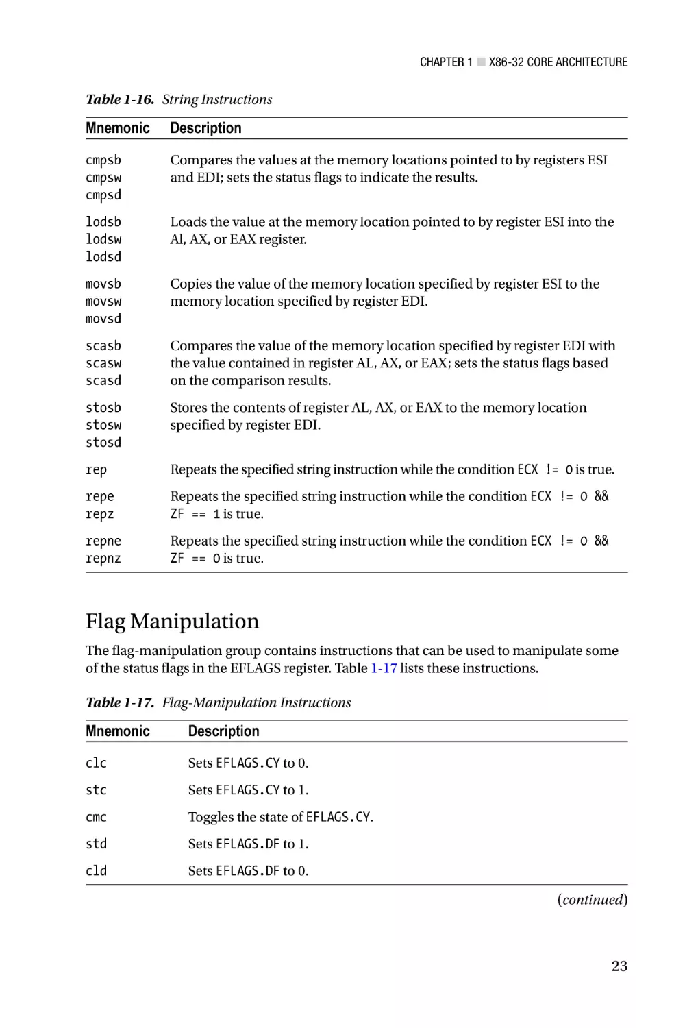
String
The string-instruction group contains instructions that perform compares, loads, moves,
scans, and stores of text strings or blocks of memory. All of the string instructions use
register ESI as the source pointer and register EDI as the destination pointer. The string
instructions also increment or decrement these registers depending on the value of the
direction flag (EFLAGS.DF). Repeated execution of a string instruction using register ECX
as a counter is possible with a rep, repe/ repz, or repne / repnz prefix. Table 1-16 lists the
string instructions.
22
Chapter 1 ■ X86-32 Core Architecture
Table 1-16. String Instructions
Mnemonic
Description
cmpsb
cmpsw
cmpsd
Compares the values at the memory locations pointed to by registers ESI
and EDI; sets the status flags to indicate the results.
lodsb
lodsw
lodsd
Loads the value at the memory location pointed to by register ESI into the
Al, AX, or EAX register.
movsb
movsw
movsd
Copies the value of the memory location specified by register ESI to the
memory location specified by register EDI.
scasb
scasw
scasd
Compares the value of the memory location specified by register EDI with
the value contained in register AL, AX, or EAX; sets the status flags based
on the comparison results.
stosb
stosw
stosd
Stores the contents of register AL, AX, or EAX to the memory location
specified by register EDI.
rep
Repeats the specified string instruction while the condition ECX != 0 is true.
repe
repz
Repeats the specified string instruction while the condition ECX != 0 &&
ZF == 1 is true.
repne
repnz
Repeats the specified string instruction while the condition ECX != 0 &&
ZF == 0 is true.
Flag Manipulation
The flag-manipulation group contains instructions that can be used to manipulate some
of the status flags in the EFLAGS register. Table 1-17 lists these instructions.
Table 1-17. Flag-Manipulation Instructions
Mnemonic
Description
clc
Sets EFLAGS.CY to 0.
stc
Sets EFLAGS.CY to 1.
cmc
Toggles the state of EFLAGS.CY.
std
Sets EFLAGS.DF to 1.
cld
Sets EFLAGS.DF to 0.
(continued)
23
Chapter 1 ■ X86-32 Core Architecture
Table 1-17. (continued)
Mnemonic
Description
lahf
Loads register AH with the values of the status flags. The bits of register AH
(most significant to least significant) are loaded as follows: EFLAGS.SF,
EFLAGS. ZF, 0, EFLAGS.AF, 0, EFLAGS.PF, 1, EFLAGS.CF.
sahf
Stores register AH to the status flags. The bits of register AH (most
significant to least significant) are stored to the status flags as follows:
EFLAGS.SF, EFLAGS.ZF, 0, EFLAGS.AF, 0, EFLAGS.PF, 1, EFLAGS.CF (a zero
or one indicates the actual value used instead of the corresponding bit in
register AH).
pushfd
Pushes the EFLAGS register onto the stack.
popfd
Pops the top most value from the stack and copies it to the EFLAGS
register. Note that the reserved bits in the EFLAGS register are not
affected by this instruction.
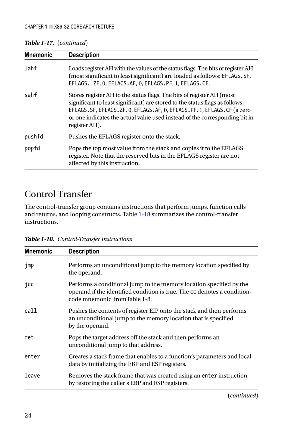
Control Transfer
The control-transfer group contains instructions that perform jumps, function calls
and returns, and looping constructs. Table 1-18 summarizes the control-transfer
instructions.
Table 1-18. Control-Transfer Instructions
Mnemonic
Description
jmp
Performs an unconditional jump to the memory location specified by
the operand.
jcc
Performs a conditional jump to the memory location specified by the
operand if the identified condition is true. The cc denotes a conditioncode mnemonic fromTable 1-8.
call
Pushes the contents of register EIP onto the stack and then performs
an unconditional jump to the memory location that is specified
by the operand.
ret
Pops the target address off the stack and then performs an
unconditional jump to that address.
enter
Creates a stack frame that enables to a function’s parameters and local
data by initializing the EBP and ESP registers.
leave
Removes the stack frame that was created using an enter instruction
by restoring the caller’s EBP and ESP registers.
(continued)
24
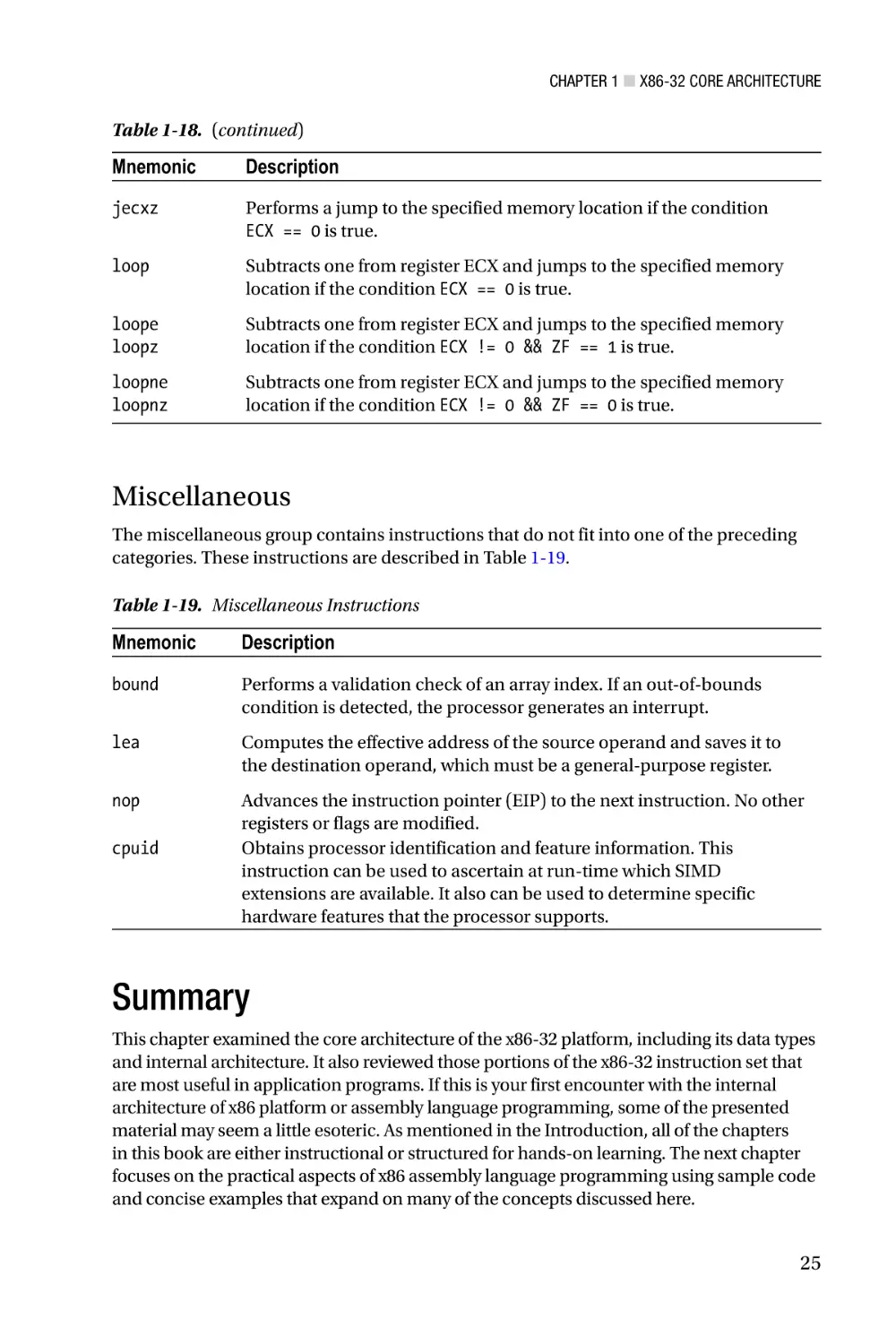
Chapter 1 ■ X86-32 Core Architecture
Table 1-18. (continued)
Mnemonic
Description
jecxz
Performs a jump to the specified memory location if the condition
ECX == 0 is true.
loop
Subtracts one from register ECX and jumps to the specified memory
location if the condition ECX == 0 is true.
loope
loopz
Subtracts one from register ECX and jumps to the specified memory
location if the condition ECX != 0 && ZF == 1 is true.
loopne
loopnz
Subtracts one from register ECX and jumps to the specified memory
location if the condition ECX != 0 && ZF == 0 is true.
Miscellaneous
The miscellaneous group contains instructions that do not fit into one of the preceding
categories. These instructions are described in Table 1-19.
Table 1-19. Miscellaneous Instructions
Mnemonic
Description
bound
Performs a validation check of an array index. If an out-of-bounds
condition is detected, the processor generates an interrupt.
lea
Computes the effective address of the source operand and saves it to
the destination operand, which must be a general-purpose register.
nop
Advances the instruction pointer (EIP) to the next instruction. No other
registers or flags are modified.
Obtains processor identification and feature information. This
instruction can be used to ascertain at run-time which SIMD
extensions are available. It also can be used to determine specific
hardware features that the processor supports.
cpuid
Summary
This chapter examined the core architecture of the x86-32 platform, including its data types
and internal architecture. It also reviewed those portions of the x86-32 instruction set that
are most useful in application programs. If this is your first encounter with the internal
architecture of x86 platform or assembly language programming, some of the presented
material may seem a little esoteric. As mentioned in the Introduction, all of the chapters
in this book are either instructional or structured for hands-on learning. The next chapter
focuses on the practical aspects of x86 assembly language programming using sample code
and concise examples that expand on many of the concepts discussed here.
25
Chapter 2
X86-32 Core Programming
The previous chapter focused on the fundamentals of the x86-32 platform, including its
data types, execution environment, and instruction set. This chapter concentrates on
the basics of x86-32 assembly language programming. More specifically, you’ll examine
how to code x86 assembly language functions that can be called from a C++ program.
You’ll also learn about the semantics and syntax of x86 an assembly language source code
file. The sample programs and accompanying remarks of this chapter are intended to
complement the instructive material presented in Chapter 1.
This chapter’s content is organized as follows. The first section describes how to code
a simple assembly language function. You’ll explore the essentials of passing arguments
and return values between functions written in C++ and x86 assembly language. You’ll
also consider some of the issues related to x86-32 instruction set use and learn a little bit
about the Visual Studio development tools.
The next section discusses the fundamentals of x86-32 assembly language
programming. It presents additional details regarding passing arguments and using
return values between functions, including function prologs and epilogs. This section
also reviews several universal x86 assembly language programming topics, including
memory addressing modes, variable use, and conditional instructions. Following the
section on assembly language fundamentals is a section that discusses array use. Virtually
all applications employ arrays to some degree and the content of this section illustrates
assembly language programming techniques using one-dimensional and
two-dimensional arrays.
Many application programs also use structures to create and manage user-defined
data types. Structure use is illustrated in the next section and includes a discussion
of several issues that developers need to be aware of when using structures between
C++ and assembly-language functions. The final section of this chapter demonstrates
using the x86’s string instructions. These instructions are commonly used to perform
operations with text strings, but they also can be used to process the elements of an array.
It should be noted that the primary purpose of the sample code presented in
this chapter is to illustrate x86-32 instruction set use and basic assembly language
programming techniques. All of the assembly language code is straightforward, but not
necessarily optimal since understanding optimized assembly language code can be
challenging, especially for beginners. The sample code that’s discussed in later chapters
places more emphasis on efficient coding techniques. Chapters 21 and 22 also review a
number of strategies that can be used to create efficient assembly language code.
27
Chapter 2 ■ X86-32 Core Programming
Getting Started
This section examines a couple of simple programs that illustrate how to pass data
between a C++ function and an x86-32 assembly language function. You’ll also learn how
to use a few common x86-32 assembly language instructions and some basic assembler
directives. As mentioned in the Introduction, all of the sample code discussed in this
book was created using Microsoft’s Visual C++ and Macro Assembler (MASM), which are
included with Visual Studio. Before you take a look at the first sample program, you need
to learn a few requisites about these development tools.
Visual Studio uses entities called solutions and projects to help simplify application
development. A solution is a collection of one or more projects that are used to build
an application. Projects are container objects that help organize an application’s files,
including source code, resources, icons, bitmaps, HTML, and XML. A Visual Studio
project is usually created for each buildable component (e.g. executable file, dynamiclinked library, static library, etc.) of an application. You can open and load any of the
sample programs into the Visual Studio development environment by double-clicking
on its solution (.sln) file. You’ll explore Visual Studio use a bit more later in this section.
Appendix A also contains a brief tutorial on how to create a Visual Studio solution and
project that includes both C++ and x86 assembly language files.
First Assembly Language Function
The first x86-32 assembly language program that you’ll examine is called CalcSum. This
sample program demonstrates some basic assembly language concepts, including
argument passing, stack use, and return values. It also illustrates how to use several
common assembler directives.
Before diving into the specifics of sample program CalcSum, let’s review what
happens when a C++ function calls another function. Like many programming languages,
C++ uses a stack-oriented architecture to support argument passing and local variable
storage. In Listing 2-1, the function CalcSumTest calculates and returns the sum of
three integer values. Prior to the calling of this function from _tmain, the values of a, b,
and c are pushed onto the stack from right to left. Upon entry into CalcSumTest, a stack
frame pointer is initialized that facilitates access to the three integer arguments that
were pushed onto the stack in _tmain. The function also allocates any local stack space
it needs. Next, CalcSumTest calculates the sum, copies this value into a pre-designated
return value register, releases any previously-allocated local stack space, and returns to
_tmain. It should be noted that while the preceding discussion is conceptually accurate,
a modern C++ compiler is likely to eliminate some if not all of the stack-related operations
using either local or whole-program optimization.
Listing 2-1. CalcSumTest.cpp
#include "stdafx.h"
int CalcSumTest(int a, int b, int c)
{
return a + b + c;
}
28
Chapter 2 ■ X86-32 Core Programming
int _tmain(int argc, _TCHAR* argv[])
{
int a = 17, b = 11, c = 14;
int sum = CalcSumTest(a, b, c);
printf("
printf("
printf("
printf("
return 0;
a:
b:
c:
sum:
%d\n",
%d\n",
%d\n",
%d\n",
a);
b);
c);
sum);
}
The same function-calling procedure outlined in the previous paragraph is also
used to invoke an assembly language function from C++. Listings 2-2 and 2-3 show the
C++ and x86 assembly language code for the sample program CalcSum. In this example,
the assembly language function is named CalcSum_. Since CalcSum_ is your first x86-32
assembly language function, it makes sense to methodically examine Listings 2-2 and 2-3.
Listing 2-2. CalcSum.cpp
#include "stdafx.h"
extern "C" int CalcSum_(int a, int b, int c);
int _tmain(int argc, _TCHAR* argv[])
{
int a = 17, b = 11, c = 14;
int sum = CalcSum_(a, b, c);
printf("
printf("
printf("
printf("
return 0;
a:
b:
c:
sum:
%d\n",
%d\n",
%d\n",
%d\n",
a);
b);
c);
sum);
}
Listing 2-3. CalcSum_.asm
.model flat,c
.code
; extern "C" int CalcSum_(int a, int b, int c)
;
; Description: This function demonstrates passing arguments between
;
a C++ function and an assembly language function.
;
; Returns:
a + b + c
29
Chapter 2 ■ X86-32 Core Programming
CalcSum_ proc
; Initialize a stack frame pointer
push ebp
mov ebp,esp
; Load the argument values
mov eax,[ebp+8]
mov ecx,[ebp+12]
mov edx,[ebp+16]
; eax = 'a'
; ecx = 'b'
; edx = 'c'
; Calculate the sum
add eax,ecx
add eax,edx
; eax = 'a' + 'b'
; eax = 'a' + 'b' + 'c'
; Restore the caller's stack frame pointer
pop ebp
ret
CalcSum_ endp
end
■■Note In the sample code, all assembly language file, function, and public variable
names include a trailing underscore for easier recognition.
The file CalcSum.cpp looks straightforward but includes a few lines that warrant
some explanatory comments. The #include "stdafx.h" statement specifies a
project-specific header file that contains references to frequently used system items.
Visual Studio automatically generates this file whenever a new C++ console application
project is created. The line extern "C" int CalcSum_(int a, int, b, int c) is a
C++ declaration statement that defines the parameters and return value for the assembly
language function CalcSum_. It also instructs the compiler to use the C-style naming
convention for the function CalcSum_, instead of a C++ decorated name (a C++ decorated
name includes extra characters that help support overloading). The remaining lines in
CalcSum.cpp perform standard console output using the printf function.
The first few lines of CalcSum_.asm are MASM directives. A MASM directive is
a statement that instructs the assembler how to perform certain actions. The.model
flat,c directive tells the assembler to produce code for a flat memory model and to
use C-style names for public symbols. The .code statement defines the starting point of
a memory block that contains executable code. You’ll learn how to use other directives
throughout this chapter. The next few lines are comments; any character that appears
on a line after a semicolon is ignored by the assembler. The statement CalcSum_ proc
indicates the start of the function (or procedure). Toward the end of the source file, the
statement CalcSum_ endp marks the end of the function. It should be noted that the
proc and endp statements are not executable instructions but assembler directives that
30
Chapter 2 ■ X86-32 Core Programming
denote the beginning and end of a function. The final end statement is another assembler
directive that signifies the end of statements for the file; the assembler ignores any text
that appears after the end directive.
The first x86-32 assembly-language instruction of CalcSum_ is push ebp (Push
Doubleword onto the Stack). This instruction saves the contents of the caller’s EBP register
on the stack. The next instruction, mov ebp,esp (Move), copies the contents of ESP to
EBP, which initializes EBP as a stack frame pointer for CalcSum_ and enables access to the
function’s arguments. Figure 2-1 illustrates the contents of the stack following execution
of the mov ebp,esp instruction. The saving of the caller’s EBP register and initialization of
the stack frame pointer form part of a code block known as the function prolog. Function
prologs are discussed in greater detail later in this chapter.
High Memory
Low Memory
.
.
.
c
+16
b
+12
a
+8
Return address
+4
Old EBP
� EBP, ESP
Figure 2-1. Contents of the stack after initialization of the stack frame pointer. Offsets of
data on the stack are relative to registers EBP and ESP
Following initialization of the stack frame pointer, the argument values arguments
a, b, and c are loaded into registers EAX, ECX, and EDX, respectively, using a series of
mov instructions. The source operand of each mov instruction uses the BaseReg+Disp
form of memory addressing to reference each value on the stack (see Chapter 1 for
more information on memory addressing modes). After loading the argument values
into registers, calculation of the required sum can commence. The add eax,ecx (Add)
instruction sums registers EAX and ECX, which contain the argument values a and b, and
saves the result to register EAX. The next instruction add eax,edx adds c to the previously
computed sum and saves the result in EAX.
An x86-32 assembly language function must use the EAX register to return a 32-bit
integer value to its calling function. In the current program, no additional instructions are
required to achieve this since EAX already contains the correct value. The pop ebp (Pop
a Value from the Stack) instruction restores the caller’s EBP register and is considered
part of the function’s epilog code. Function epilogs are discussed in greater detail later in
this chapter. The final ret (Return from Procedure) instruction transfers program control
back to the calling function _tmain. Output 2-1 shows the results of running the sample
program CalcSum.
31
Chapter 2 ■ X86-32 Core Programming
Output 2-1. Sample Program Calcsum
a:
b:
c:
sum:
17
11
14
42
You can view the source code files and run the sample program using Visual Studio
by performing the following steps:
1.
Using the Windows File Explorer, double-click on the
following Visual Studio solution file:
Chapter02\CalcSum\CalcSum.sln.
2.
If necessary, select VIEW ➤ Solution Explorer to open the
Solution Explorer Window.
3.
In the Solution Explorer Window tree control, expand the
nodes labeled CalcSum and Source Files.
4.
Double-click on CalcSum.cpp and CalcSum_.asm to open the
files in the editor.
5.
To run the program, select DEBUG ➤ Start Without Debugging.
You’ll learn a few more details about Visual Studio use throughout this chapter.
Integer Multiplication and Division
The next sample program that you’ll examine is called IntegerMulDiv. This program
demonstrates how to perform signed-integer multiplication and division using the imul
(Signed Multiply) and idiv (Signed Divide) instructions, respectively. It also illustrates
how to pass data between a C++ function and an assembly language function using
pointers. You can open the Visual Studio solution file using Windows Explorer by
doubling-click on the Chapter02\IntegerMulDiv\IntegerMulDiv.sln file.
Listing 2-4 shows the C++ source code for IntegerMulDiv.cpp. Near the top of this
file is a declaration statement for the assembly language function that will calculate
the required results. The function IntegerMuDiv_ defines five parameters: two integer
data values and three integer pointers for the results. This function also returns an
integer value that indicates a division-by-zero error condition. The remaining lines in
the file IntegerMulDiv.cpp contain code that exercise the assembly language function
IntegerMulDiv_ using several test cases.
32
Chapter 2 ■ X86-32 Core Programming
Listing 2-4. IntegerMulDiv.cpp
#include "stdafx.h"
extern "C" int IntegerMulDiv_(int a, int b, int* prod, int* quo, int* rem);
int _tmain(int argc, _TCHAR* argv[])
{
int a = 21, b = 9;
int prod = 0, quo = 0, rem = 0;
int rc;
rc = IntegerMulDiv_(a,
printf(" Input1 - a:
printf("Output1 - rc:
printf("
quo:
b, &prod, &quo, &rem);
%4d b:
%4d\n", a, b);
%4d prod: %4d\n", rc, prod);
%4d rem: %4d\n\n", quo, rem);
a = -29;
prod = quo = rem = 0;
rc = IntegerMulDiv_(a,
printf(" Input2 - a:
printf("Output2 - rc:
printf("
quo:
b, &prod, &quo, &rem);
%4d b:
%4d\n", a, b);
%4d prod: %4d\n", rc, prod);
%4d rem: %4d\n\n", quo, rem);
b = 0;
prod = quo = rem = 0;
rc = IntegerMulDiv_(a,
printf(" Input3 - a:
printf("Output3 - rc:
printf("
quo:
return 0;
b, &prod, &quo, &rem);
%4d b:
%4d\n", a, b);
%4d prod: %4d\n", rc, prod);
%4d rem: %4d\n\n", quo, rem);
}
Listing 2-5 contains the assembly language function IntegerMulDiv_. The first few
lines of this function are similar to the first few lines of sample program you studied in the
previous section; they contain assembler directives that define the memory model and
the start of a code block. The function prolog contains the necessary instructions to save
the caller’s EBP register and initialize a stack frame pointer. It also includes a push ebx
instruction, which saves the caller’s EBX register on the stack. According to the Visual C++
calling convention that is defined for 32-bit programs, a called function must preserve
the values of the following registers: EBX, ESI, EDI, and EBP. These registers are called
non-volatile registers. The volatile registers EAX, ECX, and EDX need not be preserved
across function calls. You’ll learn more about the Visual C++ calling convention and its
requirements throughout the remainder of this chapter.
33
Chapter 2 ■ X86-32 Core Programming
Listing 2-5. IntegerMulDiv_.asm
.model flat,c
.code
; extern "C" int IntegerMulDiv_(int a, int b, int* prod, int* quo, int*
rem);
;
; Description: This function demonstrates use of the imul and idiv
;
instructions. It also illustrates pointer usage.
;
; Returns:
0 Error (divisor is zero)
;
1 Success (divisor is zero)
;
; Computes:
*prod = a * b;
;
*quo = a / b
;
*rem = a % b
IntegerMulDiv_ proc
; Function prolog
push ebp
mov ebp,esp
push ebx
; Make sure the divisor is not zero
xor eax,eax
mov ecx,[ebp+8]
mov edx,[ebp+12]
or edx,edx
jz InvalidDivisor
; Calculate product and save result
imul edx,ecx
mov ebx,[ebp+16]
mov [ebx],edx
;set error return code
;ecx = 'a'
;edx = 'b'
;jump if 'b' is zero
;edx = 'a' * 'b'
;ebx = 'prod'
;save product
; Calculate quotient and remainder, save results
mov eax,ecx
;eax = 'a'
cdq
;edx:eax contains dividend
idiv dword ptr [ebp+12]
;eax = quo, edx = rem
mov
mov
mov
mov
mov
34
ebx,[ebp+20]
[ebx],eax
ebx,[ebp+24]
[ebx],edx
eax,1
;ebx = 'quo'
;save quotient
;ebx = 'rem'
;save remainder
;set success return code
Chapter 2 ■ X86-32 Core Programming
; Function epilog
InvalidDivisor:
pop ebx
pop ebp
ret
IntegerMulDiv_ endp
end
Figure 2-2 shows the contents of the stack subsequent to the push ebx instruction.
Following the function prolog, the argument values a and b are loaded into registers ECX
and EDX, respectively. An or edx,edx (Logical Inclusive OR) instruction follows. This
instruction performs a bitwise inclusive OR of EDX with itself, which updates the status flags
in the EFLAGS register while preserving the original value in register EDX. The argument
b is being tested in order to avoid a division-by-zero condition. The jz InvalidDivisor
(Jump if Zero) instruction that follows is a conditional jump instruction that gets performed
only if EFLAGS.ZF == 1 is true. The destination operand of this conditional jump instruction
is a label that specifies the target of the jump (i.e. the next instruction to be executed) if the
zero flag is set. In the current sample program, the target label InvalidDivisior: is located
toward the end of the listing just before the first epilog instruction.
High Memory
Low Memory
.
.
.
rem
+24
quo
+20
prod
+16
b
+12
a
+8
Return Address
+4
Old EBP
� EBP
Old EBX
� ESP
Figure 2-2. Stack contents after execution of push ebx. Offsets shown are relative to
register EBP
If the value of b is not zero, program execution continues with the imul edx,ecx
instruction. This instruction multiplies the contents of EDX and ECX using signed-integer
multiplication, truncates the product to 32-bits, and saves this value in register EDX
(the one-operand form of imul with 32-bit operands saves the complete quadword
product in register pair EDX:EAX). The next instruction, mov ebx,[ebp+16], loads the
pointer prod into register EBX. This is followed by a mov [ebx],edx instruction that saves
the previously-calculated multiplicative product to the required memory location.
35
Chapter 2 ■ X86-32 Core Programming
The next block of x86-32 instructions in IntegerMulDiv_ calculates a / b and a % b
using signed-integer division. On an x86 processor, signed-integer division using 32-bit
wide operands must be performed using a 64-bit wide dividend that is loaded in register
pair EDX:EAX. The cdq (Convert Doubleword to Quadword) instruction sign-extends
the contents of EAX, which contains argument a due to the preceding mov eax,ecx
instruction, into register pair EDX:EAX. The next instruction, idiv dword ptr [ebp+12],
performs the signed integer division. Note that the idiv instruction specifies only a single
source operand: the 32-bit (or doubleword) divisor. The contents of register pair EDX:EAX
is always used as the dividend. It should be noted that the idiv instruction can also be
used to perform 8-bit and 16-bit signed integer division, which explains the dword ptr
operator that’s used in the current example. Following execution of the idiv instruction,
registers EAX and EDX contain the quotient and remainder, respectively. These values are
then saved to the memory locations specified by the pointers quo and rem.
The final block of code in function IntegerMulDiv_ contains the epilog. Before
execution of the ret instruction, the caller’s EBX and EBP registers must be restored using pop
instructions. If an assembly language function fails to properly restore a non-volatile registers
that it altered, a program crash is likely to occur. This same disastrous outcome is virtually
guaranteed to happen if ESP points to an unremoved data item on the stack or contains an
invalid value. The results of the sample program IntegerMulDiv are shown in Output 2-2.
Output 2-2. Sample Program IntegerMulDiv
Input1 - a:
Output1 - rc:
quo:
21
1
2
b:
prod:
rem:
9
189
3
Input2 - a:
Output2 - rc:
quo:
-29
1
-3
b:
9
prod: -261
rem:
-2
Input3 - a:
Output3 - rc:
quo:
-29
0
0
b:
prod:
rem:
0
0
0
X86-32 Programming Fundamentals
The sample code of the previous section introduced x86-32 assembly language
programming. In this section, you’ll continue exploring by focusing on the fundamentals
of x86-32 assembly language programming. You’ll begin by taking a closer look at the
calling convention that x86-32 assembly language functions must observe in order to be
callable from C++. This is followed by a sample program that illustrates how to employ
commonly-used memory addressing modes. Integer addition using various-sized
operands is the primary emphasis of the next sample program while the final sample
program surveys condition codes and conditional instructions. The title of this section
includes the word “fundamentals” and should provide a clue as to its importance. All of
the presented material encompasses essential topics that aspiring x86 assembly language
programmers need to fully understand.
36
Chapter 2 ■ X86-32 Core Programming
Calling Convention
When writing functions using C++, programmers frequently declare one or more local
variables that hold temporary values or intermediate results. For example, in Listing 2-6
you see that the function LocalVars contains three local variables: val1, val2, and
val3. If the C++ compiler determines that memory is needed on the stack to hold these
variables or other temporary values, it is usually allocated and released in the function’s
prolog and epilog, respectively. Assembly-language functions can use this same
technique to allocate space on the stack for local variables or other transient uses.
Listing 2-6. LocalVars.cpp
double LocalVars(int a, int b)
{
int val1 = a * a;
int val2 = b * b;
double val3 = sqrt(val1 + val2);
return val3;
}
The next sample program that you’ll study is called CallingConvention and
its purpose is twofold. First, it illustrates some additional aspects of the C++ calling
convention, including allocation of space on the stack for local variable storage.
Second, the sample program demonstrates proper use of a few more commonly-used
x86-32 assembly language instructions. The C++ and assembly language listings for
CallingConvention.cpp and CallingConvention_.asm are shown in Listings 2-7
and 2-8. The Visual Studio solution file is named Chapter02\CallingConvention\
CallingConvention.sln.
Listing 2-7. CallingConvention.cpp
#include "stdafx.h"
extern "C" void CalculateSums_(int a, int b, int c, int* s1, int* s2, int*
s3);
int _tmain(int argc, _TCHAR* argv[])
{
int a = 3, b = 5, c = 8;
int s1a, s2a, s3a;
CalculateSums_(a, b, c, &s1a, &s2a, &s3a);
// Compute the sums again so we can verify the results
// of CalculateSums_().
37
Chapter 2 ■ X86-32 Core Programming
int s1b = a + b + c;
int s2b = a * a + b * b + c * c;
int s3b = a * a * a + b * b * b + c * c * c;
printf("Input: a:
%4d b:
%4d c:
%4d\n", a, b, c);
printf("Output: s1a: %4d s2a: %4d s3a: %4d\n", s1a, s2a, s3a);
printf("
s1b: %4d s2b: %4d s3b: %4d\n", s1b, s2b, s3b);
return 0;
}
Listing 2-8. CallingConvention_.asm
.model flat,c
.code
; extern "C" void CalculateSums_(int a, int b, int c, int* s1, int* s2, int*
s3);
;
; Description: This function demonstrates a complete assembly
;
language prolog and epilog.
;
; Returns: None.
;
; Computes:
*s1 = a + b + c
;
*s2 = a * a + b * b + c * c
;
*s3 = a * a * a + b * b * b + c * c * c
CalculateSums_
proc
; Function prolog
push ebp
mov ebp,esp
sub esp,12
push ebx
push esi
push edi
; Load arguments
mov eax,[ebp+8]
mov ebx,[ebp+12]
mov ecx,[ebp+16]
mov edx,[ebp+20]
mov esi,[ebp+24]
mov edi,[ebp+28]
38
;Allocate local storage space
;eax
;ebx
;ecx
;edx
;esi
;edi
=
=
=
=
=
=
'a'
'b'
'c'
's1'
's2'
's3'
Chapter 2 ■ X86-32 Core Programming
; Compute 's1'
mov [ebp-12],eax
add [ebp-12],ebx
add [ebp-12],ecx
;final 's1' result
; Compute 's2'
imul eax,eax
imul ebx,ebx
imul ecx,ecx
mov [ebp-8],eax
add [ebp-8],ebx
add [ebp-8],ecx
;final 's2' result
; Compute 's3'
imul eax,[ebp+8]
imul ebx,[ebp+12]
imul ecx,[ebp+16]
mov [ebp-4],eax
add [ebp-4],ebx
add [ebp-4],ecx
;final 's3' result
; Save 's1', 's2', and 's3'
mov eax,[ebp-12]
mov [edx],eax
mov eax,[ebp-8]
mov [esi],eax
mov eax,[ebp-4]
mov [edi],eax
; Function epilog
pop edi
pop esi
pop ebx
mov esp,ebp
pop ebp
ret
CalculateSums_ endp
end
;save 's1'
;save 's2'
;save 's3'
;Release local storage space
You can see in Listing 2-7 that _tmain calls a function named CalculateSums_. This
function calculates three sum values using the provided integer arguments. The assembly
language definition of CalculateSums_ that’s shown in Listing 2-8 begins with the now
familiar stack frame pointer initialization along with the preservation of all non-volatile
registers on the stack. Before the non-volatile registers are saved, a sub esp,12 (Subtract)
instruction is executed. This instruction subtracts 12 from the contents of ESP register,
which effectively allocates 12 bytes of local (and private) storage space on the stack
that can be used by the function. The reason a sub instruction is used instead of an add
39
Chapter 2 ■ X86-32 Core Programming
instruction is because the x86’s stack grows downward toward lower-memory addresses.
The allocation of local storage space on the stack reveals another purpose of the prolog’s
mov ebp,esp instruction. When using the EBP register to access values on the stack,
function arguments are always referenced using positive displacement values, while local
variables are referenced using negative displacement values, as illustrated in Figure 2-3.
High Memory
s3
+28
s2
+24
s1
+20
c
+16
b
+12
a
+8
Return Address
+4
Old EBP
EBP
Temp s3
-4
Temp s2
-8
Temp s1
-12
Old EBX
Old ESI
Low Memory
Old EDI
ESP
Figure 2-3. Organization of a stack with local storage space
Following the prolog code, the function arguments a, b, and c are loaded into
registers EAX, EBX, and ECX, respectively. The calculation of s1 illustrates the use of an
add instruction with a memory destination operand instead of a register. I should note
that in this particular case, the use of a memory destination operand is inefficient; s1
easily could be computed using register operands. The reason for employing memory
destination operands here is to elucidate the use of local variables on the stack.
The values of s2 and s3 are then calculated using the two-operand form of imul.
Note that the imul instructions employed to calculate s3 use the original values on the
stack as source operands since the contents of EAX, EBX, and ECX no longer contain the
original values of a, b, and c. Subsequent to the calculation of the required results, the
values s1, s2, s3, are copied from their temporary locations on the stack to the caller’s
memory locations using the provided pointers.
40
Chapter 2 ■ X86-32 Core Programming
CalculateSums_ concludes with an epilog that restores the non-volatile registers
EBX, ESI, and EDI using pop instructions. It also includes a mov esp,ebp instruction,
which essentially releases the previously allocated local storage space and restores the
ESP register to the correct value prior to execution of the ret instruction. Execution of the
sample program CallingConvention yields text that’s shown in Output 2-3.
Output 2-3. Sample Program CallingConvention
Input: a:
Output: s1a:
s1b:
3 b:
16 s2a:
16 s2b:
5 c:
98 s3a:
98 s3b:
8
664
664
The prolog and epilog of CalculateSums_ are typical examples of the calling
convention that must be observed when invoking an assembly-language function from a
Visual C++ function. Later in this chapter, you will explore a couple of additional calling
convention requirements related to 64-bit values and C++ structures. Chapter 4 also
discusses the calling convention requirements for floating-point values. Appendix B
contains a complete summary of the Visual C++ calling convention for x86-32 programs.
■■Note The assembly language calling convention described in this chapter may be
different for other high-level languages and operating systems. If you’re reading this book
to learn x86 assembly language programming and plan on using it in a different execution
environment, you should consult the appropriate documentation for specific information
regarding the target platform’s calling convention.
Finally, when coding an assembly language function prolog or epilog, it is usually
only necessary to include those instructions that are specifically needed by the function.
For example, if a function does not alter the contents of register EBX, it is not necessary
for the prolog to save and the epilog to restore its value. Similarly, a function that defines
zero parameters is not required to initialize a stack frame pointer. The one caveat of
skipping a prolog or epilog action is the situation where an assembly language function calls
another function that does not preserve the non-volatile registers. In this case, the calling
function should ensure that the non-volatile registers are properly saved and restored.
Memory Addressing Modes
You learned in Chapter 1 that the x86 instruction set supports a variety of addressing
modes that can be used to reference an operand in memory. In this section, you’ll
examine an assembly-language function that illustrates how to use some of these modes.
You’ll also learn how define an assembly language lookup table and a global variable
that can be accessed from a C++ function. The name of the sample program for this
section is called MemoryAddressing. Listings 2-9 and 2-10 show the contents of the source
files MemoryAddressing.cpp and MemoryAddressing_.asm, respectively. The Visual
Studio solution file for this sample program is named Chapter02\MemoryAddressing\
MemoryAddressing.sln.
41
Chapter 2 ■ X86-32 Core Programming
Listing 2-9. MemoryAddressing.cpp
#include "stdafx.h"
extern "C" int NumFibVals_;
extern "C" int MemoryAddressing_(int i, int* v1, int* v2, int* v3, int* v4);
int _tmain(int
{
for (int i
{
int v1
int rc
argc, _TCHAR* argv[])
= -1; i < NumFibVals_ + 1; i++)
= -1, v2 = -1, v3 = -1, v4 = -1;
= MemoryAddressing_(i, &v1, &v2, &v3, &v4);
printf("i: %2d rc: %2d - ", i, rc);
printf("v1: %5d v2: %5d v3: %5d v4: %5d\n", v1, v2, v3, v4);
}
return 0;
}
Listing 2-10. MemoryAddressing_.asm
.model flat,c
; Simple lookup table (.const section data is read only)
FibVals
.const
dword 0, 1, 1, 2, 3, 5, 8, 13
dword 21, 34, 55, 89, 144, 233, 377, 610
NumFibVals_ dword ($ - FibVals) / sizeof dword
public NumFibVals_
; extern "C" int MemoryAddressing_(int i, int* v1, int* v2, int* v3, int*
v4);
;
; Description: This function demonstrates various addressing
;
modes that can be used to access operands in
;
memory.
;
; Returns:
0 = error (invalid table index)
;
1 = success
.code
MemoryAddressing_ proc
push ebp
mov ebp,esp
42
Chapter 2 ■ X86-32 Core Programming
push ebx
push esi
push edi
; Make sure 'i' is valid
xor eax,eax
mov ecx,[ebp+8]
cmp ecx,0
jl InvalidIndex
cmp ecx,[NumFibVals_]
jge InvalidIndex
; Example #1 - base register
mov ebx,offset FibVals
mov esi,[ebp+8]
shl esi,2
add ebx,esi
mov eax,[ebx]
mov edi,[ebp+12]
mov [edi],eax
; Example #2 - base register + displacement
; esi is used as the base register
mov esi,[ebp+8]
shl esi,2
mov eax,[esi+FibVals]
mov edi,[ebp+16]
mov [edi],eax
;ecx = i
;jump if i < 0
;jump if i >=NumFibVals_
;ebx = FibVals
;esi = i
;esi = i * 4
;ebx = FibVals + i * 4
;Load table value
;Save to 'v1'
;esi = i
;esi = i * 4
;Load table value
;Save to 'v2'
; Example #3 - base register + index register
mov ebx,offset FibVals
;ebx = FibVals
mov esi,[ebp+8]
;esi = i
shl esi,2
;esi = i * 4
mov eax,[ebx+esi]
;Load table value
mov edi,[ebp+20]
mov [edi],eax
;Save to 'v3'
; Example #4 - base register + index register * scale factor
mov ebx,offset FibVals
;ebx = FibVals
mov esi,[ebp+8]
;esi = i
mov eax,[ebx+esi*4]
;Load table value
mov edi,[ebp+24]
mov [edi],eax
;Save to 'v4'
mov eax,1
;Set return code
43
Chapter 2 ■ X86-32 Core Programming
InvalidIndex:
pop edi
pop esi
pop ebx
pop ebp
ret
MemoryAddressing_ endp
end
Let’s start by examining the assembly language function named MemoryOperands_.
In this function, the parameter named i is employed as an index into an array (or lookup
table) of constant integers, while the four pointer variables are used to save values read
from the lookup table using different addressing modes. Near the top of Listing 2-10 is a
.const directive, which defines a memory block that contains read-only data. Immediately
following the .const directive, a lookup table named FibVals is defined. This table
contains 16 doubleword integer values; the text dword is an assembler directive that is used
to allocate storage space and optionally initialize a doubleword value (the text dd can also
be used as a synonym for dword).
The line NumFibVals_ dword ($ - FibVals) / sizeof dword allocates storage space
for a single doubleword value and initializes it with the number of doubleword elements in
the lookup table FibVals. The $ character is an assembler symbol that equals the current
value of the location counter (or offset from the beginning of the current memory block).
Subtracting the offset of FibVals from $ yields the size of the table in bytes; dividing this
result by the size in bytes of a doubleword value generates the correct number of elements.
The statements in the .const section replicate a commonly-used technique in C++ to
define and initialize a variable with the number of elements in an array:
int Values[] = {10, 20, 30, 40, 50};
int NumValues = sizeof(Values) / sizeof(int);
The final line of the .const section declares NumFibVals_ as a public symbol in order
to enable its use by the function _tmain.
Let’s now look at the assembly language code for MemoryAddressing_. Immediately
following the function’s prolog, the argument i is checked for validity since it will be used
as an index into the lookup table FibVals. The cmp ecx,0 (Compare Two Operands)
instruction compares the contents of ECX, which contains i, to the immediate value 0.
The processor carries out this comparison by subtracting the source operand from the
destination operand; it then sets the status flags based on the result of the subtraction (the
result is not saved to the destination operand). If the condition ecx < 0 is true, program
control will be transferred to the location specified by the jl (Jump if Less) instruction.
A similar sequence of instructions is used to determine if the value of i is too large. In
this case, a cmp ecx,[NumFibVals_] instruction compares ECX against the number of
elements in the lookup table. If ecx >= [NumFibVals] is true, a jump is performed to the
target location specified by the jge (Jump if Greater or Equal) instruction.
The remaining instructions of the function MemoryAddressing_ illustrate accessing
items in the lookup table using various memory addressing modes. The first example
uses a single base register to read an item from the table. In order to use a single base
register, the function must manually calculate the address of the i-th table element, which
44
Chapter 2 ■ X86-32 Core Programming
is achieved by adding the offset (or starting address) of FibVals and the value i * 4. The
mov ebx,offset FibVals instruction loads EBX with the correct table offset value. The
value of i is then loaded into ESI, followed by a shl esi,2 (Shift Logical Left) instruction.
This computes the offset of the i-th item relative to the start of the lookup table. An add
ebx,esi instruction calculates the final address. Once this is complete, the specified
table value is read using a mov eax,[ebx] instruction and saved to the memory location
specified by the argument v1.
The second memory-addressing example uses the BaseReg+Disp form to read a table
item. Like the previous example, the offset of the i-th table element relative to the start of
the table is calculated using a shl esi,2 instruction. The correct table entry is the loaded
into EAX using a mov eax,[esi+FibVals] instruction. In this example, the processor
computes the final effective address by adding the contents of ESI (the base register) and
the displacement (or offset) of FibVals.
In the third memory-addressing example, the table value is read using
BaseReg+IndexReg memory addressing. This example is similar to the first example
except that the processor computes the final effective address during execution of the
mov eax,[ebx+esi] instruction. The fourth and final example demonstrates the use of
BaseReg+IndexReg*ScaleFactor addressing. In this example, the offset of FibVals and
the value i are loaded into registers EBX and ESI, respectively. The correct table value is
loaded into EAX using a mov eax,[ebx+esi*4] instruction.
The file MemoryAddressing.cpp (Listing 2-10) contains a simple looping construct
that exercises the function MemoryOperands_ including cases with an invalid index. Note
that the for loop uses the variable NumFibVals_, which was defined as a public symbol
in the assembly language file MemoryOperands_.asm. The output for the sample program
MemoryAddressing is shown in Output 2-4.
Output 2-4. Sample Program MemoryAddressing
i:
i:
i:
i:
i:
i:
i:
i:
i:
i:
i:
i:
i:
i:
i:
i:
i:
i:
-1
0
1
2
3
4
5
6
7
8
9
10
11
12
13
14
15
16
rc:
rc:
rc:
rc:
rc:
rc:
rc:
rc:
rc:
rc:
rc:
rc:
rc:
rc:
rc:
rc:
rc:
rc:
0
1
1
1
1
1
1
1
1
1
1
1
1
1
1
1
1
0
-
v1:
v1:
v1:
v1:
v1:
v1:
v1:
v1:
v1:
v1:
v1:
v1:
v1:
v1:
v1:
v1:
v1:
v1:
-1
0
1
1
2
3
5
8
13
21
34
55
89
144
233
377
610
-1
v2:
v2:
v2:
v2:
v2:
v2:
v2:
v2:
v2:
v2:
v2:
v2:
v2:
v2:
v2:
v2:
v2:
v2:
-1
0
1
1
2
3
5
8
13
21
34
55
89
144
233
377
610
-1
v3:
v3:
v3:
v3:
v3:
v3:
v3:
v3:
v3:
v3:
v3:
v3:
v3:
v3:
v3:
v3:
v3:
v3:
-1
0
1
1
2
3
5
8
13
21
34
55
89
144
233
377
610
-1
v4:
v4:
v4:
v4:
v4:
v4:
v4:
v4:
v4:
v4:
v4:
v4:
v4:
v4:
v4:
v4:
v4:
v4:
-1
0
1
1
2
3
5
8
13
21
34
55
89
144
233
377
610
-1
45
Chapter 2 ■ X86-32 Core Programming
Given the multiple addressing modes that are available on an x86 processor, you
might wonder which mode should be used most often. The answer to this question
depends on a number of factors including register availability, the number of times an
instruction (or sequence of instructions) is expected to execute, instruction ordering, and
memory space vs. execution time tradeoffs. Hardware features such as the processor’s
underlying microarchitecture and memory cache sizes also need to be considered.
When coding an x86 assembly language function, one suggested guideline is to
use simple (a single register or displacement) rather than complex (multiple registers)
instruction forms to reference an operand in memory. The drawback of this approach
is that the simpler forms generally require the programmer to code longer instruction
sequences and may consume more code space. The use of a simple form also may be
imprudent if extra instructions are needed to preserve non-volatile registers on the stack.
In Chapters 21 and 22, you’ll learn about some of the issues that can affect the efficiency
of assembly language code in greater detail.
Integer Addition
Visual C++ supports the standard C++ fundamental types, including char, short, int,
and long long. These parallel the x86 fundamental types byte, word, doubleword, and
quadword, respectively. This section examines a program that performs integer addition
using various-sized integers. You’ll also learn how to use global variables defined in
a C++ file from an x86 assembly language function and a few more commonly used
x86 instructions. The Visual Studio solution file for this section is named Chapter02\
IntegerAddition\IntegerAddition.sln and the source code files are shown in
Listings 2-11 and 2-12.
Listing 2-11. IntegerAddition.cpp
#include "stdafx.h"
extern
extern
extern
extern
"C"
"C"
"C"
"C"
char GlChar = 10;
short GlShort = 20;
int GlInt = 30;
long long GlLongLong = 0x000000000FFFFFFFE;
extern "C" void IntegerAddition_(char a, short b, int c, long long d);
int _tmain(int argc, _TCHAR* argv[])
{
printf("Before GlChar:
%d\n", GlChar);
printf("
GlShort:
%d\n", GlShort);
printf("
GlInt:
%d\n", GlInt);
printf("
GlLongLong: %lld\n", GlLongLong);
printf("\n");
IntegerAddition_(3, 5, -37, 11);
46
Chapter 2 ■ X86-32 Core Programming
printf("After
printf("
printf("
printf("
return 0;
GlChar:
GlShort:
GlInt:
GlLongLong:
%d\n", GlChar);
%d\n", GlShort);
%d\n", GlInt);
%lld\n", GlLongLong);
}
Listing 2-12. IntegerAddition_.asm
.model flat,c
; These are defined in IntegerAddition.cpp
extern GlChar:byte
extern GlShort:word
extern GlInt:dword
extern GlLongLong:qword
; extern "C" void IntegerTypes_(char a, short b, int c, long long d);
;
; Description: This function demonstrates simple addition using
;
various-sized integers.
;
; Returns: None.
.code
IntegerAddition_ proc
; Function prolog
push ebp
mov ebp,esp
; Compute GlChar += a
mov al,[ebp+8]
add [GlChar],al
; Compute GlShort += b, note offset of 'b' on stack
mov ax,[ebp+12]
add [GlShort],ax
; Compute GlInt += c, note offset of 'c' on stack
mov eax,[ebp+16]
add [GlInt],eax
; Compute GlLongLong += d, note use of dword ptr operator and adc
mov eax,[ebp+20]
mov edx,[ebp+24]
add dword ptr [GlLongLong],eax
adc dword ptr [GlLongLong+4],edx
47
Chapter 2 ■ X86-32 Core Programming
; Function epilog
pop ebp
ret
IntegerAddition_ endp
end
The C++ portion of this sample program defines four global signed integers using
different fundamental types. Note that each variable definition includes the string "C",
which instructs the compiler to use C-style names instead of C++ decorated names when
generating public symbols for use by the linker. The C++ file also contains a declaration
for the assembly language function IntegerAddition_. This function performs some
simple integer addition using the four global variables.
Near the top of the file IntegerAddition_.asm are four extern statements. Similar to
its C++ counterpart, the extern directive notifies the assembler that the named variable
is defined outside the scope of the current file. Each extern directive also includes the
fundamental type of the variable. The extern directive can also include a language type
specifier to override the default type that’s specified by the .model flat,c directive. Later
in this chapter, you’ll learn how to use the extern directive to reference external functions.
Following the prolog, the function IntegerAdditions_ loads argument a into
register AL and then computes GlChar += a using an add [GlChar],al instruction. In a
similar manner, the calculation of GlShort += b is performed next using register AX with
an important distinction; the stack offset of parameter b is +12 and not +9 as you might
expect. The reason for this is that Visual C++ size extends 8-bit and 16-bit values to
32 bits before pushing them onto the stack, as illustrated in Figure 2-4. This ensures that
the stack pointer register ESP is always properly aligned to a 32-bit boundary.
High Memory
d (high dword )
+24
d (low dword )
+20
c
+16
+12
b
a
Return Address
Low Memory
Old EBP
+8
+4
EBP, ESP
Figure 2-4. Organization of stack arguments in the function IntegerAdditions_
An add [GlInt],eax instruction is then used to calculate GlInt += c. The stack
offset of c is +16, which is not two but four bytes greater than the offset of b. The final
calculation, GlLongLong += d, is carried out using two 32-bit add instructions. The
add dword ptr [GlLongLong],eax instruction adds the lower-order doublewords; the
adc dword ptr [GlLongLong+4],edx (Add With Carry) instruction completes the 64-bit
48
Chapter 2 ■ X86-32 Core Programming
add operation. Two separate add instructions are used here since x86-32 mode does
not support addition using 64-bit operands. The add and adc instructions also include a
dword ptr operator since the variable GlLongLong is declared as a quadword type. Output
2-5 exhibits the output for the sample program called IntegerAddition.
Output 2-5. Sample Program IntegerAddition
Before GlChar:
GlShort:
GlInt:
GlLongLong:
10
20
30
4294967294
After
13
25
-7
4294967305
GlChar:
GlShort:
GlInt:
GlLongLong:
Condition Codes
The final sample program of this section demonstrates how to use the x86’s conditional
instructions including jcc, cmovcc (Conditional Move), and setcc (Set Byte on
Condition). The execution of a conditional instruction is contingent on its specified
condition code and the state of one or more status flags, as discussed in Chapter 1. You
have already seen a few examples of the conditional jump instruction. The function
IntegerMulDiv_ (Listing 2-5) used a jz to prevent a potential division-by-zero error.
In MemoryAddressingModes_ (Listing 2-10), the jl and jge instructions were used
following a cmp instruction to validate a table index. The sample program for this section
is called ConditionCodes and the Visual Studio solution file is named Chapter02\
ConditionCodes\ConditionCodes.sln. Listings 2-13 and 2-14 show the source code for
ConditionCodes.cpp and ConditionCodes_.asm, respectively.
Listing 2-13. ConditionCodes.cpp
#include "stdafx.h"
extern
extern
extern
extern
"C"
"C"
"C"
"C"
int
int
int
int
SignedMinA_(int
SignedMaxA_(int
SignedMinB_(int
SignedMaxB_(int
a,
a,
a,
a,
int
int
int
int
b,
b,
b,
b,
int
int
int
int
c);
c);
c);
c);
int _tmain(int argc, _TCHAR* argv[])
{
int a, b, c;
int smin_a, smax_a;
int smin_b, smax_b;
49
Chapter 2 ■ X86-32 Core Programming
// SignedMin examples
a = 2; b = 15; c = 8;
smin_a = SignedMinA_(a,
smin_b = SignedMinB_(a,
printf("SignedMinA(%4d,
printf("SignedMinB(%4d,
b, c);
b, c);
%4d, %4d) = %4d\n", a, b, c, smin_a);
%4d, %4d) = %4d\n\n", a, b, c, smin_b);
a = -3; b = -22; c = 28;
smin_a = SignedMinA_(a, b, c);
smin_b = SignedMinB_(a, b, c);
printf("SignedMinA(%4d, %4d, %4d) = %4d\n", a, b, c, smin_a);
printf("SignedMinB(%4d, %4d, %4d) = %4d\n\n", a, b, c, smin_b);
a = 17; b = 37; c = -11;
smin_a = SignedMinA_(a, b, c);
smin_b = SignedMinB_(a, b, c);
printf("SignedMinA(%4d, %4d, %4d) = %4d\n", a, b, c, smin_a);
printf("SignedMinB(%4d, %4d, %4d) = %4d\n\n", a, b, c, smin_b);
// SignedMax examples
a = 10; b = 5; c = 3;
smax_a = SignedMaxA_(a,
smax_b = SignedMaxB_(a,
printf("SignedMaxA(%4d,
printf("SignedMaxB(%4d,
b, c);
b, c);
%4d, %4d) = %4d\n", a, b, c, smax_a);
%4d, %4d) = %4d\n\n", a, b, c, smax_b);
a = -3; b = 28; c = 15;
smax_a = SignedMaxA_(a,
smax_b = SignedMaxB_(a,
printf("SignedMaxA(%4d,
printf("SignedMaxB(%4d,
b, c);
b, c);
%4d, %4d) = %4d\n", a, b, c, smax_a);
%4d, %4d) = %4d\n\n", a, b, c, smax_b);
a = -25; b = -37; c = -17;
smax_a = SignedMaxA_(a, b, c);
smax_b = SignedMaxB_(a, b, c);
printf("SignedMaxA(%4d, %4d, %4d) = %4d\n", a, b, c, smax_a);
printf("SignedMaxB(%4d, %4d, %4d) = %4d\n\n", a, b, c, smax_b);
}
Listing 2-14. ConditionCodes_.asm
.model flat,c
.code
; extern "C" int SignedMinA_(int a, int b, int c);
;
; Description: Determines minimum of three signed integers
;
using conditional jumps.
;
; Returns
min(a, b, c)
50
Chapter 2 ■ X86-32 Core Programming
SignedMinA_ proc
push ebp
mov ebp,esp
mov eax,[ebp+8]
mov ecx,[ebp+12]
;eax = 'a'
;ecx = 'b'
; Determine
cmp
jle
mov
min(a, b)
eax,ecx
@F
eax,ecx
;eax = min(a, b)
; Determine
@@:
mov
cmp
jle
mov
min(a, b, c)
ecx,[ebp+16]
eax,ecx
@F
eax,ecx
;ecx = 'c'
;eax = min(a, b, c)
@@:
pop ebp
ret
SignedMinA_ endp
; extern "C" int SignedMaxA_(int a, int b, int c);
;
; Description: Determines maximum of three signed integers
;
using conditional jumps.
;
; Returns:
max(a, b, c)
SignedMaxA_ proc
push ebp
mov ebp,esp
mov eax,[ebp+8]
mov ecx,[ebp+12]
cmp eax,ecx
jge @F
mov eax,ecx
@@:
mov
cmp
jge
mov
ecx,[ebp+16]
eax,ecx
@F
eax,ecx
;eax = 'a'
;ecx = 'b'
;eax = max(a, b)
;ecx = 'c'
;eax = max(a, b, c)
@@:
pop ebp
ret
SignedMaxA_ endp
51
Chapter 2 ■ X86-32 Core Programming
; extern "C" int SignedMinB_(int a, int b, int c);
;
; Description: Determines minimum of three signed integers
;
using conditional moves.
;
; Returns
min(a, b, c)
SignedMinB_ proc
push ebp
mov ebp,esp
mov eax,[ebp+8]
mov ecx,[ebp+12]
;eax = 'a'
;ecx = 'b'
; Determine smallest value using the CMOVG instruction
cmp eax,ecx
cmovg eax,ecx
;eax = min(a, b)
mov ecx,[ebp+16]
;ecx = 'c'
cmp eax,ecx
cmovg eax,ecx
;eax = min(a, b, c)
pop ebp
ret
SignedMinB_ endp
; extern "C" int SignedMaxB_(int a, int b, int c);
;
; Description: Determines maximum of three signed integers
;
using conditional moves.
;
; Returns:
max(a, b, c)
SignedMaxB_ proc
push ebp
mov ebp,esp
mov eax,[ebp+8]
mov ecx,[ebp+12]
;eax = 'a'
;ecx = 'b'
; Determine largest value using the CMOVL instruction
cmp eax,ecx
cmovl eax,ecx
;eax = max(a, b)
mov ecx,[ebp+16]
;ecx = 'c'
cmp eax,ecx
cmovl eax,ecx
;eax = max(a, b, c)
pop ebp
ret
SignedMaxB_ endp
end
52
Chapter 2 ■ X86-32 Core Programming
When developing code to implement a particular algorithm, it is often necessary
to determine the minimum or maximum value of two numbers. Visual C++ defines two
macros called __min and __max to perform these operations. The file ConditionCodes_.asm
contains several three-argument versions of signed-integer minimum and maximum
functions. The purpose of these functions is to illustrate proper use of the jcc and cmovcc
instructions.
The first function, called SignedMinA_, finds the minimum value of three signed
integers. Following the function’s prolog, the first code block determines min(a, b) using
two instructions: cmp eax,ecx and jle @F. The cmp instruction, which you saw earlier
in this chapter, subtracts the source operand from the destination operand and sets the
status flags based on the result (the result is not saved to the destination operand). The
target of the jle (Jump if Less or Equal) instruction, @F, is an assembler symbol that
designates nearest forward @@ label as the target of the conditional jump (the symbol @B
can be used for backward jumps). Following the calculation of min(a, b), the next code
block determines min(min(a, b), c) using the same technique. With the result already
present in register EAX, SignedMinA_ can execute its epilog code and return to the caller.
The function SignedMaxA_ uses the same method to find the maximum of three
signed integers. The only difference between SignedMaxA_ and SignedMinA_ is the use of
a jump if a jge (Jump if Greater or Equal) instead of a jle instruction.
Versions of the functions SignedMinA_ and SignedMaxA_ that operate on unsigned
integers can be easily created by changing the jle and jge instructions to jbe (Jump
if Below or Equal) and jae (Jump if Above or Equal), respectively. Recall from the
discussion in Chapter 1 that condition codes using the words “greater” and “less” are
used with signed-integer operands, while “above” and “below” are used with unsignedinteger operands.
The file SignedMinMax_.asm also contains the functions SignedMinB_ and SignedMaxB_.
These functions determine the minimum and maximum of three signed integers using
conditional move instructions instead of conditional jumps. The cmovcc instruction tests
the specified condition and if it’s true, the source operand is copied to the destination
operand. If the specified condition is false, the destination operand is not altered.
If you examine the function SignedMaxB_, you will notice that following each
cmp eax,ecx instruction is a cmovg eax,ecx instruction. The cmovg instruction copies
the contents of ECX to EAX if EAX is greater than ECX. The same technique is used
in SignedMinB_, which employs cmovl instead of cmovg to save the smaller signed
integer. Unsigned versions of these functions can be easily created by using cmova and
cmovb instead of cmovg and cmovl, respectively. The output for the sample program
ConditionCodes is shown in Output 2-6.
Output 2-6. Sample Program ConditionCodes
SignedMinA(
SignedMinB(
2,
2,
15,
15,
8) =
8) =
2
2
SignedMinA(
SignedMinB(
-3,
-3,
-22,
-22,
28) =
28) =
-22
-22
SignedMinA(
SignedMinB(
17,
17,
37,
37,
-11) =
-11) =
-11
-11
53
Chapter 2 ■ X86-32 Core Programming
SignedMaxA(
SignedMaxB(
10,
10,
5,
5,
3) =
3) =
10
10
SignedMaxA(
SignedMaxB(
-3,
-3,
28,
28,
15) =
15) =
28
28
SignedMaxA( -25,
SignedMaxB( -25,
-37,
-37,
-17) =
-17) =
-17
-17
The use of a conditional move instruction to eliminate one or more conditional jump
statements frequently results in faster code, especially in situations where the processor is
unable to accurately predict whether the jump will be performed. Chapter21 will examine
some of the issues related to optimal use of conditional jump instructions in greater detail.
The final conditional instruction that you’ll look at is the setcc instruction. As
implied by its name, the setcc instruction sets an 8-bit destination operand to 1 if the
tested condition is true; otherwise, the destination operand is set to 0. This instruction is
useful for functions that return or set a bool value, as illustrated in Listing 2-15. You’ll see
additional examples of the setcc instruction later in this book.
Listing 2-15. Example for Set byte on condition instruction
; extern "C" bool SignedIsEQ_(int a, int b);
SignedIsEQ_ proc
push ebp
mov ebp,esp
xor eax,eax
mov ecx,[ebp+8]
cmp ecx,[ebp+12]
sete al
pop ebp
ret
SignedIsEQ_ endp
Arrays
Arrays are an indispensable data construct in virtually all programming languages. In
C++ there is an inherent connection between arrays and pointers since the name of an
array is essentially a pointer to its first element. Moreover, whenever an array is used as a
C++ function parameter, a pointer is passed instead of duplicating the array on the stack.
Pointers are also employed for arrays that are dynamically allocated at run-time. This
section examines some x86-32 assembly language functions that operate on arrays. The
first sample program reveals how to access the elements of a one-dimensional array; the
second sample program demonstrates element processing using an input and output
array; and the final example illustrates some techniques for manipulating the elements of
a two-dimensional array.
54
Chapter 2 ■ X86-32 Core Programming
Before examining the sample programs, let’s quickly review some C++ array concepts.
Consider the simple program that is shown in Listing 2-16. In the function CalcArrayCubes,
the elements of arrays x and y are stored in contiguous blocks of memory on the stack.
Invocation of the function CalcArrayCubes causes the compiler to push three arguments
onto the stack from right to left: the value of n, a pointer to the first element of x, and a pointer
to the first element of y. The for loop of function CalcArrayCubes contains the statement
int temp= x[i], which assigns the value of the i-th element of array x to temp. The memory
address of this element is simply the sum of x and i * 4 since the size of an int is four bytes.
The same method is also used to calculate the address of an element in the y array.
Listing 2-16. CalcArrayCubes.cpp
#include "stdafx.h"
void CalcArrayCubes(int* y, const int* x, int n)
{
for (int i = 0; i < n; i++)
{
int temp = x[i];
y[i] = temp * temp * temp;
}
}
int _tmain(int argc, _TCHAR* argv[])
{
int x[] = { 2, 7, -4, 6, -9, 12, 10 };
const int n = sizeof(x) / sizeof(int);
int y[n];
CalcArrayCubes(y, x, n);
for (int i = 0; i < n; i++)
printf("i: %4d x: %4d y: %4d\n", i, x[i], y[i]);
printf("\n");
return 0;
}
One-Dimensional Arrays
This section examines a couple of sample programs that demonstrate using x86 assembly
language with one-dimensional arrays. The first sample program is called CalcArraySum.
This program contains a function that calculates the sum of an integer array. It also
illustrates how to iteratively access each element of an array. The source code for
files CalArraySum.cpp and CalcArraySum_.asm are shown in Listings 2-17 and 2-18,
respectively.
55
Chapter 2 ■ X86-32 Core Programming
Listing 2-17. CalcArraySum.cpp
#include "stdafx.h"
extern "C" int CalcArraySum_(const int* x, int n);
int CalcArraySumCpp(const int* x, int n)
{
int sum = 0;
for (int i = 0; i < n; i++)
sum += *x++;
return sum;
}
int _tmain(int argc, _TCHAR* argv[])
{
int x[] = {1, 7, -3, 5, 2, 9, -6, 12};
int n = sizeof(x) / sizeof(int);
printf("Elements of x[]\n");
for (int i = 0; i < n; i++)
printf("%d ", x[i]);
printf("\n\n");
int sum1 = CalcArraySumCpp(x, n);
int sum2 = CalcArraySum_(x, n);
printf("sum1: %d\n", sum1);
printf("sum2: %d\n", sum2);
return 0;
}
Listing 2-18. CalcArraySum_.asm
.model flat,c
.code
; extern "C" int CalcArraySum_(const int* x, int n);
;
; Description: This function sums the elements of a signed
;
integer array.
CalcArraySum_ proc
push ebp
mov ebp,esp
56
Chapter 2 ■ X86-32 Core Programming
; Load arguments and initialize sum
mov edx,[ebp+8]
mov ecx,[ebp+12]
xor eax,eax
;edx = 'x'
;ecx = 'n'
;eax = sum
; Make sure 'n' is greater than zero
cmp ecx,0
jle InvalidCount
; Calculate
@@:
add
add
dec
jnz
the array element sum
eax,[edx]
edx,4
ecx
@B
;add next element to sum
;set pointer to next element
;adjust counter
;repeat if not done
InvalidCount:
pop ebp
ret
CalcArraySum_ endp
end
■■Note The Visual Studio solution files for the remaining sample code in this chapter and
beyond use the following naming convention: Chapter##\<ProgramName>\<ProgramName>.sln,
where ## denotes the chapter number and <ProgramName> represents the name of the
sample program.
The C++ portion of the sample program CalcArraySum (Listing 2-17) includes a
test function called CalcArraySumCpp that sums the elements of a signed-integer array.
While hardly necessary in this case, coding a function using C++ first followed by its x86
assembly language equivalent is often helpful during software testing and debugging.
The assembly language function CalcArraySum_ (Listing 2-18) computes the same result
as CalcArraySumCpp. Following its function prolog, a pointer to array x is loaded into
register EDX. Next, the argument value of n is copied into ECX. This is followed by an xor
eax,eax (Logical Exclusive OR) instruction, which initializes the running sum to 0.
Sweeping through the array to sum the elements requires only four instructions.
The add eax,[edx] instruction adds the current array element to the running sum.
Four is then added to register EDX, which points it to the next element in the array.
A dec ecx instruction subtracts 1 from the counter and updates the state of EFLAGS.ZF.
This enables the jnz (Jump if not Zero) instruction to terminate the loop after all n
elements have been summed. The instruction sequence employed here to calculate
the array sum is the assembly language equivalent of the for loop that was used by the
function CalcArraySumCpp. The output for the sample program CalcArraySum is shown
in Output 2-7.
57
Chapter 2 ■ X86-32 Core Programming
Output 2-7. Sample Program CalcArraySum
Elements of x[]
1 7 -3 5 2 9 -6 12
sum1: 27
sum2: 27
When working with arrays, it is frequently necessary to define functions that perform
element-by-element transformations. You saw an example of this in the function
CalcArrayCubes (Listing 2-16), which cubed each element of an input array and
saved the results to a separate output array. The next sample program, named
CalcArraySquares, exemplifies how to code an assembly-language function to perform
similar processing. Listings 2-19 and 2-20 show the source code for CalcArraySquares.cpp
and CalcArraySquares_.asm, respectively.
Listing 2-19. CalcArraySquares.cpp
#include "stdafx.h"
extern "C" int CalcArraySquares_(int* y, const int* x, int n);
int CalcArraySquaresCpp(int* y, const int* x, int n)
{
int sum = 0;
for (int i = 0; i < n; i++)
{
y[i] = x[i] * x[i];
sum += y[i];
}
return sum;
}
int _tmain(int argc, _TCHAR* argv[])
{
int x[] = {2, 3, 5, 7, 11, 13, 17, 19, 23, 29};
const int n = sizeof(x) / sizeof(int);
int y1[n];
int y2[n];
int sum_y1 = CalcArraySquaresCpp(y1, x, n);
int sum_y2 = CalcArraySquares_(y2, x, n);
for (int i = 0; i < n; i++)
printf("i: %2d x: %4d y1: %4d
printf("\n");
58
y2: %4d\n", i, x[i], y1[i], y2[i]);
Chapter 2 ■ X86-32 Core Programming
printf("sum_y1: %d\n", sum_y1);
printf("sum_y2: %d\n", sum_y2);
return 0;
}
Listing 2-20. CalcArrayCubes.cpp
.model flat,c
.code
; extern "C" int CalcArraySquares_(int* y, const int* x, int n);
;
;Description:
This function cComputes y[i] = x[i] * x[i].
;
; Returns:
Sum of the elements in array y.
CalcArraySquares_ proc
push ebp
mov ebp,esp
push ebx
push esi
push edi
; Load arguments
mov edi,[ebp+8]
mov esi,[ebp+12]
mov ecx,[ebp+16]
;edi = 'y'
;esi = 'x'
;ecx = 'n'
; Initialize array sum register, calculate
; and initialize element offset register.
xor eax,eax
;eax =
cmp ecx,0
jle EmptyArray
shl ecx,2
;ecx =
xor ebx,ebx
;ebx =
; Repeat loop until finished
@@:
mov edx,[esi+ebx]
imul edx,edx
mov [edi+ebx],edx
add eax,edx
add ebx,4
cmp ebx,ecx
jl @B
size of array in bytes,
sum of 'y' array
size of array in bytes
array element offset
;load next x[i]
;compute x[i] * x[i]
;save result to y[i]
;update running sum
;update array element offset
;jump if not finished
59
Chapter 2 ■ X86-32 Core Programming
EmptyArray:
pop edi
pop esi
pop ebx
pop ebp
ret
CalcArraySquares_ endp
end
The function CalcArraySquares_ (Listing 2-20) computes the square of each
element in array x and saves this result to the corresponding element in array y. It also
computes the sum of the elements in y. Following the function prolog, registers ESI
and EDI are initialized as pointers to x and y, respectively. The function also loads n
into register ECX and initializes EAX, which will be used to compute the sum, to zero.
Following a validity check of n, the size of the array in bytes is calculated using a shl ecx,2
instruction. This value will be used to terminate the processing loop. The function then
initializes register EBX to zero and will use this register as an offset into both x and y.
The processing loop uses a mov edx,[esi+ebx] instruction to load x[i] into register
EDX and then computes the square using the two-operand form of imul. This value is
then saved to y[i] using a mov [edi+ebx],edx instruction. An add eax,edx instruction
adds y[i] to the running sum in register EAX. The offset of the next element in both x
and y is computed using an add ebx,4 instruction. The processing loop repeats as long as
the offset value in register EBX is less than the size in bytes of the arrays, which resides in
register ECX. Output 2-8 shows the results of CalcArraySquares.
Output 2-8. Sample Program CalcArraySquares
i:
i:
i:
i:
i:
i:
i:
i:
i:
i:
0
1
2
3
4
5
6
7
8
9
x:
x:
x:
x:
x:
x:
x:
x:
x:
x:
2
3
5
7
11
13
17
19
23
29
y1:
y1:
y1:
y1:
y1:
y1:
y1:
y1:
y1:
y1:
4
9
25
49
121
169
289
361
529
841
y2:
y2:
y2:
y2:
y2:
y2:
y2:
y2:
y2:
y2:
4
9
25
49
121
169
289
361
529
841
sum_y1: 2397
sum_y2: 2397
Two-Dimensional Arrays
In C++ it is possible to use a contiguous block of memory to store the elements of a
two-dimensional array or matrix. This enables the compiler to generate code that uses
simple pointer arithmetic to uniquely access each matrix element. It also allows the
programmer to manually perform the same pointer arithmetic when working with a
60
Chapter 2 ■ X86-32 Core Programming
matrix. The sample program in this section demonstrates using x86 assembly language
to access the elements of a matrix. Before you examine the source code files, you’ll take a
closer look at how C++ handles matrices in memory.
C++ uses row-major ordering to organize the elements of a two-dimensional matrix
in memory. Row-major ordering arranges the elements of a matrix first by row and then
by column. For example, elements of the matrix int x[3][2] are stored in memory as
follows: x[0][0], x[0][1], x[1][0], x[1][1], x[2][0], and x[2][1]. In order to access a
specific element in the matrix, a C++ compiler must know the row and column indices,
the total number of columns, and the starting address. Using this information, an element
can be accessed using pointer arithmetic, as illustrated in Listing 2-21.
Listing 2-21. CalcMatrixCubes.cpp
#include "stdafx.h"
void CalcMatrixCubes(int* y, const int* x, int nrows, int ncols)
{
for (int i = 0; i < nrows; i++)
{
for (int j = 0; j < ncols; j++)
{
int k = i * ncols + j;
y[k] = x[k] * x[k] * x[k];
}
}
}
int _tmain(int argc, _TCHAR* argv[])
{
const int nrows = 4;
const int ncols = 3;
int x[nrows][ncols] = { { 1, 2, 3 }, { 4, 5, 6 }, { 7, 8, 9 },
{ 10, 11, 12 } };
int y[nrows][ncols];
CalcMatrixCubes(&y[0][0], &x[0][0], nrows, ncols);
for (int i = 0; i < nrows; i++)
{
for (int j = 0; j < ncols; j++)
printf("(%2d, %2d): %6d, %6d\n", i, j, x[i][j], y[i][j]);
}
return 0;
}
61
Chapter 2 ■ X86-32 Core Programming
In function CalcMatrixCubes (Listing 2-21), the offset of a specific matrix element
is uniquely determined by the formula i * ncols + j, where i and j correspond to
the row and column indices of the element. Following calculation of the offset, the
matrix element can be referenced using the same syntax that is used to reference an
element of a one-dimensional array. The sample program for this section, which is called
CalcMatrixRowColSums, uses this technique to sum the rows and columns of a matrix.
Listings 2-22 and 2-23 show the source code for files CalcMatrixRowColSums.cpp and
CalcMatrixRowColSums_.asm.
Listing 2-22. CalcMatrixRowColSums.cpp
#include "stdafx.h"
#include <stdlib.h>
// The function PrintResults is defined in CalcMatrixRowColSumsMisc.cpp
extern void PrintResults(const int* x, int nrows, int ncols, int* row_sums,
int* col_sums);
extern "C" int CalcMatrixRowColSums_(const int* x, int nrows, int ncols,
int* row_sums, int* col_sums);
void CalcMatrixRowColSumsCpp(const int* x, int nrows, int ncols, int*
row_sums, int* col_sums)
{
for (int j = 0; j < ncols; j++)
col_sums[j] = 0;
for (int i = 0; i < nrows; i++)
{
row_sums[i] = 0;
int k = i * ncols;
for (int j = 0; j < ncols; j++)
{
int temp = x[k + j];
row_sums[i] += temp;
col_sums[j] += temp;
}
}
}
int _tmain(int argc, _TCHAR* argv[])
{
const int nrows = 7, ncols = 5;
int x[nrows][ncols];
62
Chapter 2 ■ X86-32 Core Programming
// Initialize the test matrix
srand(13);
for (int i = 0; i < nrows; i++)
{
for (int j = 0; j < ncols; j++)
x[i][j] = rand() % 100;
}
// Calculate the row and column sums
int row_sums1[nrows], col_sums1[ncols];
int row_sums2[nrows], col_sums2[ncols];
CalcMatrixRowColSumsCpp((const int*)x, nrows, ncols, row_sums1,
col_sums1);
printf("\nResults using CalcMatrixRowColSumsCpp()\n");
PrintResults((const int*)x, nrows, ncols, row_sums1, col_sums1);
CalcMatrixRowColSums_((const int*)x, nrows, ncols, row_sums2,
col_sums2);
printf("\nResults using CalcMatrixRowColSums_()\n");
PrintResults((const int*)x, nrows, ncols, row_sums2, col_sums2);
return 0;
}
Listing 2-23. CalcMatrixRowColSums_.asm
.model flat,c
.code
; extern "C" int CalcMatrixRowColSums_(const int* x, int nrows, int ncols,
int* row_sums, int* col_sums);
;
; Description: The following function sums the rows and columns
;
of a 2-D matrix.
;
; Returns:
0 = 'nrows' or 'ncols' is invalid
;
1 = success
CalcMatrixRowColSums_ proc
push ebp
mov ebp,esp
push ebx
push esi
push edi
63
Chapter 2 ■ X86-32 Core Programming
; Make sure
xor
cmp
jle
mov
cmp
jle
'nrow' and 'ncol' are valid
eax,eax
dword ptr [ebp+12],0
InvalidArg
ecx,[ebp+16]
ecx,0
InvalidArg
;error return code
;[ebp+12] = 'nrows'
;jump if nrows <= 0
;ecx = 'ncols'
;jump if ncols <= 0
; Initialize elements of 'col_sums' array to zero
mov edi,[ebp+24]
;edi = 'col_sums'
xor eax,eax
;eax = fill value
rep stosd
;fill array with zeros
; Initialize outer loop variables
mov ebx,[ebp+8]
xor esi,esi
;ebx = 'x'
;i = 0
; Outer loop
Lp1:
mov edi,[ebp+20]
mov dword ptr [edi+esi*4],0
;edi = 'row_sums'
;row_sums[i] = 0
xor edi,edi
mov edx,esi
imul edx,[ebp+16]
; Inner loop
Lp2:
mov ecx,edx
add ecx,edi
mov eax,[ebx+ecx*4]
mov ecx,[ebp+20]
add [ecx+esi*4],eax
mov ecx,[ebp+24]
add [ecx+edi*4],eax
; Is inner loop finished?
inc edi
cmp edi,[ebp+16]
jl Lp2
; Is outer loop finished?
inc esi
cmp esi,[ebp+12]
jl Lp1
mov eax,1
64
;j = 0
;edx = i
;edx = i * ncols
;ecx = i * ncols
;ecx = i * ncols + j
;eax = x[i * ncols + j]
;ecx = 'row_sums'
;row_sums[i] += eax
;ecx = 'col_sums'
;col_sums[j] += eax
;j++
;jump if j < ncols
;i++
;jump if i < nrows
;set success return code
Chapter 2 ■ X86-32 Core Programming
InvalidArg:
pop edi
pop esi
pop ebx
pop ebp
ret
CalcMatrixRowColSums_ endp
end
Start by taking a look at the C++ implementation of the row-column summing
algorithm. Listing 2-22 contains a function named CalcMatrixRowColSumsCpp. This
function sweeps through an input matrix x and during each iteration, it adds the current
matrix element to the appropriate entries in the arrays row_sums and col_sums. Function
CalcMatrixRowColSumsCpp uses the previously-described pointer arithmetic technique to
uniquely reference a matrix element.
Listing 2-23 shows the assembly language version of the row-column summing
algorithm. Following the function prolog, the arguments nrows and ncols are tested for
validity. The elements of col_sums are then initialized to zero using a rep stosd (Repeat
Store String Doubleword) instruction. The stosd instruction stores the contents of EAX
to the memory location specified by EDI; it then updates EDI to point to the next array
element. The rep mnemonic is an instruction prefix that tells the processor to repeat the
store operation using ECX as a counter. After each store operation, ECX is decremented
by 1; stosd execution continues until ECX equals zero. You’ll take a closer look at the x86
string processing instructions later in this chapter.
The function CalcMatrixRowColSums_ uses register EBX to hold the base address
of the input matrix x. Registers ESI and EDI contain the row and column indices,
respectively. Each outer loop starts by initializing row_sums[i] to zero and computing
a value for k. Within the inner loop, the final offset for the current matrix element is
calculated. This matrix element is loaded into EAX using a mov eax,[ebx+ecx*4]
instruction. Next, the function adds EAX to the corresponding entries in the arrays
row_sums and col_sums. This process is repeated until all of the elements in matrix x
have been added to the total arrays. Note that the function CalcMatrixRowColSums makes
extensive use of BaseReg+IndexReg*ScaleFactor memory addressing, which simplifies
the loading of elements from matrix x and the updating of elements in both row_sums
and col_sums, as shown in Figure 2-5. The results of CalcMatrixRowColSums are shown in
Output 2-9.
65
Chapter 2 ■ X86-32 Core Programming
x[7][5]
ebx
i = 2; j = 3; ecx=i*ncols+j
[0][0]
[0][1]
[0][2]
...
[2][3]
...
[6][4]
mov eax,[ebx+ecx*4]
row_sums[7]
ecx
[0]
i = esi = 2
[1]
[2]
[3]
[4]
[5]
[6]
add [ecx+esi*4],eax
col_sums[5]
ecx
[0]
j = edi = 3
[1]
[2]
[3]
[4]
add [ecx+edi*4],eax
Figure 2-5. Memory addressing used in the function CalcMatrixRowColSums_
Output 2-9. Sample Program CalcMatrixRowColSums
Results using CalcMatrixRowColSumsCpp()
81
76
96
48
72 -373
76
59
99
93
23 -350
30
73
4
75
23 -205
40
99
69
96
88 -392
37
67
40
92
88 -324
15
80
16
62
72 -245
90
23
4
55
22 -194
369
477
328
521
388
Results using CalcMatrixRowColSums_()
81
76
96
48
72 -373
76
59
99
93
23 -350
30
73
4
75
23 -205
40
99
69
96
88 -392
37
67
40
92
88 -324
15
80
16
62
72 -245
90
23
4
55
22 -194
369
66
477
328
521
388
Chapter 2 ■ X86-32 Core Programming
Structures
A structure is a programming language construct that enables a programmer to define
new data types using one or more existing data types. Both Visual C++ and MASM
support structures. In this section, you’ll learn how to use a common structure definition
in both a C++ and assembly language function. You’ll also explore some of the issues that
developers need to be aware of when defining a structure that will be used by software
written using different languages. Besides basic structure use, the sample programs of
this section demonstrate how to call standard C++ library functions from an x86 assembly
language function. You’ll also learn how to use a few more x86-32 assembly language
instructions.
In C++ a structure is equivalent to a class. When a data type is defined using the
keyword struct instead of class, all members are public by default. Another option
for structure definition is to use C-style definitions such as typedef struct { ... }
MyStruct;. This style is suitable for simple data-only structures and will be used by
the sample programs in this section. C++ structure definitions are usually placed in
header files so they can be easily referenced by multiple files. The same technique is also
used to define and reference structures that are used in assembly language functions.
Unfortunately, it is not possible to define a single structure in a header file and include
this file in both C++ and assembly-language source code files. If you want to use the
”same” structure in both C++ and assembly language, it must be defined twice and both
definitions must be semantically equivalent.
Simple Structures
The first sample program that you’ll study is called CalcStructSum. This program
demonstrates basic structure use between two functions: one written using C++ and the
other written using x86 assembly language. Let’s begin by defining a simple structure that
will be used by all of the sample programs in this section. Listings 2-24 and 2-25 each
contain a structure definition named TestStruct.
Listing 2-24. TestStruct.h
typedef struct
{
__int8 Val8;
__int8 Pad8;
__int16 Val16;
__int32 Val32;
__int64 Val64;
} TestStruct;
67
Chapter 2 ■ X86-32 Core Programming
Listing 2-25. TestStruct_.inc
TestStruct struct
Val8
byte ?
Pad8
byte ?
Val16
word ?
Val32
dword ?
Val64
qword ?
TestStruct ends
The C++ definition of TestStruct (Listing 2-24) uses sized integer types instead
of the more common ANSI types. Some developers (including me) prefer to use
sized integer types for assembly language structures and function arguments since
it emphasizes the exact size of the data types that are being manipulated. The other
noteworthy detail regarding TestStruct is the definition of structure member Pad8.
While not explicitly required, the inclusion of this member helps document the fact that
the C++ compiler defaults to aligning structure members to their natural boundaries.
The assembly language version of TestStruct (Listing 2-25) looks similar to its C++
counterpart. The biggest difference between the two is that the assembler does not
automatically align structure members to their natural boundaries. Here the definition
of Pad8 is required; without the member Pad8, the C++ and assembly language versions
would be semantically different. The ? symbol that’s included with each data element
declaration notifies the assembler to perform storage allocation only and is customarily
used to remind the programmer that structure members are always uninitialized.
The C++ and assembly language source code for the sample program CalcStructSum
are shown in Listings 2-26 and 2-27, respectively. The C++ portion of this program is
straightforward. The function _tmain declares an instance of TestStruct named ts. Following
initialization of ts, the function CalcStructSumCpp is called, which sums the members of
ts and returns a 64-bit integer result. The function _tmain then calls the assembly language
function CalcStructSum_ to perform the same member-summing calculation.
Listing 2-26. CalcStructSum.cpp
#include "stdafx.h"
#include "TestStruct.h"
extern "C" __int64 CalcStructSum_(const TestStruct* ts);
__int64 CalcStructSumCpp(const TestStruct* ts)
{
return ts->Val8 + ts->Val16 + ts->Val32 + ts->Val64;
}
int _tmain(int argc, _TCHAR* argv[])
{
TestStruct ts;
ts.Val8 = -100;
ts.Val16 = 2000;
68
Chapter 2 ■ X86-32 Core Programming
ts.Val32 = -300000;
ts.Val64 = 40000000000;
__int64 sum1 = CalcStructSumCpp(&ts);
__int64 sum2 = CalcStructSum_(&ts);
printf("Input: %d %d %d %lld\n", ts.Val8, ts.Val16, ts.Val32,
ts.Val64);
printf("sum1: %lld\n", sum1);
printf("sum2: %lld\n", sum2);
if (sum1 != sum2)
printf("Sum verify check failed!\n");
return 0;
}
Listing 2-27. CalcStructSum_.asm
.model flat,c
include TestStruct_.inc
.code
; extern "C" __int64 CalcStructSum_(const TestStruct* ts);
;
; Description: This function sums the members of a TestStruc.
;
; Returns:
Sum of 'ts' members as a 64-bit integer.
CalcStructSum_ proc
push ebp
mov ebp,esp
push ebx
push esi
; Compute ts->Val8 + ts->Val16, note sign extension to 32-bits
mov esi,[ebp+8]
movsx eax,byte ptr [esi+TestStruct.Val8]
movsx ecx,word ptr [esi+TestStruct.Val16]
add eax,ecx
; Sign extend previous sum to 64 bits, save result to ebx:ecx
cdq
mov ebx,eax
mov ecx,edx
; Add ts->Val32 to sum
mov eax,[esi+TestStruct.Val32]
cdq
69
Chapter 2 ■ X86-32 Core Programming
add eax,ebx
adc edx,ecx
; Add ts->Val64 to sum
add eax,dword ptr [esi+TestStruct.Val64]
adc edx,dword ptr [esi+TestStruct.Val64+4]
pop esi
pop ebx
pop ebp
ret
CalcStructSum_ endp
end
Following its prolog, the function CalcStructSum_ (Listing 2-27) loads register ESI
with a pointer to ts. Two movsx (Move with Sign Extension) instructions then are used to
load the values of structure members ts->Val8 and ts->Val16 into registers EAX and ECX,
respectively. The movsx instruction creates a temporary copy of the source operand and
sign-extends this value before copying it to the destination operand. As illustrated in this
function, the movsx instruction is frequently used to load a 32-bit register using an 8-bit or
16-bit source operand. The movsx instructions also illustrate the syntax that is required to
reference a structure member in an assembly language instruction. From the perspective
of the assembler, the instruction movsx ecx,word ptr [esi+TestStruct.Val16] is simply
an instance of BaseReg+Disp memory addressing since the assembler ultimately resolves
the structure member identifier TestStruct.Val16 to a constant offset value.
The function CalcStructSum_ uses an add eax,ecx instruction to compute the
sum of ts->Val8 and ts->Val16. It then sign-extends this sum to 64 bits using a cdq
instruction and copies the result to register pair ECX:EBX. The value of ts->Val32 is then
loaded into EAX, sign-extended into EDX:EAX, and added to the previous intermediate
sum using add and adc instructions. The final structure member value ts->Val64 is
added next, which yields the final result. The Visual C++ calling convention requires
64-bit return values to be placed in register pair EDX:EAX. Since the final result is already
in the required register pair, no additional mov instructions are necessary. Output 2-10
displays the results of the sample program CalcStructSum.
Output 2-10. Sample Program CalcStructSum
Input: -100 2000 -300000
sum1: 39999701900
sum2: 39999701900
40000000000
Dynamic Structure Creation
Many C++ programs use the new operator to dynamically create instances of classes or
structures. For simple data-only structures like TestStruct, the standard library function
malloc also can be used at run-time to allocate storage space for a new instance. In this
section, you’ll look at creating structures dynamically from an x86 assembly language
70
Chapter 2 ■ X86-32 Core Programming
function. You’ll also learn how to call C++ library functions from an assembly language
function. The sample program for this section is named CreateStruct. The C++ and
assembly language files are shown in Listings 2-28 and 2-29.
Listing 2-28. CreateStruct.cpp
#include "stdafx.h"
#include "TestStruct.h"
extern "C" TestStruct* CreateTestStruct_(__int8 val8, __int16 val16, __int32
val32, __int64 val64);
extern "C" void ReleaseTestStruct_(TestStruct* p);
void PrintTestStruct(const char* msg, const TestStruct* ts)
{
printf("%s\n", msg);
printf(" ts->Val8:
%d\n", ts->Val8);
printf(" ts->Val16: %d\n", ts->Val16);
printf(" ts->Val32: %d\n", ts->Val32);
printf(" ts->Val64: %lld\n", ts->Val64);
}
int _tmain(int argc, _TCHAR* argv[])
{
TestStruct* ts = CreateTestStruct_(40, -401, 400002, -4000000003LL);
PrintTestStruct("Contents of TestStruct 'ts'", ts);
ReleaseTestStruct_(ts);
return 0;
}
Listing 2-29. CreateStruct_.asm
.model flat,c
include TestStruct_.inc
extern malloc:proc
extern free:proc
.code
; extern "C" TestStruct* CreateTestStruct_(__int8 val8, __int16 val16,
__int32 val32, __int64 val64);
;
; Description: This function allocates and initializes a new TestStruct.
;
; Returns:
A pointer to the new TestStruct or NULL error occurred.
71
Chapter 2 ■ X86-32 Core Programming
CreateTestStruct_ proc
push ebp
mov ebp,esp
; Allocate a block of memory for the new TestStruct; note that
; malloc() returns a pointer to memory block in EAX
push sizeof TestStruct
call malloc
add esp,4
or eax,eax
; NULL pointer test
jz MallocError
; Jump if malloc failed
; Initialize the new TestStruct
mov dl,[ebp+8]
mov [eax+TestStruct.Val8],dl
mov dx,[ebp+12]
mov [eax+TestStruct.Val16],dx
mov edx,[ebp+16]
mov [eax+TestStruct.Val32],edx
mov
mov
mov
mov
ecx,[ebp+20]
edx,[ebp+24]
dword ptr [eax+TestStruct.Val64],ecx
dword ptr [eax+TestStruct.Val64+4],edx
MallocError:
pop ebp
ret
CreateTestStruct_ endp
; extern "C" void ReleaseTestStruct_(const TestStruct* p);
;
; Description: This function release a previously created TestStruct.
;
; Returns:
None.
ReleaseTestStruct_ proc
push ebp
mov ebp,esp
; Call free() to release previously created TestStruct
push [ebp+8]
call free
add esp,4
72
Chapter 2 ■ X86-32 Core Programming
pop ebp
ret
ReleaseTestStruct_ endp
end
The C++ portion of sample program CreateStruct (Listing 2-28) is straightforward.
It includes some simple test code that exercises the assembly language functions
CreateTestStruct_ and ReleaseTestStruct_. Near the top of the CreateStructure_.asm
file (Listing 2-29) is the statement extern malloc:proc, which declares the external C++
library function malloc. Another extern statement follows for the C++ library function
free. Unlike its C++ counterpart, the assembly language version of extern does not
support function parameters or return types. This means that the assembler cannot
perform static type checking and the programmer is responsible for ensuring that the
correct arguments are placed on the stack.
Following its prolog, CreateTestStruct_ uses the function malloc to allocate a
memory block for a new instance of TestStruct. In order to use malloc or any C++
run-time library function, the calling function must observe the standard C++ calling
convention. The instruction push sizeof TestStruct pushes the size in bytes of the
structure TestStruct onto the stack. A call malloc instruction invokes the C++ library
function. This is followed by an add esp,4 instruction, which removes the size argument
from the stack. Like all other standard functions, malloc uses register EAX for its return
value. The returned pointer is tested for validity prior to its use. If the pointer returned
by malloc is valid, the new structure instance is initialized using the provided argument
values. The pointer is then returned to the caller.
The use of malloc by CreateTestStruct_ means that the memory block will need
to be released following its use. Requiring the caller to use the standard library function
free would work, but this exposes the inner workings of CreateTestStruct_ and creates
an unnecessary dependency. A real-world implementation of CreateTestStruct_
might want to manage a pool of pre-allocated TestStruct buffers. To allow for this
possibility, the file CreateStructure_.asm also defines a separate function named
ReleaseTestStruct_. In the current program, ReleaseTestStruct_ calls free to release
the block of memory that was previously allocated in CreateTestStruct_. The results of
the sample program CreateStruct are shown in Output 2-11.
Output 2-11. Sample Program CreateStruct
Contents of TestStruct 'ts'
ts->Val8:
40
ts->Val16: -401
ts->Val32: 400002
ts->Val64: -4000000003
Strings
The x86 instruction set includes several instructions that manipulate strings. In x86
parlance, a string is a contiguous sequence of bytes, word, or doublewords. Programs
can use the string instructions to process conventional text strings such as “Hello,
73
Chapter 2 ■ X86-32 Core Programming
World.” They also can be employed to perform operations using the elements of an array
or on blocks of memory. In this section, you’ll examine some sample programs that
demonstrate how to use the x86 string instructions with text strings and integer arrays.
Counting Characters
The first sample program that you’ll examine in this section is named CountChars,
which illustrates how to use the lods (Load String) instruction to count the number of
occurrences of a character in a text string. The source code files for this program are
shown in Listings 2-30 and 2-31.
Listing 2-30. CountChars.cpp
#include "stdafx.h"
extern "C" int CountChars_(wchar_t* s, wchar_t c);
int _tmain(int argc, _TCHAR* argv[])
{
wchar_t c;
wchar_t* s;
s = L"Four score and seven seconds ago, ...";
wprintf(L"\nTest string: %s\n", s);
c = L's';
wprintf(L" SearchChar: %c Count: %d\n", c, CountChars_(s,
c = L'F';
wprintf(L" SearchChar: %c Count: %d\n", c, CountChars_(s,
c = L'o';
wprintf(L" SearchChar: %c Count: %d\n", c, CountChars_(s,
c = L'z';
wprintf(L" SearchChar: %c Count: %d\n", c, CountChars_(s,
s = L"Red Green Blue Cyan Magenta Yellow";
wprintf(L"\nTest string: %s\n", s);
c = L'e';
wprintf(L" SearchChar: %c Count: %d\n", c,
c = L'w';
wprintf(L" SearchChar: %c Count: %d\n", c,
c = L'Q';
wprintf(L" SearchChar: %c Count: %d\n", c,
c = L'l';
wprintf(L" SearchChar: %c Count: %d\n", c,
return 0;
}
74
c));
c));
c));
c));
CountChars_(s, c));
CountChars_(s, c));
CountChars_(s, c));
CountChars_(s, c));
Chapter 2 ■ X86-32 Core Programming
Listing 2-31. CountChars_.asm
.model flat,c
.code
; extern "C" int CountChars_(wchar_t* s, wchar_t c);
;
; Description: This function counts the number of occurrences
;
of 'c' in 's'
;
; Returns: Number of occurrences of 'c'
CountChars_ proc
push ebp
mov ebp,esp
push esi
; Load parameters and initialize count registers
mov esi,[ebp+8]
;esi = 's'
mov cx,[ebp+12]
;cx = 'c'
xor edx,edx
;edx = Number of occurrences
; Repeat loop until the entire string has been scanned
@@:
lodsw
;load next char into ax
or ax,ax
;test for end-of-string
jz @F
;jump if end-of-string found
cmp ax,cx
;test current char
jne @B
;jump if no match
inc edx
;update match count
jmp @B
@@:
mov
pop
pop
ret
CountChars_
end
eax,edx
esi
ebp
;eax = character count
endp
The assembly language function CountChars_ accepts two arguments: a text string
pointer s and a search character c. Both arguments are of type wchar_t, which means
that each text string character and the search character are 16-bit values. The function
CountChars_ starts by loading s and c into ESI and CX respectively. EDX is then initialized
to zero so that it can be used as an occurrence counter. The processing loop uses the
lodsw (Load String Word) instruction to read each text string character. This instruction
loads register AX with the contents of the memory pointed to by ESI; it then increments
ESI by two so that it points to the next character. The function uses an or ax,ax
instruction to test for the end-of-string ('\0') character. If the end-of-string character
is not found, a cmp ax,cx instruction compares the current text string character to the
75
Chapter 2 ■ X86-32 Core Programming
search character. If a match is detected, the occurrence counter is incremented by one.
This process is repeated until the end-of-string character is found. Following completion
of the text string scan, the final occurrence count is moved into register EAX and returned
to the caller. The results of the sample program CountChars are shown in Output 2-12.
Output 2-12. Sample Program CountChars
Test string: Four score and seven seconds ago, ...
SearchChar: s Count: 4
SearchChar: F Count: 1
SearchChar: o Count: 4
SearchChar: z Count: 0
Test string: Red Green
SearchChar: e Count:
SearchChar: w Count:
SearchChar: Q Count:
SearchChar: l Count:
Blue Cyan Magenta Yellow
6
1
0
3
A version of CountChars_ that processes strings of type char instead of wchar_t
can be easily created by changing the lodsw instruction to a lodsb (Load String Byte)
instruction. Register AL would also be used instead of AX. The last character of an x86
string instruction mnemonic always indicates the size of the operand that is processed.
String Concatenation
The concatenation of two text strings is a common operation that is performed by many
programs. In Visual C++ applications can use the library functions strcat, strcat_s,
wcscat, and wcscat_s to concatenate two strings. One drawback of these functions is that
they can process only a single source string. Multiple calls are necessary if an application
needs to concatenate several strings together. The next sample application of this section
is called ConcatStrings and demonstrates how to use the scas (Scan String) and movs
(Move String) instructions to concatenate multiple strings. Listing 2-32 shows the
source code for ConcatStrings.cpp while Listing 2-33 contains the source code file for
ConcatStrings_.asm.
Listing 2-32. ConcatStrings.cpp
#include "stdafx.h"
extern "C" int ConcatStrings_(wchar_t* des, int des_size, const wchar_t*
const* src, int src_n);
int _tmain(int argc, _TCHAR* argv[])
{
printf("\nResults for ConcatStrings\n");
76
Chapter 2 ■ X86-32 Core Programming
// Destination buffer large enough
wchar_t* src1[] = { L"One ", L"Two ", L"Three ", L"Four" };
int src1_n = sizeof(src1) / sizeof(wchar_t*);
const int des1_size = 64;
wchar_t des1[des1_size];
int des1_len = ConcatStrings_(des1, des1_size, src1, src1_n);
wchar_t* des1_temp = (*des1 != '\0') ? des1 : L"<empty>";
wprintf(L" des_len: %d (%d) des: %s \n", des1_len, wcslen(des1_temp),
des1_temp);
// Destination buffer too small
wchar_t* src2[] = { L"Red ", L"Green ", L"Blue ", L"Yellow " };
int src2_n = sizeof(src2) / sizeof(wchar_t*);
const int des2_size = 16;
wchar_t des2[des2_size];
int des2_len = ConcatStrings_(des2, des2_size, src2, src2_n);
wchar_t* des2_temp = (*des2 != '\0') ? des2 : L"<empty>";
wprintf(L" des_len: %d (%d) des: %s \n", des2_len, wcslen(des2_temp),
des2_temp);
// Empty string test
wchar_t* src3[] = { L"Airplane ", L"Car ", L"", L"Truck ", L"Boat " };
int src3_n = sizeof(src3) / sizeof(wchar_t*);
const int des3_size = 128;
wchar_t des3[des3_size];
int des3_len = ConcatStrings_(des3, des3_size, src3, src3_n);
wchar_t* des3_temp = (*des3 != '\0') ? des3 : L"<empty>";
wprintf(L" des_len: %d (%d) des: %s \n", des3_len, wcslen(des3_temp),
des3_temp);
return 0;
}
Listing 2-33. ConcatStrings_.asm
.model flat,c
.code
; extern "C" int ConcatStrings_(wchar_t* des, int des_size, const wchar_t*
const* src, int src_n)
;
; Description: This function performs string concatenation using
;
multiple input strings.
;
77
Chapter 2 ■ X86-32 Core Programming
; Returns:
;
;
; Locals Vars:
;
-1
n >=0
Invalid 'des_size'
Length of concatenated string
[ebp-4] = des_index
[ebp-8] = i
ConcatStrings_ proc
push ebp
mov ebp,esp
sub esp,8
push ebx
push esi
push edi
; Make sure
mov
mov
cmp
jle
'des_size' is valid
eax,-1
ecx,[ebp+12]
ecx,0
Error
; Perform required initializations
xor eax,eax
mov ebx,[ebp+8]
mov [ebx],ax
mov [ebp-4],eax
mov [ebp-8],eax
;ecx = 'des_size'
;ebx = 'des'
;*des = '\0'
;des_index = 0
;i = 0
; Repeat loop until concatenation is finished
Lp1:
mov eax,[ebp+16]
;eax
mov edx,[ebp-8]
;edx
mov edi,[eax+edx*4]
;edi
mov esi,edi
;esi
; Compute length of s[i]
xor eax,eax
mov ecx,-1
repne scasw
not ecx
dec ecx
; Compute des_index + src_len
mov eax,[ebp-4]
mov edx,eax
add eax,ecx
; Is des_index + src_len >=des_size?
cmp eax,[ebp+12]
jge Done
78
=
=
=
=
'src'
i
src[i]
src[i]
;find '\0'
;ecx = len(src[i])
;eax= des_index
;edx = des_index_temp
;des_index + len(src[i])
Chapter 2 ■ X86-32 Core Programming
; Update des_index
add [ebp-4],ecx
;des_index += len(src[i])
; Copy src[i] to &des[des_index] (esi already contains src[i])
inc ecx
;ecx = len(src[i]) + 1
lea edi,[ebx+edx*2]
;edi = &des[des_index_temp]
rep movsw
;perform string move
; Update i and repeat if not done
mov eax,[ebp-8]
inc eax
mov [ebp-8],eax
cmp eax,[ebp+20]
jl Lp1
; Return length of concatenated string
Done:
mov eax,[ebp-4]
Error: pop edi
pop esi
pop ebx
mov esp,ebp
pop ebp
ret
ConcatStrings_ endp
end
;i++
;jump if i < src_n
;eax = des_index
Let’s begin by examining the contents of ConcatStrings.cpp (Listing 2-31). It starts
with a declaration statement for the assembly language function ConcatStrings_, which
includes four parameters: des is the destination buffer for the final string; the size of des
in characters is specified by des_size; and parameter src points to an array that contains
pointers to src_n text strings. The function ConcatStrings_ returns the length of des or
-1 if the supplied value for des_size is less than or equal to zero.
The test cases presented in _tmain illustrate the use of ConcatStrings_. For example,
if src points to a text string array consisting of {"Red", "Green", "Blue"}, the final
string in des is "RedGreenBlue" assuming the size of des is sufficient. If the size of des is
insufficient, ConcatStrings_ generates a partially concatenated string. For example, a
des_size equal to 10 would yield "RedGreen" as the final string.
The prolog of function ConcatStrings_ (Listing 2-32) allocates space for two local
variables: des_index is used as an offset into des for string copies and i is the index of the
current string in src. Following a validity check of des_size, ConcatStrings_ loads des
into register EBX and initializes the buffer with an empty string. The values of des_index
and i are then initialized to zero. The subsequent block of instructions marks the top of the
concatenation loop; registers ESI and EDI are loaded with a pointer to the string src[i].
The length of src[i] is determined next using a repne scasw instruction in
conjunction with several support instructions. The repne (Repeat String Operation While
not Equal) is an instruction prefix that repeats execution of a string instruction while the
condition ECX != 0 && EFLAGS.ZF == 0 is true. The exact operation of the repne scasw
79
Chapter 2 ■ X86-32 Core Programming
(Scan String Word) combination is as follows: If ECX is not zero, the scasw instruction
compares the string character pointed to by EDI to the contents of register AX and sets the
status flags according to the results. Register EDI is then automatically incremented by
two so that it points to the next character and a count of one is subtracted from ECX. This
string-processing operation is repeated so long as the aforementioned test conditions
remain true; otherwise, the repeat string operation terminates.
Prior to execution of repne scasw, register ECX was loaded with -1. Upon completion
of the repne scasw instruction, register ECX contains -(L + 2), where L denotes the actual
string length of src[i]. The value L is calculated using a not ecx (One’s Complement
Negation) instruction followed by a dec ecx (Decrement by 1) instruction, which is equal to
subtracting 2 from the two’s complement negation of -(L + 2). (The instruction sequence
shown here to calculate the length of a text string is a well-known x86 technique.)
Before continuing it should be noted that the Visual C++ run-time environment
assumes that EFLAGS.DF is always cleared. If an assembly language function sets EFLAGS.DF
in order to perform an auto-decrement operation with a string instruction, the flag must be
cleared before returning to the caller or using any library functions. The sample program
ReverseArray discusses this in greater detail.
Following the computation of len(src[i]), a check is made to verify that the string
src[i] will fit into the destination buffer. If the sum des_index + len(src[i]) is greater
than or equal to des_size, the function terminates. Otherwise, len(src[i]) is added to
des_index and string src[i] is copied to the correct position in des using a rep movsw
(Repeat Move String Word) instruction.
The rep movsw instruction copies the string pointed to by ESI to the memory location
pointed to by EDI using the length specified by ECX. An inc ecx instruction is executed
before the string copy to ensure that the end-of-string terminator '\0' is also transferred to
des. Register EDI is initialized to the correct location in des using a lea edi,[ebx+edx*2]
(Load Effective Address) instruction, which computes the address of the source operand.
The function can use a lea instruction since register EBX points to the start of des and
EDX contains the value of des_index prior its addition with len(src[i]). Subsequent
to the string copy operation, the value of i is updated and if it’s less than src_n, the
concatenation loop is repeated. Following completion of the concatenation operation,
register EAX is loaded with des_index, which is the length of the final string in des. Output
2-13 shows the results of the sample program ConcatStrings.
Output 2-13. Sample Program ConcatStrings
Results for ConcatStrings
des_len: 18 (18) des: One Two Three Four
des_len: 15 (15) des: Red Green Blue
des_len: 24 (24) des: Airplane Car Truck Boat
Comparing Arrays
As mentioned in the beginning of this section, the x86 string instructions also can be
used to process blocks of memory. The sample application CompareArrays illustrates
use of the cmps (Compare String Operands) instruction to compare the elements of two
arrays. Listings 2-34 and 2-35 contain the C++ and assembly language source code for this
sample program.
80
Chapter 2 ■ X86-32 Core Programming
Listing 2-34. CompareArrays.cpp
#include "stdafx.h"
#include <stdlib.h>
extern "C" int CompareArrays_(const int* x, const int* y, int n);
int _tmain(int argc, _TCHAR* argv[])
{
const int n = 21;
int x[n], y[n];
int result;
// Initialize test arrays
srand(11);
for (int i = 0; i < n; i++)
x[i] = y[i] = rand() % 1000;
printf("\nResults for CompareArrays\n");
// Test using invalid 'n'
result = CompareArrays_(x, y, -n);
printf(" Test #1 - expected: %3d actual: %3d\n", -1, result);
// Test using first element mismatch
x[0] += 1;
result = CompareArrays_(x, y, n);
x[0] -= 1;
printf(" Test #2 - expected: %3d actual: %3d\n", 0, result);
// Test using middle element mismatch
y[n / 2] -= 2;
result = CompareArrays_(x, y, n);
y[n / 2] += 2;
printf(" Test #3 - expected: %3d actual: %3d\n", n / 2, result);
// Test using last element mismatch
x[n - 1] *= 3;
result = CompareArrays_(x, y, n);
x[n - 1] /=3;
printf(" Test #4 - expected: %3d actual: %3d\n", n - 1, result);
// Test with identical elements in each array
result = CompareArrays_(x, y, n);
printf(" Test #5 - expected: %3d actual: %3d\n", n, result);
return 0;
}
81
Chapter 2 ■ X86-32 Core Programming
Listing 2-35. CompareArrays_.asm
.model flat,c
.code
; extern "C" int CompareArrays_(const int* x, const int* y, int n)
;
; Description: This function compares two integer arrays element
;
by element for equality
;
; Returns
-1
Value of 'n' is invalid
;
0 <= i < n Index of first non-matching element
;
n
All elements match
CompareArrays_ proc
push ebp
mov ebp,esp
push esi
push edi
; Load arguments and validate 'n'
mov eax,-1
mov esi,[ebp+8]
mov edi,[ebp+12]
mov ecx,[ebp+16]
test ecx,ecx
jle @F
mov eax,ecx
;invalid 'n' return code
;esi = 'x'
;edi = 'y'
;ecx = 'n'
;jump if 'n' <= 0
;eax = 'n
; Compare the arrays for equality
repe cmpsd
je @F
;arrays are equal
; Calculate index of unequal elements
sub eax,ecx
dec eax
;eax = index of mismatch
@@:
pop edi
pop esi
pop ebp
ret
CompareArrays_ endp
end
82
Chapter 2 ■ X86-32 Core Programming
The assembly language function CompareArrays_ (Listing 2-34) compares the
elements of two integer arrays and returns the index of the first non-matching element.
If the arrays are identical, the number of elements is returned. Otherwise, -1 is returned
to indicate an error. The function loads ESI and EDI with pointers to arrays x and y,
respectively. Register ECX is then loaded with the number of elements and checked
for validity using a test ecx,ecx instruction. The test (Logical Compare) instruction
performs a bitwise AND of the two operands and sets the status flags EFLAGS.ZF, EFLAGS.
SF, and EFLAGS.PF based on the result (EFLAGS.CF and EFLAGS.OF are cleared). The result
of the AND operation is discarded. A test instruction is sometimes used as an alternative
to a cmp instruction, especially in situations where use of the former results in a smaller
instruction encoding.
The arrays are compared using a repe cmpsd (Compare String Dowubleword)
instruction. This instruction compares the two doublewords pointed to by ESI and EDI
and sets the status flags according to the results. Registers ESI and EDI are incremented
(the value 4 is added to each register since a doubleword compare is being performed)
after each compare operation. The repe (Repeat While Equal) prefix instructs the
processor to repeat the cmpsd instruction as long as the condition ECX != 0 && EFLAGS.
ZF == 1 is true. Upon completion of the doubleword compare, a conditional jump is
performed if the arrays are equal (EAX already contains the correct return value) or the
index of the first non-matching elements is calculated. Output 2-14 shows the results of
CompareArrays.
Output 2-14. Sample Program CompareArrays
Results for
Test #1 Test #2 Test #3 Test #4 Test #5 -
CompareArrays
expected: -1
expected:
0
expected: 10
expected: 20
expected: 21
actual:
actual:
actual:
actual:
actual:
-1
0
10
20
21
Array Reversal
The final sample program of this section is called ReverseArray and demonstrates using
the lods (Load String) instruction to reverse the elements of an array. Unlike the previous
sample applications of this section, ReverseArray sweeps through the source array from
the last element to the first element, which requires modification of control flag EFLAGS.DF.
The source code files ReverseArray.cpp and ReverseArray_.asm are shown in Listings
2-36 and 2-37, respectively.
Listing 2-36. ReverseArray.cpp
#include "stdafx.h"
#include <stdlib.h>
extern "C" void ReverseArray_(int* y, const int* x, int n);
83
Chapter 2 ■ X86-32 Core Programming
int _tmain(int argc, _TCHAR* argv[])
{
const int n = 21;
int x[n], y[n];
// Initialize test array
srand(31);
for (int i = 0; i < n; i++)
x[i] = rand() % 1000;
ReverseArray_(y, x, n);
printf("\nResults for ReverseArray\n");
for (int i = 0; i < n; i++)
{
printf(" i: %5d y: %5d x: %5d\n", i, y[i], x[i]);
if (x[i] != y[n - 1 - i])
printf(" Compare failed!\n");
}
return 0;
}
Listing 2-37. ReverseArray_.asm
.model flat,c
.code
; extern "C" void ReverseArray_(int* y, const int* x, int n);
;
; Description: The following function saves the elements of array 'x'
;
to array 'y' in reverse order.
;
; Returns
0 = Invalid 'n'
;
1 = Success
ReverseArray_ proc
push ebp
mov ebp,esp
push esi
push edi
; Load arguments, make sure 'n' is valid
xor eax,eax
mov edi,[ebp+8]
mov esi,[ebp+12]
mov ecx,[ebp+16]
test ecx,ecx
jle Error
84
;error
;edi =
;esi =
;ecx =
return code
'y'
'x'
'n'
;jump if 'n' <= 0
Chapter 2 ■ X86-32 Core Programming
; Initialize pointer to x[n - 1] and direction flag
lea esi,[esi+ecx*4-4]
;esi = &x[n - 1]
pushfd
;save current direction flag
std
;EFLAGS.DF = 1
; Repeat loop until array reversal is complete
@@:
lodsd
;eax = *x-mov [edi],eax
;*y = eax
add edi,4
;y++
dec ecx
;n-jnz @B
popfd
mov eax,1
;restore direction flag
;set success return code
Error:
pop edi
pop esi
pop ebp
ret
ReverseArray_ endp
end
The function ReverseArray_ (Listing 2-36) copies the elements of a source array to
a destination array in reverse order. The function requires three parameters: a pointer
to a destination array named y, a pointer to a source array named x, and the number of
elements n. The argument values of parameters are loaded into registers EDI, ESI, and
ECX, respectively.
In order to reverse the elements of the source array, the address of the last
array element x[n - 1] needs to be calculated. This is accomplished using a lea
esi,[esi+ecx*4-4] instruction, which computes the effective address of the source
memory operand (i.e. it performs the arithmetic specified between the brackets). The
current state of EFLAGS.DF is saved on the stack using a pushfd (Push EFLAGS Register
onto the Stack), followed by a std (Set Direction Flag) instruction. The duplication
of array elements from x to y is straightforward. A lodsd (Load String Doubleword)
instruction loads an element from x into EAX and decrements register ESI. This value is
saved to the element in y that is pointed to by EDI. An add edi,4 instruction points EDI
to the next element in y. Register ECX is then decremented and the loop is repeated until
the array reversal is complete.
Following the reverse array loop, a popfd (Pop Stack into EFLAGS Register) is used
to restore the original state of EFLAGS.DF. One question that might be asked at this point
is if the Visual C++ run-time environment assumes that EFLAGS.DF is always cleared,
why doesn’t the function ReverseArray_ use a cld (Clear Direction Glag) instruction
to restore EFLAGS.DF instead of a pushfd/popfd sequence? Yes, the Visual C++ run-time
environment assumes that EFLAGS.DF is always cleared, but it cannot enforce this policy
during program execution. Since ReverseArray_ is declared as a public function, it could
be called by another assembly language function that violates the EFLAGS.DF state rules.
If ReverseArray_ were to be included in a DLL, it could conceivably be called by a
85
Chapter 2 ■ X86-32 Core Programming
function written in a language that uses a different convention for the direction flag.
Using pushfd and popfd ensures that the state of the caller’s direction is always properly
restored. The results of the sample program ReverseArray are shown in Output 2-15.
Output 2-15. Sample Program ReverseArray
Results
i:
i:
i:
i:
i:
i:
i:
i:
i:
i:
i:
i:
i:
i:
i:
i:
i:
i:
i:
i:
i:
for
0
1
2
3
4
5
6
7
8
9
10
11
12
13
14
15
16
17
18
19
20
ReverseArray
y:
409 x:
y:
48 x:
y:
981 x:
y:
643 x:
y:
102 x:
y:
114 x:
y:
366 x:
y:
697 x:
y:
87 x:
y:
466 x:
y:
268 x:
y:
862 x:
y:
789 x:
y:
76 x:
y:
547 x:
y:
453 x:
y:
927 x:
y:
503 x:
y:
971 x:
y:
240 x:
y:
139 x:
139
240
971
503
927
453
547
76
789
862
268
466
87
697
366
114
102
643
981
48
409
Summary
This chapter examined a significant amount of material related to x86 assembly language
programming. This includes the rudiments of an x86 assembly language function;
essential topics such as calling conventions, integer arithmetic, memory addressing
modes, and condition codes; and how to use x86 assembly language with common
programming constructs such as arrays, structures, and text strings.
If this is your first venture into the world of assembly language programing and
you’re feeling a little overwhelmed at this point, don’t worry. It has been my experience
that the best way to become comfortable with a new programming language is to start by
coding simple programs and then gradually work toward learning the more sophisticated
aspects of the language. The sample code that’s included with this book is structured to
achieve this goal. All of the assembly language functions are relatively short and contain
minimal dependencies in order to facilitate “hands-on” learning and experimentation.
Simple console programs are also used in order to avoid excessive complexity.
Chapters 1 and 2 explained key elements of the x86-32 platform and its execution
environment. You’ll use this knowledge as you explore other facets of the x86 platform,
including the x87 floating-point unit, which is the topic of Chapters 3 and 4.
86
Chapter 3
X87 Floating-Point Unit
The x86 platform includes a discrete execution unit that is capable of performing
floating-point arithmetic. This unit, known as the x87 floating-point unit (FPU), employs
dedicated hardware to implement fundamental floating-point operations such as
addition, subtraction, multiplication and division. It is also equipped to carry out more
sophisticated computations using built-in square root, trigonometric, and logarithmic
instructions. The x87 FPU supports a variety of numerical data types, including single and
double precision floating-point, signed integers, and packed BCD.
This chapter examines the architecture of the x87 FPU. You’ll learn about the
x87 FPU’s major components, including its data registers, control register, and status
register. You’ll also study the binary encoding formats that the x87 FPU uses to
represent floating-point numbers and certain special values. Software developers who
understand these encoding schemes can frequently use this knowledge to minimize
potential floating-point errors or improve the performance of algorithms that make
heavy use of floating-point values. The chapter concludes with an overview of the
x87 FPU instruction set.
X87 FPU Core Architecture
Architecturally, the x87 FPU includes eight 80-bit wide data registers and a set of
special-purpose registers. The special-purpose register set contains a control register and
a status register that the programmer can use to configure the x87 FPU and determine its
current status. The special-purpose register set also includes several auxiliary registers
that are used primarily by operating systems and floating-point exception handlers.
Figure 3-1 illustrates the major components of the x87 FPU.
87
Chapter 3 ■ X87 Floating-Point Unit
79
64
R7 S Exponent
0
Significand
R6
Control Register
Status Register
R5
Tag Register
R4
R3
Last Instruction Pointer
R2
R1
Last Data Pointer
R0
Last Instruction Opcode
Data Registers
Special-Purpose Registers
Figure 3-1. X87 FPU core architecture
Data Registers
The x87 FPU’s eight data registers are organized as a stack. All arithmetic instructions are
executed using either implicit or explicit operands relative to the stack top. Different data
types can be pushed onto or popped off the x87 FPU register stack, including signed integers
(16, 32, and 64 bits), floating-point values (32, 64, and 80 bits), and 80-bit packed BCD
quantities. Data transfers between an x87 FPU data register and an x86-32 general-purpose
register are not possible; an intermediate memory location must be used to perform
this type of operation. However, it should be noted that these types of data transfers are
not performed that often. Except for an exceedingly small set of commonly used values,
arithmetic constants also must be loaded onto the x87 FPU register stack using a memory
operand since the x87 FPU instruction set does not support immediate operands.
All of the x87 FPU’s numerical formats, processing algorithms, and exception
signaling procedures are based on an IEEE standard for binary floating-point arithmetic
(IEEE 754-1985). Internally, the x87 FPU maintains numerical values using an 80-bit
double extended-precision format. Conversion between this internal format and all
supported integer, floating-point, and BCD formats occurs automatically during x87 FPU
register load and store operations.
X87 FPU Special-Purpose Registers
The x87 FPU contains several special-purpose registers, which are used to configure
the FPU, determine its status, and facilitate exception processing. The x87 FPU control
register, shown in Figure 3-2, allows a task to enable or disable various floating-point
processing options, including exceptions, rounding method, and precision level. Unlike
most other x86 control registers, modification of the x87 FPU control register does not
require elevated run-time privileges; application programs can configure the x87 FPU
based on an algorithm’s specific processing requirements. Table 3-1 describes the
meaning of each field in the x87 FPU control register.
88
Chapter 3 ■ X87 Floating-Point Unit
15
14
13
12
11
X
10
9
RC
8
7
PC
6
5
4
3
2
1
0
PM
UM
OM
ZM
DM
IM
Figure 3-2. X87 FPU control register
Table 3-1. X87 FPU Control Register Fields
Bit
Field Name
Description
IM
Invalid operation mask
Invalid operation exception mask bit; 1 disables
the exception.
DM
Denormal operand mask
Denormal operand exception mask bit; 1 disables
the exception.
ZM
Zero divide mask
Division-by-zero exception mask bit; 1 disables
the exception.
OM
Overflow mask
Overflow exception mask bit; 1 disables the
exception.
UM
Underflow mask
Underflow exception mask bit; 1 disables the
exception.
PM
Precision mask
Precision exception mask bit; 1 disables the
exception.
PC
Precision control field
Specifies the precision for basic floating-point
calculations. Valid options include single
precision (00b), double precision (10b), and
double extended precision (11b).
RC
Rounding control field
Specifies the method for rounding x87 FPU
results. Valid options include round to nearest
(00b), round down towards -∞ (01b), round up
towards +∞ (10b), and round towards zero or
truncate (11b).
X
Infinity control bit
Enables processing of infinity values in a
manner that is compatible with the 80287 math
coprocessor. Modern software can ignore this flag.
Setting an exception mask bit to 1 in the x87 FPU control register disables only
the generation of a processor exception. The x87 FPU status register always records the
occurrence of any x87 FPU exception condition. Application programs cannot directly
access the internal processor table that specifies the x87 FPU exception handler. Most C and
C++ compilers, however, provide a library function that allows an application program to
designate a callback function that gets invoked whenever an x87 FPU exception occurs.
89
Chapter 3 ■ X87 Floating-Point Unit
The x87 FPU status register contains a 16-bit value that allows a task to determine
the results of an arithmetic operation, check if an exception has occurred, or query stack
status information. Figure 3-3 shows the organization of the fields in the x87 FPU status
register and Table 3-2 describes the meaning of each status register field.
15
14
B
C3
13
12
TOP
11
10
9
8
7
6
5
4
3
2
1
0
C2
C1
C0
ES
SF
PE
UE
OE
ZE
DE
IE
Figure 3-3. X87 FPU status register
Table 3-2. X87 FPU Status Register Fields
Bit
Field Name
Description
IE
Invalid operation exception
Invalid operation exception status; set to
1 whenever an instruction uses an invalid
operand.
DE
Denormal operand
exception
Denormal operand exception status; set to
1 whenever an instruction uses a denormal
operand.
ZE
Zero divide exception
Division-by-zero exception status; set to 1
whenever an instruction attempts divisionby-zero.
OE
Overflow exception
Overflow exception status; set to 1 if a result
exceeds the maximum allowable value for
destination operand.
UE
Underflow exception
Underflow exception status; set to 1 if a result
is smaller than the minimum allowable value
for destination operand.
PE
Precision exception
Precision exception status; set to 1 if a result
cannot be exactly represented using binary
format of destination operand.
SF
Stack fault
Signifies that a stack fault has occurred when
set to 1 (the Invalid Operation exception
flag is also set to 1); condition code bit C1
indicates the stack fault type: underflow (C1 = 0)
or overflow (C1 = 1).
ES
Error summary status
Indicates that at least one unmasked
exception bit is set.
C0
Condition code flag 0
X87 FPU status flag (see text).
(continued)
90
Chapter 3 ■ X87 Floating-Point Unit
Table 3-2. (continued)
Bit
Field Name
Description
C1
Condition code flag 1
X87 FPU status flag (see text).
C2
Condition code flag 2
X87 FPU status flag (see text).
TOS
Top-of-stack register
Three-bit value that indicates the current topof-stack register.
C3
Condition code flag 3
X87 FPU status flag (see text).
B
Busy flag
Duplicates the state of the ES flag; provided
for 8087 compatibility; modern application
programs can ignore this flag.
The exception flags in the x87 FPU status register are set whenever a floating-point
error condition occurs following the execution of an x87 FPU instruction. These flags
are not automatically cleared by the processor; they must manually reset using an fclex
or fnclex (Clear Exceptions) instruction. The condition code flags report the results of
floating-point arithmetic and compare operations. They are also used by some instructions
to indicate errors or additional status information. The bits of the x87 FPU status register
(also called the x87 FPU status word) cannot be directly tested. They must be copied to
memory or register AX using an fstsw or fnstsw (Store x87 FPU Status Word) instruction.
The x87 FPU also contains a 16-bit tag word register, which denotes the contents of
each 80-bit data register. The tag word can be examined either by an application program
or exception handler. Possible floating-point register tags states include valid (00b),
zero (01b), special (10b), or empty (11b). The special tag state includes invalid format,
denormal, or infinity. The meanings of these states are described later in this chapter.
Finally, the x87 FPU includes three registers that are used primarily by operating
systems and exception handlers. The last instruction pointer, last data pointer, and
last instruction opcode registers allow an exception handler to ascertain additional
information about the specific instruction that caused an exception. The sizes of the last
instruction pointer and last data pointer registers vary depending on the whether the
current processor execution mode is x86-32 or x86-64. The size of the last instruction
opcode register is 11 bits. This register contains the low-order opcode bits of the last
non-control x87 FPU instruction that was executed (the upper five bits of an x87 FPU
instruction opcode are not saved since these bits are always 11011b).
X87 FPU Operands and Encodings
The x87 FPU instruction set supports three types of memory operands: signed integer,
floating-point, and packed BCD. Usable signed-integer operands include word (16 bits),
doubleword (32 bits), and quadword (64 bits). Supported floating-point operands include
single precision (32 bits), double precision (64 bits), and double extended-precision (80
bits). Many C and C++ compilers use the single-precision and double-precision operand
types to implement float and double values, respectively. The sole packed BCD format
91
Chapter 3 ■ X87 Floating-Point Unit
is 80 bits in length. X87 FPU instructions may use any of the addressing modes that
were described in Chapter 1 to specify an operand in memory. Figure 3-4 illustrates the
organization of all valid x87 memory operand types.
0
16
80
64
32
Bit Position
Word
s
Doubleword
s
s
Quadword
s
s
s
D9
D8
D7
D6
D5
D4
D3
D2
D1
D0
Packed BCD
N
D17 D16 D15 D14 D13 D12 D11 D10
N+4
X
Double Extended
Precision
significand
N+2
exp
N+10
s
Double Precision
significand
exp
N+8
s
Single Precision
significand
exp
Memory Address
Figure 3-4. X87 memory operand types
The x87 FPU encodes a floating-point value using three distinct fields: a significand,
an exponent, and a sign bit. The significand field represents a number’s significant digits
(or fractional part). The exponent specifies the location of the binary “decimal” point in the
significand, which determines the magnitude. The sign bit indicates whether the number
is positive (s = 0) or negative (s = 1). Table 3-3 lists the various size parameters that are used
to encode single, double, and double-extended precision floating-point values.
Table 3-3. Floating-Point Size Parameters
Parameter
Single
Double
Double-Extended
Total width
32
64
80
Significand width
23
52
63
Exponent width
8
11
15
Sign width
1
1
1
Exponent bias
+127
+1023
+16383
92
Chapter 3 ■ X87 Floating-Point Unit
Figure 3-5 illustrates the process that is used to convert a decimal number into an
x87-FPU compatible floating-point encoded value. In this example, the number 237.8325
is transformed from a decimal number to its single-precision floating-point encoding.
The process starts by converting the number from base 10 to base 2. Next, the base 2
value is transformed to a binary scientific value. The value to the right of the E2 symbol
is the binary exponent. A properly encoded floating-point value uses a biased exponent
instead of the true exponent since this expedites floating-point compare operations. For
a single-precision floating-point number, the bias value is +127. Adding the exponent
bias value to the true exponent creates a binary scientific with biased exponent value. In
the example that’s shown in Figure 3-5, adding 111b to 1111111b (+127) yields a binary
scientific with a biased exponent value of 10000110b.
235.8325
Base 10
27 26 25 24 23 22 21 20
1
1
1
0
1
1
0
1
2-1 2-2 2-3 2-4
.
1
1
1.11011011101 E2 111
1.11011011101 E2 10000110
0
1
Base 2
Binary Scientific
Binary Scientific with
Biased Exponent
0 10000110 11011011101000000000000
Sign Bit, Exponent,
Normalized Significand
0x436DD000
Final Single-Precision
Encoding
Figure 3-5. Single-precision floating-point encoding process
When encoding a single-precision or double-precision floating-point value,
the leading 1 digit of the significand is implied and not included in the final binary
representation. The leading 1 digit is included when encoding a number using double
extended-precision format. Dropping the leading 1 digit forms a normalized significand.
The three fields required for an IEEE 754 complaint encoding are now available, as shown
in Table 3-4. A reading of the bit fields in Table 3-4 from left to right yields the 32-bit value
0x436DD000, which is the final single-precision floating-point encoding of 237.8325.
Table 3-4. IEEE 754-Compliant Fields
Sign
Biased Exponent
Normalized Significand
0
10000110
11011011101000000000000
93
Chapter 3 ■ X87 Floating-Point Unit
The x87 FPU encoding scheme also reserves a small set of bit patterns for special
values that are used to handle certain processing conditions. The first group of special
values includes denormalized numbers (also called a denormal). As shown in the earlier
encoding example, the standard encoding of a floating-point number assumes that the
leading digit of the significand is always a 1. One drawback of x87 FPU’s floating-point
encoding scheme is its inability to accurately represent numbers very close to zero.
In these cases, the x87 FPU will encode such numbers using a non-normalized format,
which enables tiny numbers close to zero (both positive and negative) to be encoded
using less precision. Denormals rarely occur but when they do, the x87 FPU can still
process them. In algorithms where the use of a denormal is problematic, a function can
test a floating-point value in order to ascertain its denormal state or the x87 FPU can be
configured to generate either an underflow or denormal exception.
Another application of special values involves the encodings that are used for
floating-point zero. The x87 FPU supports two different representations of floating-point
zero: positive zero (+0.0) and negative zero (–0.0). A negative zero can be generated either
algorithmically or as a side effect of the x87 FPU’s rounding mode. Computationally, the
x87 FPU treats positive and negative zero the same and the programmer typically does
not need to be concerned. However, the x87 FPU includes instructions that can be used to
test the sign bit of a floating-point value.
The x87 FPU encoding scheme also supports positive and negative representations
of infinity. Infinities are produced by certain numerical algorithms, overflow conditions,
or division by zero. As discussed earlier in this chapter, the x87 FPU can be configured to
generate an exception whenever an overflow occurs or a program attempts to divide a
number by zero.
The final special value type is called Not a Number (NaN). NaNs are simply
floating-point encodings that are not valid numbers. The x87 FPU defines two types of
NaNs: signaling NaN (SNaN) and quiet NaN (QNaN). SNaNs are created by software;
the FPU will not create a SNaN during any arithmetic operation. Any attempt by an
instruction to use a SNaN will cause an invalid operation exception, unless the exception
is masked. SNaNs are useful for testing exception handlers. They also can be exploited by
an application program for proprietary numerical-processing purposes. The x87 FPU uses
QNaNs as a default response to certain invalid arithmetic operations whose exceptions
are masked. For example, one unique encoding of a QNaN, called an indefinite, is
substituted for a result whenever a function uses the fsqrt (Square Root) instruction with
a negative value. QNaNs also can be used by programs to signify algorithm-specific errors
or other unusual numerical conditions. When QNaNs are used as operands, they enable
continued processing without generating an exception.
When developing software for the x87 FPU or any other floating-point platform,
it is important to keep in mind that the employed encoding scheme is simply an
approximation of a real-number system. It is impossible for any floating-point encoding
system to represent an infinite number of values using a finite number of bits. This
leads to floating-point rounding errors that can affect the accuracy of a calculation.
Also, some mathematical properties that hold true for integers and real numbers are not
necessarily true for floating-point numbers. For example, floating-point multiplication is
not necessarily associative; (a * b) * c may not equal a * (b * c) depending on the
values of a, b, and c. Developers of algorithms that require high levels of floating-point
accuracy must be aware of these issues.
94
Chapter 3 ■ X87 Floating-Point Unit
X87 FPU Instruction Set
The following section presents a brief overview of the x87 FPU instruction set. Similar to
the x86-32 instruction set review in Chapter 1, the purpose of this section is to provide
you with a general understanding of the x87 FPU instruction set. Additional information
regarding each x87 FPU instruction including valid operands, affected condition codes,
and the effects of control word options is available in the reference manuals published
by AMD and Intel. A list of these manuals and other x87 FPU documentation resources is
included in Appendix C. The sample code of Chapter 4 also contains more information
regarding x87 FPU instruction set use.
The x87 FPU instruction set can be partitioned into the following six functional groups:
•
Data transfer
•
Basic arithmetic
•
Data comparison
•
Transcendental
•
Constants
•
Control
In the instruction descriptions that follow, ST(0) denotes the top-most value on the
x87 FPU register stack, while ST(i) denotes the i-th register from the current stack top.
Most x87 FPU calculating instructions use ST(0) as an implicit operand while ST(i) must
be explicitly specified.
Data Transfer
The data transfer group contains instructions that push values onto or pop values from
the x87 FPU register stack. The x87 FPU uses different instruction mnemonics to perform
push (load) and pop (store) operations depending on whether the operand data type is
a floating-point, integer, or packed BCD value. Table 3-5 summaries the data-transfer
instructions.
Table 3-5. X87 FPU Data-Transfer Instructions
Mnemonic
Description
fld
Pushes a floating-point value onto the register stack. The source operand
can be the contents of ST(i) or a memory location.
flid
Reads a signed integer operand from memory, converts the value to a double
extended-precision value, and pushes this result onto the register stack.
fbld
Reads a packed-BCD operand from memory, converts the value to a double
extended-precision value, and pushes this result onto the stack.
fst
Copies ST(0) to ST(i) or a memory location.
(continued)
95
Chapter 3 ■ X87 Floating-Point Unit
Table 3-5. (continued)
Mnemonic
Description
fstp
Performs the same operation as the fst instruction and pops the stack.
fist
Converts the value in ST(0) to an integer and saves the result to the
specified memory location.
fistp
Performs the same operation as the fist instruction and pops the stack.
fisttp
Converts the value in ST(0) to an integer using truncation, saves the result
to the specified memory location, and pops the stack. This instruction is
available on processors that support SSE3.
fbstp
Converts the value in ST(0) to packed BCD format, saves the result to the
specified memory location, and pops the stack.
fxch
Exchanges the contents of registers ST(0) and ST(i).
fcmovcc
Conditionally copies the contents of ST(i) to ST(0) if the specified
condition is true. Valid condition codes are outlined in Table 3-6.
A floating-point compare instruction is generally used before an fmovcc
instruction. See the “Data Comparison” section for more information
about floating-point compares.
Table 3-6. Condition Codes for fcmovcc Instruction
Condition Code
Description
Test Condition
B
Below
CF == 1
NB
Not below
CF == 0
E
Equal
ZF == 1
NE
Not equal
ZF == 0
BE
Below or equal
CF == 1 || ZF == 1
NBE
Not below or equal
CF == 0 && ZF == 0
U
Unordered
PF == 1
NU
Not unordered (i.e. ordered)
PF == 0
The “Data Comparison” section contains additional details regarding the use of
ordered and unordered floating-point compares.
Basic Arithmetic
The basic arithmetic group contains instructions that perform standard arithmetic
operations including addition, subtraction, multiplication, division, and square roots.
These instructions are summarized in Table 3-7.
96
Chapter 3 ■ X87 Floating-Point Unit
Table 3-7. X87 FPU Basic Arithmetic Instructions
Mnemonic
Description
fadd
Adds the source and destination operands. The source operand can be a
memory location or an x87 FPU register. The destination operand must be
an x87 FPU register.
faddp
Adds ST(i) and ST(0), saves sum to ST(i), and pops the stack.
fiadd
Adds ST(0) and the specified integer operand and saves the sum to ST(0).
fsub
Subtracts the source operand (subtrahend) from destination operand
(minuend) and saves the result in the destination operand. The source
operand can be a memory location or an x87 FPU register. The destination
operand must be an x87 FPU register.
fsubr
Subtracts the destination operand (subtrahend) from the source operand
(minuend) and saves the result in the destination operand. The source
operand can be a memory location or an x87 FPU register. The destination
operand must be an x87 FPU register.
fsubp
Subtracts ST(0) from ST(i), saves the difference to ST(i), and pops the stack.
fsubrp
Subtracts ST(i) from ST(0), saves the difference to ST(i), and pops the stack.
fisub
Subtracts the specified integer operand from ST(0) and saves the
difference to ST(0).
fisubr
Subtracts ST(0) from the specified integer operand and saves the difference
to ST(0).
fmul
Multiplies the source and destination operands and saves the product in
the destination operand. The source operand can be a memory location or
an x87 FPU register. The destination operand must be an x87 FPU register.
fmulp
Multiplies ST(i) and ST(0), saves the product to ST(i), and pops the stack.
fimul
Multiplies ST(0) and the specified integer operand and then saves the
product to ST(0).
fdiv
Divides the destination operand (dividend) by the source operand
(divisor). The source operand can be a memory location an FPU register.
The destination operand must be an x87 FPU register.
fdivr
Divides the source operand (dividend) by the destination operand
(divisor). The source operand can be a memory location or an FPU
register. The destination operand must be an x87 FPU register.
fdivp
Divides ST(i) by ST(0), saves the quotient to ST(i), and pops the stack.
fdivrp
Divides ST(0) by ST(i), saves the quotient to ST(i), and pops the stack.
(continued)
97
Chapter 3 ■ X87 Floating-Point Unit
Table 3-7. (continued)
Mnemonic
Description
fidiv
Divides ST(0) by the specified integer operand and then saves the
quotient to ST(0).
fidivr
Divides the specified integer operand by ST(0) and then saves the
quotient to ST(0).
fprem
Calculates a partial remainder of ST(0) divided by ST(1) and the saves the
result to ST(0). This instruction is typically used in a loop to calculate the
true remainder.
fprem1
Similar to the fprem instruction except that the partial remainder is
calculated using the algorithm specified by the IEEE 754 standard.
fabs
Calculates the absolute value of ST(0) and saves the result to ST(0).
fchs
Complements the sign bit of ST(0) and saves the result to ST(0).
frndint
Rounds the value in ST(0) to the nearest integer and then saves the result
to ST(0). The RC field of the x87 FPU control word specifies the rounding
method that is used.
fsqrt
Calculates the square root of ST(0) and then saves the result to ST(0).
fxtract
Separates ST(0) into its exponent and significand components. Following
execution of this instruction, ST(0) contains the significand and ST(1)
contains the exponent.
Data Comparison
The data-comparison group contains instructions that are used to compare and test
floating-point values. As discussed earlier in this chapter, the x87 FPU status word
contains a set of condition code flags that are used to indicate the results of arithmetic
and compare instructions. Table 3-8 shows the state of the condition code flags following
execution of a floating-point compare or test instruction (e.g. fcom, fucom, ficom, ftst,
or fxam, and the “pop” versions of these instructions where applicable). Table 3-9
summarizes the x87 FPU data compare instructions.
Table 3-8. Condition Code Flags for x87 FPU Compare Instructions
Condition
C3
C2
C0
ST(0) > SRC_OP
0
0
0
ST(0) < SRC_OP
0
0
1
ST(0) == SRC_OP
1
0
0
Unordered
1
1
1
98
Chapter 3 ■ X87 Floating-Point Unit
Table 3-9. X87 FPU Data Compare Instructions
Mnemonic
Description
fcom
Compares ST(0) with ST(i) or an operand in memory and sets the x87 FPU
condition code flags based on the result.
fcomp
fcompp
Compares ST(0) with ST(i) or an operand in memory, sets the x87 FPU
condition code flags, and pops the stack. The fcompp instruction pops the
stack twice.
fucom
Performs an unordered compare of ST(0) and ST(i) and sets the x87 FPU
condition code flags based on the result.
fucomp
fucompp
Performs an unordered compare of ST(0) and ST(i), sets the x87 FPU
condition code flags, and pops the stack. The fucompp pops the stack twice.
ficom
Compares ST(0) with a memory-based integer operand and sets the x87
FPU condition code flags based on the result.
ficomp
Compares ST(0) with a memory-based integer operand, sets the x87 FPU
condition code flags, and pops the stack.
fcomi
Compares ST(0) with ST(i) and directly sets EFLAGS.CF, EFLAGS.PF, and
EFLAGS.ZF based on the result.
fcomip
Performs the same operation as fcomi and pops the stack.
fucomi
Performs an unordered compare of ST(0) and ST(i) and directly sets
EFLAGS.CF, EFLAGS.PF, and EFLAGS.ZF based on the result.
fucomip
Performs the same operation as fucomi and pops the stack.
ftst
Compares ST(0) with 0.0 and sets the x87 FPU condition code flags based
on the result.
fxam
Examines ST(0) and sets the x87 FPU condition code flags, which signifies
the class of the value. Possible classes include denormal number, empty,
infinity, NaN, normal finite number, unsupported, and zero.
There are no x86 or x87 FPU conditional jump instructions that directly test the
condition code flags. In order to make a program control-flow jump decision based on
the state of the condition code flags, the flags must be transferred to the processor’s
EFLAGS register. This is accomplished using the instruction sequences fstsw ax (Store
x87 FPU status word in AX) and sahf (Store AH into flags), which copy the condition code
flags C0, C2, and C3 to EFLAGS.CF, EFLAGS.PF, and EFLAGS.ZF, respectively. Processors
based on a P6 or later microarchitecture (which includes all processors marketed since
1997) also can use the fcomi and fucomi instructions to directly set EFLAGS.CF, EFLAGS.PF,
and EFLAGS.ZF. Following setting of EFLAGS status bits, a conditional jump can be
performed using the condition codes described in Table 3-6.
99
Chapter 3 ■ X87 Floating-Point Unit
Unlike an integer compare, there are four possible and mutually exclusive outcomes
of a floating-point compare: less than, equal, greater than, and unordered. An unordered
floating-point compare occurs when at least one of the operands is a NaN or invalid
floating-point value. In an ordered compare, both operands are valid floating-point
numbers. Using an x87 FPU ordered compare instruction with a NaN or invalid value will
cause the processor to generate an invalid operation exception. If the invalid operation
exception is masked, the x87 FPU condition code flags or EFLAGS status bits are set
accordingly. An unordered compare instruction will generate an x87 FPU invalid operation
exception if one of the operands is a SNaN or invalid. The x87 FPU condition code flags or
EFLAGS status bits are set if the invalid operation exception is masked. The use of a QNaN
operand during execution of an unordered compare instruction causes the condition code
flags or EFLAGS status bits to be set accordingly, but an exception is never generated.
Transcendental
The transcendental group contains instructions that perform trigonometric,
logarithmic, and exponential operations on floating-point operands. Table 3-10 lists the
transcendental group instructions.
Table 3-10. X87 FPU Transcendental Instructions
Mnemonic
Description
fsin
Calculates the sine of ST(0) and saves the result to ST(0).
fcos
Calculates the cosine of ST(0) and saves the result to ST(0).
fsincos
Calculates the sin and cosine of ST(0). Following execution of this
instruction, ST(0) and ST(1) contain the cosine and sine, respectively,
of the original operand.
fptan
Computes the tangent of ST(0), saves the result to ST(0), and pushes
the constant 1.0 onto the stack.
fpatan
Computes the arctangent of ST(1) divided by ST(0) and saves the
result to ST(0).
f2xm1
Computes 2^(ST(0) – 1) and saves the result in ST(0). The value of
the source operand must reside between -1.0 and +1.0.
fyl2x
Computes ST(1) * log2(ST(0)), saves the result in ST(1), and pops
the stack.
fyl2xp1
Computes ST(1) * log2(ST(0) + 1.0), saves the result in ST(1), and
pops the stack.
fscale
Truncates the value in ST(1) and adds this value to the exponent of
ST(0). This instruction is used to perform fast multiplication and
division by an integral power-of-two.
100
Chapter 3 ■ X87 Floating-Point Unit
Constants
The constants group contains instructions that are used to load commonly-used floatingpoint constant values. Table 3-11 lists the constants group instructions.
Table 3-11. X87 FPU Constants Instructions
Mnemonic
Description
fld1
Pushes the constant +1.0 onto the x87 FPU register stack.
fldz
Pushes the constant +0.0 onto the x87 FPU stack.
fldpi
Pushes the constant p onto the x87 FPU stack.
fldl2e
Pushes the constant value log2(e) onto the x87 FPU stack.
fldln2
Pushes the constant value ln(2) onto the x87 FPU stack
fldl2t
Pushes the constant log2(10) onto the x87 FPU stack.
fldlg2
Pushes the constant log10(2) onto the x87 FPU stack.
Control
The control group contains instructions that are used to manage the x87 FPU control register
and status register. It also includes instructions that facilitate administration of the x87 FPU’s
execution environment and running state. Table 3-12 outlines the control group instructions.
An instruction whose mnemonic begins with the prefix fn will ignore all pending unmasked
floating-point exceptions prior to its execution. The standard prefix version services any
pending unmasked floating-point exceptions prior to performing the required operation.
Table 3-12. X87 FPU Control Instructions
Mnemonic
Description
finit
fninit
Initializes the x87 FPU to its default state.
fincstp
Changes the current stack pointer position by adding one to the TOS field
in the x87 FPU status word. The contents of the x87 FPU’s data registers
and tag word are not modified, which means that this instruction is
not equivalent to a stack pop. This instruction can be used to manually
manage the x87 FPU register stack.
fdecstp
Changes the current stack pointer position by subtracting one from the TOS
field in the x87 FPU status word. The contents of the x87 FPU’s data registers
and tag word are not modified, which means that this instruction is not
equivalent to a stack push. This instruction can be used to manually manage
the x87 FPU register stack.
(continued)
101
Chapter 3 ■ X87 Floating-Point Unit
Table 3-12. (continued)
Mnemonic
Description
ffree
Frees an x87 FPU floating-point register by setting its tag word state to
empty.
flcdw
Loads the x87 FPU control word from the specified memory location.
fstcw
fnstcw
Stores the x87 FPU control word to the specified memory location.
fstsw
fnstsw
Stores the x87 FPU status word to the AX register or a memory location.
fclex
fnclex
Clears the following x87 FPU status word bits: PE, UE, OE, ZE, DE, IE,
ES, SF, and B. The state of condition code flags C0, C1, C2, and C3 are
undefined following execution of this instruction.
fstenv
fnstenv
Saves the current x87 FPU execution environment to memory, which
includes the control word, status word, tag word, x87 FPU data pointer,
x87 FPU instruction pointer, and x87 FPU last instruction opcode.
fldenv
Loads an x87 FPU execution environment from memory.
fsave
fnsave
Saves the current x87 FPU operating state, which includes the contents
of all data registers and following items: control word, status word, tag
word, x87 FPU data pointer, x87 FPU instruction pointer, and x87 FPU last
instruction opcode.
frstor
Loads an x87 FPU operating state from memory.
Summary
This chapter covered the core architecture of the x87 FPU including its data types,
stack-oriented register set, control register, and status register. You also learned a little
about the binary encodings that are used to represent floating-point values. If this is
your first encounter with a floating-point architecture, some of the presented material
might seem a little abstruse. The content of Chapter 4, which contains a number of
sample programs that illustrate how to perform floating-point calculations using the
x87 FPU instruction set, should help clairify any lingering abstruseness.
102
Chapter 4
X87 FPU Programming
This chapter covers additional details about the architecture of the x87 FPU and its
instruction set. The chapter includes an assortment of x86 assembly language functions
that demonstrate the fundamentals of x87 FPU programming along with some advanced
techniques. You’ll begin your exploration of the x87 FPU with an examination of some
sample programs that illustrate how to perform basic arithmetic and compare operations
using floating-point numbers. Next, you’ll learn how to perform calculations using
floating-point arrays. The final set of sample programs in this chapter describes the x87
FPU’s transcendental instructions along with a few techniques that exemplify efficient
x87 FPU register stack use. The content of this chapter assumes that you’re familiar with
material presented in Chapters 1, 2, and 3.
■■Note Development of software that employs floating-point arithmetic always entails a
few caveats. The purpose of the sample programs presented in this chapter is to elucidate
the architecture and instruction set of the x87 FPU. The sample programs do not address
important floating-point concerns such as rounding errors, numerical stability, or ill-conditioned
functions. Software developers must always be cognizant of these issues during the design
and implementation of any algorithm that employs floating-point arithmetic. If you’re interested
in learning more about the potential pitfalls of floating-point arithmetic, consult the references
listed in Appendix C.
X87 FPU Programming Fundamentals
This section examines a couple of sample programs that illustrate the fundamentals
of x87 FPU programming. The first sample program demonstrates using the x87 FPU
to perform simple arithmetic. It also shows you how to declare and reference integer
and floating-point constants in memory. The second sample program explains how to
perform compare operations using floating-point values. You’ll also learn how to carry
out conditional jumps using the results of a compare operation.
103
Chapter 4 ■ X87 FPU Programming
Simple Arithmetic
The first sample program that you’ll look at is called TemperatureConversions. This
sample program contains a couple of functions that convert a temperature value
from Fahrenheit to Celsius and vice versa using the x87 FPU. Despite their triviality,
these temperature-conversion functions demonstrate a number of essential x87 FPU
programming concepts including utilization of x87 FPU register stack and treatment
of floating-point constants in memory. They also illustrate how an assembly language
function can return a floating-point value back to its caller. Listings 4-1 and 4-2 contain
the C++ and assembly language source code files for this sample program.
Listing 4-1. TemperatureConversions.cpp
#include "stdafx.h"
extern "C" double FtoC_(double deg_f);
extern "C" double CtoF_(double deg_c);
int _tmain(int argc, _TCHAR* argv[])
{
double deg_fvals[] = {-459.67, -40.0, 0.0, 32.0, 72.0, 98.6, 212.0};
int nf = sizeof(deg_fvals) / sizeof(double);
for (int i = 0; i < nf; i++)
{
double deg_c = FtoC_(deg_fvals[i]);
printf("i: %d f: %10.4lf c: %10.4lf\n", i, deg_fvals[i], deg_c);
}
printf("\n");
double deg_cvals[] = {-273.15, -40.0, -17.77, 0.0, 25.0, 37.0, 100.0};
int nc = sizeof(deg_cvals) / sizeof(double);
for (int i = 0; i < nc; i++)
{
double deg_f = CtoF_(deg_cvals[i]);
printf("i: %d c: %10.4lf f: %10.4lf\n", i, deg_cvals[i], deg_f);
}
return 0;
}
104
Chapter 4 ■ X87 FPU Programming
Listing 4-2. TemperatureConversions_.asm
.model flat,c
.const
r8_SfFtoC
r8_SfCtoF
i4_32
real8 0.5555555556
real8 1.8
dword 32
; 5 / 9
; 9 / 5
; extern "C" double FtoC_(double f)
;
; Description: Converts a temperature from Fahrenheit to Celsius.
;
; Returns:
Temperature in Celsius.
FtoC_
.code
proc
push ebp
mov ebp,esp
fld [r8_SfFtoC]
fld real8 ptr [ebp+8]
fild [i4_32]
fsubp
fmulp
FtoC_
;load 5/9
;load 'f'
;load 32
;ST(0) = f - 32
;ST(0) = (f - 32) * 5/9
pop ebp
ret
endp
; extern "C" double CtoF_(double c)
;
; Description: Converts a temperature from Celsius to Fahrenheit.
;
; Returns:
Temperature in Fahrenheit.
CtoF_
proc
push ebp
mov ebp,esp
fld real8 ptr [ebp+8]
fmul [r8_SfCtoF]
fiadd [i4_32]
CtoF_
;load 'c'
;ST(0) = c * 9/5
;ST(0) = c * 9/5 + 32
pop ebp
ret
endp
end
105
Chapter 4 ■ X87 FPU Programming
Here are the formulas that you’ll need to convert a temperature value from
Fahrenheit to Celsius and vice versa:
C = ( F - 32) ´ 5 9
F = C ´ 9 5 + 32
Near the top of Listing 4-2 is a .const directive, which defines the start of a memory
block that contains constant values. Unlike the x86 general-purpose instruction set,
the x87 FPU instruction set does not support using a constant value as an immediate
operand. Constant values must be always loaded from memory, except for the few
values supported by a constant load instruction. The .const section includes the two
temperature conversion scale factors. The real8 directive allocates and initializes a
double-precision floating-point value. This section also declares a dword (32-bit) integer
that contains the value 32. The other detail to note about the .const section is that the
values are ordered to ensure proper alignment of each constant.
Immediately following the function prolog in FtoC_, the first x87 FPU instruction fld
[r8_SfFtoC] (Load Floating-Point Value) loads (or pushes) the constant 5/9 onto the x87
FPU register stack. The next instruction, fld real8 ptr [ebp+8], loads the Fahrenheit
temperature argument value onto the x87 FPU register stack. The real8 ptr operator
informs the assembler that the size of the operand in memory is double-precision
floating-point (the operator qword ptr could also be used here but I prefer to use real8
ptr since it accentuates the loading of a double-precision floating-point value).
The instruction fild [i4_32] (Load Integer) pushes the doubleword integer 32 from
memory onto the x87 FPU stack. Subsequent to reading the operand from its memory
location, the x87 FPU automatically converts the value from a signed doubleword integer
to double extended-precision floating-point value, which is the format used internally
by the x87 FPU. Given that this conversion process takes time, it would have been more
prudent to define the constant 32 using real8 instead of dword, but in this function I
wanted to include an example of fild instruction use. Following the fild instruction,
the x87 FPU contains three values on its register stack: the constant 32.0, the Fahrenheit
temperature parameter, and the constant 5/9, as illustrated in Figure 4-1.
R7
0.5555555555555556
R6
Temperature value
R5
32.0
TOS
R4
R3
R2
R1
R0
Figure 4-1. Contents of the x87 register stack after fild instruction
106
Chapter 4 ■ X87 FPU Programming
The fsubp (Subtract) instruction subtracts ST(0) from ST(1), saves the difference to
ST(1), and pops the x87 FPU stack. Following this instruction, ST(0) contains the value
F – 32 and ST(1) contains the value 5/9. The fmulp instruction multiplies ST(1) by ST(0),
saves the product to ST(1), and pops the register stack. Following execution of the fmulp
(Multiply) instruction, ST(0) contains the converted temperature value in Celsius and is
the sole item on the x87 FPU register stack.
The Visual C++ calling convention for 32-bit programs specifies that a function must
use ST(0) to return a floating-point value back to its caller. All other x87 FPU registers
must be empty. If a function does not need to return a floating-point value, the entire x87
FPU register stack must be empty. Functions that modify any of the flags in the x87 FPU
control register must also restore these flags to their original state prior to returning. Since
in the current example the x87 FPU register stack already contains the required return
value, no additional instructions are needed prior to the function epilog.
The organization of function CtoF_, which converts a temperature value from Celsius
to Fahrenheit, is similar to FtoC_. The main difference between these two functions is
that the former performs its arithmetic calculations using memory operands, which
requires fewer instructions.The CtoF_ function starts by loading the Celsius temperature
argument onto the x87 FPU stack. Next, an fmul [r8_SfCtoF] instruction multiplies
the temperature value in ST(0) by 9/5 (or 1.8) and saves the product to ST(0). The final
instruction fiadd [i4_32] (Add) adds 32 to ST(0), which yields the final temperature
value in degrees Fahrenheit.
The C++ file for this example, shown in Listing 4-1, contains some test
cases to exercise the functions FtoC_ and CtoF_. The output for sample program
TemperatureConversions is shown in Output 4-1. Lastly, it would be remiss for me not
to mention that the conversion functions of this sample program do not perform any
validity checks for temperature values that are theoretically impossible. For example, a
temperature of -1000 degrees Fahrenheit could be used as the argument value for FtoC_
and the function will carry out its calculations irrespective of any physical limitations.
Output 4-1. Sample Program TemperatureConversions
i:
i:
i:
i:
i:
i:
i:
0
1
2
3
4
5
6
f:
f:
f:
f:
f:
f:
f:
-459.6700
-40.0000
0.0000
32.0000
72.0000
98.6000
212.0000
c:
c:
c:
c:
c:
c:
c:
-273.1500
-40.0000
-17.7778
0.0000
22.2222
37.0000
100.0000
i:
i:
i:
i:
i:
i:
i:
0
1
2
3
4
5
6
c:
c:
c:
c:
c:
c:
c:
-273.1500
-40.0000
-17.7700
0.0000
25.0000
37.0000
100.0000
f:
f:
f:
f:
f:
f:
f:
-459.6700
-40.0000
0.0140
32.0000
77.0000
98.6000
212.0000
107
Chapter 4 ■ X87 FPU Programming
Floating-Point Compares
The next sample program that you’ll examine is called CalcSphereAreaVolume. This
program demonstrates how to compare two floating-point numbers. It also illustrates
use of several common x87 FPU constant-loading instructions. The C++ and assembly
language source code files for CalcSphereAreaVolume are shown in Listings 4-3 and 4-4,
respectively.
Listing 4-3. CalcSphereAreaVolume.cpp
#include "stdafx.h"
extern "C" bool CalcSphereAreaVolume_(double r, double* sa, double* v);
int _tmain(int argc, _TCHAR* argv[])
{
double r[] = { -1.0, 0.0, 1.0, 2.0, 3.0, 5.0, 10.0, 20.0 };
int num_r = sizeof(r) / sizeof(double);
for (int i = 0; i < num_r; i++)
{
double sa = -1;
double v = -1;
bool rc = CalcSphereAreaVolume_(r[i], &sa, &v);
printf("rc: %d
r: %8.2lf
sa: %10.4lf
v: %10.4lf\n", rc, r[i], sa,
v);
}
return 0;
}
Listing 4-4. CalcSphereAreaVolume_.asm
r8_4p0
r8_3p0
.model flat,c
.const
real8 4.0
real8 3.0
; extern "C" bool CalcSphereAreaVolume_(double r, double* sa, double* v);
;
; Description: This function calculates the surface area and volume
;
of a sphere.
;
; Returns:
0 = invalid radius
;
1 = valid radius
108
Chapter 4 ■ X87 FPU Programming
.code
CalcSphereAreaVolume_ proc
push ebp
mov ebp,esp
; Make sure radius is valid
xor eax,eax
fld real8 ptr [ebp+8]
fldz
fcomip st(0),st(1)
fstp st(0)
jp Done
ja Done
;set error return code
;ST(0) = r
;ST(0) = 0.0, ST(1) = r
;compare 0.0 to r
;remove r from stack
;jump if unordered operands
;jump if r < 0.0
; Calculate sphere surface area
fld real8 ptr [ebp+8]
fld st(0)
fmul st(0),st(0)
fldpi
fmul [r8_4p0]
fmulp
;ST(0)
;ST(0)
;ST(0)
;ST(0)
;ST(0)
;ST(0)
mov edx,[ebp+16]
fst real8 ptr [edx]
; Calculate sphere volume
fmulp
fdiv [r8_3p0]
mov edx,[ebp+20]
fstp real8 ptr [edx]
mov eax,1
=
=
=
=
=
=
r
r, ST(1) = r
r * r, ST(1) = r
pi
4 * pi
4 * pi * r * r
;save surface area
;ST(0) = pi * 4 * r * r * r
;ST(0) = pi * 4 * r * r * r / 3
;save volume
;set success return code
Done:
pop ebp
ret
CalcSphereAreaVolume_ endp
end
The surface area and volume of a sphere can be calculated using the following
formulas:
sa = 4p r 2
v = 4p r 3 / 3 = ( 4p r 2 ) r / 3
Following its prolog, the function CalcSphereAreaVolume_ (Listing 4-4) performs a
validity check of the sphere’s radius. The argument value r is pushed onto the x87 FPU
register stack using a fld real8 ptr [ebp+8] instruction. The next instruction, fldz
109
Chapter 4 ■ X87 FPU Programming
(Load Constant 0.0), loads the floating-point constant value 0.0 onto the register stack.
The instruction fcomip st(0),st(1) (Compare Floating-Point Values and Set EFLAGS)
compares ST(0) with ST(1) (or 0.0 with r) and sets the status flags based on the results.
The fcomip instruction also pops the x87 FPU register stack. This is followed by an fstp
st(0) (Store Floating-Point Value and Pop Register Stack) instruction, which removes the
value r from the x87 FPU register stack and leaves it empty. The x87 FPU register stack is
emptied before testing the status flags to ensure compliance with the Visual C++ calling
convention should the value of r turn out to be invalid. Following cleanup of the x87 FPU
register stack, there are two conditional jump instructions. A jp Done or ja Done jump is
performed if r is a NaN (or invalid) or is less than zero.
The details of the compare operation that is performed by the fcomip instruction
warrant closer scrutiny. This instruction subtracts ST(1) from ST(0) and sets the status
flags, as shown in Table 4-1 (the difference is discarded). The x87 FPU instructions
fcomi, fucomi, and fucomip also report their results using the same status flags. The
setting of flags EFLAGS.ZF, EFLAGS.PF, and EFLAGS.CF by fcomip or one of its companion
instructions enables a function to make a floating-point relational decision using a
conditional jump instruction, as outlined in Table 4-2.
Table 4-1. Status Flags Set by f(u)comi(p) Instructions
Condition
EFLAGS.ZF
EFLAGS.PF
EFLAGS.CF
ST(0) > ST(i)
0
0
0
ST(0) = ST(i)
1
0
0
ST(0) < ST(i)
0
0
1
Unordered
1
1
1
Table 4-2. Conditional Jumps Following f(u)comi(p) Instructions
Relational Operator
Conditional Jump
EFLAGS Test Condition
ST(0) < ST(i)
jb
CF == 1
ST(0) <= ST(i)
jbe
CF == 1 || ZF == 1
ST(0) == ST(i)
jz
ZF == 1
ST(0) != ST(i)
jnz
ZF == 0
ST(0) > ST(i)
ja
CF == 0 && ZF == 0
ST(0) >=ST(i)
jae
CF == 0
It should be noted that the status flag states shown in Table 4-1 are set only if the x87
FPU invalid operation exception (bit IM in the x87 FPU control register) is masked (the
default state for Visual C++). If the invalid operation exception is unmasked, a fcomi(p)
instruction will raise an exception if either operand is any type of NaN or is invalid. A
fucomi(p) instruction will also raise an exception if either operand is a SNaN or invalid;
110
Chapter 4 ■ X87 FPU Programming
a QNaN operand causes the processor to set the status flags to indicate an unordered
condition but no exception is generated. Chapter 3 contains additional information
regarding the x87 FPU’s use of NaNs and ordered versus unordered compares.
If the value of r is valid, the function uses a fld real8 ptr [ebp+8] instruction
to push r onto the x87 FPU register stack. This is followed by a fld st(0) instruction,
which duplicates the top-most item on the x87 FPU register stack. The instruction
fmul st(0),st(0) squares the radius and saves the result in ST(0). The fldpi instruction
pushes the constant p onto the x87 FPU register stack. Following execution of the fldpi
instruction, the x87 FPU register stack contains three items: the constant p in ST(0), the
value r * r in ST(1), and r in ST(2). This is shown on the left side of Figure 4-2. Final
calculation of the sphere’s surface area occurs next using two multiply instructions:
fmul [r8_4p0] followed by fmulp. The surface area is then saved to the memory location
specified by the caller using a fst instruction. Subsequent to the saving of the surface
area, two values remain on the x87 FPU register stack as illustrated on the right side of
Figure 4-2: the computed surface area in ST(0) and the radius in ST(1).
R7
r
R7
r
R6
r r
R6
surface area
R5
TOS
TOS
R5
R4
R4
R3
R3
R2
R2
R1
R1
R0
R0
Stack following
Stack following
Figure 4-2. Contents of x87 register stack following the execution of the fldpi and
fmulp instructions
The function computes the sphere volume using a fmulp instruction followed by
a fdiv [r8_3p0] (Divide) instruction, which multiplies the surface area by the radius
and divides this product by 3.0. The final sphere volume is then saved to the caller’s
memory location using a fstp real8 ptr [edx] instruction. Following execution of this
instruction, the x87 FPU register stack is empty. Output 4-2 shows the results for sample
program CalcSphereAreaVolume.
Output 4-2. Sample Program CalcSphereAreaVolume
rc: 0
rc: 1
rc: 1
r:
r:
r:
-1.00
0.00
1.00
sa:
sa:
sa:
-1.0000
0.0000
12.5664
v:
v:
v:
-1.0000
0.0000
4.1888
111
Chapter 4 ■ X87 FPU Programming
rc:
rc:
rc:
rc:
rc:
1
1
1
1
1
r:
r:
r:
r:
r:
2.00
3.00
5.00
10.00
20.00
sa:
sa:
sa:
sa:
sa:
50.2655
113.0973
314.1593
1256.6371
5026.5482
v:
33.5103
v:
113.0973
v:
523.5988
v: 4188.7902
v: 33510.3216
X87 FPU Advanced Programming
In the previous section, you learned how to perform a few basic floating-point operations
using the x87 FPU. The remainder of this chapter focuses on some advanced x87 FPU
programming techniques. You’ll begin with an analysis of two sample programs that
process floating-point arrays. This will be followed by a sample program that illustrates
the use of several x87 FPU transcendental instructions. The final sample program of the
chapter highlights advanced x87 FPU register stack use.
Floating-Point Arrays
The following section contains two sample programs that illustrate using the x87 FPU
to process the values in a floating-point array. The sample programs of this section also
illustrate some additional x87 FPU instructions, including square roots and floating-point
conditional moves.
The first sample program that you’ll examine is called CalcMeanStdev. This
program calculates the sample mean and sample standard deviation of the values in a
double-precision floating-point array. Listings 4-5 and 4-6 contain the C++ and
assembly language source code, respectively.
Listing 4-5. CalcMeanStdev.cpp
#include "stdafx.h"
#include <math.h>
extern "C" bool CalcMeanStdev_(const double* a, int n, double* mean, double*
stdev);
bool CalcMeanStdevCpp(const double* a, int n, double* mean, double* stdev)
{
if (n <= 1)
return false;
double sum = 0.0;
for (int i = 0; i < n; i++)
sum += a[i];
*mean = sum / n;
sum = 0.0;
for (int i = 0; i < n; i++)
112
Chapter 4 ■ X87 FPU Programming
{
double temp = a[i] - *mean;
sum += temp * temp;
}
*stdev = sqrt(sum / (n - 1));
return true;
}
int _tmain(int argc, _TCHAR* argv[])
{
double a[] = { 10, 2, 33, 15, 41, 24, 75, 37, 18, 97};
const int n = sizeof(a) / sizeof(double);
double mean1, stdev1;
double mean2, stdev2;
CalcMeanStdevCpp(a, n, &mean1, &stdev1);
CalcMeanStdev_(a, n, &mean2, &stdev2);
for (int i = 0; i < n; i++)
printf("a[%d] = %g\n", i, a[i]);
printf("\n");
printf("mean1: %g stdev1: %g\n", mean1, stdev1);
printf("mean2: %g stdev2: %g\n", mean2, stdev2);
}
Listing 4-6. CalcMeanStdev_.asm
.model flat,c
.code
; extern "C" bool CalcMeanStdev(const double* a, int n, double* mean,
double* stdev);
;
; Description: The following function calculates the mean and
;
standard deviation of the values in an array.
;
; Returns:
0 = invalid 'n'
;
1 = valid 'n'
CalcMeanStdev_ proc
push ebp
mov ebp,esp
sub esp,4
; Make sure 'n' is valid
xor eax,eax
113
Chapter 4 ■ X87 FPU Programming
mov
cmp
jle
dec
mov
inc
ecx,[ebp+12]
ecx,1
Done
ecx
[ebp-4],ecx
ecx
; Compute sample mean
mov edx,[ebp+8]
fldz
@@:
fadd real8 ptr [edx]
add edx,8
dec ecx
jnz @B
fidiv dword ptr [ebp+12]
; Compute sample stdev
mov edx,[ebp+8]
mov ecx,[ebp+12]
fldz
@@:
fld real8 ptr [edx]
fsub st(0),st(2)
fmul st(0),st(0)
faddp
add edx,8
dec ecx
jnz @B
fidiv dword ptr [ebp-4]
fsqrt
; Save results
mov eax,[ebp+20]
fstp real8 ptr [eax]
mov eax,[ebp+16]
fstp real8 ptr [eax]
mov eax,1
Done:
mov esp,ebp
pop ebp
ret
CalcMeanStdev_ endp
end
114
;jump if n <= 1
;save n - 1 for later
;edx = 'a'
;sum = 0.0
;sum += *a
;a++
;mean = sum / n
;edx = 'a'
;n
;sum = 0.0, ST(1) = mean
;ST(0) = *a,
;ST(0) = *a - mean
;ST(0) = (*a - mean) ^ 2
;update sum
;var = sum / (n - 1)
;final stdev
;save stddev
;save mean
;set success return code
Chapter 4 ■ X87 FPU Programming
Here are the formulas that sample program CalcMeanStdev uses to calculate the
sample mean and sample standard deviation:
x=
1
å xi
n i
s=
1
2
å ( xi - x )
n -1 i
■■Note If they’re not explicitly specified, it can be assumed that the lower and upper
bounds of any summation operator index appearing in this book are 0 and n – 1.
Immediately following its prolog, the function CalcMeanStdev_ performs a validity
check of the array element count n. In order to calculate the sample standard deviation,
the number of elements in the array must be greater than or equal to 2. Following this
validation, the value n – 1 is computed and saved to a local variable on the stack. This
calculation is performed now since n is already loaded in register ECX. It is also faster to
perform the subtraction using integer rather than floating-point arithmetic. The reason
for saving n - 1 to a memory location is that the x86 does not support data transfers
between general-purpose and x87 FPU registers.
Computation of the sample mean is straightforward and requires only seven
instructions. Prior to entering a summation loop, the function CalcMeanStdev_ uses a mov
edx,[ebp+8] instruction to initialize register EDX with a pointer to array a. The function
also uses a fldz instruction that allows ST(0) to be used as a summation variable. During
the summation loop, a fadd real8 ptr [edx] instruction adds the current array element
to the running sum in ST(0). The real8 ptr operator is used since the data array contains
double-precision floating-point values. Following addition of the current array element to
the running sum in ST(0), an add edx,8 instruction updates register EDX so that it points
to the next array element. The summation loop is repeated until summation of the array
elements is complete. The sample mean is then calculated using a fidiv dword ptr
[ebp+12] instruction, which replaces the array element sum value in ST(0) with the final
sample mean.
The sample standard deviation is also calculated using a summation loop. Before
entering the loop, registers EDX and ECX are re-initialized as an array pointer and
loop counter. A fldz instruction initializes the sum value to 0.0. Following the fldz,
instruction ST(0) contains 0.0 and ST(1) contains the sample mean. Within the
summation loop, each array element is loaded onto the x87 FPU register stack using
a fld real8 ptr [edx] instruction. The fsub st(0),st(2) instruction subtracts the
previously-computed mean from the current array element and saves the difference to
ST(0). This difference value is then squared using an fmul st(0),st(0) instruction and
added to the variance sum using an faddp instruction. The summation loop repeats until
each element of the array has been processed.
Following completion of summation loop, the x87 FPU register stack contains two
values: the computed sum in ST(0) and the sample mean in ST(1). The function uses a
fidiv dword ptr [ebp-4] instruction to calculate the sample variance. Recall that the
memory location [ebp-4] contains the value n - 1 that was derived earlier during the
115
Chapter 4 ■ X87 FPU Programming
validation of n. Following calculation of the sample variance, the function computes the
final sample standard deviation using a fsqrt (Square Root) instruction, which replaces
the value in ST(0) with its square root. The x87 FPU register stack now contains two
values: the sample standard deviation in ST(0) and the sample mean in ST(1). These
values are removed from the x87 FPU stack and saved to the memory locations specified
by the caller using the fstp instruction. Output 4-3 shows the results for sample program
CalcMeanStdev.
Output 4-3. Sample Program CalcMeanStdev
a[0]
a[1]
a[2]
a[3]
a[4]
a[5]
a[6]
a[7]
a[8]
a[9]
=
=
=
=
=
=
=
=
=
=
10
2
33
15
41
24
75
37
18
97
mean1: 35.2 stdev1: 29.8358
mean2: 35.2 stdev2: 29.8358
The second sample program of this section, called CalcMinMax, determines the
minimum and maximum values of a single-precision floating-point array. The C++ and
assembly language files are shown in Listings 4-7 and 4-8, respectively.
Listing 4-7. CalcMinMax.cpp
#include "stdafx.h"
#include <float.h>
extern "C" bool CalcMinMax_(const float* a, int n, float* min, float* max);
bool CalcMinMaxCpp(const float* a, int n, float* min, float* max)
{
if (n <= 0)
return false;
float min_a = FLT_MAX;
float max_a = -FLT_MAX;
for (int i = 0; i < n; i++)
{
if (a[i] < min_a)
min_a = a[i];
116
Chapter 4 ■ X87 FPU Programming
if (a[i] > max_a)
max_a = a[i];
}
*min = min_a;
*max = max_a;
return true;
}
int _tmain(int argc, _TCHAR* argv[])
{
float a[] = { 20, -12, 42, 97, 14, -26, 57, 74, -18, 63, 34, -9};
const int n = sizeof(a) / sizeof(float);
float min1, max1;
float min2, max2;
CalcMinMaxCpp(a, n, &min1, &max1);
CalcMinMax_(a, n, &min2, &max2);
for (int i = 0; i < n; i++)
printf("a[%2d] = %8.2f\n", i, a[i]);
printf("\n");
printf("min1: %8.2f
printf("min2: %8.2f
max1: %8.2f\n", min1, max1);
max2: %8.2f\n", min2, max2);
}
Listing 4-8. CalcMinMax_.asm
.model flat,c
.const
r4_MinFloat dword 0ff7fffffh
r4_MaxFloat dword 7f7fffffh
.code
;smallest float number
;largest float number
; extern "C" bool CalcMinMax_(const float* a, int n, float* min, float*
max);
;
; Description: The following function calculates the min and max values
;
of a single-precision floating-point array.
;
; Returns:
0 = invalid 'n'
;
1 = valid 'n'
CalcMinMax_ proc
push ebp
mov ebp,esp
117
Chapter 4 ■ X87 FPU Programming
; Load argument values and make sure 'n' is valid.
xor eax,eax
;set error return code
mov edx,[ebp+8]
;edx = 'a'
mov ecx,[ebp+12]
;ecx = 'n'
test ecx,ecx
jle Done
;jump if 'n' <= 0
fld [r4_MinFloat]
fld [r4_MaxFloat]
; Find min and max of input array
@@:
fld real4 ptr [edx]
fld st(0)
;initial max_a value
;initial min_a value
;load *a
;duplicate *a on stack
fcomi st(0),st(2)
fcmovnb st(0),st(2)
fstp st(2)
;compare *a with min
;ST(0) equals smaller val
;save new min value
fcomi st(0),st(2)
fcmovb st(0),st(2)
fstp st(2)
;compare *a with max_a
;st(0) equals larger val
;save new max value
add edx,4
dec ecx
jnz @B
;point to next a[i]
; Save results
mov eax,[ebp+16]
fstp real4 ptr [eax]
mov eax,[ebp+20]
fstp real4 ptr [eax]
mov eax,1
;repeat loop until finished
;save final min
;save final max
;set success return code
Done:
pop ebp
ret
CalcMinMax_ endp
end
Following a validation check of n, CalcMinMax_ uses a fld [r4_MinFloat]
instruction to initialize max_a on the x87 FPU register stack. This is followed by an fld
[r4_MaxFloat] instruction that initializes min_a. The memory operands [r4_MinFloat]
and [r4_MaxFloat] are defined in the .const section and contain the hexadecimal
encodings for the smallest and largest single-precision floating-point values supported by
the x87 FPU.
The processing loop in CalcMinMax_ loads two copies of the current array element
onto the x87 FPU register stack using a fld real4 ptr [edx] instruction followed by a
fld st(0) instruction. After execution of these instructions, the x87 FPU register stack
contains a[i], a[i], min_a, and max_a, as shown in Figure 4-3. The fcomi st(0),st(2)
118
Chapter 4 ■ X87 FPU Programming
instruction compares a[i] to min_a and sets the status flags in EFLAGS. A conditional
move instruction, fcmovnb st(0),st(2) (Floating-Point Conditional Move), ensures
that ST(0) contains the smaller of these two values. Next, a fstp st(2) instruction copies
ST(0) to ST(2) and pops the x87 FPU register stack, which updates the value of min_a on
the stack. Following execution of the fstp st(2) instruction, the x87 FPU register stack
contains a[i], min_a, and max_a.
R7
max_a
R6
min_a
R5
a[i]
R4
a[i]
TOS
R3
R2
R1
R0
Figure 4-3. Contents of the x87 register stack following execution of the fld st(0) instruction
CalcMinMax_ uses a similar series of instructions to update max_a. A fcomi
st(0),st(2) instruction compares a[i] to max_a and a fcmovb st(0),st(2) instruction
ensures that ST(0) contains the larger value. Next, a fstp st(2) instruction updates the
value of max_a on the x87 FPU register stack. Upon completion of the processing loop, the
x87 FPU register stack contains the final min_a and max_a. These values are then saved to
the required memory locations. The output for CalcMinMax is shown in Output 4-4.
Output 4-4. Sample Program CalcMinMax
a[ 0]
a[ 1]
a[ 2]
a[ 3]
a[ 4]
a[ 5]
a[ 6]
a[ 7]
a[ 8]
a[ 9]
a[10]
a[11]
min1:
min2:
=
=
=
=
=
=
=
=
=
=
=
=
20.00
-12.00
42.00
97.00
14.00
-26.00
57.00
74.00
-18.00
63.00
34.00
-9.00
-26.00
-26.00
max1:
max2:
97.00
97.00
119
Chapter 4 ■ X87 FPU Programming
Transcendental Instructions
The next sample program is named ConvertCoordinates. This program demonstrates
how to use some of the x87 FPU’s transcendental instructions. The program includes a
couple of functions that perform coordinate conversions using rectangular and polar
coordinates. Listings 4-9 and 4-10 contain the C++ and x86 assembly language code for
the sample program ConvertCoordinates.
Listing 4-9. ConvertCoordinates.cpp
#include "stdafx.h"
extern "C" void RectToPolar_(double x, double y, double* r, double* a);
extern "C" void PolarToRect_(double r, double a, double* x, double* y);
int _tmain(int argc, _TCHAR* argv[])
{
double x1[] = { 0, 3, -3, 4, -4 };
double y1[] = { 0, 3, -3, 4, -4 };
const int nx = sizeof(x1) / sizeof(double);
const int ny = sizeof(y1) / sizeof(double);
for (int i = 0; i < ny; i++)
{
for (int j = 0; j < nx; j++)
{
double r, a, x2, y2;
RectToPolar_(x1[i], y1[j], &r, &a);
PolarToRect_(r, a, &x2, &y2);
printf("[%d, %d]: ", i, j);
printf("(%8.4lf, %8.4lf) ", x1[i], y1[j]);
printf("(%8.4lf, %10.4lf) ", r, a);
printf("(%8.4lf, %8.4lf)\n", x2, y2);
}
}
return 0;
}
Listing 4-10. ConvertCoordinates_.asm
.model flat,c
.const
DegToRad real8 0.01745329252
RadToDeg real8 57.2957795131
.code
120
Chapter 4 ■ X87 FPU Programming
; extern "C" void RectToPolar_(double x, double y, double* r, double* a);
;
; Description: This function converts a rectangular coordinate to a
;
to polar coordinate.
RectToPolar_ proc
push ebp
mov ebp,esp
; Calculate the angle. Note that fpatan computes atan2(ST(1) / ST(0))
fld real8 ptr [ebp+16]
;load y
fld real8 ptr [ebp+8]
;load x
fpatan
;calc atan2 (y / x)
fmul [RadToDeg]
;convert angle to degrees
mov eax,[ebp+28]
fstp real8 ptr [eax]
;save angle
; Calculate the radius
fld real8 ptr [ebp+8]
fmul st(0),st(0)
fld real8 ptr [ebp+16]
fmul st(0),st(0)
faddp
fsqrt
mov eax,[ebp+24]
fstp real8 ptr [eax]
;load x
;x * x
;load y
;y * y
;x * x + y * y
;sqrt(x * x + y * y)
;save radius
pop ebp
ret
RectToPolar_
endp
; extern "C" void PolarToRect_(double r, double a, double* x, double* y);
;
; Description: The following function converts a polar coordinate
;
to a rectangular coordinate.
PolarToRect_ proc
push ebp
mov ebp,esp
; Calculate sin(a) and cos(a).
; Following execution of fsincos, ST(0) = cos(a) and ST(1) = sin(a)
fld real8 ptr [ebp+16]
;load angle in degrees
fmul [DegToRad]
;convert angle to radians
fsincos
;calc sin(ST(0)) and cos(ST(0))
fmul real8 ptr [ebp+8]
;x = r * cos(a)
121
Chapter 4 ■ X87 FPU Programming
mov eax,[ebp+24]
fstp real8 ptr [eax]
;save x
fmul real8 ptr [ebp+8]
mov eax,[ebp+28]
fstp real8 ptr [eax]
;y = r * sin(a)
;save y
pop ebp
ret
PolarToRect_
endp
end
Before examining the source code, let’s quickly review the rudiments of a two-dimensional
coordinate system. A point on a two-dimensional plane can be uniquely specified using
an (x, y) ordered pair. The values for x and y represent signed distances from an origin
point, which is located at the intersection of two perpendicular axes. An ordered (x, y)
pair is called a rectangular or Cartesian coordinate. A point on a two-dimensional
plane also can be uniquely specified using a radius vector r and angle q, as illustrated in
Figure 4-4. An ordered (r, q) pair is called a polar coordinate.
Y
R=
5
4
=53.13°
X
3
Figure 4-4. Specification of a point using rectangular and polar coordinates
Conversion between rectangular and polar coordinates is accomplished using the
following formulas:
r = x2 + y2
q = atan 2 ( y x ) where - p £ q £ +p
x = r cos(q )
122
y = r sin(q )
Chapter 4 ■ X87 FPU Programming
The file ConvertCoordinates_.asm contains a function called RectToPolar_ that
converts a rectangular coordinate to a polar coordinate. Immediately following the function
prolog, the argument values y and x are loaded onto the register stack using two fld
instructions. The next instruction, fpatan (Partial Arctangent), calculates atan2 (st(1) /
st(0)), stores the resultant angle in ST(1), and pops the x87 FPU stack. A fmul [RadToDeg]
instruction converts the angle value, which is stored in ST(0), from radians to degrees. The
polar coordinate angle is then saved to the caller’s specified memory location.
The value of r is calculated as follows. A fld real8 ptr [ebp+8] instruction
loads x onto the x87 FPU stack. The square of x is calculated using a fmul st(0),st(0)
instruction. The square of y is calculated next, using a similar sequence of instructions.
A faddp instruction sums the squares and the final radius value is computed using fsqrt.
The polar coordinate radius is then saved to the specified memory location.
The inverse of function RectToPolar_ is called PolarToRect_. It begins by loading
the polar angle value onto the x87 FPU register stack using a fld real8 ptr [ebp+16]
instruction. A fmul [DegToRad] instruction converts the angle from degrees to radians.
This is followed by a fsincos (Sine and Cosine) instruction, which calculates both the
sine and cosine of the value in ST(0). Upon completion of the fsincos instruction, ST(0)
and ST(1) contain the cosine and sine, respectively. As a side note, the x87 FPU also
includes the instructions fsin and fcos; however, use of the fsincos instruction is faster
when both values are needed.
A fmul real8 ptr [ebp+8] instruction multiples the polar angle’s cosine by the
polar radius, which yields the rectangular x coordinate. This value is then saved to the
specified memory location. A similar sequence of instructions calculates the rectangular
y coordinate by multiplying the polar angle’s sine and radius. Output 4-5 shows the
output for sample program ConvertCoordinates.
Output 4-5. Sample Program ConvertCoordinates
[0,
[0,
[0,
[0,
[0,
[1,
[1,
[1,
[1,
[1,
[2,
[2,
[2,
[2,
[2,
[3,
[3,
[3,
[3,
[3,
0]:
1]:
2]:
3]:
4]:
0]:
1]:
2]:
3]:
4]:
0]:
1]:
2]:
3]:
4]:
0]:
1]:
2]:
3]:
4]:
(
(
(
(
(
(
(
(
(
(
(
(
(
(
(
(
(
(
(
(
0.0000,
0.0000,
0.0000,
0.0000,
0.0000,
3.0000,
3.0000,
3.0000,
3.0000,
3.0000,
-3.0000,
-3.0000,
-3.0000,
-3.0000,
-3.0000,
4.0000,
4.0000,
4.0000,
4.0000,
4.0000,
0.0000)
3.0000)
-3.0000)
4.0000)
-4.0000)
0.0000)
3.0000)
-3.0000)
4.0000)
-4.0000)
0.0000)
3.0000)
-3.0000)
4.0000)
-4.0000)
0.0000)
3.0000)
-3.0000)
4.0000)
-4.0000)
(
(
(
(
(
(
(
(
(
(
(
(
(
(
(
(
(
(
(
(
0.0000,
3.0000,
3.0000,
4.0000,
4.0000,
3.0000,
4.2426,
4.2426,
5.0000,
5.0000,
3.0000,
4.2426,
4.2426,
5.0000,
5.0000,
4.0000,
5.0000,
5.0000,
5.6569,
5.6569,
0.0000)
90.0000)
-90.0000)
90.0000)
-90.0000)
0.0000)
45.0000)
-45.0000)
53.1301)
-53.1301)
180.0000)
135.0000)
-135.0000)
126.8699)
-126.8699)
0.0000)
36.8699)
-36.8699)
45.0000)
-45.0000)
(
(
(
(
(
(
(
(
(
(
(
(
(
(
(
(
(
(
(
(
0.0000,
-0.0000,
-0.0000,
-0.0000,
-0.0000,
3.0000,
3.0000,
3.0000,
3.0000,
3.0000,
-3.0000,
-3.0000,
-3.0000,
-3.0000,
-3.0000,
4.0000,
4.0000,
4.0000,
4.0000,
4.0000,
0.0000)
3.0000)
-3.0000)
4.0000)
-4.0000)
0.0000)
3.0000)
-3.0000)
4.0000)
-4.0000)
-0.0000)
3.0000)
-3.0000)
4.0000)
-4.0000)
0.0000)
3.0000)
-3.0000)
4.0000)
-4.0000)
123
Chapter 4 ■ X87 FPU Programming
[4,
[4,
[4,
[4,
[4,
0]:
1]:
2]:
3]:
4]:
(
(
(
(
(
-4.0000,
-4.0000,
-4.0000,
-4.0000,
-4.0000,
0.0000)
3.0000)
-3.0000)
4.0000)
-4.0000)
(
(
(
(
(
4.0000,
5.0000,
5.0000,
5.6569,
5.6569,
180.0000)
143.1301)
-143.1301)
135.0000)
-135.0000)
(
(
(
(
(
-4.0000,
-4.0000,
-4.0000,
-4.0000,
-4.0000,
-0.0000)
3.0000)
-3.0000)
4.0000)
-4.0000)
Advanced Stack Usage
Thus far the sample programs of this chapter haven’t stressed the limits of the x87
register stack. This will change in the final x87 FPU sample program, which is called
CalcLeastSquares. In CalcLeastSquares, you’ll learn how to calculate a least squares
regression line using the x87 FPU. The source code for CalcLeastSquares.cpp and
CalcLeastSquares_.asm is shown in Listings 4-11 and 4-12, respectively.
Listing 4-11. CalcLeastSquares.cpp
#include "stdafx.h"
#include <math.h>
extern "C" double LsEpsilon_;
extern "C" bool CalcLeastSquares_(const double* x, const double* y, int n,
double* m, double* b);
bool CalcLeastSquaresCpp(const double* x, const double* y, int n, double* m,
double* b)
{
if (n <= 0)
return false;
double
double
double
double
sum_x = 0;
sum_y = 0;
sum_xx = 0;
sum_xy = 0;
for (int i = 0; i < n; i++)
{
sum_x += x[i];
sum_xx += x[i] * x[i];
sum_xy += x[i] * y[i];
sum_y += y[i];
}
double denom = n * sum_xx - sum_x * sum_x;
if (LsEpsilon_ >=fabs(denom))
return false;
124
Chapter 4 ■ X87 FPU Programming
*m = (n * sum_xy - sum_x * sum_y) / denom;
*b = (sum_xx * sum_y - sum_x * sum_xy) / denom;
return true;
}
int _tmain(int argc, _TCHAR* argv[])
{
const int n = 7;
double x[n] = { 0, 2, 4, 6, 8, 10, 12};
double y[n] = { 51.125, 62.875, 71.25, 83.5, 92.75, 101.1, 110.5 };
double m1 = 0, m2 = 0;
double b1 = 0, b2 = 0;
bool rc1, rc2;
rc1 = CalcLeastSquaresCpp(x, y, n, &m1, &b1);
rc2 = CalcLeastSquares_(x, y, n, &m2, &b2);
for (int i = 0; i < n; i++)
printf("%12.4lf, %12.4lf\n", x[i], y[i]);
printf("\n");
printf("rc1: %d
printf("rc2: %d
return 0;
m1: %12.4lf
m2: %12.4lf
b1: %12.4lf\n", rc1, m1, b1);
b2: %12.4lf\n", rc2, m2, b2);
}
Listing 4-12. CalcLeastSquares_.asm
.model flat,c
.const
public LsEpsilon_
LsEpsilon_ real8 1.0e-12
.code
;epsilon for valid denom test
; extern "C" bool CalcLeastSquares_(const double* x, const double* y, int n,
double* m, double* b);
;
; Description: The following function computes the slope and intercept
;
of a least squares regression line.
;
; Returns
0 = error
;
1 = success
CalcLeastSquares_ proc
push ebp
mov ebp,esp
sub esp,8
;space for denom
125
Chapter 4 ■ X87 FPU Programming
xor eax,eax
mov ecx,[ebp+16]
test ecx,ecx
jle Done
mov eax,[ebp+8]
mov edx,[ebp+12]
; Initialize all sum variables to zero
fldz
fldz
fldz
fldz
;STACK: sum_x, sum_y, sum_xy, sum_xx
;set error return code
;n
;jump if n <= 0
;ptr to x
;ptr to y
;sum_xx
;sum_xy
;sum_y
;sum_x
@@:
fld real8 ptr [eax]
;load next x
fld st(0)
fld st(0)
fld real8 ptr [edx]
;load next y
;STACK: y, x, x, x, sum_x, sum_y, sum_xy, sum_xx
fadd st(5),st(0)
;sum_y += y
fmulp
;STACK: xy, x, x, sum_xm sum_y, sum_xy, sum_xx
faddp st(5),st(0)
;STACK: x, x, sum_x, sum_y, sum_xy, sum_xx
;sum_xy += xy
fadd st(2),st(0)
fmulp
;STACK: xx, sum_x, sum_y, sum_xy, sum_xx
;sum_x += x
faddp st(4),st(0)
;STACK: sum_x, sum_y, sum_xy, sum_xx
;sum_xx += xx
; Update pointers and repeat until elements have been processed.
add eax,8
add edx,8
dec ecx
jnz @B
; Compute denom = n * sum_xx - sum_x * sum_x
fild dword ptr [ebp+16]
;n
fmul st(0),st(4)
;n * sum_xx
;STACK: n * sum_xx, sum_x, sum_y, sum_xy, sum_xx
fld st(1)
fld st(0)
;STACK: sum_x, sum_x, n * sum_xx, sum_x, sum_y, sum_xy, sum_xx
126
Chapter 4 ■ X87 FPU Programming
fmulp
fsubp
fst real8 ptr [ebp-8]
;save denom
;STACK: denom, sum_x, sum_y, sum_xy, sum_xx
; Verify that denom is valid
fabs
fld real8 ptr [LsEpsilon_]
fcomip st(0),st(1)
fstp st(0)
jae InvalidDenom
;STACK: sum_x, sum_y, sum_xy, sum_xx
;fabs(denom)
;compare epsilon and fabs(demon)
;remove fabs(denom) from stack
;jump if LsEpsilon_ >=fabs(denom)
; Compute slope = (n * sum_xy - sum_x * sum_y) / denom
fild dword ptr [ebp+16]
;STACK: n, sum_x, sum_y, sum_xy, sum_xx
fmul st(0),st(3)
fld st(2)
fld st(2)
fmulp
fsubp
fdiv real8 ptr [ebp-8]
mov eax,[ebp+20]
fstp real8 ptr [eax]
;STACK: sum_x, sum_y, sum_xy, sum_xx
;n * sum_xy
;sum_y
;sum_x
;sum_x * sum_y
;n * sum_xy - sum_x * sum_y
;calculate slope
;save slope
; Calculate intercept = (sum_xx * sum_y - sum_x * sum_xy) / denom
fxch st(3)
;STACK: sum_xx, sum_y, sum_xy, sum_x
fmulp
fxch st(2)
;STACK: sum_x, sum_xy, sum_xx * sum_y
fmulp
fsubp
;STACK: sum_xx * sum_y - sum_x * sum_xy
fdiv real8 ptr [ebp-8]
mov eax,[ebp+24]
fstp real8 ptr [eax]
mov eax,1
Done:
;calculate intercept
;save intercept
;set success return code
mov esp,ebp
pop ebp
ret
127
Chapter 4 ■ X87 FPU Programming
InvalidDenom:
; Cleanup x87 FPU register stack
fstp st(0)
fstp st(0)
fstp st(0)
fstp st(0)
xor eax,eax
mov esp,ebp
pop ebp
ret
CalcLeastSquares_ endp
end
;set error return code
Simple linear regression is a statistical technique kthat models a linear relationship
between two variables. One popular method of simple linear regression is called least
squares fitting, which uses a set of sample data points to determine a best fit or optimal
curve between two variables. When used with a simple linear regression model, the
curve is a straight line whose equation is y = mx + b. In this equation, x denotes the
independent variable, y represents the dependent (or measured) variable, m is the line’s
slope, and b is the line’s y-axis intercept point. The slope and intercept of a least squares
line are determined using a series of computations that minimize the sum of the squared
deviations between the line and sample data points. Following calculation of the slope and
intercept values, the least squares line is frequently used to predict an unknown y value
using a known x value. If you’re interested in learning more about the theory of simple
linear regression and least squares fitting, consult the resources listed in Appendix C.
In sample program CalcLeastSquares, the following formulas are used to calculate
the least squares slope and intercept point:
m=
n å xi yi - å xi å yi
i
i
i
æ
ö
n å xi2 - ç å xi ÷
i
è i ø
2
b=
åx åy -åx åx y
2
i
i
i
i
i
i
i
i
i
æ
ö
n å xi2 - ç å xi ÷
i
è i ø
2
At first glance, the slope and intercept equations may appear a little daunting.
However, upon closer examination, a couple of simplifications become apparent.
First, the slope and intercept denominators are the same, which means that this value
only needs to be computed once. Second, it is only necessary to calculate four simple
summation quantities (or sum variables), as shown in the following formulas:
sum _ x = å xi
i
sum _ xy = å xi yi
i
sum _ y = å yi
i
sum _ xx = å xi2
i
Subsequent to the calculation of the sum variables, the least-squares slope and
intercept are easily derived using straightforward multiplication, subtraction, and
division.
128
Chapter 4 ■ X87 FPU Programming
The function CalcLeastSquares_ is somewhat more complicated than the other x87
FPU functions discussed in this chapter in that it uses all eight positions in the x87 FPU
register stack. When coding an x87 FPU function that uses more than four entries in the
x87 FPU register stack, I find it helpful to include occasional comments in the source code
that document the values stored on the stack. In Listing 4-12, comment lines that begin
with the word STACK denote the contents of the x87 FPU register stack following execution
of the instruction immediately above the comment. The stack contents are listed in order
from top to bottom starting with ST(0).
Let’s review the source code for the function CalcLeastSquares_. Following a
validity check of n, a series of fldz instructions initializes sum_x, sum_y, sum_xy, and
sum_xx to 0.0. The order of the sum variables in the previous sentence represents their
position on the x87 FPU register stack starting with ST(0). This sequence will not change
during execution of the processing loop but the positions of the sum variables relative
to the stack top will vary. While use of the x87 FPU register stack for intermediate values
increases the complexity of the algorithm slightly, it also results in better performance
compared to using intermediate values in memory.
Subsequent to the initialization of the sum variables to 0.0, the function enters a
loop that iterates through the data points and computes the sum variables. At the top
of the loop, the current x and y values are loaded onto the x87 FPU register stack using
a series of fld instructions. Immediately following execution of these instructions, the
x87 FPU register stack is completely full, as shown in Figure 4-5 (the value sum_xx would
be lost if another value were loaded onto the x87 FPU register stack). The sum variables
are then updated using a series of floating-point additions and multiplications. Note
that some of the fadd instructions use a destination operand other than ST(0). It is also
important to notice that the relative positions of the sum variables on the stack change as
computations are performed. Upon completion of the iteration loop, the x87 FPU stack
contains the final values of the four sum variables.
R7
sum_xx
R6
sum_xy
R5
sum_y
R4
sum_x
R3
x
R2
x
R1
x
R0
y
TOS
Figure 4-5. Contents of the x87 FPU stack following execution of the fld real8 ptr
[edx] instruction
129
Chapter 4 ■ X87 FPU Programming
Calculation of the common slope-intercept denominator (denom) occurs next. This
requires the function to calculate two intermediate values, n * sum_xx and sum_x *
sum_x, using variations of the fld and fmul instructions. Once these values are calculated,
the latter product is subtracted from the former product to generate the final value of
denom. This value is then saved to a temporary local variable on the x86 stack. Before
proceeding to the next calculation, the value of denom is validated to prevent a divisionby-zero error. If denom is invalid, program control is transferred to a block of code near the
end of function CalcLeastSquares_ that cleans up the x87 FPU stack, loads register EAX
with the appropriate error code, and returns to the caller.
Following calculation of denom, the function computes the least-squares slope.
During calculation of the slope, the order of the sum variables on the x87 FPU stack is
maintained since these values will also be needed to calculate the intercept. The final
slope value is saved to the caller-specified memory location. Computation of the leastsquares intercept value requires the use of two fxch instructions. The reason for this is
that all x87 FPU arithmetic instructions must use ST(0) either as an implicit or explicit
operand. The final fstp instruction saves the intercept value to the caller’s specified
memory location and yields an empty x87 FPU register stack. Output 4-6 shows the
results for sample program CalcLeastSquares.
Output 4-6. Sample Program CalcLeastSquares
0.0000,
2.0000,
4.0000,
6.0000,
8.0000,
10.0000,
12.0000,
rc1: 1
rc2: 1
m1:
m2:
51.1250
62.8750
71.2500
83.5000
92.7500
101.1000
110.5000
4.9299
4.9299
b1:
b2:
52.2920
52.2920
Summary
In this chapter, you learned a little more about the architecture of the x87 FPU and how
to exploit the computational capabilities of this resource in order to perform a variety of
floating-point operations. Unlike the x86’s general-purpose registers, effective use of the
x87 FPU’s stack-oriented register set requires you to adopt a slightly different mindset
when writing code. This shift in approach tends to become second nature over time as
you gain experience with the architecture.
If you are familiar with the scalar floating-point capabilities of x86-SSE, you may
question why I spent quite a few pages explaining features and discussing sample code
of an architecture that many consider deprecated. I did it for a number of reasons. First,
despite any perceptions of deprecation, the x87 FPU’s architecture and instruction set will
130
Chapter 4 ■ X87 FPU Programming
remain relevant for the foreseeable future due to the tremendous amount of legacy code
that exists. Another reason is that the Visual C++ calling convention for 32-bit programs
still uses the x87 FPU register stack for floating-point return values even if the compiler is
configured to generate floating-point code using SSE2 instructions. This means that many
developers will need at least a basic understanding of the x87 FPU. Finally, ultra-low-power
microarchitectures such as Intel’s Quark do not include any of the floating-point resources
provided by x86-SSE. Developers targeting Quark and similar platforms have no choice
but to use the x87 FPU in code that requires floating-point arithmetic.
131
Chapter 5
MMX Technology
Chapters 1-4 focused on the essence of the x86-32 platform. You learned about the
x86’s basic data types, its general-purpose registers, its memory addressing modes, and
the core x86-32 instruction set. You also examined a cornucopia of sample code that
illustrated the nuts and bolts of x86 assembly language programming, including basic
operands, integer arithmetic, compare operations, conditional jumps, and manipulation
of common data structures. This was followed by an examination of the x87 FPU’s
architecture, including its stack-oriented register set and how to write assembly language
code to perform floating-point arithmetic.
The next twelve chapters concentrate on the single instruction multiple data (SIMD)
capabilities of the x86 platform. This chapter examines the x86’s first SIMD extension,
which is called MMX technology. MMX technology adds integer SIMD processing to the
x86 platform. The chapter opens with an explanation of some basic SIMD processing
concepts. It then describes the difference between wraparound and saturated integer
arithmetic and when it’s appropriate to use the latter. This is followed by a discussion of
the MMX execution environment, including its register set and supported data types.
The chapter concludes with a summary of the MMX instruction set.
MMX technology defines a basis for subsequent x86 SIMD extensions including
x86-SSE and x86-AVX, which are discussed in Chapters 7 through 16. If your ultimate
objective is to create software that exploits one of the newer SIMD extensions, attaining
a thorough understanding of this chapter’s content is strongly recommended since it will
ultimately reduce the time that you spend on the x86 SIMD learning curve.
SIMD Processing Concepts
Before examining the particulars of MMX technology, this section reviews some basic
SIMD processing concepts. As implied by the words of its acronym, a SIMD computing
element performs the same operation on multiple data items simultaneously. Typical
SIMD operations include basic arithmetic (addition, subtraction, multiplication, and
division), shifts, compares, and data conversions. Processors facilitate SIMD operations
by reinterpreting the bit pattern of an operand in a register or memory location.
A 32-bit register, for example, can contain a single 32-bit integer value. It is also capable
of accommodating two 16-bit integers or four 8-bit integers, as illustrated in Figure 5-1.
133
Chapter 5 ■ MMX Technology
32-bit integer
31
0
16-bit integer
16-bit integer
0 15
15
8-bit integer
8-bit integer
07
7
0
8-bit integer
07
8-bit integer
0
07
Figure 5-1. 32-bit register using multiple integer sizes
The bit patterns shown in Figure 5-1 make it possible to perform an operation using
each distinct data element. Figure 5-2 exemplifies this in greater detail. In this figure,
integer addition is illustrated using a single 32-bit integer, two 16-bit integers, and four
8-bit integers. Processing performance improvements are possible when multiple data
items are used since the processor can carry out the required operations in parallel.
In Figure 5-2, the processor can simultaneously perform each 16-bit or 8-bit integer
addition using the supplied operands.
2000
3000
+
5000
31
0
+
200
100
500
300
700
400
15
+
0 15
40
30
20
-10
25
-45
60
100
65
7
0
-15
07
80
07
90
07
Figure 5-2. Example of SIMD integer addition
134
0
Chapter 5 ■ MMX Technology
On the x86 platform, MMX technology supports 64-bit wide registers and memory
operands. This means that a SIMD operation can be performed using two 32-bit, four
16-bit, or eight 8-bit values. Moreover, MMX SIMD operations are not limited to simple
arithmetic operations such as addition and subtraction. Other common operations
such as shifts, Boolean operations, compares, and data conversions are also possible.
MMX technology also supports a number of atomic high-level operations that normally
require several instructions to complete. Figure 5-3 illustrates execution of the MMX
pmaxub (Maximum of Packed Unsigned Byte Integers) instruction using 64-bit MM
registers containing 8-bit unsigned integers. In this example, the processor compares
each 8-bit unsigned integer pair, separately and simultaneously, and stores the larger
value in the destination operand. You’ll take a closer look at the MMX instruction set
later in this chapter.
pmaxub mm1, mm0
23
33
4
10
2
13
1
5
mm 1
5
7
40
89
41
3
51
34
mm 0
23
33
40
89
41
13
51
34
mm 1
Figure 5-3. Operation of MMX pmaxub instruction
Wraparound vs. Saturated Arithmetic
One extremely useful feature of MMX technology is its support for saturated integer
arithmetic. In saturated integer arithmetic, computational results are automatically
clipped by the processor to prevent overflow and underflow conditions. This differs from
normal wraparound integer arithmetic where an overflow or underflow result is retained.
Saturated arithmetic is handy when working with pixel values since it eliminates the
need to explicitly check the result of each pixel calculation for an overflow or underflow
condition. MMX technology includes instructions that perform saturated arithmetic
using 8-bit and 16-bit integers, both signed and unsigned.
Let’s take a closer look at some examples of wraparound and saturated arithmetic.
Figure 5-4 shows an example of 16-bit signed integer addition using both wraparound
and saturated arithmetic. An overflow condition occurs if the two 16-bit signed integers
are added using wraparound arithmetic. With saturated arithmetic, however, the result is
clipped to the largest possible 16-bit signed integer value. Figure 5-5 illustrates a similar
example using 8-bit unsigned integers. Besides addition, MMX technology also supports
saturated integer subtraction, as shown in Figure 5-6. Table 5-1 summarizes the saturated
arithmetic range limits for all possible integer sizes and sign types.
135
Chapter 5 ■ MMX Technology
16-bit Signed Integer Addition
+
Wraparound
Saturated
20000 (0x4e20)
20000 (0x4e20)
15000 (0x3a98)
15000 (0x3a98)
-30536 (0x88b8)
32767 (0x7fff)
Figure 5-4. 16-bit signed integer addition using wraparound and saturated arithmetic
8-bit Unsigned Integer Addition
+
Wraparound
Saturated
150 (0x96)
150 (0x96)
135 (0x87)
135 (0x87)
29 (0x1d)
255 (0xff)
Figure 5-5. 8-bit unsigned integer addition using wraparound and saturated arithmetic
16-bit Signed Integer Subtraction
Wraparound
-
Saturated
-5000 (0xEC78)
-5000 (0xEC78)
30000 (0x7530)
30000 (0x7530)
30536 (0x7748)
-32768 (0x8000)
Figure 5-6. 16-bit signed integer subtraction using wraparound and saturated arithmetic
Table 5-1. Range Limits for Saturated Arithmetic
Integer Type
Lower Limit
Upper Limit
8-bit signed
-128 (0x80)
+127 (0x7f )
8-bit unsigned
0
+255 (0xff )
16-bit signed
-32768 (0x8000)
+32767 (0x7fff )
16-bit unsigned
0
+65535 (0xffff )
136
Chapter 5 ■ MMX Technology
MMX Execution Environment
From the perspective of an application program, MMX technology adds eight 64-bit
registers to the core x86-32 platform. These registers, shown in Figure 5-7, are named
MM0–MM7 and can be used to perform SIMD operations using eight 8-bit integers, four
16-bit integers, or two 32-bit integers. Both signed and unsigned integers are supported.
The MMX registers also can be used to carry out a limited number of operations using
64-bit integers. Unlike the x87 FPU register set, the MMX registers are directly
addressable; a stack-based architecture is not used. The MMX registers cannot be used
to perform floating-point arithmetic or address operands located in memory. Figure 5-8
illustrates the packed data types that are supported by MMX.
63
0
MM7
MM6
MM5
MM4
MM3
MM2
MM1
MM0
Figure 5-7. MMX register set
63
56
48
40
Bit Position
32
24
16
8
0
Packed
Bytes
Packed
Words
Packed
Doublewords
s
Single
Quadword
N+7
N+6
N+5
N+4
N+3
N+2
N+1
N
Memory Address
Figure 5-8. MMX data types
137
Chapter 5 ■ MMX Technology
Within an x86 processor, the MMX registers are aliased with the x87 FPU registers.
This means that the MMX and x87 FPU registers use the same storage bits. The aliasing of
the MMX and x87 FPU registers imposes some restrictions on intermixing MMX and x87
FPU instructions. In order to avoid conflicts between the MMX and x87 FPU execution
units, MMX state information must be cleared using the emms (Empty MMX Technology
State) instruction whenever a transition from executing MMX instructions to executing
x87 FPU instructions occurs. The sample code in Chapter 6 illustrates this requirement
in greater detail. Failure to properly use the emms instruction may cause the x87 FPU to
generate an unexpected exception or compute an invalid result.
MMX Instruction Set
This section presents a brief overview of the MMX instruction set. Similar to the
instruction set reviews in Chapters 1 and 3, the purpose of this section is to provide you
with a general understanding of the MMX instruction set. Comprehensive information
regarding each MMX instruction, including valid operands and potential exceptions, is
available in the reference manuals published by AMD and Intel. A list of these manuals
is included in Appendix C. The sample code that’s discussed in Chapter 6 also contains
additional details regarding MMX instruction set use.
The MMX instruction set can be partitioned into the following eight functional
groups:
•
Data transfer
•
Arithmetic
•
Comparison
•
Conversion
•
Logical and Shift
•
Unpack and Shuffle
•
Insertion and Extraction
•
State and Cache Control
The instruction set overview surveys all of the instructions that were included with
the initial release of MMX. It also encompasses MMX instructions that were added as
part of an x86-SSE enhancement (e.g. SSE, SSE2, SSE3, or SSSE3). The summary tables
include the requisite MMX or x86-SSE version for each instruction. Unless otherwise
noted, the source operand of an MMX instruction can be a memory location or an MMX
register. The destination operand must be an MMX register. When referencing a memory
location, an MMX instruction can use any of the x86-32 addressing modes described
in Chapter 1. Proper alignment of memory operands is not required but strongly
recommended since multiple memory cycles may be required to read a value from an
unaligned memory location.
138
Chapter 5 ■ MMX Technology
■■Caution The MMX instructions do not update any of the status bits in the EFLAGS
register. Software routines must be used to detect, correct, or prevent potential error
conditions such as arithmetic overflow or underflow.
Most MMX instruction mnemonics use the letters b (byte), w (word), d (doubleword),
and q (quadword) to denote the width of the elements that will be processed.
Data Transfer
The data transfer group contains instructions that copy packed integer data values
between MMX registers, general-purpose registers, and memory. Table 5-2 summarizes
the data transfer instructions.
Table 5-2. MMX Data Transfer Instructions
Mnemonic
Description
Version
movd
Copies the low-order doubleword of an MMX register to
a general-purpose register or a memory location. This
instruction also can be used to copy the contents of a
general-purpose register or memory location to the
low-order doubleword of an MMX register.
MMX
movq
Copies the contents of an MMX register to another MMX
register. This instruction also can be used to copy the
contents of a memory location to an MMX register or
vice versa.
MMX
Arithmetic
The arithmetic group contains instructions that perform basic arithmetic (addition,
subtraction, and multiplication) on packed operands. This group also includes
instructions that are used to perform high-level operations such as min/max, averaging,
absolute values, and integer sign changes. All the arithmetic instructions support signed
and unsigned integers unless otherwise noted. Table 5-3 lists the arithmetic group
instructions.
139
Chapter 5 ■ MMX Technology
Table 5-3. MMX Arithmetic Instructions
Mnemonic
Description
Version
paddb
paddw
paddd
paddq
Performs packed integer addition using the specified
operands.
MMX
paddsb
paddsw
Performs packed signed integer addition using saturation.
MMX
paddusb
paddusw
Performs packed unsigned integer addition using
saturation.
MMX
psubb
psubw
psubd
psubq
Performs packed integer subtraction using the specified
operands. The source operand contains the subtrahends
and the destination operands contain the minuends.
MMX
psubsb
psubsw
Performs packed signed integer subtraction using
saturation. The source operand contains the subtrahends
and the destination operands contain the minuends.
MMX
psubusb
psubusw
Performs packed unsigned integer subtraction using
saturation. The source operand contains the subtrahends
and the destination operands contain the minuends.
MMX
pmaddwd
Performs a packed signed-integer multiplication followed
by a signed-integer addition that uses neighboring data
elements within the products. This instruction can be used
to calculate an integer dot product.
MMX
pmaddubsw
Performs a packed-integer multiplication using the
signed-byte elements of the source operand and the
unsigned-byte elements of the destination operand. The
resultant signed-word values are added adjacently using
saturation arithmetic and saved in the destination operand.
SSSE3
pmuludq
Multiplies the low-order doublewords of the source and
destination operands and saves the quadword result in the
destination operand.
SSE2
pmullw
Performs packed signed integer multiplication using word
values. The low-order word of each doubleword product is
saved to the destination operand.
MMX
pmulhw
Performs packed signed integer multiplication using word
values. The high-order word of each doubleword product
is saved to the destination operand.
MMX
SSE2
(paddq)
SSE2
(psubq)
(continued)
140
Chapter 5 ■ MMX Technology
Table 5-3. (continued)
Mnemonic
Description
Version
pmulhuw
Performs packed unsigned integer multiplication using
word values. The high-order word of each doubleword
product is saved to the destination operand.
SSE
pmulhrsw
Performs packed signed integer multiplication using word
values. The doubleword products are rounded to 18 bits,
scaled to 16 bits, and saved to the destination operand.
SSSE3
pavgb
pavgw
Computes the packed means of the specified operands
using unsigned integer arithmetic.
SSE
pmaxub
Compares two packed unsigned-byte integer operands
and saves the larger data element of each comparison.
SSE
pminub
Compares two packed unsigned-byte integer operands
and saves the smaller data element of each comparison.
SSE
pmaxsw
Compares two packed signed-word integer operands
and saves the larger data element of each comparison.
SSE
pminsw
Compares two packed signed-word integer operands
and saves the smaller data element of each comparison.
SSE
pabsb
pabsw
pabsd
Computes the absolute value of each packed integer
data element.
SSSE3
psignb
psignw
psignd
Negates, zeros, or keeps each signed-integer data
element in the destination operand based on the sign
of the matching data element in the source operand.
SSSE3
phaddw
phaddd
Performs integer addition using adjacent data elements in
the source and destination operands.
SSSE3
phaddsw
Performs signed-integer addition using adjacent data
elements of the source and destination operands. The
saturated results are saved to the destination operand.
SSSE3
phsubw
phsubd
Performs integer subtraction using adjacent data elements
in the source and destination operands.
SSSE3
phsubsw
Performs signed-integer subtraction using adjacent data
elements of the source and destination operands. The
saturated results are saved to the destination operand.
SSSE3
141
Chapter 5 ■ MMX Technology
Comparison
The comparison group contains instructions that compare two packed operands
element-by-element. The results of each comparison are saved to the corresponding
position in the destination operand. Table 5-4 lists the comparison group instructions.
Table 5-4. MMX Comparison Instructions
Mnemonic
Description
Version
pcmpeqb
pcmpeqw
pcmpeqd
Compares two packed integer operands element-by-element
for equality. If the source and destination data elements are
equal, the corresponding data element in the destination
operand is set to all ones; otherwise, the destination operand
data element is set to all zeros.
MMX
pcmpgtb
pcmpgtw
pcmpgtd
MMX
Compares two packed signed-integer operands e lement-byelement for magnitude. If the destination operand data element
is larger, the corresponding data element in the destination
operand is set to all ones; otherwise, the destination operand
data element is set to all zeros.
Conversion
The conversion group contains instructions that are used to pack the data elements of an
operand. These instructions facilitate the conversion of integers from one type to another.
Table 5-5 shows the conversion group instructions.
Table 5-5. MMX Conversion Instructions
Mneomonic
Description
Version
packsswb
packssdw
Converts the word/doubleword packed integers in the
source and destination operands to byte/word packed
integers using signed saturation.
MMX
packuswb
Converts the word packed integers in the source and
destination operands to byte packed integers using
unsigned saturation.
MMX
Logical and Shift
The logical and shift group contains instructions that perform bitwise logical operations
of operands. It also includes instructions that perform logical and arithmetic shifts using
the individual data elements of a packed operand. Table 5-6 summarizes the logical and
shift group instructions.
142
Chapter 5 ■ MMX Technology
Table 5-6. MMX Logical and Shift Instructions
Mnemonic
Description
Version
pand
Performs a bitwise logical AND between the specified
source and destination operands.
MMX
pandn
Performs a bitwise logical AND of the source operand
and inverted destination operand.
MMX
por
Performs a bitwise logical inclusive OR between the
specified source and destination operands.
MMX
pxor
Performs a bitwise logical exclusive OR between the
specified source and destination operands.
MMX
psllw
pslld
psllq
Performs a logical left shift of each data element in the
destination operand, shifting 0s into the low-order bits.
The number of bits to shift is specified by the source
operand and can be a memory location, an MMX
register, or an immediate operand.
MMX
pslrw
pslrd
pslrq
Performs a logical right shift of each data element in the
destination operand, shifting 0s into the high-order bits.
The number of bits to shift is specified by the source
operand and can be a memory location, an MMX
register, or an immediate operand.
MMX
psraw
psrad
Performs an arithmetic right shift of each data element
in the destination operand, shifting the original sign bit
into the high-order bits. The number of bits to shift is
specified by the source operand and can be a memory
location, an MMX register, or an immediate operand.
MMX
palignr
Concatenates the destination and source operands
to form a temporary value. This temporary value is
byte-shifted right using a count that is specified by an
immediate operand. The right-most quadword of the
temporary value is saved to the destination operand.
SSSE3
Unpack and Shuffle
The unpack and shuffle group contains instructions that interleave (unpack) the data
elements of a packed operand. It also contains instructions that can be used to reorder
(shuffle) the data elements of a packed operand. These instructions are shown in Table 5-7.
143
Chapter 5 ■ MMX Technology
Table 5-7. MMX Unpack and Shuffle Instructions
Mnemonic
Description
Version
punpckhbw
punpckhwd
punpckhdq
Unpacks and interleaves the high-order data elements
of the source and destination operands. These
instructions can be used to convert bytes to words,
words to doublewords, or doublewords to quadwords.
MMX
punpcklbw
punpcklwd
punpckldq
Unpacks and interleaves the low-order data elements of
the source and destination operands. These instructions
can be used to convert bytes to words, words to
doublewords, or doublewords to quadwords.
MMX
pshufb
Shuffles the bytes in the destination operand according
to a control mask that is specified by the source operand.
This instruction is used to reorder the bytes of a packed
operand.
SSSE3
pshufw
Shuffles the words in the source operand according
to a control mask that is specified using an immediate
operand. This instruction is used to reorder the words
of a packed operand.
SSE
Insertion and Extraction
The insertion and extraction group contains instructions that are used to insert or
extract word values in an MMX register. Table 5-8 outlines the insertion and extraction
instructions.
Table 5-8. Insertion and Extraction Instructions
Mnemonic
Description
Version
pinsrw
Copies the low-order word from a general-purpose register
and inserts it into an MMX register. The element position in
the MMX register is specified using an immediate operand.
SSE
pextrw
Extracts a word from an MMX register and copies it to the
low-order word of a general-purpose register. The element
position in the MMX register is specified using an
immediate operand.
SSE
144
Chapter 5 ■ MMX Technology
State and Cache Control
The state and cache control group contains instructions that inform the processor of
MMX to x87 FPU state transitions. It also contains instructions that perform memory
stores using non-temporal hints. A non-temporal hint notifies the processor that the data
value can be written directly to memory without being stored in a memory cache. This
can improve cache efficiency in applications such as audio and video encoding since
cache clutter is eliminated. Table 5-9 reviews the state and cache control instructions.
Table 5-9. MMX State and Cache Control Instructions
Mnemonic
Description
Version
emms
Clears MMX state information by resetting the x87 FPU tag
word to indicate that all x87 FPU registers are empty. This
instruction must be used whenever a program transitions
from executing MMX instructions to executing x87 FPU
instructions.
MMX
movntq
Copies the contents of an MMX register to memory using
a non-temporal hint.
SSE
maskmovq
Conditionally copies the bytes of an MMX register to
memory using a non-temporal hint. A mask value, which
is contained in a second MMX register, specifies the bytes
that will be copied. Register EDI points to the destination
memory location.
SSE
Summary
This chapter explored the essentials of MMX technology, including its register set,
supported data types, and instruction set. You also studied some basic SIMD processing
concepts and learned about the differences between wraparound and saturated integer
arithmetic. Unlike other x86 computation resources such as the x87 FPU, it may not be
completely obvious how a software developer can take advantage of MMX technology
to solve real-world programming challenges. In Chapter 6 you’ll examine a collection of
sample code that demonstrates the benefits MMX technology and shows the proper use
of its instruction set.
145
Chapter 6
MMX Technology
Programming
This chapter focuses on MMX programming. It begins by exploring MMX programming
fundamentals. This is followed by an examination of some advanced MMX programming
techniques that can accelerate the processing of integer arrays. All of the ensuing discussions
and sample programs assume that you’re familiar with the material in Chapter 5.
It was mentioned in Chapter 5 that MMX technology defines a basis for subsequent
x86 SIMD extensions, including x86-SSE and x86-AVX. This means that you are strongly
encouraged to peruse this chapter in order to acquire a thorough understanding of MMX
programming and its associated instruction set, even if your ultimate goal is to develop
code that targets one of the newer extensions. Understanding this chapter’s material is
also a must if you need to maintain an existing MMX code base.
MMX Programming Fundamentals
You’ll begin your exploration of MMX technology by examining some sample programs that
illustrate the basics of MMX programming. The first sample program that you’ll study illustrates
how to perform packed integer addition using both byte- and word-sized integers. The second
sample program demonstrates use of the MMX shift instructions using packed operands. The
final sample program shows how to perform packed signed integer multiplication. The primary
purpose of the sample programs in this section is pedagogical. Later in this chapter, you’ll learn
how to code complete algorithms using the MMX instruction set.
Before you examine the sample programs, you’ll review some data types that have
been defined in order to simplify the MMX sample code. The header file MiscDefs.h
includes several C++ typedef statements for common signed and unsigned integer types.
These type definitions are shown in Listing 6-1 and are used by the sample code in this
chapter and in subsequent chapters. The header file MmxVal.h, shown in Listing 6-2,
declares a union named MmxVal that is used to exchange data between C++ and assembly
language functions. Items declared in the union MmxVal match the packed data types
that are supported by MMX. This union also includes several declarations for text string
helper functions, which are used to format and display the contents of an MmxVal variable.
The file MmxVal.cpp contains the definitions of the ToString_ conversion functions.
This file is not shown here but is included in the sample source code distribution file and
is located in a subfolder named CommonFiles.
147
Chapter 6 ■ MMX Technology Programming
Listing 6-1. MiscDefs.h
#pragma once
// Signed integer typdefs
typedef __int8 Int8;
typedef __int16 Int16;
typedef __int32 Int32;
typedef __int64 Int64;
// Unsigned integer typdefs
typedef unsigned __int8 Uint8;
typedef unsigned __int16 Uint16;
typedef unsigned __int32 Uint32;
typedef unsigned __int64 Uint64;
Listing 6-2. MmxVal.h
#pragma once
#include "MiscDefs.h"
union MmxVal
{
Int8 i8[8];
Int16 i16[4];
Int32 i32[2];
Int64 i64;
Uint8 u8[8];
Uint16 u16[4];
Uint32 u32[2];
Uint64 u64;
};
148
char*
char*
char*
char*
ToString_i8(char* s, size_t len);
ToString_i16(char* s, size_t len);
ToString_i32(char* s, size_t len);
ToString_i64(char* s, size_t len);
char*
char*
char*
char*
ToString_u8(char* s, size_t len);
ToString_u16(char* s, size_t len);
ToString_u32(char* s, size_t len);
ToString_u64(char* s, size_t len);
char*
char*
char*
char*
ToString_x8(char* s, size_t len);
ToString_x16(char* s, size_t len);
ToString_x32(char* s, size_t len);
ToString_x64(char* s, size_t len);
Chapter 6 ■ MMX Technology Programming
Packed Integer Addition
The first sample program that you’ll examine is called MmxAddition. This sample program
illustrates the basics of SIMD addition using packed signed and unsigned integers. It also
illustrates how to perform packed integer addition using both wraparound and saturated
arithmetic. Besides demonstrating packed integer addition, MmxAddition exemplifies use
of some common C++ and assembly language programming constructs, including unions
and jump tables. The source code files for this sample program, MmxAddition.cpp and
MmxAddition_.asm, are shown in Listings 6-3 and 6-4, respectively.
Listing 6-3. MmxAddition.cpp
#include "stdafx.h"
#include "MmxVal.h"
// The order of the name constants in the following enum must match
// the table that is defined in MmxAddition_.asm.
enum MmxAddOp : unsigned int
{
paddb,
// packed byte addition with wraparound
paddsb,
// packed byte addition with signed saturation
paddusb,
// packed byte addition with unsigned saturation
paddw,
// packed word addition with wraparound
paddsw,
// packed word addition with signed saturation
paddusw,
// packed word addition with unsigned saturation
paddd
// packed doubleword addition with wrapround
};
extern "C" MmxVal MmxAdd_(MmxVal a, MmxVal b, MmxAddOp op);
void MmxAddBytes(void)
{
MmxVal a, b, c;
char buff [256];
// Packed
a.i8[0] =
a.i8[1] =
a.i8[2] =
a.i8[3] =
byte addition - signed integers
50;
b.i8[0] = 30;
80;
b.i8[1] = 64;
-27; b.i8[2] = -32;
-70; b.i8[3] = -80;
a.i8[4]
a.i8[5]
a.i8[6]
a.i8[7]
-42;
60;
64;
100;
=
=
=
=
b.i8[4]
b.i8[5]
b.i8[6]
b.i8[7]
=
=
=
=
90;
-85;
90;
-30;
149
Chapter 6 ■ MMX Technology Programming
printf("\n\nPacked byte addition - signed integers\n");
printf("a: %s\n", a.ToString_i8(buff, sizeof(buff)));
printf("b: %s\n", b.ToString_i8(buff, sizeof(buff)));
c = MmxAdd_(a, b, MmxAddOp::paddb);
printf("\npaddb results\n");
printf("c: %s\n", c.ToString_i8(buff, sizeof(buff)));
c = MmxAdd_(a, b, MmxAddOp::paddsb);
printf("\npaddsb results\n");
printf("c: %s\n", c.ToString_i8(buff, sizeof(buff)));
// Packed
a.u8[0] =
a.u8[1] =
a.u8[2] =
a.u8[3] =
byte
50;
80;
132;
200;
addition - unsigned integers
b.u8[0] = 30;
b.u8[1] = 64;
b.u8[2] = 130;
b.u8[3] = 180;
a.u8[4]
a.u8[5]
a.u8[6]
a.u8[7]
42;
60;
140;
10;
b.u8[4]
b.u8[5]
b.u8[6]
b.u8[7]
=
=
=
=
=
=
=
=
90;
85;
160;
14;
printf("\n\nPacked byte addition - unsigned integers\n");
printf("a: %s\n", a.ToString_u8(buff, sizeof(buff)));
printf("b: %s\n", b.ToString_u8(buff, sizeof(buff)));
c = MmxAdd_(a, b, MmxAddOp::paddb);
printf("\npaddb results\n");
printf("c: %s\n", c.ToString_u8(buff, sizeof(buff)));
c = MmxAdd_(a, b, MmxAddOp::paddusb);
printf("\npaddusb results\n");
printf("c: %s\n", c.ToString_u8(buff, sizeof(buff)));
}
void MmxAddWords(void)
{
MmxVal a, b, c;
char buff [256];
// Packed word addition - signed integers
a.i16[0] = 550;
b.i16[0] = 830;
a.i16[1] = 30000;
b.i16[1] =5000;
a.i16[2] = -270;
b.i16[2] = -320;
a.i16[3] = -7000;
b.i16[3] = -32000;
150
Chapter 6 ■ MMX Technology Programming
printf("\n\nPacked word addition - signed integers\n");
printf("a: %s\n", a.ToString_i16(buff, sizeof(buff)));
printf("b: %s\n", b.ToString_i16(buff, sizeof(buff)));
c = MmxAdd_(a, b, MmxAddOp::paddw);
printf("\npaddw results\n");
printf("c: %s\n", c.ToString_i16(buff, sizeof(buff)));
c = MmxAdd_(a, b, MmxAddOp::paddsw);
printf("\npaddsw results\n");
printf("c: %s\n", c.ToString_i16(buff, sizeof(buff)));
// Packed word addition - unsigned integers
a.u16[0] = 50;
b.u16[0] = 30;
a.u16[1] = 48000; b.u16[1] = 20000;
a.u16[2] = 132;
b.u16[2] = 130;
a.u16[3] = 10000; b.u16[3] = 60000;
printf("\n\nPacked word addition - unsigned integers\n");
printf("a: %s\n", a.ToString_u16(buff, sizeof(buff)));
printf("b: %s\n", b.ToString_u16(buff, sizeof(buff)));
c = MmxAdd_(a, b, MmxAddOp::paddw);
printf("\npaddw results\n");
printf("c: %s\n", c.ToString_u16(buff, sizeof(buff)));
c = MmxAdd_(a, b, MmxAddOp::paddusw);
printf("\npaddusw results\n");
printf("c: %s\n", c.ToString_u16(buff, sizeof(buff)));
}
int _tmain(int argc, _TCHAR* argv[])
{
MmxAddBytes();
MmxAddWords();
return 0;
}
Listing 6-4. MmxAddition_.asm
.model flat,c
.code
; extern "C" MmxVal MmxAdd_(MmxVal a, MmxVal b, MmxAddOp add_op);
;
; Description: The following function demonstrates use of the
151
Chapter 6 ■ MMX Technology Programming
;
;
; Returns:
MmxAdd_
padd* instructions.
Register pair edx:eax contains the calculated result.
proc
push ebp
mov ebp,esp
; Make sure 'add_op' is valid
mov eax,[ebp+24]
cmp eax,AddOpTableCount
jae BadAddOp
;load 'add_op'
;compare to table count
;jump if 'add_op' is invalid
; Load parameters and execute specified instruction
movq mm0,[ebp+8]
;load 'a'
movq mm1,[ebp+16]
;load 'b'
jmp [AddOpTable+eax*4]
;jump to specified 'add_op'
MmxPaddb:
paddb mm0,mm1
jmp SaveResult
;packed byte addition using
;wraparound
MmxPaddsb:
paddsb mm0,mm1
jmp SaveResult
;packed byte addition using
;signed saturation
MmxPaddusb: paddusb mm0,mm1
jmp SaveResult
;packed byte addition using
;unsigned saturation
MmxPaddw:
paddw mm0,mm1
jmp SaveResult
;packed word addition using
;wraparound
MmxPaddsw:
paddsw mm0,mm1
jmp SaveResult
;packed word addition using
;signed saturation
MmxPaddusw: paddusw mm0,mm1
jmp SaveResult
;packed word addition using
;unsigned saturation
MmxPaddd:
paddd mm0,mm1
jmp SaveResult
;packed dword addition using
;wraparound
BadAddOp:
pxor mm0,mm0
;return 0 if 'add_op' is bad
; Move final result into edx:eax
SaveResult: movd eax,mm0
pshufw mm2,mm0,01001110b
movd edx,mm2
152
;eax = low dword of mm0
;swap high & low dwords
;edx:eax = final result
Chapter 6 ■ MMX Technology Programming
emms
pop ebp
ret
;clear MMX state
; The order of the labels in the following table must match
; the enum that is defined in MmxAddition.cpp.
align 4
AddOpTable:
dword MmxPaddb, MmxPaddsb, MmxPaddusb
dword MmxPaddw, MmxPaddsw, MmxPaddusw, MmxPaddd
AddOpTableCount equ ($ - AddOpTable) / size dword
MmxAdd_ endp
end
Near the top of MmxAddition.cpp (Listing 6-3) is a C++ enumeration named
MmxAddOp, which defines a set of enumerators that specify the type of packed addition
to perform. In this example, the C++ compiler assigns the enumerators consecutive
unsigned integer values starting with 0. The order of these enumerators is important
and must match the jump table that is defined in MmxAddition_.asm (Listing 6-4). You’ll
review the jump table ordering requirement in more depth later in this section. Following
the definition of MmxAddOp is a declaration for the assembly language function MmxAdd_.
The MmxVal parameters a and b represent the two packed operands that will be added.
The MmxAddOp parameter add_op specifies the type of packed addition to perform while
packed sum is returned as an MmxVal.
The source code file MmxAddition.cpp contains two principal functions:
MmxAddBytes and MmxAddWords. These functions demonstrate MMX addition using
packed byte and packed word operands. The function MmxAddBytes starts by initializing
two MmxVal variables using 8-bit signed integer values. The x86 assembly language
function MmxAdd_ is then called twice to perform packed integer addition using both
wraparound and saturated arithmetic. Following each call to MmxAdd_, the results are
displayed on the screen. A similar sequence of C++ code is then used to carry out packed
addition for 8-bit unsigned integers. The C++ function MmxAddWords follows the same
pattern for 16-bit signed and unsigned integers.
Let’s now take a look at the assembly language file MmxAddition_.asm (Listing 6-4).
Toward the bottom of this file is the previously mentioned assembly language jump
table. The table named AddOpTable contains a list of assembly language labels that
are defined in the function MmxAdd_. The target of each label contains a different MMX
add instruction. The mechanics of jump table use is described shortly. The symbol
AddOpTableCount defines the number of items in the jump table and is used to validate
the function argument add_op. The align 4 statement instructs the assembler to locate
the table AddOpTable on a doubleword boundary in order to avoid unaligned memory
accesses. Also note that the jump table is defined between the proc and endp statements.
This means that storage for the table is allocated in a code block. Clearly, the jump table
does not contain executable instructions, which explains why it is positioned after the ret
instruction. This also implies that the jump table is read-only; the processor will generate
an exception on any write attempt to the table.
153
Chapter 6 ■ MMX Technology Programming
Following its function prolog, function MmxAdd_ loads the value of add_op into
register EAX. A mov eax,[ebp+24] instruction is used to load add_op since the MmxVal
arguments a and b are passed by value and each one requires eight bytes of stack space.
A cmp instruction followed by a jae conditional jump instruction is then used to validate
the value of add_op.
Subsequent to the validation of add_op, the function MmxAdd_ loads argument a
into register MM0 using a movq mm0,[ebp+8] (Move Quadword) instruction. A second
movq instruction is used to load argument b into MM1. The next instruction, jmp
[AddOpTable+eax*4], performs an indirect jump to the specified MMX add instruction.
During execution of this instruction, the processor loads register EIP with the contents
of the memory location that is specified by the instruction operand. In the current
sample program, the processor reads the new EIP value from the memory location
[AddOpTable+eax*4] (recall that register EAX contains add_op). This causes the processor
to execute one of the MMX add instructions since the all of the label values in AddOpTable
correspond to a padd instruction.
Each MMX add instruction sums the contents of MM0 and MM1 using the required
packed element size and either wraparound or saturated arithmetic. Following each MMX
addition, an unconditional jump is performed to a common block of code that saves the
computed result. Note that if an invalid value for add_op was detected, a pxor mm0,mm0
(Logical Exclusive OR) instruction is executed and it sets register MM0 to all zeros.
The computed packed sum is saved near the label SaveResult. This warrants a
closer look. The Visual C++ calling convention uses register pair EDX:EAX for 64-bit
return values, which means that the contents of MM0 must be copied to this register pair.
The instruction movd eax,mm0 (Move Doubleword) copies the low-order doubleword
of MM0 into EAX. Somewhat surprisingly, there is no MMX instruction that copies the
high-order doubleword of an MMX register into a general-purpose register. In order to get
around this limitation, a pshufw mm2,mm0,01001110b (Shuffle Packed Words) instruction
is used to swap the high and low doublewords of MM0. This instruction uses an 8-bit
immediate operand to specify a word shuffle (or ordering) pattern. Reading this pattern
value from right to left, each two-bit field represents a word location in the destination
operand (i.e. bits 0-1 = word 0, bits 2-3 = word 1, etc.). The value of each two-bit field
denotes the source operand word that gets copied to the designated destination operand
word, as illustrated in Figure 6-1. Following the high-low doubleword swap, a movd
edx,mm2 instruction loads register EDX with the correct return value.
pshufw des,src,ord
ord[7:6]
ord[5:4]
ord[3:2]
ord
src[3]
src[2]
src[1]
src[0]
src
src[ord[7:6]]
src[ord[5:4]]
src[ord[3:2]]
src[ord[1:0]]
des
ord[x:y] = bits x – y of ord (order) operand
Figure 6-1. Operation of the pshufw instruction
154
ord[1:0]
Chapter 6 ■ MMX Technology Programming
The final instruction before the function epilog is emms (Empty MMX Technology
State). As discussed in Chapter 5, the emms instruction must be used to reinstate the
x87 FPU to normal floating-point operations following the execution of any MMX
instruction. If an x87 FPU instruction is executed following an MMX instruction without
an intervening emms, the x87 FPU may generate an exception or produce an invalid result.
Output 6-1 shows the results of the sample program MmxAddition. The test cases
illustrate various combinations of signed and unsigned integers using both wraparound
and saturated addition. In the first test case, byte integers are added. Note the difference
when the values 80 and 64 are summed using wraparound (paddb results) and saturated
addition (paddsb results); the former produces a result of -112 (an overflow), while
the latter yields 127. At the other end of the range scale, adding -70 and -80 generates
106 (another overflow) and -128 when using wraparound and saturated addition,
respectively. Output 6-1 also illustrates variations between wraparound and saturated
addition using unsigned byte integers, signed word integers, and unsigned word integers.
Output 6-1. Sample Program MmxAddition
Packed byte addition - signed integers
a:
50
80 -27 -70 -42
60
64
b:
30
64 -32 -80
90 -85
90
paddb results
c:
80 -112
-59
106
-25 -102
48
100
-30
70
paddsb results
c:
80 127 -59 -128
48 -25 127
70
Packed byte addition - unsigned integers
a:
50
80 132 200
42
60 140
10
b:
30
64 130 180
90
85 160
14
paddb results
c:
80 144
6
124
132
44
145
paddusb results
c:
80 144 255 255 132 145 255
Packed word addition - signed integers
a:
550
30000
-270
-7000
b:
830
5000
-320
-32000
paddw results
c:
1380
paddsw results
c:
1380
-30536
-590
26536
32767
-590
-32768
24
24
155
Chapter 6 ■ MMX Technology Programming
Packed word addition - unsigned integers
a:
50
48000
132
10000
b:
30
20000
130
60000
paddw results
c:
80
2464
262
4464
paddusw results
c:
80
65535
262
65535
Packed Integer Shifts
The next sample program that you’ll examine is called MmxShift and it demonstrates
the use of the MMX shift instructions. Listings 6-5 and 6-6 contain the source code
files MmxShift.cpp and MmxShift_.asm, respectively. Since the logical organization of
MmxShift is very similar to the sample program MmxAddition, the comments that follow
are succinct.
Listing 6-5. MmxShift.cpp
#include "stdafx.h"
#include "MmxVal.h"
// The order of the name constants in the following enum must
// correspond to the table that is defined in MmxShift_.asm.
enum MmxShiftOp
{
psllw,
psrlw,
psraw,
pslld,
psrld,
psrad,
};
: unsigned int
//
//
//
//
//
//
shift
shift
shift
shift
shift
shift
left logical word
right logical word
right arithmetic word
left logical dword
right logical dword
right arithmetic dword
extern "C" bool MmxShift_(MmxVal a, MmxShiftOp shift_op, int count, MmxVal*
b);
void MmxShiftWords(void)
{
MmxVal a, b;
int count;
char buff[256];
a.u16[0] = 0x1234;
a.u16[1] = 0xFF00;
156
Chapter 6 ■ MMX Technology Programming
a.u16[2] = 0x00CC;
a.u16[3] = 0x8080;
count = 2;
MmxShift_(a, MmxShiftOp::psllw, count, &b);
printf("\nResults for psllw - count = %d\n", count);
printf("a: %s\n", a.ToString_x16(buff, sizeof(buff)));
printf("b: %s\n", b.ToString_x16(buff, sizeof(buff)));
MmxShift_(a, MmxShiftOp::psrlw, count, &b);
printf("\nResults for psrlw - count = %d\n", count);
printf("a: %s\n", a.ToString_x16(buff, sizeof(buff)));
printf("b: %s\n", b.ToString_x16(buff, sizeof(buff)));
MmxShift_(a, MmxShiftOp::psraw, count, &b);
printf("\nResults for psraw - count = %d\n", count);
printf("a: %s\n", a.ToString_x16(buff, sizeof(buff)));
printf("b: %s\n", b.ToString_x16(buff, sizeof(buff)));
}
void MmxShiftDwords(void)
{
MmxVal a, b;
int count;
char buff[256];
a.u32[0] = 0x00010001;
a.u32[1] = 0x80008000;
count = 3;
MmxShift_(a, MmxShiftOp::pslld, count, &b);
printf("\nResults for pslld - count = %d\n", count);
printf("a: %s\n", a.ToString_x32(buff, sizeof(buff)));
printf("b: %s\n", b.ToString_x32(buff, sizeof(buff)));
MmxShift_(a, MmxShiftOp::psrld, count, &b);
printf("\nResults for psrld - count = %d\n", count);
printf("a: %s\n", a.ToString_x32(buff, sizeof(buff)));
printf("b: %s\n", b.ToString_x32(buff, sizeof(buff)));
MmxShift_(a, MmxShiftOp::psrad, count, &b);
printf("\nResults for psrad - count = %d\n", count);
printf("a: %s\n", a.ToString_x32(buff, sizeof(buff)));
printf("b: %s\n", b.ToString_x32(buff, sizeof(buff)));
}
157
Chapter 6 ■ MMX Technology Programming
int _tmain(int argc, _TCHAR* argv[])
{
MmxShiftWords();
MmxShiftDwords();
return 0;
}
Listing 6-6. MmxShift_.asm
.model flat,c
.code
; extern "C" bool MmxShift_(MmxVal a, MmxShiftOp shift_op, int count,
MmxVal* b);
;
; Description: The following function demonstrates use of various MMX
;
shift instructions.
;
; Returns:
0 = invalid 'shift_op' argument
;
1 = success
MmxShift_
proc
push ebp
mov ebp,esp
; Make sure 'shift_op' is valid
xor eax,eax
mov edx,[ebp+16]
cmp edx,ShiftOpTableCount
jae BadShiftOp
;set error code
;load 'shift_op'
;compare against table count
;jump if 'shift_op' invalid
; Jump to the specfied shift operation
mov eax,1
movq mm0,[ebp+8]
movd mm1,dword ptr [ebp+20]
jmp [ShiftOpTable+edx*4]
;set success return code
;load 'a'
;load 'count' into low dword
MmxPsllw:
psllw mm0,mm1
jmp SaveResult
;shift left logical word
MmxPsrlw:
psrlw mm0,mm1
jmp SaveResult
;shift right logical word
MmxPsraw:
psraw mm0,mm1
jmp SaveResult
;shift right arithmetic word
MmxPslld:
pslld mm0,mm1
jmp SaveResult
;shift left logical dword
158
Chapter 6 ■ MMX Technology Programming
MmxPsrld:
psrld mm0,mm1
jmp SaveResult
;shift right logical dword
MmxPsrad:
psrad mm0,mm1
jmp SaveResult
;shift right arithmetic dword
BadShiftOp: pxor mm0,mm0
;use 0 if 'shift_op' is bad
SaveResult: mov edx,[ebp+24]
movq [edx],mm0
emms
;edx = ptr to 'b'
;save shift result
;clear MMX state
pop ebp
ret
; The order of the labels in the following table must correspond
; to the enum that is defined in MmxShift.cpp.
align
ShiftOpTable:
dword
dword
ShiftOpTableCount
4
MmxPsllw, MmxPsrlw, MmxPsraw
MmxPslld, MmxPsrld, MmxPsrad
equ ($ - ShiftOpTable) / size dword
MmxShift_ endp
end
Toward the top of file MmxShift.cpp (Listing 6-5), a C++ enumeration named
ShiftOp defines enumerators for the various MMX shift operations. Next is a declaration
statement for the x86 assembly language function MmxShift_. The prototype for this
function differs slightly from MmxAdd_. MmxShift_ saves its result to a caller-provided
memory location instead of returning an MmxVal.
Following its prolog, the assembly language function MmxShift_ (Listing 6-6)
validates the value of argument shift_op. Next a movq mm0,[ebp+8] instruction loads the
value of a into MMX register MM0. This is followed by a movd mm1,dword ptr [ebp+20]
that loads the bit-shift count into the low-order doubleword of MM1. This count value
specifies the number of bits that each word or doubleword element in a will be shifted
(MMX instruction shift counts can also be specified using an immediate operand). The
jmp [ShiftOpTable+edx*4] instruction transfers program control to the specified MMX
shift instruction. Following completion of the shift operation, the results are saved to
the memory location specified by the caller. Note that it is not necessary to use a pshufw
instruction to swap the high and low doublewords of the result since all 64 bits are saved
directly to memory by the movq instruction. Output 6-2 shows the results of the sample
program MmxShift.
159
Chapter 6 ■ MMX Technology Programming
Output 6-2. Sample Program MmxShift
Results for psllw - count = 2
a: 1234 FF00 00CC 8080
b: 48D0 FC00 0330 0200
Results for psrlw - count = 2
a: 1234 FF00 00CC 8080
b: 048D 3FC0 0033 2020
Results for psraw - count = 2
a: 1234 FF00 00CC 8080
b: 048D FFC0 0033 E020
Results for pslld - count = 3
a: 00010001 80008000
b: 00080008 00040000
Results for psrld - count = 3
a: 00010001 80008000
b: 00002000 10001000
Results for psrad - count = 3
a: 00010001 80008000
b: 00002000 F0001000
Packed Integer Multiplication
The final sample program of this section is called MmxMultiplication and it
demonstrates how to perform signed integer multiplication using packed word operands.
Listings 6-7 and 6-8 contain the source code for the files MmxMultiplication.cpp and
MmxMultiplication_.asm, respectively. For the ensuing discussion, it’s helpful to recall
that the multiplicative product of two-word (16-bit) integers is always a doubleword
(32-bit) integer.
Listing 6-7. MmxMultiplication.cpp
#include "stdafx.h"
#include "MmxVal.h"
extern "C" void MmxMulSignedWord_(MmxVal a, MmxVal b, MmxVal* prod_lo,
MmxVal* prod_hi);
int _tmain(int argc, _TCHAR* argv[])
{
MmxVal a, b, prod_lo, prod_hi;
char buff[256];
160
Chapter 6 ■ MMX Technology Programming
a.i16[0]
a.i16[1]
a.i16[2]
a.i16[3]
=
=
=
=
10;
30;
-50;
-70;
b.i16[0]
b.i16[1]
b.i16[2]
b.i16[3]
=
=
=
=
2000;
-4000;
6000;
-8000;
MmxMulSignedWord_(a, b, &prod_lo, &prod_hi);
printf("\nResults for MmxMulSignedWord_\n");
printf("a: %s\n", a.ToString_i16(buff, sizeof(buff)));
printf("b: %s\n\n", b.ToString_i16(buff, sizeof(buff)));
printf("prod_lo: %s\n", prod_lo.ToString_i32(buff, sizeof(buff)));
printf("prod_hi: %s\n", prod_hi.ToString_i32(buff, sizeof(buff)));
return 0;
}
Listing 6-8. MmxMultiplication_.asm
.model flat,c
.code
; extern "C" void MmxMulSignedWord_(MmxVal a, MmxVal b, MmxVal* prod_lo,
MmxVal* prod_hi)
;
; Description: The following function performs a SIMD multiplication of
;
two packed signed word operands. The resultant doubleword
;
products are saved to the specified memory locations.
MmxMulSignedWord_ proc
push ebp
mov ebp,esp
; Load arguments 'a' and 'b'
movq mm0,[ebp+8]
movq mm1,[ebp+16]
;mm0 = 'a'
;mm1 = 'b'
; Perform packed signed integer word multiplication
movq mm2,mm0
;mm2 = 'a'
pmullw mm0,mm1
;mm0 = product low result
pmulhw mm1,mm2
;mm1 = product high result
; Unpack and interleave low and high products to
; final packed doubleword products
movq mm2,mm0
;mm2
punpcklwd mm0,mm1
;mm0
punpckhwd mm2,mm1
;mm2
form
= product low result
= low dword products
= high dword products
161
Chapter 6 ■ MMX Technology Programming
; Save the packed doubleword results
mov eax,[ebp+24]
mov edx,[ebp+28]
movq [eax],mm0
movq [edx],mm2
;eax = pointer to 'prod_lo'
;edx = pointer to 'prod_hi'
;save low dword products
;save high dword products
pop ebp
ret
MmxMulSignedWord_ endp
end
Let’s begin by examining the assembly language function MmxMulSignedWord_
(Listing 6-8). This function multiplies two packed signed word operands and saves
the resultant packed doubleword products to memory. Immediately following the
function prolog, the MmxVal arguments a and b are loaded into registers MM0 and
MM1, respectively. The instruction pmullw mm0,mm1 (Multiply Packed Integers and
Store Low Result) multiplies the two packed signed word integers and stores the
low-order 16 bits of each product to register MM0. Similarly, the instruction pmulhw
mm1,mm2 (Multiply Packed Integers and Store High Result) multiplies and stores the
high-order 16 bits of each product to register MM1 (note that MM0 was copied to MM2
prior to execution of the pmullw instruction). Figure 6-2 elucidates the operation of the
pmullw and pmulhw instructions.
pmullw des,src
a3
a2
a1
a0
src
b3
b2
b1
b0
des
lo16(a3 * b3)
lo16(a2 * b2)
lo16(a1 * b1)
lo16(a0 * b0)
des
pmulhw des,src
a3
a2
a1
a0
src
b3
b2
b1
b0
des
hi16(a3 * b3)
hi16(a2 * b2)
hi16(a1 * b1)
hi16(a0 * b0)
des
lo16( ) = low-order 16 bits of 32-bit product; hi16( ) = high-order 16 bits of 32-bit product
Figure 6-2. Operation of the pmullw and pmulhw instructions
162
Chapter 6 ■ MMX Technology Programming
Following calculation of the products, the high and low results need to be combined in
order to create the final packed signed doublewords products. This is accomplished using
the punpcklwd (Unpack Low Data, Word to Doubleword) and punpckhwd (Unpack High
Data, Word to Doubleword) instructions. These instructions unpack and interleave the
elements of a packed word value, as illustrated in Figure 6-3. The MMX instruction set also
includes similar instructions that unpack and interleave the elements of packed byte and
packed doubleword values. You’ll see an example of the former later in this chapter.
punpcklwd des,src
a3
a2
a1
a0
src
b3
b2
b1
b0
des
a1
b1
a0
b0
des
punpckhwd des,src
a3
a2
a1
a0
src
b3
b2
b1
b0
des
a3
b3
a2
b2
des
Figure 6-3. Operation of the punpcklwd and punpckhwd instructions
The final few instructions of MmxMulSignedWord_ save the packed doubleword
data values in MM0 and MM2 to the memory locations specified by the caller. The file
MmxMultiplication.cpp (Listing-6-7) contains some straightforward code that sets up a
test case, calls MmxMulSignedWord_, and prints the result. Note that the display text strings
for prod_lo and prod_hi are formatted using the member function MmxVal::ToString_i32,
since both of these instances contain two doublewords. Output 6-3 shows the results of
the sample program MmxMultiplication.
Output 6-3. Sample Program MmxMultiplication
Results for MmxMulSignedWord_
a:
10
30
-50
b:
2000
-4000
6000
prod_lo:
prod_hi:
20000
-300000
-70
-8000
-120000
560000
163
Chapter 6 ■ MMX Technology Programming
MMX Advanced Programming
The sample programs of the previous section were intended as an introduction to MMX
programming. Each program included a simple x86 assembly language function that
demonstrated the operation of several MMX instructions using instances of the union
MmxVal. For some real-world application programs, it may be acceptable to create a small
set of functions similar to the ones you’ve seen thus far. However, in order to fully exploit
the benefits of the x86’s SIMD architecture, you need to code functions that implement
complete algorithms. That is the focus of this section.
The sample programs that follow illustrate the processing of 8-bit unsigned
integer arrays using the MMX instruction set. In the first program, you’ll learn how to
determine the minimum and maximum value of an array. This sample program has a
certain practicality to it since digital images often use arrays of 8-bit unsigned integers to
represent images in memory and many image-processing algorithms need to determine
the minimum (darkest) and maximum (lightest) pixels in an image. The second sample
program illustrates how to calculate the mean value of an array. This is another example
of a realistic algorithm that is directly relevant to the province of image processing.
You read in the book’s Introduction that x86 assembly language can be used to
accelerate the performance of certain algorithms, but you haven’t seen any evidence thus
far to support this claim. That will change in this section. In both sample programs, the
key algorithms are coded using both C++ and x86 assembly language in order to facilitate
quantitative timing measurements and comparisons. The specific details of these timing
measurements are included as part of the discussions that follow.
Integer Array Processing
The sample program of this section is named MmxCalcMinMax and it computes the
maximum and minimum values of an array of 8-bit unsigned integers. It also demonstrates
some techniques that can be used to measure the performance of an x86 assembly
language function. The source code files MmxCalcMinMax.h, MmxCalcMinMax.cpp, and
MmxCalcMinMax_.asm are shown in Listings 6-9, 6-10, and 6-11, respectively.
Listing 6-9. MmxCalcMinMax.h
#pragma once
#include "MiscDefs.h"
// Functions defined in MmxCalcMinMax.cpp
extern bool MmxCalcMinMaxCpp(Uint8* x, int n, Uint8* x_min, Uint8* x_max);
// Functions defined in MmxCalcMinMaxTimed.cpp
extern void MmxCalcMinMaxTimed(void);
// Functions defined in MmxCalcMinMax_.asm
extern "C" bool MmxCalcMinMax_(Uint8* x, int n, Uint8* x_min, Uint8* x_max);
164
Chapter 6 ■ MMX Technology Programming
// Common constants
const int NUM_ELEMENTS = 0x800000;
const int SRAND_SEED = 14;
Listing 6-10. MmxCalcMinMax.cpp
#include "stdafx.h"
#include "MmxCalcMinMax.h"
#include <stdlib.h>
extern "C" int NMIN = 16;
// Minimum number of array elements
bool MmxCalcMinMaxCpp(Uint8* x, int n, Uint8* x_min, Uint8* x_max)
{
if ((n < NMIN) || ((n & 0x0f) != 0))
return false;
Uint8 x_min_temp = 0xff;
Uint8 x_max_temp = 0;
for (int i = 0; i < n; i++)
{
Uint8 val = *x++;
if (val < x_min_temp)
x_min_temp = val;
else if (val > x_max_temp)
x_max_temp = val;
}
*x_min = x_min_temp;
*x_max = x_max_temp;
return true;
}
void MmxCalcMinMax()
{
const int n = NUM_ELEMENTS;
Uint8* x = new Uint8[n];
// Initialize test array with known min and max values
srand(SRAND_SEED);
for (int i = 0; i < n; i++)
x[i] = (Uint8)((rand() % 240) + 10);
x[n / 4] = 4;
x[n / 2] = 252;
165
Chapter 6 ■ MMX Technology Programming
bool rc1, rc2;
Uint8 x_min1 = 0, x_max1 = 0;
Uint8 x_min2 = 0, x_max2 = 0;
rc1 = MmxCalcMinMaxCpp(x, n, &x_min1, &x_max1);
rc2 = MmxCalcMinMax_(x, n, &x_min2, &x_max2);
printf("\nResults for MmxCalcMinMax()\n");
printf("rc1: %d x_min1: %3u x_max1: %3u\n", rc1, x_min1, x_max1);
printf("rc2: %d x_min2: %3u x_max2: %3u\n", rc2, x_min2, x_max2);
delete[] x;
}
int _tmain(int argc, _TCHAR* argv[])
{
MmxCalcMinMax();
MmxCalcMinMaxTimed();
return 0;
}
Listing 6-11. MmxCalcMinMax_.asm
.model flat,c
.const
StartMinVal qword 0ffffffffffffffffh
StartMaxVal qword 0000000000000000h
.code
extern NMIN:dword
;Initial packed min value
;Initial packed max value
;Minimum size of array
; extern "C" bool MmxCalcMinMax__(Uint8* x, int n, Uint8* x_min, Uint8*
x_max);
;
; Description: The following function calculates the minimum and
;
maximum values of an array of 8-bit unsigned integers.
;
; Returns:
0 = invalid 'n'
;
1 = success
MmxCalcMinMax_
proc
push ebp
mov ebp,esp
; Make sure 'n' is valid
xor eax,eax
mov ecx,[ebp+12]
cmp ecx,[NMIN]
jl Done
166
;set error return code
;ecx = 'n'
;jump if n < NMIN
Chapter 6 ■ MMX Technology Programming
test ecx,0fh
jnz Done
; Initialize
shr ecx,4
mov edx,[ebp+8]
movq mm4,[StartMinVal]
movq mm6,mm4
movq mm5,[StartMaxVal]
movq mm7,mm5
; Scan array for min & max values
@@:
movq mm0,[edx]
movq mm1,[edx+8]
pminub mm6,mm0
pminub mm4,mm1
pmaxub mm7,mm0
pmaxub mm5,mm1
add edx,16
dec ecx
jnz @B
; Determine final minimum value
pminub mm6,mm4
pshufw mm0,mm6,00001110b
pminub mm6,mm0
pshufw mm0,mm6,00000001b
pminub mm6,mm0
pextrw eax,mm6,0
cmp al,ah
jbe @F
mov al,ah
@@:
mov edx,[ebp+16]
mov [edx],al
; Determine final maximum value
pmaxub mm7,mm5
pshufw mm0,mm7,00001110b
pmaxub mm7,mm0
pshufw mm0,mm7,00000001b
pmaxub mm7,mm0
pextrw eax,mm7,0
cmp al,ah
jae @F
mov al,ah
@@:
mov edx,[ebp+20]
mov [edx],al
;jump if n & 0x0f != 0
;ecx = number of 16-byte blocks
;edx = pointer to 'x'
;mm6:mm4 current min values
;mm7:mm5 current max values
;mm0
;mm1
;mm6
;mm4
;mm7
;mm5
;set
= packed 8 bytes
= packed 8 bytes
= updated min values
= updated min values
= updates max values
= updates max values
edx to next 16 byte block
;jump if more data remains
;mm6[63:0] = final 8 min vals
;mm0[31:0] = mm6[63:32]
;mm6[31:0] = final 4 min vals
;mm0[15:0] = mm6[31:16]
;mm6[15:0] = final 2 min vals
;ax = final 2 min vals
;jump if al <= ah
;al = final min value
;save final min value
;mm7[63:0] = final 8 max vals
;mm0[31:0] = mm7[63:32]
;mm7[31:0] = final 4 max vals
;mm0[15:0] = mm7[31:16]
;mm7[15:0] = final 2 max vals
;ax = final 2 max vals
;jump if al >=ah
;al = final max value
;save final max value
167
Chapter 6 ■ MMX Technology Programming
; Clear MMX state and set return code
emms
mov eax,1
Done:
pop ebp
ret
MmxCalcMinMax_
end
endp
Near the top of the MmxCalcMinMax.cpp file (Listing 6-10) is a function named
MmxCalcMinMaxCpp. This function is a C++ implementation of an algorithm that scans an
array of 8-bit unsigned integers to find the smallest and largest values. Parameters for this
function include a pointer to the array, the number of elements in the array, and pointers
for the minimum and maximum values. The algorithm itself consists of a simple loop
that tests each array element to see if it’s smaller or larger than the current minimum or
maximum values. One item to note in function MmxCalcMinMaxCpp is that the size of the
array must be greater than or equal to 16 and evenly divisible by 16. There are two reasons
for these restrictions. First, they simplify the code of the assembly language function that
implements the same algorithm as MmxCalcMinMaxCpp. Second, they eliminate the need
to add extra code to process partial pixel blocks, which ultimately improves performance.
The MmxCalcMinMax.cpp file also includes a function called MmxCalcMinMax, which
initializes a test array, invokes the appropriate C++ and assembly language functions,
and displays results. The test array is initialized using the standard library function
rand except for two elements that help confirm the correctness of the algorithms.
Function MmxCalcMinMax is called from _tmain. Also note that _tmain calls a function
named MmxCalcMinMaxTimed, which contains code to measure the performance of both
MmxCalcMinMax and MmxCalcMinMax_. I’ll discuss this function later in this section.
The assembly language function MmxCalcMinMax_ (Listing 6-11) implements the
same algorithm as its C++ counterpart with one significant difference. It processes array
elements using 8-byte packets, which is the maximum number of 8-bit integers that can
be stored in an MMX register. The function MmxCalcMinMax_ begins by ensuring that the
size of argument n is valid.
Following validation of n, function MmxCalcMinMax_ performs some basic
initialization. A shr ecx,4 instruction computes the number of 16-byte blocks in
the array. The number of 16-byte blocks is calculated since the processing loop in
MmxCalcMinMax_ analyzes 16 bytes per iteration, which is slightly faster than analyzing
8 bytes per iteration. You’ll learn why this is true in Chapter21. After initialization of
register EDX as a pointer to array x, register pairs MM6:MM4 and MM7:MM5 are primed
to maintain the current minimum and maximum of the array. Note than unlike the C++
implementation of the algorithm, the assembly language version will track 16 minimum
and maximum values simultaneously. Following completion of the processing loop, the
algorithm will determine the final array minimum and maximum using the values in the
aforementioned register pairs.
The processing loop of MmxCalcMinMax_ is remarkably short. During each iteration,
the instructions movq mm0[edx] and movq mm1,[edx+8] load registers MM0 and MM1
with the next block of pixels. This block of pixels is then compared against the current
minimums using two pminub (Minimum of Packed Unsigned Byte Integers) instructions.
The pminub instruction performs an unsigned compare of matching elements in the
168
Chapter 6 ■ MMX Technology Programming
specified registers and saves the smaller values to the destination operand. The current
maximum values are then updated in a similar manner using two consecutive pmaxub
(Maximum of Packed Unsigned Byte Integers) instructions. Processing of the array
continues until all elements have been examined. Subsequent to the completion of the
processing loop, register pairs MM6:MM4 and MM7:MM5 contain the packed minimums
and maximums, respectively.
Following the processing loop is a sequence of instructions that reduces the 16
values in MM6:MM4 to the final minimum value. This is achieved using a series of
pminub, pshufw, and pextrw (Extract Word) instructions, as illustrated in Figure 6-4.
A pminub mm6,mm4 instruction reduces the packed minimums from 16 to 8 values, which
means that they now fit in a single MMX register. Next, a pshufw mm0,mm6,00001110b
instruction copies the upper four byte values in MM6 to the low-order positions of
MM0. This is followed by the pminub mm6,mm0 instruction, which reduces the number
of minimum values from eight to four (the upper doublewords of mm6 and mm0 are
don’t-care values). Another pshufw/pminub instruction sequence reduces the number
of minimum values to two. The final minimum value is determined as follows. First, a
pextrw eax,mm6,0 instruction copies the low-order word element of MM6 (specified by
the immediate operand 0) to the low-order word of register EAX; the high-order word of
EAX is set to zero. Following execution of this instruction, the two penultimate minimum
values are stored in registers AH and AL. The final minimum value is determined using
an x86 compare and conditional jump instruction.
Packed Minimums After Processing Loop
10
12
12
8
5
4
7
15
11
14
7
mm4
6
5
9
13
8
mm6
pminub mm6,mm4
mm6
10
12
7
6
5
4
7
8
pshufw mm0,mm6,00001110b
mm0
X
X
X
X
10
12
7
6
7
6
pminub mm6,mm0
mm6
X
X
X
X
5
4
pshufw mm0,mm6,00000001b
mm0
X
X
mm6
X
X
X
X
X
X
5
4
X
5
4
pminub mm6,mm0
X
X
X
Note: X = Don’t-Care
Figure 6-4. Reduction of packed minimum values. The data values in this figure
illustrate operation of the MMX instruction sequence
169
Chapter 6 ■ MMX Technology Programming
Function MmxCalcMinMax_ uses a similar sequence of instructions to compute the
maximum value in the array. The only modifications are the use of a pmaxub instruction
instead of pminub and a different conditional jump. Output 6-4 shows the results of the
sample program MmxCalcMinMax.
Output 6-4. Sample Program MmxCalcMinMax
Results for MmxCalcMinMax()
rc1: 1 x_min1:
4 x_max1: 252
rc2: 1 x_min2:
4 x_max2: 252
Results for MmxCalcMinMaxTimed()
x_min1:
4 x_max1: 252
x_min2:
4 x_max2: 252
Benchmark times saved to file __MmxCalcMinMaxTimed.csv
Output 6-4 includes a reference to a CSV (comma-separated value) file that contains
benchmark times. This file is created by the function MmxCalcMinMaxTimed, which
measures the performance of the functions MmxCalcMinMaxCpp and MmxCalcMinMax_.
Listing 6-12 shows the source code for the MmxCalcMinMaxTimed.cpp file.
Listing 6-12. MmxCalcMinMaxedTimed.cpp
#include
#include
#include
#include
"stdafx.h"
"MmxCalcMinMax.h"
"ThreadTimer.h"
<stdlib.h>
void MmxCalcMinMaxTimed(void)
{
// Force current thread to execute on a single processor
ThreadTimer::SetThreadAffinityMask();
const int n = NUM_ELEMENTS;
Uint8* x = new Uint8[n];
// Initialize test array with known min and max values
srand(SRAND_SEED);
for (int i = 0; i < n; i++)
x[i] = (Uint8)((rand() % 240) + 10);
x[n / 4] = 4;
x[n / 2] = 252;
const int num_it = 100;
const int num_alg = 2;
const double et_scale = 1.0e6;
170
Chapter 6 ■ MMX Technology Programming
double et[num_it][num_alg];
Uint8 x_min1 = 0, x_max1 = 0;
Uint8 x_min2 = 0, x_max2 = 0;
ThreadTimer tt;
for (int i = 0; i < num_it; i++)
{
tt.Start();
MmxCalcMinMaxCpp(x, n, &x_min1, &x_max1);
tt.Stop();
et[i][0] = tt.GetElapsedTime() * et_scale;
}
for (int i = 0; i < num_it; i++)
{
tt.Start();
MmxCalcMinMax_(x, n, &x_min2, &x_max2);
tt.Stop();
et[i][1] = tt.GetElapsedTime() * et_scale;
}
const char* fn = "__MmxCalcMinMaxTimed.csv";
ThreadTimer::SaveElapsedTimeMatrix(fn, (double*)et, num_it, num_alg);
printf("\nResults for MmxCalcMinMaxTimed()\n");
printf("x_min1: %3u x_max1: %3d\n", x_min1, x_max1);
printf("x_min2: %3u x_max2: %3d\n", x_min2, x_max2);
printf("\nBenchmark times saved to file %s\n", fn);
delete[] x;
}
The function MmxCalcMinMaxTimed relies on a C++ class named ThreadTimer to measure
how long a section of code takes to execute. This class uses a couple of Windows API functions,
QueryPerformanceCounter and QueryPerformanceFrequency, to implement a simple software
stopwatch. The member functions ThreadTimer::Start and ThreadTimer::Stop record the
value of a system counter while ThreadTimer::GetElapsedTime computes the difference in
seconds between the start and stop counters. Class ThreadTimer also includes several member
functions that help manage process and thread affinity. These functions can be applied to
select a specific execution CPU for a process or thread, which improves the accuracy of the
timing measurements. The source code for class ThreadTimer is not shown here but included
as part of the downloadable software package. Table 6-1 contains the mean execution times for
the functions MmxCalcMinMaxCpp and MmxCalcMinMax_ using several different processors.
171
Chapter 6 ■ MMX Technology Programming
Table 6-1. Mean Execution Times (in Microseconds) for MmxCalcMinMax Functions
CPU
MmxCalcMinMaxCpp (C++)
MmxCalcMinMax_ (x86-32 MMX)
Intel Core i7-4770
10813
364
Intel Core i7-4600U
12833
570
Intel Core i3-2310M
20980
950
As shown in Output 6-4, the file __MmxCalcMinMaxTimed.csv was generated by
running the executable MmxCalcMinMax.exe. This EXE file was built using the Visual C++
Release Configuration option and the default settings for code optimization. All time
measurements were made using ordinary desktop and notebook PCs running Windows
8.x or Windows 7 with Service Pack 1. No attempt was made to account for any hardware,
software, operating system, or configuration differences between the PCs prior to running
the sample program executable file.
The values shown in Table 6-1 were computed using the Excel spreadsheet function
TRIMMEAN(array,0.10) and the execution times in the CSV file. For sample program
MmxCalcMinMax, the x86-32 MMX implementation of the min-max algorithm clearly
outperforms the C++ version by a wide margin. I should mention that the performance
gains observed in sample program MmxCalcMinMax are somewhat atypical. Nevertheless,
it is not uncommon to achieve significant speed improvements using x86 assembly
language, especially by algorithms that can exploit the SIMD parallelism of an x86
processor. You’ll see additional examples of accelerated algorithmic performance
throughout the remainder of this book.
Like automobile fuel economy estimates and smartphone battery run-time
approximations, software performance benchmarking is not an exact science.
Measurements must be made and results construed in a context that is appropriate
for the specific benchmark and target execution environment. The methods used here
to benchmark execution times are generally worthwhile, but results can vary between
runs depending on the configuration of the test PC. When conducting performance
benchmarking, I find that in most cases it is usually better to focus on the relative
differences in execution times rather than on absolute measurements.
Using MMX and the x87 FPU
The final sample program of this chapter is called MmxCalcMean and it calculates the
arithmetic mean of an array of 8-bit unsigned integers. The sample program MmxCalcMean
also illustrates how to size-promote packed unsigned integers and use x87 FPU
instructions in a function that includes MMX instructions. Listings 6-13, 6-14, and 6-15
contain the source code for the sample program.
172
Chapter 6 ■ MMX Technology Programming
Listing 6-13. MmxCalcMean.h
#pragma once
#include "MiscDefs.h"
// Functions defined in MmxCalcMean.cpp
extern bool MmxCalcMeanCpp(const Uint8* x, int n, Uint32* sum_x, double*
mean);
// Functions defined in MmxCalcMeanTimed.cpp
extern void MmxCalcMeanTimed(void);
// Functions defined in MmxCalcMean_.asm
extern "C" bool MmxCalcMean_(const Uint8* x, int n, Uint32* sum_x, double*
mean);
// Common constants
const int NUM_ELEMENTS = 0x800000;
const int SRAND_SEED = 23;
Listing 6-14. MmxCalcMean.cpp
#include "stdafx.h"
#include "MmxCalcMean.h"
#include <stdlib.h>
extern "C" int NMIN = 16;
extern "C" int NMAX = 16777216;
// Minimum number of elements
// Maximum number of elements
bool MmxCalcMeanCpp(const Uint8* x, int n, Uint32* sum_x, double* mean_x)
{
if ((n < NMIN) || (n > NMAX) || ((n & 0x0f) != 0))
return false;
Uint32 sum_x_temp = 0;
for (int i = 0; i < n; i++)
sum_x_temp += x[i];
*sum_x = sum_x_temp;
*mean_x = (double)sum_x_temp / n;
return true;
}
void MmxCalcMean()
{
const int n = NUM_ELEMENTS;
Uint8* x = new Uint8[n];
173
Chapter 6 ■ MMX Technology Programming
srand(SRAND_SEED);
for (int i = 0; i < n; i++)
x[i] = rand() % 256;
bool rc1, rc2;
Uint32 sum_x1 = 0, sum_x2 = 0;
double mean_x1 = 0, mean_x2 = 0;
rc1 = MmxCalcMeanCpp(x, n, &sum_x1, &mean_x1);
rc2 = MmxCalcMean_(x, n, &sum_x2, &mean_x2);
printf("\nResults for MmxCalcMean()\n");
printf("rc1: %d sum_x1: %u mean_x1: %12.6lf\n", rc1, sum_x1, mean_x1);
printf("rc2: %d sum_x2: %u mean_x2: %12.6lf\n", rc2, sum_x2, mean_x2);
delete[] x;
}
int _tmain(int argc, _TCHAR* argv[])
{
MmxCalcMean();
MmxCalcMeanTimed();
return 0;
}
Listing 6-15. MmxCalcMean_.asm
.model flat,c
.code
extern NMIN:dword, NMAX:dword
;min and max array sizes
; extern "C" bool MmxCalcMean_(const Uint8* x, int n, Uint32* sum_x, double*
↳ mean);
;
; Description: This function calculates the sum and mean of an array
;
containing 8-bit unsigned integers.
;
; Returns
0 = invalid 'n'
;
1 = success
MmxCalcMean_ proc
push ebp
mov ebp,esp
sub esp,8
; Verify n is valid
xor eax,eax
mov ecx,[ebp+12]
cmp ecx,[NMIN]
174
;local storage for x87 transfer
;set error return code
Chapter 6 ■ MMX Technology Programming
jl Done
cmp ecx,[NMAX]
jg Done
test ecx,0fh
jnz Done
shr ecx,4
;jump if n < NMIN
;jump if n > NMAX
; Perform required initializations
mov eax,[ebp+8]
pxor mm4,mm4
pxor mm5,mm5
pxor mm7,mm7
;jump if n % 16 != 0
;number of 16-byte blocks
;pointer to array 'x'
; Load the next block of 16 array values
@@:
movq mm0,[eax]
movq mm1,[eax+8]
;mm5:mm4 = packed sum (4 dwords)
;mm7 = packed zero for promotions
;mm1:mm0 = 16 byte block
; Promote array values from bytes to words, then sum the words
movq mm2,mm0
movq mm3,mm1
punpcklbw mm0,mm7
;mm0 = 4 words
punpcklbw mm1,mm7
;mm1 = 4 words
punpckhbw mm2,mm7
;mm2 = 4 words
punpckhbw mm3,mm7
;mm3 = 4 words
paddw mm0,mm2
paddw mm1,mm3
paddw mm0,mm1
;mm0 = pack sums (4 words)
; Promote packed sums to dwords, then update dword sums in mm5:mm4
movq mm1,mm0
punpcklwd mm0,mm7
;mm0 = packed sums (2 dwords)
punpckhwd mm1,mm7
;mm1 = packed sums (2 dwords)
paddd mm4,mm0
paddd mm5,mm1
;mm5:mm4 = packed sums (4 dwords)
add eax,16
dec ecx
jnz @B
; Compute final sum_x
paddd mm5,mm4
pshufw mm6,mm5,00001110b
paddd mm6,mm5
movd eax,mm6
emms
;eax = next 16 byte block
;repeat loop if not done
;mm5 = packed sums (2 dwords)
;mm6[31:0] = mm5[63:32]
;mm6[31:0] = final sum_x
;eax = sum_x
;clear mmx state
175
Chapter 6 ■ MMX Technology Programming
; Compute mean value
mov dword ptr [ebp-8],eax
mov dword ptr [ebp-4],0
fild qword ptr [ebp-8]
fild dword ptr [ebp+12]
fdivp
mov edx,[ebp+20]
fstp real8 ptr [edx]
mov edx,[ebp+16]
mov [edx],eax
mov eax,1
;save sum_x as 64-bit value
;load sum_x
;load n
;mean = sum_x / n
;save mean
;save sum_x
;set return code
Done:
mov esp,ebp
pop ebp
ret
MmxCalcMean_ endp
end
The general structure of sample program MmxCalcMean is similar to MmxCalcMinMax.
Near the top of MmxCalcMean.cpp (Listing 6-14) is a function named MmxCalcMeanCpp that
computes the mean of an 8-bit unsigned integer array. The maximum size of the array
is restricted in order to prevent an arithmetic overflow during summation of the array
elements. The function MmxCalcMean creates a test array, invokes MmxCalcMeanCpp and
MmxCalcMean_, and displays the results. Sample program MmxCalcMean also includes a
benchmark function named MmxCalcMeanTimed (source code not shown) that measures
the execution time of both MmxCalcMeanCpp and MmxCalcMean_.
Like its C++ counterpart, the x86 assembly language function MmxCalcMean_
(Listing 6-15) starts by validating the size of the array. Next, the function sets up a
processing loop that sums the array’s elements. During computation of the array sum, the
processing loop performs two separate size promotions in order to avoid an arithmetic
overflow. This process is illustrated in Figure 6-5. First, the 16 array elements are
promoted from unsigned bytes to unsigned words using the punpcklbw and punpckhbw
instructions (note that the source operand MM7 contains all zeros). These values are
then summed using a series of paddw instructions. Following execution of the final paddw
instruction, register MM0 contains four intermediate sums. The sum values are then
promoted to doublewords and added to the packed doubleword sums in register pair
MM5:MM4.
176
Chapter 6 ■ MMX Technology Programming
Byte Values
15
100 200
35
210 150
40
80
240 170
65
movq mm3,mm1
220
50
120 230 190
movq mm2,mm0
Byte to Word Promotions
210
150
40
80
50
120
punpcklbw mm1,mm7
15
100
200
230
190
punpcklbw mm0,mm7
35
240
170
punpckhbw mm3,mm7
65
220
punpckhbw mm2,mm7
Packed Word Additions
225
250
240
115
290
290
paddw mm1,mm3
295
410
paddw mm0,mm2
515
540
535
525
paddw mm0,mm1
Word to Doubleword Promotions
515
540
535
525
movq mm1,mm0
515
540
punpckhwd mm1,mm7
535
525
punpcklwd mm0,mm7
Note: mm7 = 0x0000000000000000
Figure 6-5. Processing loop array element size promotions
Subsequent to the completion of the summation loop, the final value of sum_x is
calculated using two paddd instructions and a pshufw instruction, which reduces the
four intermediate doubleword sums to the required final value. This value is then copied
into register EAX. Before the final mean value can be computed, an emms instruction is
executed in order to return the x87 FPU to normal operation. The value of sum_x is then
saved to a local memory location on the stack as a 64-bit signed integer (recall that the
x87 FPU does not support unsigned integer operands or data transfers to or from an x86
general-purpose registers). The final mean value is then calculated using the x87 FPU.
Output 6-5 shows the results of the sample program MmxCalcMean. Table 6-2
also contains a summary of the benchmark times that were obtained for the C++ and
assembly language versions of the array mean calculating algorithm.
177
Chapter 6 ■ MMX Technology Programming
Output 6-5. Sample Program MmxCalcMean
Results for MmxCalcMean()
rc1: 1 sum_x1: 1069226624 mean_x1:
rc2: 1 sum_x2: 1069226624 mean_x2:
127.461746
127.461746
Results for MmxCalcMeanTimed()
sum1: 1069226624 mean1:
127.461746
sum2: 1069226624 mean2:
127.461746
Benchmark times saved to file __MmxCalcMeanTimed.csv
Table 6-2. Mean Execution Times (in Microseconds) for MmxCalcMean Functions
CPU
MmxCalcMeanCpp (C++)
MmxCalcMean_ (x86-32 MMX)
Intel Core i7-4770
1750
843
Intel Core i7-4600U
2074
995
Intel Core i3-2310M
4184
1704
Summary
In this chapter, you learned how to perform some basic SIMD arithmetic and shift
operations using the MMX instruction set. Additionally, you analyzed a couple of sample
programs that demonstrated the performance benefits of using MMX technology to
implement realistic integer array processing algorithms. These latter sample programs
also elucidated proper use of several essential MMX instructions, including pshufw,
punpcklbw, punpckhbw, punpcklwd, and punpckhwd.
In order to fully exploit the benefits of a SIMD architecture, software developers must
frequently “forget” long-established coding strategies, techniques, and constructs. The
design and implementation of effective SIMD algorithms usually requires an extreme
shift in programming mindset; it’s not uncommon for even experienced software
developers to undergo a little retooling of their programming ethos when learning to use
a SIMD architecture. In the next four chapters, you’ll continue your exploration of the
x86’s SIMD platforms by examining the computational resources of x86-SSE.
178
Chapter 7
Streaming SIMD Extensions
In Chapters 5 and 6, you examined MMX technology, which was the x86 platform’s first
SIMD enhancement. In this chapter, you'll explore the successor to MMX technology.
X86 Streaming SIMD Extensions (x86-SSE) refers to a collection of architectural
enhancements that have steadily advanced the SIMD computing capabilities of the x86
platform. X86-SSE adds new registers and instructions that facilitate SIMD computations
using packed floating-point data types. It also extends the integer SIMD processing
capabilities of MMX technology.
Chapter 7 begins with a brief overview of x86-SSE, including its various versions and
capabilities. This is followed by a detailed examination of the execution environment that
focuses on x86-SSE’s registers, supported data types, and control-status mechanisms.
You’ll also examine some fundamental x86-SSE processing techniques that will help
elucidate the platform’s computational capabilities. The final section of this chapter
presents an overview of the x86-SSE instruction set.
The explanations and discussions in this chapter focus on using x86-SSE in an
x86-32 execution environment. If you’re interested in developing x86-64 based x86-SSE
programs, you’ll need to thoroughly understand the material presented in this chapter,
along with the content of Chapter 19.
X86-SSE Overview
The original Streaming SIMD Extension, called SSE, was introduced with the Pentium III
processor. SSE adds new registers and instructions that facilitate SIMD operations using
packed single-precision floating-point values. SSE also includes new instructions for scalar
single-precision floating-point arithmetic. The Pentium IV processor included an upgrade
to SSE called SSE2, which broadens SSE’s single-precision floating-point capabilities
to include packed and scalar double-precision floating-point arithmetic. SSE2 also
incorporates additional SIMD processing resources for packed integer data types. Later in
this chapter, you’ll learn more about the packed and scalar data types of SSE and SSE2.
Since the introduction of SSE2, there have been a number of constructive x86-SSE
enhancements. SSE3 and SSSE3 (Supplemental SSE3) incorporate new instructions that
perform SIMD horizontal (or adjacent element) arithmetic using packed floating-point
and packed integer operands, respectively. These extensions also include a number
of data transfer instructions that offer either improved performance or additional
programming flexibility. SSE4.1 augments the x86 platform with new instructions that
perform advanced SIMD operations, including dot products and data blending. It also
179
Chapter 7 ■ Streaming SIMD Extensions
adds new data insertion, data extraction, and floating-point rounding instructions. The
final x86-SSE enhancement, called SSE4.2, adds SIMD text string processing capabilities
to the x86 platform. Table 7-1 summarizes the evolution of x86-SSE, which uses the
acronyms SPFP and DPFP to signify single-precision floating-point and double-precision
floating-point, respectively.
Table 7-1. Evolution of X86-SSE
Release
Data Types
Key Features and Enhancements
SSE
Packed SPFP
Scalar SPFP
SIMD arithmetic using packed SPFP
Scalar arithmetic using SPFP
Cache control instructions
Memory ordering instructions
SSE2
Packed SPFP, DPFP
Scalar SPFP, DPFP
Packed integers
SIMD arithmetic using packed SPFP and DPFP
Scalar arithmetic using SPFP and DPFP
SIMD processing using packed integers
Additional cache control instructions
SSE3
Same as SSE2
Horizontal addition and subtraction using packed
SPFP and DPFP operands
Enhanced data transfer instructions
SSSE3
Same as SSE2
Horizontal addition and subtraction using packed
integer operands
Enhanced SIMD processing instructions using
packed integers
SSE4.1
Same as SSE2
SPFP and DPFP dot products
SPFP and DPFP blend instructions
XMM register insertion and extraction instructions
Packed integer blend instructions
SSE4.2
Same as SSE2
Packed text strings
Packed text strings instructions
CRC acceleration instructions
Additional details regarding the key features and enhancements shown in Table 7-1 are
provided throughout this chapter and in Chapters 8 through 11. As a reminder, this book
uses the term x86-SSE to describe generic or common capabilities of the x86 platform’s
Streaming SIMD Extensions. When discussing aspects or instructions of a specific SIMD
enhancement, the acronyms shown in Table 7-1 are used.
X86-SSE Execution Environment
In this section, you’ll examine the execution environment of x86-SSE starting with a
description of its register set. This is followed by a discussion of the various packed and
scalar data types that x86-SSE supports. You’ll also take a look at the x86-SSE control-status
180
Chapter 7 ■ Streaming SIMD Extensions
register, which can be used to configure x86-SSE processing options and detect error
conditions. The content of this section assumes that you have a basic understanding of
MMX technology, which was described in Chapter 5.
X86-SSE Register Set
X86-SSE adds eight 128-bit wide registers to the x86-32 platform, as illustrated in
Figure 7-1. These registers are named XMM0-XMM7 and can be employed to carry
out computations using scalar and packed single-precision floating-point values. On
processors that support SSE2, the XMM registers are capable of performing calculations
using scalar and packed double-precision floating-point values. SSE2 also supports use of
the XMM registers to perform a variety of SIMD operations using packed integer values.
127
0
XMM 0
XMM 1
XMM 2
XMM 3
XMM 4
XMM 5
XMM 6
XMM 7
Figure 7-1. X86-SSE register set in x86-32 mode
Unlike the MMX registers, the XMM registers are not aliased with the x87 FPU
registers. This means that a program can switch between x86-SSE and x87-FPU
instructions without having to save or restore any state information. The XMM registers are
also directly addressable; a stack-based architecture is not used. Data can be transferred
between an XMM register and memory using any of the addressing modes described in
Chapter 1. The XMM registers cannot be used to address operands in memory.
X86-SSE Data Types
X86-SSE supports a variety of packed and scalar data types, as illustrated in Figure 7-2. A
128-bit wide XMM register or memory location can accommodate four single-precision
or two double-precision floating-point values. When working with packed integer values,
a 128-bit wide operand is capable of holding sixteen byte, eight word, four doubleword, or
two quadword items. The low-order doubleword and quadword of an XMM register also
can be used to perform computations using scalar single-precision and double-precision
floating-point values, respectively.
181
Chapter 7 ■ Streaming SIMD Extensions
127
112
96
80
Bit Position
64
48
32
16
0
Packed
Bytes
Packed
Words
Packed
Doublewords
Packed
Quadwords
Scalar
SPFP
Scalar
DPFP
Packed
SPFP
Packed
DPFP
N+14
N+12
N+10
N+8
N+6
N+4
N+2
N
Memory Address or XMM Register Byte Position
Figure 7-2. X86-SSE supported data types
When referencing an operand in memory, nearly all x86-SSE instructions that use
128-bit wide operands require such operands to be properly aligned. This means that
the address of a packed integer or packed floating-point value in memory must be evenly
divisible by 16. The only exception to this rule applies to a small set of x86-SSE move
instructions that are intended to perform data transfers between an XMM register and
an improperly aligned packed data value. Otherwise, the processor will generate an
exception if an x86-SSE instruction attempts to access a misaligned operand in memory.
It is important to recognize that this memory alignment requirement applies to x86-SSE
data values that are defined in both C++ and assembly language functions. In Chapters 9
and 10, you’ll learn a couple of techniques that can be used to specify the alignment of
data values defined in a Visual C++ function.
Scalar single-precision and double-precision floating-point values can be copied
from an unaligned memory location to an XMM register or vice versa. However, like all
other x86 multi-byte values, proper alignment of scalar floating-point values is strongly
recommended in order to avoid potential performance penalties. Finally, unlike the
x87-FPU, x86-SSE does not support packed BCD data types.
182
Chapter 7 ■ Streaming SIMD Extensions
X86-SSE Control-Status Register
The x86-SSE execution environment includes a 32-bit control-status register. This register,
named MXCSR, contains a series of control flags that enable a program to specify options
for floating-point calculations and exceptions. It also includes a set of status flags that
can be tested to detect x86-SSE floating-point error conditions. Figure 7-3 shows the
organization of the bits in MXCSR; Table 7-2 describes the purpose of each bit field.
31
16
Reserved
15
FZ
14
13
RC
12
11
10
9
8
7
6
5
4
3
2
1
0
PM
UM
OM
ZM
DM
IM
DAZ
PE
UE
OE
ZE
DE
IE
Figure 7-3. X86-SSE MXCSR control and status register
Table 7-2. X86-SSE MXCSR Control and Status Register Fields
Bit
Field Name
Description
IE
Invalid operation
flag
X86-SSE floating-point invalid operation error flag.
DE
Denormal flag
X86-SSE floating-point denormal error flag.
ZE
Divide-by-zero flag
X86-SSE floating-point division-by-zero error flag.
OE
Overflow flag
X86-SSE floating-point overflow error flag.
UE
Underflow flag
X86-SSE floating-point underflow error flag.
PE
Precision flag
X86-SSE floating-point precision error flag.
DAZ Denormals are zeros When set to 1, forcibly converts a denormal source operand
to zero prior to its use in a calculation.
IM
Invalid operation
mask
X86-SSE floating-point invalid operation error
exception mask.
DM
Denormal mask
X86-SSE floating-point denormal error exception mask.
ZM
Divide-by-zero-mask X86-SSE floating-point divide-by-zero error exception mask.
OM
Overflow mask
X86-SSE floating-point overflow error exception mask.
UM
Underflow mask
X86-SSE floating-point underflow error exception mask.
PM
Precision mask
X86-SSE floating-point precision error exception mask.
(continued)
183
Chapter 7 ■ Streaming SIMD Extensions
Table 7-2. (continued)
Bit
Field Name
Description
RC
Rounding control
Specifies the method for rounding X86-SSE floating-point
results. Valid options include round to nearest (00b), round
down toward –∞ (01b), round up toward +∞ (10b), and
round toward zero or truncate (11b).
FZ
Flush to zero
When set to 1, forces a zero result if the underflow exception
is masked and an X86-SSE floating-point underflow error
occurs.
An application program can modify any of the MXCSR’s control flags or status bits
to accommodate its specific SIMD floating-point processing requirements. Any attempt
to write a non-zero value to a reserved bit position will cause the processor to generate
an exception. The MXCSR’s status flags are not automatically cleared by the processor
following the occurrence of an error condition; they must be manually reset. The control
flags and status bits of the MXCSR register can be modified using either the ldmxcsr (Load
MXCSR Register) or fxrstor (Restore x87 FPU, MMX, XMM, and MXCSR State) instruction.
The processor sets an MXCSR error flag to 1 following the occurrence of an error
condition. Setting the MXCSR.DAZ control flag to 1 can improve the performance of
algorithms where the rounding of a denormal value to zero is acceptable. Similarly, the
MXCSR.FZ control flag can be used to accelerate computations where floating-point
underflows are common. The downside of using either of these control flag options is
non-compliance with the IEEE 754 floating-point standard.
X86-SSE Processing Techniques
An x86 processor uses several different techniques to process x86-SSE data types. Most
x86-SSE SIMD operations involving packed integer operands are carried out using the
same calculations as MMX technology, except that the calculations are performed using
128-bit instead of 64-bit wide operands. For example, Figure 7-4 illustrates x86-SSE
SIMD addition using packed byte, word, and doubleword unsigned integers. X86-SSE
also supports SIMD arithmetic using packed single-precision and double-precision
floating-point data types. Figures 7-5 and 7-6 show some common x86-SSE SIMD
arithmetic operations using packed single-precision and double-precision
floating-point values.
184
Chapter 7 ■ Streaming SIMD Extensions
X86-SSE Packed Unsigned Byte Addition
+
90
10
220
170
60
120
15
105
25
130
50
75
95
200
225
85
src
80
240
15
20
75
105
50
80
60
15
60
70
125
30
10
95
des
170
250
235
190
135
225
65
185
85
145
110
145
220
230
235
180
des
X86-SSE Packed Unsigned Word Addition
+
1700
2300
6000
500
22000
15500
12000
18000
src
9000
80
300
900
8500
16750
32700
25000
des
10700
2380
6300
1400
30500
32250
44700
43000
des
X86-SSE Packed Unsigned Doubleword Addition
+
120000
275000
65000
420500
src
800000
1800
300750
70500
des
920000
276800
365750
491000
des
Figure 7-4. X86-SSE addition using packed unsigned integer values
X86-SSE Packed Single-Precision Floating-Point Addition
+
12.0
37.25
100.875
0.125
src
88.0
98.5
-50.625
-0.375
des
100.0
135.75
50.25
-0.25
des
X86-SSE Packed Single-Precision Floating-Point Multiplication
×
1.5
100.25
1000 .0
-50.125
src
-200.25
3.625
250.875
-40.75
des
-300.375
363.40625
250875 .0
2042 .59375
des
Figure 7-5. X86-SSE arithmetic using packed single-precision floating-point values
185
Chapter 7 ■ Streaming SIMD Extensions
X86-SSE Packed Double-Precision Floating-Point Subtraction
-
12.0
100.875
src
188.75
25.5
des
-176.75
75.375
des
X86-SSE Packed Double-Precision Floating-Point Division
÷
300.0
255.5
src
6.25
0.625
des
48.0
408.8
des
Figure 7-6. X86-SSE arithmetic using packed double-precision floating-point values
X86-SSE also can be used to perform scalar floating-point arithmetic using
single-precision or double-precision values. Figure 7-7 illustrates a couple of examples.
Note that when performing x86-SSE scalar floating-point arithmetic, only the low-order
element of the destination operand is modified; the high-order elements are not affected.
The scalar floating-point capabilities of x86-SSE are often used as a modern alternative
to the x87 FPU. The reasons for this technological shift include faster performance and
directly-addressable registers. Having directly-addressable registers enables high-level
language compilers to generate machine code that is more efficient. It also simplifies
considerably the coding of x86 assembly language functions that need to perform scalar
floating-point arithmetic.
186
Chapter 7 ■ Streaming SIMD Extensions
X86-SSE Scalar Single-Precision Floating-Point Addition
+
17.0
42.375
56.125
12.625
src
5.5
200.875
3216 .75
2000 .0
des
5.5
200.875
3216 .75
2012 .625
des
X86-SSE Scalar Double-Precision Floating-Point Multiplication
×
300.0
642.75
src
6.25
-0.50
des
6.25
-321.375
des
Figure 7-7. X86-SSE arithmetic using scalar floating-point values
X86-SSE also supports horizontal arithmetic operations. A horizontal arithmetic
operation carries out its computations using the adjacent elements of a packed data
type. Figure 7-8 illustrates horizontal addition using single-precision floating-point and
horizontal subtraction using double-precision floating-point operands. The x86-SSE
instruction set also supports integer horizontal addition and subtraction using packed
words and doublewords. Horizontal operations are frequently used to reduce a packed
data operand that contains multiple intermediate values to a single result.
187
Chapter 7 ■ Streaming SIMD Extensions
X86-SSE Single-Precision Floating-Point Horizontal Addition
10.0
12.0
500.0
8.0
des
-462.0
des
-470.0
+
22.0
src
+
+
32.0
5.0
300.0
+
305.0
532.0
X86-SSE Double-Precision Floating-Point Horizontal Subtraction
475.0
900.0
src
350.0
des
-150.0
des
-
500.0
-
425.0
Figure 7-8. X86-SSE horizontal addition and subtraction using single-precison and
double-precision floating-point values
X86-SSE Instruction Set Overview
The following section presents a brief overview of the x86-SSE instruction set. It observes
the same format used by other instruction set summaries in this book. The x86-SSE
instruction set can be partitioned into the following functional groups:
188
•
Scalar floating-point data transfer
•
Scalar floating-point arithmetic
•
Scalar floating-point comparison
•
Scalar floating-point conversion
•
Packed floating-point data transfer
Chapter 7 ■ Streaming SIMD Extensions
•
Packed floating-point arithmetic
•
Packed floating-point comparison
•
Packed floating-point conversion
•
Packed floating-point shuffle and unpack
•
Packed floating-point insertion and extraction
•
Packed floating-point blend
•
Packed floating-point logical
•
Packed integer extensions
•
Packed integer data transfer
•
Packed integer arithmetic
•
Packed integer comparison
•
Packed integer conversion
•
Packed integer shuffle and unpack
•
Packed integer insertion and extraction
•
Packed integer blend
•
Packed integer shift
•
Text string processing
•
Non-temporal data transfer and cache control
•
Miscellaneous
Unless otherwise stated, an x86-SSE instruction can use either an XMM register
or a memory location as a source operand. Packed 128-bit wide source operands
located in memory must be aligned on a 16-byte boundary, except for instructions that
explicitly support unaligned data transfers. Aside from the data transfer instructions, the
destination operand of an x86-SSE instruction must be an XMM register.
A program can intermix x86-SSE and MMX instructions. This may be appropriate
for code maintenance and migration scenarios. X86-SSE based programs that use the
MMX instruction set are still required to use the emms instruction before using any x87
FPU instructions. Intermixing of x86-SSE and MMX instructions is not recommended for
new development.
The instruction descriptions use the acronyms SPFP and DPFP to denote singleprecision floating-point and double-precision floating-point, respectively. Most x86-SSE
floating-point instruction mnemonics use two-letter codes to denote the operand type,
including ps (Packed SPFP), pd (Packed DPFP), ss (Scalar SPFP), and sd (Scalar DPFP).
Additional information regarding x86-SSE instruction use, including valid operands and
potential exceptions, is available in the reference manuals published by AMD and Intel.
A list of these manuals is included in Appendix C. The sample code of Chapters 8 through
11 also contains elucidatory comments regarding specific x86-SSE instructions.
189
Chapter 7 ■ Streaming SIMD Extensions
Scalar Floating-Point Data Transfer
The scalar floating-point data transfer group contains instructions that are used to
transfer scalar SPFP and DPFP values between an XMM register and a memory location,
as shown in Table 7-3.
Table 7-3. X86-SSE Scalar Floating-Point Data Transfer Instructions
Mnemonic
Description
Version
movss
movsd
Copies a scalar floating-point value between two
SSE/SSE2
XMM registers or between a memory location and an
XMM register.
Scalar Floating-Point Arithmetic
The scalar floating-point arithmetic group contains instructions that perform basic
arithmetic using scalar operands. These instructions can be used instead of or in
conjunction with the x87 FPU. For all instructions, the source operand can be a memory
location or an XMM register. The destination operand must be an XMM register. Table 7-4
summarizes the scalar floating-point arithmetic instructions.
Table 7-4. X86-SSE Scalar Floating-Point Arithmetic Instructions
Mnemonic
Description
Version
addss
addsd
Performs a scalar addition using the specified operands.
SSE/SSE2
subss
subsd
Performs a scalar subtraction using the specified operands.
The source operand specifies the subtrahend and the
destination operand specifies the minuend.
SSE/SSE2
mulss
mulsd
Performs a scalar multiplication using the specified
operands.
SSE/SSE2
divss
divsd
Performs a scalar division using the specified operands. The
source specifies the divisor and the destination operand
specifies the dividend.
SSE/SSE2
sqrtss
sqrtsd
Computes the square root of the specified source operand.
SSE/SSE2
maxss
maxsd
Compares the source and destination operands and saves the SSE/SSE2
larger value in the destination operand.
(continued)
190
Chapter 7 ■ Streaming SIMD Extensions
Table 7-4. (continued)
Mnemonic
Description
Version
minss
minsd
Compares the source and destination operands and saves the SSE/SSE2
smaller value in the destination operand.
roundss
roundsd
Rounds a scalar floating-point value using the rounding
method specified by an immediate operand.
SSE4.1
rcpss
Computes an approximate reciprocal of the specified
operand.
SSE
rsqrtss
Computes an approximate reciprocal square root of the
specified operand.
SSE
Scalar Floating-Point Comparison
The scalar floating-point comparison group contains instructions that perform compare
operations between two scalar floating-point values. These instructions are summarized
in Table 7-5.
Table 7-5. X86-SSE Scalar Floating-Point Comparison Instructions
Mnemonic
Description
Version
cmpss
cmpsd
SSE/SSE2
Compares two scalar floating-point values. An immediate
operand specifies the comparison operator. The results of
the comparison are saved to the destination operand (all 1s
signifies true; all 0s signifies false).
comiss
comisd
Performs an ordered compare of two scalar floating-point
values and reports the results using EFLAGS.ZF, EFLAGS.PF,
and EFLAGS.CF.
SSE/SSE2
ucomiss
ucomisd
Performs an unordered compare of two scalar floatingpoint values and reports the results using EFLAGS.ZF,
EFLAGS.PF, and EFLAGS.CF.
SSE/SSE2
Scalar Floating-Point Conversion
The floating-point scalar conversion group contains instructions that are used to convert
scalar SPFP values to DPFP and vice versa. Conversions to and from doubleword integers
are also supported. Table 7-6 summarizes the scalar floating-point conversion instructions.
191
Chapter 7 ■ Streaming SIMD Extensions
Table 7-6. X86-SSE Scalar Floating-Point Conversion Instructions
Mnemonic
Description
Version
cvtsi2ss
cvtsi2sd
Converts a signed-doubleword integer to a floating-point
value. The source operand can be a memory location or a
general-purpose register. The destination operand must
be an XMM register.
SSE/SSE2
cvtss2si
cvtsd2si
Converts a floating-point value to a signed doubleword
integer. The source operand can be a memory location
or an XMM register. The destination operand must be a
general-purpose register.
SSE/SSE2
cvttss2si
cvttsd2si
Converts a floating-point value to a doubleword integer
using truncation. The source operand can be a memory
location or an XMM register. The destination operand
must be a general-purpose register.
SSE/SSE2
cvtss2sd
Converts a SPFP value to a DPFP value. The source
operand can be a memory location or an XMM register.
The destination operand must be an XMM register.
SSE2
cvtsd2ss
Converts a DPFP value to a SPFP value. The source
operand can be a memory location or an XMM register.
The destination operand must be an XMM register.
SSE2
Packed Floating-Point Data Transfer
The packed floating-point data transfer group includes instructions that copy packed
floating-point data values between a memory location and an XMM register or two XMM
registers. Table 7-7 summarizes the packed floating-point data transfer instructions.
Table 7-7. X86-SSE Packed Floating-Point Data Transfer Instructions
Mnemonic Description
Version
movaps
movapd
Copies a packed SPFP/DPFP value between a memory
location and an XMM register or two XMM registers.
SSE/SSE2
movups
movupd
Copies a packed SPFP/DPFP value between an unaligned
memory location and an XMM register or two XMM registers.
SSE/SSE2
(continued)
192
Chapter 7 ■ Streaming SIMD Extensions
Table 7-7. (continued)
Mnemonic Description
Version
SSE/SSE2
movlps
movlpd
Copies the low-order quadword of a packed SPFP/DPFP
value from memory to an XMM register or vice versa. If the
destination is an XMM register, the high-order quadword is
not modified.
movhps
movhpd
SSE/SSE2
Copies the high-order quadword of a packed SPFP/DPFP
value from memory to an XMM register or vice versa. If the
destination is an XMM register, the low-order quadword is not
modified.
movlhps
Copies the low-order quadword of a packed SPFP source
operand to the high-order quadword of the destination
operand. Both operands must be XMM registers.
SSE
movhlps
Copies the high-order quadword of a packed SPFP source
operand to the low-order quadword of the destination
operand. Both operands must be XMM registers.
SSE
movsldup
Copies the low-order SPFP value of each quadword in the
source operand to the same position in the destination
operand. The low-order SPFP value of each destination
operand quadword is then duplicated in the high-order
32 bits.
SSE3
movshdup
SSE3
Copies the high-order SPFP value of each quadword in
the source operand to the same position in the destination
operand. The high-order SPFP value of each destination
operand quadword is then duplicated in the low-order 32 bits.
movddup
Copies the low-order DPFP value of the source operand to
the low-order and high-order quadwords of the destination
operand.
SSE3
movmskps
movmskpd
Extracts the sign bits from each packed SPFP/DPFP data
element in the source operand and stores them in the loworder bits of a general-purpose register. The high-order bits
are set to zero.
SSE/SSE2
Packed Floating-Point Arithmetic
The packed floating-point arithmetic group includes instructions that perform basic
arithmetic operations using packed single-precision and double-precision floating-point
operands. Table 7-8 outlines these instructions.
193
Chapter 7 ■ Streaming SIMD Extensions
Table 7-8. X86-SSE Packed Floating-Point Arithmetic Instructions
Mnemonic
Description
Version
addps
addpd
Performs a packed floating-point addition
using the data elements of the source and
destination operands.
SSE/SSE2
subps
subpd
Performs a packed floating-point subtraction
using the data elements of the source and
destination operands. The source operand
contains the subtrahends and the destination
operands contain the minuends.
SSE/SSE2
mulps
mulpd
Performs a packed floating-point
multiplication using the data elements of the
source and destination operands.
SSE/SSE2
divps
divpd
Performs a packed floating-point division
using the data elements of the source and
destination operands. The source operand
contains the divisors and the destination
operand contains the dividends.
SSE/SSE2
sqrtps
sqrtpd
Computes the square roots of the packed
floating-point data elements in the source
operand.
SSE/SSE2
maxps
maxpd
Compares the floating-point data elements
of the source and destination operands and
saves the larger values in the destination
operand.
SSE/SSE2
minps
minpd
Compares the floating-point data elements
of the source and destination operands and
saves the smaller values in the destination
operand.
SSE/SSE2
rcpps
Computes an approximate reciprocal of each
floating-point element.
SSE/SSE2
rsqrtps
Computes an approximate reciprocal square
root of each floating-point element.
SSE
addsubps
addsubpd
Adds the odd-numbered floating-point
elements and subtracts the even-numbered
floating-point elements.
SSE3
(continued)
194
Chapter 7 ■ Streaming SIMD Extensions
Table 7-8. (continued)
Mnemonic
Description
Version
dpps
dppd
SSE4.1
Performs a conditional multiplication of the
packed floating-point elements followed by an
addition. This instruction is used to calculate
dot products.
roundps
roundpd
Rounds the specified packed floating-point
data elements using the rounding mode that
is specified by an immediate operand.
SSE4.1
haddps
haddpd
Adds adjacent floating-point data elements
contained in the source and destination
operands.
SSE3
hsubps
hsubpd
Subtracts adjacent floating-point data
elements contained in the source and
destination operands.
SSE3
Packed Floating-Point Comparison
The packed floating-point comparison group includes instructions that perform compare
operations using the data elements of a packed floating-point data value. Table 7-9 lists
the instructions in this group.
Table 7-9. X86-SSE Packed Floating-Point Comparison Instructions
Mnemonic
Description
Version
cmpps
cmppd
Compares the floating-point data elements of the source
and destination operands using the specified immediate
comparison operator. The results of the comparison are
saved to the destination operand (all 1s signifies true; all 0s
signifies false).
SSE/SSE2
Packed Floating-Point Conversion
The packed floating-point conversion group contains instructions that convert the data
elements of a packed floating-point operand from one data type to another. Table 7-10
reviews the instructions in this group.
195
Chapter 7 ■ Streaming SIMD Extensions
Table 7-10. X86-SSE Packed Floating-Point Conversion Instructions
Mnemonic
Description
Version
cvtpi2ps
cvtpi2pd
Converts two packed signed doubleword integers to two
packed floating-point values. The source operand can be
a memory location or an MMX register. The destination
operand must be an XMM register.
SSE/SSE2
cvtps2pi
cvtpd2pi
Converts two packed floating-point values to two packed
signed doubleword integers. The source operand can be
a memory location or an XMM register. The destination
operand must be an MMX register.
SSE/SSE2
cvttps2pi
cvttpd2pi
Converts two packed floating-point values to two signed
doubleword integers using truncation. The source operand
can be a memory location or an XMM register. The
destination operand must be an MMX register.
SSE/SSE2
cvtdq2ps
Converts four packed signed doubleword integers to four
packed single-precision floating-point values.
SSE2
cvtdq2pd
Converts two packed signed doubleword integers to two
packed double-precision floating-point values.
SSE2
cvtps2dq
Converts four packed single-precision floating-point values
to four packed signed-doubleword integers.
SSE2
cvttps2dq
Converts four packed single-precision floating-point values SSE2
to four packed signed doubleword integers using truncation
as the rounding mode.
cvtpd2dq
Converts two packed double-precision floating-point values SSE2
to two packed signed doubleword integers.
cvttpd2pq
Converts two packed double-precision floating-point values SSE2
to two packed signed doubleword integers using truncation
as the rounding mode.
cvtps2pd
Converts two packed single-precision floating-point values
to two packed double-precision floating-point values.
cvtpd2ps
Converts two packed double-precision floating-point values SSE2
to two packed single-precision floating-point values.
SSE2
Packed Floating-Point Shuffle and Unpack
The packed floating-point shuffle and unpack group contains instructions that are used
to reorder the data elements of a packed floating-point operand. These instructions are
shown in Table 7-11.
196
Chapter 7 ■ Streaming SIMD Extensions
Table 7-11. X86-SSE Packed Floating-Point Shuffle and Unpack Instructions
Mnemonic
Description
Version
shufps
shufpd
Moves the specified elements in both the source and
destination operands to the destination operand. An 8-bit
immediate operand specifies which elements to move.
SSE/SSE2
unpcklps
unpcklpd
Unpacks and interleaves the low-order elements of the
source and destination operands and places the result in
the destination operand.
SSE/SSE2
unpckhps
unpckhpd
Unpacks and interleaves the high-order elements of the
source and destination operands and places the result in
the destination operand.
SSE/SSE2
Packed Floating-Point Insertion and Extraction
The floating-point insertion and extraction group contains instructions that insert or
extract elements from packed single-precision floating-point operands. Table 7-12
summarizes these instructions.
Table 7-12. X86-SSE Packed Floating-Point Insertion and Extraction Instructions
Mnemonic Description
Version
SSE4.1
insertps
Copies a SPFP value from the source operand and inserts it into
the destination operand. The source operand can be a memory
location or an XMM register. The destination operand must be
an XMM register. The destination operand element is specified
by an immediate operand.
extractps
Extracts a SPFP element from the source operand and copies it to SSE4.1
the destination operand. The source operand must be an XMM
register. The destination operand can be a memory location or a
general-purpose register. The location of the element to extract is
specified by an immediate operand.
Packed Floating-Point Blend
The packed floating-point blend group contains instructions that are used to
conditionally copy and merge packed floating-point data values. Table 7-13 presents an
overview of these instructions.
197
Chapter 7 ■ Streaming SIMD Extensions
Table 7-13. X86-SSE Packed Floating-Point Blend Instructions
Mnemonic
Description
Version
blendps
blendpd
Conditionally copies floating-point elements from the source
and destination operands to the destination operand. An
immediate operand designates the specific elements to copy.
SSE4.1
blendvps
blendvpd
Conditionally copies floating-point elements from the source
and destination operands to the destination operand. A mask
value in the XMM0 register designates the specific to copy.
SSE4.1
Packed Floating-Point Logical
The packed floating-point logical group contains instructions that perform bitwise logical
operations using packed floating-point operands. Table 7-14 describes these instructions.
Table 7-14. X86-SSE Packed Floating-Point Logical Instructions
Mnemonic
Description
Version
andps
andpd
Performs a bitwise logical AND of the data elements in the
specified packed floating-point operands.
SSE/SSE2
andnps
andnpd
Performs a bitwise logical NOT of the destination operand
following by a bitwise logical AND of the source and
destination operands.
SSE/SSE2
orps
orpd
Performs a bitwise logical inclusive OR of the data elements
in the specified packed floating-point operands.
SSE/SSE2
xorps
xorpd
Performs a bitwise logical exclusive OR of the data elements
in the specified packed floating-point operands.
SSE/SSE2
Packed Integer Extensions
SSE2 extends the packed-integer capabilities of the x86-platform in two ways. First, all of
the packed integer instructions defined by MMX technology (except pshufw) can use the
XMM registers and 128-bit wide memory locations as operands. Second, SSE2 and the
subsequent x86 SIMD extensions include a number of new packed integer instructions
that require at least one operand to be an XMM register or a 128-bit memory location.
These instructions are reviewed in the following sections.
198
Chapter 7 ■ Streaming SIMD Extensions
Packed Integer Data Transfer
The packed integer data transfer group contains instructions that are used to move packed
integer values between an XMM register and memory location or two XMM registers. This
group also contains instructions that perform data moves between an XMM register and
an MMX register. Table 7-15 lists the packed integer data transfer group instructions.
Table 7-15. X86-SSE Packed Integer Data Transfer Instructions
Mnemonic
Description
Version
movdqa
Copies an aligned double quadword from memory to an
SSE2
XMM register or vice versa. This instruction also can be used
to perform XMM register-to-register transfers.
movdqu
Copies an unaligned double quadword from memory to an
XMM register or vice versa.
SSE2
movq2dq
Copies the contents of an MMX register to the lower
quadword of an XMM register. This instruction causes a
transition of the x87 FPU to MMX mode.
SSE2
movdq2q
Copies the lower quadword of an XMM register to an MMX SSE2
register. This instruction causes a transition of the x87 FPU to
MMX mode.
Packed Integer Arithmetic
The packed integer arithmetic group contains instructions that perform arithmetic
operations using packed integer operands. Table 7-16 describes these instructions.
Table 7-16. X86-SSE Packed Integer Arithmetic Instructions
Mnemonic Description
Version
pmulld
Performs a packed signed multiplication between the source
and destination operands. The low-order doubleword of each
product is saved in the destination operand.
SSE4.1
pmuldq
Multiplies the first and third signed doublewords of source
and destination operands. The quadword products are saved
to the destination operand.
SSE4.1
pminub
pminuw
pminud
Compares two packed unsigned integer values and saves the
smaller data element of each comparison to the destination
operand. The source operand can be a memory location or a
register. The destination operand must be a register.
SSE2
(pminub)
SSE4.1
(continued)
199
Chapter 7 ■ Streaming SIMD Extensions
Table 7-16. (continued)
Mnemonic Description
Version
pminsb
pminsw
pminsd
Compares two packed signed integer values and saves the
smaller data element of each comparison to the destination
operand. The source operand can be a memory location or
register. The destination operand must be a register.
SSE2
(pminsw)
SSE4.1
pmaxub
pmaxuw
pmaxud
Compares two packed unsigned integer values and saves the
larger data element of each comparison to the destination
operand. The source operand can be a memory location or
register. The destination operand must be a register.
SSE2
(pmaxub)
SSE4.1
pmaxsb
pmaxsw
pmaxsd
Compares two packed signed integer values and saves the
larger data element of each comparison to the destination
operand. The source operand can be a memory location or
register. The destination operand must be a register.
SSE2
(pmaxsw)
SSE4.1
Packed Integer Comparison
The packed integer comparison group contains instructions that perform compare
operations between two packed integer values. Table 7-17 summarizes the packed integer
comparison instructions.
Table 7-17. X86-SSE Packed Integer Comparison Instructions
Mnemonic Description
Version
pcmpeqb
pcmpeqw
pcmpeqd
pcmpeqq
SSE2
Compares two packed integer values element-by-element for
equality. If the source and destination data elements are equal, SSE4.1
(pcmpeqq)
the corresponding data element in the destination operand is
set to all 1s; otherwise, the destination operand data element is
set to all 0s.
pcmpgtb
pcmpgtw
pcmpgtd
pcmpgtq
Compares two packed signed-integer values element-byelement for greater magnitude. If the destination element
is larger, the corresponding data element is set to all 1s;
otherwise, the destination operand data element is set to all 0s.
200
SSE2
SSE4.2
(pcmpgtq)
Chapter 7 ■ Streaming SIMD Extensions
Packed Integer Conversion
The packed integer data conversion group contains instructions that convert packed
integers from one type to another type. This group includes both sign-extend and zeroextend instruction variants. Table 7-18 lists the packed integer conversion instructions.
Table 7-18. X86-SSE Packed Integer Conversion Instructions
Mnemonic
Description
Version
packuswb
packusdw
Converts n packed unsigned integers in both the source
and destination operands to 2 * n packed unsigned
integers using unsigned saturation.
SSE2
(packuswb)
SSE4.1
(packusdw)
pmovsxbw
pmovsxbd
pmovsxbq
Sign extends the low-order signed-byte integers of the
source operand and copies these values to the destination
operand.
SSE4.1
pmovsxwd
pmovsxwq
Sign extends the low-order signed-word integers of the
source operand and copies these values to the destination
operand.
SSE4.1
pmovsxdq
Sign extends the two low-order signed doublewords
integers of the source operand and copies the resultant
quadword values to the destination operand.
SSE4.1
pmovzxbw
pmovzxbd
pmovzxbq
Zero extends the low-order unsigned-integer bytes of the
source operand and copies these values to the destination
operand.
SSE4.1
pmovzxwd
pmovzxwq
Zero extends the low-order unsigned-integer words of the
source operand and copies these values to the destination
operand.
SSE4.1
pmovzxdq
Zero extends the two low-order unsigned integer
doublewords of the source operand and copies the
resultant quadword values to the destination operand.
SSE4.1
201
Chapter 7 ■ Streaming SIMD Extensions
Packed Integer Shuffle and Unpack
The packed integer shuffle and unpack group contains instructions that are used to
re-order or unpack the elements of a packed integer data value. For all instructions in this
group, the source operand can be an XMM register or a memory location; the destination
operand must be an XMM register. Table 7-19 outlines the packed integer shuffle and
unpack instructions.
Table 7-19. X86-SSE Packed Integer Shuffle and Unpack Instructions
Mnemonic
Description
Version
pshufd
Copies the doublewords of the source operand to the
destination operand using an ordering scheme specified by
an immediate operand.
SSE2
pshuflw
Copies the low-order words of the source operand to the
low-order words of the destination operand using an
ordering scheme specified by an immediate operand.
SSE2
pshufhw
Copies the high-order words of the source operand to the
high-order words of the destination operand using an
ordering scheme specified by an immediate operand.
SSE2
punpcklqdq
Copies the low-order quadword of the source operand
to the high-order quadword of the destination operand.
The low-order quadword of the destination operand is
unmodified.
SSE2
punpckhqdq
SSE2
Copies the high-order quadword of the source operand to
the high-order quadword of the destination operand. It also
copies the high-order quadword of the destination to the
low-order quadword of the destination.
Packed Integer Insertion and Extraction
The packed integer insertion and extraction group contains byte, word, and doubleword
insertion and extraction instructions. These instructions can be used to copy the
low-order value of a general-purpose register into an XMM register location or vice versa.
Table 7-20 lists the packed integer insertion and extraction instructions.
202
Chapter 7 ■ Streaming SIMD Extensions
Table 7-20. X86-SSE Packed Integer Insertion and Extraction Instructions
Mnemonic
Description
Version
pinsrb
pinsrw
pinsrd
Copies an integer from the source operand to the destination SSE2
(pinsrw)
operand. The position of the integer in the destination
operand is specified using an immediate operand. The source SSE4.1
operand can be a memory location or general-purpose
register. The destination operand must be an XMM register.
pextrb
pextrw
pextrd
Copies an integer from the source operand to the destination SSE2
operand. The position of the integer in the source operand is (pextrw)
SSE4.1
specified using an immediate operand. The source operand
must be an XMM register. The destination operand must be a
memory location or a general-purpose register.
Packed Integer Blend
The packed integer blend group contains instructions that are used to conditionally copy
and merge packed integer data values. Table 7-21 outlines these instructions.
Table 7-21. X86-SSE Packed Integer Blend Instructions
Mnemonic
Description
Version
pblendw
Conditionally copies word values from the source and destination SSE4.1
operands to the destination operand. An immediate mask
value designates the specific word values that are copied.
pblendvb
Conditionally copies byte values from the source and destination SSE4.1
operands to the destination operand. A mask value in register
XMM0 designates the specific byte values that are copied.
Packed Integer Shift
The packed integer shift group contains instructions that perform byte-oriented logical
shifts using values in an XMM register. Table 7-22 describes these instructions.
Table 7-22. X86-SSE Packed Integer Shift Instructions
Mnemonic
Description
Version
pslldq
Performs a byte-oriented left shift of a packed integer value SSE2
in an XMM register, filling the low-order bytes with zeros.
The shift count is specified as an immediate operand.
psrldq
Performs a byte-oriented right shift of a packed integer
SSE2
value in an XMM register, filling the high-order bytes with
zeros. The shift count is specified as an immediate operand.
203
Chapter 7 ■ Streaming SIMD Extensions
Text String Processing
The text string processing group contains instructions that are used to perform string
operations using explicit or implicit length strings. An explicit-length text string is a
text string whose length is known in advance, while the length of an implicit-length
text string must be determined by searching for an end-of-string character. The text
string processing instructions can be used to perform SIMD text string compares and
length calculations. They also can be used to accelerate text string search and replace
algorithms. Table 7-23 summarizes the text string processing instructions.
Table 7-23. X86-SSE Text String Processing Instructions
Mnemonic
Description
Version
pcmpestri
Performs a packed compare of two explicit-length text strings; SSE4.2
returns the index result in ECX.
pcmpestrm
Performs a packed compare of two explicit-length text strings; SSE4.2
returns the mask result in XMM0.
pcmpistri
Performs a packed compare of two implicit-length text
strings; returns the index result in ECX.
SSE4.2
pcmpistrm
Performs a packed compare of two implicit-length text
strings; returns the mask result in XMM0.
SSE4.2
Non-Temporal Data Transfer and Cache Control
The non-temporal data transfer and cache control group contains instructions that
perform non-temporal memory stores, cache pre-fetching and flushing, and memory load
and store fencing. A non-temporal memory store notifies the processor that the data value
can be written directly to memory without being stored in a processor memory cache.
This can improve cache efficiency in certain applications (such as with audio and video
encoding) since cache clutter is eliminated. The cache pre-fetching instructions notify the
processor to load a cache data line into a specific cache level for future use. A memoryfence instruction serializes any pending memory load or store operations, which can
improve the performance of multi-processor-based producer-consumer algorithms.
It should be noted that non-temporal memory stores, cache pre-fetching operations,
and memory-fencing transactions are simply hints to the processor; the processor may
choose to exploit or ignore any provided hints. Also note that the use of any hints does not
affect the program execution state of the processor including its registers and status flags.
It is neither necessary nor possible to include additional code that ascertains whether
or not the processor accepted a hint. Table 7-24 lists the non-temporal data transfer and
cache control instructions.
204
Chapter 7 ■ Streaming SIMD Extensions
Table 7-24. X86-SSE Non-Temporal Data Transfer and Cache Control Instructions
Mnemonic
Description
Version
movnti
Copies the contents of a general-purpose register to memory
using a non-temporal hint.
SSE2
movntdq
Copies the contents of an XMM register to memory using a
non-temporal hint.
SSE2
maskmovdqu
Conditionally copies the bytes of an XMM register to memory SSE2
using a non-temporal hint. A mask value, which is contained
in a second XMM register, specifies the bytes that will be
copied. Register EDI points to the destination memory
location.
movntdqa
Loads a memory-based double quadword into an XMM
register using a non-temporal hint.
SSE4.1
sfence
Serializes all previously issued memory-store operations.
SSE
lfence
Serializes all previously issued memory-load operations.
SSE2
mfence
Serializes all previously issued memory-load and memorystore operations.
SSE2
prefetchH
Provides a hint to the processor that data can be loaded from
main memory into cache memory. The source operand
specifies the main memory location. The H is a placeholder
that specifies the cache-hint type. Valid options are T0
(temporal data; all cache levels), T1 (temporal data;
level 1 cache), T2 (temporal data; level 2 cache), or NTA
(non-temporal data aligned; all cache levels).
SSE
clflush
Flushes and invalidates a cache line. The source operand
specifies the memory location of the cache line.
SSE2
Miscellaneous
The miscellaneous instruction group contains instructions that can be used to manipulate
x86-SSE control-status register MXCSR. It also contains several algorithm-specific
acceleration instructions. These instructions are shown in Table 7-25.
205
Chapter 7 ■ Streaming SIMD Extensions
Table 7-25. X86-SSE Miscellaneous Instructions
Mnemonic Description
Version
ldmxcsr
Loads the x86-SSE MXCSR control-status register from memory.
SSE
stmxcsr
Saves the x86-SSE MXCSR control-status register to memory.
SSE
fxsave
Saves the current x87 FPU, MMX technology, XMM, and MXCSR SSE
state to memory. This instruction is intended to support operating
system task switching but also can be used by application
programs.
fxrstor
Loads an x87 FPU, MMX technology, XMM, and MXCSR state
from memory. This instruction is intended to support operating
system task switching but also can be used by application
programs.
crc32
SSE4.2
Accelerates the calculation of a 32-bit cyclic redundancy check
(CRC). The source operand can be a memory location or generalpurpose register. The destination operand must be a 32-bit
general-purpose register and contain the previous intermediate
result. The polynomial used to calculate the CRC is 0x11EDC6F41.
popcnt
Counts the number of bits that are set to 1 in the source operand.
The source operand can be a memory location or a generalpurpose register. The destination operand must be a generalpurpose register.
SSE
SSE4.2
Summary
In this chapter, you examined the fundamentals of x86-SSE, including its register set,
supported packed and scalar data types, and basic processing techniques. You also
reviewed the x86-SSE instruction set in order to gain a better understanding of x86-SSE’s
computational potential. The breadth of x86-SSE’s execution environment, data types,
and instruction set make it an extremely suitable programming tool for a wide variety of
algorithmic problems. In the next four chapters, you’ll put your knowledge of X86-SSE to
good use by examining a variety of sample programs that expound on material presented
in this chapter.
206
Chapter 8
X86-SSE programming –
Scalar Floating-Point
In the previous chapter, you explored the computational resources of x86-SSE, including its
data types and instruction set. In this chapter, you learn how to perform scalar floating-point
arithmetic using the x86-SSE instruction set. The content of this chapter is divided into two
sections. The first section illustrates basic x86-SSE scalar floating-point operations, including
simple arithmetic, compares, and type conversions. The second section contains a couple of
sample programs that demonstrate advanced x86-SSE scalar floating-point techniques.
All of the sample programs in this chapter require a processor that supports SSE2, which
includes virtually all AMD and Intel processors marketed since 2003. The documentation
header of each assembly language source code listing in this and subsequent x86-SSE
programming chapters specifies the minimum version that’s required to run the program.
Appendix C also lists a couple of freely available utilities that can be used to determine the
version of x86-SSE that’s supported by the processor in your PC and its operating system.
Scalar Floating-Point Fundamentals
The scalar floating-point capabilities of x86-SSE provides programmers with a modern
alternative to the x87 FPU. The ability to directly access the XMM registers means that
performing elementary scalar floating-point operations such as addition, subtraction,
multiplication, and division is very similar to performing integer arithmetic using the generalpurpose registers. Each instruction requires both a source and destination operand and the
arithmetic operation that gets performed is des = des ★ src, where ★ represents the specific
operation. Not having to worry about the state of a register stack improves program readability
significantly, which is exemplified by the sample programs of this section.
Scalar Floating-Point Arithmetic
The first x86-SSE scalar floating-point sample program that you examine is called
SseScalarFloatingPointArithmetic. This program describes how to use the x86-SSE scalar
floating-point instruction set to perform basic arithmetic operations using single-precision
and double-precision values. The C++ and x86-32 assembly language source code are shown
in Listings 8-1 and 8-2.
207
Chapter 8 ■ X86-SSE programming – Scalar Floating-Point
Listing 8-1. SseScalarFloatingPointArithmetic.cpp
#include "stdafx.h"
#define _USE_MATH_DEFINES
#include <math.h>
extern "C" void SseSfpArithmeticFloat_(float a, float b, float c[8]);
extern "C" void SseSfpArithmeticDouble_(double a, double b, double c[8]);
void SseSpfArithmeticFloat(void)
{
float a = 2.5f;
float b = -7.625f;
float c[8];
SseSfpArithmeticFloat_(a, b, c);
printf("\nResults for SseSfpArithmeticFloat_()\n");
printf(" a:
%.6f\n", a);
printf(" b:
%.6f\n", b);
printf(" add:
%.6f\n", c[0]);
printf(" sub:
%.6f\n", c[1]);
printf(" mul:
%.6f\n", c[2]);
printf(" div:
%.6f\n", c[3]);
printf(" min:
%.6f\n", c[4]);
printf(" max:
%.6f\n", c[5]);
printf(" fabs(b):
%.6f\n", c[6]);
printf(" sqrt(fabs(b)): %.6f\n", c[7]);
}
void SseSpfArithmeticDouble(void)
{
double a = M_PI;
double b = M_E;
double c[8];
SseSfpArithmeticDouble_(a, b, c);
printf("\nResults for SseSfpArithmeticDouble_()\n");
printf(" a:
%.14f\n", a);
printf(" b:
%.14f\n", b);
printf(" add:
%.14f\n", c[0]);
printf(" sub:
%.14f\n", c[1]);
printf(" mul:
%.14f\n", c[2]);
printf(" div:
%.14f\n", c[3]);
printf(" min:
%.14f\n", c[4]);
printf(" max:
%.14f\n", c[5]);
printf(" fabs(b):
%.14f\n", c[6]);
printf(" sqrt(fabs(b)): %.14f\n", c[7]);
}
208
Chapter 8 ■ X86-SSE programming – Scalar Floating-Point
int _tmain(int argc, _TCHAR* argv[])
{
SseSpfArithmeticFloat();
SseSpfArithmeticDouble();
}
Listing 8-2. SseScalarFloatingPointArithmetic_.asm
.model flat,c
.const
; Mask values for floating-point absolute values
align 16
AbsMaskFloat
dword 7fffffffh,0ffffffffh,0ffffffffh,0ffffffffh
AbsMaskDouble
qword 7fffffffffffffffh,0ffffffffffffffffh
.code
; extern "C" void SseSfpArithmeticFloat_(float a, float b, float c[8])
;
; Description: The following function demonstrates basic arithmetic
;
operations using scalar single-precision floating-point
;
values.
;
; Requires
SSE
SseSfpArithmeticFloat_ proc
push ebp
mov ebp,esp
; Load argument values
movss xmm0,real4 ptr [ebp+8]
movss xmm1,real4 ptr [ebp+12]
mov eax,[ebp+16]
;xmm0 = a
;xmm1 = b
;eax = c
; Perform single-precision arithmetic operations
movss xmm2,xmm0
addss xmm2,xmm1
;xmm2 = a + b
movss real4 ptr [eax],xmm2
movss xmm3,xmm0
subss xmm3,xmm1
movss real4 ptr [eax+4],xmm3
;xmm3 = a - b
movss xmm4,xmm0
mulss xmm4,xmm1
movss real4 ptr [eax+8],xmm4
;xmm4 = a * b
209
Chapter 8 ■ X86-SSE programming – Scalar Floating-Point
movss xmm5,xmm0
divss xmm5,xmm1
movss real4 ptr [eax+12],xmm5
;xmm5 = a / b
movss xmm6,xmm0
minss xmm6,xmm1
movss real4 ptr [eax+16],xmm6
;xmm6 = min(a, b)
movss xmm7,xmm0
maxss xmm7,xmm1
movss real4 ptr [eax+20],xmm7
;xmm7 = max(a, b)
andps xmm1,[AbsMaskFloat]
movss real4 ptr [eax+24],xmm1
;xmm1 = fabs(b)
sqrtss xmm0,xmm1
movss real4 ptr [eax+28],xmm0
;xmm0 = sqrt(fabs(b))
pop ebp
ret
SseSfpArithmeticFloat_ endp
; extern "C" void SseSfpArithmeticDouble_(double a, double b, double c[8])
;
; Description: The following function demonstrates basic arithmetic
;
operations using scalar double-precision floating-point
;
values.
;
; Requires
SSE2
SseSfpArithmeticDouble_ proc
push ebp
mov ebp,esp
; Load argument values
movsd xmm0,real8 ptr [ebp+8]
movsd xmm1,real8 ptr [ebp+16]
mov eax,[ebp+24]
;xmm0 = a
;xmm1 = b
;eax = c
; Perform double-precision arithmetic operations
movsd xmm2,xmm0
addsd xmm2,xmm1
;xmm2 = a + b
movsd real8 ptr [eax],xmm2
movsd xmm3,xmm0
subsd xmm3,xmm1
movsd real8 ptr [eax+8],xmm3
210
;xmm3 = a - b
Chapter 8 ■ X86-SSE programming – Scalar Floating-Point
movsd xmm4,xmm0
mulsd xmm4,xmm1
movsd real8 ptr [eax+16],xmm4
;xmm4 = a * b
movsd xmm5,xmm0
divsd xmm5,xmm1
movsd real8 ptr [eax+24],xmm5
;xmm5 = a / b
movsd xmm6,xmm0
minsd xmm6,xmm1
movsd real8 ptr [eax+32],xmm6
;xmm6 = min(a, b)
movsd xmm7,xmm0
maxsd xmm7,xmm1
movsd real8 ptr [eax+40],xmm7
;xmm7 = max(a, b)
andpd xmm1,[AbsMaskDouble]
movsd real8 ptr [eax+48],xmm1
;xmm1 = fabs(b)
sqrtsd xmm0,xmm1
movsd real8 ptr [eax+56],xmm0
;xmm0 = sqrt(fabs(b))
pop ebp
ret
SseSfpArithmeticDouble_ endp
end
The C++ code for sample program SseScalarFloatingPointArithmetic
(see Listing 8-1) contains a function called SseSfpArithmeticFloat, which initializes a
couple of single-precision floating-point variables and invokes an x86 assembly language
function to perform a variety of basic floating-point arithmetic operations. The assembly
language function saves the result of each arithmetic operation to a caller-supplied array.
These results are then printed. A similar function named SseSfpArithmeticDouble
performs the same operations using double-precision values.
The assembly language file SseScalarFloatingPointArithmetic_.asm (see Listing 8-2)
includes a function named SseSfpArithmeticFloat_, which illustrates use the x86-SSE
scalar single-precision floating-point instructions. Following the function prolog, a movss
xmm0,real4 ptr [ebp+8] instruction (Move Scalar Single-Precision Floating-Point Value)
copies the argument value a to the low-order 32 bits of register XMM0. The high-order
bits of XMM0 are not modified by this instruction. The function uses another movss
instruction to copy argument value b into XMM1. It then loads the results array pointer
into register EAX.
The code block following register initialization exemplifies use of the scalar
single-precision floating-point arithmetic instructions, which should be self-explanatory.
Unlike the x87-FPU, there is no x86-SSE scalar floating-point absolute value (fabs)
instruction. A scalar single-precision floating-point absolute value can easily be calculated
using the andps (Bitwise Logical AND of Packed Single-Precision Floating-Point Values)
211
Chapter 8 ■ X86-SSE programming – Scalar Floating-Point
instruction to clear the sign bit. All of the x86-SSE scalar single-precision floating-point
arithmetic instructions modify only the low-order 32 bits of the destination XMM register;
the high-order bits are not modified. (Note that the andps instruction is a packed instruction,
which means that the high-order bits of the destination operand are modified.) The result of
each arithmetic instruction is saved to the caller-provided array using a movss instruction.
Proper alignment of a movss operand in memory is not required but recommended for
performance reasons.
The x86-SSE scalar double-precision floating-point arithmetic instructions are shown
in the function SseSfpArithmeticDouble_. The logical organization of this function mirrors
the single-precision version. When using scalar double-precision floating-point values in an
XMM register, only the low-order 64-bits are used; the high-order 64-bits are not modified.
Proper alignment of scalar double-precision floating-point operands in memory is also not
required but strongly recommended. The results of the SseScalarFloatingPointArithmetic
sample program are shown in Output 8-1.
Output 8-1. Sample Program SseScalarFloatingPointArithmetic
Results for SseSfpArithmeticFloat_()
a:
2.500000
b:
-7.625000
add:
-5.125000
sub:
10.125000
mul:
-19.062500
div:
-0.327869
min:
-7.625000
max:
2.500000
fabs(b):
7.625000
sqrt(fabs(b)): 2.761340
Results for SseSfpArithmeticDouble_()
a:
3.14159265358979
b:
2.71828182845905
add:
5.85987448204884
sub:
0.42331082513075
mul:
8.53973422267357
div:
1.15572734979092
min:
2.71828182845905
max:
3.14159265358979
fabs(b):
2.71828182845905
sqrt(fabs(b)): 1.64872127070013
Scalar Floating-Point Compare
The next x86-SSE scalar floating-point sample program that you’ll study is called
SseScalarFloatingPointCompare. This program shows you how to use the x86-SSE scalar
floating-point compare instructions comiss and comisd. The C++ and x86 assembly language
source code for SseScalarFloatingPointCompare is shown in Listings 8-3 and 8-4,
respectively.
212
Chapter 8 ■ X86-SSE programming – Scalar Floating-Point
Listing 8-3. SseScalarFloatingPointCompare.cpp
#include "stdafx.h"
#include <limits>
using namespace std;
extern "C" void SseSfpCompareFloat_(float a, float b, bool* results);
extern "C" void SseSfpCompareDouble_(double a, double b, bool* results);
const int m = 7;
const char* OpStrings[m] = {"UO", "LT", "LE", "EQ", "NE", "GT", "GE"};
void SseSfpCompareFloat()
{
const int n = 4;
float a[n] = {120.0, 250.0, 300.0, 42.0};
float b[n] = {130.0, 240.0, 300.0, 0.0};
// Set NAN test value
b[n - 1] = numeric_limits<float>::quiet_NaN();
printf("Results for SseSfpCompareFloat()\n");
for (int i = 0; i < n; i++)
{
bool results[m];
SseSfpCompareFloat_(a[i], b[i], results);
printf("a: %8f b: %8f\n", a[i], b[i]);
for (int j = 0; j < m; j++)
printf(" %s=%d", OpStrings[j], results[j]);
printf("\n");
}
}
void SseSfpCompareDouble(void)
{
const int n = 4;
double a[n] = {120.0, 250.0, 300.0, 42.0};
double b[n] = {130.0, 240.0, 300.0, 0.0};
// Set NAN test value
b[n - 1] = numeric_limits<double>::quiet_NaN();
213
Chapter 8 ■ X86-SSE programming – Scalar Floating-Point
printf("\nResults for SseSfpCompareDouble()\n");
for (int i = 0; i < n; i++)
{
bool results[m];
SseSfpCompareDouble_(a[i], b[i], results);
printf("a: %8lf b: %8lf\n", a[i], b[i]);
for (int j = 0; j < m; j++)
printf(" %s=%d", OpStrings[j], results[j]);
printf("\n");
}
}
int _tmain(int argc, _TCHAR* argv[])
{
SseSfpCompareFloat();
SseSfpCompareDouble();
return 0;
}
Listing 8-4. SseScalarFloatingPointCompare_.asm
.model flat,c
.code
; extern "C" void SseSfpCompareFloat_(float a, float b, bool* results);
;
; Description: The following function demonstrates use of the comiss
;
instruction.
;
; Requires SSE
SseSfpCompareFloat_ proc
push ebp
mov ebp,esp
; Load argument values
movss xmm0,real4 ptr [ebp+8]
movss xmm1,real4 ptr [ebp+12]
mov edx,[ebp+16]
; Set result flags based on compare status
comiss xmm0,xmm1
setp byte ptr [edx]
jnp @F
xor al,al
214
;xmm0 = a
;xmm1 = b
;edx = results array
;EFLAGS.PF = 1 if unordered
Chapter 8 ■ X86-SSE programming – Scalar Floating-Point
mov
mov
mov
mov
mov
mov
jmp
@@:
byte
byte
byte
byte
byte
byte
Done
ptr
ptr
ptr
ptr
ptr
ptr
[edx+1],al
[edx+2],al
[edx+3],al
[edx+4],al
[edx+5],al
[edx+6],al
setb byte ptr [edx+1]
setbe byte ptr [edx+2]
sete byte ptr [edx+3]
setne byte ptr [edx+4]
seta byte ptr [edx+5]
setae byte ptr [edx+6]
;Use default result values
;set
;set
;set
;set
;set
;set
byte
byte
byte
byte
byte
byte
if
if
if
if
if
if
a
a
a
a
a
a
< b
<= b
== b
!= b
> b
>= b
Done:
pop ebp
ret
SseSfpCompareFloat_ endp
; extern "C" void SseSfpCompareDouble_(double a, double b, bool* results);
;
; Description: The following function demonstrates use of the comisd
;
instruction.
;
; Requires
SSE2
SseSfpCompareDouble_ proc
push ebp
mov ebp,esp
; Load argument values
movsd xmm0,real8 ptr [ebp+8]
movsd xmm1,real8 ptr [ebp+16]
mov edx,[ebp+24]
; Set result flags based on compare status
comisd xmm0,xmm1
setp byte ptr [edx]
jnp @F
xor al,al
mov byte ptr [edx+1],al
mov byte ptr [edx+2],al
mov byte ptr [edx+3],al
mov byte ptr [edx+4],al
mov byte ptr [edx+5],al
mov byte ptr [edx+6],al
jmp Done
;xmm0 = a
;xmm1 = b
;edx = results array
;EFLAGS.PF = 1 if unordered
;Use default result values
215
Chapter 8 ■ X86-SSE programming – Scalar Floating-Point
@@:
setb byte ptr [edx+1]
setbe byte ptr [edx+2]
sete byte ptr [edx+3]
setne byte ptr [edx+4]
seta byte ptr [edx+5]
setae byte ptr [edx+6]
;set
;set
;set
;set
;set
;set
byte
byte
byte
byte
byte
byte
if
if
if
if
if
if
a
a
a
a
a
a
< b
<= b
== b
!= b
> b
>= b
Done:
pop ebp
ret
SseSfpCompareDouble_ endp
end
The logical organization of SseScalarFloatingPointCompare.cpp (see Listing 8-2)
is similar to the previous sample program. It also contains two functions that initialize
test cases for scalar single-precision and double-precision floating-point values. Note
that each test array pair includes a NaN value in order to verify proper handling of an
unordered compare. The C++ code also contains statements that display the results of
each test case.
The assembly language code in SseScalarFloatingPointCompare_.asm
(see Listing 8-4) includes separate single-precision and double-precision functions.
Following its prolog, function SseSfpCompareFloat_ uses a movss instruction to load
argument values a and b into registers XMM0 and XMM1, respectively. It then loads a
pointer to the results array into register EDX. The comiss xmm0,xmm1 (Compare Scalar
Ordered Single-Precision Floating-Point Values and Set EFLAGS) instruction compares
the scalar single-precision floating-point values in registers XMM0 and XMM1. This
instruction sets status bits in the EFLAGS register to report its results as outlined in
Table 8-1. Note that the condition codes shown in this table are the same as the ones used
by the x87 FPU f(u)comi(p) instructions, which were discussed in Chapter 4.
Table 8-1. EFLAG Results for comiss and comisd Instructions
Relational Operator
Condition Code
(for jcc or setcc)
EFLAGS Test
XMM0 < XMM1
b
CF == 1
XMM0 <= XMM1
be
CF == 1 || ZF == 1
XMM0 == XMM1
z
ZF == 1
XMM0 != XMM1
nz
ZF == 0
XMM0 > XMM1
a
CF == 0 && ZF == 0
XMM0 >= XMM1
ae
CF == 0
216
Chapter 8 ■ X86-SSE programming – Scalar Floating-Point
The SseSfpCompareFloat_ function uses a series of setcc instructions to decode
and save the results of the compare operation. Note that if register XMM0 or XMM1
contains an unordered floating-point value, the status bit EFLAGS.PF is set and the
function will assign each Boolean flag in the results array to false. It is also possible to
use a conditional jump instruction following a comiss or comisd instruction. The function
SseSfpCompareDouble_ is virtually identical to SseSfpCompareFloat_ except for the use
of movsd instead of movss, comisd instead of comiss, and stack offsets that are appropriate
for scalar double-precision floating-point values. Output 8-2 shows the results of the
SseScalarFloatingPointCompare sample program.
Output 8-2. Sample Program SseScalarFloatingPointCompare
Results for SseSfpCompareFloat()
a: 120.000000 b: 130.000000
UO=0 LT=1 LE=1 EQ=0 NE=1 GT=0
a: 250.000000 b: 240.000000
UO=0 LT=0 LE=0 EQ=0 NE=1 GT=1
a: 300.000000 b: 300.000000
UO=0 LT=0 LE=1 EQ=1 NE=0 GT=0
a: 42.000000 b: 1.#QNAN0
UO=1 LT=0 LE=0 EQ=0 NE=0 GT=0
Results for SseSfpCompareDouble()
a: 120.000000 b: 130.000000
UO=0 LT=1 LE=1 EQ=0 NE=1 GT=0
a: 250.000000 b: 240.000000
UO=0 LT=0 LE=0 EQ=0 NE=1 GT=1
a: 300.000000 b: 300.000000
UO=0 LT=0 LE=1 EQ=1 NE=0 GT=0
a: 42.000000 b: 1.#QNAN0
UO=1 LT=0 LE=0 EQ=0 NE=0 GT=0
GE=0
GE=1
GE=1
GE=0
GE=0
GE=1
GE=1
GE=0
Scalar Floating-Point Conversions
X86-SSE includes a number of instructions that perform conversions between
different data types. For example, a common operation in many C++ programs is
to convert a floating-point value to an integer or vice versa. The sample program
SseScalarFloatingPointConversions demonstrates how to use the x86-SSE conversion
instructions to perform this type of operation. It also illustrates how to modify the rounding
control field of the MXCSR register in order to change the x86-SSE floating-point rounding
mode. Listings 8-5 and 8-6 contain the C++ and x86-32 assembly language source code,
respectively, for the SseScalarFloatingPointConversions sample program.
217
Chapter 8 ■ X86-SSE programming – Scalar Floating-Point
Listing 8-5. SseScalarFloatingPointConversions.cpp
#include "stdafx.h"
#define _USE_MATH_DEFINES
#include <math.h>
#include "MiscDefs.h"
// Simple union for data exchange
union XmmScalar
{
float r32;
double r64;
Uint32 i32;
Uint64 i64;
};
// The order of values below must match the jump table
// that's defined in SseScalarFloatingPointConversions_.asm.
enum CvtOp : unsigned int
{
Cvtsi2ss,
// Int32 to float
Cvtss2si,
// float to Int32
Cvtsi2sd,
// Int32 to double
Cvtsd2si,
// double to Int32
Cvtss2sd,
// float to double
Cvtsd2ss,
// double to float
};
// Enumerated type for x86-SSE rounding mode
enum SseRm : unsigned int
{
Nearest, Down, Up, Truncate
};
extern "C" Uint32 SseGetMxcsr_(void);
extern "C" Uint32 SseSetMxcsr_(Uint32 mxcsr);
extern "C" SseRm SseGetMxcsrRoundingMode_(void);
extern "C" void SseSetMxcsrRoundingMode_(SseRm rm);
extern "C" bool SseSfpConversion_(XmmScalar* a, XmmScalar* b, CvtOp cvt_op);
const SseRm SseRmVals[] = {SseRm::Nearest, SseRm::Down, SseRm::Up,
SseRm::Truncate};
const char* SseRmStrings[] = {"Nearest", "Down", "Up", "Truncate"};
218
Chapter 8 ■ X86-SSE programming – Scalar Floating-Point
void SseSfpConversions(void)
{
XmmScalar src1, src2;
XmmScalar des1, des2;
const int num_rm = sizeof(SseRmVals) / sizeof (SseRm);
Uint32 mxcsr_save = SseGetMxcsr_();
src1.r32 = (float)M_PI;
src2.r64 = -M_E;
for (int i = 0; i < num_rm; i++)
{
SseRm rm1 = SseRmVals[i];
SseRm rm2;
SseSetMxcsrRoundingMode_(rm1);
rm2 = SseGetMxcsrRoundingMode_();
if (rm2 != rm1)
{
printf(" SSE rounding mode change failed)\n");
printf(" rm1: %d rm2: %d\n", rm1, rm2);
}
else
{
printf("X86-SSE rounding mode = %s\n", SseRmStrings[rm2]);
SseSfpConversion_(&des1, &src1, CvtOp::Cvtss2si);
printf(" cvtss2si: %12lf --> %6d\n", src1.r32, des1.i32);
SseSfpConversion_(&des2, &src2, CvtOp::Cvtsd2si);
printf(" cvtsd2si: %12lf --> %6d\n", src2.r64, des2.i32);
}
}
SseSetMxcsr_(mxcsr_save);
}
int _tmain(int argc, _TCHAR* argv[])
{
SseSfpConversions();
return 0;
}
219
Chapter 8 ■ X86-SSE programming – Scalar Floating-Point
Listing 8-6. SseScalarFloatingPointConversions_.asm
.model flat,c
.code
; extern "C" bool SseSfpConversion_(XmmScalar* des, const XmmScalar* src,
CvtOp cvt_op)
;
; Description: The following function demonstrates use of the x86-SSE
;
scalar floating-point conversion instructions.
;
; Requires:
SSE2
SseSfpConversion_ proc
push ebp
mov ebp,esp
; Load argument values and make sure cvt_op is valid
mov eax,[ebp+16]
;cvt_op
mov ecx,[ebp+12]
;ptr to src
mov edx,[ebp+8]
;ptr to des
cmp eax,CvtOpTableCount
jae BadCvtOp
;jump if cvt_op is invalid
jmp [CvtOpTable+eax*4]
;jump to specified conversion
SseCvtsi2ss:
mov eax,[ecx]
cvtsi2ss xmm0,eax
movss real4 ptr [edx],xmm0
mov eax,1
pop ebp
ret
SseCvtss2si:
movss xmm0,real4 ptr [ecx]
cvtss2si eax,xmm0
mov [edx],eax
mov eax,1
pop ebp
ret
SseCvtsi2sd:
mov eax,[ecx]
cvtsi2sd xmm0,eax
movsd real8 ptr [edx],xmm0
mov eax,1
pop ebp
ret
220
;load integer value
;convert to float
;save result
;load float value
;convert to integer
;save result
;load integer value
;convert to double
;save result
Chapter 8 ■ X86-SSE programming – Scalar Floating-Point
SseCvtsd2si:
movsd xmm0,real8 ptr [ecx]
cvtsd2si eax,xmm0
mov [edx],eax
mov eax,1
pop ebp
ret
SseCvtss2sd:
movss xmm0,real4 ptr [ecx]
cvtss2sd xmm1,xmm0
movsd real8 ptr [edx],xmm1
mov eax,1
pop ebp
ret
SseCvtsd2ss:
movsd xmm0,real8 ptr [ecx]
cvtsd2ss xmm1,xmm0
movss real4 ptr [edx],xmm1
mov eax,1
pop ebp
ret
BadCvtOp:
xor eax,eax
pop ebp
ret
;load double value
;convert to integer
;save result
;load float value
;convert to double
;save result
;load double value
;convert to float
;save result
;set error return code
; The order of values in following table must match the enum CvtOp
; that's defined in SseScalarFloatingPointConversions.cpp
align 4
CvtOpTable dword SseCvtsi2ss, SseCvtss2si
dword SseCvtsi2sd, SseCvtsd2si
dword SseCvtss2sd, SseCvtsd2ss
CvtOpTableCount equ ($ - CvtOpTable) / size dword
SseSfpConversion_ endp
; extern "C" Uint32 SseGetMxcsr_(void);
;
; Description: The following function obtains the current contents of
;
the MXCSR register.
;
; Returns:
Contents of MXCSR
221
Chapter 8 ■ X86-SSE programming – Scalar Floating-Point
SseGetMxcsr_ proc
push ebp
mov ebp,esp
sub esp,4
stmxcsr [ebp-4]
mov eax,[ebp-4]
;save mxcsr register
;move to eax for return
mov esp,ebp
pop ebp
ret
SseGetMxcsr_ endp
; extern "C" Uint32 SseSetMxcsr_(Uint32 mxcsr);
;
; Description: The following function loads a new value into the
;
MXCSR register.
SseSetMxcsr_ proc
push ebp
mov ebp,esp
sub esp,4
mov eax,[ebp+8]
and eax,0ffffh
mov [ebp-4],eax
ldmxcsr [ebp-4]
;eax = new mxcsr value
;bits mxcsr[31:16] must be 0
;load mxcsr register
mov esp,ebp
pop ebp
ret
SseSetMxcsr_ endp
; extern "C" SseRm SseGetMxcsrRoundingMode_(void);
;
; Description: The following function obtains the current x86-SSE
;
floating-point rounding mode from MXCSR.RC.
;
; Returns:
Current x86-SSE rounding mode.
MxcsrRcMask equ 9fffh
MxcsrRcShift equ 13
SseGetMxcsrRoundingMode_ proc
push ebp
mov ebp,esp
sub esp,4
222
;bit pattern for MXCSR.RC
;shift count for MXCSR.RC
Chapter 8 ■ X86-SSE programming – Scalar Floating-Point
stmxcsr [ebp-4]
mov eax,[ebp-4]
shr eax,MxcsrRcShift
and eax,3
;save mxcsr register
;eax[1:0] = MXCSR.RC bits
;masked out unwanted bits
mov esp,ebp
pop ebp
ret
SseGetMxcsrRoundingMode_ endp
;extern "C" void SseSetMxcsrRoundingMode_(SseRm rm);
;
; Description: The following function updates the rounding mode
;
value in MXCSR.RC.
SseSetMxcsrRoundingMode_ proc
push ebp
mov ebp,esp
sub esp,4
mov ecx,[ebp+8]
and ecx,3
shl ecx,MxcsrRcShift
;ecx = rm
;masked out unwanted bits
;ecx[14:13] = rm
stmxcsr [ebp-4]
mov eax,[ebp-4]
and eax,MxcsrRcMask
or eax,ecx
mov [ebp-4],eax
ldmxcsr [ebp-4]
;save current MXCSR
;masked out old MXCSR.RC bits
;insert new MXCSR.RC bits
;load updated MXCSR
mov esp,ebp
pop ebp
ret
SseSetMxcsrRoundingMode_ endp
end
Near the top of SseScalarFloatingPointConversions.cpp (see Listing 8-5) is a
declaration for a C++ union named XmmScalar, which is used by the sample program for
data exchange purposes. This is followed by two enumerations: one to select a floatingpoint conversion type (CvtOp) and another to specify an x86-SSE floating-point rounding
mode (SseRm). The C++ function SseSfpConversions initializes a couple of XmmScalar
instances as test values and invokes an x86 assembly language function to perform
floating-point to integer conversions using different rounding modes. The result of each
conversion operation is displayed for verification and comparison purposes.
223
Chapter 8 ■ X86-SSE programming – Scalar Floating-Point
The x86-SSE floating-point rounding mode is determined by the rounding control
field (bits 14 and 13) of register MXCSR. The default rounding mode for Visual C++
programs is round to nearest. According to the Visual C++ calling convention, the default
values in MXCSR[15:6] (i.e., MXCSR register bits 15 through 6) must be preserved across
most function boundaries. The function SseSfpConversions fulfills this requirement
by saving the contents of MXCSR prior to changing the x86-SSE rounding mode. It also
restores the original contents of MXCSR before exiting.
The assembly language file SseScalarFloatingPointConversions_.asm
(see Listing 8-6) contains the conversion and MXCSR control functions. The function
SseSfpConversion_ performs floating-point conversions using the specified
values and conversion operator. This function uses a jump table similar to what
you’ve already seen in previous sample programs. The assembly language file
SseScalarFloatingPointConversions_.asm also contains several MXCSR management
methods. The functions SseGetMxcsr_ and SseSetMxcsr_ are employed to perform reads
and writes of the MXCSR register. These functions use the stmxcsr (Store MXCSR Register
State) and ldmxcsr (Load MXCSR Register) instructions, respectively. Both stmxcsr and
ldmxcsr require their sole operand to be a doubleword value in memory. The functions
SseGetMxcsrRoundingMode_ and SseSetMxcsrRoundingMode_ can be used to change the
current x86-SSE floating-point rounding mode. These functions exercise the enumeration
SseRm to save or select an x86-SSE floating-point rounding mode.
Conversions between two different numerical data types are not always possible.
For example, the cvtss2si instruction is unable convert large floating-point values to
signed doubleword integers. If a particular conversion is impossible and invalid operation
exceptions (MXCSR.IM) are masked (the default for Visual C++), the processor sets MXCSR.
IE (Invalid Operation Error Flag) and the value 0x80000000 is copied to the destination
operand. Output 8-3 contains the results of the SseScalarFloatingPointConversions
sample program.
Output 8-3. Sample Program SseScalarFloatingPointConversions
X86-SSE rounding mode = Nearest
cvtss2si:
3.141593 -->
cvtsd2si:
-2.718282 -->
X86-SSE rounding mode = Down
cvtss2si:
3.141593 -->
cvtsd2si:
-2.718282 -->
X86-SSE rounding mode = Up
cvtss2si:
3.141593 -->
cvtsd2si:
-2.718282 -->
X86-SSE rounding mode = Truncate
cvtss2si:
3.141593 -->
cvtsd2si:
-2.718282 -->
224
3
-3
3
-3
4
-2
3
-2
Chapter 8 ■ X86-SSE programming – Scalar Floating-Point
Advanced Scalar Floating-Point Programming
The sample programs in this section demonstrate how to use the x86-SSE scalar
floating-point instruction set to perform advanced computations. The first sample
program is a rehash of an earlier program that highlights key differences between the
original x87 FPU and x86-SSE. In the second sample program, you learn how to exploit
data structures and standard C++ library functions in an assembly language function that
uses x86-SSE instructions.
Scalar Floating-Point Spheres
Now that you’re acquainted with the scalar floating-point capabilities of x86-SSE, it’s
time to examine some code that performs practical calculations. The sample program
that you study in this section is called SseScalarFloatingPointSpheres. This program
contains an assembly language function that calculates the surface area and volume
of a sphere using the scalar floating-point instructions of x86-SSE. You may recall that
Chapter 4 included a sample program that calculated the surface area and volume of a
sphere using the x87 FPU instruction set. The refactoring of the sphere area-volume code
from x87 FPU to x86-SSE is carried out in order to emphasize how much easier the latter
is to create. Listings 8-7 and 8-8 show the source code for the C++ and assembly language
files SseScalarFloatingPointSpheres.cpp and ScalarFloatingPointSpheres_.asm,
respectively.
Listing 8-7. SseScalarFloatingPointSpheres.cpp
#include "stdafx.h"
extern "C" bool SseSfpCalcSphereAreaVolume_(double r, double* sa, double* v);
int _tmain(int argc, _TCHAR* argv[])
{
const double r[] = {-1.0, 0.0, 1.0, 2.0, 3.0, 5.0, 10.0, 20.0};
int num_r = sizeof(r) / sizeof(double);
for (int i = 0; i < num_r; i++)
{
double sa, v;
bool rc = SseSfpCalcSphereAreaVolume_(r[i], &sa, &v);
printf("rc: %d
r: %8.2lf
sa: %10.4lf
vol: %10.4lf\n", rc, r[i],
sa, v);
}
return 0;
}
225
Chapter 8 ■ X86-SSE programming – Scalar Floating-Point
Listing 8-8. SseScalarFloatingPointSpheres_.asm
.model flat,c
; Constants required to calculate sphere surface area and volume.
.const
r8_pi
real8 3.14159265358979323846
r8_four
real8 4.0
r8_three
real8 3.0
r8_neg_one real8 -1.0
.code
;
;
;
;
;
;
;
;
;
extern "C" bool SseSfpCalcSphereAreaVolume_(double r, double* sa, double* v);
Description:
The following function calculates the surface area and
volume of a sphere.
Returns:
0 = invalid radius
1 = success
Requires:
SSE2
SseSfpCalcSphereAreaVolume_ proc
push ebp
mov ebp,esp
; Load arguments and make sure radius is valid
movsd xmm0,real8 ptr [ebp+8]
;xmm0 = r
mov ecx,[ebp+16]
;ecx = sa
mov edx,[ebp+20]
;edx = v
xorpd xmm7,xmm7
;xmm7 = 0.0
comisd xmm0,xmm7
;compare r against 0.0
jp BadRadius
;jump if r is NAN
jb BadRadius
;jump if r < 0.0
; Compute the
movsd
mulsd
mulsd
mulsd
movsd
226
surface area
xmm1,xmm0
xmm1,xmm1
xmm1,[r8_four]
xmm1,[r8_pi]
real8 ptr [ecx],xmm1
;xmm1
;xmm1
;xmm1
;xmm1
;save
= r
= r * r
= 4 * r * r
= 4 * pi r * r
surface area
Chapter 8 ■ X86-SSE programming – Scalar Floating-Point
; Compute the volume
mulsd xmm1,xmm0
divsd xmm1,[r8_three]
movsd real8 ptr [edx],xmm1
mov eax,1
pop ebp
ret
;xmm1 = 4 * pi * r * r * r
;xmm1 = 4 * pi * r * r * r / 3
;save volume
;set success return code
; Invalid radius - set surface area and volume to -1.0
BadRadius:
movsd xmm0,[r8_neg_one]
;xmm0 = -1.0
movsd real8 ptr [ecx],xmm0
;*sa = -1.0
movsd real8 ptr [edx],xmm0
;*v = -1.0;
xor eax,eax
;set error return code
pop ebp
ret
SseSfpCalcSphereAreaVolume_ endp
end
The C++ portion of project SseScalarFloatingPointSpheres (see Listing 8-7)
contains some simple code that exercises the assembly language function
SseSfpCalcSphereAreaVolume_ using different test values for the radius. Following its
prolog, the function SseSfpCalcSphereAreaVolume_ (see Listing 8-8) loads argument
values r, sa, and v into registers XMM0, ECX, and EDX, respectively. A comisd xmm0,xmm7
instruction compares the value of r against 0.0 and uses status bits in EFLAGS to indicate
the results. Unlike the x87 FPU, the x86-SSE instruction set does not support load-constant
instructions such as fldz and fldpi. All floating-point constants must be loaded from
memory or computed using available x86-SSE instructions, which explains why an xorpd
(Bitwise Logical XOR for Double-Precision Floating-Point Values) instruction is used before
comisd. Two conditional jump instructions, jp and jb, are employed to prevent the function
from using an invalid radius value during calculation of the surface area and volume.
Computation of the surface area occurs next and is carried out using the mulsd
instruction. This is followed by a section of code that calculates the sphere’s volume
using mulsd and divsd. The function SseSfpCalcSphereAreaVolume_ is a good
example of how much simpler it is to perform scalar floating-point arithmetic using
the x86-SSE vs. the x87 FPU instruction set. Output 8-4 shows the results of the
SseScalarFloatingPointSpheres sample program.
Output 8-4. Sample Program SseScalarFloatingPointSpheres
rc:
rc:
rc:
rc:
rc:
rc:
rc:
rc:
0
1
1
1
1
1
1
1
r:
r:
r:
r:
r:
r:
r:
r:
-1.00
0.00
1.00
2.00
3.00
5.00
10.00
20.00
sa:
sa:
sa:
sa:
sa:
sa:
sa:
sa:
-1.0000
0.0000
12.5664
50.2655
113.0973
314.1593
1256.6371
5026.5482
vol:
-1.0000
vol:
0.0000
vol:
4.1888
vol:
33.5103
vol:
113.0973
vol:
523.5988
vol: 4188.7902
vol: 33510.3216
227
Chapter 8 ■ X86-SSE programming – Scalar Floating-Point
Scalar Floating-Point Parallelograms
The final scalar floating-point sample program of this chapter is called
SseScalarFloatingPointParallelograms. This program demonstrates how to
use x86-SSE scalar floating-point instruction set to calculate the area and diagonal
lengths of a parallelogram using its side lengths and one angle measurement. It also
illustrates how to invoke a C++ library routine from an assembly language function
that exercises x86-SSE instructions. The C++ and assembly language files for sample
program SseScalarFloatingPointParallelograms are shown in Listings 8-9 and 8-10,
respectively.
Listing 8-9. SseScalarFloatingPointParallelograms.cpp
#include "stdafx.h"
#define _USE_MATH_DEFINES
#include <math.h>
#include <stddef.h>
// Uncomment line below to enable display of PDATA information
//#define DISPLAY_PDATA_INFO
// This structure must agree with the structure that's defined
// in file SseScalarFloatingPointParallelograms_.asm.
typedef struct
{
double A;
// Length of left and right
double B;
// Length of top and bottom
double Alpha;
// Angle alpha in degrees
double Beta;
// Angle beta in degrees
double H;
// Height of parallelogram
double Area;
// Parallelogram area
double P;
// Length of diagonal P
double Q;
// Length of diagonal Q
bool BadValue;
// Set to true if A, B, or Alpha is invalid
char Pad[7];
// Reserved for future use
} PDATA;
extern "C"
extern "C"
extern "C"
const bool
bool SseSfpParallelograms_(PDATA* pdata, int n);
double DegToRad = M_PI / 180.0;
int SizeofPdataX86_;
PrintPdataInfo = true;
void SetPdata(PDATA* pdata, double a, double b, double alpha)
{
pdata->A = a;
pdata->B = b;
pdata->Alpha = alpha;
}
228
Chapter 8 ■ X86-SSE programming – Scalar Floating-Point
int _tmain(int argc, _TCHAR* argv[])
{
#ifdef DISPLAY_PDATA_INFO
size_t spd1 = sizeof(PDATA);
size_t spd2 = SizeofPdataX86_;
if (spd1 != spd2)
printf("PDATA size discrepancy [%d, %d]", spd1, spd2);
else
{
printf("sizeof(PDATA):
%d\n", spd1);
printf("Offset of A:
%d\n", offsetof(PDATA, A));
printf("Offset of B:
%d\n", offsetof(PDATA, B));
printf("Offset of Alpha:
%d\n", offsetof(PDATA, Alpha));
printf("Offset of Beta:
%d\n", offsetof(PDATA, Beta));
printf("Offset of H
%d\n", offsetof(PDATA, H));
printf("Offset of Area:
%d\n", offsetof(PDATA, Area));
printf("Offset of P:
%d\n", offsetof(PDATA, P));
printf("Offset of Q:
%d\n", offsetof(PDATA, Q));
printf("Offset of BadValue %d\n", offsetof(PDATA, BadValue));
printf("Offset of Pad
%d\n", offsetof(PDATA, Pad));
}
#endif
const int n = 10;
PDATA pdata[n];
// Create some test
SetPdata(&pdata[0],
SetPdata(&pdata[1],
SetPdata(&pdata[2],
SetPdata(&pdata[3],
SetPdata(&pdata[4],
SetPdata(&pdata[5],
SetPdata(&pdata[6],
SetPdata(&pdata[7],
SetPdata(&pdata[8],
SetPdata(&pdata[9],
parallelograms
-1.0, 1.0, 60.0);
1.0, -1.0, 60.0);
1.0, 1.0, 181.0);
1.0, 1.0, 90.0);
3.0, 4.0, 90.0);
2.0, 3.0, 30.0);
3.0, 2.0, 60.0);
4.0, 2.5, 120.0);
5.0, 7.125, 135.0);
8.0, 8.0, 165.0);
SseSfpParallelograms_(pdata, n);
for (int i = 0; i < n; i++)
{
PDATA* p = &pdata[i];
printf("\npdata[%d] - BadValue = %d\n", i, p->BadValue);
printf("A: %12.6lf B: %12.6lf\n", p->A, p->B);
229
Chapter 8 ■ X86-SSE programming – Scalar Floating-Point
printf("Alpha: %12.6lf Beta: %12.6lf\n", p->Alpha, p->Beta);
printf("H: %12.6lf Area: %12.6lf\n", p->H, p->Area);
printf("P: %12.6lf Q: %12.6lf\n", p->P, p->Q);
}
return 0;
}
Listing 8-10. SseScalarFloatingPointParellelograms_.asm
.model flat,c
; This structure must agree with the structure that's defined
; in file SseScalarFloatingPointParallelograms.cpp.
PDATA
struct
A
real8 ?
B
real8 ?
Alpha
real8 ?
Beta
real8 ?
H
real8 ?
Area
real8 ?
P
real8 ?
Q
real8 ?
BadVal byte ?
Pad
byte 7 dup(?)
PDATA
ends
; Constant values used by function
.const
public SizeofPdataX86_
r8_2p0
real8 2.0
r8_180p0
real8 180.0
r8_MinusOne real8 -1.0
SizeofPdataX86_ dword size PDATA
.code
extern sin:proc, cos:proc
extern DegToRad:real8
; extern "C" bool SseSfpParallelograms_(PDATA* pdata, int n);
;
; Description: The following function calculates area and length
;
values for parallelograms.
;
; Returns:
0
n <= 0
;
1
n > 0
;
230
Chapter 8 ■ X86-SSE programming – Scalar Floating-Point
; Local stack: [ebp-8]
;
[ebp-16]
;
; Requires SSE2
x87 FPU transfer location
Alpha in radians
SseSfpParallelograms_ proc
push ebp
mov ebp,esp
sub esp,16
push ebx
; Load arguments and validate n
xor eax,eax
mov ebx,[ebp+8]
mov ecx,[ebp+12]
test ecx,ecx
jle Done
; Initialize constant values
Loop1: movsd xmm6,real8 ptr [r8_180p0]
xorpd xmm7,xmm7
sub esp,8
; Load and validate A and B
movsd xmm0,real8 ptr [ebx+PDATA.A]
movsd xmm1,real8 ptr [ebx+PDATA.B]
comisd xmm0,xmm7
jp InvalidValue
jbe InvalidValue
comisd xmm1,xmm7
jp InvalidValue
jbe InvalidValue
;allocate space for local vars
;set error code
;ebx = pdata
;ecx = n
;jump if n <= 0
;xmm6 = 180.0
;xmm7 = 0.0
;space for sin/cos arg value
;xmm0 = A
;xmm0 = B
;jump if A <= 0.0
;jump if B <= 0.0
; Load and validate Alpha
movsd xmm2,real8 ptr [ebx+PDATA.Alpha]
comisd xmm2,xmm7
jp InvalidValue
jbe InvalidValue
;jump if Alpha <= 0.0
comisd xmm2,xmm6
jae InvalidValue
;jump if Alpha >= 180.0
; Compute Beta
subsd xmm6,xmm2
movsd real8 ptr [ebx+PDATA.Beta],xmm6
;Beta = 180.0 - Alpha
;Save Beta
231
Chapter 8 ■ X86-SSE programming – Scalar Floating-Point
; Compute sin(Alpha)
mulsd xmm2,real8 ptr [DegToRad]
movsd real8 ptr [ebp-16],xmm2
movsd real8 ptr [esp],xmm2
call sin
fstp real8 ptr [ebp-8]
; Compute parallelogram Height and Area
movsd xmm0,real8 ptr [ebx+PDATA.A]
mulsd xmm0,real8 ptr [ebp-8]
movsd real8 ptr [ebx+PDATA.H],xmm0
mulsd xmm0,real8 ptr [ebx+PDATA.B]
movsd real8 ptr [ebx+PDATA.AREA],xmm0
; Compute cos(Alpha)
movsd xmm0,real8 ptr [ebp-16]
movsd real8 ptr [esp],xmm0
call cos
fstp real8 ptr [ebp-8]
;convert Alpha to radians
;save value for later
;copy Alpha onto stack
;save sin(Alpha)
;A
;A * sin(Alpha)
;save height
;A * sin(Alpha) * B
;save area
;xmm0 = Alpha in radians
;copy Alpha onto stack
;save cos(Alpha)
; Compute 2.0
movsd
movsd
movsd
mulsd
mulsd
mulsd
* A * B * cos(Alpha)
xmm0,real8 ptr [r8_2p0]
xmm1,real8 ptr [ebx+PDATA.A]
xmm2,real8 ptr [ebx+PDATA.B]
xmm0,xmm1
xmm0,xmm2
xmm0,real8 ptr [ebp-8]
;2 * A
;2 * A * B
;2 * A * B * cos(Alpha)
; Compute A *
movsd
movsd
mulsd
mulsd
addsd
movsd
A + B * B
xmm3,xmm1
xmm4,xmm2
xmm3,xmm3
xmm4,xmm4
xmm3,xmm4
xmm4,xmm3
;A
;B
;A
;A
; Compute P and Q
subsd xmm3,xmm0
sqrtsd xmm3,xmm3
movsd real8 ptr [ebx+PDATA.P],xmm3
addsd xmm4,xmm0
sqrtsd xmm4,xmm4
movsd real8 ptr [ebx+PDATA.Q],xmm4
mov dword ptr [ebx+PDATA.BadVal],0
232
*
*
*
*
A
B
A + B * B
A + B * B
;xmm3 = P
;xmm4 = Q
;set BadVal to false
Chapter 8 ■ X86-SSE programming – Scalar Floating-Point
NextItem:
add ebx,size PDATA
dec ecx
jnz Loop1
Done:
add
pop
mov
pop
ret
;ebx = next element in array
;repeat loop until done
esp,8
ebx
esp,ebp
ebp
;restore ESP
; Set structure members to know values for display purposes
InvalidValue:
movsd xmm0,real8 ptr [r8_MinusOne]
movsd real8 ptr [ebx+PDATA.Beta],xmm0
movsd real8 ptr [ebx+PDATA.H],xmm0
movsd real8 ptr [ebx+PDATA.Area],xmm0
movsd real8 ptr [ebx+PDATA.P],xmm0
movsd real8 ptr [ebx+PDATA.Q],xmm0
mov dword ptr [ebx+PDATA.BadVal],1
jmp NextItem
SseSfpParallelograms_ endp
end
Before examining the source code for the sample program
SseScalarFloatingPointParallelograms, let’s review some basic parallelogram
geometry. Figure 8-1 illustrates a standard parallelogram. This figure (as well as the
source code) uses the letter A to represent the length of the left and right sides; B to
denote the length of the top and bottom sides; H to indicate the height; a and b to signify
the left and right angles; and the letters P and Q to symbolize the lengths of the diagonals.
B
P
Q
A
A
H
B
Figure 8-1. Illustration of a standard parallelogram
233
Chapter 8 ■ X86-SSE programming – Scalar Floating-Point
The values of H, b, P, and Q can be derived from A, B, and a using the following
formulas:
b = 180 - a H = A sin(a ) Area = AB sin(a )
P = A 2 + B 2 - 2 AB cos( A) Q = A 2 + B 2 + 2 AB co
os( A)
The sample program SseScalarFloatingPointParallelograms employs
a structure to help manage the parallelogram parameters. The C++ version
of this structure is named PDATA and is declared near the top of source file
SseScalarFloatingPointParallelograms.cpp (see Listing 8-9). When declaring a C++
structure that contains more than a few items, it is often helpful to know the offset of
each structure item in order to confirm congruence with the assembly language version.
The block of code near the top of function _tmain can be enabled by defining a C++
preprocessor named DISPLAY_PDATA_INFO. It is also important to verify size equality
of the C++ and assembly language versions of structure PDATA given that the assembly
language function SseSfpParallelograms_ processes an array of PDATA items.
Near the top of file SseScalarFloatingPointParallelograms_,asm (see Listing 8-10)
is the assembly language version of structure PDATA. Keep in mind that unlike the C++
compiler, the assembler does not automatically align structure members to their natural
boundaries. It is often necessary to add padding bytes to an assembly language structure
in order to achieve equivalence with its C++ counterpart. The assembly language function
SseSfpParallelograms_ uses a processing loop to compute the required values for each
parallelogram. The sub esp,8 statement near the label Loop1 creates space on the stack
for a double-precision floating-point function argument that’s used later. During each
iteration, the processing loop begins by validating the parallelogram values A, B, and
Alpha using a series of comisd and conditional jump instructions. If these values are valid,
it then calculates and saves the value of angle Beta.
The next computation is the calculation of sin(Alpha), which opens with the
conversion of Alpha from degrees to radians. A movsd real8 ptr [ebp-16],xmm2
instruction saves the converted angle value in a local stack variable for later use. The
angle value is also saved on the stack using a movsd real8 ptr [esp],xmm2 instruction.
This is followed by a call sin instruction, which computes the sine of Alpha using
the C++ library function. Unlike the x87 FPU, x86-SSE does not include transcendental
instructions such as fsin and fcos. The return value from function sin is saved on the
x87 FPU register stack per the Visual C++ calling convention. A fstp real8 ptr [ebp-8]
instruction copies sin(Alpha) to a local stack variable and removes this value from the
x87 FPU register stack. It is important to note that the Visual C++ calling convention for
32-bit programs treats all XMM registers as volatile, which means that no assumptions
can be made about the values in XMM0-XMM7 following execution of the function sin or
any other library function.
Following calculation of sin(Alpha), the parallelogram’s area and height are
computed and saved to the instance of PDATA pointed to by EBX. Calculation of
cos(Alpha) occurs next using the C++ library function cos. Finally, the lengths of P and
Q are calculated. Note that the common sub-expressions required for both P and Q are
computed only once. All loop variables are updated in the code block following the
label NextItem. Subsequent to the completion of the processing loop, an add esp,8
instruction restores register ESP to its proper value before the function epilog. The results
of SseScalarFloatingPointParallelograms are shown in Output 8-5.
234
Chapter 8 ■ X86-SSE programming – Scalar Floating-Point
Output 8-5. Sample Program SseScalarFloatingPointParallelograms
pdata[0] - BadValue = 1
A:
-1.000000
Alpha:
60.000000
H:
-1.000000
P:
-1.000000
B:
Beta:
Area:
Q:
1.000000
-1.000000
-1.000000
-1.000000
pdata[1] - BadValue = 1
A:
1.000000
Alpha:
60.000000
H:
-1.000000
P:
-1.000000
B:
Beta:
Area:
Q:
-1.000000
-1.000000
-1.000000
-1.000000
pdata[2] - BadValue = 1
A:
1.000000
Alpha:
181.000000
H:
-1.000000
P:
-1.000000
B:
Beta:
Area:
Q:
1.000000
-1.000000
-1.000000
-1.000000
pdata[3] - BadValue = 0
A:
1.000000
Alpha:
90.000000
H:
1.000000
P:
1.414214
B:
Beta:
Area:
Q:
1.000000
90.000000
1.000000
1.414214
pdata[4] - BadValue = 0
A:
3.000000
Alpha:
90.000000
H:
3.000000
P:
5.000000
B:
Beta:
Area:
Q:
4.000000
90.000000
12.000000
5.000000
pdata[5] - BadValue = 0
A:
2.000000
Alpha:
30.000000
H:
1.000000
P:
1.614836
B:
Beta:
Area:
Q:
3.000000
150.000000
3.000000
4.836559
pdata[6] - BadValue = 0
A:
3.000000
Alpha:
60.000000
H:
2.598076
P:
2.645751
B:
Beta:
Area:
Q:
2.000000
120.000000
5.196152
4.358899
235
Chapter 8 ■ X86-SSE programming – Scalar Floating-Point
pdata[7] - BadValue = 0
A:
4.000000
Alpha:
120.000000
H:
3.464102
P:
5.678908
B:
Beta:
Area:
Q:
2.500000
60.000000
8.660254
3.500000
pdata[8] - BadValue = 0
A:
5.000000
Alpha:
135.000000
H:
3.535534
P:
11.231517
B:
Beta:
Area:
Q:
7.125000
45.000000
25.190679
5.038280
pdata[9] - BadValue = 0
A:
8.000000
Alpha:
165.000000
H:
2.070552
P:
15.863118
B:
Beta:
Area:
Q:
8.000000
15.000000
16.564419
2.088419
Summary
In this chapter, you learned how to perform essential scalar floating-point arithmetic
using the x86-SSE instruction set. You also examined a couple of sample programs that
illustrated advanced x86-SSE scalar floating-point techniques. In the next chapter, you’ll
continue your x86-SSE assembly language programming education, which focuses on the
packed floating-point capabilities of x86-SSE.
236
Chapter 9
X86-SSE Programming –
Packed Floating-Point
In this chapter, you learn how to create assembly language functions that manipulate
the packed floating-point resources of x86-SSE. You begin by examining a few sample
programs that demonstrate essential x86-SSE packed floating-point operations, including
basic arithmetic, compares, and data type conversions. This is followed by a section that
illustrates use of the x86-SSE instruction set to carry out more sophisticated mathematical
techniques using packed single-precision and double-precision floating-point values.
The sample code in this chapter exercises various levels of x86-SSE. The specific level
that’s required for each assembly language function is shown in its documentation header. As
a reminder, you can use one of the freely available utilities listed in Appendix C to determine
the version of x86-SSE that’s supported by your PC’s processor and operating system.
Packed Floating-Point Fundamentals
The sample code in this section explains how to perform fundamental packed floating-point
operations, including basic arithmetic, compares, and type conversions. Some of the ensuing
sample programs in this chapter use a C++ union named XmmVal (see Listing 9-1) to facilitate
data exchange between a C++ and assembly language function. The items that are declared
in this union match the packed data types supported by x86-SSE. The union XmmVal also
includes several declarations for text string formatting functions. The file XmmVal.cpp
(source code not shown) contains definitions for the ToString_ formatting functions and is
included in the sample code distribution file subfolder CommonFiles.
Listing 9-1. XmmVal.h
#pragma once
#include "MiscDefs.h"
union XmmVal
{
Int8 i8[16];
Int16 i16[8];
237
Chapter 9 ■ X86-SSE Programming – Packed Floating-Point
Int32 i32[4];
Int64 i64[2];
Uint8 u8[16];
Uint16 u16[8];
Uint32 u32[4];
Uint64 u64[2];
float r32[4];
double r64[2];
char*
char*
char*
char*
ToString_i8(char* s, size_t len);
ToString_i16(char* s, size_t len);
ToString_i32(char* s, size_t len);
ToString_i64(char* s, size_t len);
char*
char*
char*
char*
ToString_u8(char* s, size_t len);
ToString_u16(char* s, size_t len);
ToString_u32(char* s, size_t len);
ToString_u64(char* s, size_t len);
char*
char*
char*
char*
ToString_x8(char* s, size_t len);
ToString_x16(char* s, size_t len);
ToString_x32(char* s, size_t len);
ToString_x64(char* s, size_t len);
char* ToString_r32(char* s, size_t len);
char* ToString_r64(char* s, size_t len);
};
Packed Floating-Point Arithmetic
The first x86-SSE packed floating-point program that you look at is called
SsePackedFloatingPointArithmetic. This program illustrates how to perform basic
arithmetic operations using packed floating-point operands. The C++ and x86 assembly
language source code for this project are shown in Listings 9-2 and 9-3, respectively.
Listing 9-2. SsePackedFloatingPointArithmetic.cpp
#include "stdafx.h"
#include "XmmVal.h"
#define _USE_MATH_DEFINES
#include <math.h>
extern "C" void SsePackedFpMath32_(const XmmVal* a, const XmmVal* b, XmmVal c[8]);
extern "C" void SsePackedFpMath64_(const XmmVal* a, const XmmVal* b, XmmVal c[8]);
238
Chapter 9 ■ X86-SSE Programming – Packed Floating-Point
void SsePackedFpMath32(void)
{
_declspec(align(16)) XmmVal a;
_declspec(align(16)) XmmVal b;
_declspec(align(16)) XmmVal c[8];
char buff[256];
a.r32[0]
a.r32[1]
a.r32[2]
a.r32[3]
=
=
=
=
36.0f;
(float)(1.0 / 32.0);
2.0f;
42.0f;
b.r32[0]
b.r32[1]
b.r32[2]
b.r32[3]
=
=
=
=
-(float)(1.0 / 9.0);
64.0f;
-0.0625f;
8.666667f;
SsePackedFpMath32_(&a, &b, c);
printf("\nResults for SsePackedFpMath32_\n");
printf("a:
%s\n", a.ToString_r32(buff, sizeof(buff)));
printf("b:
%s\n", b.ToString_r32(buff, sizeof(buff)));
printf("\n");
printf("addps:
%s\n", c[0].ToString_r32(buff, sizeof(buff)));
printf("subps:
%s\n", c[1].ToString_r32(buff, sizeof(buff)));
printf("mulps:
%s\n", c[2].ToString_r32(buff, sizeof(buff)));
printf("divps:
%s\n", c[3].ToString_r32(buff, sizeof(buff)));
printf("absps a:
%s\n", c[4].ToString_r32(buff, sizeof(buff)));
printf("sqrtps a: %s\n", c[5].ToString_r32(buff, sizeof(buff)));
printf("minps:
%s\n", c[6].ToString_r32(buff, sizeof(buff)));
printf("maxps:
%s\n", c[7].ToString_r32(buff, sizeof(buff)));
}
void SsePackedFpMath64(void)
{
_declspec(align(16)) XmmVal a;
_declspec(align(16)) XmmVal b;
_declspec(align(16)) XmmVal c[8];
char buff[256];
a.r64[0]
a.r64[1]
b.r64[0]
b.r64[1]
=
=
=
=
2.0;
M_PI;
M_E;
-M_1_PI;
SsePackedFpMath64_(&a, &b, c);
printf("\nResults for SsePackedFpMath64_\n");
printf("a: %s\n", a.ToString_r64(buff, sizeof(buff)));
printf("b: %s\n", b.ToString_r64(buff, sizeof(buff)));
239
Chapter 9 ■ X86-SSE Programming – Packed Floating-Point
printf("\n");
printf("addpd:
printf("subpd:
printf("mulpd:
printf("divpd:
printf("abspd a:
printf("sqrtpd a:
printf("minpd:
printf("maxpd:
%s\n",
%s\n",
%s\n",
%s\n",
%s\n",
%s\n",
%s\n",
%s\n",
c[0].ToString_r64(buff,
c[1].ToString_r64(buff,
c[2].ToString_r64(buff,
c[3].ToString_r64(buff,
c[4].ToString_r64(buff,
c[5].ToString_r64(buff,
c[6].ToString_r64(buff,
c[7].ToString_r64(buff,
sizeof(buff)));
sizeof(buff)));
sizeof(buff)));
sizeof(buff)));
sizeof(buff)));
sizeof(buff)));
sizeof(buff)));
sizeof(buff)));
}
int _tmain(int argc, _TCHAR* argv[])
{
SsePackedFpMath32();
SsePackedFpMath64();
}
Listing 9-3. SsePackedFloatingPointArithmetic_.asm
.model flat,c
.const
; Mask values used to calculate floating-point absolute values
align 16
Pfp32Abs
dword 7fffffffh,7fffffffh,7fffffffh,7fffffffh
Pfp64Abs
qword 7fffffffffffffffh,7fffffffffffffffh
.code
; extern "C" void SsePackedFpMath32_(const XmmVal* a, const XmmVal* b,
XmmVal c[8]);
;
; Description: The following function demonstrates basic math using
;
packed single-precision floating-point values.
;
; Requires:
SSE
SsePackedFpMath32_ proc
push ebp
mov ebp,esp
; Load packed SP floating-point values
mov eax,[ebp+8]
mov ecx,[ebp+12]
mov edx,[ebp+16]
movaps xmm0,[eax]
movaps xmm1,[ecx]
240
;eax = 'a'
;ecx = 'b'
;edx = 'c'
;xmm0 = *a
;xmm1 = *b
Chapter 9 ■ X86-SSE Programming – Packed Floating-Point
; Packed SP floating-point addition
movaps xmm2,xmm0
addps xmm2,xmm1
movaps [edx+0],xmm2
; Packed SP floating-point subtraction
movaps xmm2,xmm0
subps xmm2,xmm1
movaps [edx+16],xmm2
; Packed SP floating-point multiplication
movaps xmm2,xmm0
mulps xmm2,xmm1
movaps [edx+32],xmm2
; Packed SP floating-point division
movaps xmm2,xmm0
divps xmm2,xmm1
movaps [edx+48],xmm2
; Packed SP floating-point absolute value
movaps xmm2,xmm0
andps xmm2,xmmword ptr [Pfp32Abs]
movaps [edx+64],xmm2
; Packed SP floating-point square root
sqrtps xmm2,xmm0
movaps [edx+80],xmm2
; Packed SP floating-point minimum
movaps xmm2,xmm0
minps xmm2,xmm1
movaps [edx+96],xmm2
; Packed SP floating-point maximum
maxps xmm0,xmm1
movaps [edx+112],xmm0
pop ebp
ret
SsePackedFpMath32_ endp
; extern "C" void SsePackedFpMath64_(const XmmVal* a, const XmmVal* b,
XmmVal c[8]);
;
; Description: The following function demonstrates basic math using
;
packed double-precision floating-point values.
;
; Requires:
SSE2
241
Chapter 9 ■ X86-SSE Programming – Packed Floating-Point
SsePackedFpMath64_ proc
push ebp
mov ebp,esp
; Load packed DP floating-point values
mov eax,[ebp+8]
mov ecx,[ebp+12]
mov edx,[ebp+16]
movapd xmm0,[eax]
movapd xmm1,[ecx]
; Packed DP floating-point addition
movapd xmm2,xmm0
addpd xmm2,xmm1
movapd [edx+0],xmm2
; Packed DP floating-point subtraction
movapd xmm2,xmm0
subpd xmm2,xmm1
movapd [edx+16],xmm2
; Packed DP floating-point multiplication
movapd xmm2,xmm0
mulpd xmm2,xmm1
movapd [edx+32],xmm2
; Packed DP floating-point division
movapd xmm2,xmm0
divpd xmm2,xmm1
movapd [edx+48],xmm2
; Packed DP floating-point absolute value
movapd xmm2,xmm0
andpd xmm0,xmmword ptr [Pfp64Abs]
movapd [edx+64],xmm2
; Packed DP floating-point square root
sqrtpd xmm2,xmm0
movapd [edx+80],xmm2
; Packed DP floating-point minimum
movapd xmm2,xmm0
minpd xmm2,xmm1
movapd [edx+96],xmm2
242
;eax = 'a'
;ecx = 'b'
;edx = 'c'
;xmm0 = *a
;xmm1 = *b
Chapter 9 ■ X86-SSE Programming – Packed Floating-Point
; Packed DP floating-point maximum
maxpd xmm0,xmm1
movapd [edx+112],xmm0
pop ebp
ret
SsePackedFpMath64_ endp
end
The C++ file SsePackedFloatingPointArithmetic.cpp (see Listing 9-2) contains
a function named SsePackedFpMath32 that defines and initializes a couple of XmmVal
instances using packed single-precision floating-point values. Note that the XmmVal
variables are declared using the Visual C++ extended attribute __declspec(align(16)),
which aligns each instance to a 16-byte boundary. The assembly language function
SsePackedFpMath32_ performs the required packed arithmetic and returns its results
to the specified array. The result of each packed arithmetic operation is then displayed.
The functions SsePackedFpMath64 and SsePackedFpMath64_ perform a similar set of
operations for packed double-precision floating-point values.
The functions SsePackedFpMath32_ and SsePackedFpMath64_ are defined in
SsePackedFloatingPointArithmetic_.asm (see Listing 9-3). These functions illustrate
use of common x86-SSE packed single-precision and double-precision floating-point
instructions. Note that the movaps and movapd (Move Aligned Packed Single-Precision/
Double-Precision Floating-Point Values) instructions require 16-byte alignment of a
source or destination operand in memory. The rounding mode that’s specified in MXCSR.
RC also applies to packed floating-point arithmetic. Output 9-1 shows the results of
SsePackedFloatingPointArithmetic.
Output 9-1. Sample Program SsePackedFloatingPointArithmetic
Results for SsePackedFpMath32_
a:
36.000000
0.031250 |
b:
-0.111111
64.000000 |
addps:
subps:
mulps:
divps:
absps a:
sqrtps a:
minps:
maxps:
35.888889
36.111111
-4.000000
-324.000000
36.000000
6.000000
-0.111111
36.000000
64.031250
-63.968750
2.000000
0.000488
0.031250
0.176777
0.031250
64.000000
Results for SsePackedFpMath64_
a:
2.000000000000
b:
2.718281828459
|
|
|
|
|
|
|
|
|
|
2.000000
-0.062500
42.000000
8.666667
1.937500
2.062500
-0.125000
-32.000000
2.000000
1.414214
-0.062500
2.000000
50.666668
33.333332
364.000000
4.846154
42.000000
6.480741
8.666667
42.000000
3.141592653590
-0.318309886184
243
Chapter 9 ■ X86-SSE Programming – Packed Floating-Point
addpd:
subpd:
mulpd:
divpd:
abspd a:
sqrtpd a:
minpd:
maxpd:
4.718281828459
-0.718281828459
5.436563656918
0.735758882343
2.000000000000
1.414213562373
2.000000000000
2.718281828459
|
|
|
|
|
|
|
|
2.823282767406
3.459902539774
-1.000000000000
-9.869604401089
3.141592653590
1.772453850906
-0.318309886184
3.141592653590
Packed Floating-Point Compare
In Chapter 8, you learned how to compare scalar single-precision and double-precision
floating-point values using the comiss and comisd instructions, respectively. X86-SSE
also includes instructions that perform packed floating-point compares. The cmpps and
cmppd (Compare Packed Single-Precision and Double-Precision Floating-Point Values)
instructions perform SIMD compare operations using two packed values. Unlike their
scalar counterparts, the packed compare instructions require a third operand that
specifies a compare predicate. They also report their results by loading doubleword mask
values into an XMM register instead of setting status bits in the EFLAGS register.
The required syntax of a cmppX (X = s or d) instruction is cmppX
CmpOp1,CmpOp2,PredOp, where CmpOp1 is the first source operand and must be an XMM
register; CmpOp2 is the second source operand and can be an XMM register or 128-bit
wide packed operand in memory; and PredOp is an immediate value that specifies the
compare predicate. Table 9-1 summarizes the eight compare predicates supported
by x86-SSE. The results of a packed compare are saved to CmpOp1 as a doubleword
mask, where all 1s represent a true compare and all 0s signify false. As an alternative
to using an immediate compare predicate, many assemblers including MASM support
packed compare pseudo-instructions, which enhance code readability. These pseudoinstructions are included in Table 9-1.
Table 9-1. Compare Predicate Information for cmpps and cmppd Instructions
PredOp
Predicate
Description
Pseudo-Instructions
0
EQ
CmpOp1 == CmpOp2
cmpeqp(s|d)
1
LT
CmpOp1 < CmpOp2
cmpltp(s|d)
2
LE
CmpOp1 <= CmpOp2
cmplep(s|d)
3
UNORD
CmpOp1 && CmpOp2 are unordered
cmpunordp(s|d)
4
NEQ
!(CmpOp1 == CmpOp2)
cmpneqp(s|d)
5
NLT
!(CmpOp1 < CmpOp2)
cmpnltp(s|d)
6
NLE
!(CmpOp1 <= CmpOp2)
cmpnlep(s|d)
7
ORD
CmpOp1 && CmpOp2 are ordered
cmpordp(s|d)
244
Chapter 9 ■ X86-SSE Programming – Packed Floating-Point
Note that in Table 9-1 the NLT predicate is equivalent to greater than or equal (GE)
and NLE is equivalent to greater than (GT).
Figure 9-1 depicts the execution of a cmpps xmm0,xmm1,0 (or cmpeqps xmm0,xmm1)
instruction. In this example, the single-precision floating-point values in XMM0 and
XMM1 are compared for equality. If the values are equal, a mask of 0xFFFFFFFF is written
to the corresponding position in XMM0; otherwise, 0x00000000 is written.
cmpps xmm0,xmm1,0 (or cmpeqps xmm0, xmm1)
4.125
2.375
-72.5
44.125
xmm 1
8.625
2.375
-72.5
15.875
xmm 0
0x00000000
0xFFFFFFFF
0xFFFFFFFF
0x00000000
xmm 0
Figure 9-1. Execution of a cmpps instruction
SsePackedFloatingPointCompare is the name of the sample program in this section.
This program elucidates execution of the cmpps instruction using packed single-precision
floating-point values (operation of cmppd is the same except that it uses packed
double-precision floating-point values). The C++ and assembly language source code
is shown in Listings 9-4 and 9-5, respectively.
Listing 9-4. SsePackedFloatingPointCompare.cpp
#include "stdafx.h"
#include "XmmVal.h"
#include <limits>
using namespace std;
extern "C" void SsePfpCompareFloat_(const XmmVal* a, const XmmVal* b, XmmVal c[8]);
const char* CmpStr[8] =
{
"EQ", "LT", "LE", "UNORDERED", "NE", "NLT", "NLE", "ORDERED"
};
void SsePfpCompareFloat(void)
{
__declspec(align(16)) XmmVal a;
__declspec(align(16)) XmmVal b;
__declspec(align(16)) XmmVal c[8];
char buff[256];
a.r32[0]
a.r32[1]
a.r32[2]
a.r32[3]
=
=
=
=
2.0;
7.0;
-6.0;
3.0;
b.r32[0]
b.r32[1]
b.r32[2]
b.r32[3]
=
=
=
=
1.0;
12.0;
-6.0;
8.0;
245
Chapter 9 ■ X86-SSE Programming – Packed Floating-Point
for (int i = 0; i < 2; i++)
{
if (i == 1)
a.r32[0] = numeric_limits<float>::quiet_NaN();
SsePfpCompareFloat_(&a, &b, c);
printf("\nResults for SsePfpCompareFloat_ (Iteration %d)\n", i);
printf("a: %s\n", a.ToString_r32(buff, sizeof(buff)));
printf("b: %s\n", b.ToString_r32(buff, sizeof(buff)));
printf("\n");
for (int j = 0; j < 8; j++)
{
char* s = c[j].ToString_x32(buff, sizeof(buff));
printf("%10s: %s\n", CmpStr[j], s);
}
}
}
int _tmain(int argc, _TCHAR* argv[])
{
SsePfpCompareFloat();
return 0;
}
Listing 9-5. SsePackedFloatingPointCompare_.asm
.model flat,c
.code
; extern "C" void SsePfpCompareFloat_(const XmmVal* a, const XmmVal* b,
XmmVal c[8]);
;
; Description: The following program illustrates use of the cmpps
;
instruction.
;
; Requires:
SSE2
SsePfpCompareFloat_ proc
push ebp
mov ebp,esp
mov eax,[ebp+8]
mov ecx,[ebp+12]
mov edx,[ebp+16]
movaps xmm0,[eax]
movaps xmm1,[ecx]
246
;eax = ptr to 'a'
;ecx = ptr to 'b'
;edx = ptr to 'c'
;load 'a' into xmm0
;load 'b' into xmm1
Chapter 9 ■ X86-SSE Programming – Packed Floating-Point
; Perform packed EQUAL compare
movaps xmm2,xmm0
cmpeqps xmm2,xmm1
movdqa [edx],xmm2
; Perform packed LESS THAN compare
movaps xmm2,xmm0
cmpltps xmm2,xmm1
movdqa [edx+16],xmm2
; Perform packed LESS THAN OR EQUAL compare
movaps xmm2,xmm0
cmpleps xmm2,xmm1
movdqa [edx+32],xmm2
; Perform packed UNORDERED compare
movaps xmm2,xmm0
cmpunordps xmm2,xmm1
movdqa [edx+48],xmm2
; Perform packed NOT EQUAL compare
movaps xmm2,xmm0
cmpneqps xmm2,xmm1
movdqa [edx+64],xmm2
; Perform packed NOT LESS THAN compare
movaps xmm2,xmm0
cmpnltps xmm2,xmm1
movdqa [edx+80],xmm2
; Perform packed NOT LESS THAN OR EQUAL compare
movaps xmm2,xmm0
cmpnleps xmm2,xmm1
movdqa [edx+96],xmm2
; Perform packed ORDERED compare
movaps xmm2,xmm0
cmpordps xmm2,xmm1
movdqa [edx+112],xmm2
pop ebp
ret
SsePfpCompareFloat_ endp
end
247
Chapter 9 ■ X86-SSE Programming – Packed Floating-Point
The C++ source code (see Listing 9-4) contains a simple function that initializes
a couple of packed floating-point variables, invokes the assembly language compare
function, and prints the results. Note that on the second iteration of the for loop,
a NaN value is copied into XmmVal variable a in order to verify correct operation
of the ordered and unordered predicates. The assembly language function
SsePfpCompareFloat_ (see Listing 9-5) loads registers XMM0 and XMM1 with the packed
values a and b. It then executes all eight predicate compares and saves the results of each
operation to the specified array. The assembly language function uses the compare
pseudo-instructions in order to improve readability. Another reason for becoming familiar
with the pseudo-instructions is that the x86-AVX version of cmpps supports 32 compare
predicates, which are significantly more challenging to remember than the eight supported
by x86-SSE. Output 9-2 shows the results of the SsePackedFloatingPointCompare
sample program.
Output 9-2. Sample Program SsePackedFloatingPointCompare
Results for SsePfpCompareFloat_ (Iteration 0)
a:
2.000000
7.000000 |
-6.000000
b:
1.000000
12.000000 |
-6.000000
EQ:
LT:
LE:
UNORDERED:
NE:
NLT:
NLE:
ORDERED:
00000000
00000000
00000000
00000000
FFFFFFFF
FFFFFFFF
FFFFFFFF
FFFFFFFF
00000000
FFFFFFFF
FFFFFFFF
00000000
FFFFFFFF
00000000
00000000
FFFFFFFF
|
|
|
|
|
|
|
|
FFFFFFFF
00000000
FFFFFFFF
00000000
00000000
FFFFFFFF
00000000
FFFFFFFF
00000000
FFFFFFFF
FFFFFFFF
00000000
FFFFFFFF
00000000
00000000
FFFFFFFF
Results for SsePfpCompareFloat_ (Iteration 1)
a:
1.#QNAN0
7.000000 |
-6.000000
b:
1.000000
12.000000 |
-6.000000
EQ:
LT:
LE:
UNORDERED:
NE:
NLT:
NLE:
ORDERED:
00000000
00000000
00000000
FFFFFFFF
FFFFFFFF
FFFFFFFF
FFFFFFFF
00000000
00000000
FFFFFFFF
FFFFFFFF
00000000
FFFFFFFF
00000000
00000000
FFFFFFFF
|
|
|
|
|
|
|
|
FFFFFFFF
00000000
FFFFFFFF
00000000
00000000
FFFFFFFF
00000000
FFFFFFFF
3.000000
8.000000
3.000000
8.000000
00000000
FFFFFFFF
FFFFFFFF
00000000
FFFFFFFF
00000000
00000000
FFFFFFFF
Packed Floating-Point Conversions
The next x86-SSE packed floating-point program that you examine is called
SsePackedFloatingPointConversions. This program demonstrates how to convert a
packed doubleword signed integer value to a packed single-precision or packed
double-precision floating-point value and vice versa. It also shows conversions between
248
Chapter 9 ■ X86-SSE Programming – Packed Floating-Point
packed single-precision and double-precision floating-point values. Listings 9-6
and 9-7 show the C++ and assembly language source code for the sample program
SsePackedFloatingPointConversions.
Listing 9-6. SsePackedFloatingPointConversions.cpp
#include "stdafx.h"
#include "XmmVal.h"
#define _USE_MATH_DEFINES
#include <math.h>
// The order of values in the following enum must match the table
// that's defined in SsePackedFloatingPointConversions_.asm.
enum CvtOp : unsigned int
{
Cvtdq2ps,
// Packed signed doubleword to SPFP
Cvtdq2pd,
// Packed signed doubleword to DPFP
Cvtps2dq,
// Packed SPFP to signed doubleword
Cvtpd2dq,
// Packed DPFP to signed doubleword
Cvtps2pd,
// Packed SPFP to DPFP
Cvtpd2ps
// Packed DPFP to SPFP
};
extern "C" void SsePfpConvert_(const XmmVal* a, XmmVal* b, CvtOp cvt_op);
void SsePfpConversions32(void)
{
_declspec(align(16)) XmmVal a;
_declspec(align(16)) XmmVal b;
char buff[256];
a.i32[0] = 10;
a.i32[1] = -500;
a.i32[2] = 600;
a.i32[3] = -1024;
SsePfpConvert_(&a, &b, CvtOp::Cvtdq2ps);
printf("\nResults for CvtOp::Cvtdq2ps\n");
printf(" a: %s\n", a.ToString_i32(buff, sizeof(buff)));
printf(" b: %s\n", b.ToString_r32(buff, sizeof(buff)));
a.r32[0] = 1.0f / 3.0f;
a.r32[1] = 2.0f / 3.0f;
a.r32[2] = -a.r32[0] * 2.0f;
a.r32[3] = -a.r32[1] * 2.0f;
SsePfpConvert_(&a, &b, CvtOp::Cvtps2dq);
printf("\nResults for CvtOp::Cvtps2dq\n");
printf(" a: %s\n", a.ToString_r32(buff, sizeof(buff)));
printf(" b: %s\n", b.ToString_i32(buff, sizeof(buff)));
249
Chapter 9 ■ X86-SSE Programming – Packed Floating-Point
// cvtps2pd converts the two low-order SPFP values of 'a'
a.r32[0] = 1.0f / 7.0f;
a.r32[1] = 2.0f / 9.0f;
a.r32[2] = 0;
a.r32[3] = 0;
SsePfpConvert_(&a, &b, CvtOp::Cvtps2pd);
printf("\nResults for CvtOp::Cvtps2pd\n");
printf(" a: %s\n", a.ToString_r32(buff, sizeof(buff)));
printf(" b: %s\n", b.ToString_r64(buff, sizeof(buff)));
}
void SsePfpConversions64(void)
{
_declspec(align(16)) XmmVal a;
_declspec(align(16)) XmmVal b;
char buff[256];
// cvtdq2pd converts the two low-order doubleword integers of 'a'
a.i32[0] = 10;
a.i32[1] = -20;
a.i32[2] = 0;
a.i32[3] = 0;
SsePfpConvert_(&a, &b, CvtOp::Cvtdq2pd);
printf("\nResults for CvtOp::Cvtdq2pd\n");
printf(" a: %s\n", a.ToString_i32(buff, sizeof(buff)));
printf(" b: %s\n", b.ToString_r64(buff, sizeof(buff)));
// cvtpd2dq sets the two high-order doublewords of 'b' to zero
a.r64[0] = M_PI;
a.r64[1] = M_E;
SsePfpConvert_(&a, &b, CvtOp::Cvtpd2dq);
printf("\nResults for CvtOp::Cvtpd2dq\n");
printf(" a: %s\n", a.ToString_r64(buff, sizeof(buff)));
printf(" b: %s\n", b.ToString_i32(buff, sizeof(buff)));
// cvtpd2ps sets the two high-order SPFP values of 'b' to zero
a.r64[0] = M_SQRT2;
a.r64[1] = M_SQRT1_2;
SsePfpConvert_(&a, &b, CvtOp::Cvtpd2ps);
printf("\nResults for CvtOp::Cvtpd2ps\n");
printf(" a: %s\n", a.ToString_r64(buff, sizeof(buff)));
printf(" b: %s\n", b.ToString_r32(buff, sizeof(buff)));
}
250
Chapter 9 ■ X86-SSE Programming – Packed Floating-Point
int _tmain(int argc, _TCHAR* argv[])
{
SsePfpConversions32();
SsePfpConversions64();
return 0;
}
Listing 9-7. SsePackedFloatingPointConversions_.asm
.model flat,c
.code
; extern "C" void SsePfpConvert_(const XmmVal* a, XmmVal* b, CvtOp cvt_op);
;
; Description: The following function demonstrates use of the packed
;
floating-point conversion instructions.
;
; Requires:
SSE2
SsePfpConvert_ proc
push ebp
mov ebp,esp
; Load arguments and make sure 'cvt_op' is valid
mov eax,[ebp+8]
;eax = 'a'
mov ecx,[ebp+12]
;ecx = 'b'
mov edx,[ebp+16]
;edx =cvt_op
cmp edx,CvtOpTableCount
jae BadCvtOp
jmp [CvtOpTable+edx*4]
;jump to specified conversion
; Convert packed doubleword signed integers to packed SPFP values
SseCvtdq2ps:
movdqa xmm0,[eax]
cvtdq2ps xmm1,xmm0
movaps [ecx],xmm1
pop ebp
ret
; Convert packed doubleword signed integers to packed DPFP values
SseCvtdq2pd:
movdqa xmm0,[eax]
cvtdq2pd xmm1,xmm0
movapd [ecx],xmm1
pop ebp
ret
251
Chapter 9 ■ X86-SSE Programming – Packed Floating-Point
; Convert packed SPFP values to packed doubleword signed integers
SseCvtps2dq:
movaps xmm0,[eax]
cvtps2dq xmm1,xmm0
movdqa [ecx],xmm1
pop ebp
ret
; Convert packed DPFP values to packed doubleword signed integers
SseCvtpd2dq:
movapd xmm0,[eax]
cvtpd2dq xmm1,xmm0
movdqa [ecx],xmm1
pop ebp
ret
; Convert packed SPFP to packed DPFP
SseCvtps2pd:
movaps xmm0,[eax]
cvtps2pd xmm1,xmm0
movapd [ecx],xmm1
pop ebp
ret
; Convert packed DPFP to packed SPFP
SseCvtpd2ps:
movapd xmm0,[eax]
cvtpd2ps xmm1,xmm0
movaps [ecx],xmm1
pop ebp
ret
BadCvtOp:
pop ebp
ret
; The order of values in the following table must match the enum CvtOp
; that's defined in SsePackedFloatingPointConversions.cpp.
align 4
CvtOpTable dword SseCvtdq2ps, SseCvtdq2pd, SseCvtps2dq
dword SseCvtpd2dq, SseCvtps2pd, SseCvtpd2ps
CvtOpTableCount equ ($ - CvtOpTable) / size dword
SsePfpConvert_ endp
end
252
Chapter 9 ■ X86-SSE Programming – Packed Floating-Point
The C++ file SsePackedFloatingPointConversions.cpp (see Listing 9-6) contains
an enum named CvtOp that lists the valid conversion operators. Note that a few of
the enumeration names and corresponding x86 assembly language mnemonics are
somewhat confusing. The letters dq are used to designate a packed doubleword signed
integer and not a double quadword as might be expected. Also note that the actual
number of items converted depends on the data types. For example, the enumeration
CvtOp::Cvtps2pd (or cvtps2pd instruction) converts the two low-order single-precision
floating-point values to two double-precision floating-point values. When converting
packed double-precision floating-point values to single-precision or doubleword signed
integers, the high-order values in the destination operand are set to zero.
The assembly language file SsePackedFloatingPointConversions_asm
(see Listing 9-7) employs a jump table to execute the chosen conversion instruction.
For each conversion code block, packed data transfers to and from memory are carried
out using a movaps, movapd, or movdqa (Move Aligned Double Quadword) instruction.
All of these instructions require proper alignment of any memory-based operand. The
packed conversion instructions use the rounding mode that’s specified by MXCSR.
RC. The default rounding mode for Visual C++ is round to nearest. Some of the packed
conversion instructions also set the invalid operation flag (MXCSR.IE) if invalid
operation exceptions (MXCSR.IM) are masked and the specific conversion cannot be
performed. The results of the SsePackedFloatingPointConversions sample program
are shown in Output 9-3.
Output 9-3. Sample Program SsePackedFloatingPointConversions
Results for CvtOp::Cvtdq2ps
a:
10
-500 |
b:
10.000000 -500.000000 |
Results for CvtOp::Cvtps2dq
a:
0.333333
0.666667 |
b:
0
1 |
600
-1024
600.000000 -1024.000000
-0.666667
-1
-1.333333
-1
Results for CvtOp::Cvtps2pd
a:
0.142857
0.222222 |
b:
0.142857149243 |
0.000000
0.000000
0.222222223878
Results for CvtOp::Cvtdq2pd
a:
10
-20 |
b:
10.000000000000 |
0
0
-20.000000000000
Results for CvtOp::Cvtpd2dq
a:
3.141592653590 |
b:
3
3 |
2.718281828459
0
0
Results for CvtOp::Cvtpd2ps
a:
1.414213562373 |
b:
1.414214
0.707107 |
0.707106781187
0.000000
0.000000
253
Chapter 9 ■ X86-SSE Programming – Packed Floating-Point
Advanced Packed Floating-Point Programming
The sample code in this section illustrates the use of the x86-SSE instruction set to
implement common mathematical techniques using packed single-precision and
double-precision floating-point values. In the first sample program, you learn how to
perform SIMD arithmetic using double-precision floating-point arrays. The second
sample program explains how to use the computational resources of x86-SSE to improve
the performance of algorithms that exercise 4 × 4 matrices.
Packed Floating-Point Least Squares
In Chapter 4 you studied a sample program that calculated the slope and intercept of
a least squares regression line using the x87 FPU. The sample program of this section
calculates a regression line slope and intercept using x86-SSE packed double-precision
floating-point arithmetic. Listings 9-8 and 9-9 show the source for the sample program
SsePackedFloatingPointLeastSquares.
Listing 9-8. SsePackedFloatingPointLeastSquares.cpp
#include "stdafx.h"
#include <stddef.h>
#include <math.h>
extern "C" double LsEpsilon = 1.0e-12;
extern "C" bool SsePfpLeastSquares_(const double* x, const double* y,
int n, double* m, double* b);
bool SsePfpLeastSquaresCpp(const double* x, const double* y, int n,
double* m, double* b)
{
if (n < 2)
return false;
// Make sure x and y are properly aligned
if ((((uintptr_t)x & 0xf) != 0) || (((uintptr_t)y & 0xf) != 0))
return false;
double sum_x = 0, sum_y = 0.0, sum_xx = 0, sum_xy = 0.0;
for (int i = 0; i < n; i++)
{
sum_x += x[i];
sum_xx += x[i] * x[i];
sum_xy += x[i] * y[i];
sum_y += y[i];
}
254
Chapter 9 ■ X86-SSE Programming – Packed Floating-Point
double denom = n * sum_xx - sum_x * sum_x;
if (fabs(denom) >= LsEpsilon)
{
*m = (n * sum_xy - sum_x * sum_y) / denom;
*b = (sum_xx * sum_y - sum_x * sum_xy) / denom;
return true;
}
else
{
*m = *b = 0.0;
return false;
}
}
int _tmain(int argc, _TCHAR* argv[])
{
const int n = 11;
__declspec(align(16)) double x[n] = {10, 13, 17, 19, 23, 7, 35, 51,
89, 92, 99};
__declspec(align(16)) double y[n] = {1.2, 1.1, 1.8, 2.2, 1.9, 0.5,
3.1, 5.5, 8.4, 9.7, 10.4};
double m1, m2, b1, b2;
bool rc1 = SsePfpLeastSquaresCpp(x, y, n, &m1, &b1);
bool rc2 = SsePfpLeastSquares_(x, y, n, &m2, &b2);
printf("\nResults from SsePackedFloatingPointLeastSquaresCpp\n");
printf(" rc:
%12d\n", rc1);
printf(" slope:
%12.8lf\n", m1);
printf(" intercept: %12.8lf\n", b1);
printf("\nResults from SsePackedFloatingPointLeastSquares_\n");
printf(" rc:
%12d\n", rc2);
printf(" slope:
%12.8lf\n", m2);
printf(" intercept: %12.8lf\n", b2);
return 0;
}
Listing 9-9. SsePackedFloatingPointLeastSquares_.asm
.model flat,c
extern LsEpsilon:real8
.const
PackedFp64Abs qword 7fffffffffffffffh,7fffffffffffffffh
.code
255
Chapter 9 ■ X86-SSE Programming – Packed Floating-Point
; extern "C" bool SsePfpLeastSquares_(const double* x, const double* y,
int n, double* m, double* b);
;
; Description: The following function computes the slope and intercept
;
of a least squares regression line.
;
; Returns
0 = error (invalid n or improperly aligned array)
;
1 = success
;
; Requires:
SSE3
SsePfpLeastSquares_ proc
push ebp
mov ebp,esp
push ebx
; Load and validate arguments
xor eax,eax
mov ebx,[ebp+8]
test ebx,0fh
jnz Done
mov edx,[ebp+12]
test edx,0fh
jnz Done
mov ecx,[ebp+16]
cmp ecx,2
jl Done
; Initialize sum registers
cvtsi2sd xmm3,ecx
mov eax,ecx
and ecx,0fffffffeh
and eax,1
xorpd
xorpd
xorpd
xorpd
xmm4,xmm4
xmm5,xmm5
xmm6,xmm6
xmm7,xmm7
;set error return code
;ebx = 'x'
;jump if 'x' not aligned
;edx ='y'
;jump if 'y' not aligned
;ecx = n
;jump if n < 2
;xmm3 = DPFP n
;ecx = n / 2 * 2
;eax = n % 2
;sum_x (both qwords)
;sum_y (both qwords)
;sum_xx (both qwords)
;sum_xy (both qwords)
; Calculate sum variables. Note that two values are processed each cycle.
@@:
movapd xmm0,xmmword ptr [ebx]
;load next two x values
movapd xmm1,xmmword ptr [edx]
;load next two y values
movapd xmm2,xmm0
;copy of x
addpd xmm4,xmm0
addpd xmm5,xmm1
mulpd xmm0,xmm0
256
;update sum_x
;update sum_y
;calc x * x
Chapter 9 ■ X86-SSE Programming – Packed Floating-Point
addpd xmm6,xmm0
mulpd xmm2,xmm1
addpd xmm7,xmm2
;update sum_xx
;calc x * y
;update sum_xy
add
add
sub
jnz
;ebx = next x array value
;edx = next x array value
;adjust counter
;repeat until done
ebx,16
edx,16
ecx,2
@B
; Update sum variables with final x, y values if 'n' is odd
or eax,eax
jz CalcFinalSums
;jump if n is even
movsd xmm0,real8 ptr [ebx]
;load final x
movsd xmm1,real8 ptr [edx]
;load final y
movsd xmm2,xmm0
addsd
addsd
mulsd
addsd
mulsd
addsd
xmm4,xmm0
xmm5,xmm1
xmm0,xmm0
xmm6,xmm0
xmm2,xmm1
xmm7,xmm2
; Calculate final sum values
CalcFinalSums:
haddpd xmm4,xmm4
haddpd xmm5,xmm5
haddpd xmm6,xmm6
haddpd xmm7,xmm7
; Compute denom and make sure it's valid
; denom = n * sum_xx - sum_x * sum_x
movsd xmm0,xmm3
movsd xmm1,xmm4
mulsd xmm0,xmm6
mulsd xmm1,xmm1
subsd xmm0,xmm1
movsd xmm2,xmm0
andpd xmm2,xmmword ptr [PackedFp64Abs]
comisd xmm2,real8 ptr [LsEpsilon]
jb BadDenom
; Compute and save slope
; slope = (n * sum_xy - sum_x * sum_y) / denom
movsd xmm1,xmm4
mulsd xmm3,xmm7
mulsd xmm1,xmm5
;update
;update
;calc x
;update
;calc x
;update
sum_x
sum_y
* x
sum_xx
* y
sum_xy
;xmm4[63:0]
;xmm5[63:0]
;xmm6[63:0]
;xmm7[63:0]
=
=
=
=
final
final
final
final
sum_x
sum_y
sum_xx
sum_xy
;n
;sum_x
;n * sum_xx
;sum_x * sum_x
;xmm0 = denom
;xmm2 = fabs(denom)
;jump if denom < fabs(denom)
;sum_x
;n * sum_xy
;sum_x * sum_y
257
Chapter 9 ■ X86-SSE Programming – Packed Floating-Point
subsd xmm3,xmm1
divsd xmm3,xmm0
mov edx,[ebp+20]
movsd real8 ptr [edx],xmm3
;slope_numerator
;xmm3 = final slope
;edx = 'm'
;save slope
; Compute and save intercept
; intercept = (sum_xx * sum_y - sum_x * sum_xy) / denom
mulsd xmm6,xmm5
;sum_xx * sum_y
mulsd xmm4,xmm7
;sum_x * sum_xy
subsd xmm6,xmm4
;intercept_numerator
divsd xmm6,xmm0
;xmm6 = final intercept
mov edx,[ebp+24]
;edx = 'b'
movsd real8 ptr [edx],xmm6
;save intercept
mov eax,1
;success return code
Done:
pop ebx
pop ebp
ret
; Set 'm' and 'b' to 0.0
BadDenom:
xor eax,eax
mov edx,[ebp+20]
mov [edx],eax
mov [edx+4],eax
mov edx,[ebp+24]
mov [edx],eax
mov [edx+4],eax
jmp Done
;set error code
;eax = 'm'
;*m = 0.0
;edx = 'b'
;*b = 0.0
SsePfpLeastSquares_ endp
end
The source file SsePackedFloatingPointLeastSquares.cpp (see Listing 9-8)
includes a C++ function named SsePfpLeastSquaresCpp that calculates the slope and
intercept for comparison purposes. The function _tmain defines a couple of test arrays
named x and y using the extended attribute __declspec(align(16)), which instructs the
compiler to align each of these arrays on a 16-byte boundary. The remainder of _tmain
calls both implementations of the least squares algorithm and prints the results.
The assembly language code for function SsePfpLeastSquares_ (see Listing 9-9)
begins by validating n for size and the arrays x and y for proper alignment. The test
ebx,0fh instruction performs a bitwise AND of the address of array x and 0x0f; a
non-zero result indicates that the array is improperly aligned. A similar check is also
performed for array y. Following validation of the function arguments, a series of
initializations is performed. A cvtsi2sd xmm3,ecx instruction converts the value of n to
double-precision floating-point for later use. The value in ECX is then rounded down to
258
Chapter 9 ■ X86-SSE Programming – Packed Floating-Point
the nearest even number using an and ecx,0fffffffeh instruction and EAX is set to
0 or 1 depending on whether the original value of n is even or odd. These adjustments are
required in order to ensure proper processing of arrays x and y using packed arithmetic.
Recall from the discussions in Chapter 4 that in order to compute the slope and
intercept of a least squares regression line, you need to calculate four intermediate sum
values: sum_x, sum_y, sum_xx, and sum_xy. The summation loop that calculates these
values in this sample program uses packed double-precision floating-point arithmetic.
This means that the function can process two elements from arrays x and y during each
loop iteration, which halves the number of required iterations. The sum values for array
elements with even-numbered indices are computed using the low-order quadwords of
XMM4-XMM7, while the high-order quadwords are used to calculate the sum values for
array elements with odd-numbered indices.
Prior to entering the summation loop, each sum value register is initialized to 0 using
an xorpd instruction. At the top of the summation loop, a movapd xmm0,xmmword ptr
[ebx] essentially copies x[i] and x[i+1] into the low-order and high-order quadwords
of XMM0, respectively. The next instruction, movapd xmm1,xmmword ptr [edx], loads
y[i] and y[i+1] into the low-order and high-order quadwords of XMM1. A sequence
of addpd and mulpd instructions updates the packed sum values that are maintained in
XMM4-XMM7. Array pointer registers EBX and EDX are then incremented by 16 (or the
size of two double-precision floating-point values) and the count value in ECX is adjusted
before the next summation loop iteration. Following completion of the summation loop,
a check is made to determine if the original value of n was odd. If this is true, the last
element of array x and array y must be included in the packed sum values. Note that the
scalar instructions addsd and mulsd are used to carry out this operation.
Following computation of the packed sum values, a series of haddpd (Packed
Double-FP Horizontal Add) instructions compute the final values of sum_x, sum_y,
sum_xx, and sum_xy. Each haddpd DesOp, SrcOp instruction computes DesOp[63:0] =
DesOp[127:64] + DesOp[63:0] and DesOp[127:64] = SrcOp[127:64] + SrcOp[63:0].
Subsequent to the execution of the haddpd instructions, the low-order quadwords of
registers XMM4-XMM7 contain the final sum values. The high-order quadwords of these
registers also contain the final sum values, but this is a consequence of using haddpd
with the same source and destination operand. The value of denom is computed next and
tested to make sure it’s greater than or equal to LsEpsilon (values less than LsEpsilon are
considered too close to zero to be valid). After validation of denom, the slope and intercept
values are calculated using simple x86-SSE scalar arithmetic. Output 9-4 shows the results
of SsePackedFloatingPointLeastSquares.
Output 9-4. Sample Program SsePackedFloatingPointLeastSquares
Results from SsePackedFloatingPointLeastSquaresCpp
rc:
1
slope:
0.10324631
intercept: -0.10700632
Results from SsePackedFloatingPointLeastSquares_
rc:
1
slope:
0.10324631
intercept: -0.10700632
259
Chapter 9 ■ X86-SSE Programming – Packed Floating-Point
Packed Floating-Point 4 × 4 Matrices
Software applications such as computer graphics and computer-aided design programs
often make extensive use of matrices. For example, three-dimensional (3D) computer
graphics software typically employs matrices to perform common transformations
such as translation, scaling, and rotation. When using homogeneous coordinates, each
of these operations can be efficiently represented using a single 4 × 4 matrix. Multiple
transformations can also be applied by merging a series of distinct transformation
matrices into a single transformation matrix using matrix multiplication. This combined
matrix is typically applied to an array of object vertices that defines a 3D model. It is
important for 3D computer graphics software to carry out operations such as matrix
multiplication and matrix-vector multiplication as quickly as possible since a 3D model
may contain thousands or even millions of object vertices.
The product of two matrices is defined as follows. Let A be an m × n matrix where m
and n denote the number of rows and columns, respectively. Let B be an n × p matrix.
Let C be the product of A and B, which is an m × p matrix. The value of each element c(i, j)
in C can be calculated using the following formula:
n -1
ci j = å aik bk j i = 0 , ,m - 1; j = 0 , , p - 1
k =0
Before proceeding to the sample code, a few comments are warranted. According
to the definition of matrix multiplication, the number of columns in A must equal the
number of rows in B. For example, if A is a 3 × 4 matrix and B is a 4 × 2 matrix, the product
AB (a 3 × 2 matrix) can be calculated but BA is undefined. Also note that the value of
each c(i, j) in C is simply the dot product of row i in matrix A and column j in matrix B.
The sample assembly language code will exploit this fact to perform matrix-matrix and
matrix-vector multiplications using SIMD arithmetic. Finally, unlike most mathematical
texts, the subscripts in the matrix multiplication equation use zero-based indexing. This
simplifies translating the equation into C++ and assembly language code.
SsePackedFloatingPointMatrix4x4 is the name of the next sample program.
This sample program demonstrates using the x86-SSE instruction set to perform
matrix-matrix and matrix-vector multiplication using 4 × 4 matrices and 4 × 1 vectors.
Listings 9-10 and 9-11 show the C++ and x86 assembly language source for sample
program SsePackedFloatingPointMatrix4x4.
Listing 9-10. SsePackedFloatingPointMatrix4x4.cpp
#include "stdafx.h"
#include "SsePackedFloatingPointMatrix4x4.h"
// The functions Mat4x4Mul and Mat4x4MulVec are defined in
// the file CommonFiles\Mat4x4.cpp
void SsePfpMatrix4x4MultiplyCpp(Mat4x4 m_des, Mat4x4 m_src1, Mat4x4 m_src2)
{
Mat4x4Mul(m_des, m_src1, m_src2);
}
260
Chapter 9 ■ X86-SSE Programming – Packed Floating-Point
void SsePfpMatrix4x4TransformVectorsCpp(Vec4x1* v_des, Mat4x4 m_src,
Vec4x1* v_src, int num_vec)
{
for (int i= 0; i < num_vec; i++)
Mat4x4MulVec(v_des[i], m_src, v_src[i]);
}
void SsePfpMatrix4x4Multiply(void)
{
__declspec(align(16)) Mat4x4 m_src1;
__declspec(align(16)) Mat4x4 m_src2;
__declspec(align(16)) Mat4x4 m_des1;
__declspec(align(16)) Mat4x4 m_des2;
Mat4x4SetRow(m_src1,
Mat4x4SetRow(m_src1,
Mat4x4SetRow(m_src1,
Mat4x4SetRow(m_src1,
0,
1,
2,
3,
10.5, 11, 12, -13.625);
14, 15, 16, 17.375);
18.25, 19, 20.125, 21);
22, 23.875, 24, 25);
Mat4x4SetRow(m_src2,
Mat4x4SetRow(m_src2,
Mat4x4SetRow(m_src2,
Mat4x4SetRow(m_src2,
0,
1,
2,
3,
7, 1, 4, 8);
14, -5, 2, 9);
10, 9, 3, 6);
2, 11, -14, 13);
SsePfpMatrix4x4MultiplyCpp(m_des1, m_src1, m_src2);
SsePfpMatrix4x4Multiply_(m_des2, m_src1, m_src2);
printf("\nResults for SsePfpMatrix4x4Multiply()\n");
Mat4x4Printf(m_src1, "\nMatrix m_src1\n");
Mat4x4Printf(m_src2, "\nMatrix m_src2\n");
Mat4x4Printf(m_des1, "\nMatrix m_des1\n");
Mat4x4Printf(m_des2, "\nMatrix m_des2\n");
}
void SsePfpMatrix4x4TransformVectors(void)
{
const int n = 8;
__declspec(align(16)) Mat4x4 m_src;
__declspec(align(16)) Vec4x1 v_src[n];
__declspec(align(16)) Vec4x1 v_des1[n];
__declspec(align(16)) Vec4x1 v_des2[n];
Vec4x1Set(v_src[0],
Vec4x1Set(v_src[1],
Vec4x1Set(v_src[2],
Vec4x1Set(v_src[3],
Vec4x1Set(v_src[4],
Vec4x1Set(v_src[5],
10,
10,
11,
11,
10,
10,
10,
11,
10,
11,
10,
11,
10,
10,
10,
10,
12,
12,
1);
1);
1);
1);
1);
1);
261
Chapter 9 ■ X86-SSE Programming – Packed Floating-Point
Vec4x1Set(v_src[6], 11, 10, 12, 1);
Vec4x1Set(v_src[7], 11, 11, 12, 1);
// m_src = scale(2,
Mat4x4SetRow(m_src,
Mat4x4SetRow(m_src,
Mat4x4SetRow(m_src,
Mat4x4SetRow(m_src,
3,
0,
1,
2,
3,
4)
2,
0,
0,
0,
0,
3,
0,
0,
0,
0,
7,
0,
0);
0);
0);
1);
SsePfpMatrix4x4TransformVectorsCpp(v_des1, m_src, v_src, n);
SsePfpMatrix4x4TransformVectors_(v_des2, m_src, v_src, n);
printf("\nResults for SsePfpMatrix4x4TransformVectors()\n");
Mat4x4Printf(m_src, "Matrix m_src\n");
printf("\n");
for (int i = 0; i < n; i++)
{
const char* fmt = "%4s %4d: %12.6f %12.6f %12.6f %12.6f\n";
printf(fmt, "v_src ", i, v_src[i][0], v_src[i][1], v_src[i][2],
v_src[i][3]);
printf(fmt, "v_des1 ", i, v_des1[i][0], v_des1[i][1], v_des1[i][2],
v_des1[i][3]);
printf(fmt, "v_des2 ", i, v_des2[i][0], v_des2[i][1], v_des2[i][2],
v_des2[i][3]);
printf("\n");
}
}
int _tmain(int argc, _TCHAR* argv[])
{
SsePfpMatrix4x4Multiply();
SsePfpMatrix4x4TransformVectors();
SsePfpMatrix4x4MultiplyTimed();
SsePfpMatrix4x4TransformVectorsTimed();
return 0;
}
Listing 9-11. SsePackedFloatingPointMatrix4x4_.asm
.model flat,c
.code
; _Mat4x4Transpose macro
;
; Description: This macro computes the transpose of a 4x4
;
single-precision floating-point matrix.
;
262
Chapter 9 ■ X86-SSE Programming – Packed Floating-Point
;
Input Matrix
;
xmm0
a3 a2 a1 a0
;
xmm1
b3 b2 b1 b0
;
xmm2
c3 c2 c1 c0
;
xmm3
d3 d2 d1 d0
;
; Note:
The row of a 4x4 matrix
;
XMM register due to x86
;
; Requires: SSE
Output Matrtix
xmm4
d0 c0 b0 a0
xmm5
d1 c1 b1 a1
xmm6
d2 c2 b2 a2
xmm7
d3 c3 b3 a3
is reversed when loaded into an
little-endian ordering.
_Mat4x4Transpose macro
movaps xmm4,xmm0
unpcklps xmm4,xmm1
unpckhps xmm0,xmm1
movaps xmm5,xmm2
unpcklps xmm5,xmm3
unpckhps xmm2,xmm3
movaps xmm1,xmm4
movlhps xmm4,xmm5
movhlps xmm5,xmm1
movaps xmm6,xmm0
movlhps xmm6,xmm2
movaps xmm7,xmm2
movhlps xmm7,xmm0
endm
;xmm4 = b1 a1 b0 a0
;xmm0 = b3 a3 b2 a2
;xmm5 = d1 c1 d0 c0
;xmm2 = d3 c3 d2 c2
;xmm4 = d0 c0 b0 a0
;xmm5 = d1 c1 b1 a1
;xmm6 = d2 c2 b2 a2
;xmm7 = d3 c3 b2 a3
; extern "C" void SsePfpMatrix4x4Multiply_(Mat4x4 m_des, Mat4x4 m_src1,
Mat4x4 m_src2);
;
; Description: The following function computes the product of two
;
4x4 single-precision floating-point matrices.
;
; Requires: SSE4.1
SsePfpMatrix4x4Multiply_ proc
push ebp
mov ebp,esp
push ebx
; Compute transpose of m_src2 (m_src2_T)
mov ebx,[ebp+16]
movaps xmm0,[ebx]
movaps xmm1,[ebx+16]
movaps xmm2,[ebx+32]
movaps xmm3,[ebx+48]
_Mat4x4Transpose
;ebx = m_src2
;xmm3:xmm0 = m_src2
;xmm7:xmm4 = m_src2_T
263
Chapter 9 ■ X86-SSE Programming – Packed Floating-Point
; Perform initializations for matrix product
mov edx,[ebp+8]
;edx = m_des
mov ebx,[ebp+12]
;ebx = m_src1
mov ecx,4
;ecx = number of rows
xor eax,eax
;eax = offset into arrays
; Repeat loop until matrix product is calculated.
align 16
@@:
movaps xmm0,[ebx+eax]
;xmm0 = row i of m_src1
; Compute dot product of m_src1 row i and m_src2_T row 0
movaps xmm1,xmm0
dpps xmm1,xmm4,11110001b
;xmm1[31:0] = dot product
insertps xmm3,xmm1,00000000b
;xmm3[31:0] = xmm1[31:0]
; Compute dot product of m_src1 row i and m_src2_T row 1
movaps xmm2,xmm0
dpps xmm2,xmm5,11110001b
;xmm2[31:0] = dot product
insertps xmm3,xmm2,00010000b
;xmm3[63:32] = xmm2[31:0]
; Compute dot product of m_src1 row i and m_src2_T row 2
movaps xmm1,xmm0
dpps xmm1,xmm6,11110001b
;xmm1[31:0] = dot product
insertps xmm3,xmm1,00100000b
;xmm3[95:64] = xmm1[31:0]
; Compute dot product of m_src1 row i and m_src2_T row 3
movaps xmm2,xmm0
dpps xmm2,xmm7,11110001b
;xmm2[31:0] = dot product
insertps xmm3,xmm2,00110000b
;xmm3[127:96] = xmm2[31:0]
; Save m_des.row i and update loop variables
movaps [edx+eax],xmm3
;save current row result
add eax,16
;set array offset to next row
dec ecx
jnz @B
pop ebx
pop ebp
ret
SsePfpMatrix4x4Multiply_ endp
; extern void SsePfpMatrix4x4TransformVectors_(Vec4x1* v_des, Mat4x4 m_src,
Vec4x1* v_src, int num_vec);
;
; Description: The following function applies a transformation matrix
;
to an array 4x1 single-precision floating-point vectors.
;
; Requires:
SSE4.1
264
Chapter 9 ■ X86-SSE Programming – Packed Floating-Point
SsePfpMatrix4x4TransformVectors_ proc
push ebp
mov ebp,esp
push esi
push edi
; Make sure num_vec is valid
mov ecx,[ebp+20]
test ecx,ecx
jle Done
;ecx = num_vec
;jump if num_vec <= 0
; Load m_src into xmm3:xmm0
mov eax,[ebp+12]
movaps xmm0,[eax]
movaps xmm1,[eax+16]
movaps xmm2,[eax+32]
movaps xmm3,[eax+48]
;eax = pointer to m_src
;xmm0 = row 0
;xmm1 = row 1
;xmm2 = row 2
;xmm3 = row 3
; Initialize pointers to v_src and v_des
mov esi,[ebp+16]
mov edi,[ebp+8]
xor eax,eax
;esi = pointer to v_src
;edi = pointer to v_des
;eax = array offset
; Compute v_des[i] = m_src * v_src[i]
align 16
@@:
movaps xmm4,[esi+eax]
;xmm4 = vector v_src[i]
; Compute dot product of m_src row 0 and v_src[i]
movaps xmm5,xmm4
dpps xmm5,xmm0,11110001b
;xmm5[31:0] = dot product
insertps xmm7,xmm5,00000000b
;xmm7[31:0] = xmm5[31:0]
; Compute dot product of m_src row 1 and v_src[i]
movaps xmm6,xmm4
dpps xmm6,xmm1,11110001b
;xmm6[31:0] = dot product
insertps xmm7,xmm6,00010000b
;xmm7[63:32] = xmm6[31:0]
; Compute dot product of m_src row 2 and v_src[i]
movaps xmm5,xmm4
dpps xmm5,xmm2,11110001b
;xmm5[31:0] = dot product
insertps xmm7,xmm5,00100000b
;xmm7[95:64] = xmm5[31:0]
; Compute dot product of m_src row 3 and v_src[i]
movaps xmm6,xmm4
dpps xmm6,xmm3,11110001b
;xmm6[31:0] = dot product
insertps xmm7,xmm6,00110000b
;xmm7[127:96] = xmm6[31:0]
265
Chapter 9 ■ X86-SSE Programming – Packed Floating-Point
; Save v_des[i] and update loop variables
movaps [edi+eax],xmm7
add eax,16
dec ecx
jnz @B
;save transformed vector
Done:
pop edi
pop esi
pop ebp
ret
SsePfpMatrix4x4TransformVectors_ endp
end
The C++ file SsePackedFloatingPointMatrix4x4.cpp (see Listing 9-10) contains
a couple of test functions that demonstrate matrix-matrix multiplication and matrixvector transformation. The function SsePfpMatrix4x4Multiply initializes a couple of test
matrices. It then invokes C++ and assembly language versions of a matrix multiplication
function. The results of these functions are then printed for comparison purposes. Note
that some of C++ matrix functions are defined in a file named Mat4x4.cpp. This file is
not shown here but is included as part of the downloadable source code. The function
SsePfpMatrix4x4TransformVectors uses the same arrangement to demonstrate
matrix-vector transformations.
The notable parts of sample program SsePackedFloatingPointMatrix4x4 are
contained in the assembly language file SsePackedFloatingPointMatrix4x4_.asm
(see Listing 9-11). Near the top of this file is a macro named _Mat4x4Transpose. A macro
is an assembler text substitution mechanism that enables a programmer to represent
a sequence of assembly language instructions, data definitions, or other statements
using a single text string. During assembly of an x86 assembly language source code file,
the assembler replaces any occurrence of the macro name with the statements that are
declared between the macro and endm directives. Assembly language macros are typically
employed to generate sequences of instructions that will be used more than once.
Macros are also frequently used to avoid the performance overhead of a function call.
You’ll learn more about the macro processing capabilities of MASM throughout the
remainder of this book.
The macro _Mat4x4Transpose declares a sequence of assembly language instructions
that computes the transpose of a 4 × 4 matrix of single-precision floating-point values.
The transpose of a matrix is defined as follows. If A is an m × n matrix, the transpose of
A (denoted by B) is an n × m matrix, where b(i,j) = a(j,i). The macro _Mat4x4Transpose
requires the source matrix to be loaded in registers XMM0-XMM3 and saves the
transposed matrix in registers XMM4-XMM7. The actual transposition of the source matrix
is performed using a combination of movaps, unpcklps, unpckhps, movlhps, and movhlps
instructions, as illustrated in Figure 9-2.
266
Chapter 9 ■ X86-SSE Programming – Packed Floating-Point
Matrix A in xmm3:xmm0
Matrix A
3
3
2
8
7
2
xmm 0
11 14 16 10
24 21 27 29
31 34 38 33
10
16
14
11
xmm 1
29
27
21
24
xmm 2
33
38
34
31
xmm 3
movaps xmm4, xmm0
3
8
7
2
xmm 4
unpcklps xmm4, xmm1
14
7
11
2
xmm 4
unpckhps xmm0, xmm1
10
3
16
8
xmm 0
movaps xmm5, xmm2
29
27
21
24
xmm 5
unpcklps xmm5, xmm3
34
21
31
24
xmm 5
unpckhps xmm2, xmm3
33
29
38
27
xmm 2
movaps xmm1, xmm4
14
7
11
2
xmm 1
movlhps xmm4, xmm5
31
24
11
2
xmm 4
movhlps xmm5, xmm1
34
21
14
7
xmm 5
movaps xmm6, xmm0
10
3
16
8
xmm 6
movlhps xmm6, xmm2
38
27
16
8
xmm 6
movaps xmm7, xmm2
33
29
38
27
xmm 7
movhlps xmm7, xmm0
33
29
10
3
xmm 7
A=
7
8
Transpose of Matrix A
31
24
11
2
xmm 4
7 14 21 34
34
21
14
7
xmm 5
8 16 27 38
3 10 29 33
38
27
16
8
xmm 6
33
29
10
3
xmm 7
2
AT =
Transpose of Matrix A in xmm7:xmm3
1
1
2
4
3
1
Figure 9-2. Instruction sequence used by macro _Mat4x4Transpose to transpose a
4 × 4 matrix of single-precision floating-point values
The function SsePfpMatrix4x4Multiply_ uses the macro _Mat4x4Transpose to
compute the product of two 4 × 4 matrices. Earlier in this section you learned that each
c(i,j) of the matrix product C = AB is simply the dot product of row i in A and column j in
B. This means that you can use the x86-SSE dpps (Dot Product of Packed Single-Precision
Floating-Point Values) instruction to accelerate the multiplication of two 4 × 4 matrices.
Recall that C++ uses row-major ordering to organize the elements of a two-dimensional
267
Chapter 9 ■ X86-SSE Programming – Packed Floating-Point
matrix in memory. The use of row-major ordering means that an entire row of a 4 × 4
single-precision floating-point matrix can be loaded into an XMM register using the
movaps instruction. Unfortunately, there is no single x86-SSE instruction that can load the
column of a matrix into an XMM register. The solution to the dilemma is to transpose one
of the matrices since this facilitates use of the dpps instruction.
Take a closer look at the function SsePfpMatrix4x4Multiply_. Immediately
following its prolog, the matrix m_src2 is loaded into registers XMM0-XMM3 using a
series of movaps instructions. The macro _Mat4x4Transpose is then employed to compute
the transpose of matrix m_src2, which is represented by m_src2_T. (Figure 9-3 contains a
portion of the MASM listing file that shows the expansion of macro _Mat4x4Transpose.)
Next, registers EBX and EDX are initialized as pointers to m_src1 and m_des, respectively.
ECX is then initialized as a loop counter and EAX as a row offset value for both m_src1
and m_des. At the top of the main processing loop, a movaps xmm0,[ebx+eax] instruction
loads row 0 of m_src1 into XMM0. Following a movaps xmm1,xmm0 instruction, a dpps
xmm1,xmm4,11110001b instruction computes the dot product of m_src1 row 0 and
m_src2_T row 0. The upper four bits of the dpps immediate operand is a conditional mask
that specifies which element pairs in XMM1 and XMM4 are multiplied. In this example,
all four product pairs are computed (i.e., xmm1[31:0] * xmm4[31:0], xmm1[63:32] *
xmm4[63:32], and so on). If a conditional mask bit position is equal to zero, a value of 0.0
is used for the result instead of the multiplicative product. The lower four bits of the dpps
immediate operand are a broadcast mask that specifies whether the dot product result
(bit = 1) or 0.0 is copied to the corresponding element in the destination operand.
Figure 9-3. Expansion of macro _Mat4x4Transpose
268
Chapter 9 ■ X86-SSE Programming – Packed Floating-Point
An insertps xmm3,xmm1,00000000b instruction copies the computed dot product
into the correct elemental position of m_des that is maintained in XMM3. Bits 7:6 of the
insertps immediate operand specify which source operand element to copy; bits 5:4
specify the destination operand element. Bits 3:0 are used as a zero mask to conditionally
set a destination operand element to zero. The next set of movaps, dpps, and insertps
instructions calculates and saves the dot product of m_src1 row 0 and m_src2_T row 1.
This dot product computation pattern is repeated using the rows of m_src1 and m_src2_T
until all 16 required dot products have been calculated and saved.
The assembly language file SsePackedFloatingPointMatrix4x4_.asm also contains
a function named SsePfpMatrix4x4TransformVectors_. This function applies a 4 × 4
transformation matrix to each vector in an array of 4 × 1 vectors. It also uses the dpps
instruction to accelerate the process of multiplying a 4 × 4 matrix by a 4 × 1 vector.
Output 9-5 shows the results of the SsePackedFloatingPointMatrix4x4 sample program.
Tables 9-2 and 9-3 contain some timing measurements for comparison purposes. The
source code for the timing measurements is not shown here but is included as part of the
downloadable sample code file.
Table 9-2. Mean Execution Times (in Microseconds) for SsePfpMatrix4x4Multiply
Functions (2,000 Matrix Multiplications)
CPU
C++
X86-SSE
Intel Core i7-4770
50
31
Intel Core i7-4600U
64
41
Intel Core i3-2310M
97
68
Table 9-3. Mean Execution Times (in Microseconds) for SsePfpMatrix4x4TransformVectors
Functions (10,000 Vector Transformations)
CPU
C++
X86-SSE
Intel Core i7-4770
43
26
Intel Core i7-4600U
55
31
Intel Core i3-2310M
91
63
Output 9-5. Sample Program SsePackedFloatingPointMatrix4x4
Results for SsePfpMatrix4x4Multiply()
Matrix m_src1
10.500000
14.000000
18.250000
22.000000
11.000000
15.000000
19.000000
23.875000
12.000000
16.000000
20.125000
24.000000
-13.625000
17.375000
21.000000
25.000000
269
Chapter 9 ■ X86-SSE Programming – Packed Floating-Point
Matrix m_src2
7.000000
14.000000
10.000000
2.000000
1.000000
-5.000000
9.000000
11.000000
4.000000
2.000000
3.000000
-14.000000
8.000000
9.000000
6.000000
13.000000
Matrix m_des1
320.250000
502.750000
637.000000
778.250000
-86.375000
274.125000
335.375000
393.625000
290.750000
-109.250000
-122.625000
-142.250000
77.875000
568.875000
710.750000
859.875000
Matrix m_des2
320.250000
502.750000
637.000000
778.250000
-86.375000
274.125000
335.375000
393.625000
290.750000
-109.250000
-122.625000
-142.250000
77.875000
568.875000
710.750000
859.875000
Results for SsePfpMatrix4x4TransformVectors()
Matrix m_src
2.000000
0.000000
0.000000
0.000000
3.000000
0.000000
0.000000
0.000000
7.000000
0.000000
0.000000
0.000000
0.000000
0.000000
0.000000
1.000000
v_src
v_des1
v_des2
0:
0:
0:
10.000000
20.000000
20.000000
10.000000
30.000000
30.000000
10.000000
70.000000
70.000000
1.000000
1.000000
1.000000
v_src
v_des1
v_des2
1:
1:
1:
10.000000
20.000000
20.000000
11.000000
33.000000
33.000000
10.000000
70.000000
70.000000
1.000000
1.000000
1.000000
v_src
v_des1
v_des2
2:
2:
2:
11.000000
22.000000
22.000000
10.000000
30.000000
30.000000
10.000000
70.000000
70.000000
1.000000
1.000000
1.000000
v_src
v_des1
v_des2
3:
3:
3:
11.000000
22.000000
22.000000
11.000000
33.000000
33.000000
10.000000
70.000000
70.000000
1.000000
1.000000
1.000000
v_src
v_des1
v_des2
4:
4:
4:
10.000000
20.000000
20.000000
10.000000
30.000000
30.000000
12.000000
84.000000
84.000000
1.000000
1.000000
1.000000
270
Chapter 9 ■ X86-SSE Programming – Packed Floating-Point
v_src
v_des1
v_des2
5:
5:
5:
10.000000
20.000000
20.000000
11.000000
33.000000
33.000000
12.000000
84.000000
84.000000
1.000000
1.000000
1.000000
v_src
v_des1
v_des2
6:
6:
6:
11.000000
22.000000
22.000000
10.000000
30.000000
30.000000
12.000000
84.000000
84.000000
1.000000
1.000000
1.000000
v_src
v_des1
v_des2
7:
7:
7:
11.000000
22.000000
22.000000
11.000000
33.000000
33.000000
12.000000
84.000000
84.000000
1.000000
1.000000
1.000000
Results for SsePfpMatrix4x4MultiplyTimed()
Benchmark times saved to __SsePfpMatrix4x4MultiplyTimed.csv
Results for SsePfpMatrix4x4TransformVectorsTimed()
Benchmark times saved to __SsePfpMatrix4x4TransformVectorsTimed.csv
■■Note If you run a sample program using the Visual Studio IDE, any program-generated
result files are saved in the folder Chapter##\<ProgramName>\<ProgramName>,
where ## denotes the chapter number and <ProgramName> represents the name of the
sample program.
Using the x86-SSE instruction set to perform matrix multiplication produced a
30-38 percent improvement in performance depending on the target processor. The
x86-SSE matrix-vector multiplication function also generated a noteworthy performance
improvement of 31-40 percent.
Summary
This chapter focused on the packed floating-point capabilities of x86-SSE. You learned
how to perform basic arithmetic operations using 128-bit wide packed floating-point
operands. You also examined some sample code that demonstrated practical SIMD
processing techniques using floating-point arrays and 4 × 4 matrices. In the next chapter,
you’ll learn how to create assembly language functions that exploit the packed integer
resources of x86-SSE.
271
Chapter 10
X86-SSE Programming –
Packed Integers
In Chapter 6 you learned how to manipulate packed integers using the computational
resources of MMX. In this chapter, you learn how to process packed integers using the
computational resources of x86-SSE. The first sample program highlights using the
x86-SSE instruction set to perform basic packed integer operations with the XMM
registers. You’ll learn rather quickly that working with the 128-bit wide XMM registers to
perform packed integer operations is not that much different than using the 64-bit wide
MMX registers. The last two sample programs explain how to use the x86-SSE instruction
set to perform common image-processing tasks, including histogram construction and
grayscale image thresholding.
Like the previous two chapters, the sample code in this chapter uses various levels
of x86-SSE. The documentation header of each assembly language function lists the
required x86-SSE extension. You can verify the level of x86-SSE supported by your PC
using one of the software utilities listed in Appendix C.
Packed Integer Fundamentals
The first x86-SSE packed integer sample program that you study is named
SsePackedIntegerFundamentals. The purpose of this sample program is to demonstrate
how to perform common packed integer operations using the XMM registers. The C++
and assembly language source code for sample program SsePackedIntegerFundamentals
is shown in Listings 10-1 and 10-2.
Listing 10-1. SsePackedIntegerFundamentals.cpp
#include "stdafx.h"
#include "XmmVal.h"
extern "C" void SsePiAddI16_(const XmmVal* a, const XmmVal* b, XmmVal c[2]);
extern "C" void SsePiSubI32_(const XmmVal* a, const XmmVal* b, XmmVal* c);
extern "C" void SsePiMul32_(const XmmVal* a, const XmmVal* b, XmmVal c[2]);
273
Chapter 10 ■ X86-SSE Programming – Packed Integers
void SsePiAddI16(void)
{
_declspec(align(16)) XmmVal a;
_declspec(align(16)) XmmVal b;
_declspec(align(16)) XmmVal c[2];
char buff[256];
a.i16[0]
a.i16[1]
a.i16[2]
a.i16[3]
a.i16[4]
a.i16[5]
a.i16[6]
a.i16[7]
=
=
=
=
=
=
=
=
10;
200;
30;
-32766;
50;
60;
32000;
-32000;
b.i16[0]
b.i16[1]
b.i16[2]
b.i16[3]
b.i16[4]
b.i16[5]
b.i16[6]
b.i16[7]
=
=
=
=
=
=
=
=
100;
-200;
32760;
-400;
500;
-600;
1200;
-950;
SsePiAddI16_(&a, &b, c);
printf("\nResults for SsePiAddI16_\n");
printf("a:
%s\n", a.ToString_i16(buff, sizeof(buff)));
printf("b:
%s\n", b.ToString_i16(buff, sizeof(buff)));
printf("c[0]: %s\n", c[0].ToString_i16(buff, sizeof(buff)));
printf("\n");
printf("a:
%s\n", a.ToString_i16(buff, sizeof(buff)));
printf("b:
%s\n", b.ToString_i16(buff, sizeof(buff)));
printf("c[1]: %s\n", c[1].ToString_i16(buff, sizeof(buff)));
}
void SsePiSubI32(void)
{
_declspec(align(16)) XmmVal a;
_declspec(align(16)) XmmVal b;
_declspec(align(8)) XmmVal c;
char buff[256];
a.i32[0]
a.i32[1]
a.i32[2]
a.i32[3]
=
=
=
=
800;
500;
1000;
900;
b.i32[0]
b.i32[1]
b.i32[2]
b.i32[3]
// Misaligned XmmVal
=
=
=
=
250;
-2000;
-40;
1200;
SsePiSubI32_(&a, &b, &c);
printf("\nResults
printf("a: %s\n",
printf("b: %s\n",
printf("c: %s\n",
}
274
for SsePiSubI32_\n");
a.ToString_i32(buff, sizeof(buff)));
b.ToString_i32(buff, sizeof(buff)));
c.ToString_i32(buff, sizeof(buff)));
Chapter 10 ■ X86-SSE Programming – Packed Integers
void SsePiMul32(void)
{
__declspec(align(16)) XmmVal a;
__declspec(align(16)) XmmVal b;
__declspec(align(16)) XmmVal c[2];
char buff[256];
a.i32[0]
a.i32[1]
a.i32[2]
a.i32[3]
=
=
=
=
10;
20;
-30;
-40;
b.i32[0]
b.i32[1]
b.i32[2]
b.i32[3]
=
=
=
=
100;
-200;
300;
-400;
SsePiMul32_(&a, &b, c);
printf("\nResults for SsePiMul32_\n");
printf("a:
%s\n", a.ToString_i32(buff, sizeof(buff)));
printf("b:
%s\n", b.ToString_i32(buff, sizeof(buff)));
printf("c[0]: %s\n", c[0].ToString_i32(buff, sizeof(buff)));
printf("\n");
printf("a:
%s\n", a.ToString_i32(buff, sizeof(buff)));
printf("b:
%s\n", b.ToString_i32(buff, sizeof(buff)));
printf("c[1]: %s\n", c[1].ToString_i64(buff, sizeof(buff)));
}
int _tmain(int argc, _TCHAR* argv[])
{
SsePiAddI16();
SsePiSubI32();
SsePiMul32();
return 0;
}
Listing 10-2. SsePackedIntegerFundamentals_.asm
.model flat,c
.code
; extern "C" void SsePiAddI16_(const XmmVal* a, const XmmVal* b, XmmVal c[2]);
;
; Description: The following function demonstrates packed signed word
;
addition using wraparound and saturated modes.
;
; Requires:
SSE2
SsePiAddI16_ proc
push ebp
mov ebp,esp
275
Chapter 10 ■ X86-SSE Programming – Packed Integers
; Initialize
mov eax,[ebp+8]
mov ecx,[ebp+12]
mov edx,[ebp+16]
; Load XmmVals
movdqa
movdqa
movdqa
a and b
xmm0,[eax]
xmm1,xmm0
xmm2,[ecx]
;eax = pointer to a
;ecx = pointer to b
;edx = pointer to c
;xmm0 = a
;xmm2 = b
; Perform packed word additions
paddw xmm0,xmm2
paddsw xmm1,xmm2
;packed add - wraparound
;packed add - saturated
; Save results
movdqa [edx],xmm0
movdqa [edx+16],xmm1
;save c[0]
;save c[1]
pop ebp
ret
SsePiAddI16_ endp
; extern "C" void SsePiSubI32_(const XmmVal* a, const XmmVal* b, XmmVal* c);
;
; Description: The following function demonstrates packed signed
;
doubleword subtraction.
;
; Requires:
SSE2
SsePiSubI32_ proc
push ebp
mov ebp,esp
; Initialize
mov eax,[ebp+8]
mov ecx,[ebp+12]
mov edx,[ebp+16]
;eax = pointer to a
;ecx = pointer to b
;edx = pointer to c
; Perform packed doubleword subtraction
movdqa xmm0,[eax]
psubd xmm0,[ecx]
movdqu [edx],xmm0
;xmm0 = a
;xmm0 = a - b
;save result to unaligned mem
pop ebp
ret
SsePiSubI32_ endp
276
Chapter 10 ■ X86-SSE Programming – Packed Integers
; extern "C" void SsePiMul32_(const XmmVal* a, const XmmVal* b, XmmVal c[2]);
;
; Description: The following function demonstrates packed doubleword
;
multiplication.
;
; Requires:
SSE4.1
SsePiMul32_ proc
push ebp
mov ebp,esp
; Initialize
mov eax,[ebp+8]
mov ecx,[ebp+12]
mov edx,[ebp+16]
;eax = pointer to a
;ecx = pointer to b
;edx = pointer to c
; Load values and perform the multiplication
movdqa xmm0,[eax]
;xmm0 = a
movdqa xmm1,[ecx]
;xmm1 = b
movdqa xmm2,xmm0
pmulld xmm0,xmm1
pmuldq xmm2,xmm1
;signed dword mul - low result
;signed dword mul - qword result
movdqa [edx],xmm0
movdqa [edx+16],xmm2
;c[0] = pmulld result
;c[1] = pmuldq result
pop ebp
ret
SsePiMul32_ endp
end
The C++ file SsePackedIntegerFundamentals.cpp (see Listing 10-1) contains three
test functions that exemplify packed integer addition, subtraction, and multiplication
using the x86-SSE instruction set. The first function, named SsePiAddI16, initializes a
couple of XmmVal instances using 16-bit signed integers. It then invokes an assembly
language function to perform packed integer addition using both wraparound and
saturated arithmetic. The second test function, called SsePiSubI32, readies a few XmmVal
variables in order to illustrate packed integer subtraction using 32-bit signed integers.
Note that in this function, the XmmVal variable c is deliberately misaligned in order to
demonstrate use of an unaligned data transfer instruction. SsePiMul32 is the name of the
final test function, which primes a couple of XmmVal variables for packed 32-bit integer
multiplication.
The assembly language file SsePackedIntegerFundamentals_.asm (see Listing 10-2)
contains the corresponding assembly language functions. Following its prolog, the
function SsePiAddI16_ loads the argument values a, b, and c into registers EAX, ECX, and
EDX, respectively. A movdqa xmm0,[eax] (Move Aligned Double Quadword) instruction
277
Chapter 10 ■ X86-SSE Programming – Packed Integers
loads a into XMM0. As implied by its name, the movdqa instruction requires any memory
operand that it references to be properly aligned on a 16-byte boundary. A movdqa
xmm1,xmm0 is then used to copy the contents of XMM0 into XMM1. This is followed by
a movdqa xmm2,[ecx] instruction that loads b into XMM2. The instructions paddw and
paddsw perform packed 16-bit signed integer addition using wraparound and saturated
arithmetic, respectively. The results are then saved to the caller-specified array using a set
of movdqa instructions.
The function SsePiSub32_ uses the psubd instruction to perform packed subtraction
using doubleword signed integers. Note that the result is saved to memory using a
movdqu (Move Unaligned Double Quadword) instruction. The destination operand of
this instruction corresponds to the XmmVal that was intentionally misaligned in the C++
function SsePiSubI32. Using a movdqa instruction here would cause the processor to
generate an exception. The final assembly language function, SsePiMul32_, illustrates
packed doubleword signed integer multiplication. Note that the x86-SSE instruction
set supports two different forms of packed doubleword signed integer multiplication.
The pmulld (Multiply Packed Signed Dword Integers and Store Low Result) instruction
performs signed integer multiplication using 32-bit values and saves the low-order 32
bits of each product. The pmuldq (Multiply Packed Signed Dword Integers) instruction
computes des[63:0] = des[31:0] * src[31:0] and des[127:64] = des[95:64] *
src[95:64] using signed integer multiplication and saves the entire 64-bit (quadword)
product. Output 10-1 shows the results of the SsePackedIntegerFundamentals sample
program.
Output 10-1. Sample Program SsePackedIntegerFundamamentals
Results for SsePiAddI16_
a:
10
200
30
b:
100
-200
32760
c[0]: 110
0
-32746
-32766 |
-400 |
32370 |
50
500
550
60
-600
-540
32000
1200
-32336
-32000
-950
32586
a:
10
b:
100
c[1]: 110
-32766 |
-400 |
-32768 |
50
500
550
60
-600
-540
32000
1200
32767
-32000
-950
-32768
200
-200
0
30
32760
32767
Results for SsePiSubI32_
a:
800
500 |
b:
250
-2000 |
c:
550
2500 |
Results for SsePiMul32_
a:
10
b:
100
c[0]:
1000
a:
b:
c[1]:
278
10
100
1000
-40
1040
900
1200
-300
20 |
-200 |
-4000 |
-30
300
-9000
-40
-400
16000
20 |
-200 |
1000 |
-30
300
-40
-400
-9000
Chapter 10 ■ X86-SSE Programming – Packed Integers
Advanced Packed Integer Programming
The packed integer capabilities of x86-SSE are frequently used to accelerate the
performance of common algorithms in image processing and computer graphics. In this
section, you learn how to construct an image histogram using the x86-SSE instruction
set. You also examine a sample program that performs image thresholding using SIMD
processing techniques.
Packed Integer Histogram
The next sample program that you study is called SsePackedIntegerHistogram, which
builds a histogram of intensity values for an image containing 8-bit grayscale pixels.
Figure 10-1 shows a sample grayscale image and its histogram. This program also
demonstrates how to dynamically allocate a memory buffer that is properly aligned for
use with the x86-SSE instruction set. Listings 10-3 and 10-4 show the C++ and assembly
language source code for the SsePackedIntegerHistogram sample program.
Figure 10-1. Sample grayscale image and its histogram
Listing 10-3. SsePackedIntegerHistogram.cpp
#include
#include
#include
#include
"stdafx.h"
"SsePackedIntegerHistogram.h"
<string.h>
<malloc.h>
extern "C" Uint32 NUM_PIXELS_MAX = 16777216;
279
Chapter 10 ■ X86-SSE Programming – Packed Integers
bool SsePiHistogramCpp(Uint32* histo, const Uint8* pixel_buff, Uint32 num_pixels)
{
// Make sure num_pixels is valid
if ((num_pixels > NUM_PIXELS_MAX) || (num_pixels % 32 != 0))
return false;
// Make sure histo is aligned to a 16-byte boundary
if (((uintptr_t)histo & 0xf) != 0)
return false;
// Make sure pixel_buff is aligned to a 16-byte boundary
if (((uintptr_t)pixel_buff & 0xf) != 0)
return false;
// Build the histogram
memset(histo, 0, 256 * sizeof(Uint32));
for (Uint32 i = 0; i < num_pixels; i++)
histo[pixel_buff[i]]++;
return true;
}
void SsePiHistogram(void)
{
const wchar_t* image_fn = L"..\\..\\..\\DataFiles\\TestImage1.bmp";
const char* csv_fn = "__TestImage1_Histograms.csv";
ImageBuffer ib(image_fn);
Uint32 num_pixels = ib.GetNumPixels();
Uint8* pixel_buff = (Uint8*)ib.GetPixelBuffer();
Uint32* histo1 = (Uint32*)_aligned_malloc(256 * sizeof(Uint32), 16);
Uint32* histo2 = (Uint32*)_aligned_malloc(256 * sizeof(Uint32), 16);
bool rc1, rc2;
rc1 = SsePiHistogramCpp(histo1, pixel_buff, num_pixels);
rc2 = SsePiHistogram_(histo2, pixel_buff, num_pixels);
printf("Results for SsePiHistogram()\n");
if (!rc1 || !rc2)
{
printf(" Bad return code: rc1=%d, rc2=%d\n", rc1, rc2);
return;
}
280
Chapter 10 ■ X86-SSE Programming – Packed Integers
FILE* fp;
bool compare_error = false;
if (fopen_s(&fp, csv_fn, "wt") != 0)
printf(" File open error: %s\n", csv_fn);
else
{
for (Uint32 i = 0; i < 256; i++)
{
fprintf(fp, "%u, %u, %u\n", i, histo1[i], histo2[i]);
if (histo1[i] != histo2[i])
{
printf(" Histogram compare error at index %u\n", i);
printf("
counts: [%u, %u]\n", histo1[i], histo2[i]);
compare_error = true;
}
}
if (!compare_error)
printf(" Histograms are identical\n");
fclose(fp);
}
}
int _tmain(int argc, _TCHAR* argv[])
{
try
{
SsePiHistogram();
SsePiHistogramTimed();
}
catch (...)
{
printf("Unexpected exception has occurred!\n");
printf("File: %s (_tmain)\n", __FILE__);
}
return 0;
}
281
Chapter 10 ■ X86-SSE Programming – Packed Integers
Listing 10-4. SsePackedIntegerHistogram_.asm
.model flat,c
.code
extern NUM_PIXELS_MAX:dword
; extern bool SsePiHistogram_(Uint32* histo, const Uint8* pixel_buff,
Uint32 num_pixels);
;
; Description: The following function builds an image histogram.
;
; Returns:
0 = invalid argument value
;
1 = success
;
; Requires:
SSE4.1
SsePiHistogram_ proc
push ebp
mov ebp,esp
and esp,0FFFFFFF0H
sub esp,1024
mov edx,esp
push ebx
push esi
push edi
; Make sure num_pixels is valid
xor eax,eax
mov ecx,[ebp+16]
cmp ecx,[NUM_PIXELS_MAX]
ja Done
test ecx,1fh
jnz Done
;align ESP to 16 byte boundary
;allocate histo2
;edx = histo2
;set error return code
;ecx = num_pixels
;jump if num_pixels too big
;jump if num_pixels % 32 != 0
; Make sure histo & pixel_buff are properly aligned
mov ebx,[ebp+8]
;ebx = histo
test ebx,0fh
jnz Done
;jump if misaligned
mov esi,[ebp+12]
;esi = pixel_buff
test esi,0fh
jnz Done
;jump if misaligned
; Initialize the histogram buffers (set all entries to zero)
mov edi,ebx
;edi = histo
mov ecx,256
rep stosd
;initialize histo
mov edi,edx
;edi = histo2
mov ecx,256
rep stosd
;initialize histo2
282
Chapter 10 ■ X86-SSE Programming – Packed Integers
; Perform processing loop initializations
mov edi,edx
mov ecx,[ebp+16]
shr ecx,5
;edi = histo2
;ecx = number of pxiels
;ecx = number of pixel blocks
; Build the histograms
; Register usage: ebx = histo, edi = histo2, esi = pixel_buff
align 16
;align jump target
@@:
movdqa xmm0,[esi]
;load pixel block
movdqa xmm2,[esi+16]
;load pixel block
movdqa xmm1,xmm0
movdqa xmm3,xmm2
; Process pixels 0 - 3
pextrb eax,xmm0,0
add dword ptr [ebx+eax*4],1
pextrb edx,xmm1,1
add dword ptr [edi+edx*4],1
pextrb eax,xmm0,2
add dword ptr [ebx+eax*4],1
pextrb edx,xmm1,3
add dword ptr [edi+edx*4],1
; Process pixels 4 - 7
pextrb eax,xmm0,4
add dword ptr [ebx+eax*4],1
pextrb edx,xmm1,5
add dword ptr [edi+edx*4],1
pextrb eax,xmm0,6
add dword ptr [ebx+eax*4],1
pextrb edx,xmm1,7
add dword ptr [edi+edx*4],1
; Process pixels 8 - 11
pextrb eax,xmm0,8
add dword ptr [ebx+eax*4],1
pextrb edx,xmm1,9
add dword ptr [edi+edx*4],1
pextrb eax,xmm0,10
add dword ptr [ebx+eax*4],1
pextrb edx,xmm1,11
add dword ptr [edi+edx*4],1
; Process pixels 12 - 15
pextrb eax,xmm0,12
add dword ptr [ebx+eax*4],1
pextrb edx,xmm1,13
add dword ptr [edi+edx*4],1
;extract & count pixel 0
;extract & count pixel 1
;extract & count pixel 2
;extract & count pixel 3
;extract & count pixel 4
;extract & count pixel 5
;extract & count pixel 6
;extract & count pixel 7
;extract & count pixel 8
;extract & count pixel 9
;extract & count pixel 10
;extract & count pixel 11
;extract & count pixel 12
;extract & count pixel 13
283
Chapter 10 ■ X86-SSE Programming – Packed Integers
pextrb eax,xmm0,14
add dword ptr [ebx+eax*4],1
pextrb edx,xmm1,15
add dword ptr [edi+edx*4],1
; Process pixels 16 - 19
pextrb eax,xmm2,0
add dword ptr [ebx+eax*4],1
pextrb edx,xmm3,1
add dword ptr [edi+edx*4],1
pextrb eax,xmm2,2
add dword ptr [ebx+eax*4],1
pextrb edx,xmm3,3
add dword ptr [edi+edx*4],1
; Process pixels 20 - 23
pextrb eax,xmm2,4
add dword ptr [ebx+eax*4],1
pextrb edx,xmm3,5
add dword ptr [edi+edx*4],1
pextrb eax,xmm2,6
add dword ptr [ebx+eax*4],1
pextrb edx,xmm3,7
add dword ptr [edi+edx*4],1
; Process pixels 24 - 27
pextrb eax,xmm2,8
add dword ptr [ebx+eax*4],1
pextrb edx,xmm3,9
add dword ptr [edi+edx*4],1
pextrb eax,xmm2,10
add dword ptr [ebx+eax*4],1
pextrb edx,xmm3,11
add dword ptr [edi+edx*4],1
; Process pixels 28 - 31
pextrb eax,xmm2,12
add dword ptr [ebx+eax*4],1
pextrb edx,xmm3,13
add dword ptr [edi+edx*4],1
pextrb eax,xmm2,14
add dword ptr [ebx+eax*4],1
pextrb edx,xmm3,15
add dword ptr [edi+edx*4],1
add esi,32
sub ecx,1
jnz @B
284
;extract & count pixel 14
;extract & count pixel 15
;extract & count pixel 16
;extract & count pixel 17
;extract & count pixel 18
;extract & count pixel 19
;extract & count pixel 20
;extract & count pixel 21
;extract & count pixel 22
;extract & count pixel 23
;extract & count pixel 24
;extract & count pixel 25
;extract & count pixel 26
;extract & count pixel 27
;extract & count pixel 28
;extract & count pixel 29
;extract & count pixel 30
;extract & count pixel 31
;esi = ptr next pixel block
;update counter
;repeat loop if not done
Chapter 10 ■ X86-SSE Programming – Packed Integers
; Add histo2 to histo for final histogram. Note that each loop iteration
; adds 8 histogram entries.
mov ecx,32
;ecx = number of iterations
xor eax,eax
;eax = offset for histo arrays
@@:
movdqa xmm0,xmmword ptr [ebx+eax]
;load histo counts
movdqa xmm1,xmmword ptr [ebx+eax+16]
paddd xmm0,xmmword ptr [edi+eax]
;add counts from histo2
paddd xmm1,xmmword ptr [edi+eax+16]
movdqa xmmword ptr [ebx+eax],xmm0
;save final histo counts
movdqa xmmword ptr [ebx+eax+16],xmm1
add
sub
jnz
mov
eax,32
ecx,1
@B
eax,1
;update array offset
;update counter
;repeat loop if not done
;set success return code
Done:
pop edi
pop esi
pop ebx
mov esp,ebp
pop ebp
ret
SsePiHistogram_ endp
end
Near the top of the SsePackedIntegerHistogram.cpp file (see Listing 10-3) is a
function named SsePiHistogramCpp, which constructs an image histogram using C++.
The function begins by checking num_pixels to ensure that it’s not greater than
NUM_PIXELS_MAX and evenly divisible by 32 (the divisibility test is performed in order to
match the logic in the corresponding assembly language histogram function). Next, the
addresses of histo and pixel_buff are verified for proper alignment. A call to memset
initializes each pixel count in the histogram buffer to zero. Construction of the histogram
is then performed using a simple for loop.
The function SsePiHistogram uses a C++ class named ImageBuffer to load the pixels
of an image file into memory. (The source code for class ImageBuffer is not shown but
is included as part of the downloadable sample code file.) The variables num_pixels and
pixel_buff are then initialized using member functions of class ImageBuffer. Next, two
histogram buffers are dynamically allocated using the Visual C++ run-time function
_aligned_malloc. This function includes an extra parameter that enables the caller to
specify an alignment boundary for the allocated memory block. The next two statements
invoke the C++ and assembly language histogram functions. The remaining code in
SsePiHistogram compares the two histograms for equality and writes the results to a .CSV file.
285
Chapter 10 ■ X86-SSE Programming – Packed Integers
The x86-SSE assembly language version of the histogram function is named
SsePiHistogram_ and is located in the file SsePackedIntegerHistogram_.asm
(see Listing 10-4). Unlike its C++ counterpart, SsePiHistogram_ constructs two partial
histograms synchronously. It then merges these intermediate histograms to form the final
image histogram. In order to implement this algorithm, SsePiHistogram_ must allocate
a second histogram buffer. This is performed as part of the function’s prolog. Subsequent
to the standard push ebp and mov ebp,esp instructions, an and esp,0FFFFFFF0H
instruction aligns ESP to a 16-byte boundary. This is followed by a sub esp,1024
instruction, which allocates storage space on the stack for the second histogram buffer.
The remainder of the prolog saves non-volatile registers EBX, ESI, and EDI on the stack.
Figure 10-2 illustrates organization of the stack after the push edi instruction.
High Memory
num _pixels
+16
pixel _buff
+12
histo
+8
Return Address
+4
Old EBP
�EBP
histo2 alignment
(0, 4, 8, or 12 bytes)
histo2
(1024 bytes)
�EDX
Old EBX
Old ESI
Low Memory
Old EDI
�ESP
Figure 10-2. Organization of the stack in function SsePiHistogram_ following the prolog
Following its prolog, the function SsePiHistogram_ performs the same argument
error checking that the C++ version performed, including verification of num_pixels and
proper alignment confirmation of histo and pixel_buff. It then initializes the counts
in both histogram buffers to zero using the rep stosd instruction. Prior to the main
processing loop, register EBX points to histo, EDI to histo2, and ESI to pixel_buff.
Register ECX also contains the number of 32-byte pixel blocks in the image.
286
Chapter 10 ■ X86-SSE Programming – Packed Integers
At the top of the main processing loop, two movdqa instructions load the next 32 pixels
into registers XMM0 and XMM2. The packed pixel values are also duplicated in XMM1
and XMM3 to improve performance. A pextrb eax,xmm0,0 (Extract Byte) instruction
extracts byte (or pixel) number 0 from XMM0 and copies it to the low-order byte of register
EAX (the high-order bits of EAX are set to zero). An add dword ptr [ebx+eax*4],1
instruction adds 1 to the appropriate histogram entry in histo. The pextrb edx,xmm0,1
instruction that follows extracts byte number 1 from XMM0, and an add dword ptr
[edi+edx*4],1 instruction updates the appropriate histogram entry in histo2. This chain
of pextrb and add instructions is repeated until all 32 bytes in the current block pixel
block have been processed. While it may seem somewhat counterintuitive, the use of two
intermediate histograms in the main processing loop is actually faster than using a single
histogram buffer. The reason for this is that a single histogram buffer creates a memory
bottleneck since only one entry can be updated. Despite the fact that the dual histogram
approach still extracts individual pixel values from registers XMM0-XMM3, it can better
exploit the processor’s out-of-order instruction execution mechanisms and memory
caching facilities. In Chapter 21, you learn more about processor out-of-order instruction
execution and memory caching.
Following completion of the main processing loop, a series of movdqa and paddd
instructions sum the pixel counts in the intermediate histograms to create the final
histogram. Note that the histogram-summing loop adds eight unsigned doubleword
entries during each iteration, which improves performance. Output 10-2 shows the
results of the SsePackedIntegerHistogram sample program and Table 10-1 contains
some timing measurements.
Output 10-2. Sample Program SsePackedIntegerHistogram
Results for SsePiHistogram()
Histograms are identical
Benchmark times saved to file __SsePackedIntegerHistogramTimed.csv
Table 10-1. Mean Execution Times (in Microseconds) for Histogram Functions in Sample
Program SsePackedIntegerHistogram Using TestImage1.bmp
CPU
SsePiHistogramCpp (C++)
SsePiHistogram_ (x86-SSE)
Intel Core i7-4770
296
235
Intel Core i7-4600U
351
277
Intel Core i3-2310M
668
485
287
Chapter 10 ■ X86-SSE Programming – Packed Integers
Packed Integer Threshold
The final x86-SSE packed integer sample program that you examine is called
SsePackedIntegerThreshold. This sample program illustrates how to perform a common
image-processing technique called thresholding using the x86-SSE instruction set. It also
shows how to compute the mean intensity value of select pixels in a grayscale image.
Listings 10-5, 10-6, and 10-7 show the C++ and assembly language source code for the
SsePackedIntegerThreshold sample program.
Listing 10-5. SsePackedIntegerThreshold.h
#pragma once
#include "ImageBuffer.h"
// Image threshold data structure. This structure must agree with the
// structure that's defined in SsePackedIntegerThreshold_.asm.
typedef struct
{
Uint8* PbSrc;
// Source image pixel buffer
Uint8* PbMask;
// Mask mask pixel buffer
Uint32 NumPixels;
// Number of source image pixels
Uint8 Threshold;
// Image threshold value
Uint8 Pad[3];
// Available for future use
Uint32 NumMaskedPixels;
// Number of masked pixels
Uint32 SumMaskedPixels;
// Sum of masked pixels
double MeanMaskedPixels;
// Mean of masked pixels
} ITD;
// Functions defined in SsePackedIntegerThreshold.cpp
extern bool SsePiThresholdCpp(ITD* itd);
extern bool SsePiCalcMeanCpp(ITD* itd);
// Functions defined in SsePackedIntegerThreshold_.asm
extern "C" bool SsePiThreshold_(ITD* itd);
extern "C" bool SsePiCalcMean_(ITD* itd);
// Functions defined in SsePackedIntegerThresholdTimed.cpp
extern void SsePiThresholdTimed(void);
// Miscellaneous constants
const Uint8 TEST_THRESHOLD = 96;
288
Chapter 10 ■ X86-SSE Programming – Packed Integers
Listing 10-6. SsePackedIntegerThreshold.cpp
#include "stdafx.h"
#include "SsePackedIntegerThreshold.h"
#include <stddef.h>
extern "C" Uint32 NUM_PIXELS_MAX = 16777216;
bool SsePiThresholdCpp(ITD* itd)
{
Uint8* pb_src = itd->PbSrc;
Uint8* pb_mask = itd->PbMask;
Uint8 threshold = itd->Threshold;
Uint32 num_pixels = itd->NumPixels;
// Make sure num_pixels is valid
if ((num_pixels == 0) || (num_pixels > NUM_PIXELS_MAX))
return false;
if ((num_pixels & 0x1f) != 0)
return false;
// Make sure image buffers are properly aligned
if (((uintptr_t)pb_src & 0xf) != 0)
return false;
if (((uintptr_t)pb_mask & 0xf) != 0)
return false;
// Threshold the image
for (Uint32 i = 0; i < num_pixels; i++)
*pb_mask++ = (*pb_src++ > threshold) ? 0xff : 0x00;
return true;
}
bool SsePiCalcMeanCpp(ITD* itd)
{
Uint8* pb_src = itd->PbSrc;
Uint8* pb_mask = itd->PbMask;
Uint32 num_pixels = itd->NumPixels;
// Make sure num_pixels is valid
if ((num_pixels == 0) || (num_pixels > NUM_PIXELS_MAX))
return false;
if ((num_pixels & 0x1f) != 0)
return false;
289
Chapter 10 ■ X86-SSE Programming – Packed Integers
// Make sure image buffers are properly aligned
if (((uintptr_t)pb_src & 0xf) != 0)
return false;
if (((uintptr_t)pb_mask & 0xf) != 0)
return false;
// Calculate mean of masked pixels
Uint32 sum_masked_pixels = 0;
Uint32 num_masked_pixels = 0;
for (Uint32 i = 0; i < num_pixels; i++)
{
Uint8 mask_val = *pb_mask++;
num_masked_pixels += mask_val & 1;
sum_masked_pixels += (*pb_src++ & mask_val);
}
itd->NumMaskedPixels = num_masked_pixels;
itd->SumMaskedPixels = sum_masked_pixels;
if (num_masked_pixels > 0)
itd->MeanMaskedPixels = (double)sum_masked_pixels /
num_masked_pixels;
else
itd->MeanMaskedPixels = -1.0;
return true;
}
void SsePiThreshold()
{
wchar_t* fn_src = L"..\\..\\..\\DataFiles\\TestImage2.bmp";
wchar_t* fn_mask1 = L"__TestImage2_Mask1.bmp";
wchar_t* fn_mask2 = L"__TestImage2_Mask2.bmp";
ImageBuffer* im_src = new ImageBuffer(fn_src);
ImageBuffer* im_mask1 = new ImageBuffer(*im_src, false);
ImageBuffer* im_mask2 = new ImageBuffer(*im_src, false);
ITD itd1, itd2;
itd1.PbSrc = (Uint8*)im_src->GetPixelBuffer();
itd1.PbMask = (Uint8*)im_mask1->GetPixelBuffer();
itd1.NumPixels = im_src->GetNumPixels();
itd1.Threshold = TEST_THRESHOLD;
itd2.PbSrc = (Uint8*)im_src->GetPixelBuffer();
itd2.PbMask = (Uint8*)im_mask2->GetPixelBuffer();
itd2.NumPixels = im_src->GetNumPixels();
itd2.Threshold = TEST_THRESHOLD;
290
Chapter 10 ■ X86-SSE Programming – Packed Integers
bool rc1 = SsePiThresholdCpp(&itd1);
bool rc2 = SsePiThreshold_(&itd2);
if (!rc1 || !rc2)
{
printf("Bad Threshold return code: rc1=%d, rc2=%d\n", rc1, rc2);
return;
}
im_mask1->SaveToBitmapFile(fn_mask1);
im_mask2->SaveToBitmapFile(fn_mask2);
// Calculate mean of masked pixels
rc1 = SsePiCalcMeanCpp(&itd1);
rc2 = SsePiCalcMean_(&itd2);
if (!rc1 || !rc2)
{
printf("Bad CalcMean return code: rc1=%d, rc2=%d\n", rc1, rc2);
return;
}
printf("Results for SsePackedIntegerThreshold\n\n");
printf("
C++
X86-SSE\n");
printf("--------------------------------------------\n");
printf("SumPixelsMasked: ");
printf("%12u %12u\n", itd1.SumMaskedPixels, itd2.SumMaskedPixels);
printf("NumPixelsMasked: ");
printf("%12u %12u\n", itd1.NumMaskedPixels, itd2.NumMaskedPixels);
printf("MeanPixelsMasked: ");
printf("%12.6lf %12.6lf\n", itd1.MeanMaskedPixels, itd2.MeanMaskedPixels);
delete im_src;
delete im_mask1;
delete im_mask2;
}
int _tmain(int argc, _TCHAR* argv[])
{
try
{
SsePiThreshold();
SsePiThresholdTimed();
}
291
Chapter 10 ■ X86-SSE Programming – Packed Integers
catch (...)
{
printf("Unexpected exception has occurred!\n");
printf("File: %s (_tmain)\n", __FILE__);
}
return 0;
}
Listing 10-7. SsePackedIntegerThreshold_.asm
.model flat,c
extern NUM_PIXELS_MAX:dword
; Image threshold data structure (see SsePackedIntegerThreshold.h)
ITD
struct
PbSrc
dword ?
PbMask
dword ?
NumPixels
dword ?
Threshold
byte ?
Pad
byte 3 dup(?)
NumMaskedPixels
dword ?
SumMaskedPixels
dword ?
MeanMaskedPixels
real8 ?
ITD
ends
.const
align 16
PixelScale
byte 16 dup(80h)
CountPixelsMask byte 16 dup(01h)
R8_MinusOne
real8 -1.0
.code
;
;
;
;
;
;
;
;
;
;uint8 to int8 scale value
;mask to count pixels
;invalid mean value
extern "C" bool SsePiThreshold_(ITD* itd);
Description:
The following function performs image thresholding
of an 8 bits-per-pixel grayscale image.
Returns:
0 = invalid size or unaligned image buffer
1 = success
Requires:
SSSE3
SsePiThreshold_ proc
push ebp
mov ebp,esp
push esi
push edi
292
Chapter 10 ■ X86-SSE Programming – Packed Integers
; Load and verify the argument values in ITD structure
mov edx,[ebp+8]
;edx = 'itd'
xor eax,eax
;set error return code
mov ecx,[edx+ITD.NumPixels]
;ecx = NumPixels
test ecx,ecx
jz Done
;jump if num_pixels == 0
cmp ecx,[NUM_PIXELS_MAX]
ja Done
;jump if num_pixels too big
test ecx,0fh
jnz Done
;jump if num_pixels % 16 != 0
shr ecx,4
;ecx = number of packed pixels
mov esi,[edx+ITD.PbSrc]
test esi,0fh
jnz Done
mov edi,[edx+ITD.PbMask]
test edi,0fh
jnz Done
;esi = PbSrc
;jump if misaligned
;edi = PbMask
;jump if misaligned
; Initialize packed threshold
movzx eax,byte ptr [edx+ITD.Threshold]
movd xmm1,eax
pxor xmm0,xmm0
pshufb xmm1,xmm0
movdqa xmm2,xmmword ptr [PixelScale]
psubb xmm1,xmm2
; Create the mask image
@@:
movdqa xmm0,[esi]
psubb xmm0,xmm2
pcmpgtb xmm0,xmm1
movdqa [edi],xmm0
add esi,16
add edi,16
dec ecx
jnz @B
mov eax,1
;eax = threshold
;xmm1[7:0] = threshold
;mask for pshufb
;xmm1 = packed threshold
;xmm1 = scaled threshold
;load next packed pixel
;xmm0 = scaled image pixels
;compare against threshold
;save packed threshold mask
;repeat until done
;set return code
Done:
pop edi
pop esi
pop ebp
ret
SsePiThreshold_ endp
293
Chapter 10 ■ X86-SSE Programming – Packed Integers
;
;
;
;
;
;
;
;
;
;
extern "C" bool SsePiCalcMean_(ITD* itd);
Description:
The following function calculates the mean value all
above-threshold image pixels using the mask created by
the function SsePiThreshold_.
Returns:
0 = invalid image size or unaligned image buffer
1 = success
Requires:
SSSE3
SsePiCalcMean_ proc
push ebp
mov ebp,esp
push ebx
push esi
push edi
; Load and verify the argument values in ITD structure
mov eax,[ebp+8]
;eax = 'itd'
mov ecx,[eax+ITD.NumPixels]
;ecx = NumPixels
test ecx,ecx
jz Error
;jump if num_pixels == 0
cmp ecx,[NUM_PIXELS_MAX]
ja Error
;jump if num_pixels too big
test ecx,0fh
jnz Error
;jump if num_pixels % 16 != 0
shr ecx,4
;ecx = number of packed pixels
mov edi,[eax+ITD.PbMask]
test edi,0fh
jnz Error
mov esi,[eax+ITD.PbSrc]
test esi,0fh
jnz Error
;edi = PbMask
;jump if PbMask not aligned
;esi = PbSrc
;jump if PbSrc not aligned
; Initialize values for mean calculation
xor edx,edx
;edx = update counter
pxor xmm7,xmm7
;xmm7 = packed zero
294
pxor xmm2,xmm2
pxor xmm3,xmm3
pxor xmm4,xmm4
;xmm2 = sum_masked_pixels (8 words)
;xmm3 = sum_masked_pixels (8 words)
;xmm4 = sum_masked_pixels (4 dwords)
pxor xmm6,xmm6
xor ebx,ebx
;xmm6 = num_masked_pixels (8 bytes)
;ebx = num_masked_pixels (1 dword)
Chapter 10 ■ X86-SSE Programming – Packed Integers
;
;
;
;
;
;
;
;
;
;
Register usage for processing loop
esi = PbSrc, edi = PbMask, eax = itd
ebx = num_pixels_masked, ecx = NumPixels / 16, edx = update counter
xmm0 = packed pixel, xmm1 = packed mask
xmm3:xmm2 = sum_masked_pixels (16 words)
xmm4 = sum_masked_pixels (4 dwords)
xmm5 = scratch register
xmm6 = packed num_masked_pixels
xmm7 = packed zero
@@:
movdqa xmm0,xmmword ptr [esi]
movdqa xmm1,xmmword ptr [edi]
;load next packed pixel
;load next packed mask
; Update sum_masked_pixels (word values)
movdqa xmm5,xmmword ptr [CountPixelsMask]
pand xmm5,xmm1
paddb xmm6,xmm5
;update num_masked_pixels
pand xmm0,xmm1
;set non-masked pixels to zero
movdqa xmm1,xmm0
punpcklbw xmm0,xmm7
punpckhbw xmm1,xmm7
;xmm1:xmm0 = masked pixels (words)
paddw xmm2,xmm0
paddw xmm3,xmm1
;xmm3:xmm2 = sum_masked_pixels
; Check and see if it's necessary to update the dword sum_masked_pixels
; in xmm4 and num_masked_pixels in ebx
inc edx
cmp edx,255
jb NoUpdate
call SsePiCalcMeanUpdateSums
NoUpdate:
add esi,16
add edi,16
dec ecx
jnz @B
;repeat loop until done
; Main processing loop is finished. If necessary, perform final update
; of sum_masked_pixels in xmm4 & num_masked_pixels in ebx.
test edx,edx
jz @F
call SsePiCalcMeanUpdateSums
; Compute and save final sum_masked_pixels & num_masked_pixels
@@:
phaddd xmm4,xmm7
phaddd xmm4,xmm7
movd edx,xmm4
;edx = final sum_mask_pixels
mov [eax+ITD.SumMaskedPixels],edx
;save final sum_masked_pixels
mov [eax+ITD.NumMaskedPixels],ebx
;save final num_masked_pixels
295
Chapter 10 ■ X86-SSE Programming – Packed Integers
; Compute mean of masked pixels
test ebx,ebx
;is num_mask_pixels zero?
jz NoMean
;if yes, skip calc of mean
cvtsi2sd xmm0,edx
;xmm0 = sum_masked_pixels
cvtsi2sd xmm1,ebx
;xmm1 = num_masked_pixels
divsd xmm0,xmm1
;xmm0 = mean_masked_pixels
jmp @F
NoMean: movsd xmm0,[R8_MinusOne]
;use -1.0 for no mean
@@:
movsd [eax+ITD.MeanMaskedPixels],xmm0
;save mean
mov eax,1
;set return code
Done:
pop
pop
pop
pop
ret
edi
esi
ebx
ebp
Error:
xor eax,eax
jmp Done
SsePiCalcMean_ endp
;
;
;
;
;
;
;
;
;
;
;
;
;
;
;
;
;set error return code
void SsePiCalcMeanUpdateSums
Description:
The following function updates sum_masked_pixels in xmm4
and num_masked_pixels in ebx. It also resets any
necessary intermediate values in order to prevent an
overflow condition.
Register contents:
xmm3:xmm2 = packed word sum_masked_pixels
xmm4 = packed dword sum_masked_pixels
xmm6 = packed num_masked_pixels
xmm7 = packed zero
ebx = num_masked_pixels
Temp registers:
xmm0, xmm1, xmm5, edx
SsePiCalcMeanUpdateSums proc private
; Promote packed word sum_masked_pixels to dword
movdqa xmm0,xmm2
movdqa xmm1,xmm3
punpcklwd xmm0,xmm7
punpcklwd xmm1,xmm7
punpckhwd xmm2,xmm7
punpckhwd xmm3,xmm7
296
Chapter 10 ■ X86-SSE Programming – Packed Integers
; Update packed dword sums in sum_masked_pixels
paddd xmm0,xmm1
paddd xmm2,xmm3
paddd xmm4,xmm0
paddd xmm4,xmm2
;xmm4 = packed sum_masked_pixels
; Sum num_masked_pixel counts (bytes) in xmm6, then add to total in ebx.
movdqa xmm5,xmm6
punpcklbw xmm5,xmm7
punpckhbw xmm6,xmm7
;xmm6:xmm5 = packed num_masked_pixels
paddw xmm6,xmm5
;xmm6 = packed num_masked_pixels
phaddw xmm6,xmm7
phaddw xmm6,xmm7
phaddw xmm6,xmm7
;xmm6[15:0] = final word sum
movd edx,xmm6
add ebx,edx
;ebx = num_masked_pixels
; Reset intermediate values
xor edx,edx
pxor xmm2,xmm2
pxor xmm3,xmm3
pxor xmm6,xmm6
ret
SsePiCalcMeanUpdateSums endp
end
Image thresholding is an image-processing technique that creates a binary image
from a grayscale one. This binary (or mask) image signifies which pixels in the original
image are greater than a predetermined (or algorithmically derived) intensity threshold
value. Figure 10-3 illustrates a thresholding example. Mask images are often employed to
perform additional calculations using the original grayscale image. For example, a typical
use of the mask image that’s shown in Figure 10-3 is to compute the mean intensity
value of all above-threshold pixels in the original grayscale image. The application of a
mask image simplifies calculating the mean since it facilitates the use of simple Boolean
expressions to exclude unwanted pixels from the computations. The sample program in
this section demonstrates these methods.
297
Chapter 10 ■ X86-SSE Programming – Packed Integers
Original Grayscale Image
Mask Image After Thresholding
Figure 10-3. Sample grayscale image and mask image
The algorithm used by the SsePackedIntegerThreshold sample program consists
of two phases. Phase 1 constructs that mask image that’s shown in Figure 10-3. Phase 2
computes the mean intensity value of all pixels whose corresponding mask image pixel
is white. The file SsePackedIntegerThreshold.h (see Listing 10-5) defines a structure
named ITD that is used to maintain data required by the algorithm. Note this structure
contains two pixel count elements: NumPixels and NumMaskedPixels. The former variable
is the total number of image pixels while the latter value is used to maintain a count of
grayscale image pixels greater than the structure element Threshold.
The C++ file SsePackedIntegerThreshold.cpp (see Listing 10-6) contains separate
thresholding and mean calculating functions. The function SsePiThresholdCpp constructs
the mask image by comparing each pixel in the grayscale image to the threshold value
that’s specified by itd->Threshold. If a grayscale image pixel is greater than this value, its
corresponding pixel in the mask image is set to 0xff; otherwise, the mask image pixel is
set to 0x00. The function SsePiCalcMeanCpp uses this mask image to calculate the mean
intensity value of all grayscale image pixels greater than the threshold value. Note that the
for loop of this function computes num_mask_pixels and sum_mask_pixels using simple
Boolean expressions instead of logical compare statements. The latter approach is usually
faster and, as you’ll learn shortly, easy to implement using SIMD arithmetic.
Listing 10-7 shows the assembly language versions of the thresholding and mean
calculating functions. Following its prolog, the function SsePiThreshold_ performs
validity checks of ITD.NumPixels, ITD.PbSrc, and ITD.PbMask. A movzx eax,byte ptr
[edx+ITD.Threshold] instruction copies the specified threshold value into register EAX.
After a movd xmm1,eax instruction, a packed threshold value is created using a pshufb
(Packed Shuffle Bytes) instruction. The pshufb instruction uses the low-order four bits
of each byte in the source operand as an index to permute the bytes in the destination
operand (a zero is copied if the high-order bit is set in a source operand byte). This
process is illustrated in Figure 10-4. In the current program, the pshufb xmm1,xmm0
instruction copies the value in XMM1[7:0] to each byte element in XMM1 since XMM0
contains all zeros. The packed threshold value is then scaled for use by the main
processing loop.
298
Chapter 10 ■ X86-SSE Programming – Packed Integers
Illustration of pshufb des, src instruction
15
14
13
12
11
10
9
8
7
6
5
4
3
2
1
0
10
11
8
6
6
4
128
15
11
14
12
14
5
5
7
2
src
105
17
122
47
40
54
224
73
24
144
49
154
46
109
13
98
des
54
40
73
144 144 154
0
105
40
17
47
17
49
49
24
109
des
Using pshufb xmm1, xmm0 to create a packed threshold
15
14
13
12
11
10
9
8
7
6
5
4
3
2
1
0
0
0
0
0
0
0
0
0
0
0
0
0
0
0
0
0
xmm 0
105
17
122
47
40
54
224
73
24
144
49
154
46
109
13
98
xmm 1
98
98
98
98
98
98
98
98
98
98
98
98
98
98
98
98
xmm 1
Figure 10-4. Illustration of the pshufb instruction
The main processing loop of function SsePiThreshold_ uses the pcmpgtb
(Compare Packed Signed Integers for Greater Than) instruction to create the mask
image. This instruction performs pairwise compares of the bytes in the destination
and source operands and sets each destination operand byte to 0xff if it’s greater than
its corresponding source operand byte; otherwise, a value of 0x00 is used as shown
in Figure 10-5. It is important to recognize that the pcmpgtb instruction performs its
compares using signed integer arithmetic. This means that the pixels values in the
grayscale image, which are unsigned byte values, must be re-scaled in order to be
compatible with the pcmpgtb instruction. The psubb xmm0,xmm2 instruction remaps the
grayscale image pixels values in XMM0 from [0, 255] to [-128, 127]. Following execution of
the pcmpgtb instruction, a movdqa instruction saves the result to the mask image buffer.
299
Chapter 10 ■ X86-SSE Programming – Packed Integers
Illustration of pcmpgtb des, src Instruction
12
-10
-9
126
9
-7
-53 112
41
-21 -72
15
-9
-7
115
src
60
-89
22
-45
45
-55 114 -37 112
14
96
46
9
13
98
des
ffh
00h ffh
00h ffh
ffh
ffh
00h
des
00h ffh
83
00h ffh
ffh
00h 00h ffh
-72
Figure 10-5. Illustration of the pcmpgtb instruction
Like its C++ counterpart, the assembly language function SsePiCalcMean_
computes the mean intensity value of all above-threshold pixels in the grayscale image.
In order to compute the required pixel sum, the main processing loop manipulates two
intermediate packed pixel sums using both unsigned words and unsigned doublewords.
This minimizes the number packed byte to word and word to doubleword size
promotions that must be performed. During each iteration, all above-threshold grayscale
pixel values in XMM0 are promoted to words and added to the packed word sums in
XMM3:XMM2. The main processing loop also updates the count of above-threshold
pixels that’s maintained in XMM6. Figure 10-6 illustrates execution of the code block that
performs these calculations. Note that the method employed in Figure 10-6 is essentially
a SIMD implementation of the technique used in the for loop of the C++ function
SsePiCalcMeanCpp.
300
Chapter 10 ■ X86-SSE Programming – Packed Integers
Grayscale Image Pixel Values
233
xmm 0
00h 00h ffh
xmm 1
01h 01h 01h 01h 01h 01h 01h 01h 01h 01h 01h 01h 01h 01h 01h 01h
xmm 5
108 112
42
38
41
44
45
187 192
ffh
00h 00h 00h 00h 00h ffh
41
199 200 220
65
67
Mask Image Pixel Values
ffh
ffh
00h ffh
ffh
ffh
CountPixelsMask
num _masked_pixels
10
15
14
33
7
29
83
50
110
40
30
21
19
40
25
120
xmm 6
sum_masked_pixels (low words )
500
150
5000
1250
1200
670
2500
2200
xmm 2
5100
3690
xmm 3
sum_masked_pixels (high words )
1500
4000
1900
750
800
3250
pand xmm5, xmm1
01h 01h 00h 00h 00h 00h 00h 01h 01h 00h 01h 01h 01h 00h 00h 01h
xmm 5
paddb xmm6, xmm5
11
16
14
33
7
29
83
51
111
40
31
20
40
25
121
xmm 6
0
0
0
187 192
0
199 200 220
0
0
233
xmm 0
0
0
0
187 192
0
199 200 220
0
0
233
xmm 1
22
pand xmm0, xmm1
108 112
0
0
movdqa xmm1, xmm0
108 112
0
0
punpcklbw xmm0, xmm7
192
0
200
220
0
0
233
xmm 0
0
0
0
0
0
187
xmm 1
5199
1450
1420
670
2500
2433
xmm 2
1900
750
800
3250
5100
3877
xmm 3
199
punpckhbw xmm1, xmm7
108
112
paddw xmm2, xmm0
692
150
paddw xmm3, xmm1
1608
4112
Note: xmm7 contains all zeros.
Figure 10-6. Calculation of the pixel sums and pixel counts
301
Chapter 10 ■ X86-SSE Programming – Packed Integers
After every 255 iterations, the packed word pixel sums in XMM3:XMM2 are
promoted to packed doublewords and added to the packed doubleword pixel sums in
XMM4. The packed byte pixel counts in XMM6 are also summed and added to EBX,
which contains the variable num_masked_pixels (the 255 iteration limit prevents an
arithmetic overflow of the packed byte pixel counts in XMM6). These computations
are performed in a private function named SsePiCalcMeanUpdateSums. Execution of
the processing loop continues until all image pixels have been evaluated. Following
completion of the processing loop, the four doubleword pixel intensity sums in XMM4 are
reduced to the final value sum_masked_pixels using a couple of phaddd instructions.
The function then uses two cvtsi2sd instructions to convert EDX (sum_masked_pixels)
and EBX (num_mask_pixels) to double-precision floating-point; it then calculates
ITD.MeanMaskedPixels using a divsd instruction. Output 10-3 shows the results of the
SsePackedIntegerThreshold sample program. Timing measurements are shown in
Table 10-2.
Output 10-3. Sample Program SsePackedIntegerThreshold
Results for SsePackedIntegerThreshold
C++
X86-SSE
-------------------------------------------SumPixelsMasked:
23813043
23813043
NumPixelsMasked:
138220
138220
MeanPixelsMasked:
172.283628
172.283628
Benchmark times saved to file __SsePackedImageThresholdTimed.csv
Table 10-2. Mean Execution Times (in Microseconds) for Algorithms Used in Sample
Program SsePackedImageThreshold Using TestImage2.bmp
CPU
C++
X86-SSE
Intel Core i7-4770
515
49
Intel Core i7-4600U
608
60
Intel Core i3-2310M
1199
108
Summary
In this chapter, you learned how to perform fundamental arithmetic operations using the
packed integer capabilities of x86-SSE. You also reviewed a couple of sample programs
that illustrated accelerated implementations of common image processing algorithms.
Your x86-SSE programming edification continues in the next chapter, which examines the
text string processing instructions of x86-SSE.
302
Chapter 11
X86-SSE Programming –
Text Strings
The sample code from the previous three chapters focused on using the x86-SSE
instruction set to implement numerically-oriented algorithms. In this chapter, you learn
about the x86-SSE text string processing instructions. The x86-SSE text string instructions
are somewhat different than other x86-SSE instructions since their execution depends
on the value of an immediate control byte. The first section of this chapter explains the
various control byte options and their operation paradigms. It also discusses several
programming precautions that you must observe when using SIMD techniques to
process text strings. In the second section, you examine a couple of sample programs that
illustrate basic use of the x86-SSE text string instructions.
The x86-SSE text string instructions are available on processors that support SSE4.2,
which includes the AMD FX and Intel Core processor families. You can use one of
the utilities mentioned in Appendix C to determine whether the processor in your PC
supports SSE4.2. In Chapter 16, you learn how to detect processor features and extensions
such as SSE4.2 at run-time using the cupid instruction.
Text String Fundamentals
Programming languages typically use one of two techniques to manage and process
text strings. An explicit-length text string is a sequence of consecutive characters whose
length is pre-computed and maintained along with the actual text string. Programming
languages such as Pascal use this approach. An implicit-length text string uses a
terminating end-of-string (EOS) character (usually 0) to signify the end of a text string
in memory and facilitate string-processing functions such as length calculations and
concatenations. This method is used by C++, as discussed in Chapter 2 (see the sample
programs CountChars and ConcatStrings).
Text string processing tends to require a higher level of processor utilization than
you might expect. The primary reason for this is that many text string handling functions
process text strings either character-by-character or in small multi-character packets.
Text string functions also are likely to make extensive use of loop constructs, which
can result in less-than-optimal use of the processor’s front-end instruction pipelines.
303
Chapter 11 ■ X86-SSE Programming – Text Strings
The x86-SSE text string processing instructions that you examine in this section can
be used to accelerate many common string primitives, including length calculations,
compare operations, and token finds. They also can be used to significantly improve the
performance of string search and parsing algorithms.
X86-SSE includes four SIMD text string instructions that are capable of processing
text string fragments up to 128 bits in length. These instructions, which are summarized
in Table 11-1, can be used to process either explicit or implicit length text strings. Two
output format options, index and mask, are available and the meaning of these options
is described shortly. The processor also uses status bits in the EFLAGS register to report
additional text string instruction results. Each x86-SSE text string instruction requires an
8-bit immediate control value that enables the programmer to select instruction options,
including character size (8-bit or 16-bit), compare and aggregation method, and output
format. Since C++ uses implicit-length strings, the explanations that follow primarily
focus on the pcmpistri and pcmpistrm instructions. Execution of the explicit-length
instructions pcmpestri and pcmpestrm is essentially the same, except that the text string
fragment lengths must be specified using registers EAX and EDX.
Table 11-1. Summary of x86-SSE Text String Instructions
Mnemonic
String Type
Output Format
Pcmpestri
Explicit
Index (ECX)
Pcmpestrm
Explicit
Mask (XMM0)
Pcmpistri
Implicit
Index (ECX)
Pcmpistrm
Implicit
Mask (XMM0)
The x86-SSE text string instructions are extremely powerful and flexible. The drawback
of this power and flexibility is increased instruction complexity, which some programmers
initially find confusing. I’ll do my best to eliminate some of this confusion by emphasizing a
few common text string processing operations, which should provide a solid basis for more
advanced x86-SSE text string instruction use. If you’re interested in learning additional
details about the x86-SSE text string instructions, you should consult the Intel and AMD
reference manuals listed in Appendix C for more information.
Figure 11-1 shows an execution flow diagram for the instructions pcmpistri and
pcmpistrm. The operands strA and strB are both source operands and can hold either
a text string fragment or individual character values. Operand strA must be an XMM
register, while operand strB can be an XMM register or a 128-bit value in memory. The
operand imm specifies instruction control options as illustrated by the ovals in the flow
diagram. Table 11-2 describes the purpose of each imm control option.
304
Chapter 11 ■ X86-SSE Programming – Text Strings
pcmpistr(i/m) strA,strB,imm
strA
Data Format
Select
imm [1:0]
strB
Compare and Aggregation
Aggregation
Select
imm [3:2]
IntRes 1
Polarity
Least Significant
Index ((ECX)
ECX))
Output Format
IntRes 2
Output
Format Select
imm [6]
Most Significant
Index (ECX)
( ECX))
pcmpistri
Polarity Select
imm [5:4]
Bit Mask
((XMM
XMM 0))
Output Format
Byte /Word Mask
((XMM
XMM 0))
EFLAGS CF,ZF,SF,OF
pcmpistrm
Figure 11-1. Flow diagram for the pcmpistrX instructions
305
Chapter 11 ■ X86-SSE Programming – Text Strings
Table 11-2. Description of Control Options for pcmpistrX Instructions
Control Option
Value
Description
Data Format
00
Packed unsigned bytes
[1:0]
01
Packed unsigned words
10
Packed signed bytes
11
Packed signed words
Aggregation
00
Equal any (match characters)
[3:2]
01
Equal range (match characters in a range)
10
Equal each (string compare)
11
Equal ordered (substring search)
Polarity
00
Positive (IntRes2[i] = IntRes1[i])
[5:4]
01
Negative (IntRes2[i] = ~IntRes1[i])
10
Masked positive (IntRes2[i] = IntRes1[i])
11
Masked negative (IntRes2[i] = IntRes1[i] if strB[i] is
invalid; otherwise = IntRes2[i] = ~IntRes1[i]
Output Format
0
pcmpistri - ECX = index of least significant set bit in IntRes2
[6]
1
pcmpistri - ECX = index of most significant bit set in IntRes2
0
pcmpistrm - IntRes2 saved as a bit mask in low-order bits of
XMM0 (high-order bits are zeroed)
1
pcmpistrm - IntRes2 saved as a byte/word mask in XMM0
In order to better understand the pcmpistrX flow diagram and the meaning of each
control option, you need to take a look at a few simple examples. Suppose you are given a
text string fragment and want to create a mask to indicate the positions of the uppercase
characters within the string. For example, each 1 in the mask 1000110000010010b
signifies an uppercase character in the corresponding position of the text string
"Ab1cDE23f4gHi5J6". You could create a C++ function to create such a mask, which
would require a scanning loop and testing of each character to see if its value lies in
a range between A and Z, inclusively. Another (perhaps better) option is to use the
pcmpistrm instruction to construct the mask, as illustrated in Figure 11-2. In this example,
the desired character range and text string fragment are loaded into registers XMM1 and
XMM2, respectively. The immediate control value 00000100b specifies that execution of
pcmpistrm should be performed using the options described in Table 11-3.
306
Chapter 11 ■ X86-SSE Programming – Text Strings
pcmpistrm xmm1, xmm2, 00000100b
00h
00h
00h
00h
00h
00h
00h
00h
00h
00h
00h
00h
00h
00h
'Z'
'A'
xmm 1
'6'
'J'
'5'
'i'
'H'
'g'
'4'
'f'
'3'
'2'
'E'
'D'
'c'
'1'
'b'
'A'
xmm 2
00h
00h
00h
00h
00h
00h
00h
00h
00h
00h
00h
00h
00h
00h
48h
31h
xmm 0
EFLAGS: CF=1 ZF=0 SF=1 OF=1
Figure 11-2. Using pcmpistrm to create a bit mask of uppercase characters
Table 11-3. Control Functions for pcmpistrm xmm1,xmm2,00000100b
Bit Field
Value
Control Function
7
0
Reserved; must always be zero
6
0
Do not expand IntRes2 mask to bytes
5
0
Not used since IntRes1 is not negated
4
0
Do not negate IntRes1
3:2
01
Use equal range compare and aggregation
1:0
00
Source data is formatted as packed unsigned bytes
In Figure 11-2, the low-order bytes of XMM1 contain the lower and upper limits
of the desired character range, while XMM2 contains the text string fragment. Note
that the text string fragment in XMM2 is arranged using little-endian ordering, which
automatically happens when a text string fragment is loaded using the movdqa or movdqu
instruction. Most of the computations performed by pmcpistrm occur in the box that’s
labeled “Compare and Aggregation” in Figure 11-1. The specific operation that the
processor performs here varies depending on the selected compare and aggregation
method and is explained further in a later example. The output of the compare and
aggregation operation, called IntRes1, contains a bit mask of the uppercase characters
in XMM2. The control value specifies that the intermediate result IntRes1 should not be
inverted, which means that IntRes2 is assigned the same value as IntRes1. The control
value also specifies that the 16-bit mask should not be expanded to bytes. The final mask
value is saved in the low-order bytes of XMM0 and matches the little-endian ordering of
the text string fragment in XMM2.
Figure 11-3 shows several additional examples of pcmpistrm instruction execution.
The first example is similar to the example in Figure 11-2 except that the output format
bit 6 is set, which means that the mask value is expanded to bytes. Expansion of the mask
value to bytes is useful for further processing of the string fragment using simple Boolean
expressions. The second example illustrates use of the pcmpistrm instruction with multiple
character ranges. In this example, XMM1 contains two range pairs: one for uppercase
letters and one for lowercase letters. The last example in Figure 11-3 shows a pcmpistrm
instruction using a text string fragment that includes an embedded EOS character.
307
Chapter 11 ■ X86-SSE Programming – Text Strings
Note that the final mask value excludes matching range characters following the EOS
character. Also note that EFLAGS.ZF is set to 1, which indicates the presence of the EOS
character in the text string fragment. The final pmcpistrm example, shown in Figure 11-4,
illustrates the matching of individual characters in a text string fragment. This is
accomplished by selecting “equal any” as the compare and aggregation control option.
pcmpistrm xmm1, xmm2, 01000100b
00h
00h
00h
00h
00h
00h
00h
00h
00h
00h
00h
00h
00h
00h
'Z'
'A'
xmm 1
'6'
'J'
'5'
'i'
'H'
'g'
'4'
'f'
'3'
'2'
'E'
'D'
'c'
'1'
'b'
'A'
xmm 2
00h
FFh
00h
00h
FFh
00h
00h
00h
00h
00h
FFh
FFh
00h
00h
00h
FFh
xmm 0
EFLAGS: CF=1 ZF=0 SF=1 OF=1
pcmpistrm xmm1, xmm2, 01000100b
00h
00h
00h
00h
00h
00h
00h
00h
00h
00h
00h
00h
'z'
'a'
'Z'
'A'
xmm 1
'6'
'J'
'5'
'i'
'H'
'g'
'4'
'f'
'3'
'2'
'E'
'D'
'c'
'1'
'b'
'A'
xmm 2
00h
FFh
00h
FFh
FFh
FFh
00h
FFh
00h
00h
FFh
FFh
FFh
00h
FFh
FFh
xmm 0
EFLAGS: CF=1 ZF=0 SF=1 OF=1
pcmpistrm xmm1, xmm2, 01000100b
00h
00h
00h
00h
00h
00h
00h
00h
00h
00h
00h
00h
'z'
'a'
'Z'
'A'
xmm 1
'6'
'J'
'5'
'i'
'\0'
'g'
'4'
'f'
'3'
'2'
'E'
'D'
'c'
'1'
'b'
'A'
xmm 2
00h
00h
00h
00h
00h
FFh
00h
FFh
00h
00h
FFh
FFh
FFh
00h
FFh
FFh
xmm 0
EFLAGS: CF=1 ZF=1 SF=1 OF=1
Figure 11-3. Execution examples of the pcmpistrm instruction
pcmpistrm xmm1, xmm2, 01000000b
00h
00h
00h
00h
00h
00h
00h
00h
00h
00h
00h
'J'
'i'
'4'
'c'
'A'
xmm 1
'6'
'J'
'5'
'i'
'H'
'g'
'4'
'f'
'3'
'2'
'E'
'D'
'c'
'1'
'b'
'A'
xmm 2
00h
FFh
00h
FFh
00h
00h
FFh
00h
00h
00h
00h
00h
FFh
00h
00h
FFh
xmm 0
EFLAGS: CF=1 ZF=0 SF=1 OF=1
Figure 11-4. Using the pcmpistrm instruction to match characters
308
Chapter 11 ■ X86-SSE Programming – Text Strings
The pcmpistri instruction can be used to determine the index of a character or
characters in a text string fragment. One use of this instruction is to find the index of an
EOS character in a text string fragment, as illustrated in Figure 11-5. In the top example,
the text string fragment does not contain an EOS character. In this case, execution of the
pcmpistri instruction clears EFLAGS.ZF to indicate that the text string fragment does
not contain an EOS character. It also loads the number of characters tested into register
ECX, which happens to be an invalid index. In the bottom example, EFLAGS.ZF is set to
indicate the presence of an EOS character and register ECX contains the corresponding
index. In both the top and bottom examples, the control option value specifies a compare
and aggregation method of “equal any” and inversion of the intermediate result IntRes1.
pcmpistri xmm1, xmm2, 00010100b
0
0
0
0
0
0
0
0
0
0
0
0
0
0
ffh
01h
xmm 1
'6'
'J'
'5'
'i'
'H'
'g'
'4'
'f'
'3'
'2'
'E'
'D'
'c'
'1'
'b'
'A'
xmm 2
EFLAGS: CF=0 ZF=0 SF=1 OF=0
ecx
16
pcmpistri xmm1, xmm2, 00010100b
0
0
0
0
0
0
0
0
0
0
0
0
0
0
ffh
01h
xmm 1
'6'
'J'
'5'
'i'
'\0'
'g'
'4'
'f'
'3'
'2'
'E'
'D'
'c'
'1'
'b'
'A'
xmm 2
EFLAGS: CF=1 ZF=1 SF=1 OF=0
11
ecx
Figure 11-5. Using pcmpistri to find an EOS character in a string fragment
Figure 11-6 contains a more detailed example of pcmpistri instruction execution.
Internally, the processor uses the compare and aggregation type to select a compare
method and uses this method to compare all character pairs in the specified operands. In
the current example, the selected aggregation type is “equal range” and Table 11-4 shows
the specific compare operations. Logically, the processor is composing an 8x8 matrix of
character-pair compare results and uses this matrix to compute IntRes1 (a 16x16 matrix
would be composed for byte-wide characters). Compare results for character positions
including and after the EOS terminator are forced to 0. Following construction of the
compare matrix, the processor computes IntRes1 using the algorithm shown in
Listing 11-1. This algorithm also varies depending on the selected compare and aggregation
method. The value IntRes2 is determined by inverting IntRes1 as specified by the
polarity field of the control value. The index of the EOS character corresponds to the
index of the lowest 1 bit in IntRes2.
309
Chapter 11 ■ X86-SSE Programming – Text Strings
pcmpistri xmm1, xmm2, 00010101b
xmm 1
>= <= >= <= >= <= >=
<=
01h
ffh
00h
00h
00h
00h
00h
00h
'A'
1
1
0
0
0
0
0
'B'
1
1
0
0
0
0
'C'
1
1
0
0
0
'D'
1
1
0
0
'E'
1
1
0
'\0'
0
0
'G'
0
'H'
0
Least
Significant
Word
IntRes 1
IntRes 2
0
1
0
0
0
1
0
0
0
0
1
0
0
0
0
0
1
0
0
0
0
0
0
1
0
0
0
0
0
0
0
0
1
0
0
0
0
0
0
0
0
1
0
0
0
0
0
0
0
0
1
xmm 2
= Computed Result
= Forced Result
EFLAGS: CF=1 ZF=1 SF=1 OF=0
ecx
5
Figure 11-6. Detailed illustration of the pcmpistri instruction
Table 11-4. Compare Operations for the pcmpistri Truth Table
XMM1 Index
CmpRes
j is even
CmpRes[i, j] = (xmm2[i] >= xmm1[j]) ? 1 : 0;
j is odd
CmpRes[i, j] = (xmm2[i] <= xmm1[j]) ? 1 : 0;
Listing 11-1. Computation of IntRes1
for (i = 0; i < 8; i++)
{
for (j = 0; j < 8; j += 2)
IntRes[i] |= CmpRes[i, j] & CmpRes[i, j+1];
}
310
Chapter 11 ■ X86-SSE Programming – Text Strings
In order to use the x86-SSE text string instructions in an assembly language function,
you must observe several programming precautions. Unlike multi-byte integers and
floating-point values, text strings have no natural alignment boundary in memory.
This means that text string fragments are usually loaded into an XMM register using the
movdqu instruction; the movdqa instruction can be used only if the text string fragment
is properly aligned. The processing of text strings using SIMD techniques requires the
programmer to ensure that any data beyond the EOS character is not inadvertently
modified. Care must also be observed when reading or writing a text string fragment in
memory that’s located toward the end of a page. Since x86-SSE text string reads and writes
are 128-bits wide, attempting to access a short text string near the end of a page may
require the processor to access the next page, as illustrated in Figure 11-7. A processor
exception will occur if this page does not belong to the current process. The sample
code in the next section illustrates several techniques that can be used to address the
precautions outlined in this paragraph.
EBX
Page n + 1
Page n
'H'
'e'
'l'
'l'
'o'
''
'W'
'o'
'r'
'l'
'd'
4082
movdqu xmm1,[ebx]
;processor will access page n and page n + 1
'\0'
X
X
X
4095
0
X
X = Don't Care
Figure 11-7. Text string load near an end-of-page boundary
Text String Programming
The discussions of the previous section focused on the key aspects of the x86-SSE text
string instructions. In this section, you learn how to use the pcmpistri and pcmpistrm
instructions to perform common text string processing operations. You also learn more
about the programming strategies that you must employ when processing text strings
using SIMD techniques.
Text String Calculate Length
The first x86-SSE text string sample program that you examine is called
SseTextStringCalcLength. This program demonstrates how to calculate the length of a
null-terminated text string using the pcmpistri instruction. It also shows how to handle
some of the SIMD text processing caveats that were discussed earlier in this section.
The C++ and assembly language source code for this program are shown in Listings 11-2
and 11-3, respectively.
311
Chapter 11 ■ X86-SSE Programming – Text Strings
Listing 11-2. SseTextStringCalcLength.cpp
#include "stdafx.h"
#include <malloc.h>
#include <string.h>
extern "C" int SseTextStringCalcLength_(const char* s);
const char * TestStrings[] =
{
"0123456",
"0123456789abcde",
"0123456789abcdef",
"0123456789abcdefg",
"0123456789abcdefghijklmnopqrstu",
"0123456789abcdefghijklmnopqrstuv",
"0123456789abcdefghijklmnopqrstuvw",
"0123456789abcdefghijklmnopqrstuvwxyz",
"",
};
//
//
//
//
//
//
//
//
//
Length
Length
Length
Length
Length
Length
Length
Length
Length
=
=
=
=
=
=
=
=
=
7
15
16
17
31
32
33
36
0
const int OffsetMin = 4096 - 40;
const int OffsetMax = 4096 + 40;
const int NumTestStrings = sizeof(TestStrings) / sizeof(char*);
void SseTextStringCalcLength(void)
{
const int buff_size = 8192;
const int page_size = 4096;
char* buff = (char*)_aligned_malloc(buff_size, page_size);
printf("\nResults for SseTextStringCalcLength()\n");
for (int i = 0; i < NumTestStrings; i++)
{
bool error = false;
const char* ts = TestStrings[i];
printf("Test string: \"%s\"\n", ts);
for (int offset = OffsetMin; offset <= OffsetMax; offset++)
{
char* s2 = buff + offset;
memset(buff, 0x55, buff_size);
strcpy_s(s2, buff_size - offset, ts);
312
Chapter 11 ■ X86-SSE Programming – Text Strings
int len1 = strlen(s2);
int len2 = SseTextStringCalcLength_(s2);
if ((len1 != len2) && !error)
{
error = true;
printf(" String length compare failed!\n");
printf(" buff: 0x%p offset: %5d s2: 0x%p", buff, offset, s2);
printf(" len1: %5d len2: %5d\n",len1, len2);
}
}
if (!error)
printf("No errors detected\n");
}
}
int _tmain(int argc, _TCHAR* argv[])
{
SseTextStringCalcLength();
return 0;
}
Listing 11-3. SseTextStringCalcLength_.asm
.model flat,c
.code
;
;
;
;
;
;
;
;
extern "C" int SseTextStringCalcLength_(const char* s);
Description:
The following function calculates the length of a
text string using the x86-SSE instruction pcmpistri.
Returns:
Length of text string
Requires
SSE4.2
SseTextStringCalcLength_ proc
push ebp
mov ebp,esp
; Initialize registers for string length calculation
mov eax,[ebp+8]
;eax ='s'
sub eax,16
;adjust eax for use in loop
mov edx,0ff01h
movd xmm1,edx
;xmm1[15:0] = char range
313
Chapter 11 ■ X86-SSE Programming – Text Strings
; Calculate next address and test for near end-of-page condition
@@:
add eax,16
;eax = next text block
mov edx,eax
and edx,0fffh
;edx = low 12 bits of address
cmp edx,0ff0h
ja NearEndOfPage
;jump if within 16 bytes of page boundary
; Test current text block for '\0' byte
pcmpistri xmm1,[eax],14h
;compare char range and text
jnz @B
;jump if '\0' byte not found
; Found '\0' byte in current block (index in ECX)
; Calculate string length and return
add eax,ecx
;eax = ptr to '\0' byte
sub eax,[ebp+8]
;eax = final string length
pop ebp
ret
; Search for the '\0' terminator by examining each character
NearEndOfPage:
mov ecx,4096
;ecx = size of page in bytes
sub ecx,edx
;ecx = number of bytes to check
@@::
mov dl,[eax]
or dl,dl
jz FoundNull
inc eax
dec ecx
jnz @B
;dl = next text string character
;jump if '\0' found
;eax = ptr to next char
;jump if more chars to test
; Remainder of text string can be searched using 16-byte blocks
; EAX is now aligned on a 16-byte boundary
sub eax,16
;adjust eax for use in loop
@@:
add eax,16
;eax = ptr to next text block
pcmpistri xmm1,[eax],14h
;compare char range and text
jnz @B
;jump if '\0' byte not found
; Found '\0' byte in current block (index in ECX)
add eax,ecx
;eax = ptr to '\0' byte
; Calculate final string length and return
FoundNull:
sub eax,[ebp+8]
;eax = final string length
pop ebp
ret
SseTextStringCalcLength_ endp
end
314
Chapter 11 ■ X86-SSE Programming – Text Strings
The C++ portion of sample program SseTextStringCalcLength (see Listing 11-2)
begins by allocating a page-aligned memory block. This memory block is used to
initialize different test scenarios in order to verify that the x86-32 assembly language
function SseTextStringCalcLength_ can correctly process text strings located near the
end of a page. This includes the case where the EOS terminator is located on the last
byte of a page. The admittedly brute-force test code also verifies that strings located
completely within a page or across a page boundary are properly handled. Each string
length result returned by the function SseTextStringCalcLength_ is compared against
the length value computed by the standard C++ run-time function strlen. The test code
displays an error message if a length discrepancy is detected.
The assembly language function SseTextStringCalcLength_ (see Listing 11-3)
starts by loading the text string pointer s into register EAX. The sub eax,16 instruction
adjusts the pointer value in EAX for use by the processing loop. The range values required
by the pcmpistri instruction are then loaded into register XMM2. At the top of the first
processing loop, an add eax,16 instruction updates register EAX so that it contains
the address of the next 16-byte text block in memory. Updating EAX at the top of the
processing loop using a constant value eliminates a jump instruction and prevents a
loop-carry dependency condition, which can adversely affect performance. (A loop-carry
dependency occurs when execution of an instruction inside a loop is dependent on the
result of previous iteration. See Intel 64 and IA-32 Architectures Optimization Reference
Manual for more information about loop-carry dependencies.) The address value in EAX
is then tested to determine if the next text string fragment is located near the end of a page.
A conditional jump instruction is executed to avoid accessing a text block that spans a page
boundary since at this point you don’t know if the page belongs to the current process.
If the current text block is not located near the end of a page, a pcmpistri instruction
is used to determine if the EOS character lies in the text string fragment. If the EOS
character is found, as indicated by EFLAGS.ZF being set to 1, the final string length is
calculated and returned to the caller. Otherwise, the processing loop is repeated. The
control option value for the pcmpistri instruction is set for unsigned bytes, “equal range,”
and IntRes1 inversion.
The section of code following the label NearEndOfPage individually checks each
character near the end of a page to see if it’s an EOS character. If an EOS character is
found, the final string length is calculated and returned to the caller. If an EOS character
is not found on the current page, the text string spans multiple pages and it’s safe to
resume searching for the EOS character using the pcmpistri instruction. Note that
end-of-page boundary checks are no longer necessary since the pointer value in EAX
is now aligned to a 16-byte boundary. Also note that the movdqa instruction can now be
used since the text string pointer is properly aligned. Output 11-1 shows the results of the
SseTextStringCalcLength sample program.
315
Chapter 11 ■ X86-SSE Programming – Text Strings
Output 11-1. Sample Program SseTextStringCalcLength
Results for SseTextStringCalcLength()
Test string: "0123456"
No errors detected
Test string: "0123456789abcde"
No errors detected
Test string: "0123456789abcdef"
No errors detected
Test string: "0123456789abcdefg"
No errors detected
Test string: "0123456789abcdefghijklmnopqrstu"
No errors detected
Test string: "0123456789abcdefghijklmnopqrstuv"
No errors detected
Test string: "0123456789abcdefghijklmnopqrstuvw"
No errors detected
Test string: "0123456789abcdefghijklmnopqrstuvwxyz"
No errors detected
Test string: ""
No errors detected
Text String Replace Characters
The second x86-SSE text string sample program that you examine is called
SseTextStringReplaceChar. This sample program scans a text string and replaces
all occurrences of a specified character. Listings 11-4 and 11-5 show the code for
SseTextStringReplaceChar.cpp and SseTextStringReplaceChar_.asm, respectively.
Listing 11-4. SseTextStringReplaceChar.cpp
#include "stdafx.h"
#include <string.h>
#include <malloc.h>
extern "C" int SseTextStringReplaceChar_(char* s, char old_char, char new_char);
const char* TestStrings[] =
{
"*Red*Green*Blue*",
"Cyan*Magenta Yellow*Black Tan",
"White*Pink Brown Purple*Gray Orange*",
"Beige Silver Indigo Fuchsia Maroon",
"***************",
"*****+*****+*****+*****+*****",
""
};
316
Chapter 11 ■ X86-SSE Programming – Text Strings
const
const
const
const
const
const
char OldChar = '*';
char NewChar = '#';
int OffsetMin = 4096 - 40;
int OffsetMax = 4096 + 40;
int NumTestStrings = sizeof(TestStrings) / sizeof (char*);
unsigned int CheckNum = 0x12345678;
int SseTextStringReplaceCharCpp(char* s, char old_char, char new_char)
{
char c;
int n = 0;
while ((c = *s) != '\0')
{
if (c == OldChar)
{
*s = NewChar;
n++;
}
s++;
}
return n;
}
void SseTextStringReplaceChar(void)
{
const int buff_size = 8192;
const int page_size = 4096;
char* buff1 = (char*)_aligned_malloc(buff_size, page_size);
char* buff2 = (char*)_aligned_malloc(buff_size, page_size);
printf("\nResults for SseTextStringReplaceChars()\n");
printf("OldChar = '%c'NewChar = '%c'\n", OldChar, NewChar);
for (int i = 0; i < NumTestStrings; i++)
{
const char* s = TestStrings[i];
int s_len = strlen(s);
for (int offset = OffsetMin; offset <= OffsetMax; offset++)
{
bool print = (offset == OffsetMin) ? true : false;
char* s1 = buff1 + offset;
char* s2 = buff2 + offset;
int size = buff_size - offset;
int n1 = -1, n2 = -1;
317
Chapter 11 ■ X86-SSE Programming – Text Strings
strcpy_s(s1, size, s);
*(s1 + s_len + 1) = OldChar;
*((unsigned int*)(s1 + s_len + 2)) = CheckNum;
strcpy_s(s2, size, s);
*(s2 + s_len + 1) = OldChar;
*((unsigned int*)(s2 + s_len + 2)) = CheckNum;
if (print)
printf("\ns1 before replace: \"%s\"\n", s1);
n1 = SseTextStringReplaceCharCpp(s1, OldChar, NewChar);
if (print)
printf("s1 after replace: \"%s\"\n", s1);
if (print)
printf("\ns2 before replace: \"%s\"\n", s2);
n2 = SseTextStringReplaceChar_(s2, OldChar, NewChar);
if (print)
printf("s2 after replace: \"%s\"\n", s2);
if (strcmp(s1, s1) != 0)
printf("Error - string compare failed\n");
if (n1 != n2)
printf("Error - character count compare failed\n");
if (*(s1 + s_len + 1) != OldChar)
printf("Error - buff1 OldChar overwrite\n");
if (*(s2 + s_len + 1) != OldChar)
printf("Error - buff2 OldChar overwrite\n");
if (*((unsigned int*)(s1 + s_len +
printf("Error - buff1 CheckNum
if (*((unsigned int*)(s2 + s_len +
printf("Error - buff2 CheckNum
}
}
_aligned_free(buff1);
_aligned_free(buff2);
}
int _tmain(int argc, _TCHAR* argv[])
{
SseTextStringReplaceChar();
return 0;
}
318
2)) != CheckNum)
overwrite\n");
2)) != CheckNum)
overwrite\n");
Chapter 11 ■ X86-SSE Programming – Text Strings
Listing 11-5. SseTextStringReplaceChar_asm
.model flat,c
.const
align 16
PxorNotMask db 16 dup(0ffh)
.code
; extern "C" int
;
; Description:
;
;
; Requires
;pxor logical not mask
SseTextStringReplaceChar_(char* s, char old_char, char new_char);
The following function replaces all instances of old_char
with new_char in the provided text string.
SSE4.2 and POPCNT feature flag.
SseTextStringReplaceChar_ proc
push ebp
mov ebp,esp
push ebx
push esi
push edi
; Initialize
mov eax,[ebp+8]
sub eax,16
xor edi,edi
;eax = 's'
;adjust eax for loop below
;edi = num replaced chars
; Build packed old_char and new_char
movzx ecx,byte ptr [ebp+12]
movd xmm1,ecx
;xmm1[7:0] = old_char
movzx ecx,byte ptr [ebp+16]
;ecx = new char
movd xmm6,ecx
pxor xmm5,xmm5
pshufb xmm6,xmm5
;xmm6 = packed new_char
movdqa xmm7,xmmword ptr [PxorNotMask]
;xmm7 = pxor not mask
; Calculate next string address
Loop1: add eax,16
mov edx,eax
and edx,0fffh
cmp edx,0ff0h
ja NearEndOfPage
and test for near end-of-page condition
;eax = next text block
;edx = low 12 bits of address
;jump if within 16 bytes of page boundary
319
Chapter 11 ■ X86-SSE Programming – Text Strings
; Compare current text block to find characters
movdqu xmm2,[eax]
;load next text block
pcmpistrm xmm1,xmm2,40h
;test for old_char match
setz cl
;set if '\0' found
jc FoundMatch1
;jump if matches found
jz Done
;jump if '\0' found
jmp Loop1
;jump if no matches found
; Character matches found (xmm0 = match mask)
; Update character match count in EDI
FoundMatch1:
pmovmskb edx,xmm0
;edx = match mask
popcnt edx,edx
;count the number of matches
add edi,edx
;edi = total match count
; Replace all old_char with new_char
movdqa xmm3,xmm0
pxor xmm0,xmm7
pand xmm0,xmm2
pand xmm3,xmm6
por xmm0,xmm3
movdqu [eax],xmm0
or cl,cl
jnz Done
jmp Loop1
;xmm3 = match mask
;remove old_chars
;insert new_chars
;save updated string
;does current block contain '\0'?
;jump if yes
;continue processing text string
; Replace old_char with new_char near end of page
NearEndOfPage:
mov ecx,4096
;size of page in bytes
sub ecx,edx
;ecx = number of bytes to check
mov dl,[ebp+12]
;dl = old_char
mov dh,[ebp+16]
;dh = new_char
Loop2:
@@:
320
mov bl,[eax]
or bl,bl
jz Done
cmp dl,bl
jne @F
mov [eax],dh
inc edi
inc eax
dec ecx
jnz Loop2
sub eax,16
;load next input string character
;jump if '\0' found
;jump if no match
;replace old_char with new_char
;update num replaced characters
;eax = ptr to next char
;repeat until end of page
;adjust eax to eliminate jump
Chapter 11 ■ X86-SSE Programming – Text Strings
; Process remainder of text string; note that movdqa can now be used
Loop3: add eax,16
;eax = next text block
movdqa xmm2,[eax]
;load next text block
pcmpistrm xmm1,xmm2,40h
;test for old_char match
setz cl
;set if '\0' found
jc FoundMatch3
;jump if matches found
jz Done
;jump if '\0' found
jmp Loop3
;jump if no matches found
FoundMatch3:
pmovmskb edx,xmm0
popcnt edx,edx
add edi,edx
; Replace all old_char with new_char
movdqa xmm3,xmm0
pxor xmm0,xmm7
pand xmm0,xmm2
pand xmm3,xmm6
por xmm0,xmm3
movdqa [eax],xmm0
or cl,cl
jnz Done
jmp Loop3
Done:
mov eax,edi
pop edi
pop esi
pop ebx
pop ebp
ret
SseTextStringReplaceChar_ endp
end
;edx = match mask
;count the number of matches
;edi = total match count
;xmm3 = match mask
;mask out all old_chars
;insert new_chars
;save updated string
;does current block contain '\0'?
;jump if yes
;continue processing text string
;eax = num replaced characters
Near the top of file SseTextStringReplaceChar.cpp (see Listing 11-4) is a function
named SseTextStringReplaceCharCpp, which implements a C++ version of the replace
character algorithm. The function SseTextStringReplaceChar initializes a variety of
test cases in order to confirm operation of both replace character functions. Since the
assembly language version of the replace character algorithm will be updating the text
string using SIMD techniques, the character to be replaced and a check number are
written to the memory buffer immediately after the EOS character. This signature pattern
is used to determine if any bytes following the EOS character are erroneously modified.
Similar to the previous sample program, the function SseTextStringReplaceChar also
copies each test string to multiple locations in the memory buffer in order to verify proper
handling of end-of-page and page-spanning text strings.
321
Chapter 11 ■ X86-SSE Programming – Text Strings
The assembly language function SseTextStringReplaceChar_ (see Listing 11-5)
starts by initializing EAX as a pointer to the text string. Register EDI is then set to zero and
is used to maintain a count of replaced characters. The argument values old_char and
new_char are loaded into registers XMM1 and XMM6, respectively. Note that old_char
occupies only the low-order byte of XMM1 (the other bytes of XMM1 are zero), while
new_char resides in each byte position of XMM6. A pshufb xmm6,xmm5 instruction
(XMM5 contains all zeros) creates a packed version of new_char (i.e., all byte positions in
XMM5 equal new_char) and this value will be used during replace operations. XMM7 is
then loaded with a character inversion mask value.
Near the top of Loop1, the string pointer in EAX is tested to determine if the next text
string fragment crosses a page boundary. If the current text string fragment is not located
near the end of a page, it is loaded into XMM2 using a movdqu instruction. A pcmpistrm
xmm1,xmm2,40h instruction tests the current text string fragment for any occurrences of
old_char. The control value for this instruction specifies unsigned packed bytes,
“equal any,” and byte mask. EFLAGS.CF is set if a character match is found while EFLAGS.
ZF is set if the current text string fragment contains an EOS character. It is important
to recognize that these are not mutually exclusive conditions, which is why a setz cl
instruction is used to save the status of EFLAGS.ZF for later use. Following execution of
the pcmpistrm instruction, XMM0 contains a mask of matched characters (0x00 = no
match, 0xff = match).
The section of code following the label FoundMatch1 updates the matching character
count and performs a packed character replacement. The instruction pmovmskb edx,xmm0
(Move Byte Mask) creates a mask using the most significant bits of each byte in XMM0
and saves this mask to the low-order word of register EDX (the high-order word is
zero-filled). A popcnt edx,edx (Return the Count of Number of Bits Set to 1) instruction
counts the number of set bits in EDX, which equals the number of matching characters.
This count value is then added to the total number of matching characters that’s
maintained in register EDI. Figure 11-8 illustrates the technique used to replace each
occurrence of old_char with new_char. Following the packed character replacement
operation, program control is transferred either back to the top of Loop1 or to the
function’s epilog if the current text string fragment contains an EOS terminator byte.
322
Chapter 11 ■ X86-SSE Programming – Text Strings
Initial XMM register values
ffh
00h 00h 00h 00h ffh
00h 00h 00h 00h 00h ffh
00h 00h 00h ffh
xmm 0
xmm 3
'* '
'e'
'u'
'l'
'B'
'* '
'n'
'e'
'e'
'r'
'G'
'* '
'd'
'e'
'R'
'* '
xmm 2
'#'
'#'
'#'
'#'
'#'
'#'
'#'
'#'
'#'
'#'
'#'
'#'
'#'
'#'
'#'
'#'
xmm 6
ffh
ffh
ffh
ffh
ffh
ffh
ffh
ffh
ffh
ffh
ffh
ffh
ffh
ffh
ffh
ffh
xmm 7
ffh
00h ffh
ffh
ffh
ffh
ffh
00h ffh
ffh
ffh
00h
xmm 0
'e'
'e'
'r'
'G' 00h
'e'
'R' 00h
xmm 0
pxor xmm0, xmm7
00h ffh
ffh
ffh
pand xmm0, xmm2
00h
'e'
'u'
'l'
'B' 00h
'n'
'd'
pand xmm3, xmm6
'#' 00h 00h 00h 00h
'#' 00h 00h 00h 00h 00h
'#' 00h 00h 00h
'#'
xmm 3
'#'
'#'
'#'
xmm 0
por xmm0, xmm3
'#'
'e'
'u'
'l'
'B'
'n'
'e'
'e'
'r'
'G'
'd'
'e'
'R'
Figure 11-8. Illustration of the packed character replacement technique
The label NearEndOfPage marks the start of a code block that performs character
replacements near the end of a page. Text string characters are tested individually for a
match with old_char and replaced with new_char if a match is found. This block of code
also checks each character to see if it’s equal to the EOS terminator. If an EOS terminator
is found, execution of the replacement loop is terminated.
After processing the characters near the end of a page, the function can resume
SIMD text string character match checking using the pcmpistrm instruction. Since the
pointer in register EAX is now aligned on a 16-byte boundary, a movdqa instruction is
used to load the remaining text string fragment into register XMM2. The processing loop
following label Loop3 uses the same method to replace matched characters, as shown
in Figure 11-8. Output 11-2 shows the results of the SseTextStringReplaceChar sample
program.
323
Chapter 11 ■ X86-SSE Programming – Text Strings
Output 11-2. Sample Program SseTextStringReplaceChar
Results for SseTextStringReplaceChars()
OldChar = '*' NewChar = '#'
s1 before replace: "*Red*Green*Blue*"
s1 after replace: "#Red#Green#Blue#"
s2 before replace: "*Red*Green*Blue*"
s2 after replace: "#Red#Green#Blue#"
s1 before replace: "Cyan*Magenta Yellow*Black Tan"
s1 after replace: "Cyan#Magenta Yellow#Black Tan"
s2 before replace: "Cyan*Magenta Yellow*Black Tan"
s2 after replace: "Cyan#Magenta Yellow#Black Tan"
s1 before replace: "White*Pink Brown Purple*Gray Orange*"
s1 after replace: "White#Pink Brown Purple#Gray Orange#"
s2 before replace: "White*Pink Brown Purple*Gray Orange*"
s2 after replace: "White#Pink Brown Purple#Gray Orange#"
s1 before replace: "Beige Silver Indigo Fuchsia Maroon"
s1 after replace: "Beige Silver Indigo Fuchsia Maroon"
s2 before replace: "Beige Silver Indigo Fuchsia Maroon"
s2 after replace: "Beige Silver Indigo Fuchsia Maroon"
s1 before replace: "***************"
s1 after replace: "###############"
s2 before replace: "***************"
s2 after replace: "###############"
s1 before replace: "*****+*****+*****+*****+*****"
s1 after replace: "#####+#####+#####+#####+#####"
s2 before replace: "*****+*****+*****+*****+*****"
s2 after replace: "#####+#####+#####+#####+#####"
s1 before replace: ""
s1 after replace: ""
s2 before replace: ""
s2 after replace: ""
324
Chapter 11 ■ X86-SSE Programming – Text Strings
Summary
In this chapter, you learned how to perform basic operations using the x86-SSE text
string processing instructions. You also gained a few insights regarding the programming
precautions that you must observe when you’re using SIMD techniques to process
text strings. Earlier in this chapter I mentioned that the x86-SSE text string instructions
are extremely powerful and flexible, but somewhat confusing to use. Hopefully, I’ve
eliminated or at least reduced some of the confusion surrounding these instructions.
The previous four chapters surveyed a significant amount of x86-SSE sample
code. They included numerous sample programs (perhaps too many) and meticulous
explanations to accentuate the importance of x86-SSE and its computational advantages.
The title of this book incorporates the word modern and was chosen to encourage the
use of contemporary processor extensions such as x86-SSE over legacy instructions and
architectural resources whenever feasible. In the next set of chapters, you expand your
knowledge of modern assembly language programming by examining the most recent
SIMD extension to the x86 platform, which is called Advanced Vector Extensions.
325
Chapter 12
Advanced Vector
Extensions (AVX)
In the previous seven chapters, you learned about the SIMD processing capabilities of
MMX and x86-SSE. MMX introduced elementary integer SIMD arithmetic and related
operations to the x86 platform. These capabilities were extended by x86-SSE to include
wider operands, additional registers, and enhanced floating-point arithmetic using scalar
and packed operands. This chapter examines the x86’s most recent SIMD augmentation,
which is called Advanced Vector Extensions (x86-AVX).
Like its predecessor extensions, x86-AVX adds new registers, data types, and instructions
to the x86 platform. It also introduces a modern three-operand assembly language instruction
syntax that helps streamline assembly language programming and improve performance.
Concomitant with the introduction of x86-AVX are several distinct feature extensions,
including half-precision floating-point conversions, fused-multiply-add (FMA) operations,
and new general-purpose register instructions.
The content in this chapter assumes that you have a basic understanding of x86-SSE
and its instruction set. Similar to the approach that was used in Chapter 7 with x86-SSE,
the discussions in this chapter focus on using x86-AVX in an x86-32 execution
environment. In Chapters 19 and 20, you learn how to develop x86-64 programs that use
the computational resources of x86-AVX.
X86-AVX Overview
The first x86-AVX extension, called AVX, was introduced in 2011 with the Sandy Bridge
microarchitecture. AVX extends the packed single-precision and double-precision
floating-point capabilities of x86-SSE from 128 bits to 256 bits. It also supports a new
three-operand instruction syntax using non-destructive source operands that simplifies
assembly language programming considerably. Programmers can use this new
instruction syntax with packed 128-bit integer, packed 128-bit floating-point, and packed
256-bit floating-point operands. The new instruction syntax can also be used to perform
scalar single-precision and double-precision floating-point arithmetic. In 2012 Intel
introduced an updated version of the Sandy Bridge microarchitecture called Ivy Bridge,
which added instructions that perform half-precision floating-point conversions. You
learn more about half-precision floating-point later in this chapter.
327
Chapter 12 ■ Advanced Vector Extensions (AVX)
In 2013 Intel launched a new microarchitecture called Haswell. Processors based on
this microarchitecture include AVX2, which extends the packed integer capabilities of AVX
from 128 bits to 256 bits. It also includes enhanced data broadcast, blend, and permute
instructions, and introduces a new vector-index addressing mode that facilitates memory
loads (or gathers) of data elements from non-contiguous locations. All Haswell-based
processors incorporate several AVX2-associated technologies, including FMA, enhanced
bit manipulation, and flagless rotate and shift instructions.
In July of 2013, Intel announced AVX-512, which will extend the SIMD capabilities
of AVX and AVX2 from 256 bits to 512 bits in future processors. Table 12-1 summarizes
current and planned x86-AVX technologies. This table uses the acronyms SPFP and
DPFP to signify single-precision floating-point and double-precision floating-point,
respectively.
Table 12-1. Summary of x86-AVX Technologies
Release
Supported Types
Key Features and Enhancements
AVX
Packed 128-bit integer
Packed 128-bit SPFP
SIMD operations using supported data types
and three-operand instruction syntax
Packed 128-bit DPFP
Conditional packed data loads and stores
Packed 256-bit SPFP
Packed floating-point broadcast and permute
Packed 256-bit DPFP
New floating-point compare predicates
Scalar SPFP, DPFP
Half-precision floating-point conversions
Packed 256-bit integer
SIMD operations using packed 256-bit integers
AVX2
Data gather instructions
Enhanced broadcast and permute instructions
FMA instructions
Enhanced bit manipulation instructions
Flagless rotate and shift instructions
AVX-512
Packed 512-bit integer
SIMD operations using packed 512-bit operands
Packed 512-bit SPFP
Conditional packed data-element operations
Packed 512-bit DPFP
Instruction-level rounding overrides
Data scatter instructions
The Sandy Bridge microarchitecture is used in second-generation Intel Core
(i3, i5, and i7 series) processors. Third- and fourth-generation Intel Core processors are
based on the Ivy Bridge and Haswell microarchitectures, respectively. The server and
workstation oriented Xeon E3, E3 v2, and E3 v3 processor families are also based on the
Sandy Bridge, Ivy Bridge, and Haswell microarchitectures, respectively. The Intel product
information website that’s listed in Appendix C contains additional information regarding
processor families and their corresponding microarchitectures.
328
Chapter 12 ■ Advanced Vector Extensions (AVX)
X86-AVX Execution Environment
The following section examines the x86-AVX execution environment, which includes its
register set and supported data types. It also explains the new three-operand assembly
language instruction syntax that’s used by x86-AVX. The subject matter of this section
assumes that you are familiar with the x86-SSE material presented in Chapters 7 through 11.
X86-AVX Register Set
X86-AVX adds eight new 256-bit wide registers named YMM0-YMM7 to the x86 platform.
These directly-addressable registers can be used to manipulate a variety of data types,
including packed integer, packed floating-point, and scalar floating-point values. The
low-order 128 bits of each YMM register are aliased with the corresponding XMM register,
as illustrated in Figure 12-1. X86-AVX instructions can use either the XMM or YMM registers
as operands. If an x86-AVX instruction uses an XMM register as a destination operand,
the processor zeroes the upper 128 bits of the matching YMM register during execution.
On processors that support x86-AVX, the high-order 128 bits of a YMM register are never
modified during execution of an x86-SSE instruction. The default handling of a YMM register’s
upper 128 bits during instruction execution is discussed further later in this chapter.
255
128 127
0
YMM 0
XMM 0
YMM 1
XMM 1
YMM 2
XMM 2
YMM 3
XMM 3
YMM 4
XMM 4
YMM 5
XMM 5
YMM 6
XMM 6
YMM 7
XMM 7
Figure 12-1. X86-AVX register set in x86-32 mode
X86-AVX Data Types
AVX supports SIMD operations using 256-bit and 128-bit wide packed single-precision
or packed double-precision floating-point operands. A 256-bit wide YMM register or
memory location can hold eight single-precision or four double-precision values, as shown
in Figure 12-2. When used with a 128-bit wide XMM register or memory location, an AVX
instruction can process four single-precision or two double-precision values. Like SSE and
SSE2, AVX manipulates the low-order doubleword or quadword of an XMM register when
performing scalar single-precision or double-precision floating-point arithmetic, respectively.
329
Chapter 12 ■ Advanced Vector Extensions (AVX)
YMM Register or 256-Bit Memory
XMM Register or 128-Bit Memory
Bit Position
255
224
192
160
128
96
64
32
0
Packed
Bytes
Packed
Words
Packed
Doublewords
Packed
Quadwords
Scalar
SPFP
Scalar
DPFP
Packed
SPFP
Packed
DPFP
N+28
N+24
N+20
N+16
N+12
N+8
N+4
N
Register or Memory Byte Position
Figure 12-2. X86-AVX data types
AVX also accommodates use of the XMM registers to perform SIMD operations
using a variety of packed integer operands, including bytes, words, doublewords, and
quadwords. AVX2 extends the packed integer processing capabilities of AVX to the YMM
registers and 256-bit wide memory locations. Figure 12-2 also shows these data types.
X86-AVX Instruction Syntax
Perhaps the most noteworthy aspect of x86-AVX is its use of a contemporary assembly
language instruction syntax. Most x86-AVX instructions use a three-operand format
that consists of two source operands and one destination operand. The general syntax
that’s employed for these instructions is InstrMnemonic DesOp, SrcOp1, SrcOp2, where
InstrMnemonic signifies the x86-AVX instruction mnemonic, and DesOp, SrcOp1, and
SrcOp2 denote the destination and source operands, respectively. The remaining x86-AVX
instructions require either one or three source operands. Nearly all x86-AVX instruction
source operands are non-destructive (i.e., the operand is not modified during instruction
execution), except in cases where a destination operand register is the same as one of the
source operand registers.
330
Chapter 12 ■ Advanced Vector Extensions (AVX)
Table 12-2 contains a few examples that illustrate the general syntax of an x86-AVX
instruction. Note that all of the instruction mnemonics begin with the letter v. Later in
this chapter, you learn that many x86-AVX instructions are straightforward extensions
of a corresponding x86-SSE instruction. This extension becomes readily apparent if you
remove the v prefix from the instruction mnemonics shown in Table 12-2.
Table 12-2. X86-AVX Instruction Syntax Examples
Instruction
Operation
vaddpd ymm0,ymm1,ymm2
ymm0[63:0] = ymm1[63:0] + ymm2[63:0]
(Packed double-precision
floating-point addition)
ymm0[127:64] = ymm1[127:64] + ymm2[127:64]
ymm0[191:128] = ymm1[191:128] +
ymm2[191:128]
ymm0[255:192] = ymm1[255:192] +
ymm2[255:192]
vmulps xmm0,xmm1,xmm2
xmm0[31:0] = xmm1[31:0] * xmm2[31:0]
(Packed single-precision
floating-point multiplication)
xmm0[63:31] = xmm1[63:31] * xmm2[63:31]
xmm0[95:64] = xmm1[95:64] * xmm2[95:64]
xmm0[127:96] = xmm1[127:96] * xmm2[127:96]
ymm0[255:128] = 0
vunpcklps xmm0,xmm1,xmm2
xmm0[31:0] = xmm1[31:0]
(Unpack low single-precision
floating-point values)
xmm0[63:31] = xmm2[31:0]
xmm0[95:64] = xmm1[63:32]
xmm0[127:96] = xmm2[63:32]
ymm0[255:128] = 0
vpxor ymm0,ymm1,ymm2
ymm0[255:0] = ymm1[255:0] ^ ymm2[255:0]
(Logical exclusive-or)
vmovdqa ymm0,ymm1
ymm0[255:0] = ymm1[255:0]
(Move aligned double quadwords)
vblendpd ymm0,ymm1,ymm2,06h
ymm0[63:0] = ymm1[63:0]
(Blend packed double-precision
floating-point values)
ymm0[127:64] = ymm2[127:64]
ymm0[191:128] = ymm2[191:128]
ymm0[255:192] = ymm1[255:192]
X86-AVX’s ability to support a three-operand instruction syntax is due to a new
instruction-encoding prefix. The vector extension (VEX) prefix enables x86-AVX
instructions to be encoded using a more efficient format than the prefixes used for x86-SSE
instructions. It also provides a migration path for future x86-AVX instruction enhancements.
Most of the new general-purpose register instructions also use the VEX prefix.
331
Chapter 12 ■ Advanced Vector Extensions (AVX)
X86-AVX Feature Extensions
Concomitant with the introduction of AVX and AVX2 are several new feature extensions
to the x86 platform. The feature extensions include half-precision floating-point
conversions, FMA computations, and general-purpose register instruction enhancements.
The remainder of this section briefly outlines these extensions along with some caveats
regarding their use that programmers need to be aware of.
Processors based on the Ivy Bridge and Haswell microarchitectures incorporate
instructions that carry out half-precision floating-point conversions. Compared to a
standard single-precision floating-point value, a half-precision value is a reduced-precision
floating-point number that contains three fields: an exponent (5 bits), a significand
(11 bits), and a sign bit. Each half-precision floating-point value is 16 bits wide; the
leading digit of the significand is implied. Compatible processors include instructions
that can convert packed half-precision floating-point values to packed single-precision
floating-point and vice versa. However, it is not possible to perform common arithmetic
calculations such as addition, subtraction, multiplication, and division using half-precision
float-point values. Half-precision floating-point values are primarily intended to reduce
space requirements, either in memory or on a data storage device. The drawbacks of
using half-precision floating-point values are reduced precision and limited range.
Haswell-based processors also include instructions that perform FMA operations.
A FMA instruction combines multiplication and addition (or subtraction) into a single
operation. More specifically, a fused-multiply-add (or fused-multiply-subtract) calculation
performs a floating-point multiplication followed by a floating-point addition (or subtraction)
using a single rounding operation. As an example, consider the expression a = (b * c) +
d. Using standard floating-point arithmetic, the processor initially performs a multiplication
that includes a rounding operation. This is followed by a floating-point addition and another
rounding operation. If the expression is evaluated using FMA arithmetic, the processor
does not round the intermediate product b * c. Rounding is carried out only once using
the final product-sum (b * c) + d. The FMA instructions can be used improve the
performance and accuracy of multiply-accumulate computations such as dot products and
matrix multiplications. Many signal-processing algorithms also make extensive use of FMA
operations. The FMA instruction set supports operations using both scalar and packed
single-precision and double-precision floating-point values.
The final feature extension adds new general-purpose register instructions.
These instructions, which are available on Haswell processors, support enhanced bit
manipulations, flagless register rotate and shift operations, and flagless unsigned integer
multiplication. The flagless rotate, shift, and multiplication instructions do not affect
any of the status flags in the EFLAGS register. This can improve the performance of
many integer-oriented calculations and algorithms. Most of the new general-purpose
instructions registers also use the new three-operand assembly-language syntax.
The extensions described in the previous paragraphs are considered distinct processor
features. What this means from a programming perspective is that a software developer
cannot assume the corresponding instruction sets are available based on whether or not the
processor supports AVX or AVX2. For example, a future processor that targets mobile devices
might include support for AVX2 but not FMA in order to achieve a specific thermal design
point. The presence of a particular feature extension should always be explicitly tested for
using the cpuid instruction. In Chapter 16, you examine some sample code that illustrates
how to use this instruction in order to detect specific processor feature extensions.
332
Chapter 12 ■ Advanced Vector Extensions (AVX)
X86-AVX Instruction Set Overview
The x86-AVX instruction set can be broadly partitioned into three groups. The first group
includes the x86-SSE instructions that have been promoted to exploit the new three-operand
syntax using either 128-bit or 256-bit wide operands. The next group consists of new
instructions that were introduced with AVX or AVX2. The final group includes x86-AVX
feature extension instructions, including half-precision floating point conversions, FMA, and
new general-purpose register instructions.
Before proceeding to the overview, there are some syntactical and execution
commonalities regarding the x86-AVX instruction set that warrant a few comments. As
mentioned earlier in this chapter, all x86-AVX instructions employ an assembly language
syntax that consists of an instruction mnemonic, a destination operand, and up to three
source operands. If an instruction performs a data transfer operation, the destination
operand can specify a location in memory; otherwise, it must be an XMM or YMM
register. Only one of the source operands can specify a location in memory; the remaining
source operands must be an XMM register, a YMM register, or an immediate operand.
X86-AVX relaxes the alignment requirements of instruction operands in memory.
Except for data transfer instructions that explicitly reference a 16-byte or 32-byte aligned
operand in memory, proper alignment of an x86-AVX instruction operand in memory is
not required. Despite this alignment relaxation, it is strongly recommended that all
16-byte and 32-byte operands in memory be properly aligned for best possible performance.
X86-SSE instructions that execute on processors that support x86-AVX must still use
properly aligned memory operands.
Promoted x86-SSE Instructions
Most x86-SSE instructions that manipulate 128-bit wide operands have a corresponding
x86-AVX instruction. This includes packed single-precision floating-point, double-precision
floating-point, and integer values. For example, the x86-SSE instruction mulps xmm0,xmm1
multiplies the packed single-precision floating-point values in registers XMM0 and
XMM1 and saves the packed product result to register XMM0. The parallel x86-AVX
instruction is vmulps xmm0,xmm0,xmm1. Another example is the x86-SSE add packed
byte integers instruction paddb xmm0,xmm1 and its corresponding x86-AVX instruction
is vpaddb xmm0,xmm0,xmm1. Note that in both of these examples, register XMM0 is used
destructively. Non-destructive examples of the x86-AVX instructions include vmulps
xmm0,xmm1,xmm2 and vpaddb xmm0,xmm1,xmm2, whose execution does not modify the
values in XMM1 and XMM2.
Nearly all 128-bit wide x86-SSE instructions have an x86-AVX form that can be used
with 256-bit wide operands. For example, the vsubpd ymm7,ymm0,ymm1 instruction performs
a packed floating-point subtraction using four pairs of double-precision values. The vdivps
ymm7,ymm0,ymm1 instruction performs packed single-precision floating-point division using
eight value pairs, and vpsubb ymm7,ymm0,ymm1 subtracts 32 pairs of integer byte values.
Within a processor, each 256-bit AVX register is partitioned into an upper and lower
128-bit lane. Most x86-AVX instructions carry out their operations using same-lane
source and destination operand elements. This independent lane execution tends to be
inconspicuous when using x86-AVX instructions that perform arithmetic calculations.
333
Chapter 12 ■ Advanced Vector Extensions (AVX)
However, when using instructions that re-order the data elements of a packed quantity
(such as vshufps and vpunpcklwd), the effect of separate execution lanes is more evident,
as illustrated in Figure 12-3. In these examples, the floating-point shuffle and word
unpack operations are carried out independently in both the upper (bits 255:128) and
lower (bits 127:0) double quadwords.
vshufps ymm0,ymm1,ymm2,01110010b
3
2
1
0
3
2
1
0
400
300
200
100
40
30
20
10
ymm 1
800
700
600
500
80
70
60
50
ymm 2
600
800
100
300
60
80
10
30
ymm 0
vpunpcklwd ymm0,ymm1,ymm2
57
56
55
54
53
52
51
50
17
16
15
14
13
12
11
10
ymm 1
0
0
0
0
0
0
0
0
0
0
0
0
0
0
0
0
ymm 2
0
53
0
52
0
51
0
50
0
14
0
12
0
11
0
10
ymm 0
Figure 12-3. Examples of x86-AVX instruction execution using independent lanes
The X86-AVX instruction set also supports three-operand forms of the x86-SSE scalar
floating-point instructions. The vaddss xmm0,xmm1,xmm2 instruction, for example, adds
the scalar single-precision floating-point values in XMM1 and XMM2 and saves the sum
to XMM0. The instruction vmulsd xmm0,xmm1,xmm2 multiplies the scalar double-precision
values in XMM1 and XMM2; the resultant product is then saved to register XMM0.
A comprehensive list of all x86-SSE to x86-AVX promoted instructions is included in the
Intel and AMD reference manuals, which can be downloaded from the websites listed in
Appendix C.
The high degree of instructional symmetry between x86-SSE and x86-AVX and the
aliasing of the XMM and YMM register sets introduces a few programming issues that
software developers need to keep in mind. The first issue relates to the processor’s handling
of a YMM register’s high-order 128 bits when the corresponding XMM register is used as a
destination operand. When executing on a processor that supports x86-AVX technology,
an x86-SSE instruction that uses an XMM register as a destination operand will never
access the upper 128 bits of the corresponding YMM register. However, the equivalent
334
Chapter 12 ■ Advanced Vector Extensions (AVX)
x86-AVX instruction will zero the upper 128 bits of the respective YMM register. Consider,
for example, the following instances of the (v)cvtps2pd (Convert Packed Single-Precision
to Packed Double-Precision Floating Point Values) instruction:
cvtps2pd xmm0,xmm1
vcvtps2pd xmm0,xmm1
vcvtps2pd ymm0,ymm1
The x86-SSE cvtps2pd instruction converts the two packed single-precision
floating-point values in the low-order quadword of XMM1 to double-precision
floating-point and saves the result in register XMM0. The high-order 128 bits of register
YMM0 are not modified. The first vcvtps2pd instruction performs the same packed
single-precision to packed double-precision conversion operation; it also zeros the
high-order 128 bits of YMM0. The second vcvtps2pd instruction converts the four
packed single-precision floating-point values in the low-order 128 bits of YMM1 to
packed double-precision floating-point values and saves the result to YMM0.
All x86-AVX scalar floating-point instructions set the upper 128 bit of a YMM
register to zero. These instructions also copy unused bits of the first source operand to
the destination operand, as shown in Table 12-3, using the x86-AVX vaddss and vaddsd
(Add Scalar Single/Double Precision Floating-Point Values) instructions. Table 12-3
also illustrates operation of the vsqrtss and vsqrtsd (Compute Scalar Square Root of
Single/Double Precision Floating-Point Value) instructions. Note that these instructions
require two source operands even though they perform a unary operation using only the
second source operand.
Table 12-3. Examples of x86-AVX Scalar Floating-Point Instructions
Instruction
Operation
vaddss xmm0,xmm1,xmm2
xmm0[31:0] = xmm1[31:0] + xmm2[31:0]
(Add scalar single-precision floating-point
value)
xmm0[127:32] = xmm1[127:32]
vaddsd xmm0,xmm1,xmm2
xmm0[63:0] = xmm1[63:0] + xmm2[63:0]
(Add scalar single-precision floating-point
value)
xmm0[127:64] = xmm1[127:64]
vsqrtss xmm0,xmm1,xmm2
xmm0[31:0] = sqrt(xmm2[31:0])
(Square root of single-precision
floating-point value)
xmm0[127:32] = xmm1[127:32]
vsqrtsd xmm0,xmm1,xmm2
xmm0[63:0] = sqrt(xmm2[63:0])
(Square root of double-precision
floating-point value)
xmm0[127:64] = xmm1[127:64]
ymm0[255:128] = 0
ymm0[255:128] = 0
ymm0[255:128] = 0
ymm0[255:128] = 0
335
Chapter 12 ■ Advanced Vector Extensions (AVX)
The last issue that programmers need to be aware of involves the intermixing of
x86-AVX and x86-SSE instructions. Programs are allowed to intermix x86-AVX and
x86-SSE instructions but any intermixing should be kept to a minimum in order avoid
internal processor state transition penalties that can affect performance. These penalties
can occur if the processor is required to preserve the upper 128 bits of each YMM register
during a transition from executing x86-AVX to executing x86-SSE instructions. State
transition penalties can be completely avoided by using the vzeroupper (Zero Upper Bits
of YMM Registers) instruction, which zeroes the upper 128 bits of all YMM registers. This
instruction should be used prior to any transition from 256-bit x86-AVX code (i.e., any
x86-AVX instruction that uses a YMM register) to x86-SSE code.
One common use of the vzeroupper instruction is by a public function that uses
256-bit x86-AVX instructions. These types of functions should include a vzeroupper
instruction prior to the execution of any ret instruction since this prevents processor
state transition penalties from occurring in any high-level language code that uses
x86-SSE instructions. The vzeroupper instruction should also be employed before calling
any library functions that might contain x86-SSE code. The sample code in Chapters 14
through 16 contains examples that demonstrate proper use of the vzeroupper instruction.
Functions can also use the vzeroall (Zero All YMM Registers) instruction in order to
avoid x86-AVX /x86-SSE state transition penalties.
New Instructions
The following section briefly reviews the new x86-AVX instructions. These instructions
have been partitioned into the following subgroups:
•
Broadcast
•
Blend
•
Permute
•
Extract and Insert
•
Masked Move
•
Variable Bit Shift
•
Gather
The instruction table summaries list the x86-AVX release (or version) that’s required
in order to use the instruction. If a table entry lists both AVX and AVX2, it means that
additional forms of the instruction were added in AVX2.
Broadcast
The broadcast group contains instructions that copy (or broadcast) a single data value to
multiple elements of a packed destination operand. Broadcast instructions are available
for all packed data types, including single-precision floating-point, double-precision
floating-point, and integers. Table 12-4 summarizes the broadcast instructions.
336
Chapter 12 ■ Advanced Vector Extensions (AVX)
Table 12-4. X86-AVX Broadcast Instructions
Mnemonic
Description
Version
vbroadcastss
Copies a SPFP value to all elements of the destination
operand.
AVX
Copies a DPFP value to all elements of the destination
operand.
AVX
vbroadcastf128
Copies a packed 128-bit floating-point value from
memory to the lower and upper double quadwords of
the destination operand.
AVX
vbroadcasti128
Copies a packed 128-bit integer value from memory
to the lower and upper double quadwords of the
destination operand.
AVX2
vpbroadcastb
vpbroadcastw
vpbroadcastd
vpbroadcastq
Copies an 8-bit, 16-bit, 32-bit, or 64-bit integer value to AVX2
all elements of the destination operand.
vbroadcastsd
AVX2
AVX2
Blend
The blend group contains instructions that conditionally merge the elements of two
packed data types. These instructions are shown in Table 12-5.
Table 12-5. X86-AVX Blend Instructions
Mnemonic
Description
Version
vpblendd
Conditionally copies doubleword values from the first
AVX2
two source operands to the destination operand using
the control mask that’s specified by an immediate value.
Permute
The permute group includes instructions that reorder or replicate the elements of a
packed data type. Multiple packed data types are supported, including doublewords,
single-precision floating-point, and double-precision floating point. Table 12-6 outlines
these instructions.
337
Chapter 12 ■ Advanced Vector Extensions (AVX)
Table 12-6. X86-AVX Permute Instructions
Mnemonic
Description
Version
vpermd
Permutes the doubleword elements of the second source
operand using the indices specified by the first source
operand. This instruction can be used to reorder or replicate
the doubleword values in the second source operand.
AVX2
vpermpd
Permutes the DPFP elements of the first source operand
using the indices specified by an immediate operand. This
instruction can be used to reorder or replicate the DPFP
values in the source operand.
AVX2
vpermps
Permutes the SPFP elements of the second source operand
using the indices specified by the first source operand. This
instruction can be used to reorder or replicate SPFP values in
the second source operand.
AVX2
vpermq
Permutes the quadword elements of the first source operand
using the indices specified by an immediate operand. This
instruction can be used to reorder or replicate the quadword
values in the source operand.
AVX2
vperm2i128
Permutes the packed 128-bit integer values of the first two
source operands using the indices specified by an immediate
mask. This instruction can be used to reorder, replicate, or
interleave the values in the first two source operands.
AVX2
vpermilpd
Permutes the DPFP values in the first source operand using
the control value specified by the second source operand.
Each 128-bit lane is permuted independently.
AVX
vpermilps
Permutes the SPFP values in the first source operand using the AVX
control value specified by the second source operand. Each
128-bit lane is permuted independently.
vperm2f128
Permutes the packed 128-bit floating-point values of the
first two source operands using the indices specified by an
immediate mask. This instruction can be used to reorder,
replicate, or interleave the values in the first two source
operands.
AVX
Extract and Insert
The extract and insert group contains instructions that copy 128-bit packed integer
values between a YMM register and an XMM register or memory location. Table 12-7
summarizes the instructions in the extract and insert group.
338
Chapter 12 ■ Advanced Vector Extensions (AVX)
Table 12-7. X86-AVX Extract and Insert Instructions
Mnemonic
Description
Version
vextracti128
Extracts the low-order or high-order packed 128-bit
integer value from the source operand and copies it to the
destination operand. The value to extract is specified by an
immediate operand.
AVX2
vinserti128
Inserts a 128-bit packed integer value from the second
source operand into the destination operand. The
location in the destination operand (lower or upper
128-bits) is specified by an immediate operand. The
remaining destination operand element is filled using the
corresponding element of the first source operand.
AVX2
Masked Move
The masked move group includes instructions that perform conditional moves of the
elements in a packed data value. A control mask determines whether or not a specific
element is copied from the source operand to the destination operand. If the element is
not copied, zero is saved to the corresponding destination operand element. Table 12-8
lists the masked move instructions.
Table 12-8. X86-AVX Masked Move Instructions
Mnemonic
Description
Version
vmaskmovps
Conditionally copies the SPFP elements of the second source AVX
operand to the corresponding elements in the destination
operand according to a control mask that’s specified by the
first source operand.
vmaskmovpd
Conditionally copies the DPFP elements of the second source AVX
operand to the corresponding elements in the destination
operand according to a control mask that’s specified by the
first source operand.
vpmaskmovd
Conditionally copies the doubleword elements of the
second source operand to the corresponding elements in
the destination operand according to a control mask that’s
specified by the first source operand.
AVX2
vpmaskmovq
Conditionally copies the quadword elements of the second
source operand to the corresponding elements in the
destination operand according to a control mask that’s
specified by the first source operand.
AVX2
339
Chapter 12 ■ Advanced Vector Extensions (AVX)
Variable Bit Shift
The variable bit shift group contains instructions that perform arithmetic or logical shifts
on the elements of a packed doubleword or quadword data value using different bit
counts. These instructions are summarized in Table 12-9.
Table 12-9. X86-AVX Variable Bit Shift Instructions
Mnemonic
Description
Version
vpsllvd
Shifts each doubleword/quadword data element of the first
source operand to the left while shifting in 0s. The bit shift
count is specified by the corresponding data element of the
second source operand.
AVX2
vpsravd
Shifts each doubleword data element of the first source
operand to the right while shifting in the element’s sign bit.
The bit shift count is specified by the corresponding data
element of the second source operand.
AVX2
vpsrlvd
Shifts each doubleword/quadword data element of the first
source operand to the right while shifting in 0s. The bit shift
count is specified by the corresponding data element of the
second source operand.
AVX2
vpsllvq
vpsrlvq
Gather
The gather group contains instructions that conditionally copy data elements from a
memory-based array into an XMM or YMM register. These instructions use a special
memory addressing mode called vector scale-index-base (VSIB). VSIB memory
addressing employs the following components to specify an operand:
•
Base—A general-purpose register that points to the start of an
array in memory.
•
Scale—The array element size scale factor (1, 2, 4, or 8).
•
Index—A vector register (XMM or YMM) that contains the signed
doubleword or signed quadword array indices.
•
Displacement—An optional fixed offset from the start of the array.
Depending on the instruction, the vector register must contain two, four, or eight
signed-integer indices. The indices are used to select elements from the array. Figure 12-4
illustrates execution of the instruction vgatherdps xmm0,[esi+xmm1*4],xmm2. In this
example, register ESI points to the start of an array containing single-precision
floating-point values. Register XMM1 holds four signed doubleword array indices and
register XMM2 contains a conditional copy control mask.
340
Chapter 12 ■ Advanced Vector Extensions (AVX)
ESI
Data Array in Memory
32.0
23.0
47.0
101.0
67.0
39.0
18.0
-75.0
0
1
2
3
4
5
6
7
...
XMM Registers Before Execution of
vgatherdps xmm0 , [esi+xmm1*4] , xmm2
200.0
335.0
-144.0
16.0
xmm 0
5
7
3
2
xmm 1
0x80000000
0x80000000
0x00000000
0x80000000
xmm 2
XMM Registers After Execution of
vgatherdps xmm0 ,[ esi+xmm1*4] , xmm2
39.0
-75.0
-144.0
47.0
xmm 0
5
7
3
2
xmm 1
0x00000000
0x00000000
0x00000000
0x00000000
xmm 2
Figure 12-4. Illustration of the vgatherps instruction
The destination operand and second source operand (the copy control mask) of
a gather group instruction must be an XMM or YMM register. The first source operand
specifies the VSIB components (i.e., array base register, scale factor, array indices, and
optional displacement). Note that the gather instructions do not check for an invalid
array index; the use of an invalid array index will yield an incorrect result. Table 12-10
summarizes the gather group instructions. In this table, each gather instruction
mnemonic uses the prefix vgatherd or vgatherq to specify doubleword or quadword
array indices, respectively.
341
Chapter 12 ■ Advanced Vector Extensions (AVX)
Table 12-10. X86-AVX Gather Instructions
Mnemonic
Description
Version
vgatherdpd
Conditionally copies two or four double-precision
floating-point values from a memory-based array using
VSIB addressing.
AVX2
Conditionally copies four or eight single-precision
floating-point values from a memory-based array using
VSIB addressing.
AVX2
Conditionally copies four or eight doubleword values
from a memory-based array using VSIB addressing.
AVX2
Conditionally copies two or four quadword values
from a memory-based array using VSIB addressing.
AVX2
vgatherqpd
vgatherdps
vgatherqps
vgatherdd
vgatherqd
vgatherdq
vgatherqq
Feature Extension Instructions
The following section describes the x86-AVX concomitant feature extension instructions,
including half-precision floating-point conversions, FMA, general-purpose register
enhancements. In order to use any of the instructions in these groups, they must be
supported by the processor as indicated by the corresponding cpuid instruction feature
flag. The half-precision and FMA instruction groups also require a processor that
supports AVX or AVX2, respectively, along with an operating system that performs YMM
register state saves during thread and process context switches.
Half-Precision Floating-Point
The half-precision floating-point group contains instructions that perform packed
half-precision floating-point to single-precision floating-point conversions and vice
versa. Processor support for these instructions is indicated via the cpuid F16C feature
flag. Table 12-11 contains a synopsis of the half-precision floating-point conversion
instructions.
342
Chapter 12 ■ Advanced Vector Extensions (AVX)
Table 12-11. X86-AVX Half-Precision Floating-Point Instructions
Mnemonic
Description
Version
vcvtph2ps
Converts four or eight half-precision floating-point values in
the source operand to single-precision floating-point values
and saves the results to the destination operand. The number
of performed conversions depends on the size of the size of
the destination operand, which must be an XMM or YMM
register.
AVX
vcvtps2ph
Converts four or eight single-precision floating-point values
in the source operand to half-precision floating-point values
and saves the results to the destination operand. The number
of performed conversions depends on the size of the first
source operand, which must be an XMM or YMM register.
This instruction also requires an immediate operand, which
specifies the rounding mode.
AVX
FMA
The FMA (fused-multiply-add) group contains instructions that perform fused-multiply-add
or fused-multiply-subtract operations using packed floating-point or scalar floating-point
operands. The FMA instructions carry out their computations using one of the following
generic expressions:
a
a
a
a
=
=
=
=
(b * c) + d
(b * c) – d
-(b * c) + d
-(b * c) - d
In each of these expressions, the processor applies only one rounding operation to
calculate the final result, which can improve the speed and accuracy of the calculation.
All FMA instruction mnemonics employ a three-digit operand-ordering scheme
that specifies the source operands to use for multiplication and addition (or subtraction).
The first digit specifies the source operand to use as the multiplicand; the second digit
specifies the source operand to use as the multiplier; and the third digit specifies the
source operand that is added to (or subtracted from) the product. For example, consider
the following instruction: vfmadd132sd xmm0,xmm1,xmm2 (Fused Multiply-Add of Scalar
Double-Precision Floating-Point Values). In this example, registers XMM0, XMM1,
and XMM2 are source operands 1, 2, and 3, respectively. The vfmadd132sd instruction
computes (xmm0[63:0] * xmm2[63:0]) + xmm1[63:0], rounds the product-sum
according to the rounding mode specified by MXCSR.RC, and saves the final result to
xmm0[63:0].
The FMA instruction set supports operations using packed and scalar single-precision
and double-precision floating-point data values. Packed FMA operations can be
performed using either the XMM or YMM registers. The XMM (YMM) registers support
packed FMA calculations using two (four) double-precision or four (eight) single-precision
343
Chapter 12 ■ Advanced Vector Extensions (AVX)
floating-point values. Scalar FMA calculations must be performed using the XMM register
set. For all FMA instructions, the first and second source operands must be a register.
The third source operand can be a register or a memory location. If an FMA instruction uses
an XMM register as a destination operand, the high-order 128 bits of the corresponding
YMM register are set to zero. FMA instructions carry out their sole rounding operation using
the mode that’s specified by MXCSR.RC, as explained in the previous paragraph.
The remainder of this section reviews the FMA instruction set, which has been
partitioned into six subgroups in order to facilitate comprehension. In the subgroup
description tables, the following two-letter suffixes are used by the instruction
mnemonics: pd (packed double-precision floating-point), ps (packed single-precision
floating-point), sd (scalar double-precision floating-point), and ss (scalar single-precision
floating-point). The symbols src1, src2, and src3 denote the three source operands, and
des signifies the destination operand, which is the same as src1.
VFMADD Subgroup
The VFMADD subgroup contains instructions that perform fused-multiply-add operations
using either packed floating-point or scalar floating-point data types. These instructions
are summarized in Table 12-12.
Table 12-12. FMA VFMADD Subgroup Instructions
Mnemonics
Operation
vfmadd132(pd|ps|sd|ss)
des = src1 * src3 + src2
vfmadd213(pd|ps|sd|ss)
des = src2 * src1 + src3
vfmadd231(pd|ps|sd|ss)
des = src2 * src3 + src1
VFMSUB Subgroup
The VFMSUB subgroup contains instructions that perform fused-multiply-subtract
operations using either packed floating-point or scalar floating-point data types.
Table 12-13 lists these instructions and their operations.
Table 12-13. FMA VFMSUB Subgroup Instructions
Mnemonics
Operation
vfmsub132(pd|ps|sd|ss)
des = src1 * src3 - src2
vfmsub213(pd|ps|sd|ss)
des = src2 * src1 - src3
vfmsub231(pd|ps|sd|ss)
des = src2 * src3 - src1
344
Chapter 12 ■ Advanced Vector Extensions (AVX)
VFMADDSUB Subgroup
The VFMADDSUB subgroup includes instructions that perform fused-multiply
operations on packed data types using addition for the odd elements and subtraction for
the even elements. Table 12-14 outlines these instructions.
Table 12-14. FMA VFMADDSUB Subgroup Instructions
Mnemonics
Operation
vfmaddsub132(pd|ps)
des = src1 * src3 + src2 (odd elements)
des = src1 * src3 - src2 (even elements)
vfmaddsub213(pd|ps)
des = src2 * src1 + src3 (odd elements)
des = src2 * src1 - src3 (even elements)
vfmaddsub231(pd|ps)
des = src2 * src3 + src1 (odd elements)
des = src2 * src3 - src1 (even elements)
VFMSUBADD Subgroup
The VFMSUBADD subgroup contains instructions that perform fused-multiply
operations on packed data types using subtraction for the odd elements and addition for
the even elements. Table 12-15 summarizes these instructions.
Table 12-15. FMA VFMSUBADD Subgroup Instructions
Mnemonics
Operation
vfmsubadd132(pd|ps)
des = src1 * src3 - src2 (odd elements)
des = src1 * src3 + src2 (even elements)
vfmsubadd213(pd|ps)
des = src2 * src1 - src3 (odd elements)
des = src2 * src1 + src3 (even elements)
vfmsubadd231(pd|ps)
des = src2 * src3 - src1 (odd elements)
des = src2 * src3 + src1 (even elements)
345
Chapter 12 ■ Advanced Vector Extensions (AVX)
VFNMADD Subgroup
The VFNMADD subgroup contains instructions that perform fused negative multiply-add
operations. Table 12-16 lists these instructions.
Table 12-16. FMA VFNMADD Subgroup Instructions
Mnemonics
Operation
vfnmadd132(pd|ps|sd|ss)
des = -(src1 * src3) + src2
vfnmadd213(pd|ps|sd|ss)
des = -(src2 * src1) + src3
vfnmadd231(pd|ps|sd|ss)
des = -(src2 * src3) + src1
VFNMSUB Subgroup
The VFNMSUB subgroup contains instructions that perform fused negative multiplysubtract operations. Table 12-17 describes the operation of these instructions.
Table 12-17. FMA VFNMSUB Subgroup Instructions
Mnemonics
Operation
vfnmsub132(pd|ps|sd|ss)
des = -(src1 * src3) - src2
vfnmsub213(pd|ps|sd|ss)
des = -(src2 * src1) - src3
vfnmsub231(pd|ps|sd|ss)
des = -(src2 * src3) - src1
General-Purpose Register
The general-purpose register group includes new instructions that support enhanced
bit manipulations, flagless rotate and shift operations, and flagless unsigned integer
multiplication. These instructions are summarized in Table 12-18. Processor support
for these instructions is indicated via the CPUID feature flags, which are also shown in
Table 12-18.
346
Chapter 12 ■ Advanced Vector Extensions (AVX)
Table 12-18. General-Purpose Register Instructions
Mnemonic
Description
Feature Flag
andn
BMI1
Performs a bitwise logical AND of the inverted first source
operand with the second source operand and saves the
result to the destination operand. The first source operand
and destination operand must be a general-purpose register.
The second source operand can be a memory location or a
general-purpose register.
bextr
Extracts a bit field from the first source operand using an
index and length that is specified by the second source
operand. The result is written to the destination operand.
The second source operand and destination operand must
be general-purpose registers. The first source operand can
be a memory location or a general-purpose register.
blsi
BMI1
Extracts the lowest 1 bit from the source operand and sets
the corresponding bit in the destination operand. All other
destination operand bits are set to zero. The source operand
must be a memory location or general-purpose register. The
destination operand must be a general-purpose register.
blsmsk
Determines the bit position of the lowest set bit in the source BMI1
operand; sets this bit and all lower bits to 1 in the destination
operand. Non-mask bits in the destination operand are set
to zero. The source operand can be a memory location or a
general-purpose register. The destination operand must be a
general-purpose register.
blsr
Copies the source operand to the destination operand;
resets the destination operand bit corresponding to the
lowest 1 bit in the source operand. The source operand can
be a memory location or a general-purpose register. The
destination operand must be a general-purpose register.
bzhi
BMI2
Copies the first source operand to the destination operand;
clears the high-order bits of the destination operand using the
index value that is specified by the second source operand.
The destination operand and second source operand must be
general-purpose registers. The first source operand can be a
memory location or a general-purpose register.
BMI1
BMI1
(continued)
347
Chapter 12 ■ Advanced Vector Extensions (AVX)
Table 12-18. (continued)
Mnemonic
Description
Feature Flag
lzcnt
Counts the number of leading zero bits in the source
operand and saves this value to the destination operand.
If the value of the source operand is zero, the destination
operand is set to the operand size. This instruction is used
as an alternative to the bsr instruction, which leaves the
destination operand undefined if the value of the source
operand is zero.
LZCNT
mulx
BMI2
Performs an unsigned multiplication between register
EDX and the source operand. The high and low parts of
the product are saved to the first and second destination
operands, respectively. None of the status bits in EFLAGS are
updated. The source operand can be a memory location or
a general-purpose register. The first and second destination
operands must be general-purpose registers.
pdep
Transfers and scatters the low-order bits of the first source
operand to the destination operand using a bit mask that
is specified by the second source operand. Destination
operand bits not included in the bit mask are set to zero.
The destination operand and first source operand must be
general-purpose registers. The second source operand can
be a memory location or a general-purpose register.
pext
Transfers bits from the first source operand to the low-order BMI2
bit positions of the destination operand using a bit mask that
is specified by the second source operand. The destination
operand and first source operand must be general-purpose
registers. The second source operand can be a memory
location or a general-purpose register.
rdrand
Loads a hardware-generated random number into the
specified destination operand, which must be a
general-purpose register.
RDRAND
roxr
Rotates the bits of the source operand using a count value
that is specified by an immediate operand; the result is
saved to the destination operand. This instruction does not
update the status bits in EFLAGS. The source operand can
be a memory location or a general-purpose register. The
destination operand must be a general-purpose register.
BMI2
BMI2
(continued)
348
Chapter 12 ■ Advanced Vector Extensions (AVX)
Table 12-18. (continued)
Mnemonic
Description
sarx
BMI2
Shifts (right-arithmetic, left-logical, or right-logical) the
first source operand using a count value that is specified
by the second source operand. The result is saved to the
destination operand. None of the status bits in EFLAGS are
updated. The first source operand can be a memory location
or a general-purpose register. The second source operand
and destination operand must be general-purpose registers.
shlx
shrx
tzcnt
Counts the number of trailing zero bits in the source
operand and saves this value to the destination operand.
If the value of the source operand is zero, the destination
operand is set to the operand size. This instruction is used
as an alternative to the bsf instruction, which leaves the
destination operand undefined if the value of the source
operand is zero.
Feature Flag
BMI1
Summary
In this chapter, you learned about key aspects of x86-AVX, including its execution
environment, supported data types, and assembly language instruction syntax. You
also explored several x86-AVX associated feature extensions, including half-precision
floating-point conversions, FMA operations, and enhancements to the general-purpose
register instruction set. Despite your newly-acquired knowledge, you’ve only reached
a sojourn in your x86-AVX pedagogical odyssey. The journey continues in Chapters 13
through 16, which present a series of sample programs that elucidate the subject material
presented in this chapter.
349
Chapter 13
X86-AVX Programming Scalar Floating-Point
In the previous chapter, you learned about the computational resources of x86-AVX,
including its execution environment, supported data types, and instruction set. This
chapter introduces x86-AVX programming and focuses on its scalar floating-point
capabilities. It includes a couple of sample programs that illustrate how to perform basic
scalar floating-point arithmetic. This chapter also contains a set of sample programs
that demonstrate advanced scalar floating-point programming using x86-AVX. All of the
sample programs in this chapter require a processor that supports AVX. Appendix C lists
a couple of freely available utilities that you can use to determine the version of x86-AVX
that’s supported by your PC’s processor and its operating system.
Programming Fundamentals
In this section, you learn how to perform essential scalar floating-point operations
using the x86-AVX instruction set. The first sample program demonstrates basic scalar
floating-point arithmetic, including addition, subtraction, multiplication, and division.
The second sample program elucidates scalar floating-point compare operations. Both
sample programs also delve into the ancillary actions that are carried out by most
x86-AVX instructions compared to their x86-SSE counterparts.
Scalar Floating-Point Arithmetic
The first sample program that you examine in this section is called
AvxScalarFloatingPointArithmetic. This program demonstrates how to perform
basic scalar double-precision floating-point arithmetic operations using the x86-AVX
instruction set. Listings 13-1 and 13-2 contain the C++ and assembly language source
code, respectively, for sample program AvxScalarFloatingPointArithmetic.
351
Chapter 13 ■ X86-AVX Programming - Scalar Floating-Point
Listing 13-1. AvxScalarFloatingPointArithmetic.cpp
#include "stdafx.h"
extern "C" void AvxSfpArithmetic_(double a, double b, double results[8]);
int _tmain(int argc, _TCHAR* argv[])
{
const int n = 8;
const char* inames[n] =
{
"vaddsd", "vsubsd", "vmulsd", "vdivsd",
"vminsd", "vmaxsd", "vsqrtsd a", "fabs b"
};
double a = 17.75;
double b = -39.1875;
double c[n];
AvxSfpArithmetic_(a, b, c);
printf("\nResults for AvxScalarFloatingPointArithmetic\n");
printf("a:
%.6lf\n", a);
printf("b:
%.6lf\n", b);
for (int i = 0; i < n; i++)
printf("%-14s %-12.6lf\n", inames[i], c[i]);
return 0;
}
Listing 13-2. AvxScalarFloatingPointArithmetic_.asm
.model flat,c
.const
AbsMask qword 7fffffffffffffffh, 7fffffffffffffffh
.code
; extern "C" void AvxSfpArithmetic_(double a, double b, double results[8]);
;
; Description: The following function demonstrates how to use basic
;
scalar DPFP arithmetic instructions.
;
; Requires:
AVX
AvxSfpArithmetic_ proc
push ebp
mov ebp,esp
352
Chapter 13 ■ X86-AVX Programming - Scalar Floating-Point
; Load argument values
mov eax,[ebp+24]
vmovsd xmm0,real8 ptr [ebp+8]
vmovsd xmm1,real8 ptr [ebp+16]
;eax = ptr to results array
;xmm0 = a
;xmm1 = b
; Perform basic arithmetic using AVX scalar
vaddsd xmm2,xmm0,xmm1
vsubsd xmm3,xmm0,xmm1
vmulsd xmm4,xmm0,xmm1
vdivsd xmm5,xmm0,xmm1
vmovsd real8 ptr [eax+0],xmm2
vmovsd real8 ptr [eax+8],xmm3
vmovsd real8 ptr [eax+16],xmm4
vmovsd real8 ptr [eax+24],xmm5
DPFP instructions
;xmm2 = a + b
;xmm3 = a - b
;xmm4 = a * b
;xmm5 = a / b
;save a + b
;save a - b
;save a * b
;save a / b
; Compute min(a, b), max(a, b), sqrt(a) and fabs(b)
vminsd xmm2,xmm0,xmm1
;xmm2 = min(a, b)
vmaxsd xmm3,xmm0,xmm1
;xmm3 = max(a, b)
vsqrtsd xmm4,xmm0,xmm0
;xmm4 = sqrt(a)
vandpd xmm5,xmm1,xmmword ptr [AbsMask] ;xmm5 = fabs(b)
vmovsd real8 ptr [eax+32],xmm2
;save min(a, b)
vmovsd real8 ptr [eax+40],xmm3
;save max(a, b)
vmovsd real8 ptr [eax+48],xmm4
;save sqrt(a)
vmovsd real8 ptr [eax+56],xmm5
;save trunc(sqrt(a))
pop ebp
ret
AvxSfpArithmetic_ endp
end
The C++ code in the AvxScalarFloatingPointArithmetic.cpp file (see Listing 13-1)
should be clear-cut. Near the top of the file is a declaration for the assembly language
function AvxSpfArithmetic_, which requires two double-precision floating-point
parameter values and a pointer to a results array. The function _tmain contains code
that performs basic programming tasks, including initialization of the test variables a
and b. It then invokes the function AvxSpfArithmetic_ and displays the results.
The assembly language function AvxSfpArithmetic_ uses the x86-AVX instruction
set to perform several common double-precision floating-point arithmetic operations.
Following the function prolog, a vmovsd xmm0,real8 ptr [ebp+8] instruction loads
argument value a into the low-order quadword of register XMM0. Execution of the x86-AVX
instruction vmovsd is nearly identical to the corresponding x86-SSE instruction movsd
with one key exception: it sets the high-order 192 bits of YMM0 (ymm0[255:64]) to zero.
The next instruction, vmovsd xmm1,real8 ptr [ebp+16], performs a similar operation
and loads argument value b into register XMM1.
Subsequent to the loading of argument values a and b into registers XMM0 and
XMM1, the vaddsd xmm2,xmm0,xmm1 instruction adds the scalar double-precision
floating-point values in XMM0 and XMM1, and saves the result to the low-order
353
Chapter 13 ■ X86-AVX Programming - Scalar Floating-Point
quadword of XMM2. Unlike its x86-SSE counterpart instruction, vaddsd executes two
ancillary operations. It copies the upper quadword of register XMM0 to the upper
quadword of XMM2 (xmm2[127:64] = xmm0[127:64]) and sets the high-order 128 bits of
YMM2 (ymm2[255:128]) to zero.
The next three instructions—vsubsd, vmulsd, and vdivsd—carry out scalar doubleprecision floating-point subtraction, multiplication, and division, respectively. These
instructions also perform the previously described secondary operations on their
corresponding destination operands. Following execution of the four basic arithmetic
instructions, the outcomes are saved to the results array using a series of vmovsd
instructions. Note that when the vmovsd instruction is used with a memory destination
operand, only the low-order quadword of the source operand is coped to memory. No
additional quadword data transfers or bit zeroing operations are performed.
The next code block illustrates use of the vminsd, vmaxsd, and vsqrtsd instructions.
It also demonstrates use of the vandpd instruction to compute the absolute value of a
scalar double-precision floating-point value. The vminsd xmm2,xmm0,xmm1 and vmaxsd
xmm3,xmm0,xmm1 instructions compute min(a,b) and max(a,b), respectively. Note that
the x86-AVX vsqrtsd instruction requires two source operands, but only computes the
square root of its second source operand. These three instructions also copy the upper
quadword of their first source operand the upper quadword of the destination operand
and zero out the high-order 128 bits of the destination operand’s corresponding YMM
register.
The vandpd xmm5,xmm1,xmmword ptr [AbsMask] performs a logical bitwise AND of
two packed double-precision floating point values and saves the result to the destination
operand (there is no vandsd instruction). The second source operand of this instruction
is defined in the .const section. It contains a bit pattern that clears the sign bit of both
double-precision floating-point values in a 128-bit wide packed operand. The vandpd
instruction that’s used here also sets the bits ymm5[255:128] to zero.
You may have already noticed that the AvxSpfArithmetic_ function lacks any registerto-register data transfer instructions. This is an intended consequence of the three-operand
syntax that’s employed by x86-AVX. A similarly-coded x86-SSE function would have
required several additional register-to-register or memory-to-register movsd instructions.
Output 13-1 shows the results for sample program AvxScalarFloatingPointArithmetic.
Output 13-1. Sample Program AvxScalarFloatingPointArithmetic
Results for AvxScalarFloatingPointArithmetic
a:
17.750000
b:
-39.187500
vaddsd
-21.437500
vsubsd
56.937500
vmulsd
-695.578125
vdivsd
-0.452951
vminsd
-39.187500
vmaxsd
17.750000
vsqrtsd a
4.213075
fabs b
39.187500
354
Chapter 13 ■ X86-AVX Programming - Scalar Floating-Point
Scalar Floating-Point Compares
The x86-AVX instruction set supports several different instructions for performing
scalar floating-point compares. The vcomisd and vcomiss instructions set status bits in
the EFLAGS register to indicate the results of a compare operation. In Chapter 8, you
reviewed a sample program that used the x86-SSE equivalent instructions comisd and
comiss to perform scalar floating-point compares. In this section, you examine a sample
program named AvxScalarFloatingPointCompare, which illustrates how to compare two
scalar double-precision floating-point values using the x86-AVX vcmpsd (Compare Scalar
Double-Precision Floating-Point Values) instruction. The C++ and assembly language
source code for the sample program AvxScalarFloatingPointCompare are shown in
Listings 13-3 and 13-4, respectively.
Listing 13-3. AvxScalarFloatingPointCompare.cpp
#include "stdafx.h"
#include <limits>
using namespace std;
extern "C" void AvxSfpCompare_(double a, double b, bool results[8]);
int _tmain(int argc, _TCHAR* argv[])
{
const int n = 4;
const int m = 8;
const char* inames[8] =
{
"vcmpeqsd", "vcmpneqsd", "vcmpltsd", "vcmplesd",
"vcmpgtsd", "vcmpgesd", "vcmpordsd", "vcmpunordsd"
};
double a[n] = { 20.0, 50.0, 75.0, 42.0 };
double b[n] = { 30.0, 40.0, 75.0, 0.0 };
bool results[n][m];
b[3] = numeric_limits<double>::quiet_NaN();
printf("Results for AvxScalarFloatingPointCompare\n");
for (int i = 0; i < n; i++)
{
AvxSfpCompare_(a[i], b[i], results[i]);
printf("\na: %8lf b: %8lf\n", a[i], b[i]);
355
Chapter 13 ■ X86-AVX Programming - Scalar Floating-Point
for (int j = 0; j < m; j++)
printf("%12s = %d\n", inames[j], results[i][j]);
}
return 0;
}
Listing 13-4. AvxScalarFloatingPointCompare_.asm
.model flat,c
.code
; extern "C" void AvxSfpCompare_(double a, double b, bool results[8]);
;
; Description: The following function demonstrates use of the
;
x86-AVX compare instruction vcmpsd.
;
; Requires:
AVX
AvxSfpCompare_ proc
push ebp
mov ebp,esp
; Load argument values
vmovsd xmm0,real8 ptr [ebp+8]
vmovsd xmm1,real8 ptr [ebp+16]
mov eax,[ebp+24]
;xmm0 = a
;xmm1 = b;
;eax = ptr to results array
; Perform compare for equality
vcmpeqsd xmm2,xmm0,xmm1
vmovmskpd ecx,xmm2
test ecx,1
setnz byte ptr [eax+0]
;perform compare operation
;move result to bit 0 of ecx
;test bit result
;save result as C++ bool
; Perform compare for inequality. Note that vcmpneqsd returns true
; if used with QNaN or SNaN operand values.
vcmpneqsd xmm2,xmm0,xmm1
vmovmskpd ecx,xmm2
test ecx,1
setnz byte ptr [eax+1]
; Perform compare for less than
vcmpltsd xmm2,xmm0,xmm1
vmovmskpd ecx,xmm2
test ecx,1
setnz byte ptr [eax+2]
356
Chapter 13 ■ X86-AVX Programming - Scalar Floating-Point
; Perform compare for less than or equal
vcmplesd xmm2,xmm0,xmm1
vmovmskpd ecx,xmm2
test ecx,1
setnz byte ptr [eax+3]
; Perform compare for greater than
vcmpgtsd xmm2,xmm0,xmm1
vmovmskpd ecx,xmm2
test ecx,1
setnz byte ptr [eax+4]
; Perform compare for greater than or equal
vcmpgesd xmm2,xmm0,xmm1
vmovmskpd ecx,xmm2
test ecx,1
setnz byte ptr [eax+5]
; Perform compare for ordered
vcmpordsd xmm2,xmm0,xmm1
vmovmskpd ecx,xmm2
test ecx,1
setnz byte ptr [eax+6]
; Perform compare for unordered
vcmpunordsd xmm2,xmm0,xmm1
vmovmskpd ecx,xmm2
test ecx,1
setnz byte ptr [eax+7]
pop ebp
ret
AvxSfpCompare_ endp
end
The _tmain function in AvxScalarFloatingPointCompare.cpp (see Listing 13-3)
contains some elementary C++ statements that exercise the assembly language function
AvxSfpCompare_ using different test values. Note that the last entry of the double-precision
floating-point array b is assigned a value of QNaN. (QNaN values are discussed in Chapter 3.)
This assignment is performed in order to demonstrate an unordered floating-point
compare operation. For each pair of test values, the function _tmain displays the results of
eight distinct double-precision floating-point compare operations.
Before examining the assembly language source code, you need to learn a few
details about the vcmpsd instruction. The comments that follow also apply to the vcmpss
(Compare Scalar Single-Precision Floating-Point Values) instruction. These instructions
support two different assembly language syntax formats. The first format requires four
operands: a destination operand, two source operands, and an immediate operand that
specifies a compare predicate. Most x86 assemblers including MASM also support a
357
Chapter 13 ■ X86-AVX Programming - Scalar Floating-Point
three-operand pseudo-instruction format that incorporates the compare predicate within
the instruction mnemonic.
The vcmpsd and vcmpss instructions support 32 different compare predicates.
Table 13-1 lists the most commonly-used compare predicates and their corresponding
operations. Information regarding the other compare predicates may be found in the
Intel and AMD instruction reference manuals listed in Appendix C. Execution of a
vcmpsd (vcmpss) instruction yields a quadword (doubleword) mask result that is saved to
the destination operand. The only possible values for the mask result are all 1s
(true compare) or all 0s (false compare). Figure 13-1 illustrates execution of the
vcmpsd and vcmpss instructions. In Chapter 14, you learn about the vcmppd and vcmpps
instructions, which are the packed version equivalents of vcmpsd and vcmpss.
Table 13-1. Common vcmpsd and vcmpss Compare Predicates
PredOp
Predicate
Description
Pseudo-Instructions
0
EQ
Src1 == Src2
vcmpeqs(s|d)
1
LT
Src1 < Src2
vcmplts(s|d)
2
LE
Src1 <= Src2
vcmples(s|d)
3
UNORD
Src1 && Src2 are unordered
vcmpunords(s|d)
4
NEQ
Src1 != Src2
vcmpneqs(s|d)
13
GE
Src1 >= Src2
vcmpges(s|d)
14
GT
Src1 > Src2
vcmpgts(s|d)
7
ORD
Src1 && Src2 are ordered
vcmpords(s|d)
vcmpsd xmm0,xmm1,xmm2,1 (or vcmpltsd xmm0,xmm1,xmm2)
64.375
52.375
xmm2
-8.0
23.0625
xmm1
-8.0
0xFFFFFFFFFFFFFFFF
xmm0
vcmpss xmm0,xmm1,xmm2,0 (or vcmpeqss xmm0,xmm1,xmm2)
12.125
3.625
17.0625
44.125
xmm2
8.75
2.375
-72.5
15.875
xmm1
8.75
2.375
-72.5
0x00000000
xmm0
Note:In both of the above examples, ymm0[255:128] is set to all 0s.
Figure 13-1. Execution of the vcmpsd and vcmpss instructions
358
Chapter 13 ■ X86-AVX Programming - Scalar Floating-Point
Following its prolog, the function AvxSfpCompare_ (see Listing 13-4) loads
argument values a and b into registers XMM0 and XMM1, respectively, using two
vmovsd instructions. It then initializes a pointer to the array results. The vcmpeqsd
xmm2,xmm0,xmm1 instruction compares a and b for equality; it then saves the resultant
mask value to the low-order quadword of XMM2. This instruction also performs the same
ancillary operations that you learned about in the previous section. More specifically, all
vcmpsd (vcmpss) instructions copy the upper 64 (96) bits of the first source operand to
corresponding positions in the destination operand. They also zero the high-order
128 bits of the destination operand’s corresponding YMM register.
The next instruction, vmovmskpd ecx,xmm2, copies the sign bits of each double-precision
floating-point value in the source operand to the low-order bits of the destination operand
(the unused high-order bits of the destination operand are set to zero). In the current
example, the low-order quadword of XMM2 contains the result of the vcmpeqsd compare
operation, which is either all 0s or all 1s. The high-order quadword of XMM2 is a
“don’t care” value. Use of the vmovmskpd instruction sets bit zero of register ECX according
to the result of the compare. The test ecx,1 and setnz byte ptr [eax+0] instructions
save the compare result to the results array.
The remaining compare operations are performed using the same sequence of
instructions, except for the specific compare instruction. Note that unlike the x86-SSE
cmpsd and cmpss instructions, the vcmpsd and vcmpss instructions explicitly support
the compare predicates GT and GE. Also note that the vcmpneqsd instruction returns a
value of true if a QNaN or SNaN operand is used. You may be asking yourself, given a
choice between the vcmpsd/vcmpss and vcomisd/vcomiss instructions, which variation
should be used? The latter two instructions are simpler to use, but only support a
small set of compare operations. Besides supporting an extensive set of compare
predicates, the former set of instructions is useful if you need a bit mask to perform
subsequent Boolean operations. Output 13-2 shows the results for sample program
AvxScalarFloatingPointCompare.
Output 13-2. Sample Program AvxScalarFloatingPointCompare
Results for AvxScalarFloatingPointCompare
a: 20.000000 b: 30.000000
vcmpeqsd = 0
vcmpneqsd = 1
vcmpltsd = 1
vcmplesd = 1
vcmpgtsd = 0
vcmpgesd = 0
vcmpordsd = 1
vcmpunordsd = 0
a: 50.000000 b: 40.000000
vcmpeqsd = 0
vcmpneqsd = 1
vcmpltsd = 0
vcmplesd = 0
359
Chapter 13 ■ X86-AVX Programming - Scalar Floating-Point
vcmpgtsd = 1
vcmpgesd = 1
vcmpordsd = 1
vcmpunordsd = 0
a: 75.000000 b: 75.000000
vcmpeqsd = 1
vcmpneqsd = 0
vcmpltsd = 0
vcmplesd = 1
vcmpgtsd = 0
vcmpgesd = 1
vcmpordsd = 1
vcmpunordsd = 0
a: 42.000000 b: 1.#QNAN0
vcmpeqsd = 0
vcmpneqsd = 1
vcmpltsd = 0
vcmplesd = 0
vcmpgtsd = 0
vcmpgesd = 0
vcmpordsd = 0
vcmpunordsd = 1
Advanced Programming
In this section, you learn how to use the x86-AVX instruction set to perform advanced scalar
floating-point computations. The first sample program illustrates how to calculate the
roots of a quadratic equation. The second sample program uses the scalar floating-point
capabilities of x86-AVX to carry out spherical coordinate conversions. This sample program
also demonstrates using standard C++ library functions from an assembly language
function that uses x86-AVX instructions. Both sample programs also emphasize the
computational advantages and simplified programming of using x86-AVX versus x86-SSE.
Roots of a Quadratic Equation
The next sample program, named AvxScalarFloatingPointQuadEqu, demonstrates
using the x86-AVX instruction set to compute the roots of a quadratic equation. It also
provides additional examples of how to use the x86-AVX scalar floating-point arithmetic
instructions. Listings 13-5 and 13-6 contain the C++ and x86-AVX assembly language
code for AvxScalarFloatingPointQuadEqu.
360
Chapter 13 ■ X86-AVX Programming - Scalar Floating-Point
Listing 13-5. AvxScalarFloatingPointQuadEqu.cpp
#include "stdafx.h"
#include <math.h>
extern "C" void AvxSfpQuadEqu_(const double coef[3], double roots[2],
double epsilon, int* dis);
void AvxSfpQuadEquCpp(const double coef[3], double roots[2], double
epsilon, int* dis)
{
double a = coef[0];
double b = coef[1];
double c = coef[2];
double delta = b * b - 4.0 * a * c;
double temp = 2.0 * a;
if (fabs(a) < epsilon)
{
*dis = 9999;
return;
}
if (fabs(delta) < epsilon)
{
roots[0] = -b / temp;
roots[1] = -b / temp;
*dis = 0;
}
else if (delta > 0)
{
roots[0] = (-b + sqrt(delta)) / temp;
roots[1] = (-b - sqrt(delta)) / temp;
*dis = 1;
}
else
{
// roots[0] contains real part, roots[1] contains imaginary part
// complete answer is (r0, +r1), (r0, -r1)
roots[0] = -b / temp;
roots[1] = sqrt(-delta) / temp;
*dis = -1;
}
}
361
Chapter 13 ■ X86-AVX Programming - Scalar Floating-Point
int _tmain(int argc, _TCHAR* argv[])
{
const int n = 4;
const double coef[n * 3] =
{
2.0, 8.0, -15.0,
// real roots (b * b > 4 * a * c)
1.0, 6.0, 9.0,
// identical roots (b * b = 4 * a * c)
3.0, 2.0, 4.0,
// complex roots (b * b < 4 * a * c)
1.0e-13, 7.0, -5.0,
// invalid value for a
};
const double epsilon = 1.0e-12;
printf("Results for AvxScalarFloatingPointQuadEqu\n");
for (int i = 0; i < n * 3; i += 3)
{
double roots1[2], roots2[2];
const double* coef2 = &coef[i];
int dis1, dis2;
AvxSfpQuadEquCpp(coef2, roots1, epsilon, &dis1);
AvxSfpQuadEqu_(coef2, roots2, epsilon, &dis2);
printf("\na: %lf, b: %lf c: %lf\n", coef2[0], coef2[1], coef2[2]);
if (dis1 != dis2)
{
printf("Discriminant compare error\b");
printf("dis1/dis2: %d/%d\n", dis1, dis2);
}
switch (dis1)
{
case 1:
printf("Distinct real roots\n");
printf("C++ roots: %lf %lf\n", roots1[0], roots1[1]);
printf("AVX roots: %lf %lf\n", roots2[0], roots2[1]);
break;
case 0:
printf("Identical roots\n");
printf("C++ root: %lf\n", roots1[0]);
printf("AVX root: %lf\n", roots2[0]);
break;
362
Chapter 13 ■ X86-AVX Programming - Scalar Floating-Point
case -1:
printf("Complex roots\n");
printf("C++ roots: (%lf %lf) ", roots1[0], roots1[1]);
printf("(%lf %lf)\n", roots1[0], -roots1[1]);
printf("AVX roots: (%lf %lf) ", roots2[0], roots2[1]);
printf("(%lf %lf)\n", roots2[0], -roots2[1]);
break;
case 9999:
printf("Coefficient 'a' is invalid\n");
break;
default:
printf("Invalid discriminant value: %d\n", dis1);
return 1;
}
}
return 0;
}
Listing 13-6. AvxScalarFloatingPointQuadEqu_.asm
.model flat,c
.const
FpNegateMask
qword 8000000000000000h,0
FpAbsMask
qword 7FFFFFFFFFFFFFFFh,-1
r8_0p0
real8 0.0
r8_2p0
real8 2.0
r8_4p0
real8 4.0
.code
;mask to negate DPFP value
;mask to compute fabs()
; extern "C" void AvxSfpQuadEqu_(const double coef[3], double roots[2],
double epsilon, int* dis);
;
; Description: The following function calculates the roots of a
;
quadratic equation using the quadratic formula.
;
; Requires:
AVX
AvxSfpQuadEqu_ proc
push ebp
mov ebp,esp
363
Chapter 13 ■ X86-AVX Programming - Scalar Floating-Point
; Load argument values
mov eax,[ebp+8]
mov ecx,[ebp+12]
mov edx,[ebp+24]
vmovsd xmm0,real8
vmovsd xmm1,real8
vmovsd xmm2,real8
vmovsd xmm7,real8
ptr
ptr
ptr
ptr
[eax]
[eax+8]
[eax+16]
[ebp+16]
; Make sure coefficient a is valid
vandpd xmm6,xmm0,[FpAbsMask]
vcomisd xmm6,xmm7
jb Error
; Compute intermediate values
vmulsd xmm3,xmm1,xmm1
vmulsd xmm4,xmm0,[r8_4p0]
vmulsd xmm4,xmm4,xmm2
vsubsd xmm3,xmm3,xmm4
vmulsd xmm0,xmm0,[r8_2p0]
vxorpd xmm1,xmm1,[FpNegateMask]
; Test delta to determine root type
vandpd xmm2,xmm3,[FpAbsMask]
vcomisd xmm2,xmm7
jb IdenticalRoots
vcomisd xmm3,[r8_0p0]
jb ComplexRoots
;eax = ptr to coeff array
;ecx = ptr to roots array
;edx = ptr to dis
;xmm0 = a
;xmm1 = b
;xmm2 = c
;xmm7 = epsilon
;xmm2 = fabs(a)
;jump if fabs(a) < epsilon
;xmm3
;xmm4
;xmm4
;xmm3
;xmm0
;xmm1
=
=
=
=
=
=
b *
4 *
4 *
b *
2 *
-b
b
a
a * c
b - 4 * a * c
a
;xmm2 = fabs(delta)
;jump if fabs(delta) < epsilon
;jump if delta < 0.0
; Distinct real roots
; r1 = (-b + sqrt(delta)) / 2 * a, r2 = (-b - sqrt(delta)) / 2 * a
vsqrtsd xmm3,xmm3,xmm3
;xmm3 = sqrt(delta)
vaddsd xmm4,xmm1,xmm3
;xmm4 = -b + sqrt(delta)
vsubsd xmm5,xmm1,xmm3
;xmm5 = -b - sqrt(delta)
vdivsd xmm4,xmm4,xmm0
;xmm4 = final r1
vdivsd xmm5,xmm5,xmm0
;xmm5 = final r2
vmovsd real8 ptr [ecx],xmm4
;save r1
vmovsd real8 ptr [ecx+8],xmm5
;save r2
mov dword ptr [edx],1
;*dis = 1
jmp done
; Identical roots
; r1 = r2 = -b / 2 * a
IdenticalRoots:
vdivsd xmm4,xmm1,xmm0
vmovsd real8 ptr [ecx],xmm4
vmovsd real8 ptr [ecx+8],xmm4
mov dword ptr [edx],0
jmp done
364
;xmm4
;save
;save
;*dis
= -b / 2 * a
r1
r2
= 0
Chapter 13 ■ X86-AVX Programming - Scalar Floating-Point
; Complex roots
; real = -b / 2 * a, imag = sqrt(-delta) / 2 * a
; final roots: r1 = (real, imag), r2 = (real, -imag)
ComplexRoots:
vdivsd xmm4,xmm1,xmm0
;xmm4 = -b / 2 * a
vxorpd xmm3,xmm3,[FpNegateMask]
;xmm3 = -delta
vsqrtsd xmm3,xmm3,xmm3
;xmm3 = sqrt(-delta)
vdivsd xmm5,xmm3,xmm0
;xmm5 = sqrt(-delta) / 2 * a
vmovsd real8 ptr [ecx],xmm4
;save real part
vmovsd real8 ptr [ecx+8],xmm5
;save imaginary part
mov dword ptr [edx],-1
;*dis = -1
Done:
pop ebp
ret
Error:
mov dword ptr [edx],9999
pop ebp
ret
AvxSfpQuadEqu_ endp
end
;*dis = 9999 (error code)
A quadratic equation is a polynomial of the form ax2 + bx + c = 0. In this equation, x is
an unknown variable; a, b, and c are constant coefficients; and coefficient a must not be
equal to zero. A quadratic equation always has two solutions for the variable x, which are
called roots. The roots of a quadratic equation can be calculated using the well-known
quadratic formula:
x=
-b ± b 2 - 4ac
2a
A solution to the quadratic formula can take one of three forms, depending
on the values of a, b, and c. Table 13-2 outlines these forms. The sample program
AvxScalarFloatingPointQuadEqu uses the quadratic formula and the discriminant
expressions shown in Table 13-2 to calculate the roots of a quadratic equation.
Table 13-2. Solution Forms for a Quadratic Equation
Discriminant
Root Type
Description
b2 − 4ac > 0
Distinct real
root1 and root2 are different
b − 4ac = 0
Identical real
root1 and root2 are the same
b − 4ac < 0
Complex
root1 and root2 are different
2
2
365
Chapter 13 ■ X86-AVX Programming - Scalar Floating-Point
■■Caution The algorithm employed in this section to calculate the roots of a quadratic
equation is intended to illustrate use of the x86-AVX instruction set. You should consult the
references listed in Appendix C for additional information regarding the drawbacks of using
the quadratic formula to compute the roots of a quadratic equation.
The C++ code for sample program AvxScalarFloatingPointQuadEqu (see Listing 13-5)
contains a function named AvxSfpQuadEquCpp that computes the roots of a quadratic
equation. This function mimics the method that is used by the assembly language
function AvxSfpQuadEqu_ and provides a means to confirm its results. The _tmain
function includes statements that perform test case initialization, result comparisons,
and output display.
Toward top of the x86-AVX assembly language function AvxSfpQuadEqu_
(see Listing 13-6), three vmovsd instructions load the coefficients a, b, and c into registers
XMM0, XMM1, and XMM2, respectively. Another vmovsd instruction loads the argument
value epsilon into register XMM7. Before attempting to calculate the roots, the function
AvxSfpQuadEqu_ must verify that the coefficient a is not equal to zero. When working
with floating-point numbers, it is generally not good programming practice to carry
out equality compares using constant values since the limitations of floating-point
arithmetic can cause such compares to fail catastrophically. Instead, the function tests
the value of coefficient a to determine if it’s near zero. This is accomplished using the
vandpd xmm6,xmm0,[FpAbsMask] and vcomisd xmm6,xmm7 instructions, which evaluate
whether or not fabs(a) < epsilon is true. If the relational expression is true, the value of
coefficient a is considered invalid and the function terminates.
Following the validation of coefficient a, the function AvxSfpQuadEqu_ calculates
several intermediate values, including the discriminant value delta = b * b - 4 * a * c.
If relational expression fabs(delta) < epsilon is true, delta is deemed equal zero and
a conditional jump is used to handle the case of identical real roots. If delta < 0 is true,
another conditional jump is employed to process the complex root case. The
fall-through condition occurs if delta > 0 is true, which means that there are two distinct
real roots.
Table 13-3 summarizes the equations used by function AvsSfpQuadEqu_ to calculate
the required roots. These calculations are carried out using the previously computed
intermediate values and the x86-AVX scalar double-precision floating-point arithmetic
instructions vsqrtsd, vaddsd, vsubsd, and vdivsd. The function also sets dis as follows:
+1 (distinct real roots), 0 (identical roots), -1 (complex roots), or 9999 (coefficient a is invalid).
This informs the caller of the root type and facilitates further processing of the results.
366
Chapter 13 ■ X86-AVX Programming - Scalar Floating-Point
Table 13-3. Root Computation Equations
Case
Root Computation Equations
Distinct real roots
r1 = (-b + sqrt(delta)) / 2 * a
r2 = (-b - sqrt(delta)) / 2 * a
Identical real roots
r1 = -b / 2 * a
r2 = -b / 2 * a
Complex roots
real = -b / 2 * a; imag = sqrt(-delta) / 2 * a
r1 = (real, imag)
r2 = (real, -imag)
You may have noticed again that the function AvxSfpQuadEqu_ does not perform any
register-to-register data transfers using the vmovsd instruction. This is direct consequence
of x86-AVX’s three-operand syntax. Output 13-3 shows the results for sample program
AvxScalarFloatingPointQuadEqu.
Output 13-3. Sample Program AvxScalarFloatingQuadEqu
Results for AvxScalarFloatingPointQuadEqu
a: 2.000000, b: 8.000000 c: -15.000000
Distinct real roots
C++ roots: 1.391165 -5.391165
AVX roots: 1.391165 -5.391165
a: 1.000000, b: 6.000000 c: 9.000000
Identical roots
C++ root: -3.000000
AVX root: -3.000000
a: 3.000000, b: 2.000000 c: 4.000000
Complex roots
C++ roots: (-0.333333 1.105542) (-0.333333 -1.105542)
AVX roots: (-0.333333 1.105542) (-0.333333 -1.105542)
a: 0.000000, b: 7.000000 c: -5.000000
Coefficient 'a' is invalid
367
Chapter 13 ■ X86-AVX Programming - Scalar Floating-Point
Spherical Coordinates
The final x86-AVX scalar floating-point sample program of this section is called
AvxScalarFloatingPointSpherical. This program contains a couple of assembly
language functions that convert a three-dimensional coordinate from rectangular to
spherical units and vice versa. It also illustrates how to invoke a standard library function
from a function that makes use of the x86-AVX instruction set. Listings 13-7 and 13-8
contain the C++ and assembly language source code, respectively, for sample program
AvxScalarFloatingPointSpherical.
Listing 13-7. AvxScalarFloatingPointSpherical.cpp
#include "stdafx.h"
#include <float.h>
#define _USE_MATH_DEFINES
#include <math.h>
extern "C" bool RectToSpherical_(const double r_coord[3], double
s_coord[3]);
extern "C" bool SphericalToRect_(const double s_coord[3], double
r_coord[3]);
extern "C" double DegToRad = M_PI / 180.0;
extern "C" double RadToDeg = 180.0 / M_PI;
void PrintCoord(const char* s, const double c[3])
{
printf("%s %14.8lf %14.8lf %14.8lf\n", s, c[0], c[1], c[2]);
}
int _tmain(int argc, _TCHAR* argv[])
{
const int n = 7;
//
368
const double r_coords[n * 3] =
{
x coord
y coord
2.0,
3.0,
-2.0,
-2.0,
0.0,
M_SQRT2 / 2.0,
M_SQRT2,
1.0,
0.0,
0.0,
-1.0,
0.0,
0.0,
0.0,
};
z coord
6.0,
2.0 * M_SQRT2,
-M_SQRT2 / 2.0,
-1.0,
M_SQRT2,
0.0,
0.0,
Chapter 13 ■ X86-AVX Programming - Scalar Floating-Point
printf("Results for AvxScalarFloatingPointSpherical\n\n");
for (int i = 0; i < n; i++)
{
double r_coord1[3], s_coord1[3], r_coord2[3];
r_coord1[0] = r_coords[i * 3];
r_coord1[1] = r_coords[i * 3 + 1];
r_coord1[2] = r_coords[i * 3 + 2];
RectToSpherical_(r_coord1, s_coord1);
SphericalToRect_(s_coord1, r_coord2);
PrintCoord("r_coord1 (x,y,z): ", r_coord1);
PrintCoord("s_coord1 (r,t,p): ", s_coord1);
PrintCoord("r_coord2 (x,y,z): ", r_coord2);
printf("\n");
}
return 0;
}
Listing 13-8. AvxScalarFloatingPointSpherical_.asm
Epsilon
r8_0p0
r8_90p0
.model flat,c
.const
real8 1.0e-15
real8 0.0
real8 90.0
.code
extern DegToRad:real8, RadToDeg:real8
extern sin:proc, cos:proc, acos:proc, atan2:proc
; extern "C" bool RectToSpherical_(const double r_coord[3], double
s_coord[3]);
;
; Description: The following function performs rectangular to
;
spherical coordinate conversion.
;
; Requires: AVX
RectToSpherical_ proc
push ebp
mov ebp,esp
push esi
push edi
sub esp,16
;space for acos & atan2 args
369
Chapter 13 ■ X86-AVX Programming - Scalar Floating-Point
; Load argument values
mov esi,[ebp+8]
mov edi,[ebp+12]
vmovsd xmm0,real8 ptr [esi]
vmovsd xmm1,real8 ptr [esi+8]
vmovsd xmm2,real8 ptr [esi+16]
; Compute r = sqrt(x * x + y * y + z * z)
vmulsd xmm3,xmm0,xmm0
vmulsd xmm4,xmm1,xmm1
vmulsd xmm5,xmm2,xmm2
vaddsd xmm6,xmm3,xmm4
vaddsd xmm6,xmm6,xmm5
vsqrtsd xmm7,xmm7,xmm6
; Compute phi = acos(z / r)
vcomisd xmm7,real8 ptr [Epsilon]
jae LB1
vmovsd xmm4,real8 ptr [r8_0p0]
vmovsd real8 ptr [edi],xmm4
vmovsd xmm4,real8 ptr [r8_90p0]
vmovsd real8 ptr [edi+16],xmm4
jmp LB2
LB1:
vmovsd real8 ptr [edi],xmm7
vdivsd xmm4,xmm2,xmm7
vmovsd real8 ptr [esp],xmm4
call acos
fmul real8 ptr [RadToDeg]
fstp real8 ptr [edi+16]
; Compute theta = atan2(y, x)
LB2:
vmovsd xmm0,real8 ptr [esi]
vmovsd xmm1,real8 ptr [esi+8]
vmovsd real8 ptr [esp+8],xmm0
vmovsd real8 ptr [esp],xmm1
call atan2
fmul real8 ptr [RadToDeg]
fstp real8 ptr [edi+8]
add esp,16
pop edi
pop esi
pop ebp
ret
RectToSpherical_ endp
370
;esi = ptr to r_coord
;edi = ptr to s_coord
;xmm0 = x coord
;xmm1 = y coord
;xmm2 = z coord
;xmm3 = x * x
;xmm4 = y * y
;xmm5 = z * z
;xmm7 = r
;jump if r >= epsilon
;round r to 0.0
;save r
;phi = 90.0 degrees
;save phi
;save r
;xmm4 = z / r
;save on stack
;convert phi to degrees
;save phi
;xmm0 = x
;xmm1 = y
;convert theta to degrees
;save theta
Chapter 13 ■ X86-AVX Programming - Scalar Floating-Point
; extern "C" bool SphericalToRect(const double s_coord[3], double
r_coord[3]);
;
; Description: The following function performs spherical to
;
rectangular coordinate conversion.
;
; Requires: AVX
;
; Local stack variables
;
ebp-8
sin(theta)
;
ebp-16
cos(theta)
;
ebp-24
sin(phi)
;
ebp-32
cos(phi)
SphericalToRect_ proc
push ebp
mov ebp,esp
sub esp,32
push esi
push edi
sub esp,8
; Load argument values
mov esi,[ebp+8]
mov edi,[ebp+12]
;local variable space
;space for sin & cos argument
;esi = ptr to s_coord
;edi = ptr to r_coord
; Compute sin(theta) and cos(theta)
vmovsd xmm0,real8 ptr [esi+8]
;xmm0 = theta
vmulsd xmm1,xmm0,real8 ptr [DegToRad]
;xmm1 = theta in radians
vmovsd real8 ptr [ebp-16],xmm1
;save theta for later use
vmovsd real8 ptr [esp],xmm1
call sin
fstp real8 ptr [ebp-8]
;save sin(theta)
vmovsd xmm1,real8 ptr [ebp-16]
;xmm1 = theta in radians
vmovsd real8 ptr [esp],xmm1
call cos
fstp real8 ptr [ebp-16]
;save cos(theta)
; Compute sin(phi) and cos(phi)
vmovsd xmm0,real8 ptr [esi+16]
vmulsd xmm1,xmm0,real8 ptr [DegToRad]
vmovsd real8 ptr [ebp-32],xmm1
vmovsd real8 ptr [esp],xmm1
call sin
;xmm0 = phi
;xmm1 = phi in radians
;save phi for later use
371
Chapter 13 ■ X86-AVX Programming - Scalar Floating-Point
fstp real8 ptr [ebp-24]
vmovsd xmm1,real8 ptr [ebp-32]
vmovsd real8 ptr [esp],xmm1
call cos
fstp real8 ptr [ebp-32]
;save sin(phi)
;xmm1 = phi in radians
;save cos(phi)
; Compute x = r * sin(phi) * cos(theta)
vmovsd xmm0,real8 ptr [esi]
vmulsd xmm1,xmm0,real8 ptr [ebp-24]
vmulsd xmm2,xmm1,real8 ptr [ebp-16]
vmovsd real8 ptr [edi],xmm2
;xmm0
;xmm1
;xmm2
;save
; Compute y = r * sin(phi) * sin(theta)
vmulsd xmm2,xmm1,real8 ptr [ebp-8]
vmovsd real8 ptr [edi+8],xmm2
;xmm2 = r*sin(phi)*sin(theta)
;save y
= r
= r * sin(phi)
= r*sin(phi)*cos(theta)
x
; Compute z = r * cos(phi)
vmulsd xmm1,xmm0,real8 ptr [ebp-32] ;xmm1 = r * cos(phi)
vmovsd real8 ptr [edi+16],xmm1
;save z
add esp,8
pop edi
pop esi
mov esp,ebp
pop ebp
ret
SphericalToRect_ endp
end
Before examining the source code, let’s quickly review the basics of a three-dimensional
coordinate system. A point in three-dimensional space can be uniquely specified using an
ordered tuple (x, y, and z). The values for x, y, and z represent signed distances from an origin
point, which is located at the intersection of two perpendicular planes. The ordered tuple
(x, y, and z) is called a rectangular or Cartesian coordinate. A point in three-dimensional
space also can be uniquely specified using a radius vector r, angle q, and angle j, as
illustrated in Figure 13-2. An ordered tuple (r, q, and j) is called a spherical coordinate.
372
Chapter 13 ■ X86-AVX Programming - Scalar Floating-Point
Z
r
Y
X
Figure 13-2. Specification of a point using rectangular and spherical coordinates
A point in three-dimensional space can be converted from rectangular to spherical
coordinates and vice versa using the following formulas:
r = x2 + y2 + z2 ,
q = tan
-1
f = cos
-1
x = r sin f cosq ,
(y x),
(z r ),
r ³0
-p £q £ p
0 £f £p
y = r sin f sin q ,
z = r cos f
The inverse tangent function that’s used to compute q corresponds to the C++ library
function atan2, which uses the signs of x and y to determine the correct quadrant.
Toward the top of the AvxScalarFloatingPointSpherical.cpp file (see Listing 13-7)
are the declaration statements for the coordinate conversion functions. Both functions
use three-element double-precision floating-point arrays to represent a rectangular or
spherical coordinate. Elements 0, 1, and 2 of an r_coord array correspond to the x, y, and
z values of a rectangular coordinate. Similarly, the spherical coordinate components r,
theta, and phi are stored in elements 0, 1, and 2 of an s_coord array. The _tmain function
contains a simple for loop that exercises the assembly language coordinate conversion
functions using different test cases and prints the results.
373
Chapter 13 ■ X86-AVX Programming - Scalar Floating-Point
The AvxScalarFloatingPointSpherical_.asm file (see Listing 13-8) contains the
assembly language code for the RectToSpherical_ and SphericalToRect_ functions.
Following the prolog in function RectToSpherical_, a sub esp,16 instruction allocates
space on the stack for two double-precision floating-point numbers. This space is used
to store the argument values when calling the C++ library functions acos and atan2. The
rectangular coordinate values x, y, and z are then loaded into registers XMM0, XMM1,
and XMM2, respectively, using a series of vmovsd instructions. Next, the value of r is
calculated according to the previously-defined formula and saved to the appropriate
location in s_coord.
Before calculating phi, the function RectToSpherical_ must determine if r is less
than Epsilon. If true, r is rounded to zero and phi is set to 90 degrees. Otherwise, the
function RectToSpherical_ calculates z / r and saves the quotient on the stack. It then
calls the C++ library function acos to compute the inverse cosine of z / r. Note that
according to the Visual C++ calling convention for 32-bit programs, called functions are
not required to preserve the contents of the XMM registers. This means that the contents
of the XMM registers are unknown following execution of acos.
The function acos stores its return value on the x87 FPU register stack. This value is
converted from radians to degrees and saved in the array s_coord. Computation of theta
occurs next. The argument values required by the C++ library function atan2, x and y, are
copied onto the stack prior to the call atan2 instruction. Upon return from atan2, the
top of the x87 FPU stack contains theta in radians. This value is converted to degrees and
saved to the s_coord array.
The SphericalToRect_ function is a little more complicated than RectToSpherical_
since it needs to compute several intermediate values in order to perform a
spherical-to-rectangular coordinate conversion. The prolog for SphericalToRect_
allocates 32 bytes of stack space for intermediate values, including sin(theta),
cos(theta), sin(phi), and cos(phi). A sub esp,8 instruction allocates space on the
stack for a double-precision floating-point argument value. This space is used to pass an
argument value to the library functions sin and cos.
Following the obligatory prolog and register initializations, the function
SphericalToRect_ computes sin(theta) and cos(theta). Figure 13-3 shows the
contents of the stack prior to the call sin and call cos instructions. Note that theta
must be re-copied onto the stack prior to the call cos instruction since the library
function sin may have altered the original value on the stack. Computation of sin(phi)
and cos(phi) occurs next using the same approach. Subsequent to the calculation of
the requisite angle sines and cosines, the rectangular coordinate components x, y, and z
are computed and saved to the r_coord array. Output 13-4 shows the results for sample
program AvxScalarFloatingPointSpherical.
374
Chapter 13 ■ X86-AVX Programming - Scalar Floating-Point
High Memory
r_coord
+12
s_coord
+8
Return Address
+4
Old EBP
Local
Variables
EBP
sin (theta) high dword
-4
sin (theta) low dword
-8
cos (theta) high dword
-12
cos (theta) low dword
-16
sin (phi) high dword
-20
sin (phi) low dword
-24
cos (phi) high dword
-28
cos (phi) low dword
-32
Old ESI
Old EDI
theta high dword
Low Memory
theta low dword
ESP
Figure 13-3. Stack contents prior to the call sin and call cos instructions
Output 13-4. Sample Program AvxScalarFloatingPointSpherical
Results for AvxScalarFloatingPointSpherical
r_coord1 (x,y,z):
s_coord1 (r,t,p):
r_coord2 (x,y,z):
2.00000000
7.00000000
2.00000000
3.00000000
56.30993247
3.00000000
6.00000000
31.00271913
6.00000000
r_coord1 (x,y,z):
s_coord1 (r,t,p):
r_coord2 (x,y,z):
-2.00000000
4.00000000
-2.00000000
-2.00000000
-135.00000000
-2.00000000
2.82842712
45.00000000
2.82842712
r_coord1 (x,y,z):
s_coord1 (r,t,p):
r_coord2 (x,y,z):
0.00000000
1.00000000
0.00000000
0.70710678
90.00000000
0.70710678
-0.70710678
135.00000000
-0.70710678
375
Chapter 13 ■ X86-AVX Programming - Scalar Floating-Point
r_coord1 (x,y,z):
s_coord1 (r,t,p):
r_coord2 (x,y,z):
1.41421356
2.00000000
1.41421356
1.00000000
35.26438968
1.00000000
-1.00000000
120.00000000
-1.00000000
r_coord1 (x,y,z):
s_coord1 (r,t,p):
r_coord2 (x,y,z):
0.00000000
1.41421356
0.00000000
0.00000000
0.00000000
0.00000000
1.41421356
0.00000000
1.41421356
r_coord1 (x,y,z):
s_coord1 (r,t,p):
r_coord2 (x,y,z):
-1.00000000
1.00000000
-1.00000000
0.00000000
180.00000000
0.00000000
0.00000000
90.00000000
0.00000000
r_coord1 (x,y,z):
s_coord1 (r,t,p):
r_coord2 (x,y,z):
0.00000000
0.00000000
0.00000000
0.00000000
0.00000000
0.00000000
0.00000000
90.00000000
0.00000000
Summary
In this chapter, you learned how to perform scalar floating-point calculations using the
x86-AVX instruction set. You also became familiar with some of the differences between
the execution environments of x86-SSE and x86-AVX. As exemplified by the sample
programs of this chapter, x86-AVX offers programmers a number of notable benefits
including simplified assembly language coding and reduced register-to-register data
transfers. In the next chapter, you learn about the packed floating-point capabilities of the
x86-AVX instruction set.
376
Chapter 14
X86-AVX Programming Packed Floating-Point
In Chapter 9, you became familiar with the packed floating-point resources of x86-SSE.
In this chapter, the packed floating-point capabilities of x86-AVX are explored. The
sample programs illustrate how to perform basic packed floating-point arithmetic using
256-bit wide operands. They also exemplify use of the x86-AVX instruction set to carry
out arithmetic operations using floating-point arrays and matrices. All of the sample
programs in this chapter require a processor and operating system that supports AVX.
As a reminder, Appendix C contains a list of several freely-available tools that you can
use to ascertain whether your PC supports AVX.
Programming Fundamentals
In this section, you examine two sample programs that elucidate fundamental packed
floating-point operations using the x86-AVX instruction set. The first sample program
demonstrates how to perform single-precision and double-precision floating-point
arithmetic using 256-bit wide packed operands. The second sample program explains
packed floating-point compare operations. These programs also illustrate several
important x86-AVX programming ancillaries, including operand alignment and proper
use of the vzeroupper instruction.
Some of the sample programs in this and subsequent chapters make use of a
C++ union named YmmVal, shown in Listing 14-1, to facilitate data exchange between
C++ and assembly language functions. The items declared in this union correspond to
packed data types of a 256-bit wide operand. The union YmmVal also contains several text
string formatting function declarations. The file YmmVal.cpp (source code not shown)
contains the definitions for the ToString_ formatting functions and is included in the
sample code subfolder CommonFiles.
377
Chapter 14 ■ X86-AVX Programming - Packed Floating-Point
Listing 14-1. YmmVal.h
#pragma once
#include "MiscDefs.h"
union YmmVal
{
Int8 i8[32];
Int16 i16[16];
Int32 i32[8];
Int64 i64[4];
Uint8 u8[32];
Uint16 u16[16];
Uint32 u32[8];
Uint64 u64[4];
float r32[8];
double r64[4];
char*
char*
char*
char*
ToString_i8(char* s, size_t len, bool upper_half);
ToString_i16(char* s, size_t len, bool upper_half);
ToString_i32(char* s, size_t len, bool upper_half);
ToString_i64(char* s, size_t len, bool upper_half);
char*
char*
char*
char*
ToString_u8(char* s, size_t len, bool upper_half);
ToString_u16(char* s, size_t len, bool upper_half);
ToString_u32(char* s, size_t len, bool upper_half);
ToString_u64(char* s, size_t len, bool upper_half);
char*
char*
char*
char*
ToString_x8(char* s, size_t len, bool upper_half);
ToString_x16(char* s, size_t len, bool upper_half);
ToString_x32(char* s, size_t len, bool upper_half);
ToString_x64(char* s, size_t len, bool upper_half);
char* ToString_r32(char* s, size_t len, bool upper_half);
char* ToString_r64(char* s, size_t len, bool upper_half);
};
Packed Floating-Point Arithmetic
The first sample program of this section, called AvxPackedFloatingPointArithmetic,
demonstrates how to perform common arithmetic operations using packed 256-bit wide
floating-point operands. It also illustrates proper use of the vzeroupper instruction, which
must be used in order to avoid potential performance penalties whenever a function uses
the YMM registers. Listings 14-2 and 14-3 show the C++ and assembly language source
code for AvxPackedFloatingPointArithmetic.
378
Chapter 14 ■ X86-AVX Programming - Packed Floating-Point
Listing 14-2. AvxPackedFloatingPointArithmetic.cpp
#include "stdafx.h"
#include "YmmVal.h"
extern
YmmVal
extern
YmmVal
"C" void AvxPfpArithmeticFloat_(const YmmVal* a, const YmmVal* b,
c[6]);
"C" void AvxPfpArithmeticDouble_(const YmmVal* a, const YmmVal* b,
c[5]);
void AvxPfpArithmeticFloat(void)
{
__declspec(align(32)) YmmVal a;
__declspec(align(32)) YmmVal b;
__declspec(align(32)) YmmVal c[6];
a.r32[0]
a.r32[1]
a.r32[2]
a.r32[3]
a.r32[4]
a.r32[5]
a.r32[6]
a.r32[7]
=
=
=
=
=
=
=
=
2.0f;
3.5f;
-10.75f;
15.0f;
-12.125f;
3.875f;
2.0f;
-6.35f;
b.r32[0]
b.r32[1]
b.r32[2]
b.r32[3]
b.r32[4]
b.r32[5]
b.r32[6]
b.r32[7]
=
=
=
=
=
=
=
=
12.5f;
52.125f;
17.5f;
13.982f;
-4.75f;
3.0625f;
7.875f;
-48.1875f;
AvxPfpArithmeticFloat_(&a, &b, c);
printf("Results for AvxPfpArithmeticFloat()\n\n");
printf(" i
a
b
Add
Sub
Mul
Div
Abs
Neg\n");
printf("-----------------------------------------------------------\n");
for (int i = 0; i < 8; i++)
{
const char* fs = "%8.3f ";
printf("%2d ", i);
printf(fs, a.r32[i]);
printf(fs, b.r32[i]);
printf(fs, c[0].r32[i]);
printf(fs, c[1].r32[i]);
printf(fs, c[2].r32[i]);
printf(fs, c[3].r32[i]);
printf(fs, c[4].r32[i]);
printf(fs, c[5].r32[i]);
printf("\n");
}
}
379
Chapter 14 ■ X86-AVX Programming - Packed Floating-Point
void AvxPfpArithmeticDouble(void)
{
__declspec(align(32)) YmmVal a;
__declspec(align(32)) YmmVal b;
__declspec(align(32)) YmmVal c[5];
a.r64[0]
a.r64[1]
a.r64[2]
a.r64[3]
=
=
=
=
12.0;
13.5;
18.75;
5.0;
b.r64[0]
b.r64[1]
b.r64[2]
b.r64[3]
=
=
=
=
0.875;
-125.25;
72.5;
-98.375;
AvxPfpArithmeticDouble_(&a, &b, c);
printf("\n\nResults for AvxPfpArithmeticDouble()\n\n");
printf(" i
a
b
Min
Max
Sqrt a
HorAdd HorSub\n");
printf("----------------------------------------------------------\n");
for (int i = 0; i < 4; i++)
{
const char* fs = "%9.3lf ";
printf("%2d ", i);
printf(fs, a.r64[i]);
printf(fs, b.r64[i]);
printf(fs, c[0].r64[i]);
printf(fs, c[1].r64[i]);
printf(fs, c[2].r64[i]);
printf(fs, c[3].r64[i]);
printf(fs, c[4].r64[i]);
printf("\n");
}
}
int _tmain(int argc, _TCHAR* argv[])
{
AvxPfpArithmeticFloat();
AvxPfpArithmeticDouble();
return 0;
}
380
Chapter 14 ■ X86-AVX Programming - Packed Floating-Point
Listing 14-3. AvxPackedFloatingPointArithmetic_.asm
.model flat,c
.const
align 16
; Mask value for packed SPFP absolute value
AbsMask dword 7fffffffh,7fffffffh,7fffffffh,7fffffffh
dword 7fffffffh,7fffffffh,7fffffffh,7fffffffh
; Mask value for packed SPFP negation
NegMask dword 80000000h,80000000h,80000000h,80000000h
dword 80000000h,80000000h,80000000h,80000000h
.code
; extern "C" void AvxPfpArithmeticFloat_(const YmmVal* a, const YmmVal* b,
YmmVal c[6]);
;
; Description: The following function illustrates how to use common
;
packed SPFP arithmetic instructions using the YMM
;
registers.
;
; Requires:
AVX
AvxPfpArithmeticFloat_ proc
push ebp
mov ebp,esp
; Load argument values. Note that the vmovaps instruction
; requires proper aligment of operands in memory.
mov eax,[ebp+8]
;eax = ptr to a
mov ecx,[ebp+12]
;ecx = ptr to b
mov edx,[ebp+16]
;edx = ptr to c
vmovaps ymm0,ymmword ptr [eax]
;ymm0 = a
vmovaps ymm1,ymmword ptr [ecx]
;ymm1 = b
; Perform packed SPFP addition, subtraction, multiplication,
; and division
vaddps ymm2,ymm0,ymm1
;a + b
vmovaps ymmword ptr [edx],ymm2
vsubps ymm3,ymm0,ymm1
vmovaps ymmword ptr [edx+32],ymm3
;a - b
vmulps ymm4,ymm0,ymm1
vmovaps ymmword ptr [edx+64],ymm4
;a * b
381
Chapter 14 ■ X86-AVX Programming - Packed Floating-Point
vdivps ymm5,ymm0,ymm1
vmovaps ymmword ptr [edx+96],ymm5
;a / b
; Compute packed SPFP absolute value
vmovups ymm6,ymmword ptr [AbsMask]
vandps ymm7,ymm0,ymm6
vmovaps ymmword ptr [edx+128],ymm7
;ymm6 = AbsMask
;ymm7 = packed fabs
; Compute packed SPFP negation
vxorps ymm7,ymm0,ymmword ptr [NegMask]
vmovaps ymmword ptr [edx+160],ymm7
;ymm7 = packed neg.
; Zero upper 128-bit of all YMM registers to avoid potential x86-AVX
; to x86-SSE transition penalties.
vzeroupper
pop ebp
ret
AvxPfpArithmeticFloat_ endp
; extern "C" void AvxPfpArithmeticDouble_(const YmmVal* a, const YmmVal* b,
YmmVal c[5]);
;
; Description: The following function illustrates how to use common
;
packed DPFP arithmetic instructions using the YMM
;
registers.
;
; Requires:
AVX
AvxPfpArithmeticDouble_ proc
push ebp
mov ebp,esp
; Load argument values. Note that the vmovapd instruction
; requires proper aligment of operands in memory.
mov eax,[ebp+8]
;eax = ptr to a
mov ecx,[ebp+12]
;ecx = ptr to b
mov edx,[ebp+16]
;edx = ptr to c
vmovapd ymm0,ymmword ptr [eax]
;ymm0 = a
vmovapd ymm1,ymmword ptr [ecx]
;ymm1 = b
; Compute packed min, max and square root
vminpd ymm2,ymm0,ymm1
vmaxpd ymm3,ymm0,ymm1
vsqrtpd ymm4,ymm0
382
Chapter 14 ■ X86-AVX Programming - Packed Floating-Point
; Perform horizontal addition and subtraction
vhaddpd ymm5,ymm0,ymm1
vhsubpd ymm6,ymm0,ymm1
; Save the results
vmovapd ymmword
vmovapd ymmword
vmovapd ymmword
vmovapd ymmword
vmovapd ymmword
ptr
ptr
ptr
ptr
ptr
[edx],ymm2
[edx+32],ymm3
[edx+64],ymm4
[edx+96],ymm5
[edx+128],ymm6
; Zero upper 128-bit of all YMM registers to avoid potential x86-AVX
; to x86-SSE transition penalties.
vzeroupper
pop ebp
ret
AvxPfpArithmeticDouble_ endp
end
The C++ code for AvxPackedFloatingPointArithmetic (see Listing 14-2) contains
a function named AvxPfpArithmeticFloat. This function begins by initializing a
couple of YmmVal variables with single-precision floating-point test values. Note that
each YmmVal instance is aligned to a 32-byte boundary using the Visual C++ extended
attribute __declspec(align(32)). The AvxPfpArithmeticFloat function invokes an
x86-AVX assembly language function named AvxPfpArithmeticFloat_ that demonstrates
common packed single-precision floating-point arithmetic operations. The results
of these arithmetic operations are displayed in matrix form using a series of printf
statements. The C++ code also includes a function named AvxPfpArithmeticDouble,
which illustrates arithmetic operations using packed double-precision floating-point
values. The logical organization of this function is the similar to its packed singleprecision floating-point counterpart.
Listing 14-3 shows the x86-AVX assembly language code for the sample program
AvxPackedFloatingPointArithmetic. Toward the top of the listing is a .const section
that defines a 32-byte wide packed mask value named AbsMask, which is used to compute
packed single-precision floating-point absolute values. A second packed mask called
NegMask is defined to carry out packed single-precision floating-point negation. Note that
when used in a .const section, the size argument of an align directive cannot exceed 16.
This means that the packed values AbsMask and NegMask may not be properly aligned.
Because of x86-AVX’s relaxed alignment requirements for memory operands (discussed
in Chapter 12), these values can be referenced by most x86-AVX instructions without
causing a processor exception to occur. Another option is to use the MASM segment
directive to define a constant section that permits data values to be aligned on a 32-byte
boundary. You learn how to do this in Chapter 15.
Following the prolog and argument register initializations, a vmovaps ymm0,ymmword
ptr [eax] instruction loads packed value a into register YMM0. The vmovaps instruction
requires its memory-based source operand to be properly aligned. Next, a vmovaps
ymm1,ymmword ptr [ecx] instruction loads packed value b into register YMM1. This is
383
Chapter 14 ■ X86-AVX Programming - Packed Floating-Point
followed by a vaddps ymm2,ymm0,ymm1 instruction, which sums the packed single-precision
floating-point values in YMM0 and YMM1 and saves the result to YMM2. The function then
performs packed single-precision floating-point subtraction, multiplication, and division
using the vsubps, vmulps, and vdivps instructions, respectively.
The next two instructions—vmovups ymm6,ymmword ptr [AbsMask] and vandps
ymm7,ymm0,ymm6—compute the packed absolute value of a. Note that the vmovaps
instruction cannot be used to load AbsMask into a YMM register since it’s improperly
aligned. The vxorps ymm7,ymm0,ymmword ptr [NegMask] instruction negates the
elements of a. It also exemplifies x86-AVX’s relaxed memory alignment requirements
since NegMask is not explicitly aligned to a 32-byte boundary. The final instruction
before the epilog is vzeroupper, which is necessary to avoid potential performance
penalties that can occur when an x86 processor transitions from executing x86-AVX to
x86-SSE instructions. Chapter 12 discusses potential x86-AVX to x86-SSE state transition
performance penalties in greater detail.
The AvxPfpArithmeticDouble_ function (see Listing 14-3) illustrates use of several
additional packed floating-point arithmetic operations using double-precision instead of
single-precision values. The vminpd, vmaxpd, and vsqrtpd instructions compute packed
double-precision minimums, maximums, and square roots, respectively. Horizontal
(adjacent element) addition and subtraction are carried out using the vhaddpd and
vhsubpd instructions (see Figure 7-8). The results of these operations are saved to the
caller’s array using a series of vmovapd instructions. The last instruction in function
AvxPfpArithmeticDouble_ prior to its epilog is vzeroupper. To reiterate, this instruction
should be included (before any ret instructions) whenever a function employs YMM
register operands in order to avoid processor state transition delays. Chapter 12 contains
more information about the proper use of the vzeroupper instruction. Output 14-1 shows
the results of the sample program AvxPackedFloatingPointArithmetic.
Output 14-1. Sample Program AvxPackedFloatingPointArithmetic
Results for AvxPfpArithmeticFloat()
i
a
b
Add
Sub
Mul
Div
Abs
Neg
-------------------------------------------------------------------------0
2.000
12.500
14.500 -10.500
25.000
0.160
2.000
-2.000
1
3.500
52.125
55.625 -48.625 182.438
0.067
3.500
-3.500
2 -10.750
17.500
6.750 -28.250 -188.125
-0.614
10.750
10.750
3
15.000
13.982
28.982
1.018 209.730
1.073
15.000 -15.000
4 -12.125
-4.750 -16.875
-7.375
57.594
2.553
12.125
12.125
5
3.875
3.063
6.938
0.813
11.867
1.265
3.875
-3.875
6
2.000
7.875
9.875
-5.875
15.750
0.254
2.000
-2.000
7
-6.350 -48.188 -54.537
41.838 305.991
0.132
6.350
6.350
384
Chapter 14 ■ X86-AVX Programming - Packed Floating-Point
Results for AvxPfpArithmeticDouble()
i
a
b
Min
Max
Sqrt a
HorAdd
HorSub
-------------------------------------------------------------------------0
12.000
0.875
0.875
12.000
3.464
25.500
-1.500
1
13.500 -125.250 -125.250
13.500
3.674 -124.375
126.125
2
18.750
72.500
18.750
72.500
4.330
23.750
13.750
3
5.000
-98.375
-98.375
5.000
2.236
-25.875
170.875
Packed Floating-Point Compares
In Chapter 13, you learned how to use the vcmpsd instruction to compare two scalar
double-precision floating-point numbers. In this section, you learn how to use the vcmppd
instruction to compare two packed double-precision floating-point values. This instruction
performs pairwise compares of the elements in two source operands; it then sets the
corresponding destination operand elements to indicate the results (all 1s for true or all
0s for false). The C++ and assembly language source code listings for sample program
AvxPackedFloatingPointCompare are shown in Listings 14-4 and 14-5, respectively.
Listing 14-4. AvxPackedFloatingPointCompare.cpp
#include "stdafx.h"
#include "YmmVal.h"
#include <limits>
using namespace std;
extern "C" void AvxPfpCompare_(const YmmVal* a, const YmmVal* b, YmmVal c[8]);
int _tmain(int argc, _TCHAR* argv[])
{
char buff[256];
__declspec(align(32)) YmmVal a;
__declspec(align(32)) YmmVal b;
__declspec(align(32)) YmmVal c[8];
const char* instr_names[8] =
{
"vcmpeqpd", "vcmpneqpd", "vcmpltpd", "vcmplepd",
"vcmpgtpd", "vcmpgepd", "vcmpordpd", "vcmpunordpd"
};
a.r64[0]
a.r64[1]
a.r64[2]
a.r64[3]
=
=
=
=
42.125;
-36.875;
22.95;
3.75;
385
Chapter 14 ■ X86-AVX Programming - Packed Floating-Point
b.r64[0]
b.r64[1]
b.r64[2]
b.r64[3]
=
=
=
=
-0.0625;
-67.375;
22.95;
numeric_limits<double>::quiet_NaN();
AvxPfpCompare_(&a, &b, c);
printf("Results for AvxPackedFloatingPointCompare\n");
printf("a: %s\n", a.ToString_r64(buff, sizeof(buff), false));
printf("a: %s\n", a.ToString_r64(buff, sizeof(buff), true));
printf("\n");
printf("b: %s\n", b.ToString_r64(buff, sizeof(buff), false));
printf("b: %s\n", b.ToString_r64(buff, sizeof(buff), true));
for (int i = 0; i < 8; i++)
{
printf("\n%s results\n", instr_names[i]);
printf(" %s\n", c[i].ToString_x64(buff, sizeof(buff), false));
printf(" %s\n", c[i].ToString_x64(buff, sizeof(buff), true));
}
return 0;
}
Listing 14-5. AvxPackedFloatingPointCompare_.asm
.model flat,c
.code
; extern "C" void AvxPfpCompare_(const YmmVal* a, const YmmVal* b, YmmVal c[8]);
;
; Description: The following function demonstrates use of the
;
x86-AVX compare instruction vcmppd.
;
; Requires:
AVX
AvxPfpCompare_ proc
push ebp
mov ebp,esp
; Load argument values
mov eax,[ebp+8]
mov ecx,[ebp+12]
mov edx,[ebp+16]
vmovapd ymm0,ymmword ptr [eax]
vmovapd ymm1,ymmword ptr [ecx]
386
;eax = ptr to a
;ecx = ptr to b
;edx = ptr to c
;ymm0 = a
;ymm1 = b
Chapter 14 ■ X86-AVX Programming - Packed Floating-Point
; Compare for equality
vcmpeqpd ymm2,ymm0,ymm1
vmovapd ymmword ptr [edx],ymm2
; Compare for inequality
vcmpneqpd ymm2,ymm0,ymm1
vmovapd ymmword ptr [edx+32],ymm2
; Compare for less than
vcmpltpd ymm2,ymm0,ymm1
vmovapd ymmword ptr [edx+64],ymm2
; Compare for less than or equal
vcmplepd ymm2,ymm0,ymm1
vmovapd ymmword ptr [edx+96],ymm2
; Compare for greater than
vcmpgtpd ymm2,ymm0,ymm1
vmovapd ymmword ptr [edx+128],ymm2
; Compare for greater than or equal
vcmpgepd ymm2,ymm0,ymm1
vmovapd ymmword ptr [edx+160],ymm2
; Compare for ordered
vcmpordpd ymm2,ymm0,ymm1
vmovapd ymmword ptr [edx+192],ymm2
; Compare for unordered
vcmpunordpd ymm2,ymm0,ymm1
vmovapd ymmword ptr [edx+224],ymm2
; Zero upper 128-bit of all YMM registers to avoid potential x86-AVX
; to x86-SSE transition penalties.
vzeroupper
pop ebp
ret
AvxPfpCompare_ endp
end
The _tmain function in AvxPackedFloatingPointCompare.cpp (see Listing 14-4) uses
the C++ union YmmVal to initialize two packed double-precision floating-point values for
test purposes. Note that the last element of b is assigned a value of QNaN in order to highlight
an unordered floating-point compare. The remaining lines of _tmain invoke the assembly
language function _AvxPfpCompare and print the results. The printf statements display the
unaltered mask result of each packed double-precision floating-point compare operation.
387
Chapter 14 ■ X86-AVX Programming - Packed Floating-Point
Listing 14-5 contains the assembly language function AvxPfpCompare_. This
function uses the vmovapd instruction to load the packed double-precision floating-point
argument values a and b into registers YMM0 and YMM, respectively. The function
then exercises the most commonly-used forms of the vcmppd instruction and saves each
packed mask result to the specified array. Note that just before the function epilog, a
vzeroupper instruction is used to avert the aforementioned x86-AVX to x86-SSE state
transition performance penalties.
Like its scalar counterpart, the vcmppd instruction supports two formats: a fouroperand format that uses an immediate value to specify the compare predicate and
a three-operand variant that encompasses the compare predicate string within
the instruction mnemonic. The vcmppd instruction also supports the same 32
compare predicates as the vcmpsd instruction. In functions that manipulate packed
single-precision floating-point quantities, the vcmpps instruction can be used to
perform compare operations. Output 14-2 shows the results of the sample program
AvxPackedFloatingPointCompare.
Output 14-2. Sample Program AvxPackedFloatingPointCompare
Results for AvxPackedFloatingPointCompare
a:
42.125000000000 |
-36.875000000000
a:
22.950000000000 |
3.750000000000
b:
b:
-0.062500000000
22.950000000000
|
|
vcmpeqpd results
0000000000000000 | 0000000000000000
FFFFFFFFFFFFFFFF | 0000000000000000
vcmpneqpd results
FFFFFFFFFFFFFFFF | FFFFFFFFFFFFFFFF
0000000000000000 | FFFFFFFFFFFFFFFF
vcmpltpd results
0000000000000000 | 0000000000000000
0000000000000000 | 0000000000000000
vcmplepd results
0000000000000000 | 0000000000000000
FFFFFFFFFFFFFFFF | 0000000000000000
vcmpgtpd results
FFFFFFFFFFFFFFFF | FFFFFFFFFFFFFFFF
0000000000000000 | 0000000000000000
vcmpgepd results
FFFFFFFFFFFFFFFF | FFFFFFFFFFFFFFFF
FFFFFFFFFFFFFFFF | 0000000000000000
388
-67.375000000000
1.#QNAN0000000
Chapter 14 ■ X86-AVX Programming - Packed Floating-Point
vcmpordpd results
FFFFFFFFFFFFFFFF | FFFFFFFFFFFFFFFF
FFFFFFFFFFFFFFFF | 0000000000000000
vcmpunordpd results
0000000000000000 | 0000000000000000
0000000000000000 | FFFFFFFFFFFFFFFF
Advanced Programming
In this section, you examine a couple of sample programs that illustrate advanced x86-AVX
programming techniques using packed double-precision floating-point operands. The
first sample program shows how to calculate a correlation coefficient using the x86-AVX
instruction set. The second sample program computes the column means of a matrix
containing double-precision floating-point values. The techniques that these programs use
can also be applied to similar programs that process single-precision or double-precision
floating-point arrays and matrices.
Correlation Coefficient
The next sample program is called AvxPackedFloatingPointCorrCoef, which explains
how to use the packed floating-point capabilities of x86-AVX to calculate a statistical
correlation coefficient. This program also demonstrates how to perform several common
operations using packed floating-point data types, including extractions and packed
horizontal additions. Listings 14-6 and 14-7 contain the C++ and assembly language
source code for AvxPackedFloatingPointCorrCoef.
Listing 14-6. AvxPackedFloatingPointCorrCoef.cpp
#include "stdafx.h"
#include <math.h>
#include <stdlib.h>
extern "C" __declspec(align(32)) double CcEpsilon = 1.0e-12;
extern "C" bool AvxPfpCorrCoef_(const double* x, const double* y, int n,
double sums[5], double* rho);
bool AvxPfpCorrCoefCpp(const double* x, const double* y, int n, double
sums[5], double* rho)
{
double sum_x = 0, sum_y = 0;
double sum_xx = 0, sum_yy = 0, sum_xy = 0;
389
Chapter 14 ■ X86-AVX Programming - Packed Floating-Point
// Make sure x and y are properly aligned to a 32-byte boundary
if (((uintptr_t)x & 0x1f) != 0)
return false;
if (((uintptr_t)y & 0x1f) != 0)
return false;
// Make sure n is valid
if ((n < 4) || ((n & 3) != 0))
return false;
// Calculate and save sum variables
for (int i = 0; i < n; i++)
{
sum_x += x[i];
sum_y += y[i];
sum_xx += x[i] * x[i];
sum_yy += y[i] * y[i];
sum_xy += x[i] * y[i];
}
sums[0]
sums[1]
sums[2]
sums[3]
sums[4]
=
=
=
=
=
sum_x;
sum_y;
sum_xx;
sum_yy;
sum_xy;
// Calculate rho
double rho_num = n * sum_xy - sum_x * sum_y;
double rho_den = sqrt(n * sum_xx - sum_x * sum_x) * sqrt(n * sum_yy -
sum_y * sum_y);
if (rho_den >= CcEpsilon)
{
*rho = rho_num / rho_den;
return true;
}
else
{
*rho = 0;
return false;
}
}
int _tmain(int argc, _TCHAR* argv[])
{
const int n = 100;
__declspec(align(32)) double x[n];
__declspec(align(32)) double y[n];
390
Chapter 14 ■ X86-AVX Programming - Packed Floating-Point
double sums1[5], sums2[5];
double rho1, rho2;
srand(17);
for (int i = 0; i < n; i++)
{
x[i] = rand();
y[i] = x[i] + ((rand() % 6000) - 3000);
}
bool rc1 = AvxPfpCorrCoefCpp(x, y, n, sums1, &rho1);
bool rc2 = AvxPfpCorrCoef_(x, y, n, sums2, &rho2);
printf("Results for AvxPackedFloatingPointCorrCoef\n\n");
if (!rc1 || !rc2)
{
printf("Invalid return code (rc1: %d, rc2: %d)\n", rc1, rc2);
return 1;
}
printf("rho1: %.8lf rho2: %.8lf\n", rho1, rho2);
printf("\n");
printf("sum_x: %12.0lf %12.0lf\n", sums1[0], sums2[0]);
printf("sum_y: %12.0lf %12.0lf\n", sums1[1], sums2[1]);
printf("sum_xx: %12.0lf %12.0lf\n", sums1[2], sums2[2]);
printf("sum_yy: %12.0lf %12.0lf\n", sums1[3], sums2[3]);
printf("sum_xy: %12.0lf %12.0lf\n", sums1[4], sums2[4]);
return 0;
}
Listing 14-7. AvxPackedFloatingPointCorrCoef_.asm
.model flat,c
.code
extern CcEpsilon:real8
; extern "C" bool AvxPfpCorrCoef_(const double* x, const double* y, int n,
double sums[5], double* rho);
;
; Description: The following function computes the correlation
;
coeficient for the specified x and y arrays.
;
; Requires:
AVX
AvxPfpCorrCoef_ proc
push ebp
mov ebp,esp
391
Chapter 14 ■ X86-AVX Programming - Packed Floating-Point
; Load and validate argument values
mov eax,[ebp+8]
test eax,1fh
jnz BadArg
mov edx,[ebp+12]
test edx,1fh
jnz BadArg
mov ecx,[ebp+16]
cmp ecx,4
jl BadArg
test ecx,3
jnz BadArg
shr ecx,2
; Initialize sum variables to zero
vxorpd ymm3,ymm3,ymm3
vmovapd ymm4,ymm3
vmovapd ymm5,ymm3
vmovapd ymm6,ymm3
vmovapd ymm7,ymm3
;eax = ptr to x
;jump if x is not aligned
;edx = ptr to y
;jump if y is not aligned
;ecx = n
;jump if n < 4
;is n evenly divisible by 4?
;jump if no
;ecx = num iterations
;ymm3
;ymm4
;ymm5
;ymm6
;ymm7
=
=
=
=
=
packed
packed
packed
packed
packed
sum_x
sum_y
sum_xx
sum_yy
sum_xy
; Calculate intermediate packed sum variables
@@:
vmovapd ymm0,ymmword ptr [eax]
;ymm0 = packed x values
vmovapd ymm1,ymmword ptr [edx]
;ymm1 = packed y values
vaddpd ymm3,ymm3,ymm0
vaddpd ymm4,ymm4,ymm1
;update packed sum_x
;update packed sum_y
vmulpd ymm2,ymm0,ymm1
vaddpd ymm7,ymm7,ymm2
;ymm2 = packed xy values
;update packed sum_xy
vmulpd
vmulpd
vaddpd
vaddpd
;ymm0 =
;ymm1 =
;update
;update
packed
packed
packed
packed
;update
;update
;update
;repeat
x ptr
y ptr
loop counter
if not finished
add
add
dec
jnz
ymm0,ymm0,ymm0
ymm1,ymm1,ymm1
ymm5,ymm5,ymm0
ymm6,ymm6,ymm1
eax,32
edx,32
ecx
@B
; Calculate final sum variables
vextractf128 xmm0,ymm3,1
vaddpd xmm1,xmm0,xmm3
vhaddpd xmm3,xmm1,xmm1
392
xx values
yy values
sum_xx
sum_yy
;xmm3[63:0] = sum_x
Chapter 14 ■ X86-AVX Programming - Packed Floating-Point
vextractf128 xmm0,ymm4,1
vaddpd xmm1,xmm0,xmm4
vhaddpd xmm4,xmm1,xmm1
;xmm4[63:0] = sum_y
vextractf128 xmm0,ymm5,1
vaddpd xmm1,xmm0,xmm5
vhaddpd xmm5,xmm1,xmm1
;xmm5[63:0] = sum_xx
vextractf128 xmm0,ymm6,1
vaddpd xmm1,xmm0,xmm6
vhaddpd xmm6,xmm1,xmm1
;xmm6[63:0] = sum_yy
vextractf128 xmm0,ymm7,1
vaddpd xmm1,xmm0,xmm7
vhaddpd xmm7,xmm1,xmm1
;xmm7[63:0] = sum_xy
; Save final sum variables
mov eax,[ebp+20]
vmovsd real8 ptr [eax],xmm3
vmovsd real8 ptr [eax+8],xmm4
vmovsd real8 ptr [eax+16],xmm5
vmovsd real8 ptr [eax+24],xmm6
vmovsd real8 ptr [eax+32],xmm7
;eax = ptr to sums array
;save sum_x
;save sum_y
;save sum_xx
;save sum_yy
;save sum_xy
; Calculate rho numerator
; rho_num = n * sum_xy - sum_x * sum_y;
vcvtsi2sd xmm2,xmm2,dword ptr [ebp+16]
vmulsd xmm0,xmm2,xmm7
vmulsd xmm1,xmm3,xmm4
vsubsd xmm7,xmm0,xmm1
;
;
;
;
Calculate rho denominator
t1 = sqrt(n * sum_xx - sum_x * sum_x)
t2 = sqrt(n * sum_yy - sum_y * sum_y)
rho_den = t1 * t2
vmulsd xmm0,xmm2,xmm5
;xmm0
vmulsd xmm3,xmm3,xmm3
;xmm3
vsubsd xmm3,xmm0,xmm3
;xmm3
vsqrtsd xmm3,xmm3,xmm3
;xmm3
;xmm2 = n
;xmm0= = n * sum_xy
;xmm1 = sum_x * sum_y
;xmm7 = rho_num
=
=
=
=
n * sum_xx
sum_x * sum_x
n * sum_xx - sum_x * sum_x
t1
=
=
=
=
n * sum_yy
sum_y * sum_y
n * sum_yy - sum_y * sum_y
t2
vmulsd xmm0,xmm2,xmm6
vmulsd xmm4,xmm4,xmm4
vsubsd xmm4,xmm0,xmm4
vsqrtsd xmm4,xmm4,xmm4
;xmm0
;xmm4
;xmm4
;xmm4
vmulsd xmm0,xmm3,xmm4
;xmm0 = rho_den
393
Chapter 14 ■ X86-AVX Programming - Packed Floating-Point
; Calculate final value of rho
xor eax,eax
vcomisd xmm0,[CcEpsilon]
setae al
jb BadRho
;clear upper bits of eax
;is rho_den < CcEpsilon?
;set return code
;jump if rho_den < CcEpsilon
SvRho:
vdivsd xmm1,xmm7,xmm0
mov edx,[ebp+24]
vmovsd real8 ptr [edx],xmm1
Done:
vzeroupper
pop ebp
ret
;xmm1 = rho
;eax = ptr to rho
;save rho
; Error handlers
BadRho: vxorpd xmm1,xmm1,xmm1
jmp SvRho
BadArg: xor eax,eax
jmp Done
;rho = 0
;eax = invalid arg ret code
AvxPfpCorrCoef_ endp
end
A correlation coefficient measures the strength of a linear association between
two data sets or variables. Correlation coefficients can range in value from -1 to +1,
signifying either a perfect negative or perfect positive linear relationship between the
variables. Real-world correlation coefficients are rarely equal to these limits. A correlation
coefficient of zero indicates that the data sets are not linearly associated. The sample
program AvxPackedFloatingPointCorrCoef uses the following formula to calculate a
correlation coefficient:
n å x i yi - å x i å yi
r=
i
i
2
é
æ
ö ù
2
ên å x i - ç å x i ÷ ú
è i
ø úû
êë i
i
2
é
ö ù
æ
ên å yi2 - ç å yi ÷ ú
ø úû
è i
êë i
You can see from the correlation coefficient formula that the sample program must
calculate five separate sum variables:
sum _ x = å xi
sum _ y = å yi
i
sum _ xx = å x
i
2
i
i
sum _ yy = å y
i
2
i
sum _ xy = å xi yi
i
Listing 14-6 shows a C++ implementation of the correlation coefficient algorithm.
The function AvxPfpCorrCoefCpp computes a correlation coefficient between the data
arrays x and y. Note that both of these arrays must be aligned to a 32-byte boundary.
Also note that the number of elements n must be evenly divisible by four. These
394
Chapter 14 ■ X86-AVX Programming - Packed Floating-Point
restrictions are enforced in order to facilitate 256-bit wide packed arithmetic operations
in the corresponding x86-AVX assembly language function. The processing loop in
AvxPfpCorrCoefCpp sweeps through the data arrays and computes the required sum
variables. It then saves these values to the sums array and calculates the intermediate
values rho_num and rho_den. Before computing the final value of rho, the function verifies
that rho_den is greater than or equal to CcEpsilon.
Following its function prolog, the assembly language function AvxPfpCorrCoef_
(see Listing 14-7) performs the requisite array alignment and size validations. It then
initializes packed versions of sum_x, sum_y, sum_xx, sum_yy, and sum_xy to zero using
registers YMM3-YMM7, respectively. During each iteration of the main loop, the function
processes four elements from arrays x and y using packed double-precision floating-point
arithmetic. This means that the loop maintains four distinct intermediate values for each
of the aforementioned sum variables.
Following completion of the main loop, the function must reduce each packed
sum variable to a final result. A vextractf128 (Extract Packed Floating-Point Values)
instruction copies the upper 128-bits of each 256-bit wide packed sum variable to an
XMM register. The function then calculates a final result for each sum variable using the
vaddpd and vhaddpd instructions. Figure 14-1 illustrates this technique for the variable
sum_x. The final sum values are then saved to the sums array for comparison purposes
with the C++ implementation of the algorithm.
Initial packed value of sum_x
1298.0
3625.0
1710.0
2030.0
ymm3
0.0
1298.0
3625.0
ymm0
0.0
3008.0
5655.0
ymm1
0.0
8663.0
8663.0
ymm3
vextractf128 xmm0,ymm3,1
0.0
vaddpd xmm1,xmm0,xmm3
0.0
vhaddpd xmm3,xmm1,xmm1
0.0
Figure 14-1. Calculation of final sum_x using vextractf128, vaddpd, and vhaddpd
The value of rho is then computed using ordinary x86-AVX scalar double-precision
floating-point arithmetic. Note that the vcvtsi2sd xmm2,xmm2,dword ptr [ebp+16]
instruction requires two source operands. The second source operand specifies the
signed doubleword integer that is converted to a double-precision floating-point
value. This instruction also sets des[127:64] = src1[127:64]. Also note that before
computing the final value of rho, the function AvxPfpCorrCoef_ employs a vcomisd
instruction to confirm that rho_den is greater than or equal to CcEpsilon. A vzeroupper
instruction is included just before the function epilog. The results of sample program
AvxPackedFloatingPointCorrCoef are shown in Output 14-3.
395
Chapter 14 ■ X86-AVX Programming - Packed Floating-Point
Output 14-3. Sample Program AvxPackedFloatingPointCorrCoef
Results for AvxPackedFloatingPointCorrCoef
rho1: 0.98083554
sum_x:
sum_y:
sum_xx:
sum_yy:
sum_xy:
rho2: 0.98083554
1549166
1537789
32934744842
32471286601
32532024390
1549166
1537789
32934744842
32471286601
32532024390
Matrix Column Means
The final sample program of this chapter, AvxPackedFloatingPointColMeans, uses the
x86-AVX instruction set to calculate the arithmetic mean of each column in a matrix of
double-precision floating-point values. The C++ and assembly language source code are
shown in Listings 14-8 and 14-9, respectively.
Listing 14-8. AvxPackedFloatingPointColMeans.cpp
#include "stdafx.h"
#include <memory.h>
#include <stdlib.h>
extern "C" bool AvxPfpColMeans_(const double* x, int nrows, int ncols,
double* col_means);
bool AvxPfpColMeansCpp(const double* x, int nrows, int ncols, double*
col_means)
{
// Make sure nrows and ncols are valid
if ((nrows <= 0) || (ncols <= 0))
return false;
// Make sure col_means is properly aligned
if (((uintptr_t)col_means & 0x1f) != 0)
return false;
// Calculate column means
memset(col_means, 0, ncols * sizeof(double));
for (int i = 0; i < nrows; i++)
{
for (int j = 0; j < ncols; j++)
col_means[j] += x[i * ncols + j];
}
396
Chapter 14 ■ X86-AVX Programming - Packed Floating-Point
for (int j = 0; j < ncols; j++)
col_means[j] /= nrows;
return true;
}
int _tmain(int argc, _TCHAR* argv[])
{
const int nrows = 13;
const int ncols = 11;
double* x = (double*)malloc(nrows * ncols * sizeof(double));
double* col_means1 = (double*)_aligned_malloc(ncols * sizeof(double), 32);
double* col_means2 = (double*)_aligned_malloc(ncols * sizeof(double), 32);
srand(47);
rand();
for (int i = 0; i < nrows; i++)
{
for (int j = 0; j < ncols; j++)
x[i * ncols + j] = rand() % 511;
}
bool rc1 = AvxPfpColMeansCpp(x, nrows, ncols, col_means1);
bool rc2 = AvxPfpColMeans_(x, nrows, ncols, col_means2);
printf("Results for sample program AvxPackedFloatingPointColMeans\n");
if (rc1 != rc2)
{
printf("Bad return code (rc1 = %d, rc2 = %d)\n", rc1, rc2);
return 1;
}
printf("\nTest Matrix\n");
for (int i = 0; i < nrows; i++)
{
printf("row %2d: ", i);
for (int j = 0; j < ncols; j++)
printf("%5.0lf ", x[i * ncols + j]);
printf("\n");
}
printf("\n");
397
Chapter 14 ■ X86-AVX Programming - Packed Floating-Point
for (int j = 0; j < ncols; j++)
{
printf("col_means1[%2d]: %12.4lf
printf("col_means2[%2d]: %12.4lf
printf("\n");
}
", j, col_means1[j]);
", j, col_means2[j]);
free(x);
_aligned_free(col_means1);
_aligned_free(col_means2);
return 0;
}
Listing 14-9. AvxPackedFloatingPointColMeans_.asm
.model flat,c
.code
; extern "C" bool AvxPfpColMeans_(const double* x, int nrows, int ncols,
double* col_means)
;
; Description: The following function computes the mean value of each
;
column in a matrix of DPFP values.
;
; Requires:
AVX
AvxPfpColMeans_ proc
push ebp
mov ebp,esp
push ebx
push esi
push edi
; Load and validate arguments
mov esi,[ebp+8]
xor eax,eax
mov edx,[ebp+12]
test edx,edx
jle BadArg
398
;esi = ptr to x
;edx = nrows
;jump if nrows <= 0
mov ecx,[ebp+16]
test ecx,ecx
jle BadArg
;ecx = ncols
mov edi,[ebp+20]
test edi,1fh
jnz BadArg
;edi = ptr to col_means
;jump if ncols <= 0
;jump if col_means not aligned
Chapter 14 ■ X86-AVX Programming - Packed Floating-Point
; Set col_means to zero
mov ebx,ecx
shl ecx,1
rep stosd
;ebx = ncols
;ecx = num dowrds in col_means
;set col_means to zero
; Compute the sum of each column in x
LP1:
mov edi,[ebp+20]
xor ecx,ecx
;edi = ptr to col_means
;ecx = col_index
LP2:
;eax = col_index
mov eax,ecx
add eax,4
cmp eax,ebx
jg @F
; Update col_means using next four columns
vmovupd ymm0,ymmword ptr [esi]
vaddpd ymm1,ymm0,ymmword ptr [edi]
vmovapd ymmword ptr [edi],ymm1
add ecx,4
add esi,32
add edi,32
jmp NextColSet
@@:
sub eax,2
cmp eax,ebx
jg @F
; Update col_means using next two columns
vmovupd xmm0,xmmword ptr [esi]
vaddpd xmm1,xmm0,xmmword ptr [edi]
vmovapd xmmword ptr [edi],xmm1
add ecx,2
add esi,16
add edi,16
jmp NextColSet
;4 or more columns remaining?
;jump if col_index + 4 > ncols
;load next 4 cols of cur row
;add to col_means
;save updated col_means
;col_index += 4
;update x ptr
;update col_means ptr
;2 or more columns remaining?
;jump if col_index + 2 > ncols
;load next 2 cols of cur row
;add to col_meanss
;save updated col_meanss
;col_index += 2
;update x ptr
;update col_means ptr
; Update col_means using next column (or last column in the current row)
@@:
vmovsd xmm0,real8 ptr [esi]
;load x from last column
vaddsd xmm1,xmm0,real8 ptr [edi]
;add to col_means
vmovsd real8 ptr [edi],xmm1
;save updated col_means
add ecx,1
;col_index += 1
add esi,8
;update x ptr
NextColSet:
cmp ecx,ebx
jl LP2
dec edx
jnz LP1
;more columns in current row?
;jump if yes
;nrows -= 1
;jump if more rows
399
Chapter 14 ■ X86-AVX Programming - Packed Floating-Point
; Compute the final col_means
mov eax,[ebp+12]
vcvtsi2sd xmm2,xmm2,eax
mov edx,[ebp+16]
mov edi,[ebp+20]
@@:
vmovsd xmm0,real8 ptr [edi]
vdivsd xmm1,xmm0,xmm2
vmovsd real8 ptr [edi],xmm1
add edi,8
dec edx
jnz @B
mov eax,1
vzeroupper
BadArg: pop
pop
pop
pop
ret
;eax = nrows
;xmm2 = DPFP nrows
;edx = ncols
;edi = ptr to col_means
;xmm0 = col_means[i]
;compute final mean
;save col_mean[i]
;update col_means ptr
;ncols -= 1
;repeat until done
;set success return code
edi
esi
ebx
ebp
AvxPfpColMeans_ endp
end
Toward the top of the AvxPackedFloatingPointColMeans.cpp file (see Listing 14-8)
is a function named AvxPfpColMeans, which computes the column means of a matrix
using a simple algorithm written in C++. Note that the function does not check the input
array x for proper alignment. The reason for this is that the algorithm must be able to
process a standard C++ matrix of double-precision floating-point values without any
constraints on the number of rows or columns. Recall that the elements of a C++ matrix
are stored in a contiguous block of memory using row-major ordering (see Chapter 2),
which means that it’s impossible to specify the alignment of a specific row, column,
or element. The col_means array is tested for proper alignment since an x86-AVX
assembly language function can use the vmovapd instruction to access the elements
of a one-dimensional array without having to worry about multiple rows.
The function _tmain allocates and initializes a matrix of test values. Note that the
malloc and _aligned_malloc functions are used to dynamically allocate storage space for
matrix x and array col_means, respectively. The corresponding memory-free functions
are also employed toward the end of _tmain. The remaining statements in _tmain invoke
the C++ and assembly language column-mean calculating functions and print the results.
The x86-AVX assembly language function AvxPfpColMeans _ (see Listing 14-9)
performs the same argument validations as its C++ counterpart function. Next, the
elements of the col_means array are initialized to zero since they’re used to calculate
the column sums. This action is carried out by the rep stosd instruction. In order to
maximize throughput, the column summation loop uses different x86-AVX data move
and add instructions depending on the current column index and the total number of
columns in the matrix. For example, assume that the matrix x contains seven columns.
The elements of the first four columns in x can be added to col_means using 256-bit wide
400
Chapter 14 ■ X86-AVX Programming - Packed Floating-Point
packed addition. The elements of the next two columns can be added to col_means using
128-wide packed addition, and the final column element must be added to col_means
using scalar addition. Figure 14-2 illustrates this tactic in greater detail.
ESI
EDI
Col 0 Value
Col 1 Value
Col 2 Value
Col 0 Sum
vmovupd ymm0,ymmword ptr [esi]
vaddpd ymm1,ymm0,ymmword ptr [edi]
vmovapd ymmword ptr [edi],ymm1
Col 3 Value
Col 4 Value
Col 5 Value
Col 6 Value
Row i of Matrix x
Col 1 Sum
Col 2 Sum
Col 3 Sum
vmovupd xmm0,xmmword ptr [esi+32]
vaddpd xmm1,xmm0,xmmword ptr [edi+32]
vmovapd xmmword ptr [edi+32],xmm1
vmovsd xmm0,real 8 ptr[esi+48]
vaddsd xmm1,xmm0,real8 ptr [edi+48]
vmovsd real8 ptr [edi+48],xmm1
Example x86-AVX Instructions
Col 4 Sum
Col 5 Sum
Col 6 Sum
col_means Array
Figure 14-2. Updating the col_means array using different operand sizes
The top of the column summation loop, located next to label LP1, is the starting point
for processing each row in matrix x. Prior to the first summation loop iteration, register
EDX contains nrows and register ESI contains a pointer to x. Each summation loop
iteration begins with a mov edi,[ebp+20] instruction, which loads EDI with a pointer to
col_means. The xor ecx,ecx instruction initializes col_index to zero. Next to the label
LP2, a series of instructions determines the number of columns that remain in the current
row. If there are four or more columns remaining, the next four elements are added to
the col_means array using instructions that manipulate 256-bit wide packed operands.
A vmovupd ymm0,ymmword ptr [esi] instruction loads four elements from matrix x
into YMM0 (recall that elements of matrix x are not aligned to either a 16- or 32-byte
boundary). Next, a vaddpd ymm1,ymm0,ymmword ptr [edi] instruction sums the current
matrix elements in YMM0 and the corresponding elements in col_means. The updated
401
Chapter 14 ■ X86-AVX Programming - Packed Floating-Point
sums are then saved to col_means, which is properly aligned, using a vmovapd ymmword
ptr [edi],ymm1 instruction. Registers ECX, ESI, and EDI are then updated in preparation
for the next set of matrix columns.
The summation loop repeats the steps described in the previous paragraph until the
number of columns remaining the current row is less than four. As soon as this condition
is detected, the function knows that the elements in the remaining columns (if any) must
be processed using instructions that handle 128-bit wide packed or 64-bit wide scalar
operands, or both if three columns remain. This accounts for the distinct blocks of code
that manage these scenarios. Following computation of the column sums, each element
in col_means is divided by nrows, which yields the final column mean value. Output 14-4
shows the results for the sample program AvxPackedFloatingPointColMeans.
Output 14-4. Sample Program AvxPackedFloatingPointColMeans
Results for sample program AvxPackedFloatingPointColMeans
Test Matrix
row 0:
423
row 1:
311
row 2:
318
row 3:
360
row 4:
452
row 5:
76
row 6:
133
row 7:
202
row 8:
239
row 9:
198
row 10:
508
row 11:
53
row 12:
7
col_means1[ 0]:
col_means1[ 1]:
col_means1[ 2]:
col_means1[ 3]:
col_means1[ 4]:
col_means1[ 5]:
col_means1[ 6]:
col_means1[ 7]:
col_means1[ 8]:
col_means1[ 9]:
col_means1[10]:
402
199
277
317
508
432
331
277
131
336
501
161
499
230
393
174
439
466
389
341
250
6
419
208
291
132
301
252.3077
323.0000
293.0000
280.6154
262.7692
268.7692
284.6154
216.6154
271.8462
334.0769
212.7692
76
369
267
274
386
329
504
338
223
24
503
339
16
320
189
450
402
155
388
80
49
336
475
386
26
160
72
380
202
240
438
313
481
41
483
75
352
346
71
col_means2[ 0]:
col_means2[ 1]:
col_means2[ 2]:
col_means2[ 3]:
col_means2[ 4]:
col_means2[ 5]:
col_means2[ 6]:
col_means2[ 7]:
col_means2[ 8]:
col_means2[ 9]:
col_means2[10]:
225
509
182
327
471
336
20
144
433
30
492
422
109
63
95
154
442
93
36
109
428
296
236
226
159
479
252.3077
323.0000
293.0000
280.6154
262.7692
268.7692
284.6154
216.6154
271.8462
334.0769
212.7692
220
449
246
365
313
75
445
3
208
461
291
292
166
499
210
239
291
148
328
407
240
459
436
258
411
417
22
324
150
353
430
224
252
145
407
36
276
62
85
Chapter 14 ■ X86-AVX Programming - Packed Floating-Point
Summary
This chapter focused on the packed floating-point capabilities of x86-AVX. You learned
how to perform basic arithmetic operations using 256-bit wide packed floating-point
operands. You also examined some sample code that demonstrated useful SIMD
processing techniques for floating-point arrays and matrices. The sample code reinforced
what you learned about the advantages of the x86-AVX instruction set in Chapters 13 and
14: simpler assembly language coding and elimination of most register-to-register data
transfer operations. You also see these same benefits in the next chapter, which explains
how to create functions that exploit the packed integer resources of x86-AVX.
403
Chapter 15
X86-AVX Programming Packed Integers
This chapter illustrates how to use the x86-AVX instruction set to perform operations
using 256-bit wide packed integer operands. It includes a couple of sample programs that
explain how to carry out basic packed integer arithmetic and unpack operations. It also
contains a few of sample programs that implement commonly-used image processing
algorithms using 8-bit unsigned integers. All of the sample programs in this chapter
require a processor and operating system that support AVX2.
Packed Integer Fundamentals
This section demonstrates how to perform packed integer operations using the x86-AVX
instruction set. The first sample program illustrates essential packed integer arithmetic
operations using 256-bit wide operands. The second sample program shows how to
perform integer unpack and pack operations using the YMM registers. This program also
highlights how these instructions carry out their operations using two separate 128-bit
wide lanes.
Packed Integer Arithmetic
The first sample program of this section, called AvxPackedIntegerArithmetic,
demonstrates how to perform common arithmetic operations using 256-bit wide packed
integer operands. It also exemplifies some of the packed integer processing differences
between x86-AVX and x86-SSE. The C++ and x86-AVX assembly language source code
files for this program are shown in Listings 15-1 and 15-2, respectively.
405
Chapter 15 ■ X86-AVX Programming - Packed Integers
Listing 15-1. AvxPackedIntegerArithmetic.cpp
#include "stdafx.h"
#include "YmmVal.h"
extern "C" void AvxPiI16_(YmmVal* a, YmmVal* b, YmmVal c[6]);
extern "C" void AvxPiI32_(YmmVal* a, YmmVal* b, YmmVal c[5]);
void AvxPiI16(void)
{
__declspec(align(32))
__declspec(align(32))
__declspec(align(32))
YmmVal a;
YmmVal b;
YmmVal c[6];
a.i16[0]
a.i16[1]
a.i16[2]
a.i16[3]
=
=
=
=
10;
20;
3000;
4000;
b.i16[0]
b.i16[1]
b.i16[2]
b.i16[3]
=
=
=
=
1000;
2000;
30;
40;
a.i16[4]
a.i16[5]
a.i16[6]
a.i16[7]
=
=
=
=
30000;
6000;
2000;
4000;
b.i16[4]
b.i16[5]
b.i16[6]
b.i16[7]
=
=
=
=
3000;
32000;
-31000;
-30000;
a.i16[8]
a.i16[9]
a.i16[10]
a.i16[11]
=
=
=
=
4000;
3600;
6000;
-20000;
b.i16[8]
b.i16[9]
b.i16[10]
b.i16[11]
=
=
=
=
-2500;
-1200;
9000;
-20000;
a.i16[12]
a.i16[13]
a.i16[14]
a.i16[15]
=
=
=
=
-25000;
8000;
3;
-15000;
b.i16[12]
b.i16[13]
b.i16[14]
b.i16[15]
=
=
=
=
-27000;
28700;
-32766;
24000;
//
//
//
//
add
add
sub
sub
overflow
overflow
overflow
overflow
//
//
//
//
add
add
sub
sub
overflow
overflow
overflow
overflow
AvxPiI16_(&a, &b, c);
printf("\nResults for AvxPiI16()\n\n");
printf("i
a
b
vpaddw vpaddsw vpsubw vpsubsw vpminsw
↳ vpmaxsw\n");
printf("-----------------------------------------------------------\n");
for (int i = 0; i < 16; i++)
{
const char* fs = "%7d ";
printf("%2d ", i);
printf(fs, a.i16[i]);
printf(fs, b.i16[i]);
printf(fs, c[0].i16[i]);
printf(fs, c[1].i16[i]);
406
Chapter 15 ■ X86-AVX Programming - Packed Integers
printf(fs, c[2].i16[i]);
printf(fs, c[3].i16[i]);
printf(fs, c[4].i16[i]);
printf(fs, c[5].i16[i]);
printf("\n");
}
}
void AvxPiI32(void)
{
__declspec(align(32))
__declspec(align(32))
__declspec(align(32))
a.i32[0]
a.i32[1]
a.i32[2]
a.i32[3]
a.i32[4]
a.i32[5]
a.i32[6]
a.i32[7]
=
=
=
=
=
=
=
=
64;
1024;
-2048;
8192;
-256;
4096;
16;
512;
YmmVal a;
YmmVal b;
YmmVal c[5];
b.i32[0]
b.i32[1]
b.i32[2]
b.i32[3]
b.i32[4]
b.i32[5]
b.i32[6]
b.i32[7]
=
=
=
=
=
=
=
=
4;
5;
2;
5;
8;
7;
3;
6;
AvxPiI32_(&a, &b, c);
↳
printf("\nResults for AvxPiI32()\n\n");
printf("i
a
b
vphaddd vphsubd vpmulld vpsllvd
vpsravd\n");
printf("-----------------------------------------------------------\n");
for (int i = 0; i < 8; i++)
{
const char* fs = "%8d ";
printf("%2d ", i);
printf(fs, a.i32[i]);
printf(fs, b.i32[i]);
printf(fs, c[0].i32[i]);
printf(fs, c[1].i32[i]);
printf(fs, c[2].i32[i]);
printf(fs, c[3].i32[i]);
printf(fs, c[4].i32[i]);
printf("\n");
}
}
407
Chapter 15 ■ X86-AVX Programming - Packed Integers
int _tmain(int argc, _TCHAR* argv[])
{
AvxPiI16();
AvxPiI32();
return 0;
}
Listing 15-2. AvxPackedIntegerArithmetic_.asm
.model flat,c
.code
; extern "C" void AvxPiI16_(YmmVal* a, YmmVal* b, YmmVal c[6]);
;
; Description: The following function illustrates use of various
;
packed 16-bit integer arithmetic instructions
;
using 256-bit wide operands.
;
; Requires:
AVX2
AvxPiI16_ proc
push ebp
mov ebp,esp
; Load argument values
mov eax,[ebp+8]
mov ecx,[ebp+12]
mov edx,[ebp+16]
;eax = ptr to a
;ecx = ptr to b
;edx = ptr to c
; Load a and b, which must be properly aligned
vmovdqa ymm0,ymmword ptr [eax]
;ymm0 = a
vmovdqa ymm1,ymmword ptr [ecx]
;ymm1 = b
; Perform packed arithmetic operations
vpaddw ymm2,ymm0,ymm1
vpaddsw ymm3,ymm0,ymm1
vpsubw ymm4,ymm0,ymm1
vpsubsw ymm5,ymm0,ymm1
vpminsw ymm6,ymm0,ymm1
vpmaxsw ymm7,ymm0,ymm1
; Save results
vmovdqa
vmovdqa
vmovdqa
vmovdqa
vmovdqa
vmovdqa
408
ymmword
ymmword
ymmword
ymmword
ymmword
ymmword
ptr
ptr
ptr
ptr
ptr
ptr
[edx],ymm2
[edx+32],ymm3
[edx+64],ymm4
[edx+96],ymm5
[edx+128],ymm6
[edx+160],ymm7
;add
;add with signed saturation
;sub
;sub with signed saturation
;signed minimums
;signed maximums
;save
;save
;save
;save
;save
;save
vpaddw result
vpaddsw result
vpsubw result
vpsubsw result
vpminsw result
vpmaxsw result
Chapter 15 ■ X86-AVX Programming - Packed Integers
vzeroupper
pop ebp
ret
AvxPiI16_ endp
; extern "C" void AvxPiI32_(YmmVal* a, YmmVal* b, YmmVal c[5]);
;
; Description: The following function illustrates use of various
;
packed 32-bit integer arithmetic instructions
;
using 256-bit wide operands.
;
; Requires:
AVX2
AvxPiI32_ proc
push ebp
mov ebp,esp
; Load argument values
mov eax,[ebp+8]
mov ecx,[ebp+12]
mov edx,[ebp+16]
;eax = ptr to a
;ecx = ptr to b
;edx = ptr to c
; Load a and b, which must be properly aligned
vmovdqa ymm0,ymmword ptr [eax]
;ymm0 = a
vmovdqa ymm1,ymmword ptr [ecx]
;ymm1 = b
; Perform packed arithmetic operations
vphaddd ymm2,ymm0,ymm1
vphsubd ymm3,ymm0,ymm1
vpmulld ymm4,ymm0,ymm1
vpsllvd ymm5,ymm0,ymm1
vpsravd ymm6,ymm0,ymm1
;horizontal add
;horizontal sub
;signed mul (low 32 bits)
;shift left logical
;shift right arithmetic
; Save results
vmovdqa
vmovdqa
vmovdqa
vmovdqa
vmovdqa
;save
;save
;save
;save
;save
ymmword
ymmword
ymmword
ymmword
ymmword
ptr
ptr
ptr
ptr
ptr
[edx],ymm2
[edx+32],ymm3
[edx+64],ymm4
[edx+96],ymm5
[edx+128],ymm6
vphaddd
vphsubd
vpmulld
vpsllvd
vpsravd
result
result
result
result
result
vzeroupper
pop ebp
ret
AvxPiI32_ endp
end
409
Chapter 15 ■ X86-AVX Programming - Packed Integers
The C++ file AvxPackedIntegerArithmetic.cpp (see Listing 15-1) includes a
function named AvxPiI16 that initializes a couple of YmmVal variables using 16-bit signed
integers. It then calls the assembly language function AvxPiI16_, which carries out a
number of common packed arithmetic operations, including addition, subtraction,
signed minimums, and signed maximums. The results of these operations are then
displayed using a series of printf statements. AvxPackedIntegerArithmetic.cpp also
includes a function named AvxPiI32 that arranges a couple of YmmVal instances using
32-bit signed integers. These YmmVal values are passed to the assembly language function
named AvxPiI32_, which performs horizontal addition and subtraction, multiplication,
and variable shift operations.
Following its function prolog, function AvxPiI16_ loads pointer argument values
a, b, and c into registers EAX, ECX, and EDX, respectively. The instruction vmovdqa
ymm0,ymmword ptr [eax] loads the variable a into register YMM0. Note that the vmovdqa
instruction requires any 256-bit wide memory operand that it references to be properly
aligned on a 32-byte boundary (the vmovdqu instruction can be used for unaligned
operands). Another vmovdqa instruction loads b into YMM1. A series of arithmetic
instructions follows next, including packed signed integer addition (vpaddw and vpaddsw),
subtraction (vpsubw and vpsubsw), signed minimums (vpminsw), and signed maximums
(vpmaxsw). The results are then saved to the array c, which also must be properly aligned.
The function AvxPiI32_ uses the same sequence of instructions as AvxPiI16_ to
load a and b into registers YMM0 and YMM1. It then performs some common arithmetic
operations, including horizontal addition (vphaddd), horizontal subtraction (vphsubd),
and signed 32-bit multiplication (vpmulld). The AvxPiI32_function also exercises the
variable bits shift instructions vpsllvd (Variable Bit Shift Left Logical) and vpsravd
(Variable Bit Shift Right Arithmetic). These instructions, first included with AVX2, shift
the doubleword elements of the first source operand using bit counts that are specified by
the corresponding doubleword elements of the second source operand, as illustrated in
Figure 15-1. Note that both AvxPiI16_ and AvxPiI32_ include a vzeroupper instruction
prior to their respective epilogs. Output 15-1 shows the results of the sample program
AvxPackedIntegerArithmetic.
410
Chapter 15 ■ X86-AVX Programming - Packed Integers
vpsllvd ymm2,ymm0,ymm1
512
16
4096
-256
8192
-2048
1024
64
ymm0
6
3
7
8
5
2
5
4
ymm1
32768
128
524288
-65536
262144
-8192
32768
1024
ymm2
vpsravd ymm2,ymm0,ymm1
512
16
4096
-256
8192
-2048
1024
64
ymm0
6
3
7
8
5
2
5
4
ymm1
8
2
32
-1
256
-512
32
4
ymm2
Figure 15-1. Execution of the vpsllvd and vpsravd instructions
Output 15-1. Sample Program AvxPackedIntegerArithmetic
Results for AvxPiI16()
i
a
b
vpaddw vpaddsw vpsubw vpsubsw vpminsw vpmaxsw
-------------------------------------------------------------------0
10
1000
1010
1010
-990
-990
10
1000
1
20
2000
2020
2020
-1980
-1980
20
2000
2
3000
30
3030
3030
2970
2970
30
3000
3
4000
40
4040
4040
3960
3960
40
4000
4
30000
3000 -32536
32767
27000
27000
3000
30000
5
6000
32000 -27536
32767 -26000 -26000
6000
32000
6
2000 -31000 -29000 -29000 -32536
32767 -31000
2000
7
4000 -30000 -26000 -26000 -31536
32767 -30000
4000
8
4000
-2500
1500
1500
6500
6500
-2500
4000
9
3600
-1200
2400
2400
4800
4800
-1200
3600
10
6000
9000
15000
15000
-3000
-3000
6000
9000
11 -20000 -20000
25536 -32768
0
0 -20000 -20000
12 -25000 -27000
13536 -32768
2000
2000 -27000 -25000
13
8000
28700 -28836
32767 -20700 -20700
8000
28700
14
3 -32766 -32763 -32763 -32767
32767 -32766
3
15 -15000
24000
9000
9000
26536 -32768 -15000
24000
411
Chapter 15 ■ X86-AVX Programming - Packed Integers
Results for AvxPiI32()
i
a
b
vphaddd vphsubd vpmulld vpsllvd vpsravd
------------------------------------------------------------------0
64
4
1088
-960
256
1024
4
1
1024
5
6144
-10240
5120
32768
32
2
-2048
2
9
-1
-4096
-8192
-512
3
8192
5
7
-3
40960
262144
256
4
-256
8
3840
-4352
-2048
-65536
-1
5
4096
7
528
-496
28672
524288
32
6
16
3
15
1
48
128
2
7
512
6
9
-3
3072
32768
8
Packed Integer Unpack Operations
Like MMX and x86-SSE, the x86-AVX instruction set supports data unpack
operations using various element sizes. In the next sample program, which is called
AvxPackedIntegerUnpack, you learn about the instructions that unpack doublewords
to quadwords using 256-bit wide operands. You also learn how to pack a 256-bit wide
operand of doublewords to words using signed saturation. Listings 15-3 and 15-4
show the C++ and assembly language source code for the sample program
AvxPackedIntegerUnpack.
Listing 15-3. AvxPackedIntegerUnpack.cpp
#include "stdafx.h"
#include "YmmVal.h"
extern "C" void AvxPiUnpackDQ_(YmmVal* a, YmmVal* b, YmmVal c[2]);
extern "C" void AvxPiPackDW_(YmmVal* a, YmmVal* b, YmmVal* c);
void AvxPiUnpackDQ(void)
{
__declspec(align(32))
__declspec(align(32))
__declspec(align(32))
YmmVal a;
YmmVal b;
YmmVal c[2];
a.i32[0]
a.i32[1]
a.i32[2]
a.i32[3]
=
=
=
=
0x00000000;
0x11111111;
0x22222222;
0x33333333;
b.i32[0]
b.i32[1]
b.i32[2]
b.i32[3]
=
=
=
=
0x88888888;
0x99999999;
0xaaaaaaaa;
0xbbbbbbbb;
a.i32[4]
a.i32[5]
a.i32[6]
a.i32[7]
=
=
=
=
0x44444444;
0x55555555;
0x66666666;
0x77777777;
b.i32[4]
b.i32[5]
b.i32[6]
b.i32[7]
=
=
=
=
0xcccccccc;
0xdddddddd;
0xeeeeeeee;
0xffffffff;
AvxPiUnpackDQ_(&a, &b, c);
412
Chapter 15 ■ X86-AVX Programming - Packed Integers
printf("\nResults for AvxPiUnpackDQ()\n\n");
printf("i
a
b
vpunpckldq vpunpckhdq\n");
printf("--------------------------------------------------\n");
for (int i = 0; i < 8; i++)
{
const char* fs = "0x%08X
";
printf("%-2d ", i);
printf(fs, a.u32[i]);
printf(fs, b.u32[i]);
printf(fs, c[0].u32[i]);
printf(fs, c[1].u32[i]);
printf("\n");
}
}
void AvxPiPackDW(void)
{
char buff[256];
__declspec(align(32))
__declspec(align(32))
__declspec(align(32))
YmmVal a;
YmmVal b;
YmmVal c;
a.i32[0]
a.i32[1]
a.i32[2]
a.i32[3]
=
=
=
=
10;
-200000;
300000;
-4000;
b.i32[0]
b.i32[1]
b.i32[2]
b.i32[3]
=
=
=
=
32768;
6500;
42000;
-68000;
a.i32[4]
a.i32[5]
a.i32[6]
a.i32[7]
=
=
=
=
9000;
80000;
200;
-32769;
b.i32[4]
b.i32[5]
b.i32[6]
b.i32[7]
=
=
=
=
25000;
500000;
-7000;
12500;
AvxPiPackDW_(&a, &b, &c);
printf("\nResults for AvxPiPackDW()\n\n");
printf("a lo %s\n", a.ToString_i32(buff, sizeof(buff), false));
printf("a hi %s\n", a.ToString_i32(buff, sizeof(buff), true));
printf("\n");
printf("b lo %s\n", b.ToString_i32(buff, sizeof(buff), false));
printf("b hi %s\n", b.ToString_i32(buff, sizeof(buff), true));
printf("\n");
printf("c lo %s\n", c.ToString_i16(buff, sizeof(buff), false));
printf("c hi %s\n", c.ToString_i16(buff, sizeof(buff), true));
}
413
Chapter 15 ■ X86-AVX Programming - Packed Integers
int _tmain(int argc, _TCHAR* argv[])
{
AvxPiUnpackDQ();
AvxPiPackDW();
return 0;
}
Listing 15-4. AvxPackedIntegerUnpack_.asm
.model flat,c
.code
; extern "C" void AvxPiUnpackDQ_(YmmVal* a, YmmVal* b, YmmVal c[2]);
;
; Description: The following function demonstrates use of the
;
vpunpckldq and vpunpckhdq instructions using
;
256-bit wide operands.
;
; Requires:
AVX2
AvxPiUnpackDQ_ proc
push ebp
mov ebp,esp
; Load argument values
mov eax,[ebp+8]
mov ecx,[ebp+12]
mov edx,[ebp+16]
vmovdqa ymm0,ymmword ptr [eax]
vmovdqa ymm1,ymmword ptr [ecx]
;eax = ptr to a
;ecx = ptr to b
;edx = ptr to c
;ymm0 = a
;ymm1 = b
; Perform dword to qword unpacks
vpunpckldq ymm2,ymm0,ymm1
vpunpckhdq ymm3,ymm0,ymm1
vmovdqa ymmword ptr [edx],ymm2
vmovdqa ymmword ptr [edx+32],ymm3
;unpack low doublewords
;unpack high doublewords
;save low result
;save high result
vzeroupper
pop ebp
ret
AvxPiUnpackDQ_ endp
; extern "C" void AviPiPackDW_(YmmVal* a, YmmVal* b, YmmVal* c);
;
; Description: The following function demonstrates use of
;
vpackssdw using 256-bit wide operands.
;
; Requires:
AVX2
414
Chapter 15 ■ X86-AVX Programming - Packed Integers
AvxPiPackDW_ proc
push ebp
mov ebp,esp
; Load argument values
mov eax,[ebp+8]
mov ecx,[ebp+12]
mov edx,[ebp+16]
vmovdqa ymm0,ymmword ptr [eax]
vmovdqa ymm1,ymmword ptr [ecx]
;eax = ptr to a
;ecx = ptr to b
;edx = ptr to c
;ymm0 = a
;ymm1 = b
; Perform pack dword to word with signed saturation
vpackssdw ymm2,ymm0,ymm1
;ymm2 = packed words
vmovdqa ymmword ptr [edx],ymm2
;save result
vzeroupper
pop ebp
ret
AvxPiPackDW_ endp
end
Near the top of Listing 15-3, the function AvxPiUnpackDQ initializes YmmVal instances
a and b using doubleword test values. It then invokes the assembly language function
AvxPiUnpackDQ_, which executes the x86-AVX unpack instructions vpunpckldq and
vpunpckhdq. The results from this function are then displayed using a simple for
loop and several printf statements. The C++ code also includes a function named
AvxPiPackDW. This function initializes two YmmVal variables and calls AvxPiPackDW_ in
order to demonstrate use of the vpackssdw (Pack with Signed Saturation Doubleword to
Word) instruction.
The assembly language file AvxPackedIntegerUnpack_.asm (see Listing 15-4)
contains the definitions for functions AvxPiUnpackDQ_ and AvxPiPackDW_. The former
function begins by loading argument values a and b into registers YMM0 and YMM1,
respectively. It then executes the vpunpckldq and vpunpckhdq instructions and saves the
results to the c array. Recall from the discussion in Chapter 12 that many 256-bit wide
x86-AVX instructions carry out their operation using two independent 128-bit wide lanes.
Figure 15-2 illustrates this principle in greater detail for the instructions vpunpckldq
and vpunpckhdq.This figure shows that both of these instructions perform two discrete
unpack operations: one that uses register bits 255:128 (upper lane) and another that
employs register bits 127:0 (lower lane). Exploitation of the YMM registers by function
AvxPiUnpackDQ_ also necessitates inclusion of a vzeroupper instruction prior to its epilog.
415
Chapter 15 ■ X86-AVX Programming - Packed Integers
vpunpckldq ymm2,ymm0,ymm1
0x7777
0x6666
0x5555
0x4444
0x3333
0x2222
0x1111
0x0000
ymm0
0xFFFF
0xEEEE
0xDDDD
0xCCCC
0xBBBB
0xAAAA
0x9999
0x8888
ymm1
0xDDDD
0x5555
0xCCCC
0x4444
0x9999
0x1111
0x8888
0x0000
ymm2
vpunpckhdq ymm2,ymm0,ymm1
0x7777
0x6666
0x5555
0x4444
0x3333
0x2222
0x1111
0x0000
ymm0
0xFFFF
0xEEEE
0xDDDD
0xCCCC
0xBBBB
0xAAAA
0x9999
0x8888
ymm1
0xFFFF
0x7777
0xEEEE
0x6666
0xBBBB
0x3333
0xAAAA
0x2222
ymm2
= Don’t care value
Figure 15-2. Execution of the vpunpckldq and vpunpckhdq instructions
The assembly language function AvxPiPackDW_ also loads argument values a and b
into registers YMM0 and YMM1, respectively. A vpackssdw ymm2,ymm0,ymm1 instruction
converts the packed signed doubleword integers in YMM0 and YMM1 to packed signed
word integers using signed saturation. It then saves the result to YMM2. Figure 15-3
elucidates execution of the vpackssdw instruction in greater detail. Output 15-2 shows the
results of the sample program AvxPackedIntegerUnpack.
vpackssdw ymm2,ymm0,ymm1
-32769
200
80000
9000
-4000
300000
-200000
10
ymm 0
12500
-7000
500000
25000
-68000
42000
6500
32768
ymm 1
12500 -7000 32767 25000 -32768 200
ymm1[255:128]
32767 9000 -32768 32767 6500 32767 -4000 32767 -32768
ymm0[255:128]
ymm 1[127:0]
Original Source Operands
Figure 15-3. Execution of the vpackssdw instruction
416
ymm0[127:0]
10
ymm 2
Chapter 15 ■ X86-AVX Programming - Packed Integers
Output 15-2. Sample Program AvxPackedIntegerUnpack
Results for AvxPiUnpackDQ()
i
a
b
vpunpckldq vpunpckhdq
-------------------------------------------------0
0x0000
0x8888
0x0000
0x2222
1
0x1111
0x9999
0x8888
0xAAAA
2
0x2222
0xAAAA
0x1111
0x3333
3
0x3333
0xBBBB
0x9999
0xBBBB
4
0x4444
0xCCCC
0x4444
0x6666
5
0x5555
0xDDDD
0xCCCC
0xEEEE
6
0x6666
0xEEEE
0x5555
0x7777
7
0x7777
0xFFFF
0xDDDD
0xFFFF
Results for AvxPiPackDW()
a lo
a hi
10
9000
-200000 |
80000 |
300000
200
-4000
-32769
b lo
b hi
32768
25000
6500 |
500000 |
42000
-7000
-68000
12500
c lo
10
c hi 9000
-32768
32767
32767
200
-4000 |
-32768 |
32767
25000
6500
32767
32767
-7000
-32768
12500
Advanced Programming
The sample programs in this section emphasize advanced programming techniques
using the packed integer resources of x86-AVX. The first sample program employs the
x86-AVX instruction set to implement a pixel-clipping algorithm. The second sample
program is an x86-AVX implementation of the image-thresholding algorithm that you saw
in Chapter 10. Besides illustrating the differences between x86-SSE and x86-AVX, both
of these sample programs also demonstrate how to use some of the new packed integer
instructions included with AVX2.
Image Pixel Clipping
Pixel clipping is an image-processing technique that bounds the intensity value of each
pixel in an image between two threshold limits. This technique is often used to reduce the
dynamic range of an image by eliminating its extremely dark and light pixels. The sample
program of this section, called AvxPackedIntegerPixelClip, illustrates how to use the
x86-AVX instruction set to clip the pixels of an 8-bit grayscale image. The source code files
for this sample program are shown in Listings 15-5, 15-6, and 15-7.
417
Chapter 15 ■ X86-AVX Programming - Packed Integers
Listing 15-5. AvxPackedIntegerPixelClip.h
#pragma once
#include "MiscDefs.h"
// The following structure must match the stucture that's declared
// in the file AvxPackedIntegerPixelClip_.asm.
typedef struct
{
Uint8* Src;
// source buffer
Uint8* Des;
// destination buffer
Uint32 NumPixels;
// number of pixels
Uint32 NumClippedPixels;
// number of clipped pixels
Uint8 ThreshLo;
// low threshold
Uint8 ThreshHi;
// high threshold
} PcData;
// Functions defined in AvxPackedIntegerPixelClip.cpp
bool AvxPiPixelClipCpp(PcData* pc_data);
// Functions defined in AvxPackedIntegerPixelClip_.asm
extern "C" bool AvxPiPixelClip_(PcData* pc_data);
// Functions defined in AvxPackedIntegerPixelClipTimed.cpp
void AvxPackedIntegerPixelClipTimed(void);
Listing 15-6. AvxPackedIntegerPixelClip.cpp
#include
#include
#include
#include
#include
"stdafx.h"
"AvxPackedIntegerPixelClip.h"
<malloc.h>
<memory.h>
<stdlib.h>
bool AvxPiPixelClipCpp(PcData* pc_data)
{
Uint32 num_pixels = pc_data->NumPixels;
Uint8* src = pc_data->Src;
Uint8* des = pc_data->Des;
if ((num_pixels < 32) || ((num_pixels & 0x1f) != 0))
return false;
if (((uintptr_t)src & 0x1f) != 0)
return false;
if (((uintptr_t)des & 0x1f) != 0)
return false;
418
Chapter 15 ■ X86-AVX Programming - Packed Integers
Uint8 thresh_lo = pc_data->ThreshLo;
Uint8 thresh_hi = pc_data->ThreshHi;
Uint32 num_clipped_pixels = 0;
for (Uint32 i = 0; i < num_pixels; i++)
{
Uint8 pixel = src[i];
if (pixel < thresh_lo)
{
des[i] = thresh_lo;
num_clipped_pixels++;
}
else if (pixel > thresh_hi)
{
des[i] = thresh_hi;
num_clipped_pixels++;
}
else
des[i] = src[i];
}
pc_data->NumClippedPixels = num_clipped_pixels;
return true;
}
void AvxPackedIntegerPixelClip(void)
{
const Uint8 thresh_lo = 10;
const Uint8 thresh_hi = 245;
const Uint32 num_pixels = 4 * 1024 * 1024;
Uint8* src = (Uint8*)_aligned_malloc(num_pixels, 32);
Uint8* des1 = (Uint8*)_aligned_malloc(num_pixels, 32);
Uint8* des2 = (Uint8*)_aligned_malloc(num_pixels, 32);
srand(157);
for (int i = 0; i < num_pixels; i++)
src[i] = (Uint8)(rand() % 256);
PcData pc_data1;
PcData pc_data2;
pc_data1.Src = pc_data2.Src = src;
pc_data1.Des = des1;
pc_data2.Des = des2;
pc_data1.NumPixels = pc_data2.NumPixels = num_pixels;
pc_data1.ThreshLo = pc_data2.ThreshLo = thresh_lo;
pc_data1.ThreshHi = pc_data2.ThreshHi = thresh_hi;
419
Chapter 15 ■ X86-AVX Programming - Packed Integers
AvxPiPixelClipCpp(&pc_data1);
AvxPiPixelClip_(&pc_data2);
printf("Results for AvxPackedIntegerPixelClip\n");
if (pc_data1.NumClippedPixels != pc_data2.NumClippedPixels)
printf(" NumClippedPixels compare error!\n");
printf("
printf("
NumClippedPixels1: %u\n", pc_data1.NumClippedPixels);
NumClippedPixels2: %u\n", pc_data2.NumClippedPixels);
if (memcmp(des1, des2, num_pixels) == 0)
printf(" Destination buffer memory compare passed\n");
else
printf(" Destination buffer memory compare failed!\n");
_aligned_free(src);
_aligned_free(des1);
_aligned_free(des2);
}
int _tmain(int argc, _TCHAR* argv[])
{
AvxPackedIntegerPixelClip();
AvxPackedIntegerPixelClipTimed();
return 0;
}
Listing 15-7. AvxPackedIntegerPixelClip_.asm
.model flat,c
; The following structure must match the stucture that's declared
; in the file AvxPackedIntegerPixelClip.h.
PcData
Src
Des
NumPixels
NumClippedPixels
ThreshLo
ThreshHi
PcData
struct
dword ?
dword ?
dword ?
dword ?
byte ?
byte ?
ends
;source buffer
;destination buffer
;number of pixels
;number of clipped pixels
;low threshold
;high threshold
; Custom segment for constant values
PcConstVals segment readonly align(32) public
PixelScale
420
byte 32 dup(80h)
;Pixel Uint8 to Int8 scale value
Chapter 15 ■ X86-AVX Programming - Packed Integers
; The following values defined are for illustrative purposes only
; Note that the align 32 directive does not work in a .const section
Test1
dword 10
Test2
qword -20
align 32
Test3
byte 32 dup(7fh)
PcConstVals ends
.code
; extern "C" bool AvxPiPixelClip_(PcData* pc_data);
;
; Description: The following function clips the pixels of an image
;
buffer to values between ThreshLo and ThreshHi.
;
; Requires:
AVX2, POPCNT
AvxPiPixelClip_ proc
push ebp
mov ebp,esp
push ebx
push esi
push edi
; Load and validate arguments
xor eax,eax
mov ebx,[ebp+8]
mov ecx,[ebx+PcData.NumPixels]
cmp ecx,32
jl BadArg
test ecx,1fh
jnz BadArg
;ebx = pc_data
;ecx = num_pixels
;jump if num_pixels < 32
;jump if num_pixels % 32 != 0
mov esi,[ebx+PcData.Src]
test esi,1fh
jnz BadArg
;esi = Src
mov edi,[ebx+PcData.Des]
test edi,1fh
jnz BadArg
;edi = Des
;jump if Src is misaligned
;jump if Des is misaligned
; Create packed thresh_lo and thresh_hi data values
vmovdqa ymm5,ymmword ptr [PixelScale]
vpbroadcastb ymm0,[ebx+PcData.ThreshLo]
vpbroadcastb ymm1,[ebx+PcData.ThreshHi]
vpsubb ymm6,ymm0,ymm5
vpsubb ymm7,ymm1,ymm5
;ymm0 = thresh_lo
;ymm1 = thresh_hi
;ymm6 = scaled thresh_lo
;ymm7 = scaled thresh_hi
421
Chapter 15 ■ X86-AVX Programming - Packed Integers
xor edx,edx
shr ecx,5
;edx = num_clipped_pixels
;ecx = number of 32-byte blocks
; Sweep through the image buffer and clip pixels to threshold values
@@:
vmovdqa ymm0,ymmword ptr [esi]
;ymmo = unscaled pixels
vpsubb ymm0,ymm0,ymm5
;ymm0 = scaled pixels
vpcmpgtb ymm1,ymm0,ymm7
vpand ymm2,ymm1,ymm7
;mask of pixels GT thresh_hi
;new values for GT pixels
vpcmpgtb ymm3,ymm6,ymm0
vpand ymm4,ymm3,ymm6
;mask of pixels LT thresh_lo
;new values for LT pixels
vpor ymm1,ymm1,ymm3
;mask of all clipped pixels
vpor ymm2,ymm2,ymm4
vpandn ymm3,ymm1,ymm0
;clipped pixels
;unclipped pixels
vpor ymm4,ymm3,ymm2
vpaddb ymm4,ymm4,ymm5
;final scaled clipped pixels
;final unscaled clipped pixels
vmovdqa ymmword ptr [edi],ymm4
;save clipped pixels
; Update num_clipped_pixels
vpmovmskb eax,ymm1
popcnt eax,eax
add edx,eax
add esi,32
add edi,32
dec ecx
jnz @B
;eax = clipped pixel mask
;count clipped pixels
;update num_clipped_pixels
; Save num_clipped_pixels
mov eax,1
;set success return code
mov [ebx+PcData.NumClippedPixels],edx
vzeroupper
BadArg: pop edi
pop esi
pop ebx
pop ebp
ret
AvxPiPixelClip_ endp
end
The C++ header file AvxPackedIntegerPixelClip.h (see Listing 15-5) declares a structure
named PcData. This structure and its assembly language equivalent are used to maintain the
pixel-clipping algorithm’s data items. Toward the top of the AvxPackedIntegerPixelClip.cpp
422
Chapter 15 ■ X86-AVX Programming - Packed Integers
file (see Listing 15-6) is a function named AvxPiPixelClipCpp, which clips the pixels of the
source image buffer using the provided threshold limits. The function starts by performing a
validation check of num_pixels for the correct size and even divisibility by 32. Restricting the
algorithm to images that contain an even multiple of 32 pixels is not as inflexible as it might
appear. Most digital camera images are sized using multiples of 64 pixels due to the processing
requirements of the JPEG compression technique. The image buffers src and des are then
checked for proper alignment.
The algorithm used by the main processing loop is straightforward. Any pixel in the
source image buffer determined to be below thresh_lo or above thresh_hi is replaced in
the destination image buffer with the corresponding threshold value. Source image buffer
pixels between the two threshold limits are copied to the destination buffer unaltered.
The processing loop also counts the number of clipped pixels for comparison purposes
with the assembly language version of the algorithm.
Listing 15-6 also includes a C++ function AvxPackedIntegerPixelClip, which
starts its processing by dynamically allocating storage space for simulated source and
destination image buffers. It then initializes each pixel in the source image buffer using a
random value between 0 and 255. Following initialization of the PcData structure variables
pc_data1 and pc_data2, the function invokes the C++ and assembly language versions of
the pixel-clipping algorithm. It then compares the results for any discrepancies.
Listing 15-7 shows the assembly language implementation of the pixel-clipping
algorithm. It begins by declaring an assembly language version of the structure PcData.
Next, a discrete memory segment named PcConstVals is defined, which contains the
constant values required by the algorithm. A discrete memory segment is used here instead
of a .const section since the latter does not allow its data items to be aligned on a 32-byte
boundary. The PcConstVals segment readonly align(32) public statement defines a
read-only memory segment that permits 32-byte aligned data values. Note that the first data
value in this memory segment, PixelScale, is automatically aligned to a 32-byte boundary.
Proper alignment of 256-bit wide packed values enables use of the vmovdqa instruction.
The remaining data values in PcConstVals are included for illustrative purposes only.
Following its prolog, the function AvxPiPixelClip_ performs the same pixel size
and buffer alignment validations as its C++ counterpart. A vmovdqa ymm5,ymmword ptr
[PixelScale] instruction loads the pixel scale value into register YMM5. This value
is used to rescale image pixel values from [0, 255] to [-128, 127]. The next instruction,
vpbroadcastb ymm0,[ebx+PcData.ThreshLo] (Broadcast Integer Data), copies the
source operand byte ThreshLo to all 32 byte elements in YMM0. Another vpbroadcastb
instruction performs the same operation using register YMM1 and ThreshHi. Both of
these values are then rescaled by PixelScale using a vpsubb instruction.
Figure 15-4 highlights the sequence of instructions that carry out the pixel-clipping
procedure. Each iteration of the main processing loop starts by loading a block of
32 pixels from the source image buffer into register YMM0 using a vmovdqa instruction.
The function then rescales the pixels in YMM0 using a vpsubb ymm0,ymm0,ymm5
instruction (recall that YMM5 contains PixelScale). This facilitates use of the vpcmpgtb
instruction, which computes a mask of all pixels greater than ThreshHi. Note that the
vpcmpgtb instruction performs its byte compares using signed integer arithmetic,
and explains the previous pixel rescaling operations. A second vpcmpgtb instruction
calculates a mask of all pixels less than ThreshLo. It is important to note here that the
source operands are reversed (i.e., the first operand contains the threshold values and
the second operand contains the pixel values), which is required by vpcmpgtb in order to
compute a mask of pixels less than ThreshLo. The function uses these threshold masks
423
Chapter 15 ■ X86-AVX Programming - Packed Integers
and some packed Boolean algebra to replace all pixels above or below the threshold with
the corresponding threshold limits. The updated pixel block is then saved to the
destination buffer.
PixelScale
80h 80h 80h 80h 80h 80h 80h 80h
ymm5
Scaled ThreshLo (Unscaled = 0Ah)
8Ah 8Ah 8Ah 8Ah 8Ah 8Ah 8Ah 8Ah
ymm6
Scaled ThreshHi (Unscaled = F5h)
75h 75h 75h 75h 75h 75h 75h 75h
ymm7
vmovdqa ymm0, ymmword ptr [esi]
21h 06h FBh FAh 44h 16h 08h 11h
ymm0
Unscaled Pixels
ymm0
Scaled Pixels
ymm1
Mask of Pixels GT ThreshHi
ymm2
New Values for Pixels GT ThreshHi
ymm3
Mask of Pixels LT ThreshLo
ymm4
New Values for Pixels LT ThreshLo
ymm1
Mask of All Clipped Pixels
ymm2
Clipped Pixels
ymm3
Unclipped Pixels
ymm4
Final Scaled Clipped Pixels
ymm4
Final Unscaled Clipped Pixels
vpsubb ymm0, ymm0, ymm5
A1h 86h 7Bh 7Ah C4h 96h 88h 91h
vpcmpgtb ymm1, ymm0, ymm7
00h 00h FFh FFh 00h 00h 00h 00h
vpand ymm2, ymm1, ymm7
00h 00h 75h 75h 00h 00h 00h 00h
vpcmpgtb ymm3, ymm6, ymm0
00h FFh 00h 00h 00h 00h FFh 00h
vpand ymm4, ymm3, ymm6
00h 8Ah 00h 00h 00h 00h 8Ah 00h
vpor ymm1, ymm1, ymm3
00h FFh FFh FFh 00h 00h FFh 00h
vpor ymm2, ymm2, ymm4
00h 8Ah 75h 75h 00h 00h 8Ah 00h
vpandn ymm3, ymm1, ymm0
A1h 00h 00h 00h C4h 96h 00h 91h
vpor ymm4, ymm3, ymm2
A1h 8Ah 75h 75h C4h 96h 8Ah 91h
vpaddb ymm4, ymm4, ymm5
21h 0Ah F5h F5h 44h 16h 0Ah 11h
Note: The instruction sequence shown above shows
only the low-order eight bytes of each YMM register.
Figure 15-4. X86-AVX instruction sequence used to perform pixel clipping
424
Chapter 15 ■ X86-AVX Programming - Packed Integers
A vpmovmskb eax,ymm1 instruction creates a mask of clipped pixels and
saves this mask to register EAX (the operation performed by vpmovmskb corresponds to
eax[i] = ymm1[i*8+7] for i = 0,1,2, ... 31). This is followed by a popcnt eax,eax
instruction, which counts and saves the number of clipped pixels in the current pixel
block to EAX. An add edx,eax then updates the total number of clipped pixels that’s
maintained in EDX. Upon completion of the main processing loop, register EDX is saved
to PcData structure member NumClippedPixels.
The results of the sample program AvxPackedIntegerPixelClip are shown in
Output 15-3. Table 15-1 presents timing measurements for the C++ and assembly
language versions of the pixel-clipping algorithm using an 8MB image buffer. Unlike
earlier timing measurement tables in this book, Table 15-1 does not include benchmark
times for an Intel Core i3-2310M since this processor doesn’t support the AVX2
instruction set.
Output 15-3. Sample Program AvxPackedIntegerPixelClip
Results for AvxPackedIntegerPixelClip
NumClippedPixels1: 327228
NumClippedPixels2: 327228
Destination buffer memory compare passed
Benchmark times saved to file __AvxPackedIntegerPixelClipTimed.csv
Table 15-1. Mean Execution Times (in Microseconds) for AvxPiPixelClip Functions
CPU
AvxPiPixelClipCpp (C++)
AvxPiPixelClip_ (x86-AVX)
Intel Core i7-4770
8866
1075
Intel Core i7-4600U
10235
1201
Image Threshold Part Deux
In Chapter 10, you examined a sample program named SsePackedIntegerThreshold,
which used the x86-SSE instruction set to perform image thresholding of a grayscale image.
It also calculated the mean intensity value of the grayscale pixels that exceeded the threshold
value. In this section, an x86-AVX compatible version of the image-thresholding program
is presented. The updated sample program, which is named AvxPackedIntegerThreshold,
also substantiates the performance benefits of x86-AVX versus x86-SSE. The source code
for this sample program is presented in Listings 15-8, 15-9, and 15-10.
425
Chapter 15 ■ X86-AVX Programming - Packed Integers
Listing 15-8. AvxPackedIntegerThreshold.h
#pragma once
#include "ImageBuffer.h"
// Image threshold data structure. This structure must agree with the
// structure that's defined in AvxPackedIntegerThreshold_.asm.
typedef struct
{
Uint8* PbSrc;
// Source image pixel buffer
Uint8* PbMask;
// Mask mask pixel buffer
Uint32 NumPixels;
// Number of source image pixels
Uint8 Threshold;
// Image threshold value
Uint8 Pad[3];
// Available for future use
Uint32 NumMaskedPixels;
// Number of masked pixels
Uint32 SumMaskedPixels;
// Sum of masked pixels
double MeanMaskedPixels;
// Mean of masked pixels
} ITD;
// Functions defined in AvxPackedIntegerThreshold.cpp
extern bool AvxPiThresholdCpp(ITD* itd);
extern bool AvxPiCalcMeanCpp(ITD* itd);
// Functions defined in AvxPackedIntegerThreshold_.asm
extern "C" bool AvxPiThreshold_(ITD* itd);
extern "C" bool AvxPiCalcMean_(ITD* itd);
// Functions defined in AvxPackedIntegerThresholdTimed.cpp
extern void AvxPiThresholdTimed(void);
// Miscellaneous constants
const Uint8 TEST_THRESHOLD = 96;
Listing 15-9. AvxPackedIntegerThreshold.cpp
#include "stdafx.h"
#include "AvxPackedIntegerThreshold.h"
#include <stddef.h>
extern "C" Uint32 NUM_PIXELS_MAX = 16777216;
bool AvxPiThresholdCpp(ITD* itd)
{
Uint8* pb_src
= itd->PbSrc;
Uint8* pb_mask
= itd->PbMask;
Uint8 threshold
= itd->Threshold;
Uint32 num_pixels = itd->NumPixels;
426
Chapter 15 ■ X86-AVX Programming - Packed Integers
// Make sure num_pixels is valid
if ((num_pixels == 0) || (num_pixels > NUM_PIXELS_MAX))
return false;
if ((num_pixels & 0x1f) != 0)
return false;
// Make sure image buffers are properly aligned
if (((uintptr_t)pb_src & 0x1f) != 0)
return false;
if (((uintptr_t)pb_mask & 0x1f) != 0)
return false;
// Threshold the image
for (Uint32 i = 0; i < num_pixels; i++)
*pb_mask++ = (*pb_src++ > threshold) ? 0xff : 0x00;
return true;
}
bool AvxPiCalcMeanCpp(ITD* itd)
{
Uint8* pb_src = itd->PbSrc;
Uint8* pb_mask = itd->PbMask;
Uint32 num_pixels = itd->NumPixels;
// Make sure num_pixels is valid
if ((num_pixels == 0) || (num_pixels > NUM_PIXELS_MAX))
return false;
if ((num_pixels & 0x1f) != 0)
return false;
// Make sure image buffers are properly aligned
if (((uintptr_t)pb_src & 0x1f) != 0)
return false;
if (((uintptr_t)pb_mask & 0x1f) != 0)
return false;
// Calculate mean of masked pixels
Uint32 sum_masked_pixels = 0;
Uint32 num_masked_pixels = 0;
for (Uint32 i = 0; i < num_pixels; i++)
{
Uint8 mask_val = *pb_mask++;
num_masked_pixels += mask_val & 1;
sum_masked_pixels += (*pb_src++ & mask_val);
}
427
Chapter 15 ■ X86-AVX Programming - Packed Integers
itd->NumMaskedPixels = num_masked_pixels;
itd->SumMaskedPixels = sum_masked_pixels;
if (num_masked_pixels > 0)
itd->MeanMaskedPixels = (double)sum_masked_pixels /
↳num_masked_pixels;
else
itd->MeanMaskedPixels = -1.0;
return true;
}
void AvxPiThreshold()
{
wchar_t* fn_src = L"..\\..\\..\\DataFiles\\TestImage2.bmp";
wchar_t* fn_mask1 = L"__TestImage2_Mask1.bmp";
wchar_t* fn_mask2 = L"__TestImage2_Mask2.bmp";
ImageBuffer* im_src = new ImageBuffer(fn_src);
ImageBuffer* im_mask1 = new ImageBuffer(*im_src, false);
ImageBuffer* im_mask2 = new ImageBuffer(*im_src, false);
ITD itd1, itd2;
itd1.PbSrc
itd1.PbMask
itd1.NumPixels
itd1.Threshold
=
=
=
=
(Uint8*)im_src->GetPixelBuffer();
(Uint8*)im_mask1->GetPixelBuffer();
im_src->GetNumPixels();
TEST_THRESHOLD;
itd2.PbSrc = (Uint8*)im_src->GetPixelBuffer();
itd2.PbMask = (Uint8*)im_mask2->GetPixelBuffer();
itd2.NumPixels = im_src->GetNumPixels();
itd2.Threshold = TEST_THRESHOLD;
bool rc1 = AvxPiThresholdCpp(&itd1);
bool rc2 = AvxPiThreshold_(&itd2);
if (!rc1 || !rc2)
{
printf("Bad Threshold return code: rc1=%d, rc2=%d\n", rc1, rc2);
return;
}
im_mask1->SaveToBitmapFile(fn_mask1);
im_mask2->SaveToBitmapFile(fn_mask2);
// Calculate mean of masked pixels
rc1 = AvxPiCalcMeanCpp(&itd1);
rc2 = AvxPiCalcMean_(&itd2);
428
Chapter 15 ■ X86-AVX Programming - Packed Integers
if (!rc1 || !rc2)
{
printf("Bad CalcMean return code: rc1=%d, rc2=%d\n", rc1, rc2);
return;
}
printf("Results for AvxPackedIntegerThreshold\n\n");
printf("
C++
X86-AVX\n");
printf("--------------------------------------------\n");
printf("SumPixelsMasked: ");
printf("%12u %12u\n", itd1.SumMaskedPixels, itd2.SumMaskedPixels);
printf("NumPixelsMasked: ");
printf("%12u %12u\n", itd1.NumMaskedPixels, itd2.NumMaskedPixels);
printf("MeanPixelsMasked: ");
printf("%12.6lf %12.6lf\n", itd1.MeanMaskedPixels,
↳itd2.MeanMaskedPixels);
delete im_src;
delete im_mask1;
delete im_mask2;
}
int _tmain(int argc, _TCHAR* argv[])
{
try
{
AvxPiThreshold();
AvxPiThresholdTimed();
}
catch (...)
{
printf("Unexpected exception has occurred!\n");
printf("File: %s (_tmain)\n", __FILE__);
}
return 0;
}
Listing 15-10. AvxPackedIntegerThreshold_.asm
.model flat,c
extern NUM_PIXELS_MAX:dword
; Image threshold data structure (see AvxPackedIntegerThreshold.h)
ITD
struct
PbSrc
dword ?
PbMask
dword ?
NumPixels
dword ?
429
Chapter 15 ■ X86-AVX Programming - Packed Integers
Threshold
Pad
NumMaskedPixels
SumMaskedPixels
MeanMaskedPixels
ITD
byte ?
byte 3 dup(?)
dword ?
dword ?
real8 ?
ends
; Custom segment for constant values
ItConstVals segment readonly align(32) public
PixelScale
byte 32 dup(80h)
;uint8 to int8 scale value
R8_MinusOne
real8 -1.0
;invalid mean value
ItConstVals
ends
.code
;
;
;
;
;
;
;
;
;
extern "C" bool AvxPiThreshold_(ITD* itd);
Description:
The following function performs image thresholding
of an 8 bits-per-pixel grayscale image.
Returns:
0 = invalid size or unaligned image buffer
1 = success
Requires:
AVX2
AvxPiThreshold_ proc
push ebp
mov ebp,esp
push esi
push edi
; Load and verify the argument values in ITD structure
mov edx,[ebp+8]
;edx = 'itd'
xor eax,eax
;set error return code
mov ecx,[edx+ITD.NumPixels]
;ecx = NumPixels
test ecx,ecx
jz Done
;jump if num_pixels == 0
cmp ecx,[NUM_PIXELS_MAX]
ja Done
;jump if num_pixels too big
test ecx,1fh
jnz Done
;jump if num_pixels % 32 != 0
shr ecx,5
;ecx = number of packed pixels
mov esi,[edx+ITD.PbSrc]
test esi,1fh
jnz Done
mov edi,[edx+ITD.PbMask]
430
;esi = PbSrc
;jump if misaligned
;edi = PbMask
Chapter 15 ■ X86-AVX Programming - Packed Integers
test edi,1fh
jnz Done
;jump if misaligned
; Initialize packed threshold
vpbroadcastb ymm0,[edx+ITD.Threshold]
vmovdqa ymm7,ymmword ptr [PixelScale]
vpsubb ymm2,ymm0,ymm7
; Create the mask image
@@:
vmovdqa ymm0,ymmword ptr [esi]
vpsubb ymm1,ymm0,ymm7
vpcmpgtb ymm3,ymm1,ymm2
vmovdqa ymmword ptr [edi],ymm3
add
add
dec
jnz
mov
esi,32
edi,32
ecx
@B
eax,1
;ymm0 = packed threshold
;ymm7 = uint8 to int8 SF
;ymm1 = scaled threshold
;load next packed pixel
;ymm1 = scaled image pixels
;compare against threshold
;save packed threshold mask
;repeat until done
;set return code
Done:
pop edi
pop esi
pop ebp
ret
AvxPiThreshold_ endp
;
;
;
;
;
;
;
;
;
;
;
;
;
Marco AvxPiCalcMeanUpdateSums
Description:
The following macro updates sum_masked_pixels in ymm4.
It also resets any necessary intermediate values in
order to prevent an overflow condition.
Register contents:
ymm3:ymm2 = packed word sum_masked_pixels
ymm4 = packed dword sum_masked_pixels
ymm7 = packed zero
Temp registers:
ymm0, ymm1, ymm5, ymm6
AvxPiCalcMeanUpdateSums macro
; Promote packed word sum_masked_pixels to dword
vpunpcklwd ymm0,ymm2,ymm7
vpunpcklwd ymm1,ymm3,ymm7
vpunpckhwd ymm5,ymm2,ymm7
vpunpckhwd ymm6,ymm3,ymm7
431
Chapter 15 ■ X86-AVX Programming - Packed Integers
; Update packed dword sums in sum_masked_pixels
vpaddd ymm0,ymm0,ymm1
vpaddd ymm5,ymm5,ymm6
vpaddd ymm4,ymm4,ymm0
vpaddd ymm4,ymm4,ymm5
; Reset intermediate values
xor edx,edx
vpxor ymm2,ymm2,ymm2
vpxor ymm3,ymm3,ymm3
endm
;
;
;
;
;
;
;
;
;
;
;reset update counter
;reset sum_masked_pixels lo
;reset sum_masked_pixels hi
extern "C" bool AvxPiCalcMean_(ITD* itd);
Description:
The following function calculates the mean value of all
above-threshold image pixels using the mask created by
function AvxPiThreshold_.
Returns:
0 = invalid image size or unaligned image buffer
1 = success
Requires:
AVX2, POPCNT
AvxPiCalcMean_ proc
push ebp
mov ebp,esp
push ebx
push esi
push edi
; Load and verify the argument values in ITD structure
mov eax,[ebp+8]
;eax = 'itd'
mov ecx,[eax+ITD.NumPixels]
;ecx = NumPixels
test ecx,ecx
jz Error
;jump if num_pixels == 0
cmp ecx,[NUM_PIXELS_MAX]
ja Error
;jump if num_pixels too big
test ecx,1fh
jnz Error
;jump if num_pixels % 32 != 0
shr ecx,5
;ecx = number of packed pixels
mov edi,[eax+ITD.PbMask]
test edi,1fh
jnz Error
mov esi,[eax+ITD.PbSrc]
test esi,1fh
jnz Error
432
;edi = PbMask
;jump if PbMask not aligned
;esi = PbSrc
;jump if PbSrc not aligned
Chapter 15 ■ X86-AVX Programming - Packed Integers
; Initialize values for mean calculation
xor edx,edx
;edx = update counter
vpxor ymm7,ymm7,ymm7
;ymm7 = packed zero
vmovdqa ymm2,ymm7
;ymm2 = sum_masked_pixels (16 words)
vmovdqa ymm3,ymm7
;ymm3 = sum_masked_pixels (16 words)
vmovdqa ymm4,ymm7
;ymm4 = sum_masked_pixels (8 dwords)
xor ebx,ebx
;ebx = num_masked_pixels (1 dword)
;
;
;
;
;
;
;
;
;
;
Register usage for processing loop
esi = PbSrc, edi = PbMask, eax = scratch register
ebx = num_pixels_masked, ecx = NumPixels / 32, edx = update counter
ymm0 = packed pixel, ymm1 = packed mask
ymm3:ymm2 = sum_masked_pixels (32 words)
ymm4 = sum_masked_pixels (8 dwords)
ymm5 = scratch register
ymm6 = scratch register
ymm7 = packed zero
@@:
vmovdqa ymm0,ymmword ptr [esi]
vmovdqa ymm1,ymmword ptr [edi]
;load next packed pixel
;load next packed mask
; Update mum_masked_pixels
vpmovmskb eax,ymm1
popcnt eax,eax
add ebx,eax
; Update sum_masked_pixels (word values)
vpand ymm6,ymm0,ymm1
;set non-masked pixels to zero
vpunpcklbw ymm0,ymm6,ymm7
vpunpckhbw ymm1,ymm6,ymm7
;ymm1:ymm0 = masked pixels (words)
vpaddw ymm2,ymm2,ymm0
vpaddw ymm3,ymm3,ymm1
;ymm3:ymm2 = sum_masked_pixels
; Check and see if it's necessary to update the dword sum_masked_pixels
; in xmm4 and num_masked_pixels in ebx
inc edx
cmp edx,255
jb NoUpdate
AvxPiCalcMeanUpdateSums
NoUpdate:
add esi,32
add edi,32
dec ecx
jnz @B
;repeat loop until done
433
Chapter 15 ■ X86-AVX Programming - Packed Integers
; Main processing loop is finished. If necessary, perform final update
; of sum_masked_pixels in xmm4 & num_masked_pixels in ebx.
test edx,edx
jz @F
AvxPiCalcMeanUpdateSums
; Compute and save final sum_masked_pixels & num_masked_pixels
@@:
vextracti128 xmm0,ymm4,1
vpaddd xmm1,xmm0,xmm4
vphaddd xmm2,xmm1,xmm7
vphaddd xmm3,xmm2,xmm7
vmovd edx,xmm3
;edx = final sum_mask_pixels
mov eax,[ebp+8]
mov [eax+ITD.SumMaskedPixels],edx
mov [eax+ITD.NumMaskedPixels],ebx
;eax = 'itd'
;save final sum_masked_pixels
;save final num_masked_pixels
; Compute mean of masked pixels
test ebx,ebx
;is num_mask_pixels zero?
jz NoMean
;if yes, skip calc of mean
vcvtsi2sd xmm0,xmm0,edx
;xmm0 = sum_masked_pixels
vcvtsi2sd xmm1,xmm1,ebx
;xmm1 = num_masked_pixels
vdivsd xmm0,xmm0,xmm1
;xmm0 = mean_masked_pixels
jmp @F
NoMean: vmovsd xmm0,[R8_MinusOne]
;use -1.0 for no mean
@@:
vmovsd [eax+ITD.MeanMaskedPixels],xmm0 ;save mean
mov eax,1
;set return code
vzeroupper
Done:
Error:
pop
pop
pop
pop
ret
edi
esi
ebx
ebp
xor eax,eax
jmp Done
AvxPiCalcMean_ endp
end
;set error return code
The C++ code for the sample program AvxPackedIntegerThreshold (see
Listings 15-8 and 15-9) is nearly identical to the C++ code in SsePackedIntegerThreshold.
The most notable change is that num_pixels is now tested to determine if it’s an even
multiple of 32 instead of 16 in functions AvxPiThresholdCpp and AvxPiCalcMeanCpp.
These functions also check the source and destination image buffers for proper alignment
on a 32-byte boundary.
434
Chapter 15 ■ X86-AVX Programming - Packed Integers
The assembly language code in the AvxPackedIntegerThreshold_.asm file (see
Listing 15-10) contains a number of modifications that warrant discussion. The most
obvious difference between the original x86-SSE implementation and the new x86-AVX
version is the latter’s use of the YMM registers instead of the XMM registers. This means
the algorithms can process pixel blocks of 32 instead of 16. The x86-AVX version also
uses instructions not supported by SSSE3, which was the level of x86-SSE used to code
the original image-thresholding and mean-calculating algorithms. A custom memory
segment named ItConstVals is also defined in order to facilitate proper alignment of the
256-bit wide constant value PixelScale.
The AvxPiThreshold_ function includes some minor changes compared to its
corresponding x86-SSE function. The value of structure member NumPixels is now
tested for even divisibility by 32 instead of 16. The source and destination image buffers,
PbSrc and PbDes, are also checked for 32-byte alignment. Finally, a vpbroadcastb
ymm0, [edx+ITD.Threshold] instruction creates the packed threshold value instead of a
vpshufb instruction.
The original x86-SSE version included a private function named
SsePiCalcMeanUpdateSums, which periodically updated the intermediate doubleword
pixels sums and pixel counts maintained by the algorithm. The x86-AVX implementation
of the algorithm implements AvxPiCalcMeanUpdateSums as a macro since it has fewer
processing requirements. The primary reason for the reduced processing requirements is
a more efficient method of counting the masked pixels.
The AvxPiCalcMean_ function also includes the aforementioned sizes and
alignment checks of NumPixels and the image buffers. The main processing loop now
uses the vpmovmskb and popcnt instructions to count the number of masked pixels.
This change eliminated a couple of data transfer instructions and also simplified the
coding of the AvxPiCalcMeanUpdateSums macro. Following the main processing loop, a
vextracti128 instruction is now used in the sequence of instructions that calculates the
final value of SumMaskedPixels, as illustrated in Figure 15-5. The last change involves the
vcvtsi2sd instruction, which requires two source operands. Like all other x86-AVX scalar
double-precision floating-point instructions, the upper quadword of the first source
operand is copied to the upper quadword of the destination operand. The second source
operand contains the signed integer value that is converted to double-precision floatingpoint. This result is saved to the lower quadword of the destination operand. Output 15-4
shows the results of AvxPackedIntegerThreshold.
435
Chapter 15 ■ X86-AVX Programming - Packed Integers
Initial value of SumMaskedPixels (8 doublewords)
1200
520
210
425
1475
330
940
ymm4
0
0
1200
520
750
210
ymm0
0
0
1625
1995
1080
1150
ymm1
0
0
0
3620
2230
ymm2
0
0
0
0
5850
ymm3
5850
edx
750
vextracti128 xmm0,ymm4,1
0
0
vpaddd xmm1,xmm0,xmm4
0
0
vphaddd xmm2,xmm1,xmm7
0
0
0
vphaddd xmm3,xmm2,xmm7
0
0
0
vmovd edx,xmm3
Note: Register XMM7 contains all zeros.
Figure 15-5. Instruction sequence used to calculate the final value of SumMaskedPixels
Output 15-4. Sample Program AvxPackedIntegerThreshold
Results for AvxPackedIntegerThreshold
C++
X86-AVX
-------------------------------------------SumPixelsMasked:
23813043
23813043
NumPixelsMasked:
138220
138220
MeanPixelsMasked:
172.283628
172.283628
Benchmark times saved to file __AvxPackedImageThresholdTimed.csv
Table 15-2 presents some timing measurements for the C++ and x86-AVX assembly
language versions of the thresholding algorithms. It also contains timing measurements
for the x86-SSE implementation of the algorithm that were reported in Table 10-2.
436
Chapter 15 ■ X86-AVX Programming - Packed Integers
Table 15-2. Mean Execution Times (in Microseconds) of
Image-Thresholding Algorithms Using TestImage2.bmp
CPU
C++
X86-AVX
X86-SSE
Intel Core i7-4770
518
39
49
Intel Core i7-4600U
627
50
60
Summary
This chapter illustrated how to use the packed integer capabilities of x86-AVX. You learned
how to perform basic arithmetic operations using 256-bit wide packed integer operands.
You also examined a couple of sample programs that employed the x86-AVX instruction
set to carry out common image-processing techniques. The sample programs in this
chapter and the two previous chapters accentuated many of the differences between
x86-SSE and x86-AVX when working with packed integer, packed floating-point, and scalar
floating-point operands. In the next chapter, you learn how to exploit some of the new
instructions that were introduced with AVX2 and its concomitant feature set extensions.
437
Chapter 16
X86-AVX Programming - New
Instructions
In the previous three chapters, you learned how to manipulate scalar floating-point,
packed floating-point, and packed integer operands using the x86-AVX instruction set.
In this chapter you how to use some of the new programming features included with
x86-AVX. The chapter begins with a sample program that illustrates the use of the cpuid
instruction, which can be used to determine if the processor supports x86-SSE, x86-AVX,
or a specific instruction-group feature extension. This is followed by collection of sample
programs that explain how to use x86-AVX’s advanced data-manipulation instructions.
The final section of this chapter describes some of the x86’s new general-purpose register
instructions.
Detecting Processor Features (CPUID)
When writing software that exploits an x86 processor feature extension such as x86-SSE,
x86-AVX, or one of the instruction group enhancements, you should never assume that
the corresponding instruction set is available based on the processor’s microarchitecture,
model number, or brand name. You should always test for a specific feature using the
cpuid (CPU Identification) instruction. The sample program of this section, called
AvxCpuid, illustrates how to use this instruction to detect specific processor extensions
and features. Listings 16-1 and 16-2 show the C++ and assembly language source for this
sample program.
Listing 16-1. AvxCpuid.cpp
#include "stdafx.h"
#include "MiscDefs.h"
#include <memory.h>
// This structure is used to save cpuid instruction results. It must
// match the structure that's defined in AvxCpuid_.asm.
439
Chapter 16 ■ X86-AVX Programming - New Instructions
typedef struct
{
Uint32 EAX;
Uint32 EBX;
Uint32 ECX;
Uint32 EDX;
} CpuidRegs;
// This structure contains status flags for cpuid reportable features
// used in this book.
typedef struct
{
// General information
Uint32 MaxEAX;
// Maximum EAX value supported by cpuid
char VendorId[13]; // Processor vendor id string
// Processor feature flags. Set to 'true' if feature extension
// or instruction group is available for use.
bool SSE;
bool SSE2;
bool SSE3;
bool SSSE3;
bool SSE4_1;
bool SSE4_2;
bool AVX;
bool AVX2;
bool F16C;
bool FMA;
bool POPCNT;
bool BMI1;
bool BMI2;
bool LZCNT;
bool MOVBE;
// OS enabled feature information
bool OSXSAVE;
// True if XSAVE feature set is enabled by the OS
bool SSE_STATE;
// True if XMM state is enabled by the OS
bool AVX_STATE;
// True if YMM state is enabled by the OS
} CpuidFeatures;
extern "C" Uint32 Cpuid_(Uint32 r_eax, Uint32 r_ecx, CpuidRegs* out);
extern "C" void Xgetbv_(Uint32 r_ecx, Uint32* r_eax, Uint32* r_edx);
// This function will not work on older CPUs, especially
// those introduced before 2006. It has been tested using
// only Windows 7 (SP1) and Windows 8.1.
440
Chapter 16 ■ X86-AVX Programming - New Instructions
void GetCpuidFeatures(CpuidFeatures* cf)
{
CpuidRegs r_out;
memset(cf, 0, sizeof(CpuidFeatures));
// Get MaxEAX and VendorID
Cpuid_(0, 0, &r_out);
cf->MaxEAX = r_out.EAX;
*(Uint32 *)(cf->VendorId + 0) = r_out.EBX;
*(Uint32 *)(cf->VendorId + 4) = r_out.EDX;
*(Uint32 *)(cf->VendorId + 8) = r_out.ECX;
cf->VendorId[12] = '\0';
// Quit if processor is too old
if (cf->MaxEAX < 10)
return;
// Get CPUID.01H feature flags
Cpuid_(1, 0, &r_out);
Uint32 cpuid01_ecx = r_out.ECX;
Uint32 cpuid01_edx = r_out.EDX;
// Get CPUID (EAX = 07H, ECX = 00H) feature flags
Cpuid_(7, 0, &r_out);
Uint32 cpuid07_ebx = r_out.EBX;
// CPUID.01H:EDX.SSE[bit 25]
cf->SSE = (cpuid01_edx & (0x1 << 25)) ? true : false;
// CPUID.01H:EDX.SSE2[bit 26]
if (cf->SSE)
cf->SSE2 = (cpuid01_edx & (0x1 << 26)) ? true : false;
// CPUID.01H:ECX.SSE3[bit 0]
if (cf->SSE2)
cf->SSE3 = (cpuid01_ecx & (0x1 << 0)) ? true : false;
// CPUID.01H:ECX.SSSE3[bit 9]
if (cf->SSE3)
cf->SSSE3 = (cpuid01_ecx & (0x1 << 9)) ? true : false;
// CPUID.01H:ECX.SSE4.1[bit 19]
if (cf->SSSE3)
cf->SSE4_1 = (cpuid01_ecx & (0x1 << 19)) ? true : false;
441
Chapter 16 ■ X86-AVX Programming - New Instructions
// CPUID.01H:ECX.SSE4.2[bit 20]
if (cf->SSE4_1)
cf->SSE4_2 = (cpuid01_ecx & (0x1 << 20)) ? true : false;
// CPUID.01H:ECX.POPCNT[bit 23]
if (cf->SSE4_2)
cf->POPCNT = (cpuid01_ecx & (0x1 << 23)) ? true : false;
// CPUID.01H:ECX.OSXSAVE[bit 27]
cf->OSXSAVE = (cpuid01_ecx & (0x1 << 27)) ? true : false;
// Test OSXSAVE status to verify XGETBV is enabled
if (cf->OSXSAVE)
{
// Use XGETBV to obtain following information
// XSAVE uses SSE state if (XCR0[1] == 1) is true
// XSAVE uses AVX state if (XCR0[2] == 1) is true
Uint32 xgetbv_eax, xgetbv_edx;
Xgetbv_(0, &xgetbv_eax, &xgetbv_edx);
cf->SSE_STATE = (xgetbv_eax & (0x1 << 1)) ? true : false;
cf->AVX_STATE = (xgetbv_eax & (0x1 << 2)) ? true : false;
// Is SSE and AVX state information supported by the OS?
if (cf->SSE_STATE && cf->AVX_STATE)
{
// CPUID.01H:ECX.AVX[bit 28] = 1
cf->AVX = (cpuid01_ecx & (0x1 << 28)) ? true : false;
if (cf->AVX)
{
// CPUID.01H:ECX.F16C[bit 29]
cf->F16C = (cpuid01_ecx & (0x1 << 29)) ? true : false;
// CPUID.01H:ECX.FMA[bit 12]
cf->FMA = (cpuid01_ecx & (0x1 << 12)) ? true : false;
// CPUID.(EAX = 07H, ECX = 00H):EBX.AVX2[bit 5]
cf->AVX2 = (cpuid07_ebx & (0x1 << 5)) ? true : false;
}
}
}
442
Chapter 16 ■ X86-AVX Programming - New Instructions
// CPUID.(EAX = 07H, ECX = 00H):EBX.BMI1[bit 3]
cf->BMI1 = (cpuid07_ebx & (0x1 << 3)) ? true : false;
// CPUID.(EAX = 07H, ECX = 00H):EBX.BMI2[bit 8]
cf->BMI2 = (cpuid07_ebx & (0x1 << 8)) ? true : false;
// CPUID.80000001H:ECX.LZCNT[bit 5]
Cpuid_(0x80000001, 0, &r_out);
cf->LZCNT = (r_out.ECX & (0x1 << 5)) ? true : false;
// Get MOVBE
// CPUID.01H:ECX.MOVBE[bit 22]
cf->MOVBE = cpuid01_ecx & (0x1 << 22) ? true : false;
}
int _tmain(int argc, _TCHAR* argv[])
{
CpuidFeatures cf;
GetCpuidFeatures(&cf);
printf("Results for AvxCpuid\n");
printf("MaxEAX:
%d\n", cf.MaxEAX);
printf("VendorId: %s\n", cf.VendorId);
printf("SSE:
%d\n", cf.SSE);
printf("SSE2:
%d\n", cf.SSE2);
printf("SSE3:
%d\n", cf.SSE3);
printf("SSSE3:
%d\n", cf.SSSE3);
printf("SSE4_1:
%d\n", cf.SSE4_1);
printf("SSE4_2:
%d\n", cf.SSE4_2);
printf("POPCNT:
%d\n", cf.POPCNT);
printf("AVX:
%d\n", cf.AVX);
printf("F16C:
%d\n", cf.F16C);
printf("FMA:
%d\n", cf.FMA);
printf("AVX2:
%d\n", cf.AVX2);
printf("BMI1
%d\n", cf.BMI1);
printf("BMI2
%d\n", cf.BMI2);
printf("LZCNT
%d\n", cf.LZCNT);
printf("MOVBE
%d\n", cf.MOVBE);
printf("\n");
printf("OSXSAVE
%d\n", cf.OSXSAVE);
printf("SSE_STATE %d\n", cf.SSE_STATE);
printf("AVX_STATE %d\n", cf.AVX_STATE);
return 0;
}
443
Chapter 16 ■ X86-AVX Programming - New Instructions
Listing 16-2. AvxCpuid_.asm
.model flat,c
; This structure must match the structure that's defined
; in AvxCpuid.cpp
CpuidRegs
RegEAX
RegEBX
RegECX
RegEDX
CpuidRegs
struct
dword ?
dword ?
dword ?
dword ?
ends
.code
; extern "C" Uint32 Cpuid_(Uint32 r_eax, Uint32 r_ecx, CpuidRegs* r_out);
;
; Description: The following function uses the CPUID instruction to
;
query processor identification and feature information.
;
; Returns:
eax == 0
Unsupported CPUID leaf
;
eax != 0
Supported CPUID leaf
;
;
The return code is valid only if r_eax <= MaxEAX.
Cpuid_
proc
push ebp
mov ebp,esp
push ebx
push esi
; Load eax and ecx with provided values, then use cpuid
mov eax,[ebp+8]
mov ecx,[ebp+12]
cpuid
; Save results
mov esi,[ebp+16]
mov [esi+CpuidRegs.RegEAX],eax
mov [esi+CpuidRegs.RegEBX],ebx
mov [esi+CpuidRegs.RegECX],ecx
mov [esi+CpuidRegs.RegEDX],edx
; Test for
or
or
or
444
unsupported CPUID leaf
eax,ebx
ecx,edx
eax,ecx
;eax = return code
Chapter 16 ■ X86-AVX Programming - New Instructions
Cpuid_
pop esi
pop ebx
pop ebp
ret
endp
; extern "C" void Xgetbv_(Uint32 r_ecx, Uint32* r_eax, Uint32* r_edx);
;
; Description: The following function uses the XGETBV instruction to
;
obtain the contents of the extended control register
;
that's specified by r_ecx.
;
; Notes:
A processor exception will occur if r_ecx is invalid
;
or if the XSAVE feature set is disabled.
Xgetbv_
proc
push ebp
mov ebp,esp
mov ecx,[ebp+8]
xgetbv
mov
mov
mov
mov
ecx,[ebp+12]
[ecx],eax
ecx,[ebp+16]
[ecx],edx
;ecx = extended control reg
;save result (low dword)
;save result (high dword)
pop ebp
ret
Xgetbv_ endp
end
Before examining the source code, you need to understand the basics of how the
cpuid instruction works. Prior to using this instruction, register EAX must be loaded with
a “leaf” value that specifies what type of information the cpuid instruction should return.
A second or “sub-leaf” value also may be required in register ECX depending on the leaf
value in EAX. The cpuid instruction returns its results in registers EAX, EBX, ECX, and
EDX. The sample program of this section focuses on using the cpuid instruction to detect
architectural features and instruction groups that are allied with this book’s content.
You should refer to the Intel or AMD reference manuals and application notes listed in
Appendix C if you’re interested in learning how to use the cpuid instruction to identify
additional processor features and hardware capabilities.
Toward the top of the AvxCpuid.cpp file (see Listing 16-1), two C++ structures are
declared. The first structure is called CpuidRegs and is used to save the results returned
by the cpuid instruction. The second structure, named CpuidFeatures, contains various
flags that indicate whether or not a particular processor feature is available for use.
445
Chapter 16 ■ X86-AVX Programming - New Instructions
Following the structure declarations are two declaration statements for the assembly
language functions Cpuid_ and Xgetbv_, which are used to execute the cpuid and xgetbv
(Get Value of Extended Control Register) instructions, respectively.
In the function GetCpuidFeatures, the statement Cpuid_(0, 0, &r_out)
determines the maximum EAX value that is supported by the cpuid instruction. The first
two arguments of Cpuid_ are used to initialize registers EAX and ECX prior to execution
of the cpuid instruction; the third argument designates a CpuidRegs structure for the
results from cpuid. Note that in the function GetCpuidFeatures, the value supplied for
register ECX is ignored by the cpuid instruction, except when EAX is equal to seven. Upon
return from Cpuid_, r_out.EAX contains the maximum allowable EAX value supported by
the cpuid instruction, and r_out.EBX, r_out.ECX, and r_out.EDX comprise a processor
vendor ID string. All of these values are saved to the specified CpuidFeatures structure.
In order to keep the remaining logic reasonable, the GetCpuidFeatures function
terminates if it detects that it’s running on an older processor. Next, the function Cpuid_
is called twice to obtain the necessary cpuid feature status flags. The cpuid status flags
related to x86-SSE are then decoded and saved.
An application program can use the computational resources of x86-AVX only if it’s
supported by both the processor and its host operating system. The processor’s OSXSAVE
flag indicates whether or not the operating system saves x86-AVX state information
during a task switch. An OSXSAVE flag state of true also indicates that it’s safe to use the
xgetbv instruction in order to determine operating system state support for the XMM
and YMM registers. Once this information is established, the GetCpuidFeatures function
proceeds to decode the cpuid status flags related to x86-AVX and its concomitant feature
extensions. It also ascertains the presence of several instruction groups whose availability
is independent of operating system state support for x86-AVX.
Near the top of the AvxCpuid_.asm file (see Listing 16-2) is the assembly language
version of the CpuidRegs structure. The code for function Cpuid_ is straightforward: It
loads registers EAX and ECX with the provided argument values, executes the cpuid
instruction, and saves the results to the designated location in memory. Note that if the
leaf value supplied in EAX is invalid and less than or equal to the maximum leaf value
supported by the processor, the cpuid instruction returns zeroes in registers EAX, EBX,
ECX, and EDX.
The code for function Xgetbv_ is also straight forward. It’s important to note,
however, that the processor will generate an exception if the extended control register
that’s specified in r_ecx is invalid or if the processor’s OSXSAVE status flag is set to false.
This explains why OSXSAVE was tested in the C++ function GetCpuidFeatures prior to
calling Xgetbv_. Table 16-1 summarizes the results generated by the AvxCpuid sample
program using several different processors.
446
Chapter 16 ■ X86-AVX Programming - New Instructions
Table 16-1. Summary of Results from Sample Program AvxCpuid
Feature
E6700
Q9650
i3-2310M
i7-4600U
i7-4770
MaxEAX
10
13
13
13
13
VendorId GenuineIntel GenuineIntel GenuineIntel GenuineIntel
GenuineIntel
SSE
1
1
1
1
1
SSE2
1
1
1
1
1
SSE3
1
1
1
1
1
SSSE3
1
1
1
1
1
SSE4_1
0
1
1
1
1
SSE4_2
0
0
1
1
1
POPCNT 0
0
1
1
1
AVX
0
0
1
1
1
F16C
0
0
0
1
1
FMA
0
0
0
1
1
AVX2
0
0
0
1
1
BMI1
0
0
0
1
1
BMI2
0
0
0
1
1
LZCNT
0
0
0
1
1
MOVBE
0
0
0
1
1
Data-Manipulation Instructions
X86-AVX includes a variety of enhanced data-manipulation instructions that can be used
with either packed floating-point or packed integer operands. Many of these instructions
are structured to be a more efficient substitute for an existing x86-SSE instruction or
sequence of instructions. Enhanced data manipulations include broadcast, blend,
permute, and gather operations. The sample code in this section demonstrates how to
use representative instructions from each of these groups.
Data Broadcast
The first sample program of this section, named AvxBroadcast, demonstrates how to
use some of x86-AVX’s integer and floating-point broadcast instructions. A broadcast
instruction copies a single data value to each element of the destination operand. These
instructions are often used to create packed constant values. Listings 16-3 and 16-4 show
the C++ and assembly language source for sample program AvxBroadcast.
447
Chapter 16 ■ X86-AVX Programming - New Instructions
Listing 16-3. AvxBroadcast.cpp
#include "stdafx.h"
#include "XmmVal.h"
#include "YmmVal.h"
#include <memory.h>
#define _USE_MATH_DEFINES
#include <math.h>
// The order of values in the following enum must match the table
// that's defined in AvxBroadcast_.asm.
enum Brop : unsigned int
{
Byte, Word, Dword, Qword
};
extern "C" void AvxBroadcastIntegerYmm_(YmmVal* des, const XmmVal* src, Brop op);
extern "C" void AvxBroadcastFloat_(YmmVal* des, float val);
extern "C" void AvxBroadcastDouble_(YmmVal* des, double val);
void AvxBroadcastInteger(void)
{
char buff[512];
__declspec(align(16)) XmmVal src;
__declspec(align(32)) YmmVal des;
memset(&src, 0, sizeof(XmmVal));
src.i16[0] = 42;
AvxBroadcastIntegerYmm_(&des, &src, Brop::Word);
printf("\nResults for
printf("src
%s\n",
printf("des lo %s\n",
printf("des hi %s\n",
AvxBroadcastInteger() - Brop::Word\n");
src.ToString_i16(buff, sizeof(buff)));
des.ToString_i16(buff, sizeof(buff), false));
des.ToString_i16(buff, sizeof(buff), true));
src.i64[0] = -80;
AvxBroadcastIntegerYmm_(&des, &src, Brop::Qword);
printf("\nResults for AvxBroadcastInteger() - Brop::Qword\n");
printf("src: %s\n", src.ToString_i64(buff, sizeof(buff)));
printf("des lo: %s\n", des.ToString_i64(buff, sizeof(buff), false));
printf("des hi: %s\n", des.ToString_i64(buff, sizeof(buff), true));
}
448
Chapter 16 ■ X86-AVX Programming - New Instructions
void AvxBroadcastFloatingPoint(void)
{
char buff[512];
__declspec(align(32)) YmmVal des;
AvxBroadcastFloat_(&des, (float)M_SQRT2);
printf("\nResults for AvxBroadcastFloatingPoint() - float\n");
printf("des lo: %s\n", des.ToString_r32(buff, sizeof(buff), false));
printf("des hi: %s\n", des.ToString_r32(buff, sizeof(buff), true));
AvxBroadcastDouble_(&des, M_PI);
printf("\nResults for AvxBroadcastFloatingPoint() - double\n");
printf("des lo: %s\n", des.ToString_r64(buff, sizeof(buff), false));
printf("des hi: %s\n", des.ToString_r64(buff, sizeof(buff), true));
}
int _tmain(int argc, _TCHAR* argv[])
{
AvxBroadcastInteger();
AvxBroadcastFloatingPoint();
return 0;
}
Listing 16-4. AvxBroadcast_.asm
.model flat,c
.code
; extern "C" void AvxBroadcastIntegerYmm_(YmmVal* des, const XmmVal* src,
Brop op);
;
; Description: The following function demonstrates use of the
;
vpbroadcastX instruction.
;
; Requires:
AVX2
AvxBroadcastIntegerYmm_ proc
push ebp
mov ebp,esp
; Make sure
mov
cmp
jae
op is valid
eax,[ebp+16]
eax,BropTableCount
BadOp
;eax = op
;jump if op is invalid
449
Chapter 16 ■ X86-AVX Programming - New Instructions
; Load parameters and jump to specified
mov ecx,[ebp+8]
mov edx,[ebp+12]
vmovdqa xmm0,xmmword ptr [edx]
mov edx,[BropTable+eax*4]
jmp edx
instruction
;ecx = des
;edx = src
;xmm0 = broadcast value (low item)
; Perform byte broadcast
BropByte:
vpbroadcastb ymm1,xmm0
vmovdqa ymmword ptr [ecx],ymm1
vzeroupper
pop ebp
ret
; Perform word broadcast
BropWord:
vpbroadcastw ymm1,xmm0
vmovdqa ymmword ptr [ecx],ymm1
vzeroupper
pop ebp
ret
; Perform dword broadcast
BropDword:
vpbroadcastd ymm1,xmm0
vmovdqa ymmword ptr [ecx],ymm1
vzeroupper
pop ebp
ret
; Perform qword broadcast
BropQword:
vpbroadcastq ymm1,xmm0
vmovdqa ymmword ptr [ecx],ymm1
vzeroupper
pop ebp
ret
BadOp:
pop ebp
ret
; The order of values in the following table must match the enum Brop
; that's defined in AvxBroadcast.cpp.
align 4
BropTable dword BropByte, BropWord, BropDword, BropQword
BropTableCount equ ($ - BropTable) / size dword
450
Chapter 16 ■ X86-AVX Programming - New Instructions
AvxBroadcastIntegerYmm_ endp
; extern "C" void AvxBroadcastFloat_(YmmVal* des, float val);
;
; Description: The following function demonstrates use of the
;
vbroadcastss instruction.
;
; Requires:
AVX
AvxBroadcastFloat_ proc
push ebp
mov ebp,esp
; Broadcast val to all elements of des
mov eax,[ebp+8]
vbroadcastss ymm0,real4 ptr [ebp+12]
vmovaps ymmword ptr [eax],ymm0
vzeroupper
pop ebp
ret
AvxBroadcastFloat_ endp
; extern "C" void AvxBroadcastDouble_(YmmVal* des, double val);
;
; Description: The following function demonstrates use of the
;
vbroadcastsd instruction.
;
; Requires:
AVX
AvxBroadcastDouble_ proc
push ebp
mov ebp,esp
; Broadcast val to all elements of des.
mov eax,[ebp+8]
vbroadcastsd ymm0,real8 ptr [ebp+12]
vmovapd ymmword ptr [eax],ymm0
vzeroupper
pop ebp
ret
AvxBroadcastDouble_ endp
end
451
Chapter 16 ■ X86-AVX Programming - New Instructions
The C++ file AvxBroadcast.cpp (see Listing 16-3) includes two functions that
initialize test cases for integer and floating-point broadcast operations. The first function,
AvxBroadcastInteger, invokes the assembly language function AvxBroadcastInteger_
to illustrate integer broadcasts using words and quadwords. The second function,
AvxBroadcastFloat, employs two assembly language functions that demonstrate
broadcast operations using single-precision and double-precision floating-point values.
The assembly language file AvxBroadcast_.asm (see Listing 16-4) contains
the functions that perform the actual broadcast operations. The function named
AvxBroadcastInteger_ illustrates use of the vpbroadcast( b| w| d| q) (byte, word,
doubleword, and quadword) instructions. The source operand for these instructions
must be an XMM register (the low-order element) or a memory location. The destination
operand can be either an XMM or YMM register. Besides the vpbroadcast( b| w| d| q)
instructions, the x86-AVX instruction set also includes a vbroadcasti128 instruction,
which broadcasts 128 bits of integer data from a memory location to the lower and upper
128 bits of a YMM register.
The functions AvxBroadcastFloat_ and AvxBroadcastDouble_ illustrate use of
the vbroadcastss and vbroadcastsd (Broadcast Floating-Point Data) instructions.
The source operands for these instructions must be a memory location or an XMM
register. Note that AVX2 is required to use these instructions with an XMM source
operand. The destination operand of the vbroadcastss instruction can be an XMM
or YMM register; the destination operand of the vbroadcastsd instruction must be a
YMM register. The x86-AVX instruction set also supports a 128-bit broadcast instruction
named vbroadcastf128 for floating-point data. Output 16-1 shows the results for sample
program AvxBroadcast.
Output 16-1. Sample Program AvxBroadcast
Results for AvxBroadcastInteger() - Brop::Word
src
42
0
0
0 |
0
des lo
42
42
42
42 |
42
des hi
42
42
42
42 |
42
0
42
42
Results for AvxBroadcastInteger() - Brop::Qword
src:
-80 |
0
des lo:
-80 |
-80
des hi:
-80 |
-80
Results for AvxBroadcastFloatingPoint() - float
des lo:
1.414214
1.414214 |
1.414214
des hi:
1.414214
1.414214 |
1.414214
1.414214
1.414214
Results for AvxBroadcastFloatingPoint() - double
des lo:
3.141592653590 |
3.141592653590
des hi:
3.141592653590 |
3.141592653590
452
0
42
42
0
42
42
Chapter 16 ■ X86-AVX Programming - New Instructions
Data Blend
A data blend operation conditionally copies the elements of two packed source operands
to a packed destination operand using a control value that specifies which elements to
copy. The next sample program is called AvxBlend and it demonstrates the use of two
x86-AVX blend instructions using packed floating-point and packed integer operands.
Listings 16-5 and 16-6 show the C++ and assembly language source code for AvxBlend.
Listing 16-5. AvxBlend.cpp
#include "stdafx.h"
#include "YmmVal.h"
extern "C" void AvxBlendFloat_(YmmVal* des, YmmVal* src1, YmmVal* src2,
YmmVal* src3);
extern "C" void AvxBlendByte_(YmmVal* des, YmmVal* src1, YmmVal* src2,
YmmVal* src3);
void AvxBlendFloat(void)
{
char buff[256];
const Uint32 select1 = 0x00000000;
const Uint32 select2 = 0x80000000;
__declspec(align(32)) YmmVal des, src1, src2, src3;
src1.r32[0]
src1.r32[1]
src1.r32[2]
src1.r32[3]
src1.r32[4]
src1.r32[5]
src1.r32[6]
src1.r32[7]
=
=
=
=
=
=
=
=
100.0f;
200.0f;
300.0f;
400.0f;
500.0f;
600.0f;
700.0f;
800.0f;
src3.u32[0]
src3.u32[1]
src3.u32[2]
src3.u32[3]
src3.u32[4]
src3.u32[5]
src3.u32[6]
src3.u32[7]
=
=
=
=
=
=
=
=
select2;
select2;
select1;
select2;
select1;
select1;
select2;
select1;
src2.r32[0]
src2.r32[1]
src2.r32[2]
src2.r32[3]
src2.r32[4]
src2.r32[5]
src2.r32[6]
src2.r32[7]
=
=
=
=
=
=
=
=
-1000.0f;
-2000.0f;
-3000.0f;
-4000.0f;
-5000.0f;
-6000.0f;
-7000.0f;
-8000.0f;
AvxBlendFloat_(&des, &src1, &src2, &src3);
printf("\nResults for AvxBlendFloat()\n");
printf("src1 lo: %s\n", src1.ToString_r32(buff, sizeof(buff), false));
printf("src1 hi: %s\n", src1.ToString_r32(buff, sizeof(buff), true));
453
Chapter 16 ■ X86-AVX Programming - New Instructions
printf("src2 lo:
printf("src2 hi:
printf("\n");
printf("src3 lo:
printf("src3 hi:
printf("\n");
printf("des lo:
printf("des hi:
%s\n", src2.ToString_r32(buff, sizeof(buff), false));
%s\n", src2.ToString_r32(buff, sizeof(buff), true));
%s\n", src3.ToString_x32(buff, sizeof(buff), false));
%s\n", src3.ToString_x32(buff, sizeof(buff), true));
%s\n", des.ToString_r32(buff, sizeof(buff), false));
%s\n", des.ToString_r32(buff, sizeof(buff), true));
}
void AvxBlendByte(void)
{
char buff[256];
__declspec(align(32)) YmmVal des, src1, src2, src3;
// Control values required to perform doubleword blend
// using vpblendvb instruction
const Uint32 select1 = 0x00000000;
// select src1
const Uint32 select2 = 0x80808080;
// select src2
src1.i32[0]
src1.i32[1]
src1.i32[2]
src1.i32[3]
src1.i32[4]
src1.i32[5]
src1.i32[6]
src1.i32[7]
=
=
=
=
=
=
=
=
100;
200;
300;
400;
500;
600;
700;
800;
src3.u32[0]
src3.u32[1]
src3.u32[2]
src3.u32[3]
src3.u32[4]
src3.u32[5]
src3.u32[6]
src3.u32[7]
=
=
=
=
=
=
=
=
select1;
select1;
select2;
select1;
select2;
select2;
select1;
select2;
src2.i32[0]
src2.i32[1]
src2.i32[2]
src2.i32[3]
src2.i32[4]
src2.i32[5]
src2.i32[6]
src2.i32[7]
=
=
=
=
=
=
=
=
-1000;
-2000;
-3000;
-4000;
-5000;
-6000;
-7000;
-8000;
AvxBlendByte_(&des, &src1, &src2, &src3);
printf("\nResults for AvxBlendByte() - doublewords\n");
printf("src1 lo: %s\n", src1.ToString_i32(buff, sizeof(buff),
printf("src1 hi: %s\n", src1.ToString_i32(buff, sizeof(buff),
printf("src2 lo: %s\n", src2.ToString_i32(buff, sizeof(buff),
printf("src2 hi: %s\n", src2.ToString_i32(buff, sizeof(buff),
printf("\n");
printf("src3 lo: %s\n", src3.ToString_x32(buff, sizeof(buff),
454
false));
true));
false));
true));
false));
Chapter 16 ■ X86-AVX Programming - New Instructions
printf("src3 hi: %s\n", src3.ToString_x32(buff, sizeof(buff), true));
printf("\n");
printf("des lo: %s\n", des.ToString_i32(buff, sizeof(buff), false));
printf("des hi: %s\n", des.ToString_i32(buff, sizeof(buff), true));
}
int _tmain(int argc, _TCHAR* argv[])
{
AvxBlendFloat();
AvxBlendByte();
return 0;
}
Listing 16-6. AvxBlend_.asm
.model flat,c
.code
; extern "C" void AvxBlendFloat_(YmmVal* des, YmmVal* src1, YmmVal* src2,
YmmVal* src3);
;
; Description: The following function demonstrates used of the vblendvps
;
instruction using YMM registers.
;
; Requires:
AVX
AvxBlendFloat_ proc
push ebp
mov ebp,esp
; Load argument values
mov eax,[ebp+12]
mov ecx,[ebp+16]
mov edx,[ebp+20]
vmovaps ymm1,ymmword ptr [eax]
vmovaps ymm2,ymmword ptr [ecx]
vmovdqa ymm3,ymmword ptr [edx]
; Perform variable SPFP blend
vblendvps ymm0,ymm1,ymm2,ymm3
mov eax,[ebp+8]
vmovaps ymmword ptr [eax],ymm0
;eax = ptr to src1
;ecx = ptr to src2
;edx = ptr to src3
;ymm1 = src1
;ymm2 = src2
;ymm3 = src3
;ymm0 = blend result
;save blend result
vzeroupper
pop ebp
ret
AvxBlendFloat_ endp
455
Chapter 16 ■ X86-AVX Programming - New Instructions
; extern "C" void AvxBlendByte_(YmmVal* des, YmmVal* src1, YmmVal* src2,
YmmVal* src3);
;
; Description: The following function demonstrates use of the vpblendvb
;
instruction.
;
; Requires:
AVX2
AvxBlendByte_ proc
push ebp
mov ebp,esp
; Load argument values
mov eax,[ebp+12]
mov ecx,[ebp+16]
mov edx,[ebp+20]
vmovdqa ymm1,ymmword ptr [eax]
vmovdqa ymm2,ymmword ptr [ecx]
vmovdqa ymm3,ymmword ptr [edx]
; Perform variable byte blend
vpblendvb ymm0,ymm1,ymm2,ymm3
mov eax,[ebp+8]
vmovdqa ymmword ptr [eax],ymm0
vzeroupper
pop ebp
ret
AvxBlendByte_ endp
end
;eax = ptr to src1
;ecx = ptr to src2
;edx = ptr to src3
;ymm1 = src1
;ymm2 = src2
;ymm3 = src3
;ymm0 = blend result
;save blend result
The C++ file AvxBlend.cpp (see Listing 16-5) contains a function named
AvxBlendFloat that initializes YmmVal variables src1 and src2 using single-precision
floating-point values. It also initializes a third YmmVal instance named src3 for use as a
blend control value. The high-order bit of each doubleword element in src3 specifies
whether the corresponding element from src1 (high-order bit = 0) or src2 (high-order
bit = 1) is copied to the destination operand. The three source operands are used by the
vblendvps (Variable Blend Packed Single-Precision Floating-Point Values) instruction,
which is executed by the assembly language function AvxBlendFloat_. Following
execution of this function, a series of printf statements displays the results.
The AvxBlend.cpp file also contains a function named AvxBlendInt32, which
initializes YmmVal variables src1 and src2 in order to demonstrate a packed doubleword
integer blend operation. This function also uses a third source operand to specify which
source operand elements are copied to the destination operand. The values src1, src2,
and src3 are ultimately used by the vpblendvb (Variable Blend Packed Bytes) instruction,
which is contained in the assembly language function AvxBlendInt32_.
456
Chapter 16 ■ X86-AVX Programming - New Instructions
The AvxBlendFloat_ function (see Listing 16-6) begins by loading argument values
src1, src2, and src3 into registers YMM1, YMM2, and YMM3, respectively. It then
executes a vblendvps ymm0,ymm1,ymm2,ymm3 instruction to carry out the floating-point
blend operation, as shown in Figure 16-1. The vblendvps instruction and its doubleprecision counterpart vblendvpd are examples of x86-AVX instructions that require three
source operands. Floating-point blend operations using an immediate control value are
possible with the vblendps and vblendpd instructions.
vblendvps ymm0,ymm1,ymm2,ymm3
800.0
700.0
600.0
500.0
400.0
300.0
200.0
100.0
ymm 1
-8000.0
-7000.0
-6000.0
-5000.0
-4000.0
-3000.0
-2000.0
-1000.0
ymm 2
00000000 80000000 00000000 00000000 80000000 00000000 80000000 80000000
800.0
-7000.0
600.0
500.0
-4000.0
300
-2000.0
-1000.0
ymm 3
ymm 0
Note: Each doubleword element of YMM3 is a hexadecimal value.
Figure 16-1. Execution of the vblendvps instruction
X86-AVX includes several instructions that can be used to carry out integer blend
operations. The vpblendw (Blend Packed Words) and vpblendd (Blend Packed Dwords)
instructions perform packed integer blends using words and doublewords, respectively.
Both of these instructions require an 8-bit immediate operand that specifies the blend
control value.
The x86-AVX instruction set also includes the vpblendvb instruction that blends
bytes using a variable control value. This instruction uses the high-order bit of each byte
in the third source operand to select a byte from one of the first two source operands.
The vpblendvb instruction can also be employed to blend words, doublewords, and
quadwords if it’s used with a suitable control value. For example, in order to blend
doublewords, the AvxBlendInt32_ function (see Listing 16-6) uses the control value
0x00000000 or 0x80808080 to select a doubleword element from the first or second source
operand, respectively. Output 16-2 contains the results for sample program AvxBlend.
Output 16-2. Sample Program AvxBlend
Results for AvxBlendFloat()
src1 lo:
100.000000
200.000000
src1 hi:
500.000000
600.000000
src2 lo: -1000.000000 -2000.000000
src2 hi: -5000.000000 -6000.000000
|
300.000000
400.000000
|
700.000000
800.000000
| -3000.000000 -4000.000000
| -7000.000000 -8000.000000
src3 lo: 80000000 80000000 | 00000000 80000000
src3 hi: 00000000 00000000 | 80000000 00000000
457
Chapter 16 ■ X86-AVX Programming - New Instructions
des lo:
des hi:
-1000.000000 -2000.000000 |
300.000000 -4000.000000
500.000000
600.000000 | -7000.000000
800.000000
Results for AvxBlendByte() - doublewords
src1 lo:
100
200 |
src1 hi:
500
600 |
src2 lo:
-1000
-2000 |
src2 hi:
-5000
-6000 |
300
700
-3000
-7000
400
800
-4000
-8000
src3 lo: 00000000 00000000 | 80808080 00000000
src3 hi: 80808080 80808080 | 00000000 80808080
des lo:
des hi:
100
-5000
200 |
-6000 |
-3000
700
400
-8000
Data Permute
The x86-AVX instruction set includes several data permute instructions, which rearrange
the elements of a packed data value according to a control value. The sample program
of this section, named AvxPermute, explains how to use a few of these instructions.
Listings 16-7 and 16-8 present the source code for sample program AvxPermute.
Listing 16-7. AvxPermute.cpp
#include "stdafx.h"
#include "YmmVal.h"
#include <math.h>
extern "C" void AvxPermuteInt32_(YmmVal* des, YmmVal* src, YmmVal* ind);
extern "C" void AvxPermuteFloat_(YmmVal* des, YmmVal* src, YmmVal* ind);
extern "C" void AvxPermuteFloatIl_(YmmVal* des, YmmVal* src, YmmVal* ind);
void AvxPermuteInt32(void)
{
__declspec(align(32)) YmmVal des, src, ind;
src.i32[0]
src.i32[1]
src.i32[2]
src.i32[3]
src.i32[4]
src.i32[5]
src.i32[6]
src.i32[7]
=
=
=
=
=
=
=
=
10;
20;
30;
40;
50;
60;
70;
80;
ind.i32[0]
ind.i32[1]
ind.i32[2]
ind.i32[3]
ind.i32[4]
ind.i32[5]
ind.i32[6]
ind.i32[7]
AvxPermuteInt32_(&des, &src, &ind);
=
=
=
=
=
=
=
=
458
3;
7;
0;
4;
6;
6;
1;
2;
Chapter 16 ■ X86-AVX Programming - New Instructions
printf("\nResults for AvxPermuteInt32()\n");
for (int i = 0; i < 8; i++)
{
printf("des[%d]: %5d ", i, des.i32[i]);
printf("ind[%d]: %5d ", i, ind.i32[i]);
printf("src[%d]: %5d ", i, src.i32[i]);
printf("\n");
}
}
void AvxPermuteFloat(void)
{
__declspec(align(32)) YmmVal des, src, ind;
// src1 indices must be between 0 and
src.r32[0] = 800.0f;
ind.i32[0]
src.r32[1] = 700.0f;
ind.i32[1]
src.r32[2] = 600.0f;
ind.i32[2]
src.r32[3] = 500.0f;
ind.i32[3]
src.r32[4] = 400.0f;
ind.i32[4]
src.r32[5] = 300.0f;
ind.i32[5]
src.r32[6] = 200.0f;
ind.i32[6]
src.r32[7] = 100.0f;
ind.i32[7]
7.
= 3;
= 7;
= 0;
= 4;
= 6;
= 6;
= 1;
= 2;
AvxPermuteFloat_(&des, &src, &ind);
printf("\nResults for AvxPermuteFloat()\n");
for (int i = 0; i < 8; i++)
{
printf("des[%d]: %8.1f ", i, des.r32[i]);
printf("ind[%d]: %5d ", i, ind.i32[i]);
printf("src[%d]: %8.1f ", i, src.r32[i]);
printf("\n");
}
}
void AvxPermuteFloatIl(void)
{
__declspec(align(32)) YmmVal des, src, ind;
// Lower lane
src.r32[0] = sqrt(10.0f);
src.r32[1] = sqrt(20.0f);
src.r32[2] = sqrt(30.0f);
src.r32[3] = sqrt(40.0f);
ind.i32[0]
ind.i32[1]
ind.i32[2]
ind.i32[3]
=
=
=
=
3;
2;
2;
0;
459
Chapter 16 ■ X86-AVX Programming - New Instructions
// Upper lane
src.r32[4] = sqrt(50.0f);
src.r32[5] = sqrt(60.0f);
src.r32[6] = sqrt(70.0f);
src.r32[7] = sqrt(80.0f);
ind.i32[4]
ind.i32[5]
ind.i32[6]
ind.i32[7]
=
=
=
=
1;
3;
3;
2;
AvxPermuteFloatIl_(&des, &src, &ind);
printf("\nResults for AvxPermuteFloatIl()\n");
for (int i = 0; i < 8; i++)
{
if (i == 0)
printf("Lower lane\n");
else if (i == 4)
printf("Upper lane\n");
printf("des[%d]: %8.4f ", i, des.r32[i]);
printf("ind[%d]: %5d ", i, ind.i32[i]);
printf("src[%d]: %8.4f ", i, src.r32[i]);
printf("\n");
}
}
int _tmain(int argc, _TCHAR* argv[])
{
AvxPermuteInt32();
AvxPermuteFloat();
AvxPermuteFloatIl();
return 0;
}
Listing 16-8. AvxPermute_.asm
.model flat,c
.code
; extern "C" void AvxPermuteInt32_(YmmVal* des, YmmVal* src, YmmVal* ind);
;
; Description: The following function demonstrates use of the
;
vpermd instruction.
;
; Requires:
AVX2
AvxPermuteInt32_ proc
push ebp
mov ebp,esp
460
Chapter 16 ■ X86-AVX Programming - New Instructions
; Load argument values
mov eax,[ebp+8]
mov ecx,[ebp+12]
mov edx,[ebp+16]
; Perform dword permutation
vmovdqa ymm1,ymmword ptr [edx]
vpermd ymm0,ymm1,ymmword ptr [ecx]
vmovdqa ymmword ptr [eax],ymm0
;eax = ptr to des
;ecx = ptr to src
;edx = ptr to ind
;ymm1 = ind
;save result
vzeroupper
pop ebp
ret
AvxPermuteInt32_ endp
; extern "C" void AvxPermuteFloat_(YmmVal* des, YmmVal* src, YmmVal* ind);
;
; Description: The following function demonstrates use of the
;
vpermps instruction.
;
; Requires:
AVX2
AvxPermuteFloat_ proc
push ebp
mov ebp,esp
; Load argument values
mov eax,[ebp+8]
mov ecx,[ebp+12]
mov edx,[ebp+16]
;eax = ptr to des
;ecx = ptr to src
;edx = ptr to ind
; Perform SPFP permutation
vmovdqa ymm1,ymmword ptr [edx]
;ymm1 = ind
vpermps ymm0,ymm1,ymmword ptr [ecx]
vmovaps ymmword ptr [eax],ymm0
;save result
vzeroupper
pop ebp
ret
AvxPermuteFloat_ endp
; extern "C" void AvxPermuteFloatIl_(YmmVal* des, YmmVal* src, YmmVal* ind);
;
; Description: The following function demonstrates use of the
;
vpermilps instruction.
;
; Requires:
AVX2
461
Chapter 16 ■ X86-AVX Programming - New Instructions
AvxPermuteFloatIl_ proc
push ebp
mov ebp,esp
; Load argument values
mov eax,[ebp+8]
mov ecx,[ebp+12]
mov edx,[ebp+16]
;eax = ptr to des
;ecx = ptr to src
;edx = ptr to ind
; Perform in-lane SPFP permutation. Note that the second source
; operand of vpermilps specifies the indices.
vmovdqa ymm1,ymmword ptr [ecx]
;ymm1 = src
vpermilps ymm0,ymm1,ymmword ptr [edx]
vmovaps ymmword ptr [eax],ymm0
;save result
vzeroupper
pop ebp
ret
AvxPermuteFloatIl_ endp
end
The source code file AvxPermute.cpp (see Listing 16-7) includes a function named
AvxPermuteInt32 that initializes a test case in order to demonstrate a packed doubleword
integer permutation. The variable ind contains a set of indices that specifies which
elements from src are copied to des. For example, the statement ind.i32[0] = 3
signifies that the permute operation should perform des.i32[0] = src.i32[3]. Each
index in ind must lie between zero and seven. An index can be used more than once
in ind in order to copy an element from src to multiple locations in des. The function
AvxPermuteFloat is similar to AvxPermuteInt32, except that it establishes a test case for a
packed single-precision floating-point permutation.
The source code file AvxPermute.cpp also contains a function named
AvxPermuteFloatIl, which initializes the YmmVal variables src and ind for an in-lane
permutation of a packed single-precision floating-point value. An in-lane permutation
carries out its operations using two separate 128-bit lanes. The control indices for an
in-lane permutation must range between zero and three, and each lane requires its own
set of indices.
The assembly language file AvxPermute_.asm (see Listing 16-8) contains the
AvxPermuteInt32_ and AvxPermuteFloat_ functions. These functions use the x86-AVX
instructions vpermd and vpermps to carry out packed doubleword integer and singleprecision floating-point permutations. Both instructions require the first source operand
to contain the control indices; the second source operand contains the packed data value
to permute. The AvxPermute_.asm file also includes the AvxPermuteFloatIl_ function,
which demonstrates use of the in-lane permutation instruction vpermilps. Note that for
this instruction, the first source operand contains the packed data value to permute and
the second source operand holds the control indices. Output 16-3 shows the results for
sample program AvxPermute.
462
Chapter 16 ■ X86-AVX Programming - New Instructions
Output 16-3. Sample Program AvxPermute
Results for AvxPermuteInt32()
des[0]:
40 ind[0]:
3
des[1]:
80 ind[1]:
7
des[2]:
10 ind[2]:
0
des[3]:
50 ind[3]:
4
des[4]:
70 ind[4]:
6
des[5]:
70 ind[5]:
6
des[6]:
20 ind[6]:
1
des[7]:
30 ind[7]:
2
src[0]:
src[1]:
src[2]:
src[3]:
src[4]:
src[5]:
src[6]:
src[7]:
Results for AvxPermuteFloat()
des[0]:
500.0 ind[0]:
des[1]:
100.0 ind[1]:
des[2]:
800.0 ind[2]:
des[3]:
400.0 ind[3]:
des[4]:
200.0 ind[4]:
des[5]:
200.0 ind[5]:
des[6]:
700.0 ind[6]:
des[7]:
600.0 ind[7]:
3
7
0
4
6
6
1
2
Results for AvxPermuteFloatIl()
Lower lane
des[0]:
6.3246 ind[0]:
3
des[1]:
5.4772 ind[1]:
2
des[2]:
5.4772 ind[2]:
2
des[3]:
3.1623 ind[3]:
0
Upper lane
des[4]:
7.7460 ind[4]:
1
des[5]:
8.9443 ind[5]:
3
des[6]:
8.9443 ind[6]:
3
des[7]:
8.3666 ind[7]:
2
10
20
30
40
50
60
70
80
src[0]:
src[1]:
src[2]:
src[3]:
src[4]:
src[5]:
src[6]:
src[7]:
800.0
700.0
600.0
500.0
400.0
300.0
200.0
100.0
src[0]:
src[1]:
src[2]:
src[3]:
3.1623
4.4721
5.4772
6.3246
src[4]:
src[5]:
src[6]:
src[7]:
7.0711
7.7460
8.3666
8.9443
Data Gather
The final sample program of this section, AvxGather, illuminates use of the x86-AVX gather
instructions. A gather instruction conditionally copies elements from an array in memory
to an XMM or YMM register. Each gather instruction requires a set of indices and a control
mask that specifies the exact elements to copy from the array. The C++ and assembly
language source for sample program AvxGather are shown in Listings 16-9 and 16-10.
463
Chapter 16 ■ X86-AVX Programming - New Instructions
Listing 16-9. AvxGather.cpp
#include
#include
#include
#include
"stdafx.h"
"XmmVal.h"
"YmmVal.h"
<stdlib.h>
extern "C" void AvxGatherFloat_(YmmVal* des, YmmVal* indices, YmmVal* mask,
const float* x);
extern "C" void AvxGatherI64_(YmmVal* des, XmmVal* indices, YmmVal* mask,
const Int64* x);
void AvxGatherFloatPrint(const char* msg, YmmVal& des, YmmVal& indices,
YmmVal& mask)
{
printf("\n%s\n", msg);
for (int i = 0; i < 8; i++)
{
printf("ElementID: %d ", i);
printf("des: %8.1f ", des.r32[i]);
printf("indices: %4d ", indices.i32[i]);
printf("mask: 0x%08X\n", mask.i32[i]);
}
}
void AvxGatherI64Print(const char* msg, YmmVal& des, XmmVal& indices,
YmmVal& mask)
{
printf("\n%s\n", msg);
for (int i = 0; i < 4; i++)
{
printf("ElementID: %d ", i);
printf("des: %8lld ", des.i64[i]);
printf("indices: %4d ", indices.i32[i]);
printf("mask: 0x%016llX\n", mask.i64[i]);
}
}
void AvxGatherFloat(void)
{
const int merge_no = 0;
const int merge_yes = 0x80000000;
const int n = 15;
float x[n];
__declspec(align(32)) YmmVal des;
__declspec(align(32)) YmmVal indices;
__declspec(align(32)) YmmVal mask;
464
Chapter 16 ■ X86-AVX Programming - New Instructions
// Initialize the test array
srand(22);
for (int i = 0; i < n; i++)
x[i] = (float)(rand() % 1000);
// Load des with initial values
for (int i = 0; i < 8; i++)
des.r32[i] = -1.0f;
// Initialize the indices
indices.i32[0] = 2;
indices.i32[1] = 1;
indices.i32[2] = 6;
indices.i32[3] = 5;
indices.i32[4] = 4;
indices.i32[5] = 13;
indices.i32[6] = 11;
indices.i32[7] = 9;
// Initialize
mask.i32[0] =
mask.i32[1] =
mask.i32[2] =
mask.i32[3] =
mask.i32[4] =
mask.i32[5] =
mask.i32[6] =
mask.i32[7] =
the mask value
merge_yes;
merge_yes;
merge_no;
merge_yes;
merge_yes;
merge_no;
merge_yes;
merge_yes;
printf("\nResults for AvxGatherFloat()\n");
printf("Test array\n");
for (int i = 0; i < n; i++)
printf("x[%02d]: %6.1f\n", i, x[i]);
printf("\n");
const char* s1 = "Values BEFORE call to AvxGatherFloat_()";
const char* s2 = "Values AFTER call to AvxGatherFloat_()";
AvxGatherFloatPrint(s1, des, indices, mask);
AvxGatherFloat_(&des, &indices, &mask, x);
AvxGatherFloatPrint(s2, des, indices, mask);
}
void AvxGatherI64(void)
{
const Int64 merge_no = 0;
const Int64 merge_yes = 0x8000000000000000LL;
const int n = 15;
465
Chapter 16 ■ X86-AVX Programming - New Instructions
Int64 x[n];
__declspec(align(32)) YmmVal des;
__declspec(align(16)) XmmVal indices;
__declspec(align(32)) YmmVal mask;
// Initialize the test array
srand(36);
for (int i = 0; i < n; i++)
x[i] = (Int64)(rand() % 1000);
// Load des with initial values
for (int i = 0; i < 4; i++)
des.i64[i] = -1;
// Initialize the indices and mask elements
indices.i32[0] = 2;
indices.i32[1] = 7;
indices.i32[2] = 9;
indices.i32[3] = 12;
mask.i64[0]
mask.i64[1]
mask.i64[2]
mask.i64[3]
=
=
=
=
merge_yes;
merge_yes;
merge_no;
merge_yes;
printf("\nResults for AvxGatherI64()\n");
printf("Test array\n");
for (int i = 0; i < n; i++)
printf("x[%02d]: %8lld\n", i, x[i]);
printf("\n");
const char* s1 = "Values BEFORE call to AvxGatherI64_()";
const char* s2 = "Values AFTER call to AvxGatherI64_()";
AvxGatherI64Print(s1, des, indices, mask);
AvxGatherI64_(&des, &indices, &mask, x);
AvxGatherI64Print(s2, des, indices, mask);
}
int _tmain(int argc, _TCHAR* argv[])
{
AvxGatherFloat();
AvxGatherI64();
return 0;
}
466
Chapter 16 ■ X86-AVX Programming - New Instructions
Listing 16-10. AvxGather_.asm
.model flat,c
.code
; extern "C" void AvxGatherFloat_(YmmVal* des, YmmVal* indices, YmmVal*
mask, const float* x);
;
; Description: The following function demonstrates use of the
;
vgatherdps instruction.
;
; Requires:
AVX2
AvxGatherFloat_ proc
push ebp
mov ebp,esp
push ebx
; Load argument values. The contents of des are loaded into ymm0
; prior to execution of the vgatherdps instruction in order to
; demonstrate the conditional effects of the control mask.
mov eax,[ebp+8]
;eax = ptr to des
mov ebx,[ebp+12]
;ebx = ptr to indices
mov ecx,[ebp+16]
;ecx = ptr to mask
mov edx,[ebp+20]
;edx = ptr to x
vmovaps ymm0,ymmword ptr [eax]
;ymm0 = des (initial values)
vmovdqa ymm1,ymmword ptr [ebx]
;ymm1 = indices
vmovdqa ymm2,ymmword ptr [ecx]
;ymm2 = mask
; Perform the gather operation and save the
vgatherdps ymm0,[edx+ymm1*4],ymm2
vmovaps ymmword ptr [eax],ymm0
vmovdqa ymmword ptr [ebx],ymm1
vmovdqa ymmword ptr [ecx],ymm2
results.
;ymm0 = gathered elements
;save des
;save indices (unchanged)
;save mask (all zeros)
vzeroupper
pop ebx
pop ebp
ret
AvxGatherFloat_ endp
; extern "C" void AvxGatherI64_(YmmVal* des, XmmVal* indices, YmmVal* mask,
const Int64* x);
;
; Description: The following function demonstrates use of the vpgatherdq
;
instruction.
;
; Requires:
AVX2
467
Chapter 16 ■ X86-AVX Programming - New Instructions
AvxGatherI64_ proc
push ebp
mov ebp,esp
push ebx
; Load argument values. Note
; into register XMM1.
mov eax,[ebp+8]
mov ebx,[ebp+12]
mov ecx,[ebp+16]
mov edx,[ebp+20]
vmovdqa ymm0,ymmword
vmovdqa xmm1,xmmword
vmovdqa ymm2,ymmword
that the indices are loaded.
ptr [eax]
ptr [ebx]
ptr [ecx]
;eax = ptr to des
;ebx = ptr to indices
;ecx = ptr to mask
;edx = ptr to x
;ymm0 = des (initial values)
;xmm1 = indices
;ymm2 = mask
; Perform the gather and save the results. Note that the
; scale factor matches the size of the gathered elements.
vpgatherdq ymm0,[edx+xmm1*8],ymm2
;ymm0 = gathered elements
vmovdqa ymmword ptr [eax],ymm0
;save des
vmovdqa xmmword ptr [ebx],xmm1
;save indices (unchanged)
vmovdqa ymmword ptr [ecx],ymm2
;save mask (all zeros)
vzeroupper
pop ebx
pop ebp
ret
AvxGatherI64_ endp
end
Chapter 12 presented an overview of the x86-AVX gather instructions, including a
graphic (see Figure 12-4) that illustrated execution of a gather instruction. You may find
it helpful to review that material prior to perusing the comments and sample code in this
section.
The C++ file AvxGather.cpp (see Listing 16-9) includes a function named
AvxGatherFloat, which initializes a test case in order to demonstrate use of the
vgatherdps (Gather Packed SPFP Values Using Signed Dword Indices) instruction. This
function starts by initializing an array of single-precision floating-point values that will be
used by the vgatherdps instruction as its source array. It then loads the necessary array
indices into the YmmVal instance indices. Note that the values in indices are treated as
signed integers. The YmmVal variable mask is initialized next, which selects the values that
are ultimately copied from the source array to des. The AvxGather.cpp file also includes
a function named AvxGatherI64. This function prepares a test array, a set of indices, and
a control mask in order to illustrate use of the vpgatherdq (Gather Packed Qword Values
Using Signed Dword Indices) instruction.
Listing 16-10 shows the assembly language code for sample program AvxGather. The
AvxGatherFloat _ function loads des, indices, and mask into registers YMM0, YMM1,
and YMM2, respectively. It also load a pointer to the source array x into register EDX.
468
Chapter 16 ■ X86-AVX Programming - New Instructions
The vgatherdps ymm0,[edx+ymm1*4],ymm2 instruction performs the actual gather
operation. Note that the VSIB operand uses a scale factor of four, which designates
that the size of each element in the source array is four bytes. The scale factor also
specifies the size of the elements in the control mask. The use of an incorrect scale
factor by a gather instruction will yield an invalid result. Following execution of the
vgatherdps instruction, registers YMM0, YMM1, and YMM0 are saved to des, indices,
and mask. The organization of assembly language function AvxGatherI64_ is similar to
AvxGatherFloat_. One noteworthy difference between these two functions is the former’s
use of XMM1 to hold the indices. The vpgatherdq ymm0,[edx+xmm1*8],ymm2 instruction
uses a scale factor of eight since the instruction is gathering quadword values from the
source array.
Output 16-4 shows the results for sample program AvxGather. The x86-AVX gather
instructions are somewhat atypical in that they modify the source operand register that
contains the control mask. This is illustrated in the output. The control mask register of
a gather instruction is set to all zeros if the instruction completes its execution without
causing a processor exception.
Output 16-4. Sample Program AvxGather
Results for AvxGatherFloat()
Test array
x[00]: 110.0
x[01]: 808.0
x[02]:
34.0
x[03]: 542.0
x[04]: 399.0
x[05]: 649.0
x[06]: 303.0
x[07]: 653.0
x[08]: 257.0
x[09]: 427.0
x[10]: 599.0
x[11]:
70.0
x[12]: 446.0
x[13]: 852.0
x[14]: 245.0
Values BEFORE
ElementID: 0
ElementID: 1
ElementID: 2
ElementID: 3
ElementID: 4
ElementID: 5
ElementID: 6
ElementID: 7
call to AvxGatherFloat_()
des:
-1.0 indices:
2
des:
-1.0 indices:
1
des:
-1.0 indices:
6
des:
-1.0 indices:
5
des:
-1.0 indices:
4
des:
-1.0 indices:
13
des:
-1.0 indices:
11
des:
-1.0 indices:
9
mask:
mask:
mask:
mask:
mask:
mask:
mask:
mask:
0x80000000
0x80000000
0x00000000
0x80000000
0x80000000
0x00000000
0x80000000
0x80000000
469
Chapter 16 ■ X86-AVX Programming - New Instructions
Values AFTER call to AvxGatherFloat_()
ElementID: 0 des:
34.0 indices:
ElementID: 1 des:
808.0 indices:
ElementID: 2 des:
-1.0 indices:
ElementID: 3 des:
649.0 indices:
ElementID: 4 des:
399.0 indices:
ElementID: 5 des:
-1.0 indices:
ElementID: 6 des:
70.0 indices:
ElementID: 7 des:
427.0 indices:
2
1
6
5
4
13
11
9
mask:
mask:
mask:
mask:
mask:
mask:
mask:
mask:
0x00000000
0x00000000
0x00000000
0x00000000
0x00000000
0x00000000
0x00000000
0x00000000
call to AvxGatherI64_()
des:
-1 indices:
des:
-1 indices:
des:
-1 indices:
des:
-1 indices:
2
7
9
12
mask:
mask:
mask:
mask:
0x8000000000000000
0x8000000000000000
0x0000000000000000
0x8000000000000000
Values AFTER call to AvxGatherI64_()
ElementID: 0 des:
988 indices:
ElementID: 1 des:
207 indices:
ElementID: 2 des:
-1 indices:
ElementID: 3 des:
710 indices:
2
7
9
12
mask:
mask:
mask:
mask:
0x0000000000000000
0x0000000000000000
0x0000000000000000
0x0000000000000000
Results for
Test array
x[00]:
x[01]:
x[02]:
x[03]:
x[04]:
x[05]:
x[06]:
x[07]:
x[08]:
x[09]:
x[10]:
x[11]:
x[12]:
x[13]:
x[14]:
AvxGatherI64()
156
446
988
748
731
87
109
207
43
890
528
686
710
125
255
Values BEFORE
ElementID: 0
ElementID: 1
ElementID: 2
ElementID: 3
Fused-Multiply-Add Programming
Fused-multiply-add operations are suitable for use in a wide variety of algorithmic
domains, including computer graphics and signal processing. The sample program of
this section, called AvxFma, demonstrates how to implement a common signal-processing
technique using FMA instructions. Listings 16-11 and 16-12 contain the C++ and
assembly language source code for sample program AvxFma.
470
Chapter 16 ■ X86-AVX Programming - New Instructions
Listing 16-11. AvxFma.cpp
#include "stdafx.h"
#include "AvxFma.h"
#include <stdio.h>
#include <malloc.h>
#define _USE_MATH_DEFINES
#include <math.h>
#include <stdlib.h>
bool AvxFmaInitX(float* x, Uint32 n)
{
const float degtorad = (float)(M_PI / 180.0);
const float t_start = 0;
const float t_step = 0.002f;
const Uint32 m = 3;
const float amp[m] = {1.0f, 0.80f, 1.20f};
const float freq[m] = {5.0f, 10.0f, 15.0f};
const float phase[m] = {0.0f, 45.0f, 90.0f};
float t = t_start;
srand(97);
for (Uint32 i = 0; i < n; i++, t += t_step)
{
float x_total = 0;
for (Uint32 j = 0; j < m; j++)
{
float omega = 2.0f * (float)M_PI * freq[j];
float x_temp1 = amp[j] * sin(omega * t + phase[j] * degtorad);
float noise = (float)((rand() % 300) - 150) / 10.0f;
float x_temp2 = x_temp1 + x_temp1 * noise / 100.0f;
x_total += x_temp2;
}
x[i] = x_total;
}
return true;
}
471
Chapter 16 ■ X86-AVX Programming - New Instructions
void AvxFmaSmooth5Cpp(float* y, const float*x, Uint32 n, const float*
sm5_mask)
{
for (Uint32 i = 2; i < n - 2; i++)
{
float sum = 0;
sum +=
sum +=
sum +=
sum +=
sum +=
y[i] =
x[i x[i x[i +
x[i +
x[i +
sum;
2]
1]
0]
1]
2]
*
*
*
*
*
sm5_mask[0];
sm5_mask[1];
sm5_mask[2];
sm5_mask[3];
sm5_mask[4];
}
}
void AvxFma(void)
{
const Uint32 n = 512;
float* x = (float*)_aligned_malloc(n * sizeof(float), 32);
float* y_cpp = (float*)_aligned_malloc(n * sizeof(float), 32);
float* y_a = (float*)_aligned_malloc(n * sizeof(float), 32);
float* y_b = (float*)_aligned_malloc(n * sizeof(float), 32);
float* y_c = (float*)_aligned_malloc(n * sizeof(float), 32);
const float sm5_mask[] = { 0.0625f, 0.25f, 0.375f, 0.25f, 0.0625f };
printf("Results for AvxFma\n");
if (!AvxFmaInitX(x, n))
{
printf("Data initialization failed\n");
return;
}
AvxFmaSmooth5Cpp(y_cpp,
AvxFmaSmooth5a_(y_a, x,
AvxFmaSmooth5b_(y_b, x,
AvxFmaSmooth5b_(y_c, x,
x,
n,
n,
n,
n, sm5_mask);
sm5_mask);
sm5_mask);
sm5_mask);
FILE* fp;
const char* fn = "__AvxFmaRawData.csv";
if (fopen_s(&fp, fn, "wt") != 0)
{
printf("File open failed (%s)\n", fn);
return;
}
472
Chapter 16 ■ X86-AVX Programming - New Instructions
fprintf(fp, "i, x, y_cpp, y_a, y_b, y_c, ");
fprintf(fp, "diff_ab, diff_ac, diff_bc\n");
Uint32 num_diff_ab = 0, num_diff_ac = 0, num_diff_bc = 0;
for (Uint32 i = 2; i < n - 2; i++)
{
bool diff_ab = false, diff_ac = false, diff_bc = false;
if (y_a[i] != y_b[i])
{
diff_ab = true;
num_diff_ab++;
}
if (y_a[i] != y_c[i])
{
diff_ac = true;
num_diff_ac++;
}
if (y_b[i] != y_c[i])
{
diff_bc = true;
num_diff_bc++;
}
const char*
fprintf(fp,
fprintf(fp,
fprintf(fp,
fprintf(fp,
fprintf(fp,
fprintf(fp,
fprintf(fp,
fprintf(fp,
fs1 = "%15.8f, ";
"%4d, ", i);
fs1, x[i]);
fs1, y_cpp[i]);
fs1, y_a[i]);
fs1, y_b[i]);
fs1, y_c[i]);
"%d, %d, %d, ", diff_ab, diff_ac, diff_bc);
"\n");
}
fclose(fp);
printf("\nRaw data saved to file %s\n", fn);
printf("\nNumber of data point differences between\n");
printf(" y_a and y_b: %u\n", num_diff_ab);
printf(" y_a and y_c: %u\n", num_diff_ac);
printf(" y_b and y_c: %u\n", num_diff_bc);
473
Chapter 16 ■ X86-AVX Programming - New Instructions
_aligned_free(x);
_aligned_free(y_cpp);
_aligned_free(y_a);
_aligned_free(y_b);
_aligned_free(y_c);
}
int _tmain(int argc, _TCHAR* argv[])
{
try
{
AvxFma();
AvxFmaTimed();
}
catch (...)
{
printf("Unexpected exception has occurred!\n");
printf("File: %s (_tmain)\n", __FILE__);
}
return 0;
}
Listing 16-12. AvxFma_.asm
.model flat,c
.code
; void AvxFmaSmooth5a_(float* y, const float*x, Uint32 n, const float*
sm5_mask);
;
; Description: The following function applies a weighted-average
;
smoothing transformation to the input array x using
;
scalar SPFP multiplication and addition.
;
; Requires:
AVX
AvxFmaSmooth5a_ proc
push ebp
mov ebp,esp
push esi
push edi
; Load argument values
mov edi,[ebp+8]
mov esi,[ebp+12]
mov ecx,[ebp+16]
mov eax,[ebp+20]
474
;edi
;esi
;ecx
;eax
=
=
=
=
ptr to y
ptr to x
n
ptr to sm5_mask
Chapter 16 ■ X86-AVX Programming - New Instructions
add esi,8
add edi,8
sub ecx,4
align 16
;adjust pointers and
;counter to skip first 2
;and last 2 elements
; Apply smoothing operator to each element of x
@@:
vxorps xmm6,xmm6,xmm6
;x_total=0
; Compute x_total += x[i-2]*sm5_mask[0]
vmovss xmm0,real4 ptr [esi-8]
vmulss xmm1,xmm0,real4 ptr [eax]
vaddss xmm6,xmm6,xmm1
; Compute x_total += x[i-1]*sm5_mask[1]
vmovss xmm2,real4 ptr [esi-4]
vmulss xmm3,xmm2,real4 ptr [eax+4]
vaddss xmm6,xmm6,xmm3
; Compute x_total += x[i]*sm5_mask[2]
vmovss xmm0,real4 ptr [esi]
vmulss xmm1,xmm0,real4 ptr [eax+8]
vaddss xmm6,xmm6,xmm1
; Compute x_total += x[i+1]*sm5_mask[3]
vmovss xmm2,real4 ptr [esi+4]
vmulss xmm3,xmm2,real4 ptr [eax+12]
vaddss xmm6,xmm6,xmm3
; Compute x_total += x[i+2]*sm5_mask[4]
vmovss xmm0,real4 ptr [esi+8]
vmulss xmm1,xmm0,real4 ptr [eax+16]
vaddss xmm6,xmm6,xmm1
; Save x_total
vmovss real4 ptr [edi],xmm6
add
add
sub
jnz
esi,4
edi,4
ecx,1
@B
pop edi
pop esi
pop ebp
ret
AvxFmaSmooth5a_ endp
475
Chapter 16 ■ X86-AVX Programming - New Instructions
; void AvxFmaSmooth5b_(float* y, const float*x, Uint32 n, const float*
sm5_mask);
;
; Description: The following function applies a weighted-average
;
smoothing transformation to the input array x using
;
scalar SPFP fused-multiply-add operations.
;
; Requires:
AVX2, FMA
AvxFmaSmooth5b_ proc
push ebp
mov ebp,esp
push esi
push edi
; Load argument values
mov edi,[ebp+8]
mov esi,[ebp+12]
mov ecx,[ebp+16]
mov eax,[ebp+20]
add esi,8
add edi,8
sub ecx,4
align 16
;edi
;esi
;ecx
;eax
=
=
=
=
ptr to y
ptr to x
n
ptr to sm5_mask
;adjust pointers and
;counter to skip first 2
;and last 2 elements
; Apply smoothing operator to each element of x
@@:
vxorps xmm6,xmm6,xmm6
;set x_total1 = 0
vxorps xmm7,xmm7,xmm7
;set x_total2 = 0
; Compute x_total1 = x[i-2] * sm5_mask[0] + x_total1
vmovss xmm0,real4 ptr [esi-8]
vfmadd231ss xmm6,xmm0,real4 ptr [eax]
; Compute x_total2 = x[i-1] * sm5_mask[1] + x_total2
vmovss xmm2,real4 ptr [esi-4]
vfmadd231ss xmm7,xmm2,real4 ptr [eax+4]
; Compute x_total1 = x[i] * sm5_mask[2] + x_total1
vmovss xmm0,real4 ptr [esi]
vfmadd231ss xmm6,xmm0,real4 ptr [eax+8]
; Compute x_total2 = x[i+1] * sm5_mask[3] + x_total2
vmovss xmm2,real4 ptr [esi+4]
vfmadd231ss xmm7,xmm2,real4 ptr [eax+12]
476
Chapter 16 ■ X86-AVX Programming - New Instructions
; Compute x_total1 = x[i+2] * sm5_mask[4] + x_total1
vmovss xmm0,real4 ptr [esi+8]
vfmadd231ss xmm6,xmm0,real4 ptr [eax+16]
; Compute final x_total and save result
vaddss xmm5,xmm6,xmm7
vmovss real4 ptr [edi],xmm5
add
add
sub
jnz
esi,4
edi,4
ecx,1
@B
pop edi
pop esi
pop ebp
ret
AvxFmaSmooth5b_ endp
; void AvxFmaSmooth5c_(float* y, const float*x, Uint32 n, const float*
sm5_mask);
; Description: The following function applies a weighted-average
;
smoothing transformation to the input array x using
;
scalar SPFP fused-multiply-add operations.
;
; Requires:
AVX2, FMA
AvxFmaSmooth5c_ proc
push ebp
mov ebp,esp
push esi
push edi
; Load argument values
mov edi,[ebp+8]
mov esi,[ebp+12]
mov ecx,[ebp+16]
mov eax,[ebp+20]
add esi,8
add edi,8
sub ecx,4
align 16
;edi
;esi
;ecx
;eax
=
=
=
=
ptr to y
ptr to x
n
ptr to sm5_mask
;adjust pointers and
;counter to skip first 2
;and last 2 elements
477
Chapter 16 ■ X86-AVX Programming - New Instructions
; Apply smoothing operator to each element of x, save result to y
@@:
vxorps xmm6,xmm6,xmm6
;set x_total = 0
; Compute x_total = x[i-2] * sm5_mask[0] + x_total
vmovss xmm0,real4 ptr [esi-8]
vfmadd231ss xmm6,xmm0,real4 ptr [eax]
; Compute x_total = x[i-1] * sm5_mask[1] + x_total
vmovss xmm0,real4 ptr [esi-4]
vfmadd231ss xmm6,xmm0,real4 ptr [eax+4]
; Compute x_total = x[i] * sm5_mask[2] + x_total
vmovss xmm0,real4 ptr [esi]
vfmadd231ss xmm6,xmm0,real4 ptr [eax+8]
; Compute x_total = x[i+1] * sm5_mask[3] + x_total
vmovss xmm0,real4 ptr [esi+4]
vfmadd231ss xmm6,xmm0,real4 ptr [eax+12]
; Compute x_total = x[i+2] * sm5_mask[4] + x_total
vmovss xmm0,real4 ptr [esi+8]
vfmadd231ss xmm6,xmm0,real4 ptr [eax+16]
; Save result
vmovss real4 ptr [edi],xmm6
add
add
sub
jnz
esi,4
edi,4
ecx,1
@B
pop edi
pop esi
pop ebp
ret
AvxFmaSmooth5c_ endp
end
Smoothing transformations are often used to reduce the amount of noise that’s
present in a signal, as shown in Figure 16-2. In this figure, the raw signal in the top
graph contains a fair amount of noise. The signal in the bottom graph presents the data
subsequent to the application of a smoothing operator. A smoothing operator is a set of
constant weight values that are applied to each raw signal data point and its adjacent
neighbors. Figure 16-3 illustrates this technique in greater detail. The application
of a smoothing operator to each raw signal data point normally involves successive
multiplications and additions. This means that data-smoothing algorithms are ideal for
implementation using FMA operations.
478
Chapter 16 ■ X86-AVX Programming - New Instructions
3.5
2.5
1.5
0.5
-0.5
-1.5
-2.5
-3.5
3.5
2.5
1.5
0.5
-0.5
-1.5
-2.5
-3.5
Figure 16-2. Illustration of a raw data signal (top) and its smoothed counterpart (bottom)
...
×
x[i-2]
x[i-1]
x[i]
x[i+1]
x[i+2]
12.0
11.75
12.5
13.125
13.0
0.0625
0.25
0.375
0.25
0.0625
Smoothing
Operator
0.75
2.9375
4.6875
3.28125
0.8125
Weighted
Signal
...
Raw
Signal
�
12.4688
Smoothed
Signal
Figure 16-3. Application of a smoothing operator to a raw signal data point
479
Chapter 16 ■ X86-AVX Programming - New Instructions
The C++ file AvxFma.cpp (see Listing 16-11) contains a function named AvxFmaInitX.
This function constructs a synthetic raw data signal and saves the corresponding data
points to an array for test purposes. The raw data signal consists of three sinusoidal
waveforms that are summed along with some random noise. The raw data signal
corresponds to the top graph in Figure 16-2. Following AvxFmaInitX is a function named
AvxFmaSmooth5Cpp, which applies the smoothing operator to the raw data signal x. Note
that the smoothing operator is not applied to the first two and last two data points in x in
order to simplify both the C++ and assembly language versions of the algorithm.
The other function of note in AvxFma.cpp is called AvxFma. This function allocates
space for the required signal arrays, invokes the various smoothing functions, and saves
the results. Besides the function AvxFmaSmooth5Cpp, AvxFma also calls the smoothing
functions AvxFmaSmooth5a_, AvxFmaSmooth5b_, and AvxFmaSmooth5c_. These functions
implement the smoothing algorithm using different assembly language instruction
sequences.
Listing 16-12 shows the source code for the aforementioned assembly language
smoothing functions. The AvxFmaSmooth5a_ function carries out the smoothing
technique using a series of vmulss and vaddss instructions. Note that when performing
multiplication, the AvxFmaSmooth5a_ function alternates between XMM register pairs,
which improves performance. The AvxFmaSmooth5b_ function takes advantage of the
vfmadd231ss (Fused Multiply-Add of Scalar Single-Precision Floating-Point Values)
instruction to perform data smoothing. This function employs multiple XMM registers
to compute two intermediate FMA results. These intermediate values are then summed
using a vaddss instruction, which generates the final result.
Effective use of the FMA instructions often requires a bit of programming diligence
in order to avoid inadvertent performance delays. For example, the AvxFmaSmooth5c_
function also employs the vfmadd231ss instruction, but each instruction uses XMM6
as its destination register. This creates a detrimental data dependency that prevents the
processor from fully exploiting all of its FMA execution units (processor execution units
are discussed in Chapter 21).
Table 16-2 contains timing measurements for the various smoothing functions in
sample program AvxFma. Note that the mean execution time of the Smooth5b_ function,
which uses FMA instructions, is about 5% faster than the non-FMA function Smooth5a_.
In other words, performing five FMA operations is noticeably faster than five discrete
multiplications and additions. Also note that the intentional data dependency added
to Smooth5c_ causes it to execute about 7% slower than Smooth5b_, even though both
functions use the vfmadd231ss instruction. The Smooth5c_ function is also slower
than the non-FMA function Smooth5a_. The lesson of sample program AvxFma is that
simple replacement of discrete multiplications and additions with an equivalent FMA
instruction is not guaranteed to improve performance, and may actually be slower if the
code contains critical data dependencies.
480
Chapter 16 ■ X86-AVX Programming - New Instructions
Table 16-2. Mean Execution Times (in Microseconds) of the Smoothing Functions
(50,000 Data Points)
CPU
C++
Intel Core i7-4770
Intel Core i7-4600U
Smooth5a_
vmulss,vaddss
Smooth5b_
Smooth5c_
vfmadd231ss vfmadd231ss
(One XMM reg.)
76.4
73.7
70.2
75.1
116.7
109.1
104.5
112.4
Not surprisingly, a function that performs its calculations using FMA operations
normally generates slightly different results than an equivalent function using discrete
multiplication and addition. This is confirmed by the results of sample program AvxFma
(see Output 16-5), which shows the number of data point differences between the various
result arrays. The output file __AvxFmaRawData.csv contains the raw data points along
with the smoothed values computed by each implementation of the algorithm. Table 16-3
contains a few examples of data points from this file that are different. For this sample
program, the magnitudes of these differences are insignificant given that the smoothing
algorithm performs only five multiply-add operations per data point. The benefits of
FMA’s improved precision are likely to be more apparent in algorithms that require
numerous multiply-add operations or in programs where the accumulation of rounding
errors must be kept to a minimum.
Output 16-5. Sample Program AvxFma
Results for AvxFma
Raw data saved to file __AvxFmaRawData.csv
Number of
y_a and
y_a and
y_b and
data
y_b:
y_c:
y_c:
point differences between
178
178
0
Benchmark times saved to file __AvxFmaTimed.csv
Table 16-3. Examples of Data Point Values Using Various Smoothing Algorithms
Index
4
x
1.89155102
C++
Smooth5a_
Smooth5b_
Smooth5c_
1.90318263
1.90318263
1.90318251
1.90318251
17
-0.323192
-0.28281462
-0.28281462
-0.28281465
-0.28281465
120
-0.37265474
-0.19113629
-0.19113629
-0.19113627
-0.19113627
135
1.30851579
1.29426527
1.29426527
1.29426503
1.29426503
-2.96991372
-2.96991372
-2.96991324
-2.96991324
482
-2.9402566
481
Chapter 16 ■ X86-AVX Programming - New Instructions
General-Purpose Register Instructions
Processors based on recent micro architectures such as Has well include several new
general-purpose register instructions. These instructions can be used to carry out flagless
multiplication and shift operations, which are faster than their flag-based counterparts.
Instructions are also available that support enhanced bit-manipulation operations. The
sample code in this section illustrates how to perform flagless multiplications and shifts.
It also demonstrates use of several enhanced bit-manipulation instructions.
Flagless Multiplication and Bit Shifts
In this section, you examine a sample program named AvxGprMulxShiftx, which
illustrates use of the flagless unsigned integer multiplication and shift instructions.
Listings 16-13 and 16-14 show the C++ and assembly language source code for sample
program AvxGprMulxShiftx.
Listing 16-13. AvxGprMulxShiftx.cpp
#include "stdafx.h"
#include "MiscDefs.h"
extern "C" Uint64 AvxGprMulx_(Uint32 a, Uint32 b, Uint8 flags[2]);
extern "C" void AvxGprShiftx_(Int32 x, Uint32 count, Int32 results[3]);
void AvxGprMulx(void)
{
const int n = 3;
Uint32 a[n] = {64, 3200, 100000000};
Uint32 b[n] = {1001, 12, 250000000};
printf("Results for AvxGprMulx()\n");
for (int i = 0; i < n; i++)
{
Uint8 flags[2];
Uint64 c = AvxGprMulx_(a[i], b[i], flags);
printf("Test case %d\n", i);
printf(" a: %u b: %u c: %llu\n", a[i], b[i], c);
printf(" status flags before mulx: 0x%02X\n", flags[0]);
printf(" status flags after mulx: 0x%02X\n", flags[1]);
}
}
void AvxGprShiftx(void)
{
const int n = 4;
Int32 x[n] = { 0x00000008, 0x80000080, 0x00000040, 0xfffffc10 };
Uint32 count[n] = { 2, 5, 3, 4 };
482
Chapter 16 ■ X86-AVX Programming - New Instructions
printf("\nResults for AvxGprShiftx()\n");
for (int i = 0; i < n; i++)
{
Int32 results[3];
AvxGprShiftx_(x[i], count[i], results);
printf("Test case %d\n", i);
printf(" x:
0x%08X (%11d) count: %u\n", x[i], x[i], count[i]);
printf(" sarx: 0x%08X (%11d)\n", results[0], results[0]);
printf(" shlx: 0x%08X (%11d)\n", results[1], results[1]);
printf(" shrx: 0x%08X (%11d)\n", results[2], results[2]);
}
}
int _tmain(int argc, _TCHAR* argv[])
{
AvxGprMulx();
AvxGprShiftx();
return 0;
}
Listing 16-14. AvxGprMulxShiftx_.asm
.model flat,c
.code
; extern "C" Uint64 AvxGprMulx_(Uint32 a, Uint32 b, Uint8 flags[2]);
;
; Description: The following function demonstrates use of the
;
flagless unsigned integer multiply instruction mulx.
;
; Requires
BMI2.
AvxGprMulx_ proc
push ebp
mov ebp,esp
; Save copy of status flags before mulx
mov ecx,[ebp+16]
lahf
mov byte ptr [ecx],ah
; Perform flagless multiplication. The mulx instruction below computes
; the product of explicit source operand [ebp+8] and implicit source
; operand edx. The 64-bit result is saved to the register pair edx:eax.
mov edx,[ebp+12]
;edx = b
mulx edx,eax,[ebp+8]
;edx:eax = [ebp+8] * edx
483
Chapter 16 ■ X86-AVX Programming - New Instructions
; Save copy of status flags after mulx
push eax
lahf
mov byte ptr [ecx+1],ah
pop eax
pop ebp
ret
AvxGprMulx_ endp
; extern "C" void AvxGprShiftx_(Int32 x, Uint32 count, Int32 results[3]);
;
; Description: The following function demonstrates use of the flagless
;
shift instructions sarx, shlx, and shrx.
;
; Requires
BMI2
AvxGprShiftx_ proc
push ebp
mov ebp,esp
; Load argument values and perform shifts. Note that each shift
; instruction requires three operands: DesOp, SrcOp, and CountOp.
mov ecx,[ebp+12]
;ecx = shift bit count
mov edx,[ebp+16]
;edx = ptr to results
sarx eax,[ebp+8],ecx
mov [edx],eax
shlx eax,[ebp+8],ecx
mov [edx+4],eax
shrx eax,[ebp+8],ecx
mov [edx+8],eax
;shift arithmetic right
;shift logical left
;shift logical right
pop ebp
ret
AvxGprShiftx_ endp
end
The AvxGprMulxShiftx.cpp file (see Listing 16-13) contains two functions named
AvxGprMulx and AvxGprShiftx. These functions set up test cases that demonstrate
flagless multiplication and shift operations, respectively. In function AvxGprMulx, the
flags array contains the values of the status bits in EFLAGS before and after each flagless
multiplication operation.
Listing 16-14 shows the assembly language code for sample program
AvxGprMulxShiftx. The AvxGprMulx_ function uses a mulx edx,eax,[ebp+8] (Unsigned
Multiply Without Affecting Flags) instruction to perform flagless multiplication. This
instruction multiplies the contents of memory location [ebp+8] by implicit operand EDX
484
Chapter 16 ■ X86-AVX Programming - New Instructions
and saves the 64-bit unsigned product to register pair EDX:EAX. Note that a lahf
(Load Status Flags into AH register) instruction is used before and after mulx in order to
verify that the status bits in EFLAGS were not modified.
The AvxGprShift_ function includes examples of the sarx, shlx, and shrx
(Shift Without Affecting Flags) instructions. These instructions shift the first source
operand by the count value that’s specified in the second source operand. The result is
then saved to the destination operand. Output 16-6 shows the results for sample program
AvxGprMulxShiftx.
Output 16-6. Sample Program AvxGprMulxShiftX
Results for AvxGprMulx()
Test case 0
a: 64 b: 1001 c: 64064
status flags before mulx: 0x46
status flags after mulx: 0x46
Test case 1
a: 3200 b: 12 c: 38400
status flags before mulx: 0x93
status flags after mulx: 0x93
Test case 2
a: 100000000 b: 250000000 c: 25000000000000000
status flags before mulx: 0x97
status flags after mulx: 0x97
Results for AvxGprShiftx()
Test case 0
x:
0x00000008 (
8)
sarx: 0x00000002 (
2)
shlx: 0x00000020 (
32)
shrx: 0x00000002 (
2)
Test case 1
x:
0x80000080 (-2147483520)
sarx: 0xFC000004 ( -67108860)
shlx: 0x00001000 (
4096)
shrx: 0x04000004 (
67108868)
Test case 2
x:
0x00000040 (
64)
sarx: 0x00000008 (
8)
shlx: 0x00000200 (
512)
shrx: 0x00000008 (
8)
Test case 3
x:
0xFFFFFC10 (
-1008)
sarx: 0xFFFFFFC1 (
-63)
shlx: 0xFFFFC100 (
-16128)
shrx: 0x0FFFFFC1 ( 268435393)
count: 2
count: 5
count: 3
count: 4
485
Chapter 16 ■ X86-AVX Programming - New Instructions
Enhanced Bit Manipulation
The final sample program in this chapter, AvxGprBitManip, illustrates how to use some
of the new bit-manipulation instructions. It also demonstrates an alternative method
of accessing argument values on the stack. The source code for sample program
AvxGprBitManip is shown in Listings 16-15 and 16-16.
Listing 16-15. AvxGprBitManip.cpp
#include "stdafx.h"
#include "MiscDefs.h"
extern "C" void AvxGprCountZeroBits_(Uint32 x, Uint32* lzcnt, Uint32* tzcnt);
extern "C" Uint32 AvxGprBextr_(Uint32 x, Uint8 start, Uint8 length);
extern "C" Uint32 AvxGprAndNot_(Uint32 x, Uint32 y);
void AvxGprCountZeroBits(void)
{
const int n = 5;
Uint32 x[n] = { 0x001000008, 0x00008000, 0x8000000, 0x00000001, 0 };
printf("\nResults for AvxGprCountZeroBits()\n");
for (int i = 0; i < n; i++)
{
Uint32 lzcnt, tzcnt;
AvxGprCountZeroBits_(x[i], &lzcnt, &tzcnt);
printf("x: 0x%08X ", x[i]);
printf("lzcnt: %2u ", lzcnt);
printf("tzcnt: %2u\n", tzcnt);
}
}
void AvxGprExtractBitField(void)
{
const int n = 3;
Uint32 x[n] = { 0x12345678, 0x80808080, 0xfedcba98 };
Uint8 start[n] = { 4, 7, 24 };
Uint8 len[n] = { 16, 9, 8 };
printf("\nResults for AvxGprExtractBitField()\n");
for (int i = 0; i < n; i++)
{
Uint32 bextr = AvxGprBextr_(x[i], start[i], len[i]);
printf("x: 0x%08X ", x[i]);
printf("start: %2u ", start[i]);
486
Chapter 16 ■ X86-AVX Programming - New Instructions
printf("len: %2u ", len[i]);
printf("bextr: 0x%08X\n", bextr);
}
}
void AvxGprAndNot(void)
{
const int n = 3;
Uint32 x[n] = { 0xf000000f, 0xff00ff00, 0xaaaaaaaa };
Uint32 y[n] = { 0x12345678, 0x12345678, 0xffaa5500 };
printf("\nResults for AvxGprAndNot()\n");
for (int i = 0; i < n; i++)
{
Uint32 andn = AvxGprAndNot_(x[i], y[i]);
printf("x: 0x%08X y: 0x%08X z: 0x%08X\n", x[i], y[i], andn);
}
}
int _tmain(int argc, _TCHAR* argv[])
{
AvxGprCountZeroBits();
AvxGprExtractBitField();
AvxGprAndNot();
return 0;
}
Listing 16-16. AvxGrpBitManip_.asm
.model flat,c
.code
; extern "C" void AvxGprCountZeroBits_(Uint32 x, Uint32* lzcnt, Uint32* tzcnt);
;
; Description: The following function demonstrates use of the lzcnt and
;
tzcnt instructions.
;
; Requires:
BMI1, LZCNT
AvxGprCountZeroBits_ proc
mov eax,[esp+4]
lzcnt ecx,eax
mov edx,[esp+8]
mov [edx],ecx
;eax = x
;count leading zeros
;save result
487
Chapter 16 ■ X86-AVX Programming - New Instructions
tzcnt ecx,eax
mov edx,[esp+12]
mov [edx],ecx
ret
AvxGprCountZeroBits_ endp
;count trailing zeros
;save result
; extern "C" Uint32 AvxGprBextr_(Uint32 x, Uint8 start, Uint8 length);
;
; Description: The following function demonstrates use of the
;
bextr instruction.
;
; Requires:
BMI1
AvxGprBextr_ proc
mov cl,[esp+8]
mov ch,[esp+12]
bextr eax,[esp+4],ecx
ret
AvxGprBextr_ endp
;cl = start index
;ch = length of bit field
;eax = extracted bit field
; extern "C" Uint32 AvxGprAndNot_(Uint32 x, Uint32 y);
;
; Description: The following function demonstrates use of the
;
andn instruction.
;
; Requires:
BMI1
AvxGprAndNot_ proc
mov ecx,[esp+4]
andn eax,ecx,[esp+8]
ret
AvxGprAndNot_ endp
end
;eax = ~ecx & [esp+8]
Most of the new bit-manipulation instructions are geared toward improving the
performance of specialized algorithms such as data encryption and decryption. They
also can be employed to simplify bit-manipulation operations in more mundane
algorithms. The sample program AvxGprBitManip demonstrates how to use some of the
bit-manipulation instructions that have broad generic applications.
The C++ file AvxGprBitManip.cpp (see Listing 16-15) contains three short functions
that set up test cases for the assembly language functions. The first function, named
AvxGprCountZeroBits, initializes an array of test values for use with the lzcnt (Count
the Number of Leading Zero Bits) and tzcnt (Count the Number of Trailing Zero Bits)
instructions. The second function, called AvxGprExtractBitField, demonstrates the
bextr (Bit Field Extract) instruction. The final function in AvxGprBitManip is called
AvxGprAndNot and it prepares several test values for use with the andn (Logical AND NOT)
instruction.
488
Chapter 16 ■ X86-AVX Programming - New Instructions
The assembly language functions that exercise the aforementioned bit-manipulation
instructions are located in the AvxGprBitManip_.asm file (see Listing 16-16). The
AvxGprCountZeroBits_ function demonstrates use of the lzcnt and tzcnt instructions,
which count the number of leading and trailing zero bits, respectively, in the source
operand. It also illustrates an alternative method of accessing argument values on the
stack using the ESP register instead of EBP. Figure 16-4 shows the contents of the stack
prior to execution of the mov eax,[esp+4] instruction, which uses the ESP register as a
base pointer to access the argument x on the stack. This approach is suitable for short leaf
functions (i.e., functions that do not call other functions). Note that register EBP is still
considered a volatile register and its contents must be preserved. The drawback of using
ESP instead of EBP is that the argument value offsets are not fixed; changing the value of
ESP changes the offsets of any argument values (and local variables) on the stack.
High Memory
.
.
.
Low Memory
tzcnt
+12
lzcnt
+8
x
+4
Return Address
� ESP
Figure 16-4. Stack contents at entry to function AvxGprCountZeroBits_
The AvxGprBextr_ function exercises the bextr instruction. This instruction
extracts a contiguous bit field from the first source operand using the start index and
length specified by the second source operand. Note that the AvxGprBextr_ function
uses the instructions mov cl,[esp+8] and mov ch,[esp+12] to transfer the start index
and length into the correct positions of the second source operand. The last assembly
language function is named AvxGprAndNot_. This function shows how to use the andn
instruction, which computes DesOp = ~SrcOp1 & SrcOp2. The andn instruction is often
used to simplify Boolean masking operations. Output 16-7 presents the results for sample
program AvxGprBitManip.
Output 16-7. Sample Program AvxGprBitManip
Results for AvxGprCountZeroBits()
x: 0x01000008 lzcnt: 7 tzcnt: 3
x: 0x00008000 lzcnt: 16 tzcnt: 15
x: 0x08000000 lzcnt: 4 tzcnt: 27
x: 0x00000001 lzcnt: 31 tzcnt: 0
x: 0x00000000 lzcnt: 32 tzcnt: 32
489
Chapter 16 ■ X86-AVX Programming - New Instructions
Results for AvxGprExtractBitField()
x: 0x12345678 start: 4 len: 16 bextr: 0x00004567
x: 0x80808080 start: 7 len:
9 bextr: 0x00000101
x: 0xFEDCBA98 start: 24 len:
8 bextr: 0x000000FE
Results for AvxGprAndNot()
x: 0xF000000F y: 0x12345678
x: 0xFF00FF00 y: 0x12345678
x: 0xAAAAAAAA y: 0xFFAA5500
z: 0x02345670
z: 0x00340078
z: 0x55005500
Summary
In this chapter, you learned how to use the cpuid instruction to detect processor support
for x86-SSE, x86-AVX, and other x86 instruction set extensions. You also discovered how
to exploit some of x86-AVX’s data-manipulation instructions. Finally, you examined
sample code that highlighted use of several new general-purpose instructions, including
flagless operations and enhanced bit manipulations.
Thus far, this book’s instructive material and sample code book has focused
exclusively on x86-32 assembly language programming. This changes in the next chapter,
where the focus shifts to learning about the x86’s 64-bit computational resources and
programming environment.
490
Chapter 17
X86-64 Core Architecture
Chapter 17 explores the fundamentals of the x86-64 core architecture. It begins with
an overview of its internal architecture, which includes details of the execution units,
general-purpose registers, instruction operands, and memory addressing modes. Next is
a discussion of the differences between the x86-64 and x86-32 execution environments
that programmers need to be aware of when coding assembly language functions. The
final section of this chapter encapsulates the x86-64 instruction set. All of the material in
this chapter assumes that you have a basic understanding of the x86-32 core architecture
and the x86-32 instruction set.
Internal Architecture
From the perspective of an application program, the internal architecture of an x86-64
processor can be logically partitioned into several distinct execution units, as shown in
Figure 17-1. The core execution unit includes the general-purpose registers, RFLAGS
register, and the RIP (or instruction pointer) register. Other execution units include the
x87 FPU and the computational elements that perform SIMD operations. An executing
task always uses the resources of the core execution unit; use of the x87 FPU or a SIMD
resource is optional.
491
Chapter 17 ■ X86-64 Core Architecture
RFLAGS
Program Status
And Control
RAX
R7 (MM7)
YMM0/XMM0
RBX
R6 (MM6)
YMM1/XMM1
RCX
R5 (MM5)
YMM2/XMM2
RIP
RDX
R4 (MM4)
YMM3/XMM3
Instruction Pointer
RSI
R3 (MM3)
YMM4/XMM4
RDI
R2 (MM2)
YMM5/XMM5
RBP
R1 (MM1)
YMM6/XMM6
RSP
R0 (MM0)
YMM7/XMM7
R8
X87 Register Stack
(MMX Registers)
YMM8/XMM8
R9
R10
R11
R12
YMM9/XMM9
YMM10/XMM10
X87 Control, Status,
and
Tag Registers
YMM11/XMM11
YMM12/XMM12
R13
YMM13/XMM13
R14
YMM14/XMM14
R15
General Purpose
Registers
YMM15/XMM15
AVX/SSE
Registers
MXCSR
AVX/SSE Control
and Status
Figure 17-1. X86-64 internal architecture
The remainder of this section explores the x86-64 core execution unit in greater
detail. It focuses on the execution elements that an application program uses, including
the general-purpose registers, RFLAGS register, and the instruction pointer. Following this
is an examination of x86-64 instruction operands and memory addressing modes. Use of
the x87 FPU and MMX execution units by an x86-64 assembly language function is also
mentioned later in this chapter. Chapter 19 discusses the x86-64 SIMD execution units.
General-Purpose Registers
The x86-64 core execution unit contains 16 64-bit general-purpose registers, which are
used to perform arithmetic, logical, and address calculations. They also can be employed
as pointers to reference data items in memory. The low-order doubleword, word, and
byte of each 64-bit register are independently accessible and can be used to manipulate
32-bit, 16-bit, and 8-bit wide operands. Figure 17-2 shows the complete set of generalpurpose registers.
492
Chapter 17 ■ X86-64 Core Architecture
63
31
0
15
7
0
RAX
EAX
AX
AL
RBX
EBX
BX
BL
RCX
ECX
CX
CL
RDX
EDX
DX
DL
RSI
ESI
SI
SIL
RDI
EDI
DI
DIL
RBP
EBP
BP
BPL
RSP
ESP
SP
SPL
R8
R8D
R8W
R8B
R9
R9D
R9W
R9B
R10
R10D
R10W
R10B
R11
R11D
R11W
R11B
R12
R12D
R12W
R12B
R13
R13D
R13W
R13B
R14
R14D
R14W
R14B
R15
R15D
R15W
R15B
64-Bit and 32-Bit Registers
16-Bit and 8-Bit
Registers
Figure 17-2. X86-64 general-purpose registers
It should be noted that a discrepancy exists regarding the names of the eight new
byte registers. The Intel documentation refers to these registers as R8L-R15L. However,
the Microsoft 64-bit assembler requires instructions to use the names that are shown
in Figure 17-2. This book uses the names R8B-R15B in order to maintain consistency
between the text and the sample code. The x86-64 platform also supports use of the
legacy registers AH, BH, CH, and DH, albeit with some restrictions. These restrictions are
discussed later in this chapter.
Similar to the x86-32 instruction set, the x86-64 instruction set includes some
constraints on how the 64-bit registers can be used. For example, the single operand
version of the imul instruction always returns a 128-bit product in register pair RDX:RAX.
The idiv instruction requires its 128-bit dividend to be loaded in register pair RDX:RAX;
493
Chapter 17 ■ X86-64 Core Architecture
the 64-bit quotient and remainder are saved to RAX and RDX, respectively. All string
instructions must use RSI and RDI as pointers to the source and destination strings,
and any string instruction that employs a repeat prefix must use register RCX as the
counter. Finally, the 64-bit rotate and shift instructions are required to use register CL to
carry out variable-bit operations.
The processor uses the stack pointer register RSP to support function calls and
returns. The call and ret instructions carry out their stack write and read operations
using 64-bit wide operands. The push and pop instructions also use 64-bit operands. This
means that the location of the stack in memory is usually aligned to an 8-byte boundary.
Some run-time environments align the stack and RSP to a 16-byte boundary in order to
enable aligned data transfers to and from an XMM register. Register RBP can be used as a
stack frame pointer or as a general-purpose register.
RFLAGS Register
The RFLAGS register is a 64-bit wide register that contains various processor status flags
and control bits. The low-order 32 bits of this register correspond to the EFLAGS register;
the function of the auxiliary carry flag (AF), carry flag (CF), overflow flag (OF), parity flag
(PF), sign flag (SF), and zero flag (ZF) are unchanged. The high-order 32-bits of RFLAGS
are reserved for future use. The pushfq and popfq instructions can be used to push or pop
RFLAGS onto or from the stack, respectively.
Instruction Pointer Register
The 64-bit RIP register contains the offset of the next instruction to be executed. Like
its 32-bit counterpart, RIP is implicitly manipulated by the control-transfer instructions
call, ret, jmp, and jcc. The processor also uses the RIP register to support a new
memory operand addressing mode, which is discussed later in this chapter. It is not
possible for a task to directly access the RIP register.
Instruction Operands
Most x86-64 instructions use operands, which designate the specific values that are
acted upon. Nearly all instructions require a single destination operand along with one
or more source operands. Most instructions require explicit specification of the source
and destination operands. However, a number of x86-64 instructions use implicit or
forced operands. X86-64 mode supports the same three basic operand types as x86-32
mode: immediate, register, and memory. Table 17-1 shows examples of instructions that
illustrate the various operand types.
494
Chapter 17 ■ X86-64 Core Architecture
Table 17-1. Examples of Basic Operand Types
Type
Example
Equivalent C/C++ Statement
Immediate
mov rax,42
rax = 42
imul r12,-47
r12 *= -47
shl r15,8
r15 <<= 8
xor ecx,80000000h
ecx ^= 0x80000000
sub r9b,14
r9b -= 14
mov rax,rbx
rax = rbx
add rbx,r10
rbx += r10
mul rbx
rdx:rax = rax * rbx
and r8w,0ff00h
r8w &= 0xff00
mov rax,[r13]
rax = *r13
or rcx,[rbx+rsi*8]
rcx |= *(rbx+rsi*8)
mov qword ptr [r8],17
*(long long*)r8 = 17
shl word ptr [r12],2
*(short*)r12 <<= 2
Register
Memory
Memory Addressing Modes
The x86-64 instruction set requires up to four separate components in order to specify the
location of an operand in memory. The four components include a constant displacement
value, a base register, an index register, and a scale factor. Using these components, the
processor calculates an effective address for a memory operand as follows:
EffectiveAddress = BaseReg + IndexReg * ScaleFactor + Disp
When calculating an x86-64 effective address, the processor uses the four
effective address components in a manner that’s similar to an x86-32 effective address
calculation. The base register (BaseReg) can be any general-purpose register. The index
register (IndexReg) can be any general-purpose register except RSP. Valid scale factors
(ScaleFactor) include 1, 2, 4, and 8. Finally, the displacement (Disp) is a constant
8-bit, 16-bit or 32-bit signed offset that’s encoded within the instruction. Table 17-2
illustrates the various x86-64 memory addressing modes using different forms of the
mov instruction. Note that it is not necessary to explicitly specify all of the components
required for an effective address calculation. The final size of an effective address
calculation is always 64 bits.
495
Chapter 17 ■ X86-64 Core Architecture
Table 17-2. X86-64 Memory Operand Addressing Forms
Addressing Form
Example
RIP + Disp
mov rax,[Val]
BaseReg
mov rax,[rbx]
BaseReg + Disp
mov rax,[rbx+16]
IndexReg * SF + Disp
mov rax,[r15*8+48]
BaseReg + IndexReg
mov rax,[rbx+r15]
BaseReg + IndexReg + Disp
mov rax,[rbx+r15+32]
BaseReg + IndexReg * SF
mov rax,[rbx+r15*8]
BaseReg + IndexReg * SF + Disp
mov rax,[rbx+r15*8+64]
The x86-64 instruction set also uses a new addressing mode to compute the effective
address of a static operand in memory. The mov rax,[Val] instruction that’s shown in
the first row of Table 17-2 is an example of RIP-relative (or instruction pointer relative)
addressing. With RIP-relative addressing, the processor calculates an effective address
using the contents of the RIP register and a signed 32-bit displacement value that’s
encoded within the instruction. Figure 17-3 illustrates this calculation in greater detail.
RIP-relative addressing allows the processor to reference a static operand using a 32-bit
displacement instead of a 64-bit displacement, which saves code space. It also facilitates
position-independent code. (The little-endian byte ordering that’s shown in Figure 17-3 is
discussed in Chapter 1 and illustrated in Figure 1-1.)
RIP
Memory Address
Machine Code
Instruction
00007FF778A06490
48 8B 05 F9 67 00 00
mov rax ,[Val ]
00007FF778A06497
48 03 C1
add rax ,rcx
00007FF778A0649A
48 2B C2
sub rax,rdx
+
00007FF778A0CC90
88 13 00 00 00 00 00 00
Val = 5000
Note: Machine code uses little-endian byte ordering for displacement
of Val.
Figure 17-3. Illustration of RIP-relative effective address calculation
496
Chapter 17 ■ X86-64 Core Architecture
The one limitation of RIP-relative addressing is that the target operand must reside
within a ± 2GB address window of the RIP register. For most programs, this limitation
is rarely a concern. The calculation of a RIP-relative displacement value is usually
determined automatically by the assembler during code generation. This means that you
can use instructions such as mov eax,[MyVal] without having to worry about the details
of the displacement value calculation.
Differences Between X86-64 and X86-32
Most existing x86-32 instructions have an x86-64 equivalent instruction that enables
a function to exploit 64-bit wide addresses and operands. An x86-64 function can also
perform calculations using instructions that manipulate 8-bit, 16-bit, or 32-bit registers
and operands. Except for the mov instruction, the maximum size of an x86-64 mode
immediate value is 32 bits. If an instruction manipulates a 64-bit wide register or memory
operand, any specified 32-bit immediate value is signed-extended to 64 bits prior to its use.
The immediate value size limitation warrants some extra discussion since it affects
the instruction sequences that a program must use to carry out certain operations.
Figure 17-4 contains a few examples of instructions that use a 64-bit register with
an immediate operand. In the first example, the mov rax,100 instruction loads an
immediate value into the RAX register. Note that the machine code uses only 32 bits to
encode the immediate value 100. This value is signed-extended to 64 bits and saved in
RAX. The add rax,200 instruction that follows also sign-extends its immediate value to
64 bits prior to performing the addition. The next example opens with a mov rcx,-2000
instruction that loads a negative immediate value into RCX. The machine code for this
instruction also uses only 32 bits to encode the immediate value -2000, which is signedextended to 64 bits and saved in RCX. The subsequent add rcx,1000 instruction yields a
64-bit result of -1000.
497
Chapter 17 ■ X86-64 Core Architecture
Machine Code
Instruction
DesOp Result
48 C7 C0 64 00 00 00
mov rax,100
0000000000000064h
48 05 C0 C8 00 00 00
add rax,200
000000000000012Ch
48 C7 C1 30 F8 FF FF
mov rcx,-2000
FFFFFFFFFFFFF830h
48 81 C1 E8 03 00 00
add rcx,1000
FFFFFFFFFFFFFC18h
48 C7 C2 FF 00 00 00
mov rdx,0ffh
00000000000000FFh
48 81 CA 00 00 00 80
or rdx,80000000h
FFFFFFFF800000FFh
48 C7 C2 FF 00 00 00
mov rdx,0ffh
00000000000000FFh
49 B8 00 00 00 80 00 00 00 00
mov r8,80000000h
0000000080000000h
49 0B D0
or rdx,r8
00000000800000FFh
Note: Machine code immediate values are underlined.
Figure 17-4. Examples of using 64-bit registers with immediate operands
The third example employs a mov rdx,0ffh instruction to initialize register
RDX. This is followed by an or rdx,800000000h instruction that sign-extends the
immediate value 0x80000000 to 0xFFFFFFFF80000000, and then performs a logical
bitwise inclusive OR operation. The value that’s shown for RDX is almost certainly not
the intended result. The final example illustrates how to carry out an operation that
requires a 64-bit immediate value. A mov r8,80000000h instruction loads the 64-bit value
0x0000000080000000 into R8. As mention earlier in this section, the mov instruction is the
only instruction that supports 64-bit immediate operands. Execution of the ensuing or
rdx,r8 instruction yields the correct value.
The 32-bit size limitation for immediate values also applies to jmp and call
instructions that specify relative-displacement targets. In these cases, the target of a jmp
or call instruction must reside within a ± 2GB address window of the current RIP register.
Program transfer control targets whose relative displacements exceed this window can
only be accessed using a jmp or call instruction that employs an indirect operand (for
example, jmp qword ptr [FuncPtr] or call rax). Like RIP-relative addressing, the
size limitations described in this paragraph are unlikely to present obstacles for most
assembly language functions.
Another difference between x86-32 and x86-64 mode is the effect that some
instructions have on the upper 32 bits of a 64-bit general-purpose register. When using
instructions that manipulate 32-bit registers and operands, high-order 32 bits of the
corresponding 64-bit general-purpose register are zeroed during execution. For example,
assume that register RAX contains the value 0x8000000000000000. Execution of the
498
Chapter 17 ■ X86-64 Core Architecture
instruction add eax,10 generates a result of 0x000000000000000A in RAX. However,
when working with 8-bit or 16-bit registers and operands, the upper 56 or 48 bits of
the corresponding 64-bit general-purpose register are not modified. Assuming again
that if RAX contains 0x8000000000000000, execution of the instructions add al,20 or
add ax,40 would yield RAX values of 0x8000000000000014 or 0x8000000000000028,
respectively.
The final x86-64 versus x86-32 difference worthy of mention involves the 8-bit
registers AH, BH, CH, and DH. These registers cannot be used with instructions that
also reference one of the new 8-bit registers (that is, SIL, DIL, BPL, SPL, and R8B-15B).
Instructions that reference the original 8-bit registers such as mov ah,bl and add dh,bl
can still be used by x86-64 programs. However, mov ah,r8b and add dh,r8b are invalid
instructions.
Instruction Set Overview
The following section presents an overview of the x86-64 instruction set. It begins with
a synopsis of basic instruction use. Next is a short summary of instructions that are
no longer valid in x86-64 mode. This is followed by a quick review of instructions that
are either new or whose operation is somewhat different in x86-64 mode. The section
concludes with a discussion of deprecated x86-64 computational resources.
Basic Instruction Use
The x86-64 instruction set is a logical extension of the x86-32 instruction set. Most x86-32
instructions have been promoted to support 64-bit operands. In addition, 64-bit assembly
language functions can still use instructions with 8-bit, 16-bit, and 32-bit operands, as
illustrated in Table 17-3. Note that the memory operands in these example instructions
are referenced using 64-bit registers, which is required in order to access the entire 64-bit
effective address space. While it is possible in x86-64 mode to reference a memory operand
using a 32-bit register (for example, mov r10,[eax]), the location of the operand must
reside in the low 4GB portion of the 64-bit effective address space. Using 32-bit registers
to access memory operands in x86-64 mode is not recommended since it introduces
unnecessary code obfuscations and complicates software testing and debugging.
Table 17-3. Examples of X86-64 Instructions Using Various Operand Sizes
8-Bit
16-Bit
32-Bit
64-Bit
add al,bl
add ax,bx
add eax,ebx
add rax,rbx
cmp dl,[r15]
cmp dx,[r15]
cmp edx,[r15]
cmp rdx,[r15]
mul r10b
mul r10w
mul r10d
mul r10
or [r8+rdi],al
or [r8+rdi*2],ax
or [r8+rdi*4],eax
or [r8+rdi*8],rax
shl r9b,cl
shl r9w,cl
shl r9d,cl
shl r9,cl
499
Chapter 17 ■ X86-64 Core Architecture
Except for a few differences that are discussed later in this section, most of the x86-32
instruction descriptions presented in Chapter 1 also are applicable to x86-64 instruction
use. Additional information regarding the x86-64 instruction set is available in the
reference manuals published by Intel and AMD, which can be downloaded from their
respective websites. Appendix C contains a list of these manuals.
Invalid Instructions
A handful of rarely used x86-32 instructions are invalid for use in x86-64 mode.
Table 17-4 lists these instructions. Somewhat surprisingly, early-generation x86-64
processors did not support the lahf (Load Status Flags into AH Register) and sahf
(Store AH into Flags) instructions in x86-64 mode (they still worked in x86-32 mode).
Fortunately, these instructions were reinstated and should be available in most AMD
and Intel processors marketed since 2006. A program can confirm processor support
for the lahf and sahf instructions in x86-64 mode by testing the cpuid feature flag
LAHF/SAHF.
Table 17-4. X86-64 Mode Invalid Instructions
Mnemonic
Name
aaa
ASCII Adjust After Addition
aad
ASCII Adjust Before Division
aam
ASCII Adjust After Multiplication
aas
ASCII Adjust After Subtraction
bound
Check Array Index Against Bounds
daa
Decimal Adjust After Addition
das
Decimal Adjust After Subtraction
into
Interrupt if EFLAGS.OF is 1
popa/popad
Pop All General-Purpose Registers
pusha/pushad
Push All General-Purpose Registers
New Instructions
The x86 instruction set includes a number of new instructions that carry out their
operations using 64-bit wide operands. It also modifies the behavior of a few existing
instructions. Table 17-5 summarizes these instructions and uses the acronym GPR for
general-purpose register.
500
Chapter 17 ■ X86-64 Core Architecture
Table 17-5. X86-64 New Instructions
Mnemonic
Description
cdqe
Sign-extends the doubleword value in EAX and saves the result to RAX.
cmpsb
Compares the values at the memory locations pointed to by registers
RSI and RDI; sets the status flags to indicate the results.
cmpsw
cmpsd
cmpsq
cmpxchg16b
Compares RDX:RAX with an 16-byte memory operand and performs
an exchange based on the results.
cqo
Sign-extends the contents of RAX to RDX:RAX.
jrcxz
Performs a jump to the specified memory location if the condition
RCX == 0 is true.
lodsb
Loads the value at the memory location pointed to by register RSI into
the Al, AX, EAX, or RAX register.
lodsw
lodsd
lodsq
movsb
movsw
Copies the value of the memory location specified by register RSI to
the memory location specified by register RDI.
movsd
movsq
movxsd
Copies and sign-extends a doubleword value from the source operand
and saves it to the destination operand.
pop
Pops the top-most item from the stack. This instruction copies the
contents of the memory location pointed to by RSP to the specified
GPR or memory location; RSP is then automatically adjusted to reflect
the pop. This instruction cannot be used with 32-bit wide operands.
popfq
Pops the top-most quadword from the stack and saves the low-order
doubleword to the low-order 32 bits of RFLAGS. The high-order 32 bits
of RFLAGS are set to zero. This instruction does not modify reserved
bits and certain control bits in RFLAGS.
push
Pushes a GPR, memory location, or immediate value onto the stack;
RSP is automatically adjusted to reflect the push. This instruction
cannot be used with 32-bit wide operands.
pushfq
Pushes RFLAGS onto the stack.
(continued)
501
Chapter 17 ■ X86-64 Core Architecture
Table 17-5.
(continued)
Mnemonic
Description
rep
Repeats the specified string instruction while RCX != 0 and the
specified compare condition are true.
repe/repz
repne/repnz
scasb
scasw
scasd
Compares the value of the memory location specified by register RDI
with the value contained in register AL, AX, EAX, or RAX; sets the
status flags based on the comparison results.
scasq
stosb
stosw
Stores the contents of register AL, AX, EAX, or RAX to the memory
location specified by register RDI.
stosd
stosq
Deprecated Resources
Processors that support the x86-64 instruction set also include the computational
resources of SSE2. This means that x86-64 programs can safely use the packed integer
capabilities of SSE2 instead of MMX. It also means that x86-64 programs can use the
scalar floating-point resources of SSE2 instead of the x87 FPU. Programs can still take
advantage of the MMX and x87 FPU instruction sets in an x86-64 execution environment,
and such use might be appropriate in a legacy code migration situation. For new
software development, however, use of the MMX and x87 FPU instruction sets is not
recommended.
Summary
In this chapter, you learned about the core architecture of the x86-64 platform, including
its execution units, general-purpose registers, instruction operands, and memoryaddressing modes. You also acquired important knowledge about the differences
between the x86-64 and x86-32 execution environments and their associated instruction
sets. In Chapter 18, you’ll focus on learning the fundamentals of x86-64 assembly
language programming using sample code that elucidates most of the topics presented in
this chapter.
502
Chapter 18
X86-64 Core Programming
In the previous chapter, you learned about the core architecture of the x86-64 platform,
including its execution units, general-purpose registers, instruction operands, and
memory-addressing modes. You also became versed regarding the differences between
the x86-32 and x86-64 execution environments and their corresponding instruction sets.
In this chapter, you focus on the basics of x86-64 assembly language programming.
The content of this chapter is organized as follows:
•
The first section explains the basics of x86-64 assembly language
programming, including how to perform integer arithmetic, use
memory-addressing modes, and carry out scalar floating-point
arithmetic.
•
The next section elucidates the calling conventions that must be
observed by an x86-64 assembly language function in order to be
callable from a high-level language such as C++.
•
The last section demonstrates x86-64 programming techniques
using arrays and text strings.
All of the sample code in this chapter requires an x86-64 compatible processor and
operating system.
X86-64 Programming Fundamentals
This section introduces the essentials of x86-64 assembly language programming. It begins
with a brief overview of the calling convention that must be observed in order to call an
x86-64 assembly language function from C++. This is followed by a sample program that
illustrates how to perform basic integer arithmetic using the x86-64 instruction set. The
second sample program exemplifies use of commonly-used memory-addressing modes.
The final two sample programs elucidate use of integer operands and scalar floating-point
arithmetic in an x86-64 function.
Like its 32-bit counterpart, the Visual C++ 64-bit run-time environment defines
a calling convention that must be observed by an x86-64 assembly language function.
The calling convention designates each processor general-purpose register as volatile or
non-volatile. It also applies a volatile or non-volatile classification to each XMM register.
An x86-64 assembly language function can modify the contents of any volatile register,
503
Chapter 18 ■ X86-64 Core Programming
but it must preserve the contents of the non-volatile registers. Table 18-1 lists the 64-bit
volatile and non-volatile registers. Other aspects of the Visual C++ calling convention are
explained throughout this chapter. Appendix B also contains a complete summary of the
calling convention.
Table 18-1. Visual C++ 64-bit Volatile and Non-Volatile Registers
Register Type
Volatile Registers
Non-Volatile Registers
General-purpose
RAX, RCX, RDX, R8, R9,
R10, R11
RBX, RSI, RDI, RBP, RSP,
R12, R13, R14, R15
X86-SSE XMM
XMM0-XMM5
XMM6-XMM15
On systems that support x86-AVX, the upper 128 bits of each YMM register are
classified as volatile. Visual C++ 64-bit programs normally don’t use the x87 FPU.
X86-64 assembly language functions that use this resource are not required to preserve
the contents of the x87 FPU register stack, which means that the entire register stack
should be considered volatile.
Compared to the 32-bit calling convention, the Visual C++ 64-bit calling convention
imposes stricter programming requirements on assembly language functions. These
requirements vary depending on whether the function is a leaf or non-leaf function.
Leaf functions are functions that:
•
Do not call any other functions.
•
Do not modify the contents of the RSP register.
•
Do not allocate any local stack space.
•
Do not modify any of the non-volatile general-purpose or XMM
registers.
•
Do not use exception handling.
X86-64 assembly language leaf functions are easier to code, but they’re only suitable
for relatively simple computational tasks. A non-leaf function can use the entire x86-64
register set, create a stack frame, allocate local stack space, or call other functions provided
it complies with the calling convention’s precise requirements for prologs and epilogs.
The sample code in this section consists of leaf functions that illustrate the fundamentals
of x86-64 assembly language programming. You learn how to create non-leaf functions
later in this chapter.
Integer Arithmetic
The first sample program that you examine is called IntegerArithmetic, which
demonstrates how to perform basic integer arithmetic using the x86-64 instruction set.
This sample program also illustrates use of the fundamental conventions that specify
504
Chapter 18 ■ X86-64 Core Programming
how argument values are passed from a C++ function to an x86-64 assembly language
function. Listings 18-1 and 18-2 show the C++ and assembly language source code for
sample program IntegerArithmetic.
Listing 18-1. IntegerArithmetic.cpp
#include "stdafx.h"
#include "MiscDefs.h"
extern "C" Int64 IntegerAdd_(Int64 a, Int64 b, Int64 c, Int64 d, Int64 e,
Int64 f);
extern "C" Int64 IntegerMul_(Int8 a, Int16 b, Int32 c, Int64 d, Int8 e,
Int16 f, Int32 g, Int64 h);
extern "C" void IntegerDiv_(Int64 a, Int64 b, Int64 quo_rem_ab[2], Int64 c,
Int64 d, Int64 quo_rem_cd[2]);
void IntegerAdd(void)
{
Int64 a = 100;
Int64 b = 200;
Int64 c = -300;
Int64 d = 400;
Int64 e = -500;
Int64 f = 600;
// Calculate a + b + c + d + e + f
Int64 sum = IntegerAdd_(a, b, c, d, e, f);
printf("\nResults for IntegerAdd\n");
printf("a: %5lld b: %5lld c: %5lld\n", a, b, c);
printf("d: %5lld e: %5lld f: %5lld\n", d, e, f);
printf("sum: %lld\n", sum);
}
void IntegerMul(void)
{
Int8 a = 2;
Int16 b = -3;
Int32 c = 8;
Int64 d = 4;
Int8 e = 3;
Int16 f = -7;
Int32 g = -5;
Int64 h = 10;
// Calculate a * b * c * d * e * f * g * h
Int64 result = IntegerMul_(a, b, c, d, e, f, g, h);
505
Chapter 18 ■ X86-64 Core Programming
printf("\nResults for IntegerMul\n");
printf("a: %5d b: %5d c: %5d d: %5lld\n", a, b, c, d);
printf("e: %5d f: %5d g: %5d h: %5lld\n", e, f, g, h);
printf("result: %5lld\n", result);
}
void IntegerDiv(void)
{
Int64 a = 102;
Int64 b = 7;
Int64 quo_rem_ab[2];
Int64 c = 61;
Int64 d = 9;
Int64 quo_rem_cd[2];
// Calculate a / b and c / d
IntegerDiv_(a, b, quo_rem_ab, c, d, quo_rem_cd);
printf("\nResults for IntegerDiv\n");
printf("a:
%5lld b:
%5lld ", a, b);
printf("quo: %5lld rem: %5lld\n", quo_rem_ab[0], quo_rem_ab[1]);
printf("c:
%5lld d:
%5lld ", c, d);
printf("quo: %5lld rem: %5lld\n", quo_rem_cd[0], quo_rem_cd[1]);
}
int _tmain(int argc, _TCHAR* argv[])
{
IntegerAdd();
IntegerMul();
IntegerDiv();
return 0;
}
Listing 18-2. IntegerArithmetic_.asm
.code
; extern "C" Int64 IntegerAdd_(Int64 a, Int64 b, Int64 c, Int64 d, Int64 e,
Int64 f)
;
; Description: The following function demonstrates 64-bit integer
;
addition.
IntegerAdd_ proc
; Calculate sum of argument values
add rcx,rdx
add r8,r9
506
;rcx = a + b
;r8 = c + d
Chapter 18 ■ X86-64 Core Programming
mov rax,[rsp+40]
add rax,[rsp+48]
;rax = e
;rax = e + f
add rcx,r8
add rax,rcx
;rcx = a + b + c + d
;rax = a + b + c + d + e + f
ret
IntegerAdd_ endp
; extern "C" Int64 IntegerMul_(Int8 a, Int16 b, Int32 c, Int64 d, Int8 e,
Int16 f, Int32 g, Int64 h);
;
; Description: The following function demonstrates 64-bit signed
;
integer multiplication.
IntegerMul_ proc
; Calculate a * b
movsx r10,cl
movsx r11,dx
imul r10,r11
;r10 = sign_extend(a)
;r11 = sign_extend(b)
;r10 = a * b
;Calculate c * d
movsxd rcx,r8d
imul rcx,r9
;rcx = sign_extend(c)
;rcx = c * d
; Calculate e * f
movsx r8,byte ptr [rsp+40]
movsx r9,word ptr [rsp+48]
imul r8,r9
;r8 = sign_extend(e)
;r9 = sign_extend(f)
;r8 = e * f
; Calculate g * h
movsxd rax,dword ptr [rsp+56]
imul rax,[rsp+64]
;rax = sign_extend (g)
;rax = g * h
; Compute final result
imul r10,rcx
imul rax,r8
imul rax,r10
;r10 = a * b * c * d
;rax = e * f * g * h
;rax = final product
ret
IntegerMul_ endp
; extern "C" void IntegerDiv_(Int64 a, Int64 b, Int64 quo_rem_ab[2],
Int64 c, Int64 d, Int64 quo_rem_cd[2]);
;
; Description: The following function demonstrates 64-bit signed
;
integer division.
507
Chapter 18 ■ X86-64 Core Programming
IntegerDiv_ proc
; Calculate a / b, save quotient and remainder
mov [rsp+16],rdx
;save b
mov rax,rcx
;rax = a
cqo
;rdx:rax = sign_extend(a)
idiv qword ptr [rsp+16]
;rax = quo a/b, rdx = rem a/b
mov [r8],rax
;save quotient
mov [r8+8],rdx
;save remainder
; Calculate c / d, save quotient and remainder
mov rax,r9
;rax = c
cqo
;rdx:rax = sign_extend(c)
idiv qword ptr [rsp+40]
;rax = quo c/d, rdx = rem c/d
mov r10,[rsp+48]
;r10 = ptr to quo_rem_cd
mov [r10],rax
;save quotient
mov [r10+8],rdx
;save remainder
ret
IntegerDiv_ endp
end
The C++ file IntegerArithmetic.cpp (see Listing 18-1) includes the header file
MiscDefs.h, which contains a series of typedef statements for sized integer types. This
is the same header file that was used by the 32-bit C++ sample code. The remainder
of IntegerArithmetic.cpp contains three simple functions that perform test variable
initialization, assembly language function execution, and results presentation. The
primary purpose of the assembly language functions is to illustrate 64-bit argument
passing, the layout of the stack, and 64-bit integer arithmetic.
Listing 18-2 shows the x86-64 assembly language code for sample program
IntegerArithmetic. Toward the top of the IntegerArithmetic_asm file is a .code
directive, which defines the start of a code block. The .model directive that was used in
the x86-32 assembly language source files is neither required nor supported by the
64-bit version of MASM. The IntegerAdd_ proc statement defines the entry point for the
assembly language function IntegerAdd_, and the end of this function’s code section is
demarcated by the IntegerAdd_ endp statement.
The first four integer or pointer arguments of a 64-bit Visual C++ function are passed
in registers RCX, RDX, R8, and R9. Any additional arguments are passed via the stack.
The Visual C++ 64-bit calling convention requires the caller of a function to allocate 32
bytes of stack space for use by the called function. This uninitialized stack space, which
is called the home area (or space), is primarily intended as a temporary storage area for
argument values that are passed in registers. The home space can also be used by a called
function to store other transient values. It should be noted that the caller of a function
must always allocate 32 bytes of home space regardless of the number of actual argument
values. Figure 18-1 illustrates layout of the stack and the argument registers at entry to
IntegerAdd_.
508
Chapter 18 ■ X86-64 Core Programming
High
Memory
Low
Memory
.
.
.
f
+48
e
+40
R9 Home
+32
d
R9
R8 Home
+24
c
R8
RDX Home
+16
b
RDX
RCX Home
+8
a
RCX
Return Address
RSP
Stack
Registers
Figure 18-1. Stack layout and register contents at entry to function IntegerAdd_
The IntegerAdd_ function returns the sum of its six 64-bit signed integer argument
values. The first two instructions of this function, add rcx,rdx and add r8,r9, compute
the sums a + b and c + d, respectively. A mov rax,[rsp+40] instruction then loads
argument value e into register RAX. This is followed by an add rax,[rsp+48] instruction,
which computes e + f. The next two instructions, add rcx,r8 and add rax,rcx, compute
the final sum. A 64-bit assembly language function must use the RAX register to return a
64-bit integer value to its caller. Since RAX already contains the final result, no additional
mov instructions are necessary. The final instruction of IntegerAdd_ is a ret instruction.
The next assembly language function, IntegerMul_, demonstrates how to perform
integer multiplication. Figure 18-2 illustrates layout of the stack and argument registers at
entry to IntegerMul_. Note that argument values shorter than 64 bits are right-justified,
either in a register or on the stack, and the high-order bits are undefined.
High
Memory
.
.
.
h
+64
g
+56
f
+48
e
Low
Memory
+40
R9 Home
+32
R8 Home
+24
RDX Home
+16
RCX Home
+8
Return Address
Stack
R9
d
R8
c
RDX
b
a
RCX
RSP
Registers
= Undefined
Figure 18-2. Stack layout and register contents at entry to function IntegerMul_
509
Chapter 18 ■ X86-64 Core Programming
The IntegerMul_ function computes the product of its eight signed integer argument
values. It begins with a movsx r10,cl instruction, which loads a sign-extended copy of
argument value a into R10. A movsx r11,dx instruction performs a similar operation
using the argument value b. This is followed by an imul r10,r11 instruction that
computes a * b. The next two instructions, movsxd rcx,r8d and imul rcx,r9 calculate
the product c * d. Note that the x86-64 instruction set defines a distinct mnemonic
(movsxd) to perform a sign-extended move of a 32-bit value into a 64-bit register.
Calculation of the intermediate products e * f and g * h occurs next using a series of
movsx, movsxd, and imul instructions. The argument values e, f, g, and h are located on
the stack and referenced using constant offsets relative to the RSP register. The final three
imul instructions compute the final 64-bit product.
The final assembly language function is named IntegerDiv_. This function
demonstrates how to perform 64-bit signed integer division. Figure 18-3 shows the
layout of the stack at entry to IntegerDiv_. The first instruction of IntegerDiv_, mov
[rsp+16],rdx, saves the contents of register RDX (or argument value b) to its home
area on the stack. The next instruction, mov rax,rcx, copies the dividend value a into
register RAX. A cqo (Convert Quadword to Double Quadword) instruction sign extends
the contents of RAX to register pair RDX:RAX. This is followed by an idiv qword ptr
[rsp+16] instruction that divides register pair RDX:RAX by the contents of [rsp+16]
(or a / b). Following execution of the idiv instruction, registers RAX and RDX contain
the quotient and remainder, respectively. These values are saved to the result array
pointed to by R8, which corresponds to the argument variable quo_rem_ab. The next
block of instructions computes c / d using a similar sequence of instructions. Output
18-1 shows the results of the sample program IntegerArithmetic.
High
Memory
Low
Memory
.
.
.
quo _rem _cd
+48
d
+40
R9 Home
+32
c
R9
R8 Home
+24
quo _rem _ab
R8
RDX Home
+16
b
RDX
RCX Home
+8
a
RCX
Return Address
Stack
RSP
Registers
Figure 18-3. Stack layout and register contents at entry to function IntegerDiv_
510
Chapter 18 ■ X86-64 Core Programming
Output 18-1. Sample Program IntegerArithmetic
Results for IntegerAdd
a:
100 b:
200 c: -300
d:
400 e: -500 f:
600
sum: 500
Results for IntegerMul
a:
2 b:
-3 c:
e:
3 f:
-7 g:
result: -201600
8 d:
-5 h:
Results for IntegerDiv
a:
102 b:
7 quo:
c:
61 d:
9 quo:
4
10
14 rem:
6 rem:
4
7
Memory Addressing
The next sample program is called MemoryAddressing, which exemplifies use of
frequently-used x86-64 memory-addressing modes. This sample program is a 64-bit
version of the 32-bit sample program that you examined in Chapter 2. Listings 18-3 and
18-4 contain the source code for sample program MemoryAddressing.
Listing 18-3. MemoryAddressing.cpp
#include "stdafx.h"
extern "C" int NumFibVals_, FibValsSum_;
extern "C" int MemoryAddressing_(int i, int* v1, int* v2, int* v3, int* v4);
int _tmain(int argc, _TCHAR* argv[])
{
FibValsSum_ = 0;
for (int i = -1; i < NumFibVals_ + 1; i++)
{
int v1 = -1, v2 = -1, v3 = -1, v4 = -1;
int rc = MemoryAddressing_(i, &v1, &v2, &v3, &v4);
printf("i: %2d rc: %2d - ", i, rc);
printf("v1: %5d v2: %5d v3: %5d v4: %5d\n", v1, v2, v3, v4);
}
printf("FibValsSum_: %d\n", FibValsSum_);
return 0;
}
511
Chapter 18 ■ X86-64 Core Programming
Listing 18-4. MemoryAddressing_.asm
; Simple lookup table (.const section data is read only)
.const
dword 0, 1, 1, 2, 3, 5, 8, 13
dword 21, 34, 55, 89, 144, 233, 377, 610, 987, 1597
NumFibVals_ dword ($ - FibVals) / sizeof dword
public NumFibVals_
FibVals
.data
FibValsSum_ dword ?
public FibValsSum_
;value to demo RIP-relative addressing
.code
; extern "C" int MemoryAddressing_(int i, int* v1, int* v2, int* v3,
int* v4);
;
; Description: This function demonstrates various addressing modes
;
that can be used to access operands in memory.
;
; Returns:
0 = error (invalid table index)
;
1 = success
MemoryAddressing_ proc
; Make sure 'i' is valid
cmp ecx,0
jl InvalidIndex
cmp ecx,[NumFibVals_]
jge InvalidIndex
;jump if i < 0
;jump if i >= NumFibVals_
; Sign extend i for use in address calculations
movsxd rcx,ecx
;sign extend i
mov [rsp+8],rcx
;save copy of i
; Example #1 - base register
mov r11,offset FibVals
shl rcx,2
add r11,rcx
mov eax,[r11]
mov [rdx],eax
;r11 = FibVals
;rcx = i * 4
;r11 = FibVals + i * 4
;eax = FibVals[i]
;Save to v1
; Example #2 - base register + index register
mov r11,offset FibVals
;r11 = FibVals
mov rcx,[rsp+8]
;rcx = i
512
Chapter 18 ■ X86-64 Core Programming
shl rcx,2
mov eax,[r11+rcx]
mov [r8],eax
;rcx = i * 4
;eax = FibVals[i]
;Save to v2
; Example #3 - base register + index register * scale factor
mov r11,offset FibVals
;r11 = FibVals
mov rcx,[rsp+8]
;rcx = i
mov eax,[r11+rcx*4]
;eax = FibVals[i]
mov [r9],eax
;Save to v3
; Example #4 - base register + index register * scale factor + disp
mov r11,offset FibVals-42
;r11 = FibVals - 42
mov rcx,[rsp+8]
;rcx = i
mov eax,[r11+rcx*4+42]
;eax = FibVals[i]
mov r10,[rsp+40]
;r10 = ptr to v4
mov [r10],eax
;Save to v4
; Example #5 - RIP relative
add [FibValsSum_],eax
mov eax,1
ret
InvalidIndex:
xor eax,eax
ret
;Update sum
;set success return code
;set error return code
MemoryAddressing_ endp
end
In the source code file MemoryAddressing.cpp (see Listing 18-3), the _tmain
function contains a simple loop that exercises the assembly language function
MemoryAddresssing_. This function uses the index value i to select values from an array
of 32-bit integers. Following each call to MemoryAddressing_, the integer variables v1, v2,
v3, and v4 contain the results of accessing the array using different addressing modes.
These values are then displayed using the printf function for comparison purposes.
Toward the top of the MemoryAddressing_.asm file (see Listing 18-4) is an array
named FibVals. This array contains a set of 32-bit constant integer values that are
accessed using different memory-addressing modes. Next is a .data section that
contains a 32-bit integer named FibValsSum_, which is used to demonstrate RIP-relative
addressing. The MemoryAddressing_ function begins its execution by validating the
argument value i that’s contained in register ECX. A movsxd rcx,ecx instruction sign
extends i from 32 bits to 64 bits since this value is used to calculate the address of an
element in FibVals. It’s then saved to the RCX home area on the stack for later use.
The remaining instructions in the MemoryAddressing_ function illustrate how to
access the specified element in FibVals using different memory-addressing modes.
The addressing modes used here are essentially the same as those employed in the
32-bit version of function MemoryAddressing_, except for the use of 64-bit address
513
Chapter 18 ■ X86-64 Core Programming
registers. Note that the operand in each mov r11,offset FibVals instruction is a 64-bit
immediate value. All other x86-64 instructions use 32-bit immediate values as discussed
in Chapter 17. In the MemoryAddressing_ function, the cmp ecx,[NumFibvals_] and add
[FibValsSum_],eax instructions are examples of RIP-relative addressing. Output 18-2
shows the results of the sample program MemoryAddressing.
Output 18-2. Sample Program MemoryAddressing
i: -1 rc: 0 - v1:
i: 0 rc: 1 - v1:
i: 1 rc: 1 - v1:
i: 2 rc: 1 - v1:
i: 3 rc: 1 - v1:
i: 4 rc: 1 - v1:
i: 5 rc: 1 - v1:
i: 6 rc: 1 - v1:
i: 7 rc: 1 - v1:
i: 8 rc: 1 - v1:
i: 9 rc: 1 - v1:
i: 10 rc: 1 - v1:
i: 11 rc: 1 - v1:
i: 12 rc: 1 - v1:
i: 13 rc: 1 - v1:
i: 14 rc: 1 - v1:
i: 15 rc: 1 - v1:
i: 16 rc: 1 - v1:
i: 17 rc: 1 - v1:
i: 18 rc: 0 - v1:
FibValsSum_: 4180
-1
0
1
1
2
3
5
8
13
21
34
55
89
144
233
377
610
987
1597
-1
v2:
v2:
v2:
v2:
v2:
v2:
v2:
v2:
v2:
v2:
v2:
v2:
v2:
v2:
v2:
v2:
v2:
v2:
v2:
v2:
-1
0
1
1
2
3
5
8
13
21
34
55
89
144
233
377
610
987
1597
-1
v3:
v3:
v3:
v3:
v3:
v3:
v3:
v3:
v3:
v3:
v3:
v3:
v3:
v3:
v3:
v3:
v3:
v3:
v3:
v3:
-1
0
1
1
2
3
5
8
13
21
34
55
89
144
233
377
610
987
1597
-1
v4:
v4:
v4:
v4:
v4:
v4:
v4:
v4:
v4:
v4:
v4:
v4:
v4:
v4:
v4:
v4:
v4:
v4:
v4:
v4:
-1
0
1
1
2
3
5
8
13
21
34
55
89
144
233
377
610
987
1597
-1
Integer Operands
Most x86-64 instructions can be used with operands ranging in size from 8 bits to 64
bits. The sample program IntegerOperands illustrates how to perform common bitwise
logical operations using various sized integers. The C++ and assembly language source
code for this sample program are shown in Listings 18-5 and 18-6.
Listing 18-5. IntegerOperands.cpp
#include "stdafx.h"
#include "MiscDefs.h"
// The following structure must match the structure that's
// declared in IntegerOperands_.asm.
typedef struct
514
Chapter 18 ■ X86-64 Core Programming
{
Uint8 a8;
Uint16 a16;
Uint32 a32;
Uint64 a64;
Uint8 b8;
Uint16 b16;
Uint32 b32;
Uint64 b64;
} ClVal;
extern "C" void CalcLogical_(ClVal* cl_val, Uint8 c8[3], Uint16 c16[3],
Uint32 c32[3], Uint64 c64[3]);
int _tmain(int argc, _TCHAR* argv[])
{
ClVal x;
Uint8 c8[3];
Uint16 c16[3];
Uint32 c32[3];
Uint64 c64[3];
x.a8 = 0x81;
x.a16 = 0xF0F0;
x.a32 = 0x87654321;
x.a64 = 0x0000FFFF00000000;
x.b8 = 0x88;
x.b16 = 0x0FF0;
x.b32 = 0xF000F000;
x.b64 = 0x0000FFFF00008888;
CalcLogical_(&x, c8, c16, c32, c64);
printf("\nResults for CalcLogical()\n");
printf("\n8-bit operations\n");
printf("0x%02X & 0x%02X = 0x%02X\n", x.a8, x.b8, c8[0]);
printf("0x%02X | 0x%02X = 0x%02X\n", x.a8, x.b8, c8[1]);
printf("0x%02X ^ 0x%02X = 0x%02X\n", x.a8, x.b8, c8[2]);
printf("\n16-bit
printf("0x%04X &
printf("0x%04X |
printf("0x%04X ^
operations\n");
0x%04X = 0x%04X\n", x.a16, x.b16, c16[0]);
0x%04X = 0x%04X\n", x.a16, x.b16, c16[1]);
0x%04X = 0x%04X\n", x.a16, x.b16, c16[2]);
printf("\n32-bit
printf("0x%08X &
printf("0x%08X |
printf("0x%08X ^
operations\n");
0x%08X = 0x%08X\n", x.a32, x.b32, c32[0]);
0x%08X = 0x%08X\n", x.a32, x.b32, c32[1]);
0x%08X = 0x%08X\n", x.a32, x.b32, c32[2]);
515
Chapter 18 ■ X86-64 Core Programming
printf("\n64-bit operations\n");
printf("0x%016llX & 0x%016llX = 0x%016llX\n", x.a64, x.b64, c64[0]);
printf("0x%016llX | 0x%016llX = 0x%016llX\n", x.a64, x.b64, c64[1]);
printf("0x%016llX ^ 0x%016llX = 0x%016llX\n", x.a64, x.b64, c64[2]);
return 0;
}
Listing 18-6. IntegerOperands_.asm
; The following structure must match the structure that's
; declared in IntegerOperands.cpp. Note the version below
; includes "pad" bytes, which are needed to account for the
; member alignments performed by the C++ compiler.
ClVal
struct
a8
byte ?
pad1
byte ?
a16
word ?
a32
dword ?
a64
qword ?
b8
byte ?
pad2
byte ?
b16
word ?
b32
dword ?
b64
qword ?
ClVal
ends
.code
; extern "C" void CalcLogical_(ClVal* cl_val, Uint8 c8[3], Uint16 c16[3],
Uint32 c32[3], Uint64 c64[3]);
;
; Description: The following function demonstrates logical operations
;
using different sizes of integers.
CalcLogical_ proc
; 8-bit logical operations
mov r10b,[rcx+ClVal.a8]
mov r11b,[rcx+ClVal.b8]
mov al,r10b
and al,r11b
mov [rdx],al
mov al,r10b
or al,r11b
mov [rdx+1],al
mov al,r10b
xor al,r11b
mov [rdx+2],al
516
;r10b = a8
;r11b = b8
;calc a8 & b8
;calc a8 | b8
;calc a8 ^ b8
Chapter 18 ■ X86-64 Core Programming
; 16-bit logical operations
mov rdx,r8
mov r10w,[rcx+ClVal.a16]
mov r11w,[rcx+ClVal.b16]
mov ax,r10w
and ax,r11w
mov [rdx],ax
mov ax,r10w
or ax,r11w
mov [rdx+2],ax
mov ax,r10w
xor ax,r11w
mov [rdx+4],ax
; 32-bit logical operations
mov rdx,r9
mov r10d,[rcx+ClVal.a32]
mov r11d,[rcx+ClVal.b32]
mov eax,r10d
and eax,r11d
mov [rdx],eax
mov eax,r10d
or eax,r11d
mov [rdx+4],eax
mov eax,r10d
xor eax,r11d
mov [rdx+8],eax
; 64-bit logical operations
mov rdx,[rsp+40]
mov r10,[rcx+ClVal.a64]
mov r11,[rcx+ClVal.b64]
mov rax,r10
and rax,r11
mov [rdx],rax
mov rax,r10
or rax,r11
mov [rdx+8],rax
mov rax,r10
xor rax,r11
mov [rdx+16],rax
;rdx = ptr to c16
;r10w = a16
;r11w = b16
;calc a16 & b16
;calc a16 | b16
;calc a16 ^ b16
;rdx = ptr to c32
;r10d = a32
;r11d = b32
;calc a32 & b32
;calc a32 | b32
;calc a32 ^ b32
;rdx = ptr to c64
;r10 = a64
;r11 = b64
;calc a64 & b64
;calc a64 | b64
;calc a64 ^ b64
ret
CalcLogical_ endp
end
517
Chapter 18 ■ X86-64 Core Programming
Toward the top of the IntegerOperands.cpp file (see Listing 18-5) is a structure
declaration named ClVal that contains standard-sized integer members. This structure is
used to pass source operands to the assembly language function CalcLogical_. The _tmain
function initializes an instance of ClVal, calls CalcLogical_, and displays the results.
The assembly language version of structure ClVal is declared in the
IntegerOperands_.asm file (see Listing 18-6). When declaring structures, it is important
to keep in mind that most C++ compilers will, by default, pad a structure in order to
ensure proper alignment of multi-byte values. In the current program, the Visual C++
compiler adds extra bytes to properly align structure members a16 and b16. Assembly
language structure declarations, however, are not automatically padded for proper
alignment. This accounts for the additional structure members pad1 and pad2 in the
assembly language version of ClVal.
Inside the CalcLogical_ function are four independent code blocks that carry
out bitwise logical operations using various sized integer operands. The result of each
logical operation is saved to the corresponding result array. This function also illustrates
proper use of the suffixes that must be used to reference the low-order byte, word, and
doubleword of registers R8-R15. Output 18-3 shows the results of the sample program
IntegerOperands.
Output 18-3. Sample Program IntegerOperands
Results for CalcLogical()
8-bit operations
0x81 & 0x88 = 0x80
0x81 | 0x88 = 0x89
0x81 ^ 0x88 = 0x09
16-bit
0xF0F0
0xF0F0
0xF0F0
operations
& 0x0FF0 = 0x00F0
| 0x0FF0 = 0xFFF0
^ 0x0FF0 = 0xFF00
32-bit operations
0x87654321 & 0xF000F000 = 0x80004000
0x87654321 | 0xF000F000 = 0xF765F321
0x87654321 ^ 0xF000F000 = 0x7765B321
64-bit operations
0x0000FFFF00000000 & 0x0000FFFF00008888 = 0x0000FFFF00000000
0x0000FFFF00000000 | 0x0000FFFF00008888 = 0x0000FFFF00008888
0x0000FFFF00000000 ^ 0x0000FFFF00008888 = 0x0000000000008888
518
Chapter 18 ■ X86-64 Core Programming
Floating-Point Arithmetic
In Chapter 17 you learned that all x86-64 compatible processors include the scalar
floating-point resources of SSE2, which means that you can perform floating-point
arithmetic using the XMM registers instead of the x87 FPU. The availability of SSE2 also
facilitates use of the XMM registers for scalar floating-point function argument and
return values. The sample program in this section is called FloatingPointArithmetic
and illustrates how to perform scalar floating-point arithmetic in an x86-64 assembly
language function. Listings 18-7 and 18-8 show the source code for sample program
FloatingPointArithmetic.
Listing 18-7. FloatingPointArithmetic.cpp
#include "stdafx.h"
extern "C" double CalcSum_(float a, double b, float c, double d, float e,
double f);
extern "C" double CalcDist_(int x1, double x2, long long y1, double y2,
float z1, short z2);
void CalcSum(void)
{
float a = 10.0f;
double b = 20.0;
float c = 0.5f;
double d = 0.0625;
float e = 15.0f;
double f = 0.125;
double sum = CalcSum_(a, b, c, d, e, f);
printf("\nResults for CalcSum()\n");
printf("a: %10.4f b: %10.4lf c: %10.4f\n", a, b, c);
printf("d: %10.4lf e: %10.4f f: %10.4lf\n", d, e, f);
printf("\nsum: %10.4lf\n", sum);
}
void CalcDist(void)
{
int x1 = 5;
double x2 = 12.875;
long long y1 = 17;
double y2 = 23.1875;
float z1 = -2.0625;
short z2 = -6;
double dist = CalcDist_(x1, x2, y1, y2, z1, z2);
519
Chapter 18 ■ X86-64 Core Programming
printf("\nResults for CalcDist()\n");
printf("x1: %10d x2: %10.4lf\n", x1, x2);
printf("y1: %10lld y2: %10.4lf\n", y1, y2);
printf("z1: %10.4f z2: %10d\n", z1, z2);
printf("\ndist: %12.6lf\n", dist);
}
int _tmain(int argc, _TCHAR* argv[])
{
CalcSum();
CalcDist();
return 0;
}
Listing 18-8. FloatingPointArithmetic_.asm
.code
; extern "C" double CalcSum_(float a, double b, float c, double d, float e,
double f);
;
; Description: The following function demonstrates how to access
;
floating-point argument values in an x86-64 function.
CalcSum_ proc
; Sum the argument values
cvtss2sd xmm0,xmm0
addsd xmm0,xmm1
;promote a to DPFP
;xmm0 = a + b
cvtss2sd xmm2,xmm2
addsd xmm0,xmm2
addsd xmm0,xmm3
;promote c to DPFP
;xmm0 = a + b + c
;xmm0 = a + b + c + d
cvtss2sd xmm4,real4 ptr [rsp+40]
addsd xmm0,xmm4
;promote e to DPFP
;xmm0 = a + b + c + d + e
addsd xmm0,real8 ptr [rsp+48]
;xmm0 =
a + b + c + d + e + f
ret
CalcSum_ endp
; extern "C" double CalcDist_(int x1, double x2, long long y1, double y2,
float z1, short z2);
;
; Description: The following function demonstrates how to access mixed
;
floating-point and integer arguments values in an
;
x86-64 function.
520
Chapter 18 ■ X86-64 Core Programming
CalcDist_ proc
; Calculate xd = (x2 - x1) * (x2 - x1)
cvtsi2sd xmm4,ecx
subsd xmm1,xmm4
mulsd xmm1,xmm1
;convert x1 to DPFP
;xmm1 = x2 - x1
;xmm1 = xd
; Calculate yd = (y2 - y1) * (y2 - y1)
cvtsi2sd xmm5,r8
subsd xmm3,xmm5
mulsd xmm3,xmm3
;convert y1 to DPFP
;xmm3 = y2 - y1
;xmm3 = yd
; Calculate zd = (z2 - z1) * (z2 - z1)
movss xmm0,real4 ptr [rsp+40]
cvtss2sd xmm0,xmm0
movsx eax,word ptr [rsp+48]
cvtsi2sd xmm4,eax
subsd xmm4,xmm0
mulsd xmm4,xmm4
;xmm=0 = z1
;convert z1 to DPFP
;eax = sign-extend z2
;convert z2 to DPFP
;xmm4 = z2 - z1
;xmm4 = zd
; Calculate final distance sqrt(xd + yd + zd)
addsd xmm1,xmm3
;xmm1 = xd + yd
addsd xmm4,xmm1
;xmm4 = xd + yd + zd
sqrtsd xmm0,xmm4
;xmm0 = sqrt(xd + yd + zd)
ret
CalcDist_ endp
end
The FloatingPointArithmetic.cpp file (see Listing 18-7) contains two functions
that set up test cases for the assembly language functions CalcSum_ and CalcDist_. Note
that the former function’s declaration includes only floating-point values while the latter
function specifies a combination of floating-point and integer values. The purpose of
these functions is to illustrate how the Visual C++ calling convention handles different
types of numerical values.
According to the Visual C++ calling convention, the first four floating-point
arguments are passed to a function using registers XMM0-XMM3. Any additional
floating-point arguments are passed via the stack. If a function requires a combination of
integer and floating-point arguments, the first four values (integer or floating-point) are
passed using either a general-purpose or XMM register; any remaining arguments are
passed on the stack. The calling convention treats registers XMM0-XMM5 as volatile and
registers XMM6-XMM15 as non-volatile. A function must use register XMM0 to return a
floating-point value to its caller.
Listing 18-8 contains the x86-64 assembly language source code for function CalcSum_.
This function computes the sum of its six floating-point arguments. Figure 18-4 shows the
contents of the stack and argument registers at entry to CalcSum_. Registers XMM0-XMM4
contain argument values a, b, c, and d, respectively (bits 127-64 of each XMM register are
521
Chapter 18 ■ X86-64 Core Programming
undefined and not shown). Argument values e and f are passed on the stack. Note that
general-purpose registers RCX, RDX, R8, and R9 are undefined since the function CalcSum_
does not specify any integer arguments. The code for function CalcSum_ is straightforward;
a series of addsd instructions sums up the argument values. The cvtss2sd instruction
is also employed to promote the single-precision floating-point arguments a, c, and e
to double-precision. Since the calculated sum is already in register XMM0, a final movsd
instruction is not necessary.
63
High
Memory
.
.
.
XMM3
c
b
+48
f
e
Low
Memory
0
d
XMM2
XMM1
a
XMM0
+40
R9 Home
+32
R9
R8 Home
+24
R8
RDX Home
+16
RDX
RCX Home
+8
RCX
Return Address
Stack
RSP
Registers
= Undefined
Figure 18-4. Stack layout and register contents at entry to function CalcSum_
For functions that include both integer and floating-point arguments, the caller must
use either a general-purpose register or an XMM register depending on the argument
type and position. If a called function’s first argument is an integer (or pointer) type, the
value is passed using register RCX. If the first argument is a floating-point value, register
XMM0 must be used. The second function argument must be placed in register RDX or
XMM1, depending on whether it’s an integer or floating-point type. The caller must copy
the third and fourth arguments to registers R8/XMM2 and R9/XMM3, respectively. Any
additional arguments are passed using the stack.
The CalcDist_ function computes the distance between two points in threedimensional space. The first four arguments of this function are located in either a
general-purpose or XMM register, depending on the argument type. The remaining
arguments are passed via the stack, as shown in Figure 18-5. The arithmetic calculations
carried out by CalcDist_ are straightforward. Note that the cvtsi2sd and cvtss2sd
instructions are used to convert integer and single-precision floating-point argument
values to double-precision floating-point. Output 18-4 shows the results of the sample
program FloatingPointArithmetic.
522
Chapter 18 ■ X86-64 Core Programming
High
Memory
63
.
.
.
0
XMM3
y2
XMM2
XMM1
x2
z2
z1
Low
Memory
+48
R9 Home
+32
R8 Home
+24
RDX Home
+16
RCX Home
+8
Return Address
XMM0
+40
R9
R8
y1
RDX
x1
RCX
RSP
Stack
Registers
= Undefined
Figure 18-5. Stack layout and register contents at entry to function CalcDist_
Output 18-4. Sample Program FloatingPointArithmetic
Results for CalcSum()
a:
10.0000 b:
20.0000 c:
d:
0.0625 e:
15.0000 f:
sum:
0.5000
0.1250
45.6875
Results for CalcDist()
x1:
5 x2:
12.8750
y1:
17 y2:
23.1875
z1:
-2.0625 z2:
-6
dist:
10.761259
X86-64 Calling Convention
In this section, you learn how to code an x86-64 non-leaf function. As mentioned earlier
in this chapter, the Visual C++ calling convention imposes some strict programming
requirements for prologs and epilogs in non-leaf functions. The calling convention also
mandates the use of additional assembler directives, which are used by the assembler
to generate static data that the Visual C++ run-time environment needs to process
exceptions. The benefits of creating non-leaf functions include complete use of all
general-purpose and XMM registers, stack frame pointers, local stack variables, and the
ability to call other functions.
523
Chapter 18 ■ X86-64 Core Programming
The first three sample programs in this section illustrate how to code x86-64
non-leaf functions using explicit instructions and assembler directives. They also convey
critical programming information regarding the organization of a non-leaf function
stack. The fourth sample program exemplifies use of several prolog and epilog macros,
which can be employed to automate most of the programming labor that’s associated
with non-leaf functions.
Basic Stack Frames
The first sample program in this section is named CallingConvention1. This program
demonstrates how to initialize a stack frame pointer in an x86-64 assembly language
function, which can be used to reference argument values and local variables on the
stack. It also illustrates some of the programming protocols that an x86-64 assembly
language function prolog and epilog must observe. Listings 18-9 and 18-10 show the
C++ and assembly language source code for CallingConvention1.
Listing 18-9. CallingConvention1.cpp
#include "stdafx.h"
#include "MiscDefs.h"
extern "C" Int64 Cc1_(Int8 a, Int16 b, Int32 c, Int64 d, Int8 e, Int16 f,
Int32 g, Int64 h);
int _tmain(int argc, _TCHAR* argv[])
{
Int8 a = 10, e = -20;
Int16 b = -200, f = 400;
Int32 c = 300, g = -600;
Int64 d = 4000, h = -8000;
Int64 x = Cc1_(a, b, c, d, e, f, g, h);
printf("\nResults for CallingConvention1\n");
printf(" a, b, c, d: %8d %8d %8d %8lld\n", a, b, c, d);
printf(" e, f, g, h: %8d %8d %8d %8lld\n", e, f, g, h);
printf(" x:
%8lld\n", x);
return 0;
}
524
Chapter 18 ■ X86-64 Core Programming
Listing 18-10. CallingConvention1_.asm
.code
; extern "C" Int64 Cc1_(Int8 a, Int16 b, Int32 c, Int64 d, Int8 e, Int16 f,
Int32 g, Int64 h);
;
; Description: The following function illustrates how to create and
;
use a basic x86-64 stack frame pointer.
Cc1_ proc frame
; Function prolog
push rbp
.pushreg rbp
;save caller's rbp register
sub rsp,16
.allocstack 16
;allocate local stack space
mov rbp,rsp
.setframe rbp,0
;set frame pointer
RBP_RA = 24
.endprolog
;offset from rbp to ret addr
;mark end of prolog
; Save argument registers to home area (optional)
mov [rbp+RBP_RA+8],rcx
mov [rbp+RBP_RA+16],rdx
mov [rbp+RBP_RA+24],r8
mov [rbp+RBP_RA+32],r9
; Sum the argument values a, b, c, and d
movsx rcx,cl
movsx rdx,dx
movsxd r8,r8d
add rcx,rdx
add r8,r9
add r8,rcx
mov [rbp],r8
;rcx = a
;rdx = b
;r8 = c;
;rcx = a + b
;r8 = c + d
;r8 = a + b + c + d
;save a + b + c + d
; Sum the argument values e, f, g, and h
movsx rcx,byte ptr [rbp+RBP_RA+40]
movsx rdx,word ptr [rbp+RBP_RA+48]
movsxd r8,dword ptr [rbp+RBP_RA+56]
add rcx,rdx
add r8,qword ptr [rbp+RBP_RA+64]
add r8,rcx
;rcx = e
;rdx = f
;r8 = g
;rcx = e + f
;r8 = g + h
;r8 = e + f + g + h
525
Chapter 18 ■ X86-64 Core Programming
; Compute the final sum
mov rax,[rbp]
add rax,r8
; Function epilog
add rsp,16
pop rbp
ret
Cc1_
endp
end
;rax = a + b + c + d
;rax = final sum
;release local stack space
;restore caller's rbp register
The purpose of the code in the CallingConvention1.cpp file (see Listing 18-9) is to
initialize a test case for the assembly language function Cc1_. This function calculates
and returns the sum of its eight signed-integer argument values. The results are then
displayed using a series of calls to printf.
The Cc1_ function is located in the CallingConvention1_.asm file (see Listing
18-10). Following the .code directive is the Cc1_ proc fame statement. The proc
statement marks the beginning of the function’s prolog and the frame attribute notifies
the assembler that the function Cc1_ uses a stack frame pointer. It also instructs the
assembler to generate static table data that the Visual C++ run-time environment uses to
process exceptions. The ensuing push rbp instruction saves the caller’s RBP register on
the stack since the Cc1_ function uses this register as its stack frame pointer. The .pushreg
rbp statement that follows is an assembler directive that saves offset information about
the push rbp instruction in the exception handling tables. Keep in mind that assembler
directives are not executable instructions; they are directions to the assembler on how to
perform specific actions during assembly of the source code.
A sub rsp,16 instruction allocates 16 bytes of stack space for local variables. The
Cc1_ function only uses eight bytes of this space, but the x86-64 calling convention
requires non-leaf functions to maintain 16-byte alignment of the stack pointer outside
of the prolog. You learn more about stack pointer alignment requirements later in this
section. The next statement, .allocstack 16, is an assembler directive that saves local
stack size allocation information in the run-time exception handling tables.
The mov rbp,rsp instruction initializes register RBP as the stack frame pointer, and
the .setframe rbp,0 directive notifies the assembler of this action. The offset value 0
that’s included in the .setframe directive is the difference in bytes between RSP and RBP.
In function Cc1_, registers RSP and RBP are the same so the offset value is zero. Later in
this section, you learn more about the .setframe directive. It should be noted that x86-64
assembly language functions can use any non-volatile register as a stack frame pointer.
Using RBP provides consistency between x86-32 and x86-64 functions. The final assembler
directive, .endprolog, signifies the end of the prolog for function Cc1_. Figure 18-6 shows
the stack layout and argument registers following completion of the prolog.
526
Chapter 18 ■ X86-64 Core Programming
High
Memory
.
.
.
63
XMM3
h
g
f
e
Low
Memory
+88
XMM2
+80
XMM1
+72
XMM0
+64
R9 Home
+56
R8 Home
+48
RDX Home
+40
RCX Home
+32
Return Address
+24
Old RBP
+16
LocalVar 2
+8
LocalVar 1
Stack
0
R9
d
R8
c
RDX
b
a
RCX
RSP, RBP
Registers
= Undefined
Figure 18-6. Stack layout and register contents at the end of the prolog for function Cc1_
The next block of instructions saves registers RCX, RDX, R8, and R9 to their
respective home areas on this stack. This action is optional and included in Cc1_ for
illustrative purposes. Note that the offset of each mov instruction includes the RBP_RA
symbol, which equals 24 and represents the extra offset bytes (compared to a standard
leaf function) needed to correctly reference the home area of Cc1_. Another option
allowed by the Visual C++ calling convention is to save an argument register to its
corresponding home area prior to the push rbp instruction using RSP as a base register
(e.g., mov [rsp+8],rcx, mov [rsp+16],rdx, and so on). Also keep in mind that a function
can use its home area to store other temporary values. When used for alternative storage
purposes, the home area should not be referenced by an assembly language instruction
until after the .endprologdirective.
Following the argument register save operation, the function Cc1_ sums argument
values a, b, c, and d. It then saves this intermediate sum to LocalVar1 on the stack using
a mov [rbp],r8 instruction. Note that the summation calculation sign-extends argument
values a, b, and c using a movsx or movsxd instruction. A similar sequence of instructions
is used to sum argument values e, f, g, and h, which are located on the stack and
referenced using the stack frame pointer RBP and a constant offset. The RBP_RA symbol is
also used here to account for the extra stack space needed to reference argument values
on the stack. The two intermediate sums are then added to produce the final result in
register RAX.
527
Chapter 18 ■ X86-64 Core Programming
An x86-64 function epilog must release any local stack storage space that was
allocated in the prolog, restore any non-volatile registers that were saved on the stack, and
execute a function return. The add rsp,16 instruction releases the 16 bytes of stack space
that Cc1_ allocated in its prolog. This is followed by a pop rbp instruction, which restores
the caller’s RBP register. The obligatory ret instruction is next. Output 18-5 shows the
results of the sample program CallingConvention1.
Output 18-5. Sample Program CallingConvention1
Results for CallingConvention1
a, b, c, d:
10
-200
e, f, g, h:
-20
400
x:
-4110
300
-600
4000
-8000
Using Non-Volatile Registers
The next sample program, which is named CallingConvention2, demonstrates how
to use the non-volatile general-purpose registers in an x86-64 function. It also provides
additional programming details regarding the stack frame and use of local variables. The
C++ and assembly language source code for sample program CallingConvention2 are
shown in Listings 18-11 and 18-12.
Listing 18-11. CallingConvention2.cpp
#include "stdafx.h"
#include "MiscDefs.h"
extern "C" bool Cc2_(const Int64* a, const Int64* b, Int32 n, Int64 * sum_a,
Int64* sum_b, Int64* prod_a, Int64* prod_b);
int _tmain(int argc, _TCHAR* argv[])
{
const __int32 n = 6;
Int64 a[n] = { 2, -2, -6, 7, 12, 5 };
Int64 b[n] = { 3, 5, -7, 8, 4, 9 };
Int64 sum_a, sum_b;
Int64 prod_a, prod_b;
printf("\nResults for CallingConvention2\n");
bool rc = Cc2_(a, b, n, &sum_a, &sum_b, &prod_a, &prod_b);
if (!rc)
printf("Invalid return code from Cc2_()\n");
else
{
for (int i = 0; i < n; i++)
printf("%7lld %7lld\n", a[i], b[i]);
528
Chapter 18 ■ X86-64 Core Programming
printf("\n");
printf("sum_a: %7lld sum_b: %7lld\n", sum_a, sum_b);
printf("prod_a: %7lld prod_b: %7lld\n", prod_a, prod_b);
}
return 0;
}
Listing 18-12. CallingConvention2_.asm
.code
; extern "C" void Cc2_(const Int64* a, const Int64* b, Int32 n, Int64*
sum_a, Int64* sum_b, Int64* prod_a, Int64* prod_b);
;
; Description: The following function illustrates how to initialize and
;
use a stack frame pointer. It also demonstrates use
;
of several non-volatile general-purpose registers.
;
;
;
;
;
;
;
;
Named expressions for constant values.
NUM_PUSHREG
STK_LOCAL1
STK_LOCAL2
STK_PAD
STK_TOTAL
RBP_RA
NUM_PUSHREG
STK_LOCAL1
STK_LOCAL2
STK_PAD
STK_TOTAL
RBP_RA
Cc2_
=
=
=
=
=
=
number of prolog non-volatile register pushes
size in bytes of STK_LOCAL1 area (see figure in text)
size in bytes of STK_LOCAL2 area (see figure in text)
extra bytes (0 or 8) needed to 16-byte align RSP
total size in bytes of local stack
number of bytes between RBP and ret addr on stack
=
=
=
=
=
=
4
32
16
((NUM_PUSHREG AND 1) XOR 1) * 8
STK_LOCAL1 + STK_LOCAL2 + STK_PAD
NUM_PUSHREG * 8 + STK_LOCAL1 + STK_PAD
proc frame
; Save non-volatile registers on the stack
push rbp
.pushreg rbp
push rbx
.pushreg rbx
push r12
.pushreg r12
push r13
.pushreg r13
529
Chapter 18 ■ X86-64 Core Programming
; Allocate local stack space and set frame pointer
sub rsp,STK_TOTAL
;allocate local stack space
.allocstack STK_TOTAL
lea rbp,[rsp+STK_LOCAL2]
.setframe rbp,STK_LOCAL2
;set frame pointer
.endprolog
;end of prolog
; Initialize local variables on the stack (demonstration only)
pxor xmm5,xmm5
movdqa [rbp-16],xmm5
;save xmm5 to LocalVar2A/2B
mov qword ptr [rbp],0aah
;save 0xaa to LocalVar1A
mov qword ptr [rbp+8],0bbh
;save 0xbb to LocalVar1B
mov qword ptr [rbp+16],0cch
;save 0xcc to LocalVar1C
mov qword ptr [rbp+24],0ddh
;save 0xdd to LocalVar1D
; Save argument values to home area (optional)
mov qword ptr [rbp+RBP_RA+8],rcx
mov qword ptr [rbp+RBP_RA+16],rdx
mov qword ptr [rbp+RBP_RA+24],r8
mov qword ptr [rbp+RBP_RA+32],r9
; Perform required initializations for processing loop
test r8d,r8d
;is n <= 0?
jle Error
;jump if n <= 0
xor
xor
xor
mov
mov
rbx,rbx
r10,r10
r11,r11
r12,1
r13,1
; Compute the array sums and products
@@:
mov rax,[rcx+rbx]
add r10,rax
imul r12,rax
mov rax,[rdx+rbx]
add r11,rax
imul r13,rax
add rbx,8
dec r8d
jnz @B
; Save the final results
mov [r9],r10
mov rax,[rbp+RBP_RA+40]
530
;rbx
;r10
;r11
;r12
;r13
=
=
=
=
=
current element offset
sum_a
sum_b
prod_a
prod_b
;rax = a[i]
;update sum_a
;update prod_a
;rax = b[i]
;update sum_b
;update prod_b
;set ebx to next element
;adjust count
;repeat until done
;save sum_a
;rax = ptr to sum_b
Chapter 18 ■ X86-64 Core Programming
mov
mov
mov
mov
mov
mov
[rax],r11
rax,[rbp+RBP_RA+48]
[rax],r12
rax,[rbp+RBP_RA+56]
[rax],r13
eax,1
; Function epilog
Done:
lea rsp,[rbp+STK_LOCAL1+STK_PAD]
pop r13
pop r12
pop rbx
pop rbp
ret
Error:
Cc2_
xor eax,eax
jmp Done
endp
end
;save sum_b
;rax = ptr to prod_a
;save prod_a
;rax = ptr to prod_b
;save prod_b
;set return code to true
;restore rsp
;restore NV registers
;set return code to false
The purpose of the code C++ in the CallingConvention2.cpp file (see Listing 18-11)
is to set up a simple test case in order to exercise the assembly language function Cc2_.
In this sample program, the function Cc2_ calculates the sums and products of two 64-bit
signed integer arrays. The results are then displayed using a series of printf statements.
Toward the top of the assembly language file CallingConvention2_.asm
(see Listing 18-12) is a series of named constants that control how much stack space is
allocated in the prolog of function Cc2_. Like the previous sample program, the function
Cc2_ includes the frame attribute as part of its proc statement to indicate that it uses a
stack frame pointer. A series of push instructions saves non-volatile registers RBP, RBX,
R12, and R13 on the stack. Note that a .pushreg directive is used following each push
instruction, which instructs the assembler to add information about each push operation
to the Visual C++ run-time exception handling tables.
A sub rsp,STK_TOTAL instruction allocates space on the stack for local variables,
and the required .allocstack STK_TOTAL directive follows next. Register RBP is then
initialized as the function’s stack frame pointer using an lea rbp,[rsp+STK_LOCAL2]
instruction, which sets RBP equal to rsp + STK_LOCAL2. Figure 18-7 illustrates the layout
of the stack following execution of the lea instruction. Positioning RBP so that it “splits”
the local stack area into two sections enables the assembler to generate machine code
that's slightly more efficient since a larger portion of the local stack area can be referenced
using 8-bit instead of 32-bit displacements. It also simplifies saving and restoring of
the non-volatile XMM registers, which is discussed later in this section. Following the
lea instruction is a .setframe rbp,STK_LOCAL2 directive that enables the assembler to
properly configure the run-time exception handling tables. Note that the size parameter
of this directive must be an even multiple of 16 and less than or equal to 240. The
.endprolog directive signifies the end of the prolog for function Cc2_.
531
Chapter 18 ■ X86-64 Core Programming
High
Memory
0
XMM3
XMM2
prod _b
+128
XMM1
prod _a
+120
XMM0
sum_b
+112
R9 Home
+104
R8 Home
+96
RDX Home
+88
b
RDX
RCX Home
+80
a
RCX
Return Address
+72
Registers
Old RBP
+64
Old RBX
+56
Old R 12
+48
Old R 13
+40
STK_PAD
+32
LocalVar 1D
+24
LocalVar 1C
+16
LocalVar 1B
+8
LocalVar 1A
Low
Memory
63
.
.
.
sum_a
R9
n
STK_LOCAL1
R8
STK_TOTAL
RBP
LocalVar 2B
-8
LocalVar 2A
-16 (RSP)
STK_LOCAL 2
Stack
= Undefined
Figure 18-7. Stack layout and register contents following execution of the
lea rbp,[rsp+STK_LOCAL2] instruction in function Cc2_
The next code block contains instructions that initialize the local variables on the
stack. These instructions are for demonstration purposes only. Note that this block includes
a movdqa [rbp-16],xmm5 instruction, which requires its destination operand to be aligned
on a 16-byte boundary. This is another reason why the calling convention mandates
16-byte alignment of the RSP register. Following initialization of the local variables, the
argument registers are saved to their home locations, also for demonstration purposes.
The logic of the main processing loop is straightforward. Following validation of
argument value n, the function Cc2_ initializes the intermediate values sum_a (R10) and
sum_b (R11) to zero and prod_a (R12) and prod_b ( R13) to one. It then calculates the
sum and product of the input arrays a and b. The final results are saved to the memory
locations specified by the caller. Note that the pointers for sum_b, prod_a, and prod_b are
located on the stack.
532
Chapter 18 ■ X86-64 Core Programming
The function’s epilog begins with a lea rsp,[rbp+STK_LOCAL1+STK_PAD]
instruction, which restores register RSP to the value it had just after the push r13
instruction in the prolog. When restoring RSP in an epilog, the Visual C++ calling
convention specifies that either a lea rsp,[rfp+X] or add rsp,X instruction must be
used, where rfp denotes the frame pointer register and X is a constant value. This limits
the number of instruction patterns that the run-time exception handler must identify.
The subsequent pop instructions restore the non-volatile general-purpose registers prior
to execution of the ret instruction. According to the Visual C++ calling convention,
function epilogs must be void of any processing logic, including the setting of a return
value. Output 18-6 shows the results of the sample program CallingConvention2.
Output 18-6. Sample Program CallingConvention2
Results for CallingConvention2
2
3
-2
5
-6
-7
7
8
12
4
5
9
sum_a:
prod_a:
18 sum_b:
10080 prod_b:
22
-30240
Using Non-Volatile XMM Registers
Earlier in this chapter, you learned how to use the volatile XMM registers to perform
scalar floating-point arithmetic. The sample program in this section, which is named
CallingConvention3, illustrates the prolog and epilog conventions that must be observed
in order to use the non-volatile XMM registers. The C++ and assembly language source
code for sample program CallingConvention3 are shown in Listings 18-13 and 18-14.
Listing 18-13. CallingConvention3.cpp
#include "stdafx.h"
#define _USE_MATH_DEFINES
#include <math.h>
extern "C" void Cc3_(const double* r, const double* h, int n, double*
sa_cone, double* vol_cone);
int _tmain(int argc, _TCHAR* argv[])
{
const int n = 6;
double r[n] = { 1, 1, 2, 2, 3, 3 };
double h[n] = { 1, 2, 3, 4, 5, 10 };
double sa_cone1[n], sa_cone2[n];
double vol_cone1[n], vol_cone2[n];
533
Chapter 18 ■ X86-64 Core Programming
// Calculate surface area and volume of right-circular cones
for (int i = 0; i < n; i++)
{
sa_cone1[i] = M_PI * r[i] * (r[i] + sqrt(r[i] * r[i] + h[i] * h[i]));
vol_cone1[i] = M_PI * r[i] * r[i] * h[i] / 3.0;
}
Cc3_(r, h, n, sa_cone2, vol_cone2);
printf("\nResults for CallingConvention3\n");
for (int i = 0; i < n; i++)
{
printf(" r/h: %14.2lf %14.2lf\n", r[i], h[i]);
printf(" sa: %14.6lf %14.6lf\n", sa_cone1[i], sa_cone2[i]);
printf(" vol: %14.6lf %14.6lf\n", vol_cone1[i], vol_cone2[i]);
printf("\n");
}
return 0;
}
Listing 18-14. CallingConvention4_.asm
r8_3p0
r8_pi
.const
real8 3.0
real8 3.14159265358979323846
.code
; extern "C" bool Cc3_(const double* r, const double* h, int n, double*
sa_cone, double* vol_cone);
;
; Description: The following function illustrates how to initialize and
;
use a stack frame pointer. It also demonstrates use
;
of non-volatile general-purpose and XMM registers.
;
;
;
;
;
;
;
;
Named expressions for constant values.
NUM_PUSHREG
STK_LOCAL1
STK_LOCAL2
STK_PAD
STK_TOTAL
RBP_RA
NUM_PUSHREG
STK_LOCAL1
STK_LOCAL2
534
=
=
=
=
=
=
number of prolog non-volatile register pushes
size in bytes of STK_LOCAL1 area (see figure in text)
size in bytes of STK_LOCAL2 area (see figure in text)
extra bytes (0 or 8) needed to 16-byte align RSP
total size in bytes of local stack
number of bytes between RBP and ret addr on stack
= 7
= 16
= 64
Chapter 18 ■ X86-64 Core Programming
STK_PAD
STK_TOTAL
RBP_RA
Cc3_
= ((NUM_PUSHREG AND 1) XOR 1) * 8
= STK_LOCAL1 + STK_LOCAL2 + STK_PAD
= NUM_PUSHREG * 8 + STK_LOCAL1 + STK_PAD
proc frame
; Save non-volatile registers on the stack.
push rbp
.pushreg rbp
push rbx
.pushreg rbx
push rsi
.pushreg rsi
push r12
.pushreg r12
push r13
.pushreg r13
push r14
.pushreg r14
push r15
.pushreg r15
; Allocate local stack space and initialize frame pointer
sub rsp,STK_TOTAL
;allocate local stack space
.allocstack STK_TOTAL
lea rbp,[rsp+STK_LOCAL2]
;rbp = stack frame pointer
.setframe rbp,STK_LOCAL2
; Save non-volatile registers XMM12 - XMM15. Note that STK_LOCAL2 must
; be greater than or equal to the number of XMM register saves times 16.
movdqa xmmword ptr [rbp-STK_LOCAL2+48],xmm12
.savexmm128 xmm12,48
movdqa xmmword ptr [rbp-STK_LOCAL2+32],xmm13
.savexmm128 xmm13,32
movdqa xmmword ptr [rbp-STK_LOCAL2+16],xmm14
.savexmm128 xmm14,16
movdqa xmmword ptr [rbp-STK_LOCAL2],xmm15
.savexmm128 xmm15,0
.endprolog
; Access local variables on the stack (demonstration only)
mov qword ptr [rbp],-1
;LocalVar1A = -1
mov qword ptr [rbp+8],-2
;LocalVar1B = -2
535
Chapter 18 ■ X86-64 Core Programming
; Initialize the processing loop variables. Note that many of the
; register initializations below are performed merely to illustrate
; use of the non-volatile GP and XMM registers.
movsxd rsi,r8d
;rsi = n
test rsi,rsi
;is n <= 0?
jle Error
;jump if n <= 0
xor rbx,rbx
mov r12,rcx
mov r13,rdx
mov r14,r9
mov r15,[rbp+RBP_RA+40]
movsd xmm14,[r8_pi]
movsd xmm15,[r8_3p0]
;rbx =
;r12 =
;r13 =
;r14 =
;r15 =
;xmm14
;xmm15
; Calculate cone surface areas and volumes
; sa = pi * r * (r + sqrt(r * r + h * h))
; vol = pi * r * r * h / 3
@@:
movsd xmm0,real8 ptr [r12+rbx]
movsd xmm1,real8 ptr [r13+rbx]
movsd xmm12,xmm0
movsd xmm13,xmm1
536
array element offset
ptr to r
ptr to h
ptr to sa_cone
ptr to vol_cone
= pi
= 3.0
;xmm0 = r
;xmm1 = h
;xmm12 = r
;xmm13 = h
mulsd xmm0,xmm0
mulsd xmm1,xmm1
addsd xmm0,xmm1
;xmm0 = r * r
;xmm1 = h * h
;xmm0 = r * r + h * h
sqrtsd xmm0,xmm0
addsd xmm0,xmm12
mulsd xmm0,xmm12
mulsd xmm0,xmm14
;xmm0
;xmm0
;xmm0
;xmm0
mulsd
mulsd
mulsd
divsd
;xmm12
;xmm13
;xmm13
;xmm13
xmm12,xmm12
xmm13,xmm14
xmm13,xmm12
xmm13,xmm15
=
=
=
=
sqrt(r * r + h * h)
r + sqrt(r * r + h * h)
r * (r + sqrt(r * r + h * h))
pi * r * (r + sqrt(r * r + h * h))
=
=
=
=
r * r
h * pi
pi * r * r * h
pi * r * r * h / 3
movsd real8 ptr [r14+rbx],xmm0
movsd real8 ptr [r15+rbx],xmm13
;save surface area
;save volume
add
dec
jnz
mov
;set rbx to next element
;update counter
;repeat until done
;set success return code
rbx,8
rsi
@B
eax,1
Chapter 18 ■ X86-64 Core Programming
; Restore non-volatile XMM registers
Done:
movdqa xmm12,xmmword ptr [rbp-STK_LOCAL2+48]
movdqa xmm13,xmmword ptr [rbp-STK_LOCAL2+32]
movdqa xmm14,xmmword ptr [rbp-STK_LOCAL2+16]
movdqa xmm15,xmmword ptr [rbp-STK_LOCAL2]
; Function epilog
lea rsp,[rbp+STK_LOCAL1+STK_PAD]
pop r15
pop r14
pop r13
pop r12
pop rsi
pop rbx
pop rbp
ret
Error:
Cc3_
xor eax,eax
jmp Done
endp
end
;restore rsp
;restore NV GP registers
;set error return code
The _tmain function (see Listing 18-13) contains code that calculates the surface
area and volume of right-circular cones. It also exercises an x86-64 assembly language
function named Cc3_, which performs the same surface area and volume calculations.
The following formulas are used to calculate a cone’s surface area and volume:
(
sa = p r r + r 2 + h 2
) vol = p r h / 3
2
The Cc3_ function (see Listing 18-14) begins by saving the non-volatile general-purpose
registers that it uses on the stack. It then allocates the specified amount of local stack
space and initializes RBP as the stack frame pointer. The next code block saves
non-volatile registers XMM12-XMM15 on the stack using a series of movdqa instructions.
A .savexmm128 directive must be used after each movdqa instruction. Like the other
prolog directives, the .savexmm128 directive instructs the assembler to store information
regarding an XMM register save operation in its exception handling tables. The offset
argument of a .savexmm128 directive represents the displacement of the saved XMM
register on the stack relative to the RSP register. Note that the size of STK_LOCAL2 must be
greater than or equal to the number of saved XMM registers multiplied by 16. Figure 18-8
illustrates the layout of the stack following execution of the movdqa xmmword ptr
[rbp-STK_LOCAL2],xmm15 instruction.
537
Chapter 18 ■ X86-64 Core Programming
63
High
Memory
0
XMM3
.
.
.
XMM2
XMM1
XMM0
vol_cone
+112
R9 Home
+104
R8 Home
+96
RDX Home
+88
h
RDX
RCX Home
+80
r
RCX
Return Address
+72
Registers
Old RBP
+64
Old RBX
+56
Old RSI
+48
Old R 12
+40
Old R 13
+32
Old R 14
+24
Old R 15
+16
LocalVar 1B
+8
LocalVar 1A
Low
Memory
RBP
XMM 12[127:64]
-8
XMM 12[63:0]
-16
XMM 13[127:64]
-24
XMM 13[63:0]
-32
XMM 14[127:64]
-40
XMM 14[63:0]
-48
XMM 15[127:64]
-56
XMM 15[63:0]
R9
sa_cone
n
R8
STK_LOCAL 1
STK_TOTAL
STK_LOCAL 2
-64 (RSP)
Stack
= Undefined
Figure 18-8. Stack layout and register contents following execution of the movdqa xmmword
ptr [rbp-STK_LOCAL2],xmm15 instruction in function Cc3_
538
Chapter 18 ■ X86-64 Core Programming
Following the prolog, the local variables LocalVar1A and LocalVar1B are accessed
for demonstration purposes only. Initialization of the registers used by the main
processing loop occurs next. Note that many of these initializations are superfluous; they
are performed merely to elucidate use of the non-volatile general-purpose and XMM
registers. Calculation of the cone surface areas and volumes is then carried out using
SSE2 double-precision floating-point arithmetic.
Subsequent to the completion of the processing loop, the non-volatile XMM registers
are restored using a series of movdqa instructions. The function Cc3_ then releases its local
stack space and restores the previously saved non-volatile general-purpose registers that it
used. The results of the sample program CallingConvention3 are shown in Output 18-7.
Output 18-7. Sample Program CallingConvention3
Results for CallingConvention3
r/h:
1.00
1.00
sa:
7.584476
7.584476
vol:
1.047198
1.047198
r/h:
sa:
vol:
1.00
10.166407
2.094395
2.00
10.166407
2.094395
r/h:
sa:
vol:
2.00
35.220717
12.566371
3.00
35.220717
12.566371
r/h:
sa:
vol:
2.00
40.665630
16.755161
4.00
40.665630
16.755161
r/h:
sa:
vol:
3.00
83.229761
47.123890
5.00
83.229761
47.123890
r/h:
sa:
vol:
3.00
126.671905
94.247780
10.00
126.671905
94.247780
Macros for Prologs and Epilogs
The purpose of the previous three sample programs was to elucidate use of the Visual
C++ calling convention for 64-bit non-leaf functions. The calling convention’s rigid
requirements for function prologs and epilogs are somewhat lengthy and a potential
source of programming errors. It is important to reconginze that the stack layout of a
64-bit non-leaf function is primarily determined by the number of non-volatile
539
Chapter 18 ■ X86-64 Core Programming
(both general-purpose and XMM) registers that must be preserved and the amount of
local stack storage space that’s needed. A method is needed to automate most of the
coding drudgery associated with the calling convention.
The sample program in this section exemplifies the use of several macros that the
author has written to simplify stack frame creation and preservation of non-volatile
registers in a 64-bit non-leaf function. Listings 18-15 and 18-16 contain the C++ and
assembly language source code for sample program CallingConvention4.
Listing 18-15. CallingConvention4.cpp
#include "stdafx.h"
#include <math.h>
extern "C" bool Cc4_(const double* ht, const double* wt, int n, double*
bsa1, double* bsa2, double* bsa3);
int _tmain(int argc, _TCHAR* argv[])
{
const int n = 6;
const double ht[n] = { 150, 160, 170, 180, 190, 200 };
const double wt[n] = { 50.0, 60.0, 70.0, 80.0, 90.0, 100.0 };
double bsa1_a[n], bsa1_b[n];
double bsa2_a[n], bsa2_b[n];
double bsa3_a[n], bsa3_b[n];
for (int i = 0;
{
bsa1_a[i] =
bsa2_a[i] =
bsa3_a[i] =
}
i < n; i++)
0.007184 * pow(ht[i], 0.725) * pow(wt[i], 0.425);
0.0235 * pow(ht[i], 0.42246) * pow(wt[i], 0.51456);
sqrt(ht[i] * wt[i]) / 60.0;
Cc4_(ht, wt, n, bsa1_b, bsa2_b, bsa3_b);
printf("Results for CallingConvention4\n\n");
for (int i = 0; i < n; i++)
{
printf("height: %6.1lf cm\n", ht[i]);
printf("weight: %6.1lf kg\n", wt[i]);
printf("BSA (C++): %10.6lf %10.6lf %10.6lf (sq. m)\n", bsa1_a[i],
bsa2_a[i], bsa3_a[i]);
printf("BSA (X86-64): %10.6lf %10.6lf %10.6lf (sq. m)\n", bsa1_b[i],
bsa2_b[i], bsa3_b[i]);
printf("\n");
}
return 0;
}
540
Chapter 18 ■ X86-64 Core Programming
Listing 18-16. CallingConvention4_.asm
include <MacrosX86-64.inc>
; Floating-point constants for BSA equations
.const
r8_0p007184
real8 0.007184
r8_0p725
real8 0.725
r8_0p425
real8 0.425
r8_0p0235
real8 0.0235
r8_0p42246
real8 0.42246
r8_0p51456
real8 0.51456
r8_60p0
real8 60.0
.code
extern pow:proc
; extern "C" bool Cc4_(const double* ht, const double* wt, int n, double*
bsa1, double* bsa2, double* bsa3);
;
; Description: The following function demonstrates use of the macros
;
_CreateFrame, _DeleteFrame, _EndProlog, _SaveXmmRegs,
;
and _RestoreXmmRegs.
Cc4_
proc frame
_CreateFrame Cc4_,16,64,rbx,rsi,r12,r13,r14,r15
_SaveXmmRegs xmm6,xmm7,xmm8,xmm9
_EndProlog
; Save argument registers to home area (optional). Note that the home
; area can also be used to store other transient data values.
mov qword ptr [rbp+Cc4_OffsetHomeRCX],rcx
mov qword ptr [rbp+Cc4_OffsetHomeRDX],rdx
mov qword ptr [rbp+Cc4_OffsetHomeR8],r8
mov qword ptr [rbp+Cc4_OffsetHomeR9],r9
; Initialize processing loop pointers. Note that the pointers are
; maintained in non-volatile registers, which eliminates reloads
; after calls to pow().
test r8d,r8d
;is n <= 0?
jle Error
;jump if n <= 0
mov [rbp],r8d
;save n to local var
mov
mov
mov
mov
mov
xor
r12,rcx
r13,rdx
r14,r9
r15,[rbp+Cc4_OffsetStackArgs]
rbx,[rbp+Cc4_OffsetStackArgs+8]
rsi,rsi
;r12 =
;r13 =
;r14 =
;r15 =
;rbx =
;array
ptr to ht
ptr to wt
ptr to bsa1
ptr to bsa2
ptr to bsa3
element offset
541
Chapter 18 ■ X86-64 Core Programming
; Allocate home space on stack for use by pow()
sub rsp,32
; Calculate bsa1 = 0.007184 * pow(ht, 0.725) * pow(wt, 0.425);
@@:
movsd xmm0,real8 ptr [r12+rsi]
;xmm0 = height
movsd xmm8,xmm0
movsd xmm1,real8 ptr [r8_0p725]
call pow
;xmm0 = pow(ht,0.725)
movsd xmm6,xmm0
movsd xmm0,real8 ptr [r13+rsi]
movsd xmm9,xmm0
movsd xmm1,real8 ptr [r8_0p425]
call pow
mulsd xmm6,real8 ptr [r8_0p007184]
mulsd xmm6,xmm0
;xmm0 = weight
;xmm0 = pow(wt,0.425)
;xmm6 = bsa1
; Calculate bsa2 = 0.0235 * pow(ht, 0.42246) * pow(wt, 0.51456);
movsd xmm0,xmm8
;xmm0 = height
movsd xmm1,real8 ptr [r8_0p42246]
call pow
;xmm0 = pow(ht,0.42246)
movsd xmm7,xmm0
movsd xmm0,xmm9
movsd xmm1,real8 ptr [r8_0p51456]
call pow
mulsd xmm7,real8 ptr [r8_0p0235]
mulsd xmm7,xmm0
;xmm0 = weight
;xmm0 = pow(wt,0.51456)
;xmm7 = bsa2
; Calculate bsa3 = sqrt(ht * wt) / 60.0;
mulsd xmm8,xmm9
sqrtsd xmm8,xmm8
divsd xmm8,real8 ptr [r8_60p0]
;xmm8 = bsa3
; Save BSA results
movsd real8 ptr [r14+rsi],xmm6
movsd real8 ptr [r15+rsi],xmm7
movsd real8 ptr [rbx+rsi],xmm8
;save bsa1 result
;save bsa2 result
;save bsa3 result
add
dec
jnz
mov
rsi,8
dword ptr [rbp]
@B
eax,1
;update array offset
;n = n - 1
;set success return code
; Restore all used non-volatile XMM and GP registers. Note that the
; _DeleteFrame macro restores rsp from rbp, which means that it is not
; necessary to include an explicit add rsp,32 instruction to "free"
542
Chapter 18 ■ X86-64 Core Programming
; the pow() home area.
Done:
_RestoreXmmRegs xmm6,xmm7,xmm8,xmm9
_DeleteFrame rbx,rsi,r12,r13,r14,r15
ret
Error:
Cc4_
xor eax,eax
jmp Done
endp
end
;set error return code
Similar to the previous sample programs in this section, the primary goal of the code
in _tmain (see Listing 18-15) is to exercise x86-64 assembly language function Cc4_.
This function calculates estimates of human body surface areas (BSA) using several
well-known equations, which are defined in Table 18-2. Each equation in this table uses
the symbol H for height in centimeters, W for weight in kilograms, and BSA for body
surface area in square meters.
Table 18-2. Body Surface Area Equations
Formula
Equation
DuBois and DuBois
BSA = 0.007184 × H 0.725 × W 0.425
Gehan and George
BSA = 0.0235 × H 0.42246 × W 0.51456
Mosteller
BSA = H ´W 3600
The assembly language file CallingConvention4_.asm (see Listing 18-16) begins
with an include statement that incorporates the contents of the MacrosX86-64.
inc file (source code not shown). This file, which is located in a subfolder named
CommonFiles, contains the macro definitions that are used by the sample program
CallingConvention4. These macros are also used in subsequent sample programs.
Following the include statement is a .const section that contains definitions for the
various floating-point constant values used in the BSA equations.
Figure 18-9 contains a generic stack layout diagram of an x86-64 non-leaf function.
Note the similarities between this figure and the more detailed stack layouts of
Figures 18-7 and 18-8. The macros that are defined in the file MacrosX86-64.inc assume
that a function’s basic stack layout will conform to what’s shown in Figure 18-9. They
enable a function to tailor its own detailed stack frame by specifying the amount of
local stack space that’s needed and which non-volatile registers must be preserved. The
macros also perform most of the required stack offset calculations, which reduces the risk
of a programming error in the prolog or epilog.
543
Chapter 18 ■ X86-64 Core Programming
High
Memory
.
.
.
63
0
XMM3
XMM2
XMM1
Stack Arguments
XMM0
R9 Home
R9
R8 Home
R8
RDX Home
RDX
RCX Home
RCX
Return Address
Register Arguments
Old RBP
Saved Non-Volatile GeneralPurpose Registers
Stack Pad (if necessary)
StkSizeLocal1
Local1 Variables
RBP
StkSizeTotal
Local2 Variables (optional)
Low
Memory
Saved Non-Volatile XMM
Registers
StkSizeLocal2
RSP
Figure 18-9. Generic stack layout of an x86-64 non-leaf function
Following the Cc4_ proc frame statement, the macro _CreateFrame is used to
generate the code that initializes the function’s stack frame. It also saves the specified
non-volatile general-purpose registers on the stack. The macro requires a number of
additional parameters, including a prefix string and the size in bytes of StkSizeLocal1
and StkSizeLocal2 (see Figure 18-9). The macro _CreateFrame uses the specified prefix
string to create symbolic names that can be used to reference items on the stack. It’s
somewhat convenient to use the name of the function as the prefix string but any unique
text string can be used. Both StkSizeLocal1 and StkSizeLocal2 must be evenly divisible
by 16. StkSizeLocal2 must also be less than or equal to 240, and greater than or equal to
the number of saved XMM registers multiplied by 16.
The next statement employs the _SaveXmmRegs macro to save the specified
non-volatile XMM registers to the XMM save area on the stack. This is followed by the
_EndProlog macro, which signifies the end of the function’s prolog. Subsequent to the
completion of the prolog, register RBP is configured as the function’s stack frame pointer.
544
Chapter 18 ■ X86-64 Core Programming
It is also safe to use any of the saved non-volatile general-purpose or XMM registers
subsequent to the _EndProlog macro.
The block of instructions that follows _EndProlog saves the argument registers to
their home locations on the stack. Note that each mov instruction includes a symbolic
name that equates to the offset of the register’s home area on the stack relative to the RBP
register. The symbolic names and the corresponding offset values were automatically
generated by the _CreateFrame macro. The home area can also be used to store
temporary data instead of the argument registers, as mentioned earlier in this chapter.
Initialization of the processing loop variables occurs next. The value n in register
R8D is checked for validity and saved on the stack as a local variable. Several non-volatile
registers are then initialized as pointer registers. Non-volatile registers are used in order to
avoid register reloads following each call to the library function pow. Note that the pointer
to array bsa2 is loaded from the stack using a mov r15,[rbp+Cc4_OffsetStackArgs]
instruction. The symbolic constant Cc4_OffsetStackArgs also was automatically
generated by the macro _CreateFrame and equates to the offset of the first stack argument
relative to the RBP register. A mov rbx,[rbp+Cc4_OffsetStackArgs+8] instruction
loads argument bsa3 into register RBX; the constant +8 is included as part of the source
operand displacement since bsa3 is the second argument passed via the stack.
The Visual C++ calling convention requires the caller of a function to allocate the
home area of any called function. The sub rsp,32 instruction performs this operation.
The ensuing block of code calculates the BSA values using the equations shown in
Table 18-2. Note that registers XMM0 and XMM1 are loaded with the necessary argument
values prior to each call to pow. Also note that some of the return values from pow are
preserved in non-volatile XMM registers prior to their actual use.
Following completion of the BSA processing loop is the function epilog. Before
execution of the ret instruction, the Cc4_ function must restore all non-volatile XMM
and general-purpose registers that it saved in the prolog. The stack frame must also be
properly deleted. The _RestoreXmmRegs macro restores the non-volatile XMM registers.
Note that this macro requires the order of the registers in its argument list to match
the register list that was used with the _SaveXmmRegs macro. Stack frame cleanup and
general-purpose register restores are handled by the _DeleteFrame macro. The order
of the registers specified in this macro’s argument list must be identical to the prolog’s
_CreateFrame macro. Note that the _DeleteFrame macro restores register RSP from RBP,
which means that it’s not necessary to include an explicit add rsp,32 instruction to
release the pow function home area. Output 18-8 shows the results of the sample program
CallingConvention4.
Output 18-8. Sample Program CallingConvention4
Results for CallingConvention4
height: 150.0 cm
weight:
50.0 kg
BSA (C++):
1.432500
BSA (X86-64):
1.432500
1.460836
1.460836
1.443376 (sq. m)
1.443376 (sq. m)
545
Chapter 18 ■ X86-64 Core Programming
height: 160.0 cm
weight:
60.0 kg
BSA (C++):
1.622063
BSA (X86-64):
1.622063
1.648868
1.648868
1.632993 (sq. m)
1.632993 (sq. m)
height: 170.0 cm
weight:
70.0 kg
BSA (C++):
1.809708
BSA (X86-64):
1.809708
1.831289
1.831289
1.818119 (sq. m)
1.818119 (sq. m)
height: 180.0 cm
weight:
80.0 kg
BSA (C++):
1.996421
BSA (X86-64):
1.996421
2.009483
2.009483
2.000000 (sq. m)
2.000000 (sq. m)
height: 190.0 cm
weight:
90.0 kg
BSA (C++):
2.182809
BSA (X86-64):
2.182809
2.184365
2.184365
2.179449 (sq. m)
2.179449 (sq. m)
height: 200.0 cm
weight: 100.0 kg
BSA (C++):
2.369262
BSA (X86-64):
2.369262
2.356574
2.356574
2.357023 (sq. m)
2.357023 (sq. m)
X86-64 Arrays and Strings
The sample programs in this section illustrate how to use the x86-64 instruction set to
manipulate common programming constructs. The first program demonstrates using
64-bit pointer arithmetic to process the elements of a two-dimensional array. The
second sample program exemplifies use of several x86 string instructions. Both of these
sample programs exploit the calling convention macros that you learned about in the
previous section.
Two-Dimensional Arrays
In Chapter 2, you learned how to implement a two-dimensional array or matrix using
a contiguous block of memory and simple pointer arithmetic. The sample program in
this section uses the same pointer arithmetic techniques to implement an x86-64 matrix
multiplication function. Listings 18-17 and 18-18 show the C++ and assembly language
source code for sample program MatrixMul.
546
Chapter 18 ■ X86-64 Core Programming
Listing 18-17. MatrixMul.cpp
#include "stdafx.h"
#include <stdlib.h>
extern "C" double* MatrixMul_(const double* m1, int nr1, int nc1, const
double* m2, int nr2, int nc2);
void MatrixPrint(const double* m, int nr, int nc, const char* s)
{
printf("%s\n", s);
if (m != NULL)
{
for (int i = 0; i < nr; i++)
{
for (int j = 0; j < nc; j++)
{
double m_val = m[i * nc + j];
printf("%8.1lf ", m_val);
}
printf("\n");
}
}
else
printf("NULL pointer\n");
}
double* MatrixMulCpp(const double* m1, int nr1, int nc1, const double* m2,
int nr2, int nc2)
{
if ((nr1 < 0) || (nc1 < 0) || (nr2 < 0) || (nc2 < 0))
return NULL;
if (nc1 != nr2)
return NULL;
double* m3 = (double*)malloc(nr1 * nc2 * sizeof(double));
for (int i = 0; i < nr1; i++)
{
for (int j = 0; j < nc2; j++)
{
double sum = 0;
547
Chapter 18 ■ X86-64 Core Programming
for (int k
{
double
double
sum +=
}
m3[i * nc2
= 0; k < nc1; k++)
m1_val = m1[i * nc1 + k];
m2_val = m2[k * nc2 + j];
m1_val * m2_val;
+ j] = sum;
}
}
return m3;
}
void MatrixMul1(void)
{
const int nr1 = 3;
const int nc1 = 2;
const int nr2 = 2;
const int nc2 = 3;
double m1[nr1 * nc1] = { 6, 2, 4, 3, -5, -2 };
double m2[nr2 * nc2] = { -2, 3, 4, -3, 6, 7 };
double* m3_a = MatrixMulCpp(m1, nr1, nc1, m2, nr2, nc2);
double* m3_b = MatrixMul_(m1, nr1, nc1, m2, nr2, nc2);
printf("\nResults for MatrixMul1()\n");
MatrixPrint(m1, nr1, nc1, "Matrix m1");
MatrixPrint(m2, nr2, nc2, "Matrix m2");
MatrixPrint(m3_a, nr1, nc2, "Matrix m3_a");
MatrixPrint(m3_b, nr1, nc2, "Matrix m3_b");
free(m3_a);
free(m3_b);
}
void MatrixMul2(void)
{
const int nr1 = 2;
const int nc1 = 3;
const int nr2 = 3;
const int nc2 = 4;
double m1[nr1 * nc1] = { 5, -3, 2, -2, 5, 4 };
double m2[nr2 * nc2] = { 7, -4, 3, 3, 2, 6, -2, 5, 4, 9, 3, 5 };
double* m3_a = MatrixMulCpp(m1, nr1, nc1, m2, nr2, nc2);
double* m3_b = MatrixMul_(m1, nr1, nc1, m2, nr2, nc2);
printf("\nResults for MatrixMul2()\n");
MatrixPrint(m1, nr1, nc1, "Matrix m1");
MatrixPrint(m2, nr2, nc2, "Matrix m2");
548
Chapter 18 ■ X86-64 Core Programming
MatrixPrint(m3_a, nr1, nc2, "Matrix m3_a");
MatrixPrint(m3_b, nr1, nc2, "Matrix m3_b");
free(m3_a);
free(m3_b);
}
int _tmain(int argc, _TCHAR* argv[])
{
MatrixMul1();
MatrixMul2();
return 0;
}
Listing 18-18. MatrixMul_.asm
include <MacrosX86-64.inc>
.code
extern malloc:proc
; extern "C" double* MatrixMul_(const double* m1, int nr1, int nc1, const
double* m2, int nr2, int nc2);
;
; Description: The following function computes the product of two
;
matrices.
MatrixMul_ proc frame
_CreateFrame MatMul_,0,0,rbx,r12,r13,r14,r15
_EndProlog
; Verify the matrix size values.
movsxd r12,edx
test r12,r12
jle Error
movsxd r13,r8d
test r13,r13
jle Error
;r12 = nr1
;jump if nr1 <= 0
;r13 = nc1
;jump if nc1 <= 0
movsxd r14,dword ptr [rbp+MatMul_OffsetStackArgs]
;r14 = nr2
test r14,r14
jle Error
;jump if nr2 <= 0
movsxd r15,dword ptr [rbp+MatMul_OffsetStackArgs+8]
;r15 = nc2
test r15,r15
jle Error
;jump if nc2 <= 0
cmp r13,r14
jne Error
;jump if nc1 != nr2
549
Chapter 18 ■ X86-64 Core Programming
; Allocate storage
mov [rbp+MatMul_OffsetHomeRCX],rcx
mov [rbp+MatMul_OffsetHomeR9],r9
mov rcx,r12
imul rcx,r15
shl rcx,3
sub rsp,32
call malloc
mov rbx,rax
;save m1
;save m2
;rcx = nr1
;rcx = nr1 * nc2
;rcx = nr1 * nc2 * size real8
;allocate home space
;rbx = ptr to m3
; Initialize source matrix pointers and row
mov rcx,[rbp+MatMul_OffsetHomeRCX]
mov rdx,[rbp+MatMul_OffsetHomeR9]
xor r8,r8
index i
;rcx = ptr to m1
;rdx = ptr to m2
;i = 0
; Initialize column index j
Lp1:
xor r9,r9
;j = 0
; Initialize sum and index k
Lp2:
xorpd xmm4,xmm4
xor r10,r10
;sum = 0;
;k = 0;
; Calculate sum += m1[i * nc1 + k] * m2[k * nc2 + j]
Lp3:
mov rax,r8
;rax = i
imul rax,r13
;rax = i * nc1
add rax,r10
;rax = i * nc1 + k
movsd xmm0,real8 ptr [rcx+rax*8]
;xmm0 = m1[i * nc1 + k]
mov r11,r10
imul r11,r15
add r11,r9
movsd xmm1,real8 ptr [rdx+r11*8]
mulsd xmm0,xmm1
addsd xmm4,xmm0
;xmm0 = m1[i * nc1 + k] * m2[k * nc2 + j]
;update sum
inc r10
cmp r10,r13
jl Lp3
; Save sum to m3[i * nc2 + j]
mov rax,r8
imul rax,r15
add rax,r9
movsd real8 ptr [rbx+rax*8],xmm4
550
;r11 = k;
;r11 = k * nc2
;r11 = k * nc2 + j
;xmm1 = m2[k * nc2 + j]
;k++
;jump if k < nc1
;rax = i
;rax = i * nc2
;rax = i * nc2 + j
;m3[i * nc2 + j] = sum
Chapter 18 ■ X86-64 Core Programming
; Update loop counters and repeat until done
inc r9
;j++
cmp r9,r15
jl Lp2
;jump if j < nc2
inc r8
;i++
cmp r8,r12
jl Lp1
;jump if i < nr1
mov rax,rbx
Done:
;rax = ptr to m3
_DeleteFrame rbx,r12,r13,r14,r15
ret
Error:
xor rax,rax
jmp Done
MatrixMul_ endp
end
;return NULL
The product of two matrices is defined as follows. Let A be a matrix of m rows and
n columns, and B a matrix of n rows and p columns. The elements of the matrix C = AB,
where C is a matrix of m rows and p columns, are computed as follows:
n -1
ci j = å ai k bk j
k =0
i = 0 , , m - 1, j = 0 , , p - 1
The source code file MatrixMul.cpp (see Listing 18-17) contains a function named
MatrixMulCpp that computes the product of two matrices. Following validation of the
matrix sizes, the function MatrixMulCpp calls malloc to dynamically allocate a block of
memory for the product matrix. It then multiplies the two sources matrices using the
previously defined equation. The remaining code in MatrixMul.cpp establishes a couple
of matrix multiplication test cases and prints the results for comparison purposes.
Listing 18-18 contains the x86-64 assembly language code for the MatrixMul_
function. Immediately after the MatrixMul_ proc frame statement, the _CreateFrame
macro is employed to save the appropriate non-volatile general-purpose registers and
initialize a stack frame pointer. Note that both stack size parameters of the _CreateFrame
macro are zero since the MatrixMul_ function does not require any local variable space
and there is no need to preserve any of the non-volatile XMM registers. The matrix size
arguments nr1, nc1, nr2, nc2, are then loaded into registers R12, R13, R14, and R15,
respectively. Note that nr1 and nc1 were passed to MatrixMul_ in registers EDX and R8D
while the latter two were passed via the stack.
The storage space for the destination matrix is then allocated using the standard
library function malloc. Prior to calling malloc, the source matrix pointers m1 and m2 are
saved to their respective home areas on the stack since they were passed to MatrixMul_
using volatile registers RCX and R9, respectively. Also note that a sub rsp,32 instruction
is employed just before the call malloc instruction, which allocates the obligatory home
area for malloc.
551
Chapter 18 ■ X86-64 Core Programming
Following allocation of the destination matrix memory block, the source matrix
pointers m1 and m2 are loaded into registers RCX and RDX, respectively. The function then
calculates the matrix product using the same three-loop construct as its C++ counterpart.
All double-precision floating-point arithmetic is carried out using volatile XMM registers.
Upon completion of the matrix multiplication processing loop, the _DeleteFrame macro
is used to restore the previously-saved non-volatile general-purpose registers. The results
of sample program MatrixMul are shown in Output 18-9.
Output 18-9. Sample Program MatrixMul
Results for MatrixMul1()
Matrix m1
6.0
2.0
4.0
3.0
-5.0
-2.0
Matrix m2
-2.0
3.0
4.0
-3.0
6.0
7.0
Matrix m3_a
-18.0
30.0
38.0
-17.0
30.0
37.0
16.0
-27.0
-34.0
Matrix m3_b
-18.0
30.0
38.0
-17.0
30.0
37.0
16.0
-27.0
-34.0
Results for MatrixMul2()
Matrix m1
5.0
-3.0
2.0
-2.0
5.0
4.0
Matrix m2
7.0
-4.0
3.0
2.0
6.0
-2.0
4.0
9.0
3.0
Matrix m3_a
37.0
-20.0
27.0
12.0
74.0
-4.0
Matrix m3_b
37.0
-20.0
27.0
12.0
74.0
-4.0
552
3.0
5.0
5.0
10.0
39.0
10.0
39.0
Chapter 18 ■ X86-64 Core Programming
Strings
The final sample program in this section and chapter is named ConcatStrings. This
sample program is an x86-64 implementation of the x86-32 string concatenation
program that you studied in Chapter 2, which illustrated how to use the scasw and movsw
instructions to concatenate multiple strings. Listings 18-19 and 18-20 contain the C++
and assembly language source code for sample program ConcatStrings.
Listing 18-19. ConcatStrings.cpp
#include "stdafx.h"
extern "C" int ConcatStrings_(wchar_t* des, int des_size, const wchar_t*
const* src, int src_n);
int _tmain(int argc, _TCHAR* argv[])
{
printf("\nResults for ConcatStrings\n");
// Destination buffer large enough
wchar_t* src1[] = { L"One ", L"Two ", L"Three ", L"Four" };
int src1_n = sizeof(src1) / sizeof(wchar_t*);
const int des1_size = 64;
wchar_t des1[des1_size];
int des1_len = ConcatStrings_(des1, des1_size, src1, src1_n);
wchar_t* des1_temp = (*des1 != '\0') ? des1 : L"<empty>";
wprintf(L" des_len: %d (%d) des: %s \n", des1_len, wcslen(des1_temp),
des1_temp);
// Destination buffer too small
wchar_t* src2[] = { L"Red ", L"Green ", L"Blue ", L"Yellow " };
int src2_n = sizeof(src2) / sizeof(wchar_t*);
const int des2_size = 16;
wchar_t des2[des2_size];
int des2_len = ConcatStrings_(des2, des2_size, src2, src2_n);
wchar_t* des2_temp = (*des2 != '\0') ? des2 : L"<empty>";
wprintf(L" des_len: %d (%d) des: %s \n", des2_len, wcslen(des2_temp),
des2_temp);
// Empty string test
wchar_t* src3[] = { L"Airplane ", L"Car ", L"", L"Truck ", L"Boat " };
int src3_n = sizeof(src3) / sizeof(wchar_t*);
const int des3_size = 128;
wchar_t des3[des3_size];
553
Chapter 18 ■ X86-64 Core Programming
int des3_len = ConcatStrings_(des3, des3_size, src3, src3_n);
wchar_t* des3_temp = (*des3 != '\0') ? des3 : L"<empty>";
wprintf(L" des_len: %d (%d) des: %s \n", des3_len, wcslen(des3_temp),
des3_temp);
return 0;
}
Listing 18-20. ConcatStrings_.asm
include <MacrosX86-64.inc>
.code
; extern "C" int ConcatStrings_(wchar_t* des, int des_size, const wchar_t*
const* src, int src_n)
;
; Description: This function performs string concatenation using
;
multiple input strings.
;
; Returns:
-1
Invalid des_size or src_n
;
n >= 0
Length of concatenated string
ConcatStrings_ proc frame
_CreateFrame ConcatStrings_,0,0,rbx,rsi,rdi
_EndProlog
; Make sure des_size and src_n are
movsxd rdx,edx
test rdx,rdx
jle Error
movsxd r9,r9d
test r9,r9
jle Error
; Perform required initializations
mov rbx,rcx
xor r10,r10
xor r11,r11
mov word ptr [rbx],r10w
greater than zero
;rdx = des_size
;jump if des_size <= 0
;r9 = src_n
;jump if src_n <= 0
;rbx = des
;des_index = 0
;i = 0
;*des = '\0';
; Repeat loop until concatenation is finished
Lp1:
mov rdi,[r8+r11*8]
;rdi = src[i]
mov rsi,rdi
;rsi = src[i]
; Compute length of s[i]
xor rax,rax
mov rcx,-1
554
Chapter 18 ■ X86-64 Core Programming
repne scasw
not rcx
dec rcx
; Compute des_index + src_len
mov rax,r10
add rax,rcx
;find '\0'
;rcx = len(src[i])
;rax= des_index
;rax = des_index + len(src[i])
; Is des_index + src_len >= des_size?
cmp rax,rdx
jge Done
; Copy src[i] to &des[des_index] (rsi already contains src[i])
inc rcx
;rcx = len(src[i]) + 1
lea rdi,[rbx+r10*2]
;rdi = &des[des_index]
rep movsw
;perform string move
; Update des_index
mov r10,rax
;des_index += len(src[i])
; Update i and repeat if not done
inc r11
cmp r11,r9
jl Lp1
;i += 1
;is i >= src_n?
;jump if i < src_n
; Return length of concatenated string
Done:
mov eax,r10d
_DeleteFrame rbx,rsi,rdi
ret
; Return error code
Error: mov eax,-1
_DeleteFrame rbx,rsi,rdi
ret
;eax = trunc(des_index)
;eax = error code
ConcatStrings_ endp
end
The source code file ConcatStrings.cpp (see Listing 18-19) is identical to the
one that was used in Chapter 2. It simply sets up a couple of test cases to exercise the
assembly language function ConcatStrings_ and displays the results. Listing 18-20 shows
the x86-64 code for ConcatStrings_. Since this function doesn’t require any local storage,
the _CreateFrame macro is used solely to save the contents of non-volatile registers RBX,
RSI, and RDI. The function then validates the size arguments des_size (RDX) and src_n
(R9). Note that these values are sign-extended to 64 bits prior to validation in order to
simplify the compare operations in the main processing loop.
555
Chapter 18 ■ X86-64 Core Programming
A mov rbx,rcx instruction copies the argument des into register RBX since RCX
must be used as the count register by scasw and movsw. The main processing loop
commences with a mov rdi,[r8+r11*8] instruction that loads src[i] into register RDI.
A scale factor of eight is used since each string address in src[i] is eight bytes wide. Next,
the length of string src[i] is calculated using the scasw instruction. The function then
verifies that sufficient space is available in des to accommodate the new string. If enough
space is available, a movsw instruction concatenates the string src[i] to the existing string
in des; otherwise the processing loop terminates. The processing loop is then repeated
until all strings in src have been processed or sufficient space is no longer available.
The ConcatStrings_ function contains two epilogs. While this approach is
inconsequential in ConcatStrings_, the use of multiple epilogs may improve the
performance of some functions compared to the execution of additional jmp instructions.
Note that both epilogs use the _DeleteFrame macro to restore the previously-saved
non-volatile registers. Output 18-10 shows the results of the sample program
ConcatStrings.
Output 18-10. Sample Program ConcatStrings
Results for ConcatStrings
des_len: 18 (18) des: One Two Three Four
des_len: 15 (15) des: Red Green Blue
des_len: 24 (24) des: Airplane Car Truck Boat
Summary
This chapter focused on x86-64 core architecture assembly language programming.
You learned about the fundamentals of x86-assembly language programming, including
integer arithmetic and operands, memory addressing, and scalar floating-point
arithmetic. You also acquired practical knowledge and experience regarding the calling
convention and its requirements. In the next two chapters, you continue your exploration
of the x86-64 platform with an examination of its SIMD components.
556
Chapter 19
X86-64 SIMD Architecture
The previous two chapters focused on the fundamentals of the x86-64 platform and its
core architecture. In this chapter, exploration of the x86-64 platform continues with an
examination of its SIMD architecture, which includes the computational resources of
x86-SSE and x86-AVX. In the first section, you learn about the 64-bit x86-SSE execution
environment, including its register set, supported data types, and instruction sets.
The second section contains a similarly-ordered discussion that focuses on the 64-bit
x86-AVX execution environment.
The content of this chapter assumes that you have a basic understanding of the
material presented earlier in this book regarding x86-SSE and x86-AVX. This chapter is
intentionally brief given the high degree of similarity between the SIMD architectures
on the x86-32 and x86-64 platforms. In the discussions that follow, a “-32” or “-64” suffix
is appended to the terms x86-SSE and x86-AVX when necessary in order to differentiate
between the 32-bit and 64-bit SIMD architectures.
X86-SSE-64 Execution Environment
The following section discusses the execution environment of x86-SSE-64, including its
register set and supported data types. From the perspective of an application program,
most of the differences between the x86-SSE-64 and x86-SSE-32 execution environments
are minor. Both environments use the same instructions, operands, and packed data types.
As mentioned in Chapter 17, all x86-64 compatible processors include the
computational resources of SSE2. X86-64 processor support for extensions subsequent
to SSE2 (SSE3, SSSE3, SSE4.1, and SSE4.2) varies depending on the particular
microarchitecture. An application program should use the cpuid instruction to test
whether a specific post-SSE2 extension is available for use.
X86-SSE-64 Register Set
The x86-SSE-64 register set includes 16 128-bit registers, which are named XMM0-XMM15.
These are illustrated in Figure 19-1. The XMM registers support SIMD operations using
packed integer operands. They also can be used to perform scalar and packed floatingpoint calculations using single-precision and double-precision values.
557
Chapter 19 ■ X86-64 SIMD Architecture
127
0
XMM0
XMM1
XMM2
XMM3
XMM4
XMM5
XMM6
XMM7
XMM8
XMM9
XMM10
XMM11
XMM12
XMM13
XMM14
XMM15
Figure 19-1. X86-SSE-64 register set
An x86-64 assembly language function can use the X86-SSE control-status register
MXCSR to select SIMD floating-point configuration options. The status bits in MXCSR
can also be tested to detect SIMD floating-point error conditions. The purpose and
operation of each control flag and status bit in MXCSR is the same in both the x86-64 and
x86-32 execution environments, and are explained in Chapter 7, particularly in Figure 7-3
and Table 7-2. Chapter 8 contains an example program that illustrates use of the MXCSR.
558
Chapter 19 ■ X86-64 SIMD Architecture
X86-SSE-64 Data Types
X86-SSE-64 supports the same data types as its 32-bit counterpart. This includes pack
integers (8-, 16-, 32-, and 64-bit), scalar floating-point (32-bit single-precision and 64-bit
double-precision), and packed floating-point (32-bit single-precision and 64-bit doubleprecision). Figure 7-2 illustrates the X86-SSE data types. Except for a small subset of
instructions, all 128-bit wide packed integer and floating-point operands in memory must
be properly aligned on a 16-byte boundary. Alignment of scalar floating-point operands
is not required but strongly recommended for performance reasons. Chapter 7 contains
additional information regarding x86-SSE data types.
X86-SSE-64 Instruction Set Overview
The x86-SSE-64 instruction set is essentially the same as its 32-bit analogue, except for a
small subset of instructions that require general-purpose register operands. All X86-SSE
instructions that employ general-purpose register operands have been extended to support
the 64-bit general-purpose register set. Table 19-1 lists the X86-SSE instructions that can
be used with a 64-bit general-purpose register operand. The table descriptions use the
acronyms DPFP and SPFP to represent double-precision floating-point and single-precision
floating-point, respectively.
Table 19-1. X86-SSE 64-Bit General-Purpose Register Instructions
Mnemonic
Description
cvtsd2si
Convert scalar DPFP to signed integer
cvtsi2sd
Convert signed integer to scalar DPFP
cvtsi2ss
Convert signed integer to scalar SPFP
cvtss2si
Convert scalar SPFP to signed integer
cvttsd2si
Convert with truncation scalar DPFP to signed integer
cvttss2si
Convert with truncation scalar SPFP to signed integer
movmskpd
Extract packed DPFP sign mask
movmskps
Extract packed SPFP sign mask
movq
Move quadword
pextrq
Extract quadword
pinsrq
Insert quadword
pmovmskb
Move byte mask
559
Chapter 19 ■ X86-64 SIMD Architecture
Execution of x86-SSE instructions is the same in both 64-bit and 32-bit processor
operating modes. When operating in 64-bit mode, some of the x86-SSE packed text string
instructions use 64-bit instead of 32-bit implicit register operands. For example, the string
fragment lengths required by the pcmpestri and pcmpestrm instructions must be loaded
into registers RAX and RDX instead of EAX and EDX. Also, the pcmpestri and pcmpistri
instructions store the calculated character index in RCX instead of ECX.
X86-AVX Execution Environment
The following section discusses the execution environment of x86-AVX-64, including its
register set and supported data types. Similar to x86-SSE, most of the differences between
the X86-AVX-64 and X86-AVX-32 execution environments are relatively minor. It should
be noted that not all x86-64 compatible processors support x86-AVX. An application
program should use the cpuid instruction to test whether the host processor supports
AVX, AVX2, or any of the x86-AVX concomitant feature set extensions such as FMA.
X86-AVX-64 Register Set
The x86-AVX-64 register set contains 16 256-bit registers, which are named YMM0YMM15. These registers can be used to manipulate a variety of data types including
packed integer, packed floating-point, and scalar floating-point values. The low-order
128-bits of each YMM register are aliased with the corresponding XMM register, as
illustrated in Figure 19-2. Most x86-AVX-64 instructions can use any of the XMM or YMM
registers as operands.
560
Chapter 19 ■ X86-64 SIMD Architecture
255
128 127
0
YMM0
XMM0
YMM1
XMM1
YMM2
XMM2
YMM3
XMM3
YMM4
XMM4
YMM5
XMM5
YMM6
XMM6
YMM7
XMM7
YMM8
XMM8
YMM9
XMM9
YMM10
XMM10
YMM11
XMM11
YMM12
XMM12
YMM13
XMM13
YMM14
XMM14
YMM15
XMM15
Figure 19-2. X86-AVX-64 register set
X86-AVX-64 Data Types
X86-AVX-64 supports the same data types as x86-AVX-32, including packed integers,
scalar floating-point, and packed floating-point. Chapter 12 discusses these data types
in greater detail; they’re also illustrated in Figure 12-2. Most x86-AVX instructions can
manipulate 128-bit or 256-bit wide packed operands using either an XMM or YMM
register, respectively. The relaxed memory alignment requirements discussed in
Chapter 12 also apply to x86-AVX-64 operands in memory. To reiterate, except for data
transfer instructions that explicitly reference an aligned 128-bit or 256-bit wide operand
in memory, proper alignment of an x86-AVX operand is not required but strongly
recommended for best possible performance.
561
Chapter 19 ■ X86-64 SIMD Architecture
X86-AVX-64 Instruction Set Overview
Excluding the instructions that require a general-purpose register operand, the x86AVX-64 instruction set is basically the same as its 32-bit counterpart. The x86-AVX forms
of the instructions listed in Table 19-1 are permitted to use 64-bit general-purpose
register operands. Instructions that use VSIB memory addressing (such as vgatherdpd,
vgatherdps, and so on) can also specify a 64-bit general-purpose register as the base
register operand.
Execution of x86-AVX instructions does not vary between 64-bit and 32-bit
operating modes. This includes the zeroing of a YMM register’s upper 128 bits when the
corresponding XMM register is used as an operand, and the processing rules that affect
the unused bits of an x86-AVX scalar floating-point operand. X86-64 assembly language
functions should also use the vzeroupper or vzeroall instructions to avoid potential
state transition delays that can occur when switching between x86-AVX and x86-SSE
instructions. Chapter 12 discusses these and other x86-AVX instruction set programming
issues in greater detail.
Summary
In this chapter, you learned about the x86-SSE-64 and x86-AVX-64 architectures. You
also discovered that these 64-bit SIMD architectures are very similar to their 32-bit
counterparts. The larger register sets afforded by x86-SSE-64 and x86-AVX-64 offer a
number of benefits, including simplified assembly language coding and opportunities for
increased performance. In the next chapter, you examine a variety of sample programs
that expound on the material presented in this chapter.
562
Chapter 20
X86-64 SIMD Programming
This chapter explains how to code x86-64 assembly language functions that exploit the
computational resources of x86-SSE and x86-AVX. The first section includes sample
code that focuses on use of the x86-SSE instruction set. The second section exemplifies
operation of the x86-AVX instruction set. Most of the x86-SSE and x86-AVX instructions
exercised by the sample code in this chapter have already been examined in previous
chapters. This allows the ensuing discussions to place more emphasis on algorithmic
techniques and 64-bit processing methods instead of instruction execution minutiae.
X86-SSE-64 Programming
In Chapters 9 and 10, you learned how to use the x86-SSE instruction set to write
functions that process packed floating-point and integer data. In this section, you
discover how to exploit the resources of x86-SSE in a 64-bit assembly language function.
The first sample program is a 64-bit implementation of the image histogram construction
algorithm that was discussed in Chapter 10. The next two sample programs illustrate use
of the x86-SSE instruction set with packed floating-point data. All of the sample programs
in this section accentuate application of the additional computing resources that are
available in an x86-64 execution environment.
Image Histogram
In Chapter 10, you learned how to construct a histogram for an 8-bit grayscale image
using the x86-SSE instruction set. In this section, you examine a 64-bit implementation
of the same image-histogram processing algorithm. Listings 20-1 and 20-2 show the C++
and assembly language source code for sample program Sse64ImageHistogram.
563
Chapter 20 ■ X86-64 SIMD Programming
Listing 20-1. Sse64ImageHistogram.cpp
#include
#include
#include
#include
"stdafx.h"
"Sse64ImageHistogram.h"
<string.h>
<malloc.h>
extern "C" Uint32 NUM_PIXELS_MAX = 16777216;
bool Sse64ImageHistogramCpp(Uint32* histo, const Uint8* pixel_buff, Uint32
num_pixels)
{
// Make sure num_pixels is valid
if ((num_pixels == 0) || (num_pixels > NUM_PIXELS_MAX))
return false;
if (num_pixels % 32 != 0)
return false;
// Make sure histo is aligned to a 16-byte boundary
if (((uintptr_t)histo & 0xf) != 0)
return false;
// Make sure pixel_buff is aligned to a 16-byte boundary
if (((uintptr_t)pixel_buff & 0xf) != 0)
return false;
// Build the histogram
memset(histo, 0, 256 * sizeof(Uint32));
for (Uint32 i = 0; i < num_pixels; i++)
histo[pixel_buff[i]]++;
return true;
}
void Sse64ImageHistogram(void)
{
const wchar_t* image_fn = L"..\\..\\..\\DataFiles\\TestImage1.bmp";
const char* csv_fn = "__TestImage1_Histograms.csv";
ImageBuffer ib(image_fn);
Uint32 num_pixels = ib.GetNumPixels();
Uint8* pixel_buff = (Uint8*)ib.GetPixelBuffer();
Uint32* histo1 = (Uint32*)_aligned_malloc(256 * sizeof(Uint32), 16);
Uint32* histo2 = (Uint32*)_aligned_malloc(256 * sizeof(Uint32), 16);
bool rc1, rc2;
564
Chapter 20 ■ X86-64 SIMD Programming
rc1 = Sse64ImageHistogramCpp(histo1, pixel_buff, num_pixels);
rc2 = Sse64ImageHistogram_(histo2, pixel_buff, num_pixels);
printf("Results for Sse64ImageHistogram()\n");
if (!rc1 || !rc2)
{
printf(" Bad return code: rc1=%d, rc2=%d\n", rc1, rc2);
return;
}
FILE* fp;
bool compare_error = false;
if (fopen_s(&fp, csv_fn, "wt") != 0)
printf(" File open error: %s\n", csv_fn);
else
{
for (Uint32 i = 0; i < 256; i++)
{
fprintf(fp, "%u, %u, %u\n", i, histo1[i], histo2[i]);
if (histo1[i] != histo2[i])
{
printf(" Histogram compare error at index %u\n", i);
printf("
counts: [%u, %u]\n", histo1[i], histo2[i]);
compare_error = true;
}
}
if (!compare_error)
printf(" Histograms are identical\n");
fclose(fp);
}
}
int _tmain(int argc, _TCHAR* argv[])
{
try
{
Sse64ImageHistogram();
Sse64ImageHistogramTimed();
}
565
Chapter 20 ■ X86-64 SIMD Programming
catch (...)
{
printf("Unexpected exception has occurred!\n");
printf("File: %s (_tmain)\n", __FILE__);
}
return 0;
}
Listing 20-2. Sse64ImageHistogram_.asm
include <MacrosX86-64.inc>
.code
extern NUM_PIXELS_MAX:dword
; extern bool Sse64ImageHistogram_(Uint32* histo, const Uint8* pixel_buff,
Uint32 num_pixels);
;
; Description: The following function builds an image histogram.
;
; Returns:
0 = invalid argument value
;
1 = success
;
; Requires:
X86-64, SSE4.1
Sse64ImageHistogram_ proc frame
_CreateFrame Sse64Ih_,1024,0,rbx,rsi,rdi
_EndProlog
; Make sure num_pixels is valid
test r8d,r8d
jz Error
cmp r8d,[NUM_PIXELS_MAX]
ja Error
test r8d,1fh
jnz Error
;jump if num_pixels is zero
;jump if num_pixels too big
;jump if num_pixels % 32 != 0
; Make sure histo & pixel_buff are properly aligned
mov rsi,rcx
;rsi = ptr to histo
test rsi,0fh
jnz Error
;jump if histo misaligned
mov r9,rdx
test r9,0fh
jnz Error
;jump if pixel_buff misaligned
566
Chapter 20 ■ X86-64 SIMD Programming
; Initialize local histogram buffers (set all entries to zero)
xor rax,rax
mov rdi,rsi
;rdi = ptr to histo
mov rcx,128
;rcx = size in qwords
rep stosq
;zero histo
mov rdi,rbp
;rdi = ptr to histo2
mov rcx,128
;rcx = size in qwords
rep stosq
;zero histo2
; Perform processing loop initializations
shr r8d,5
mov rdi,rbp
; Build the histograms
align 16
@@:
movdqa xmm0,[r9]
movdqa xmm2,[r9+16]
movdqa xmm1,xmm0
movdqa xmm3,xmm2
; Process pixels 0 - 3
pextrb rax,xmm0,0
add dword ptr [rsi+rax*4],1
pextrb rbx,xmm1,1
add dword ptr [rdi+rbx*4],1
pextrb rcx,xmm0,2
add dword ptr [rsi+rcx*4],1
pextrb rdx,xmm1,3
add dword ptr [rdi+rdx*4],1
; Process pixels 4 - 7
pextrb rax,xmm0,4
add dword ptr [rsi+rax*4],1
pextrb rbx,xmm1,5
add dword ptr [rdi+rbx*4],1
pextrb rcx,xmm0,6
add dword ptr [rsi+rcx*4],1
pextrb rdx,xmm1,7
add dword ptr [rdi+rdx*4],1
; Process pixels 8 - 11
pextrb rax,xmm0,8
add dword ptr [rsi+rax*4],1
pextrb rbx,xmm1,9
add dword ptr [rdi+rbx*4],1
;r8d = number of pixel blocks
;rdi = ptr to histo2
;align jump target
;load pixel block
;load pixel block
;count pixel 0
;count pixel 1
;count pixel 2
;count pixel 3
;count pixel 4
;count pixel 5
;count pixel 6
;count pixel 7
;count pixel 8
;count pixel 9
567
Chapter 20 ■ X86-64 SIMD Programming
pextrb rcx,xmm0,10
add dword ptr [rsi+rcx*4],1
pextrb rdx,xmm1,11
add dword ptr [rdi+rdx*4],1
; Process pixels 12 - 15
pextrb rax,xmm0,12
add dword ptr [rsi+rax*4],1
pextrb rbx,xmm1,13
add dword ptr [rdi+rbx*4],1
pextrb rcx,xmm0,14
add dword ptr [rsi+rcx*4],1
pextrb rdx,xmm1,15
add dword ptr [rdi+rdx*4],1
; Process pixels 16 - 19
pextrb rax,xmm2,0
add dword ptr [rsi+rax*4],1
pextrb rbx,xmm3,1
add dword ptr [rdi+rbx*4],1
pextrb rcx,xmm2,2
add dword ptr [rsi+rcx*4],1
pextrb rdx,xmm3,3
add dword ptr [rdi+rdx*4],1
; Process pixels 20 - 23
pextrb rax,xmm2,4
add dword ptr [rsi+rax*4],1
pextrb rbx,xmm3,5
add dword ptr [rdi+rbx*4],1
pextrb rcx,xmm2,6
add dword ptr [rsi+rcx*4],1
pextrb rdx,xmm3,7
add dword ptr [rdi+rdx*4],1
; Process pixels 24 - 27
pextrb rax,xmm2,8
add dword ptr [rsi+rax*4],1
pextrb rbx,xmm3,9
add dword ptr [rdi+rbx*4],1
pextrb rcx,xmm2,10
add dword ptr [rsi+rcx*4],1
pextrb rdx,xmm3,11
add dword ptr [rdi+rdx*4],1
568
;count pixel 10
;count pixel 11
;count pixel 12
;count pixel 13
;count pixel 14
;count pixel 15
;count pixel 16
;count pixel 17
;count pixel 18
;count pixel 19
;count pixel 20
;count pixel 21
;count pixel 22
;count pixel 23
;count pixel 24
;count pixel 25
;count pixel 26
;count pixel 27
Chapter 20 ■ X86-64 SIMD Programming
; Process pixels 28 - 31
pextrb rax,xmm2,12
add dword ptr [rsi+rax*4],1
pextrb rbx,xmm3,13
add dword ptr [rdi+rbx*4],1
pextrb rcx,xmm2,14
add dword ptr [rsi+rcx*4],1
pextrb rdx,xmm3,15
add dword ptr [rdi+rdx*4],1
;count pixel 28
;count pixel 29
;count pixel 30
add r9,32
sub r8d,1
jnz @B
;count pixel 31
;r9
= next pixel block
;repeat loop if not done
; Merge intermediate histograms into final histogram
mov ecx,32
;ecx = num iterations
xor rax,rax
;rax = common offset
@@:
movdqa xmm0,xmmword ptr [rsi+rax]
movdqa xmm1,xmmword ptr [rsi+rax+16]
paddd xmm0,xmmword ptr [rdi+rax]
paddd xmm1,xmmword ptr [rdi+rax+16]
movdqa xmmword ptr [rsi+rax],xmm0
movdqa xmmword ptr [rsi+rax+16],xmm1
add
sub
jnz
mov
Done:
Error:
rax,32
ecx,1
@B
eax,1
;load histo counts
;add counts from histo2
;save final result
;set success return code
_DeleteFrame rbx,rsi,rdi
ret
xor eax,eax
jmp Done
Sse64ImageHistogram_ endp
end
;set error return code
The C++ source code for sample program Sse64ImageHistogram (Listing 20-1) is
almost identical to the code that you studied in Chapter 10. Toward the top of the listing
is a function named Sse64ImageHistogramCpp that constructs an image histogram using
a simple for loop. The function Sse64ImageHistogram contains code that loads an 8-bit
grayscale test image, invokes the image-histogram processing functions, and compares
the results for any discrepancies. It also saves a copy of the histogram pixel counts to a
CSV file for subsequent processing or plotting using a spreadsheet program.
The file Sse64ImageHistogram_.asm (Listing 20-2) contains a function named
Sse64ImageHistogram_, which constructs an image histogram using the x86-64
instruction set and SSE4.1. Similar to the earlier histogram sample program in
569
Chapter 20 ■ X86-64 SIMD Programming
Chapter 10, this function builds two intermediate histograms and merges them into a
final histogram. The Sse64ImageHistogram_ function starts by creating a stack frame
using the _CreateFrame macro. Note that the stack frame includes 1024 bytes of local
storage, which is used as storage space for one of the intermediate histogram buffers.
The caller-provided buffer histo is used to store the second intermediate and final
histograms. Following the _EndProlog macro, function arguments histo and pixel_buff
are validated for proper alignment, and num_pixels is validated for proper size. The count
values in the two intermediate histogram buffers are then initialized to zero using the
stosq instruction.
The main processing loop of the Sse64ImageHistogram_ function is slightly different
than its 32-bit counterparts since it uses additional general-purpose registers. At the top
of the loop, two movdqa instructions load the next block of 32 pixels into registers XMM0/
XMM1 and XMM2/XMM3. A pextrb rax,xmm0,0 instruction extracts pixel number 0
from XMM0 and copies it to register RAX (the high-order bits of RAX are set to zero). An
add dword ptr [rsi+rax*4],1 instruction updates the appropriate pixel count entry in
the first intermediate histogram. The next two instructions,—pextrb rbx,xmm1,1 and
add dword ptr [rdi+rbx*4],1—process pixel number 1 in the same manner using the
second intermediate histogram. This pixel-processing technique is then repeated for the
remaining pixels in the current block.
Following completion of the main processing loop, the pixel count values in
the two intermediate histograms are summed to create the final image histogram.
The _DeleteFrame macro is then used to release the local stack frame and restore the
previously-saved non-volatile general-purpose registers. Output 20-1 shows the results
for sample program Sse64ImageHistogram.
Output 20-1. Sample Program Sse64ImageHistogram
Results for Sse64ImageHistogram()
Histograms are identical
Benchmark times saved to file __Sse64ImageHistogramTimed.csv
Table 20-1 contains some benchmark timing measurements for sample program
Sse64ImageHistogram. The timing measurements shown in this table are essentially
the same as those shown in Table 10-1 for the 32-bit version of the image-histogram
generation algorithm. This is an expected result since the algorithm used to construct
the histogram is access constrained; only one pixel count entry in each intermediate
histogram is updated per add instruction.
Table 20-1. Mean Execution Times (in Microseconds) for the Histogram Functions
in the Sse64ImageHistogram Sample Program using TestImage1.bmp
CPU
C++
x86-SSE-64
Intel Core i7-4770
300
234
Intel Core i7-4600U
354
278
Intel Core i3-2310M
679
485
570
Chapter 20 ■ X86-64 SIMD Programming
Image Conversion
In order to implement certain image-processing algorithms, it is often necessary to
convert the pixels of an 8-bit grayscale image from unsigned integer to single-precision
floating-point values and vice versa. The sample program in this section illustrates how
to do this using the x86-SSE instruction set. Listings 20-3 and 20-4 show the C++ and
assembly language source code for sample program Sse64ImageConvert.
Listing 20-3. Sse64ImageConvert.cpp
#include
#include
#include
#include
"stdafx.h"
"MiscDefs.h"
<malloc.h>
<stdlib.h>
extern "C" Uint32 NUM_PIXELS_MAX = 16777216;
extern "C" bool ImageUint8ToFloat_(float* des, const Uint8* src, Uint32
num_pixels);
extern "C" bool ImageFloatToUint8_(Uint8* des, const float* src, Uint32
num_pixels);
bool ImageUnit8ToFloatCpp(float* des, const Uint8* src, Uint32 num_pixels)
{
// Make sure num_pixels is valid
if ((num_pixels == 0) || (num_pixels > NUM_PIXELS_MAX))
return false;
if (num_pixels % 32 != 0)
return false;
// Make sure src and des are aligned to a 16-byte boundary
if (((uintptr_t)src & 0xf) != 0)
return false;
if (((uintptr_t)des & 0xf) != 0)
return false;
// Convert the image
for (Uint32 i = 0; i < num_pixels; i++)
des[i] = src[i] / 255.0f;
return true;
}
bool ImageFloatToUint8Cpp(Uint8* des, const float* src, Uint32 num_pixels)
{
// Make sure num_pixels is valid
if ((num_pixels == 0) || (num_pixels > NUM_PIXELS_MAX))
return false;
if (num_pixels % 32 != 0)
return false;
571
Chapter 20 ■ X86-64 SIMD Programming
// Make sure src and des are aligned to a 16-byte boundary
if (((uintptr_t)src & 0xf) != 0)
return false;
if (((uintptr_t)des & 0xf) != 0)
return false;
for (Uint32 i = 0; i < num_pixels; i++)
{
if (src[i] > 1.0f)
des[i] = 255;
else if (src[i] < 0.0)
des[i] = 0;
else
des[i] = (Uint8)(src[i] * 255.0f);
}
return true;
}
Uint32 ImageCompareFloat(const float* src1, const float* src2, Uint32
num_pixels)
{
Uint32 num_diff = 0;
for (Uint32 i = 0; i < num_pixels; i++)
{
if (src1[i] != src2[i])
num_diff++;
}
return num_diff;
}
Uint32 ImageCompareUint8(const Uint8* src1, const Uint8* src2, Uint32
num_pixels)
{
Uint32 num_diff = 0;
for (Uint32 i = 0; i < num_pixels; i++)
{
// Pixels values are allowed to differ by 1 to account for
// slight variations in FP arithmetic
if (abs((int)src1[i] - (int)src2[i]) > 1)
num_diff++;
}
return num_diff;
}
572
Chapter 20 ■ X86-64 SIMD Programming
void ImageUint8ToFloat(void)
{
const Uint32 num_pixels = 1024;
Uint8* src = (Uint8*)_aligned_malloc(num_pixels * sizeof(Uint8), 16);
float* des1 = (float*)_aligned_malloc(num_pixels * sizeof(float), 16);
float* des2 = (float*)_aligned_malloc(num_pixels * sizeof(float), 16);
srand(12);
for (Uint32 i = 0; i < num_pixels; i++)
src[i] = (Uint8)(rand() % 256);
bool rc1 = ImageUnit8ToFloatCpp(des1, src, num_pixels);
bool rc2 = ImageUint8ToFloat_(des2, src, num_pixels);
if (!rc1 || !rc2)
{
printf("Invalid return code - [%d, %d]\n", rc1, rc2);
return;
}
Uint32 num_diff = ImageCompareFloat(des1, des2, num_pixels);
printf("\nResults for ImageUint8ToFloat\n");
printf(" num_diff = %u\n", num_diff);
_aligned_free(src);
_aligned_free(des1);
_aligned_free(des2);
}
void ImageFloatToUint8(void)
{
const Uint32 num_pixels = 1024;
float* src = (float*)_aligned_malloc(num_pixels * sizeof(float), 16);
Uint8* des1 = (Uint8*)_aligned_malloc(num_pixels * sizeof(Uint8), 16);
Uint8* des2 = (Uint8*)_aligned_malloc(num_pixels * sizeof(Uint8), 16);
// Initialize the src pixel buffer. The first few entries in src
// are set to known values for test purposes.
src[0] = 0.125f;
src[8] = 0.01f;
src[1] = 0.75f;
src[9] = 0.99f;
src[2] = -4.0f;
src[10] = 1.1f;
src[3] = 3.0f;
src[11] = -1.1f;
src[4] = 0.0f;
src[12] = 0.99999f;
src[5] = 1.0f;
src[13] = 0.5f;
src[6] = -0.01f;
src[14] = -0.0;
src[7] = +1.01f;
src[15] = .333333f;
573
Chapter 20 ■ X86-64 SIMD Programming
srand(20);
for (Uint32 i = 16; i < num_pixels; i++)
src[i] = (float)rand() / RAND_MAX;
bool rc1 = ImageFloatToUint8Cpp(des1, src, num_pixels);
bool rc2 = ImageFloatToUint8_(des2, src, num_pixels);
if (!rc1 || !rc2)
{
printf("Invalid return code - [%d, %d]\n", rc1, rc2);
return;
}
Uint32 num_diff = ImageCompareUint8(des1, des2, num_pixels);
printf("\nResults for ImageFloatToUint8\n");
printf(" num_diff = %u\n", num_diff);
_aligned_free(src);
_aligned_free(des1);
_aligned_free(des2);
}
int _tmain(int argc, _TCHAR* argv[])
{
ImageUint8ToFloat();
ImageFloatToUint8();
return 0;
}
Listing 20-4. Sse64ImageConvert_.asm
include <MacrosX86-64.inc>
extern NUM_PIXELS_MAX:dword
.const
; All of these values must be aligned to a 16-byte boundary
Uint8ToFloat
real4 255.0, 255.0, 255.0, 255.0
FloatToUint8Min
real4 0.0, 0.0, 0.0, 0.0
FloatToUint8Max
real4 1.0, 1.0, 1.0, 1.0
FloatToUint8Scale
real4 255.0, 255.0, 255.0, 255.0
.code
; extern "C" bool ImageUint8ToFloat_(float* des, const Uint8* src, Uint32
num_pixels);
;
; Description: The following function converts the values in a Uint8
;
pixel buffer to normalized [0.0, 1.0] SPFP.
;
; Requires:
X86-64, SSE2
574
Chapter 20 ■ X86-64 SIMD Programming
ImageUint8ToFloat_ proc frame
_CreateFrame U2F_,0,64
_SaveXmmRegs xmm10,xmm11,xmm12,xmm13
_EndProlog
; Make sure num_pixels is valid and pixel buffers are properly aligned
test r8d,r8d
jz Error
;jump if num_pixels
cmp r8d,[NUM_PIXELS_MAX]
ja Error
;jump if num_pixels too big
test r8d,1fh
jnz Error
;jump if num_pixels % 32 != 0
test rcx,0fh
jnz Error
;jump if des not aligned
test rdx,0fh
jnz Error
;jump if src not aligned
; Initialize processing loop registers
shr r8d,5
movaps xmm4,xmmword ptr [Uint8ToFloat]
pxor xmm5,xmm5
align 16
; Load the next block of 32 pixels
@@:
movdqa xmm0,xmmword ptr [rdx]
movdqa xmm10,xmmword ptr [rdx+16]
;number of pixel blocks
;xmm4 = packed 255.0f
;xmm5 = packed 0
;xmm0 = pixel block
;xmm10 = pixel block
; Promote the pixel values in xmm0 from unsigned bytes to unsigned dwords
movdqa xmm2,xmm0
punpcklbw xmm0,xmm5
punpckhbw xmm2,xmm5
;xmm2 & xmm0 = 8 word pixels
movdqa xmm1,xmm0
movdqa xmm3,xmm2
punpcklwd xmm0,xmm5
punpckhwd xmm1,xmm5
punpcklwd xmm2,xmm5
punpckhwd xmm3,xmm5
;xmm3:xmm0 = 16 dword pixels
; Promote the pixel values in xmm10 from unsigned bytes to unsigned dwords
movdqa xmm12,xmm10
punpcklbw xmm10,xmm5
punpckhbw xmm12,xmm5
;xmm12 & xmm10 = 8 word pixels
movdqa xmm11,xmm10
movdqa xmm13,xmm12
punpcklwd xmm10,xmm5
punpckhwd xmm11,xmm5
punpcklwd xmm12,xmm5
punpckhwd xmm13,xmm5
;xmm13:xmm10 = 16 dword pixels
575
Chapter 20 ■ X86-64 SIMD Programming
; Convert pixel values from dwords to SPFP
cvtdq2ps xmm0,xmm0
cvtdq2ps xmm1,xmm1
cvtdq2ps xmm2,xmm2
cvtdq2ps xmm3,xmm3
cvtdq2ps xmm10,xmm10
cvtdq2ps xmm11,xmm11
cvtdq2ps xmm12,xmm12
cvtdq2ps xmm13,xmm13
;xmm3:xmm0 = 16 SPFP pixels
;xmm13:xmm10 = 16 SPFP pixels
; Normalize all pixel values to [0.0, 1.0] and save the results
divps xmm0,xmm4
movaps xmmword ptr [rcx],xmm0
;save pixels 0 - 3
divps xmm1,xmm4
movaps xmmword ptr [rcx+16],xmm1
;save pixels 4 - 7
divps xmm2,xmm4
movaps xmmword ptr [rcx+32],xmm2
;save pixels 8 - 11
divps xmm3,xmm4
movaps xmmword ptr [rcx+48],xmm3
;save pixels 12 - 15
divps xmm10,xmm4
movaps xmmword ptr
divps xmm11,xmm4
movaps xmmword ptr
divps xmm12,xmm4
movaps xmmword ptr
divps xmm13,xmm4
movaps xmmword ptr
add
add
sub
jnz
mov
Done:
Error:
rdx,32
rcx,128
r8d,1
@B
eax,1
[rcx+64],xmm10
;save pixels 16 - 19
[rcx+80],xmm11
;save pixels 20 - 23
[rcx+96],xmm12
;save pixels 24 - 27
[rcx+112],xmm13
;save pixels 28 - 31
;update src ptr
;update des ptr
;repeat until done
;set success return code
_RestoreXmmRegs xmm10,xmm11,xmm12,xmm13
_DeleteFrame
ret
xor eax,eax
jmp done
ImageUint8ToFloat_ endp
;set error return code
; extern "C" bool ImageFloatToUint8_(Uint8* des, const float* src, Uint32
num_pixels);
;
576
Chapter 20 ■ X86-64 SIMD Programming
; Description:
;
;
; Requires
The following function converts a normalized [0.0, 1.0]
SPFP pixel buffer to Uint8
X86-64, SSE4.1
ImageFloatToUint8_ proc frame
_CreateFrame F2U_,0,32
_SaveXmmRegs xmm6,xmm7
_EndProlog
; Make sure num_pixels is valid and pixel buffers are properly aligned
test r8d,r8d
jz Error
;jump if num_pixels
cmp r8d,[NUM_PIXELS_MAX]
ja Error
;jump if num_pixels too big
test r8d,1fh
jnz Error
;jump if num_pixels % 32 != 0
test rcx,0fh
jnz Error
;jump if des not aligned
test rdx,0fh
jnz Error
;jump if src not aligned
; Load required packed constants into registers
movaps xmm5,xmmword ptr [FloatToUint8Scale] ;xmm5 = packed 255.0
movaps xmm6,xmmword ptr [FloatToUint8Min]
;xmm6 = packed 0.0
movaps xmm7,xmmword ptr [FloatToUint8Max]
;xmm7 = packed 1.0
LP1:
shr r8d,4
mov r9d,4
; Convert 16 float pixels to Uint8
LP2:
movaps xmm0,xmmword ptr [rdx]
movaps xmm1,xmm0
cmpltps xmm1,xmm6
andnps xmm1,xmm0
movaps xmm0,xmm1
;number of pixel blocks
;num pixel quartets per block
;xmm0 = pixel quartet
;compare pixels to 0.0
;clip pixels < 0.0 to 0.0
;save result
cmpnleps xmm1,xmm7
movaps xmm2,xmm1
andps xmm1,xmm7
andnps xmm2,xmm0
orps xmm2,xmm1
mulps xmm2,xmm5
;compare pixels to 1.0
cvtps2dq xmm1,xmm2
packusdw xmm1,xmm1
packuswb xmm1,xmm1
;xmm1 = dword pixels [0, 255]
;xmm1[63:0] = word pixels
;xmm1[31:0] = bytes pixels
;clip
;xmm2
;xmm2
;xmm2
pixels > 1.0 to 1.0
= pixels <= 1.0
= final clipped pixels
= FP pixels [0.0, 255.0]
577
Chapter 20 ■ X86-64 SIMD Programming
; Save the current byte pixel quartet
pextrd eax,xmm1,0
psrldq xmm3,4
pinsrd xmm3,eax,3
add rdx,16
sub r9d,1
jnz LP2
;eax = new pixel quartet
;adjust xmm3 for new quartet
;xmm3[127:96] = new quartet
;update src ptr
;repeat until done
; Save the current byte pixel block (16 pixels)
movdqa xmmword ptr [rcx],xmm3
;save current pixel block
add rcx,16
;update des ptr
sub r8d,1
jnz LP1
;repeat until done
mov eax,1
;set success return code
Done:
Error:
_RestoreXmmRegs xmm6,xmm7
_DeleteFrame
ret
mov eax,eax
jmp Done
ImageFloatToUint8_ endp
end
;set error return code
Toward the top of the file Sse64ImageConvert.cpp (Listing 20-3) is a function named
ImageUint8ToFloatCpp, which converts all of the pixels in the buffer src from Uint8
[0, 255] to single-precision floating-point [0.0, 1.0]. This function contains a simple for
loop that calculates des[i] = src[i] / 255.0f for each pixel in src. The next function,
ImageFloatToUint8Cpp, performs the inverse operation. Note that this function clips any
floating-point pixels values greater than 1.0 and less than 0.0. The next two functions—
ImageCompareFloat and ImageCompareUint8—are used to compare two single-precision
floating-point or two Uint8 pixel buffers for equality following a conversion operation.
Note that the latter function allows Uint8 pixel values to differ by a count of one,
which accounts for minor variations in floating-point arithmetic between the C++ and
assembly language pixel conversion functions (recall that floating-point arithmetic is not
necessarily associative, as explained in Chapter 3).
The ImageUint8ToFloat function sets up a test case that exercises the C++ and
assembly language Uint8 to floating-point conversion functions. A similar function
named ImageFloatToUint8 tests the corresponding floating-point to Uint8 conversion
routines. Note that this function initializes the first few values of the src pixel buffer to
known values in order to test the aforementioned pixel clipping requirement. Following
each test case conversion operation, the number of detected pixel differences is displayed.
The assembly language conversion function ImageUnit8ToFloat_ is shown
in Listing 20-4. Each iteration of the main processing loop converts 32 pixels from
Uint8 to single-precision floating-point. The pixel conversion technique begins with
the promotion of image pixel values from unsigned bytes to unsigned doublewords
using a series of x86-SSE unpack instructions (punpcklbw, punpckhbw, punpcklwd, and
578
Chapter 20 ■ X86-64 SIMD Programming
punpckhwd). The doubleword values are then converted to single-precision floating-point
using the cvtdq2ps instruction. The resultant floating-point values are then normalized
to [0.0, 1.0] and saved to the destination buffer.
Listing 20-4 also contains the assembly language code for the ImageFloatToUint8_
function. The inner loop of this conversion function uses the cmpltps and cmpnleps
instructions along with some Boolean logic to clip any floating-point pixel values that are
outside the range [0.0, 1.0]. Figure 20-1 illustrates this technique. The clipped floatingpoint pixel values are then converted to unsigned bytes using the instructions cvtps2dq,
packusdw, and packuswb. The resultant byte quartet is then saved in XMM3[127:96] using
the pextrd, psrldq, and pinsrd instructions. This process is repeated three more times.
Following completion of the inner loop, XMM3 contains 16 converted pixels. This block
of pixels is then saved to the destination buffer using a movdqa instruction. Output 20-2
shows the results for sample program Sse64ImageConvert.
Packed constants
255.0
255.0
255.0
255.0
xmm5
0.0
0.0
0.0
0.0
xmm6
1.0
1.0
1.0
1.0
xmm7
-4.0
0.75
0.125
xmm0
-4.0
0.75
0.125
xmm1
FFFFFFFFh
00000000h
00000000h
xmm1
0.0
0.75
0.125
xmm1
0.0
0.75
0.125
xmm0
00000000h
00000000h
00000000h
xmm1
00000000h
00000000h
00000000h
xmm2
0.0
0.0
0.0
xmm1
0.0
0.75
0.125
xmm2
0.0
0.75
0.125
xmm2
0.0
191.25
31.875
xmm2
movaps xmm0, xmmword ptr [rdx]
3.0
movaps xmm1, xmm0
3.0
cmpltps xmm1, xmm6
00000000h
andnps xmm1, xmm0
3.0
movaps xmm0, xmm1
3.0
cmpnleps xmm1, xmm7
FFFFFFFFh
movaps xmm2, xmm1
FFFFFFFFh
andps xmm1, xmm7
1.0
andnps xmm2, xmm0
0.0
orps xmm2, xmm1
1.0
mulps xmm2, xmm5
255.0
Figure 20-1. Illustration of floating-point pixel clipping technique used in function
ImageFloatToUint8_
579
Chapter 20 ■ X86-64 SIMD Programming
Output 20-2. Sample Program Sse64ImageConvert
Results for ImageUint8ToFloat
num_diff = 0
Results for ImageFloatToUint8
num_diff = 0
Vector Arrays
The x86-SSE and x86-AVX instruction sets are often used to accelerate the performance
of algorithms that carry out computations using large vector arrays. The sample program
of this section, which is named Sse64VectorArrays, illustrates how to calculate cross
products using vectors stored in an array. It also exemplifies the use of two different data
storage methods and their effect on performance. Listings 20-5, 20-6, and 20-7 show the
source code for sample program Sse64VectorArrays.
Listing 20-5. Sse64VectorArrays.h
// Simple vector structure
typedef struct
{
float X;
// Vector X component
float Y;
// Vector Y component
float Z;
// Vector Z component
float Pad;
// Pad for 16 byte structure size
} Vector;
// Vector structure
typedef struct
{
float* X;
float* Y;
float* Z;
} VectorSoA;
of arrays
// Pointer to X components
// Pointer to Y copmonents
// Pointer to Z components
Listing 20-6. Sse64VectorArrays.cpp
#include "stdafx.h"
#include "Sse64VectorArrays.h"
#include <stdlib.h>
void Sse64VectorCrossProd(void)
{
const Uint32 num_vectors = 8;
const size_t vsize1 = num_vectors * sizeof(Vector);
const size_t vsize2 = num_vectors * sizeof(float);
580
Chapter 20 ■ X86-64 SIMD Programming
Vector* a1 = (Vector*)_aligned_malloc(vsize1, 16);
Vector* b1 = (Vector*)_aligned_malloc(vsize1, 16);
Vector* c1 = (Vector*)_aligned_malloc(vsize1, 16);
VectorSoA a2, b2, c2;
a2.X
a2.Y
a2.Z
b2.X
b2.Y
b2.Z
c2.X
c2.Y
c2.Z
=
=
=
=
=
=
=
=
=
(float*)_aligned_malloc(vsize2,
(float*)_aligned_malloc(vsize2,
(float*)_aligned_malloc(vsize2,
(float*)_aligned_malloc(vsize2,
(float*)_aligned_malloc(vsize2,
(float*)_aligned_malloc(vsize2,
(float*)_aligned_malloc(vsize2,
(float*)_aligned_malloc(vsize2,
(float*)_aligned_malloc(vsize2,
srand(103);
for (Uint32 i
{
float a_x
float a_y
float a_z
float b_x
float b_y
float b_z
a1[i].X =
a1[i].Y =
a1[i].Z =
b1[i].X =
b1[i].Y =
b1[i].Z =
a1[i].Pad
16);
16);
16);
16);
16);
16);
16);
16);
16);
= 0; i < num_vectors; i++)
=
=
=
=
=
=
(float)(rand()
(float)(rand()
(float)(rand()
(float)(rand()
(float)(rand()
(float)(rand()
%
%
%
%
%
%
100);
100);
100);
100);
100);
100);
a2.X[i] = a_x;
a2.Y[i] = a_y;
a2.Z[i] = a_z;
b2.X[i] = b_x;
b2.Y[i] = b_y;
b2.Z[i] = b_z;
= b1[i].Pad = 0;
}
Sse64VectorCrossProd1_(c1, a1, b1, num_vectors);
Sse64VectorCrossProd2_(&c2, &a2, &b2, num_vectors);
bool error = false;
printf("Results for Sse64VectorCrossProd()\n\n");
for (Uint32 i = 0; i < num_vectors && !error; i++)
{
const char* fs = "[%8.1f %8.1f %8.1f]\n";
printf("Vector cross product %d\n", i);
581
Chapter 20 ■ X86-64 SIMD Programming
printf(" a1/a2: ");
printf(fs, a1[i].X, a1[i].Y,
printf(" b1/b2: ");
printf(fs, b1[i].X, b1[i].Y,
printf(" c1:
");
printf(fs, c1[i].X, c1[i].Y,
printf(" c2:
");
printf(fs, c2.X[i], c2.Y[i],
printf("\n");
a1[i].Z);
b1[i].Z);
c1[i].Z);
c2.Z[i]);
bool error_x = c1[i].X != c2.X[i];
bool error_y = c1[i].Y != c2.Y[i];
bool error_z = c1[i].Z != c2.Z[i];
if (error_x || error_y || error_z)
{
printf("Compare error at index %d\n", i);
printf(" %d, %d, %d\n", error_x, error_y, error_z);
error = true;
}
}
_aligned_free(a1);
_aligned_free(a2.X);
_aligned_free(b2.X);
_aligned_free(c2.X);
_aligned_free(b1);
_aligned_free(a2.Y);
_aligned_free(b2.Y);
_aligned_free(c2.Y);
_aligned_free(c1);
_aligned_free(a2.Z);
_aligned_free(b2.Z);
_aligned_free(c2.Z);
}
int _tmain(int argc, _TCHAR* argv[])
{
Sse64VectorCrossProd();
Sse64VectorCrossProdTimed();
}
Listing 20-7. Sse64VectorArrays_.asm
include <MacrosX86-64.inc>
.code
; This structure must match the
; defined in Sse64VectorArray.h
VectorSoA struct
X
qword ?
;pointer to
Y
qword ?
;pointer to
Z
qword ?
;pointer to
VectorSoA ends
582
VectorSoA structure that's
vector X components
vector Y components
vector Z components
Chapter 20 ■ X86-64 SIMD Programming
; extern "C" bool Sse64VectorCrossProd1_(Vector* c, const Vector* a, const
Vector* b, Uint32 num_vectors);
;
; Description: The following function computes the cross product of two
;
3D vectors.
Sse64VectorCrossProd1_ proc frame
_CreateFrame Vcp1_,0, 32, r12, r13
_SaveXmmRegs xmm6,xmm7
_EndProlog
; Perform required argument validations
test r9d,r9d
jz Error
test r9d,3
jnz Error
test rcx,0fh
jnz Error
test rdx,0fh
jnz Error
test r8,0fh
jnz Error
xor rax,rax
align 16
; Load the next two vectors from a and b
@@:
movaps xmm0,[rdx+rax]
movaps xmm1,[r8+rax]
movaps xmm2,xmm0
movaps xmm3,xmm1
movaps xmm4,[rdx+rax+16]
movaps xmm5,[r8+rax+16]
movaps xmm6,xmm4
movaps xmm7,xmm5
;jump if num_vectors == 0
;jump if num_vectors % 4 != 0
;jump if a is misaligned
;jump if b is misaligned
;jump if c is misaligned
;rax = common array offset
;a[i]
;b[i]
;a[i+1]
;b[i+1]
; Calculate the cross products and save the results (# = don't care)
shufps xmm0,xmm0,11001001b
;xmm0 = # | ax | az | ay
shufps xmm1,xmm1,11010010b
;xmm1 = # | by | bx | bz
mulps xmm0,xmm1
shufps xmm2,xmm2,11010010b
;xmm2 = # | ay | ax | az
shufps xmm3,xmm3,11001001b
;xmm3 = # | bx | bz | by
mulps xmm2,xmm3
subps xmm0,xmm2
;xmm0 = # | cz | cy | cx
movaps [rcx+rax],xmm0
;save c[i]
583
Chapter 20 ■ X86-64 SIMD Programming
Done:
shufps xmm4,xmm4,11001001b
shufps xmm5,xmm5,11010010b
mulps xmm4,xmm5
shufps xmm6,xmm6,11010010b
shufps xmm7,xmm7,11001001b
mulps xmm6,xmm7
subps xmm4,xmm6
movaps [rcx+rax+16],xmm4
;xmm4 = # | ax | az | ay
;xmm5 = # | by | bx | bz
add
sub
jnz
mov
;update array offset
rax,32
r9d,2
@B
eax,1
;xmm6 = # | ay | ax | az
;xmm7 = # | bx | bz | by
;xmm4 = # | cz | cy | cx
;save c[i+1]
;repeat until done
;set success return code
_RestoreXmmRegs xmm6,xmm7
_DeleteFrame r12, r13
ret
Error:
xor eax,eax
jmp Done
Sse64VectorCrossProd1_ endp
;set error return code
; extern "C" bool Sse64VectorCrossProd2_(VectorSoA* c, const VectorSoA* a,
const VectorSoA* b, Uint32 num_vectors);
;
; Description: The following function computes the cross products
;
of the vectors in two VectorSoA instances.
Sse64VectorCrossProd2_ proc frame
_CreateFrame Vcp2_,0,32,rbx,rsi,rdi,r12,r13,r14,r15
_SaveXmmRegs xmm6,xmm7
_EndProlog
; Make sure num_vectors is valid
test r9d,r9d
jz Error
test r9d,3
jnz Error
shr r9d,2
;jump if num_vectors == 0
;jump if num_vectors % 4 != 0
; Initialize vector component array pointers
xor rax,rax
;misaligned pointer test value
mov rbx,[rcx+VectorSoA.X]
or rax,rbx
mov rsi,[rcx+VectorSoA.Y]
or rax,rsi
584
;rbx = ptr to c.X
;rsi = ptr to c.Y
Chapter 20 ■ X86-64 SIMD Programming
mov rdi,[rcx+VectorSoA.Z]
or rax,rdi
;rdi = ptr to c.Z
mov r10,[rdx+VectorSoA.X]
or rax,r10
mov r11,[rdx+VectorSoA.Y]
or rax,r11
mov r12,[rdx+VectorSoA.Z]
or rax,r12
;r10 = ptr to a.X
mov r13,[r8+VectorSoA.X]
or rax,r13
mov r14,[r8+VectorSoA.Y]
or rax,r14
mov r15,[r8+VectorSoA.Z]
or rax,r15
;r13 = ptr to b.X
and rax,0fh
jnz Error
;is a pointer misaligned?
;jump if yes
xor rax,rax
align 16
;rax = common array offset
; Load the next block of four vectors
@@:
movaps xmm0,xmmword ptr [r10+rax]
movaps xmm1,xmmword ptr [r11+rax]
movaps xmm2,xmmword ptr [r12+rax]
movaps xmm6,xmm1
movaps xmm7,xmm2
movaps xmm3,xmmword ptr [r13+rax]
movaps xmm4,xmmword ptr [r14+rax]
movaps xmm5,xmmword ptr [r15+rax]
;
;
;
;
;r11 = ptr to a.Y
;r12 = ptr to a.Z
;r14 = ptr to b.Y
;r15 = ptr to b.C
;xmm0 = a.X components
;xmm1 = a.Y components
;xmm2 = a.Z components
;xmm3 = b.X components
;xmm4 = b.Y components
;xmm5 = b.Z components
Compute four vector cross products
c.X[i] = a.Y[i] * b.Z[i] - a.Z[i] * b.Y[i]
c.Y[i] = a.Z[i] * b.X[i] - a.X[i] * b.Z[i]
c.Z[i] = a.X[i] * b.Y[i] - a.Y[i] * b.X[i]
mulps xmm6,xmm5
;xmm6 = a.Y * b.Z
mulps xmm7,xmm4
;xmm7 = a.Z * b.Y
subps xmm6,xmm7
;xmm6 = c.X components
mulps xmm2,xmm3
mulps xmm5,xmm0
subps xmm2,xmm5
;xmm2 = a.Z * b.X
;xmm5 = a.X * b.Z
;xmm2 = c.Y components
mulps xmm0,xmm4
mulps xmm1,xmm3
subps xmm0,xmm1
;xmm0 = a.X * b.Y
;xmm1 = a.Y * b.X
;xmm0 = c.Z components
585
Chapter 20 ■ X86-64 SIMD Programming
Done:
Error:
movaps [rdi+rax],xmm0
movaps [rsi+rax],xmm2
movaps [rbx+rax],xmm6
;save c.Z
;save c.Y
;save c.X
add
sub
jnz
mov
;update array offset
rax,16
r9d,1
@B
eax,1
;repeat until done
;set success return code
_RestoreXmmRegs xmm6,xmm7
_DeleteFrame rbx,rsi,rdi,r12,r13,r14,r15
ret
xor eax,eax
jmp Done
Sse64VectorCrossProd2_ endp
end
;set error return code
The cross product of two three-dimensional vectors a and b is a third vector called c
that is perpendicular to both a and b. The x, y, and z components of c can be calculated
using the following equations:
c x = a y bz - az by c y = az bx - a x bz c z = a x by - a y bx
The sample program Sse64VectorArrays manages its vector data using two different
storage methods. The first technique employs an array of structures (AOS) using a
structure named Vector, which is declared in the C++ header file Sse64VectorArrays.h
(Listing 20-5). This structure includes declarations for the vector component values X, Y,
and Z. The structure Vector also includes an extra Pad element that rounds up its size
to 16 bytes. The second data storage method uses three separate floating-point arrays
to maintain the vector component values. A structure named VectorSoA, which is also
declared in the C++ header file Sse64VectorArrays.h, implements this structure of
arrays (SOA) technique. The sample program Sse64VectorArrays includes assembly
language functions that carry out vector cross product calculations using both AOS and
SOA storage techniques in order to exemplify instructional and performance differences
between the two approaches.
Listing 20-6 shows the C++ source code for sample program Sse64VectorArrays.
A function named Sse64VectorCrossProd carries out the requisite vector data storage
allocations and initializations. It also invokes two assembly language functions that
perform cross product calculations using an AOS (Sse64VectorCrossProd1_) and a SOA
(Sse64VectorCrossProd2_). The vector cross product results from both methods are then
compared for equality.
The assembly language file Sse64VectorArrays_.asm (Listing 20-7) contains
two vector cross product calculating functions. The first function, which is named
Sse64VectorCrossProd1_, computes cross products using arrays of the structure Vector.
At the top of the main processing loop, vectors a[i], b[i], a[i+1] and b[i+1] are loaded
586
Chapter 20 ■ X86-64 SIMD Programming
into registers XMM0-XMM7. Next, the vector cross product c[i] = a[i] × b[i] is
calculated using a series of shufps, mulps, and subps instructions. Figure 20-2 illustrates
this technique in greater detail. This same sequence of instructions is then used to
calculate the vector cross product c[i+1] = a[i+1] × b[i+1]. Note that vector calculating
instructions ignore the high-order floating-point element of each XMM register (bits
127:96), which means that the processor’s SIMD resources are not fully exploited.
Vectors a (xmm0, xmm2) and b (xmm1, xmm3)
Z
Y
X
#
40.0
93.0
74.0
xmm0
#
34.0
80.0
58.0
xmm1
#
40.0
93.0
74.0
xmm2
#
34.0
80.0
58.0
xmm3
40.0
93.0
xmm0
80.0
58.0
34.0
xmm1
5920 .0
2320 .0
3162 .0
xmm0
74.0
40.0
xmm2
58.0
34.0
80.0
xmm3
5394 .0
2516 .0
3200 .0
xmm2
526.0
-196.0
-38.0
xmm0
shufps xmm0, xmm0, 11001001b
#
74.0
shufps xmm1, xmm1, 11010010b
#
mulps xmm0, xmm1
#
shufps xmm2, xmm2, 11010010b
#
93.0
shufps xmm3, xmm3, 11001001b
#
mulaps xmm2, xmm3
#
subps xmm0, xmm2
#
# = Don’t Care
Figure 20-2. Vector cross product calculation method used in the Sse64VectorCrossProd1_
function
The second cross product function Sse64VectorCrossProd2_ computes its cross
products using instances of VectorSoA. In this particular example, the application of a
SOA to organize the vector component data eliminates the need to perform data shuffle
operations. It also facilitates the computation of four vector cross products in parallel. At
the top of the main processing loop, the function Sse64vectorCrossProd2_ loads each
587
Chapter 20 ■ X86-64 SIMD Programming
XMM register with four X, Y, or Z components. Calculation of four vector cross products
is performed next using six mulps and three subps instructions, as shown in Figure 20-3.
The results are then saved to the VectorSoA buffer named c.
xmm0 = a.X, xmm1 = a.Y,xmm2 = a.Z xmm3 = b.X, xmm4 = b.Y, xmm5 = b.Z
21.0
55.0
68.0
74.0
xmm0
89.0
16.0
88.0
93.0
xmm1/6
25.0
70.0
8.0
40.0
xmm2/7
95.0
72.0
53.0
58.0
xmm3
86.0
86.0
87.0
80.0
xmm4
14.0
39.0
37.0
34.0
xmm5
624.0
3256 .0
3162 .0
xmm6
6020 .0
696.0
3200 .0
xmm7
mulps xmm6, xmm5
1246 .0
mulps xmm7, xmm4
2150 .0
subps xmm6, xmm7 ;xmm6 = c.X components (4 vectors)
-904.0
-5396 .0
2560 .0
-38.0
xmm6
5040 .0
424.0
2320 .0
xmm2
2145 .0
2516 .0
2516 .0
xmm5
mulps xmm2, xmm3
2375 .0
mulps xmm5, xmm0
294.0
subps xmm2, xmm5 ;xmm2 = c.Y components (4 vectors)
2081 .0
2895 .0
-2092 .0
-196.0
xmm2
4730 .0
5916 .0
5920 .0
xmm0
1152 .0
4664 .0
5394 .0
xmm1
526.0
xmm0
mulps xmm0, xmm4
1806 .0
mulps xmm1, xmm3
8455 .0
subps xmm0, xmm1 ;xmm0 = c.Z components (4 vectors)
-6649 .0
3578 .0
1252 .0
Figure 20-3. Vector cross product calculation method used in the Sse64VectorCrossProd2_
function
588
Chapter 20 ■ X86-64 SIMD Programming
Output 20-3 shows the results for sample program Sse64VectorArrays.
Table 20-2 shows some timing measurements for the vector cross product functions
Sse64VectorCrossProd1_ and Sse64VectorCrossProd2_. For this sample program, the
SOA approach is noticeably faster than the AOS technique.
Output 20-3. Sample Program Sse64VectorArrays
Results for Sse64VectorCrossProd()
Vector cross product 0
a1/a2: [
74.0
93.0
b1/b2: [
58.0
80.0
c1:
[
-38.0
-196.0
c2:
[
-38.0
-196.0
40.0]
34.0]
526.0]
526.0]
Vector cross product 1
a1/a2: [
68.0
88.0
b1/b2: [
53.0
87.0
c1:
[ 2560.0 -2092.0
c2:
[ 2560.0 -2092.0
8.0]
37.0]
1252.0]
1252.0]
Vector cross product 2
a1/a2: [
55.0
16.0
b1/b2: [
72.0
86.0
c1:
[ -5396.0
2895.0
c2:
[ -5396.0
2895.0
70.0]
39.0]
3578.0]
3578.0]
Vector cross product 3
a1/a2: [
21.0
89.0
b1/b2: [
95.0
86.0
c1:
[ -904.0
2081.0
c2:
[ -904.0
2081.0
25.0]
14.0]
-6649.0]
-6649.0]
Vector cross product 4
a1/a2: [
36.0
65.0
b1/b2: [
68.0
92.0
c1:
[
840.0
-380.0
c2:
[
840.0
-380.0
5.0]
20.0]
-1108.0]
-1108.0]
Vector cross product 5
a1/a2: [
31.0
86.0
b1/b2: [
47.0
97.0
c1:
[ 6823.0 -2303.0
c2:
[ 6823.0 -2303.0
13.0]
94.0]
-1035.0]
-1035.0]
589
Chapter 20 ■ X86-64 SIMD Programming
Vector cross product 6
a1/a2: [
78.0
58.0
b1/b2: [
47.0
48.0
c1:
[
372.0 -1255.0
c2:
[
372.0 -1255.0
43.0]
42.0]
1018.0]
1018.0]
Vector cross product 7
a1/a2: [
23.0
64.0
b1/b2: [
10.0
42.0
c1:
[
932.0
-773.0
c2:
[
932.0
-773.0
86.0]
71.0]
326.0]
326.0]
Benchmark times saved to file __Sse64VectorCrossProdTimed.csv
Table 20-2. Mean Execution Times (in Microseconds) for Vector Cross Product Functions
in Sample Program Sse64VectorArrays (num_vectors = 50,000)
CPU
Sse64VectorCrossProd1_ (SOA) Sse64VectorCrossProd2_ (AOS)
Intel Core i7-4770
67
50
Intel Core i7-4600U
106
74
Intel Core i3-2310M 165
126
X86-AVX-64 Programming
The sample code in this section demonstrates how to exploit the computational resources
of x86-AVX in a 64-bit assembly language function. This includes the scalar floating-point,
packed integer, and packed floating-point instructions of x86-AVX. The sample code also
exemplifies use of C++ library functions and additional macro-processing techniques.
Ellipsoid Calculations
This section examines a sample program that calculates the volume and surface area
of an ellipsoid using the scalar floating-point capabilities of x86-AVX. It also illustrates
how to call a standard C++ library function from a 64-bit function that uses x86-AVX
instructions. Listings 20-8 and 20-9 show the C++ and assembly language source code for
sample program Avx64CalcEllipsoid.
Listing 20-8. Avx64CalcEllipoid.cpp
#include "stdafx.h"
#define _USE_MATH_DEFINES
#include <math.h>
extern "C" bool Avx64CalcEllipsoid_(const double* a, const double* b, const
double* c, int n, double p, double* sa, double* vol);
590
Chapter 20 ■ X86-64 SIMD Programming
bool Avx64CalcEllipsoidCpp(const double* a, const double* b, const double*
c, int n, double p, double* sa, double* vol)
{
if (n <= 0)
return false;
for (int i
{
double
double
double
= 0; i < n; i++)
a_p = pow(a[i], p);
b_p = pow(b[i], p);
c_p = pow(c[i], p);
double temp1 = (a_p * b_p + a_p * c_p + b_p * c_p) / 3;
sa[i] = 4 * M_PI * pow(temp1, 1.0 / p);
vol[i] = 4 * M_PI * a[i] * b[i] * c[i] / 3;
}
return true;
}
int _tmain(int argc, _TCHAR*
{
const int n = 8;
const double p = 1.6075;
const double a[n] = { 1,
const double b[n] = { 1,
const double c[n] = { 1,
double sa1[n], vol1[n];
double sa2[n], vol2[n];
argv[])
2, 6, 3, 4, 5, 5, 2};
2, 1, 7, 2, 6, 5, 7};
2, 7, 4, 3, 11, 5, 9};
Avx64CalcEllipsoidCpp(a, b, c, n, p, sa1, vol1);
Avx64CalcEllipsoid_(a, b, c, n, p, sa2, vol2);
printf("Results for Avx64CalcEllipsoid\n\n");
for (int i = 0; i < n; i++)
{
printf("\na, b, c: %6.2lf %6.2lf %6.2lf\n", a[i], b[i], c[i]);
printf(" sa1, vol1: %14.8lf %14.8lf\n", sa1[i], vol1[i]);
printf(" sa2, vol2: %14.8lf %14.8lf\n", sa2[i], vol2[i]);
}
return 0;
}
591
Chapter 20 ■ X86-64 SIMD Programming
Listing 20-9. Avx64CalcEllipsoid_.asm
include <MacrosX86-64.inc>
extern pow:proc
r8_1p0
r8_3p0
r8_4p0
r8_pi
.const
real8
real8
real8
real8
.code
1.0
3.0
4.0
3.14159265358979323846
; extern "C" bool Avx64CalcEllipsoid_(const double* a, const double* b,
const double* c, int n, double p, double* sa, double* vol);
;
; Description: The following function calculates the surface area
;
and volume of an ellipsoid
;
; Requires:
x86-64, AVX
Avx64CalcEllipsoid_ proc frame
_CreateFrame Ce_,0,144,rbx,rsi,rdi,r12,r13,r14,r15
_SaveXmmRegs xmm6,xmm7,xmm8,xmm9,xmm10,xmm12,xmm13,xmm14,xmm15
_EndProlog
; Perform required register initializations. Note that non-volatile
; registers are used since this function calls the function pow().
test r9d,r9d
;is n <= 0?
jle Error
;jump if yes
mov r12,rcx
;r12 = a ptr
mov r13,rdx
;r13 = b ptr
mov r14,r8
;r14 = c ptr
mov r15d,r9d
;r15 = n
vmovsd
vmovsd
vdivsd
vmovsd
vmulsd
vmovsd
mov
mov
xor
sub
@@:
592
xmm12,real8 ptr [rbp+Ce_OffsetStackArgs]
;xmm12 = p
xmm0,real8 ptr [r8_1p0]
xmm13,xmm0,xmm12
;xmm13 = 1 / p
xmm1,real8 ptr [r8_4p0]
xmm14,xmm1,[r8_pi]
;xmm14 = 4 * pi
xmm15,[r8_3p0]
;xmm15 = 3
rsi,[rbp+Ce_OffsetStackArgs+8]
rdi,[rbp+Ce_OffsetStackArgs+16]
rbx,rbx
rsp,32
vmovsd xmm6,real8 ptr [r12+rbx]
vmovsd xmm7,real8 ptr [r13+rbx]
vmovsd xmm8,real8 ptr [r14+rbx]
;rsi = sa ptr
;rdi = vol ptr
;rbx = common array offset
;allocate home area for pow()
;xmm6 = a
;xmm7 = b
;xmm8 = c
Chapter 20 ■ X86-64 SIMD Programming
; Calculate the ellipsoid's volume
vmulsd xmm0,xmm14,xmm6
vmulsd xmm1,xmm7,xmm8
vmulsd xmm0,xmm0,xmm1
vdivsd xmm0,xmm0,xmm15
vmovsd real8 ptr [rdi+rbx],xmm0
;xmm0
;xmm1
;xmm0
;xmm0
;save
= 4 * pi * a
= b * c;
= 4 * pi * a * b * c
= 4 * pi * a * b * c / 3
ellipsoid volume
; Calculate the ellipsoid's surface area (see text for equation)
vmovsd xmm0,xmm0,xmm6
;xmm0 = a
vmovsd xmm1,xmm1,xmm12
;xmm1 = p
call pow
vmovsd xmm9,xmm9,xmm0
;xmm9 = pow(a,p)
vmovsd xmm0,xmm0,xmm7
vmovsd xmm1,xmm1,xmm12
call pow
vmovsd xmm10,xmm10,xmm0
;xmm0 = b
;xmm1 = p
vmovsd xmm0,xmm0,xmm8
vmovsd xmm1,xmm1,xmm12
call pow
;xmm0 = c
;xmm1 = p
;xmm0 = pow(c,p)
vmulsd xmm1,xmm9,xmm10
vmulsd xmm2,xmm9,xmm0
vmulsd xmm3,xmm10,xmm0
;xmm1 = pow(a,p) * pow(b,p)
;xmm2 = pow(a,p) * pow(c,p)
;xmm3 = pow(b,p) * pow(c,p)
vaddsd xmm0,xmm1,xmm2
vaddsd xmm0,xmm0,xmm3
vdivsd xmm0,xmm0,xmm15
vmovsd xmm1,xmm1,xmm13
call pow
vmulsd xmm0,xmm0,xmm14
vmovsd real8 ptr [rsi+rbx],xmm0
;xmm0
;xmm1
;xmm0
;xmm0
;save
;xmm10 = pow(b,p)
= bracket sub expression
= 1 / p
= pow(subexpr,1/p)
= final surface area
surface area
; Update the counter and offset value, repeat if not finished
add rbx,8
sub r15,1
jnz @B
mov eax,1
;set success return code
Done:
Error:
_RestoreXmmRegs xmm6,xmm7,xmm8,xmm9,xmm10,xmm12,xmm13,xmm14,xmm15
_DeleteFrame rbx,rsi,rdi,r12,r13,r14,r15
ret
xor eax,eax
jmp done
Avx64CalcEllipsoid_ endp
end
;set error return code
593
Chapter 20 ■ X86-64 SIMD Programming
An ellipsoid is a three-dimensional solid figure whose plane cross sections are
ellipses. The size of an ellipsoid is determined by the lengths of its three semi-axes a, b,
and c. The internal volume of an ellipsoid is easily computed using these lengths. Precise
calculation of an ellipsoid’s surface area, however, requires multipart calculations using
elliptic integrals. Fortunately, the much simpler Knud Thomsen approximation (see
Appendix C for references) is an acceptable alternative for many applications. Here are
the equations that sample program Avx64CalcEllipsoid uses to calculate the volume
and surface area of an ellipsoid:
4
é1
ù
V = p abc SA = 4p ê ( a p b p + a p c p + b p c p ) ú
3
ë3
û
1/p
p » 1.6075
The C++ file for sample program Avx64CalcEllipsoid (Listing 20-8) contains two
straightforward functions. The first function, named Avx64CalcEllipsoidCpp, calculates
the volumes and surface areas of the ellipsoids specified by the semi-axis arrays a, b,
and c. The other function, _tmain, includes code that initializes test cases for the C++
function Avx64CalcEllipsoidCpp and the corresponding assembly language function
Avx64CalcEllipsoid_.
Listing 20-9 shows the assembly language source code for the function
Avx64CalcEllipsoid_. Immediately following the function prolog, argument values a, b,
c, and n are copied to registers R12-R15, respectively. These registers are used since their
values are preserved by the C++ library function pow. The next block of instructions loads
the necessary double-precision floating-point constant values into registers XMM12XMM15. Several miscellaneous initializations are then performed, including result array
pointer registers and allocation of the stack home area for the function pow.
The main processing loop starts by loading semi-axis values a[i], b[i], and c[i]
into registers XMM6-XMM8, respectively. The function then calculates the volume of
the ellipsoid using the vmulsd and vdivsd instructions. The ellipsoid’s surface area is
calculated next using the previously defined approximation equation. Note that the
required argument values are copied to registers XMM0 and XMM1 prior to each call
pow instruction. Also note that the function Avx64CalcEllispoid_ saves the return value
from pow in a non-volatile register prior to the next call. Output 20-4 shows the results for
sample program Avx64CalcEllipsoid.
Output 20-4. Sample Program Avx64CalcEllipsoid
Results for Avx64CalcEllipsoid
a, b, c:
1.00
1.00
1.00
sa1, vol1:
12.56637061
sa2, vol2:
12.56637061
4.18879020
4.18879020
a, b, c:
2.00
2.00
2.00
sa1, vol1:
50.26548246
sa2, vol2:
50.26548246
33.51032164
33.51032164
594
Chapter 20 ■ X86-64 SIMD Programming
a, b, c:
6.00
1.00
7.00
sa1, vol1:
282.73569300
175.92918860
sa2, vol2:
282.73569300
175.92918860
a, b, c:
3.00
7.00
4.00
sa1, vol1:
263.60352668
351.85837720
sa2, vol2:
263.60352668
351.85837720
a, b, c:
4.00
2.00
3.00
sa1, vol1:
111.60403108
100.53096491
sa2, vol2:
111.60403108
100.53096491
a, b, c:
5.00
6.00 11.00
sa1, vol1:
649.98183211 1382.30076758
sa2, vol2:
649.98183211 1382.30076758
a, b, c:
5.00
5.00
5.00
sa1, vol1:
314.15926536
523.59877560
sa2, vol2:
314.15926536
523.59877560
a, b, c:
2.00
7.00
9.00
sa1, vol1:
452.93733288
527.78756580
sa2, vol2:
452.93733288
527.78756580
RGB Image Processing
The next sample program is called Avx64CalcRgbMinMax, and it illustrates how to
calculate the minimum and maximum red, green, and blue pixel values of an RGB image.
It also demonstrates use of some additional macro processing techniques. The C++ and
assembly language source code for sample program Avx64CalcRgbMinMax are shown in
Listings 20-10 and 20-11.
Listing 20-10. Avx64CalcRgbMinMax.cpp
#include
#include
#include
#include
"stdafx.h"
"MiscDefs.h"
<stdlib.h>
<malloc.h>
extern "C" bool Avx64CalcRgbMinMax_(Uint8* rgb[3], Uint32 num_pixels, Uint8
min_vals[3], Uint8 max_vals[3]);
bool Avx64CalcRgbMinMaxCpp(Uint8* rgb[3], Uint32 num_pixels, Uint8
min_vals[3], Uint8 max_vals[3])
{
// Make sure num_pixels is valid
if ((num_pixels == 0) || (num_pixels % 32 != 0))
return false;
595
Chapter 20 ■ X86-64 SIMD Programming
// Make sure the color planes are properly aligned
for (Uint32 i = 0; i < 3; i++)
{
if (((uintptr_t)rgb[i] & 0x1f) != 0)
return false;
}
// Find the min and max of each color plane
for (Uint32 i = 0; i < 3; i++)
{
min_vals[i] = 255;
max_vals[i] = 0;
for (Uint32 j = 0; j < num_pixels; j++)
{
if (rgb[i][j] < min_vals[i])
min_vals[i] = rgb[i][j];
else if (rgb[i][j] > max_vals[i])
max_vals[i] = rgb[i][j];
}
}
return true;
}
int _tmain(int argc, _TCHAR* argv[])
{
const Uint32 n = 1024;
Uint8* rgb[3];
rgb[0] = (Uint8*)_aligned_malloc(n * sizeof(Uint8), 32);
rgb[1] = (Uint8*)_aligned_malloc(n * sizeof(Uint8), 32);
rgb[2] = (Uint8*)_aligned_malloc(n * sizeof(Uint8), 32);
for (Uint32 i
{
rgb[0][i]
rgb[1][i]
rgb[2][i]
}
= 0; i < n; i++)
= 5 + rand() % 245;
= 5 + rand() % 245;
= 5 + rand() % 245;
// Initialize known min & max values for validation purposes
rgb[0][n / 4] = 4;
rgb[1][n / 2] = 1;
rgb[2][3 * n / 4] = 3;
rgb[0][n / 3] = 254; rgb[1][2 * n / 5] = 251; rgb[2][n - 1] = 252;
Uint8 min_vals1[3], max_vals1[3];
Uint8 min_vals2[3], max_vals2[3];
596
Chapter 20 ■ X86-64 SIMD Programming
Avx64CalcRgbMinMaxCpp(rgb, n, min_vals1, max_vals1);
Avx64CalcRgbMinMax_(rgb, n, min_vals2, max_vals2);
printf("Results for Avx64CalcRgbMinMax\n\n");
printf("
R
G
B\n");
printf("----------------------\n");
printf("min_vals1: %3d %3d %3d\n", min_vals1[0],
min_vals1[2]);
printf("min_vals2: %3d %3d %3d\n", min_vals2[0],
min_vals2[2]);
printf("\n");
printf("max_vals1: %3d %3d %3d\n", max_vals1[0],
max_vals1[2]);
printf("max_vals2: %3d %3d %3d\n", max_vals2[0],
max_vals2[2]);
min_vals1[1],
min_vals2[1],
max_vals1[1],
max_vals2[1],
_aligned_free(rgb[0]);
_aligned_free(rgb[1]);
_aligned_free(rgb[2]);
return 0;
}
Listing 20-11. Avx64CalcRgbMinMax_.asm
include <MacrosX86-64.inc>
; 256-bit wide constants
ConstVals segment readonly align(32)
InitialPminVal db 32 dup(0ffh)
InitialPmaxVal db 32 dup(00h)
ConstVals ends
.code
; Macro _YmmVpextrMinub
;
; Description: The following macro generates code that extracts the
;
smallest unsigned byte value from register YmmSrc.
_YmmVpextrMinub macro GprDes,YmmSrc,YmmTmp
; Make sure YmmSrc and YmmTmp are different
.erridni <YmmSrc>, <YmmTmp>, <Invalid registers>
; Construct text strings for the corresponding XMM registers
YmmSrcSuffix SUBSTR <YmmSrc>,2
XmmSrc CATSTR <X>,YmmSrcSuffix
597
Chapter 20 ■ X86-64 SIMD Programming
YmmTmpSuffix SUBSTR <YmmTmp>,2
XmmTmp CATSTR <X>,YmmTmpSuffix
; Reduce the 32 byte values in YmmSrc to the smallest value
vextracti128 XmmTmp,YmmSrc,1
vpminub XmmSrc,XmmSrc,XmmTmp
;XmmSrc = final 16 min values
vpsrldq XmmTmp,XmmSrc,8
vpminub XmmSrc,XmmSrc,XmmTmp
;XmmSrc = final 8 min values
vpsrldq XmmTmp,XmmSrc,4
vpminub XmmSrc,XmmSrc,XmmTmp
;XmmSrc = final 4 min values
vpsrldq XmmTmp,XmmSrc,2
vpminub XmmSrc,XmmSrc,XmmTmp
;XmmSrc = final 2 min values
vpsrldq XmmTmp,XmmSrc,1
vpminub XmmSrc,XmmSrc,XmmTmp
;XmmSrc = final 1 min value
vpextrb GprDes,XmmSrc,0
endm
;mov final min value to Gpr
; Macro _YmmVpextrMaxub
;
; Description: The following macro generates code that extracts the
;
largest unsigned byte value from register YmmSrc.
_YmmVpextrMaxub macro GprDes,YmmSrc,YmmTmp
; Make sure YmmSrc and YmmTmp are different
.erridni <YmmSrc>, <YmmTmp>, <Invalid registers>
; Construct text strings for the corresponding XMM registers
YmmSrcSuffix SUBSTR <YmmSrc>,2
XmmSrc CATSTR <X>,YmmSrcSuffix
YmmTmpSuffix SUBSTR <YmmTmp>,2
XmmTmp CATSTR <X>,YmmTmpSuffix
; Reduce the 32 byte values in YmmSrc to the largest value
vextracti128 XmmTmp,YmmSrc,1
vpmaxub XmmSrc,XmmSrc,XmmTmp
;XmmSrc = final 16 max values
598
vpsrldq XmmTmp,XmmSrc,8
vpmaxub XmmSrc,XmmSrc,XmmTmp
;XmmSrc = final 8 max values
vpsrldq XmmTmp,XmmSrc,4
vpmaxub XmmSrc,XmmSrc,XmmTmp
;XmmSrc = final 4 max values
Chapter 20 ■ X86-64 SIMD Programming
vpsrldq XmmTmp,XmmSrc,2
vpmaxub XmmSrc,XmmSrc,XmmTmp
;XmmSrc = final 2 max values
vpsrldq XmmTmp,XmmSrc,1
vpmaxub XmmSrc,XmmSrc,XmmTmp
;XmmSrc = final 1 max value
vpextrb GprDes,XmmSrc,0
endm
;mov final max value to Gpr
; extern "C" bool Avx64CalcRgbMinMax_(Uint8* rgb[3], Uint32 num_pixels,
Uint8 min_vals[3], Uint8 max_vals[3]);
;
; Description: The following function determines the minimum and maximum
;
pixel values of each color plane array.
;
; Requires:
x86-64, AVX2
Avx64CalcRgbMinMax_ proc frame
_CreateFrame CalcMinMax_,0,48,r12
_SaveXmmRegs xmm6,xmm7,xmm8
_EndProlog
; Make sure num_pixels and the color plane arrays are valid
test edx,edx
jz Error
;jump if num_pixels == 0
test edx,01fh
jnz Error
;jump if num_pixels % 32 != 0
xor rax,rax
mov r10,[rcx]
or rax,r10
mov r11,[rcx+8]
or rax,r11
mov r12,[rcx+16]
or rax,r12
test rax,1fh
jnz Error
; Initialize the processing loop registers
shr edx,5
xor rcx,rcx
;r10 = R color plane ptr
;r11 = G color plane ptr
;r12 = B color plane ptr
;jump if R, G, or B misaligned
;edx = number of pixel blocks
;rcx = common array offset
vmovdqa ymm3,ymmword ptr [InitialPminVal]
vmovdqa ymm4,ymm3
vmovdqa ymm5,ymm3
;ymm3 = R minimums
;ymm4 = G minimums
;ymm5 = B minimums
599
Chapter 20 ■ X86-64 SIMD Programming
vmovdqa ymm6,ymmword ptr [InitialPmaxVal]
vmovdqa ymm7,ymm6
vmovdqa ymm8,ymm6
; Scan RGB color plane arrays for packed minimums
@@:
vmovdqa ymm0,ymmword ptr [r10+rcx] ;ymm0
vmovdqa ymm1,ymmword ptr [r11+rcx] ;ymm1
vmovdqa ymm2,ymmword ptr [r12+rcx] ;ymm2
;ymm6 = R maximums
;ymm7 = G maximums
;ymm8 = B maximums
and
= R
= G
= B
maximums
pixels
pixels
pixels
vpminub ymm3,ymm3,ymm0
vpminub ymm4,ymm4,ymm1
vpminub ymm5,ymm5,ymm2
;update R minimums
;update G minimums
;update B minmums
vpmaxub ymm6,ymm6,ymm0
vpmaxub ymm7,ymm7,ymm1
vpmaxub ymm8,ymm8,ymm2
;update R maximums
;update G maximums
;update B maximums
add rcx,32
sub edx,1
jnz @B
; Calculate the final RGB minimum values
_YmmVpextrMinub rax,ymm3,ymm0
mov byte ptr [r8],al
_YmmVpextrMinub rax,ymm4,ymm0
mov byte ptr [r8+1],al
_YmmVpextrMinub rax,ymm5,ymm0
mov byte ptr [r8+2],al
; Calculate the final RGB maximum values
_YmmVpextrMaxub rax,ymm6,ymm1
mov byte ptr [r9],al
_YmmVpextrMaxub rax,ymm7,ymm1
mov byte ptr [r9+1],al
_YmmVpextrMaxub rax,ymm8,ymm1
mov byte ptr [r9+2],al
mov eax,1
vzeroupper
Done:
Error:
;save min G
;save min B
;save max R
;save max G
;save max B
;set success return code
_RestoreXmmRegs xmm6,xmm7,xmm8
_DeleteFrame r12
ret
xor eax,eax
jmp Done
Avx64CalcRgbMinMax_ endp
end
600
;save min R
;set error return code
Chapter 20 ■ X86-64 SIMD Programming
Near the top of the C++ file Avx64CalcRgbMinMax.cpp (Listing 20-10) is a function
named Avx64CalcRgbMinMaxCpp. This function contains a simple for loop that
determines the minimum and maximum RGB values of the input color plane arrays. The
C++ file additionally includes the function _tmain, which contains code that initializes
the color plane arrays for test purposes. This function also invokes the C++ and assembly
language RGB min-max functions and displays the results.
Listing 20-11 shows the source code for the assembly language file
Avx64CalcRgbMinMax_.asm. Immediately following the ConstVals segment are two
macro definitions: _YmmVpextrMinub and _YmmVpextrMaxub. These macros generate
code that extracts the smallest or largest unsigned byte value from a YMM register. The
source code statements of both macros are the same, except for use of the vpminub or
vpmaxub instructions. The ensuing paragraphs explain the statements and logic of the
_YmmVpextrMinub macro in greater detail.
The _YmmVpextrMinub macro requires three parameters: a destination generalpurpose register (GprDes), a source YMM register (YmmSrc), and a temporary YMM
register (YmmTmp). Note that YmmSrc and YmmTmp must be different registers. If they’re the
same, the .erridni directive (Error if Text Items are Identical, Case Insensitive) produces
an error during assembly.
In order to generate the correct assembly language code, the macro _YmmVpextrMinub
requires an XMM register text string (XmmSrc) that corresponds to the low-order portion
of the specified YmmSrc register. For example, if YmmSrc equals “YMM0”, the macro text
string XmmSrc equals “XMM0”. The macro directives substr (Return Substring of Text
Item) and catstr (Concatenate Text Items) are used to initialize XmmSrc. The statement
YmmSrcSuffix SUBSTR <YmmSrc>,2 assigns a text string value to YmmSrcSuffix that
excludes the leading character of macro parameter YmmSrc. The next statement, XmmSrc
CATSTR <X>,YmmSrcSuffix, adds a leading “X” to the value of YmmSrcSuffix and assigns it
to XmmSrc. The same set of directives is then used to assign a text string value to XmmTmp.
Following initialization of the required macro text strings are the instructions that
extract the smallest byte value from the specified YMM register. The vextracti128
XmmTmp,YmmSrc,1 instruction copies the upper 16 bytes of register YmmSrc to XmmTmp. A
vpminub XmmSrc,XmmSrc,XmmTmp instruction loads the final 16 minimum values into
XmmSrc. The vpsrldq XmmTmp,XmmSrc,8 instruction shifts a copy of the value that’s in
XmmSrc to the right by eight bytes and saves the result to XmmTmp. This facilitates the
use of another vpminub instruction that reduces the number of minimum byte values
from 16 to 8. Repeated sets of the vpsrldq and vpminub instructions are then employed
until the final minimum value resides in the low-order byte of XmmSrc. A vpextrb
GprDes,XmmSrc,0 instruction copies the final minimum value to the specified generalpurpose register.
The function Avx64CalcRgbMinMax_ uses registers YMM3-YMM5 and YMM6-YMM8
to maintain the RGB minimum and maximum values, respectively. During each iteration
of the main processing loop, a series of vpminub and vpmaxub instructions update the
current RGB minimums and maximums. Upon completion of the main processing loop,
the aforementioned YMM registers contain the final 32 RGB minimum and maximum
pixels values. The _YmmVpextrMinub and _YmmVpextrMaxub macros are then exploited to
extract the final RGB minimum and maximum pixel values. These values are then saved
to the specified results array.
601
Chapter 20 ■ X86-64 SIMD Programming
Use of the YMM registers by function Avx64CalcRgbMinMax_ means that a
vzeroupper is required before any epilog code, which begins with the macro statement
_RestoreXmmRegs. It should be noted that using the alternative vzeroall instruction prior
to the epilog doesn’t make sense since 64-bit functions must preserve the contents of
registers XMM6-XMM15. The vzeroall instruction can still be used within the body of
a 64-bit function provided the contents of the non-volatile XMM registers are preserved.
Output 20-5 shows the results for sample program Avx64CalcRgbMinMax.
Output 20-5. Sample Program Avx64CalcRgbMinMax
Results for Avx64CalcRgbMinMax
R
G
B
---------------------min_vals1:
4
1
3
min_vals2:
4
1
3
max_vals1: 254 251 252
max_vals2: 254 251 252
Matrix Inverse
In Chapter 9, you learned how to accelerate the multiplication of two single-precision
floating-point 4×4 matrices using the x86-SSE instruction set. In this section, you study a
program that calculates the inverse of a 4×4 single-precision floating-point matrix using
64-bit x86-AVX. Listings 20-12 and 20-13 show the C++ and assembly languages source
code for sample program Avx64CalcMat4x4Inv.
Listing 20-12. Avx64CalcMat4x4Inv.cpp
#include "stdafx.h"
#include <math.h>
#include "Avx64CalcMat4x4Inv.h"
//#define MAT_INV_DEBUG
// Remove comment to enable extra printfs
bool Mat4x4InvCpp(Mat4x4 m_inv, Mat4x4 m, float epsilon, bool* is_singular)
{
__declspec(align(32)) Mat4x4 m2;
__declspec(align(32)) Mat4x4 m3;
__declspec(align(32)) Mat4x4 m4;
float t1, t2, t3, t4;
float c1, c2, c3, c4;
602
Chapter 20 ■ X86-64 SIMD Programming
// Make sure matrices are properly aligned
if (((uintptr_t)m_inv & 0x1f) != 0)
return false;
if (((uintptr_t)m & 0x1f) != 0)
return false;
// Calculate the required matrix trace values
Mat4x4Mul(m2, m, m);
Mat4x4Mul(m3, m2, m);
Mat4x4Mul(m4, m3, m);
t1 = Mat4x4Trace(m);
t2 = Mat4x4Trace(m2);
t3 = Mat4x4Trace(m3);
t4 = Mat4x4Trace(m4);
#ifdef MAT_INV_DEBUG
printf("t1: %16e\n",
printf("t2: %16e\n",
printf("t3: %16e\n",
printf("t4: %16e\n",
#endif
c1
c2
c3
c4
=
=
=
=
t1);
t2);
t3);
t4);
-t1;
-1.0f / 2.0f * (c1 * t1 + t2);
-1.0f / 3.0f * (c2 * t1 + c1 * t2 + t3);
-1.0f / 4.0f * (c3 * t1 + c2 * t2 + c1 * t3 + t4);
#ifdef MAT_INV_DEBUG
printf("c1: %16e\n",
printf("c2: %16e\n",
printf("c3: %16e\n",
printf("c4: %16e\n",
#endif
c1);
c2);
c3);
c4);
// Make sure matrix is not singular
if ((*is_singular = (fabs(c4) < epsilon)) != false)
return false;
// Calculate = -1.0 / c4 * (m3 + c1 * m2 + c2 * m + c3 * I)
__declspec(align(32)) Mat4x4 I;
__declspec(align(32)) Mat4x4 tempA, tempB, tempC, tempD;
Mat4x4SetI(I);
Mat4x4MulScalar(tempA, I, c3);
Mat4x4MulScalar(tempB, m, c2);
Mat4x4MulScalar(tempC, m2, c1);
603
Chapter 20 ■ X86-64 SIMD Programming
Mat4x4Add(tempD, tempA, tempB);
Mat4x4Add(tempD, tempD, tempC);
Mat4x4Add(tempD, tempD, m3);
Mat4x4MulScalar(m_inv, tempD, -1.0f / c4);
return true;
}
void Avx64Mat4x4Inv(Mat4x4 m, const char* s)
{
Mat4x4Printf(m, s);
for (int i = 0; i <= 1; i++)
{
const float epsilon = 1.0e-9f;
__declspec(align(32)) Mat4x4 m_inv;
__declspec(align(32)) Mat4x4 m_ver;
bool rc, is_singular;
if (i == 0)
{
printf("\nCalculating inverse matrix - Mat4x4InvCpp\n");
rc = Mat4x4InvCpp(m_inv, m, epsilon, &is_singular);
}
else
{
printf("\nCalculating inverse matrix - Mat4x4Inv_\n");
rc = Mat4x4Inv_(m_inv, m, epsilon, &is_singular);
}
if (!rc)
{
if (is_singular)
printf("Matrix 'm' is singular\n");
else
printf("Error occurred during calculation of matrix
inverse\n");
}
else
{
Mat4x4Printf(m_inv, "\nInverse matrix\n");
Mat4x4Mul(m_ver, m_inv, m);
Mat4x4Printf(m_ver, "\nInverse matrix verification\n");
}
}
}
604
Chapter 20 ■ X86-64 SIMD Programming
void Avx64CalcMat4x4Inv(void)
{
__declspec(align(32)) Mat4x4 m;
printf("Results for Avx64CalcMat4x4Inv\n");
Mat4x4SetRow(m, 0, 2, 7, 3, 4);
Mat4x4SetRow(m, 1, 5, 9, 6, 4.75);
Mat4x4SetRow(m, 2, 6.5, 3, 4, 10);
Mat4x4SetRow(m, 3, 7, 5.25, 8.125, 6);
Avx64Mat4x4Inv(m, "\nTest Matrix #1\n");
Mat4x4SetRow(m, 0, 0.5, 12, 17.25, 4);
Mat4x4SetRow(m, 1, 5, 2, 6.75, 8);
Mat4x4SetRow(m, 2, 13.125, 1, 3, 9.75);
Mat4x4SetRow(m, 3, 16, 1.625, 7, 0.25);
Avx64Mat4x4Inv(m, "\nTest Matrix #2\n");
Mat4x4SetRow(m, 0, 2, 0, 0, 1);
Mat4x4SetRow(m, 1, 0, 4, 5, 0);
Mat4x4SetRow(m, 2, 0, 0, 0, 7);
Mat4x4SetRow(m, 3, 0, 0, 0, 6);
Avx64Mat4x4Inv(m, "\nTest Matrix #3\n");
}
int _tmain(int argc, _TCHAR* argv[])
{
#ifdef _DEBUG
Avx64CalcMat4x4InvTest();
#endif
Avx64CalcMat4x4Inv();
Avx64CalcMat4x4InvTimed();
return 0;
}
Listing 20-13. Avx64CalcMat4x4Inv_.asm
include <MacrosX86-64.inc>
ConstVals segment readonly align(32) 'const'
VpermpsTranspose
dword 0,4,1,5,2,6,3,7
VpermsTrace
dword 0,2,5,7,0,0,0,0
Mat4x4I
real4
real4
real4
real4
1.0,
0.0,
0.0,
0.0,
0.0,
1.0,
0.0,
0.0,
0.0,
0.0,
1.0,
0.0,
0.0
0.0
0.0
1.0
605
Chapter 20 ■ X86-64 SIMD Programming
r4_SignBitMask
r4_AbsMask
dword 80000000h,80000000h,80000000h,80000000h
dword 7fffffffh,7fffffffh,7fffffffh,7fffffffh
r4_1p0
r4_N1p0
r4_N0p5
r4_N0p3333
r4_N0p25
ConstVals ends
.code
real4
real4
real4
real4
real4
1.0
-1.0
-0.5
-0.3333333333
-0.25
; _Mat4x4TraceYmm macro
;
; Description: The following macro generates code that calculates the
;
trace of a 4x4 SPFP matrix in registers ymm1:ymm0.
_Mat4x4TraceYmm macro
vblendps ymm0,ymm0,ymm1,84h
vmovdqa ymm2,ymmword ptr [VpermsTrace]
vpermps ymm1,ymm2,ymm0
vhaddps ymm0,ymm1,ymm1
vhaddps ymm0,ymm0,ymm0
endm
;
;
;
;
;
;
;
;
;
;
;
;copy diagonals to ymm0
;ymm1[127:0] = diagonals
;ymm0[31:0] = trace
Mat4x4Mul
Description:
The following function computes the product of two
4x4 matrices.
Input:
ymm1:ymm0
ymm3:ymm2
m1
m2
Output:
ymm1:ymm0
m1 * m2
Notes:
In comments below, m2T denotes the transpose of matrix m2.
Mat4x4Mul proc private
; Calculate transpose of m2
vmovdqa ymm6,ymmword ptr [VpermpsTranspose] ;ymm6 = vperms indices
vunpcklps ymm4,ymm2,ymm3
vunpckhps ymm5,ymm2,ymm3
;ymm5:ymm4 = partial transpose
vpermps ymm2,ymm6,ymm4
vpermps ymm3,ymm6,ymm5
;ymm3:ymm2 = m2T
606
Chapter 20 ■ X86-64 SIMD Programming
; Copy rows of m2T
vperm2f128
vperm2f128
vperm2f128
vperm2f128
;
;
;
;
;
;
;
;
;
;
to ymm*[255:128] and ymm*[127:0]
ymm4,ymm2,ymm2,00000000b
;ymm4
ymm5,ymm2,ymm2,00010001b
;ymm5
ymm6,ymm3,ymm3,00000000b
;ymm6
ymm7,ymm3,ymm3,00010001b
;ymm7
=
=
=
=
m2T.row0
m2T.row1
m2T.row2
m2T.row3
Perform mat4x4 multiplication, rows 0 and 1
Note that all unused vdpps destination register elements are set to zero
ymm8[31:0]
= dp(m1.row0, m2T.row0)
ymm8[159:128]
= dp(m1.row1, m2T.row0)
ymm9[63:32]
= dp(m1.row0, m2T.row1)
ymm9[191:160]
= dp(m1.row1, m2T.row1)
ymm10[95:64]
= dp(m1.row0, m2T.row2)
ymm10[223:192] = dp(m1.row1, m2T.row2)
ymm11[127:96]
= dp(m1.row0, m2T.row3)
ymm11[255:224] = dp(m1.row1, m2T.row3)
vdpps ymm8,ymm0,ymm4,11110001b
vdpps ymm9,ymm0,ymm5,11110010b
vdpps ymm10,ymm0,ymm6,11110100b
vdpps ymm11,ymm0,ymm7,11111000b
vorps ymm8,ymm8,ymm9
vorps ymm10,ymm10,ymm11
vorps ymm0,ymm8,ymm10
;ymm0 = rows 0 and 1
;
;
;
;
;
;
;
;
;
Perform mat4x4 multiplication, rows 2 and 3
ymm8[31:0]
= dp(m1.row2, m2T.row0)
ymm8[159:128]
= dp(m1.row3, m2T.row0)
ymm9[63:32]
= dp(m1.row2, m2T.row1)
ymm9[191:160]
= dp(m1.row3, m2T.row1)
ymm10[95:64]
= dp(m1.row2, m2T.row2)
ymm10[223:192] = dp(m1.row3, m2T.row2)
ymm11[127:96]
= dp(m1.row2, m2T.row3)
ymm11[255:224] = dp(m1.row3, m2T.row3)
vdpps ymm8,ymm1,ymm4,11110001b
vdpps ymm9,ymm1,ymm5,11110010b
vdpps ymm10,ymm1,ymm6,11110100b
vdpps ymm11,ymm1,ymm7,11111000b
vorps ymm8,ymm8,ymm9
vorps ymm10,ymm10,ymm11
vorps ymm1,ymm8,ymm10
;ymm1 = rows 2 and 3
ret
Mat4x4Mul endp
; extern "C" bool Mat4x4Inv_(Mat4x4 m_inv, Mat4x4 m, float epsilon, bool*
is_singular);
;
607
Chapter 20 ■ X86-64 SIMD Programming
; Description:
;
;
; Requires:
;
; Notes:
The following function computes the inverse of a 4x4
matrix.
x86-64, AVX2
In the comments below, m2 = m * m, m3 = m * m * m, etc.
; Offsets of temporary values on the stack
OffsetM2Lo equ 0
OffsetM2Hi equ 32
OffsetM3Lo equ 64
OffsetM3Hi equ 96
;m2
;m2
;m3
;m3
rows
rows
rows
rows
0
2
0
2
and
and
and
and
1
3
1
3
Mat4x4Inv_ proc frame
_CreateFrame Minv_,16,160
_SaveXmmRegs xmm6,xmm7,xmm8,xmm9,xmm10,xmm11,xmm12,xmm13,xmm14,xmm15
_EndProlog
; Perform required initializations and validations
test rcx,01fh
jnz Error
;jump if m_inv is misaligned
test rdx,01fh
jnz Error
;jump if m is misaligned
vmovaps ymm14,[rdx]
vmovaps ymm15,[rdx+32]
;ymm15:ymm14 = m
vmovss real4 ptr [rbp],xmm2
;save epsilon for later use
; Allocate 128 bytes of 32-byte aligned stack space for temp matrices
and rsp,0ffffffe0h
;align rsp to 32-byte boundary
sub rsp,128
;alloc space for temp matrices
; Compute m2
vmovaps ymm0,ymm14
vmovaps ymm1,ymm15
vmovaps ymm2,ymm14
vmovaps ymm3,ymm15
call Mat4x4Mul
vmovaps [rsp+OffsetM2Lo],ymm0
vmovaps [rsp+OffsetM2Hi],ymm1
; Compute m3
vmovaps ymm2,ymm14
vmovaps ymm3,ymm15
call Mat4x4Mul
vmovaps [rsp+OffsetM3Lo],ymm0
vmovaps [rsp+OffsetM3Hi],ymm1
vmovaps ymm12,ymm0
vmovaps ymm13,ymm1
608
;ymm1:ymm0 = m
;ymm3:ymm2 = m
;ymm1:ymm0 = m2
;save m2
;ymm3:ymm2 = m
;ymm1:ymm0 = m3
;save m3
;ymm13:ymm12 = m3
Chapter 20 ■ X86-64 SIMD Programming
; Compute m4
vmovaps ymm2,ymm14
vmovaps ymm3,ymm15
call Mat4x4Mul
;ymm3:ymm2 = m
;ymm1:ymm0 = m4
; Compute and save matrix trace values
_Mat4x4TraceYmm
vmovss xmm10,xmm0,xmm0
;xmm10 = t4
vmovaps ymm0,ymm12
vmovaps ymm1,ymm13
_Mat4x4TraceYmm
vmovss xmm9,xmm0,xmm0
;xmm9 = t3
vmovaps ymm0,[rsp+OffsetM2Lo]
vmovaps ymm1,[rsp+OffsetM2Hi]
_Mat4x4TraceYmm
vmovss xmm8,xmm0,xmm0
;xmm8 = t2
vmovaps ymm0,ymm14
vmovaps ymm1,ymm15
_Mat4x4TraceYmm
vmovss xmm7,xmm0,xmm0
;xmm7 = t1
;
;
;
;
;
;
;
Calculate the required coefficients
c1 = -t1;
c2 = -1.0f / 2.0f * (c1 * t1 + t2);
c3 = -1.0f / 3.0f * (c2 * t1 + c1 * t2 + t3);
c4 = -1.0f / 4.0f * (c3 * t1 + c2 * t2 + c1 * t3 + t4);
Registers used: t1-t4 = xmm7-xmm10, c1-c4 = xmm12-xmm15
vxorps xmm12,xmm7,real4 ptr [r4_SignBitMask]
;xmm12 = c1
vmulss xmm13,xmm12,xmm7
vaddss xmm13,xmm13,xmm8
vmulss xmm13,xmm13,[r4_N0p5]
;c1 * t1
;c1 * t1 + t2
;xmm13 = c2
vmulss
vmulss
vaddss
vaddss
vmulss
xmm14,xmm13,xmm7
xmm0,xmm12,xmm8
xmm14,xmm14,xmm0
xmm14,xmm14,xmm9
xmm14,xmm14,[r4_N0p3333]
;c2 * t1
;c1 * t2
;c2 * t1 + c1 * t2
;c2 * t1 + c1 * t2 + t3
;xmm14 = c3
vmulss
vmulss
vmulss
vaddss
xmm15,xmm14,xmm7
xmm0,xmm13,xmm8
xmm1,xmm12,xmm9
xmm2,xmm0,xmm1
;c3
;c2
;c1
;c2
*
*
*
*
t1
t2
t3
t2 + c1 * t3
609
Chapter 20 ■ X86-64 SIMD Programming
vaddss xmm15,xmm15,xmm2
vaddss xmm15,xmm15,xmm10
vmulss xmm15,xmm15,[r4_N0p25]
; Make sure matrix is not singular
vandps xmm1,xmm15,[r4_AbsMask]
vcomiss xmm1,real4 ptr [rbp]
setp al
setb ah
or al,ah
mov [r9],al
jnz Error
;c3 * t1 + c2 * t2 + c1 * t3
;c3 * t1 + c2 * t2 + c1 * t3 + t4
;xmm15 = c4
;compute fabs(c4)
;compare against epsilon
;set al = if unordered
;set ah = if fabs(c4) < epsilon
;al = is_singular
;save is_singular state
;jump if singular
; Calculate m_inv = -1.0 / c4 * (m3 + c1 * m2 + c2 * m1 + c3 * I)
vmovaps ymm0,[rsp+OffsetM3Lo]
vmovaps ymm1,[rsp+OffsetM3Hi]
;ymm1:ymm0 = m3
vbroadcastss ymm12,xmm12
vmulps ymm2,ymm12,[rsp+OffsetM2Lo]
vmulps ymm3,ymm12,[rsp+OffsetM2HI]
;ymm3:ymm2 = c1 * m2
vbroadcastss ymm13,xmm13
vmulps ymm4,ymm13,[rdx]
vmulps ymm5,ymm13,[rdx+32]
;ymm5:ymm4 = c2 * m
vbroadcastss ymm14,xmm14
vmulps ymm6,ymm14,[Mat4x4I]
vmulps ymm7,ymm14,[Mat4x4I+32]
;ymm7:ymm6 = c3 * I
vaddps
vaddps
vaddps
vaddps
vaddps
vaddps
ymm0,ymm0,ymm2
ymm1,ymm1,ymm3
ymm8,ymm4,ymm6
ymm9,ymm5,ymm7
ymm0,ymm0,ymm8
ymm1,ymm1,ymm9
vmovss xmm2,[r4_N1p0]
vdivss xmm2,xmm2,xmm15
vbroadcastss ymm2,xmm2
vmulps ymm0,ymm0,ymm2
vmulps ymm1,ymm1,ymm2
vmovaps [rcx],ymm0
vmovaps [rcx+32],ymm1
mov eax,1
610
;ymm1:ymm0 = m3 + c1*m2
;ymm9:ymm8 = c2*m + c3*I
;ymm1:ymm0 = matrix sum
;xmm2 = -1.0 / c4
;ymm1:ymm0 = m_inv
;save m_inv
;set success return code
Chapter 20 ■ X86-64 SIMD Programming
Done:
vzeroupper
_RestoreXmmRegs xmm6,xmm7,xmm8,xmm9,xmm10,xmm11,xmm12,xmm13,
xmm14,xmm15
_DeleteFrame
ret
Error:
xor eax,eax
jmp Done
Mat4x4Inv_ endp
; The following functions are for software test & debug.
Mat4x4Trace_ proc
_Mat4x4TraceYmm
ret
Mat4x4Trace_ endp
Mat4x4Mul_ proc
call Mat4x4Mul
ret
Mat4x4Mul_ endp
end
The multiplicative inverse of a matrix is defined as follows. Let A and X represent
n × n matrices. Matrix X is an inverse of A if AX = XA = I is true, where I denotes an n × n
identity matrix. Figure 20-4 shows an example of an inverse matrix. It should be noted that
inverses do not exist for all n × n matrices. A matrix that does not have an inverse is called
a singular matrix.
Figure 20-4. Matrix A and its multiplicative inverse, Matrix X
The inverse of a matrix can be calculated using a variety of mathematical techniques.
The sample program Avx64CalcMat4x4Inv uses a computational method based on the
Cayley-Hamilton theorem, which employs common matrix operations that are easy to
carry out using SIMD arithmetic. Figure 20-5 defines the equations necessary to calculate
the inverse of a 4×4 matrix. Note that the trace of a matrix is simply the sum of its diagonal
elements.
611
Chapter 20 ■ X86-64 SIMD Programming
Figure 20-5. Calculation of a 4 × 4 matrix inverse
Listing 20-12 shows the C++ code for sample program Avx64CalcMat4x4Inv.
Toward the top of this listing is a function named Mat4x4InvCpp, which calculates the
inverse of a 4×4 single-precision floating-point matrix using the equations presented
in Figure 20-5. Following validation of the Mat4x4 arguments m and m_inv for proper
alignment, the function Mat4x4InvCpp calculates the values t1-t4 using the helper
functions Mat4x4Mul and Max4x4Trace (the source code for these helper functions is not
shown but included as part of the downloadable software package). Values c1-c4 are
calculated next using simple scalar floating-point arithmetic. If the value of c4 is zero,
the matrix m is singular and the function Mat4x4InvCpp terminates. Otherwise, the final
inverse matrix is calculated and saved to m_inv.
The assembly language file Avx64CalcMat4x4Inv_.asm (Listing 20-13) defines a
macro named _Mat4x4TraceYmm, which computes the trace of a 4×4 matrix of singleprecision floating-point values. This macro requires its source 4×4 matrix to be loaded
in registers YMM0 (rows 0 and 1) and YMM1 (rows 2 and 3). The macro uses the vblendps,
vpermps, and vhaddps instructions to calculate the trace value, as illustrated in Figure 20-6.
612
Chapter 20 ■ X86-64 SIMD Programming
ymm0[127:0] = row0, ymm0[255:128] = row1
10.0
5.0
4.0
9.0
6.0
8.0
3.0
19.0
2.0
7.0
ymm0
ymm1[127:0] = row2, ymm1[255:128] = row3
25.0
13.0
12.0
1.0
3.0
22.0
ymm1
8.0
3.0
1.0
2.0
7.0
ymm0
0
7
5
2
0
ymm2
#
4.0
6.0
1.0
7.0
ymm1
#
#
#
10
8
ymm0
#
#
#
#
18.0
ymm0
vblendps ymm0, ymm0, ymm1, 84h
4.0
5.0
6.0
vmovdqa ymm2, ymmword ptr [VpermsTrace]
0
0
0
vpermps ymm1, ymm2, ymm0
#
#
#
vhaddps ymm0, ymm1, ymm1
#
#
#
vhaddps ymm0, ymm0, ymm0
#
#
#
# = Don’t Care
Figure 20-6. Calculation of a matrix trace value
Following definition of the macro _Max4x4TraceYmm is a private function named
Mat4x4Mul. This function computes the product of two 4×4 single-precision floating-point
matrices. The technique employed here is similar to the method used in Chapter 10.
First, the transpose of matrix m2 is calculated using the vunpcklps, vunpckhps, and vperms
instructions, as shown in Figure 20-7. Each row of the transposed matrix is then copied to
the lower and upper 128 bits of a YMM register using the vperm2f128 (Permute FloatingPoint Values) instruction. The duplication of each matrix row reduces the number of dot
product calculations that must be performed from 16 to 8. The final matrix product is
calculated using a series of vdpps and vorps instructions. Note that the unused elements
of each vdpps YMM destination operand are set to 0.0, which facilitates use of the vorps
instruction to calculate the final values.
613
Chapter 20 ■ X86-64 SIMD Programming
ymm2[127:0] = M.row0, ymm2[255:128] = M.row1
11.0
12.0
2.0
5.0
7.0
10.0
6.0
ymm2
3.0
4.0
13.0
ymm3
3.0
ymm3[127:0] = M.row2, ymm3[255:128] = M.row3
2.0
1.0
5.0
8.0
9.0
vmovdqa ymm6, ymmword ptr [VpermsTranspose]
7
3
6
2
5
1
4
0
ymm6
5.0
4.0
10.0
13.0
6.0
ymm4
12.0
9.0
7.0
3.0
3.0
ymm5
13.0
5.0
6.0
ymm2
12.0
3.0
ymm3
vunpcklps ymm4, ymm2, ymm3
5.0
2.0
8.0
vunpckhps ymm5, ymm2, ymm3
2.0
11.0
1.0
vpermps ymm2, ymm6, ymm4 ;ymm2 = M_T rows 0 and 1
5.0
4.0
2.0
10.0
8.0
vpermps ymm3, ymm6, ymm5 ;ymm3 = M_T rows 2 and 3
2.0
9.0
11.0
7.0
1.0
3.0
Figure 20-7. Calculation of a matrix transpose
The Max4x4Inv_ function computes its inverse using the same logic as its C++
counterpart. First, the trace values t1-t4 are calculated using the function Mat4x4Mul
and macro _Mat4x4TraceYmm. The coefficients c1-c4 are calculated next using x86-AVX
scalar floating-point arithmetic. The coefficient c4 is then tested to ensure that the source
matrix is not singular. Finally, the required matrix inverse is computed. Note that all of the
arithmetic necessary to calculate the inverse matrix is carried out using straightforward
packed multiplication (vmulps) and addition (vaddps). Output 20-6 shows the results for
sample program Avx64Mat4x4Inv. Table 20-3 also contains some timing measurements.
614
Chapter 20 ■ X86-64 SIMD Programming
Output 20-6. Sample Program Avx64CalcMat4x4Inv
Results for Avx64CalcMat4x4Inv
Test Matrix #1
2.000000
5.000000
6.500000
7.000000
7.000000
9.000000
3.000000
5.250000
3.000000
6.000000
4.000000
8.125000
4.000000
4.750000
10.000000
6.000000
Calculating inverse matrix - Mat4x4InvCpp
Inverse matrix
-0.943926
-0.056882
0.545399
0.412456
0.916570
0.251148
-0.647656
-0.412053
0.197547
0.003028
-0.213597
0.056125
-0.425579
-0.165952
0.505123
0.124363
Inverse matrix verification
1.000000
-0.000000
0.000000
1.000000
-0.000000
0.000000
0.000000
0.000000
0.000000
0.000000
1.000000
0.000000
-0.000000
0.000000
0.000000
1.000000
Calculating inverse matrix - Mat4x4Inv_
Inverse matrix
-0.943926
-0.056882
0.545399
0.412456
0.916570
0.251148
-0.647656
-0.412053
0.197547
0.003028
-0.213597
0.056125
-0.425579
-0.165952
0.505123
0.124363
Inverse matrix verification
1.000000
-0.000000
0.000000
1.000000
-0.000000
0.000000
0.000000
0.000000
0.000000
0.000000
1.000000
0.000000
-0.000000
0.000000
0.000000
1.000000
17.250000
6.750000
3.000000
7.000000
4.000000
8.000000
9.750000
0.250000
Test Matrix #2
0.500000
5.000000
13.125000
16.000000
12.000000
2.000000
1.000000
1.625000
615
Chapter 20 ■ X86-64 SIMD Programming
Calculating inverse matrix - Mat4x4InvCpp
Inverse matrix
0.001652
0.135369
-0.035010
-0.005335
-0.069024
-0.359846
0.239298
0.056194
0.054959
0.242038
-0.183964
0.060361
0.038935
-0.090325
0.077221
-0.066908
Inverse matrix verification
1.000001
0.000000
-0.000000
1.000000
0.000000
0.000000
0.000000
0.000000
0.000000
-0.000000
1.000001
0.000000
0.000000
-0.000000
0.000000
1.000001
Calculating inverse matrix - Mat4x4Inv_
Inverse matrix
0.001652
0.135369
-0.035010
-0.005335
-0.069024
-0.359846
0.239298
0.056194
0.054959
0.242038
-0.183964
0.060361
0.038935
-0.090325
0.077221
-0.066908
Inverse matrix verification
1.000001
0.000000
-0.000000
1.000000
0.000000
0.000000
0.000000
0.000000
0.000000
-0.000000
1.000001
0.000000
0.000000
-0.000000
0.000000
1.000001
0.000000
5.000000
0.000000
0.000000
1.000000
0.000000
7.000000
6.000000
Test Matrix #3
2.000000
0.000000
0.000000
0.000000
0.000000
4.000000
0.000000
0.000000
Calculating inverse matrix - Mat4x4InvCpp
Matrix 'm' is singular
Calculating inverse matrix - Mat4x4Inv_
Matrix 'm' is singular
Benchmark times saved to file __Avx64CalcMat4x4InvTimed.csv
616
Chapter 20 ■ X86-64 SIMD Programming
Table 20-3. Mean Execution Times (in Microseconds) for Matrix Inverse Functions
in Sample Program Avx64CalcMat4x4Inv (10,000 Matrix Inverse Operations)
CPU
C++
x86-AVX-64
Intel Core i7-4770
980
420
Intel Core i7-4600U
1194
491
Miscellaneous Instructions
The last sample program in this chapter, which is named Avx64MiscInstructions,
demonstrates how to exercise select gather and half-precision floating-point instructions
in a 64-bit assembly language function. Listings 20-14 and 20-15 show the C++ and
assembly language source code for sample program Avx64MiscInstructions.
Listing 20-14. Avx64MiscInstructions.cpp
#include "stdafx.h"
#include "MiscDefs.h"
#define _USE_MATH_DEFINES
#include <math.h>
extern "C" void
indices[8]);
extern "C" void
indices[4]);
extern "C" void
extern "C" void
Avx64GatherFloatIndx32_(float g[8], const float* x, Int32
Avx64GatherFloatIndx64_(float g[4], const float* x, Int64
Avx64FloatToHp_(Uint16 x_hp[8], float x1[8]);
Avx64HpToFloat_(float x[8], Uint16 x_hp[8]);
void Avx64GatherFloat(void)
{
const int n = 20;
float x1[n];
printf("Results for Avx64GatherFloat()\n");
printf("\nSource array\n");
for (int i = 0; i < n; i++)
{
x1[i] = i * 100.0f;
printf("x1[%02d]: %6.1f\n", i, x1[i]);
}
printf("\n");
float g1_32[8], g1_64[4];
Int32 g1_indices32[8] = {2, 3, 7, 1, 1, 12, 4, 17};
Int64 g1_indices64[4] = {5, 0, 19, 13};
617
Chapter 20 ■ X86-64 SIMD Programming
Avx64GatherFloatIndx32_(g1_32, x1, g1_indices32);
for (int i = 0; i < 8; i++)
printf("g1_32[%02d] = %6.1f (gathered from x[%02d])\n", i, g1_32[i],
g1_indices32[i]);
printf("\n");
Avx64GatherFloatIndx64_(g1_64, x1, g1_indices64);
for (int i = 0; i < 4; i++)
printf("g1_64[%02d] = %6.1f (gathered from x[%02lld])\n", i,
g1_64[i], g1_indices64[i]);
}
void Avx64HalfPrecision(void)
{
float x1[8], x2[8];
Uint16 x_hp[8];
x1[0]
x1[2]
x1[4]
x1[6]
=
=
=
=
0.5f;
1004.0625f;
42000.5f;
-6002.125f;
x1[1]
x1[3]
x1[5]
x1[7]
=
=
=
=
1.0f / 512.0f;
5003.125f;
75600.875f;
(float)M_PI;
Avx64FloatToHp_(x_hp, x1);
Avx64HpToFloat_(x2, x_hp);
printf("\nResults for Avx64HalfPrecision()\n");
for (int i = 0; i < 8; i++)
printf("%d %16.6f %16.6f\n", i, x1[i], x2[i]);
}
int _tmain(int argc, _TCHAR* argv[])
{
Avx64GatherFloat();
Avx64HalfPrecision();
return 0;
}
Listing 20-15. Avx64MiscInstructions_.asm
include <Macrosx86-64.inc>
.const
MaskVgatherdps
MaskVgatherqps
.code
618
dword 80000000h,80000000h,80000000h,80000000h
dword 80000000h,80000000h,80000000h,80000000h
dword 80000000h,80000000h,80000000h,80000000h
Chapter 20 ■ X86-64 SIMD Programming
; extern "C" void Avx64GatherFloatIndx32_(float g[8], const float* x, Int32
indices[8]);
;
; Description: The following function demonstrates use of the
;
vgatherdps instruction.
;
; Requires
X86-64, AVX2
Avx64GatherFloatIndx32_ proc
vmovdqu ymm0,ymmword ptr [r8]
vmovdqu ymm1,ymmword ptr [MaskVgatherdps]
vgatherdps ymm2,[rdx+ymm0*4],ymm1
vmovups ymmword ptr [rcx],ymm2
vzeroupper
ret
Avx64GatherFloatIndx32_ endp
;ymm2 = gathered SPFP values
;save result
; extern "C" void Avx64GatherFloatIndx64_(float g[4], const float* x, Int64
indices[4]);
;
; Description: The following function demonstrates use of the
;
vgatherqps instruction.
;
; Requires
X86-64, AVX2
Avx64GatherFloatIndx64_ proc
vmovdqu ymm0,ymmword ptr [r8]
vmovdqu xmm1,xmmword ptr [MaskVgatherqps]
vgatherqps xmm2,[rdx+ymm0*4],xmm1
vmovups xmmword ptr [rcx],xmm2
vzeroupper
ret
Avx64GatherFloatIndx64_ endp
;xmm2 = gathered SPFP values
;save result
; extern "C" void Avx64FloatToHp_(Uint16 x_hp[8], float x1[8]);
;
; Desciption:
The following function converts an array of eight
;
SPFP values to HPFP.
;
; Requires
X86-64, AVX, F16C
619
Chapter 20 ■ X86-64 SIMD Programming
Avx64FloatToHp_ proc
vmovups ymm0,ymmword ptr [rdx]
vcvtps2ph xmmword ptr [rcx],ymm0,00000100b
ret
Avx64FloatToHp_ endp
;use round to nearest
; extern "C" void Avx64HpToFloat_(float x[8], Uint16 x_hp[8]);
;
; Desciption:
The following function converts an array of eight
;
HPFP values to SPFP.
;
; Requires
X86-64, AVX, F16C
Avx64HpToFloat_ proc
vcvtph2ps ymm0,xmmword ptr [rdx]
vmovups ymmword ptr [rcx],ymm0
ret
Avx64HpToFloat_ endp
end
The C++ file Avx64MiscInstructions.cpp (Listing 20-14) includes a function
named Avx64GatherFloat. This function initializes the data and index arrays
that are used by the assembly language functions Avx64GatherFloatIndx32_ and
Avx64GatherFloatIndx64_. The file Avx64MiscInstructions.cpp also contains a
function named Avx64HalfPrecision, which exercises the half-precision floating-point
conversion functions Avx64FloatToHp_ and Avx64HpToFloat_. Note that an array of type
Uint16 is used to temporarily store the half-precision floating-point values since C++
does not natively support a half-precision floating-point data type.
Listing 20-15 shows the assembly language functions for sample program
Avx64MiscInstructions. The functions Avx64GatherFloatIndx32_ and
Avx64GatherFloatIndx64_ demonstrate use of the vgatherdps and vgatherqps
instructions, respectively. (Figure 12-4 illustrates execution of the vgatherdps
instruction.) Note that the former instruction uses doubleword indices while the latter
uses quadwords. The use of quadword indices by vgatherqps means that it can gather
only four single-precision floating-point values instead of eight.
The assembly language file Avx64MiscInstructions_.asm also contains the halfprecision conversion functions Avx64FloatToHp_ and Avx64HpToFloat_. These functions
use the conversion instructions vcvtps2ph (Convert Single-Precision FP Value to 16-bit
FP Value) and vcvtph2ps (Convert 16-bit FP Values to Single-Precision FP Values) to
perform single-precision to half-precision floating-point conversions and vice versa.
Note that the vcvtps2ph instruction includes an immediate operand that specifies the
rounding method to use during the conversion. Table 20-4 shows the rounding options
for the vcvtps2ph instruction.
620
Chapter 20 ■ X86-64 SIMD Programming
Table 20-4. Rounding Options for vcvtps2ph Instruction
Operand Bits
Value
Description
1:0
00
Round to nearest
01
Round down
10
Round up
11
Truncate
0
Use bits 1:0 for rounding
1
Use bits MXCSR.RC for rounding
2
7:3
Not used
Output 20-7 shows the results for sample program Avx64MiscInstructions. Note
the magnitude of rounding that occurs when a single-precision floating-point value
is converted to half-precision floating-point. Also note that the value 75600.875 was
converted to infinity since it’s greater than the largest possible half-precision floatingpoint value (the printf function displays the text 1.#INF00 for infinity). The halfprecision floating-point conversion instructions are primarily intended to reduce storage
requirements, as discussed in Chapter 12.
Output 20-7. Sample Program Avx64MiscInstructions
Results for Avx64GatherFloat()
Source array
x1[00]:
0.0
x1[01]: 100.0
x1[02]: 200.0
x1[03]: 300.0
x1[04]: 400.0
x1[05]: 500.0
x1[06]: 600.0
x1[07]: 700.0
x1[08]: 800.0
x1[09]: 900.0
x1[10]: 1000.0
x1[11]: 1100.0
x1[12]: 1200.0
x1[13]: 1300.0
x1[14]: 1400.0
x1[15]: 1500.0
x1[16]: 1600.0
621
Chapter 20 ■ X86-64 SIMD Programming
x1[17]: 1700.0
x1[18]: 1800.0
x1[19]: 1900.0
g1_32[00]
g1_32[01]
g1_32[02]
g1_32[03]
g1_32[04]
g1_32[05]
g1_32[06]
g1_32[07]
= 200.0 (gathered from
= 300.0 (gathered from
= 700.0 (gathered from
= 100.0 (gathered from
= 100.0 (gathered from
= 1200.0 (gathered from
= 400.0 (gathered from
= 1700.0 (gathered from
x[02])
x[03])
x[07])
x[01])
x[01])
x[12])
x[04])
x[17])
g1_64[00]
g1_64[01]
g1_64[02]
g1_64[03]
= 500.0 (gathered
=
0.0 (gathered
= 1900.0 (gathered
= 1300.0 (gathered
x[05])
x[00])
x[19])
x[13])
from
from
from
from
Results for Avx64HalfPrecision()
0
0.500000
0.500000
1
0.001953
0.001953
2
1004.062500
1004.000000
3
5003.125000
5004.000000
4
42000.500000
42016.000000
5
75600.875000
1.#INF00
6
-6002.125000
-6004.000000
7
3.141593
3.140625
Summary
In this chapter, you learned how to use the computational resources of x86-SSE and
x86-AVX in an x86-64 execution environment. You also discovered that the performance
of a SIMD algorithm can vary depending on the organization of its data structures. In the
next two chapters, you learn about some additional programming strategies that can
be employed to optimize the performance of x86 assembly language functions.
622
Chapter 21
Advanced Topics and
Optimization Techniques
In order to maximize the performance of your assembly language code, you need to
understand a few pivotal details about the inner workings of an x86 processor. In this
chapter, you’ll study the internal architecture of a modern x86 multi-core processor and
its underlying microarchitecture. Boosting assembly language software performance also
requires appropriate use of certain x86 coding strategies and techniques, which are also
examined in this chapter.
The content of this chapter should be regarded as an introductory tutorial to
its topics. A comprehensive examination of x86 microarchitectures and assembly
language optimization techniques would minimally require several lengthy chapters, or
conceivably an entire book. The primary reference source for this chapter’s material is the
Intel 64 and IA-32 Architectures Optimization Reference Manual. You are encouraged to
consult this important reference guide for additional information and insights regarding
x86 microarchitectures and assembly language optimization techniques.
■■Note You can download the Intel 64 and IA-32 Architectures Optimization Reference
Manual and other important x86 software developer manuals from the following Intel
website: http://www.intel.com/content/www/us/en/processors/architecturessoftware-developer-manuals.html.
Processor Microarchitecture
The performance capabilities of an x86 processor are principally determined by its
underlying microarchitecture. A processor’s microarchitecture is characterized by
the organization and operation of its internal hardware components, which include
instruction pipelines, decoders, schedulers, execution units, data buses, and caches.
Developers who understand the basics of a processor’s microarchitecture can often glean
constructive insights that enable them to develop more efficient code.
623
Chapter 21 ■ Advanced Topics and Optimization Techniques
Companies such as AMD and Intel regularly market processors based on enhanced
or new microarchitectures. In the discussions that follow, I describe the high-level
organization of Intel’s Haswell microarchitecture, which is used in fourth-generation
Core i7, i5, and i3 series processors. The structural organization and operation of earlier
Intel microarchitectures such as Nehalem, Sandy Bridge, and Ivy Bridge (or first, second,
and third generation Core i7, i5, and i3 series processors) are similar to Haswell, although
the latter includes significant enhancements in terms of performance and reduced power
consumption.
Multi-Core Processor Overview
The architectural details of a processor based on Haswell or any other modern
microarchitecture are best examined using the framework of a multi-core processor.
Figure 21-1 shows a simplified block diagram of a typical Haswell-based quad-core
processor. Note that each CPU core includes first-level (L1) instruction and data caches,
which are labeled I-Cache and D-Cache. As implied by their names, these memory
caches contain instructions and data that a CPU core can rapidly access. Each CPU core
also includes a second-level (L2) unified cache, which holds both instructions and data.
The L1 and L2 caches enable the CPU cores to carry out independent operations in
parallel without having to access the higher-level L3 shared cache or main memory.
624
Chapter 21 ■ Advanced Topics and Optimization Techniques
DMI
Main
Memory
PCIe
System Agent
256K L2
Unified Cache
256K L2
Unified Cache
256K L2
Unified Cache
CPU Core 0
L3 Slice
CPU Core 1
L3 Slice
32K L1
D-Cache
32K L1
I-Cache
32K L1
D-Cache
Ring Interconnect
256K L2
Unified Cache
32K L1
I-Cache
32K L1
I-Cache
L3 Shared Cache
(size varies)
CPU Core 2
L3 Slice
CPU Core 3
L3 Slice
32K L1
D-Cache
32K L1
I-Cache
32K L1
D-Cache
Processor Graphics / Media Engine
Figure 21-1. Simplified block diagram of a Haswell-based quad-core processor
If a CPU core requires an instruction or data item that is not present in its L1 or L2
cache, it must be loaded from the L3 cache or main memory. The L3 cache is partitioned
into multiple “slices.” Each slice consists of a logic controller and data array. The logic
controller manages access to its corresponding data array. It also handles cache misses
and writes to main memory (a cache miss occurs when requested data is not found in
the cache and must be loaded from main memory). The data array includes the actual
cache data, which is organized into 64-byte wide packets called cache lines. The Ring
625
Chapter 21 ■ Advanced Topics and Optimization Techniques
Interconnect is a high-speed internal bus that facilitates data transfers between the CPU
cores, L3 cache, graphics unit, and System Agent. The System Agent handles data traffic
among the processor, its external data buses, and main memory.
Microarchitecture Pipeline Functionality
During program execution, a CPU core performs five elementary instructional
operations: fetch, decode, dispatch, execute, and retire. The particulars of these
operations are determined by the functionality of the CPU’s microarchitecture pipeline.
Figure 21-2 shows a streamlined block diagram of CPU pipeline functionality in a
Haswell-based processor. In the paragraphs that follow, the operations performed by
these pipeline units are examined in greater detail.
32K L1
I-Cache
Instruction Fetch
and
Pre-Decode
Instruction
Queue
256K L2 Unified
Cache
Decoded
Instruction Cache
(Micro-Ops)
Instruction
Decoders (4)
Branch Prediction
Unit
Micro-Op
Instruction
Queue
Loop Stream
Detector
Load Buffers
Store Buffers
Reorder Buffers
Allocate/Rename
(Dataflow Reorder)
Retire Unit
(Program Reorder)
In-Order
Out-of-Order
Scheduler
Port 0
Port 1
Port 2
Port 3
Port 4
Execution Engine
Figure 21-2. Haswell CPU core pipeline functionality
626
Port 5
Port 6
Port 7
Chapter 21 ■ Advanced Topics and Optimization Techniques
The Instruction Fetch and Pre-Decode Unit grabs instructions from the L1 I-Cache
and begins the process of preparing them for execution. Steps performed by this stage
include instruction length resolution, decoding of x86 instructional prefixes, and property
marking to assist the downstream decoders. The Instruction Fetch and Pre-Decode Unit
is also responsible for feeding a constant stream of instructions to the Instruction Queue,
which queues up instructions for presentation to the Instruction Decoders.
The Instruction Decoders translate x86 instructions into micro-ops. A micro-op is a
self-contained low-level instruction that is ultimately executed by one of the Execution
Engine’s Execution Units, which are discussed in the next section. The number of micro-ops
generated by the decoders for an x86 instruction varies depending on its complexity. Simple
register-register instructions such as add eax,edx and pxor xmm0,xmm0 are decoded into a
single micro-op. Instructions that perform more complex operations, such as idiv rcx and
vdivpd ymm0,ymm1,ymm2, require multiple micro-ops. The translation of x86 instructions
into micro-ops facilitates a number of architectural and performance benefits, including
instruction-level parallelism and out-of-order executions.
The Instruction Decoders also perform two ancillary operations that improve
utilization of available pipeline bandwidth. The first of these operations is called microfusion, which combines simple micro-ops from the same x86 instruction into a single
complex micro-op. Examples of micro-fused instructions include memory stores
(mov [ebx+16],eax) and calculating instructions that reference operands in memory
(sub r9,qword ptr [rbp+48]). Fused complex micro-ops are dispatched by the
Execution Engine multiple times (each dispatch executes a simple micro-op from the
original instruction). The second ancillary operation carried out by the Instruction
Decoders is called macro-fusion. Macro-fusion combines certain commonly-used x86
instruction pairs into a single micro-op. Examples of macro-fusible instruction pairs
include many (but not all) conditional jump instructions that are preceded by an add,
and, cmp, dec, inc, sub, or test instruction.
Micro-ops from the Instruction Decoders are transferred to the Micro-Op Instruction
Queue for eventual dispatch by the Scheduler. They’re also cached, when necessary, in
the Decoded Instruction Cache. The Micro-Op Instruction Queue is also used by the
Loop Stream Detector, which identifies and locks small program loops in the Micro-Op
Instruction Queue. This improves performance since a small loop can repeatedly execute
without requiring any additional instruction fetch, decode, and micro-op cache read
operations.
The Allocate/Rename block serves as a bridge between the in-order front-end
pipelines and the out-of-order Scheduler and Execution Engine. It allocates any
needed internal buffers to the micro-ops. It also eliminates false dependencies between
micro-ops, which facilitates out-of-order execution. (A false dependency occurs when
two micro-ops need to simultaneously access distinct versions of the same hardware
resource.) Micro-ops are then transferred to the Scheduler. This unit queues micro-ops
until all of the necessary source operands are available. It then dispatches ready-to-execute
micro-ops to the appropriate Execution Unit in the Execution Engine. The Retire Unit
removes micro-ops that have completed their execution using the program’s original
instruction-ordering pattern. It also signals any processor exceptions that may have
occurred during micro-op execution.
Finally, the Branch Prediction Unit helps select the next set of instructions to execute
by predicting the branch targets that are most likely to execute based on recent code
execution patterns. A branch target is simply the destination operand of a transfer control
627
Chapter 21 ■ Advanced Topics and Optimization Techniques
instruction, such as jcc, jmp, call, or ret. The Branch Prediction Unit enables a CPU
core to speculatively execute the micro-ops of an instruction before the outcome of a
branch decision is known. When necessary, a CPU core searches (in order) the Decoded
Instruction Cache, L1 I-Cache, L2 Unified Cache, L3 Cache, and main memory for
instructions to execute.
Execution Engine
The Execution Engine executes micro-ops passed to it by the Scheduler. Figure 21-3 shows
a high-level block diagram of a Haswell CPU Core Execution Engine. The rectangular
blocks beneath each dispatch port denote micro-op Execution Units. Note that four of the
Scheduler ports facilitate access to Execution Units that carry out calculating functions
including integer, floating-point, and SIMD arithmetic. The remaining four ports support
memory load and store operations.
Scheduler
Port 0
Port 1
Port 2
Port 3
Port 4
Port 5
Port 6
Port 7
Integer
ALU & Shift
Integer
ALU & LEA
Load /Store
Address
Load /Store
Address
Store
Data
Integer
ALU & LEA
Integer
ALU & Shift
Store
Address
FMA
FP Mul
FMA
FP Mul/Add
FP/SIMD
Shuffle
Branch
SIMD
Integer Mul
SIMD
Integer ALU
SIMD
Integer ALU
SIMD
Logical
SIMD
Logical
SIMD
Logical
FP Div
Memory Control
SIMD Shift
Branch
256K L2 Unified Cache
32K L1 Data Cache
Figure 21-3. Haswell CPU core Execution Engine and its Execution Units
628
Chapter 21 ■ Advanced Topics and Optimization Techniques
Each Execution Unit performs a specific calculation or operation. For example, the
Integer ALU & Shift Execution Units carry out integer arithmetic and shift operations.
The SIMD Integer ALU Execution Units are designed to perform SIMD integer arithmetic.
Note that the Execution Engine contains multiple instances of select Execution Units.
This allows the Execution Engine to simultaneously execute multiple instances of certain
micro-ops in parallel. For example, the Execution Engine can concurrently perform three
separate SIMD logical operations in parallel using the SIMD Logical Execution Units.
A Haswell Scheduler can dispatch a maximum of eight micro-ops per cycle (one per
port) to the Execution Engine. The out-of-order engine, which includes the Scheduler,
Execution Engine, and Retire Unit, supports up to 192 “in-flight” (or coexistent) micro-ops.
Table 21-1 show key buffers sizes for recent Intel microarchitectures.
Table 21-1. Comparison of Key Microarchitecture Buffer Sizes
Parameter
Nehalem
Sandy Bridge
Haswell
Dispatch Ports
6
6
8
In-Flight Micro-Ops
128
168
192
In-Flight Loads
48
64
72
In-Flight Stores
32
36
42
Scheduler Entries
36
54
60
Optimizing Assembly Language Code
This section discusses some straightforward programming techniques that you can
use to optimize the performance of x86 assembly language code. These techniques are
recommended for use in code that targets recent Intel microarchitectures, including
Haswell, Sandy Bridge, and Nehalem. Most of them are also appropriate for use in code
that will execute on an earlier microarchitecture. The optimization techniques and
ancillary guidelines are organized into five generic categories:
•
Basic optimizations
•
Floating-point arithmetic
•
Program branches
•
Data alignment
•
SIMD techniques
It is important to keep in mind that all of the ensuing optimization techniques must
be applied in a prudent manner. For example, it makes little sense to add extra push and
pop instructions in order to avoid using a non-recommended instruction form only once.
Moreover, none of the optimization techniques described in this chapter will remedy
an inappropriate or poorly designed algorithm. The Intel 64 and IA-32 Architectures
Optimization Reference Manual contains additional information about the optimization
techniques discussed in this section.
629
Chapter 21 ■ Advanced Topics and Optimization Techniques
Basic Optimizations
The following list contains a number of basic optimization techniques that are often used
to improve the performance of x86 assembly language code:
•
Use the test instruction instead of the cmp instruction whenever
possible.
•
Avoid using the memory-immediate forms of the cmp and test
instructions (e.g., cmp dword ptr [ebp+16],100 or test byte
ptr [r12],0fh) whenever possible. Load the memory value into
a register and use the register-immediate form of the cmp or test
instruction (e.g., mov eax,dword ptr [ebp+16] followed by
cmp eax,100).
•
Use an add or sub instruction instead of an inc or dec instruction,
especially in performance-critical loops. The latter two instructions
do not update all of the status flags in EFLAGS, which is often slower.
•
Use an xor, sub, pxor, xorps, and so on, instruction to zero a
register instead of a data move instruction. For example, xor eax,
eax, and xorps xmm0,xmm0 are preferred over mov eax,0 and
movaps xmm0,xmmword ptr [XmmZero].
•
Avoid using 16-bit immediate values in instructions that require an
operand-size prefix. Use an equivalent 8-bit or 32-bit immediate
value instead. For example, use mov edx,42 instead of mov dx,42.
•
Unroll (or partially unroll) small loops that require a constant
number of iterations.
•
Load any memory values that are needed for multiple
calculations into a register. If a memory value is needed only
for a single calculation, use the register-memory form of the
calculating instruction. Table 21-2 shows several examples.
Table 21-2. Instruction Form Examples for Single and Multiple-Use Memory Values
Register-Memory
(Single-Use Data)
Move and Register-Register Form
(Multiple-Use Data)
add edx,dword ptr [x]
mov eax,dword ptr [x]
add edx,eax
and rax,qword ptr [rbx+16]
mov rcx,[rbx+16]
and rax,rcx
cmp ecx,dword ptr [n]
mov eax,dword ptr [n]
cmp ecx,eax
mulpd xmm0,xmmword ptr [rdx]
movapd xmm1,xmmword ptr [rdx]
mulpd xmm0,xmm1
630
Chapter 21 ■ Advanced Topics and Optimization Techniques
X86-64 code can benefit from the following optimization techniques:
•
Use 32-bit general-purpose registers and instruction forms when
working with 32-bit wide data values.
•
Favor use of general-purpose registers EAX, EBX, ECX, EDX, ESI,
and EDI before registers R8D-R15D when manipulating 32-bit
wide data values. The instruction encodings for the latter register
group require an extra byte.
•
Exploit the additional general-purpose and SIMD registers
in order to minimize data dependencies and register spills (a
register spill occurs when a program must temporarily save the
contents of a register to memory in order to free up the register for
other calculations).
•
Use the two- or three-operand form of the imul instruction to
multiply two 64-bit integers if the full 128-bit product is not
needed.
Floating-Point Arithmetic
The following guidelines should be observed when coding assembly language functions
that employ floating-point arithmetic:
•
Use the scalar floating-point instructions of x86-SSE or x86-AVX
instead of the x87 FPU in new code.
•
Avoid arithmetic underflows and denormal values during
arithmetic calculations whenever possible.
•
Avoid using denormalized floating-point constants.
•
If excessive arithmetic underflows are expected, consider enabling
the flush-to-zero (MXCSR.FZ) and denormals-are-zero (MXCSR.
DAZ) modes. See Chapter 7, “Streaming SIMD Extensions” for
more information regarding the proper use of these modes.
Program Branches
Program branch instructions, such as jmp, call, and ret, are potentially time-consuming
operations to perform since they can affect the contents of the front-end pipelines and
internal caches. The conditional jump instruction jcc is also a performance concern
given its frequency of use. The following optimization techniques can be employed
to minimize the adverse performance effects of branch instructions and improve the
accuracy of the Branch Prediction Unit:
•
Organize code to minimize necessary branch instructions.
•
Use the setcc and cmovcc instructions to eliminate unpredictable
data-dependent branches.
631
Chapter 21 ■ Advanced Topics and Optimization Techniques
•
Align branch targets in performance-critical loops to 16-byte
boundaries.
•
Move conditional code that is unlikely to execute (e.g. errorhandling code) to another program section or memory page.
The Branch Prediction Unit employs both static and dynamic techniques when
predicting the target of a branch instruction. Incorrect branch predictions can be
minimized if blocks of code containing conditional jump instructions are arranged such
that they’re consistent with the Branch Prediction Unit’s static prediction algorithm:
•
Use forward conditional jumps when the fall-through code is
likely to be executed.
•
Use backward conditional jumps when the fall-through code is
unlikely to be executed.
The forward conditional jump method is frequently used in blocks of code that
perform function argument validation. The backward conditional jump technique can be
employed at the bottom of a program loop code block following a counter update or other
loop-terminating test decision. Listing 21-1 contains a short assembly language function
that illustrates these practices in greater detail.
Listing 21-1. Use of conditional jump instructions that correspond to the static branch
prediction algorithm
.model flat,c
.code
; extern "C" bool CalcResult_(double* des, const double* src, int n);
CalcResult_ proc
push ebp
mov ebp,esp
push esi
push edi
; Forward conditional jumps are used in this code block since
; the fall-through cases are more likely to occur.
mov edi,[ebp+8]
;edi = des
test edi,0fh
jnz Error
;jump if des is not aligned
mov esi,[ebp+12]
;esi =src
test esi,0fh
jnz Error
;jump if src is not aligned
mov ecx,[ebp+16]
;ecx = n
cmp ecx,2
jl Error
;jump if n < 2
test ecx,1
jnz Error
;jump if n % 2 != 0
632
Chapter 21 ■ Advanced Topics and Optimization Techniques
; Simple array processing loop
xor eax,eax
@@:
movapd xmm0,xmmword ptr [esi+eax]
mulpd xmm0,xmm0
movapd xmmword ptr [edi+eax],xmm0
; A backward conditional jump is used in this code block since
; the fall-through case is less likely to occur.
add eax,16
sub ecx,2
jnz @B
mov
pop
pop
pop
ret
eax,1
edi
esi
ebp
; Error handling code, which is unlikely to execute.
Error: xor eax,eax
pop edi
pop esi
pop ebp
ret
CalcResult_ endp
end
Data Alignment
It’s been mentioned a number of times in this book, but the importance of using properly
aligned data cannot be over emphasized. Programs that manipulate improperly aligned data
are likely to trigger the processor into performing additional memory cycles and micro-op
executions, which can negatively affect overall system performance. The following data
alignment practices should be considered universal truths and always observed:
•
Align multi-byte integer and floating-point values to their natural
boundaries.
•
Align 64-, 128-, and 256-bit wide packed data values to their
proper boundaries.
•
Pad data structures if necessary to ensure proper alignment.
•
Use the appropriate compiler directives and library functions
to align data items that that are allocated in high-level code. For
example, the __declspec(align(n)) directive and _aligned_
malloc function can be used to properly align data items
allocated in a Visual C++ function.
•
Give preference to aligned stores over aligned loads.
633
Chapter 21 ■ Advanced Topics and Optimization Techniques
The following data arrangement techniques are also recommended:
•
Align and position small arrays and short text strings in a data
structure to avoid cache line splits.
•
Evaluate the performance effects of different data layouts such as
structure of arrays versus array of structures.
SIMD Techniques
The following techniques should be observed, when appropriate, by any function that
uses the computational resources of x86-SSE or x86-AVX:
•
Eliminate register dependencies in order to exploit multiple
Execution Units in the Execution Engine.
•
Use packed single-precision instead double-precision floatingpoint values.
•
Load multiple-use memory operands and packed constants into
a register.
•
Perform packed data loads and stores using the aligned move
instructions (e.g., movdqa, movaps, movapd, and so on).
•
Process SIMD arrays using small data blocks in order to maximize
reuse of resident cache data.
•
Use data blends instead of data shuffles in x86-AVX code.
•
Use the vzeroupper instruction when required to avoid x86-AVX
to x86-SSE state transition penalties.
•
Use the doubleword forms of the x86-AVX vgather instructions
instead of the quadword forms. Perform any required gather
operations well ahead of when the data is needed.
The following practices can be employed to improve the performance of certain
algorithms that perform SIMD encoding and decoding operations:
•
Use the non-temporal store instructions (e.g., movntdqa, movntpd,
movntps, and so on) to minimize cache pollution.
•
Use the data prefetch instructions (e.g., prefetcht0, prefetchnta,
and so on) to notify the processor of expected-use data items.
Chapter 22 contains sample code that illustrates use of the non-temporal store and
data prefetch instructions.
634
Chapter 21 ■ Advanced Topics and Optimization Techniques
Summary
In this penultimate chapter, you examined the inner workings of a modern x86 processor,
including multi-core composition and microarchitecture arrangement. You also learned
some useful techniques that can be easily employed to improve the performance of x86
assembly language code. In the final chapter of this book, you’ll study some sample code
that expounds on the topics presented in this chapter.
635
Chapter 22
Advanced Topics
Programming
This chapter examines a couple of sample programs that illustrate some advanced x86
assembly language programming techniques. The first sample program explains how to
accelerate the performance of a SIMD processing algorithm using non-temporal memory
stores. The second sample program exemplifies use of software data prefetches to speed
up linked list traversals. Both sample programs implement their respective algorithms
using x86-32 and x86-64 assembly language functions in order to facilitate performance
comparisons between the two execution environments.
Non-Temporal Memory Stores
From the perspective of a memory cache, data can be classified as temporal or nontemporal. Temporal data is any value that is accessed more than once within a short
period of time. Examples of temporal data include the elements of an array or data
structure that are referenced multiple times during execution of a program loop. It also
includes the code bytes of a program. Non-temporal data is any value that is accessed
once and not immediately reused. The destination arrays of many SIMD processing
algorithms often contain non-temporal data.
Processor performance degrades if its memory caches contain excessive amounts
of non-temporal data. This condition is commonly called cache pollution. Ideally, a
processor’s memory caches contain only temporal data since it makes little sense to cache
items that are accessed only once. The x86-SSE instruction set includes several nontemporal memory store instructions that a program can use to minimize cache pollution.
The sample program of this section, which is called NonTemporalStore, illustrates
use of the non-temporal memory store instruction movntps (Store Packed SinglePrecision Floating-Point Values Using Non-Temporal Hint). It also compares the
performance of this instruction to the standard movaps instruction. Listings 22-1, 22-2,
and 22-3 contain the C++ and assembly language source code for the sample program
NonTemporalStore.
637
Chapter 22 ■ Advanced Topics Programming
Listing 22-1. NonTemporalStore.cpp
#include
#include
#include
#include
#include
#include
"stdafx.h"
"NonTemporalStore.h"
<math.h>
<malloc.h>
<stdlib.h>
<stddef.h>
bool CalcResultCpp(float* c, const float* a, const float* b, int n)
{
if ((n <= 0) || ((n & 0x3) != 0))
return false;
if (((uintptr_t)a & 0xf) != 0)
return false;
if (((uintptr_t)b & 0xf) != 0)
return false;
if (((uintptr_t)c & 0xf) != 0)
return false;
for (int i = 0; i < n; i++)
c[i] = sqrt(a[i] * a[i] + b[i] * b[i]);
return true;
}
bool CompareResults(const float* c1, const float* c2a, const float*c2b,
int n, bool pf)
{
const float epsilon = 1.0e-9f;
bool compare_ok = true;
for (int i = 0; i < n; i++)
{
if (pf)
printf("%2d - %10.4f %10.4f %10.4f\n", i, c1[i], c2a[i],
c2b[i]);
bool b1 = fabs(c1[i] - c2a[i]) > epsilon;
bool b2 = fabs(c1[i] - c2b[i]) > epsilon;
if (b1 || b2)
{
compare_ok = false;
638
Chapter 22 ■ Advanced Topics Programming
if (pf)
printf("Compare error at index %2d: %f %f %f\n", i, c1[i],
c2a[i], c2b[i]);
}
}
return compare_ok;
}
void NonTemporalStore(void)
{
const int n = 16;
const int align = 16;
float* a = (float*)_aligned_malloc(n * sizeof(float), align);
float* b = (float*)_aligned_malloc(n * sizeof(float), align);
float* c1 = (float*)_aligned_malloc(n * sizeof(float), align);
float* c2a = (float*)_aligned_malloc(n * sizeof(float), align);
float* c2b = (float*)_aligned_malloc(n * sizeof(float), align);
srand(67);
for (int i = 0; i < n; i++)
{
a[i] = (float)(rand() % 100);
b[i] = (float)(rand() % 100);
}
CalcResultCpp(c1, a, b, n);
CalcResultA_(c2a, a, b, n);
CalcResultB_(c2b, a, b, n);
#ifdef _WIN64
const char* platform = "Win64";
#else
const char* platform = "Win32";
#endif
printf("Results for LinkedListPrefetch (platform = %s)\n", platform);
bool rc = CompareResults(c1, c2a, c2b, n, true);
if (rc)
printf("Array compare OK\n");
else
printf("Array compare FAILED\n");
_aligned_free(a);
_aligned_free(b);
_aligned_free(c1);
639
Chapter 22 ■ Advanced Topics Programming
_aligned_free(c2a);
_aligned_free(c2b);
}
int _tmain(int argc, _TCHAR* argv[])
{
NonTemporalStore();
NonTemporalStoreTimed();
return 0;
}
Listing 22-2. NonTemporalStore32_.asm
IFDEF ASMX86_32
.model flat,c
.code
; _CalcResult32 Macro
;
; The following macro contains a simple calculating loop that is used
; to compare performance of the movaps and movntps instructions.
_CalcResult32 macro MovInstr
push ebp
mov ebp,esp
push ebx
push edi
; Load and validate arguments
mov edi,[ebp+8]
test edi,0fh
jnz Error
mov ebx,[ebp+12]
test ebx,0fh
jnz Error
mov edx,[ebp+16]
test edx,0fh
jnz Error
mov ecx,[ebp+20]
test ecx,ecx
jle Error
test ecx,3
jnz Error
;edi = c
;jump if c is not aligned
;ebx = a
;jump if a is not aligned
;edx = b
;jump if b is not aligned
;ecx = n
;jump if n <= 0
;jump if n % 4 != 0
; Calculate c[i] = sqrt(a[i] * a[i] + b[i] * b[i])
xor eax,eax
;eax = common array offset
align 16
640
Chapter 22 ■ Advanced Topics Programming
@@:
Error:
movaps xmm0,xmmword ptr [ebx+eax]
movaps xmm1,xmmword ptr [edx+eax]
mulps xmm0,xmm0
mulps xmm1,xmm1
addps xmm0,xmm1
sqrtps xmm0,xmm0
MovInstr xmmword ptr [edi+eax],xmm0
;xmm0
;xmm1
;xmm0
;xmm1
;xmm0
;xmm0
;save
add eax,16
sub ecx,4
jnz @B
;update offset
;update counter
mov
pop
pop
pop
ret
;set success return code
eax,1
edi
ebx
ebp
xor eax,eax
pop ebx
pop ebp
ret
endm
= values from a[]
= values from b[]
= a[i] * a[i]
= b[i] * b[i]
= sum
= final result
final values to c
;set error return code
;extern bool CalcResultA_(float* c, const float* a, const float* b, int n)
CalcResultA_ proc
_CalcResult32 movaps
CalcResultA_ endp
;extern bool CalcResultB_(float* c, const float* a, const float* b, int n)
CalcResultB_ proc
_CalcResult32 movntps
CalcResultB_ endp
ENDIF
end
Listing 22-3. NonTemporalStore64_.asm
IFDEF ASMX86_64
.code
; _CalcResult64 Macro
;
; The following macro contains a simple calculating loop that is used
; to compare performance of the movaps and movntps instructions.
641
Chapter 22 ■ Advanced Topics Programming
_CalcResult64 macro MovInstr
; Load and validate arguments
test rcx,0fh
jnz Error
test rdx,0fh
jnz Error
test r8,0fh
jnz Error
test r9d,r9d
jle Error
test r9d,3
jnz Error
;jump if c is not aligned
;jump if a is not aligned
;jump if b is not aligned
;jump if n <= 0
;jump if n % 4 != 0
; Calculate c[i] = sqrt(a[i] * a[i] + b[i] * b[i])
xor eax,eax
;eax = common array offset
align 16
@@:
movaps xmm0,xmmword ptr [rdx+rax]
;xmm0 = values from a[]
movaps xmm1,xmmword ptr [r8+rax]
;xmm1 = values from b[]
mulps xmm0,xmm0
;xmm0 = a[i] * a[i]
mulps xmm1,xmm1
;xmm1 = b[i] * b[i]
addps xmm0,xmm1
;xmm0 = sum
sqrtps xmm0,xmm0
;xmm0 = final result
MovInstr xmmword ptr [rcx+rax],xmm0 ;save final values to c
Error:
add rax,16
sub r9d,4
jnz @B
;update offset
;update counter
mov eax,1
ret
;set success return code
xor eax,eax
ret
endm
;set error return code
;extern bool CalcResultA_(float* c, const float* a, const float* b, int n)
CalcResultA_ proc
_CalcResult64 movaps
CalcResultA_ endp
;extern bool CalcResultB_(float* c, const float* a, const float* b, int n)
CalcResultB_ proc
_CalcResult64 movntps
CalcResultB_ endp
ENDIF
end
642
Chapter 22 ■ Advanced Topics Programming
Toward the top of the file NonTemporalStore.cpp (Listing 22-1) is a function named
CalcResultCpp. This function computes a simple arithmetic value using the elements of
two single-precision floating-point arrays (a and b). It then writes the result to destination
array c. The assembly language functions used in this sample program compute the
same result. The next function, CompareResults, is used to confirm equivalence between
the various C++ and assembly language output arrays. The function NonTemporalStore
allocates and initializes the test arrays. It then invokes the aforementioned function
CalcResultCpp. This is followed by calls to the corresponding assembly language functions
CalcResultA_ and CalcResultB_, which are described later in this section. The output
arrays of the three calculating functions are then compared for any discrepancies.
The sample program NonTemporalStore includes both x86-32 and x86-64
implementations of the calculating functions CalcResultA_ and CalcResultB_.
Listing 22-2 shows the assembly language source code for the x86-32 versions. The
function definitions for CalcResultA_ and CalcResultB_ are shown near the bottom of
the NonTemporalStore32_.asm file. These functions use a macro named _CalcResult32,
which generates the calculating code. Note that each use of the macro _CalcResult32
uses a different value for the move instruction parameter.
The macro _CalcResult32 is defined near the top of the file
NonTemporalStore32_.asm. Following argument validation is a simple block of
instructions that calculates c[i] = sqrt(a[i] * a[i] + b[i] * b[i]) using x86-SSE
packed single-precision floating-point arithmetic. The statement MovInstr xmmword ptr
[edi+eax],xmm0 saves the final result to the destination array c using either a movaps or
movntps instruction depending on the value of macro parameter MovInstr. This means
that the code executed by functions CalcResultA_ and CalcResultB_ is identical, except
for the instruction that saves results to the destination array.
Listing 22-3 shows the source code for the assembly language file
NonTemporalStore64_.asm. The organization and logic of the x86-64 implementations
of CalcResultA_ and CalcResultB_ are similar to their x86-32 counterparts.
The macro _CalcResult64 also uses the same x86-SSE calculating instructions as the
macro _CalcResult32.
Note that except for the end directive, all of the statements in the files
NonTemporalStore32_.asm and NonTemporalStore64_.asm are grouped inside an
assembler IFDEF directive. The MASM preprocessor symbols ASMX86_32 and ASMX86_64
are defined on the appropriate Visual C++ property pages for each execution platform.
This enables the Visual C++ project for sample program NonTemporalStore to support
builds of both Win32 and Win64 executables. Appendix A , which you can download from
http://www.apress.com/9781484200650, contains additional information on how to
configure a Visual C++ project for multiple executable targets.
Output 22-1 shows the results for the Win32 build sample program
NonTemporalStore. The output of the Win64 build is identical except for the platform
name and benchmark filename. Tables 22-1 and 22-2 show timing measurements for
both execution environments and contain some interesting outcomes. For sample
program NonTemporalStore, use of the movntps instruction on the Haswell-based i7-4770
and i7-4600U processors is significantly faster than the corresponding movaps instruction.
The execution times for the Sandy Bridge-based i3-2310M are the same (keep in mind
that the movntps instruction merely provides a hint to the processor and is not guaranteed
643
Chapter 22 ■ Advanced Topics Programming
to improve performance). The considerable time differences between the x86-32 and
x86-64 versions of the function CalcResultCpp are also curious. The reason for these
numbers is that the 64-bit version of the Visual C++ compiler generated code that
exploited x86-SSE SIMD floating-point arithmetic, whereas the 32-bit edition produced
x86-SSE scalar floating-point code.
Output 22-1. Sample Program NonTemporalStore
Results for NonTemporalStore (platform = Win32)
0 87.2066
87.2066
87.2066
1 51.4781
51.4781
51.4781
2 44.1022
44.1022
44.1022
3 112.4144
112.4144
112.4144
4 16.5529
16.5529
16.5529
5 53.1507
53.1507
53.1507
6 96.1769
96.1769
96.1769
7 125.3196
125.3196
125.3196
8 91.5478
91.5478
91.5478
9 85.8021
85.8021
85.8021
10 63.6003
63.6003
63.6003
11 76.0066
76.0066
76.0066
12 67.1863
67.1863
67.1863
13 91.2853
91.2853
91.2853
14 96.3172
96.3172
96.3172
15 27.0185
27.0185
27.0185
Array compare OK
Benchmark times saved to file __NonTemporalStore32.csv
Table 22-1. Mean Execution Times (in Microseconds) for X86-32 Functions
CalcResultCpp, CalcResultA_, and CalcResultB_ (n = 1,000,000)
CPU
CalcResultCpp CalcResultA_(movaps) CalcResultB_(movntps)
Intel Core i7-4770
1864
572
468
Intel Core i7-4600U
2377
812
595
Intel Core i3-2310M
5145
1707
1702
644
Chapter 22 ■ Advanced Topics Programming
Table 22-2. Mean Execution Times (in Microseconds) for X86-64 Functions
CalcResultCpp, CalcResultA_, and CalcResultB_ (n = 1,000,000)
CPU
CalcResultCpp CalcResultA_(movaps) CalcResultB_(movntps)
Intel Core i7-4770
585
572
468
Intel Core i7-4600U
776
768
583
1707
1702
Intel Core i3-2310M 1714
Data Prefetch
An application program can also use the prefetch (Prefetch Data Into Caches)
instruction to improve the performance of certain algorithms. This instruction facilitates
pre-loading of expected-use data into the cache hierarchy of a processor. There are two
basic forms of the prefetch instruction. The first form (prefetcht0) pre-loads temporal
data into all levels of the processor’s cache hierarchy. The second form (prefetchnta)
pre-loads non-temporal data into the L2 cache and is used to help minimize cache
pollution. It is important to note that both forms of the prefetch instruction only provide
a hint to the processor about the data that a program expects to use. A processor may
choose to perform the prefetch operation or ignore the hint.
The prefetch instructions are suitable for use with a variety of data structures,
including large arrays and linked lists. A linked list is sequentially-organized collection
of nodes. Each node includes a data section and one or more pointers (or links) to its
adjacent nodes. Figure 22-1 illustrates a simple linked list. Linked lists are useful since
their size can grow or shrink (i.e. nodes can be added or deleted) depending on data
storage requirements. One drawback of a linked list is that the nodes are usually not
stored in a contiguously-allocated block of memory. This tends to increase access times
when traversing a list.
Link to Next Node
Data
End-of-List Terminator
Data
Data
Data
0
Node
Figure 22-1. Simple linked list
The next sample program is named LinkedListPrefetch. This program contains
x86-32 and x86-64 functions that perform linked list traversals both with and without the
prefetchnta instruction. Listings 22-4 and 22-5 show the C++ and assembly language
header files for sample program LinkedListPrefetch. The corresponding source code is
shown in Listings 22-6 through 22-8.
645
Chapter 22 ■ Advanced Topics Programming
Listing 22-4. LinkedListPrefetch.h
#pragma once
#include "MiscDefs.h"
// This structure must match the corresponding structure definition
// in LinkedListPrefetch.inc.
typedef struct llnode
{
double ValA[4];
double ValB[4];
double ValC[4];
double ValD[4];
Uint8 FreeSpace[376];
llnode* Link;
#ifndef _WIN64
Uint8 Pad[4];
#endif
} LlNode;
extern void LlTraverseCpp(LlNode* p);
extern LlNode* LlCreate(int num_nodes);
extern bool LlCompare(int num_nodes, LlNode* l1, LlNode* l2, LlNode* l3,
int* node_fail);
extern "C" void LlTraverseA_(LlNode* p);
extern "C" void LlTraverseB_(LlNode* p);
extern void LinkedListPrefetchTimed(void);
Listing 22-5. LinkedListPrefetch.inc
; This structure must match the corresponding structure definition
; in LinkedListPrefetch.h
LlNode struct
ValA
real8 4 dup(?)
ValB
real8 4 dup(?)
ValC
real8 4 dup(?)
ValD
real8 4 dup(?)
FreeSpace
byte 376 dup(?)
IFDEF ASMX86_32
Link
dword ?
Pad
byte 4 dup(?)
ENDIF
646
Chapter 22 ■ Advanced Topics Programming
IFDEF ASMX86_64
Link
qword ?
ENDIF
LlNode
ends
Listing 22-6. LinkedListPrefetch.cpp
#include
#include
#include
#include
#include
"stdafx.h"
"LinkedListPrefetch.h"
<stdlib.h>
<math.h>
<stddef.h>
bool LlCompare(int num_nodes, LlNode* l1, LlNode* l2, LlNode* l3, int*
node_fail)
{
const double epsilon = 1.0e-9;
for (int i = 0; i < num_nodes; i++)
{
*node_fail = i;
if ((l1 == NULL) || (l2 == NULL) || (l3 == NULL))
return false;
for (int j = 0; j < 4; j++)
{
bool b12_c = fabs(l1->ValC[j] - l2->ValC[j]) > epsilon;
bool b13_c = fabs(l1->ValC[j] - l3->ValC[j]) > epsilon;
if (b12_c || b13_c)
return false;
bool b12_d = fabs(l1->ValD[j] - l2->ValD[j]) > epsilon;
bool b13_d = fabs(l1->ValD[j] - l3->ValD[j]) > epsilon;
if (b12_d || b13_d)
return false;
}
l1 = l1->Link;
l2 = l2->Link;
l3 = l3->Link;
}
*node_fail = -2;
if ((l1 != NULL) || (l2 != NULL) || (l3 != NULL))
return false;
647
Chapter 22 ■ Advanced Topics Programming
*node_fail = -1;
return true;
}
void LlPrint(LlNode* p, FILE* fp, const char* msg)
{
int i = 0;
const char* fs = "%14.6lf %14.6lf %14.6lf %14.6lf\n";
if (msg != NULL)
fprintf(fp, "%s\n", msg);
while (p != NULL)
{
fprintf(fp, "\nLlNode %d [0x%p]\n", i, p);
fprintf(fp, " ValA: ");
fprintf(fp, fs, p->ValA[0], p->ValA[1], p->ValA[2], p->ValA[3]);
fprintf(fp, " ValB: ");
fprintf(fp, fs, p->ValB[0], p->ValB[1], p->ValB[2], p->ValB[3]);
fprintf(fp, " ValC: ");
fprintf(fp, fs, p->ValC[0], p->ValC[1], p->ValC[2], p->ValC[3]);
fprintf(fp, " ValD: ");
fprintf(fp, fs, p->ValD[0], p->ValD[1], p->ValD[2], p->ValD[3]);
i++;
p = p->Link;
}
}
LlNode* LlCreate(int num_nodes)
{
LlNode* first = NULL;
LlNode* last = NULL;
srand(83);
for (int i = 0; i < num_nodes; i++)
{
LlNode* p = (LlNode*)_aligned_malloc(sizeof(LlNode), 64);
p->Link = NULL;
648
Chapter 22 ■ Advanced Topics Programming
if (i == 0)
first = last = p;
else
{
last->Link = p;
last = p;
}
for (int i = 0; i < 4; i++)
{
p->ValA[i] = rand() % 500 + 1;
p->ValB[i] = rand() % 500 + 1;
p->ValC[i] = 0;
p->ValD[i] = 0;
}
}
return first;
}
void LlTraverseCpp(LlNode* p)
{
while (p != NULL)
{
for (int i = 0; i < 4; i++)
{
p->ValC[i] = sqrt(p->ValA[i] * p->ValA[i] + p->ValB[i] *
p->ValB[i]);
p->ValD[i] = sqrt(p->ValA[i] / p->ValB[i] + p->ValB[i] /
p->ValA[i]);
}
p = p->Link;
}
}
void LinkedListPrefetch(void)
{
const int num_nodes = 8;
LlNode* list1 = LlCreate(num_nodes);
LlNode* list2a = LlCreate(num_nodes);
LlNode* list2b = LlCreate(num_nodes);
#ifdef _WIN64
const char* platform = "X86-64";
size_t sizeof_ll_node = sizeof(LlNode);
const char* fn = "__LinkedListPrefetchResults64.txt";
649
Chapter 22 ■ Advanced Topics Programming
#else
const char* platform = "X86-32";
size_t sizeof_ll_node = sizeof(LlNode);
const char* fn = "__LinkedListPrefetchResults32.txt";
#endif
printf("\nResults for LinkedListPrefetch\n");
printf("Platform target: %s\n", platform);
printf("sizeof(LlNode):
%d\n", sizeof_ll_node);
printf("LlNode member offsets\n");
printf(" ValA:
%d\n", offsetof(LlNode,
printf(" ValB:
%d\n", offsetof(LlNode,
printf(" ValC:
%d\n", offsetof(LlNode,
printf(" ValD:
%d\n", offsetof(LlNode,
printf(" FreeSpace:
%d\n", offsetof(LlNode,
printf(" Link:
%d\n", offsetof(LlNode,
printf("\n");
ValA));
ValB));
ValC));
ValD));
FreeSpace));
Link));
LlTraverseCpp(list1);
LlTraverseA_(list2a);
LlTraverseB_(list2b);
int node_fail;
if (!LlCompare(num_nodes, list1, list2a, list2b, &node_fail))
printf("\nLinked list compare FAILED - node_fail = %d\n",
node_fail);
else
printf("\nLinked list compare OK\n");
FILE* fp;
if (fopen_s(&fp, fn, "wt") == 0)
{
LlPrint(list1, fp, "\n----- list1 -----");
LlPrint(list2a, fp, "\n ----- list2a -----");
LlPrint(list2b, fp, "\n ----- list2b -----");
fclose(fp);
printf("\nLinked list results saved to file %s\n", fn);
}
}
int _tmain(int argc, _TCHAR* argv[])
{
LinkedListPrefetch();
LinkedListPrefetchTimed();
return 0;
}
650
Chapter 22 ■ Advanced Topics Programming
Listing 22-7. LinkedListPrefetch32_.asm
IFDEF ASMX86_32
include <LinkedListPrefetch.inc>
.model flat,c
.code
; Macro _LlTraverse32
;
; The following macro generates linked list traversal code using the
; prefetchnta instruction if UsePrefetch is equal to 'Y'.
_LlTraverse32 macro UsePrefetch
mov eax,[esp+4]
test eax,eax
jz Done
@@:
;eax = ptr to 1st node
;jump if end-of-list
align 16
mov ecx,[eax+LlNode.Link]
vmovapd ymm0,ymmword ptr [eax+LlNode.ValA]
vmovapd ymm1,ymmword ptr [eax+LlNode.ValB]
IFIDNI <UsePrefetch>,<Y>
mov edx,ecx
test edx,edx
cmovz edx,eax
prefetchnta [edx]
ENDIF
;ecx = next node
;ymm0 = ValA
;ymm1 = ValB
;is there another node?
;avoid prefetch of NULL
;prefetch start of next node
; Calculate ValC[i] = sqrt(ValA[i] * ValA[i] + ValB[i] * ValB[i])
vmulpd ymm2,ymm0,ymm0
;ymm2 = ValA * ValA
vmulpd ymm3,ymm1,ymm1
;ymm3 = ValB * ValB
vaddpd ymm4,ymm2,ymm3
;ymm4 = sums
vsqrtpd ymm5,ymm4
;ymm5 = square roots
vmovntpd ymmword ptr [eax+LlNode.ValC],ymm5 ;save result
; Calculate ValD[i] = sqrt(ValA[i] / ValB[i] + ValB[i] / ValA[i]);
vdivpd ymm2,ymm0,ymm1
;ymm2 = ValA / ValB
vdivpd ymm3,ymm1,ymm0
;ymm3 = ValB / ValA
vaddpd ymm4,ymm2,ymm3
;ymm4 = sums
vsqrtpd ymm5,ymm4
;ymm5 = square roots
vmovntpd ymmword ptr [eax+LlNode.ValD],ymm5 ;save result
mov eax,ecx
test eax,eax
jnz @B
vzeroupper
;eax = ptr to next node
651
Chapter 22 ■ Advanced Topics Programming
Done:
ret
endm
; extern "C" void LlTraverseA_(LlNode* first);
LlTraverseA_ proc
_LlTraverse32 n
LlTraverseA_ endp
; extern "C" void LlTraverseB_(LlNode* first);
LlTraverseB_ proc
_LlTraverse32 y
LlTraverseB_ endp
ENDIF
end
Listing 22-8. LinkedListPrefetch64_.asm
IFDEF ASMX86_64
include <LinkedListPrefetch.inc>
.code
; Macro _LlTraverse64
;
; The following macro generates linked list traversal code using the
; prefetchnta instruction if UsePrefetch is equal to 'Y'.
_LlTraverse64 macro UsePrefetch
mov rax,rcx
test rax,rax
jz Done
@@::
;rax = ptr to 1st node
;jump if end-of-list
align 16
mov rcx,[rax+LlNode.Link]
vmovapd ymm0,ymmword ptr [rax+LlNode.ValA]
vmovapd ymm1,ymmword ptr [rax+LLNode.ValB]
IFIDNI <UsePrefetch>,<Y>
mov rdx,rcx
test rdx,rdx
cmovz rdx,rax
prefetchnta [rdx]
ENDIF
;rcx = next node
;ymm0 = ValA
;ymm1 = ValB
;is there another node?
;avoid prefetch of NULL
;prefetch start of next node
; Calculate ValC[i] = sqrt(ValA[i] * ValA[i] + ValB[i] * ValB[i])
vmulpd ymm2,ymm0,ymm0
;ymm2 = ValA * ValA
vmulpd ymm3,ymm1,ymm1
;ymm3 = ValB * ValB
vaddpd ymm4,ymm2,ymm3
;ymm4 = sums
652
Chapter 22 ■ Advanced Topics Programming
vsqrtpd ymm5,ymm4
;ymm5 = square roots
vmovntpd ymmword ptr [rax+LlNode.ValC],ymm5 ;save result
; Calculate ValD[i] = sqrt(ValA[i] / ValB[i] + ValB[i] / ValA[i]);
vdivpd ymm2,ymm0,ymm1
;ymm2 = ValA / ValB
vdivpd ymm3,ymm1,ymm0
;ymm3 = ValB / ValA
vaddpd ymm4,ymm2,ymm3
;ymm4 = sums
vsqrtpd ymm5,ymm4
;ymm5 = square roots
vmovntpd ymmword ptr [rax+LlNode.ValD],ymm5 ;save result
mov rax,rcx
test rax,rax
jnz @B
vzeroupper
Done:
;rax = ptr to next node
ret
endm
; extern "C" void LlTraverseA_(LlNode* first);
LlTraverseA_ proc
_LlTraverse64 n
LlTraverseA_ endp
; extern "C" void LlTraverseB_(LlNode* first);
LlTraverseB_ proc
_LlTraverse64 y
LlTraverseB_ endp
ENDIF
end
The header file LinkedListPrefetch.h (Listing 22-4) contains the declaration for
the C++ structure LlNode. The sample program LinkedListPrefetch uses this structure
to construct linked lists of test data. Structure members ValA through ValD hold the data
values that are manipulated by the linked list traversal functions. The member FreeSpace
is included to increase the size of LlNode for demonstration purposes since prefetching
works best with large data structures. A real-word implementation of the data structure
LlNode could use this space for additional data items. The final member of LlNode is a
pointer named Link, which points to the next LlNode structure in a linked list. Note that
the Win32 version of LlNode includes an extra four-byte member named Pad in order to
maintain structure size equivalence between the 32-bit and 64-bit executables. Listing
22-5 shows the corresponding declaration of the assembly language implementation of
LlNnode.
Near the top of the file LinkedListPrefetch.cpp (Listing 22-6) is an ancillary
function named LlCompare that compares linked lists manipulated by the sample
program for data equivalence. This is followed by another ancillary function named
653
Chapter 22 ■ Advanced Topics Programming
LlPrint that prints the data members of a linked list to the specified FILE stream. The
function LlCreate constructs a linked list that contains num_nodes instances of the data
structure LlNode. Note that each LlNode is allocated on a 64-byte boundary in order to
avoid cache line splits of the data arrays. The function LlTraverse contains code that
traverses the designated linked list and performs the required calculations using the data
arrays of each LlNode in a list. Finally, the function LinkedListPrefetch contains code
that constructs the test linked lists. It then calls the C++ and assembly language traversal
functions LlTraverseCpp, LlTraverseA_, and LlTraverseB_.
The assembly language files LinkedListPrefetch32_.asm (Listing 22-7)
and LinkedListPrefetch64_.asm (Listing 22-8) contain the 32-bit and 64-bit
implementations of the linked list traversal functions LlTraverseA_ and LlTraverseB_.
These functions, which are defined near the bottom of their respective files, use macros
named _LlTraverse32 or _LlTraverse64 to generate the necessary code. Both of these
macros require a single parameter that specifies whether the traversal code should
include a prefetchnta instruction. Logically and structurally, the macros _LlTraverse32
and _LlTraverse64 are equivalent except for the pointer sizes. The discussions of the
next two paragraphs will focus on the macro _LlTraverse32.
At the top of the linked list traversal loop, the data arrays ValA and ValB of the
current node are loaded into registers YMM0 and YMM1, respectively. A pointer to the
next node is also loaded into register ECX (and conditionally into EDX). If the macro
parameter UsePrefetch equals the character Y, a prefetchnta [edx] is instruction is
generated. This instruction non-temporally prefetches the start bytes of the next node,
which includes data arrays ValA and ValB, into the L2 cache. Prior to execution of the
prefetchnta [edx] instruction, EDX is tested in order to avoid performing a prefetch
operation using a NULL memory address, which can degrade processor performance.
It is also important to note that a program should never attempt to execute a prefetch
instruction using a memory address that is owned by another program.
A prefetch instruction works best if the processor can carry out the requested
memory operation in the background while the CPU core continues to execute
instructions. The calculating portion of _LlTraverse32 employs some irrelevant packed
double-precision float-point arithmetic to simulate a time-consuming operation. The
computed results are saved to the destination arrays ValC and ValD using vmovntpd
instructions since these arrays are referenced only once.
Output 22-2 shows the results for sample program LinkedListPrefetch. Timing
measurements for the Win32 and Win64 builds are shown in Tables 22-3 and 22-4,
respectively. For sample program LinkedListPrefetch, use of the prefetchnta instruction
yielded better performance on the Haswell-based processors, especially the i7-4770. It
should be noted that any performance benefits provided by the prefetch instructions are
highly dependent on data usage patterns and the underlying microarchitecture. According
to the Intel 64 and IA-32 Architectures Optimization Reference Manual, the data prefetch
instructions are “implementation specific.” This means that in order to maximize prefetch
performance, an algorithm must be “tuned to each implementation” or microarchitecture.
The aforementioned reference manual contains addition information regarding use of the
data prefetch instructions.
654
Chapter 22 ■ Advanced Topics Programming
Output 22-2. Sample Program LinkedListPrefetch
Results for LinkedListPrefetch
Platform target: X86-32
sizeof(LlNode):
512
LlNode member offsets
ValA:
0
ValB:
32
ValC:
64
ValD:
96
FreeSpace:
128
Link:
504
Linked list compare OK
Linked list results saved to file __LinkedListPrefetchResults32.txt
Benchmark times saved to file __LinkedListPrefetch32.csv
Table 22-3. Mean Execution Times (in Microseconds) for X86-32 Functions
LlTraverseCpp, LlTraverseA_ and LlTraverseB_ (num_nodes = 20,000)
CPU
LlTraverseCpp
LlTraverseA_
LlTraverseB_(prefetchnta)
Intel Core i7-4770
1912
867
799
Intel Core i7-4600U
1911
969
955
Intel Core i3-2310M
3601
1676
1669
Table 22-4. Mean Execution Times (in Microseconds) for X86-64 Functions
LlTraverseCpp, LlTraverseA_, and LlTravserseB_ (num_nodes = 20,000)
CPU
LlTraverseCpp
LlTraverseA_
LlTraverseB_(prefetchnta)
Intel Core i7-4770
1660
843
793
Intel Core i7-4600U
1645
902
879
Intel Core i3-2310M
3391
1676
1669
655
Chapter 22 ■ Advanced Topics Programming
Summary
In this chapter, you learned a few details about the basics of non-temporal memory
stores and the types of algorithms that may benefit from their use. You also learned how
to use the x86’s data prefetch instructions. The sample programs of this chapter should
be regarded as mere primers to advanced x86 assembly language programming. You are
encouraged to consult the references listed in Appendix C, which is available online at
http://www.apress.com/9781484200650, for additional information regarding advanced
x86 assembly language programming topics.
656
Index
A
acos function, 374
andn instruction, 347
Arrays
one-dimensional arrays
CalcArraySquares program, 58, 60
CalcArraySum program, 57
source code implementation, 55
two-dimensional arrays
CalcMatrixRowColSums, 62, 65
row-major ordering, 61
AVX, 327–328
AVX2, 328
AVX-512, 328
B
bextr instruction, 347
Blend instructions, 337
blsi instruction, 347
blsmsk instruction, 347
blsr instruction, 347
Bonnell, 3
Branch Prediction Unit
backward conditional jump, 633
forward conditional jump, 632
Broadcast instructions, 336
Bulldozer microarchitecture, 3
bzhi instruction, 347
C
CalcLeastSquares program
code implementation, 124
fadd instructions, 129
formula, 128
slope-intercept denominator, 130
stack register, 129
statistical technique, 128
CalcMeanStdev program, 112, 116
code implementation, 112
ECX registers, 115
EDX registers, 115
fldz instruction, 115
formula, 115
FPU registers, 115
CalcMinMax program
code implementation, 116
stack register, 119
validation check, 118
CalcSphereAreaVolume program
code implementation, 108
flag status, 110
fmulp instruction, 111
formula, 109
f (u) comi (p) instructions, 110
stack register, 111
ConvertCoordinates program
code implementation, 120
formula, 122
polar coordinate, 122
PolarToRect_, 123
two-dimensional plane, 122
Core microarchitecture, 2
Correlation coefficient, 394
Correlation coefficient program
AvxPackedFloatingPoint
CorrCoef_.asm, 391
AvxPackedFloatingPoint
CorrCoef.cpp, 389, 394
program output, 396
Cpuid instruction
AvxCpuid_.asm, 444
AvxCpuid.cpp, 439
cvtps2pd instruction, 335
657
■ index
D
E
Data blend, 453
AvxBlend_.asm, 455
AvxBlend.cpp, 453, 456
program output, 457
vblendvps instruction, 457
vpblendvb instruction, 457
vpblendw and vpblendd
instructions, 457
Data broadcast, 447
AvxBroadcast_.asm, 449, 452
AvxBroadcast.cpp, 448, 452
program output, 452
Data gather, 463
AvxGather_.asm, 467–469
AvxGather.cpp, 464, 468
Data-manipulation
instructions, 447
data blend
AvxBlend_.asm, 455
AvxBlend.cpp, 453, 456
program output, 457
vpblendvb instruction, 457
vpblendw and vpblendd
instructions, 457
data broadcast, 447
AvxBroadcast_.asm, 449, 452
AvxBroadcast.cpp, 448, 452
program output, 452
data gather, 463
AvxGather_.asm, 467–469
AvxGather.cpp, 464, 468
data permute
AvxPermute_.asm, 460, 462
AvxPermute.cpp, 458, 462
program output, 463
Data permute
AvxPermute_.asm, 460, 462
AvxPermute.cpp, 458, 462
program output, 463
Data prefetch, 645
Data types, x86-32, 4
BCD values, 8
bit fields, 7
bit strings, 8
fundamental, 4
numerical, 5
packed, 6
strings, 7
End-of-string (EOS) character, 303
Extract and insert instructions, 338
658
F
Feature extension instructions
fused-multiply-add group, 343
VFMADD subgroup, 344
VFMADDSUB
subgroup, 345
VFMSUBADD subgroup, 345
VFMSUB subgroup, 344
VFNMADD subgroup, 346
VFNMSUB subgroup, 346
general-purpose
register group, 346
half-precision floating-point
group, 342
Floating-point shuffle and word
unpack operations, 334
Fused-multiply-add (FMA)
instructions, 343
VFMADD subgroup, 344
VFMADDSUB subgroup, 345
VFMSUBADD subgroup, 345
VFMSUB subgroup, 344
VFNMADD subgroup, 346
VFNMSUB subgroup, 346
Fused-multiply-add
programming, 470
AvxFma_.asm, 474
AvxFma.cpp, 471
G
Gather instructions, 340
General-purpose register
instructions, 346, 482
enhanced bit manipulation
AvxGprBitManip.cpp, 486, 488
AvxGrpBitManip_.asm, 487, 489
program output, 489
stack contents, 489
flagless multiplication and
bit shifts
AvxGprMulxShiftx_.asm, 483–484
AvxGprMulxShiftx.cpp, 482, 484
program output, 485
■ Index
H
Half-precision floating-point
instructions, 342
Haswell-based quad-core processor, 625
Execution Engine, 628
pipeline functionality, 626
allocate/rename block, 627
Branch Prediction Unit, 627
Instruction Decoders, 627
Instruction Fetch, 627
micro-fusion, 627
micro-ops, 627
Pre-Decode Unit, 627
Haswell microarchitecture, 3
Haswell processors, 328
I, J, K
Image-processing
image-thresholding program, 425
AvxPackedInteger
Threshold_.asm, 429
AvxPackedInteger
Threshold.h, 426
pixel clipping
AvxPackedInteger
PixelClip_.asm, 420
AvxPackedInteger
PixelClip.cpp, 418, 423
AvxPackedInteger
PixelClip.h, 418, 422
definition, 417
instructions sequence, 423
mean execution times, 425
program output, 425
Image-thresholding program, 425
AvxPackedInteger
Threshold_.asm, 429
AvxPackedIntegerThreshold.h, 426
Instruction pointer register (EIP), 13
Instruction set
MMX technology
arithmetic group, 140
comparison group, 142
conversion group, 142
data transfer group, 139
insertion and extraction group, 144
local and shift group, 143
state and cache
control group, 145
unpack and shuffle group, 144
x86-32
binary arithmetic group, 18
byte set and bit string
instruction group, 22
conditional codes, 16
control transfer group, 24
data comparison group, 20
data conversion group, 20
data transfer group, 18
flag manipulation group, 23
functional categories, 17
logical group, 21
miscellaneous group, 25
mnemonic suffixes, 16
purposes of, 15
rotate and shift group, 21
string instruction group, 22
test conditions, 16
x87 floating-point unit (FPU), 95
arithmetic group, 96
constants group, 101
control group, 101
data-comparison group, 98
data transfer group, 95
transcendental group, 100
IntegerMulDiv program, 32
epilog, 36
InvalidDivisior instruction, 35
push ebx instruction, 33
signed-integer division, 36
source code implementation, 32
Intel 80386 microprocessor, 1
Internal architecture, x86-32, 8
EFLAGS register, 11
EIP register, 13
general-purpose registers, 9
instruction operands, 13
memory addressing modes, 14
segment registers, 9
L
lzcnt instruction, 348
M
Masked move instructions, 339
4 × 4 Matrices
definition, 260
formula, 260
SsePackedFloatingPointMatrix4x4
program, 260
659
■ index
Matrix column means
AvxPackedFloatingPoint
ColMeans_.asm, 398
AvxPackedFloatingPoint
ColMeans.cpp, 396, 400
col_means array updation, 401
program output, 402
Microarchitectures, 2
MmxAddition program
AddOpTable, 153
cmp instruction, 154
coding implementation, 149–153
emms instruction, 155
enumerators, 153
MmxAddBytes function, 153
MmxAddOp parameter, 153
MmxAddWords function, 153
MmxVal parameter, 153
movq instruction, 154
pshufw instruction, 154
test cases, 155–156
Visual C++, 154
MmxCalcMean program, 172, 178
array element, 177
coding implementation, 173–176
MmxCalcMeanTimed, 176
pshufw instruction, 177
punpcklbw and punpckhbw
instructions, 176
MmxCalcMinMax program
C++ counterpart, 168
coding implementation, 164–168
MmxCalcMinMax.exe, 172
MmxCalcMinMax
Timed.cpp file, 170–171
pmaxub instruction, 169
pminub instruction, 168
pointer, 168
pshufw/pminub instruction, 169
restrictions, 168
standard library function, 168
MmxMultiplication
coding implementation, 160–161
MmxMulSignedWord, 162–163
pmullw and pmulhw
instructions, 162
punpcklwd and punpckhwd
instructions, 163
MmxShift program, 160
coding implementation, 156–159
enumerators, 159
jmp instruction, 159
660
movq instruction, 159
pshufw instruction, 159
MMX technology, 2, 133, 147
and x87 FPU, 172
data types, 137
instruction set, 138
arithmetic group, 139
comparison group, 142
conversion group, 142
data transfer group, 139
insertion and extraction group, 144
local and shift group, 142
state and cache control group, 145
unpack and shuffle group, 143
integer array processing, 164
MiscDefs.h, 148
MmxVal.h, 148
packed integer addition, 147, 149, 164
packed integer multiplication, 147, 160
packed integer shifts, 156
register set, 137
SIMD processing, 133
arithmetic operations, 134
bit patterns, 134
pmaxub instruction, 135
wraparound vs. saturated
arithmetic, 135
mulps instruction, 333
mulx instruction, 348
N
Nehalem microarchitecture, 2
Netburst, 2
New instructions
blend group, 337
broadcast group, 336
extract and insert group, 338
gather group, 340
masked move group, 339
permute group, 337
variable bit shift group, 340
Non-temporal memory stores, 637
O
Optimization techniques, 623, 629
basic optimizations, 630
Branch Prediction Unit, 631
data alignment, 633
floating-point arithmetic, 631
SMID techniques, 634
■ Index
P
Packed floating-point arithmetic
AvxPackedFloatingPoint
Arithmetic_.asm, 381, 383
AvxPackedFloatingPoint
Arithmetic.cpp, 379, 383
compare instruction, 244
conversions, 249
correlation coefficient
AvxPackedFloatingPoint
CorrCoef_.asm, 391
AvxPackedFloatingPoint
CorrCoef.cpp, 389, 394
program output, 396
least squares, 254
matrix column means
AvxPackedFloatingPoint
ColMeans_.asm, 398
AvxPackedFloatingPointCol
Means.cpp, 396, 400
col_means array updation, 401
program output, 402
operations, 238
program output, 384
ToString_ formatting
functions, 237
YmmVal.h, 378
Packed floating-point compares
AvxPackedFloatingPoint
Compare_.asm, 386, 388
AvxPackedFloatingPoint
Compare.cpp, 385, 387
program output, 388–389
Packed integers
arithmetic operations, 405
AvxPackedInteger
Arithmetic_.asm, 408
AvxPackedInteger
Arithmetic.cpp, 406
program output, 411
vpsllvd and vpsravd
instructions, 410
fundamentals, 273
histogram, 279
threshold, 288
unpack operations, 412
AvxPackedInteger
Unpack_.asm, 414–415
AvxPackedInteger
Unpack.cpp, 412, 415
program output, 417
vpackssdw instruction, 416
vpunpckldq and vpunpckhdq
instructions, 415–416
paddb instruction, 333
pdep instruction, 348
Permute instructions, 337
pext instruction, 348
Pixel clipping algorithm
AvxPackedInteger
PixelClip_.asm, 420
AvxPackedInteger
PixelClip.cpp, 418, 423
AvxPackedInteger
PixelClip.h, 418, 422
definition, 417
instructions sequence, 423
mean execution times, 425
sample program, 425
Q
Quark microarchitecture, 3
R
rdrand instruction, 348
Roots of quadratic equation, 360
AvxScalarFloatingPoint
QuadEqu_.asm, 363
AvxScalarFloatingPoint
QuadEqu.cpp, 361
program output, 367
root computation equations, 367
solution forms, 365
roxr instruction, 348
S
Sandy Bridge, 2
sarx instruction, 349
Scalar floating-point arithmetic, 351
AvxScalarFloatingPoint
Arithmetic_.asm, 352–353
AvxScalarFloatingPoint
Arithmetic.cpp, 352–353
compare instructions, 212
conversions, 217
operation, 207
parallelograms, 228
program output, 354
661
■ index
Scalar floating-point arithmetic (cont.)
roots of quadratic equation, 360
AvxScalarFloatingPoint
QuadEqu_.asm, 363
AvxScalarFloatingPoint
QuadEqu.cpp, 361
program output, 367
root computation equations, 367
solution forms, 365
spheres, 225
spherical coordinates
acos function, 374
AvxScalarFloatingPoint
Spherical_.asm, 369, 374
AvxScalarFloatingPoint
Spherical.cpp, 368, 373
call sin and call cos
instructions, 375
program output, 375
rectangular coordinates, 373
three-dimensional
coordinate system, 372
Scalar floating-point compares
AvxScalarFloatingPoint
Compare_.asm, 356
AvxScalarFloatingPoint
Compare.cpp, 355, 357
program output, 359–360
vcmpsd and vcmpss instructions, 358
shlx instruction, 349
shrx instruction, 349
Silvermont microarchitecture, 3
Silvermont System on a Chip (SoC)
microarchitecture, 3
Single instruction multiple
data (SIMD), 133, 563
AVX-64 execution environment
data types, 561
instruction set, 562
register set, 560
AVX-64 programming
ellipsoid calculations, 590
matrix inverse, 602
miscellaneous instructions, 617
RGB image processing, 595
processing algorithm
data prefetch, 645
non-temporal memory stores, 637
SSE-64 execution environment
data types, 559
instruction set, 559
register set, 557
662
SSE-64 programming
image conversion, 571
image histogram, 563
vector arrays, 580
Spherical coordinates program
acos function, 374
AvxScalarFloatingPoint
Spherical_.asm, 369, 374
AvxScalarFloatingPoint
Spherical.cpp, 368, 373
call sin and call cos instructions, 375
program output, 375
rectangular coordinates, 373
three-dimensional coordinate
system, 372
SsePackedFloatingPoint
Arithmetic.program
coding implementation, 238
movaps and movapd, 243
SsePackedFpMath32_ and
SsePackedFp
Math64_functions, 243
XmmVal instances, 243
SsePackedFloatingPointCompare
program, 248
cmpps and cmppd instructions, 244
coding implementation, 245–247
SsePackedFloatingPointConversions
program
coding implementation, 249–252
cvtps2pd instruction, 253
SsePackedFloatingPointLeastSquares
program
coding implementation, 254
_tmain function, 258
xorpd instruction, 259
SsePackedFloatingPointMatrix4x4
program, 260
SsePackedIntegerFundamentals program
coding implementation, 273
pmulld instruction, 278
SsePiSubI32 function, 277
SsePackedIntegerHistogram program
coding implementation, 279
grayscale image, 279
SsePackedIntegerThreshold program, 288
SseScalarFloatingPointArithmetic
program
andps instruction, 212
caller-supplied array, 211
coding implementation, 208–211
movss instruction, 211
■ Index
SseScalarFloatingPointCompare program
coding implementation, 213–215
comiss and comisd instructions, 216
single-precision and doubleprecision, 216
SseSfpCompareFloat_ function, 217
SseScalarFloatingPointConversions
program, 217–218
SseScalarFloatingPointParallelograms
program
coding implementation, 228
cos function, 234
formulas, 234
illustration of, 233
sin function, 234
sub esp,8 statement, 234
transcendental instructions, 234
SseScalarFloatingPointSpheres
program, 225
coding implementation, 225–226
mulsd instruction, 227
xorpd instruction, 227
SseTextStringCalcLength program, 311
coding implementation, 312
pcmpistri instruction, 315
strlen function, 315
SseTextStringReplaceChar program, 324
coding implementation, 316
EOS terminator byte, 322
pcmpistrm xmm1,xmm2,40h
instruction, 322
popcnt edx,edx instruction, 322
pshufb xmm6,xmm5 instruction, 322
State transition penalties, 336
Streaming SIMD Extension (SSE), 179
Strings
CompareArrays
repe cmpsd, 83
results for, 83
source code implementation, 80
test instruction, 83
ConcatStrings
declaration statement, 79
des_index, 79
drawbacks, 76
rep movsw, 80
repne scasw, 80
counting characters
CountChars program, 76
search character, 75
source code implementation, 74
text string, 75
ReverseArray
parameters, 85
pushfd and popfd, 85
results for, 86
source code implementation, 83
T, U
TemperatureConversions
program, 104, 107
code implementation, 104
.const directive, 106
fild instruction, 106
floating-point value, 107
formula, 106
memory operands, 107
real8 directive, 106
stack register, 106
Text string, 303
fundamentals
EOS character, 303
explicit/implicit length, 304
IntRes1 algorithm, 310
pcmpestri instruction, 304
pcmpestrm instruction, 304
pcmpistri instruction, 309–310
pcmpistrm instruction, 307–308
pcmpistrX flow diagram, 305–306
processor exception, 311
length calculation, 311
replace characters, 316
tzcnt instruction, 349
V, W
vaddsd instruction, 335
vaddss instruction, 334–335
Variable bit shift instructions, 340
vblendvps instruction, 457
vbroadcastf128 instruction, 337
vbroadcasti128 instruction, 337
vbroadcastsd instruction, 337
vbroadcastss instruction, 337
vcmpsd and vcmpss instructions, 358
vcvtps2pd instruction, 335
vdivps instruction, 333
vextracti128 instruction, 339
VFMADD instructions, 344
VFMADDSUB instructions, 345
VFMSUBADD instructions, 345
VFMSUB instructions, 344
VFNMADD instructions, 346
663
■ index
VFNMSUB instructions, 346
vgatherdd instruction, 342
vgatherd instruction, 341
vgatherdpd instruction, 342
vgatherdps instruction, 340, 342
vgatherdq instruction, 342
vgatherqd instruction, 342
vgatherq instruction, 341
vgatherqpd instruction, 342
vgatherqps instruction, 342
vgatherqq instruction, 342
vinserti128 instruction, 339
vmaskmovpd instruction, 339
vmaskmovps instruction, 339
vmulps instruction, 333
vmulsd instruction, 334
vpackssdw instruction, 416
vpaddb instruction, 333
vpblendd instruction, 337
vpblendvb instruction, 457
vpblendw and vpblendd
instructions, 457
vpbroadcastb instruction, 337
vpbroadcastd instruction, 337
vpbroadcastq instruction, 337
vpbroadcastw instruction, 337
vperm2f128 instruction, 338
vperm2i128 instruction, 338
vpermd instruction, 338
vpermilpd instruction, 338
vpermilps instruction, 338
vpermpd instruction, 338
vpermps instruction, 338
vpermq instruction, 338
vpmaskmovd instruction, 339
vpmaskmovq instruction, 339
vpsllvd and vpsravd instructions, 410
vpsllvd instruction, 340
vpsllvq instruction, 340
vpsravd instruction, 340
vpsrlvd instruction, 340
vpsrlvq instruction, 340
vpsubb instruction, 333
vpunpckldq and vpunpckhdq
instructions, 415–416
vsqrtsd instruction, 335
vsqrtss and vsqrtsd instructions, 335
vsqrtss instruction, 335
vsubpd instruction, 333
vzeroall instruction, 336
vzeroupper instruction, 336
664
X, Y, Z
x86-32 assembly language
programming, 27
arrays, 54
one-dimensional arrays, 55
two-dimensional arrays, 60
CalcSum, 28
argument passing, 28
function epilogs, 31
function prologs, 31
MASM directives, 30
stack-related operations, 28
calling convention
CalculateSums_, 39
C++ and assemble language
listings, 37
LocalVars program, 37
prolog and epilog, 41
results for, 41
stack organization, 40
condition codes, 49
_min and _max macros, 53
results for, 53
setcc instruction, 54
SignedMinA_ and
SignedMaxA_, 53
source code implementation, 49
integer addition
extern directive, 48
register AX, 48
results for, 49
source code implementation, 46
IntegerMulDiv, 32
memory addressing modes, 41
.const directive, 44
drawbacks, 46
hardware features, 46
MemoryAddressing_ function, 44
MemoryOperands_ function, 44
results for, 45
source code implementation, 41
strings (see also Strings)
CompareArrays, 80
ConcatStrings, 76
counting characters, 74
ReverseArray, 83
structures, 67
dynamic structure creation, 70
simple structures, 67
Visual Studio project, 28
■ Index
x86-32 core architecture, 1
data types
BCD values, 8
bit fields, 7
bit strings, 8
fundamental, 4
numerical, 5
packed, 6
strings, 7
history of, 1
instruction set
binary arithmetic group, 18
byte set and bit string
instruction group, 22
conditional codes, 16
control transfer group, 24
data comparison group, 20
data conversion group, 20
data transfer group, 18
flag manipulation group, 23
functional categories, 17
logical group, 21
miscellaneous group, 25
mnemonic suffixes, 16
purposes of, 15
rotate and shift group, 21
string instruction group, 22
test conditions, 16
internal architecture, 8
EFLAGS register, 11
EIP register, 13
general-purpose registers, 9
instruction operands, 13
memory addressing modes, 14
segment registers, 9
X86-64
instruction set, 499
deprecated resources, 502
invalid instructions, 500
new instructions, 500
operand sizes, 499
internal architecture, 491
general-purpose
registers, 493
instruction operands, 494
memory addressing modes, 495
RFLAGS register, 494
RIP register, 494
optimization techniques, 629
basic optimizations, 630
Branch Prediction Unit, 631
data alignment, 633
floating-point arithmetic, 631
SMID techniques, 634
processor microarchitecture, 623
Execution engine, 628
multi-core processor, 624
pipeline functionality, 626
SIMD (see Single instruction
multiple data (SIMD))
vs. x86-32, 497
x86-64 assembly language
programming, 503
calling convention, 523
non-volatile registers, 528
non-volatile XMM registers, 533
prologs and epilogs, 539
stack frame pointer, 524
ConcatStrings, 553
FloatingPointArithmetic, 519
IntegerArithmetic, 505
argument registers, 508–509
IntegerAdd_ function, 509
IntegerDiv_ function, 510
IntegerMul_ function, 510
stack layout, 509
typedef statements, 508
uninitialized stack space, 508
IntegerOperands, 514
leaf functions, 504
MemoryAddressing, 511
non-leaf function, 504
overview, 503
two-dimensional array, 546
volatile and non-volatile
registers, 504
X86-AVX data types, 329
X86-AVX execution environment, 329
data types, 329
instruction syntax, 330
register set, 329
X86-AVX feature extensions, 332
X86-AVX instruction set, 333
cvtps2pd instruction, 335
feature extension instructions, 342
fused-multiply-add group, 343
general-purpose
register group, 346
half-precision floatingpoint group, 342
floating-point shuffle and word
unpack operations, 334
665
■ index
X86-AVX instruction set (cont.)
mulps instruction, 333
new instructions
blend group, 337
broadcast group, 336
extract and insert group, 338
gather group, 340
masked move group, 339
permute group, 337
variable bit shift group, 340
paddb instruction, 333
state transition penalties, 336
vaddsd instruction, 335
vaddss instruction, 334–335
vcvtps2pd instruction, 335
vdivps instruction, 333
vmulps instruction, 333
vmulsd instruction, 334
vpaddb instruction, 333
vpsubb instruction, 333
vsqrtsd instruction, 335
vsqrtss and vsqrtsd
instructions, 335
vsqrtss instruction, 335
vsubpd instruction, 333
vzeroall instruction, 336
vzeroupper instruction, 336
X86-AVX instruction syntax, 330
X86-AVX programming
cpuid instruction, 439
AvxCpuid_.asm, 444
AvxCpuid.cpp, 439
data-manipulation instructions, 447
data blend, 453
data broadcast, 447
data gather, 463
data permute, 458
fused-multiply-add
programming, 470
AvxFma_.asm, 474
AvxFma.cpp, 471
general-purpose register
instructions, 482
enhanced bit manipulation, 486
flagless multiplication
and bit shifts, 482
image processing
image-thresholding
program, 425
pixel clipping algorithm, 417
666
packed floating-point arithmetic
AvxPackedFloatingPoint
Arithmetic_.asm, 381, 383
AvxPackedFloatingPoint
Arithmetic.cpp, 379, 383
correlation coefficient, 389, 394
matrix column means, 396
program output, 384
YmmVal.h, 378
packed floating-point compares, 385
AvxPackedFloatingPoint
Compare_.asm, 386, 388
AvxPackedFloatingPoint
Compare.cpp, 385, 387
program output, 388–389
packed integer, 405
arithmetic operations, 405
unpack operations, 412
scalar floating-point arithmetic, 351
AvxScalarFloatingPoint
Arithmetic_.asm, 352–353
AvxScalarFloatingPoint
Arithmetic.cpp, 352–353
program output, 354
roots of quadratic equation, 360
spherical coordinates, 368
scalar floating-point compares, 355
AvxScalarFloatingPoint
Compare_.asm, 356
AvxScalarFloatingPoint
Compare.cpp, 355, 357
program output, 359–360
vcmpsd and vcmpss
instructions, 358
X86-AVX register set, 329
X86-AVX technologies, 327
AVX, 327–328
AVX2, 328
AVX-512, 328
Haswell Processors, 328
Sandy Bridge microarchitecture, 328
X86-SSE, 179
evolution, 180
execution environment, 181
control-status register, 183
data types, 181
register set, 181
instruction set, 188, 197
cache control, 204
miscellaneous, 205
■ Index
non-temporal data transfer, 204
packed floating-point
arithmetic, 193
packed floating-point blend, 197
packed floating-point
comparison, 195
packed floating-point
conversion, 195
packed floating-point
data transfer, 192
packed floating-point logical, 198
packed floating-point
shuffle and unpack, 196
packed integer arithmetic, 199
packed integer blend, 203
packed integer
comparison, 200
packed integer conversion, 201
packed integer
data transfer, 199
packed integer extensions, 198
packed integer insertion and
extraction, 202
packed integer shift, 203
packed integer shuffle and
unpack, 202
scalar floating-point
arithmetic, 190
scalar floating-point
comparison, 191
scalar floating-point
conversion, 191
scalar floating-point
data transfer, 190
text string processing, 204
overview, 179
processing techniques, 188
X86-SSE programming
packed floating-point (see Packed
floating-point arithmetic)
packed integers
fundamentals, 273
histogram, 279
threshold, 288
scalar floating-point (see Scalar
floating-point arithmetic)
text string (see Text string)
X86 Streaming SIMD Extensions.
See X86-SSE
x87 floating-point unit (FPU), 87, 103
architecture, 87
control register, 89
data registers, 88
encoding process, 93
compliant fields, 93
negative zero, 94
Not a Number (NaN), 94
positive zero, 94
exception handlers, 91
floating-point array, 112
floating-point values, 108
instruction set, 95
arithmetic group, 96
constants group, 101
control group, 101
data-comparison group, 98
data transfer group, 95
transcendental group, 100
memory operands, 92
parameters, 92
simple arithmetic, 104
stack register, 124
status register, 90
transcendental instructions, 120
667
Modern X86
Assembly Language
Programming
32-bit, 64-bit, SSE, and AVX
Daniel Kusswurm
Modern X86 Assembly Language Programming: 32-bit, 64-bit, SSE, and AVX
Copyright © 2014 by Daniel Kusswurm
This work is subject to copyright. All rights are reserved by the Publisher, whether the whole or part
of the material is concerned, specifically the rights of translation, reprinting, reuse of illustrations,
recitation, broadcasting, reproduction on microfilms or in any other physical way, and transmission
or information storage and retrieval, electronic adaptation, computer software, or by similar or
dissimilar methodology now known or hereafter developed. Exempted from this legal reservation are
brief excerpts in connection with reviews or scholarly analysis or material supplied specifically for
the purpose of being entered and executed on a computer system, for exclusive use by the purchaser
of the work. Duplication of this publication or parts thereof is permitted only under the provisions
of the Copyright Law of the Publisher’s location, in its current version, and permission for use must
always be obtained from Springer. Permissions for use may be obtained through RightsLink at the
Copyright Clearance Center. Violations are liable to prosecution under the respective Copyright Law.
ISBN-13 (pbk): 978-1-4842-0065-0
ISBN-13 (electronic): 978-1-4842-0064-3
Trademarked names, logos, and images may appear in this book. Rather than use a trademark
symbol with every occurrence of a trademarked name, logo, or image we use the names, logos, and
images only in an editorial fashion and to the benefit of the trademark owner, with no intention of
infringement of the trademark.
The use in this publication of trade names, trademarks, service marks, and similar terms, even if they
are not identified as such, is not to be taken as an expression of opinion as to whether or not they are
subject to proprietary rights.
While the advice and information in this book are believed to be true and accurate at the date of
publication, neither the authors nor the editors nor the publisher can accept any legal responsibility
for any errors or omissions that may be made. The publisher makes no warranty, express or implied,
with respect to the material contained herein.
Managing Director: Welmoed Spahr
Lead Editors: Steve Weiss (Apress); Patrick Hauke (Intel)
Technical Reviewer: Paul Cohen
Editorial Board: Steve Anglin, Gary Cornell, Louise Corrigan, James T. DeWolf, Jonathan
Gennick, Robert Hutchinson, Michelle Lowman, James Markham, Matthew Moodie,
Jeff Olson, Jeffrey Pepper, Douglas Pundick, Ben Renow-Clarke, Gwenan Spearing,
Matt Wade, Steve Weiss
Coordinating Editor: Melissa Maldonado
Copy Editor: Kezia Endsley
Compositor: SPi Global
Indexer: SPi Global
Artist: SPi Global
Cover Designer: Anna Ishchenko
Distributed to the book trade worldwide by Springer Science+Business Media New York,
233 Spring Street, 6th Floor, New York, NY 10013. Phone 1-800-SPRINGER, fax (201) 348-4505,
e-mail orders-ny@springer-sbm.com, or visit www.springeronline.com. Apress Media, LLC is a
California LLC and the sole member (owner) is Springer Science + Business Media Finance Inc
(SSBM Finance Inc). SSBM Finance Inc is a Delaware corporation.
For information on translations, please e-mail rights@apress.com, or visit www.apress.com.
Apress and friends of ED books may be purchased in bulk for academic, corporate, or promotional
use. eBook versions and licenses are also available for most titles. For more information, reference
our Special Bulk Sales–eBook Licensing web page at www.apress.com/bulk-sales.
Any source code or other supplementary materials referenced by the author in this text is available
to readers at www.apress.com. For detailed information about how to locate your book’s source code,
go to www.apress.com/source-code/.
This book is dedicated to those individuals who suffer the ravages of Alzheimer’s
disease and their unsung compassionate caregivers.
Contents
About the Author���������������������������������������������������������������������������� xix
About the Technical Reviewer�������������������������������������������������������� xxi
Acknowledgments������������������������������������������������������������������������ xxiii
Introduction������������������������������������������������������������������������������������xxv
■■Chapter 1: X86-32 Core Architecture��������������������������������������������� 1
Historical Overview��������������������������������������������������������������������������������� 1
Data Types����������������������������������������������������������������������������������������������� 4
Fundamental Data Types������������������������������������������������������������������������������������������ 4
Numerical Data Types����������������������������������������������������������������������������������������������� 5
Packed Data Types���������������������������������������������������������������������������������������������������� 6
Miscellaneous Data Types���������������������������������������������������������������������������������������� 7
Internal Architecture�������������������������������������������������������������������������������� 8
Segment Registers��������������������������������������������������������������������������������������������������� 9
General-Purpose Registers��������������������������������������������������������������������������������������� 9
EFLAGS Register����������������������������������������������������������������������������������������������������� 11
Instruction Pointer�������������������������������������������������������������������������������������������������� 13
Instruction Operands���������������������������������������������������������������������������������������������� 13
Memory Addressing Modes������������������������������������������������������������������������������������ 14
Instruction Set Overview����������������������������������������������������������������������� 15
Data Transfer���������������������������������������������������������������������������������������������������������� 18
Binary Arithmetic���������������������������������������������������������������������������������������������������� 18
Data Comparison���������������������������������������������������������������������������������������������������� 20
vii
■ Contents
Data Conversion����������������������������������������������������������������������������������������������������� 20
Logical�������������������������������������������������������������������������������������������������������������������� 21
Rotate and Shift������������������������������������������������������������������������������������������������������ 21
Byte Set and Bit String������������������������������������������������������������������������������������������� 22
String���������������������������������������������������������������������������������������������������������������������� 22
Flag Manipulation��������������������������������������������������������������������������������������������������� 23
Control Transfer������������������������������������������������������������������������������������������������������ 24
Miscellaneous��������������������������������������������������������������������������������������������������������� 25
Summary����������������������������������������������������������������������������������������������� 25
■■Chapter 2: X86-32 Core Programming����������������������������������������� 27
Getting Started�������������������������������������������������������������������������������������� 28
First Assembly Language Function������������������������������������������������������������������������� 28
Integer Multiplication and Division������������������������������������������������������������������������� 32
X86-32 Programming Fundamentals���������������������������������������������������� 36
Calling Convention�������������������������������������������������������������������������������������������������� 37
Memory Addressing Modes������������������������������������������������������������������������������������ 41
Integer Addition������������������������������������������������������������������������������������������������������ 46
Condition Codes������������������������������������������������������������������������������������������������������ 49
Arrays���������������������������������������������������������������������������������������������������� 54
One-Dimensional Arrays����������������������������������������������������������������������������������������� 55
Two-Dimensional Arrays����������������������������������������������������������������������������������������� 60
Structures���������������������������������������������������������������������������������������������� 67
Simple Structures��������������������������������������������������������������������������������������������������� 67
Dynamic Structure Creation����������������������������������������������������������������������������������� 70
Strings��������������������������������������������������������������������������������������������������� 73
Counting Characters����������������������������������������������������������������������������������������������� 74
String Concatenation���������������������������������������������������������������������������������������������� 76
viii
■ Contents
Comparing Arrays��������������������������������������������������������������������������������������������������� 80
Array Reversal�������������������������������������������������������������������������������������������������������� 83
Summary����������������������������������������������������������������������������������������������� 86
■■Chapter 3: X87 Floating-Point Unit����������������������������������������������� 87
X87 FPU Core Architecture�������������������������������������������������������������������� 87
Data Registers�������������������������������������������������������������������������������������������������������� 88
X87 FPU Special-Purpose Registers����������������������������������������������������������������������� 88
X87 FPU Operands and Encodings������������������������������������������������������������������������� 91
X87 FPU Instruction Set������������������������������������������������������������������������� 95
Data Transfer���������������������������������������������������������������������������������������������������������� 95
Basic Arithmetic����������������������������������������������������������������������������������������������������� 96
Data Comparison���������������������������������������������������������������������������������������������������� 98
Transcendental����������������������������������������������������������������������������������������������������� 100
Constants�������������������������������������������������������������������������������������������������������������� 101
Control������������������������������������������������������������������������������������������������������������������ 101
Summary��������������������������������������������������������������������������������������������� 102
■■Chapter 4: X87 FPU Programming���������������������������������������������� 103
X87 FPU Programming Fundamentals������������������������������������������������� 103
Simple Arithmetic������������������������������������������������������������������������������������������������� 104
Floating-Point Compares�������������������������������������������������������������������������������������� 108
X87 FPU Advanced Programming�������������������������������������������������������� 112
Floating-Point Arrays�������������������������������������������������������������������������������������������� 112
Transcendental Instructions��������������������������������������������������������������������������������� 120
Advanced Stack Usage����������������������������������������������������������������������������������������� 124
Summary��������������������������������������������������������������������������������������������� 130
ix
■ Contents
■■Chapter 5: MMX Technology������������������������������������������������������� 133
SIMD Processing Concepts����������������������������������������������������������������� 133
Wraparound vs. Saturated Arithmetic������������������������������������������������� 135
MMX Execution Environment�������������������������������������������������������������� 137
MMX Instruction Set���������������������������������������������������������������������������� 138
Data Transfer�������������������������������������������������������������������������������������������������������� 139
Arithmetic������������������������������������������������������������������������������������������������������������� 139
Comparison���������������������������������������������������������������������������������������������������������� 142
Conversion������������������������������������������������������������������������������������������������������������ 142
Logical and Shift��������������������������������������������������������������������������������������������������� 142
Unpack and Shuffle���������������������������������������������������������������������������������������������� 143
Insertion and Extraction���������������������������������������������������������������������������������������� 144
State and Cache Control��������������������������������������������������������������������������������������� 145
Summary��������������������������������������������������������������������������������������������� 145
■■Chapter 6: MMX Technology Programming�������������������������������� 147
MMX Programming Fundamentals������������������������������������������������������ 147
Packed Integer Addition���������������������������������������������������������������������������������������� 149
Packed Integer Shifts������������������������������������������������������������������������������������������� 156
Packed Integer Multiplication������������������������������������������������������������������������������� 160
MMX Advanced Programming������������������������������������������������������������� 164
Integer Array Processing ������������������������������������������������������������������������������������� 164
Using MMX and the x87 FPU�������������������������������������������������������������������������������� 172
Summary��������������������������������������������������������������������������������������������� 178
■■Chapter 7: Streaming SIMD Extensions�������������������������������������� 179
X86-SSE Overview������������������������������������������������������������������������������ 179
X86-SSE Execution Environment��������������������������������������������������������� 180
X86-SSE Register Set������������������������������������������������������������������������������������������� 181
x
■ Contents
X86-SSE Data Types��������������������������������������������������������������������������������������������� 181
X86-SSE Control-Status Register������������������������������������������������������������������������� 183
X86-SSE Processing Techniques��������������������������������������������������������� 184
X86-SSE Instruction Set Overview������������������������������������������������������ 188
Scalar Floating-Point Data Transfer���������������������������������������������������������������������� 190
Scalar Floating-Point Arithmetic��������������������������������������������������������������������������� 190
Scalar Floating-Point Comparison������������������������������������������������������������������������ 191
Scalar Floating-Point Conversion������������������������������������������������������������������������� 191
Packed Floating-Point Data Transfer�������������������������������������������������������������������� 192
Packed Floating-Point Arithmetic������������������������������������������������������������������������� 193
Packed Floating-Point Comparison���������������������������������������������������������������������� 195
Packed Floating-Point Conversion������������������������������������������������������������������������ 195
Packed Floating-Point Shuffle and Unpack���������������������������������������������������������� 196
Packed Floating-Point Insertion and Extraction���������������������������������������������������� 197
Packed Floating-Point Blend�������������������������������������������������������������������������������� 197
Packed Floating-Point Logical������������������������������������������������������������������������������ 198
Packed Integer Extensions����������������������������������������������������������������������������������� 198
Packed Integer Data Transfer������������������������������������������������������������������������������� 199
Packed Integer Arithmetic������������������������������������������������������������������������������������ 199
Packed Integer Comparison���������������������������������������������������������������������������������� 200
Packed Integer Conversion����������������������������������������������������������������������������������� 201
Packed Integer Shuffle and Unpack��������������������������������������������������������������������� 202
Packed Integer Insertion and Extraction��������������������������������������������������������������� 202
Packed Integer Blend������������������������������������������������������������������������������������������� 203
Packed Integer Shift��������������������������������������������������������������������������������������������� 203
Text String Processing������������������������������������������������������������������������������������������ 204
Non-Temporal Data Transfer and Cache Control��������������������������������������������������� 204
Miscellaneous������������������������������������������������������������������������������������������������������� 205
Summary��������������������������������������������������������������������������������������������� 206
xi
■ Contents
■■Chapter 8: X86-SSE programming – Scalar Floating-Point�������� 207
Scalar Floating-Point Fundamentals��������������������������������������������������� 207
Scalar Floating-Point Arithmetic��������������������������������������������������������������������������� 207
Scalar Floating-Point Compare����������������������������������������������������������������������������� 212
Scalar Floating-Point Conversions����������������������������������������������������������������������� 217
Advanced Scalar Floating-Point Programming����������������������������������� 225
Scalar Floating-Point Spheres������������������������������������������������������������������������������ 225
Scalar Floating-Point Parallelograms������������������������������������������������������������������� 228
Summary��������������������������������������������������������������������������������������������� 236
■■Chapter 9: X86-SSE Programming – Packed Floating-Point������� 237
Packed Floating-Point Fundamentals������������������������������������������������� 237
Packed Floating-Point Arithmetic������������������������������������������������������������������������� 238
Packed Floating-Point Compare��������������������������������������������������������������������������� 244
Packed Floating-Point Conversions���������������������������������������������������������������������� 248
Advanced Packed Floating-Point Programming���������������������������������� 254
Packed Floating-Point Least Squares������������������������������������������������������������������� 254
Packed Floating-Point 4 × 4 Matrices������������������������������������������������������������������ 260
Summary��������������������������������������������������������������������������������������������� 271
■■Chapter 10: X86-SSE Programming – Packed Integers�������������� 273
Packed Integer Fundamentals������������������������������������������������������������� 273
Advanced Packed Integer Programming��������������������������������������������� 279
Packed Integer Histogram������������������������������������������������������������������������������������ 279
Packed Integer Threshold������������������������������������������������������������������������������������� 288
Summary��������������������������������������������������������������������������������������������� 302
xii
■ Contents
■■Chapter 11: X86-SSE Programming – Text Strings �������������������� 303
Text String Fundamentals�������������������������������������������������������������������� 303
Text String Programming��������������������������������������������������������������������� 311
Text String Calculate Length��������������������������������������������������������������������������������� 311
Text String Replace Characters���������������������������������������������������������������������������� 316
Summary��������������������������������������������������������������������������������������������� 325
■■Chapter 12: Advanced Vector Extensions (AVX)������������������������� 327
X86-AVX Overview������������������������������������������������������������������������������� 327
X86-AVX Execution Environment��������������������������������������������������������� 329
X86-AVX Register Set������������������������������������������������������������������������������������������� 329
X86-AVX Data Types���������������������������������������������������������������������������������������������� 329
X86-AVX Instruction Syntax���������������������������������������������������������������������������������� 330
X86-AVX Feature Extensions��������������������������������������������������������������� 332
X86-AVX Instruction Set Overview������������������������������������������������������ 333
Promoted x86-SSE Instructions���������������������������������������������������������������������������� 333
New Instructions��������������������������������������������������������������������������������������������������� 336
Feature Extension Instructions����������������������������������������������������������������������������� 342
Summary��������������������������������������������������������������������������������������������� 349
■■Chapter 13: X86-AVX Programming - Scalar Floating-Point������ 351
Programming Fundamentals��������������������������������������������������������������� 351
Scalar Floating-Point Arithmetic��������������������������������������������������������������������������� 351
Scalar Floating-Point Compares��������������������������������������������������������������������������� 355
Advanced Programming���������������������������������������������������������������������� 360
Roots of a Quadratic Equation������������������������������������������������������������������������������ 360
Spherical Coordinates������������������������������������������������������������������������������������������ 368
Summary��������������������������������������������������������������������������������������������� 376
xiii
■ Contents
■■Chapter 14: X86-AVX Programming - Packed Floating-Point������������377
Programming Fundamentals��������������������������������������������������������������� 377
Packed Floating-Point Arithmetic������������������������������������������������������������������������� 378
Packed Floating-Point Compares������������������������������������������������������������������������� 385
Advanced Programming���������������������������������������������������������������������� 389
Correlation Coefficient������������������������������������������������������������������������������������������ 389
Matrix Column Means������������������������������������������������������������������������������������������� 396
Summary��������������������������������������������������������������������������������������������� 403
■■Chapter 15: X86-AVX Programming - Packed Integers�������������� 405
Packed Integer Fundamentals������������������������������������������������������������� 405
Packed Integer Arithmetic������������������������������������������������������������������������������������ 405
Packed Integer Unpack Operations���������������������������������������������������������������������� 412
Advanced Programming���������������������������������������������������������������������� 417
Image Pixel Clipping��������������������������������������������������������������������������������������������� 417
Image Threshold Part Deux���������������������������������������������������������������������������������� 425
Summary��������������������������������������������������������������������������������������������� 437
■■Chapter 16: X86-AVX Programming - New Instructions������������� 439
Detecting Processor Features (CPUID)������������������������������������������������ 439
Data-Manipulation Instructions����������������������������������������������������������� 447
Data Broadcast����������������������������������������������������������������������������������������������������� 447
Data Blend������������������������������������������������������������������������������������������������������������ 453
Data Permute�������������������������������������������������������������������������������������������������������� 458
Data Gather����������������������������������������������������������������������������������������������������������� 463
Fused-Multiply-Add Programming������������������������������������������������������ 470
General-Purpose Register Instructions����������������������������������������������� 482
Flagless Multiplication and Bit Shifts������������������������������������������������������������������� 482
Enhanced Bit Manipulation����������������������������������������������������������������������������������� 486
Summary��������������������������������������������������������������������������������������������� 490
xiv
■ Contents
■■Chapter 17: X86-64 Core Architecture��������������������������������������� 491
Internal Architecture���������������������������������������������������������������������������� 491
General-Purpose Registers����������������������������������������������������������������������������������� 492
RFLAGS Register��������������������������������������������������������������������������������������������������� 494
Instruction Pointer Register���������������������������������������������������������������������������������� 494
Instruction Operands�������������������������������������������������������������������������������������������� 494
Memory Addressing Modes���������������������������������������������������������������������������������� 495
Differences Between X86-64 and X86-32������������������������������������������� 497
Instruction Set Overview��������������������������������������������������������������������� 499
Basic Instruction Use�������������������������������������������������������������������������������������������� 499
Invalid Instructions����������������������������������������������������������������������������������������������� 500
New Instructions��������������������������������������������������������������������������������������������������� 500
Deprecated Resources����������������������������������������������������������������������������������������� 502
Summary��������������������������������������������������������������������������������������������� 502
■■Chapter 18: X86-64 Core Programming������������������������������������� 503
X86-64 Programming Fundamentals�������������������������������������������������� 503
Integer Arithmetic������������������������������������������������������������������������������������������������� 504
Memory Addressing���������������������������������������������������������������������������������������������� 511
Integer Operands�������������������������������������������������������������������������������������������������� 514
Floating-Point Arithmetic�������������������������������������������������������������������������������������� 519
X86-64 Calling Convention������������������������������������������������������������������ 523
Basic Stack Frames���������������������������������������������������������������������������������������������� 524
Using Non-Volatile Registers�������������������������������������������������������������������������������� 528
Using Non-Volatile XMM Registers����������������������������������������������������������������������� 533
Macros for Prologs and Epilogs���������������������������������������������������������������������������� 539
X86-64 Arrays and Strings������������������������������������������������������������������ 546
Two-Dimensional Arrays��������������������������������������������������������������������������������������� 546
Strings������������������������������������������������������������������������������������������������������������������ 553
Summary��������������������������������������������������������������������������������������������� 556
xv
■ Contents
■■Chapter 19: X86-64 SIMD Architecture�������������������������������������� 557
X86-SSE-64 Execution Environment��������������������������������������������������� 557
X86-SSE-64 Register Set�������������������������������������������������������������������������������������� 557
X86-SSE-64 Data Types���������������������������������������������������������������������������������������� 559
X86-SSE-64 Instruction Set Overview������������������������������������������������������������������ 559
X86-AVX Execution Environment��������������������������������������������������������� 560
X86-AVX-64 Register Set�������������������������������������������������������������������������������������� 560
X86-AVX-64 Data Types���������������������������������������������������������������������������������������� 561
X86-AVX-64 Instruction Set Overview������������������������������������������������������������������ 562
Summary��������������������������������������������������������������������������������������������� 562
■■Chapter 20: X86-64 SIMD Programming������������������������������������ 563
X86-SSE-64 Programming������������������������������������������������������������������ 563
Image Histogram�������������������������������������������������������������������������������������������������� 563
Image Conversion������������������������������������������������������������������������������������������������� 571
Vector Arrays�������������������������������������������������������������������������������������������������������� 580
X86-AVX-64 Programming������������������������������������������������������������������ 590
Ellipsoid Calculations�������������������������������������������������������������������������������������������� 590
RGB Image Processing����������������������������������������������������������������������������������������� 595
Matrix Inverse������������������������������������������������������������������������������������������������������� 602
Miscellaneous Instructions����������������������������������������������������������������������������������� 617
Summary��������������������������������������������������������������������������������������������� 622
■■Chapter 21: Advanced Topics and Optimization Techniques������ 623
Processor Microarchitecture��������������������������������������������������������������� 623
Multi-Core Processor Overview���������������������������������������������������������������������������� 624
Microarchitecture Pipeline Functionality�������������������������������������������������������������� 626
Execution Engine�������������������������������������������������������������������������������������������������� 628
xvi
■ Contents
Optimizing Assembly Language Code������������������������������������������������� 629
Basic Optimizations���������������������������������������������������������������������������������������������� 630
Floating-Point Arithmetic�������������������������������������������������������������������������������������� 631
Program Branches������������������������������������������������������������������������������������������������ 631
Data Alignment����������������������������������������������������������������������������������������������������� 633
SIMD Techniques�������������������������������������������������������������������������������������������������� 634
Summary��������������������������������������������������������������������������������������������� 635
■■Chapter 22: Advanced Topics Programming������������������������������ 637
Non-Temporal Memory Stores������������������������������������������������������������ 637
Data Prefetch�������������������������������������������������������������������������������������� 645
Summary��������������������������������������������������������������������������������������������� 656
Index���������������������������������������������������������������������������������������������� 657
xvii
About the Author
Daniel Kusswurm has over 30 years of professional
experience as a software developer and computer
scientist. During his career, he has developed innovative
software for medical devices, scientific instruments,
and image processing applications. On many of these
projects, he successfully employed x86 assembly
language to significantly improve the performance of
computationally-intense algorithms or solve unique
programming challenges. His educational background
includes a BS in Electrical Engineering Technology from
Northern Illinois University along with an MS and PhD
in Computer Science from DePaul University.
xix
About the Technical
Reviewer
Paul Cohen joined Intel Corporation during the very
early days of the x86 architecture, starting with the
8086, and retired from Intel after 26 years in sales/
marketing/management. He is currently partnered
with Douglas Technology Group, focusing on the
creation of technology books on behalf of Intel and
other corporations. Paul also teaches a class that
transforms middle and high school students into
real, confident entrepreneurs, in conjunction with
the Young Entrepreneurs Academy (YEA) and is
a Traffic Commissioner for the City of Beaverton,
Oregon and on the Board of Directors of multiple
non-profit organizations.
xxi
Acknowledgments
The production of a motion picture and the publication of a book are somewhat
analogous. Movie trailers extol the performances of the lead actors. The front cover
of a book trumpets the authors’ names. Actors and authors ultimately receive public
acclamation for their efforts. It is, however, impossible to produce a movie or publish a
book without the dedication, expertise, and creativity of a professional behind-the-scenes
team. This book is no exception.
I would like to thank Patrick Hauke for his valuable advice and championing of the
book project during its conceptual stage. I am indebted to Steve Weiss for his editorial
savvy and guidance through the book publishing jungle. I am extremely appreciative of
Melissa Maldonado’s efforts to keep me and everyone else focused and on schedule. Paul
Cohen deserves kudos for his meticulous technical review and practical suggestions.
Copy editor Kezia Endsley and proofreader Ed Kusswurm merit applause and recognition
for their hard work and constructive feedback. I accept full responsibility for any
remaining imperfections.
I would also like to thank Dhaneesh Kumar and the entire production staff at Apress
for their contributions, Vyacheslav Klochkov and Mitch Bodart for their help in clarifying
how to effectively use the FMA instructions, and my professional colleagues for their
support and encouragement. Finally, I would like to recognize parental nodes Armin
(RIP) and Mary along with sibling nodes Mary, Tom, Ed, and John for their inspiration
during the writing of this book
xxiii