/


Tags: weapons military affairs machine gun
Year: 1939
Text
FOB OFFICIAL USE ONLY,
NOT TO
I» not to be ccmmsHffcated, either direct I у
or Indirectly, to me Pre»» or to amy 'Р^рцп
not holding an official position ,i;4 ^1*-,-
Majesty'» Service.
аб
fidemuafi
*799
Notified m
ACJifor the
^tkaiditn
8th February
*939
Small Arms Training
Volume I, Pamphlet No. 7
•303-inch Machine Gun
Part I.—Mechanical Subjects
1939
Crown Copyright Raarved
(Re-printed with the permission of the Controller, His Majesty’s
Stationery Office, London.)
By Authority: Modern Printing Co. Pty. Ltd., Melbourne.
•A.M.R.4O. 1587.
NOT TO BE
SHED
The information given in this documem
is not to be communicated, either? .directly
or Indirectly, to the Press orjto^ny person
not holding an official position in His
Majesty's Service.
26
Manuals
1799
Notified in
A.CJt, for^the
week ending
8 th February
1939
Small Arms Training
Volume I, Pamphlet No. 7
•303-inch Machine Gun
Part I.—Mechanical Subjects
1939
Crown Copyright Reserved
(Ke-printed with the permission of the Controller, His Majesty’s
Stationery Office, London.)
By Authority: Modern Printing Co. Pty. Ltd., Melbourne.
By Command of the Army Council,
The War Office,
8th February, 1939.
3
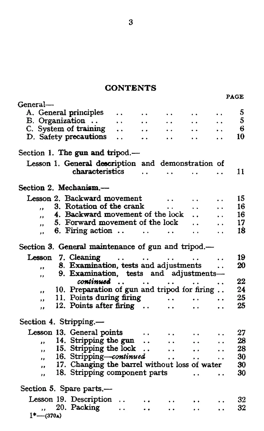
CONTENTS
PAGE
General—
A, General principles .. .. .. .. .. 5
Б. Organization .. .. .. .. .. .. 5
C. System of training.............................. 6
D. Safety precautions .. .. .. .. .. 10
Section 1. The gun and tripod.—
Lesson 1. General description and demonstration of
characteristics .. .. .. ., 11
Section 2. Mechanism.—
Lesson 2. Backward movement .. .. 15
, , 3. Rotation of the crank .. 16
„ 4. Backward movement of the lock . ♦ .. 16
„ 5. Forward movement of the lock .. .. 17
, , 6. Firing action .. .. .. 18
Section 3. General maintenance of gun and tripod.—
Lesson 7. Cleaning ................................19
„ 8. Examination, tests and adjustments .. 20
,, 9. Examination, tests and adjustments—
continued .. .. .. 22
,, 10. Preparation of gun and tripod for firing .. 24
,, 11. Points during firing .. .. .. 25
,, 12. Points after firing .. .. .. .. 25
Section 4. Stripping.—
Lesson 13. General points .. .. .. .. 27
„ 14. Stripping the gun.......................28
, , 15. Stripping the lock....................28
„ 16. Stripping—continued .. .. .. 30
„ 17. Changing the barrel without loss of water 30
„ 18. Stripping component parts .. .. 30
Section 5. Spare parts.—
Lesson 19. Description .. .. .. .. .. 32
,, 20. Packing .................................32
1*—(370a)
4
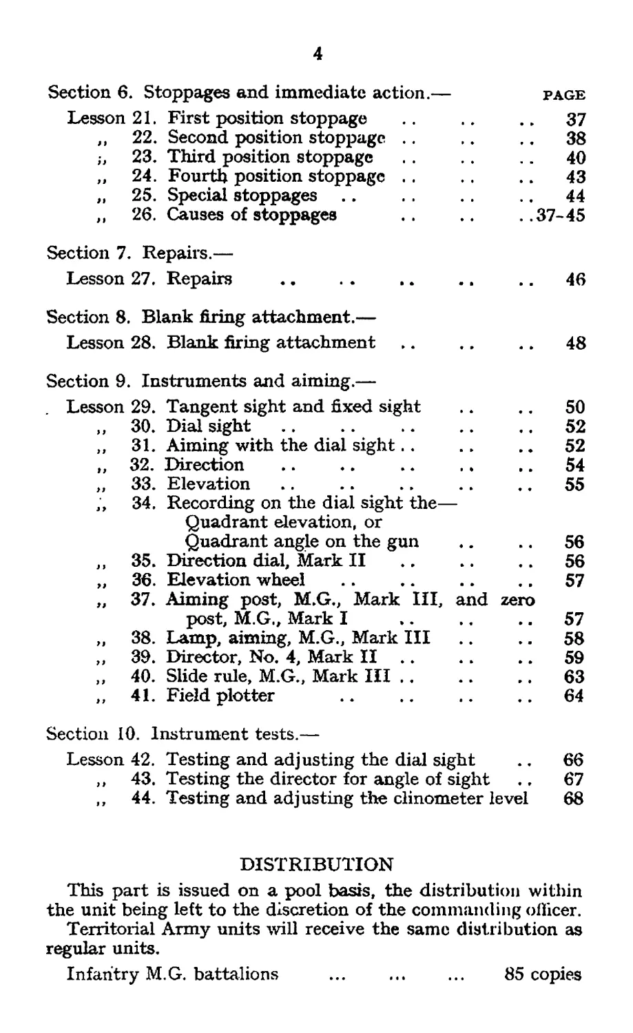
Section 6. Stoppages and immediate action.— page
Lesson 21. First position stoppage .. .. 37
,, 22. Second position stoppage .. .. .. 38
,, 23. Third position stoppage .. 40
,, 24. Fourth position stoppage .. .. 43
„ 25. Special stoppages .. . . .. 44
,, 26. Causes of stoppages . . .. . .37-45
Section 7. Repairs.—
Lesson 27. Repairs .. . . .. .. .. 46
Section 8. Blank firing attachment.—
Lesson 28. Blank firing attachment .. .. .. 48
Section 9. Instruments and aiming.—
. Lesson 29. Tangent sight and fixed sight .. .. 50
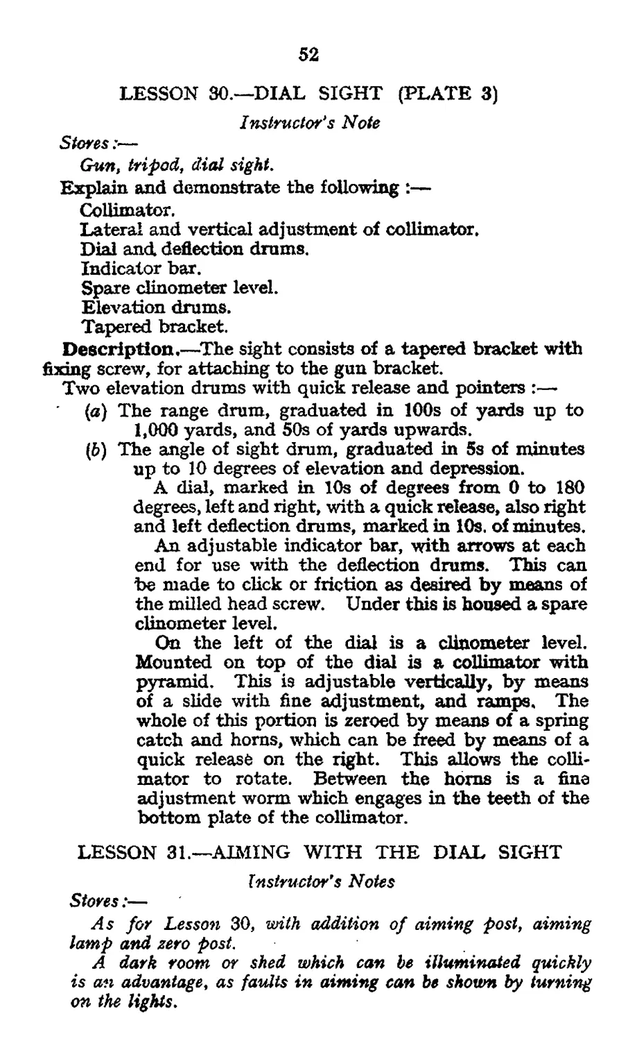
, , 30. Dial sight .. .. .. .. .. 52
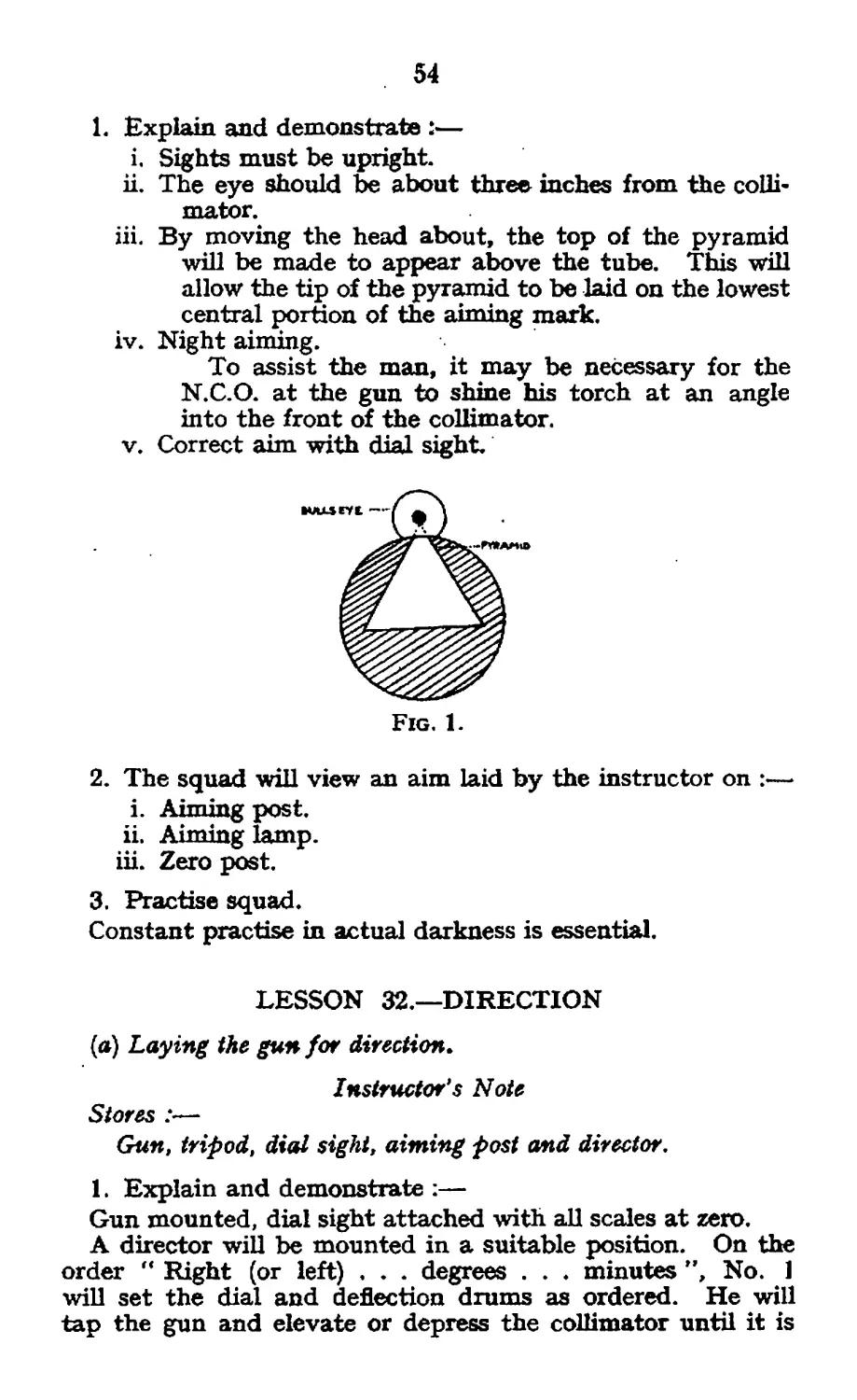
, , 31. Aiming with the dial sight.. .. .. 52
„ 32. Direction .. ♦. .. .. .. 54
„ 33. Elevation .. .. .. .. .. 55
3 4. Recording on the dial sight the—
Quadrant elevation, or
Quadrant angle on the gun .. .. 56
, , 35. Direction dial, Mark II .. .. .. 56
„ 36. Elevation wheel .. .. .. .. 57
„ 37. Aiming post, M.G., Mark III, and zero
post, M.G., Mark I ». .. .. 57
„ 38. Lamp, aiming, M.G., Mark III .. .. 58
„ 39. Director, No. 4, Mark II .. .. .. 59
„ 40. Slide rule, M.G., Mark III..................63
, , 41. Field plotter .. .. .. .. 64
Section 10. Instrument tests.—
Lesson 42. Testing and adjusting the dial sight .. 66
,, 43. Testing the director for angle of sight ., 67
,, 44. Testing and adjusting the clinometer level 68
DISTRIBUTION
This part is issued on a pool basis, the distribution within
the unit being left to the discretion of the commanding officer.
Territorial Army units will receive the same distribution as
regular units.
Infantry M.G. battalions ... ... ... 85 copies
5
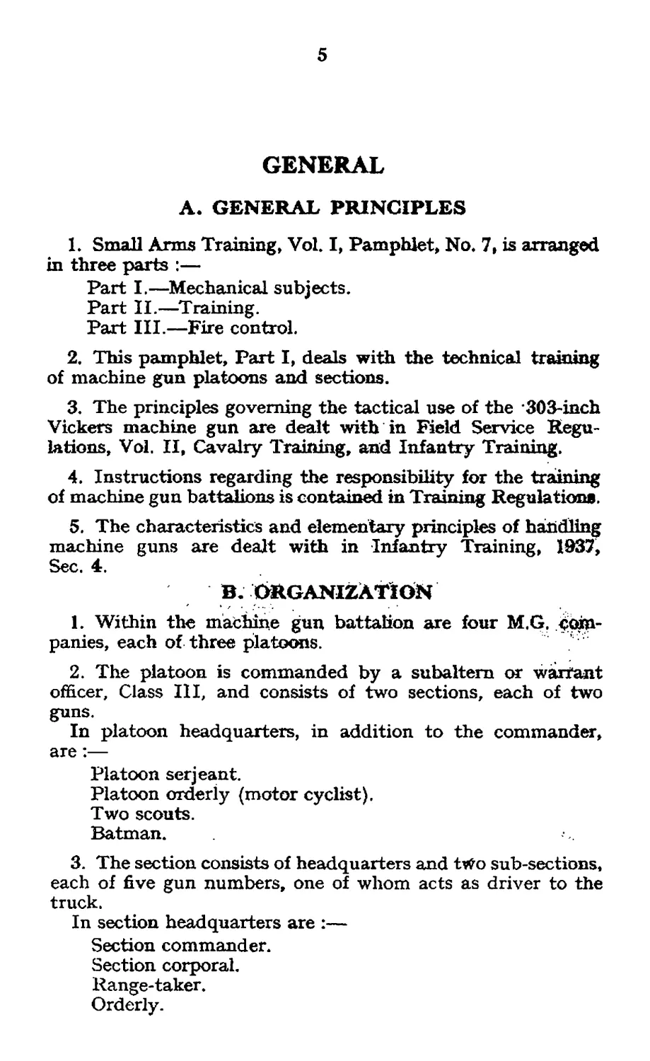
GENERAL
A. GENERAL PRINCIPLES
1. Small Arms Training, Vol. I, Pamphlet, No. 7, is arranged
in three parts :—
Part I. —Mechanical subjects.
Part II. —Training.
Part III. —Fire control.
2. This pamphlet, Part I, deals with the technical training
of machine gun platoons and sections.
3. The principles governing the tactical use of the ЗОЗ-тсЬ
Vickers machine gun are dealt with in Field Service Regu-
lations, Vol. II, Cavalry Training, and Infantry Training.
4. Instructions regarding the responsibility for the training
of machine gun battalions is contained in Training Regulations.
5. The characteristics and elementary principles of handling
machine guns are dealt with in Infantry Training, 1937,
Sec. 4.
B.ORGANIZATION
1. Within the machine gun battalion are four M.G. com-
panies, each of three platoons.
2. The platoon is commanded by a subaltern or warrant
officer, Class III, and consists of two sections, each of two
guns.
In platoon headquarters, in addition to the commander,
are:—
Platoon serjeant.
Platoon orderly (motor cyclist).
Two scouts.
Batman.
3. The section consists of headquarters and two sub-sections,
each of five gun numbers, one of whom acts as driver to the
truck.
In section headquarters are :—
Section commander.
Section corporal.
Range-taker.
Orderly.
6
4. The complete personnel, stores, equipment and ammuni-
tion of M.G, companies are carried in vehicles.
i. Company headquarters in trucks and lorries.
ii. Platoons in 6 trucks, sub-divided as under :—
Platoon headquarters .. 2 trucks.
Each section .. .. 2 trucks.
The distribution of personnel and stores of the M.G. platoon
is set out in Sec. 15.
C. SYSTEM OF TRAINING
1. General.—i. Before personnel can be considered in-
dividually fit to take their places in a M.G. platoon, they must
first receive instruction in preliminary training.
It is essential that this training be continuous ; where part
only can be carried out at the depot, the remainder must be
completed immediately after joining the battalion. This will
probably necessitate centralization under battalion arrange-
ments, the men not being posted to platoons until their
preliminary training has been completed.
ii. On completion of the preliminary training period such
personnel should receive further practice as opportunity offers,
as individuals in handling the gun, and complete their know-
ledge of mechanical detail. They will also begin training as
members of sub-sections in section and platoon collective
training exercises.
iii. Officers, N.C.Os. and potential N.C.Os. must receive
instruction in fire control and leadership.
iv. Personnel of both section and platoon headquarters must
receive instruction in their duties in the field.
This training of headquarters' personnel is an essential
preliminary to the handling of sections and platoons in the
field.
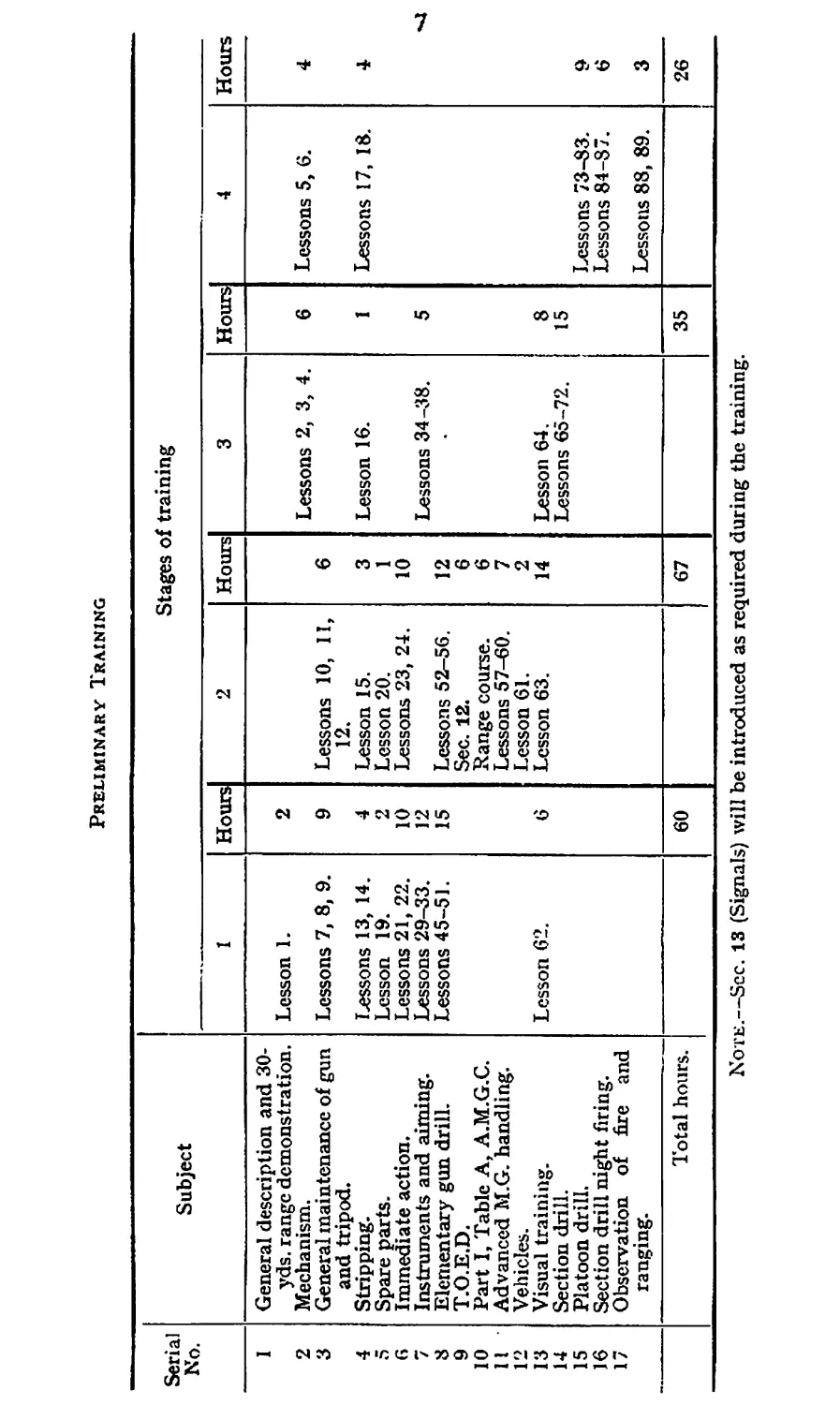
2. Preliminary training.—i. The table shown on p. 7
gives the subjects which must be taught in preliminary
training. As a guide for organizing that training the course
is shown divided into four stages, with a suggested number of
hours for each lesson or group of lessons. The sequence of
lessons in each stage should be arranged to suit local conditions.
The division into stages is not arbitrary nor does it attempt
to give a dividing line between depot and battalion periods.
ii. The practices of Part I, A, A.M.G.C., may be fired in any
order and at such times as instructors consider that individuals
have reached a sufficiently high standard of training.
They should not, however, be fired in one day.
Preliminary Training
Serial No. Subject Stages of training
1 Hours 2 Hours 3 Hours 4 Hours
I 2 3 4 5 6 7 8 9 10 II 12 13 14 15 16 17 General description and 30- yds. range demonstration. Mechanism. General maintenance of gun and tripod. Stripping. Spare parts. Immediate action. Instruments and aiming. Elementary gun drill. T.O.E.D. Part I, Table A, A.M.G.C. Advanced M.G. handling. Vehicles. Visual training. Section drill. Platoon drill. Section drill night firing. Observation of fire and ranging. Lesson 1. Lessons 7, 8, 9. Lessons 13, 14. Lesson 19. Lessons 21, 22. Lessons 29-33. Lessons 45-5 ]. Lesson 62. 2 9 4 2 10 12 15 6 Lessons 10, II, 12. Lesson 15. Lesson 20. Lessons 23, 24. Lessons 52-56. Sec. 12. Range course. Lessons 57-60. Lesson 61. Lesson 63. 6 3 1 10 12 6 6 7 2 14 Lessons 2, 3, 4. Lesson 16. Lessons 34-38. Lesson 64. Lessons 65-72. 6 1 5 8 15 Lessons 5, 6. Lessons 17, 18. Lessons 73-83. Lessons 84-87. Lessons 88, 89. 4 4 9 6 3
Total hours. 60 67 35 26
Note.—See. 13 (Signals) will be introduced as required during the training.
8
3. Subsequent training of private soldiers.—i. On
completion of preliminary training private soldiers will be
posted to platoons.
With the object of producing a higher standard of training,
further practice in all subjects taught in preliminary training
must be carried out, and, in addition, instruction must be
given in mechanical subjects, such as special stoppages and
causes of stoppages (Lessons 25 and 26), repairs (Lesson 27),
and blank firing attachment (Lesson 28).
ii. They should be exercised in the field in section and
platoon training exercises covering all tactical operations.
iii. Part I, B, A.M.G.C., should be fired during the weapon
training year in which the men join their battalions, and after
the completion of preliminary training. They may also be
required, if they have reached a sufficiently high standard of
training, to fire Parts III and IV of the A.M.G.C.
iv. Part II, A.M.G.C,, will be fired by the men in their
second weapon training year if they have qualified in Part I, В
(see Pamphlet No. 15).
v. Range-takers, orderlies and scouts, in addition to being
trained as gun numbers, will require instruction in their special
duties.
Range-takers will be trained in accordance with the instruc-
tions laid down in Pamphlet 10, and orderlies and scouts as
specified in Infantry Training and Infantry Section Leading.
Orderlies will also be trained to carry out certain technical
duties in the field (see Sec. 22).
vi. All ranks, in addition to their training as machine-
gunners, should receive instruction in driving mechanical
vehicles.
The importance of training in tactical driving cannot be
over-estimated.
vii. Judging distance tests will be carried out in accordance
with Sec. 16*
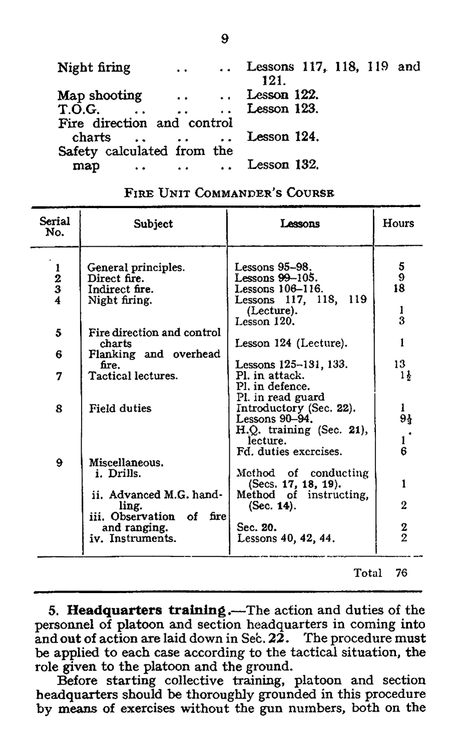
4. Officers and N.C.Os.—i. A suggested course in fire
control and leadership designed for junior officers and N.C.Os.,
with an allotment of hours to cover approximately three
weeks, is set out below. The organization of this course
should be centralized under battalion arrangements.
ii. In addition, officers and senior N.C.Os. should receive
further instruction in :—
Director, No. 4, Mark 11 .. Lesson 39.
Field plotter .. .. Lesson 41.
Testing director for angle of
sight .. .. .. Lesson 43.
Spotlight apparatus .. Appendix I, Part II.
9
Night firing
Map shooting
T.O.G......................
Fire direction and control
charts
Safety calculated from the
map
Lessons 117, 118, 119 and
121.
Lesson 122.
Lesson 123.
Lesson 124.
Lesson 132.
Fire Unit Commander's Course
Serial No. Subject Lessons Hours
1 General principles. Lessons 95-98. 5
2 Direct fire. Lessons 99-105. 9
3 Indirect fire. Lessons 106-116. 18
4 Night firing. Lessons 117, 118, 119
(Lecture). 1
Lesson 120. 3
5 Fire direction and control
charts Lesson 124 (Lecture). 1
6 Flanking and overhead
fire. Lessons 125-131, 133. 13
7 Tactical lectures. Pl. in attack. Pl. in defence. Pl. in read guard 4
8 Field duties Introductory (Sec. 22). 1
Lessons 90-94. H.Q. training (Sec. 21), 9$
lecture. Г
Fd. duties exercises. 6
9 Miscellaneous.
i. Drills. Method of conducting
(Secs. 17, 18, 19). 1
ii. Advanced M.G. hand- Method of instructing,
ling. (Sec. 14). 2
iii. Observation of fire
and ranging. Sec. 20. 2
iv. Instruments. Lessons 40, 42, 44. 2
Total 76
5. Headquarters training.—The action and duties of the
personnel of platoon and section headquarters in coming into
and out of action are laid down in Sec. 22. The procedure must
be applied to each case according to the tactical situation, the
role given to the platoon and the ground.
Before starting collective training, platoon and section
headquarters should be thoroughly grounded in this procedure
by means of exercises without the gun numbers, both on the
10
sand table and on the ground. This training can be carried
out at a time when the remaining personnel of the company
are otherwise employed.
The method of instruction is contained in Secs. 21 and 22.
D. SAFETY PRECAUTIONS
On all occasions when the gun and dummy cartridges
are used for instructional purposes, the instructor will
carry out the following safety precautions :-
1. Inspect all locks to ensure that the striker does
not protrude through the firing pin hole.
ii. Inspect all ammunition to ensure that all cartridges
are dummies.
Note.—When instruction is being given in mechanical
subjects, D.P. stores, if available, will always be used.
11
SECTION 1.—THE GUN AND TRIPOD
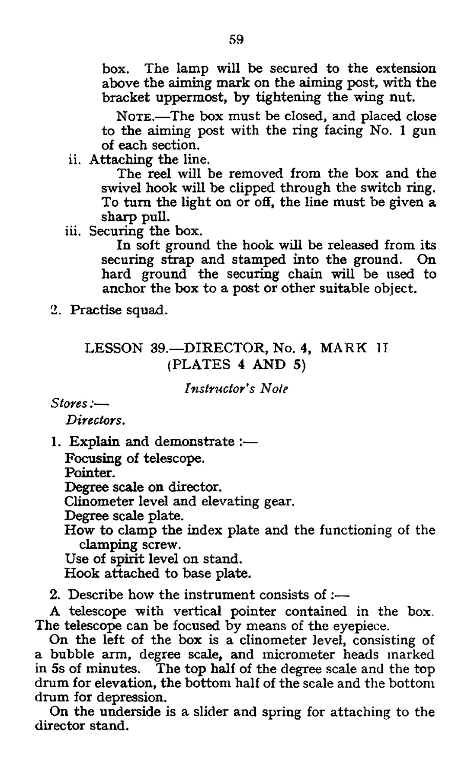
LESSON 1—GENERAL DESCRIPTION AND
DEMONSTRATION OF CHARACTERISTICS
Instructor’s Notes
Stores.—
Gun, tripod, belt box, belt and dummy cartridges, spare parts
case, condenser and tube, gun chest, spare barrel cleaning rod,
(Diagram if available.)
Do not expect the man to remember the names of all the parts.
Only mention the names of the main parts of the gun and
tripod, and point out these as they are named.
Strip the gun down and show the parts affected by recoil.
Emphasize the strength of all parts.
• Use diagrams (if available) when explaining the waler
cooling system.
Demonstration of characteristics should follow immediately
the general description.
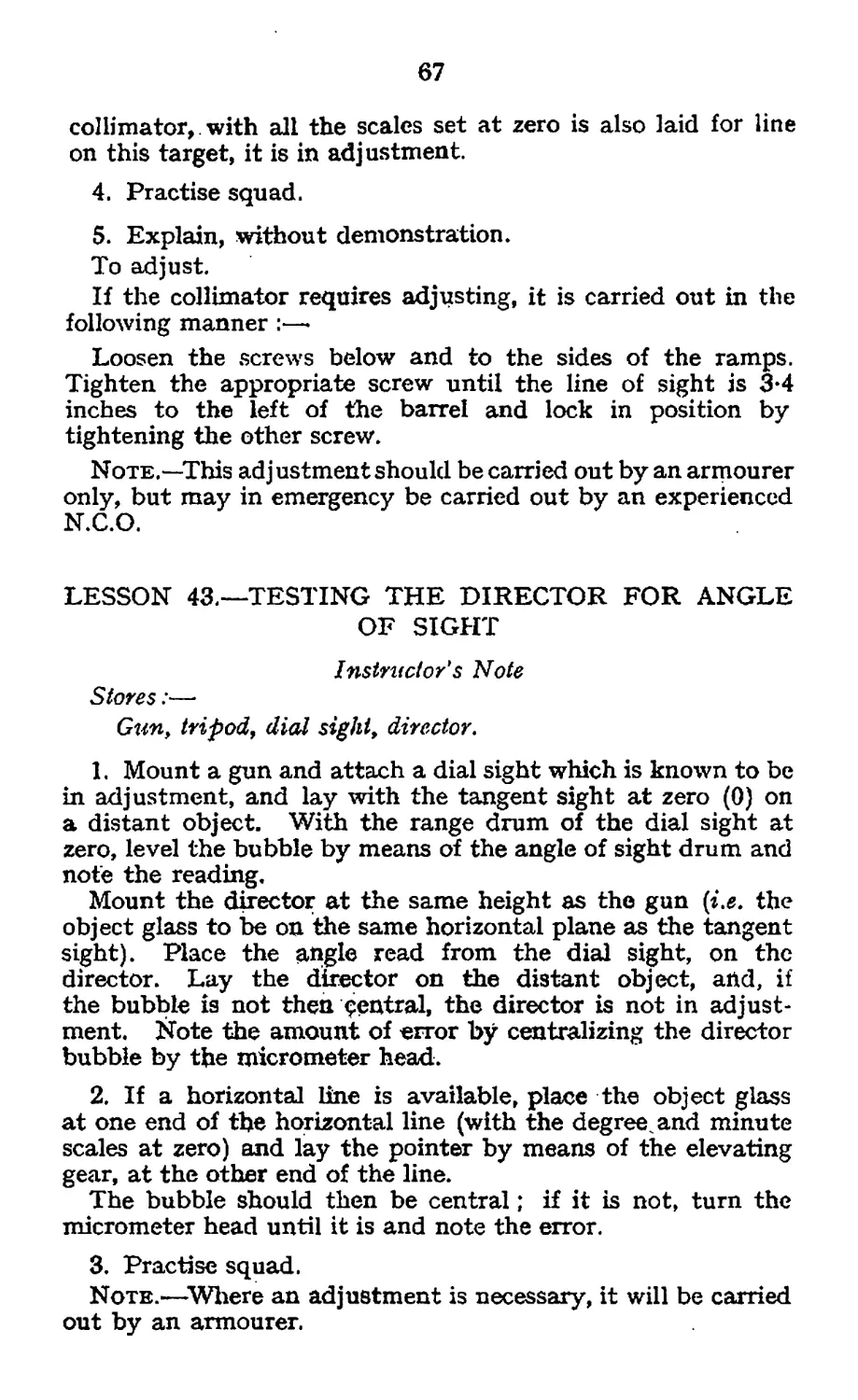
A. General Description (Plate 1)
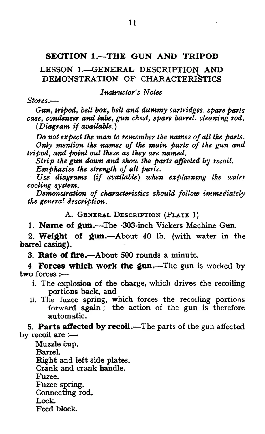
1. Name of gun.—The -303-inch Vickers Machine Gun.
2. Weight of gun.—About 40 lb. (with water in the
barrel casing).
3. Rate of fire*—About 500 rounds a minute.
4, Forces which work the gun.—The gun is worked by
two forces :—
i. The explosion of the charge, which drives the recoiling
portions back, and
ii. The fuzee spring, which forces the recoiling portions
forward again; the action of the gun is therefore
automatic.
5. Parts affected by recoil.—The parts of the gun affected
by recoil are :—►
Muzzle cup.
Barrel.
Right and left side plates.
Crank and crank handle.
Fuzee.
Fuzee spring.
Connecting rod.
Lock.
Feed block.
12
6. Barrel casing.—On the outside of the barrel casing are
fitted the muzzle attachment, the foresight, two screwed
plugs for filling and emptying the water, adapter for condenser,
and cork plug.
Inside the barrel casing are the barrel and steam tube. The
barrel is surrounded by water for cooling purposes. When
the gun is fired, the barrel becomes hot, which in turn heats
the water. After about 500 rounds the water boils and gives
off steam.
Inside and at the top of the barrel casing is the steam tube,
which is fitted with a sliding valve. On the steam tube are
three holes, one at the rear and two at the front.
When the gun is fired with elevation, the valve covers the
rear hole and allows the steam to enter the front hole and pass
out through the steam escape tube,.
When the gun is fired with depression, the valve covers the
front hole, thereby allowing the steam to enter the rear hole
and again pass out through the steam escape tube.
Fitted to the adapter is the condenser tube which carries
the steam from the steam escape tube into the condenser can.
In order to condense the steam, the condenser can must be
about two thirds full of water and the end of the condenser tube
placed below the level of the water.
7. Breech casing.—The breech casing consists of two out-
side plates, bottom plate, front and rear covers, and rear
cross-piece. On the left side of the breech casing are the
fuzee spring and box, a bracket with fittings for the dial sight,
and left slide ; on the right side the check lever and right slide.
On the rear cover is the tangent sight; on the bottom plate
the sliding shutter, and on the rear cross-piece are the
traversing handles, safety catch and thumb-piece. The rear
cross-piece is held in position by the T fixing pin.
8. Feed.—The gun is fed by a belt containing 250 rounds,
which passes through the feedblock from right to left.
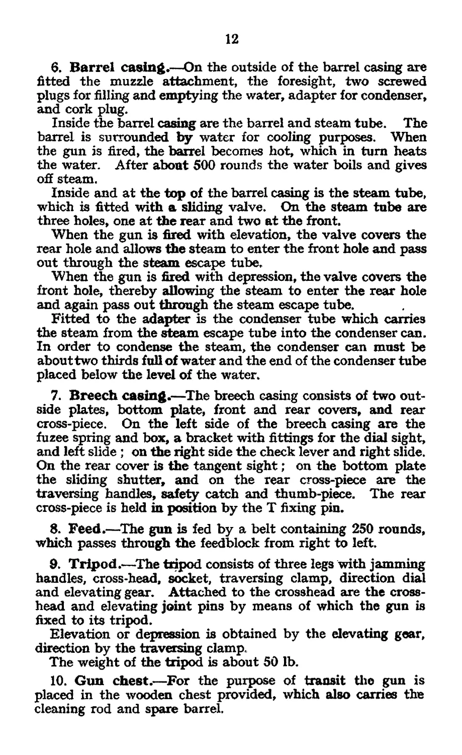
9. Tripod.—The tripod consists of three legs with jamming
handles, cross-head, socket, traversing clamp, direction dial
and elevating gear. Attached to the crosshead are the cross-
head and elevating joint pins by means of which the gun is
fixed to its tripod.
Elevation or depression is obtained by the elevating gear,
direction by the traversing clamp.
The weight of the tripod is about 50 lb.
10. Gun chest.—For the purpose of transit the gun is
placed in the wooden chest provided, which also carries the
cleaning rod and spare barrel.
Plate 1
Mounting, Tripod, -303-in., M.G., Mark IV
[To face p. 12.
SIDE ELEVATION.
47.
А /Хгг^Лл^ gear.
C. Socket
d. crosshead.
f. Screw. ctamp.checJirng Traverse,
g. Tumh/er. derating ^ear,
h. Qo/f.derating $«ar,
J Trent tys .
m. Shoes >
n. Sachet kgs .
s .Stud.joints. к jamming hand/e. Thant/гул.
t. Stud, pin к jamming hand/e, rear fcg.
К Chatn, securing, ehvah'ng serene.
nr. d/rechon dr'aT.
K.^/erah 'ng evheeT
g AdnTer, dt 'reeT/on drat (MTjO) .
je.ftdhfer. derating
13
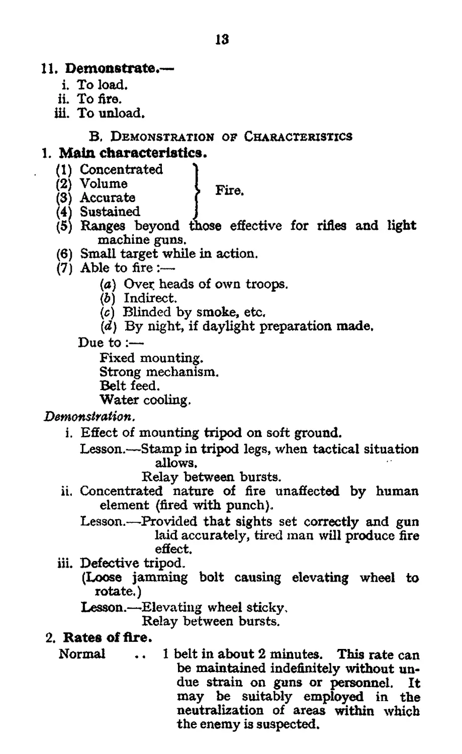
JFire.
ose effective for rifles and light
IL Demonstrate.—
i. To load,
ii. To fire.
Ш. To unload.
B. Demonstration of Characteristics
1. Main characteristics.
(1) Concentrated
(2) Volume
3) Accurate
(4) Sustained
(5) Ranges beyond
machine guns.
(6) Small target while in action.
(7) Able to fire:—
(a) Over, heads of own troops.
(b) Indirect.
($) Blinded by smoke, etc,
(iZ) By night, if daylight preparation made.
Due to:—
Fixed mounting.
Strong mechanism.
Belt feed.
Water cooling.
Demonstration.
i. Effect of mounting tripod on soft ground.
Lesson.—Stamp in tripod legs, when tactical situation
allows.
Relay between bursts.
ii. Concentrated nature of fire unaffected by human
element (fired with punch).
Lesson.—Provided that sights set correctly and gun
laid accurately, tired man will produce fire
effect.
iii. Defective tripod.
(Loose jamming bolt causing elevating wheel to
rotate.)
Lesson.—Elevating wheel sticky.
Relay between bursts.
2. Rates of fire.
Normal •. 1 belt in about 2 minutes. This rate can
be maintained indefinitely without un-
due strain on guns or personnel. It
may be suitably employed in the
neutralization of areas within which
the enemy is suspected.
14
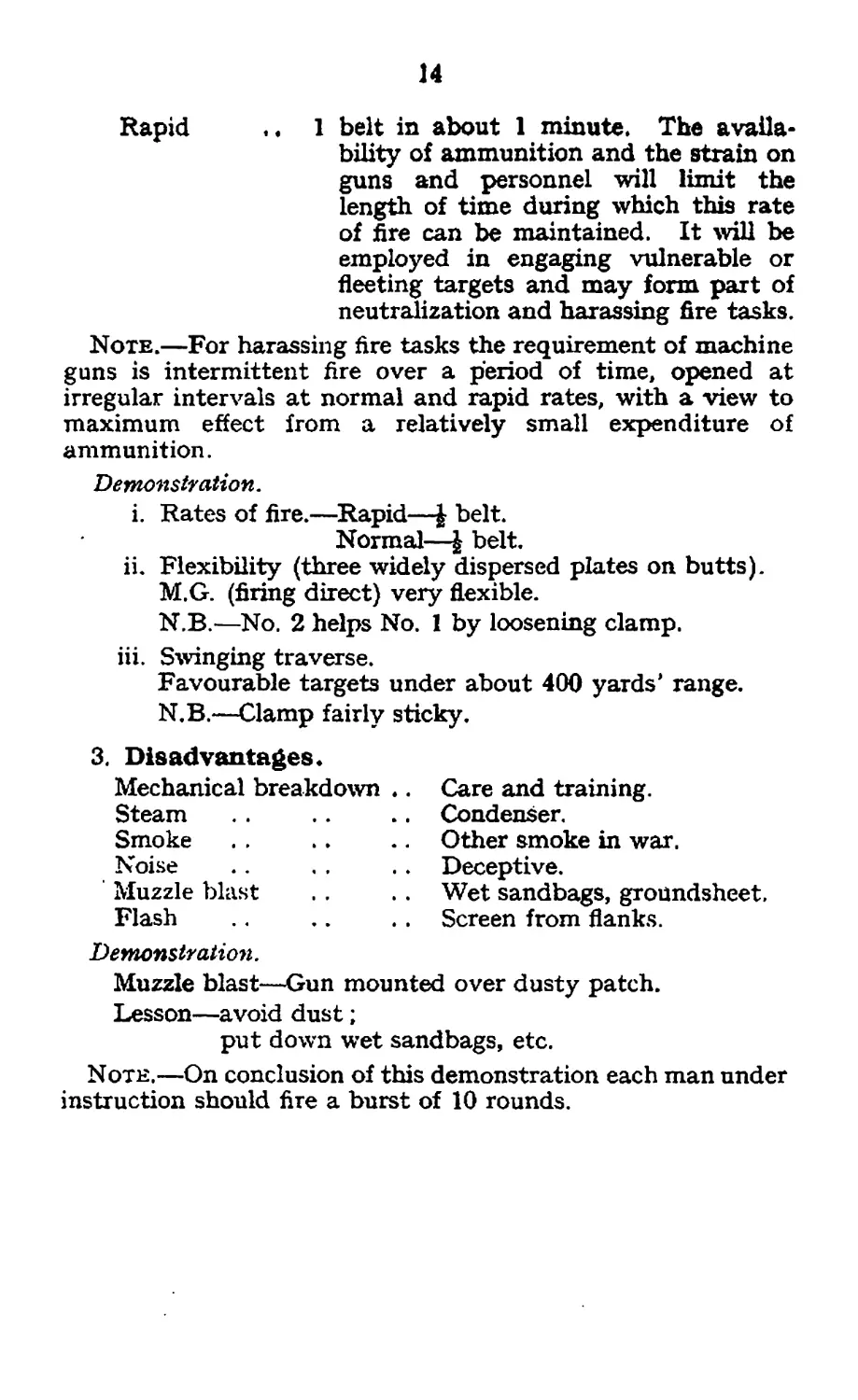
Rapid .. 1 belt in about 1 minute. The availa-
bility of ammunition and the strain on
guns and personnel will limit the
length of time during which this rate
of fire can be maintained. It will be
employed in engaging vulnerable or
fleeting targets and may form part of
neutralization and harassing fire tasks.
Note.—For harassing fire tasks the requirement of machine
guns is intermittent fire over a period of time, opened at
irregular intervals at normal and rapid rates, with a view to
maximum effect from a relatively small expenditure of
ammunition.
Demonstration.
i. Rates of fire.—Rapid—J belt.
Normal—J belt.
ii. Flexibility (three widely dispersed plates on butts).
M.G. (firing direct) very flexible.
N.B.—No. 2 helps No. 1 by loosening clamp.
iii. Swinging traverse.
Favourable targets under about 400 yards' range.
N.B.—Clamp fairly sticky.
3. Disadvantages*
Mechanical breakdown
Steam
Smoke
Noise
Muzzle blast
Flash
Care and training.
Condenser.
Other smoke in war.
Deceptive.
Wet sandbags, groundsheet.
Screen from flanks.
Demonstration.
Muzzle blast—Gun mounted over dusty patch.
Lesson—avoid dust;
put down wet sandbags, etc.
Note.—On conclusion of this demonstration each man under
instruction should fire a burst of 10 rounds.
15
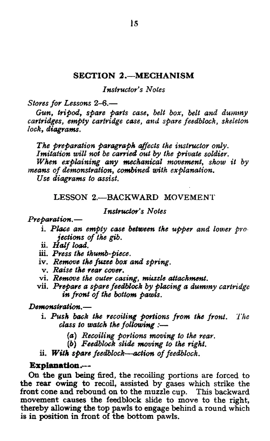
SECTION 2.—MECHANISM
Instructor's Notes
Stores for Lessons 2-6.—
Gun, tripod, spare parts case, belt box, belt and dummy
cartridges, empty cartridge case, and spare feedblock, skeleton
lock, diagrams.
The preparation paragraph affects the instructor only.
Imitation will not be carried out by the private soldier.
When explaining any mechanical movement, show it by
means of demonstration, combined with explanation.
Use diagrams to assist.
LESSON 2,—BACKWARD MOVEMENT
Instructor's Notes
Preparation. —
i. Place an empty case between the upper and lower pro
jections of the gib.
ii. Half load.
iii. Press the thumb-piece.
iv. Remove the fuzee box and spring.
v. Raise the rear cover.
vi. Remove the outer casing, muzzle attachment.
vii. Prepare a spare feedblock by placing a dummy cartridge
in front of the bottom pawls.
Demonstration. —
i. Push back the recoiling portions from the front. The
doss to watch the following :—
(a) Recoiling portions moving to the rear.
(&) Feedblock slide moving to the right.
ii. With spare feedblock—action of feedblock.
Explanation.—
On the gun being fired, the recoiling portions are forced to
the rear owing to recoil, assisted by gases which strike the
front cone and rebound on to the muzzle cup. This backward
movement causes the feedblock slide to move to the right,
thereby allowing the top pawls to engage behind a round which
is in position in front of the bottom pawls.
16
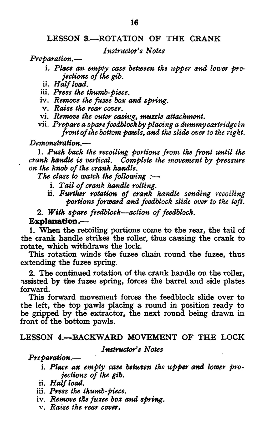
LESSON 3.—ROTATION OF THE CRANK
Instructor's Notes
Preparation.—
i. Place an empty case between the upper and lower pro-
jections of the gib.
ii. Half load.
iii. Press the thumb-piece.
iv. Remove the fuzee box and spring.
v. Raise the rear cover.
vi. Remove the outer casing, muzzle attachment.
vii. Prepare a spare feedblock by placing a dummy cartridge in
front of the bottom pawls, and the slide over to the right.
Demonstration.—
1. Push back the recoiling portions from the front until the
crank handle is vertical. Complete the movement by pressure
on the knob of the crank handle.
The class to watch the following :—►
i. Tail of crank handle rolling.
ii. Further rotation of crank handle sending recoiling
portions forward and feedblock slide over to the left.
2. With spare feedblock—action of feedblock.
Explanation*—
1. When the recoiling portions come to the rear, the tail of
the crank handle strikes the roller, thus causing the crank to
rotate, which withdraws the lock.
This rotation winds the fuzee chain round the fuzee, thus
extending the fuzee spring.
2. The continued rotation of the crank handle on the roller,
assisted by the fuzee spring, forces the barrel and side plates
forward.
This forward movement forces the feedblock slide over to
the left, the top pawls placing a round in position ready to
be gripped by the extractor, the next round being drawn in
front of the bottom pawls.
LESSON 4.—BACKWARD MOVEMENT OF THE LOCK
Instructor's Notes
Preparation.—
i. Place an empty case between the upper and lower pro-
jections of the gib.
ii. Half load.
iii. Press the thumb-piece.
iv. Remove the fuzee box and spring.
v. Raise the rear cover.
17
Demonstration.—
1. Draw back the recoiling portions from the rear.
The class to watch the following :—
i. Live round and empty case being withdrawn.
ii. Live round being brought in line with chamber.
iii. Rotation of the tumbler.
2. (With skeleton lock.)
The class io watch :—
L Rotation of tumbler.
ii. Withdrawal of firing pin.
iii. Compression of lock spring.
iv. Action of sear.
Explanation.—
As the lock comes to the rear, it brings with it a live round
from the feedblock, and an empty case from the chamber.
When the horns of the extractor reach the rear of the cams,
the extractor is forced down by the ramps on the rear cover,
thus bringing the live round in line with the chamber; the
empty case probably falls off. During this movement the
side lever head is raised and bears on the tail of the tumbler.
This rotation of the tumbler withdraws the firing pin which
compresses the lock spring. The firing pin is held back by the
sear.
LESSON 5,—FORWARD MOVEMENT OF THE LOCK
Instructor's Notes
Preparation.
i. Half load.
ii. Remove the fuzee box and spring.
iii. Pull the crank handle on to the roller and pull the belt.
iv. Raise the rear cover.
Demonstration.
Force the crank handle on to the check lever.
The class to watch the following:—
Fuzee chain unwinding.
Lock going forward.
Explanation.—
The fuzee spring rotates the crank and forces the lock
forward. The extractor places the live round in the chamber
and, being forced to rise b/the action of the side and extractor
levers, thus grips the round in position in the feedblock. The
firing pin hole is now opposite the round in the chamber.
If the empty case has not fallen off, it will be forced off when the
extractor rises.
18
LESSON 6.—-FIRING ACTION
Instructor's Notes
Preparation.
i. Half load.
ii. Remove the trigger bar.
iii. Pull the crank handle on to the roller and pull ike belt.
iv. Raise the rear cover.
De monstration.
i. (a) Allow the lock to go forward showing the side lever
head depressing the sear.
(b) Place the trigger bar over trigger and trigger bar
lever.
{c} Press the thumb-piece and show trigger bar pulling
back the tail of the trigger.
(d) Show pressure being released from the thumb-piece
and the action of the trigger bar.
ii. With skeleton lock—repeat i. (a), i. ($) and L (4), above.
Explanation.—
1. Each, time the lock goes forward the side lever head
depresses the sear, thus allowing the firing pin to move forward
until checked by the nose of the trigger engaging in the bent
of the tumbler. If the safety catch is raised and the thumb-
piece pressed, the trigger bar is withdrawn, which in turn
disengages the nose of the trigger from the bent of the tumbler.
The firing pin is now driven forward by the lock spring.
2. When pressure on the thumb-piece is maintained, con-
tinuous fire will result, as the trigger will be kept out of action.
When this pressure is released, the nose of the trigger
re-engages in the bent of the tumbler and prevents the firing
pin from going forward.
19
SECTION 3.—GENERAL MAINTENANCE OF GUN
AND TRIPOD
1. Care and cleaning of the gun is of the utmost importance
in order that the gun may fulfil an}" task demanded of it.
2. Machine guns and equipment should be examined when
first taken over. Further frequent examinations will also be
necessary.
Instructor*s Note
Stores for Lessons 7-12.—
Gun, tripod, belt boxes, belt with dummy cartridges, spare
parts, box and case, condenser can and lube, cleaning rod,
flannelette and old linen,
LESSON 7.—CLEANING
1. Daily cleaning.—The outside of the gun will oe cleaned
daily, and all parts of the mechanism which can be reached
without stripping will be wiped over with an oily rag. The
inside of the barrel will be left oily. On completion of daily
cleaning the gun will be inspected both for cleanliness and
damage. In examining the barrel the mirror reflector will be
used.
To clean the barrel.—Take out the lock, take off the muzzle
attachment and muzzle cup. Place a piece of dry flannelette
(4 by 2) in the eye of the cleaning rod and insert it into the
muzzle end of the barrel. Ensure that the bush is over the
muzzle, and. move the rod backwards aiid forwards. Repeat
with fresh pieces of flannelette until the barrel is clean.
To oil the barrel.—’Repeat the above with a smaller piece
of flannelette well soaked in oil.
To use the double pull-through.—Before use it is essential
to see that the weight is not bent and that the cord is in good
condition. Ensure that the gauze is thoroughly oiled and
that the muzzle protector is placed on the barrel. The barrel
may either be left in the gun or taken out for the purpose of
cleaning. If left in the gun, proceed as follows :—
Take out the lock. Take out the elevating joint pin and
depress the gun. Pass the pull-through from the breech end
through the barrel. Lower the rear cross-piece. Replace the
elevation joint pin. Pass the loop, end on the pull-through
under the crank and replace the lock in the ° Clear Gun M
2*----(370a)
20
position. The pull-through is then pulled backwards and
forwards through the barrel. Care must be taken to keep the
cord taut and prevent wear on the breech end of the barrel.
If the barrel is removed from the gun for cleaning, it should
be fixed in a suitable vice or held firmly by a man.
An effective means of cleaning the barrel is with boiling
water. Having removed the barrel from the gun, adopt the
same procedure as used in cleaning the rifle (see Pamphlet
No. 3, page 15).
2. Weekly cleaning.—The gun will be stripped down and
all parts cleaned and left dry for inspection. Wbere the bore
has become rusty, it should be wiped out with flannelette;
boiling water should then be used, and, finally, the barrel
cleaned with the double pull-through.
After inspection the gun will be oiled before being put away.
Spare parts and stores will also be examined and checked.
LESSON 8.—EXAMINATION, TESTS
AND ADJUSTMENTS
1. Muzzle attachment. Free from fouling and burrs, disc
cleaned, split pin and chain in good condition.
2. Muzzle cup. Clean, threads neither damaged nor badly
worn.
3. Steam tube. Keeper screw in correct position, sliding
valve working. (To test this, take the gun off the tripod and
give it a rocking movement. The movement of the valve
should then be heard.)
4. Foresight. Blade in good condition.
5. Front cover catch. Working correctly.
6. Fuzee spring and fuzee. Claws of spring, fuzee and
chain in good condition. Vice pin not bent.
Instructions for weighing and adjusting the fuzee spring.—
Take out the lock and place the loop of the spring balance
over the knob of the crank handle. Pull the balance vertically
upwards, resting the wrist on the breech casing. The reading
indicated when the crank handle begins to move will be the
weight of the fuzee spring. This weight should be between
7 and 9 lb. If the spring is over, or not up to, weight, adjust
by means of the vice pin. Generally six clicks (three revolu-
tions) make a difference of about 1 lb. Turning the vice pin
upwards decreases the weight and vice versa. The tension
of the fuzee spring should always be kept as high as possible,
consistent with maintaining the normal rate of fire of about
500 rounds a minute.
21
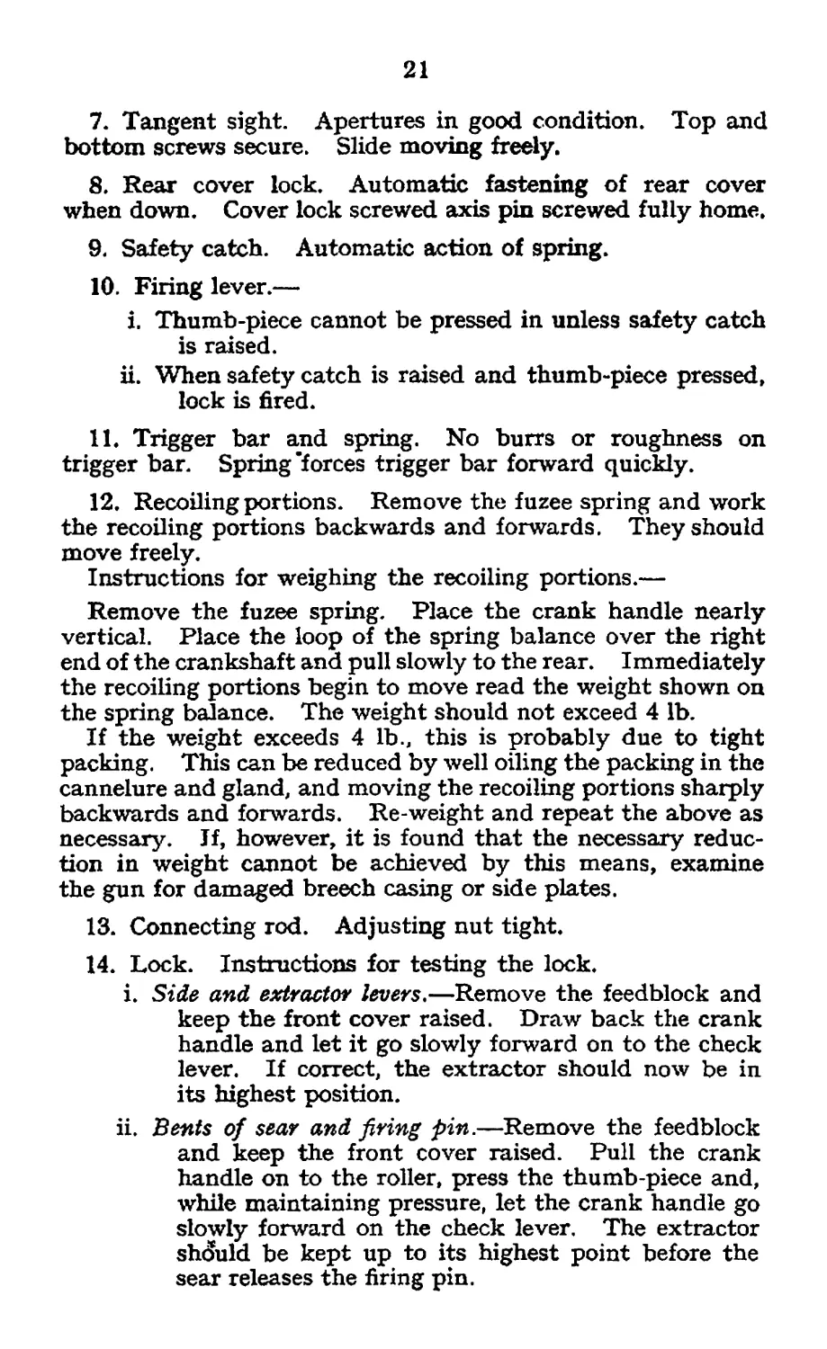
7. Tangent sight. Apertures in good condition. Top and
bottom screws secure. Slide moving freely.
8. Rear cover lock. Automatic fastening of rear cover
when down. Cover lock screwed axis pin screwed fully home.
9. Safety catch. Automatic action of spring.
10. Firing lever.—
i. Thumb-piece cannot be pressed in unless safety catch
is raised.
ii. When safety catch is raised and thumb-piece pressed,
lock is fired.
11. Trigger bar and spring. No burrs or roughness on
trigger bar. Spring’forces trigger bar forward quickly.
12. Recoiling portions. Remove the fuzee spring and work
the recoiling portions backwards and forwards. They should
move freely.
Instructions for weighing the recoiling portions.—
Remove the fuzee spring. Place the crank handle nearly
vertical. Place the loop of the spring balance over the right
end of the crankshaft and pull slowly to the rear. Immediately
the recoiling portions begin to move read the weight shown on
the spring balance. The weight should not exceed 4 lb.
If the weight exceeds 4 lb., this is probably due to tight
packing. This can be reduced by well oiling the packing in the
cannelure and gland, and moving the recoiling portions sharply
backwards and forwards. Re-weight and repeat the above as
necessary. Jf, however, it is found that the necessary reduc-
tion in weight cannot be achieved by this means, examine
the gun for damaged breech casing or side plates.
13. Connecting rod. Adjusting nut tight.
14. Lock. Instructions for testing the lock.
i. Side and extractor levers.—Remove the feedblock and
keep the front cover raised. Draw back the crank
handle and let it go slowly forward on to the check
lever. If correct, the extractor should now be in
its highest position.
ii. Bents of sear and firing pin.—Remove the feedblock
and keep the front cover raised. Pull the crank
handle on to the roller, press the thumb-piece and,
while maintaining pressure, let the crank handle go
slowly forward on the check lever. The extractor
should be kept up to its highest point before the
sear releases the firing pin.
22
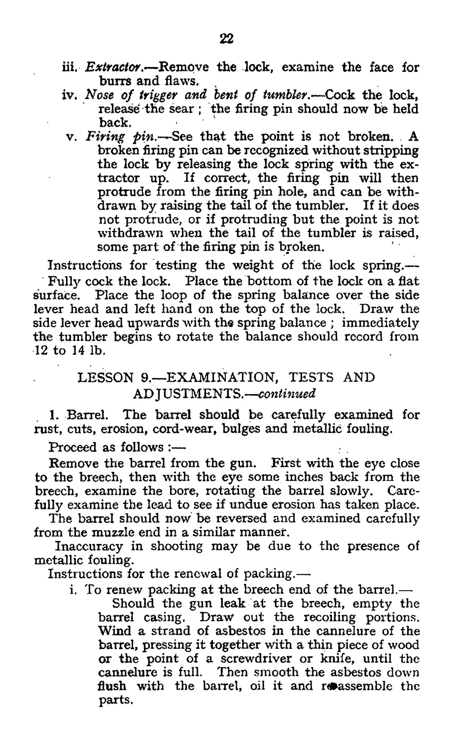
iii, Extractor,—Remove the lock, examine the face for
burrs and flaws,
iv. Nose of trigger and bent of tumbler.—Cock the lock,
release the sear ; the firing pin should now be held
back.
v. Firing pin.-^-See that the point is not broken. A
broken firing pin can be recognized without stripping
the lock by releasing the lock spring with the ex-
tractor up. If correct, the firing pin will then
protrude from the firing pin hole, and can be with-
drawn by raising the tail of the tumbler. If it does
not protrude, or if protruding but the point is not
withdrawn when the tail of the tumbler is raised,
some part of the firing pin is broken.
Instructions for testing the weight of the lock spring.—
Fully cock the lock. Place the bottom of the lock on a flat
surface. Place the loop of the spring balance over the side
lever head and left hand on the top of the lock. Draw the
side lever head upwards with the spring balance ; immediately
the tumbler begins to rotate the balance should record from
12 to 14 lb.
LESSON 9,—EXAMINATION, TESTS AND
ADJUSTMENTS.—-continued
1. Barrel. The barrel should be carefully examined for
rust, cuts, erosion, cord-wear, bulges and metallic fouling.
Proceed as follows :—
Remove the barrel from the gun. First with the eye close
to the breech, then with the eye some inches back from the
breech, examine the bore, rotating the barrel slowly. Care-
fully examine the lead to see if undue erosion has taken place.
The barrel should now be reversed and examined carefully
from the muzzle end in a similar manner.
Inaccuracy in shooting may be due to the presence of
metallic fouling.
Instructions for the renewal of packing.—
i. To renew packing at the breech end of the barrel.—
Should the gun leak at the breech, empty the
barrel casing. Draw out the recoiling portions.
Wind a strand of asbestos in the cannelure of the
barrel, pressing it together with a thin piece of wood
or the point of a screwdriver or knife, until the
cannelure is full. Then smooth the asbestos down
flush with the barrel, oil it and reassemble the
parts.
23
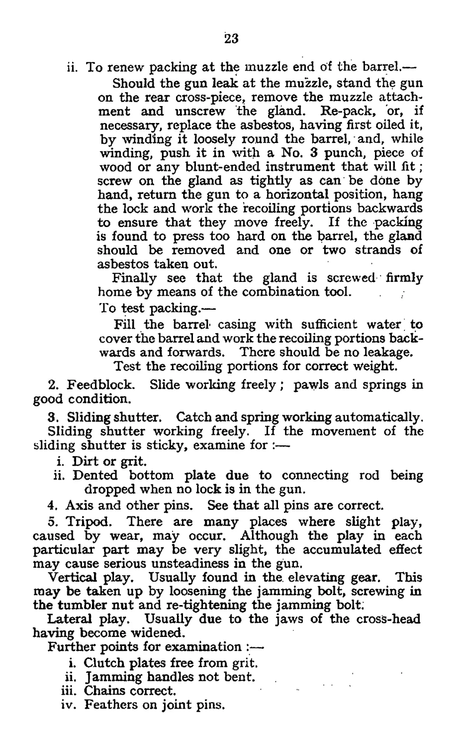
ii. To renew packing at the muzzle end of the barrel.—
Should the gun leak at the muzzle, stand the gun
on the rear cross-piece,, remove the muzzle attach-
ment and unscrew the gland. Re-pack, or, if
necessary, replace the asbestos, having first oiled it,
by winding it loosely round the barrel, and, while
winding, push it in with a No. 3 punch, piece of
wood or any blunt-ended instrument that will fit ;
screw on the gland as tightly as can be done by
hand, return the gun to a horizontal position, hang
the lock and work the recoiling portions backwards
to ensure that they move freely. If the packing
is found to press too hard on the barrel, the gland
should be removed and one or two strands of
asbestos taken out.
Finally see that the gland is screwed firmly
home by means of the combination tool.
To test packing.—
Fill the barrel casing with sufficient water; to
cover the barrel and work the recoiling portions back-
wards and forwards. There should be no leakage.
Test the recoiling portions for correct weight.
2. Feedblock. Slide working freely ; pawls and springs in
good condition.
3. Sliding shutter. Catch and spring working automatically.
Sliding shutter working freely. If the movement of the
sliding shutter is sticky, examine for :—
i. Dirt or grit.
ii. Dented bottom plate due to connecting rod being
dropped when no lock is in the gun.
4. Axis and other pins. See that all pins are correct.
5. Tripod. There are many places where slight play,
caused by wear, may occur. Although the play in each
particular part may be very slight, the accumulated effect
may cause serious unsteadiness in the gun.
Vertical play. Usually found in the. elevating gear. This
may be taken up by loosening the jamming bolt, screwing in
the tumbler nut and re-tightening the jamming bolt;
Lateral play. Usually due to the jaws of the cross-head
having become widened.
Further points for examination :—
i. Clutch plates free from grit.
ii. Jamming handles not bent.
iii. Chains correct.
iv. Feathers on joint pins.
24
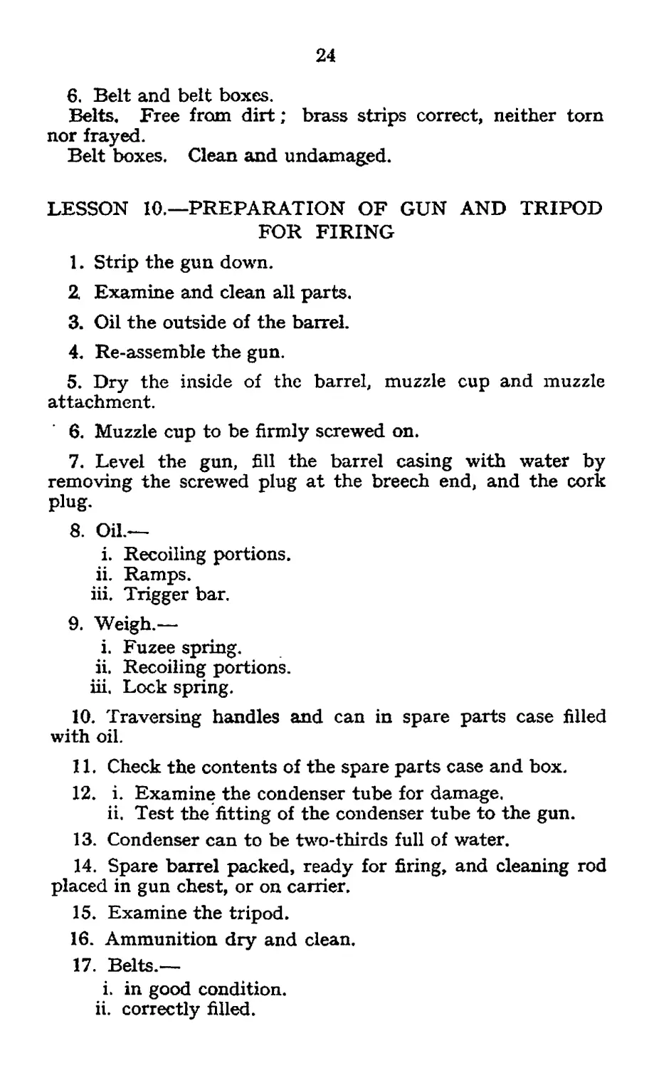
6. Belt and belt boxes.
Belts. Free from dirt; brass strips correct, neither torn
nor frayed.
Belt boxes. Clean and undamaged.
LESSON 10,—PREPARATION OF GUN AND TRIPOD
FOR FIRING
1. Strip the gun down.
2. Examine and clean all parts.
3. Oil the outside of the barrel.
4. Re-assemble the gun.
5. Dry the inside of the barrel, muzzle cup and muzzle
attachment.
6. Muzzle cup to be firmly screwed on.
7. Level the gun, fill the barrel casing with water by
removing the screwed plug at the breech end, and the cork
plug.
8. Oil.—
i. Recoiling portions.
ii. Ramps.
iii. Trigger bar.
9. Weigh.—
i. Fuzee spring.
ii. Recoiling portions.
iii. Lock spring.
10. Traversing handles and can in spare parts case filled
with oil.
11. Check the contents of the spare parts case and box.
12. i. Examine the condenser tube for damage.
ii. Test the fitting of the condenser tube to the gun.
13. Condenser can to be two-thirds full of water.
14. Spare barrel packed, ready for firing, and cleaning rod
placed in gun chest, or on carrier.
15. Examine the tripod.
16. Ammunition dry and clean.
17. Belts.—
i. in good condition.
ii. correctly filled.
25
18. Examine the belt boxes.
Action in cold weather. Keep the friction of the recoiling
portions as low as possible, i.e. between two and three lb.,
and adjust the weight of the fuzee spring to not more than
seven lb. at the start. Remove all old oil from the lock and
keep the front face and slide of the extractor, also the extractor
levers, free from oil. Wrap straw, sacking or blankets round
the barrel casing. Work the recoiling portions by hand at
frequent intervals.
Action in sandy countries. Ensure that only a small
quantity of oil is used.
Working parts wiped over with a slightly oily rag will
prevent rust through the night and will be sufficient lubrication
for working the gun during firing.
LESSON 11.—POINTS DURING FIRING
1. Watch the water supply. (As soon as the water begins
to boil, and so long as it continues to boil, about If pints will
be lost for every two belts fired.)
2. Ensure that the belt.—
i. Is kept in line with the feedblock.
ii. Has free movement.
3. See that all repairs are carried out immediately.
Lock repairs.—To replace any part of the lock, the ordinary
sequence for stripping the lock must be followed, until the
required part is reached.
In the case of a lock spring, where the broken portions fall
clear, a new lock spring may be assembled without stripping
the lock.
4. During a temporary cessation of fire.—
i. Oil up :—bearing parts of barrel;
recoiling portions (except muzzle cup) ;
ramps ;
trigger bar.
ii. Ensure that the front cone, muzzle cup and jamming
handles are tight, and that the end of the condenser
tube is in the condenser can below water level.
5. Anti-gas measures.
See Pamphlet No. 3, Lesson 4.
LESSON 12.—POINTS AFTER FIRING
1. On the range.—
i. Unload, remove the lock, muzzle attachment and
muzzle cup.
26
ii. Clean the barrel of superficial fouling with the cleaning
rod and oiled flannelette, followed by dry
flannelette.
iii. Use the double pull-through to remove any metallic
fouling which is still left in the barrel.
iv. Re-oil the barrel with the cleaning rod.
v. Oil the muzzle cup, muzzle attachment and lock.
vi. Re-assemble the gum
vii. Sort live rounds from empty cases.
Note.—It may assist in the cleaning of the barrel on return
to barracks if the water is left in the barrel casing.
2. On return to barracks.—
i. Strip the gun and thoroughly clean all parts.
ii. Release tension from the fuzee spring.
iii. Pour boiling water through the barrel and then, if
necessary, use the double pull-through.
iv. In order to prevent the formation of rust on the
exterior of the barrel due to condensation of
moisture, completely empty the barrel casing,
and remove the screwed and cork plugs to permit
the free circulation of air through the casing.
If the gun is likely to be so left for any length of
time, remove the asbestos packing from the can-
nelure and gland.
v. Clean and overhaul the tripod, belts and belt boxes,
spare parts and ammunition.
(a) Belts :—Dry wet belts.
If dirty or greasy, clean by soaking for two
hours in a solution consisting of :—
One part soda.
Three parts soft soap.
Ten parts water.
After soaking scrub, and when dry, plug the
belts with the belt plug. Care must be taken
in using the belt plug, or loose pockets will
result.
(d) Belt boxes.—Remove all dirt and mud, and
wipe over the outside with an oily rag.
27
SECTION 4.- STRIPPING
Instructor's Notes
Stores.—
Gun, tripod, spare parts, case and box.
i. Lay emphasis on the “ Points to be observed ** section.
ii. The squad should be proficient in Lessons 13. 14, 15, 16
and 17 before going on to Lesson 18.
LESSON 13.—GENERAL POINTS
1. Use the correct tool, e.g. screwdrivers according to the size
of the screw, correct punches, etc. If this rule is not observed,
screws get burred and can only be removed by an artificer.
2. Before attempting to withdraw screwed axis pins; make
certain that the threads of the screw are fully unscrewed.
3. When replacing screwed axis pins, do not use force ; the
threads will engage without unnecessary pressure.
If this rule is not observed, the threads (which are extremely
fine) will become so burred that it will be impossible to replace
the pin, e.g. cover lock, screwed axis pin.
4. When raising the rear cover, do not throw it upwards,
but lift it. The hinges are liable to strain. Before lowering
see that the lock is correctly in the gun.
5. * Before closing down the front cover, see that the feedblock
is correctly in position and the front cover catch raised.
6. The firing pin should never be released unless the extractor
is up against the top stop.
7. When removing parts secured by chains, do not tug on
the chain; otherwise they get broken and the part eventually
is lost, e.g. outer casing split pin, cork plug, screwed plugs,
tripod pins.
8. With reasonable care defects and breakages in machine*
guns should be of extremely rare occurrence. They are
simply due to neglect of ordinary precautions.
9. Direct hammer blows must never fall on any part of the
gun. Wood must always be placed over the part to receive
blows from a hammer or mallet.
10. In stripping examinations no time limit will be imposed,
in order to avoid damage to the gun by careless handling.
28
LESSON 14,—STRIPPING THE GUN
1. Lock. Unload, pull the crank handle on to the roller,
raise the rear cover, see that the extractor drops, place the
linger between the extractor and stop and lift the lock—at the
same time allowing the crank handle to move slowly forward
until the lock is released from the side plate. Give the lock
a slight turn and lift it out.
2. Muzzle attachment. Withdraw the split pin, turn the
outer casing and remove it. Unscrew and remove the muzzle
cup.
3. Feedblock. Raise the front cover and lift out.
4. Fuzee spring box. With the right hand at the rear and
the left at the front, press the box forward until clear of the
stud and remove. Disconnect the fuzee chain and remove
the box and the spring.
5. Fuzee. Turn the fuzee to the rear until the lugs on the
stem are free to be withdrawn.
6. Recoiling portions. Raise the rear cover, unscrew the
T fixing pin and lower the rear cross-piece ; remove the right
and left slides and draw out the barrel and side plates, Dis-
connect the side plates, removing the left one first.
To assemble the gun.—
1. Reverse all the foregoing operations.
2. When assembling the barrel and side plates, ensure that
the radial groove is uppermost and that no force is used. If
the side plates are not home on the barrel trunnions and
crankshaft, the barrel must be withdrawn and the side plates
properly assembled; otherwise burrs on the crankshaft may
occur.
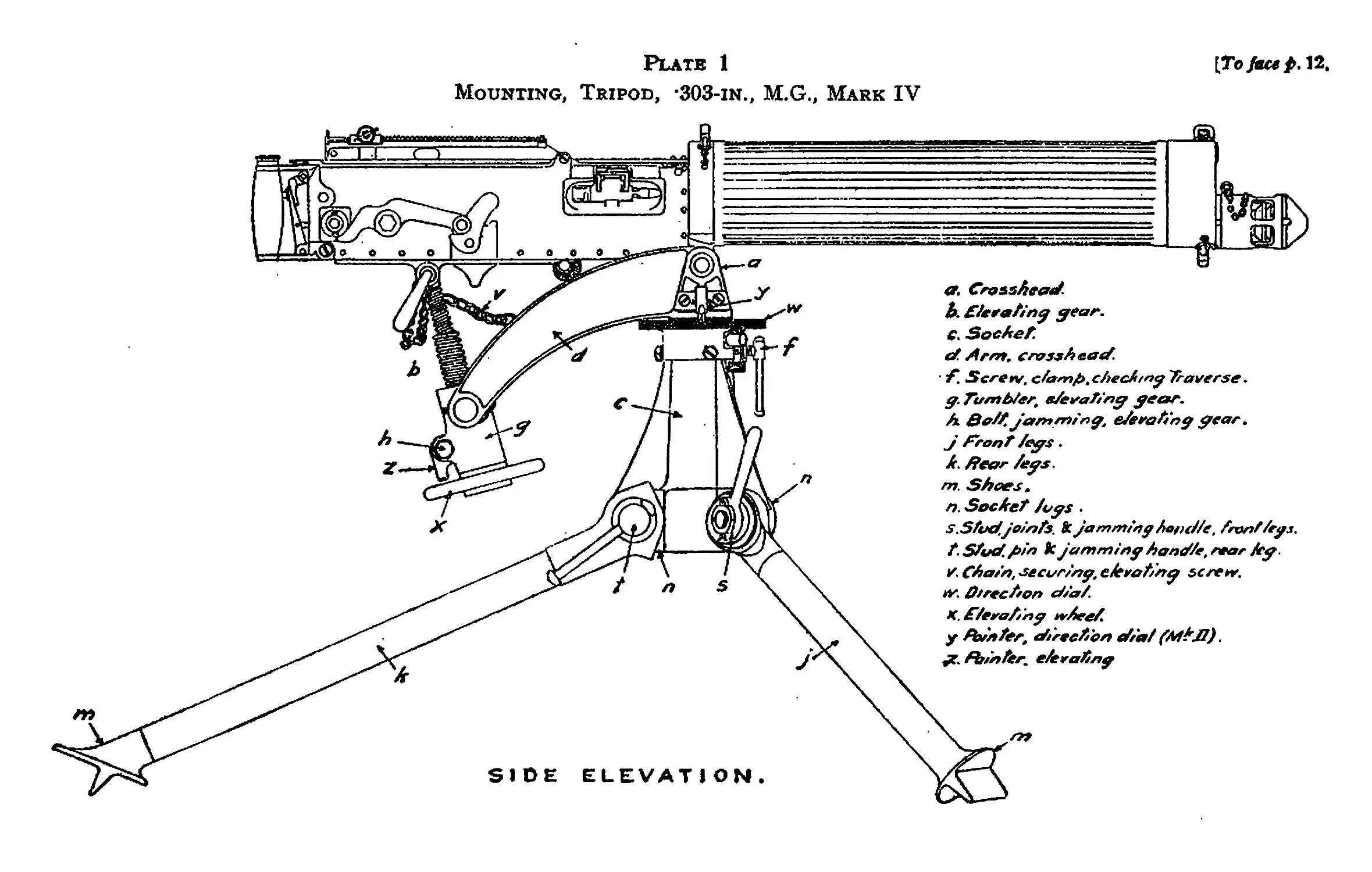
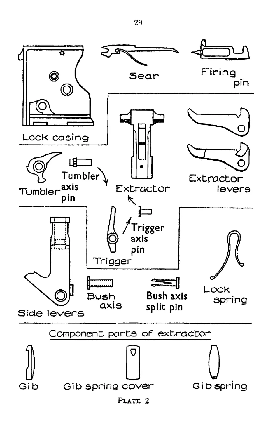
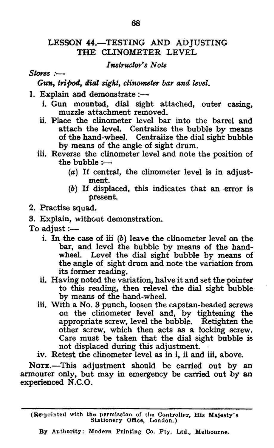
LESSON 15.—STRIPPING THE LOCK (PLATE 2)
1. To strip the lock.—See that the lock is cocked ; force
out the side lever split pin and axis bush ; remove the side
levers, extractor levers and extractor. Push out the tumbler
axis pin and remove. Release the lock spring, push out the
• trigger axis pin. Remove the trigger, lock spring, firing pin,
and sear with spring.
2. To assemble the lock.—Reverse the above except:—
i. Replace the tumbler before the trigger.
ii. The lock spring must be forced home, the long arm
towards the extractor, when the lock is in the fired
position, and when all other parts are assembled.
2»
Side levers
Bush
axis
Bush axis
split pin
Lock
spring
Component parts oF extractor
Jib
0
Gib spring cover
Plate 2
30
Note.—The names and parts of the lock are in the order in
which the lock will be assembled, reading from left to right
3. To strip the extractor.—Push out the gib spring cover
and remove the spring and gib.
LESSON 16.—STRIPPING-wntfnw^
1. To strip the feedblock.—Force out the split pin and
separate the top and bottom levers. Take out the slide and
remove the pawls and spring. Draw out the bottom pawl
axis pin and remove the spring and pawls.
2. To assemble.—Reverse the above.
3. To remove the sliding shutter.—Press in the catch
and force the shutter to the front until it is against the stop,
then press in the plunger with a No. 3 punch and force the
shutter forward until it is clear of the breech casing.
LESSON 17.—CHANGING THE BARREL WITHOUT
LOSS OF WATER
The necessity of saving water in the barrel casing entirely
depends on the prevailing conditions. In tropical countries
every drop of water is of value. Again, in action water may
not be available and time may be of the utmost importance.
On the other hand, if the gun has to be stripped in barracks
or billets, there is no necessity to save the water, provided that
a further supply can be easily obtained.
Follow the normal sequence of stripping until the slides
have been removed. Then remove the elevating point pin
and depress the gun. Great care must be taken to avoid
damage to the direction dial.
Order No. 2 to hold a rag or pad over the muzzle and, when
the recoiling portions are being withdrawn, to follow up the
barrel with the pad, in order to close the hole in the front
end of the barrel casing. Withdraw the recoiling portions.
In replacing the new barrel the above operations should be
reversed.
The water may also be saved by allowing it to run from the
barrel casing into a receptacle, when the barrel will be changed
by the normal procedure.
LESSON 18 — STRIPPING COMPONENT PARTS
1. Front cone, muzzle attachment. Using the combination
tool, unscrew the front cone from the outer casing muzzle
attachment.
3!
2, Gland of the muzzle attachment. Using the combination
tool, unscrew the packing gland from the barrel casing. When
assembling, ensure that the gland is screwed fully home.
3. Front cover catch. To remove the spring and plunger,
force the plug inwards and give J turn by means of a screw-
driver, when the plug will be forced out by the spring.
Before the plunger is removed, it must be turned so that the
slides are free to pass the lugs in the catch.
4. Tangent sight. Unscrew the axis pin and remove.
Remove the tangent sight piston'and spring.
5. Rear cover lock. Unscrew the axis pin and remove.
Remove the rear cover lock and spring.
6. Trigger bar. Remove the rear cover lock and trigger bar
spring and withdraw the trigger bar.
7. Roller. Remove the split fixing pin, collar and roller.
32
SECTION 5,—SPARE PARTS
The importance of knowing what is and what is not carried
spare should be impressed on all machine gunners. It is
essential to know where to find any spare parts that may be
required. All spare parts must be given their proper names.
A list of deficiences should be kept inside each box, and the
necessity or checking spare parts whenever opportunity occurs
must be emphasized. Breakages and losses must be reported
immediately. Spare parts must be kept slightly oiled.
Instructor* s Notes
. Stores:—
Gun, tripod, spare parts, case and box.
The sequence of instruction will be:—
Having laid out the whole of the contents of the spare
Parts box, case and wallet, teach the squad as follows :—
Hold up each article {in accordance with the official list
of spare parts) and call out the correct name given to it.
The use of the spare part being dealt with will be explained,
LESSON 19.—DESCRIPTION
Describe the spare parts box, case and wallet, teach the
names and use of spare parts.
LESSON 20.—PACKING
Teach the method of packing.
Contents of Wallet
Cork for plug .. .. .. .. .. .. 1
Cup, muzzle attachment .. .. .. .. <. 1
Disc, muzzle attachment .. .. .. .. .. 1
Fuzee, with chain .. .. .. .. .. .. 1
Gib..................................................... 1
Pins, trigger lock .. .. .. .. .. .. 1
„ tumbler .. .. .. .. .. .. 1
,, firing .. .. .. .. .. .. 1
„ keep split, Jx2| in. (for Mk. IV tripod mtg.) .. 3
Pliers, side cutting, pairs .. .. .. .. 1
33
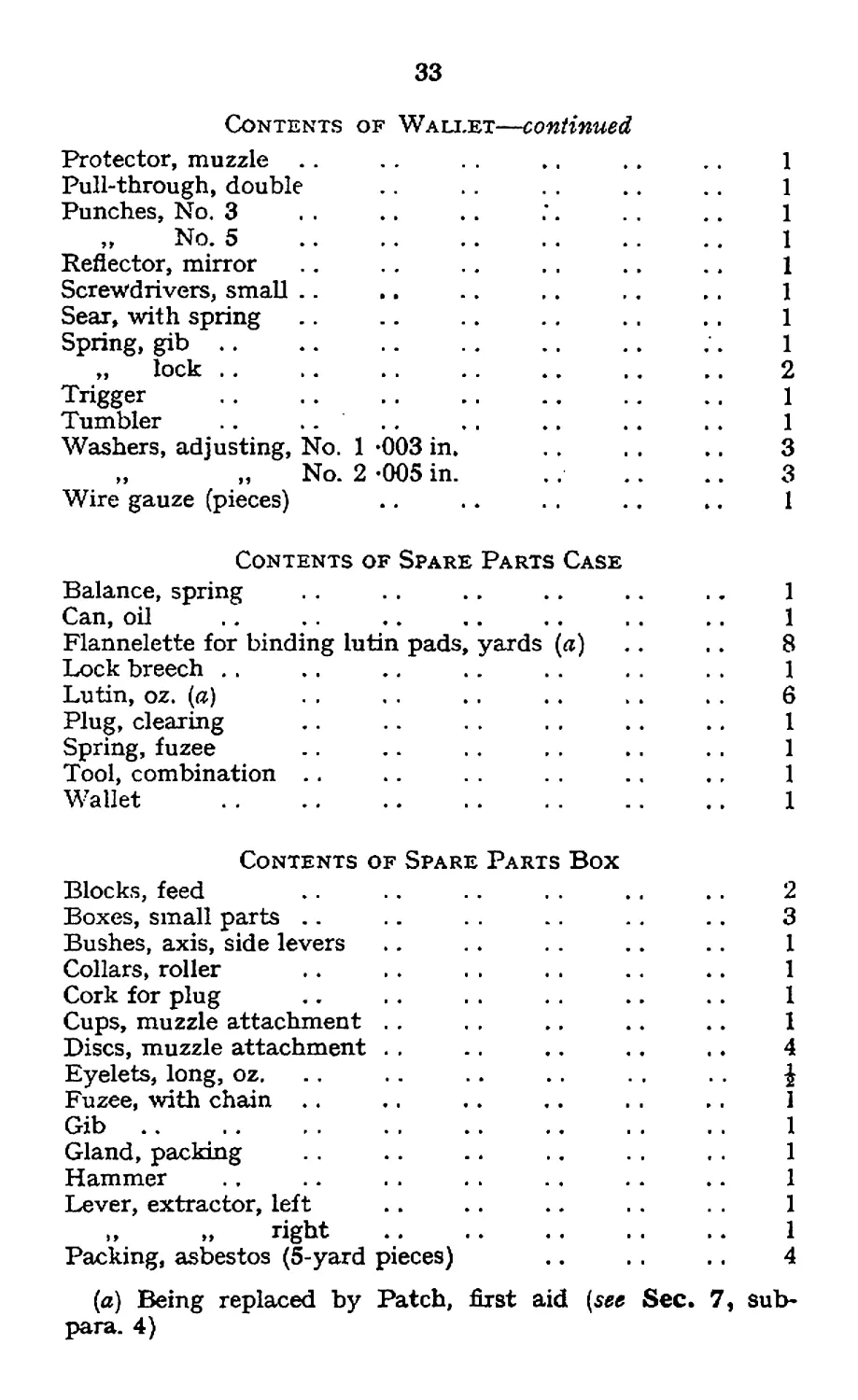
Contents of Wallet—continued
Protector, muzzle .. . . .. .. .. 1
Pull-through, double .. . . . . .. .. 1
Punches, No. 3 . . .. .. . . . .. 1
„ No. 5 .................................... 1
Reflector, mirror .. . . .. . . .. .. 1
Screwdrivers, small .. .. .. ,. .. .. 1
Sear, with spring .. .. .. .. .. .. 1
Spring, gib .. .. .. .. .. .. .. 1
„ lock .. .. .. .. .. .. .. 2
Trigger ................................................ 1
Tumbler .. .. .. . . .. .. .. 1
Washers, adjusting, No. 1 *003 in. . . . . .. 3
„ „ No. 2 «005 in. .. .. .. 3
Wire gauze (pieces) .. .. . . .. .. 1
Contents of Spare Parts Case
Balance, spring . . . . .. .. .. .. 1
Can, oil .. .. .. .. .. .. .. 1
Flannelette for binding lutin pads, yards (a) .. . . 8
Lock breech .. .. .. .. .. . . . . 1
Lutin, oz. (a) . . . . .. .. . . . . 6
Plug, clearing .. .. . . . . .. .. 1
Spring, fuzee -. .. .. , . .. . . 1
Tool, combination .. .. .. .. 1
Wallet ................................................. 1
Contents of Spare Parts Box
Blocks, feed .. .. .. . . .. .. 2
Boxes, small parts .. .. .. .. .. 3
Bushes, axis, side levers .. .. . . .. .. 1
Collars, roller .. . . . . . . .. .. 1
Cork for plug .. . . . . . . .. .. 1
Cups, muzzle attachment . . . . .. .. .. 1
Discs, muzzle attachment . . .. .. .. . ♦ 4
Eyelets, long, oz. .. .. .. .. . . . . j
Fuzee, with chain .. .. .. .. . . .. 1
Gib..................................................... 1
Gland, packing .. .. .. . . . . 1
Hammer . . .. . . . . . . . . .. 1
Lever, extractor, left .. .. .. . . 1
,, „ right .. .. .. . . .. 1
Packing, asbestos (5-yard pieces) .. . . .. 4
(a) Being replaced by Patch, first aid (see Sec. 7, sub-
para. 4)
34
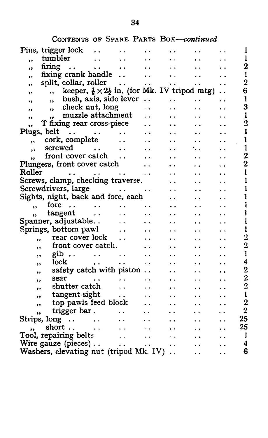
Contents of Spake Parts Box—continued
Pins, trigger lock ,. .. .. . . .. .. 1
,, tumbler .. .. .. .. 1
o firing................................................ 2
„ fixing crank handle .. ». .. .. .. 1
,, split, collar, roller .. .. .. .. .. 2
,, keeper, |x2| in. (for Mk. IV tripod m.tg) .. 6
,, ., bush, axis, side lever .. .. .. .. 1
„ ,, check nut, long .. . . .. 3
,, „ muzzle attachment .. 1
,, T fixing rear cross-piece . . .. .. _ 2
Plugs, belt .. .. .. .. ., .. .. 1
„ cork, complete .. .. .. .. 1
„ screwed .. .. .. .. \. . . 1
„ front cover catch .. .. .. . . .. 2
Plungers, front cover catch .. .. .. .. 2
Roller ................................................... 1
Screws, clamp, checking traverse. . . .. 1
Screwdrivers, large .. .. ., .. . . I
Sights, night, back and fore, each .. . . . . 1
„ fore .. .. .. .. .. .. 1
„ tangent .. .. .. .. .. .. 1
Spanner, adjustable.. . - .. . . .. .. 1
Springs, bottom pawl .. .. .. .. .. 1
„ rear cover lock .. .. .. .. .. 2
„ front cover catch. .. . . .. .. 2
м gib............................................... 1
„ lock .. .. . . . . .. .. 4
„ safety catch with piston .. .. .. .. 2
, , sear .. .. .. . . .. .. 2
„ shutter catch .. . . . . .. .. 2
„ tangent sight .. .. .. 1
„ top pawls feed block .. .. .. .. 2
„ trigger bar. ........................... 2
Strips, long .. .. . . .. .. .. 25
„ short .. .. . . .. .. .. 25
Tool, repairing belts .. .. .. 1
Wire gauze (pieces) .. .. .. .. .. 4
Washers, elevating nut (tripod Mk. IV).. .. 6
35
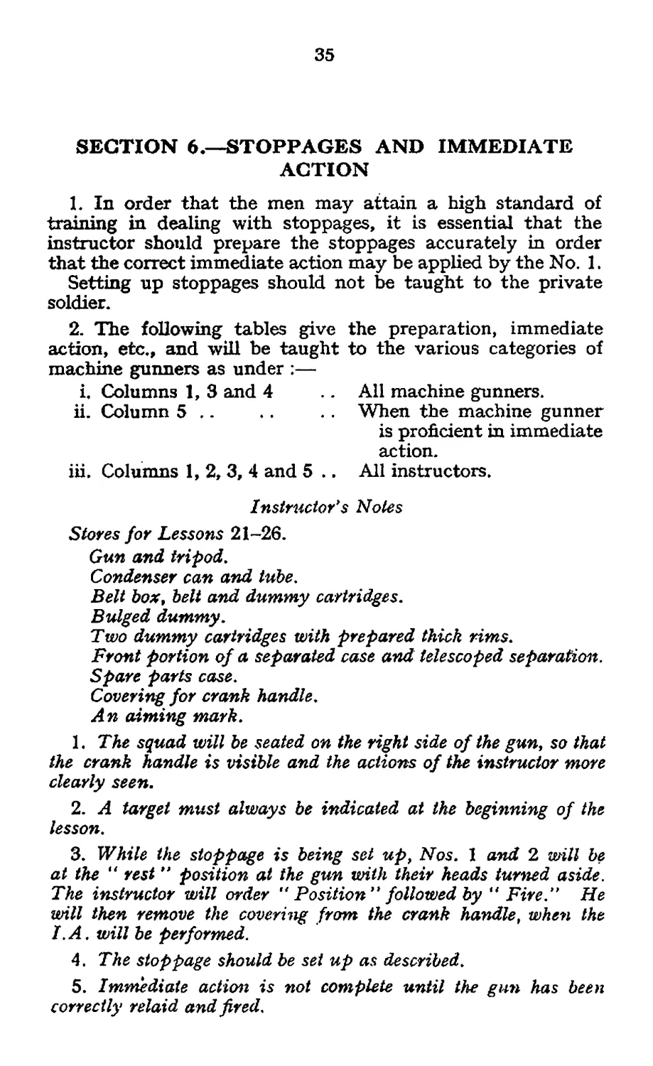
SECTION 6.—STOPPAGES AND IMMEDIATE
ACTION
L In order that the men may attain a high standard of
training in dealing with stoppages, it is essential that the
instructor should prepare the stoppages accurately in order
that the correct immediate action may be applied by the No. 1.
Setting up stoppages should not be taught to the private
soldier.
2. The following tables give the preparation, immediate
action, etc., and will be taught to the various categories of
machine gunners as under :—
i. Columns 1, 3 and 4 .. All machine gunners.
ii. Column 5 .. .. When the machine gunner
is proficient in immediate
action.
iii. Columns 1, 2, 3, 4 and 5 .. All instructors.
Instructor's Notes
Stores for Lessons 21-26.
Gun and tripod.
Condenser can and tube.
Belt box, belt and dummy cartridges.
Bulged dummy.
Two dummy cartridges with prepared thick rims.
Front portion of a separated case and telescoped separation.
Spare parts case.
Covering for crank handle.
An aiming mark.
1. The squad will be seated on the right side of the gun, so that
the crank handle is visible and the actions of the instructor more
clearly seen.
2. A target must always be indicated at the beginning of the
lesson.
3. While the stoppage is being set up, Nos. 1 and 2 will be
at the “ rest ” position at the gun with their heads turned aside.
The instructor will order Position” followed by “ Fire.” He
will then remove the covering from the crank handle, when the
I.A. will be performed.
4. The stoppage should be set up as described.
5. Immediate action is not complete until the gun has been
correctly relaid and fired.
36
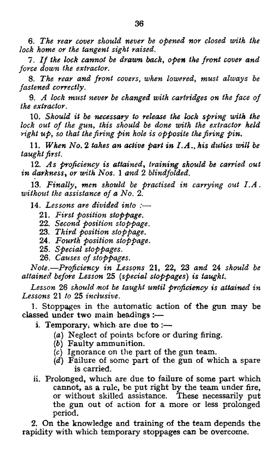
6. The rear cover should never be opened nor closed with the
lock home or the tangent sight raised.
7. If the lock cannot be drawn back, open the front cover and
force down the extractor.
8. The rear and front covers, when lowered, must always be
fastened correctly.
9. A lock must never be changed with cartridges on the face of
the extractor.
10. Should it be necessary to release the lock spring with the
lock out of the gun, this should be done with the extractor held
right up, so that the firing pin hole is opposite the firing pin,
11. When No, 2 takes an active part in I.A., his duties will be
taught first.
12. As proficiency is attained, training should be carried out
in darkness, or with Nos. 1 and 2 blindfolded.
13. Finally, men should be practised in carrying out I, A.
without the assistance of a No. 2.
14. Lessons are divided into :—
21. First position stoppage.
22. Second position stoppage.
23. Third position stoppage.
24. Fourth position stoppage.
25. Special stoppages.
26. Causes of stoppages.
Note.—Proficiency in Lessons 21, 22, 23 and 24 should be
attained before Lesson 25 {special stoppages) is taught.
Lesson 26 should mot be taught until proficiency is attained in
Lessons 21 to 25 inclusive.
1. Stoppages in the automatic action of the gun may be
classed under two main headings :—
i. Temporary; which are due to :—
(a) Neglect of points before or during firing.
(d) Faulty ammunition.
(c) Ignorance on the part of the gun team.
(rf) Failure of some part of the gun of which a spare
is carried.
ii. Prolonged, which are due to failure of some part which
cannot, as a rule, be put right by the team under fire,
or without skilled assistance. These necessarily put
the gun out of action for a more or less prolonged
period.
2. On the knowledge and training of the team depends the
rapidity with which temporary stoppages can be overcome.
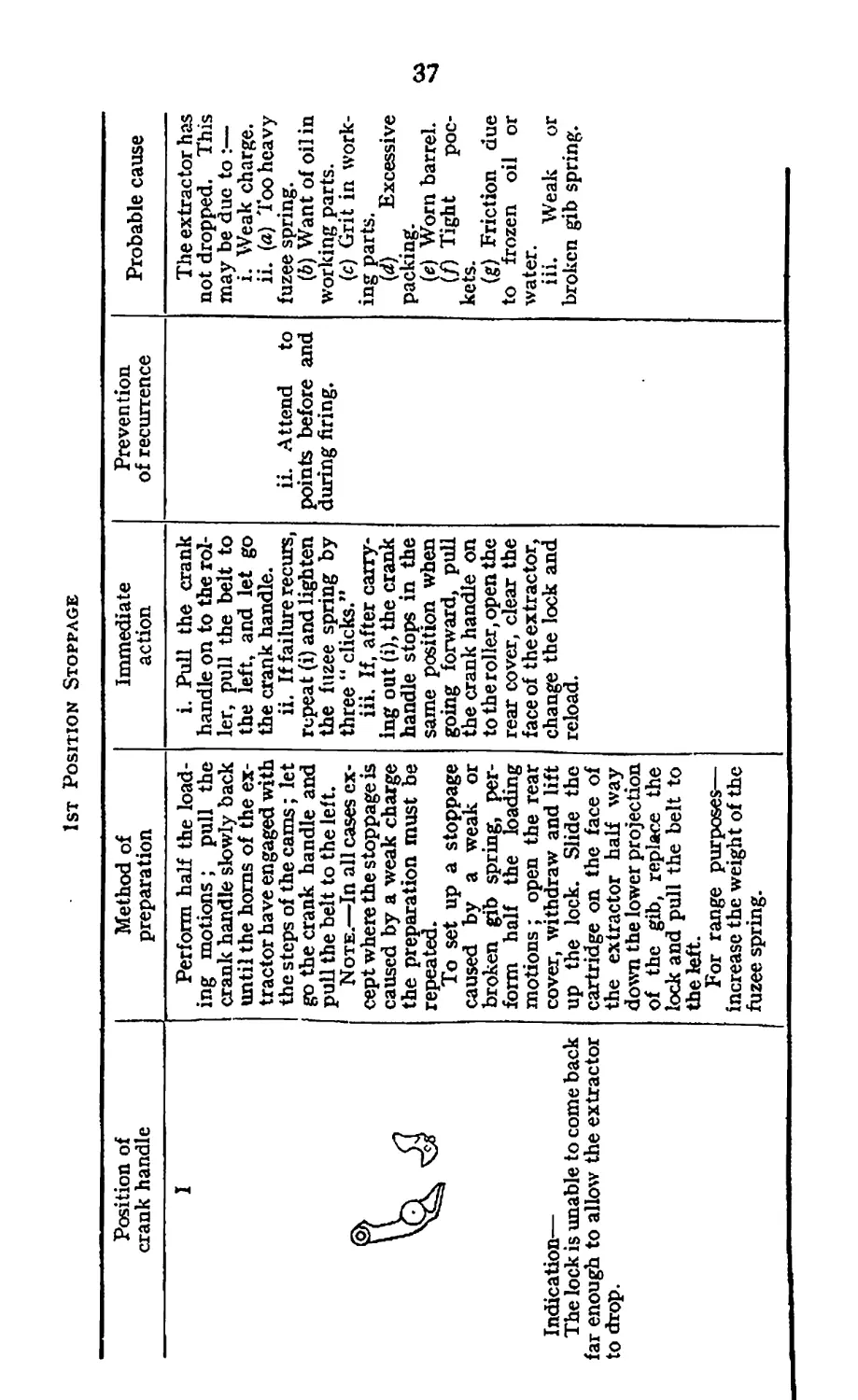
1st Position Stoppage
Position of crank handle Method of preparation Immediate action Prevention of recurrence Probable cause
I Indication— The lock is unable to come back far enough to allow the extractor to drop. Perform half the load- ing motions; pull the crank handle slowly back until the horns of the ex- tractor have engaged with the steps of the cams; let go the crank handle and pull the belt to the left. Note.—In all cases ex- cept where the stoppage is caused by a weak charge the preparation must be repeated. To set up a stoppage caused by a weak or broken gib spring, per- form half the loading motions ; open the rear cover, withdraw and lift up the lock. Slide the cartridge on the face of the extractor half way down the lower projection of the gib, replace the lock and pull the belt to the left. For range purposes— increase the weight of the fuzee spring. i. Pull the crank handle on to the rol- ler, pull the belt to the left, and let go the crank handle. ii. If failure recurs, repeat (i) and lighten the fuzee spring by three “ clicks.” iii. If, after carry- ing out (i), the crank handle stops in the same position when going forward, pull the crank handle on to the roller, open the rear cover, clear the face of the extractor, change the lock and reload. ii. Attend to points before and during firing. The extractor has not dropped. This may be due to :— i. Weak charge. ii. (a) Too heavy fuzee spring. (b) Want of oil in working parts. (c) Grit in work- ing parts. (d) Excessive packing. (e) Worn barrel. м (/) Tight poc- kets. (g) Friction due to frozen oil or water. iii. Weak or broken gib spring.
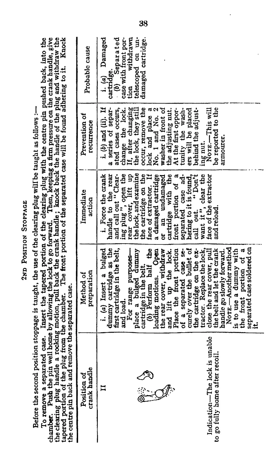
2nd Position Stoppage
Before the second position stoppage is taught, the use of the clearing plug will’be taught as follows :—
To remove a separated case. Insert the tapered portion of the clearing plug with the centre pin pushed back, into the
chamber. Push the pin well home by allowing the lock to go forward. Then, keeping a firm pressure on the crank handle, give
the clearing plug handle a rocking motion, pull back the crank handle; knock back the handle of the plug and withdraw the
tapered portion of the plug from the chamber. The front portion of the separated case will be found adhering to it. Knock
the centre pin back and remove the separated case.
Position of crank handle Method of preparation Immediate action I Prevention of recurrence Probable cause
II V Indication—The lock is unable to go fully home after recoil. i. (a) Insert a bulged dummy cartridge as the first cartridge in the belt, and load. For range purposes— place a bulged dummy cartridge in the belt. (b) Perform half the loading motions. Open the rear cover, withdraw and lift up the lock. Place the front portion of a separated case se- curely over the bullet of the cartridge on the ex- tractor, Replace the lock, close the rear cover, pull the belt and let the crank handle, go slowly forward. Note.—Another method is to use a dummy with the front portion of a separated case soldered on it. i. Force the crank handle to the rear and call out " Clear- ing plug ”, open the rear cover, lift up the lock, and examine the cartridge on the face of extractor. If a damaged cartridge or an undamaged cartridge with the front portion of a separated case ad- hering to it is found, call out. “ Don’t want it ”, clear the face of the extractor and reload. i. (d) and (ii). If a series of separ- ated cases occurs, change the lock. If, after changing the lock, they still occur, remove the lock and place a No. 1 and No. 2 washer in front of the adjusting nut. At the first oppor- tunity the wash- ers will be placed behind the adjust- ing nut. Note.—This will be reported to the armourer. i i i. (a) Damaged cartridge. (b) Separated case with front por- tion withdrawn telescoped on un- damaged cartridge. §§ i
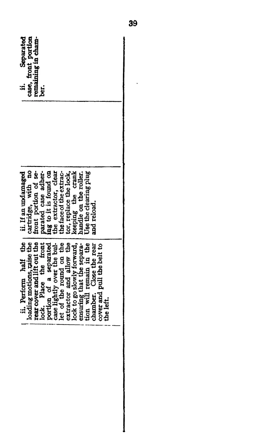
ii» Perform half the
loading motions, uaise the
rear cover and lift out the
lock. Place the front
portion of a separated
case lightly over the bul-
let of the round on the
extractor and allow the
lock to go slowly forward,
ensuring that the separa-
tion will remain in the
chamber. Close the rear
cover and pull the belt to
the left.
ii. If an undamaged
cartridge, with no
front portion of se-
parated case adher-
ing to it is found on
the extractor, clear
the face of the extrac-
tor, replace the lock,
keeping the crank
handle on the roller.
Use the clearing plug
and reload.
ii. Separated
case, front portion
remaining in cham-
ber.
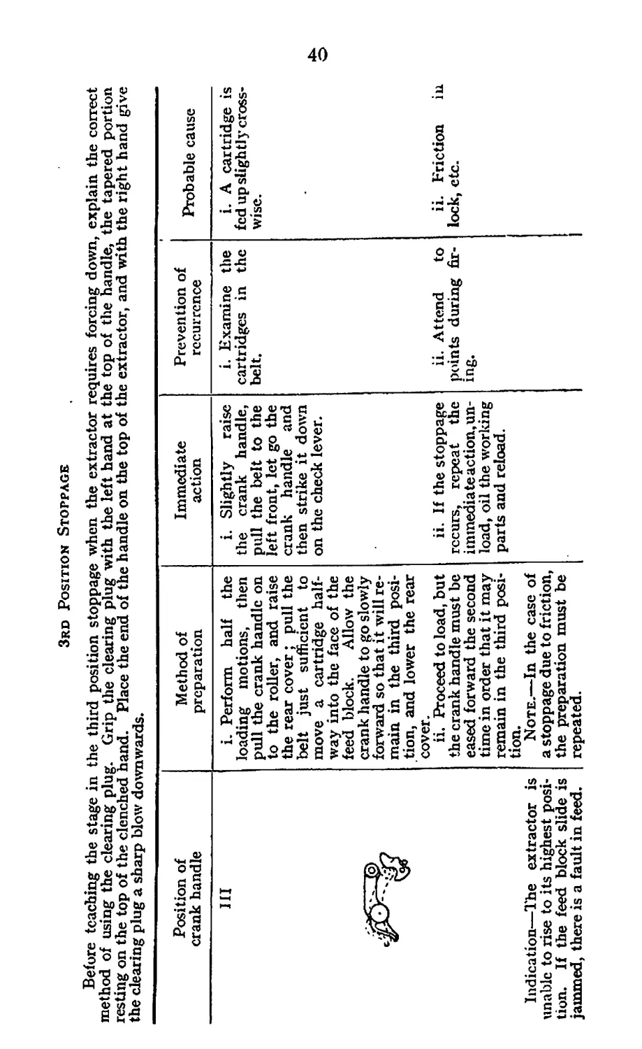
3rd Position Stoppage
Before teaching the stage in the third position stoppage when the extractor requires forcing down, explain the correct
method of using the clearing plug. Grip the clearing plug with the left hand at the top of the handle, the tapered portion
resting on the top of the clenched hand. Place the end of the handle on the top of the extractor, and with the right hand give
the clearing plug a sharp blow downwards.
Position of crank handle Method of preparation Immediate action Prevention of recurrence Probable cause
HI Indication—The extractor is unable to rise to its highest posi- tion. If the feed block slide is jammed, there is a fault in feed. i. Perform half the loading motions, then pull the crank handle on to the roller, and raise the rear cover ; pull the belt just sufficient to move a cartridge half- way into the face of the feed block. Allow the crank handle to go slowly forward so that it will re- main in the third posi- tion, and lower the rear cover. ii. Proceed to load, but the crank handle must be eased forward the second time in order that it may remain in the third posi- tion. Note.—In the case of a stoppage due to friction, the preparation must be repeated. i. Slightly raise the crank handle, pull the belt to the left front, let go the crank handle and then strike it down on the check lever. ii. If the stoppage recurs, repeat the immediate action, un- load, oil the world ng parts and reload. i. Examine the cartridges in the belt. ii. Attend to points during fir- ing. i. A cartridge is fed up slightly cross- wise. ii. Friction in lock, etc.
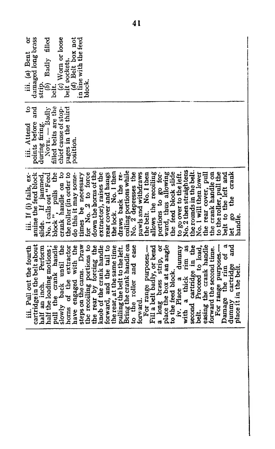
iii. Pull out the fourth
cartridge in the belt about
half an inch. Perform
half the loading motions ;
pull the crank handle
slowly back until the
horns of the extractor
have engaged with the
steps on the cams. Draw
the recoiling portions to
the rear by forcing the
knob of the crank handle
forward, and the tail to
the rear, at the same time
pulling the belt to the left.
Bring the crank handle on
to the roller and ease
forward.
For range purposes.—
Fill a belt badly, or bend
a long brass strip, or
place the box at an angle
to the feed block.
iv. Place a dummy
with a thick rim as
second cartridge in the
belt. Proceed to load,
easing the crank handle
forward the second time.
For range purposes.—
Damage the rim of a
dummy cartridge and
place it in the belt.
iii. If (i) fails, ex-
amine the feed block
slide. If jammed,
No. 1 calls out “Feed
block ”, pulls the
crank handle on to
the roller (in order to
do this it may some-
times be necessary
for No. -2 to force
down the horns of the
extractor), raises the
rear cover and hangs
the lock. No. 1 then
draws back the re-
coiling portions while
No. 2 depresses the
pawls and withdraws
the belt. No. 1 then
allows the recoiling
portions to go for-
ward, thus allowing
the feed block slide
to go over to the left.
No. 2 then straightens
the rounds in the belt.
No. 1 will then lower
the rear cover, pull
the crank handle on
to the roller, pull the
belt to the left and
let go the crank
handle.
iii. Attend to
points before and
during firing.
Note. — Badly
filled belts are the
chief cause of stop-
pages in the third
position.
iii. (a) Bent or
damaged long brass
strip.
(b) Badly filled
belt.
(c) Worn or loose
belt Dockets.
(d) Belt box not
in line with the feed
block.
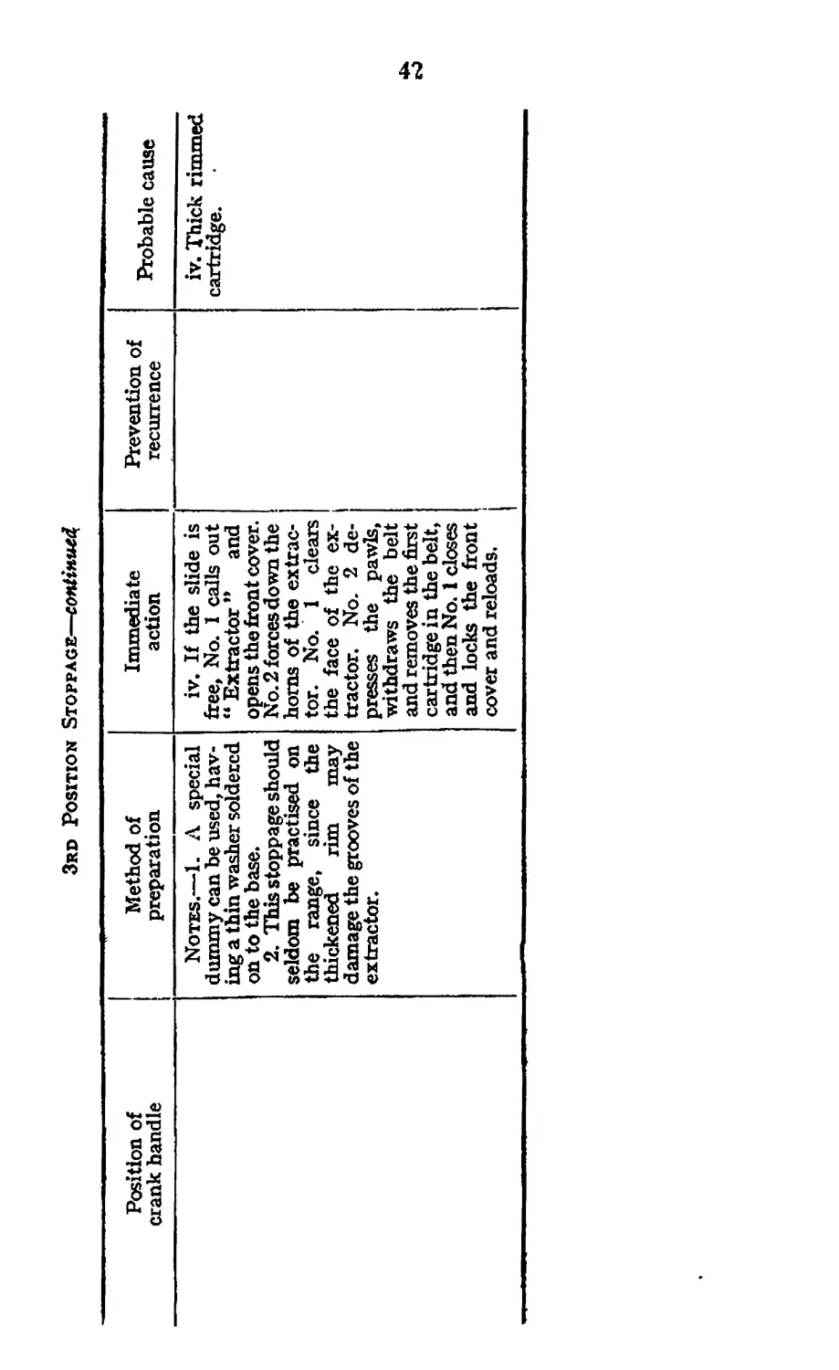
3rd Position Stoppage—continue#
Position of crank handle Method of preparation Immediate action Prevention of recurrence Probable cause
Notes.—1. A special dummy can be used, hav- ing a thin washer soldered on to the base. 2. This stoppage should seldom be practised on the range, since the thickened rim may damage the grooves of the extractor. iv. If the slide is free, No. 1 calls out “ Extractor ” and opens the front cover. No. 2 forces down the horns of the extrac- tor. No. 1 clears the face of the ex- tractor. No. 2 de- presses the pawls, withdraws the belt and removes the first cartridge in the belt, and then No. 1 closes and locks the front cover and reloads. iv. Thick rimmed cartridge.
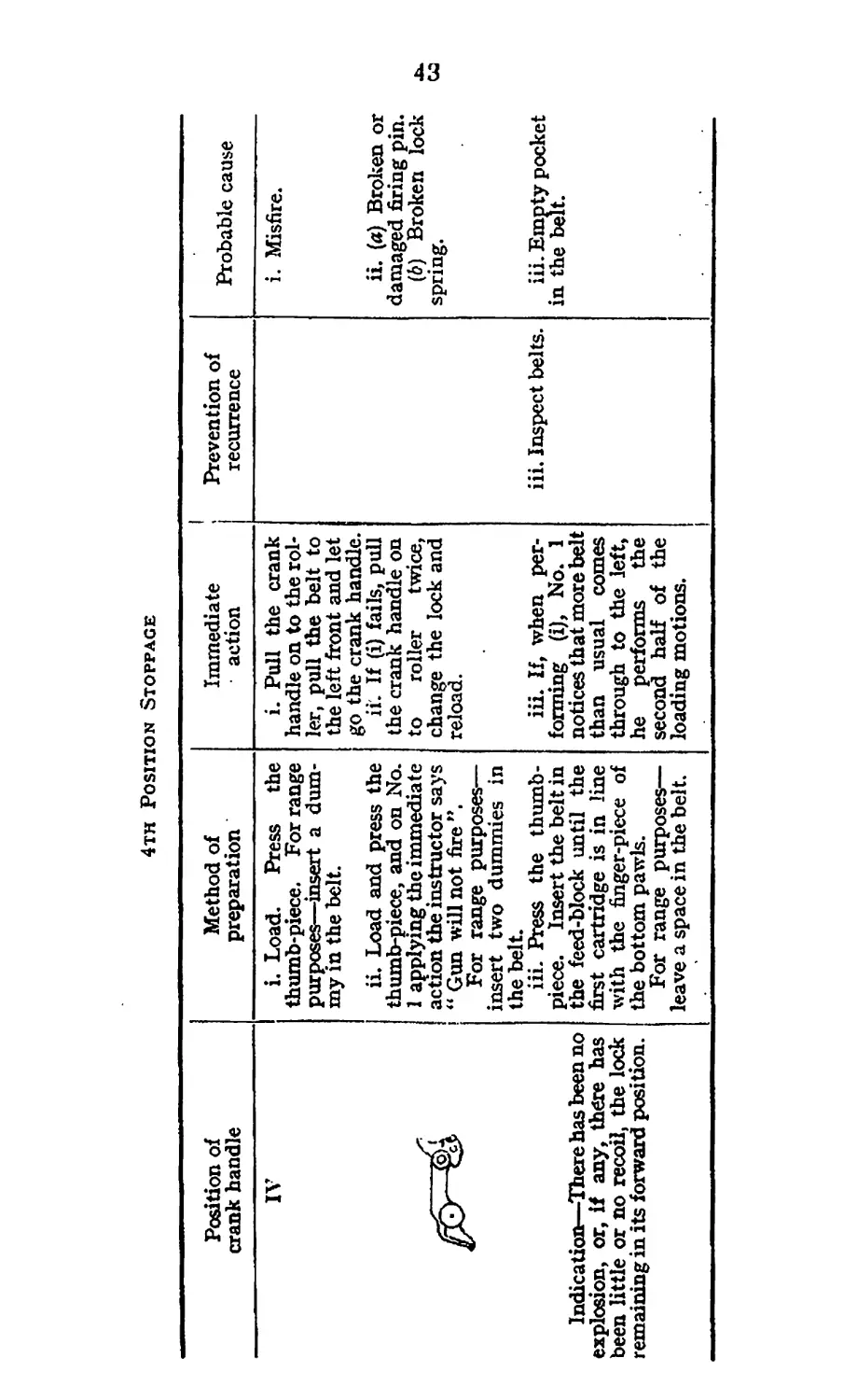
4тн Position Stoppage
Position of crank handle Method of preparation Immediate action Prevention of recurrence Probable cause
IV Indication—There has been no explosion, or, if any, there has been little or no recoil, the lock remaining in its forward position. i. Load. Press the thumb-piece. For range purposes—insert a dum- my in the belt. ii. Load and press the thumb-piece, and on No. 1 applying the immediate action the instructor says “ Gun will not fire ”. For range purposes— insert two dummies in the belt. iii. Press the thumb- piece. Insert the belt in the feed-block until the first cartridge is in line with the finger-piece of the bottom pawls. For range purposes— leave a space in the belt. i. Pull the crank handle on to the rol- ler, pull the belt to the left front and let go the crank handle. ii. If (i) fails, pull the crank handle on to roller twice, change the lock and reload. iii. If, when per- forming (i), No. 1 notices that more belt than usual comes through to the left, he performs the second half of the loading motions. iii. Inspect belts. i. Misfire. ii. («) Broken or damaged firing pin. (b) Broken lock spring. iii. Empty pocket in the belt.
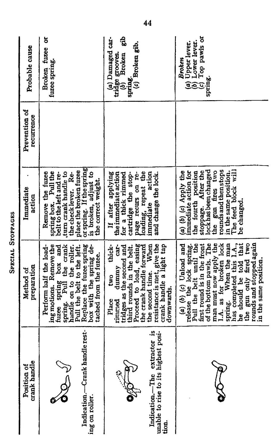
Special Stoppages
Position of crank handle Method of preparation Immediate action
Indication.—Crank handle rest- ing on roller. Perform half the load- ing motions. Remove the fuzee spring box and spring. Pull the crank handle on to the roller. Pull the belt to the left. Replace the fuzee spring box with the spring de- tached from the fuzee. Remove the fuzee spring box. Pull the belt to the left and re- ctum crank handle to the check lever. Re- place the broken fuzee or spring. If the spring is broken, adjust to the correct weight.
Indication.—The extractor is unable to rise to its highest posi- tion. Place two thick- rimmed dummy car- tridges as the second and third rounds in the belt. Proceed to load, easing the crank handle forward the second time. When resistance is met, give the crank handle a light tap downwards. If after applying the immediate action for a thick rimmed cartridge the stop- page recurs on re- loading, repeat the immediate action and change the lock.
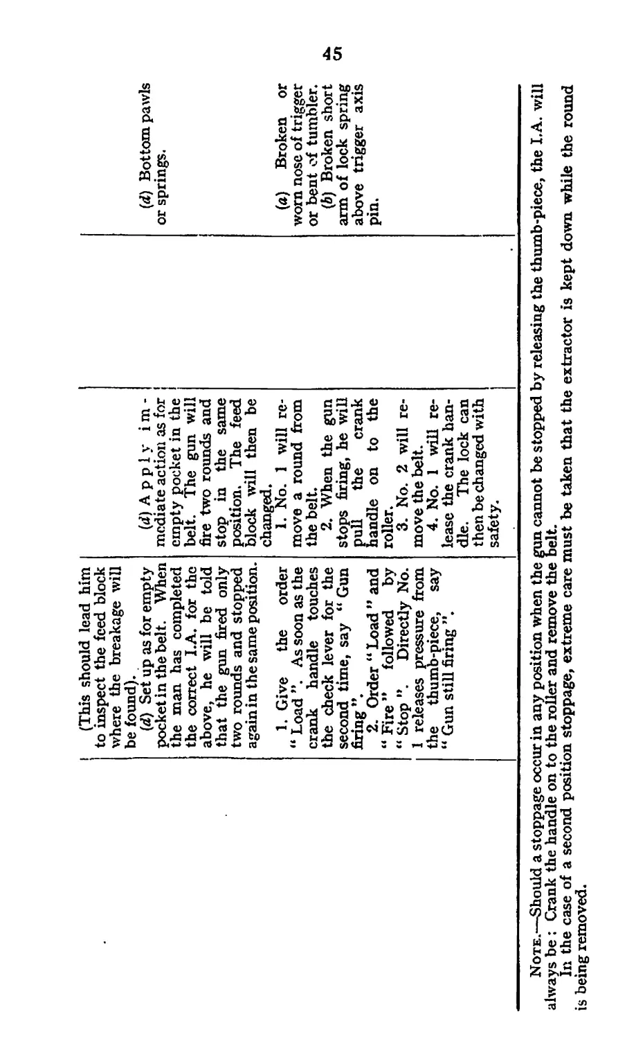
(a) (6) (c) Unload and release the lock spring. Pull the belt until the first round is in the front of the bottom pawls. The man must now apply the I.A. as for broken lock spring. When the man has completed this I.A., he should be told that the gun only fired two rounds and stopped again in the same position. (a) (d) (c) Apply the immediate action for the fourth position stoppage. After the lock has been changed the gun fixes two rounds and then stops in the same position. The feed block will be changed.
Prevention of recurrence Probable cause Broken fuzee or fuzee spring, (a) Damaged car- tridge grooves. (6) Broken gib spring. (c) Broken gib. Broken {a) Upper lever. (&) Lower lever. (c) Top pawls or spring.
(This should lead him to inspect the feed block where the breakage will be found). (d) Set up as for empty pocket in the belt. When the man has completed the correct I.A. for the above, he will be told that the gun fired only two rounds and stopped again in the same position. 1. Give the order “ Load ”. As soon as the crank handle touches the check lever for the second time, say “ Gun firing ”. 2. Order “ Load ” and “ Fire ’* followed by “ Stop ”. Directly No. 1 releases pressure from the thumb-piece, say “ Gun still firing ”. (d) A p p 1 у i m - mediate action as for empty pocket in the belt. The gun will fire two rounds and stop in the same position. The feed block will then be changed. I. No. 1 will re- move a round from the belt. 2. When the gun stops firing, he will pull the crank handle on to the roller. 3. No. 2 will re- move the belt. 4. No. 1 will re- lease the crank han- dle. The lock can then be changed with safety. (d) Bottom pawls or springs. (a) Broken or worn nose of trigger or bent of tumbler. (6) Broken short arm of lock spring above trigger axis pin.
Note.—Should a stoppage occur in any position when the gun cannot be stopped by releasing the thumb-piece, the I. A. will
always be : Crank the handle on to the roller and remove the belt.
In the case of a second position stoppage, extreme care must be taken that the extractor is kept down while the round
is being removed.
46
SECTION 7,—REPAIRS
LESSON 27.—REPAIRS
Instructor's Notes
Stores:—
Gun, tripod, spare parts case and box, parts of an old belt,
sufficient flannelette and lutin.
The lateral adjustment of the foresight will not be taught to
private soldiers.
If lutin is not available, any suitable substance, e.g. plasticine
or putty, may be used for instructional purposes.
1.. Fitting spare discs for the muzzle attachment. Unscrew
the front cone, cut the edge of the disc, driving sufficient metal
up to provide a hold for the pliers. Remove the disc and
replace it with a new one.
In replacing it may be necessary to tap the disc on to the
front cone.
2. Fitting auxiliary packing gland. In the event of the
packing gland being damaged by bullets, etc., it can be re-
placed by the auxiliary packing gland as follows :—
Remove the outer casing muzzle attachment, muzzle cup
and damaged packing gland, screw in the auxiliary packing
gland, using the combination tool, and lighten the fuzee spring
by about 3 lb.
3. Lateral adjustment of the foresight. If the foresight has
become damaged or displaced, re-adjustment will be necessary.
This will only be carried out by an experienced N.C.O.
It will be carried out on the 30-yards range.
Target.—Any target with a thick vertical line as an aiming
mark with a pencil line | in. to the right of the middle of the
thick line, the pencil line being invisible to the firer.
Settling bursts will first be fired.
Then a group of ten rounds will be fired by inserting a punch
between the firing lever and the safety catch.
If the gun is sighted correctly, the mean point of impact
will be on the thin pencil line, i.e. § in. to the right of the point
aimed at.
If there is any lateral error, the foresight will be tapped in
the same direction as the error, using a No. 3 punch and
hammer.
Another burst of ten rounds will be fired,after each adjust-
ment until the sighting is correct. Adjustments are very fine
and great care must be exercised in tapping the foresight.
When the foresight is very tight, the bracket should be sup-
ported to prevent it from jarring loose. It is important that
the socket of the tripod should be perfectly upright. After
each group is fired/ the aim must be carefully checked to see
that the tripod has not moved.
4. Perforation of the barrel casing.
In the event of the barrel casing being pierced by bullets,
etc., repairs will be carried out locally as follows :—
A pad of lutin, preferably wrapped in a piece of flannelette
or cloth to prevent it from being squeezed through the hole
or holes, is pressed over the latter and covered with an oiled
pad of flannelette; the whole is then bound round with
flannelette. This, while not preventing leakage entirely,
should do so sufficiently to enable the gun to be kept fit for
action.
Note.—A patch, first aid, has now been introduced and will
replace lutin.
5. Use of the tool for repairing belts.
Remove the damaged strips and eyelets. If a long strip
requires fitting, first join the two faces of the strip as follows :—
Place the eyelet in the hole of the dished end, insert the
punch of the tool into the unopened end of the eyelet (the
open end should rest on the die and gently press the handles
together), then put the punch in the other end of the eyelet
and press the handles. Keep the strip horizontal, move, the
handles of the tool backwards and forwards in a circular
direction, with the punch of the tool as the centre, so as to
shape the head of the eyelet.
Put the strips into position on the belt, insert the eyelet
and repeat the above operation.
Short strips are fitted in a similar manner, except that they
do not require to be joined at one end before being placed on
the belt.
Care must be taken to press the eyelets as far through the
strips as possible before using the tool.
6. To repair a torn belt.
If badly torn, cut out the torn portion and sew or rivet
together the cut ends and cover with the brass strips. The
cutting of the belt should be done in such a manner as to ensure
that the repair to the top portion of the webbing does not
coincide with the repair to the bottom portion.
48
SECTION 8.—BLANK FIRING ATTACHMENT
LESSON 28.—BLANK FIRING ATTACHMENT
Instructor's Notes
Stores :—
Barrel, Mark II “ D.P.B." {drill purposes, blank).
Cone, front, muzzle attachment, blank.
Cup, muzzle attachment, blank.
Nut, adjusting, muzzle attachment, blank.
Screw, adjusting, muzzle attachment, blank.
Spanner, muzzle attachment, blank.
1. The barrel is specially choked at the breech and is marked
" D.P.B/’ on the trunnion block.
The adjusting screw is screwed into the front cone from the
rear, so that its large end may engage in the muzzle cup.
The front cone with adjusting screw assembles into the
outer casing of the muzzle attachment in place of the existing
front cone.
The adjusting nut screws on to the projecting end of the
adjusting screw and locks against the face of the front cone.
The spanner is suitably arranged for the muzzle cup,
adjusting screw and nut.
2. Adjustment of the gun when assembled with the special
parts. The weight of the recoiling parts of the gun should not
exceed 2 lb.
The weight of fuzee spring should be about 4J lb.
The adjusting screw of the muzzle attachment should first
be screwed inwards to the muzzle cup until it just begins to
force the recoiling portions backwards ; it should then be
unscrewed 1} turns and secured in position by the nut. The
screw may require further adjustment in order to obtain
correct functioning, but in no case should the screw be less
than 1 turn back from the muzzle cup. Adjustment should
be made in quarter turns.
Notes.
1. Service guns only will be used for firing.
2. A belt, preferably part-worn as regards size of pockets,
should be employed. The blank ammunition should be inserted
crimped end flush with the front edge of the belt, in groups of 10
49
rounds each, T his number is sufficient for the purposes of locating
machine gun fire and also ensures a longer life of choke in the
barrel.
3. When firing becomes noticeably irregular, the barrel should
be sei aside for examination by an armourer.
4. The barrel casing will be filled with water as for ball
ammunition.
5, When the gun is fitted with the blank firing attachment,
it cannot be placed in its chest unless the outer casing of the muzzle
attachment with its fittings is first removed.
6. On completion of blank firing the guns will immediately
be restored to their normal condition for firing ball ammunition.
7. The gun will be cleaned in the normal way (i.e. as if the
ball ammiinition had been fired), except that no attempt will be
made to clean the inside of the barrel in front of the choke.
50
SECTION 9.— INSTRUMENTS AND AIMING
GENERAL
1. All ranks must be proficient in the use of the following : —
Aiming post.
Zero post.
Direction dial.
Elevating wheel.
Dial sight.
Aiming lamp.
• 2. Officers and N.C,Os. must be proficient in the use of the
slide rule. The former and full rank N.C.Os. will also be
trained to use :—
Director.
Plotter.
3. In addition to the above, all officers and N.C.Os. should
be able to determine whether a dial sight is in adjustment.
Similarly, those officers and N.C.Os, who are trained in the
use of the director should be able to test the instrument for
accuracy.
4. For the standard to be reached, see T.O.E.D,
LESSON 29.—TANGENT SIGHT AND FIXED SIGHT
Instructor’s Note
Stores
Gun, tripod, belt box, landscape target,
1. Setting the sights.
Explain and demonstrate :—
i. The use of sights to obtain direction and elevation.
ii. The method of adjusting the sights. Fifty yards
will be taught as the smallest adjustment.
iii. The correct line on the graduated plate for any
particular range is the one under the figures
indicating that range.
iv. The fixed sight will be used up to 550 yards inclusive.
The men should be required to make several adjustments.
51
2. Rules of aiming.
Explain :—
i. Sights must be upright. This is ensured by correct
mounting of the tripod.
ii. The eye should be as close to the aperture as possible.
iii. The firer must look through and not at the aperture.
Demonstrate the common faults of aiming (see Pamphlet.
No. 3, Lesson 6).
Explain that, in aiming at a bullseye for instructional
purposes, or at the aiming post or lamp, the aim must be taken
at the lowest central portions, as the foresight will not show
up clearly if laid on the centre.
3. Methods and sequence of instruction in laying an aim.
i. Lay a correct aim at the aiming post without * ' holding ’ ’.
While laying, the chin must be supported on the
hand. A belt box may be placed across the knees
and.the elbows rested on the box, or the box may
be placed on the ground resting on end, and the arms
rested on top.
Explain that direction is obtained by tapping
the traversing handles, and elevation by turning the
wheel.
ii. Every man should view the aim, and in turn lay the
gun, without holding.
Should any faults be detected, explain their
effects, and ensure that such faults are remedied.
If a man's aim is incorrect, he must be convinced
that it is so.
iii. The men will be taught to lay on aim with “holding".
The tripod must be in good condition; otherwise
there will be considerable difference in aim with
and without holding. There should be little
difference.
iv. Show how to lay an aim at points on a landscape
target, and finally on natural objects.
v. Show how to note a point of aim to the right or to
the left of the original mark.
Tap the gun off and ask the man to describe where
the gun is laid.
vi. Demonstrate how to select and note a point of aim
immediately above or below the target by moving
the tangent slide up or down.
52
LESSON 30.—DIAL SIGHT (PLATE 3)
Instructor's Note
Stores:—
Gun, tripod, dial sight.
Explain and demonstrate the following :—
Collimator.
Lateral and vertical adjustment of collimator.
Dial and deflection drams.
Indicator bar.
Spare clinometer level.
Elevation drums.
Tapered bracket.
Description,—The sight consists of a tapered bracket with
fixing screw, for attaching to the gun bracket.
Two elevation drums with quick release and pointers :—
(a) The range drum, graduated in 100s of yards up to
1,000 yards, and 50s of yards upwards.
(5) The angle of sight drum, graduated in 5s of minutes
up to 10 degrees of elevation and depression.
A dial, marked in 10s of degrees from 0 to 180
degrees, left and right, with a quick release, also right
and left deflection drums, marked in 10s. of minutes.
An adjustable indicator bar, with arrows at each
end for use with the deflection drums. This can
be made to click or friction as desired by means of
the milled head screw. Under this is housed a spare
clinometer level.
On the left of the dial is a clinometer level.
Mounted on top of the dial is a collimator with
pyramid. This is adjustable vertically, by means
of a slide with fine adjustment, and ramps. The
whole of this portion is zeroed by means of a spring
catch and horns, which can be freed by means of a
quick release on the right. This allows the colli-
mator to rotate. Between the horns is a fine
adjustment worm which engages in the teeth of the
bottom plate of the collimator.
LESSON 31.—AIMING WITH THE DIAL SIGHT
Instructor's Notes
Stores:—
As for Lesson 30, with addition of aiming post, aiming
lamp and zero post.
A dark room or shed which can be illuminated quickly
is an advantage, as faults in aiming can be shown by turning
on the lights.
53
Plate 3
Dial Sight, M.G.
1. Clinometer level.
2. Slide.
3, Homs.
4. Spring catch.
5. Collimator.
6. Fine adjustment.
7. Ramps.
8. Quick release.
9 Dial.
Key
10. Deflection drum.
11. For spare clinometer level.
12. Tapered bracket.
13. Fixingscrew.
14. Elevation drums.
15. Quick release.
16. Indicator bar.
17. Milled head screw.
18. Deflection drum.
19. Pointer.
54
1. Explain and demonstrate :—
i. Sights must be upright.
ii. The eye should be about three inches from the colli-
mator.
iii. By moving the head about, the top of the pyramid
will be made to appear above the tube. This will
allow the tip of the pyramid to be laid on the lowest
central portion of the aiming mark.
iv. Night aiming.
To assist the man, it may be necessary for the
N.C.O. at the gun to shine his torch at an angle
into the front of the collimator.
v. Correct aim with dial sight.
Fig. 1.
2. The squad will view an aim laid by the instructor on :—
i. Aiming post.
ii. Aiming lamp.
iii. Zero post.
3. Practise squad.
Constant practise in actual darkness is essential.
LESSON 32.—DIRECTION
(a) Laying the gun for direction,,
Instructor’s Note
Stores :—
Gun, tripod, dial sight, aiming post and director,
1. Explain and demonstrate :—
Gun mounted, dial sight attached with all scales at zero.
A director will be mounted in a suitable position. On the
order " Right (or left) . . . degrees . . . minutes ”, No. 1
will set the dial and deflection drums as ordered. He will
tap the gun and elevate or depress the collimator until it is
55
laid on the centre of the director. The direction dial and
deflection drums will be re-set at zero.
2. Practise squad.
(b) Maintenance of direction.
Note.—The aiming post will be put out in a suitable position
by the instructor.
1. The collimator is rotated, and elevated or depressed until
a correct aim is obtained on the aiming post.
2. In checking for direction during firing or on the command
“ Stop the gun will be tapped until direction is obtained on
the aiming post.
3. Practise squad.
LESSON 33.—ELEVATION
(a) Placing elevation or depression on the gun by means of the
dial sight.
Instructor's Note
Stores :—
As for Lesson 32.
1. Explain and demonstrate :—
Gun mounted and dial sight attached with all scales at zero,
aiming post put out and collimator adjusted to it. On a range
and angle of sight being ordered, No. 1 places them on the
elevation drums and levels the bubble by means of the elevating
wheel. When levelling the bubble, No. 1 will retain his holding
with his left hand. The collimator will then be adjusted to a
correct aim on the aiming post. Orders in range to be given
to the nearest 50 yards. Orders in elevation to be given to
the nearest 5 minutes.
Note.—When a quadrant angle is ordered, the range drum
will remain at zero.
2. Practise squad.
(6) Maintenance of elevation.
1. In checking for elevation during firing or on the command
" Stop ", the bubble will be brought central and the aim
checked on the aiming post. Should the aim be incorrect for
elevation, the setting of the elevation drums will be checked,
and, if they are found to be correct, the collimator will be
adjusted. When the setting of the elevation drums is found
to be incorrect, it will be corrected, the bubble will be brought
central and the collimator adjusted if necessary.
2. Practise squad.
56
LESSON 34.—RECORDING ON THE DIAL SIGHT THE
QUADRANT ELEVATION OR QUADRANT ANGLE
ON THE GUN
Instructor's Note
Stores :—
Gun, tripod, dial sight,
1. Explain and demonstrate :—
Gun mounted and laid on a target with any range on the
tangent sight.
L No. 1 attaches the dial sight, places the same range on
the range drum, levels the bubble by means of the
angle of sight drum and then clamps up.
The two drums will now record the quadrant
elevation.
ii. No 1 attaches the dial sight, sets the range drum at
zero and levels the bubble by means of the angle of
sight drum.
The resultant angle on the drum will be the quadrant
angle.
2. Practise squad.
LESSON 35.—DIRECTION DIAL MK. II
Instructor's Note
Stores:—
Gun and tripod,
1. Explain and demonstrate :—
Graduations.
Markings " R ” and “ L ”.
Pointer.
Clamping screw.
i. Description.
The direction dial is graduated from 0 to 180
degrees RIGHT and LEFT. 0 is marked by a
screw. The scale can be rotated round the socket,
and can be fixed in any position by a clamping screw.
A pointer is fitted to die right hand side of the cross-
head for use in connection with the dial.
ii. To set the dial at zero.
No 2 loosens the clamping screw, rotates the dial
until 0 is opposite the pointer and then screws up
the clamping screw.
57
iii. To lay off an angle of direction by the dial.
Gun mounted and direction dial set at zero.
No 2 at the gun. No. 2 loosens the traversing
J? .-,p ;uid swings the gun so that the pointer moves
towards “R” or "L” as ordered. He adjusts
the pointer to the number of degrees or minutes
ordered and tightens up the traversing clamp.
Switches should be given out in multiples of 10
minutes, and adjustments made to within 10
minutes.
2. Practise squad.
LESSON 36.—ELEVATING WHEEL
Instructors Note
Stores:—
Gun and tripod.
1. Explain:—
The elevating wheel is marked by wide notches for degrees,
thin notches for ten minutes and dots for five minutes.
A pointer is attached to the elevating gear for use with the
wheel.
The graduations on the wheel will be explained to the
man.
2. Show how to elevate or depress the gun.
(Jun mounted and laid on an aiming mark No. 1 at the gun.
No. 1 will elevate or depress the gun the necessary amount
by means of the wheel. On completion No. 1 will re-align
his sights on the aiming mark.
3. Practise squad.
LESSON 37.—AIMING POST M.G., MARK Ш, AND
ZERO POST M.G., MARK I
Instructors Note
Stores—
Gun, tripod, dial sight, aiming post and zero post.
1. Aiming post,—
i. Explain and demonstrate :—
Folding arm.
Lamp bracket.
Securing extension.
58
ii. Describe how the aiming post consists of a triangular
base with three spikes for securing the post into
the ground. The stand has an adjustable arm
with an aiming rpark and lamp bracket, and an
extension to act as a support. The following will
be explained to the man :—
iii. A gun will be mounted, dial sight attached, and No. 3
will be instructed to put out the post about 15 yards
to the left front of the gun. The aiming post should
be vertical or lying on its side, with the flat side of
the base and the securing extension on the ground.
iv. Practise squad.
2. Zero post, M.G., Mark I,—
i. Explain:—
The post is 3 feet long ; it has a ring 4 inches in
diameter at the upper end, and the lower end is
pointed.
ii. Show how to put out the zero post.
The gun will be mounted, the dial sight attached,
and laid with any elevation. No. 1 at the gun.
No. 3 a few yards in rear with the zero post.
The instructor will act as No. 1.
No. 3 will drive the zero post in about 10 yards
in front.
No. 1 will direct No. 3 by signal to move the
post for direction, and will adjust the collimator
for elevation only, until his aim is on the point
where the ring joins the stem.
iii. Practise squad.
LESSON 38.—LAMP, AIMING, M.G., MARK III
Instructor's Note
Stores:—
Aiming lamp and aiming post.
1. Explain and demonstrate :—
Aiming lamp.
The lamp is contained in a box divided into three partitions,
one containing the lamp, another two batteries, and the third
a two-way switch with wire lead to the external ring ; line
and reel, securing chain and spare bulb.
On the base of the box is a securing hook.
i. Attaching the lamp to the aiming post.
The box will be opened, the lamp removed and
the cable passed through the slot in the side of the
59
box. The lamp will be secured to the extension
above the aiming mark on the aiming post, with the
bracket uppermost, by tightening the wing nut.
Note.—The box must be closed, and placed close
to the aiming post with the ring facing No. 1 gun
of each section.
ii. Attaching the line.
The reel will be removed from the box and the
swivel hook will be clipped through the switch ring.
To turn the light on or off, the line must be given a
sharp pull.
iii. Securing the box.
In soft ground the hook will be released from its
securing strap and stamped into the ground. On
hard ground the securing chain will be used to
anchor the box to a post or other suitable object.
2. Practise squad.
LESSON 39.—DIRECTOR, No. 4, MARK И
(PLATES 4 AND 5)
Instructors Note
Stores:—
Directors.
1. Explain and demonstrate :—
Focusing of telescope.
Pointer.
Degree scale on director.
Clinometer level and elevating gear.
Degree scale plate.
How to clamp the index plate and the functioning of the
clamping screw.
Use of spirit level on stand.
Hook attached to base plate.
2. Describe how the instrument consists of :—
A telescope with vertical pointer contained in the box.
The telescope can be focused by means of the eyepiece.
On the left of the box is a clinometer level, consisting of
a bubble arm, degree scale, and micrometer heads marked
in 5s of minutes. The top half of the degree scale and the top
drum for elevation, the bottom half of the scale and the bottom
drum for depression.
On the underside is a slider and spring for attaching to the
director stand.
60
Plate 4
Director, No. 4, Mark II
(2)
Key
1. For focusing telescope.
2. Clinometer level.
3. Angle of sight degree scale.
4. For levelling bubble.
61
Plate 5
Stand Director, No. 4, Mark II
1. Legs.
2. Hook.
3. Base plate.
4. Clamping socket.
5. Clamping screw.
6. Degree scale plate.
7. Index plate.
Key
8. Spirit level.
9. Clamping nut.
10. Magnetic compass.
11. Carrier bracket.
12. Carrier.
13. Side spring.
14. Elevating gear.
62
The director stand consists of three hinged legs, between
which is a hook for use with a plumb line. The legs are
attached to a circular plate, to which is attached the clamping
socket.
The clamping socket rotates, and has a clamping screw for
clamping the socket to the base.
The degree sc&le plate is attached to the top of the damping
socket, and is marked in degrees from 0 to 180 right and left,
(R. and L).
Above this is the index plate, which has an arrow inserted
on the outer edge. On this plate is a milled nut for clamping
the plate to the degree scale plate, and a spirit level for getting
the director stand upright, and a compass.
The carrier to which the director slider is attached is
elevated or depressed by means of the slow motion elevating
gear.
The springs on the carrier and slider are for taking up play.
3. Show how to set up the director.
Remove the director from the case, and the director stand.
Fit the base of the director into the carrier.
Splay out the legs of the stand so that the director is at a
convenient height. It will be found that the kneeling position
is the most suitable, but a lower position may have to be
adopted. Press the legs firmly into the ground. Make sure
that the degree scale plate is approximately level.
4. Show how to take an angle of sight.
Focus the telescope. Unloosen the clamping screw. By
means of the elevating gear and milled portion of the clamping
socket lay the tip of the pointer on the target.
By means of the milled head below the depression micro-
meter head, level the bubble. Read the angle of sight by
means of the degree scale and micrometer heads. Once the
bubble has been levelled, the reading of the angle of sight may
be taken later at any convenient time. Readings to be to the
nearest minute.
When finished with, the arrows will be set at zero.
5. Explain how to measure the lateral angle between two
points.
Set the pointer on the index plate opposite r< zero ” on the
degree scale.
Tighten up the clamping nut. By means of the elevating
gear and milled portion of the clamping socket, lay the pointer
on the first point. Tighten up the clamping screw.
Loosen the clamping nut and lay the pointer on the second
point.
63
Read off the number of degrees and minutes, direction right
or left, from the degree scale to the nearest 10 minutes.
Ensure that the degree scale plate does not slip when the index
plate is moved. Always move the index plate by holding the
carrier bracket, and not the director.
Before putting the director stand in its case, set the slide
horizontal, clamp the compass and set the pointer on the
index plate at 180 degrees.
6. Practise squad.
LESSON 40,—SLIDE RULE, M.G. MARK III
Instructor's Note
Stores:—
Slide rules.
1. Description.
On the front side are extracts from the Range Tables.
On the sides are measuring scales.
Attached to the rule is a cord, 24 inches long.
On the back of the rule is the following :—
i. Safety angle scale.
On the right centre of the rule is marked a range
to target scale, and on the right slide a range to
troops scale, up to 500 yards in red and over 500
yards in black.
ii. Degree scale.
On the right side of the right slide is a degree
scale and on top of the rule is an arrow.
To use :—To measure angular widths—when the
rule is held-at the length of the cord from the eye,
the amount of slide projecting at the top of the rule
will cover on the ground the amount in degrees and
minutes shown opposite the arrow.
iii. Wind scale.
On the reverse of the right slide are the minute
allowances. On the right of the rule is the range
scale. On each side of the slide on the rule are
marked the wind directions.
This scale is marked for a 20 m.p.h. wind.
To use :—Place the arrow on the slide opposite
the range to target. Opposite the appropriate
wind direction lines read the range and/or line
corrections in minutes.
64
iv. V.I. scale.
On. the left slide is marked the H.E. scale and an
arrow. On the rule is marked the V.I. scale and a
degree scale.
To use :—With a known V.I. and H.E. the angle
subtended can be found by setting the H.E. on
the sliding scale opposite the V.I. on the fixed
scale. The angle can be read opposite the arrow
on the right of the slide. The V.I. or H.E. can
be found in a similar manner when the remaining
factors are known.
v. Displacement scale.
On the reverse of the left slide is the conversion
scale marked in degrees, and on the left centre of
the rule is a degree scale.
To use :—Place the angle T.O.G. opposite the
oblique base (on the V.I. scale) and read the true
base from the 90 degree index.
The range correction can also be obtained by add-
ing 90 degrees to the angle T.O.G. when О is behind
the gun position, or subtracting 90 degree from the
angle T.O.G. when О is in front of the gun position.
Place this angle opposite the oblique base on the
V.I. scale; the resultant reading from the 90 degrees
index will be the range correction (see Lesson 109).
Reverse the slide—place ttie range to target
(H.E. scale on slide) against the true base (V.I.
scale) and read off the angle by the arrow on the
right. This is the angle by which the director set-
ting differs from 180 degrees. The angle at which the
director must be set is also shown against the arrow.
2. Practise squad.
LESSON 41.—FIELD PLOTTER
Instructor's Note
Stores:—
Field plotters.
1. Explain and demonstrate.
Scales on base.
Range arms.
Protractors.
Use of clamping screws.
i. Description.
The field plotter consists of a base of two slides,
marked on the inner side in yards.
65
On each slide is a semi-circular protractor marked
in degrees, from which run the range arms marked
in yards, and tangent elevations.
For use with each scale is a clamp and a pointer.
The following will be explained :—
ii. To use the field plotter.
The field plotter is used to solve triangles.
From it, given two sides and the included angle,
the other angles and the third side can be found.
Fig. 2.
In the triangle TOG, Fig. 2, suppose OG to be
the base (600 yards) and suppose TO to be the range
(1,600 yards) and the angle TOG to be 110 degrees.
To find the angle TGO and TG:—
Loosen all clamps and draw out the slides on the
base until the arrow on the right of the protractor
can be set at 600 yards.
Clamp up the clamping screw on the base.
Move the arrows on the slide of the range arm to
1,600 yards and clamp up the screw. Move the
range arm until 110 degrees on the protractor is
opposite the arrow on the centre of the base plate.
Clamp up the screw.
Reverse the plotter. Read the angle T.G.O from
the other protractor (52 degrees 40 feet) and TG
from the range arm (1,895 yards).
2. Practise squad.
66
SECTION 10.—INSTRUMENT TESTS
LESSON 42.—TESTING AND ADJUSTING THE DIAL
SIGHT
Instructor's Note
Stoves :—
Gun, tripod, dial sight, clinometer bar and level, plain
target,
1. Explain and demonstrate :—
Elevation.
Mount the gun and attach the dial sight with all scales at
zero.
Remove the outer casing, muzzle attachment, and insert
the clinometer bar into the barrel. Place the clinometer
level (known to be in adjustment) on the bar, and level the
bubble by means of the handwheel. If the dial sight bubble
is not central, it is out of adjustment.
Note the amount of error by centralizing the dial sight
bubble by means of the angle of sight drum.
Note.—An armourer only will make the necessary
adjustment.
2. Practise squad in above test.
3. Explain and demonstrate :—
Direction.
The collimator sight will be zeroed for line at the same
time as the lateral adjustment of the foresight on the 30 yards
range.
This is carried out in the following way :—
A thick line is drawn, parallel to, and 34 inches to the
left of, the thin line on which the shots fall. If, when the
M.P.I. of the group fired falls on the thin line, the tip of the
pyramid coincides with the thick line, the collimator is in
adjustment.
As an alternative test without firing, the gun will be laid
on a distant target by means of the tangent sight, and, if the
67
collimator, with all the scales set at zero is also laid for line
on this target, it is in adjustment.
4. Practise squad.
5. Explain, without demonstration.
To adjust.
If the collimator requires adjusting, it is carried out in the
following manner :—*
Loosen the screws below and to the sides of the ramps.
Tighten the appropriate screw until the line of sight is 3-4
inches to the left of the barrel and lock in position by
tightening the other screw.
Note.—This adjustment should be carried out by an armourer
only, but may in emergency be carried out by an experienced
N.C.O.
LESSON 43.—TESTING THE DIRECTOR FOR ANGLE
OF SIGHT
Instructor's Note
Stores:—
Gun, tripod, dial sight, director.
1. Mount a gun and attach a dial sight which is known to be
in adjustment, and lay with the tangent sight at zero (0) on
a distant object. With the range drum of the dial sight at
zero, level the bubble by means of the angle of sight drum and
note the reading.
Mount the director at the same height as the gun (i.e. the
object glass to be on the same horizontal plane as the tangent
sight). Place the angle read from the dial sight, on the
director. Lay the director on the distant object, and, if
the bubble is not then central, the director is not in adjust-
ment. Note the amount of error by centralizing the director
bubble by the micrometer head.
2. If a horizontal line is available, place the object glass
at one end of the horizontal line (with the degree^ and minute
scales at zero) and lay the pointer by means of the elevating
gear, at the other end of the line.
The bubble should then be central; if it is not, turn the
micrometer head until it is and note the error.
3. Practise squad.
Note.—Where an adjustment is necessary, it will be carried
out by an armourer.
68
LESSON 44,—TESTING AND ADJUSTING
THE CLINOMETER LEVEL
Instructor 's Note
Stores :—
Gun, tripod, dial sight, clinometer bar and level.
1. Explain and demonstrate:—.
i. Gun mounted, dial sight attached, outer casing,
muzzle attachment removed.
ii. Place the clinometer level bar into the barrel and
attach the leveL Centralize the bubble by means
of the hand-wheel. Centralize the dial sight bubble
by means of the angle of sight drum.
iii. Reverse the clinometer level and note the position of
the bubble :—-
(a) If central, the clinometer level is in adjust-
ment.
(b) If displaced, this indicates that an error is
present.
2. Practise squad.
3. Explain, without demonstration.
To adjust:—
i. In the case of iii (£) leave the clinometer level on the
bar, and level the bubble by means of the hand-
wheel. Level the dial sight bubble by means of
the angle of sight drum and note the variation from
its former reading.
ii. Having noted the variation, halve it and set the pointer
to this reading, then relevel the dial sight bubble
by means of the hand-wheel.
iii. With a No. 3 punch, loosen the capstan-headed screws
on the clinometer level and, by tightening the
appropriate screw, level the bubble. Retighten the
other screw, which then acts as a locking screw.
Care must be taken that the dial sight bubble is
not displaced during this adjustment.
iv. Retest the clinometer level as in i, ii and iii, above.
Note.—This adjustment should be carried out by an
armourer only, but may in emergency be carried out by an
experienced N.C.O.
(Re-printed with the permission of the Controller. His Majesty*в
Stationery Office, London.)
By Authority: Modern Printing Co. Pty. Ltd,, Melbourne.