/


Tags: weapons military affairs machine gun
Year: 1940
Text
NOT TO BE PUBLISHED
The information given in this document
is not to be communicated, either dhrctfjy
or indirectly, to the Press or to any parser»
not holding an official position in Hit
Majesty's Service.
G.S. Publications
Ж
Notified in
A.C.Is. for the
week ending
6th March
1940
Small Arms Training
Volume I., Pamphlet No. 7, Part 1—1939
.303-inch Machine Gun
SUPPLEMENT
(The Clinometer and Bar Foresight)
1940
MODIFIED FOR AUSTRALIA.
Crown Copyright Reserved
By Authority, HINSLEY AND SON, 217-219 King St., Melb.
(Reprinted with the permission of the Controller,
His Majesty's Stationery Office, London.)
1.
NOT TO BE PUBLISHED
The information given in this document
is not to be communicated, either directly
or indirectly, to the Press or to any person
not holding an official position in His
Majesty's Service.
26
G.S. Publications
279
Notified in
A.C.is. for the
week ending
6th March
1940
Small Arms Training
Volume I., Pamphlet No. 7, Part 1—1939
.303-inch Machine Gun
SUPPLEMENT
(The Clinometer and Bar Foresight)
1940
MODIFIED FOR AUSTRALIA.
Crown Copyright Reserved
By Authority, HINSLEY AND SON, 217-219 King St., Melb.
(Reprinted with the permission of the Controller,
His Majesty's Stationery Office, London.)
it
By Command of the Army Council,
THE WAR OFFICE,
1st March, 1940
ill.
1
AMENDMENTS TO S.A.T., VOL. 1.
PAMPHLET NO. 7, PART L, 1939.
GENERAL NOTE.—Until dial sights are issued, training-
will be carried out in the use of the clinometer, bar fore-
sight, etc. The following- lessons will be substituted.
1 .—Page 52, insert New Lesson.
“LESSON 30A—-BAR FORESIGHT.
Instructor’s Notes.
Stores—Gun, tripod, bar foresight.
Explain and demonstrate the following:—
1. The graduation on the bar, the pointers, and the mark-
ings R. and L.
The graduations on the upper surface of the bracket.
The sliding sight and clamp screw.
The clamping screw on the bracket.
2. To affix the bar foresight.
Gun mounted, No. 2 kneeling on the right of the gun
with bar foresight in pouch, slung over left shoulder.
No. 2 will remove the bar foresight from the pouch,
seeing that it is set at zero. He will place it over the
foresight protecting wings of the gun, and, being care-
ful that the spring stud engages on the opening on
the right wing, will tighten up the clamp screw on the
bracket.
3. To lay off an angle of direction with the bar foresight.
Gun mounted, with bar foresight, affixed, and laid on
an aiming mark. No. 2 at the gun.
No. 2 will adjust the bar foresight in accordance
with the deflection given.
It should be noted that the sight is moved in the
opposite direction to that ordered, i.e., if right is
ordered the sliding sight is moved to the left.
Adjustments will be made to the nearest 10 minutes.
When the bar foresight is replaced in its pouch, it
will be set at zero.”
2 .—Page 52, insert New Lesson.
“LESSON 31 A—THE CLINOMETER.
Instructor’s Notes.
Stores—Gun, tripod, clinometer.
Explain and demonstrate:—
2
1. The graduations on the cradle and micrometer collars.
Method of adjustment by milled head and quick release.
The arrow on the base.
2. To place elevation or depression on the gun by means
of the clinometer.
Gun mounted approximately level. No. 2 kneeling
on the right side of the gun, clinometer in case, set at
zero, slung over the left shoulder.
No. 2 removes the clinometer from its case and sets
it at the angle ordered. He places it, with the arrow
to the front, on the side plates of the breech casing of
the gun. It should be placed so as not to foul either
the trigger bar level, or the tail of the trigger. By
moving the hand wheel, No. 2 centralizes the spirit
bubble.
The clinometer will be set at zero when it is no
longer required. At other times it will be left at the
• setting ordered. Elevations will be given to the
nearest five minutes.
3. To ascertain the quadrant elevation on the gun.
Gun mounted and laid at any angle of elevation or
depression. No. 2 kneeling on the right side, with
clinometer set at zero.
No. 2 places the clinometer on the side plates of the
breech casing, arrow pointing to the front. He turns
the milled head until the bubble is central, removes the
clinometer and takes the reading.”
3 .—Page 57, insert New Lesson.
“LESSON 37A—AIMING POST AND ZERO POST.
MARK 1.
Instructor’s Notes.
Stores—Gun, tripod, bar foresight, aiming post, zero post.
1. AIMING POST, MARK I. (Mark III. is described in
Lesson 37).
(i.) Explain and demonstrate:—
The telescopic portion.
The collar on the inner rod.
The bracket.
That when used in conjunction with the clino-
meter and bar foresight, an aiming post is
required for each gun.
(ii.) To plant the aiming post when used with bar
foresight.
The gun will be mounted and laid with any quadrant.
3
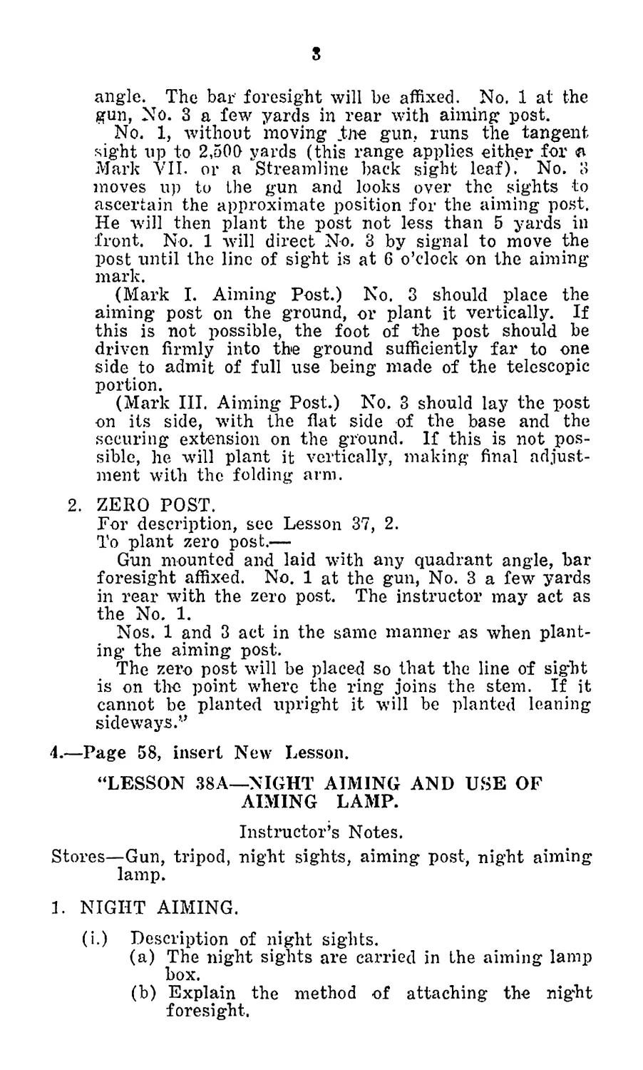
angle. The bar foresight will be affixed. No. 1 at the
gun, No. 3 a few yards in rear with aiming post.
No. 1, without moving tne gun. runs the tangent
sight up to 2,500 yards (this range applies either for a
Mark VII. or a Streamline back sight leaf). No. 3
moves up to the gun and looks over the sights to
ascertain the approximate position for the aiming post.
He will then plant the post not less than 5 yards in
front. No. 1 will direct No. 3 by signal to move the
post until the line of sight is at G o’clock on the aiming
mark.
(Mark I. Aiming Post.) No. 3 should place the
aiming post on the ground, or plant it vertically. If
this is not possible, the foot of the post should be
driven firmly into the ground sufficiently far to one
side to admit of full use being made of the telescopic
portion.
(Mark III. Aiming Post.) No. 3 should lay the post
on its side, with the flat side of the base and the
securing extension on the ground. If this is not pos-
sible, he will plant it vertically, making final adjust-
ment with the folding arm.
2. ZERO POST.
Гог description, see Lesson 37, 2.
To plant zero post.—
Gun mounted and laid with any quadrant angle, bar
foresight affixed. No. 1 at the gun, No. 3 a few yards
in rear with the zero post. The instructor may act as
the No. 1.
Nos. 1 and 3 act in the same manner as when plant-
ing the aiming post.
The zero post will be placed so that the line of sig’ht
is on the point where the ring joins the stem. If it
cannot be planted upright it will be planted leaning
sideways.’7
4 .—Page 58, insert New Lesson.
“LESSON 38A—NIGHT AIMING AND USE OF
AIMING LAMP.
Instructor’s Notes.
Stores—Gun, tripod, night sights, aiming post, night aiming
lamp.
1. NIGHT AIMING.
(i.) Description of night sights.
(a) The night sights are carried in the aiming lamp
box.
(b) Explain the method of attaching the night
foresight.
4
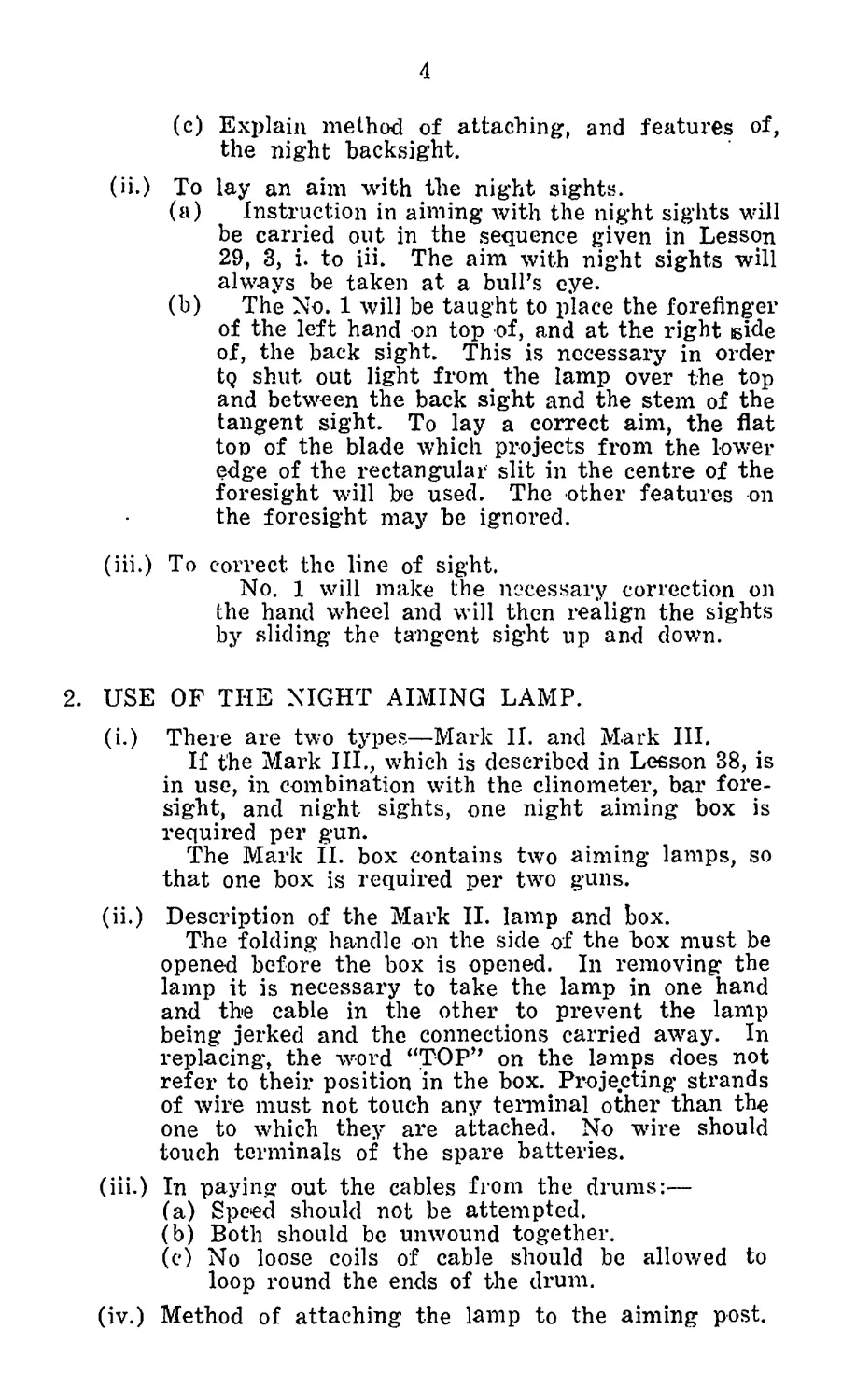
(c) Explain method of attaching, and features of,
the night backsight.
(ii.) To lay an aim with the night sights.
(a) Instruction in aiming with the night sights will
be carried out in the sequence given in Lesson
29, 3, i. to iii. The aim with night sights will
always be taken at a bull's eye.
(b) The No. 1 will be taught to place the forefinger
of the left hand on top of, and at the right iside
of, the back sight. This is necessary in order
tQ shut out light from, the lamp over the top
and between the back sight and the stem of the
tangent sight. To lay a correct aim, the flat
ton of the blade which projects from the lower
edge of the rectangular slit in the centre of the
foresight will be used. The other features on
the foresight may be ignored.
(iii.) To correct the line of sight.
No. 1 will make the necessary correction on
the hand wheel and will then realign the sights
by sliding the tangent sight up and down.
2. USE OF THE NIGHT AIMING LAMP.
(i.) There are two types—Mark II. and Mark III.
If the Mark III., which is described in Lesson 38, is
in use, in combination with the clinometer, bar fore-
sight, and night sights, one night aiming box is
required per gun.
The Mark II. box contains two aiming lamps, so
that one box is required per two guns.
(ii.) Description of the Mark II. lamp and box.
The folding handle on the side of the box must be
opened before the box is opened. In removing the
lamp it is necessary to take the lamp in one hand
and the cable in the other to prevent the lamp
being jerked and the connections carried away. In
replacing, the word “TOP" on the lamps does not
refer to their position in the box.. Projecting strands
of wire must not touch any terminal other than the
one to which they are attached. No wire should
touch terminals of the spare batteries.
(iii.) In paying out the cables from the drums:—
(a) Speed should not be attempted.
(b) Both should be unwound together.
(c) No loose coils of cable should be allowed to
loop round the ends of the drum.
(iv.) Method of attaching the lamp to the aiming post.
(v.) Lighting, dimming and extinguishing the lamps.
(a) The method of using the switch.
(b) The switch must be turned off before the lamps
arc replaced in the box.”
5.—Page 63, insert New Lesson.
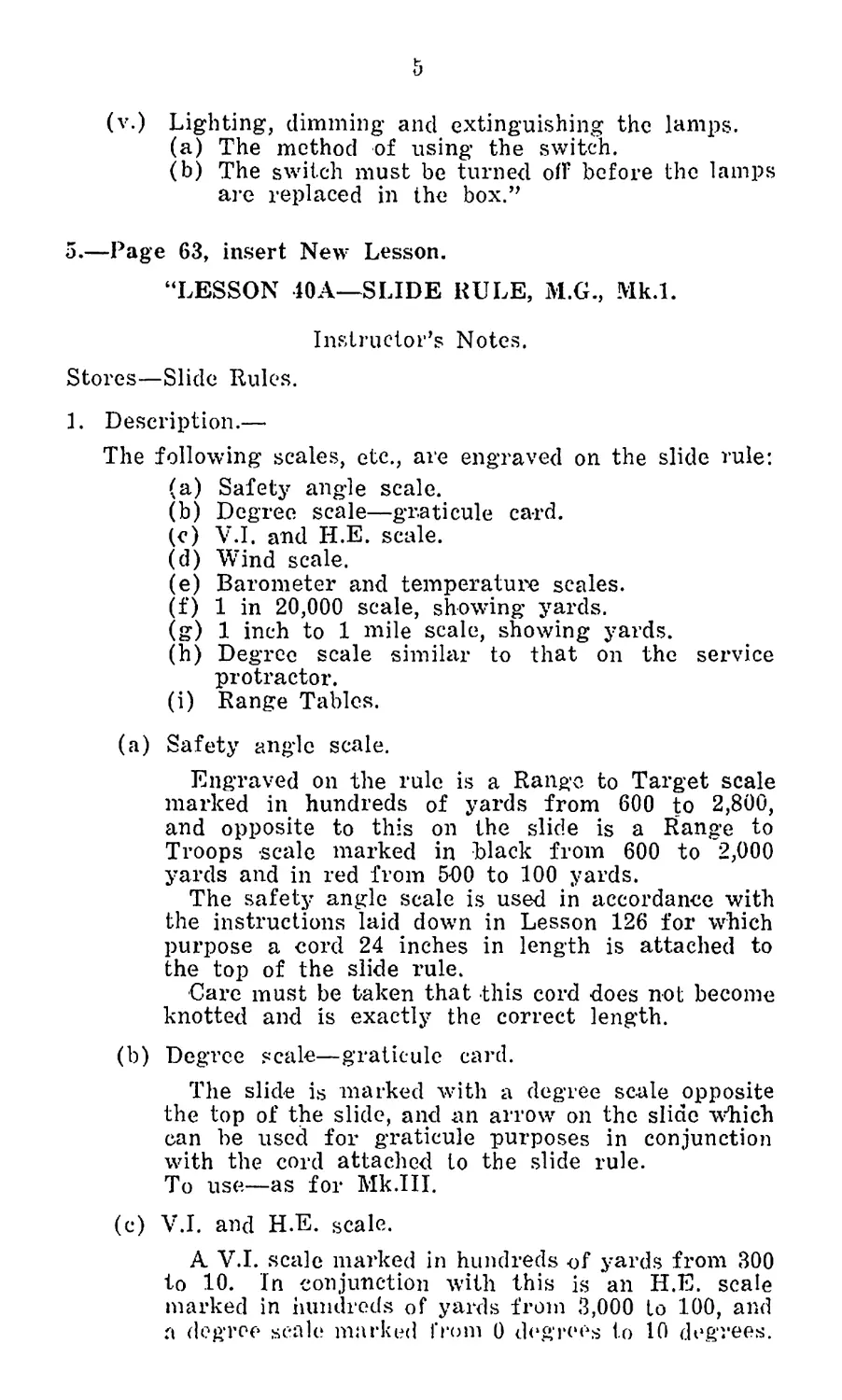
“LESSON 40A—SLIDE RULE, M.G., Mk.l.
Instructor’s Notes.
Stores—Slide Rules.
1. Description.—
The following scales, etc., are engraved on the slide rule:
(a) Safety angle scale.
(b) Degree scale—graticule card.
(c) V.I. and H.E. scale.
(d) Wind scale.
(e) Barometer and temperature scales.
(f) 1 in 20,000 scale, showing yards.
(g) 1 inch to 1 mile scale, showing yards.
(h) Degree scale similar to that on the service
protractor.
(i) Range Tables.
(a) Safety angle scale.
Engraved on the rule is a Rango to Target scale
marked in hundreds of yards from 600 to 2,800,
and opposite to this on the slide is a Range to
Troops scale marked in black from 600 to 2,000
yards and in red from 500 to 100 yards.
The safety angle scale is used in accordance with
the instructions laid down in Lesson 126 for which
purpose a cord 24 inches in length is attached to
the top of the slide rule.
Care must be taken that this cord does not become
knotted and is exactly the correct length.
(b) Degree scale—graticule card.
The slide is marked with a degree scale opposite
the top of the slide, and an arrow on the slide which
can be used for graticule purposes in conjunction
with the cord attached to the slide rule.
To use—as for Mk.III.
(c) V.I. and H.E. scale.
A V.I. scale marked in hundreds of yards from 300
to 10. In conjunction with this is an H.E. scale
marked in hundreds of yards from 3,000 to 100, and
a degree scale marked from 0 degrees to 10 degrees.
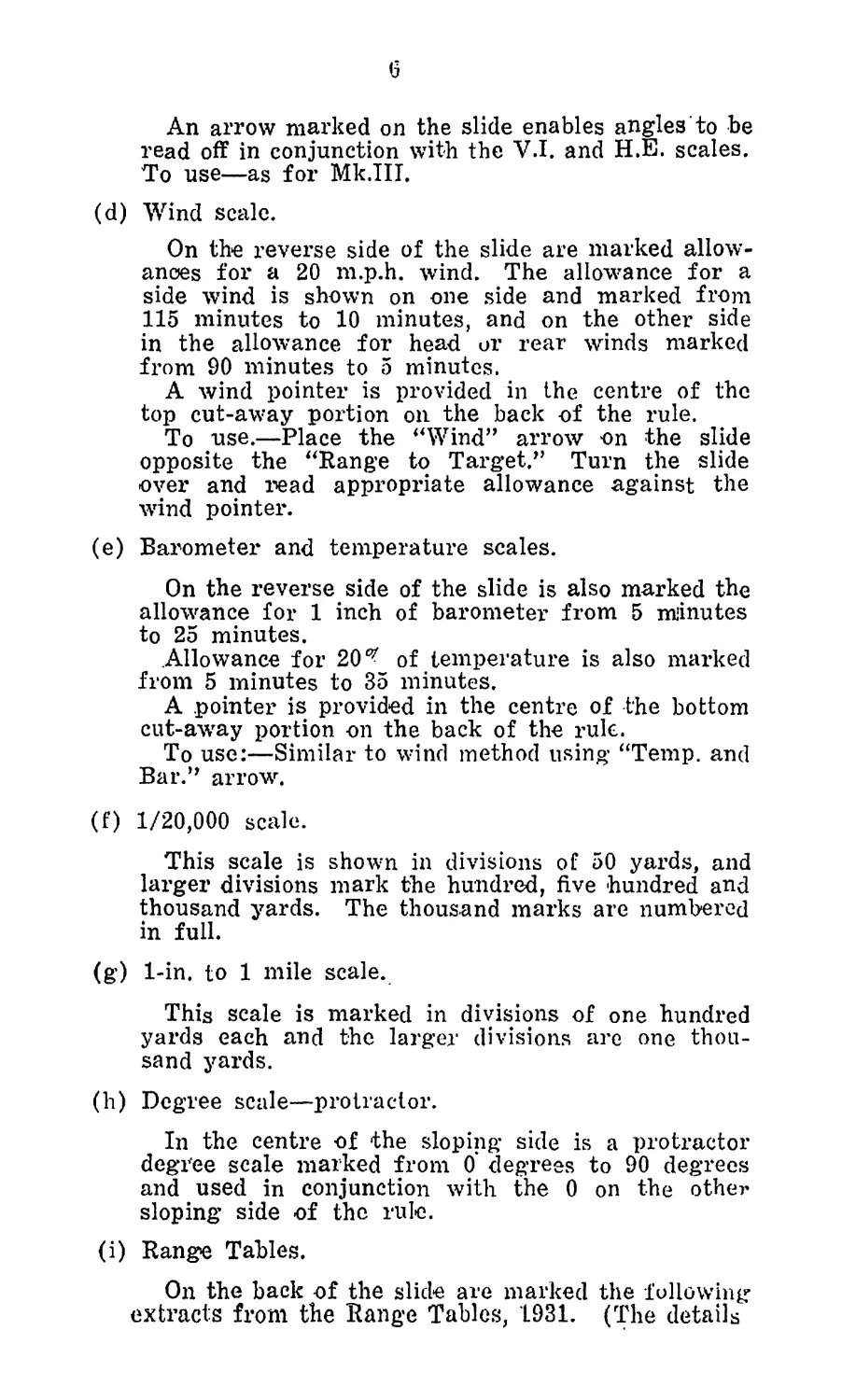
6
An arrow marked on the slide enables angles to be
read off in conjunction with the V.I. and H.E. scales.
To use—as for Mk.III.
(d) Wind scale.
On the reverse side of the slide are marked allow-
ances for a 20 m.p.h. wind. The allowance for a
side wind is shown on one side and marked from
115 minutes to 10 minutes, and on the other side
in the allowance for head or rear winds marked
from 90 minutes to 5 minutes.
A wind pointer is provided in the centre of the
top cut-away portion on the back of the rule.
To rise.—Place the “Wind” arrow on the slide
opposite the “Range to Target?’ Turn the slide
over and read appropriate allowance against the
wind pointer.
(e) Barometer and temperature scales.
On the reverse side of the slide is also marked the
allowance for 1 inch of barometer’ from 5 minutes
to 25 minutes.
Allowance for 20 of temperature is also marked
from 5 minutes to 35 minutes.
A pointer is provided in the centre of the bottom
cut-away portion on the back of the rule.
To use:—Similar to wind method using “Temp, and
Bar.” arrow.
(f) 1/20,000 scale.
This scale is shown in divisions of 50 yards, and
larger divisions mark the hundred, five hundred and
thousand yards. The thousand marks are numbered
in full.
(g) 1-in. to 1 mile scale.
This scale is marked in divisions of one hundred
yards each and the larger divisions are one thou-
sand yards.
(h) Degree scale—protractor.
In the centre of the sloping side is a protractor
degree scale marked from 0 degrees to 90 degrees
and used in conjunction with the 0 on the othe?'
sloping side of the rule.
(i) Range Tables.
On the back of the slide are marked the following
extracts from the Range Tables, 1931. (The details
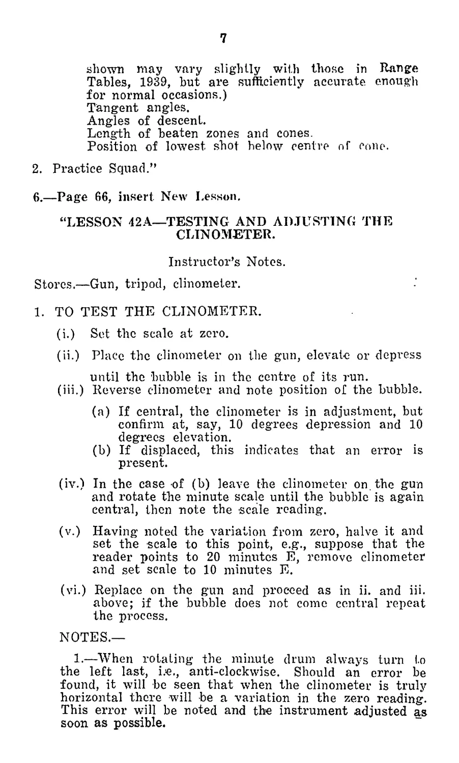
1
shown may vary slightly with those in Range
Tables, 1939, but are sufficiently accurate enough
for normal occasions.)
Tangent angles.
Angles of descent.
Length of beaten zones and cones.
Position of lowest shot helow centre of cone.
2. Practice Squad.”
6 .—Page 66, insert. New Lesson.
“LESSON 42A—TESTING AND ADJUSTING THE
CLINOMETER.
Instructor’s Notes.
Stores.—Gun, tripod, clinometer.
1. TO TEST THE CLINOMETER.
(i.) Set the scale at zero.
(ii.) Place the clinometer on the gun, elevate or depress
until the bubble is in the centre of its run.
(iii.) Reverse clinometer and note position of the bubble.
(a) If central, the clinometer is in adjustment, but
confirm at, say, 10 degrees depression and 10
degrees elevation.
(b) If displaced, this indicates that an error is
present.
(iv.) In the case of (b) leave the clinometer on. the gun
and rotate the minute scale until the bubble is again
central, then note the -scale reading.
(v.) Having noted the variation from zero, halve it and
set the scale to this point, e.g., suppose that the
reader points to 20 minutes E, remove clinometer
and set scale to 10 minutes E.
(vi.) Replace on the gun and proceed as in ii. and iii.
above; if the bubble does not come central repeat
the process.
NOTES.—
1.—When rotating the minute drum always turn to
the left last, i.e., anti-clockwise. Should an error be
found, it will be seen that when the clinometer is truly
horizontal there will be a variation in the zero reading.
This error will be noted and the instrument adjusted as
soon as possible.
я
2.—If a gun is levelled with a clinometer known to he
in adjustment, then any number of clinometers can be
tested by placing them on the gun in the ordinary way
and noting if there is any error.
2. TO ADJUST THE CLINOMETER.
Set the clinometer at the error noted. With the span-
ner loosen the “nuts securing micrometer collar,” set the
scale to zero and tighten up.
If the variation is large, it may be necessary to reset
the degree reader. This is done by loosening the two
securing screws and sliding the reader to the right or left,
and then clamping up.
NOTE.—Except in an emergency, adjustments will be
carried out only by armourers.”
7 .—Page 67, insert New Lesson.
“LESSON 43A—TESTING THE No. 9 MK.I DIRECTOR
FOR ANGLE OF SIGHT.
Instructor’s Notes.
Stores.—Gun, tripod, dial sight, director.
1. Mount a gun, attach a dial sight known to be in adjust-
ment, .and lay with the tangent sight at zero (0) on a
distant object. With the range drum of the dial sight at
zero, level the bubble by means of the angle of sight
drum and note the reading.
Mount the director at the same height as the gun (i.e.,
object glass on the same level as the tangent sight) and
take angle of sight to distant object.
If this is the same as the reading' on the angle of sight
drum the director is in adjustment. If not, note the
amount of error.
2. If a horizontal line is available (see para. 3 below), place
the object glass at one end of the horizontal line and
take the angle of sight to the other end. If this is zero
the director is in adjustment; if not, note the error.
3. TO LAY OUT A HORIZONTAL PLANE, AND TEST
DIRECTOR FOR ANGLE OF SIGHT.
(i.) Select a position where there are two walls or
upright posts, about 200 yards apart, and as far
as possible in the same horizontal plane.
(ii.) Take director to one wall (A), if possible a corner
of a house. Lay director at the other wall (B),
and direct an assistant to make a mark on (B),
which appears to have no angle of sight (i.e., an
angle of sight of zero).
Make a mark on (A) level with the object glass.
(iii.) Take director to (B), mount it with object glass
level with the mark, and lay it at mark on (A).
(a) If mark on (A) has no angle of sight, the two
marks are on the same horizontal plane and the
director is in adjustment.
(b) If the mark on (A) appears to show an angle
of sight, make a second mark which has not.
(e) By measurement, make a third mark (X) on
(A), midway between the two existing marks.
(X) is on the same horizontal plane as the
mark on (B).
(iv.) (a) Any director may now be tested for angle of
sight and the errors, if any, noted.
(b) Adjustments will only be made by an ar-
mourer.
4. Practice squad.
NOTE.—Where an adjustment is necessary, it will be
carried out by an armourer.”
10
APPENDIX 1
8. DESCRIPTION AND TESTING OF INSTRUMENTS
USED IN CONJUNCTION WITH THE .303-IN. VICKERS
MACHINE GUN.
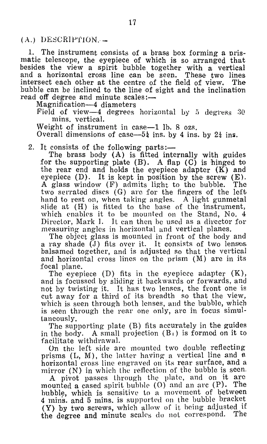
1 .—Foresight, bar, deflection, Mark I.
(Plate I.) ,
The sight is of steel and consists of:—
(i.) A bar (A) about 10 inches jn length, graduated in
intervals of 10 minutes and degrees up to 7 degrees
right and left of the centre line.
(ii.) An inverted U-shaped bracket (B) to which the bar
is a fixture and which is arranged to assemble over
the projecting wings of the ordinary gun foresight,
where it is secured by a screw (C) in the left side of
the bracket and a spring stud (D) in the right, the
former engaging in the hole in the left wing and the
latter in the opening in the right wing.
The upper surface of the bracket (E) is graduated
in ten-minute intervals, in continuation of the gradua-
tions on the bar, the centre line being indicated as
zero.
(iii.) The sliding sight (F) with clamp screw (G) for
fixing in any desired position on (A).
The sight has a central blade and protecting wings,
and is arranged to take night sights when required
for night firing.
Two pointers (H) are provided on the slide to
register respectively with the scale on (A) and on
(B).
When assembling the sight, care must be taken that
excessive pressure is not applied to the screw, as
such will distort the sight protecting wings of the
gun, and thereby affect the level of the bar.
2 .—Post, aiming, M.G., Mark I.
The aiming post consists of a single telescopic stand, the
top half of which can be raised or lowered.
The base of the stand is a metal plate with three spikes.
The plate enables the spikes to be pushed into the ground
by means of the feet, and also prevents the stand sinking too
far in soft ground.
The lower half, or tube, of the aiming post has a clamping
screw at the top which allows the top half to be fixed at the
required ’extension.
The top half, or inner rod, is surmounted by a bracket, to
one side of which a day aiming mark (black bullseye on a.
white background) is permanently fixed. The other side of the
bracket provides a support for the night aiming lamp when
in use. On the inner rod is a collar and clamping screw
which allows this rod to be maintained at a given height
when rotated.
By this means the aiming lamp can be set at the same
height as the day aiming mark if desired.
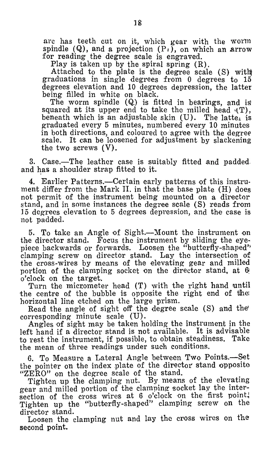
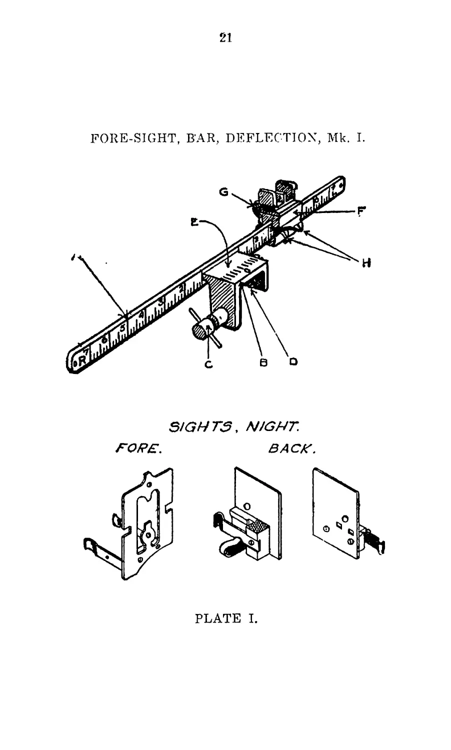
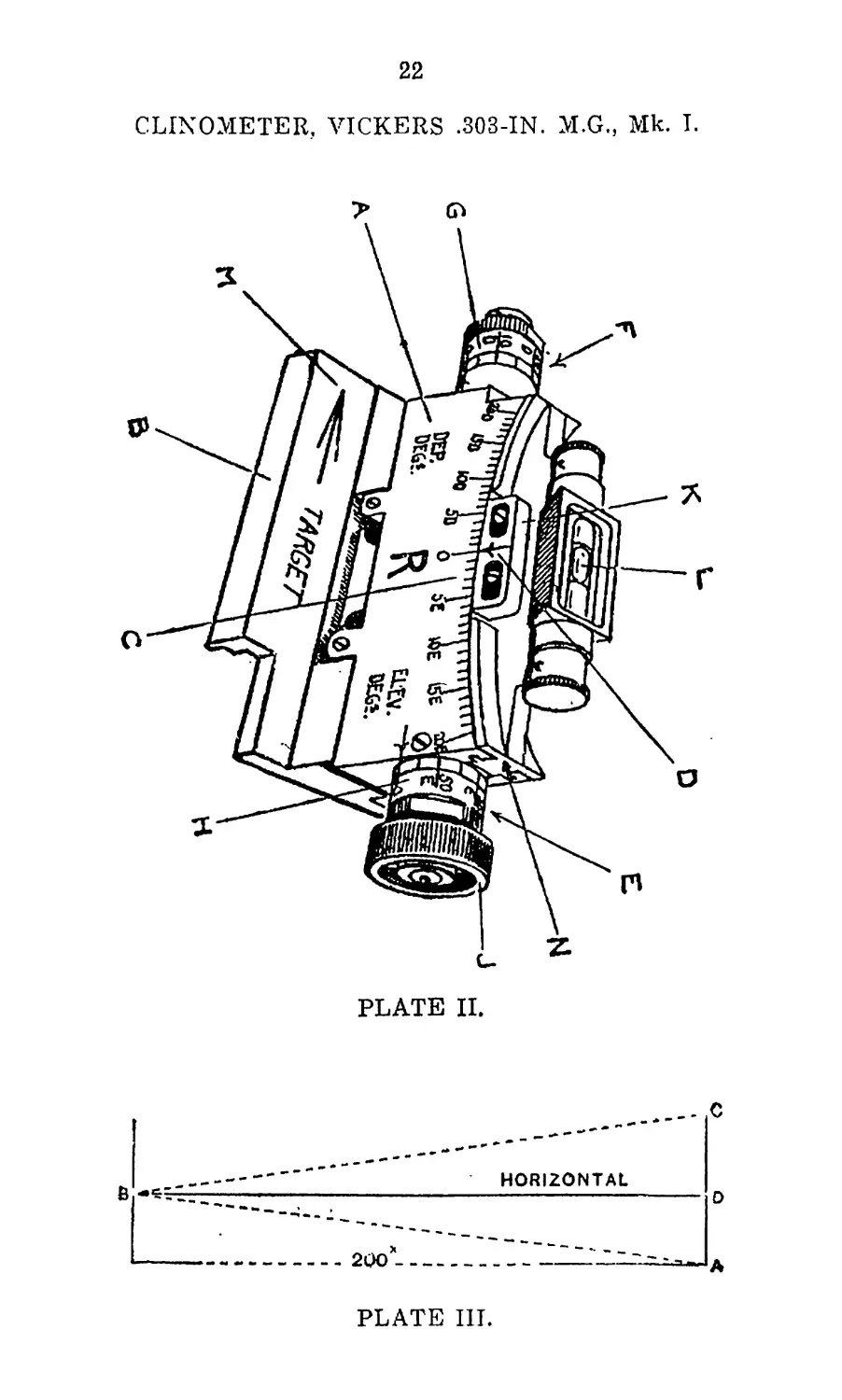
3 .—Clinometer, Vickers .303-in. M.G., Mark I.
(Plate IT.)
1. Description.—This instrument consists of a manganese
bronze casting called the “cradle” (A). The upper surface
is cut to form the arc of a circle in which the arc (N) can
slide, and to the lower surface is attached a cast steel base
(B) adapted to rest between the side plates of the gun when
the rear cover is raised.
A scale of degrees (C) from zero to 20 degrees elevation
and depression is engraved on one face and is read from an
arrow (D) on the arc. The graduations for elevation and
depression are filled in with black and are numbered every
5 degrees and followed by the letters “E” and “D” respec-
tively.
A worm spindle is fitted in two bearings in the cradle,
one end (E) being on a pivot. This allows the worm to be
put out of gear with the arc, for quick setting, by pressing
downwards on the other end (F) of the worm spindle.
A spring is provided to keep the worm spindle and arc
in gear.
Two micrometei' collars are fixed to the worm spindle,
one (G) for reading depression in minutes, the other (H)
for reading elevation in minutes.
The micrometer collars are divided every five minutes and
numbered every ten minutes, and are coloured the same as
the degree scale. The figures on the micrometer collars have
the letters “E” and “D” engraved underneath to indicate
elevation and depression respectively.
At one end of the worm spindle a milled head (J) is firmly
attached; one turn of this milled head represents one degree.
The arc (N) is shaped to slide in the cradle. On its under
surface are teeth into which the worm gears. Attached to
it by two screws is an adjustable reader (K) for the degree
scale. @n its upper surface is attached a spirit-level (L).
Engraved on the base is an arrow (M) and the word
“Target.” This is to indicate the correct direction in which
to place the clinometer on the gun.
4 .—Director, No. 4, Mark II.
(For Plates, see Lesson 39).
1. Description.—This instrument consists of:—
12
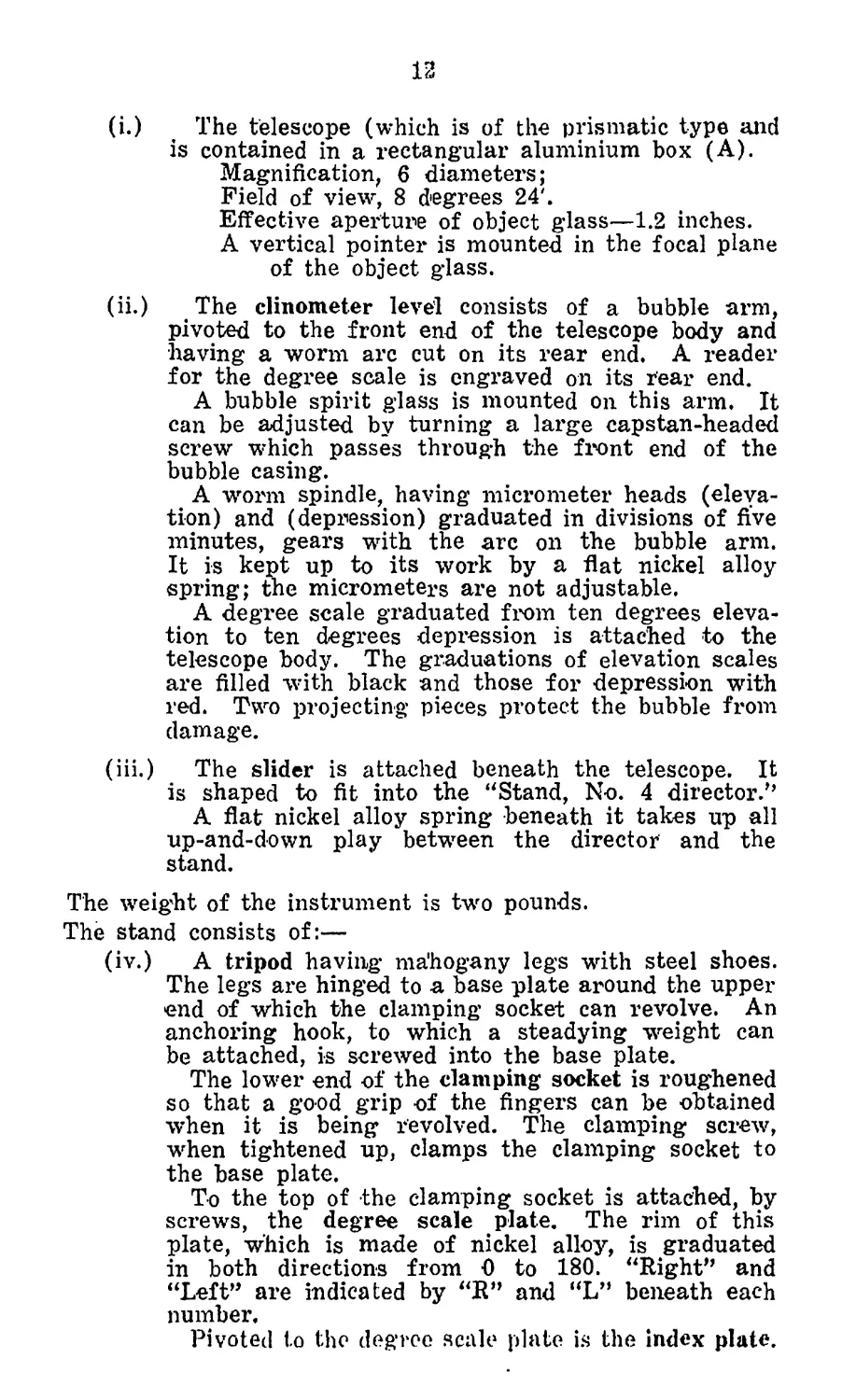
(i.) The telescope (which is of the prismatic type and
is contained in a rectangular aluminium box (A).
Magnification, 6 diameters;
Field of view, 8 degrees 24'.
Effective aperture of object glass—1.2 inches.
A vertical pointer is mounted in the focal plane
of the object glass.
(ii.) The clinometer level consists of a bubble arm,
pivoted to the front end of the telescope body and
•having a worm arc cut on its rear end. A reader
for the degree scale is engraved on its rear end.
A bubble spirit glass is mounted on this arm. It
can be adjusted by turning a large capstan-headed
screw which passes through the front end of the
bubble casing.
A worm spindle, having micrometer heads (eleva-
tion) and (depression) graduated in divisions of five
minutes, gears with the arc on the bubble arm.
It is kept up to its work by a flat nickel alloy
spring; the micrometers are not adjustable.
A degree scale graduated from ten degrees eleva-
tion to ten degrees depression is attached to the
telescope body. The graduations of elevation scales
are filled with black and those for depression with
red. Two projecting pieces protect the bubble from
damage.
(iii.) The slider is attached beneath the telescope. It
is shaped to fit into the “Stand, No. 4 director/’
A flat nickel alloy spring beneath it takes up all
up-and-down play between the director and the
stand.
The weight of the instrument is two pounds.
The stand consists of:—
(iv.) A tripod having mahogany legs with steel shoes.
The legs are hinged to a base plate around the upper
end of which the clamping socket can revolve. An
anchoring hook, to which a steadying weight can
be attached, is screwed into the base plate.
The lower end of the clamping socket is roughened
so that a good grip of the fingers can be obtained
when it is being revolved. The clamping screw,
when tightened up, clamps the clamping socket to
the base plate.
To the top of the clamping socket is attached, by
screws, the degree scale plate. The rim of this
plate, which is made of nickel alloy, is graduated
in both directions from 0 to 180. “Right” and
“Left” are indicated by “R” and “L” beneath each
number.
Pivoted to the degree scale plate is the index plate.
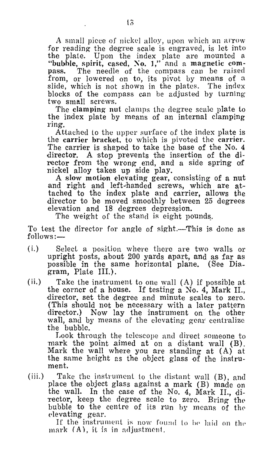
13
A small piece of nickel alloy, upon which an arrow
for reading the degree scale is engraved, is let into
the plate. Upon the index plate are mounted a
“bubble, spirit, cased, No. 1,” and a magnetic com-
pass. The needle of the compass can be raised
from, or lowered on to, its pivot by means of a
slide, which is not shown in the plates. The index
blocks of the compass can be adjusted by turning-
two small screws.
The clamping nut clamps the degree scale plate to
the index plate by means of an internal clamping
ring.
Attached to the upper surface of the index plate is
the carrier bracket, to which is pivoted the carrier.
The carrier is shaped to take the base of the No. 4
director. A stop prevents the insertion of the di-
rector from the wrong end, and a side spring of
nickel alloy takes up side play.
A slow motion elevating gear, consisting of a nut
and right and left-handed screws, which are at-
tached to the index plate and carrier, allows the
director to be moved smoothly between 25 degrees
elevation and 18 degrees depression.
The weight of the stand is eight pounds.
To test the director for angle of sight.—This is done as
follows:—
(i.) Select a position where there are two Avails or
upright posts, about 200 yards apart, and as far as
possible in the same horizontal plane. (See Dia-
gram, Plate III.).
(ii.) Take the instrument to one wall (A) if possible at
the corner of a house. If testing a No. 4, Mark IL,
director, set the degree and minute scales to zero.
(This should not be necessary with a later pattern
director.) Now lay the instrument on the other
wall, and by means of the elevating gear centralize
the bubble.
Look through the telescope and direct someone to
mark the point aimed at on a distant wall (B).
Mark the wall where you are standing at (A) at
the same height as the object glass of the instru-
ment.
(iii.) Take the instrument to the distant wall (B), and
place the object glass against a mark (B) made on
the wall. In the case of the No. 4, Mark IL, di-
rector, keep the degree scale to zero. Bring the
bubble to the centre of its run by moans of the
elevating gear.
If the instrument is now found to be laid on the
mark (A), it is in adjustment.
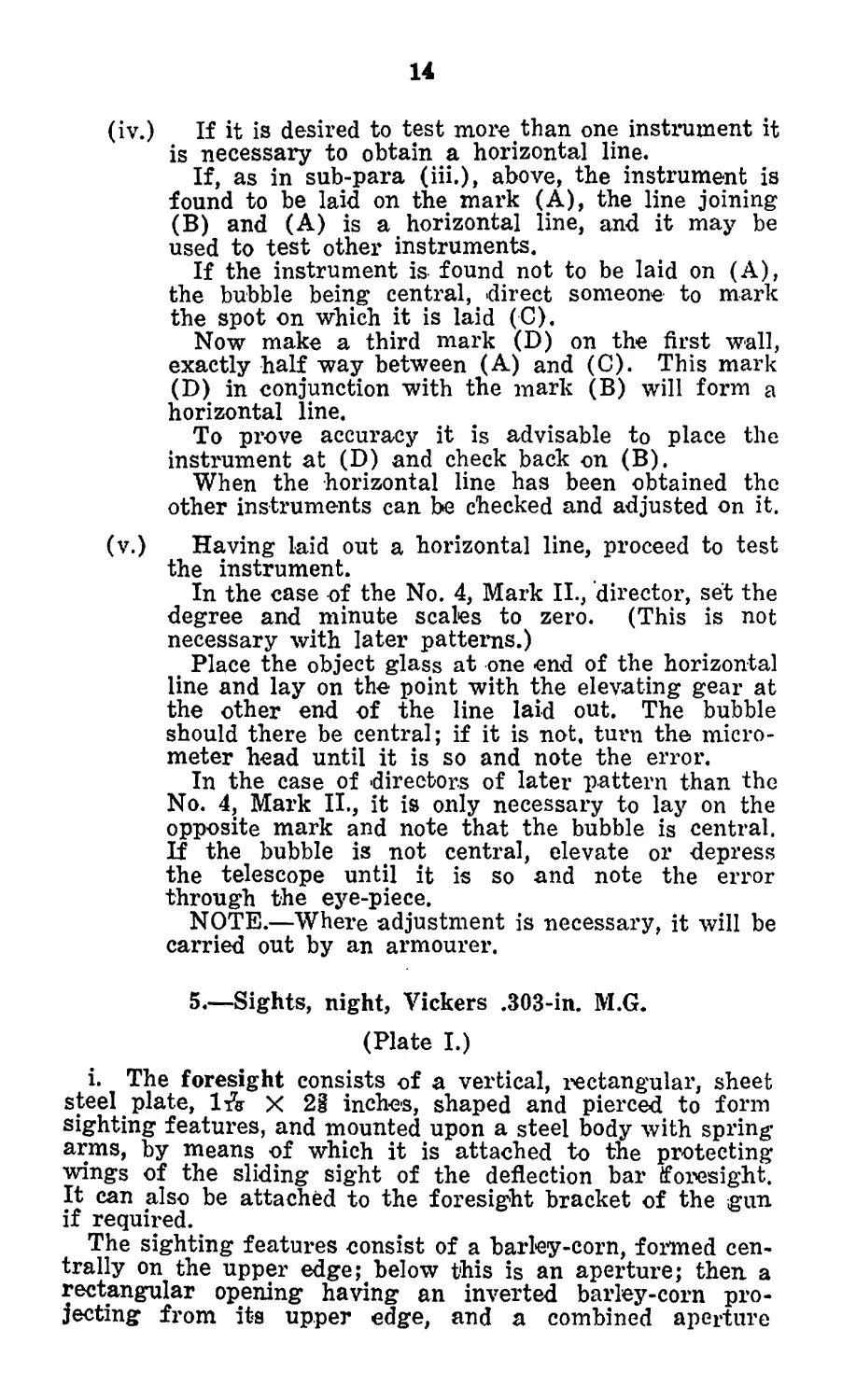
14
(iv.) If it is desired to test more than one instrument it
is necessary to obtain a horizontal line.
If, as in sub-para (iii.), above, the instrument is
found to be laid on the mark (A), the line joining
(B) and (A) is a horizontal line, and it may be
used to test other instruments.
If the instrument is found not to be laid on (A),
the bubble being central, direct someone to mark
the spot on which it is laid (C).
Now make a third mark (D) on the first wall,
exactly half way between (A) and (C). This mark
(D) in conjunction with the mark (B) will form a
horizontal line.
To prove accuracy it is advisable to place the
instrument at (D) and check back on (B).
When the horizontal line has been obtained the
other instruments can be checked and adjusted on it.
(v.) Having laid out a horizontal line, proceed to test
the instrument.
In the case of the No. 4, Mark II., director, set the
degree and minute scales to zero. (This is not
necessary with later patterns.)
Place the object glass at one end of the horizontal
line and lay on the point with the elevating gear at
the other end of the line laid out. The bubble
should there be central; if it is not. turn the micro-
meter head until it is so and note the error.
In the case of directors of later pattern than the
No. 4, Mark II., it is only necessary to lay on the
opposite mark and note that the bubble is central.
If the bubble is not central, elevate or depress
the telescope until it is so and note the error
through the eye-piece.
NOTE.—Where adjustment is necessary, it will be
carried out by an armourer.
5 .—Sights, night, Vickers .303-in. M.G.
(Plate I.)
i. The foresight consists of a vertical, rectangular, sheet
steel plate, 1ft X 2i inches, shaped and pierced to form
sighting features, and mounted upon a steel body with spring
arms, by means of which it is attached to the protecting
wings of the sliding sight of the deflection bar foresight.
It can also be attached to the foresight bracket of the gun
if required.
The sighting features consist of a barley-corn, formed cen-
trally on the upper edge; below this is an aperture; then a
rectangular opening having an inverted barley-corn pro-
jecting from its upper edge, and a combined aperture
15
and blade from its lower edge, w’hilst a notch is cut in each
side to indicate normal limits of traverse, the spacing being
equal to about one degree of angle in each direction.
The foresight is assembled to the sliding sight of the
deflection bar foresight by being sprung on to the protecting
wings from the side which faces the breech of the gun.
ii. The backsight consists of a vertical rectangular steel
plate about X li inches, pierced to form a sighting
aperture about inch in diameter, and below, to the right
and left of the aperture, two small rectangular openings
behind which a background of luminous paint can be em-
ployed if required as a guide to the position of the aper-
ture.
The plate is secured to a small steel body, to which is
attached a spring clip for engagement with the tangent
sight slide of the gun.
The backsight is assembled to the slide by pressing it
on to the projecting blade portion from the left, care being
taken to see that the horizontal ledge of the body rests
on the upper edge of the blade, and that the bent lip on
the right side of the spring engages over the inner edge of
the slide.
6 .—Lamps, aiming, M.G., Mark II.
1. Description.—
The lamps are contained in a wooden box, there being two
lamps in each box. On the side of the box is a folding4
handle.
In the lid of the box is a drum on which is wound a
separate cable for each lamp. This drum is operated by the
folding handle.
In the box is the battery and a spare battery, held in
place by an ebonite strip and a screw. On the side of the
fcioimpartment for the batteries is an adjustable resistance
rfor regulating the amount of light shown by the lamps.
Next to the batteries is the switch. Either lamp can be
illuminated by moving the switch to one of the points
marked 1 and 2 on either side of the “Off” position.
Both can be put on together by moving the switch to the
point opposite the “Off,” also marked 1, so that the switch
covers that point and also that marked 2.
Next to the switch is a block of wood with two holes to
take spare bulbs. A hole is cut in the side of the box so
that the lid can be closed when the cable is out and the
lamps ready for use. Two spare batteries for the lamps are
carried in addition to those in the box.
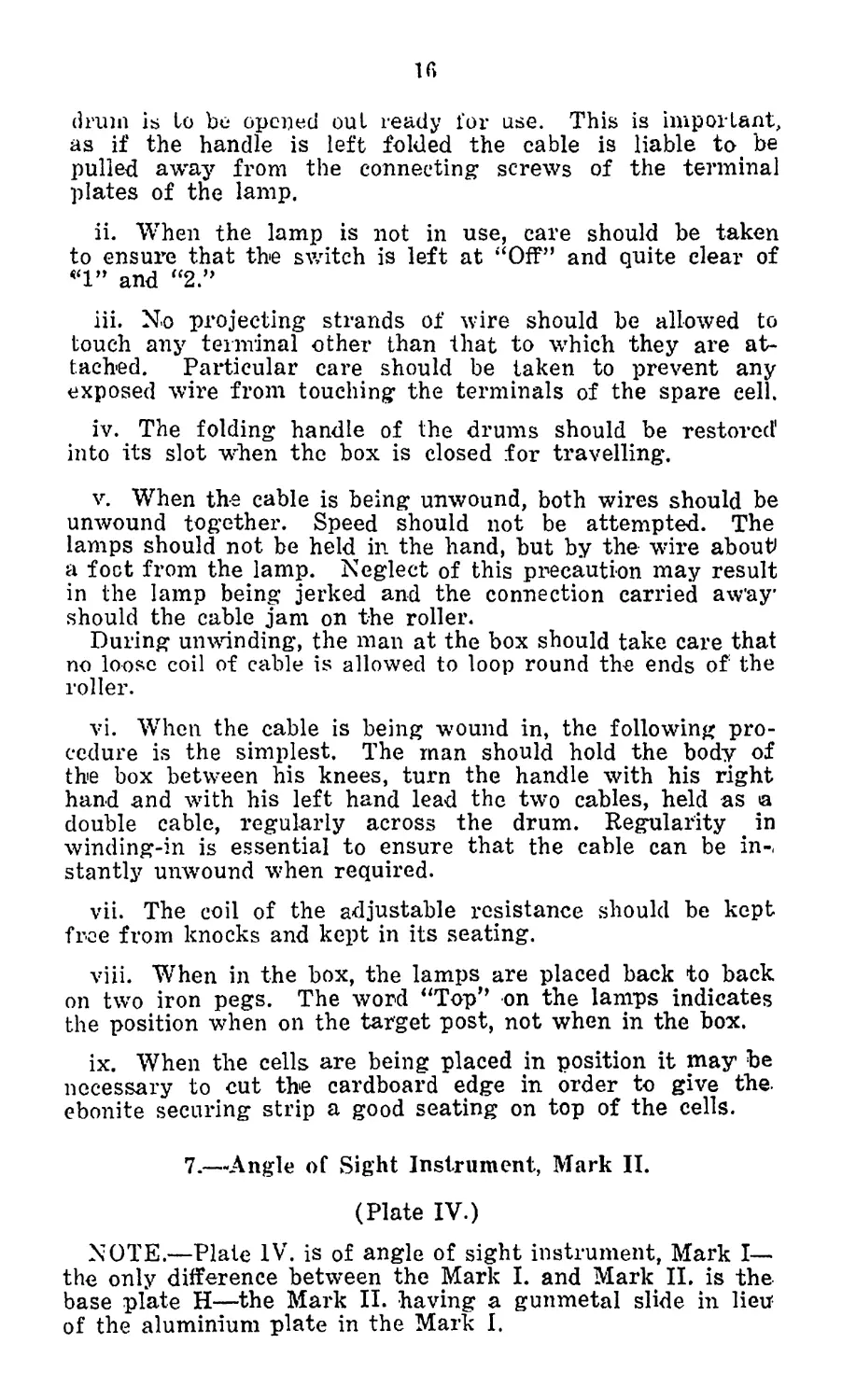
2. Instructions for' the care and use of Lamps, aiming, M.G.
i. Before the box is opened, the folding handle of the
16
drum is to be opened out ready for use. This is important,
as if the handle is left folded the cable is liable to. be
pulled away from the connecting screws of the terminal
plates of the lamp.
ii. When the lamp is not in use, care should be taken
to ensure that the switch is left at ‘‘Off” and quite clear of
*1” and “2.”
iii. No projecting strands of wire should be allowed to
touch any terminal other than that to which they are at-
tached. Particular care should be taken to prevent any
exposed wire from touching the terminals of the spare cell.
iv. The folding handle of the drums should be restored1
into its slot when the box is closed for travelling.
v. When the cable is being unwound, both wires should be
unwound together. Speed should not be attempted. The
lamps should not be held in the hand, but by the wire about
a foot from the lamp. Neglect of this precaution may result
in the lamp being jerked and the connection carried aw'ay’
should the cable jam on the roller.
During unwinding, the man at the box should take care that
no loose coil of cable is allowed to loop round the ends of the
roller.
vi. When the cable is being wound in, the following pro-
cedure is the simplest. The man should hold the body of
the box between his knees, turn the handle with his right
hand and with his left hand lead the two cables, held as a
double cable, regularly across the drum. Regularity in
winding-in is essential to ensure that the cable can be in-,
stantly unwound when required.
vii. The coil of the adjustable resistance should be kept
free from knocks and kept in its seating.
viii. When in the box, the lamps are placed back to back
on two iron pegs. The word “Top” on the lamps indicates
the position when on the target post, not when in the box.
ix. When the cells are being placed in position it may be
necessary to cut the cardboard edge in order to give the.
ebonite securing strip a good seating on top of the cells.
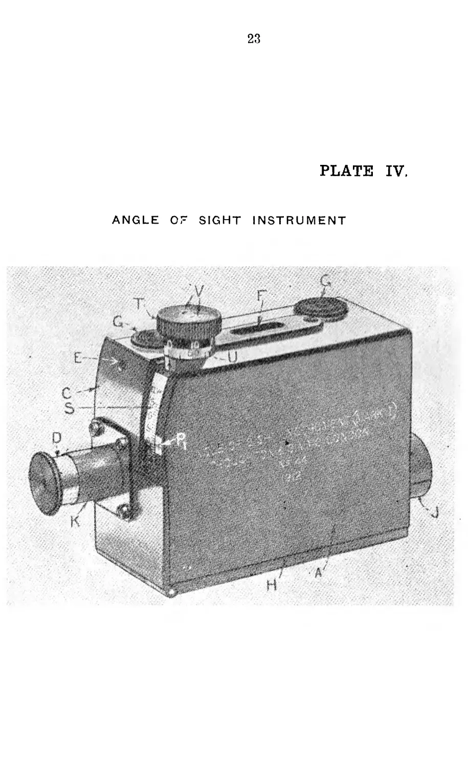
7.—Angle of Sight Instrument, Mark II.
(Plate IV.)
NOTE.—Plate IV. is of angle of sight instrument, Mark I—
the only difference between the Mark I. and Mark П. is the
base plate H—the Mark II. having a gunmetal slide in lieu
of the aluminium plate in the Mark I.
17
(A.) DESCRIPTION.—
1. The instrument consists of a brass box forming a pris-
matic telescope, the eyepiece of which is so arranged that
besides the view a spirit bubble together with a vertical
and a horizontal cross line c.an be seen. These two lines
intersect each other at the centre of the field of view. The
bubble can be inclined to the line of sight and the inclination
read off degree and minute scales:—
Magnification—4 diameters
Field of view—4 degrees horizontal by 5 degress 30
mins, vertical.
Weight of instrument in case—1 lb. 8 ozs.
Overall dimensions of case—ins. by 4 ins. by 2i ins.
2. It consists of the following parts:—
The brass body (A) is fitted internally with guides
for the supporting plate (B’). A flap (C) is hinged to
the rear end and holds the eyepiece adapter (K) and
eyepiece (D). It is kept in position by the- screw (E).
A glass window (F) admits light to the bubble. The
two serrated discs (G) are for the fingers of the left
hand to rest on, when taking angles. A light gunmetal
slide at (H) is fitted to the base of the instrument,
which enables it to be mounted on the Stand, No. 4
Director, Mark I. It can then be used as a director for
measuring angles in horizontal and vertical planes.
The object glass is mounted in front of the body and
a ray shade (J) fils over it. It consists of two lenses
balsamed together, and is adjusted so that the vertical
and horizontal cross lines on the prism (M) are in its
focal plane.
The eyepiece (D) fits in the eyepiece adapter (K),
and is focussed by sliding it backwards or fonvards, and
not by twisting it. It has two lenses, the front one is
cut away for a third of its breadth so that the view,
which is seen through both lenses, and the bubble, which
is seen through the rear one only, are in focus simul-
taneously.
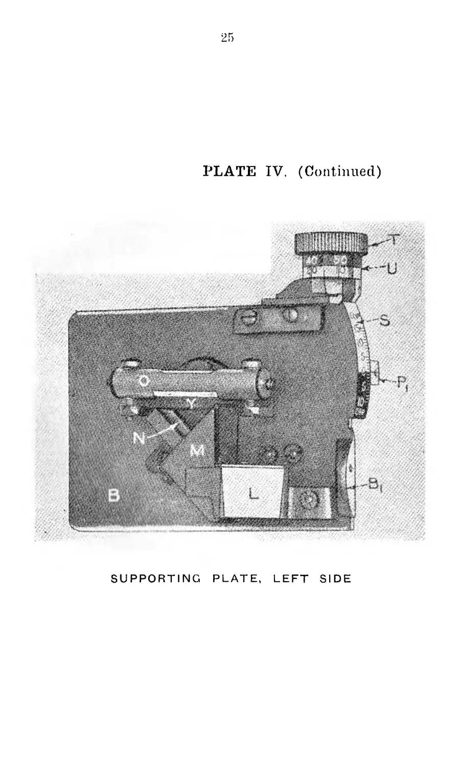
The supporting plate (B) fits accurately in the guides
in the body. A small projection (B ।) is formed on it co
facilitate withdrawal.
On the left side arc mounted two double reflecting
prisms (L, M), the latter having a vertical line and fl
horizontal cross line engraved on its rear surface, and a
mirror (N) in which the reflection of the bubble is seen.
A pivot passes through the plate, and on it are
mounted a cased spirit bubble (0) and an arc (P). The
bubble, wThich is sensitive to a movement of between
4 mins, and 5 mins, is supported on the bubble bracket
(Y) by two screws, which allow of it being adjusted if
the degree and minute scales do not correspond. The
18
arc has teeth cut on it, which gear with the worm
spindle (Q), and a projection (Pi), on which an arrow
for reading the degree scale is engraved.
Play is taken up by the spiral spring (R).
Attached to the plate is the degree scale (S) witty
graduations in single degrees from 0 degrees to 15
degrees elevation and 10 degrees depression, the latter
being filled in white on black.
The worm spindle (Q.) is fitted in bearings, and is!
squared at its upper end to take the milled head ЧТ),
beneath which is an adjustable skin (U). The lattei is
graduated every 5 minutes, numbered every 10 minutes
in both directions, and coloured to agree with the degree
scale. It can be loosened for adjustment by slackening
the two screws (V).
3. Case.—The leather case is suitably fitted and padded,
and has a shoulder strap fitted to it.
4. Earlier Patterns.—Certain early patterns of this instru-
ment differ from the Mark II. in that the base plate (H) does
not permit of the instrument being mounted on a director
stand, and in some instances the degree scale (S) reads from
15 degrees elevation to 5 degrees depression, and the case is
not padded.
5. To take an Angle of Sight.—Mount the instrument on
the director stand. Focus the instrument by sliding the eye-
piece backwards or forwards. Loosen the “butterfly-shaped’5 6
clamping screw on director stand. Lay the intersection of
the cross-wires by means of the elevating gear and milled
portion of the clamping socket on the director stand, at
o’clock on the target.
Turn the micrometer head (T) with the right hand until
the centre of the bubble is opposite the right end of tlhei
horizontal line etched on the large prism.
Read the angle of sight off the degree scale (S) and the'
corresponding minute scale (U).
Angles -of sight may be taken holding the instrument in the
left hand if a director stand is not available. It is advisable
to rest the instrument, if possible, to obtain steadiness. Take
the mean of three readings under such conditions.
6. To Measure a Lateral Angle between Two Points.—Set
the pointer on the index plate of the director stand opposite
“ZERO” on the degree scale of the stand.
Tighten up the clamping* nut. By means of the elevating
gear and milled portion of the clamping -socket lay the inter-
section of the cross wires at 6 o’clock on the first pointy
Tighten up the “butterfly-shaped” clamping screw on the
director stand.
Loosen the clamping nut and lay the cross wires on the
second point.
19
Read oft' the number of degrees, minutes, and direction,
right or left, from the degree scale. For further details, see
Lesson 39, where, although the detail refers particularly to
the director, No. 4, Mark II., the method of use is similar
when employing an instrument, angle of sight.
(B.) TO TEST AND ADJUST THE INSTUMENT.
1. Lay out a horizontal line. This is done as follows:—
(i.) Select a position where there are two walls or
upright posts, and about 200 yards apart, and as
far as possible on the same horizontal plane.
(ii.) Take the instrument to one wall (A), if pos-
. sible at the corner of a house. Set the angle
of sight scale to zero, direct the telescope at the
other wall and bring the bubble to the centre of
its run. Look through the telescope and direct
someone to mark the point where the cross-wire
cuts through the distant wall (B). Mark the
wall where you are standing at (A) the same
height as the object glass of the instrument.
(iii.) Take the instrument to the distant wall (B) and
place the object glass against the mark (B) made
on it. Still keeping the angle of sight scale at
zero, bring the bubble to the centre of its run.
If the instrument is in adjustment the cross-wire
should be in line with the mark (A) on the first
wall and the line between the two marks is in a
horizontal plane.
(iv.) If such is not the case direct someone to mark
on the first Avail (A) another point (C) on which
the cross-wire is layed, the bubble being central.
(v.) Make a third mark (D) on the first wall exactly
halfway between (A) and (C).
(vi.) With the instrument still at (B) on the second
wall elevate or depress the telescope until the
20
cross-wire is layed on the third mark (D). While
keeping it layed on this point rotate the micro-
meter head of the instrument until the bubble is
again in the centre of its run.
(vii.) Without altering the readings take the instru-
ment to (D) and check the adjustment back on
(B). If correct, a line between these marks is
in the same horizontal plane.
When once a horizontal line has been obtained
any number of instruments can be checked and
adjusted on it.
2. Having now layed out a horizontal line, proceed to
adjust the instruments. Set the degree and minute scales
to zero. Place the object glass at one end of the horizontal
line and lay the right end of the cross-wire in the instru-
ment on the point at the other end of the line layed out.
The centre of the bubble should then be in line with the
horizontal cross-wire in the instrument.
3. If it is not, turn the micrometer head until it is so.
Loosen the two small outer screws on the top of the micro-
meter head and rotate the “minute skin” until it reads zero.
Tighten up the screws.
4. If the degree scale is found to be more than a few
minutes off zero, it will be necessary to start afresh and
manipulate the screw supporting the cased bubble until, the
scales being at zero, the horizontal cross-wire in the instru-
ment is layed on the distant point in the same horizontal
plane, and at the same time is opposite the centre of the
bubble.
This is a delicate operation and can only be carried out
by an expert, as there is danger of damaging the mechanism
and smashing the bubble glass.
21
FORE-SIGHT, BAR, DEFLECTION, Mk. I.
PLATE I.
22
CLINOMETER, VICKERS .303-IN. M.G., Mk. I.
PLATE III.
23
PLATE IV.
ANGLE Or SIGHT INSTRUMENT
24
PLATE IV. (Continued)
ANGLE OF SIGHT INSTRUMENT (Continued)
SUPPORTING PLATE, RIGHT SIDE
25
PLATE IV. (Continued)
SUPPORTING PLATE, LEFT SIDE
26
27
AMENDMENTS TO S.A.T., VoL I.
Pamphlet No. 7, Part I.
Published with Supplement to above Pamphlet.
9. Page 5—B, Organisation, para. 2, lines 1 and 2, delete
“or warrant officer, Class III;” para. 2, line 9, after
“Batman” add “Two Drivers M.T.”
10. Page 6—C, System of Training—below heading, insert
Note: “NOTE—Certain details contained in this Sec-
tion are not applicable to the ;A.M.F.”
11. Page 34—against “Screws, clamp, checking traverse”
insert “4-” and add Footnote “ + Not on Peace equip-
ment.”
12. Page 3G—Para. 6, 2nd line—delete “lock home or the;”
para. 9, 2nd lino, after “extractor” add—'“Should it
become necessary to remove a cartridge from the face
of the extractor, the lock will be removed from th.o
guides in the side plates, care being taken to ensure
that the extractor is kept down, the cartridge being
moved off the extractor before the lock is changed (or
replaced in the guides).”
13. Page 4—delete “Distribution” and relevant detail thereto.
28