/
Tags: weapons military affairs patent
Year: 1962

Text
May 25, 1965 f. walther 3,184,876
FIRING PIN SAFETY MECHANISM FOR FIREARMS
Filed March 15, 1962
Jnventor
3,184,876
Patented May 25, 1965
United States Patent Office
tively prevent the firing of the firearm with the safety
mechanism in the safety-on position, even upon the oc-
currence of unintentional release of the firing pin mech-
anism.
These and other objects will become apparent when
reading the following description and accompanying
drawings, in which:
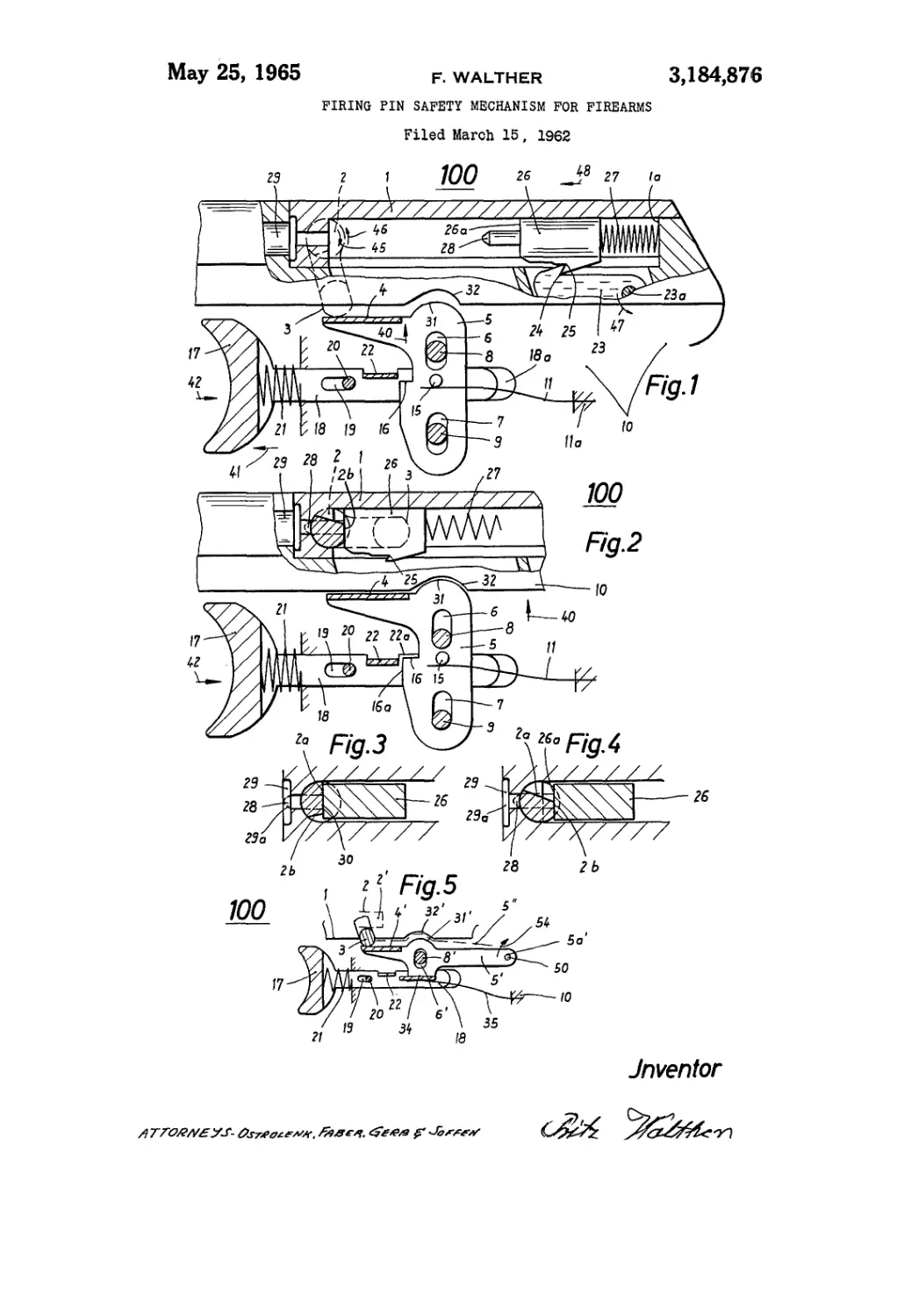
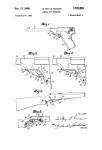
FIGURE 1 is an elevational view of a portion of a fire-
arm shown partially in cross-section to expose the firing
pin safety mechanism and wherein the safety lever is in
the safety-off position with the firing pin in the cocked
position.
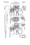
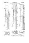
FIGURE 2 is an elevational view of the safety mech-
anism shown in FIGURE 1 with the firing pin in the
uncocked position, and the safety lever in the safety-on
position.
FIGURE 3 shows a portion of the safety mechanism
of FIGURES 1 and 2 with the safety lever in the safety-
off position, and the firing pin in the uncocked position.
FIGURE 4 shows a portion of the safety mechanism
of FIGURES 1 and 2 with the safety lever in the safety-
on position, and the firing pin in the uncocked position.
FIGURE 5 shows another preferred embodiment of
the safety mechanism of FIGURES 1 and 2.
Referring now to the drawings, FIGURE 1 shows a
portion of a firearm 100 which may, for example, be
an automatic pistol which is comprised of a breech-block
1 containing a pivotally mounted safety lever 2 which is
pivoted to rotate clockwise and/or counterclockwise in
the directions shown by arrows 45 and 46 respectively.
The safety lever, when in the position as shown in
FIGUR.E 1, is arranged so that its lower end 3 abuts
a flanged portion 4 of safety ratchet lever 5 which recip-
rocates in a vertical direction. The safety ratchet
lever 5 is a substantially L-shaped member having lon-
gitudinally positioned slots 6 and 7 which are slidably
engaged by pins 8 and 9 respectively, which pins are in-
tegrally mounted onto the frame 10 of the firearm 100.
The safety ratchet lever 5 operates as a trigger locking
means in a manner to be more fully described.
A leaf spring member 11 is arranged so that its first
end is embedded in a rear portion of the firearm frame
10, while its opposite end abuts against the lower edge
of a pin 15 secured at an intermediate point along safety
ratchet lever 5. The spring member 11 is biased in such
a manner that it urges safety ratchet lever 5, which is
guided by pins 8 and 9, in the direction shown by arrow
40. Thus, with the safety lever 2 in the position shown
in FIGURE 1, safety lever 5 is restrained from any fur-
ther movement in the upward vertical direction due to
the lever flange 4 abutting the lower edge 3 of safety
lever 2.
The left-hand edge of safety lever 5 is provided with
a notched portion 16 which cooperates with a flanged
portion 22 of rail 18 in a manner to be more fully de-
scribed.
The reciprocating rail member 18 is positioned in a
groove 18a of similar configuration provided in the
weapon frame 10. The longitudinal motion of rail 18
is limited by means of the horizontally aligned slot 19
in rail 18 which slidably engages a pin 20 provided in
weapon frame 10. The left-hand end 17 of rail 18 forms
the finger-actuated trigger portion. A spring member
21 is positioned between the right-hand edge of spring-
actuated trigger 17 and the left-hand edge 10a of firearm
frame 10 so as to urge rail member 18 in the direction
shown by arrow 41.
In order to operate firearm 10Э, trigger 17 is urged
against the force of spring member 21 in the direction
shown by arrow 42. The trigger 17 in rail 18 is coupled
by a coupling mechanism (not shown) to the release
member 23 which is mounted to pivot about a pivot
3,184,876
FIRING PIN SAFETY MECHANISM FOR FIREARMS
Fritz Walther, Wettersteinweg 4, Ulm (Danube), Germany
Filed Mar. 15,1962, Ser. No. 179,948 5
Claims priority, application Germany, Mar. 18, 1961,
W 29,674
6 Claims. (Cl. 42—70)
This invention relates to firearms, and more particular-
ly to automatic firing pin safety mechanisms for firearms 10
which are adapted to achieve the utmost safety against
accidental firing of the weapon in the safety-on position
by making it impossible for the firing pin to come into
contact with the firing cap of the shell, and to further
definitely prevent firing of the weapon by locking the 15
trigger.
Safety devices known to the prior art for preventing
contact between the firing pin and the firing cap of a
shell have the safety mechanism arranged so that the
safety lever is positioned in the rear part of the firearm. 20
One example of this arrangement is employed in auto-
matic pistols which have such trigger-lock constructions.
On designs of this type, actual practice has proven that
this type of safety device is not foolproof in operation
since the projection or lug of the safety pin in the arrest- 25
ing position wears appreciably due to the permanent
stress imposed upon the lug material by the firing pin
and trigger mechanisms, respectively. This makes it pos-
sible, therefore, for the firing pin to make contact with
the firing cap of the shell with the safety mechanism in 30
the safety-on position, although such contact is inadvert-
ently made, thereby causing a shot to be fired, thus lead-
ing to possible accidents.
The instant invention sets forth a novel arrangement
to avoid the above described disadvantages by having the 33
safety mechanism arranged in the front portion of the
firearm for the purpose of arresting the firing pin mech-
anism, and simultaneously therewith for blocking the
firearm trigger mechanism.
With this arrangement, even in the presence of a faulty 40
firing pin mechanism, no unintentional firing can occur,
since the primer of the shell cannot be reached or en-
gaged by the firing pin. This is provided for by means
of a pivotally mounted safety lever having a cammed
portion wherein a first portion of the cammed surface 46
permits firing of the firearm, while a second portion of
the cammed surface prevents firing of the firearm when
the safety lever is rotated to the appropriate position.
The lower portion of the safety lever, when in the safety-
on position, abuts a slidable member of the trigger lock- 1,0
ing assembly, preventing actuation of the trigger simul-
taneously with the prevention of contact between firing
pin and primer. With the safety lever in the upper or
safety-off position, however, the slidable member of the r
trigger locking assembly is urged to its normal position, °
thus unlocking the trigger of the firearm, thereby per-
mitting firing of the firearm with the safety lever in the
safety-off position.
The safety mechanism is positioned in the front por-
tion of the firearm adjacent the region where contact is °
made between firing pin and firing cap. This produces
the advantage of reducing the size of the elements em-
ployed in the trigger assembly which, in turn, results in
advantages with regard to manufacturing time and ex-
pense. 65
It is, therefore, one object of my invention to provide
a safety mechanism for a firearm which is so arranged
as to simultaneously block the trigger mechanism, while
preventing engagement between firing pin and primer of
a shell positioned in the firearm.
Another object of this invention is to provide a safety
mechanism for a firearm which is so designed as to posi-
3,184,876
3
pin 23a. The movement of the trigger 17 in the direction
of arrow 42 causes the release lever 23 to pivot counter-
clockwise in the direction shown by arrow 47 about its
pivot point 23a. This causes the disengagement of the
projection 24 on release lever 23 from the nose 25 of
striking pin member 26.
Just prior to firing of the weapon—that is, with the
striking pin member 26 in the position shown in FIG-
URE 1—striking pin member 26 has a large force ex-
erted upon it, urging it toward the direction shown by
arrow 48 due to a spring member 27 which is compressed
between the rear wall of striking pin member 26 and
the rear end la of breech-block 1.
With the disengagement of projection 24 from nose
25, the compressed spring member 27 urges striking pin
member 26 in the direction shown by arrow 48. The
striking pin member, under control of this force, ulti-
mately moves to the position shown in FIGURE 3 so that
the firing pin 28 of striking pin member 26 comes into con-
tact with the cartridge 29a of shell 29. This engagement
is permitted, since the shoulder portion 26a of striking
pin member 26 engages the cammed surface 2a of safety
lever 2 which is so designed as to permit contact between
firing pin 28 and cartridge 29a.
When the safety lever 2 (see FIGURE 1) is pivoted
counterclockwise, as shown by arrow 46, to the position
shown in FIGURE 2, the weapon is now in the safety-on
position, preventing contact between firing pin and car-
tridge, and simultaneously therewith preventing actua-
tion of the trigger 17. This is provided for in the fol-
lowing manner:
With the rotation of safety lever 2 to the position shown
in FIGURE 2, the lower edge 3 of the safety lever no
longer abuts flange 4 of safety ratchet lever 5. This per-
mits lever 5 to move upward in the direction shown by
arrow 40 under control of leaf spring member 11. This
causes the crown portion 31 of lever 5 to abut a groove
32 of similar configuration provided in the frame portion
10 of the weapon 100. In this position, the left-hand
edge 16a is so positioned that it abuts the right-hand
edge 22a of flange 22, preventing the movement of rail
18 and, hence, trigger 17 in the direction shown by arrow
42. It should be understood that the flange 22, as por-
trayed in FIGURES 1 and 2, extends vertically upward
from the plane of the figure so that its right-hand edge 22a
abuts the left-hand edge 16a of notch 16.
The rotation of safety lever 2 to the position shown
in FIGURE 2 causes the cammed surface 2b to be ro-
tated counterclockwise so that this surface now engages
the shoulder 26a of striking pin member 26. It can be
seen from FIGURE 4 that with the safety lever 2 in this
position, the firing pin 28 fails to reach the cartridge
29a of shell 29, thereby preventing firing intentionally
or unintentionally of the firearm 100. It should be noted,
however, that no firing will take place due to the locking
function provided by the lever 5 which prevents actua-
tion of trigger member 17.
Another preferred embodiment of the safety mecha-
nism is shown in FIGURE 5 wherein the safety lever 5'
has an aperture 5a' which engages a pin 50 of firearm
frame 10 so as to be pivotally mounted thereby. Lever
member 5' is provided with an upper and a lower flanged
portion 4' and 34, and with a longitudinally aligned slot
6' slidably engaged by a pin 8' extending from firearm
frame 10. The lever 5' provided in FIGURE 5 is arranged
so that the flange 4 is abutted by the lower portion 3 of
the safety lever 2 with the safety lever in the position
shown in FIGURE 5. In this position, the lower flange
34 is physically beneath the flange 22 provided on rail
member 18, preventing a contact therebetween. With the
lever 2 rotated to the dotted position 2', lever 5' rotates
in the clockwise direction, as shown by arrow 54 causing
the crown portion 31' to be seated in the mating groove 32'
under control of the leaf spring member 35. The leaf
spring member 35 may be chosen so as to be of a heavier
5
10
15
20
25
30
35
40
45
50
55
60
65
70
75
4
gauge than that shown in FIGURES 1 and 2, due to the
different configuration of the lever member 5' from the
lever 5 shown in FIGURES 1 and 2.
With the lever member 5' in the dotted line position 5",
the left-hand edge of flange 34 abuts the right-hand edge
of flange 22 on rail 18, thereby locking trigger 17 in the
same manner as that described with reference to the
safety mechanism shown in FIGURES 1 and 2.
It can, therefore, be seen that this invention provides a
safety mechanism which prevents any contact whatsoever
between the firing pin and the primer of cartridge and
which simultaneously therewith locks the trigger mecha-
nism when the safety lever is in the safety-on position.
Although this invention has been described with respect
to its preferred embodiments, it should be understood that
many variations and modifications will now be obvious to
those skilled in the art, and it is preferred, therefore, that
the scope of this invention be limited not by the specific
disclosure herein but only by the appended claims.
The embodiments of the invention in which an exclusive
privilege or property is claimed are defined as follows.
I claim:
1. A safety mechanism and a firearm having a cham-
ber, a trigger and a firing pin means for engaging the
primer of a cartridge, said mechanism comprising pivotally
mounted safety lever means positioned between said fir-
ing pin means and the primer of the cartridge to be fired
and adjacent said primer; said safety lever means being
movable between a first and a second position; trigger
locking means movable between a first and second posi-
tion; bias means urging said trigger locking means towards
said first position; said trigger locking means preventing
movement of the firearm trigger when said trigger lock-
ing means is in said first position; said safety lever means
urging said trigger locking means toward said second
position when said lever means is rotated to said second
position; said lever means and said trigger locking means
permitting said firing pin means to engage the primer
and said firearm trigger to be actuated when in their
respective second positions.
2. A safety mechanism and a firearm having a cham-
ber, a trigger and a firing pin means for engaging the
primer of a cartridge, said mechanism comprising pivotally
mounted safety lever means positioned between said fir-
ing pin means and the primer of the cartridge to be fired
and adjacent said primer; said safety lever means being
movable between a first and a second position; trigger
locking means movable between a first and second posi-
tion; bias means urging said trigger locking means towards
said first position; said trigger locking means preventing
movement of the firearm trigger when said trigger lock-
ing means is in said first position; said safety lever means
urging said trigger locking means toward said second
position when said lever means is rotated to said second
position; said lever means and said trigger locking means
permitting said firing pin means to engage the primer
and said firearm trigger to be actuated when in their
respective second position; said safety lever means pre-
venting said firing pin means from engaging the primer
when rotated to said first position.
3. A safety mechanism and a firearm having a chamber,
a trigger and a firing pin means for engaging the primer
of a cartridge, said mechanism comprising pivotally
mounted safety lever means positioned between said firing
pin means and a primer of the cartridge to be fired and
adjacent said primer; said safety lever means being mov-
able between a first and a second position; trigger locking
means movable between a first and second position; bias
means urging said trigger locking means towards said
first position; said trigger locking means preventing move-
ment of the firearm trigger when said trigger locking
means is in said first position; said safety lever means
urging said trigger locking means toward said second posi-
tion when said lever means is rotated to said second posi-
tion; said lever means and said trigger locking means per-
3,184,876
5
mitting said firing pin means to engage ths primer and
said firearm trigger to be actuated when in their respective
second positions; said safety lever means preventing said
firing pin means from engaging the primer when rotated
to said first position; said safety lever means having a por-
tion projecting into said chamber, said projecting portion
having first and second cam surfaces, said first surface
preventing said firing pin means from engaging said primer
and said second cam surface permitting said firing pin
means to engage said primer when said safety lever means
is in said first and second positions respectively.
4. A safety mechanism and a firearm having a chamber,
a trigger and a firing pin means for engaging the primer
of a cartridge, said mechanism comprising pivotally
mounted safety lever means positioned between said firing
pin means and a primer of the cartridge to be fired and
adjacent said primer; said safety lever means being mov-
able between a first and a second position; trigger locking
means movable between a first and second position; bias
means urging said trigger locking means towards said first
position; said trigger locking means preventing movement
of the firearm trigger when said trigger locking means is
in said first position; said safety lever means urging said
trigger locking means toward said second position when
said lever means is rotated to said second position; said
lever means and said trigger locking means permitting
said firing pin means to engage the primer and said fire-
arm trigger to be actuated when in their respective second
positions; said safety lever means preventing said firing pin
means from engaging the primer when rotated to said
first position; said trigger locking means comprising a
first reciprocating member biassed towards said first posi-
tion by said bias means; a second reciprocating member
integral with said firearm trigger and mounted substan-
tially perpendicular to said first reciprocating member;
second bias means urging said second reciprocating means
towards a first position.
5. A safety mechanism and a firearm having a chamber,
a trigger and a firing pin means for engaging the primer
of a cartridge, said mechanism comprising pivotally
mounted safety lever means positioned between said firing
pin means and a primer of the cartridge to be fired and
adjacent said primer; said safety lever means being mov-
able between a first and a second position; trigger locking
means movable between a first and second position; bias
means urging said trigger locking means towards said first
position; said trigger locking means preventing movement
of the firearm trigger when said trigger locking means is
in said first position; said safety lever means urging said
trigger locking means toward said second position when
said lever means is rotated to said second position;
said lever means and said trigger locking means permitting
said firing pin means to engage the primer and said fire-
arm trigger to be actuated when in their respective second
positions; said safety lever means preventing said filing
pin means from engaging the primer when rotated to said
first position; said trigger locking means comprising a first
reciprocating member biassed towards said first position
by said bias means; a second reciprocating member inte-
о
10
15
20
25
30
35
40
45
50
55
60
6
gral with said firearm trigger and mounted substantially
perpendicular to said first reciprocating member; second
bias means urging said second reciprocating means to-
wards a first position; said second reciprocating member
having a flange projecting towards said first reciprocating
member; said first reciprocating member having a notch
along one edge; said notch abutting said flange when said
first reciprocating member is in said first position prevent-
ing movement of said firearm trigger.
6. A safety mechanism and a firearm having a chamber,
a trigger and a firing pin means for engaging the primer
of a cartridge, said mechanism comprising pivotally
mounted safety lever means positioned between said firing
pin means and a primer of the cartridge to be fired and
adjacent said primer; said safety lever means being mov-
able between a first and a second position; trigger locking
means movable between a first and second position; bias
means urging said trigger locking means towards said first
position; said trigger locking means preventing movement
of the firearm trigger when said trigger locking means is
in 'said first position; said safety lever means urging said
trigger locking means toward said second position when
said lever means is rotated to said second position; said
lever means and said trigger locking means permitting said
firing pin means to engage the cartridge and said firearm
trigger to be actuated when in their respective second
positions; said safety lever means preventing said firing
pin means from engaging the cartridge when rotated to
said first position; said trigger locking means comprising
a first reciprocating member biassed towards said first
position by said bias means; a second reciprocating mem-
ber integral with said firearm trigger and mounted sub-
stantially perpendicular to said first reciprocating member;
second bias means urging said second reciprocating means
towards a first position; said second reciprocating member
having a flange projecting towards said first reciprocating
member; said first reciprocating member having a notch
along one edge; said notch abutting said flange when said
first reciprocating member is in said first position pre-
venting movement of said firearm trigger; said first recip-
rocating member having a flanged upper portion posi-
tioned adjacent said safety lever means; said safety lever
means abutting said flanged upper portion when in said
second position causing said first reciprocating member
to move to its second position; said notch permitting actu-
tion of said firearm trigger when said first reciprocating
member is in second position.
References Cited by the Examiner
UNITED STATES PATENTS
125,829 4/72 Milbank____________________42—70
311,732 2/85 Ehbets_____________________42—70
1,026,609 5/12 Schwarzlose__________________42—70
1,089,195 3/14 Falco________________________42—70
1,379,238 5/21 Barnard______________________42—70
2,455,990 12/48 Gaugler______________________42—70
2,539,644 1/51 Turner_______________________42—70
BENJAMIN A. BORCHELT, Primary Examiner.