/
Tags: weapons military affairs patent
Year: 1950
Text
2,525,886
Oct. 17, 1950
LE ROY B. FRASER
SAFETY FOR FIREARMS
Filed July 9, 1945
2 Sheets-Sheet 1
2,525,886
LE ROY B. FRASER
SAFETY FOR FIREARMS
Oct. 17, 1950
Filed July 9, 1945
2 Sheets-Sheet 2
Patented Oct. 17, 1950
2,525,886
UNITED STATES PATENT OFFICE
2,525,886
SAFETY FOR FIREARMS
Le Roy B. Fraser, Woodbridge, Conn.
Application July 9,1945, Serial No. 603,891
5 Claims.
1
This invention relates to guns and, while
it is particularly designed for application to guns
for beginners in the use of firearms, it is not
necessarily limited in this respect. It also, in
some respects, is particularly designed for use
with short guns or pistols, but may be applied
and used to advantage with shoulder guns as
well.
The use of hand guns or pistols is sometimes
considered more dangerous than that of long or
shoulder guns, and, for this reason, safety de-
vices have, in many instances, been applied to
such firearms. While various safety appliances
have been provided, such appliances usually are
not foolproof in that, while they may, in many
instances, prevent accidental discharge of the
gun, it is still possible for it to be accidentally
discharged with unfortunate results.
I contemplate by the present invention the
provision of a gun which will be so constructed
so that it cannot be fired without the deliberate
intent of the user. In the embodiment of my in-
vention shown in the accompanying drawings,
this is effected by surrounding the trigger of
the firearm with a movable guard, the guard
normally standing in such a position that the
trigger will be effectively shielded from contact
or engagement with any object. Locking or de-
tent means are provided to hold the trigger guard
in operative position, which means will be in turn
controlled or moved to inoperative position by
proper gripping or handling of the gun when its
discharge is intended. In addition to shielding
the trigger, the guard also prevents actuation
of the trigger until moved to its inoperative
position.
As illustrated, the trigger guard is normally
urged to its operative position by a spring and,
after being freed for movement, is raised or
moved to expose the trigger by the trigger finger
of the user. This produces a steadying effect
of the finger on the trigger, so that a more
steady squeezing action of the finger on the
trigger is obtained, and thus the technique of the
shooting of the gun is improved. Thus the ad-
vantage arising from the use of the invention lies
not only in the safety feature, but also in the
fact that it trains a beginner in the proper tech-
nique of firing the gun.
One object of the present invention is to pro-
vide a new and improved safety feature for guns.
A still further object of the invention is to pro-
vide a gun which may not be fired without the
deliberate intent of the user.
Still another object of the invention is to pro-
(CI. 42—70)
2
vide a firearm which will be useful in teaching
to beginners, the proper handling of a gun in
shooting.
To these and other ends the invention consists
6 in the novel features and combinations of parts
to be hereinafter described and claimed.
In the accompanying drawings:
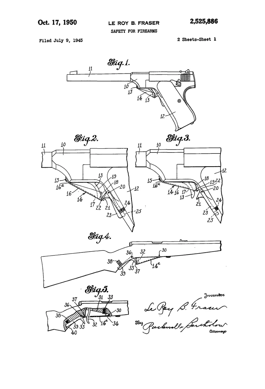
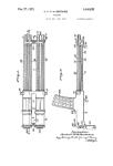
Fig. 1 is a side elevational view of a hand gun
or pistol embodying my improvements;
10 Fig. 2 is an enlarged view of the portion of the
gun adjacent the trigger;
Fig. 3 is a view similar to Fig. 2 showing the
trigger guard and retaining or detent member
in a different position;
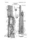
15 Fig. 4 is a partial side elevational view of a
shoulder gun or rifle equipped with my invention;
Fig. 5 is a fragmentary view, partly in section,
of the gun shown in Fig. 4, showing the parts
in another position;
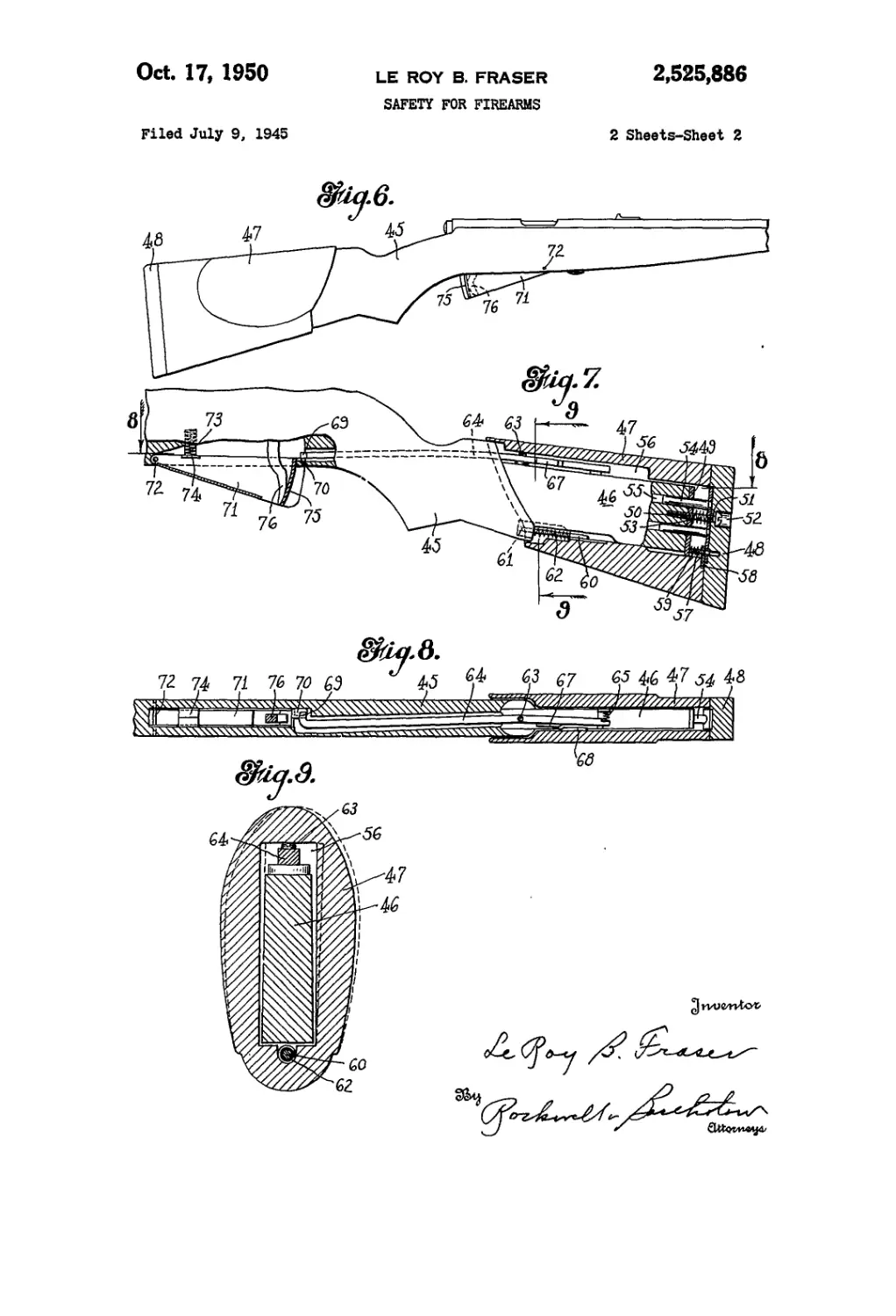
20 Fig. 6 is a side elevational view of a shoulder
gun having a trigger guard embodying my inven-
tion, which guard is controlled in a different
manner;
Fig. 7 is a view, partly in section, of the gun
25 shown in Fig. 6;
Fig. 8 is a sectional view on line 8—8 of Fig. 7;
and
Fig. 9 is a sectional view on line 9—9 of Fig. 7.
To illustrate one embodiment of my invention,
30 I have shown in Fig. 1 of the drawings a pistol
or hand gun comprising a frame portion 10, a
barrel II, and a grip 12. Pivoted in the frame
portion of the gun and projecting therefrom is a
trigger 13 provided with a guard designated gen-
85 erally by the numeral 14, the guard being se-
cured to the frame at its forward end by a screw
15 or some similar retaining member. The
guard 14 is of channel or U-shaped form in cross
section and extends rearwardly to receive be-
40 tween its side walls the outer portion of the trig-
ger 13. The member 14 may also be provided
with a bottom wall 16 which is provided with an
opening П through which the lower portion of
the trigger may project when the guard is raised
45 as shown, for example, in Fig. 3. The bottom
wall 16 of the guard may be extended forwardly
as shown at I6a to provide a resilient or spring
end portion to receive the screw 15, so that the
guard is movable about the tongue portion I6a.
50 The resilience of this portion will, however, nor-
mally maintain the guard in its operative or
shielding position as shown in Fig. 2.
The guard is also provided with a rear wall 18
which normally stands closely adjacent the rear
Sfi face of the lower encl of the trigger as shown
2.525.888
3
in Fig. 2, so that it will positively prevent the
trigger being pulled rearwardly. Thus the guard
not only shields the trigger and prevents the en-
gagement of the finger or other object with the
trigger, but also by the engagement of the rear
•wall back of the trigger prevents movement of
the latter. If necessary, the upper portion of the
trigger may be cut away or recessed slightly as
shown at 19 so that it may have sufficient move-
ment or travel to fire the gun when the guard is
in its raised or inoperative position as shown
in Fig. 3.
While the trigger guard is normally held in.the
position shown in Fig. 2 by the inherent resil-
ience of the portion !6a, means are provided for
locking or retaining the guard in this position
except when the gun is intended to be fired. A-
detent or retaining member is pivoted to the
grip portion of the gun at 20, this member having
a. nose, portion 2,1. designed to engage above a
shoulder or projection 22 on the trigger, guard;
so as to prevent upward movement of the latter.
The. retaining member is also provided; with a
body.portion 23 which extends downwardly along,
the forward face of the grip 12, and a spring 24
mounted in the grip bears against the body por-
tion 23 to normally hold the latter forwardly and
hold the nose portion in. engagement with the
trigger guard. The grip portion of the gun is pro-
vided with a recess 25 to receive the portion 23
of.the, retaining member, when the fingers of the
user grip the gun and squeeze the part 23 toward
the grip. This position of the parts is shown in
Fig, 3, where, it will be noted the detent or nose
portion 21 of the retaining member has been
moved downwardly and rearwardly so it no longer
engages the shoulder 22 on the trigger guard.
The normal position of the parts is shown in
Fig. 2 where, as will be apparent, the guard em-
braces the trigger and prevents engagement of
any obj.ect therewith and also prevents the rear-
ward movement of the trigger, the guard being
retained in this position by the detent 21 of the
retaining member. When the user desires to fire
the gun and grasps the grip 12. in his hand in
position for firing, his fingers will extend aroiind
the. forward portion of the grip and squeeze the
body portion 23 of the retaining member into
the recess,25, thus releasing the nose "i.from the
shoulder 22. The trigger finger of the user is
then drawn, rearwardly and upwardly s’ong the
lower wall .I S of the guard, thus moving the guard
upwardly against the tension of the spring por-
tion . i 6a from the position shown in: Fig. 2 to
that shown in. Fig. 3. The pressure, of the guard
on the finger will bring about a steadying action,
so that, as the finger is drawn rearwardly along
the lower surface of the guard, it will contact
the.trigger by a steady squeezing movement and
result in more accurate marksmanship. Thus,
while the improved trigger guard is useful as a
safety device, it will also improve the technique
of the user of the gun.
In Figs. 4 and 5 of the drawings, I have shown
my invention as applied to a shoulder firearm.
In this case, the guard 14a, which is constructed
in-a manner generally similar to the guard 14, is
pivoted- to the forearm of the gun at 30. The
rear, portion of the forearm may be provided
with a recess 31 to receive the guard when it is
raised to expose the trigger 32 as shown in Fig. 5.
In this, case, it will be noted that the guard is
relatively wide or deep and covers substantially
the.entire trigger, a construction which is possible
when the frame or forearm of the gun may be
4
recessed as at 31 to receive the guard. A spring
33 normally urges the guard downwardly to its
operative position, the spring acting against
laterally turned lugs 34 at the upper edges of the
5 side walls of the guard. A retaining or detent
member 35 is pivoted at 36 adjacent the grip of
the gun, this member engaging a shoulder 37 on
the guard as described in connection with the
form of my invention illustrated in Figs. 1 to 3.
10 The retaining member 35. is normally held in
its operative position by the spring 33 acting
against the tail portion 39 which is adapted to be
received in a recess 40 in the grip of the gun when
it is grasped by the user in the normal way in
15 which a gun would be held when it is to be fired.
The operation of the modification of my device
shown in Figs. 4 and 5 is similar to that shown
in Figs. 1 to 3, and detailed description of the
operation, therefore, will-mot be necessary. When
20 the guard is unlocked by* the gripping of.the gun
in the normal way, it may be raised by the trigger
finger of- the user-, being drawn rearwardly with
slight' upward pressure along the- lower portion
of the guard; thus raising the- latter member
25 from the position shown in Fig. 4 to that shown
in Fig. 5 in which position the trigger finger may
engage and squeeze the trigger rearwardly to
discharge the gun.
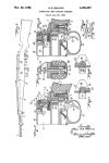
In Figs. 6 to 9 of the drawings, I have shown
30 a shoulder firearm equipped-with a trigger guard
embodying my invention, the guard; however, be-
ing controlled. in- a- different manner. In my
previous Patent No. 2,122;415, granted July 5;
1938, 1 have illustrated a gun so constructed that'
35 it may not be discharged-until therequired shoul-
der and check pressures are exerted upon it by
the user. In other words, if- a shoulder gun is
held properly, it will be-pressed firmly against the-
shoulder of the user, and also- the cheek of the
40 user will be pressed against the side of the stock.
The principle, developed in the patent referred
to; of preventing the discharge of the firearm
until itis properly -held and grasped by the user
is, in this modification of the present invention,
applied to the movable; trigger guard, so that the
latter is not released until the proper shoulder
and cheek pressures have-been exerted.
As shown in Figs. 6 to 9 of the drawings, the
stock - 45 of the gun is provided with a reduced
60 rear portion or post 46; and slidably telescoped
over this post is a supplemental stock or sleeve
portion 47 held-in place-by the butt 48 secured
to post 46. Upon the rear end of the post 46
is secured a plate 49 in which- is threaded-ly
55 mounted a-screw 50-passing-loosely through an
opening 51 in the butt 48, the. head of the screw
being disposed in a recess 52. A spring 53' is
mounted upon the-screw between the plate 49 and
the butt 48, thus normally holding the latter in
05 a rearward, or extended-position. Pressure, how-
ever, of the butt 48 against the shoulder will-move
the butt 48 forwardly in opposition to the-pres-
sure of the spring, and, as the butt rests against
the rear end of the portion 47, this will-also-move
05 the latter forwardly with - respect to the post.-
The butt 48 may be guided .in its.movement by
dowel pins 54 secured to the butt and slidably
mounted in openings 55 in the post.
As shown in Fig.. 9, the opening 56 in the sup-
70 plemental stock, portion 47 is somewhat larger
than the post 46, especially at the upper edge
of the latter, so that the member 47 may be
rotated or pivotally moved to a slight extent with
respect to. the post. A pivot, pin 57 is secured
75 to the plate 49 "at one end and at its other end
2,526,886
6
is supported by the butt 48. A bracket 58 is
loosely mounted on this pivot pin and secured to
the stock member 47, a compression spring 59
acting between the plate 49 and the bracket 58.
This spring tends to hold the member 47 in a 5
rearward position against the butt 48 and also
serves as one of two pivotal mountings for the
stock portion 47. The-other pivotal mounting is
constituted by the rod 60 secured to the stock
Portion 47 and rotatably mounted at its forward io
end at 61 in the stock 45. A spring 62 surrounds
this rod and normally urges the stock member 47
rearwardly toward the butt. Pressure of the
cheek against the member 47 may swing the
stock in a clockwise direction as shown in Fig. lb
9 to its dotted line position about the pivot pins
57 and 60. This, however, does not move the butt
48 as the latter is secured to the post 46 and not
to the member 47.
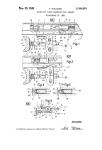
Pivoted at 63 to the post 46 is a lever 64, the 20
lever being normally held in the position shown
in Fig. 8 by a compression spring 65. Adjacent
the rear end of this lever is a lug 67 normally
spaced slightly forwardly of a lug 68 on the mov-
able stock portion 47. In the normal position of 25
the parts, the lug 68 does not engage the lug 67.
However, when the gun is pressed against the
shoulder, and the butt 48 and sleeve member 47
are moved forwardly, the lug 68 will be moved
forwardly and will be in position to engage the 30
lug 67 when the sleeve portion 64 is given a ro-
tating movement by cheek pressure. Therefore,
by a combination of shoulder pressure and cheek
Pressure, the lever 64 will be moved in a counter-
clockwise direction as shown in Fig. 8. 35
The lever 64 extends forwardly through the
grip portion of the gun and is provided with a
laterally turned portion 69 at its forward end
designed to overlie the horizontal portion of
an L-shaped lug 70 at the rear end of a trigger 40
guard 71 pivoted at 72 to the forearm of the
gun and normally held in a downward position
by the spring 73 acting against inturned lugs 74.
It will be understood that this trigger guard and
its operation are similar to the construction and
operation of the trigger guard shown in Figs. 4
and 5.
In the normal position of the parts, the for-
ward end 69 of the lever 64 holds the trigger
guard downwardly in the position in Fig. 7, 60
which not only prevents engagement of the
trigger by the finger of the user, but also, by en-
gagement of the rear wall 75 with the trigger 76,
blocks the trigger against movement. When,
however, the gun is pressed against the shoulder,
thus moving the sleeve portion 47 forwardly
and is also engaged by the cheek with sufficient
pressure to rotate the portion 47 about the pivot
pins 57 and 60, the lug 68 will be caused to engage
lug 67 and swing the lever 64 in a counterclock- eo
wise direction as shown in Fig. 8, to as to remove
the end 69 of this lever from engagement with
the portion 70 of the trigger guard, and thus
permit the latter to be moved upwardly by pres-
sure of the trigger finger of the user there- 65
against. Therefore, the trigger guard is in locked
position until the proper shoulder and cheek
pressures are applied to the gun. When the
cheek and shoulder pressures are released, the
portion 47 will be moved pivotally to its normal 70
position by the spring 65 and will be moved rear-
wardly against the butt 48 by the springs 59
and 62, the butt, of course, being returned by the
spring 53.
While I have shown and described some pre- 75
ferred embodiments of my invention, it will be
understood that it is not to be limited to all of
the details shown, but is capable of modification
and variation within the spirit of the invention
and within the scope of the claims.
What I claim is:
;-;l.rIm a firearm, a frame, a trigger pivoted
thereto, a guard member for the'trigger adapted
to normally embrace the latter, means movably
connecting said guard'member to the frame to
swing toward and from the frame about an axis
transverse to the plane of movement of- the
trigger, means- normally urging, said member
away from the frame -to a position in which it
shields the trigger against engagement by the
finger, said member when in said position pre-
venting operation of -the -trigger, and retaining
means to prevent movement of said member to-
ward the frame and away from shielding position.
2. In a firearm, a frame, a trigger pivoted
thereto, a guard member for the trigger adapted
to normally embrace the latter, means movably
connecting said guard member to the frame to
swing toward and from the frame about an axis
transverse to1 the plane of movement of the trig-
ger, means normally urging said member away
from the frame to a position in which it shields
the trigger against engagement by the finger,
said member when in said position preventing
operation of the trigger, and retaining means to
prevent movement of said member toward the
frame and away from shielding position, said re-
taining means being controlled by the gripping
of the firearm by the user.
3. A firearm comprising a frame, a grip, a trig-
ger pivoted to the frame and extending below
the same, a guard member hinged to the frame
forwardly of the trigger to move about an axis
transversely to the plane of movement of the
trigger and formed to embrace the latter and
shield it against engagement by the finger of the
user, and spring means normally urging said
member downwardly away from the frame to
shielding position, said member having a part
disposed rearwardly of the trigger to prevent
movement of the latter.
4. A firearm comprising a frame, a grip, a trig-
ger pivoted to the frame and extending below
the same, a guard member hinged to the frame
forwardly of the trigger to move about an axis
transversely to the plane of movement of the
trigger and formed to embrace the latter and
shield it against engagement by the finger of the
user, spring means normally urging said member
downwardly away from the frame to shielding
position, said member having a part disposed
rearwardly of the trigger to prevent movement of
the latter, a detent member normally engaging
said part, and means movably mounting said de-
tent member to permit it to be moved to disen-
gaging position.
5. A firearm comprising a frame, a grip, a trig-
ger pivoted to the frame and extending below
the same, a guard member hinged to the frame
forwardly of the trigger to move about an axis
transversely to the plane of movement of the
trigger and formed to embrace the latter and
shield it against engagement by the finger of the
user, spring means normally urging said member
downwardly away from the frame to shielding
position, said member having a part disposed
rearwardly of the trigger to prevent movement
of the latter, a detent member normally engaging
said part, means movably mounting said detent
member to permit it to be moved to disengaging
2,525,886
7
position, and said detent member having a part Number
disposed adjacent the grip of the firearm to be controlled by a finger of the user. LE ROY B. FRASER. REFERENCES CITED The following references are of record in the file of this patent: 5 1,085,698 1,204,426 1,379,238 1,450,976 1,686,482 1,887,308 2,080,202 2 122 415
UNITED STATES Number Name 834,772 Tambour 920,682 Stephan 932,183 Schwarzlose _ PATENTS Date Oct. 30, 1906 May 4, 1909 Aug. 24, 1909 10 2,195,693 2,401,482 Number
955,237 965,386 1,070,965 Wescott et al. Hansen Jones Apr. 19, 1910 July 26, 1910 Aug. 19, 1913 IS 12,841 227,077 100,975
8
Name , Date
Nelson_____________Feb. 3, 1914
Gladwin et al.____Nov. 14, 1916
Barnard____________May 24, 1921
Larson_________-__Apr. 10, 1923
Windle ____________Oct. 2, 1928
Jessup ;___________Nov. 8, 1932
Drake.;.__________May 11, 1937
Fraser_____________July 5, 1938
Clifton___._______Apr. 2, 1940
Hendey_____;______June 4, 1946
FOREIGN PATENTS
Country Date
Austria Aug. 10, 1903
Germany __ Oct. 14, 1910
Switzerland Aug. 16, 1923