/

Tags: weapons military affairs pistol
Year: 1962


Text
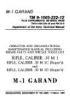
ТМ 9-1095-201-15
DEPARTMENT OF THE ARMY TECHNICAL MANOAL
OPERATOR, ORGANIZATIONAL, FIELD
AND DEPOT MAINTENANCE MANUAL
GROUND SIGNAL PROJECTOR
M1A1; HAND PYROTECHNIC
PROJECTOR M9; AND
PYROTECHNIC PISTOL AN-M8
WITH PYROTECHNIC PISTOL
HEADQUARTERS, DEPARTMENT OF THE ARM}
NOVEMBER 1962
*ТМ 9-1095-201-15
Technical Manual
No. 9-1095-201-15
HEADQUARTERS,
DEPARTMENT OF THE ARMY
WASHINGTON 25, D.C., 13 November 1961
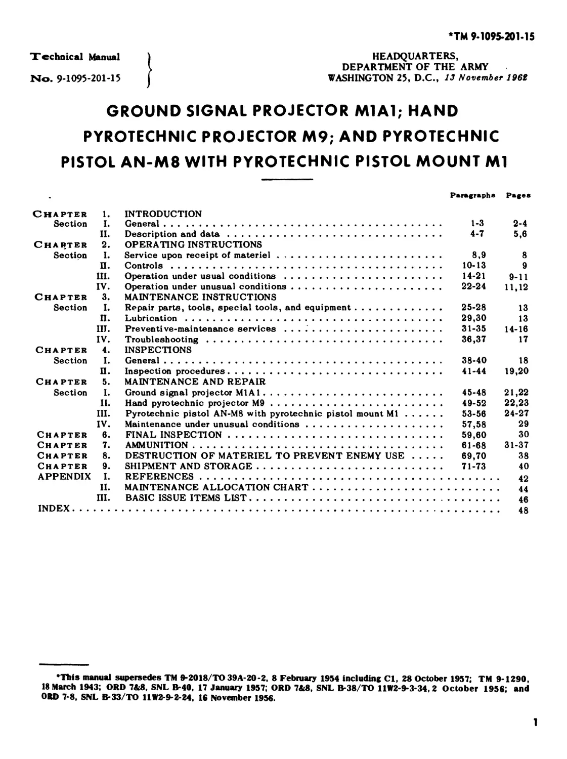
GROUND SIGNAL PROJECTOR M1A1; HAND
PYROTECHNIC PROJECTOR M9; AND PYROTECHNIC
PISTOL AN-M8 WITH PYROTECHNIC PISTOL MOUNT Ml
Paragraphs Pages
Chapter 1.
Section I.
II.
Charter 2.
Section I.
П.
III.
IV.
Chapter 3.
Section I.
П.
Ш.
IV.
Chapter 4.
Section I.
П.
Chapter 5.
Section I.
II.
III.
IV.
Chapter 6.
Chapter 7.
Chapter 8.
Chapter 9.
APPENDIX I.
II.
III.
INDEX.......
INTRODUCTION
General..................................................
Description and data.....................................
OPERATING INSTRUCTIONS
Service upon receipt of materiel..........................
Controls.................................................
Operation under usual conditions..........................
Operation under unusual conditions.......................
MAINTENANCE INSTRUCTIONS
Repair parts, tools, special tools, and equipment........
Lubrication..............................................
Preventive-maintenance services .........................
Troubleshooting..........................................
INSPECTIONS
General..................................................
Inspection procedures.....................................
MAINTENANCE AND REPAIR
Ground signal projector M1A1.............................
Hand pyrotechnic projector M9............................
Pyrotechnic pistol AN-M8 with pyrotechnic pistol mount Ml.
Maintenance under unusual conditions.....................
FINAL INSPECTION.........................................
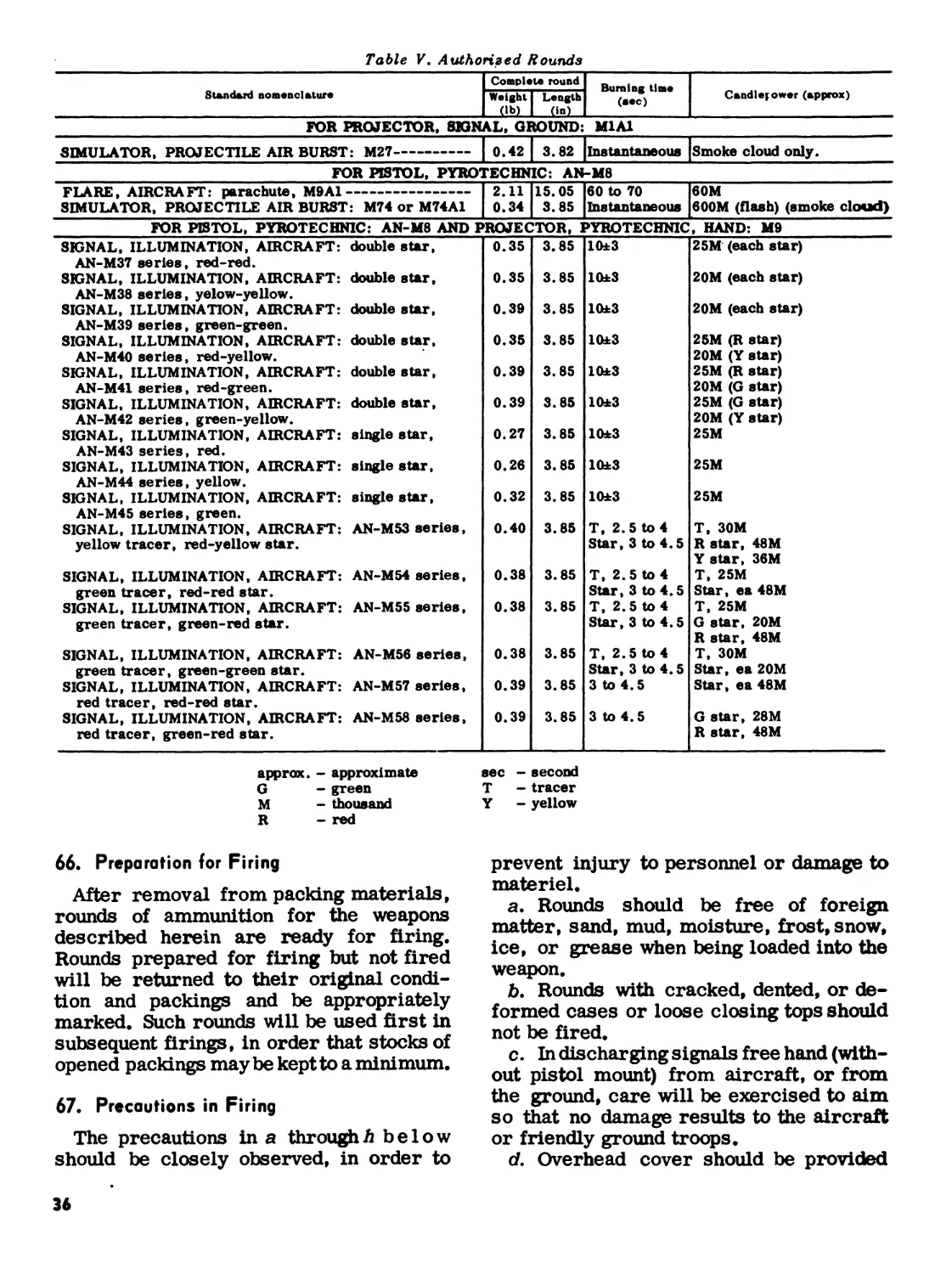
AMMUNITION................................................
DESTRUCTION OF MATERIEL TO PREVENT ENEMY USE.............
SHIPMENT AND STORAGE.....................................
REFERENCES ..............................................
MAINTENANCE ALLOCATION CHART.............................
BASIC ISSUE ITEMS LIST...................................
1-3
4-7
8,9
10-13
14-21
22-24
25-28
29,30
31-35
36,37
38-40
41-44
45-48
49-52
53-56
57,58
59,60
61-68
69,70
71-73
2-4
5,6
8
9
9-11
11,12
13
13
14-16
17
18
19,20
21,22
22,23
24-27
29
30
31-37
38
40
42
44
46
48
•This manual supersedes TM 9-2018/TO 39A-20-2, 8 February 1954 including Ci, 28 October 1957; TM 9*1290,
18 March 1943; ORD 7&8. SNL B-40, 17 January 1957; ORD 7&8, SNL B-38/TO 11W2-9-3-34, 2 October 1958; and
ORD 7-8, SNL B-33/TO 11W2-9-2-24, 16 November 1956.
1
CHAPTER 1
INTRODUCTION
Section I. GENERAL
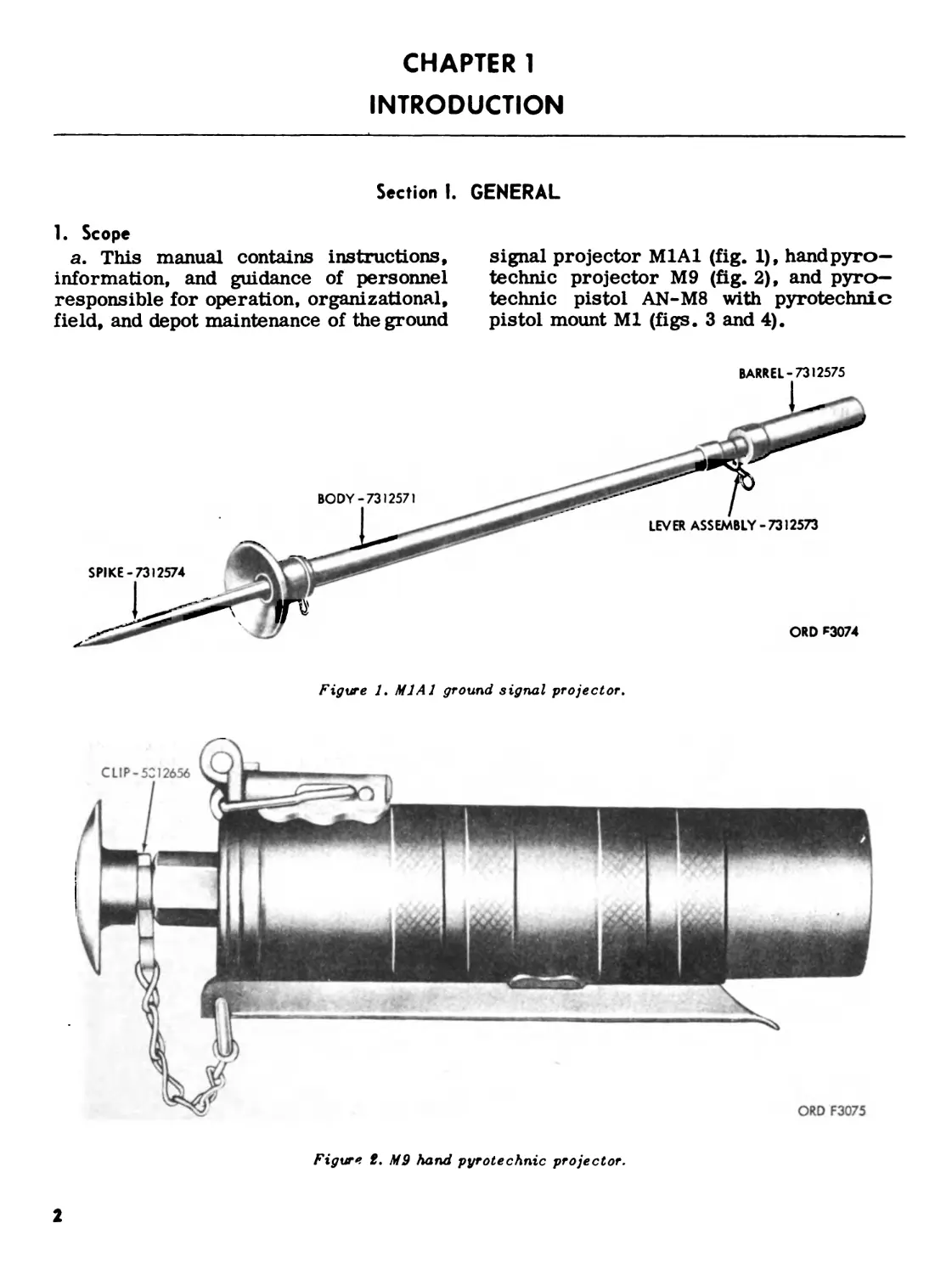
1. Scope
a. This manual contains instructions,
information, and guidance of personnel
responsible for operation, organizational,
field, and depot maintenance of the ground
signal projector M1A1 (fig. 1), hand pyro-
technic projector M9 (fig. 2), and pyro-
technic pistol AN-M8 with pyrotechnic
pistol mount Ml (figs. 3 and 4).
ORD F3075
Figure t. MS hand pyrotechnic projector.
2
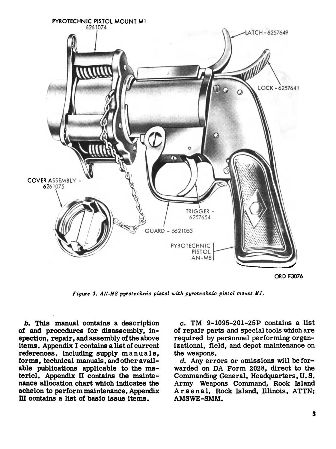
PYROTECHNIC PISTOL MOUNT Ml
ORD F3076
Figure 3. AN-M8 pyrotechnic pistol with pyrotechnic pistol mount Ml.
b. This manual contains a description
of and procedures for disassembly, in-
spection, repair, and assembly of the above
items. Appendix I contains a list of current
references, including supply manuals,
forms, technical manuals, and other avail-
able publications applicable to the ma-
teriel. Appendix П contains the mainte-
nance allocation chart which indicates the
echelon to perform maintenance. Appendix
Ш contains a list of basic issue items.
c. TM 9-1095-201-25P contains a list
of repair parts and special tools which are
required by personnel performing organ-
izational, field, and depot maintenance on
the weapons.
d. Any errors or omissions will be for-
warded on DA Form 2028, direct to the
Commanding General, Headquarters,U.S.
Army Weapons Command, Rock Island
Arsenal, Rock Island, Illinois, ATTN:
AMSWE-SMM.
3
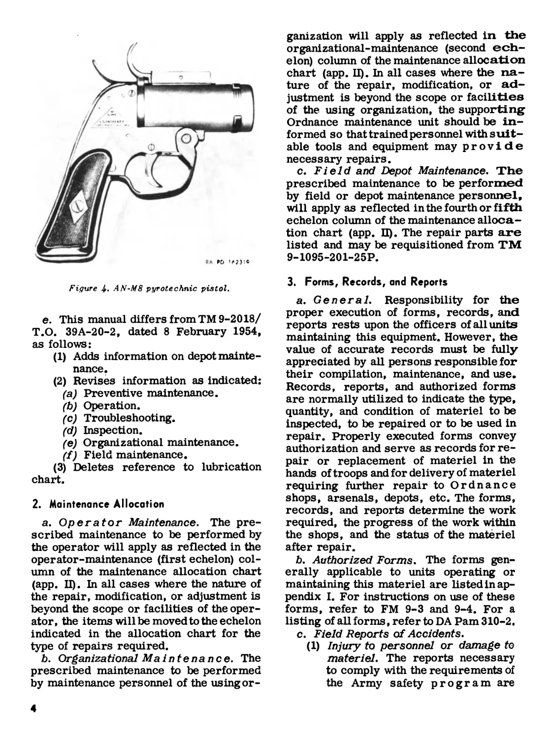
Figure 4- AN-M8 pyrotechnic pistol.
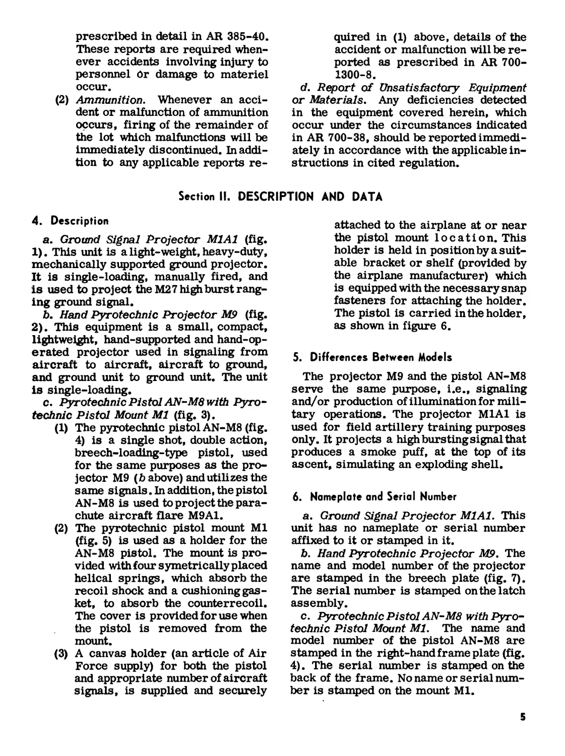
e. This manual differs from TM 9-2018/
T.O. 39A-20-2, dated 8 February 1954,
as follows:
(1) Adds information on depot mainte-
nance.
(2) Revises information as indicated:
(a) Preventive maintenance.
(b) Operation.
(c) Troubleshooting.
(d) Inspection.
(e) Organizational maintenance.
(f) Field maintenance.
(3) Deletes reference to lubrication
chart.
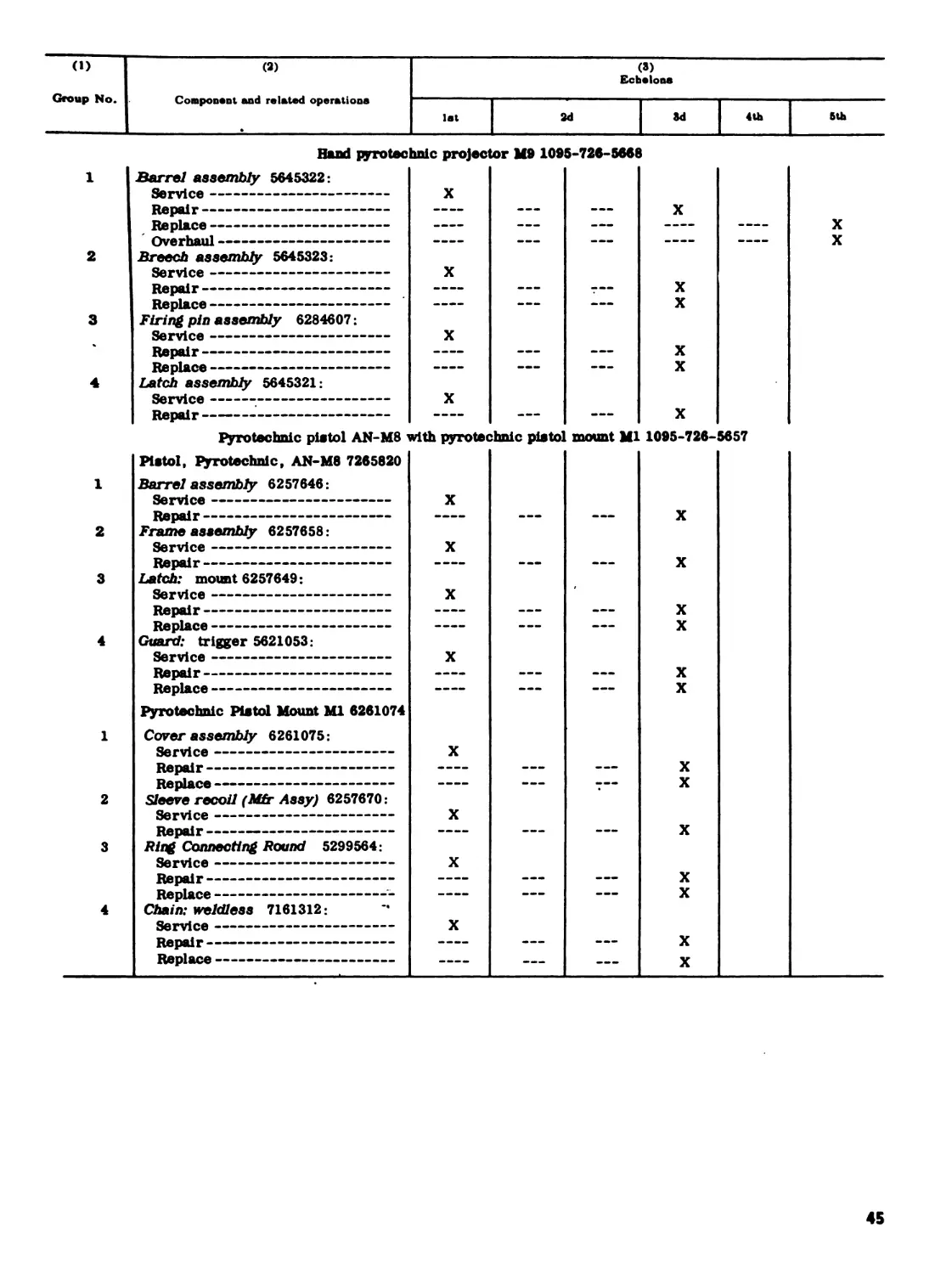
2. Maintenance Allocation
a. Operator Maintenance. The pre-
scribed maintenance to be performed by
the operator will apply as reflected in the
operator-maintenance (first echelon) col-
umn of the maintenance allocation chart
(app. II). In all cases where the nature of
the repair, modification, or adjustment is
beyond the scope or facilities of the oper-
ator, the items will be moved to the echelon
indicated in the allocation chart for the
type of repairs required.
b. Organizational Maintenance. The
prescribed maintenance to be performed
by maintenance personnel of the using or-
ganization will apply as reflected in the
organizational-maintenance (second ech-
elon) column of the maintenance allocation
chart (app. II). In all cases where the na-
ture of the repair, modification, or ad-
justment is beyond the scope or facilities
of the using organization, the supporting
Ordnance maintenance unit should be in-
formed so that trained personnel with suit-
able tools and equipment may provide
necessary repairs.
c. Field and Depot Maintenance. The
prescribed maintenance to be performed
by field or depot maintenance personnel,
will apply as reflected in the fourth or fifth
echelon column of the maintenance alloca-
tion chart (app. П). The repair parts are
listed and may be requisitioned from TM
9-1095-201-25P.
3. Forms, Records, and Reports
a. General. Responsibility for the
proper execution of forms, records, and
reports rests upon the officers of all units
maintaining this equipment. However, the
value of accurate records must be fully
appreciated by all persons responsible for
their compilation, maintenance, and use.
Records, reports, and authorized forms
are normally utilized to indicate the type,
quantity, and condition of materiel to be
inspected, to be repaired or to be used in
repair. Properly executed forms convey
authorization and serve as records for re-
pair or replacement of materiel in the
hands of troops and for delivery of materiel
requiring further repair to Ordnance
shops, arsenals, depots, etc. The forms,
records, and reports determine the work
required, the progress of the work within
the shops, and the status of the materiel
after repair.
b. Authorized Forms. The forms gen-
erally applicable to units operating or
maintaining this materiel are listed in ap-
pendix I. For instructions on use of these
forms, refer to FM 9-3 and 9-4. For a
listing of all forms, refer to DA Pam 310-2.
c. Field Reports of Accidents.
(1) Injury to personnel or damage to
materiel. The reports necessary
to comply with the requirements of
the Army safety program are
prescribed in detail in AR 385-40.
These reports are required when-
ever accidents involving injury to
personnel Or damage to materiel
occur.
(2) Ammunition. Whenever an acci-
dent or malfunction of ammunition
occurs, firing of the remainder of
the lot which malfunctions will be
immediately discontinued. In addi-
tion to any applicable reports re-
quired in (1) above, details of the
accident or malfunction will be re-
ported as prescribed in AR 700-
1300-8.
d. Report of Unsatisfactory Equipment
or Materials. Any deficiencies detected
in the equipment covered herein, which
occur under the circumstances indicated
in AR 700-38, should be reported immedi-
ately in accordance with the applicable in-
structions in cited regulation.
Section II. DESCRIPTION AND DATA
4. Description
a. Ground Signal Projector M1A1 (fig.
1). This unit is a light-weight, heavy-duty,
mechanically supported ground projector.
It is single-loading, manually fired, and
is used to project the М2 7 high burst rang-
ing ground signal.
b. Hand Pyrotechnic Projector M9 (fig.
2). This equipment is a small, compact,
lightweight, hand-supported and hand-op-
erated projector used in signaling from
aircraft to aircraft, aircraft to ground,
and ground unit to ground unit. The unit
is single-loading.
c. Pyrotechnic Pistol AN-M8 with Pyro-
technic Pistol Mount Ml (fig. 3).
(1 ) The pyrotechnic pistol AN-M8 (fig.
4) is a single shot, double action,
breech-loading-type pistol, used
for the same purposes as the pro-
jector M9 (b above) and utilizes the
same signals. In addition, the pistol
AN-M8 is used to project the para-
chute aircraft flare M9A1.
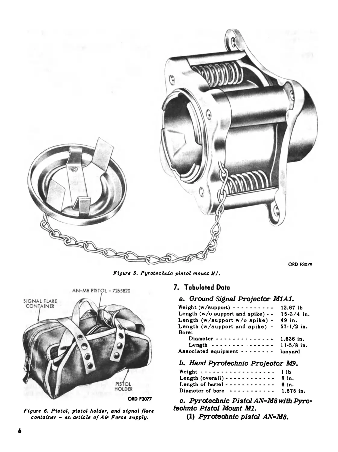
(2 ) The pyrotechnic pistol mount Ml
(fig. 5) is used as a holder for the
AN-M8 pistol. The mount is pro-
vided with four symetrically placed
helical springs, which absorb the
recoil shock and a cushioning gas-
ket, to absorb the counterrecoil.
The cover is provided for use when
the pistol is removed from the
mount.
(3 ) A canvas holder (an article of Air
Force supply) for both the pistol
and appropriate number of aircraft
signals, is supplied and securely
attached to the airplane at or near
the pistol mount location. This
holder is held in position by a suit-
able bracket or shelf (provided by
the airplane manufacturer) which
is equipped with the necessary snap
fasteners for attaching the holder.
The pistol is carried in the holder,
as shown in figure 6.
5. Differences Between Models
The projector M9 and the pistol AN-M8
serve the same purpose, i.e., signaling
and/or production of illumination for mili-
tary operations. The projector M1A1 is
used for field artillery training purposes
only. It projects a high bursting signal that
produces a smoke puff, at the top of its
ascent, simulating an exploding shell.
6. Nameplate and Serial Number
a. Ground Signal Projector M1A1. This
unit has no nameplate or serial number
affixed to it or stamped in it.
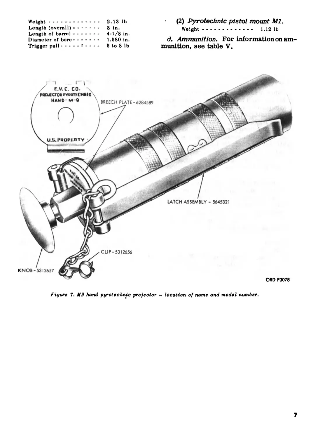
b. Hand Pyrotechnic Projector M9. The
name and model number of the projector
are stamped in the breech plate (fig. 7).
The serial number is stamped on the latch
assembly.
c. Pyrotechnic Pistol AN-M8 with Pyro-
technic Pistol Mount Ml. The name and
model number of the pistol AN-M8 are
stamped in the right-hand frame plate (fig.
4). The serial number is stamped on the
back of the frame. No name or serial num-
ber is stamped on the mount Ml.
5
Figure 5. Pyrotechnic pistol mount MJ.
7. Tabulated Data
AN-M8 PISTOL - 7265820
Figure 6. Pistol, pistol holder, and signal flare
container - an article of Air Force supply.
a. Ground Signal Projector M1A1.
Weight (w/support)............... 12.67 lb
Length (w/o support and spike) - - 15-3/4 in.
Length (w/support w/o spike) - 49 in.
Length (w/support and spike) - 57-1/2 in.
Bore:
Diameter...................- 1.636 in.
Length............ - ------ 11-5/8 in.
Associated equipment.......... lanyard
b. Hand Pyrotechnic Projector M9.
Weight........................... I lb
Length (overall)................. 8 in.
Length of barrel................. 6 in.
Diameter of bore................... 1.575 in.
c. Pyrotechnic Pistol AN-M8 with Pyro-
technic Pistol Mount Ml.
(1) Pyrotechnic pistol AN-M8.
Weight.................... 2.13 lb
Length (overall) -........ 8in.
Length of barrel............ 4-1/8 in.
Diameter of bore.......... 1.580 in.
Trigger pull - ------ - - - - 5 to 8 lb
(2) Pyrotechnic pistol mount Ml.
Weight................ 1.12 lb
d. Ammunition. For information on am-
munition, see table V.
/ E.V.C. CO-
PROJECTOR PYPOTECMMIC
LATCH ASSEMBLY - 5645321
CLIP-5312656
KNOB-5312657
ORD F3078
Figure 7. M9 hand pyrotechnic projector - location of name and model number.
CHAPTER 2
OPERATING INSTRUCTIONS
Section!. SERVICE UPON RECEIPT OF MATERIEL
8. General
a. When a new or reconditioned projec-
tor M1A1, hand projector M9, pistol AN-
M8 with pistol mount Ml is received, it is
the responsibility of the officer in charge
to determine whether the materiel has been
properly prepared for service by the sup-
plying organization and to be sure it is in
condition to perform its function.
b. All repair parts, tools, and equip-
ment will be checked with the listing in
appendix Ш, this manual, and TM 9-1095-
201-25P.
c. A record will be made of all missing
parts, tools, and equipment and of any mal-
functions. Deficiencies will be corrected
as quickly as possible.
d. The materiel should be cleaned and
prepared for service in accordance with
instructions in paragraph 9.
9. Services
a. Unpacking.
(1) Ground signal projector M1A1.
(a) Check identification label of the
issue pack (nomenclature and
stock number).
(b) Remove tape from closure seam
of fiber can container.
(c) Remove wrapped projector from
container.
(d) Remove each projector from VC 1
bag.
(2) Hand pyrotechnic projector M9.
(a) Check identification label of the
issue pack (nomenclature and
stock number).
(b) Remove tape from closure seam
of fiber board carton.
(c) Remove wrapped projector from
carton.
(d) Remove each projector from
greaseproof barrier material
VCI bag.
(3) Pyrotechnic pistol AN-M8 with
pyrotechnic pistol mount Ml.
(a) Check identification label of the
issue pack (nomenclature and
stock number).
(b) Remove tape from closure seam
of fiber board carton.
(c) Open carton and remove wrapped
pistol and mount from the sup-
ports within the carton.
(d) Remove pistol and mount from
greaseproof barter material.
b. Cleaning.
(1) Ground signal projector M1A1.
(a) Remove excess preservative
with wiping cloths.
(b) Immerse the projector in dry-
cleaning solvent or volatile min-
eral spirits.
(c) Dry projector thoroughly before
lubricating.
(2) Hand pyrotechnic projector M9.
(a) Remove excess preservative
with wiping cloths.
(b) Immerse the projector in dry-
cleaning solvent or volatile min-
eral spirits.
(c) Dry projector thoroughly before
lubricating.
(3) Pyrotechnic pistol AN-MS with
pyrotechnic pistol mount Ml.
(a) Remove excess preservative
with wiping cloths.
(b) Immerse the pistol and mount in
dry-cleaning solvent or volatile
mineral spirits and, with a brush,
remove the preservative from
the interior and exterior sur-
faces.
(c) Dry pistol and mount thoroughly
before lubricating.
c. Lubrication. Check lubrication of the
projector M1A1, projector M9, pistol AN-
M8 and mount Ml, and lubricate as neces-
sary (pars. 29 and 30).
8
d. Inspection.
(1) Ground signal projector M1A1.
(a) Check the lever assembly and
make certain that it operates
(fig. 1).
(b) Check complete assembly (pars.
45-48).
(2) Hand pyrotechnic projector M9.
(a) Check operation of all controls
(fig. 7).
Section II.
10. General
This section describes, locates, and il-
lustrates the various controls provided
for the operation and maintenance of the
projector M1A1, projector M9, and pistol
AN-M8 with mount Ml.
11. Ground Signal Projector M1A1
The lever assembly is the only control
on this projector. The improvised lanyard
is attached to the ring on the lever assem-
bly (fig. 1) which enables the projector to
be operated from a safe distance.
12. Hand Pyrotechnic Projector M9
a. Knob. The knob (fig. 7), which is lo-
cated at the rear of the projector, contains
the firing pin. Depression of the knob
causes the firing pin to strike the signal
primer.
b. Clip. The purpose of the clip (fig. 7)
is to prevent accidental depression of the
knob and firing of the projector. The clip
is shown in the SAFE position in figure 2.
To prevent loss, the clip is attached to the
latch pin with a chain.
(b) Check complete assembly (pars.
49-52).
(3) Pyrotechnic pistol AN-M8 with
pyrotechnic pistol mount Ml.
(a) Check operation of controls (fig.
3).
(b) Check complete assembly (pars.
53-56).
CONTROLS
c. Latch Assembly. The latch assembly
(fig. 7) is fitted with a plunger that snaps
into the catch which is welded to the bar-
rel. The purpose of this arrangement is to
keep the breech closed. Pulling up on
the latch assembly will cause the
plunger to disengage and the breech
to open.
13. Pyrotechnic Pistol AN-M8 with
Pyrotechnic Pistol Mount Ml
a. Lock. The lock (fig. 3) is used to lock
or open the breech. Pulling up on the lock
will cause it to disengage from the frame,
permitting the frame to swing downward,
thereby opening the breech. When the
frame is pulled upward, it closes the
breech and engages the lock.
b. Latch. The latch (fig. 3) is located in
front of the lock and assists in locking the
pistol into the mount.
c. Trigger. The trigger (fig. 3) is lo-
cated within the trigger guard. The pistol
is a double-action type, retracting the trig-
ger cocks the hammer against spring ten-
sion and releases the hammer at a speci-
fied point to strike the firing pin.
Section III. OPERATION UNDER USUAL CONDITIONS
14. General
This section contains instructions for the
operation of the ground projector M1A1,
hand projector M9, and pistol AN-M8 with
pistol mount Ml, under conditions of mod-
erate temperatures and humidity. Instruc-
tions for operation under unusual condi-
tions are covered in paragraphs 22, 23,
and 24.
15. Preparation for Use
a. Ground Signal Projector M1A1.
(1) The projector can be fired with or
without the spike attached.
(2) Force spike (fig. 1) into the ground
at the desired angle.
(3) Pull on lanyard until the lever as-
sembly is pulled down.
b. Hand Pyrotechnic Projector M9.
9
(1) Remove clip (fig. 2) from SAFE
position.
(2) Disengage latch assembly and open
breech (fig. 7).
(3) Replace clip into SAFE position
(fig. 2).
c. Pyrotechnic Pistol AN-M8 with
Pyrotechnic Pistol Mount Ml.
(1) Press up on knurled side of lock
(fig. 3) and open breech.
(2) Close the breech.
(3) Press back trigger and dry fire
weapon.
(4) When pistol is installed in the
pistol mount Ml, this is accom-
plished in (a) through (d).
(a) Remove the mount cover from
mount.
(b) Hold the pistol in position, so that
the lugs on the barrel line up with
the slots in the mount.
(c) Push the pistol into the mount as
far as it will go.
(d) Rotate the pistol one-eighth turn,
or 45 degrees, until the mount
latch on the pistol barrel snaps
into one of the slots on the mount.
16. Service Before Firing
Perform the before firing operations in
table П, Operators Preventive-Main-
tenance Services.
17. Loading
a. Ground Signal Projector M1A1.
Slowly insert (he signal into the barrel,
primer end first.
b. Hand Pyrotechnic Projector M9.
(1) With projector open, insert signal
through breech end.
(2) Make certain that the ejector pro-
truding from breech end of the bar-
rel engages the rim of the signal.
(3) Close the breech and engage the
latch plunger in the barrel catch.
c. Pyrotechnic Pistol AN-M8 with
Pyrotechnic Pistol Mount Ml.
(1) Open the breech by pressing up-
ward on the breech lock.
(2) Insert signal into the barrel
through the breech, primer end
last.
(3) Snap the breech closed.
(4) The aircraft parachute flare M9A1
must be loaded through the muzzle.
(a) Insert the flare through the muz-
zle.
(b) Stop when ejector engages the
groove.
(c) The parachute flare M9A1 will
not pass through the mount Ml,
therefore, it must be fired free-
hand.
18. Firing
a. Ground Signal Projector M1A1.
(1) Sit, kneel, or lie so that head is
well below and behind projector
muzzle.
(2) Firmly grasp lower part of pro-
jector body with one hand and snap
lanyard down sharply with the
other.
(3) Exercise extreme care when firing
through trees or similarly inflam-
mable obstructions.
b. Hand Pyrotechnic Projector M9.
(1) Hold projector barrel firmly in one
hand.
(2) Direct projector away from face
and other personnel in area.
(3) Pull safety spring from SAFE po-
sition.
(4) Strike hand knob sharply with palm
of other hand.
Note. Firing can be accomplished by
striking the hand knob against some rigid
object.
(5) Exercise extreme care when firing
through trees or other obstruc-
tions.
c. Pyrotechnic Pistol AN-M8 with
Pyrotechnic Pistol Mount Ml.
(1) Squeeze back the trigger until the
pistol fires.
(2) Exercise extreme care when firing
through trees or similar obstruc-
tions.
(3) When the aircraft parachute flare
M9A1 is to be fired, hold the
pistol firmly with both hands.
The weight and design of this
flare causes extreme recoil when
fired.
10
19. Misfire
a. Ground Signal Projector Ml Al.
(1) If signal fails to fire, make two
more attempts to fire. If signal
still fails to fire, unload the
weapon.
(2) Examine the signal for primer in-
dentation due to firing pin. If in-
dentation exists, dispose of signal
and load projector with a new sig-
nal.
(3) If no indentation exists, the firing
mechanism may be defective; see
table IV, Troubleshooting.
b. Hand Pyrotechnic Projector -M9.
(1) If signal fails to fire, make two
more attempts to fire. If signal
still fails to fire, unload the
weapon.
(2) Examine the signal for primer in-
dentation due to firing pin. If in-
dentation exists, dispose of signal
and load projector with a new sig-
nal.
(3) If no indentation exists, the firing
mechanism may be defective; see
table IV, Troubleshooting.
c. Pyrotechnic Pistol AN-M8 with
Pyrotechnic Pistol Mount Ml.
(1) If signal fails to fire, make two
more attempts to fire. If signal
still fails to fire, unload the
weapon.
(2) In the case of the aircraft parachute
flare M9A1, after two attempts to
Section IV. OPERATION U
22. General Conditions
a. In addition to the normal operating
procedures for usual conditions, special
instructions for operating and servicing
the projectors under unusual conditions
are contained or referred to herein. In
addition to the normal preventive-mainte-
nance, service special care in cleaning and
lubrication must be observed where ex-
tremes of temperature, humidity, and at-
mospheric conditions are present or antic-
ipated. Proper cleaning, lubrication and
storage and handling of lubricants not only
insure operation and functioning but also
fire, unload the pistol and dispose
of the flare quickly and safely.
(3) For signals other than the M9A1,
examine the signal for primer in-
dentation due to firing pin. If in-
dentation exists, dispose of signal
and load pistol with a new signal.
(4) If no indentation exists, the firing
mechanism may be defective; see
table IV, Troubleshooting.
20. Service During Firing
Perform the ’’during firing’ operations
in table П. Operators Preventive-Mainte-
nance Services.
21. Unloading
a. Ground Signal Projector M1A1.
(1) Pull projector from the ground.
(2) Invert projector.
(3) Allow signal case to fall out on
ground.
b. Hand Pyrotechnic Projector M9.
(1) Disengage the latch from the bar-
rel catch.
(2) Open the breech.
(3) Remove signal case from breech
end of barrel.
c. Pyrotechnic Pistol AN-M8 with
Pyrotechnic Pistol Mount Ml.
(1) Open the breech by pushing up on
the breech lock.
(2) Pull the signal case from the pis-
tol.
ER UNUSUAL CONDITIONS
guard against excessive wear of the work-
ing parts and deterioration of the materiel.
b. See paragraph 30 for instructions on
lubrication under unusual conditions,pre-
ventive-maintenance schedules in table in
for preventive -maintenance checks to be
made when materiel is subjected to unusual
conditions, and paragraphs 31 through 35
for preventive-maintenance services.
c. When chronic failure of materiel re-
sults from subjection to extreme condi-
tions, report of such chronic failure should
be made in accordance with para-
graph 3d.
11
23. Operation in Cold Climates
a. In climates where the temperature is
consistently below freezing, it is neces-
sary to prepare the materiel for cold-
weather operation.
b. Exercise the various controls through
their entire range, at intervals as re-
quired, to aid in keeping them from freez-
ing in place and to reduce the effort
required to operate them.
c. When materiel is not in use, pay par-
ticular attention to protecting it with the
proper covering making certain they are
securely fastened so that snow and ice will
be kept from the operating parts. Provide
as much protection as possible for all parts
of the materiel and equipment.
d. See TM 9-207 for information on fol-
lowing points:
Handling and storage of lubricants.
Problems of cold-weather operation.
Lubrication in preparation for and dur-
ing cold-weather operation.
Operation and maintenance in extreme
cold.
e. See FM 31-70 for additional informa-
tion on basic cold weather operations.
24. Operation in Hot Climates
a. General.
(1) In hot climates, the filmof oilnec-
essary for operation and preserva-
tion will dissipate quickly. Inspect
materiel frequently, paying partic-
ular attention to all hidden
surfaces, such as the bore, springs
and spring seats, firing pin, and
like places, where corrosion might
occur and not be quickly noticed.
(2) Perspiration from the hands is a
contributing factor to rusting be-
cause it contains acids and salts.
After handling, clean, wipe dry, and
restore the oil film.
(3) For care, handling, and preserva-
tion of ammunition, see paragraph
64.
b. Hot, Dry Climates.
(1) When operating in hot climates
where sand and dust are likely to
enter the bore and mechanism, the
materiel should be wiped clean
more frequently than usual, and
disassembled to the extent that all
parts can have a thorough cleaning.
(2) Oiling should be kept to a minimum,
as oil will collect dust which will
cause wear of the working parts.
It should be applied lightly and only
to the surfaces or working parts
showing signs of wear.
(3) Rapid temperature changes cause
a moisture condensation film to
form on unpainted metal, resulting
in rust. Immediately, when this
moisture film occurs on metal
parts of the weapon, wipe briskly
until dry and coat with (PL special)
general purpose lubricating oil to
prevent rusting.
c. Hot, Damp, and Salty Atmosphere.
(1) Inspect materiel frequently, when
operating in hot, moist areas.
(2) When the materiel is active, clean
and lubricate the bore and exposed
metal surfaces more frequently
than is prescribed for normal
service.
(3) Moist and salty atmospheres have
a tendency to emulsify oils and
greases and destroy their rust-
preventive qualities. Inspect all
parts frequently for cor r os ion.
Protect from elements as much of
the time as firing conditions
permit.
(4) When the materiel is inactive,
cover surfaces with a film of (PL
special) general purpose lubrica-
ting oil. Keep protective covering
in place.
12
CHAPTER 3
MAINTENANCE INSTRUCTIONS
Section I. REPAIR PARTS, TOOLS, SPECIAL TOOLS, AND EQUIPMENT
25. General
Repair parts, tools, and equipment are
issued to the using organization for oper-
ating and maintaining the materiel. Tools
and equipment should not be used for pur-
poses other than prescribed and, when not
in use, should be properly stowed.
26. Repair Parts
Repair parts are supplied to the using
organization for replacement when they
become worn, broken, or otherwise un-
serviceable. No repair parts are supplied
to first echelon. Repair parts supplied to
second, third, fourth, and fifth echelons
are listed in TM 9-1095-201-25P.
27. Tools and Equipment
Tools and equipment having general ap-
plication to this materiel are authorized
by tables of allowances (TA's) and tables
of organization and equipment (TO&E's).
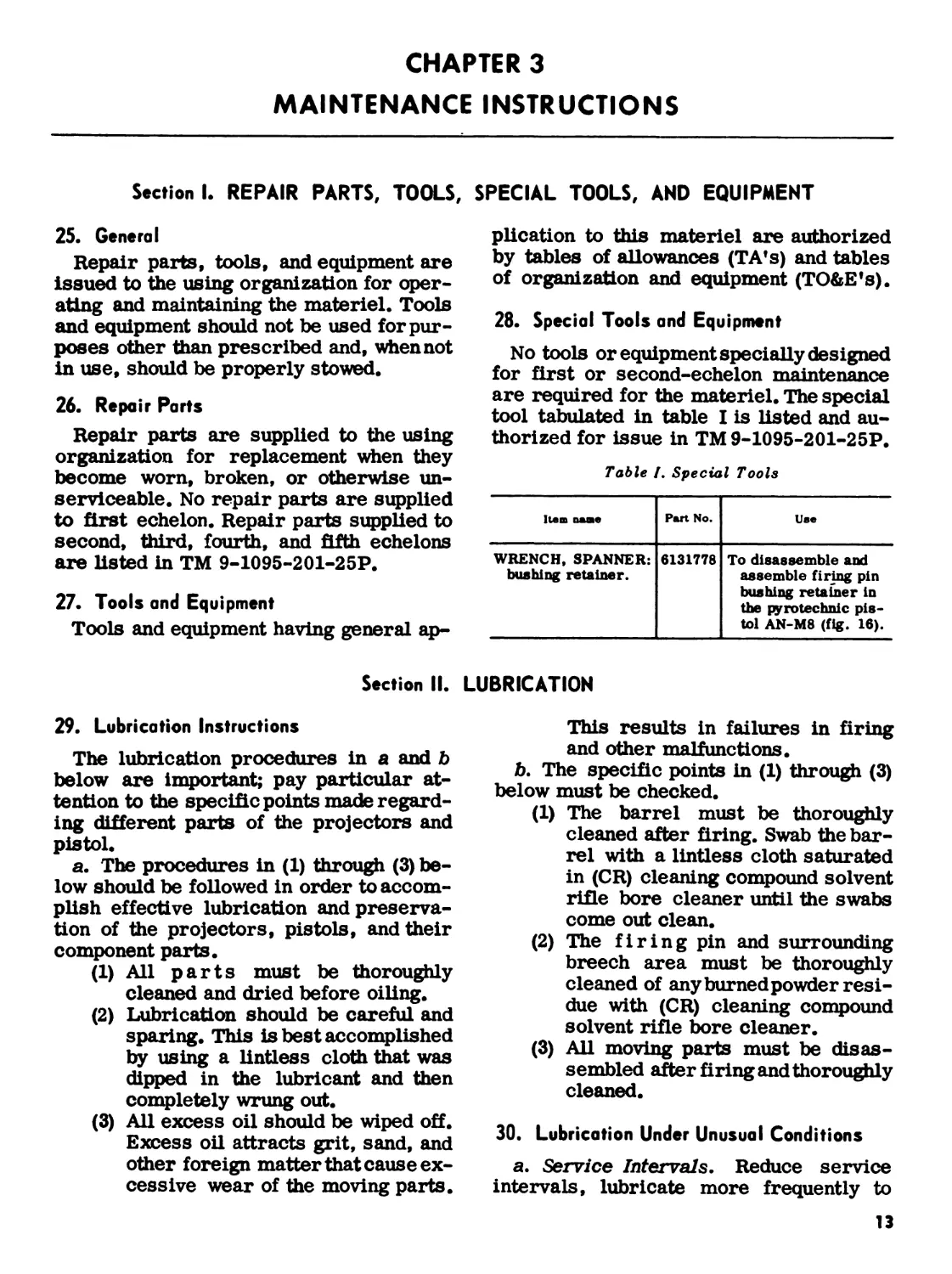
28. Special Tools and Equipment
No tools or equipment specially designed
for first or second-echelon maintenance
are required for the materiel. The special
tool tabulated in table I is listed and au-
thorized for issue in TM 9-1095-201-25P.
Table /, Special Toole
Item name Part No. Use
WRENCH, SPANNER: bushing retainer. 6131778 To disassemble and assemble firing pin bushing retainer in the pyrotechnic pis- tol AN-M8 (fig. 16).
Section II. LUBRICATION
29. Lubrication Instructions
The lubrication procedures in a and b
below are important; pay particular at-
tention to the specific points made regard-
ing different parts of the projectors and
pistol.
a. The procedures in (1) through (3) be-
low should be followed in order to accom-
plish effective lubrication and preserva-
tion of the projectors, pistols, and their
component parts.
(1) All parts must be thoroughly
cleaned and dried before oiling.
(2) Lubrication should be careful and
sparing. This is best accomplished
by using a lintless cloth that was
dipped in the lubricant and then
completely wrung out.
(3) All excess oil should be wiped off.
Excess oil attracts grit, sand, and
other foreign matter that cause ex-
cessive wear of the moving parts.
This results in failures in firing
and other malfunctions.
b. The specific points in (1) through (3)
below must be checked.
(1) The barrel must be thoroughly
cleaned after firing. Swab the bar-
rel with a lintless cloth saturated
in (CR) cleaning compound solvent
rifle bore cleaner until the swabs
come out clean.
(2) The firing pin and surrounding
breech area must be thoroughly
cleaned of any burned powder resi-
due with (CR) cleaning compound
solvent rifle bore cleaner.
(3) AU moving parts must be disas-
sembled after firing and thoroughly
cleaned.
30. Lubrication Under Unusual Conditions
a. Service Intervals. Reduce service
intervals, lubricate more frequently to
13
compensate for abnormal or extreme con-
ditions, such as high or lowtemperatures,
prolonged periods of firing, continued fir-
ing in sand or dust, or exposure to mois-
ture. Any one of these operations or condi-
tions may cause contamination and quickly
destroy the protective properties of the
lubricant.
b. Extreme Cold-Weather Lubrication.
Lubricate parts with weapons lubricating
oil (LAW) when temperature is below 0*F.
c. Extreme Hot-Weather Lubrication.
Special lubricants will ordinarily not be
required at extreme high temperatures,
as lubricants prescribed for temperatures
above 0°F provide adequate protection.
However, more frequent servicing than
specified in table П is necessary because
the heat tends to dissipate the lubricants.
d. Lubrication for Humid and Salt-Air
Conditions. High humidity, moisture or
salt air contaminate lubricants, necessi-
tating more frequent service than specified
in table П.
e. Lubrication After Operation Under
Sandy or Dusty Conditions. If prolonged
firing has occurred under dusty or sandy
conditions, clean and inspect all lubricated
surfaces for fouled lubricants. Lubricate
as necessary.
Section III. PREVENTIVE-MAINTENANCE SERVICES
31. General
a. Responsibility and Intervals. Preven-
tive-maintenance services are the respon-
sibility of the using organization. These
consist of before-firing, during-firing,
after-firing, daily, and weekly services
performed by the operator (firstechelon),
and the scheduled services to be per-
formed at the weekly, bimonthly, and
semiannual intervals by the armorer of
the using organization (second echelon).
b. Definition of Terms. The general in-
spection of each item applies also to any
supporting member or connection and is
generally a check to see whether the item
is in good condition, correctly assembled,
secure, and not worn.
(1) The inspection for good condition
is usually an external visual in-
spection to determine whether the
unit is damaged beyond safe or
serviceable limits. The term good
condition is explained further by
the following: not bent or twisted,
not chafed or burred, not broken
or cracked, not bare or frayed, not
dented or collapsed, not torn or cut,
not deteriorated.
(2) The inspection of a unit to see that
it is correctly assembled is usually
an external visual inspection to see
if it is in its normal assembled
position in the materiel and func-
tions properly when manually op-
erated.
(3) Inspection of a unit to determine
if it is secure is usually an external
visual examination or a check by
wrench or hand for looseness. Such
an inspection must include any
brackets, lockwashers, locknuts,
locking wire, or cotter pins used.
(4) By worn is meant worn beyond
serviceable limits or to a point
likely to result in failure if the unit
is not replaced before the next
scheduled inspection.
32. Cleaning and Care
a. General. Any special instructions for
cleaning and care of components are con-
tained in the pertinent sections. General
Instructions are given in b and c below.
b. Cleaning Instructions.
(1) Powder-fouled parts. Use (CR)
cleaning compound solvent rifle
bore cleaner to clean all parts
which have been exposed to powder
fouling during firing.
Note. This compound is not a lubricant.
Parts which require Lubrication will be
wiped dry and oiled. Do not use dry-
cleaning solventor mineral spirits paint
thinner, because these solvents will not
readily dissolve the corrosive salts from
powder and primer compositions.
(2) General usage. Use dry-cleaning
solvent or mineral spirits paint
14
thinner to clean or wash grease or
oil from all parts of the weapon.
(3) Heavy accumulations. New mate-
riel, and component parts received
from storage for immediate use
may have heavy accumulations of
grease or coatings of rust-preven-
tive compound. This may be partly
by scraping with sticks or other
articles which will not damage
parts. Remove the residue with
waste, wiping cloths, or a brush
saturated with (CR) cleaning com-
pound. After cleaning, rinse off any
remaining compound with cold
water. Dry and lubricate as speci-
fied in paragraph 29. Apply a light
grade of oil to all nonpainted metal
surfaces to prevent rusting.
c. General Precautions in Cleaning.
(1) Dry-cleaning solvent and mineral
spirits paint thinner are flammable
and should not be used near an open
flame. Fire extinguishers should
be readily available when these
materials are used. In addition,
they evaporate quickly and have a
drying effect on the skin. If used
without gloves, they may cause
cracks in the skin and, in the case
of some individuals, a mild irri-
tation or inflammation. Use only
in well-ventilated places.
(2) Avoid getting petroleum products,
such as dry-cleaning solvent, min-
eral spirits paint thinner, or lubri-
cants on rubber parts as they will
attack the rubber and destroy its
characteristics.
(3) The use of Diesel fuel oil, gasoline,
or benzene (benzol) for cleaning
or the use of high-pressure water
or steam for cleaning the weapon
is prohibited.
(4) Do not dilute (CR) cleaning com-
pound solvent rifle bore cleaner.
Do not add antifreeze. Store
cleaners in a warm place, if prac-
tical. Shake (CR) cleaning com-
pound well before using.
33. Basic Preventive Maintenance
The general preventive-maintenance
procedures outlined in a through e below
will be observed in addition to those re-
ferred to in table П. Special maintenance
of specific components of the materiel is
covered, when necessary, in the sections
pertaining to the components.
a. Rust, dirt, grit, gummed oil, and
water cause rapid deterioration of internal
mechanism and outer unpainted surfaces.
Particular care should be taken to keep all
bearing surfaces clean and properly lubri-
cated. Remove all traces of rust from un-
painted bearing surfaces with crocus cloth,
which is the coarsest abrasive to be used
by the using organization for this
purpose.
b. Loose parts will be tightened and
broken parts replaced or repaired.
c. At least every 6 months, check if all
modifications have been applied. For a list
of current modification work orders, see
DA Pam 310-4. No alteration or modifica-
tion will be made except as authorized by
modification work orders.
d. Check equipment for completeness.
Replace missing items and turn in for re-
pair all damaged items. Use only tools that
are provided and see that they are service-
able. After use, items must be thoroughly
cleaned, coated with a film of oil, and
stowed in their proper chests or tool
rolls.
e. Inspect and service the weapon, as
described in paragraphs 40 through 42 at
least once every 6 months and after any
extended travel with the weapon, as the
tactical situation permits.
34. Schedule of Preventive Maintenance
a. Purpose. To insure mechanical effi-
ciency, it is necessary that the materiel
be systematically inspected at regular in-
tervals, so defects may be discovered and
corrected before they result in serious
damage or failure. Certain scheduled
maintenance services or unsatisfactory
operating characteristics beyond the scope
of the operators to correct must be re-
ported at the earliest opportunity to the
designated individual in authority.
b. Schedule. The items and points to be
inspected and serviced are listed in table
П.
IS
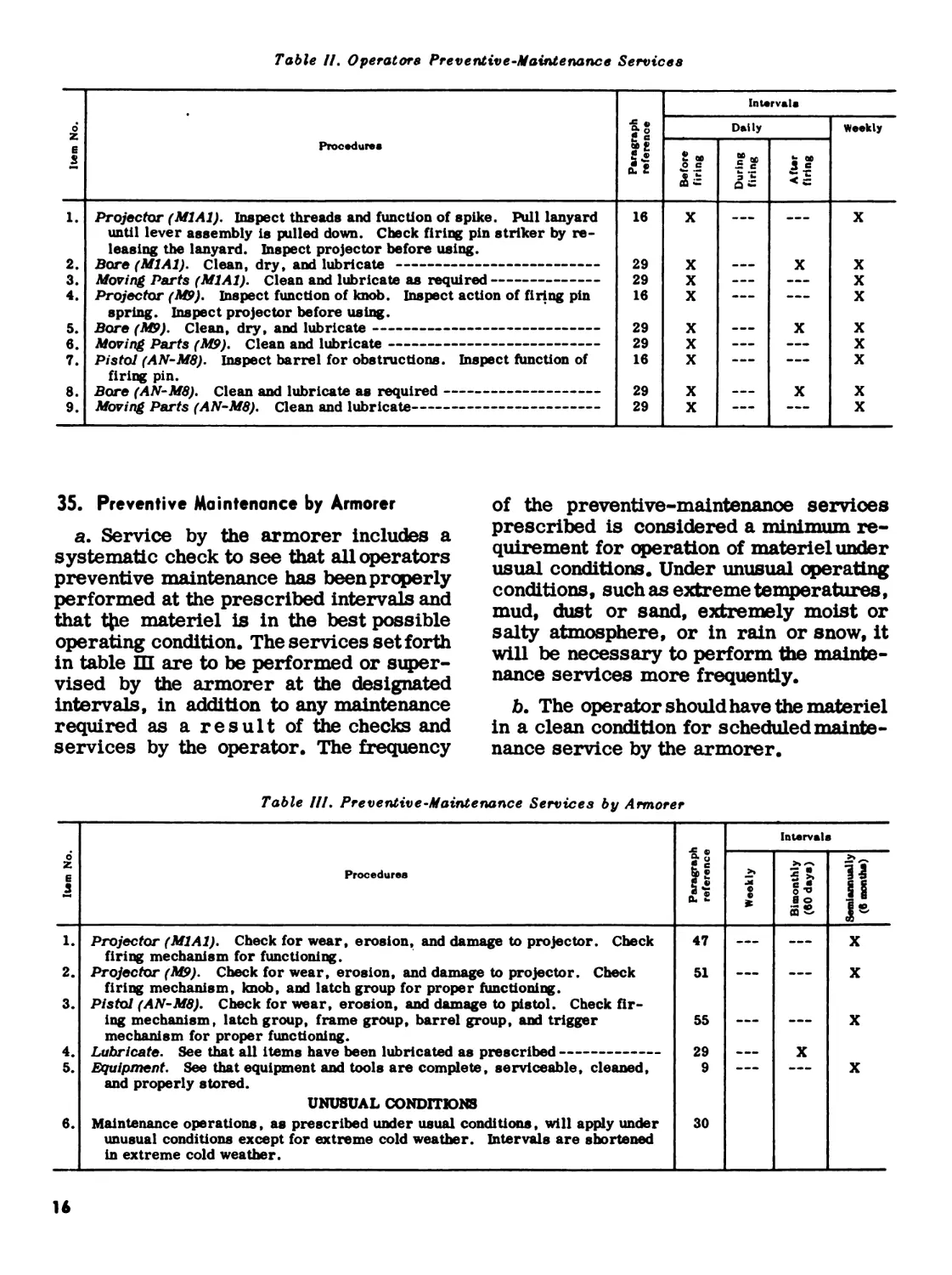
Table //. Operators Preventive-Maintenance Services
0 z E s Procedures Paragraph reference Intervals
Daily Weekly
Before firing During firing After firing 1
1. Projector (MlAl). Inspect threads and function of spike. Pull lanyard until lever assembly is pulled down. Check firing pin striker by re- leasing the lanyard. Inspect projector before using. 18 X --- X
2. Bore (MlAl). Clean, dry, and lubricate 29 X ——— X X
3. Moving Parts (M1A1). Clean and lubricate as required 29 X ... X
4. Projector (M9). Inspect function of knob. Inspect action of firing pin spring. Inspect projector before using. 18 X — — X
5. Bore (MP). Clean, dry, and lubricate 29 X ... X X
6. Moving Parts (MP). Clean and lubricate 29 X ——— X
7. Pistol (AN-M8). Inspect barrel for obstructions. Inspect function of firing pin. 18 X X
8. Bore (AN-M8). Clean and lubricate as required 29 X ——— X X
9. Moving Parts (AN-M8). Clean and lubricate 29 X — — X
35. Preventive Maintenance by Armorer
a. Service by the armorer includes a
systematic check to see that all operators
preventive maintenance has been properly
performed at the prescribed intervals and
that Ц1е materiel is in the best possible
operating condition. The services set forth
in table Ш are to be performed or super-
vised by the armorer at the designated
intervals, in addition to any maintenance
required as a result of the checks and
services by the operator. The frequency
of the preventive-maintenance services
prescribed is considered a minimum re-
quirement for operation of materiel under
usual conditions. Under unusual operating
conditions, such as extreme temperatures,
mud, dust or sand, extremely moist or
salty atmosphere, or in rain or snow, it
will be necessary to perform the mainte-
nance services more frequently.
b. The operator should have the materiel
in a clean condition for scheduled mainte-
nance service by the armorer.
Table Hl. Preventive-Maintenance Services by Armorer
Intervals
0* z E 3 Procedures Paragrapl reference Weekly Bimonthly (вО days)
1. 2. 3. 4. 5. Projector (MlAl). Check for wear, erosion, and damage to projector. Check firing mechanism for functioning. Projector (M9). Check for wear, erosion, and damage to projector. Check firing mechanism, knob, and latch group for proper functioning. Pistol (AN-M8). Check for wear, erosion, and damage to pistol. Check fir- ing mechanism, latch group, frame group, barrel group, and trigger mechanism for proper functioning. Lubricate. See that all items have been lubricated as prescribed Equipment. See that equipment and tools are complete, serviceable, cleaned, and properly stored. 47 51 55 29 9 — X
UNUSUAL CONDITIONS
6. Maintenance operations, as prescribed under usual conditions, will apply under unusual conditions except for extreme cold weather. Intervals are shortened 30
in extreme cold weather.
X
X
X
X
16
Section IV. TROUBLESHOOTING
36. Scope
This section contains troubleshoot-
ing information and tests for locating
and correcting some of the troubles
which may develop in the materiel.
Troubleshooting is the systematic
study of trouble signs, testing to de-
termine the defective components,
and applying corrective action. Each
malfunction is followed by probable
causes and suggested procedures to
be followed.
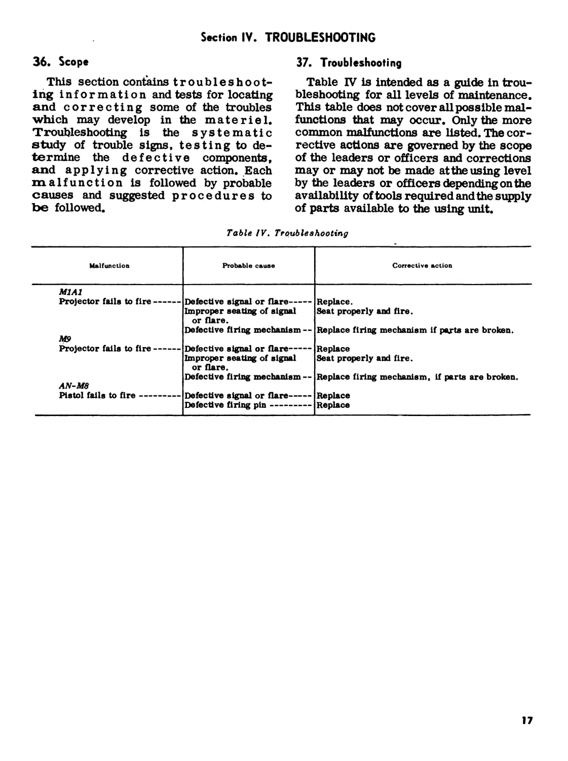
37. Troubleshooting
Table IV is intended as a guide in trou-
bleshooting for all levels of maintenance.
This table does not cover all possible mal-
functions that may occur. Only the more
common malfunctions are listed. The cor-
rective actions are governed by the scope
of the leaders or officers and corrections
may or may not be made atthe using level
by the leaders or officers depending on the
availability of tools required and the supply
of parts available to the using unit.
Table IV. Troubleshooting
Malfunction Probable cause Corrective action
M1A1 Projector fails to fire MP Projector fails to fire AN-M8 Pistol fails to fire Defective signal or flare Improper seating of signal or flare. Defective firing mechanism — Defective signal or flare Improper seating of signal or flare. Defective firing mechanism — Defective signal or flare Defective firing pin Replace. Seat properly and fire. Replace firing mechanism if parts are broken. Replace Seat properly and fire. Replace firing mechanism, if parts are broken. Replace Replace
17
CHAPTER 4
INSPECTIONS
Section I.
38. Scope
This chapter provides specific instruc-
tions for the inspection by Ordnance main-
tenance personnel of materiel in the hands
of troops in the field, in Ordnance shops,
and in alerted units scheduled for oversea
duty. Troubleshooting information is in-
corporated wherever applicable as a nor-
mal phase of inspection.
39. Purpose of Inspection
Inspections are made for the purpose of
(1) determining the condition of an item as
to serviceability, (2) recognizing condi-
tions that would cause failure, (3) assuring
proper application of maintenance policies
at prescribed levels, and (4) determining
the ability of a unit to accomplish its main-
tenance and supply missions.
40. Categories of Inspection
In general, three categories of inspection
are performed by Ordnance field mainte-
nance personnel.
a. Inspection of Materiel in the Hands
of Troops in the Field.
(1) Spot-check inspection. This is an
inspection performed on a percent-
age of materiel in order to ascer-
tain the adequacy and effectiveness
of organizational maintenance and
supply. Included within this scope
is inspection of equipment to detect
incipient failures before unserv-
iceability occurs; inspection to as-
certain the availability and use of
technical and supply manuals and
lubrication orders; inspection to
determine the accuracy of records,
authorized levels of equipment and
supplies, practice of supply econ-
omy, preservation, and safekeep-
ing of tools, availability of repair
parts and supplies; and knowledge
GENERAL
of the proper procedures for req—
usitioning supplies and equipment
and followup thereon.
(2) Command maintenance. Command
maintenance inspections will be
performed at least annually. The
purpose of the inspection is to as-
certain the serviceability of equip-
ment, to predict maintenance and
supply requirements, and to deter-
mine the adequacy of facilities and
effectiveness of procedures. In-
formation obtained during the in-
spection should indicate future
requirements for depot mainte-
nance and for replacement, as well
as disclose immediate needs for
maintenance and application of
modification work orders. During
inspection, correction of deficien-
cies will be made on spot when
practical. For additional informa-
tion relative to these inspections
and the forms to be used therewith,
refer to AR 750-8.
b. Ordnance S&op Inspection.
(1) Initial inspection. This is an in-
spection of materiel received in
Ordnance shops for the purpose of
determining the degree of repair
and parts requirement. This in-
cludes determination of modifica-
tion work orders to be applied.
(2) In-process inspection. This is
performed in the process of re-
pairing the materiel, to insure that
all parts conform to the prescribed
repair standards, that the work-
manship is in accordance with ap-
proved methods and procedures,
and that deficiencies not disclosed
by the initial inspection are found
and corrected.
(3) Final inspection. This is an ac-
ceptance inspection performed by
18
a final inspector after repair has
been completed, to insure that the
materiel is acceptable for return
to user or storage.
c. Preembarkation Inspection. This in-
spection is conducted on materiel in
alerted units scheduled for oversea duty
to insure that such materiel will not be-
come unserviceable or worn out in a rela-
tively short time. It prescribes a higher
percentage of remaining usable life in
serviceable materiel to meet a specific
need beyond minimum serviceability.
Section II. INSPECTION PROCEDURES
41. General
Warning: Before starting an inspection,
be sure the weapon is clean. Do not actuate
the trigger or firing mechanism until the
weapon has been cleared. Inspect the
chamber to insure that it is empty. Avoid
having live ammunition in the vicinity of
work area.
a. Check to see that the weapon has been
cleaned of grease, excessive oil, dirt, or
foreign matter which might interfere with
proper functioning or obscure the true
condition of the parts.
b. Make an overall inspection of the
weapon for general appearance, condition,
and operation.
42. Inspection of Materiel in the
Hands of Troops in the Field
Refer to TM 9-1100 and AR 750-8 for
responsibilities and fundamental duties of
inspecting personnel, the necessary notice
and preparations to be made, forms to be
used, and general procedures and methods
to be followed by inspectors. In the course
of this inspection, the inspector will ac-
complish the following:
a. Determine serviceability, i.e., the
degree of serviceability, completeness,
and readiness for immediate use, with
special reference to safe and proper func-
tioning of the materiel. If the materiel is
found unserviceable or incipient failures
are disclosed, the deficiencies will be cor-
rected on the spot or advice given as to
corrective measures when applicable, or
the materiel will be tagged and delivered
to Ordnance maintenance personnel for
repair.
b. Determine causes of mechanical and
functional difficulties that troops may be
experiencing and check for apparent re-
sults of lack of knowledge, misinforma-
tion, neglect, improper handling and stor-
age, security, and preservation.
c. See that all authorized modifications
have been applied, that no unauthorized
alterations have been made, and that no
work beyond the authorized scope of the
unit is being attempted. Check DA Pam
310-4 and current MWO files for any mod-
ification work orders printed after the date
of this manual.
d. Instruct the using personnel in proper
preventive-maintenance procedures (par.
33).
e. Check on completeness of the organ-
izational maintenance allowances and pro-
cedures for obtaining replenishments.
f. Inspect lettering on nameplates for
legibility.
g. Note general appearance. Check ex-
terior of materiel for missing or broken
parts.
h. Check storage conditions of general
supplies.
i. Initiate a thorough report on materiel
on ’’deadline,” with reasons therefor, for
further appropriate action.
j. Report to the responsible officer any
carelessness, negligence, unauthorized
modifications, or tampering. This report
should be accompanied by recommenda-
tions for correcting the unsatisfactory
condition.
43. Ordnance Shop Inspections
a. Initial Inspection. In addition to ma-
terial covered in paragraphs 41 and42, the
initial inspection will determine the cause
of unserviceability, extent of required re-
pairs, and estimate of parts required.
19
Table IV, Troubleshooting is provided to
help determine malfunction. If the required
repair is determined to be beyond the scope
of field maintenance personnel, the mater-
iel will be tagged and delivered to rebuild
organizations (depot maintenance). For
malfunctions and corrections pertinent to
the using personnel, see table I, Operators
Preventive-Maintenance Services.
b. In-Process Inspection. Detailed in-
structions for in-process inspection of the
materiel are contained in the maintenance
and repair chapter together with the appli-
cable repair instructions.
c. Final Inspection. Detailed instruc-
tions for final inspection of materiel are
contained in paragraphs 59 and 60.
44. Preembarkation Inspections of Materiel
in Units Alerted for Oversea Movement
a. General. Materiel destined for over-
sea movement must be inspected for serv-
iceability as described in paragraph 40.
Serviceable materiel will also meet the
standards set forth in ТВ ORD 385.
b. Spare Parts and Equipment. When
shipped overseas the weapons must be ac-
companied by a complete set of spare parts
and equipment as normally issued. AU
parts and equipment must be examined
for serviceability. Replace any de-
fective items. It is not normally nec-
essary to inspect items in sealed
packages.
20
CHAPTER 5
MAINTENANCE AND REPAIR
Section I. GROUND SIGNAL PROJECTOR M1A1
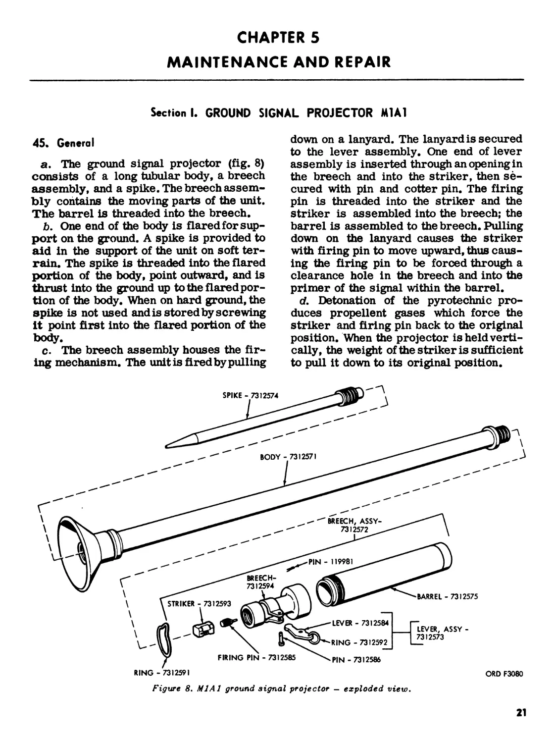
45. General
a. The ground signal projector (fig. 8)
consists of a long tubular body, a breech
assembly, and a spike. The breech assem-
bly contains the moving parts of the unit.
The barrel is threaded into the breech.
b. One end of the body is flared for sup-
port on the ground. A spike is provided to
aid in the support of the unit on soft ter-
rain. The spike is threaded into the flared
portion of the body, point outward, and is
thrust into the ground up to the flared por-
tion of the body. When on hard ground, the
spike is not used and is stored by screwing
it point first into the flared portion of the
body.
c. The breech assembly houses the fir-
ing mechanism. The unit is fired by pulling
down on a lanyard. The lanyard is secured
to the lever assembly. One end of lever
assembly is inserted through an opening in
the breech and into the striker, then se-
cured with pin and cotter pin. The firing
pin is threaded into the striker and the
striker is assembled into the breech; the
barrel is assembled to the breech. Pulling
down on the lanyard causes the striker
with firing pin to move upward, thus caus-
ing the firing pin to be forced through a
clearance hole in the breech and into the
primer of the signal within the barrel.
d. Detonation of the pyrotechnic pro-
duces propellent gases which force the
striker and firing pin back to the original
position. When the projector is held verti-
cally, the weight of the striker is sufficient
to pull it down to its original position.
RING -7312591
ORD F3080
Figure 8. Ml Al ground signal projector — exploded view.
21
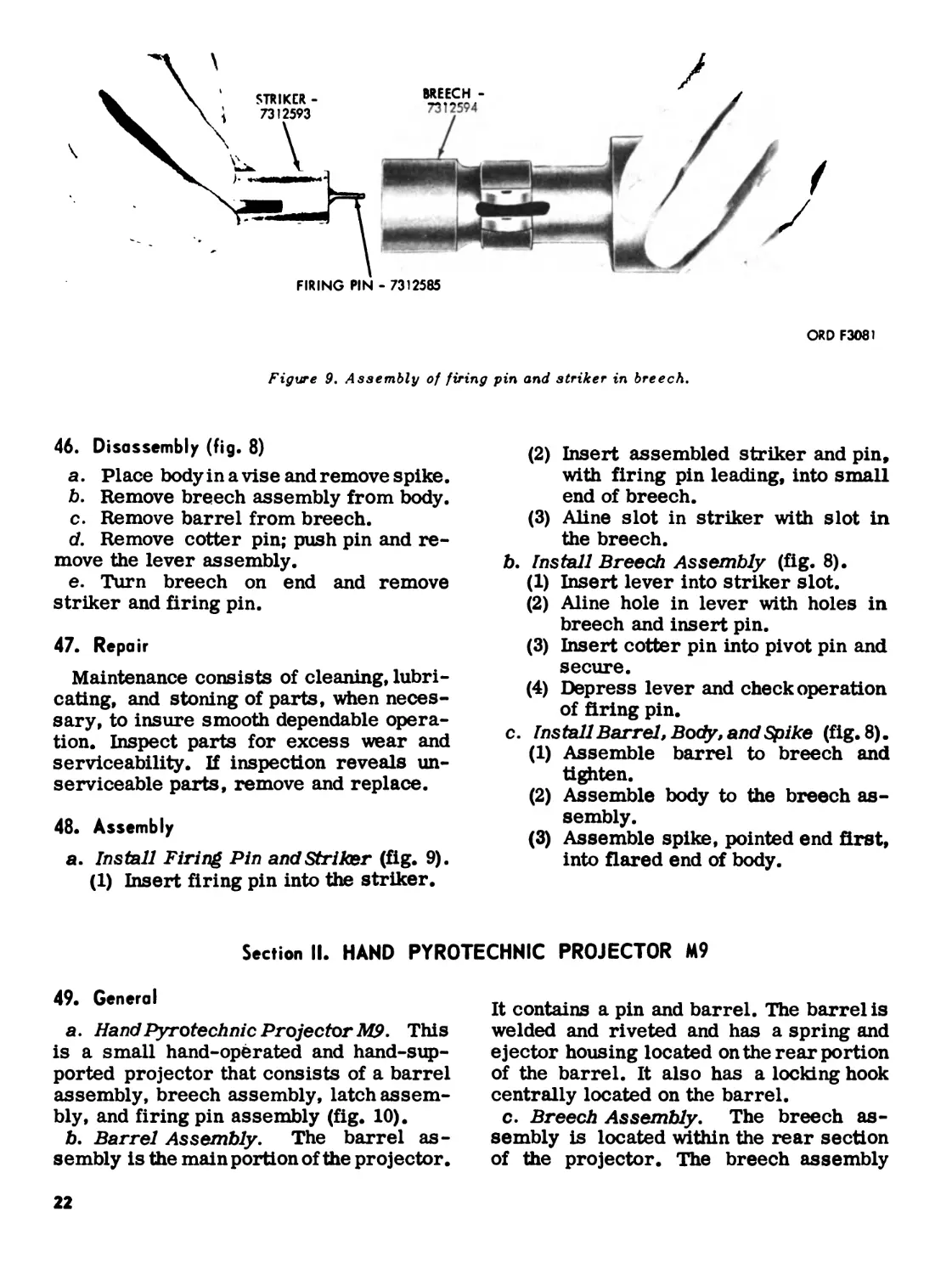
FIRING PIN - 7312585
Figure 9. Assembly of firing pin and striker in breech.
ORD F3081
46. Disassembly (fig. 8)
a. Place body in a vise and remove spike.
b. Remove breech assembly from body,
c. Remove barrel from breech.
d. Remove cotter pin; push pin and re-
move the lever assembly.
e. Turn breech on end and remove
striker and firing pin.
47. Repair
Maintenance consists of cleaning, lubri-
cating, and stoning of parts, when neces-
sary, to insure smooth dependable opera-
tion. Inspect parts for excess wear and
serviceability. If inspection reveals un-
serviceable parts, remove and replace.
48. Assembly
a. Install Firing Pin and Striker (fig. 9).
(1) Insert firing pin into the striker.
(2) Insert assembled striker and pin,
with firing pin leading, into small
end of breech.
(3) Aline slot in striker with slot in
the breech.
b. Install Breech Assembly (fig. 8).
(1) Insert lever into striker slot.
(2) Aline hole in lever with holes in
breech and insert pin.
(3) Insert cotter pin into pivot pin and
secure.
(4) Depress lever and check operation
of firing pin.
c. Install Barrel, Body, and Spike (fig. 8).
(1) Assemble barrel to breech and
tighten.
(2) Assemble body to the breech as-
sembly.
(3) Assemble spike, pointed end first,
into flared end of body.
Section II. HAND PYROTECHNIC PROJECTOR M9
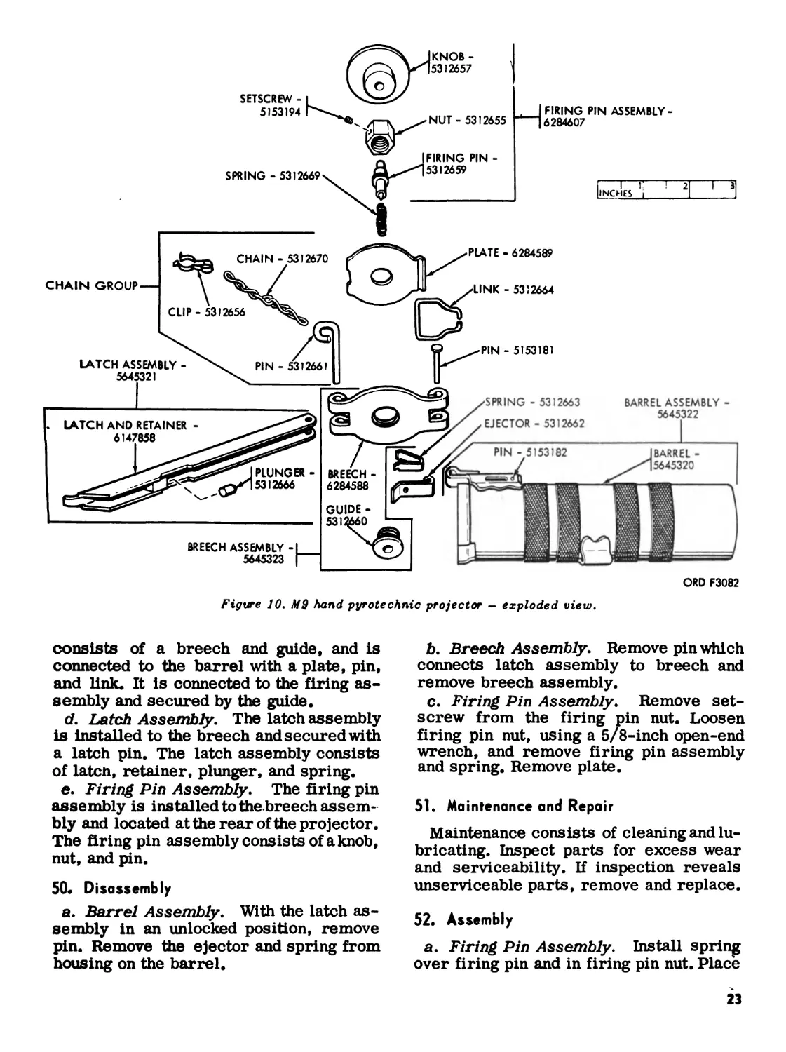
49. General
a. Hand Pyrotechnic Projector M9. This
is a small hand-operated and hand-sup-
ported projector that consists of a barrel
assembly, breech assembly, latch assem-
bly, and firing pin assembly (fig. 10).
b. Barrel Assembly. The barrel as-
sembly is the main portion of the projector.
It contains a pin and barrel. The barrel is
welded and riveted and has a spring and
ejector housing located on the rear portion
of the barrel. It also has a locking hook
centrally located on the barrel.
c. Breech Assembly. The breech as-
sembly is located within the rear section
of the projector. The breech assembly
22
ORD F3082
Figure JO. MS hand pyrotechnic projector — exploded view.
consists of a breech and guide, and is
connected to the barrel with a plate, pin,
and link. It is connected to the firing as-
sembly and secured by the guide.
d. Latch Assembly. The latch assembly
is Installed to the breech and secured with
a latch pin. The latch assembly consists
of latcn, retainer, plunger, and spring.
e. Firing Pin Assembly. The firing pin
assembly is installed to the breech assem-
bly and located at the rear of the projector.
The firing pin assembly consists of a knob,
nut, and pin.
50. Disassembly
a. Barrel Assembly. With the latch as-
sembly in an unlocked position, remove
pin. Remove the ejector and spring from
housing on the barrel.
b. Breech Assembly. Remove pin which
connects latch assembly to breech and
remove breech assembly.
c. Firing Pin Assembly. Remove set-
screw from the firing pin nut. Loosen
firing pin nut, using a 5/8-inch open-end
wrench, and remove firing pin assembly
and spring. Remove plate.
51. Maintenance and Repair
Maintenance consists of cleaning and lu-
bricating. Inspect parts for excess wear
and serviceability. If inspection reveals
unserviceable parts, remove and replace.
52. Assembly
a. Firing Pin Assembly. Install spring
over firing pin and in firing pin nut. Place
23
plate over firing pin guide and place ejector
link between the groove in plate and breech.
Insert firing pin through firing pin guide.
Install firing pin nut on firing pin guide
and secure with a 5/8-inch open-end
wrench. Install setscrew into firingpin nut
and secure.
b. Latch Assembly. Aline the holes in
latch assembly with the holes in breech
and insert pin.
c. Barrel Assembly. Assemble the ejec-
tor and spring into the housing, located on
the rear section of the barrel. Snap the
link open and insert prongs through the
housing and into the ejector.
Section III. PYROTECHNIC PISTOL AN-M8
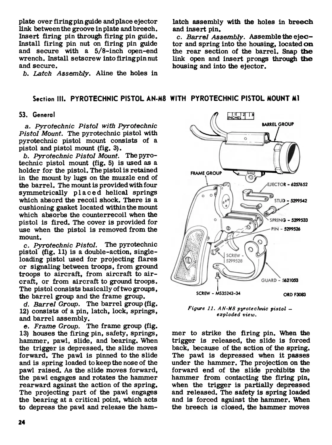
53. General
a. Pyrotechnic Pistol with Pyrotechnic
Pistol Mount. The pyrotechnic pistol with
pyrotechnic pistol mount consists of a
pistol and pistol mount (fig. 3).
b. Pyrotechnic Pistol Mount. The pyro-
technic pistol mount (fig. 5) is used as a
holder for the pistol. The pistol is retained
in the mount by lugs on the muzzle end of
the barrel. The mount is provided with four
symmetrically placed helical springs
which absord the recoil shock. There is a
cushioning gasket located within the mount
which absorbs the counterrecoil when the
pistol is fired. The cover is provided for
use when the pistol is removed from the
mount.
c. Pyrotechnic Pistol. The pyrotechnic
pistol (fig. 11) is a double-action, single-
loading pistol used for projecting flares
or signaling between troops, from ground
troops to aircraft, from aircraft to air-
craft, or from aircraft to ground troops.
The pistol consists basically of two groups,
the barrel group and the frame group.
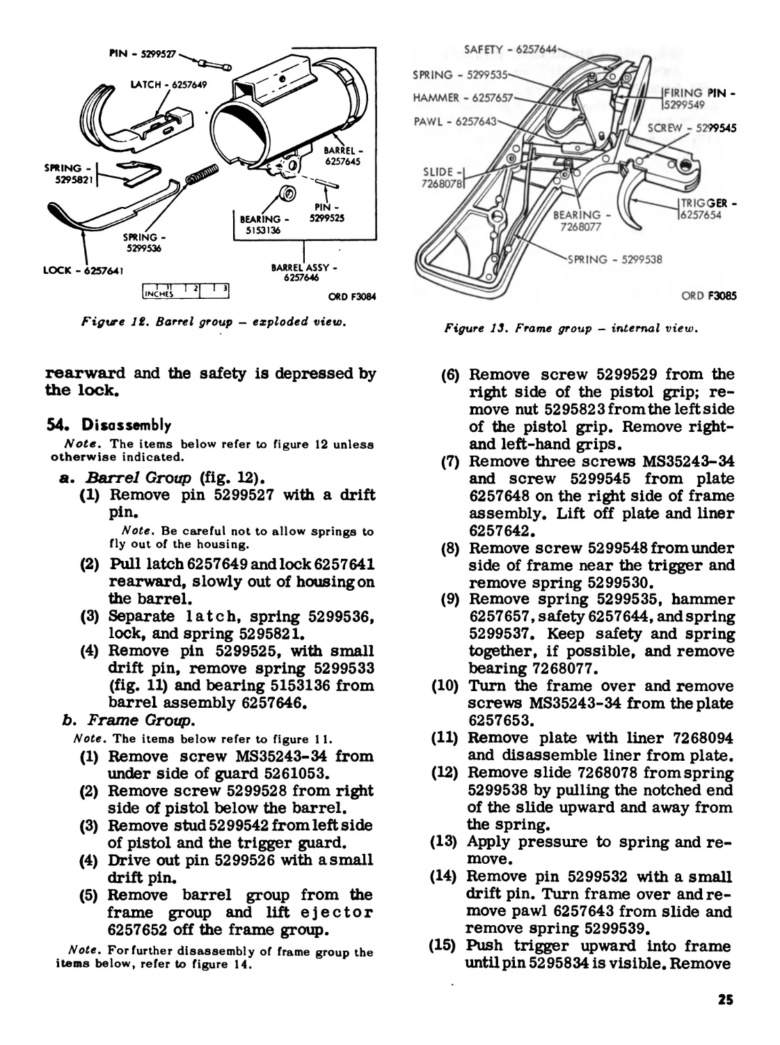
d. Barrel Group. The barrel group (fig.
12) consists of a pin, latch, lock, springs,
and barrel assembly.
e. Frame Group. The frame group (fig.
13) houses the firing pin, safety, springs,
hammer, pawl, slide, and bearing. When
the trigger is depressed, the slide moves
forward. The pawl is pinned to the slide
and is spring loaded to keep the nose of the
pawl raised. As the slide moves forward,
the pawl engages and rotates the hammer
rearward against the action of the spring.
The projecting part of the pawl engages
the bearing at a critical point, which acts
to depress the pawl and release the ham-
WITH PYROTECHNIC PISTOL MOUNT Ml
Figure 11. AN-M8 pyrotechnic pistol —
exploded view.
mer to strike the firing pin. When the
trigger is released, the slide is forced
back, because of the action of the spring.
The pawl is depressed when it passes
under the hammer. The projection on the
forward end of the slide prohibits the
hammer from contacting the firing pin,
when the trigger is partially depressed
and released. The safety is spring loaded
and is forced against the hammer. When
the breech is closed, the hammer moves
24
Figure 12, Barrel group — exploded view.
ORD F3085
Figure 13. Frame group — internal view.
rearward and the safety is depressed by
the lock.
54. Disassembly
Note. The items below refer to figure 12 unless
otherwise indicated.
a. Barrel Group (fig. 12).
(1) Remove pin 5299527 with a drift
pin.
Note. Be careful not to allow springs to
fly out of the housing.
(2) Pull latch 6257649 and lock 6257641
rearward, slowly out of housing on
the barrel.
(3) Separate latch, spring 5299536,
lock, and spring 5295821.
(4) Remove pin 5299525, with small
drift pin, remove spring 5299533
(fig. 11) and bearing 5153136 from
barrel assembly 6257646.
b. Frame Group.
Note. The items below refer to figure 11.
(1) Remove screw MS35243-34 from
under side of guard 5261053.
(2) Remove screw 5299528 from right
side of pistol below the barrel.
(3) Remove stud 5299542 from left side
of pistol and the trigger guard.
(4) Drive out pin 5299526 with a small
drift pin.
(5) Remove barrel group from the
frame group and lift ejector
6257652 off the frame group.
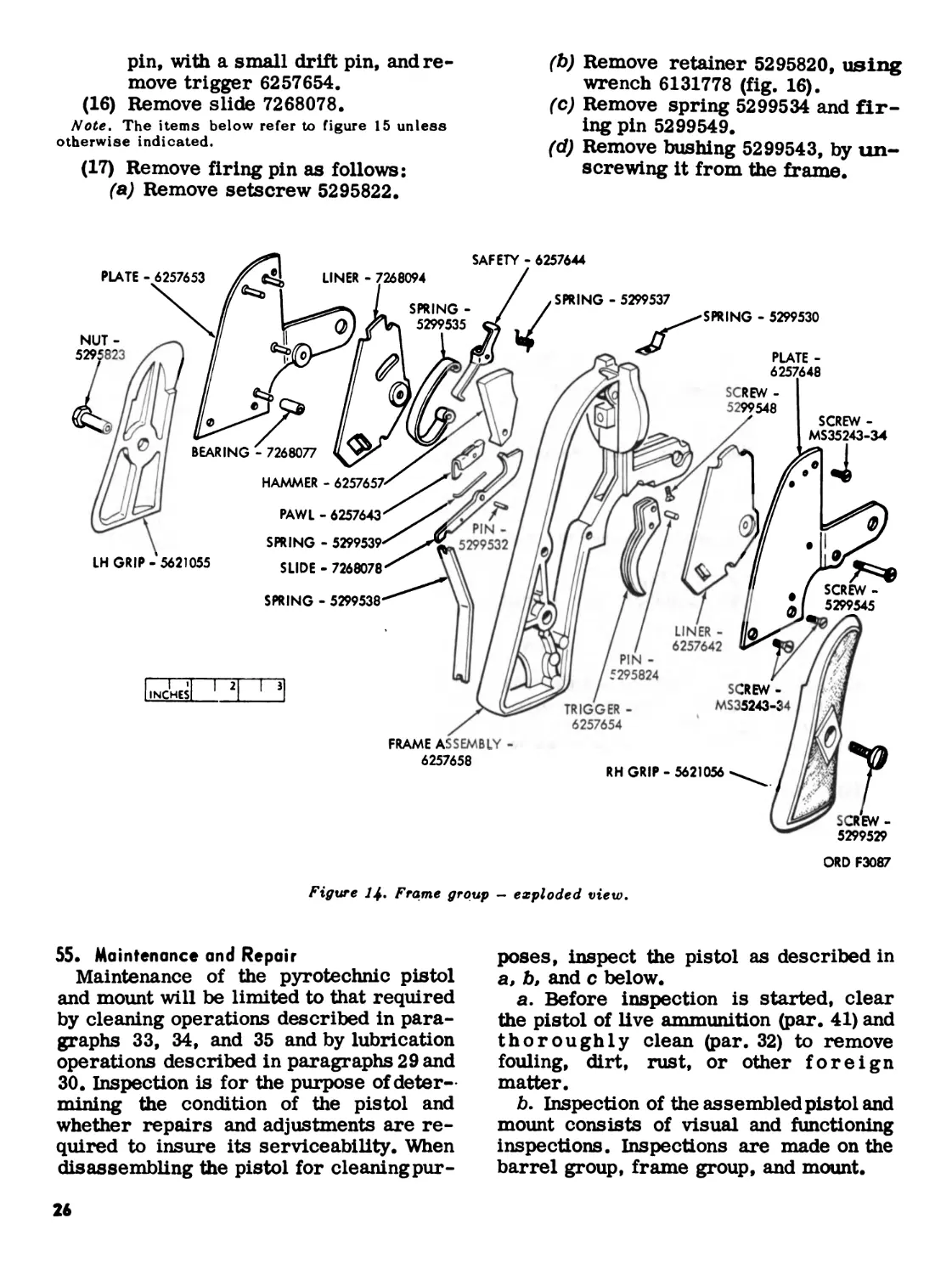
Note. Forfurther disassembly of frame group the
items below, refer to figure 14.
(6) Remove screw 5299529 from the
right side of the pistol grip; re-
move nut 5295823 from the left side
of the pistol grip. Remove right-
and left-hand grips.
(7) Remove three screws MS35243-34
and screw 5299545 from plate
6257648 on the right side of frame
assembly. Lift off plate and liner
6257642.
(8) Remove screw 5299548 from under
side of frame near the trigger and
remove spring 5299530.
(9) Remove spring 5299535, hammer
6257657, safety 6257644, and spring
5299537. Keep safety and spring
together, if possible, and remove
bearing 7268077.
(10) Turn the frame over and remove
screws MS35243-34 from the plate
6257653.
(11) Remove plate with liner 7268094
and disassemble liner from plate.
(12) Remove slide 7268078 from spring
5299538 by pulling the notched end
of the slide upward and away from
the spring.
(13) Apply pressure to spring and re-
move.
(14) Remove pin 5299532 with a small
drift pin. Turn frame over and re-
move pawl 6257643 from slide and
remove spring 5299539.
(15) Push trigger upward into frame
until pin 52 95834 is visible. Remove
25
pin, with a small drift pin, and re-
move trigger 6257654.
(16) Remove slide 7268078.
Note. The items below refer to figure 15 unless
otherwise indicated.
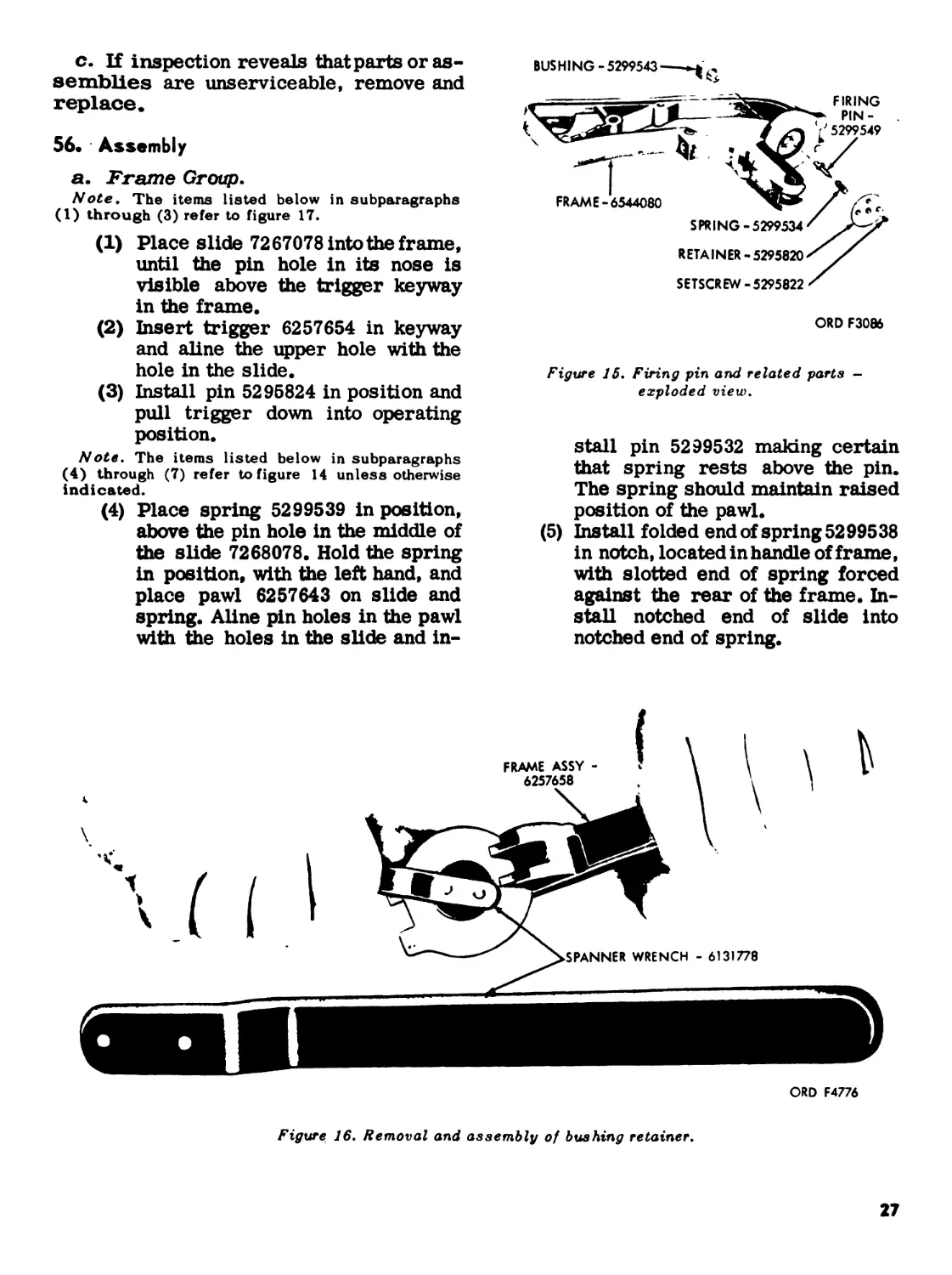
(17) Remove firing pin as follows:
(a) Remove setscrew 5295822.
(b) Remove retainer 5295820, using
wrench 6131778 (fig. 16).
(c) Remove spring 5299534 and fir-
ing pin 5299549.
(d) Remove bushing 5299543, by un-
screwing it from the frame.
SAFETY - 6257644
PLATE - 6257653
LINER - 7268094
SPRING - 5299537
SPRING - 5299530
SPRING -
5299535
NUT -
5295823
CREW -
5299548
SCREW -
MS35243-34
PLATE -
6257648
BEARING - 7268077
HAMMER - 6257657
PAWL - 6257643
SPRING - 5299539
LH GRIP-5621055
SLIDE - 7268078
SPRING - 5299538
ы и и
RH GRIP - 5621056
TRIGGER -
6257654
LINER -
6257642
PIN -
5295824
SCREW -
5299529
FRAME ASSEMBLY -
6257658
ORD F3087
Figure Frame group — exploded view.
PIN -
5299532
SCREW -
5299545
SCREW
MS35243-34
55. Maintenance and Repair
Maintenance of the pyrotechnic pistol
and mount will be limited to that required
by cleaning operations described in para-
graphs 33, 34, and 35 and by lubrication
operations described in paragraphs 29 and
30. Inspection is for the purpose of deter-
mining the condition of the pistol and
whether repairs and adjustments are re-
quired to insure its serviceability. When
disassembling the pistol for cleaningpur-
poses, inspect the pistol as described in
a, b, and c below.
a. Before inspection is started, clear
the pistol of live ammunition (par. 41) and
thoroughly clean (par. 32) to remove
fouling, dirt, rust, or other foreign
matter.
b. Inspection of the assembled pistol and
mount consists of visual and functioning
inspections. Inspections are made on the
barrel group, frame group, and mount.
26
c. If inspection reveals that parts or as-
semblies are unserviceable, remove and
replace.
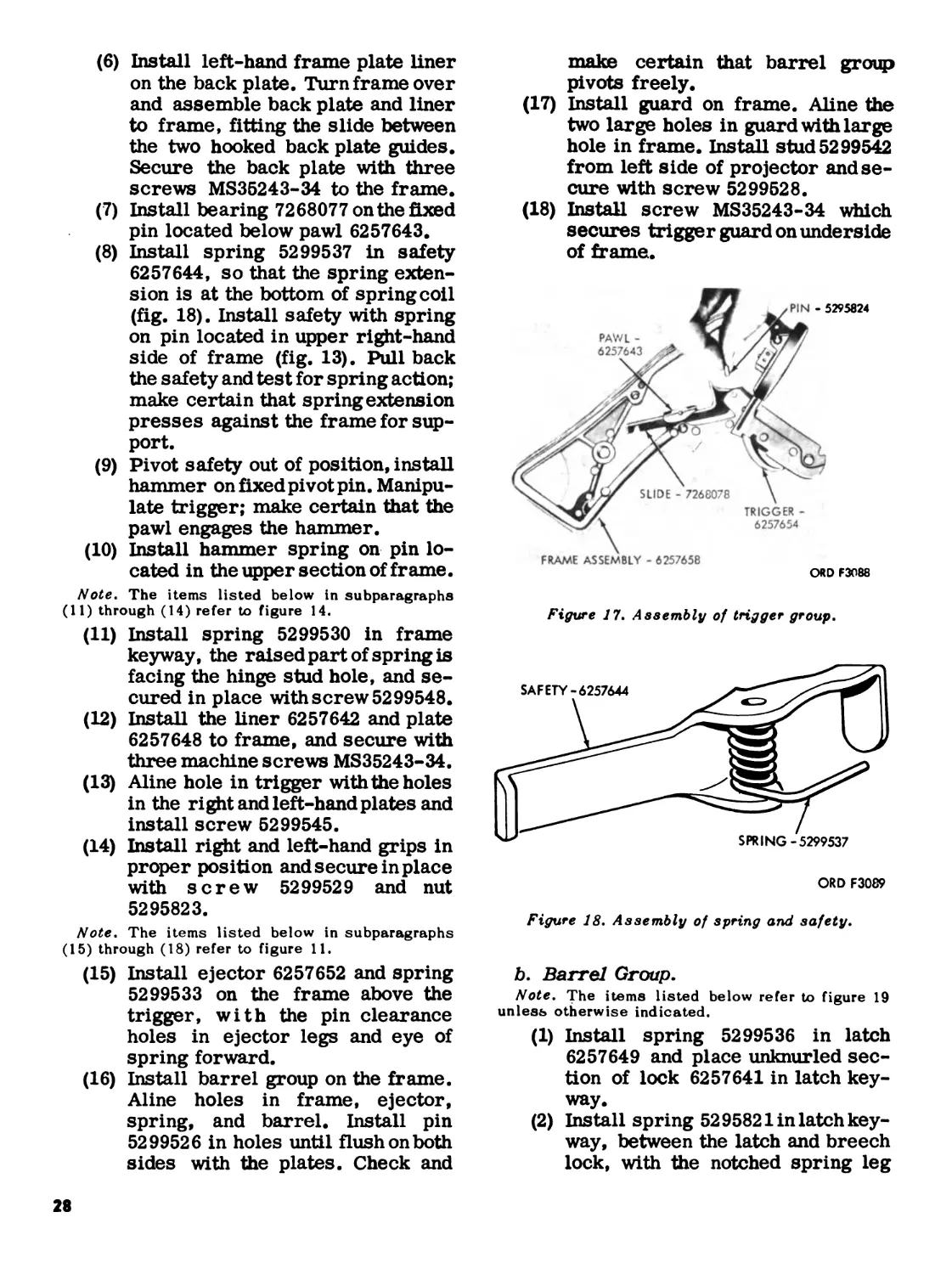
56. Assembly
a. Frame Group.
Note. The items listed below in subparagraphs
(1) through (3) refer to figure 17.
(1) Place slide 7267078 into the frame,
until the pin hole in its nose is
visible above the trigger keyway
in the frame.
(2) Insert trigger 6257654 in keyway
and aline the upper hole with the
hole in the slide.
(3) Install pin 5295824 in position and
pull trigger down into operating
position.
Note. The items listed below in subparagraphs
(4) through (7) refer to figure 14 unless otherwise
indicated.
(4) Place spring 5299539 in position,
above the pin hole in the middle of
the slide 7268078. Hold the spring
in position, with the left hand, and
place pawl 6257643 on slide and
spring. Aline pin holes in the pawl
with the holes in the slide and in-
BUSHING-5299543
ORD F3086
Figure 15. Firing pin and related parts -
exploded view.
stall pin 5299532 making certain
that spring rests above the pin.
The spring should maintain raised
position of the pawl.
(5) Install folded end of spring 5299538
in notch, located in handle of frame,
with slotted end of spring forced
against the rear of the frame. In-
stall notched end of slide into
notched end of spring.
ORD F4776
Figure 16. Removal and assembly of bushing retainer.
27
(6) Install left-hand frame plate liner
on the back plate. Turn frame over
and assemble back plate and liner
to frame, fitting the slide between
the two hooked back plate guides.
Secure the back plate with three
screws MS35243-34 to the frame.
(7) Install bearing 7268077 on the fixed
pin located below pawl 6257643.
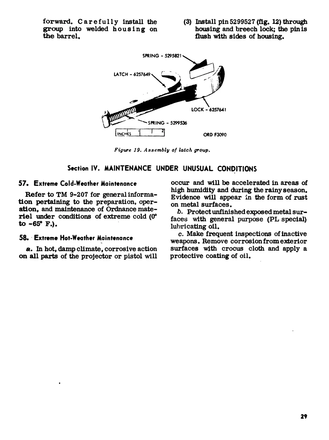
(8) Install spring 5299537 in safety
6257644, so that the spring exten-
sion is at the bottom of spring coil
(fig. 18). Install safety with spring
on pin located in upper right-hand
side of frame (fig. 13). Pull back
the safety and test for spring action;
make certain that spring extension
presses against the frame for sup-
port.
(9) Pivot safety out of position, install
hammer on fixed pivot pin. Manipu-
late trigger; make certain that the
pawl engages the hammer.
(10) Install hammer spring on pin lo-
cated in the upper section of frame.
Note. The items listed below in subparagraphs
(11) through (14) refer to figure 14.
(11) Install spring 5299530 in frame
keyway, the raised part of spring is
facing the hinge stud hole, and se-
cured in place with screw 5299548.
(12) Install the liner 6257642 and plate
6257648 to frame, and secure with
three machine screws MS35243-34.
(13) Aline hole in trigger with the holes
in the right and left-hand plates and
install screw 5299545.
(14) Install right and left-hand grips in
proper position and secure in place
with screw 5299529 and nut
5295823.
Note. The items listed below in subparagraphs
(15) through (18) refer to figure 11.
(15) Install ejector 6257652 and spring
5299533 on the frame above the
trigger, with the pin clearance
holes in ejector legs and eye of
spring forward.
(16) Install barrel group on the frame.
Aline holes in frame, ejector,
spring, and barrel. Install pin
5299526 in holes until flush on both
sides with the plates. Check and
make certain that barrel group
pivots freely.
(17) Install guard on frame. Aline the
two large holes in guard with large
hole in frame. Install stud 5299542
from left side of projector and se-
cure with screw 5299528.
(18) Install screw MS35243-34 which
secures trigger guard on underside
of frame.
Figure 17. Assembly of trigger group.
ORD F3089
Figure 18. Assembly of spring and safety.
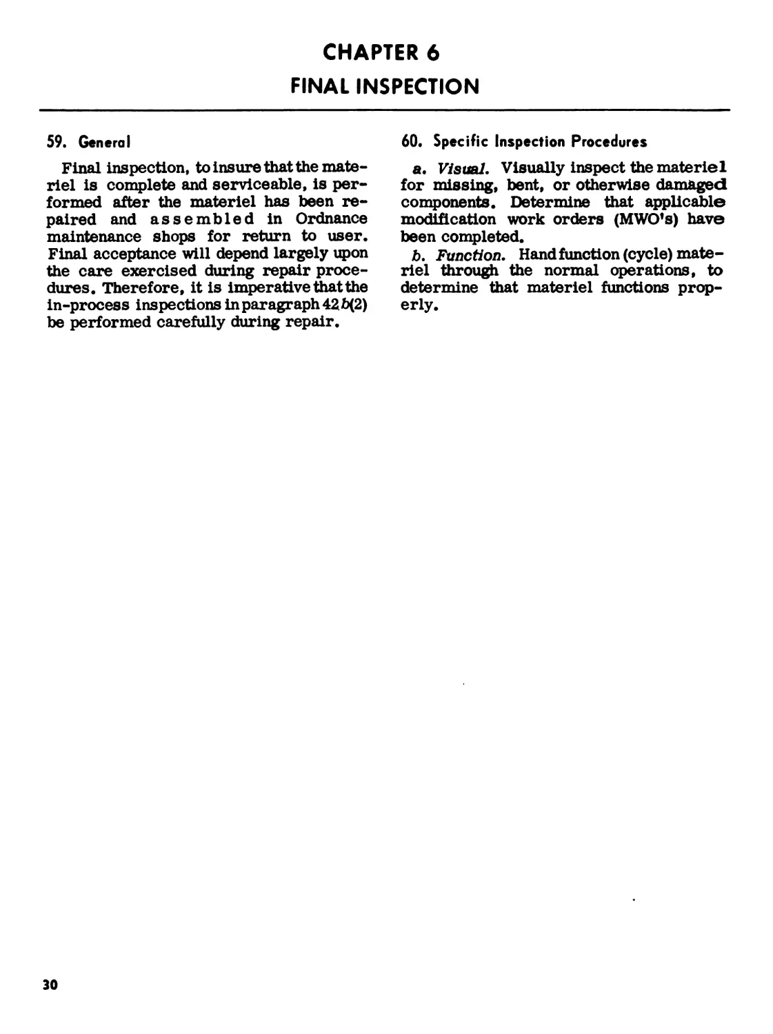
b. Barrel Group.
Note. The items listed below refer to figure 19
unless otherwise indicated.
(1) Install spring 5299536 in latch
6257649 and place unknurled sec-
tion of lock 6257641 in latch key-
way.
(2) Install spring 5295821 in latch key-
way, between the latch and breech
lock, with the notched spring leg
28
forward. Carefully install the
group into welded housing on
the barrel.
(3) Install pin 5299527 (fig. 12) through
housing and breech lock; the pin is
flush with sides of housing.
Figure 19, Assembly of latch group.
Section IV. MAINTENANCE UNDER UNUSUAL CONDITIONS
57. Extreme Cold-Weather Maintenance
Refer to TM 9-207 for general informa-
tion pertaining to the preparation, oper-
ation, and maintenance of Ordnance mate-
riel under conditions of extreme cold (0°
to -65° F.).
58. Extreme Hot-Weather Maintenance
a. In hot, damp climate, corrosive action
on all parts of the projector or pistol will
occur and will be accelerated in areas of
high humidity and during the rainy season.
Evidence will appear in the form of rust
on metal surfaces.
b. Protect unfinished exposed metal sur-
faces with general purpose (PL special)
lubricating oil.
c. Make frequent inspections of inactive
weapons. Remove corrosion from exterior
surfaces with crocus cloth and apply a
protective coating of oil.
29
CHAPTER 6
FINAL INSPECTION
59. General
Final inspection, to insure that the mate-
riel is complete and serviceable, is per-
formed after the materiel has been re-
paired and assembled in Ordnance
maintenance shops for return to user.
Final acceptance will depend largely upon
the care exercised during repair proce-
dures. Therefore, it is imperative that the
in-process inspections in paragraph 42 b{2)
be performed carefully during repair.
60. Specific Inspection Procedures
a. Visual. Visually inspect the materiel
for missing, bent, or otherwise damaged,
components. Determine that applicable
modification work orders (MWO's) have
been completed.
b. Function. Hand function (cycle) mate-
riel through the normal operations, to
determine that materiel functions prop-
erly.
30
CHAPTER 7
AMMUNITION
61. General
Ammunition for use in pyrotechnic pis-
tols and projectors is issued in the form of
complete rounds of fixed ammunition. A
complete round consists of all the ammuni-
tion components required to fire the pistol
or projector once. The complete round
consists of a primer, a delay element,
propelling charge, and a pyrotechnic
charge, all contained in a cartridge case.
The term ’’fixed,” used in connection with
ammunition fired from pyrotechnic dis-
chargers, signifies the propelling charge
is fixed (not adjustable) and that the round
is loaded into the discharger as a unit.
62. Classification
a. Dependent upon use or the effect pro-
duced, ammunition fired from pyrotechnic
dischargers is classified as aircraft il-
lumination signals, aircraft parachute
flares, and projectile air burst simulators.
b. Aircraft illumination signals (fig. 20)
were originally intended for signaling from
aircraft-to-aircraft or from aircraft-to-
ground. The use of ground projectors also
permits their use by ground troops. The
signals are manufactured to produce, upon
firing, a single colored star or two stars
of the same or different colors. The double
star signals are also available with a tracer
element of the same color as one of the
stars. The colors of stars and tracers are
green, red, and yellow. Early models of
the signals (without ”A1” suffix designa-
tions) are available and are assembled
inside of a paper case with a brass head;
other models (with "Al” suffix designa-
tions) are assembled inside of an all
aluminum one-piece or two-piece case.
Some of these signals, with brass heads
and aluminum cases, may be encountered.
Later models ("A2" suffix designations)
are of one-piece rimmed-case construc-
tion with a steel closing cap.
c. The projectile airburst simulator
M27 (fig. 21) is used in training to simulate
the high burst of artillery projectiles, and
produces a smoke puff at the top of its
rise of approximately 650 feet.
d. The aircraft parachute flare M9A1
(fig. 22) is intended for aerial reconnais-
sance. Upon firing, the flare case is pro-
jected from the pistol and, after a 2.5-
second delay, ignited candle and para-
chute are expelled from the case.
e. The projectile air burst simulator
M74 (fig. 20) is intended primarily for
umpires, to simulate air burst of artillery
fire for training troops. Simulators of
earlier manufacture have an aluminum
body and brass base; simulators of later
manufacture have an all aluminum case.
63. Identification
a. General. Ammunition and ammuni-
tion components are completely identified
by the painting and marking (including an
ammunition lot number) on the ammunition
items and on all original packing con-
tainers; refer to figures 20 through 23.
b. Model. To identify a particular de-
sign, a model designation is assigned at
the time the item is classified as an
adopted type. This model designation be-
comes an essential part of the standard
nomenclature and is included in the mark-
ing on the item. The present system of
model designation for a standard item con-
sists of the letter ”M” followed by an
Arabic numeral, for example, ”M9.’’ Mod-
ifications are indicated by adding the letter
”A” and the appropriate Arabic numeral.
Thus, "M9A1” indicates the first modifica-
tion of an item for which the original model
designation was "M9.” Items standardized
for use by both Army and Navy are desig-
nated by ”AN” preceding the model desig-
nation.
c. Ammunition Lot Number. When am-
munition is manufactured, an ammunition
lot number, which becomes an essential
part of the marking, is assigned in ac-
cordance with pertinent specifications.
31
BAND OF RED LETTERS
ORDNANCE INSIGNIA
DESCRIPTIVE NOMENCLATURE
INCLUDING MODEL NUMBER
AIR BURST, M74AI
1.57
APPROX.
LOT PA-9-71
3-62
ALUMINUM (MARKING IN BLACK)
--------3.85 MAX.-----------
ORD D481
Figure £0. Aircraft illumination signals and projectile air burst simulators.
32
PAINTED WHITE
— 163 MAX - -
DESCRIPTIVE NOMENCLATURE
ALUMINUM (MARKING IN BLACK)
3 82 MAX
ORD D48?
Figure tl. Projectile air burst simulator Mil
The lot number is stamped or marked on
every loaded complete round and on all
packing containers. It is required for all
purposes of record, including reports on
condition, functioning, or accident, in
which ammunition may be involved. In any
one lot of ammunition, the components
used in the assembly are manufactured
under as nearly identical conditions as
practicable.
d. Painting. The ammunition described
herein is coated with a colorless lacquer.
In addition to the lacquer, aircraft illu-
mination signals have colored bands or
colored bands of letters painted around
the case, in colors corresponding to the
stars and tracer assembled within. To
provide a ready means of identification,
the closing disk on the projectile air burst
simulator M27 is painted white.
e. Marking.
(1) Onthebody(stenciledunlessother-
wise indicated);
Descriptive nomenclature includ-
ing model number.
Ammunition lot number including
the loader's initials or symbol
(stamped on aircraft parachute
flare).
Month and year of manufacture
(stamped on aircraft parachute
flare).
Ordnance insignia (stamped on air-
craft parachute flare).
"TR" or colored band of letters
("T") on aircraft illumination
signals containing a tracer.
(2) On the base of the aircraft para-
chute flare case (stamped unless
otherwise indicated):
Ammunition lot number including
loader's initials or symbol.
Month and year of manufacture.
Model number (stenciled).
(3) On the head of aircraft illumination
signals (stenciled):
Color of star or stars (paper-cased
signals only).
Model number (aluminum-cased
signals only).
64. Care, Handling, and Preservation
Warning: Pyrotechnics must be handled
with appropriate care at all times. The
explosive elements in primers and expell-
ing charges are particularly sensitive to
undue shock and high temperature. Boxes
containing pyrotechnics should not be
dropped, thrown, tumbled, or dragged.
a. Ammunition is packed to withstand
conditions ordinarily encountered in the
field. Care must be observed to keep pack-
ings from becoming broken or damaged.
All broken packings must be repaired
33
Figure 22. Aircraft parachute flare M9A1
ICC SHIPPING NAME
Figure 63. Packing box for aircraft illumination signals.
immediately and careful attention given to
the transfer of all markingto the newparts.
b. Since pyrotechnics are adversely af-
fected by moisture and high temperature,
due consideration should be given as indi-
cated in (1) and (2) below.
(1) Do not break the moisture-resist-
ant seal until the pyrotechnic is to
be used.
(2) Store pyrotechnics in a dry, well-
ventilated place, out of the direct
rays of the sun, and protected
against excessive or variable tem-
peratures.
c. Do not attempt to disassemble the
complete round or any of its components.
d. Before loading into the discharger,
the round should be free of sand, mud,
moisture, frost, snow, ice, oil, grease,
and any foreign matter.
e. Do not handle duds, as they are ex-
tremely dangerous. They will not be moved
or touched but will be destroyed in place
in accordance with TM 9-1903.
65. Authorized Rounds
The ammunition authorized for use in the
pyrotechnic pistol AN-M8, hand pyrotech-
nic projector M9, and ground signal pro-
jector M1A1 is listed in table V. Standard
nomenclature, which is used in the listing,
completely identifies the ammunition, ex-
cept for ammunition lot number.
35
Table К. Authorized Rounds
Standard nomenclature Complete round Burning time (вес) Candlepower (approx)
Weight (lb) Length (in)
FOR PROJECTOR, SIGNAL, GROUND: M1A1
SIMULATOR. PROJECTILE AIR BURST: M27 0.42 3.82 Instantaneous Smoke cloud only.
FOR PISTOL, PYROTECHNIC: AN-M8
FLARE, AIRCRAFT: parachute, M9A1 2.11 15.05 00 to 70 00M
SIMULATOR, PROJECTILE AIR BURST: M74 or M74A1 0.34 3.85 Instantaneous 000M (flash) (smoke cloud)
FOR PISTOL, PYROTECHNIC: AN-M8 AND PROJECTOR, 1 PYROTECHNIC , HAND: M9
SIGNAL, ILLUMINATION, AIRCRAFT: double eUr, 0.35 3.85 10±3 25M (each star)
AN-M37 series, red-red.
SIGNAL, ILLUMINATION, AIRCRAFT: double eUr, 0.35 3.85 10±3 20M (each star)
AN-M38 series, yelow-yellow. SIGNAL. ILLUMINATION, AIRCRAFT: double star, 0.39 3.85 10±3 20M (each star)
AN-M39 series, green-green. SIGNAL, ILLUMINATION, AIRCRAFT: double eUr, 0.35 3.85 10±3 25M (R star)
AN-M40 series, red-yellow. 20M (Y star)
SIGNAL, ILLUMINATION, AIRCRAFT: double star, 0.39 3.85 10±3 25M (R star)
AN-M41 series, red-green. 20M (G star)
SIGNAL, ILLUMINATION, AIRCRAFT: double star, 0.39 3.85 10±3 25M (G star)
AN-M42 series, green-yellow. 20M (Y star)
SIGNAL, ILLUMINATION, AIRCRAFT: single star, 0.27 3.85 10±3 25M
AN-M43 series, red. SIGNAL, ILLUMINATION, AIRCRAFT: single star, 0.20 3.85 10±3 25M
AN-M44 series, yellow. SIGNAL, ILLUMINATION, AIRCRAFT: single star, 0.32 3.85 10±3 25M
AN-M45 series, green. SIGNAL, ILLUMINATION, AIRCRAFT: AN-M53 series. 0.40 3.85 T, 2.5 to 4 T, 30M
yellow tracer, red-yellow star. Star, 3 to 4.5 R star, 48M Y star, 36M
SIGNAL, ILLUMINATION, AIRCRAFT: AN-M54 series, 0.38 3.85 T, 2.5 to 4 T, 25M
green tracer, red-red star. Star, 3 to 4.5 Star, ea 48M
SIGNAL, ILLUMINATION, AIRCRAFT: AN-M55 series, 0.38 3.85 T, 2.5 to 4 T, 25M
green tracer, green-red star. Star, 3 to 4.5 G star, 20M R star, 48M
SIGNAL, ILLUMINATION, AIRCRAFT: AN-M50 series, 0.38 3.85 Т» 2.5 to 4 T, 30M
green tracer, green-green star. Star, 3 to 4.5 Star, ea 20M
SIGNAL, ILLUMINATION, AIRCRAFT: AN-M57 series, 0.39 3.85 3 to 4.5 Star, ea 48M
red tracer, red-red star. SIGNAL, ILLUMINATION, AIRCRAFT: AN-M58 series, 0.39 3.85 3 to 4.5 G star, 28M
red tracer, green-red star. R star, 48M
approx. - approximate
G - green
M - thousand
R - red
sec - second
T - tracer
Y - yellow
66. Preparation for Firing
After removal from packing materials,
rounds of ammunition for the weapons
described herein are ready for firing.
Rounds prepared for firing but not fired
will be returned to their original condi-
tion and packings and be appropriately
marked. Such rounds will be used first in
subsequent firings, in order that stocks of
opened packings maybe kept to a minimum.
67. Precautions in Firing
The precautions in a throughbelow
should be closely observed, in order to
prevent injury to personnel or damage to
materiel.
a. Rounds should be free of foreign
matter, sand, mud, moisture, frost, snow,
ice, or grease when being loaded into the
weapon.
b. Rounds with cracked, dented, or de-
formed cases or loose closing tops should
not be fired.
c. In discharging signals free hand (with-
out pistol mount) from aircraft, or from
the ground, care will be exercised to aim
so that no damage results to the aircraft
or friendly ground troops.
d. Overhead cover should be provided
36
when firing. When discharging the weapon
free hand (withoutpistol mount), the firer’s
body should be below the level of the muzzle
of the pistol or projector.
e. When firing projectile air burst
simulators over the heads of troops, the
weapon should not be aimed at an ele-
vation of less than 45 degrees to insure
sufficient height of burst. Personnel
should not face toward the point of burst
of the simulator.
f. Due to the powerful recoil, two hands
should be used when firing the aircraft
parachute flare M9A1. Never fire this
flare from a grounded aircraft.
g. Misfires will be handled in accord-
ance with paragraph 19 and AR 385-
63.
b. Appropriate precautions should be
observed when firing in wooded or other
areas containing objects in the line of fire.
In such firing, injury to the firer or
adjacent personnel may result should
the signal or flare strike a branch,
overhead wires, or other object that
would prevent its normal flight and
function.
68. Packing and Marking
a. Packing.
(1) The types and quantities of signals
and flares packed in wooden boxes,
as well as pertinent data, are shown
in table VI.
(2) Complete data are published inSM
9-5-1370.
b. Marking. The information in (1)
through (10) below is marked in black on
packing boxes of pyrotechnics (fig. 23).
(1) Interstate Commerce Commission
(ICC) shipping name.
(2) Federal Stock Number and Depart-
ment of Defense Ammunition Code.
(3) Ammunition lot number.
(4) Gross weight of packing box and
contents.
(5) Cubical displacement of packing
box.
(6) Date loaded.
(7) Quantity and descriptive nomen-
clature of packed items.
(8) Ordnance insignia.
(9) Name and address of box manu-
facturer and date manufactured.
(10) Inspector’s stamp.
Table VI. Ammunition Packing Data
Item Packing Dimensions (in) Volume (cu ft) Weight (lb)
Aircraft parachute flare -— Aircraft illumination signals Simulators 7/mtl cntr, 2 cntr (14 flare)/wdn bx 1/fbr cntr M102, 25 cntr (25 flare)/wdn bx 10/ctn, 8 ctn (80 signal)/wdn bx 12/с tn, 6 ctn (72 signal)/wdn bx 12 ctn, 12 ctn (144 signal)/wdn bx 10/wax dipped wtrprf ctn, 10 ctn (100 simulators)/wdn bx. 10/Svax dipped wtrprf ctn, 8 ctn (80 simulators)/wdn bx. 2/fbr cntr M73, 50 cntr (100 simulators)/ wdn bx. 17-1/4 x 17-3/8 x 9-1/4— 19-1/2 x 15-3/8 x 16-1/8 20 x 11-1/2 x 12-1/8 15-5/8 x 13-5/8 x 12-5/8 28-1/8 x 13-5/8 x 12-5/8 23-7/8 x 11-1/4 x 11-3/4 20-5/8 x 12-1/8 x 11-1/2 23-5/8 x 9-7/8 x 12-5/8— 1.59 2.78 i.eo 1.54 2.78 1.81 1.65 1.66 49.7 99.7 57.1 57.8 92.9 64.3 48.9 70.7
bx — box
cntr — container
ctn — carton
fbr — fiber
mtl — metal
wdn — wooden
wtrprf — waterproof
37
CHAPTER 8
DESTRUCTION OF MATERIEL TO PREVENT ENEMY USE
69. General
a. Destruction of the ground signal pro-
jector M1A1, pyrotechnic pistol AN-M8,
or hand pyrotechnic projector M9, when
subject to capture or abandonment in the
combat zone, will be undertaken by the
using army only when, in the judgement
of the unit commander concerned, such
action is necessary in accordance with
order of or policy established by the army
commander. When the projector or pistol
is in the possession of Ordnance mainte-
nance personnel or in storage, destruction
will be in accordance with FM 9-1 and
applicable portions of the information in
b, c, and d below.
b. The information that follows is for
guidance only. Certain of the procedures
described require the use of explosives
and incendiary grenades, which normally
may not be authorized items of issue to the
using organization. The issue of these and
related materials and the conditions under
which destruction will be effected are
command decisions in each case, accord-
ing to the tactical situation. Of the several
means of destruction, those most generally
applicable are:
(1) Mechanical. Requires axe, pick
mattock, sledge, crowbar, or sim-
ilar implement.
(2) Burning. Requires gasoline, oil,
incendiary grenades, or other
flammables.
(3) Demolition. 1 Requires suitable ex-
plosives or ammunition.
(4) Gunfire A Includes artillery, ma-
chine guns, rifles using rifle gre-
nades, and launchers using antitank
rockets. Under some circum-
stances, hand grenades may be
used.
(5) Disposal. Requires burying in the
ground, dumping in the streams or
marshes, or scattering so widely
as to preclude recovery of essen-
tial parts.
In general, destruction of essential parts,
followed by burning will usually be suf-
ficient to render the materiel useless.
However, selection of the particular
method of destruction requires imagina-
tion and resourcefulness in the utilization
of the facilities at hand under the existing
conditions. Time is usually critical.
c. If destruction to prevent enemy use is
resorted to, the materiel must be so badly
damaged that it cannot be restored to a
usable condition in the combat zone either
by repair or cannibalization. Adequate
destruction, requires that all parts essen-
tial to the operation of the materiel, in-
cluding essential spare parts, be destroyed
or damaged beyond repair. However, when
lack of time and personnel prevents de-
struction of all parts, priority is given to
the destruction of those parts most difficult
to replace. Equally important, the same
essential parts must be destroyed on all
like materiel, so that the enemy cannot
construct one complete unit from several
damaged ones.
d. If destruction by demolition or gun-
fire is directed, due consideration should
be given to the observance of appropriate
safety precautions.
70. Destruction of Ground Signal Projector
Ml Al, Pyrotechnic Pistol AN-M8, or
Hand Pyrotechnic Projector M9
a. Method No. 1—by Mechanical Means.
Using an axe, pick mattock, sledge, or
other heavy implement, thoroughly smash
the projector or pistol. Elapsed time: about
1 minute.
b. Method No. 2 — by Burning. Place the
projector or pistol on a pile of combusti-
ble. Pour gasoline over the combustible.
1 Generally applicable only when the projector or pistol is to be destroyed in conjunction with other
equipment.
38
Ignite and take cover. A hot fire is re-
quired to render the materiel useless.
Elapsed time: about 3 minutes.
duition: When Igniting gasoline, due
consideration should be given to the highly
inflammable nature of gasoline and its
vapor. Carelessness in its use may result
in painful burns.
c. Method No. 3—by Disposal. Bury the
projector or pistol in a suitable hole or
throw it into a stream. Elapsed time: about
2 minutes.
39
CHAPTER 9
SHIPMENT AND STORAGE
71. Shipping Instructions
a. Responsibility. When shipping the
projector or pistol, the officer in charge
of preparing the shipment will be respon-
sible for furnishing materiel in a service-
able condition and properly processed for
shipment, including the preparation of
Army shipping documents.
b. Preparation for Shipment. Personnel
withdrawing the projector or pistol from
storage for shipment must not remove
preservatives other than to insure that
the materiel is complete and serviceable.
It is has been determined that preserva-
tives are not adequate, they must be re-
stored prior to shipment, as prescribed
in paragraph 73.
c. Army Shipping Documents. Prepare
all Army shipping documents in accord-
ance with AR 725-5.
72. Storage Instructions
a. General.
(1) Prepare DD Form 6 for all ship-
ments received in a damaged or
otherwise unsatisfactory condition.
(2) Projectors or pistols received for
storage and already processed for
domestic shipment must not be
reprocessed, unless inspection
performed on receipt of materiel
reveals corrosion, deterioration,
etc.
(3) Completely process projector or
pistol upon receipt directly from
manufacturing facilities or when
preservatives have been rendered
in effective.
(4) Projector or pistol to be prepared
for limited storage must be given
a limited technical inspection and
processed as prescribed in para-
graph 73. The results of the in-
spection and classification will be
noted by attaching tags indicating
any deficiencies.
(5) After inspection, replace or repair
all missing or broken parts. If re-
pairs are beyond the scope of the
unit and materiel will will be in-
activated for an appreciable length
of time, place materiel in limited
storage and attach tags specifying
the repairs needed. The reports of
these conditions will be submitted
by the unit commander for action
by an Ordnance maintenance unit.
(6) When materiel is inactivated, it
will be processed in accordance
with paragraph 73.
b. Inspection During Storage. Perform
a visual inspection periodically to de-
termine general conditions of materiel.
If damage or corrosion is found on any
part, repair or reprocess as prescribed
in paragraph 73.
c. Storage Site. The preferred storage
site is indoors.
73. Cleaning, Preservation, Packaging,
and Packing Instructions
Note. Prior to cleaning, disassemble the grips,
barrel assembly, and frame assembly.
a. Cleaning. Clean all surfaces by one
of the methods indicated in (1) through (3)
below, whichever is applicable or avail-
able at installation. It is of utmost import-
ance that all parts be spotlessly cleaned
prior to application of preservatives and
packaging.
(1) Dip-tank method (metal accesso-
ries only). Place metal parts in a
metal perforated basket and sub-
merge and agitate for approxi-
mately 1 minute in a tank contain-
ing dry-cleaning solvent or volatile
mineral spirits. Remove and sub-
merge into a second tank contain-
ing clean solvent. Agitate for about
1 minute and remove. Submerge
into a third tank containing a sup-
pressor or fingerprint remover
oil (type A) to remove all acids.
Remove and dry the parts thor-
oughly with dry compressed air
40
(provided with special moisture
filter traps), infra-red lamps,
heating oven, or by wiping the part
with clean lint-free cloths.
(2) Scrubbing method. Clean all parts
by scrubbing with cloths soaked in
the solvent (1) above, by wiping
with clean, solvent-soaked cloths.
When the solvent-soaked cloths
used for the first scrubbing oper-
ation become too dirty for further
use, discard them and use clean
solvent-soaked cloths. Clean cloths
must be soaked with clean solvent
for the final wiping operation. Ap-
ply fingerprint remover oil (type
A) and dry thoroughly as pre-
scribed in (1) above.
(3) Vapor degreaser method (metal ac-
cessories only). Tanks containing
a heated solution of trichlorethyl-
ene or perchloroethylene (type П)
are used mostly for degreasing
items that are very greasy, oily,
and grimy and not readily cleaned
by the dip-tank method (1) above.
Place parts in a metal perforated
basket and submerge just below the
vapors in the tank for about 2 or 3
minutes until all the oil or grease
melts and runs off items in the
basket. Remove basket and apply
fingerprint remover oil (type A) to
items and dry thoroughly as pre-
scribed in (1) above.
Warning: Personnel operating
vapor degreasers are cautioned not
to breathe the vapor fumes.
b. Preservation. Remove fingerprints
and apply a coat of oil (PL special), gen-
eral purpose lubricating oil to the metal
portion of the projector and pistol.
c. Packaging.
(1) Ground signal projector M1A1.
(a) Put the projector in atype 1 bar-
rier material bag and secure
with heat.
(b) Put bag and contents into fiber
can container.
(c) Assemble top to container and
seal with tape.
(2) Pyrotechnic pistol AN-M8
with pyrotechnic pistol mount
Ml.
(a) Put each pistol and mount in a
type 1 barrier material bag and
secure with heat.
(b) Construct mount and pistol
supports from corrugated fiber-
board.
(c) Position supports in the corru-
gated fiberboard carton and
locate the wrapped mount and
pistol in the supports within the
fiberboard box.
(d) Close carton, and seal along the
closure seam with 3-inch Kraft
gummed cloth tape or equal.
(3) Hand pyrotechnic projector M9.
(a) Wrap each projector in barrier
material; secure with tape.
(b) Insert wrapped projector into
barrier-type bag and seal with
heat.
(c) Position the wrapped projector
in the fiberboard carton (fig. 26).
(d) Close carton and seal along the
closure seam with 3-inch Kraft
gummed cloth tape or equal.
d. Packing Instructions.
(1) Ground signal projector Ml Al.
Pack in accordance with MIL-C-
3955.
(2) Pyrotechnic pistol AN-M8 with
pyrotechnic pistol mount Ml. Pack
in accordance with MIL-P-3974
and drawing F7267877.
(3) Hand pyrotechnic projector M9.
Pack in accordance with MIL-P-
20102A.
e. Marking Instructions. Standard and
precautionary marking will be ap-
plied to boxes as prescribed in TM 9-
200.
41
APPENDIX I
REFERENCES
1. Publication Indexes
The following indexes should be consulted frequently for the latest changes or revisions
of references given in this appendix and for new publications relating to materiel covered
in this manual.
Index of Army Motion Pictures, Film Strips, Slides, and Phono DA Pam 108-1
Recordings,
Military Publications:
Index of Administrative Publications...............................DA Pam 310-1
Index of Blank Forms...............................................DA Pam 310-2
Index of Graphic Training Aids and Devices.........................DA Pam 310-5
Index of Supply Manuals — Ordnance Corps...........................DA Pam 310-29
Index of Technical Manuals, Technical Bulletins, Supply Bulletins, DA Pam 310-4
Lubrication Orders, and Modification Work Orders.
Index of Training Publications.....................................DA Pam 310-3
2. Supply Manuals
The following supply manuals of the Department of die Army supply manuals pertain
to this materiel:
d. Destruction to Prevent Enemy Use.
Ammunition and Explosives: Land Mines...........................SM 9-5-1345
Ammunition Explosives (Class 1370 Pyrotechnics).................SM 9-5-1370
b. General.
Introduction....................................................ORD 1
c. Repair, Rebuild, and Supply.
Organizational, Field and Depot Maintenance Repair Parts and TM 9-1095-201-25P
Special Tool List for M1A1 Ground Signal Projector, M9 Hand
Pyrotechnic Projector, AN-M8 Pyrotechnic Pistol with Pyro-
technic Pistol Mount Ml.
Shop Set, Field Maintenance, Small Arms (5180-754-0664).........SM 9-4-5180-A18
Shop Set, Field Maintenance, Small Arms, Post, Camp, and SM 9-4-5180-A28
Station, Set A (5180-348-7393).
Tool Kit, Armorer’s........................................... SM 9-4-5180-A56
Tool Kit, Small Arms Repairman’s (5180-357-7770)................SM 9-4-5180-A57
3. Forms
The following forms pertain to this materiel.
DA Form 9-79, Parts Requisition.
DA Form 9-80, Job Order File.
DA Form 9-81, Exchange Part or Unit Identification Tag.
DA Form 828, Job Time Ticket — Individual.
DA Form 829, Rejection Memorandum.
DA Form 2028, Recommended Changes to DA Technical Manual Parts Lists or Supply
Manual 7, 8, or 9.
DA Form 2407, Unsatisfactory Equipment Report.
DD Form 6, Report of Damaged or Improper Shipment.
42
4. Other Publications
The following explanatory publications contain information pertinent to this materiel
and associated equipment,
a. Ammunition.
Ammunition, General...................................................TM 9-1900
Ammunition for Training...............................................TA 23-100
Care, Handling, Preservation, and Destruction of Ammunition...........TM 9-1903
Demolition Materials..................................................TM 9-1946
Disposal of Supplies and Equipment:
Ammunition.......................................................................AR 755-140-1
Explosives and Demolitions............................................FM 5-25
Safety:
Identification of Inert Ammunition and Ammunition Components.........AR 385-65
Regulations for Firing Ammunition for Training, Target Practice, and AR 385-63
Combat.
b. Chemical Attacks and Decontamination.
Chemical, Biological, and Radiological (CBR) Decontamination............TM 3-220
Grenades and Pyrotechnics...............................................FM 23-30
Military Chemistry and Chemical Agents..................................TM 3-215
Small Unit Procedures in Nuclear, Biological, and Chemical Warfare......FM 21-40
c. General.
Dictionary of United States Army Terms................................AR 320-5
Logistics (General): Malfunctions Involving Ammunition and Explosives AR 700-1300-8
Military Symbols......................................................FM 21-30
Military Terms, Abbreviations, and Symbols; Authorized Abbreviations AR 320-50
and Brevity Codes.
Military Training................................................... FM 21-5
Ordnance Direct Support Service....................................FM 9-3
Ordnance General and Depot Support Service............................FM 9-4
Ordnance Service in the Field ........................................FM 9-1
Safety: Accident Reporting and Records................................AR 385-40
Techniques of Military Instructions................................. FM 21-6
d. Inspection and Maintenance.
Basic Cold Weather Manual.............................................FM 31-70
Cleaning and Black Finishing of Ferrous Metals........................TM 9-1861
Cleaning of Ordnance Materiel.........................................TM 9-208-1
Field Inspection and Serviceability Standards for Small Arms Materiel. . ТВ ORD 587
Inspection of Ordnance Materiel in Hands of Troops....................TM 91100
Logistics (General): Unsatisfactory Equipment Report..................AR 700-38
Maintenance of Supplies and Equipment: Command Maintenance Inspec- AR 750-8
tions.
Materials Used for Cleaning, Preserving, Abrading, and Cementing Ord- TM 9-247
nance Materiel; and Related Materials Including Chemicals.
Operation and Maintenance: General Signal Projector Ml Al; Hand Pyro- TM 9-2018/
technic Projector M9; Pyrotechnic Pistol Mount Ml. TO 29A-20-2
Operation and Maintenance of Ordnance Materiel in Extreme Cold TM 9-207
Weather 0° to -65° F.
e. Shipment and Standby or Long Term Storage.
General Packaging Instructions for Ordnance General Supplies..........TM 9-200
Issue of Supplies and Equipment: Preparation, Processing, and Documen- AR 725-5
tation for Requisitioning, Shipping, and Receiving.
Standards for Oversea Shipment and Domestic Issue of Ordnance Materiel ТВ ORD 385
Other Than Ammunition and Army Aircraft.
43
APPENDIX II
MAINTENANCE ALLOCATION CHART
1. Purpose
To allocate specific maintenance operations to the proper echelon on the basis of time,
tools, and skills normally available to various echelons in combat situation and influenced
by maintenance policy and sound maintenance practices as authorized in AR 750-6.
2. Explanation of Columns
The maintenance allocation chart designates overall responsibility for the maintenance
function on end item or assembly. Repair and/or overhaul of major assemblies is desig-
nated by authority of the Army Commander representative, except for the specific repair
subfunctions listed in the maintenance allocation charts. Deviation from maintenance
operations allocated in the maintenance allocation chart is authorized only upon approval
of the Army commander representative.
SERVICE To clean, to preserve, and to re- rable to new by disassembling plenish lubricants. the item to determine the con-
INSPECT To verify serviceability and to dition of each of its component detect incipient electrical or parts and reassembling it using mechanical failure by scrutiny. serviceable, rebuilt, or new as-
REPLACE To substitute serviceable as- semblies, subassemblies, and semblies, subassemblies, and parts, parts for unserviceable com- SYMBOL “Xм The symbol **X” placed in the ponents. appropriate column indicates
REPAIR To restore to a serviceable con- the echelon responsible for dition by replacing unservice- performing that particular main- able parts or by any other action tenance operation, but does not required utilizing tools, equip- necessarily indicate that repair ment and skills available, to will be stocked at that level, include welding, grinding, Echelons higher than the ech- riveting, straightening, adjust- elon marked by "Xм are au- ing, etc. thorized to perform the indi-
OVERHAUL To restore to a condition compa- cated operation.
(D Group No. (3) Component and related operations («) Echelons
let 3d 3d 4th 5th
Ground Signal Projector M1A11095-731-2570
1 Barre/ 7312575:
Service X
Repair ... ... X
2 Body assembly 7312571:
Service X
Repair — ... ... X
3 Breech assembly 7312572;
Service X
Repair — ... ... X
4 Lever firing pin striker 7312572:
Service X
Repair ... ... X
Replace ... ... X
5 Spike assembly 7312574:
Service X
Repair .... ... ... X
Replace — ... ... X
44
(1) Group No. (3) Component and related operations (3) Echelons
1st 2d 3d 4th Sth
Hand pyrotechnic projector M9 1095-726-5668
1 Barrel assembly 5645322:
Service X
Repair ———— — ... X
Replace ———— — ... .... ....
Overhaul ———— ——— ... .... ....
2 Breech assembly 5645323:
Service X
Repair — ... X
Replace ———— — ... X
3 Firing pin assembly 6284607:
Service X
Repair — — —— — ... X
Replace ---- ... X
4 Latch assembly 5645321:
Service X
Repair — — ... X
tyrotechnic pistol AN-M8 with pyrotechnic pistol mount Ml 1095-726-5657
Pistol, tyrotechnic, AN-M8 7265820
1 Barrel assembly 6257646:
Service X
Repair .... ... ... X
2 Frame assembly 6257658:
Service X
Repair — ... ... X
3 Latch: mount 6257649:
Service X
Repair .... ... ... X
Replace .... ... ... X
4 Guard: trigger 5621053:
Service X
Repair .... — - ... X
Replace — ... .— X
Pyrotechnic Pistol Mount Ml 6261074
1 Cover assembly 6261075:
Service X
Repair — — ... X
Replace — — ... X
2 Sleeve recoil (Mfr Assy) 6257670:
Service X
Repair — ... X
3 Ring Connecting Round 5299564:
Service X
Repair ... ... X
Replace — ... ... X
4 Chain: weldless 7161312:
Service X
Repair —— ... ... X
Replace — ... X
45
APPENDIX III
BASIC ISSUE ITEMS LIST
Section I. PREFACE
1. General
This appendix is a list of the basic issue
items that are required for stockage by
first echelon. It includes accessories, at-
tachments , and component assemblies with
quantities thereof, which constitute the
major end item of equipment; and the first
echelon accessories, tools, supplies, spare
assemblies, and repair parts accompany-
ing the equipment, all of which constitute
the major end item for issue to users.
2. Explanation and Definitions
a. Source, Maintenance, and Recover-
ability Code. This column lists a code that
indicates the selection status and source
of supply of the repair part or item, the
lowest echelon capable of installing the
repair part, and the re coverability aspects
of the repair part. An example of this code
is P, O, R. The P indicates that the item
is a mission stockage list repair part that
is procured and stocked on a national
program basis, the О indicates that the
repair part is authorized to first and sec-
ond echelons, and the R indicates that the
repair part is an expendable, recoverable
item. When repair parts supply respon-
sibility has been assigned to a technical
service other than Ordnance, the basic
number of the supplying technical service
is listed in the first position of the source
code, for example, 11 for a Signal Corps
item. Refer to paragraph 3 for an explana-
tion of all codes appearing in this manual.
b. Federal Stock Number. This column
lists the Federal stock number Much has
been assigned by the Cataloging Division,
Defense Logistics Services Center.
c. Description. This column lists the
Federal item name (shown in capital let-
ters) and any additional description re-
quired for supply operations. The ab-
44
breviation w/e (with equipment) Mien used
as a portion of the nomenclature indicates
that the major item or major combination
includes all armament, equipment, acces-
sories, and repair parts issued with the
item. The technical service number is also
included for reference.
d. Unit of Issue. This column lists the
minimum quantity that will be supplied.
Where the unit of issue is shown as ft, in,
etc., such as for bulk materials, the requi-
sition should indicate the exact amount
that is required.
e. Quantity Authorized. This column
lists the quantity of the listed item author-
ized for stockage by first echelon.
f. Illustration. This column indicates
the figure number of the illustration that
depicts the item.
3. Explanation of Codes
a. Technical Service Number. Items
not coded in this column are considered
(9) Ordnance items.
Code Explanation
12 Adjutant General
b. Recoverability. When no code is in-
dicated in column 1(d), the item is expend-
able and not recoverable.
Code Explanation
R Indicates a repair part or assembly
that is expendable and recoverable
and is economically repairable
and, when available, is furnished
by supply on an exchange basis.
4. Suggestions and Recommendations
Notice of discrepancies and recommen-
dations for additions and deletions of repair
parts and special tools should be forwarded
on DA Form 2028 direct to Commanding
General, Headquarters, US Army Weapons
Command, Rock Island Arsenal, Rock
Island, Illinois, ATTN: AMSWE-SMM.
Section II. BASIC ISSUE ITEMS
(1) Source, maintenance, and recoverability code (2) Federal stock No. (3) Description Unit of issue Quantity authorized Illustration «
Technical eervi ce No. Source 'a Maintenance level g Recover* ability
R 1095-726-5657 MAJOR COMBINATION The major combination listed below is requisi- tioned for initial issue only. PISTOL, PYROTECHNIC: AN-M8, w/mount, 1 3
R 1095-726-5820 pistol, pyrotechnic, Ml (7265657). COMPONENTS OF MAJOR COMBINATION The items listed under subheadings below are components of the major combination. Replace- ment for all items will be requisitioned separately under their individual stock numbers. MOUNT, PISTOL, PYROTECHNIC, Ml (6261074) PISTOL, PYROTECHNIC: AN-M8 (7265820) 5 4
R 1095-726-5668 MAJOR ITEMS The major items listed below are requisitioned for initial issue. PROJECTOR, PYROTECHNIC, HAND: M9 1 2
R 1095-731-2570 (7265668). PROJECTOR, SIGNAL, GROUND: M1A1 (7312570) 1 — 1
12 REPAIR PARTS None authorized. TOOLS AND EQUIPMENT None authorized. MISCELLANEOUS MATERIEL The items listed under subheadings below are not issued with the major combination or major items, but are requisitioned in accordance with TOE, TA or as otherwise authorized. Ammunition Ammunition for use with above weapons is shown in SM 9-5-1370. Material issued by Other Technical Services The following items are issued by The Adjutant General in accordance with distribution formula. Additional copies, when required, will be requisi- tioned from The Adjutant General. TECHNICAL MANUAL, TM 9-1095-201-25P
47
INDEX
Paragraph Page
Accidents, field report of................ 3c 4
Allocation, maintenance (See maintenance
allocation)
Ammunition:
Authorized rounds........................ 35 35
Care, handling, and preservation . . . 64 33
Classification........................ 62 31
General............................... 61 31
Identification........................ 63 31
Packing and marking................... 68 37
Precautions in firing................. 67 36
Preparation for firing................ 66 36
Ammunition, packing and marking (See
Packing and marking)
Ammunition packing data (table VI) ... . 68 37
Armorer, preventive maintenance by
(See Preventive maintenance by
armorer)
Assembly (See specific items)
Authorized forms........................ 3b 4
Authorized rounds....................... 65 35
Basic preventive maintenance............ 33 15
Before firing, service (See Service be-
fore firing)
Care, handling, and preservation of
ammunition................................. 64 33
Categories of Inspection................... 40 18
Classification of ammunition............... 62 31
Cleaning................................... 9o 8
Cleaning and care.......................... 32 14
Cleaning instructions.................... 32b 14
Cleaning, preservation, packaging, and
packing instructions....................... 73 40
Cold climates, operation in (See Opera-
tion in cold climates)
Cold-weather lubrication, extreme • • • • 30b 14
Cold-weather maintenance, extreme
(See Maintenance under unusual condi-
tions)
Conditions, general (See General condi-
tions)
Controls...............................10-13 9
Data, tabulated (See Tabulated data)
Description............................... 4 5
Destruction of materiel to prevent
enemy use:
Destruction.......................... 70 38
General.............................. 69 38
Difference between models................. 5 5
Disassembly (See specific items)
During firing service.................... 20 П
Equipment and tools (See Tools and
equipment)
Equipment and tools, special (See
Special tools and equipment)
Final inspection:
General..................................... 59 30
Specific inspection procedures • • • • 60 30
Firing...................................... 18 10
Firing, precautions in (See Precautions
in firing)
Firing, preparation for (See Preparation
for firing)
Forms, records, and reports.................. 3 4
General conditions.......................... 22 11
Paragraph Page
General precautions in cleaning........ 32c 15
Ground signal projector, M1A1:
Assembly.............................. 48 22
Disassembly........................... 46 22
General............................... 45 21
Repair................................ 47 22
Hand pyrotechnic projector, M9:
Assembly.................................. 52 23
Disassembly........................... 50 23
General............................... 49 22
Maintenance and repair................ 51 23
Hot climates, operation in (See Opera-
tion in hot climates)
Hot, damp, and salty atmosphere........ 24c 12
Hot, dry climates........................ 24b 12
Hot-weather lubrication, extreme....... 30c 14
Hot-weather maintenance, extreme (Sbe
Maintenance under unusual conditions)
Humid and salt-air conditions, lubrica-
tion for............................... 30d 14
Identification of ammunition........... 63 31
Inspection, categories of (See Cate-
gories of inspection)
Inspection, final (See Final inspection)
Inspection, general....................... 9d 9
Inspection of materiel in the hands of
troops in the field.................... 40a 18
Inspection, Ordnance shop (See Ord-
nance shop inspection)
Inspection, preembarkation (See Pre-
embarkation inspection)
Inspection procedures:
General................................... 41 19
Inspection of materiel in the hands of
troops in the field................. 42 19
Ordnance shop inspections.......... 43 19
Preembarkation inspections of mate-
riel in units alerted for oversea
movement............................ 44 20
Inspection, purpose of (See Purpose of
inspection)
Inspection, scope......................... 38 18
Instructions, cleaning, preservation,
packaging and packing..................... 73 40
Instructions, cleaning (See Cleaning
instructions)
Instructions, lubrication (See Lubrication
instructions)
Introduction............................. 1-7 2-6
Loading................................ 17 10
Lubrication, extreme cold-weather (See
Extreme cold-weather lubrication)
Lubrication, general...................... 9c 8
Lubrication instructions.................. 29 13
Lubrication under unusual conditions... 30 13
Maintenance allocation..................... 2 4
Maintenance and repair..................45-56 21-27
Maintenance instructions............... 25-37 13-17
Maintenance under unusual conditions:
Extreme cold-weather maintenance 57 29
Extreme hot-weather maintenance • • 58 29
Marking of ammunition.................... 68b 37
Misfire................................... 19 11
Nameplate and serial number................ 6 5
Operating instructions.................. 8-24 8-12
48
Paragraph Page
Operators preventive-maintenance
services (table П)...................... 34 13
Operation in cold climates......... • 23 12
Operation in hot climates............... 24 12
Operation under sandy or dusty condi-
tions, lubrication after............... 30e 14
Operation under unusual conditions .... 22-24 11-12
Operation under usual conditions......14-21 9-11
Ordnance shop Inspection............... 40b 18
Packing and marking of ammunition ... 88 37
Packing of ammunition.................. 88a 37
Precautions in cleaning (See General
precautions in cleaning)
Precautions in firing................... 87 36
Preembarkation inspection............. 40c 19
Preparation for firing.................. 66 36
Preparation for use..................... 15 9
Preventive maintenance, basic (See
basic preventive maintenance)
Preventive maintenance, schedule of (See
Schedule of preventive maintenance)
Preventive maintenance services ..... 31-37 14-17
Preventive-maintenance services by
armorer (table Ш).................... 35 16
Purpose of inspection................... 39 18
Pyrotechnic pistol AN-M8 with pyro-
technic pistol mount Ml:
Assembly............................. 56 27
Disassembly........................ 54 25
General............................ 53 24
Maintenance and repair............. 55 26
Records, reports, and forms (See
Forms, records, and reports)
Repair parts................... • • • 26 13
Reports, records, and forms (See
Forms, records, and reports)
Paragraph Pago
Rounds, authorized (See Authorized
rounds)
Schedule of preventive maintenance.... 34 15
Scope of manual........................... 1 2
Scope of troubleshooting................. 36 17
Serial number (See Nameplate and serial
number)
Service before firing.................... 16 10
Service during firing.................... 20 11
Service upon receipt of materiel...... 8,9 8
Services.......... ....................... 9 8
Services, preventive-maintenance (See
Preventive-maintenance services)
Shipment and storage.................. 71-73 40
Shipping instructions.................... 71 40
Special tools (table I).................. 28 13
Storage instructions..................... 72 40
Tables:
Ammunition packing data (table VI) ..... 37
Authorized rounds (table V)................ 36
Operators preventive-maintenance serv-
ices (table П)............................. 16
Preventive-maintenance services by
armorer (table Ш).......................... 16
Special tools (table I) ................... 13
Troubleshooting (table IV)................. 17
Tabulated data............................ 7 6
Tools and equipment...................... 27 13
Tools and equipment, special (See
Special tools and equipment)
Troubleshooting (table IV)............ 37 17
Unloading............................. 21 11
Unsatisfactory equipment or materials,
report of............................. 3d 5
49
By Order of Secretary of the Army:
Official:
J. C. LAMBERT,
Major General, United States Army,
The Adjutant General.
EARLE G. WHEELER,
General, United States Агту{
Chief of Staff.
Distribution:
Active Army:
DCSLOG (1)
CNGB (1)
CofEngrs (1)
TSG (1)
CSigO (1)
AMC, Det #1 (ORD) (1)
USA Ord CD Agcy (2)
USCONARC (3)
USA Mat Comd (5)
ARADCOM (2)
ARADCOM Rgn (2)
OS Ma Comd (2) except
USA.IEUR (3)
USARJ (3)
OS Bas e Comd (2)
LOGCOMD (2)
MDW (2)
Armies (3)
Corps (2)
USA Corps (2)
Div (2)
Bde (2)
Regt/Gp/BG (2)
Bn (2)
Co/Btry (1) except
Ord Co (2)
Instl (2)
USA Msl Comd (2)
USA Wpns Comd (2)
USA Ammo Proc & Sup Agcy (2)
GENDEP (OS) (1)
Ord Sec, GENDEP (2)
Ord Dep (OS) (2)
Army Dep (2) except
Raritan (10)
POE (1)
Army Tml (1)
OSA (1)
Ord PG (10)
Ord Arsenals (5)
Springfield Armory (5)
Ord Dist (2)
Br Svc Sch (2) except
USA Ord Sch (50)
NG: State AG (3); Units — Same as Active Army except allowance is one copy to each unit.
US AR: Same as Active Army except allowance is one copy to each unit.
For explanation of abbreviations used, see AR 320*50.
ifir U.S. GOVERNMENT PRINTINS OFFICE» 1988-202-421/80178 Region No. 2
50