/


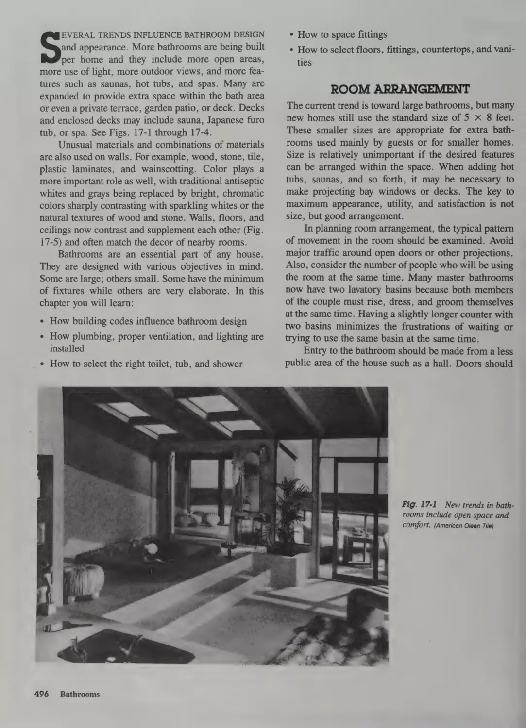


Text
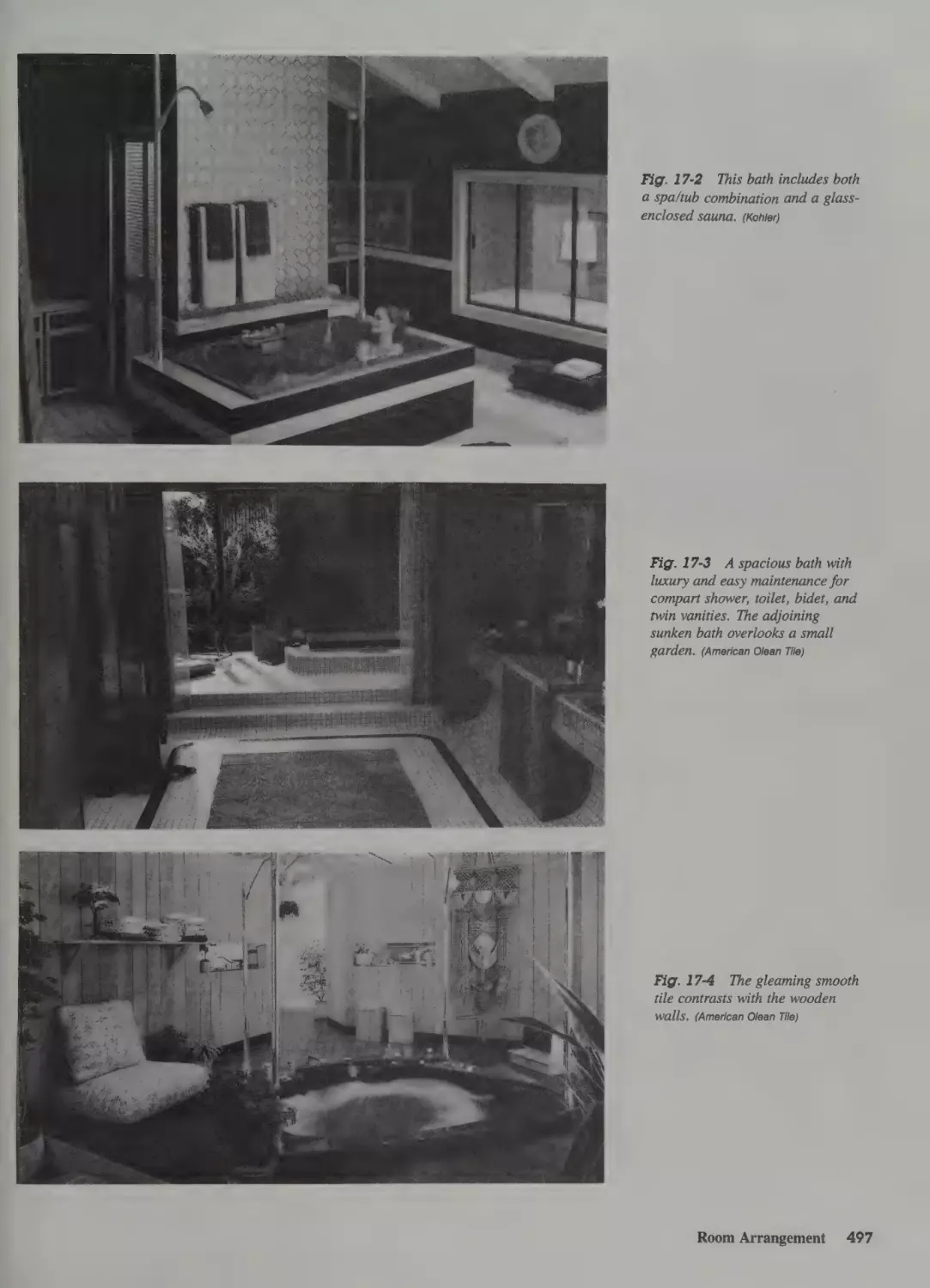
FeSHis ne
She
peat
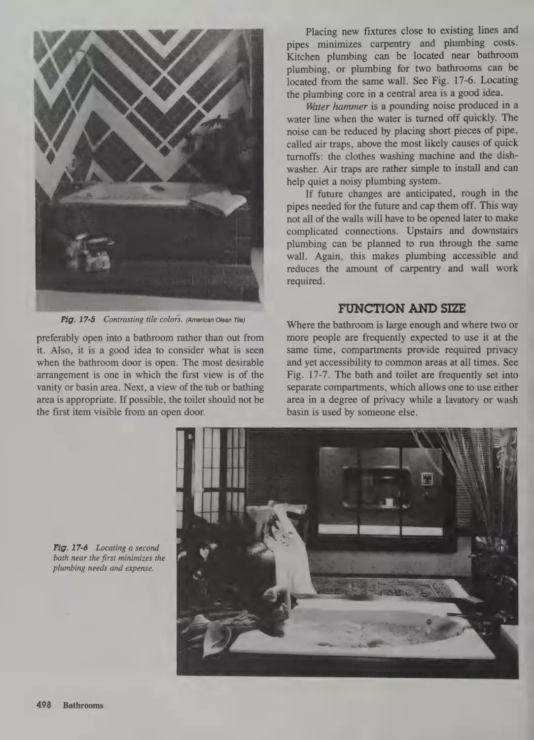
ane
2
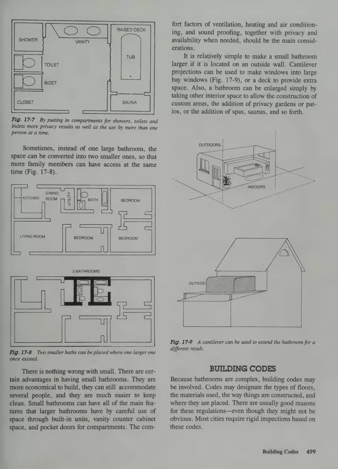
vr
Reece
Sxiiceiee
aie
Rex Miller and
Glenn E. Baker
-/
i
3
7
Carpentry
onstruction
2nd Edition
REX MILLER
State University
College at Buffalo
GLENN E. BAKER
Texas A&M
University
TAB Books
Division of McGraw-Hill
New York SanFrancisco Washington, D.C. Auckland Bogota
Caracas Lisbon London Madrid Mexico City Milan
Montreal New Delhi San Juan Singapore
Sydney Tokyo Toronto
© 1991 by TAB Books.
TAB Books is a division of McGraw-Hill, Inc.
Printed in the United States of America. All rights reserved. The publisher takes no
responsibility for the use of any of the materials or methods described in this book,
nor for the products thereof.
pbk
hoe
T2839 NOW
12 1S MAL IMAL
9°59 857
12.56475 36) 7 8). 9 MALIMAE 939080717 6 15:°°43):2-1
Library of Congress Cataloging-in-Publication Data
Miller, Rex, 1929—
Carpentry & construction / by Rex Miller and Glenn E. Baker.—
2nd ed.
p. cm.
Rev. ed. of: Carpentry fundamentals / Glenn Baker, Rex Miller.
©1981.
Includes index.
ISBN 0-8306-8678-9 (hard) ISBN 0-8306-3678-1 (paper)
1. Carpentry. 2. House construction. I. Baker, Glenn E.
II. Baker, Glenn E. Carpentry fundamentals. III. Title.
_IV. Title: Carpentry and construction.
__THS606.M52 1991 ]
694—dc20-———
91-9383
CIP
Acquisitions Editor: Kim Tabor
Book Editor: Joanne M. Slike
Director of Production: Katherine G. Brown
Cover photograph by Brent Blair, Harrisburg, Pa.
Contents
Preface xi
Acknowledgments
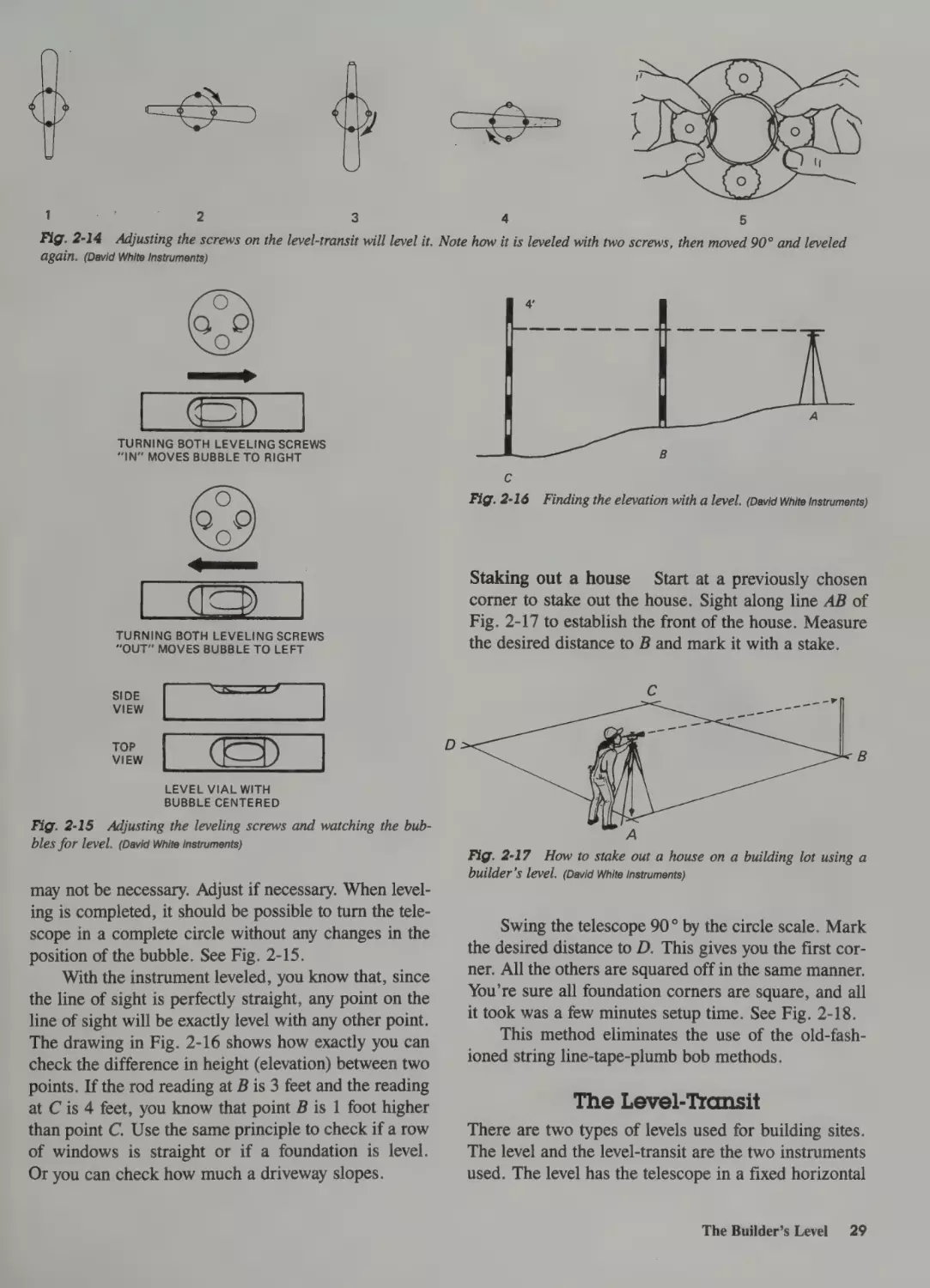
Preparing the Instrument 28
The Level-Transit 29
Using the Level and Level-Transit 30
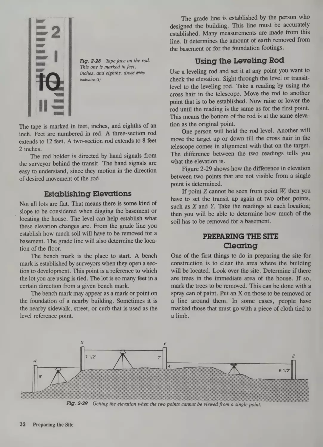
Establishing Elevations 32
Using the Leveling Rod 32
xiii
]Starting the Job
Safety 2
Preparing the Site 32
Other Safety Measures 2
General Safety Rules 3
Safety on the Job 4
Safety Hazards 4
Clearing 32
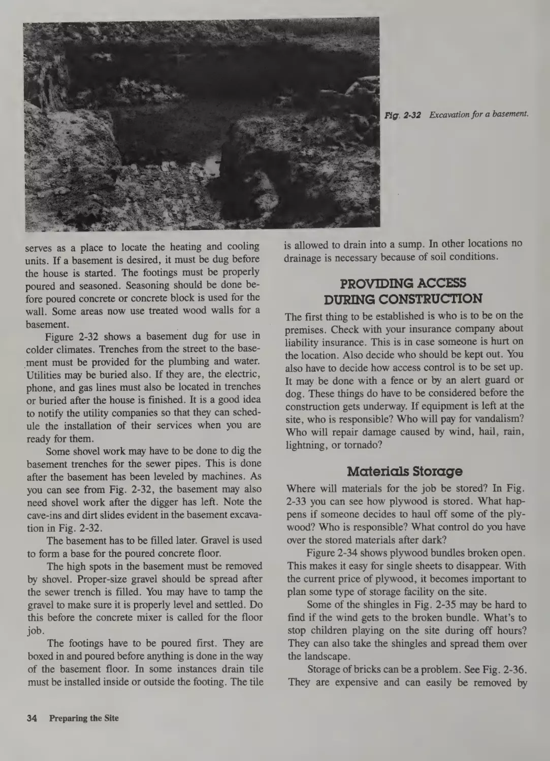
Excavating 33
Providing Access During Construction 34
Using Carpenter Tools 5
Measuring Tools 5
Saws 6
Hammers and Other Small Tools 7
Squares 9
Power Tools 12
Following Correct Sequences
19
Preparing the Site 19
The Basement 19
The Floor 19
Wall Frames 19
Sheathing 20
Roofing 21
Siding 21
Finishing 21
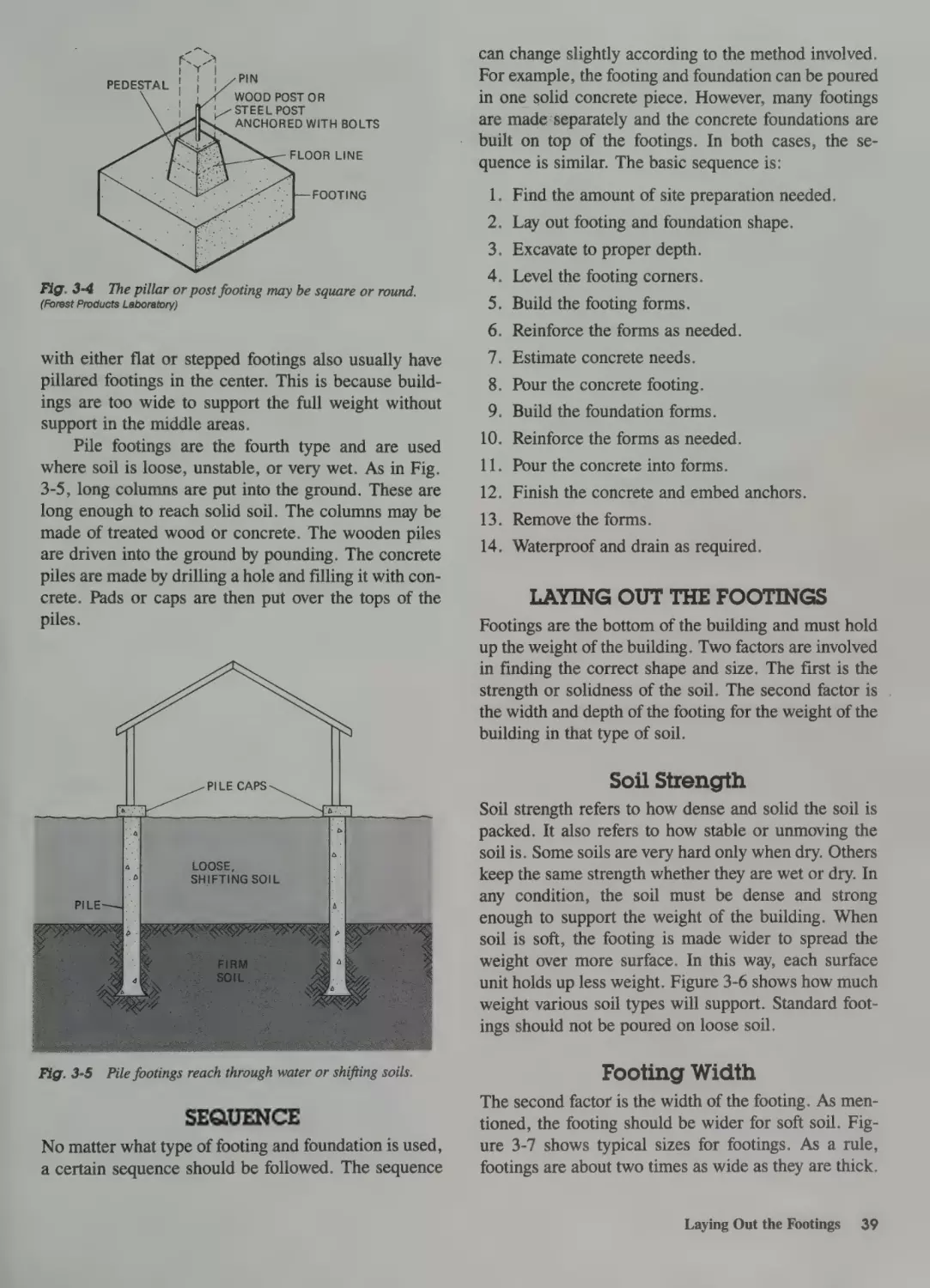
3 Laying Footings & Foundations
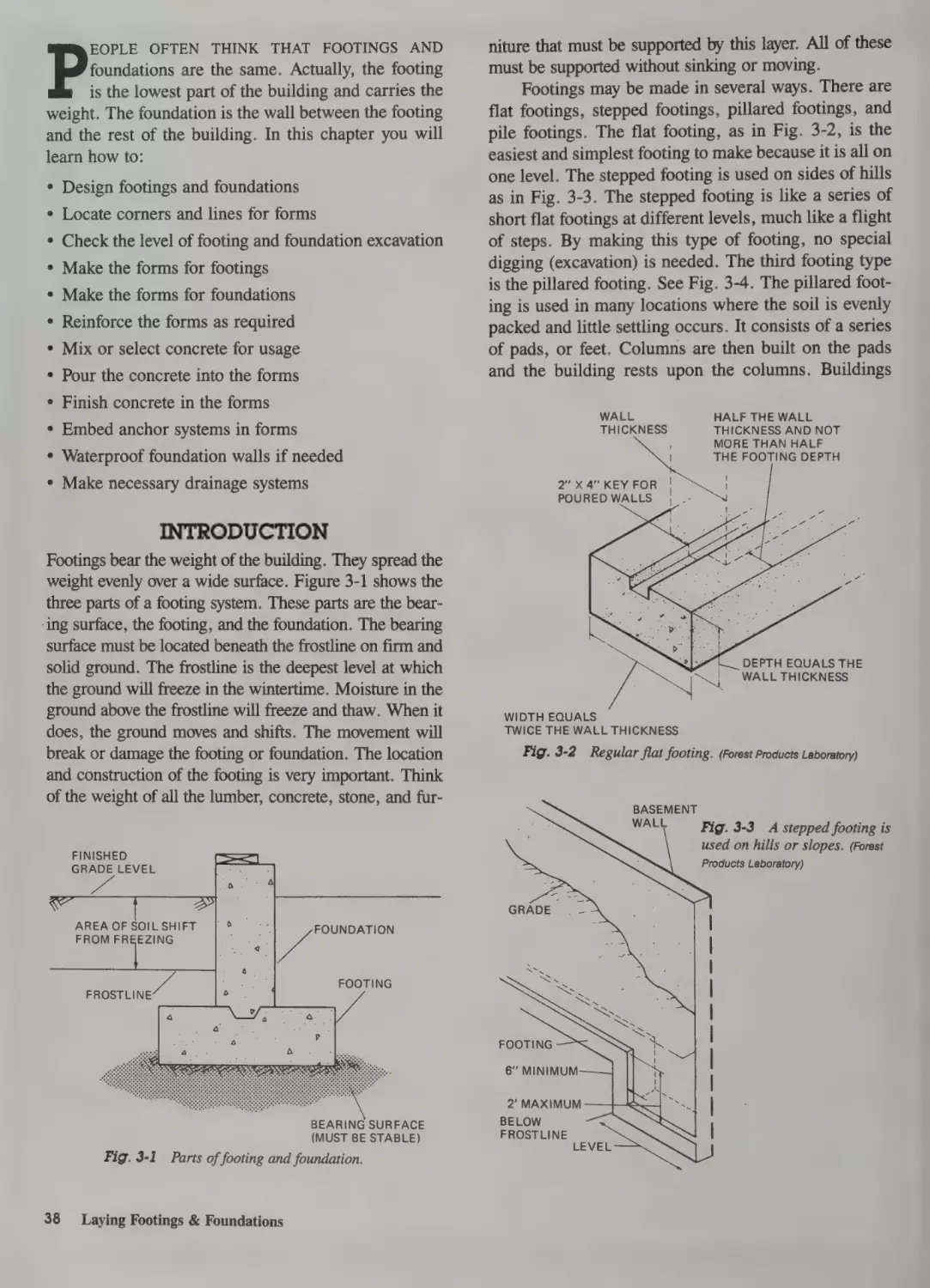
Introduction 38
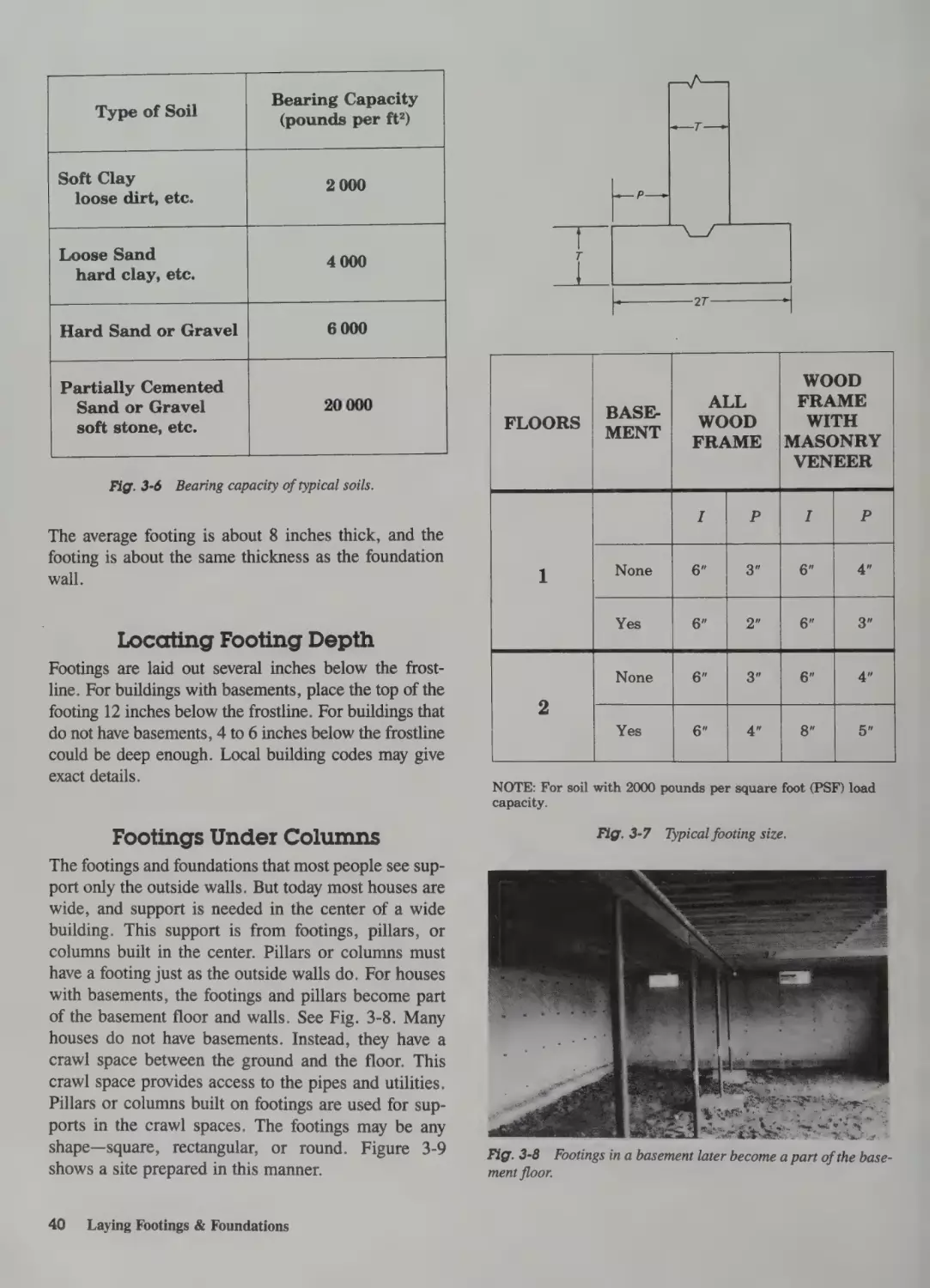
Sequence 39
Laying Out the Footings 39
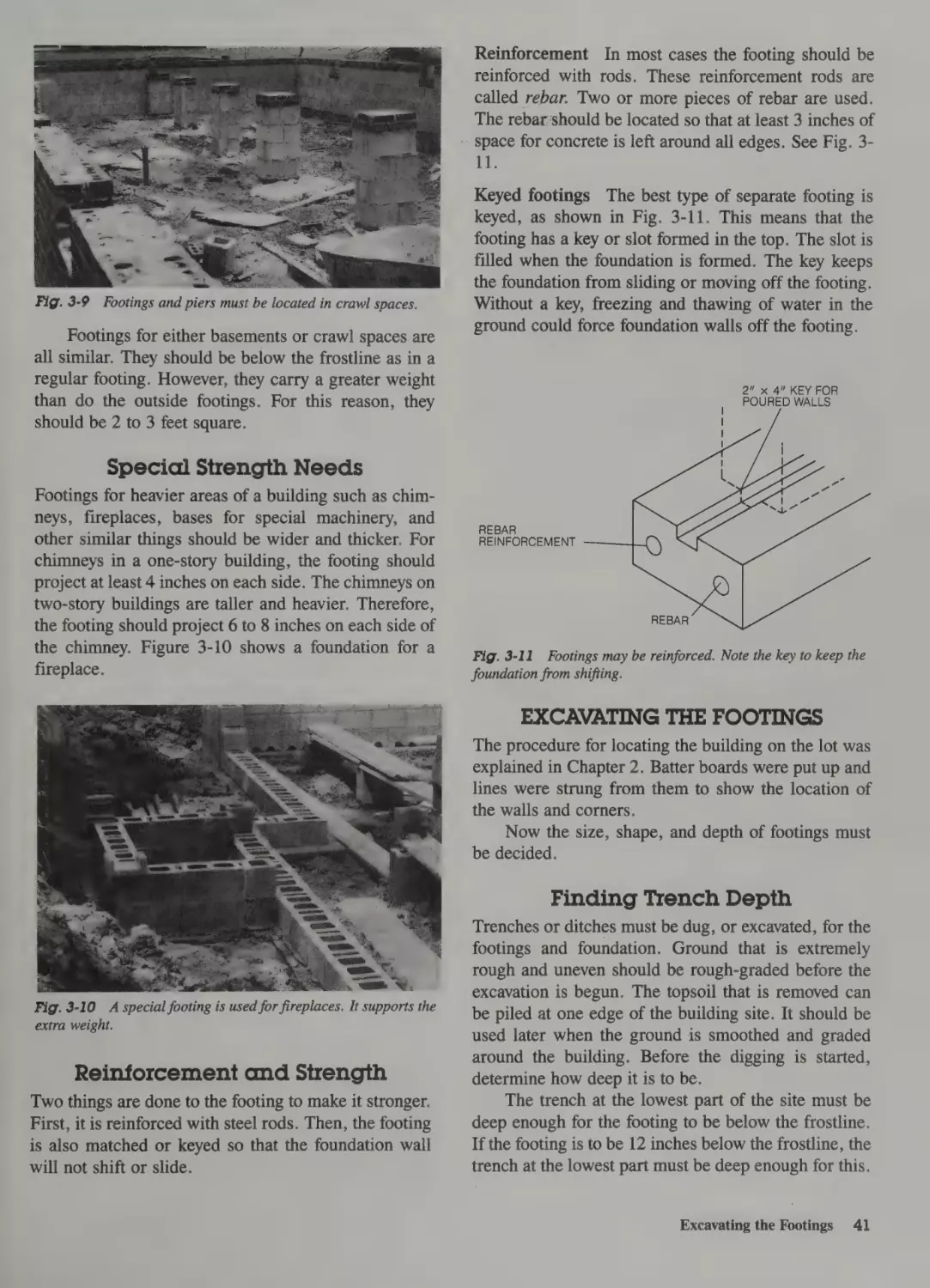
Soil Strength 39
Footing Width 39
Locating Footing Depth 40
Footings Under Columns 40
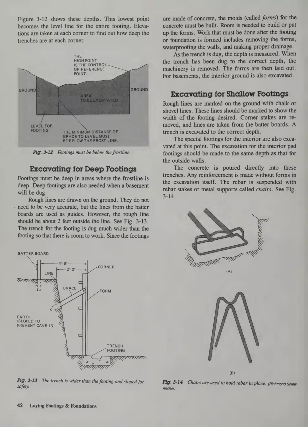
Special Strength Needs 41
Reinforcement and Strength 41
Excavating the Footings 41
2 Preparing the Site
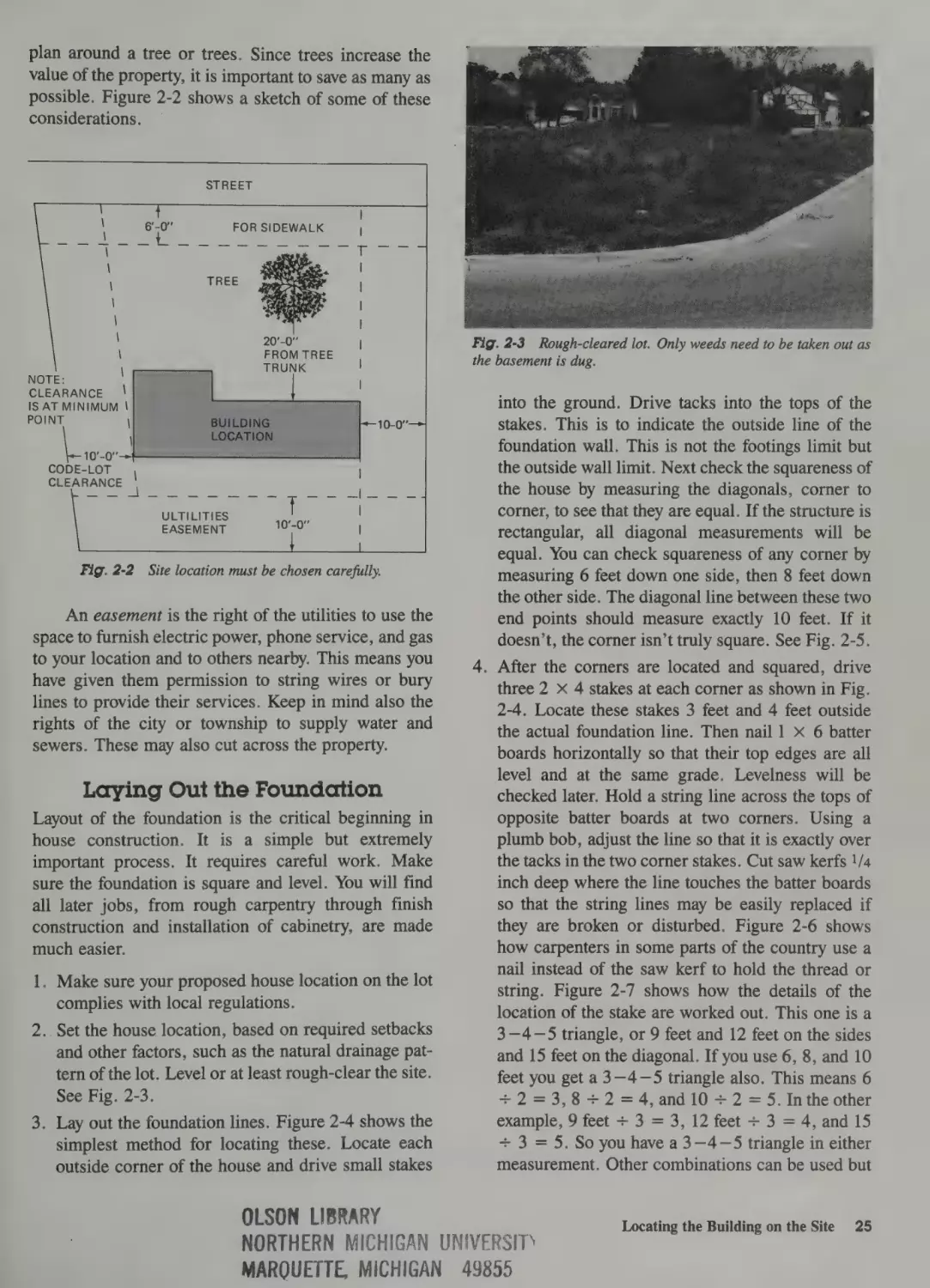
Basic Sequence 24
Locating the Building on the Site 24
Property Boundaries 24
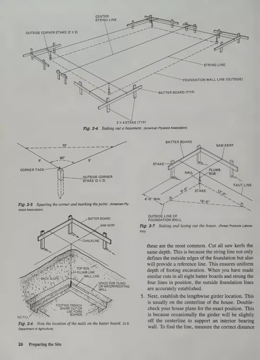
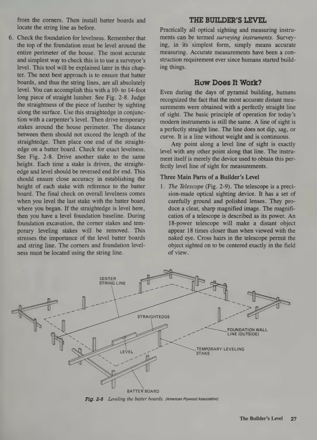
Laying Out the Foundation
The Builder’s Level 27
How Does It Work?
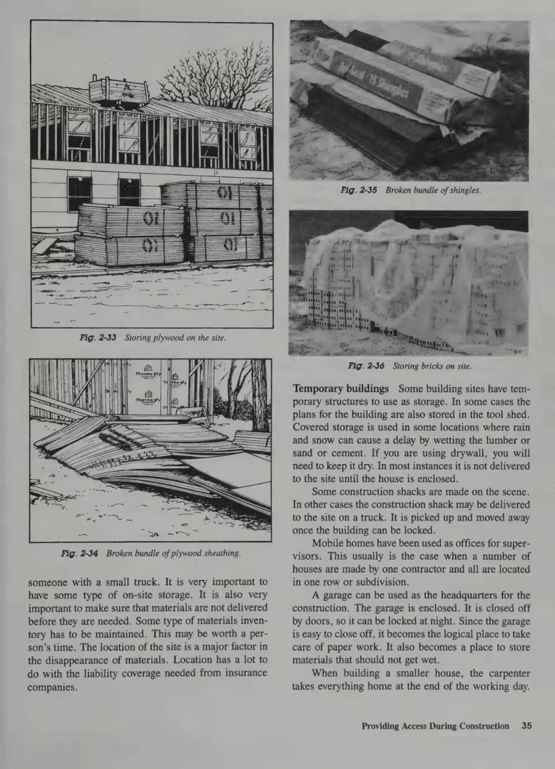
Materials Storage 34
Temporary Utilities 36
Waste Disposal 36
Arranging Delivery Routes 36
27
25
Finding Trench Depth 41
Excavating for Deep Footings 42
Excavating for Shallow Footings 42
Slab Footings and Basements 43
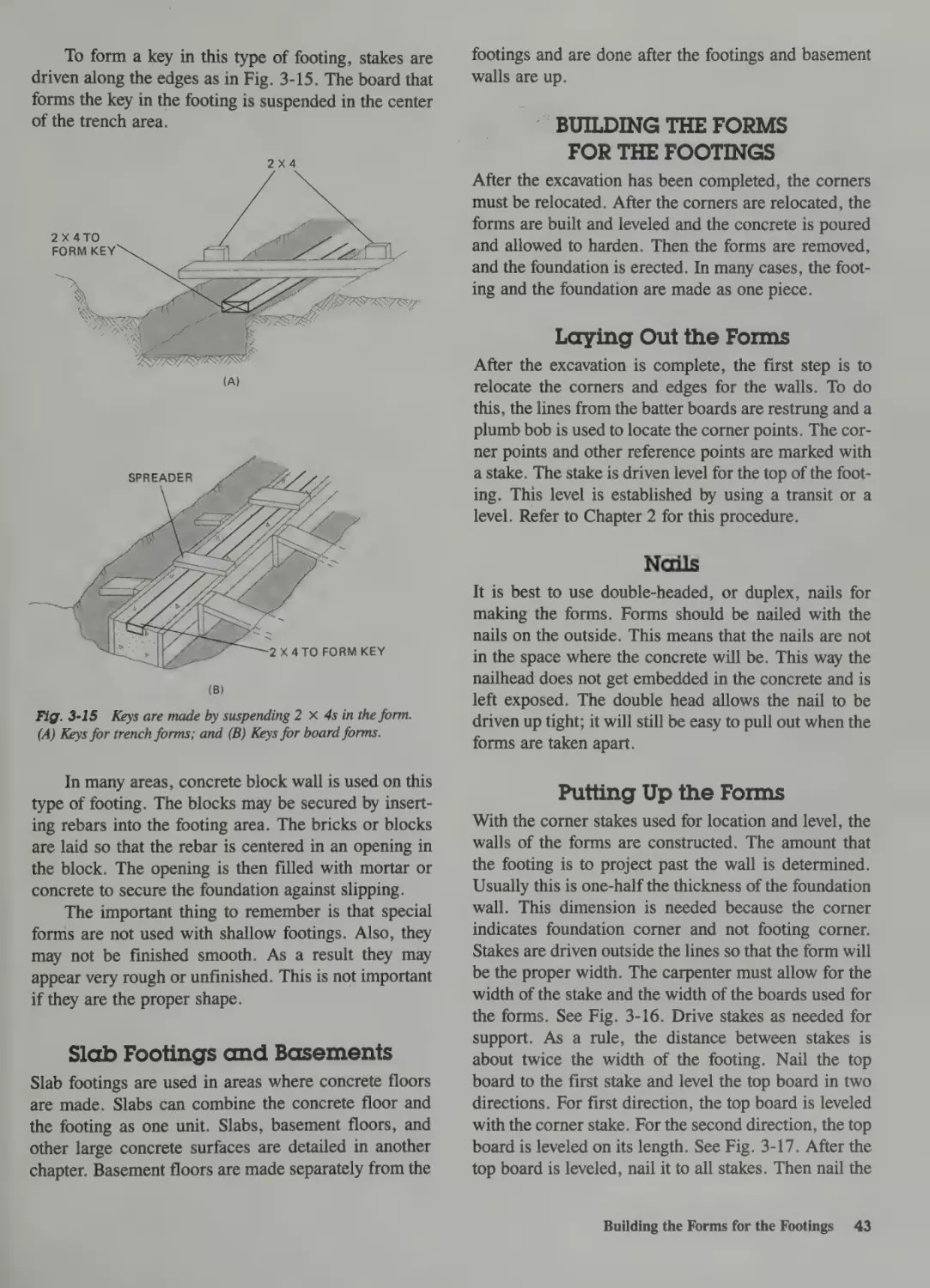
Building the Forms for the Footings 43
Laying Out the Forms 43
Nails 43
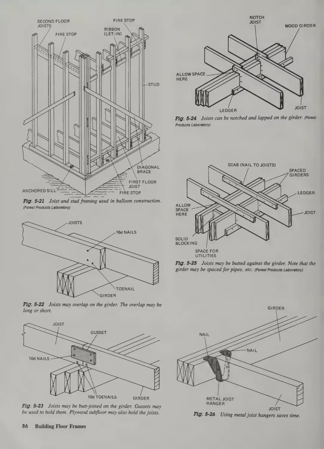
5 Building Floor Frames
Putting Up the Forms 43
Working with Concrete 44
Introduction 78
Sequence 78
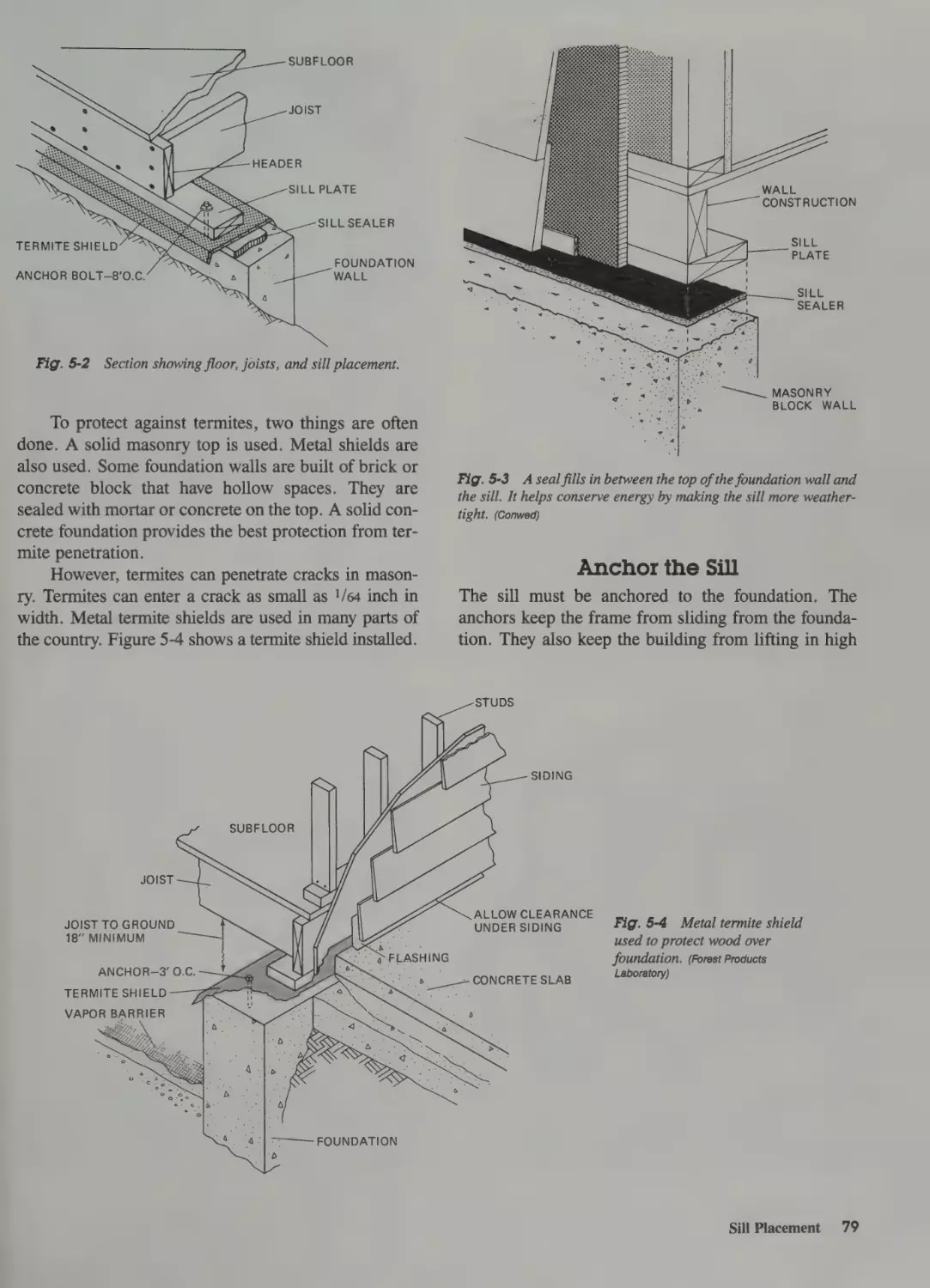
Sill Placement 78
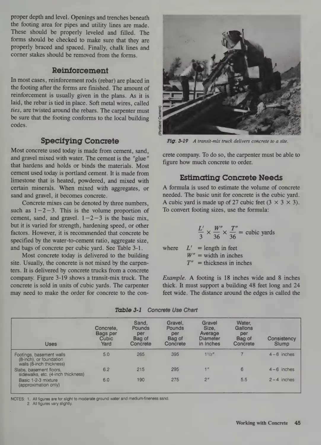
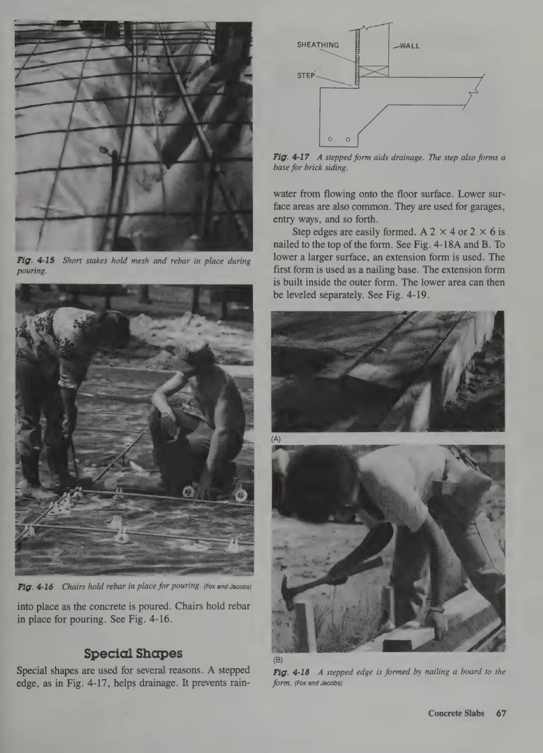
Reinforcement 45
Specifying Concrete 45
Estimating Concrete Needs 45
Pouring the Concrete 46
Anchor the Sill 79
Setting Girders 81
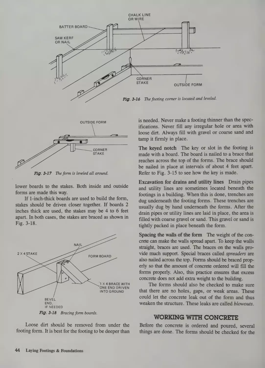
Building the Foundation Forms 47
Making the Forms 47
Joining the Forms Together 47
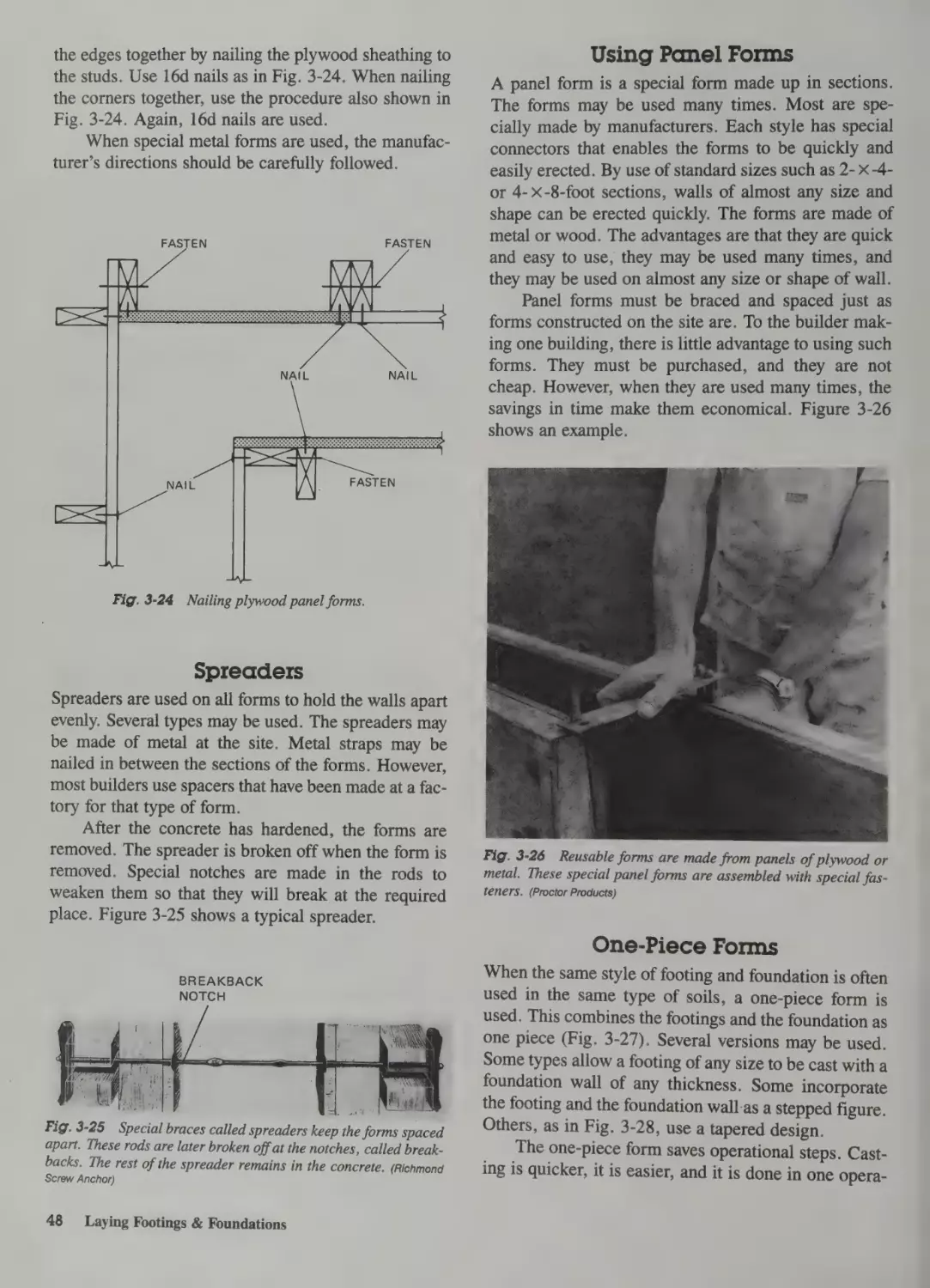
Spreaders 48
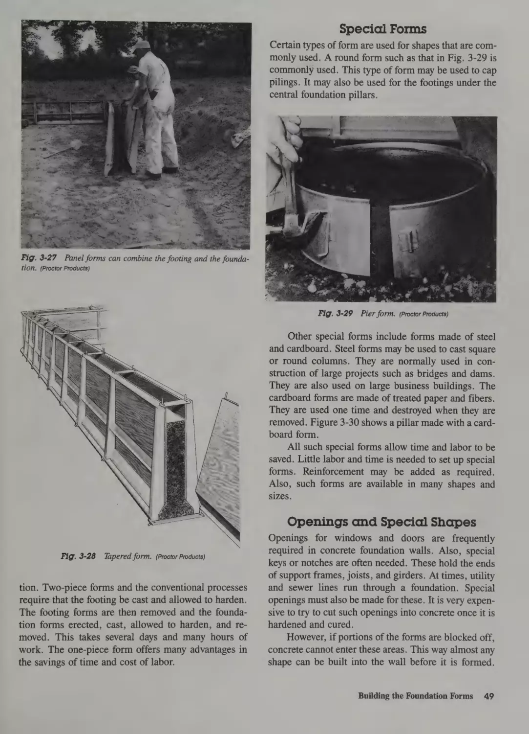
Using Panel Forms 48
One-Piece Forms 48
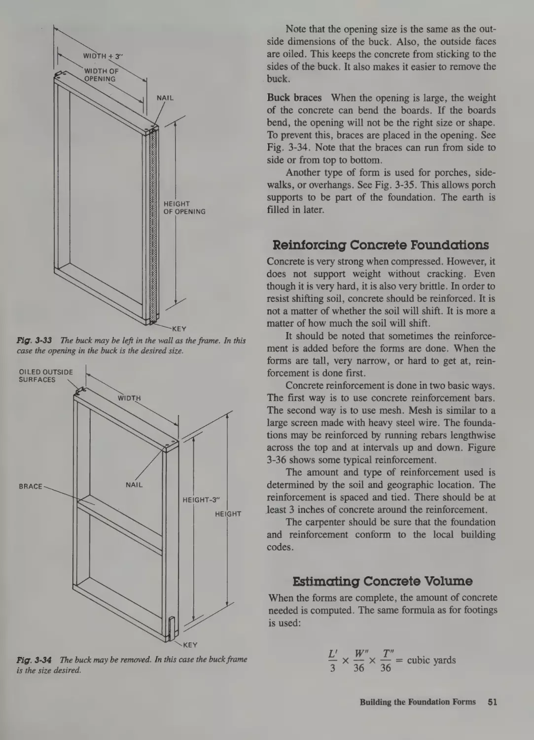
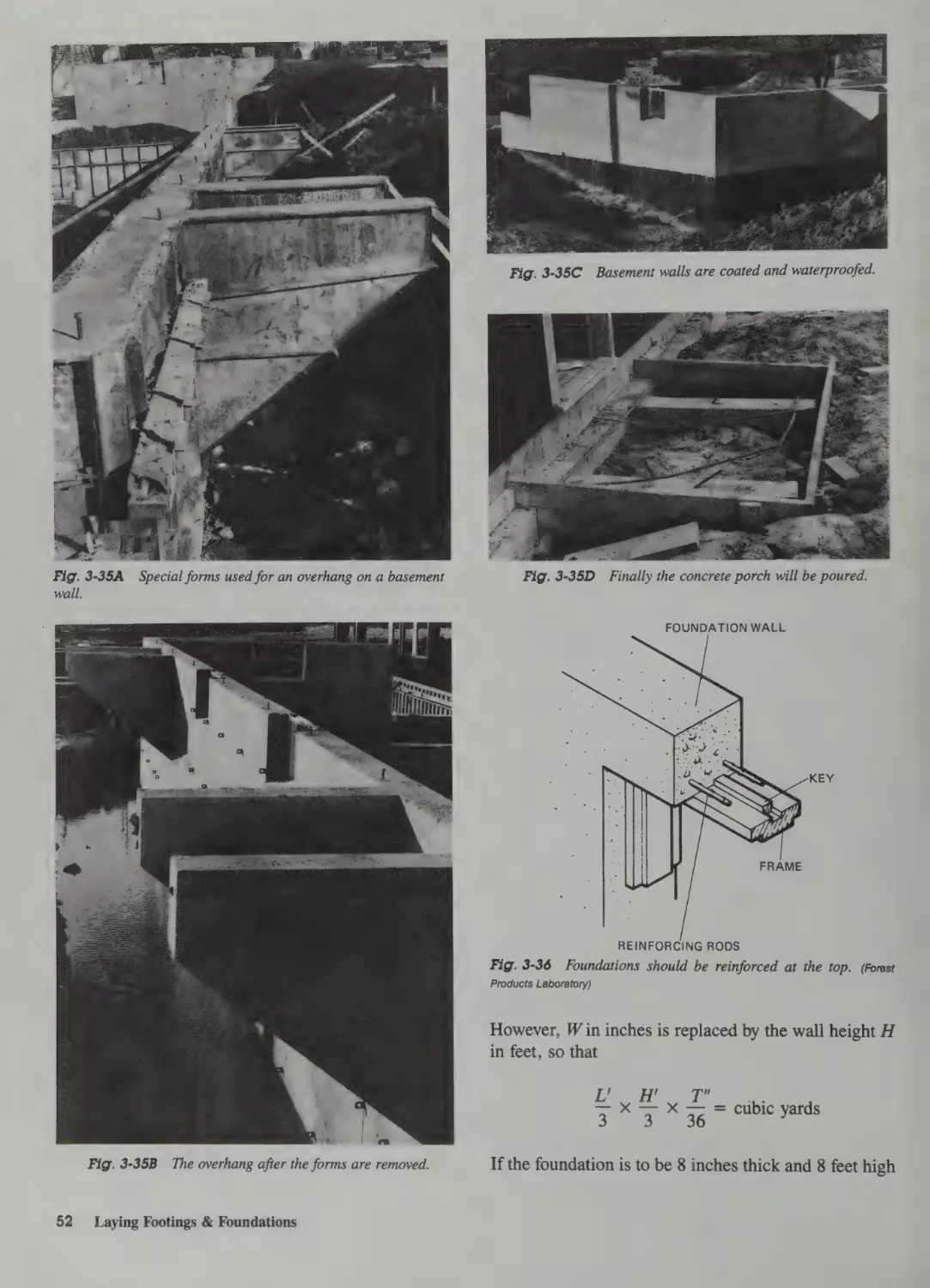
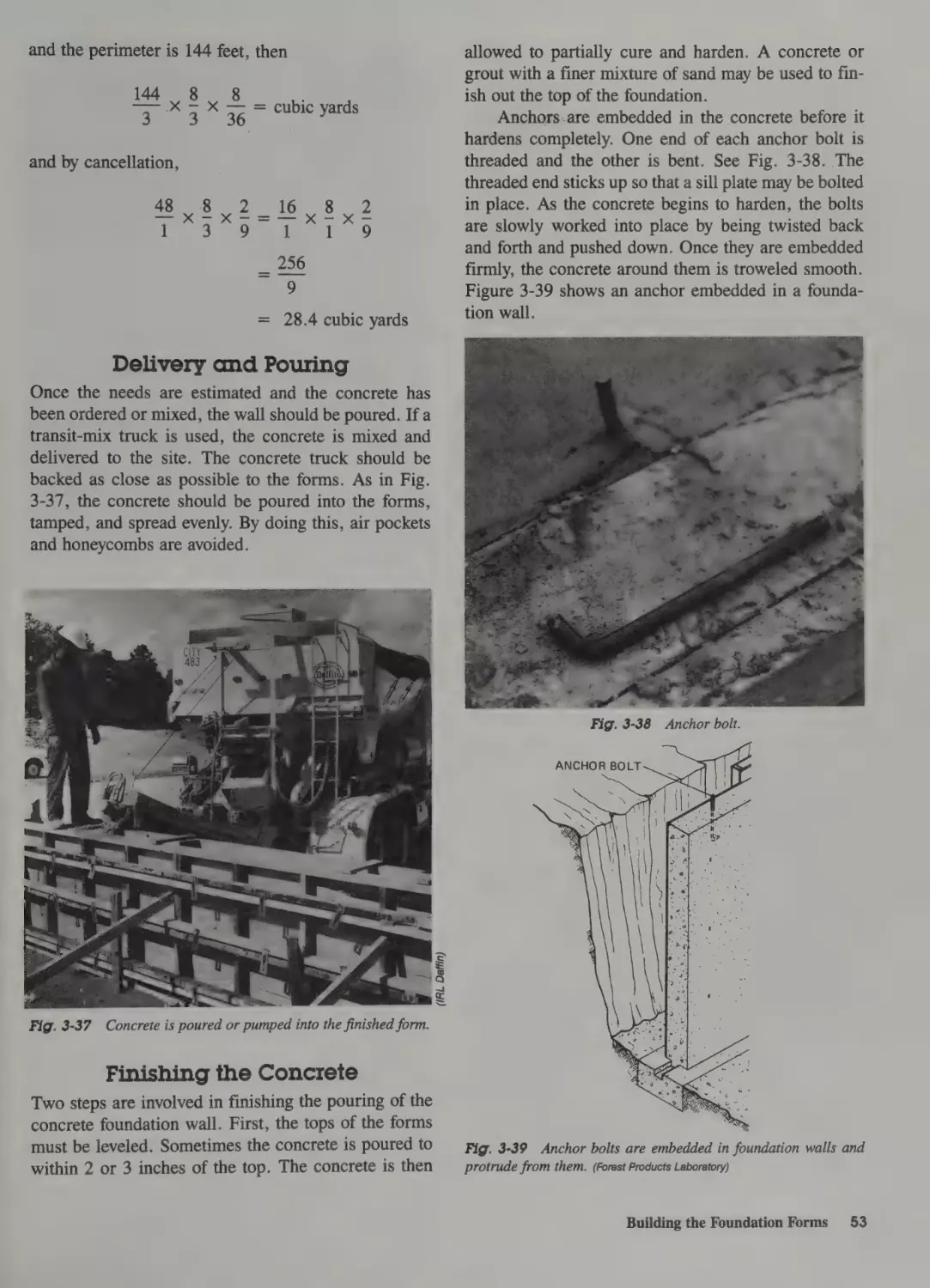
Special Forms 49
Openings and Special Shapes 49
Reinforcing Concrete Foundations
Estimating Concrete Volume 51
Delivery and Pouring 53
Finishing the Concrete 53
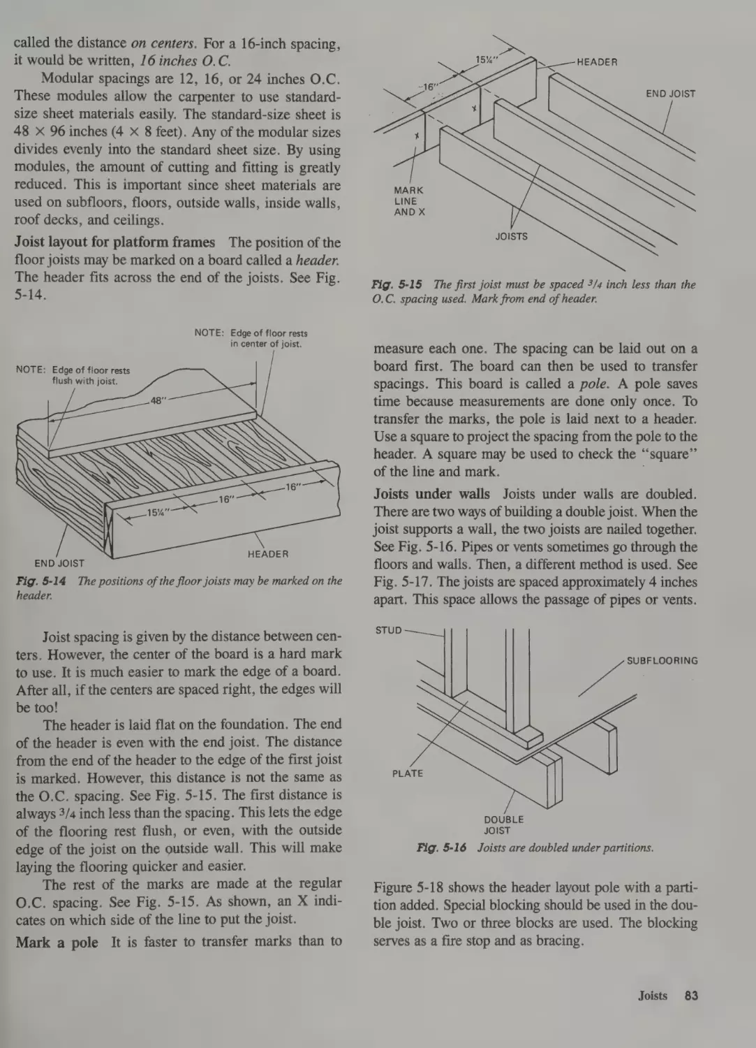
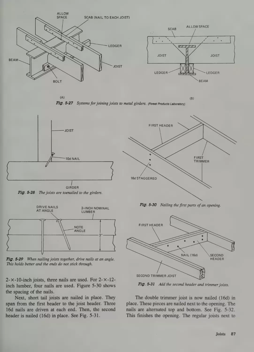
Joists 81
Lay Out the Joists 81
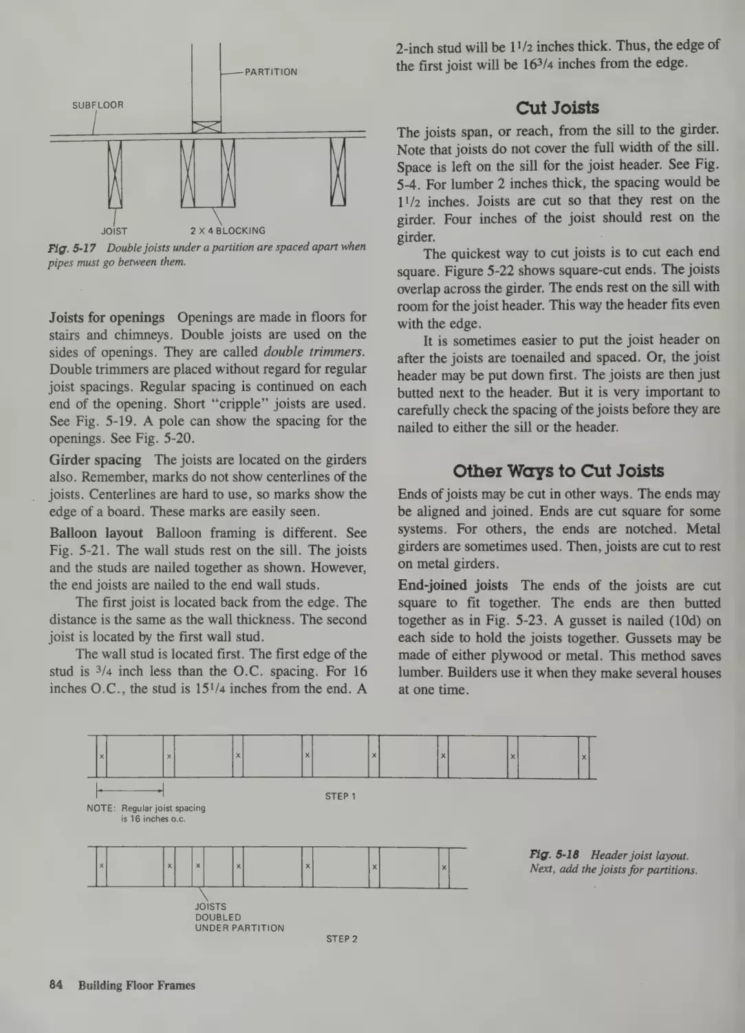
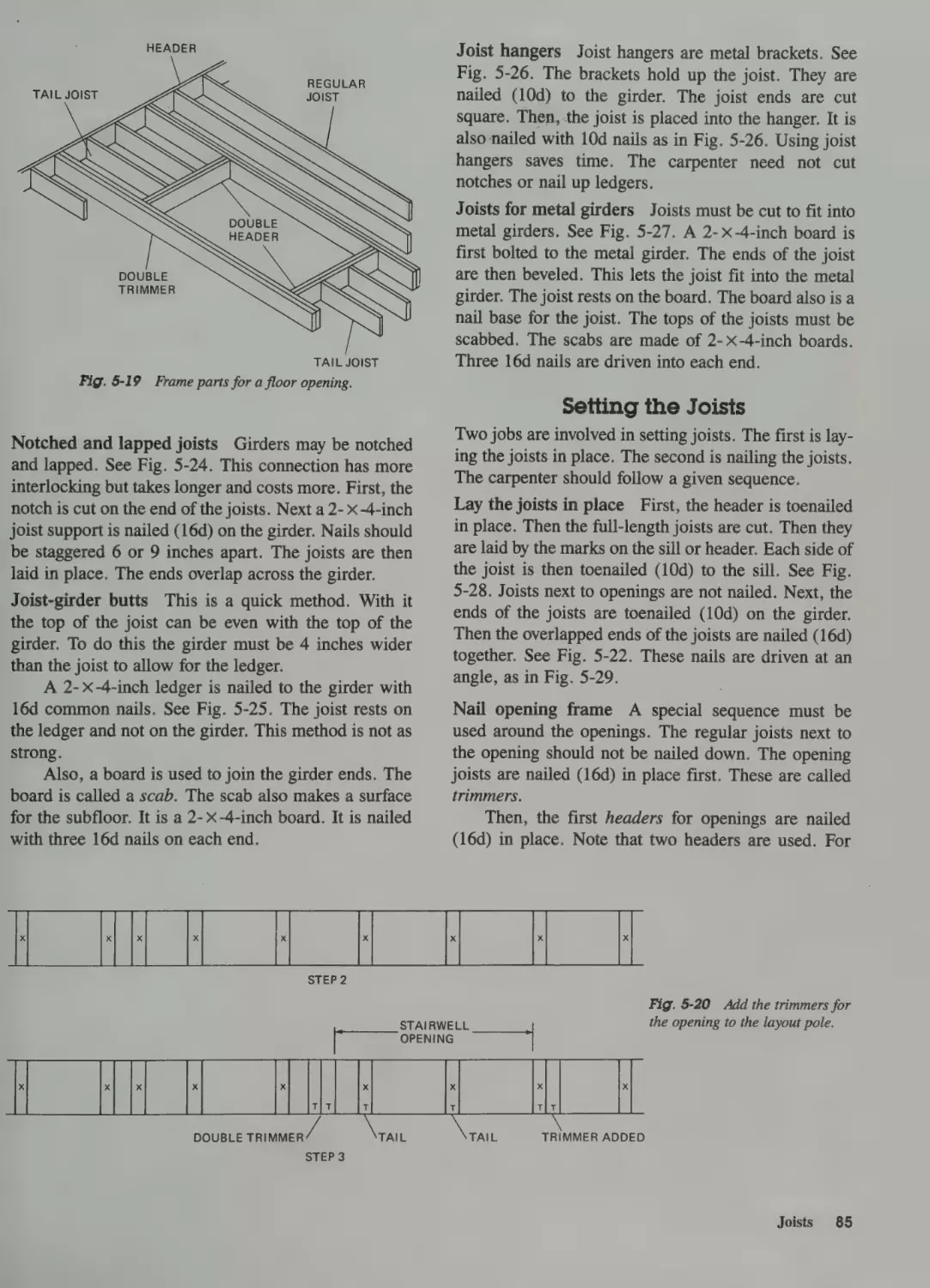
Cut Joists 84
Other Ways to Cut Joists 84
Setting the Joists 85
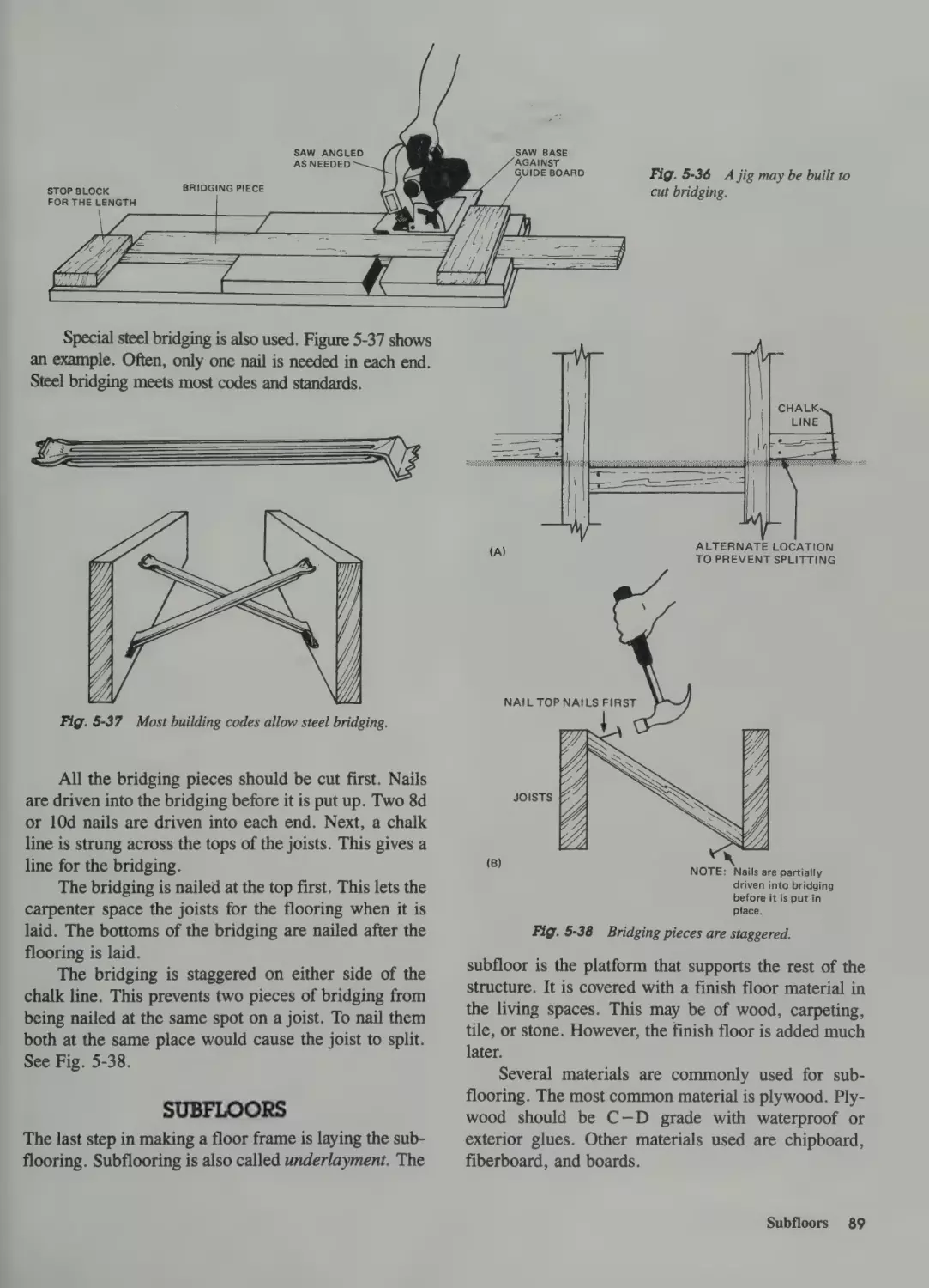
Fire Stops 88
Bridging 89
Subfloors 89
51
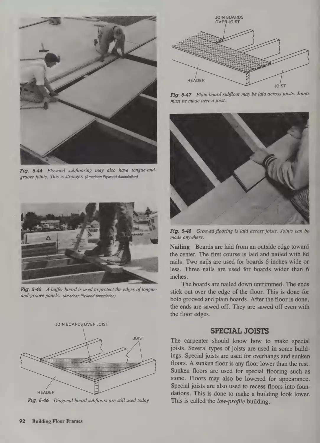
Plywood Subfloor 90
Chipboard and Fiberboard
Laying Sheets 90
Board Subflooring 91
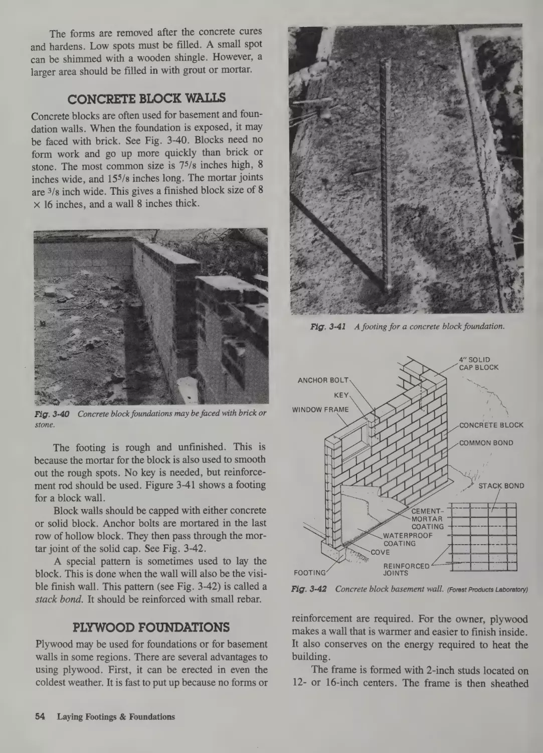
Concrete Block Walls 54
Plywood Foundations 55
Drainage and Waterproofing 55
Special Joists 92
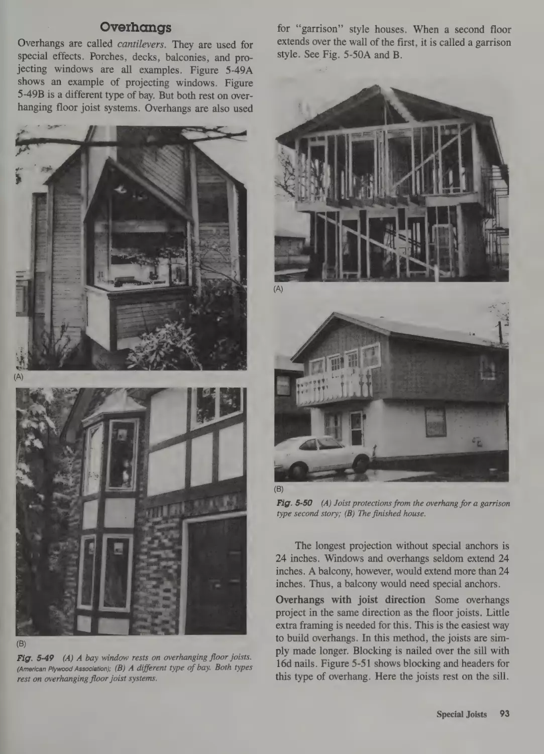
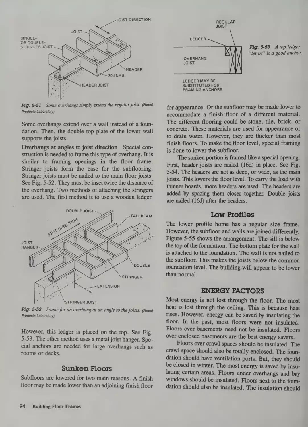
Overhangs 93
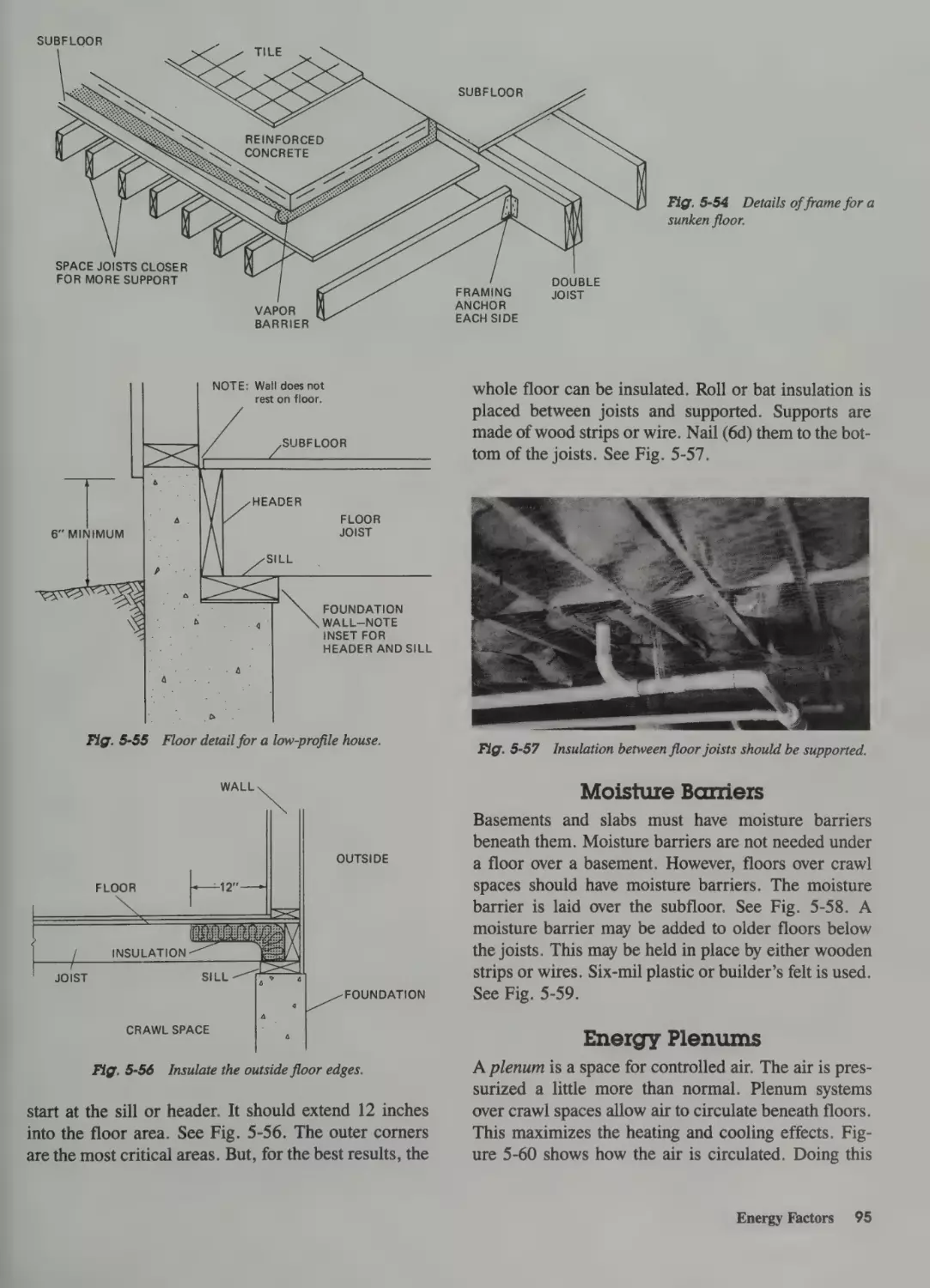
Sunken Floors 94
Low Profiles 94
Waterproofing Basement Walls 55
Termites 56
Types of Termites 56
Termite Protection 57
Termites and Treated Wood
Energy Factors 94
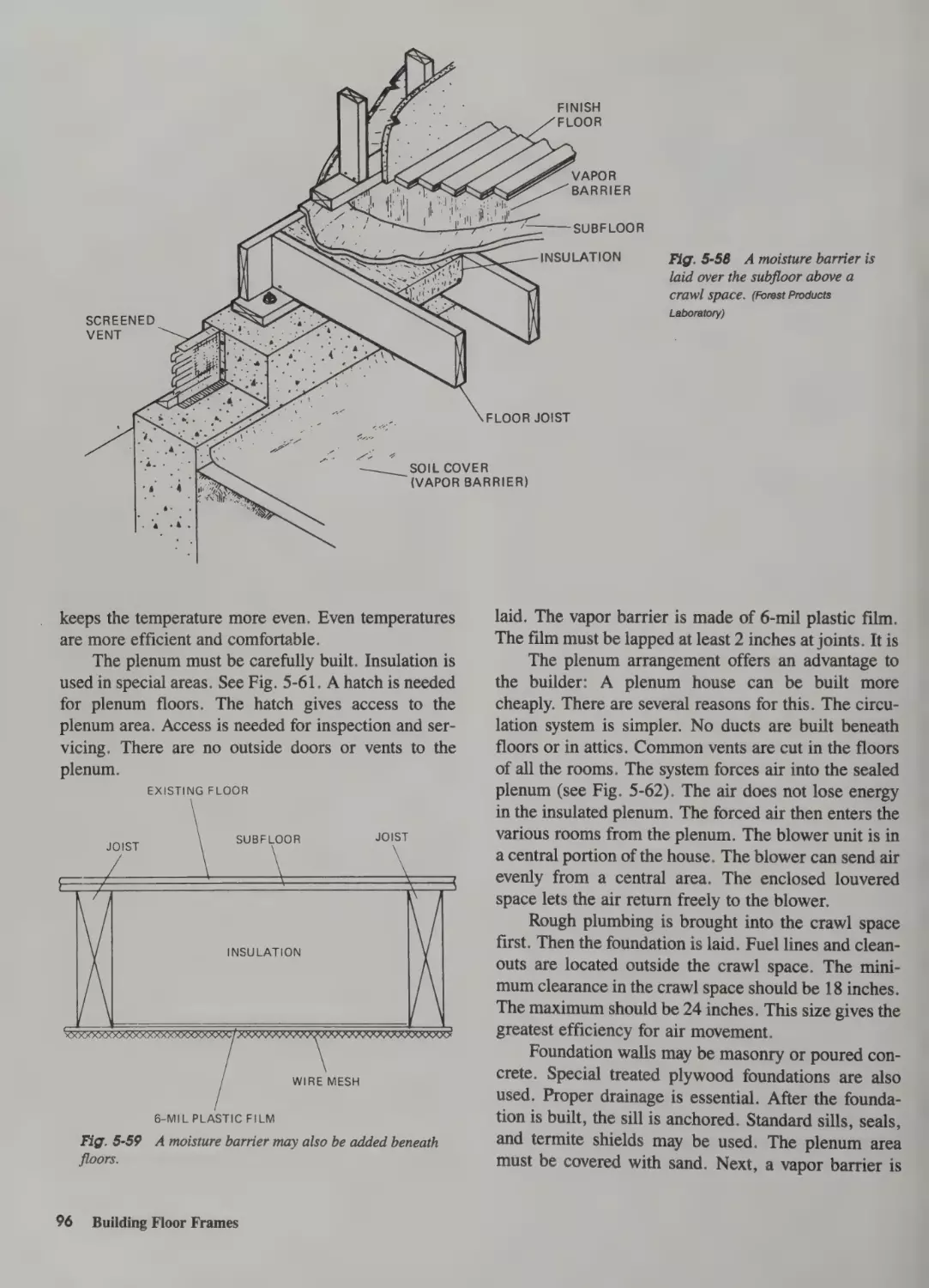
Moisture Barriers 95
Energy Plenums 95
58
Pressure-Treated Wood 59
Preservatives 59
Above-Ground and In-Ground Treatment
Nails and Fasteners 60
Handling and Storing Treated Wood 60
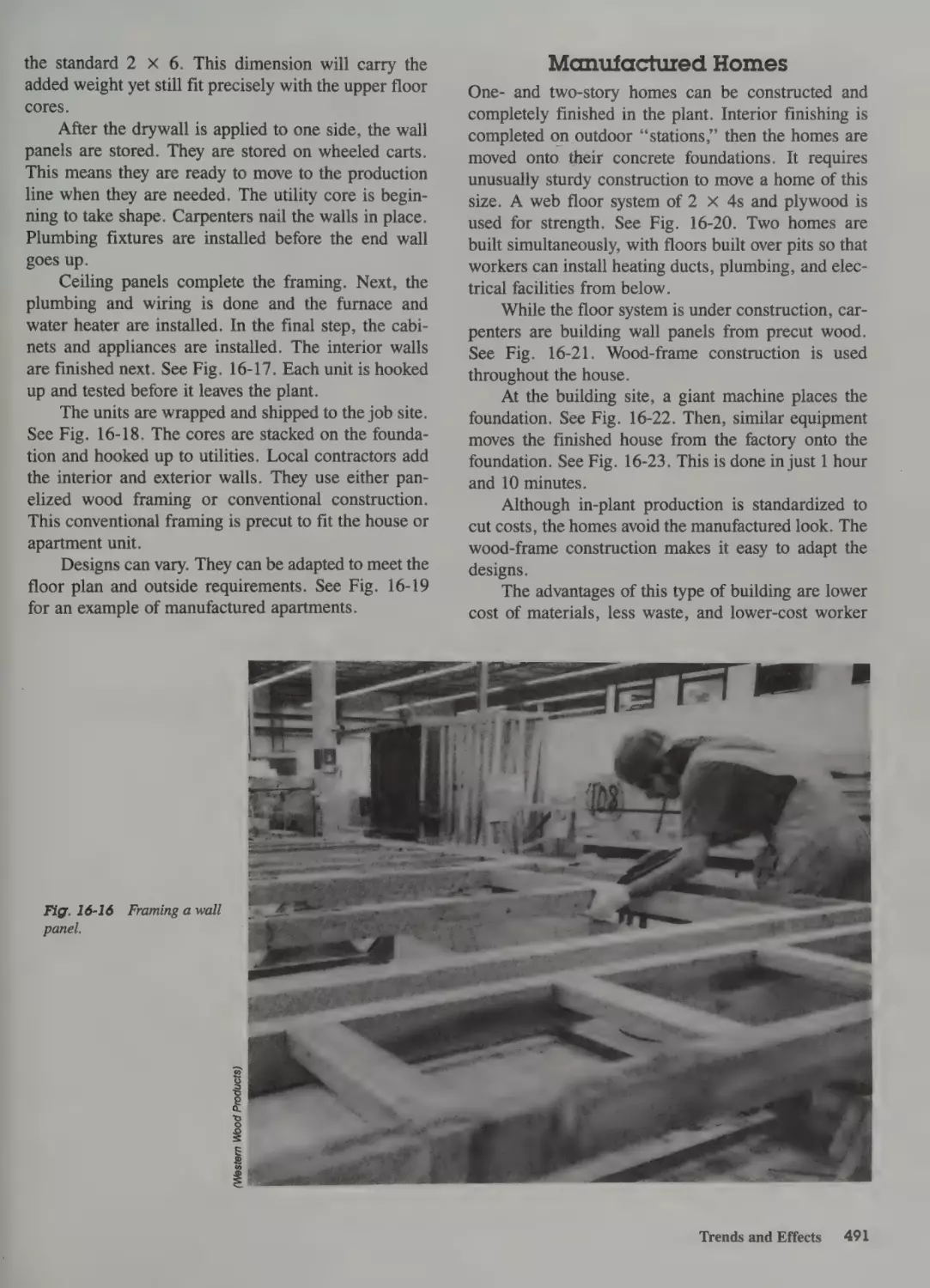
6 Framing Walls
59
4 Pouring Concrete Slabs & Floors
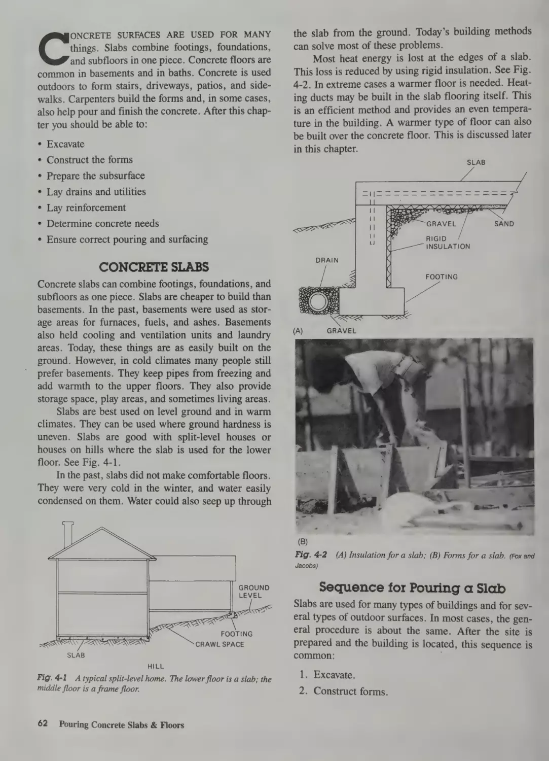
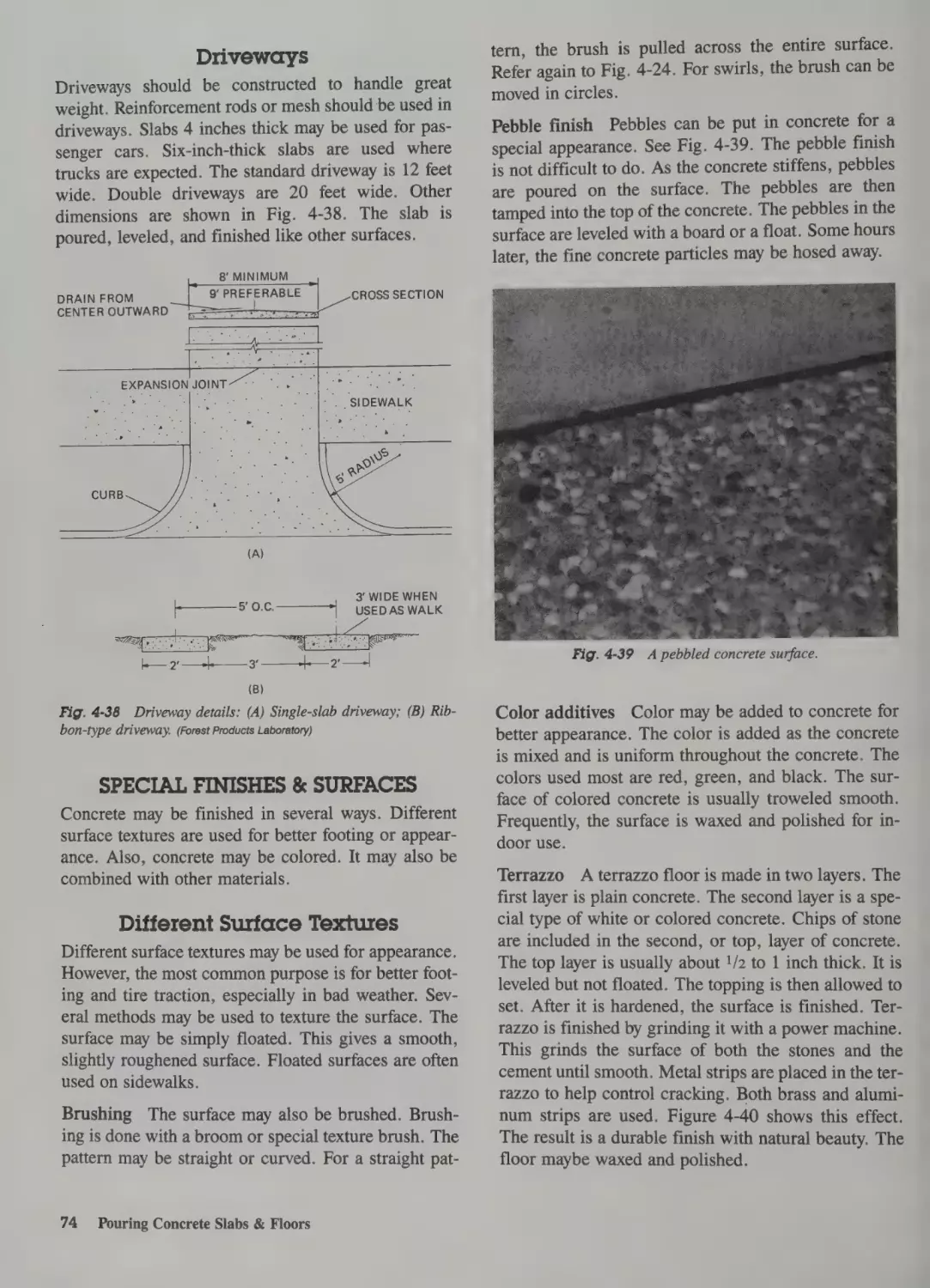
Concrete Slabs 62
Sequence for Preparing a Slab 62
Types of Slabs 63
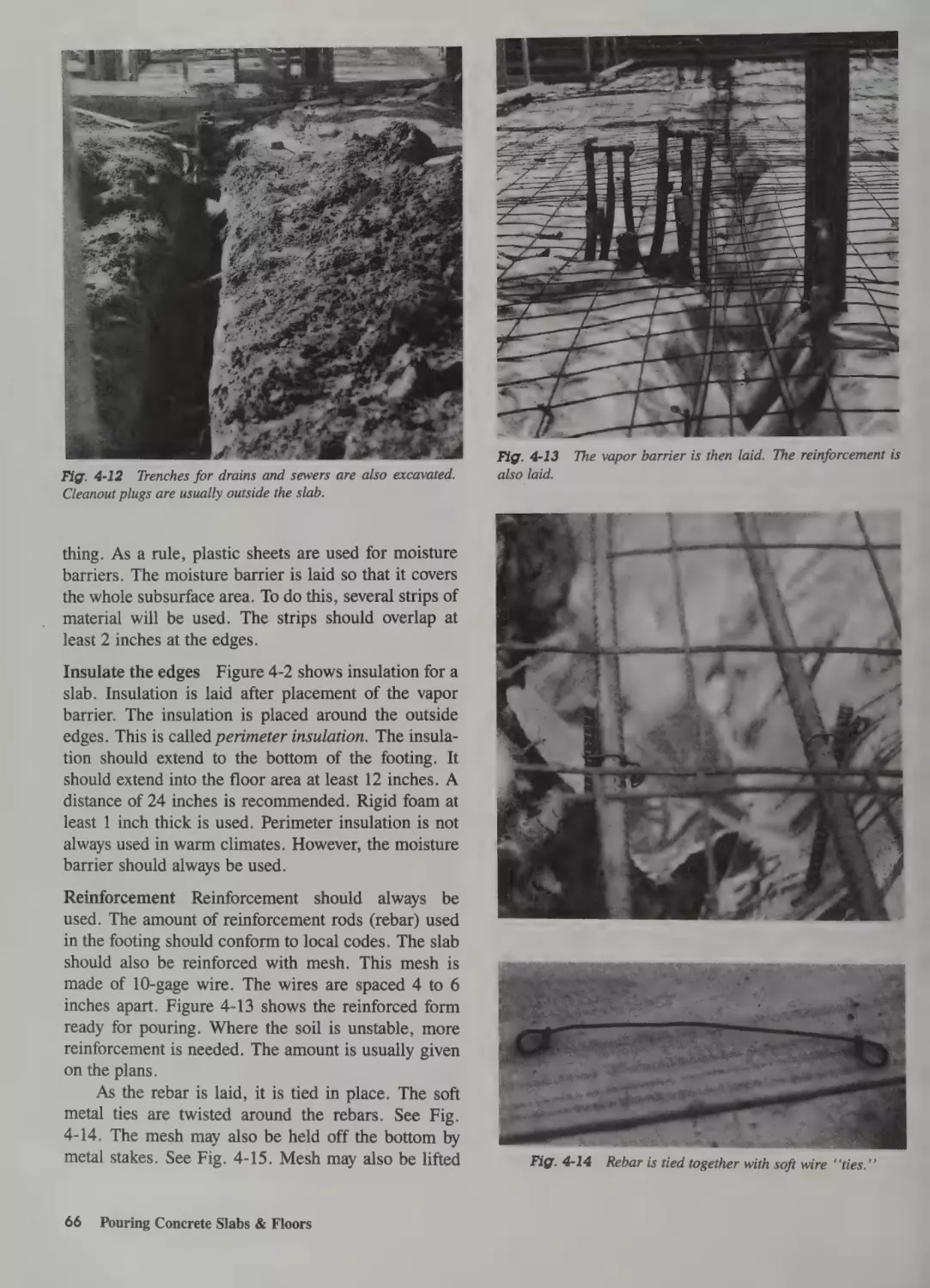
Excavate 63
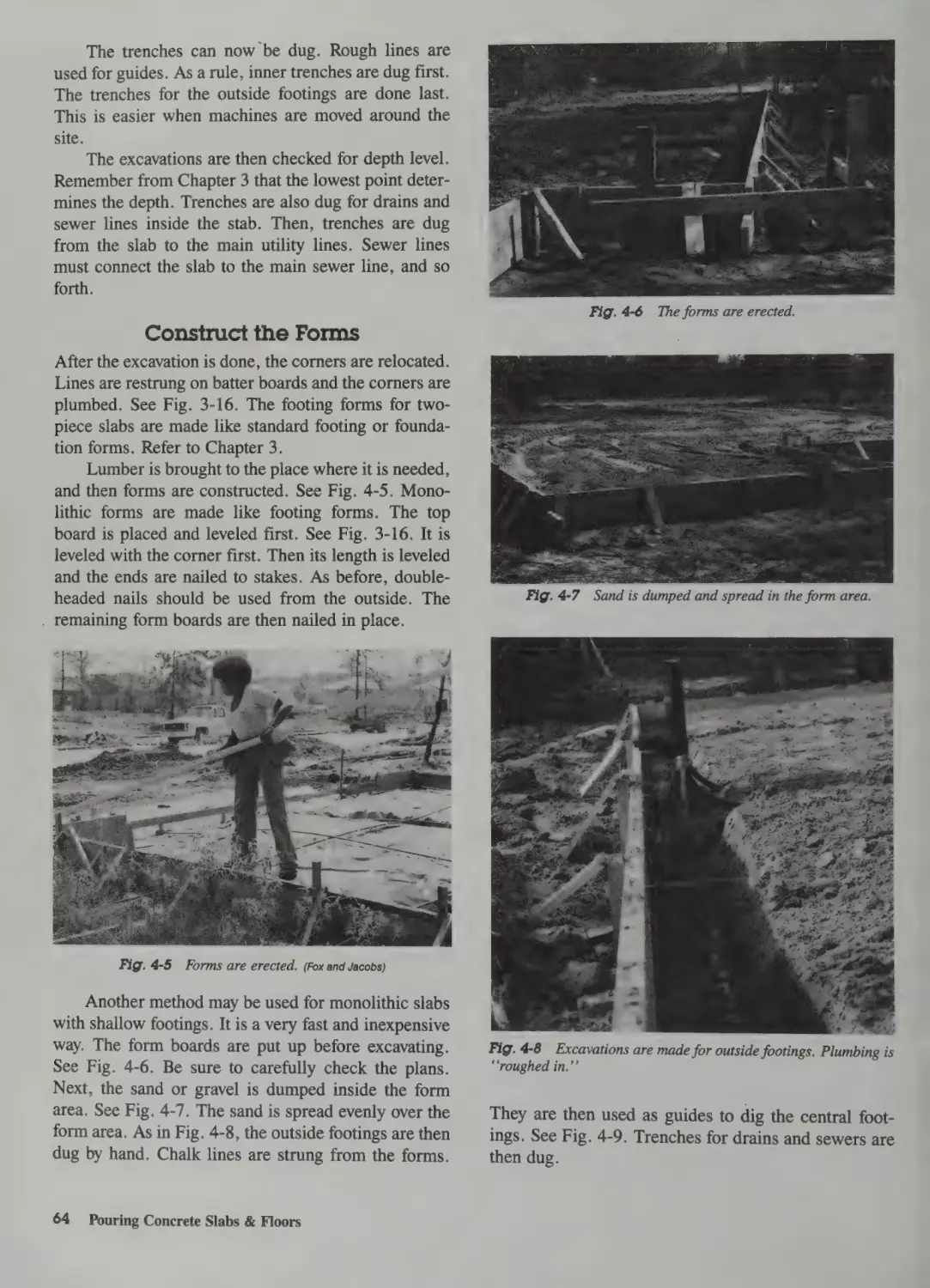
Construct the Forms 64
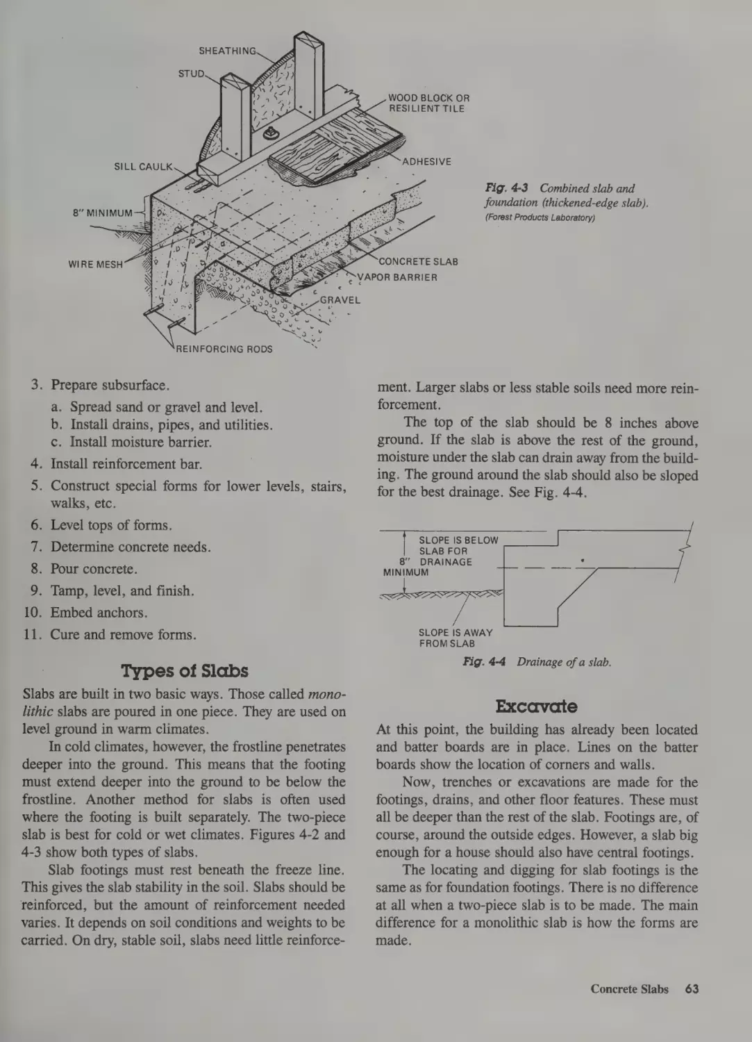
Prepare the Subsurface 65
Special Shapes 67
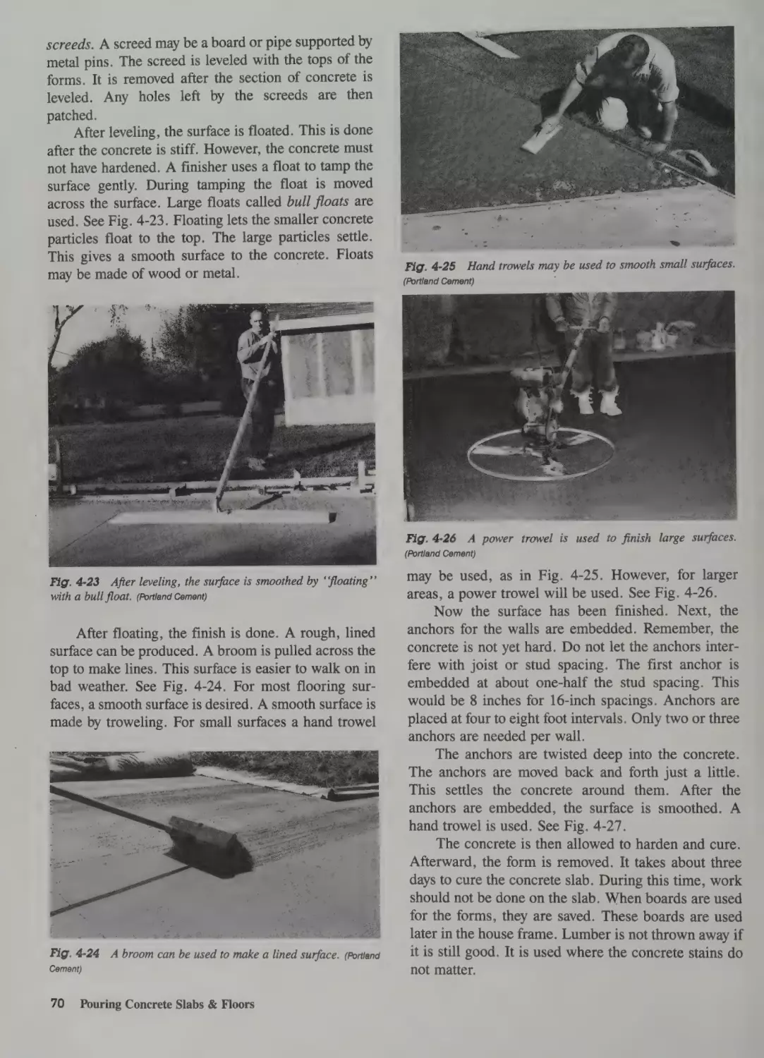
Pouring the Slab 68
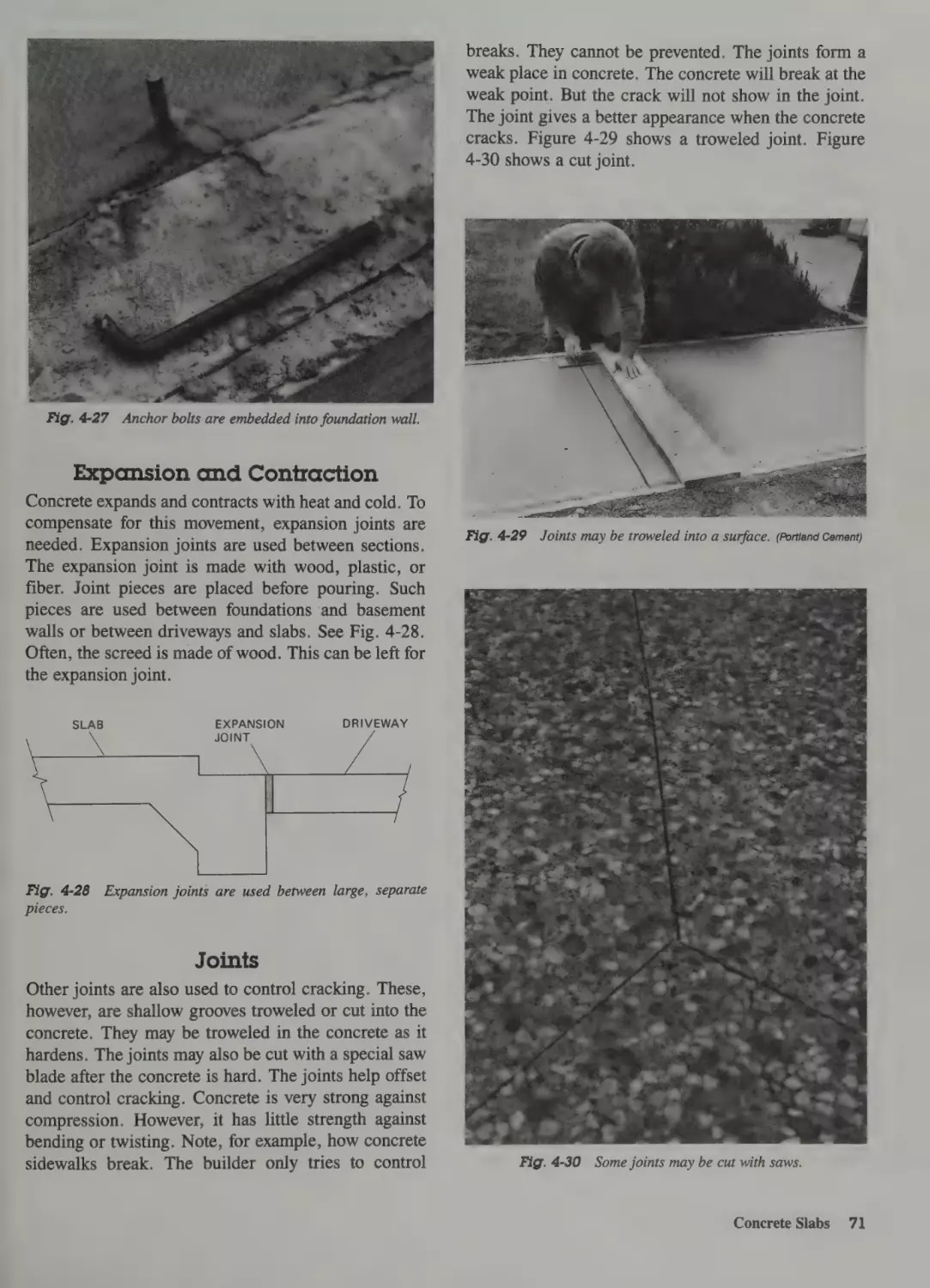
Expansion and Contraction 71
Joints 71
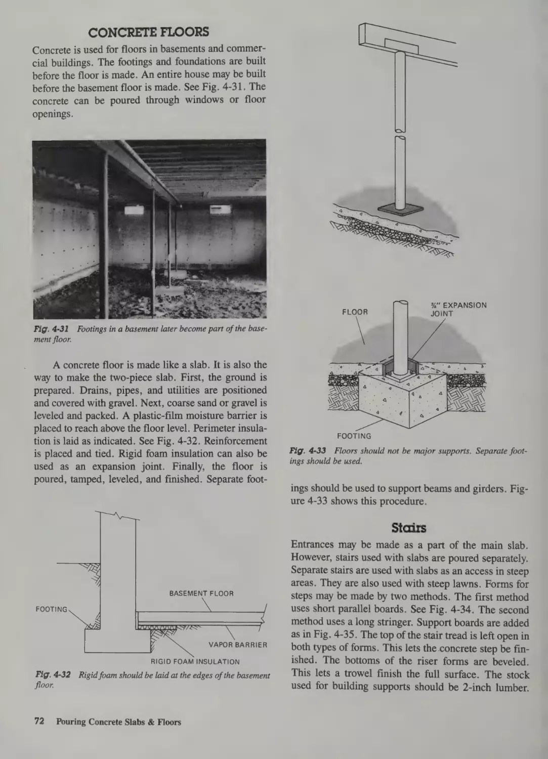
Concrete Floors 72
Stairs 72
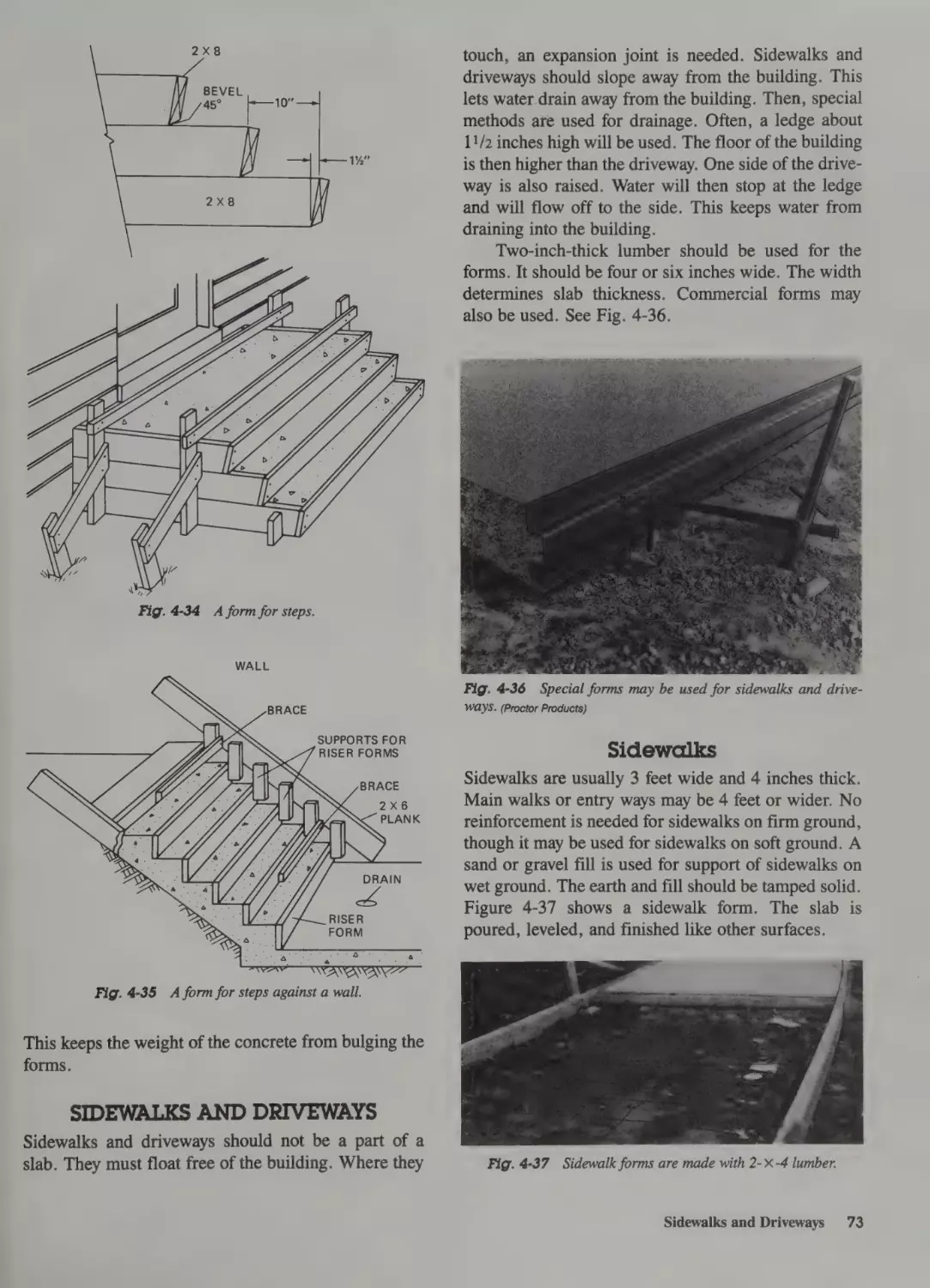
Sidewalks and Driveways 73
Sidewalks 73
Driveways 74
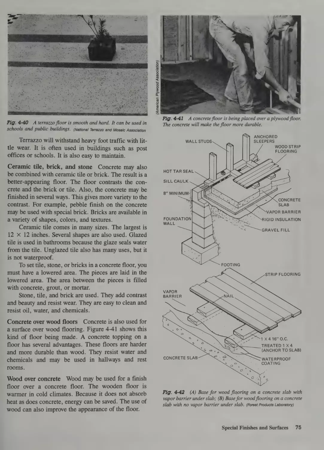
Special Finishes and Surfaces 74
Different Surface Textures 74
Energy Factors 76
90
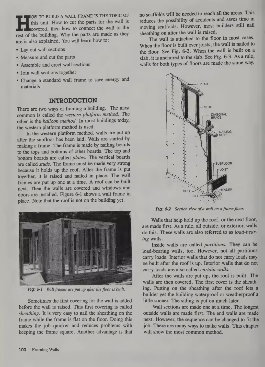
Introduction 100
Sequence 101
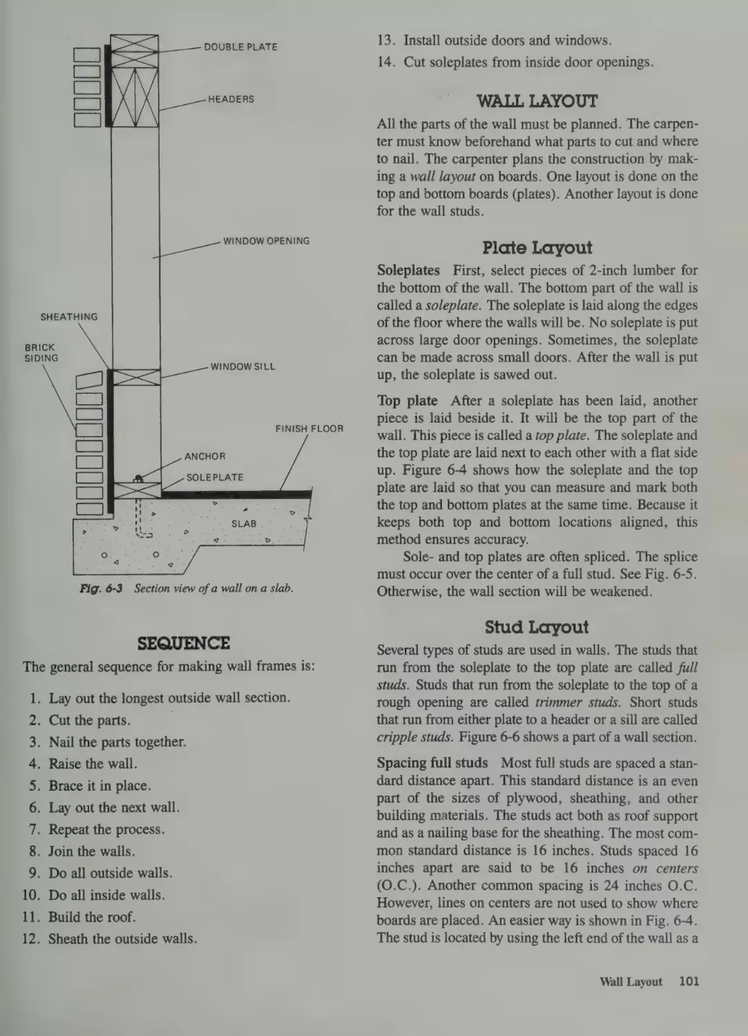
Wall Layout 101
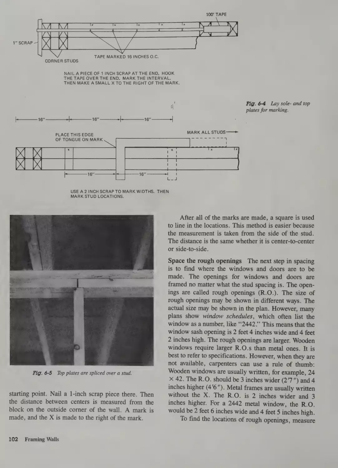
Plate Layout 101
Stud Layout 101
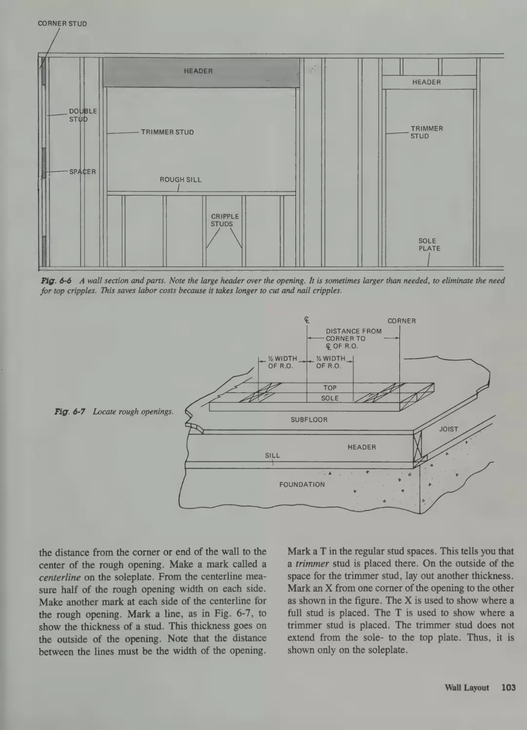
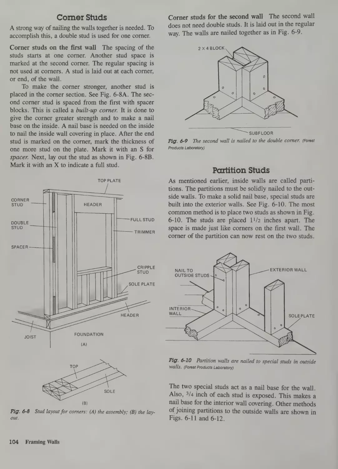
Corner Studs 104
Partition Studs 104
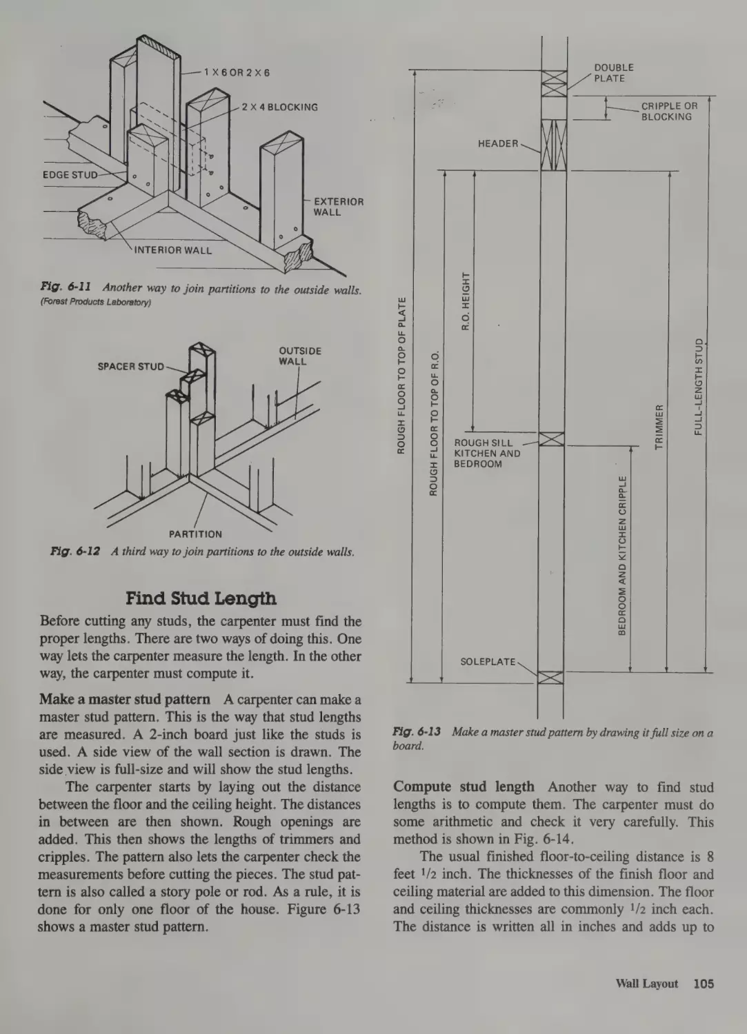
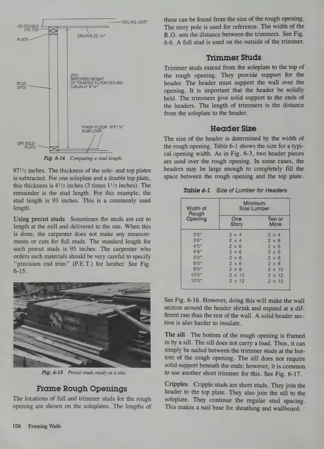
Find Stud Length 105
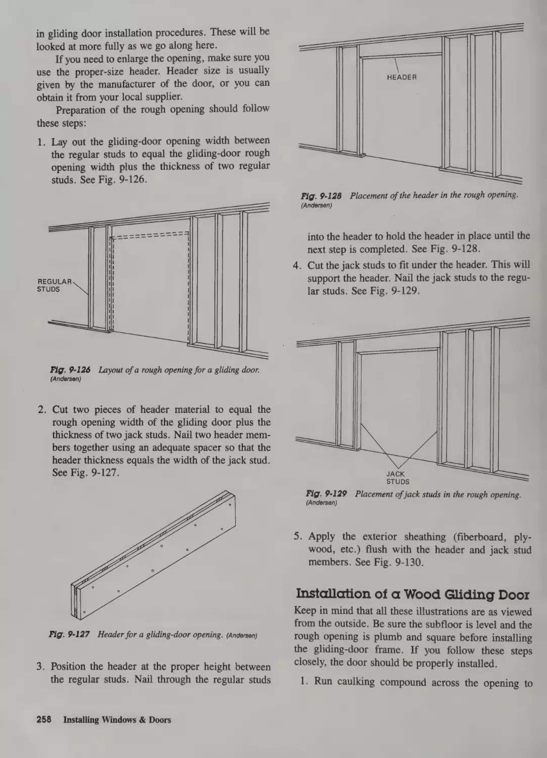
Frame Rough Openings
Trimmer Studs 106
Header Size 106
106
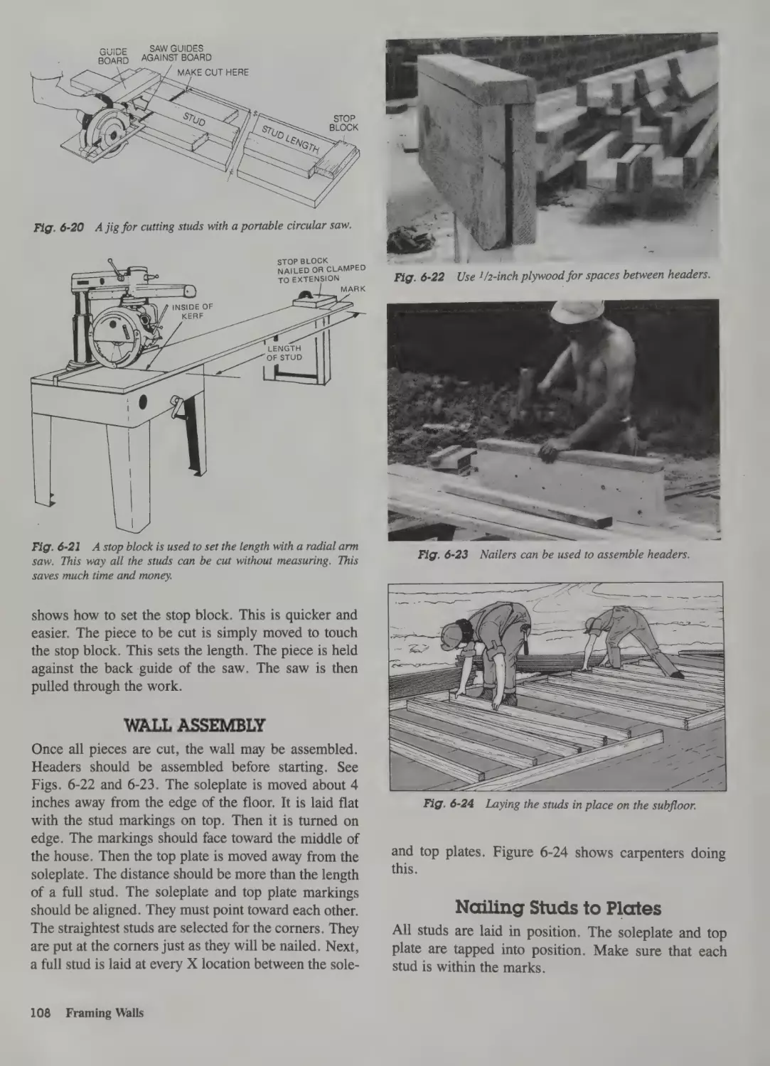
Cutting Studs to Length 107
Cutting Tips: 107
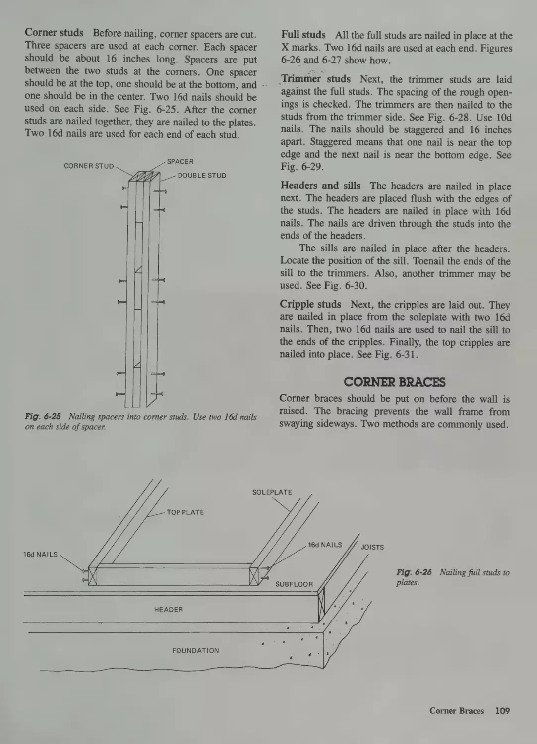
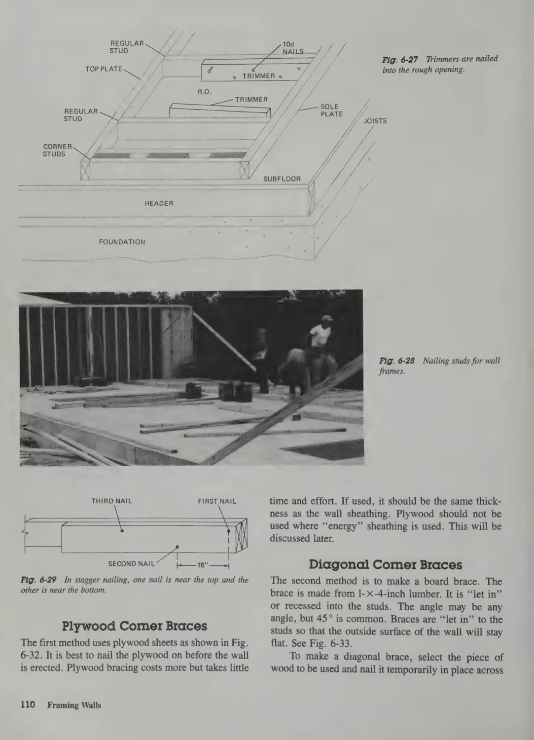
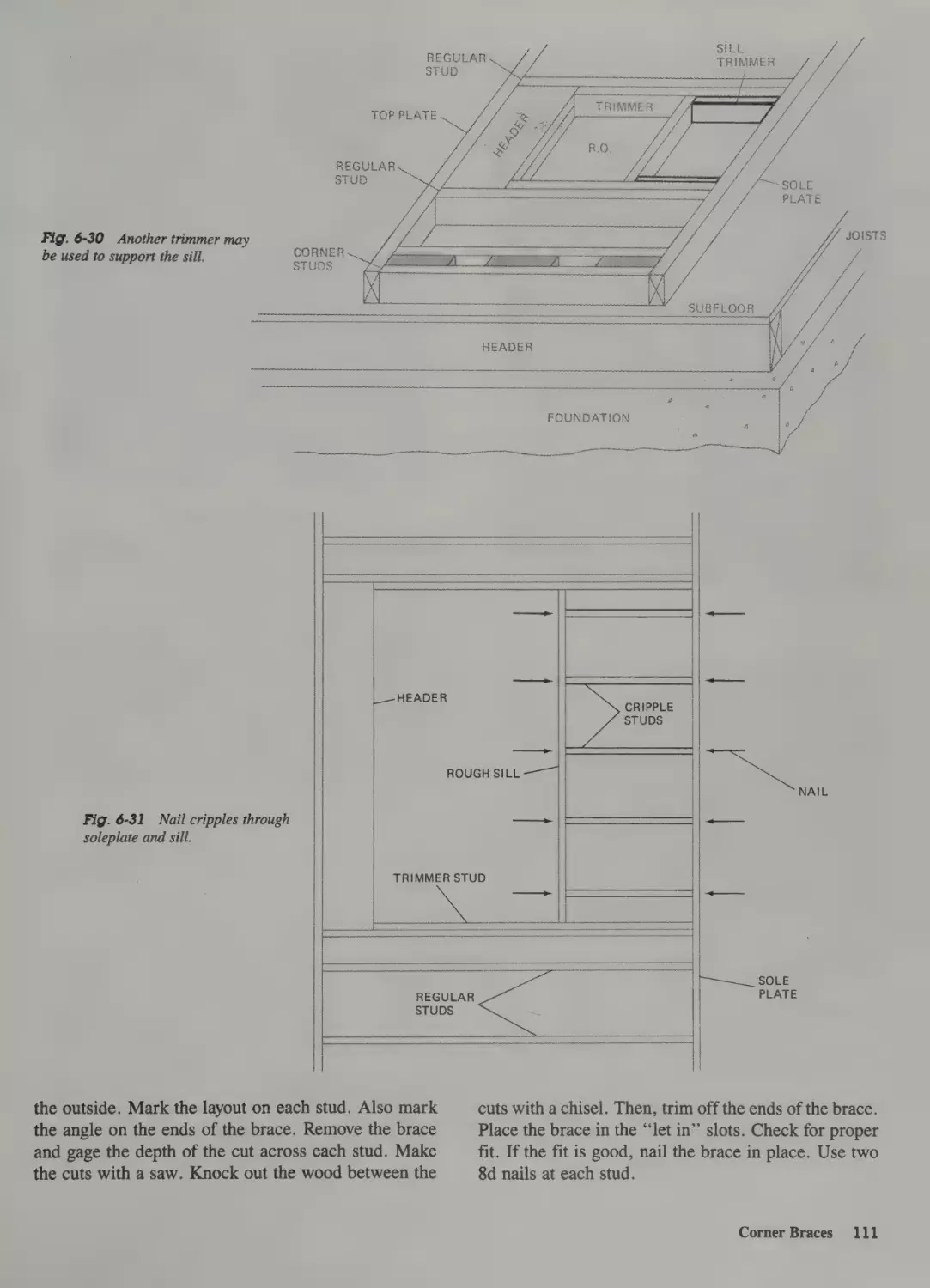
Wall Assembly
108
Nailing Studs to Plates
108
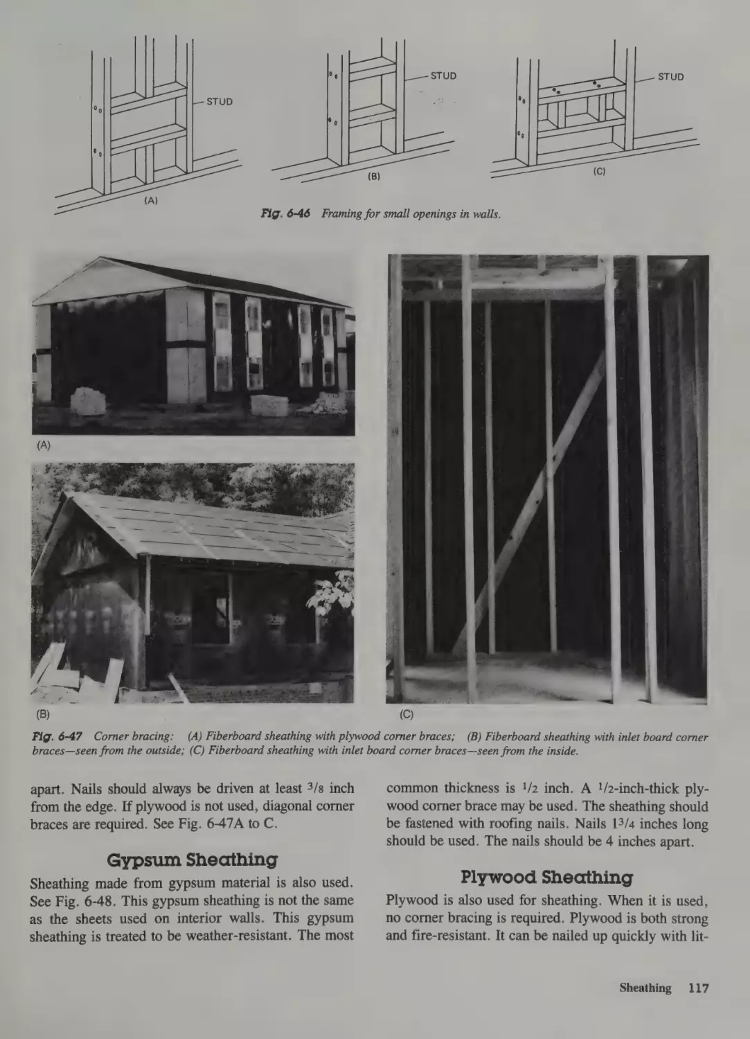
Corner Braces 109
Plywood Corner Braces 110
Diagonal Corner Braces 110
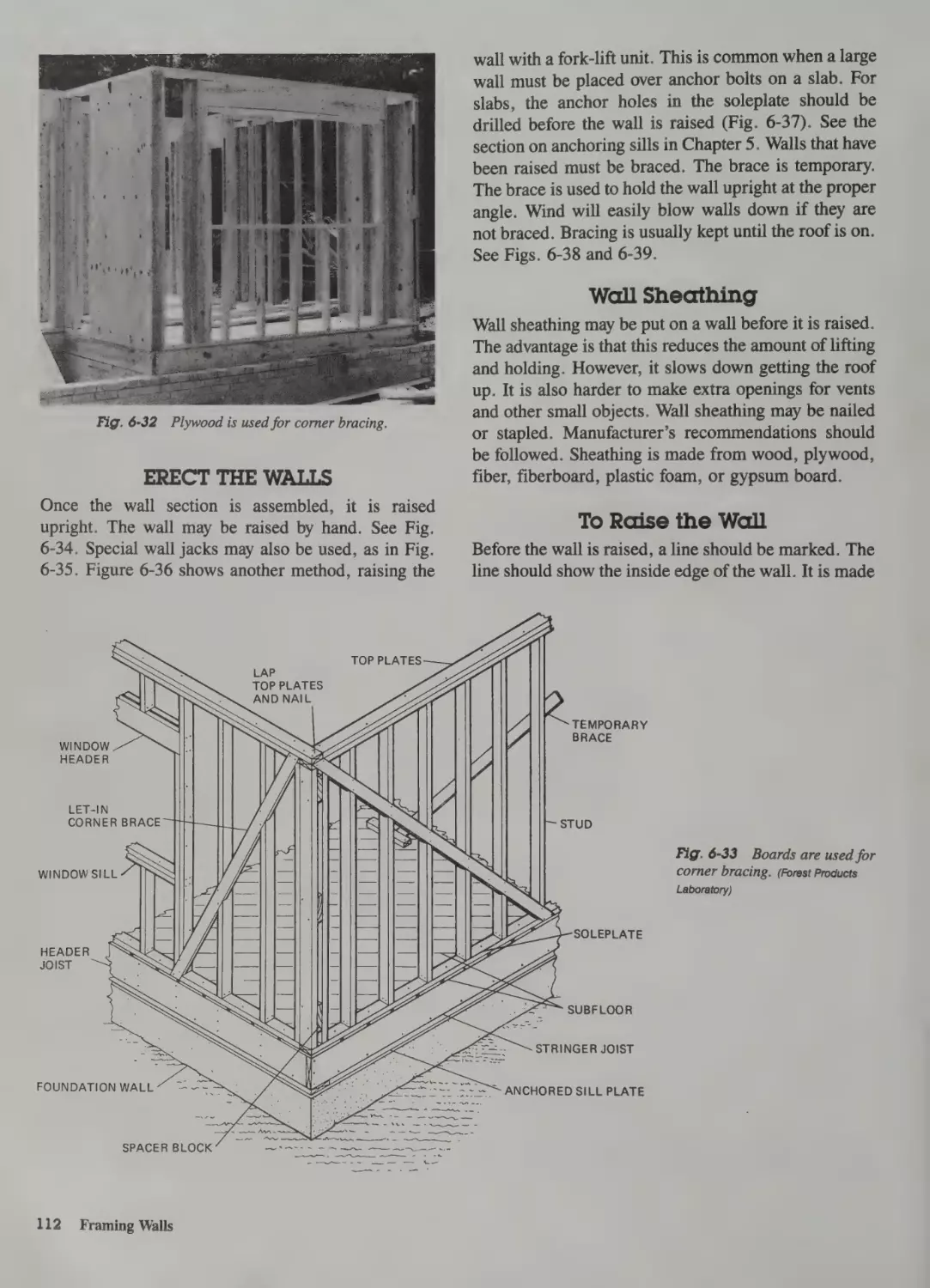
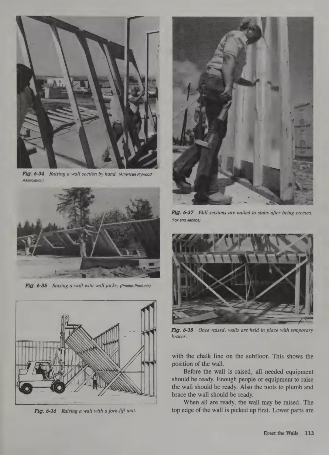
Erect the Walls 112
Wall Sheathing 112
To Raise the Wall 112
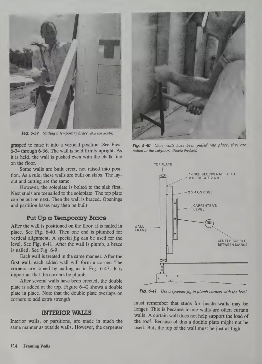
Put Up a Temporary Brace
Interior Walls 114
114
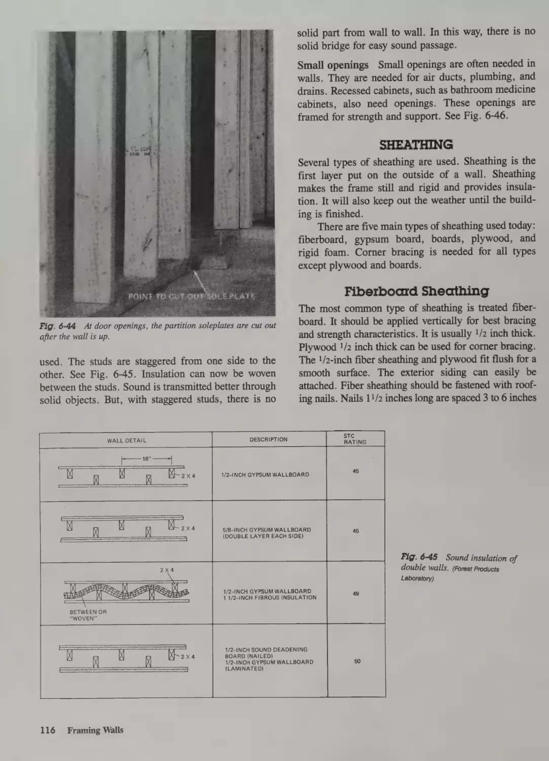
Locate Soleplates for Partitions
Studs 115
Corners 115
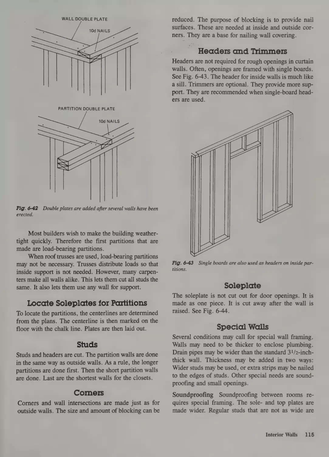
Headers and Trimmers 115
Soleplate 115
Special Walls 115
115
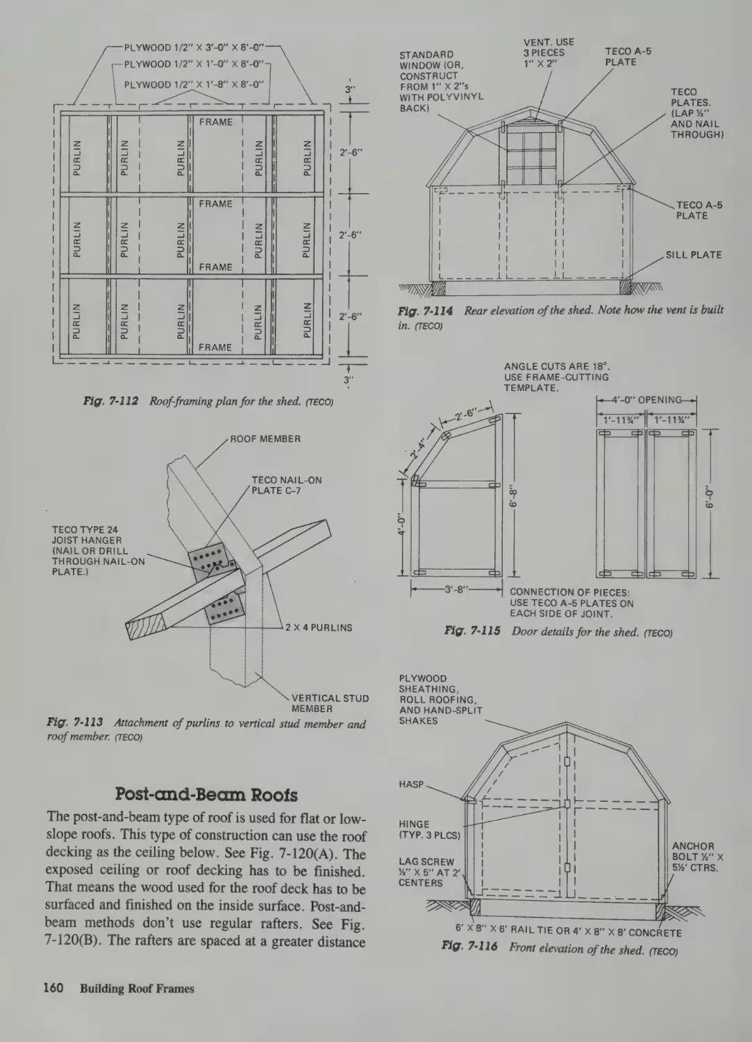
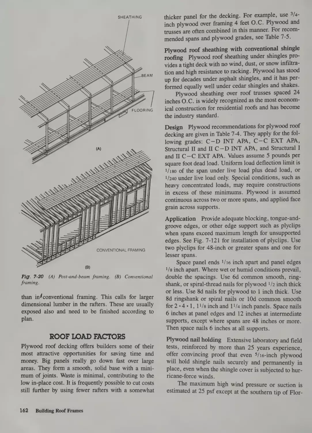
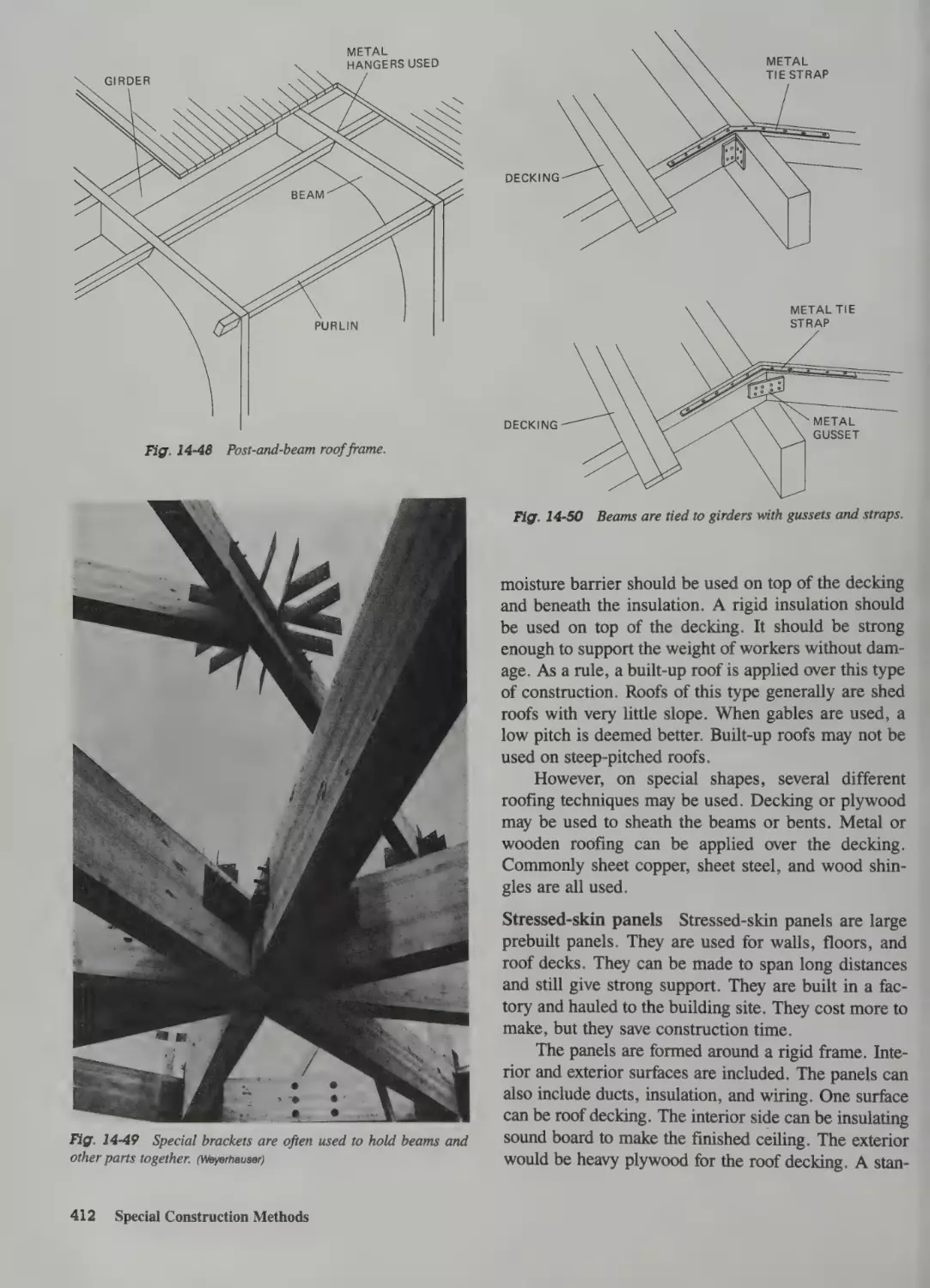
Post-and-Beam Roofs
Roof Load Factors 162
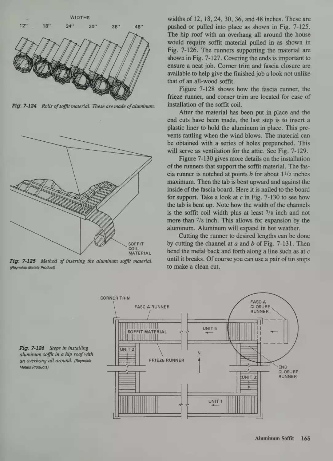
Laying Out a Stair 163
Aluminum Soffit 164
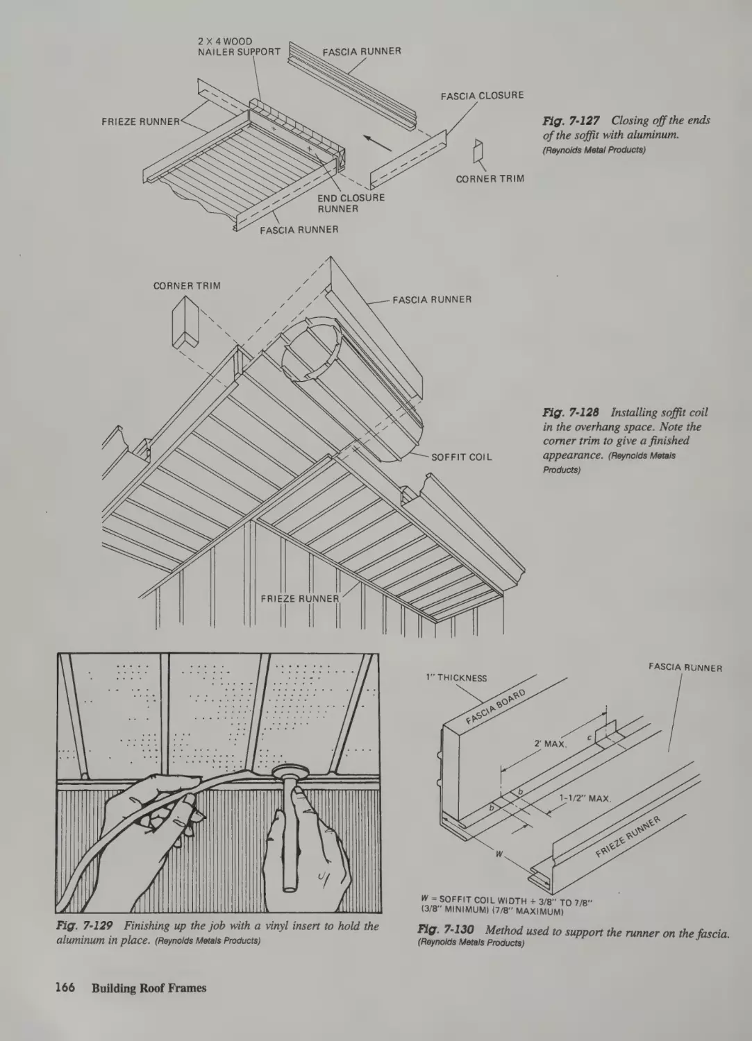
Material Availability
Fiberboard Sheathing 116
Gypsum Sheathing 117
Plywood Sheathing 117
Energy Sheathing 118
Boards 118
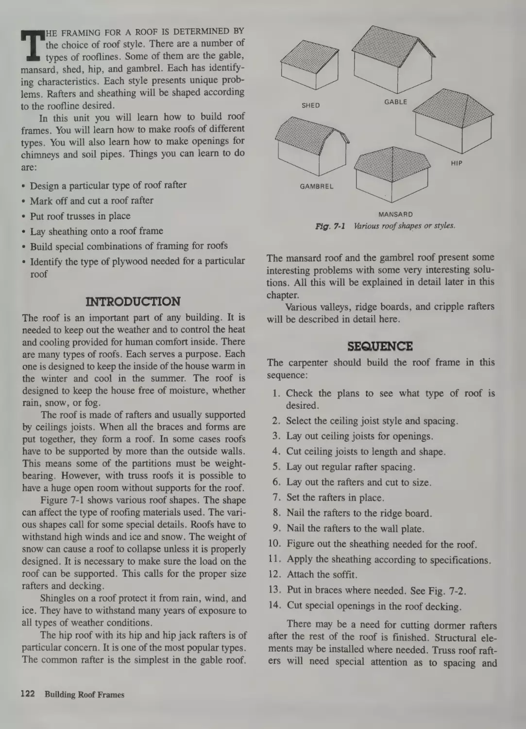
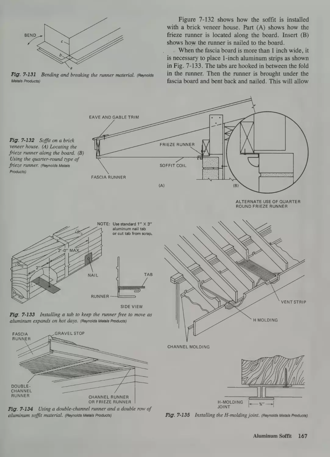
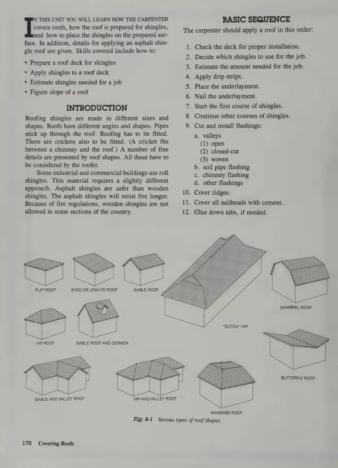
Introduction 170
Basic Sequence 170
Types of Roofs 171
Drainage Factors 171
Roofing Terms 172
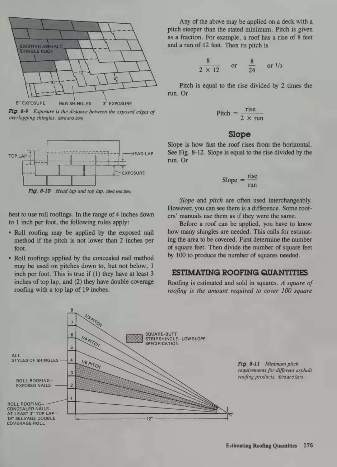
Pitch 173
Slope 175
118
Standard Spacing 119
Modular Standards 119
Energy 120
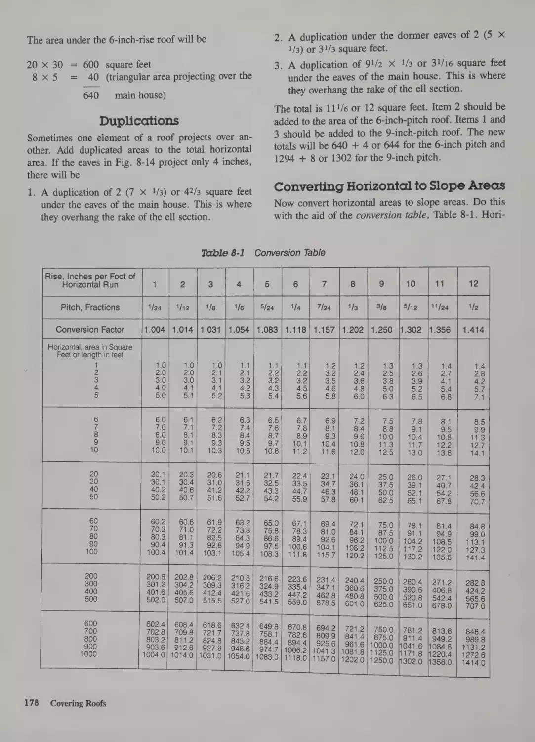
Estimating Roofing Quantities 175
Estimating Area 176
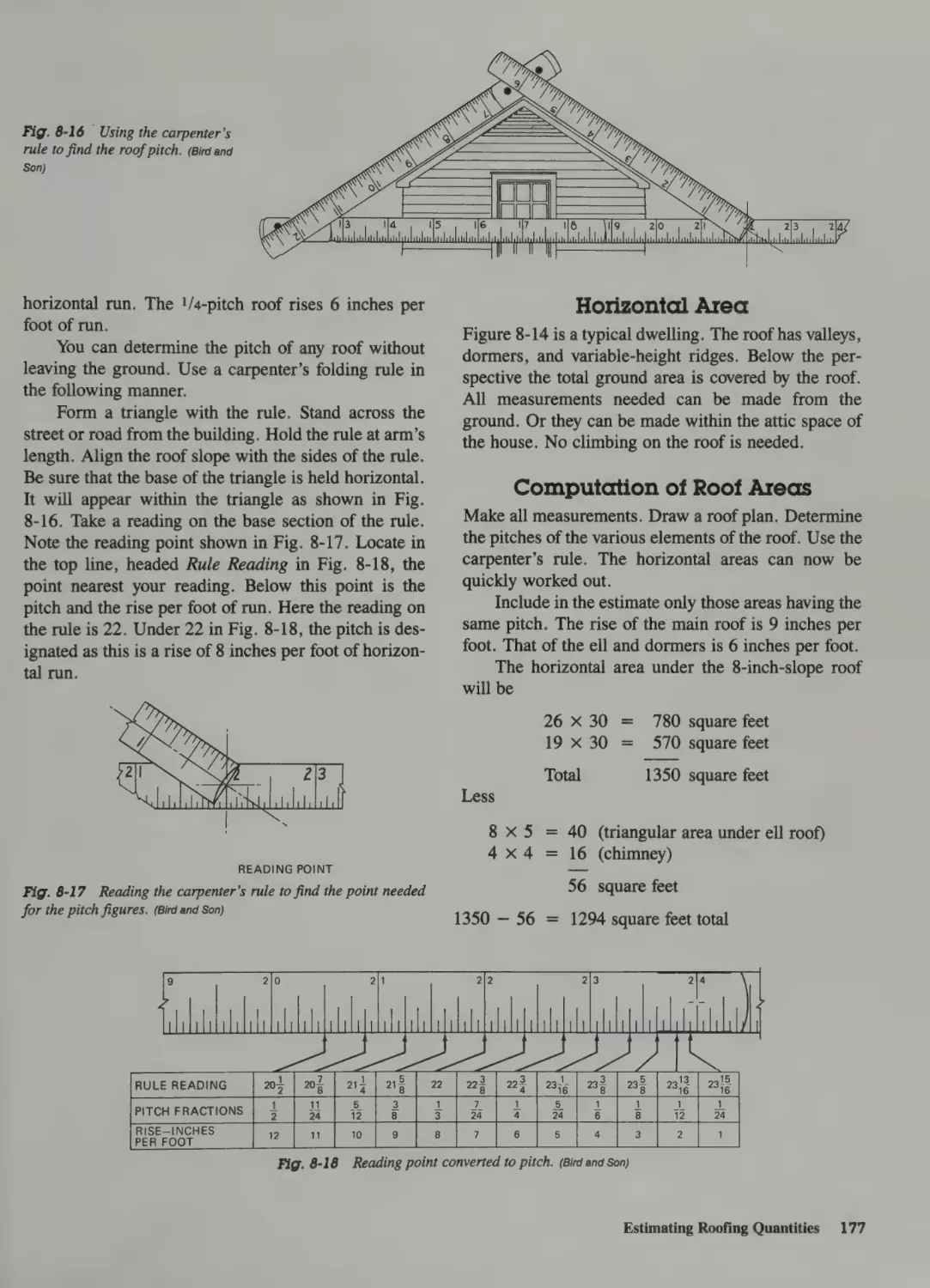
Horizontal Area 177
Computation of Roof Areas
7 Building Roof Frames
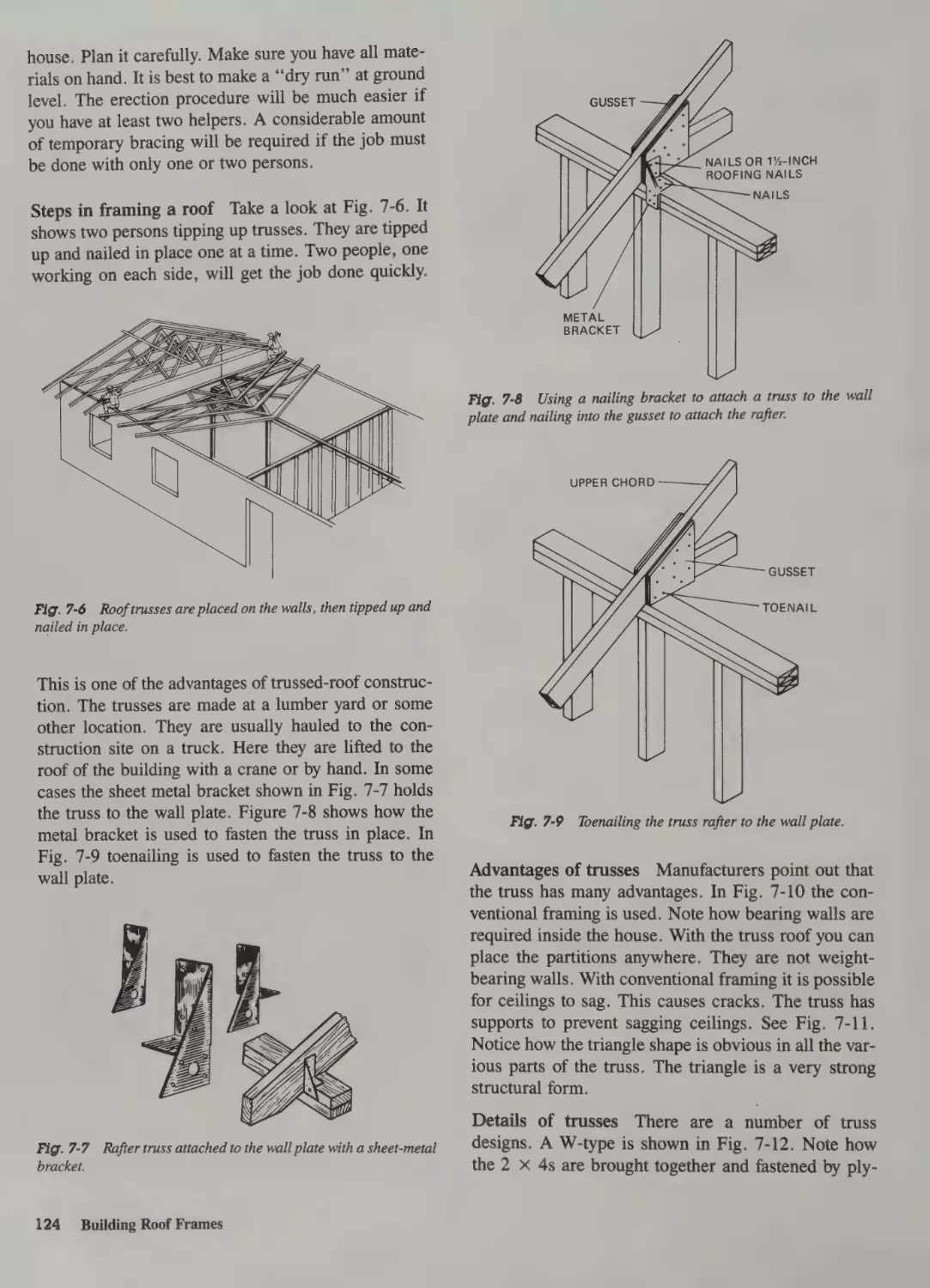
Introduction 122
Sequence 122
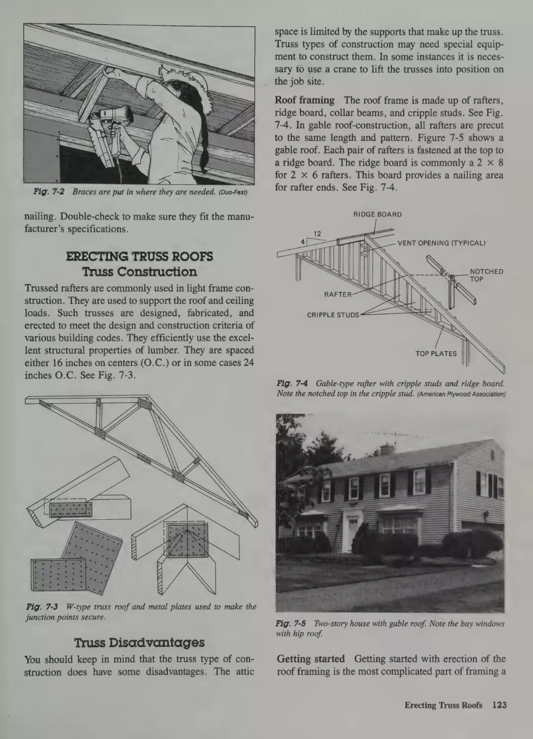
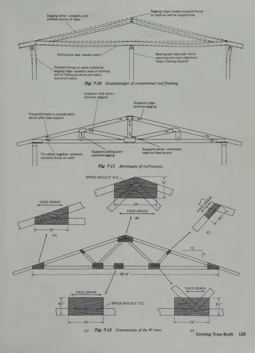
Erecting Truss Roofs 123
Duplications
177
178
Converting Horizontal to Slope Areas
Accessories 179
178
Length of Rake 179
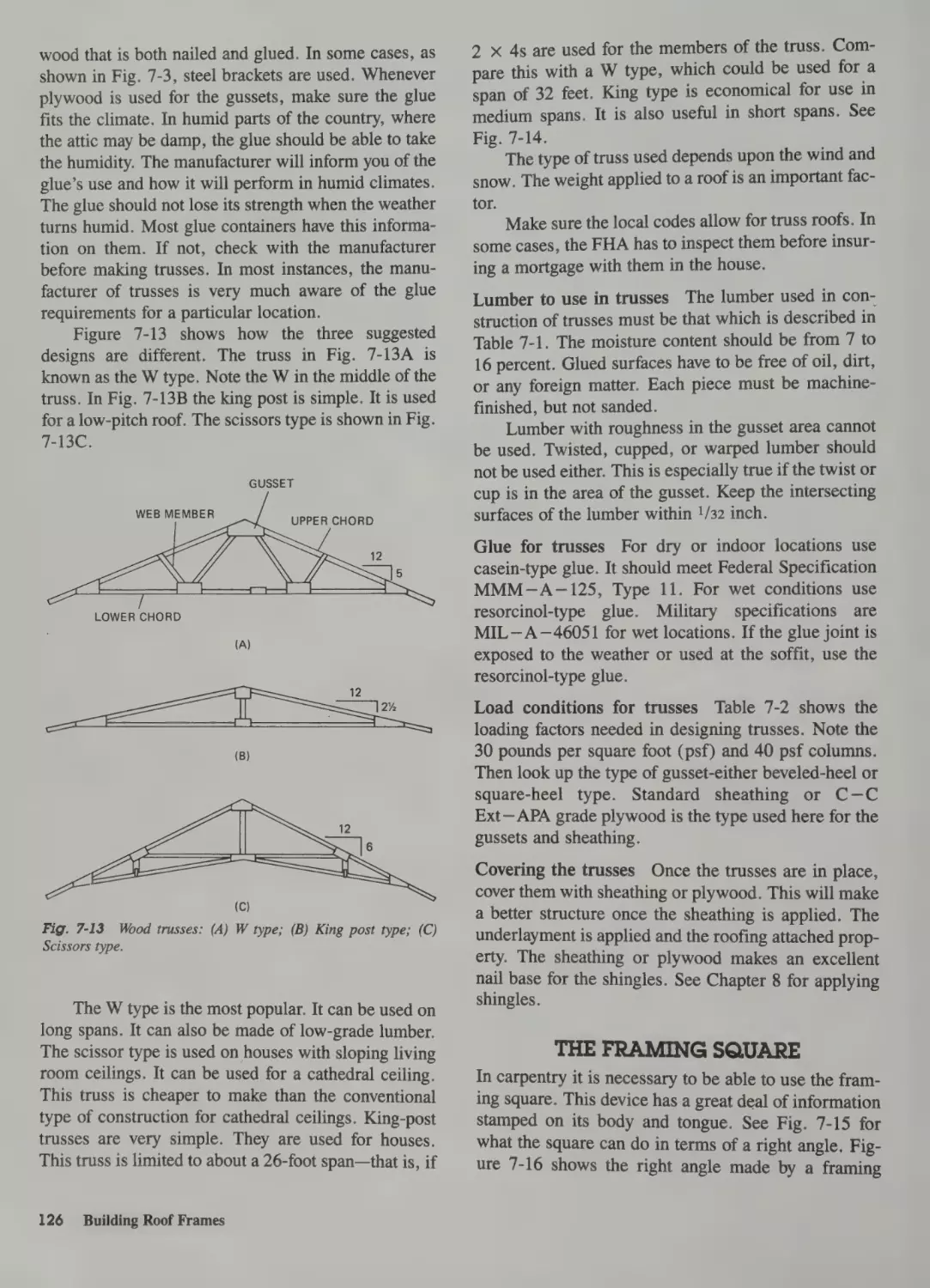
Truss Construction 123
Truss Disadvantages 123
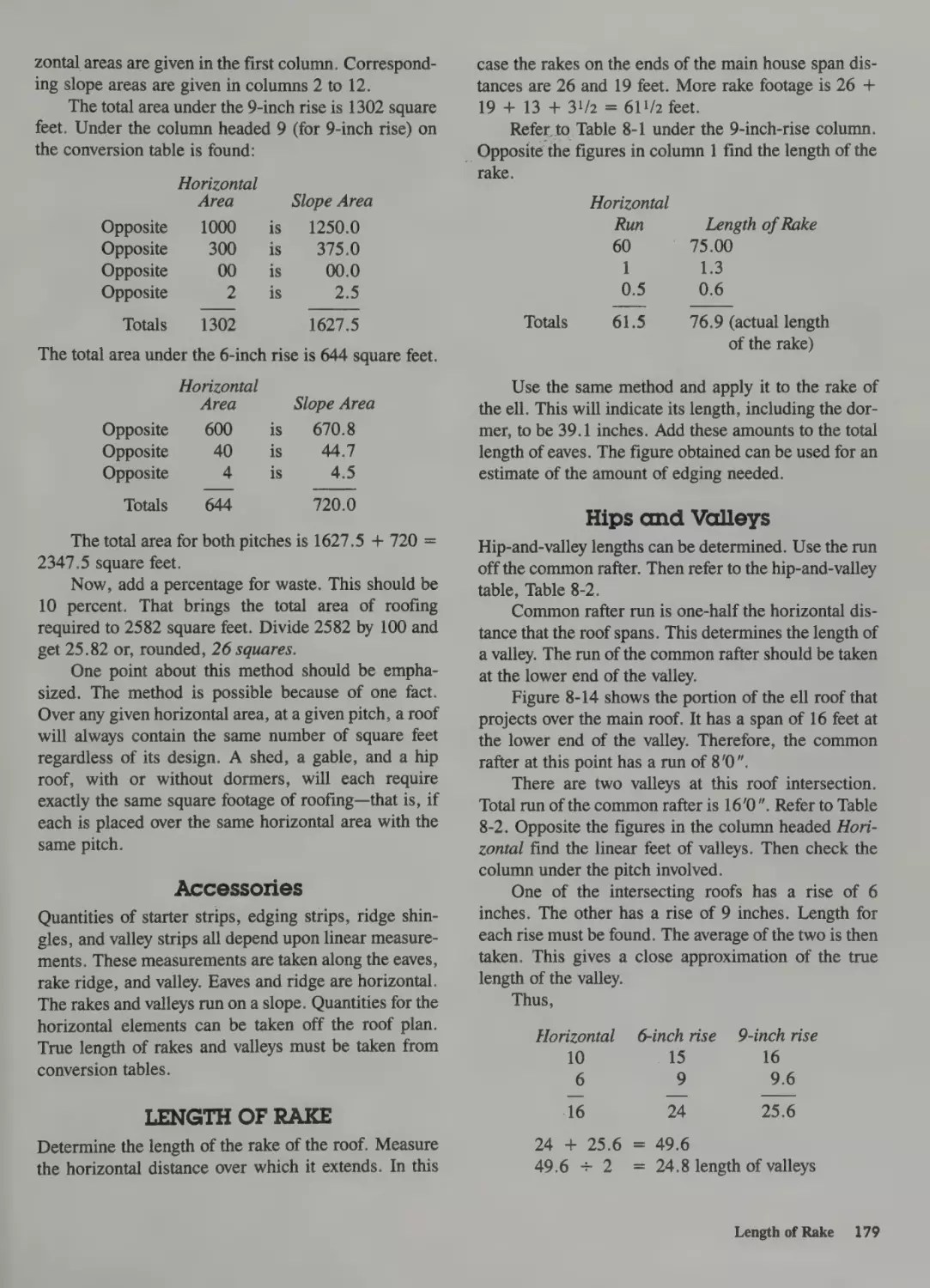
Hips and Valleys 179
Dormer Valleys 180
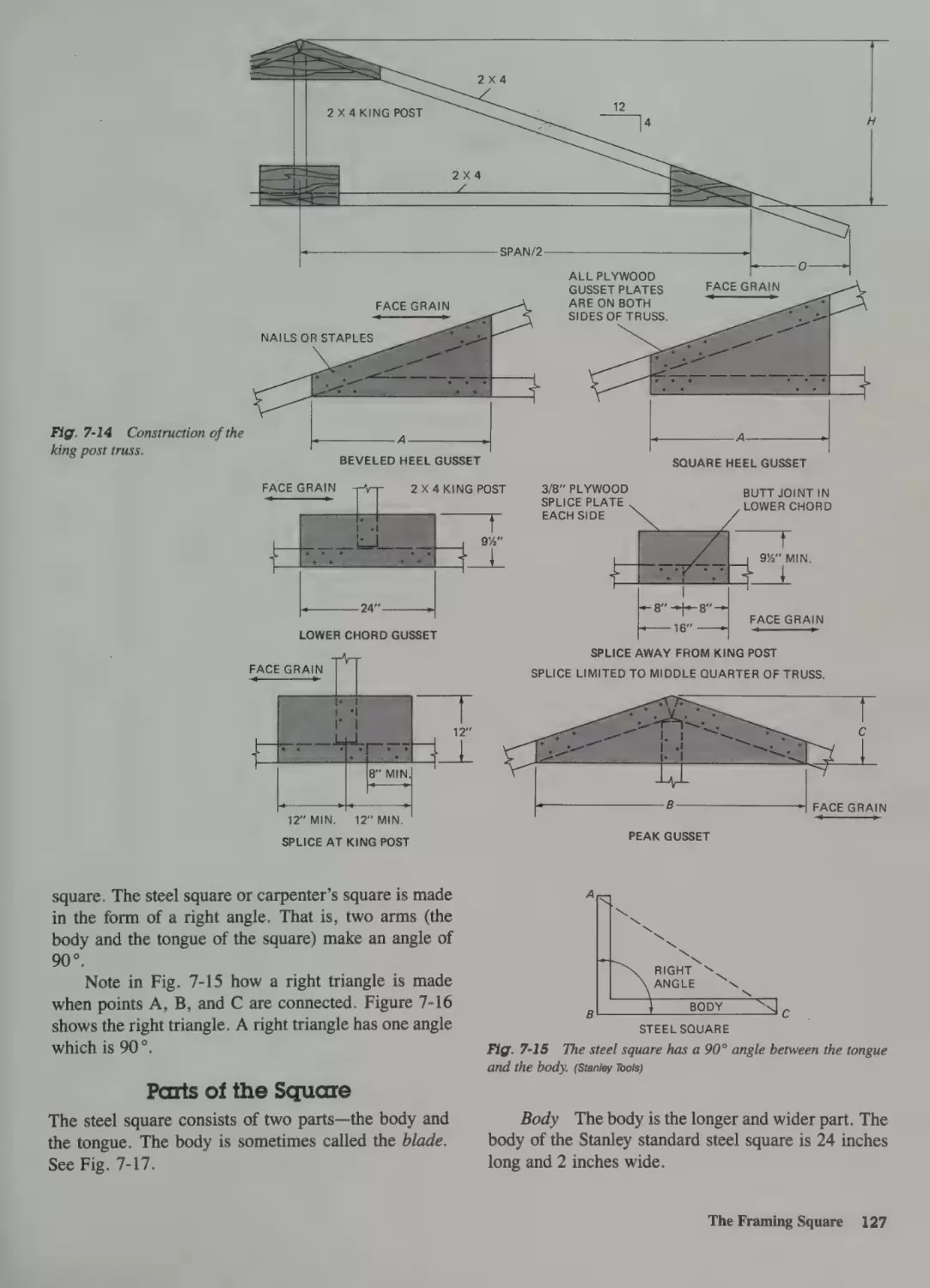
The Framing Square 126
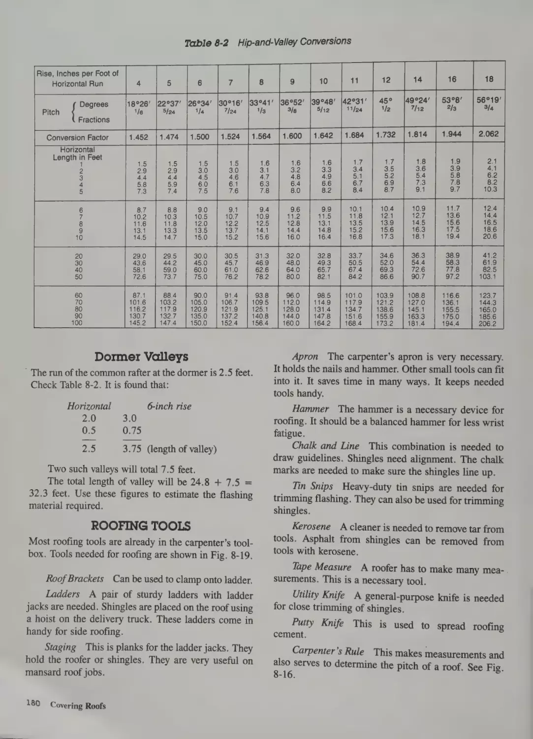
Roofing Tools 180
Safety 181
Parts of the Square 127
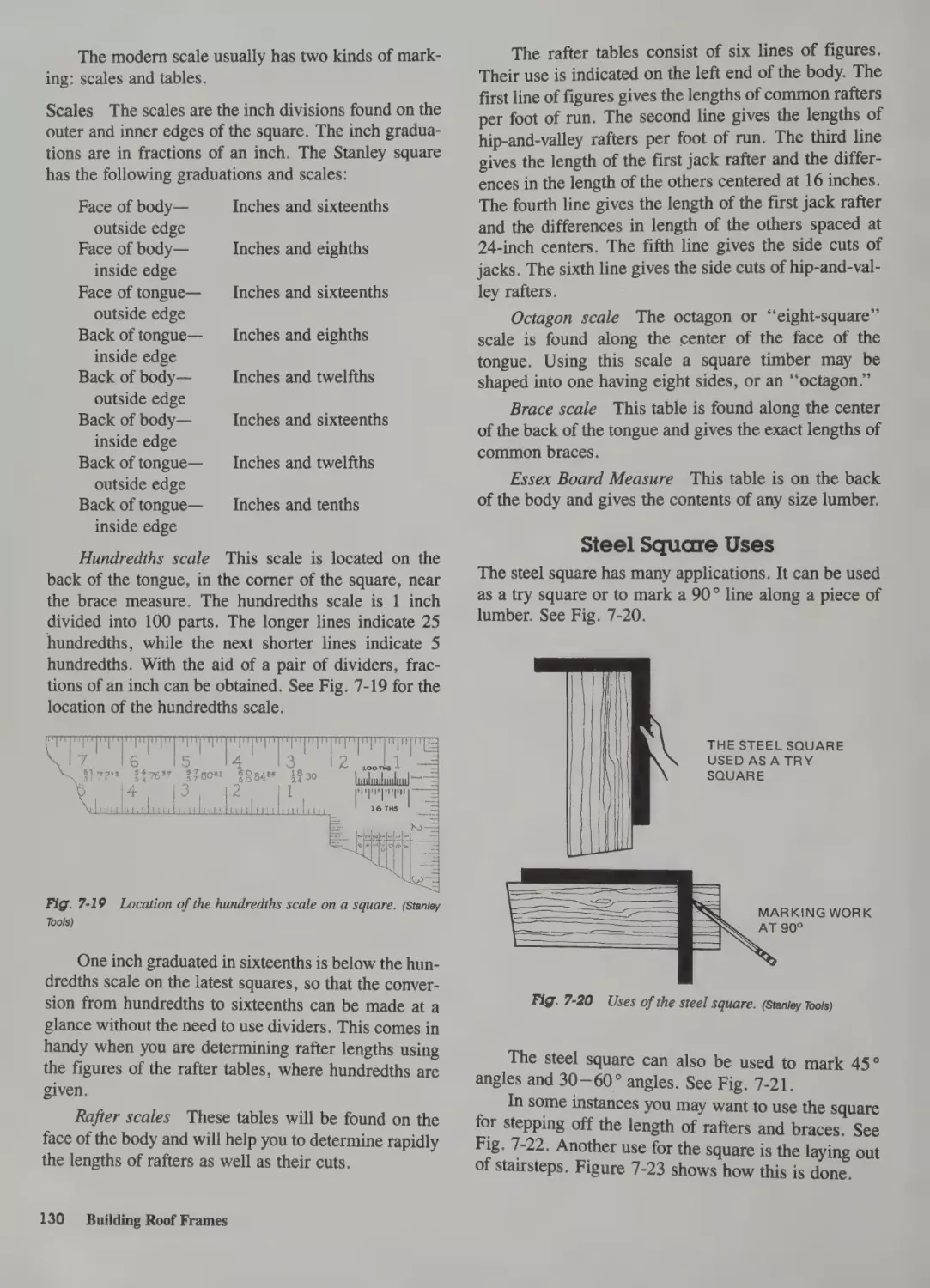
Steel Square Uses 130
Roof Framing 131
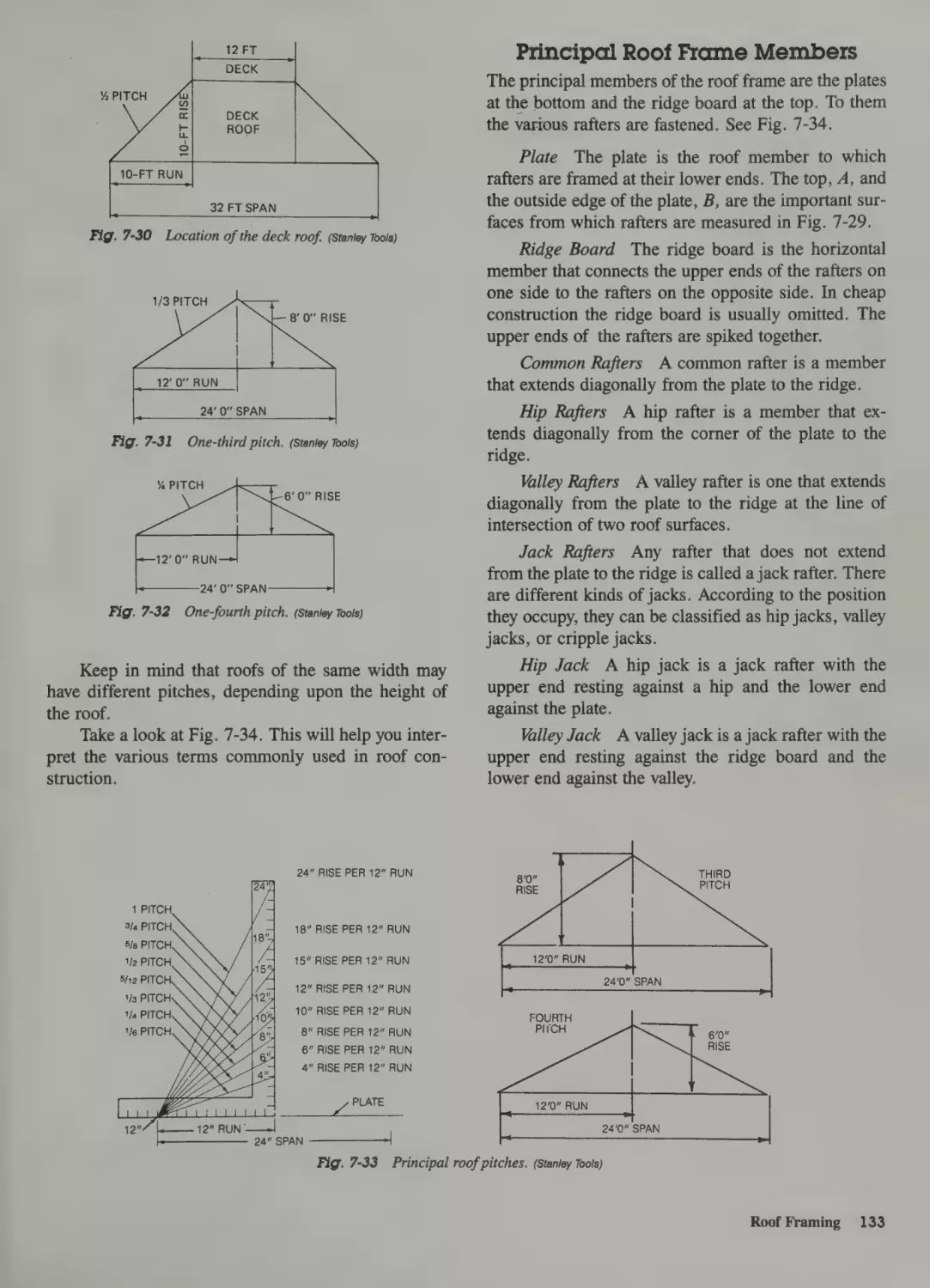
Roof Terms 132
Principal Roof Frame Members
164
& Covering Roofs
Sheathing 116
Factors in Wall Construction
160
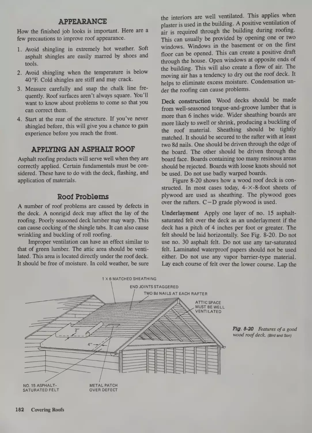
Appearance
182
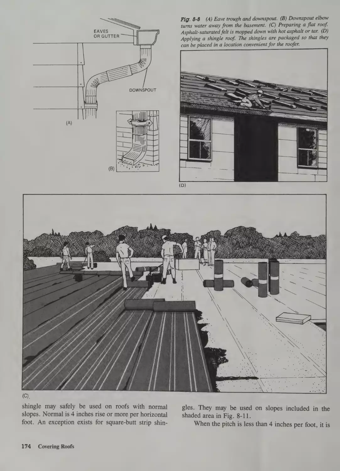
Applying an Asphalt Roof 182
133
Roof Problems
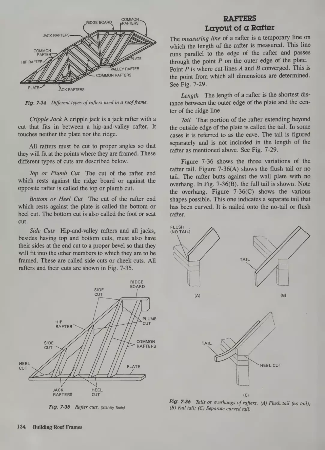
Rafters 134
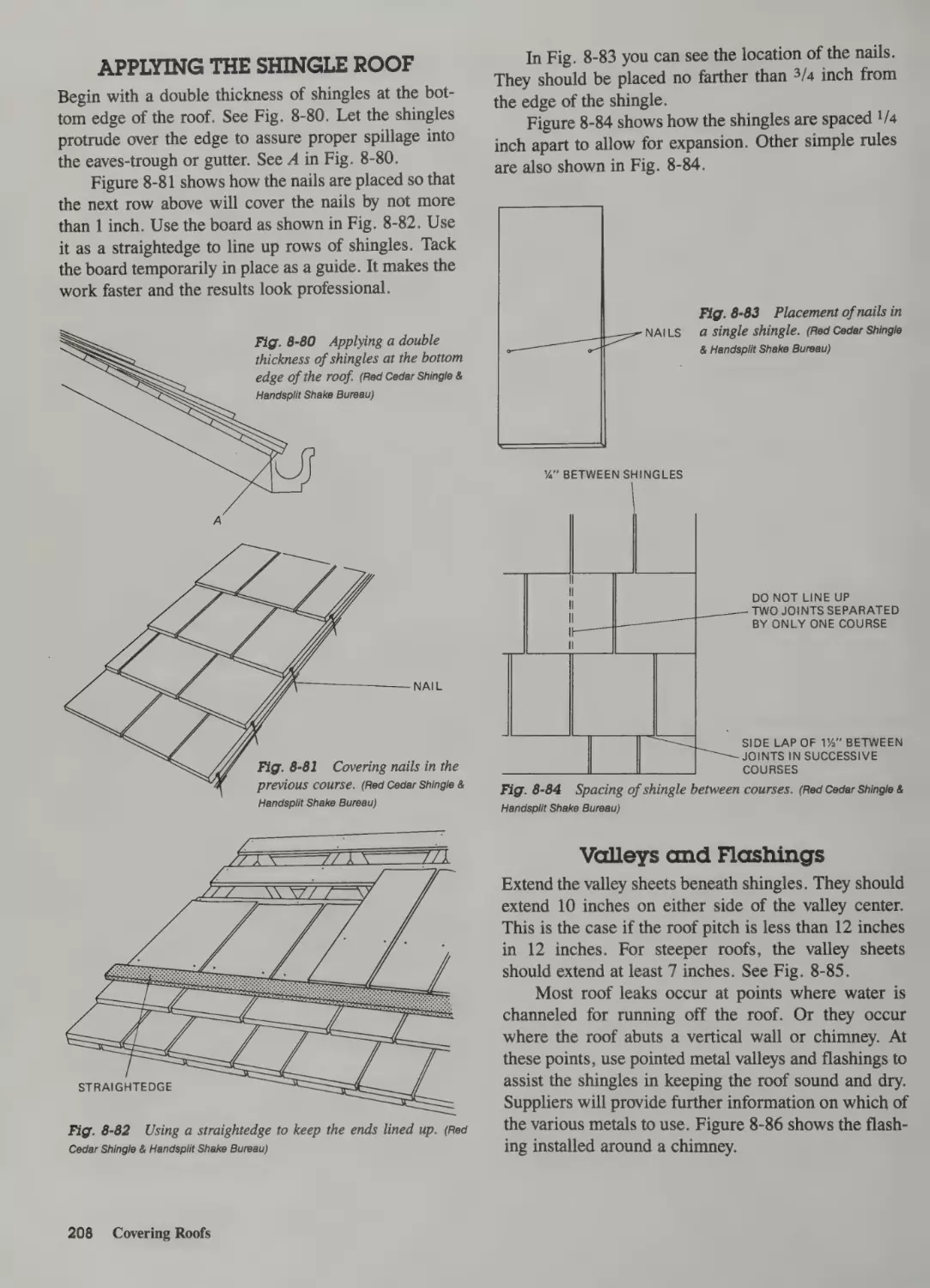
Putting Down Shingles 184
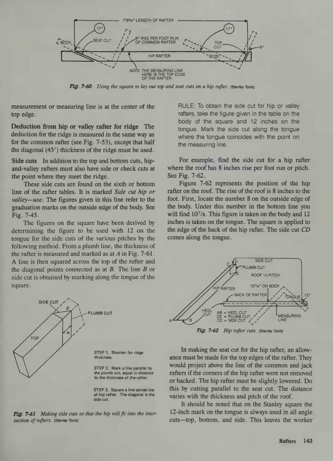
Layout of a Rafter 134
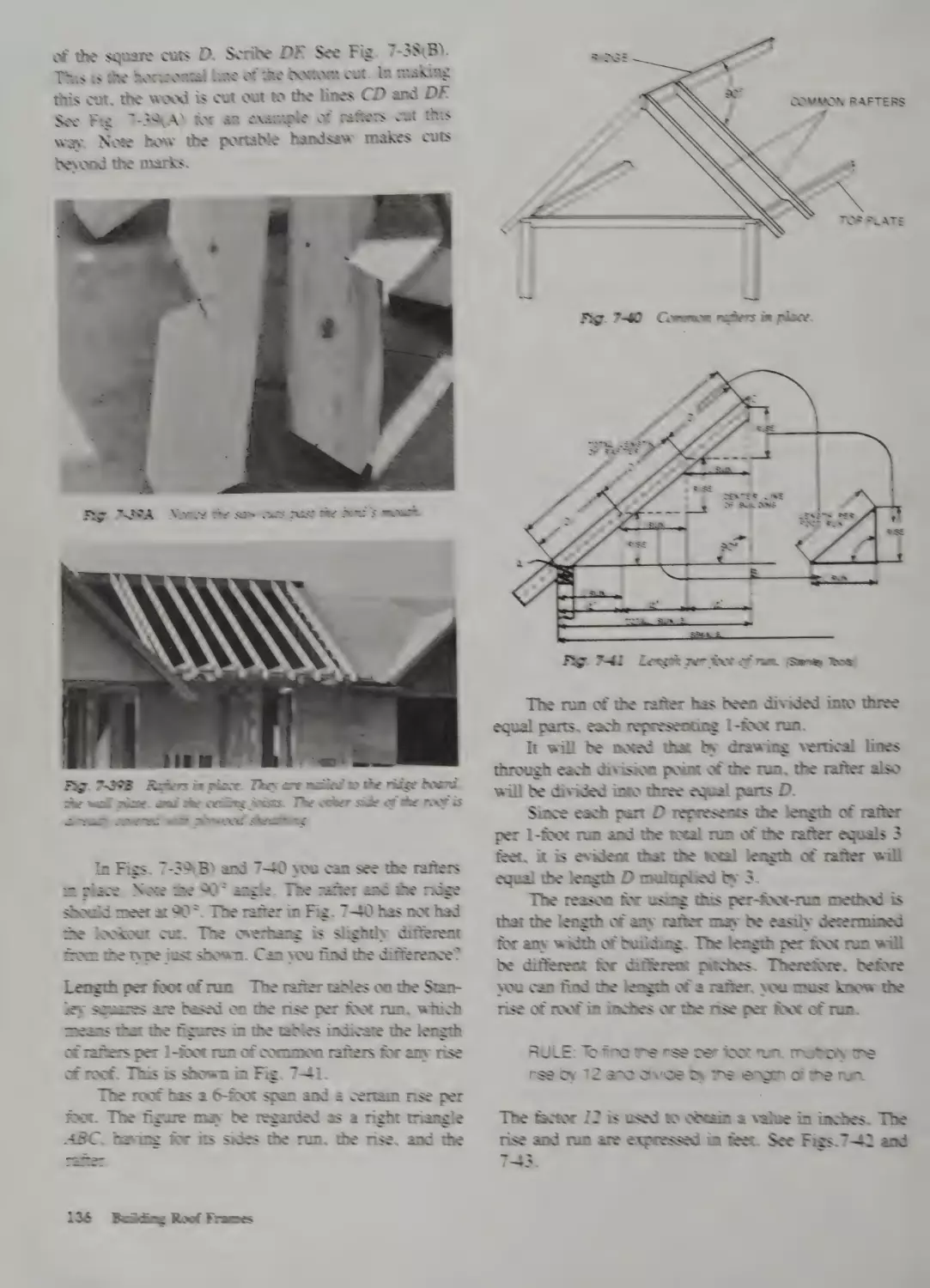
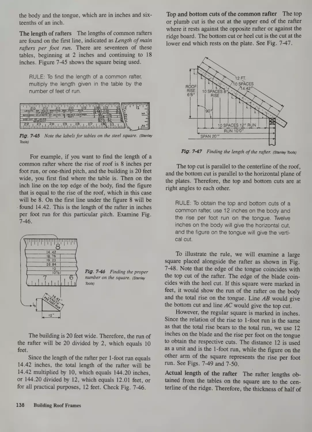
Length of Rafters 137
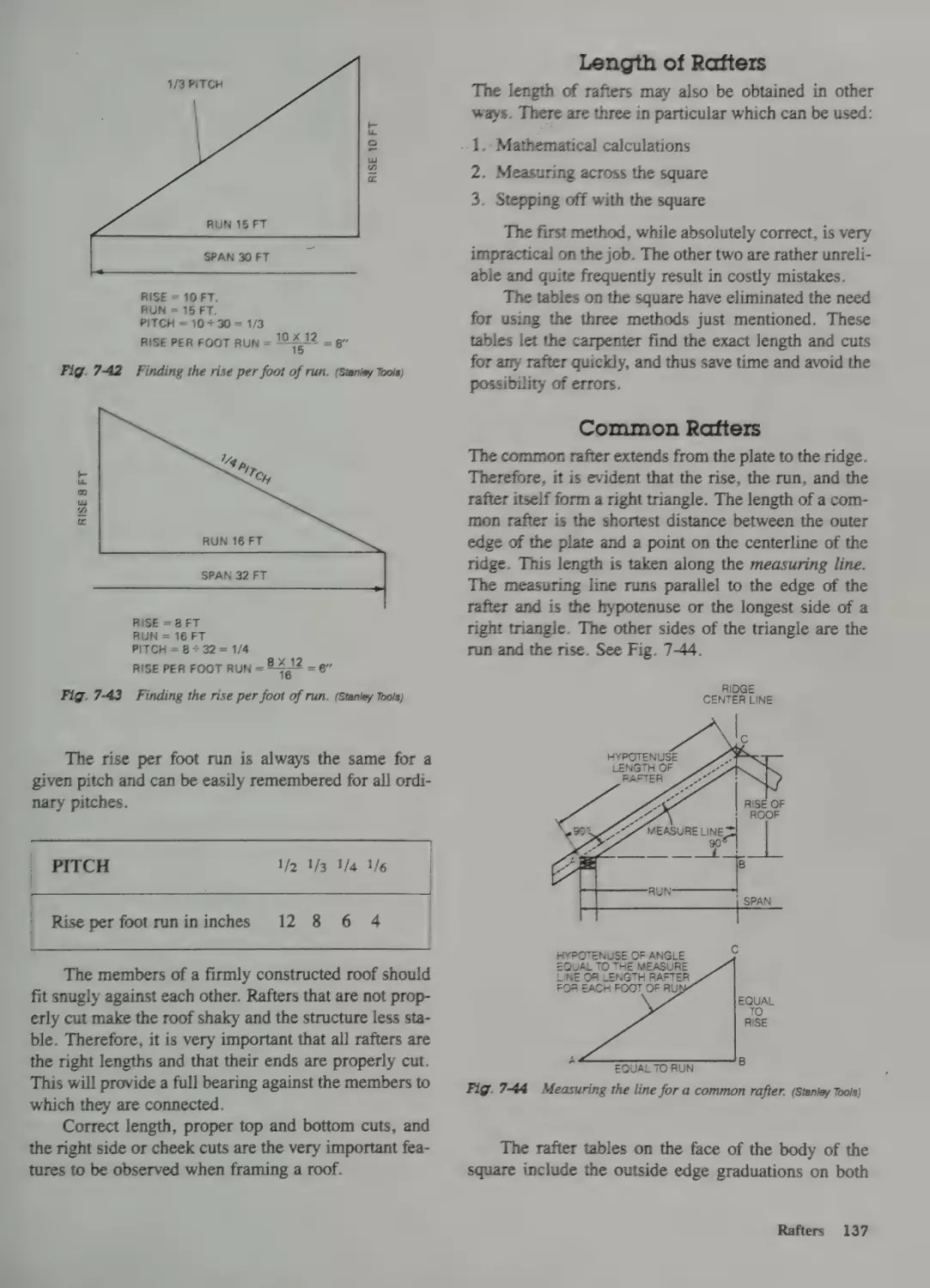
Common Rafters 137
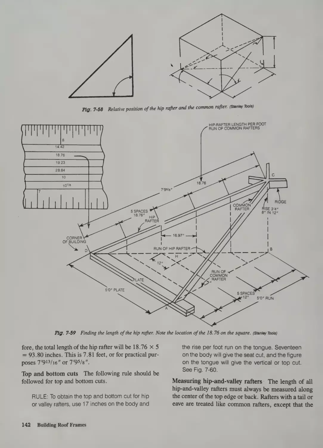
Hip-and-Valley Rafters 141
Jack Rafters 144
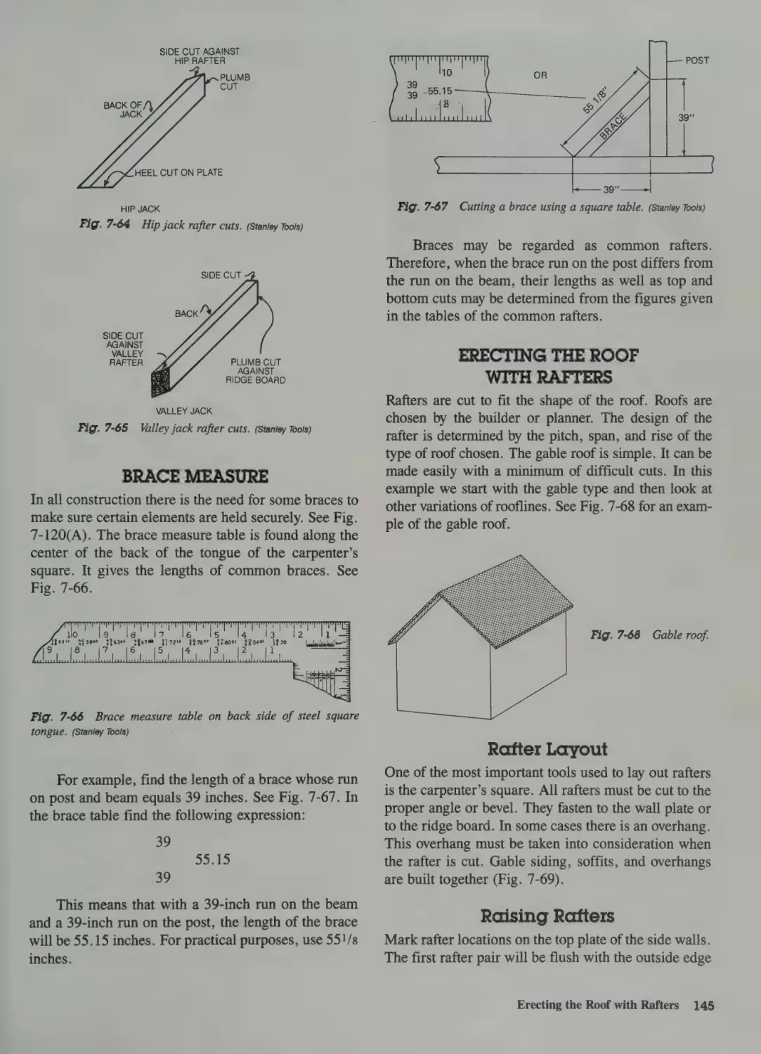
Brace Measure 145
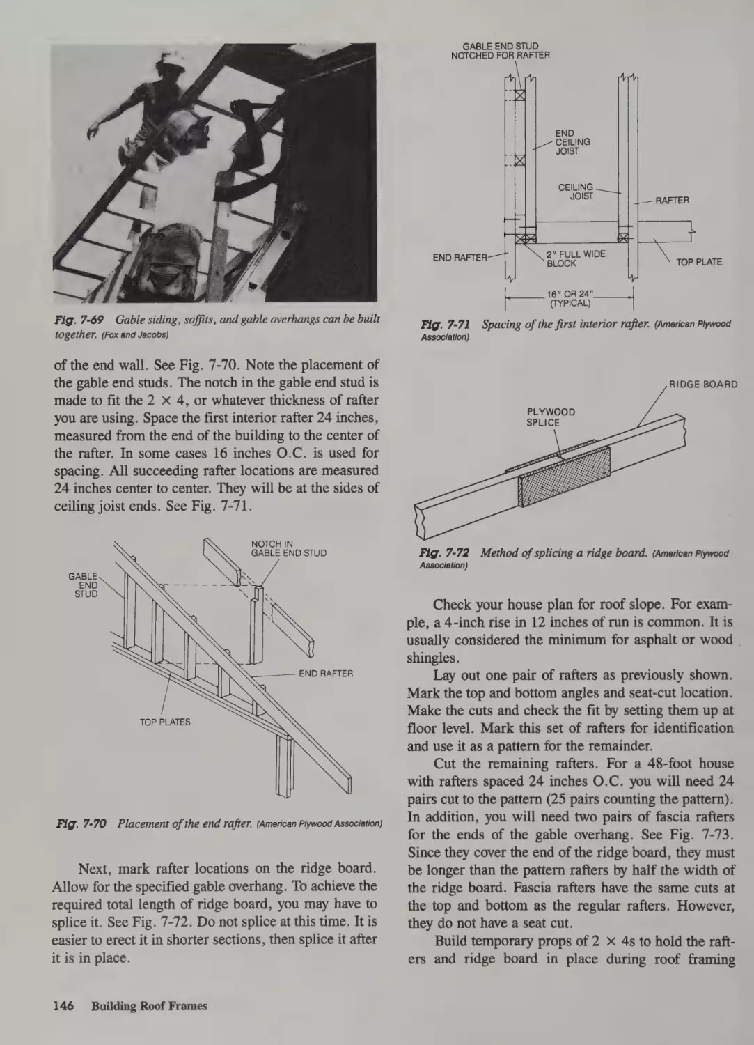
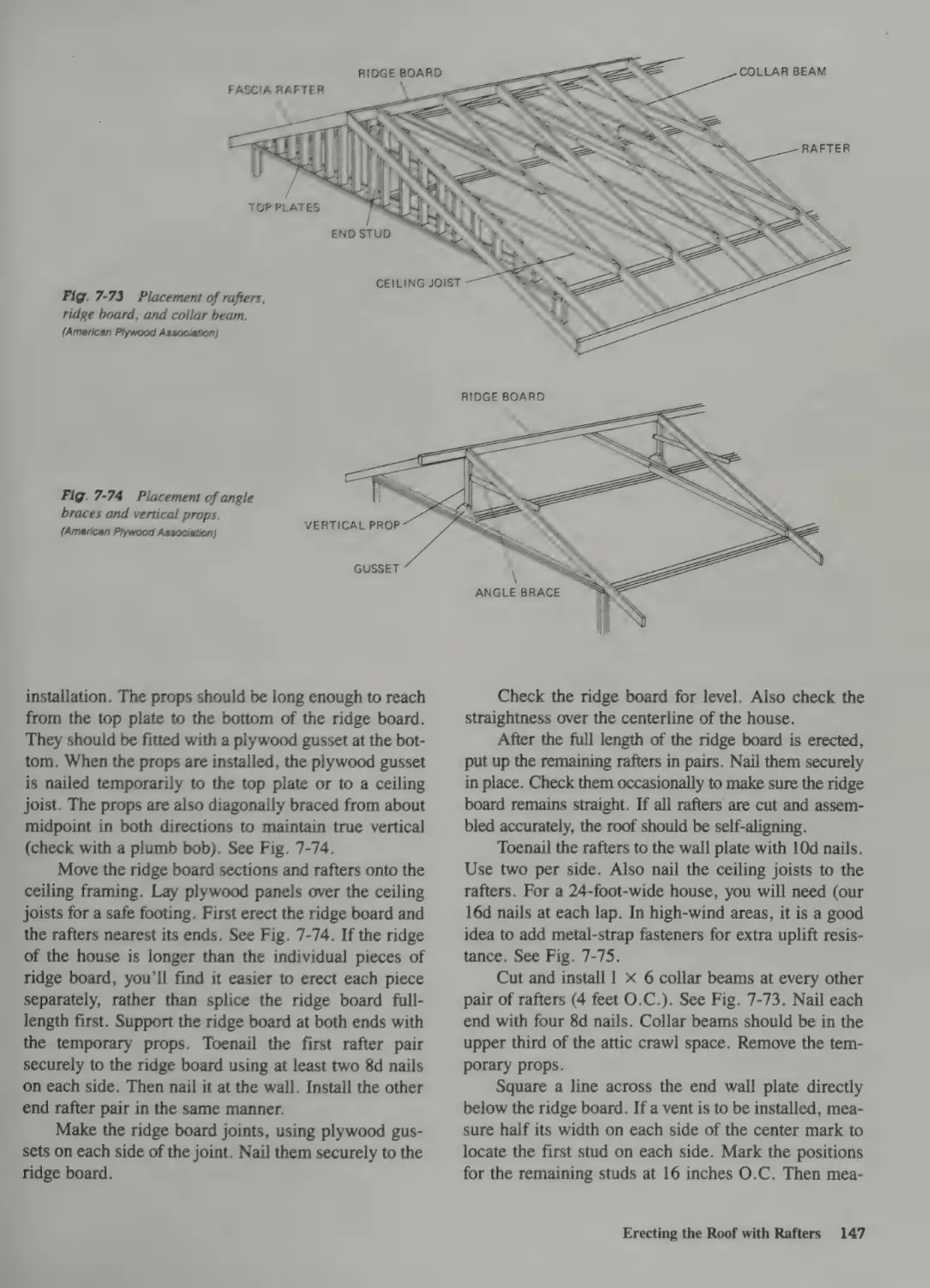
Erecting the Roof with Rafters 145
Rafter Layout 145
Raising Rafters 145
Nails 184
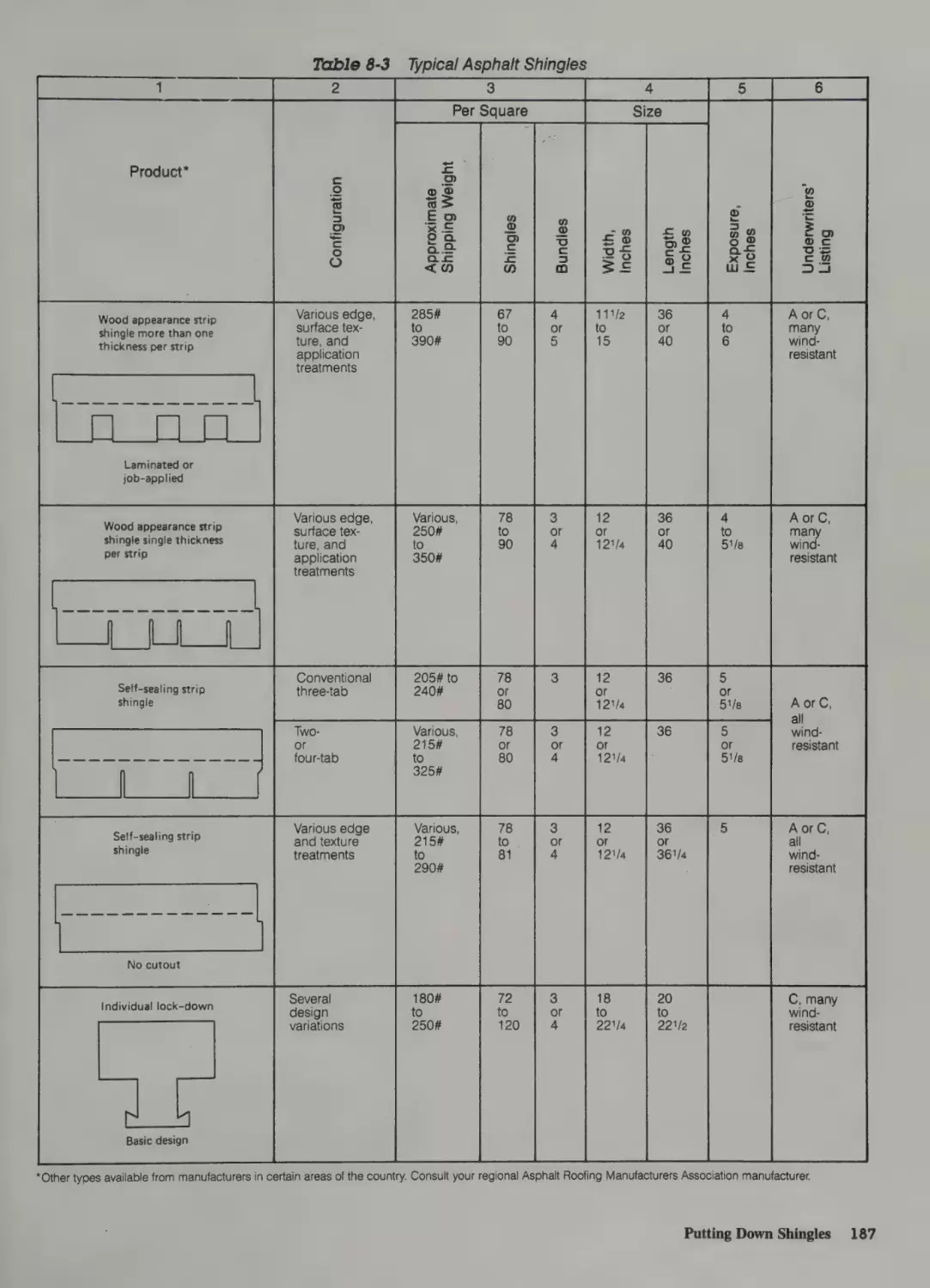
Fasteners for Nonwood Materials 186
Shingle Selection 186
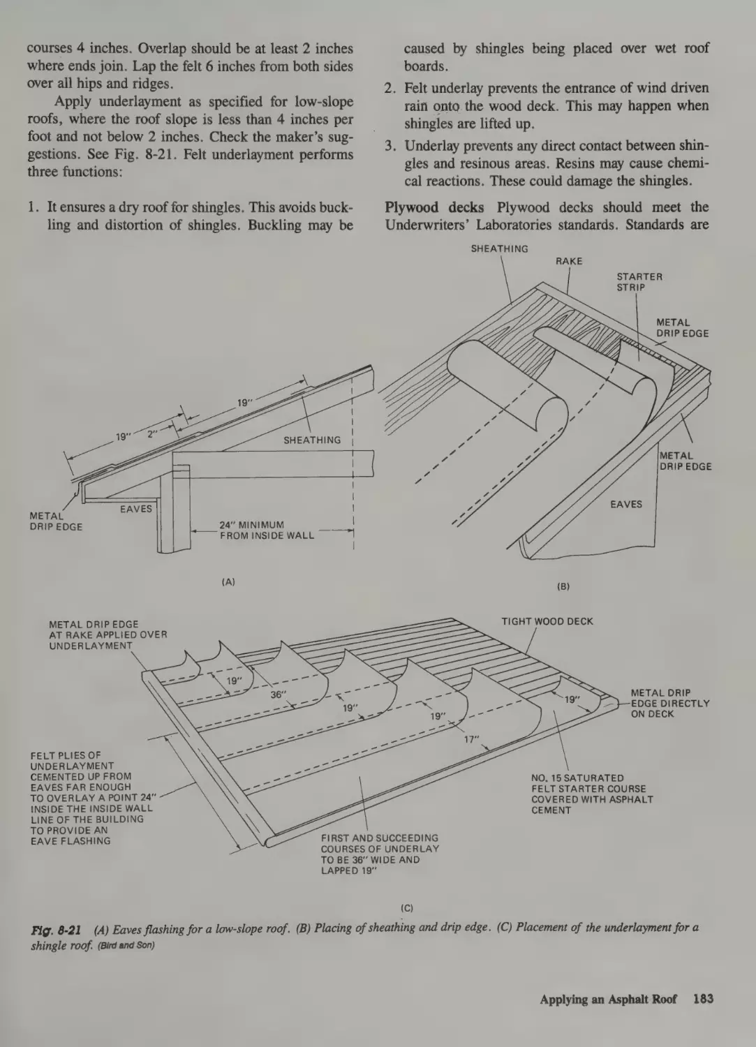
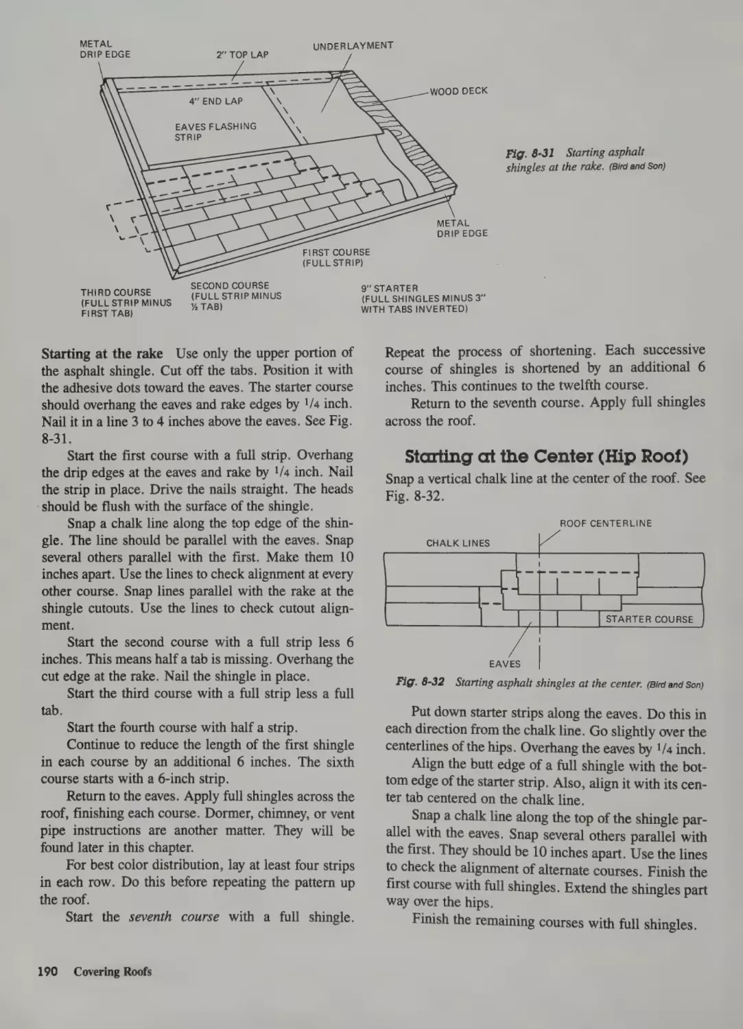
Starter Course 189
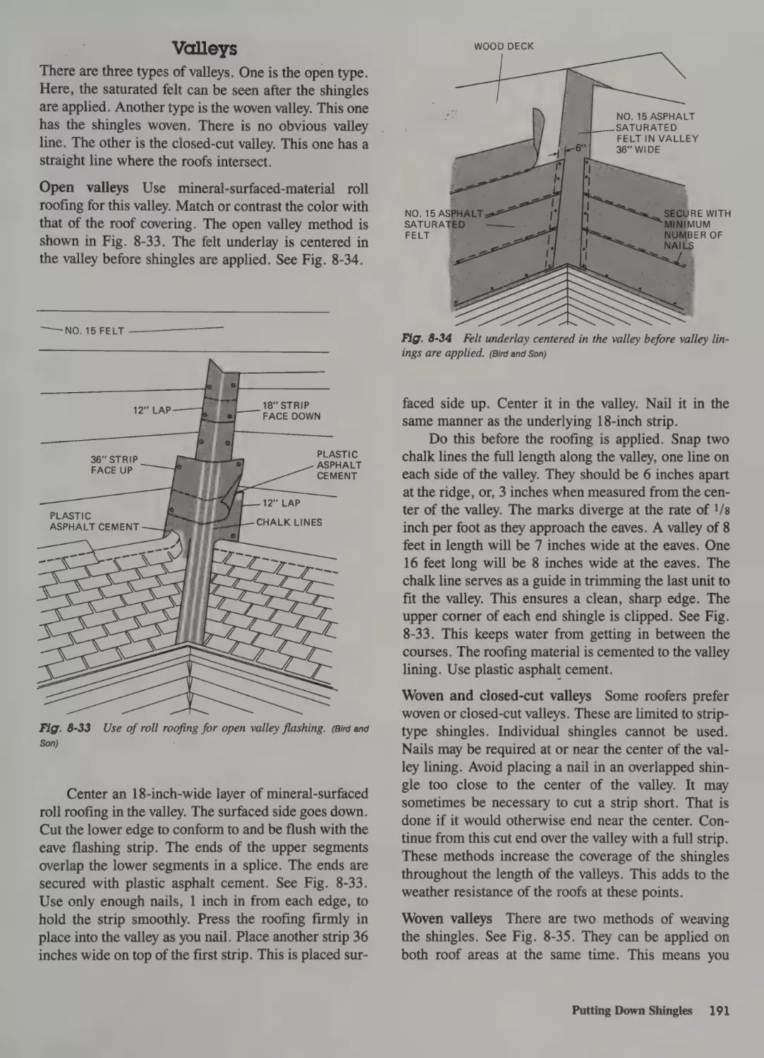
Starting at the Center (Hip Roof) 190
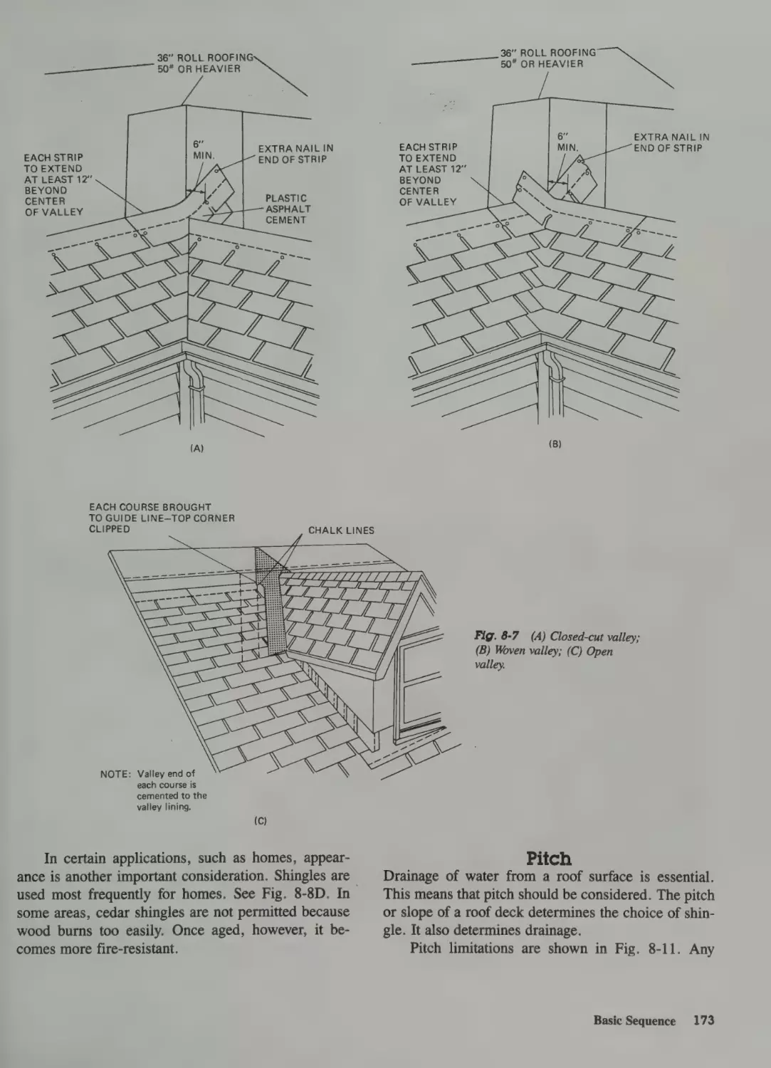
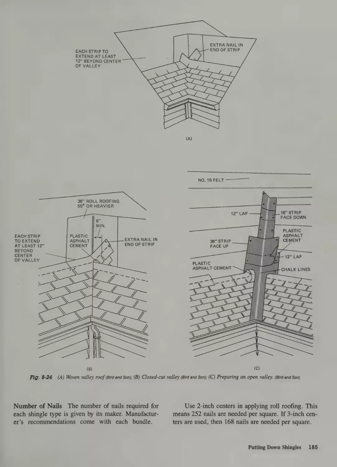
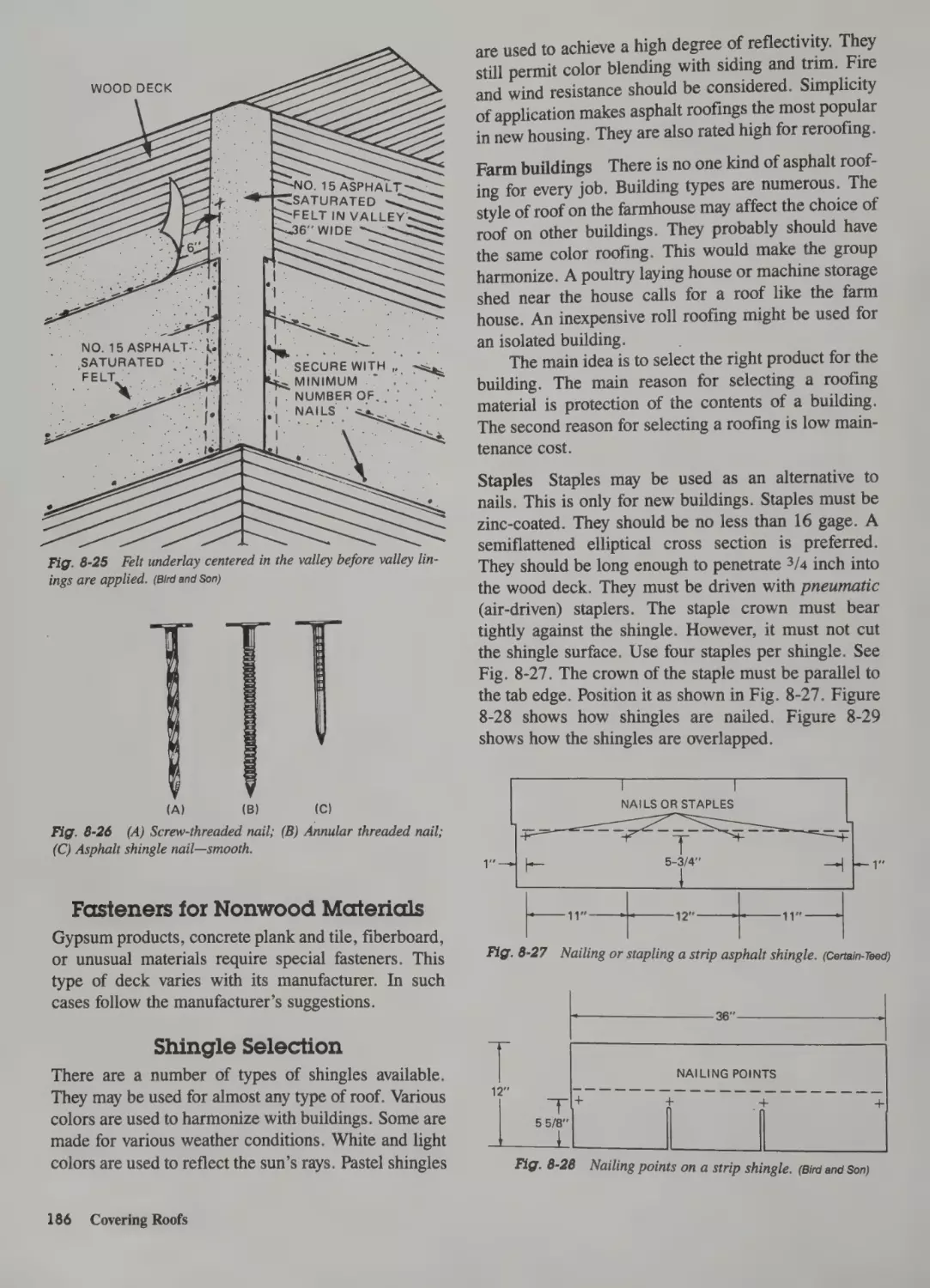
Valleys 191
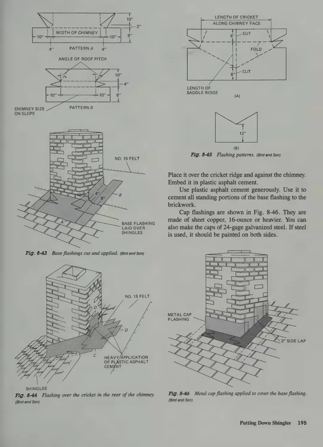
Flashing against a Vertical Wall 193
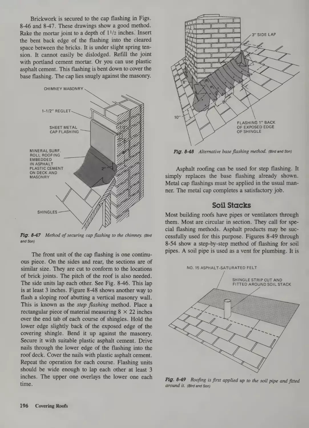
Chimneys 194
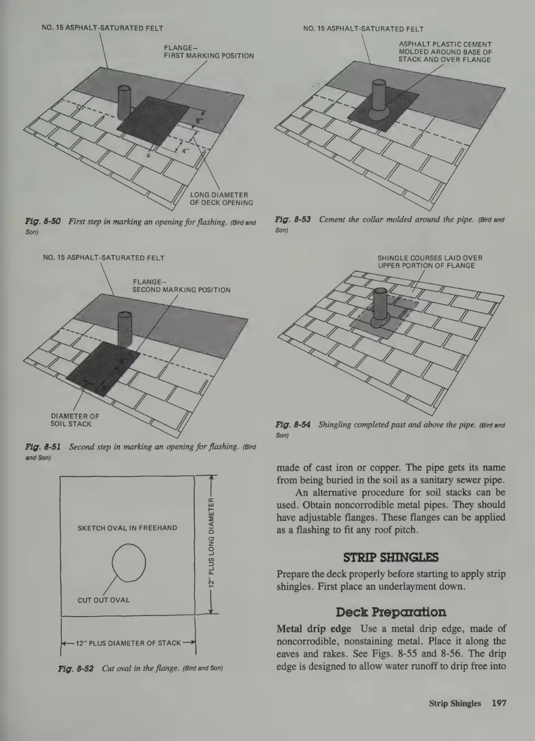
Soil Stacks 196
Strip Shingles 197
Special Rafters 148
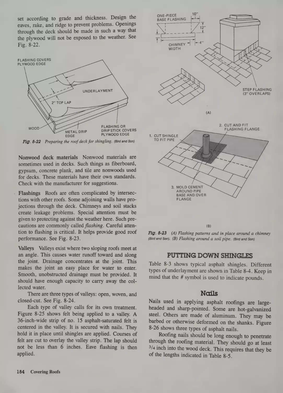
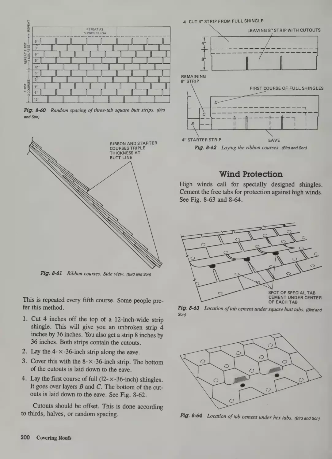
Deck Preparation 197
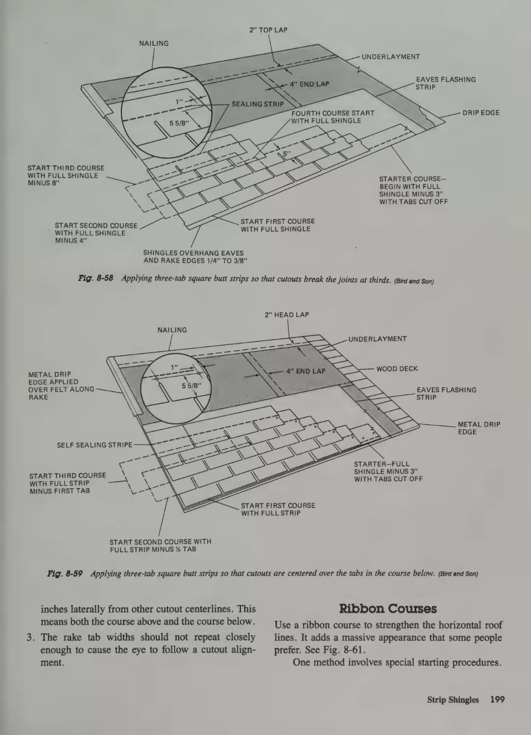
First and Succeeding Courses 198
Ribbon Courses 199
Wind Protection 200
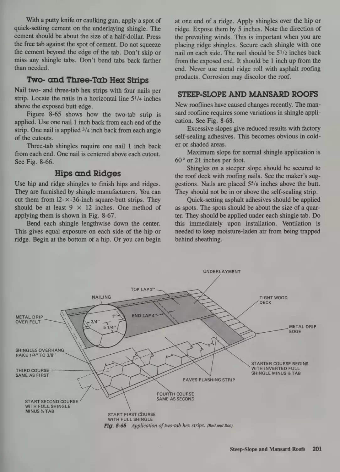
Two- and Three-Tab Hex Strips 201
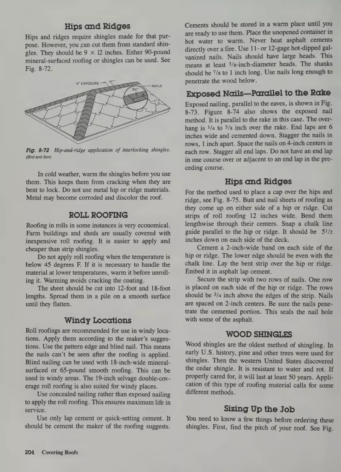
Hips and Ridges 201
Dormers 148
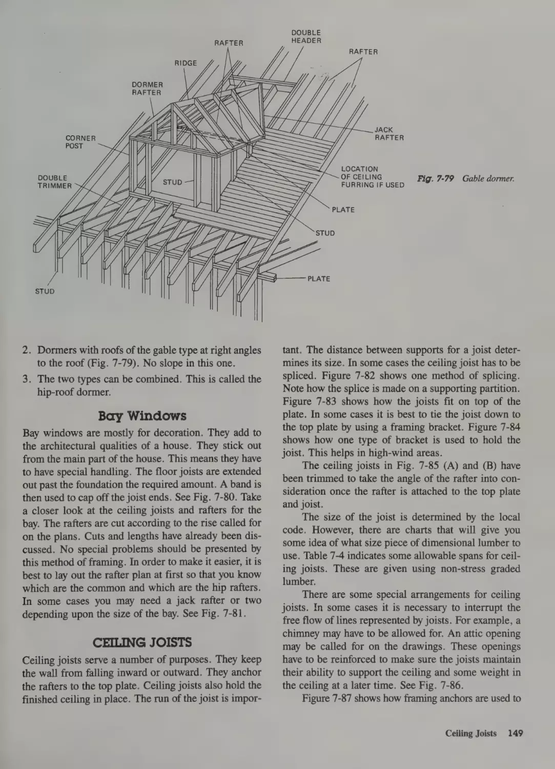
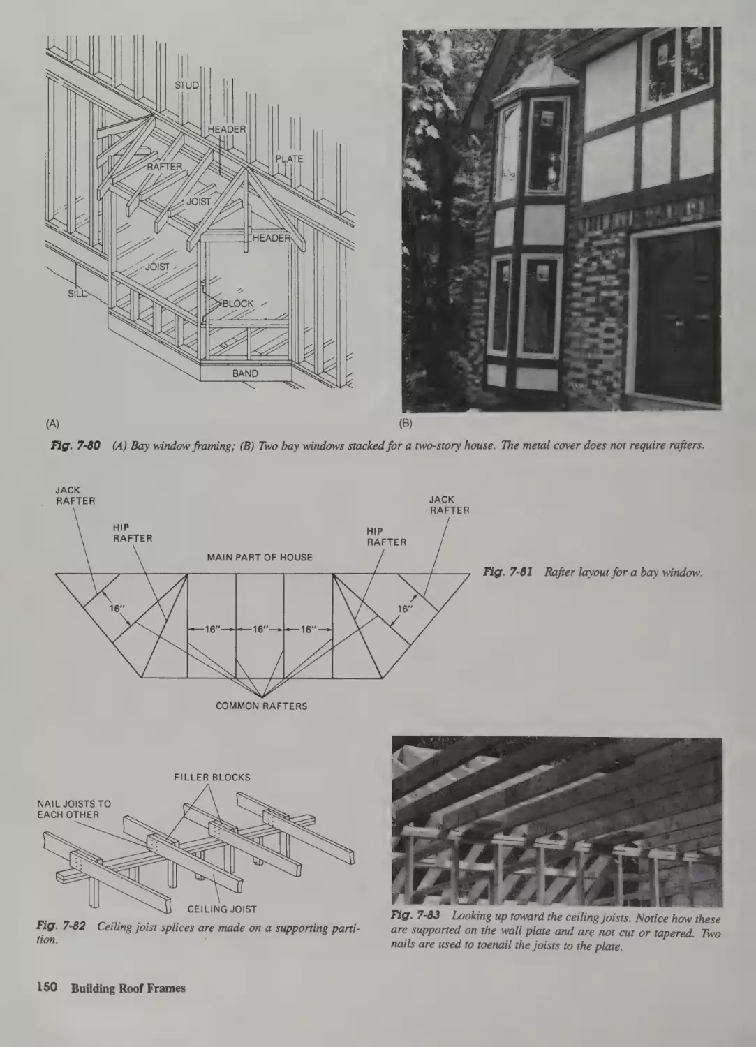
Bay Windows 149
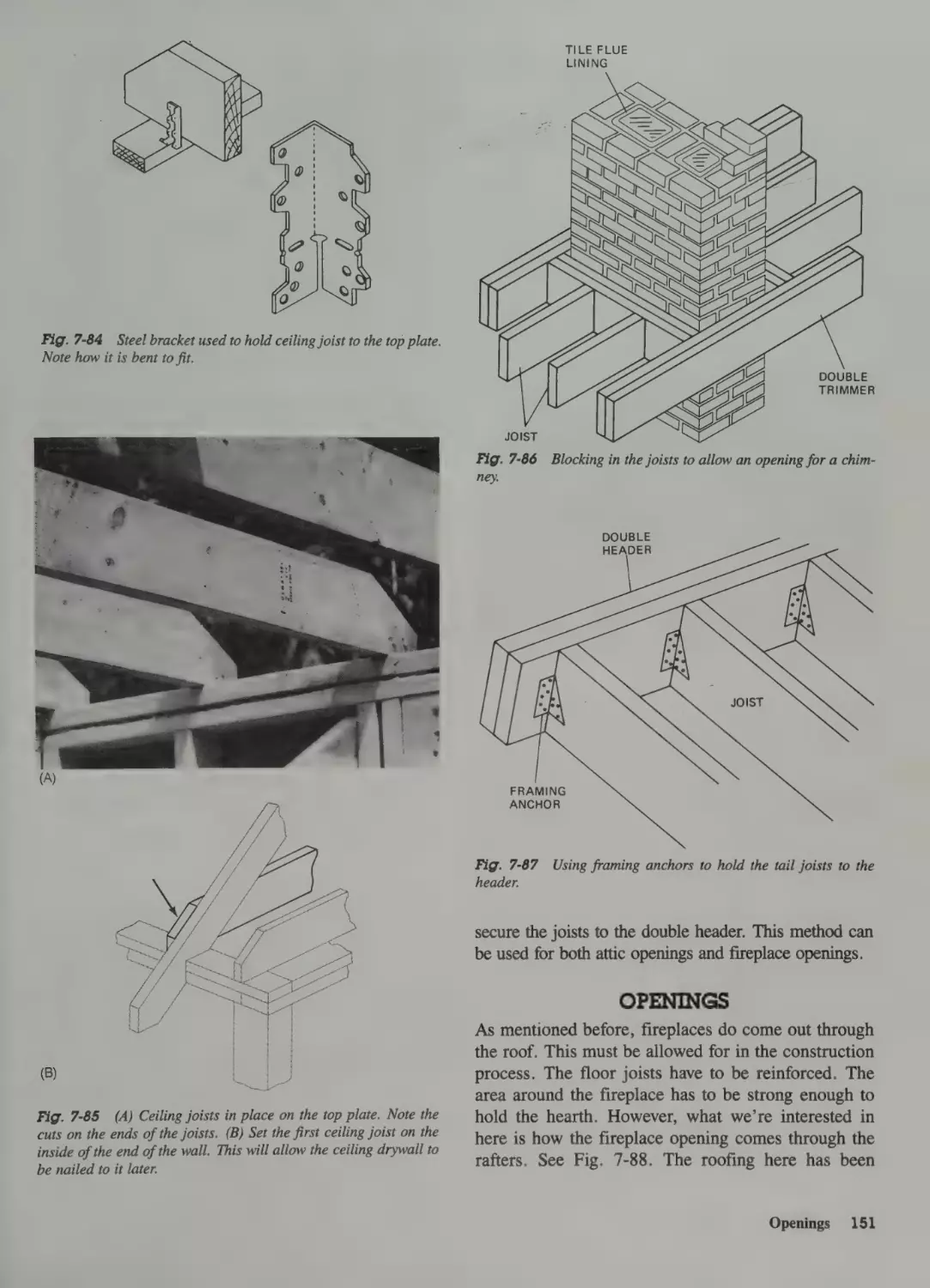
Ceiling Joists 149
Openings 151
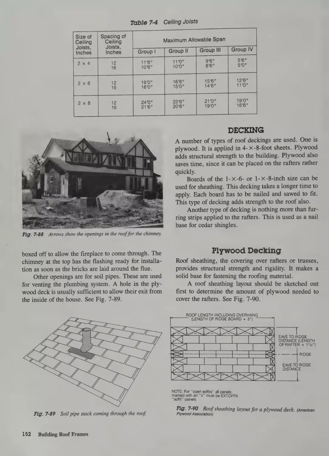
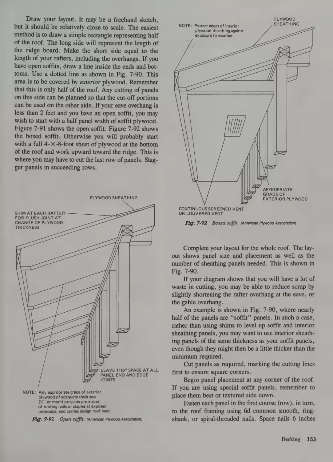
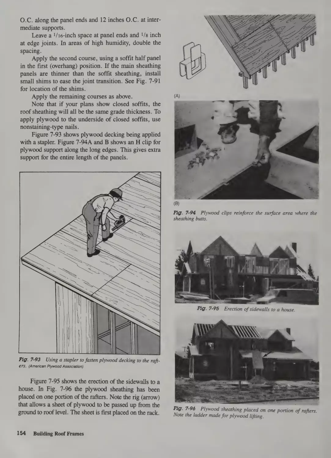
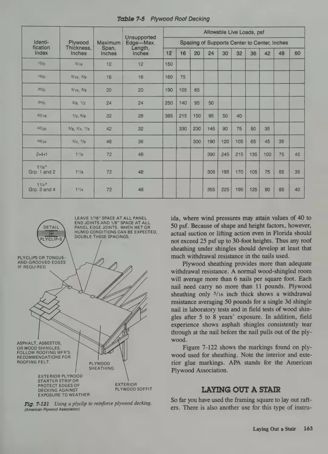
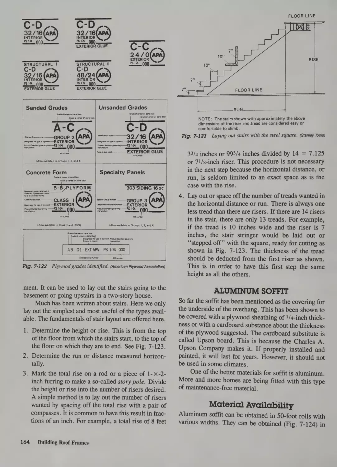
Decking 152
Plywood Decking 152
Boards for Decking 155
Shingle Stringers 155
Steep-Slope and Mansard Roofs 201
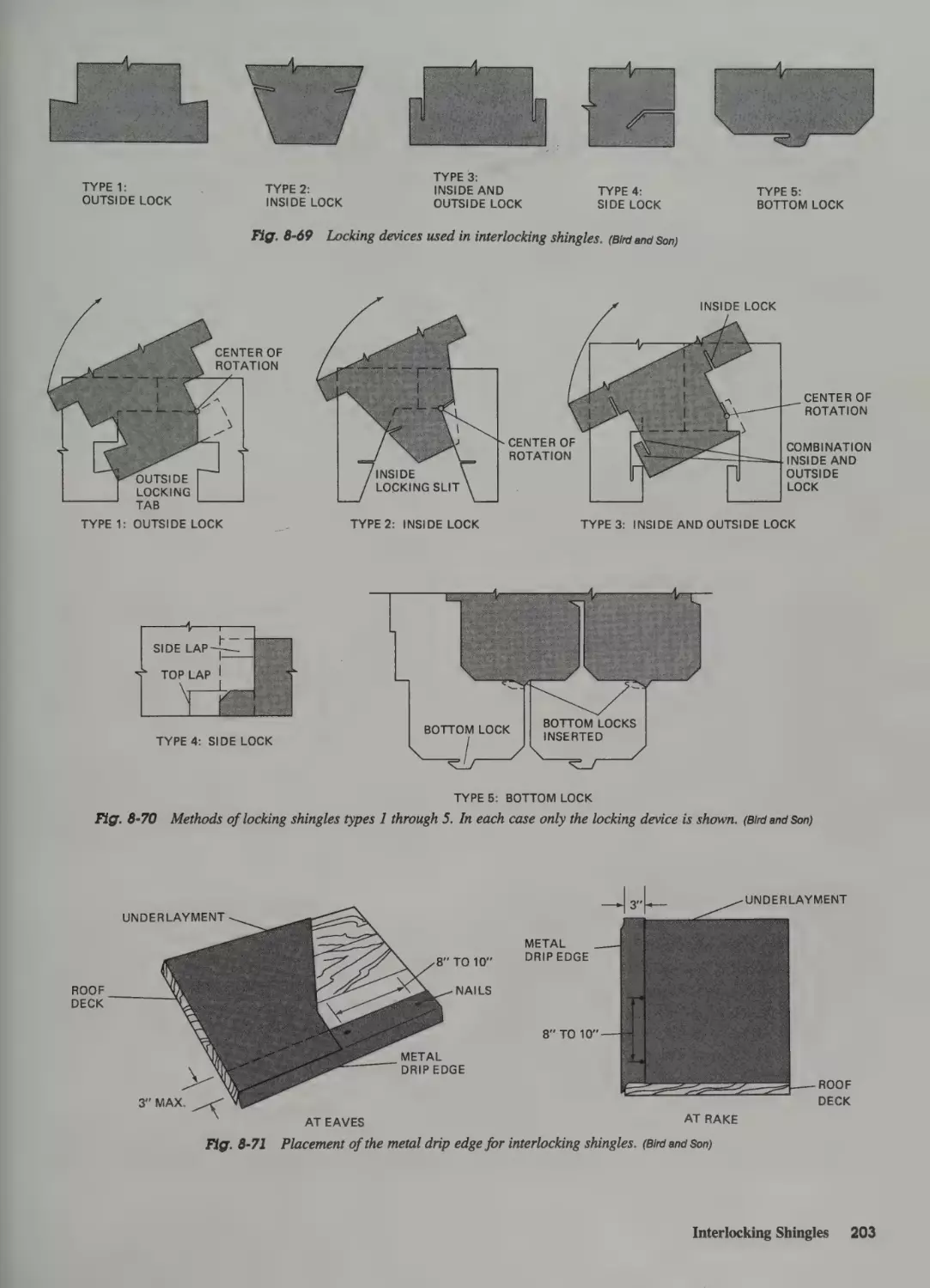
Interlocking Shingles 202
Hips and Ridges 204
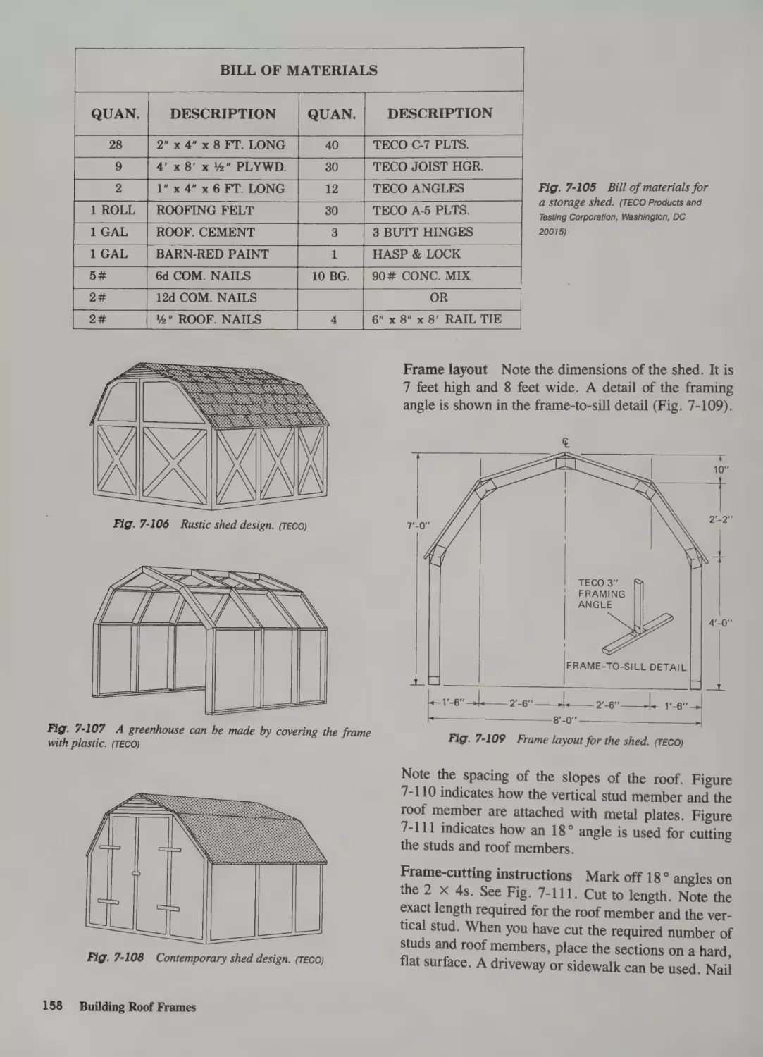
Constructing Special Shapes 157
Gambrel-Shaped-Roof Storage Shed
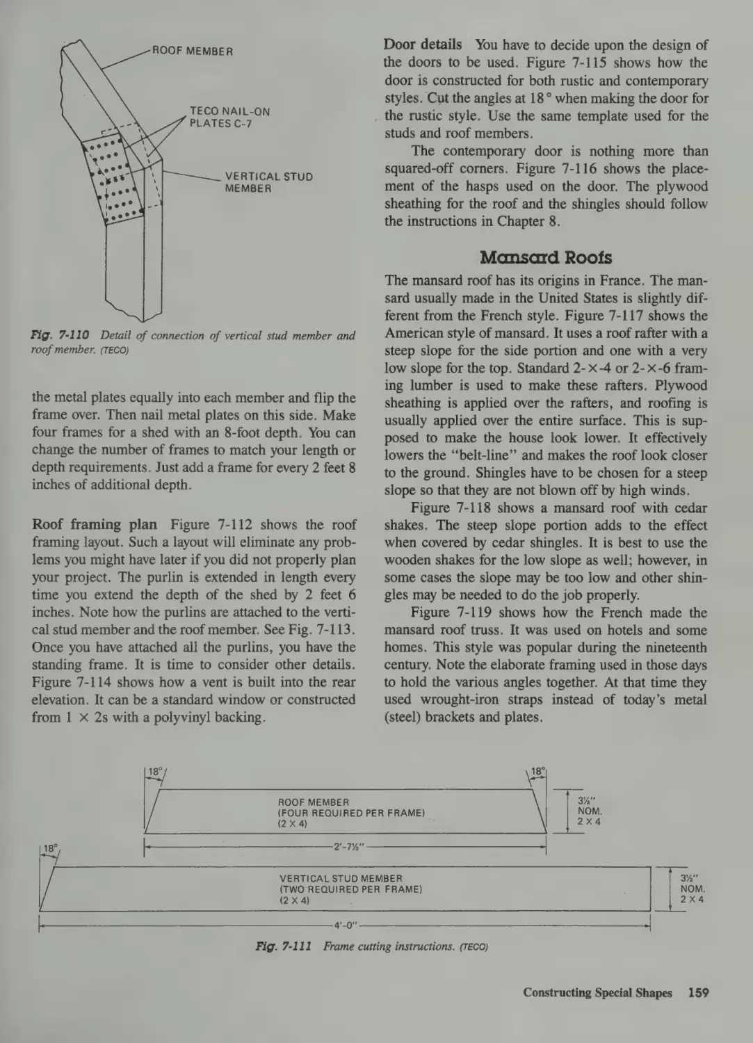
Mansard Roofs 159
184
157
Roll Roofing 204
Windy Locations 204
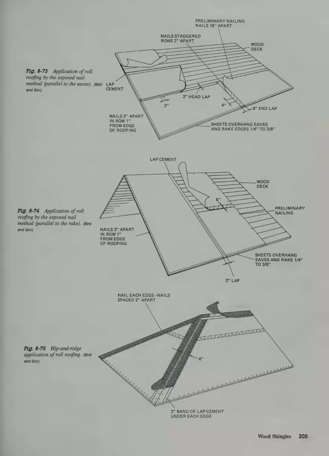
Exposed Nails—Parallel to the Rake 204
Hips and Ridges 204
Wood Shingles 204
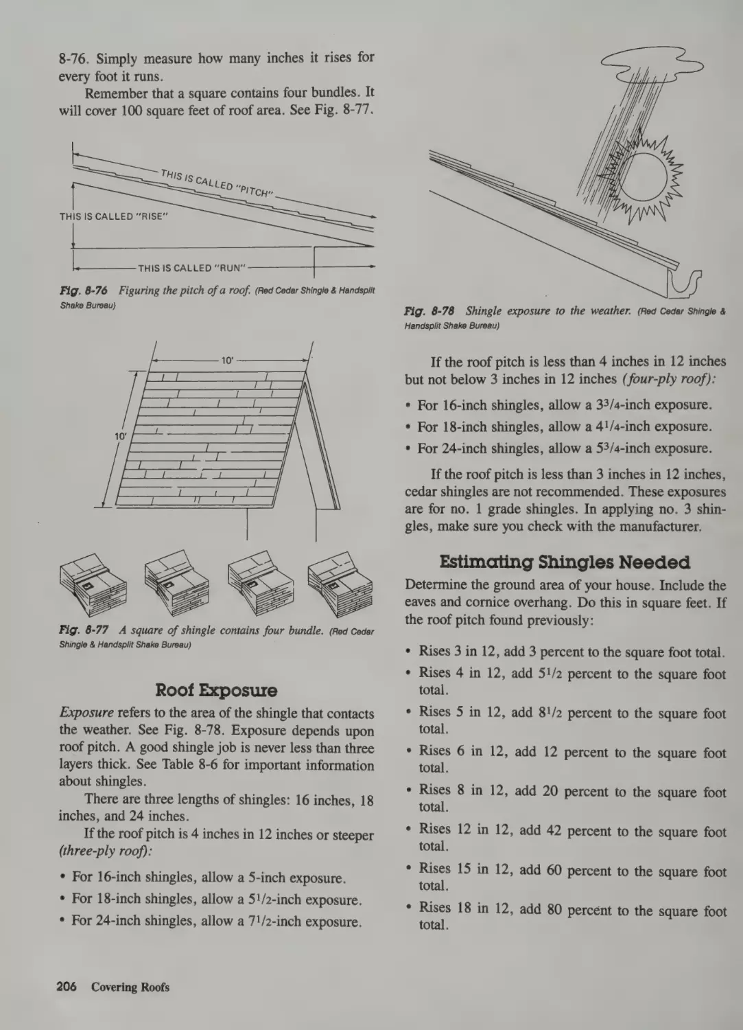
Sizing Up the Job 204
Roof Exposure 206
Estimating Shingles Needed
Tools of the Trade 207
206
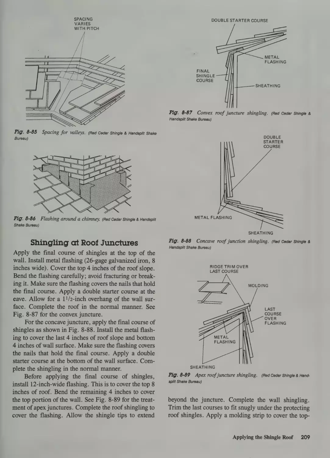
Applying the Shingle Roof 208
Valleys and Flashings 208
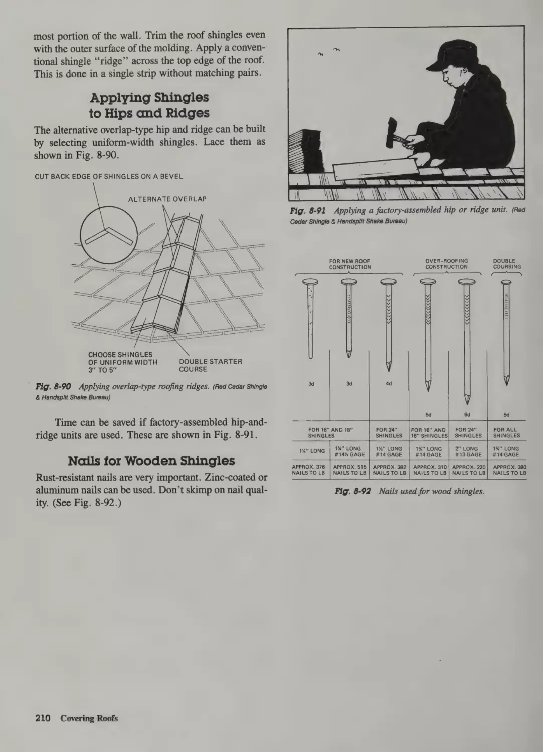
Shingling at Roof Junctures 209
Applying Shingles to Hips and Ridges 210
Nails for Wooden Shingles 210
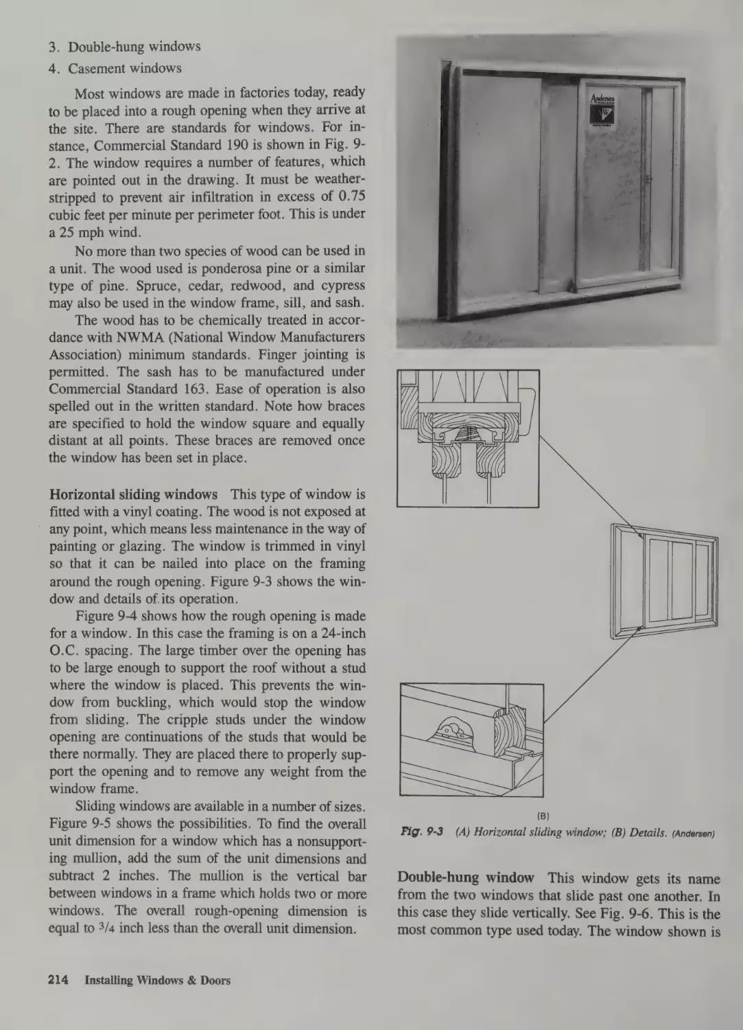
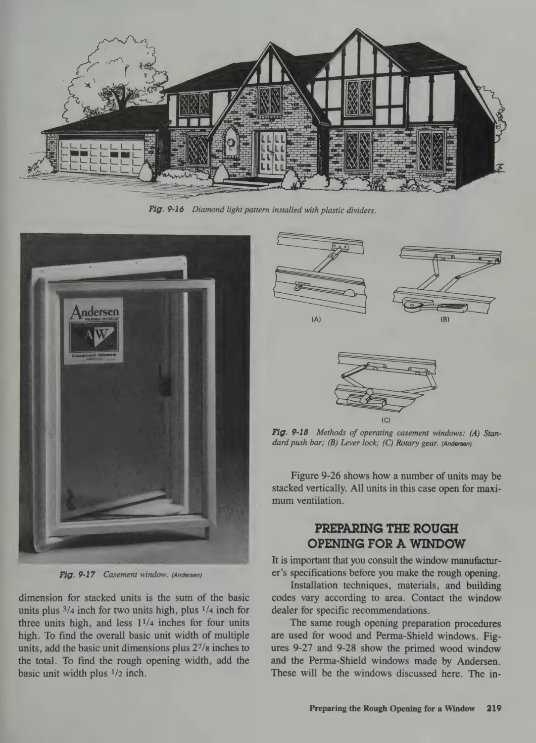
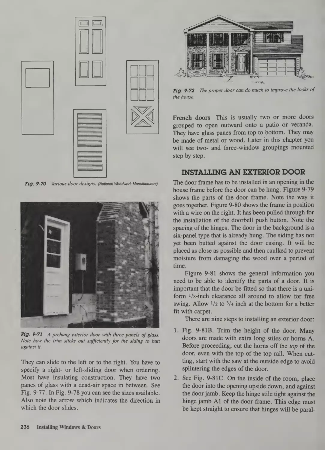
Q Installing Windows & Doors
Basic Sequence 212
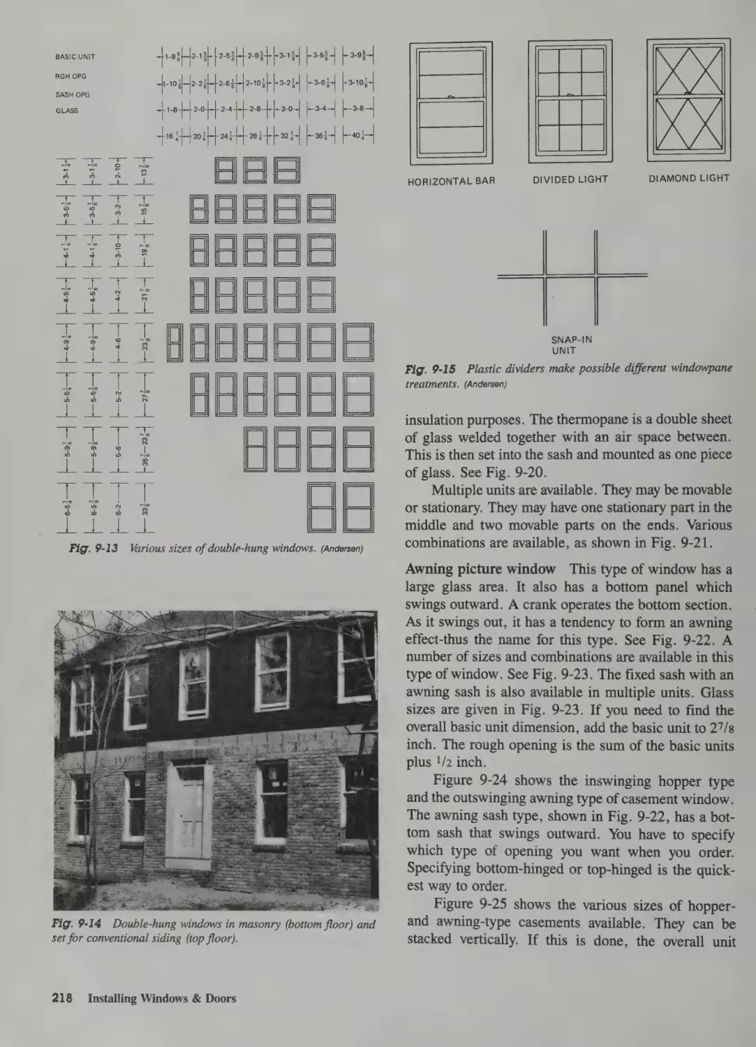
Types of Windows 213
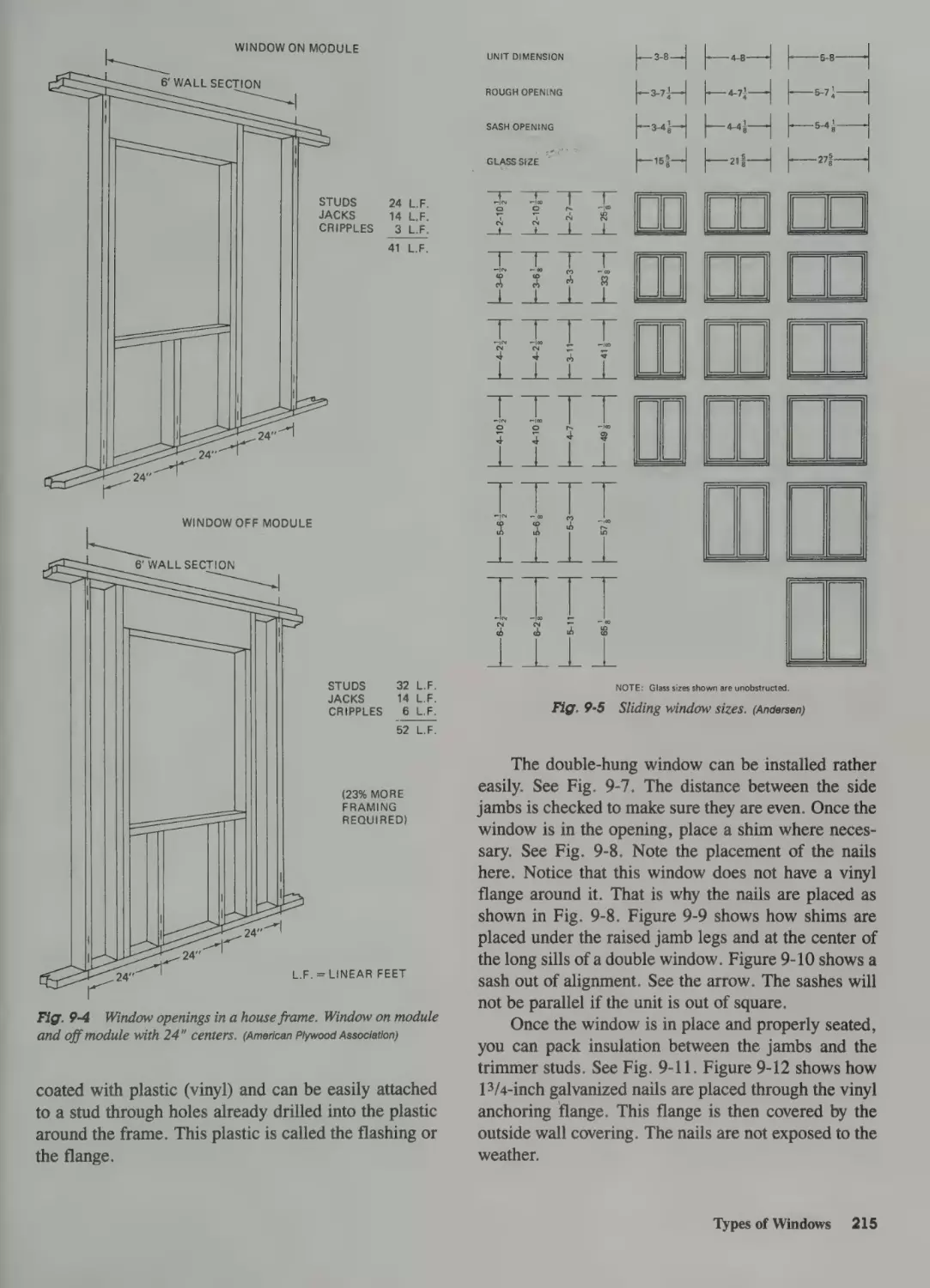
Preparing the Rough Opening
for a Window 219
Steps in Preparing the Rough Opening 222
Installing a Wood Window
Installing an Andersen
Perma-Shield Window
224
226
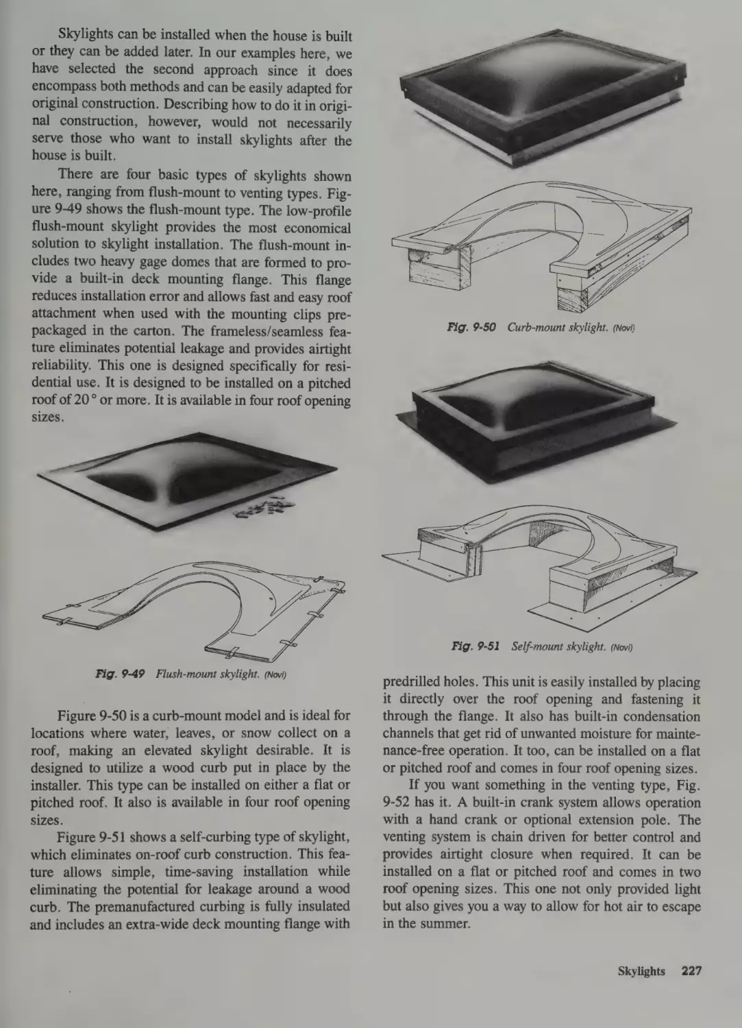
Skylights 226
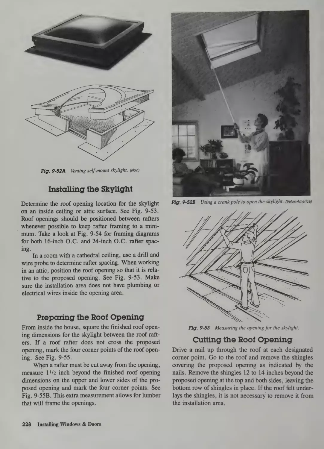
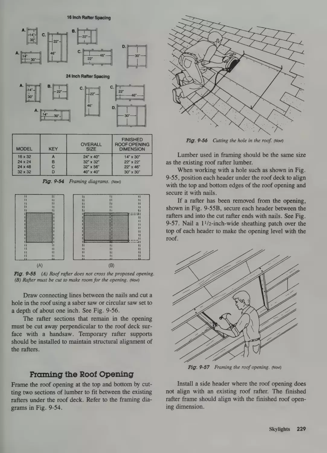
Installing the Skylight 228
Preparing the Roof Opening 228
Cutting the Roof Opening 228
Framing the Roof Opening 229
Mounting the Skylight 230
Sealing the Installation 230
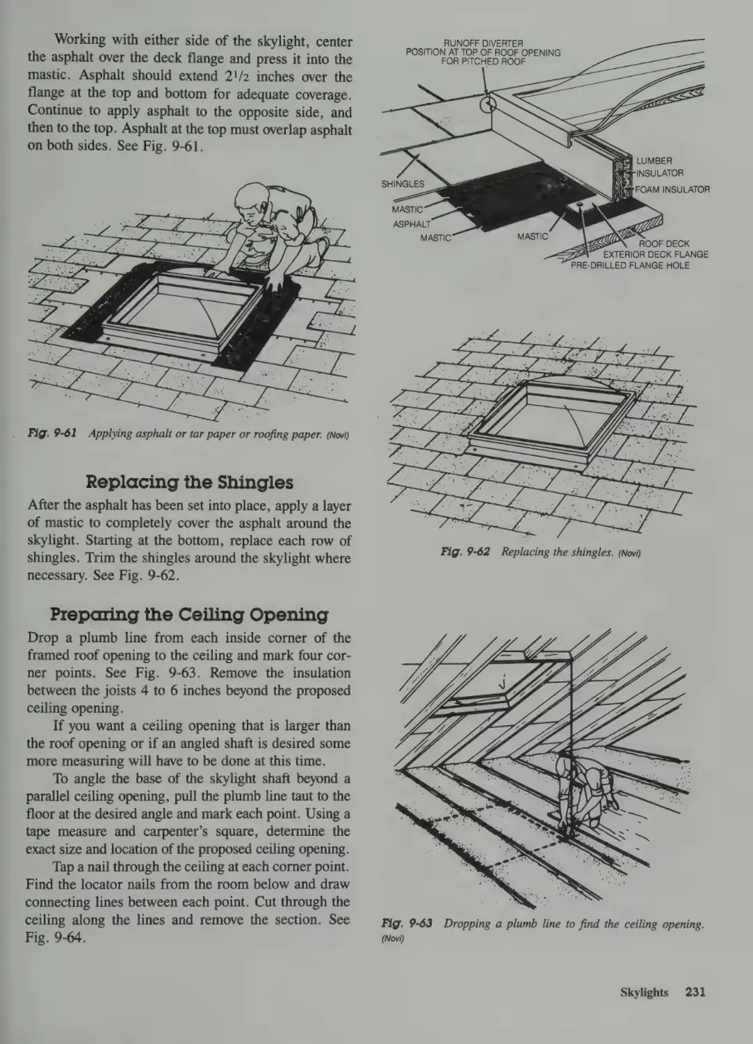
Replacing the Shingles 231
Preparing the Ceiling Opening 231
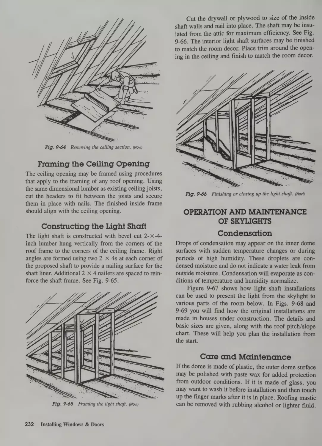
Framing the Ceiling Opening 232
Constructing the Light Shaft 232
Operation and Maintenance
of Skylights 232
Condensation 232
Care and Maintenance
232
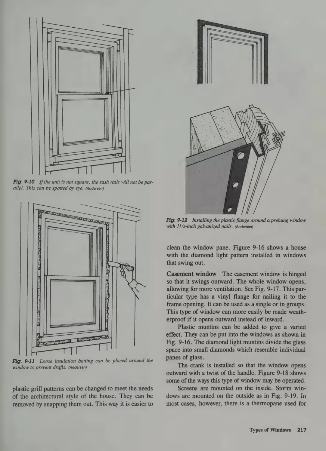
Terms Used in Window Installation 233
Prehung Doors 233
Types of Doors 233
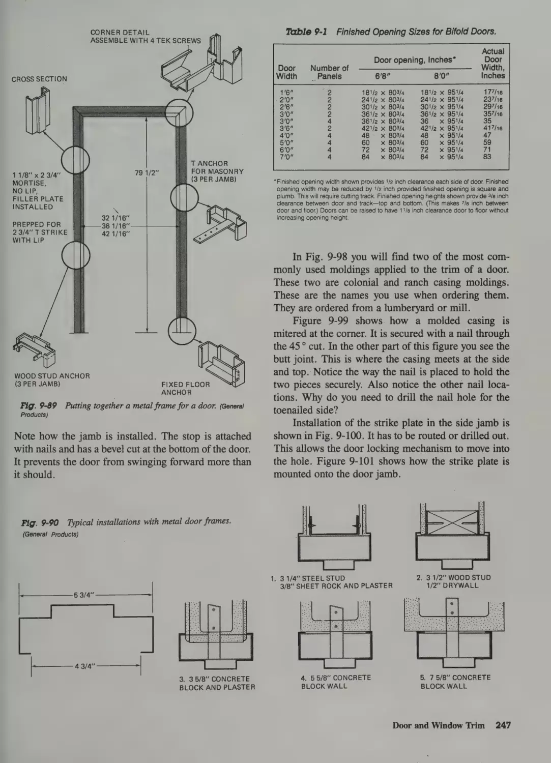
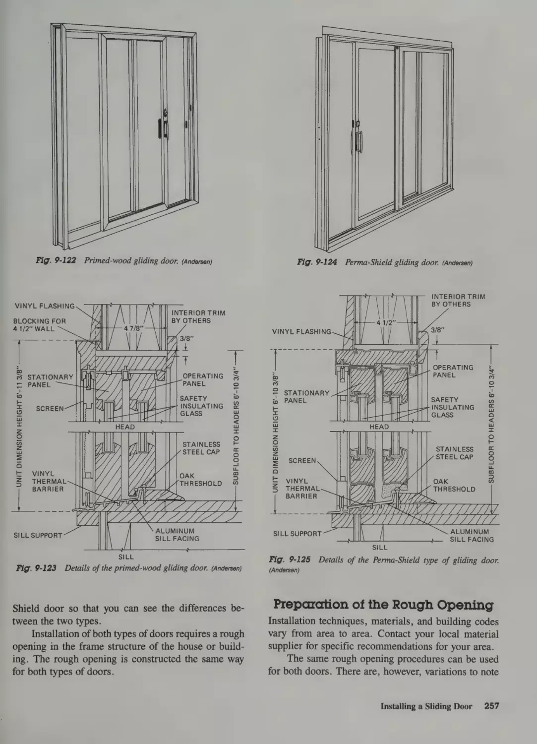
Preparation of the Rough Opening 257
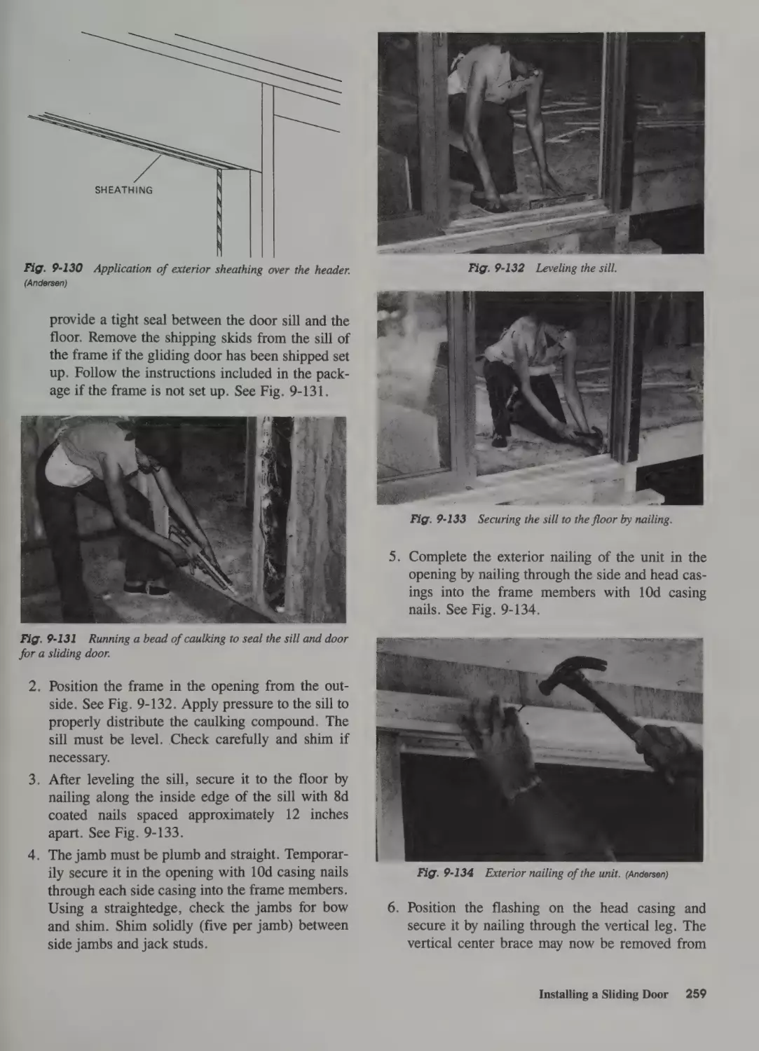
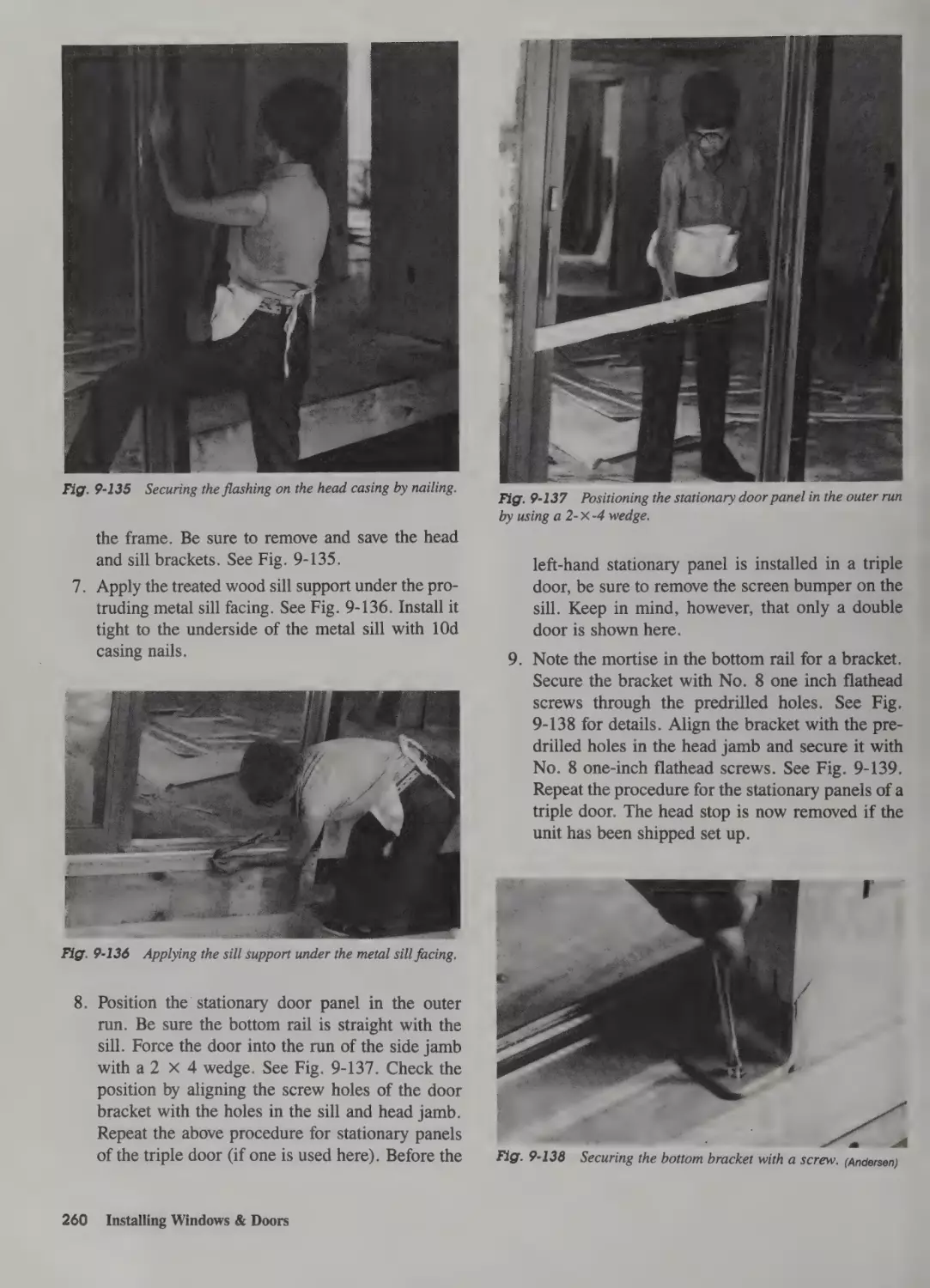
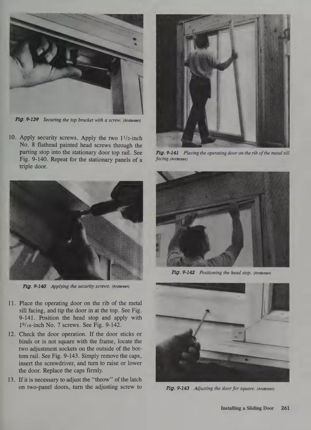
Installation of a Wood Gliding Door 258
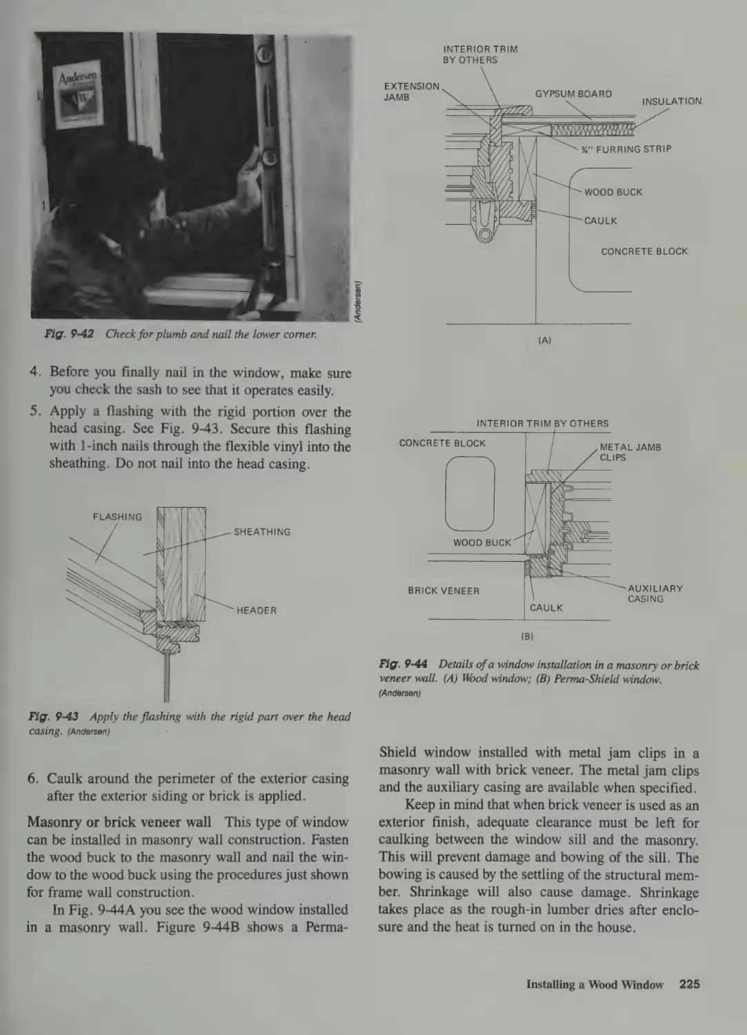
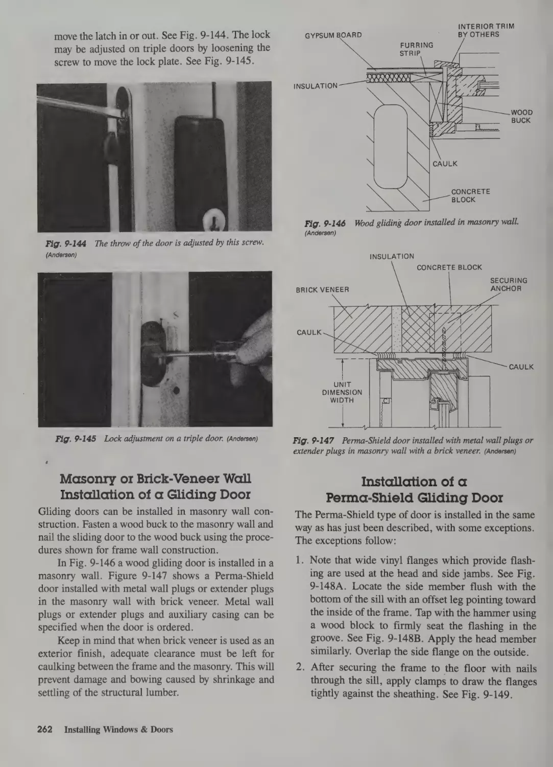
Masonry or Brick-Veneer Wall Installation
of a Gliding Door 262
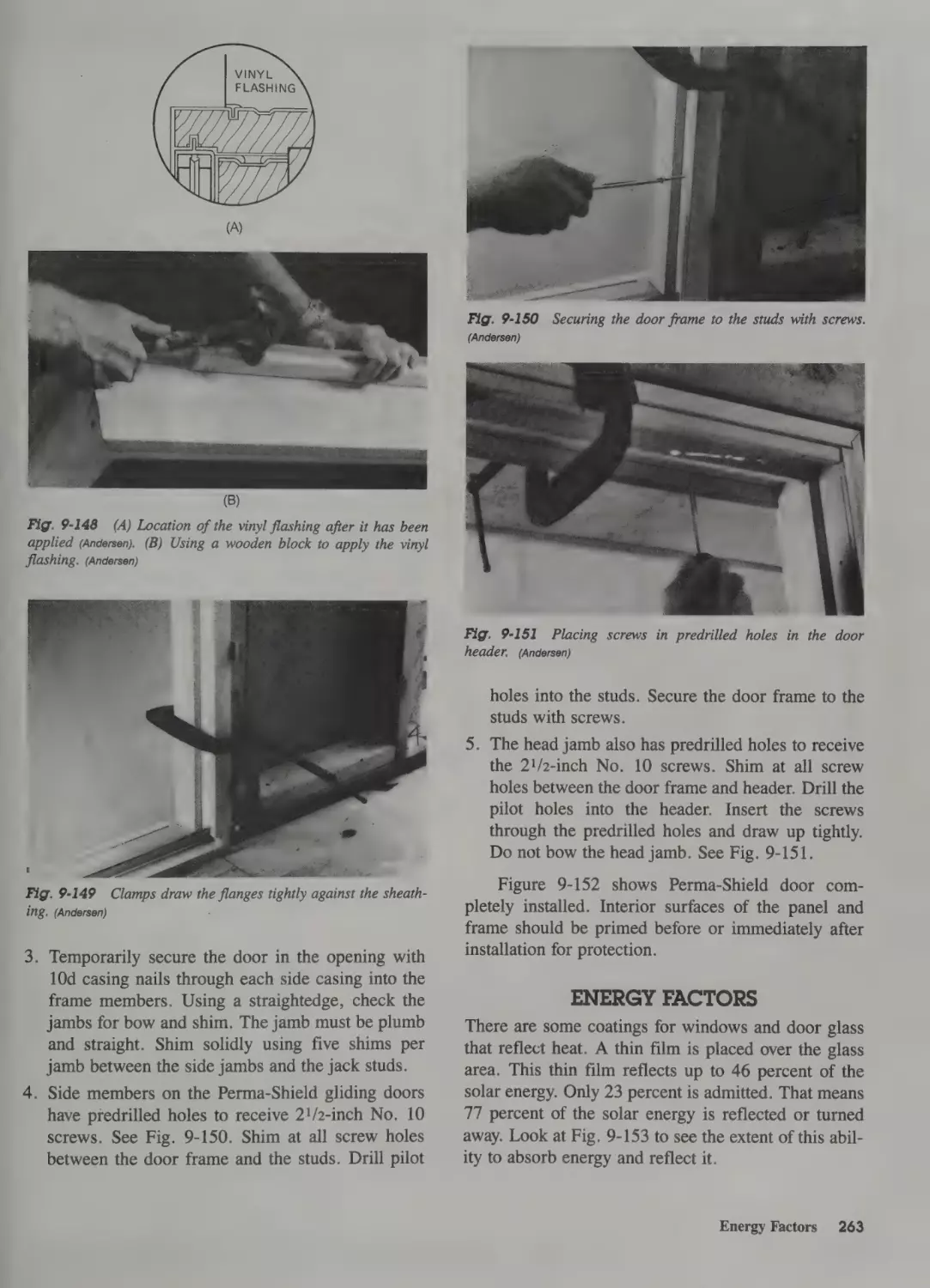
Installation of a Perma-Shield Gliding Door 262
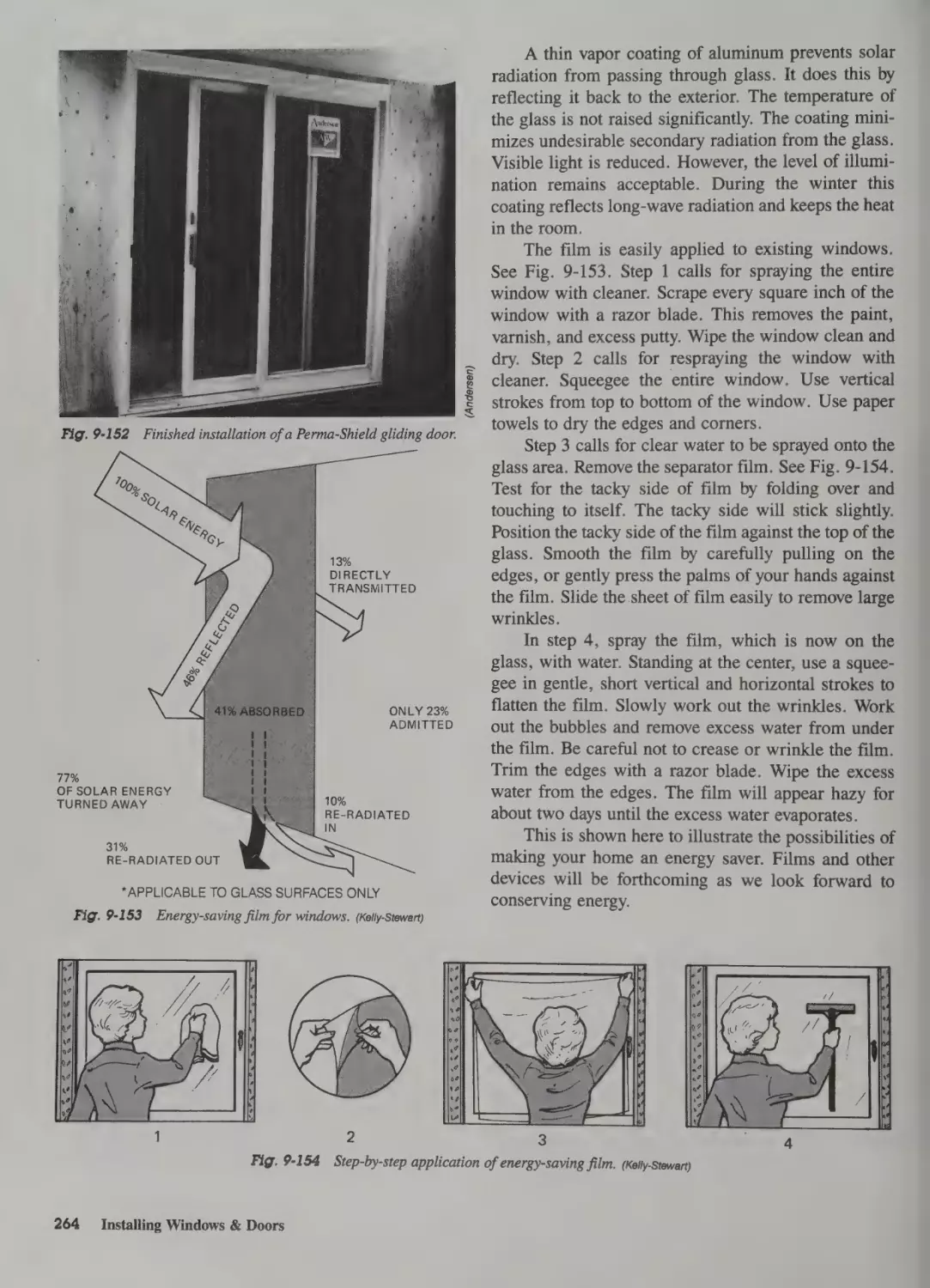
Energy Factors 263
10 Finishing Exterior Walls
Introduction 266
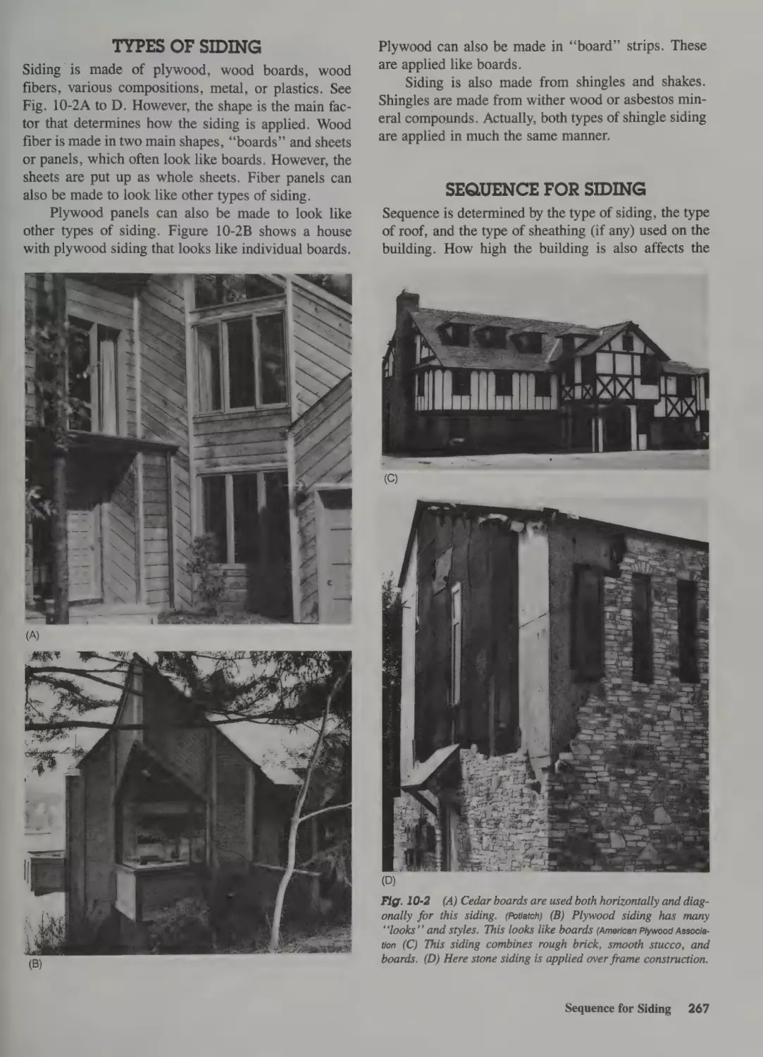
Types of Siding 267
Sequence for Siding 267
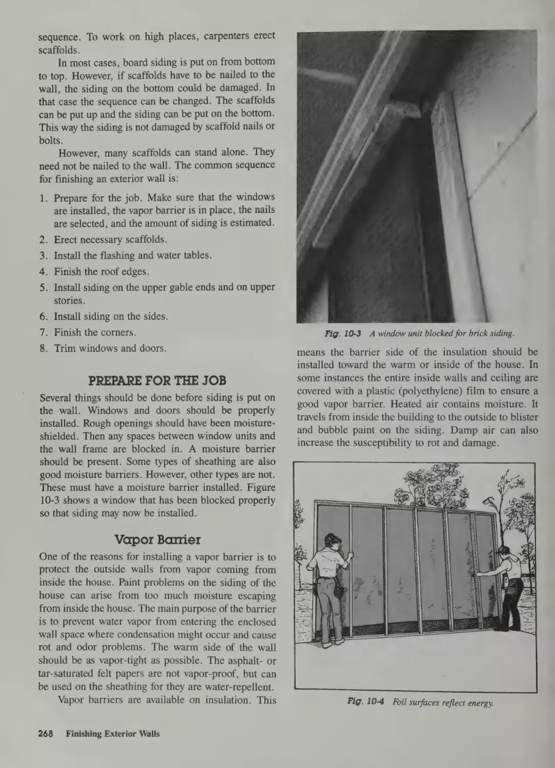
Prepare for the Job 268
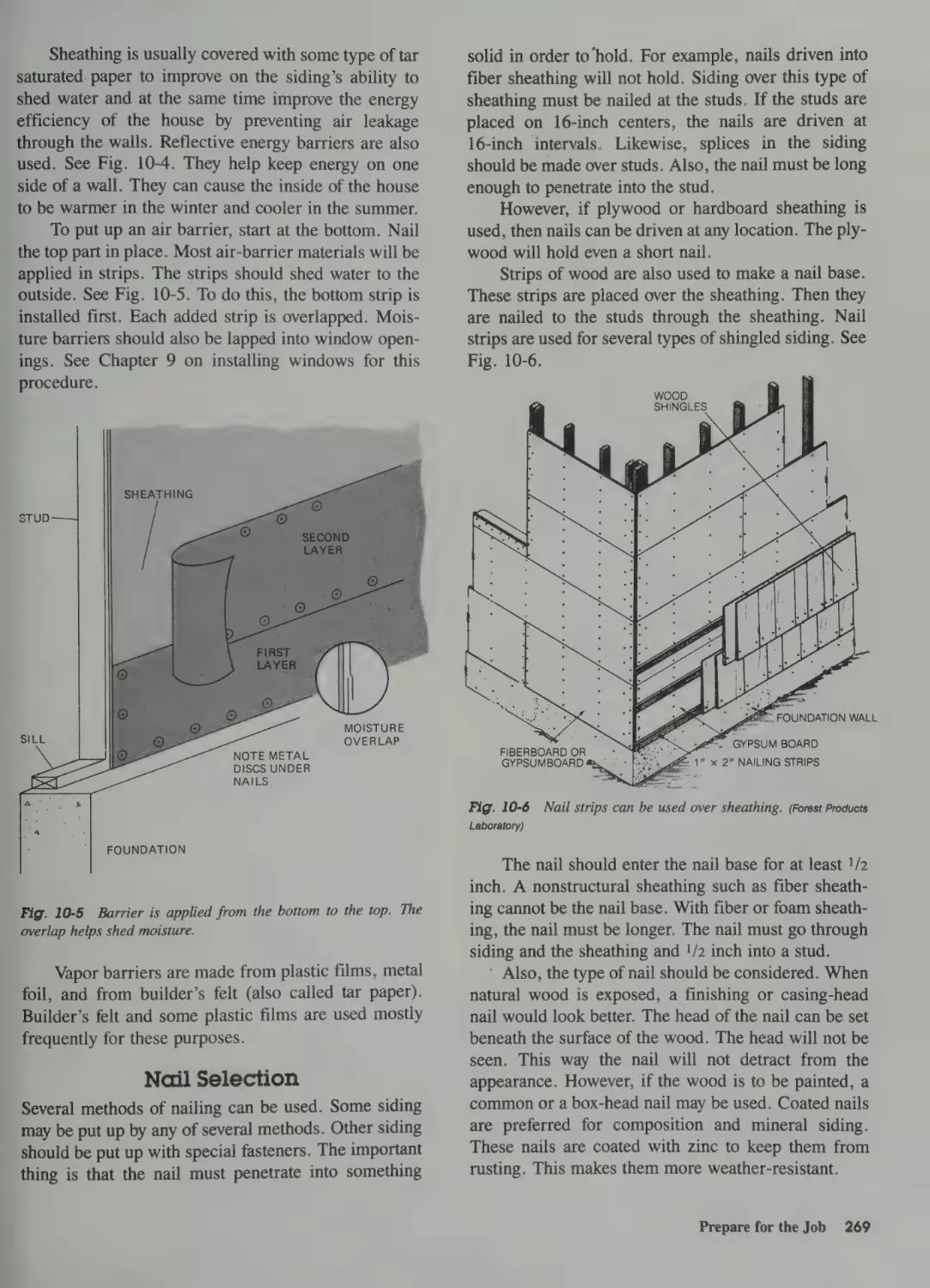
Vapor Barrier 268
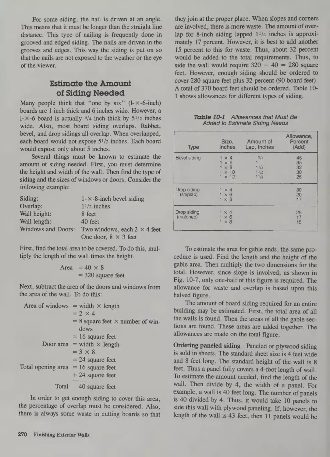
Nail Selection 269 .
Estimate the Amount of Siding Needed
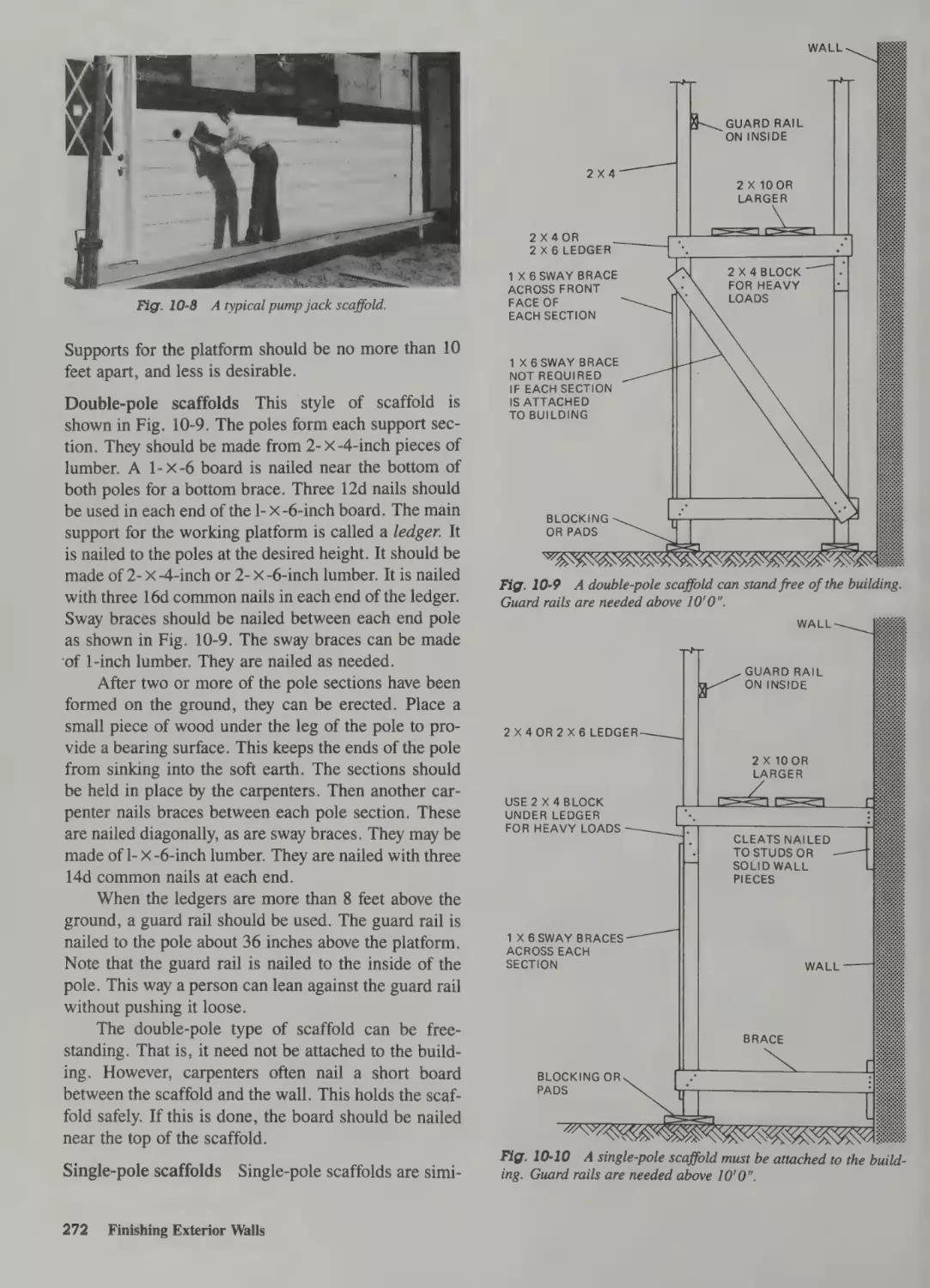
Erecting Scaffolds 271
Job-Built Scaffolds 271
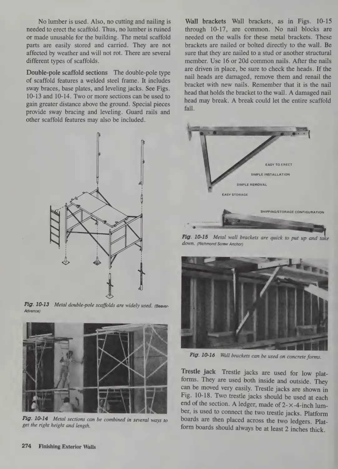
Factory Scaffolds 273
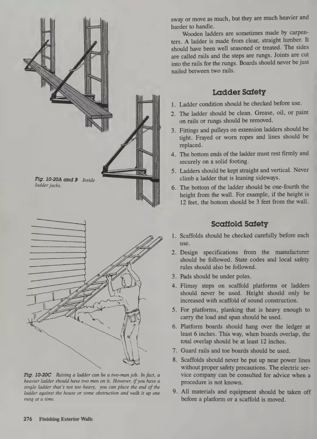
Ladder Use 275
Ladder Safety 276
Scaffold Safety 276
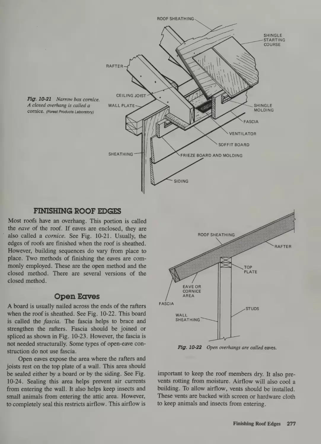
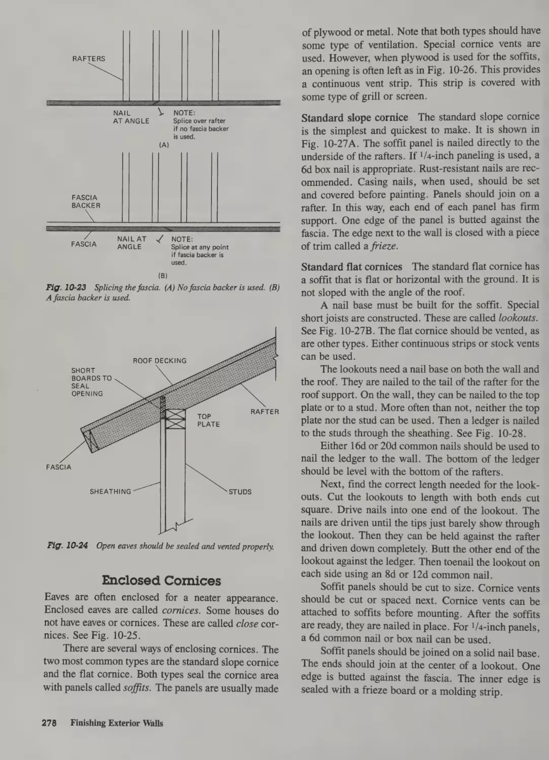
Finishing Roof Edges 277
Open Eaves 277
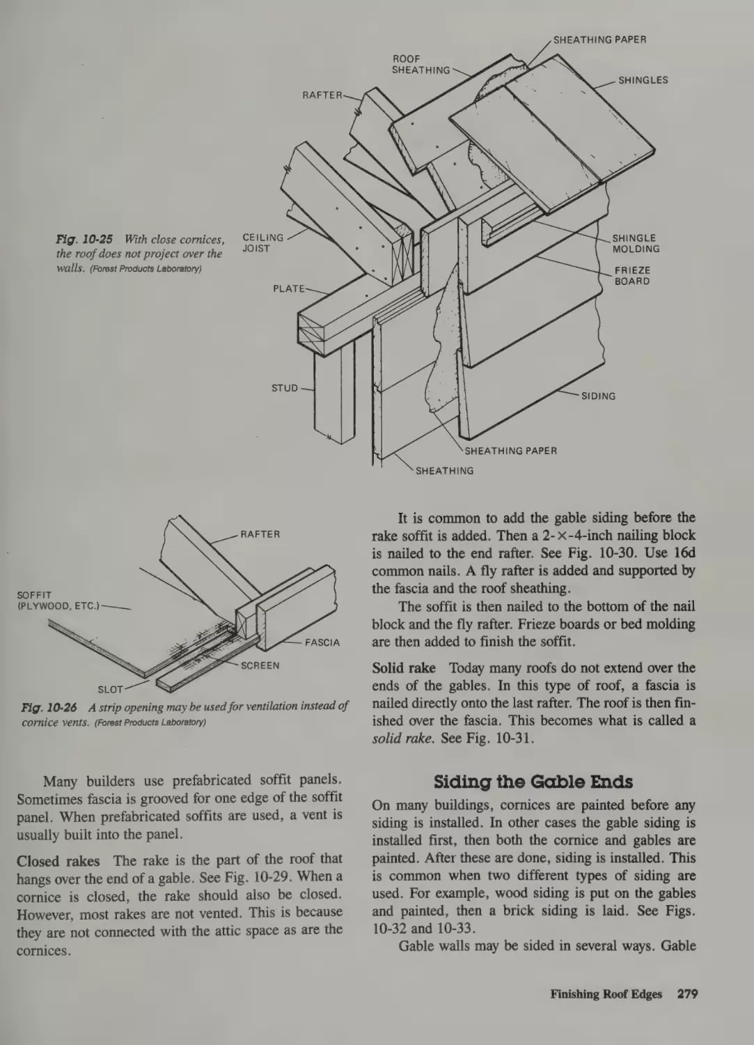
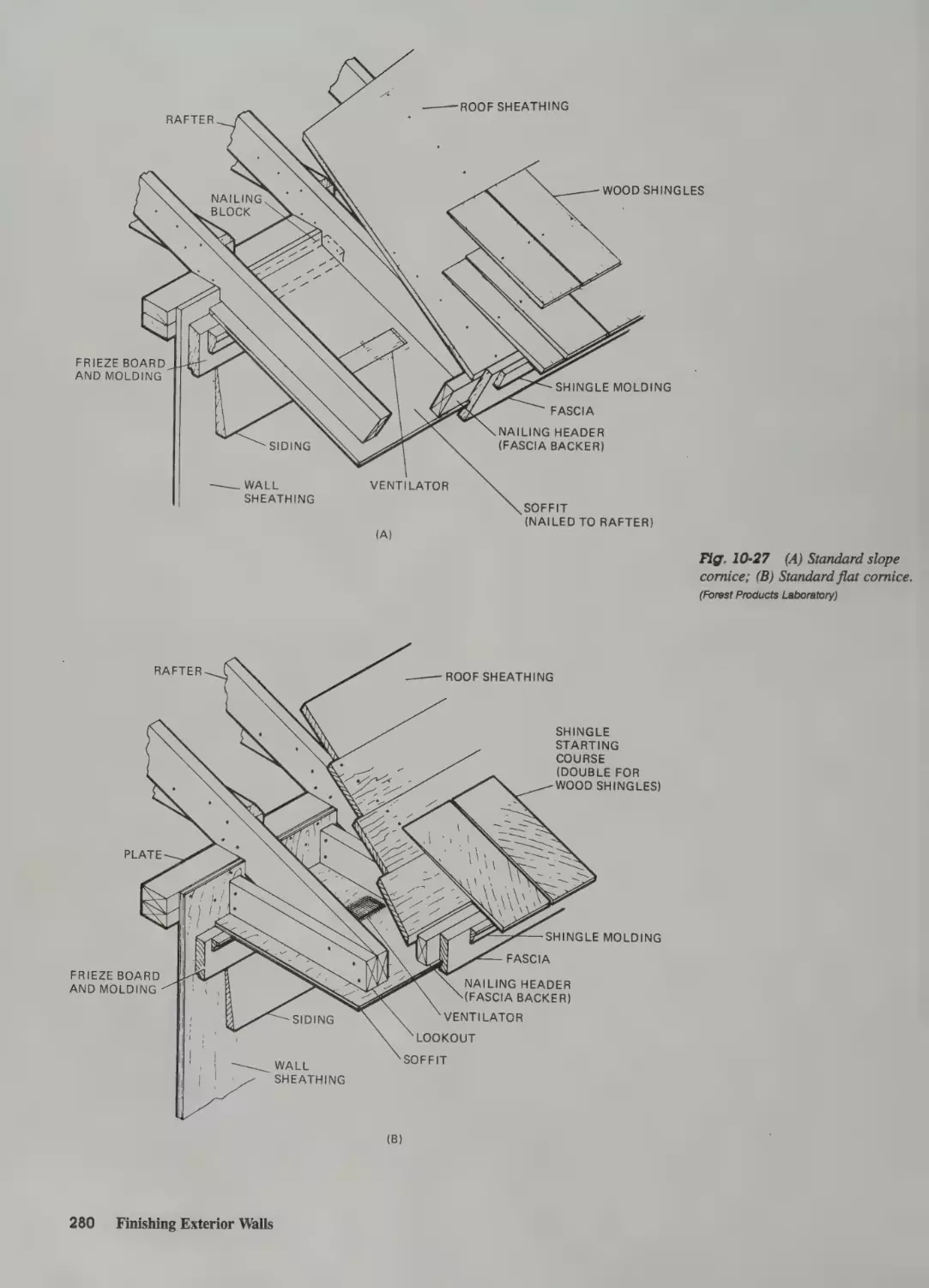
Enclosed Cornices 278
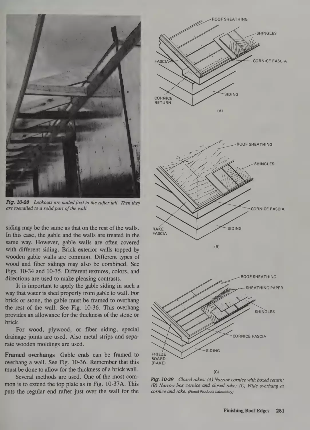
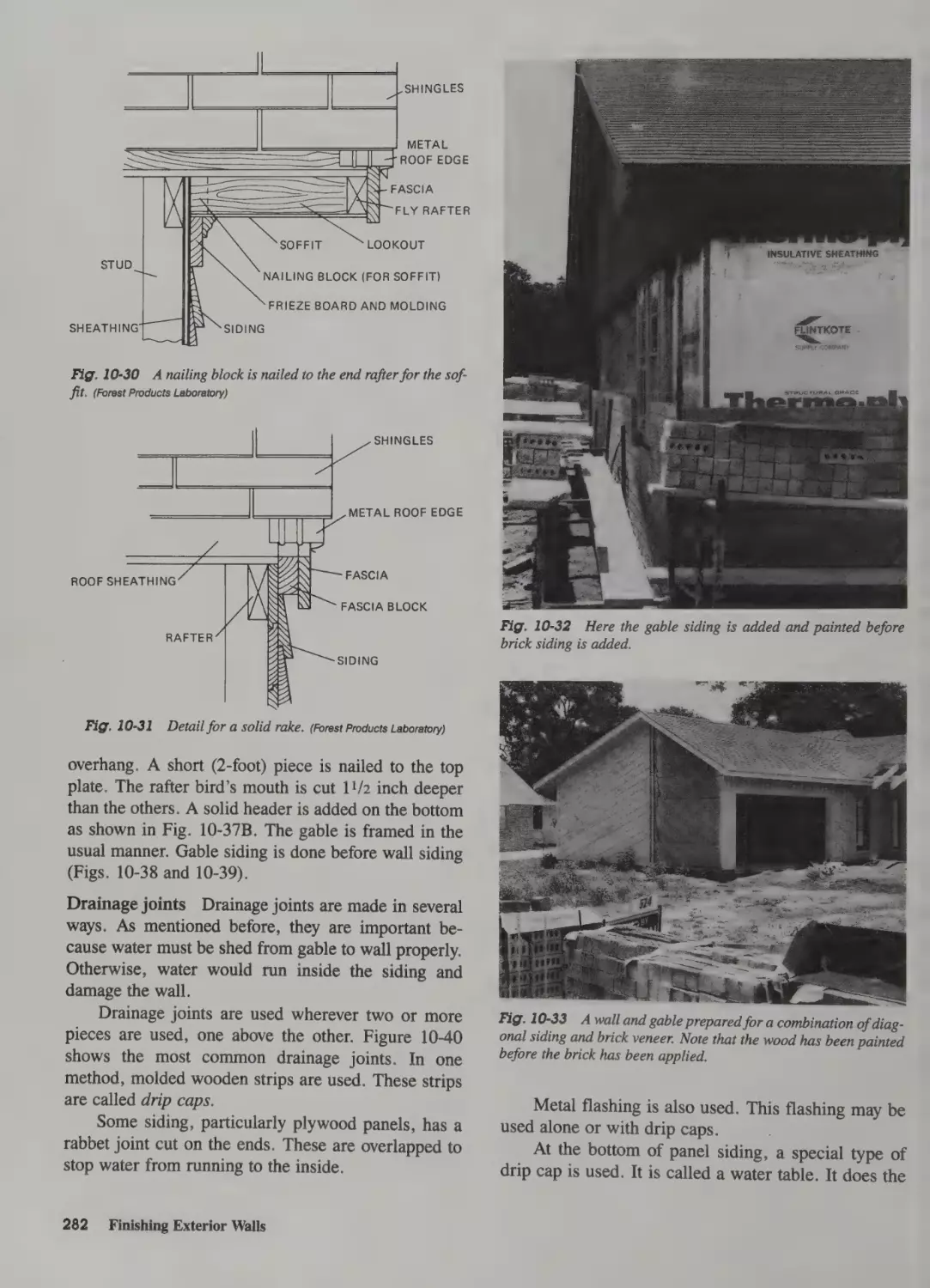
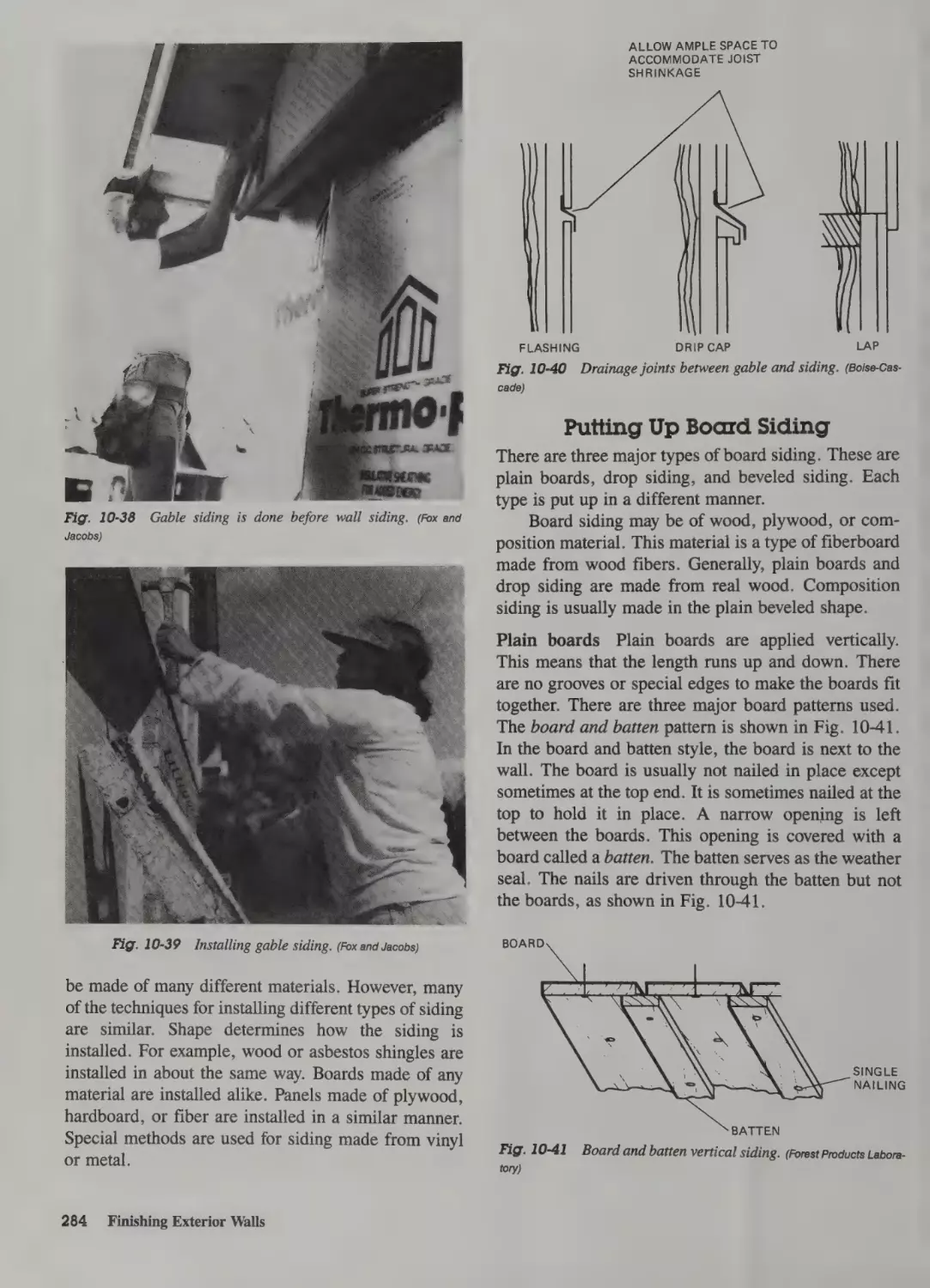
Siding the Gable Ends 279
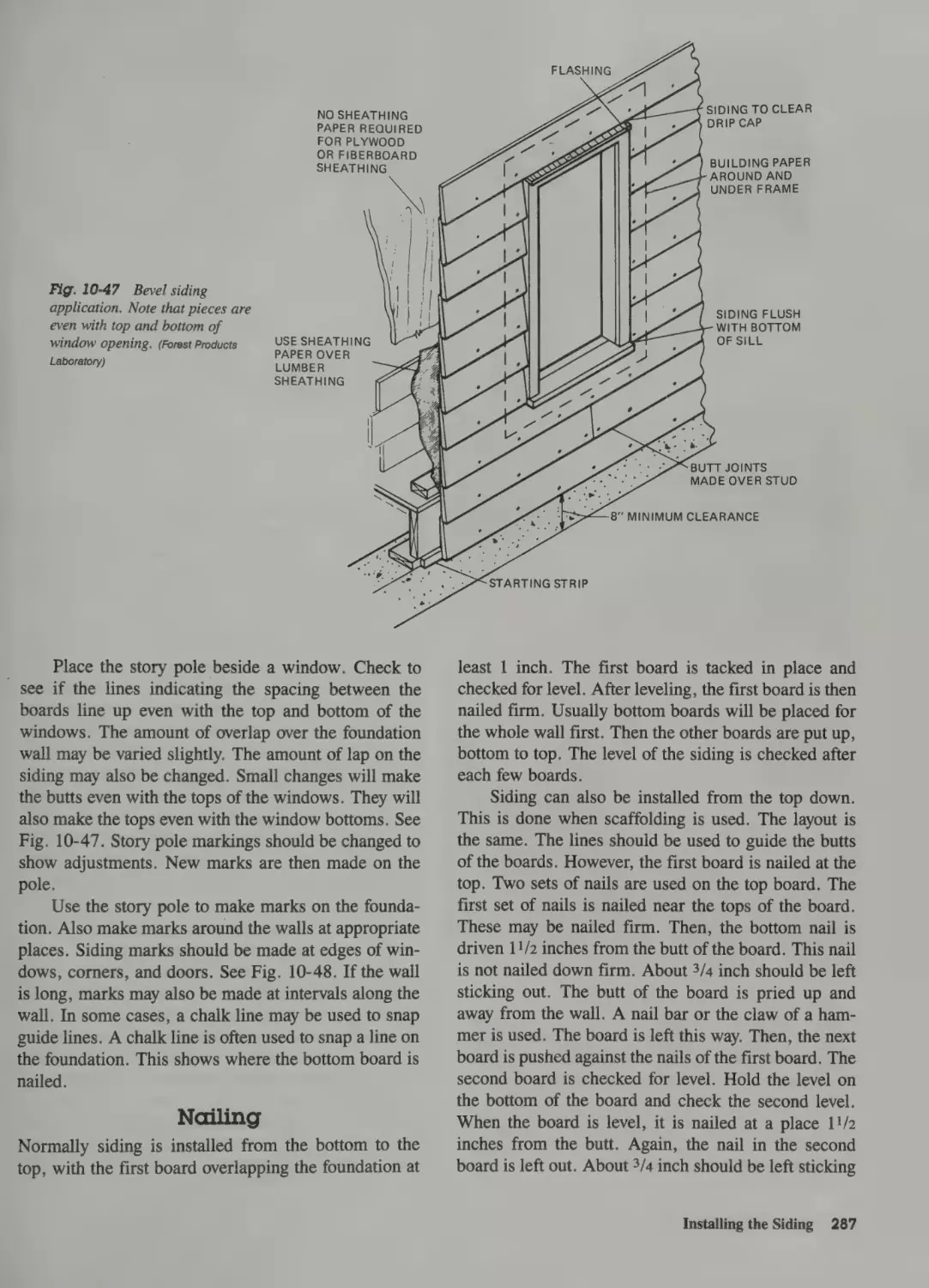
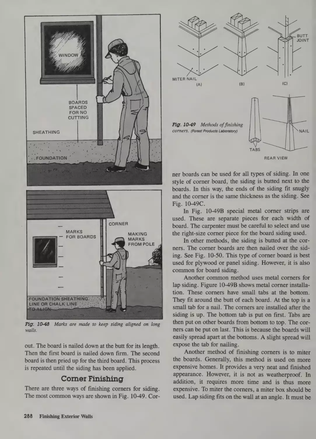
Installing the Siding 283
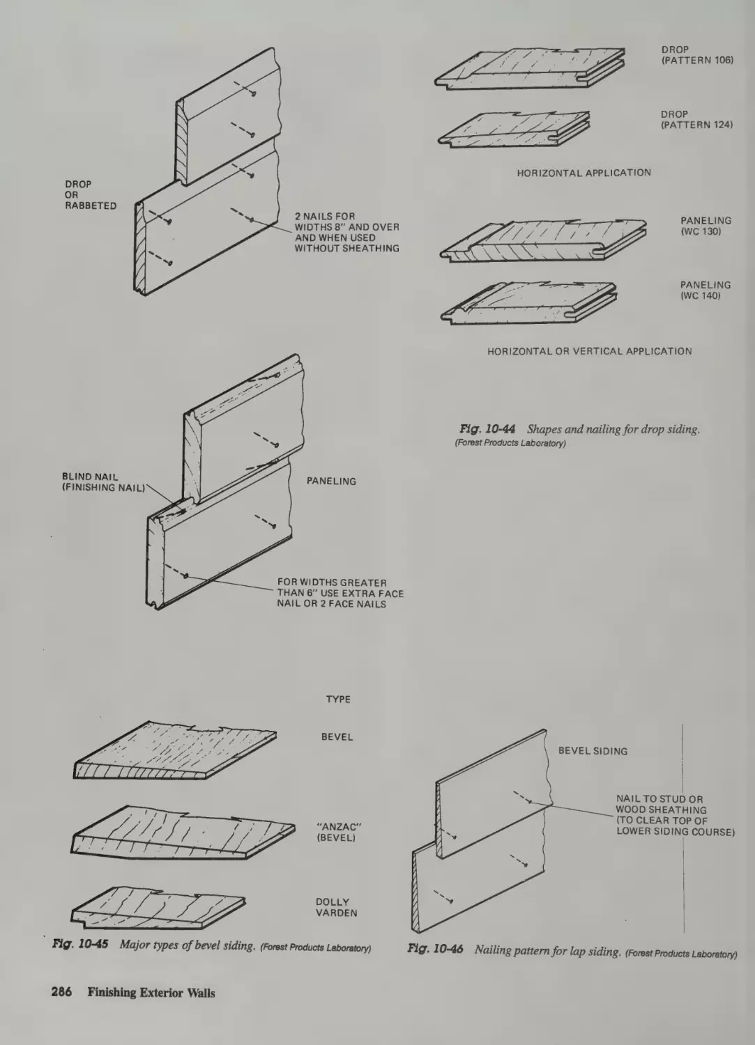
Putting Up Board Siding 284
Siding Layout 285
Nailing 287
Corner Finishing 288
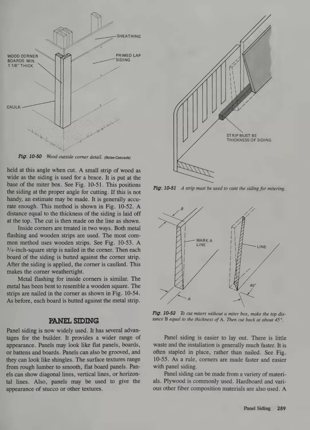
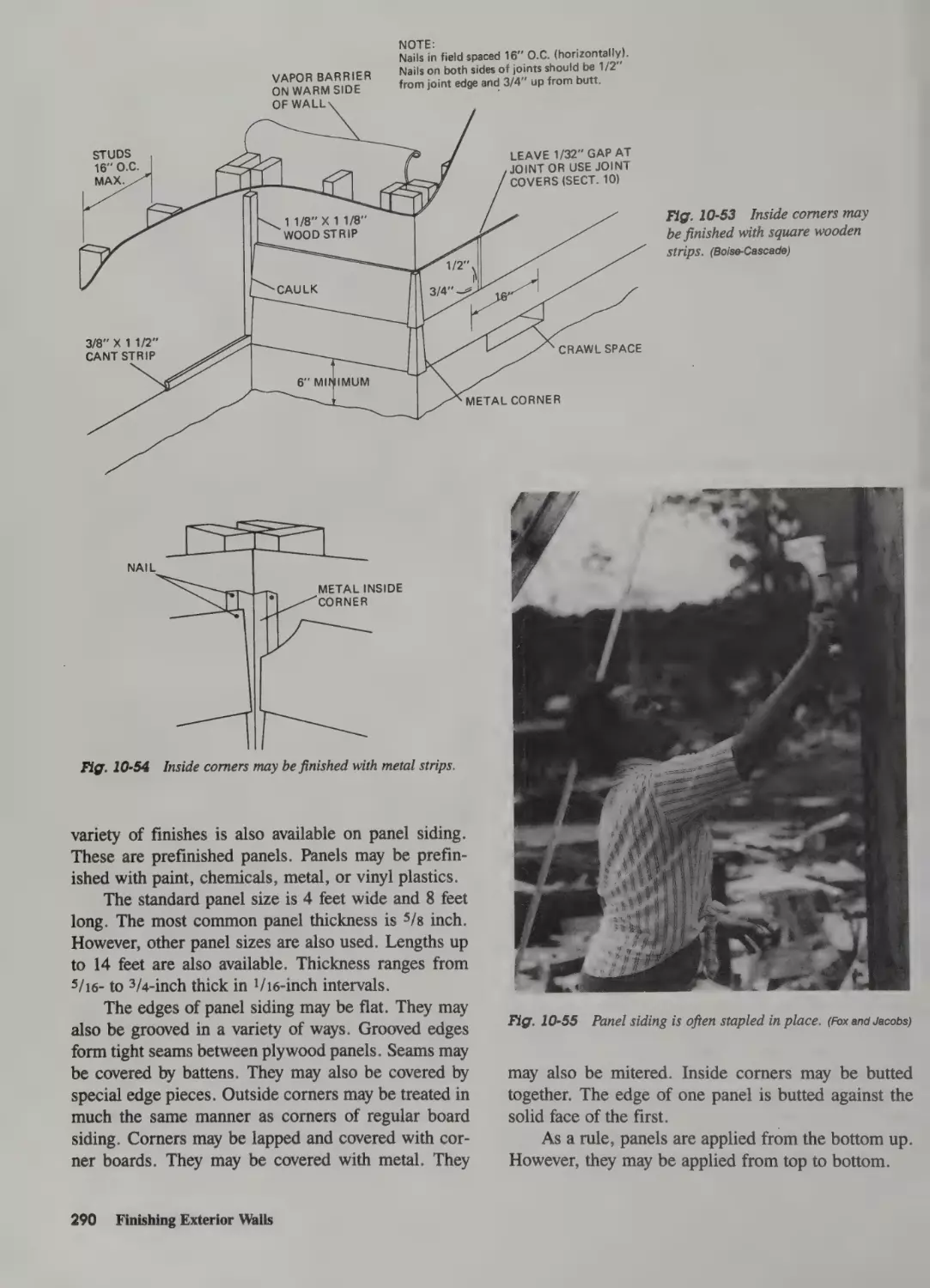
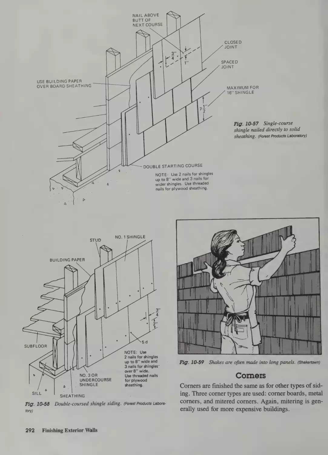
Panel Siding 289
Shingle and Shake Siding 291
Shingles
Nailing
Shakes
Corners
291
291
291
292
Preparation for Other Wall Finishes 293
Stucco Finish 293
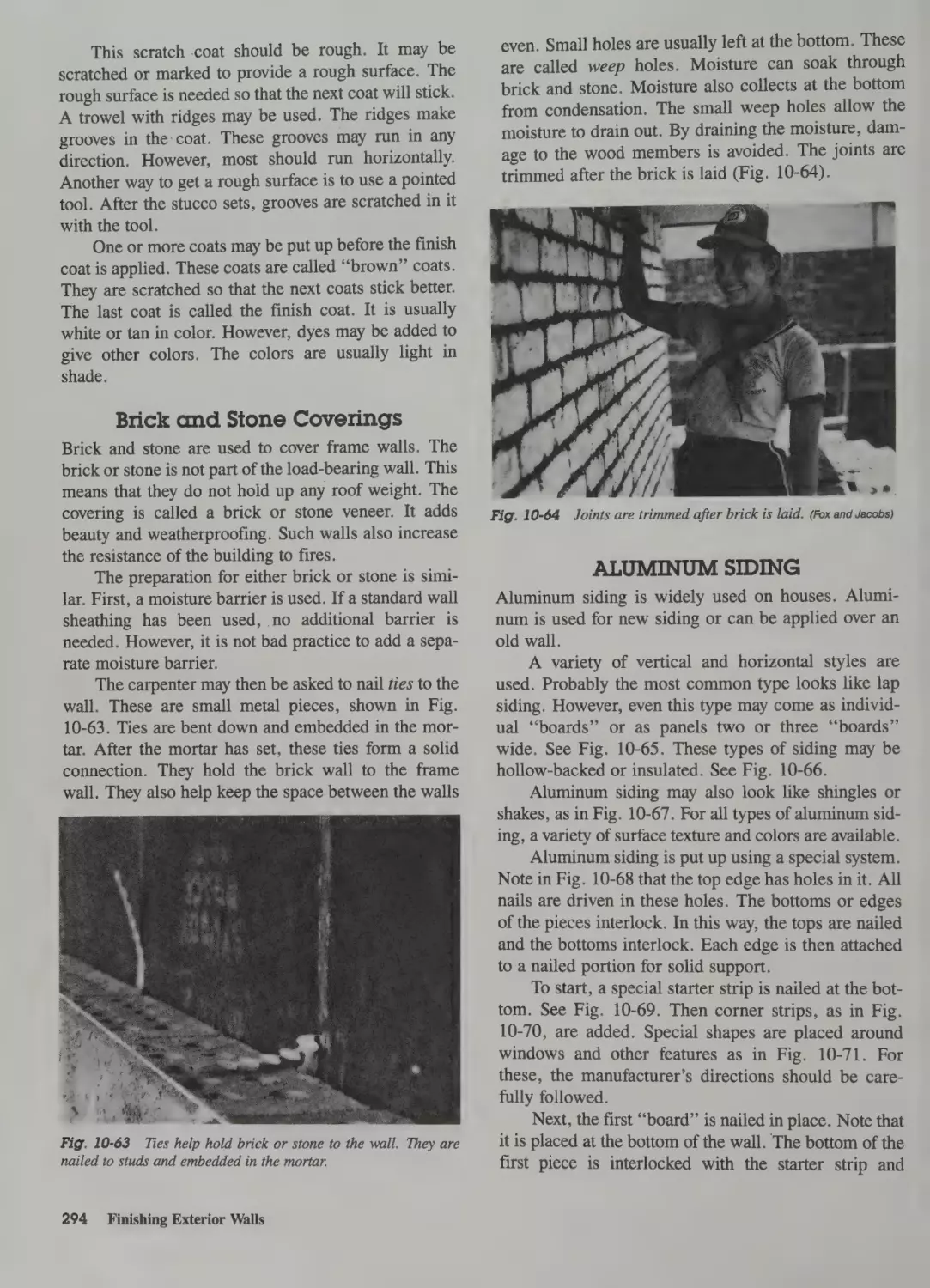
Brick and Stone Coverings 294
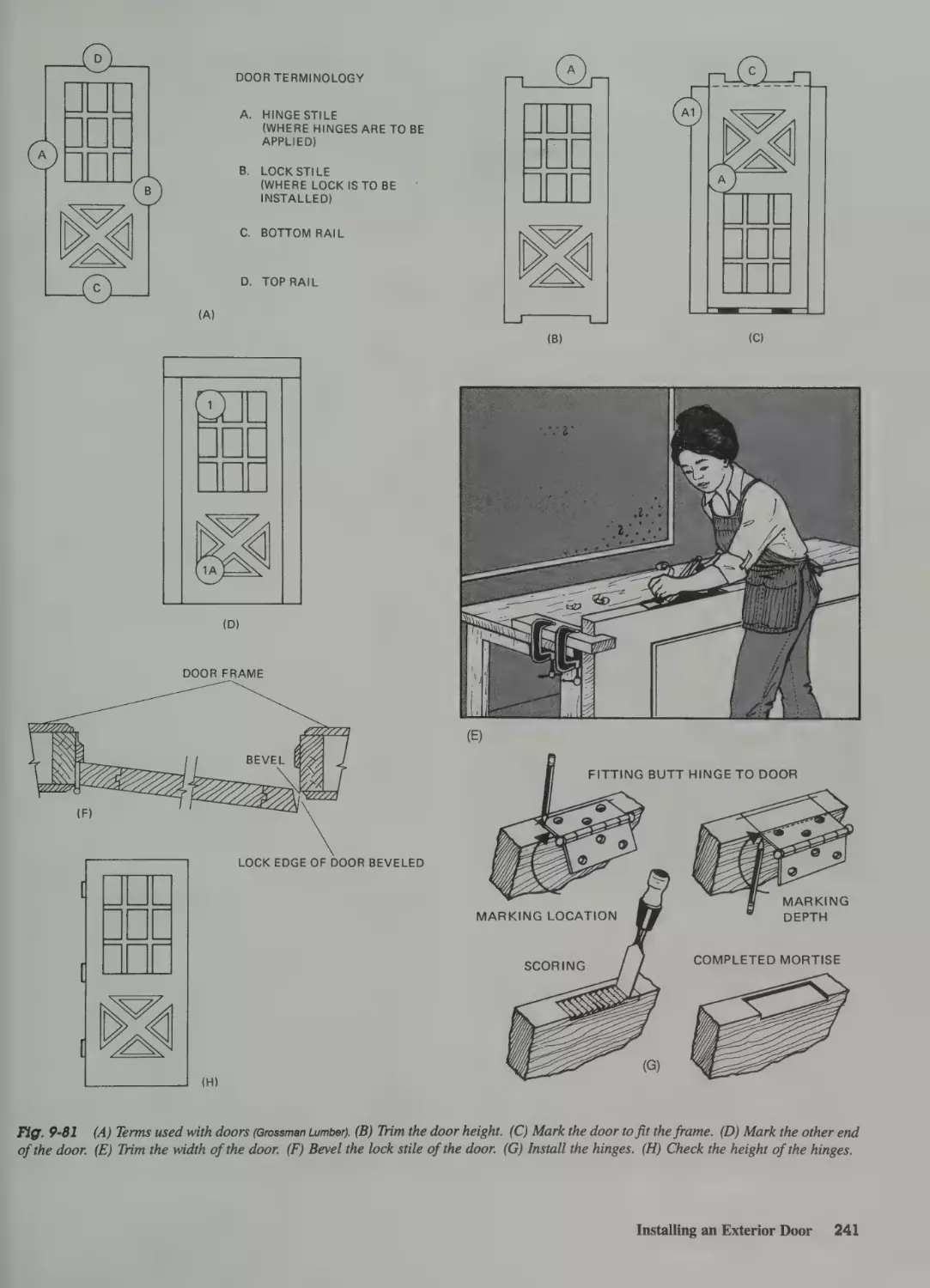
Installing an Exterior Door 236
Aluminum Siding 294
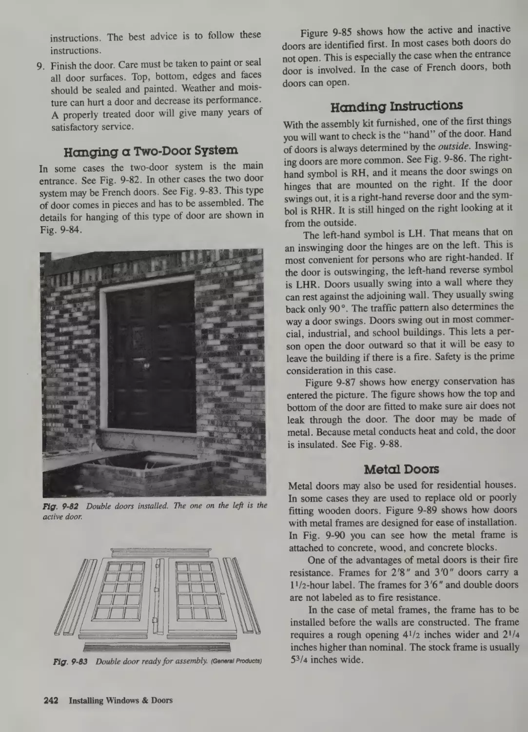
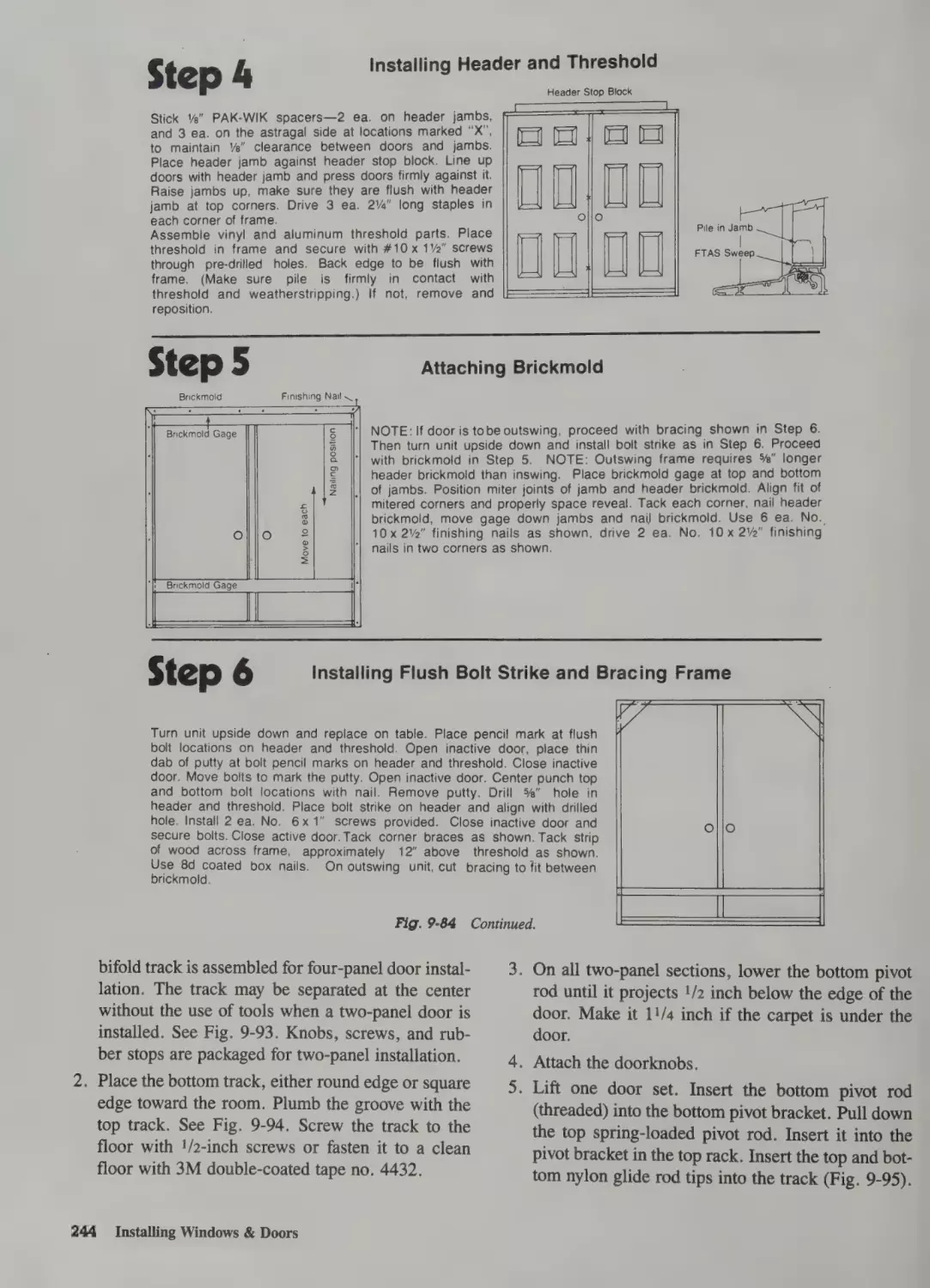
Hanging a Two-Door System 242
Handing Instructions 242
Metal Doors 242
Solid Vinyl Siding 297
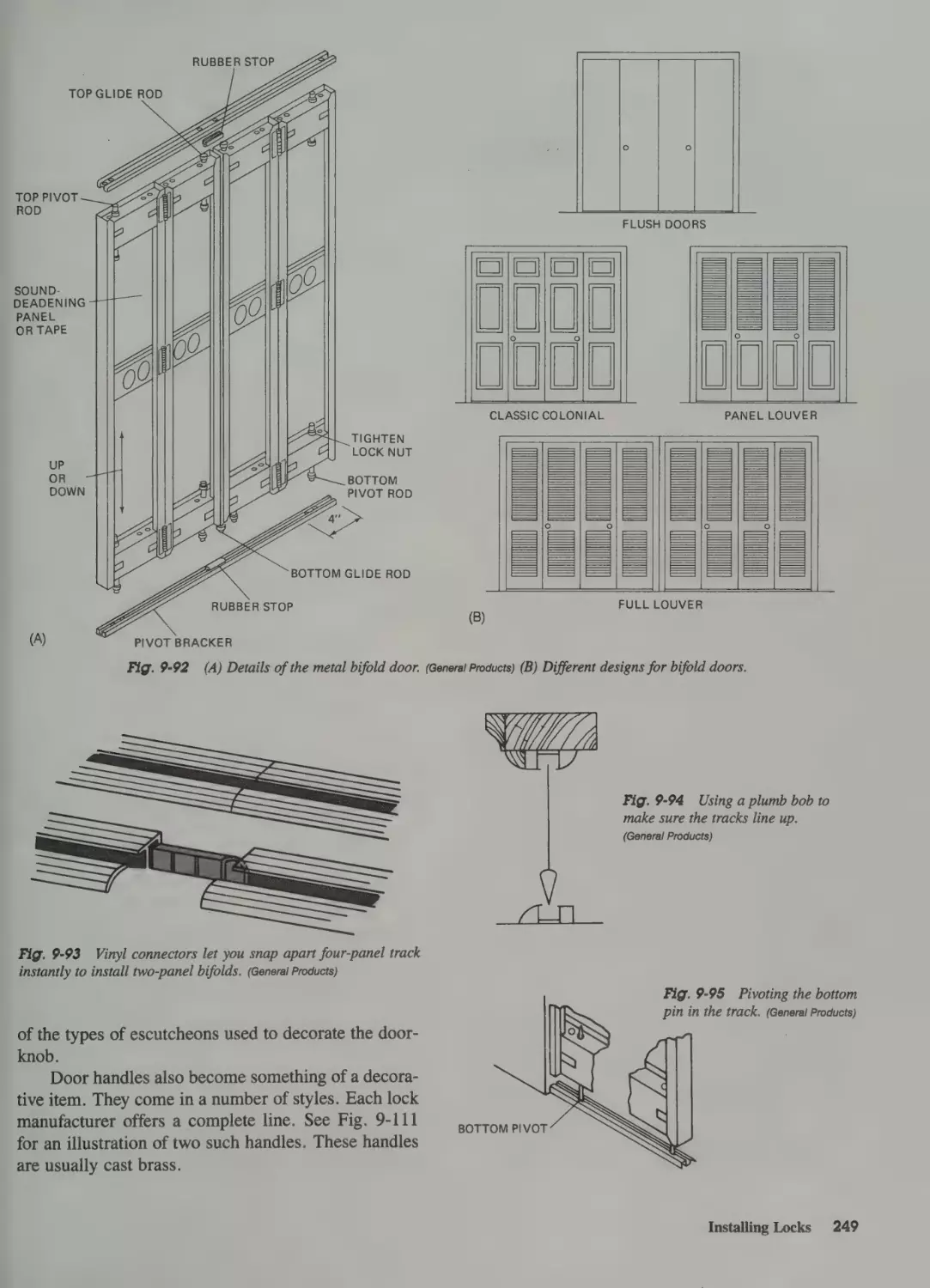
Installing Folding Doors 243
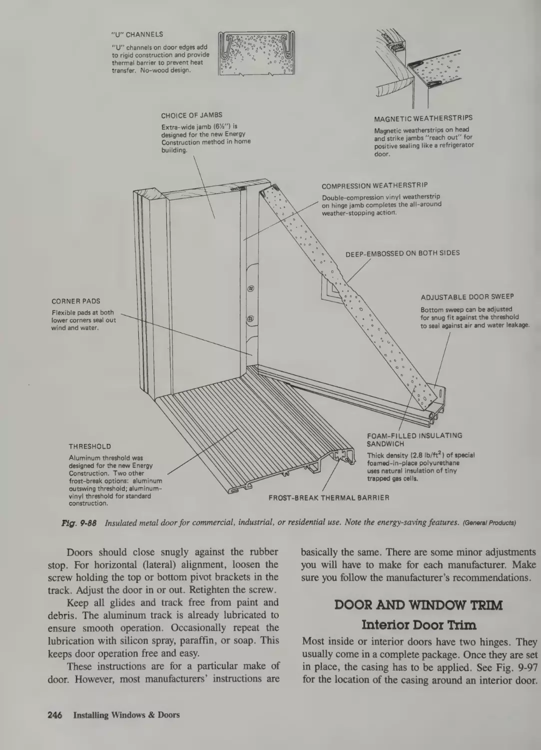
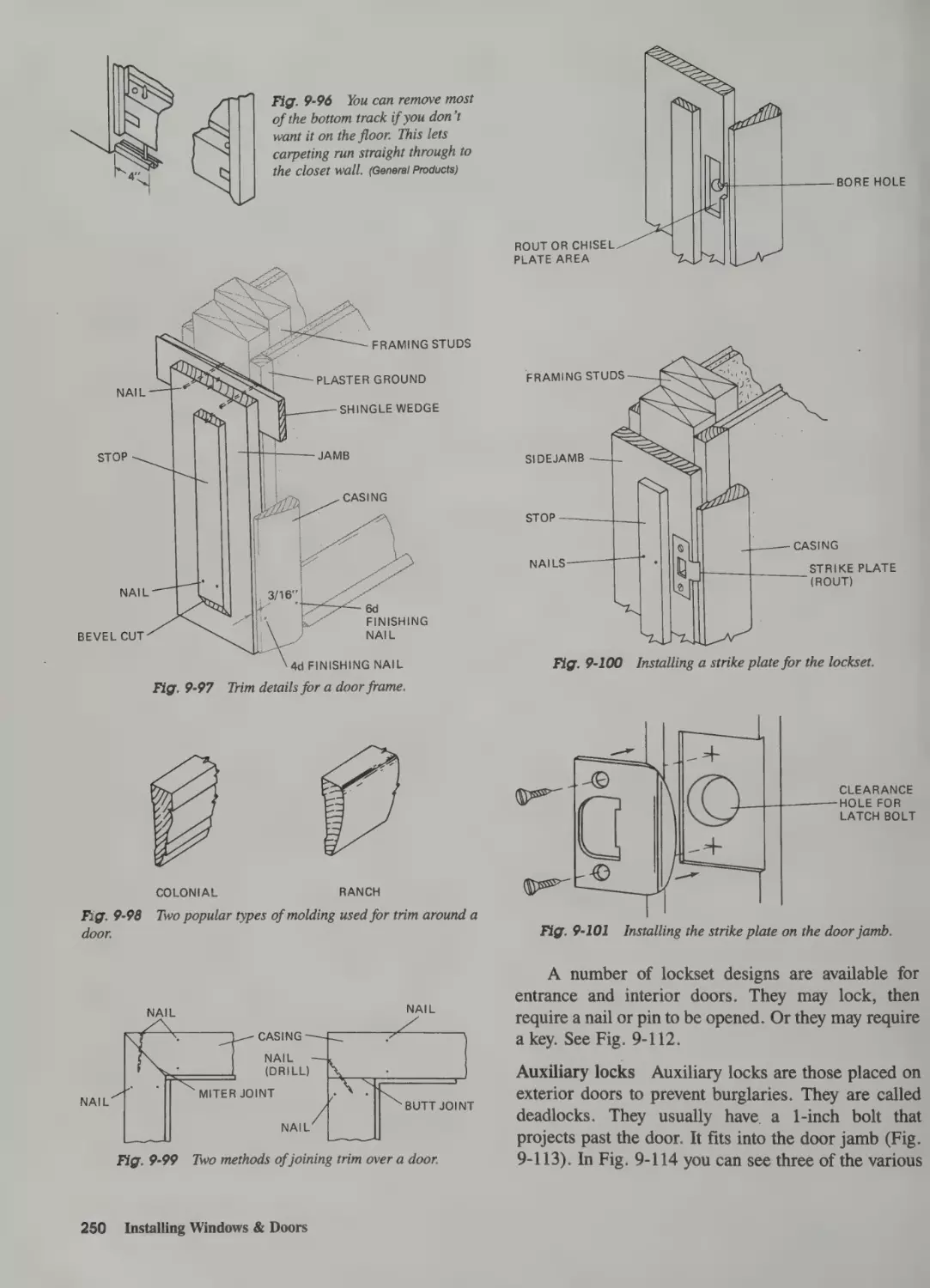
Door and Window Trim 246
Interior Door Trim 246
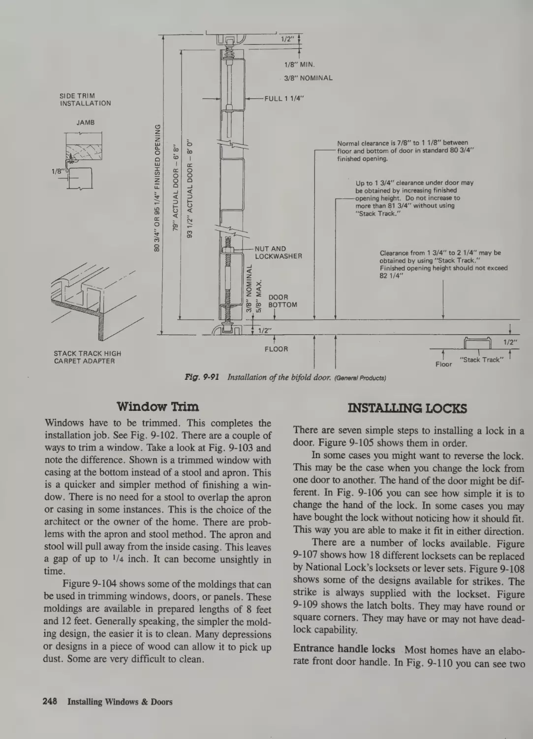
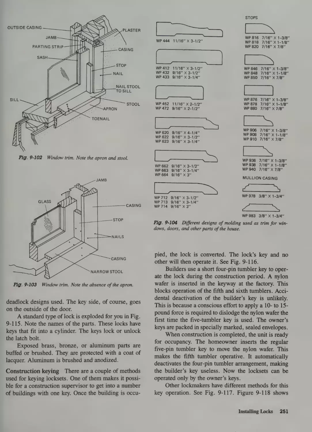
Window Trim 248
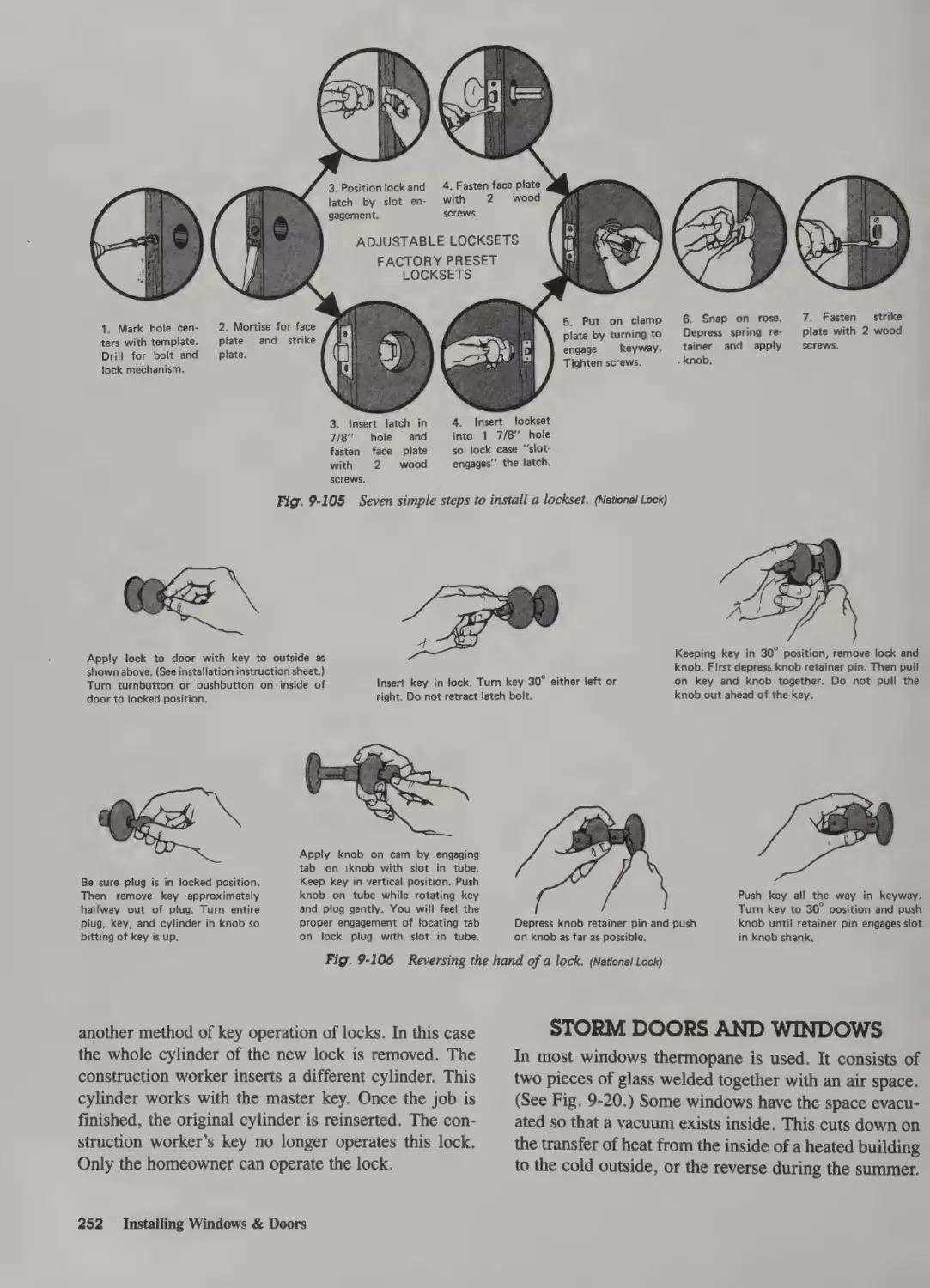
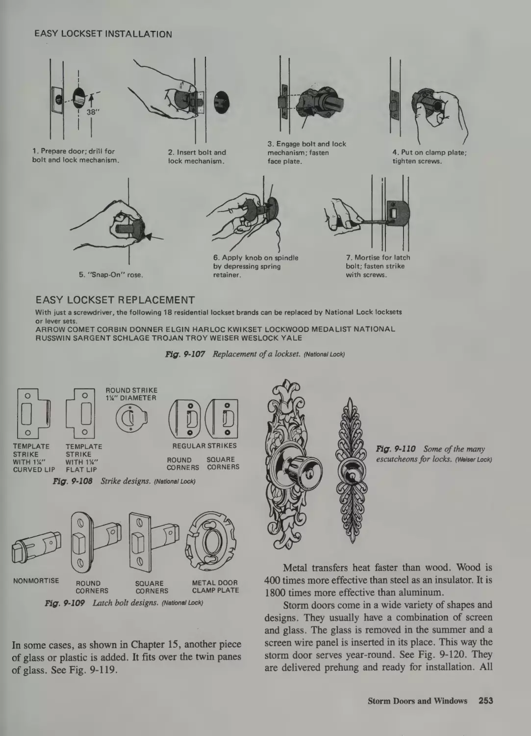
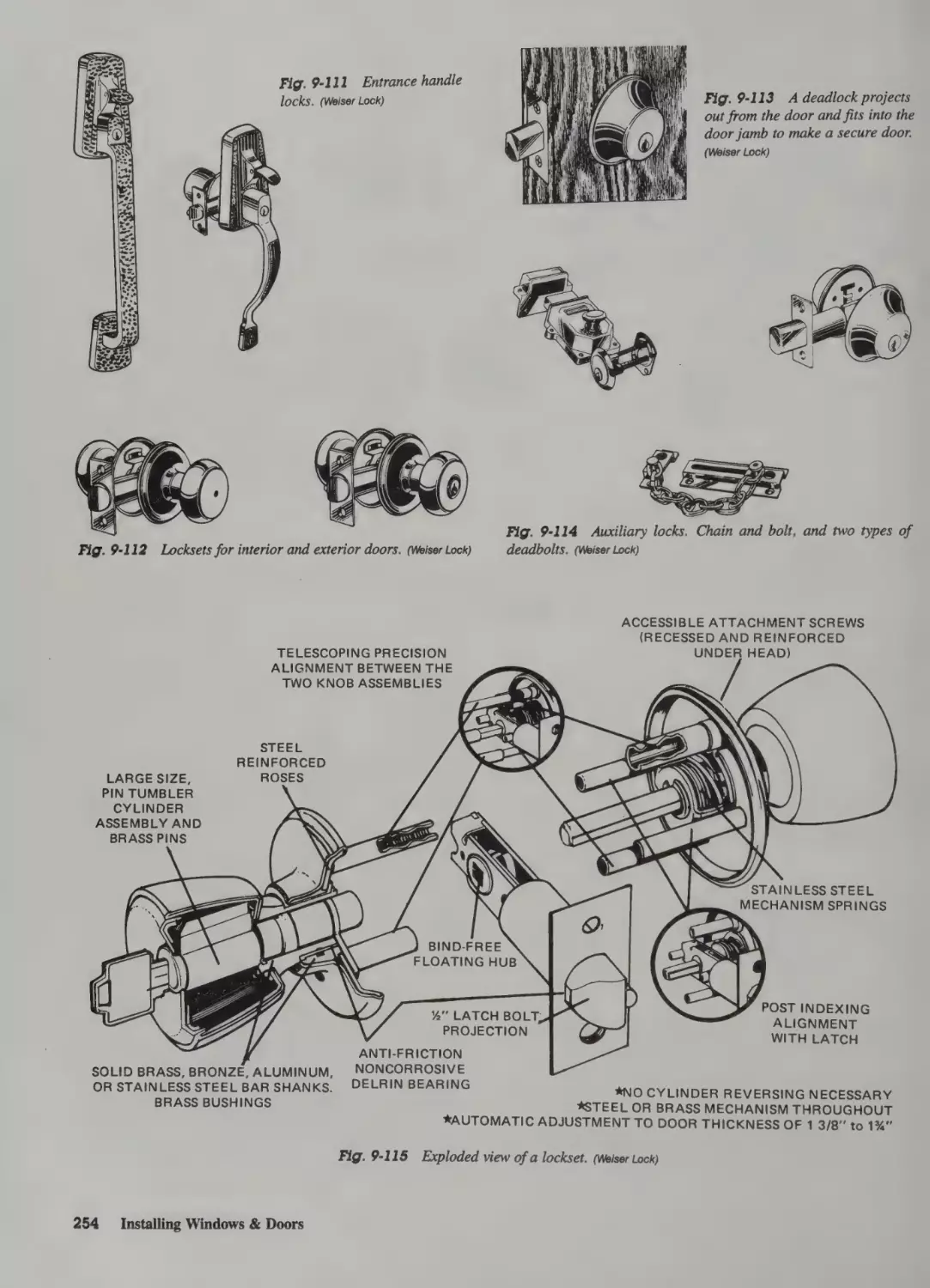
Installing Locks 248
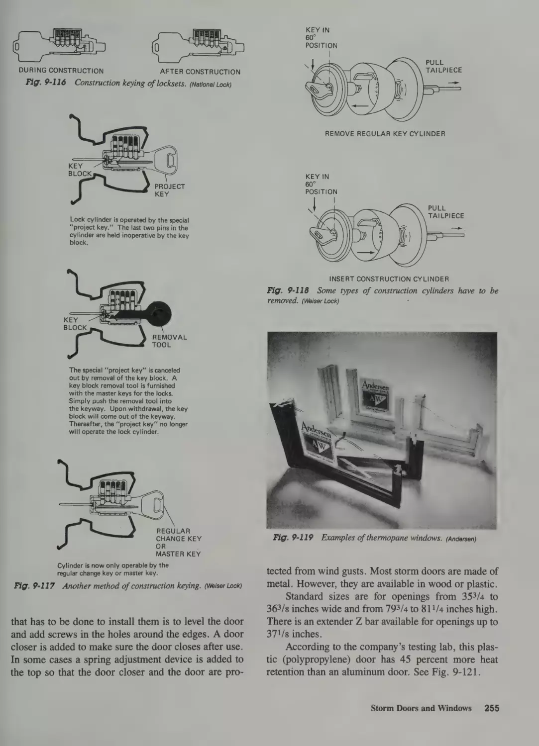
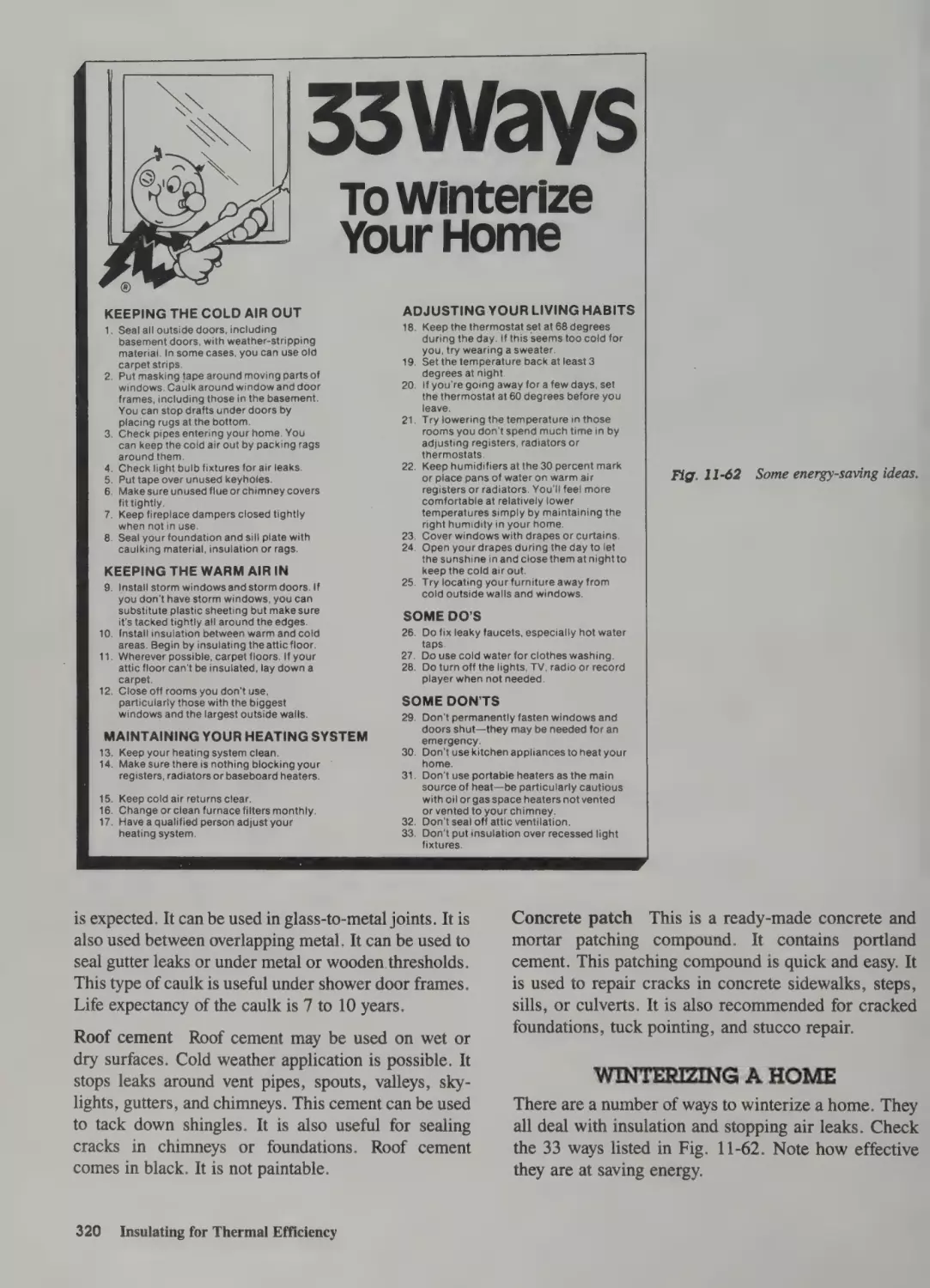
Storm Doors and Windows 252
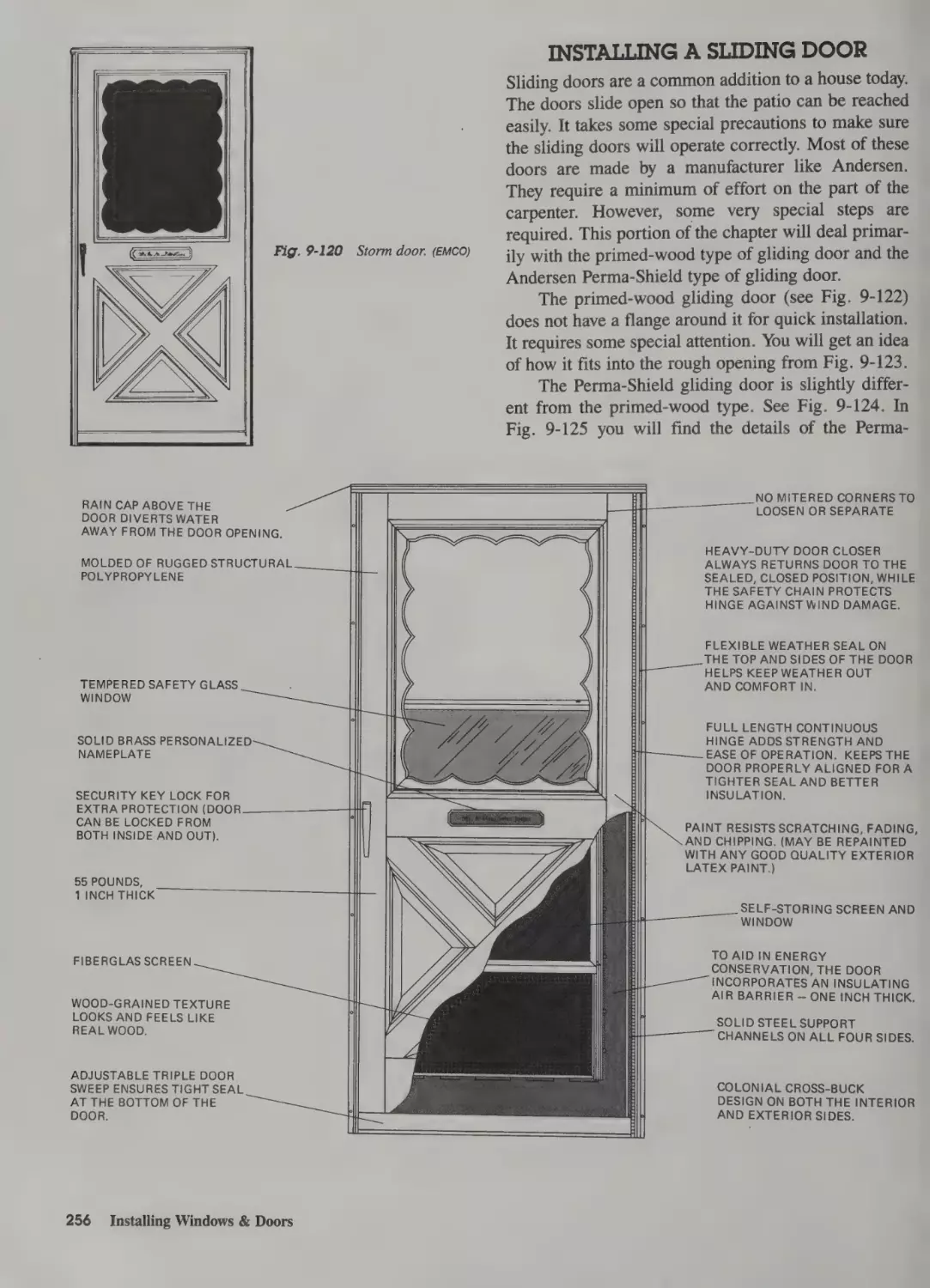
Installing a Sliding Door 256
270
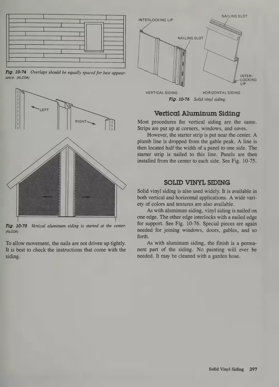
Vertical Aluminum Siding 297
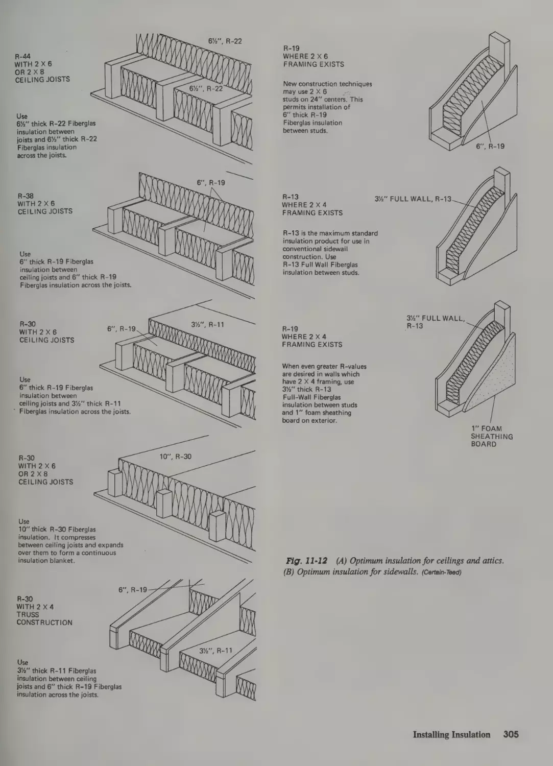
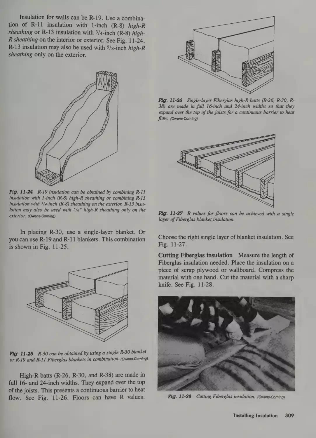
]] Insulating for Thermal Efficiency
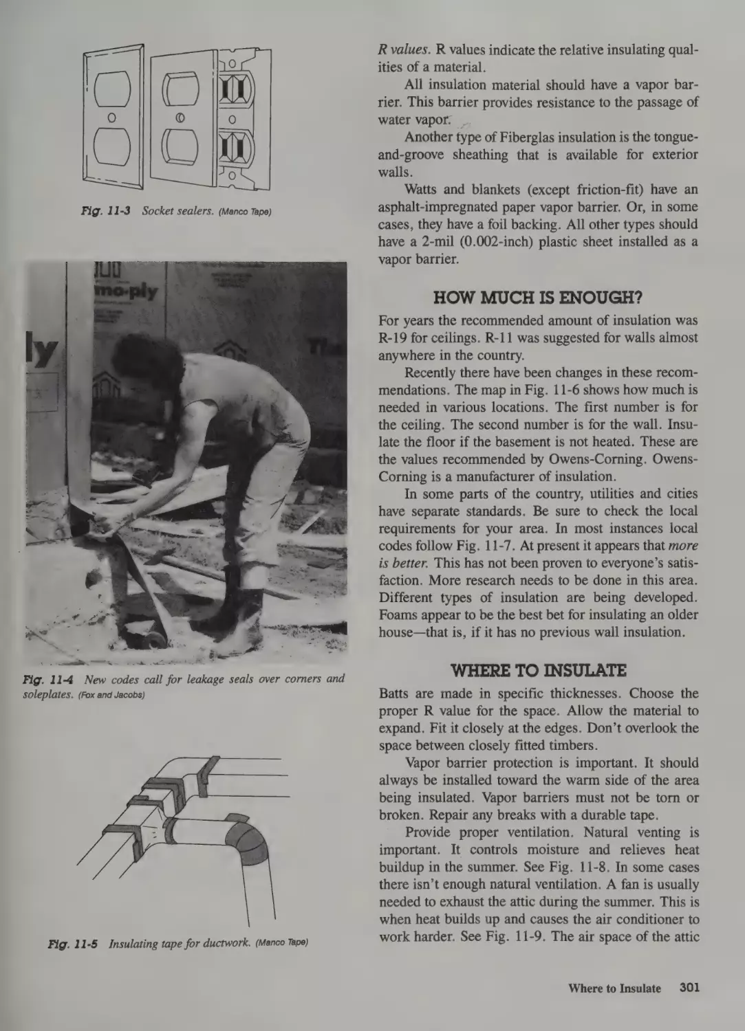
Types of Insulation 300
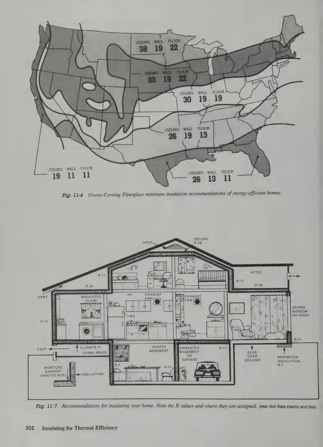
How Much Is Enough? 301
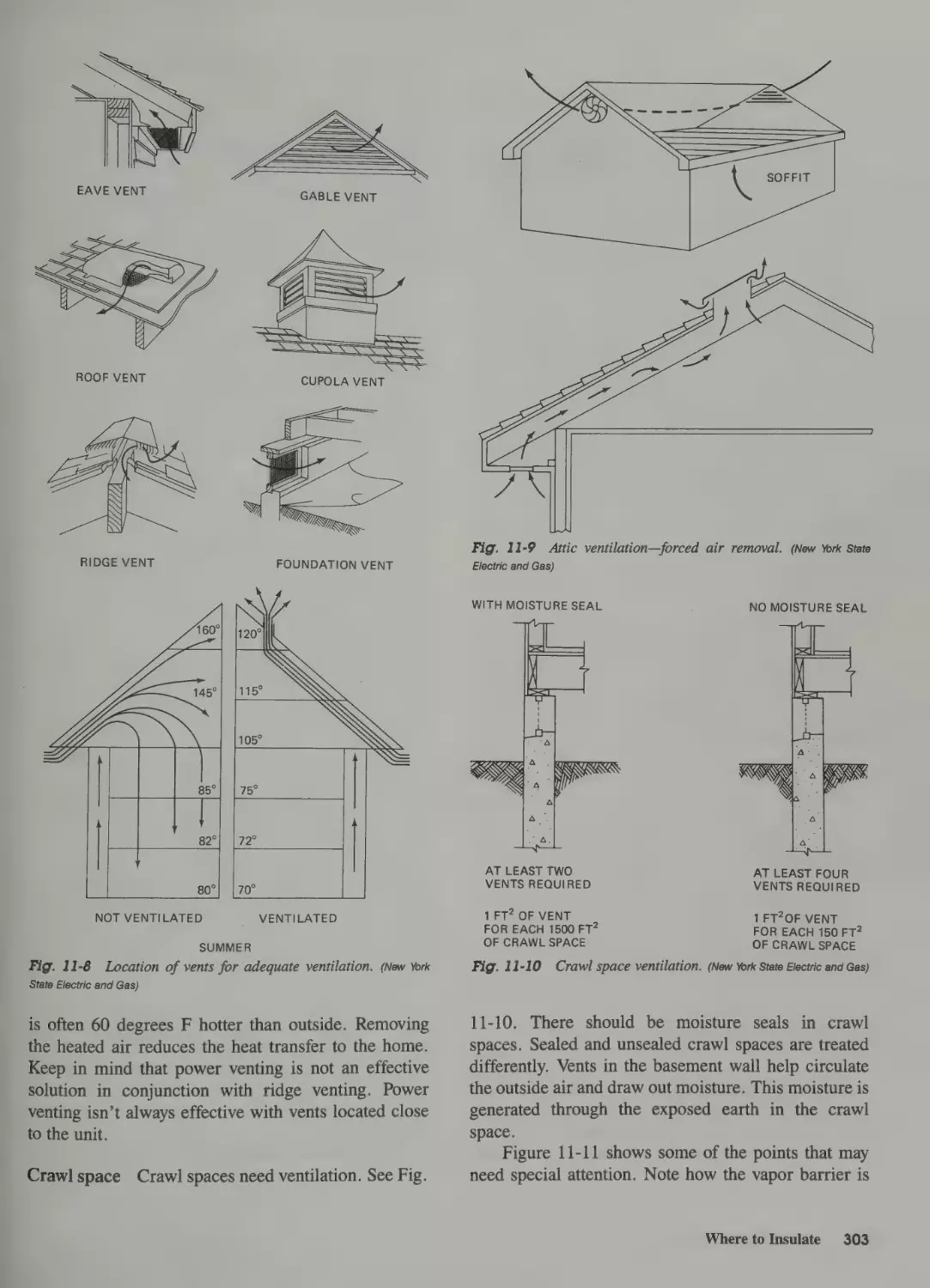
Where to Insulate 301
Installing Insulation 304
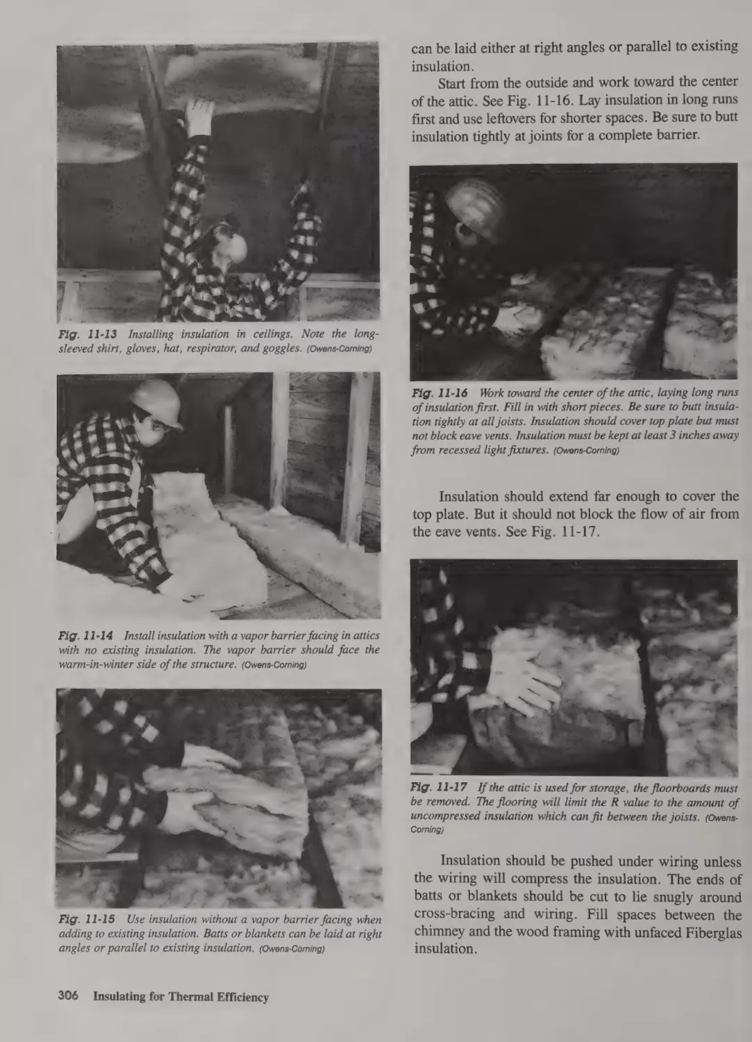
Installing Insulation in Ceilings 304
Installation Safety 304
Installing
~ Installing
Installing
Insulating
Insulating
Installing
Insulation in Unfloored Attics 304
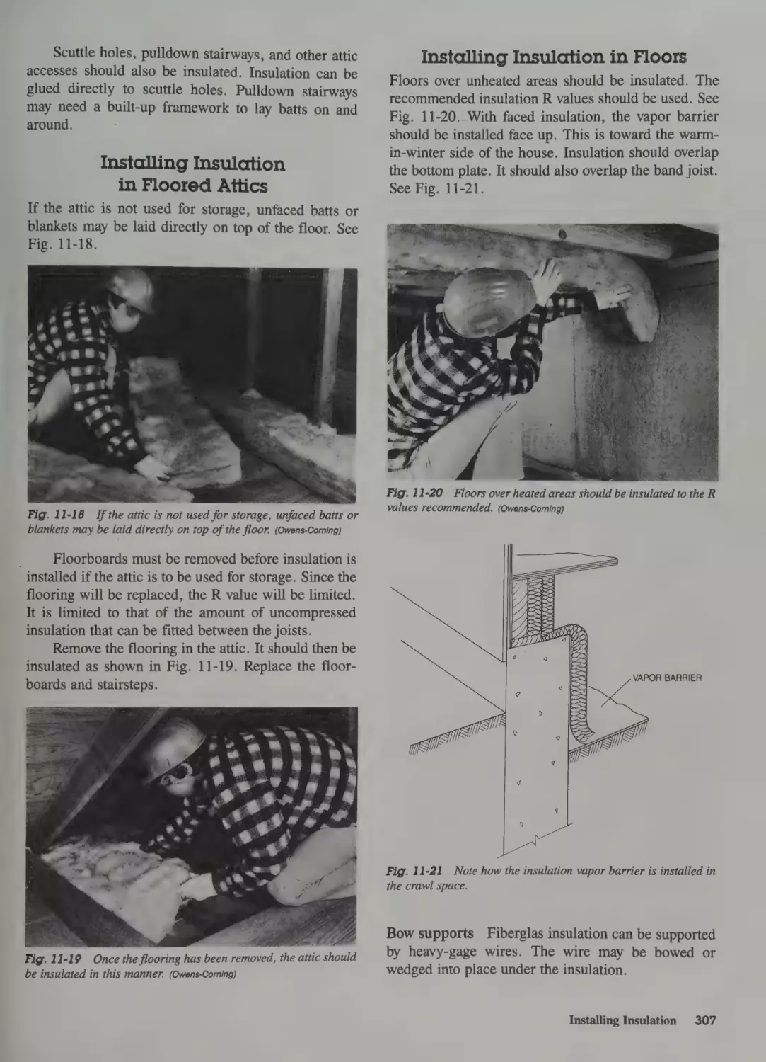
Insulation in Floored Attics 307
Insulation in Floors 307
Basement Walls 308
Crawl Spaces 308
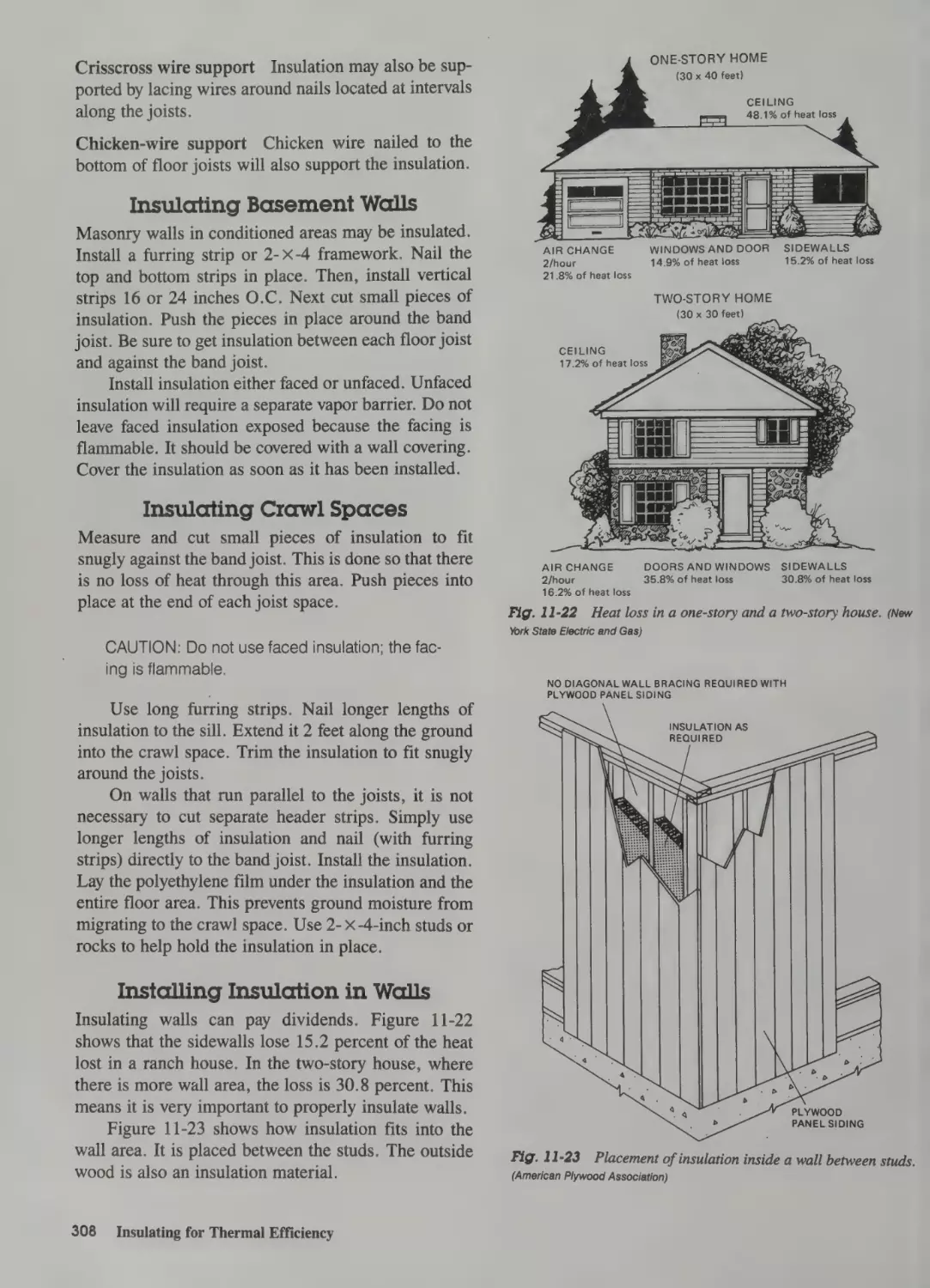
Insulation in Walls 308
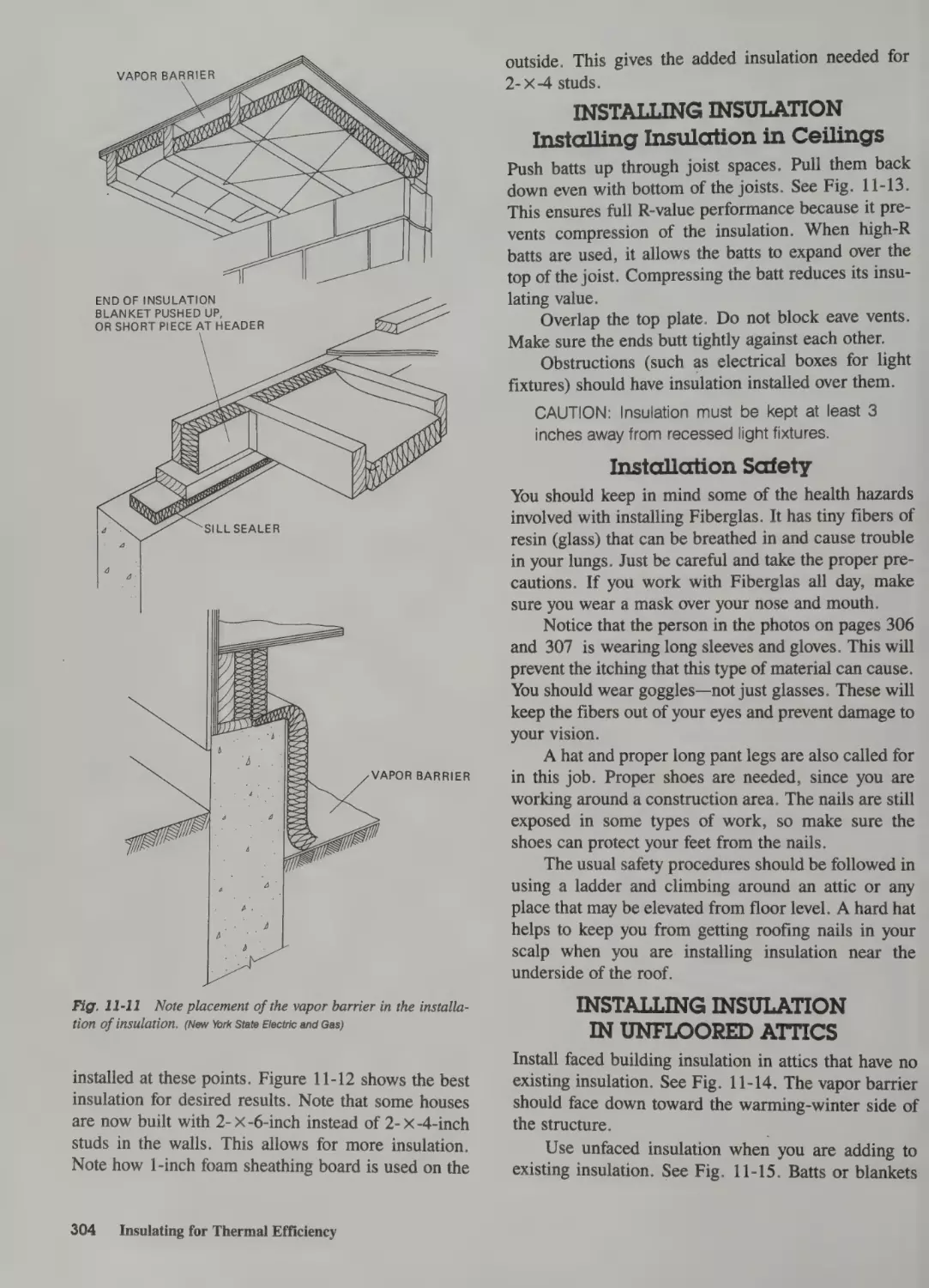
Vapor Barriers and Moisture Control 312
Condensation
312
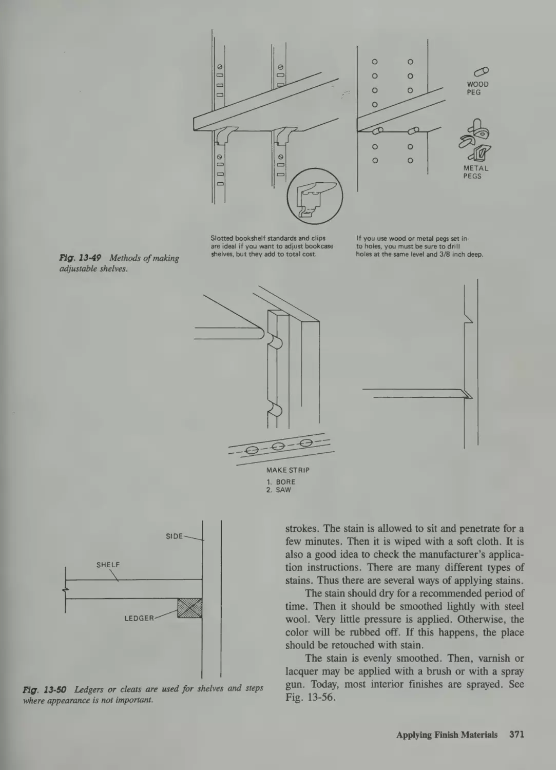
Applying Finish Materials 370
Applying Stain 370
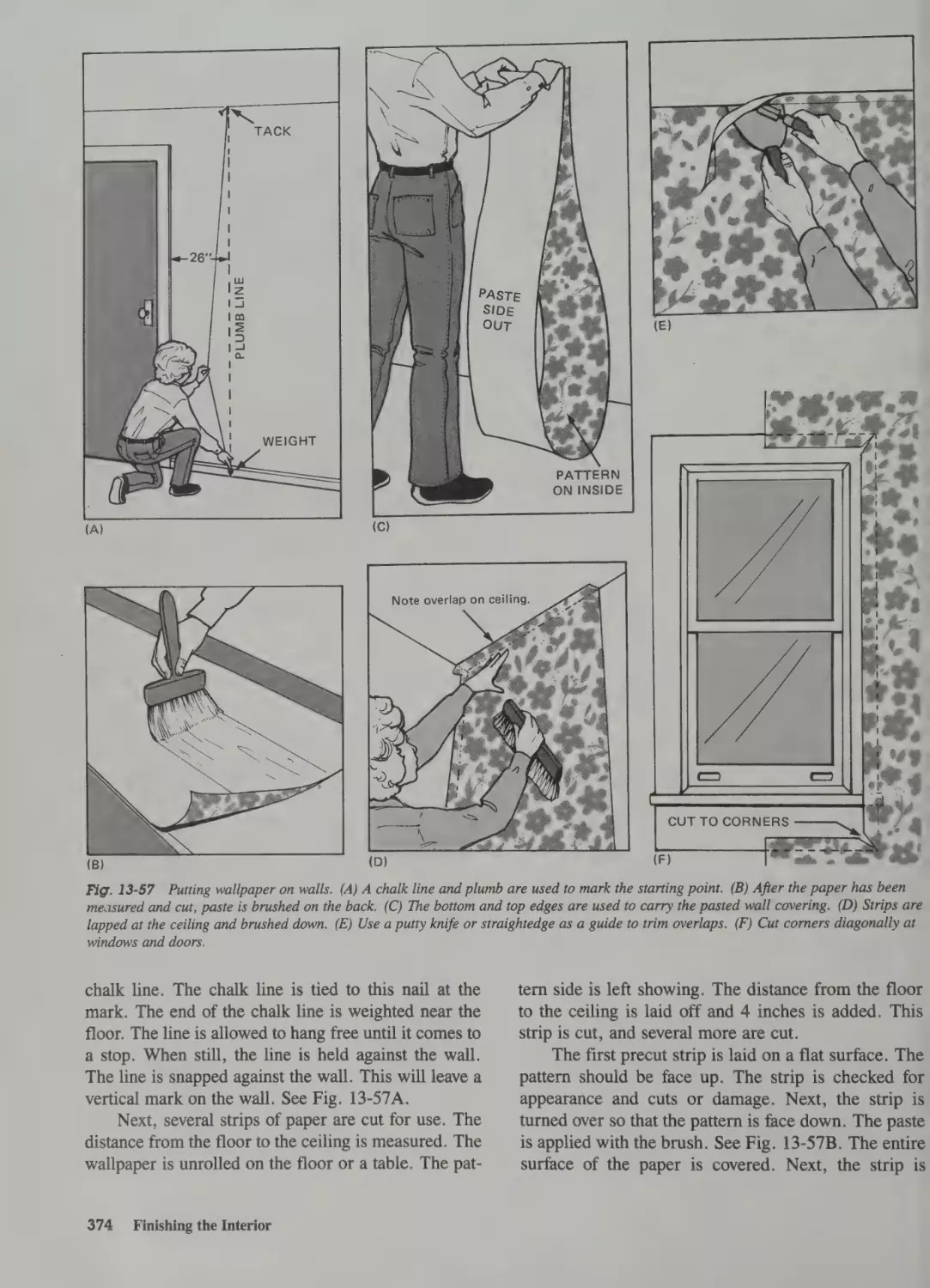
Applying the Wall Finish 373
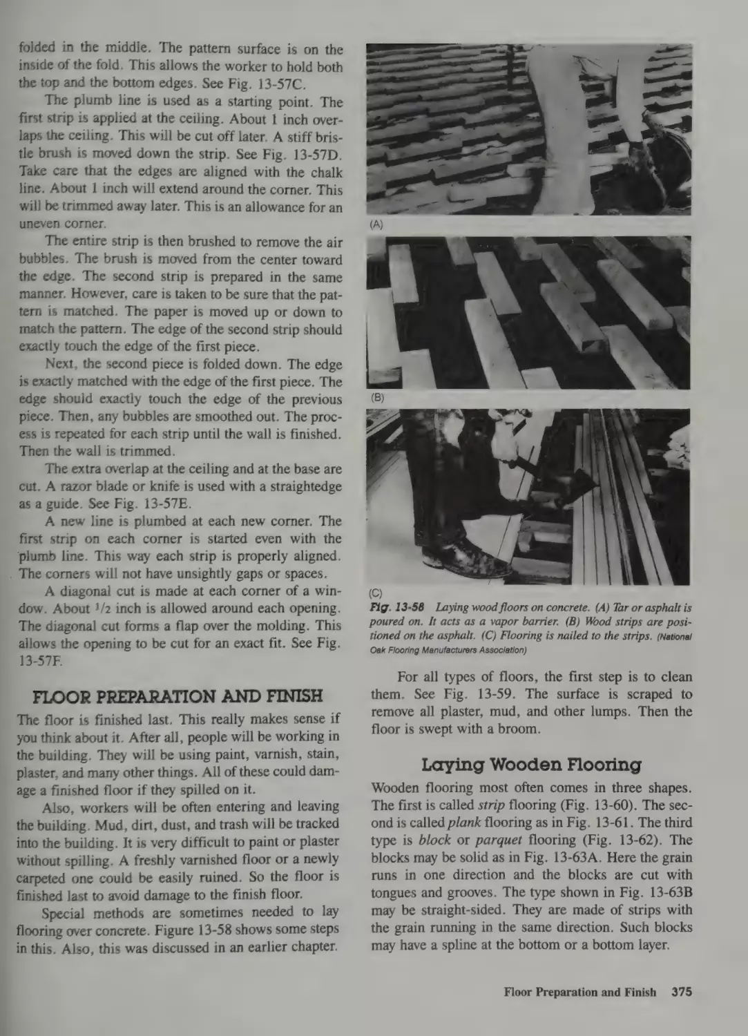
Floor Preparation and Finish 375
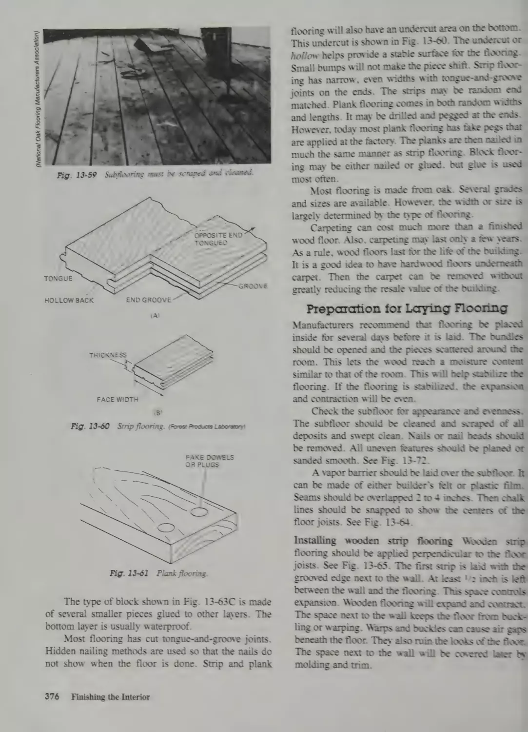
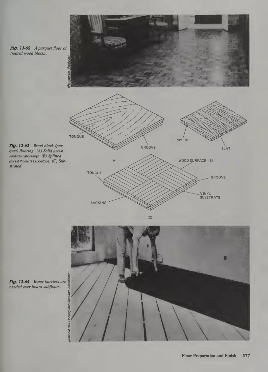
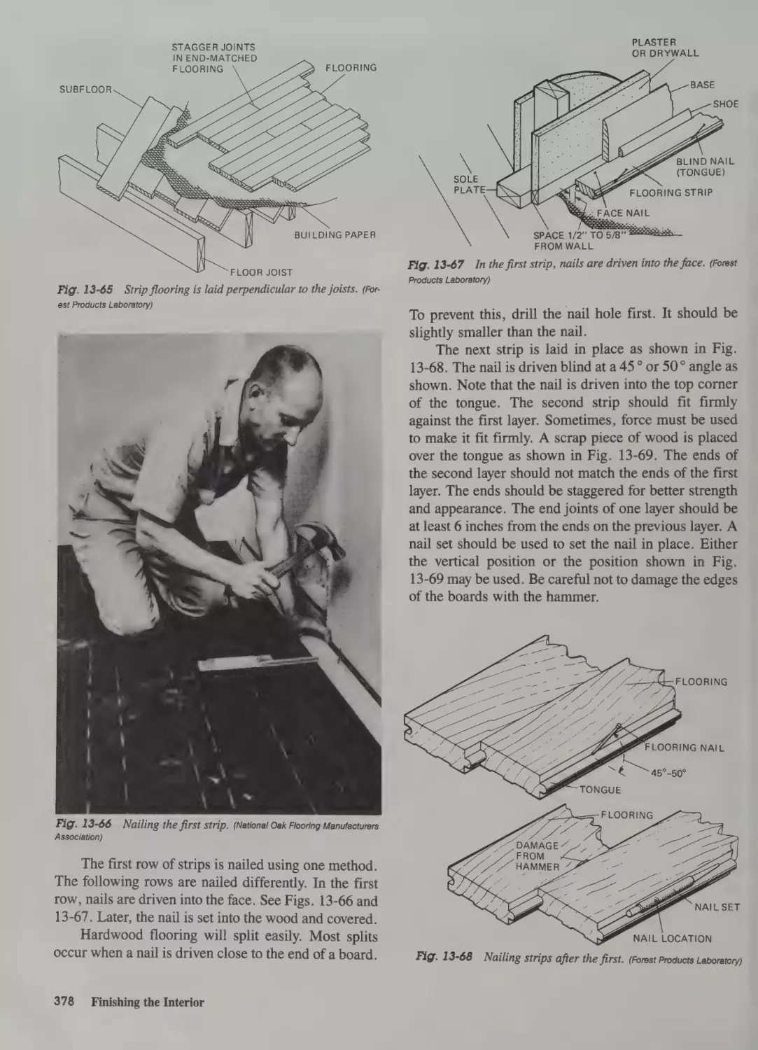
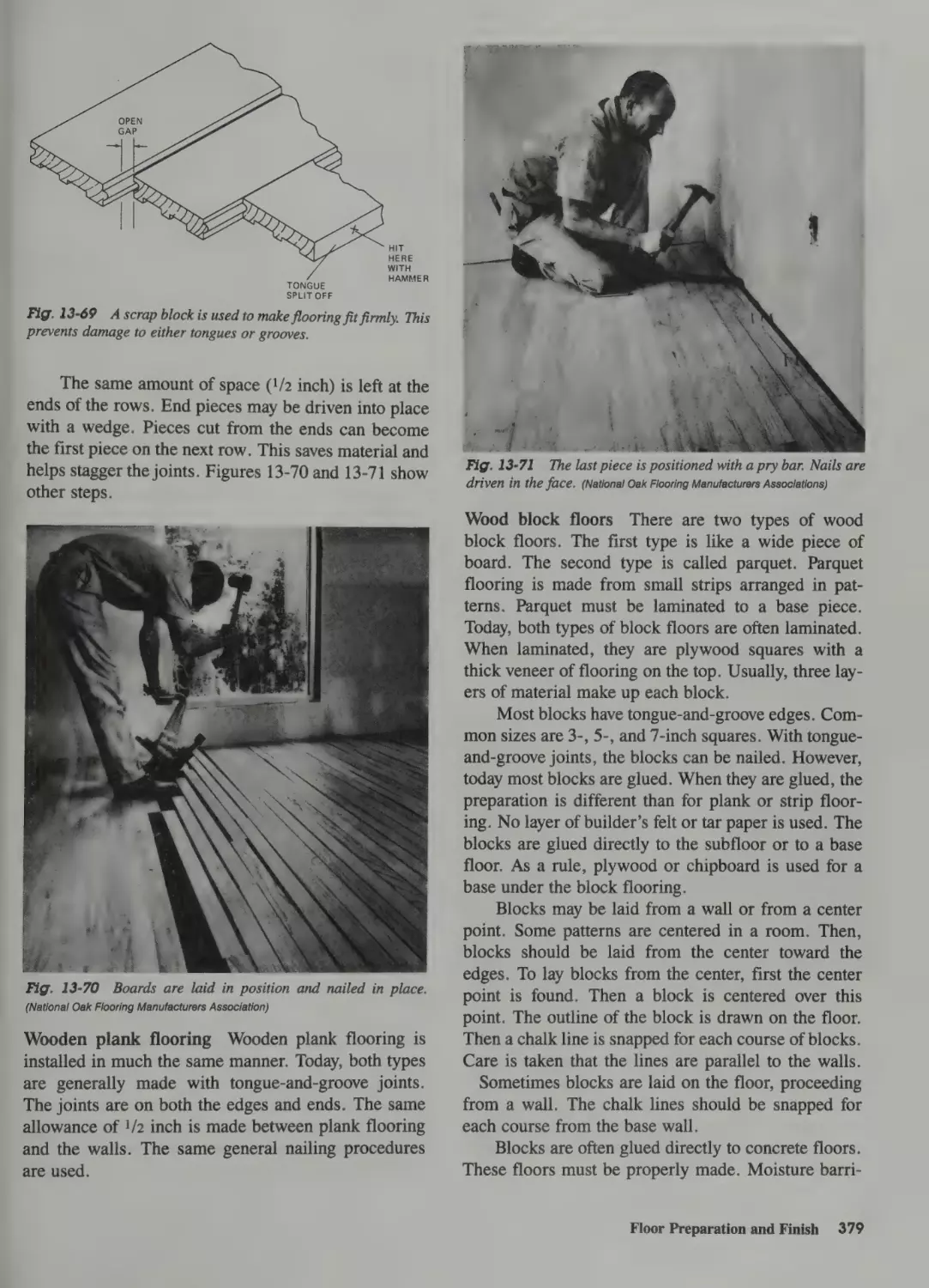
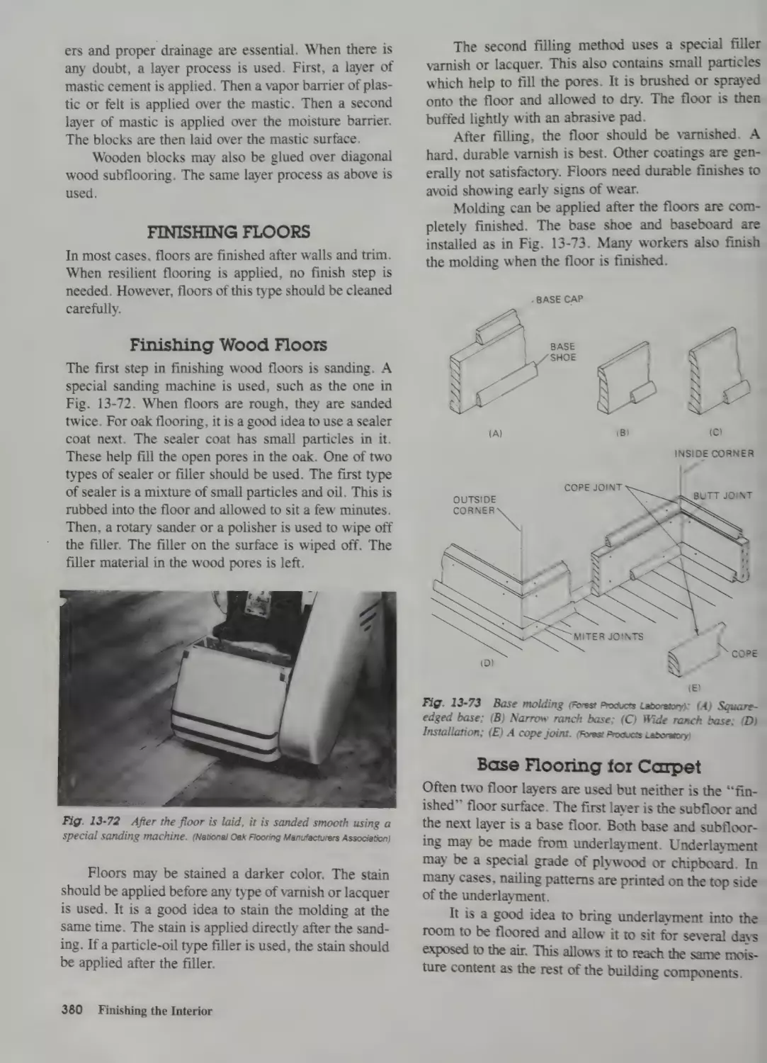
Laying Wooden Flooring 375
Preparation for Laying Flooring 376
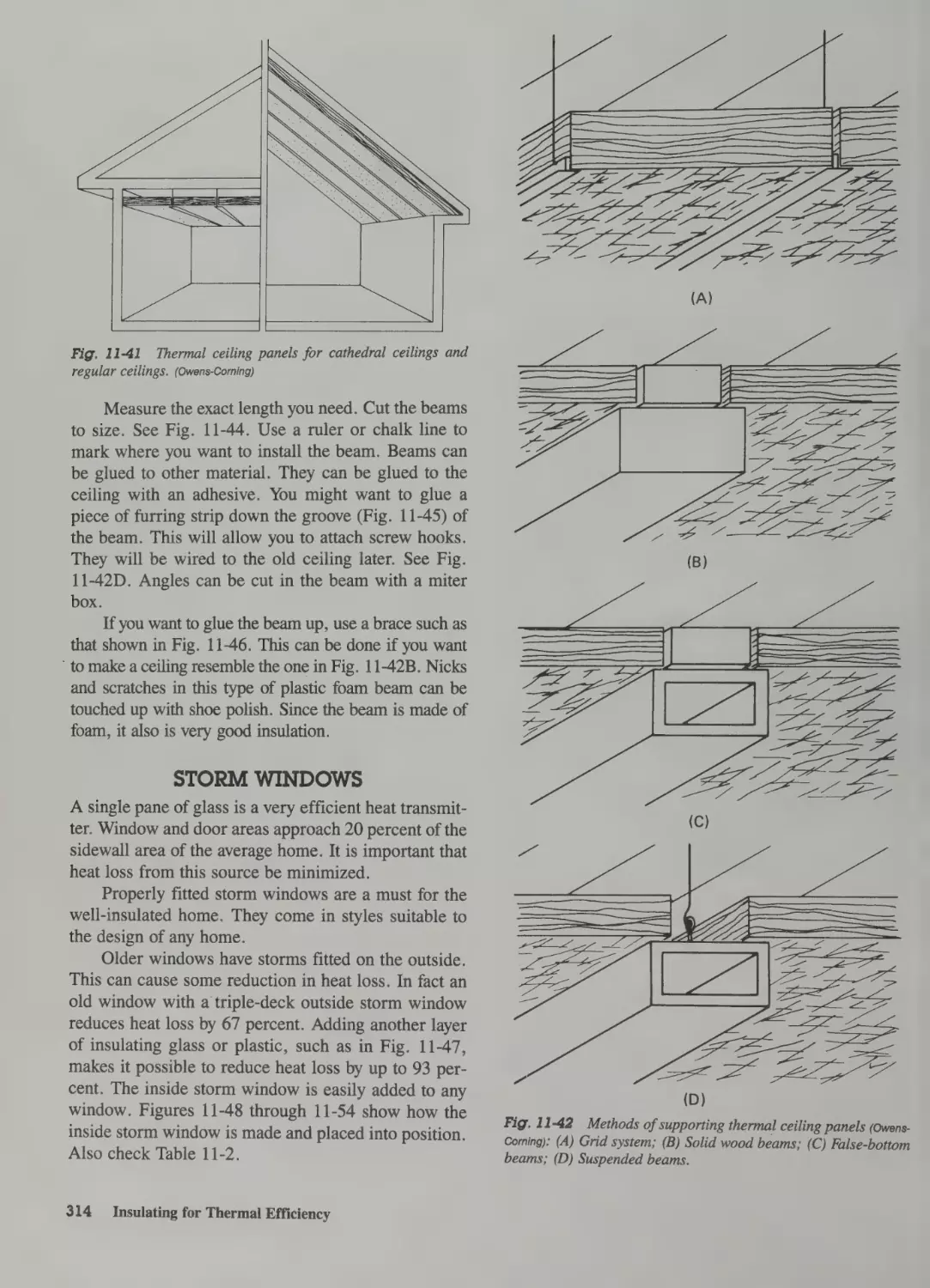
Thermal Ceilings 313
Installing Thermal Ceiling Panels 313
Decorative Beams 313
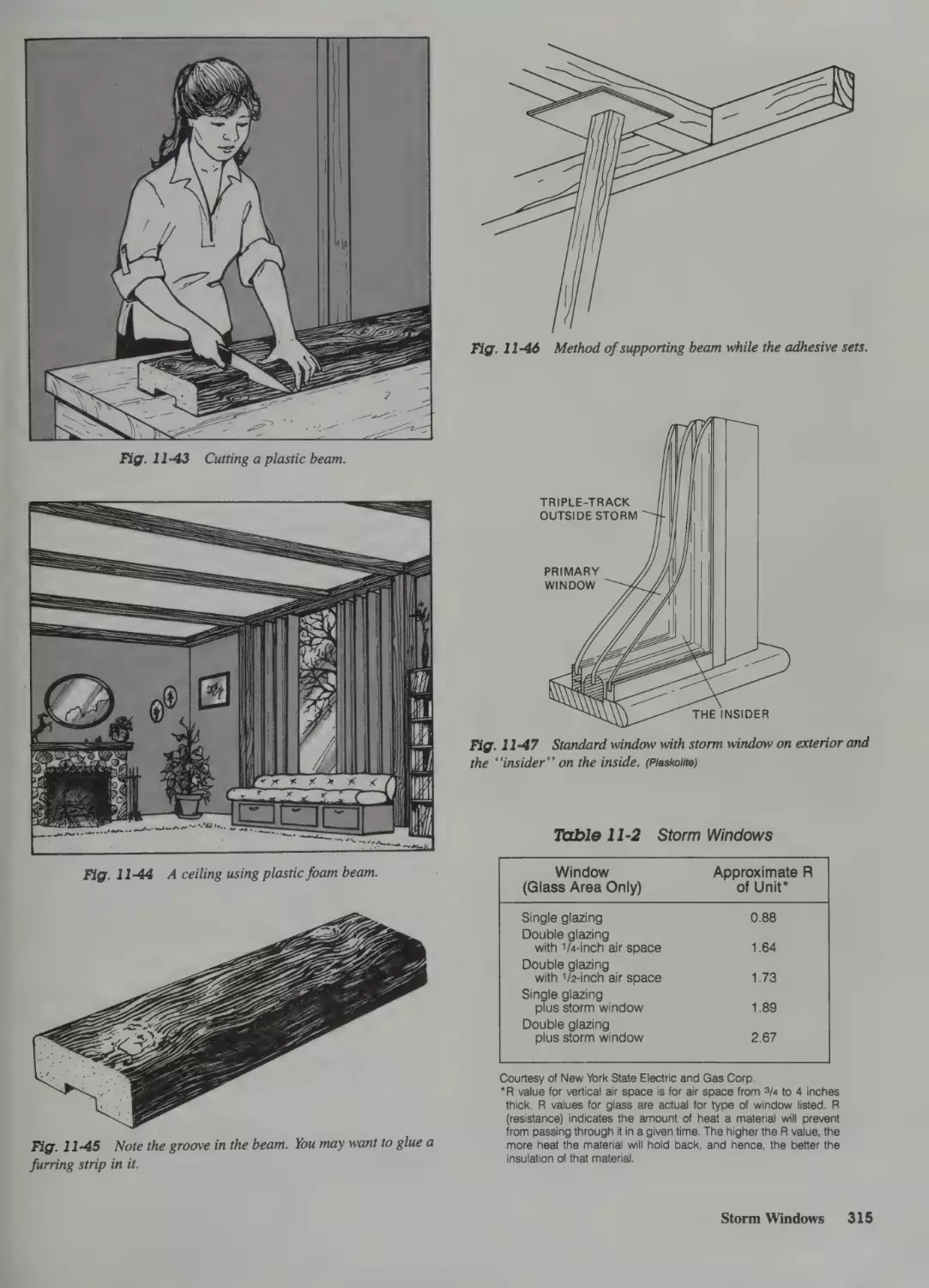
Storm Windows 314
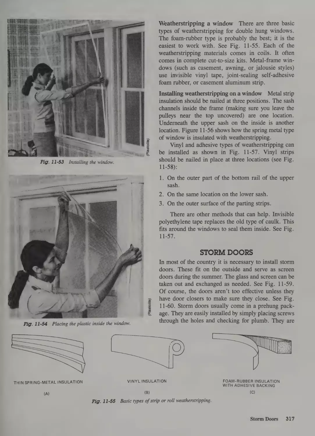
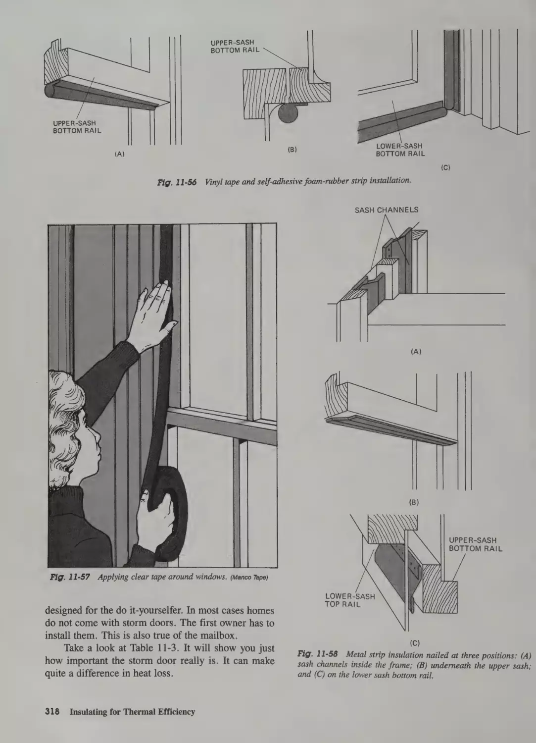
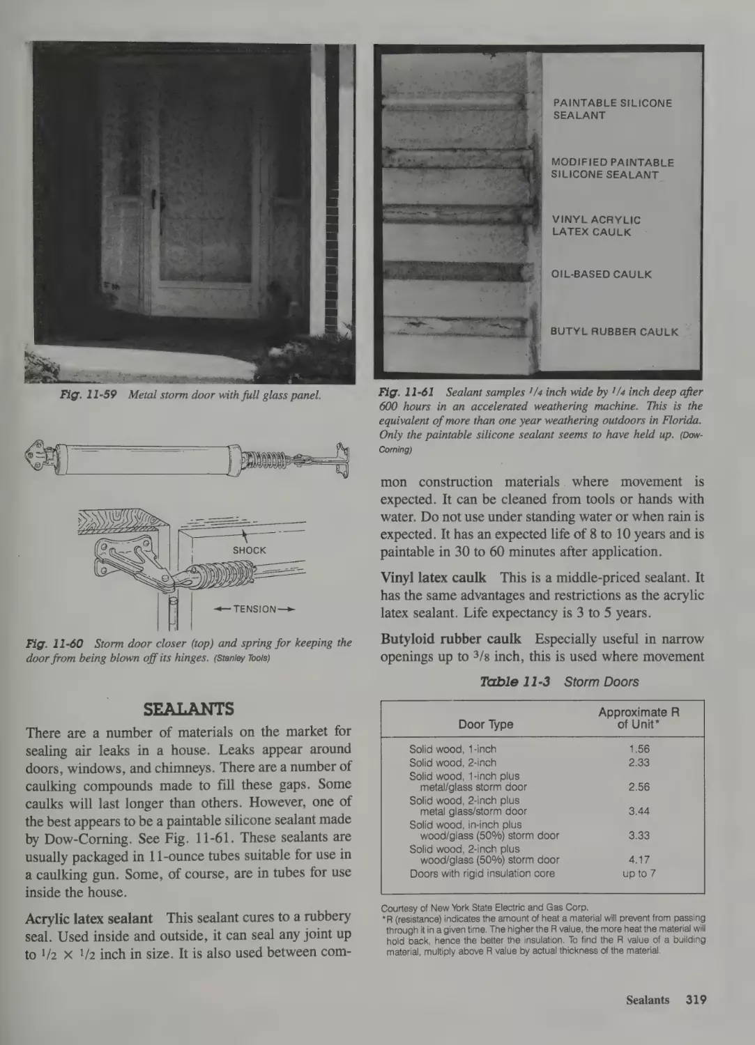
Storm Doors 317
Sealants 319
Winterizing a Home 320
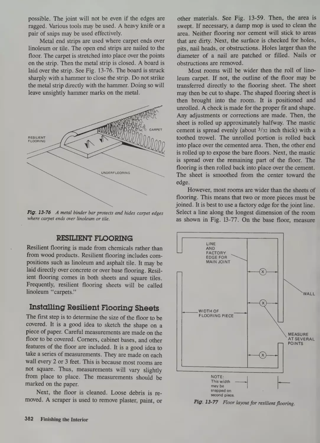
Finishing Floors 380
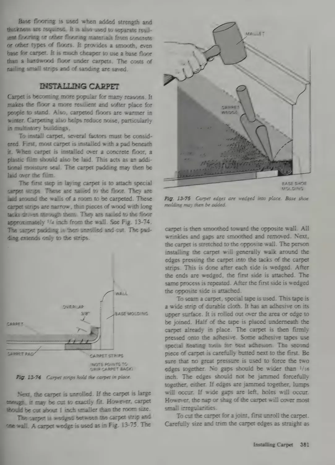
Finishing Wood Floors 380
Base Flooring for Carpet 380
Installing Carpet 381
Resilient Flooring 382
Installing Resilient Flooring Sheets 382
To Install Resilient Block Flooring 383
12 Preparing Interior Walls & Ceilings
Sequence 322
Putting Insulation in Walls 322
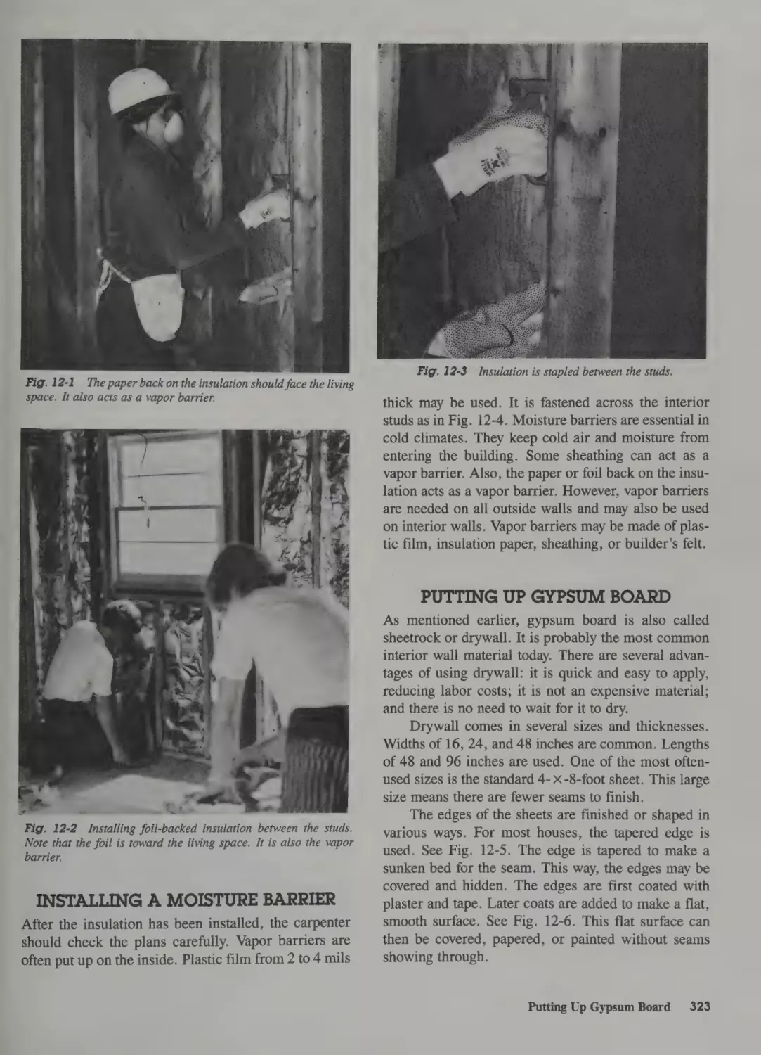
Installing a Moisture Barrier 323
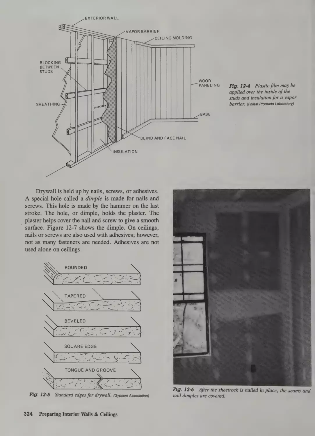
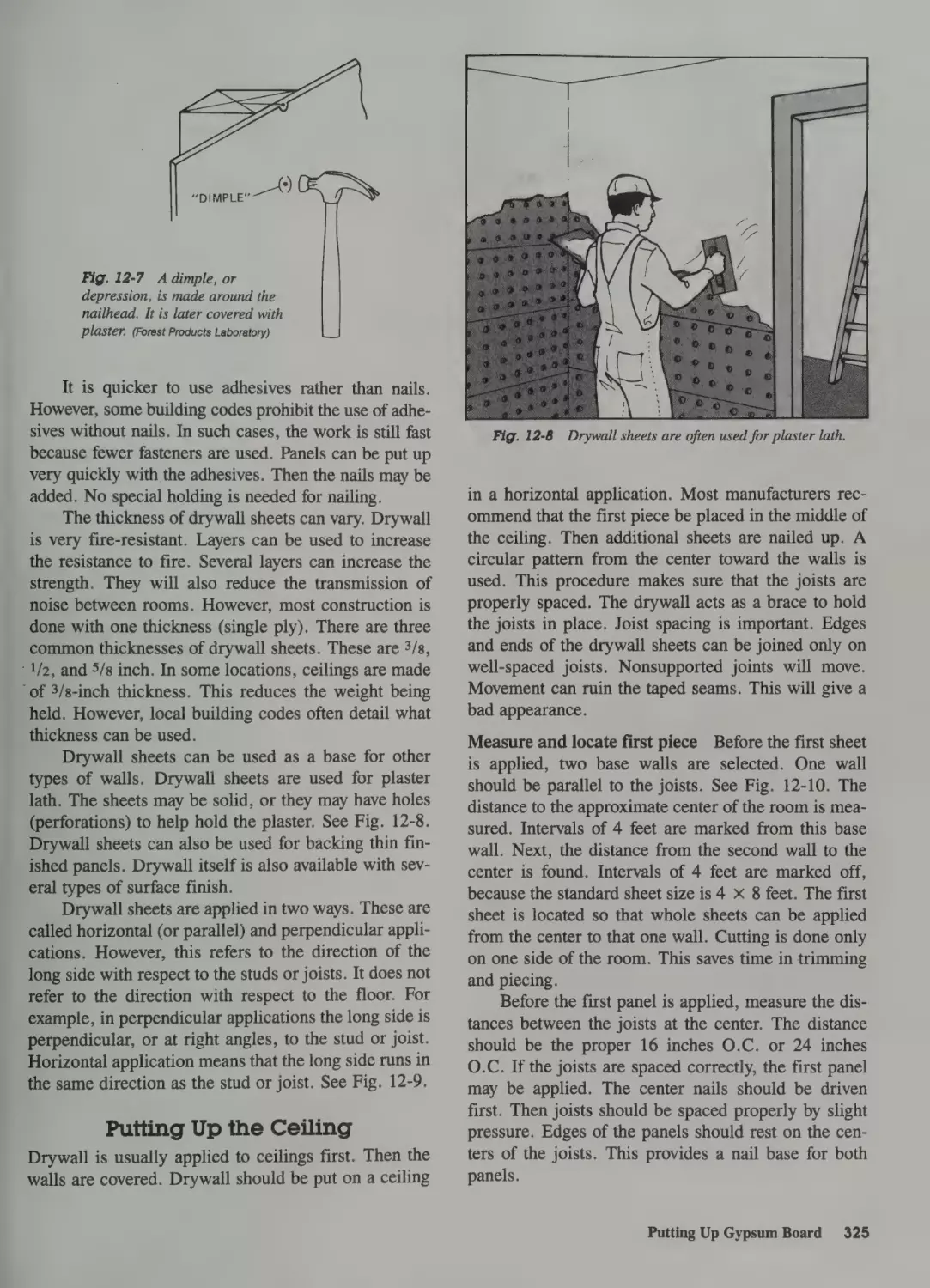
Putting Up Gypsum Board 323
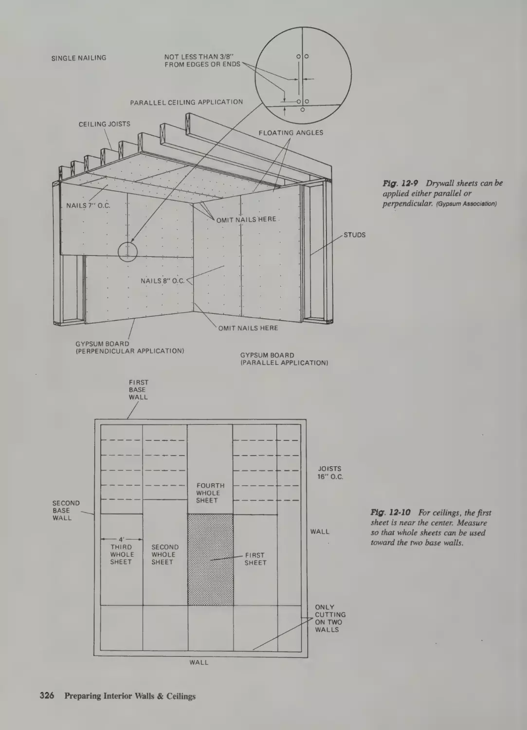
Putting Up the Ceiling 325
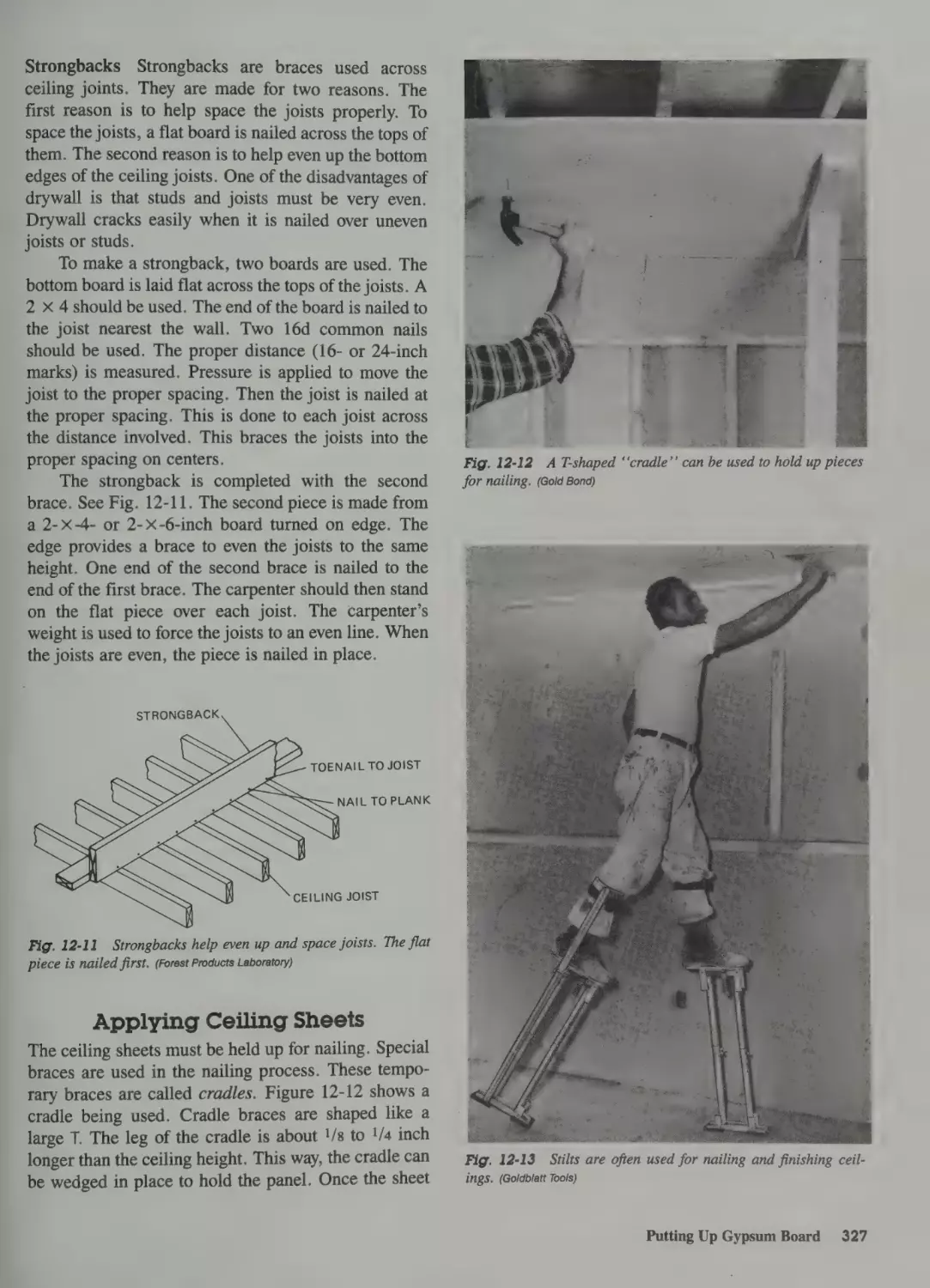
Applying Ceiling Sheets 327
Cutting Gypsum Board 328
Applying Wall Sheets 329
Double-Ply Construction 331
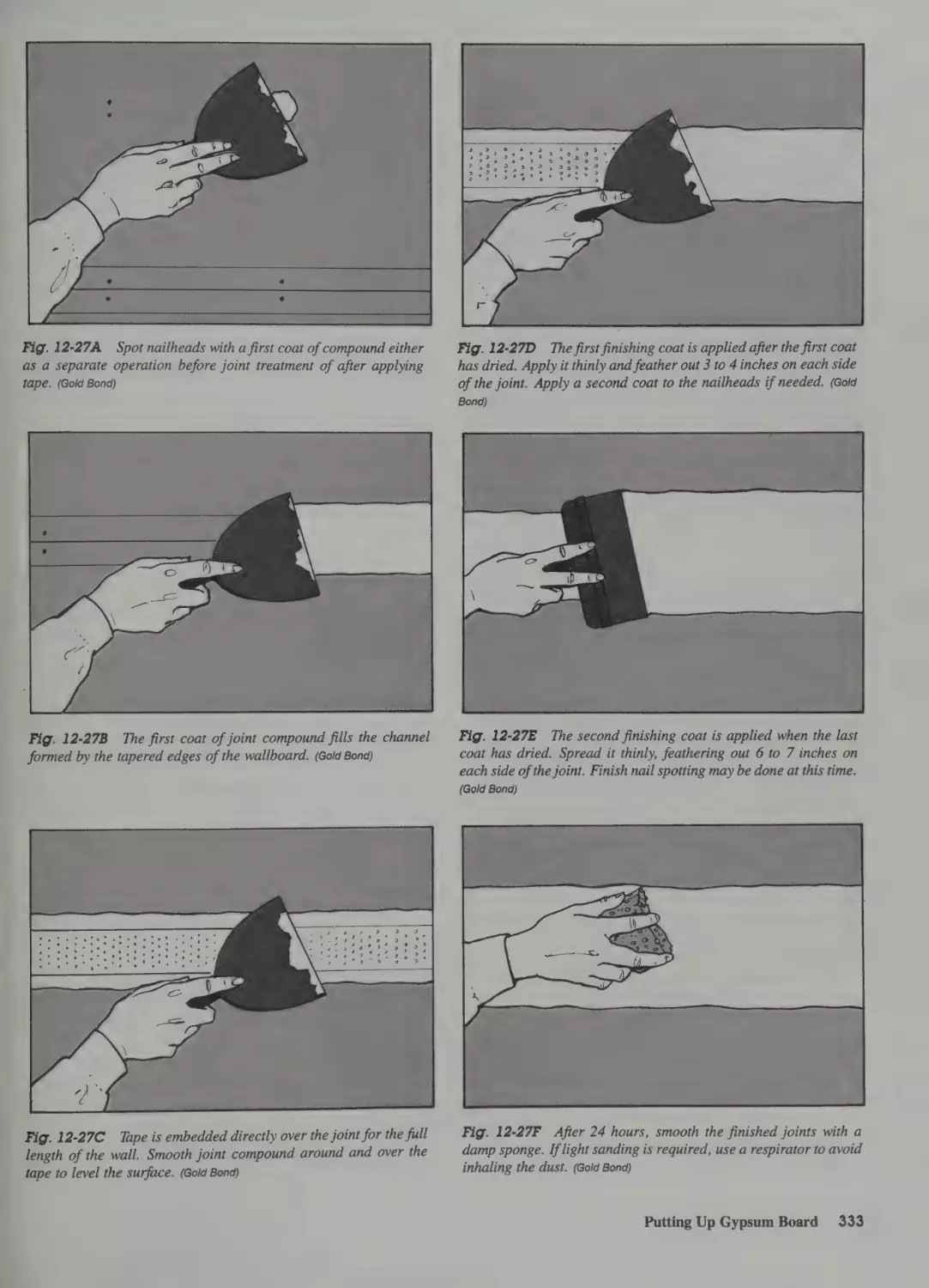
Finishing Joints and Seams 332
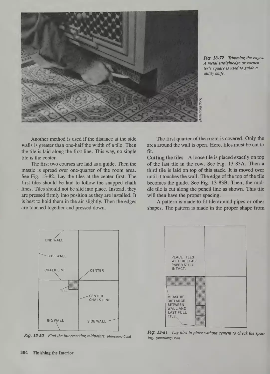
Laying Ceramic Tile 385
14 Special Construction Methods
Stairs 388
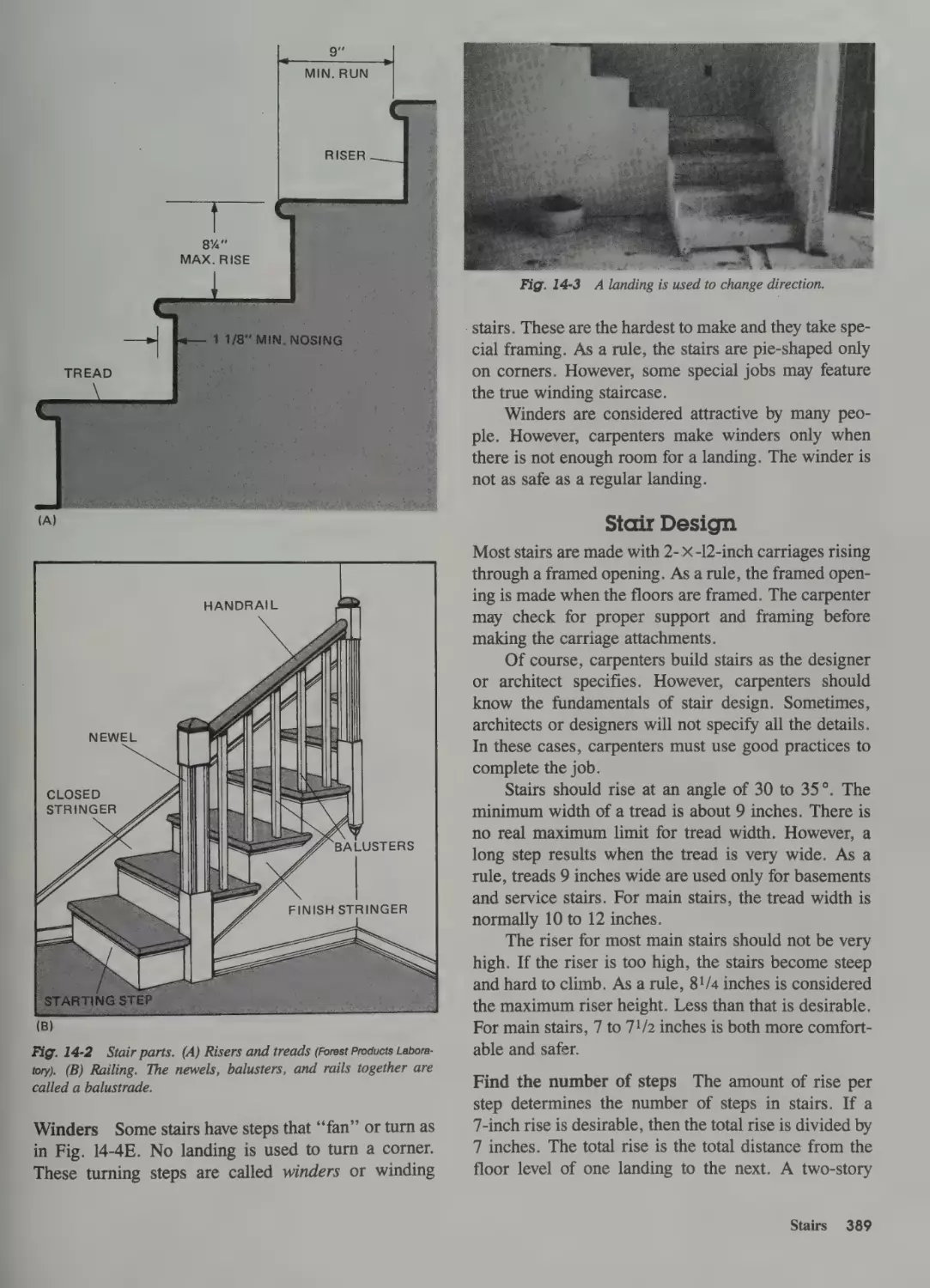
Stair Parts 388
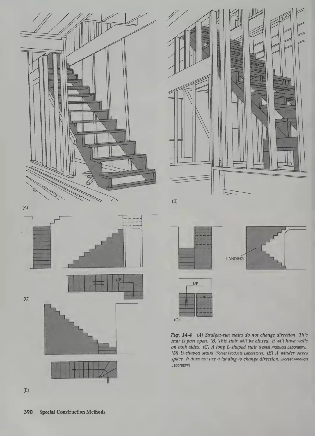
Stair Shapes 388
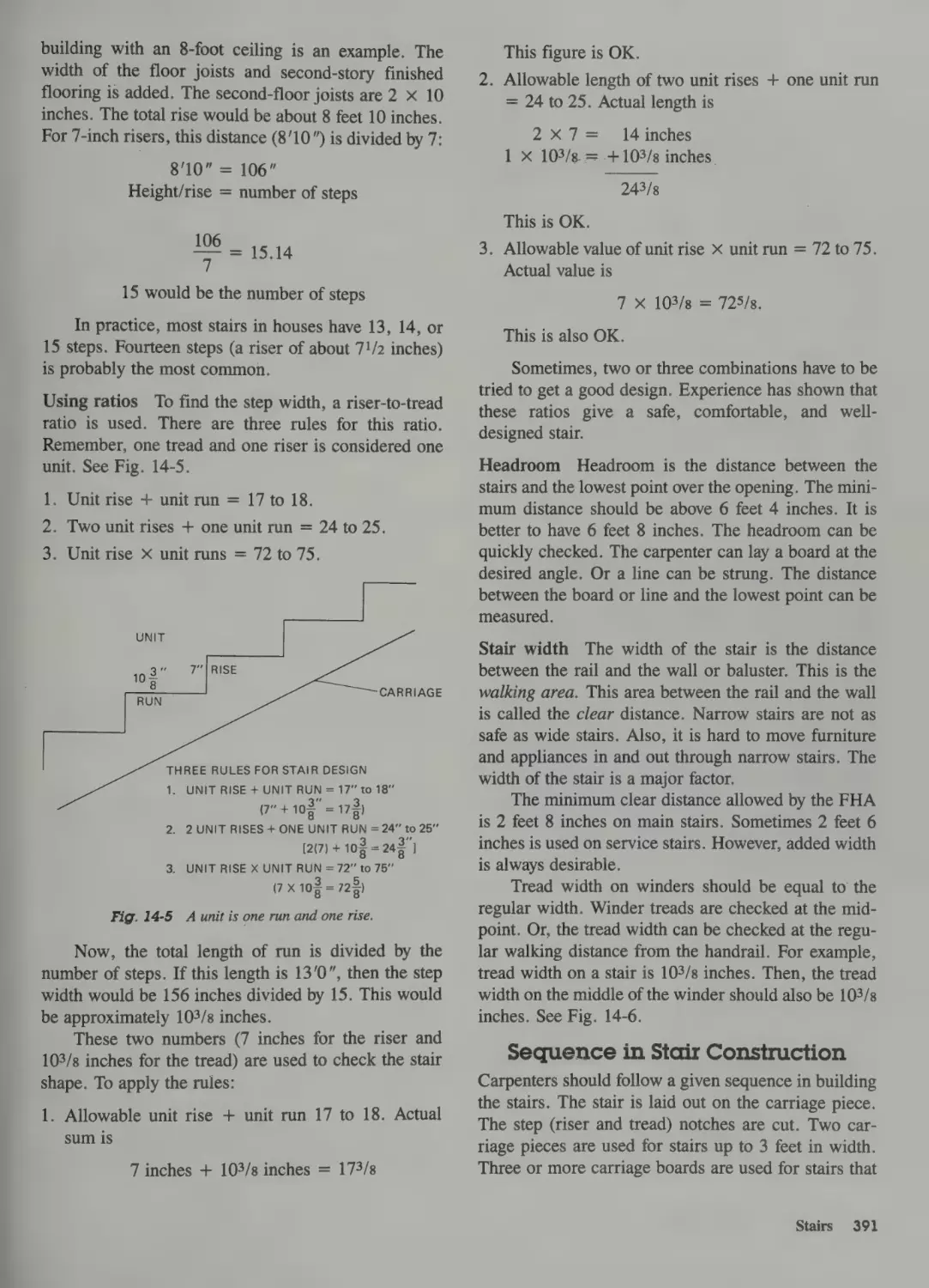
Stair Design 389
Sequence in Stair Construction 391
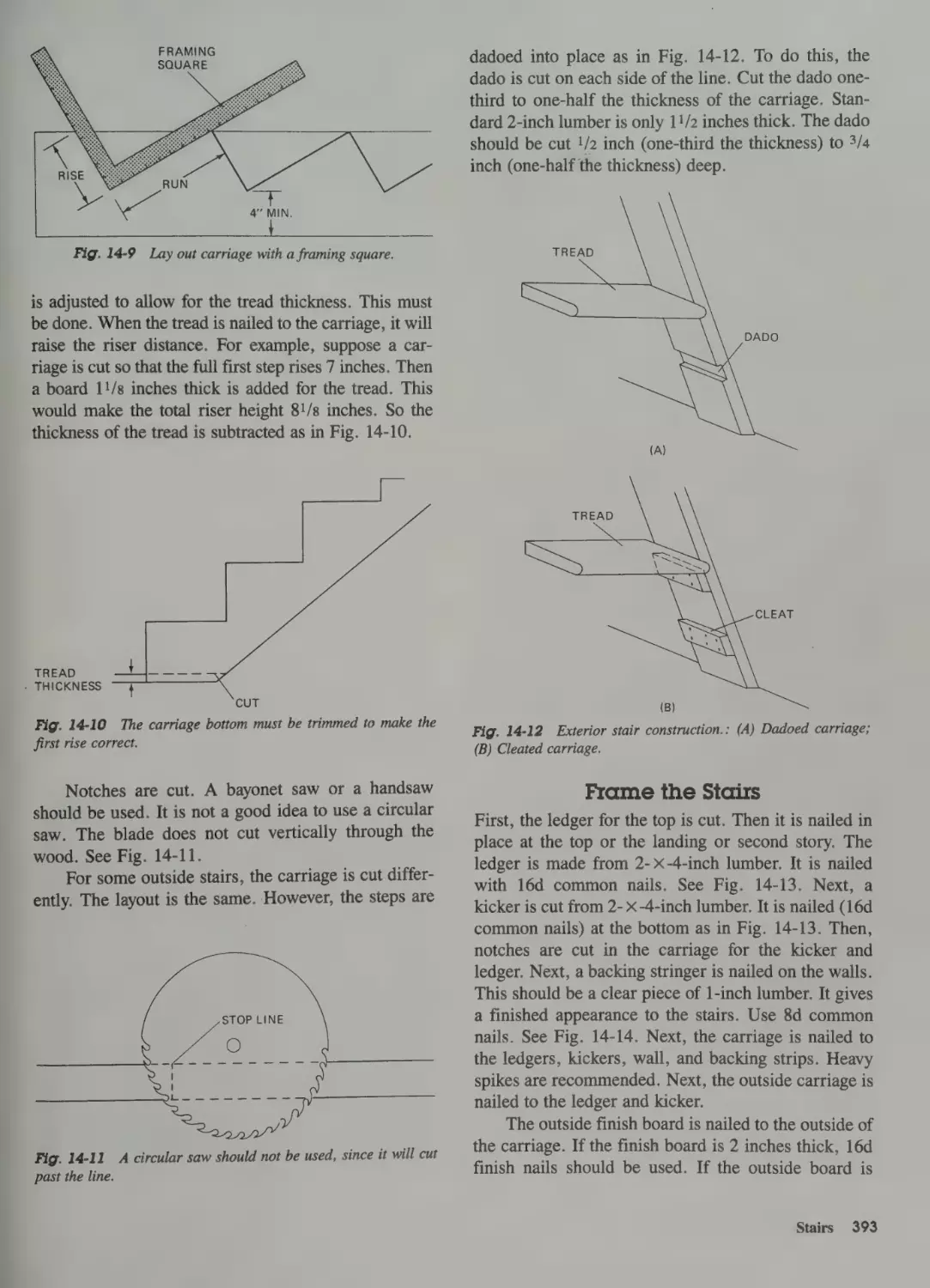
Carriage Layout 392
Frame the Stairs 393
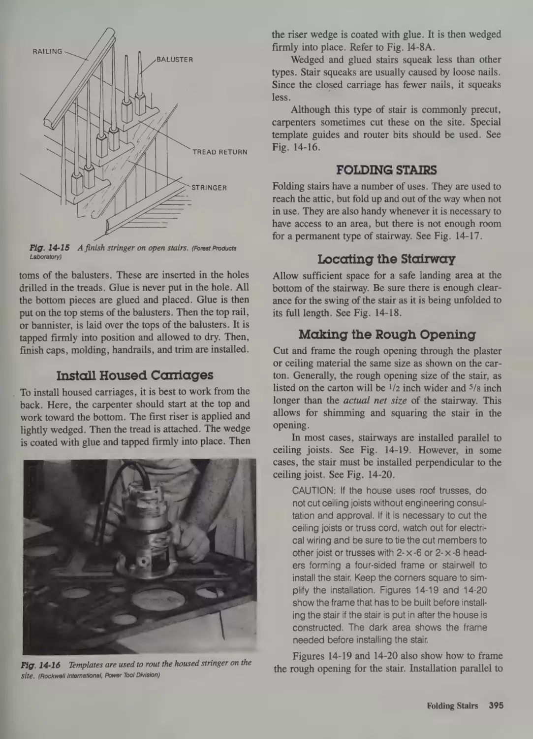
Install Housed Carriages
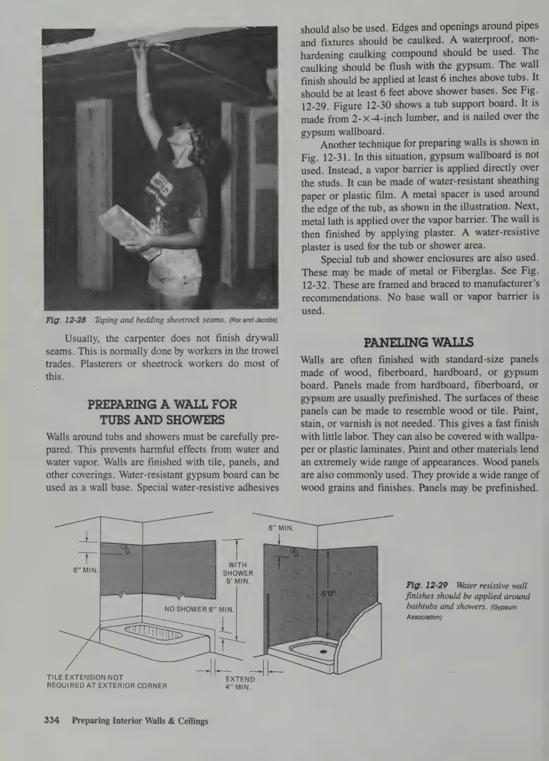
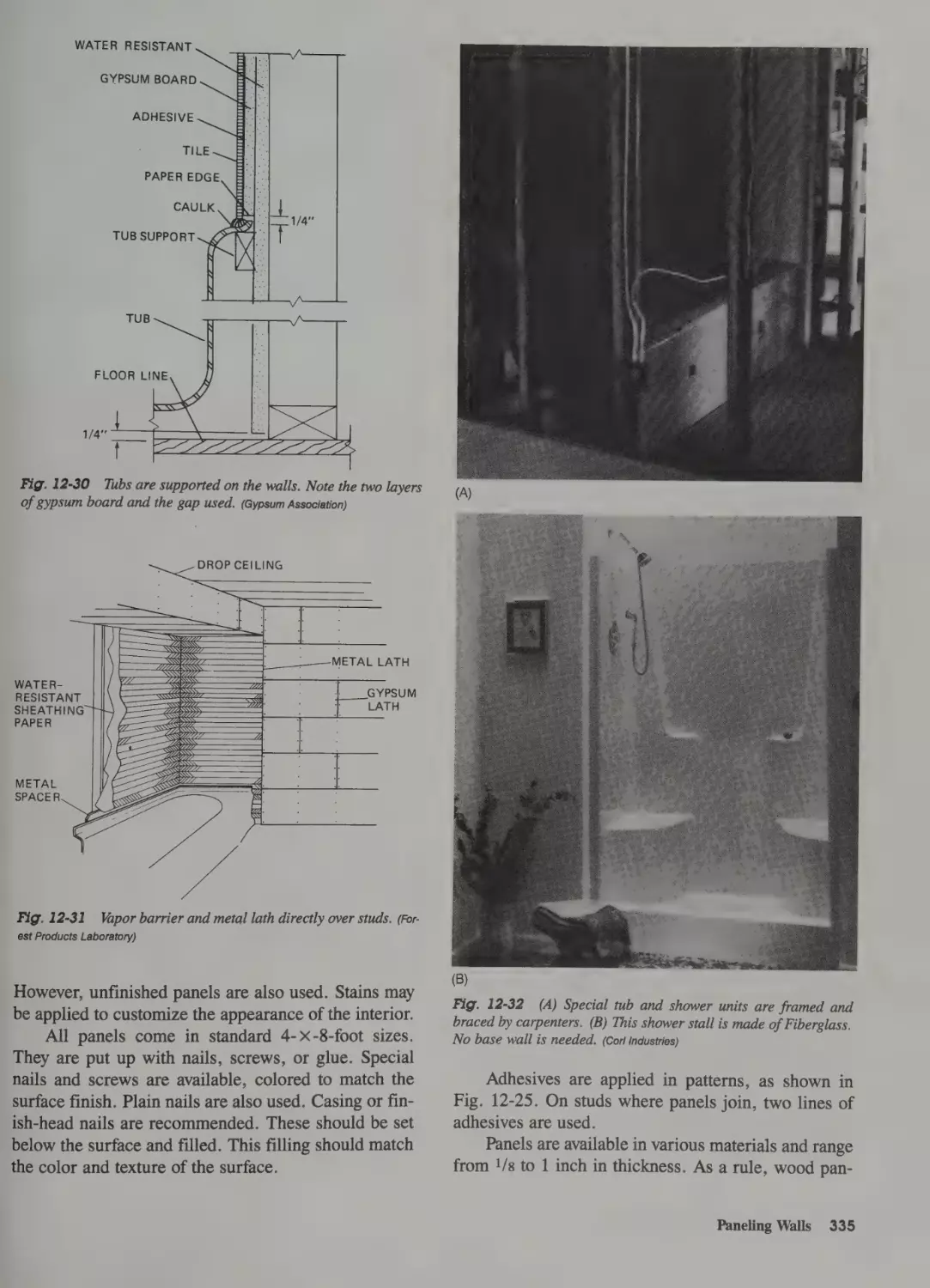
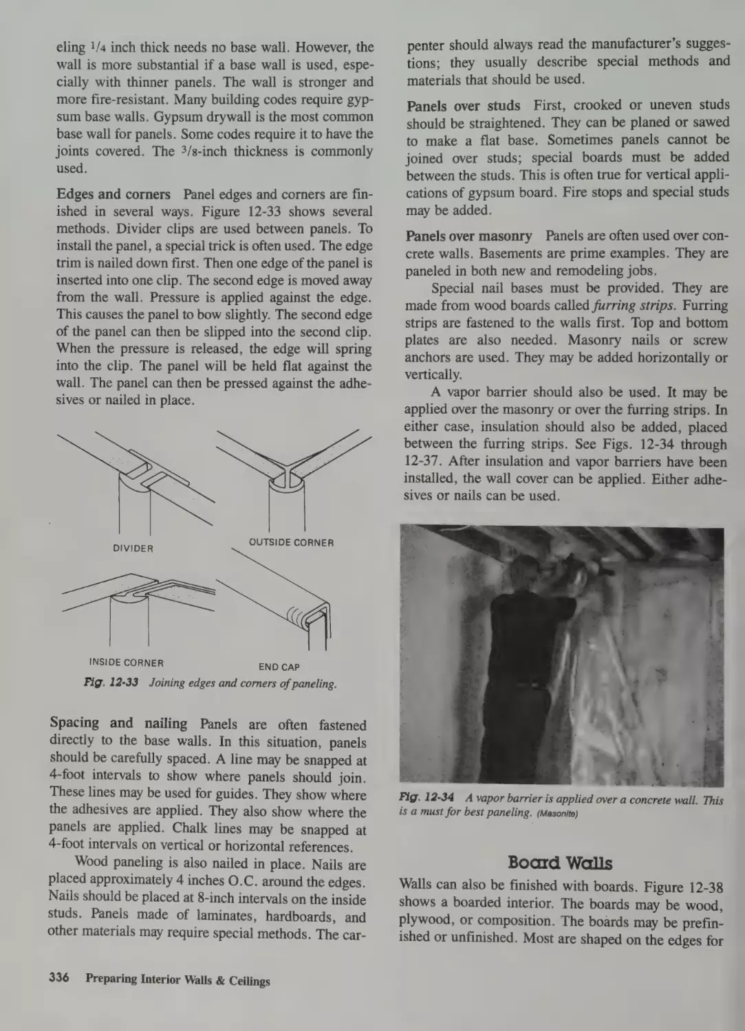
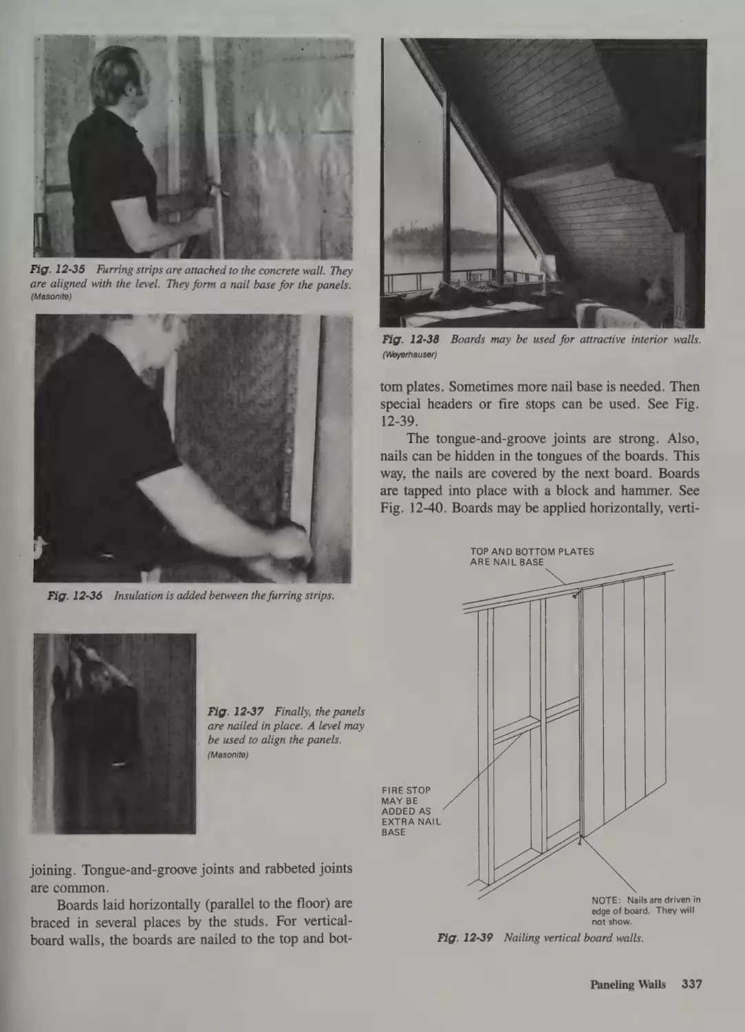
Preparing a Wall for Tubs and Showers 334
Paneling Walls 334
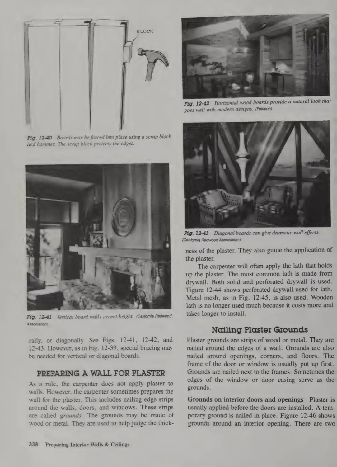
Board Walls 336
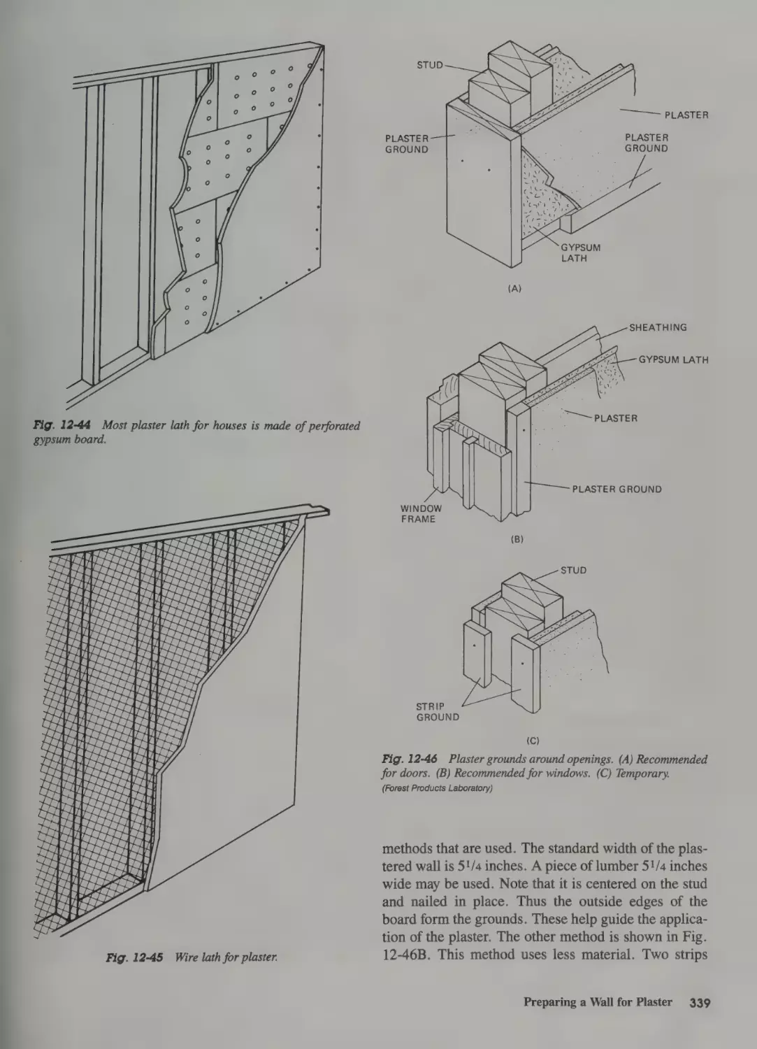
Preparing a Wall for Plaster 338
Nailing Plaster Grounds
Making Custom Cabinets 358
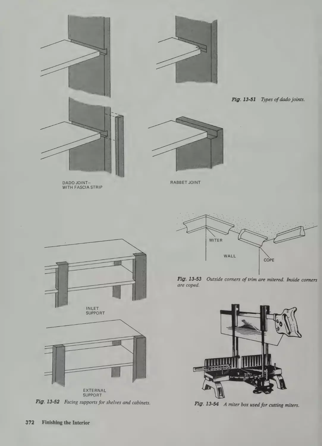
Shelves 369
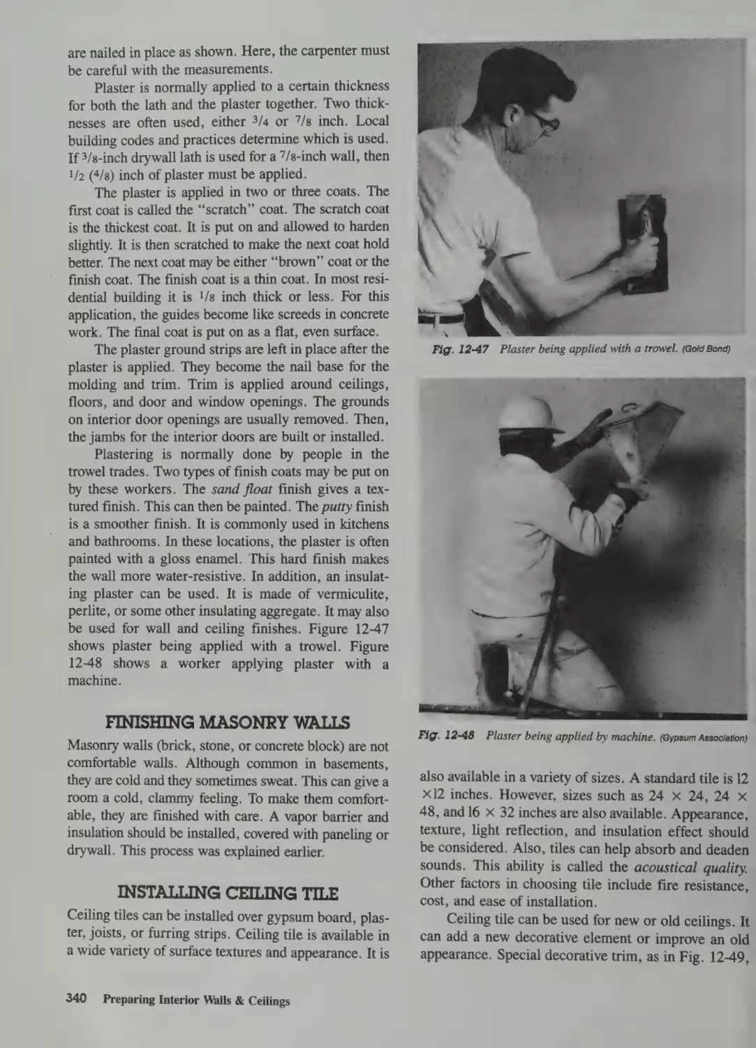
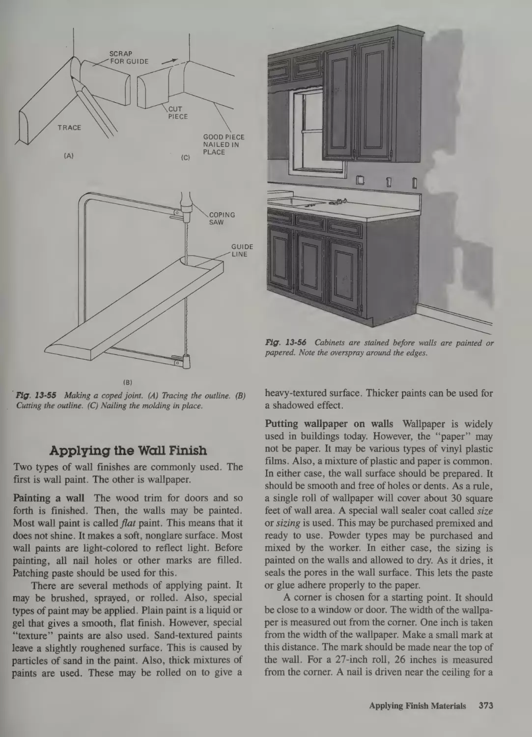
Applying Finish Trim 370
338
Finishing Masonry Walls 340
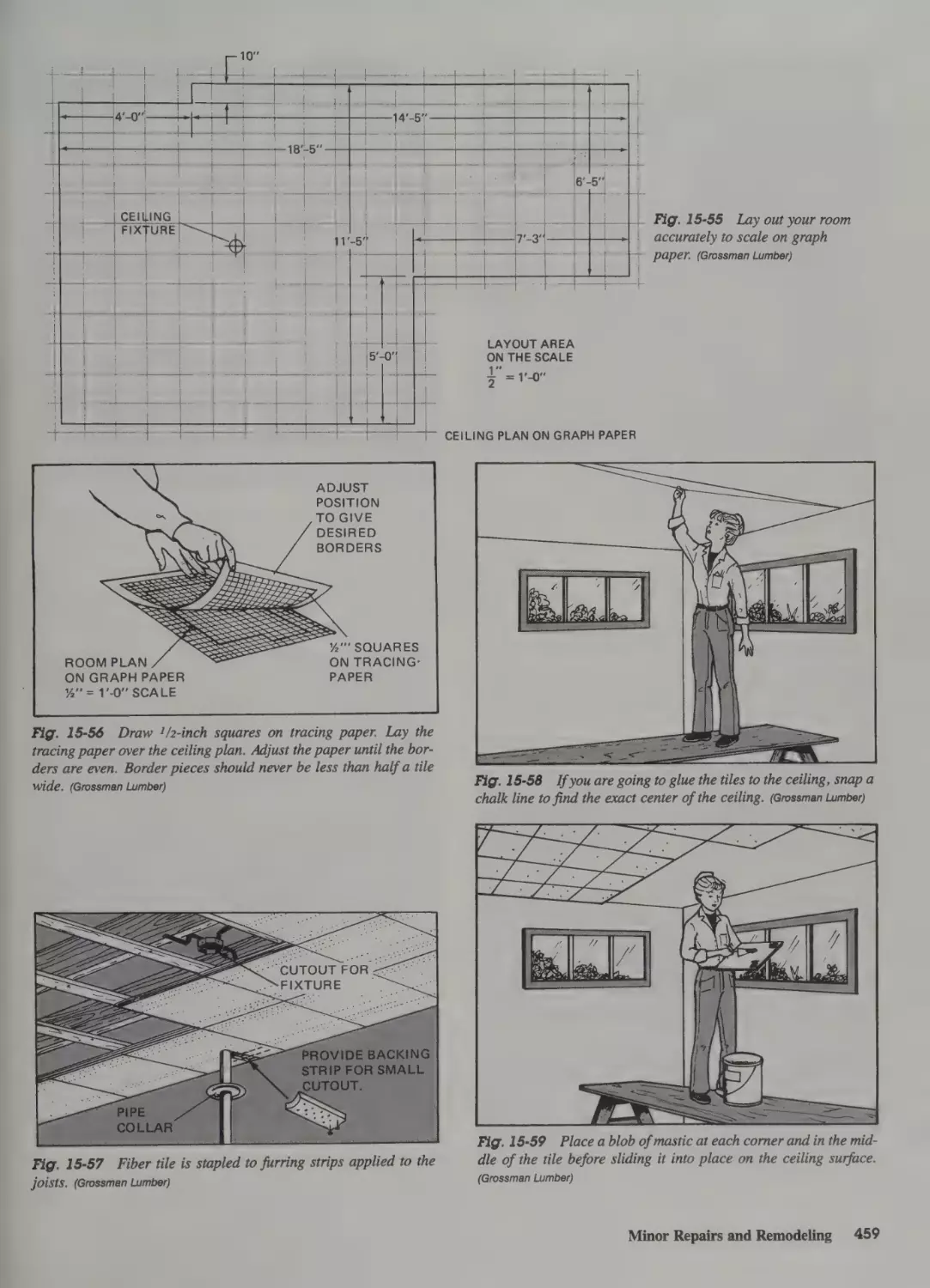
Installing Ceiling Tile 340
395
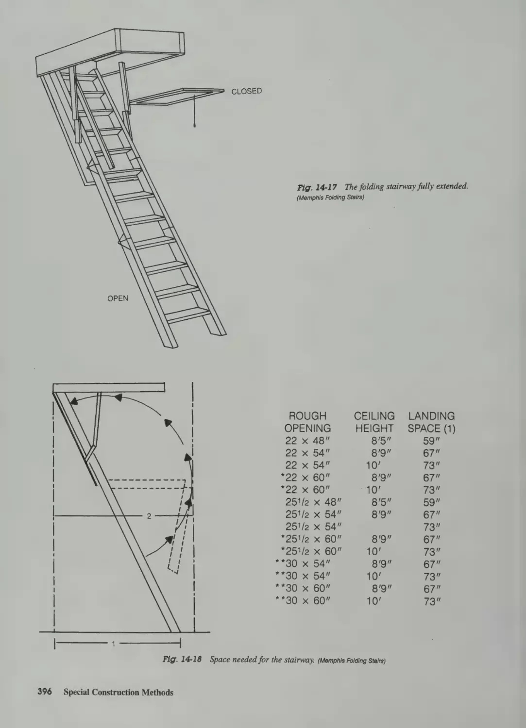
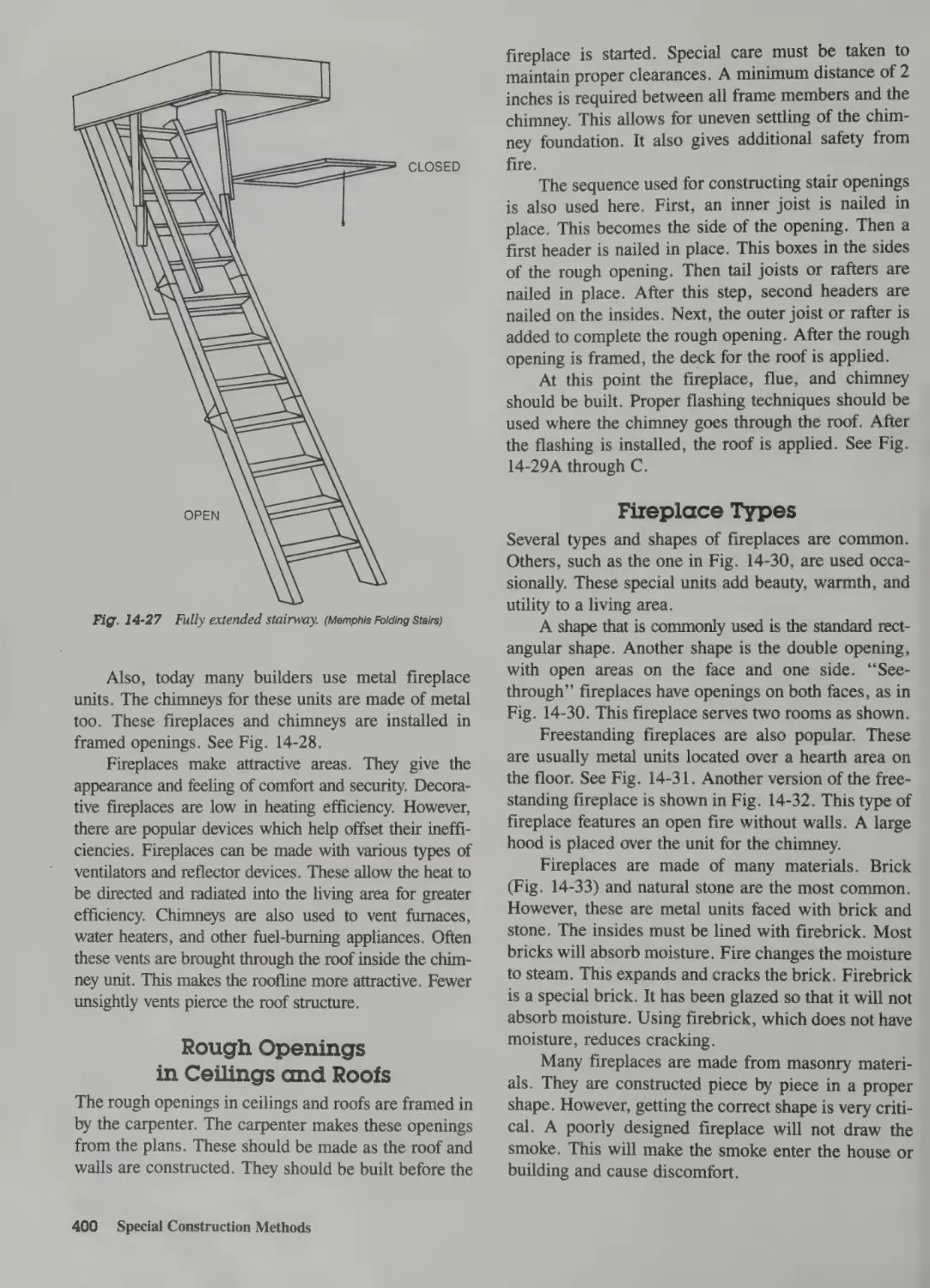
Folding Stairs 395
Locating the Stairway 395
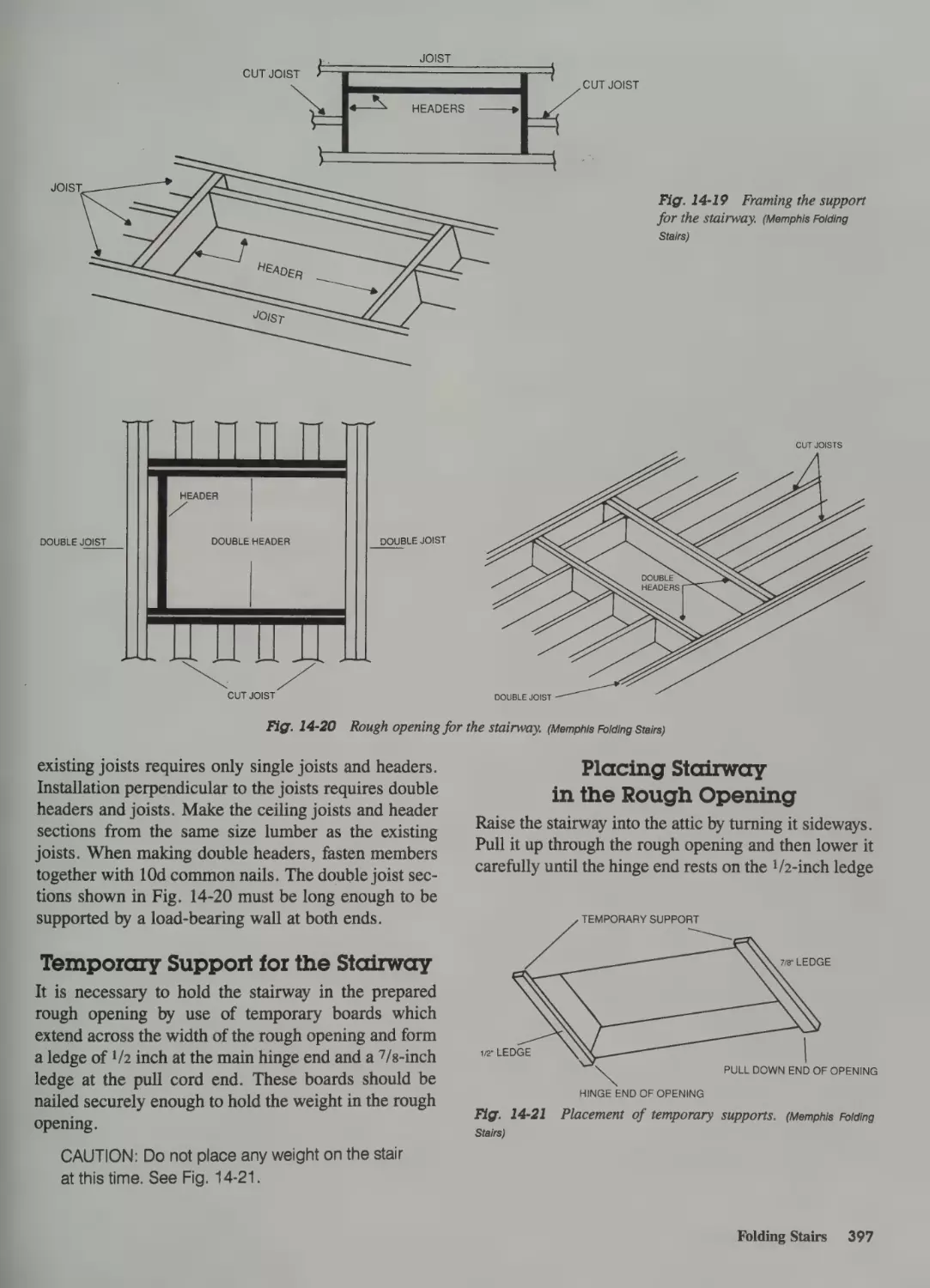
Making the Rough Opening 395
Temporary Support for the Stairway 397
Placing Stairway in the Rough Opening 397
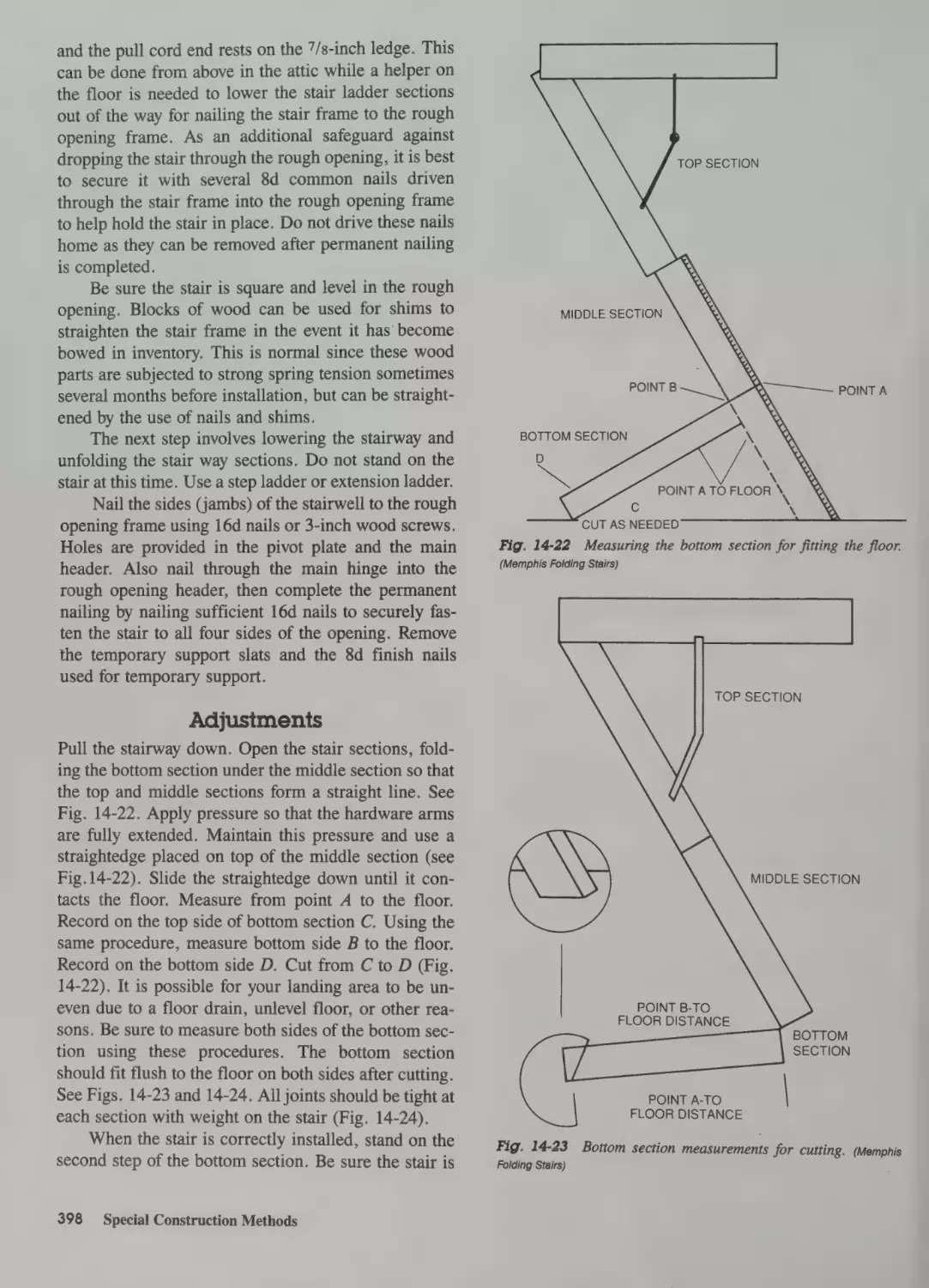
Adjustments 398
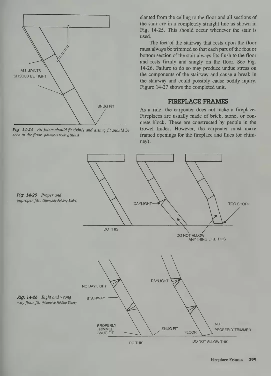
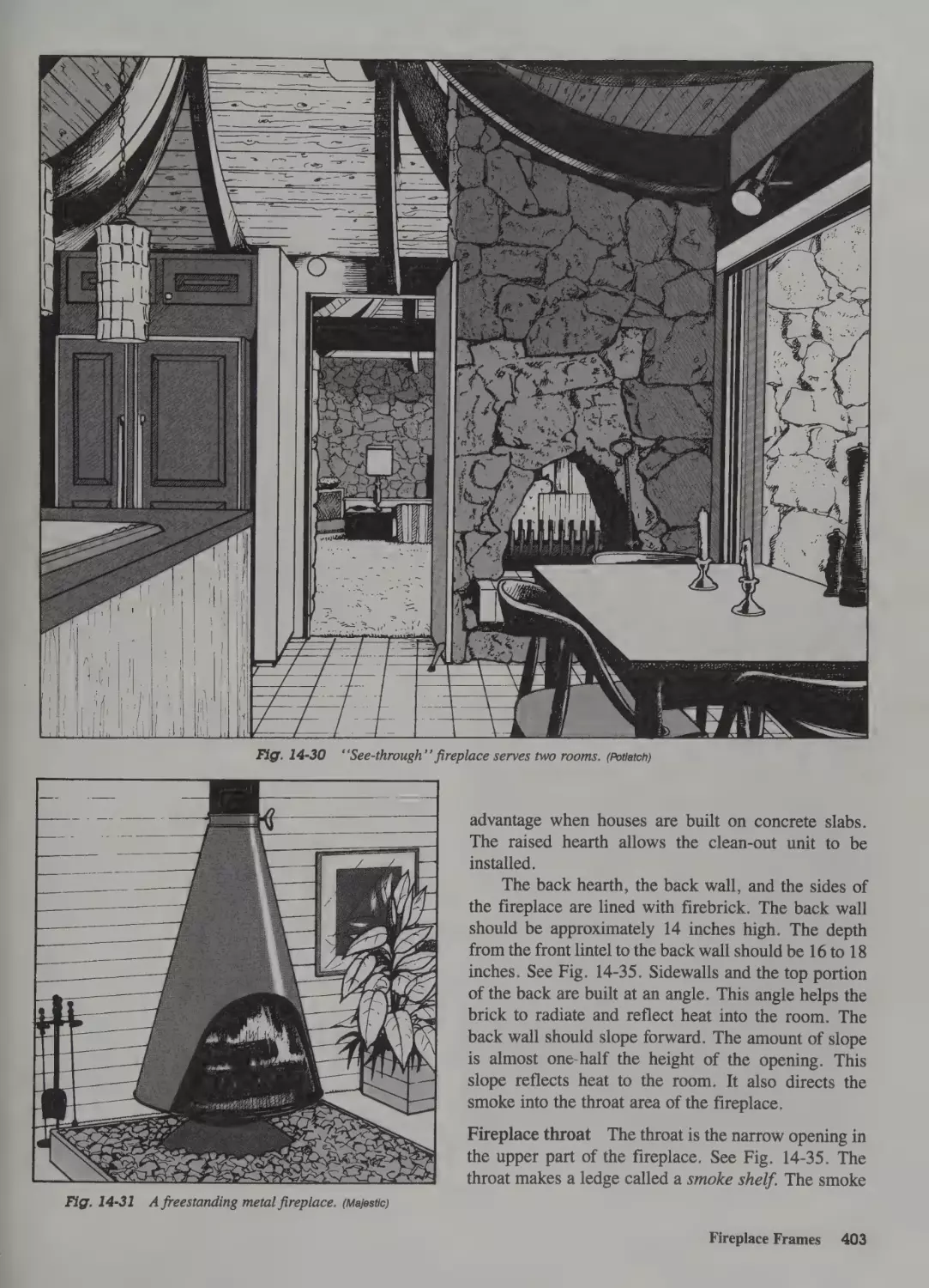
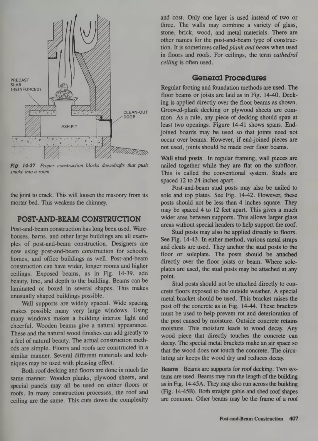
Fireplace Frames 399
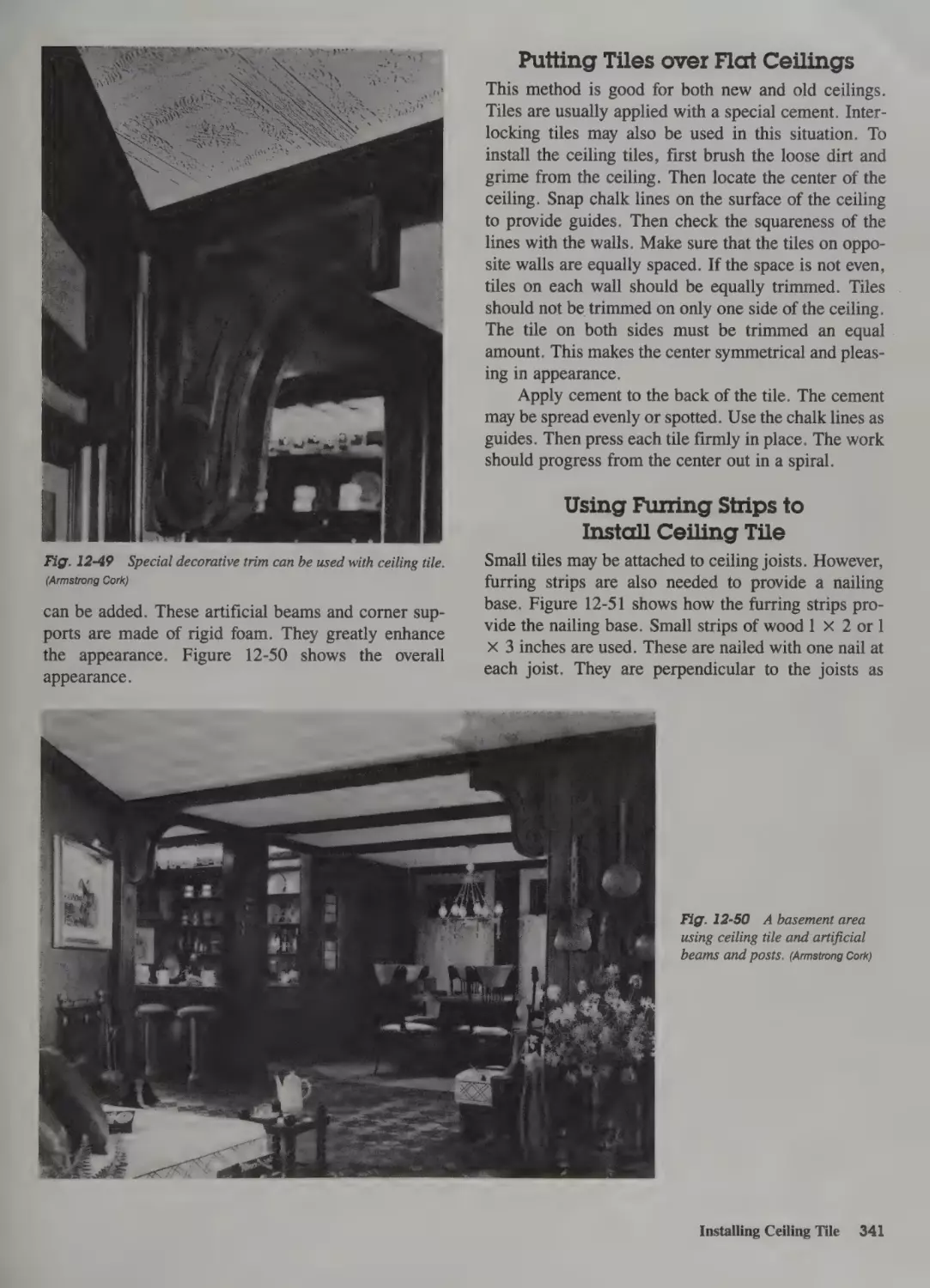
Putting Tiles over Flat Ceilings 341
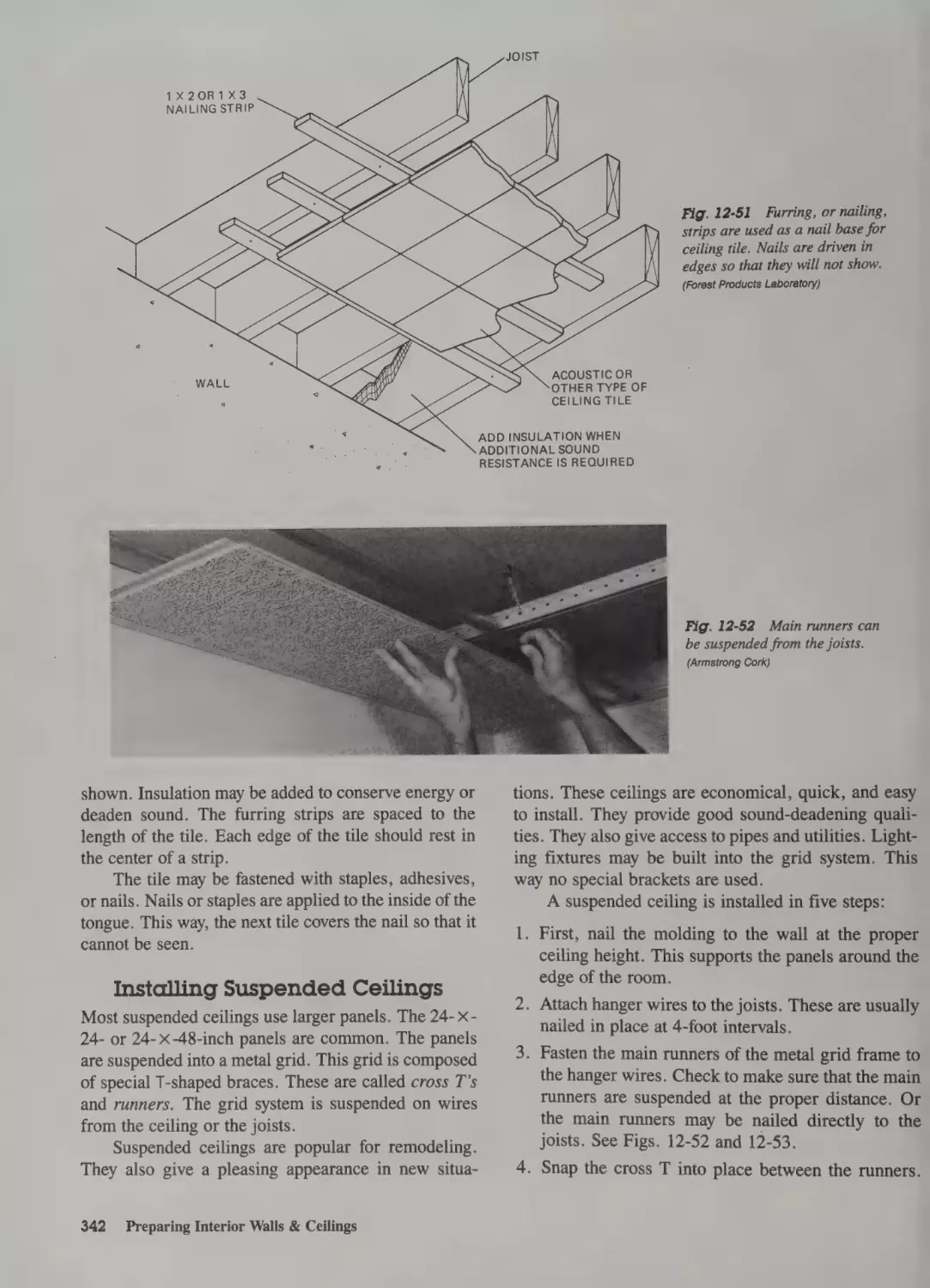
Using Furring Strips to Install Ceiling Tile 341
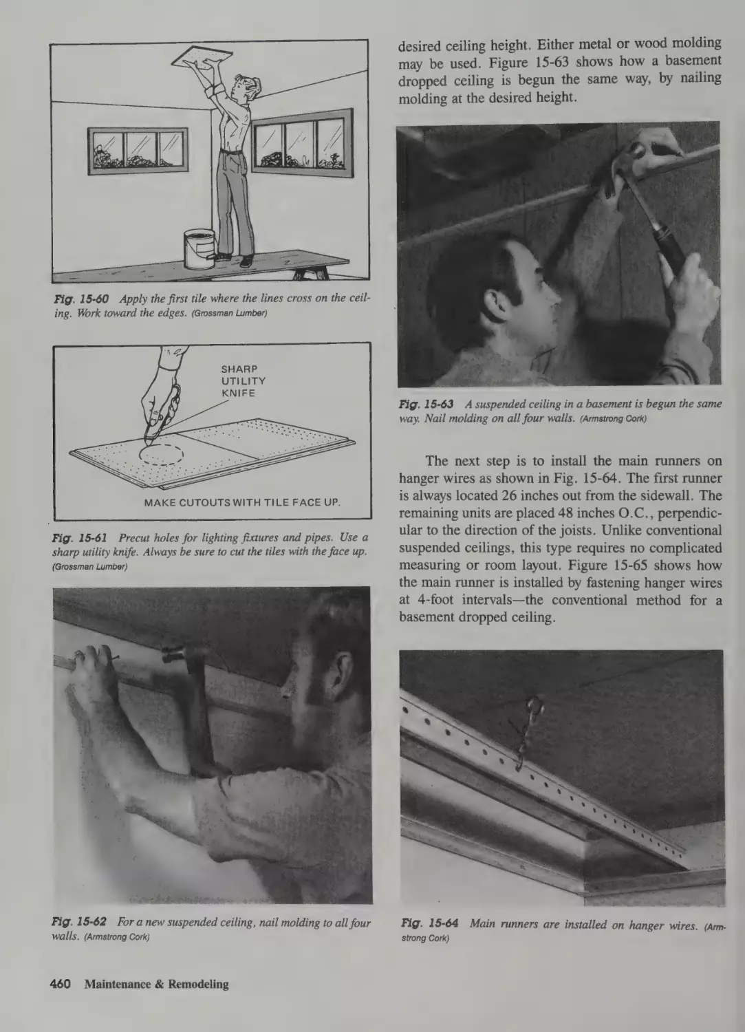
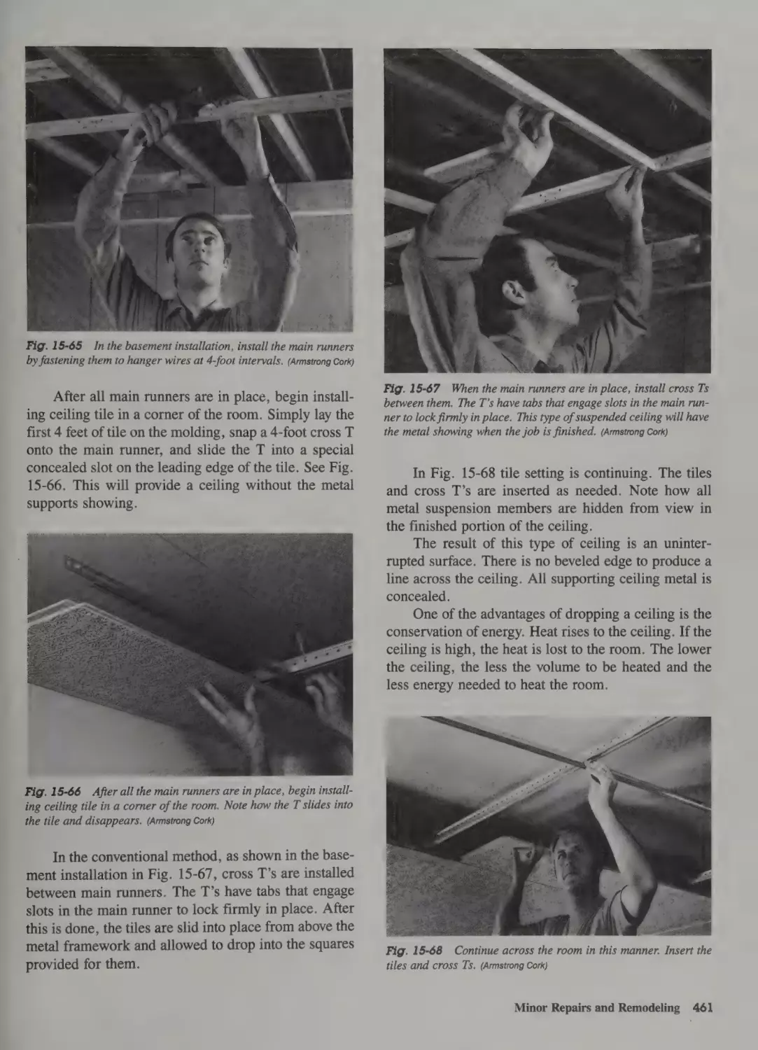
Installing Suspended Ceilings 342
Concealed Suspended Ceilings 343
Rough Openings in Ceiling and Roofs 400
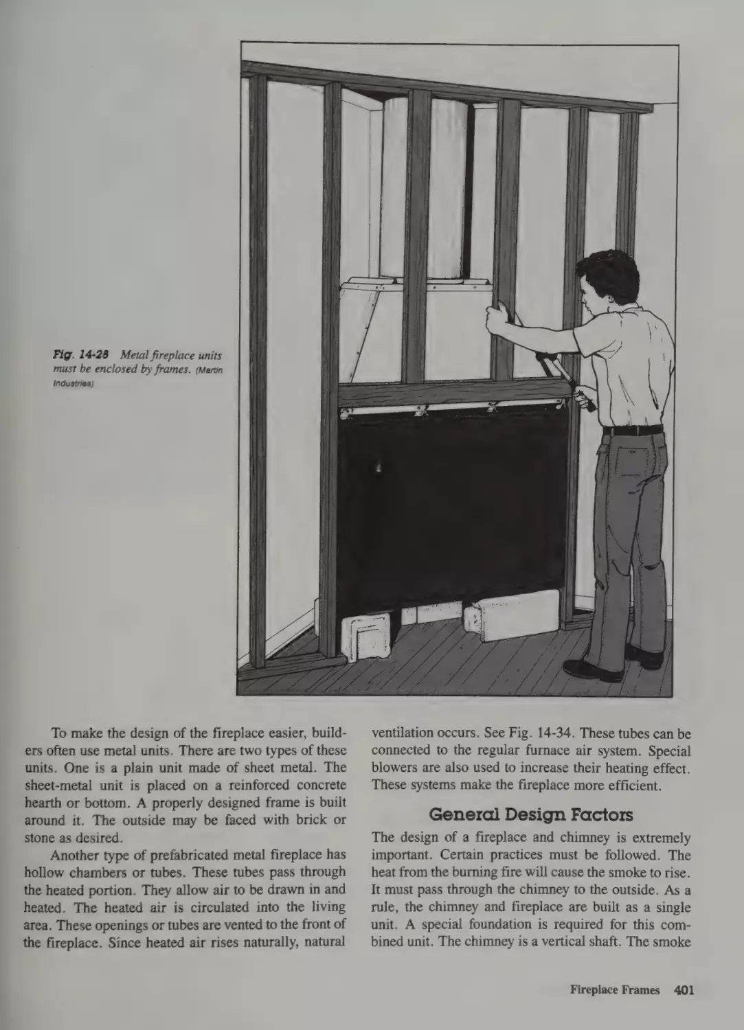
Fireplace Types 400
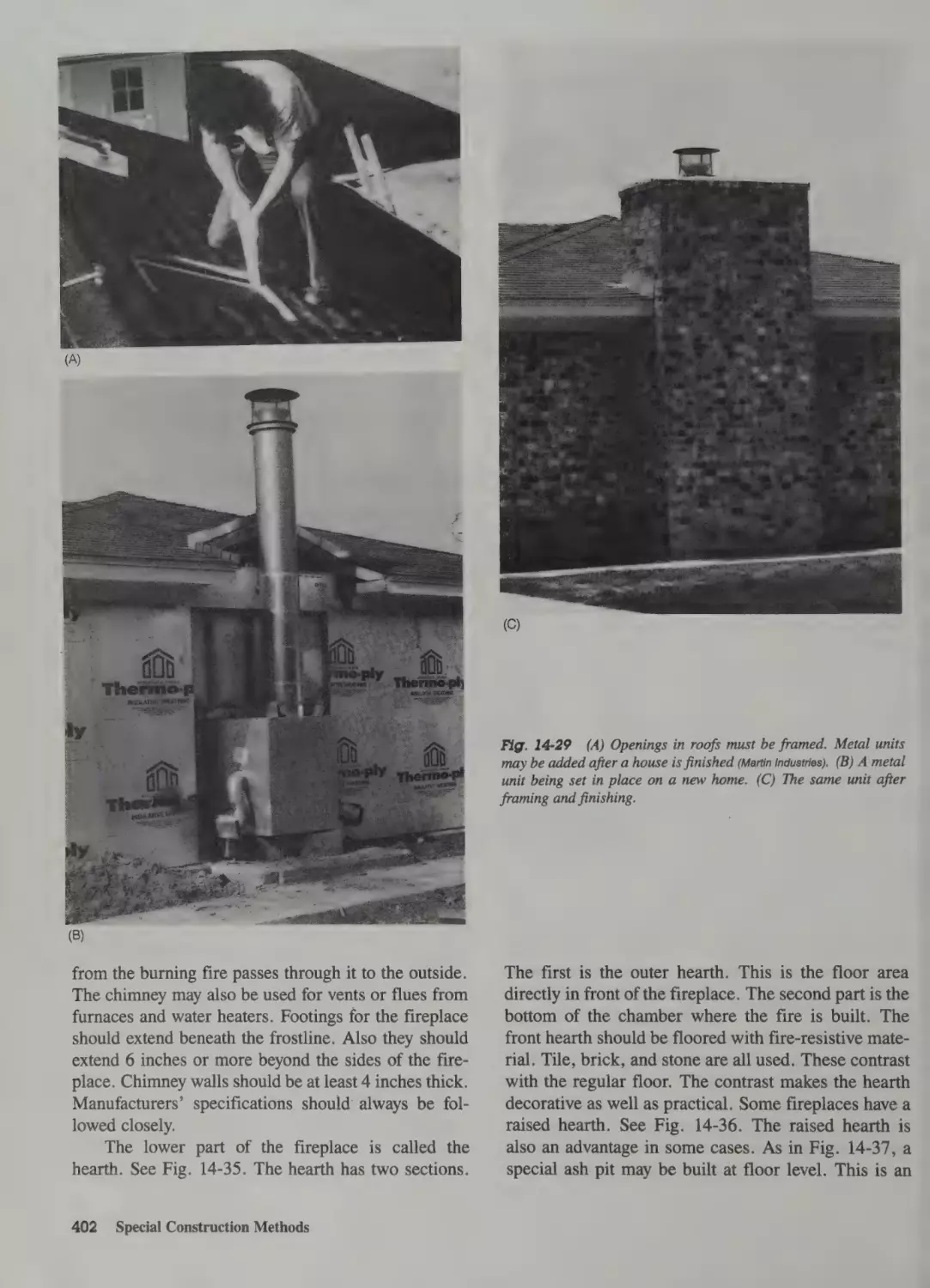
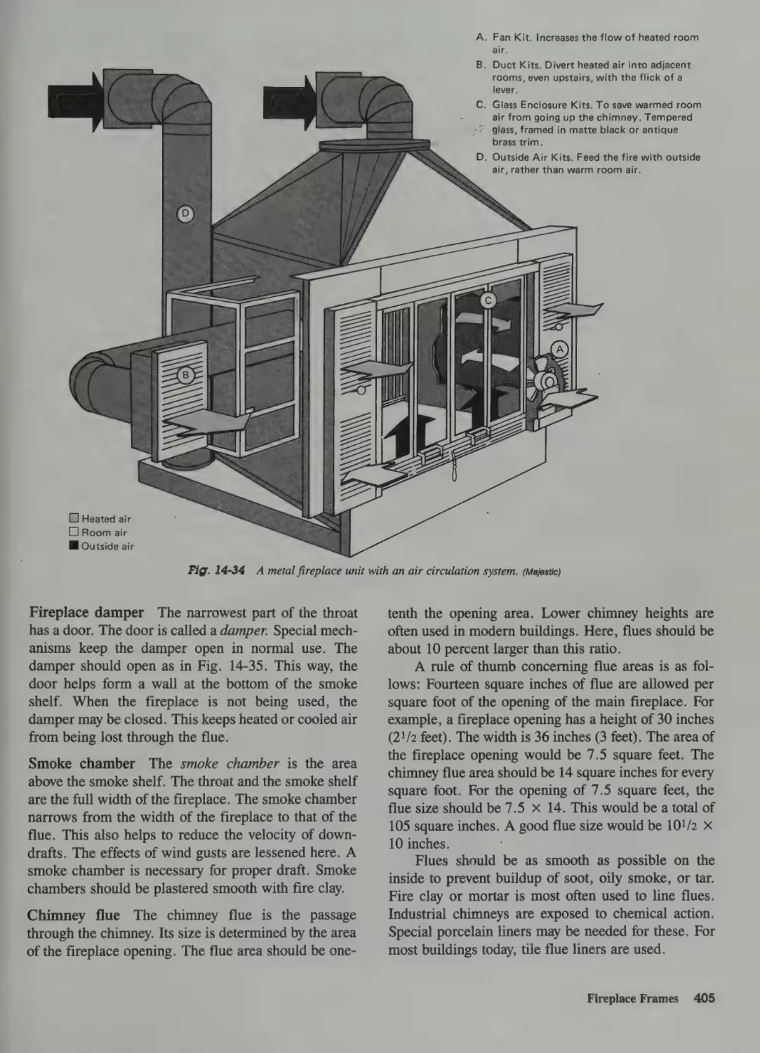
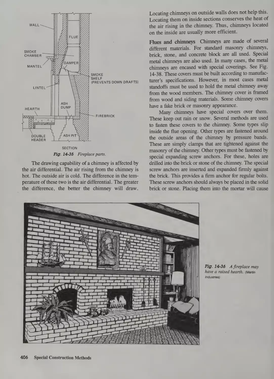
General Design Factors 401
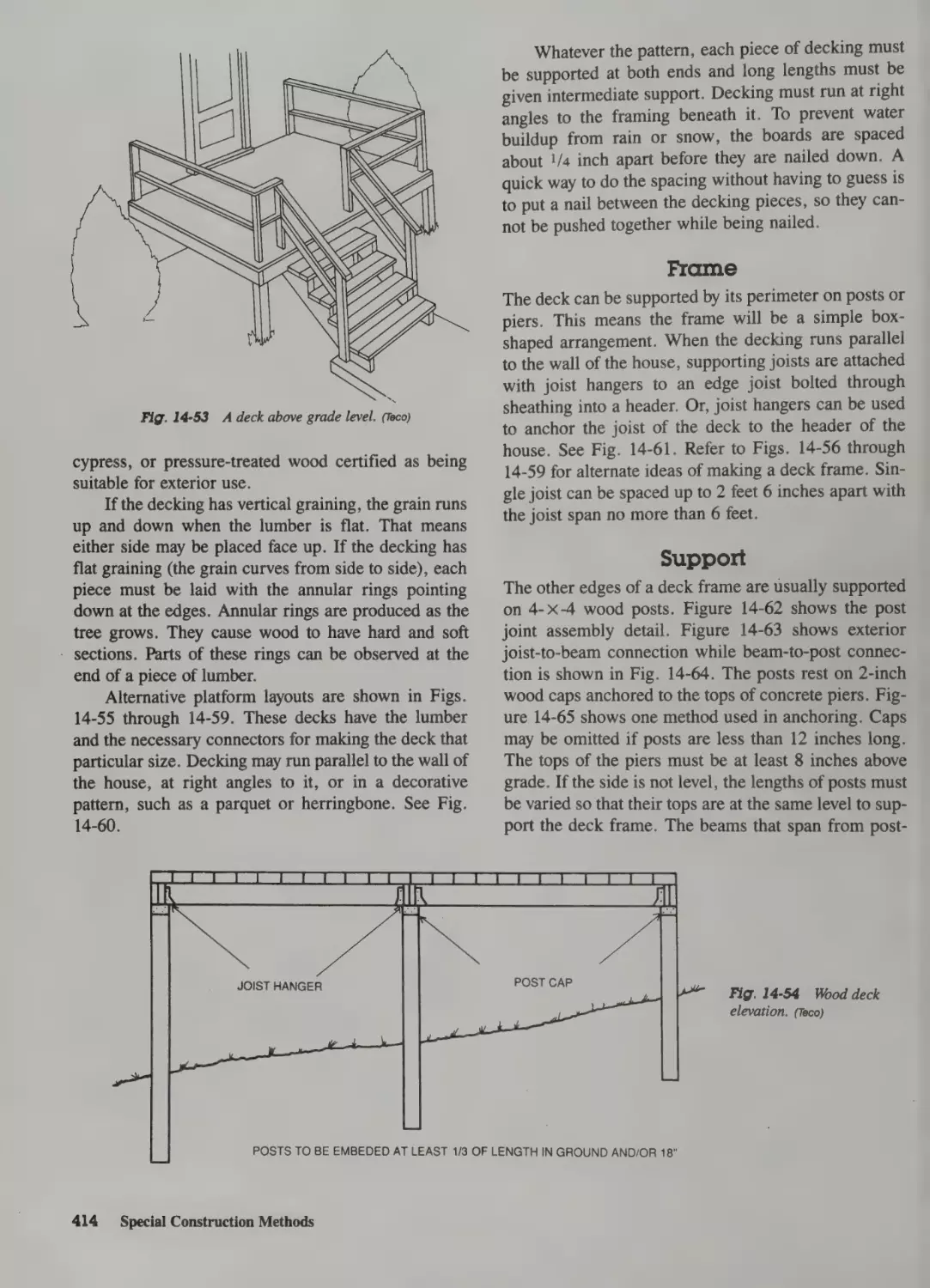
Post-and-Beam Construction 407
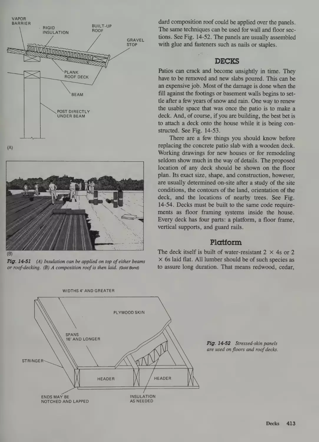
General Procedures 407
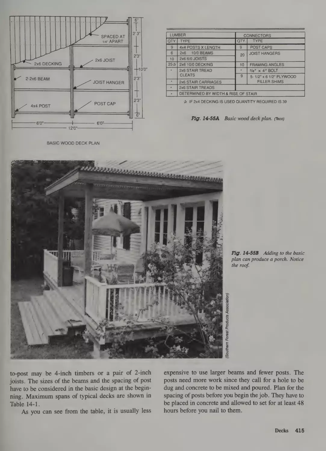
Decks 413
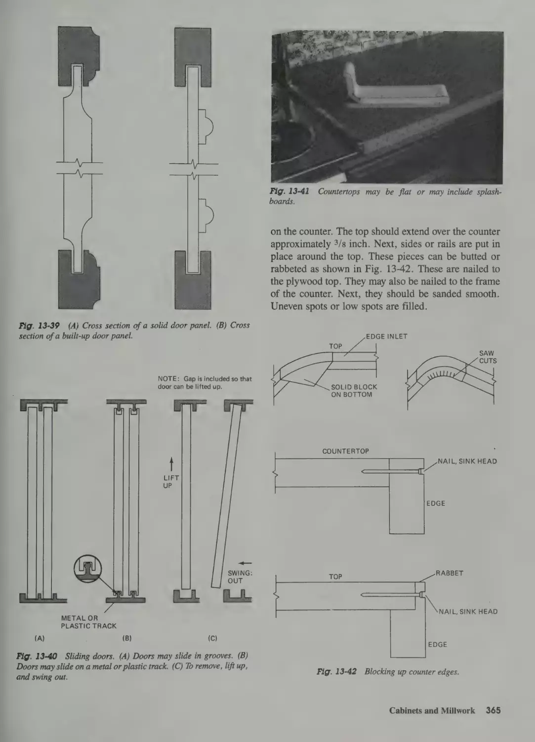
13 Finishing the Interior
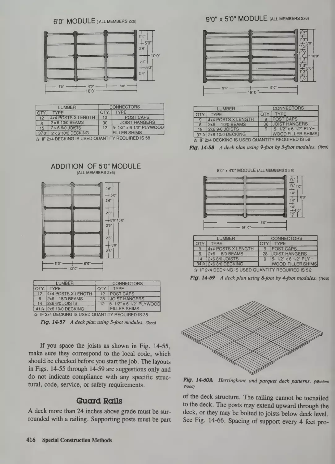
Platform 413
Sequence 346
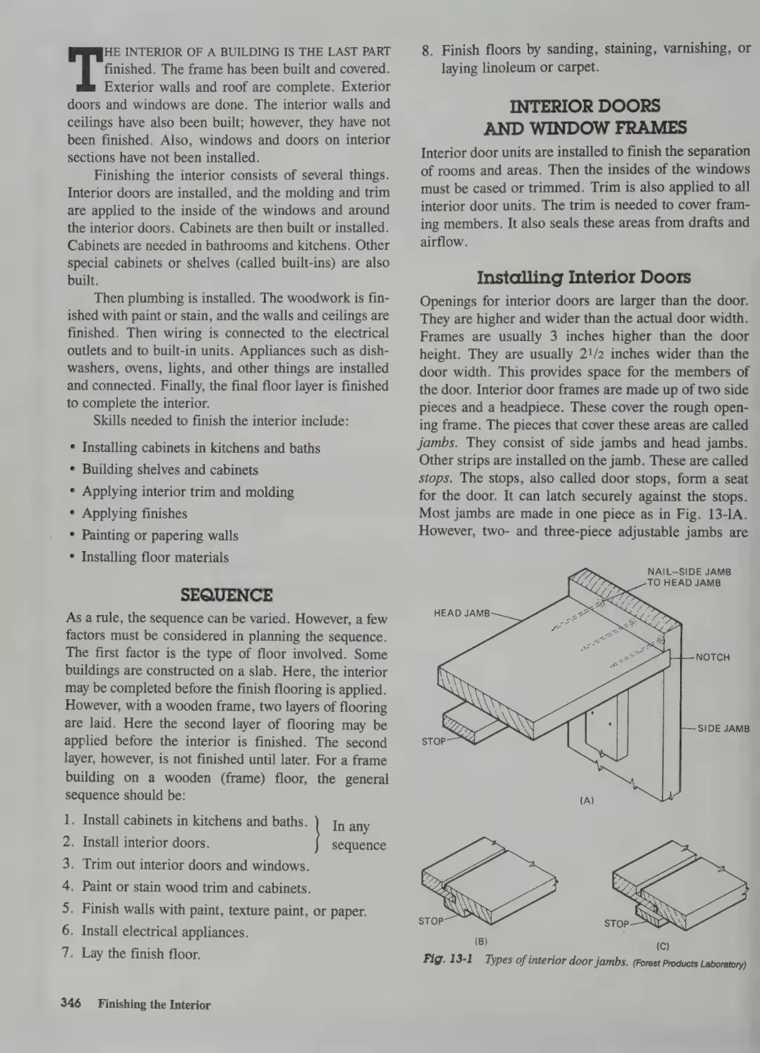
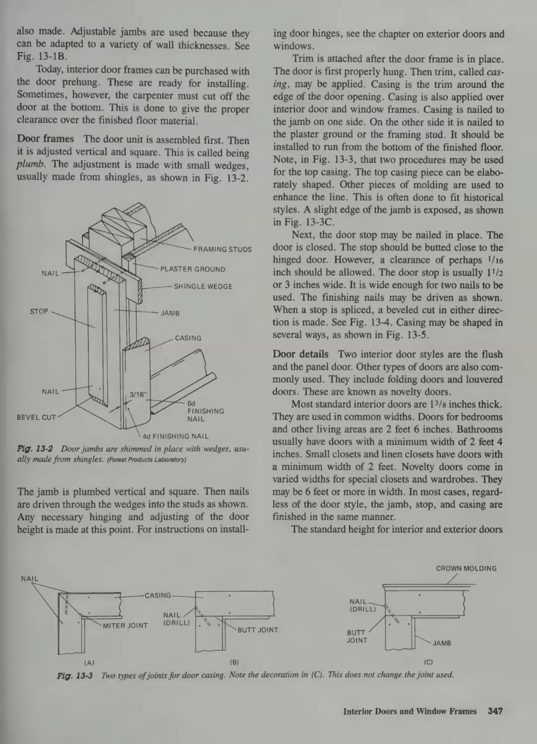
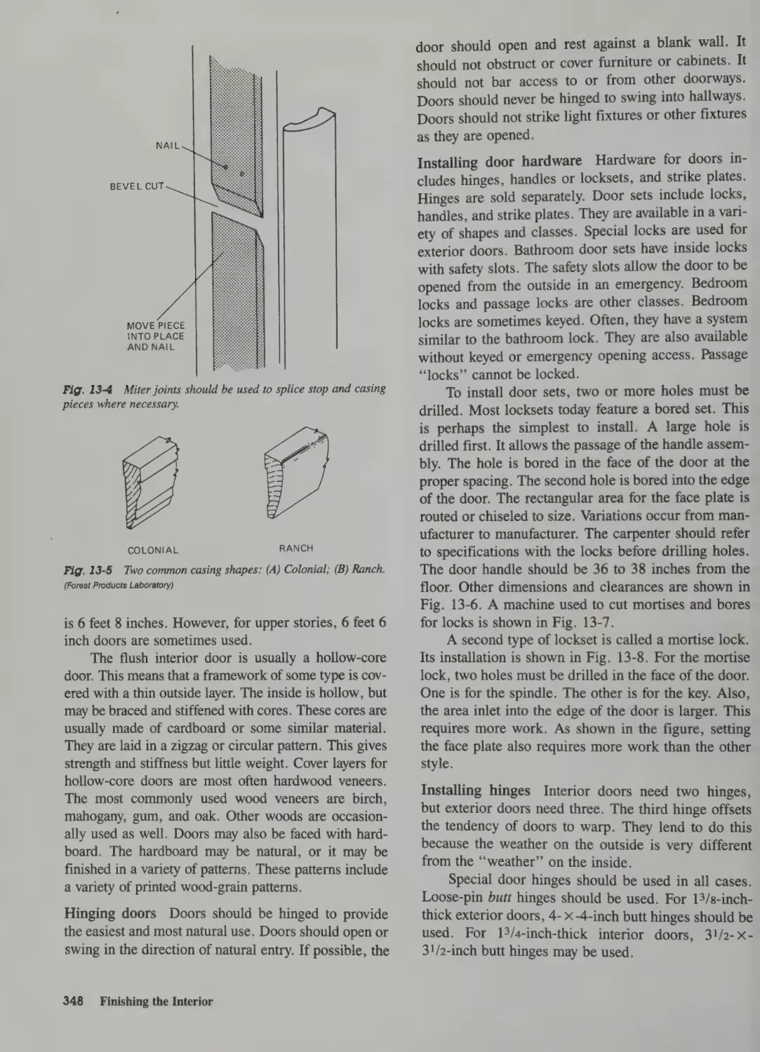
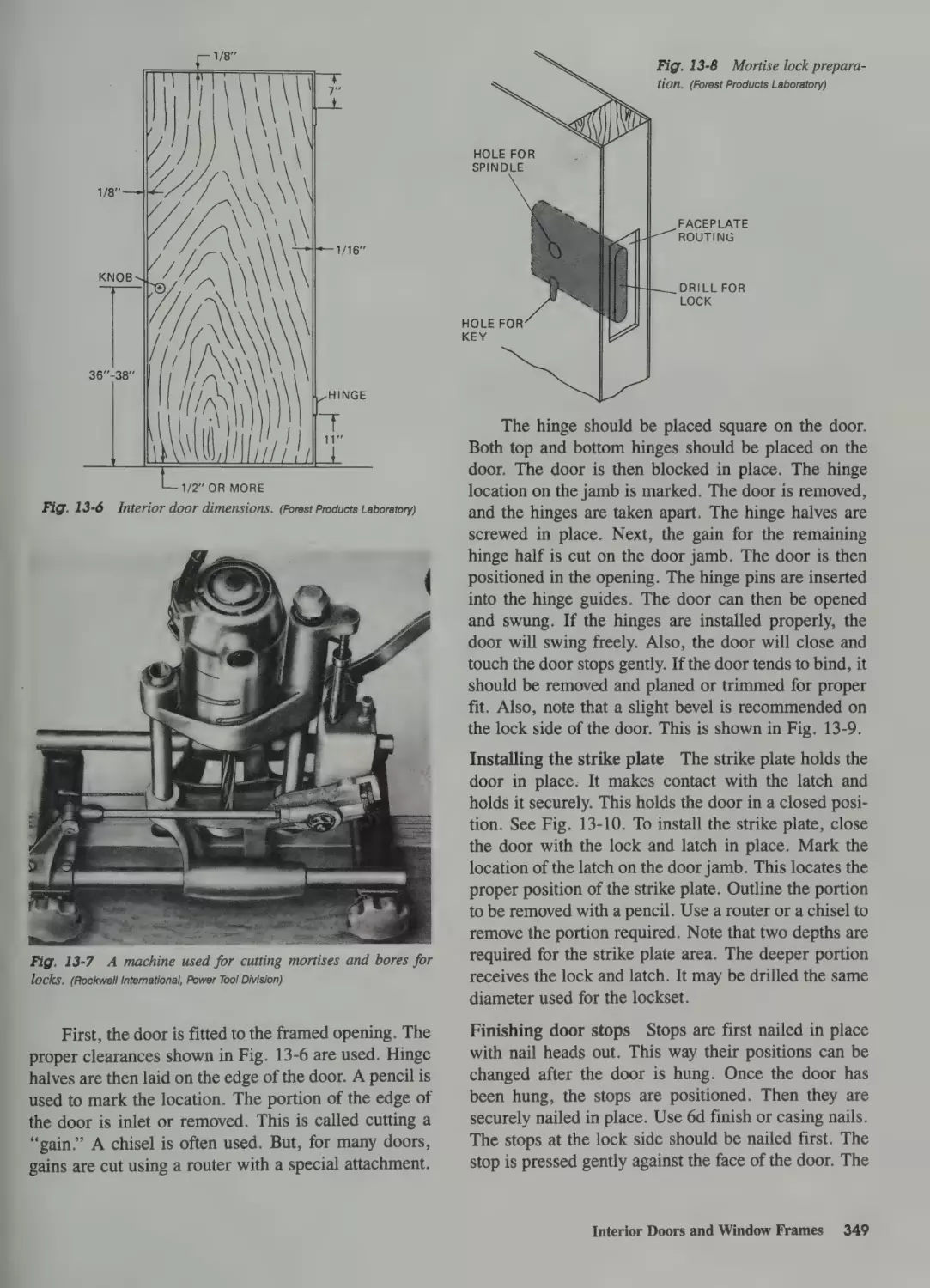
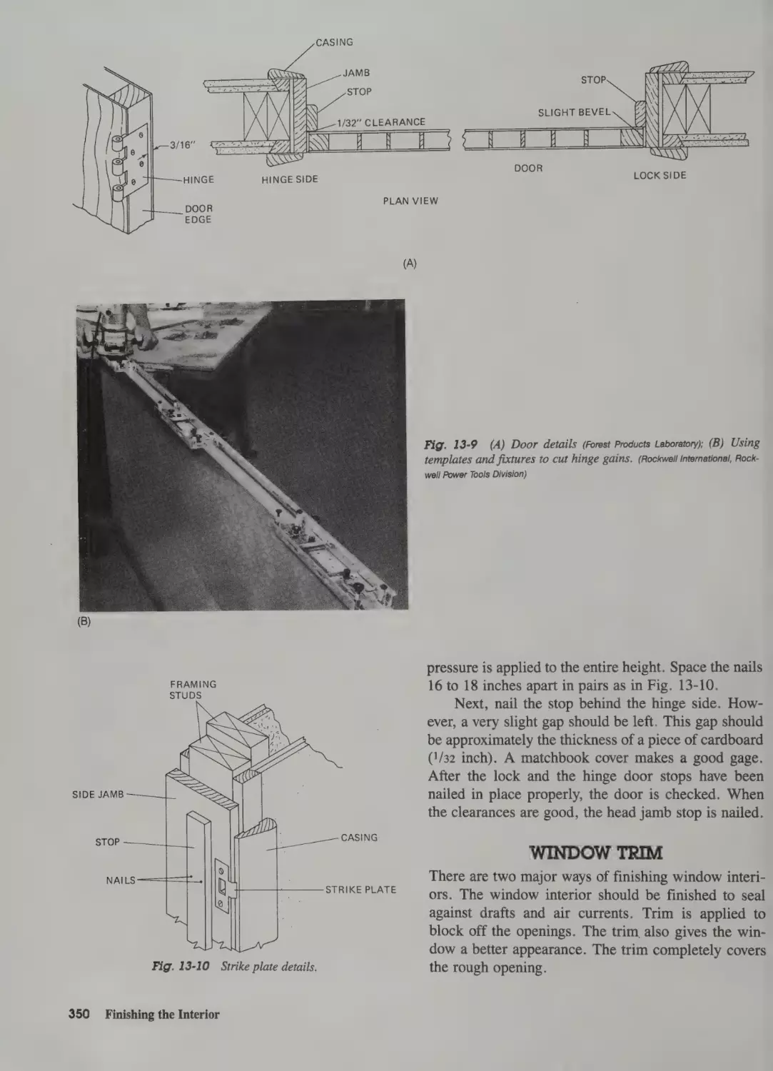
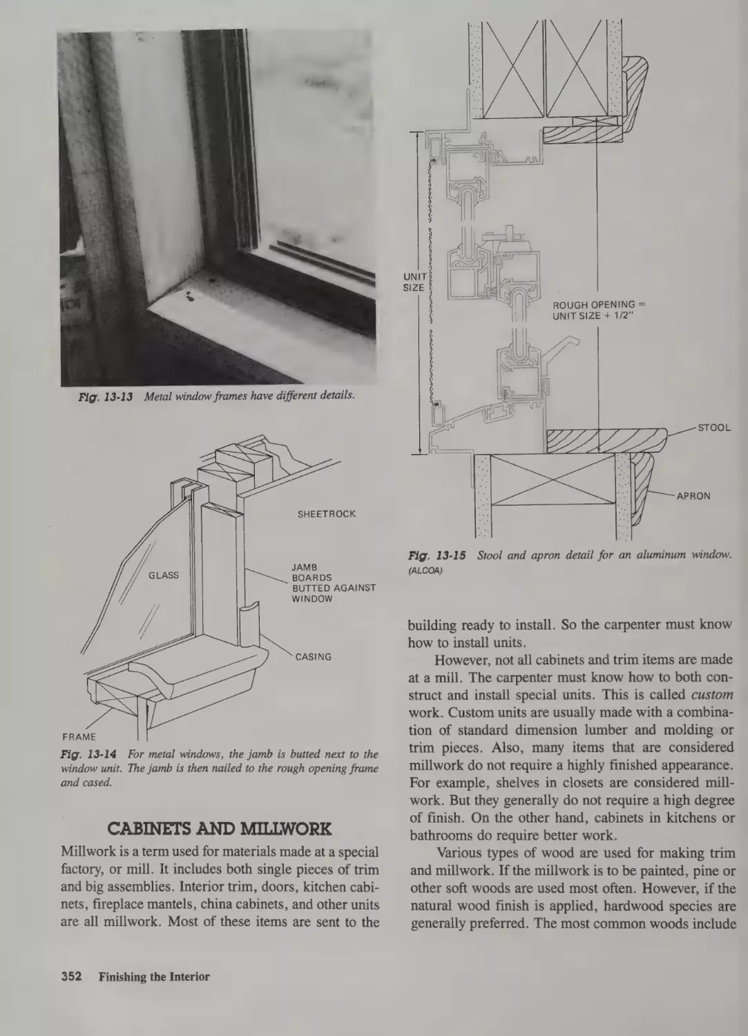
Interior Doors and Window Frames 346
Installing Interior Doors
346
Window Trim 350
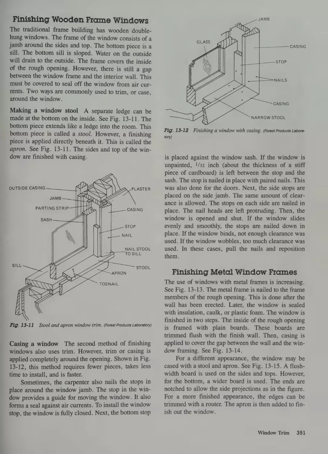
Finishing Wooden Frame Windows 351
Finishing Metal Window Frames 351
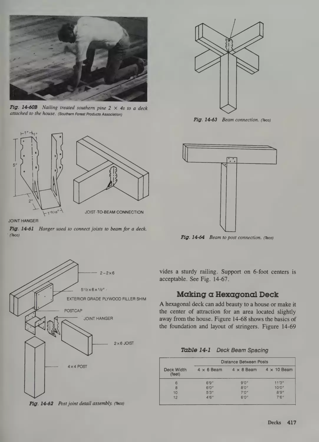
Guard Rails 416
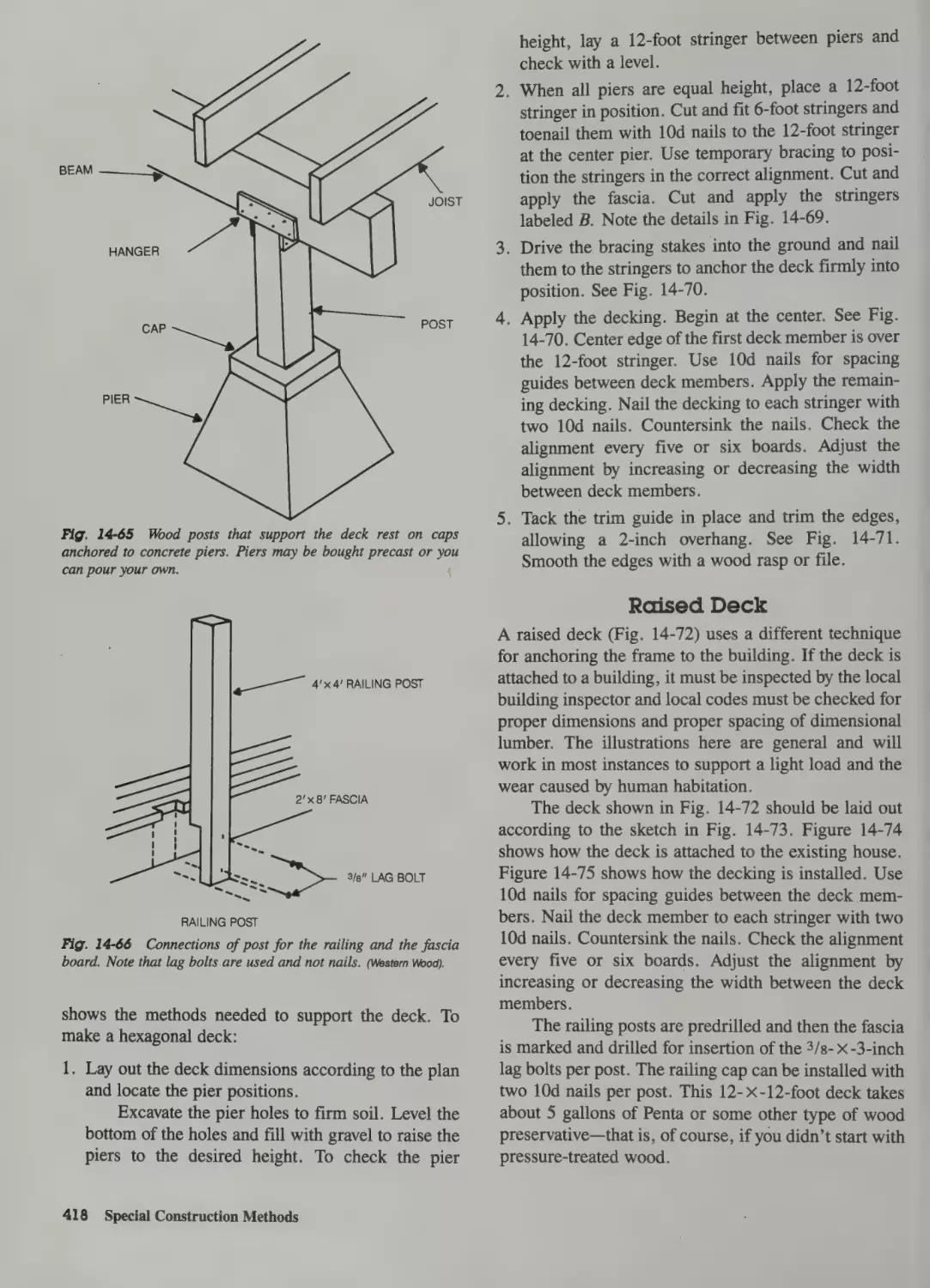
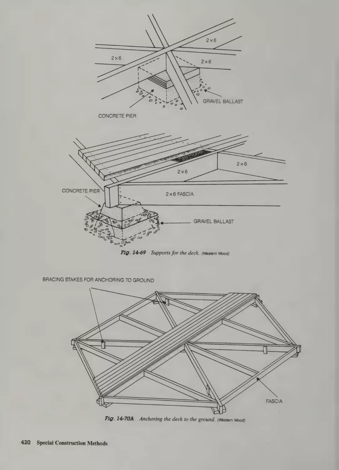
Making a Hexagonal Deck 417
Raised Deck 418
Steps 419
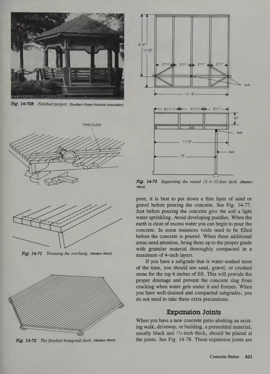
Concrete Patios 419
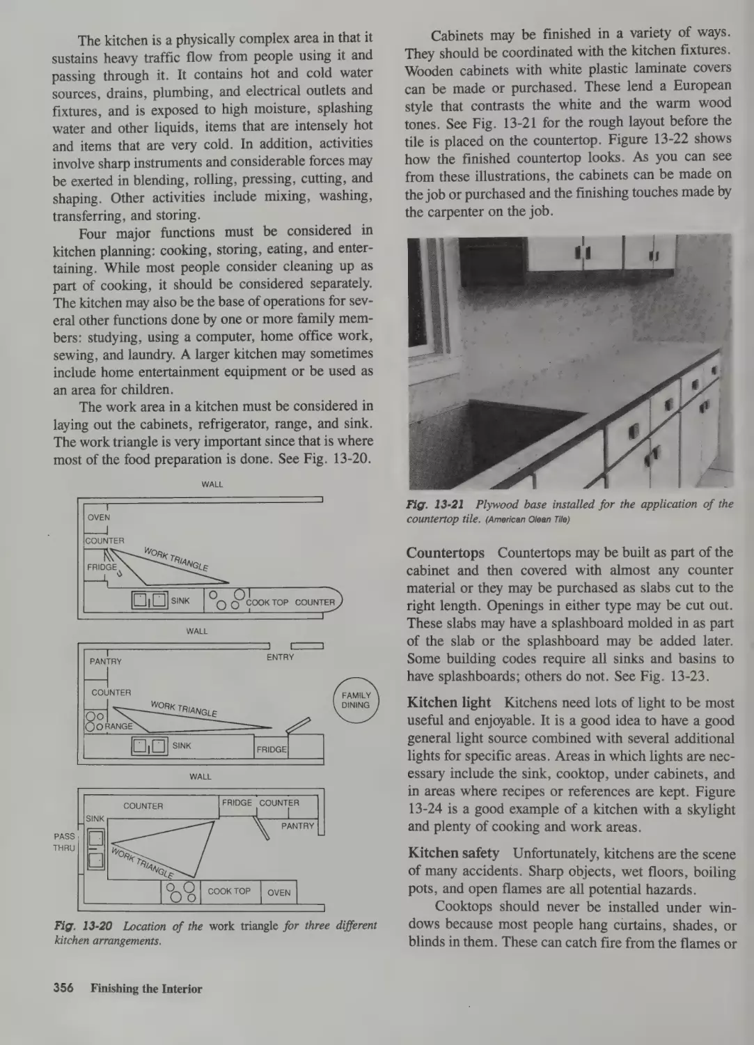
Cabinets and Millwork 352
Installing Ready-Built Cabinets
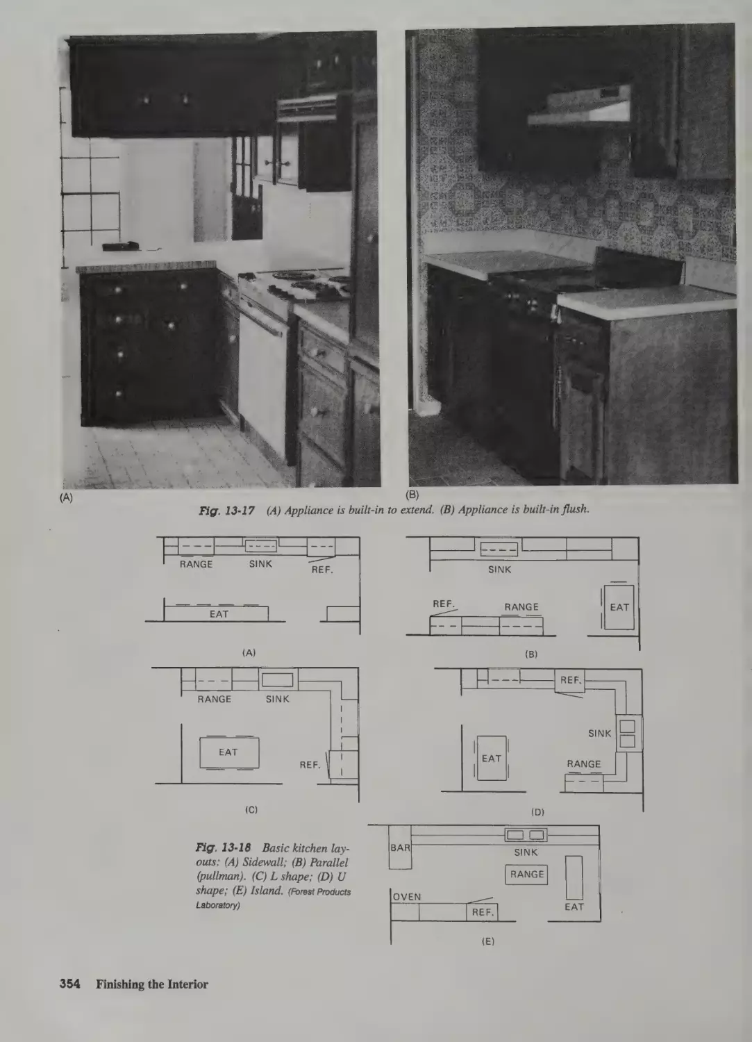
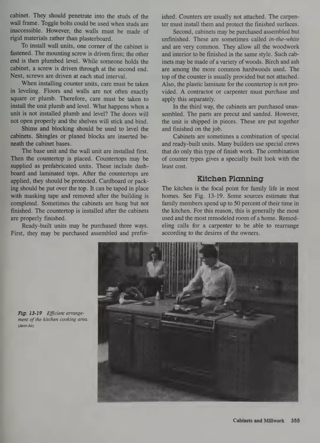
Kitchen Planning 355
Frame 414
Support 414
353
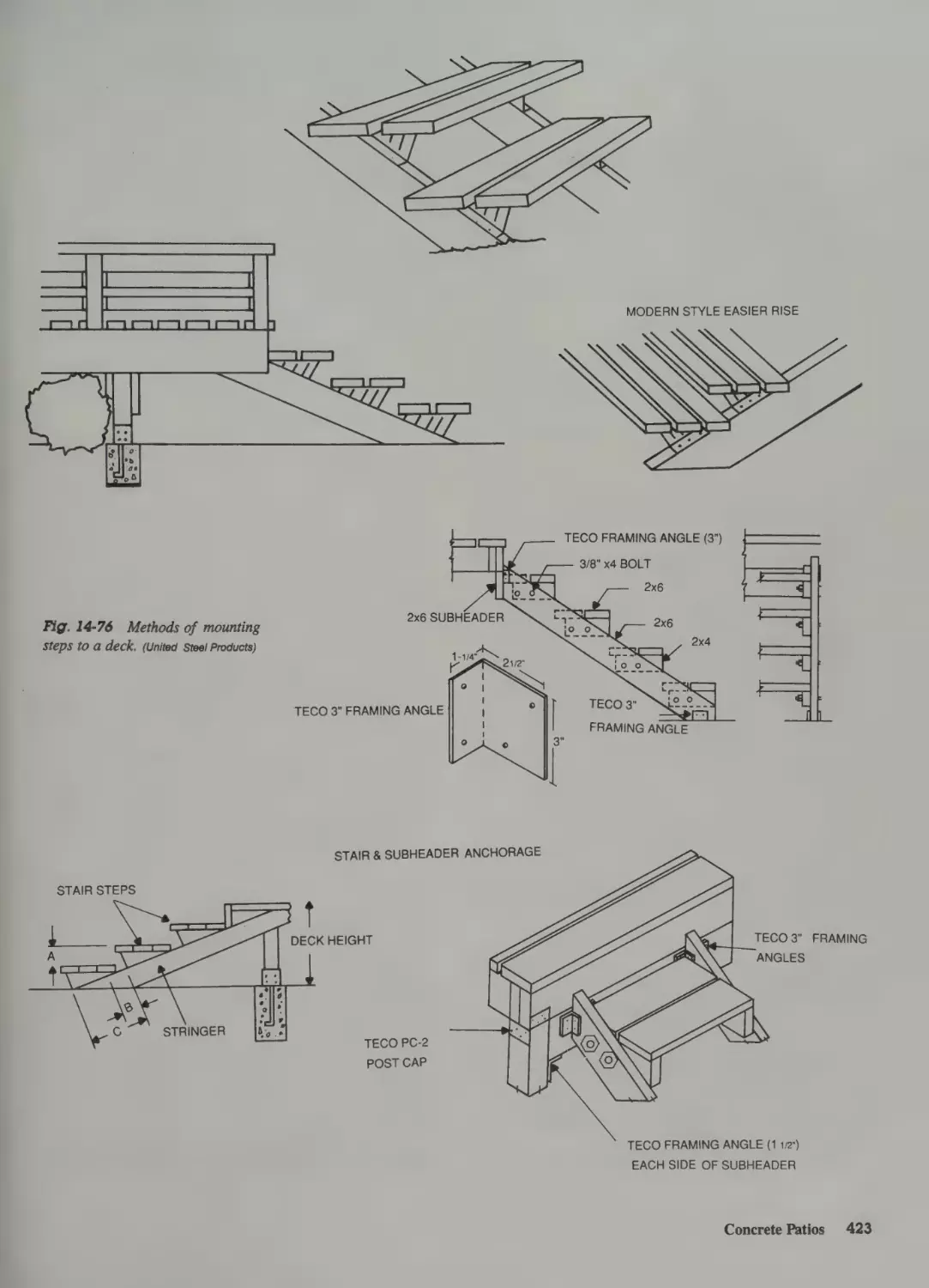
Sand and Gravel Base 419
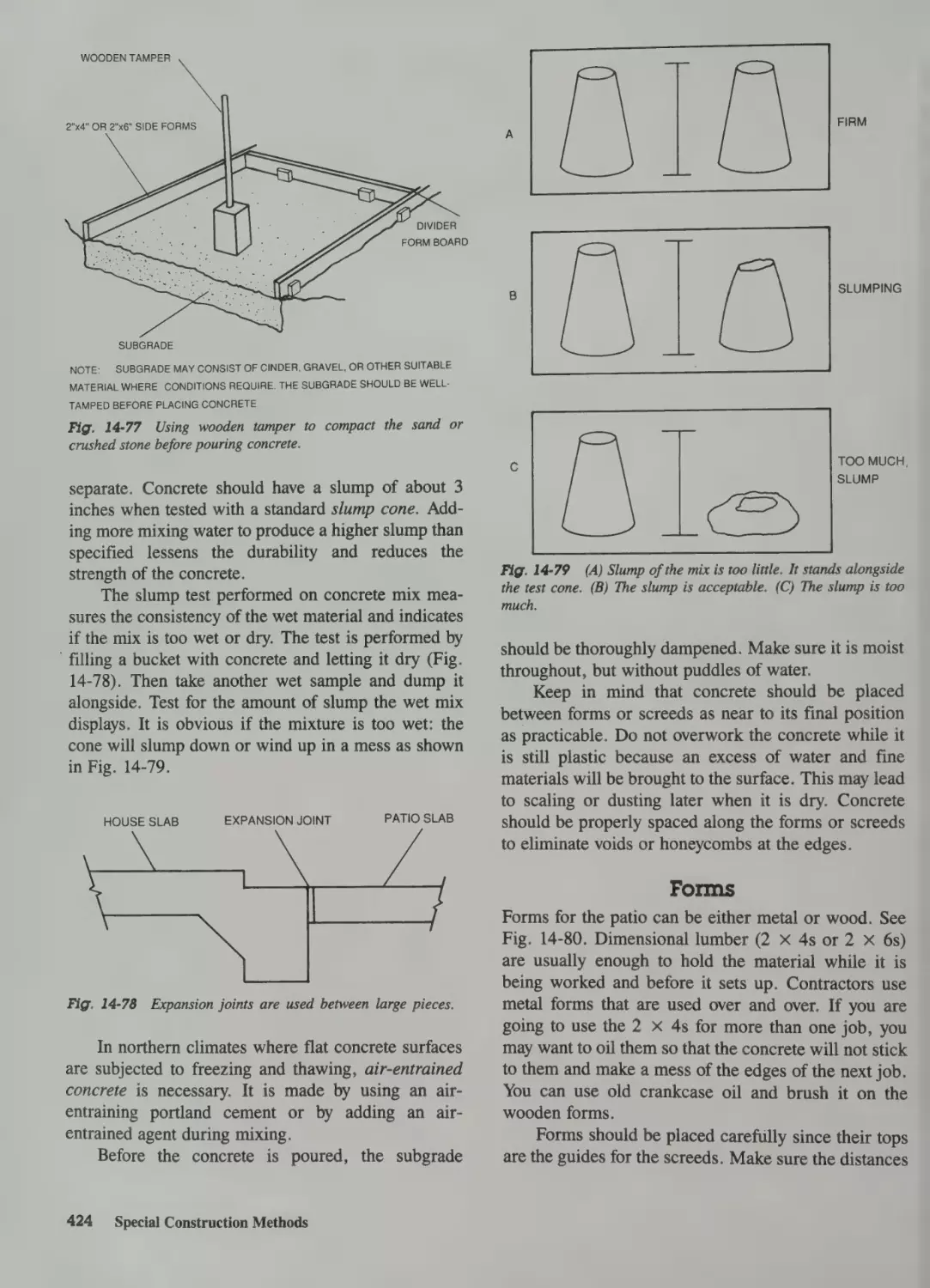
Expansion Joints 421
The Mix 422
Forms 424
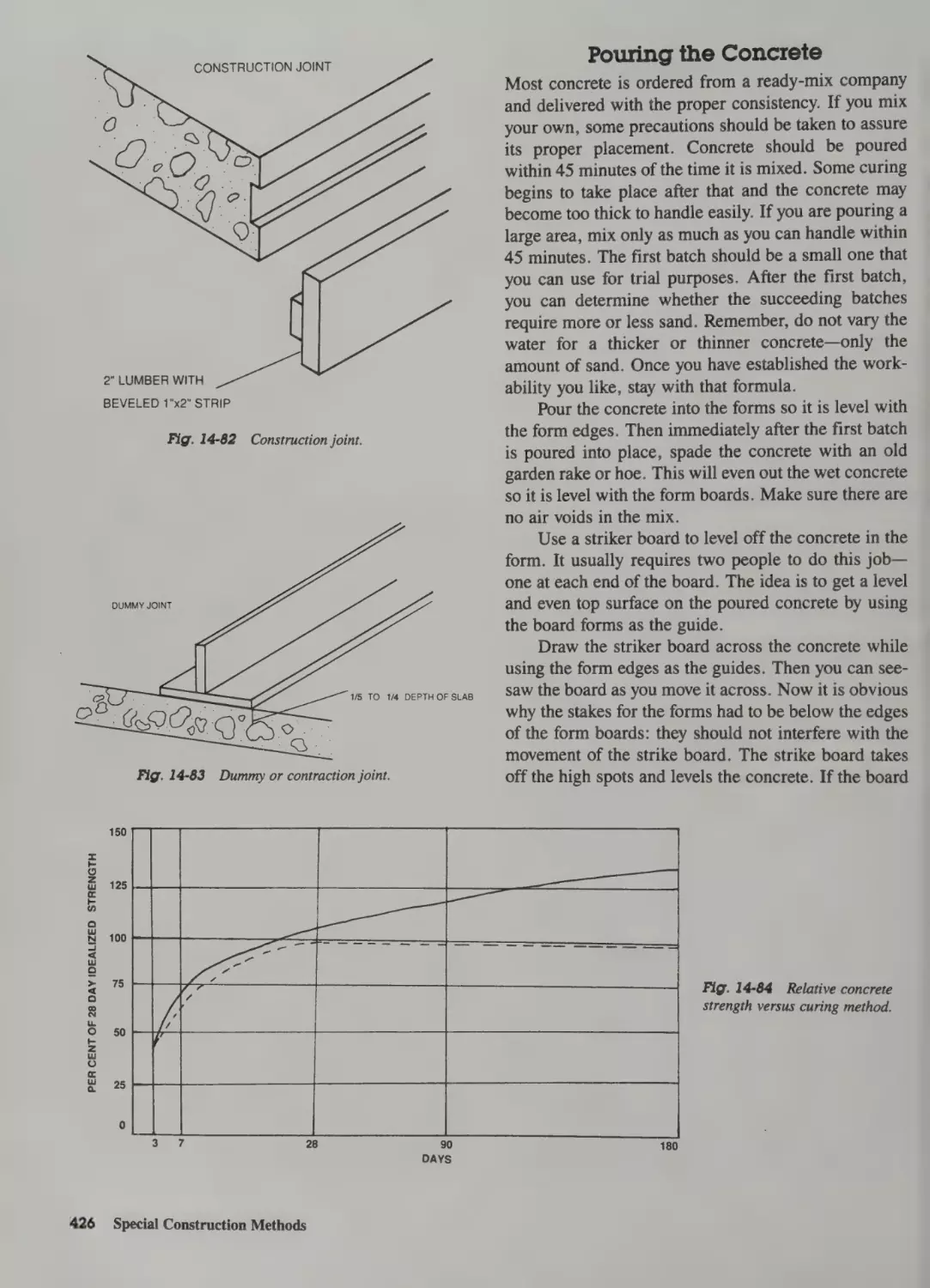
Placing the Joints 425
Pouring the Concrete 426
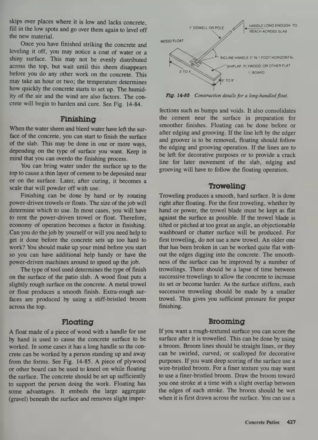
Finishing 427
Floating 427
Troweling 427
Brooming 427
Grooving 428
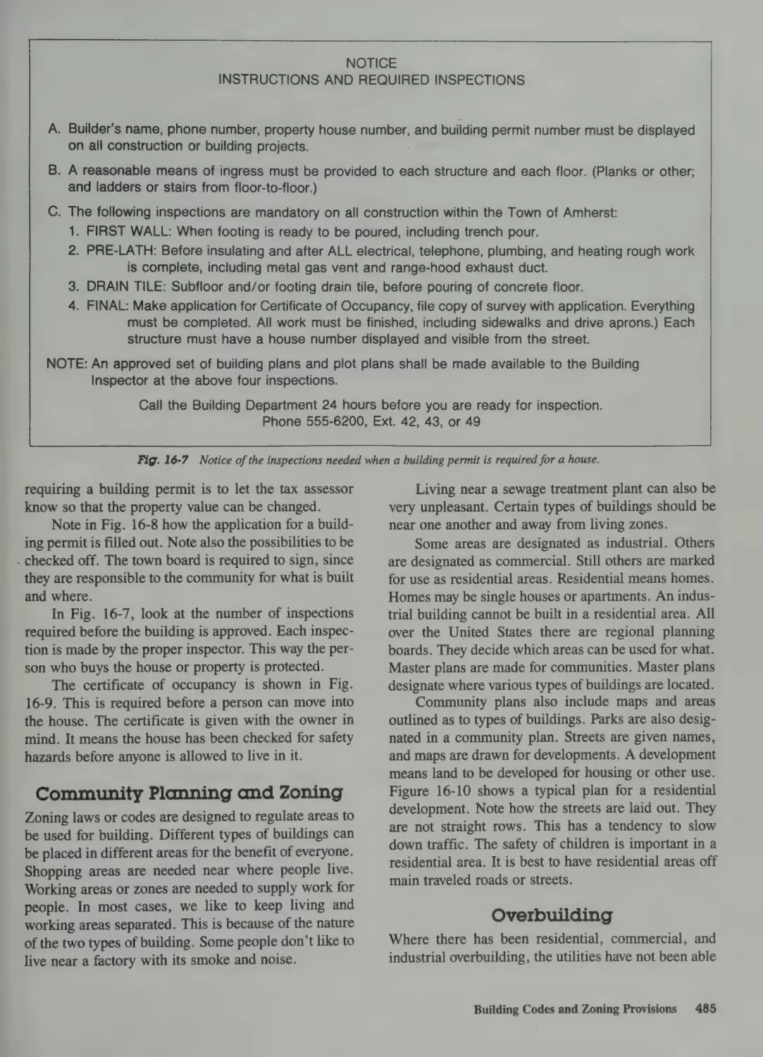
Building Codes and Zoning Provisions 484
Building Codes 484
Community Planning and Zoning 485
Overbuilding 485
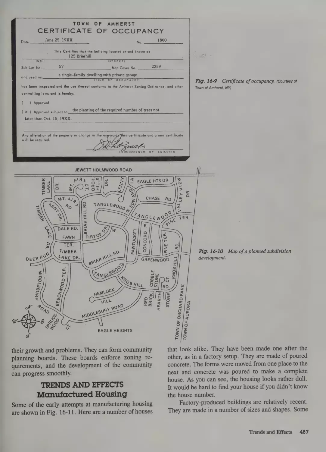
Trends and Effects 487
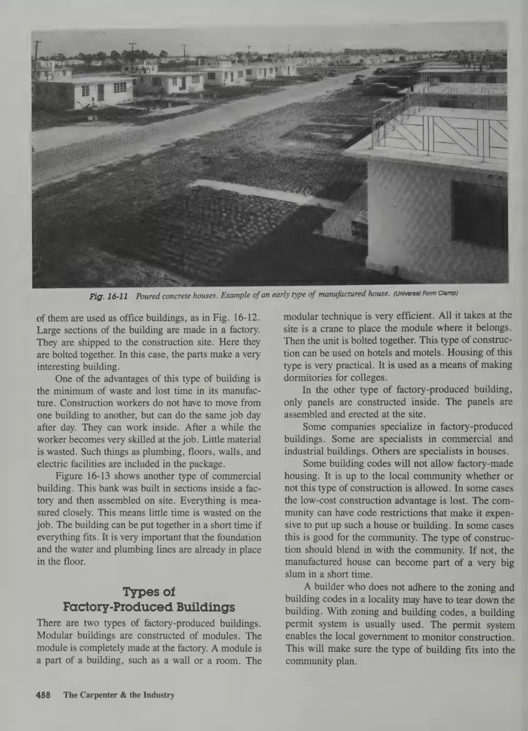
Manufactured Housing 487
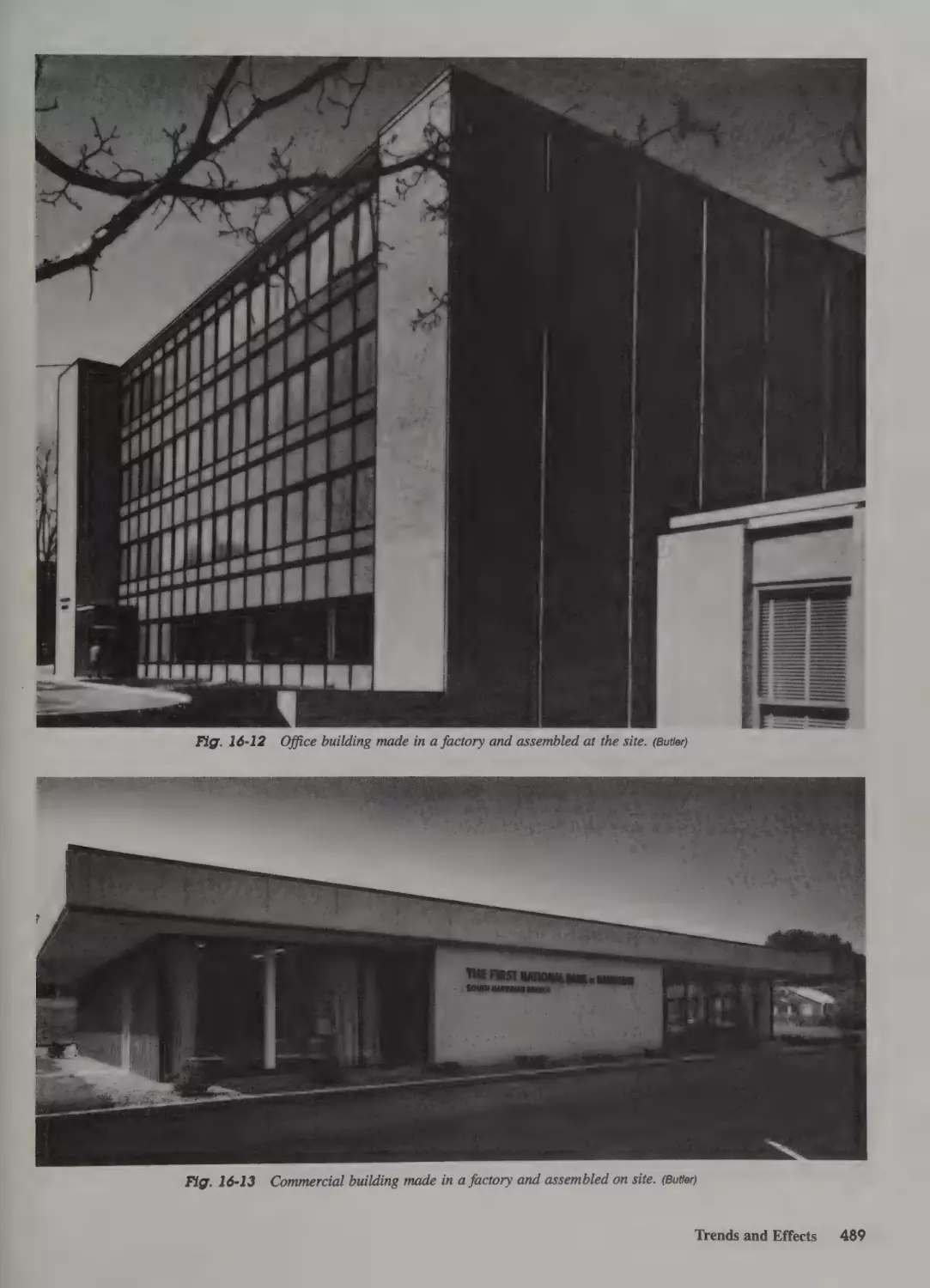
Types of Factory-Produced Buildings 488
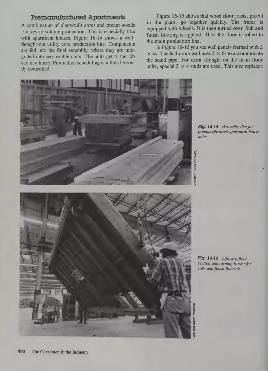
Premanufactured Apartments 490
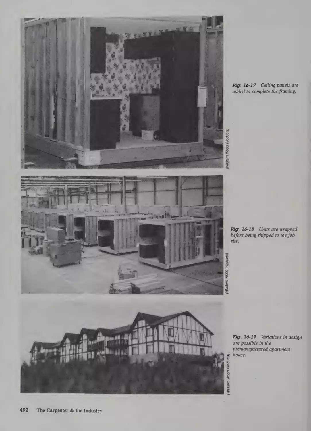
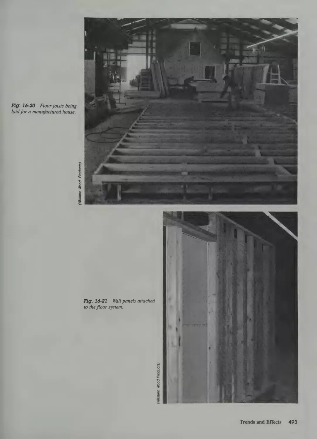
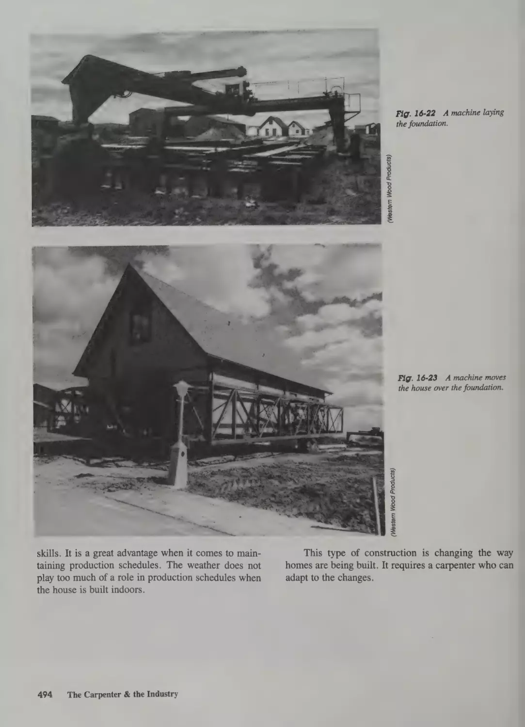
Manufactured Homes 491
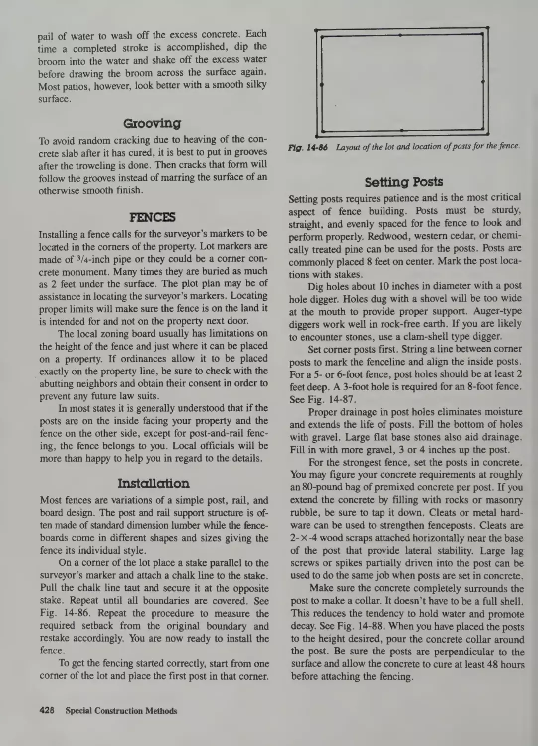
Fences 428
Installation 428
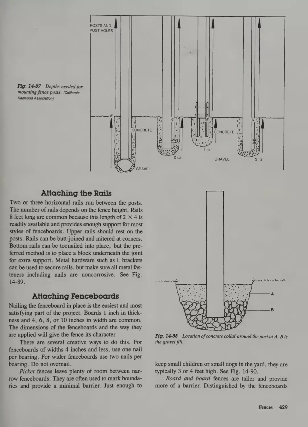
Setting Posts 428
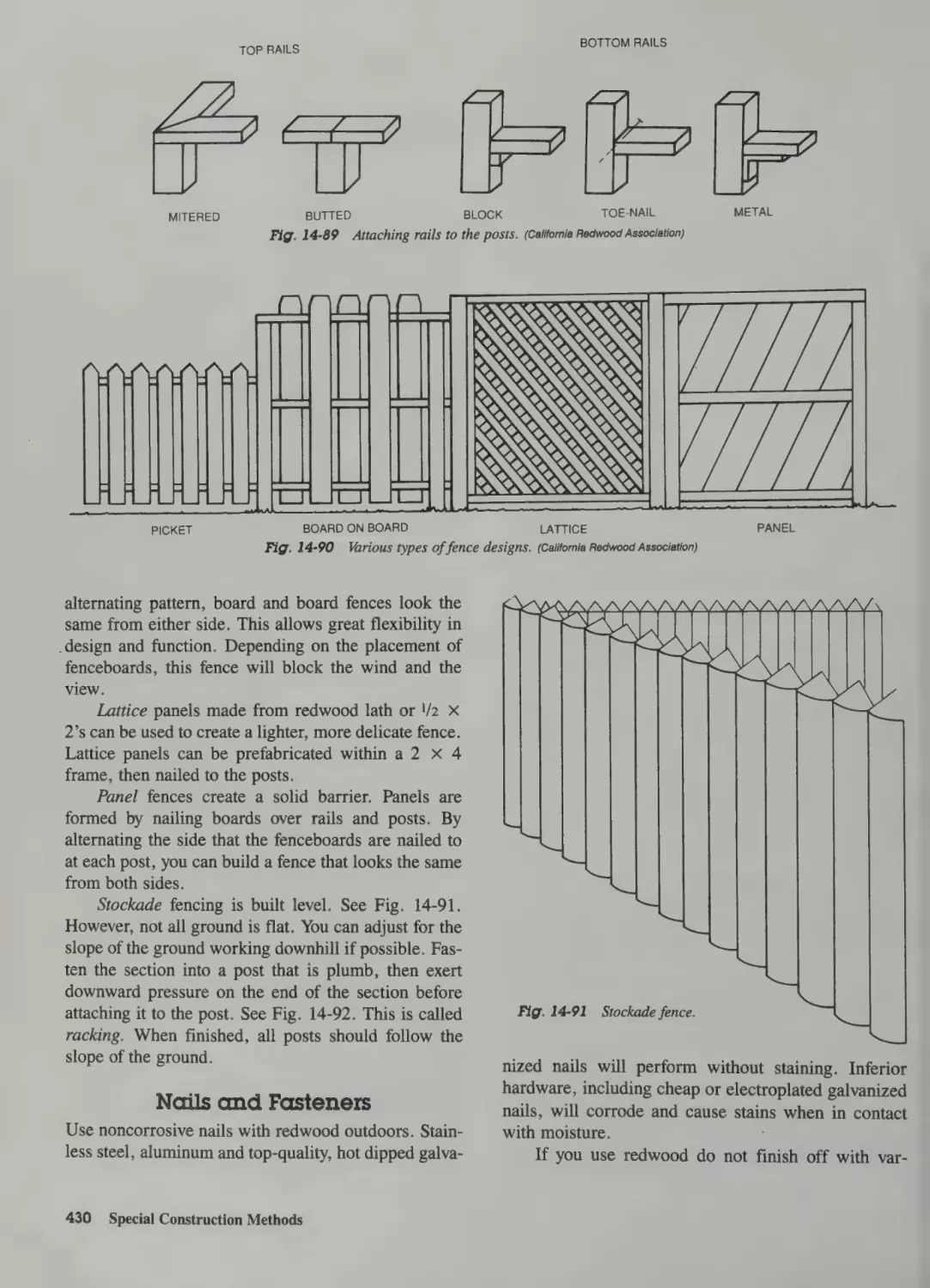
Attaching the Rails 429
Attaching Fenceboards 429
Nails and Fasteners 430
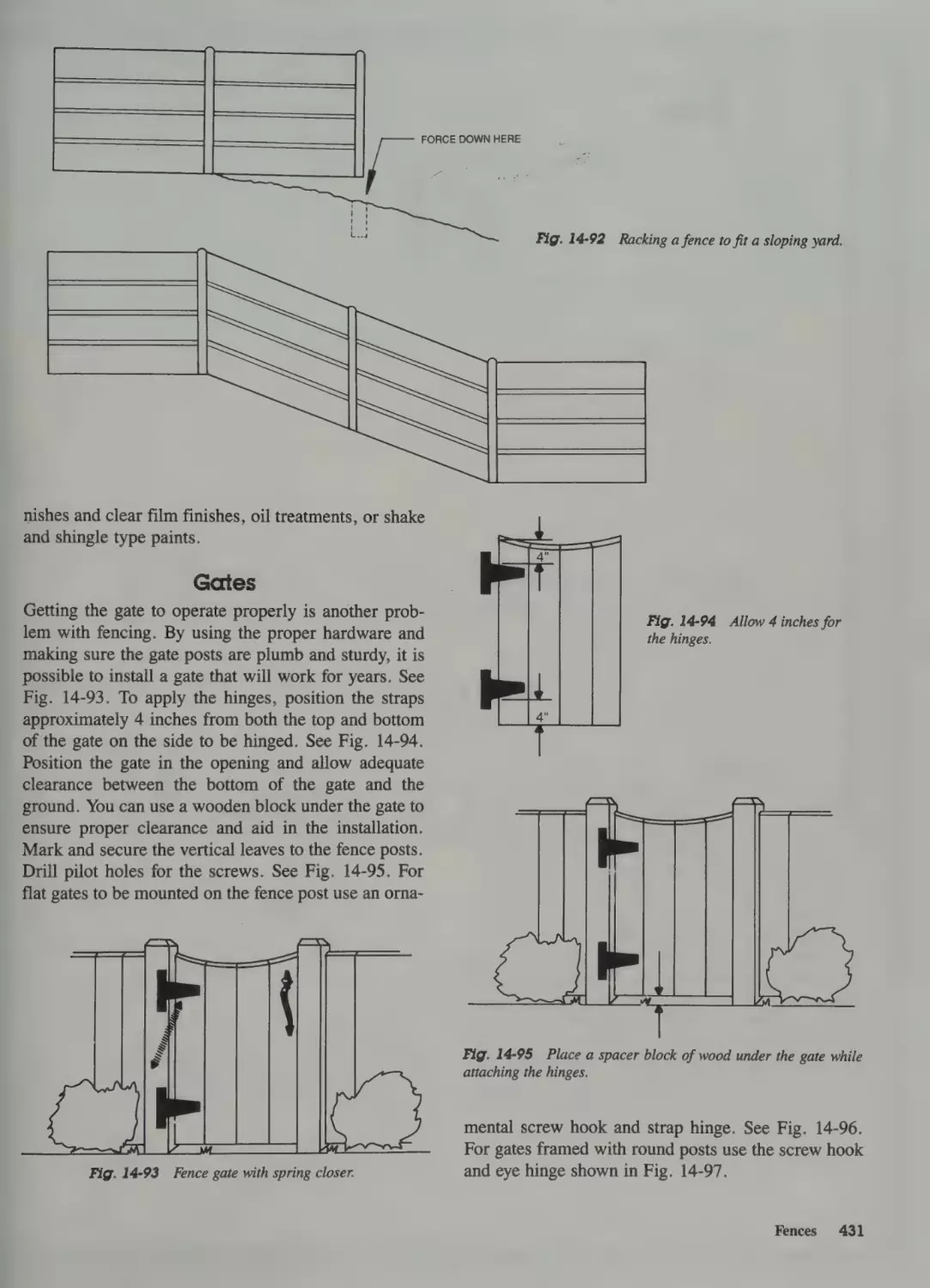
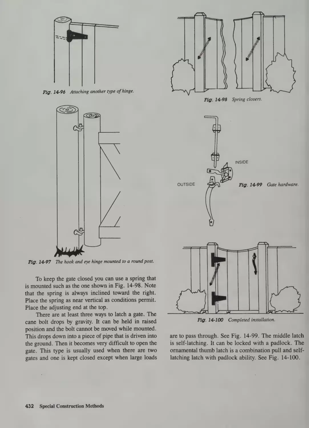
Gates 431
15Maintenance & Remodeling
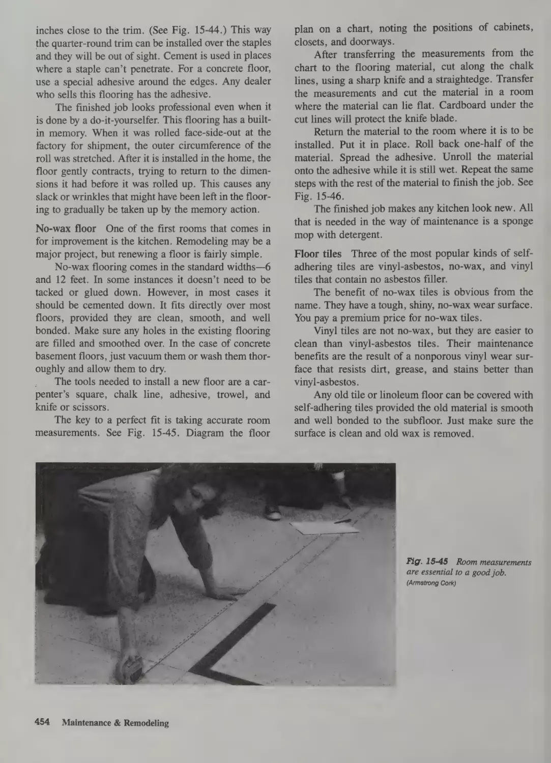
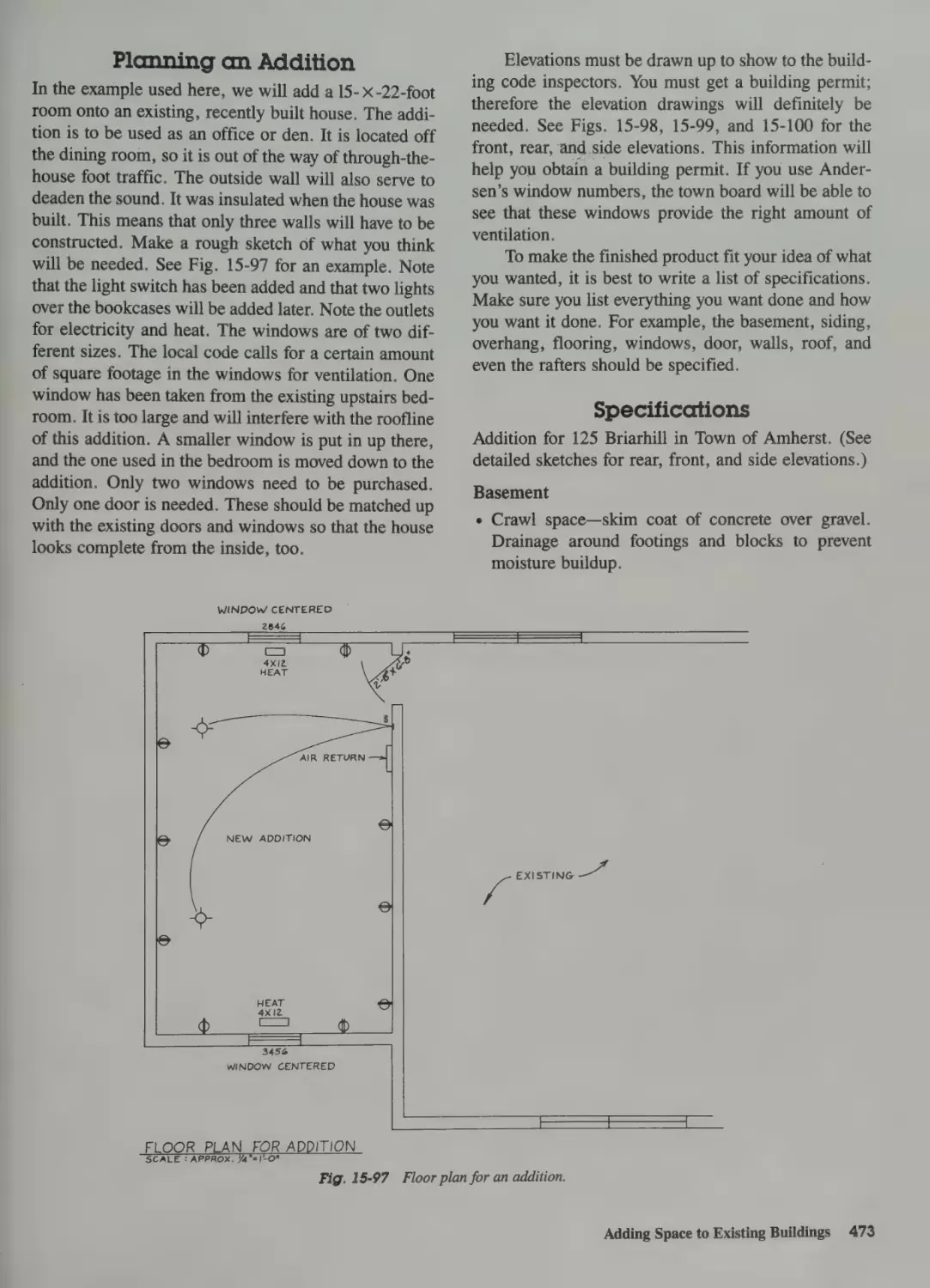
Planning the Job 434
Diagnosing Problems 434
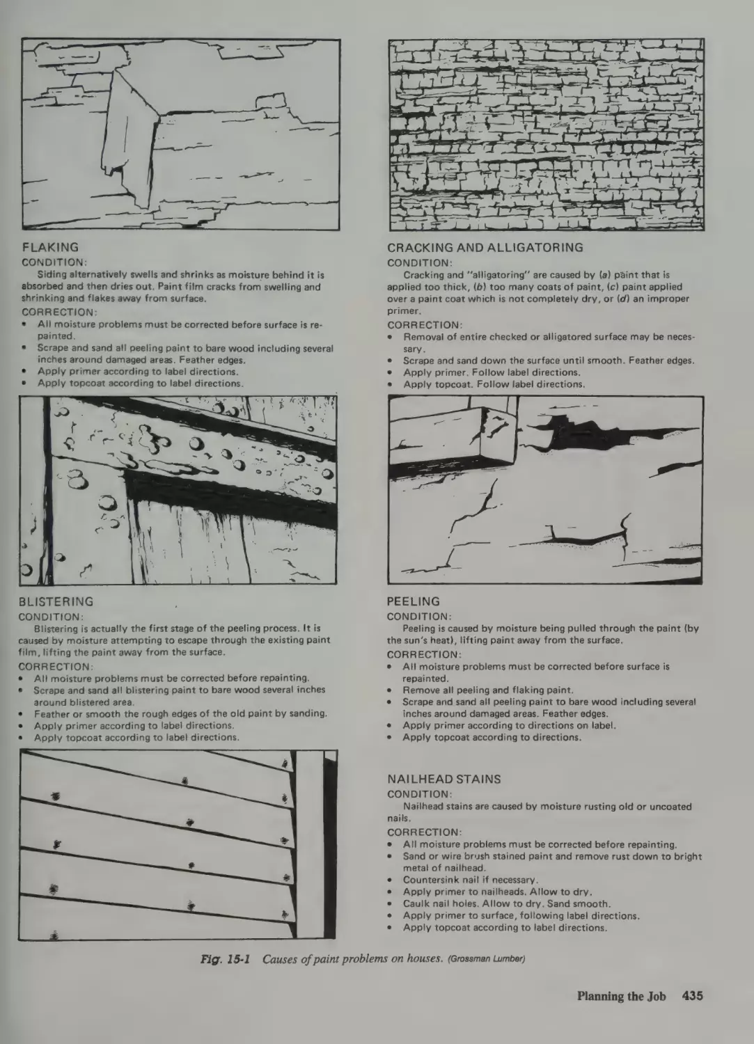
Identifying Needed Operations 434
Sequencing Work to Be Done 434
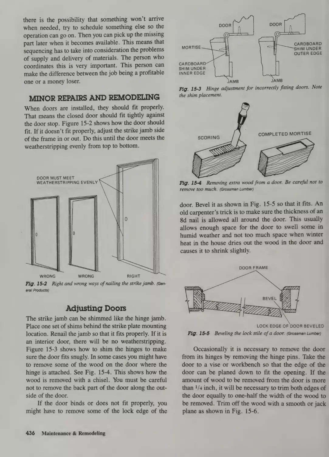
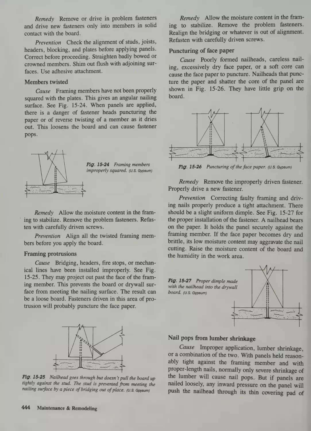
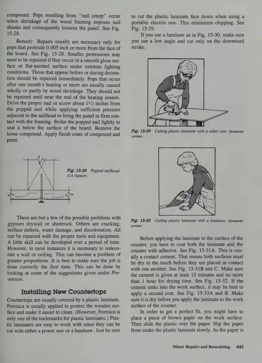
Minor Repairs and Remodeling 436
Adjusting Doors 436
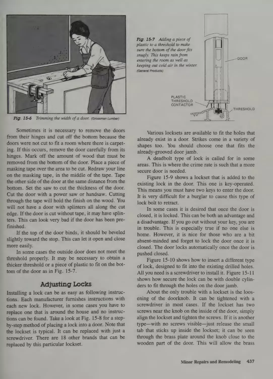
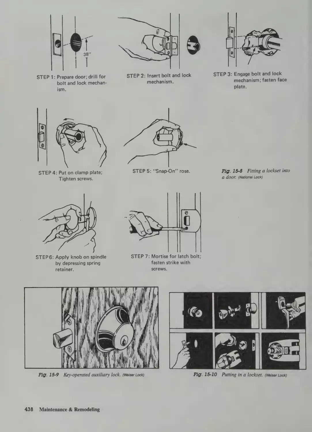
Adjusting Locks 437
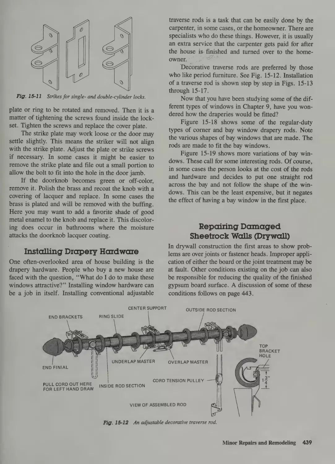
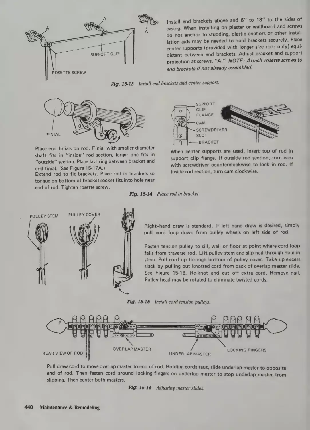
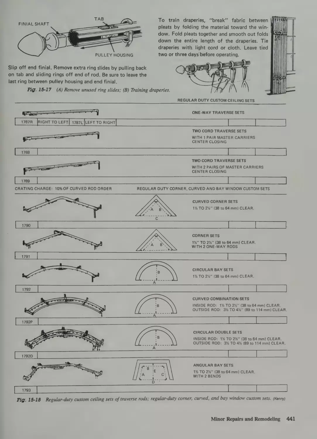
Installing Drapery Hardware 439
Repairing Damaged
Sheetrock Walls (Drywall) 439
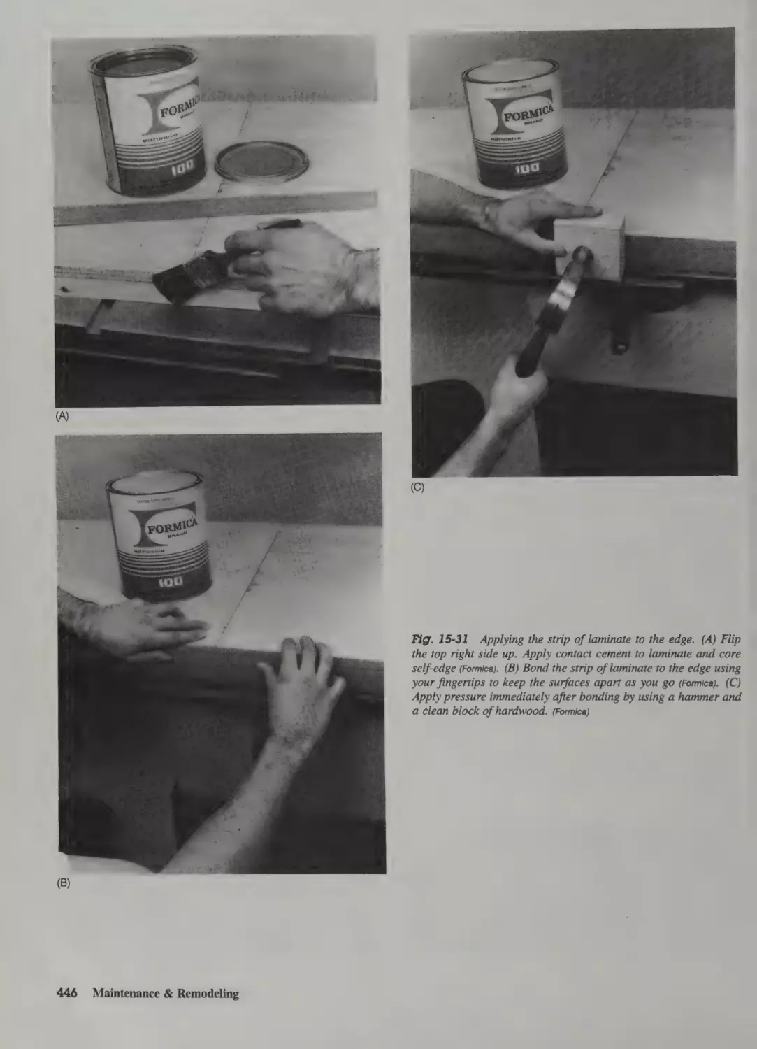
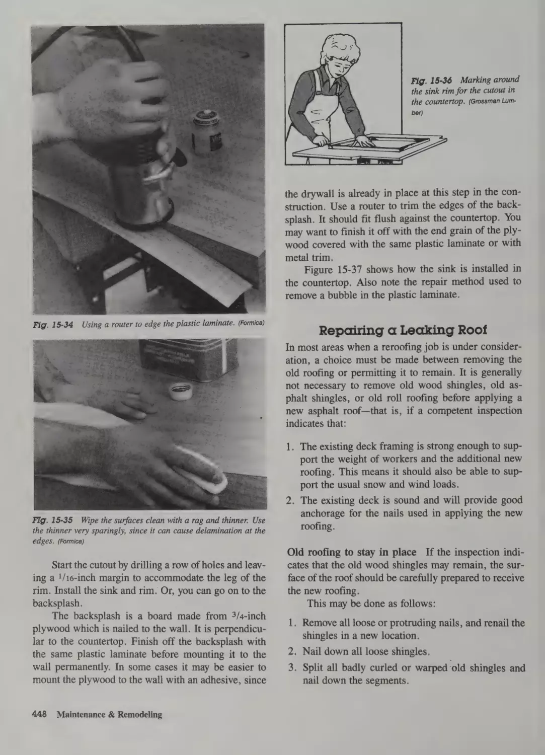
Installing New Countertops 445
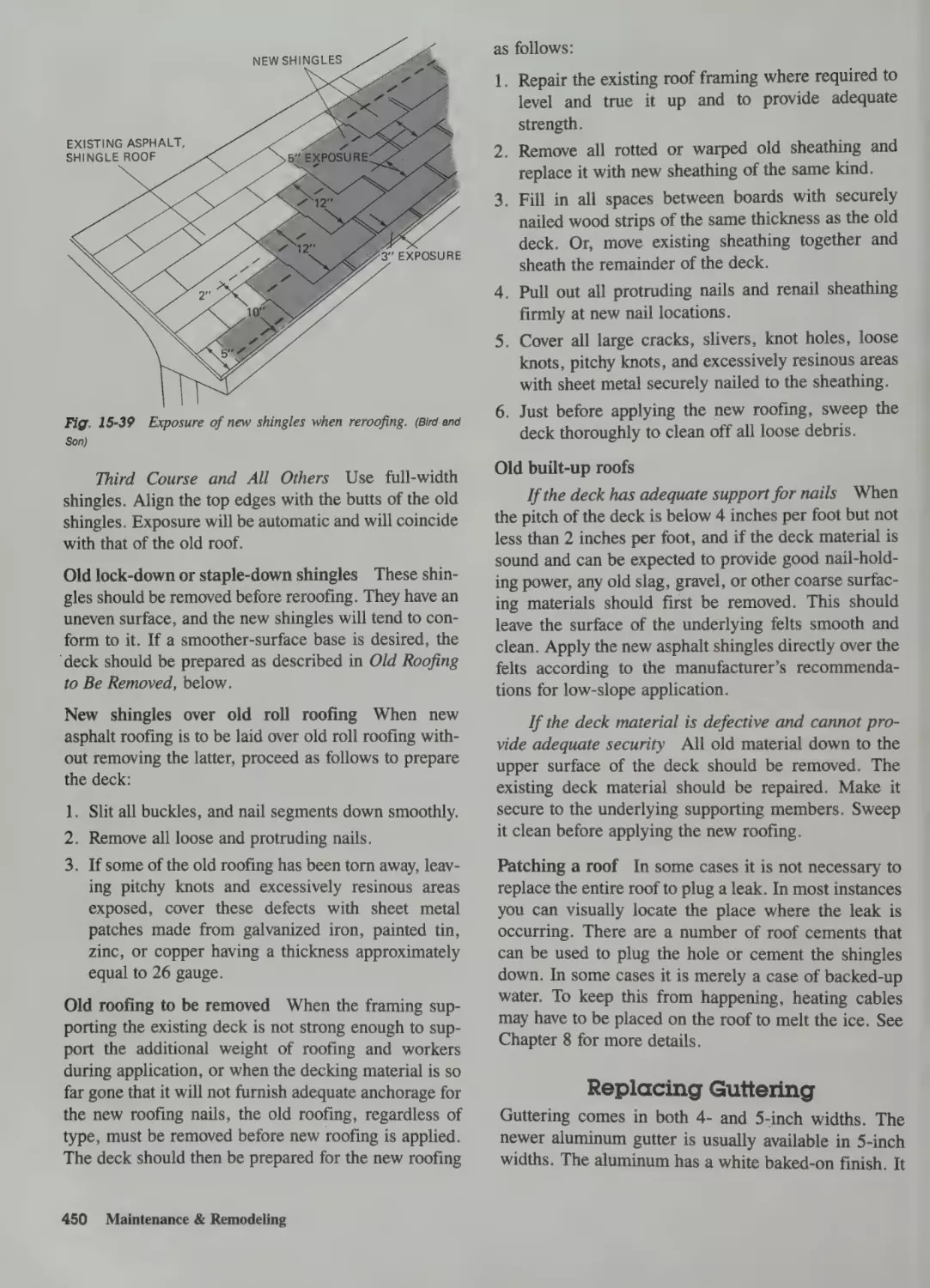
Repairing a Leaking Roof 448
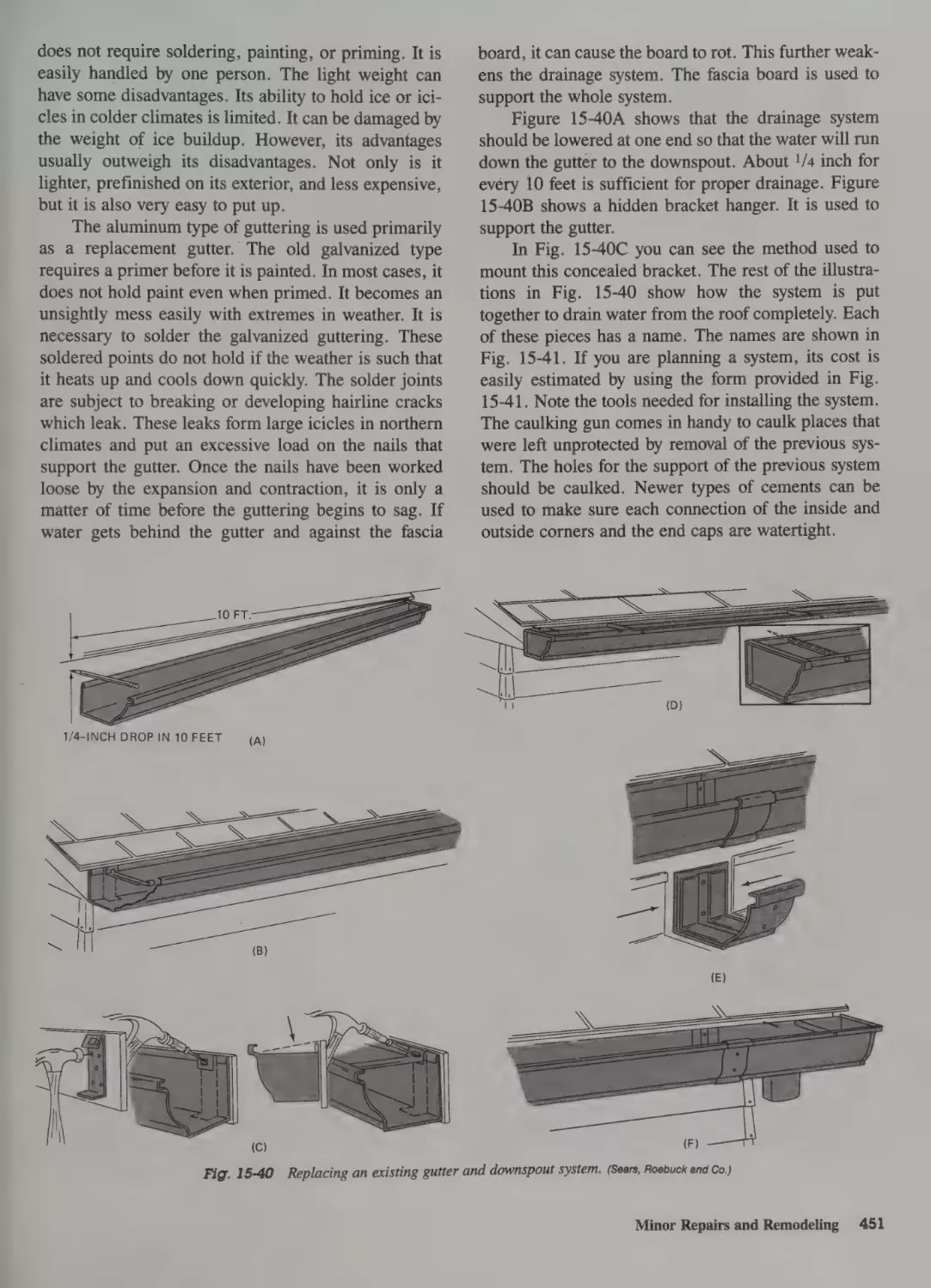
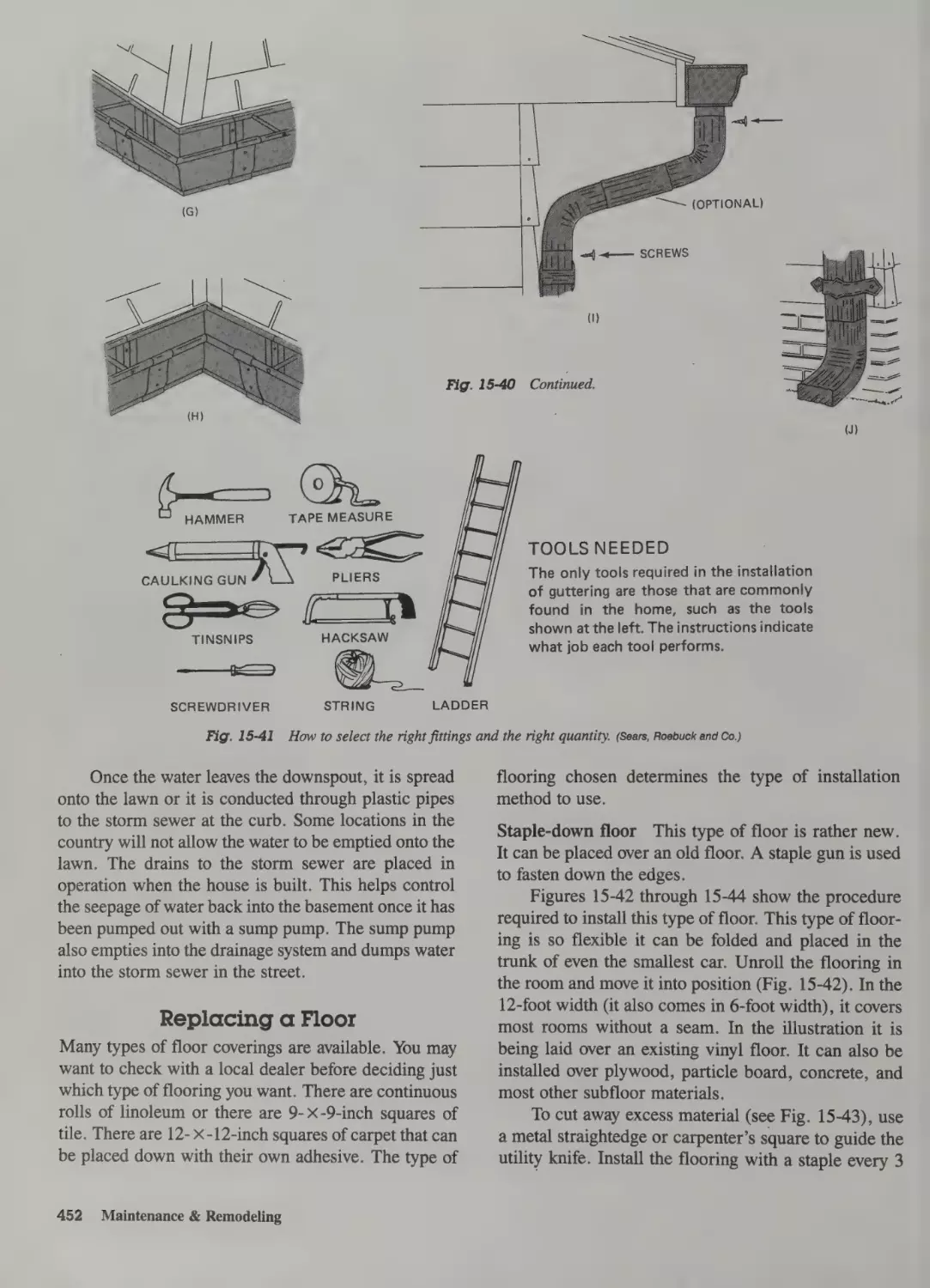
Replacing Guttering 450
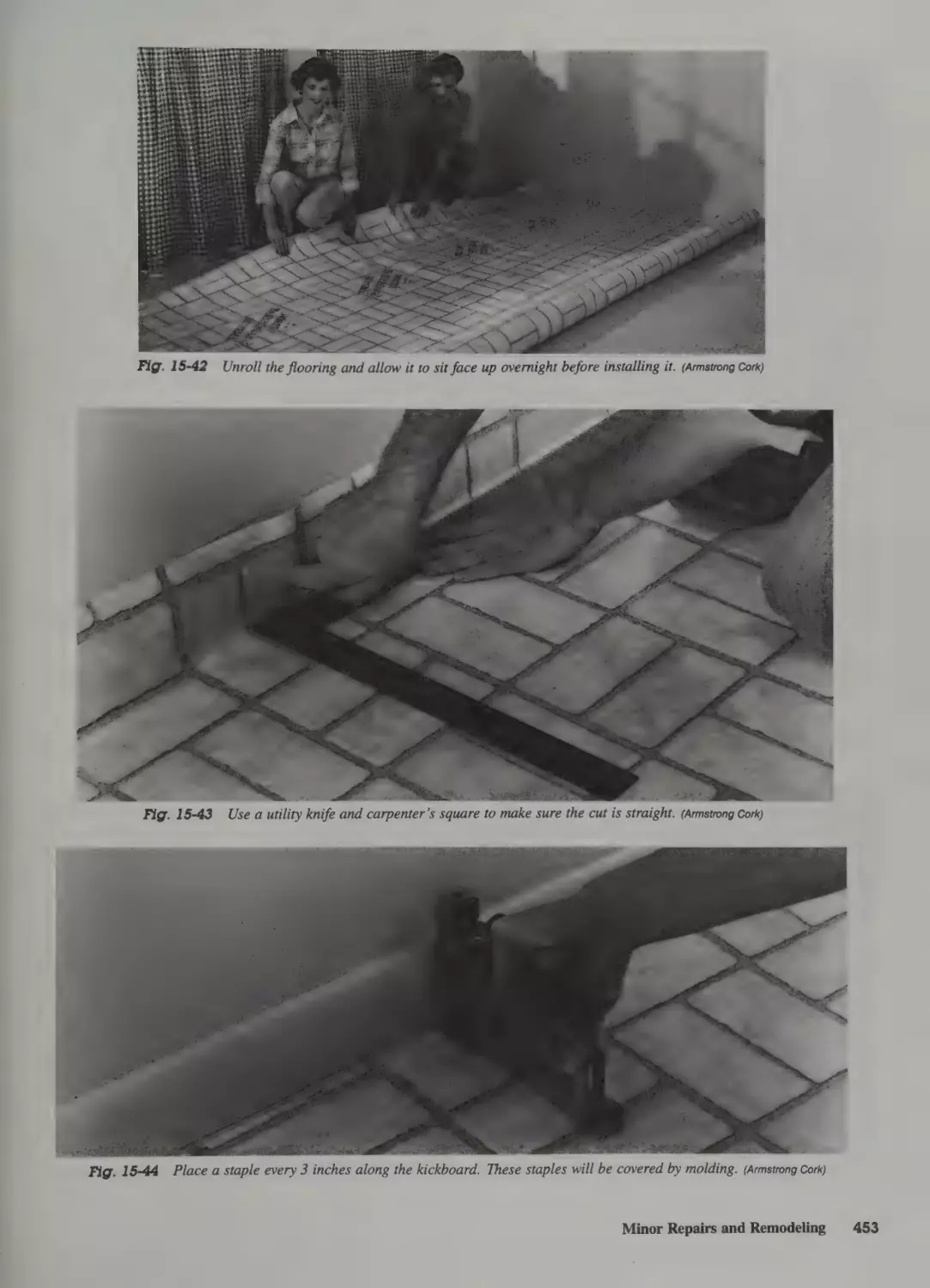
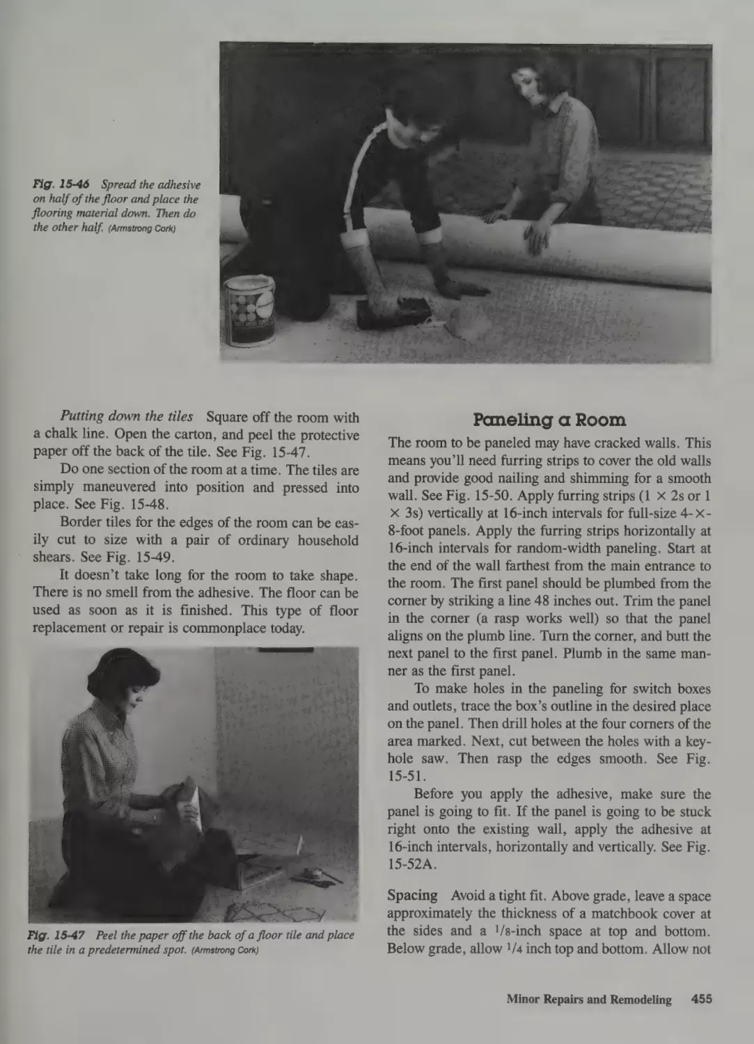
Replacing a Floor 452
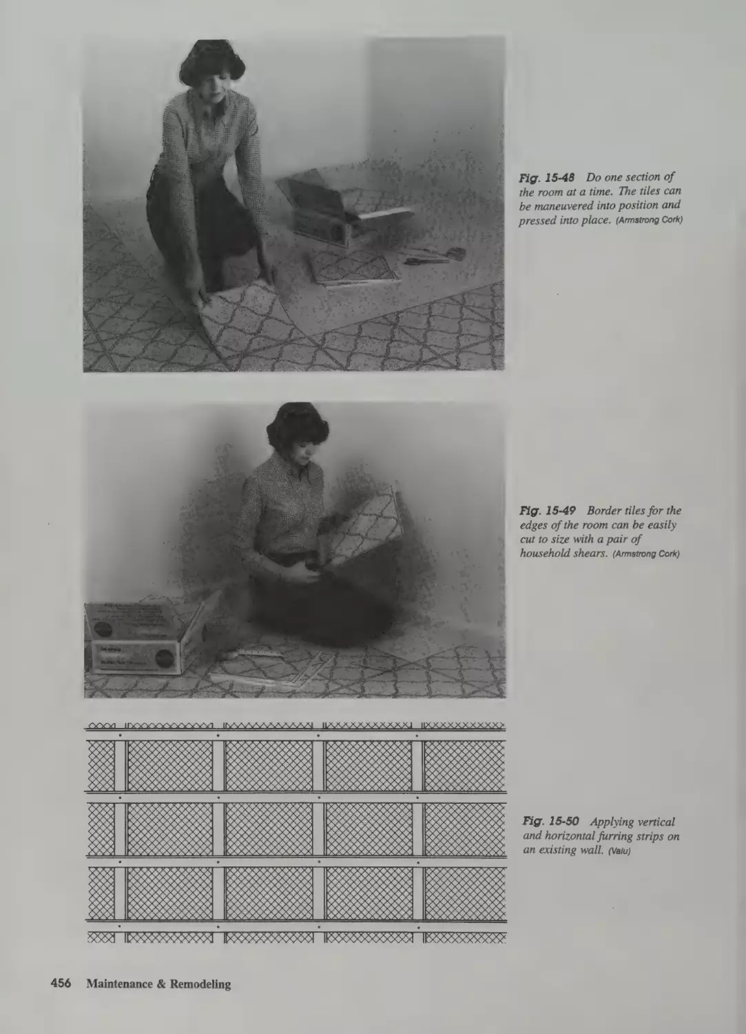
Paneling a Room 455
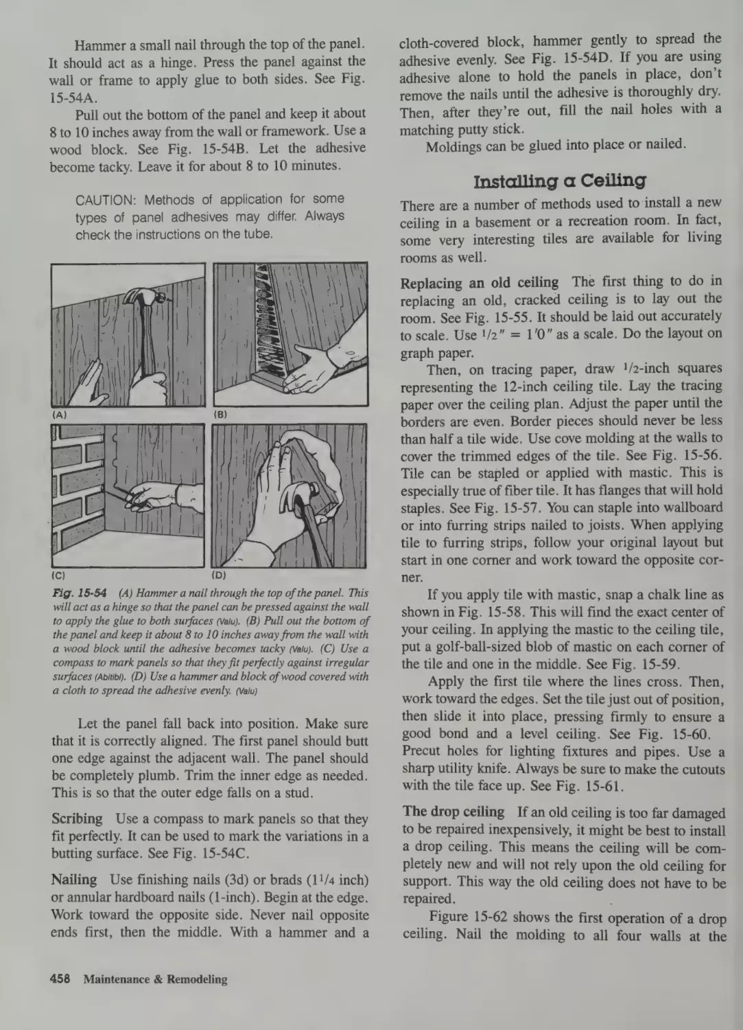
Installing a Ceiling 458
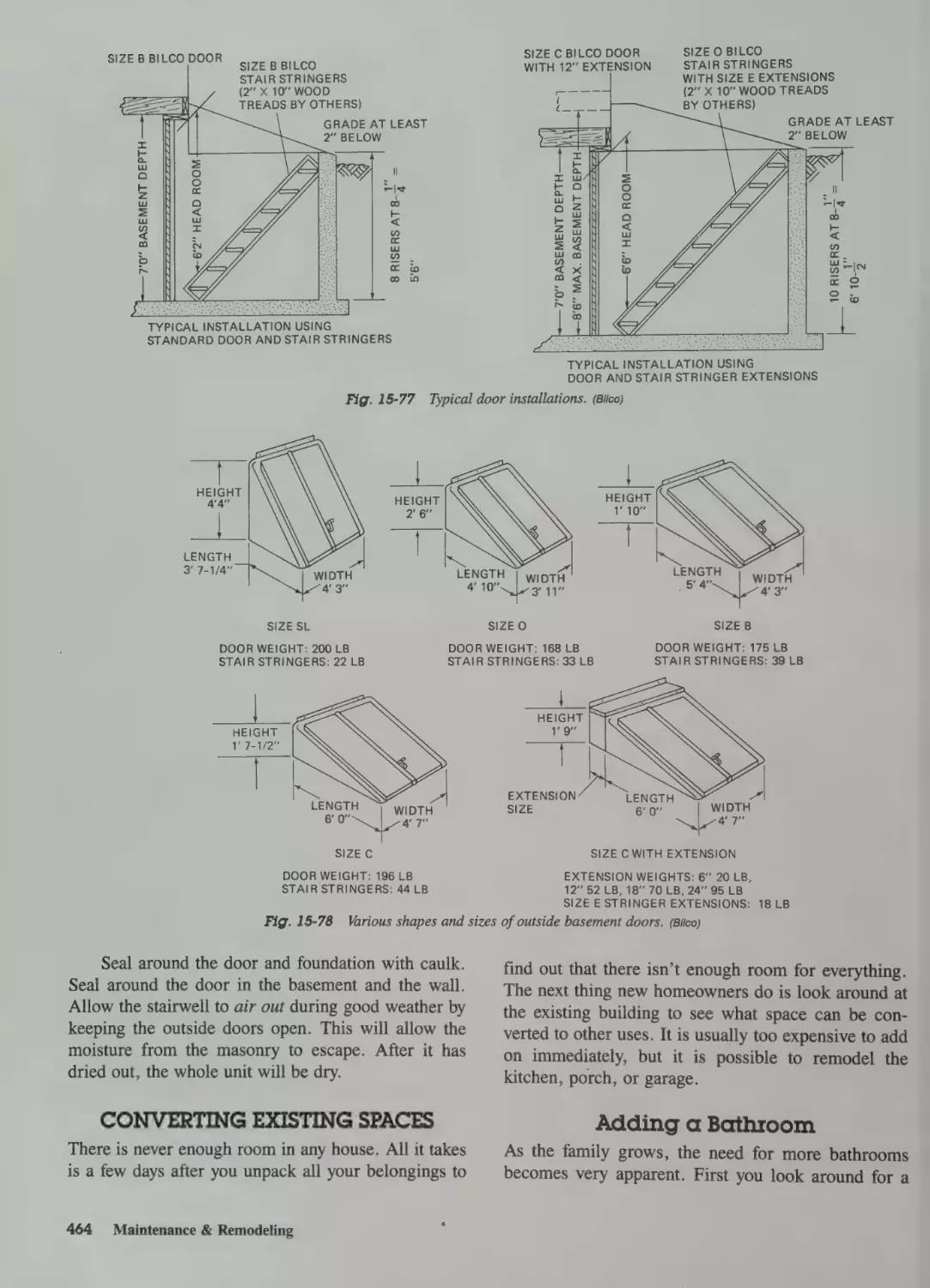
Replacing an Outside Basement Door 462
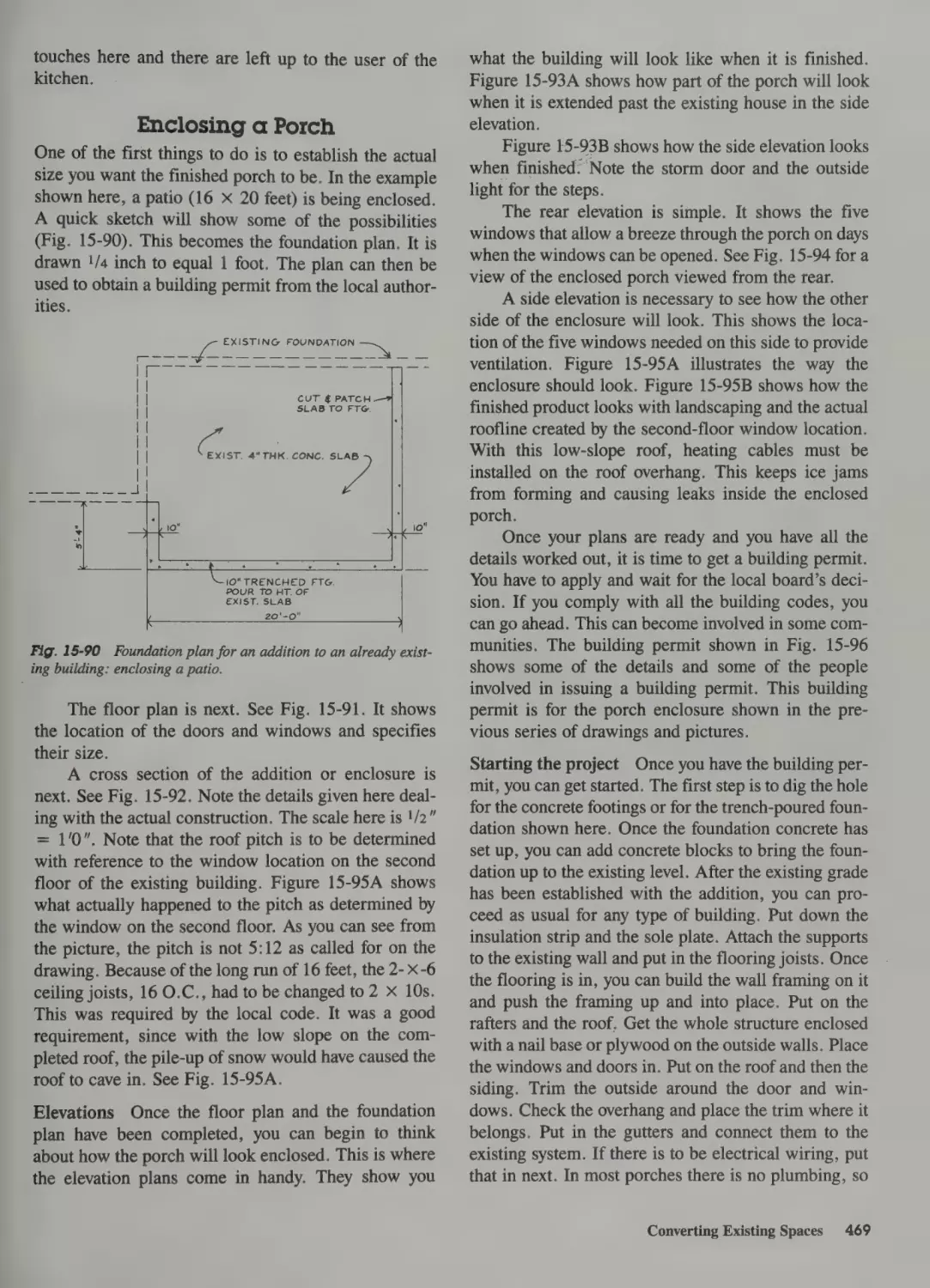
Converting Existing Spaces 464
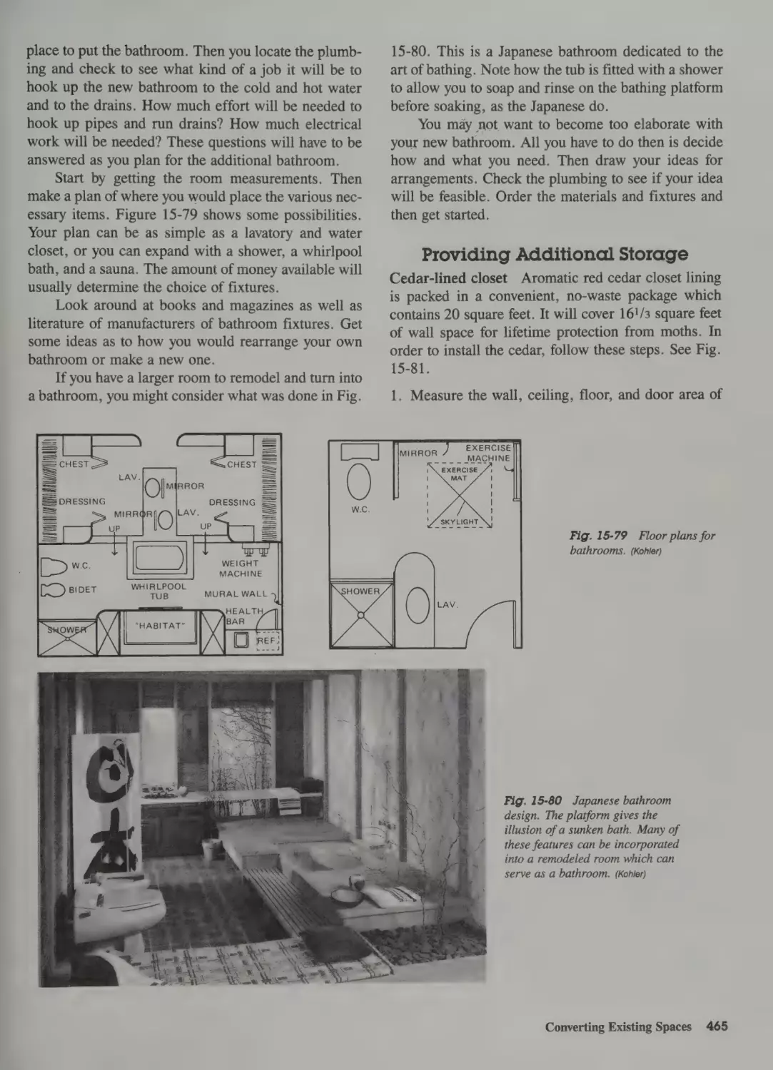
Adding a Bathroom 464
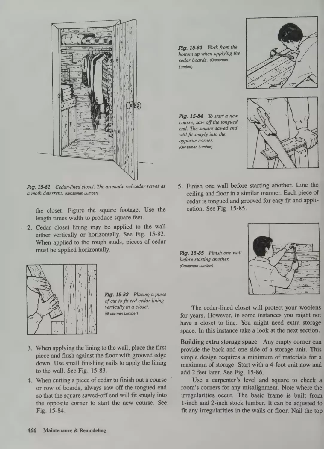
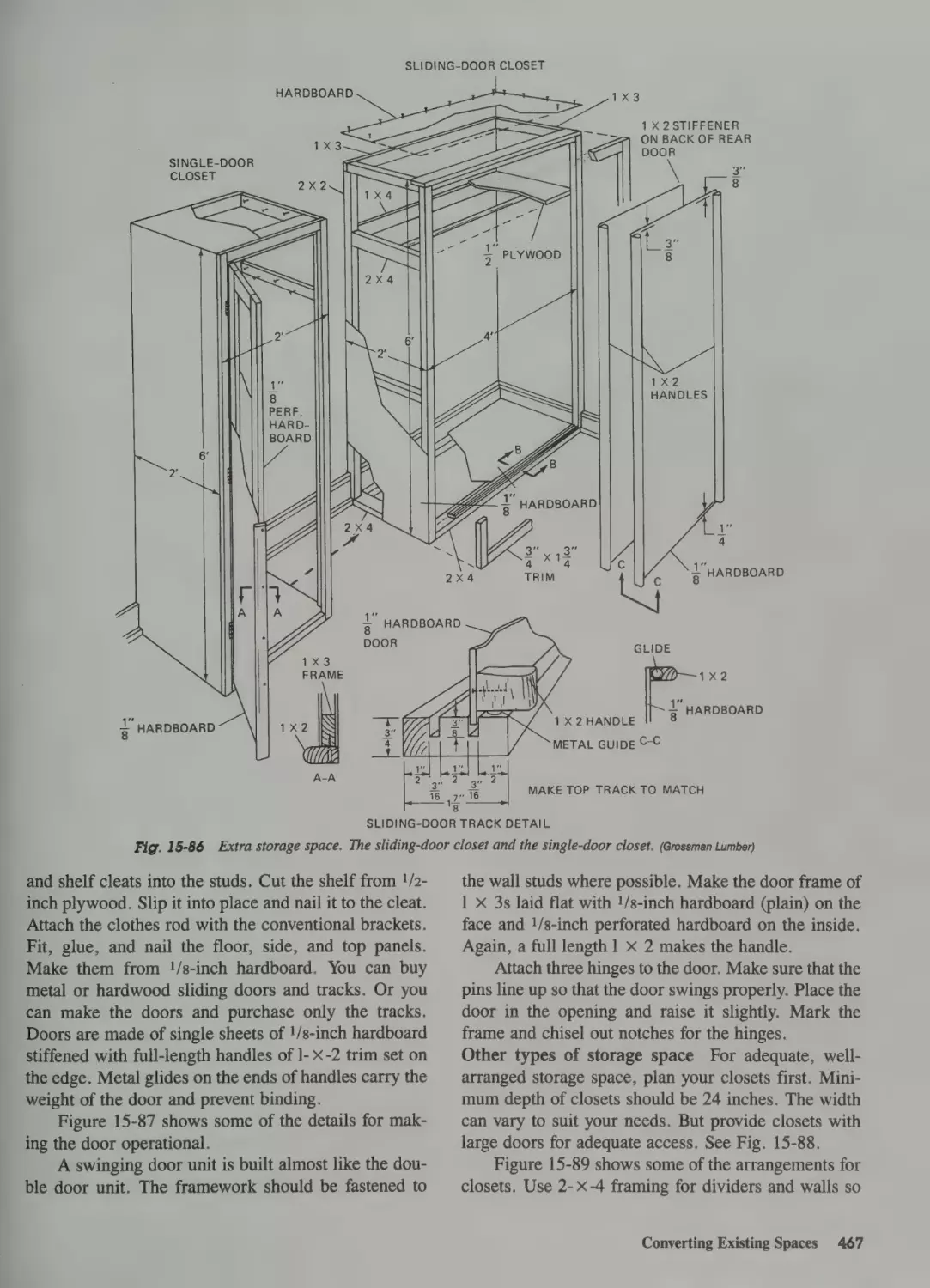
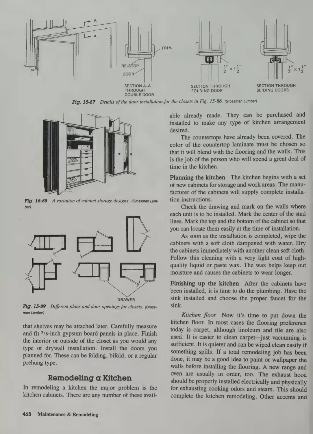
Providing Additional Storage 465
Remodeling a Kitchen 468
Enclosing a Porch 469
Adding Space to Existing Buildings 472
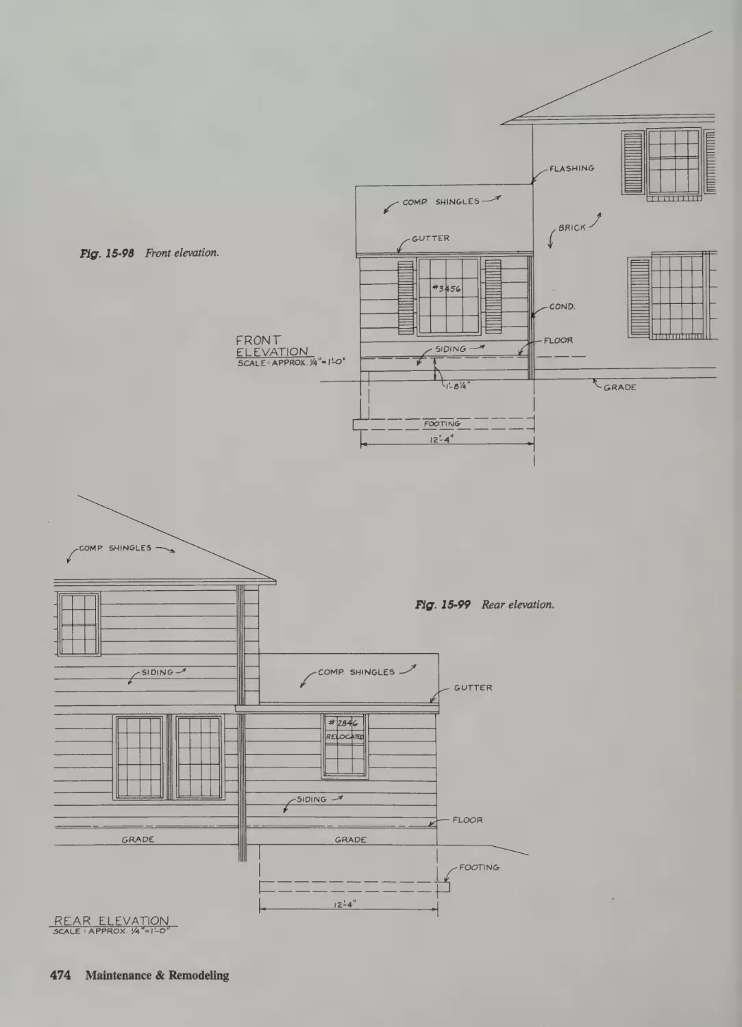
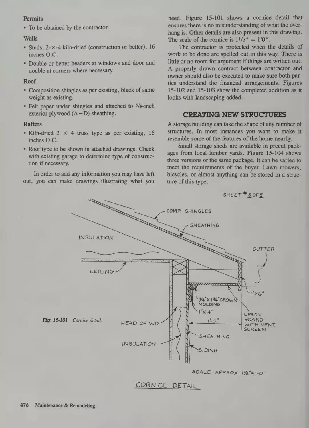
Planning an Addition 473
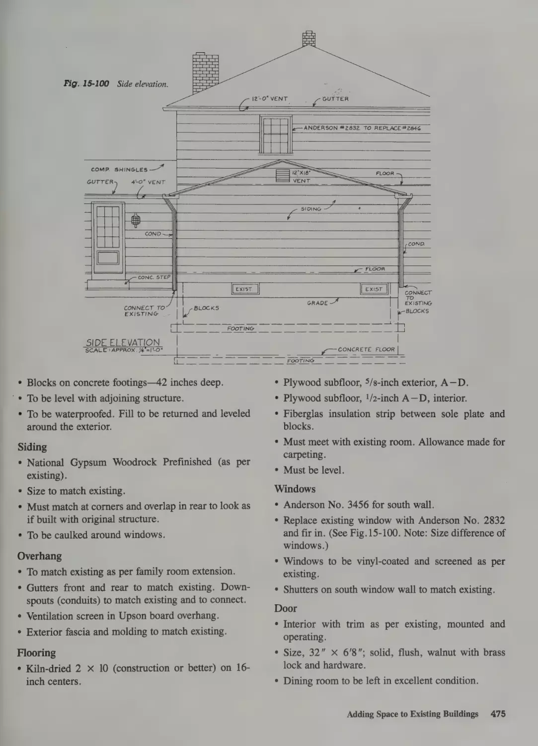
Specifications 473
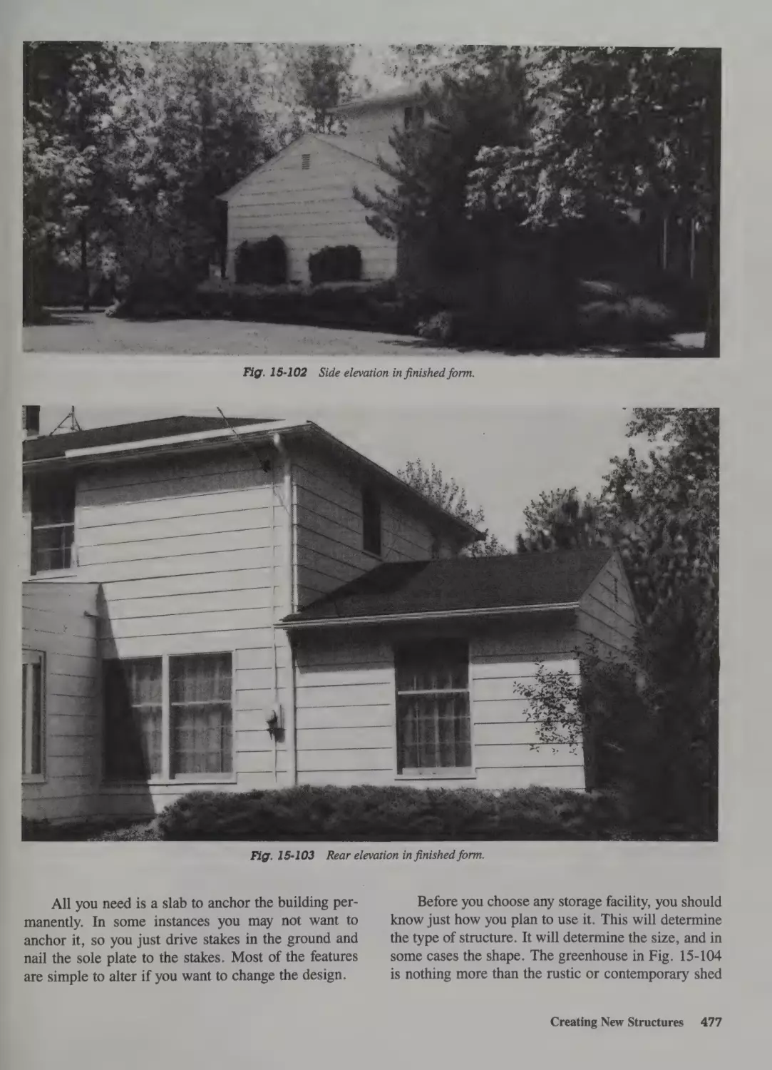
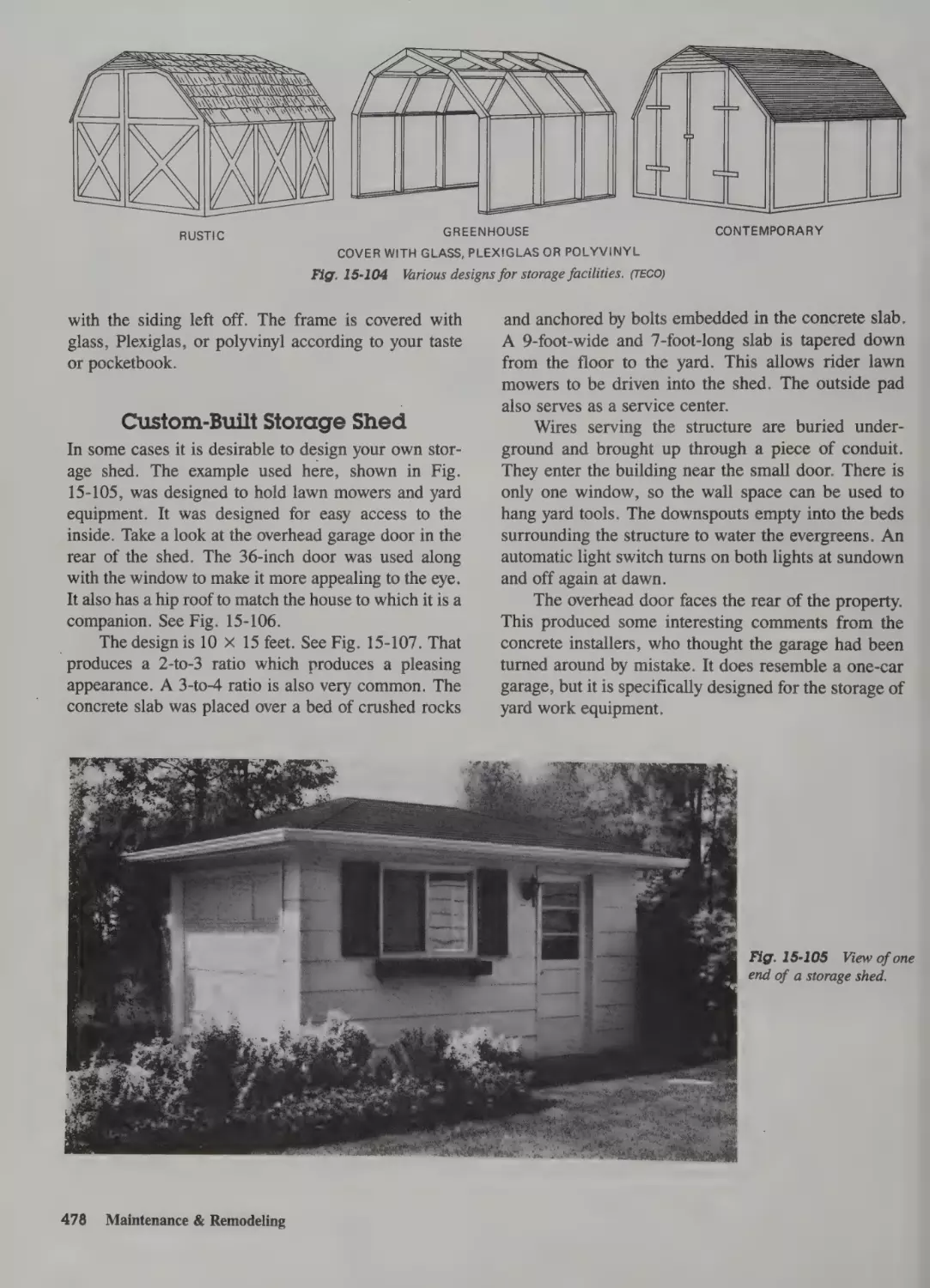
Creating New Structures 476
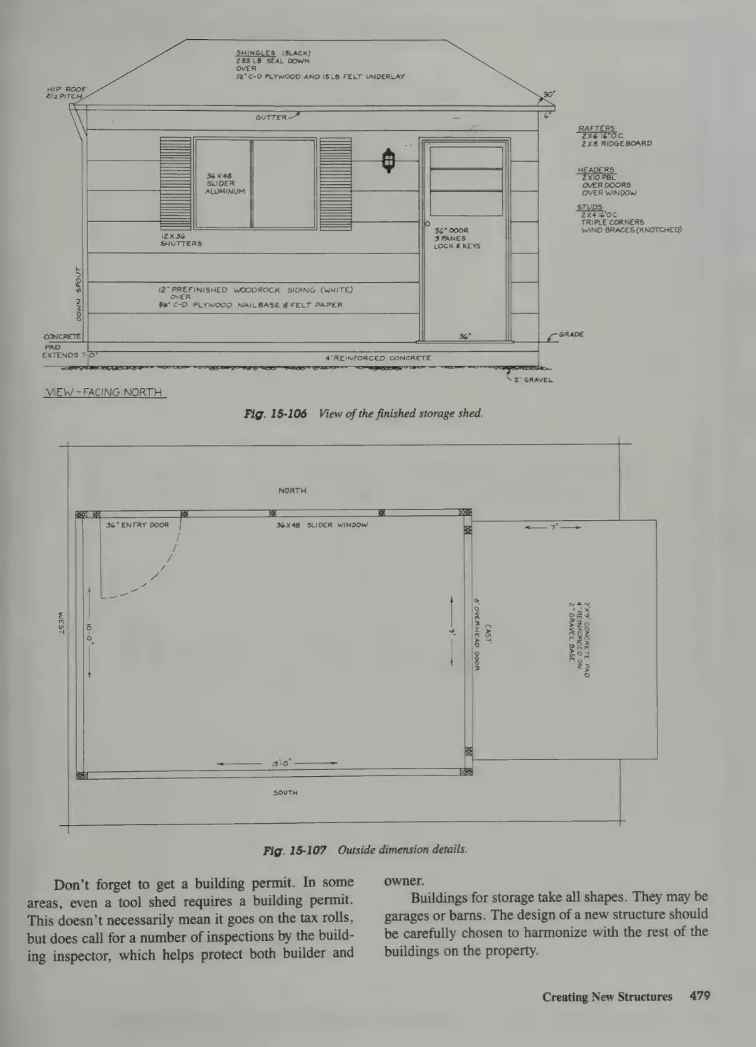
Custom-Built Storage Shed 478
]6The Carpenter & the Industry
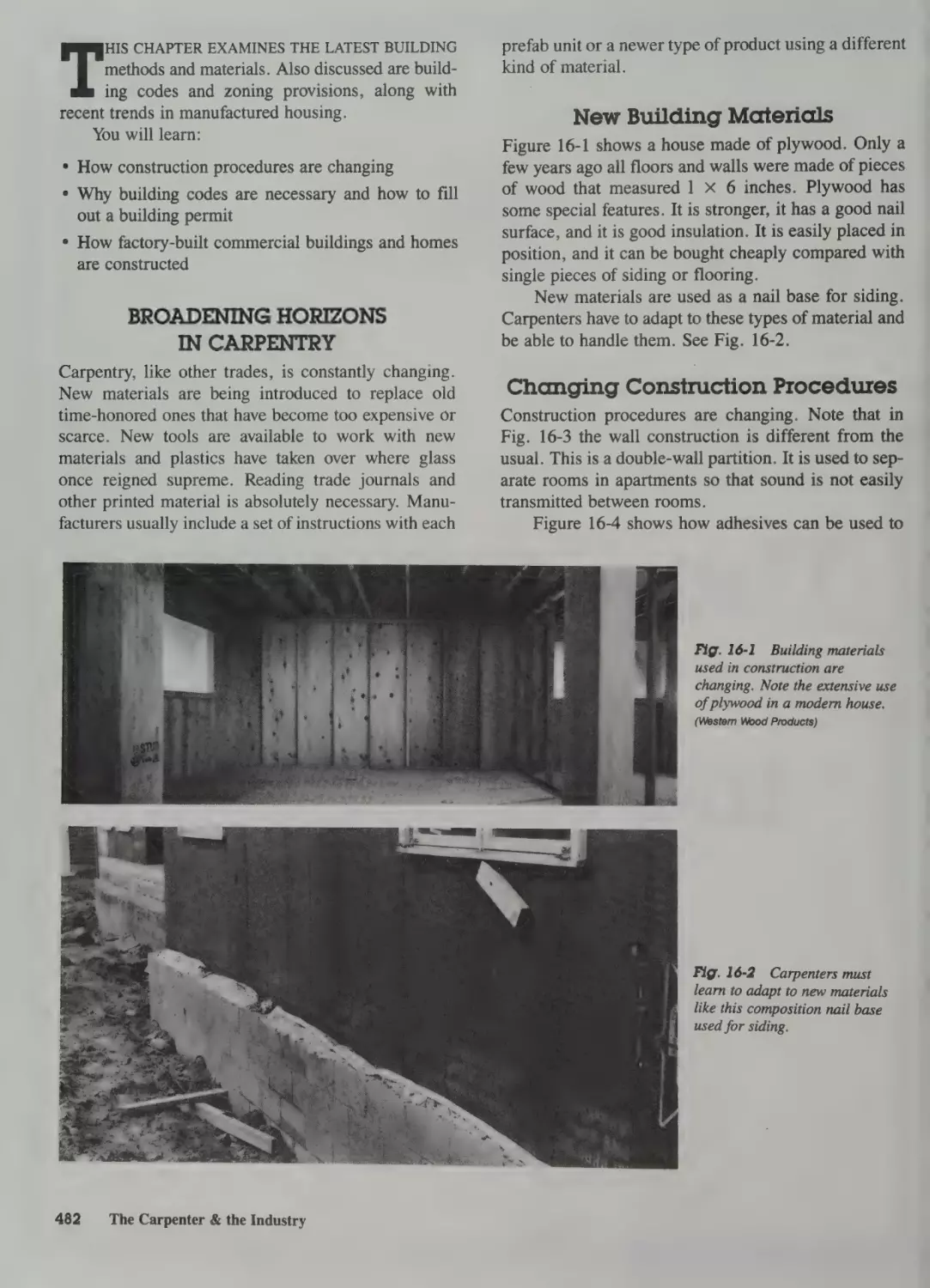
Broadening Horizons in Carpentry 482
New Building Materials 482
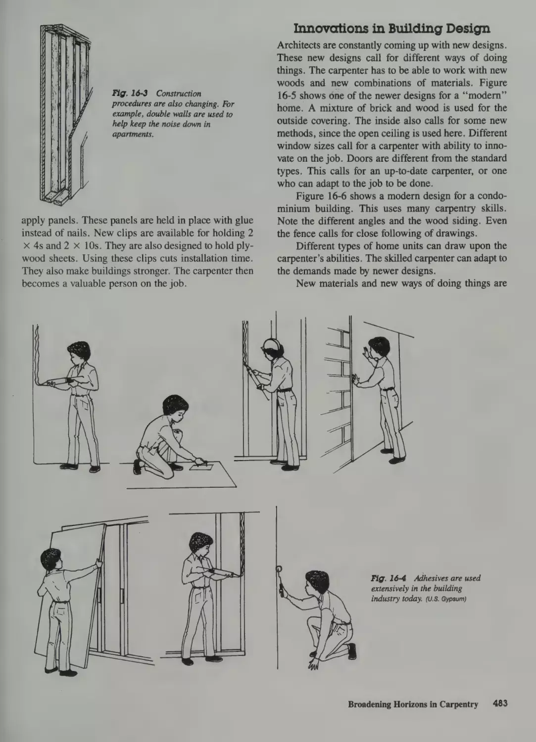
Changing Construction Procedures 482
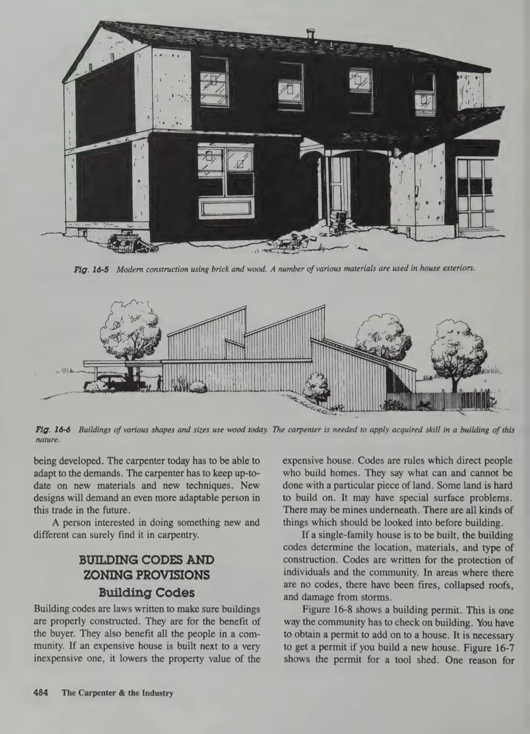
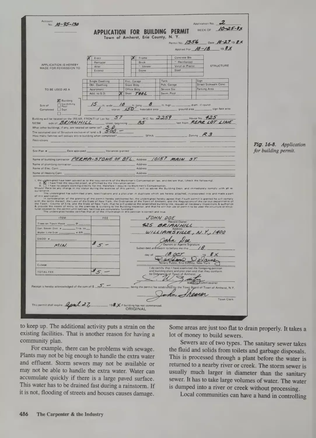
Innovations in Building Design 483
17 Bathrooms
Room Arrangement 496
Function and Size 498
Building Codes 499
Plumbing 500
Electrical 500
Ventilation 500
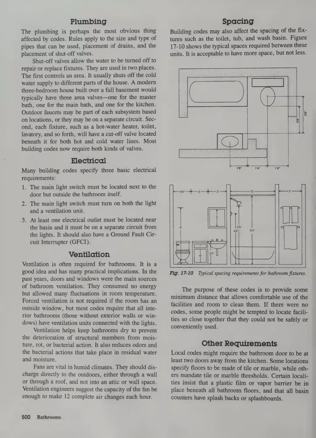
Spacing 500
Other Requirements
500
Furnishings 501
Fixtures 501
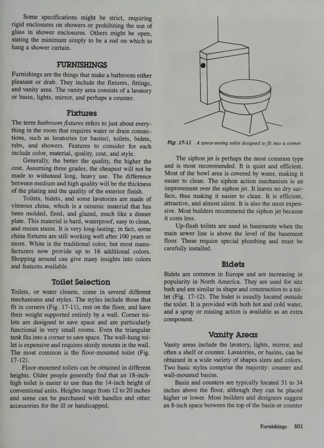
Toilet Selection 501
Bidets 501
Vanity Areas 501
Countertop Basins 502
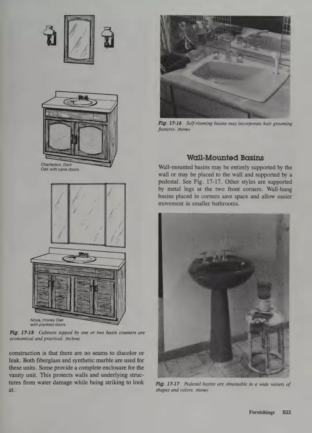
Wall-Mounted Basins 503
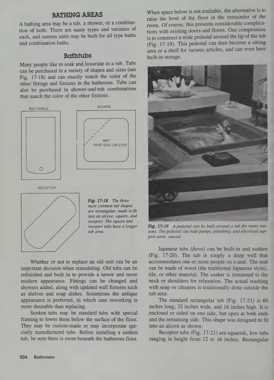
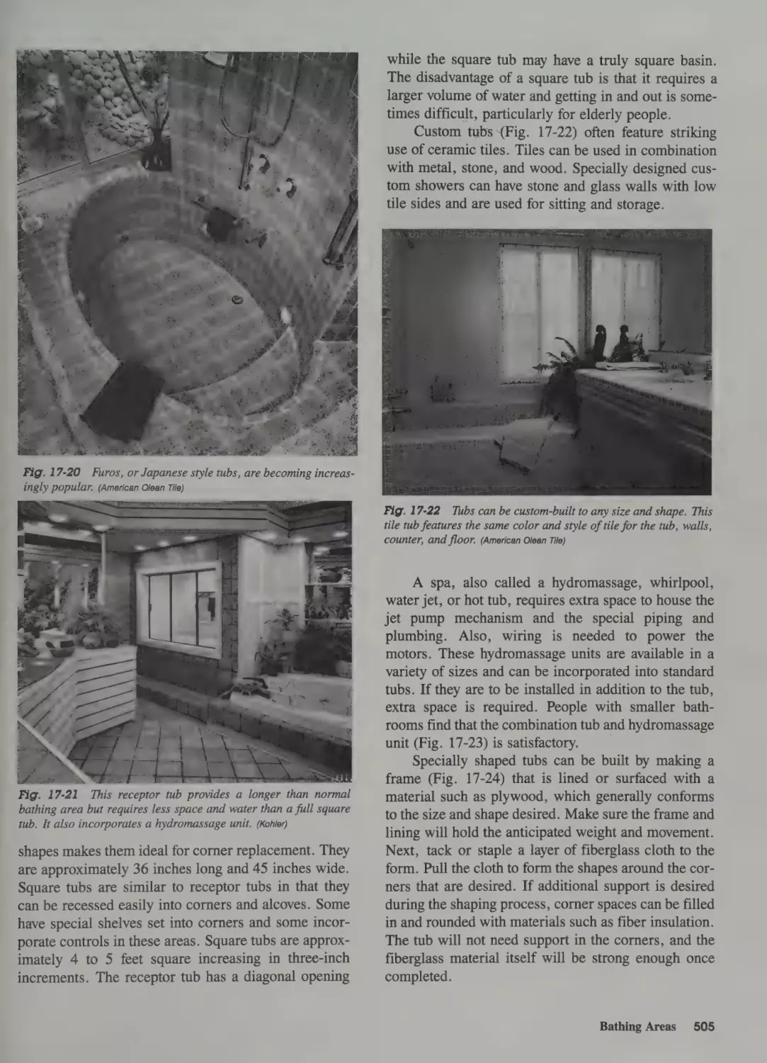
Bathing Areas 504
Bathtubs 504
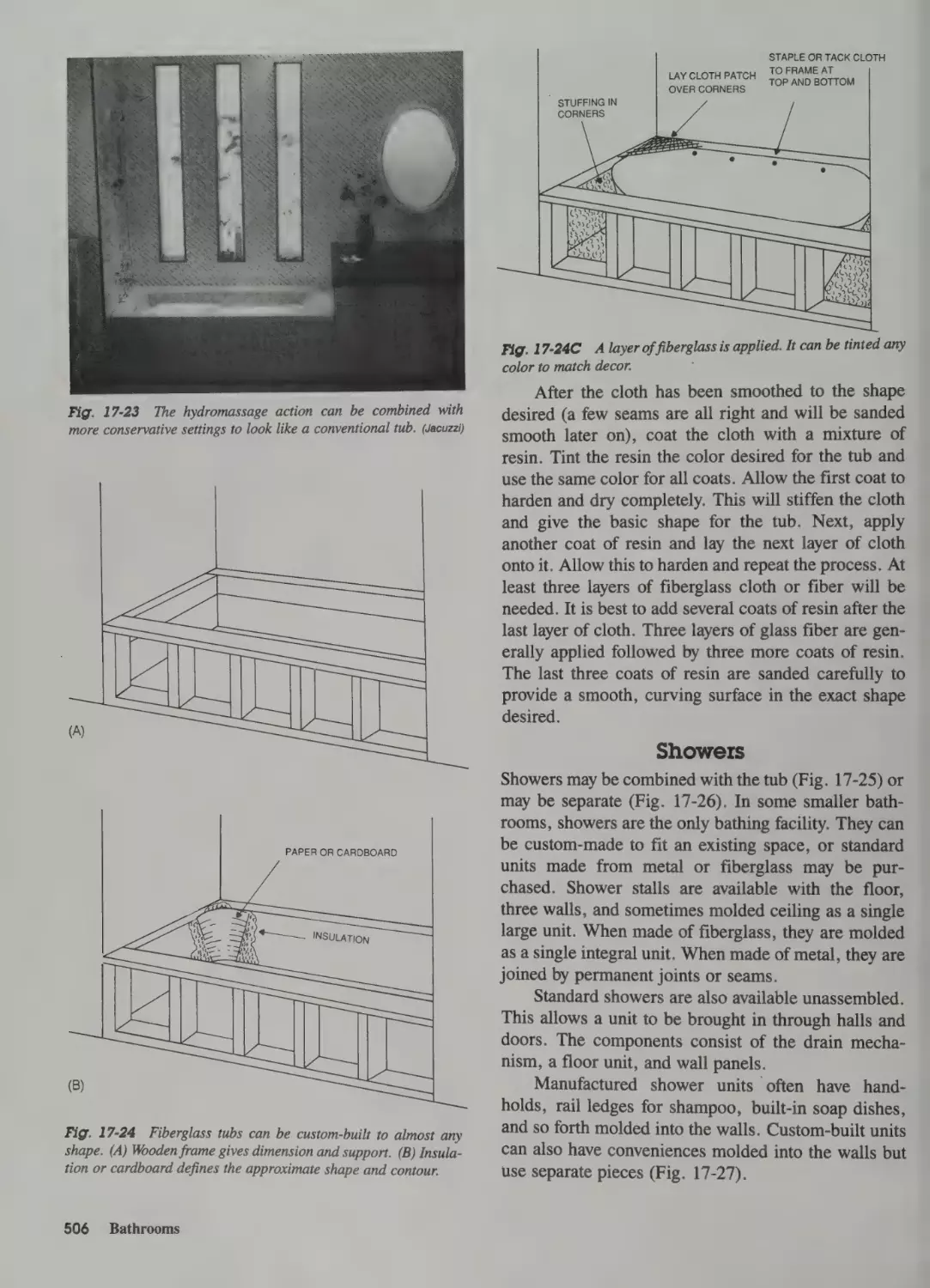
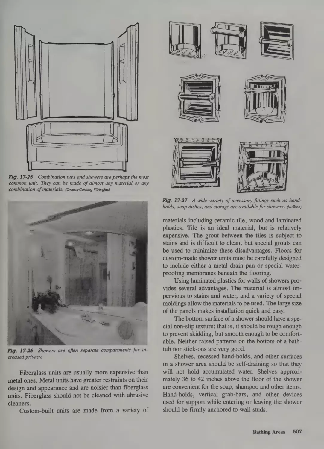
Showers 506
Fittings 508
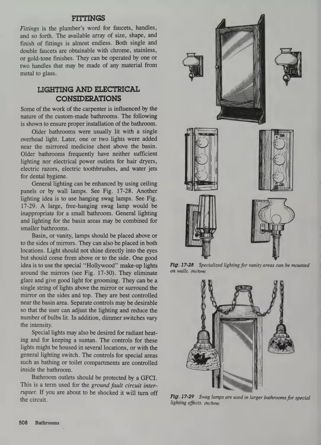
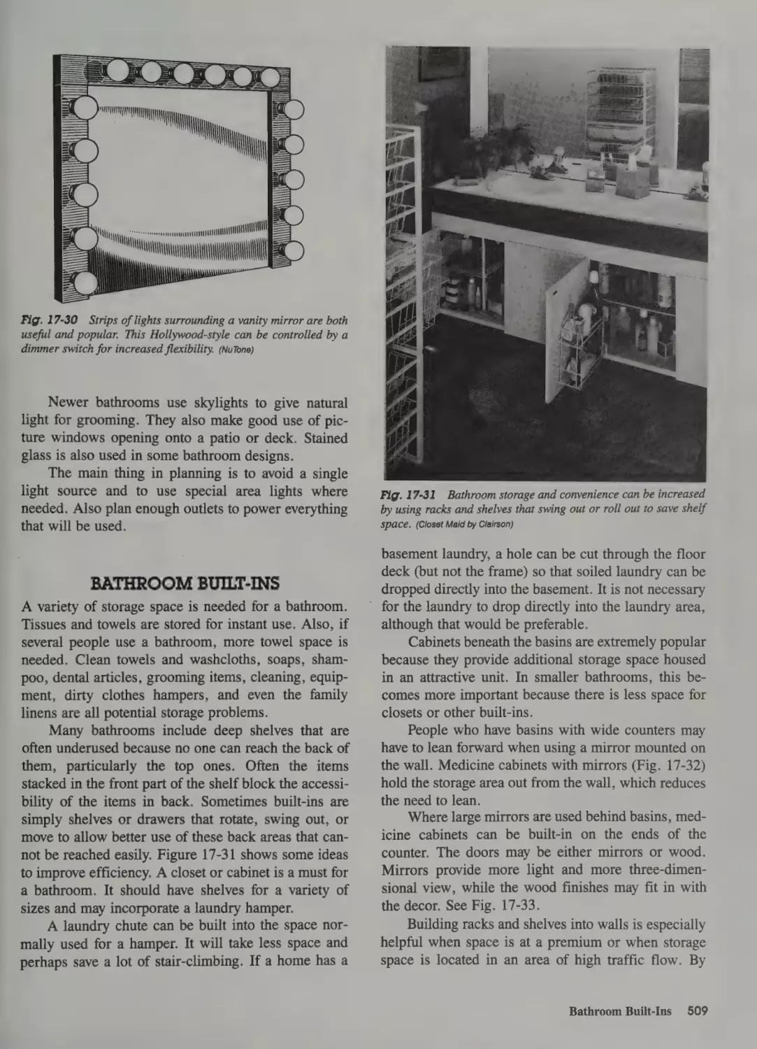
Lighting and Electrical Considerations 508
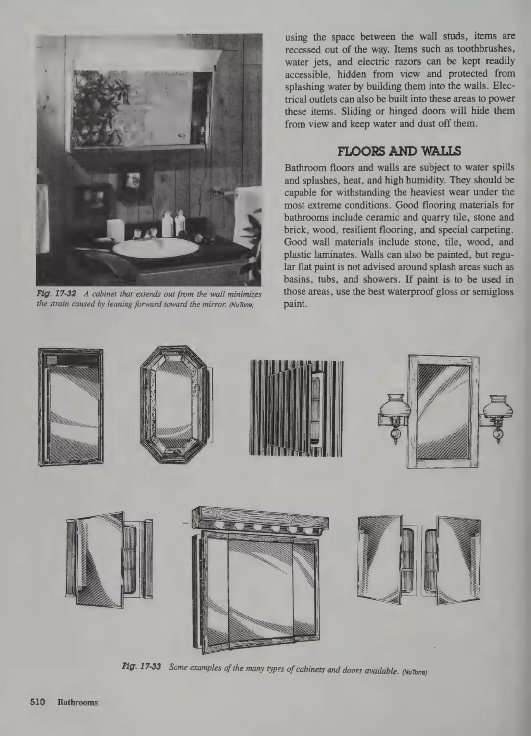
Bathroom Built-Ins 509
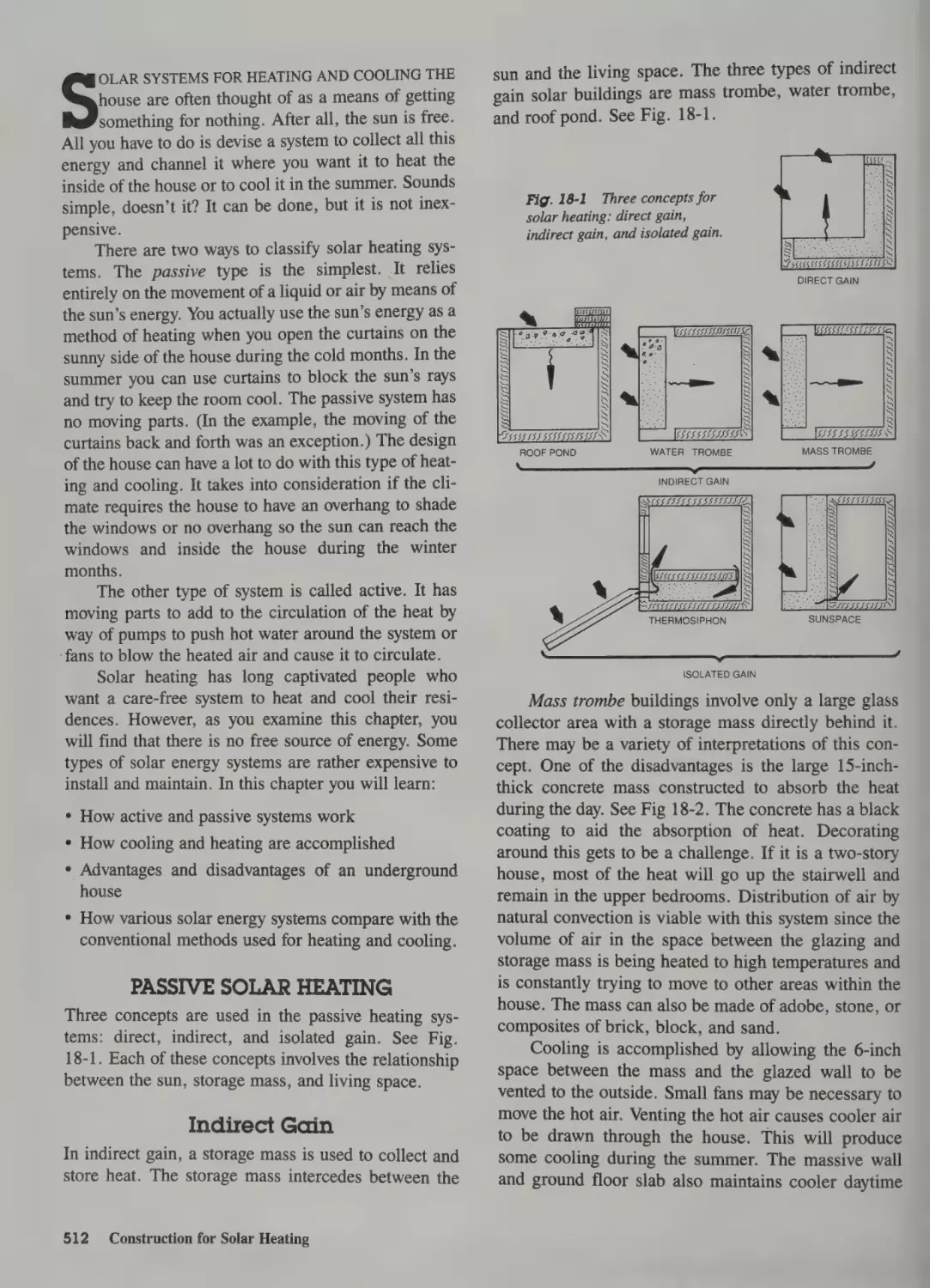
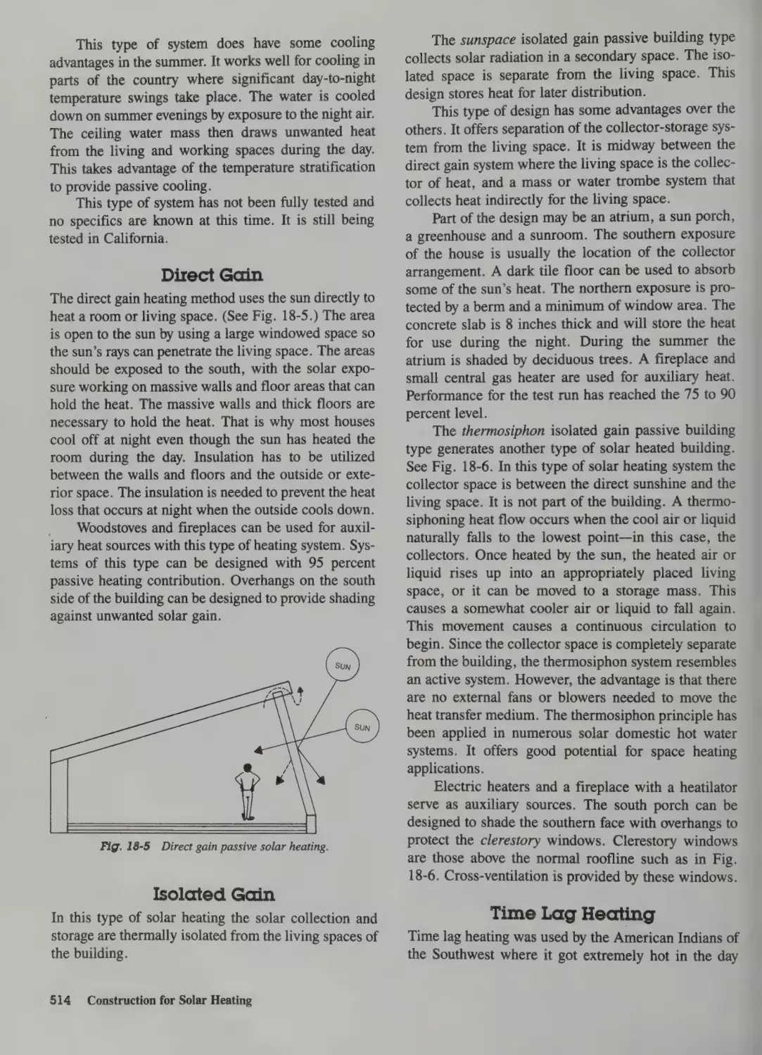
Floors and Walls 510
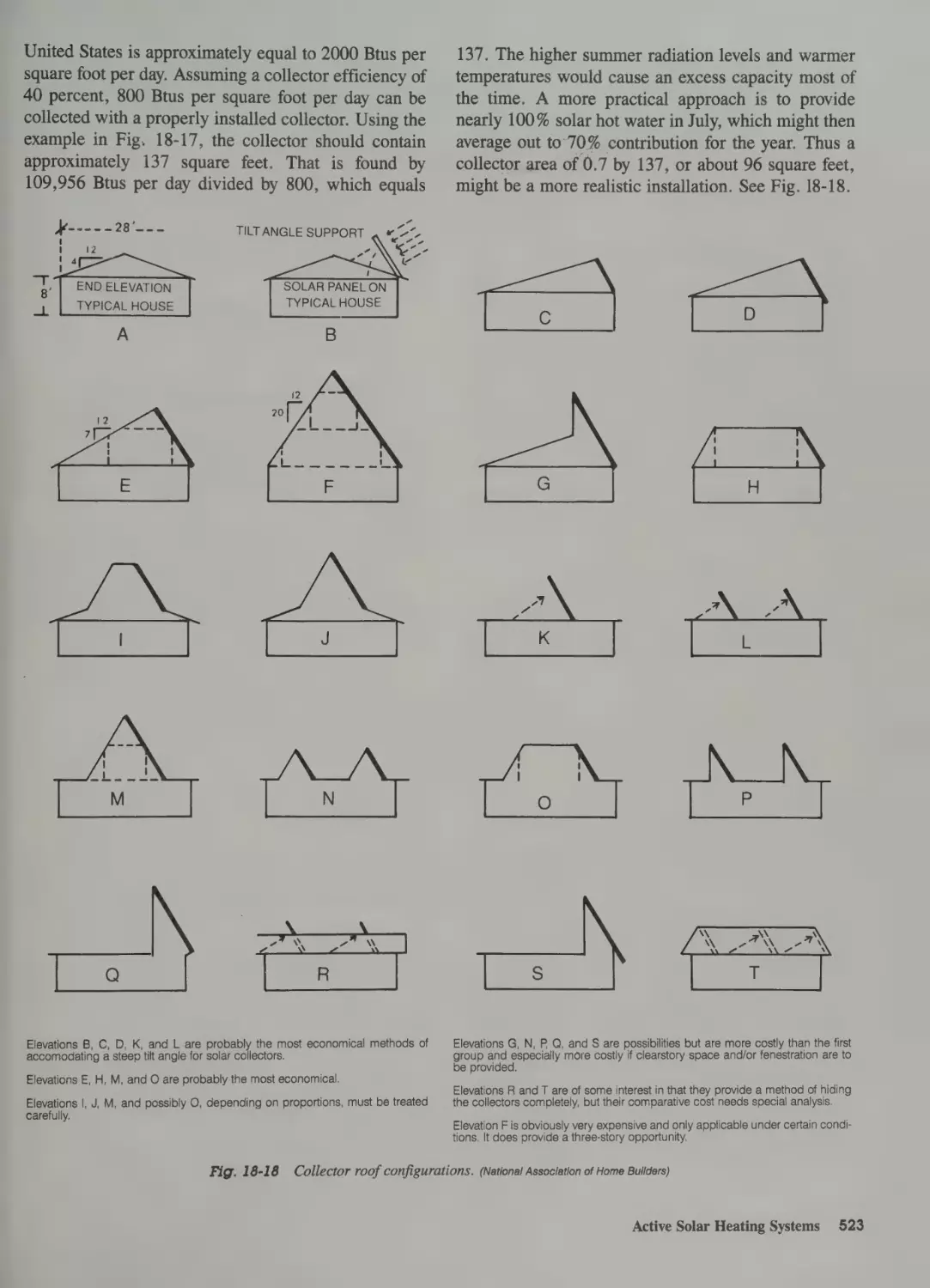
18 Construction for Solar Heating
Passive Solar Heating 512
Indirect Gain 512
Direct Gain 514
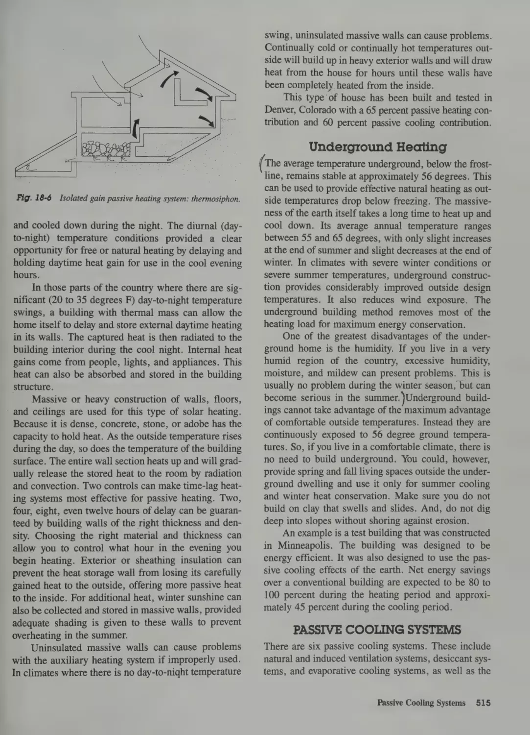
Isolated Gain 514
Time Lag Heating 514
Underground Heating 515
Passive Cooling Systems 515
Natural Ventilation 516
Induced Ventilation 516
Desiccant Cooling 516
Evaporative Cooling 516
Night Sky Radiation Cooling 516
Time Lag Cooling 516
Underground Cooling 516
Active Solar Heating Systems 517
_ Operation of Solar Heating Systems 517
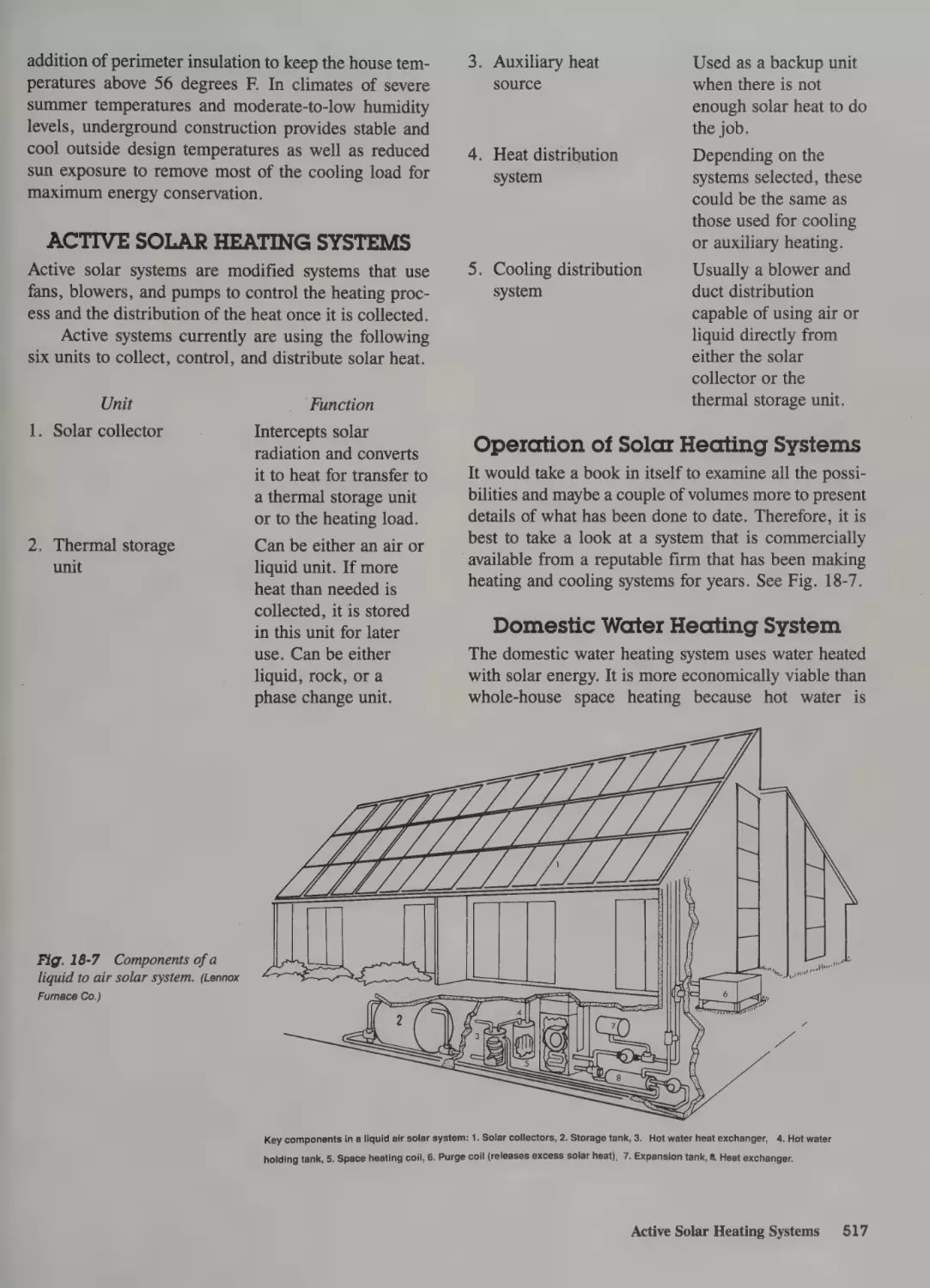
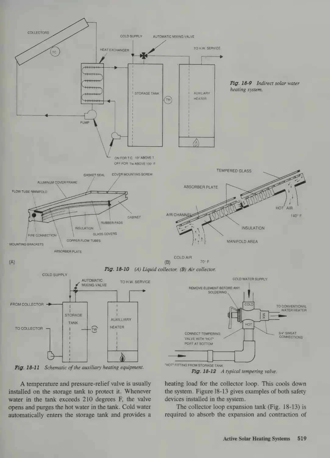
Domestic Water Heating System 517
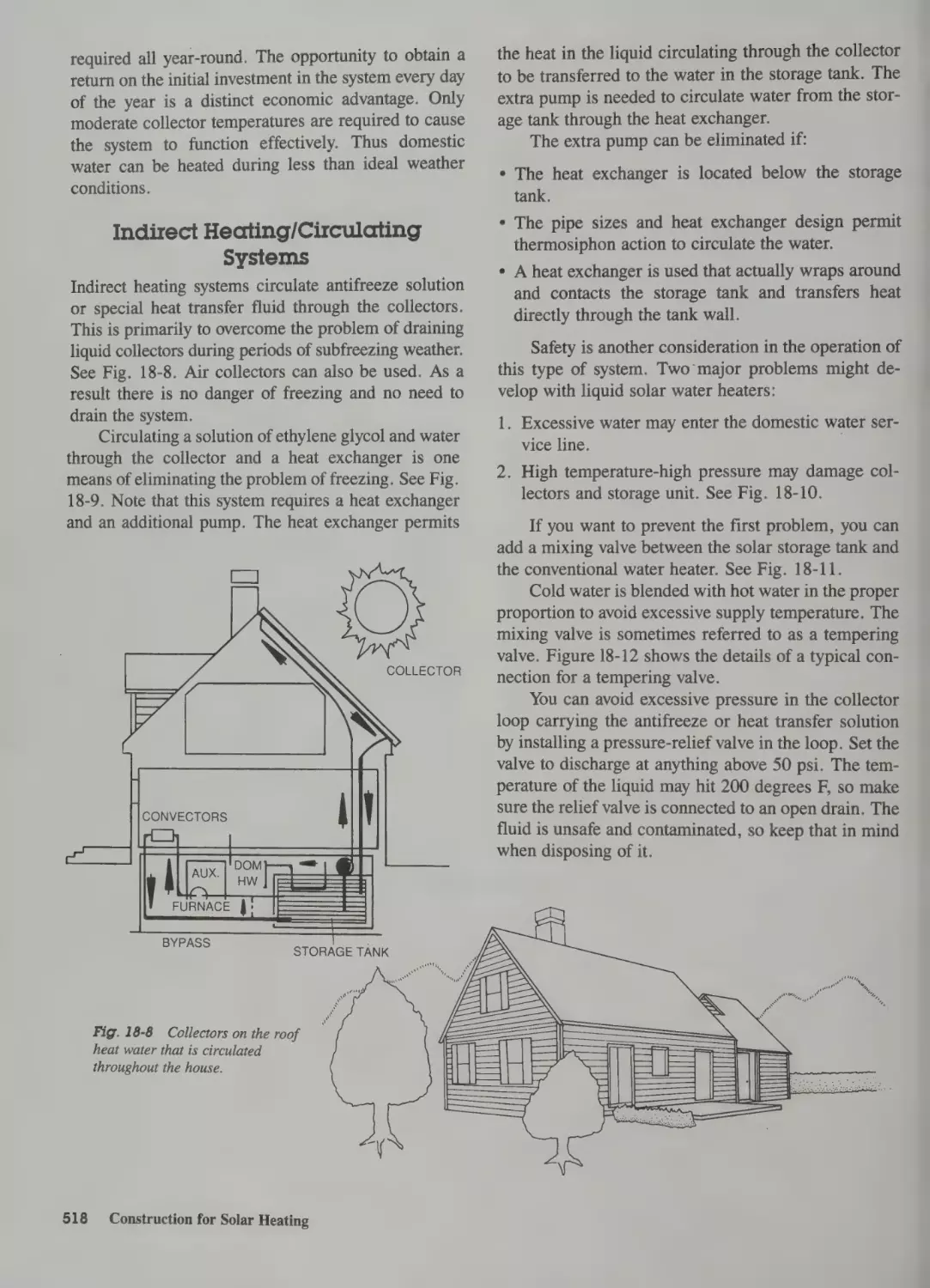
Indirect Heating/Circulating Systems 518
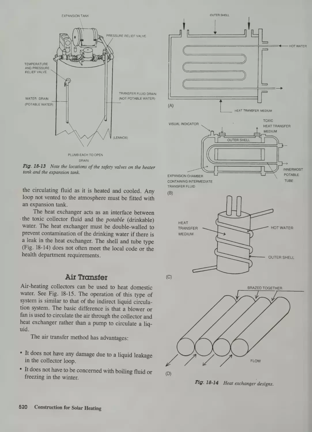
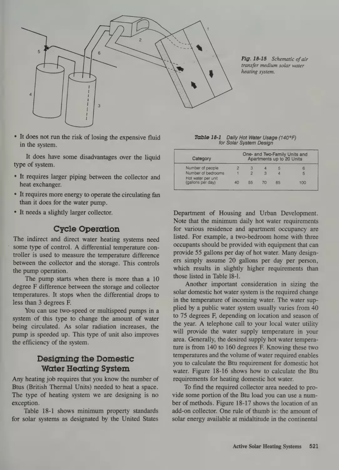
Air Transfer 520
Cycle Operation 521
Designing the Domestic Water Heating
System 521
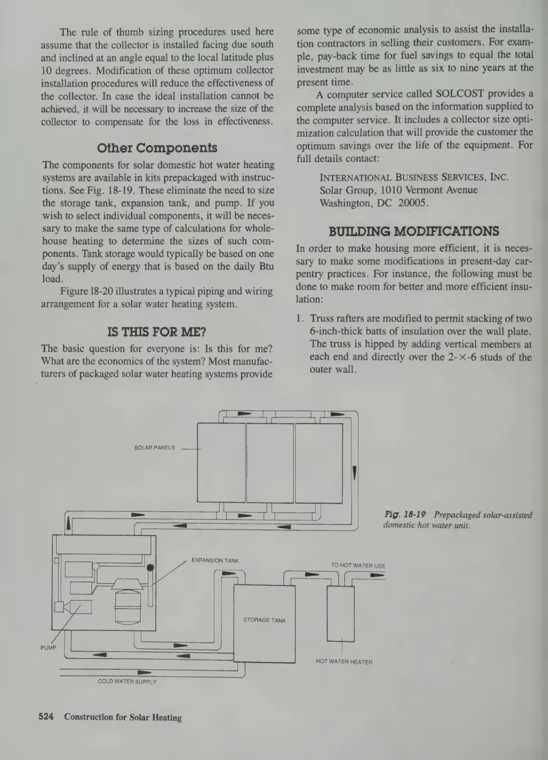
Other Components 524
Is This for Me? 524
Building Modifications 524
Building Underground 525
Advantages
526
Glossary
529
Index
539
Preface
Carpentry and Construction is written for everyone
who wants or needs to know about carpentry and construction. Whether remodeling an existing home or
building a new one, the rewards from a job well done
are many-fold.
This text can be used by students in vocational
courses, technical colleges, and apprenticeship programs. The home do-it-yourselfer will find answers to
many questions that pop up in the course of getting a
job done whether over a weekend or over a year’s
time.
In order to prepare this text, the authors examined
courses of study in schools located all over the country. An effort was made to take into consideration the
geographic differences and the special environmental
factors relevant to a particular area.
Notice how the text is organized. The first chapter, ‘‘Starting the Job,’ presents the information
needed to get construction underway. The next chapter
covers preparing the site. Then the footings and foundation are described. Once the footings are in, the
pouring of slabs or floors is discussed for those who
do not want a complete basement with poured walls.
Floor frames continue the sequence. Wall framing,
roof frames, openings in the roof and elsewhere, are
discussed before the covering of roofs is described.
Once the roof is in place, the next step is the installation of windows and doors. When the windows and
doors are in place, the exterior siding is applied. Next,
heating and cooling is covered—an all-important consideration for living quarters. Once the insulation is in
place, the interior walls and ceilings are covered in
detail before presenting interior finishing methods.
Special construction methods, maintenance and
remodeling, as well as careers in carpentry are then
described. The building of solar houses and the design
of solar heating are covered to keep the student and doit-yourselfer up-to-date with the latest developments in
energy conservation.
No book can be complete without the aid of many
people. The acknowledgments that follow on page xi
mention some of those who contributed to making this
text the most current in design and technology techniques available to the carpenter. We trust you will
enjoy using the book as much as we did writing it.
REX MILLER
GLENN BAKER
Acknowledgmenis
The authors would like to thank the following manufacturers for their generous efforts. They furnished
photographs, drawings, and technical assistance.
Without the donations of time and effort on the part of
many people, this book would not have been possible.
We hope this acknowledgment of some of the contributions will let you know that the field you are working in or about to enter is one of the best. (The name
given below in parentheses indicates the abbreviated
form used in the credit lines for the photographs
appearing in this text.)
(Grossman Lumber); Gypsum Association (Gypsum.); Hilti Fastening Systems (Hilti); IRL Daffin
Company (IRL Daffin); Kelly-Stewart Company, Inc.
(Kelly-Stewart); Kenny Manufacturing Company
(Kenny); Kirch Company (Kirch); Kohler Company
(Kohler); Lennox Furnace Co.; Majestic; Manco
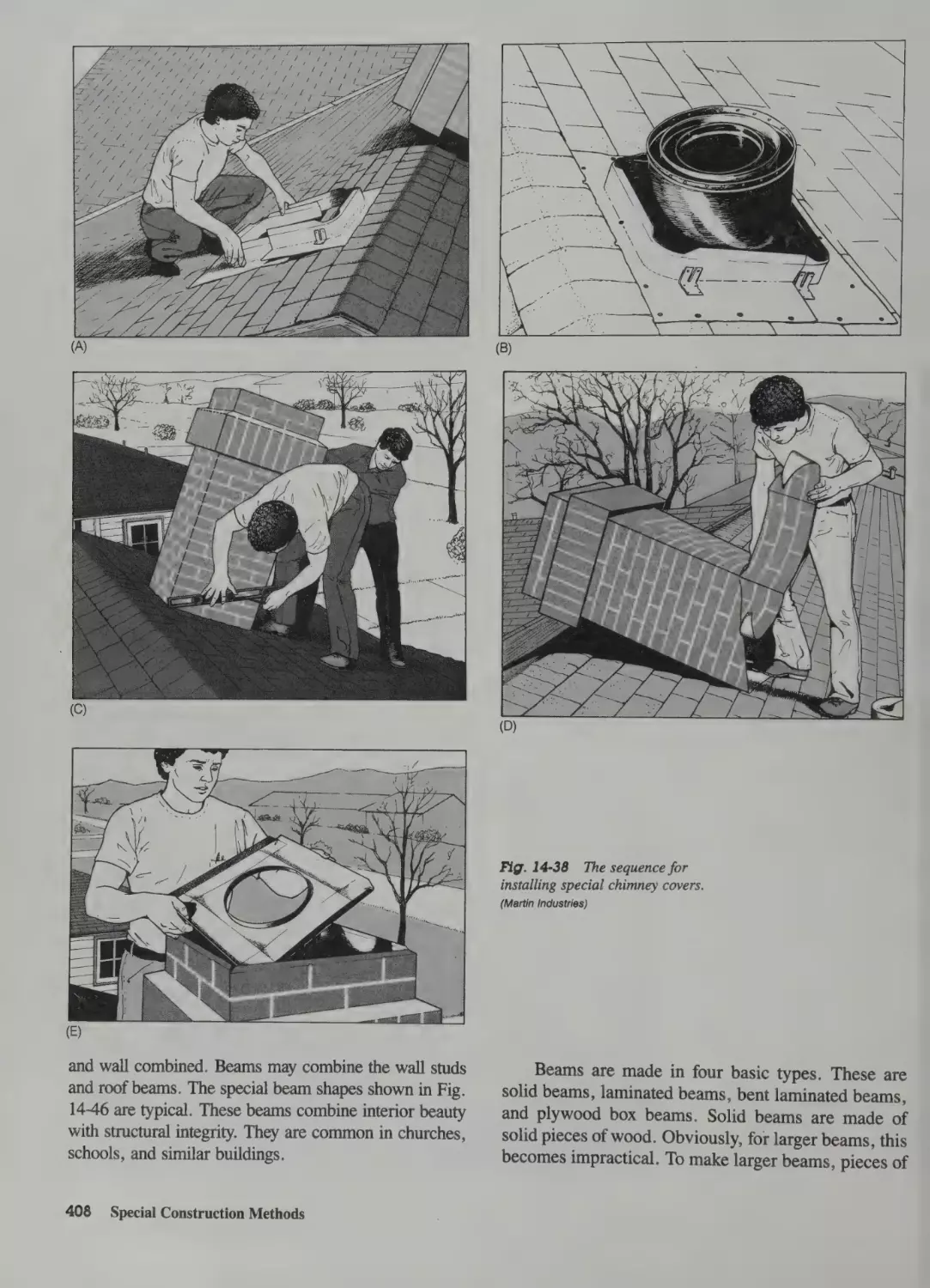
Tape, Inc. (Manco Tape); Martin Industries (Martin);
Masonite Corporation (Masonite); MFS; Milwaukee
Electric Tool Company (Milwaukee Electric Tool);
NAHB (National Association of Home Builders);
National Aeronautical & Space Administration
(NASA); National Homes; National Lock Hardware
Company (Armstrong Cork); C. Arnold and Sons;
Beaver-Advance Company (Beaver-Advance); The
Company; National Oak Flooring Manufacturer’s
Association (National Oak Flooring Manufacturers);
National Wood Manufacturers Association (National
Wood Manufacturers); New York State Electric and
Gas Corporation (NYSE & G); Novi; NuTone;
Owens-Corning Fiberglas Corporation (Owens-Corning); Patent Scaffolding Company (Patent Scaffold-
Bilco Company (Bilco); Bird and Son, Inc. (Bird and
ing);
Son); Black & Decker Manufacturing Company
(Black & Decker); Boise-Cascade; Butler Manufacturing Company (Butler); Certain-Teed Corporation
Permograin Products; Plaskolite, Inc. (Plaskolite);
Portland Cement Association (Portland Cement); Potlatch Corporation (Potlatch); Proctor Products, Inc.
(Certain-Teed); California Redwood Association (California Redwood Assoc.); Conwed Corporation (Conwed); Corl Corporation; Dewalt, Div. of American
(Proctor Products); Red Cedar Shingle & Handsplit
ucts; Richmond Screw Anchor Company (Richmond
Machine and Foundry Company (DeWalt); Dow
Chemical Company (Dow Chemical); Dow-Corning
Company (Dow-Corning); Duo-Fast Corporation
(Duo-Fast); EMCO; Formica Corporation (Formica);
Screw Anchor); Riviera Kitchens, Div. of Evans
Products; Rockwell International, Power Tool Division (Rockwell); Sears, Roebuck and Company
(Sears, Roebuck); Shakertown Corporation; Simplex
Abitibi Corporation; ALCOA; American Olean Tile
Co.; American Plywood Association; Town of
Amherst, New York (Town of Amherst, N.Y.);
Andersen Corporation (Andersen); Armstrong Cork
Pella
Windows
and
Doors,
Inc.
(Pella);
Shake Bureau (RCS & HSB); Reynolds Metals Prod-
Fox & Jacobs Corporation (Fox and Jacobs); General
Industries (Simplex); Stanley Tools Company (Stanley
(General Products);
Georgia-
(Georgia-Pacific);
Goldblatt
Tools); State University College at Buffalo; Southern
Forest Products Association; TECO Products and
Products
Pacific
Corporation
Corporation
Tools, Inc. (Goldblatt Tools); Gold Bond Building
Products (Gold Bond); Grossman Lumber Company
Testing Corporation, Washington, D.C. 20015; Texas
A & M University (Texas A & M); U.S. Gypsum
xi
Company (U.S.Gypsum); U.S. Department of Energy
(U.S. Dept. of Energy); U.S. Bureau of Labor Statis-
Industries
tics; U.S. Forest Service, Forest Products Laboratory
(Forest Products Lab); United Steel Products; Univer-
erhauser Company (Weyerhauser); David White
Instruments, Div. of Realist, Inc. (David White).
sal Fastenings Corporation; Universal Form Clamp
In addition, the authors would also like to thank
Company (Universal Form Clamp); Valu, Inc. (Valu);
Velux-American; Weiser Lock, Division of Norris
Paul Consiglio of Buffalo, NY for many of the line
drawings used.
xii
Acknowledgments
(Weiser Lock),
Weslock;
Western
Wood
Products Association (Western Wood Products); Wey-
Ben
CARPENTRY
INVOLVES
ALL
KINDS
OF
challenging jobs, it is an exciting industry. You
will have to work with hand tools, power tools,
and all types of building materials. You can become
very skilled at your job. You get a chance to be proud
of what you do. You can stand back and look at the
building you just helped erect and feel great about a
job well done.
One of the exciting things about being a carpenter
is watching a building come up. You actually see it
grow from the ground up. Many people work with you
to make it possible to complete the structure. Being
part of a team can be rewarding, too.
This book will help you do a good job in carpentry, whether you are remodeling an existing building
or starting from the ground up. Because it covers all
the basic construction techniques, it will aid you in
making the right decisions.
You have to do something over and over again to
gain skill. When reading this book, you might not
always get the idea the first time. Go over it again until
you understand. Then go out and practice what you
just read. This way you can see for yourself how the
instructions
actually work.
Of course,
no one can
learn carpentry by merely reading a book. You have to
read, reread, and then do. This “do” part is the most
important. You have to take the hammer or saw in
hand and actually do the work. There is nothing like
good, honest sweat from a hard day’s work. At the end
of the day you can say “I did that” and be proud that
you did.
This chapter should help you build these skills:
* Select personal protective gear
* Work safely as a carpenter
* Measure building materials
¢ Lay out building parts
* Cut building materials
Fig. 1-1 This carpenter is using an air-driven nail driver to nail
these framing members. (Duo-Fast)
As for safety, notice the carpenter’s shoes. They
have rubber soles for gripping the wood. This will prevent a slip through the joists and a serious fall. The steel
toes in the shoes prevent damage to a foot from falling
materials. The soles of the shoes are very thick to prevent nails from going through. The hard hat protects the
carpenter’s head from falling lumber, shingles, or other
building materials. The carpenter’s safety glasses can-
not be seen in Fig. 1-1, but they are required equipment
for the safe worker.
¢ Fasten materials
¢ Shape and smooth materials
° Identify basic hand tools
* Recognize common power tools
SAFETY
Figure 1-1 shows a carpenter using one of the latest
means of driving nails: the compressed-air-driven nail
driver, which drives nails into the wood with a single
stroke. The black cartridge that appears to run up near
the carpenter’s leg is a part of the nailer. It holds the
nails and feeds them as needed.
2 =‘ Starting the Job
Other Safety Measures
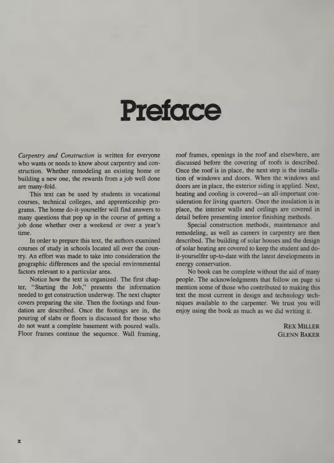
To protect the eyes, it is best to wear safety glasses.
Make sure your safety glasses are of tempered glass.
They will not shatter and cause eye damage. In some
instances you should wear goggles. This prevents
splinters and other flying objects from entering the eye
from under or around the safety glasses. Ordinary
glasses aren’t always the best, even if they are tempered glass. Just become aware of the possibilities of
eye damage whenever you start a new job or procedure. See Fig. 1-2 for a couple of types of safety
glasses.
General Safety Rules
Some safety procedures should be followed at all
times. This applies to carpentry work especially:
¢ Pay close attention to what is being done.
Fig. 1-2
Safety glasses.
Sneakers are used only by roofers. Sneakers, sandals, and dress shoes do not provide enough protection
for the carpenter on the job. Only safety shoes should
be worn on the job.
* Move carefully when walking or climbing.
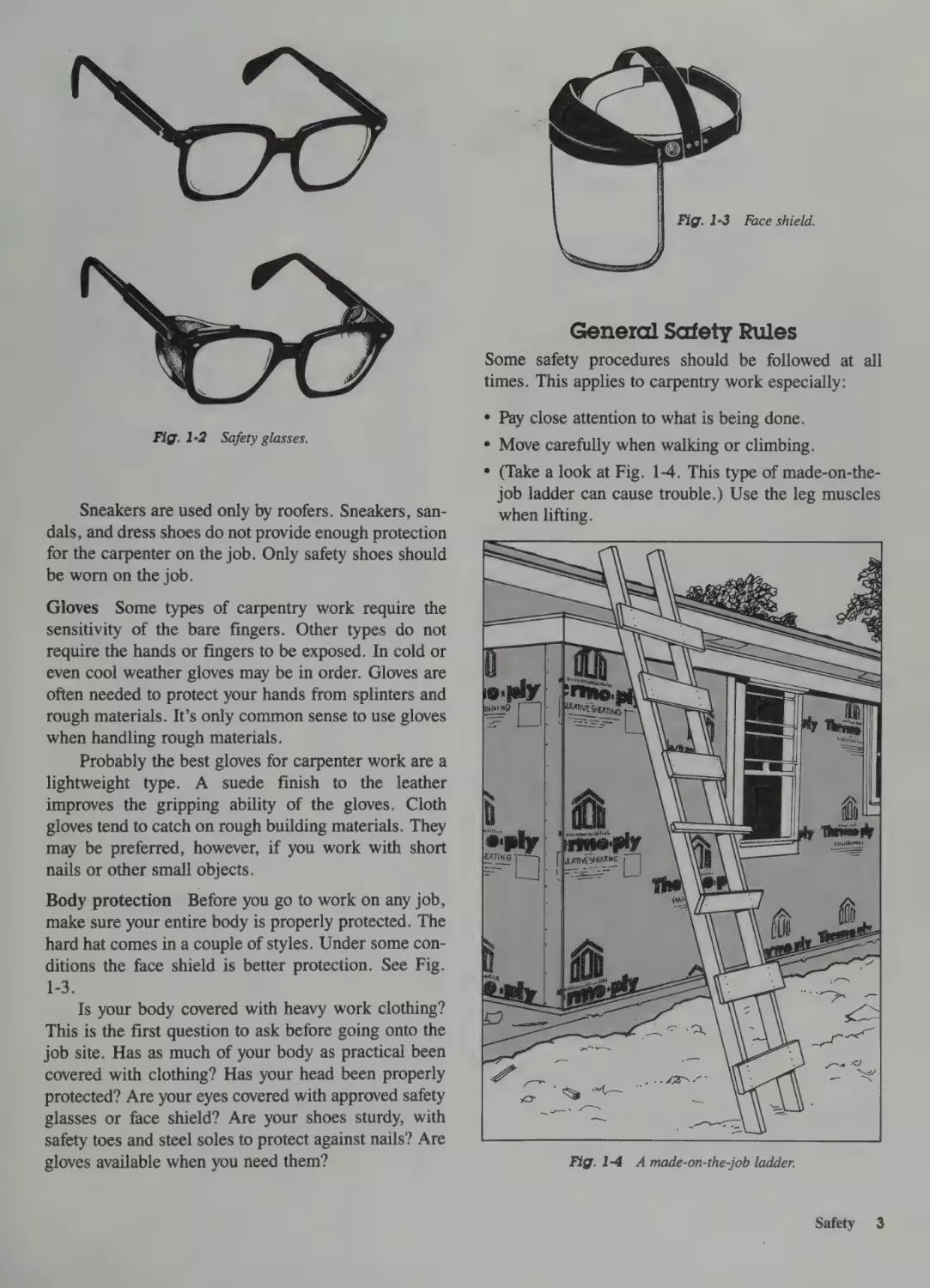
* (Take a look at Fig. 1-4. This type of made-on-thejob ladder can cause trouble.) Use the leg muscles
when lifting.
Gloves Some types of carpentry work require the
sensitivity of the bare fingers. Other types do not
require the hands or fingers to be exposed. In cold or
even cool weather gloves may be in order. Gloves are
often needed to protect your hands from splinters and
rough materials. It’s only common sense to use gloves
when handling rough materials.
Probably the best gloves for carpenter work are a
lightweight type. A suede finish to the leather
improves the gripping ability of the gloves. Cloth
gloves tend to catch on rough building materials. They
may be preferred, however, if you work with short
nails or other small objects.
Body protection Before you go to work on any job,
make sure your entire body is properly protected. The
hard hat comes in a couple of styles. Under some conditions the face shield is better protection. See Fig.
1-3.
Is your body covered with heavy work clothing?
This is the first question to ask before going onto the
job site. Has as much of your body as practical been
covered with clothing? Has your head been properly
protected? Are your eyes covered with approved safety
glasses or face shield? Are your shoes sturdy, with
safety toes and steel soles to protect against nails? Are
gloves available when you need them?
Fig. 1-4
A made-on-the-job ladder.
Safety
3
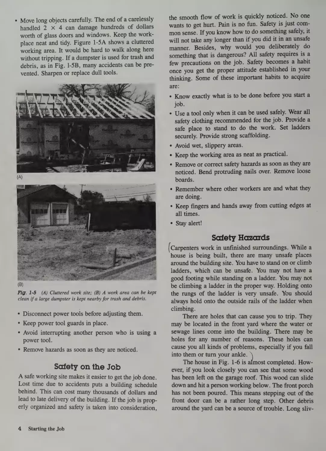
° Move long objects carefully. The end of a carelessly
handled 2 x 4 can damage hundreds of dollars
worth of glass doors and windows. Keep the workplace neat and tidy. Figure 1-5A shows a cluttered
working area. It would be hard to walk along here
without tripping. If a dumpster is used for trash and
debris, as in Fig. |-5B, many accidents can be prevented. Sharpen or replace dull tools.
the smooth flow of work is quickly noticed. No one
wants to get hurt. Pain is no fun. Safety is just common sense. If you know how to do something safely, it
will not take any longer than if you did it in an unsafe
manner. Besides, why would you deliberately do
something that is dangerous? All safety requires is a
few precautions on the job. Safety becomes a habit
once you get the proper attitude established in your
thinking. Some of these important habits to acquire
are:
¢ Know exactly what is to be done before you start a
job.
Use a tool only when it can be used safely. Wear all
safety clothing recommended for the job. Provide a
safe place to stand to do the work. Set ladders
securely. Provide strong scaffolding.
¢ Avoid wet, slippery areas.
¢ Keep the working area as neat as practical.
¢ Remove or correct safety hazards as soon as they are
noticed. Bend protruding nails over. Remove loose
boards.
¢ Remember where other workers are and what they
are doing.
¢ Keep fingers and hands away from cutting edges at
all times.
e Stay alert!
Safety Hazards
(B)
Fig. 1-5 (A) Cluttered work site; (B) A work area can be kept
clean if a large dumpster is kept nearby for trash and debris.
e Disconnect power tools before adjusting them.
° Keep power tool guards in place.
¢ Avoid interrupting another person who is using a
power tool.
¢ Remove hazards as soon as they are noticed.
(Carpenters work in unfinished surroundings. While a
house is being built, there are many unsafe places
around the building site. You have to stand on or climb
ladders, which can be unsafe. You may not have a
good footing while standing on a ladder. You may not
be climbing a ladder in the proper way. Holding onto
the rungs of the ladder is very unsafe. You should
always hold onto the outside rails of the ladder when
climbing.
There are holes that can cause you to trip. They
may be located in the front yard where the water or
sewage lines come into the building. There may be
holes for any number of reasons. These holes can
cause you all kinds of problems, especially if you fall
into them or turn your em
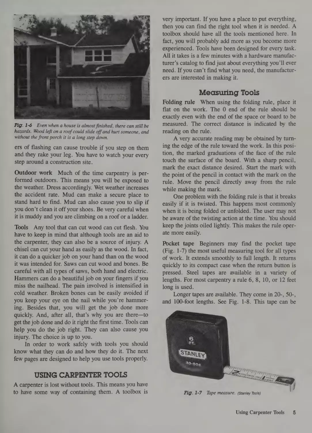
The house in Fig. 1-6 is
almost completed. How-
Safety on the Job
ever, if you look closely you can see that some wood
A safe working site makes it easier to get the job done.
Lost time due to accidents puts a building schedule
behind. This can cost many thousands of dollars and
lead to late delivery of the building. If the job is properly organized and safety is taken into consideration,
has been left on the garage roof. This wood can slide
down and hit a person working below. The front porch
has not been poured. This means stepping out of the
front door can be a rather long step. Other debris
around the yard can be a source of trouble. Long sliv-
4
Starting the Job
very important. If you have a place to put everything,
then you can find the right tool when it is needed. A
toolbox should have all the tools mentioned here. In
fact, you will probably add more as you become more
Del
experienced. Tools have been designed for every task.
All it takes is a few minutes with a hardware manufacturer’s catalog to find just about everything you’ll ever
need. If you can’t find what you need, the manufacturers are interested in making it.
Measuring Tools
Fig. 1-6 Even when a house is almost finished, there can still be
hazards. Wood left on a roof could slide off and hurt someone, and
without the front porch it is a long step down.
ers of flashing can cause trouble if you step on them
and. they rake your leg. You have to watch your every
step around a construction site.
Outdoor work Much of the time carpentry is performed outdoors. This means you will be exposed to
the weather. Dress accordingly. Wet weather increases
the accident rate. Mud can make asecure place to
stand hard to find. Mud can also cause you to slip if
you don’t clean it off your shoes. Be very careful when
it is muddy and you are climbing on a roof or a ladder.
Tools Any tool that can cut wood can cut flesh. You
have to keep in mind that although tools are an aid to
the carpenter, they can also be a source of injury. A
chisel can cut your hand as easily as the wood. In fact,
it can do a quicker job on your hand than on the wood
it was intended for. Saws can cut wood and bones. Be
careful with all types of saws, both hand and electric.
Hammers can do a beautiful job on your fingers if you
miss the nailhead. The pain involved is intensified in
cold weather. Broken bones can be easily avoided if
you keep your eye on the nail while you’re hammering. Besides that, you will get the job done more
quickly. And, after all, that’s why you are there—to
get the job done and do it right the first time. Tools can
help you do the job right. They can also cause you
injury. The choice is up to you.
In order to work safely with tools you should
know what they can do and how they do it. The next
few pages are designed to help you use tools properly.
Folding rule When using the folding rule, place it
flat on the work. The 0 end of the rule should be
exactly even with the end of the space or board to be
measured. The correct distance is indicated by the
reading on the rule.
A very accurate reading may be obtained by turning the edge of the rule toward the work. In this position, the marked graduations of the face of the rule
touch the surface of the board. With a sharp pencil,
mark the exact distance desired. Start the mark with
the point of the pencil in contact with the mark on the
rule. Move the pencil directly away from the rule
while making the mark.
One problem with the folding rule is that it breaks
easily if it is twisted. This happens most commonly
when it is being folded or unfolded. The user may not
be aware of the twisting action at the time. You should
keep the joints oiled lightly. This makes the rule operate more easily.
Pocket tape Beginners may find the pocket tape
(Fig. 1-7) the most useful measuring tool for all types
of work. It extends smoothly to full length. It returns
quickly to its compact case when the return button is
pressed. Steel tapes are available in a variety of
lengths. For most carpentry a rule 6, 8, 10, or 12 feet
long is used.
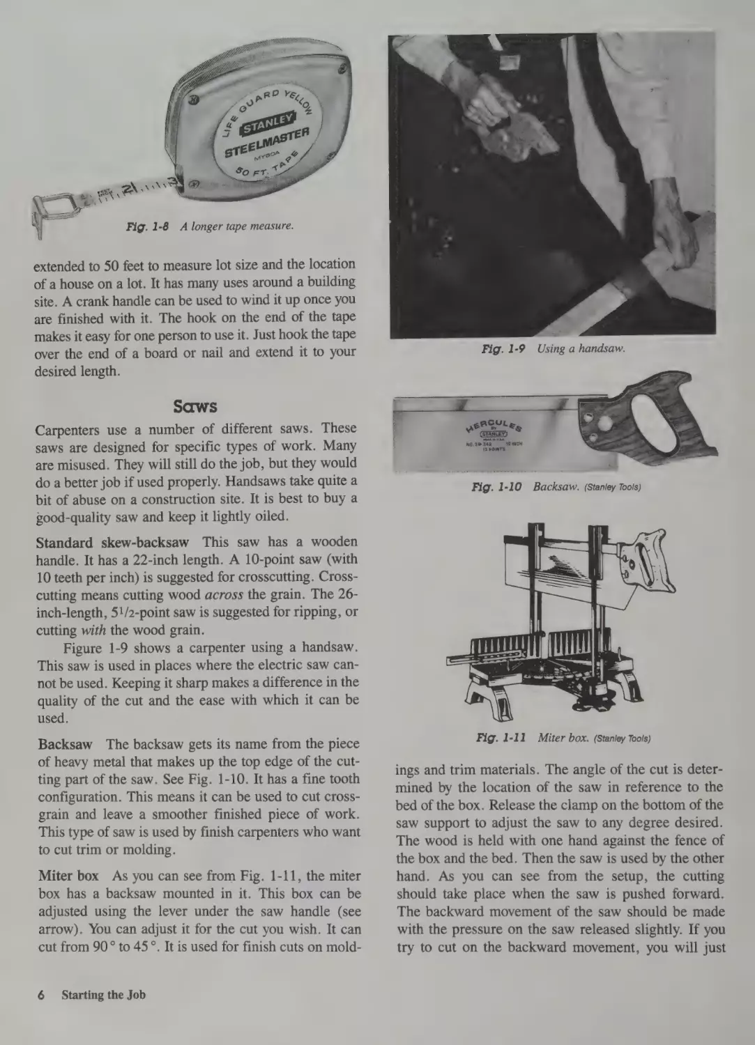
Longer tapes are available. They come in 20-, 50-,
and 100-foot lengths. See Fig. 1-8. This tape can be
USING CARPENTER TOOLS
A carpenter is lost without tools. This means you have
to have some way of containing them. A toolbox is
Fig. 1-7
Tape measure. (Stanley Tools)
Using Carpenter Tools
5
extended to 50 feet to measure lot size and the location
of a house on alot. It has many uses around a building
site. A crank handle can be used to wind it up once you
are finished with it. The hook on the end of the tape
makes it easy for one person to use it. Just hook the tape
over the end of a board or nail and extend it to your
desired length.
Saws
Carpenters use a number of different saws. These
saws are designed for specific types of work. Many
are misused. They will still do the job, but they would
do a better job if used properly. Handsaws take quite a
bit of abuse on a construction site. It is best to buy a
good-quality saw and keep it lightly oiled.
Standard skew-backsaw This saw has a wooden
handle. It has a 22-inch length. A 10-point saw (with
10 teeth per inch) is suggested for crosscutting. Crosscutting means cutting wood across the grain. The 26inch-length, 5!/2-point saw is suggested for ripping, or
cutting with the wood grain.
Figure 1-9 shows a carpenter using a handsaw.
This saw is used in places where the electric saw cannot be used. Keeping it sharp makes a difference in the
quality of the cut and the ease with which it can be
used.
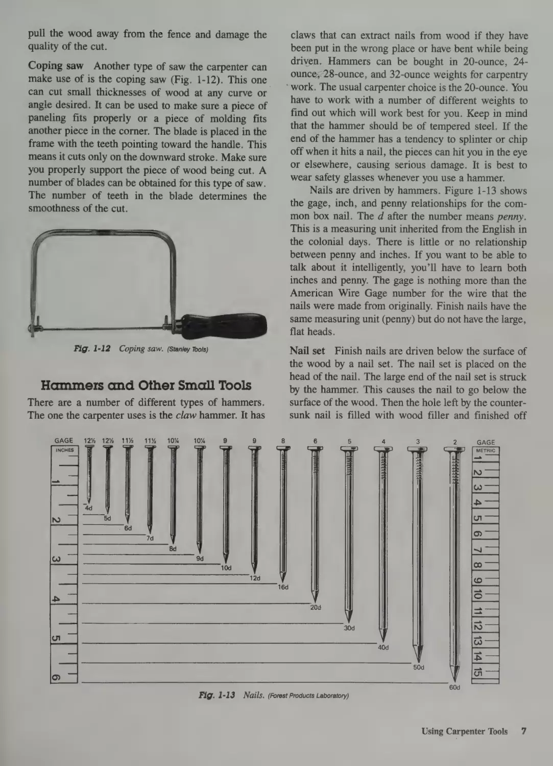
Backsaw The backsaw gets its name from the piece
of heavy metal that makes up the top edge of the cutting part of the saw. See Fig. 1-10. It has a fine tooth
configuration. This means it can be used to cut crossgrain and leave a smoother finished piece of work.
This type of saw is used by finish carpenters who want
to cut trim or molding.
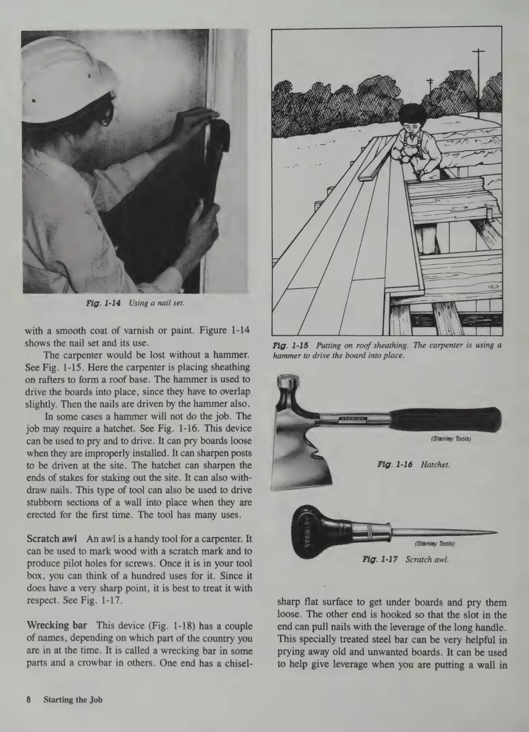
Miter box As you can see from Fig. 1-11, the miter
box has a backsaw mounted in it. This box can be
adjusted using the lever under the saw handle (see
arrow). You can adjust it for the cut you wish. It can
cut from 90° to 45°. It is used for finish cuts on mold-
6
Starting the Job
Fig. 1-11
Miter box. (Stanley Tools)
ings and trim materials. The angle of the cut is determined by the location of the saw in reference to the
bed of the box. Release the clamp on the bottom of the
saw support to adjust the saw to any degree desired.
The wood is held with one hand against the fence of
the box and the bed. Then the saw is used by the other
hand. As you can see from the setup, the cutting
should take place when the saw is pushed forward.
The backward movement of the saw should be made
with the pressure on the saw released slightly. If you
try to cut on the backward movement, you will just
pull the wood away from the fence and damage the
quality of the cut.
claws that can extract nails from wood if they have
been put in the wrong place or have bent while being
Coping saw Another type of saw the carpenter can
make use of is the coping saw (Fig. 1-12). This one
driven. Hammers can be bought in 20-ounce, 24-
can cut small thicknesses of wood at any curve or
angle desired. It can be used to make sure a piece of
paneling fits properly or a piece of molding fits
another piece in the corner. The blade is placed in the
frame with the teeth pointing toward the handle. This
means it cuts only on the downward stroke. Make sure
you properly support the piece of wood being cut. A
number of blades can be obtained for this type of saw.
The number of teeth in the blade determines the
smoothness of the cut.
Fig. 1-12
Coping saw. (Stanley Tools)
Hammers and Other Small Tools
There are a number of different types of hammers.
The one the carpenter uses is the claw hammer. It has
GAGE
12%
12%
11%
11%
10%
10%
9
ounce;28-ounce, and 32-ounce weights for carpentry
“work. The usual carpenter choice is the 20-ounce. You
have to work with a number of different weights to
find out which will work best for you. Keep in mind
that the hammer should be of tempered steel. If the
end of the hammer has a tendency to splinter or chip
off when it hits a nail, the pieces can hit you in the eye
or elsewhere, causing serious damage. It is best to
wear safety glasses whenever you use a hammer.
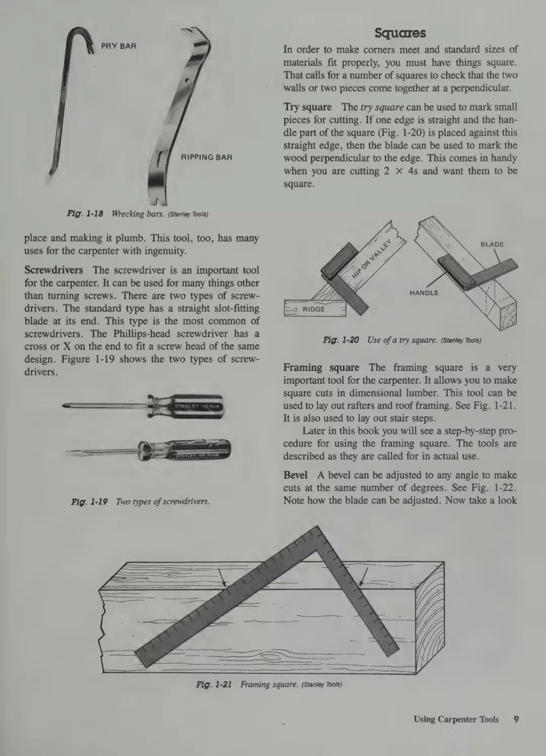
Nails are driven by hammers. Figure 1-13 shows
the gage, inch, and penny relationships for the common box nail. The d after the number means penny.
This is a measuring unit inherited from the English in
the colonial days. There is little or no relationship
between penny and inches. If you want to be able to
talk about it intelligently, you’ll have to learn both
inches and penny. The gage is nothing more than the
American Wire Gage number for the wire that the
nails were made from originally. Finish nails have the
same measuring unit (penny) but do not have the large,
flat heads.
Nail set Finish nails are driven below the surface of
the wood by a nail set. The nail set is placed on the
head of the nail. The large end of the nail set is struck
by the hammer. This causes the nail to go below the
surface of the wood. Then the hole left by the countersunk nail is filled with wood filler and finished off
9
be)
a=bbbbbhbb
- 6d
8d
10d
12d
20d
30d
40d
50d
Fig. 1-13
Nails. (Forest Products Laboratory)
Using Carpenter Tools
7
Fig. 1-14
Using a nail set.
with a smooth coat of varnish or paint. Figure 1-14
shows the nail set and its use.
The carpenter would be lost without a hammer.
See Fig. 1-15. Here the carpenter is placing sheathing
on rafters to form a roof base. The hammer is used to
drive the boards into place, since they have to overlap
slightly. Then the nails are driven by the hammer also.
In some cases a hammer will not do the job. The
job may require a hatchet. See Fig. 1-16. This device
can be used to pry and to drive. It can pry boards loose
when they are improperly installed. It can sharpen posts
to be driven at the site. The hatchet can sharpen the
ends of stakes for staking out the site. It can also withdraw nails. This type of tool can also be used to drive
stubborn sections of a wall into place when they are
erected for the first time. The tool has many uses.
Scratch awl An awl is a handy tool for a carpenter. It
can be used to mark wood with a scratch mark and to
produce pilot holes for screws. Once it is in your tool
box, you can think of a hundred uses for it. Since it
does have a very sharp point, it is best to treat it with
respect. See Fig. 1-17.
Wrecking bar
This device (Fig. 1-18) has a couple
of names, depending on which part of the country you
are in at the time. It is called a wrecking bar in some
parts and a crowbar in others. One end hasa chisel-
8
Starting the Job
Fig. 1-15 Putting on roof sheathing. The carpenter is using a
hammer to drive the board into place.
(Stanley Tools)
Fig. 1-16
Hatchet.
(Stanley Tools)
Fig. 1-17
Scratch awl.
sharp flat surface to get under boards and pry them
loose. The other end is hooked so that the slot in the
end can pull nails with the leverage of the long handle.
This specially treated steel bar can be very helpful in
prying away old and unwanted boards. It can be used
to help give leverage when you are putting a wall in
squares
\ PRY BAR
In order to make corners meet and standard sizes of
materials fit properly, you must have things square.
That calls for a number of squares to check that the two
walls or two pieces come together at a perpendicular.
Try square The try square can be used to mark small
pieces for cutting. If one edge is straight and the handle part of the square (Fig. 1-20) is placed against this
straight edge, then the blade can be used to mark the
wood perpendicular to the edge. This comes in handy
when you are cutting 2 xX 4s and want them to be
square.
RIPPING BAR
all wil)
Fig. 1-18
Wrecking bars. (Stanley Tools)
place and making it plumb. This tool, too, has many
uses for the carpenter with ingenuity.
Screwdrivers
The screwdriver is an important tool
for the carpenter. It can be used for many things other
than turning screws. There are two types of screwdrivers. The standard type has a straight slot-fitting
blade at its end. This type is the most common of
screwdrivers. The Phillips-head screwdriver has a
cross or X on the end to fit a screw head of the same
design. Figure 1-19 shows the two types of screwdrivers.
act iia
Fig. 1-19
eat
‘at
————
j
a
CSTE
aoe ea
Two types of screwdrivers.
Fig. 1-21
HANDLE
Fig. 1-20
Use of a try square. (Stanley Tools)
Framing square The framing square is a very
important tool for the carpenter. It allows you to make
square cuts in dimensional lumber. This tool can be
used to lay out rafters and roof framing. See Fig. 1-21.
It is also used to lay out stair steps.
Later in this book you will see a step-by-step procedure for using the framing square. The tools are
described as they are called for in actual use.
Bevel A bevel can be adjusted to any angle to make
cuts at the same number of degrees. See Fig. 1-22.
Note how the blade can be adjusted. Now take a look
Framing square. (Stanley Tools)
Using Carpenter Tools
9
with a hammer, the cutting end will do its job. That is,
of course, if you have kept it sharpened. See Fig. 1-24.
The chisel is commonly used in fitting or hanging
doors. It is used to remove the area where the door
hinge fits. Note how it is used to score the area (Fig.
BLADE
1-24); it is then used at an angle to remove the ridges.
A great deal of the work with the chisel is done by
HANDLE
Fig. 1-22
Bevel. (Stanley Tools)
at Fig. 1-23. Here you can see the overhang of rafters.
If you want the ends to be parallel with the side of the
house, you can use the bevel to mark them before they
are cut off. Simply adjust the bevel so the handle is on
top of the rafter and the blade fits against the soleplate
below. Tighten the screw and move the bevel down the
rafter to where you want the cut. Mark the angle along
the blade of the bevel. Cut along the mark, and you
have what you see in Fig. 1-23. It is a good device for
transferring angles from one place to another.
Chisel Occasionally you may need a wood chisel. It
is sharpened on one end. When the other end is struck
using the palm of the hand as the force behind the cutting edge. A hammer can be used. In fact, chisels have
a metal tip on the handle so the force of the hammer
blows will not chip the handle. Other applications are
up to you, the carpenter. You’ll find many uses for the
chisel in making things fit.
MARKING
DEPTH
“a5
Fig. 1-24
COMPLETED MORTISE
Using a wood chisel to complete a mortise.
Plane Planes (Fig. 1-25) are designed to remove
small shavings of wood along a surface. One hand
holds the knob in front and the other the handle in
back. The blade is adjusted so that only a small sliver
of wood is removed each time the plane is passed over
the wood. It can be used to make sure that doors and
windows fit properly. It can be used for any number of wood smoothing operations.
Pd
y a
Fig. 1-23
J
Pt
oe
Rafter overhang cut to a given angle.
10 = Starting the Job
Fig. 1-25
Smooth plane. (Stanley Tools)
100T HS
DIVIDERS
COMPASS
Fig. 1-26A_
Dividers and compass.
Fig. 1-26B
Dividers being used to transfer hundredths of an inch.
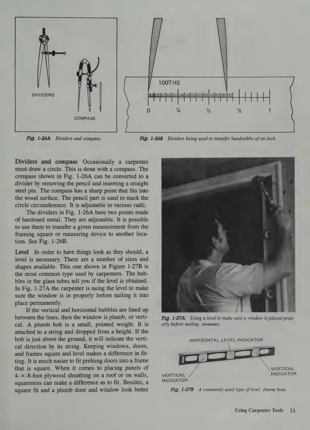
Dividers and compass Occasionally a carpenter
must draw a circle. This is done with a compass. The
compass shown in Fig. 1-26A can be converted to a
divider by removing the pencil and inserting a straight
steel pin. The compass hasa sharp point that fits into
the wood surface. The pencil part is used to mark the
circle circumference. It is adjustable to various radii.
The dividers in Fig. 1-26A have two points made
of hardened metal. They are adjustable. It is possible
to use them to transfer a given measurement from the
framing square or measuring device to another location. See Fig. 1-26B.
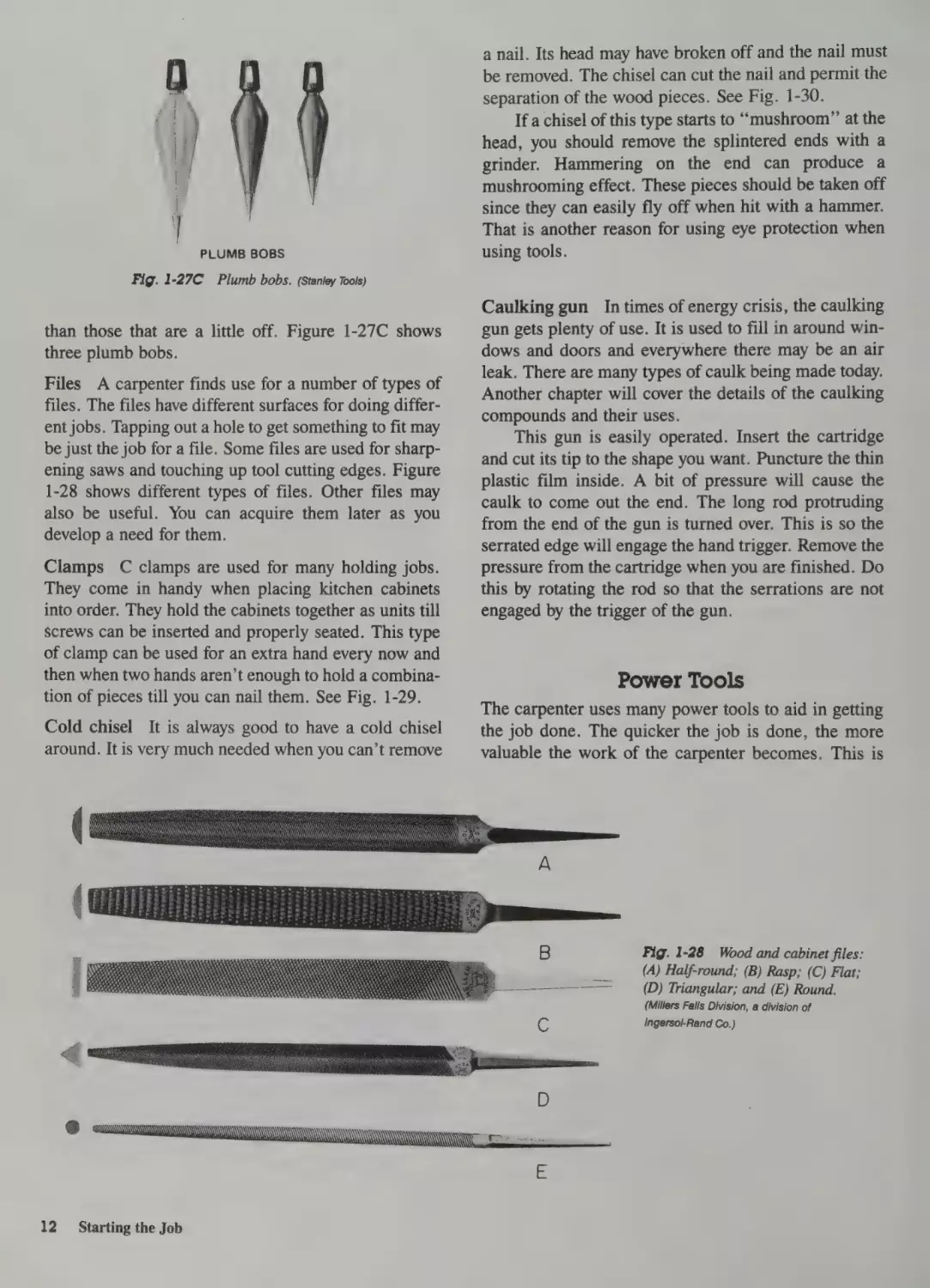
Level In order to have things look as they should, a
level is necessary. There are a number of sizes and
shapes available. This one shown in Figure 1-27B is
the most common type used by carpenters. The bubbles in the glass tubes tell you if the level is obtained.
In Fig. 1-27A the carpenter is using the level to make
sure the window is in properly before nailing it into
place permanently.
If the vertical and horizontal bubbles are lined up
between the lines, then the window is plumb, or vertical. A plumb bob is a small, pointed weight. It is
attached to a string and dropped from a height. If the
bob is just above the ground, it will indicate the vertical direction by its string. Keeping windows, doors,
and frames square and level makes a difference in fitting. It is much easier to fit prehung doors into a frame
that is square. When it comes to placing panels of
4-x-8-foot plywood sheathing on a roof or on walls,
squareness can make a difference as to fit. Besides, a
square fit and a plumb door and window look better
Fig. 1-27A Using a level to make sure a window is placed properly before nailing. (Andersen)
HORIZONTAL
VERTICAL
INDICATOR
Fig. 1-27B
LEVEL INDICATOR
VERTICAL
INDICATOR
A commonly used type of level. (Stanley Tools)
Using Carpenter Tools
11]
PLUMB
Fig. 1-27C
BOBS
a nail. Its head may have broken off and the nail must
be removed. The chisel can cut the nail and permit the
separation of the wood pieces. See Fig. 1-30.
If a chisel of this type starts to “mushroom” at the
head, you should remove the splintered ends with a
grinder. Hammering on the end can produce a
mushrooming effect. These pieces should be taken off
since they can easily fly off when hit with a hammer.
That is another reason for using eye protection when
using tools.
Plumb bobs. (Stanley Tools)
Caulking gun
than those that are a little off. Figure 1-27C shows
three plumb bobs.
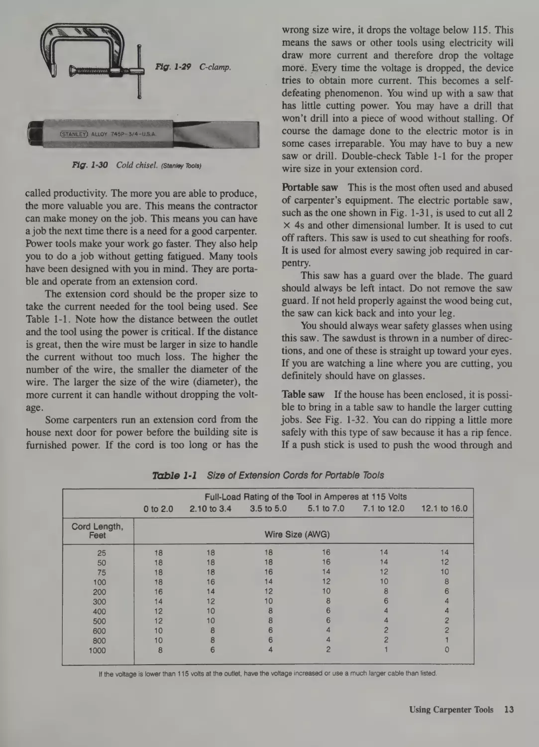
Files A carpenter finds use for a number of types of
files. The files have different surfaces for doing different jobs. Tapping out a hole to get something to fit may
be just the job for a file. Some files are used for sharpening saws and touching up tool cutting edges. Figure
1-28 shows different types of files. Other files may
also be useful. You can acquire them later as you
develop a need for them.
Clamps C clamps are used for many holding jobs.
They come in handy when placing kitchen cabinets
into order. They hold the cabinets together as units till
screws can be inserted and properly seated. This type
of clamp can be used for an extra hand every now and
then when two hands aren’t enough to hold a combination of pieces till you can nail them. See Fig. 1-29.
Cold chisel It is always good to have a cold chisel
around. It is very much needed when you can’t remove
In times of energy crisis, the caulking
gun gets plenty of use. It is used to fill in around windows and doors and everywhere there may be an air
leak. There are many types of caulk being made today.
Another chapter will cover the details of the caulking
compounds and their uses.
This gun is easily operated. Insert the cartridge
and cut its tip to the shape you want. Puncture the thin
plastic film inside. A bit of pressure will cause the
caulk to come out the end. The long rod protruding
from the end of the gun is turned over. This is so the
serrated edge will engage the hand trigger. Remove the
pressure from the cartridge when you are finished. Do
this by rotating the rod so that the serrations are not
engaged by the trigger of the gun.
Power Tools
The carpenter uses many power tools to aid in getting
the job done. The quicker the job is done, the more
valuable the work of the carpenter becomes. This is
Fig. 1-28
Wood and cabinet files:
(A) Half-round; (B) Rasp; (C) Flat;
(D) Triangular; and (E) Round.
C
12 =‘Starting the Job
(Millers Falls Division, a division of
Ingersol-Rand Co.)
Fig. 1-29 C-clamp.
Fig. 1-30
Cold chisel. (Stanley Tools)
called productivity. The more you are able to produce,
the more valuable you are. This means the contractor
can make money on the job. This means you can have
a job the next time there is a need for a good carpenter.
Power tools make your work go faster. They also help
you to do a job without getting fatigued. Many tools
have been designed with you in mind. They are portable and operate from an extension cord.
The extension cord should be the proper size to
take the current needed for the tool being used. See
Table 1-1. Note how the distance between the outlet
and the tool using the power is critical. If the distance
is great, then the wire must be larger in size to handle
the current without too much loss. The higher the
number of the wire, the smaller the diameter of the
wire. The larger the size of the wire (diameter), the
more current it can handle without dropping the voltage.
Some carpenters run an extension cord from the
house next door for power before the building site is
furnished power. If the cord is too long or has the
Table 1-1
0 to 2.0
wrong size wire, it drops the voltage below 115. This
means the saws or other tools using electricity will
draw more current and therefore drop the voltage
more. Every time the voltage is dropped, the device
tries to obtain more current. This becomes aselfdefeating phenomenon. You wind up with a saw that
has little cutting power. You may have adrill that
won’t drill into a piece of wood without stalling. Of
course the damage done to the electric motor is in
some cases irreparable. You may have to buy a new
saw or drill. Double-check Table 1-1 for the proper
wire size in your extension cord.
Portable saw
This is the most often used and abused
of carpenter’s equipment. The electric portable saw,
such as the one shown in Fig. 1-31, is used to cut all 2
X 4s and other dimensional lumber. It is used to cut
off rafters. This saw is used to cut sheathing for roofs.
It is used for almost every sawing job required in carpentry.
This saw has a guard over the blade. The guard
should always be left intact. Do not remove the saw
guard. If not held properly against the wood being cut,
the saw can kick back and into your leg.
You should always wear safety glasses when using
this saw. The sawdust is thrown in a number of directions, and one of these is straight up toward your eyes.
If you are watching a line where you are cutting, you
definitely should have on glasses.
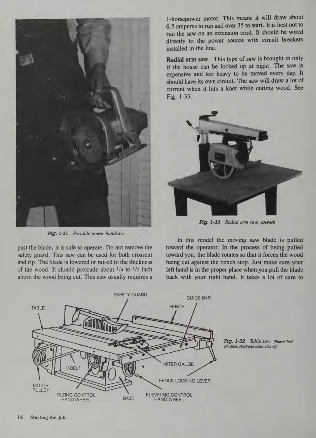
Table saw If the house has been enclosed, it is possible to bring in a table saw to handle the larger cutting
jobs. See Fig. 1-32. You can do ripping a little more
safely with this type of saw because it has a rip fence.
If a push stick is used to push the wood through and
Size of Extension Cords for Portable Tools
Full-Load Rating of the Tool in Amperes at 115 Volts
5.1 to 7.0
7.1 to 12.0
3.5 to 5.0
2.10 to 3.4
12.1 to 16.0
Cc
If the voltage is lower than 115 volts at the outlet, have the voltage increased or use a much larger cable than listed.
Using Carpenter Tools
13
1-horsepower motor. This means it will draw about
6.5 amperes to run and over 35 to start. It is best not to
run the saw on an extension cord. It should be wired
directly to the power source with circuit breakers
installed in the line.
Radial arm saw This type of saw is brought in only
if the house can be locked up at night. The saw is
expensive and too heavy to be moved every day. It
should have its own circuit. The saw will draw a lot of
current when it hits a knot while cutting wood. See
Fig. 1-33.
Fig. 1-33
Fig. 1-31
Portable power handsaw.
In this model the moving saw blade is pulled
toward the operator. In the process of being pulled
toward you, the blade rotates so that it forces the wood
being cut against the bench stop. Just make sure your
left hand is in the proper place when you pull the blade
back with your right hand. It takes a lot of care to
past the blade, it is safe to operate. Do not remove the
safety guard. This saw can be used for both crosscut
and rip. The blade is lowered or raised to the thickness
of the wood. It should protrude about !/4 to !/2 inch
above the wood being cut. This saw usually requires a
SAFETY GUARD
TABLE
GUIDE BAR
LE
ai
se
—
Se
—
FENCE
—.
BIAS
Be
he[
aH CS>
@
Df
\
MITER GAUGE
MOTOR
PUBEEY
14
FENCE LOCKING LEVER
TILTING CONTROL
HAND WHEEL
Starting the Job
Radial arm saw. (DeWalt)
BASE
ELEVATING CONTROL
HAND WHEEL
Fig. 1-32
Table saw. (Power Tool
.
.
Division
, Rockwell International)
operate a saw of this type. The saw works well for cutting large-dimensional lumber. It will crosscut or rip.
This saw will also do miter cuts at almost any angle.
Once you become familiar with it, the saw can be used
to bevel crosscut, bevel miter, bevel rip, and even cut
circles. However, it does take practice to develop some
degree of skill with this saw.
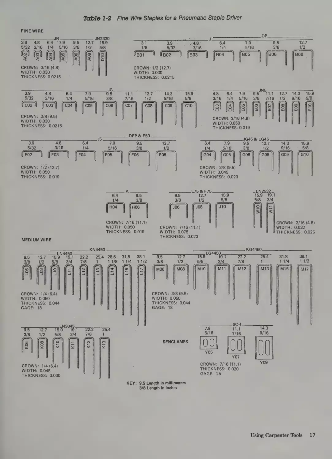
Router The router has a high-speed type of motor. It
will slow down when overloaded. It takes the beginner
some time to adjust to feeding the router properly. If
you feed it too fast, it will stall or burn the edge you’re
routing. If you feed it too slowly, it may not cut the
way you wish. You will have to practice with this tool
for some time before you’re ready to use it to make
furniture. It can be used for routing holes where
needed. It can be used to take the edges off laminated
plastic on countertops. Use the correct bit, though.
This type of tool can be used to the extent of the carpenter’s imagination. See Fig. 1-34.
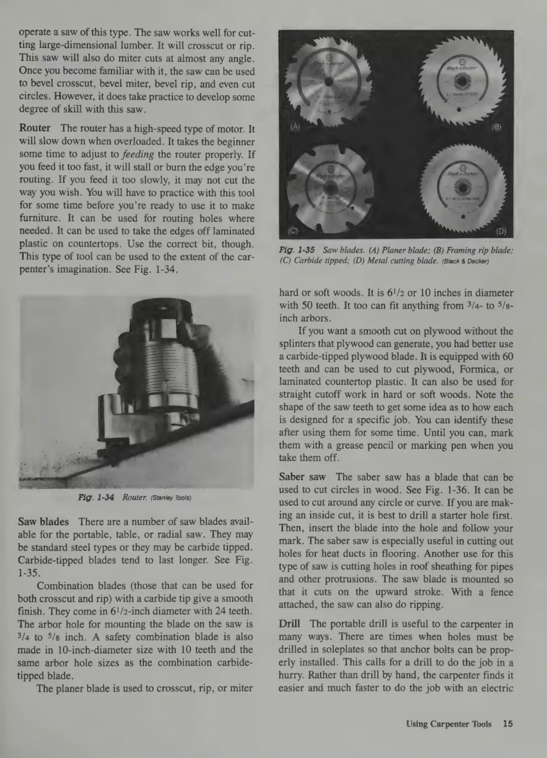
Fig. 1-35 Saw blades. (A) Planer blade; (B) Framing rip blade;
(C) Carbide tipped; (D) Metal cutting blade. (Black & Decker)
hard or soft woods. It is 6!/2 or 10 inches in diameter
with 50 teeth. It too can fit anything from 3/4- to 5/sinch arbors.
If you want a smooth cut on plywood without the
splinters that plywood can generate, you had better use
a carbide-tipped plywood blade. It is equipped with 60
teeth and can be used to cut plywood, Formica,
or
laminated countertop plastic. It can also be used for
straight cutoff work in hard or soft woods. Note the
shape of the saw teeth to get some idea as to how each
is designed for a specific job. You can identify these
after using them for some time. Until you can, mark
them with a grease pencil or marking pen when you
take them off.
Fig. 1-34
Router. (Stanley Tools)
Saw blades There are a number of saw blades available for the portable, table, or radial saw. They may
be standard steel types or they may be carbide tipped.
Carbide-tipped blades tend to last longer. See Fig.
1-35.
Combination blades (those that can be used for
both crosscut and rip) with a carbide tip give a smooth
finish. They come in 61/2-inch diameter with 24 teeth.
The arbor hole for mounting the blade on the saw is
3/4 to 5/8 inch. A safety combination blade is also
made in 10-inch-diameter size with 10 teeth and the
same arbor hole sizes as the combination carbidetipped blade.
The planer blade is used to crosscut, rip, or miter
Saber saw The saber saw has a blade that can be
used to cut circles in wood. See Fig. 1-36. It can be
used to cut around any circle or curve. If you are making an inside cut, it is best to drill a starter hole first.
Then, insert the blade into the hole and follow your
mark. The saber saw is especially useful in cutting out
holes for heat ducts in flooring. Another use for this
type of saw is cutting holes in roof sheathing for pipes
and other protrusions. The saw blade is mounted so
that it cuts on the upward stroke. With a fence
attached, the saw can also do ripping.
Drill The portable drill is useful to the carpenter in
many ways. There are times when holes must be
drilled in soleplates so that anchor bolts can be properly installed. This calls for a drill to do the job in a
hurry. Rather than drill by hand, the carpenter finds it
easier and much faster to do the job with an electric
Using Carpenter Tools
15
Fig. 1-38
Fig. 1-37
Hand-held portable drill.
drill. The drill shown in Fig. 1-37 is capable of drilling through all dimensional lumber on the job. With a
carbide tip it is capable of drilling into concrete whenever the carpenter needs to anchor a partition into a
slab.
The uses for an electric drill are limited only by
the imagination of the user. It comes in handy when
mounting countertops to cabinets in the kitchen, for
example.
Sanders The belt sander shown in Fig. 1-38 and the
orbital sanders shown in Figs. 1-39A and B can do
almost any required sanding job. The carpenter needs
the sander occasionally. It helps align parts properly,
especially those that don’t fit by just a small amount.
The sander can be used to finish off windows, doors,
counters, cabinets, and floors. A larger model of the
belt sander is used to sand floors before they are sealed
and varnished. The orbital or vibrating sanders are
16
Starting the Job
Belt sander. (Black& Decker)
Fig. 1-39
Orbital sanders: (A) dual action and (B) single action.
(Black & Decker)
used primarily to put a very fine finish on a piece of
wood. Sandpaper is attached to the bottom of the
sander. The sander is held by hand over the area to be
sanded. The operator has to remove the sanding dust
occasionally to see how well the job is progressing.
Nailers One of the greatest tools the carpenter has
acquired recently is the nailer. See Fig. 1-40. It can
drive nails or staples into wood better than a hammer.
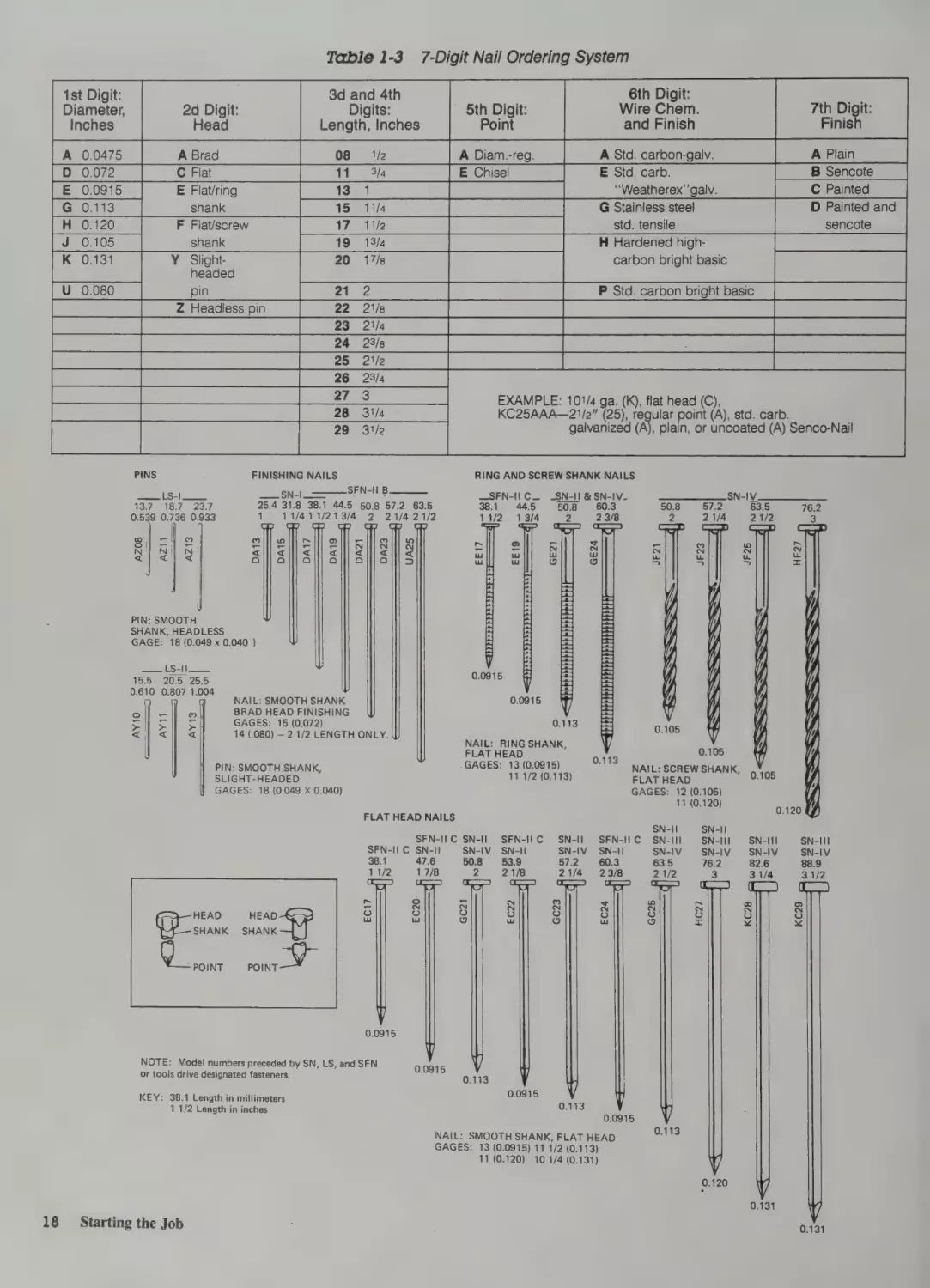
Table 1-2
Fine Wire Staples for a Pneumatic Staple Driver
FINE WIRE
JN
eat6.4 7.9.
1/4 5/16
Som
aS 3/16
JN2330
127001519
1/2
5/8
9:5
3/8
3.1
1/8
BO1
|fel
fg) fg) ig fs]
CROWN: 3/16(4.8)
WIDTH: 0.030
THICKNESS: 0.0215
AB
3/16
BO3
6.4
1/4
BO4
ae
7.9
5/16
BO5
9.5
3/8
B06
Pay
1/2
BOs —
CROWN:
1/2 (12.7)
WIDTH: 0.030
THICKNESS: 0.0215
48
3/16
Ae
3.9
5/32
B02
JG
9.5
3/8
7.9
5/16
a
Fco2 V (co3) (coa
E =}fe
7.9
5/16
N5
11.1
7/16
1257
1/2
14.3
9/16
15.9
5/8
ae
CO7
C08
cog
"C10
fz (s| E
sl
(|
|
fe|St
a
a
Ti
7/16
27a
1/2
Lu
CROWN: 3/8
WIDTH:
0.030(9.5)
THICKNESS: aM0.0215
3.9
5/3
FO2
48
3/16
(Fos
ae
9/16
9
5/8
WS
ye
Lu
Lu
CROWN: 3/16(4.8)
WIDTH
0.0500.019
THICKNESS:
6.4
1/4
)i Fo4
DFP & F50
95
3/8
FO6
7.9
5/16
{FO5
12.7
1/2
FO8
6.4
1/4
G04
JG45 & LG45
9.5
12.7
3/8
1/2
G06
7.9
5/16
G05
14.3
9/16
15.9
5/8
|
CROWN: 1/2 (12.7)
CROWN:
3/8(9.5)
WIDTH: 0.050
THICKNESS: 0.019
WIDTH: 0.045
THICKNESS: 0.023
6.4
1/4
A
HO4
9.5
3/8
HO6
N4450
LN445
Sis al 25:0
19s
/Omer 3/4
3/8 eel 20>
>) i
>)
oe
2 2een 254: 28160
11/8
en
7/Sa
,
(
JO6
|
CROWN: 7/16 (11.1)
WIDTH: 0.050
THICKNESS: 0.019
MEDIUM WIRE
9.5
3/8
L75 & F75
12:7
1/2
_LN2532_
15.9 19.1
5/8 3/4
15.9
J08
jel)
=
CROWN: 3/16 (4.8)
| WIDTH: 0.032
THICKNESS: 0.025
CROWN: 7/16 (11.1)
WIDTH: 0.075
THICKNESS: 0.023
631.8
11/4
9.5
3/8
1237
1/2
(0)
moe | if mos
15.
fz
=
LG4450
%
38.1
11/2
f 17
al
CROWN: 1/4(6.4)
WIDTH: 0.050
THICKNESS: 0.044
GAGE: 18
9.5
S/S
©oO
v
R
12:7
men
2oO
x
CROWN: 3/8 (9.5)
WIDTH: 0.050
THICKNESS: 0.044
GAGE: 18
LN3045
15Ove 19st
205)
°
1
x
SCs cee = ane
rine
wi22.2
S348
=c
SENCLAMPS
5/16
[00|
11.1
14.3
7/16
00
9/16
“
CROWN: 7/16 (11.1)
:
;
ee Bane ”
THICKNESS:
|
THICKNESS: 0.020
Yoo
GAGE: 25
0.030
KEY:
9.5 Length in millimeters
3/8 Length in inches
Using Carpenter Tools
17
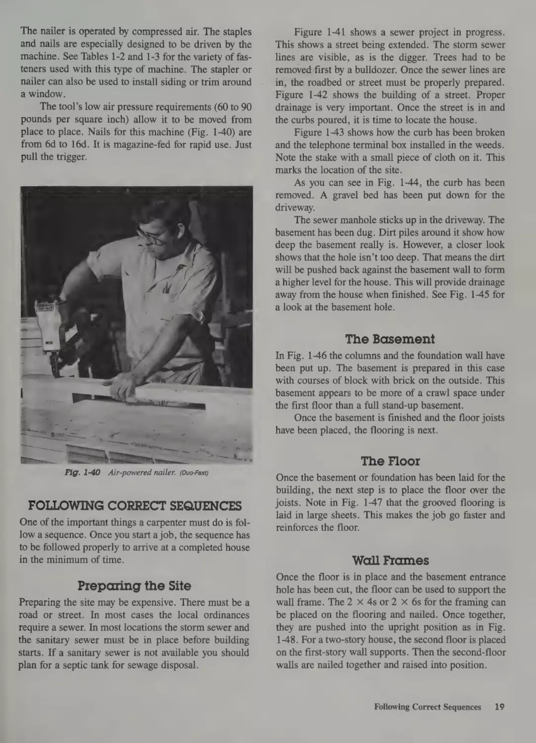
Table 1-3
1st Digit:
Diameter,
Inches
7-Digit Nail Ordering System
3d and 4th
Digits:
Length, Inches
2d Digit:
Head
6th Digit:
Wire Chem.
and Finish
5th Digit:
Point
yi
7th Digit:
Finish
A Plain
E Flat/ring
Bas
F Flat/screw
ies edPAR Ue eons Oe
shank
K 0.131
eee a
eae
Pate20 te
ae
17/s
Y Slightheaded
B Sencote
“Weatherex’’galv.
aeee
C Painted
ee
std. tensile
eer
carbon bright basic
D sencote
Painted and
pin
eree ee
eo
eure Sez Headiessipin a [5 22 2Nen eR
eee
a
ee
ee
Be
aI Rw 28g ye Ee
I
BB fe
Ses ieee
26 23/4
are rio PS KR
eR
PREMIER ALS78LS |ODT TER Oe
EXAMPLE: 101/4 ga. (K), flat head (C),
KC25AAA—21/2” (25), regular point (A), std. carb.
Nee
Me pea
at
eB aN
galvanized (A), plain, or uncoated (A) Senco-Nail
PINS
peer cae
137. 189 23.7
FINISHING NAILS
___ SN-|_=
SFN-I B
25.4 31.8 38.1 44.5 50.8 57.2 63.5
0.539 0.736 0.933
1
11/411/213/4
2
RING AND SCREW SHANK NAILS
_SFN-II1C_ _SN-II & SN-IV38.1 445
508
60.3
21/4 21/2
1/2
\
13/4
2
\
N
23/8
21/2
qi
Ww
uw
oO
Ww
Ww
DA13 DA15 DA17 DA19 DA21 DA23 UA25
|
2
ee Ee Sey
63.5
oO
PIN: SMOOTH
SHANK, HEADLESS
GAGE: 18 (0.049 x 0.040 )
eee
15.5 20.5 25.5
0.610 0.807 1.004
f
|
|
|
| >
el
zi
ei
;
NAIL: SMOOTH SHANK
BRAD HEAD FINISHING
GAGES: 15 (0.072)
2
21
Zi
Pell
steps
—PhpeeenePrenpp
pen
0.0915
0.113
14.080)
—21/2 LENGTH ONLY.
NAIL: RING SHANK,
FLAT HEAD
GAGES: 13 (0.0915)
11 1/2 (0.113)
PIN: SMOOTH SHANK,
SLIGHT-HEADED
GAGES: 18 (0.049
Xx0.040)
FLAT HEAD NAILS
SFN-I1C SN-Il
SFN-I1C SN-I! | SN-IV.
38.1
47.6
50.8
11/2
HEAD
SHANK
Doe et
HEAD
EC17
17/8
2
fi
EC20
GC21
SFN-I1C
SN-II
53.9
21/8
EC22
SN-Il
SN-IV
57.2
21/4
GC23
i
oa
0.105
NAIL: SCREW SHANK, 9 Yog
FLAT HEAD
;
GAGES: 12 (0.105)
11 (0.120)
‘
SN-I| — SN-II
SFN-I1C SN-IIl
SN-IIl
SN-II
SN-IV.
SN-IV.
60.3
63.5
76.2
2 1/2
@
EC24
SHANK
GC25
3
HC27
0.120
SN-IIl — SN-III
SN-IV.__SN-IV
82.6
88.9
31/4
KC28
31/2
KC29
POINT
0.0915
NOTE: Model numbers preceded by SN, LS, and SFN
or tools drive designated fasteners.
KEY:
38.1 Length in millimeters
1 1/2 Length in inches
0.0915
5
0.113
o~
0.0915
0.113
0.0915
NAIL: SMOOTH SHANK, FLAT HEAD
GAGES: 13 (0.0915) 11 1/2 (0.113)
11 (0.120) 10 1/4 (0.131)
0.113
0.120
0.131
18
Starting the Job
0.131
The nailer is operated by compressed air. The staples
and nails are especially designed to be driven by the
machine. See Tables 1-2 and 1-3 for the variety of fasteners used with this type of machine. The stapler or
nailer can also be used to install siding or trim around
a window.
The tool’s low air pressure requirements (60 to 90
pounds per square inch) allow it to be moved from
place to place. Nails for this machine (Fig. 1-40) are
from 6d to 16d. It is magazine-fed for rapid use. Just
pull the trigger.
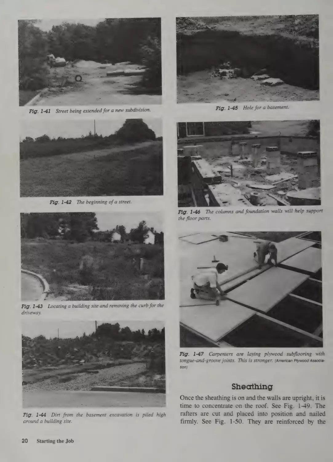
Figure 1-41 shows a sewer project in progress.
This shows a street being extended. The storm sewer
lines are visible, as is the digger. Trees had to be
removed first by a bulldozer. Once the sewer lines are
in, the roadbed or street must be properly prepared.
Figure 1-42 shows the building of a street. Proper
drainage is very important. Once the street is in and
the curbs poured, it is time to locate the house.
Figure 1-43 shows how the curb has been broken
and the telephone terminal box installed in the weeds.
Note the stake with a small piece of cloth on it. This
marks the location of the site.
As you can see in Fig. 1-44, the curb has been
removed. A gravel bed has been put down for the
driveway.
The sewer manhole sticks up in the driveway. The
basement has been dug. Dirt piles around it show how
deep the basement really is. However, a closer look
shows that the hole isn’t too deep. That means the dirt
will be pushed back against the basement wall to form
a higher level for the house. This will provide drainage
away from the house when finished. See Fig. 1-45 for
a look at the basement hole.
The Basement
In Fig. 1-46 the columns and the foundation wall have
been put up. The basement is prepared in this case
with courses of block with brick on the outside. This
basement appears to be more of a crawl space under
the first floor than a full stand-up basement.
Once the basement is finished and the floor joists
have been placed, the flooring is next.
The Floor
Fig. 1-40
Air-powered nailer. (Duo-Fast)
FOLLOWING CORRECT SEQUENCES
One of the important things a carpenter must do is follow a sequence. Once you start a job, the sequence has
to be followed properly to arrive at a completed house
in the minimum of time.
Preparing the Site
Preparing the site may be expensive. There must be a
road or street. In most cases the local ordinances
require a sewer. In most locations the storm sewer and
the sanitary sewer must be in place before building
starts. If a sanitary sewer is not available you should
plan for a septic tank for sewage disposal.
Once the basement or foundation has been laid for the
building, the next step is to place the floor over the
joists. Note in Fig. 1-47 that the grooved flooring is
laid in large sheets. This makes the job go faster and
reinforces the floor.
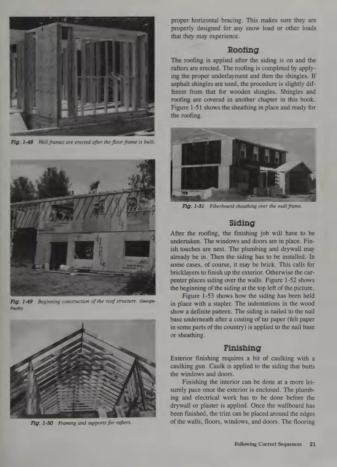
Wall Frames
Once the floor is in place and the basement entrance
hole has been cut, the floor can be used to support the
wall frame. The 2 X 4s or 2 X 6s for the framing can
be placed on the flooring and nailed. Once together,
they are pushed into the upright position as in Fig.
1-48. For a two-story house, the second floor is placed
on the first-story wall supports. Then the second-floor
walls are nailed together and raised into position.
Following Correct Sequences
19
AGE
Fig. 1-41
Street being extended for a new subdivision.
-.
\
A oe
—
<m
~
7
cane
Fig. 1-46 The columns and foundation walls will help support
the floor parts.
me
.
.
$
Fig. 1-4
driveway.
Fig. 1-47 Carpenters are laying plywood subflooring with
tongue-and-groove joints. This is stronger. (American Plywood Association)
Sheathing
:
Fig. 1-44
:
Dirt from the basement excavation
around
a building site.
20 _—s Starting the Job
=
ees
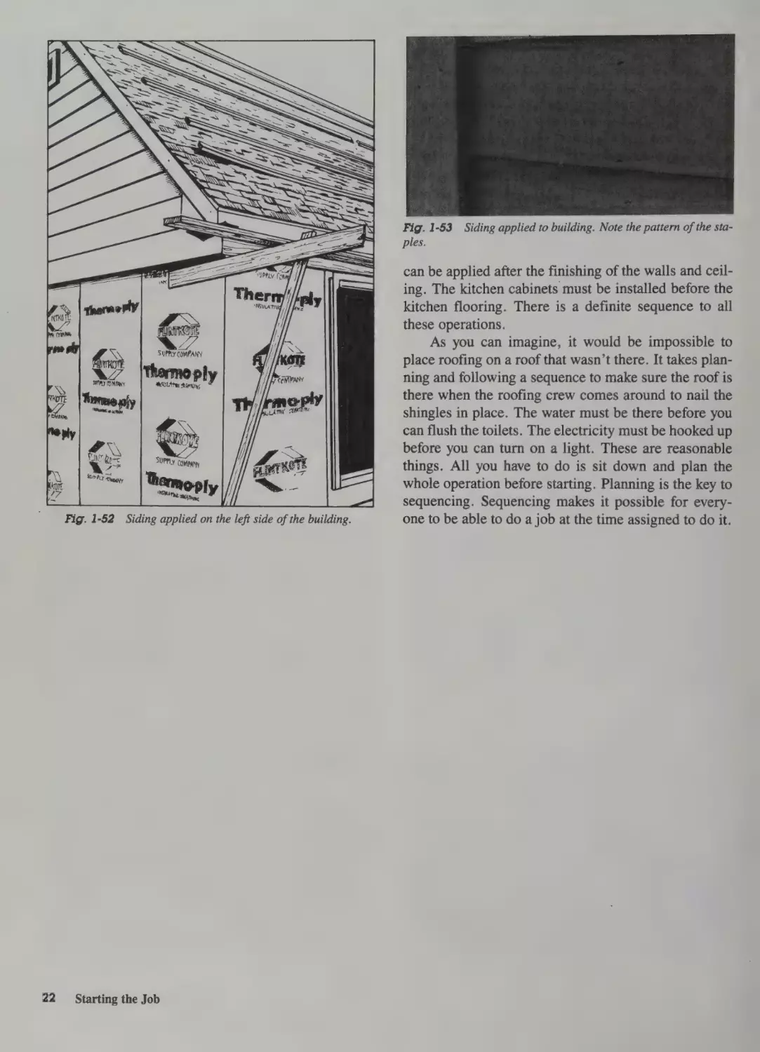
Once the sheathing is on and the walls are upright, it is
time to concentrate on the roof. See Fig. 149. The
is piled high
rafters are cut and placed into position and nailed
firmly. See Fig. 1-50. They are reinforced by the
proper horizontal bracing. This makes sure they are
properly designed for any snow load or other loads
that they may experience.
Roofing
The roofing is applied after the siding is on and the
rafters are erected. The roofing is completed by applying the proper underlayment and then the shingles. If
asphalt shingles are used, the procedure is slightly different from that for wooden shingles. Shingles and
roofing are covered in another chapter in this book.
Figure 1-51 shows the sheathing in place and ready for
the roofing.
7.
| Fig. 1-51 Fiberboard sheathing over the wall frame.
siding
After the roofing, the finishing job will have to be
undertaken. The windows and doors are in place. Finish touches are next. The plumbing and drywall may
already be in. Then the siding has to be installed. In
some cases, of course, it may be brick. This calls for
A
Fig. 1-49
Beginning construction of the roof structure. (Georgia-
Pacific)
bricklayers to finish up the exterior. Otherwise the carpenter places siding over the walls. Figure 1-52 shows
the beginning of the siding at the top left of the picture.
Figure 1-53 shows how the siding has been held
in place with a stapler. The indentations in the wood
show a definite pattern. The siding is nailed to the nail
base underneath after a coating of tar paper (felt paper
in some parts of the country) is applied to the nail base
or sheathing.
Finishing
Exterior finishing requires a bit of caulking with a
caulking gun. Caulk is applied to the siding that butts
the windows and doors.
Finishing the interior can be done at a more leisurely pace once the exterior is enclosed. The plumbing and electrical work has to be done before the
drywall or plaster is applied. Once the wallboard has
been finished, the trim can be placed around the edges
Fig. 1-50
Framing and supports for rafters.
of the walls, floors, windows, and doors. The flooring
Following Correct Sequences
21
Fig. 1-53
ples.
SUPPLY COMPANY
SULA TL oP
y
SUPPLY COMPany
oPly
Fig. 1-52
22
Siding applied on the left side of the building.
Starting the Job
Siding applied to building. Note the pattern of the sta-
can be applied after the finishing of the walls and ceiling. The kitchen cabinets must be installed before the
kitchen flooring. There is a definite sequence to all
these operations.
As you can imagine, it would be impossible to
place roofing on a roof that wasn’t there. It takes planning and following a sequence to make sure the roof is
there when the roofing crew comes around to nail the
shingles in place. The water must be there before you
can flush the toilets. The electricity must be hooked up
before you can turn on a light. These are reasonable
things. All you have to do is sit down and plan the
whole operation before starting. Planning is the key to
sequencing. Sequencing makes it possible for everyone to be able to do a job at the time assigned to do it.
Preparing
the Site
[== PLANNING IS VITALLY IMPORTANT TO THE
success of the completed job. Before you begin any
construction, you must plan the building on paper.
Always keep in mind that it is much cheaper to make a
mistake on paper than on site.
In this chapter, you will learn how to develop
these skills:
e Locate the boundaries
¢ Lay out buildings
¢ Use the carpenter’s level
¢ Prepare for the start of construction
Each has its importance. Locating the boundaries will
allow you to properly lay out the building on the site.
The builder’s level will show you how to make
sure the building is level. No new leaning tower of
Pisa is needed today. One is enough. It would be very
hard to sell one today. That means you should choose
the site so that the soil will support the weight of the
building.
There is a basic sequence to follow in building. It
should be followed for the benefit of those who are
supposed to operate as part of the team.
records or have someone who is paid for this type of
work do it. An abstract of the history of the ownership
of the land is usually provided. In Iowa, for instance,
the abstract traces ownership back to the Louisiana
Purchase of 1803. In New York State the history of the
land is traced by owners from the days of the Holland
Land Company. Alabama can provide records back to
the time the Creek or other Indians owned the land.
Each state has its own history and its own procedure
for establishing absolute ownership of land. It is best
to have proof of this ownership before starting any
construction project.
Surveyors should be called in to establish the limits of the property. A plot plan is drawn by the surveyors. This can be used to locate the property. Figure 2-1
is a plot plan showing the location of a house onalot.
paint 60. we. SUPTALO. =-¥-
Dr.
ewes
WESTBROOK
BASIC SEQUENCE
The basic sequence involves the following operations:
Dr.
1. Cruise the site and plan the job.
. Locate the boundaries.
Woe
CN
. Locate the building area or areas.
a
. Define the site work that is needed.
_
. Clear any unwanted trees.
. Lay out the building.
. Establish the exact elevations.
a
m
xX
°oO
“
a
. Excavate the basement or foundation.
. Provide for access
Oo
nN
WN
OorNA
FW
during construction.
—oS
. Start the delivery of materials to the site.
ee —
. Have a crew arrive to start with the footings.
LOCATING THE BUILDING
ON THE SITE
The proper location of a building is very important. It
would be embarrassing and costly to move a building
once it is built. That means a lot of things have to be
checked first.
Property Boundaries
First, a clear deed to the land should be established.
This can be done in the county courthouse. Check the
24
Preparing the Site
TON
suavey,
Ci
oe. teTW
6.
>)
House Loc. Vows SO /H
'
= 2° eT.
TnawinOd | BEING
<>
da7-/4
Doow
SI
IRRSURVEYEO:
ew
Fig. 2-1
or
taps
Se
HKOF
KREHBIEL & KREHBIEL
CIVIL ENGINEERS
Plot plan.
Sidewalks, utilities easements,
and other things
have to be taken into consideration. The location of the
house may be specified by local ordinance. This type
of ordinance will usually specify what clearance the
house must have on each side. It will probably set the
limits of setback from the street. You may also want to
plan around a tree or trees. Since trees increase the
value of the property, it is important to save as many as
possible. Figure 2-2 shows a sketch of some of these
considerations.
STREET
FROM TREE
TRUNK
NOTE:
CLEARANCE
IS AT MINIMUM
POINT
10’-0”
CODE-LOT
CLEARANCE
\
“4
ULTILITIES
EASEMENT
Fig. 2-2
Site location must be chosen carefully.
An easement is the right of the utilities to use the
space to furnish electric power, phone service, and gas
to your location and to others nearby. This means you
have given them permission to string wires or bury
lines to provide their services. Keep in mind also the
rights of the city or township to supply water and
sewers. These may also cut across the property.
Laying Out the Foundation
Layout of the foundation is the critical beginning in
house construction. It is a simple but extremely
important process. It requires careful work. Make
sure the foundation is square and level. You will find
all later jobs, from rough carpentry through finish
construction and installation of cabinetry, are made
much easier.
1. Make sure your proposed house location on the lot
complies with local regulations.
2.. Set the house location, based on required setbacks
and other factors, such as the natural drainage pattern of the lot. Level or at least rough-clear the site.
See Fig. 2-3.
3. Lay out the foundation lines. Figure 2-4 shows the
simplest method for locating these. Locate each
outside corner of the house and drive small stakes
Fig. 2-3
Rough-cleared lot. Only weeds need to be taken out as
the basement is dug.
into the ground. Drive tacks into the tops of the
stakes. This is to indicate the outside line of the
foundation wall. This is not the footings limit but
the outside wall limit. Next check the squareness of
the house by measuring the diagonals, corner to
corner, to see that they are equal. If the structure is
rectangular, all diagonal measurements will be
equal. You can check squareness of any corner by
measuring 6 feet down one side, then 8 feet down
the other side. The diagonal line between these two
end points should measure exactly 10 feet. If it
doesn’t, the corner isn’t truly square. See Fig. 2-5.
4. After the corners are located and squared, drive
three 2 X 4 stakes at each corner as shown in Fig.
2-4. Locate these stakes 3 feet and 4 feet outside
the actual foundation line. Then nail 1 X< 6 batter
boards horizontally so that their top edges are all
level and at the same grade. Levelness will be
checked later. Hold a string line across the tops of
opposite batter boards at two corners. Using a
plumb bob, adjust the line so that it is exactly over
the tacks in the two corner stakes. Cut saw kerfs !/4
inch deep where the line touches the batter boards
so that the string lines may be easily replaced if
they are broken or disturbed. Figure 2-6 shows
how carpenters in some parts of the country use a
nail instead of the saw kerf to hold the thread or
string. Figure 2-7 shows how the details of the
location of the stake are worked out. This one is a
3—4-—5S triangle, or 9 feet and 12 feet on the sides
and 15 feet on the diagonal. If you use 6, 8, and 10
feet you get a 3—4—5S triangle also. This means 6
+2 =3,8 +2 =4, and 10 + 2 =5S. In the other
example, 9 feet + 3 = 3, 12 feet + 3 = 4, and 15
+ 3 =5. So you have a 3—4~—S triangle in either
measurement. Other combinations can be used but
OLSON LIBRARY
NORTHERN MICHIGAN UNIVERSITY
MARQUETTE, MICHIGAN 49855
Locating the Building on the Site
25
CENTER
STRING LINE
Th
%
5
ee
OUTSIDE CORNER STAKE (2 X 2)
2 X 4STAKE
(TYP)
Staking out a basement. (American Plywood Association)
Fig. 2-4
BATTER BOARD
OUTSIDE CORNER
STAKE (2 X 2)
4’-0” MIN.
Fig. 2-5
Squaring the corner and marking the point. (American Ply-
wood Association)
t
Z|
SE
OUTSIDE LINE OF
ee
<
FOUNDATION WALL
SAW KERF
|
Se
| |
J
oe
:
toy [iy WALLLINE 5 0SION
eK
SPACE FOR TILING
LABS
OR WATERPROOFING
er
2>
SS
WALL
tx
Cas
~
-_
So
a
ig
me Siu geet
SHARPCUTOR
7-7
BOARDS .2%0 0382"
Fig. 2-6
Note the location of the nails on the batter board. (U.S.
Department of Agriculture)
26
_~—~Preparing the Site
these are the most common. Cut all saw kerfs the
same depth. This is because the string line not only
defines the outside edges of the foundation but also
Shien
pe .
ih Fs CIENE Ge seu
we
Staking and laying out the house. (Forest Products Labora-
tory)
Bee
]
om
Fig. 2-7
will provide a reference line. This ensures uniform
depth of footing excavation. When you have made
similar cuts in all eight batter boards and strung the
four lines in position, the outside foundation lines
are accurately established.
5. Next, establish the lengthwise girder location. This
is usually on the centerline of the house. Doublecheck your house plans for the exact position. This
is because occasionally the girder will be slightly
off the centerline to support an interior bearing
wall. To find the line, measure the correct distance
from the corners.
THE BUILDER’S LEVEL
Then install batter boards and
locate the string line as before.
. Check the foundation for levelness. Remember that
the top of the foundation must be level around the
entire perimeter of the house. The most accurate
and simplest way to check this is to use a surveyor’s
level. This tool will be explained later in this chapter. The next best approach is to ensure that batter
boards, and thus the string lines, are all absolutely
level. You can accomplish this with a 10- to 14-foot
long piece of straight lumber. See Fig. 2-8. Judge
the straightness of the piece of lumber by sighting
along the surface. Use this straightedge in conjunction with a carpenter’s level. Then drive temporary
stakes around the house perimeter. The distance
between them should not exceed the length of the
straightedge. Then place one end of the straight-
Practically all optical sighting and measuring instruments-can be termed surveying instruments. Surveying, in its simplest form, simply means accurate
- measuring. Accurate measurements have been a construction requirement ever since humans started building things.
How Does It Work?
Even during the days of pyramid building, humans
recognized the fact that the most accurate distant measurements were obtained with a perfectly straight line
of sight. The basic principle of operation for today’s
modern instruments is still the same. A line of sight is
a perfectly straight line. The line does not dip, sag, or
curve. It is a line without weight and is continuous.
Any point along a level line of sight is exactly
level with any other point along that line. The instrument itself is merely the device used to obtain this perfectly level line of sight for measurements.
edge on a batter board. Check for exact levelness.
See Fig. 2-8. Drive another stake to the same
height. Each time a stake is driven, the straightedge and level should be reversed end for end. This
should ensure close accuracy in establishing the
height of each stake with reference to the batter
board. The final check on overall levelness comes
when you level the last stake with the batter board
where you began. If the straightedge is level here,
then you have a level foundation baseline. During
Three Main Parts of a Builder’s Level
1. The Telescope (Fig. 2-9). The telescope is a precision-made optical sighting device. It has a set of
carefully ground and polished lenses. They produce a clear, sharp magnified image. The magnification of a telescope is described as its power. An
18-power telescope will make a distant object
appear 18 times closer than when viewed with the
naked eye. Cross hairs in the telescope permit the
object sighted on to be centered exactly in the field
foundation excavation, the corner stakes and tem-
porary leveling stakes will be removed. This
stresses the importance of the level batter boards
and string line. The corners and foundation levelness must be located using the string line.
of view.
CENTER
STRING LINE
ise
ea
STRAIGHTEDGE
gicid
ee
=
iy 7
——___ FOUNDATION WALL
TEMPORARY
STAKE
BATTER
Fig. 2-8
LINE (OUTSIDE)
LEVELING
BOARD
Leveling the batter boards. (American Plywood Association)
The Builder’s Level
27
Fig. 2-9
The telescope on an optical level. (David White Instruments)
2. The Leveling Vial (Fig. 2-10). Also called the
“bubble,” the leveling vial works just like the
familiar carpenter’s level. However, it is much
more sensitive and accurate in this instrument.
Four leveling screws on the instrument base permit
the user to center (level) the vial bubble perfectly
and thus establish a level line of sight through the
telescope. A vital first step in instrument use is leveling. Instrument vials are available in various
degrees of sensitivity. In general, the more sensi-
:
Fig. 2-12
NN
i
pies
Using the optical (or builder’s level) on the job.
(David White Instruments)
tive the vial, the more precise the results that may
be obtained.
Te
oe evan eas
Fig. 2-10
The leveling vial on an optical level. (David White Instru-
ments)
3. The Circle (Fig. 2-11). The perfectly flat plate
upon which the telescope rests is called the circle.
It is marked in degrees and can be rotated in any
horizontal direction. With the use of an index
pointer, any horizontal angle can be measured
quickly. Most instruments have a vernier scale. An
additional scale is subdivided. It divides degrees
into minutes. There are 60 minutes in each degree.
There are 360° in a circle.
Fig. 2-11
The circle on an optical level. (David White instruments)
Preparing the Instrument
Figure 2-12 shows a builder’s level on site. Leveling
the instrument is the most important operation in preparing the instrument for use.
Leveling the instrument
First, secure the instrument to its tripod and proceed to level it as follows.
Figure 2-13A shows the type of tripod used to support
the instrument. The target pole is shown in Fig.
2-13B.
Place the telescope directly over one pair of opposite leveling screws. (See Fig. 2-14.) Turn the screws
28
Preparing the Site
(A)
(B)
Fig. 2-13 (A) The tripod for an optical level; (David White) (B) the
rod holder for use with an optical level. (David White)
directly under the scope in opposite directions at the
same time (see step 5 in Fig. 2-14) until the level-vial
bubble is centered. The telescope is then given a quar-
ter (90°) turn. Place it directly over the other pair of
leveling screws (step 2 of Fig. 2-14). The leveling operation is then repeated. Then recheck the other positions
(steps 3 and 4 of Fig. 2-14) and make adjustments. This
1
3
Fig. 2-14
4
5
Adjusting the screws on the level-transit will level it. Note how it is leveled with two screws, then moved 90° and leveled
again. (David White Instruments)
O
©
Om
TURNING BOTH LEVELING SCREWS
“IN” MOVES BUBBLE TO RIGHT
Cc
Fig. 2-16
TURNING BOTH LEVELING SCREWS
“QUT” MOVES BUBBLE TO LEFT
Finding the elevation with a level. (David White Instruments)
Staking out a house
Start at a previously chosen
corner to stake out the house. Sight along line AB of
Fig. 2-17 to establish the front of the house. Measure
the desired distance to B and mark it with a stake.
SIDE
VIEW
TOP
VIEW
eas
ce
LEVEL VIAL WITH
BUBBLE CENTERED
Fig. 2-15 Adjusting the leveling screws and watching the bubbles for level. (David White Instruments)
Fig. 2-17
How to stake out a house on a building lot using a
builder’s level. (David White Instruments)
may not be necessary. Adjust if necessary. When leveling is completed, it should be possible to turn the telescope in a complete circle without any changes in the
position of the bubble. See Fig. 2-15.
With the instrument leveled, you know that, since
the line of sight is perfectly straight, any point on the
line of sight will be exactly level with any other point.
The drawing in Fig. 2-16 shows how exactly you can
check the difference in height (elevation) between two
points. If the rod reading at B is 3 feet and the reading
at C is 4 feet, you know that point B is 1 foot higher
than point C. Use the same principle to check if a row
of windows is straight or if a foundation is level.
Or you can check how much a driveway slopes.
Swing the telescope 90° by the circle scale. Mark
the desired distance to D. This gives you the first corner. All the others are squared off in the same manner.
You’re sure all foundation corners are square, and all
it took was a few minutes setup time. See Fig. 2-18.
This method eliminates the use of the old-fashioned string line-tape-plumb bob methods.
The Level-Transit
There are two types of levels used for building sites.
The level and the level-transit are the two instruments
used. The level has the telescope in a fixed horizontal
The Builder’s Level
29
Fig. 2-18
Squaring the other corner in laying out a building on a
lot. (David White Instruments)
position but can move sideways 360° to measure horizontal angles. It is usually all that is needed at a building site for a house. See Fig. 2-19.
Fig. 2-20
(David White Instruments)
Level-transit.
ra
Pre hd
&
Fig. 2-19
Builder’s level. (David White Instruments)
Fig. 2-21
Using the level-transit on the site. (David White Instruments)
A combination instrument is called a level-transit.
The telescope can move in two directions. It can move
up and down 45° as well as from side to side 360°.
See Fig. 2-20. It can measure vertical as well as horizontal angles.
A lock lever or levers permit the telescope to be
securely locked in a true level position for use as a
level. A full transit instrument, in addition to the features just mentioned, has a telescope that can rotate
360° vertically.
The level-transit is shown in operation in Fig.
2-21.
Using the Level and Level-Transit
Reading the circle and vernier
The 360° circle is
divided in quadrants (0 to 90°). The circle is marked
by degrees and numbered every 10°. See Fig. 2-22.
30
Preparing the Site
75 DEGREES
Fig. 2-22
Reading the circle. (David White Instruments)
To obtain degree readings it is only necessary to
read the exact degree at the intersection of the zero
index mark on the vernier and the degree mark on the
circle (or on the vertical arc of the level-transit).
For more precise readings, the vernier scale is
used. See Fig. 2-23. The vernier lets you subdivide
each whole degree on the circle into fractions, or minutes. There are 60 minutes in a degree. If the vernier
75 DEGREES, 45 MINUTES
Fig. 2-23
Reading the circle and vernier. (David White Instruments)
zero does not line up exactly with a degree mark on
the circle, note the last degree mark passed and, read-
ing up the vernier scale, locate a vernier mark that
coincides with a circle mark. This will indicate your
reading in degrees and minutes.
Hanging the plumb bob To hang the plumb bob,
attach a cord to the plumb bob hook on the tripod.
Knot the cord as shown in Fig. 2-24.
Fig. 2-24 To hang a plumb bob,
attach a cord to the plumb bob
hook on the tripod and knot the
cord as shown here.
(David White Instruments)
24 X
Fig. 2-25
37 X
Variable instrument power is available.
(David White
Instruments)
High power is used for sighting under bright light
conditions. It is used for long-range sighting and for
more precise rod readings.
Rod Leveling rods are a necessary part of the transit
leveling equipment. Rods are direct-reading with large
graduations. All rods are equipped with a tough, permanent polyester film scale that will not shrink or
expand. This is important when you consider the graduations can be !/100 of a foot. Figure 2-26 shows a leveling rod with the target attached at 4’ 51/4”. The
target (Fig. 2-27) can be moved by releasing a small
clamp in the back. Figure 2-28 shows a tape and the
graduations. They are 1/s inch wide and !/s inch apart.
If you are setting up over a point, attach the plumb
bob. Move the tripod and instrument over the approximate point. Be sure the tripod is set up firmly again.
Shift the instrument on the tripod head until the plumb
bob is directly over the point. Then set the instrument
leveling screws again to level the instrument.
Power The power of a telescope is rated in terms of
magnification. It may be 24X or 37X. The 24X means
the telescope is presenting a view 24 times as close as
you could see it with the naked eye. Some instruments
are equipped with a feature that lets you zoom in from
24X to 37X. It increases the effective reading range of
the instrument more than 42 percent. It also permits
greater flexibility in matching range, image, and light
conditions. Use low power for brighter images in dim
light. Since it gives a wider field of view, it is also
handy in locating targets. Low power also provides
better visibility for sighting through heat waves. See
Fig. 2-25.
Fig. 2-27 Target that fits wood
rods. (David White Instruments)
Fig. 2-26
lO
Leveling rod made of
wood. (David White Instruments)
The Builder’s Level
31
The grade line is established by the person who
designed the building. This line must be accurately
established. Many measurements are made from this
line. It determines the amount of earth removed from
the basement or for the foundation footings.
Fig. 2-28 Tape face on the rod.
This one is marked in feet,
inches, and eighths. (David White
Instruments)
The tape is marked in feet, inches, and eighths of an
inch. Feet are numbered in red. A three-section rod
extends to 12 feet. A two-section rod extends to 8 feet
2 inches.
The rod holder is directed by hand signals from
the surveyor behind the transit. The hand signals are
easy to understand, since they motion in the direction
of desired movement of the rod.
Establishing Elevations
Not all lots are flat. That means there is some kind of
slope to be considered when digging the basement or
~ locating the house. The level can help establish what
these elevation changes are. From the grade line you
establish how much soil will have to be removed for a
basement. The grade line will also determine the location of the floor.
The bench mark is the place to start. A bench
mark is established by surveyors when they open a section to development. This point is a reference to which
the lot you are using is tied. The lot is so many feet in a
certain direction from a given bench mark.
The bench mark may appear as a mark or point on
the foundation of a nearby building. Sometimes it is
the nearby sidewalk, street, or curb that is used as the
level reference point.
Fig. 2-29
32
Preparing the Site
Using the Leveling Rod
Use a leveling rod and set it at any point you want to
check the elevation. Sight through the level or transitlevel to the leveling rod. Take a reading by using the
cross hair in the telescope. Move the rod to another
point that is to be established. Now raise or lower the
rod until the reading is the same as for the first point.
This means the bottom of the rod is at the same elevation as the original point.
One person will hold the rod level. Another will
move the target up or down till the cross hair in the
telescope comes in alignment with that on the target.
The difference between the two readings tells you
what the elevation is.
Figure 2-29 shows how the difference in elevation
between two points that are not visible from a single
point is determined.
If point Z cannot be seen from point W, then you
have to set the transit up again at two other points,
such as X and Y. Take the readings at each location;
then you will be able to determine how much of the
soil has to be removed for a basement.
PREPARING THE SITE
Clearing
One of the first things to do in preparing the site for
construction is to clear the area where the building
will be located. Look over the site. Determine if there
are trees in the immediate area of the house. If so,
mark the trees to be removed. This can be done with a
spray can of paint. Put an X on those to be removed or
a line around them. In some cases, people have
marked those that must go with a piece of cloth tied to
a limb.
Getting the elevation when the two points cannot be viewed from a single point.
Also make sure those that are staying are not damaged when the heavy equipment is brought onto the
site. Scarring trees can cause them to die later. Covering them more than 12 inches will probably kill them
also. You have to cut off a part of the treetop. This
helps it survive the covering of the roots.
Don’t dig the sewer trench or the water lines
through the root system of the trees to be saved. This
ANCHORED
SLEEPERS
WOOD STRIP
FLOORING
can cause the tops of the trees to die later, and in some
cases will kill them altogether.
Make a rough drawing of the location of the house
and the trees to be saved. Make sure the persons operating the bulldozer and digger are made aware of the
effort to save trees.
Cutting trees Keep in mind that removing trees can
also be profitable. You can cut the trees into small logs
for use in fireplaces. This has become an interest of
many energy conservationists. The brush and undergrowth can be removed with a bulldozer or other type
of equipment. Do not burn the brush or the limbs
without checking with local authorities. There is
always someone who is interested in hauling off the
accumulation of wood.
Stump removal In some cases a tree stump is left
and must be removed. There are a number of ways of
doing this. One is to use a winch and pull it up by
hooking the winch to some type of power takeoff on a
truck, tractor, or heavy equipment. You could dig it
out, but this can take time and too much effort in most
cases.
The use of explosives to remove the stump is not
permitted in some locations. Better check with the
local police before setting off the blast.
The best way is to use the bulldozer to uproot the
entire stump or tree. It all depends upon the size of the
tree and the size of the equipment available for the job.
Anyway, be sure the lot is cleared so the digging of the
basement or footings can take place.
Excavation
A house built on a slab does not require any extensive
excavation. One-piece or monolithic slabs are used on
level ground and in warm climates. In cold climates,
where the frostline penetrates deeper, or in areas
where drainage is a problem, a two-piece slab has to
be used. Figures 2-30 and 2-31 both show two-piece
slab foundations.
Slab footings must rest beneath the frostline. This
gives stability in the soil. The amount of reinforce-
Fig. 2-30
Two-piece slab with block foundation wall. (Forest
Products Laboratory)
SLAB
Nh
B
T\/
a, SN IN LOLOL Tenas)
Boe
ORE Ere
GRAVEL
SAND
RIGID
INSULATION
FOOTING
GRAVEL
Fig. 2-31
Two-piece slab with poured wall and footer.
ment needed for a slab varies. The condition of the soil
and the weights to be carried determine the reinforcement. Larger slabs and those on less stable soil need
more reinforcement.
The top of the slab must be 8 inches above
ground. This allows moisture under the slab to drain
away from the building. It also gives you a good
chance to spot termites building their tunnels from the
earth to the floor of the house. The slab should always
rest slightly above the existing grade. This is to provide for runoff water during a rainstorm.
Basements A basement is the area usually located
underground. It provides most homes with a lot of
storage. In some it is a place to do the laundry. It also
Preparing the Site
33
Fig. 2-32
serves as a place to locate the heating and cooling
units. If a basement is desired, it must be dug before
the house is started. The footings must be properly
poured and seasoned. Seasoning should be done before poured concrete or concrete block is used for the
wall. Some areas now use treated wood walls for a
basement.
Figure 2-32 shows a basement dug for use in
colder climates. Trenches from the street to the base‘ment must be provided for the plumbing and water.
Utilities may be buried also. If they are, the electric,
phone, and gas lines must also be located in trenches
or buried after the house is finished. It is a good idea
to notify the utility companies so that they can schedule the installation of their services when you are
ready for them.
Some shovel work may have to be done to dig the
basement trenches for the sewer pipes. This is done
after the basement has been leveled by machines. As
you can see from Fig. 2-32, the basement may also
need shovel work after the digger has left. Note the
cave-ins and dirt slides evident in the basement excavation in Fig. 2-32.
The basement has to be filled later. Gravel is used
to form a base for the poured concrete floor.
The high spots in the basement must be removed
by shovel. Proper-size gravel should be spread after
the sewer trench is filled. You may have to tamp the
gravel to make sure it is properly level and settled. Do
this before the concrete mixer is called for the floor
job.
The footings have to be poured first. They are
boxed in and poured before anything is done in the way
of the basement floor. In some instances drain tile
must be installed inside or outside the footing. The tile
34
Preparing the Site
Excavation for a basement.
is allowed to drain into a sump. In other locations no
drainage is necessary because of soil conditions.
PROVIDING ACCESS
DURING CONSTRUCTION
The first thing to be established is who is to be on the
premises. Check with your insurance company about
liability insurance. This is in case someone is hurt on
the location. Also decide who should be kept out. You
also have to decide how access control is to be set up.
It may be done with a fence or by an alert guard or
dog. These things do have to be considered before the
construction gets underway. If equipment is left at the
site, who is responsible? Who will pay for vandalism?
Who will repair damage caused by wind, hail, rain,
lightning, or tornado?
Materials Storage
Where will materials for the job be stored? In Fig.
2-33 you can see how plywood is stored. What happens if someone decides to haul off some of the plywood? Who is responsible? What control do you have
over the stored materials after dark?
Figure 2-34 shows plywood bundles broken open.
This makes it easy for single sheets to disappear. With
the current price of plywood, it becomes important to
plan some type of storage facility on the site.
Some of the shingles in Fig. 2-35 may be hard to
find if the wind gets to the broken bundle. What’s to
stop children playing on the site during off hours?
They can also take the shingles and spread them over
the landscape.
Storage of bricks can be a problem. See Fig. 2-36.
They are expensive and can easily be removed by
Fig. 2-35
|
"LA
Fig. 2-34
Broken bundle of plywood sheathing.
someone with a small truck. It is very important to
have some type of on-site storage. It is also very
important to make sure that materials are not delivered
before they are needed. Some type of materials inventory has to be maintained. This may be worth a person’s time. The location of the site is a major factor in
the disappearance of materials. Location has a lot to
do with the liability coverage needed from insurance
companies.
Fig. 2-36
Broken bundle of shingles.
Storing bricks on site.
Temporary buildings Some building sites have temporary structures to use as storage. In some cases the
plans for the building are also stored in the tool shed.
Covered storage is used in some locations where rain
and snow can cause a delay by wetting the lumber or
sand or cement. If you are using drywall, you will
need to keep it dry. In most instances it is not delivered
to the site until the house is enclosed.
Some construction shacks are made on the scene.
In other cases the construction shack may be delivered
to the site on a truck. It is picked up and moved away
once the building can be locked.
Mobile homes have been used as offices for supervisors. This usually is the case when a number of
houses are made by one contractor and all are located
in one row or subdivision.
A garage can be used as the headquarters for the
construction. The garage is enclosed. It is closed off
by doors, so it can be locked at night. Since the garage
is easy to close off, it becomes the logical place to take
care of paper work. It also becomes a place to store
materials that should not get wet.
When building a smaller house, the carpenter
takes everything home at the end of the working day.
Providing Access During Construction
35
The carpenter’s car or truck becomes the working
office away from home. Materials are scheduled for
delivery only when actually needed. In larger projects
some local office is needed, so the garage, tool shed,
mobile home, or construction shack is used.
Storing construction materials Storing construction
materials can be a problem. It requires a great deal of
effort to make sure the materials are on the job when
needed. If delivery schedules are delayed, work has to
stop. This puts people out of work.
If materials are stored on the job, make sure they
are neatly arranged. This prevents accidents such as
tripping over scattered materials. Sand should be
delivered and placed out of the way. Keep it out of the
normal traffic flow from the street to the building.
Everything should be kept in some order. This
means you know where things are when you need
them. Then you don’t have to plow through a mound
of supplies just to find a box of nails. Everything
should be laid out according to its intended order of
use.
Lumber should be kept flat. This prevents warpage, cupping, and twisting. Plywood should be protected from rain and snow if it is interior grade. In any
case it should not be allowed to become soaked. Keep
it flat and covered.
Humidity control is important inside a house.
This is especially true when you’re working with drywall. It should be allowed to dry by keeping the windows open. Too much humidity can cause the wood to
react and twist or warp.
Temporary Utilities
You will need electricity to operate the power tools.
Power can be obtained by using a long extension cord
from the house nearby. Or, you may have to arrange
for the power company to extend aline to the side and
put in a meter on a pole nearby.
Water is needed to mix mortar. The local line will
have to be tapped, or you may have to dig the well
before you start construction. It all depends upon
where the building site is located. If the house is being
built near another, you may want to arrange with the
neighbors to supply water with a hose to their outside
faucet. Make sure you arrange to pay for the service.
Waste Disposal
Every building site has waste. It may be human waste
or paper and building-material wrappings. Human
waste can be controlled by renting a Porta John or a
Johnny-on-the-Spot. This can prevent the house from
36
Preparing the Site
smelling like a urinal when you enter. The sump basin
should not be used as a urinal. It does lend an odor to
the place. Besides, it is unsanitary.
Waste paper can be burned in some localities. In
others burning is strictly forbidden. You should check
before you arrange to have a large bonfire for getting
rid of the trash, cut lumber ends, paper, and loose
shingles. There are companies that provide a trashcollecting service for construction areas. They leave
the place broom clean. It leaves a better impression of
the contractor when a building is delivered in order,
without trash and wood pieces lying around. If you go
to the trouble of building a fine home for someone, the
least you can do is deliver it in a clean condition. After
all, this is going to be a home.
Arranging Delivery Routes
Damage to the construction site by delivery trucks can
cause problems later. You should arrange a driveway
by putting in gravel at the planned location of the
drive. Get permission and remove the curb at the
entrance to the driveway. Make sure deliveries are
made by this route. Pile the materials so that they are
arranged in an orderly manner and can be reached
when needed.
Concrete has to be delivered to the site for the
basement, foundation, and garage floor. Be sure to
allow room for the ready-mix truck to get to these
locations. Lumber is usually strapped together. Make
allowance for bundles of lumber to be dumped near
the location where they will be needed.
Make sure the nearby plants or trees are protected. This may require a fence or stakes. Some
method should be devised to keep the trucks, diggers,
and earth movers from destroying natural vegetation.
Access to the building site is important. If this is
the first house in the subdivision, or if it is located off
the road, you have to provide for delivery of materials.
You may have to put in a temporary road. This should
be a road that can be traveled in wet weather without
the delivery trucks becoming bogged down or stuck.
As you can see, it takes much planning to accomplish a building program that will come off smoothly.
The more planning you do ahead of time, the less time
will be spent trying to obtain the correct permissions
and deliveries.
The key to a successful building program is plan-
ning. Make a checklist of the items that need attention
beforehand. Use this checklist to keep yourself current
with the delivery of materials and permissions.
It is assumed here the proper financial arrangements have been made before construction begins.
Footings &
Foundations
Pew
OFTEN
THINK
THAT
FOOTINGS
AND
foundations are the same. Actually, the footing
is the lowest part of the building and carries the
weight. The foundation is the wall between the footing
and the rest of the building. In this chapter you will
learn how to:
¢ Design footings and foundations
¢ Locate corners and lines for forms
¢ Check the level of footing and foundation excavation
¢ Make the forms for footings
¢ Make the forms for foundations
¢ Reinforce the forms as required
¢ Mix or select concrete for usage
¢ Pour the concrete into the forms
niture that must be supported by this layer. All of these
must be supported without sinking or moving.
Footings may be made in several ways. There are
flat footings, stepped footings, pillared footings, and
pile footings. The flat footing, as in Fig. 3-2, is the
easiest and simplest footing to make because it is all on
one level. The stepped footing is used on sides of hills
as in Fig. 3-3. The stepped footing is like a series of
short flat footings at different levels, much likea flight
of steps. By making this type of footing, no special
digging (excavation) is needed. The third footing type
is the pillared footing. See Fig. 3-4. The pillared footing is used in many locations where the soil is evenly
packed and little settling occurs. It consists of a series
of pads, or feet. Columns are then built on the pads
and the building rests upon the columns. Buildings
¢ Finish concrete in the forms
WALL
THICKNESS
¢ Embed anchor systems in forms
¢ Waterproof foundation walls if needed
HALF THE WALL
THICKNESS AND NOT
MORE THAN HALF
THE FOOTING DEPTH
|
¢ Make necessary drainage systems
2” X 4” KEY FOR
POURED WALLS
INTRODUCTION
Footings bear the weight of the building. They spread the
weight evenly over a wide surface. Figure 3-1 shows the
three parts of a footing system. These parts are the bear-ing surface, the footing, and the foundation. The bearing
surface must be located beneath the frostline on firm and
solid ground. The frostline is the deepest level at which
the ground will freeze in the wintertime. Moisture in the
ground above the frostline will freeze and thaw. When it
does, the ground moves and shifts. The movement will
break or damage the footing or foundation. The location
and construction of the footing is very important. Think
i = a
WIDTH EQUALS
TWICE THE WALL THICKNESS
Fig. 3-2
Regular flat footing. (Forest Products Laboratory)
of the weight of all the lumber, concrete, stone, and fur-
BASEMENT
WALL.
A stepped footing is
Products Laboratory)
AREA OF SOIL SHIFT
FROM FREEZING
oa, ie
FOOTING
FOOTING
6” MINIMUM
2’ MAXIMUM
BEARING SURFACE
(MUST BE STABLE)
38
Fig. 3-3
used on hills or slopes. (Forest
FINISHED
GRADE LEVEL
Fig. 3-1
DEPTH EQUALS THE
WALL THICKNESS
Parts offooting and foundation.
Laying Footings & Foundations
BELOW
FROSTLINE
LEVEL
WS
ly
PEDESTAL | |
WOOD POST OR
STEEL POST
ANCHORED WITH BOLTS
FLOOR LINE
FOOTING
can change slightly according to the method involved.
For example, the footing and foundation can be poured
in one solid concrete piece. However, many footings
are made’separately and the concrete foundations are
built on top of the footings. In both cases, the sequence is similar. The basic sequence is:
. Find the amount of site preparation needed.
—_
. Lay out footing and foundation shape.
. Excavate to proper depth.
Fig. 3-4
. Level the footing corners.
The pillar or post footing may be square or round.
. Build the footing forms.
(Forest Products Laboratory)
. Reinforce the forms as needed.
with either flat or stepped footings also usually have
pillared footings in the center. This is because buildings are too wide to support the full weight without
support in the middle areas.
Pile footings are the fourth type and are used
where soil is loose, unstable, or very wet. As in Fig.
3-5, long columns are put into the ground. These are
long enough to reach solid soil. The columns may be
made of treated wood or concrete. The wooden piles
are driven into the ground by pounding. The concrete
piles are made by drilling a hole and filling it with concrete. Pads or caps are then put over the tops of the
piles.
. Estimate concrete needs.
. Pour the concrete footing.
Oo
NY
FW
NA
AHN
ON
. Build the foundation
forms.
— oe
. Reinforce the forms as needed.
—=—
. Pour the concrete into forms.
—N
. Finish the concrete and embed anchors.
—Ww
. Remove the forms.
—£&
. Waterproof and drain as required.
LAYING OUT THE FOOTINGS
Footings are the bottom of the building and must hold
up the weight of the building. Two factors are involved
in finding the correct shape and size. The first is the
strength or solidness of the soil. The second factor is |
the width and depth of the footing for the weight of the
building in that type of soil.
Soil Strength
Soil strength refers to how dense and solid the soil is
packed. It also refers to how stable or unmoving the
soil is. Some soils are very hard only when dry. Others
keep the same strength whether they are wet or dry. In
any condition, the soil must be dense and strong
enough to support the weight of the building. When
soil is soft, the footing is made wider to spread the
weight over more surface. In this way, each surface
unit holds up less weight. Figure 3-6 shows how much
weight various soil types will support. Standard footings should not be poured on loose soil.
Fig. 3-5
Pile footings reach through water or shifting soils.
SEQUENCE
No matter what type of footing and foundation is used,
a certain sequence should be followed. The sequence
Footing Width
The second factor is the width of the footing. As mentioned, the footing should be wider for soft soil. Figure 3-7 shows typical sizes for footings. As a rule,
footings are about two times as wide as they are thick.
Laying Out the Footings
39
Type of Soil
Bearing Capacity
(pounds per ft?)
Soft Clay
2 000
loose dirt, etc.
Loose Sand
hard clay, etc.
4000
Hard Sand or Gravel
6 000
Partially Cemented
Sand or Gravel
soft stone, etc.
Fig. 3-6
20 000
FLOORS
Bearing capacity of typical soils.
The average footing is about 8 inches thick, and the
footing is about the same thickness as the foundation
wall.
Locating Footing Depth
Footings are laid out several inches below the frostline. For buildings with basements, place the top of the
footing 12 inches below the frostline. For buildings that
do not have basements, 4 to 6 inches below the frostline
could be deep enough. Local building codes may give
exact details.
Footings Under Columns
NOTE: For soil with 2000 pounds per square foot (PSF) load
capacity.
Fig. 3-7
Typical footing size.
The footings and foundations that most people see support only the outside walls. But today most houses are
wide, and support is needed in the center of a wide
building. This support is from footings, pillars, or
columns built in the center. Pillars or columns must
have a footing just as the outside walls do. For houses
with basements, the footings and pillars become part
of the basement floor and walls. See Fig. 3-8. Many
houses do not have basements.
Instead, they have a
crawl space between the ground and the floor. This
crawl space provides access to the pipes and utilities.
Pillars or columns built on footings are used for supports in the crawl spaces. The footings may be any
shape—square, rectangular, or round. Figure 3-9
shows a site prepared in this manner.
40
Laying Footings & Foundations
ek
=
a
e8
Fig. 3-8 Footings in a basement later become a part of the basement floor.
Reinforcement
In most cases the footing should be
reinforced with rods. These reinforcement rods are
called rebar. Two or more pieces of rebar are used.
The rebar should be located so that at least 3 inches of
- space for concrete is left around all edges. See Fig. 3-
11.
Keyed footings The best type of separate footing is
keyed, as shown in Fig. 3-11. This means that the
footing has a key or slot formed in the top. The slot is
Fig. 3-9
Footings and piers must be located in crawl spaces.
Footings for either basements or crawl spaces are
all similar. They should be below the frostline as in a
regular footing. However, they carry a greater weight
than do the outside footings. For this reason,
filled when the foundation is formed. The key keeps
the foundation from sliding or moving off the footing.
Without a key, freezing and thawing of water in the
ground could force foundation walls off the footing.
2" x 4” KEY FOR
POURED WALLS
they
should be 2 to 3 feet square.
Special Strength Needs
Footings for heavier areas of a building such as chimneys, fireplaces, bases for special machinery, and
other similar things should be wider and thicker. For
chimneys in a one-story building, the footing should
project at least 4 inches on each side. The chimneys on
two-story buildings are taller and heavier. Therefore,
the footing should project 6 to 8 inches on each side of
the chimney. Figure 3-10 shows a foundation for a
fireplace.
REBAR
REINFORCEMENT
Fig. 3-11 Footings may be reinforced. Note the key to keep the
foundation from shifting.
EXCAVATING THE FOOTINGS
The procedure for locating the building on the lot was
explained in Chapter 2. Batter boards were put up and
lines were strung from them to show the location of
the walls and corners.
Now the size, shape, and depth of footings must
be decided.
Finding Trench Depth
Trenches or ditches must be dug, or excavated, for the
Fig. 3-10 A special footing is used for fireplaces. It supports the
extra weight.
Reinforcement and Strength
footings and foundation. Ground that is extremely
rough and uneven should be rough-graded before the
excavation is begun. The topsoil that is removed can
be piled at one edge of the building site. It should be
used later when the ground is smoothed and graded
around the building. Before the digging is started,
determine how deep it is to be.
Two things are done to the footing to make it stronger.
The trench at the lowest part of the site must be
First, it is reinforced with steel rods. Then, the footing
deep enough for the footing to be below the frostline.
is also matched or keyed so that the foundation wall
will not shift or slide.
If the footing is to be 12 inches below the frostline, the
trench at the lowest part must be deep enough for this.
Excavating the Footings
41
Figure 3-12 shows these depths. This lowest point
becomes the level line for the entire footing. Eleva-
tions are taken at each corner to find out how deep the
trenches are at each corner.
THE
HIGH POINT
IS THE CONTROL
OR REFERENCE
POINT.
are made of concrete, the molds (called forms) for the
concrete must be built. Room is needed to build or put
up the forms. Work that must be done after the footing
or foundation is formed includes removing the forms,
waterproofing the walls, and making proper drainage.
As the trench is dug, the depth is measured. When
the trench has been dug to the correct depth, the
machinery is removed. The forms are then laid out.
For basements, the interior ground is also excavated.
Excavating for Shallow Footings
Rough lines are marked on the ground with chalk or
shovel lines. These lines should be marked to show the
width of the footing desired. Corner stakes are removed, and lines are taken from the batter boards. A
Fig. 3-12
Footings must be below the frostline.
Excavating for Deep Footings
Footings must be deep in areas where the frostline is
deep. Deep footings are also needed when a basement
will be dug.
Rough lines are drawn on the ground. They do not
- need to be very accurate, but the lines from the batter
boards are used as guides. However, the rough line
should be about 2 feet outside the line. See Fig. 3-13.
The trench for the footing is dug much wider than the
footing so that there is room to work. Since the footings
trench is excavated to the correct depth.
The special footings for the interior are also excavated at this point. The excavation for the interior pad
footings should be made to the same depth as that for
the outside walls.
The concrete is poured directly into these
trenches. Any reinforcement is made without forms in
the excavation itself. The rebar is suspended with
rebar stakes or metal supports called chairs. See Fig.
3-14.
BATTER BOARD
(A)
TRENCH
FOOTING
(B)
Fig. 3-13
Safety.
42
The trench is wider than the footing and sloped for
Laying Footings & Foundations
Fig. 3-14
Anchor)
Chairs are used to hold rebar in place. (Richmond Screw
To form a key in this type of footing, stakes are
driven along the edges as in Fig. 3-15. The board that
forms the key in the footing is suspended in the center
of the trench area.
footings and are done after the footings and basement
walls are up.
BUILDING THE FORMS
FOR THE FOOTINGS
After the excavation has been completed, the corners
must be relocated. After the corners are relocated, the
forms are built and leveled and the concrete is poured
and allowed to harden. Then the forms are removed,
yy
oN
TR
oS
ee
DOSTRIIR
: O
LEYS
,
‘
egy
&ip
Ke
.
RITA NIN NG
(A)
A
SPREADER
a
y
Me
Le
one
and the foundation is erected. In many cases, the footing and the foundation are made as one piece.
Laying Out the Forms
After the excavation is complete, the first step is to
relocate the corners and edges for the walls. To do
this, the lines from the batter boards are restrung and a
plumb bob is used to locate the corner points. The corner points and other reference points are marked with
a stake. The stake is driven level for the top of the footing. This level is established by using a transit or a
level. Refer to Chapter 2 for this procedure.
Nails
eal
AS.
~
Ds
Ys
LC
It is best to use double-headed, or duplex, nails for
CC
ke So
ns
5
Rb. tae |
LC-
~~
2 X 4TO FORM
KEY
for
(B)
Fig. 3-15 Keys are made by suspending 2 X 4s in the form.
(A) Keys for trench forms; and (B) Keys for board forms.
In many areas, concrete block wall is used on this
type of footing. The blocks may be secured by inserting rebars into the footing area. The bricks or blocks
are laid so that the rebar is centered in an opening in
the block. The opening is then filled with mortar or
concrete to secure the foundation against slipping.
The important thing to remember is that special
forms are not used with shallow footings. Also, they
may not be finished smooth. As a result they may
appear very rough or unfinished. This is not important
if they are the proper shape.
Slab Footings and Basemenis
Slab footings are used in areas where concrete floors
are made. Slabs can combine the concrete floor and
the footing as one unit. Slabs, basement floors, and
other large concrete surfaces are detailed in another
chapter. Basement floors are made separately from the
making the forms. Forms should be nailed with the
nails on the outside. This means that the nails are not
in the space where the concrete will be. This way the
nailhead does not get embedded in the concrete and is
left exposed. The double head allows the nail to be
driven up tight; it will still be easy to pull out when the
forms are taken apart.
Putting Up the Forms
With the corner stakes used for location and level, the
walls of the forms are constructed. The amount that
the footing is to project past the wall is determined.
Usually this is one-half the thickness of the foundation
wall. This dimension is needed because the corner
indicates foundation corner and not footing corner.
Stakes are driven outside the lines so that the form will
be the proper width. The carpenter must allow for the
width of the stake and the width of the boards used for
the forms. See Fig. 3-16. Drive stakes as needed for
support. As a rule, the distance between stakes is
about twice the width of the footing. Nail the top
board to the first stake and level the top board in two
directions. For first direction, the top board is leveled
with the corner stake. For the second direction, the top
board is leveled on its length. See Fig. 3-17. After the
top board is leveled, nail it to all stakes. Then nail the
Building the Forms for the Footings
43
CHALK LINE
OR WIRE
oe a
[
BATTER BOARD
|eae
SAW KERF
OR NAIL
Bs ae
AT
ke
\ ila
~~
wel!
fe
Ce
gy
EX
CORNER
STARE
Fig. 3-16
OUTSIDE FORM
CORNER
STAKE
The form is leveled all around.
lower boards to the stakes. Both inside and outside
forms are made this way.
If 1-inch-thick boards are used to build the form,
stakes should be driven closer together. If boards 2
inches thick are used, the stakes may be 4 to 6 feet
apart. In both cases, the stakes are braced as shown in
Fig. 3-18.
2 X 4STAKE
FORM BOARD
‘1X 4 BRACE WITH
ONE END DRIVEN
INTO GROUND
END,
IF NEEDED
Fig. 3-18
Bracing form boards.
Loose dirt should be removed from under the
footing form. It is best for the footing to be deeper than
44
“j
ae
\
EZ
Fig. 3-17
aml
VEN
Laying Footings & Foundations
OUTSIDE FORM
The footing corner is located and leveled.
is needed. Never make a footing thinner than the specifications. Never fill any irregular hole or area with
loose dirt. Always fill with gravel or coarse sand and
tamp it firmly in place.
The keyed notch The key or slot in the footing is
made with a board. The board is nailed to a brace that
reaches across the top of the forms. The brace should
be nailed in place at intervals of about 4 feet apart.
Refer to Fig. 3-15 to see how the key is made.
Excavation for drains and utility lines Drain pipes
and utility lines are sometimes located beneath the
footings in a building. When this is done, trenches are
dug underneath the footing forms. These trenches are
usually dug by hand underneath the forms. After the
drain pipes or utility lines are laid in place, the area is
filled with coarse gravel or sand. This gravel or sand is
tightly packed in place beneath the form.
Spacing the walls of the form The weight of the concrete can make the walls spread apart. To keep the walls
straight, braces are used. The braces on the walls provide much support. Special braces called spreaders are
also nailed across the top. Forms should be braced properly so that the amount of concrete ordered will fill the
forms properly. Also, this practice ensures that excess
concrete does not add extra weight to the building.
The forms should also be checked to make sure
that there are no holes, gaps, or weak areas. These
could let the concrete leak out of the form and thus
weaken the structure. These leaks are called blowouts.
WORKING WITH CONCRETE
Before the concrete is ordered and poured,
several
things are done. The forms should be checked for the
proper depth and level. Openings and trenches beneath
the footing area for pipes and utility lines are made.
These should be properly leveled and filled. The
forms should be checked to make sure that they are
properly braced and spaced. Finally, chalk lines and
corner stakes should be removed from the forms.
Reinforcement
In most cases, reinforcement rods (rebar) are placed in
the footing after the forms are finished. The amount of
reinforcement is usually given in the plans. As it is
laid, the rebar is tied in place. Soft metal wires, called
ties, are twisted around the rebars. The carpenter must
be sure that the footing conforms to the local building
codes.
Cement)
(Portland
Specifying Concrete
Fig. 3-19
Most concrete used today is made from cement, sand,
A transit-mix truck delivers concrete to a Site.
crete company. To do so, the carpenter must be able to
figure how much concrete to order.
and gravel mixed with water. The cement is the “glue”
that hardens and holds or binds the materials. Most
cement used today is portland cement. It is made from
Estimating Concrete Needs
limestone that is heated, powdered, and mixed with
certain minerals. When mixed with aggregates, or
sand and gravel, it becomes concrete.
Concrete mixes can be denoted by three numbers,
such as 1—2-—3. This is the volume proportion of
A formula is used to estimate the volume of concrete
needed. The basic unit for concrete is the cubic yard.
A cubic yard is made up of 27 cubic feet (3 x 3 X 3).
To convert footing sizes, use the formula:
cement, sand, and gravel. 1—2-—3 is the basic mix,
but it is varied for strength, hardening speed, or other
Ee x
factors. However, it is recommended that concrete be
Te
specified by the water-to-cement ratio, aggregate size,
and bags of concrete per cubic yard. See Table 3-1.
Most concrete today is delivered to the building
site. Usually, the concrete is not mixed by the carpenters. It is delivered by concrete trucks from a concrete
company. Figure 3-19 shows a transit-mix truck. The
concrete is sold in units of cubic yards. The carpenter
may need to make the order for concrete to the conTable 3-1
where
ao
cubic
:
yards
L’ = length in feet
Example. A footing is 18 inches wide and 8 inches
thick. It must support a building 48 feet long and 24
feet wide. The distance around the edges is called the
Concrete Use Chart
Sand,
Pounds
per
Gravel,
Pounds
per
Bag of
Bag of
Yard
Concrete
Concrete
Footings, basement walls
(8-inch), or foundation
walls (8-inch thickness)
Slabs, basement floors,
sidewalks, etc. (4-inch thickness)
Basic 1-2-3 mixture
(approximation only)
NOTES:
a
W” = width in inches
T” = thickness in inches
Concrete,
Bags per
Cubic
ee
6
Diameter
in Inches
Concrete
Consistency
Slump
4-6
inches
4-6
inches
2-4
inches
1. All figures are for slight to moderate ground water and medium-fineness sand.
2. All figures vary slightly.
Working with Concrete
45
perimeter. The perimeter is (2 x 48) + (2 X 24), or
144 feet. This would be:
pe
—
3
Ww"
X —
SOc
is
X =
30
:
= cubic yards
=
144
3
—
18
36,
—
—«xX —
736
and by cancellation,
x :x ;
= = 5.33 cubic yards
Dispel
BES
Fig. 3-21
The minimum amount that can be ordered is one
cubic yard. After the first cubic yard, fractions can be
ordered. The estimate is 51/3 cubic yards. Often alittle
more is ordered to make sure enough is delivered.
Pouring the Concrete
To be ready, the carpenter sees to two things. First the
forms must be done. Then the concrete truck must
have a close access. The driver can move the spout to
cover some distance. However, it may be necessary to
carry the concrete an added distance. This can be done.
by pumping the concrete or by carrying it. Wheelbar-
ci
A dump bucket is used to dump concrete into forms
that trucks can’t reach.
(Universal Form Clamp
The builder must spread, carry, and level the con-
crete. The truck will only deliver it to the site. The
truck driver can remain only a few minutes. The driver
is not allowed to help work the concrete. As the concrete is poured, it should be tamped. This is done with a
board or shovel that is plunged into the concrete. See
Fig. 3-22. Tamping helps get rid of air pockets. This
makes the concrete solidly fill all the form.
For shallow footings, no smoothing or “‘finishing” need be done. For deep footings, the surface
-rows, as in Fig. 3-20, are sometimes used.
Fig. 3-22 Concrete is
tamped into forms to get rid
of air pockets. (Portland
Fig. 3-20
Sometimes the concrete must be carried from the truck
to the worksite. (IRL Daftin)
Another method is to use a dump bucket carried
by a crane. See Fig. 3-21.
46
Laying Footings & Foundations
Cement)
should be roughly leveled. This is done by resting the
ends of a board across the top of the form. The board
is then used to scrape the top of the concrete smooth
and even with the form.
is ordered to fill the forms. If the forms are allowed to
spread, more concrete is used. Thus enough concrete
might not be delivered to the site.
Making the Forms
BUILDING THE FOUNDATION FORMS
In making forms, several things must be considered.
The foundation is a wall between the footing and the
floor of the building. It is often made of concrete.
First, sections of a form must fit tightly together. This
prevents leaks at the edges. Leaks can cause bubbles
and air pockets in the concrete. This is called honeycomb. Honeycomb weakens the foundation wall.
When special forms are used and assembled to
make the total form, they must be braced properly.
However, it may also be made of concrete blocks,
bricks, or stone. In some regions, foundation walls are
made of treated plywood as well.
When concrete is used, special forms may be used
for the foundations. These forms are easily put up and
down. Often the footing and the foundation are made
in one solid piece.
Builders also make the foundation in much the
same way as they make the forms for the footings.
Forms up to 4 feet wide are braced on the back side
with studs. These forms are made from metal sheets or
from plywood sheathing 3/4 inch thick or thicker. For
building walls higher than 4 feet, special braces called
wales are used. See Fig. 3-23.
The sheathing is nailed to the studs and wales
from the inside. The studs are laid out flat on the
ground. The sheathing is then laid on the studs and
nailed down. The assembled form is then erected and
placed into position. It is spaced properly, and wales
and braces are added.
Braces are erected every 4 to 6 feet. However, for
extra weight or wall height, braces may be closer.
After the form is removed, the lumber is used in fram-
ing the house.
In either method, the form should be spaced for
the correct width. It must also be spaced to prevent the
weight of the concrete from spreading the forms. The
width of the form is important. A form that is not wide
enough will not carry the weight of the building safely.
A form that is too wide uses too much concrete. Too
much concrete costs more and adds weight to the
building. This weight can cause settling problems.
However, spreading forms can also cause errors in
pouring the concrete. Frequently, just enough concrete
Joining the Forms Together
Edges and corners should be joined tightly so that no
concrete leaks occur. When using plywood forms, join
REUSABLE FORMS
(PLYWOOD OR
>
OTHER FACING)
|
ANCHOR BOLT
ca ‘'
AN
WALE
/
)
een
HORIZONTAL
BRACE
l
DIAGONAL BRACE
\\ 4 (WHEN REQUIRED)
a
Fig. 3 -23 Special braces called
wales are sometimes needed.
(Forest Products Laboratory)
Building the Foundation Forms
47
the edges together by nailing the plywood sheathing to
the studs. Use 16d nails as in Fig. 3-24. When nailing
the corners together, use the procedure also shown in
Fig. 3-24. Again, 16d nails are used.
When special metal forms are used, the manufacturer’s directions should be carefully followed.
Using Panel Forms
A panel form is a special form made up in sections.
The forms may be used many times. Most are specially made by manufacturers. Each style has special
connectors that enables the forms to be quickly and
easily erected. By use of standard sizes such as 2- x -4or 4- X-8-foot sections, walls of almost any size and
FASTEN
FASTEN
shape can be erected quickly. The forms are made of
metal or wood. The advantages are that they are quick
and easy to use, they may be used many times, and
they may be used on almost any size or shape of wall.
Panel forms must be braced and spaced just as
forms constructed on the site are. To the builder making one building, there is little advantage to using such
forms. They must be purchased, and they are not
cheap. However, when they are used many times, the
savings in time make them economical. Figure 3-26
shows an example.
FASTEN
Fig. 3-24
Nailing plywood panel forms.
Spreaders
Spreaders are used on all forms to hold the walls apart
evenly. Several types may be used. The spreaders may
be made of metal at the site. Metal straps may be
nailed in between the sections of the forms. However,
most builders use spacers that have been made at a fac-
tory for that type of form.
After the concrete has hardened, the forms are
removed. The spreader is broken off when the form is
removed. Special notches are made in the rods to
weaken them so that they will break at the required
place. Figure 3-25 shows a typical spreader.
Fig. 3-26 Reusable forms are made from panels of plywood or
metal. These special panel forms are assembled with special fasteners.
(Proctor Products)
One-Piece Forms
BREAKBACK
NOTCH
Pe
aa
SS
Fig. 3-25 Special braces called spreaders keep the forms spaced
apart. These rods are later broken off at the notches, called breakbacks. The rest of the spreader remains in the concrete. (Richmond
Screw Anchor)
48
Laying Footings & Foundations
When the same style of footing and foundation is often
used in the same type of soils, a one-piece form is
used. This combines the footings and the foundation as
one piece (Fig. 3-27). Several versions may be used.
Some types allow a footing of any size to be cast witha
foundation wall of any thickness. Some incorporate
the footing and the foundation wall-as a stepped figure.
Others, as in Fig. 3-28, use a tapered design.
The one-piece form saves operational steps. Casting is quicker, it is easier, and it is done in one opera-
Special Forms
Certain types of form are used for shapes that are commonly used. A round form such as that in Fig. 3-29 is
commonly used. This type of form may be used to cap
pilings. It may also be used for the footings under the
central foundation pillars.
See
Fig. 3-27
NEE
SS
ss
Panel forms can combine the footing and the founda-
tion. (Proctor Products)
Fig. 3-29
Pier form. (Proctor Products)
Other special forms include forms made of steel
and cardboard. Steel forms may be used to cast square
or round columns. They are normally used in construction of large projects such as bridges and dams.
They are also used on large business buildings. The
cardboard forms are made of treated paper and fibers.
They are used one time and destroyed when they are
removed. Figure 3-30 shows a pillar made with a cardboard form.
All such special forms allow time and labor to be
saved. Little labor and time is needed to set up special
forms. Reinforcement may be added as required.
Also, such forms are available in many shapes and
sizes.
Openings and Special Shapes
Openings
Fig. 3-28
Tapered form. (Proctor Products)
tion. Two-piece forms and the conventional processes
require that the footing be cast and allowed to harden.
The footing forms are then removed and the foundation forms erected, cast, allowed to harden, and re-
moved. This takes several days and many hours of
work. The one-piece form offers many advantages in
the savings of time and cost of labor.
for windows
and doors
are
frequently
required in concrete foundation walls. Also, special
keys or notches are often needed. These hold the ends
of support frames, joists, and girders. At times, utility
and sewer lines run through a foundation. Special
openings must also be made for these. It is very expensive to try to cut such openings into concrete once it is
hardened and cured.
However, if portions of the forms are blocked off,
concrete cannot enter these areas. This way almost any
shape can be built into the wall before it is formed.
Building the Foundation Forms
49
2Zi
Fig. 3-31
Openings may be made with special forms that can be
reused. (Proctor Products)
hold frames or units in the opening. These strips are
called keys. See Fig. 3-32. If the buck is removed, the
key is left in place. If the buck is left in place, the key
holds the buck frame securely. Note how the key is
undercut. The undercut prevents the key from being
pulled out.
OPENING
WALL
oe
Fig. 3-30
A round form made of cardboard.
(Proctor Products)
This shape is called a block-out or a buck. The concrete is then poured and moves around these blockedout areas. When the concrete hardens, the shape is
part of the wall. This is quicker, cheaper, and easier. It
also provides better strength to the wall and makes the
forms used more versatile.
Of course, a carpenter can build a block-out of
almost any shape in a form. First, one wall of the form
is sheathed. The shape can then be framed out on that
side. The inside of the shaped opening may be used for
nails and braces. The outside, next to the concrete,
should be kept smooth and well finished. However, it
Fig. 3-32 Keys are placed along the sides of openings as a nail
base. Note undercut so that key cannot be removed.
Bucks should be made from 2-inch lumber. The
key can be made of either 1- or 2-inch lumber. The key
needs to be only 1 or 2 inches wide. Usually, only the
sides of the bucks are keyed.
Buck left as a frame First find the size of the opening. Next, cut the top and bottom pieces longer than
the width. These pieces are usually 3 inches longer
is expensive to pay a carpenter to frame special openings if they have to be repeated many times. It is better
to use a form that can be used over again. Figure 3-31
shows an example.
When building a buck or block-out, first check the
plans. Sometimes bucks are removed; other times they
are left to form a wooden frame around the opening.
In either case, the size of the opening is the
important thing. To determine rough opening sizes for
windows in walls, see the chapter on building walls.
than the width. See Fig. 3-33. Next, cut the two sides
Buck keys Strips of wood are used along the sides of
Openings in concrete. These are used as a nail base to
used). See Fig. 3-34. Nail the frame together with 16d
nails as shown.
50 _——Laying Footings & Foundations
to the same height as the desired opening. Nail with
two or three 16d nails as shown. Note that the top
piece goes over the sides. The desired size for the
opening is the same as the size of the opening in the
buck.
Buck removed First find the opening size. Next, cut
the top and bottom pieces to the exact width of the
opening. Then cut the two sides shorter. The amount
is usually 3 inches (twice the thickness of the lumber
Note that the opening size is the same as the outside dimensions of the buck. Also, the outside faces
are Oiled. This keeps the concrete from sticking to the
&
sides of the buck. It also makes it easier to remove the
buck.
Buck braces When the opening is large, the weight
of the concrete can bend the boards. If the boards
bend, the opening will not be the right size or shape.
To prevent this, braces are placed in the opening. See
Fig. 3-34. Note that the braces can run from side to
side or from top to bottom.
Another type of form is used for porches, sidewalks, or overhangs. See Fig. 3-35. This allows porch
supports to be part of the foundation. The earth is
filled in later.
|| HEIGHT
%|| OF OPENING
Reinforcing Concrete Foundations
Concrete is very strong when compressed. However, it
does not support weight without cracking. Even
though it is very hard, it is also very brittle. In order to
Ss
resist shifting soil, concrete should be reinforced. It is
Fig. 3-33 The buck may be left in the wall as the frame. In this
case the opening in the buck is the desired size.
OILED OUTSIDE
SURFACES
BRACE
HEIGHT-3”
HEIGHT
not a matter of whether the soil will shift. It is more a
matter of how much the soil will shift.
It should be noted that sometimes the reinforcement is added before the forms are done. When the
forms are tall, very narrow, or hard to get at, reinforcement is done first.
Concrete reinforcement is done in two basic ways.
The first way is to use concrete reinforcement bars.
The second way is to use mesh. Mesh is similar to a
large screen made with heavy steel wire. The foundations may be reinforced by running rebars lengthwise
across the top and at intervals up and down. Figure
3-36 shows some typical reinforcement.
The amount and type of reinforcement used is
determined by the soil and geographic location. The
reinforcement is spaced and tied. There should be at
least 3 inches of concrete around the reinforcement.
The carpenter should be sure that the foundation
and reinforcement conform to the local building
codes.
Estimating Concrete Volume
When the forms are complete, the amount of concrete
needed is computed. The same formula as for footings
is used:
au
Fig. 3-34 The buck may be removed. In this case the buck frame
is the size desired.
Ww"
— X —
S365
iG
:
X = = cubic yards
036
Building the Foundation Forms
51
aw
mes
Fig. 3-35A
wall.
Special forms used for an overhang on a basement
Fig. 3-35D
Finally the concrete porch will be poured.
FOUNDATION WALL
REINFORCING
Fig. 3-36
RODS
Foundations should be reinforced at the top. (Forest
Products Laboratory)
However, W in inches is replaced by the wall height H
in feet, so that
se x nm x se
By
Fig. 3-35B
52
The overhang after the forms are removed.
Laying Footings & Foundations
ies
cubic
2 yards
If the foundation is to be 8 inches thick and 8 feet high
allowed to partially cure and harden. A concrete or
grout with a finer mixture of sand may be used to finish out the top of the foundation.
and the perimeter is 144 feet, then
144
8.
8
exe
3
Bot —
36,= cubiccubi yards
Anchors.are embedded in the concrete before it
hardens completely. One end of each anchor bolt is
threaded and the other is bent. See Fig. 3-38. The
threaded end sticks up so that a sill plate may be bolted
in place. As the concrete begins to harden, the bolts
are slowly worked into place by being twisted back
and forth and pushed down. Once they are embedded
firmly, the concrete around them is troweled smooth.
Figure 3-39 shows an anchor embedded in a foundation wall.
and by cancellation,
BBCiin 2 16) 822
1
Se)
79
1
eo
_ 256
9
28.4 cubic yards
Delivery and Pouring
Once the needs are estimated and the concrete has
been ordered or mixed, the wall should be poured. If a
transit-mix truck is used, the concrete is mixed and
delivered to the site. The concrete truck should be
backed as close as possible to the forms. As in Fig.
3-37, the concrete should be poured into the forms,
tamped, and spread evenly. By doing this, air pockets
and honeycombs are avoided.
4
.
ee
Fig. 3-37
—
ag
7
=
Le
(IRL
Daftin)
Concrete is poured or pumped into the finished form.
Finishing the Concrete
Two steps are involved in finishing the pouring of the
concrete foundation wall. First, the tops of the forms
must be leveled. Sometimes the concrete is poured to
within 2 or 3 inches of the top. The concrete is then
Fig. 3-39
Anchor bolts are embedded in foundation walls and
protrude from them. (Forest Products Laboratory)
Building the Foundation Forms
53
The forms are removed after the concrete cures
and hardens. Low spots must be filled. A small spot
can be shimmed with a wooden shingle. However, a
larger area should be filled in with grout or mortar.
CONCRETE BLOCK WALLS
Concrete blocks are often used for basement and foundation walls. When the foundation is exposed, it may
be faced with brick. See Fig. 3-40. Blocks need no
form work and go up more quickly than brick or
stone. The most common
size is 75/s inches high, 8
inches wide, and 155/s inches long. The mortar joints
are 3/s inch wide. This gives a finished block size of 8
x 16 inches, and a wall 8 inches thick.
4” SOLID
CAP BLOCK
ANCHOR BOLT
KEY
ay”
Fig. 3-40
stone.
Concrete block foundations may be faced with brick or
CONCRETE BLOCK
The footing is rough and unfinished. This is
because the mortar for the block is also used to smooth
out the rough spots. No key is needed, but reinforcement rod should be used. Figure 3-41 shows a footing
for a block wall.
Block walls should be capped with either concrete
or solid block. Anchor bolts are mortared in the last
row of hollow block. They then pass through the mortar joint of the solid cap. See Fig. 3-42.
A special pattern is sometimes used to lay the
block. This is done when the wall will also be the visible finish wall. This pattern (see Fig. 3-42) is called a
stack bond. It should be reinforced with small rebar.
PLYWOOD FOUNDATIONS
Plywood may be used for foundations or for basement
walls in some regions. There are several advantages to
using plywood. First, it can be erected in even the
coldest weather. It is fast to put up because no forms or
54
[eam
Laying Footings & Foundations
COMMON
~
BOND
Lil)
> STACK BOND
COATING
WATERPROOF
COATING
COVE
FOOTING
Fig. 3-42
=
4
REINFORCED
JOINTS
Concrete block basement wall. (Forest Products Laboratory)
reinforcement are required. For the owner, plywood
makes a wall that is warmer and easier to finish inside.
It also conserves on the energy required to heat the
building.
The frame is formed with 2-inch studs located on
12- or 16-inch centers. The frame is then sheathed
with plywood. Insulation is placed between the studs.
BASEMENT WALL
The exterior of the wall is covered with plastic film,
FIELD-APPLIED UNTREATED
TOP PLATE
and building paper is lapped over the top part. The
building paper is laid over the top of the rock fill and
helps drainage. See Figs. 3-43 and 3-44.
It is important to note that all lumber and plywood
must be pressure-treated with preservative.
TREATED TOP PLATE
2X4 or 2X6 STUDS
IZ VOR 16,406;
TYPICAL PANEL
3/4” PLYWOOD LAP TO
COVER HALF OF FIELD
APPLIED TOP PLATE
K
PLYWOOD STRIP
TO PROTECT POLYTHYLENE
FILM AT TOP
NAILS 6” O.C.
AT EDGES
AND 12” O.C.
==
FINISH GRADE
ELSEWHERE
INSULATION
N
OX)
yYYee
ASPHALT BUILDING PAPER
=
POLYETHYLENE FILM
MOISTURE BARRIER
2X TOP PLATE
END-NAILED TO STUDS
APA PLYWOOD
SHEATHING
CONCRETE SLAB
SCREED BOARD
BOTTOM PLATE
2X STUDS
Stud and plate size and
spacing vary with height
of backfill, soil pressure,
and vertical loads.
GRAVEL OR CRUSHED STONE FILL
TO BELOW FROSTLINE
FOOTING PLATE
PLYWOOD APPLIED WITH
FACE GRAIN PARALLEL OR
PERPENDICULAR TO STUDS
POLYETHYLENE
Thickness depends on
grain orientation, height of
fill, soil pressure, and
stud spacing.
NOTE:
FILM MOISTURE BARRIER
Wood and plywood below untreated top plate is treated.
Fig. 3-44
Cross section of plywood basement wall.
(American
Plywood Association)
FOOTING
NOTE:
PLATE
2X BOTTOM
PLATE END-NAILED
TO STUDS
Wood and plywood are treated.
Fig. 3-43
A typical plywood foundation panel. (American Plywood
BASEMENT WALL
Association)
WATERPROOF
COATING
DRAINAGE AND WATERPROOFING
A foundation wall should be drained and waterproofed
properly. If a wall is not drained properly, the water
may build up and overflow the top of the foundation.
Unless the wall is waterproofed, water may seep
through it and cause damage to the foundation and
footings. It may also cause damage to the interior of a
basement. Proper drainage is ensured by placing drain
pipes or drain tile around the outside edges of the footing. A gravel fill is used to place the tile slightly below
the level of the top of the footing. Figure 3-45 shows
the proper location of the drain pipe. The pipe is then
covered with loose gravel and compacted slightly.
If the house has a basement, the foundation walls
should be waterproofed. If the house has only a crawl
space, no waterproofing is needed.
6’-8" GRAVEL
COVER
ASPHALT FELT COVER
FOOTING
DRAIN TILE
2” GRAVEL
Fig. 3-45
Basement walls should be coated and drained. (Forest
Products Laboratory)
Waterproofing Basement Walls
Three types of walls are commonly used today for
basements. The most common is the solid cast conDrainage and Waterproofing
55
crete wall. However, concrete blocks are also used and
so is plywood.
Concrete block foundations Concrete blocks should
be plastered and waterproofed. Figure 3-42 shows the
processes involved. First, the concrete wall is coated
with a thin coat of plaster. This is called a scratch
coat. After this has hardened, the surface is scratched
so that the next coat will adhere more firmly. The second coat of plaster is applied thickly and smoothly
over both the wall and the top of the footing. As shown
in Fig. 3-42, this outside layer is then covered with a
waterproof coating. Such a coating could include layers of bitumen, builder’s felt, or plastic.
Waterproofing Concrete Walls No plaster is needed
over a cast-concrete wall. The wall may be quickly
coated with bitumen. However, plastic sheeting may
also be applied to cover both the footing and the foundation in one piece. The most common process, as shown
in Fig. 3-45, involves a bitumen layer. This bitumen
layer is sometimes reinforced by a plastic panel which is
then coated with another layer of bitumen.
(C)
Fig. 3-46 (A) The supplementary queen leaves the colony to
mate, then sets up a new colony. She breaks off her wings before
mating; (B) The worker termite is small and has a pale soft body.
Workers gather food for the colony; (C) The soldier termite is
extremely large when compared to the worker. The soldier has a
hard head and defends the colony.
TERMITES
Termite is the common name applied to white ants. They
are neither all-white nor ants. In fact, they are closely
related to cockroaches. Termites do, however, live in
colonies somewhat in the same manner as ants do.
Most termite colonies are made up of three castes.
The highest caste is the royal or reproductive group
(Fig. 3-46a). The middle caste is the soldier. The
worker is at the bottom of the social groupings (Fig.
3-46c). In every mature colony of termites, a group of
young winged reproductives leave the parent nest,
mate, and set out to found new colonies. Their wings
are used only once; then they are broken off just
before they seek a mate.
The worker caste is made up of small, blind, and
wingless termites (Fig. 3-46b). They have pale or
whitish soft bodies. Only their feet and heads are covered by a hard coating. The worker caste makes up the
largest group within a colony.
The soldiers have very long heads in proportion to
their bodies and are responsible for protecting the colony against its enemies, usually ants. The soldiers are
also blind and wingless. Because of this, the workers
do all the work. They enlarge the nest, search for food
and water, and make tunnels. They also take care of
the soldiers since they have to be fed individually.
Termite castes contain both female and male. The
kings live as long as the queens. The queens become
as long as the males—three inches—when they are full
56
Laying Footings & Foundations
of eggs. They can lay many thousands of eggs a day for
many days. The eggs for all castes appear the same.
Termites live in warm areas such as Africa, Aus-
tralia, and the Amazon. They build nests as high as 20
feet, with the inside divided into chambers and galleries. They keep the king and queen separated in a
closed cell. The workers carry the eggs away as fast as
the queen lays them. The workers then care for the
eggs until they hatch and then take care of the young
until they grow up. Termites digest wood, paper, and
other materials. They use cellulose for food. Most of
the damage they do to homes and furniture is through
tunneling. They have also been known to destroy
books in search for cellulose to digest. They also do
great damage to sugar cane and orange trees. They are
considered a serious pest in many parts of the United
States where they damage houses.
The best way to provide protection for a home is
to follow some suggestions that have been developed
through the years. There are about 2,000 different species of termites known. About 40 species live in the
United States and two species in Europe. They do not
build large mounds in the United States or Europe, but
do most of their damage out of sight.
Types of Termites
Three groups of termites exist in the United States.
They are grouped according to their habits. The
Termite protection generally
_
not required, except that certain
localities may require protection
when a hazard exists.
« hy
Termite protection not required
(including Alaska).
Fig. 3-47 Note where the
termites are located in the U.S.
Termite protection
required in all areas
(including Hawaii).
Termite protection
Puerto Rico is an
generally required.
area of severe termite
infestation. All lumber
should be pressure treated
per AWPB standards.
subterranean (underground) termites are the smallest
and the most destructive, for they nest underground.
They extend their habitat for long distances into wood
structures. The damp wood termites live only in very
moist wood. This type causes trouble only on the
Pacific Coast. The dry wood termites need very little
moisture. They are found to be destructive in the
Southwest. The damp wood and dry wood types do
not have a distinctive working caste. (Fig. 3-47).
Once termites get into the house, they eat books,
cloth, and furniture. They also attack bridges, trestles,
and other wooden structures. They do more damage
each year in the United States than fire.
Termite Protection
Most termites cannot live without water. The best
approach is to eliminate their source of moisture. This
can be done by applying chemicals to the soil around
the foundation of a building or impregnating the wood
with chemicals that repel or kill termites. Creosote and
other types of chemicals are used around the footings of
buildings and termite shields are used to keep them
from reaching the wood sill (Fig. 3-48). Metal shields
are also placed on copper water pipe or soil pipe to prevent their climbing up the metal pipes to reach the wood
of the building (see Fig. 3-49). The builder must take
every precaution to prevent infestation.
Infestation can be prevented by using minimum
space between joists and the soil in the crawl space
Fig. 3-48
(A) A metal shield is placed over the concrete founda-
tion before the wood sill is applied; (B) Even masonry walls should
have a termite shield in areas infested with termites.
Termites
57
METAL SHIELD
6" MINIUMUM
METAL SHIELD
Fig. 3-49 Note the placement of
shield over pipes to protect the
wooden floors from infestation.
FOUNDATION WALL
(see Fig. 3-50). Keep the space to a minimum of 18
inches. The minimum recommended space between
girders and the soil is 18 inches. The lowest wood
member of the exterior of a house should be placed 6
inches or more above the grade. Metal termite shields
should be used on each side of a masonry wall (see
Fig. 3-48A). Metal shields should be at least 24-gage
galvanized iron. Concrete should be compacted as it is
placed in the forms. This makes sure rock pockets and
honeycombs are eliminated.
After a house is completed make sure all wood
scraps are removed. Any scraps buried in backfilling
or during grading become possible pockets for termite
colonies. From there they can tunnel into a house (see
Fig. 3-51). Make sure there are no fine cracks in the
concrete foundation or loose mortar in the cement
blocks. Termites have been known to build clay tunnels around metal shields.
WOOD SILL
SHEATHING PAPER
EARTH LIKE SHELTER TUBES
FOUNDATION WALL
SHIELD
8" MIN.
6" MIN.
Fig. 3-51
18” MIN
Termites are well known for their tunneling ability.
MASONRY
CAP
Termites and Treated Wood
DAMP PROOFED
SOIL COVER
Fig. 3-50
the grade.
58
WHEN
NEEDED
Note the minimum spacings for wood in reference to
Laying Footings & Foundations
Decay and termite attack can occur when all four of
the following conditions prevail: a favorable temperature (approximately 50—90 degrees F), a source of
oxygen, a moisture content above 20 percent, and a
source of food (wood fiber). If any one of these conditions is removed, infestation will not occur. Chemical
preservatives eliminate wood as a food source.
PRESSURE-TREATED WOOD
Treatment of wood adds to its versatility. Treatment
with chemical preservatives protects wood that is
exposed to the elements, is in contact with the ground,
or is used in areas of high humidity. The treatment of
wood allows you to build a project for outside exposure that will last a lifetime.
Properly treated, pressure-treated wood resists
GRADED BY THE SOUTHERN PINE
INSPECTION BUREAU
\
SYMBOL FOR
MEMBERS
OF SFPA
§P|Re N (3): lz
“AUISWu
KILN DRIED (MAX. 19% M. ee
wee
IDENTIFICATION
ee DRY
rot, decay and termites, and provides excellent ser-
vice, even when exposed to severe conditions. It is
wood that has been treated under pressure and under
controlled conditions with chemical preservatives that
penetrate deeply into the cellular structure.
Just because a wood is green in color doesn’t
mean it is pressure-treated wood. And just because it
is pressure treated doesn’t mean there is enough of the
chemical deep enough in the wood to prevent decay
and keep insects at bay. Only in recent years has
treated wood been readily available from local lumber
yards.
In order to obtain the properly treated wood you
should use the American Wood Preservers Bureau’s
recommendations. First, you should consider the
wood. Not all wood is created equal. Most wood species don’t readily accept chemical preservatives. To
assist preservative penetration, the American Wood
Preservers Association standards require incising for
all species except southern pine, ponderosa pine, and
red pine. Incising is a series of little slits along the
grain of the wood which assists chemical penetration
and uniform retention. Depth of penetration is impor-
tant in providing a chemical barrier thick enough so
that any checking or splitting won’t expose untreated
wood to decay or insect attack.
To make sure the wood is strong enough for your
intended use, you should always insist that the lumber
you buy bears a lumber grade mark. See Fig. 3-52.
This is typical of the symbols (grade marks) found on
southern pine lumber.
Preservatives
There are three types of wood preservatives used.
Waterborne preservatives are used in residential, commercial, recreational, marine, agricultural, and indus-
trial applications. Creosote and mixtures of creosote
and coal tar in heavy oil are used for railroad ties, util-
ity poles, piles and similar applications. Pentachlorophenol (Penta) in various solvents is used in industrial applications, utility poles, and some farm uses.
Waterborne preservatives are most commonly
used in home construction due to their clean, odorless
GRADED BY TIMBER
PRODUCTS INSPECTION
KILN DRIED
(MAX. 15% M.C.)
"28 (S TPNO.1 KD-15
SYMBOL FOR
i
vid
OF SFPA
SYP
- 000
MILL
IDENTIFICATION
NUMBER
Fig. 3-52
LUMBER SPECIES
LUMBER GRADE
Two typical lumber grade marks. (Southern Forest Products
Association)
appearance. Wood treatment with waterborne preservatives can be stained or painted when dry. These preservatives also meet stringent EPA health guidelines.
The preservative most commonly used in residential
construction lumber is known by a variety of brand
names, but in the trade it is known simply as CCA.
The CCA stands for Chromates Copper Arsenate. It
also accounts for the green (copper) color in the
treated wood.
CCA is a waterborne preservative. The chromium
salts combine with the wood sugar to form an insoluble compound that renders the CCA preservative nonleachable. Some estimate the life of properly treated
wood to exceed 100 years because the chemicals do
not leach out in time or with exposure to the elements.
However, in order to make sure the wood is
i properly
treated after it has been cut you must treat the exposed
area with chemicals. It is a good idea to avoid field
cuts and drilling in portions of treated wood that will
be submerged in water.
Above-Ground
and In-Ground Treatment
The standard retentions most commonly found in lumber yards are 0.25 (pounds of chemical per cubic foot
of wood) for above-ground use and 0.40 for below- (or
in ground contact with) ground use. The only difference is a slightly higher concentration of chemical in
0.40 below-ground treatments. So if the above-ground
[.25] material is not available, below-ground [.40] can
be used instead. However you should not use 0.25
material in contact with the ground.
Pressure-Treated Wood
59
Retentions (lbs./cu. ft.)
Uses
0.25
0.40
above ground
ground contact
0.60
2.50
wood foundation
in salt water
Only FDN (foundation) treatment should be used
for wood foundation lumber and plywood applications. All pieces of lumber and plywood used for
wood foundation applications must be identified by the
FDN stamp (0.60 retention). That means the foundation should have a life longer than that of the rest of the
structure.
Nails and Fasteners
Hot-dipped galvanized or stainless-steel nails and fasteners should be used to ensure maximum performance in
treated wood. Such fasteners ensure permanence and
prevent corrosion, which stains both the wood and its
finishes. In structural applications, where a long service
life is required, stainless steel, silicon, bronze, or copper
fasteners are recommended. Smaller nails may be used
with southern pine because of its greater nail-holding
ability. Use 10d nails to fasten 2-inch dimensional lumber, 8d nails for fastening 1-inch boards to 2-inch dimensional lumber, and 6d nails for fastening 1-inch boards to
-inch boards. The use of treated lumber adhesives can
be considered for attaching deck boards to joists, in
building fences or in applications where the appearance
of nailheads is not desired. For deck applications, fastening boards bark-side-up will help reduce surface checking and cupping. See Fig. 3-53.
60
Laying Footings & Foundations
LEN
——
Fig. 3-53 The bark side of the
lumber is exposed when using
treated wood for a deck or other
exposed surface. (Southern Forest
Products Association)
Handling and Storing Treated Wood
When properly handled, pressure-treated wood is not
believed to be a health hazard. Treated wood should be
disposed of by ordinary trash collection or burial. It
should not be burned. Prolonged inhalation of sawdust
from untreated and treated wood should be avoided.
Sawing should be performed outdoors while wearing a
dust mask. Eye goggles should be worn when powersawing or machining. Before eating, drinking or using
tobacco products, areas of skin that have come in contact with treated wood should be washed thoroughly.
Clothes accumulating preservatives and sawdust
should be laundered before reuse and washed separately from other household clothing.
Care should be taken to prevent splitting or excessively damaging the surface of the lumber, since this
could permit decay organisms to get past the chemical
barrier and start deterioration from within. Treated
lumber should be stacked and stored in the same manner as untreated wood. Treated wood will also
weather. If it is stored outside and exposed to the sun
and elements, the green color will eventually turn to
the characteristic gray, just as natural brown or redcolored wood does.
1 Concrete Slabs
& Floors
ONCRETE
SURFACES
ARE
USED
FOR
MANY
things. Slabs combine footings, foundations,
and subfloors in one piece. Concrete floors are
common in basements and in baths. Concrete is used
outdoors to form stairs, driveways, patios, and sidewalks. Carpenters build the forms and, in some cases,
also help pour and finish the concrete. After this chapter you should be able to:
¢ Excavate
the slab from the ground. Today’s building methods
can solve most of these problems.
Most heat energy is lost at the edges of a slab.
This loss is reduced by using rigid insulation. See Fig.
4-2. In extreme cases a warmer floor is needed. Heating ducts may be built in the slab flooring itself. This
is an efficient method and provides an even temperature in the building. A warmer type of floor can also
be built over the concrete floor. This is discussed later
in this chapter.
* Construct the forms
SLAB
¢ Prepare the subsurface
¢ Lay drains and utilities
e Lay reinforcement
¢ Determine concrete needs
¢ Ensure correct pouring and surfacing
INSULATION
CONCRETE SLABS
FOOTING
Concrete slabs can combine footings, foundations, and
subfloors as one piece. Slabs are cheaper to build than
basements. In the past, basements were used as storage areas for furnaces, fuels, and ashes. Basements
also held cooling and ventilation units and laundry
areas. Today, these things are as easily built on the
ground. However, in cold climates many people still
prefer basements. They keep pipes from freezing and
add warmth to the upper floors. They also provide
storage space, play areas, and sometimes living areas.
Slabs are best used on level ground and in warm
climates. They can be used where ground hardness is
uneven. Slabs are good with split-level houses or
houses on hills where the slab is used for the lower
floor. See Fig. 4-1.
In the past, slabs did not make comfortable floors.
They were very cold in the winter, and water easily
condensed on them. Water could also seep up through
(B)
Fig. 4-2
(A) Insulation for a slab; (B) Forms for a slab. (Fox and
Jacobs)
GROUND
AON]RO
|
een
|
FOOTING
CRAWL SPACE
rapM
sequence for Pouring a Slab
Slabs are used for many types of buildings and for several types of outdoor surfaces. In most cases, the general procedure is about the same. After the site is
prepared and the building is located, this sequence is
common:
HILL
Fig. 4-1 A typical split-level home. The lower floor is a slab; the
middle floor is a frame floor.
62
Pouring Concrete Slabs & Floors
1. Excavate.
2. Construct forms.
SHEATHING
STUD
6
D4
&
kv
A
<<!
IN
>
ee
Fig. 4-3 Combined slab and
foundation (thickened-edge slab).
(Forest Products Laboratory)
CONCRETE SLAB
*
0
c
oa...
B Oo
fo
REINFORCING
GRAVEL
ome
v
v
~
“, VAPOR BARRIER
:
“
.
Su
RODS
3. Prepare subsurface.
a. Spread sand or gravel and level.
b. Install drains, pipes, and utilities.
c. Install moisture barrier.
4. Install reinforcement bar.
oi Construct special forms for lower levels, stairs,
walks, etc.
ment. Larger slabs or less stable soils need more reinforcement.
The top of the slab should be 8 inches above
ground. If the slab is above the rest of the ground,
moisture under the slab can drain away from the building. The ground around the slab should also be sloped
for the best drainage. See Fig. 4-4.
Level tops of forms.
Determine concrete needs.
Pour concrete.
SLOPE IS BELOW
SLAB FOR
8" DRAINAGE
MINIMUM
aa Tamp, level, and finish.
Be
10. Embed anchors.
11. Cure and remove forms.
Types of Slabs
Slabs are built in two basic ways. Those called monolithic slabs are poured in one piece. They are used on
level ground in warm climates.
In cold climates, however, the frostline penetrates
deeper into the ground. This means that the footing
must extend deeper into the ground to be below the
frostline. Another method for slabs is often used
where the footing is built separately. The two-piece
slab is best for cold or wet climates. Figures 4-2 and
4-3 show both types of slabs.
Slab footings must rest beneath the freeze line.
This gives the slab stability in the soil. Slabs should be
reinforced, but the amount of reinforcement needed
varies. It depends on soil conditions and weights to be
carried. On dry, stable soil, slabs need little reinforce-
SLOPE IS AWAY
FROM SLAB
Fig. 4-4
Drainage of a slab.
Excavate
At this point, the building has already been located
and batter boards are in place. Lines on the batter
boards show the location of corners and walls.
Now, trenches or excavations are made for the
footings, drains, and other floor features. These must
all be deeper than the rest of the slab. Footings are, of
course, around the outside edges. However, a slab big
enough for a house should also have central footings.
The locating and digging for slab footings is the
same as for foundation footings. There is no difference
at all when a two-piece slab is to be made. The main
difference for a monolithic slab is how the forms are
made.
Concrete Slabs
63
The trenches can now be dug. Rough lines are
used for guides. As a rule, inner trenches are dug first.
The trenches for the outside footings are done last.
This is easier when machines are moved around the
site.
The excavations are then checked for depth level.
Remember from Chapter 3 that the lowest point determines the depth. Trenches are also dug for drains and
sewer lines inside the stab. Then, trenches are dug
from the slab to the main utility lines. Sewer lines
must connect the slab to the main sewer line, and so
forth.
Fig. 4-6
The forms are erected.
Construct the Forms
After the excavation is done, the corners are relocated.
Lines are restrung on batter boards and the corners are
plumbed. See Fig. 3-16. The footing forms for twopiece slabs are made like standard footing or foundation forms. Refer to Chapter 3.
Lumber is brought to the place where it is needed,
and then forms are constructed. See Fig. 4-5. Monolithic forms are made like footing forms. The top
board is placed and leveled first. See Fig. 3-16. It is
leveled with the corner first. Then its length is leveled
and the ends are nailed to stakes. As before, double-
headed nails should be used from the outside. The
. remaining form boards are then nailed in place.
Fig. 4-5
Forms are erected. (Fox and Jacobs)
Another method may be used for monolithic slabs
with shallow footings. It is a very fast and inexpensive
way. The form boards are put up before excavating.
See Fig. 4-6. Be sure to carefully check the plans.
Next, the sand or gravel is dumped inside the form
area. See Fig. 4-7. The sand is spread evenly over the
form area. As in Fig. 4-8, the outside footings are then
dug by hand. Chalk lines are strung from the forms.
64
Pouring Concrete Slabs & Floors
e
Fig. 4-8 Excavations are made for outside footings. Plumbing is
“roughed in.”’
They are then used as guides to dig the central footings. See Fig. 4-9. Trenches for drains and sewers are
then dug.
Fig. 4-9
Excavations are also made for footings in the slab.
Prepare the Subsurface
The ground under any type of slab must be prepared
for moisture control. Water must be kept from seeping
up through a slab. The water must also be drained
from under the slab. This preparation is needed
because water from rain and snow will seep under the
slab.
Outside moisture can be reduced by using good
siding methods. The edges of the slab can be stepped
for brick. The sheathing can overlap the slab edge on
other types of siding. As mentioned before, heat
energy can be lost easily from slabs. The main area of
loss is around the edges. Rigid foam insulation can be
put under the slab’s edges. This will reduce the heat
energy losses of the slab.
Subsurface
preparation
After
excavation,
ae
Fig. 4-10 All openings in pipes a re covered. This prevents them
jrom clogging with dirt or concrete.
drains,
water lines, and utilities are ‘“‘roughed in.’ These
should be placed for areas such as the kitchen, baths,
and laundry. Water lines may be run in ceilings or
beneath the slab. If they are to be beneath the slab, soft
copper should be used. Extra length should be coiled
loosely to allow for slab movement. Metal or plastic
pipe may be used for the drains. Conduit (metal pipe
for electrical wires) should be laid for any electrical
wires to go under the slab. Wires should never be laid
without the conduit. All openings in the pipes are then
capped. See Fig. 4-10. This keeps dirt and concrete
from clogging them.
The various pipes are then covered with sand or
gravel. Sand or gravel is dumped in the slab area and
carefully smoothed and leveled. Chalk lines are strung
across the forms to check the level. See Fig. 4-11. It is
also wise to install a clean-out plug between the slab
and the sewer line. See Fig. 4-12.
Lay a vapor seal
Once the sand is leveled, the mois-
ture barrier is laid. The terms vapor barrier, moisture
barrier, vapor seal, and membrane
mean
the same
es
Fig. 4-11
The sand is leveled. Chalk lines are used as guides.
Concrete Slabs
65
1
ss
eee
an
par
Fig. 4-13.
Fig. 4-12 Trenches for drains and sewers are also excavated.
Cleanout plugs are usually outside the slab.
The vapor barrier is then laid. The reinforcement is
also laid.
thing. As a rule, plastic sheets are used for moisture
barriers. The moisture barrier is laid so that it covers
the whole subsurface area. To do this, several strips of
material will be used. The strips should overlap at
least 2 inches at the edges.
Insulate the edges Figure 4-2 shows insulation for a
slab. Insulation is laid after placement of the vapor
barrier. The insulation is placed around the outside
edges. This is called perimeter insulation. The insulation should extend to the bottom of the footing. It
should extend into the floor area at least 12 inches. A
distance of 24 inches is recommended. Rigid foam at
least 1 inch thick is used. Perimeter insulation is not
always used in warm climates. However, the moisture
barrier should always be used.
Reinforcement
Reinforcement
should
always
be
used. The amount of reinforcement rods (rebar) used
in the footing should conform to local codes. The slab
should also be reinforced with mesh. This mesh is
made of 10-gage wire. The wires are spaced 4 to 6
inches apart. Figure 4-13 shows the reinforced form
ready for pouring. Where the soil is unstable, more
reinforcement is needed. The amount is usually given
on the plans.
As the rebar is laid, it is tied in place. The soft
metal ties are twisted around the rebars. See Fig.
4-14. The mesh may also be held off the bottom by
metal stakes. See Fig. 4-15. Mesh may also be lifted
66
Pouring Concrete Slabs & Floors
:
Fig. 4-14
Rebar is tied together with soft wire ‘‘ties.”’
SHEATHING
—WALL
STEP. ee
Fig. 4-17 A stepped form aids drainage. The step also forms a
base for brick siding.
water from flowing onto the floor surface. Lower surface areas are also common. They are used for garages,
entry ways, and so forth.
Fig. 4-15
pouring.
Short stakes hold mesh and rebar in place during
Step edges are easily formed. A2 X 40r2 X 6is
nailed to the top of the form. See Fig. 4-18A and B. To
lower a larger surface, an extension form is used. The
first form is used as a nailing base. The extension form
is built inside the outer form. The lower area can then
be leveled separately. See Fig. 4-19.
Fig. 4-16
Chairs hold rebar in place for pouring. (Fox and Jacobs)
into place as the concrete is poured. Chairs hold rebar
in place for pouring. See Fig. 4-16.
Special Shapes
Special shapes are used for several reasons. A stepped
edge, as in Fig. 4-17, helps drainage. It prevents rain-
a
Fig. 4-18 A stepped edge is formed by nailing a board to the
form. (Fox and Jacobs)
Concrete Slabs
67
(E)
Fig. 4-19
A lower surface is used for a garage. (See top left through bottom right.)
Pouring the Slab
First, the corners of the forms are leveled. See Fig.
4-20. A transit is used for large slabs, but small areas
are leveled with a carpenter’s level. See Chapter 2 for
the leveling process with a transit.
Diagonals are checked for squareness, and all
dimensions are checked.
Most concrete today is delivered to the building
site. Usually, the concrete is not mixed by the carpenters. It is delivered by transit-mix trucks from a concrete company. The concrete is sold in units of cubic
yards. Before the concrete can be ordered, the amount
of concrete needed must be determined.
Estimating volume
A formula is used to estimate
the volume of concrete needed. The following formula
68
Pouring Concrete Slabs & Floors
is used:
= x ee x ae cubic
3
ase
:yards
For example, a slab has a footing 1 foot wide. The slab
is to be 30 feet wide and 48 feet long. The slab is to be
6 inches thick. From the formula, the amount required
is
30 | 48 . 6
3
3.
36-4)
8640
324
160
1 _ 160
686
= 2622
3
Fig. 4-20
Corners of forms are leveled before pouring the slab.
(Portland Cement)
But the perimeter footings are 18 inches deep. They
are not just 6 inches deep. Thus, a portion 12 inches
thick (18 minus 6) must be added. This additional
amount of concrete is calculated as follows. The linear
distance around the slab is
48 + 48 + 30 + 30 = 156
Then
Peet
OH 156° 12
=x—xXx>=-x—x=
any ag
3 56
ae y=
ig
ae
157cubic yards
ale A 3p
Fig. 4-21
Concrete is spread evenly in the form.
or shovel is plunged into the concrete. Be careful not to
cut the moisture barrier. Tamping helps get rid of air
pockets. This makes the concrete solidly fill all the
form.
After tamping, the concrete is leveled.
This is
done with a long board called a strike-off. See Fig.
4-22. The ends rest across the top of the forms. The
board is moved back and forth across the top. A short
back-and-forth motion is used. If the board is not long
enough, special supports are used. These are called
Thus, to fill the slab, the two elements are added:
26.7
SLO oh
32.4 cubic yards
Pouring To be ready, the carpenter sees to two
things. First the forms must be done. Then the concrete truck must have a close access.
The builder must spread, carry, and level the concrete. The truck will only deliver it to the site. The
truck driver can remain only a few minutes. The driver
4
is not allowed to help work the concrete. As the con-
crete is poured, it should be spread and tamped. This is
done with a board or shovel. See Fig. 4-21. The board
Fig. 4-22
As the form is filled, it is leveled. This is done with a
long board called a strike-off. (Goldblatt)
Concrete Slabs
69
screeds. A screed may be a board or pipe supported by
metal pins. The screed is leveled with the tops of the
forms. It is removed after the section of concrete is
leveled. Any holes left by the screeds are then
patched.
After leveling, the surface is floated. This is done
after the concrete is stiff. However, the concrete must
not have hardened. A finisher uses a float to tamp the
surface gently. During tamping the float is moved
across the surface. Large floats called bull floats are
used. See Fig. 4-23. Floating lets the smaller concrete
particles float to the top. The large particles settle.
This gives a smooth surface to the concrete. Floats
may be made of wood or metal.
Fig. 4-25
Hand trowels may be used to smooth small surfaces.
.
(Portland Cement)
Fig. 4-26
A power
trowel is used to finish large surfaces.
(Portland Cement)
Fig. 4-23 After leveling, the surface is smoothed by ‘‘floating’’
with a bull float. (Portland Cement)
After floating, the finish is done. A rough, lined
surface can be produced. A broom is pulled across the
top to make lines. This surface is easier to walk on in
bad weather. See Fig. 4-24. For most flooring surfaces, a smooth surface is desired. A smooth surface is
made by troweling. For small surfaces a hand trowel
may be used, as in Fig. 4-25. However, for larger
areas, a power trowel will be used. See Fig. 4-26.
Now the surface has been finished. Next, the
anchors for the walls are embedded. Remember, the
concrete is not yet hard. Do not let the anchors interfere with joist or stud spacing. The first anchor is
embedded at about one-half the stud spacing. This
would be 8 inches for 16-inch spacings. Anchors are
placed at four to eight foot intervals. Only two or three
anchors are needed per wall.
The anchors are twisted deep into the concrete.
The anchors are moved back and forth just a little.
This settles the concrete around them. After the
anchors are embedded,
the surface is smoothed.
A
hand trowel is used. See Fig. 4-27.
The concrete is then allowed to harden and cure.
Afterward, the form is removed. It takes about three
oP
Fig. 4-24
A broom can be used to make a lined surface. (Portland
not matter.
Cement)
70
days to cure the concrete slab. During this time, work
should not be done on the slab. When boards are used
for the forms, they are saved. These boards are used
later in the house frame. Lumber is not thrown away if
it is still good. It is used where the concrete stains do
Pouring Concrete Slabs & Floors
breaks. They cannot be prevented. The joints form a
weak place in concrete. The concrete will break at the
weak point. But the crack will not show in the joint.
The joint gives a better appearance when the concrete
cracks. Figure 4-29 shows a troweled joint. Figure
4-30 shows a cut joint.
Fig. 4-27
Anchor bolts are embedded into foundation wall.
Expansion and Contraction
Concrete expands and contracts with heat and cold. To
compensate for this movement, expansion joints are
needed. Expansion joints are used between sections.
The expansion joint is made with wood, plastic, or
fiber. Joint pieces are placed before pouring. Such
pieces are used between foundations and basement
walls or between driveways and slabs. See Fig. 4-28.
Often, the screed is made of wood. This can be left for
the expansion joint.
SLAB
Fig. 4-28
pieces.
EXPANSION
JOINT
DRIVEWAY
Expansion joints are used between large, separate
Joints
Other joints are also used to control cracking. These,
however, are shallow grooves troweled or cut into the
concrete. They may be troweled in the concrete as it
hardens. The joints may also be cut with a special saw
blade after the concrete is hard. The joints help offset
and control cracking. Concrete is very strong against
compression. However, it has little strength against
bending or twisting. Note, for example, how concrete
sidewalks break. The builder only tries to control
Fig. 4-30
Some joints may be cut with saws.
Concrete Slabs
71
CONCRETE FLOORS
Concrete is used for floors in basements and commercial buildings. The footings and foundations are built
before the floor is made. An entire house may be built
before the basement floor is made. See Fig. 4-31. The
concrete can be poured through windows or floor
openings.
J" EXPANSION
JOINT
Fig. 4-31 Footings in a basement later become part of the basement floor.
A concrete floor is made like a slab. It is also the
way to make the two-piece slab. First, the ground is
prepared. Drains, pipes, and utilities are positioned
and covered with gravel. Next, coarse sand or gravel is
leveled and packed. A plastic-film moisture barrier is
placed to reach above the floor level. Perimeter insulation is laid as indicated. See Fig. 4-32. Reinforcement
is placed and tied. Rigid foam insulation can also be
used as an expansion joint. Finally, the floor is
poured, tamped, leveled, and finished. Separate foot-
FOOTING
Fig. 4-33 Floors should not be major supports. Separate footings should be used.
ings should be used to support beams and girders. Figure 4-33 shows this procedure.
Stairs
BASEMENT FLOOR
FOOTING
VAPOR BARRIER
RIGID FOAM INSULATION
Fig. 4-32
Rigid foam should be laid at the edges of the basement
floor.
72
Pouring Concrete Slabs & Floors
Entrances may be made as a part of the main slab.
However, stairs used with slabs are poured separately.
Separate stairs are used with slabs as an access in steep
areas. They are also used with steep lawns. Forms for
steps may be made by two methods. The first method
uses short parallel boards. See Fig. 4-34. The second
method uses a long stringer. Support boards are added
as in Fig. 4-35. The top of the stair tread is left open in
both types of forms. This lets the concrete step be finished. The bottoms of the riser forms are beveled.
This lets a trowel finish the full surface. The stock
used for building supports should be 2-inch lumber.
touch, an expansion joint is needed. Sidewalks and
driveways should slope away from the building. This
lets water drain away from the building. Then, special
methods are used for drainage. Often, a ledge about
11/2 inches high will be used. The floor of the building
is then higher than the driveway. One side of the driveway is also raised. Water will then stop at the ledge
and will flow off to the side. This keeps water from
draining into the building.
Two-inch-thick lumber should be used for the
forms. It should be four or six inches wide. The width
determines slab thickness. Commercial forms may
also be used. See Fig. 4-36.
Fig. 4-36
Special forms may be used for sidewalks and drive-
ways. (Proctor Products)
SUPPORTS FOR
RISER FORMS
sidewalks
Sidewalks are usually 3 feet wide and 4 inches thick.
Main walks or entry ways may be 4 feet or wider. No
reinforcement is needed for sidewalks on firm ground,
though it may be used for sidewalks on soft ground. A
sand or gravel fill is used for support of sidewalks on
wet ground. The earth and fill should be tamped solid.
Figure 4-37 shows a sidewalk form. The slab is
poured, leveled, and finished like other surfaces.
Fig. 4-35
A form for steps against a wall.
This keeps the weight of the concrete from bulging the
forms.
SIDEWALKS AND DRIVEWAYS
Sidewalks and driveways should not be a part of a
slab. They must float free of the building. Where they
Fig. 4-37
Sidewalk forms are made with 2- x-4 lumber.
Sidewalks and Driveways
73
tern, the brush is pulled across the entire surface.
Driveways
Driveways should be constructed to handle great
weight. Reinforcement rods or mesh should be used in
driveways. Slabs 4 inches thick may be used for passenger cars. Six-inch-thick slabs are used where
trucks are expected. The standard driveway is 12 feet
wide. Double driveways are 20 feet wide. Other
dimensions are shown in Fig. 4-38. The slab is
poured, leveled, and finished like other surfaces.
8’ MINIMUM
| 9 ERCPEROESE |
DRAIN FROM
Pac epee piel ener
CENTER OUTWARD ee
f=
5 0.0. =|"
Refer again to Fig. 4-24. For swirls, the brush can be
moved in circles.
Pebble finish Pebbles can be put in concrete for a
special appearance. See Fig. 4-39. The pebble finish
is not difficult to do. As the concrete stiffens, pebbles
are poured on the surface. The pebbles are then
tamped into the top of the concrete. The pebbles in the
surface are leveled with a board or a float. Some hours
later, the fine concrete particles may be hosed away.
CROSS SECTION
3’ WIDE WHEN
sep AS WALK
(B)
Fig. 4-38 Driveway details: (A) Single-slab driveway; (B) Ribbon-type driveway. (Forest Products Laboratory)
Color additives Color may be added to concrete for
better appearance. The color is added as the concrete
is mixed and is uniform throughout the concrete. The
SPECIAL FINISHES & SURFACES
colors used most are red, green, and black. The sur-
Concrete may be finished in several ways. Different
surface textures are used for better footing or appearance. Also, concrete may be colored. It may also be
combined with other materials.
Different Surface Textures
Different surface textures may be used for appearance.
However, the most common purpose is for better foot-
ing and tire traction, especially in bad weather. Several methods may be used to texture the surface. The
surface may be simply floated. This gives a smooth,
slightly roughened surface. Floated surfaces are often
used on sidewalks.
Brushing The surface may also be brushed. Brushing is done with a broom or special texture brush. The
pattern may be straight or curved. For a straight pat-
74
Pouring Concrete Slabs & Floors
face of colored concrete is usually troweled smooth.
Frequently, the surface is waxed and polished for indoor use.
Terrazzo A terrazzo floor is made in two layers. The
first layer is plain concrete. The second layer is a special type of white or colored concrete. Chips of stone
are included in the second, or top, layer of concrete.
The top layer is usually about !/2 to 1 inch thick. It is
leveled but not floated. The topping is then allowed to
set. After it is hardened, the surface is finished. Ter-
razzo is finished by grinding it with a power machine.
This grinds the surface of both the stones and the
cement until smooth. Metal strips are placed in the terrazzo to help control cracking. Both brass and aluminum strips are used. Figure 4-40 shows this effect.
The result is a durable finish with natural beauty. The
floor maybe waxed and polished.
Association)
Plywood
(American
Fig. 4-40 A terrazzo floor is smooth and hard. It can be used in
schools and public buildings. (National Terrazzo and Mosaic Association
Fig. 4-41 A concrete floor is being placed over a plywood floor.
The concrete will make the floor more durable.
ANCHORED
SLEEPERS
Terrazzo will withstand heavy foot traffic with little wear. It is often used in buildings such as post
offices or schools. It is also easy to maintain.
Ceramic tile, brick, and stone
Concrete may also
be combined with ceramic tile or brick. The result is a
better-appearing floor. The floor contrasts the concrete and the brick or tile. Also, the concrete may be
finished in several ways. This gives more variety to the
contrast. For example, pebble finish on the concrete
may be used with special brick. Bricks are available in
a variety of shapes, colors, and textures.
Ceramic tile comes in many sizes. The largest is
12 X 12 inches. Several shapes are also used. Glazed
tile is used in bathrooms because the glaze seals water
from the tile. Unglazed tile also has many uses, but it
is not waterproof.
WOOD STRIP
FLOORING
HOT TAR SEAL
SILL CAULK
8” MINIMUM
CONCRETE
SLAB
VAPOR BARRIER
To set tile, stone, or bricks in a concrete floor, you
FOOTING
must have a lowered area. The pieces are laid in the
lowered area. The area between the pieces is filled
with concrete, grout, or mortar.
Stone, tile, and brick are used. They add contrast
RIGID INSULATION
WALL
STRIP FLOORING
VAPOR
BARRIER
and beauty and resist wear. They are easy to clean and
resist oil, water, and chemicals.
Concrete over wood floors Concrete is also used for
a surface over wood flooring. Figure 4-41 shows this
kind of floor being made. A concrete topping on a
floor has several advantages. These floors are harder
and more durable than wood. They resist water and
chemicals and may be used in hallways and rest
rooms.
Wood over concrete Wood may be used for a finish
floor over a concrete floor. The wooden floor is
warmer in cold climates. Because it does not absorb
heat as does concrete, energy can be saved. The use of
wood can also improve the appearance of the floor.
TREATED 1X4
(ANCHOR TO SLAB)
CONCRETE SLAB
WATERPROOF
COATING
Fig. 4-42 (A) Base for wood flooring on a concrete slab with
vapor barrier under slab; (B) Base for wood flooring on a concrete
slab with no vapor barrier under slab. (Forest Products Laboratory)
Special Finishes and Surfaces
75
EXTERIOR PLYWOOD
TONGUE AND GROOVE
%"" MINIMUM THICKNESS
|} 1"
z
MINIMUM THICKNESS
TILE, CARPETING,
WOOD STRIP,OR WOOD
BLOCK FLOORING
ADHESIVE
FOAMED PLASTIC
VAPOR BARRIER
CONCRETE SLAB
NOTE:
Vapor barrier may be omitted if an effective vapor
barrier is in place beneath the slab.
Fig. 4-43 A wood floor may be laid over insulation. The insulation is glued to the concrete floor. (American Plywood Association)
Two methods are used for putting wood over a
concrete floor. The first method is the older. A special
76
Pouring Concrete Slabs & Floors
glue, called mastic, is spread over the concrete. Then
strips of wood are laid on the mastic. A wooden floor
may be nailed to these strips. Figure 4-42A and B on
previous page shows a cross section.
For better energy savings, a newer method is
used. In this method, rigid insulation is laid on the
concrete. Mastic may be used to hold the insulation to
the floor. See Fig. 4-43. The wooden floor is laid over
the rigid insulation. Plywood or chipboard underlayment can also be used. The floor may then be carpeted. If desired, special wood surfaces can be used.
ENERGY FACTORS
There are two ways of saving energy that are used with
concrete floors. The first is to insulate around the
edges of the slab. The second is to cover the floor with
insulated material. Both methods have been mentioned
previously.
CHAPTER
Frames
[: THIS
UNIT
YOU
WILL
HOW
LEARN
TO BUILD
frame floors. You will learn how to make floors
over basements and crawl spaces. You will also
learn how to make openings for stairs and other things.
Overall, you will learn how to:
* Connect the floor to the foundation
¢ Place needed girders and supports
¢ Lay out the joist spacings
¢ Measure and cut the parts
¢ Put the floor frame together
joists support the floor surface. The joists are supported by the sill and girder. These in turn rest on the
foundation.
Two types of floor framing are used on multistory
buildings. The most common is the platform type. In
platform construction each floor is built separately.
The other type is called the balloon frame. In balloon
frames the wall studs reach from the sill to the top of
the second floor. Wall frames are attached to the long
wall studs. The two differ on how the wall and floor
frames are connected. These will be covered in detail
later.
¢ Lay the subflooring
SEQUENCE
¢ Build special framing
¢ Alter a standard floor frame to save energy
INTRODUCTION
Floors form the base for the rest of the building. Floor
frames are built over basements and crawl spaces.
Houses built on concrete slabs do not have floor
frames. However, multilevel buildings may have both
slabs and floor frames.
First the foundation is laid. Then the floor frame
is made of posts, beams, sill plates, joists, and a subfloor. When these are put together they form a level
_ platform. The rest of the building is held up by this
platform. The first wooden parts are called the sill
plates. The sill plates are laid on the edges of the foundations. Often, additional supports are needed in the
middle of the foundation area. See Fig. 5-1. These are
called midfloor supports and may take several forms.
The carpenter should build the floor frame in this
sequence:
1. Check the level of foundation and supports.
Lay sill seals, termite shields, etc.
Lay the sill.
Lay girders.
Select joist style and spacing.
Lay out joists for openings and partitions.
Cut joists to length and shape.
Set joists.
a. Lay in place.
b. Nail opening frame.
c. Nail regular joists.
9. Cut scabs, trim joist edges.
10. Nail bridging at tops.
11. Lay subfloor.
12. Nail bridging at bottom.
13. Trim floor at ends and edges.
14. Cut special openings in floor.
SILL PLACEMENT
The sill is the first wooden part attached to the foundation. However, other things must be done before the
sill is laid. When the anchors and foundation surface
are adequate, a seal must be placed on the foundation.
Hie
y
a
se
Fig. 5-1 The piers and foundation walls will help support the
floor frame.
These supports may be made of concrete or masonry.
Wooden posts and metal columns are also used.
Wooden timbers called girders are laid across the central supports. Floor joists then reach (span) from the
sill on the foundation to the central girder. The floor
78
Building Floor Frames
The seal may be a roll of insulation material or caulking. If a metal termite shield is used, it is placed over
the seal. Next, the sill is prepared and fitted over the
anchor bolts onto the foundation. See Fig. 5-2.
The seal forms a barrier to moisture and insects.
Roll-insulation-type material, as in Fig. 5-3, may be
used. The roll should be laid in one continuous strip
with no joints. At corners, the rolls should overlap
about 2 inches.
oe
SUBFLOOR
;
e
JOIST
e
iz
HEADER
SILL PLATE
\
5
SILL SEALER
<>
TERMITE SHIELD
ANCHOR
FOUNDATION
WALL
BOLT-—8’0.C.
WALL
CONSTRUCTION
SILL
PLATE
SILL
Fig. 5-2
Section showing floor, joists, and sill placement.
"~—~__. MASONRY
BLOCK WALL
To protect against termites, two things are often
done. A solid masonry top is used. Metal shields are
also used. Some foundation walls are built of brick or
concrete block that have hollow spaces. They are
sealed with mortar or concrete on the top. A solid concrete foundation provides the best protection from termite penetration.
Fig. 5-3 A seal fills in between the top of the foundation wall and
the sill. It helps conserve energy by making the sill more weathertight. (Conwed)
Anchor the Sill
However, termites can penetrate cracks in mason-
ry. Termites can enter a crack as small as !/64 inch in
width. Metal termite shields are used in many parts of
the country. Figure 5-4 shows a termite shield installed.
The sill must be anchored to the foundation. The
anchors keep the frame from sliding from the foundation. They also keep the building from lifting in high
SIDING
SUBFLOOR
JOIST
ALLOW CLEARANCE
JOIST TO GROUND
a
18” " MINIMUM
gic.
<2.) & FLASHING
Sea
ANCHOR-3’ 0.C.
VAPOR
Si Re Pat gs ONCE
eo
TERMITE SHIELD
UNDER SIDING
SLAB
;
Fig. 5-4
.
°
Metal termite shield
used to protect wood over
foundation. (Forest Products
Laboratory)
BARRIER
‘a: |———— FOUNDATION
a
eS:
Sill Placement
79
winds. Three methods are used to anchor the sill to the
foundation. The first uses bolts embedded in the foundation, as in Fig. 5-5. Sill straps are also used and so
are special drilled bolt anchors. See Figs. 5-6 and 5-7.
Special masonry nails are also sometimes used; however, they are not recommended for anchoring exterior
walls. It is not necessary to use many anchors per
wall. Anchors should be used about every 4 feet,
depending upon local codes. Anchors may not be
required on walls shorter than 4 feet.
STEP 1: DRILL
Fig. 5-7
STEP 3: ANCHOR
STEP 2: INSERT
Anchor holes may be drilled after the concrete has set.
(Hilti-Fastening Systems)
bolts. See Fig. 5-8. Lines are marked using a framing
square as a guide. The sheathing thickness is subtracted from one-half the width of the board. This distance is used to find the center of the hole for each
anchor. The centers for the holes are then marked. As
a rule the hole is bored 1/4 inch larger than the bolt.
This leaves some room for adjustments and makes it
easier to place the sill.
ANCHOR BOLT
SILL
SQUARE LINES
FROM SIDE OF BOLT
TO TOP OF SILL
SHEATHING
LOCATION
NOTE:
Fig. 5-8
Fig. 5-6
Anchor straps or clips can be used to anchor the sill.
The anchor bolts must fit through the sill. The
holes are located first. Washers and nuts are taken
from the anchor bolts. The sill board is laid next to the
80
Building Floor Frames
OF HOLE
Measurement from the
outside of the wall to
the center of the bolt
less % inch gives dimension X.
Locate the holes for anchor bolts.
Next, the sill is put over the anchors and the spacing and locations are checked. All sills are fitted and
then removed. Sill sealer and termite shields are laid,
and the sills are replaced. The washers and nuts are
put on the bolts and tightened. The sill is checked for
levelness and straightness. Low spots in the founda-
tion can be shimmed with wooden wedges. However,
it is best to use grout or mortar to level the foundation.
Special masonry nails may be used to anchor interior walls on slabs. These are driven by sledge hammers or by nail guns. The nail mainly prevents side
slippage of the wall. Figure 5-9 shows a nail gun
application.
Fig. 5-10
Built-up wood girder. (Forest Products Laboratory)
the other hand, will sag when it gets hot. It only takes
a few minutes for steel to get hot enough to sag.
The ends of girders can be supported in several
ways. Figure 5-11A and B shows two methods. The
ends of girders set in walls should be cut at an angle.
See Fig. 5-12. In a fire, the beam may fall free. If the
ends are cut at an angle, they will not break the wall.
Fig. 5-9
A nail gun can be used to drive nails in the slab and for
toenailing. (Duo-Fast)
Setting Girders |
Girders support the joists on one end. Usually the
girder is placed halfway between the outside walls.
The distance between the supports is called the span.
The span on most houses is too great for joists to reach
from wall to wall. Central support is given by girders.
Determine girder location Plans give the general
spacing for supports and girders. Spans up to 14 feet
are common for 2- X-10-inch or 2- X-12-inch lumber.
The girder is laid across the leveled girder supports. A
chalk line may be used to check the level. The support
may be shimmed with mortar, grout, or wooden
wedges. The supports are placed to equalize the span.
They also help lower expense. The piers shown in Fig.
5-1 must be leveled for the floor frame.
The girder is often built by nailing boards together.
Figure 5-10 shows a built-up girder. Girders are often
made of either 2-x-10-inch or 2-X-12-inch lumber.
Joints in the girder are staggered. The size of the girder
and joists is also given on the plans.
There are several advantages to using built-up
girders. First, thin boards are less expensive than thick
ones. The lumber is more stable because it is drier.
There is less shrinkage and movement of this type of
girder. Wooden girders are also more fire-resistant
than steel girders. Solid or laminated wooden girders
take a long time to burn through. They do not sag or
break until they have burned nearly through. Steel, on
Metal girders should have a wooden sill plate on
top. This board forms a nail base for the joists. Basement girders are often supported by post jacks. See
Fig. 5-13. Post jacks are used until the basement floor
is finished. A support post, called a Jolly column, may
be built beneath the girder. It is usually made from
2 X 4 lumber. Walls may be built beneath the girder.
In many areas this is done so that the basement may
later be finished out as rooms.
JOISTS
Joists are the supports under the floor. They span from
the sill to the girder. The subfloor is laid on the joists.
Lay Out the Joists
Joists are built in two basic ways. The first is the platform method. The platform method is the more common method today. The other method is called balloon
framing. It is used for two-story buildings in some
areas. However, the platform method is more common
for multistory buildings.
Joist spacing The most common spacing is 16
inches. This makes a strong floor support. It also
allows the carpenter to use standard sizes. However,
12-inch and 24-inch spacing are also used. The spacing depends upon the weight the floor must carry.
Weight
comes
from
people,
furniture,
and
snow,
wind, and rain. Local building codes will often tell
what joist spacings should be used.
Joist spacings are given by the distance from the
center of one board to the center of the next. This is
Joists
81
%"" CLEARANCE
(SIDES—END)
‘
Me,
y7]
yin
i Gb Ca
oe
:
4’ MINIMUM
BEARING
(B)
e
Fig. 5-11 Two methods of supporting girder ends: (A) Projecting
post; (B) Recessed pocket. (Forest Products Laboratory)
_——_ WALL SWAYS OUT
DAMAGE
CORNER
SWINGS UP
SAGGING GIRDER
FROM FIRE
(A)
NO CORNER TO BREAK
FLOOR, FRAME, OR
(B)
Fig. 5-12
82
For solid walls, girder ends must be cut at an angle.
Building Floor Frames
Fig. 5-13 A post jack supports the girder until a column or a
wall is built.
called the distance on centers. For a 16-inch spacing,
it would be written, 16 inches O.C.
HEADER
Modular spacings are 12, 16, or 24 inches O.C.
These modules allow the carpenter to use standardsize sheet materials easily. The standard-size sheet is
48 x 96 inches (4 x 8 feet). Any of the modular sizes
divides evenly into the standard sheet size. By using
modules, the amount of cutting and fitting is greatly
reduced. This is important since sheet materials are
END JOIST
used on subfloors, floors, outside walls, inside walls,
roof decks, and ceilings.
Joist layout for platform frames
floor joists may be marked on a board called a header.
The header fits across the end of the joists. See Fig.
5-14.
NOTE:
Fig. 5-15 The first joist must be spaced 3/4 inch less than the
O.C. spacing used. Mark from end of header.
Edge of floor rests
in center of joist.
NOTE:
JOISTS
The position of the
Edge of floor rests
flush with joist.
measure each one. The spacing can be laid out on a
board first. The board can then be used to transfer
spacings. This board is called a pole. A pole saves
time because measurements are done only once. To
transfer the marks, the pole is laid next to a header.
Use a square to project the spacing from the pole to the
header. A square may be used to check the “‘square”’
of the line and mark.
Joists under walls Joists under walls are doubled.
There are two ways of building a double joist. When the
joist supports a wall, the two joists are nailed together.
HEADER
END JOIST
Fig. 5-14
header.
The positions of the floor joists may be marked on the
Joist spacing is given by the distance between cen-
See Fig. 5-16. Pipes or vents sometimes go through the
floors and walls. Then, a different method is used. See
Fig. 5-17. The joists are spaced approximately 4 inches
apart. This space allows the passage of pipes or vents.
STUD
ters. However, the center of the board is a hard mark
saa
to use. It is much easier to mark the edge of a board.
After all, if the centers are spaced right, the edges will
be too!
The header is laid flat on the foundation. The end
of the header is even with the end joist. The distance
from the end of the header to the edge of the first joist
is marked. However, this distance is not the same as
PLATE
the O.C. spacing. See Fig. 5-15. The first distance is
always 3/4 inch less than the spacing. This lets the edge
DOUBLE
JOIST
of the flooring rest flush, or even, with the outside
edge of the joist on the outside wall. This will make
laying the flooring quicker and easier.
The rest of the marks are made at the regular
O.C. spacing. See Fig. 5-15. As shown, an X indicates on which side of the line to put the joist.
Mark a pole It is faster to transfer marks than to
Fig. 5-16
Joists are doubled under partitions.
Figure 5-18 shows the header layout pole with a partition added. Special blocking should be used in the double joist. Two or three blocks are used. The blocking
serves as a fire stop and as bracing.
Joists
83
2-inch stud will be 11/2 inches thick. Thus, the edge of
the first joist will be 163/4 inches from the edge.
PARTITION
Cut Joists
SUBFLOOR
The joists span, or reach, from the sill to the girder.
Note that joists do not cover the full width of the sill.
Space is left on the sill for the joist header. See Fig.
5-4. For lumber 2 inches thick, the spacing would be
JOIST
2 X 4BLOCKING
Fig. 5-17 Double joists under a partition are spaced apart when
pipes must go between them.
Joists for openings Openings are made in floors for
stairs and chimneys. Double joists are used on the
sides of openings. They are called double trimmers.
Double trimmers are placed without regard for regular
joist spacings. Regular spacing is continued on each
end of the opening. Short “cripple’’ joists are used.
See Fig. 5-19. A pole can show the spacing for the
openings. See Fig. 5-20.
Girder spacing
The joists are located on the girders
also. Remember, marks do not show centerlines of the
joists. Centerlines are hard to use, so marks show the
edge of a board. These marks are easily seen.
Balloon layout Balloon framing is different. See
Fig. 5-21. The wall studs rest on the sill. The joists
and the studs are nailed together as shown. However,
the end joists are nailed to the end wall studs.
The first joist is located back from the edge. The
distance is the same as the wall thickness. The second
joist is located by the first wall stud.
The wall stud is located first. The first edge of the
stud is 3/4 inch less than the O.C. spacing. For 16
inches O.C., the stud is 151/4 inches from the end. A
NOTE:
11/2 inches. Joists are cut so that they rest on the
girder. Four inches of the joist should rest on the
girder.
The quickest way to cut joists is to cut each end
square. Figure 5-22 shows square-cut ends. The joists
overlap across the girder. The ends rest on the sill with
room for the joist header. This way the header fits even
with the edge.
It is sometimes easier to put the joist header on
after the joists are toenailed and spaced. Or, the joist
header may be put down first. The joists are then just
butted next to the header. But it is very important to
carefully check the spacing of the joists before they are
nailed to either the sill or the header.
Other Ways to Cut Joists
Ends of joists may be cut in other ways. The ends may
be aligned and joined. Ends are cut square for some
systems.
For others,
the ends
are notched.
Metal
girders are sometimes used. Then, joists are cut to rest
on metal girders.
End-joined joists The ends of the joists are cut
square to fit together. The ends are then butted
together as in Fig. 5-23. A gusset is nailed (10d) on
each side to hold the joists together. Gussets may be
made of either plywood or metal. This method saves
lumber. Builders use it when they make several houses
at one time.
Regular joist spacing
is 16 inches o.c.
Fig. 5-18 Header joist layout.
Next, add the joists for partitions.
JOISTS
DOUBLED
UNDER PARTITION
STEP 2
84
Building Floor Frames
Joist hangers Joist hangers are metal brackets. See
Fig. 5-26. The brackets hold up the joist. They are
HEADER
REGULAR
JOIST
nailed (10d) to the girder. The joist ends are cut
square. Then, the joist is placed into the hanger. It is
also nailed with 10d nails as in Fig. 5-26. Using joist
hangers saves time. The carpenter need not cut
notches or nail up ledgers.
Joists for metal girders Joists must be cut to fit into
metal girders. See Fig. 5-27. A 2-X-4-inch board is
first bolted to the metal girder. The ends of the joist
are then beveled. This lets the joist fit into the metal
girder. The joist rests on the board. The board also is a
nail base for the joist. The tops of the joists must be
scabbed. The scabs are made of 2- X-4-inch boards.
Three 16d nails are driven into each end.
DOUBLE
HEADER
DOUBLE
TRIMMER
TAIL JOIST
Fig. 5-19
Frame parts for a floor opening.
Setting the Joists
Notched and lapped joists Girders may be notched
and lapped. See Fig. 5-24. This connection has more
interlocking but takes longer and costs more. First, the
notch is cut on the end of the joists. Next a 2- x -4-inch
joist support is nailed (16d) on the girder. Nails should
be staggered 6 or 9 inches apart. The joists are then
laid in place. The ends overlap across the girder.
Joist-girder butts
This is a quick method. With it
the top of the joist can be even with the top of the
girder. To do this the girder must be 4 inches wider
than the joist to allow for the ledger.
A 2-X-4-inch ledger is nailed to the girder with
16d common nails. See Fig. 5-25. The joist rests on
the ledger and not on the girder. This method is not as
strong.
Also, a board is used to join the girder ends. The
board is called a scab. The scab also makes a surface
for the subfloor. It is a 2- X-4-inch board. It is nailed
with three 16d nails on each end.
|
DOUBLE TRIMMER
Two jobs are involved in setting joists. The first is laying the joists in place. The second is nailing the joists.
The carpenter should follow a given sequence.
Lay the joists in place
First, the header is toenailed
in place. Then the full-length joists are cut. Then they
are laid by the marks on the sill or header. Each side of
the joist is then toenailed (10d) to the sill. See Fig.
5-28. Joists next to openings are not nailed. Next, the
ends of the joists are toenailed (10d) on the girder.
Then the overlapped ends of the joists are nailed (16d)
together. See Fig. 5-22. These nails are driven at an
angle, as in Fig. 5-29.
Nail opening frame A special sequence must be
used around the openings. The regular joists next to
the opening should not be nailed down. The opening
joists are nailed (16d) in place first. These are called
trimmers.
Then, the first headers for openings are nailed
(16d) in place. Note that two headers are used. For
STAIRWELL
OPENING
Fig. 5-20 Add the trimmers for
the opening to the layout pole.
TAIL
STEP 3
Joists
85
SECOND FLOOR
JOISTS
FIRE STOP
FIRE STOP
WOOD GIRDER
RIBBON
(LET-IN)
HERE
Fig. 5-24
Joists can be notched and lapped on the girder. (Forest
Products Laboratory)
SCAB (NAIL TO JOISTS)
Fig. 5-21
Joist and studframing used in balloon construction.
(Forest Products Laboratory)
SOLID
BLOCKING
SPACE FOR
UTILITIES
Fig. 5-25 Joists may be butted against the girder. Note that the
girder may be spaced for pipes, etc. (Forest Products Laboratory)
Fig. 5-22 Joists may overlap on the girder. The overlap may be
long or short.
GIRDER
10d NAILS
10d TOENAILS
GIRDER
Fig. 5-23 Joists may be butt-joined on the girder. Gussets may
be used to hold them. Plywood subfloor may also hold the joists.
86
Building Floor Frames
METAL JOIST
HANGER
JOIST
Fig. 5-26
Using metal joist hangers saves time.
SCAB (NAIL TO EACH JOIST)
|
JOIST
(ZL ZZLZA
(A)
Fig. 5-27
Systems for joining joists to metal girders. (Forest Products Laboratory)
FIRST HEADER
JOIST
FIRST
TRIMMER
10d NAIL
16d STAGGERED
GIRDER
Fig. 5-28
The joists are toenailed to the girders.
DRIVE NAILS
AT ANGLE
2-INCH NOMINAL
LUMBER
Fig. 5-30
Nailing the first parts of an opening.
FIRST HEADER
Fig. 5-29 When nailing joists together, drive nails at an angle.
This holds better and the ends do not stick through.
2- X-10-inch joists, three nails are used. For 2- x-12inch lumber, four nails are used. Figure 5-30 shows
the spacing of the nails.
Next, short tail joists are nailed in place. They
span from the first header to the joist header. Three
16d nails are driven at each end. Then, the second
header is nailed (16d) in place. See Fig. 5-31.
HEADER
SECOND TRIMMER JOIST
Fig. 5-31
Add the second header and trimmer joists.
The double trimmer joist is now nailed (16d) in
place. These pieces are nailed next to the opening. The
nails are alternated top and bottom. See Fig. 5-32.
This finishes the opening. The regular joists next to
Joists
87
Most bridging is cut from boards. It may be cut
from either 1-inch or 2-inch lumber. Use the framing
square to mark the angles as in Fig. 5-34. With this
DOUBLE
TRIMMER
method, the angle may be found.
2 X 10 JOIST
16” O.C.
TRIMMER
Fig. 5-32 Stagger nails on double trimmer. Alternate nails on
top and bottom.
WIDTH
OF JOIST
the opening are nailed in place. Finally, the header is
nailed to the joist ends. Three 16d nails are driven into
each joist.
DISTANCE
BETWEEN JOISTS
(14%” FOR 16” O.C.)
Fire Stops
Fig. 5-34
Fire stops are short pieces nailed between joists and
studs. See Fig. 5-33. They are made of the same
boards as the joists. Fire stops keep fire from spreading between walls and floors. They also help keep
joists from twisting and spreading. Fire stops are usually put at or near the girder. Two 16d nails are driven
at each end of the stop. Stagger the boards slightly as
shown. This makes it easy to nail them in place.
Use a square to lay out bridging.
A radial arm saw may be used to cut multiple
pieces. See Fig. 5-35. Also, a jig can be built to use a
portable power saw. See Fig. 5-36.
FIRE STOPS
JOISTS
STEP 1. Set saw at angle and place stop.
STAGGERED
ALIGNMENT
BOARD (ANY LENGTH)
fo
SAW DIRECTION
GIRDER
Fig. 5-33 Fire stops are nailed in. They keep fire from spreading
between walls and floors.
Bridging
Bridging is used to keep joists from twisting or bending. Bridging is centered between the girder and the
header. For most spans, center bridging is adequate.
For joist spans longer than 16 feet, more bridging is
used. Bridging should be put in every 8 feet. This must
be done to comply with most building codes.
88
Building Floor Frames
STEP 2.M
Lo
STEP 3. Reverse short board and
make second cut.
Fig. 5-35
Radial arm saw set up for bridging.
SAW BASE
AGAINST
GUIDE BOARD
SAW ANGLED
AS NEEDED
STOP BLOCK
Fig. 5-36 A jig may be built to
cut bridging.
BRIDGING PIECE
FOR THE LENGTH
Special steel bridging is also used. Figure 5-37 shows
an example. Often, only one nail is needed in each end.
Steel bridging meets most codes and standards.
A
:
ALTERNATE LOCATION
TO PREVENT SPLITTING
(A)
\
NAIL TOP NAILS ‘
Fig. 5-37
4
Most building codes allow steel bridging.
JOISTS
or 10d nails are driven into each end. Next, a chalk
line is strung across the tops of the joists. This gives a
line for the bridging.
The bridging is nailed at the top first. This lets the
carpenter space the joists for the flooring when it is
laid. The bottoms of the bridging are nailed after the
flooring is laid.
The bridging is staggered on either side of the
chalk line. This prevents two pieces of bridging from
being nailed at the same spot on a joist. To nail them
both at the same place would cause the joist to split.
See Fig. 5-38.
SUBFLOORS
The last step in making a floor frame is laying the subflooring. Subflooring is also called underlayment. The
ee
p
All the bridging pieces should be cut first. Nails
are driven into the bridging before it is put up. Two 8d
Z
GO
(B)
NOTE:
Fig. 5-38
Nails are partially
driven into bridging
before it is put in
place.
Bridging pieces are staggered.
subfloor is the platform that supports the rest of the
structure. It is covered with a finish floor material in
the living spaces. This may be of wood, carpeting,
tile, or stone. However, the finish floor is added much
later.
Several materials are commonly used for subflooring. The most common material is plywood. Plywood should be C—D grade with waterproof or
exterior glues. Other materials used are chipboard,
fiberboard, and boards.
Subfloors
89
1/8" SPACE BETWEEN SHEETS
NOTE STAGGERED
ENDS
NAIL EVERY 10”
ON JOISTS
NAIL EVERY
6” ON EDGE
JOISTS
Fig. 5-39
The ends of subfloor sheets are staggered.
Plywood Subfloor
Plywood is an ideal subflooring material. It is quickly
laid and takes little cutting and trimming. It may be
either nailed or glued to the joists. Plywood is very
flat and smooth. This makes the finished floor smooth
and easy to lay. Builders use thicknesses from !/2- to
_ 3/4-inch plywood. The most common thicknesses are
Table 5-1
Minimum Flooring Standards
Single-Layer (Resilient) Floor
Joists,
Inches
O.C.
Minimum
Thickness,
Inches
Chipboard and Fiberboard
As a tule, plywood is stronger than other types of
underlayment. However, both fiberboard and chipboard are also used. Chipboard underlayment is used
more often. The minimum thickness for chipboard or
fiberboard is 5/s inch. This thickness must also be laid
over 16-inch joist spacing. Both chipboard and fiberboard are laid in the same manner as plywood. In any
case, the ends of the large sheets are staggered. See
Fig. 5-39.
Laying Sheets
The same methods are used for any sheet subflooring.
Nails are used most often, but glue is also used. An
outside corner is used as the starting point. The long
grain or sheet length is laid across the joists. See Fig.
5-40. The ends of the different courses are staggered.
90
Building Floor Frames
ves
Minimum
Inches
Index
5/8
5/8 or 3/4
1/2 and 5/8 inch. The FHA minimum is !/2-inch-thick
plywood.
Plywood as subflooring has fewer squeaks than
boards. This is because fewer nails are required. The
squeak in floors is caused when nails work loose.
Table 5-1 shows minimum standards for plywood use.
Common
Thickness,
3/4
Subflooring with Finish Floor Layer Applied
Joists,
Inches
0.C.
Minimum
Thickness,
Inches
Common
'
Thickness,
Inches
Minimum
Index
1/2 or 5/8
5/38
3/4
NOTES: 1. C-C grade underlayment plywood.
2. Each piece must be continuous over two spans.
3. Sizes can vary with span and depth of joists in some locations.
This prevents the ends from all lining up on one joist.
If they did, it could weaken the floor. By staggering
the end joints, each layer adds strength to the total
floor. The carpenter must allow for expansion and
contraction. To do this, the sheets are spaced slightly
apart. A paper match cover may be used for spacing.
Its thickness is about the correct space.
Nailing The outside edges are nailed first with 8d
nails. Special “sinker” nails may be used. The outside
nails should be driven about 6 inches apart. Nails are
driven into the inner joists about 10 inches apart. See
Fig. 5-40 The long grain runs
across the joists.
Fig. 5-41. Power nailers can be used to save time,
cost, and effort. See Fig. 5-42.
Gluing
Gluing is now widely used for subflooring.
Modern glues are strong and durable. Glues, also
called adhesives, are quickly applied. Glue will not
squeak as will nails. Figure 5-43 shows glue being
applied to floor joists. Floors are also laid with
tongue-and-groove joints (Fig. 5-44). Buffer boards
are used to protect the edges of the boards as the panels are put in place. (See Fig. 5-45.)
Fig. 5-41 Flooring nails. Note
the “‘sinker’’ head on the first
nail.
Fig. 5-42
Using power nailers saves time and effort. (Duo-Fast)
Board Subflooring
Boards are also used for subflooring. There are two
ways of using boards. The older method lays the
boards diagonally across the joists. Figure 5-46 shows
this. This way takes more time and trimming. It takes
a longer time to lay the floor, and more material is
wasted by trimming. However, diagonal flooring is
still used. It is preferred where wood board finish
flooring will be used. This way the finish flooring may
be laid at right angles to the joists. Having two layers
that run in different directions gives greater strength.
Today, board subflooring is often laid at right
angles to the joists. This is appropriate when the finish
floor will be sheets of material.
Either way, two kinds of boards are used. Plain
boards are laid with a small space between the boards.
Fig. 5-43 Subflooring is often glued to the joists. This makes the
floor free of squeaks. (American Plywood Association)
It allows for expansion. End joists must be made over
a joist for support. See Fig. 5-47. Grooved boards are
also used. See Fig. 5-48. End joints may be made at
any point with grooved boards.
Subfloors
91
JOIN BOARDS
OVER JOIST
HEADER
y
A
JOIST
Fig. 5-47 Plain board subfloor may be laid across joists. Joints
must be made over ajoist.
Fig. 5-44 Plywood subflooring may also have tongue-andgroove joints. This is stronger. (American Plywood Association)
Fig. 5-48 Grooved flooring is laid across joists. Joints can be
made anywhere.
Nailing Boards are laid from an outside edge toward
the center. The first course is laid and nailed with 8d
Fig. 5-45
A buffer board is used to protect the edges of tongue-
and-groove panels.
(American Plywood Association)
JOIN BOARDS OVER JOIST
HEADER
Fig. 5-46
92
Diagonal board subfloors are still used today.
Building Floor Frames
nails. Two nails are used for boards 6 inches wide or
less. Three nails are used for boards wider than 6
inches.
The boards are nailed down untrimmed. The ends
stick out over the edge of the floor. This is done for
both grooved and plain boards. After the floor is done,
the ends are sawed off. They are sawed off even with
the floor edges.
SPECIAL JOISTS
The carpenter should know how to make special
joists. Several types of joists are used in some buildings. Special joists are used for overhangs and sunken
floors. A sunken floor is any floor lower than the rest.
Sunken floors are used for special flooring such as
stone. Floors may also be lowered for appearance.
Special joists are also used to recess floors into foundations. This is done to make a building look lower.
This is called the low-profile building.
Overhangs
Overhangs are called cantilevers. They are used for
special effects. Porches, decks, balconies, and pro-
for “garrison” style houses. When a second floor
extends over the wall of the first, it is called a garrison
style. See Fig. 5-50A and B.
jecting windows are all examples. Figure 5-49A
shows an example of projecting windows. Figure
5-49B is a different type of bay. But both rest on overhanging floor joist systems. Overhangs are also used
(B)
Fig. 5-50 (A) Joist protections from the overhang for a garrison
type second story; (B) The finished house.
The longest projection without special anchors is
24 inches. Windows and overhangs seldom extend 24
inches. A balcony, however, would extend more than 24
inches. Thus, a balcony would need special anchors.
(B)
Fig. 5-49 (A) A bay window rests on overhanging floor joists.
(American Plywood Association); (B) A different type of bay. Both types
rest on overhanging floor joist systems.
Overhangs with joist direction Some overhangs
project in the same direction as the floor joists. Little
extra framing is needed for this. This is the easiest way
to build overhangs. In this method, the joists are simply made longer. Blocking is nailed over the sill with
16d nails. Figure 5-51 shows blocking and headers for
this type of overhang. Here the joists rest on the sill.
Special Joists
93
JOIST DIRECTION
SINGLEOR DOUBLESTRINGER JOIST
REGULAR
JOIST
LEDGER:
Fig. 5-53 A top ledger
“let in’’ is a good anchor.
OVERHANG
JOIST
LEDGER MAY BE
SUBSTITUTED FOR
FRAMING ANCHORS
Fig. 5-51
Some overhangs simply extend the regular joist. (Forest
Products Laboratory)
Some overhangs extend over a wall instead of a foundation. Then, the double top plate of the lower wall
supports the joists.
Overhangs at angles to joist direction
Special con-
struction is needed to frame this type of overhang. It is
similar to framing openings in the floor frame.
Stringer joists form the base for the subflooring.
Stringer joists must be nailed to the main floor joists.
See Fig. 5-52. They must be inset twice the distance of
the overhang. Two methods of attaching the stringers
are used. The first method is to use a wooden ledger.
DOUBLE JOIST.
for appearance. Or the subfloor may be made lower to
accommodate a finish floor of a different material.
The different flooring could be stone, tile, brick, or
concrete. These materials are used for appearance or
to drain water. However, they are thicker than most
finish floors. To make the floor level, special framing
is done to lower the subfloor.
The sunken portion is framed like a special opening.
First, header joists are nailed (16d) in place. See Fig.
5-54. The headers are not as deep, or wide, as the main
joists. This lowers the floor level. To carry the load with
thinner boards, more headers are used. The headers are
added by spacing them closer together. Double joists
are nailed (16d) after the headers.
Low Profiles
The lower profile home has a regular size frame.
However, the subfloor and walls are joined differently.
Figure 5-55 shows the arrangement. The sill is below
the top of the foundation. The bottom plate for the wall
is attached to the foundation. The wall is not nailed to
the subfloor. This makes the joists below the common
foundation level. The building will appear to be lower
than normal.
ENERGY FACTORS
STRINGER JOIST
Fig. 5-52
Frame for an overhang at an angle to the joists. (Forest
Products Laboratory)
However, this ledger is placed on the top. See Fig.
5-53. The other method uses a metal joist hanger. Special anchors are needed for large overhangs such as
rooms or decks.
Sunken Floors
Subfloors are lowered for two main reasons. A finish
floor may be made lower than an adjoining finish floor
94
Building Floor Frames
Most energy is not lost through the floor. The most
heat is lost through the ceiling. This is because heat
rises. However, energy can be saved by insulating the
floor. In the past, most floors were not insulated.
Floors over basements need not be insulated. Floors
over enclosed basements are the best energy savers.
Floors over crawl spaces should be insulated. The
crawl space should also be totally enclosed. The foundation should have ventilation ports. But, they should
be closed in winter. The most energy is saved by insulating certain areas. Floors under overhangs and bay
windows should be insulated. Floors next to the foundation should also be insulated. The insulation should
SUBFLOOR
SUBFLOOR
|
)
Fig. 5-54 Details offrame for a
sunken floor.
SPACE JOISTS CLOSER
FOR MORE SUPPORT
FRAMING
ANCHOR
EACH SIDE
vAPOR
iN
BARRIER
NOTE:
whole floor can be insulated. Roll or bat insulation is
placed between joists and supported. Supports are
made of wood strips or wire. Nail (6d) them to the bottom of the joists. See Fig. 5-57.
Wall does not
rest on floor.
SUBFLOOR
6” MINIMUM
me FOUNDATION
WALL—NOTE
INSET FOR
HEADER AND SILL
6
Fig. 5-55
Floor detail for a low-profile house.
ae
Fig. 5-57
Insulation between floor joists should be supported.
Moisture Barriers
Basements and slabs must have moisture barriers
beneath them. Moisture barriers are not needed under
OUTSIDE
FLOOR
JOIST
-— 2
SILL
ee
|
7
FOUNDATION
CRAWL SPACE
Fig. 5-56
Insulate the outside floor edges.
start at the sill or header. It should extend 12 inches
into the floor area. See Fig. 5-56. The outer corners
are the most critical areas. But, for the best results, the
a floor over a basement. However, floors over crawl
spaces should have moisture barriers. The moisture
barrier is laid over the subfloor. See Fig. 5-58. A
moisture barrier may be added to older floors below
the joists. This may be held in place by either wooden
strips or wires. Six-mil plastic or builder’s felt is used.
See Fig. 5-59.
Energy Plenums
A plenum is a space for controlled air. The air is pressurized a little more than normal. Plenum systems
over crawl spaces allow air to circulate beneath floors.
This maximizes the heating and cooling effects. Figure 5-60 shows how the air is circulated. Doing this
Energy Factors
95
SUBFLOOR
INSULATION
Fig. 5-58
A moisture barrier is
laid over the subfloor above a
crawl space. (Forest Products
Laboratory)
SCREENED
VENT
FLOOR JOIST
time
\
SOIL COVER
(VAPOR BARRIER)
keeps the temperature more even. Even temperatures
are more efficient and comfortable.
The plenum must be carefully built. Insulation is
used in special areas. See Fig. 5-61. A hatch is needed
for plenum floors. The hatch gives access to the
plenum area. Access is needed for inspection and servicing. There are no outside doors or vents to the
plenum.
EXISTING
FLOOR
SUBFLOOR
JOIST
INSULATION
WIRE MESH
6-MIL PLASTIC FILM
Fig. 5-59
floors.
96
A moisture barrier may also be added beneath
Building Floor Frames
laid. The vapor barrier is made of 6-mil plastic film.
The film must be lapped at least 2 inches at joints. It is
The plenum arrangement offers an advantage to
the builder: A plenum house can be built more
cheaply. There are several reasons for this. The circulation system is simpler. No ducts are built beneath
floors or in attics. Common vents are cut in the floors
of all the rooms. The system forces air into the sealed
plenum (see Fig. 5-62). The air does not lose energy
in the insulated plenum. The forced air then enters the
various rooms from the plenum. The blower unit is in
a central portion of the house. The blower can send air
evenly from a central area. The enclosed louvered
space lets the air return freely to the blower.
Rough plumbing is brought into the crawl space
first. Then the foundation is laid. Fuel lines and cleanouts are located outside the crawl space. The minimum clearance in the crawl space should be 18 inches.
The maximum should be 24 inches. This size gives the
greatest efficiency for air movement.
Foundation walls may be masonry or poured concrete. Special treated plywood foundations are also
used. Proper drainage is essential. After the foundation is built, the sill is anchored. Standard sills, seals,
and termite shields may be used. The plenum area
must be covered with sand. Next, a vapor barrier is
Fig. 5-60 The air-circulation
system for an energy plenum.
(Western Wood Products)
INSULATION
FLOOR
24” MAXIMUM
laid over the ground and extends up over the sill. See
Fig. 5-61. This completely seals the plenum area (Fig.
5-62). Then insulation is laid. Either rigid or batt insulation may be used. It should extend from the sill to
about 24 inches inside the plenum. The most energy
loss occurs at foundation corners. The insulation covers these corners. Then, the floor joists are nailed to
the sill. The joist header is nailed (16d) on and insu-
lated. Subflooring is then nailed to the joists. This
completes the plenum. After this, the building is built
as a normal platform.
=o
5-62 Conditioned air is circulated through
the plenum. (Western Wood Products)
Energy Factors
97
BH
TO BUILD A WALL FRAME IS THE TOPIC OF
this unit. How to cut the parts for the wall is
covered, then how to connect the wall to the
rest of the building. Why the parts are made as they
are is also explained. You will learn how to:
¢ Lay out wall sections
e Measure and cut the parts
e Assemble and erect wall sections
¢ Join wall sections together
¢ Change a standard wall frame to save energy and
materials
no scaffolds will be needed to reach all the areas. This
reduces the possibility of accidents and saves time in
moving scaffolds. However, most builders still nail
sheathing on after the wall is raised.
The wall is attached to the floor in most cases.
When the floor is built over joists, the wall is nailed to
the floor. See Fig. 6-2. When the wall is built on a
slab, it is anchored to the slab. See Fig. 6-3. As a rule,
walls for both types of floors are made the same way.
INTRODUCTION
There are two ways of framing a building. The most
common is called the western platform method. The
other is the balloon method. In most buildings today,
the western platform method is used.
In the western platform method, walls are put up
after the subfloor has been laid. Walls are started by
making a frame. The frame is made by nailing boards
to the tops and bottoms of other boards. The top and
bottom boards are called plates. The vertical boards
are called studs. The frame must be made very strong
because it holds up the roof. After the frame is put
together, it is raised and nailed in place. The wall
frames are put up one at a time. A roof can be built
next. Then the walls are covered and windows and
doors are installed. Figure 6-1 shows a wall frame in
place. Note that the roof is not on the building yet.
)
KS
Fig. 6-2
Section view of a wall on a frame floor.
Walls that help hold up the roof, or the next floor,
are made first. As a rule, all outside, or exterior, walls
do this. These walls are also referred to as load-bearing walls.
Inside walls are called partitions. They can be
load-bearing walls, too. However,
not all partitions
carry loads. Interior walls that do not carry loads may
Fig. 6-1
Wall frames are put up after the floor is built.
Sometimes the first covering for the wall is added
before the wall is raised. This first covering is called
sheathing. It is very easy to nail the sheathing on the
frame while the frame is flat on the floor. Doing this
makes the job quicker and reduces problems with
keeping the frame square. Another advantage is that
100
Framing Walls
be built after the roof is up. Interior walls that do not
carry loads are also called curtain walls.
After the walls are put up, the roof is built. The
walls are then covered. The first cover is the sheathing. Putting on the sheathing after the roof lets a
builder get the building waterproof or weatherproof a
little sooner. The siding is put on much later.
Wall sections are made one at a time. The longest
outside walls are made first. The end walls are made
next. However, the sequence can be changed to fit the
job. There are many ways to make walls. This chapter
will show the most common method.
13. Install outside doors and windows.
DOUBLE PLATE
14. Cut soleplates from inside door openings.
WALL LAYOUT
HEADERS
All the parts of the wall must be planned. The carpenter must know beforehand what parts to cut and where
to nail. The carpenter plans the construction by making a wall layout on boards. One layout is done on the
top and bottom boards (plates). Another layout is done
for the wall studs.
WINDOW OPENING
Plate Layout
Soleplates
BRICK
SIDING
First, select pieces of 2-inch lumber for
the bottom of the wall. The bottom part of the wall is
called a soleplate. The soleplate is laid along the edges
of the floor where the walls will be. No soleplate is put
across large door openings. Sometimes, the soleplate
can be made across small doors. After the wall is put
up, the soleplate is sawed out.
WINDOW SILL
FINISH FLOOR
ANCHOR
SOLEPLATE
Top plate After a soleplate has been laid, another
piece is laid beside it. It will be the top part of the
wall. This piece is called a top plate. The soleplate and
the top plate are laid next to each other with a flat side
up. Figure 6-4 shows how the soleplate and the top
plate are laid so that you can measure and mark both
the top and bottom plates at the same time. Because it
keeps both top and bottom locations aligned, this
method ensures accuracy.
Sole- and top plates are often spliced. The splice
must occur over the center of a full stud. See Fig. 6-5.
Fig. 6-3
Section view of a wall on aslab.
SEQUENCE
The general sequence for making wall frames is:
. Lay out the longest outside wall section.
. Cut the parts.
|
. Nail the parts together.
. Raise the wall.
. Brace it in place.
. Lay out the next wall.
. Repeat the process.
. Join the walls.
. Do all outside walls.
Oo
FL
Nn
HN
ON
WN
. Do all inside walls.
. Build the roof.
FS
NY
© . Sheath the outside walls.
ek
et
—
Otherwise, the wall section will be weakened.
Stud Layout
Several types of studs are used in walls. The studs that
run from the soleplate to the top plate are called full
studs. Studs that run from the soleplate to the top of a
rough opening are called trimmer studs. Short studs
that run from either plate to a header orasill are called
cripple studs. Figure 6-6 showsa part of a wall section.
Spacing full studs
Most full studs are spaced a stan-
dard distance apart. This standard distance is an even
part of the sizes of plywood, sheathing, and other
building materials. The studs act both as roof support
and as a nailing base for the sheathing. The most common standard distance is 16 inches. Studs spaced 16
inches apart are said to be 16 inches on centers
(O.C.). Another common spacing is 24 inches O.C.
However, lines on centers are not used to show where
boards are placed. An easier way is shown in Fig. 6-4.
The stud is located by using the left end of the wall as a
Wall Layout
101
100’ TAPE
|KOK
a aeRL
URSA BOa ea
Taaeeee eS
Fe i ee
VAN SN vie Saha AO ao e/g
[Se
1” SCRAP
i
XX
\/
ae
Na a
RE
CORNER STUDS
TAPE MARKED
ee
YP
16 INCHES O.C.
NAIL A PIECE OF 1 INCH SCRAP AT THE END, HOOK
THE TAPE OVER THE END. MARK THE INTERVAL.
THEN MAKE A SMALL X TO THE RIGHT OF THE MARK.
|
,
Fig. 6-4 Lay sole- and top
plates for marking.
4
7g
}¢——— 4g”
| _ ___4g6____..
MARK ALL STUDS——>-
PLACE THIS EDGE
OF TONGUE ON MARK
Pie
onl oe
SU Se
Se eee
+}———16"
USE A 2 INCH SCRAP TO MARK WIDTHS.
MARK STUD LOCATIONS.
THEN
After all of the marks are made, a square is used
to line in the locations. This method is easier because
the measurement is taken from the side of the stud.
The distance is the same whether it is center-to-center
or side-to-side.
Space the rough openings The next step in spacing
is to find where the windows and doors are to be
made. The openings for windows and doors are
framed no matter what the stud spacing is. The openings are called rough openings (R.O.). The size of
rough openings may be shown in different ways. The
actual size may be shown in the plan. However, many
plans show window schedules, which often list the
window as a number, like “‘2442.” This means that the
window sash opening is 2 feet 4 inches wide and 4 feet
2 inches high. The rough openings are larger. Wooden
windows require larger R.O.s than metal ones. It is
best to refer to specifications. However, when they are
not available, carpenters can use a rule of thumb:
Fig. 6-5
Top plates are spliced over a stud.
starting point. Nail a l-inch scrap piece there. Then
the distance between centers is measured from the
block on the outside corner of the wall. A mark is
made, and the X is made to the right of the mark.
102
Framing Walls
Wooden windows are usually written, for example, 24
x 42. The R.O. should be 3 inches wider (2’7”) and 4
inches higher (4’6”). Metal frames are usually written
without the X. The R.O. is 2 inches wider and 3
inches higher. For a 2442 metal window, the R.O.
would be 2 feet 6 inches wide and4 feet 5 inches high.
To find the locations of rough Openings, measure
CORNER STUD
HEADER
HEADER
DOUBLE
STUD
TRIMMER
STUD
TRIMMER STUD
SPACER
ROUGH SILL
0
a a
CRIPPLE
STUDS
|od
oe
ee)
La]
Fig. 6-6 A wall section and parts. Note the large header over the opening. It is sometimes larger than needed, to eliminate the need
for top cripples. This saves labor costs because it takes longer to cut and nail cripples.
¢
CORNER
DISTANCE FROM
CORNER TO
¢ OF R.O.
% WIDTH
OF R.O.
Fig. 6-7
Locate rough openings.
FOUNDATION
the distance from the corner or end of the wall to the
center of the rough opening. Make a mark called a
centerline on the soleplate. From the centerline measure half of the rough opening width on each side.
Make another mark at each side of the centerline for
the rough opening. Mark a line, as in Fig. 6-7, to
show the thickness of a stud. This thickness goes on
the outside of the opening. Note that the distance
between the lines must be the width of the opening.
—
Mark a T in the regular stud spaces. This tells you that
a trimmer stud is placed there. On the outside of the
space for the trimmer stud, lay out another thickness.
Mark an X from one corner of the opening to the other
as shown in the figure. The X is used to show where a
full stud is placed. The T is used to show where a
trimmer stud is placed. The trimmer stud does not
extend from the sole- to the top plate. Thus, it is
shown only on the soleplate.
Wall Layout
103
Comer Studs
A strong way of nailing the walls together is needed. To
accomplish this, a double stud is used for one corner.
Corner studs on the first wall
Corner studs for the second wall The second wall
does not need double studs. It is laid out in the regular
way. The walls are nailed together as in Fig. 6-9.
The spacing of the
2 X 4BLOCK
studs starts at one corner. Another stud space is
marked at the second corner. The regular spacing is
not used at corners. A stud is laid out at each corner,
or end, of the wall.
To make the corner stronger, another stud is
placed in the corner section. See Fig. 6-8A. The second corner stud is spaced from the first with spacer
blocks. This is called a built-up corner. It is done to
give the corner greater strength and to make a nail
base on the inside. A nail base is needed on the inside
to nail the inside wall covering in place. After the end
~~ suse Loor
The second wall is nailed to the double corner. (Forest
stud is marked on the corner, mark the thickness of
Fig. 6-9
one more stud on the plate. Mark it with an S for
spacer. Next, lay out the stud as shown in Fig. 6-8B.
Mark it with an X to indicate a full stud.
Products Laboratory)
TOP PLATE
CORNER
STUD
FULL ST
DOUBLE
SFUD
Up
TRIMMER
Partition Studs
As mentioned earlier, inside walls are called partitions. The partitions must be solidly nailed to the outside walls. To make a solid nail base, special studs are
built into the exterior walls. See Fig. 6-10. The most
common method is to place two studs as shown in Fig.
6-10. The studs are placed 11/2 inches apart. The
space is made just like corners on the first wall. The
corner of the partition can now rest on the two studs.
SPACER
CRIPPLE
STUD
NAIL TO
OUTSIDE STUDS
EXTERIOR WALL
SOLE PLATE
INTERIOR
HEADER
FOUNDATION
(A)
Fig. 6-10
Partition walls are nailed to special studs in outside
walls. (Forest Products Laboratory)
SOLE
(B)
Fig. 6-8
out.
104
Stud layout for corners: (A) the assembly; (B) the lay-
Framing Walls
The two special studs act as a nail base for the wall.
Also, 3/4 inch of each stud is exposed. This makes a
nail base for the interior wall covering. Other methods
of joining partitions to the outside walls are shown in
Figs. 6-11 and 6-12.
DOUBLE
PLATE
|
DM
CRIPPLE OR
BLOCKING
EXTERIOR
WALL
Fig. 6-11
Another way to join partitions to the outside walls.
(Forest Products Laboratory)
R.O.
HEIGHT
OUTSIDE
SPACER STUD
WALL
FULL-LENGT
STUD
ROUGH SILL
KITCHEN AND
BEDROOM
ROUGH
TO
FLOOR
TOP
PLATE
OF
TRIMMER
ROUGH
FLOOR
TO
TOP
R.O.
OF
PARTITION
Fig. 6-12 A third way to join partitions to the outside walls.
Find Stud Length
Before cutting any studs, the carpenter must find the
proper lengths. There are two ways of doing this. One
way lets the carpenter measure the length. In the other
way, the carpenter must compute it.
Make a master stud pattern A carpenter can make a
master stud pattern. This is the way that stud lengths
are measured. A 2-inch board just like the studs is
used. A side view of the wall section is drawn. The
side view is full-size and will show the stud lengths.
The carpenter starts by laying out the distance
between the floor and the ceiling height. The distances
in between are then shown. Rough openings are
added. This then shows the lengths of trimmers and
cripples. The pattern also lets the carpenter check the
measurements before cutting the pieces. The stud pattern is also called a story pole or rod. As a rule, it is
done for only one floor of the house. Figure 6-13
shows a master stud pattern.
BEDROOM
CRIPPLE
KITCHEN
AND
SOLEPLATE
Fig. 6-13
board.
yee
BEE
No
aS
/\
/\
Make a master stud pattern by drawing it full size on a
Compute stud length Another way to find stud
lengths is to compute them. The carpenter must do
some arithmetic and check it very carefully. This
method is shown in Fig. 6-14.
The usual finished floor-to-ceiling distance is 8
feet 1/2 inch. The thicknesses of the finish floor and
ceiling material are added to this dimension. The floor
and ceiling thicknesses are commonly !/2 inch each.
The distance is written all in inches and adds up to
Wall Layout
105
CEILING JOIST
(D) DOUBLE
(TP) TOP
te
CEILING (C) 1/2"
these can be found from the size of the rough opening.
The story pole is used for reference. The width of the
R.O. sets the distance between the trimmers. See Fig.
6-6. A full stud is used on the outside of the trimmer.
Trimmer Studs
Trimmer studs extend from the soleplate to the top of
FH)
COeCIFIED HEIGHT
OF FINISHED FLOOR-CEILING
(USUALLY 81/2”
STUD
(STD)
the rough opening. They provide support for the
header. The header must support the wall over the
opening. It is important that the header be solidly
held. The trimmers give solid support to the ends of
the headers. The length of trimmers is the distance
from the soleplate to the header.
FINISH FLOOR
SUBFLOOR
(FF) 4”
(SP) SOLEPLATE
Fig. 6-14
Computing a stud length.
971/2 inches. The thickness of the sole- and top plates
is subtracted. For one soleplate and a double top plate,
this thickness is 41/2 inches (3 times 11/2 inches). The
remainder is the stud length. For this example, the
stud length is 93 inches. This is a commonly used
length.
Using precut studs Sometimes the studs are cut to
length at the mill and delivered to the site. When this
is done, the carpenter does not make any measurements or cuts for full studs. The standard length for
such precut studs is 93 inches. The carpenter who
orders such materials should be very careful to specify
Header Size
The size of the header is determined by the width of
the rough opening. Table 6-1 shows the size for a typical opening width. As in Fig. 6-3, two header pieces
- are used over the rough opening. In some cases, the
headers may be large enough to completely fill the
space between the rough opening and the top plate.
Table 6-1
Width of
Rough
Opening
Size of Lumber for Headers
Minimum
Size Lumber
One
Story
Two or
More
“precision end trim” (P.E.T.) for lumber. See Fig.
6-15.
See Fig. 6-16. However, doing this will make the wall
section around the header shrink and expand ata different rate than the rest of the wall. A solid header section is also harder to insulate.
The sill The bottom of the rough opening is framed
in bya sill. The sill does not carry a load. Thus, it can
simply be nailed between the trimmer studs at the bot-
tom of the rough opening. The sill does not require
solid support beneath the ends; however, it is common
to use another short trimmer for this. See Fig. 6-17.
Frame Rough Openings
The locations of full and trimmer studs for the rough
Opening are shown on the soleplates. The lengths of
106
Framing Walls
Cripples Cripple studs are short studs. They join the
header to the top plate. They also join the sill to the
soleplate. They continue the regular stud spacing.
This makes a nail base for sheathing and wallboard.
i|
Fig. 6-16
5
E
Solid headers may be used instead of cripples.
Uy}
Ee
Fig. 6-17
A trimmer may be used under both the header and the
sill.
CUTTING STUDS TO LENGTH
After the wall parts are laid out, carpenters must find
how many studs are needed. They must do this for
each length. A great deal of time can be saved if all
studs are cut at one time. Saws are set and full studs
are cut first. Then the settings are changed and all
trimmer studs are cut. Next, cripple studs are cut.
Headers and sills should be cut last.
Cutting Tips
Most cuts to length are done with power saws. Two
types are used. Radial arm saws can be moved to a
location. See Fig. 6-18. Portable circular saws can be
used almost anyplace. See Fig. 6-19. With either type
Fig. 6-19
Portable circular saws can be used almost anywhere.
of saw, special setups can be used. Pieces can be cut to
the right length without measuring each one.
Portable circular saw Sawing several pieces to the
same length is done with a special jig. See Fig. 6-20.
Two pieces of stud lumber are nailed to a base.
Enough space is left between them for another stud. A
stop block is nailed at one end. A guide board is then
nailed across the two outside pieces. Care should be
taken because the guide is for the saw frame. The
blade cuts a few inches away.
Radial arm saw A different method is used on a
radial arm saw. No marking is done. Figure 6-21
Cutting Studs to Length
107
GUIDE
BOARD
Fig. 6-20
SAW GUIDES
AGAINST BOARD
A jig for cutting studs with a portable circular saw.
STOP BLOCK
NAILED OR CLAMPED
TO EXTENSION
Use 1/2-inch plywood for spaces between headers.
INSIDE OF
KERF
Fig. 6-21 A stop block is used to set the length with a radial arm
saw. This way all the studs can be cut without measuring. This
saves much time and money.
shows how to set the stop block. This is quicker and
easier. The piece to be cut is simply moved to touch
the stop block. This sets the length. The piece is held
against the back guide of the saw. The saw is then
pulled through the work.
WALL ASSEMBLY
Once all pieces are cut, the wall may be assembled.
Headers should be assembled before starting. See
Figs. 6-22 and 6-23. The soleplate is moved about 4
inches away from the edge of the floor. It is laid flat
with the stud markings on top. Then it is turned on
edge. The markings should face toward the middle of
ss"
Fig. 6-24
Laying the studs in place on the subfloor.
soleplate. The distance should be more than the length
and top plates. Figure 6-24 shows carpenters doing
this.
of a full stud. The soleplate and top plate markings
should be aligned. They must point toward each other.
Nailing Studs to Plates
the house. Then the top plate is moved away from the
The straightest studs are selected for the corners. They
are put at the corners just as they will be nailed. Next,
a full stud is laid at every X location between the sole-
108
Framing Walls
All studs are laid in position. The soleplate and top
plate are tapped into position. Make sure that each
stud is within the marks.
Corner studs
Before nailing, corner spacers are cut.
Three spacers are used at each corner. Each spacer
should be about 16 inches long. Spacers are put
between the two studs at the corners. One spacer
should be at the top, one should be at the bottom, and one should be in the center. Two 16d nails should be
used on each side. See Fig. 6-25. After the corner
studs are nailed together, they are nailed to the plates.
Two 16d nails are used for each end of each stud.
SPACER
CORNER STUD
Full studs All the full studs are nailed in place at the
X marks. Two 16d nails are used at each end. Figures
6-26 and 6-27 show how.
Trimmer studs Next, the trimmer studs are laid
against the full studs. The spacing of the rough openings is checked. The trimmers are then nailed to the
studs from the trimmer side. See Fig. 6-28. Use 10d
nails. The nails should be staggered and 16 inches
apart. Staggered means that one nail is near the top
edge and the next nail is near the bottom edge. See
Fig. 6-29.
DOUBLE STUD
Headers and sills The headers are nailed in place
next. The headers are placed flush with the edges of
the studs. The headers are nailed in place with 16d
nails. The nails are driven through the studs into the
ends of the headers.
The sills are nailed in place after the headers.
Locate the position of the sill. Toenail the ends of the
sill to the trimmers. Also, another trimmer may be
used. See Fig. 6-30.
rt
calieseore
Pete
Cripple studs Next, the cripples are laid out. They
are nailed in place from the soleplate with two 16d
nails. Then, two 16d nails are used to nail the sill to
the ends of the cripples. Finally, the top cripples are
nailed into place. See Fig. 6-31.
-
CORNER BRACES
Fig. 6-25 Nailing spacers into corner studs. Use two 16d nails
on each side of spacer.
Corner braces should be put on before the wall is
raised. The bracing prevents the wall frame from
swaying sideways. Two methods are commonly used.
SOLEPLATE
TOP PLATE
16d NAILS
JOISTS
16d NAILS
SUBFLOOR
Fig. 6-26
plates.
Nailing full studs to
HEADER
FOUNDATION
Corner Braces
109
REGULAR
STUD
Fig. 6-27 Trimmers are nailed
into the rough opening.
REGULAR
STUD
ae? é
//, SOISTS
ae
he
ae
f
CORNER
STUDS
JL
7/ /
fo
" SUBFLOOR
ee
//
/
/
Lok
J
/
b
Toe
fff
f
/-,
J
/
FOUNDATION
Fig. 6-28
frames.
Nailing studs for wall
ems
THIRD NAIL
FIRST NAIL
time and effort. If used, it should be the same thick-
ness as the wall sheathing. Plywood should not be
used where “‘energy”’ sheathing is used. This will be
discussed later.
SECOND NAIL
je AIG
|
Fig. 6-29 In stagger nailing, one nail is near the top and the
other is near the bottom.
Plywood Comer Braces
The first method uses plywood sheets as shown in Fig.
6-32. It is best to nail the plywood on before the wall
is erected. Plywood bracing costs more but takes little
110 = Framing Walls
Diagonal Corner Braces
The second method is to make a board brace. The
brace is made from 1- X-4-inch lumber. It is “let in”
or recessed into the studs. The angle may be any
angle, but 45° is common. Braces are “‘let in” to the
studs so that the outside surface of the wall will stay
flat. See Fig. 6-33.
To make a diagonal brace, select the piece of
wood to be used and nail it temporarily in place across
SILL
TRIMMER
Fig. 6-30
Another trimmer may
be used to support the sill.
JOISTS
CORNER
HEADER
FOUNDATION
Eine |rae
ees
— ef fe
|
HEADER
CRIPPLE
STUDS
—E
ROUGH SILL
NAIL
eeree
—< ie
Fig. 6-31 Nail cripples through
soleplate and sill.
TRIMMER STUD
Se
s
REGULAR
STUDS
ee
ee
PLATE
the outside. Mark the layout on each stud. Also mark
cuts with a chisel. Then, trim off the ends of the brace.
the angle on the ends of the brace. Remove the brace
and gage the depth of the cut across each stud. Make
the cuts with a saw. Knock out the wood between the
Place the brace in the “‘let in’’ slots. Check for proper
fit. If the fit is good, nail the brace in place. Use two
8d nails at each stud.
Corner Braces
111
wall with a fork-lift unit. This is common when alarge
wall must be placed over anchor bolts on a slab. For
slabs, the anchor holes in the soleplate should be
drilled before the wall is raised (Fig. 6-37). See the
section on anchoring sills in Chapter 5. Walls that have
been raised must be braced. The brace is temporary.
The brace is used to hold the wall upright at the proper
angle. Wind will easily blow walls down if they are
not braced. Bracing is usually kept until the roof is on.
See Figs. 6-38 and 6-39.
Wall Sheathing
Wall sheathing may be put on a wall before it is raised.
Fig. 6-32
Plywood is used for corner bracing.
ERECT THE WALLS
Once
the wall
section
is assembled,
it is raised
upright. The wall may be raised by hand. See Fig.
6-34. Special wall jacks may also be used, as in Fig.
6-35. Figure 6-36 shows another method, raising the
The advantage is that this reduces the amount of lifting
and holding. However, it slows down getting the roof
up. It is also harder to make extra openings for vents
and other small objects. Wall sheathing may be nailed
or stapled. Manufacturer’s recommendations should
be followed. Sheathing is made from wood, plywood,
fiber, fiberboard, plastic foam, or gypsum board.
To Raise the Wall
Before the wall is raised, a line should be marked. The
line should show the inside edge of the wall. It is made
TEMPORARY
WINDOW
HEADER
LET-IN
CORNER BRACE
Fig. 6-33 Boards are used for
corner bracing. (Forest Products
Laboratory)
HEADER
JOIST
112
Framing Walls
Fig. 6-34
Raising a wall section by hand. (American Plywood
Association)
Fig. 6-37
Wall sections are nailed to slabs after being erected.
(Fox and Jacobs)
Fig. 6-38
braces.
Once raised, walls are held in place with temporary
with the chalk line on the subfloor. This shows the
position of the wall.
Before the wall is raised, all needed equipment
should be ready. Enough people or equipment to raise
the wall should be ready. Also the tools to plumb and
brace the wall should be ready.
When all are ready, the wall may be raised. The
Fig. 6-36
Raising a wall with a fork-lift unit.
top edge of the wall is picked up first. Lower parts are
Erect the Walls
113
Fig. 6-39
Nailing a temporary brace. (Fox and Jacobs)
Oe
grasped to raise it into a vertical position. See Figs.
6-34 through 6-36. The wall is held firmly upright. As
it is held, the wall is pushed even with the chalk line
on the floor.
Some walls are built erect, not raised into posi-
Fig. 6-40
Once walls have been pulled into place, they are
nailed to the subfloor.
(Proctor Products)
TOP PLATE
1-INCH BLOCKS NAILED TO
A STRAIGHT 2 X 4
tion. As a rule, these walls are built on slabs. The lay-
out and cutting are the same.
However, the soleplate is bolted to the slab first.
Next studs are toenailed to the soleplate. The top plate
can be put on next. Then the wall is braced. Openings
and partition bases may then be built.
2 X 40ON EDGE
CARPENTER’S
LEVEL
Put Up a Temporary Brace
After the wall is positioned on the floor, it is nailed in
place. See Fig. 6-40. Then one end is plumbed for
vertical alignment. A special jig can be used for the
level. See Fig. 6-41. After the wall is plumb, a brace
is nailed. See Fig. 6-9.
Each wall is treated in the same manner. After the
WALL
FRAME
CENTER BUBBLE
BETWEEN MARKS
first wall, each added wall will form a corner. The
corners are joined by nailing as in Fig. 6-47. It is
important that the corners be plumb.
After several walls have been erected, the double
plate is added at the top. Figure 6-42 shows a double
plate in place. Note that the double plate overlaps on
corners to add extra strength.
INTERIOR WALLS
Interior walls, or partitions, are made in much the
same manner as outside walls. However, the carpenter
114
‘Framing Walls
Fig. 6-41
Use a spanner jig to plumb corners with the level.
must remember that studs for inside walls may be
longer. This is because inside walls are often curtain
walls. A curtain wall does not help support the load of
the roof. Because of this a double plate might not be
used. But, the top of the wall must be just as high.
WALL DOUBLE PLATE
10d NAILS
reduced. The purpose of blocking is to provide nail
surfaces. These are needed at inside and outside cor-
ners. They are a base for nailing wall covering.
~ Headers and Trimmers
ea
Headers are not required for rough openings in curtain
walls. Often, openings are framed with single boards.
See Fig. 6-43. The header for inside walls is much like
a sill. Trimmers are optional. They provide more support. They are recommended when single-board headers are used.
Lao
PARTITION DOUBLE PLATE
10d NAILS
Fig. 6-42
erected.
Double plates are added after several walls have been
Most builders wish to make the building weathertight quickly. Therefore the first partitions that are
made are load-bearing partitions.
When roof trusses are used, load-bearing partitions
may not be necessary. Trusses distribute loads so that
inside support is not needed. However, many carpenters make all walls alike. This lets them cut all studs the
same. It also lets them use any wall for support.
Fig. 6-43
titions.
Single boards are also used as headers on inside par-
Soleplate
To locate the partitions, the centerlines are determined
The soleplate is not cut out for door openings. It is
made as one piece. It is cut away after the wall is
raised. See Fig. 6-44.
from the plans. The centerline is then marked on the
floor with the chalk line. Plates are then laid out.
Special Walls
Locate Soleplates for Partitions
studs
Studs and headers are cut. The partition walls are done
in the same way as outside walls. As a rule, the longer
partitions are done first. Then the short partition walls
are done. Last are the shortest walls for the closets.
Comers
Corners and wall intersections are made just as for
outside walls. The size and amount of blocking can be
Several conditions may call for special wall framing.
Walls may need to be thicker to enclose plumbing.
Drain pipes may be wider than the standard 3!/2-inchthick wall. Thickness may be added in two ways:
Wider studs may be used, or extra strips may be nailed
to the edges of studs. Other special needs are soundproofing and small openings.
Soundproofing
Soundproofing between rooms
re-
quires special framing. The sole- and top plates are
made wider. Regular studs that are not as wide are
Interior Walls
115
solid part from wall to wall. In this way, there is no
solid bridge for easy sound passage.
Small openings Small openings are often needed in
walls. They are needed for air ducts, plumbing, and
drains. Recessed cabinets, such as bathroom medicine
cabinets, also need openings. These openings are
framed for strength and support. See Fig. 6-46.
SHEATHING
Several types of sheathing are used. Sheathing is the
first layer put on the outside of a wall. Sheathing
makes the frame still and rigid and provides insulation. It will also keep out the weather until the building is finished.
There are five main types of sheathing used today:
fiberboard, gypsum board, boards, plywood, and
rigid foam. Corner bracing is needed for all types
except plywood and boards.
Fiberboard Sheathing
Fig. 6-44 At door openings, the partition soleplates are cut out
after the wall is up.
used. The studs are staggered from one side to the
other. See Fig. 6-45. Insulation can now be woven
between the studs. Sound is transmitted better through
solid objects. But, with staggered studs, there is no
DESCRIPTION
WALL DETAIL
¢
Woy
Pe
M
The most common type of sheathing is treated fiberboard. It should be applied vertically for best bracing
and strength characteristics. It is usually 1/2 inch thick.
Plywood !/2 inch thick can be used for corner bracing.
The !/2-inch fiber sheathing and plywood fit flush for a
smooth surface. The exterior siding can easily be
attached. Fiber sheathing should be fastened with roofing nails. Nails 11/2 inches long are spaced 3 to 6 inches
STC
RATING
gave
a
axe
1/2-INCH GYPSUM WALLBOARD
5/8-INCH GYPSUM WALLBOARD
(DOUBLE LAYER EACH SIDE)
Fig. 6-45
Sound insulation of
double walls. (Forest Products
Laboratory)
1/2-INCH GYPSUM WALLBOARD
1 1/2-INCH FIBROUS INSULATION
BETWEEN OR
“WOVEN”
Wo,
=
116
Ug
ae
=Framing Walls
bhaxs
ee
ee
1/2-INCH SOUND DEADENING
BOARD (NAILED)
1/2-INCH GYPSUM WALLBOARD
(LAMINATED)
Fig. 6-46
Framing for small openings in walls.
(C)
(B)
Fig. 6-47 Corner bracing:
(A) Fiberboard sheathing with plywood corner braces; (B) Fiberboard sheathing with inlet board corner
braces—seen from the outside; (C) Fiberboard sheathing with inlet board corner braces—seen from the inside.
apart. Nails should always be driven at least 3/8 inch
from the edge. If plywood is not used, diagonal corner
braces are required. See Fig. 6-47A to C.
common thickness is !/2 inch. A 1/2-inch-thick plywood corner brace may be used. The sheathing should
be fastened with roofing nails. Nails 13/4 inches long
should be used. The nails should be 4 inches apart.
Gypsum Sheathing
Sheathing made from gypsum material is also used.
See Fig. 6-48. This gypsum sheathing is not the same
as the sheets used on interior walls. This gypsum
sheathing is treated to be weather-resistant. The most
Plywood Sheathing
Plywood is also used for sheathing. When it is used,
no corner bracing is required. Plywood is both strong
and fire-resistant. It can be nailed up quickly with lit-
Sheathing
117
Fig. 6-49
Rigid ees ee sheathing provides more insu-
lation. (Dow Chemical)
Fig. 6-48
Gypsum sheathing is inexpensive and fire resistive.
tle cutting. A moisture barrier must be added when
plywood is used. However, plywood and board
sheathing are both expensive.
When plywood is used, it should be at least 5/16
inch thick. Half-inch thickness is recommended. Exterior siding can be nailed directly to 1/2-inch plywood.
Plywood sheets can be applied vertically or horizontally. The sheets should be fastened with 6d or 8d
nails. The nails should be 6 to 12 inches apart.
Fig. 6-50 Rigid polystyrene foam may be coated with reflective
foil to increase its effectiveness as an insulation sheathing.
Energy Sheathing
Boards
Two types of energy sheathing are commonly used.
The first is a special plastic foam called rigid foam.
See Fig. 6-49. Its use can greatly reduce energy consumption. It is roughly equivalent to 3 more inches of
regular wall insulation. It is grooved on the sides and
ends. It is fitted together horizontally and is nailed in
place with 11/4-inch nails spaced 9 to 12 inches apart.
Joints may be made at any point. Rigid foam may also
be covered with a shiny foil on one or both sides. See
Fig. 6-50. The foil surface further reduces energy
losses. It does so because the shiny surface reflects
heat. Also, the foil prevents air from passing through
the foam. However, foam burns easily. A gypsum
board interior wall should be used with the foam. The
gypsum wall reduces the fire hazard.
118
Framing Walls
The second type is a special fiber. It is also
backed on both sides with foil. Its fibers do not insulate as well as foam. It does prevent air movement better than plain foam. The foil surface is an effective
reflector. Also, it is more fire-resistant and costs less.
See Fig. 6-51.
Boards are still used for sheathing. However, diagonal
boards are seldom used. Plain boards may be used.
Boards with both side and end tongue-and-groove
joints are used. For grooved boards, joints need not
occur over a stud. This saves installation time. Carpenters need not cut boards to make joints over studs.
However, for plain boards joints should be made over
studs. A special moisture barrier should be added on
the outside. Builder’s felt is used most often. It is
nailed in place with 1-inch nails through metal disks.
The bottom layers are applied first. See Fig. 6-52.
FACTORS IN WALL CONSTRUCTION
A carpenter may learn the procedure for making a
wall. However, the carpenter may not know why walls
corners. The top plate is doubled to help support the
weight of the rafters and ceiling. A rafter or a ceiling
joist between studs is held up by the top plate. A single
top plate could eventually sag and bend.
Standard Spacing
The spacing of wall members is also important. Standard construction materials are 4 feet wide and 8 feet
long. Standard finish floor-to-ceiling heights are 8 feet
1/2 inch. The extra 1/2 inch lets pieces 8 feet long be
used without binding.
Further, using even multiples of 4 or 8 means that
less cutting is needed. Buildings are often designed in
multiples of 4 feet. Two-foot roof overhangs can be
used. The overhang at each end adds up to 4 feet. This
reduces the cutting done on siding, floors, walls, and
ceilings, thereby reducing time and costs.
Fig. 6-51 Another style of energy efficient sheathing is similar to
hardboard but is coated with reflective foil. (Simplex)
are made as they are. Each part of a wall frame has a
specific role. The corner pieces help tie the walls
together. The double top plates also add strength to
NO SHEATHING
PAPER REQUIRED
FOR PLYWOOD
OR FIBERBOARD
SHEATHING
Modular Standards
Currently, a new modular system of construction is
being used more. The modular system uses stud and
rafter systems 24 inches O.C. The wider spacing does
not provide as much support for wall sheathing. However, the ability to support the roof is not reduced
Z
cS
SIDING TO CLEAR
DRIP CAP
SESSS
BUILDING PAPER
AROUND AND
UNDER FRAME
Fig. 6-52
Board sheathing must
have a separate moisture barrier.
(Forest Products Laboratory)
USE SHEATHING
PAPER OVER
LUMBER
SHEATHING
SIDING FLUSH
WITH BOTTOM
OF SILL
STARTING STRIP
Factors in Wall Construction
119
IN WINTER
IN SUMMER
much. A building with studs on 16-inch centers is very
strong. Yet the difference in strength between 16- and
;
VY
24-inch centers is very small. The advantage of using
the 24-inch modular system is that it saves on costs.
For a three-bedroom house, the cost of wall studs may
be reduced about 25 percent. Moreover, the costs of
labor are also reduced. This saves the time that would.
WITHOUT
INSULATION
be used for cutting and nailing that many more studs.
The savings are even more in terms of money and
wages paid. This saving is made because fewer
resources are used with almost the same results. In the
modular system, several ways of reducing material use
are employed. Floor joists are butted and not lapped.
Building and roof size are exact multiples of 4 or 8
feet. Also, single top plates are used on partitions.
Fig. 6-53
Energy
WITHOUT
INSULATION
WITH
ALUMINUM
WITH
ALUMINUM
FOIL
FOIL
INSULATION
INSULATION
Reflected heat makes the house cooler in summer and
warmer in winter. (U.S. Gypsum)
Energy is also a matter of concern today. Insulated
walls save energy used for heating and cooling. The
amount of insulation helps determine the efficiency. A
6-inch-thick wall can hold more insulation than a
4-inch wall. It will reduce the energy used by about 20
ENERGY
SHEATHING
SOLID
SHEATHING
STUD
percent. However, it takes more material to build such
a wall. Canadian building codes often specify 6-inch
walls.
The double-wall system of frame buildings is a
INTERIOR
WALL
INTERIOR
WALL
better insulator than a solid wall. Wood is good insula-
tion when compared with other materials. But the best
insulation is a hollow space filled with material that
does not conduct heat. A wall should have three layers. An outside, weatherproof wall is needed.
Headers reduce time and construction costs; however,
they are also difficult to insulate. Truss headers or a
single header is better. This allows more insulation to
be used.
The builder and the carpenter can alter a wall
Framing Walls
SIDING
This
layer stops rain and wind. A thick layer of insulation is
next. This helps keep heat energy from being conducted through the wall. The inside wall is the third
layer. It helps reduce air movement. It also helps seal
and hold the insulation in place.
More insulation effect can also be added by adding a shiny surface. See Figs. 6-51 and 6-53.
Energy sheathing adds insulation in two ways: it
insulates in the same way as regular insulation, and it
also covers the studs. This way, the stud does not conduct heat directly through the wall. See Fig. 6-54.
The use of headers also affects wall construction.
120
SIDING
STUD
(A)
(B)
Fig. 6-54 (A) Solid sheathing, stud and wall are a solid path.
This conducts energy loss straight through a wall; (B) Energy
sheathing forms a barrier. There is no solid path for energy.
frame to save energy. Walls can be made thicker so
that more insulation can be used. Thicker walls also
let insulation cover studs in the same way as for sound
insulation. Energy sheathing can be used to cover the
studs. It adds insulation without requiring thick walls.
Reflective foil also makes it more efficient. See Fig.
6-53.
Roof Frames
TT
FRAMING
FOR A ROOF IS DETERMINED
BY
the choice of roof style. There are a number of
types of rooflines. Some of them are the gable,
mansard, shed, hip, and gambrel. Each has identify-
ing characteristics. Each style presents unique problems. Rafters and sheathing will be shaped according
to the roofline desired.
In this unit you will learn how to build roof
frames. You will learn how to make roofs of different
types. You will also learn how to make openings for
chimneys and soil pipes. Things you can learn to do
are:
* Design a particular type of roof rafter
° Mark off and cut a roof rafter
SHED
GAMBREL
¢ Put roof trusses in place
¢ Lay sheathing onto a roof frame
MANSARD
Fig. 7-1
Various roof shapes or styles.
* Build special combinations of framing for roofs
¢ Identify the type of plywood needed for a particular
roof
INTRODUCTION
The roof is an important part of any building. It is
needed to keep out the weather and to control the heat
and cooling provided for human comfort inside. There
are many types of roofs. Each serves a purpose. Each
one is designed to keep the inside of the house warm in
the winter and cool in the summer. The roof is
designed to keep the house free of moisture, whether
rain, snow, or fog.
The roof is made of rafters and usually supported
by ceilings joists. When all the braces and forms are
put together, they form a roof. In some cases roofs
have to be supported by more than the outside walls.
This means some of the partitions must be weightbearing. However, with truss roofs it is possible to
have a huge open room without supports for the roof.
Figure 7-1 shows various roof shapes. The shape
can affect the type of roofing materials used. The various shapes call for some special details. Roofs have to
withstand high winds and ice and snow. The weight of
snow can cause a roof to collapse unless it is properly
designed. It is necessary to make sure the load on the
roof can be supported. This calls for the proper size
rafters and decking.
Shingles on a roof protect it from rain, wind, and
ice. They have to withstand many years of exposure to
all types of weather conditions.
The hip roof with its hip and hip jack rafters is of
particular concern. It is one of the most popular types.
The common rafter is the simplest in the gable roof.
122
Building Roof Frames
The mansard roof and the gambrel roof present some
interesting problems with some very interesting solutions. All this will be explained in detail later in this
chapter.
Various valleys, ridge boards, and cripple rafters
will be described in detail here.
SEQUENCE
The carpenter should build the roof frame in this
sequence:
1. Check the plans to see what type of roof is
desired.
. Select the ceiling joist style and spacing.
. Lay out ceiling joists for openings.
. Cut ceiling joists to length and shape.
. Lay out regular rafter spacing.
. Lay out the rafters and cut to size.
. Set the rafters in place.
. Nail the rafters to the ridge board.
. Nail the rafters to the wall plate.
. Figure out the sheathing needed for the roof.
—_
—WN
NH
ANA
FW
ON
OO
= . Apply the sheathing according to specifications.
. Attach the soffit.
. Put in braces where needed. See Fig. 7-2.
—kh
=
WN . Cut special openings in the roof decking.
WwW
There may be a need for cutting dormer rafters
after the rest of the roof is finished. Structural elements may be installed where needed. Truss roof rafters will need special attention as to spacing and
space is limited by the supports that make up the truss.
Truss types of construction may need special equipment to construct them. In some instances it is necessary to use.a crane to lift the trusses into position on
the job site.
Roof framing The roof frame is made up of rafters,
ridge board, collar beams, and cripple studs. See Fig.
7-4. In gable roof-construction, all rafters are precut
to the same length and pattern. Figure 7-5 shows a
Fig. 7-2
Braces are put in where they are needed. (Duo-Fast
gable roof. Each pair of rafters is fastened at the top to
a ridge board. The ridge board is commonly a2 X 8
for 2 X 6 rafters. This board provides a nailing area
for rafter ends. See Fig. 7-4.
RIDGE BOARD
nailing. Double-check to make sure they fit the manufacturer’s specifications.
ERECTING TRUSS ROOFS
Truss Construction
NOTCHED
TOP
Trussed rafters are commonly used in light frame construction. They are used to support the roof and ceiling
loads.
Such
trusses
are
designed,
fabricated,
and
erected to meet the design and construction criteria of
various building codes. They efficiently use the excellent structural properties of lumber. They are spaced
either 16 inches on centers (O.C.) or in some cases 24
inches O.C. See Fig. 7-3.
Fig. 7-3 W-type truss roof and metal plates used to make the
junction points secure.
Truss Disadvantages
You should keep in mind that the truss type of construction does have some disadvantages. The attic
TOP PLATES
Fig. 7-4 Gable-type rafter with cripple studs and ridge board.
Note the notched top in the cripple stud. (American Plywood Association)
Fig. 7-5 Two-story house with gable roof. Note the bay windows
with hip roof.
Getting started
Getting started with erection of the
roof framing is the most complicated part of framing a
Erecting Truss Roofs
123
house. Plan it carefully. Make sure you have all materials on hand. It is best to make a ‘“‘dry run” at ground
level. The erection procedure will be much easier if
you have at least two helpers. A considerable amount
of temporary bracing will be required if the job must
be done with only one or two persons.
Steps in framing a roof
GUSSET 4
C
ea
NAILS OR 1%-INCH
ROOFING NAILS
NAILS
Take a look at Fig. 7-6. It
shows two persons tipping up trusses. They are tipped
up and nailed in place one at a time. Two people, one
working on each side, will get the job done quickly.
METAL
BRACKET
Fig. 7-8 Using a nailing bracket to attach a truss to the wall
plate and nailing into the gusset to attach the rafter.
UPPER CHORD
Fig. 7-6 Roof trusses are placed on the walls, then tipped up and
nailed in place.
This is one of the advantages of trussed-roof construction. The trusses are made at a lumber yard or some
other location. They are usually hauled to the construction site on a truck. Here they are lifted to the
roof of the building with a crane or by hand. In some
cases the sheet metal bracket shown in Fig. 7-7 holds
the truss to the wall plate. Figure 7-8 shows how the
metal bracket is used to fasten the truss in place. In
Fig. 7-9 toenailing is used to fasten the truss to the
wall plate.
Fig. 7-9
Toenailing the truss rafter to the wall plate.
Advantages of trusses Manufacturers point out that
the truss has many advantages. In Fig. 7-10 the conventional framing is used. Note how bearing walls are
required inside the house. With the truss roof you can
place the partitions anywhere. They are not weightbearing walls. With conventional framing it is possible
for ceilings to sag. This causes cracks. The truss has
supports to prevent sagging ceilings. See Fig. 7-11.
Notice how the triangle shape is obvious in all the various parts of the truss. The triangle is a very strong
structural form.
Fig. 7-7
bracket.
124
Rafter truss attached to the wall plate with a sheet-metal
Building Roof Frames
Details of trusses There are a number of truss
designs. A W-type is shown in Fig. 7-12. Note how
the 2 x 4s are brought together and fastened by ply-
eee!)
Sagging rafter—unsightly and
possible source of leaks
Sagging ridge—creates outward thrust
on walls as well as unsightliness
.—
Bearing wall required—limits
planning and room alignment.
Heavy footing required
Ceiling joist sags—causes cracks
Outward thrust on walls created by
sagging ridge—possible cause of sticking
and ill-fitting windows and doors,
source of cracks
Fig. 7-10
Disadvantages of conventional roof framing.
Supports mid-rafter—
prevents sagging
Supports ridge—
prevents sagging
Transmits loads to outside walls,
which offer best support
S
:
Tie rafters together—prevents
upports
ren
calling ioist
ceiling joist—
Supports center—eliminates
:
need for bearing wall
prevents eaging
outward thrust on walls
Fig. 7-11
Advantages of roof trusses.
SPACE NAILS 3” O.C.
24”
~
FACE GRAIN
<a
FACE GRAIN
ee
GRAIN
rE
gy,"
SPACE NAILS 3” O.C.
(Dp)
Fig. 7-12
Construction of the Wtruss.
(E )
Erecting Truss Roofs
125
wood that is both nailed and glued. In some cases, as
shown in Fig. 7-3, steel brackets are used. Whenever
plywood is used for the gussets, make sure the glue
fits the climate. In humid parts of the country, where
the attic may be damp, the glue should be able to take
the humidity. The manufacturer will inform you of the
glue’s use and how it will perform in humid climates.
The glue should not lose its strength when the weather
turns humid. Most glue containers have this information on them. If not, check with the manufacturer
before making trusses. In most instances, the manufacturer of trusses is very much aware of the glue
requirements for a particular location.
Figure 7-13 shows how the three suggested
designs are different. The truss in Fig. 7-13A is
known as the W type. Note the W in the middle of the
truss. In Fig. 7-13B the king post is simple. It is used
for a low-pitch roof. The scissors type is shown in Fig.
7-13C.
GUSSET
WESIMEMGER
UPPER CHORD
2 x 4s are used for the members of the truss. Compare this with a W type, which could be used for a
span of 32 feet. King type is economical for use in
medium spans. It is also useful in short spans. See
Fig. 7-14.
The type of truss used depends upon the wind and
snow. The weight applied to a roof is an important factor.
Make sure the local codes allow for truss roofs. In
some cases, the FHA has to inspect them before insuring a mortgage with them in the house.
Lumber to use in trusses
The lumber used in con-
struction of trusses must be that which is described in
Table 7-1. The moisture content should be from 7 to
16 percent. Glued surfaces have to be free of oil, dirt,
or any foreign matter. Each piece must be machinefinished, but not sanded.
Lumber with roughness in the gusset area cannot
be used. Twisted, cupped, or warped lumber should
not be used either. This is especially true if the twist or
cup is in the area of the gusset. Keep the intersecting
surfaces of the lumber within 1/32 inch.
Glue for trusses For dry or indoor locations use
casein-type glue. It should meet Federal Specification
MMM-—A-125,
(A)
12
(B)
12
<<
3
(C)
Fig. 7-13 Wood trusses: (A) W type; (B) King post type; (C)
Scissors type.
The W type is the most popular. It can be used on
long spans. It can also be made of low-grade lumber.
The scissor type is used on houses with sloping living
room ceilings. It can be used for a cathedral ceiling.
This truss is cheaper to make than the conventional
type of construction for cathedral ceilings. King-post
trusses are very simple. They are used for houses.
This truss is limited to about a 26-foot span—that is, if
Building Roof Frames
use
Load conditions for trusses Table 7-2 shows the
loading factors needed in designing trusses. Note the
30 pounds per square foot (psf) and 40 psf columns.
Soe
126
11. For wet conditions
resorcinol-type glue. Military specifications are
MIL—A-—46051 for wet locations. If the glue joint is
exposed to the weather or used at the soffit, use the
resorcinol-type glue.
LOWER CHORD
ee
Type
Then look up the type of gusset-either beveled-heel or
square-heel type. Standard sheathing or C—C
Ext— APA grade plywood is the type used here for the
gussets and sheathing.
Covering the trusses Once the trusses are in place,
cover them with sheathing or plywood. This will make
a better structure once the sheathing is applied. The
underlayment is applied and the roofing attached property. The sheathing or plywood makes an excellent
nail base for the shingles. See Chapter 8 for applying
shingles.
THE FRAMING SQUARE
In carpentry it is necessary to be able to use the framing square. This device hasa great deal of information
stamped on its body and tongue. See Fig. 7-15 for
what the square can do in terms of a right angle. Figure 7-16 shows the right angle made by a framing
2X 4 KING POST
ALL PLYWOOD
GUSSET PLATES
ARE ON BOTH
FACE GRAIN
aha,
SIDES OF TRUSS.
Fig. 7-14 Construction of the
king post truss.
BEVELED HEEL GUSSET
FACE GRAIN
SQUARE HEEL GUSSET
2 X 4 KING POST
oe
3/8” PLYWOOD
SPLICE PLATE
BUTT JOINT IN
LOWER CHORD
EACH SIDE
ers
9%"
9%" MIN.
pasar:
|
Ss
+
<
8”
FACE GRAIN
———
16”
LOWER CHORD GUSSET
SPLICE AWAY FROM KING POST
FACE GRAIN
a
12” MIN.
SPLICE LIMITED TO MIDDLE QUARTER OF TRUSS.
FACE GRAIN
——<$—_—=
12” MIN.
SPLICE AT KING POST
square. The steel square or carpenter’s square is made
in the form of a right angle. That is, two arms (the
body and the tongue of the square) make an angle of
90°.
Note in Fig. 7-15 how a right triangle is made
when points A, B, and C are connected. Figure 7-16
shows the right triangle. A right triangle has one angle
which is 90°.
Cc
STEEL SQUARE
Fig. 7-15 The steel square has a 90° angle between the tongue
and the body. (Stanley Tools)
Parts of the Square
The steel square consists of two parts—the body and
the tongue. The body is sometimes called the blade.
See Fig. 7-17.
Body
The body is the longer and wider part. The
body of the Stanley standard steel square is 24 inches
long and 2 inches wide.
The Framing Square
127
Table 7-1
Chord Code Table for Roof Trusses
Grade and Species Meeting
Chord
Code
2x4
Select structural light framing WCDF
No. 1 dense kiln-dried Southern pine
1.8E
exes:
1500f industrial light framing WCDF
1500f industrial light framing WCH No. 1 2-inch dimension Southern pine
1.4E
Grading
1200f industrial light framing WCDF
1200f industrial light framing WCH
No, 2 2-inch dimension Southern pine
2x6
Select structural J&P WCDF
Select structural J&P Western larch
No. 1 dense kiln-dried Southern pine
1.8E
Construction grade J&P WCDF
Construction grade J&P WCH
Structural J&P Western larch
ee 2-inch dimension Southern pine
1.4
Standard grade J&P WCDF
Standard grade J&P WCH
Standard structural Western larch
No. 2 2-inch dimension Southern pine
Nh x aS
Select structural light framing WCDF
Select structural light framing Western larch
Nee dense kiln-dried Southern pine
1.8
1500f
Select
Select
1500f
wey
industrial light framing WCDF
structural light framing WCH
structural light framing WH
industrial light framing Western larch
2-inch dimension Southern pine
1.4
2x4
a oO
Zexao
1200f
1200f
1500f
1500f
No. 2
industrial light framing WCDF
industrial light framing Western larch
industrial light framing WCH
industrial light framing WH
2-inch dimension Southern pine
Select structural J&P WCDF
Select structural J&P Western larch
Noe dense kiln-dried Southern pine
a =k
2x6
Construction grade J&P WCDF
Construction grade J&P Western larch
Select structural J&P WCH
Select structural J&P WH
ee 2-dimension Southern pine
seie}
Nh x oO
Standard grade J&P WCDF
Standard grade J&P Western larch
Standard grade J&P WCH
Standard grade J&P WH
No. 2 2-inch dimension dense Southern pine
1200
128
Building Roof Frames
1000
1000
1000
1000
1050
Table 7-2
Designs When Using Standard Sheathing as C-C EXT
Beveled-Heel Gusset
Loading Condition,
Dimensions,
ae
Dimensions,
eer ee Lette [ee[a[3]6 eshte
Total Roof Load, psf
Inches
30 psf (20 psf live load, 10 psf
Chord code
Inches
f19 [32 [12 [4e%e [4a | 2
|3
feper[35 [as TefareTae[1] 2 PasfaeTiefametae to
eee teTete ee
ee eect
25/6" [dey eres 168]S7ile.[48] 1
2 [82 eo | 16[60% 1/480] Sis 2
on
eee
[22’e" |32 |60_| 16 |49% |48|
Peenie
dead load) on upper chord and
10 psf dead load on lower
chord. Meets FHA requirements.
40 psf (30 psf live load, 10 psf
dead load) on upper chord and
10 psf dead load on lower chord.
Table 7-3
Square-Heel Gusset
ep
ee
peepee
Plywood Veneer Grades
te
16ths
Special order ‘‘natural finish’ veneer. Select all heart-
8ths
wood or all sapwood. Free of open defects. Allows
some repairs.
EIGHT SQUARE SCALE
Smooth and paintable. Neatly made repairs permissible.
jets
FACE
Also used for natural finish in less demanding applica-
RAFTER TABLES
Solid surface veneer. Circular repair plugs and tight knots
permitted.
BODY
Knotholes to 1”. Occasional knotholes 1/2” larger permitted providing total width of all knots and knotholes within
a specified section does not exceed certain limits. Limited splits permitted. Minimum veneer permitted in Exterior type plywood.
Improved C veneer with splits limited to 1/8” in width
and knotholes and borer holes limited to 1/4” by 1/2”.
Permits knots and knotholes to 21/2” in width, and 1/2”
larger under certain specified limits. Limited splits
permitted.
A
|
Fig. 7-17
BoCes
le
Parts of the steel square—face side. (Stanley Tools)
Uae
the manufacturer’s
Cee
name,
Suse
as the side on which
Stanley
in this case,
is
stamped, or the visible side when the body is held in
the left hand and the tongue is held in the right hand.
See Fig. 7-17.
Back The back is the side opposite the face. See
Fig. 7-18.
HYPOTENUSE
ALTITUDE
BRACE MEASURE
12ths
HEEL
B
\
Cc
et
RIGHT TRIANGLE
Fig. 7-16
The parts of a right triangle. (Stanley Tools)
HUNDREDTH
SCALE
BACK MEASURE F4 dy
Tongue The tongue is the shorter and narrower
part and usually is 16 inches long and 11/2 inches
wide.
Heel The point at which the body and the tongue
meet on the outside edge of the square is called the
heel. The intersection of the inner edges of the body
and tongue is sometimes also called the heel.
12ths
Fig. 7-18 Back side of the steel square labeled. (Stanley Tools)
The Framing Square
129
The modern scale usually has two kinds of marking: scales and tables.
Scales The scales are the inch divisions found on the
outer and inner edges of the square. The inch graduations are in fractions of an inch. The Stanley square
has the following graduations and scales:
Face of body—
outside edge
Face of body—
inside edge
Face of tongue—
outside edge
Back of tongue—
inside edge
Back of body—
outside edge
Back of body—
inside edge
Back of tongue—
outside edge
Back of tongue—
inside edge
Inches and sixteenths
Inches and eighths
Inches and sixteenths
Inches and eighths
Inches and twelfths
The rafter tables consist of six lines of figures.
Their use is indicated on the left end of the body. The
first line of figures gives the lengths of common rafters
per foot of run. The second line gives the lengths of
hip-and-valley rafters per foot of run. The third line
gives the length of the first jack rafter and the differ-
ences in the length of the others centered at 16 inches.
The fourth line gives the length of the first jack rafter
and the differences in length of the others spaced at
24-inch centers. The fifth line gives the side cuts of
jacks. The sixth line gives the side cuts of hip-and-valley rafters.
Octagon scale The octagon or “‘eight-square”’
scale is found along the center of the face of the
tongue. Using this scale a square timber may be
shaped into one having eight sides, or an “octagon.”
Brace scale This table is found along the center
of the back of the tongue and gives the exact lengths of
common braces.
Inches and sixteenths
Inches and twelfths
Essex Board Measure This table is on the back
of the body and gives the contents of any size lumber.
Inches and tenths
Hundredths scale This scale is located on the
back of the tongue, in the corner of the square, near
the brace measure. The hundredths scale is 1 inch
divided into 100 parts. The longer lines indicate 25
Steel Square Uses
The steel square has many applications. It can be used
as a try square or to mark a 90° line along a piece of
lumber. See Fig. 7-20.
hundredths, while the next shorter lines indicate 5
hundredths. With the aid of a pair of dividers, frac-
tions of an inch can be obtained. See Fig. 7-19 for the
location of the hundredths scale.
area ea Run apa Tey Tease
j
|
i
j
i
ie
| wo
x
\
al
“
|
iz yo!
os
A 14
|
enh el
i
|
: 3
l
tides
Fig. 7-19
.
TTT?
as 1
fae
Nears
!
THE STEEL SQUARE
USED ASA TRY
SQUARE
=
footie
—
TOOT
ere
=
16 THS
Location of the hundredths scale on a square. (Stanley
MARKING WORK
AT 90°
Tools)
One inch graduated in sixteenths is below the hundredths scale on the latest squares, so that the conver-
sion from hundredths to sixteenths can be made at a
glance without the need to use dividers. This comes in
handy when you are determining rafter lengths using
the figures of the rafter tables, where hundredths are
given.
Rafter scales These tables will be found on the
face of the body and will help you to determine rapidly
the lengths of rafters as well as their cuts.
130
Building Roof Frames
Fig. 7-20
Uses of the steel square. (Stanley Tools)
The steel square can also be used to mark 45°
angles and 30—60° angles. See Fig. 7-21.
In some instances you May want to use the squar
e
for stepping off the length of rafters and braces.
See
Fig. 7-22. Another use for the square is the layin
g out
of stairsteps. Figure 7-23 shows how this is done
.
square. Rafter cuts are shown in the following sections.
~_.
ROOF FRAMING
There are a number of types of roofs. A great variety
of shapes is prevalent, as you can see in any neighborhood. Some of the most common types will be identified and worked with here.
Shed Roof The shed roof is the most common
type. Easy to make, it is also sometimes called the
lean-to roof. It has only a single slope. See Fig. 7-24.
MARKING WORK AT ANGLES
FOR RAFTERS, BRACES OR
POLYGONS
Fig. 7-21
Fig. 7-22
Fig. 7-24
Lean-to or shed roof.
(Stanley Tools)
Using the steel square for marking angles. (Stanley Tools)
Using the steel square to step off the length of rafters
Gable or Pitch Roof This is another type of roof
that is commonly used. It has two slopes meeting at
the center or ridge, forming a gable. It is a very simple
form of roof, and perhaps the easiest to construct. See
Fig. 7-25.
and braces. (Stanley Tools)
FLOOR LINE
Fig. 7-25
Gable roof. (Stanley
Tools)
FLOOR LINE
Gable-and-Valley or Hip-and-Valley Roof This is
a combination of two intersecting gable or hip roofs.
The valley is the place where two slopes of the roof
meet. The roofs run in different directions. There are
many modifications of this roof, and the intersections
usually are at right angles. See Figs. 7-26 and 7-27.
NOTE: The stairs shown with approximately the above
dimensions of the riser and tread are considered easy or
comfortable to climb.
Fig. 7-23 Using the square to lay out stairs. (Stanley Tools)
However, one of the most important roles the
square plays in carpentry is the layout of roof framing.
Here it is used to make sure the rafters fit the proper
angles. The length of the rafters and the angles to be
cut can be determined by the use of the framing
Fig. 7-26
Gable-and-valley roof. (Stanley Tools)
Roof Framing
131
Fig. 7-27
Hip-and-valley roof. (Stanley Tools)
Hip Roof This roof has four sides, all sloping
toward the center of the building. The rafters run up
diagonally to meet the ridge, into which the other rafters are framed. See Fig. 7-28.
Fig. 7-28
Hip roof. (Stanley Tools)
Roof Terms
There are a number of terms you should be familiar
with in order to work with roof framing. Each type of
roof has its own particular terms; however, some of
the common terms are:
Span The span of a roof is the distance over the wall
plates. See Fig. 7-29.
Run The run ofa roof is the shortest horizontal distance measured from a plumb line through the center of the ridge to the outer edge of the plate. See
Fig. 7-29. In equally pitched roofs, the run is always
equal to half the span or generally half the width of
the building.
Rise The rise of a roof is the distance from the top of
the ridge and of the rafter to the level of the foot. In
an
figuring rafters, the rise is considered as the vertical
distance from the top of the wall plate to the upper
end of the measuring line. See Fig. 7-29.
Deck Roof When rafters rise to a deck instead of a
ridge, the width of the deck should be subtracted
from the span. The remainder divided by 2 will
equal the run. Thus, in Fig. 7-30 the span is 32 feet
and the deck is 12 feet wide. The difference between
32 and 12 is 20 feet, which divided by 2 equals 10
feet. This is the run of the common rafters. Since the
rise equals 10 feet, this is a '/2-pitch roof.
Pitch The pitch of a roof is the slant or the slope
from the ridge to the plate. It may be expressed in
;
several ways:
1. The pitch may be described in terms of the
ratio of the total width of the building to the
total rise of the roof. Thus, the pitch of a roof
having a 24-foot span with an 8-foot rise will
be 8 divided by 24, which equals !/3 pitch.
See Fig. 7-31.
2. The pitch of a roof may also be expressed
as so many inches of vertical rise to each foot
of horizontal run. A roof with a 24-foot span
and rising 8 inches to each foot of run will
have a total rise of 8 X 12 = 96 inches or 8
feet. Eight divided by 24 equals !/3.Therefore, the roof is pitch. See Fig. 7-31.
Note that in Fig. 7-32 the building is 24 feet wide.
It has a roof with a 6-foot rise. What is the pitch of the
roof? The pitch equals 6 divided by 24, or !/4.
Principal roof pitches Figure 7-33 shows the principal roof pitches. They are called !/2 pitch, !/3 pitch, or
1/4 pitch, as the case may be, because the height from
the level of the wall plate to the ridge of the roof is onehalf, one-third, or one-quarter of the total width of the
building.
RIDGE BOARD
‘
1/4” PITCH
OUTSIDE
OF BUILDING
132
Building Roof Frames
CENTER
OF
BUILDING
Fig. 7-29
4'0"”
ROOF RISE
5
PLATE SURFACES A AND B bad
ARE VERY IMPORTANT. ALL RAFTERS ARE
MEASURED FROM THEM.
Span, run, rise, and
pitch. (Stanley Tools)
Principal Roof Frame Members
12 FT
DECK
The principal members of the roof frame are the plates
% PITCH
at the bottom and the ridge board at the top. To them
DECK
ROOF
the various rafters are fastened. See Fig. 7-34.
10-FT RUN
Fig. 7-30
Location of the deck roof. (Stanley Tools)
1/3 PITCH
Plate
rafters are
the outside
faces from
The plate is the roof member to which
framed at their lower ends. The top, A, and
edge of the plate, B, are the important surwhich rafters are measured in Fig. 7-29.
Ridge Board The ridge board is the horizontal
member that connects the upper ends of the rafters on
one side to the rafters on the opposite side. In cheap
construction the ridge board is usually omitted. The
upper ends of the rafters are spiked together.
Common Rafters A common rafter is a member
that extends diagonally from the plate to the ridge.
Fig. 7-31
Hip Rafters A hip rafter is a member that extends diagonally from the corner of the plate to the
ridge.
Valley Rafters A valley rafter is one that extends
diagonally from the plate to the ridge at the line of
intersection of two roof surfaces.
One-third pitch. (Stanley Tools)
% PITCH
Fig. 7-32
Jack Rafters Any rafter that does not extend
from the plate to the ridge is called a jack rafter. There
are different kinds of jacks. According to the position
they occupy, they can be classified as hip jacks, valley
jacks, or cripple jacks.
One-fourth pitch. (Stanley Tools)
Keep in mind that
have different pitches,
the roof.
Take a look at Fig.
pret the various terms
struction.
roofs of the same width may
depending upon the height of
Hip Jack A hip jack is a jack rafter with the
upper end resting against a hip and the lower end
against the plate.
7-34. This will help you intercommonly used in roof con-
Valley Jack A valley jack is a jack rafter with the
upper end resting against the ridge board and the
lower end against the valley.
24” RISE PER 12” RUN
18” RISE PER 12” RUN
15” RISE PER 12” RUN
24'0” SPAN
12” RISE PER 12” RUN
10” RISE PER 12” RUN
8” RISE PER 12” RUN
6” RISE PER 12” RUN
4” RISE PER 12” RUN
‘iPLATE
12"
12’0" RUN
= 12” RUN ——+1
DUaGPAN
24'0” SPAN
Fig. 7-33
Principal roof pitches. (Stanley Tools)
Roof Framing
133
RAFTERS
Layout of a Rafter
The measuring line of a rafter is a temporary line on
which the length of the rafter is measured. This line
VALLEY RAFTER
COMMON RAFTERS
PLATE
JACK RAFTERS
runs parallel to the edge of the rafter and passes
through the point P on the outer edge of the plate.
Point P is where cut-lines A and B converged. This is
the point from which all dimensions are determined.
See Fig. 7-29.
Length
Fig. 7-34
Different types of rafters used in a roof frame.
Cripple Jack A cripple jack is a jack rafter with a
cut that fits in between a hip-and-valley rafter. It
touches neither the plate nor the ridge.
All rafters must be cut to proper angles so that
they will fit at the points where they are framed. These
different types of cuts are described below.
Top or Plumb Cut The cut of the rafter end
which rests against the ridge board or against the
opposite rafter is called the top or plumb cut.
Bottom or Heel Cut
The cut of the rafter end
which rests against the plate is called the bottom or
heel cut. The bottom cut is also called the foot or seat
‘cut.
Side Cuts Hip-and-valley rafters and all jacks,
besides having top and bottom cuts, must also have
their sides at the end cut to a proper bevel so that they
will fit into the other members to which they are to be
framed. These are called side cuts or cheek cuts. All
rafters and their cuts are shown in Fig. 7-35.
The length ofa rafter is the shortest dis-
tance between the outer edge of the plate and the center of the ridge line.
Tail That portion of the rafter extending beyond
the outside edge of the plate is called the tail. In some
cases it is referred to as the eave. The tail is figured
separately and is not included in the length of the
rafter as mentioned above. See Fig. 7-29.
Figure 7-36 shows the three variations of the
rafter tail. Figure 7-36(A) shows the flush tail or no
tail. The rafter butts against the wall plate with no
overhang. In Fig. 7-36(B), the full tail is shown. Note
the overhang. Figure 7-36(C) shows the various
shapes possible. This one indicates a separate tail that
has been curved. It is nailed onto the no-tail or flush
rafter.
FLUSH
(NO TAIL)
RIDGE
BOARD
(A)
(B)
COMMON
(> RAFTERS
JACK
RAFTERS
HEEL
CUT
(C)
Fig. 7-36
Fig. 7-35
134
Rafter cuts. (Stanley Tools)
Building Roof Frames
Tails or overhangs of rafters. (A) Flush tail (no tail);
(B) Full tail; (C) Separate curved tail.
TOP OR PLUMB CUT
COMMON RAFTERS
lay out the angles. Find the 12-inch mark on the
square. Note how the square is set at 12 for laying out
the cut.
The distance 12 is the same as 1 foot of run. The
other side of the square is set with the edge of the stock
to the rise in inches per foot of run. In some cases the
tail is not cut until after the rafter is in place. Then it is
cut to match the others and aligns better for the fascia
board.
Figure 7-38 shows a method of using the square to
lay out the bottom and lookout cuts. If there is a ridge
board, you have to deduct one-half the thickness of the
ridge from the rafter length. Figure 7-38 shows how to
place the square for marking the rafter lookout. Scribe
the cut line as shown in Fig. 7-38(A). The rise is 4 and
cut.
the run is 12. Then move the square to the next position and mark from C to E. The distance from B to E is
All the cuts for the various types of common rafters are made at right angles to the sides of the rafter.
Figure 7-37 shows how the framing square is used to
equal to the length of the lookout. Move the square up
to E (with the same setting). Scribe line CE. On this
line, lay off CD. This is the length of the vertical side
of the bottom cut. Now apply the same setting to the
bottom edge of the rafter. This is done so that the edge
Fig. 7-37
Using the steel square to mark off the top or plumb
VERTICAL
Fig. 7-38 Using the steel square
to lay out rafter lookout and
bird’s mouth.
LOOKOUT
BIRD’S MOUTH
(C)
Rafters
135
af the square cats D. Scribe DFE See Fig. 7-38(B).
This is ye horizontal line of the bottom cut. In making
this cut. the wood is cut out to the lines CD and DE
See Fis. 7-3Q(A) for an example of rafters cut this
way. Note how the portable handsaw makes cuts
COMMON
-
RAFTERS
beyond the marks.
~—
—_-
Fig. 40
Rig. 41
Comumon rafters m place.
Lenzth per hot of ram. Sanky Bes
The run of the rafter has been divided into three
equal parts, each representing 1-foot run.
Fig. 7-398 9Raters & place. Theyare nailed wm the ridize Soars.
the wall plane. and the ceiling joists. The other side ofthe roof
is
aireacy quered wit rivweoud sheantone.
In Figs. 7-39(B) and 7-40 you can see the rafters
im place. Note the 90° angle. The t(cned ee
should meet at 90°_ The rafter in Fig. 7-40 has not had
the lookout cut. The overhangs is slightly different
from the type just shown. Can you find the difference?
Length
per footofran The rafter tables on the Sanley squares are bas
ased on the rise per foot run, which
ee
tables indicate the lensth
of rafters per 1-foot un oto mon rafters
for any nse
of root. This
is show inFie: 7
Ti ccekas & Se Gaeta
ke
g
certain rise per
foot. The figure mayj be regarded as a right
triangle
=
=
ss
=
ABC, having for its sides Fi
. the rise, and the
gf
—
per 1-foot run and the totalrun of the refter equals 3
feet. it is evident that the total length of rafter will
equal the length
D maluplied by 3.
The reason for using this per-foot-run method is
that the length of any refter may be easily determined
for any width of building. The length per foot run will
be different for different pitches. Therefore, before
you can find the length of a rafter, you must know the
rise of roof in inches or the mise per fhot of run.
RULE: To find the nse per foot run, muliply the
nse by 12 and Ginide by the length of the mun.
The factor J2 is used to obtain 2 velme im inches. The
rise and run are expressed
im fet. See Figs.7-42
and
7-43.
—_—
136
It will be noted that by drawing vertical lines
through each division point of the run, the rafter also
willbe divided into three equal parts D.
Since each part D represents the length of rafter
Building Roof Frames
Length of Rafters
1/2 PITCH
The length of rafters may also be obtained in other
ways. There are three in particular which can be used:
_ 1. Mathematical calculations
10
RISE
FT
2. Measuring across the square
3. Stepping off with the square
The first method, while absolutely correct, is very
impractical on the job. The other two are rather unreliable and quite frequently result in costly mistakes.
The tables on the square have eliminated the need
SPAN 20 FT
RISE = 10 FT.
RUN = 15 FT.
PITCH = 10+ 30 = 1/3
RISE PER FOOT RUN = 10X12 _
6
Fig. 7-42
«(U8
for using the three methods just mentioned. These
tables let the carpenter find the exact length and cuts
og,
Finding the rise per foot of run. (Stanley Tools)
for any rafter quickly, and thus save time and avoid the
possibility of errors.
Common Rafters
The common rafter extends from the plate to the ridge.
114 Pipe
Therefore, it is evident that the rise, the run, and the
14
rafter itself form a right triangle. The length of a common rafter is the shortest distance between the outer
edge of the plate and a point on the centerline of the
ridge. This length is taken along the measuring line.
The measuring line runs parallel to the edge of the
rafter and is the hypotenuse or the longest side of a
right triangle. The other sides of the triangle are the
run and the rise. See Fig. 7-44.
RISE
8FT
RUN 16 FT
SPAN 32 FT
RISE = SFT
RUN = 16 FT
PITCH = 8+32=
1/4
RISE PER FOOT RUN =BH 12 = 6"
Fig. 7-43
RIDGE
CENTER LINE
Finding the rise per foot of run. (Stanley Tools)
The rise per foot run is always the same for a
HYPOTENUSE
LENGTH OF
given pitch and can be easily remembered for all ordinary pitches.
1/2 1/3 1/4 1/6
Rise per foot runininches
12
8
6
4
HYPOTENUSE OF ANGLE
EQUAL TO THE MEASURE
LINE OR LENGTH RAFTER
FOR EACH FOOT OF RU
The members of a firmly constructed roof should
fit snugly against each other. Rafters that are not properly cut make the roof shaky and the structure less sta-
ble. Therefore, it is very important that all rafters are
the right lengths and that their ends are properly cut.
This will provide a full bearing against the members to
which they are connected.
EQUAL TO RUN
Fig. 7-44
Measuring the line for a common rafter. (Stanley Tools)
Correct length, proper top and bottom cuts, and
the right side or cheek cuts are the very important features to be observed when framing a roof.
The rafter tables on the face of the body of the
square include the outside edge graduations on both
Rafters
137
the body and the tongue, which are in inches and sixteenths of an inch.
The length of rafters The lengths of common rafters
are found on the first line, indicated as Length of main
rafters per foot run. There are seventeen of these
tables, beginning at 2 inches and continuing to 18
inches. Figure 7-45 shows the square being used.
Top and bottom cuts of the common rafter The top
or plumb cut is the cut at the upper end of the rafter
where it rests against the opposite rafter or against the
ridge board. The bottom cut or heel cut is the cut at the
lower end which rests on the plate. See Fig. 7-47.
RULE: To find the length of a common rafter,
multiply the length given in the table by the
number of feet of run.
Fig. 7-45
Note the labels for tables on the steel square. (Stanley
SPAN 20/”
Tools)
For example, if you want to find the length of a
common rafter where the rise of roof is 8 inches per
foot run, or one-third pitch, and the building is 20 feet
wide, you first find where the table is. Then on the
inch line on the top edge of the body, find the figure
that is equal to the rise of the roof, which in this case
will be 8. On the first line under the figure 8 will be
-found 14.42. This is the length of the rafter in inches
per foot run for this particular pitch. Examine Fig.
7-46.
Fig. 7-47
Finding the length of the rafter. (Stanley Tools)
The top cut is parallel to the centerline of the roof,
and the bottom cut is parallel to the horizontal plane of
the plates. Therefore, the top and bottom cuts are at
right angles to each other.
RULE: To obtain the top and bottom cuts of a
common rafter, use 12 inches on the body and
the rise per foot run on the tongue. Twelve
inches on the body will give the horizontal cut,
and the figure on the tongue will give the vertiCal cut.
To illustrate the rule, we will examine
Fig. 7-46 Finding the proper
number on the square. (Stanley
Tools)
The building is 20 feet wide. Therefore, the run of
the rafter will be 20 divided by 2, which equals 10
feet.
Since the length of the rafter per 1-foot run equals
14.42 inches, the total length of the rafter will be
14.42 multiplied by 10, which equals 144.20 inches,
or 144.20 divided by 12, which equals 12.01 feet, or
for all practical purposes, 12 feet. Check Fig. 7-46.
138
Building Roof Frames
a large
Square placed alongside the rafter as shown in Fig.
7-48. Note that the edge of the tongue coincides with
the top cut of the rafter. The edge of the blade coincides with the heel cut. If this square were marked in
feet, it would show the run of the rafter on the body
and the total rise on the tongue. Line AB would give
the bottom cut and line AC would give the top cut.
However, the regular square is marked in inches.
Since the relation of the rise to 1-foot run is the same
as that the total rise bears to the total run, we use 12
inches on the blade and the rise per foot on the tongue
to obtain the respective cuts. The distance 12 is used
as a unit andis the 1-foot run, while the figure on the
other arm of the square represents the rise per foot
run. See Figs. 7-49 and 7-50.
Actual length of the rafter The rafter lengths obtained from the tables on the square are to the centerline of the ridge. Therefore, the thickness of half of
PLUMB CUT
Fig. 7-48 Using the steel square
to check plumb and heel cuts.
(Stanley Tools)
2419"
Fig. 7-49
——_____________l,
Using the steel square
to lay out the heel cut. (Stanley
Tools)
N
Fig. 7-50
Using the steel square
to lay out the plumb cut. (Stanley
Tools)
PLUMB CUT
the ridge board should always be deducted from the
obtained total length before the top cut is made. See
Fig. 7-51. This deduction of half the thickness of the
ridge is measured at right angles to the plumb line and
is marked parallel to this line.
DIFFERENCE BETWEEN ACTUAL LENGTH AND
LENGTH OBTAINED
LENGTH OBTAINED
FROM TABLES
HEEL CUT
Fig. 7-51
Cutting the rafter
After the total length of the rafter
has been established, both ends should be marked and
oY
c---
measuring line as the edge of the rafter, which is the
case when there is no tail or eave.
HALF RIDGEBOARD
THICKNESS
How to find the difference between the actual length
and the length obtained. (Stanley Tools)
Figure 7-52 shows the wrong and right ways of
measuring the length of rafters. Diagram D shows the
allowance made for a tail or eave. Don’t forget to
allow for half the thickness of the ridge.
Both cuts are obtained by applying the square so
that the 12-inch mark on the body and the mark on the
tongue that represents the rise are at the edge of the
stock.
All cuts for common rafters are made at right
angles to the side of the rafter.
For example, a common rafter is 12 feet 6 inches,
and the rise per foot run is 9 inches. Obtain the top and
bottom cuts. See Fig. 7-53.
Points A and B are the ends of the rafter.
To obtain
the bottom or seat cut, take 12 inches on the body of
the square and 9 inches on the tongue. Lay the square
on the rafter so that the body will coincide with point
A or the lower end of the rafter. Mark along the body
of the square and cut.
To obtain the top cut, move the square so that the
tongue coincides with point B. This is the upper end of
the rafter. Mark along the tongue of the square.
Deduction for the ridge The deduction for half the
thickness of the ridge should now be measured. Half
the thickness of the ridge is 1 inch. One inch is
deducted at right angles to the top cut mark or plumb
line, which is point C. A line is then drawn parallel to
the top cut mark, and the cut is made. You will notice
that the allowance for half the ridge measured along
the measuring line is 11/4 inches. This will vary
according to the rise per foot run. It is therefore
important to measure for this deduction at right angles
to the top cut mark or plumb line.
Rafters
139
Fig. 7-52
Right and wrong ways
of measuring rafters. (Stanley Tools)
RAFTER LENGTH 12'6”
©»
LENGTH OF RAFTER AFTER DEDUCTION FOR RIDGE 12’43/4”
He
™
45"
Z
Ne
©
LENGTH PER FOOT RUN
/~
MEASURING LINE
NOP
9” RISE PER FOOT RUN
NG
RUN OF RAFTER 10/0”
SEAT CUT
:
|
THICKNESS OF RIDG
E Oi
tor clit
ST
IG Li
Con
TOP CUT
MARK
Fig. 7-53
Applying the square to lay out cuts. (Stanley Tools)
Measuring rafters The length of rafters having a tail
or eave can also be measured along the back or top
edge instead of along the measuring line, as shown in
Fig. 7-54. To do this it is necessary to carry a plumb
line to the top edge from P, and the measurement is
started from this point.
A—RAFTER MEASURED
MEASURING LINE
B—RAFTER MEASURED
ALONG
ALONG
TOP EDGE
Fig. 7-54
140
Two places to measure a rafter. (Stanley Tools)
Building Roof Frames
Occasionally in framing a roof, the run may have
an odd number of inches; for example, a building
might have a span of 24 feet 10 inches. This would
mean a run of 12'5”. The additional 5 inches can be
added easily without mathematical division after the
length obtained from the square for 12 feet of run is
measured. The additional 5 inches is measured at right
angles to the last plumb line. See Fig. 7-55 for an
illustration of the procedure.
Fig. 7-55
Tools)
Adding extra inches to the length of a rafter. (Stanley
Hip-and-Valley Rafters
The hip rafter is a roof member that forms a hip in the
roof. This usually extends from the corner of the
building diagonally to the ridge.
The valley rafter is similar to the hip, but it forms
a valley or depression in the roof instead of a hip. It
also extends diagonally from the plate to the ridge.
Therefore, the total rise of the hip-and-valley rafters is
the same as that of the common rafter. See Fig. 7-56.
RIDGE BOARD
CTT
HIP
RAFTERS
SY
PLATE
VALLEY
RAFTER
Fig. 7-56
Hip-and-valley rafters. (Stanley Tools)
The relation of hip-and-valley rafters to the common rafter is the same as the relation of the sides of a
right triangle. Therefore, it will be well to explain here
one of the main features of right triangles.
In a right triangle, if the sides forming the right
angle are 12 inches each, the hypotenuse, or the side
opposite the right angle, is equal to 16.97 inches. This
is usually taken as 17 inches. See Fig. 7-57.
The prism (as shown in Fig. 7-58) has a base of 5 feet
square, and its height is 3 feet 4 inches.
D is-the corner of the building
BC isthe total rise of the roof
~ AC is the common rafter
DB is the run of the hip rafter
DC is the hip rafter
It should be noted that the figure DAB is a right
triangle whose sides are the portion of the plate DA,
the run of the common rafter AB, and the run of the
hip rafter DB. The run of the hip rafter is opposite
right angle A. The hypotenuse is the longest side of the
right triangle.
If we should take only 1 foot of run of common
rafter and a 1-foot length of plate, we would have a right
triangle H. The triangle’s sides are each 12 inches long.
The hypotenuse is 17 inches, or more accurately 16.97
inches. See Figs. 7-57 and 7-59.
The hypotenuse in the small triangle H in Fig.
7-59 is a portion of the run of the hip rafter DB. It corresponds to a 1-foot run of common rafter. Therefore,
the run of hip rafter is always 16.97 inches for every
12 inches of run of common rafter. The total run of the
hip rafter will be 16.97 inches multiplied by the number of feet run of common rafter.
Length of hip-and-valley rafters Lengths of the hipand-valley rafters are found on the second line of the
rafter table. It is entitled Length of hip or valley rafters per foot run. This means that the figures in the
table indicate the length of hip-and-valley rafters per
foot run of common rafters. See Fig. 7-45.
RULE: To find the length of a hip or valley rafter,
multiply the length given in the table by the
number of feet of the run of common rafter.
16.97’ TAKEN AS 17”
For example, find the length of a hip rafter where
&
the rise of the roof is 8 inches per foot of run, or one-
uy
ALTITUDE
A
B
BASE
Fig. 7-57. Ina right triangle, 12-inch base and 12-inch altitude
produces and isosceles triangle. This means the hypotenuse is
16.97 inches. (Stanley Tools)
third pitch. The building is 10 feet wide. See Fig.
7-58.
Proceed as in the case of the common rafters.
That is, find on the inch line of the body of the square
the figure corresponding to the rise of roof—which is
8. On the second line under this figure is found 18.76.
This is the length of hip rafter in inches for each foot
of run of common rafter for one-third pitch. See Fig.
7-59.
The common rafter has a 5-foot run. Therefore,
The position of the hip rafter and its relation to the
common rafter is shown in Fig. 7-58, where the hip
rafter is compared to the diagonal of a square prism.
there are also five equal lengths for the hip rafter, as
may be seen in Fig. 7-59. We have found the length of
the hip rafter to be 18.76 inches per 1 foot run. ThereRafters
141
Fig. 7-58
(Stanley Tools)
Relative position of the hip rafter and the common rafter.
HIP-RAFTER LENGTH PER FOOT
RUN OF COMMON RAFTERS
14.42
18.76
imemNEen
ee Ta
oe
eee
Cc
18.76
eee
|
7'95/e”"
I
5 SPACES
18.76" HIP
RAFTER
|
16.97" —s»|
CORNER
OF BUILDING
p\
ane
bea
| COMMON
RAFTER ,
|
|
f RIDGE
RISE 3/4"
"IN 12"
|
SR
RUN OF HIP RAFTER
<n ae.
Oe
a
i
5'0” PLATE
5’/0”
Fig. 7-59
RUN
Finding the length of the hip rafter. Note the location of the 18.76 on the square. (Stanley Tools)
fore, the total length of the hip rafter will be 18.76 x 5
= 93.80 inches. This is 7.81 feet, or for practical pur-
poses 7'913/16” or 7'95/8".
Top and bottom cuts The following rule should be
followed for top and bottom cuts.
the rise per foot run on the tongue. Seventeen
on the body will give the seat cut, and the figure
on the tongue will give the vertical or top cut.
See Fig. 7-60.
Measuring hip-and-valley rafters: The length of all
hip-and-valley rafters must always be measured along
RULE: To obtain the top and bottom cut for hip
or valley rafters, use 17 inches on the body and
142
Building Roof Frames
the center of the top edge or back. Rafters with a tail or
eave are treated like common rafters, except that the
7'98/8" LENGTH OF RAFTER
r
8” RISE PER FOOT RUN
OF COMMON RAFTER
ia
Pe
ee
CUT
HIP RAFTER
Nye"
~BODY> ~~.
wy
NOTE: THE MEASURING LINE
HERE IS THE TOP EDGE
OF THE RAFTER.
Fig. 7-60
Using the square to lay out top and seat cuts on a hip rafter. (Stanley Tools)
measurement or measuring line is at the center of the
top edge.
Deduction from hip or valley rafter for ridge The
deduction for the ridge is measured in the same way as
for the common rafter (see Fig. 7-53), except that half
the diagonal (45’) thickness of the ridge must be used.
Side cuts
In addition to the top and bottom cuts, hip-
and-valley rafters must also have side or check cuts at
the point where they meet the ridge.
These side cuts are found on the sixth or bottom
line of the rafter tables. It is marked Side cut hip or
valley—use. The figures given in this line refer to the
graduation marks on the outside edge of the body. See
Fig. 7-45.
The figures on the square have been derived by
determining the figure to be used with 12 on the
tongue for the side cuts of the various pitches by the
RULE: To obtain the side cut for hip or valley
rafters, take the figure given in the table on the
body of the square and 12 inches on the
tongue. Mark the side cut along the tongue
where the tongue coincides with the point on
the measuring line.
For example, find the side cut for a hip rafter
where the roof has 8 inches rise per foot run or pitch.
See Fig. 7-62.
Figure 7-62 represents the position of the hip
rafter on the roof. The rise of the roof is 8 inches to the
foot. First, locate the number 8 on the outside edge of
the body. Under this number in the bottom line you
will find 107/s. This figure is taken on the body and 12
inches is taken on the tongue. The square is applied to
the edge of the back of the hip rafter. The side cut CD
comes along the tongue.
following method. From a plumb line, the thickness of
the rafter is measured and marked as at A in Fig. 7-61.
A line is then squared across the top of the rafter and
the diagonal points connected as at B. The line B or
side cut is obtained by marking along the tongue of the
square.
SIDE COT!
ae
SIDE CUT
PLUMB CUT
ROOF 1/3 PITCH
Cin RAPIER
~
PLUMB CUT
CUT
AB = HEEL CUT
STEP 1. Shorten for ridge
thickness.
STEP 2. Mark a line parallel to
the plumb cut, equal in distance
to the thickness of the rafter.
STEP 3. Square a line across top
of hip rafter. The diagonal is the
side cut.
Making side cuts so that the hip will fit into the inter-
section of rafters. (Stanley Tools)
if
DE = PLUMB CUT” /”
CD = SIDECUT ¢ ,”
Fig. 7-62
Fig. 7-61
107/e” ON Ont ou
4
4
Hip rafter cuts. (Stanley Tools)
In making the seat cut for the hip rafter, an allowance must be made for the top edges of the rafter. They
would project above the line of the common and jack
rafters if the corners of the hip rafter were not removed
or backed. The hip rafter must be slightly lowered. Do
this by cutting parallel to the seat cut. The distance
varies with the thickness and pitch of the roof.
It should be noted that on the Stanley square the
12-inch mark on the tongue is always used in all angle
cuts—top, bottom, and side. This leaves the worker
Rafters
143
with only one number to remember when laying out
side or angle cuts. That is the figure taken from the
fifth or sixth line in the table.
The side cuts always come on the right-hand or
tongue side on rafters. When you are marking boards,
these can be reversed for convenience at any time by
taking the 12-inch mark on the body and using the
body references on the tongue.
Obtain additional inches in run of hip or valley
rafters by using the explanation given earlier for common rafters. However, use the diagonal (45°) of the
additional inches. This is approximately 71/16 inches
for 5 inches of run. This distance should be measured
in a similar manner.
Jack Rafters
Jack rafters are discontinued common rafters. They
are common rafters cut off by the intersection of a hip
or valley before reaching the full length from plate to
ridge.
Jack rafters lie in the same plane as common rafters. They usually are spaced the same and have the
same pitch. Therefore, they also have the same length
per foot run as common rafters have.
Jack rafters are usually spaced 16 inches or 24
inches apart. Because they rest against the hip or val- ley equally spaced, the second jack must be twice as
long as the first one, the third three times as long as
the first, and so on. See Fig. 7-63.
JACK
RAFTERS
Fig. 7-63
Location ofjack rafters. (Stanley Tools)
Length of jack rafters The lengths of jacks are given
in the third and fourth lines of the rafter tables on the
square. They are indicated:
Third line: Difference in length of jacks—16 inch
centers
Fourth line: Difference in length of jacks—2 foot
centers
The figures in the table indicate the length of the
first or shortest jack, which is also the difference in
144
Building Roof Frames
length between the first and second jacks, between the
second and third jacks, and so on.
RULE: To find the length of a jack rafter, multiply
the value given in the tables by the number indicating the position of the jack. From the obtained length, subtract half the diagonal (45°)
thickness of the hip or valley rafter.
For example, find the length of the second jack
rafter. The roof has arise of 8 inches to 1 foot of run of
common rafter. The spacing of the jacks is 16 inches.
On the outer edge of the body, find the number 8,
which corresponds to the rise of the roof. On the third
line under this figure find 191/4. This means that the
first jack rafter will be 191/4 inches long. Since the
length of the second jack is required, multiply 191/4 by
2, which equals 381/2 inches. From this length half the
diagonal (45°) thickness of the hip or valley rafter
should be deducted. This is done in the same manner
that the deduction for the ridge was made on the hip
rafter.
Proceed in the same manner when the lengths of
jacks spaced on 24-inch centers are required. It should
be borne in mind that the second jack is twice as long
as the first one. The third jack is three times as long as
the first jack, and so on.
Top and bottom cuts for jacks Since jack rafters
have the same rise per foot run as common rafters, the
method of obtaining the top and bottom cuts is the
same as for common rafters. That is, take 12 inches on
the body and the rise per foot run on the tongue.
Twelve inches will give the seat cut. The figure on the
tongue will give the plumb cut.
Side cut for jacks At the end where the jack rafter
frames to the hip or valley rafter, a side cut is required.
The side cuts for jacks are found on the fifth line of the
rafter tables on the square. It is marked: Side cut of
Jacks—use. See Fig. 7-45.
RULE: To obtain the side cut for a jack rafter,
take the figure shown in the table on the body of
the square and 12 inches on the tongue. Mark
along the tongue for side cut.
For example, find the side cut for jack rafters of a
roof having 8 inches rise per foot run, or !/3 pitch.
See
Figs. 7-64 and 7-65. Under the number 8in the
fifth
line of the table find 10. This number taken on
the outSide edge of the body and 12 inches taken
on the
tongue will give the required side cut.
SIDE CUT AGAINST
HIP RAFTER
HEEL CUT ON PLATE
Fig. 7-67
HIP JACK
Fig. 7-64
Cutting a brace using a square table. (Stanley Tools)
Hip jack rafter cuts. (Stanley Tools)
Braces may be regarded as common rafters.
Therefore, when the brace run on the post differs from
the run on the beam, their lengths as well as top and
bottom cuts may be determined from the figures given
in the tables of the common rafters.
SIDE CUT
AGAINST
VALLEY
RAFTER
~
PLUMB CUT
AGAINST
RIDGE BOARD
VALLEY JACK
Fig. 7-65
Valley jack rafter cuts. (Stanley Tools)
BRACE MEASURE
In all construction there is the need for some braces to
make sure certain elements are held securely. See Fig.
7-120(A). The brace measure table is found along the
center of the back of the tongue of the carpenter’s
square. It gives the lengths of common braces. See
Fig. 7-66.
ERECTING THE ROOF
WITH RAFTERS
Rafters are cut to fit the shape of the roof. Roofs are
chosen by the builder or planner. The design of the
rafter is determined by the pitch, span, and rise of the
type of roof chosen. The gable roof is simple. It can be
made easily with a minimum of difficult cuts. In this
example we start with the gable type and then look at
other variations of rooflines. See Fig. 7-68 for an example of the gable roof.
Fig. 7-68
Fig. 7-66
tongue.
Gable roof.
Brace measure table on back side of steel square
(Stanley Tools)
Rafter Layout
For example, find the length of a brace whose run
on post and beam equals 39 inches. See Fig. 7-67. In
the brace table find the following expression:
3D
ost
39
This means that with a 39-inch run on the beam
and a 39-inch run on the post, the length of the brace
will be 55.15 inches. For practical purposes, use 55!/s
inches.
One of the most important tools used to lay out rafters
is the carpenter’s square. All rafters must be cut to the
proper angle or bevel. They fasten to the wall plate or
to the ridge board. In some cases there is an overhang.
This overhang must be taken into consideration when
the rafter is cut. Gable siding, soffits, and overhangs
are built together (Fig. 7-69).
Raising Rafters
Mark rafter locations on the top plate of the side walls.
The first rafter pair will be flush with the outside edge
Erecting the Roof with Rafters
145
GABLE END STUD
NOTCHED FOR RAFTER
2” FULL WIDE
BLOCK
16”
OR
TOP PLATE
24"
(TYPICAL)
Fig. 7-69
Gable siding, soffits, and gable overhangs can be built
together. (Fox and Jacobs)
Fig. 7-71
Spacing of the first interior rafter. (American Plywood
Association)
of the end wall. See Fig. 7-70. Note the placement of
the gable end studs. The notch in the gable end stud is
RIDGE BOARD
made to fit the 2 x 4, or whatever thickness of rafter
PLYWOOD
SPLICE
you are using. Space the first interior rafter 24 inches,
measured from the end of the building to the center of
the rafter. In some cases 16 inches O.C. is used for
spacing. All succeeding rafter locations are measured
24 inches center to center. They will be at the sides of
ceiling joist ends. See Fig. 7-71.
NOTCH IN
GABLE END STUD
Fig. 7-72
Method of splicing a ridge board. (American Plywood
Association)
Check your house plan for roof slope. For example, a 4-inch rise in 12 inches of run is common. It is
END RAFTER
TOP PLATES
usually considered the minimum for asphalt or wood .
shingles.
Lay out one pair of rafters as previously shown.
Mark the top and bottom angles and seat-cut location.
Make the cuts and check the fit by setting them up at
floor level. Mark this set of rafters for identification
and use it as a pattern for the remainder.
Cut the remaining rafters. For a 48-foot house
with rafters spaced 24 inches O.C. you will need 24
Fig. 7-70
Placement of the end rafter. (American Plywood Association)
Next, mark rafter locations on the ridge board.
Allow for the specified gable overhang. To achieve the
required total length of ridge board, you may have to
splice it. See Fig. 7-72. Do not splice at this time. It is
easier to erect it in shorter sections, then splice it after
it is in place.
146
Building Roof Frames
pairs cut to the pattern (25 pairs counting the pattern).
In addition, you will need two pairs of fascia rafters
for the ends of the gable overhang. See Fig. 7-73.
Since they cover the end of the ridge board, they must
be longer than the pattern rafters by half the width of
the ridge board. Fascia rafters have the same cuts at
the top and bottom as the regular rafters. However,
they do not haveaseat cut.
Build temporary props of 2 X 4s to hold the rafters and ridge board in place during roof framing
FASCIA RAFTER
RIDGE BOARD
,
COLLAR BEAM
RAFTER
Fig. 7-73 Placement of rafters,
ridge board, and collar beam.
(American Plywood Association)
RIDGE BOARD
Fig. 7-74 Placement of angle
braces and vertical props.
(American Plywood Association)
GUSSET
\
ANGLE
installation. The props should be long enough to reach
from the top plate to the bottom of the ridge board.
They should be fitted with a plywood gusset at the bottom. When the props are installed, the plywood gusset
is nailed temporarily to the top plate or to a ceiling
joist. The props are also diagonally braced from about
midpoint in both directions to maintain true vertical
(check with a plumb bob). See Fig. 7-74.
Move the ridge board sections and rafters onto the
ceiling framing. Lay plywood panels over the ceiling
joists for a safe footing. First erect the ridge board and
the rafters nearest its ends. See Fig. 7-74. If the ridge
of the house is longer than the individual pieces of
ridge board, you’ll find it easier to erect each piece
separately, rather than splice the ridge board fulllength first. Support the ridge board at both ends with
the temporary props. Toenail the first rafter pair
securely to the ridge board using at least two 8d nails
on each side. Then nail it at the wall. Install the other
end rafter pair in the same manner.
Make the ridge board joints, using plywood gussets on each side of the joint. Nail them securely to the
ridge board.
BRACE
Check the ridge board for level. Also check the
straightness over the centerline of the house.
After the full length of the ridge board is erected,
put up the remaining rafters in pairs. Nail them securely
in place. Check them occasionally to make sure the ridge
board remains straight. If all rafters are cut and assembled accurately, the roof should be self-aligning.
Toenail the rafters to the wall plate with 10d nails.
Use two per side. Also nail the ceiling joists to the
rafters. For a 24-foot-wide house, you will need (our
16d nails at each lap. In high-wind areas, it is a good
idea to add metal-strap fasteners for extra uplift resistance. See Fig. 7-75.
Cut and install 1 x 6 collar beams at every other
pair of rafters (4 feet O.C.). See Fig. 7-73. Nail each
end with four 8d nails. Collar beams should be in the
upper third of the attic crawl space. Remove the temporary props.
Square a line across the end wall plate directly
below the ridge board. If a vent is to be installed, measure half its width on each side of the center mark to
locate the first stud on each side. Mark the positions
for the remaining studs at 16 inches O.C. Then meaErecting the Roof with Rafters
147
trusions, some attention may have to be given to rafter
construction.
ANCHOR BOLT
SILL
FOUNDATION
Dormers
Dormers are protrusions from the roof. They stick out
from the roof. They may be added to allow light into
Fig. 7-75
Metal framing anchors.
sure and cut the studs. Notch the top end to fit under
the rafter so that the stud bottom will be flush with the
top plate. Cut the cripple studs and headers to frame in
the vent opening. See Fig. 7-76.
Fig. 7-77
RIDGE BOARD
TYPICAL VENT OPENING
NOTCHED
TOP
A dormer.
an upstairs room. Or, they may be added for architectural effect. See Fig. 7-77. Dormers may be made in
three types. They are:
1. Dormers with flat, sloping roofs that have less
slope than the roof in which they are located. This
can be called a shed-type dormer (Fig. 7-78).
DOUBLE
RAFTERS
(TRIMMER)
Fig. 7-76
Vent openings should be blocked in. (American Plywood
Association)
Cut and install fascia board to the correct length of
the ridge board. Bevel the top edge to the roof slope.
Nail the board to the rafter ends. Then, install fascia
rafters. Fascia rafters cover the end of the ridge board.
See Fig. 7-73. Where the nails will be exposed to
weather, use hot-dipped galvanized or other nonstaining nails.
SPECIAL RAFTERS
There are some rafters needed to make special roof
shapes. The mansard roof and the hip roof both call
for special rafters. Jack rafters are needed for the hip
roof. This type of roof may also have valleys and have
to be treated especially well. Dormers call for some
special rafters, too. For bay windows and other pro148
Building Roof Frames
DOUBLE
RAFTERS
(TRIMMER)
Fig. 7-78
Shed dormer.
RIDGE
DORMER
JACK
RAFTER
CORNER
POST
LOCATION
OF CEILING
DOUBLE
TRIMMER
FURRING
SS
IF USED
Fig. 7-79
Gable dormer.
STUD
PLATE
2. Dormers with roofs of the gable type at right angles
to the roof (Fig. 7-79). No slope in this one.
3. The two types can be combined. This is called the
hip-roof dormer.
Bay Windows
Bay windows are mostly for decoration. They add to
the architectural qualities of a house. They stick out
from the main part of the house. This means they have
to have special handling. The floor joists are extended
out past the foundation the required amount. A band is
then used to cap off the joist ends. See Fig. 7-80. Take
a closer look at the ceiling joists and rafters for the
bay. The rafters are cut according to the rise called for
on the plans. Cuts and lengths have already been discussed. No special problems should be presented by
this method of framing. In order to make it easier, it is
best to lay out the rafter plan at first so that you know
which are the common and which are the hip rafters.
In some cases you may need a jack rafter or two
depending upon the size of the bay. See Fig. 7-81.
tant. The distance between supports for a joist determines its size. In some cases the ceiling joist has to be
spliced. Figure 7-82 shows one method of splicing.
Note how the splice is made on a supporting partition.
Figure 7-83 shows how the joists fit on top of the
plate. In some cases it is best to tie the joist down to
the top plate by using a framing bracket. Figure 7-84
shows how one type of bracket is used to hold the
joist. This helps in high-wind areas.
The ceiling joists in Fig. 7-85 (A) and (B) have
been trimmed to take the angle of the rafter into consideration once the rafter is attached to the top plate
and joist.
The size of the joist is determined by the local
code. However, there are charts that will give you
some idea of what size piece of dimensional lumber to
use. Table 7-4 indicates some allowable spans for ceiling joists. These are given using non-stress graded
lumber.
There are some special arrangements for ceiling
CEILING JOISTS
joists. In some cases it is necessary to interrupt the
free flow of lines represented by joists. For example, a
chimney may have to be allowed for. An attic opening
may be called for on the drawings. These openings
Ceiling joists serve a number of purposes. They keep
the wall from falling inward or outward. They anchor
the rafters to the top plate. Ceiling joists also hold the
finished ceiling in place. The run of the joist is impor-
have to be reinforced to make sure the joists maintain
their ability to support the ceiling and some weight in
the ceiling at a later time. See Fig. 7-86.
Figure 7-87 shows how framing anchors are used to
Ceiling Joists
149
SILL
(B)
(A)
Fig. 7-80
(A) Bay window framing; (B) Two bay windows stacked for a two-story house. The metal cover does not require rafters.
JACK
RAFTER
JACK
RAFTER
HIP
RAFTER
HIP
RAFTER
MAIN PART OF HOUSE
Fig. 7-81
COMMON
Rafter layout for a bay window.
RAFTERS
FILLER BLOCKS
NAIL JOISTS TO
EACH OTHER
Fig. 7-82
tion.
150
CEILING JOIST
si
Ceiling joist splices are made on a supporting parti-
Building Roof Frames
a
Fig. 7-83 Looking up toward the ceiling joists. Notice how these
are supported on the wall plate and are not cut or tapered. Two
nails are used to toenail the joists to the plate.
a
y
yi a \\
TILE FLUE
LINING
‘,
Fig. 7-84 Steel bracket used to hold ceiling joist to the top plate.
Note how it is bent to fit.
Gp
Ks
iy
AX
Yj
<
DOUBLE
TRIMMER
JOIST
Fig. 7-86
ney.
Blocking in the joists to allow an opening for a chim-
DOUBLE
HEADER
Te
JOIST
FRAMING
ANCHOR
Fig. 7-87
header.
Using framing anchors to hold the tail joists to the
secure the joists to the double header. This method can
be used for both attic openings and fireplace openings.
OPENINGS
(B)
Fig. 7-85 (A) Ceiling joists in place on the top plate. Note the
cuts on the ends of the joists. (B) Set the first ceiling joist on the
inside of the end of the wall. This will allow the ceiling drywall to
be nailed to it later.
As mentioned before, fireplaces do come out through
the roof. This must be allowed for in the construction
process. The floor joists have to be reinforced. The
area around the fireplace has to be strong enough to
hold the hearth.
]
However,
what we’re interested in
here is how the fireplace opening comes through the
rafters. See Fig. 7-88. The roofing here has been
Openings
151
Table 7-4
Size of
Spacing of
Ceiling
Joists,
Joists,
Inches
Ceiling
Ceiling Joists
Maximum Allowable Span
|Groupil
1 1 16"
10'6"
18/0”
16'0"
24'0"
21'6"
11/0"
10/0"
Group III
9/6”
5/6”
8'6"”
5/0”
16'6"
15/0”
15'6"
14'6"
22'6"
21"
20'6”
Group IV
12'6Y
11/0”
19/0"
16/6”
19/0”
DECKING
A number of types of roof deckings are used. One is
plywood. It is applied in 4- x-8-foot sheets. Plywood
adds structural strength to the building. Plywood also
saves time, since it can be placed on the rafters rather
quickly.
Boards of the 1-x-6- or 1- X-8-inch size can be
used for sheathing. This decking takes a longer time to
apply. Each board has to be nailed and sawed to fit.
This type of decking adds strength to the roof also.
Another type of decking is nothing more than furring strips applied to the rafters. This is used as a nail
base for cedar shingles.
Fig. 7-88
Arrows show the openings in the roof for the chimney.
boxed off to allow the fireplace to come through. The
chimney at the top has the flashing ready for installation as soon as the bricks are laid around the flue.
Other openings are for soil pipes. These are used
for venting the plumbing system. A hole in the plywood deck is usually sufficient to allow their exit from
the inside of the house. See Fig. 7-89.
Plywood Decking
Roof sheathing, the covering over rafters or trusses,
provides structural strength and rigidity. It makes a
solid base for fastening the roofing material.
A roof sheathing layout should be sketched out
first to determine the amount of plywood needed to
cover the rafters. See Fig. 7-90.
liao
ROOF LENGTH INCLUDING OVERHANG
"(LENGTH OF RIDGE BOARD + 3”) pats
EAVE TO RIDGE
DISTANCE (LENGTH
OF RAFTER + 11/2”)
RIDGE
EAVE TO RIDGE
DISTANCE
NOTE: For ‘‘open soffits’’ all panels
marked with an ‘‘x’’ must be EXT-DFPA
“soffit’’ panels.
Fig. 7-89
152
Soil pipe stack coming through the roof.
Building Roof Frames
Fig.
SR 7-90
eee
Roof sheathing 8 |layout t for a plywood deck. (American
j
Draw your layout. It may be a freehand sketch,
but it should be relatively close to scale. The easiest
method is to draw a simple rectangle representing half
of the roof. The long side will represent the length of
the ridge board. Make the short side equal to the
length of your rafters, including the overhangs. If you
have open soffits, draw a line inside the ends and bottoms. Use a dotted line as shown in Fig. 7-90. This
area is to be covered by exterior plywood. Remember
that this is only half of the roof. Any cutting of panels
on this side can be planned so that the cut-off portions
can be used on the other side. If your eave overhang is
less than 2 feet and you have an open soffit, you may
wish to start with a half panel width of soffit plywood.
Figure 7-91 shows the open soffit. Figure 7-92 shows
the boxed soffit. Otherwise you will probably start
NOTE:
PLYWOOD
SHEATHING
Protect edges of interior
plywood sheathing against
exposure to weather.
with a full 4- x-8-foot sheet of plywood at the bottom
of the roof and work upward toward the ridge. This is
where you may have to cut the last row of panels. Stagger panels in succeeding rows.
7
PLYWOOD SHEATHING
APPROPRIATE
GRADE OF
EXTERIOR PLYWOOD
CONTINUOUS SCREENED VENT
OR LOUVERED VENT
SHIM AT EACH RAFTER
FOR FLUSH JOINT AT
CHANGE OF PLYWOOD
THICKNESS
Fig. 7-92
Boxed soffit. (American Plywood Association)
Complete your layout for the whole roof. The layout shows panel size and placement as well as the
number of sheathing panels needed. This is shown in
Fig. 7-90.
If your diagram shows that you will have a lot of
waste in cutting, you may be able to reduce scrap by
slightly shortening the rafter overhang at the eave, or
the gable overhang.
An example is shown in Fig. 7-90, where nearly
half of the panels are “‘soffit’’ panels. In such a case,
rather than using shims to level up soffit and interior
sheathing panels, you may want to use interior sheathing panels of the same thickness as your soffit panels,
even though they might then be alittle thicker than the
minimum required.
Cut panels as required, marking the cutting lines
LEAVE 1/16” SPACE AT ALL
PANEL END AND EDGE
JOINTS
NOTE:
Any appropriate grade of exterior
plywood of adequate thickness
(%"" or more) prevents protrusion
of roofing nails or staples at exposed
underside, and carries design roof load.
Fig. 7-91
Open soffit. (American Plywood Association)
first to ensure square corners.
Begin panel placement at any corner of the roof.
If you are using special soffit panels, remember to
place them best or textured side down.
Fasten each panel in the first course (row), in turn,
to the roof framing using 6d common smooth, ringshank, or spiral-threaded nails. Space nails 6 inches
Decking
153
O.C. along the panel ends and 12 inches O.C-. at intermediate supports.
Leave a !/16-inch space at panel ends and !/s inch
at edge joints. In areas of high humidity, double the
spacing.
Apply the second course, using a soffit half panel
in the first (overhang) position. If the main sheathing
panels are thinner than the soffit sheathing, install
small shims to ease the joint transition. See Fig. 7-91
for location of the shims.
Apply the remaining courses as above.
Note that if your plans show closed soffits, the
roof sheathing will all be the same grade thickness. To
apply plywood to the underside of closed soffits, use
nonstaining-type nails.
Figure 7-93 shows plywood decking being applied
with a stapler. Figure 7-94A and B shows an H clip for
plywood support along the long edges. This gives extra
support for the entire length of the panels.
(B)
Fig. 7-94 Plywood clips reinforce the surface area where the
sheathing butts.
Fig. 7-93
Using a stapler to fasten plywood
ers. (American Plywood Association)
Figure 7-95 shows the erection of the sidewalls to a
house. In Fig. 7-96 the plywood sheathing has been
placed on one portion of the rafters. Note the rig (arrow)
that allows a sheet of plywood to be passed up from the
ground to roof level. The sheet is first placed on the rack.
154
Building Roof Frames
Fig. 7-96 Plywood sheathing placed on one portion of
rafters.
Note the ladder made for plywood lifting.
LOUVER
TEMPORARY
SUPPORT
FASCIA
Fig. 7-97 Louvered soffit held
in place with temporary braces.
Then it is taken by the person on the roof and moved over
to the needed area.
Figure 7-97 shows some boxed soffit. Note the
louvers already in the board. The temporary supports
type of decking is usually nailed, and so the nails must
be concealed. This requires nailing as shown in Fig.
7-100. Eight-inch spikes are usually used for this type
of nailing. Note the chimney opening in Fig. 7-101.
Figure 7-102 illustrates the application of 1-x-6
or 1-X-8 sheathing to the rafters. Note the two nails
used to hold the boards down. The common nail is
used here. In the concealed nailing it takes a finishing
nail to be completely concealed.
Once the decking is in place, it is covered by an
underlayment of felt paper. This paper is then covered
by shingles as selected by the builder.
hold the soffit in place until final nailing is done and it
can be supported by the fascia board. The fascia has a
groove along its entire length to allow the soffit to slide
into it.
Boards for Decking
Lumber may be used for roof decking. In fact, it is
necessary in some special-effects ceilings. It is needed
where the ceiling is exposed and the underside of the
decking is visible from below or inside the room.
Roof decking comes in a variety of sizes and
shapes. See Fig. 7-98. A 2° angle is cut in the lumber
decking ends to ensure a tight joint (Fig. 7-99). This
3X6
Shingle Stringers
For cedar shingles the roof deck may be either spaced
or solid. The climatic conditions determine if it is a
solid deck or one that is spaced. In areas where there
4x6
3X6
[e
|
3X6
4X6
fe
|
4X6
3X6
4x6
ald
ae
E
2 X 6S2S
Fig. 7-98 Different sizes and shapes of roof decking made of lumber. (A) Shows the regular V-jointed decking; (B) Indicates the
straited decking; (C) Shows the grooved type; (D) Illustrates the eased joint or bullnosed type; (E) Indicates single tongue-and-groove
with a V joint.
Decking
155
c|—
are blizzards and high humidity, the spaced deck is not
used. In snow-free areas, spaced sheathing is practical. Use 1 x 6s spaced on centers equal to the weather
exposure at which the shakes are to be laid. However,
the spacing should not be over 10 inches. In areas
where wind-driven snow is encountered, solid sheath-
ing is recommended. See Fig. 7-102 for an example of
spaced sheathing.
Fig. 7-99 A 2° angle is cut in the lumber decking ends. This
ensures a tight face joint on the exposed ceiling below.
Roof pitch and exposure Handsplit shakes should be
used on roofs where the slope or pitch is sufficient to
ensure good drainage. Minimum recommended pitch is
1/6 or 4-in-12 (4-inch vertical rise for each 12-inch hori-
zontal run), although there have been satisfactory installations on lesser slopes. Climatic conditions and skill and
techniques of application are modifying factors.
- Maximum recommended weather exposure is 10
inches for 24-inch shakes and 7!/2 inches for 18-inch
shakes. A superior three-ply roof can be achieved at
slight additional cost if these exposures are reduced to
71/2 inches for 24-inch shakes and 5!/2 inches for 18inch shakes.
Figure 7-103 shows the shakes in place on spaced
sheathing. Note how the amount of exposure to the
weather makes a difference in the spacing of the
SHEATHING
CHIMNEY
OPENING
Fig. 7-101 Note the chimney
opening in this lumber sheathing.
156
Building Roof Frames
_
SN
Fig. 7-102
Spacing of sheathing for wood shingles. (Red Cedar
Shingle & Handsplit Shake Bureau)
:
SSS
WS
SS> SSS
Sea Wa SS ES
SOUS
S
S
S
eS
Sa
Sh ee
TOS.
SS
eee
~
NSS
aoe
SSIS
a
(B)
Fig. 7-104 (A) Roof ready for application of shingles. (B) Cedar
shingle being applied to prepared sheathing.
:
(Red Cedar Shingle & Handsplit Shake Bureau)
structure with two stories. This design was brought to
the United States by Germans in the early days of the
country.
Fig. 7-103 Handsplit shakes should be used on roofs where the
slope is sufficient to ensure good drainage. Two different exposures
to the weather are shown. Note the spacing of the sheathing under
Gambrel-Shaped-Roof
Storage Shed
the shakes. (Red Cedar Shingle & Handsplit Shake Bureau)
sheathing. Figure 7-104(A) and (B) gives a better view
of the spaced sheathing and how the roofing is applied
to it.
CONSTRUCTING SPECIAL SHAPES
The gambrel shape is familiar to most people, since it
is the favorite shape for barns. It consists of a doubleslope roof. This allows for more space in the attic or
upper story. More can be stored there. In modern
home designs, this type of roof has been used to
advantage. It gives good headroom for an economical
A storage shed will give you an idea of the simplest
way to utilize the gambrel-shaped roof. Examine the
details and then obtain the equipment and supplies
needed. The bill of materials lists the supplies that are
needed. See Fig. 7-105. Now take a look at Figs.
7-106, 7-107, and 7-108. These show different ways
of finishing the shed for different purposes. For instance, the structure can be covered with glass, Plexi-
glas, or polyvinyl as in Fig. 7-107 and made into a
greenhouse. Then there is the rustic look shown in
Fig. 7-106 and the contemporary look shown in Fig.
7-108.
Constructing Special Shapes
157
BILL OF MATERIALS
SS
QUAN.
DESCRIPTION
QUAN.
DESCRIPTION
2” x 4" x 8 FT. LONG
40
TECO C-7 PLTS.
9
4' x 8’ x %" PLYWD.
30
TECO JOIST HGR.
2
1” x 4" x 6 FT. LONG
12
TECO ANGLES
ROOFING
TECO
FELT
30
1 GAL
ROOF. CEMENT
3
3 BUTT HINGES
1 GAL
BARN-RED PAINT
1
HASP & LOCK
5#
6d COM. NAILS
2#
%" ROOF. NAILS
AESS
Fe.
Testing Corporation, Washington, DC
20015)
10 BG. | 90# CONC. MIX
4
A
NRE SRO
Ss
ee
S
Fig. 7-106
A-5 PLTS.
Fig. 7-105 Bill of materials for
a storage shed. (TECO Products and
6" x 8” x 8’ RAIL TIE
Frame layout Note the dimensions of the shed. It is
7 feet high and 8 feet wide. A detail of the framing
angle is shown in the frame-to-sill detail (Fig. 7-109).
Rustic shed design. (TECO)
TTT)
za
SULT |
eal
FRAME-TO-SILL DETAIL
Y
jr ul
8 rcmotal Ninaed
Aa 4
Y
8’-0"
Fig. 7-107
A greenhouse can be made by covering the frame
with plastic. (TECO)
Fig. 7-109
Frame layout for the shed. (TECO)
Note the spacing of the slopes of the roof. Figure
7-110 indicates how the vertical stud member and the
roof member are attached with metal plates. Figur
e
7-111 indicates how an 18° angle is used for cutting
the studs and roof members.
Fig. 7-108
158
Contemporary shed design. (TECO)
Building Roof Frames
Frame-cutting instructions Mark off 18° angl
es on
the 2 x 4s. See Fig. 7-111. Cut to length. Note
the
exact length required for the roof member and
the vertical stud. When you have cut the required numb
er of
studs and roof members, place the sections
on a hard,
flat surface. A driveway or sidewalk can be
used. Nail
Door details
ROOF MEMBER
You have to decide upon the design of
the doors to be used. Figure 7-115 shows how the
door is constructed for both rustic and contemporary
styles. Cut the angles at 18° when making the door for
_ the rustic style. Use the same template used for the
studs and roof members.
The contemporary door is nothing more than
squared-off corners. Figure 7-116 shows the placement of the hasps used on the door. The plywood
sheathing for the roof and the shingles should follow
the instructions in Chapter 8.
TECO NAIL-ON
PLATES C-7
VERTICAL STUD
MEMBER
Mansard Roofs
Fig. 7-110
Detail of connection of vertical stud member and
roof member. (TECO)
the metal plates equally into each member and flip the
frame over. Then nail metal plates on this side. Make
four frames for a shed with an 8-foot depth. You can
change the number of frames to match your length or
depth requirements. Just add a frame for every 2 feet 8
inches of additional depth.
Roof framing plan Figure 7-112 shows the roof
framing layout. Such a layout will eliminate any problems you might have later if you did not properly plan
your project. The purlin is extended in length every
time you extend the depth of the shed by 2 feet 6
inches. Note how the purlins are attached to the vertical stud member and the roof member. See Fig. 7-113.
Once you have attached all the purlins, you have the
standing frame. It is time to consider other details.
Figure 7-114 shows howa vent is built into the rear
elevation. It can be a standard window or constructed
from 1 X 2s with a polyvinyl backing.
The mansard roof has its origins in France. The mansard usually made in the United States is slightly different from the French style. Figure 7-117 shows the
American style of mansard. It uses a roof rafter with a
steep slope for the side portion and one with a very
low slope for the top. Standard 2- x-4 or 2- X-6 framing lumber is used to make these rafters. Plywood
sheathing is applied over the rafters, and roofing is
usually applied over the entire surface. This is supposed to make the house look lower. It effectively
lowers the “‘belt-line”’ and makes the roof look closer
to the ground. Shingles have to be chosen for a steep
slope so that they are not blown off by high winds.
Figure 7-118 shows a mansard roof with cedar
shakes. The steep slope portion adds to the effect
when covered by cedar shingles. It is best to use the
wooden shakes for the low slope as weil; however, in
some cases the slope may be too low and other shingles may be needed to do the job properly.
Figure 7-119 shows how the French made the
mansard roof truss. It was used on hotels and some
homes. This style was popular during the nineteenth
century. Note the elaborate framing used in those days
to hold the various angles together. At that time they
used wrought-iron straps instead of today’s metal
(steel) brackets and plates.
18°
18°
ROOF MEMBER
(FOUR REQUIRED PER FRAME)
(2 X 4)
18°
|+-—
3y,"
NOM.
2x4
Dee
VERTICAL STUD MEMBER
(TWO REQUIRED PER FRAME)
(2 X 4)
Fig. 7-111
3%"
NOM.
Den
Frame cutting instructions. (TECO)
Constructing Special Shapes
159
PLYWOOD 1/2” X 3'-0” X 8'-0”
PLYWOOD 1/2” X 1’-0” X ey
\
a
PLYWOOD 1/2” X 1'-8” X 8’-0"
fe
Te ae
See Are
Ealieeiea
Fae
|
1
ai]
VENT. USE
3 PIECES
WX 2a
STANDARD
WINDOW (OR,
CONSTRUCT
FROM 1” X 2"s
WITH POLYVINYL
BACK)
TECO A-5
PLATE
ceca
PLATES:
(LAP 4"
AND NAIL
THROUGH)
2'-6"
Me
a2
SILL PLATE
Fig. 7-114
Rear elevation of the shed. Note how the vent is built
in. (TECO)
alt
ANGLE CUTS ARE 18°,
USE FRAME-CUTTING
TEMPLATE.
3"
Fig. 7-112
Uh
‘-0" OPENING
Roof-framing plan for the shed. (TECO)
1’-11%" |} 17-11%"
ROOF MEMBER
TECO NAIL-ON
a
PLATE C-7
©
TECO TYPE 24
JOIST HANGER
(NAIL OR DRILL
THROUGH NAIL-ON
PLATE.)
as
2 X 4 PURLINS
VERTICAL STUD
MEMBER
Fig. 7-113 Attachment of purlins to vertical stud member and
roof member. (TECO)
Post-and-Beam Roofs
The post-and-beam type of roof is used for flat or lowslope roofs. This type of construction can use the roof
decking as the ceiling below. See Fig. 7-120(A). The
exposed ceiling or roof decking has to be finished.
That means the wood used for the roof deck has to be
surfaced and finished on the inside surface. Post-andbeam methods don’t use regular rafters. See Fig.
7-120(B). The rafters are spaced at a greater distance
160
Building Roof Frames
2©
CONNECTION OF PIECES:
USE TECO A-5 PLATES ON
EACH SIDE OF JOINT.
Fig. 7-115
Door details for the shed. (TECO)
PLYWOOD
SHEATHING,
ROLL ROOFING,
AND HAND-SPLIT
SHAKES
HASP
HINGE
(TYP. 3 PLCS)
LAG SCREW
%" X 5" AT 2'
CENTERS
ANCHOR
BOLT %” X
5%' CTRS.
6’ X 8” X 6 RAIL TIE OR 4' x 8” X 8’
CONCRETE
Fig. 7-116
Front elevation of the shed. (TECO)
TI TH
Ah
ry
AN
Lp TP TL
TTAA
TILL
Ti
LAN
LH
LL LY
& LLL
Ee!
wy Hh IE TiIe Lt
aie
Td
treet ett
ere
er
dA (
Fig. 7-117
Mansard roof.
Fig. 7-118
try
a
Ly
rR >
/
;
y/
Handsplit shakes used on a mansard roof. (Red Cedar
Shingle & Handsplit Shake Bureau)
ROOF
SHEATHING
COMMON
a
STRUT
ea
UPPER PRINCIPAL
RAFTER
METAL
PLATE
UPPER
TIE BEAM
RAFTER
CEILING
JOISTS
WROUGHT-IRON
SHINGLES
STARARS
POST
Fig. 7-119 Truss construction
for an old type mansard roof.
LOWER RAFTER
WROUGHT-IRON
STIRRUP STRAP
FLOOR JOISTS
Baas
LOWER TIE
BEAM
CEILING JOISTS
LOWER STORY
WALL
Constructing Special Shapes
161
SHEATHING
thicker panel for the decking. For example, use 3/4inch plywood over framing 4 feet O.C. Plywood and
trusses are often combined in this manner. For recommended spans and plywood grades, see Table 7-5.
Plywood roof sheathing with conventional shingle
roofing Plywood roof sheathing under shingles provides a tight deck with no wind, dust, or snow infiltra-
tion and high resistance to racking. Plywood has stood
up for decades under asphalt shingles, and it has performed equally well under cedar shingles and shakes.
Plywood sheathing over roof trusses spaced 24
inches O.C. is widely recognized as the most economical construction for residential roofs and has become
the industry standard.
Design Plywood recommendations for plywood roof
decking are given in Table 7-4. They apply for the following grades: C-D INT APA, C—C EXT APA,
Structural II and II C—D INT APA, and Structural I
and II C—C EXT APA. Values assume 5 pounds per
square foot dead load. Uniform load deflection limit is
1/180 of the span under live load plus dead load, or
1/240 under live load only. Special conditions, such as
heavy concentrated loads, may require constructions
in excess of these minimums. Plywood is assumed
continuous across two or more spans, and applied face
grain across supports.
(B)
Fig. 7-20
framing.
(A) Post-and-beam framing.
(B) Conventional
than infconventional framing. This calls for larger
dimensional lumber in the rafters. These are usually
exposed also and need to be finished according to
plan.
ROOF LOAD FACTORS
Plywood roof decking offers builders some of their
most attractive opportunities for saving time and
money.
Big panels really go down fast over large
areas. They form a smooth, solid base with a mini-
mum of joints. Waste is minimal, contributing to the
low in-place cost. It is frequently possible to cut costs
still further by using fewer rafters with a somewhat
162
Building Roof Frames
Application Provide adequate blocking, tongue-andgroove edges, or other edge support such as plyclips
when spans exceed maximum length for unsupported
edges. See Fig. 7-121 for installation of plyclips. Use
two plyclips for 48-inch or greater spans and one for
lesser spans.
Space panel ends !/16 inch apart and panel edges
1/g inch apart. Where wet or humid conditions prevail,
double the spacings. Use 6d common smooth, ringshank, or spiral-thread nails for plywood !/2 inch thick
or less. Use 8d nails for plywood to 1 inch thick. Use
8d ringshank or spiral nails or 10d common smooth
for 2 +4-+1, 1!/s inch and 11/4 inch panels. Space nails
6 inches at panel edges and 12 inches at intermediate
supports, except where spans are 48 inches or more.
Then space nails 6 inches at all supports.
Plywood nail holding
Extensive laboratory and field
tests, reinforced by more than 25 years experience,
offer convincing proof that even 5/16-inch plywood
will hold shingle nails securely and permanently in
place, even when the shingle cover is subjected to hurricane-force winds.
The maximum high wind pressure or suction is
estimated at 25 psf except at the southern tip of Flor-
Table 7-5
Plywood Roof Decking
Unsupported
Plywood | Maximum | Edge—Max.
Thickness,
Span,
Length,
Inches
Inches
Inches
Identification
Index
Allowable Live Loads, psf
Spacing of Supports Center to Center, Inches
[36
12 |20|
il
Oe.
els
ee
= fee = lefts] LCT
a
pee Te = slesfelstele TT
= [axe |= | @e[s[=[*[@[s]
eee
ee
11/3"
Grp. 1 and 2
11/8
SOSM
19S
alicOn |e 10S:
a8
55
11/4"
Grp. 3 and 4
(
72
48
LEAVE 1/16” SPACE AT ALL
END JOINTS AND 1/8” SPACE
PANEL EDGE JOINTS. WHEN
HUMID CONDITIONS CAN BE
DOUBLE THESE SPACINGS.
PANEL
AT ALL
WET OR
EXPECTED,
PLYCLIPS OR TONGUEAND-GROOVED EDGES
IF REQUIRED
ASPHALT, ASBESTOS,
OR WOOD SHINGLES.
FOLLOW ROOFING MFR'S.
RECOMMENDATIONS FOR
ROOFING FELT.
EXTERIOR PLYWOOD
STARTER STRIP OR
PROTECT EDGES OF
DECKING AGAINST
EXPOSURE TO WEATHER
Fig. 7-121
PLYWOOD
SHEATHING
EXTERIOR
PLYWOOD SOFFIT
Using a plyclip to reinforce plywood decking.
:
a
(American
Plywood Association)
SOS Ie 25)|
19S
eno
85
40
ida, where wind pressures may attain values of 40 to
50 psf. Because of shape and height factors, however,
actual suction or lifting action even in Florida should
not exceed 25 psf up to 30-foot heights. Thus any roof
sheathing under shingles should develop at least that
much withdrawal resistance in the nails used.
Plywood sheathing provides more than adequate
withdrawal resistance. A normal wood-shingled room
will average more than 6 nails per square foot. Each
nail need carry no more than 11 pounds. Plywood
sheathing only 3/16 inch thick shows a withdrawal
resistance averaging 50 pounds for a single 3d shingle
nail in laboratory tests and in field tests of wood shingles after 5 to 8 years’ exposure. In addition, field
experience shows asphalt shingles consistently tear
through at the nail before the nail pulls out of the plywood.
Figure 7-122 shows the markings found on plywood used for sheathing. Note the interior and exterior glue markings. APA stands for the American
Plywood Association.
LAYING OUT A STAIR
So far you have
used the framing square
2 to lay out raft;
ers. There is also another use for this type of instruLaying Out a Stair
163
FLOOR LINE
C-D
32/16(aPA)
AG)
INTERIOR
INTERIOR
es
000ces
PS 1-4
000
EXTERIOR GLUE
C-C
EXTERIOR
reer esny
|
"STRUCTURAL
Cp
oe Il
138
Ge)
pam
C7
se/24@n)
inven
INTERIOR
plc 14
BPoihieae
14
seene000 “GLUE
aoe 000
‘GLUE
Unsanded Grades
Sanded Grades
Gradeofveneer onpanel lace
Grade of veneer on panel back
Gradeofveneeronpanel lace
PyarAS,
seeces
voume GROUP. 2
eee
Designates the0 ypeofpiwwood—E X TERIOR
Serer
aS
tSte
1-4
FT
NOTE: The stairs shown with approximately the above
dimensions of the riser and.tread are considered easy or
comfortable to climb.
Fig. 7-123
Laying out stairs with the steel square. (Stanley Tools)
ODD
Hobe Sarees poorera FSPA
14
Type
ogue used— evo
2GLUE
4
(Also available in Groups 1, 3, and 4)
Concrete Form
Specialty Panels
Grade ofveneer onpanel face
303 SIDING 16 0c
Soreseven
—— GROUP 3 [APA
Ovooraesneoe a orwoosEXTERIOR
Product Standard governing-——PS ]-}4
manufacture
enum
33/4 inches or 993/4 inches divided by 14 = 7.125
or 7!/s-inch riser. This procedure is not necessary
in the next step because the horizontal distance, or
run, is seldom limited to an exact space as is the
case with the rise.
4. Lay out or space off the number of treads wanted in
the horizontal distance or run. There is always one
less tread than there are risers. If there are 14 risers
in the stair, there are only 13 treads. For example,
Designates thetypeofplywood Paes SECMS
Exterior
orIntenor
AB
L
G-1- EXT-APA
Species Group number
Fig. 7-122
errsnm
PS 1-44 000
Mill number
po)
Plywood grades identified. (American Plywood Association)
ment. It can be used to lay out the stairs going to the
basement or going upstairs in a two-story house.
Much has been written about stairs. Here we only
lay out the simplest and most useful of the types available. The fundamentals of stair layout are offered here.
1. Determine the height or rise. This is from the top
of the floor from which the stairs start, to the top of
the floor on which they are to end. See Fig. 7-123.
2. Determine the run or distance measured horizontally.
3. Mark the total rise on a rod or a piece of 1- x-2inch furring to make a so-called story pole. Divide
the height or rise into the number of risers desired.
A simple method is to lay out the number of risers
wanted by spacing off the total rise with a pair of
compasses. It is common to have this result in fractions of an inch. For example, a total rise of 8 feet
164
Building Roof Frames
if the tread is 10 inches wide and the riser is 7
inches, the stair stringer would be laid out or
“stepped off’’ with the square, ready for cutting as
shown in Fig. 7-123. The thickness of the tread
should be deducted from the first riser as shown.
This is in order to have this first step the same
height as all the others.
ALUMINUM SOFFIT
So far the soffit has been mentioned as the covering for
the underside of the overhang. This has been shown to
be covered with a plywood sheathing of 1/4-inch thickness or with a cardboard substance about the thickness
of the plywood suggested. The cardboard substitute is
called Upson board. This is because the Charles A.
Upson Company makes it. If properly installed and
painted, it will last for years. However, it should not
be used in some climates.
One of the better materials for soffit is aluminum.
More and more homes are being fitted with this type
of maintenance-free material.
Material Availability
Aluminum soffit can be obtained in 50-foot rolls with
various widths. They can be obtained (Fig. 7-124) in
:
2a
WIDTHS
1Rehy
24"
widths of 12, 18, 24, 30, 36, and 48 inches. These are
30”
36”
pushed or pulled into place as shown in Fig. 7-125.
48"
The hip roof with an overhang all around the house
would require soffit material pulled in as shown in
Fig. 7-126. The runners supporting the material are
shown in Fig. 7-127. Covering the ends is important to
Xo
YE
ensure a neat job. Corner trim and fascia closure are
available to help give the finished job a look not unlike
x
ie
wy
a)
\
that of an all-wood soffit.
Figure 7-128 shows how the fascia runner, the
frieze runner, and corner trim are located for ease of
oy WO
Fig. 7-124
installation of the soffit coil.
After the material has been put in place and the
end cuts have been made, the last step is to insert a
plastic liner to hold the aluminum in place. This prevents rattling when the wind blows. The material can
be obtained with a series of holes prepunched. This
will serve as ventilation for the attic. See Fig. 7-129.
Figure 7-130 gives more details on the installation
Rolls of soffit material. These are made of aluminum.
of the runners that support the soffit material. The fascia runner is notched at points b for about 11/2 inches
maximum. Then the tab is bent upward and against the
inside of the fascia board. Here it is nailed to the board
for support. Take a look at c in Fig. 7-130 to see how
the tab is bent up. Note how the width of the channels
is the soffit coil width plus at least 3/8 inch and not
more than 7/s inch. This allows for expansion by the
aluminum. Aluminum will expand in hot weather.
Cutting the runner to desired lengths can be done
by cutting the channel at a and b of Fig. 7-131. Then
bend the metal back and forth along a line such as at c
until it breaks. Of course you can use a pair of tin snips
SOFFIT
COIL
MATERIAL
Fig. 7-125
Method of inserting the aluminum soffit material.
to make a clean cut.
(Reynolds Metals Product)
CORNER TRIM
FASCIA
CLOSURE
RUNNER
FASCIA RUNNER
ay Sa
es
a
|
ae
RT SAE
TE SPE
|
|
SOFFIT MATERIAL
[cecesaeer
Fig. 7-126 Steps in installing
aluminum soffit in a hip roof with
an overhang all around. (Reynolds
Metals Products)
a
iT?
ee
fe
|
ee
‘
|
=<
esta
FRIEZE RUNNER
l
CLOSURE
RUNNER
Aluminum Soffit
165
2 X 4WOOD
NAILER SUPPORT
FASCIA RUNNER
FASCIA CLOSURE
Closing off the ends
Fig. 7-127
FRIEZE RUNNER
of the soffit with aluminum.
vs
)
(Reynolds Metal Products)
CORNER TRIM
END CLOSURE
RUNNER
FASCIA RUNNER
Fig. 7-128 Installing soffit coil
in the overhang space. Note the
corner trim to give a finished
appearance.
(Reynolds Metals
Products)
FRIEZE RUNNER
FASCIA RUNNER
1-1/2" MAX.
d|
|
|
Fig. 7-129 Finishing up the job with a vinyl insert to hold the
aluminum in place. (Reynolds Metals Products)
166
Building Roof Frames
W = SOFFIT COIL WIDTH + 3/8”
TO 7/8"
8
(3/8'" oe MINIMUM) (7/8” MAXIMUM)
:
Fig. 7-130 Method used to support t
(Reynolds Metals Products)
PO
\
ee
a
al
\
Figure 7-132 shows how the soffit is installed
with a brick veneer house. Part (A) shows how the
frieze runner is located along the board. Insert (B)
shows how the runner is nailed to the board.
. When the fascia board is more than 1 inch wide, it
is necessary to place 1-inch aluminum strips as shown
in Fig. 7-133. The tabs are hooked in between the fold
Fig. 7-131
Bending and breaking the runner material. (Reynolds
in the runner. Then the runner is brought under the
fascia board and bent back and nailed. This will allow
Metals Products)
EAVE AND GABLE TRIM
Fig. 7-132 Soffit on a brick
veneer house. (A) Locating the
frieze runner along the board. (B)
Using the quarter-round type of
frieze runner. (Reynolds Metals
SOFFIT COIL
Products)
FASCIA RUNNER
ALTERNATE USE OF QUARTER
ROUND FRIEZE RUNNER
NOTE:
Use standard 1” X 3”
aluminum nail tab
or cut tab from scrap.
VENT STRIP
SIDE VIEW
Fig. 7-133
Installing a tab to keep the runner free to move as
H MOLDING
aluminum expands on hot days. (Reynolds Metals Products)
FASCIA
x GRAVEL STOP
A
RUNNER
ee
CHANNEL MOLDING
SS
SS}
DOUBLECHANNEL
RUNNER
ee
CHANNEL
RUNNER
OR FRIEZE RUNNER
Fig. 7-134
H-MOLDING
JOINT
Using a double-channel runner and a double row of
aluminum soffit material. (Reynolds Metals Products)
Fig. 7-135
yt
ue
Installing the H-molding joint. (Reynolds Metals Products)
Aluminum Soffit
167
the runner to expand when it is hot. Do not nail the
overlapping runners to one another.
In some instances it is necessary to use a doublechannel runner. This is done so that there will be no
sagging of the soffit material. See Fig. 7-134. Note
how the frieze runner and double-channel runner are
located. Note the gravel stop on this flat roof. In some
parts of the country more overhang is needed because
it gives more protection from the sun.
Figure 7-135 shows how the H-molding joint
works to support the two soffit materials as they are
168
Building Roof Frames
unrolled into the channel molding. Note the location
of the vent strip, when needed.
As was
mentioned
before, the aluminum
soffit
makes for a practically maintenance-free installation.
More calls will be made for this type of finish. The car-
penter will probably have to install it, since the carpenter is responsible for the exterior finish of the building
and the sealing of all the openings. With the advent
of aluminum siding, it is only natural that the soffit be
aluminum.
|:THIS UNIT YOU WILL
covers roofs, how the
é
and how to place the
face. In addition, details
gle roof are given. Skills
PaeeEae
:
LEARN HOW THE CARPENTER
roof is prepared for shingles,
shingles on the prepared surfor applying an asphalt shincovered include how to:
nine
BASIC SEQUENCE
Pes
this order: ;
ter should apply a roof in
ae
The catpenchant
1... Check the. deck, 108 prope installalon;
2. Decide which shingles to use for the job.
3. Estimate the amount needed for the job.
te cS
pie oe i e
PP ve ae SS
ders ;
¢ Estimate shingles needed for a job
f
f
1
Fi
ts sa
4. Apply drip strips.
5. Place the underlayment.
6. Nail the underlayment.
INTRODUCTION
7. Start the first course of shingles.
Roofing shingles are made in different sizes and
shapes. Roofs have different angles and shapes. Pipes
stick up through the roof. Roofing has to be fitted.
There are crickets also to be fitted. (A cricket fits
between a chimney and the roof.) A number of fine
details are presented by roof shapes. All these have to
be
ce, by the roofer.
ee
_ Some in lustrial and commercial buildings use roll
shingles. This material requires a slightly different
approach. Asphalt shingles are safer than wooden
shingles. The asphalt shingles will resist fire longer.
8. Continue other courses of shingles.
9. Cut and install flashings:
a. valleys
(1) open
(2) closed-cut
(3) woven
b. soil pipe flashing
c. chimney flashing
d. other flashings
10. Cover ridges.
Because of fire regulations, wooden shingles are not
11. Cover all nailheads with cement.
allowed in some sections of the country.
12. Glue down tabs, if needed.
FLAT ROOF
SHED OR LEAN-TO ROOF
GABLE ROOF
4
GAMBREL ROOF
“DUTCH” HIP
HIP ROOF
GABLE ROOF AND DORMER
BUTTERFLY ROOF
GABLE AND VALLEY ROOF
HIP-AND-VALLEY ROOF
MANSARD ROOF
Fig. 8-1
170
Covering Roofs
Various types of roof shapes.
Types of Roofs
There are a number of roof types; each is classified
accordinto
g its shape. Figure 8-1 shows the different
types. Each type presents roofing problems, and different methods are used to cover the decking, ridges,
and drip areas.
The mansard roof presents some unique problems. Figure 8-2 shows a mansard roof. Note that the
dark area is covered with shingles. The angles presented by the various vertical and sloping sections
need special bracing. Attaching the shingles also
requires attention to details on the vertical sections.
VNceaSESE
Fig. 8-2.
Mansard roof with hip on garage.
(Refer back to 7-119 for an illustration showing truss
construction on a mansard style roof.) The attached
garage in Fig. 8-2 has a hip roof. Figure 8-3 also
shows a hip roof. Note how the entrance is also a hip,
but shorter.
Fig. 8-5
roof. The water goes onto the ground or into the storm
sewer. Some parts of the country allow the water to be
dropped onto the earth below. Other sections require
the collected water to be moved to a storm sewer. The
main idea is to prevent water seepage. Roof water
should not seep back into a basement.
Ice is frequently a problem in colder climates. Ice
forms and makes a dam for melting snow. See Fig.
8-6A. Water backs up under the shingles and leaks
into the ceiling below. This problem can be caused by
insufficient insulation. The lack of soffit ventilation
will also cause leaks. Heating cables can be installed
to prevent ice dams. Leaking can be prevented by adding ventilation.
Fig. 8-3
Hip-and-valley roof.
The gable roof is a common type. See Fig. 8-4. It
is a simple roof that is easy to build. Figure 8-5 shows
a variety of gable roofs. Each is a complete unit. The
garage shows the angles of this type of roof very well.
Drainage Factors
The main purpose of a roof is to protect the inside of a
building. This is done by draining the water from the
Gable roof with add-ons.
If insulation can be added, this too
should be done. See Fig. 8-6B.
The point where rooflines come together is called
a valley. See Fig. 8-7A, B, and C. Valleys direct water
to the drain. This keeps it out of the house. They need
special attention during roofing.
Eave troughs and downspouts drain water from
the roof. It is drained into gutters. Downspouts carry
the water to the ground. Downspouts connect to other
pipes. That piping sometimes goes to the street storm
sewer. This eliminates seepage into the basement or
under the slab. See Fig. 8-8A. In most cases a splash
Basic Sequence
171
Head Lap
Distance between the top of the bottom
shingle and the bottom edge of the one covering it.
See Fig. 8-10.
WATER ENTERS
SHEETS BUTT
INSULATION
Top Lap Distance between the lower edge of an
overlapping shingle and the upper edge of the lapping shingle. See Fig. 8-10. Top lap is measured in
inches.
Side Lap Distance between adjacent shingles that
overlap. Measured in inches.
Valley Angle formed by two roofs meeting. The internal part of the angle is the valley.
Rake On a gable roof, the inclined edge of the surface to be covered.
NO SOFFIT
OPENING
FLASHING
(ROLL ROOFING)
ee
Flashing Metal used to cover chimneys and around
things projecting through the roofing. Used to keep
the weather out.
PLYWOOD DECK
RAFTER
Underlayment Usually No. 15 or No. 30 felt paper
applied to a roof deck. It goes between the wood and
the shingle.
Ridge The horizontal line formed by the two rafters
of a sloping roof being nailed together.
Hip The external angle formed by two sides of a roof
meeting.
INSULATION
(Do not block
vent or passageway
with insulation.)
(B)
Fig. 8-6
(A)Water leakage caused by ice dam. (B) Using ventila-
tion and insulation to prevent leaks.
block is located under the downspout to disperse the
water. See Fig. 8-8B.
Roofing Terms
There are a number of roofing terms used by roofers
and carpenters. You should become familiar with the
terms; you will then be able to talk with roofing salespersons.
Square Shingles needed to cover 100 square feet of
roof surface. That means 10 feet square, or 10 feet
by 10 feet.
Exposure Distance between exposed edges of overlapping shingles. Exposure is given in inches. See
Fig. 8-9. Note the 5-inch and 3-inch exposures.
172
Covering Roofs
Roofing is part of the exterior building. The carpenter is called upon to place the covering over a
frame. This frame is usually covered by plywood. Plywood comes in 4- X-8-foot sheets and can be quickly
installed onto the rafters. Sheathing may be 1-X-6inch or 1- X-10-inch boards. Sheathing takes longer to
install than plywood. The frame is covered with a tar
or felt paper. This paper goes on over the sheathing.
The paper allows moisture to move from the wood
upward. Moisture then escapes under the shingles.
This prevents a buildup of moisture. If the weather is
bad, moisture can freeze. This forms a frost under the
shingles.
Shingles of wood, asphalt, asbestos, and Fiberglas are used for roofing. Tile and slate were once
commonly used; however, they are rather expensive to
install. Copper, galvanized iron, and tin are also used
as roof coverings.
Commercial buildings may use a built-up roof,
which has a number of layers. This type uses a gravel
topping or cap sheet. Asphalt-saturated felt is mopped
down with hot asphalt or tar. See Fig. 8-8C. Choice of
roofing is determined by three things: cost, slope, and
life expected. In some local climates (wind, rain,
snow), flat roofs may have to be rejected.
__
——_
EXTRA NAIL IN
EACH STRIP
TO EXTEND
AT LEAST 12”
BEYOND
CENTER
OF VALLEY
= -_—
a
= =
36” ROLL ROOFING
————_50* OR HEAVIER
36” ROLL ROOFING
50* OR HEAVIER Pte
END OF STRIP
PLASTIC
ASPHALT
CEMENT
oe
an.
EXTRA NAIL IN
END OF STRIP
EACH STRIP
TO EXTEND
AT LEAST 12”
BEYOND
CENTER
OF VALLEY
-_—
= =
——.
-_—
no
(B)
EACH COURSE BROUGHT
TO GUIDE LINE—TOP CORNER
CLIPPED
CHALK LINES
Fig. 8-7 (A) Closed-cut valley;
(B) Woven valley; (C) Open
valley,
NOTE:
Valley end of
each course is
cemented to the
valley lining.
(C)
In certain applications, such as homes, appearance is another important consideration. Shingles are
used most frequently for homes. See Fig. 8-8D. In
some areas, cedar shingles are not permitted because
wood burns too easily. Once aged, however, it becomes more fire-resistant.
Pitch
Drainage of water from a roof surface is essential.
This means that pitch should be considered. The pitch
or slope of a roof deck determines the choice of shingle. It also determines drainage.
Pitch limitations are shown in Fig. 8-11. Any
Basic Sequence
173
EAVES
OR GUTTER
Fig. 8-8 (A) Eave trough and downspout. (B) Downspout elbow
turns water away from the basement. (C) Preparing a flat roof.
Asphalt-saturated felt is mopped down with hot asphalt or tar. (D)
Applying a shingle roof. The shingles are packaged so that they
can be placed in a location convenient for the roofer.
(C),
shingle may safely
be used on roofs with normal
fely
slopes. Normal is 4 inches rise or more per horizontal
foot. An exception exists for square-butt strip shin174
Covering Roofs
gles. They may be used
es i
shaded a inFig. cl pe
i
When the pitch is less than 4 inches per foot, it is
Any of the above may be applied on a deck with a
pitch steeper than the stated minimum. Pitch is given
as a fraction. For example, a roof has arise of 8 feet
and a run-of 12 feet. Then its pitch is
8
8
Ole ie
eee
2x 12
Sie
1
one
Pitch is equal to the rise divided by 2 times the
run. Or
5°" EXPOSURE
NEW SHINGLES
3’° EXPOSURE
Ditch
Fig. 8-9 Exposure is the distance between the exposed edges of
overlapping shingles. (Bird and Son)
ee
2 X run
Slope
mene LAP
TOP LAP
Slope is how fast the roof rises from the horizontal.
See Fig. 8-12. Slope is equal to the rise divided by the
run. Or
oh
EXPOSURE
Fig. 8-10
rise
Sl ope = —
aa
Head lap and top lap. (Bird and Son)
best to use roll roofings. In the range of 4 inches down
to 1 inch per foot, the following rules apply:
* Roll roofing may be applied by the exposed nail
method if the pitch is not lower than 2 inches per
foot.
¢ Roll roofings applied by the concealed nail method
may be used on pitches down to, but not below, 1
inch per foot. This is true if (1) they have at least 3
inches of top lap, and (2) they have double coverage
roofing with a top lap of 19 inches.
Slope and pitch are often used interchangeably.
However, you can see there is a difference. Some roofers’ manuals use them as if they were the same.
Before a roof can be applied, you have to know
how many shingles are needed. This calls for estimating the area to be covered. First determine the number
of square feet. Then divide the number of square feet
by 100 to produce the number of squares needed.
ESTIMATING ROOFING QUANTITIES
Roofing is estimated and sold in squares. A square of
roofing is the amount required to cover 100 square
SQUARE-BUTT
STRIP SHINGLE—LOW SLOPE
SPECIFICATION
ALL
STYLES OF SHINGLES
Fig. 8-11 Minimum pitch
requirements for different asphalt
roofing products. (Bird and Son)
ROLL ROOFING—
EXPOSED NAILS
ROLL ROOFING—
CONCEALED NAILS—
AT LEAST 3” TOP LAP—
19” SELVAGE DOUBLE
COVERAGE ROLL
[ise
eS
ee
Estimating Roofing Quantities
175
RISE
.
ainta
3 ssume:
Rise = 4’; Run = 12’
Slope: 4/12 or 4 in 12
}
co
ec age
_ rise
Slope = ran
Fig. 8-12
| eini2 | 14 |
eee intoalta 1/5
:
_
rise
Pitch
a Crun
Fig. 8-13 Simple roof types and their dimensions: Shed, gable,
and gambrell. (Bird and Son)
Slope, pitch, and run of a roof.
feet. To estimate the required amount, you have to
compute the total area to be covered. This should be
done in square feet. Then divide the amount by 100.
This determines the number of squares needed. Some
allowance should be made for cutting and waste. This
allowance is usually 10 percent. If you use 10 percent
for waste and cutting, you will have the correct num. ber of shingles. A simple roof with no dormers will
require less than 10 percent.
Complicated roofs will require more than 10 percent for cutting and fitting.
Estimating Area
The areas of simple surfaces can be computed easily.
The area of the shed roof in Fig. 8-13 is the product of
the eave line and the rake line (A X B). The area of the
simple gable roof in Fig. 8-13 equals the sum of the
two rakes B and C multiplied by the eave line A. A
gambrel roof is estimated by multiplying rake lines A,
B, C, and D by eave line E. See Fig. 8-13.
Complications arise in roofs such as the one in
Fig. 8-14. Ells, gables, or dormers can cause special
problems. Obtain the lengths of eaves, rakes, valleys,
Fig. 8-14 Complicated dwelling roof shown in perspective and
plan views. (Bird and Son)
Pitch is shown in Fig. 8-15. The pitch of a roof is
stated as a relationship between rise and span. If the
span is 24’0” and the rise is 80”, the pitch will be 8/24
or '/3. If the rise were 60”, then the pitch would be
6/24 or 1/4. The !/3-pitch roof rises 8 inches per foot of
and ridges from drawings or sketches. Measuring calls
for dangerous climbing. You may want to estimate
without climbing. To do this:
SZ On
1. The pitch of the roof must be known or determined.
2. The horizontal area in square feet covered by the
roof must be computed.
176
Covering Roofs
SPAN
Fig. 8-15
Pitch relations.
Fig. 8-16
Using the carpenter’s
rule to find the roof pitch. (Bird and
Son)
(
horizontal run. The !/4-pitch roof rises 6 inches per
foot of run.
You can determine the pitch of any roof without
leaving the ground. Use a carpenter’s folding rule in
the following manner.
Form atriangle with the rule. Stand across the
street or road from the building. Hold the rule at arm’s
length. Align the roof slope with the sides of the rule.
Be sure that the base of the triangle is held horizontal.
It will appear within the triangle as shown in Fig.
8-16. Take a reading on the base section of the rule.
Note the reading point shown in Fig. 8-17. Locate in
the top line, headed Rule Reading in Fig. 8-18, the
point nearest your reading. Below this point is the
pitch and the rise per foot of run. Here the reading on
the rule is 22. Under 22 in Fig. 8-18, the pitch is designated as this is a rise of 8 inches per foot of horizontal run.
Horizontal Area
Figure 8-14 is a typical dwelling. The roof has valleys,
dormers, and variable-height ridges. Below the perspective the total ground area is covered by the roof.
All measurements needed can be made from the
ground. Or they can be made within the attic space of
the house. No climbing on the roof is needed.
Computation of Roof Areas
Make all measurements. Draw a roof plan. Determine
the pitches of the various elements of the roof. Use the
carpenter’s rule. The horizontal areas can now be
quickly worked out.
Include in the estimate only those areas having the
same pitch. The rise of the main roof is 9 inches per
foot. That of the ell and dormers is 6 inches per foot.
The horizontal area under the 8-inch-slope roof
will be
26 x 30
19 x 30
=
780 square feet
570 square feet
1350 square feet
Total
Less
8 x5
4x4
40 (triangular area under ell roof)
16 (chimney)
READING POINT
Fig. 8-17 Reading the carpenter’s rule to find the point needed
for the pitch figures. (Bird and Son)
RULE READING
PITCH FRACTIONS
RISE—INCHES
PER FOOT
1
1
56 square feet
1350 — 56 =
1294 square feet total
7
aiiMaealieg
|es
ea ee ees aap Pern weicenlee||
1
Fig. 8-18
A
a
Reading point converted to pitch. (Bird and Son)
Estimating Roofing Quantities
177
2. A duplication under the dormer eaves of 2 (5 x
1/3) or 31/3 square feet.
The area under the 6-inch-rise roof will be
20
x 30
S25
3. A duplication of 91/2 Xx 1/3 or 31/16 square feet
under the eaves of the main house. This is where
600 square feet
40 (triangular area projecting over the
640
they overhang the rake of the ell section.
main house)
The total is 111/6 or 12 square feet. Item 2 should be
added to the area of the 6-inch-pitch roof. Items 1 and
3 should be added to the 9-inch-pitch roof. The new
totals will be 640 + 4 or 644 for the 6-inch pitch and
1294 + 8 or 1302 for the 9-inch pitch.
Duplications
Sometimes one element of a roof projects over another. Add duplicated areas to the total horizontal
area. If the eaves in Fig. 8-14 project only 4 inches,
there will be
Converting Horizontal to Slope Areas
1. A duplication of 2 (7 x 1/3) or 42/3 square feet
under the eaves of the main house. This is where
they overhang the rake of the ell section.
Table 8-1
Rise, Inches per Foot of
Horizontal Run
Pitch, Fractions
1/24
Conversion Factor
1.004
Now convert horizontal areas to slope areas. Do this
with the aid of the conversion table, Table 8-1. Hori-
Conversion Table
wef
1.014
ate
fo faefe
pe [ole |e
1.157
|1.202 |}1.250
|1.3802
|1.356 | 1.414
Horizontal, area in Square
Feet or length in feet
.0
961.6 |1000.0
081.8 }1125.0
202.0 |1250.0
178
Covering Roofs
| 911.4 | 949.2
1041.6 hogag
1171.8 220.4
1302.0 3560
zontal areas are given in the first column. Correspond-
ing slope areas are given in columns 2 to 12.
The total area under the 9-inch rise is 1302 square
feet. Under the column headed 9 (for 9-inch rise) on
the conversion table is found:
Horizontal
Area
Opposite
Opposite
Opposite
Opposite
1000
300
O0-%
2
Totals
1302
case the rakes on the ends of the main house span distances are 26 and 19 feet. More rake footage is 26 +
19 + 13 + 31/2 = 61!/2 feet.
Refer to Table 8-1 under the 9-inch-rise column.
_ Opposite the figures in column 1 find the length of the
rake.
Slope Area
is
iis
“is
is
Horizontal
Run
60
1
0.5
1250.0
375.0
00.0
20
Totals
1627.5
Length of Rake
75.00
i)
0.6
61.5
76.9 (actual length
of the rake)
The total area under the 6-inch rise is 644 square feet.
Horizontal
Area
Opposite
600
Opposite
40
Opposite
-
Totals
Use the same method and apply it to the rake of
the ell. This will indicate its length, including the dormer, to be 39.1 inches. Add these amounts to the total
length of eaves. The figure obtained can be used for an
estimate of the amount of edging needed.
Slope Area
is
is
is
644
670.8
44.7
4.5
720.0
Hips and Valleys
The total area for both pitches is 1627.5 + 720 =
2347.5 square feet.
Now, add a percentage for waste. This should be
10 percent. That brings the total area of roofing
required to 2582 square feet. Divide 2582 by 100 and
get 25.82 or, rounded, 26 squares.
One point about this method should be emphasized. The method is possible because of one fact.
Over any given horizontal area, at a given pitch, a roof
will always contain the same number of square feet
regardless of its design. A shed, a gable, and a hip
roof, with
or without
dormers,
will each
require
exactly the same square footage of roofing—that is, if
each is placed over the same horizontal area with the
same pitch.
Accessories
Quantities of starter strips, edging strips, ridge shingles, and valley strips all depend upon linear measurements. These measurements are taken along the eaves,
rake ridge, and valley. Eaves and ridge are horizontal.
The rakes and valleys run on a slope. Quantities for the
horizontal elements can be taken off the roof plan.
True length of rakes and valleys must be taken from
conversion tables.
LENGTH OF RAKE
Determine the length of the rake of the roof. Measure
the horizontal distance over which it extends. In this
Hip-and-valley lengths can be determined. Use the run
off the common rafter. Then refer to the hip-and-valley
table, Table 8-2.
Common rafter run is one-half the horizontal distance that the roof spans. This determines the length of
a valley. The run of the common rafter should be taken
at the lower end of the valley.
Figure 8-14 shows the portion of the ell roof that
projects over the main roof. It has a span of 16 feet at
the lower end of the valley. Therefore, the common
rafter at this point has a run of 8/0”.
There are two valleys at this roof intersection.
Total run of the common rafter is 16’0”. Refer to Table
8-2. Opposite the figures in the column headed Horizontal find the linear feet of valleys. Then check the
column under the pitch involved.
One of the intersecting roofs has a rise of 6
inches. The other has a rise of 9 inches. Length for
each rise must be found. The average of the two is then
taken. This gives a close approximation of the true
length of the valley.
Thus,
Horizontal
10
6
6-inch rise
15
9
9-inch rise
16
9.6
16
24
25.6
24 + 25.6 = 49.6
49.6 + 2 = 24.8 length of valleys
Length of Rake
179
Table 8-2
Rise, Inches per Foot of
Horizontal Run
Pitch
Degrees
{
Fractions
Conversion Factor
Hip-and-Valley Conversions
°26'
°37’
|26°34’
|30°16’
|33°41’
|
ens
[ortea
eam
Sa
|36°52’
|39°48’
/42°31’
45°
1/2
149924’ | 53°8'
7/12
2/3
56°19’
3/4
rae[rare[so vsee[aae[ooo[rose[noon|irae[vate|vous|26a
Horizontal
Length in Feet
Dormer Valleys
- The run of the common rafter at the dormer is 2.5 feet.
Check Table 8-2. It is found that:
Horizontal
2.0
0.5
DS
6-inch rise
3.0
O15
3.75 (length of valley)
Two such valleys will total 7.5 feet.
The total length of valley will be 24.8 + 7.5 =
32.3 feet. Use these figures to estimate the flashing
material required.
ROOFING TOOLS
Most roofing tools are already in the carpenter’s toolbox. Tools needed for roofing are shown in Fig. 8-19.
Roof Brackets
Ladders
Can be used to clamp onto ladder.
A pair of sturdy ladders with ladder
jacks are needed. Shingles are placed on the roof using
a hoist on the delivery truck. These ladders come in
handy for side roofing.
Staging This is planks for the ladder jacks. They
hold the roofer or shingles. They are very useful on
mansard roof jobs.
180
Covering Roofs
Apron The carpenter’s apron is very necessary.
It holds the nails and hammer. Other small tools can fit
into it. It saves time in many ways. It keeps needed
tools handy.
Hammer The hammer is a necessary device for
roofing. It should be a balanced hammer for less wrist
fatigue.
Chalk and Line This combination is needed to.
draw guidelines. Shingles need alignment. The chalk
marks are needed to make sure the shingles line up.
Tin Snips Heavy-duty tin snips are needed for
trimming flashing. They can also be used for trimming
shingles.
Kerosene
A cleaner is needed to remove tar from
tools. Asphalt from shingles can be removed from
tools with kerosene.
Tape Measure A roofer has to make many mea- .
surements. This is a necessary tool.
Utility Knife A general-purpose knife is needed
for close trimming of shingles.
Putty Knife This is used to spread roofing
cement.
Carpenter’s Rule
This makes measurements and
also serves to determine the pitch of a roof.
See Fig.
8-16.
Cf.
velis
Fig. 8-19 Carpenter's tools needed for roofing: (Bird and Son) (A) Planking support; (B) Ladder with planking; (C) Claw hammer; (D)
Carpenter’s apron; (E) Chalk and cord; (F) Snips; (G) Tape measure; (H) Kerosene; (I) Stapler; (J) Carpenter’s folding rule; (K)
Utility knife; (L) Putty knife.
Stapler Some new construction roofing can use
a stapler. This device replaces the hammer and nails.
1. Wear sneakers or rubber-soled shoes.'
2. Secure ladders and staging firmly.
3. Stay off wet roofs.
SAFETY
Working on a roof can be dangerous. Here are a few
helpful hints. They may save you broken bones or
pulled muscles.
4. Keep away from power lines.
5. Don’t let debris accumulate underfoot.
6. Use roofing brackets, planks if the roof slopes 4
inches or more for every 12 inches of horizontal run.
Safety
181
APPEARANCE
How the finished job looks is important. Here are a
few precautions to improve roof appearance.
1. Avoid shingling in extremely hot weather. Soft
asphalt shingles are easily marred by shoes and
tools.
2. Avoid shingling when the temperature is below
40°F. Cold shingles are stiff and may crack.
3. Measure carefully and snap the chalk line frequently. Roof surfaces aren’t always square. You’ll
want to know about problems to come so that you
can correct them.
4. Start at the rear of the structure. If you’ve never
shingled before, this will give you a chance to gain
experience before you reach the front.
APPLYING AN ASPHALT ROOF
Asphalt roofing products will serve well when they are
correctly applied. Certain fundamentals must be considered. These have to do with the deck, flashing, and
application of materials.
the interiors are well ventilated. This applies when
of
plaster is used in the building. A positive ventilation
ng.
air is required through the building during roofi
This can usually be provided by opening one or two
windows. Windows in the basement or on the first
floor can be opened. This can create a positive draft
through the house. Open windows at opposite ends of
the building. This will also create a flow of air. The
moving air has a tendency to dry out the roof deck. It
helps to eliminate excess moisture. Condensation under the roofing can cause problems.
Deck construction Wood decks should be made
from well-seasoned tongue-and-groove lumber that is
more than 6 inches wide. Wider sheathing boards are
more likely to swell or shrink, producing a buckling of
the roof material. Sheathing should be tightly
matched. It should be secured to the rafter with at least
two 8d nails. One should be driven through the edge of
the board. The other should be driven through the
board face. Boards containing too many resinous areas
should be rejected. Boards with loose knots should not
be used. Do not use badly warped boards.
Figure 8-20 shows how a wood roof deck is constructed. In most cases today, 4-X-8-foot
Roof Problems
A number of roof problems are caused by defects in
-the deck. A nonrigid deck may affect the lay of the
roofing. Poorly seasoned deck lumber may warp. This
can cause cocking of the shingle tabs. It can also cause
wrinkling and buckling of roll roofing.
Improper ventilation can have an effect similar to
that of green lumber. The attic area should be ventilated. This area is located directly under the roof deck.
It should be free of moisture. In cold weather, be sure
sheets of
plywood are used as sheathing. The plywood goes
over the rafters. C—D grade plywood is used.
Underlayment Apply one layer of no. 15 asphaltsaturated felt over the deck as an underlayment if the
deck has a pitch of 4 inches per foot or greater. The
felt should be laid horizontally. See Fig. 8-20. Do not
use no. 30 asphalt felt. Do not use any tar-saturated
felt. Laminated waterproof papers should not be used
either. Do not use any vapor barrier-type material.
Lay each course of felt over the lower course. Lap the
1 X 6 MATCHED SHEATHING
END JOINTS STAGGERED
TWO 8d NAILS AT EACH RAFTER
ATTIC SPACE
MUST BE WELL
VENTILATED
i
Fig. 8-20
WA
|
NO. 15 ASPHALTSATURATED FELT
182
Covering Roofs
METAL PATCH
OVER DEFECT
Features of a good
wood roof deck. (Bird and Son)
courses 4 inches. Overlap should be at least 2 inches
where ends join. Lap the felt 6 inches from both sides
over all hips and ridges.
Apply underlayment as specified for low-slope
caused by shingles being placed over wet roof
boards.
Felt underlay prevents the entrance of wind driven
rain onto the wood deck. This may happen when
roofs, where the roof slope is less than 4 inches per
shingles are lifted up.
foot and not below 2 inches. Check the maker’s suggestions. See Fig. 8-21. Felt underlayment performs
three functions:
1. It ensures a dry roof for shingles. This avoids buckling and distortion of shingles. Buckling may be
. Underlay prevents any direct contact between shingles and resinous areas. Resins may cause chemical reactions. These could damage the shingles.
WwW
Plywood
decks
Underwriters’
Plywood
decks should meet the
Laboratories standards. Standards are
SHEATHING
RAKE
STARTER
STRIP
/
Y
BG
4
Me
7
oy
METAL
DRIP EDGE
‘A
Z.
Ze
F.
METAL
DRIP EDGE
7
4
24” MINIMUM
FROM INSIDE WALL
a
ean
(A)
(B)
TIGHT WOOD DECK
METAL DRIP EDGE
AT RAKE APPLIED OVER
UNDERLAY MENT
METAL DRIP
EDGE DIRECTLY
ON DECK
FELT PLIES OF
UNDERLAYMENT
CEMENTED UP FROM
EAVES FAR ENOUGH
TO OVERLAY A POINT 24”
INSIDE THE INSIDE WALL
LINE OF THE BUILDING
TO PROVIDE AN
EAVE FLASHING
NO. 15 SATURATED
FELT STARTER COURSE
COVERED WITH ASPHALT
CEMENT
a
SUCCEEDING
COURSES OF UNDERLAY
TO BE 36” WIDE AND
LAPPED 19”
(C)
Fig. 8-21 (A) Eaves flashing for a low-slope roof. (B) Placing of sheathing and drip edge. (C) Placement of the underlayment for a
shingle roof. (Bird and Son)
Applying an Asphalt Roof
183
set according to grade and thickness. Design the
eaves, rake, and ridge to prevent problems. Openings
ONE-PIECE
BASE FLASHING
10"
||
through the deck should be made in such a way that
the plywood will not be exposed to the weather. See
Fig. 8-22.
WIDTH
FLASHING COVERS
PLYWOOD EDGE
STEP FLASHING
(3’° OVERLAPS)
(A)
METAL DRIP
EDGE
Fig. 8-22.
FLASHING OR
r
DRIP STICK COVER
PLYWOOD EDGE
Preparing the roof deck for shingling. (Bird and Son)
2. CUT AND FIT
FLASHING FLANGE
1. CUT SHINGLE
TOME
PIPE
Nonwood deck materials Nonwood materials are
sometimes used in decks. Such things as fiberboard,
gypsum, concrete plank, and tile are nonwoods used
for decks. These materials have their own standards.
Check with the manufacturer for suggestions.
- Flashings Roofs are often complicated by intersections with other roofs. Some adjoining walls have projections through the deck. Chimneys and soil stacks
create leakage problems. Special attention must be
given to protecting against the weather here. Such precautions are commonly called flashing. Careful attention to flashing is critical. It helps provide good roof
performance. See Fig. 8-23.
Valleys Valleys exist where two sloping roofs meet at
an angle. This causes water runoff toward and along
the joint. Drainage concentrates at the joint. This
makes the joint an easy place for water to enter.
Smooth, unobstructed drainage must be provided. It
should have enough capacity to carry away the collected water.
There are three types of valleys: open, woven, and
closed-cut. See Fig. 8-24.
Each type of valley calls for its own treatment.
Figure 8-25 shows felt being applied to a valley. A
36-inch-wide strip of no. 15 asphalt-saturated felt is
centered in the valley. It is secured with nails. They
hold it in place until shingles are applied. Courses of
felt are cut to overlay the valley strip. The lap should
not be less than 6 inches. Eave flashing is then
applied.
184
Covering Roofs
3. MOLD CEMENT
AROUND PIPE
BASE AND OVER
FLANGE
(B)
Fig. 8-23
(A) Flashing patterns and in place around a chimney
(Bird and Son). (B) Flashing around a soil pipe. (Bird and Son)
PUTTING DOWN SHINGLES
Table 8-3 shows typical asphalt shingles. Different
types of underlayment are shown in Table 8-4. Keep in
mind that the # symbol is used to indicate pounds.
Nails
Nails used in applying asphalt roofings are largeheaded and sharp-pointed. Some are hot-galvanized
steel. Others are made of aluminum. They may be
barbed or otherwise deformed on the shanks. Figure
8-26 shows three types of asphalt nails.
Roofing nails should be long enough to penetrate
through the roofing material. They should go at least
3/4 inch into the wood deck. This requires that they be
of the lengths indicated in Table 8-5.
EXTRA NAIL IN
END OF STRIP
EACH STRIP TO
EXTEND AT LEAST
12” BEYOND CENTER
OF VALLEY
(A)
NO. 15 FELT ———__
36” ROLL ROOFING
50* OR HEAVIER
12" LAP
ae
EACH STRIP
TO EXTEND
AT LEAST 12”
PLASTIC
-ASPHALT
EXTRA NAIL IN
CEMENT
END OF STRIP
BEYOND
CENTER
OF VALLEY
18” STRIP
FACE DOWN
eee
36” STRIP
FACE UP
[>
PLASTIC
ASPHALT CEMENT
Fig. 8-24
12” LAP
CHALK LINES
SS
(B)
PLASTIC
ASPHALT
CEMENT
(C)
(A) Woven valley roof (Bird and Son); (B) Closed-cut valley (Bird and Son); (C) Preparing an open valley. (Bird and Son)
Number of Nails
The number of nails required for
each shingle type is given by its maker. Manufacturer’s recommendations come with each bundle.
Use 2-inch centers in applying roll roofing. This
means 252 nails are needed per square. If 3-inch centers are used, then 168 nails are needed per square.
Putting Down Shingles
185
ectivity. They
are used to achieve a high degree of refl
trim. Fire
still permit color blending with siding and
WOOD
licity
and wind resistance should be considered. Simp
popular
of application makes asphalt roofings the most
DECK
FSO. 15 ASPHALT
A+.
<SATURATED SS
ap
PE SRELTIN VALLEY
“ yet|
LA
ofing.
in new housing. They are also rated high for rero
roofFarm buildings There is no one kind of asphalt
The
ing for every job. Building types are numerous.
36" WIDE
—=_=
style of roof on the farmhouse may affect the choice of
roof on other buildings. They probably should have
the same color roofing. This would make the group
harmonize. A poultry laying house or machine storage
shed near the house calls for a roof like the farm
,
house. An inexpensive roll roofing might be used for
POM ee ieLt
: SATURATED
:
FELT.”
Maen
|
ae
cg
e
enews
SECURE
WITH
, eee:~Xg.
=f
li tee as.
~ MINIMUM
me NOMBER OE
|.) NAILS °
Ae
aes
\
Lely
De
oe
(a:
iS
Fig. 8-25 Felt underlay centered in the valley before valley linings are applied. (Bird and Son)
an isolated building.
The main idea is to select the right product for the
building. The main reason for selecting a roofing
material is protection of the contents of a building.
The second reason for selecting a roofing is low maintenance cost.
Staples Staples may be used as an alternative to
nails. This is only for new buildings. Staples must be
zinc-coated. They should be no less than 16 gage. A
semiflattened elliptical cross section is preferred.
They should be long enough to penetrate 3/4 inch into
the wood deck. They must be driven with pneumatic
(air-driven)
staplers.
The
staple crown
must
bear
tightly against the shingle. However, it must not cut
the shingle surface. Use four staples per shingle. See
Fig. 8-27. The crown of the staple must be parallel to
the tab edge. Position it as shown in Fig. 8-27. Figure
8-28 shows how shingles are nailed. Figure 8-29
shows how the shingles are overlapped.
(A)
(C)
Fig. 8-26 (A) Screw-threaded nail; (B) Annular threaded nail;
(C) Asphalt shingle nail—smooth.
Fasteners for Nonwood Materials
Gypsum products, concrete plank and tile, fiberboard,
or unusual materials require special fasteners. This
type of deck varies with its manufacturer. In such
cases follow the manufacturer’s suggestions.
:
eo
NAILS OR STAPLES
Fig. 8-27
Nailing or stapling a strip asphalt shingle. (Certain-Teed)
a
|
Shingle Selection
There are a number of types of shingles available.
They may be used for almost any type of roof. Various
colors are used to harmonize with buildings. Some are
made for various weather conditions. White and light
colors are used to reflect the sun’s rays. Pastel shingles
186
Covering Roofs
NAILING POINTS
Fig. 8-28
Nailing points ona strip shingle. (Bird and Son)
Table 8-3
Product
Typical Asphalt Shingles
tz
bes
S
a
s
°
—_
$
Wood appearance strip
shingle more than one
thickness per strip
,
© ©
a
:
2
£2
Sa
8
elie
no
;
g
—
3
De
5EoD
x o
tin
co
w
Various edge,
surface texture, and
application
a
AorC,
many
windresistant
treatments
Laminated or
job-applied
Wood appearance strip
:
,
:
shingle single thickness
per strip
Various edge,
surface texture. and
application
AorC,
many
wind-
Various,
250#
to
350#
resistant
treatments
Self-sealing strip
shingle
Conventional
three-tab
205# to
240#
3
or
80
Twoor
four-tab
Various,
215#
to
36
or
or
121/4
78
3
or
80
or
4
51/8
12
or
121/4
36
a
ae
;
AorC,
all
windresistant
51/8
325#
etch
,
elf-sealing strip
shingle
Various edge
and texture
treatments
Various,
215#
to
78
to
81
3
or
4
12
36
121/4
361/4
or
or
290#
nO
AorC,
all
windresistant
No cutout
Le
Individual lock-down
Several
design
variations
180#
to
250#
72
to
120
3
or
4
18
to
221/4
20
to
221/2
C, many
windresistant
Basic design
*Other types available from manufacturers in certain areas of the country. Consult your regional Asphalt Roofing Manufacturers Association manufacturer.
Putting Down Shingles
187
Table 8-4
Typical Asphalt Rolls
Approximate
Shipping
Weight
Product
Package
Squares
Per
Inches
End
Side
or Lap,
Listing
Inches Underwriters’
Exposure,
oO
Mineral surface roll
double coverage
Mineral surface roll
Coated roll
Saturated felt
Table 8-5
Recommended Nail Length
Cements
Nail Length,
Purpose
Roll roofing on new deck
Strip or individual shingles—new deck
Reroofing over old asphalt roofing
Reroofing over old wood shingles
Inches
1
11/4
11/4 to 11/2
13/4
HEAD LAP
ab
Fig. 8-29
188
Overlap of shingles. (Bird and Son)
Covering Roofs
Six types of asphalt coatings and cements are:
Plastic asphalt cements
Lap cements
Quick-setting asphalt adhesives
Asphalt water emulsions
Roof coatings
ON
2
nO?
ete
BG
. Asphalt primers
Methods of softening The materials are flammable.
Cement should be applied to a dry; clean surface. It
should be troweled or brushed vigorously to remove
air bubbles. The material should flow freely. It should
be forced into all cracks and openings. An emulsion
4” SIDE LAP
may be applied to damp or wet surfaces. It should not
be applied in an exposed location. It should not be
rained on for at least 24 hours. Emulsions are water
soluble.
Uses
Plastic asphalt cements are used for flashing
cements. They are so processed that they will not flow
at summer temperatures. They are elastic after setting.
This compensates for normal expansion and contraction of a roof deck. They will not become brittle at low
temperatures.
Lap cements come in various thicknesses. Follow
the manufacturer’s suggestions. Lap cement is not as
thick as plastic cement. It is used to make a watertight
bond. The bond is between lapping elements of roll
roofing. It should be spread over the entire lapped
area. Nails used to secure the roofing should pass
through the cement. The shank of the nail should be
sealed where it penetrates the deck material.
Seal down the free tabs of strip shingles with
quick-setting asphalt adhesive. It can also be used for
sealing laps of roll roofing.
('Quick-setting asphalt adhesive is about the same
thickness as plastic-asphalt cement. However, it is very
x
2
METAL
DRIP EDGE
METAL
DRIP EDGE
SHEATHING
EAVES
RAKE
(A)
UNDERLAY MENT
EAVES
BEASHING
SHEATHING
METAL
DRIP EDGE
12’”” MINIMUM
FROM INSIDE WALL
adhesive. It is mixed with a solvent that evaporates
quickly. This permits the cement to set up rapidly.
Roof coatings are used in spray or brush thickness. They are used to coat the entire roof. They can
be used to resurface old built-up roofs. Old roll roofing or metal roofs can also be coated.
Asphalt water emulsions are a special type of roof
coating made with asphalt and sometimes mixed with
other materials. Because they are emulsified with
(B)
METAL
DRIP EDGE
RAKE
SHEATHING
water, they can freeze ie sure to store them in a warm
location. They should not be rained on for at least 24
hours.
Masonry primer is very fluid. Apply it with a
brush or by spray. It must be thin enough to penetrate
rapidly into the surface pores of masonry. It should not
leave a continuous surface film. Thin, if necessary, by
following instructions on the can.
Asphalt primer is used to prepare the masonry
surface. It should bond well with other asphalt products. These are found on built-up roofs. Other products are plastic-asphalt cement or asphalt coatings.
METAL
DRIP EDGE
Starter Course
Putting down the shingles isn’t too hard—that is, if
you have the roof deck in place. It should be covered
by the proper underlayment. The eaves should be
properly prepared. See Fig. 8-30.
(C)
Fig. 8-30 (A) Underlayment and drip edge; (B) Eaves flashing
for a roof; (C) Underlayment, eaves flashing, and metal drip edge.
(Bird and Son)
Putting Down Shingles
189
METAL
DRIP EDGE
2" TOP LAP
UNDERLAYMENT
4" END LAP
EAVES FLASHING
Fig. 8-31 Starting asphalt
shingles at the rake. (Bird and Son)
METAL
DRIP EDGE
FIRST COURSE
(FULL STRIP)
THIRD COURSE
(FULLSTRIPMINUS
SECOND COURSE
L STRIP MINUS
JFoAES
FIRST TAB)
Starting at the rake
Use only the upper portion of
the asphalt shingle. Cut off the tabs. Position it with
the adhesive dots toward the eaves. The starter course
should overhang the eaves and rake edges by !/4 inch.
Nail it in a line 3 to 4 inches above the eaves. See Fig.
8-31.
Start the first course with a full strip. Overhang
the drip edges at the eaves and rake by !/4 inch. Nail
the strip in place. Drive the nails straight. The heads
-should be flush with the surface of the shingle.
Snap a chalk line along the top edge of the shingle. The line should be parallel with the eaves. Snap
several others parallel with the first. Make them 10
inches apart. Use the lines to check alignment at every
other course. Snap lines parallel with the rake at the
shingle cutouts. Use the lines to check cutout alignment.
Start the second course with a full strip less 6
inches. This means half a tab is missing. Overhang the
cut edge at the rake. Nail the shingle in place.
Start the third course with a full strip less a full
tab.
Start the fourth course with half a strip.
Continue to reduce the length of the first shingle
in each course by an additional 6 inches. The sixth
course starts with a 6-inch strip.
Return to the eaves. Apply full shingles across the
roof, finishing each course. Dormer, chimney, or vent
pipe instructions are another matter. They will be
found later in this chapter.
For best color distribution, lay at least four strips
in each row. Do this before repeating the pattern up
the roof.
Start the seventh course with a full shingle.
190
Covering Roofs
9” STARTER
(FULL SHINGLES MINUS 3”
WITH TABS INVERTED)
Repeat the process of shortening. Each successive
course of shingles is shortened by an additional 6
inches. This continues to the twelfth course.
Return to the seventh course. Apply full shingles
across the roof.
Starting at the Center (Hip Roof)
Snap a vertical chalk line at the center of the roof. See
Fig. 8-32.
ROOF CENTERLINE
CHALK LINES
EAVES
Fig. 8-32
Starting asphalt shingles at the center. (Bird and Son)
Put down starter strips along the eaves. Do this in
each direction from the chalk line. Go slightly over the
centerlines of the hips. Overhang the eaves by 1/4 inch.
Align the butt edge of a full shingle with the bottom edge of the starter strip. Also, align it with its center tab centered on the chalk line.
Snap a chalk line along the top of the shingle parallel with the eaves. Snap several others parallel with
the first. They should be 10 inches apart. Use the lines
to check the alignment of alternate courses. Finish the
first course with full shingles. Extend the shingles part
way over the hips.
Finish the remaining courses with full shingles.
Valleys
WOOD DECK
There are three types of valleys. One is the open type.
Here, the saturated felt can be seen after the shingles
are applied. Another type is the woven valley. This one
has the shingles woven. There is no obvious valley
line. The other is the closed-cut valley. This one has a
straight line where the roofs intersect.
NO. 15 ASPHALT
SATURATED
FELT IN VALLEY
36” WIDE
Open valleys Use mineral-surfaced-material roll
roofing for this valley. Match or contrast the color with
that of the roof covering. The open valley method is
shown in Fig. 8-33. The felt underlay is centered in
the valley before shingles are applied. See Fig. 8-34.
SS
NO315 FES ——
ee
”
Cae
Fig. 8-34 Felt underlay centered in the valley before valley linings are applied. (Bird and Son)
18” STRIP
FACE DOWN
se sa
eae
FACE UP
CEMENT
faced side up. Center it in the valley. Nail it in the
same manner as the underlying 18-inch strip.
Do this before the roofing is applied. Snap two
chalk lines the full length along the valley, one line on
each side of the valley. They should be 6 inches apart
at the ridge, or, 3 inches when measured from the cen-
12". LAP
one
ASPHALT
CEMENT
Fig. 8-33
Son)
CHALK
LINES
Use of roll roofing for open valley flashing. (Bird and
:
Center an 18-inch-wide layer of mineral-surfaced
roll roofing in the valley. The surfaced side goes down.
Cut the lower edge to conform to and be flush with the
eave flashing strip. The ends of the upper segments
overlap the lower segments in a splice. The ends are
secured with plastic asphalt cement. See Fig. 8-33.
Use only enough nails, 1 inch in from each edge, to
hold the strip smoothly. Press the roofing firmly in
place into the valley as you nail. Place another strip 36
inches wide on top of the first strip. This is placed sur-
ter of the valley. The marks diverge at the rate of 1/8
inch per foot as they approach the eaves. A valley of 8
feet in length will be 7 inches wide at the eaves. One
16 feet long will be 8 inches wide at the eaves. The
chalk line serves as a guide in trimming the last unit to
fit the valley. This ensures a clean, sharp edge. The
upper corner of each end shingle is clipped. See Fig.
8-33. This keeps water from getting in between the
courses. The roofing material is cemented to the valley
lining. Use plastic asphalt cement.
Woven and closed-cut valleys Some roofers prefer
woven or closed-cut valleys. These are limited to striptype shingles. Individual shingles cannot be used.
Nails may be required at or near the center of the valley lining. Avoid placing a nail in an overlapped shingle too close to the center of the valley. It may
sometimes be necessary to cut a strip short. That is
done if it would otherwise end near the center. Continue from this cut end over the valley with a full strip.
These methods increase the coverage of the shingles
throughout the length of the valleys. This adds to the
weather resistance of the roofs at these points.
Woven valleys There are two methods of weaving
the shingles. See Fig. 8-35. They can be applied on
both roof areas at the same time. This means you
Putting Down Shingles
191
36" ROLL ROOFING
50* OR HEAVIER
EXTRA NAIL IN
END OF STRIP
EACH STRIP TO
EXTEND AT LEAST
12” BEYOND CENTER
OF VALLEY
Fig. 8-36 Worker installing shingles. Note that the first strip is at
the bottom. Also note the felt strip in the valley. (Fox and Jacobs)
36”. ROLL ROOFING
507 OR HEAVIER
Fig. 8-35
Weaving each course in turn to make a woven valley.
(Bird and Son)
weave each course, in turn, over the valley. Or, you
may cover each roof area first. Do this to a point about
3 feet from the center of the valley. Then weave the
valley shingles in later.
In the first method, lay the first course. Place it
along the eaves of one roof area up to and over the valley. Extend it along the adjoining roof area. Do this for
a distance of at least 12 inches. Then lay the first
course along the eaves of the intersecting roof area.
Extend it over the valley. It goes on top of the previously applied shingle. The next courses go on alternately. Lay along one roof area and then along the
other. Weave the valley shingles over each other. See
Fig. 8-35. Make sure that the shingles are pressed
tightly into the valley. Nail them in the normal manner.
No nails are located closer than 6 inches to the valley
centerline. Two nails are located at the end of each terminal strip. See Fig. 8-35.
Closed-cut valleys For a closed-cut valley, lay the
first course of shingles along the eaves of one roof area
up to and over the valley. Extend it along the adjoining
roof section. The distance is at least 12 inches. Follow
the same procedure when applying the next courses of
shingles. See Fig. 8-36. Make sure that the shingles
are pressed tightly into the valley. Nail in the normal
manner, except that no nail is to be located closer than
6 inches to the valley centerline. Two nails are located
at the end of each terminal strip. See Fig. 8-37.
Apply the first course of shingles. Do this along
the eaves of the intersecting roofs. Extend it over previously applied shingles. Trim a minimum of 2 inches
up from the centerline of the valley. Clip the upper
192
Covering Roofs
EACH STRIP
TO EXTEND
AT LEAST 12”
BEYOND
CENTER
OF VALLEY
EXTRA NAIL IN
END OF STRIP
PLASTIC
ASPHALT
CEMENT
ee
Fig. 8-37
Closed-cut valley. (Bird and Son)
corner of each end shingle. This prevents water from
getting between courses. Embed the end in a 3-inchwide strip of plastic asphalt cement. Other courses are
applied and completed. See Fig. 8-37.
An open valley for a dormer roof A special treatment is needed where an open valley occurs at a joint
between the dormer roof and the main roof through
which it projects. See Fig. 8-38.
First apply the underlay. Main roof shingles are
applied to a point just above the lower end of the valley. The course last applied is fitted. It is fitted close to
and flashed against the wall of the dormer. The wall is
under the projecting edge of the dormer eave. The first
strip of valley lining is then applied. Do this the same
NO. 15 ASPHALT
SATURATED FELT
36” LINING CENTERED
IN VALLEY SURFACED
SIDE UP
END TAB OF COURSE
AT LOWER END OF
VALLEY TO BE FITTED
AND FLASHED AGAINST
DORMER UNDER EAVE
werat ster X=
18” SURFACED
ROOFING SURFACED
SIDE DOWN
LINING OVERLAYS
NEAREST COURSE TO
TOP OF CUTOUTS
——
.
DE
We
ae
_»
Fig. 8-38 An open valley for a dormer roof. Shingles have been
laid on main roof up to lower end of the valley. (Bird and Son)
LINING EXTENDS
BEYOND EAVE
EDGE OF DECK
Fig. 8-39
way as for the open valley. The bottom end is cut so
that it extends 1/4 inch below the edge of the dormer
deck. The lower edge of the section lies on the main
deck. It projects at least 2 inches below the joining
roofs. Cut the second or upper strip on the dormer
side. It should match the lower end of the underlying
strip. Cut the side that lies on the main deck. It should
overlap the nearest course of shingles. This overlap is
the same as the normal lap of one shingle over another.
It depends on the type of shingle being applied. In this
case it extends to the top of the cutouts. This is a
12-inch-wide three-tab square-butt strip shingle.
The lower end of the lining is then shaped. See
Fig. 8-39. It forms a small canopy over the joint between the two decks.
Apply shingles over the valley lining. The end
shingle in each course is cut. It should conform to the
guidelines. Bed the ends in a 3-inch-wide strip of plastic asphalt cement. Valley construction is completed in
the usual manner. See Fig. 8-40.
Flashing against a Vertical Wall
Step flashing is used when the rake of a roof abuts a
vertical wall. It is best to protect the joint by using
metal flashing shingles. They are applied over the end
of each course of shingles.
The flashing shingles are rectangular in shape.
They are from 5 to 6 inches long. They are 2 inches
wider than the exposed face of the roofing shingles.
When used with strip shingles laid 5 inches to the
Application of valley lining for a dormer roof. (Bird and
Son)
EACH COURSE BROUGHT
TO GUIDE LINE—TOP CORNER
CLIPPED
CHALK LINES
NOTE:
Valley end of
each course is
cemented to the
valley lining.
Fig. 8-40
Dormer valley completed. (Bird and Son)
weather, they are 6 to 7 inches long. They are bent so
as to extend 2 inches out over the roof deck. The
remainder goes up the wall surface. Each flashing
shingle is placed just uproof from the exposed edge of
the single which overlaps it. It is secured to the wall
sheathing with one nail in the top corner. See Fig.
8-41. The metal is 7 inches wide. The roof shingles
Putting Down Shingles
193
Z
pe
NO. 15 ASPHALT-SATURATED
FELT TURNED UP ON
VERTICAL WALL 3” TO 4”
ee
VcMERE,
AEST,
Ve 4 / FLASHING TO
,, BE PLACED
FLASHING TO HAVE
2” SIDE LAP
CRICKET
JUST BACK OF
EXPOSED EDGE
OF SHINGLE
FINISH SIDING
TO SERVE AS
CAP FLASHING
CANT
STRIP
~{_ MATCHED
ROOFERS
Fig. 8-42
Cricket or saddle built behind the chimney. (Bird and
Son)
Fig. 8-41 Use of metal flashing shingles to protect the joint
between a sloping roof and a vertical wall. (Bird and Son)
are laid 5 inches to the weather. Each element of flashing will lap the next by 2 inches. See Fig. 8-41.
The finished siding is brought down over the
flashing to serve as a cap flashing. However, it is held
- far enough away from the shingles. This allows the
ends of the boards to be painted. Paint excludes dampness and prevents rot.
Chimneys
Chimneys are usually built on a separate foundation.
This avoids stresses and distortions due to uneven settling. It is subject to differential settling. Flashing at
the point where the chimney comes through the roof
calls for something that will allow movement without
damage to the water seal. It is necessary to use base
flashings. They should be secured to the roof deck.
The counter or cap flashings are secured to the
masonry. Figures 8-42 through 8-46 show how roll
roofing is used for base flashing. Metal is used for cap
flashing.
Apply shingles over the roofing felt up to the front
face of the chimney. Do this before any flashings are
placed. Make a saddle or cricket. See Fig. 8-42. This
sits between the back face of the chimney and the roof
deck. The cricket keeps snow and ice from piling up. It
also deflects downflowing water around the chimney.
Apply a coat of asphalt primer to the brick work.
This seals the surface. This is where plastic cement
194
Covering Roofs
will later be applied. Cut the base flashing for the
front. Cut according to the pattern shown in Fig. 8-43
(pattern A). This one is applied first. The lower section is laid over the shingles in a bed of plastic asphalt
cement. Secure the upper vertical section against the
masonry with the same cement. Secure the upper vertical section against the masonry with the cement.
Nails can also be used here, driven into the mortar
joints. Bend the triangular ends of the upper section
around the corners of the chimney. Cement in place.
Cut the side base flashings next. Use pattern B of
Fig. 8-43. Bend them to shape and apply them as
shown. Embed them in plastic asphalt cement. Turn
the triangular ends of the upper section around the
‘chimney corners. Cement them in place over the front
base flashing.
Figure 8-44 shows the cutting and fitting of base
flashings over the cricket. The cricket consists of two
triangular pieces of board. The board is cut to form a
ridge. The ridge extends from the centerline of the
chimney back to the roof deck. The boards are nailed
to the wood deck. They are also nailed to one another
along the ridge. This is done before felt underlayment
is applied. Cut the base flashing. See Fig. 8-45A.
Bend it to cover the entire cricket. Extend it laterally to
cover part of the side base flashing. Cut a second
rectangular piece of roofing. See Fig. 8-45B. Make a
cutout on one side to conform to the rear angle of the
cricket. Set it tightly in plastic asphalt cement. Center
it over that part of the cricket flashing extending up to
the deck. This piece provides added protection where
the ridge of the cricket meets the deck. Cut a second
similar rectangular piece of flashing. Cut a V from one
side. It should conform to the pitch of the cricket.
LENGTH OF CRICKET
ALONG CHIMNEY FACE
LENGTH OF
SADDLE RIDGE
CHIMNEY SIZE
(A)
PATTERN 8
ON SLOPE
(B)
Fig. 8-45
NO. 15 FELT
BASE FLASHING
LAID OVER
SHINGLES
Flashing patterns. (Bird and Son)
Place it over the cricket ridge and against the chimney.
Embed it in plastic asphalt cement.
Use plastic asphalt cement generously. Use it to
cement all standing portions of the base flashing to the
brickwork.
Cap flashings are shown in Fig. 8-46. They are
made of sheet copper, 16-ounce or heavier. You can
also make the caps of 24-gage galvanized steel. If steel
is used, it should be painted on both sides.
NO. 15 FELT
METAL CAP
FLASHING
OF PLASTIC ASPHALT
CEMENT
SHINGLES’
Fig. 8-44
(Bird and Son)
Flashing over the cricket in the rear of the chimney.
Fig. 8-46
Metal cap flashing applied to cover the base flashing.
(Bird and Son)
Putting Down Shingles
195
Brickwork is secured to the cap flashing in Figs.
8-46 and 8-47. These drawings show a good method.
Rake the mortar joint to a depth of 11/2 inches. Insert
the bent back edge of the flashing into the cleared
space between the bricks. It is under slight spring tension. It cannot easily be dislodged. Refill the joint
with portland cement mortar. Or you can use plastic
asphalt cement. This flashing is bent down to cover the
base flashing. The cap lies snugly against the masonry.
CHIMNEY MASONRY Pc
1-1/2"
REGLET
SHEET METAL
CAP FLASHING
MINERAL SURF.
ROLL ROOFING
EMBEDDED
IN ASPHALT
PLASTIC CEMENT
ON DECK AND
MASONRY
FLASHING 1” BACK
OF EXPOSED EDGE
OF SHINGLE
SS
Fig. 8-48
Alternative base flashing method. (Bird and Son)
Se
Asphalt roofing can be used for step flashing. It
simply replaces the base flashing already shown.
Metal cap flashings must be applied in the usual manner. The metal cap completes a satisfactory job.
SASS
MMAAAAAAMAAAMAAASAAASASSASS
SSSA
SA
Soil Stacks
SHINGLES
Fig. 8-47
Method of securing cap flashing to the chimney. (Bird
and Son)
The front unit of the cap flashing is one continu-
Most building roofs have pipes or ventilators
them. Most are circular in section. They call
cial flashing methods. Asphalt products may
cessfully used for this purpose. Figures 8-49
through
for spebe sucthrough
8-54 show astep-by-step method of flashing for soil
pipes. A soil pipe is used as a vent for plumbing. It is
ous piece. On the sides and rear, the sections are of
similar size. They are cut to conform to the locations
of brick joints. The pitch of the roof is also needed.
The side units lap each other. See Fig. 8-46. This lap
is at least 3 inches. Figure 8-48 shows another way to
flash a sloping roof abutting a vertical masonry wall.
This is known as the step flashing method. Place a
rectangular piece of material measuring 8 X 22 inches
over the end tab of each course of shingles. Hold the
lower edge slightly back of the exposed edge of the
covering shingle. Bend it up against the masonry.
Secure it with suitable plastic asphalt cement. Drive
nails through the lower edge of the flashing into the
roof deck. Cover the nails with plastic asphalt cement.
Repeat the operation for each course. Flashing units
should be wide enough to lap each other at least 3
inches. The upper one overlays the lower one each
time.
196
Covering Roofs
NO. 15 ASPHALT-SATURATED
FELT
SHINGLE STRIP CUT AND
FITTED AROUND SOIL STACK
Fig. 8-49
Roofing is first applied up to the soil pipe and fitted
around it. (Bird and Son)
NO. 15 ASPHALT-SATURATED
FELT
NO. 15 ASPHALT-SATURATED
FELT
ASPHALT PLASTIC CEMENT
MOLDED AROUND BASE OF
STACK AND OVER FLANGE
FLANGE—
FIRST MARKING POSITION
LONG DIAMETER
OF DECK OPENING
Fig. 8-50
First step in marking an opening for flashing. (Bird and
Fig. 8-53
Cement the collar molded around the pipe. (Bird and
Son)
Son)
NO. 15 ASPHALT-SATURATED
FELT
SHINGLE COURSES LAID OVER
UPPER PORTION OF FLANGE
FLANGE—
SECOND MARKING POSITION
DIAMETER OF
SOIL STACK
Fig. 8-54
Shingling completed past and above the pipe. (Bird and
Son)
Fig. 8-51
Second step in marking an opening for flashing. (Bird
and Son)
made of cast iron or copper. The pipe gets its name
from being buried in the soil as a sanitary sewer pipe.
An alternative procedure for soil stacks can be
used. Obtain noncorrodible metal pipes. They should
have adjustable flanges. These flanges can be applied
as a flashing to fit any roof pitch.
SKETCH OVAL IN FREEHAND
STRIP SHINGLES
Prepare the deck properly before starting to apply strip
shingles. First place an underlayment down.
CUT OUT OVAL
Deck Preparation
pat
Tue
LONG
PLUS
12”
-12”" PLUS DIAMETER OF STACK
Fig. 8-52
Cut oval in the flange. (Bird and Son)
Metal drip edge
Use a metal drip edge, made of
noncorrodible, nonstaining metal. Place it along the
eaves and rakes. See Figs. 8-55 and 8-56. The drip
edge is designed to allow water runoff to drip free into
Strip Shingles
197
UNDERLAYMENT
8” TO 10
NAILS
ROOF
DECK
DRIP EDGE
Fig. 8-55
Application of the metal drip edge at eaves directly
onto the deck. (Bird and Son)
fs}
UNDERLAYMENT
There are two flashing methods to prevent leakage. The methods depend on the slope of the roof.
Possible severe icing conditions is another factor in
choice of method.
Normal slope is 4 inches per foot or over. Install a
course of 90-pound mineral-surfaced roll roofing. Or,
apply a course of smooth roll roofing. It should not be
less than 50 pounds. Install it to overhang the underlay
and metal drip edge from 1/4 to 3/s inch. It should
extend up to the roof. Cover a point at least 12 inches
inside the building’s interior wall line. For a 36-inch
eave overhang, the horizontal lap joint must be
cemented. It should be located on the roof deck
extending beyond the building’s exterior wall line. See
Fig. 8-57.
EAVE FLASHING |
STRIP
METAL
DRIP EDGE
LAP JOINT
ROOF DECK
Fig. 8-56
OVERHANGpees
1/4” TO 3/8”
i
Application of the metal drip edge at the rakes over the
underlayment. (Bird and Son)
METAL
DRIP EDGE
a gutter. It should extend back from the edge of the
deck not more than 3 inches. Secure it with nails
spaced 8 to 10 inches apart. Place the nails along the
edge. Drip edges of other materials may be used. They
should be of approved types.
Underlayment Place a layer of no. 15 asphalt-saturated felt down. Cover the entire deck as shown. See
Fig. 8-20.
Chalk lines On small roofs, strip shingles may be
laid from either rake. On roofs 30 feet or longer, it is
better to start them at the center, then work both ways
from a vertical line. This ensures better vertical alignment. It also provides for meeting and matching above
a dormer or chimney. Chalk lines are used to control
shingle alignment.
Eaves flashing
mates.
Eaves flashing is required in cold cli-
(January daily average temperatures
of 25
degrees F or less call for eaves flashing.) In cold climates there is a possibility of ice forming along the
eaves. If this happens, it causes trouble. Flashing
should be used if there is doubt. Ice jams and water
backup should be avoided. They can cause leakage
into the ceiling below.
198
Covering Roofs
Fig. 8-57 Eave flashing strip for normal-slope roof. This means
4 inches per foot or over. (Bird and Son)
First and Succeeding Courses
Start the first course with a full shingle. Succeeding
courses are started with full or cut strips. It depends
upon the style of shingles being applied. There are
three major variations for square-butt strip shingles:
1. Cutouts break at joints on the thirds. See Fig. 8-58.
2. Cutouts break at joints on the halves. See Fig. 8-59.
3. Random spacing. See Fig. 8-60.
Random spacing can be done by removing different amounts from the rake tab of succeeding courses.
The amounts are removed according to the following
scheme:
1. The width of any rake tab should be at least 3
inches.
2. Cutout centerlines
should be located
at least 3
2” TOP LAP
NAILING
UNDERLAY MENT
EAVES FLASHING
STRIP
DRIP EDGE
FOURTH COURSE START
WITH FULL SHINGLE
START THIRD COURSE
WITH FULL SHINGLE
MINUS 8”
STARTER COURSE—
BEGIN WITH FULL
SHINGLE MINUS 3”
WITH TABS CUT OFF
START FIRST COURSE
WITH FULL SHINGLE
START SECOND COURSE gee
' WITH FULL SHINGLE
MINUS 4”
SHINGLES OVERHANG EAVES
AND RAKE EDGES 1/4” TO 3/8”
Fig. 8-58
Applying three-tab square butt strips so that cutouts break the joints at thirds. (Bird and Son)
2" HEAD LAP
NAILING
METAL DRIP
EDGE APPLIED
OVER FELT ALONG
RAKE
EAVES FLASHING
METAL DRIP
EDGE
SELF SEALING STRIPE
STARTER—FULL
START THIRD COURSE
WITH FULLSTRIP)
MINUS FIRST TAB
\
=——\
SHINGLE
3”
CUR OER
BS MINUS
FTE
<s
\__
ary
START FIRST COURSE
WITH FULL STRIP
START SECOND COURSE WITH
FULL STRIP MINUS % TAB
Fig. 8-59
Applying three-tab square butt strips so that cutouts are centered over the tabs in the course below. (Bird and Son)
inches laterally from other cutout centerlines. This
Ribbon Courses
means both the course above and the course below. —_ Use a ribbon course to strengthen the horizontal roof
3. The rake tab widths should not repeat closely _ lines. It adds a massive appearance that some people
enough to cause the eye to follow a cutout align- _ prefer. See Fig. 8-61.
ment.
One method involves special starting procedures.
Strip Shingles
199
A CUT 4” STRIP FROM FULL SHINGLE
REPEAT AS
SHOWN BELOW
2
FIRST
REPEAT
re
LEAVING 8” STRIP WITH CUTOUTS
LFag
rtteifies
tealeTH
cHrt
FIRST
3
—~|+—+|.—
REPEAT
courses
COURSES
}-—3
Fig. 8-60
8+
|-—23—+REMAINING
8’ STRIP
FIRST COURSE OF FULL SHINGLES
Random spacing of three-tab square butt strips. (Bird
and Son)
RIBBON AND STARTER
COURSES TRIPLE
THICKNESS AT
BUTT LINE
4” STARTER STRIP
Fig. 8-62
EAVE
Laying the ribbon courses. (Bird and Son)
Wind Protection
High winds call for specially designed shingles.
Cement the free tabs for protection against high winds.
See Fig. 8-63 and 8-64.
Fig. 8-61
Ribbon courses. Side view. (Bird and Son)
This is repeated every fifth course. Some people prefer this method.
1. Cut 4 inches off the top of a 12-inch-wide strip
SPOT OF SPECIAL TAB
CEMENT UNDER CENTER
OF EACH TAB
Fig. 8-63
Location of tab cement under square butt tabs. (Bird and
Son)
shingle. This will give you an unbroken strip 4
inches by 36 inches. You also get a strip 8 inches by
36 inches. Both strips contain the cutouts.
2. Lay the 4- x-36-inch strip along the eave.
3. Cover this with the 8- x-36-inch strip. The bottom
of the cutouts is laid down to the eave.
4. Lay the first course of full (12- x -36-inch) shingles.
It goes over layers B and C. The bottom of the cutouts is laid down to the eave. See Fig. 8-62.
Cutouts should be offset. This is done according
to thirds, halves, or random spacing.
200
Covering Roofs
Fig. 8-64
Location of tab cement under hex tabs. (Bird and Son)
With a putty knife or caulking gun, apply a spot of
quick-setting cement on the underlaying shingle. The
cement should be about the size of a half-dollar. Press
the free tab against the spot of cement. Do not squeeze
the cement beyond the edge of the tab. Don’t skip or
miss any shingle tabs. Don’t bend tabs back farther
than needed.
Two- and Three-Tab Hex Strips
Nail two- and three-tab hex strips with four nails per
strip. Locate the nails in a horizontal line 51/4 inches
above the exposed butt edge.
Figure 8-65 shows how the two-tab strip is
applied. Use one nail 1 inch back from each end of the
strip. One nail is applied 3/4 inch back from each angle
of the cutouts.
Three-tab shingles require one nail 1 inch back
from each end. One nail is centered above each cutout.
See Fig. 8-66.
Hips and Ridges
Use hip and ridge shingles to finish hips and ridges.
They are furnished by shingle manufacturers. You can
cut them from 12- X-36-inch square-butt strips. They
should be at least 9 x 12 inches. One method of
applying them is shown in Fig. 8-67.
Bend each shingle lengthwise down the center.
This gives equal exposure on each side of the hip or
ridge. Begin at the bottom of a hip. Or you can begin
at one end of a ridge. Apply shingles over the hip or
ridge. Expose them by 5 inches. Note the direction of
the prevailing winds. This is important when you are
placing ridge shingles. Secure each shingle with one
nail on each side. The nail should be 5!/2 inches back
from the exposed end. It should be 1 inch up from the
end. Never use metal ridge roll with asphalt roofing
products. Corrosion may discolor the roof.
STEEP-SLOPE AND MANSARD ROOFS
New rooflines have caused changes recently. The mansard roofline requires some variations in shingle application. See Fig. 8-68.
Excessive slopes give reduced results with factory
self-sealing adhesives. This becomes obvious in colder or shaded areas.
Maximum slope for normal shingle application is
60° or 21 inches per foot.
Shingles on a steeper slope should be secured to
the roof deck with roofing nails. See the maker’s suggestions. Nails are placed 55/8 inches above the butt.
They should not be in or above the self-sealing strip.
Quick-setting asphalt adhesives should be applied
as spots. The spots should be about the size of a quarter. They should be applied under each shingle tab. Do
this immediately upon installation. Ventilation is
needed to keep moisture-laden air from being trapped
behind sheathing.
UNDERLAY MENT
NAILING
TOP LAP 2”
ghia
TIGHT WOOD
METAL DRIP
OVER FELT
METAL DRIP
EDGE
SHINGLES OVERHANG
RAKE 1/4” TO 3/8”
STARTER COURSE BEGINS
WITH INVERTED FULL
SHINGLE MINUS % TAB
THIRD COURSE
SAME AS FIRST
FOURTH COURSE
SAME AS SECOND
START SECOND COURSE
WITH FULL SHINGLE
| S ’% TAB
MINU
START FIRST COUR
( SE
WITH FULL SHINGLE
Fig. 8-65
Application of two-tab hex strips. (Bird and Son)
Steep-Slope and Mansard Roofs
201
UNDERLAY MENT
NAILING
TIGHT WOOD
METAL
DRIP EDGE
OVER FELT
METAL
DRIP EDGE
SHINGLES
OVERHANG RAKE
EDGES 1/4” TO 3/8”
STARTER COURSE TO
BEGIN WITH FULL
SHINGLE MINUS 6”
FOURTH COURSE
SAME AS SECOND
WITH FULL SHINGLE
SECOND COURSE
STARTED WITH FULL
SHINGLE MINUS 1/2 TAB
START FIRST COURSE
WITH FULL SHINGLE
Fig. 8-66
Application of three-tab hex strips. (Bird and Son)
INTERLOCKING SHINGLES
5” EXPOSURE
Fig. 8-67
Hip-and-ridge shingles applied with hex strips. (Bird
and Son)
OVE
Lockdown shingles are designed for windy areas.
They have high resistance to high winds. They have an
integral locking device. They can be classified into
five groups. See Fig. 8-69.
These shingles generally do not require the use of
adhesives. They may require a restricted use of cement. This is needed along the rakes and eaves. That is
where the locking device may have to be removed.
Lock-type shingles can be used for both new and
old buildings. Roof pitch is not too critical with these
shingles. The designs can be classified into types 1, 2,
3,4, and 5. Type 5 is a strip shingle with two tabs per
strip.
Figure 8-70 shows how locking shingles work.
Nail placement is suggested by the manufacturer. Nail
placement is important for good results.
Figure 8-71 shows how the drip edge should be
placed. The drip edge is designed to allow water runoff to drip free into gutters. The drip edge should not
extend more than 3 inches back from the edge of the
deck. Secure it with appropriate nails. Space the nails
8 to 10 inches apart along the inner edge.
Use the manufacturer’s suggestions for starter
course placement. Chalk lines will be very useful.
Fig. 8-68
202
Covering Roofs
Mansard roof.
Because it is very short, this type of shingle needs
chalk lines for alignment.
TYPE 1:
OUTSIDE LOCK
TYPE 3:
TYPE 2:
INSIDE LOCK
Fig. 8-69
INSIDE AND
OUTSIDE LOCK
TYPE 4:
SIDE LOCK
TYPE 5:
BOTTOM LOCK
Locking devices used in interlocking shingles. (Bird andSon)
INSIDE LOCK
CENTER OF
ROTATION
CENTER OF
ROTATION
CENTER OF
ROTATION
INSIDE
LOCKING SLIT
TAB
TYPE 1: OUTSIDE LOCK
TYPE 2: INSIDE LOCK
COMBINATION
INSIDE AND
OUTSIDE
LOCK
TYPE 3: INSIDE AND OUTSIDE
LOCK
SIDE Lap
Top Lap |
BOTTOM LOCK
TYPE 4: SIDE LOCK
BOTTOM LOCKS
INSERTED
TYPE 5: BOTTOM
Fig. 8-70
LOCK
Methods of locking shingles types 1 through 5. In each case only the locking device is shown. (Bird and Son)
mie
UNDERLAYMENT
8"T010"
ROOF
DECK
UNDERLAYMENT
METAL
DRIP EDGE
NAILS
8” TO 10”
DRIP EDGE
ROOF
DECK
a" MAX. _<
AT EAVES
Fig. 8-71
AT RAKE
Placement of the metal drip edge for interlocking shingles. (Bird and Son)
Interlocking Shingles
203
Hips and Ridges
Hips and ridges require shingles made for that purpose. However, you can cut them from standard shingles. They should be 9 x 12 inches. Either 90-pound
mineral-surfaced roofing or shingles can be used. See
Fig. 8-72.
Cements should be stored in a warm place until you
are ready to use them. Place the unopened container in
hot water to warm. Never heat asphalt cements
directly over a fire. Use 11- or 12-gage hot-dipped galvanized nails. Nails should have large heads. This
means at least 3/s-inch-diameter heads. The shanks
should be 7/s to 1 inch long. Use nails long enough to
penetrate the wood below.
Exposed Nails—Parallel to the Rake
Exposed nailing, parallel to the eaves, is shown in Fig.
8-73. Figure 8-74 also shows the exposed nail
method. It is parallel to the rake in this case. The overhang is 1/4 to 3/8 inch over the rake. End laps are 6
inches wide and cemented down. Stagger the nails in
rows, 1 inch apart. Space the nails on 4-inch centers in
Fig. 8-72
Hip-and-ridge application of interlocking shingles.
(Bird and Son)
In cold weather, warm the shingles before you use
them. This keeps them from cracking when they are
bent to lock. Do not use metal hip or ridge materials.
Metal may become corroded and discolor the roof.
ROLL ROOFING
Roofing in rolls in some instances is very economical.
Farm buildings and sheds are usually covered with
inexpensive roll roofing. It is easier to apply and
cheaper than strip shingles.
Do not apply roll roofing when the temperature is
below 45 degrees F. If it is necessary to handle the
material at lower temperatures, warm it before unrolling it. Warming avoids cracking the coating.
The sheet should be cut into 12-foot and 18-foot
lengths. Spread them in a pile on a smooth surface
until they flatten.
Windy Locations
Roll roofings are recommended for use in windy locations. Apply them according to the maker’s suggestions. Use the pattern edge and blind nail. This means
the nails can’t be seen after the roofing is applied.
Blind nailing can be used with 18-inch-wide mineralsurfaced or 65-pound smooth roofing. This can be
used in windy areas. The 19-inch selvage double-coverage roll roofing is also suited for windy places.
Use concealed nailing rather than exposed nailing
to apply the roll roofing. This ensures maximum life in
service.
Use only lap cement or quick-setting cement. It
should be cement the maker of the roofing suggests.
204
Covering Roofs
each row. Stagger all end laps. Do not have an end lap
in one course over or adjacent to an end lap in the preceding course.
Hips and Ridges
For the method used to place a cap over the hips and
ridge, see Fig. 8-75. Butt and nail sheets of roofing as
they come up on either side of a hip or ridge. Cut
strips of roll roofing 12 inches wide. Bend them
lengthwise through their centers. Snap a chalk line
guide parallel to the hip or ridge. It should be 51/2
inches down on each side of the deck.
Cement a 2-inch-wide band on each side of the
hip or ridge. The lower edge should be even with the
chalk line. Lay the bent strip over the hip or ridge.
Embed it in asphalt lap cement.
Secure the strip with two rows of nails. One row
is placed on each side of the hip or ridge. The rows
should be 3/4 inch above the edges of the strip. Nails
are spaced on 2-inch centers. Be sure the nails penetrate the cemented portion. This seals the nail hole
with some of the asphalt.
WOOD SHINGLES
Wood shingles are the oldest method of shingling. In
early U.S. history, pine and other trees were used for
shingles. Then the western United States discovered
the cedar shingle. It is resistant to water and rot. If
properly cared for, it will last at least 50 years. Application of this type of roofing material calls for some
different methods.
Sizing Up the Job
You need to know a few things before ordering these
shingles. First, find the pitch of your roof. See Fig.
PRELIMINARY NAILING
NAILS 18” APART
NAILS STAGGERED
ROWS 2” APART
Fig. 8-73 Application of roll
roofing by the exposed nail
method (parallel to the eaves). (Bird LAP
end Soh)
CEMENT
NAILS 2” APART
IN
ROW
\
TF
Vet
FROMEDGER
OF ROOFING
ees
EN
9 ONS
ee
SHEETS OVERHANG
EAVES
AND RAKE EDGES 1/4” TO 3/8”
LAP CEMENT
PRELIMINARY
Fig. 8-74 Application of roll
roofing by the exposed nail
method (parallel to the rake). (Bird
and Son)
NAILING
NAILS 2” APART
IN ROW 1”
FROM EDGE
OF ROOFING
SHEETS OVERHANG
EAVES AND RAKE 1/4”
TO 3/8"
2” LAP
NAIL EACH EDGE—NAILS
SPACED 2” APART
Fig. 8-75 Hip-and-ridge
application of roll roofing. (Bird
and Son)
2” BAND OF LAP CEMENT
UNDER EACH EDGE
Wood Shingles
205
8-76. Simply measure how many inches it rises for
every foot it runs.
Remember that a square contains four bundles. It
will cover 100 square feet of roof area. See Fig. 8-77.
THIS IS CALLED “RISE”
eee
Fig. 8-76
IS CALLED “RUN”
Figuring the pitch of a roof. (Red Cedar Shingle & Handsplit
Shake Bureau)
Fig. 8-78
Shingle exposure to the weather. (Red Cedar Shingle &
Handsplit Shake Bureau)
If the roof pitch is less than 4 inches in 12 inches
but not below 3 inches in 12 inches (four-ply roof):
¢ For 16-inch shingles, allow a 33/4-inch exposure.
* For 18-inch shingles, allow a 4!/4-inch exposure.
¢ For 24-inch shingles, allow a 53/4-inch exposure.
If the roof pitch is less than 3 inches in 12 inches,
cedar shingles are not recommended. These exposures
are for no. 1 grade shingles. In applying no. 3 shingles, make sure you check with the manufacturer.
Estimating Shingles Needed
Fig. 8-77
A square of shingle contains four bundle. (Red Cedar
Shingle & Handsplit Shake Bureau)
Roof Exposure
Exposure refers to the area of the shingle that contacts
the weather. See Fig. 8-78. Exposure depends upon
roof pitch. A good shingle job is never less than three
layers thick. See Table 8-6 for important information
about shingles.
There are three lengths of shingles: 16 inches, 18
inches, and 24 inches.
If the roof pitch is 4 inches in 12 inches or steeper
(three-ply roof):
¢ For 16-inch shingles, allow a 5-inch exposure.
* For 18-inch shingles, allow a 5!/2-inch exposure.
* For 24-inch shingles, allow a 7!/2-inch exposure.
206
Covering Roofs
Determine the ground area of your house. Include the
eaves and cornice overhang. Do this in square feet. If
the roof pitch found previously:
¢ Rises 3 in 12, add 3 percent to the square foot total.
¢ Rises 4 in 12, add 51/2 percent to the square foot
total.
* Rises
total.
* Rises
total.
* Rises
total.
* Rises
total.
* Rises
total.
5 in 12, add 81/2 percent to the square foot
6 in 12, add 12 percent to the square foot
8 in 12, add 20 percent to the square foot
12 in 12, add 42 percent to the square foot
15 in 12, add 60 percent to the square foot
* Rises 18 in 12, add 80 percent to the square foot
total.
Table 8-6
Shake Type, Length,
and Thickness, Inches
Summary of Sizes, Packing, and Coverage of Wood Shingles
No. of
No. of
Courses | Bundles
per
Approximate Coverage (in Square Feet) of One
Square, When Shakes are Applied with 1/2-Inch
per
Spacing, at Following Weather Exposures
nom
[7
[rm
[ow
|
w
[ra]
Sc
Soe
Parmme — fm [= | le le[=l=fof) |
arwmanemn fm [= | fe le[fo fmfol |
ee eae
ee
| ee
Bundle | Square
(in Inches):
14k
19k
18 x 3/8 straight-split
straight
5
24 x 3/e straight-split
16k
straight
5
15 starter-finish course
9/92
65¢
iS
65
70
90/
100!
75¢
85
;
OOS
nS!
Use supplementary with shakes applied with not over
10-inch weather exposure.
aPacked in 18-inch wide frames.
‘Five bundles will cover 100 square feet of roof area when used as starter-finish course at 10-inch weather exposure; six bundles will cover 100 square feet wall area
when used at 81/2-inch weather exposure; seven bundles will cover 100 square feet roof area when used at 71/2-inch weather exposure.
cMaximum recommended weather exposure for three-ply roof construction.
dMaximum recommended weather exposure for two-ply roof construction; seven bundles will cover 100 square feet of roof area when applied at 71/2-inch weather
exposure.
eMaximum recommended weather exposure for sidewall construction; six bundles will cover 100 square feet when applied at 81/2-inch weather exposure. ”
fMaximum recommended weather exposure for starter-finish course application; five bundles will cover 100 square feet when applied at 10-inch weather exposure.”
gMaximum recommended weather exposure for application on roof pitches between 4 in 12 in 8 in 12.
hMaximum recommended weather exposure for application on roof pitches of 8 in 12 and steeper.
‘Maximum recommended weather exposure for single-coursed wall construction.
/Maximum recommended weather exposure for two-ply roof construction.
kPacked in 20-inch-wide frames.
iMaximum recommended weather exposure for double-coursed wall construction.
mA\| coverage based on 1/2-inch spacing between shakes.
CORRUGATED
NAILING HEAD
Divide the number you have found by 100. The
answer is the number of shingle “‘squares’”’ you should
aR
ADJUSTABLE
WEATHER
es
Gace
order to cover your roof if the pitch is 4 inches in 12
inches or steeper. If the roof is of lesser pitch, allow
one-third more shingles to compensate for reduced
eee
BLADE AND
HEEL
Also, add 1 square for every 100 linear feet of
hips and valleys.
Tools of the Trade
ee
A shingler’s hatchet speeds the work. See Fig. 8-79.
Sneakers or similar traction shoes make the job safer.
Fig. 8-79
A straight board keeps your rows straight and true.
Bureau)
Tools of the trade. (Red Cedar Shingle & Handsplit Shake
Wood Shingles
207
APPLYING THE SHINGLE ROOF
Begin with a double thickness of shingles at the bottom edge of the roof. See Fig. 8-80. Let the shingles
protrude over the edge to assure proper spillage into
the eaves-trough or gutter. See A in Fig. 8-80.
Figure 8-81 shows how the nails are placed so that
the next row above will cover the nails by not more
than 1 inch. Use the board as shown in Fig. 8-82. Use
it as a straightedge to line up rows of shingles. Tack
the board temporarily in place as a guide. It makes the
work faster and the results look professional.
In Fig. 8-83 you can see the location of the nails.
They should be placed no farther than 3/4 inch from
the edge of the shingle.
Figure 8-84 shows how the shingles are spaced !/4
inch apart to allow for expansion. Other simple rules
are also shown in Fig. 8-84.
NAILS
Fig. 8-80 Applying a double
thickness of shingles at the bottom
edge of the roof. (Red Cedar Shingle &
Fig. 8-83 Placement of nails in
a single shingle. (Red Cedar Shingle
& Handsplit Shake Bureau)
Handsplit Shake Bureau)
we" BETWEEN SHINGLES
DO NOT LINE UP
TWO JOINTS SEPARATED
BY ONLY ONE COURSE
NAIL
Fig. 8-81
Covering nails in the
previous course. (Red Cedar Shingle &
Fig. 8-84
Handsplit Shake Bureau)
Handsplit Shake Bureau)
i
STRAIGHTEDGE
|
Using a straightedge to keep the ends lined up. (Red
Cedar Shingle & Handsplit Shake Bureau)
208
ee
ey
Covering Roofs
Spacing of shingle between courses. (Red Cedar Shingle &
Valleys and Flashings
)
ae
ee
Fig. 8-82
SIDE LAP OF 1%” BETWEEN
JOINTS IN SUCCESSIVE
COURSES
Extend the valley sheets beneath shingles. They should
extend 10 inches on either side of the valley center.
This is the case if the roof pitch is less than 12 inches
in 12 inches. For steeper roofs, the valley sheets
should extend at least 7 inches. See Fig. 8-85.
Most roof leaks occur at points where water is
channeled for running off the roof. Or they occur
where the roof abuts a vertical wall or chimney. At
these points, use pointed metal valleys and flashings to
assist the shingles in keeping the roof sound and dry.
Suppliers will provide further information on which of
the various metals to use. Figure 8-86 shows the flashing installed around a chimney.
SPACING
VARIES
WITH PITCH
DOUBLE STARTER COURSE
A
é|
fi
METAL
FLASHING
FINAL
SHINGLE
COURSE
Fig. 8-87
SHEATHING
Convex roof juncture shingling.
(Red Cedar Shingle &
Handsplit Shake Bureau)
Fig. 8-85
Spacing for valleys. (Red Cedar Shingle & Handsplit Shake
DOUBLE
STARTER
COURSE
Bureau)
Fig. 8-86
METAL FLASHING
Flashing around a chimney. (Red Cedar Shingle & Handsplit
Shake Bureau)
SHEATHING
Shingling at Roof Junctures
Apply the final course of shingles at the top of the
wall. Install metal flashing (26-gage galvanized iron, 8
inches wide). Cover the top 4 inches of the roof slope.
Bend the flashing carefully; avoid fracturing or breaking it. Make sure the flashing covers the nails that hold
the final course. Apply a double starter course at the
eave. Allow for a 11/2-inch overhang of the wall surface. Complete the roof in the normal manner. See
Fig. 8-87 for the convex juncture.
For the concave juncture, apply the final course of
shingles as shown in Fig. 8-88. Install the metal flashing to cover the last 4 inches of roof slope and bottom
4 inches of wall surface. Make sure the flashing covers
the nails that hold the final course. Apply a double
starter course at the bottom of the wall surface. Complete the shingling in the normal manner.
Before applying the final course of shingles,
install 12-inch-wide flashing. This is to cover the top 8
inches of roof. Bend the remaining 4 inches to cover
the top portion of the wall. See Fig. 8-89 for the treatment of apex junctures. Complete the roof shingling to
cover the flashing. Allow the shingle tips to extend
Fig. 8-88
Concave roof junction shingling. (Red Cedar Shingle &
Handsplit Shake Bureau)
RIDGE TRIM OVER
LAST COURSE
MOLDING
LAST
COURSE
OVER
FLASHING
SHEATHING
Fig. 8-89
Apex roof juncture shingling.
(Red Cedar Shingle & Hand-
split Shake Bureau)
beyond the juncture. Complete the wall shingling.
Trim the last courses to fit snugly under the protecting
roof shingles. Apply a molding strip to cover the top-
Applying the Shingle Roof
209
most portion of the wall. Trim the roof shingles even
with the outer surface of the molding. Apply a conventional shingle “ridge” across the top edge of the roof.
This is done in a single strip without matching pairs.
Applying Shingles
to Hips and Ridges
The alternative overlap-type hip and ridge can be built
by selecting uniform-width shingles. Lace them as
shown in Fig. 8-90.
CUT BACK EDGE OF SHINGLES ON A BEVEL
ALTERNATE OVERLAP
Fig. 8-91
Applying a factory-assembled hip or ridge unit. (Red
Cedar Shingle & Handsplit Shake Bureau)
FOR NEW ROOF
CONSTRUCTION
—
———_
>
7
C=
OVER-ROOFING
CONSTRUCTION
(
—
\
<5
DOUBLE
COURSING
<>
iw
Vv
v
v
“|
wa
4
CHOOSE SHINGLES
OF UNIFORM WIDTH
3” TO 5”
' Fig. 8-90
DOUBLE STARTER
COURSE
Applying overlap-type roofing ridges. (Red Cedar Shingle
& Handsplit Shake Bureau)
Time can be saved if factory-assembled hip-andridge units are used. These are shown in Fig. 8-91.
FOR 16” AND 18”
SHINGLES
1h" LONG
Nails for Wooden Shingles
Rust-resistant nails are very important. Zinc-coated or
aluminum nails can be used. Don’t skimp on nail quality. (See Fig. 8-92.)
210
Covering Roofs
APPROX. 376
NAILS TO LB
1%" LONG
#14% GAGE
FOR 24”
SHINGLES
FOR 16” AND
18" SHINGLES
FOR 24”
SHINGLES
FOR ALL
SHINGLES
1h" LONG
#14 GAGE
1%" LONG
#14 GAGE
2” LONG
#13 GAGE
1%" LONG
#14 GAGE
APPROX. 515 | APPROX. 382 | APPROX. 310}
NAILS TO LB | NAILS TO LB | NAILS TO LB}
Fig. 8-92
APPROX. 220
NAILS TO LB
Nails used for wood shingles.
APPROX. 380
NAILS TO LB
Installing
Windows
& Doors
INDOWS
AND
DOORS
PLAY
Details for the placement of windows and doors
are given. Things you will learn to do are:
AN IMPORTANT
W::
in any type of house or building. They
allow the air to circulate. They also allow
passage in and out of the structure. Doors open to
allow traffic in a planned manner. Windows are closed
or open in design. There may be open and closed combinations, too. The design of a window or door is dictated by the building’s use.
Buildings like those in Fig. 9-1 use the window as
part of the design. The shape of a window may add to
or detract from the design. The designer must be able
to determine which is the right window for a building.
The designer must also be able to choose a door that is
architecturally compatible. Doors and windows come
in many designs. However, they are limited in their
function. This means some standards are set for the
¢ Prepare the window for installation
¢ Shim the window if necessary
¢ Secure the window in its opening
¢ Level and check for proper operation of the window
¢ Prepare a door for installation
¢ Shim the door if necessary
¢ Secure the door in its opening
¢ Level and check for proper operation
BASIC SEQUENCE
The carpenter should install a window in this order:
design of both. Most residential doors, for instance,
are 6 feet 8 inches in height. If you are taller than that,
1. Check for proper window opening.
2. Uncrate the prehung window.
you have to duck to pass through. Since most people
are shorter, it is a safe height to use for doors.
Windows should be placed so that they will allow
some view from either a standing or a sitting position.
In most instances the window top and the door top are
even. This way they look better from the outside.
In this unit you will learn how the carpenter
installs windows and doors. You will learn how windows and doors are used to enhance a design. You will
learn the various sizes and shapes of windows. You
will learn the different sizes and hinging arrangements
of doors. Locks will be presented so that you can learn
how to install them.
3. Remove the braces, if called for by the manufacturer.
4. Place builder’s paper or felt between window and
sheathing.
5. Place the window in the opening and check for
level and plumb.
6. Attach the window at the corner or place one nail
in the casing or flange (depending on the window
design).
7. Check for proper operation of the window.
8. Secure the window in its opening.
ee| (S
ncil
S
Ta
ll
(i
((
aa
|e
A eg — pe
Tage
n«(/ y
Fig. 9-1
212
7A
yy|a"
Ory
oP
CL
IN
[
Pp
|
0
he
Phe
f|
wi
r
Windows can add to or detract from a piece of architecture. (Western Wood Product)
Installing Windows & Doors
ONE 24” DIAGONAL
aes TO PRESQUARED
U
FIVE PINS PER HORIZONTAL CASING ON ~*~
2'8” WIDE WINDOW
MITERED
CORNERS
CROSS:
NAILED
FOUR 6-PENNY
COATED NAILS
ONE HORIZONTAL BRACE
TO MAINTAIN EXACT SASH
OPENING WIDTH
DADOED
INSIDE VIEW
SEVEN PINS PER VERTICAL
CASING ON 4’6” WINDOW
BOTH SASH OPERATIVE
& EQUIPPED WITH
BALANCES
GLASS “B” GRADE
JAMBS 3/4” THICK, MINIMUM
SASH MORTISE AND
TENON CONSTRUCTION
GLASS BEDDED
AND FACE-PUTTIED
FOUR 6-PENNY
COATED NAILS \_
SILL BEVELED 14°, MINIMUM
5lagl
DADOED
FRONT VIEW
SIDE VIEW
15/16”
THICKNESS
ONE 8-PENNY
COATED NAIL
1. Weather-stripped to prevent air infiltration in excess of 0.75 cubic feet per minute per perimeter foot, under 25
MPH wind pressure.
. No more than two species of wood per unit.
. Chemically treated in accordance with NWMA minimum standards.
. Finger-jointing permitted. See Commercial Standard 190, Par. 3.1.7.
. Sash manufactured under Commercial Standard 163.
. Ease of operation. See Commercial Standard 190, Par. 3.1.5.
WP
Ont
Fig. 9-2
Standard features of a window required to meet Commercial Standard 190. (C. Arnold& Sons)
The carpenter should install a door in this order:
6. Secure the door permanently.
1. Check the opening for correct measurements.
7. Install the lock and its associated hardware.
2. Uncrate the prehung door. If the door is not prehung, place the molding and trim in place first.
Attach the door hinges by cutting the gains and
screwing in the hinges.
3. Check for plumb and level.
TYPES OF WINDOWS
There are many types of windows. Each hinges or
swings in a different direction. They may be classified
as:
4. Temporarily secure the door with shims and nails.
1. Horizontal sliding windows
5. Check for proper operation.
2. Awning picture windows
Types of Windows
213
3. Double-hung windows
4. Casement windows
Most windows are made in factories today, ready
to be placed into a rough opening when they arrive at
the site. There are standards for windows. For instance, Commercial Standard 190 is shown in Fig. 9-
2. The window requires a number of features, which
are pointed out in the drawing. It must be weatherstripped to prevent air infiltration in excess of 0.75
cubic feet per minute per perimeter foot. This is under
a 25 mph wind.
No more than two species of wood can be used in
a unit. The wood used is ponderosa pine or a similar
type of pine. Spruce, cedar, redwood, and cypress
may also be used in the window frame, sill, and sash.
The wood has to be chemically treated in accordance with NWMA (National Window Manufacturers
Association) minimum standards. Finger jointing is
permitted. The sash has to be manufactured under
Commercial Standard 163. Ease of operation is also
spelled out in the written standard. Note how braces
are specified to hold the window square and equally
distant at all points. These braces are removed once
the window has been set in place.
Horizontal sliding windows This type of window is
fitted with a vinyl coating. The wood is not exposed at
any point, which means less maintenance in the way of
painting or glazing. The window is trimmed in vinyl
so that it can be nailed into place on the framing
around the rough opening. Figure 9-3 shows the window and details of. its operation.
Figure 9-4 shows how the rough opening is made
for a window. In this case the framing is on a 24-inch
O.C. spacing. The large timber over the opening has
to be large enough to support the roof without a stud
where the window is placed. This prevents the window from buckling, which would stop the window
from sliding. The cripple studs under the window
opening are continuations of the studs that would be
there normally. They are placed there to properly support the opening and to remove any weight from the
window frame.
Sliding windows are available in a number of sizes.
Figure 9-5 shows the possibilities. To find the overall
unit dimension for a window which has a nonsupport-
S
(B)
Fig. 9-3
(A) Horizontal sliding window; (B) Details. (Andersen)
ing mullion, add the sum of the unit dimensions and
subtract 2 inches. The mullion is the vertical bar
between windows in a frame which holds two or more
windows.
The overall rough-opening
dimension
equal to 3/4 inch less than the overall unit dimension.
214
Installing Windows & Doors
is
Double-hung
from the two
this case they
most common
window This window gets its name
windows that slide past one another. In
slide vertically. See Fig. 9-6. This is the
type used today. The window shown is
WINDOW ON MODULE
UNIT DIMENSION
+
ni 0
co
tee
STUDS
JACKS
CRIPPUESH
24 L-F.
(45E:
3 IEF:
41 LF.
ROUGH OPENING
b-s7i—
+— 4-717
SASH OPENING
- 3-4 +
r— 4-43
Guasssize
L153
ie
a
on aS ol
|
iar
ne a
nN a4 alan
Sete eae
fir
THT
Wee
ee
alee eels
t777
Fan
oefibsleas
eee als
aIN
N
pis
lo
N
me
FABBE
iviericas
tea
cin
WINDOW OFF MODULE
IN
NN
é
STUDS
JACKS
CRIPPLES
32 L
14L
_
ky
}
o
|e
3
NOTE:
Fig. 9-5
Glass sizes shown are unobstructed.
Sliding window sizes. (Andersen)
20
(23% MORE
FRAMING
REQUIRED)
L.F. = LINEAR FEET
Fig. 9-4 Window openings in a house frame. Window on module
and off module with 24" centers. (American Plywood Association)
coated with plastic (vinyl) and can be easily attached
to a stud through holes already drilled into the plastic
around the frame. This plastic is called the flashing or
the flange.
The double-hung window can be installed rather
easily. See Fig. 9-7. The distance between the side
jambs is checked to make sure they are even. Once the
window is in the opening, place a shim where necessary. See Fig. 9-8. Note the placement of the nails
here. Notice that this window does not have a vinyl
flange around it. That is why the nails are placed as
shown in Fig. 9-8. Figure 9-9 shows how shims are
placed under the raised jamb legs and at the center of
the long sills of a double window. Figure 9-10 shows a
sash out of alignment. See the arrow. The sashes will
not be parallel if the unit is out of square.
Once the window is in place and properly seated,
you can pack insulation between the jambs and the
trimmer studs. See Fig. 9-11. Figure 9-12 shows how
13/4-inch galvanized nails are placed through the vinyl
anchoring flange. This flange is then covered by the
outside wall covering. The nails are not exposed to the
weather.
Types of Windows
215
Fig. 9-8
Shim the window where necessary.
Slide jambs are
nailed through the shims. (Andersen)
Fig. 9-6
Double-hung window. (Andersen)
Fig. 9-9
Shims raise the jamb legs and keep the window square.
(Andersen)
Fig. 9-7 Measure the distance in at least three places to make
sure the window is square. (Andersen)
216
Installing Windows & Doors
Double-hung windows can be bought in a number
of sizes. Figure 9-13 shows some of the sizes. In Fig.
9-14 the windows are all in place. The upperstory
windows will be butted by siding. The downstairs windows are sitting back inside the brick. The upper windows will have part of the trim sticking out past the
exterior siding.
Once the windows are in place and the house
completed, the last step is to put the window dividers
in place. They snap into the small holes in the sides of
the window. The design may vary. See Fig. 9-15. The
Fig. 9-10
If the unit is not square, the sash rails will not be par-
allel. This can be spotted by eye. (Andersen)
Q
Fig. 9-12 Installing the plastic flange around a prehung window
with 11/2-inch galvanized nails. (Andersen)
ay
5
Sa
ora
hme
OU
Se
eet
RSS
ae
CO
aia
ORY
:
Fig. 9-11 Loose insulation batting can be placed around the
window to prevent drafts. (Andersen)
plastic grill patterns can be changed to meet the needs
of the architectural style of the house. They can be
removed by snapping them out. This way it is easier to
clean the window pane. Figure 9-16 shows a house
with the diamond light pattern installed in windows
that swing out.
Casement window
The casement window is hinged
so that it swings outward. The whole window opens,
allowing for more ventilation. See Fig. 9-17. This particular type has a vinyl flange for nailing it to the
frame opening. It can be used as a single or in groups.
This type of window can more easily be made weatherproof if it opens outward instead of inward.
Plastic muntins can be added to give a varied
effect. They can be put into the windows as shown in
Fig. 9-16. The diamond light muntins divide the glass
space into small diamonds which resemble individual
panes of glass.
The crank is installed so that the window opens
outward with a twist of the handle. Figure 9-18 shows
some of the ways this type of window may be operated.
Screens are mounted on the inside. Storm windows are mounted on the outside as in Fig. 9-19. In
most cases, however, there is a thermopane used for
Types of Windows
217
BASIC UNIT
RGH OPG
1
1
1
-f-10gfa-2yffoozl arog}
-a2t
b264
At
+1034
SASH OPG
GLASS
ee
777?
737
733?
77:7
ie
ee
eee
ABBAS
BH
HRB
HBBH
HR
Boooo
HORIZONTAL BAR
DIVIDED LIGHT
DIAMOND LIGHT
ffi BBB
cas
Belae
eit
Ee
feahe
wile,
hoe
es
A
| HEBBEEB
WL} Lt) tL) tL]
ar
Plastic dividers make possible different windowpane
treatments.
(Andersen)
272
wo
a
i
|
=
232
©
wb
7 8
35
Say
zs
fee
=|
Fig. 9-13
Fig. 9-15
7
_
cls
SNAP-IN
UNIT
33
L LJ
Various sizes of double-hung windows. (Andersen)
insulation purposes. The thermopane is a double sheet
of glass welded together with an air space between.
This is then set into the sash and mounted as one piece
of glass. See Fig. 9-20.
Multiple units are available. They may be movable
or stationary. They may have one stationary part in the
middle and two movable parts on the ends. Various
combinations are available, as shown in Fig. 9-21.
Awning picture window This type of window has a
large glass area. It also has a bottom panel which
swings outward. A crank operates the bottom section.
As it swings out, it has a tendency to form an awning
effect-thus the name for this type. See Fig. 9-22. A
number of sizes and combinations are available in this
type of window. See Fig. 9-23. The fixed sash with an
awning sash is also available in multiple units. Glass
sizes are given in Fig. 9-23. If you need to find the
overall basic unit dimension, add the basic unit to 27/8
Fig. 9-14 Double-hung windows in masonry (bottom floor) and
set for conventional siding (top floor).
218
Installing Windows & Doors
inch. The rough opening is the sum of the basic units
plus 1/2 inch.
Figure 9-24 shows the inswinging hopper type
and the outswinging awning type of casement window.
The awning sash type, shown in Fig. 9-22, has a bottom sash that swings outward. You have to specify
which type of opening you want when you order.
Specifying bottom-hinged or top-hinged is the quickest way to order.
Figure 9-25 shows the various sizes of hopperand awning-type casements available. They can be
stacked vertically. If this is done, the overall unit
Fig. 9-18
Methods of operating casement windows: (A) Stan-
dard push bar; (B) Lever lock; (C) Rotary gear. (Andersen)
Figure 9-26 shows how a number of units may be
stacked vertically. All units in this case open for maximum ventilation.
PREPARING THE ROUGH
OPENING FOR A WINDOW
se
Fig. 9-17
Casement window. (Andersen)
dimension for stacked units is the sum of the basic
units plus 3/4 inch for two units high, plus 1/4 inch for
three units high, and less 11/4 inches for four units
high. To find the overall basic unit width of multiple
units, add the basic unit dimensions plus 27/8 inches to
the total. To find the rough opening width, add the
basic unit width plus 1/2 inch.
It is important that you consult the window manufacturer’s specifications before you make the rough opening.
Installation techniques, materials, and building
codes vary according to area. Contact the window
dealer for specific recommendations.
The same rough opening preparation procedures
are used for wood and Perma-Shield windows. Figures 9-27 and 9-28 show the primed wood window
and the Perma-Shield windows made by Andersen.
These will be the windows discussed here. The in-
Preparing the Rough Opening for a Window
219
+¥—5-11,
BASIC UNIT
ROUGH OPENING
SASH OPENING
GLASS
1
15 16
1fs
i3 16
3-4!
a2
i
|
o 8
o
1
al
T+
i
7 8
o
Fig. 9-19 Double glass insulation. A !3/16-inch air space is
placed between panes. (Pella)
5-11
&
aN
a
Fig. 9-21
ke
Various sizes of casement windows. (Andersen)
AIR SPACE
GLASS
PUTTY
GLASS
ot
~~
hen
7S
~
A
Sy5s!
‘
Det
7
Fig. 9-20
Welded glass or thermopane windows.
structions for installation will show how a manufactured window is installed.
Figure 9-29 shows how the wood casement window operates. Note the operator and its location. Figure 9-30 gives the details of the Perma-Shield
Narroline window.
Figure 9-31 shows some of the possible window
arrangements available from a window manufacturer.
There is a window for almost any use. Select the window needed and follow the instructions or similar
steps for your window.
220
Installing Windows & Doors
Fig. 9-22
Picture window with awning bottom. (Andersen)
tr 3
BASIC UNIT
ped bed
ra} ee
SASH OPENING
GLASS
2833
t
a 4
sli 4
Se 3
Ba
aye =e
I 8
1 4
ee
wo
°
ee
with awning sash
gee
lake
ie
windows. (Andersen)
=
Sgr
tars
ny
i
et
ee
™|
<
8 SSS
Ss
a
eS
;-—«3—
aan
!
cic
a
—f—
©
ee
a
ee
+253
a
leah
2
|-263-
2
+
Sy
ees
|—s.10—
Fig. 9-25 Various sizes of out swinging and in swinging
windows. (Andersen)
o
4
—3.2—|
eel ies
Bh Node
P27
CO Co
alk
Fig. 9-23 Various
sizes of the fixed sash
L245
t
2N
©| 00
SASH OPENING
|}—+1—|
A]! Ee
fomptes
4 a ae
m|oo
|—s5—|
iw
ih fs
?
N
L275
4
1 2
[2.2
BASIC UNIT
hh Noel
=
es
é
:
pais
a
Ni
ae
SS
Brick veneer with a frame backup wall is similar
in construction to the frame wall in the following illustrations.
When the opening must be enlarged, make certain
the proper size header is used. Contact the dealer for
the proper size header. To install a smaller size window, frame the opening as in new installation.
Fig. 9-26
Vertical stacking of out swinging windows.
Fig. 9-24 In swinging hopper
and the out swinging awning
types of window. These are
casement windows.
ANDERSEN WOOD
CASEMENT WINDOW
Fig. 9-27
Primed-wood window. (Andersen)
OUT SWINGING AWNING
Preparing the Rough Opening for a Window
221
INSTALLATION
FLANGE
INTERIOR TRIM
AND
FLASHING
OUTER
MEMBER
UPPER
HEAD
Ve
FRAME
Ls
HY
SASH
HEAD
poll
|
G0
dip
Oey
JAMB
SASH
LOCK
SASH
LIET
Lite
CHECK
LOWER
RAIL
SASH
STOOL
SCREEN
NARROLINE®
Fig. 9-28
WINDOW
SILL
Perma-Shield window. (Andersen)
SILL
APRON
WINDBREAK
SILL
MOLDING
SASH
Y
INTERIOR TRIM
x
|
HEAD JAMB
Te
GLASS
HEAD
EXTENSION JAMB
Mt
INSIDE STOP
A
LyASS
!
foe
STULL
7 ff LH
EN
xN
BEAUTY-LINE®
WINDOW
FLEXIVENT®
WINDOW
OPERATOR
fl=<IP
Ypies
SILL
Fig. 9-29
~
SCREEN
|
BASEMENT/UTILITY
WINDOW
Details of the primed-wood casement window.
|
PERMA-SHIELD®
CASEMENT WINDOW
(Andersen)
Steps in Preparing
the Rough Opening
1. Lay out the window-opening width between regular studs to equal the window rough opening width
plus the thickness of two regular studs. See Fig.
9-32.
2. Cut two pieces of window header material to equal
the rough opening of the window plus the thickness
of two jack studs. Nail the two header members
together using an adequate
222
Installing Windows & Doors
spacer so that the
PERMA-SHIELD®
AWNING WINDOW
Fig. 9-31
GLIDING WINDOW
Various types of manufactured windows
quick installation. (Andersen)
ready for
HEADER
REGULAR
——
Fig. 9-32
How to locate a window rough opening. (Andersen)
ee
Za
JACK
STUDS
Fig. 9-35
Placement of the jack studs. (Andersen)
Ze
Fig. 9-36 Assembling the
cripples for easy placement.
(Andersen)
Fig. 9-33
Making the header outside of the window opening.
(Andersen)
header thickness equals the width of the jack stud.
See Fig. 9-33.
3. Position the header at the desired height between
the regular studs. Nail through the regular studs
into the header to hold the header in place until the
next step is completed. See Fig. 9-34.
equal to the rough opening width of the window.
Assemble the cripples by nailing the rough sill to
the ends of the cripples.
6. Fit the rough sill and cripples between the jack
studs. See Fig. 9-37. Toenail the cripples to the
bottom plate and the rough sill to the jack studs at
the sides. See the round insert in Fig. 9-37.
WINDOW
ROUGH
OPENING
REGULAR
STUDS
Fig. 9-34
Placing the header where it belongs. (Andersen)
4. Cut the jack studs to fit under the header for support. Nail the jack studs to the regular studs. See
Fig. 9-35.
5. Measure the rough opening height from the bottom
of the header to the top of the rough sill. Cut 2- x4-inch cripples and the rough sill to the proper
length. See Fig. 9-36. The rough sill length is
TOENAIL
Fig. 9-37 Placing the rough sill and cripples between the jack
studs. Note the insert showing the toenailing. (Andersen)
7. Apply the exterior sheathing (fiberboard, plywood, etc.) flush with the rough sill, header, arid
jack stud framing members. See Fig. 9-38.
Preparing the Rough Opening for a Window
223
Fig. 9-38
Applying the exterior sheathing. (Andersen)
INSTALLING
A WOOD
WINDOW
The installation of a wood window is slightly different
Fig. 9-40
Uses 31/2-inch nails to partially secure one corner
through the head casing. (Andersen)
from that of a Perma-Shield window. However, there
are many similarities. The following steps will show
you how the windows are installed in the rough opening you just made from the preceding instructions.
1. Set the window in the opening from the outside
with the exterior window casing overlapping the
exterior sheathing. Locate the unit on the rough sill
and center it between the side framing members
(jack studs). Use 3!/2-inch casing nails and partially secure one corner through the head casing. See
Fig. 9-39. Drive the nail at a slight upward angle,
through the head casing inio the header. See Fig.
9-40.
SHEATHING
Fig. 9-39
ROUGH
Fig. 9-41
SILL
through the opposite corner (Andersen). (B) Location of the shim
Placing the window in the rough opening. (Andersen)
xt
2. Level the window across the casing and nail it
through the opposite corner with a 31/2-inch casing
nail. It may be necessary to shim the window under
the side jambs at the sill to level it. See Fig. 9-41A
and B.
224
Installing Windows & Doors
(A) Level the window across the casing and nail
that holds the window level.
3. Plumb (check the vertical of) the side jamb on the
exterior window casing and drive a nail into the
lower corner. See Fig. 9-42. Complete the installation by nailing through the exterior casing with
31/2-inch nails. Space the nails about 10 inches
apart.
INTERIOR TRIM
BY OTHERS
EXTENSION
JAMB
GYPSUM BOARD
——
INSULATION
OY eer
%' FURRING STRIP
WOOD BUCK
CAULK
CONCRETE
BLOCK
(Andersen)
Fig. 9-42
Check for plumb and nail the lower corner.
(A)
4. Before you finally nail in the window, make sure
you check the sash to see that it operates easily.
5. Apply a flashing with the rigid portion over the
head casing. See Fig. 9-43. Secure this flashing
with 1-inch nails through the flexible vinyl into the
sheathing. Do not nail into the head casing.
INTERIOR TRIM BY OTHERS
CONCRETE
BLOCK
METAL JAMB
CLIPS
.
FLASHING
SHEATHING
WOOD BUCK
LEN)
AN +
AUXILIARY
CASING
BRICK VENEER
HEADER
(B)
Fig. 9-44 Details of a window installation in a masonry or brick
veneer wall. (A) Wood window, (B) Perma-Shield window.
(Andersen)
Fig. 9-43
Apply the flashing with the rigid part over the head
casing. (Andersen)
:
6. Caulk around the perimeter of the exterior casing
after the exterior siding or brick is applied.
Masonry or brick veneer wall This type of window
can be installed in masonry wall construction. Fasten
the wood buck to the masonry wall and nail the window to the wood buck using the procedures just shown
for frame wall construction.
In Fig. 9-44A you see the wood window installed
in a masonry wall. Figure 9-44B shows a Perma-
Shield window installed with metal jam clips in a
masonry wall with brick veneer. The metal jam clips
and the auxiliary casing are available when specified.
Keep in mind that when brick veneer is used as an
exterior finish, adequate clearance must be left for
caulking between the window sill and the masonry.
This will prevent damage and bowing of the sill. The
bowing is caused by the settling of the structural member. Shrinkage will also cause damage. Shrinkage
takes place as the rough-in lumber dries after enclosure and the heat is turned on in the house.
Installing a Wood Window
225
Installing an Andersen
Perma-Shield Window
F:
To install the Perma-Shield window, you follow the
installation procedure just described. There are some
exceptions, however. See Fig. 9-45.
i
Co
a |
|
Fig. 9-46 Installing the window with the plastic shield around it.
Note how easy it is to place the window into position and secure it.
INSTALLATION
FLANGE/FLASHING
oe
Fig. 9-45 Installing the Perma-Shield window. It eliminates the
need for exterior casing to secure the window to the wall.
The design of Perma-Shield windows eliminates
the need for exterior casing to secure the window to
the wall. Just apply nails (17/s-inch X 10 galvanized)
through the predrilled installation flange/flashing.
This installation eliminates the need for separate head
flashing. See Figs. 9-46 and 9-47.
Figure 9-48 shows a house with windows installed using the methods just described.
Fig. 9-47 Details of how the flange or flashing is covered by the
exterior wall covering.
SKYLIGHTS
Having windows in the walls is not enough today.
Houses also have windows in the ceiling. This new
demand has been popular where more light is needed
and an air of openness is desired. The skylight seems
to be the answer to the demands of today’s lifestyles.
Bathrooms and kitchens are the rooms most often fitted with skylights.
226
Installing Windows & Doors
(Andersen)
gt
Fig. 9-48
2
i
\
Windows help make the house attractive.
Skylights can be installed when the house is built
or they can be added later. In our examples here, we
have selected the second approach since it does
encompass both methods and can be easily adapted for
original construction. Describing how to do it in original
construction,
however,
would
not
necessarily
serve those who want to install skylights after the
house is built.
There are four basic types of skylights shown
here, ranging from flush-mount to venting types. Figure 9-49 shows the flush-mount type. The low-profile
flush-mount skylight provides the most economical
solution to skylight installation. The flush-mount includes two heavy gage domes that are formed to provide a built-in deck mounting flange. This flange
reduces installation error and allows fast and easy roof
attachment when used with the mounting clips prepackaged in the carton. The frameless/seamless feature eliminates potential leakage and provides airtight
reliability. This one is designed specifically for residential use. It is designed to be installed on a pitched
roof of 20° or more. It is available in four roof opening
sizes.
Fig. 9-50
Fig. 9-51
Fig. 9-49
Flush-mount skylight. (Novi)
Figure 9-50 is a curb-mount model and is ideal for
locations where water, leaves, or snow collect on a
roof, making an elevated skylight desirable. It is
designed to utilize a wood curb put in place by the
installer. This type can be installed on either a flat or
pitched roof. It also is available in four roof opening
sizes.
Figure 9-51 shows a self-curbing type of skylight,
which eliminates on-roof curb construction. This feature allows simple, time-saving installation while
eliminating the potential for leakage around a wood
curb. The premanufactured curbing is fully insulated
and includes an extra-wide deck mounting flange with
Curb-mount skylight. (Novi)
Self-mount skylight. (Novi)
predrilled holes. This unit is easily installed by placing
it directly over the roof opening and fastening it
through the flange. It also has built-in condensation
channels that get rid of unwanted moisture for maintenance-free operation. It too, can be installed on a flat
or pitched roof and comes in four roof opening sizes.
If you want something in the venting type, Fig.
9-52 has it. A built-in crank system allows operation
with a hand crank or optional extension pole. The
venting system is chain driven for better control and
provides airtight closure when required. It can be
installed on a flat or pitched roof and comes in two
roof opening sizes. This one not only provided light
but also gives you a way to allow for hot air to escape
in the summer.
Skylights
227
Fig. 9-52A
Venting self-mount skylight. (Novi)
Installing the Skylight
Determine the roof opening location for the skylight
on an inside ceiling or attic surface. See Fig. 9-53.
Roof openings should be positioned between rafters
_ whenever possible to keep rafter framing to a minimum. Take a look at Fig. 9-54 for framing diagrams
for both 16-inch O.C. and 24-inch O.C. rafter spacing.
. In a room with a cathedral ceiling, use a drill and
wire probe to determine rafter spacing. When working
in an attic, position the roof opening so that it is relative to the proposed opening. See Fig. 9-53. Make
sure the installation area does not have plumbing or
electrical wires inside the opening area.
Preparing the Roof Opening
From inside the house, square the finished roof opening dimensions for the skylight between the roof rafters. If a roof rafter does not cross the proposed
opening, mark the four corner points of the roof opening. See Fig. 9-55.
When a rafter must be cut away from the opening,
measure 11/2 inch beyond the finished roof opening
dimensions on the upper and lower sides of the pro-
posed opening and mark the four corner points. See
Fig. 9-55B. This extra measurement allows for lumber
that will frame the openings.
228
Installing Windows & Doors
Fig. 9-53
Measuring the opening for the skylight.
Cutting the Roof Opening
Drive a nail up through the roof at each designated
corner point. Go to the roof and remove the shingles
covering the proposed opening as indicated by the
nails. Remove the shingles 12 to 14 inches beyond the
proposed opening at the top and both sides, leaving the
bottom row of shingles in place. If the roof felt underlays the shingles, it is not necessary to remove it from
the installation area.
16 Inch Rafter Spacing
MODEL
KEY
OVERALL
SIZE
16 x 32
24x 24
24 x 48
A
B
Cc
D
24” x 40”
32” x 32”
32” x 56”
40” x 40”
FINISHED
ROOF OPENING
DIMENSION
14”
x 30”
22” x 22”
22” x 46”
30” x 30”
Fig. 9-56
Cutting the hole in the roof. (Novi)
Lumber used in framing should be the same size
as the existing roof rafter lumber.
When working with a hole such as shown in Fig.
9-55, position each header under the roof deck to align
with the top and bottom edges of the roof opening and
secure it with nails.
If a rafter has been removed from the opening,
shown in Fig. 9-55B, secure each header between the
rafters and into the cut rafter ends with nails. See Fig.
9-57. Nail a 11/2-inch-wide sheathing patch over the
top of each header to make the opening level with the
roof.
(A)
Fig. 9-55 (A) Roof rafter does not cross the proposed opening.
(B) Rafter must be cut to make room for the opening. (Novi)
Draw connecting lines between the nails and cut a
hole in the roof using a saber saw or circular saw set to
a depth of about one inch. See Fig. 9-56.
The rafter sections that remain in the opening
must be cut away perpendicular to the roof deck surface with a handsaw. Temporary rafter supports
should be installed to maintain structural alignment of
the rafters.
Framing the Roof Opening
Frame the roof opening at the top and bottom by cutting two sections of lumber to fit between the existing
rafters under the roof deck. Refer to the framing diagrams in Fig. 9-54.
Fig. 9-57
Framing the roof opening. (Novi)
Install a side header where the roof opening does
not align with an existing roof rafter. The finished
rafter frame should align with the finished roof opening dimension.
Skylights
229
Mounting the Skylight
Working on the roof, apply a layer of roof mastic (1/4
inch deep) around the outer edge of the roof opening,
3 to 4 inches wide. Keep the mastic 1 inch away from
the edge of the roof opening to prevent oozing. See
Fig. 9-58.
Fig. 9-58
Spreading mastic around the opening. (Novi)
For installations made on a pitched roof you have
to rotate the skylight until the runoff diverter strip is
positioned at the top side of the roof openings as
shown in Fig. 9-59.
Set the skylight into the mastic to align with the
roof opening. Be sure that the lower skylight flange
overlaps the bottom row of shingles by at least 1 inch.
Secure the skylight to the roof with screws using the
predrilled flange holes.
Sealing the Installation
Select a flashing material that will seal three sides of
the installation area. You may want to use metal, aluminum, or asphalt.
If you use asphalt, select a minimum 30-pound (#)
rolled asphalt. Begin by cutting three sheets 5 inches
longer than each exterior deck flange located at the top
and both sides of the skylight. The width of each sheet
should be cut to measure 8 to 10 inches. See Fig.
9-59.
Apply a layer of roof mastic to cover the exterior
deck flange and roof deck at the top and both sides of
the skylight. Spread the mastic to completely cover the
deck flange and 8 to 10 inches of the roof deck around
three sides of the installation. See Fig. 9-60.
230
Installing Windows & Doors
22
Fig. 9-59
(Novi)
A\
Making sure the diverter strip is properly located.
Working with either side of the skylight, center
the asphalt over the deck flange and press it into the
mastic. Asphalt should extend 21/2 inches over the
flange at the top and bottom for adequate coverage.
Continuto
e apply asphalt to the opposite side, and
then to the top. Asphalt at the top must overlap asphalt
on both sides. See Fig. 9-61.
RUNOFF DIVERTER
POSITION AT TOP OF ROOF OPENING
FOR PITCHED ROOF
7
FL
La
‘oS
a) LUMBER
9 INSULATOR
SHINGLES
Ita FOAM INSULATOR
MASTIC
ASPHALT
MASTIC
Fig. 9-61
gL
<A
ROOF DECK
SAX
EXTERIOR DECK FLANGE
PRE-DRILLED FLANGE HOLE
Applying asphalt or tar paper or roofing paper. (Novi)
Replacing the Shingles
After the asphalt has been set into place, apply a layer
of mastic to completely cover the asphalt around the
skylight. Starting at the bottom, replace each row of
shingles. Trim the shingles around the skylight where
necessary. See Fig. 9-62.
Preparing the Ceiling Opening
Drop a plumb line from each inside corner of the
framed roof opening to the ceiling and mark four corner points. See Fig. 9-63. Remove the insulation
between the joists 4 to 6 inches beyond the proposed
ceiling opening.
If you want a ceiling opening that is larger than
the roof opening or if an angled shaft is desired some
more measuring will have to be done at this time.
To angle the base of the skylight shaft beyond a
parallel ceiling opening, pull the plumb line taut to the
floor at the desired angle and mark each point. Using a
tape measure and carpenter’s square, determine the
exact size and location of the proposed ceiling opening.
Tap a nail through the ceiling at each corner point.
Find the locator nails from the room below and draw
connecting lines between each point. Cut through the
ceiling along the lines and remove the section. See
Fig. 9-64.
Fig. 9-63
(Novi)
Dropping a plumb line to find the ceiling opening.
Skylights
231
Cut the drywall or plywood to size of the inside
shaft walls and nail into place. The shaft may be insulated from the attic for maximum efficiency. See Fig.
9-66. The interior light shaft surfaces may be finished
to match the room decor. Place trim around the opening in the ceiling and finish to match the room decor.
Fig. 9-64
Removing the ceiling section. (Novi)
Framing the Ceiling Opening
The ceiling opening may be framed using procedures
that apply to the framing of any roof opening. Using
the same dimensional lumber as existing ceiling joists,
cut the headers to fit between the joists and secure
them in place with nails. The finished inside frame
should align with the ceiling opening.
Constructing the Light Shaft
The light shaft is constructed with bevel cut 2- x-4inch lumber hung vertically from the corners of the
roof frame to the corners of the ceiling frame. Right
angles are formed using two 2 X 4s at each corner of
the proposed shaft to provide a nailing surface for the
shaft liner. Additional 2 x 4 nailers are spaced to reinforce the shaft frame. See Fig. 9-65.
Fig. 9-66
Finishing or closing up the light shaft. (Novi)
OPERATION AND MAINTENANCE
OF SKYLIGHTS
Condensation
Drops of condensation may appear on the inner dome
surfaces with sudden temperature changes or during
periods of high humidity. These droplets are condensed moisture and do not indicate a water leak from
outside moisture. Condensation will evaporate as conditions of temperature and humidity normalize.
Figure 9-67 shows how light shaft installations
can be used to present the light from the skylight to
various parts of the room below. In Figs. 9-68 and
9-69 you will find how the original installations are
made in houses under construction. The details and
basic sizes are given, along with the roof pitch/slope
chart. These will help you plan the installation from
the start.
Care and Maintenance
If the dome is made of plastic, the outer dome surface
may be polished with paste wax for added protection
eS,
Fig. 9-65
232
Framing the light shaft. (Novi)
Installing Windows & Doors
from outdoor conditions. If it is made of glass, you
may want to wash it before installation and then touch
up the finger marks after it is in place. Roofing mastic
can be removed with rubbing alcohol or lighter fluid.
SUGGESTED LIGHT SHAFT INSTALLATIONS
Where a roof window is installed abovea flat ceiling, a light shaft will be needed. Typical installations
are shown below. Flaring the shaft will give broader light distribution. Shaft construction by others.
TUNNEL LIGHT SHAFT
(90° TO CEILING ON ALL FOUR SIDES)
ANGLED LIGHT SHAFT
(90°TO PORCH PITCH)
Fig. 9-67
WIDE ANGLE LIGHT SHAFT
(FLARED ON ALL FOUR SIDES)
Suggested light shaft installations. (Andersen)
Avoid petroleum-based or abrasive cleaners, especially on the clear plastic domes. Roof inspection
should be conducted every two years to determine
potential loosening of screws,
TUNNEL FLARE LIGHT SHAFT
(SHAFT FLARED AT HEAD & 90° TO CEILING
AT SILL)
cracked mastic, and
other weather related problems that may result from
the normal exposure to outdoor conditions.
TERMS USED IN
WINDOW INSTALLATION
Now is a good time to review the terms associated
with the installation of a window. This will make it
possible for you to understand the terminology when
you work with a crew installing windows.
window rough opening. The window unit rests on
the rough sill.
Cripples Short vertical framing members spaced
approximately 16 inches O.C., located below the
rough sill across the width of the rough opening.
Also used between the header and the top plate,
depending upon the size of the headers required.
Shim An angled wood member-wedge shaped-used
as a filler at the jamb and sill. (Wood shingle makes
a good shim.)
Wood Buck
A
structural wood member secured to a
masonry opening to provide an installation frame for
the window unit.
Plumb The act of checking the vertical line of a window when installing it in a rough opening.
PREHUNG DOORS
Level The act of checking the horizontal line of a
window when installing it in a rough opening.
Types of Doors
Regular Stud A vertical frame member that runs
from the bottom plate on the floor to the top plate at
the ceiling. In normal construction, this is a2 x 4
approximately 8 feet long.
Jack Stud A vertical frame member that forms the
window rough opening at the sides and supports the
header. It runs from the bottom plate at the floor to
the underside of the header.
Header A horizontal framing member located over
the window rough opening supported by the jack
studs. Depending upon the span, headers usually are
double 2 X 6s, 2 X 8s, or 2 X 10s in frame wall
construction, or steel I beams in heavier masonry
construction.
Rough Sill A horizontal framing member, usually
ally a single 2 X 4, located across the bottom of the
Exterior doors are made in many sizes and shapes. See
Fig. 9-70. They may be solid with a glass window.
They may have an X shape at the bottom, in which case
they are referred to as a cross-buck. These doors are
made in a factory and crated and shipped to the site.
There they are unpacked and placed in the proper
opening. There is little to do with them other than
level them and nail them in place. The hardware is
already mounted on the door.
Figure 9-71 shows a door that was prehung and
shipped to the site. Note how it sticks out from the
sheathing so that the siding can be applied and butted
to the side jamb. Doors are chosen for their contribution to the architecture of the building. They must harmonize with the design of the house. Figure 9-72
shows a door that adds to the design of the house. The
door facing or trim adds to the column effect of the
porch.
Prehung Doors
233
BASIC SIZES
Optional
later Deflector
VERTICAL DETAIL
VENT UNIT
UNIT DIM.
ott
y2'stt
+352
RGH. opc.t
4itio
42¢sZt
+3'-6"
GLASS VENT*
4155¢
[23
352
rE spe
—IN
er
©
N
wow
=
10
Double Pane
Insulating Glass
©
MIT
a
*Unobstructed glass sizes
shown in inches.
LJ
RW2133V
=
mig
ao
ys
J
Tempered
K
High Performance {P
5
|
[
FL
It
®
mm
™
es ae
Operator
Handle
RW2144V
scale 11/2” = 170”
RW4144V
RW2957V
RW4157V
pie
34°-8/12 Roof pitch shown. For
complete specifications see installation instructions.
. <
RW2944V
|
INCLINE CURB FLASHING
ROUGH OPENINGS
+When installing units with
incline curb flashing use these
HORIZONTAL DETAIL
VENT UNIT
rough openings.
Double Pane
Tempered
High Performance
Insulating Glass
Height
Dim. B
3-11/32"
2133
2144
2944
2957
21-5/8”
34-3/4”
29-1/2”
58-3/4”
4144
41-3/4”
45-1/2”
4157
41-3/4”
58-3/4”
21-5/8” | 45-1/2”
Thickness
3/8" 1
—
8-1/2”
10-1/2”
1-1/8”
1-1/2”
12-1/2”
1-13/16”
ROOF PITCH/SLOPE
CHART
UNIT DIMENSION WIDTH
ROUGH OPENING WIDTH
9° 26’
14°
VERTICAL DETAIL
VENT UNIT
Incline Curb Flashing
Batt Insulation
Vii
\
|
62
|eee
SSS
—<—
pees
PS
<<
42° 30!
45°
ot
Be ckness
|
40/12
68/12
70°
80°
Incline curb flashing is recommended for roof installations less
than 18° (4/12 pitch) to 9° (2/12 pitch) minimum.
3/1 2 root pitch (14°) shown. For complete specifications see
installation instructions.
Fig. 9-68
234
Installing Windows & Doors
Roof window vent unit, in place. (Andersen)
VERTICAL DETAIL
STATIONARY UNIT
Double Pane
Tempered
High Performance
Insulating Glass
BASIC SIZES
”
tol ”
UNIT DIM.
Hottol 42'sz+
RGH. OPG.
Hot 42°5Z+
GLASS STAT* 4182Si)¢ +26243"
+3t5s s
+3'-6"
+382es
RW2957S
RW4157S
+S
LB
€
scale'11.” =
170"
*Unobstructed glass sizes
shown in inches.
HORIZONTAL DETAIL
STATIONARY UNIT
Double Pane
Tempered
High Performance
Insulating Glass
34°-8/12 Roof pitch shown. For
complete specifications see installation instructions.
»
‘
Step Flashing
ee
Caulk
Insulation
Drywall Return
(by others)
JAMB
(os
UNIT DIMENSION WIDTH
en
JAMB
ROUGH OPENING WIDTH
Fig. 9-69
Roof window, stationary unit, in place. (Andersen)
Flush doors Flush doors are made of plywood or
some facing over a solid core. The core may be made
of a variety of materials. In some instances where the
door is used inside, the-inside of the door is nothing
more than a mesh or strips. See Fig. 9-73. Wood is
usually preferred to metal for exterior doors of homes.
Wood is nature’s own insulator. While metal readily
conducts heat and cold, wood does not. Wood is 400
times more effective an insulator than steel and 1800
times more effective than aluminum.
Stock wood flush doors come in a wide variety of
sizes,
designs,
and
shapes.
Standard
wood
door
Panel doors This type of door has solid vertical
members, rails, and panels. Many types are available.
See Figs. 9-74 and 9-75. The amount of wood and
glass varies. Many people want a glass section in the
front door. The four most popular types are clear, diamond obscure, circle obscure, and amber Flemish.
Figure 9-75 shows some of the decorative variations in
doors. Note how the type of door can improve the
architecture. The main entrance may be highlighted
with sidelights on one or both sides of the door. See
Fig. 9-76. These are 12 or 14 inches wide. The panels
of glass are varied to meet different requirements.
frames will accommodate wood combination doors,
storm
doors,
and screen
framing expense.
doors
without
additional
Sliding doors Sliding doors are just what the name
suggests. They usually have tempered or safety glass.
Prehung Doors
235
[) ()
the house.
French doors This is usually two or more doors
grouped to open outward onto a patio or veranda.
They have glass panes from top to bottom. They may
be made of metal or wood. Later in this chapter you
will see two- and three-window groupings mounted
step by step.
INSTALLING AN EXTERIOR DOOR
Fig. 9-70
Various door designs. (National Woodwork Manufacturers)
Fig. 9-71 A prehung exterior door with three panels of glass.
Note how the trim sticks out sufficiently for the siding to butt
against it.
They can slide to the left or to the right. You have to
specify a right- or left-sliding door when ordering.
Most have insulating construction. They have two
panes of glass with a dead-air space in between. See
Fig. 9-77. In Fig. 9-78 you can see the sizes available.
Also note the arrow which indicates the direction in
which the door slides.
236
Installing Windows & Doors
The door frame has to be installed in an opening in the
house frame before the door can be hung. Figure 9-79
shows the parts of the door frame. Note the way it
goes together. Figure 9-80 shows the frame in position
with a wire on the right. It has been pulled through for
the installation of the doorbell push button. Note the
spacing of the hinges. The door in the background is a
six-panel type that is already hung. The siding has not
yet been butted against the door casing. It will be
placed as close as possible and then caulked to prevent
moisture from damaging the wood over a period of
time.
Figure 9-81 shows the general information you
need to be able to identify the parts of a door. It is
important that the door be fitted so that there is a uniform !/s-inch clearance all around to allow for free
swing. Allow !/2 to 3/4 inch at the bottom for a better
fit with carpet.
There are nine steps to installing an exterior door:
1. Fig. 9-81B. Trim the height of the door. Many
doors are made with extra long stiles or horns A.
Before proceeding, cut the horns off the top of the
door, even with the top of the top rail. When cutting, start with the saw at the outside edge to avoid
splintering the edges of the door.
2. See Fig. 9-81C. On the inside of the room, place
the door into the opening upside down, and against
the door jamb. Keep the hinge stile tight against the
hinge jamb A1 of the door frame. This edge must
be kept straight to ensure that hinges will be paral-
EER =escent
LAA
[ WF
Hh
HL
ini
He
TOP AND BOTTOM RAILS—
MINIMUM 1 1/8 INCHES—
WIDTH OF STILES—
MINIMUM 1 1/8 INCHES
WOOD CORE BLOCKS 2 1/2 INCHES
MAXIMUM WIDTH OF ANY LENGTHS
AND ONE SPECIES
JOINTS STAGGERED
BLOCKS GLUED TOGETHER
WOOD CORE BLOCKS 2 1/2 INCHES
MAXIMUM WIDTH OF ANY LENGTHS
AND ONE SPECIES
JOINTS STAGGERED
BLOCKS GLUED TOGETHER
COMBINED THICKNESS OF
FACE PANELS
MINIMUM 1/12 INCH
COMBINED THICKNESS OF
FACE PANELS
MINIMUM 1/12 INCH
FACE VENEER THICKNESS—
MINIMUM 1/36 INCH
(A)
5-PLY
(ALSO AVAILABLE
FACE VENEER THICKNESS—
MINIMUM 1/36 INCH
7-PLY
(ALSO AVAILABLE
IN 7-PLY)
TOP AND BOTTOM RAILS—
MINIMUM 1 1/8 INCHES
GLUED TO CORE UNDER PRESSURE
TOP AND BOTTOM RAILS—
MINIMUM 1 1/8 INCHES
WIDTH OF STILES
MINIMUM 1 1/8 INCHES WHEN
NOT GLUED TO CORE
MINIMUM 7/8 INCH WHEN GLUED
TO CORE UNDER PRESSURE
WIDTH OF STILES — MINIMUM 1 1/8 INCHES
GLUED TO CORE UNDER PRESSURE
JOINTS TIGHT
— — WOOD LOCK BLOCKS INSERTED
WHEN SPECIFIED
CORE OF MAT-FORMED WOOD,
PARTICLEBOARD OR OTHER DRY
PROCESSED LIGNOCELLULOSE MATERIALS
COMBINED THICKNESS OF
FACE PANELS—
MINIMUM 1/12 INCH
COMBINED THICKNESS OF
FACE PANELS—
MINIMUM 1/12 INCH
FACE VENEER THICKNESS—
MINIMUM 1/36 INCH
FACE VENEER THICKNESS—
MINIMUM 1/36 INCH
(C)
IN 5-PLY)
IN 5-PLY)
TOP AND BOTTOM RAILS—
MINIMUM 2 1/2 INCHES
WIDTH OF STILES—
MINIMUM 1 1/8 INCHES
WOOD OR WOOD DERIVATIVE STRIPS
UNIFORMLY SPACED
STRIPS MAY BE STAGGERED
OR FULL WIDTH
STRIPS MAY RUN VERTICAL
OR HORIZONTAL
LOCK BLOCKS REQUIRED—
MINIMUM LENGTH 20 INCHES
LOCATED MID-LENGTH
POINT OF STILE
COMBINED WIDTH OF LOCK BLOCK
AND STILE 4 INCHES
COMBINED THICKNESS OF
FACE PANELS—
MINIMUM 1/10 INCH
(E)
7-PLY
(ALSO AVAILABLE
7-PLY
(ALSO AVAILABLE
IN 5-PLY)
FACE VENEER THICKNESS—
MINIMUM 1/36 INCH
Rom
TOP AND BOTTOM RAILS—
MINIMUM 2 1/2 INCHES
WIDTH OF STILES—
MINIMUM 1 1/8 INCHES
WOOD OR WOOD DERIVATIVE STRIPS
CELLS OF UNIFORM SIZE
LOCK BLOCKS REQUIRED
MINIMUM LENGTH 20 INCHES
LOCATED MID-LENGTH POINT
OF STILE
COMBINED WIDTH OF LOCK BLOCK
i |
AND STILE 4 INCHES
(ote
COMBINED THICKNESS OF
7].
FACE PANELS—
MINIMUM 1/10 INCH
"
FACE VENEER THICKNESS—
MINIMUM 1/36 INCH
7- PLAY,
7-PLY
Fig. 9-73
Various types of materials are used to fill the interior space in flush doors. (National Woodwork Manufacturers)
Installing an Exterior Door
237
Fig. 9-74
Add-on panels and lights give designers options with
flush doors. (General Products)
lel when installed. Place two !/4-inch blocks under
the door. These will raise the door to allow for !/sinch clearance at both top and bottom when cut.
Mark the door at C, the top of the door frame
opening, for cutting.
3. Fig. 9-81D. After cutting the door to the proper
height, place the door into the opening again—this
time right side up, with 1/s-inch blocks under the
door for clearance. With the door held tightly
against the hinge jamb of the door frame, have
someone mark a pencil line along the lock stile of
the door from outside the door opening (line 1 to
oI
|
|
Ca
| Cy
Ea Ly
CHATEAU 8-PANEL
ak
a)
|Ah
YD, LL,
WOT LL
eM
LULYY'
LLYN
LA, CUTMO
WY
WOW
YL
LL,
WD
RV
Yl
WZ
Qi
Re a
an
COLONIAL 9-LIGHT
Fig. 9-75
oon
oy
a
s
v
:
ce
¥
zn
CROSS BUCK 9-LIGHT
The four most popular door styles. They have clear, diamond obscure, circle obscure, and amber flemish safety glass.
(General Products)
238
as
Installing Windows & Doors
(Andersen)
Fig. 9-77
UNIT DIM.
Sliding door.
Pe fp
pif fo
t
4
LIGHT
SIDE
GLASS
33
75
x
wf
CLEAR OPENING — 31 x 78 1/2
Fig. 9-76 Sidelights are designed for fast installation as integrated units in wood or plastic models. This insulated safety glass
comes in 12-inch or 14-inch widths. (General Products)
1A), holding a 1/s-inch block between the pencil
and the door frame. This will automatically allow
for the necessary !/s-inch clearance needed.
—
pao
See Fig. 9-81E. Trim the width of the door. If the
CLEAR OPENING — 42 1/2 x 78 1/2
amount of wood to be removed from the door (line
1 to 1A) is more than !/4 inch, it will be necessary
to trim both edges of the door. Trim one-half the
width of the wood to be removed from each edge of
the door. Use a smooth or jack plane.
See Fig. 9-81F. Bevel the lock stile of the door. The
lock stile of the door should be planed to about a 3°
angle so that it will clear the door frame when the
door is swung shut.
wo
x
g oe
GLASS
45x75 ||
o8
CLEAR OPENING —
25 1/2.x 78 1/2
Fig. 9-78
CLEAR OPENING —
37 1/2
x781/2
Various sizes of sliding doors. (Andersen)
Installing an Exterior Door
239
SIDE JAMB LOG
HEAD JAMB DADO
DRIP CAP
DRIP CAP
HEAD
CASING
SIDE
JAMB
SIDE
JAMB
CASING
SILL
DADO
CASING
JAMB ASSEMBLY
SILL
Fig. 9-79
Assembling a door frame (left to right).
6. See Fig. 9-81G. Install the hinges. Be sure that
markings for hinges are uniform for all hinges
used. The mortises (cutouts) for hinges should be
of uniform depth (thickness of the hinge). Measure
7 inches down from the top of the door and 7//s
inches down from the underside of the door frame
top. Mark the locations of the top edge of the upper
hinge. Placement of hinges will be unnecessary if
the door is prehung.
7. See Fig. 9-81H. The bottom hinge is 9 inches up
from the door bottom (9!1/s inches up from the
threshold). The middle hinge is centered in the
door height. Attach the hinge leafs to the door and
door frame. Hang the door in the opening. If the
mortises are cut properly but the hinges still bind,
the frame jamb may be distorted or bowed. It may
be necessary to place a thin shim under one edge of
the frame hinge leaf to align it parallel and relieve
the binding.
Fig. 9-80 Prehung door in place. Note the wires hanging out on
the left side. They indicate where an outside light will go.
240
Installing Windows & Doors
8. Install the lockset. Because of the variety of styles
of locksets, there is no one way to install them.
This subject will be discussed in detail later in this
chapter. Each lockset comes with a complete set of
DOOR TERMINOLOGY
A.
HINGE STILE
(WHERE HINGES ARE TO BE
APPLIED)
B.
LOCK STILE
(WHERE LOCK IS TO BE
INSTALLED)
C.
BOTTOM RAIL
D.
TOP RAIL
DOOR FRAME
ZZ
MARKING
DEPTH
COMPLETED MORTISE
|
Fig. 9-81 (A) Terms used with doors (Grossman Lumber). (B) Trim the door height. (C) Mark the door to fit the frame. (D) Mark the other end
of the door. (E) Trim the width of the door. (F) Bevel the lock stile of the door. (G) Install the hinges. (H) Check the height of the hinges.
Installing an Exterior Door
241
instructions.
instructions.
The best advice
is to follow these
9. Finish the door. Care must be taken to paint or seal
all door surfaces. Top, bottom, edges and faces
should be sealed and painted. Weather and moisture can hurt a door and decrease its performance.
A properly treated door will give many years of
satisfactory service.
Hanging a Two-Door System
In some cases the two-door system is the main
entrance. See Fig. 9-82. In other cases the two door
system may be French doors. See Fig. 9-83. This type
of door comes in pieces and has to be assembled. The
details for hanging of this type of door are shown in
Fig. 9-84.
Figure 9-85 shows how the active and inactive
s do
doors are identified first. In most cases both door
not open. This is especially the case when the entrance
, both
door is involved. In the case of French doors
doors can open.
Handing Instructions
With the assembly kit furnished, one of the first things
you will want to check is the “hand” of the door. Hand
of doors is always determined by the outside. Inswinging doors are more common. See Fig. 9-86. The righton
hand symbol is RH, and it means the door swings
hinges that are mounted on the right. If the door
swings out, it is a right-hand reverse door and the symbol is RHR. It is still hinged on the right looking at it
from the outside.
The left-hand symbol is LH. That means that on
an inswinging door the hinges are on the left. This is
most convenient for persons who are right-handed. If
the door is outswinging, the left-hand reverse symbol
is LHR. Doors usually swing into a wall where they
can rest against the adjoining wall. They usually swing
back only 90°. The traffic pattern also determines the
way a door swings. Doors swing out in most commercial, industrial, and school buildings. This lets a person open the door outward so that it will be easy to
leave the building if there is a fire. Safety is the prime
consideration in this case.
Figure 9-87 shows how energy conservation has
entered the picture. The figure shows how the top and
bottom of the door are fitted to make sure air does not
leak through the door. The door may be made of
metal. Because metal conducts heat and cold, the door
is insulated. See Fig. 9-88.
Metal Doors
Fig. 9-82 Double doors installed.
active door.
The one on the left is the
Metal doors may also be used for residential houses.
In some cases they are used to replace old or poorly
fitting wooden doors. Figure 9-89 shows how doors
with metal frames are designed for ease of installation.
In Fig. 9-90 you can see how the metal frame is
attached to concrete, wood, and concrete blocks.
One of the advantages of metal doors is their fire
resistance. Frames for 2'8” and 3'0” doors carry a
1!/2-hour label. The frames for 3’6” and double doors
are not labeled as to fire resistance.
In the case of metal frames, the frame has to be
Fig. 9-83
242
Double door ready for assembly. (General Products)
Installing Windows & Doors
installed before the walls are constructed. The frame
requires a rough opening 4!/2 inches wider and 21/4
inches higher than nominal. The stock frame is usually
53/4 inches wide.
INSTALLING FOLDING DOORS
Folding doors are used to cover closets with any number of interesting patterns. They may be flush, and
plain or mirrored. They may have two panels or four
panels. The sizes and door widths vary to suit the particular application. See Table 9-1.
Figure 9-91 shows the openings and the details of
fitting the metal bifold door.
Step 1
Figure 9-92 shows the details of the four panels to
be installed and different panel styles available. Note
the names given to the parts so you can follow the
installation instructions.
1. Carefully center the top track lengthwise in the fin-
- ished opening. This should suit both flush and
recessed mountings. Attach the track with No. 10
x 1!/4-inch screws in the provided holes. The
Attach Astragal to Inactive Door
Remove plastic filler plates from deadbolt and lock locations. Remove
appropriate metal knock-out at deadbolt location.
Place door on edge, place astragal withnotch to door top as shown.
Compress outer flange against face of door, install bolt retainer spring
at top and bottom of astragal, and secure astragal with five (5) selftapping screws using power driver or drill.
Place two nylon screw bosses under the strike route and secure strike
with 2 No. 8 screws provided.
Strike has tab that can be adjusted to assure proper closing while hanging door.
Place the bolt assembly in top and bottom of astragal. Adjust the bolt retainer spring to proper position and secure bolt retainer wiih Allen
wrench provided.
Snap in 2 ea. channel closures in bolt recess above and below strike
location. (proper lengths provided).
Tape one pile pad to interior face of inactive door for installation on
astragal after door is installed in opening.
Step 2
Strike between closures
pane toarEN
Channel
closure
See
Notch
Exterior face of door —for inswing
Attach Sweep
Place inactive
Interior face
of door
fA
FS
ero Ea]
d
Flush bolt hole-——* \
X\
TAI
table, interior face up. Pick up
Door bo
ttom
spacer on
latch end
Place sweep on bottom of door,.flush latch end with latch edge of
astragal.
Compress tightly against door bottom and drive self drilling screws
into door skin at extreme bottom of slot. Tighten screws moderately to hold sweep in up position.
\
VSO RE Wir
Da
door on prehang
sweep with flush bolt hole, place door bottom
of sweep as shown.
spacer
Check operation of bolt assembly.
Turn door over (Interior face down)
Place active door on table (interior face up) and install sweep
same manner as first door.
Turn door over and proceed with frame prehanging. (Step 3)
al
y
(Bottom sweep latch
end shown)
in
Compress tightly
against door bottom
Step 3
Attach Hinge Jambs
Place hinge jambs beside edge of doors as shown
and attach hinges to doors with No. 10 machine
screws.
Apply caulking tape to jambs at threshold locations.
Make sure it follows contour of vinyl threshold part.
Removable
Holding
Blocks
Two strips for
Caulking Tape x
Danex 20K Ata
1” set back for 5-4
2"x 2” Dressec
FBO
FBEI
114”
Use Same Table For 6:0
Fig. 9-84
Details for hanging a two-door system.
Installing Folding Doors
243
Installing Header and Threshold
Step h
Header Stop Block
Stick Ye” PAK-WIK spacers—2 ea. on header jambs,
and 3 ea. on the astragal side at locations marked “X”,
to maintain %e” clearance between doors and jambs.
Place header jamb against header stop block. Line up
doors with header jamb and press doors firmly against it.
Raise jambs up, make sure they are flush with header
jamb at top corners. Drive 3 ea. 2%” long staples in
each corner of frame.
Assemble vinyl and aluminum threshold parts. Place
threshold in frame and secure with #10 x 12” screws
through pre-drilled holes. Back edge to be flush with
frame. (Make sure
pile is firmly in contact
with
threshold and weatherstripping.) If not, remove and
reposition.
Step 5
Attaching Brickmold
Finishing Nail _
Brickmold
Brickmold Gage
position
Nailing
=
o
oO
®
S
®>
3
=
NOTE: If door is tobe outswing, proceed with bracing shown
Then turn unit upside down and install bolt strike as in Step
with brickmold in Step 5. NOTE: Outswing frame requires
header brickmold than inswing. Place brickmold gage at top
of jambs. Position miter joints of jamb and header brickmold.
mitered corners and properly space reveal. Tack each corner,
in Step 6.
6. Proceed
%" longer
and bottom
Align fit of
nail header
brickmold, move gage down jambs and nail brickmold. Use 6 ea. No.
10x 2%" finishing nails as shown, drive 2 ea. No. 10x 2%" finishing
nails in two corners as shown.
Turn unit upside down and replace on table. Place pencil mark at flush
bolt locations on header and threshold. Open inactive door, place thin
dab of putty at bolt pencil marks on header and threshold. Close inactive
door. Move bolts to mark the putty. Open inactive door. Center punch top
and bottom bolt locations with nail. Remove putty. Drill 5” hole in
header and threshold. Place bolt strike on header and align with drilled
hole. Install 2 ea. No. 6x1” screws provided. Close inactive door and
secure bolts. Close active door. Tack corner braces as shown. Tack strip
of wood across frame, approximately
12” above threshold as shown.
Use 8d coated
brickmold.
box
nails.
On outswing
unit, cut bracing to fit between
Fig. 9-84
bifold track is assembled for four-panel door installation. The track may be separated at the center
without the use of tools when a two-panel door is
installed. See Fig. 9-93. Knobs, screws, and rub-
ber stops are packaged for two-panel installation.
. Place the bottom track, either round edge or square
edge toward the room. Plumb the groove with the
top track. See Fig. 9-94. Screw the track to the
floor with !/2-inch screws or fasten it to a clean
floor with 3M double-coated tape no. 4432.
244
Installing Windows & Doors
Continued.
3. On all two-panel sections, lower the bottom pivot
rod until it projects 1/2 inch below the edge of the
door. Make it 11/4 inch if the carpet is under the
door.
. Attach the doorknobs.
. Lift one door set. Insert the bottom pivot rod
(threaded) into the bottom pivot bracket. Pull down
the top spring-loaded pivot rod. Insert it into the
pivot bracket in the top rack. Insert the top and bottom nylon glide rod tips into the track (Fig. 9-95).
64 17/32'-5'-4" DOOR
72 17/32"-6'-0" DOOR
INACTIVE DOOR
ACTIVE
Fig. 9-85
DOOR
Active and inactive door designation. (General Products)
| INSWING
|
i“4
RIGHT HAND
SYMBOL: RH
LEFT HAND
SYMBOL: LH
RIGHT HAND
REVERSE
SYMBOL: RHR
Fig. 9-86
FBI INSWING
WITH FTAS SWEEP
LEFT HAND
REVERSE
SYMBOL: LHR
Handling chart. (General Products)
FBO OUTSWING
WITH FTAS SWEEP
FBE] ENERGY THRESHOLD
WITH FTAS SWEEP
ae
;
one
BRICK
OPENING
SUBFLOOR
6'10 1/2”
BRICK
OPENING
69 3/4”
ROUGH
OPENING
Fig. 9-87
OPENING
6°FRAME
9 5/16
OPENING
6' 9 5/16”
FRAME
SIZE
FINISH FLOOR
ti
6°Belch
93/4"
SIZE
FLOOR
SUBFLOOR
SUBFLOOR
FINISH FLOOR
Finished dimensions on a double-hung door. (General Products)
6. Install the second door set the same way.
7. Insert the rubber stop in the center of the top and
bottom tracks. Make sure that the stop seats firmly
in the track. For a two-panel installation, cut the
rubber stop to the proper length.
8. Because of their design, the bifold doors are rigid
tom points with the top pivot. See Fig. 9-96. Fasten
the section to the floor with two !/2-inch screws.
Remove the bottom glide rods from the doors. Sin-
gle-track installation is not recommended for 8'0”high
doors,
7'0”-wide
four-panel
doors,
or
3'6"-wide two-panel doors.
enough to operate smoothly without a full bottom
Final adjustments
track. This permits better carpeting in the closet.
Saw off a 4-inch section of the bottom track. Place
this on the floor. Use a plumb bob to pivot the bot-
desired height, turn the threaded bottom pivot rod with
a screwdriver. Make sure the doors are even and level
across the top. Tighten the locknut.
To raise or lower the doors to the
Installing Folding Doors
245
“U" CHANNELS
“U" channels on door edges add
to rigid construction and provide
thermal barrier to prevent heat
transfer.
No-wood design.
CHOICE OF JAMBS
MAGNETIC WEATHERSTRIPS
Extra-wide jamb (6%"’) is
Magnetic weatherstrips on head
and strike jambs ‘‘reach out” for
positive sealing like a refrigerator
door.
designed for the new Energy
Construction method in home
building.
COMPRESSION WEATHERSTRIP
Double-compression viny! weatherstrip
on hinge jamb completes the all-around
weather-stopping action.
ADJUSTABLE
CORNER PADS
DOOR SWEEP
Bottom sweep can be adjusted
Flexible pads at both
lower corners seal out
wind and water.
for snug fit against the threshold
to seal against air and water leakage.
THRESHOLD
FOAM-FILLED INSULATING
SANDWICH
Aluminum threshold was
designed for the new Energy
Construction. Two other
frost-break options: aluminum
foamed-in-place polyurethane
uses natural insulation of tiny
trapped gas cells.
Thick density (2.8 Ib/ft?) of special
outswing threshold; aluminum-
vinyl threshold for standard
construction.
Fig. 9-88
Doors
FROST-BREAK THERMAL BARRIER
Insulated metal door for commercial, industrial, or residential use. Note the energy-saving features. (General Products)
should close snugly against the rubber
stop. For horizontal
(lateral) alignment, loosen the
screw holding the top or bottom pivot brackets in the
track. Adjust the door in or out. Retighten the screw.
Keep all glides and track free from paint and
debris. The aluminum track is already lubricated to
ensure smooth operation. Occasionally repeat the
lubrication with silicon spray, paraffin, or soap. This
keeps door operation free and easy.
These instructions are for a particular make of
door. However, most manufacturers’
246
Installing Windows & Doors
instructions are
basically the same. There are some minor adjustments
you will have to make for each manufacturer. Make
sure you follow the manufacturer’s recommendations.
DOOR AND WINDOW TRIM
Interior Door Trim
Most inside or interior doors have two hinges. They
usually come in a complete package. Once they are set
in place, the casing has to be applied. See Fig. 9-97
for the location of the casing around an interior door.
Table 9-1
CORNER DETAIL
Door
Width
Finished Opening Sizes for Bifold Doors.
Number of
Panels
2
2
2
2
4
2
4
4
4
4
11/8" x 23/4”
T ANCHOR
FOR MASONRY
(3 PER JAMB)
79 1/2"
MORTISE,
NO LIP,
FILLER PLATE
INSTALLED
BR
WOOD STUD ANCHOR
(3 PER JAMB)
FIXED
eS
ANCHOR
Fig. 9-89
181/2 x 803/4
241/2 x 803/4
301/2 x 803/4
361/2 x 803/4
361/2 x 803/4
x 803/4
x 803/4
x 803/4
x 803/4
x 803/4
181/2
241/2
301/2
361/2
386
421/2
48
60
72)
84
x
x
x
x
x:
x
x
x
=x
x
Actual
Door
Width,
Inches
951/4
951/4
951/4
951/4
«951/4
951/4
Q951/4
951/4
9511/4
951/4
177/16
237/16
297/16
*Finished opening width shown provides 1/2 inch clearance each side of door. Finished
opening width may be reduced by 1/2 inch provided finished opening is square and
plumb. This will require cutting track. Finished opening heights shown provide 3/s inch
clearance between door and track—top and bottom. (This makes 7/s inch between
door and floor.) Doors can be raised to have 11/8 inch clearance door to floor without
increasing opening height.
~
32 1/16”
36 1/16”
42 1/16"
PREPPED FOR
23/4” T STRIKE
WITH LIP
Door opening, Inches*
——$__________________
6/8”
8/0”
Putting together a metal frame for a door. (General
Products)
Note how the jamb is installed. The stop is attached
with nails and has a bevel cut at the bottom of the door.
It prevents the door from swinging forward more than
it should.
In Fig. 9-98 you will find two of the most commonly used moldings applied to the trim of a door.
These two are colonial and ranch casing moldings.
These are the names you use when ordering them.
They are ordered from a lumberyard or mill.
Figure 9-99 shows how a molded casing is
mitered at the corner. It is secured with a nail through
the 45° cut. In the other part of this figure you see the
butt joint. This is where the casing meets at the side
and top. Notice the way the nail is placed to hold the
two pieces securely. Also notice the other nail locations. Why do you need to drill the nail hole for the
toenailed side?
Installation of the strike plate in the side jamb is
shown in Fig. 9-100. It has to be routed or drilled out.
This allows the door locking mechanism to move into
the hole. Figure 9-101 shows how the strike plate is
mounted onto the door jamb.
Fig. 9-90 Typical installations with metal door frames.
(General Products)
. 31/4" STEEL STUD
3/8” SHEET ROCK AND PLASTER
2. 3 1/2" WOOD STUD
1/2’ DRYWALL
5 3/4”
3. 35/8’ CONCRETE
BLOCK AND PLASTER
4. 55/8" CONCRETE
BLOCK WALL
5. 7 5/8 CONCRETE
BLOCK WALL
Door and Window Trim
247
J
rok
U
iy
1/2”
q
1/8” MIN.
- 3/8" NOMINAL
SIDE TRIM
INSTALLATION
FULL 1 1/4”
S
JAMB
z
aie
elites
6|
a
ae
&|
&
©}
|
rea aeOo
%/
6/6
=
8
a
=
Normal clearance is 7/8” to 1 1/8’ between ns
floor and bottom of door in standard 80 3/4
ae
finished opening.
Up to 1 3/4” clearance under door may
e
=
&
ole
ee
o
~
N
be obtained by increasing finished
Sie
iS
EIS
oO
Ol
Sn
— opening height. Do not increase to
more than 81 3/4” without using
“Stack Track.”
¥) "| 8
:
°
a
NBER WASHER
Clearance from 1 3/4” to 2 1/4” may be
obtained by using “Stack Track.””
S
Finished opening height should not exceed
Zz
82 1/4”
52
= = DOOR
@ ©
oo
BOTTOM
By
Meeeae
|
i
4
1/24
FLOOR
STACK TRACK HIGH
CARPET ADAPTER
Fig. 9-91
{
Flo
NS
ack
Se:
Trac
{
Installation of the bifold door. (General Products)
Window Trim
INSTALLING LOCKS
Windows have to be trimmed. This completes the
installation job. See Fig. 9-102. There are a couple of
ways to trim a window. Take a look at Fig. 9-103 and
note the difference. Shown is a trimmed window with
casing at the bottom instead of a stool and apron. This
is a quicker and simpler method of finishing a window. There is no need for a stool to overlap the apron
or casing in some instances. This is the choice of the
architect or the owner of the home. There are problems with the apron and stool method. The apron and
stool will pull away from the inside casing. This leaves
a gap of up to '/4 inch. It can become unsightly in
time.
Figure 9-104 shows some of the moldings that can
be used in trimming windows, doors, or panels. These
moldings are available in prepared lengths of 8 feet
and 12 feet. Generally speaking, the simpler the mold-
There are seven simple steps to installing a lock in a
door. Figure 9-105 shows them in order.
In some cases you might want to reverse the lock.
This may be the case when you change the lock from
one door to another. The hand of the door might be different. In Fig. 9-106 you can see how simple it is to
change the hand of the lock. In some cases you may
have bought the lock without noticing how it should fit.
This way you are able to make it fit in either direction.
There are a number of locks available. Figure
9-107 shows how 18 different locksets can be replaced
by National Lock’s locksets or lever sets. Figure 9-108
shows some of the designs available for strikes. The
strike is always supplied with the lockset. Figure
9-109 shows the latch bolts. They may have round or
Square corners. They may have or may not have dead-
ing design, the easier it is to clean. Many depressions
or designs in a piece of wood can allow it to pick up
dust. Some are very difficult to clean.
Entrance handle locks
248
Installing Windows & Doors
lock capability.
Most homes have an elabo-
rate front door handle. In Fig. 9-110 you can see two
TOP GLIDE ROD
TOP PIVOT
ROD
p
HI
Z
ae
Seen
FLUSH DOORS
~&
SOUNDDEADENING
PANEL
OR TAPE
TIGHTEN
LOCK NUT
UP
OR
DOWN
BOTTOM
PIVOT ROD
BOTTOM GLIDE ROD
FULL LOUVER
5
(A)
(B)
PIVOT BRACKER
Fig. 9-92.
(A) Details of the metal bifold door. (General Products) (B) Different designs for bifold doors.
Fig. 9-94 Using a plumb bob to
make sure the tracks line up.
(General Products)
7
Fig. 9-93 Vinyl connectors let you snap apart four-panel track
instantly to install two-panel bifolds. (General Products)
|
of the types of escutcheons used to decorate the doorknob.
Door handles also become something of a decorative item. They come in a number of styles. Each lock
manufacturer offers a complete line. See Fig. 9-111
for an illustration of two such handles. These handles
are usually cast brass.
Fig. 9-95 Pivoting the bottom
pin in the track. (General Products)
Sai INPIUOE
Installing Locks
249
Fig. 9-96 You can remove most
of the bottom track ifyou don't
want it on the floor. This lets
carpeting run straight through to
the closet wall. (General Products)
BORE HOLE
ROUT OR CHISEL
PLATE AREA
STOP
SIDEJAMB
STOP
CASING
NAILS
STRIKE PLATE
(ROUT)
FINISHING
NAIL
4d FINISHING NAIL
Fig. 9-97
|
y= 12
COLONIAL
RANCH
ysS—
C
CLEARANCE
HOLE FOR
LATCH BOLT
@
Two popular types of molding used for trim around a
Fig. 9-101
CASING
NAIL
(DRILL)
Fig. 9-99
250
Installing a strike plate for the lockset.
Trim details for a door frame.
y
Fig. 9-98
door.
Fig. 9-100
Two methods of joining trim over a door.
Installing Windows & Doors
Installing the strike plate on the door jamb.
A number of lockset designs are available for
entrance and interior doors. They may lock, then
require a nail or pin to be opened. Or they may require
a key. See Fig. 9-112.
Auxiliary locks Auxiliary locks are those placed on
exterior doors to prevent burglaries. They are called
deadlocks. They usually have a l-inch bolt that
projects past the door. It fits into the door jamb (Fig.
9-113). In Fig. 9-114 you can see three of the various
Pa —
OUTSIDE CASING
NAIL STOOL
TO SILL
SILL
WP 444
11/16” X 3-1/2”
WP 412
WP 432
WP 433
11/16” X 3-1/2”
9/16’ X 3-1/2"
9/16” X 3-1/4"
a
WP 452
WP 472
11/16” X 2-1/2”
9/16” X 2-1/2"
Ei Sie.
WP 620
WP 622
WP 623
Fig. 9-102
Window trim. Note the apron and stool.
9/16” X 4-1/4”
9/16” X 3-1/2”
9/16” X 3-1/4”
aie aaa
WP 662
WP 663
WP 664
9/16” X 3-1/2”
9/16” X 3-1/4”
9/16” X 3”
ee
WP 712
WP 713
WP 714
9/16” X 3-1/2”
9/16" X 3-1/4"
9/16"
X 3’
/
J
ef
:
:
STOPS
WP 816
WP 818
WP 820
7/16” X 1-3/8”
7/16” X 1-1/8”
7/16” X 7/8”
WP 846
WP 848
WP 850
7/16” X 1-3/8”
7/16” X 1-1/8”
7/16” X 7/8”
WP 876
WP 878
WP 880
7/16” X 1-3/8”
7/16” X 1-1/8"
7/16” X 7/8”
WP 906
WP 908
WP 910
7/16” X 1-3/8”
7/16” X 1-1/8”
7/16” X 7/8”
WP 936
WP 938
WP 940
7/16” X 1-3/8"
7/16" X 1-1/8”
7/16” X 7/8”
MULLION CASING
WP 978
3/8" X 1-3/4”
WP 983
3/8” X 1-3/4”
Fig. 9-104 Different designs of molding used as trim for windows, doors, and other parts of the house.
NARROW STOOL
Fig. 9-103
Window trim. Note the absence of the apron.
deadlock designs used. The key side, of course, goes
on the outside of the door.
A standard type of lock is exploded for you in Fig.
9-115. Note the names of the parts. These locks have
keys that fit into a cylinder. The keys lock or unlock
the latch bolt.
Exposed brass, bronze, or aluminum parts are
buffed or brushed. They are protected with a coat of
lacquer. Aluminum is brushed and anodized.
Construction keying There are a couple of methods
used for keying locksets. One of them makes it possible for a construction supervisor to get into a number
of buildings with one key. Once the building is occu-
pied, the lock is converted. The lock’s key and no
other will then operate it. See Fig. 9-116.
Builders use a short four-pin tumbler key to operate the lock during the construction period. A nylon
wafer is inserted in the keyway at the factory. This
blocks operation of the fifth and sixth tumblers. Accidental deactivation of the builder’s key is unlikely.
This is because a conscious effort to apply a 10- to 15pound force is required to dislodge the nylon wafer the
first time the five-tumbler key is used. The owner’s
keys are packed in specially marked, sealed envelopes.
When construction is completed, the unit is ready
for occupancy. The homeowner inserts the regular
five-pin tumbler key to move the nylon wafer. This
makes the fifth tumbler operative. It automatically
deactivates the four-pin tumbler arrangement, making
the builder’s key useless. Now the locksets can be
operated only by the owner’s keys.
Other lockmakers have different methods for this
key operation. See Fig. 9-117. Figure 9-118 shows
Installing Locks
251
3. Position lock and
latch by slot engagement.
4. Fasten face plate
with
screws.
2
wood
ADJUSTABLE LOCKSETS
FACTORY PRESET
LOCKSETS
1. Mark hole centers with template.
Drill for bolt and
lock mechanism.
5. Put on clamp
plate by turning to
keyway.
engage
Tighten screws.
2. Mortise for face
and strike
plate
plate.
3.
Be sure plug is in locked position.
Then remove key approximately
halfway out of plug. Turn entire
plug, key, and cylinder in knob so
bitting of key is up.
latch
in
hole
and
fasten
face
plate
with
screws.
2
Fig. 9-105
Apply lock to door with key to outside as
shown above. (See installation instruction sheet.)
Turn turnbutton or pushbutton on inside of
door to locked position.
Insert
7/8"
wood
4.
Insert
into
strike
7. Fasten
plate with 2 wood
screws.
- knob.
lockset
1 7/8’
hole
so lock case “‘slot-
engages” the latch.
Seven simple steps to install a lockset. (National Lock)
Insert key in lock. Turn key 30° either left or
right. Do not retract latch bolt.
Keeping key in 30° position, remove lock and
knob. First depress knob retainer pin. Then pull
on key and knob together. Do not pull the
knob out ahead of the key.
Apply knob on cam by engaging
tab on iknob with slot in tube.
Keep key in vertical position. Push
knob on tube while rotating key
Push
and plug gently. You will feel the
Turn key to 30° position and push
proper engagement of locating tab
on lock plug with slot in tube.
Fig. 9-106
~—siInstalling Windows & Doors
Depress knob retainer pin and push
on knob as far as possible.
key all the way
in keyway.
knob until retainer pin engages slot
in knob shank.
Reversing the hand of a lock. (National Lock)
another method of key operation of locks. In this case
the whole cylinder of the new lock is removed. The
construction worker inserts a different cylinder. This
cylinder works with the master key. Once the job is
finished, the original cylinder is reinserted. The construction worker’s key no longer operates this lock.
Only the homeowner can operate the lock.
252
6. Snap on rose.
Depress spring retainer and apply
STORM DOORS AND WINDOWS
In most windows thermopane is used. It consists of
two pieces of glass welded together with an air space.
(See Fig. 9-20.) Some windows have the space evacuated so that a vacuum exists inside. This cuts down on
the transfer of heat from the inside of a heated building
to the cold outside, or the reverse during the summer.
EASY LOCKSET INSTALLATION
1. Prepare door; drill for
bolt and lock mechanism.
3. Engage bolt and lock
mechanism; fasten
face plate.
2. Insert bolt and
lock mechanism.
7. Mortise for latch
bolt; fasten strike
with screws.
6. Apply knob on spindle
by depressing spring
5. “Snap-On” rose.
4. Put on clamp plate;
tighten screws.
retainer.
EASY LOCKSET REPLACEMENT
With just a screwdriver, the following 18 residential lockset brands can be replaced by National Lock locksets
or lever sets.
ARROW COMET CORBIN DONNER ELGIN HARLOC KWIKSET LOCKWOOD
RUSSWIN SARGENT SCHLAGE TROJAN TROY WEISER WESLOCK YALE
Fig. 9-107
MEDALIST NATIONAL
Replacement of a lockset. (National Lock)
ROUND STRIKE
1%" DIAMETER
°
TEMPLATE
STRIKE
WITH 1%”
CURVED LIP
TEMPLATE
STRIKE
WITH 1%”
FLAT LIP
Fig. 9-108
REGULAR STRIKES
SQUARE
CORNERS
Fig. 9-110
Some of the many
escutcheons for locks. (Weiser Lock)
Strike designs. (National Lock)
ROUND
CORNERS
Fig. 9-109
Pe
ROUND
CORNERS
ED
NONMORTISE
°
SQUARE
CORNERS
METAL DOOR
CLAMP PLATE
Latch bolt designs. (National Lock)
Metal transfers heat faster than wood. Wood is
400 times more effective than steel as an insulator. It is
1800 times more effective than aluminum.
Storm doors come in a wide variety of shapes and
designs. They usually have a combination of screen
and glass. The glass is removed in the summer and a
In some cases, as shown in Chapter 15, another piece
of glass or plastic is added. It fits over the twin panes
of glass. See Fig. 9-119.
screen wire panel is inserted in its place. This way the
storm door serves year-round. See Fig. 9-120. They
are delivered prehung and ready for installation. All
Sterm Doors and Windows
253
Fig. 9-111
Entrance handle
Fig. 9-113
locks. (Weiser Lock)
A deadlock projects
out from the door and fits into the
door jamb to make a secure door.
(Weiser Lock)
|
A
Fig. 9-114
Fig. 9-112
Locksets for interior and exterior doors. (Weiser Lock)
AV
L(y
Auxiliary locks. Chain and bolt, and two types of
deadbolts. (Weiser Lock)
TELESCOPING PRECISION
ALIGNMENT BETWEEN THE
TWO KNOB ASSEMBLIES
ACCESSIBLE ATTACHMENT SCREWS
(RECESSED AND REINFORCED
UNDER HEAD)
STEEL
LARGE SIZE,
PIN TUMBLER
CYLINDER
ASSEMBLY AND
REINFORCED
\\ \\y
\ WN
|
74
J
2
ROSES
|2
BRASS PINS
er)
STAINLESS STEEL
MECHANISM SPRINGS
7 POST INDEXING
ALIGNMENT
WITH LATCH
%"" LATCH BOLT:
PROJECTION
ANTI-FRICTION
SOLID BRASS, BRONZE, ALUMINUM,
OR STAINLESS STEEL BAR SHANKS.
BRASS BUSHINGS
NONCORROSIVE
DELRIN BEARING
Fig. 9-115
254
Installing Windows & Doors
*NO CYLINDER REVERSING NECESSARY
*STEEL OR BRASS MECHANISM THROUGHOUT
*AUTOMATIC ADJUSTMENT TO DOOR THICKNESS OF 1 3/8" to 1%"
Exploded view of a lockset. (Weiser Lock)
DURING CONSTRUCTION
Fig. 9-116
PULL
TAILPIECE
AFTER CONSTRUCTION
Construction keying of locksets. (National Lock)
—_>
REMOVE
PROJECT
KEY
REGULAR
KEY CYLINDER
KEY IN
60°
POSITION
4
|
PULL
TAILPIECE
Lock cylinder is operated by the special
“project key.’ The last two pins in the
cylinder are held inoperative by the key
block.
INSERT CONSTRUCTION
CYLINDER
Fig. 9-118 Some types of construction cylinders have to be
removed. (Weiser Lock)
.
REMOVAL
TOOL
The special ‘‘project key” is canceled
out by removal of the key block. A
key block removal tool is furnished
with the master keys for the locks.
Simply push the removal tool into
the keyway. Upon withdrawal, the key
block will come out of the keyway.
Thereafter, the “project key” no longer
will operate the lock cylinder.
REGULAR
CHANGE KEY
OR
;
MASTER KEY
Cylinder is now only operable by the
regular change key or master key.
Fig. 9-117
Another method of construction keying. (Weiser Lock)
that has to be done to install them is to level the door
and add screws in the holes around the edges. A door
closer is added to make sure the door closes after use.
In some cases a spring adjustment device is added to
the top so that the door closer and the door are pro-
Fig. 9-119
Examples of thermopane windows. (Andersen)
tected from wind gusts. Most storm doors are made of
metal. However, they are available in wood or plastic.
Standard sizes are for openings from 353/4 to
363/8 inches wide and from 7937/4 to 811/4 inches high.
There is an extender Z bar available for openings up to
37!/8 inches.
According to the company’s testing lab, this plastic (polypropylene) door has 45 percent more heat
retention than an aluminum door. See Fig. 9-121.
Storm Doors and Windows
255
INSTALLING A SLIDING DOOR
Sliding doors are a common addition to a house today.
The doors slide open so that the patio can be reached
easily. It takes some special precautions to make sure
the sliding doors will operate correctly. Most of these
doors are made by a manufacturer like Andersen.
They require a minimum of effort on the part of the
carpenter. However, some very special steps are
required. This portion of the chapter will deal primar-
Fig. 9-120 Storm door. (EMCO)
_ijy with the primed-wood type of gliding door and the
Andersen Perma-Shield type of gliding door.
The primed-wood gliding door (see Fig. 9-122)
does not have a flange around it for quick installation.
It requires some special attention. You will get an idea
of how it fits into the rough opening from Fig. 9-123.
The Perma-Shield gliding door is slightly different from the primed-wood type. See Fig. 9-124. In
Fig. 9-125 you will find the details of the Perma-
RAIN CAP ABOVE THE
DOOR DIVERTS WATER
AWAY FROM THE DOOR OPENING.
MOLDED OF RUGGED STRUCTURAL
POLYPROPYLENE
TEMPERED SAFETY GLASS
WINDOW
SOLID BRASS PERSONALIZED
NAMEPLATE
SECURITY KEY LOCK FOR
EXTRA PROTECTION (DOOR
CAN BE LOCKED FROM
BOTH INSIDE AND OUT).
NO MITERED CORNERS TO
LOOSEN OR SEPARATE
HEAVY-DUTY DOOR CLOSER
ALWAYS RETURNS DOOR TO THE
SEALED, CLOSED POSITION, WHILE
THE SAFETY CHAIN PROTECTS
HINGE AGAINST WIND DAMAGE.
FLEXIBLE WEATHER SEAL ON
THE TOP AND SIDES OF THE DOOR
HELPS KEEP WEATHER OUT
AND COMFORT IN.
FULL LENGTH CONTINUOUS
HINGE ADDS STRENGTH AND
EASE OF OPERATION. KEEPS THE
DOOR PROPERLY ALIGNED FORA
TIGHTER SEAL AND BETTER
INSULATION.
PAINT RESISTS SCRATCHING,
G, FADING,
Cc
AND CHIPPING. (MAY BE REPAINTED
WITH ANY GOOD QUALITY EXTERIOR
LATEX PAINT.)
55 POUNDS,
1 INCH THICK
SELF-STORING SCREEN AND
WINDOW
FIBERGLAS SCREEN
WOOD-GRAINED TEXTURE
LOOKS AND FEELS LIKE
REAL WOOD.
ADJUSTABLE TRIPLE DOOR
SWEEP ENSURES TIGHT SEAL
AT THE BOTTOM OF THE
DOOR.
256
Installing Windows & Doors
TO AID IN ENERGY
CONSERVATION, THE DOOR
INCORPORATES AN INSULATING
AIR BARRIER — ONE INCH THICK.
SOLID STEEL SUPPORT
CHANNELS ON ALL FOUR SIDES.
COLONIAL CROSS-BUCK
DESIGN ON BOTH THE INTERIOR
AND EXTERIOR SIDES.
INTERIOR TRIM
BY OTHERS
VINYL FLASHING
INTERIOR TRIM
ie OTHERS
BLOCKING FOR
41/2" WALL
ae
ee
STATIONARY
PAN
ata
tf
A
ne,77)
OPERATING
PANEL
Zi
SCREEN
STATIONARY
PANEL
SAFETY
bed “ne
Ne
Le Sm
INSULATING
LASS
STAINLESS
STEEL CAP
STAINLESS
STEEL CAP
SCREEN
VINYL
UNIT
3/8
DIMENSION
6’-11 Benet
HEIGHT
OAK
ry Vi
i
THRESHOLD
WAZEXS
i Bec. |
Wie Ze
VIL. eee
SILL SUPPORT
VINYL
4
SUBFLOOR
3/4”
6-10
HEADERS
TO
NIT
3/8”
6’-10
HEIGHT
DIMENSION
77
ALUMINUM
SILL FACING
5
THERMAL
| BARRIER
SUBFLOOR
HEADERS
TO
3/4”
6’-10
OAK
THRESHOLD
mt
IW
Zz2>
| ae aie Wes NUTT TPIT,
CIN LILLLELLLI TLL LILL
ALUMINUM
SILL FACING
SILL SUPPORT
SILL
Fig. 9-123
Details of the primed-wood gliding door. (Andersen)
Shield door so that you can see the differences between the two types.
Installation of both types of doors requires a rough
opening in the frame structure of the house or building. The rough opening is constructed the same way
for both types of doors.
Fig. 9-125
Details of the Perma-Shield type of gliding door.
(Andersen)
Preparation of the Rough Opening
Installation techniques, materials, and building codes
vary from area to area. Contact your local material
supplier for specific recommendations for your area.
The same rough opening procedures can be used
for both doors. There are, however, variations to note
Installing a Sliding Door
257
in gliding door installation procedures. These will be
looked at more fully as we go along here.
If you need to enlarge the opening, make sure you
use the proper-size header. Header size is usually
given by the manufacturer of the door, or you can
obtain it from your local supplier.
Preparation of the rough opening should follow
these steps:
Till
ae
1. Lay out the gliding-door opening width between
the regular studs to equal the gliding-door rough
opening width plus the thickness of two regular
studs. See Fig. 9-126.
Fig. 9-128
Placement of the header in the rough opening.
(Andersen)
into the header to hold the header in place until the
next step is completed. See Fig. 9-128.
4. Cut the jack studs to fit under the header. This will
support the header. Nail the jack studs to the regular studs. See Fig. 9-129.
aos
Fig. 9-126
Layout of a rough opening for a gliding door.
(Andersen)
2. Cut two pieces of header material to equal the
rough opening width of the gliding door plus the
thickness of two jack studs. Nail two header members together using an adequate spacer so that the
header thickness equals the width of the jack stud.
See Fig. 9-127.
JACK
STUDS
Fig. 9-129
Placement ofjack studs in the rough opening.
(Andersen)
5. Apply the exterior sheathing (fiberboard, plywood, etc.) flush with the header and jack stud
members. See Fig. 9-130.
Installation of a Wood Gliding Door
Fig. 9-127
Header for a gliding-door opening. (Andersen)
3. Position the header at the proper height between
the regular studs. Nail through the regular studs
258
Installing Windows & Doors
Keep in mind that all these illustrations are as viewed
from the outside. Be sure the subfloor is level and the
rough opening is plumb and square before installing
the gliding-door frame. If you follow these steps
closely, the door should be properly installed.
1. Run caulking compound across the opening to
=
SHEATHING
Fig. 9-130
Application of exterior sheathing over the header.
(Andersen)
provide a tight seal between the door sill and the
floor. Remove the shipping skids from the sill of
the frame if the gliding door has been shipped set
up. Follow the instructions included in the package if the frame is not set up. See Fig. 9-131.
cll
Fig. 9-133
a
Securing the sill to the floor by nailing.
Complete the exterior nailing of the unit in the
opening by nailing through the side and head casings into the frame members with 10d casing
nails. See Fig. 9-134.
Fig. 9-131 Running a bead of caulking to seal the sill and door
for a sliding door.
2. Position the frame in the opening from the outside. See Fig. 9-132. Apply pressure to the sill to
properly distribute the caulking compound. The
sill must be level. Check carefully and shim if
necessary.
3. After leveling the sill, secure it to the floor by
nailing along the inside edge of the sill with 8d
coated nails spaced approximately
apart. See Fig. 9-133.
12 inches
4. The jamb must be plumb and straight. Temporarily secure it in the opening with 10d casing nails
through each side casing into the frame members.
Using a straightedge, check the jambs for bow
and shim. Shim solidly (five per jamb) between
side jambs and jack studs.
Fig. 9-134
Exterior nailing of the unit. (Andersen)
6. Position the flashing on the head casing and
secure it by nailing through the vertical leg. The
vertical center brace may now be removed from
Installing a Sliding Door
259
Fig. 9-135
Securing the flashing on the head casing by nailing.
Fig. 9-137 Positioning the stationary door panel in the outer run
by using a 2-X-4 wedge.
the frame. Be sure to remove and save the head
and sill brackets. See Fig. 9-135.
7. Apply the treated wood sill support under the protruding metal sill facing. See Fig. 9-136. Install it
tight to the underside of the metal sill with 10d
ae
left-hand stationary panel is installed in a triple
door, be sure to remove the screen bumper on the
sill. Keep in mind, however, that only a double
door is shown here.
9. Note the mortise in the bottom rail for a bracket.
Secure the bracket with No. 8 one inch flathead
screws through the predrilled holes. See Fig.
9-138 for details. Align the bracket with the predrilled holes in the head jamb and secure it with
No. 8 one-inch flathead screws. See Fig. 9-139.
Repeat the procedure for the stationary panels of a
triple door. The head stop is now removed if the
unit has been shipped set up.
iit
Fig. 9-136
Applying the sill support under the metal sill facing.
8. Position the stationary door panel in the outer
run. Be sure the bottom rail is straight with the
sill. Force the door into the run of the side jamb
with a2 X 4 wedge. See Fig. 9-137. Check the
position by aligning the screw holes of the door
bracket with the holes in the sill and head jamb.
Repeat the above procedure for stationary panels
of the triple door (if one is used here). Before the
260
Installing Windows & Doors
oo
Fig. 9-138
Securing the bottom bracket with a screw.
(Andersen)
Fig. 9-139
Securing the top bracket with a screw. (Andersen)
10. Apply security screws. Apply the two 1!/2-inch
No. 8 flathead painted head screws through the
parting stop into the stationary door top rail. See
Fig. 9-141
Fig. 9-140. Repeat for the stationary panels of a
Sacing. (Andersen)
Placing the operating door on the ribof the metal sill
triple door.
Fig. 9-142
Fig. 9-140
Positioning the head stop. (Andersen)
Applying the security screws. (Andersen)
11. Place the operating door on the rib of the metal
sill facing, and tip the door in at the top. See Fig.
9-141. Position the head stop and apply with
19/16-inch No. 7 screws. See Fig. 9-142.
12. Check the door operation. If the door sticks or
binds or is not square with the frame, locate the
two adjustment sockets on the outside of the bottom rail. See Fig. 9-143. Simply remove the caps,
insert the screwdriver, and turn to raise or lower
the door. Replace the caps firmly.
13. If it is necessary to adjust the “throw” of the latch
on two-panel doors, turn the adjusting screw to
Fig. 9-143
Adjusting the door for square. (Andersen)
Installing a Sliding Door
261
move the latch in or out. See Fig. 9-144. The lock
may be adjusted on triple doors by loosening the
screw to move the lock plate. See Fig. 9-145.
INTERIOR TRIM
BY OTHERS
GYPSUM BOARD
FURRING
SPIT
CONCRETE
BLOCK
Fig. 9-146
Wood gliding door installed in masonry wall.
(Andersen)
Fig. 9-144
The throw of the door is adjusted by this screw.
(Andersen)
INSULATION
CONCRETE
SECURING
ANCHOR
BRICK VENEER
Bs
CAULK
>
ye
VO
AE eo
BLOCK
SZ
SZ
RE
Se
QO
Doe
OO
ON
eeeeroen
SXSr
UNIT
DIMENSION
WIDTH
Fig. 9-145
Lock adjustment on a triple door. (Andersen)
Fig. 9-147 Perma-Shield door installed with metal wall plugs or
extender plugs in masonry wall with a brick veneer. (Andersen)
Masonry or Brick-Veneer Wall
Installation of a Gliding Door
Installation of a
Perma-Shield Gliding Door
Gliding doors can be installed in masonry wall construction. Fasten a wood buck to the masonry wall and
nail the sliding door to the wood buck using the procedures shown for frame wall construction.
In Fig. 9-146 a wood gliding door is installed in a
masonry wall. Figure 9-147 shows a Perma-Shield
door installed with metal wall plugs or extender plugs
in the masonry wall with brick veneer. Metal wall
plugs or extender plugs and auxiliary casing can be
specified when the door is ordered.
Keep in mind that when brick veneer is used as an
The Perma-Shield type of door is installed in the same
way as has just been described, with some exceptions.
The exceptions follow:
exterior finish, adequate clearance must be left for
caulking between the frame and the masonry. This will
prevent damage and bowing caused by shrinkage and
settling of the structural lumber.
262
Installing Windows & Doors
1. Note that wide vinyl flanges which provide flashing are used at the head and side jambs. See Fig.
9-148A. Locate the side member flush with the
bottom of the sill with an offset leg pointing toward
the inside of the frame. Tap with the hammer using
a wood block to firmly seat the flashing in the
groove. See Fig. 9-148B. Apply the head member
similarly. Overlap the side flange on the outside.
2. After securing the frame to the floor with nails
through the sill, apply clamps to draw the flanges
tightly against the sheathing. See Fig. 9-149.
Fig. 9-150
Securing the door frame to the studs with screws.
(Andersen)
(B)
Fig. 9-148 (A) Location of the vinyl flashing after it has been
applied (Andersen). (B) Using a wooden block to apply the vinyl
flashing. (Andersen)
Fig. 9-151
header.
Placing screws
in predrilled holes in the door
(Andersen)
holes into the studs. Secure the door frame to the
studs with screws.
5. The head jamb also has predrilled holes to receive
the 21/2-inch No. 10 screws. Shim at all screw
holes between the door frame and header. Drill the
pilot holes into the header. Insert the screws
through the predrilled holes and draw up tightly.
Do not bow the head jamb. See Fig. 9-151.
b
Fig. 9-149
Clamps draw the flanges tightly against the sheath-
ing. (Andersen)
3. Temporarily secure the door in the opening with
10d casing nails through each side casing into the
frame members. Using a straightedge, check the
jambs for bow and shim. The jamb must be plumb
and straight. Shim solidly using five shims per
jamb between the side jambs and the jack studs.
4. Side members on the Perma-Shield gliding doors
have predrilled holes to receive 2!/2-inch No. 10
screws. See Fig. 9-150. Shim at all screw holes
between the door frame and the studs. Drill pilot
Figure 9-152 shows Perma-Shield door completely installed. Interior surfaces of the panel and
frame should be primed before or immediately after
installation for protection.
ENERGY FACTORS
There are some coatings for windows and door glass
that reflect heat. A thin film is placed over the glass
area. This thin film reflects up to 46 percent of the
solar energy. Only 23 percent is admitted. That means
77 percent of the solar energy is reflected or turned
away. Look at Fig. 9-153 to see the extent of this ability to absorb energy and reflect it.
Energy Factors
263
13%
DIRECTLY
TRANSMITTED
A thin vapor coating of aluminum prevents solar
radiation from passing through glass. It does this by
reflecting it back to the exterior. The temperature of
the glass is not raised significantly. The coating minimizes undesirable secondary radiation from the glass.
Visible light is reduced. However, the level of illumination remains acceptable. During the winter this
coating reflects long-wave radiation and keeps the heat
in the room.
The film is easily applied to existing windows.
See Fig. 9-153. Step 1 calls for spraying the entire
window with cleaner. Scrape every square inch of the
window with a razor blade. This removes the paint,
varnish, and excess putty. Wipe the window clean and
dry. Step 2 calls for respraying the window with
cleaner. Squeegee the entire window. Use vertical
strokes from top to bottom of the window. Use paper
(Andersen)
towels to dry the edges and corners.
Step 3 calls for clear water to be sprayed onto the
glass area. Remove the separator film. See Fig. 9-154.
Test for the tacky side of film by folding over and
touching to itself. The tacky side will stick slightly.
Position the tacky side of the film against the top of the
glass. Smooth the film by carefully pulling on the
edges, or gently press the palms of your hands against
the film. Slide the sheet of film easily to remove large
wrinkles.
In step 4, spray the film, which is now on the
glass, with water. Standing at the center, use a squeegee in gentle, short vertical and horizontal strokes to
ONLY 23%
ADMITTED
77%
OF SOLAR ENERGY
TURNED AWAY
10%
RE-RADIATED
IN
31%
RE-RADIATED OUT
“APPLICABLE TO GLASS SURFACES ONLY
Fig. 9-153
Energy-saving film for windows. (kelly-Stewart)
1
2
Fig. 9-154
264
flatten the film. Slowly work out the wrinkles. Work
out the bubbles and remove excess water from under
the film. Be careful not to crease or wrinkle the film.
Trim the edges with a razor blade. Wipe the excess
water from the edges. The film will appear hazy for
about two days until the excess water evaporates.
This is shown here to illustrate the possibilities of
making your home an energy saver. Films and other
devices will be forthcoming as we look forward to
conserving energy.
Installing Windows & Doors
Step-by-step application of energy-saving film. (kelly-Stewart)
CHAPTER
Finishing |
_ Exterior
Walls
|
ee
WALLS
ARE FINISHED
BY TWO
processes. The first is by covering the wall with
a wood or wood product material called siding.
The other is to cover the wall with a masonry material
such as brick, stone, or stucco.
The carpenter will
install the exterior siding and will sometimes prepare
the exterior wall for the masonry materials. However,
people employed in the “trowel trades’’ install the
masonry materials.
Exterior siding is applied over the wall sheathing.
It adds protection against weather, strengthens the
walls, and also gives the wall its final appearance or
beauty. Siding may be made of many materials. Often,
more than one type of material is used. Wood and
brick could be combined for a different look. Other
materials may also be combined. This chapter will
help you learn these new skills:
* Prepare the wall for the exterior finish
¢ Estimate the amount of siding needed
* Select the proper nails for the procedure
¢ Erect scaffolds
* Install flashing and water tables to help waterproof
the wall
¢ Finish the roof and edges
° Install exterior siding
¢ Trim out windows and doors
RAFTER
INTRODUCTION
BASIC
—
Before the exterior is finished, windows and doors
must be installed. Also, the roof should be‘up and the
sheathing should be on the walls. Then, to finish the
exterior, three things are done. First, the cornices and
rakes around the roof are enclosed. Next, the siding is
applied. Finally, the finish trim for windows and doors
is installed.
The cornice is the area beneath the roof overhang.
This area is usually enclosed or boxed in. Figure 10-1
shows a typical cornice. In many areas, the cornice is
boxed in as part of the roofing job. The cornice is often
painted before siding is installed. This is particularly
likely when brick or stone is used.
Carpenters install several types of exterior siding.
Most types of siding are made of wood, plywood, or
wood fibers. Some types of siding are made of plastic
and metal. These are usually formed to look like wood
siding.
Siding is the outer part of the house that people
see. Beauty and appearance are important factors.
However, siding is also selected for other reasons. The
builder may want a siding that can be installed quickly
and easily. This means that it costs less to install. The
Owner may want a siding that requires little maintenance. Both will want a siding that will not rot or
warp. Whether insects will attack the siding is another
factor.
ROOF SHEATHING
SHINGLE
STARTING
COURSE
(DOUBLE FOR
WOOD SHINGLES)
Fig. 10-1 Typical box cornice
framing. (Forest Products Laboratory)
SHINGLE MOLDING
ASCIA
FRIEZE BOARD
AND MOLDING
NAILING HEADER
(FASCIA BACKER)
a
ies
266
| >
Finishing Exterior Walls
’
WALL
SHEATHING
VENTILATOR
‘LOOKOUT
SOFFIT
TYPES OF SIDING
Siding is made
of plywood,
wood
boards,
wood
fibers, various compositions, metal, or plastics. See
Fig. 10-2A to D. However, the shape is the main factor that determines how the siding is applied. Wood
fiber is made in two main shapes, “‘boards”’ and sheets
or panels, which often look like boards. However, the
sheets are put up as whole sheets. Fiber panels can
also be made to look like other types of siding.
Plywood panels can also be made to look like
other types of siding. Figure 10-2B shows a house
with plywood siding that looks like individual boards.
Plywood can also be made in ‘‘board”’ strips. These
are applied like boards.
Siding is also made from shingles and shakes.
Shingles are made from wither wood or asbestos mineral compounds. Actually, both types of shingle siding
are applied in much the same manner.
SEQUENCE FOR SIDING
Sequence is determined by the type of siding, the type
of roof, and the type of sheathing (if any) used on the
building. How high the building is also affects the
{ib ”
|
PS
%
li
=
Vv
Leet
;
|
(D)
Fig. 10-2 (A) Cedar boards are used both horizontally and diagonally for this siding. (Potlatch) (B) Plywood siding has many
“looks’’ and styles. This looks like boards (American Plywood Association (C) This siding combines rough brick, smooth stucco, and
boards. (D) Here stone siding is applied over frame construction.
Sequence for Siding
267
sequence. To work on high places, carpenters erect
scaffolds.
In most cases, board siding is put on from bottom
to top. However, if scaffolds have to be nailed to the
wall, the siding on the bottom could be damaged. In
that case the sequence can be changed. The scaffolds
can be put up and the siding can be put on the bottom.
This way the siding is not damaged by scaffold nails or
bolts.
However, many scaffolds can stand alone. They
need not be nailed to the wall. The common sequence
for finishing an exterior wall is:
1. Prepare for the job. Make sure that the windows
are installed, the vapor barrier is in place, the nails
are selected, and the amount of siding is estimated.
Erect necessary scaffolds.
Install the flashing and water tables.
Finish the roof edges.
eresInstall siding on the upper gable ends and on upper
Uae
stories.
= Install siding on the sides.
Finish the corners.
8. Trim windows and doors.
PREPARE FOR THE JOB
Several things should be done before siding is put on
the wall. Windows and doors should be properly
installed. Rough openings should have been moistureshielded. Then any spaces between window units and
the wall frame are blocked in. A moisture barrier
should be present. Some types of sheathing are also
good moisture barriers. However, other types are not.
These must have a moisture barrier installed. Figure
10-3 shows a window that has been blocked properly
so that siding may now be installed.
Fig. 10-3
A window unit blocked for brick siding.
means the barrier side of the insulation should be
installed toward the warm or inside of the house. In
some instances the entire inside walls and ceiling are
covered with a plastic (polyethylene) film to ensure a
good vapor barrier. Heated air contains moisture. It
travels from inside the building to the outside to blister
and bubble paint on the siding. Damp air can also
increase the susceptibility to rot and damage.
oY
g
A
Vapor Barrier
One of the reasons for installing a vapor barrier is to
protect the outside walls from vapor coming from
inside the house. Paint problems on the siding of the
house can arise from too much moisture escaping
from inside the house. The main purpose of the barrier
is to prevent water vapor from entering the enclosed
wall space where condensation might occur and cause
rot and odor problems. The warm side of the wall
should be as vapor-tight as possible. The asphalt- or
tar-saturated felt papers are not vapor-proof, but can
be used on the sheathing for they are water-repellent.
Vapor barriers are available on insulation. This
268
Finishing Exterior Walls
Fig. 10-4
Foil surfaces reflect energy.
Sheathing is usually covered with some type of tar
saturated. paper to improve on the siding’s ability to
shed water and at the same time improve the energy
efficiency of the house by preventing air leakage
through the walls. Reflective energy barriers are also
used. See Fig. 10-4. They help keep energy on one
side of a wall. They can cause the inside of the house
to be warmer in the winter and cooler in the summer.
To put up an air barrier, start at the bottom. Nail
the top part in place. Most air-barrier materials will be
applied in strips. The strips should shed water to the
outside. See Fig. 10-5. To do this, the bottom strip is
installed first. Each added strip is overlapped. Moisture barriers should also be lapped into window openings. See Chapter 9 on installing windows for this
procedure.
solid in order to hold. For example, nails driven into
fiber sheathing will not hold. Siding over this type of
sheathing must be nailed at the studs. If the studs are
placed on 16-inch centers, the nails are driven at
16-inch intervals. Likewise, splices in the siding
should be made over studs. Also, the nail must be long
enough to penetrate into the stud.
However, if plywood or hardboard sheathing is
used, then nails can be driven at any location. The plywood will hold even a short nail.
Strips of wood are also used to make a nail base.
These strips are placed over the sheathing. Then they
are nailed to the studs through the sheathing. Nail
strips are used for several types of shingled siding. See
Fig. 10-6.
WOOD
SHINGLES
| SHEATHING -
De
MOISTURE
OVERLAP
NOTE METAL
DISCS UNDER
NAILS
~ FOUNDATION WALL
FIBERBOARD OR
GYPSUMBOARD 4,
Fig. 10-6
ef, GYPSUM BOARD
1" x 2” NAILING STRIPS
Nail strips can be used over sheathing. (Forest Products
Laboratory)
FOUNDATION
Fig. 10-5 Barrier is applied from the bottom to the top. The
overlap helps shed moisture.
Vapor barriers are made from plastic films, metal
foil, and from builder’s felt (also called tar paper).
Builder’s felt and some plastic films are used mostly
frequently for these purposes.
Nail Selection
Several methods of nailing can be used. Some siding
may be put up by any of several methods. Other siding
should be put up with special fasteners. The important
thing is that the nail must penetrate into something
The nail should enter the nail base for at least 1/2
inch. A nonstructural sheathing such as fiber sheathing cannot be the nail base. With fiber or foam sheathing, the nail must be longer. The nail must go through
siding and the sheathing and !/2 inch into a stud.
’ Also, the type of nail should be considered. When
natural wood is exposed, a finishing or casing-head
nail would look better. The head of the nail can be set
beneath the surface of the wood. The head will not be
seen. This way the nail will not detract from the
appearance. However, if the wood is to be painted, a
common or a box-head nail may be used. Coated nails
are preferred for composition and mineral siding.
These nails are coated with zinc to keep them from
rusting. This makes them more weather-resistant.
Prepare for the Job
269
For some siding, the nail is driven at an angle.
This means that it must be longer than the straight line
distance. This type of nailing is frequently done in
grooved and edged siding. The nails are driven in the
grooves and edges. This way the siding is put on so
that the nails are not exposed to the weather or the eye
of the viewer.
Estimate the Amount
of Siding Needed
Many people think that ‘“‘one by six” (1- X-6-inch)
boards are | inch thick and 6 inches wide. However, a
l- X-6 board is actually 3/4 inch thick by 5!/2 inches
wide. Also, most board siding overlaps. Rabbet,
bevel, and drop sidings all overlap. When overlapped,
each board would not expose 51/2 inches. Each board
would expose only about 5 inches.
Several things must be known to estimate the
amount of siding needed. First, you must determine
the height and width of the wall. Then find the type of
siding and the sizes of windows or doors. Consider the
following example:
Siding:
Overlap:
Wall height:
Wall length:
1- X-8-inch bevel siding
11/2 inches
8 feet
40 feet
Windows and Doors:
they join at the proper place. When slopes and corners
are involved, there is more waste. The amount of overlap for 8-inch siding lapped 11/4 inches is approximately 17 percent. However, it is best to add another
15 percent to this for waste. Thus, about 32 percent
would be added to the total requirements. Thus, to
side the wall would require 320 — 40 = 280 square
feet. However, enough siding should be ordered to
cover 280 square feet plus 32 percent (90 board feet).
A total of 370 board feet should be ordered. Table 101 shows allowances for different types of siding.
Table 10-1 Allowances that Must Be
Added to Estimate Siding Needs
Allowance,
Size,
Inches
Amount of
Lap, Inches
Percent
(Add)
Bevel siding
Drop siding
(shiplap)
Drop siding
(matched)
Two windows, each 2 X 4 feet
One door, 8 x 3 feet
First, find the total area to be covered. To do this, mul-
tiply the length of the wall times the height.
Area
=40 X 8
= 320 square feet
Next, subtract the area of the doors and windows from
the area of the wall. To do this:
Area of windows
Door area
Total opening area
= width x length
=2x4
= 8 square feet X number of windows
= 16 square feet
= width xX length
=3 x8
= 24 square feet
= 16 square feet
+ 24 square feet
Total
40 square feet
In order to get enough siding to cover this area,
the percentage of overlap must be considered. Also,
there is always some waste in cutting boards so that
270
‘Finishing Exterior Walls
To estimate the area for gable ends, the same pro-
cedure is used. Find the length and the height of the
gable area. Then multiply the two dimensions for the
total. However,
since slope is involved, as shown in
Fig. 10-7, only one-half of this figure is required. The
allowance for waste and overlap is based upon this
halved figure.
The amount of board siding required for an entire
building may be estimated. First, the total area of all
the walls is found. Then the areas of all the gable sections are found. These areas are added together. The
allowances are made on the total figure.
Ordering paneled siding Paneled or plywood siding
is sold in sheets. The standard sheet size is 4 feet wide
and 8 feet long. The standard height of the wall is 8
feet. Thus a panel fully covers a 4-foot length of wall.
To estimate the amount needed, find the length of the
wall. Then divide by 4, the width of a panel. For
example, a wall is 40 feet long. The number of panels
is 40 divided by 4. Thus, it would take 10 panels to
side this wall with plywood paneling. If, however, the
length of the wall is 43 feet, then 11 panels would be
The areas of the doors and windows should be
deducted from the total area. Shingles vary in length
and width. The size of the shingle must be considered
when estimating. Also, shingles come in packages
called bundles. Generally, four bundles are approximately 1 “square” of coverage. This means that four
bundles will cover about 100 square feet of surface
area. However, the amount of shingle exposed determines the actual coverage. If only 4 inches of a 16inch-long shingle is exposed, the coverage will be
much less. Also, if more of the shingle is exposed, a
HEIGHT (H)
Nee
The formula Z X H is used for
rectangles.
ieee
ee,
greater area can be covered. For walls, more of the
shingle can be exposed than for roofs. Table 10-2
shows the coverage of 1 square of shingles when different lengths are exposed.
i
A triangle is half of
a rectangle.
ERECTING SCAFFOLDS
Many areas on a building are high off the ground.
When carpenters must work up high, they stand scaffolds. Figure 10-8 shows a typical scaffold. Scaffolds
are also sometimes called stages.
A scaffold must be strong enough to hold up the
weight of everything on it. This includes the people,
Its formula is s (L X H)
A gable is two triangles.
the tools, and the building materials. There are several
Fig. 10-7
types of scaffolds that can be used. The type used
depends upon the number of workers involved and the
weight of the materials. Also, how high the scaffold
will be is a factor. How long the scaffold will remain
up must be considered.
Estimating gable areas.
required. Only whole panels may be ordered. No
allowances for windows and doors are made. Sections
of panels are cut out for windows and doors.
Estimating shingle coverage
To find the amount of
shingles needed, the actual wall area should be found.
Table 10-2
Job-Built Scaffolds
Scaffolds are often built from job lumber. The maximum distance above the ground should be less than 18
feet. Three main types of job scaffolds can be built.
Coverage of Wood Shingles for Varying Exposures
Approximate Coverage of Four Bundles or One Carton, @Square Feet
Length and
Thickness?
51/2
M2
coe Bian
81/2
Pana
111/2
Random-width and
dimension
1Grxealee
rer
18” x 5/21/4"
ee FS
Sate <
[ee peyane
1541/2°
pe pe [ele
1631/2 ees
aNearly all manufacturers pack four bundles to cover 100 square feet when used at maximum exposures for roof construction; rebuttedand-rejoined and machine-grooved shingles typically are packed one carton to cover 100 square feet when used at maximum exposure
for double-coursed sidewalls.
b Sum of the thickness, e.g. 5/2” means 5 butts equal 2”.
¢Maximum exposure recommended for single-coursed sidewalls.
Erecting Scaffolds
271
A
GUARD RAIL
ON INSIDE
2x4
2X 100R
LARGER
2X40OR
2X 6 LEDGER
Fig. 10-8
A typical pump jack scaffold.
Supports for the platform should be no more than 10
feet apart, and less is desirable.
Double-pole scaffolds This style of scaffold is
shown in Fig. 10-9. The poles form each support section. They should be made from 2- x-4-inch pieces of
lumber. A 1-X-6 board is nailed near the bottom of
both poles for a bottom brace. Three 12d nails should
be used in each end of the 1- X-6-inch board. The main
support for the working platform is called a ledger. It
is nailed to the poles at the desired height. It should be
made of 2- X -4-inch or 2- X-6-inch lumber. It is nailed
with three 16d common nails in each end of the ledger.
Sway braces should be nailed between each end pole
as shown in Fig. 10-9. The sway braces can be made
‘of 1-inch lumber. They are nailed as needed.
After two or more of the pole sections have been
formed on the ground, they can be erected. Place a
small piece of wood under the leg of the pole to provide a bearing surface. This keeps the ends of the pole
from sinking into the soft earth. The sections should
be held in place by the carpenters. Then another carpenter nails braces between each pole section. These
are nailed diagonally, as are sway braces. They may be
made of l- X -6-inch lumber. They are nailed with three
14d common nails at each end.
When the ledgers are more than 8 feet above the
ground, a guard rail should be used. The guard rail is
nailed to the pole about 36 inches above the platform.
Note that the guard rail is nailed to the inside of the
pole. This way a person can lean against the guard rail
without pushing it loose.
The double-pole type of scaffold can be freestanding. That is, it need not be attached to the building. However, carpenters often nail a short board
between the scaffold and the wall. This holds the scaf-
1 X 6 SWAY BRACE
ACROSS FRONT
FACE OF
EACH SECTION
2X 4 BLOCK
FOR HEAVY
1 X 6 SWAY BRACE
NOT REQUIRED
IF EACH SECTION
IS ATTACHED
TO BUILDING
BLOCKING
OR PADS
ON ONENESS
Fig. 10-9 A double-pole scaffold can stand free of the building.
Guard rails are needed above 10'0".
GUARD RAIL
ON INSIDE
2X 40OR2X6LEDGER
2X 100R
LARGER
USE 2 X 4BLOCK
UNDER LEDGER
FOR HEAVY LOADS
CLEATS NAILED
TO STUDS OR
SOLID WALL
PIECES
1X 6 SWAY BRACES
ACROSS EACH
SECTION
BLOCKING OR
PADS
fold safely. If this is done, the board should be nailed
near the top of the scaffold.
Single-pole scaffolds
272
Single-pole scaffolds are simi-
~=‘Finishing Exterior Walls
Fig. 10-10 A single-pole scaffold must be attached to the building. Guard rails are needed above 10'0".
TOP PLATES
LAP
TOP PLATES
AND NAIL
TEMPORARY
BRACE
WINDOW
HEADER
STUD
LET-IN
CORNER BRACE
SOLE PLATE
WINDOW SILL
SPIKE TO
AT LEAST
2 STUDS
Fig. 10-11
bracket.
A typical low-level wall
HEADER
JOIST
FOUNDATION WALL
SPACER BLOCK
lar to double-pole scaffolds. However, the building
forms one of the “‘poles.’ Blocks are nailed to the
building. They form a nail base for the brace and ledgers. Figure 10-10 shows asingle pole scaffold. Sway
braces are not needed on the pole sections. However,
sway braces should be used between each section of
the scaffold.
Wall brackets Wall brackets are often made on the
job. See Fig. 10-11. Wall brackets are most often used
when the distance above the ground is not very great.
They are quicker and easier to build than other scaffold types. Of course, they are also less expensive.
On the ends, the wall brackets are nailed to the
outside corners of the wall. On intersections, nail
blocks are used, similar to the single-pole scaffold
blocks. Wall brackets must be nailed to solid wall
_members. It is best to use 20d common nails to fasten
them in place. Figure 10-12 shows another type of
wall bracket. This type is sturdier than the other.
Factory Scaffolds
Today, many builders use factory-made scaffolds.
These have several advantages for a builder. They are
quick and easy to erect. They are strong and durable
and can be easily taken down and reused.
Fig. 10-12 A job-made wall-bracket scaffold. It is dangerous to
work on this kind of scaffold in high places without safety equipment.
Erecting Scaffolds
273
No lumber is used. Also, no cutting and nailing is
needed to erect the scaffold. Thus, no lumber is ruined
or made unusable for the building. The metal scaffold
parts are easily stored and carried. They are not
affected by weather and will not rot. There are several
different types of scaffolds.
Double-pole scaffold sections The double-pole type
of scaffold features a welded steel frame. It includes
sway braces, base plates, and leveling jacks. See Figs.
10-13 and 10-14. Two or more sections can be used to
gain greater distance above the ground. Special pieces
provide sway bracing and leveling. Guard rails and
other scaffold features may also be included.
Wall brackets Wall brackets, as in Figs. 10-15
through 10-17, are common. No nail blocks are
needed on the walls for these metal brackets. These
brackets are nailed or bolted directly to the wall. Be
sure that they are nailed to a stud or another structural
member. Use 16 or 20d common nails. After the nails
are driven in place, be sure to check the heads. If the
nail heads are damaged, remove them and renail the
bracket with new nails. Remember that it is the nail
head that holds the bracket to the wall. A damaged nail
head may break. A break could let the entire scaffold
fall.
EASY TO ERECT
SIMPLE
SIMPLE
INSTALLATION
REMOVAL
EASY STORAGE
SHIPPING/STORAGE
CONFIGURATION
Fig. 10-15 Metal wall brackets are quick to put up and take
down. (Richmond Screw Anchor)
Fig. 10-13
Metal double-pole scaffolds are widely used. (Beaver-
Advance)
Fig. 10-16
Wall brackets can be used on concrete forms.
Trestle jack Trestle jacks are used for low platforms. They are used both inside and outside. They
can be moved very easily. Trestle jacks are shown in
Fig. 10-18. Two trestle jacks should be used at each
Fig. 10-14 Metal sections can be combined in several ways to
get the right height and length.
274
Finishing Exterior Walls
end of the section. A ledger, made of 2- x -4-inch lumber, is used to connect the two trestle jacks. Platf
orm
boards are then placed across the two ledgers. Platform boards should always be at least 2 inches thick.
As you can see, it takes four trestle jacks for a single section. Trestle jacks can be used on uneven areas,
but they provide for a platform height of only about 24
inches. However, this is ideal for interior use.
Ladder jacks Ladder jacks, as in Fig. 10-19, hang a
platform from a ladder. They are most suitable for
repair jobs and for light work where only one carpenter is on the job. Two types of jacks are used. The type
shown in Fig. 10-19 puts the platform on the outside
of the ladder. The type shown in Fig. 10-20 places the
platform below or on the inside of the ladder.
Ladder Use
Fig. 10-17
Guard rails may be added through an end bracket.
(Richmond Screw Anchor)
Fig. 10-18
Two trestle jacks can form a base for scaffold planks.
(Patent Scaffolding Co.)
Using ladders safely is an important skill for a carpenter. A ladder to be erected is first laid on the ground.
The bottom end of the ladder should be near the building. The top end is raised and held overhead. The carpenter gets directly beneath the ladder. The hands are
then moved from rung to rung. As the top end of the
ladder is raised, the carpenter walks toward the building. Thus, the ladder is raised higher and higher with
every step. Care is taken to watch where the top of the
ladder is going. The top of the ladder is guided to its
proper position. Then the ladder is leaned firmly
against some part of the building. The base of the ladder is made secure on solid ground or concrete. Both
ends of the bottom should be on a firm base.
Both wooden and aluminum ladders are commonly used by carpenters. Aluminum ladders are light
and easy to manage. However, they have a tendency to
sway more than wooden ladders. They are very strong
and safe when used properly. Wooden ladders do not
i:
i
iLE
i"
{TTI
/I
[ty]
Lj]
i Il
el
Fig. 10-19
Outside ladder jacks.
Erecting Scaffolds
275
sway or move as much, but they are much heavier and
harder to handle.
Wooden ladders are sometimes made by carpenters. A ladder is made from clear, straight lumber. It
should have been well seasoned or treated. The sides
are called rails and the steps are rungs. Joints are cut
into the rails for the rungs. Boards should never be just
nailed between two rails.
y
ES
Sae
Ladder Safety
1.. Ladder condition should be checked before use.
2. The ladder should be clean. Grease, oil, or paint
——‘
SSS
iA
Fig. 10-20A and B
ladder jacks.
Inside
=fs[ee
SSIME
on rails or rungs should be removed.
3. Fittings and pulleys on extension ladders should be
tight. Frayed or worn ropes and lines should be
replaced.
4. The bottom ends of the ladder must rest firmly and
securely on a solid footing.
5. Ladders should be kept straight and vertical. Never
climb a ladder that is leaning sideways.
6. The bottom of the ladder should be one-fourth the
height from the wall. For example, if the height is
12 feet, the bottom should be 3 feet from the wall.
Scaffold Safety
1. Scaffolds should be checked carefully before each
use.
2. Design specifications from the manufacturer
should be followed. State codes and local safety
rules should also be followed.
3. Pads should be under poles.
4. Flimsy steps on scaffold platforms or ladders
should never be used. Height should only be
increased with scaffold of sound construction.
5. For platforms, planking that is heavy enough to
carry the load and span should be used.
6. Platform boards should hang over the ledger at
least 6 inches. This way, when boards overlap, the
total overlap should be at least 12 inches.
7. Guard rails and toe boards should be used.
Fig. 10-20C Raising a ladder can be a two-man job. In fact, a
heavier ladder should have two men on it. However, ifyou have a
single ladder that’s not too heavy, you can place the end of the
ladder against the house or some obstruction and walk it up one
rung at a time.
276
Finishing Exterior Walls
8. Scaffolds should never be put up near power lines
without proper safety precautions. The electric service company can be consulted for advice when a
procedure is not known.
9. All materials and equipment should be taken off
before a platform or a scaffold is moved.
ROOF SHEATHING
SHINGLE
STARTING
COURSE
RAFTER
;
Fig. 10-21 Narrow box cornice.
A closed overhang is called a
CEILING JOIST
WALL PLATE
SHINGLE
MOLDING
cornice. (Forest Products Laboratory)
NSS
77
FASCIA
RW / (8
wT
\
VENTILATOR
|}
SOFFIT BOARD
4
SHEATHING
yf
FRIEZE BOARD AND MOLDING
|K
NN
N
SIDING
|
FINISHING ROOF EDGES
Most roofs have an overhang. This portion is called
the eave of the roof. If eaves are enclosed, they are
also called a cornice. See Fig. 10-21. Usually, the
edges of roofs are finished when the roof is sheathed.
However, building sequences do vary from place to
place. Two methods of finishing the eaves are commonly employed. These are the open method and the
closed method. There are several versions of the
ROOF SHEATHING
closed method.
EAVE OR
CORNICE
AREA
Open Eaves
A board is usually nailed across the ends of the rafters
when the roof is sheathed. See Fig. 10-22. This board
is called the fascia. The fascia helps to brace and
strengthen the rafters. Fascia should be joined or
spliced as shown in Fig. 10-23. However, the fascia is
not needed structurally. Some types of open-eave construction do not use fascia.
Open eaves expose the area where the rafters and
joists rest on the top plate of a wall. This area should
be sealed either by a board or by the siding. See Fig.
10-24. Sealing this area helps prevent air currents
from entering the wall. It also helps keep insects and
small animals from entering the attic area. However,
to completely seal this restricts airflow. This airflow is
FASCIA
WALL
SHEATHING
Fig. 10-22
Open overhangs are called eaves.
important to keep the roof members dry. It also prevents rotting from moisture. Airflow will also cool a
building. To allow airflow, vents should be installed.
These vents are backed with screen or hardware cloth
to keep animals and insects from entering.
Finishing Roof Edges
277
of plywood or metal. Note that both types should have
some type of ventilation. Special cornice vents are
used. However, when plywood is used for the soffits,
RAFTERS
an opening is often left as in Fig. 10-26. This provides
a continuous vent strip. This strip is covered with
some type of grill or screen.
NAIL
AT ANGLE
\
NOTE:
Standard slope cornice The standard slope cornice
is the simplest and quickest to make. It is shown in
Fig. 10-27A. The soffit panel is nailed directly to the
Splice over rafter
if no fascia backer
is used,
(A)
underside of the rafters. If !/4-inch paneling is used, a
6d box nail is appropriate. Rust-resistant nails are recommended.
Casing nails, when used, should be set
and covered before painting. Panels should join on a
FASCIA
BACKER
rafter. In this way, each end of each panel has firm
AILAT
FASCIA
support. One edge of the panel is butted against the
fascia. The edge next to the wall is closed with a piece
of trim called a frieze.
NOTE:
ANGLE
Splice at any point
if fascia backer is
used.
(B)
Fig. 10-23 Splicing the fascia. (A) No fascia backer is used. (B)
A fascia backer is used.
Standard flat cornices The standard flat cornice has
a soffit that is flat or horizontal with the ground. It is
not sloped with the angle of the roof.
A nail base must be built for the soffit. Special
short joists are constructed. These are called /ookouts.
See Fig. 10-27B. The flat cornice should be vented, as
ROOF DECKING
SHORT
‘BOARDS TO
SEAL
OPENING
RAFTER
FASCIA
SHEATHING
Fig. 10-24
STUDS
Open eaves should be sealed and vented properly.
Enclosed Comices
Eaves are often enclosed for a neater appearance.
Enclosed eaves are called cornices. Some houses do
not have eaves or cornices. These are called close cornices. See Fig. 10-25.
There are several ways of enclosing cornices. The
two most common types are the standard slope cornice
and the flat cornice. Both types seal the cornice area
with panels called soffits. The panels are usually made
278
Finishing Exterior Walls
are other types. Either continuous strips or stock vents
can be used.
The lookouts need a nail base on both the wall and
the roof. They are nailed to the tail of the rafter for the
roof support. On the wall, they can be nailed to the top
plate or to a stud. More often than not, neither the top
plate nor the stud can be used. Then a ledger is nailed
to the studs through the sheathing. See Fig. 10-28.
Either 16d or 20d common nails should be used to
nail the ledger to the wall. The bottom of the ledger
should be level with the bottom of the rafters.
Next, find the correct length needed for the lookouts. Cut the lookouts to length with both ends cut
square. Drive nails into one end of the lookout. The
nails are driven until the tips just barely show through
the lookout. Then they can be held against the rafter
and driven down completely. Butt the other end of the
lookout against the ledger. Then toenail the lookout on
each side using an 8d or 12d common nail.
Soffit panels should be cut to size. Cornice vents
should be cut or spaced next. Cornice vents can be
attached to soffits before mounting. After the soffits
are ready, they are nailed in place. For 1/4-inch panels,
a 6d common nail or box nail can be used.
Soffit panels should be joined on a solid nail base.
The ends should join at the center of a lookout. One
edge is butted against the fascia. The inner edge is
sealed with a frieze board or a molding strip.
SHEATHING PAPER
ROOF
SHEATHING
SHINGLES
SHINGLE
MOLDING
Fig. 10-25
With close cornices,
the roof does not project over the
walls. (Forest Products Laboratory)
FRIEZE
BOARD
SHEATHING PAPER
SHEATHING
It is common to add the gable siding before the
SOFFIT
(PLYWOOD, ETC.) —___
rake soffit is added. Then a 2- X-4-inch nailing block
is nailed to the end rafter. See Fig. 10-30. Use 16d
common nails. A fly rafter is added and supported by
the fascia and the roof sheathing.
The soffit is then nailed to the bottom of the nail
block and the fly rafter. Frieze boards or bed molding
are then added to finish the soffit.
Fig. 10-26
A strip opening may be used for ventilation instead of
cornice vents. (Forest Products Laboratory)
Many builders use prefabricated soffit panels.
Sometimes fascia is grooved for one edge of the soffit
panel. When prefabricated soffits are used, a vent is
usually built into the panel.
Closed rakes The rake is the part of the roof that
hangs over the end of a gable. See Fig. 10-29. When a
cornice is closed, the rake should also be closed.
However, most rakes are not vented. This is because
they are not connected with the attic space as are the
cornices.
Solid rake Today many roofs do not extend over the
ends of the gables. In this type of roof, a fascia is
nailed directly onto the last rafter. The roof is then finished over the fascia. This becomes what is called a
solid rake. See Fig. 10-31.
Siding the Gable Ends
On many buildings, cornices are painted before any
siding is installed. In other cases the gable siding is
installed first, then both the cornice and gables are
painted. After these are done, siding is installed. This
is common when two different types of siding are
used. For example, wood siding is put on the gables
and painted, then a brick siding is laid. See Figs.
10-32 and 10-33.
Gable walls may be sided in several ways. Gable
Finishing Roof Edges
279
——
ROOF
SHEATHING
RAFTER
WOOD SHINGLES
NAILING
BLOCK
FRIEZE BOARD
FF
ee
SHINGLE MOLDING
Yo
X
SIDING
—__ WALL
SHEATHING
FASCIA
NAILING HEADER
(FASCIA BACKER)
fo
VENTILATOR
eOer TE
(NAILED TO RAFTER)
(A)
Fig. 10-27 (A) Standard slope
cornice; (B) Standard flat cornice.
(Forest Products Laboratory)
_——— ROOF SHEATHING
RAFTER
SHINGLE
STARTING
COURSE
(DOUBLE FOR
S
PLATE
WOOD SHINGLES)
>
IN
XX
SHINGLE
FASCIA
FRIEZE BOARD
AND MOLDING
NAILING HEADER
(FASCIA BACKER)
SIDING
isan
eee
j
ey
ie)
VENTILATOR
os
SS
LOOKOUT
SOFFIT
AN Lie
SHEATHING
(B)
280 =“ Finishing Exterior Walls
MOLDING
Ze
SHEATHING
SHINGLES
Cones
YX
FASCIA
CORNICE FASCIA
SIDING
CORNICE
RETURN
(A)
7,
ee
pe
os
i
Pea
ROOF SHEATHING
Fase
are
a
LE.
SHINGLES
nes
Va
Fig. 10-28 Lookouts are nailed first to the rafter tail. Then they
are toenailed to a solid part of the wall.
' siding may be the same as that on the rest of the walls.
In this case, the gable and the walls are treated in the
same way. However, gable walls are often covered
with different siding. Brick exterior walls topped by
wooden gable walls are common. Different types of
wood and fiber sidings may also be combined. See
Sa
~ CORNICE FASCIA
RAKE
SIDING
FASCIA
(B)
\
Figs. 10-34 and 10-35. Different textures, colors, and
directions are used to make pleasing contrasts.
It is important to apply the gable siding in such a
way that water is shed properly from gable to wall. For
SHEATHING PAPER
brick or stone, the gable must be framed to overhang
the rest of the wall. See Fig. 10-36. This overhang
Z
provides an allowance for the thickness of the stone or
brick.
For wood, plywood, or fiber siding, special
drainage joints are used. Also metal strips and sepa-
oa
Wg
SS LEO
rate wooden moldings are used.
Framed overhangs Gable ends can be framed to
overhang a wall. See Fig. 10-36. Remember that this
must be done to allow for the thickness of a brick wall.
Several methods are used. One of the most common is to extend the top plate as in Fig. 10-37A. This
puts the regular end rafter just over the wall for the
ROOF SHEATHING
FRIEZE
BOARD
(RAKE)
-
i
SHINGLES
CORNICE FASCIA
SIDING
(C)
Fig. 10-29 Closed rakes: (A) Narrow cornice with boxed return;
(B) Narrow box cornice and closed rake; (C) Wide overhang at
cornice and rake. (Forest Products Laboratory)
Finishing Roof Edges
281
SHINGLES
METAL
ROOF EDGE
NAILING BLOCK (FOR SOFFIT)
FRIEZE BOARD AND MOLDING
Fig. 10-30
A nailing block is nailed to the end rafter for the sof-
Jit. (Forest Products Laboratory)
SHINGLES
METAL ROOF EDGE
FASCIA
ROOF SHEATHING
FASCIA BLOCK
Fig. 10-32 Here the gable siding is added and painted before
brick siding is added.
y
SIDING
ZOIMMNWSULiiiillde
AQ
Fig. 10-31
Detail for a solid rake. (Forest Products Laboratory)
overhang. A short (2-foot) piece is nailed to the top
plate. The rafter bird’s mouth is cut 11/2 inch deeper
than the others. A solid header is added on the bottom
as shown in Fig. 10-37B. The gable is framed in the
usual manner. Gable siding is done before wall siding
(Figs. 10-38 and 10-39).
Drainage joints Drainage joints are made in several
ways. As mentioned before, they are important because water must be shed from gable to wall properly.
Otherwise, water would run inside the siding and
damage the wall.
Drainage joints are used wherever two or more
pieces are used, one above the other. Figure 10-40
shows the most common drainage joints. In one
method, molded wooden strips are used. These strips
are called drip caps.
Some siding, particularly plywood panels, has a
rabbet joint cut on the ends. These are overlapped to
stop water from running to the inside.
282 =‘Finishing Exterior Walls
Fig. 10-33 A wall and gable prepared for a combination of diagonal siding and brick veneer. Note that the wood has been Painted
before the brick has been applied.
Metal flashing is also used. This flashing may be
used alone or with drip caps.
At the bottom of panel siding, a special type of
drip cap is used. It is called a water table. It does the
GABLE (BOARDS
AND BATTENS)
as
Noe
RAFTER
EXTENSION
OF PLATE
Fig. 10-34 Different types of siding can be used for the gable
and the wall. (Forest Products Laboratory)
(A)!
HEADER
SHEATHING
GABLE SIDING
TOP
PLATE
NOTE OVERLAP
BRICK
STUD
Fig. 10-37. (A) Extending the top plate so that gable siding overhangs a brick or masonry wall; (B) With a solid header added on
the bottom.
same thing, but has a slightly different shape. The
water table may also be used with or without metal
flashing.
INSTALLING THE SIDING
Several shapes of siding are used. Boards, panels,
OL,
Fig. 10-36
This gable is framed to overhang the wall.
shakes, and shingles are the most common. These may
Installing the Siding
283
ALLOW AMPLE SPACE TO
ACCOMMODATE JOIST
SHRINKAGE
FLASHING
Fig. 10-40
DRIP CAP
LAP
Drainage joints between gable and siding. (Boise-Cas-
cade)
Putting Up Board Siding
Fig. 10-38
Gable siding is done before wall siding. (Fox and
Jacobs)
There are three major types of board siding. These are
plain boards, drop siding, and beveled siding. Each
type is put up in a different manner.
Board siding may be of wood, plywood, or composition material. This material is a type of fiberboard
made from wood fibers. Generally, plain boards and
drop siding are made from real wood. Composition
siding is usually made in the plain beveled shape.
Plain boards
Plain boards are applied vertically.
This means that the length runs up and down. There
are no grooves or special edges to make the boards fit
together. There are three major board patterns used.
The board and batten pattern is shown in Fig. 10-41.
In the board and batten style, the board is next to the
wall. The board is usually not nailed in place except
sometimes at the top end. It is sometimes nailed at the
top to hold it in place. A narrow opening is left
between the boards. This opening is covered with a
board called a batten. The batten serves as the weather
seal. The nails are driven through the batten but not
the boards, as shown in Fig. 10-41.
Fig. 10-39
Installing gable siding. (Fox and Jacobs)
be made of many different materials. However, many
of the techniques for installing different types of siding
are similar. Shape determines how the siding is
installed. For example, wood or asbestos shingles are
installed in about the same way. Boards made of any
material are installed alike. Panels made of plywood,
SINGLE
NAILING
hardboard, or fiber are installed in a similar manner.
Special methods are used for siding made from vinyl
or metal.
284
‘Finishing Exterior Walls
Fig. 10-41
tory)
Board and batten vertical siding. (Forest Products Labora-
The batten and board style is the second pattern.
The batten is nailed next to the wall. A typical nailing
pattern is shown in Fig. 10-42. The wide board is then
fastened to the outside as shown.
that are thicker at the bottom. Figure 10-45 shows the
major types of beveled siding. Common beveled siding is also called lap siding. The nailing pattern for lap
siding is shown in Fig. 10-46.
The minimum amount of lap for lap siding is
about 1 inch. For 10-inch widths, which are common,
about 1!/2 inches of lap is suggested. Most lap siding
;
—
\
SPACE 16” VERTICALLY
WHEN WOOD
\Q\SHEATHING USED
DOUBLE NAILING
Fig. 10-42
Batten and board vertical siding. (Forest Products Labora-
tory)
Another style is the Santa Rosa style, shown in
Fig. 10-43. All the boards are about the same width in
this style. A typical nail pattern is shown in the figure.
The inner board can be thinner than the outer board.
today is made of wood fibers. However, in many areas
wood siding is still used. When wood siding is used,
the standard nailing pattern shown in Fig. 10-46
should be used. Some authorities suggest nailing the
nails through both boards. However, this is not recommended. All wood tends to expand and contract, and
few pieces do so evenly. Nailing the two boards
together causes them to bend and bow. When this
occurs, air and moisture can easily enter.
Another type of beveled siding is called rabbeted
beveled siding. This is also called Dolly Varden siding.
The Dolly Varden siding has a groove cut into the
lower end of the board. This groove is called a rabbet.
When installed from the bottom up, each successive
board should be rested firmly on the one beneath it.
The nails are then driven into the top of the boards.
DOUBLE NAILING
Siding Layout
NOTE:
Nail for first board should be 8d or 9d.
Nail for second board should be 12d.
Fig. 10-43 The Santa Rosa or board and board style of vertical
siding. (Forest Products Laboratory)
Plain board siding can be used only vertically.
This is because it will not shed water well if it is used
flat or horizontally. The surface appearance of the
boards may vary. The boards may be rough or smooth.
For the rough effect, the boards are taken directly
from the saw mill. In order to make a smooth board
finish, the rough-sawn boards must be surfaced.
Drop siding Drop siding differs from plain boards.
Drop siding has a special groove or edge cut into it.
This edge lets each board fit into the next board. This
makes the boards fit together and resist moisture and
weather. Figure 10-44 shows some types of drop siding that are used. Nailing patterns for each type are
also shown.
Beveled siding
Beveled siding is made with boards
For all types of board siding, two or three factors are
important to remember. Boards should be spaced to
lay even with windows and doors. One board should
fit against the bottom of a window. Another should
rest on the top of a window. This way there is no cutting for an opening. Cutting should also be avoided for
vertical siding. The spacing should be adjusted so that
a board rests against the window on either side.
When siding is installed, guide marks are laid out
on the wall. These are used to align the boards properly. To do this, a pattern board, called a story pole, is
used just as in wall framing. The procedure for laying
out horizontal lap siding will be given. The procedures
for other types of siding are similar. This procedure
may be adapted accordingly.
Procedure
Choose a straight 1-inch board. Cut it to
be exactly the height of the area to be sided. Many siding styles are allowed to overlap the foundation 1 to 2
inches. Find the width of the siding and the overlap to
be used. Subtract the overlap from the siding width.
This determines the spacing between the bottom ends
of the siding. The bottom end of lap siding is called the
butt of the board. For example, siding 10 inches wide
is used. The overlap is 11/2 inches. Thus, the distance
between the board butts is 81/2 inches. On the story
pole, lay out spaces 8!/2 inches apart.
Installing the Siding
285
|
DROP
(PATTERN 106)
pai,
DROP
(PATTERN 124)
Zo,
DROP
OR
RABBETED
ff
2 NAILS FOR
WIDTHS 8” AND OVER
AND WHEN USED
WITHOUT SHEATHING
)
y
,
“
AMET EME,
ee
ee
Y
PANELING
(WC 130)
a
PANELING
(WC 140)
HOR!ZONTAL OR VERTICAL APPLICATION
Fig. 10-44
Shapes and nailing for drop siding.
(Forest Products Laboratory)
BLIND NAIL
PANELING
(FINISHING NAIL)
FOR WIDTHS GREATER
THAN 6” USE EXTRA FACE
NAIL OR 2 FACE NAILS
TYPE
BEVEL
BEVEL SIDING
A
|
NAIL TO STUD OR
WOOD SHEATHING
(TO CLEAR TOP OF
LOWER SIDING COURSE)
“ANZAC”
(BEVEL)
oo
SSS
DOLLY
VARDEN
SS
SSS
SSS
fs
Fig. 10-45
286
Major types of bevel siding. (Forest Products Laboratory)
Finishing Exterior Walls
Fig. 10-46
Nailing pattern for lap siding. (Forest Products Laboratory)
FLASHING
a
NO SHEATHING
PAPER REQUIRED
FOR PLYWOOD
OR FIBERBOARD
SHEATHING
Us
Fig. 10-47 Bevel siding
application. Note that pieces are
even with top and bottom of
window opening. (Forest Products
Laboratory)
SIDING TO CLEAR
DRIP CAP
Z
\
BUILDING PAPER
‘AROUND AND
UNDER FRAME
ae
USE SHEATHING
PAPER OVER
LUMBER
SHEATHING
ees
<a
ae
ac
We
SN..
Rr
SIDING FLUSH
WITH BOTTOM
OF SILL
BUTT JOINTS
MADE OVER STUD
8” MINIMUM CLEARANCE
Ca
>
STARTING STRIP
Place the story pole beside a window. Check to
see if the lines indicating the spacing between the
boards line up even with the top and bottom of the
windows. The amount of overlap over the foundation
wall may be varied slightly. The amount of lap on the
siding may also be changed. Small changes will make
the butts even with the tops of the windows. They will
also make the tops even with the window bottoms. See
Fig. 10-47. Story pole markings should be changed to
show adjustments. New marks are then made on the
pole.
Use the story pole to make marks on the foundation. Also make marks around the walls at appropriate
places. Siding marks should be made at edges of windows, corners, and doors. See Fig. 10-48. If the wall
is long, marks may also be made at intervals along the
wall. In some cases, a chalk line may be used to snap
guide lines. A chalk line is often used to snap aline on
the foundation. This shows where the bottom board is
nailed.
Nailing
Normally siding is installed from the bottom to the
top, with the first board overlapping the foundation at
least 1 inch. The first board is tacked in place and
checked for level. After leveling, the first board is then
nailed firm. Usually bottom boards will be placed for
the whole wall first. Then the other boards are put up,
bottom to top. The level of the siding is checked after
each few boards.
Siding can also be installed from the top down.
This is done when scaffolding is used. The layout is
the same. The lines should be used to guide the butts
of the boards. However, the first board is nailed at the
top. Two sets of nails are used on the top board. The
first set of nails is nailed near the tops of the board.
These may be nailed firm. Then, the bottom nail is
driven 1!/2 inches from the butt of the board. This nail
is not nailed down firm. About 3/4 inch should be left
sticking out. The butt of the board is pried up and
away from the wall. A nail bar or the claw of a hammer is used. The board is left this way. Then, the next
board is pushed against the nails of the first board. The
second board is checked for level. Hold the level on
the bottom of the board and check the second level.
When the board is level, it is nailed at a place 1!/2
inches from the butt. Again, the nail in the second
board is left out. About 3/4 inch should be left sticking
Installing the Siding
287
/
y. \NINDOW
MITER NAIL
(A)
(B)
BOARDS
SPACED
FOR NO
CUTTING
Fig. 10-49
corners.
SHEATHING
Methods offinishing
(Forest Products Laboratory)
NAIL
TABS
REAR VIEW
ner boards can be used for all types of siding. In one
style of corner board, the siding is butted next to the
CORNER
MARKS
FOR BOARDS
Fig. 10-48
MAKING
MARKS
FROM POLE
Marks are made to keep siding aligned on long
walls.
out. The board is nailed down at the butt for its length.
Then the first board is nailed down firm. The second
board is then pried up for the third board. This process
is repeated until the siding has been applied.
Comer Finishing
There are three ways of finishing corners for siding.
The most common ways are shown in Fig. 10-49. Cor288
Finishing Exterior Walls
boards. In this way, the ends of the siding fit snugly
and the corner is the same thickness as the siding. See
Fig. 10-49C.
In Fig. 10-49B special metal corner strips are
used. These are separate pieces for each width of
board. The carpenter must be careful to select and use
the right-size corner piece for the board siding used.
In other methods, the siding is butted at the cor-
ners. The corner boards are then nailed over the siding. See Fig. 10-50. This type of corner board is best
used for plywood or panel siding. However, it is also
common for board siding.
Another common method uses metal corners for
lap siding. Figure 10-49B shows metal corner installation. These corners have small tabs at the bottom.
They fit around the butt of each board. At the top is a
small tab for a nail. The corners are installed after the
siding is up. The bottom tab is put on first. Tabs are
then put on other boards from bottom to top. The corners can be put on last. This is because the boards will
easily spread apart at the bottoms. A slight spread will
expose the tab for nailing.
Another method of finishing corners is to miter
the boards. Generally, this method is used on more
expensive homes. It provides a very neat and finished
appearance. However, it is not as weatherproof. In
addition,
it requires
more
time and is thus more
expensive. To miter the corners, a miter box should be
used. Lap siding fits on the wall at an angle. It must be
"|een
~*~ iS
ee
eee
XS
WOOD CORNER
BOARDS
MIN.
1 1/8” THICK
Lae
ra
S_
ee
WA
S
SHEATHING
=
ee
PRIMED LAP
yr
pp
SIDING
ie
at
CAULK
- ee
=
\ po
Te wy
|
eee
aisibe
rea
STRIP MUST BE
THICKNESS OF SIDING
“e
Fig. 10-50
Wood outside corner detail. (Boise-Cascade)
held at this angle when cut. A small strip of wood as
wide as the siding is used for a brace. It is put at the
base of the miter box. See Fig. 10-51. This positions
the siding at the proper angle for cutting. If this is not
handy, an estimate may be made. It is generally accurate enough. This method is shown in Fig. 10-52. A
distance equal to the thickness of the siding is laid off
at the top. The cut is then made on the line as shown.
Inside corners are treated in two ways. Both metal
flashing and wooden strips are used. The most common method uses wooden strips. See Fig. 10-53. A
3/4-inch-square strip is nailed in the corner. Then each
board of the siding is butted against the corner strip.
After the siding is applied, the corner is caulked. This
makes the corner weathertight.
Metal flashing for inside corners is similar. The
metal has been bent to resemble a wooden square. The
strips are nailed in the corner as shown in Fig. 10-54.
As before, each board is butted against the metal strip.
PANEL SIDING
Panel siding is now widely used. It has several advantages for the builder. It provides a wider range of
appearance. Panels may look like flat panels, boards,
MARKA
Fig. 10-52 To cut miters without a miter box, make the top distance B equal to the thickness of A. Then cut back at about 45°.
or battens and boards. Panels can also be grooved, and
Panel siding is easier to lay out. There is little
waste and the installation is generally much faster. It is
often stapled in place, rather than nailed. See Fig.
they can look like shingles. The surface textures range
10-55. As a rule, corners are made faster and easier
from rough lumber to smooth, flat board panels. Pan-
with panel siding.
Panel siding can be made from a variety of materials. Plywood is commonly used. Hardboard and various other fiber composition materials are also used. A
els can show diagonal lines, vertical lines, or horizon-
tal lines. Also, panels may
be used to give the
appearance of stucco or other textures.
Panel Siding
289
NOTE:
Nails in field spaced 16” O.C. (horizontally).
VAPOR BARRIER
ON WARM SIDE
OF WALL
Nails on both sides of joints should be 1/2”
from joint edge and 3/4” up from butt.
LEAVE 1/32” GAP AT
JOINT OR USE JOINT
COVERS (SECT. 10)
STUDS
16” O.C.
MAX.
Fig. 10-53 Inside corners may
be finished with square wooden
11/8” X 1 1/8"
WOOD STRIP
strips. (Boise-Cascade)
3/8" X 11/2”
CANT STRIP
CRAWL SPACE
METAL CORNER
NAIL
METAL INSIDE
CORNER
Fig. 10-54
Inside corners may be finished with metal strips.
variety of finishes is also available on panel siding.
These are prefinished panels. Panels may be prefinished with paint, chemicals, metal, or vinyl plastics.
The standard panel size is 4 feet wide and 8 feet
long. The most common panel thickness is 5/8 inch.
However, other panel sizes are also used. Lengths up
to 14 feet are also available. Thickness ranges from
5/16- to 3/4-inch thick in 1/16-inch intervals.
The edges of panel siding may be flat. They may
also be grooved in a variety of ways. Grooved edges
form tight seams between plywood panels. Seams may
Fig. 10-55
be covered by battens. They may also be covered by
special edge pieces. Outside corners may be treated in
much the same manner as corners of regular board
siding. Corners may be lapped and covered with cor-
may also be mitered. Inside corners may
together. The edge of one panel is butted
solid face of the first.
As a tule, panels are applied from the
However, they may be applied from top to
ner boards. They may be covered with metal. They
290 =‘Finishing Exterior Walls
Panel siding is often stapled in place. (Fox and Jacobs)
be butted
against the
bottom up.
bottom.
SHINGLE AND SHAKE SIDING
WOOD
SHINGLES
Shingles and shakes are often used for exterior siding.
They are very similar in appearance. However, shakes
have been split from a log. They have a rougher sur-
face texture. Shingles
have been
sawn
and are
smoother in appearance. The procedure is the same
for either shingles or shakes.
Shingles are made from many different materials.
Shakes
are made
only from wood.
The
standard
lengths for wood shakes and shingles are 16, 18, and
24 inches.
shingles
Shingles may be made of wood, flat composition, or
mineral fiber composition. The last is a combination
of asbestos fiber and portland cement. Shingles for
roofs are lapped about two-thirds. About one-third of
the shingle is exposed. When the shingles are laid, or
¢#-., GYPSUM BOARD
FIBERBOARD OR :..
" x 2” NAILING STRIPS
GYPSUMBOARD» .
coursed, there are three layers on the roof. However,
when shingles are used for siding, the length exposed
is greater. Slightly more than one-half is exposed. This
makes a two-layer thickness instead of three as on
roofs. For asbestos mineral sidings, sometimes less
lapping is used.
Wooden shingles are made in random widths.
Shingles will vary from 3 to 14 inches in width. The
better grades will have more wide shingles than narrow shingles.
Nailing
All types of shingles may be nailed in either of two
ways. In the first method, shown in Fig. 10-56, nailing
strips are used. Note that a moisture barrier is almost
always used directly under shingles. Builder’s felt (tar
paper) is the most common moisture barrier. Shingles
should be spaced like lap siding. The butt line of the
shingles should be even with the tops of wall openings.
Top lines should be even with the bottoms. For utility
buildings such as garages, no sheathing is needed. A
moisture barrier can be put over the studs. Nailing
strips are then nailed to the studs. However, for most
residential buildings, a separate sheathing is suggested. Strips are often nailed over the sheathing. This
is done over sheathing that is not a good nail base.
Shingles may be nailed directly to board or plywood
sheathing. This is shown in Fig. 10-57.
The bottom shingle course is always nailed in
place first. Part of the bottom course can be laid for
large wall sections. The course may reach for only a
part of the wall. Then that part of the wall can be shingled. The shingled part will be a triangle from the bot-
Fig. 10-56 Nail strips are used over studs and sheathing. Shingles are then nailed to the strips. At least two nails are used for
each shingle.
tom corner upward. As a rule, two layers of shingles
are used on the bottom course. The first layer is nailed
in place, and a second layer is nailed over it. The
edges of the second shingle should not line up with the
edges of the first. This makes the siding much more
weather-resistant. This layout is shown in Fig. 10-57.
Another technique for shingles is called double
coursing. This means that two thicknesses are applied.
The first layer is often done with a cheaper grade of
shingle. Again, each course is completed before the
one above is begun. The edges should alternate for
best weather-resistive qualities. Double coursing is
shown in Fig. 10-58. The outside shingle covers the
bottom of the inside shingle. This gives a dramatic and
contrasting effect.
Shakes
The shake is similar to a shingle, but shakes may be
made into panels. Figure 10-59 shows this type of siding. Shake panels are real wooden shakes glued to a
plywood base. The strips are easier and quicker to nail
than individual shakes. Also, shakes can be spaced
more easily. A more consistent spacing is also attained. The individual panels may be finished at the
factory. Color, spacing, appearance, and texture can
be factory-made. Panels may also be combined with
insulation and weatherproofing. The panels are ap-
plied in the same manner as shingles.
Shingle and Shake Siding
291
NAIL ABOVE
BUTT OF
NEXT COURSE
CLOSED
JOINT
SPACED
JOINT
USE BUILDING PAPER
OVER BOARD SHEATHING
MAXIMUM
oe
FOR
16’ SHINGLE
Fig. 10-57 Single-course
shingle nailed directly to solid
sheathing. (Forest Products Laboratory)
DOUBLE STARTING COURSE
NOTE: Use 2 nails for shingles
up to 8" wide and 3 nails for
wider shingles. Use threaded
nails for plywood sheathing.
NOTE: Use
2 nails for shingles
up to 8” wide and
3 nails for shingles:
over 8” wide.
et,
Bt
Fig. 10-58
tory)
292
UNDERCOURSE
a
ran Sneen be
seating:
SHEATHING
Double-coursed shingle siding. (Forest Products Labora-
~=Finishing Exterior Walls
Fig. 10-59
Shakes are often made into long panels. (Shakertown)
Comers
Corners are finished the same as for other types of siding. Three corner types are used: corner boards, metal
corners, and mitered corners. Again, mitering is generally used for more expensive buildings.
Corners may also be woven.
Shingles may be
woven as in Fig. 10-60. This is done on corners and
edges of door and window openings.
Fig. 10-60 Shingle and shake
corners may be woven or lapped.
a
Fig. 10-61 A wire mesh is nailed to the wall. Stucco will then be
applied over the mesh.
PREPARATION FOR OTHER
WALL FINISHES
There are other common methods for finishing frame
walls. These include stucco, brick, and stone. As a
rule, the carpenter does not put up these wall finishes.
However, the carpenter sometimes prepares the sheathing for these coverings. The preparation depends upon
how well the carpenter understands the process.
The mesh actually supports the weight of the
stucco. The staples only hold the mesh upright, close
to the wall.
Apply the stucco Usually two or three coats are
applied. The first coat is not the finish color. The first
coat is applied in a very rough manner. It is applied
carefully but it may not be even in thickness or appearance. It is called the “‘scratch’”’ coat. Its purpose is to
provide a layer that sticks to the wire. The coat is
spread over the mesh with a trowel. See Fig. 10-62.
Stucco Finish
Stucco is widely used in the South and Southwest. It is
durable and less expensive than brick or stone. Like
brick or stone, it is fireproof. It may be put over
almost any type of wall. It can be prepared in several
colors. Several textures can also be applied to give different appearances.
Wall preparation A vapor barrier is needed for the
wall. The vapor barrier can be made of builder’s felt
or plastic film. The sheathing may also be used for the
vapor barrier. It is a good idea to apply an extra vapor
barrier over most types of walls. This includes insulating sheathing, plywood, foam, and gypsum. The
vapor barrier is applied from the bottom up. Each top
layer overlaps the bottom layer a minimum of 2 inches.
Then a wire mesh is nailed over the wall. See Fig.
10-61. Staples are generally used rather than nails. A
solid nail base is essential. The mesh should be stapled
at 18- to 24-inch intervals. The intervals should be in
all directions—across, up, and down. The wire mesh
may be of lightweight “chicken wire.” However, the
mesh should be of heavier material for large walls.
Fig. 10-62
Stucco is spread over mesh with a trowel.
Preparation for Other Wall Finishes
293
This scratch coat should be rough. It may be
scratched or marked to provide a rough surface. The
rough surface is needed so that the next coat will stick.
A trowel with ridges may be used. The ridges make
grooves in the coat. These grooves may run in any
direction. However, most should run horizontally.
Another way to get a rough surface is to use a pointed
even. Small holes are usually left at the bottom. These
are called weep holes. Moisture can soak through
brick and stone. Moisture also collects at the bottom
from condensation. The small weep holes allow the
moisture to drain out. By draining the moisture, damage to the wood members is avoided. The joints are
trimmed after the brick is laid (Fig. 10-64).
tool. After the stucco sets, grooves are scratched in it
with the tool.
One or more coats may be put up before the finish
coat is applied. These coats are called “brown” coats.
They are scratched so that the next coats stick better.
The last coat is called the finish coat. It is usually
white or tan in color. However, dyes may be added to
give other colors. The colors are usually light in
shade.
Brick and Stone Coverings
Brick and stone are used to cover frame walls. The
brick or stone is not part of the load-bearing wall. This
means that they do not hold up any roof weight. The
covering is called a brick or stone veneer. It adds
beauty and weatherproofing. Such walls also increase
the resistance of the building to fires.
The preparation for either brick or stone is similar. First, a moisture barrier is used. If a standard wall
sheathing has been used, no additional barrier is
needed. However, it is not bad practice to add a separate moisture barrier.
The carpenter may then be asked to nail ties to the
wall. These are small metal pieces, shown in Fig.
10-63. Ties are bent down and embedded in the mortar. After the mortar has set, these ties form a solid
connection. They hold the brick wall to the frame
wall. They also help keep the space between the walls
Fig. 10-64
Joints are trimmed after brick is laid. (Fox and Jacobs)
ALUMINUM SIDING
Aluminum siding is widely used on houses. Aluminum is used for new siding or can be applied over an
old wall.
A variety of vertical and horizontal styles are
used. Probably the most common type looks like lap
siding. However, even this type may come as individual ‘“‘boards” or as panels two or three “boards”
wide. See Fig. 10-65. These types of siding may be
hollow-backed or insulated. See Fig. 10-66.
Aluminum siding may also look like shingles or
shakes, as in Fig. 10-67. For all types of aluminum siding, a variety of surface texture and colors are available.
Aluminum siding is put up using a special system.
Note in Fig. 10-68 that the top edge has holes in it. All
nails are driven in these holes. The bottoms or edges
of the pieces interlock. In this way, the tops are nailed
and the bottoms interlock. Each edge is then attached
to a nailed portion for solid support.
To start, a special starter strip is nailed at the bottom. See Fig. 10-69. Then corner strips, as in Fig.
10-70, are added. Special shapes are placed around
windows and other features as in Fig. 10-71. For
these, the manufacturer’s directions should be care-
‘sia.
Fig. 10-63 Ties help hold brick or stone to the wall. They are
nailed to studs and embedded in the mortar.
294
Finishing Exterior Walls
fully followed.
Next, the first “board”’ is nailed in place. Note that
it is placed at the bottom of the wall. The bottom of the
first piece is interlocked with the starter strip and
(A)
(B)
N
(D)
(C)
Fig. 10-65 The most common type of aluminum siding locks like lap siding. (A) Single-‘‘board’’ lap siding; (B) Two-‘‘board’’ panel lap
siding; (C) Double-‘‘board’’ drop siding; (D) Vertical “‘board’’ siding.
Fig. 10-67
HOLLOW-BACKED
SIDING
Aluminum ‘‘shake’’ siding. (ALCOA)
INSULATED
SIDING
nailed. It is best to start at the rear of the house and
work toward the front. This way, overlaps do not show
as much. For the same reason, factory-cut ends should
overlap ends cut on the site. See Fig. 10-72. Backer
strips, as in Fig. 10-73, should be used at each overlap.
These provide strength at the overlaps. Also, overlaps
' should be spaced evenly, as in Fig. 10-74. Grouping the
overlaps together gives a poor appearance.
Fig. 10-66
(ALCOA)
Aluminum siding may be hollow-backed or insulated.
Allowance must be made for heat expansion.
Changes in temperature can cause the pieces to move.
Aluminum Siding
295
J CHANNEL
BEND OVER
CUT APPROXIMATELY
WIDTH OF NAIL FLANGE
Ve
A)
Fig. 10-68
Panels are nailed at the top and interlock at the bot-
tom. (ALCOA)
oe
ee
Fig. 10-71
(ALCOA)
J CHANNEL
Special pieces are used around windows and gables.
DIRECTION OF __,
INSTALLATION
CORNER POST
Fig. 10-69 A starter strip is nailed at the bottom of the wall. The
lower edge of the first board can interlock with it for support.
. (ALCOA)
I)
FRONT OF HOUSE
Fig. 10-72
—>
Siding is started at the back. (ALCOA)
BACKER
(A)
LH] SR
saan
(B)
Fig. 10-70
Corner strips for aluminum
Inside; (B) Outside.
296
Finishing Exterior Walls
we
siding (ALCOA).
(A)
Fig. 10-73
Backer strips support the ends at overlaps. (ALCOA)
NAILING SLOT
INTERLOCKING
LIP
Fig. 10-74 Overlaps should be equally spaced for best appearance. (ALCOA)
INTERLOCKING
LIP
VERTICAL SIDING
Fig. 10-76
HORIZONTAL SIDING
Solid vinyl siding.
Vertical Aluminum Siding
Most procedures for vertical siding are the same.
Strips are put up at corners, windows, and eaves.
However, the starter strip is put near the center. A
plumb line is dropped from the gable peak. A line is
then located half the width of a panel to one side. The
starter strip is nailed to this line. Panels are then
installed from the center to each side. See Fig. 10-75.
SOLID VINYL SIDING
Fig. 10-75
Vertical aluminum siding is started at the center.
(ALCOA)
To allow movement, the nails are not driven up tightly.
It is best to check the instructions that come with the
siding.
Solid vinyl siding is also used widely. It is available in
both vertical and horizontal applications. A wide variety of colors and textures are also available.
As with aluminum siding, viny] siding is nailed on
one edge. The other edge interlocks with a nailed edge
for support. See Fig. 10-76. Special pieces are again
needed for joining windows, doors, gables, and so
forth.
As with aluminum siding, the finish is a perma-
nent part of the siding. No painting will ever be
needed. It may be cleaned with a garden hose.
Solid Vinyl Siding
297
7
r
7
i
4
i
*
=
a
:
5
ae
5
y
Wy
o
>
Pe
“¢
a44.%
;
on
'
Sipe
4
+
Fe
‘
0
N
¢
é
4
i
-s
ip
;
a,
;
1
iA
os
-)
i
ard
py
bp
we
5
¥
¥
‘
4,
v
¥
Sh
3
,
my
mh
=a tipp
’
4
x
i
£
ait.
f
'
z
iy
7
;
A
>
Ve
7.
iu
7
5 7
;
;
he
‘
on
a
at
re
a)
-_
;
;
I
:
i
:
ee
ay.
‘
‘d
}
2
m
bi
ae)
a
are
ro
et
ee
ae
re
tees
5
:
|)
m)
ag”
EYyet
L
é
»
as ais
oo a
{aa
bens
i°
j
2
}
=
+
.
=
‘
a
®
S
A
f
i
»
3
¢
¢
Ms a at
t
%
‘
a
a
CHAPTER
Insulating
for Thermal
Efficiency
[ieee
MAKES A DIFFERENCE IN THE AMOUNT
of energy used to heat or cool a house. Previously,
houses were not insulated because of the low cost
of energy. Today, things have changed. It is no longer
economical to build without insulating.
According to a study conducted by the U.S.
Department of Energy, 70 percent of the energy consumed in a house is used for heating and cooling.
Another 20 percent is used to heat water. Only 10 percent is used for lighting, cooking, and appliances. See
Fig. 11-1.
stopped by using socket sealers. See Fig. 11-3. These
are foam insulation pads that are placed between the
face plate and the socket. Windows and doors have a
leakage problem, too. They can be treated in a number
of ways to cut down on leakage. The soleplate is an
important place to check for proper insulation. To conserve energy, new codes call for leakage seals over
corners and soleplates (Fig. 11-4). The ductwork in
the heating or cooling system can be insulated with
tape. Special tape is made for the job. See Fig. 11-5.
There are a number of skills to be learned in this
chapter. They are:
¢ How to check for insulation requirements
° How to apply insulation
HEATING AND COOLING
¢ How to caulk around windows and doors
* How to apply various insulation materials.
TYPES OF INSULATION
Fig. 11-1
Consumption of energy in the home. (U.S. Dept. of Energy)
Insulation can help conserve as much as 30 percent of the energy lost in a home. Note the air leakage
test results shown in Fig. 11-2. Wall outlets are a
source of 20 percent of this leakage. This can be
Batts and blankets are typically made of Fiberglas.
They may also be made of cellulose fibers. Batts are
best for use by carpenters and do-it-yourselfers. They
can be easily applied in attics and between exposed
ceiling joists.
Loose fill comes in bags. It can be poured or
blown into the joist space in open attics. It can be
blown by special machines into closed spaces such as
finished walls.
Rigid types of plastic insulation come in boards.
Foams can be applied with a spray applicator. Plastic
has high insulation quality. Thinner layers of plastic
may provide the same protection as thicker amounts of
other materials. Thinner sections may provide higher
AIR LEAKAGE TEST RESULTS
A — 20% WALL OUTLETS
B— 12% EXTERIOR
WINDOWS
C — 5% RECESSED SPOT
LIGHTS
D — 1% BATH VENT
E — 5% EXTERIOR DOORS
Fig. 11-2.
F — 2% SLIDING GLASS
DOOR
results. (Manco Tape)
G — 3% DRYER VENT
H — 5% FIREPLACE
| — 5% RANGE VENT
J— 14% DUCT SYSTEM
K — 3% OTHER
L — 25% SOLEPLATE
300
Insulating for Thermal Efficiency
Air leakage test
i
Off
a
Fig. 11-3
Socket sealers. (Manco Tape)
R values. R values indicate the relative insulating qualities of a material.
All insulation material should have a vapor barrier. This barrier provides resistance to the passage of
water vapor. _
Another type of Fiberglas insulation is the tongueand-groove sheathing that is available for exterior
walls.
Watts and blankets (except friction-fit) have an
asphalt-impregnated paper vapor barrier. Or, in some
cases, they have a foil backing. All other types should
have a 2-mil (0.002-inch) plastic sheet installed as a
vapor barrier.
HOW MUCH IS ENOUGH?
For years the recommended amount of insulation was
R-19 for ceilings. R-11 was suggested for walls almost
anywhere in the country.
Recently there have been changes in these recommendations. The map in Fig. 11-6 shows how much is
needed in various locations. The first number is for
the ceiling. The second number is for the wall. Insulate the floor if the basement is not heated. These are
the values recommended by Owens-Corning. OwensCorning is a manufacturer of insulation.
In some parts of the country, utilities and cities
have separate standards. Be sure to check the local
requirements for your area. In most instances local
codes follow Fig. 11-7. At present it appears that more
is better. This has not been proven to everyone’s satisfaction. More research needs to be done in this area.
Different types of insulation are being developed.
Foams appear to be the best bet for insulating an older
house—that is, if it has no previous wall insulation.
Fig. 11-4
New codes call for leakage seals over corners and
soleplates. (Fox and Jacobs)
Fig. 11-5
Insulating tape for ductwork. (Manco Tape)
WHERE TO INSULATE
Batts are made in specific thicknesses. Choose the
proper R value for the space. Allow the material to
expand. Fit it closely at the edges. Don’t overlook the
space between closely fitted timbers.
Vapor barrier protection is important. It should
always be installed toward the warm side of the area
being insulated. Vapor barriers must not be torn or
broken. Repair any breaks with a durable tape.
Provide proper ventilation. Natural venting is
important. It controls moisture and relieves heat
buildup in the summer. See Fig. 11-8. In some cases
there isn’t enough natural ventilation. A fan is usually
needed to exhaust the attic during the summer. This is
when heat builds up and causes the air conditioner to
work harder. See Fig. 11-9. The air space of the attic
Where to Insulate
301
WALL
CEILING
FLOOR
ll
ll
19
Fig. 11-6
Owens-Corning Fiberglass minimum insulation recommendations of energy-efficient homes.
CEILING
NNNUMINSNENY
WUN ZZ
EXHAUST
EAN
VENT
STORM
WINDOW
OR DOOR
R-11
CYYYVIVVVY
VYVTP
LEY
FLOOR
»
HEATED
BASEMENT
CRAWL SPACE
MOISTURE
BARRIER
(HEATED SIDE)
NATAL ATU
Te A
R-11
UNHEATED
EZ)
WY
BASEMENT
OR
GARAGE
VAI
Tan
UTS
OVER
GROUND
PERIMETER
INSULATION
R7
INSULATION
VV
WLU
YWVYY
AAAAAIY
RD
AMAA
BAAR
oat
ak
PART
Fig. 11-7
302
Recommendations for insulating your home. Note the R values and where they are assigned. (New York State Electric and Gas)
Insulating for Thermal Efficiency
GABLE VENT
SSS
Ss
ROOF VENT
Fig. 11-9
RIDGE VENT
FOUNDATION VENT
NOT VENTILATED
VENTILATED
SUMMER
Fig. 11-8
Location of vents for adequate ventilation. (New York
Attic ventilation—forced air removal.
(New York State
Electric and Gas)
WITH MOISTURE SEAL
NO MOISTURE SEAL
AT LEAST TWO
VENTS REQUIRED
AT LEAST FOUR
VENTS REQUIRED
1 FT? OF VENT
FOR EACH 1500 FT2
OF CRAWL SPACE
1 FT2OF VENT
FOR EACH 150 FT2
OF CRAWL SPACE
Fig. 11-10
Crawl space ventilation. (New York State Electric and Gas)
State Electric and Gas)
is often 60 degrees F hotter than outside. Removing
the heated air reduces the heat transfer to the home.
Keep in mind that power venting is not an effective
solution in conjunction with ridge venting. Power
venting isn’t always effective with vents located close
to the unit.
Crawl space
Crawl spaces need ventilation. See Fig.
11-10. There should be moisture seals in crawl
spaces. Sealed and unsealed crawl spaces are treated
differently. Vents in the basement wall help circulate
the outside air and draw out moisture. This moisture is
generated through the exposed earth in the crawl
space.
Figure 11-11 shows some of the points that may
need special attention. Note how the vapor barrier is
Where to Insulate
303
outside. This gives the added insulation needed for
2-x-4 studs.
VAPOR BARRIER
INSTALLING INSULATION
Installing Insulation in Ceilings
Push batts up through joist spaces. Pull them back
down even with bottom of the joists. See Fig. 11-13.
This ensures full R-value performance because it prevents compression of the insulation. When high-R
batts are used, it allows the batts to expand over the
top of the joist. Compressing the batt reduces its insulating value.
Overlap the top plate. Do not block eave vents.
Make sure the ends butt tightly against each other.
END OF INSULATION
BLANKET PUSHED UP,
OR SHORT PIECE AT HEADER
Obstructions (such as electrical boxes for light
fixtures) should have insulation installed over them.
CAUTION: Insulation must be kept at least 3
inches away from recessed light fixtures.
Installation Safety
VAPOR BARRIER
You should keep in mind some of the health hazards
involved with installing Fiberglas. It has tiny fibers of
resin (glass) that can be breathed in and cause trouble
in your lungs. Just be careful and take the proper precautions. If you work with Fiberglas all day, make
sure you wear a mask over your nose and mouth.
Notice that the person in the photos on pages 306
and 307 is wearing long sleeves and gloves. This will
prevent the itching that this type of material can cause.
You should wear goggles—not just glasses. These will
keep the fibers out of your eyes and prevent damage to
your vision.
A hat and proper long pant legs are also called for
in this job. Proper shoes are needed, since you are
working around a construction area. The nails are still
exposed in some types of work, so make sure the
shoes can protect your feet from the nails.
The usual safety procedures should be followed in
using a ladder and climbing around an attic or any
place that may be elevated from floor level. A hard hat
helps to keep you from getting roofing nails in your
scalp when you are installing insulation near the
underside of the roof.
Fig. 11-11 Note placement of the vapor barrier in the installation of insulation. (New York State Electric and Gas)
installed at these points. Figure 11-12 shows the best
insulation for desired results. Note that some houses
are now built with 2- X-6-inch instead of 2- x-4-inch
studs in the walls. This allows for more insulation.
Note how 1-inch foam sheathing board is used on the
304
Insulating for Thermal Efficiency
INSTALLING INSULATION
IN UNFLOORED ATTICS
Install faced building insulation in attics that have no
existing insulation. See Fig. 11-14. The vapor barrier
should face down toward the warming-winter side of
the structure.
Use unfaced insulation when you are adding to
existing insulation. See Fig. 11-15. Batts or blankets
R-44
WITH 2X6
OR2X8
CEILING JOISTS
Use
6%" thick R-22 Fiberglas
insulation between
joists and 6%” thick R-22
Fiberglas insulation
across the joists.
R-38
WITH 2 X6
CEILING JOISTS
R-19
WHERE 2 X 6
FRAMING EXISTS
New construction techniques
may use 2 X 6
a
studs on 24” centers. This
permits installation of
6” thick R-19
Fiberglas insulation
between studs.
R-13
WHERE 2 X 4
3%" FULL WALL, R-13
FRAMING EXISTS
R-13 is the maximum standard
insulation product for use in
Use
6” thick R-19 Fiberglas
insulation between
ceiling joists and 6” thick R-19
Fiberglas insulation across the joists.
R-30
WITH 2X6
CEILING JOISTS
Use
6” thick R-19 Fiberglas
insulation between
Ceiling joists and 3%” thick R-11
~ Fiberglas insulation across the joists.
conventional sidewall
construction. Use
R-13 Full Wall Fiberglas
insulation between studs.
R-19
WHERE 2 X 4
FRAMING EXISTS
fant
When even greater R-values
are desired in walls which
have 2 X 4 framing, use
3%" thick R-13
Full-Wall Fiberglas
insulation between studs
and 1” foam sheathing
board on exterior.
1” FOAM
SHEATHING
BOARD
R-30
WITH 2X6
OR2X8
CEILING JOISTS
Use
10” thick R-30 Fiberglas
insulation. It compresses
between ceiling joists and expands
over them to form a continuous
insulation blanket.
Fig. 11-12 (A) Optimum insulation for ceilings and attics.
(B) Optimum insulation for sidewalls. (Certain-Teed)
R-30
WITH 2X4
TRUSS
CONSTRUCTION
Use
3%" thick R-11 Fiberglas
insulation between ceiling
joists and 6” thick R-19 Fiberglas
insulation across the joists.
Installing Insulation
305
can be laid either at right angles or parallel to existing
insulation.
Start from the outside and work toward the center
of the attic. See Fig. 11-16. Lay insulation in long runs
first and use leftovers for shorter spaces. Be sure to butt
insulation tightly at joints for a complete barrier.
>
Fig. 11-13 Installing insulation in ceilings. Note the longsleeved shirt, gloves, hat, respirator, and goggles. (Owens-Corning)
Fig. 11-16 Work toward the center of the attic, laying long runs
of insulation first. Fill in with short pieces. Be sure to butt insulation tightly at all joists. Insulation should cover top plate but must
not block eave vents. Insulation must be kept at least 3 inches away
from recessed light fixtures. (Owens-Corning)
Insulation should extend far enough to cover the
top plate. But it should not block the flow of air from
the eave vents. See Fig. 11-17.
Fig. 11-14 Install insulation with a vapor barrier facing in attics
with no existing insulation. The vapor barrier should face the
warm-in-winter side of the structure. (Owens-Corning)
Someone
Baw
Fig. 11-17 [If the attic is used for storage, the floorboards must
be removed. The flooring will limit the R value to the amount of
uncompressed insulation which can fit between the joists. (OwensCorning)
Insulation should be pushed under wiring unless
the wiring will compress the insulation. The ends of
EE
Fig. 11-15
ay
Use insulation without a vapor barrier facing when
adding to existing insulation. Batts or blankets can be laid at right
angles or parallel to existing insulation. (Owens-Corning)
306
Insulating for Thermal Efficiency
batts or blankets should be cut to lie snugly around
cross-bracing
and
wir ing. Fill spaces
between
the
chimney and the wood framing with unfaced Fiberglas
insulation.
Scuttle holes, pulldown stairways, and other attic
accesses should also be insulated. Insulation can be
glued directly to scuttle holes. Pulldown stairways
may need a built-up framework to lay batts on and
around.
Installing Insulation
in Floored Attics
Installing Insulation in Floors
Floors over unheated areas should be insulated. The
recommended insulation R values should be used. See
Fig. 11-20. With faced insulation, the vapor barrier
should be installed face up. This is toward the warmin-winter side of the house. Insulation should overlap
the bottom plate. It should also overlap the band joist.
See Fig. 11-21.
If the attic is not used for storage, unfaced batts or
blankets may be laid directly on top of the floor. See
Fig. 11-18.
S
Fig. 11-18 [If the attic is not used for storage, unfaced batts or
blankets may be laid directly on top of the floor. (Owens-Corning)
Fig. 11-20 Floors over heated areas should be insulated to the R
values recommended. (Owens-Corning)
Floorboards must be removed before insulation is
installed if the attic is to be used for storage. Since the
flooring will be replaced, the R value will be limited.
It is limited to that of the amount of uncompressed
insulation that can be fitted between the joists.
Remove the flooring in the attic. It should then be
insulated as shown in Fig. 11-19. Replace the floorboards and stairsteps.
i
NN
y iY
(Wann
nN 0.0.00
DyYX)ni <
a
N aS y
A)
ey'o..
cy3 \y
VAPOR BARRIER
Fig. 11-21 Note how the insulation vapor barrier is installed in
the crawl space.
Bow supports
Fig. 11-19 Once the flooring has been removed, the attic should
be insulated in this manner. (Owens-Corning)
Fiberglas insulation can be supported
by heavy-gage wires. The wire may be bowed
wedged into place under the insulation.
Installing Insulation
or
307
ONE-STORY
Crisscross wire support Insulation may also be supported by lacing wires around nails located at intervals
along the joists.
HOME
(30 x 40 feet)
CEILING
48.1% of heat loss
Chicken-wire support Chicken wire nailed to the
bottom of floor joists will also support the insulation.
Insulating Basement Walls
Masonry walls in conditioned areas may be insulated.
Install a furring strip or 2-x-4 framework. Nail the
top and bottom strips in place. Then, install vertical
strips 16 or 24 inches O.C. Next cut small pieces of
insulation. Push the pieces in place around the band
joist. Be sure to get insulation between each floor joist
and against the band joist.
Install insulation either faced or unfaced. Unfaced
insulation will require a separate vapor barrier. Do not
leave faced insulation exposed because the facing is
flammable. It should be covered with a wall covering.
Cover the insulation as soon as it has been installed.
AIR CHANGE
2/hour
21.8% of heat loss
WINDOWS
AND DOOR
SIDEWALLS
14.9% of heat loss
15.2% of heat loss
TWO-STORY
HOME
(30 x 30 feet)
CEILING
17.2% of heat loss
Insulating Crawl Spaces
Measure and cut small pieces of insulation to fit
snugly against the band joist. This is done so that there
is no loss of heat through this area. Push pieces into
place at the end of each joist space.
AIR CHANGE
DOORS AND WINDOWS:
2/hour
35.8% of heat loss
SIDEWALLS
30.8% of heat loss
16.2% of heat loss
Fig. 11-22
Heat loss in a one-story and a two-story house. (New
York State Electric and Gas)
CAUTION: Do not use faced insulation; the fac-
ing is flammable.
Use long furring strips. Nail longer lengths of
insulation to the sill. Extend it 2 feet along the ground
into the crawl space. Trim the insulation to fit snugly
around the joists.
On walls that run parallel to the joists, it is not
necessary to cut separate header strips. Simply use
longer lengths of insulation and nail (with furring
strips) directly to the band joist. Install the insulation.
Lay the polyethylene film under the insulation and the
entire floor area. This prevents ground moisture from
migrating to the crawl space. Use 2- X-4-inch studs or
rocks to help hold the insulation in place.
NO DIAGONAL WALL BRACING REQUIRED WITH
PLYWOOD PANEL SIDING
Installing Insulation in Walls
Insulating walls can pay dividends. Figure 11-22
shows that the sidewalls lose 15.2 percent of the heat
lost in a ranch house. In the two-story house, where
there is more wall area, the loss is 30.8 percent. This
means it is very important to properly insulate walls.
Figure 11-23 shows how insulation fits into the
wall area. It is placed between the studs. The outside
wood is also an insulation material.
308
Insulating for Thermal Efficiency
PLYWOOD
PANEL SIDING
Fig. 11-23
Placement of insulation inside a wall between studs.
(American Plywood Association)
Insulation for walls can be R-19. Use a combination of R-11 insulation with 1-inch (R-8) high-R
sheathing or R-13 insulation with 3/4-inch (R-8) highR sheathing on the interior or exterior. See Fig. 11-24.
R-13 insulation may also be used with 5/s-inch high-R
sheathing only on the exterior.
Fig. 11-26 Single-layer Fiberglas high-R batts (R-26, R-30, R38) are made in full 16-inch and 24-inch widths so that they
expand over the top of the joists for a continuous barrier to heat
flow. (Owens-Corning)
Fig. 11-24 R-19 insulation can be obtained by combining R-11
insulation with I-inch (R-8) high-R sheathing or combining R-13
insulation with 3/4-inch (R-8) sheathing on the exterior. R-13 insulation may also be used with 5/8" high-R sheathing only on the
exterior. (Owens-Corning)
Fig. 11-27 R values for floors can be achieved with a single
layer of Fiberglas blanket insulation.
In placing R-30, use a single-layer blanket. Or
you can use R-19 and R-11 blankets. This combination
is shown in Fig. 11-25.
Choose the right single layer of blanket insulation. See
Fig. 11-27.
Cutting Fiberglas insulation Measure the length of
Fiberglas insulation needed. Place the insulation on a
piece of scrap plywood or wallboard. Compress the
material with one hand. Cut the material with a sharp
knife. See Fig. 11-28.
Fig. 11-25 R-30 can be obtained by using a single R-30 blanket
or R-19 and R-11 Fiberglas blankets in combination. (Owens-Corning)
High-R batts (R-26, R-30, and R-38) are made in
full 16- and 24-inch widths. They expand over the top
of the joists. This presents a continuous barrier to heat
flow. See Fig. 11-26. Floors can have R values.
Se
Fig. 11-28
Cutting Fiberglas insulation. (Owens-Corning)
Installing Insulation
309
Installing faced insulation Install faced insulation
using either the insert or faced stapling method. Cut
lengths 1 inch longer than needed. This is so that facing may be peeled back at the top and bottom. This
makes it possible to staple to plates. Make sure the
insulation fills the entire cavity. See Fig. 11-29.
Faced stapling Vapor barrier flanges are overlapped. They are then stapled to the edge of the stud.
Flanges must be kept smooth. This is necessary for
proper application of the wall finish. See Fig. 11-31.
Fig. 11-31
Faced stapling. (Owens-Corning)
Installing unfaced insulation Wedge unfaced batts
into the cavity. Make sure they fit snugly against the
studs. Also fit the top and bottom plates snugly. See
Figwties2.
Fig. 11-29
Installing faced insulation.
Insert stapling Insulation is pushed into the stud or
joist cavity. Vapor barrier flanges are stapled to the
sides of the studs. Make sure that flanges do not gap.
This will allow vapor to penetrate. See Fig. 11-30.
Fig. 11-32
Installing unfaced insulation.
(Owens-Corning)
Filling small gaps Hand-stuff small gaps around
window and door framing. This can be done with
Scrap pieces. Cover the stuffed areas with a vapor-
Zo
Fig. 11-30
310
Insert stapling. (Owens-Corning)
Insulating for Thermal Efficiency
resistant material. See Fig. 11-33. Insulation must fit
snugly against both the top and bottom plates. It
should also fit against the sides of the stud opening.
See Fig. 11-34. Improperly installed, it will permit
heat to escape.
will help keep pipes from freezing. It also prevents
unnecessary heat loss. Repair any tears in the vapor
barrier of faced insulation. This prevents condensation
problems. See Fig. 11-35.
Filling narrow stud spaces With unfaced insulation
you can cut to stud width. Wedge the insulation into
place. This area must be covered with a vapor barrier.
With faced insulation, make sure the vapor barrier is
properly stapled to the studs. See Fig. 11-36.
Fig. 11-34
Close doesn’t count. (Owens-Corning)
Insulating behind wiring and pipes Insulation
should be fitted behind or around heat ducts. It should
also fit closely around pipes and electrical boxes. This
Fig. | 11-36 Filling narrow stud spaces. (Owens-Corning)
Insulating around wiring Split unfaced insulation
and install it on both sides of the wiring. Install faced
insulation behind the wiring. Pull it through to permit
stapling. See Fig. 11-37.
Fig. 11-37
Insulation around wiring. (Owens-Corning)
Installing Insulation
311
VAPOR BARRIERS
AND MOISTURE CONTROL
Excess moisture may be a concern in a well-insulated
house because excess air changes have been eliminated. Therefore, some consideration must be given to
the tight house. The insulation has been properly
located. It keeps the inside air inside. This means it
doesn’t require too much energy to reheat it. It doesn’t
have to be recooled too much during the summer.
3’ MINIMUM
S-
rX
NOTE: There is 1 ft? inlet and 1 ft? outlet for each 600 ft
of ceiling area, with at least half of the vent area at the
top of the gables and the balance at the eave.
Condensation
A house must breathe. Condensation that is not
caused by insulation can be controlled. Condensation
is simply water vapor. Water in the form of a fog
comes from a variety of sources in a home. It is produced in baths, in the kitchen, and in the laundry. It
will distribute itself throughout the house. Unless it is
controlled, it can condense. Just as frost forms on the
outside of an iced glass on a warm day, vapor condenses on house surfaces. Slowly, but surely, it can
cause damage.
Moisture control There are two ways to control
moisture. They are elimination and ventilation. Elimination means to get rid of the source of moisture. This
can be leaks, wet ground in crawl spaces, or small
leaks in the structure.
Ventilation means simply getting rid of moisture.
It carries excess humidity outside. This is done with
vent fans or hoods in the kitchen. The bathroom may
be vented to the outside. Automatic clothes dryers
must be vented to the outside. They are a major source
of moisture.
Vent fans at high-moisture-producing locations
are helpful, for example, the fan over a kitchen range.
The bathroom may have a fan to remove moisture. Any
of these fans can be equipped with a humidistat that
will turn it on when the humidity gets to a preset level.
Attic ventilation Attic ventilation is very important
for many reasons. It helps eliminate moisture in the
attic. That moisture can leak into the living quarters
and ruin the ceiling. Or, it can rot studs or other parts
of the
vents
They
allow
house. One way to provide ventilation is to place
in the end of the roof structure. See Fig. 11-38.
can be various shapes. Some use cupolas to
air to move upward and out. Some use a vented
ridge section to allow hot air to escape in the summer
and a constant flow of air all during the year.
These openings must be covered to prevent
insects, birds, snow, and rain from entering. There
312
Insulating for Thermal Efficiency
VENTILATED
NOT VENTILATED
WINTER
(B)
Fig. 11-38 (A) Spacing of attic vents. (B) Ventilation can control
condensation.
are a number of materials used to cover the openings.
Table 11-1 shows some of them.
Keep in mind that it takes 1 square foot of inlet
area and | square foot of outlet area for each 600
square feet of ceiling area. At least half of the vent
should be at the top of the gables and the balance
should be at the eave.
Table 11-1
Attic Ventilation Coverings
Type of Covering
1/4-inch hardware cloth and
rain louvers
8-mesh screen
1/4-inch hardware cloth
8-mesh screen and
rain louvers
16-mesh screen
16-mesh screen and
rain louvers
Size of Covering
2 xX net vent area
11/4 x net vent area
1 x net vent area
21/4 x net vent area
2 X net vent area
3 x net vent area
THERMAL CEILINGS
Thermal ceiling panels have insulating values up to
R-12. They are the only types of insulation that can be
used for some types of homes. Take for instance the A
frame. The only way the ceiling can be insulated is
with thermal ceiling panels. See Figs. 11-39 and
11-40. These types of ceiling panels have afinish that
is pleasing. They also are sound-absorbing. They can
be used in attics being turned into living space or attics
opened up to the rest of the home. If the attic is
already finished, this may be the only way to insulate.
A variety of sizes is available, with different types
of finishes on the face. There are sizes and faces to suit
almost every installation requirement. They come in
sizes from 2 X 4 feet up to4 X 16 feet. Figure 11-41
shows some of the applications for these panels.
Installing Thermal Ceiling Panels
There are a number of ways to install thermal ceiling
panels.
Grid system This uses the suspended interlocking
metal grid system. It can be installed on the 2- x-4foot or 4- X-4-foot system. A larger-faced grid system
is needed for 3-inch R-12 panels. See Fig. 11-42A.
Solid wood beams
Solid beams as in Fig. 11-42B
are used in many homes. The beam becomes a support
system for the insulation panels. The panels can be
removed and replaced if they are damaged.
False-bottom beams A system of1- X-6-inch falsebottom or box beams provides the beauty of beams
without the expense. When wood beam support is
used, wood block spacers must be installed between
the existing ceiling or joists and the beam. This is so
that panels are not compressed when the beams are
nailed up.
Suspended beams False beams may also be used to
lower a ceiling like a grid system. Beams are suspended. They use screw eyes attached to the existing
ceiling joists.
Decorative Beams
Fig. 11-39
Corning)
Thermal ceiling panels are easy to install. (Owens-
The suspended-beams method of putting up ceiling
insulation is easy.
In Fig. 11-43 note how the plastic beams are cut
to length with a knife.
Make a sketch on paper showing the pattern you
want for your beams. Now it is simple to cut the
beams to size. Use a knife or sharp tool with a razor
blade.
Fig. 11-40 Typical installations
of thermal ceiling panels.
(Owens-Corning)
Thermal Ceilings
313
Fig. 11-41
Thermal ceiling panels for cathedral ceilings and
regular ceilings. (Owens-Corning)
Measure the exact length you need. Cut the beams
to size. See Fig. 11-44. Use a ruler or chalk line to
mark where you want to install the beam. Beams can
be glued to other material. They can be glued to the
ceiling with an adhesive. You might want to glue a
piece of furring strip down the groove (Fig. 11-45) of
the beam. This will allow you to attach screw hooks.
They will be wired to the old ceiling later. See Fig.
11-42D. Angles can be cut in the beam with a miter
box.
If you want to glue the beam up, use a brace such as
that shown in Fig. 11-46. This can be done if you want
’ to make a ceiling resemble the one in Fig. 11-42B. Nicks
and scratches in this type of plastic foam beam can be
touched up with shoe polish. Since the beam is made of
foam, it also is very good insulation.
STORM WINDOWS
A single pane of glass is a very efficient heat transmitter. Window and door areas approach 20 percent of the
sidewall area of the average home. It is important that
heat loss from this source be minimized.
Properly fitted storm windows are a must for the
well-insulated home. They come in styles suitable to
the design of any home.
Older windows have storms fitted on the outside.
This can cause some reduction in heat loss. In fact an
old window with a triple-deck outside storm window
reduces heat loss by 67 percent. Adding another layer
of insulating glass or plastic, such as in Fig. 11-47,
makes it possible to reduce heat loss by up to 93 percent. The inside storm window is easily added to any
window. Figures 11-48 through 11-54 show how the
inside storm window is made and placed into position.
Also check Table 11-2.
314
Insulating for Thermal Efficiency
\
Fig. 11-42 Methods of supporting thermal ceiling panels (OwensCorning): (A) Grid system; (B) Solid wood beams; (C) False-bottom
beams; (D) Suspended beams.
Fig. 11-46
Method of supporting beam while the adhesive sets.
TRIPLE-TRACK
OUTSIDE STORM
PRIMARY
THE INSIDER
Fig. 11-47 Standard window with storm window on exterior and
the ‘‘insider’’ on the inside. (Plaskolite)
Table 11-2
Window
(Glass Area Only)
Storm Windows
Approximate R
of Unit*
Single glazing
Double glazing
with 1/4-inch air space
Double glazing
with 1/2-inch air space
Single glazing
plus storm window
Double glazing
plus storm window
Fig. 11-45 Note the groove in the beam. You may want to glue a
furring strip in it.
Courtesy of New York State Electric and Gas Corp.
*R value for vertical air space is for air space from 3/4 to 4 inches
thick. R values for glass are actual for type of window listed. R
(resistance) indicates the amount of heat a material will prevent
from passing through it in a given time. The higher the R value, the
more heat the material will hold back, and hence, the better the
insulation of that material.
Storm Windows
315
Fig. 11-51
Placing the trim around the plastic. (Plaskolite)
CLEAR
RIGID IN-SIDER SHEET
SNAPPED OPEN
CLOSED
VINYL MOUNTING TRIM
WINDOWSILL TRIM
JOINER STRIP
Fig. 11-50
316
Cutting the trim for the window. (Plaskolite)
Insulating for Thermal Efficiency
Fig. 11-52 Pieces that go into the making of a storm window for
the inside. (Plaskolite)
Weatherstripping a window There are three basic
types of weatherstripping for double hung windows.
The foam-rubber type is probably the best; it is the
easiest to work with. See Fig. 11-55. Each of the
weatherstripping materials comes in coils. It often
comes in complete cut-to-size kits. Metal-frame windows (such as casement, awning, or jalousie styles)
use invisible vinyl tape, joint-sealing self-adhesive
foam rubber, or casement aluminum strip.
Installing weatherstripping on a window Metal strip
insulation should be nailed at three positions. The sash
channels inside the frame (making sure you leave the
pulleys near the top uncovered) are one location.
Underneath the upper sash on the inside is another
location. Figure 11-56 shows how the spring metal type
of window is insulated with weatherstripping.
Vinyl and adhesive types of weatherstripping can
be installed as shown in Fig. 11-57. Vinyl strips
(Plaskolite)
should be nailed in place at three locations (see Fig.
11-58):
1. On the outer part of the bottom rail of the upper
sash.
2. On the same location on the lower sash.
3. On the outer surface of the parting strips.
There are other methods that can help. Invisible
polyethylene tape replaces the old type of caulk. This
fits around the windows to seal them inside. See Fig.
11-57.
STORM DOORS
In most of the country it is necessary to install
doors. These fit on the outside and serve as
doors during the summer. The glass and screen
taken out and exchanged as needed. See Fig.
storm
screen
can be
11-59.
Of course, the doors aren’t too effective unless they
have door closers to make sure they close. See Fig.
11-60. Storm doors usually come in a prehung package.
(Plaskolite)
Fig. 11-54
They are easily installed by simply placing screws
through the holes and checking for plumb. They are
Placing the plastic inside the window.
THIN SPRING-METAL INSULATION
VINYL INSULATION
(A)
(B)
Fig. 11-55
FOAM-RUBBER INSULATION
WITH ADHESIVE BACKING
(C)
Basic types of strip or roll weatherstripping.
Storm Doors
317
UPPER-SASH
BOTTOM RAIL
UPPER-SASH
BOTTOM RAIL
LOWE R-SASH
(B)
(A)
BOTTOM RAIL
(C)
Fig. 11-56
Vinyl tape and self-adhesive foam-rubber strip installation.
SASH CHANNELS
(A)
(B)
UPPER-SASH
BOTTOM RAIL
;
id
Fig. 11-57
oS
a
a
I
bd
Applying clear tape around windows. (Manco Tape)
designed for the do it-yourselfer. In most cases homes
do not come with storm doors. The first owner has to
install them. This is also true of the mailbox.
Take a look at Table 11-3. It will show you just
how important the storm door really is. It can make
quite a difference in heat loss.
318
Insulating for Thermal Efficiency
7
LOWE R-SASH
TOP RAIL
(C)
Fig. 11-58 Metal strip insulation nailed at three positions: (A)
sash channels inside the frame; (B) underneath the upper sash;
and (C) on the lower sash bottom rail.
PAINTABLE SILICONE
SEALANT
MODIFIED PAINTABLE
SILICONE SEALANT
VINYL ACRYLIC
LATEX CAULK
OIL-BASED CAULK
BUTYL RUBBER CAULK _
Fig. 11-59
Metal storm door with full glass panel.
Fig. 11-61 Sealant samples 1/4 inch wide by 1/4 inch deep after
600 hours in an accelerated weathering machine. This is the
equivalent of more than one year weathering outdoors in Florida.
Only the paintable silicone sealant seems to have held up. (DowCorning)
mon construction materials where movement is
expected. It can be cleaned from tools or hands with
water. Do not use under standing water or when rain is
expected. It has an expected life of 8 to 10 years and is
paintable in 30 to 60 minutes after application.
i
—<— TENSION—>
Fig. 11-60 Storm door closer (top) and spring for keeping the
door from being blown off its hinges. (Stanley Tools)
Vinyl latex caulk This is a middle-priced sealant. It
has the same advantages and restrictions as the acrylic
latex sealant. Life expectancy is 3 to 5 years.
Butyloid rubber caulk Especially useful in narrow
openings up to 3/s inch, this is used where movement
Table 11-3
SEALANTS
There are a number of materials on the market for
sealing air leaks in a house. Leaks appear around
doors, windows, and chimneys. There are a number of
caulking compounds made to fill these gaps. Some
caulks will last longer than others. However, one of
the best appears to be a paintable silicone sealant made
by Dow-Corning. See Fig. 11-61. These sealants are
usually packaged in 11-ounce tubes suitable for use in
a caulking gun. Some, of course, are in tubes for use
inside the house.
Acrylic latex sealant This sealant cures to a rubbery
seal. Used inside and outside, it can seal any joint up
to 1/2 x 1/2 inch in size. It is also used between com-
Door Type
Storm Doors
Approximate R
of Unit*
Solid wood, 1-inch
Solid wood, 2-inch
Solid wood, 1-inch plus
metal/glass storm door
Solid wood, 2-inch plus
metal glass/storm door
Solid wood, in-inch plus
wood/glass (50%) storm door
Solid wood, 2-inch plus
wood/glass (50%) storm door
Doors with rigid insulation core
Courtesy of New York State Electric and Gas Corp.
*R (resistance) indicates the amount of heat a material will prevent from passing
through it in a given time. The higher the R value, the more heat the material will
hold back, hence the better the insulation. To find the R value of a building
material, multiply above R value by actual thickness of the material.
Sealants
319
AS 33Ways
“
To Winterize
Your Home
®
KEEPING THE COLD AIR OUT
ADJUSTING YOUR LIVING HABITS
1. Seal all outside doors, including
18. Keep the thermostat set at 68 degrees
basement doors, with weather-stripping
material. In some cases, you can use old
carpet strips.
2. Put masking tape around moving parts of
windows. Caulk around window and door
frames, including those in the basement.
You can stop drafts under doors by
placing rugs at the bottom.
3. Check pipes entering your home. You
can keep the cold air out by packing rags
around them.
4. Check light bulb fixtures for air leaks.
5. Put tape over unused keyholes.
6. Make sure unused flue or chimney covers
fit tightly.
7. Keep fireplace dampers closed tightly
when not in use.
8. Seal your foundation and sill plate with
caulking material, insulation or rags.
KEEPING THE WARM AIRIN
9. Install storm windows and storm doors. If
you don't have storm windows, you can
substitute plastic sheeting but make sure
it's tacked tightly all around the edges.
10. Install insulation between warm and cold
areas. Begin by insulating the attic floor.
11. Wherever possible, carpet floors. If your
attic floor can't be insulated, lay down a
carpet.
12. Close off rooms you don’t use,
particularly those with the biggest
windows and the largest outside walls.
MAINTAINING YOUR HEATING SYSTEM
13. Keep your heating system clean.
14. Make sure there is nothing blocking your
registers, radiators or baseboard heaters.
during the day. If this seems too cold for
you, try wearing a sweater.
19. Set the temperature back at least 3
degrees atnight.
20. If you're going away for a few days, set
the thermostat at 60 degrees
‘
leave.
21. Try lowering the temperature
rooms you don't spend much
adjusting registers, radiators
before you
in those
time in by
or
thermostats.
22. Keep humidifiers at the 30 percent mark
or place pans of water on warm air
registers or radiators. You'll feel more
Fig. 11-62
Some energy-saving ideas.
comfortable at relatively lower
temperatures simply by maintaining the
right humidity in your home.
23. Cover windows with drapes or curtains.
24. Open your drapes during the day to let
the sunshine in and close them at night to
keep the cold air out. -
25. Try locating your furniture away from
cold outside walls and windows.
’
SOME DO’S
26. Do fix leaky faucets, especially hot water
taps.
27. Do use cold water for clothes washing.
28. Do turn off the lights, TV, radio or record
player when not needed.
SOME DON’TS
29. Don't permanently fasten windows and
SReGency te ee eee
30. Don't use kitchen appliances to heat your
home.
31. Don't use portable heaters as the main
source of heat—be particularly cautious
15. Keep cold air returns clear.
16. Change or clean furnace filters monthly.
17. Have a qualified person adjust your
heating system.
with oil or gas space heaters not vented
or vented to your chimney.
32. Don't seal off attic ventilation.
33. Don't put insulation over recessed light
fixtures.
is expected. It can be used in glass-to-metal joints. It is
also used between overlapping metal. It can be used to
seal gutter leaks or under metal or wooden thresholds.
This type of caulk is useful under shower door frames.
Life expectancy of the caulk is 7 to 10 years.
Roof cement
Roof cement may be used on wet or
dry surfaces. Cold weather application is possible. It
stops leaks around vent pipes, spouts, valleys, skylights, gutters, and chimneys. This cement can be used
to tack down shingles. It is also useful for sealing
cracks in chimneys or foundations. Roof cement
comes in black. It is not paintable.
320
Insulating for Thermal Efficiency
Concrete patch This is a ready-made concrete and
mortar patching compound. It contains portland
cement. This patching compound is quick and easy. It
is used to repair cracks in concrete sidewalks, steps,
sills, or culverts. It is also recommended for cracked
foundations, tuck pointing, and stucco repair.
WINTERIZING A HOME
There are a number of ways to winterize a home. They
all deal with insulation and stopping air leaks. Check
the 33 ways listed in Fig. 11-62. Note how effective
they are at saving energy.
CHAPTER
Preparing
Interior Walls
& Ceilings
SEQUENCE
T= INSIDE WALLS AND CEILINGS OF A BUILDING
are finished after the outside walls are finished
and after doors and windows have been
installed. This makes the building weathertight and
protects the interior from damage. This is important
because most interior materials are not weatherproof.
Then the interior can be finished on bad days, when
rain or snow makes work on the exterior impractical.
As atule, ceilings are finished first; then the walls
are finished. Floors are completed last. Keep in mind
that workers will drop tools and materials as they
work; it does no damage to drop tools on unfinished
floors.
Both walls and ceilings can be finished the same
way. This is because the same materials can be used
for both walls and ceilings. Several steps can be
involved. It is common for carpenters to apply vapor
barriers. Other items to be installed include insulation,
plumbing, and electrical wiring. The carpenter usually does not do the plumbing and wiring. However,
the carpenter does install the insulation.
The most common interior material is gypsum
board. Gypsum board is made from a chalk-like paste.
This chalk is the gypsum. It is spread evenly between
two layers of heavy paper. When the gypsum hardens,
it forms a rigid board. The paper cover adds to its
strength and durability. Finish may be applied directly
to the paper. Wood panels or other materials may be
- applied over the gypsum board. Gypsum board is also
called by other names such as sheetrock and drywall.
Other interior wall panels are made of wood, plaster,
and hardboard. Wooden boards are also used for interior walls.
Carpenters use special skills in covering walls and
ceilings. These skills are related to working the various materials. Plaster is held up by strips called lath.
Lath can be made of several things. Wood boards, special drywall, or metal mesh may be used. Carpenters
often nail the wood edge guides and lath. However, the
plasterer, not the carpenter, puts up the plaster. Skills
carpenters need to prepare internal walls and ceilings
include:
* Measuring and cutting wall materials
* Installing insulation
* Installing gypsum board
* Putting up paneling
¢ Preparing walls for plaster
* Putting up board panels
* Installing ceiling materials
322
Preparing Interior Walls & Ceilings
As a tule, ceilings are done before either walls or
floors. The carpenter usually does not select the interior materials. However, the carpenter must plan the
way in which the work is done. To do this, the carpenter must know the various processes. The carpenter
must also use the right process. The sequence for the
carpenter to use is
1. Make sure the material and the fasteners are available.
. Plan the correct work sequence.
. Put insulation in the walls.
. Put in the wall material.
. Put
nA
WN
BW
in trim and molding.
PUTTING INSULATION IN WALLS
Today nearly all exterior walls are insulated. Insulation is also commonly used in interior walls. Interior
wall insulation reduces sound transmission between
rooms or apartments. Insulation must be put in before
the walls are covered.
Most insulation today is made of loose woven
fibers. The material comes in standard-width rolls or
strips. These are made to fit between the wall studs.
There are two commonly used standard widths. One is
for walls with studs that are 16 inches O.C. The other
is for walls with studs that are 24 inches O.C. The
insulation is usually made from glass or mineral fibers
that are woven into a thick mat. The mat is then glued
to a heavy paper backing alittle wider than the mat.
This way, the edges can be used to nail the insulation
to the studs. The insulation may come in long rolls, or
it may come in precut lengths. The precut lengths are
called batts.
The paper side of the material is placed toward the
living space. See Fig. 12-1. The paper backing may
also be coated with metal foil. The foil helps reduce
the energy loss. See Fig. 12-2.
To put up insulation, the material must first be
cut. Batts are cut to the proper length for the walls.
The batts are then placed between the studs. The top of
the batts should firmly touch the top plate in the walls.
The batts should reach fully from top to the bottom.
They should reach without being stretched. Either
nails or staples may be used as fasteners. The fasteners
may be driven on the inside of the studs. The edges of
the paper are sometimes lapped on the edge of the
studs. Fasteners are started at the top of the material.
The nails should be placed about 12 inches apart. Fas-
teners are alternated from side to side. See Fig. 12-3.
Fig. 12-1 The paper back on the insulation should face the living
space. It also acts as a vapor barrier.
Fig. 12-3
Insulation is stapled between the studs.
thick may be used. It is fastened across the interior
studs as in Fig. 12-4. Moisture barriers are essential in
cold climates. They keep cold air and moisture from
entering the building. Some sheathing can act as a
vapor barrier. Also, the paper or foil back on the insulation acts as a vapor barrier. However, vapor barriers
are needed on all outside walls and may also be used
on interior walls. Vapor barriers may be made of plastic film, insulation paper, sheathing, or builder’s felt.
PUTTING UP GYPSUM BOARD
As mentioned earlier, gypsum board is also called
sheetrock or drywall. It is probably the most common
interior wall material today. There are several advantages of using drywall: it is quick and easy to apply,
reducing labor costs; it is not an expensive material;
and there is no need to wait for it to dry.
Drywall comes in several sizes and thicknesses.
Widths of 16, 24, and 48 inches are common. Lengths
OF.
Fig. 12-2 Installing foil-backed insulation between the studs.
Note that the foil is toward the living space. It is also the vapor
barrier.
of 48 and 96 inches are used. One of the most oftenused sizes is the standard 4- x -8-foot sheet. This large
size means there are fewer seams to finish.
The edges of the sheets are finished or shaped in
various ways. For most houses, the tapered edge is
used. See Fig. 12-5. The edge is tapered to make a
sunken bed for the seam. This way, the edges may be
covered and hidden. The edges are first coated with
INSTALLING A MOISTURE BARRIER
plaster and tape. Later coats are added to make aflat,
After the insulation has been installed, the carpenter
should check the plans carefully. Vapor barriers are
often put up on the inside. Plastic film from 2 to 4 mils
smooth surface. See Fig. 12-6. This flat surface can
then be covered, papered, or painted without seams
showing through.
Putting Up Gypsum Board
323
EXTERIOR WALL
VAPOR BARRIER
BLOCKING
BETWEEN
STUDS
wooD
PANELING
Fig. 12-4 Plastic film may be
applied over the inside of the
studs and insulation for a vapor
barrier. (Forest Products Laboratory)
SHEATHING
Drywall is held up by nails, screws, or adhesives.
A special hole called a dimple is made for nails and
screws. This hole is made by the hammer on the last
stroke. The hole, or dimple, holds the plaster. The
plaster helps cover the nail and screw to give a smooth
- surface. Figure 12-7 shows the dimple. On ceilings,
nails or screws are also used with adhesives; however,
not as many fasteners are needed. Adhesives are not
used alone on ceilings.
MS.
S
Fig. 12-5
324
<
ROUNDED
Standard edges for drywall. (Gypsum Association)
Preparing Interior Walls & Ceilings
Fig. 12-6 After the sheetrock is nailed in place, the seams
nail dimples are covered.
ai
“DIMPLE”
—
Fig. 12-7 A dimple, or
depression, is made around the
nailhead. It is later covered with
plaster. (Forest Products Laboratory)
It is quicker to use adhesives rather than nails.
However, some building codes prohibit the use of adhesives without nails. In such cases, the work is still fast
because fewer fasteners are used. Panels can be put up
very quickly with the adhesives. Then the nails may be
added. No special holding is needed for nailing.
The thickness of drywall sheets can vary. Drywall
is very fire-resistant. Layers can be used to increase
the resistance to fire. Several layers can increase the
strength. They will also reduce the transmission of
noise between rooms. However, most construction is
done with one thickness (single ply). There are three
common thicknesses of drywall sheets. These are 3/8,
‘1/2, and 5/8 inch. In some locations, ceilings are made
of 3/s-inch thickness. This reduces the weight being
held. However, local building codes often detail what
thickness can be used.
Drywall sheets can be used as a base for other
types of walls. Drywall sheets are used for plaster
lath. The sheets may be solid, or they may have holes
(perforations) to help hold the plaster. See Fig. 12-8.
Drywall sheets can also be used for backing thin finished panels. Drywall itself is also available with several types of surface finish.
Drywall sheets are applied in two ways. These are
called horizontal (or parallel) and perpendicular applications. However, this refers to the direction of the
long side with respect to the studs or joists. It does not
refer to the direction with respect to the floor. For
example, in perpendicular applications the long side is
perpendicular, or at right angles, to the stud or joist.
Horizontal application means that the long side runs in
the same direction as the stud or joist. See Fig. 12-9.
Putting Up the Ceiling
Drywall is usually applied to ceilings first. Then the
walls are covered. Drywall should be put on a ceiling
Fig. 12-8
Drywall sheets are often used for plaster lath.
in a horizontal application. Most manufacturers recommend that the first piece be placed in the middle of
the ceiling. Then additional sheets are nailed up. A
circular pattern from the center toward the walls is
used. This procedure makes sure that the joists are
properly spaced. The drywall acts as a brace to hold
the joists in place. Joist spacing is important. Edges
and ends of the drywall sheets can be joined only on
well-spaced joists. Nonsupported joints will move.
Movement can ruin the taped seams. This will give a
bad appearance.
Measure and locate first piece Before the first sheet
is applied, two base walls are selected. One wall
should be parallel to the joists. See Fig. 12-10. The
distance to the approximate center of the room is measured. Intervals of 4 feet are marked from this base
wall. Next, the distance from the second wall to the
center is found. Intervals of 4 feet are marked off,
because the standard sheet size is 4 x 8 feet. The first
sheet is located so that whole sheets can be applied
from the center to that one wall. Cutting is done only
on one side of the room. This saves time in trimming
and piecing.
Before the first panel is applied, measure the distances between the joists at the center. The distance
should be the proper 16 inches O.C. or 24 inches
O.C. If the joists are spaced correctly, the first panel
may be applied. The center nails should be driven
first. Then joists should be spaced properly by slight
pressure. Edges of the panels should rest on the centers of the joists. This provides a nail base for both
panels.
Putting Up Gypsum Board
325
NOT LESS THAN 3/8”
FROM EDGES OR ENDS
SINGLE NAILING
Sy
Fig. 12-9 Drywall sheets can be
applied either parallel or
perpendicular. (Gypsum Association)
NAILS 8” 0.C.
OMIT NAILS HERE
GYPSUM BOARD
(PERPENDICULAR
APPLICATION)
GYPSUM BOARD
(PARALLEL APPLICATION)
FIRST
BASE
WALL
JOISTS
16” 0:6
FOURTH
WHOLE
SECOND
hose et
BASE.
Fig. 12-10
For ceilings, the first
Sheet is near the center. Measure
WALL
SECOND
WHOLE
SHEET
ONLY
CUTTING
Ly ON TWO
WALLS
WALL
326
Preparing Interior Walls & Ceilings
so that whole sheets can be used
toward the two base walls.
Strongbacks Strongbacks are braces used across
ceiling joints. They are made for two reasons. The
first reason is to help space the joists properly. To
space the joists, a flat board is nailed across the tops of
them. The second reason is to help even up the bottom
edges of the ceiling joists. One of the disadvantages of
drywall is that studs and joists must be very even.
Drywall cracks easily when it is nailed over uneven
joists or studs.
To make a strongback, two boards are used. The
bottom board is laid flat across the tops of the joists. A
2 X 4should be used. The end of the board is nailed to
the joist nearest the wall. Two 16d common nails
should be used. The proper distance (16- or 24-inch
marks) is measured. Pressure is applied to move the
joist to the proper spacing. Then the joist is nailed at
the proper spacing. This is done to each joist across
the distance involved. This braces the joists into the
proper spacing on centers.
The strongback is completed with the second
brace. See Fig. 12-11. The second piece is made from
a 2-X-4- or 2-X-6-inch board turned on edge. The
edge provides a brace to even the joists to the same
height. One end of the second brace is nailed to the
end of the first brace. The carpenter should then stand
on the flat piece over each joist. The carpenter’s
weight is used to force the joists to an even line. When
the joists are even, the piece is nailed in place.
Fig. 12-12
A T-shaped ‘‘cradle’’ can be used to hold up pieces
for nailing. (Gold Bond)
STRONGBACK
piece is nailed first. (Forest Products Laboratory)
Applying Ceiling Sheets
The ceiling sheets must be held up for nailing. Special
braces are used in the nailing process. These tempo-
rary braces are called cradles. Figure 12-12 shows a
cradle being used. Cradle braces are shaped like a
large T. The leg of the cradle is about !/8 to 1/4 inch
longer than the ceiling height. This way, the cradle can
be wedged in place to hold the panel. Once the sheet
Fig. 12-13 Stilts are often used for nailing and finishing ceilings. (Goldblatt Tools)
Putting Up Gypsum Board
327
Cutting Gypsum Board
has been nailed, the brace can be removed and used
again.
Sometimes, several workers are involved; some
Gypsum board is easily cut. Careful measurements
should be taken before cutting. It is a good idea to take
workers will hold materials in place and others will
nail. Scaffolds can also be used to let the carpenters
stand at a good working height. Stilts, as in Fig.
are also used.
12-13,
However,
workers
on
all measurements at least twice to be sure. Sometimes,
measurements are checked by measuring from two
different places.
stilts
Cutting straight lines
should not try to lift materials from the floor. A
worker on stilts cannot bend or lean over. That person
can only brace, nail, or plaster seams and joints.
being carefully marked. A pencil line is made on the
good, finished side of the sheet. See Fig. 12-16. This
line is then scored with a sharp knife. The cut should
go through the paper and slightly into the gypsum
core.
The board or sheet is then placed over a board or a
rigid back. The carpenter can sometimes use a knee
for a back. See Fig. 12-17. The board is then snapped
or broken on the scored line. The paper on the back
side is then cut with a knife. This finishes the cut. See
Fig. 12-18.
Fasteners Sheets are fastened at the center of the
panel first. Then fasteners are placed toward the
edges. Fasteners are driven at intervals on ceilings.
The spacing depends on the type of sheetrock used.
Nails, screws, and staples are all used.
Special nails are used for sheetrock. Some are
smooth and some have ridges on the shank of the nail.
Special screws are also used, driven by an attachment
that releases the screw when it is in place. Nails and
screws for sheetrock are shown in Fig. 12-14. As a
rule, the nail or screw should penetrate into solid
Cutting openings
rock hammer is used, the hatchet end may be used. The
13/8 inch long would be recommended. When staples
are used, the crown of the staple should be perpendicular to the joist or stud.
cutting edge is placed into the score. The blade is then
pushed through with even pressure. The back side is cut
with a knife and the section falls free.
Another method is to use a special device to cut
the holes. This device resembles a box with teeth on the
edges. The teeth are placed in the outlet box in the wall.
The approximate center is marked on the panel. The
panel is put in place. The handle of the special tool is
forced into the marked center. Prongs are engaged into a
slot in the teeth. The teeth quickly cut through the gypsum core. The tooth plate and core are simply pulled
Edge spacing The seams of the sheets should be
. Staggered. The edges of one junction should not align
with the edges of another junction. This is part of a
process called floating. Figure 12-15 shows how
edges are floated or staggered. This allows each sheet
to reinforce the next sheet. It makes a stronger, more
rigid wall or ceiling. Floating reduces expansion and
contraction of the walls and ceilings. With this controlled, the finished seams are less likely to crack. By
out. Thin saws, knives, and punches are also commonly
eliminating the nails, the sheets are allowed to move or
used. Care should be taken with any method. Edges
should be as smooth and even as possible.
“float.”
ioe
iv RES:
ae
Space
TYPE S
———————
————
Openings must be carefully measured
and marked. Then the lines are heavily scored. Next the
piece may be strongly tapped with a hammer. If a sheet-
wood about | inch. Thus, for 3/s-inch drywall, a nail
[orescence
Straight lines are cut after
TYPE S-12
(t)
acces
he
TYPE G
Paonia
TYPE W
ee
NR
x
.
=
TYPES
sea os
TYPE S-12
Fig. 12-14
328
IMiPES
Typical nails and screws for sheetrock. Each is used for a certain application. (Gypsum Association)
Preparing Interior Walls & Ceilings
PERPENDICULAR
CEILING APPLICATION
GYPSUM WALLBOARD
FLOATING ANGLES
(OMIT NAILS)
SINGLE NAILING
NOT LESS THAN 3/8” aa]
FROM EDGES OR ENDS
Fig. 12-15 Floating angle
construction helps eliminate nail
popping and corner cracking.
Fasteners at the intersection of
walls or ceiling are omitted. Note
that seams are not matched.
PARALLEL CEILING APPLICATION
(Gypsum Association)
STUDS
GYPSUM BOARD
(PERPENDICULAR)
Applying Wall Sheets
Most wall panels are applied horizontally to the studs.
This means the long edge is parallel to the studs. It
also means that the long edge will be vertical to the
floor.
Note that one corner of the first sheet is not
nailed. It is held in place when the second piece at that
corner is applied. This technique is also used on ceilings. See Fig. 12-19. This is part of the process of
floating. Floating allows for expansion and contraction of the walls. It helps keep seams from cracking.
Most ceilings are slightly more than 8 feet from
the subfloor. This slight distance gives some working
space and clearance. With this extra distance, standard
8-foot lengths will not catch. The drywall should be
OMIT NAILS HERE
GYPSUM BOARD
(PARALLEL APPLICATION)
butted against the ceiling. It should be raised off the
floor when applied. To start, one edge of the panel is
laid on the floor. The top is laid against the wall studs.
The sheet of drywall is then raised off the floor. Then
it is nailed in place. A kick lever as in Fig. 12-20 is
used. Kick levers may be purchased or may be made
from lumber. A carpenter can step on the pedal to
raise the panel. By using a kick lever, the carpenter
keeps both hands free for nailing and holding (Fig.
12-21).
The first piece is usually put at a corner of the
room. The work is done from corner to corner. The
carpenter does not start in the middle of a wall. Nails,
staples, or screws are driven at 8-inch intervals on the
studs.
Putting Up Gypsum Board
329
Fig. 12-18 After scoring and breading the paper back may be
cut. This separates the pieces.
Fig. 12-16
Sheetrock is marked and scored with a knife for cut-
ting. (Gold Bond)
NS ee
Ber
eee
aa
OMIT FASTENERS
IN UNDERLYING
BOARD ONLY
WALL FRAMING
CEILING FRAMING MEMBER
UNDERLYING BOARD
7” FOR SINGLE NAILING
11” TO 12” FOR DOUBLE NAILING
OR SCREWS
8" FOR SINGLE NAILING
11” TO 12” FOR DOUBLE NAILING
OR SCREWS
Fig. 12-17 After scoring, sheetrock can be ‘‘cut’’ by breaking it
over the knee or a piece of lumber. (Gold Bona)
330
Preparing Interior Walls & Ceilings
WALL FRAMING MEMBER
Fig. 12-19
Techniques for floating corners. (Gypsum Association)
Corner treatments Outside edges and corners are
reinforced with metal strips. Outside edges and corners are easily damaged and broken. The metal strips
help prevent damage to these exposed edges. The
metal strips are called beads. The most commonly
used bead is the corner bead as shown in Figs. 12-22
and 12-23. Corners are butted together. The bead is
then used to cover the corner. The reinforcement bead
protects the corner or edge. The bead helps to prevent
ugly damage to the edge or corner.
As a rule, wood is not covered with plaster. Plaster and wood expand and contract at different rates.
The difference in movement of these two materials
would cause cracking. The wood is covered with drywall. This reduces cracking.
Inside corners are normally not reinforced with
beads. They are taped just as are other seams. The taping and beading process will be explained later.
Fig. 12-21
A kick lever being used to raise the panel in place.
(Goldblatt Tools)
Double-Ply Construction
Two layers of drywall are often used. The second layer
increases the ability of the wall or ceiling to resist fire.
It also helps reduce the amount of noise transmitted
from one room to another.
Double-ply ceilings are glued and then nailed.
However, the nails are driven from 16 to 24 inches
‘CORNER BEAD
PLASTER BASE
Fig. 12-22
Corners are butted together. A metal bead is then
applied to protect the corner. (Forest Products Laboratory)
CORNERBEAD
(Numbers indicate width of flanges,
i.e.—118 is 1 1/8-inches wide flange)
CB—100
CB—118
CB—114
CB—100
CB—PF
X 100
X 118
X 114
X 114
(Paper flange,
apart. The length of the nail is also increased. A
longer nail will penetrate through the second thickness
of the drywall.
The joints of each layer should overlap. The joint
of the top layer should occur over a solid sheet. Figure
12-24 shows this. Adhesives are applied, as in Fig.
12-25. The sheets of drywall should be firmly pressed
in place. It is best to nail the glued sheets immediately.
“L” BEAD
(Numbers indicate thickness of
board to be used)
L-38
L-12
L-58
L-34
steel corner,
combination
bead)
“LK” BEAD (For use with Kerfed jamb)
LK
“U" BEAD (Numbers indicate thickness of
board to be used, i.e.—38 is 3/8 inches)
U-38
U-12
U-58
U-34
Fig. 12-23
“LC’’ BEAD (Numbers indicate thickness of
board to be used)
LC-38
LC-12
LC-58
LC-34
Metal trim and casing. (Gypsum Association)
Putting Up Gypsum Board
331
CEILING JOISTS
FINISH LAYER 3/8" or 1/2”
TAPERED EDGE GYPSUM BOARD
BASE LAYER 3/8” OR 1/2”
BACKER BOARD OR GYPSUM BOARD
LAMINATING ADHESIVE
(APPLY WITH NOTCHED
TROWEL OR MECHANICAL
SPREADER)
WOOD
FRAMING
MEMBERS
FASTENERS (SINGLE NAILS SHOWN)
BASEBOARD
Fig. 12-24
JOINT TREATMENT
(ALL JOINTS AND CORNERS)
Double-ply application. Note that joints are not in the same place for each layer. (Gypsum Association)
to be covered even when the drywall is merely a base.
The covered seams increase the fire-resistive properties.
Seams are covered with successive coats of plaster
and special tape. The tape may be either paper or
Fiberglas mesh (Fig. 12-26). Figure 12-27A through
F shows how the layers are applied. Covering seams
are also called finishing joints. The process is often
called “taping and bedding” (Fig. 12-28). The seams
on all corners and edges are taped and bedded with
plaster. However, when paneling or plaster is applied,
it is not always necessary.
TAPERED EDGES
OF GYPSUM BOARD
Fig. 12-25 Notched spreaders are used to apply adhesive for
ceiling sheet lamination.
If they must be left, a temporary brace should be used.
A brace will hold the panels firmly until the glue
dries. Nails are driven when the brace is removed.
Finishing Joints and Seams
Drywall is often used as a base. Both panels and plaster
may be applied over it. However, in most cases, it is
finished directly. It may be painted or papered. Before
gypsum board is finished, the seams should be
smoothly covered. Some building codes require seams
332
Preparing Interior Walls & Ceilings
FINISHING
THIRD COAT
EMBEDDING
FIRST COATS
li
Fig. 12-26
FINISHING
SECOND COAT
Seams are finished in layers. (Gypsum Association)
ae
Fig. 12-27A Spot nailheads with a first coat of compound either
as a separate operation before joint treatment of after applying
tape. (Gold Bond)
Fig. 12-27D The first finishing coat is applied after the first coat
has dried. Apply it thinly and feather out 3 to 4 inches on each side
of the joint. Apply a second coat to the nailheads if needed. (Gold
Bond)
Fig. 12-27B The first coat of joint compound fills the channel
formed by the tapered edges of the wallboard. (Gold Bona)
_— Fig. 12-27E The second finishing coat is applied when the last
coat has dried. Spread it thinly, feathering out 6 to 7 inches on
each side of the joint. Finish nail spotting may be done at this time.
(Gold Bond)
Fig. 12-27C Tape is embedded directly over the joint for the full
length of the wall. Smooth joint compound around and over the
tape to level the surface. (Gold Bond)
Fig. 12-27F After 24 hours, smooth the finished joints with a
damp sponge. If light sanding is required, use a respirator to avoid
inhaling the dust. (Gold Bond)
Putting Up Gypsum Board
333
should also be used. Edges and openings around pipes
and fixtures should be caulked. A waterproof, non-
hardening caulking compound should be used. The
caulking should be flush with the gypsum. The wall
finish should be applied at least 6 inches above tubs. It
should be at least 6 feet above shower bases. See Fig.
12-29. Figure 12-30 shows a tub support board. It is
made from 2- X-4-inch lumber, and is nailed over the
gypsum wallboard.
Another technique for preparing walls is shown in
Fig. 12-31. In this situation, gypsum wallboard is not
used. Instead, a vapor barrier is applied directly over
the studs. It can be made of water-resistant sheathing
paper or plastic film. A metal spacer is used around
the edge of the tub, as shown in the illustration. Next,
Fig. 12-28
Taping and bedding sheetrock seams. (Fox and Jacobs)
Usually, the carpenter does not finish drywall
seams. This is normally done by workers in the trowel
trades. Plasterers or sheetrock workers do most of
this.
PREPARING A WALL FOR
TUBS AND SHOWERS
Walls around tubs and showers must be carefully prepared. This prevents harmful effects from water and
water vapor. Walls are finished with tile, panels, and
other coverings. Water-resistant gypsum board can be
used as a wall base. Special water-resistive adhesives
WITH
SHOWER
5’ MIN.
NO SHOWER 6” MIN.
metal lath is applied over the vapor barrier. The wall is
then finished by applying plaster. A water-resistive
plaster is used for the tub or shower area.
Special tub and shower enclosures are also used.
These may be made of metal or Fiberglas. See Fig.
12-32. These are framed and braced to manufacturer’s
recommendations. No base wall or vapor barrier is
used.
PANELING WALLS
Walls are often finished with standard-size panels
made of wood, fiberboard, hardboard, or gypsum
board. Panels made from hardboard,
Fig. 12-29 Water resistive wall
finishes should be applied around
bathtubs and showers. (Gypsum
Association)
TILE EXTENSION NOT
REQUIRED AT EXTERIOR CORNER
334
Preparing Interior Walls & Ceilings
fiberboard, or
gypsum are usually prefinished. The surfaces of these
panels can be made to resemble wood or tile. Paint,
stain, or varnish is not needed. This gives a fast finish
with little labor. They can also be covered with wallpaper or plastic laminates. Paint and other materials lend
an extremely wide range of appearances. Wood panels
are also commonly used. They provide a wide range of
wood grains and finishes. Panels may be prefinished.
WATER
RESISTANT
GYPSUM BOARD
ADHESIVE
TILE
PAPER EDGE
CAULK
TTT)
TA
ATTA
f
ae :
Fig. 12-30 Tubs are supported on the walls. Note the two layers
of gypsum board and the gap used. (Gypsum Association)
(A)
DROP CEILING
WATERRESISTANT
SHEATHING
SII
SSS
SE
ES
Sy Ke
SS
Le SS ee
TY
LATH
ee
La
ee
Fig. 12-31
Vapor barrier and metal lath directly over studs. (For-
est Products Laboratory)
However, unfinished panels are also used. Stains may
be applied to customize the appearance of the interior.
All panels come in standard 4-X-8-foot sizes.
They are put up with nails, screws, or glue. Special
nails and screws are available, colored to match the
surface finish. Plain nails are also used. Casing or finish-head nails are recommended. These should be set
below the surface and filled. This filling should match
the color and texture of the surface.
(B)
Fig. 12-32 (A) Special tub and shower units are framed and
braced by carpenters. (B) This shower stall is made of Fiberglass.
No base wall is needed. (Corl industries)
Adhesives are applied in patterns, as shown in
Fig. 12-25. On studs where panels join, two lines of
adhesives are used.
Panels are available in various materials and range
from !/s to 1 inch in thickness. As a rule, wood panPaneling Walls
335
eling 1/4 inch thick needs no base wall. However, the
wall is more substantial if a base wall is used, especially with thinner panels. The wall is stronger and
more fire-resistant. Many building codes require gypsum base walls. Gypsum drywall is the most common
base wall for panels. Some codes require it to have the
joints covered. The 3/s-inch thickness is commonly
used.
Edges and corners Panel edges and corners are finished in several ways. Figure 12-33 shows several
methods. Divider clips are used between panels. To
install the panel, a special trick is often used. The edge
trim is nailed down first. Then one edge of the panel is
inserted into one clip. The second edge is moved away
from the wall. Pressure is applied against the edge.
This causes the panel to bow slightly. The second edge
of the panel can then be slipped into the second clip.
When the pressure is released, the edge will spring
into the clip. The panel will be held flat against the
wall. The panel can then be pressed against the adhesives or nailed in place.
penter should always read the manufacturer’s suggestions; they usually describe special methods and
materials that should be used.
Panels over studs First, crooked or uneven studs
should be straightened. They can be planed or sawed
to make a flat base. Sometimes panels cannot be
joined
over
studs;
special
boards
must
be added
between the studs. This is often true for vertical applications of gypsum board. Fire stops and special studs
may be added.
Panels over masonry Panels are often used over concrete walls. Basements are prime examples. They are
paneled in both new and remodeling jobs.
Special nail bases must be provided. They are
made from wood boards called furring strips. Furring
strips are fastened to the walls first. Top and bottom
plates are also needed. Masonry nails or screw
anchors are used. They may be added horizontally or
vertically.
A vapor barrier should also be used. It may be
applied over the masonry or over the furring strips. In
either case, insulation should also be added, placed
between the furring strips. See Figs. 12-34 through
12-37. After insulation and vapor barriers have been
installed, the wall cover can be applied. Either adhe-
sives or nails can be used.
oO UTSIDE CORNER
DIVIDER
LP
INSIDE CORNER
Fig. 12-33
END CAP
Joining edges and corners of paneling.
Spacing and nailing Panels are often fastened
directly to the base walls. In this situation, panels
should be carefully spaced. A line may be snapped at
4-foot intervals to show where panels should join.
These lines may be used for guides. They show where
the adhesives are applied. They also show where the
panels are applied. Chalk lines may be snapped at
4-foot intervals on vertical or horizontal references.
Wood paneling is also nailed in place. Nails are
placed approximately 4 inches O.C. around the edges.
Nails should be placed at 8-inch intervals on the inside
studs.
Panels made
of laminates,
hardboards,
and
other materials may require special methods. The car336
Preparing Interior Walls & Ceilings
Fig. 12-34 A vapor barrier is applied over a concrete wall. This
is a must for best paneling. (Masonite)
Board Walls
Walls can also be finished
shows a boarded interior.
plywood, or composition.
ished or unfinished. Most
with boards. Figure 12-38
The boards may be wood,
The boards may be prefinare shaped on the edges for
Fig. 12-35 Furring strips are attached to the concrete wall. They
are aligned with the level. They form a nail base for the panels.
(Masonite)
Fig. 12-38
Boards may be used for attractive interior walls.
(Weyerhauser)
tom plates. Sometimes more nail base is needed. Then
special headers or fire stops can be used. See Fig.
12-39.
The tongue-and-groove joints are strong. Also,
nails can be hidden in the tongues of the boards. This
way, the nails are covered by the next board. Boards
are tapped into place with a block and hammer. See
Fig. 12-40. Boards may be applied horizontally, vertiTOP AND BOTTOM PLATES
ARE NAIL BASE
es
Fig. 12-37 Finally, the panels
are nailed in place. A level may
_ be used to align the panels.
(Masonite)
FIRE STOP
MAY BE
ADDED AS
EXTRA NAIL
BASE
joining. Tongue-and-groove joints and rabbeted joints
are common.
Boards laid horizontally (parallel to the floor) are
NOTE:
braced in several places by the studs. For verticalboard walls, the boards are nailed to the top and bot-
Nails are driven in
edge of board.
They will
not show.
Fig. 12-39
Nailing vertical board walls.
Paneling Walls
337
BLOCK
look that
Fig. 12-42 Horizontal wood boards provide a natural
goes well with modern designs. (Potlatch)
Fig. 12-40 Boards may be forced into place using a scrap block
and hammer. The scrap block protects the edges.
Fig. 12-43
Diagonal boards can give dramatic wall effects.
(California Redwood Association)
Fig. 12-41
Vertical board walls accent height. (California Redwood
Association)
cally, or diagonally. See Figs. 12-41, 12-42, and
12-43. However, as in Fig. 12-39, special bracing may
be needed for vertical or diagonal boards.
PREPARING A WALL FOR PLASTER
As a rule, the carpenter does not apply plaster to
walls. However, the carpenter sometimes prepares the
wall for the plaster. This includes nailing edge strips
around the walls, doors, and windows. These strips
are called grounds. The grounds may be made of
wood or metal. They are used to help judge the thick-
338
Preparing Interior Walls & Ceilings
ness of the plaster. They also guide the application of
the plaster.
The carpenter will often apply the lath that holds
up the plaster. The most common lath is made from
drywall. Both solid and perforated drywall is used.
Figure 12-44 shows perforated drywall used for lath.
Metal mesh, as in Fig. 12-45, is also used. Wooden
lath is no longer used much because it costs more and
takes longer to install.
Nailing Plaster Grounds
Plaster grounds are strips of wood or metal. They are
nailed around the edges of a wall. Grounds are also
nailed around openings, corners, and floors. The
frame of the door or window is usually put up first.
Grounds are nailed next to the frames. Sometimes the
edges of the window or door casing serve as the
grounds.
Grounds on interior doors and openings Plaster is
usually applied before the doors are installed. A temporary ground is nailed in place. Figure 12-46 shows
grounds around an interior opening. There are two
STUD
nie
RUASTER
PLASTER
GROUND
PLASTER
GROUND
SHEATHING
GYPSUM
LATH
Fig. 12-44 Most plaster lath for houses is made of perforated
gypsum board.
PLASTER GROUND
WINDOW
FRAME
LD
PITHY
LD
AY
Al
STRIP
GROUND
(C)
Fig. 12-46 Plaster grounds around openings. (A) Recommended
for doors. (B) Recommended for windows. (C) Temporary.
(Forest Products Laboratory)
Gas
Ei
Fig. 12-45
Wire lath for plaster.
methods that are used. The standard width of the plastered wall is 51/4 inches. A piece of lumber 5!/4 inches
wide may be used. Note that it is centered on the stud
and nailed in place. Thus the outside edges of the
board form the grounds. These help guide the application of the plaster. The other method is shown in Fig.
12-46B. This method uses less material. Two strips
Preparing a Wall for Plaster
339
are nailed in place as shown. Here, the carpenter must
be careful with the measurements.
Plaster is normally applied to a certain thickness
for both the lath and the plaster together. Two thicknesses are often used, either 3/4 or 7/8 inch. Local
building codes and practices determine which is used.
If 3/s-inch drywall lath is used for a 7/s-inch wall, then
1/2 (4/8) inch of plaster must be applied.
The plaster is applied in two or three coats. The
first coat is called the “‘scratch’’ coat. The scratch coat
is the thickest coat. It is put on and allowed to harden
slightly. It is then scratched to make the next coat hold
better. The next coat may be either “brown” coat or the
finish coat. The finish coat is a thin coat. In most residential building it is 1/s inch thick or less. For this
application, the guides become like screeds in concrete
work. The final coat is put on as a flat, even surface.
The plaster ground strips are left in place after the
plaster is applied. They become the nail base for the
molding and trim. Trim is applied around ceilings,
floors, and door and window openings. The grounds
on interior door openings are usually removed. Then,
the jambs for the interior doors are built or installed.
Plastering is normally done by people in the
trowel trades. Two types of finish coats may be put on
by these workers. The sand float finish gives a textured finish. This can then be painted. The putty finish
is a smoother finish. It is commonly used in kitchens
Fig. 12-47
Plaster being applied with a trowel. (Gold Bona)
and bathrooms. In these locations, the plaster is often
painted with a gloss enamel. This hard finish makes
the wall more water-resistive. In addition, an insulat-
ing plaster can be used. It is made of vermiculite,
perlite, or some other insulating aggregate. It may also
be used for wall and ceiling finishes. Figure 12-47
shows plaster being applied with a trowel. Figure
12-48 shows a worker applying plaster with a
machine.
FINISHING MASONRY WALLS
Masonry walls (brick, stone, or concrete block) are not
comfortable walls. Although common in basements,
they are cold and they sometimes sweat. This can give a
room a cold, clammy feeling. To make them comfortable, they are finished with care. A vapor barrier and
insulation should be installed, covered with paneling or
drywall. This process was explained earlier.
INSTALLING CEILING TILE
Ceiling tiles can be installed over gypsum board, plaster, joists, or furring strips. Ceiling tile is available in
a wide variety of surface textures and appearance. It is
340
Preparing Interior Walls & Ceilings
Fig. 12-48
Plaster being applied by machine. (Gypsum Association)
also available in a variety of sizes. A standard tile is 12
x12 inches. However, sizes such as 24 x 24, 24 x
48, and 16 x 32 inches are also available. Appearance,
texture, light reflection, and insulation effect should
be considered. Also, tiles can help absorb and deaden
sounds. This ability is called the acoustical quality,
Other factors in choosing tile include fire resistance,
cost, and ease of installation.
Ceiling tile can be used for new or old ceilings. It
can add a new decorative element or improve an old
appearance. Special decorative trim, as in Fig. 12-49,
Putting Tiles over Flat Ceilings
This method is good for both new and old ceilings.
Tiles are usually applied with a special cement. Interlocking tiles may also be used in this situation. To
install the ceiling tiles, first brush the loose dirt and
grime from the ceiling. Then locate the center of the
ceiling. Snap chalk lines on the surface of the ceiling
to provide guides. Then check the squareness of the
lines with the walls. Make sure that the tiles on opposite walls are equally spaced. If the space is not even,
tiles on each wall should be equally trimmed. Tiles
should not be trimmed on only one side of the ceiling.
The tile on both sides must be trimmed an equal .
amount. This makes the center symmetrical and pleasing in appearance.
Apply cement to the back of the tile. The cement
may be spread evenly or spotted. Use the chalk lines as
guides. Then press each tile firmly in place. The work
should progress from the center out ina spiral.
Using Furring Strips to
Install Ceiling Tile
Fig. 12-49
Special decorative trim can be used with ceiling tile.
(Armstrong Cork)
can be added. These artificial beams and corner supports are made of rigid foam. They greatly enhance
the appearance. Figure 12-50 shows the overall
appearance.
Small tiles may be attached to ceiling joists. However,
furring strips are also needed to provide a nailing
base. Figure 12-51 shows how the furring strips provide the nailing base. Small strips of wood 1 X 2 or 1
x 3 inches are used. These are nailed with one nail at
each joist. They are perpendicular to the joists as
Fig. 12-50 A basement area
using ceiling tile and artificial
beams and posts. (Armstrong Cork)
Installing Ceiling Tile
341
1X20R1X3
NAILING STRIP
Fig. 12-51 Furring, or nailing,
strips are used as a nail base for
ceiling tile. Nails are driven in
edges so that they will not show.
(Forest Products Laboratory)
ACOUSTIC OR
OTHER TYPE OF
CEILING TILE
oe
ete
<
ADD INSULATION WHEN
ADDITIONAL SOUND
RESISTANCE IS REQUIRED
Fig. 12-52 Main runners can
be suspended from the joists.
(Armstrong Cork)
shown. Insulation may be added to conserve energy or
deaden sound. The furring strips are spaced to the
length of the tile. Each edge of the tile should rest in
the center of a strip.
The tile may be fastened with staples, adhesives,
or nails. Nails or staples are applied to the inside of the
tongue. This way, the next tile covers the nail so that it
cannot be seen.
Installing Suspended Ceilings
Most suspended ceilings use larger panels. The 24- x24- or 24- X-48-inch panels are common. The panels
are suspended into a metal grid. This grid is composed
of special T-shaped braces. These are called cross T’s
and runners. The grid system is suspended on wires
from the ceiling or the joists.
Suspended ceilings are popular for remodeling.
They also give a pleasing appearance in new situa342
Preparing Interior Walls & Ceilings
tions. These ceilings are economical, quick, and easy
to install. They provide good sound-deadening qualities. They also give access to pipes and utilities. Lighting fixtures may be built into the grid system. This
way no special brackets are used.
A suspended ceiling is installed in five steps:
1. First, nail the molding to the wall at the proper
ceiling height. This supports the panels around the
edge of the room.
2. Attach hanger wires to the joists. These are usually
nailed in place at 4-foot intervals.
3. Fasten the main runners of the metal grid frame to
the hanger wires. Check to make sure that the main
runners are suspended at the proper distance. Or
the main runners may be nailed directly to the
joists. See Figs. 12-52 and 12-53.
4. Snap the cross T into place between the runners.
Fig. 12-53
Main runners can also be nailed directly to joists.
(Armstrong Cork)
where no grid shows. (Armstrong Cork)
Fig. 12-54 Cross T pieces are then attached to the runner to
form a grid. (Armstrong Cork)
Fig. 12-57 No metal grid shows when grooved-edge tile is used.
(Armstrong Cork)
The cross T and runners form a grid. See Fig.
12-54.
5. Lay the ceiling panels into the grid. See Fig.
12-55.
Concealed Suspended Ceilings
In concealed suspended ceilings, a special technique is
used to hide the metal grid. Panels with a grooved
edge are used. See Figs. 12-56 and 12-57. The metal
then holds the panels from the groove. In this system,
Se
Fig. 12-55
eer
la
;
;
a.
V4
panels are installed in much the same manner as regu-
e
lar suspended ceilings; however, the metal grids fit
Last, the panels are laid in place. The pattern of the
tile helps to disguise the grid. (Armstrong Cork)
into the STOOVES: Once the tiles are in place, no grid
system is visible.
Installing Ceiling Tile
343
,
CHAPTER
Finishing
the Interior
Te
INTERIOR OF A BUILDING IS THE LAST PART
finished. The frame has been built and covered.
Exterior walls and roof are complete. Exterior
doors and windows are done. The interior walls and
ceilings have also been built; however, they have not
been finished. Also, windows and doors on interior
sections have not been installed.
Finishing the interior consists of several things.
Interior doors are installed, and the molding and trim
are applied to the inside of the windows and around
the interior doors. Cabinets are then built or installed.
Cabinets are needed in bathrooms and kitchens. Other
special cabinets or shelves (called built-ins) are also
built.
Then plumbing is installed. The woodwork is finished with paint or stain, and the walls and ceilings are
finished. Then wiring is connected to the electrical
outlets and to built-in units. Appliances such as dishwashers, ovens, lights, and other things are installed
and connected. Finally, the final floor layer is finished
to complete the interior.
Skills needed to finish the interior include:
¢ Installing cabinets in kitchens and baths
¢ Building shelves and cabinets
¢ Applying interior trim and molding
¢ Applying finishes
¢ Painting or papering walls
8. Finish floors by sanding, staining, varnishing, or
laying linoleum or carpet.
INTERIOR DOORS
AND WINDOW FRAMES
Interior door units are installed to finish the separation
of rooms and areas. Then the insides of the windows
must be cased or trimmed. Trim is also applied to all
interior door units. The trim is needed to cover framing members. It also seals these areas from drafts and
airflow.
Installing Interior Doors
Openings for interior doors are larger than the door.
They are higher and wider than the actual door width.
Frames are usually 3 inches higher than the door
height. They are usually 21/2 inches wider than the
door width. This provides space for the members of
the door. Interior door frames are made up of two side
pieces and a headpiece. These cover the rough opening frame. The pieces that cover these areas are called
jambs. They consist of side jambs and head jambs.
Other strips are installed on the jamb. These are called
stops. The stops, also called door stops, form a seat
for the door. It can latch securely against the stops.
Most jambs are made in one piece as in Fig. 13-1A.
However, two- and three-piece adjustable jambs are
* Installing floor materials
NAIL—SIDE JAMB
TO HEAD JAMB
SEQUENCE
As a rule, the sequence can be varied. However, a few
factors must be considered in planning the sequence.
The first factor is the type of floor involved. Some
buildings are constructed on a slab. Here, the interior
may be completed before the finish flooring is applied.
However, with a wooden frame, two layers offlooring
are laid. Here the second layer of flooring may be
applied before the interior is finished. The second
layer, however, is not finished until later. For a frame
building on a wooden
sequence should be:
(frame) floor, the general
1. Install cabinets in kitchens and baths.
. Install interior doors.
In any
sequence
. Trim out interior doors and windows.
. Paint or stain wood trim and cabinets.
. Finish walls with paint, texture paint, or paper.
. Install electrical appliances.
. Lay the finish floor.
bh
WW
Hh
NM
NIDA
346
Finishing the Interior
STOP
(B)
Fig. 13-1
(C)
Types of interior door jambs. (Forest Products Laboratory)
also made. Adjustable jambs are used because they
can be adapted to a variety of wall thicknesses. See
Fig. 13-1B.
Today, interior door frames can be purchased with
the door prehung.
These are ready for installing.
Sometimes, however, the carpenter must cut off the
door at the bottom. This is done to give the proper —
clearance over the finished floor material.
Door frames The door unit is assembled first. Then
it is adjusted vertical and square. This is called being
plumb. The adjustment is made with small wedges,
usually made from shingles, as shown in Fig. 13-2.
ing door hinges, see the chapter on exterior doors and
windows.
Trim is attached after the door frame is in place.
The door is first properly hung. Then trim, called casing, may be applied. Casing is the trim around the
edge of the door opening. Casing is also applied over
interior door and window frames. Casing is nailed to
the jamb on one side. On the other side it is nailed to
the plaster ground or the framing stud. It should be
installed to run from the bottom of the finished floor.
Note, in Fig. 13-3, that two procedures may be used
for the top casing. The top casing piece can be elabo- —
rately shaped. Other pieces of molding are used to
enhance the line. This is often done to fit historical
styles. A slight edge of the jamb is exposed, as shown
in Fig. 13-3C.
Next, the door stop may be nailed in place. The
FRAMING STUDS
fore
~PLA
LASTER GROUND
SHINGLE WEDGE
STOP
FINISHING
NAIL
BEVEL CUT
4d FINISHING NAIL
Fig. 13-2. Door jambs are shimmed in place with wedges, usually made from shingles. (Forest Products Laboratory)
The jamb is plumbed vertical and square. Then nails
are driven through the wedges into the studs as shown.
Any necessary hinging and adjusting of the door
height is made at this point. For instructions on install-
door is closed. The stop should be butted close to the
hinged door. However, a clearance of perhaps !/16
inch should be allowed. The door stop is usually 11/2
or 3 inches wide. It is wide enough for two nails to be
used. The finishing nails may be driven as shown.
When a stop is spliced, a beveled cut in either direction is made. See Fig. 13-4. Casing may be shaped in
several ways, as shown in Fig. 13-5.
Door details Two interior door styles are the flush
and the panel door. Other types of doors are also commonly used. They include folding doors and louvered
doors. These are known as novelty doors.
Most standard interior doors are 13/8 inches thick.
They are used in common widths. Doors for bedrooms
and other living areas are 2 feet 6 inches. Bathrooms
usually have doors with a minimum width of 2 feet 4
inches. Small closets and linen closets have doors with
a minimum width of 2 feet. Novelty doors come in
varied widths for special closets and wardrobes. They
may be 6 feet or more in width. In most cases, regardless of the door style, the jamb, stop, and casing are
finished in the same manner.
The standard height for interior and exterior doors
CROWN MOLDING
NAIL
NAIL
MITER JOINT = (DRILL)
BUTT JOINT
BUTT
JOINT
(A)
Fig. 13-3
(B)
(C)
Two types of joints for door casing. Note the decoration in (C). This does not change the joint used.
Interior Doors and Window Frames
347
door should open and rest against a blank wall. It
should not obstruct or cover furniture or cabinets. It
should not bar access to or from other doorways.
Doors should never be hinged to swing into hallways.
Doors should not strike light fixtures or other fixtures
as they are opened.
NAIL
Installing door hardware
Hardware for doors in-
cludes hinges, handles or locksets, and strike plates.
Hinges are sold separately. Door sets include locks,
handles, and strike plates. They are available in a variety of shapes and classes. Special locks are used for
exterior doors. Bathroom door sets have inside locks
with safety slots. The safety slots allow the door to be
opened from the outside in an emergency. Bedroom
locks and passage locks. are other classes. Bedroom
locks are sometimes keyed. Often, they have a system
similar to the bathroom lock. They are also available
without keyed or emergency opening access. Passage
“‘locks’’ cannot be locked.
MOVE PIECE
INTO PLACE
AND NAIL
Fig. 13-4 Miter joints should be used to splice stop and casing
pieces where necessary.
COLONIAL
Fig. 13-5
RANCH
Two common casing shapes: (A) Colonial; (B) Ranch.
(Forest Products Laboratory)
is 6 feet 8 inches. However, for upper stories, 6 feet 6
inch doors are sometimes used.
The flush interior door is usually a hollow-core
door. This means that a framework of some type is covered with a thin outside layer. The inside is hollow, but
may be braced and stiffened with cores. These cores are
usually made of cardboard or some similar material.
They are laid in a zigzag or circular pattern. This gives
strength and stiffness but little weight. Cover layers for
hollow-core doors are most often hardwood veneers.
The most commonly used wood veneers are birch,
mahogany, gum, and oak. Other woods are occasionally used as well. Doors may also be faced with hardboard. The hardboard may be natural, or it may be
finished in a variety of patterns. These patterns include
a variety of printed wood-grain patterns.
Hinging doors Doors should be hinged to provide
the easiest and most natural use. Doors should open or
swing in the direction of natural entry. If possible, the
348
Finishing the Interior
To install door sets, two or more holes must be
drilled. Most locksets today feature a bored set. This
is perhaps the simplest to install. A large hole is
drilled first. It allows the passage of the handle assembly. The hole is bored in the face of the door at the
proper spacing. The second hole is bored into the edge
of the door. The rectangular area for the face plate is
routed or chiseled to size. Variations occur from manufacturer to manufacturer. The carpenter should refer
to specifications with the locks before drilling holes.
The door handle should be 36 to 38 inches from the
floor. Other dimensions and clearances are shown in
Fig. 13-6. A machine used to cut mortises and bores
for locks is shown in Fig. 13-7.
A second type of lockset is called a mortise lock.
Its installation is shown in Fig. 13-8. For the mortise
lock, two holes must be drilled in the face of the door.
One is for the spindle. The other is for
the area inlet into the edge of the door
requires more work. As shown in the
the face plate also requires more work
style.
the key. Also,
is larger. This
figure, setting
than the other
Installing hinges Interior doors need two hinges,
but exterior doors need three. The third hinge offsets
the tendency of doors to warp. They lend to do this
because the weather on the outside is very different
from the “‘weather’’ on the inside.
Special door hinges should be used in all cases.
Loose-pin butt hinges should be used. For 13/s-inchthick exterior doors, 4- x-4-inch butt hinges should be
used. For 13/4-inch-thick interior doors, 31!/2-x-
31/2-inch butt hinges may be used.
Fig. 13-8
Mortise lock prepara-
tion. (Forest Products Laboratory)
HOLE FOR
SPINDLE
FACEPLATE
ROUTING
DRILL FOR
LOCK
The hinge should be placed square on the door.
Both top and bottom hinges should be placed on the
door. The door is then blocked in place. The hinge
1/2’ OR MORE
Fig. 13-6
Interior door dimensions. (Forest Products Laboratory)
location on the jamb is marked. The door is removed,
and the hinges are taken apart. The hinge halves are
screwed in place. Next, the gain for the remaining
hinge half is cut on the door jamb. The door is then
positioned in the opening. The hinge pins are inserted
into the hinge guides. The door can then be opened
and swung. If the hinges are installed properly, the
door will swing freely. Also, the door will close and
touch the door stops gently. If the door tends to bind, it
should be removed and planed or trimmed for proper
fit. Also, note that a slight bevel is recommended on
the lock side of the door. This is shown in Fig. 13-9.
Installing the strike plate The strike plate holds the
door in place. It makes contact with the latch and
holds it securely. This holds the door in a closed position. See Fig. 13-10. To install the strike plate, close
the door with the lock and latch in place. Mark the
location of the latch on the door jamb. This locates the
proper position of the strike plate. Outline the portion
Fig. 13-7
A machine used for cutting mortises and bores for
locks. (Rockwell International, Power Tool Division)
to be removed with a pencil. Use a router or a chisel to
remove the portion required. Note that two depths are
required for the strike plate area. The deeper portion
receives the lock and latch. It may be drilled the same
diameter used for the lockset.
First, the door is fitted to the framed opening. The
proper clearances shown in Fig. 13-6 are used. Hinge
halves are then laid on the edge of the door. A pencil is
used to mark the location. The portion of the edge of
the door is inlet or removed. This is called cutting a
“gain.” A chisel is often used. But, for many doors,
gains are cut using a router with a special attachment.
Finishing door stops Stops are first nailed in place
with nail heads out. This way their positions can be
changed after the door is hung. Once the door has
been hung, the stops are positioned. Then they are
securely nailed in place. Use 6d finish or casing nails.
The stops at the lock side should be nailed first. The
stop is pressed gently against the face of the door. The
Interior Doors and Window Frames
349
uss
LOCK SIDE
PLAN VIEW
Fig. 13-9 (A) Door details (Forest Products Laboratory); (B) Using
templates and fixtures to cut hinge gains. (Rockwell International, Rockwell Power Tools Division)
pressure is applied to the entire height. Space the nails
16 to 18 inches apart in pairs as in Fig. 13-10.
Next, nail the stop behind the hinge side. However, a very slight gap should be left. This gap should
be approximately the thickness of a piece of cardboard
('/32 inch). A matchbook cover makes a good gage.
After the lock and the hinge door stops have been
nailed in place properly, the door is checked. When
the clearances are good, the head jamb stop is nailed.
FRAMING
SIDE JAMB
CASING
STOP
STRIKE PLATE
Fig. 13-10
350
Finishing the Interior
Strike plate details.
WINDOW TRIM
There are two major ways of finishing window interiors. The window interior should be finished to seal
against drafts and air currents. Trim is applied to
block off the openings. The trim also gives the window a better appearance. The trim completely covers
the rough opening.
Finishing Wooden Frame Windows
The traditional frame building has wooden doublehung windows. The frame of the window consists of a
jamb around the sides and top. The bottom piece is a
CASING
sill. The bottom sill is sloped. Water on the outside
will drain to the outside. The frame covers the inside
of the rough opening. However, there is still a gap
between the window frame and the interior wall. This
must be covered to seal off the window from air currents. Two ways are commonly used to trim, or case,
around the window.
Making a window stool A separate ledge can be
made at the bottom on the inside. See Fig. 13-11. The
bottom piece extends like a ledge into the room. This
bottom piece is called a stool. However, a finishing
piece is applied directly beneath it. This is called the
apron. See Fig. 13-11. The sides and top of the window are finished with casing.
Fig. 13-12
Finishing a window with casing. (Forest Products Labora-
tory)
is placed against the window sash. If the window is
unpainted, 1/32 inch (about the thickness of a stiff
piece of cardboard) is left between the stop and the
sash. The stop is nailed in place with paired nails. This
was also done for the doors. Next, the side stops are
OUTSIDE CASING
placed on the side jamb. The same amount of clearance is allowed. The stops on each side are nailed in
place. The nail heads are left protruding. Then, the
window is opened and shut. If the window slides
evenly and smoothly, the stops are nailed down in
place. If the window binds, not enough clearance was
PARTING STRIP
used. If the window wobbles, too much clearance was
NAIL STOOL
TO SILL
SILL
)
STOOL
used. In these cases, pull the nails and reposition
them.
Finishing Metal Window Frames
The use of windows with metal frames is increasing.
See Fig. 13-13. The metal frame is nailed to the frame
members of the rough opening. This is done after the
wall has been erected. Later, the window is sealed
with insulation, caulk, or plastic foam. The window is
Fig. 13-11
Stool and apron window trim. (Forest Products Laboratory)
finished in two steps. The inside of the rough opening
is framed with plain boards. These boards are
trimmed flush with the finish wall. Then, casing is
Casing a window
The second method of finishing
windows also uses
applied completely
13-12, this method
time to install, and
trim. However, trim or casing is
around the opening. Shown in Fig.
requires fewer pieces, takes less
is faster.
Sometimes, the carpenter also nails the stops in
place around the window jamb. The stop in the window provides a guide for moving the window. It also
forms a seal against air currents. To install the window
stop, the window is fully closed. Next, the bottom stop
applied to cover the gap between the wall and the window framing. See Fig. 13-14.
For a different appearance, the window may be
cased with a stool and apron. See Fig. 13-15. A flushwidth board is used on the sides and tops. However,
for the bottom, a wider board is used. The ends are
notched to allow the side projections as in the figure.
For a more finished appearance, the edges can be
trimmed with a router. The apron is then added to finish out the window.
Window Trim
351
ROUGH OPENING =
UNIT SIZE + 1/2”
=
STOOL
APRON
SHEETROCK
JAMB
BOARDS
BUTTED AGAINST
WINDOW
Fig. 13-15
(ALCOA)
Stool and apron detail for an aluminum window.
Millwork is a term used for materials made at a special
factory, or mill. It includes both single pieces of trim
building ready to install. So the carpenter must know
how to install units.
However, not all cabinets and trim items are made
at a mill. The carpenter must know how to both construct and install special units. This is called custom
work. Custom units are usually made with a combination of standard dimension lumber and molding or
trim pieces. Also, many items that are considered
millwork do not require a highly finished appearance.
For example, shelves in closets are considered millwork. But they generally do not require a high degree
of finish. On the other hand, cabinets in kitchens or
bathrooms do require better work.
Various types of wood are used for making trim
and millwork. If the millwork is to be painted, pine or
and big assemblies. Interior trim, doors, kitchen cabi-
other soft woods are used most often. However, if the
nets, fireplace mantels, china cabinets, and other units
are all millwork. Most of these items are sent to the
natural wood finish is applied, hardwood species are
generally preferred. The most common woods include
Fig. 13-14 For metal windows, the jamb is butted next to the
window unit. The jamb is then nailed to the rough opening frame
and cased.
CABINETS AND MILLWORK
352
Finishing the Interior
birch, mahogany, and ash. Other woods such as poplar
and boxwood are also used. These woods need little
filling and can be stained for a variety of finishes.
Ready-built cabinets are used most in the kitchens and
bathrooms. They may be made of metal, wood, or
wood products. The carpenter should remember that
overhead cabinets may be used to hold heavy dishes
and appliances. Therefore, they must be solidly attached. Counters and lower cabinets must be strong
enough to support heavy weights. However, they need
not be fastened to the wall as rigidly as the upper units.
Ready-builts are obtained in widths from 12 to 48
inches. The increments are 3 inches. Thus cabinets of
considered. Also, natural and artificial lighting can be
combined in these areas.
Cabinets and wall units should have the same
standard height and depth. It would be poor planning
to have wall cabinets with different widths in the same
area.
ae
Five basic layouts are commonly used in the
design of a kitchen. These include the sidewall type as
shown in Fig. 13-18A. This type is recommended for
small kitchens. All elements are located along one
wall.
The next type is the parallel or pullman kitchen.
See Fig. 13-18B. This is used for narrow kitchens and
can be quite efficient. Arrangement of sink, refrigerator, and range is critical for efficiency. This type of
kitchen is not recommended for large homes or fami-
12, 15, 18, and 21 inches, and so forth, are standard.
lies. Movement in the kitchen is restricted, but it is
They may be easily obtained. Figure 13-16 shows
some typical kitchen cabinet dimensions.
efficient.
The third type is the L shape. See Fig. 13-18C.
Usually the sink and the range are on the short leg.
The refrigerator is located on the other. This type of
arrangement allows for an eating space on the open
end.
The U arrangement usually has a sink at the bottom of the U. The range and refrigerator should be
located on opposite sides for best efficiency. See Fig.
13-18D.
The final type is the island kitchen. This type is
becoming more and more popular. It promotes better
utilization and has better appearance. This arrangement makes a wide kitchen more efficient. The island
is the central work area. From it, the appliances and
other work areas are within easy reach. See Fig.
13-18E.
Screws should be used to hang cabinet units. The
screws should be at least No. 10 three-inch screws.
The screws reach through the hanging strips of the
Installing Ready-Built Cabinets
Ordering cabinets takes careful planning. There
are many factors for the builder or carpenter to consider. The finish, the size and shape of the kitchen,
and the dimensions of built-in appliances must be considered. For example, special dishwashing units and
ovens are often built-in. The cabinets ordered should
be wide enough for these to be installed. Also, appliances may be installed in many ways. Manufacturer’s
data for both the cabinet and the appliance should be
checked. Special framing may be built around the
- appliance. The frame can then be covered with plastic
laminate materials. This provides surfaces that are
_ resistant to heat, moisture, and scratching or marring.
See Fig. 13-17A and B.
Sinks,
dishwashers,
ranges,
and
refrigerators
should be carefully located in a kitchen. These locations are important in planning the installation of cabinets. Plumbing and electrical connections must also be
——
el
Uy on
i
Fig. 13-16
Typical cabinet dimensions.
Cabinets and Millwork
353
ere
Eee
(C)
Fig. 13-18 Basic kitchen layouts: (A) Sidewall; (B) Parallel
(pullman). (C) L shape; (D) U
shape; (E) Island. (Forest Products
Laboratory)
354
Finishing the Interior
cabinet. They should penetrate into the studs of the
wall frame. Toggle bolts could be used when studs are
inaccessible. However, the walls must be made of
rigid materials rather than plasterboard.
To install wall units, one corner of the cabinet is
ished. Counters are usually not attached. The carpen-
ter must install them and protect the finished surfaces.
Second, cabinets may be purchased assembled but
not open properly and the shelves will stick and bind.
Shims and blocking should be used to level the
unfinished. These are sometimes called in-the-white
and are very common. They allow all the woodwork
and interior to be finished in the same style. Such cabinets may be made of a variety of woods. Birch and ash
are among the more common hardwoods used. The
top of the counter is usually provided but not attached.
Also, the plastic laminate for the countertop is not provided. A contractor or carpenter must purchase and
apply this separately.
In the third way, the cabinets are purchased unassembled. The parts are precut and sanded. However,
the unit is shipped in pieces. These are put together
and finished on the job.
cabinets. Shingles or planed blocks are inserted beneath the cabinet bases.
The base unit and the wall unit are installed first.
Then the countertop is placed. Countertops may be
supplied as prefabricated units. These include dash-
Cabinets are sometimes a combination of special
and ready-built units. Many builders use special crews
that do only this type of finish work. The combination
of counter types gives a specially built look with the
least cost.
board and laminated tops. After the countertops are
applied, they should be protected. Cardboard or packing should be put over the top. It can be taped in place
Kitchen Planning
fastened. The mounting screw is driven firm; the other
end is then plumbed level. While someone holds the
cabinet, a screw is driven through at the second end.
Next, screws are driven at each stud interval.
When installing counter units, care must be taken
in leveling. Floors and walls are not often exactly
square or plumb. Therefore, care must be taken to
install the unit plumb and level. What happens when a
unit is not installed plumb and level? The doors will
with masking tape and removed after the building is
completed. Sometimes the cabinets are hung but not
finished. The countertop is installed after the cabinets
are properly finished.
Ready-built units may be purchased three ways.
_ First, they may be purchased assembled and prefin-
The kitchen is the focal point for family life in most
homes. See Fig. 13-19. Some sources estimate that
family members spend up to 50 percent of their time in
the kitchen. For this reason, this is generally the most
used and the most remodeled room of a home. Remodeling calls for a carpenter to be able to rearrange
according to the desires of the owners.
Fig. 13-19 Efficient arrangement of the kitchen cooking area.
(Jenn-Air)
Cabinets and Millwork
355
The kitchen is a physically complex area in that it
sustains heavy traffic flow from people using it and
passing through it. It contains hot and cold water
sources, drains, plumbing, and electrical outlets and
fixtures, and is exposed to high moisture, splashing
water and other liquids, items that are intensely hot
and items that are very cold. In addition, activities
involve sharp instruments and considerable forces may
be exerted in blending, rolling, pressing, cutting, and
shaping. Other activities include mixing, washing,
transferring, and storing.
Four major functions must be considered in
kitchen planning: cooking, storing, eating, and entertaining. While most people consider cleaning up as
part of cooking, it should be considered separately.
The kitchen may also be the base of operations for several other functions done by one or more family members: studying, using a computer, home office work,
sewing, and laundry. A larger kitchen may sometimes
include home entertainment equipment or be used as
an area for children.
The work area in a kitchen must be considered in
laying out the cabinets, refrigerator, range, and sink.
The work triangle is very important since that is where
most of the food preparation is done. See Fig. 13-20.
Cabinets may be finished in a variety of ways.
They should be coordinated with the kitchen fixtures.
Wooden cabinets with white plastic laminate covers
can be made or purchased. These lend a European
style that contrasts the white and the warm wood
tones. See Fig. 13-21 for the rough layout before the
tile is placed on the countertop. Figure 13-22 shows
how the finished countertop looks. As you can see
from these illustrations, the cabinets can be made on
the job or purchased and the finishing touches made by
the carpenter on the job.
WALL
Fig. 13-21
Plywood base installed for the application of the
countertop tile. (American Olean Tile)
COUNTER
FRIDGE
KT
»
SANG
SINK
O
O 8 COOK TOP COUNTER
WALL
PANTRY
COUNTER
Countertops Countertops may be built as part of the
cabinet and then covered with almost any counter
material or they may be purchased as slabs cut to the
right length. Openings in either type may be cut out.
These slabs may have a splashboard molded in as part
of the slab or the splashboard may be added later.
Some building codes require all sinks and basins to
have splashboards; others do not. See Fig. 13-23.
Kitchen light Kitchens need lots of light to be most
useful and enjoyable. It is a good idea to have a good
general light source combined with several additional
lights for specific areas. Areas in which lights are necessary include the sink, cooktop, under cabinets, and
in areas where recipes or references are kept. Figure
13-24 is a good example of a kitchen with a skylight
and plenty of cooking and work areas.
Fig. 13-20 Location of the work triangle for three different
kitchen arrangements.
356
Finishing the Interior
Kitchen safety Unfortunately, kitchens are the scene
of many accidents. Sharp objects, wet floors, boiling
pots, and open flames are all potential hazards.
Cooktops should never be installed under windows because most people hang curtains, shades, or
blinds in them. These can catch fire from the flames or
Fig. 13-22
Finished countertop.
Tile)
Olean
(American
Fig. 13-23 Note the splashboards
on these countertops.
Fig. 13-24 Ceramic tile is used
on the floors and the walls as well
as the countertop to provide a
durable kitchen with plenty of
light.
(American
Tile)
Olean
Cabinets and Millwork
357
heating elements. In addition, people also lean over to
look out a window or to open or shut it. This puts
them directly over the cooktop where they could be
burned.
Cooktops should have 12 to 15 inches of counter
around all sides. This keeps the handles of the pots
from extending beyond the edges where they can be
bumped by passing adults or grabbed by curious children. Either situation can cause bad spills and nasty
burns.
Using revolving shelves or tiered and layered
swingout shelves can reduce falls caused by trying to
reach the back of top shelves.
Heavy objects should be stored at or near the level
at which they are used. Above all, they should not be
stored high overhead or above a work area.
sizes and construction methods involved. Figure 13-26
shows a typical layout.
Custom cabinets can be made in either of two
wavs. The first involves cutting the parts and assembling them in place. Each piece is cut and attached to
the next piece. When the last piece is done, the cabinet
is in place. The cabinet is not moved or positioned.
For the second procedure, all parts are cut first.
The cabinet unit is assembled in a convenient place.
Then, it is moved into position. The cabinet is leveled
and plumbed and then attached.
Several steps are common to cabinet making. A
bottom frame is covered with end and bottom panels.
Then partitions are built and the back top strip is
added. Facing strips are added to brace the front.
Drawer guides and drawers are next. Shelves and
doors complete the base.
Making Custom Cabinets
Custom cabinets are special cabinets that are made on
the job. Many carpenters refer to these and any type of
millwork as built-ins. See Fig. 13-25. These jobs
include building cabinets, shelves, bookcases, china
closets, special counters, and other items.
HALL
LIVING ROOM
Fig. 13-25
Tipical built-ins.
A general sequence can be used for building cabinets. The base is constructed first. Then a frame is
made. Drawers are built and fitted next. Finally the
top is built and laminated.
Pattern layout Before beginning the cabinet, a layout of the cabinet should be made. This may be done
on plywood or cardboard. However, the layout should
be done to full size if possible. The layout should show
358
Finishing the Interior
Making the base The base for the cabinets is made
first. Either 2- x~4- or |- X-4-inch boards may be used
for this. No special joints are used. See Fig. 13-27.
Then the end panel is cut and nailed to the base. The
toeboard, or front, of the base covers the ends. The
end panel covers the end of the toeboard. A temporary
brace is nailed across the tops of the end panels. This
braces the end panels at the correct spacing and
angles.
Bottom panels are cut next. The bottom panels
serve as a floor over the base. The partition panels are
placed next. They should be notched on the back top.
This allows them to be positioned with the back top
strip.
The back top strip is nailed between the end panels as shown. The temporary brace may then be
removed. The partition panels are placed into position
and nailed to the top strip. For a cabinet built in position, the partitions are toenailed to the back strip. The
process is different if the cabinet is not built in place.
The nails are driven from the back into the edges of
the partitions. The temporary braces may be removed.
Cutting facing strips
Facing strips give the unit a
finished appearance. They cover the edges of the panels, which are usually made of plywood. This gives a
better and more pleasing appearance. The facing strips
also brace and support the cabinet. And, the facing
Strips support the drawers and doors. Because they are
ee Special notches and grooves are used to join
em.
The vertical facing strip is called a stile. The horizontal piece is called the rail. They are notched and
joined as shown in Fig. 13-28. Note that two types of
rail joints are used. The flat or horizontal type uses
a
ALTERNATIVE
TOP VIEW
TOP VIEW
ALTERNATIVE
TOP VIEW
1/4” PLY END PANEL
END PANEL
(1/4” PLY)
2/4’ PLY END PANEL
FLASH
BOARD
a
LAP JOINT
DRAWER
Fig. 13-26
i
ions
be added.
A cabinet layout.
and joints would also
ey
i]
- DRAWER
"GUIDE
|
SUPPORT |
ALTERNATIVE
JOINTS
9
9
RAIL
SHELF
STILE
poor
\»
OUBLE
DOWEL
Di
g
|
:
\
GAIN IS
COVERED BY
DRAWER LIP
ADD FACING STRIP
BETWEEN STILES
notched joint. The vertical rail type uses a notched lap
" joint in both the rail and the stile.
ting a bottom strip. This fits between the rail and the
wall. The top strip of the guide is added next. See Fig.
As atule, stiles are nailed to the end and partition
13-28. It becomes the support for the drawer guide at
panels first. The rails are then inserted from the rear.
the front of the cabinet. Glue and nails are used to
assemble this unit. The glue is applied in a weaving
strip. Finish nails are then driven on alternate sides
_ Glue may be used, butnails are preferred. Nail holes
are drilled for nails near the board ends. The hole is
drilled slightly smaller than the nail diameter. Finish-
Drawer guides After thestiles and rails, the drawer
about 6 inches apart to complete the assembly. Each
drawer should have two guides. One is on each side of
the drawer.
There are three common types of drawer guides
that are made by carpenters. These
are side guides,
assemblies are made. The first element of the drawer
corner guides, and center guides. Special guide rails
assembly is the drawer guide. This is the portion into
may also be purchased and installed. These include
special wheels, end stops, and other types of hardware. A typical set of purchased drawer guides is
ing nails should be driven in place. Then the head is
set below the surface. The hole is later filled.
which the drawer is inserted. The drawer guides act as
for the drawers. They also guide the drawers
support
as they move in and out. The drawer guide isusually
made from two pieces of wood. It provides a groove
for the side of the drawer. The side of the guide is
made from the top piece of wood. It prevents the
drawer from slipping sideways.
A strip of wood isnailed to the wall atthe back of
the cabinet. It becomes the back support for the
drawer guide. The drawer guide is then made by cut-
shown
in Fig. 13-29.
The corner guide has two boards that form a corner. The bottom edge of the drawer rests inthis corner.
See Fig. 13-30A. The side guide is a single
piece of
wood nailed to a cabinet frame. As in Fig. 13-30B, the
single piece of wood fits into a groove cut on the side
of the drawer. The guides serve both as a support and
as guides.
Cabinets
and Millwork
359
BACK TOP STRIP
TEMPORARY
BRACE
Q
END PANEL
BASE
NAIL TO
WALL STUDS
BACK STRIP AND
SHELF SUPPORT
BOTTOM PANEL
ADDED
a
ig
BT
ZN
|
3
BOTTOM
SHELF
SUPPORT
FINISH NAILS SET BELOW
SURFACE AND FILLED
ALTERNATIVE
NO SIDE USED
BASEBOARD
COVERS END
GRAIN
Fig. 13-27
to it.
The base is built first. Then end panels are attached
END PANEL
RAIL
STILE
GUIDE
CORNERS ALIGN
GUIDE
SUPPORT
RAIL
For the center guide, the weight of the drawer is
supported by the end rails. However, the drawer is
kept in alignment by a runner and guide. See Fig.
13-30C. The carpenter may make the guides by nailing two strips of wood on the bottom of the drawer.
The runner is a single piece of wood nailed to the rail.
In addition to the guides, a piece should be
installed near the top. This keeps the drawer from falling as it is opened. This piece is called a kicker. See
Fig. 13-31. Kickers may be installed over the guides.
Or, a single kicker may be installed.
Drawer guides and drawer rails should be sanded
smooth. Then they should be coated with sanding
sealer. The sealer should be sanded lightly and a coat
of wax
applied. In some
cases,
the wood
may be
sanded and wax applied directly to the wood. However, in either case, the wax will make the drawer slide
better.
Making a drawer Most drawers made by carpenters
are called lip drawers. This type of drawer hasa lip
around the front. See Fig. 13-32. The lip fits over the
drawer opening and hides it. This gives a better
appearance. It also lets the cabinet and opening be less
accurate.
The other type of drawer is called a flush drawer.
Flush drawers fit into the opening. For this reason,
they must be made very carefully. If the drawer front
is not accurate, it will not fit into the opening. Binding
or large cracks will be the result. It is far easier to
make a lip drawer.
Drawers may be made in several ways. Asa rule,
the procedure is to cut the right and left sides as in Fig.
13-33. The back ends of these have dado joints cut into
them. Note that the back of the drawer rests on the
bottom piece. The bottom is grooved into the sides and
front piece as shown.
The front of the drawer should be made carefully.
It takes the greatest strain from opening and closing.
The front should be fitted to the sides with a special
joint. Several types of joint may be used. These are
shown in Fig. 13-34.
The highest quality work can feature a special
joint called the dovetail joint. However, this joint is
expensive to make and cut. As a rule, other types of
dovetail joints are used. The dovetailed dado joint is
often used.
Drawers are made after the cabinet frame has
been assembled. Fronts of drawers may be of several
shapes. The front may be paneled as in Fig. 13-35A.
Or it can be molded, as in Fig. 13-35B. Both styles
Fig. 13-28
360
Drawer guide detail.
Finishing the Interior
can be made thicker by adding extra boards.
The wood used for the drawer fronts is selected
1/4” PLYWOOD
22-5/8” X 35-3/4”
Bane
1/4” X 16-1/4" X 33-1/2”
3/4”
LET INTO
1/4" X 3/8"
RABBET
X 18” X 38
EDGE THICKENER
3/4” X 1-1/2" X 38”
1/2” X 3-1/2" X 16-1/2”
(2 REQUIRED)
3/8” X 3/4”
GROOVE
(2 PLACES)
Yyy
16” DRAWER SLIDE
NP
3/4” X 1-1/2" X 35”
NOTE:
Use white glue and 1-1/4”
no. 8 FH screws on assembly.
16° DRAWER SLIDE
#1250 KNAPE
& VOGT
3/4” X 17-3/4" X 35-3/4"
Fig. 13-29
SIDE
PANEL
SLIDE DETAIL
A built-in uralwith jactory-made drawer guides. (Formica)
SIDE
SIDE
PANEL
PANEL
GUIDE
DRAWER
;
GUIDE
BOTTOM
WEB FRAME
SUPPORT
(B)
(A)
(C)
Fig. 13-30
Carpenter-made drawer guides: (A) Corner guide; (B) Sideguide; (C) Center guide.
KICKER—
SIDE OR
MIDDLE
BACK
DOUBLE OR
FALSE FRONT
(OPTIONAL)
LIP OF DRAWER
COVER OPENING
Fig. 13-31
Kickers keep drawers from tilting out when opened.
Cabinets and Millwork
36]
Next, the back piece is cut to the correct size.
Again, note that the back rests on the bottom. No
groove is cut. All pieces are then sanded smooth.
A piece of hardboard or plywood is chosen for the
bottom. The front and sides of the drawer are assembled. The final measurements for the bottom are
made. Then, the bottom piece is cut to the correct
MOLDED EDGE
CUT INTO SOLID
PIECE
Fig. 13-32 Lip drawers have alip that covers the opening in the
frame. Drawer fronts can be molded for appearance.
and cut to size. Joints are marked and cut for assembly. Next, the groove for the bottom is cut.
Then the stock is selected and cut for the sides. As
a rule, the sides and backs are made from different
wood than the front. This is to reduce cost. The
drawer front may be made from expensive woods finished as required. However,
the interiors are made
from less expensive materials. They are selected for
straightness and sturdiness. Plywood is not satisfactory for drawer sides and backs.
The joints for the back are cut into the sides. The
joints should be cut on the correct sides. Next, the
grooves for the drawers are cut in each side. Be sure
that they align properly with the front groove.
size. It is lightly sanded around the edges. Then the
bottom is inserted into the grooves of the bottom and
front. This is a trial assembly to check the parts for fit.
Next, the drawer is taken apart again. Grooves are cut
in the sides for the drawer guides. Also, any final
adjustments for assembly are made.
The final assembly is made when everything is
ready. Several processes may be used. However, it is
best to use glue on the front and back pieces. Sides
should not be glued. This allows for expansion and
contraction of the materials.
The drawer is checked for squareness. Then one
or two small finish nails are driven through the bottom
into the back. One nail should be driven into each side
as well. This will hold the drawer square. The bottom
of the drawer is numbered to show its location. A like
number is marked in the cabinet. This matches the
drawer with its opening.
Cabinet door construction Cabinet doors are made
in three basic patterns. These are shown in Fig. 13-36.
A common style is the rabbeted style. A rabbet about
half the thickness of the wood is cut into the edge of
the door. This allows the door to fit neatly into the
opening with a small clearance. It also keeps the cabi-
Fig. 13-33
HOLES FOR
PULL
362
Finishing the Interior
Drawer parts.
SIDE
RABBET
SIDES
SIDE
eo
:
FRONT
DRAWER
FRONT
FRAME
BUILT-UP
FRONT
(OPTIONAL)
FRONT
SIDE
MOLDED
CUT
(A)
Fig. 13-34
Joints for drawer fronts.
net door from appearing bulky and thick. The outside
edges are then rounded slightly. The door is attached
to the frame with a special offset hinge. See Figs.
13-37 and 13-38.
The molded door is much like the lip door. See
Fig. 13-36B. As can be seen in the figure, the back
side of the door fits over the opening. However, no
rabbet is cut into the edge. This way, no part of the
door fits inside the opening. The edge is molded to
reduce the apparent thickness. This can be done with a
router. Or, it may be done at a factory where the parts
are made. This method is becoming more widely used
by carpenters. Its advantages are that it does not fit in
the opening. That means no special fitting is needed.
Also, special hinges are not required. The appearance
gives extra depth and molding effects. These are not
available for other types of cabinets.
Both styles of door are commonly paneled. Paneled doors give the appearance of depth and contour.
Doors may be made from solid wood. However, when
cabinets are purchased, the panel door is very common. The panel door has a frame much like that of a
screen door. Grooves are cut in the edges of the frame
pieces. The panel and door edges are then assembled
and glued solidly together. Cross sections of solid and
built-up panels are shown in Fig. 13-39.
Flush doors fit inside the cabinet. These appear to
be the easiest to make. However, they must be cut very
(B)
This is only a section. The
actual piece would run the
full distance. This is used to
show molding shape only.
Fig. 13-35 (A) These drawer types cover the opening. The accuracy needed for fitting is less. (B) Molding can be used to give a
paneled effect.
carefully. They must be cut in the same shape as the
opening. If the cut is not carefully made, the door will
not fit properly. Wide or uneven spaces around the
door will detract from its appearance.
Sliding doors
Sliding doors are also widely used.
These doors are made of wood, hardboard, or glass.
They fit into grooves or guides in the cabinet. See Fig.
13-40. The top groove is cut deeper than the bottom
groove. The door is installed by pushing it all the way
to the top. Then the bottom of the door is moved into
the bottom groove. When the door is allowed to rest at
the bottom of the lower groove, the lip at the top will
still provide a guide. Also, special devices may be purchased for sliding doors.
Cabinets and Millwork
363
ey
MOLDING CUT
RABBETED
EDGE
MN
\
FLUSH
SURFACES
nit
(A)
(B)
Fig. 13-36 Cabinet door styles:
(A) Rabbeted; (B) Molded; (C)
Flush.
(C)
Fig. 13-37 A colorful kitchen
with rabbeted lip drawers and
cabinets. Note the lack of pulls.
Cork)
(Armstrong
Making the countertop Today, most cabinet tops are
made from laminated plastics. There are many trademarks for these. These materials are usually 1/16 to !/8
inch thick. The material is not hurt by hot objects, and
does not stain or peel. The laminate material is very
TOP
hard and durable. However, in a thin sheet it is not
strong. Most cabinets today have a base top made from
plywood or chipboard. Usually, a 1/2-inch thickness,
DRAWER
or more, is used for countertops made on the site.
UNDERCUT
USED FOR
BRULEE
FRONT
Fig. 13-38 How drawers and doors are undercut so that pulls
need not be used.
364
Finishing the Interior
Also, specially formed counters made from wood
products may be purchased. These tops have the plastic laminates and the mold board permanently formed
into a one-piece top. See Fig. 13-41. This material
may be purchased in any desired length. It is then cut
to shape and installed on the job.
The top pieces are cut to the desired length. They
may be nailed to the partitions or to the drawer kickers
Fig. 13-41
boards.
Countertops
may
be flat or may include splash-
on the counter. The top should extend over the counter
approximately 3/s inch. Next, sides or rails are put in
place around the top. These pieces can be butted or
rabbeted as shown in Fig. 13-42. These are nailed to
the plywood top. They may also be nailed to the frame
of the counter. Next, they should be sanded smooth.
Uneven spots or low spots are filled.
Fig. 13-39
(A) Cross section of a solid door panel. (B) Cross
section of a built-up door panel.
EDGE INLET
SAW
CUTS
NOTE: Gap is included so that
door can be lifted up.
SOLID BLOCK
ON BOTTOM
COUNTERTOP
ea
SINK HEAD
EDGE
TOP
oe
METAL OR
PLASTIC TRACK
(A)
RABBET
(B)
(C)
Fig. 13-40 Sliding doors. (A) Doors may slide in grooves. (B)
Doors may slide on a metal or plastic track. (C) To remove, lift up,
and swing out.
SINK HEAD
EDGE
Fig. 13-42
Blocking up counter edges.
Cabinets and Millwork
365
Particle board is commonly used for a base for the
countertop. It is inexpensive, and it does not have any
grain. Grain patterns can show through on the finished
surface. Also, the grain structure of plywood may
form pockets. Glue in pockets does not bond to the
laminate. Particle board provides a smooth, even surface that bonds easily.
Once the counter has been built, the top is
checked. Also, any openings should be cut. Openings
can be cut for sinks or appliances. Next, the plastic
laminate is cut to rough size. Rough size should be 1/8
to 1/4 inch larger in each dimension. A saw is used to
cut the laminate as in Fig. 13-43.
Next, contact cement is applied to both the laminate and the top. Contact cement should be applied
with a brush or a notched spreader. Allow both surfaces to dry completely. If a brush is used, solvent
should be kept handy. Some types of contact cement
are water-soluble. This means that soap and water can
be used to wash the brush and to clean up.
When the glue has dried, the surface is shiny. Dull
spots mean that the glue was too thin. Apply more
glue over these areas.
It usually takes about 15 or 20 minutes for contact
cement to dry. As a rule, the pieces should be joined
within a few minutes. If they are not, a thin coat of
contact cement is put on each of the surfaces again.
To glue the laminate in place, two procedures may
_ be used. First, if the piece is small, a guide edge is put
in place. The straight piece is held over the area and
the guide edge lowered until it contacts. The entire
piece is lowered into place. Pressure is applied from
the center of the piece to the outside edges. The hands
may be used, but a roller is better.
For larger pieces, a sheet of paper is used. Wax
paper may be used, but almost any type of paper is
acceptable. The glue is allowed to dry first. Then the
paper is placed on the top. The laminate is placed over
the paper. Then, the laminate is positioned carefully.
The paper is gently pulled about 1 inch from beneath
the laminate. The position of the laminate is checked.
If it is in place, pressure may be applied to the exposed
edge. If it is not in place, the laminate is moved until it
is in place. Then, the exposed edge is pressed until a
bond is made. Then the paper is removed from the
entire surface. Pressure is applied from the middle
toward the edges. See Fig. 13-44A to M.
Trim for laminated surfaces The edges should be
trimmed. The pieces were cut slightly oversize to
allow for trimming. The tops should extend over the
sides slightly. The tops and corners should be trimmed
so that a slight bevel is exposed. This may be done
with a special router bit as in Fig. 13-45A. It may also
be done with a sharp and smooth file as shown in Fig.
13-45B.
The back of most countertops has a raised portion
called a splashboard. Splashboards and countertops
may be molded as one piece. However, splashboards
are also made as two pieces, in which case metal cove
and cap strips are applied at the corners. Building
codes may set a minimum height for these
splashboards. The FHA requires a minimum height of
4 inches for kitchen counters.
Installing
hardware
Hardware
for doors
drawers means the knobs and handles. These are frequently called pulls. A variety of styles are available.
As a rule, drawers and cabinets are put into place for
y,.
Oo
Vv
Corn
FINISHED
TOP
LAMINATE
BASE
366
Finishing the Interior
and
Fig. 13-43 Cut into the laminate to avoid chipping.
COUNTER TOP
PUSH FILE
EDGE
STRIP
(A)
(B)
SLIP SHEET OR THIN STRIPS OF WOOD
SLIP SHEET HOLD AND PULL
OVERLAP
PRESSURE
(E)
(D)
(F)
(G)
Fig. 13-44 Applying plastic laminate to countertops. (A) Apply the edge strip. (B) Trim the edge strip flush with the top. (C) Apply
glue. Lay a slip sheet or sticks in place when the glue is dry. (D) Position the top. Remove the slip sheet or sticks. (E) Apply pressure
from center to edge.
(F) Trim the edge at slight bevel. (G) To cut holes for sinks, first center punch for drilling.
(H) Next drill holes at
corners (Formica).
Cabinets and Millwork
367
i
%
USE:
=
3
fi
2
(L)
Fig.
13-44
Continued.
(I) Then
cut
out
opening
(Rockwell
International, Power Tool Division). (J) Mitered corners can be held with
special clamps placed in cut-outs on the bottom (Formica). (K) Ends
may also be covered by splashboards. (Formica). (L) Lay sink in
opening (Formica). (M) Ends may be covered by strips (Formica)
(K)
finishing. However, pulls and handles are not installed. Hinges are applied in many cases. In others,
the doors are finished separately. However, pulls are
left off until the finish is completed.
Drawer pulls are placed slightly above center.
Wall cabinet pulls are placed in the bottom third of the
For cabinet doors in bottom units, the position is different. The pull is located in the top third of the door.
It is best to put it near the swinging edge. Some types
of hardware, however, may be installed in other places
for special effects. See Fig. 13-46A and B. These
pulls are installed in the center of the door panel.
doors. Door pulls are best put near the opening edge.
To install pulls, the location is first determined.
368
Finishing the Interior
LAMINATE
(B)
TRIMMING LAMINATE
Fig. 13-45 (A) Edges may be trimmed with edge trimmers or
routers (Rockwell International, Power Tool Division). (B) Edges may also be
- filed. Note direction offorce.
Sometimes a template can be made and used. Whatever method is used, the locations of the holes are
8)
found. They are marked with the point of a sharp pen-
Fig. 13-46
cil. Next, the holes are drilled from front to back. It is
a good idea to hold a block of wood behind the area.
This reduces splintering.
There are other types of hardware. These include
door catches, locks, and hinges. The carpenter should
always check the manufacturer’s instructions on each.
As a rule, it is easier to attach hinges to the cabinet first. Types of hinges are shown in Fig. 13-47.
Types of door catches are shown in Fig. 13-48.
Shelves
Most kitchen and bathroom cabinets have shelves.
Also, shelves are widely used in room dividers, bookshelves, and closets. There are several methods of
shelf construction that may be used. Figure 13-49
shows some types of shelf construction. Note that each
of these allows the shelf location to be changed.
(A) Pulls may be located in the center for dramatic
effect. (B) Regular pull location.
For work that is not seen, shelves are held up by
ledgers. Figure 13-50 shows the ledger method of
shelf construction.
Special joints may also be cut in the sides of solid
pieces. These are types of dados and rabbet joints.
Figure 13-51 shows this type of construction.
As a rule, a ledger-type shelf is used for shelves in
closets, lower cabinets, and so forth. However,
for
exposed shelves a different type of shelf arrangement
is used. Adjustable or jointed shelves look better on
bookcases, for instance.
Facing pieces are used to hide dado joints in
shelves. See Fig. 13-52. The facing may also be used
to make the cabinet flush with the wall. The facing can
be inlet into the shelf surface.
Cabinets and Millwork
369
POOR.
Agee
DOOR
FRAME
3/8” OFFSET
FRAME
DOOR
Se aloe
Lane
a
DOOR
3/4” OVERLAY
aa
eae
Act
3/4” FLUSH
INSET
bee
FRAME
3/8” INSET
BOO
3/8” INSET
DOOR
FRAME
Se
tatancd
ae
DOOR
FRAME
haerie
Fig. 13-47
:
Hinge
ae
types.
FLUSH OVERLAY
Se
3/4” OVERLAY
Applying Finish Trim
APPLYING FINISH MATERIALS
Finish trim pieces are used on the base of walls. They
cover floor seams and edges where carpet has been
As a rule, the millwork is finished before the wall sur-
laid. Also, trim is used around ceilings, windows, and
other areas. As a rule, a certain procedure is followed
for cutting and fitting trim pieces. Outside corners, as
in Fig. 13-53, are cut and fit with miter joints. These
are cut with a miter box. See Fig. 13-54.
However, trim for inside corners is cut with a dif-
ferent joint. This is done because most corners are not
square. Miter joints do not fit well into corners that
‘are not square. Unsightly gaps and cracks will be the
result of a poor fit. Instead, a coped joint is used. See
Fig. 13-53.
For a coped joint, the first piece is butted against
the corner. Then the outline is traced on the second
piece. A scrap piece is used for a guide. The outline is
then cut using a coping saw. See Fig. 13-55. The
coped joint. may be effectively used on any size or
shape of molding.
faces. Many wood surfaces are stained rather than
painted. This enhances natural wood effects. Woods
such as birch are commonly stained to resemble
darker woods such as walnut, dark oak, and pecan.
These stains and varnishes are easily absorbed by the
wall. They are put on first so that they do not ruin the
wall finish.
Paint for wood trim is usually a gloss or semigloss
paint. These paints are more washable, durable, and
costly. Flat or nonglare paints are widely used on
walls.
Paints, stains, and varnishes are often applied by
spraying. This is much faster than rolling. When spray
equipment is used, there is always an overspray. This
overspray would badly mar a wall finish. However, the
wall finish can be put on easily over the overspray. See
Fig. 13-50.
To prepare wood for stain or paint, first sand it
smooth. Mill and other marks should be sanded until
they cannot be seen. Hand or power sanding equipment may be used.
Applying Stain
Stain is much like a dye. It is clear and lets the wood
grain show through. It simply colors the surface of the
wood to the desired shade. It is a good idea to make a
test piece. The stain can be tested on it first. A scrap
piece of the same wood to be finished is used. It is
sanded smooth and the stain is applied. This lets a
Fig. 13-48
Types of cabinet door catches.
370 =‘Finishing the Interior
worker check to see if the stain will give the desired
appearance.
Stain is applied with a brush, a spray unit, or a
soft cloth. It should be applied evenly with long, firm
OF=O
\
(9)
©)
(0)
asp
“BQ
METAL
PEGS
Slotted bookshelf standards and clips
are ideal if you want to adjust bookcase
shelves, but they add to total cost.
If you use wood or metal pegs set into holes, you must be sure to drill
holes at the same level and 3/8 inch deep.
“-
Fig. 13-49 Methods of making
adjustable shelves.
Se
MAKE STRIP
1. BORE
2. SAW
Fig. 13-50 Ledgers or cleats are used for shelves and steps
where appearance is not important.
strokes. The stain is allowed to sit and penetrate for a
few minutes. Then it is wiped with a soft cloth. It is
also a good idea to check the manufacturer’s application instructions. There are many different types of
stains. Thus there are several ways of applying stains.
The stain should dry for a recommended period of
time. Then it should be smoothed lightly with steel
wool. Very little pressure is applied. Otherwise, the
color will be rubbed off. If this happens, the place
should be retouched with stain.
The stain is evenly smoothed. Then, varnish or
lacquer may be applied with a brush or with a spray
gun. Today, most interior finishes are sprayed. See
Fig. 13-56.
Applying Finish Materials
371
Fig. 13-51
DADO JOINT—
WITH FASCIA STRIP
Types of dado joints.
RABBET JOINT
Fig. 13-53
are coped.
Outside corners of trim are mitered. Inside corners
INLET
SUPPORT
EXTERNAL
SUPPORT
Fig. 13-52
372
Facing supports for shelves and cabinets.
Finishing the Interior
Fig. 13-54
A miter box used for cutting miters.
Sa
CUT
PIECE
(A)
GOOD PIECE
NAILED IN
PLACE
c)
Fig. 13-56 Cabinets are stained before walls are painted or
papered. Note the overspray around the edges.
(B)
‘Fig. 13-55
_
Making a coped joint. (A) Tracing the outline. (B)
Cutting the outline. (C) Nailing the molding in place.
Applying the Wall Finish
Two types of wall finishes are commonly used. The
first is wall paint. The other is wallpaper.
Painting a wall
The wood trim for doors and so
forth is finished.
Then, the walls may be painted.
Most wall paint is called flat paint. This means that it
does not shine. It makes a soft, nonglare surface. Most
wall paints are light-colored to reflect light. Before
painting,
all nail holes or other marks
are filled.
Patching paste should be used for this.
There are several methods of applying paint. It
may be brushed, sprayed, or rolled. Also, special
types of paint may be applied. Plain paint is a liquid or
gel that gives a smooth, flat finish. However, special
“texture” paints are also used. Sand-textured paints
leave a slightly roughened surface. This is caused by
particles of sand in the paint. Also, thick mixtures of
paints are used. These may be rolled on to give a
heavy-textured surface. Thicker paints can be used for
a shadowed effect.
Putting wallpaper on walls Wallpaper is widely
used in buildings today. However, the ‘“‘paper’’ may
not be paper. It may be various types of vinyl plastic
films. Also, a mixture of plastic and paper is common.
In either case, the wall surface should be prepared. It
should be smooth and free of holes or dents. As a rule,
a single roll of wallpaper will cover about 30 square
feet of wall area. A special wall sealer coat called size
or sizing is used. This may be purchased premixed and
ready to use. Powder types may be purchased and
mixed by the worker. In either case, the sizing is
painted on the walls and allowed to dry. As it dries, it
seals the pores in the wall surface. This lets the paste
or glue adhere properly to the paper.
A corner is chosen for a starting point. It should
be close to a window or door. The width of the wallpaper is measured out from the corner. One inch is taken
from the width of the wallpaper. Make a small mark at
this distance. The mark should be made near the top of
the wall. For a 27-inch roll, 26 inches is measured
from the corner. A nail is driven near the ceiling for a
Applying Finish Materials
373
LINE
PLUMB
WEIGHT
PATTERN
ON INSIDE
(B
(D)
Fig. 13-57 Putting wallpaper on walls. (A) A chalk line and plumb are used to mark the starting point. (B) After the paper has been
measured and cut, paste is brushed on the back. (C) The bottom and top edges are used to carry the pasted wall covering. (D) Strips are
lapped at the ceiling and brushed down. (E) Use a putty knife or straightedge as a guide to trim overlaps. (F) Cut corners diagonally at
windows and doors.
chalk line. The chalk line is tied to this nail at the
mark. The end of the chalk line is weighted near the
floor. The line is allowed to hang free until it comes to
a stop. When still, the line is held against the wall.
The line is snapped against the wall. This will leave a
vertical mark on the wall. See Fig. 13-57A.
Next, several strips of paper are cut for use. The
distance from the floor to the ceiling is measured. The
wallpaper is unrolled on the floor or a table. The pat-
374
Finishing the Interior
tern side is left showing. The distance from the floor
to the ceiling is laid off and 4 inches is added. This
strip is cut, and several more are cut.
The first precut strip is laid on a flat surface. The
pattern should be face up. The strip is checked for
appearance and cuts or damage. Next, the strip is
turned over so that the pattern is face down. The paste
is applied with the brush. See Fig. 13-57B. The entire
surface of the paper is covered. Next, the strip is
folded in the middle. The pattern surface is on the
inside of the fold. This allows the worker to hold both
the top and the bottom edges. See Fig. 13-57C.
The plumb line is used asa starting point. The
first strip is applied at the ceiling. About 1 inch overlaps the ceiling. This will be cut off later. A stiff bristle brush is moved down the strip. See Fig. 13-57D.
Take care that the edges are aligned with the chalk
line. About 1 inch will extend around the corner. This
will be trimmed away later. This is an allowance for an
uneven corner.
The entire strip is then brushed to remove the air
bubbles. The brush is moved from the center toward
the edge. The second strip is prepared in the same
manner. However, care is taken to be sure that the pattern is matched. The paper is moved up or down to
match the pattern. The edge of the second strip should
exactly touch the edge of the first piece.
Next, the second piece is folded down. The edge
is exactly matched with the edge of the first piece. The
edge should exactly touch the edge of the previous
piece. Then, any bubbles are smoothed out. The proc-
ess is repeated for each strip until the wall is finished.
Then the wall is trimmed.
The extra overlap at the ceiling and at the base are
cut. A razor blade or knife is used with a straightedge
as a guide. See Fig. 13-57E.
A new line is plumbed at each new corner. The
first strip on each corner is started even with the
plumb line. This way each strip is properly aligned.
_ The corners will not have unsightly gaps or spaces.
A diagonal cut is made at each corner of a window. About 1/2 inch is allowed around each opening.
The diagonal cut forms a flap over the molding. This
allows the opening to be cut for an exact fit. See Fig.
13-57F.
FLOOR PREPARATION AND FINISH
The floor is finished last. This really makes sense if
you think about it. After all, people will be working in
the building. They will be using paint, varnish, stain,
plaster, and many other things. All of these could dam-
age a finished floor if they spilled on it.
Also, workers will be often entering and leaving
the building. Mud, dirt, dust, and trash will be tracked
into the building. It is very difficult to paint or plaster
without spilling. A freshly varnished floor or a newly
carpeted one could be easily ruined. So the floor is
finished last to avoid damage to the finish floor.
Special methods are sometimes needed to lay
flooring over concrete. Figure 13-58 shows some steps
in this. Also, this was discussed in an earlier chapter.
(C)
Fig. 13-58 Laying wood floors on concrete. (A) Tar or asphalt is
poured on. It acts as a vapor barrier. (B) Wood strips are positioned on the asphalt. (C) Flooring is nailed to the strips. (National
Oak Flooring Manufacturers Association)
For all types of floors, the first step is to clean
them. See Fig. 13-59. The surface is scraped to
remove all plaster, mud, and other lumps. Then the
floor is swept with a broom.
Laying Wooden Flooring
Wooden flooring most often comes in three shapes.
The first is called strip flooring (Fig. 13-60). The second is called plank flooring as in Fig. 13-61. The third
type is block or parquet flooring (Fig. 13-62). The
blocks may be solid as in Fig. 13-63A. Here the grain
runs in one direction and the blocks are cut with
tongues and grooves. The type shown in Fig. 13-63B
may be straight-sided. They are made of strips with
the grain running in the same direction. Such blocks
may havea spline at the bottom or a bottom layer.
Floor Preparation and Finish
375
flooring will also have an undercut area on the bottom.
This undercut is shown in Fig. 13-60. The undercut or
hollow helps provide a stable surface for the flooring.
Small bumps will not make the piece shift. Strip floor-
ing has narrow, even widths with tongue-and-groove
joints on the ends. The strips may be random end
matched. Plank flooring comes in both random widths
and lengths. It may be drilled and pegged at the ends.
However, today most plank flooring has fake pegs that
are applied at the factory. The planks are then nailed in
much the same manner as strip flooring. Block floor-
ing may be either nailed or glued, but glue is used
Association)
Manufacturers
Flooring
Oak
(National
most often.
Most flooring is made from oak. Several grades
and sizes are available. However, the width or size is
=~ OPPOSITE END
TONGUED
largely determined by the type of flooring.
Carpeting can cost much more than a finished
wood floor. Also, carpeting may last only 2 few years.
As a rule, wood floors last for the life of the building.
It is a good idea to have hardwood floors underneath
TONGUE
GROOVE
HOLLOW BACK
END GROOVE
\A)
carpet. Then the carpet can be removed without
greatly reducing the resale value of the building.
Manufacturers recommend that flooring be placed
FACE WIDTH
(B)
Fig. 13-60 Strip flooring. (Forest Products Laborstory)
FAKE DOWELS
OR PLUGS
inside for several days before it is laid. The bundles
should be opened and the pieces scattered around the
room. This lets the wood reach 2 moisture content
similar to that of the room. This will help stabilize the
flooring. If the flooring is stabilized, the expansion
and contraction will be even.
Check the subfloor for appearance and evenness.
The subfloor should be cleaned and scraped of all
deposits and swept clean. Nails or nail heads should
be removed. All uneven features should be planed ar
sanded smooth. See Fig. 13-72.
A vapor barrier should be laid over the subfloor. Et
can be made of either builder's fek or plastic film.
Seams should be overlapped
2 to 4 inches. Then chalk
lines should be snapped to show the centers of the
floor joists. See Fig. 13-4.
Fig. 13-61 Plank flooring.
The type of block shown in Fig. 13-63C is made
of several smaller pieces glued to other layers. The
bottom layer is usually waterproof.
Most flooring has cut tongue-and-groove joints.
Hidden nailing methods are used so that the nails do
not show when the floor is done. Strip and plank
376
Finishing the Interior
Installing wooden strip flooring Wooden strip
flooring should be applied perpendicular to the floor
joists. See Fig. 13-65. The first strip is laid with the
groo
edge next
ved
to the wall. At least'/2 inch
is ke
between the wall and the flooring. This space controls
expansion. Wooden flooring will expand and contract.
The space next to the wall keeps thefloor from backling or warping. Warps and buckles can cause airgaps
beneath the floor. They also ruin the looks of the floor.
The space next tothe wallwill be covered later by
molding and trim.
Fig. 13-62 A parquet floor of
treated wood blocks.
.
(Permagrain
Products,
SPLINE
Fig. 13-63 Wood block (parquet) flooring. (A) Solid (Forest
Products Laboratory). (B) Splined
(Forest Products Laboratory). (C) Substrated.
WOOD SURFACE
TONGUE
(B)
GROOVE
VINYL
SUBSTRATE
BACKING
Fig. 13-64 Vapor barriers are
needed over board subfloors.
Association)
Manufacturers
Flooring
Oak
(National
Floor Preparation and Finish
377
PLASTER
OR DRYWALL
STAGGER JOINTS
SPACE 1/2’
FROM WALL
FLOOR JOIST
Fig. 13-65
Strip flooring is laid perpendicular to the joists. (For-
est Products Laboratory)
Fig. 13-67
In the first strip, nails are driven into the face. (Forest
Products Laboratory)
To prevent this, drill the nail hole first. It should be
slightly smaller than the nail.
The next strip is laid in place as shown in Fig.
13-68. The nail is driven blind at a 45° or 50° angle as
shown. Note that the nail is driven into the top corner
of the tongue. The second strip should fit firmly
against the first layer. Sometimes, force must be used
to make it fit firmly. A scrap piece of wood is placed
over the tongue as shown in Fig. 13-69. The ends of
the second layer should not match the ends of the first
layer. The ends should be staggered for better strength
and appearance. The end joints of one layer should be
at least 6 inches from the ends on the previous layer. A
nail set should be used to set the nail in place. Either
the vertical position or the position shown in Fig.
13-69 may be used. Be careful not to damage the edges
of the boards with the hammer.
Fig. 13-66
Nailing the first strip. (National Oak Flooring Manufacturers
Association)
The first row of strips is nailed using one method.
The following rows are nailed differently. In the first
row, nails are driven into the face. See Figs. 13-66 and
13-67. Later, the nail is set into the wood and covered.
Hardwood flooring will split easily. Most splits
occur when a nail is driven close to the end of a board.
378
Finishing the Interior
~
Fig. 13-68
NAIL LOCATION
Nailing strips after the first. (Forest Products Laboratory)
TONGUE
SPLIT OFF
HIT
HERE
WITH
HAMMER
Fig. 13-69 A scrap block is used to make flooring fit firmly. This
prevents damage to either tongues or grooves.
The same amount of space (1/2 inch) is left at the
ends of the rows. End pieces may be driven into place
with a wedge. Pieces cut from the ends can become
the first piece on the next row. This saves material and
helps stagger the joints. Figures 13-70 and 13-71 show
other steps.
Fig. 13-71
The last piece is positioned with a pry bar. Nails are
driven in the face. (National Oak Flooring Manufacturers Associations)
Wood block floors There are two types of wood
block floors. The first type is like a wide piece of
board. The second type is called parquet. Parquet
flooring is made from small strips arranged in patterns. Parquet must be laminated to a base piece.
Today, both types of block floors are often laminated.
When laminated, they are plywood squares with a
thick veneer of flooring on the top. Usually, three layers of material make up each block.
Most blocks have tongue-and-groove edges. Common sizes are 3-, 5-, and 7-inch squares. With tongueand-groove joints, the blocks can be nailed. However,
Fig. 13-70
Boards are laid in position and nailed in place.
(National Oak Flooring Manufacturers Association)
Wooden plank flooring
Wooden plank flooring is
installed in much the same manner. Today, both types
are generally made with tongue-and-groove joints.
The joints are on both the edges and ends. The same
allowance of !/2 inch is made between plank flooring
and the walls. The same general nailing procedures
are used.
today most blocks are glued. When they are glued, the
preparation is different than for plank or strip flooring. No layer of builder’s felt or tar paper is used. The
blocks are glued directly to the subfloor or to a base
floor. As a rule, plywood or chipboard is used for a
base under the block flooring.
Blocks may be laid from a wall or from a center
point. Some patterns are centered in a room. Then,
blocks should be laid from the center toward the
edges. To lay blocks from the center, first the center
point is found. Then a block is centered over this
point. The outline of the block is drawn on the floor.
Then a chalk line is snapped for each course of blocks.
Care is taken that the lines are parallel to the walls.
Sometimes blocks are laid on the floor, proceeding
from a wall. The chalk lines should be snapped for
each course from the base wall.
Blocks are often glued directly to concrete floors.
These floors must be properly made. Moisture barriFloor Preparation and Finish
379
ers and proper drainage are essential. When there is
any doubt, a layer process is used. First, a layer of
mastic cement is applied. Then a vapor barrier of plastic or felt is applied over the mastic. Then a second
layer of mastic is applied over the moisture barrier.
The blocks are then laid over the mastic surface.
Wooden blocks may also be glued over diagonal
wood subflooring. The same layer process as above is
used.
FINISHING FLOORS
In most cases, floors are finished after walls and trim.
When resilient flooring is applied, no finish step is
needed. However, floors of this type should be cleaned
carefully.
The second filling method uses a special filler
varnish or lacquer. This also contains small particles
which help to fill the pores. It is brushed or sprayed
onto the floor and allowed to dry. The floor is then
buffed lightly with an abrasive pad.
After filling, the floor should be varnished. A
hard, durable varnish is best. Other coatings are generally not satisfactory. Floors need durable finishes to
avoid showing early signs of wear.
Molding can be applied after the floors are completely finished. The base shoe and baseboard are
installed as in Fig. 13-73. Many workers also finish
the molding when the floor is finished.
BASE CAP
Finishing Wood Floors
The first step in finishing wood floors is sanding. A
special sanding machine is used, such as the one in
Fig. 13-72. When floors are rough, they are sanded
twice. For oak flooring, it is a good idea to use a sealer
coat next. The sealer coat has small particles in it.
These help fill the open pores in the oak. One of two
types of sealer or filler should be used. The first type
of sealer is a mixture of small particles and oil. This is
rubbed into the floor and allowed to sit a few minutes.
Then, a rotary sander or a polisher is used to wipe off
the filler. The filler on the surface is wiped off. The
filler material in the wood pores is left.
a
(A)
OUTSIDE
BASE
/ SHOE
Vo
(c)
INSIDE CORNER
Ne
(E)
Fig. 13-73 Base molding (Forest Products Laboratory): (A) Squareedged base; (B) Narrow ranch base; (C) Wide ranch base: (D)
Installation; (E) A cope joint. (Forest Products Laboratory)
Base Flooring for Carpet
Fig. 13-72 After the floor is laid, it is sanded smooth using a
special sanding machine. (National Oak Flooring Manufacturers Association)
Floors may be stained a darker color. The stain
should be applied before any type of varnish or lacquer
is used. It is a good idea to stain the molding at the
same time. The stain is applied directly after the sanding. If a particle-oil type filler is used, the stain should
be applied after the filler.
380
Finishing the Interior
Often two floor layers are used but neither is the “‘finished” floor surface. The first layer is the subfloor and
the next layer is a base floor. Both base and subflooring may be made from underlayment. Underlayment
may be a special grade of plywood or chipboard. In
many cases, nailing patterns are printed on the top side
of the underlayment.
It is a good idea to bring underlayment into the
room to be floored and allow it to sit for several davs
expose
tothed
air.This allows it toreachthesame mois-
ture content as the rest of the building components.
Base flooring is used when added strength and
Tia Ascesacerequised. Itisalso used 0 separate resil-
jetfooting o othes flooring materials from concrete
on ther types
A floors. ltprovides
2 smooth, even
‘base forcarpet. Ktismuch cheaper touse a base floor
than a hardwood
floor under carpets. The costs of
_nailing small stripsand ofsanding are saved.
INSTALLING CARPET
‘Carpet is becoming more popular for many reasons. It
makes the floor 2 more resilient and softer place for
| people tostand. Also, carpeted floors are warmer in
| winter. Carpeting also helps reduce noise, particularly
in multistory buildings,
To install carpet, several factors must be considaed. Fist, most carpet isinstalled with a pad beneath
it When carpet isinstalled over 2 concrete floor, 2
plastic film should also be laid. This acts as an additonal moisture seal. The carpet padding may then be
Waid over the film.
The first step in laying carpet is toattach special
ee
nc
rao
i around the walls of 2 100m to be carpeted. These
Catpe sitips are narrow , thin pieces of wood with long
tiesdacoachtacen.Thyaseaaitedwo
thefloos
“approxtmately
'/sinch from the wall. See Fig. 13-74.
The carpet padding isthen unrolled and cut. The padting
extends
only tothe strips.
BASE SHOE
MOLDING
Pig. 13-75 Copa cézes ase wedged ito place. Base shwe
wilting
way then be added.
carpet is then smoothed toward the opposite wall. All
wrinkles and gaps are smoothed and removed. Next,
the carpet is stretched tothe opposite wall. The person
installing
the carpet will generally walk around the
cages pressing thecarpet into thetacks of the carpet
we
TTTPD
|
ae
=
|
S
sf
BASE UOLDING
1
a
T PAL
CARPET STRIFS
WIOTE POINTS TO
GEIP CARPET BACK)
¥ig. 12-74 Carpet wrips ted the copes inplace.
Next, thecarpet isunrolled. Ifthecarpet islarge
strips. This is done after each side is wedged. After
the ends are wedged, the first side is attached. The
same process isrepeated. After the first side iswedged
the opposite
side isattached.
To seam 2 carpet, special tape is used. This tape is
a Wide strip of durable cloth Ithas an adhesive on its
upper surface. itis rolled out over the area or edge to
be joined. Half of the tape is placed underneath
the
carpet already in place. The carpet is then firmly
pressed
onto the adhesive. Some adhesive
tapes use
piece ofcarpet is carefully butted next to thefirst. Be
sure that no great pressure is used fo force the two
edges together. No gaps should be wider than 1/16
inch. The edges should not be jammed forcefully
together, either. Ifedges are jammed together, lumps
y However, carpet
B may be ct 1 cractlft.
6 be catcout 1 inch smaller than the room size.
will occur. If wide gaps are left, holes will occur
However, the nap or shag of the carpet will cover most
small irregularities.
wall. A carpet wedge isused as in Fig. 13-75. The
Carefully size and trim the carpet edges as straight as
Thecarpet is wedgedbetween thecarpetstripand
To cutthe carpet for a jomt, first unroll the carpet.
Installing Carpet
361
possible. The joint will not be even if the edges are
ragged. Various tools may be used. A heavy knife or a
pair of snips may be used effectively.
Metal end strips are used where carpet ends over
linoleum or tile. The open end strips are nailed to the
floor. The carpet is stretched into place over the points
on the strip. Then the metal strip is closed. A board is
laid over the strip. See Fig. 13-76. The board is struck
sharply with a hammer to close the strip. Do not strike
the metal strip directly with the hammer. Doing so will
leave unsightly hammer marks on the metal.
other materials. See Fig. 13-59. Then, the area is
swept. If necessary, a damp mop is used to clean the
area. Neither flooring nor cement will stick to areas
that are dirty. Next, the surface is checked for holes,
pits, nail heads, or obstructions. Holes larger than the
diameter of a nail are patched or filled. Nails or
obstructions are removed.
Most rooms will be wider then the roll of linoleum carpet. If not, the outline of the floor may be
transferred directly to the flooring sheet. The sheet
may then be cut to shape. The shaped flooring sheet is
then brought into the room. It is positioned and
unrolled. A check is made for the proper fit and shape.
Any adjustments or corrections are made. Then, the
sheet is rolled up approximately halfway. The mastic
cement is spread evenly (about 3/32 inch thick) with a
toothed trowel. The unrolled portion is rolled back
RESILIENT
FLOORING
into place over the cemented area. Then, the other end
UNDERFLOORING
is rolled up to expose the bare floors. Next, the mastic
is spread over the remaining part of the floor. The
flooring is then rolled back into place over the cement.
The sheet is smoothed from the center toward the
edge.
However, most rooms are wider than the sheets of
Fig. 13-76 A metal binder bar protects and hides carpet edges
where carpet ends over linoleum or tile.
flooring. This means that two or more pieces must be
joined. It is best to use a factory edge for the joint line.
Select a line along the longest dimension of the room
as shown in Fig. 13-77. On the base floor, measure
RESILIENT FLOORING
Resilient flooring is made from chemicals rather than
from wood products. Resilient flooring includes compositions such as linoleum and asphalt tile. It may be
laid directly over concrete or over base flooring. Resilient flooring comes in both sheets and square tiles.
Frequently, resilient flooring sheets will be called
linoleum “‘carpets.”’
Installing Resilient Flooring Sheets
The first step is to determine the size of the floor to be
covered. It is a good idea to sketch the shape on a
piece of paper. Careful measurements are made on the
LINE
AND
FACTORY
EDGE FOR
MAIN JOINT
ex
WIDTH OF
FLOORING PIECE
MEASURE
AT SEVERAL
POINTS
floor to be covered. Corners, cabinet bases, and other
features of the floor are included. It is a good idea to
take a series of measurements. They are made on each
wall every 2 or 3 feet. This is because most rooms are
not square. Thus, measurements will vary slightly
from place to place. The measurements should be
marked on the paper.
Next, the floor is cleaned. Loose debris is re-
moved. A scraper is used to remove plaster, paint, or
382
Finishing the Interior
WALL
NOTE:
This width
may be
_
snapped on
second piece.
Fig. 13-77
Floor layout for resilient flooring.
equal distances from a reference wall as shown. These
are the same width as the sheet. Then snap a chalk line
for this line. Often more than one joint or seam must
be used.
The same measuring process is used. Measurements are taken from the edge of the first sheet. However, for smaller pieces, a different process is used.
The center of the last line is found. A line is snapped at
right angles. This shows the pattern for the pieces of
flooring that must be cut. The second line should run
the entire width of the room. A carpenter’s square may
be used to check the squareness of the lines.
The two chalk lines are now the reference lines.
These are used for measuring the flooring and the
room area. Measurements to the cabinets or other features are made from these lines. Take several measurements from the paper layout. Walls are seldom square
or straight. Frequent measurements will help catch
these irregularities. The fit will be more accurate and
better.
Next, in a different area unroll the first sheet of
flooring to be used. Find the corresponding wall and
reference line. The factory edge is aligned on the first
line. The dimensions are marked on the resilient flooring. The necessary marks show the floor outline on
the flooring sheet. A straight blade or linoleum knife
is used to make these cuts. For best results, a guide is
used. A heavy metal straightedge is used for a guide
when cutting. A check is made to be sure that there is
_ hothing underneath the flooring. Anything beneath it
could be damaged by the knife used to cut the flooring.
Next, the cut flooring piece is carried into the
Fig. 13-78 Edges are overlapped during cutting. This way
seams will match even if the cut is not perfectly straight. (Armstrong
Cork)
used as a guide to make the straightest possible cut.
Edges cut this way will match, even if they are not perfectly straight or square. Figure 13-79 shows how
edges are trimmed.
To Install Resilient Block Flooring
and the fit is
Resilient block flooring is often called tile. This term
checked. Any adjustments necessary are made at this
point. Next, the material is rolled toward the center of
the room. The area is spread with mastic. The flooring
is rolled back into place over the cement. The sheet is
smoothed as before. Do not force the flooring material
under offsets or cabinets. Make sure that the proper
cuts are made.
The adhesive should not be allowed to dry more
than a few minutes. No more than 10 or 15 minutes
should pass before the material is placed. A heavy
roller is recommended to smooth the flooring. It
should be smoothed from the center toward the edges.
This removes air pockets and bubbles.
includes floor tile, asphalt tile, linoleum tile, and others. As a rule, the procedure for all of these is the
area.
It is unrolled
over
the area,
Where seams are made, a special procedure is
recommended. Unroll the two pieces of flooring in the
same preparation area. The two edges to be joined are
slightly overlapped. See Fig. 13-78. Next, the heavy
metal guide is laid over the doubled layer. Then both
layers are cut with a single motion. The straightedge is
same. The sizes of these tiles range from 6 to 12
inches square. To lay tile, the center of each of the end
walls is found. See Fig. 13-80. A chalk line is tied to
each of these points. Lines are then snapped down the
middle of the floor. Next, the center of the first line is
located. A square or another tile is used as a square
guide. A second line is snapped square to the first line.
Next, a row of tiles is laid along the perpendicular
chalk line as shown. They are not cemented. Then the
distance between the wall and the last tile is measured.
If the space is less than half the width of a tile, a new
line is snapped. It is placed half the width ofa tile
away from the center line. See Fig. 13-81. A second
line is snapped half the width of a tile from the perpendicular line. The first tile is then aligned on the second
snapped line. The tile can now be cemented. The first
tile becomes the center tile of the room.
Resilient Flooring
383
Fig. 13-79 Trimming the edges.
A metal straightedge or carpenter’s square is used to guide a
utility knife.
Cork)
(Armstrong
Another method is used if the distance at the side
walls is greater than one-half the width of a tile. Then
the tile is laid along the first line. This way, no single
tile is the center.
The first two courses are laid as a guide. Then the
mastic is spread over one-quarter of the room area.
See Fig. 13-82. Lay the tiles at the center first. The
first tiles should be laid to follow the snapped chalk
- lines. Tiles should not be slid into place. Instead, they
are pressed firmly into position as they are installed. It
is best to hold them in the air slightly. Then the edges
are touched together and pressed down.
The first quarter of the room is covered. Only the
area around the wall is open. Here, tiles must be cut to
fit.
Cutting the tiles A loose tile is placed exactly on top
of the last tile in the row. See Fig. 13-83A. Then a
third tile is laid on top of this stack. It is moved over
until it touches the wall. The edge of the top of the tile
becomes the guide. See Fig. 13-83B. Then, the middle tile is cut along the pencil line as shown. This tile
will then have the proper spacing.
A pattern is made to fit tile around pipes or other
shapes. The pattern is made in the proper shape from
END WALL
CHALK LINE
PLACE TILES
WITH RELEASE
PAPER STILL
INTACT.
CENTER
CENTER
CHALK LINE
=ND WALL
Fig. 13-80
384
SIDE WALL
Find the interesecting midpoints. (Armstrong Cork)
Finishing the Interior
MEASURE
DISTANCE
BETWEEN
WALL AND
LAST FULL
TILE.
Fig. 13-81
Lay tiles in place without cement to check the spac-
ing. (Armstrong Cork)
entry areas and lobbies. Two methods are used for
installing ceramic floor tile.
Strike a new
chalk line
half the width
of atile
either toward
or away from
the wall.
The
first, and more
difficult,
method
uses
a
cement-plaster combination. A special concrete is
used as the bed for the tile. This bed should be carefully mixed, poured, leveled, and troweled smooth. It
LAYING CERAMIC TILE
should be allowed to sit for a few minutes. Just before
it hardens, it is still slightly plastic. Then the tiles are
embedded in place. The tiles should be thoroughly
soaked in water if this method is used. They should be
taken out of the water one at a time and allowed to
drain slightly. The tiles are then pressed into place in
the cement base. All the tiles are installed. Then special grout is pressed into the cracks between the tiles.
This completely fills the joints between the tiles. The
grouted joints should be cleaned and tooled within a
very few hours after installation.
Adhesives are most widely used today. Adhesives
are much easier to use. The adhesives are spread
evenly on the tiles. This is much like laying resilient
tile. The adhesive should be one that is recommended
for use with ceramic tiles. After the adhesive has been
spread, the tiles are placed. Then a common grout is
forced between the tiles. It is wiped and allowed to
dry.
Tiles are available as large individual pieces. They
Several types of ceramic tile are commonly used:
are also available as assortments. Small tiles may be
ceramic tile, quarry tile, and brick. Tiles are desirable
where water will be present, such as in bathrooms and
preattached to a cloth mesh. This mesh keeps the tiles
Fig. 13-82 The next chalk line is used as a guide for laying tile.
This method places one tile in the center.
paper. This shape is traced on the tile. The tile is then
cut to shape.
.wash areas. However, ceramic tiles also make pleasing
arranged in the pattern. This also makes the tile easy
to space evenly.
ae
Fig. 13-83 Cutting and trimming tile to fit. (A) Marking tile for
edges. (B) Marking tile for corners.
PIECE TO
BE USED
(A)
PIECE TO
BE USED
Laying Ceramic Tile
385
‘J
%¥
’
Ves
7
{
“
‘
a
F
se
6A
e tah
a
f
f
iPe;
i
us
r
)
$
‘
i
\
,
-
‘
Dei
;
»
;
»
i
ie
7
an
‘
4
ces
¥
‘=P,
e
»
7
/
4
‘
e
ory
7
ity
7
’
i
'
>
4
i
'
Lee
sootheh—
-
'
A pee tg o"
2
.
er
;
te een
ord -eraii> eas ;
ke a 26 Wwe
~
¥
,
‘
ie
;
etapa
é
'
,
%
a
ot a
j
“Pu
.
Desy
t
O99
er
!
i
4neait
rH) 8
2.
na mis
2
20;
AN
~
ao;
a
‘a
wie
+,
+
AE
rile:
nis ipa
aie
eta
emg
Lost, \oslt stipend iwebal ati
’
;
Sto
7
ree
wl
=
ti
Ae actetTtan
sy =e
2
aed
Vaid ru hvae
pe-
eX =a Sage
'S Sossce
how
om
4
q
CHAPTER
special
Construction.
Methods
N BUILDING, CARPENTERS HAVE MANY JOBS TO DO.
They build the frames and cover them; however, the
carpenter must often do other jobs. The regular
methods are not always used for the frames. Special
jobs include fireplaces, chimneys, and stairs. The postand-beam method of building is also included.
Carpenters need special skills to do the special
jobs. Almost every building will involve one or more
of these special jobs. Specific skills that can be learned
in this unit are:
¢ Laying out, cutting, and installing stair parts
° Designing, cutting, and making fireplace frames
according to the manufacturer’s or builder’s specifications
¢ Planning and building basic post-and-beam frames
STAIRS
Carpenters should know how to make several types of
stairs. Main stairs should be pleasing and attractive.
This is because they are visible in the living or working areas. They should also be safe, sturdy and easy to
climb. It is a good idea to make them as wide as possible. Service stairs are not as visible. They are mainly
used to give occasional access or entry. They are used
in basements,
attics, and other such areas.
Service
stairs are not as wide or attractive as main stairs. Service stairs can be steeper and harder to climb. However, all stairs should be sturdy and safe to use.
Stair Parts
The carpenter will most often build stairs around a
notched frame. See Fig. 14-1. This frame is called a
carriage. The carriage is also called a stringer by
some carpenters. The carriage should be made of 2X-10-inch or 2- X-12-inch boards. This way one solid
board extends from the top to the bottom. The other
stair parts are then attached to the carriage.
The part on which people step is called the tread.
The vertical part at the edge is called riser. A stair unit
is made of one tread and one riser. The unit run is the
width of the tread. The unit rise is the height of the
riser. The tread is usually rounded on the front edge.
The rounded edge also extends over the riser. The part
that hangs over is called the nose or nosing. See Fig.
14-2A.
Stairs must also have a handrail. Where astair is
open, a special railing is used. The fence-like supports
are called balusters. The handrail or bannister rests on
the balusters. The end posts are called newels. See
Fig. 14-2B.
388
Special Construction Methods
Fig. 14-1. A notched frame called a carriage is the first step in
building stairs.
Some stairs rise continuously from one level to
the next. Other stairs rise only part way to a platform.
The platform is called a landing. Often landings are
used so that the stairs can change direction. See Fig.
14-3,
Stair Shapes
Stairs are made in several shapes. See Fig. 14-4A
through E. Stairs may be in open areas or they may
have walls on one or both sides. Stairs with no wall or
one wall on the side are called open stairs. Stairs that
have walls on both sides are called closed stairs.
Straight-run stairs The straight run is the simplest
stair shape. This type of stair rises in a straight line
from one level to the next. The stairs may be open or
closed. See Fig. 14-4A and B.
L-shaped stairs Figure 14-4C shows L-shaped
stairs. These stairs rise in two sections around a corner. To make these, the carpenter builds two sets of
straight runs. The first is to the platform or landing.
The second is from the landing to the next level.
U-shaped stairs The stairs in Fig. 14-4D are U-shaped
stairs. They are much like L-shaped stairs. However,
two corners are turned instead of one. As a rule, a
platform or landing is used at each corner. Again the
carpenter makes straight-run stairs from one platform
to the next.
9”
MIN. RUN
ai
8%"
MAX. RISE
Fig. 14-3
A landing is used to change direction.
- stairs. These are the hardest to make and they take special framing. As a rule, the stairs are pie-shaped only
on corners. However, some special jobs may feature
the true winding staircase.
Winders are considered attractive by many people. However, carpenters make winders only when
there is not enough room for a landing. The winder is
not as safe as a regular landing.
Stair Design
(A)
Most stairs are made with 2-x -]2-inch carriages rising
HANDRAIL
through a framed opening. As a rule, the framed opening is made when the floors are framed. The carpenter
may check for proper support and framing before
making the carriage attachments.
Of course, carpenters build stairs as the designer
or architect specifies. However, carpenters should
know the fundamentals
CLOSED
STRINGER
of stair design. Sometimes,
architects or designers will not specify all the details.
In these cases, carpenters must use good practices to
complete the job.
Stairs should rise at an angle of 30 to 35°. The
minimum width of a tread is about 9 inches. There is
no real maximum limit for tread width. However, a
long step results when the tread is very wide. As a
rule, treads 9 inches wide are used only for basements
and service stairs. For main stairs, the tread width is
normally 10 to 12 inches.
The riser for most main stairs should not be very
high. If the riser is too high, the stairs become steep
and hard to climb. As a rule, 81/4 inches is considered
the maximum riser height. Less than that is desirable.
(B)
Fig. 14-2
For main stairs, 7 to 71/2 inches is both more comfortStair parts. (A) Risers and treads (Forest Products Labora-
tory). (B) Railing. The newels, balusters, and rails together are
called a balustrade.
Winders Some stairs have steps that ‘‘fan” or turn as
in Fig. 14-4E. No landing is used to turn a corner.
These turning steps are called winders or winding
able and safer.
Find the number of steps
The amount of rise per
step determines the number of steps in stairs. If a
7-inch rise is desirable, then the total rise is divided by
7 inches. The total rise is the total distance from the
floor level of one landing to the next. A two-story
Stairs
389
s
r
i
(“ee
LANDING
Fig. 14-4 (A) Straight-run stairs do not change direction. This
stair is part open. (B) This stair will be closed. It will have walls
on both sides. (C) A long L-shaped stair (Forest Products Laboratory).
(D) U-shaped stairs (Forest Products Laboratory). (E) A winder saves
space. It does not use a landing to change direction. (Forest Products
Laboratory)
(E)
390
Special Construction Methods
building with an 8-foot ceiling is an example. The
width of the floor joists and second-story finished
flooring is added. The second-floor joists are 2 x 10
inches. The total rise would be about 8 feet 10 inches.
For 7-inch risers, this distance (8'10”) is divided by 7:
8/10” = 106”
Height/rise = number of steps
This figure is OK.
2. Allowable length of two unit rises + one unit run
= 24 to 25. Actual length is
2xX7=
1 X 10³/3s =
14 inches
+103/s inches.
243/8
This is OK.
106
— = 15.14
7
3. Allowable value of unit rise X unit run = 72 to 75.
Actual value is
15 would be the number of steps
In practice, most stairs in houses have 13, 14, or
15 steps. Fourteen steps (a riser of about 7!/2 inches)
is probably the most common.
Using ratios To find the step width, a riser-to-tread
ratio is used. There are three rules for this ratio.
Remember, one tread and one riser is considered one
unit. See Fig. 14-5.
1. Unit rise + unit run = 17 to 18.
2. Two unit rises + one unit run = 24 to 25.
3. Unit rise X unit runs = 72 to 75.
7 X 10³/8 = 725/s.
This is also OK.
Sometimes, two or three combinations have to be
tried to get a good design. Experience has shown that
these
ratios
give a safe,
comfortable,
and
well-
designed stair.
Headroom Headroom is the distance between the
stairs and the lowest point over the opening. The minimum distance should be above 6 feet 4 inches. It is
better to have 6 feet 8 inches. The headroom can be
quickly checked. The carpenter can lay a board at the
desired angle. Or a line can be strung. The distance
between the board or line and the lowest point can be
measured.
Stair width The width of the stair is the distance
between the rail and the wall or baluster. This is the
walking area. This area between the rail and the wall
is called the clear distance. Narrow stairs are not as
safe as wide stairs. Also, it is hard to move furniture
THREE
RULES FOR STAIR DESIGN
1. UNIT RISE + UNIT RUN = 17” to 18”
("+103 = 173)
2. 2 UNIT RISES + ONE UNIT RUN = 24” to 25”
(2(7) + 103= 243")
3.
UNIT RISE X UNIT RUN = 72” to 75”
(7x 103 = 722)
Fig. 14-5
A unit is one run and one rise.
Now, the total length of run is divided by the
number of steps. If this length is 13’0”, then the step
width would be 156 inches divided by 15. This would
be approximately 103/s inches.
These two numbers (7 inches for the riser and
103/s inches for the tread) are used to check the stair
shape. To apply the rules:
1. Allowable unit rise + unit run 17 to 18. Actual
sum is
7 inches + 103/s inches = 173/8
and appliances in and out through narrow stairs. The
width of the stair is a major factor.
The minimum clear distance allowed by the FHA
is 2 feet 8 inches on main stairs. Sometimes 2 feet 6
inches is used on service stairs. However, added width
is always desirable.
Tread width on winders should be equal to the
regular width. Winder treads are checked at the mid-
point. Or, the tread width can be checked at the regular walking distance from the handrail. For example,
tread width on a stair is 103/s inches. Then, the tread
width on the middle of the winder should also be 103/s
inches. See Fig. 14-6.
Sequence in Stair Construction
Carpenters should follow a given sequence in building
the stairs. The stair is laid out on the carriage piece.
The step (riser and tread) notches are cut. Two car-
riage pieces are used for stairs up to 3 feet in width.
Three or more carriage boards are used for stairs that
Stairs
391
mill. The treads are inserted from the top to the bots
tom. Glue and wedges are used to wedge the stair
tightly in place. See Fig. 14-8. This type of stair is
very sturdy and normally does not squeak.
WEDGE FOR
TREAD
BASE MOLDING
HOUSED
STRINGER
Fig. 14-6
Ina winder, tread widths should be equal on the main
path. (Forest Products Laboratory)
are wider than 3/0”. One is on each side, and one is in
the center.
WEDGE FOR
RISER
Carriage boards are often positioned as walls and
floors are framed. However, the stairs are not finished
until the walls have been finished. Often, 2-inch lum-
ber is used for temporary steps during the construction. See Fig. 14-7. Stairs that rest on concrete floors
are not built until the concrete floor is finished.
Fig. 14-8
Housed carriage stairs: (A) Housing (Forest Products Lab-
oratory); (B) Tread detail. (Forest Products Laboratory)
Carriage Layout
Fig. 14-7 Two-inch lumber is used for temporary steps during
construction. It can be left as a base for finish treads.
Three methods of making stairs are used. The
first two methods require the carpenter to make the
carriage. The treads are finished later. In the first
method, regular lumber is used for a tread. These
treads are later covered with finished hardwood flooring.
In the second method, hardwood treads are nailed
directly to the carriage. These boards are usually oak
11/8 or 11/16 inches thick.
The third method is called a housed carriage. The
carriage board has grooves to receive the treads and
risers. As a rule, these pieces are precut at a factory or
392
Special Construction Methods
Riser height and tread width are found from the ratios.
The example given used a 7-inch riser with a 103/sinch tread. A 2-X-I2-inch board of the proper length
is selected. The board is laid across the stair area to
see whether the board is long enough. If so, the board
is placed on a sawhorse or work table.
A framing square is used as in Fig. 14-9. The
square is placed at the top end of the carriage as
shown. The short blade of the square is held at the corner. The outside edge is used for these measurements.
The height of the riser is measured down from the corner on the outside tongue. The blade is swung until the
tread width is shown on the scale. This is shown when
the tread width (103/s inches) meets the edge of the
board. Lines are drawn along the edges of the squares.
This process is repeated for all the steps. On the
last step, two things are done. First, a riser is marked
for the first step height. See Fig. 14-10. Then the height
FRAMING
SQUARE
Fig. 14-9
Lay out carriage with a framing square.
dadoed into place as in Fig. 14-12. To do this, the
dado is cut on each side of the line. Cut the dado onethird to one-half the thickness of the carriage. Standard 2-inch lumber is only 1!/2 inches thick. The dado
should be cut 1/2 inch (one-third the thickness) to 3/4
inch (one-half the thickness) deep.
TREAD
is adjusted to allow for the tread thickness. This must
be done. When the tread is nailed to the carriage, it will
raise the riser distance. For example, suppose a carriage is cut so that the full first step rises 7 inches. Then
a board 11/s inches thick is added for the tread. This
would make the total riser height 8!/s inches. So the
thickness of the tread is subtracted as in Fig. 14-10.
DADO
(A)
TREAD
- THICKNESS
Fig. 14-10 The carriage bottom must be trimmed to make the
first rise correct.
Fig. 14-12 Exterior stair construction.: (A) Dadoed carriage;
(B) Cleated carriage.
Notches are cut. A bayonet saw or a handsaw
should be used. It is not a good idea to use a circular
saw. The blade does not cut vertically through the
wood. See Fig. 14-11.
For some outside stairs, the carriage is cut differently. The layout is the same. However, the steps are
Frame the Stairs
First, the ledger for the top is cut. Then it is nailed in
place at the top or the landing or second story. The
ledger is made from 2- X-4-inch lumber. It is nailed
with 16d common nails. See Fig. 14-13. Next, a
kicker is cut from 2- X-4-inch lumber. It is nailed (16d
common nails) at the bottom as in Fig. 14-13. Then,
notches are cut in the carriage for the kicker and
ledger. Next, a backing stringer is nailed on the walls.
This should be a clear piece of 1-inch lumber. It gives
a finished appearance to the stairs. Use 8d common
nails. See Fig. 14-14. Next, the carriage is nailed to
the ledgers, kickers, wall, and backing strips. Heavy
spikes are recommended. Next, the outside carriage is
Fig. 14-11 A circular saw should not be used, since it will cut
past the line.
nailed to the ledger and kicker.
The outside finish board is nailed to the outside of
the carriage. If the finish board is 2 inches thick, 16d
finish nails should be used. If the outside board is
Stairs
393
TREAD
FINISH
STAIR
CARRIAGE
(A)
HEADER
LEDGER
(B)
Fig. 14-13
(A) A kicker anchors the bottom of the carriage. (B)
(A)
The ledger anchors the top. (Forest Products Laboratory)
1-inch lumber, an 8d finish nail should be used. After
the wall is complete, the newel is nailed in place. A
finish stringer can be used as in Fig. 14-15. The finish
stringer is cut from a 1-X-12-inch board. A finish
stringer is blocked and nailed in place as shown. Finish nails should be used.
Temporary steps are now removed from the carriage. As a rule, cutting is avoided on stair pieces.
Tread overhang less than 1!/2 inches is ignored. The
overhang becomes the nosing. However, excess width
is cut from the back side.
In hardwoods it’s a good idea to drill holes for
nails. Doing this keeps the nails from splitting the
board. The drilled hole should be slightly smaller than
the nail. The nails should be set and filled after they
are driven. Of course, only finish nails are used.
First, the bottom riser is nailed in place. It must
be flush with the top of the carriage riser. It is normal
to have a small space at the bottom of the riser. The
space at the bottom can be covered by molding. The
riser is always laid first. A convenient number of steps
is worked at one time. This includes all the risers that
can be easily reached. Probably two or three steps can
be worked at the same time. Next, the bottom tread is
placed in position. It is moved firmly against the riser.
The tread is drilled and nailed as needed. Treads are
laid until one is on each placed riser. Then, the worker
moves up the steps. Again, a convenient number of
risers and treads are laid. This process is repeated
until the stair is finished.
394
Special Construction Methods
STAIR
CARRIAGE
(B)
Fig. 14-14
Backing or finish stringers on a wall. (Forest Products
Laboratory)
The baluster is started when all the treads are
installed. The ends of balusters are round like dowels.
Remember, holes are located by the center of the hole.
The centers of the holes for the balusters are located.
They are spaced and located carefully. The holes are
drilled to receive the baluster ends. The top newel post
is attached as specified by the manufacturer. Next, the
bottom newel post is fastened in place. Large spikes
should be used. It is best to attach the newel post to the
subflooring. Sometimes, carpenters must first chisel
an area in the finished floor. This receives the bottom
of the newel post. Next, glue is put on the round bot-
|BALUSTER
OY
(),
a : Nb
y
the riser wedge is coated with glue. It is then wedged
firmly into place. Refer to Fig. 14-8A.
Wedged and glued stairs squeak less than other
types. Stair squeaks are usually caused by loose nails.
Since the closed carriage has fewer nails, it squeaks
less.
Although this type of stair is commonly precut,
carpenters sometimes cut these on the site. Special
template guides and router bits should be used. See
Fig. 14-16.
FOLDING STAIRS
Folding stairs have a number of uses. They are used to
reach the attic, but fold up and out of the way when not
in use. They are also handy whenever it is necessary to
have access to an area, but there is not enough room
for a permanent type of stairway. See Fig. 14-17.
Fig. 14-15
A finish stringer on open stairs. (Forest Products
Locating the Stairway
Laboratory)
toms of the balusters. These are inserted in the holes
drilled in the treads. Glue is never put in the hole. All
the bottom pieces are glued and placed. Glue is then
put on the top stems of the balusters. Then the top rail,
or bannister, is laid over the tops of the balusters. It is
tapped firmly into position and allowed to dry. Then,
finish caps, molding, handrails, and trim are installed.
Install Housed Carriages
_ To install housed carriages, it is best to work from the
back. Here, the carpenter should start at the top and
work toward the bottom. The first riser is applied and
lightly wedged. Then the tread is attached. The wedge
is coated with glue and tapped firmly into place. Then
Allow sufficient space for a safe landing area at the
bottom of the stairway. Be sure there is enough clearance for the swing of the stair as it is being unfolded to
its full length. See Fig. 14-18.
Making the Rough Opening
Cut and frame the rough opening through the plaster
or ceiling material the same size as shown on the carton. Generally, the rough opening size of the stair, as
listed on the carton will be !/2 inch wider and 3/8 inch
longer than the actual net size of the stairway. This
allows for shimming and squaring the stair in the
opening.
In most cases, stairways are installed parallel to
ceiling joists. See Fig. 14-19. However, in some
cases, the stair must be installed perpendicular to the
ceiling joist. See Fig. 14-20.
CAUTION: If the house uses roof trusses, do
not cut ceiling joists without engineering consultation and approval. If it is necessary to cut the
ceiling joists or truss cord, watch out for electrical wiring and be sure to tie the cut members to
other joist or trusses with 2- x -6 or 2- x -8 headers forming a four-sided frame or stairwell to
install the stair. Keep the corners square to simplify the installation. Figures 14-19 and 14-20
show the frame that has to be built before installing the stair if the stair is put in after the house is
constructed. The dark area shows the frame
needed before installing the stair.
Fig. 14-16
Templates are used to rout the housed stringer on the
site. (Rockwell International, Power Tool Division)
Figures 14-19 and 14-20 also show how to frame
the rough opening for the stair. Installation parallel to
Folding Stairs
395
CLOSED
Fig. 14-17
The folding stairway fully extended.
(Memphis Folding Stairs)
ROUGH
OPENING
22 x 48”
22 x 54”
22 x 54”
S22. xr 60©
rae X60"
251/2 x 48"
251/2 x 54”
251/2 x 54”
“25 N2.x760"
*25 25x OO"
“EOE Oa”
**S0Gx2540
“TOOT xX 60"
*PS0cxe60!
Fig. 14-18
396
Special Construction Methods
CEILING LANDING
— HEIGHT SPACE (1)
8/5"
so"
10’
Sige
10’
8/5"
89”
eo%
10%
or
10’
8/9”
TO:
Space needed for the stairway. (Memphis Folding Stairs)
oe
bre
ise
G7”
Lo
Son
Or"
134
Ore
Toe
or
Hn
Oy
Toe
CUT JOIST
CUT JOIST
Fig. 14-19 Framing the support
for the stairway. (Memphis Folding
Stairs)
CUT JOISTS
HEADER
DOUBLE JOIST
|
DOUBLE HEADER
CUT JOIST
Fig. 14-20
DOUBLE JOIST
Rough opening for the stairway. (Memphis Folding Stairs)
existing joists requires only single joists and headers.
Installation perpendicular to the joists requires double
headers and joists. Make the ceiling joists and header
sections from the same size lumber as the existing
joists. When making double headers, fasten members
together with 10d common nails. The double joist sections shown in Fig. 14-20 must be long enough to be
supported by a load-bearing wall at both ends.
Placing Stairway
in the Rough Opening
Raise the stairway into the attic by turning it sideways.
Pull it up through the rough opening and then lower it
carefully until the hinge end rests on the !/2-inch ledge
TEMPORARY SUPPORT
sm
i.
Temporary Support for the Stairway
It is necessary to hold the stairway in the prepared
rough opening by use of temporary boards which
extend across the width of the rough opening and form
a ledge of !/2 inch at the main hinge end and a 7/s-inch
ledge at the pull cord end. These boards should be
nailed securely enough to hold the weight in the rough
Opening.
7/8" LEDGE
1/2" LEDGE
PULL DOWN END OF OPENING
HINGE END OF OPENING
Fig. 14-21
Placement of temporary supports.
(Memphis Folding
Stairs)
CAUTION: Do not place any weight on the stair
at this time. See Fig. 14-21.
Folding Stairs
397
and the pull cord end rests on the 7/s-inch ledge. This
can be done from above in the attic while a helper on
the floor is needed to lower the stair ladder sections
out of the way for nailing the stair frame to the rough
opening frame. As an additional safeguard against
dropping the stair through the rough opening, it is best
to secure it with several 8d common nails driven
through the stair frame into the rough opening frame
to help hold the stair in place. Do not drive these nails
home as they can be removed after permanent nailing
is completed.
Be sure the stair is square and level in the rough
opening. Blocks of wood can be used for shims to
straighten the stair frame in the event it has’ become
bowed in inventory. This is normal since these wood
parts are subjected to strong spring tension sometimes
TOP SECTION
MIDDLE SECTION
POINTB~__\
several months before installation, but can be straight-
ened by the use of nails and shims.
The next step involves lowering the stairway and
unfolding the stair way sections. Do not stand on the
stair at this time. Use a step ladder or extension ladder.
Nail the sides (jambs) of the stairwell to the rough
opening frame using 16d nails or 3-inch wood screws.
Holes are provided in the pivot plate and the main
header. Also nail through the main hinge into the
\ss
POINTA
BOTTOM SECTION
D
\
POINT A TO FLOOR i
\
CUT AS NEEDED
Fig. 14-22
Measuring the bottom section for fitting the floor.
(Memphis Folding Stairs)
rough opening header, then complete the permanent
nailing by nailing sufficient 16d nails to securely fasten the stair to all four sides of the opening. Remove
the temporary support slats and the 8d finish nails
used for temporary support.
TOP SECTION
Adjustments
Pull the stairway down. Open the stair sections, folding the bottom section under the middle section so that
the top and middle sections form a straight line. See
Fig. 14-22. Apply pressure so that the hardware arms
are fully extended. Maintain this pressure and use a
straightedge placed on top of the middle section (see
Fig. 14-22). Slide the straightedge down until it contacts the floor. Measure from point A to the floor.
Record on the top side of bottom section C. Using the
same procedure, measure bottom side B to the floor.
Record on the bottom side D. Cut from C to D (Fig.
14-22). It is possible for your landing area to be un-
MIDDLE SECTION
even due to a floor drain, unlevel floor, or other rea-
sons. Be sure to measure both sides of the bottom section using these procedures. The bottom section
should fit flush to the floor on both sides after cutting.
See Figs. 14-23 and 14-24. All joints should be tight at
each section with weight on the stair (Fig. 14-24).
When the stair is correctly installed, stand on the
second step of the bottom section. Be sure the stair is
398
Special Construction Methods
POINT B-TO
FLOOR DISTANCE
BOTTOM
SECTION
POINT A-TO
FLOOR DISTANCE
Fig. 14-23
Folding Stairs)
Bottom section measurements for cutting. (Memphis
slanted from the ceiling to the floor and all sections of
the stair are in a completely straight line as shown in
Fig. 14-25. This should occur whenever the stair is
used.
The feet of the stairway that rests upon the floor
must always be trimmed so that each part of the foot or
bottom section of the stair always fits flush to the floor
and rests firmly and snugly on the floor. See Fig.
14-26. Failure to do so may produce undue stress on
the components of the stairway and cause a break in
the stairway and could possibly cause bodily injury.
Figure 14-27 shows the completed unit.
ALL JOINTS
SHOULD BE TIGHT
FIREPLACE FRAMES
SNUG FIT
As a rule, the carpenter does not make a fireplace.
Fireplaces are usually made of brick, stone, or con-
crete block. These are constructed by people in the
Fig. 14-24
All joints should fit tightly and a.snug fit should be
seen at the floor. (Memphis Folding Stairs)
trowel
trades.
However,
the carpenter
must
make
framed openings for the fireplace and flues (or chim-
ney).
Fig. 14-25
Proper and
improper fits. (Memphis Folding Stairs)
ie
SHORT
DO THIS
DO NOT ALLOW
ANYTHING LIKE THIS
DAYLIGHT
NO DAY LIGHT
Fig. 14-26 Right and wrong
way floor fit. (Memphis Folding Stairs)
STAIRWAY
——
PROPERLY
TRIMMED
SNUG FIT
NOT
aereetoN
DO THIS
SNUG FIT
FLOOR
PROPERLY TRIMMED
DO NOT ALLOW THIS
Fireplace Frames
399
fireplace is started. Special care must be taken to
maintain proper clearances. A minimum distance of 2
inches is required between all frame members and the
chimney. This allows for uneven settling of the chim-
CLOSED
ney foundation. It also gives additional safety from
fire.
The sequence used for constructing stair openings
is also used here. First, an inner joist is nailed in
place. This becomes the side of the opening. Then a
first header is nailed in place. This boxes in the sides
of the rough opening. Then tail joists or rafters are
nailed in place. After this step, second headers are
nailed on the insides. Next, the outer joist or rafter is
added to complete the rough opening. After the rough
opening is framed, the deck for the roof is applied.
At this point the fireplace, flue, and chimney
should be built. Proper flashing techniques should be
used where the chimney goes through the roof. After
the flashing is installed, the roof is applied. See Fig.
14-29A through C.
Fireplace Types
Several types and shapes of fireplaces are common.
Others, such as the one in Fig. 14-30, are used occa-
Fig. 14-27
Fully extended stairway. (Memphis Folding Stairs)
Also, today many builders use metal fireplace
units. The chimneys for these units are made of metal
too. These fireplaces and chimneys are installed in
framed openings. See Fig. 14-28.
Fireplaces make attractive areas. They give the
appearance and feeling of comfort and security. Decorative fireplaces are low in heating efficiency. However,
there are popular devices which help offset their inefficiencies. Fireplaces can be made with various types of
ventilators and reflector devices. These allow the heat to
be directed and radiated into the living area for greater
efficiency. Chimneys
are also used to vent furnaces,
sionally. These special units add beauty, warmth, and
utility to a living area.
A shape that is commonly used is the standard rectangular shape. Another shape is the double opening,
with open areas on the face and one side. “‘Seethrough”’ fireplaces have openings on both faces, as in
Fig. 14-30. This fireplace serves two rooms as shown.
Freestanding fireplaces are also popular. These
are usually metal units located over a hearth area on
the floor. See Fig. 14-31. Another version of the freestanding fireplace is shown in Fig. 14-32. This type of
fireplace features an open fire without walls. A large
hood is placed over the unit for the chimney.
Fireplaces are made of many materials. Brick
(Fig. 14-33) and natural stone are the most common.
However, these are metal units faced with brick and
water heaters, and other fuel-burning appliances. Often
these vents are brought through the roof inside the chimney unit. This makes the roofline more attractive. Fewer
unsightly vents pierce the roof structure.
stone. The insides must be lined with firebrick. Most
bricks will absorb moisture. Fire changes the moisture
to steam. This expands and cracks the brick. Firebrick
is a special brick. It has been glazed so that it will not
Rough Openings
in Ceilings and Roofs
moisture, reduces cracking.
Many fireplaces are made from masonry materials. They are constructed piece by piece in a proper
The rough openings in ceilings and roofs are framed in
by the carpenter. The carpenter makes these openings
from the plans. These should be made as the roof and
walls are constructed. They should be built before the
400 _ Special Construction Methods
absorb moisture. Using firebrick, which does not have
shape. However, getting the correct shape is very critical. A poorly designed fireplace will not draw the
smoke. This will make the smoke enter the house or
building and cause discomfort.
Fig. 14-28 Metal fireplace units
must be enclosed by frames. (Martin
Industries)
To make the design of the fireplace easier, builders often use metal units. There are two types of these
units. One is a plain unit made of sheet metal. The
sheet-metal unit is placed on a reinforced concrete
hearth or bottom. A properly designed frame is built
around it. The outside may be faced with brick or
stone as desired.
Another type of prefabricated metal fireplace has
hollow chambers or tubes. These tubes pass through
the heated portion. They allow air to be drawn in and
heated. The heated air is circulated into the living
area. These openings or tubes are vented to the front of
the fireplace. Since heated air rises naturally, natural
ventilation occurs. See Fig. 14-34. These tubes can be
connected to the regular furnace air system. Special
blowers are also used to increase their heating effect.
These systems make the fireplace more efficient.
General Design Factors
The design of a fireplace and chimney is extremely
important. Certain practices must be followed. The
heat from the burning fire will cause the smoke to rise.
It must pass through the chimney to the outside. As a
rule, the chimney and fireplace are built as a single
unit. A special foundation is required for this combined unit. The chimney is a vertical shaft. The smoke
Fireplace Frames
401
Fig. 14-29 (A) Openings in roofs must be framed. Metal units
may be added after a house is finished (Martin industries). (B) A metal
unit being set in place on a new home. (C) The same unit after
framing and finishing.
(B)
from the burning fire passes through it to the outside.
The chimney may also be used for vents or flues from
furnaces and water heaters. Footings for the fireplace
should extend beneath the frostline. Also they should
extend 6 inches or more beyond the sides of the fireplace. Chimney walls should be at least 4 inches thick.
Manufacturers’ specifications should always be followed closely.
The lower part of the fireplace is called the
hearth. See Fig. 14-35. The hearth has two sections.
402
Special Construction Methods
The first is the outer hearth. This is the floor area
directly in front of the fireplace. The second part is the
bottom of the chamber where the fire is built. The
front hearth should be floored with fire-resistive material. Tile, brick, and stone are all used. These contrast
with the regular floor. The contrast makes the hearth
decorative as well as practical. Some fireplaces have a
raised hearth. See Fig. 14-36. The raised hearth is
also an advantage in some cases. As in Fig. 14-37, a
special ash pit may be built at floor level. This is an
vy
\
ls
OGG
cS
\\\
CINE
\
SES
So
NEE
A
——
—
=e
doe
Fig. 14-30
‘‘See-through’’ fireplace serves two rooms. (Potlatch)
advantage when houses are built on concrete slabs.
The raised hearth allows the clean-out unit to be
installed.
The back hearth, the back wall, and the sides of
the fireplace are lined with firebrick. The back wall
should be approximately 14 inches high. The depth
from the front lintel to the back wall should be 16 to 18
inches. See Fig. 14-35. Sidewalls and the top portion
of the back are built at an angle. This angle helps the
brick to radiate and reflect heat into the room. The
back wall should slope forward. The amount of slope
is almost one-half the height of the opening. This
slope reflects heat to the room. It also directs the
smoke into the throat area of the fireplace.
&
Fig. 14-31
Fireplace throat The throat is the narrow opening in
the upper part of the fireplace. See Fig. 14-35. The
throat makes a ledge called a smoke shelf. The smoke
A freestanding metal fireplace. (Majestic)
Fireplace Frames
403
Fig. 14-32 A freestanding
fireplace that is open on all sides.
(Weyerhauser)
shelf does three things for the fireplace. First, it provides a barrier for downdrafts. The smoke and heated
air rise rapidly in the chimney. This movement causes
an opposite movement of cold air from the outside.
This is called a downdraft (Fig. 14-37). The smoke
shelf blocks the downdraft as shown. It also keeps the
downdraft from disrupting the movement of the
smoke. The throat narrows the area in the chimney.
This increases the speed of the smoke. The faster
speed helps create a good draft. Without proper throat
design, the chimney will not draw well. The smoke
will reenter the living area.
Second, the smoke shelf provides a rain ledge.
The ledge shields the burning fire from direct rainfall.
Third, the throat and smoke shelf provide a fastening
ledge for the damper.
The area of the throat should not be less than that
of the flue. For best results, the throat area should be
Fig. 14-33
This metal fireplace is faced with brick and trimmed
with a formal wooden mantel. (Martin Industries)
404
Special Construction Methods
slightly bigger than the flue. For this reason, the throat
opening should be long. Its length should be the full
width of the fireplace. The throat. width is approximately one-half the width of the flue. To have the same
area, the throat must be longer than the flue.
A. Fan Kit. Increases the flow of heated room
air.
B. Duct Kits. Divert heated air into adjacent
rooms, even upstairs, with the flick of a
lever.
C. Glass Enclosure Kits. To save warmed room
air from going up the chimney. Tempered
-» Qlass, framed in matte black or antique
brass trim.
D. Outside Air Kits. Feed the fire with outside
air, rather than warm room air.
OD Heated air
CJ Room air
Wi Outside air
Fig. 14-34
A metal fireplace unit with an air circulation system. (Majestic)
Fireplace damper The narrowest part of the throat
has a door. The door is called a damper. Special mechanisms keep the damper open in normal use. The
damper should open as in Fig. 14-35. This way, the
door helps form a wall at the bottom of the smoke
shelf. When the fireplace is not being used, the
damper may be closed. This keeps heated or cooled air
from being lost through the flue.
Smoke chamber
The smoke chamber is the area
above the smoke shelf. The throat and the smoke shelf
are the full width of the fireplace. The smoke chamber
narrows from the width of the fireplace to that of the
flue. This also helps to reduce the velocity of downdrafts. The effects of wind gusts are lessened here. A
smoke chamber is necessary for proper draft. Smoke
chambers should be plastered smooth with fire clay.
Chimney
flue
The chimney
flue is the passage
through the chimney. Its size is determined by the area
of the fireplace opening. The flue area should be one-
tenth the opening area. Lower chimney heights are
often used in modern buildings. Here, flues should be
about 10 percent larger than this ratio.
A rule of thumb concerning flue areas is as follows: Fourteen square inches of flue are allowed per
square foot of the opening of the main fireplace. For
example, a fireplace opening has a height of 30 inches
(21/2 feet). The width is 36 inches (3 feet). The area of
the fireplace opening would be 7.5 square feet. The
chimney flue area should be 14 square inches for every
square foot. For the opening of 7.5 square feet, the
flue size should be 7.5 X 14. This would beatotal of
105 square inches. A good flue size would be 101/2 x
10 inches.
Flues should be as smooth as possible on the
inside to prevent buildup of soot, oily smoke, or tar.
Fire clay or mortar is most often used to line flues.
Industrial chimneys are exposed to chemical action.
Special porcelain liners may be needed for these. For
most buildings today, tile flue liners are used.
Fireplace Frames
405
Locating chimneys on outside walls does not help this.
Locating them on inside sections conserves the heat of
the air rising in the chimney. Thus, chimneys located
on the inside are usually more efficient.
WALL
Flues and chimneys Chimneys are made of several
different materials. For standard masonry chimneys,
SMOKE
CHAMBER
brick, stone, and concrete block are all used. Special
MANTEL
metal chimneys are also used. In many cases, the metal
chimneys are encased with special coverings. See Fig.
14-38. These covers must be built according to manufac-
7 SHELF
(PREVENTS DOWN DRAFTS)
FIREBRICK
DOUBLE
HEADER
SECTION
Fig. 14-35
Fireplace parts.
The drawing capability of a chimney is affected by
the air differential. The air rising from the chimney is
hot. The outside air is cold. The difference in the temperature of these two is the air differential. The greater
the difference,
the better the chimney
will draw.
turer’s specifications. However, in most cases metal
standoffs must be used to hold the metal chimney away
from the wood members. The chimney cover is framed
from wood and siding materials. Some chimney covers
have a fake brick or masonry appearance.
Many chimneys have special covers over them.
These keep out rain or snow. Several methods are used
to fasten these covers to the chimney. Some types slip
inside the flue opening. Other types are fastened around
the outside areas of the chimney by pressure bands.
These are simply clamps that are tightened against the
masonry of the chimney. Other types must be fastened by
special expanding screw anchors. For these, holes are
drilled into the brick or stone of the chimney. The special
screw anchors are inserted and expanded firmly against
the brick. This provides a firm anchor for regular bolts.
These screw anchors should always be placed in the solid
brick or stone. Placing them into the mortar will cause
Fig. 14-36
A fireplace may
have a raised hearth. (martin
Industries)
TI
7
—.
=
r
4
—#)
a:i‘ Le
EA
406
Special Construction Methods
i
and cost. Only one layer is used instead of two or
three. The walls may combine a variety of glass,
stone, brick, wood, and metal materials.
Ys
PRECAST
SLAB
(REINFORCED)
Wg
General Procedures
UY
|
XZ
YEE:
lt
Uy
aD
'@
:
yj
GY
,
a
J
ZG
CLEAN-OUT
ee
SZ.
Ly
Fig. 14-37 Proper construction blocks downdrafts that push
smoke into a room.
the joint to crack. This will loosen the masonry from its
mortar bed. This weakens the chimney.
POST-AND-BEAM CONSTRUCTION
Post-and-beam construction has long been used. Ware‘houses, barns, and other large buildings are all examples of post-and-beam construction. Designers are
now
using post-and-beam
There are
other names for the post-and-beam type of construction. It is sometimes called plank and beam when used
in floors and roofs. For ceilings, the term cathedral
ceiling is often used.
construction
for schools,
homes, and office buildings as well. Post-and-beam
construction can have wider, longer rooms and higher
ceilings. Exposed beams, as in Fig. 14-39, add
beauty, line, and depth to the building. Beams can be
laminated or boxed in several shapes. This makes
unusually shaped buildings possible.
Wall supports are widely spaced. Wide spacing
makes possible many very large windows. Using
many windows makes a building interior light and
cheerful. Wooden beams give a natural appearance.
These and the natural wood finishes can add greatly to
a feel of natural beauty. The actual construction methods are simple. Floors and roofs are constructed in a
similar manner. Several different materials and techniques may be used with pleasing effect.
Both roof decking and floors are done in much the
same manner. Wooden planks, plywood sheets, and
special panels may all be used on either floors or
roofs. In many construction processes, the roof and
ceiling are the same. This cuts down the complexity
Regular footing and foundation methods are used. The
floor beams or joists are laid as in Fig. 14-40. Decking is applied directly over the floor beams as shown.
Grooved-plank decking or plywood sheets are common. As a rule, any piece of decking should span at
least two openings. Figure 14-41 shows spans. Endjoined boards may be used so that joints need not
occur over beams. However, if end-joined pieces are
not used, joints should be made over floor beams.
Wall stud posts In regular framing, wall pieces are
nailed together while they are flat on the subfloor.
This is called the conventional system. Studs are
spaced 12 to 24 inches apart.
Post-and-beam stud posts may also be nailed to
sole and top plates. See Fig. 14-42. However, these
posts should not be less than 4 inches square. They
may be spaced 4 to 12 feet apart. This gives a much
wider area between supports. This allows larger glass
areas without special headers to help support the roof.
Stud posts may also be applied directly to floors.
See Fig. 14-43. In either method, various metal straps
and cleats are used. They anchor the stud posts to the
floor or soleplate. The posts should be attached
directly over the floor joists or beam. Where soleplates are used, the stud posts may be attached at any
point.
Stud posts should not be attached directly to concrete floors exposed to the outside weather. A special
metal bracket should be used. This bracket raises the
post off the concrete as in Fig. 14-44. These brackets
must be used to help prevent rot and deterioration of
the post caused by moisture. Outside concrete retains
moisture. This moisture leads to wood decay. Any
wood piece that directly touches the concrete can
decay. The special metal brackets make an air space so
that the wood does not touch the concrete. The circulating air keeps the wood dry and reduces decay.
Beams Beams are supports for roof decking. Two systems are used. Beams may run the length of the building
as in Fig. 14-45A. They may also run across the building
(Fig. 14-45B). Both straight gable and shed roof shapes
are common. Other beams may be the frame of a roof
Post-and-Beam Construction
407
Fig. 14-38 The sequence for
installing special chimney covers.
(Martin Industries)
and wall combined. Beams may combine the wall studs
and roof beams. The special beam shapes shown in Fig.
14-46 are typical. These beams combine interior beauty
with structural integrity. They are common in churches,
schools, and similar buildings.
408
Special Construction Methods
Beams are made in four basic types. These are
solid beams, laminated beams, bent laminated beams,
and plywood box beams. Solid beams are made of
solid pieces of wood. Obviously, for larger beams, this
becomes impractical. To make larger beams, pieces of
Fig. 14-39 Post-and-beam
construction allows wider, longer
open areas.
(Weyerhauser)
POST-AND-BEAM
FRAME
Fig. 14-40 Widely spaced floor or roof joists are decked with
long planks. (Weyerhauser)
EACH PLANK SPANS TWO OPENINGS
Sy
JOINTS AT
CENTER OF
BEAM
RY
DN
Fig. 14-41
ings.
CONVENTIONAL
FRAME
v\\WV
ay
Fig. 14-42 Posts may be nailed to top and soleplates. However,
note the greater space between posts than for conventional frames.
Any piece of decking should span at least two open-
wood are laminated and glued together. Laminated
beams may be used horizontally or vertically. To provide graceful curved shapes, beams are both laminated
and curved to shape. These are built up of many layers
of wood. Each layer is bent to the shape desired. They
are extremely strong and fire-resistant and provide
graceful beauty and open space. Laminated beams
have a more uniform moisture content. This means
Post-and-Beam Construction
409
ROOF BEAM
STRAP OR
BRACKET
NEEDED
METAL STRA
OR BRACKET
Fig. 14-43 Posts may also be anchored directly to floors. They
must be anchored solidly.
BOLTS OR RIVETS
THROUGH BEAM
ANCHOR
BOLTS IN
CONCRETE
Fig. 14-44
Foot plates help to reduce moisture damage.
that they expand and contract less. Plywood box
beams provide a heavy appearance, great strength, and
comparatively light weight. They are made as in Fig.
14-47. They have one or more wooden beams at top
410
Special Construction Methods
and bottom. These beams are stiffened and spaced by
lumber spacers as shown. However, the interiors are
hollow. The entire framework is then covered with a
plywood skin as shown. Although these beams appear
to be solid beams, they are much lighter.
Beam systems may also be used. These use small
beams between larger beams. This allows large beams
to be spaced wider apart. The secondary beams are
called purlins. See Fig. 14-48.
Beams must be anchored to either posts or top
plates. There are two ways to anchor beams. The first
is to use special wooden joints. These are cut into the
beams, posts, and other members. To prevent side
slippage and other shear forces, special pegs, dowels,
and splines are used. Many of the old buildings in
Pennsylvania and other areas were built in this manner. However, today, this method is time-consuming
and costly. Today, the second method is used more
often. In this method, special metal or wooden brackets are used. See Fig. 14-49. There are many of these
bracket devices. They hold two or more pieces together and prevent slipping and twisting. They should
be bolted rather than nailed. Nails will not hold the
heavy pieces. Although lag bolts may be used, through
bolts are both stronger and more permanent.
Ridge beams are used for gable construction using
post-and-beam methods. Where beams are joined to
the ridge beams, special straps are used. See Fig.
14-50. These straps may resemble gussets and are
applied to the sides. However, an open appearance
without brackets can be made. The straps are inlet and
applied across the top as shown.
Purlins are held by hangers and brackets like joist
hangers. They are most often made of heavy metal.
Most metal fasteners are made specifically for each
job to the designer’s recommendations.
Bearing plates Where several beams join, special
allowances must be made for expansion and contraction. The surface of this joining area should also be
enlarged. All beams may then have enough area to
support them. Special steel plates are used for these
types of situations. These are called bearing plates.
Bearing plates are used at tops of posts, bottoms of
angular braces, and other similar situations.
Decking
Common
decking materials include ply-
wood boards and 2-inch-thick lumber. Decking is
often exposed on the interior for a natural look. Both
lumber and plywood should be grooved for best effect.
The grooves should be on both the edges and ends.
Great strength is needed because of the longer spans
between supports.
i." 2 :
tty
Fig. 14-45
(A) Longitudinal beams run the length of a building. (B) Cross or transverse beams run across the width
PRESSURE-LAMINATED
LUMBER FLANGES,
TOP FLANGE
BUTT JOINT BETWEEN
PLYWOOD WEBS
BEARING STIFFENER
Fig. 14-47 Box beams look massive, but they are made of plywood over board frames.
4
Other materials used for roof coverings include
concrete and special insulated gypsum materials.
Special beam shapes may combine wall and roof
Common post-and-beam construction has insulation
:
Fig. 14-46
framing. (Weyerhauser)
De
a
applied
on
top of roof decking.
See Fig.
14-51.
Post-and-Beam Construction
A
411
METAL
HANGERS USED
GIRDER
WES
METAL
TIE STRAP
Ss
DECKING
METAL TIE
iF
PURLIN
DECKING
Fig. 14-48
GUSSET
Post-and-beam roof frame.
Fig. 14-50
Beams are tied to girders with gussets and straps.
moisture barrier should be used on top of the decking
and beneath the insulation. A rigid insulation should
be used on top of the decking. It should be strong
enough to support the weight of workers without damage. As a rule, a built-up roof is applied over this type
of construction. Roofs of this type generally are shed
roofs with very little slope. When gables are used, a
low pitch is deemed better. Built-up roofs may not be
used on steep-pitched roofs.
However,
on
special
shapes,
several
different
roofing techniques may be used. Decking or plywood
may be used to sheath the beams or bents. Metal or
wooden roofing can be applied over the decking.
Commonly sheet copper, sheet steel, and wood shingles are all used.
Stressed-skin panels
Stressed-skin panels are large
prebuilt panels. They are used for walls, floors, and
roof decks. They can be made to span long distances
and still give strong support. They are built in a factory and hauled to the building site. They cost more to
make, but they save construction time.
The panels are formed around a rigid frame. Interior and exterior surfaces are included. The panels can
also include ducts, insulation, and wiring. One surface
can be roof decking. The interior side can be insulating
Fig. 14-49 Special brackets are often used to hold beams and
other parts together. (Weyerhauser)
412
Special Construction Methods
sound board to make the finished ceiling. The exterior
would be heavy plywood for the roof decking. A stan-
- RIGID
INSULATION
BUILT-UP
ROOF
GRAVEL
STOP
L
TO
ZO
NW
ES
dard composition roof could be applied over the panels.
The same techniques can be used for wall and floor sections. See Fig. 14-52. The panels are usually assembled
with glue and fasteners such as nails or staples.
DECKS
Patios can crack and become unsightly in time. They
have to be removed and new slabs poured. This can be
an expensive job. Most of the damage is done when the
fill against the footings or basement walls begins to settle after a few years of snow and rain. One way to renew
the usable space that was once the patio is to make a
PLANK
ROOF DECK
POST DIRECTLY
UNDER BEAM
deck. And, of course, if you are building, the best bet is
to attach a deck onto the house while it is being constructed. See Fig. 14-53.
There are a few things you should know before
replacing the concrete patio slab with a wooden deck.
Working drawings for new houses or for remodeling
seldom show much in the way of details. The proposed
location of any deck should be shown on the floor
plan. Its exact size, shape, and construction, however,
are usually determined on-site after a study of the site
conditions, the contours of the land, orientation of the
deck, and the locations of nearby trees. See Fig.
14-54. Decks must be built to the same code requirements as floor framing systems inside the house.
Every deck has four parts: a platform, a floor frame,
vertical supports, and guard rails.
Platform
(8)
The deck itself is built of water-resistant 2 < 4s or 2
Fig. 14-51
(A) Insulation can be applied on top of either beams
or roof-decking. (B) A composition roof is then laid. (Gold Bond)
to assure long duration. That means redwood, cedar,
X 6s laid flat. All lumber should be of such species as
WIDTHS 4’ AND GREATER
PLYWOOD SKIN
SPANS
16’ AND LONGER
ENDS MAY BE
NOTCHED AND LAPPED
Fig. 14-52 Stressed-skin panels
are used on floors and roof decks.
INSULATION
AS NEEDED
Decks
413
Whatever the pattern, each piece of decking must
be supported at both ends and long lengths must be
given intermediate support. Decking must run at right
angles to the framing beneath it. To prevent water
buildup from rain or snow, the boards are spaced
about !/4 inch apart before they are nailed down. A
quick way to do the spacing without having to guess is
to put a nail between the decking pieces, so they cannot be pushed together while being nailed.
Frame
The deck can be supported by its perimeter on posts or
piers. This means the frame will be a simple box-
‘
Fig. 14-53
A deck above grade level. (Teco)
cypress, or pressure-treated wood certified as being
suitable for exterior use.
If the decking has vertical graining, the grain runs
up and down when the lumber is flat. That means
either side may be placed face up. If the decking has
flat graining (the grain curves from side to side), each
piece must be laid with the annular rings pointing
down at the edges. Annular rings are produced as the
tree grows. They cause wood to have hard and soft
- sections. Parts of these rings can be observed at the
end of a piece of lumber.
Alternative platform layouts are shown in Figs.
14-55 through 14-59. These decks have the lumber
and the necessary connectors for making the deck that
particular size. Decking may run parallel to the wall of
the house, at right angles to it, or in a decorative
pattern, such as a parquet or herringbone. See Fig.
14-60.
URS
i.)
a eae
|
JOIST HANGER
sess esPre]
||A
=
shaped arrangement. When the decking runs parallel
to the wall of the house, supporting joists are attached
with joist hangers to an edge joist bolted through
sheathing into a header. Or, joist hangers can be used
to anchor the joist of the deck to the header of the
house. See Fig. 14-61. Refer to Figs. 14-56 through
14-59 for alternate ideas of making a deck frame. Single joist can be spaced up to 2 feet 6 inches apart with
the joist span no more than 6 feet.
Support
The other edges of a deck frame are usually supported
on 4-x-4 wood posts. Figure 14-62 shows the post
joint assembly detail. Figure 14-63 shows exterior
joist-to-beam connection while beam-to-post connection is shown in Fig. 14-64. The posts rest on 2-inch
wood caps anchored to the tops of concrete piers. Figure 14-65 shows one method used in anchoring. Caps
may be omitted if posts are less than 12 inches long.
The tops of the piers must be at least 8 inches above
grade. If the side is not level, the lengths of posts must
be varied so that their tops are at the same level to sup-
port the deck frame. The beams that span from poster ef coy[ee eae|eae[ree |
ce
|
i]
| POST CAP
POSTS TO BE EMBEDED AT LEAST 1/3 OF LENGTH IN GROUND AND/OR 18"
414
Special Construction Methods
Fig. 14-54 Wood deck
elevation. (Teco)
LUMBER
OTYAYRE
SPACED AT
1/4" APART
CONNECTORS
ING
TAdy=
4x4 POSTS X LENGTH
Nhx< o
S 2oO w m > <= G
2x6 JOIST
Ss
le
(_ 4
1B
a1}
-2-2x6 BEAM
ee
+10'0"
JOIST HANGER
EE
4x4 POST
ee
POST CAP
25xx| 2x6 10/0 DECKING
2x6 STAIR TREAD
CLEATS
2x6 STAIR CARRIAGES
|+_|2x6 STAIR TREADS
29 | JOIST HANGERS
FRAMING ANGLES
|+ | 3/6” x 4” BOLT
ea 5- 1/2"
x6 1/2" PLYWOOD
ies
FILLER SHIMS
a
| + | DETERMINED BY WIDTH & RISE OF STAIR
x IF 2x4 DECKING IS USED QUANTITY REQUIRED IS 39
Fig. 14-55A_
epee 6:0" _______—_—
120"
|9 | POSTCAPS
ee
Basic wood deck plan. (Teco)
6'0"
BASIC WOOD DECK PLAN
Fig. 14-55B Adding to the basic
plan can produce a porch. Notice
the roof.
Association)
Products
Forest
(Southern
to-post may be 4-inch timbers or a pair of 2-inch
joists. The sizes of the beams and the spacing of post
have to be considered in the basic design at the beginning. Maximum spans of typical decks are shown in
Table 14-1.
As you can see from the table, it is usually less
expensive to use larger beams and fewer posts. The
posts need more work since they call for a hole to be
dug and concrete to be mixed and poured. Plan for the
spacing of posts before you begin the job. They have to
be placed in concrete and allowed to set for at least 48
hours before you nail to them.
Decks
415
9'0" x 5'0" MODULE (att memeers 2x6)
6'0" MODULE ait memeers 2x6)
ae eo” ——_}——- 60" ——_}+—
60"aie
1 8'0"
12
|g |2x610/0 BEAMS
_|
| 30 |JOISTHANGERS
5- 1/2" x 6 1/2" PLYWOOD
QTY.
[9 [adPOSTSXTENGTH [9 {POSTCAPS ——_
[6 |ex6
10/0BEAMS
_| 36 |JOIST HANGERS
1s{26-910 JOISTS—__} 8| 5- 1/2" x 6 1/2" PLY-
FILLER SHIMS
WOOD FILLER SHIMS
dx IF 2x4 DECKING IS USED QUANTITY REQUIRED IS 58
dx IF 2x4 DECKING IS USED QUANTITY REQUIRED IS 58
Fig. 14-58
ADDITION
OF 5'0" MODULE
A deck plan using 9-foot by 5-foot modules. (Teco)
8'0" x 410" MODULE
(ALL MEMBERS 2x6)
(ALL MEMBERS 2 x 6)
5
ood oO
stats
fa=
5
}
Bite
ate
E
—+4/'0”
CONNECTORS
TYPE
* feta
| 9 4x4 POSTS X LENGTH | 9 |POSTCAPS ____|
| 6 |2x6_ 8/0BEAMS _|_ 28 JJOISTHANGERS
_|
2x6 8/0 DECKING
WOOD FILLER SHIMS
vw IF 2x4 DECKING IS USED QUANTITY REQUIRED IS 52
CONNECTORS
Qty.
| 6 [2x6 _15/0BEAMS
Fig. 14-59
A deck plan using 8-foot by 4-foot modules. (Teco)
| _28 |JOISTHANGERS
41x
FILLER SHIMS
wx IF 2x4 DECKING IS USED QUANTITY REQUIRED IS 38
Fig. 14-57
A deck plan using 5-foot modules. (Teco)
If you space the joists as shown in Fig. 14-55,
make sure they correspond to the local code, which
should be checked before you start the job. The layouts
in Figs. 14-55 through 14-59 are suggestions only and
do not indicate compliance with any specific structural, code, service, or safety requirements.
Guard Rails
A deck more than 24 inches above grade must be surrounded with a railing. Supporting posts must be part
416
Special Construction Methods
Fig. 14-60A
Herringbone and parquet deck patterns. (Western
Wood)
of the deck structure. The railing cannot be toenailed
to the deck. The posts may extend upward through the
deck, or they may be bolted to joists below deck level.
See Fig. 14-66. Spacing of support every 4 feet pro-
_
Fig. 14-60B
“
Se
Nailing treated southern pine 2 x 4s to a deck
attached to the house. (Southern Forest Products Association)
Fig. 14-63
Beam connection. (Teco)
1 ue Ky u"
\
<
5"
y
OF
\ 419/16" \
JOIST-TO-BEAM CONNECTION
JOINT HANGER
Fig. 14-61
Hanger used to connect joists to beam for a deck.
“ (Teco)
Fig. 14-64
vides a sturdy railing. Support on 6-foot centers is
acceptable. See Fig. 14-67.
2-2x6
51/2x6x 1/2" -
EXTERIOR GRADE PLYWOOD FILLER SHIM
eee
SQ
POSTCAP
Beam to post connection. (Teco)
“JOINT HANGER
Making a Hexagonal Deck
A hexagonal deck can add beauty to a house or make it
the center of attraction for an area located slightly
away from the house. Figure 14-68 shows the basics of
the foundation and layout of stringers. Figure 14-69
2x6 JOIST
Table 14-1
Deck Beam Spacing
Distance Between Posts
4x4 POST
Deck Width
(feet)
4 x 6 Beam
4 x 8 Beam
4 x 10 Beam
‘Eee
10'0"
8'9”
Teor
Fig. 14-62
Post joint detail assembly. (Teco)
Decks
417
2.
3.
4.
5.
Fig. 14-65 Wood posts that support the deck rest on caps
anchored to concrete piers. Piers may be bought precast or you
can pour your own.
,
height, lay a 12-foot stringer between piers and
check with a level.
When all piers are equal height, place a 12-foot
stringer in position. Cut and fit 6-foot stringers and
toenail them with 10d nails to the 12-foot stringer
at the center pier. Use temporary bracing to position the stringers in the correct alignment. Cut and
apply the fascia. Cut and apply the stringers
labeled B. Note the details in Fig. 14-69.
Drive the bracing stakes into the ground and nail
them to the stringers to anchor the deck firmly into
position. See Fig. 14-70.
Apply the decking. Begin at the center. See Fig.
14-70. Center edge of the first deck member is over
the 12-foot stringer. Use 10d nails for spacing
guides between deck members. Apply the remaining decking. Nail the decking to each stringer with
two 10d nails. Countersink the nails. Check the
alignment every five or six boards. Adjust the
alignment by increasing or decreasing the width
between deck members.
Tack the trim guide in place and trim the edges,
allowing a 2-inch overhang. See Fig. 14-71.
Smooth the edges with a wood rasp or file.
Raised Deck
44’ RAILING POST
we
2'x 8’ FASCIA
4
a
Less
~~
3/s" LAG BOLT
RAILING POST
Fig. 14-66
Connections of post for the railing and the fascia
board. Note that lag bolts are used and not nails. (Western Wood).
shows the methods needed to support the deck. To
make a hexagonal deck:
1. Lay out the deck dimensions according to the plan
and locate the pier positions.
Excavate the pier holes to firm soil. Level the
bottom of the holes and fill with gravel to raise the
piers to the desired height. To check the pier
418
Special Construction Methods
A raised deck (Fig. 14-72) uses a different technique
for anchoring the frame to the building. If the deck is
attached to a building, it must be inspected by the local
building inspector and local codes must be checked for
proper dimensions and proper spacing of dimensional
lumber. The illustrations here are general and will
work in most instances to support a light load and the
wear caused by human habitation.
The deck shown in Fig. 14-72 should be laid out
according to the sketch in Fig. 14-73. Figure 14-74
shows how the deck is attached to the existing house.
Figure 14-75 shows how the decking is installed. Use
10d nails for spacing guides between the deck members. Nail the deck member to each stringer with two
10d nails. Countersink the nails. Check the alignment
every five or six boards. Adjust the alignment by
increasing or decreasing the width between the deck
members.
The railing posts are predrilled and then the fascia
is marked and drilled for insertion of the 3/s- x -3-inch
lag bolts per post. The railing cap can be installed with
two 10d nails per post. This 12- x-12-foot deck takes
about 5 gallons of Penta or some other type of wood
preservative—that is, of course, if you didn’t start with
pressure-treated wood.
Fig. 14-67 A deck located well
above-grade. (Western Wood)
‘
(3
By using the Teco framing angles it is possible to
attach the steps to the deck rather easily. See Fig.
14-75. These galvanized metal angles help secure the
steps to the deck without the sides of the steps being
cut and thus weakened. Another method can also be
used to attach steps to the deck. Figure 14-76 shows
how step brackets (galvanized steel) are used to make
a step without having to cut the wood stringers. They
come in a number of sizes to fit almost any conceivable application.
\
|
|
|
I
1
1
6'
1
CONCRETE PATIOS
Before you pour a patio a number of things must be
taken into consideration: size, location in relation to
the house, shape, and last but not least, cost. Cost is a
function of size and location. Size determines the
amount of excavation, fill, and concrete. Location is
|
|
I
!
!
1
———
Fig. 14-68
Layout of a hexagonal deck. (Western Wood)
Steps
If the deck is located at least 12 inches above the grade
you will have to install some type of step arrangement
to make it easy to get onto the deck from grade level.
Steps will also make it easier to get off the deck.
important in terms of getting the construction materials to the site. If materials must be hauled for a distance, it will naturally cost more in time and energy
and therefore the price will increase accordingly.
Sand and Gravel Base
If the soil is porous and has good drainage, it is possi-
ble to pour the concrete directly on the ground, if it is
well tamped. If the soil has a lot of clay and drainage is
Concrete Patios
419
CONCRETE PIER
2x6
2x6 FASCIA
a
Fig. 14-69
ge
GRAVEL BALLAST
Supports for the deck. (Western Wood)
BRACING STAKES FOR ANCHORING TO GROUND
i
=
ee
B rp
Fig. 14-70A
420
Special Construction Methods
Anchoring the deck to the ground. (Western Wood)
SS
ees
FASCI A
iy
9107
11°10"
4x4
Fig. 14-70B
Finished project. (Southern Forest Products Association)
TRIM GUIDE
Fig. 14-73
Supporting the raised 12-x-12-foot deck. (Western
Wood)
Fig. 14-71
Trimming the overhang. (Western Wood)
poor, it is best to put down a thin layer of sand or
gravel before pouring the concrete. See Fig. 14-77.
Just before pouring the concrete give the soil a light
water sprinkling. Avoid developing puddles. When the
earth is clear of excess water you can begin to pour the
concrete. In some instances voids need to be filled
before the concrete is poured. When these additional
areas need attention, bring them up to the proper grade
with granular material thoroughly compacted in a
maximum of 4-inch layers.
If you have a subgrade that is water-soaked most
of the time, you should use sand, gravel, or crushed
stone for the top 6 inches of fill. This will provide the
proper drainage and prevent the concrete slag from
cracking when water gets under it and freezes. When
you have well-drained and compacted subgrades, you
do not need to take these extra precautions.
Expansion Joints
When you have a new concrete patio abutting an existing walk, driveway, or building, a premolded material,
Fig. 14-72
The finished hexagonal deck. (Western Wood)
usually black and !/2-inch thick, should be placed at
the joints. See Fig. 14-78. These expansion joints are
Concrete Patios
421
LAG BOLTS
Fig. 14-74
Notched stringers are used to attach to the nailing
ribbon and to the beam. (Western Wood)
2x4 ribbon
FACE PIECE OF
NAILING RIBBON
2 x 8 FASCIA
CONCRETE PIER BLOCK
4 x 4POSTS
Fig. 14-75
Details of the raised deck. (Western Wood)
placed on all sides of the square formed by the inter-
The Mix
section of the basement wall or floor slab and the patio
slab. Whenever a great expanse is covered by the patio
it is best to include expansion joints in the layout
before pouring the concrete.
If you are going to mix your own,
suming job, keep in mind that the
tain enough water to produce
relatively stiff consistency, works
422
Special Construction Methods
which is a time-conconcrete should cona concrete that has
readily, and does not
MODERN STYLE EASIER RISE
TECO FRAMING ANGLE (3")
3/8" x4 BOLT
Fig. 14-76
Methods of mounting
Steps to a deck. (United Stee! Products)
7
TECO 3" FRAMING ANGLE
FRAMING ANGLE
STAIR & SUBHEADER
ANCHORAGE
STAIR STEPS
DECK HEIGHT
TECO PC-2
POST CAP
TECO FRAMING ANGLE (1 1/2")
EACH SIDE OF SUBHEADER
Concrete Patios
423
WOODEN TAMPER
be
FIRM
2"x4" OR 2"x6" SIDE FORMS
A
DIVIDER
FORM BOARD
B
SLUMPING
SUBGRADE
SUBGRADE MAY CONSIST OF CINDER, GRAVEL, OR OTHER SUITABLE
MATERIAL WHERE CONDITIONS REQUIRE. THE SUBGRADE SHOULD BE WELLNOTE:
TAMPED BEFORE PLACING CONCRETE
Fig. 14-77 Using wooden tamper to compact
crushed stone before pouring concrete.
the sand or
C
separate. Concrete should have a slump of about 3
inches when tested with a standard slump cone. Adding more mixing water to produce a higher slump than
specified lessens the durability and reduces the
strength of the concrete.
The slump test performed on concrete mix measures the consistency of the wet material and indicates
if the mix is too wet or dry. The test is performed by
filling a bucket with concrete and letting it dry (Fig.
14-78). Then take another wet sample and dump it
alongside. Test for the amount of slump the wet mix
displays. It is obvious if the mixture is too wet: the
cone will slump down or wind up in a mess as shown
in Fig. 14-79.
HOUSE SLAB
EXPANSION JOINT
PATIO SLAB
TOO MUCH,
SLUMP
Fig. 14-79
the test cone.
much.
(A) Slump of the mix is too little. It stands alongside
(B) The slump is acceptable.
(C) The slump is too
should be thoroughly dampened. Make sure it is moist
throughout, but without puddles of water.
Keep in mind that concrete should be placed
between forms or screeds as near to its final position
as practicable. Do not overwork the concrete while it
is still plastic because an excess of water and fine
materials will be brought to the surface. This may lead
to scaling or dusting later when it is dry. Concrete
should be properly spaced along the forms or screeds
to eliminate voids or honeycombs at the edges.
Forms
Forms for the patio can be either metal or wood. See
Fig. 14-80. Dimensional lumber (2 X 4s or 2 X 6s)
are usually enough to hold the material while it is
being worked and before it sets up. Contractors use
Fig. 14-78
Expansion joints are used between large pieces.
In northern climates where flat concrete surfaces
are subjected to freezing and thawing, air-entrained
concrete is necessary. It is made by using an airentraining portland cement or by adding an airentrained agent during mixing.
Before the concrete is poured, the subgrade
424
Special Construction Methods
metal forms that are used over and over. If you are
going to use the 2 X 4s for more than one job, you
may want to oil them so that the concrete will not stick
to them and make a mess of the edges of the next job.
You can use old crankcase oil and brush it on the
wooden forms.
Forms should be placed carefully since their tops
are the guides for the screeds. Make sure the distances
CONCRETE LEVELLED
TO TOP OF FORM BOARD
(SCREED)
STAKES
3'-O" OC.
Fig. 14-80 Forms are made of
2 X 4s or2 X 6s and staked to
Prevent movement when the
concrete is added and worked.
apart are measured accurately. Use a spirit level to
assure that they are horizontal. If the forms are used
on an inclined
slab, they must
follow the incline.
Forms or curved patios or driveways are made from
1/2-inch redwood or plywood. If you want to bend the
redwood, soak it in water for about 20 minutes before
trying to bend it.
Place stakes at intervals along the outside of the
forms and drive them into the ground. Then nail the stakes
to the forms to hold them securely in place. The tops
of the stakes must be slightly below the edge of the
‘forms so they will not interfere with the use of the
strike-off board for purposes of screeding later.
CONTINUOUS RIGID
WATERPROOF
INSULATION
BOARD
Placing the Joints
Joints are placed in concrete to allow for expansion
contraction, and shrinkage. It is best not to allow the
slab to bond to the walls of the house, but allow it to
move freely with the earth. To prevent bonding, use a
strip of rigid waterproof insulation, building paper,
polyethylene, or something similar. Also use the
expansion joint material where the patio butts against a
walk or other flat surface. See Fig. 14-81.
Wide areas such as a patio slab should be paved in
10- to 15-foot-wide alternate strips. A construction
joint is made by placing a beveled piece of wood on the
side forms. See Fig. 14-82. This creates a groove in
the slab edges. As the intermediate strips are paved,
concrete fills the groove and the two slabs are keyed
together. This type of joint keeps the slab surfaces
even and transfers the load from one slab to the other
when heavy loads are placed on the slabs.
You
have
seen
contraction joints,
often called
dummy joints, cut across a slab (Fig. 14-83). They are
ISOLATION
Fig. 14-81
expands.
Isolation joint prevents slab from cracking wall as it
cut to a depth of one-fifth to one-fourth the thickness of
the slab. This makes the slab weaker at this point. If the
concrete cracks due to shrinkage or thermal contraction, the crack usually occurs at this weakened section.
In most instances, the dummy joint is placed in the con-
crete after it is finished off. A tool is drawn through the
concrete before it sets up. It cuts a groove in the surface
and drops down into the concrete about !/2 inch. In case
the concrete cracks later after drying it will usually follow these grooves. These grooves are usually placed 10
to 15 feet apart on floor slabs or patios.
Concrete Patios
425
Pouring the Concrete
CONSTRUCTION JOINT
2" LUMBER WITH
es
BEVELED 1"x2" STRIP
Fig. 14-82
Construction joint.
DUMMY JOINT
1/5 TO
1/4 DEPTH OF SLAB
Most concrete is ordered from a ready-mix company
and delivered with the proper consistency. If you mix
your own, some precautions should be taken to assure
its proper placement. Concrete should be poured
within 45 minutes of the time it is mixed. Some curing
begins to take place after that and the concrete may
become too thick to handle easily. If you are pouring a
large area, mix only as much as you can handle within
45 minutes. The first batch should be a small one that
you can use for trial purposes. After the first batch,
you can determine whether the succeeding batches
require more or less sand. Remember, do not vary the
water for a thicker or thinner concrete—only the
amount of sand. Once you have established the workability you like, stay with that formula.
Pour the concrete into the forms so it is level with
the form edges. Then immediately after the first batch
is poured into place, spade the concrete with an old
garden rake or hoe. This will even out the wet concrete
so it is level with the form boards. Make sure there are
no air voids in the mix.
Use a striker board to level off the concrete in the
form. It usually requires two people to do this job—
one at each end of the board. The idea is to get a level
and even top surface on the poured concrete by using
the board forms as the guide.
Draw the striker board across the concrete while
using the form edges as the guides. Then you can seesaw the board as you move it across. Now it is obvious
why the stakes for the forms had to be below the edges
of the form boards: they should not interfere with the
movement of the strike board. The strike board takes
off the high spots and levels the concrete. If the board
Fig. 14-84 Relative concrete
strength versus curing method.
STRENGTH
OF
CENT
PER
IDEALIZED
DAY
28
426
Special Construction Methods
skips over places where it is low and lacks concrete,
fill in the low spots and go over them again to level off
the new material.
Once you have finished striking the concrete and
leveling it off; you may notice a coat of water or a
shiny surface. This may not be evenly distributed
across the top, but wait until this sheen disappears
before you do any other work on the concrete. This
may take an hour or two; the temperature determines
how quickly the concrete starts to set up. The humidity of the air and the wind are also factors. The concrete will begin to harden and cure. See Fig. 14-84.
Finishing
When the water sheen and bleed water have left the surface of the concrete, you can start to finish the surface
of the slab. This may be done in one or more ways,
depending on the type of surface you want. Keep in
mind that you can overdo the finishing process.
You can bring water under the surface up to the
top to cause a thin layer of cement to be deposited near
or on the surface. Later, after curing, it becomes a
scale that will powder off with use.
Finishing can be done by hand or by rotating
power-driven trowels or floats. The size of the job will
determine which to use. In most cases, you will have
to rent the power-driven trowel or float. Therefore,
economy of operation becomes a factor in finishing.
_Can you do the job by yourself or will you need help to
get it done before the concrete sets up too hard to
work? You should make up your mind before you start
so you can have additional help handy or have the
power-driven machines around to speed up the job.
The type of tool used determines the type of finish
on the surface of the patio slab. A wood float puts a
slightly rough surface on the concrete. A metal trowel
or float produces a smooth finish. Extra-rough sur-
1" DOWELL OR POLE
HANDLE LONG ENOUGH
J,| HONOLE
REACH ACROSS SLAB
TO
WOOD FLOAT
SHIPLAP, PLYWOOD, OR OTHER FLAT
1" BOARD
6" TO 8"
Fig. 14-85
Construction details for a long-handled float.
fections such as bumps and voids. It also consolidates
the cement near the surface in preparation for
smoother finishes. Floating can be done before or
after edging and grooving. If the line left by the edger
and groover is to be removed, floating should follow
the edging and grooving operation. If the lines are to
be left for decorative purposes or to provide a crack
line for later movement of the slab, edging and
grooving will have to follow the floating operation.
Troweling
Troweling produces a smooth, hard surface. It is done
right after floating. For the first troweling, whether by
hand or power, the trowel blade must be kept as flat
against the surface as possible. If the trowel blade is
tilted or pitched at too great an angle, an objectionable
washboard or chatter surface will be produced. For
first troweling, do not use a new trowel. An older one
that has been broken in can be worked quite flat without the edges digging into the concrete. The smoothness of the surface can be improved by a number of
trowelings. There should be a lapse of time between
successive trowelings to allow the concrete to increase
its set or become harder. As the surface stiffens, each
faces are produced by using a stiff-bristled broom
across the top.
successive troweling should be made by a smaller
trowel. This gives you sufficient pressure for proper
finishing.
Floating
Brooming
A float made of a piece of wood with a handle for use
by hand is used to cause the concrete surface to be
worked. In some cases it has a long handle so the concrete can be worked by a person standing up and away
from the forms. See Fig. 14-85. A piece of plywood
or other board can be used to kneel on while floating
the surface. The concrete should be set up sufficiently
to support the person doing the work. Floating has
some advantages. It embeds the large aggregate
(gravel) beneath the surface and removes slight imper-
If you want a rough-textured surface you can score the
surface after it is trowelled. This can be done by using
a broom. Broom lines should be straight lines, or they
can be swirled, curved, or scalloped for decorative
purposes. If you want deep scoring of the surface use a
wire-bristled broom. For a finer texture you may want
to use a finer-bristled broom. Draw the broom toward
you one stroke at a time with a slight overlap between
the edges of each stroke. The broom should be wet
when it is first drawn across the surface. You can use a
Concrete Patios
427
pail of
time a
broom
before
water to wash off
completed stroke
into the water and
drawing the broom
the excess concrete. Each
is accomplished, dip the
shake off the excess water
across the surface again.
Most patios, however, look better with a smooth silky
surface.
Grooving
To avoid random cracking due to heaving of the concrete slab after it has cured, it is best to put in grooves
after the troweling is done. Then cracks that form will
follow the grooves instead of marring the surface of an
otherwise smooth finish.
FENCES
Installing a fence calls for the surveyor’s markers to be
located in the corners of the property. Lot markers are
made of 3/4-inch pipe or they could be a corner concrete monument. Many times they are buried as much
as 2 feet under the surface. The plot plan may be of
assistance in locating the surveyor’s markers. Locating
proper limits will make sure the fence is on the land it
is intended for and not on the property next door.
The local zoning board usually has limitations on
the height of the fence and just where it can be placed
on a property. If ordinances allow it to be placed
exactly on the property line, be sure to check with the
abutting neighbors and obtain their consent in order to
prevent any future law suits.
In most states it is generally understood that if the
posts are on the inside facing your property and the
fence on the other side, except for post-and-rail fencing, the fence belongs to you. Local officials will be
more than happy to help you in regard to the details.
Installation
Most fences are variations of a simple post, rail, and
board design. The post and rail support structure is often made of standard dimension lumber while the fenceboards come in different shapes and sizes giving the
fence its individual style.
On a corner of the lot place a stake parallel to the
surveyor’s marker and attach a chalk line to the stake.
Pull the chalk line taut and secure it at the opposite
stake. Repeat until all boundaries are covered. See
Fig. 14-86. Repeat the procedure to measure the
required setback from the original boundary and
restake accordingly. You are now ready to install the
fence.
To get the fencing started correctly, start from one
corner of the lot and place the first post in that corner.
428
Special Construction Methods
Fig. 14-86
Layout of the lot and location of posts for thefence.
Setting Posts
Setting posts requires patience and is the most critical
aspect of fence building. Posts must be sturdy,
straight, and evenly spaced for the fence to look and
perform properly. Redwood, western cedar, or chemically treated pine can be used for the posts. Posts are
commonly placed 8 feet on center. Mark the post locations with stakes.
Dig holes about 10 inches in diameter with a post
hole digger. Holes dug with a shovel will be too wide
at the mouth to provide proper support. Auger-type
diggers work well in rock-free earth. If you are likely
to encounter stones, use a clam-shell type digger.
Set corner posts first. String a line between corner
posts to mark the fenceline and align the inside posts.
For a 5- or 6-foot fence, post holes should be at least 2
feet deep. A 3-foot hole is required for an 8-foot fence.
See Fig. 14-87.
Proper drainage in post holes eliminates moisture
and extends the life of posts. Fill the bottom of holes
with gravel. Large flat base stones also aid drainage.
Fill in with more gravel, 3 or 4 inches up the post.
For the strongest fence, set the posts in concrete.
You may figure your concrete requirements at roughly
an 80-pound bag of premixed concrete per post. If you
extend the concrete by filling with rocks or masonry
rubble, be sure to tap it down. Cleats or metal hardware can be used to strengthen fenceposts. Cleats are
2- X-4 wood scraps attached horizontally near the base
of the post that provide lateral stability. Large lag
screws or spikes partially driven into the post can be
used to do the same job when posts are set in concrete.
Make sure the concrete completely surrounds the
post to make acollar. It doesn’t have to be a full shell.
This reduces the tendency to hold water and promote
decay. See Fig. 14-88. When you have placed the posts
to the height desired, pour the concrete collar around
the post. Be sure the posts are perpendicular to the
surface and allow the concrete to cure at least 48 hours
before attaching the fencing.
POSTS AND
POST HOLES
Fig. 14-87 Depths needed for
mounting fence posts. (California
Redwood Association)
GRAVEL
Attaching the Rails
Two or three horizontal rails run between the posts.
The number of rails depends on the fence height. Rails
8 feet long are common because this length of 2 x 4 is
readily available and provides enough support for most
styles of fenceboards. Upper rails should rest on the
- posts. Rails can be butt-joined and mitered at corners.
Bottom rails can be toenailed into place, but the preferred method is to place a block underneath the joint
for extra support. Metal hardware such as L brackets
can be used to secure rails, but make sure all metal fas-
teners including
14-89.
nails are noncorrosive.
See Fig.
thier late eles
Wan i NawdsAtally
Attaching Fenceboards
Nailing the fenceboard in place is the easiest and most
satisfying part of the project. Boards 1 inch in thickness and 4, 6, 8, or 10 inches in width are common.
The dimensions of the fenceboards and the way they
are applied will give the fence its character.
There are several creative ways to do this. For
Fig. 14-88 Location aoe
concrete collar around the post at A. B is
the gravel fill.
fenceboards of widths 4 inches and less, use one nail
per bearing. For wider fenceboards use two nails per
bearing. Do not overnail.
Picket fences leave plenty of room between narrow fenceboards. They are often used to mark boundaries and provide a minimal barrier. Just enough to
keep small
typically 3
Board
more of a
children or small dogs in the yard, they are
or 4 feet high. See Fig. 14-90.
and board fences are taller and provide
barrier. Distinguished by the fenceboards
Fences
429
BOTTOM RAILS
TOP RAILS
a
MITERED
:
:
TOE-NAIL
BLOCK
BUTTED
Fig. 14-89
Pp
ie
METAL
Attaching rails to the posts. (California Redwood Association)
ne
BOARD ON BOARD
PICKET
Fig. 14-90
LATTICE
PANEL
Various types of fence designs. (California Redwood Association)
alternating pattern, board and board fences look the
same from either side. This allows great flexibility in
design and function. Depending on the placement of
fenceboards, this fence will block the wind and the
view.
Lattice panels made from redwood lath or !/2 X
2’s can be used to create a lighter, more delicate fence.
Lattice panels can be prefabricated within a 2 x 4
frame, then nailed to the posts.
Panel fences create a solid barrier. Panels are
formed by nailing boards over rails and posts. By
alternating the side that the fenceboards are nailed to
at each post, you can build a fence that looks the same
from both sides.
Stockade fencing is built level. See Fig. 14-91.
However, not all ground is flat. You can adjust for the
slope of the ground working downhill if possible. Fasten the section into a post that is plumb, then exert
downward pressure on the end of the section before
attaching it to the post. See Fig. 14-92. This is called
racking. When finished, all posts should follow the
slope of the ground.
Nails and Fasteners
Use noncorrosive nails with redwood outdoors. Stainless steel, aluminum and top-quality, hot dipped galva-
430
Special Construction Methods
Fig. 14-91
Stockade fence.
nized nails will perform without staining. Inferior
hardware, including cheap or electroplated galvanized
nails, will corrode and cause stains when in contact
with moisture.
If you use redwood do not finish off with var-
ie FORCE DOWN HERE
‘hal
eet
Fig. 14-92
Racking a fence to fit a sloping yard.
nishes and clear film finishes, oil treatments, or shake
and shingle type paints.
Gates
Getting the gate to operate properly is another problem with fencing. By using the proper hardware and
making sure the gate posts are plumb and sturdy, it is
possible to install a gate that will work for years. See
Fig. 14-93. To apply the hinges, position the straps
approximately 4 inches from both the top and bottom
of the gate on the side to be hinged. See Fig. 14-94.
Position the gate in the opening and allow adequate
clearance between the bottom of the gate and the
ground. You can use a wooden block under the gate to
ensure proper clearance and aid in the installation.
Mark and secure the vertical leaves to the fence posts.
Drill pilot holes for the screws. See Fig. 14-95. For
flat gates to be mounted on the fence post use an orna-
Fig. 14-94
the hinges.
Allow 4 inches for
Fig. 14-95 Place a spacer block of wood under the gate while
attaching the hinges.
Fig. 14-93
Fence gate with spring closer.
mental screw hook and strap hinge. See Fig. 14-96.
For gates framed with round posts use the screw hook
and eye hinge shown in Fig. 14-97.
Fences
431
Fig. 14-96
Attaching another type of hinge.
INSIDE
OUTSIDE
Fig. 14-97
Gate hardware.
The hook and eye hinge mounted to a round post.
To keep the gate closed you can use a spring that
is mounted such as the one shown in Fig. 14-98. Note
that the spring is always inclined toward the right.
Place the spring as near vertical as conditions permit.
Place the adjusting end at the top.
There are at least three ways to latch a gate. The
cane bolt drops by gravity. It can be held in raised
position and the bolt cannot be moved while mounted.
This drops down into a piece of pipe that is driven into
the ground. Then it becomes very difficult to open the
gate. This type is usually used when there are two
gates and one is kept closed except when large loads
432
Fig. 14-99
Special Construction Methods
Fig. 14-100
Completed installation.
are to pass through. See Fig. 14-99. The middle latch
is self-latching. It can be locked with a padlock. The
ornamental thumb latch is a combination pull and selflatching latch with padlock ability. See Fig. 14-100.
CHAPTER
Maintenance
&
Remodeling
Prins
IS AN IMPORTANT PART OF ANY JOB.
The job of remodeling is no exception. It takes a
plan to get the job done correctly. The plan must
have all the details worked out. This will save money,
time, and effort. The work will go smoothly if the
bugs have been worked out before the job is started.
You will learn:
¢ How to diagnose problems
¢ How to identify needed maintenance jobs
¢ How to make minor repairs
¢ How to do some minor remodeling jobs
PLANNING THE JOB
Maintenance means keeping something operating
properly. It means taking time to make sure a piece of
equipment will operate tomorrow. It means doing certain things to keep a house in good repair. Many types
of jobs present themselves when it comes to maintenance. The carpenter is the person most commonly
called upon to do maintenance. This may range from
the replacement of a lock to complete replacement of a
window or door.
Remodeling means just what the word says. It
means changing the looks and the function of a house.
It might mean you have to put in new kitchen cabinets.
The windows might need a different type of opening.
Perhaps the floor is old and needs a new covering. The
‘basement might require new paneling or tiled floors.
Working on a house when it is new calls for a carpenter who can saw, measure, and nail things in the
proper place. Working on a house after it is built calls
for many types of operations. The carpenter may be
called upon to do a number of different things related
to the trade.
Diagnosing Problems
A person who works in maintenance or remodeling
needs to know what the problem actually is. That person must be able to find out what causes a problem.
The next step is, of course, to decide what to do to cor-
rect the problem.
If you know howahouse is built, you should be
able to repair it. This means you know what has to be
done to properly construct a wall or repair it if damaged. If the roof leaks, you need to know where and
how to fix it.
In other words, you need to be able to diagnose
problems in any building. Since we are concerned
with the residential types here, it is important to know
how things go wrong in a well-built home. In addition,
it is important to be able to repair them.
434
Maintenance & Remodeling
Before you can remodel a house, or add on to it,
you need to know how the original was built. You need
to know what type of foundation was used. Can it sup-
port another story, or can the soil support what you
have in mind? Are you prepared for the electrical
loads? What about the sewage? How does all this fit
into the addition plans? What type of consideration
have you given the plumbing, drainage, and other
problems?
Identifying Needed Operations
If peeling paint needs to be removed and the wall
repainted, can you identify what caused the problem?
This will be important later when you choose another
paint. Figure 15-1 shows.what can happen with paint.
Paint problems by and large are caused by the
presence of moisture. The moisture may be in the
wood when it is painted. Or it may have seeped in
later. Take a look at Fig. 15-1 to see just what causes
cracking and alligatoring. Also notice the causes of
peeling, flaking, nailhead stains, and blistering.
Normal daily activity in the home of a family of
four can put as much as 50 pints of water vapor in the
air in one day. Since moisture vapor always seeks an
area of lesser pressure, the moisture inside the house
tries to become the same as the outside pressure. This
equalization process results in moisture passing
through walls and ceilings, sheathing, door and window casings, and the roof. The eventual result is paint
damage. This occurs as the moisture passes through
the exterior paint film.
Sequencing Work to be Done
In making repairs or doing remodeling, it is necessary
to schedule the work properly. It is necessary to make
sure things are done in order. For example, it is difficult to paint if there is no wall to paint. This might
sound ridiculous, but it is no more so than some other
problems associated with getting a job done.
It is hard to nail boards onto a house if there are
no nails. Somewhere in the planning you need to make
sure nails are available when you need them. If things
are not properly planned—in sequence—you could be
ready to place a roof on the house and not have the
proper size nails to do the job. You wouldn't try to
place a carpet on bare joists. There must be a floor or
subflooring first. This means there is some sequence
that must be followed before you do a job or even get
started with it.
Make a checklist to be sure you have all the materials you need to do a job before you get started. If
FLAKING
CRACKING AND ALLIGATORING
CONDITION:
CONDITION:
Cracking and “‘alligatoring’’ are caused by (a) paint that is
applied too thick, (b) too many coats of paint, (c) paint applied
Siding alternatively swells and shrinks as moisture behind it is
absorbed and then dries out. Paint film cracks from swelling and
shrinking and flakes away from surface.
CORRECTION:
e A\l moisture problems must be corrected before surface is repainted.
©
¢
©
Scrape and sand all peeling paint to bare wood including several
inches around damaged areas. Feather edges.
Apply primer according to label directions.
Apply topcoat according to label directions.
Over a paint coat which is not completely dry, or (d) an improper
primer.
CORRECTION:
e
Removal of entire checked or alligatored surface may be necessary.
e
Scrape and sand down the surface until smooth. Feather edges.
e
Apply primer. Follow label directions.
e
Apply topcoat. Follow label directions.
BLISTERING
PEELING
CONDITION:
Blistering is actually the first stage of the peeling process. It is
caused by moisture attempting to escape through the existing paint
film, lifting the paint away from the surface.
CONDITION:
Peeling is caused by moisture being pulled through the paint (by
the sun’s heat), lifting paint away from the surface.
CORRECTION:
e
e
©
CORRECTION:
All moisture problems must be corrected before surface is
repainted.
Remove all peeling and flaking paint.
Scrape and sand all peeling paint to bare wood including several
inches around damaged areas. Feather edges.
Apply primer according to directions on label.
Apply topcoat according to directions.
All moisture problems must be corrected before repainting.
Scrape and sand all blistering paint to bare wood several inches
around blistered area.
Feather or smooth the rough edges of the old paint by sanding.
Apply primer according to label directions.
Apply topcoat according to label directions.
NAILHEAD STAINS
CONDITION:
Nailhead stains are caused by moisture rusting old or uncoated
nails.
CORRECTION:
e
Ail moisture problems must be corrected before repainting.
e
Sand or wire brush stained paint and remove rust down to bright
metal of nailhead.
Countersink nail if necessary.
Apply primer to nailheads. Allow to dry.
Caulk nail holes. Allow to dry. Sand smooth.
Apply primer to surface, following label directions.
Apply topcoat according to label directions.
Fig. 15-1
Causes of paint problems on houses. (Grossman Lumber)
Planning the Job
435
there is the possibility that something won’t arrive
when needed, try to schedule something else so the
operation can go on. Then you can pick up the missing
part later when it becomes available. This means that
sequencing has to take into consideration the problems
of supply and delivery of materials. The person who
coordinates this is very important. This person can
make the difference between the job being a profitable
one or a money loser.
MINOR REPAIRS AND REMODELING
CARDBOARD
SHIM UNDER
OUTER EDGE
CARDBOARD
SHIM UNDER
INNER EDGE
JAMB
JAMB
Fig. 15-3 Hinge adjustment for incorrectly fitting doors. Note
the shim placement.
When doors are installed, they should fit properly.
That means the closed door should fit tightly against
the door stop. Figure 15-2 shows how the door should
fit. If it doesn’t fit properly, adjust the strike jamb side
of the frame in or out. Do this until the door meets the
weatherstripping evenly from top to bottom.
DOOR MUST MEET
WEATHERSTRIPPING
COMPLETED MORTISE
Fig. 15-4
EVENLY
Removing extra wood from a door. Be careful not to
remove too much. (Grossman Lumber)
door. Bevel it as shown in Fig. 15-5 so that it fits. An
old carpenter’s trick is to make sure the thickness of an
8d nail is allowed all around the door. This usually
allows enough space for the door to swell some in
humid weather and not too much space when winter
heat in the house dries out the wood in the door and
causes it to shrink slightly.
DOOR FRAME
WRONG
Fig. 15-2
WRONG
RIGHT
Right and wrong ways of nailing the strike jamb. (Gen-
eral Products)
Adjusting Doors
The strike jamb can be shimmed like the hinge jamb.
Place one set of shims behind the strike plate mounting
location. Renail the jamb so that it fits properly. If it is
an interior door, there will be no weatherstripping.
Figure 15-3 shows how to shim the hinges to make
sure the door fits snugly. In some cases you might have
to remove some of the wood on the door where the
hinge is attached. See Fig. 15-4. This shows how the
wood is removed with a chisel. You must be careful
not to remove the back part of the door along the outside of the door.
If the door binds or does not fit properly, you
might have to remove some of the lock edge of the
436
Maintenance & Remodeling
LOCK EDGE OF DOOR BEVELED
Fig. 15-5
Beveling the lock stile of a door. (Grossman Lumber)
Occasionally it is necessary to remove the door
from its hinges by removing the hinge pins. Take the
door to a vise or workbench so that the edge of the
door can be planed down to fit the opening. If the
amount of wood to be removed from the door is more
than !/4 inch, it will be necessary to trim both edges of
the door equally to one-half the width of the wood to
be removed. Trim off the wood with a smooth or jack
plane as shown in Fig. 15-6.
Fig. 15-7
Adding a piece of
plastic to a threshold to make
sure the bottom of the door fits
snugly. This keeps rain from
entering the room as well as
keeping out cold air in the winter.
(General Products)
PLASTIC
THRESHOLD
CONTACTOR
THRESHOLD
Fig. 15-6
Trimming the width of a door. (Grossman Lumber)
Sometimes it is necessary to remove the doors
from their hinges and cut off the bottom because the
doors were not cut to fit a room where there is carpeting. If this occurs, remove the door carefully from its
hinges. Mark off the amount of wood that must be
removed from the bottom of the door. Place a piece of
masking tape over the area to be cut. Redraw your line
on the masking tape, in the middle of the tape. Tape
the other side of the door at the same distance from the
bottom. Set the saw to cut the thickness of the door.
Cut the door with a power saw or handsaw. Cutting
through the tape will hold the finish on the wood. You
will not have a door with splinters all along the cut
_ edge. If the door is cut without tape, it may have splinters. This can look very bad if the door has been prefinished.
If the top of the door binds, it should be beveled
slightly toward the stop. This can let it open and close
more easily.
In some cases the outside door does not meet the
threshold properly. It may be necessary to obtain a
thicker threshold or a piece of plastic to fit on the bottom of the door as in Fig. 15-7.
Adjusting Locks
Installing a lock can be as easy as following instructions. Each manufacturer furnishes instructions with
each new lock. However, in some cases you have to
replace one that is around the house and no instructions can be found. Take a look at Fig. 15-8 for a step-
by-step method of placing a lock into a door. Note that
the lockset is typical. It can be replaced with just a
screwdriver. There are 18 other brands that can be
replaced by this particular lockset.
Various locksets are available to fit the holes that
already exist in a door. Strikes come in a variety of
shapes too. You should choose one that fits the
already-grooved door jamb.
A deadbolt type of lock is called for in some
areas. This is where the crime rate is such that a more
secure door is needed.
Figure 15-9 shows a lockset that is added to the
existing lock in the door. This one is key-operated.
This means you must have two keys to enter the door.
It is very difficult for a burglar to cause this type of
lock bolt to retract.
In some cases it is desired that once the door is
closed, it is locked. This can be both an advantage and
a disadvantage. If you go out without your key, you are
in trouble. This is especially true if no one else is
home.
However,
it is nice for those who are a bit
absent-minded and forget to lock the door once it is
closed. The door locks automatically once the door is
pushed closed.
Figure 15-10 shows how to insert a different type
of lock, designed to fit into the existing drilled holes.
All you need is a screwdriver to install it. Figure 15-11
shows how secure the lock can be with double cylinders to fit through the holes on the door jamb.
About the only trouble with a lockset is the loos-
ening of the doorknob. It can be tightened with a
screwdriver in most cases. If the lockset has two
screws near the knob on the inside of the door, simply
align the lockset and tighten the screws. If it is another
type—with no screws visible—just release the small
tab that sticks up inside the lockset; it can be seen
through the brass plate around the knob close to the
wooden part of the door. This will allow the brass
Minor Repairs and Remodeling
437
|
ae)
ie
STEP 1: Prepare door; drill for
bolt and lock mechanism.
STEP 3: Engage bolt and lock
mechanism; fasten face
plate.
STEP 2: Insert bolt and lock
mechanism.
a
@
ae
@
STEP 4: Put on clamp plate;
Tighten screws.
STEP6: Apply knob on spindle
by depressing spring
retainer.
Fig. 15-9
438
Fitting a lockset into
a door. (National Lock)
STEP 7: Mortise for latch bolt;
fasten strike with
screws.
Key-operated auxiliary lock. (Weiser Lock)
Maintenance & Remodeling
Fig. 15-8
STEP 5: “Snap-On” rose.
Fig. 15-10
Putting in a lockset. (Weiser Lock)
traverse rods is a task that can be easily done by the
Carpenter, in some cases, or the homeowner. There are
specialists who do these things. However, it is usually
an extra service that the carpenter gets paid for after
the house is finished and turned over to the home-
owner.
Fig. 15-11
Strikes for single- and double-cylinder locks.
plate or ring to be rotated and removed. Then it is a
matter of tightening the screws found inside the lockset. Tighten the screws and replace the cover plate.
The strike plate may work loose or the door may
settle slightly. This means the striker will not align
with the strike plate. Adjust the plate or strike screws
if necessary. In some cases it might be easier to
remove the strike plate and file out a small portion to
allow the bolt to fit into the hole in the door jamb.
If the doorknob becomes green or off-color,
remove it. Polish the brass and recoat the knob with a
covering of lacquer and replace. In some cases the
brass is plated and will be removed with the buffing.
Here you may want to add a favorite shade of good
metal enamel to the knob and replace it. This discoloring does occur in bathrooms where the moisture
attacks the doorknob lacquer coating.
Decorative traverse rods are preferred by those
who like period furniture. See Fig. 15-12. Installation
of a traverse rod is shown step by step in Figs. 15-13
through 15-17.
Now that you have been studying some of the different types of windows in Chapter 9, have you wondered how the draperies would be fitted?
Figure 15-18 shows some of the regular-duty
types of corner and bay window drapery rods. Note
the various shapes of bay windows that are made. The
rods are made to fit the bay windows.
Figure 15-19 shows more variations of bay windows. These call for some interesting rods. Of course,
in some cases the person looks at the cost of the rods
and hardware and decides to put one straight rod
across the bay and not follow the shape of the windows. This can be the least expensive, but it negates
the effect of having a bay window in the first place.
Repairing Damaged
Sheetrock Walls (Drywall)
In drywall construction the first areas to show problems are over joints or fastener heads. Improper application of either the board or the joint treatment may be
at fault. Other conditions existing on the job can also
be responsible for reducing the quality of the finished
gypsum board surface. A discussion of some of these
conditions follows on page 443.
Installing Drapery Hardware
One often-overlooked area of house building is the
drapery hardware. People who buy a new house are
faced with the question, ‘““What do I do to make these
windows attractive?”’ Installing window hardware can
be a job in itself. Installing conventional adjustable
CENTER SUPPORT
END BRACKETS
ae
OUTSIDE ROD SECTION
RING SLIDE
TOP
BRACKET
HOLE
UNDERLAP MASTER
OVERLAP MASTER
END FINIAL
PULL CORD OUT HERE
FOR LEFT HAND DRAW
CORD TENSION PULLEY
NS CERRO
SECTION
VIEW OF ASSEMBLED
Fig. 15-12
ROD
An adjustable decorative traverse rod.
Minor Repairs and Remodeling
439
sides of
Install end brackets above and 6” to 18” to the
and screws
casing. When installing on plaster or wallboard
instaldo not anchor to studding, plastic anchors or other
Place
lation aids may be needed to hold brackets securely.
equionly)
center supports (provided with longer size rods
distant between end brackets. Adjust bracket and support
SUPPORT CLIP
projection at screws. ““A.’” NOTE: Attach rosette screws to
end brackets if not already assembled.
teeth SCREW
Fig. 15-13
Install end brackets and center support.
SUPPORT
CLIP
FLANGE
SCREWDRIVER
SLOT
FINIAL
+—
Place end finials on rod. Finial with smaller diameter
shaft fits in “‘inside’’ rod section, larger one fits in
“outside” section. Place last ring between bracket and
end finial. (See Figure 15-17A.)
Extend rod to fit brackets. Place rod in brackets so
tongue on bottom of bracket socket fits into hole near
end of rod. Tighten rosette screw.
Fig. 15-14 Place
PULLEY STEM
BRACKET
When
center supports are used, insert- top of rod in
support clip flange. If outside rod section, turn cam
with screwdriver counterclockwise to lock in rod. If
inside rod section, turn cam clockwise.
rod in bracket.
PULLEY COVER
Right-hand
pull cord
draw
is standard.
If left hand
draw
is desired, simply
loop down from pulley wheels on left side of rod.
Fasten tension pulley to sill, wall or floor at point where cord loop
falls from traverse rod. Lift pulley stem and slip nail through hole in
stem. Pull cord up through bottom of pulley cover. Take up excess
slack by pulling out knotted cord from back of overlap master slide.
See Figure 15-16. Re-knot and cut off extra cord. Remove nail.
Pulley head may be rotated to eliminate twisted cords.
err
[°
Oo marae
ee
OVERLAP MASTER
UNDERLAP MASTER
LOCKING FINGERS
Pull draw cord to move overlap master to end of rod. Holding cords taut, slide underlap master to opposite
end of rod. Then fasten cord around locking fingers on underlap master to stop underlap. master from
slipping. Then center both masters.
Fig. 15-16
440
Maintenance & Remodeling
Adjusting master slides.
To train draperies, ‘‘break’’ fabric between
pleats by folding the material toward the window. Fold pleats together and smooth out folds
down the entire length of the draperies. Tie
draperies with light cord or cloth. Leave tied
two or three days before operating.
PULLEY HOUSING
Slip off end finial. Remove extra ring slides by pulling back
on tab and sliding rings off end of rod. Be sure to leave the
last ring between pulley housing and end finial.
Fig. 15-17
(A) Remove unused ring slides; (B) Training draperies.
REGULAR DUTY CUSTOM CEILING SETS
Sa
ONE-WAY TRAVERSE SETS
1787R_|RIGHT TO LEFT| 1787L|LEFT TO RIGHT
TWO CORD TRAVERSE SETS
a
WITH 1 PAIR MASTER CARRIERS
CENTER CLOSING
1788
ee
—
—_
TWO CORD TRAVERSE SETS
SS
WITH
2 PAIRS OF MASTER CARRIERS
CENTER CLOSING
g
ee
gE
Mg
CRATING CHARGE:
a
10% OF CURVED
ROD ORDER
Resioea ng
REGULAR DUTY CORNER, CURVED AND BAY WINDOW CUSTOM SETS
CURVED CORNER SETS
1% TO 2%" (38 to 64 mm) CLEAR.
1790
CORNER SETS
1h" TO 2%" (38 to 64 mm) CLEAR.
WITH 2 ONE-WAY RODS
CIRCULAR BAY SETS
1% TO 2%" (38 to 64 mm) CLEAR.
CURVED COMBINATION SETS
INSIDE ROD: 1% TO 2%” (38 to 64 mm) CLEAR.
OUTSIDE ROD: 3% TO 4%” (89 to 114 mm) CLEAR.
CIRCULAR DOUBLE SETS
INSIDE ROD: 1% TO 2%" (38 to 64 mm) CLEAR.
OUTSIDE ROD: 3% TO 4% (89 to 114 mm) CLEAR.
ANGULAR
;
y
;
BAY SETS
1% TO 2%" (38 to 64 mm) CLEAR.
WITH 2 BENDS
ee
ie eee
Fig. 15-18
ee
Regular-duty custom ceiling sets of traverse rods; regular-duty corner, curved, and bay window custom sets. (Kenny)
Minor Repairs and Remodeling
441
REGULAR DUTY CORNER, CURVED AND BAY WINDOW CUSTOM SETS
ANGULAR
COMBINATION SETS
INSIDE ROD: 1% TO 2%” (38 to 64 mm) CLEAR.
OUTSIDE ROD: 3% TO 4%” (89 to 114 mm) CLEAR.
WITH 2 BENDS
ANGULAR
DOUBLE BAY SETS
INSIDE ROD: 1% TO 2%" (38 to 64 mm) CLEAR.
OUTSIDE ROD: 3% TO 4%” (89 to 114 mm) CLEAR.
WITH 2 BENDS
PROS
SQUARE
ene
UMN
a tl a
ee
a
BAY SETS
1A" TO 2%" (38 to 64 mm) CLEAR.
WITH 2 BENDS
poe eee
ea
a
SQUARE COMBINATION SETS
INSIDE ROD: 1% TO 2%” (38 to 64 mm) CLEAR.
OUTSIDE ROD: 3% TO 4% (89 to 114 mm) CLEAR.
eee |A
ee
ee
eee
eee
SQUARE DOUBLE BAY SETS
INSIDE ROD: 1% TO 2%” (38 to 64 mm) CLEAR.
OUTSIDE ROD: 3% TO 4%” (89 to 114 mm) CLEAR.
ANGULAR BAY SETS
1% TO 2%" (38 to 64 mm) CLEAR.
WITH 4 BENDS
F
[=
ANGULAR COMBINATION SETS
INSIDE ROD: 1% TO 2%" (38 to 64 mm) CLEAR.
OUTSIDE ROD: 3% TO 4%” (89 to 114 mm) CLEAR.
WITH 4 BENDS
ANGULAR
DOUBLE BAY SETS
INSIDE ROD: 1% TO 2%” (38 to 64 mm) CLEAR.
OUTSIDE ROD: 3% TO 4%" (89 to 114 mm) CLEAR.
Fig. 15-19
442
Maintenance & Remodeling
More regular-duty corner, curved, and bay window custom rods (Kenny)
Panels improperly fitted
Cause - Forcibly wedging an oversize panel into
place. This bows the panel and builds in stresses. The
stress keeps it from contacting the framing. See Fig.
15-20.
PRESSURE
Fig. 15-22 Apply hand pressure (see arrow) while nailing the
board to the stud. (U.S. Gypsum)
Fig. 15-20
Forcibly fitted piece of gypsum board. (u.s. Gypsum)
Result After nailing, a high percentage of the
nails on the central studs probably will puncture the
paper. This may also cause joint deformation.
Remedy Remove the panel. Cut it to fit properly.
Replace it. Fasten from the center of the panel toward
the ends and edges. Apply pressure to hold the panel
tightly against the framing while driving the fasteners.
Panels with damaged edges
Cause Paper-bound edges have been damaged or
abused. This may result in ply separation along the
edge. Or it may loosen the paper from the gypsum
core. Or, it may fracture or powder the core itself.
Damaged edges are more susceptible to ridging after
joint treatment.
Remedy Cut back any severely damaged edges to
the sound board before application.
Prevention Avoid using board with damaged
edges that may easily compress. Damaged edges can
take on moisture and swell. Handle sheetrock with
care.
Surface fractured after application
Cause Heavy blows or other abuse have fractured finished wall surface. If the break is too large to
repair with joint compound, do the following.
Remedy In the shape of an equilateral triangle
around the damaged area, remove a plug of gypsum.
Use a keyhole saw. Slope the edges 45°. Cut a corresponding plug from a sound piece of gypsum. Sand the
edges to an exact fit. If necessary, cement an extra slat
of gypsum panel to the back of the face layer to serve
as a brace. Butter the edges and finish as a butt joint
with joint compound.
Framing members out of alignment
Cause Because of misaligned top plate and stud,
hammering at points X in Fig. 15-23 as panels are
applied on both sides of the partition will probably
result in nail heads puncturing the paper or cracking
the board. If framing members are more than !/4 inch
out of alignment with adjacent members, it is difficult
to bring panels into firm contact with all nailing surfaces.
TOP PARTITION
Panels loosely fastened
Cause Framing members are uneven because of
misalignment or warping. If there is lack of hand pressure on the panel during fastening, loosely fitting panels can result. See Fig. 15-21.
ee
rs
—_..~
Fig. 15-21 Damaged edges and
their effect on a joint. (U.S. Gypsum)
Remedy When panels are fastened with nails,
during final blows of the hammer use your hand to
apply additional pressure to the panel adjacent to the
nail. See Fig. 15-22.
Prevention Correct framing imperfections before applying the panels. Use screws or adhesive
method instead of nails.
a
|
PARTITION
LINE
mige
4
PLUS
Fig. 15-23 Ifframing members are bowed or misaligned, shims
are needed if the wall board is to fit properly. (U.S. Gypsum)
Minor Repairs and Remodeling
443
Remedy Remove or drive in problem fasteners
and drive new fasteners only into members in solid
contact with the board.
Prevention Check the alignment of studs, joists,
headers, blocking, and plates before applying panels.
Correct before proceeding. Straighten badly bowed or
crowned members. Shim out flush with adjoining surfaces. Use adhesive attachment.
Members twisted
Cause Framing members have not been properly
squared with the plates. This gives an angular nailing
surface. See Fig. 15-24. When panels are applied,
there is a danger of fastener heads puncturing the
paper or of reverse twisting of a member as it dries
out. This loosens the board and can cause fastener
Remedy Allow the moisture content in the framing to stabilize. Remove the problem fasteners.
Realign the bridging or whatever is out of alignment.
Refasten with carefully driven screws.
Puncturing of face paper
Cause Poorly formed nailheads, careless nailing, excessively dry face paper, or a soft core can
cause the face paper to puncture. Nailheads that puncture the paper and shatter the core of the panel are
shown in Fig. 15-26. They have little grip on the
board.
pops.
Fig. 15-24 Framing members
improperly squared. (U.S. Gypsum)
Fig. 15-26
Puncturing of the face paper. (U.S. Gypsum)
Remedy Remove the improperly driven fastener.
Properly drive a new fastener.
Remedy Allow the moisture content in the fram~ ing to stabilize. Remove the problem fasteners. Refasten with carefully driven screws.
Prevention Align all the twisted framing members before you apply the board.
Framing protrusions
Cause
Prevention Correcting faulty framing and driving nails properly produce a tight attachment. There
should be a slight uniform dimple. See Fig. 15-27 for
the proper installation of the fastener. A nailhead bears
on the paper. It holds the panel securely against the
framing member. If the face paper becomes dry and
brittle, its low moisture content may aggravate the nail
cutting. Raise the moisture content of the board and
the humidity in the work area.
Bridging, headers, fire stops, or mechan-
ical lines have been installed improperly. See Fig.
15-25. They may project out past the face of the framing member. This prevents the board or drywall surface from meeting the nailing surface. The result can
be a loose board. Fasteners driven in this area of protrusion will probably puncture the face paper.
Fig. 15-27 Proper dimple made
with the nailhead into the drywall
board. (U.S. Gypsum)
Nail pops from lumber shrinkage
Cause Improper application, lumber shrinkage,
or a combination of the two. With panels held reasonably tight against the framing member and with
proper-length nails, normally only severe shrinkage of
Fig. 15-25 Nailhead goes through but doesn’t pull the board up
tightly against the stud. The stud is prevented from meeting the
nailing surface by a piece of bridging out of place. (US. Gpysum)
444
Maintenance & Remodeling
the lumber will cause nail pops.. But if panels are
nailed loosely, any inward pressure on the panel will
push the nailhead through its thin covering pad of
compound. Pops resulting from “nail creep” occur
when shrinkage of the wood framing exposes nail
shanks and consequently loosens the panel. See Fig.
15-28.
Remedy Repairs usually are necessary only for
pops that protrude 0.005 inch or more from the face of
the board. See Fig. 15-28. Smaller protrusions may
need to be repaired if they occur in a smooth gloss surface or flat-painted surface under extreme lighting
conditions. Those that appear before or during decoration should be repaired immediately. Pops that occur
after one month’s heating or more are usually caused
wholly or partly by wood shrinkage. They should not
be repaired until near the end of the heating season.
Drive the proper nail or screw about 1!/2 inches from
the popped nail while applying sufficient pressure
adjacent to the nailhead to bring the panel in firm contact with the framing. Strike the popped nail lightly to
seat it below the surface of the board. Remove the
loose compound. Apply finish coats of compound and
paint.
Fig. 15-28
to cut the plastic laminate face down when using a
portable electric saw. This minimizes chipping. See
Fig. 15-29.
If you use a handsaw as in Fig. 15-30, make sure
you use a low angle and cut only on the downward
stroke.
=
¢
ae
A.
Fig. 15-29
@
ponte
[Yim
elie
1
re
Cutting plastic laminate with a saber saw. (Grossman
Lumber)
Popped nailhead.
(U.S. Gypsum)
These are but a few of the possible problems with
gypsum drywall or sheetrock. Others are cracking,
Fig. 15-30
Cutting plastic laminate with a handsaw. (Grossman
Lumber)
surface defects, water damage, and discoloration. All
can be repaired with the proper tools and equipment.
A little skill can be developed over a period of time.
However, in most instances it is necessary to redeco-
rate a wall or ceiling. This can become a problem of
greater proportions. It is best to make sure the job is
done correctly the first time. This can be done by
looking at some of the suggestions given under Prevention.
Installing New Countertops
Countertops are usually covered by a plastic laminate.
Formica is usually applied to protect the wooden surface and make it easier to clean. (However, Formica is
only one of the trademarks for plastic laminates.) Plastic laminates are easy to work with since they can be
cut with either a power saw or a handsaw. Just be sure
Before applying the laminate to the surface of the
counter, you have to coat both the laminate and the
counter with adhesive. See Fig. 15-31A. This is usually a contact cement. That means both surfaces must
be dry to the touch before they are placed in contact
with one another. See Fig. 15-31B and C. Make sure
the cement is given at least 15 minutes and no more
than 1 hour for drying time. See Fig. 15-32. If the
cement sinks into the work surface, it may be best to
apply a second coat. See Fig. 15-33A and B. Make
sure it is dry before you apply the laminate to the work
surface of the counter.
In order to get a perfect fit, you might have to
place a piece of brown paper on the work surface.
Then slide the plastic over the paper. Slip the paper
from under the plastic laminate slowly. As the paper is
Minor Repairs and Remodeling
445
Fig. 15-31 Applying the strip of laminate to the edge. (A) Flip
the top right side up. Apply contact cement to laminate and core
self-edge (Formica). (B) Bond the strip of laminate to the edge using
your fingertips to keep the surfaces apart as you go (Formica). (C)
Apply pressure immediately after bonding by using a hammer and
a clean block of hardwood. (Formica)
446
Maintenance & Remodeling
gay
“
Fig. 15-32 Placing the
glue-coated plastic laminate on the bottom over a
piece of paper. (Grossman
Lumber)
(E)
(A)
Fig. 15-33 (A) Use a paint roller and work from a tray to apply
the contact cement. Lining the tray with aluminum foil speeds
cleanup later (Formica). (B) Surfaces are ready for bonding when the
glue does not adhere to clean kraft paper (Formica). (C) Align the
laminate over the core. As you remove the 3/4-inch sticks, the laminate is bonded to the wood (Formica). (D) Dowel rods can also be
used to prevent bonding until they are removed (Formica). (E) Use an
ordinary rolling pin to apply pressure to create a good bond. (Formica)
removed, the two adhesive surfaces will contact and
stick. Don’t let the cemented surfaces touch until they
are in the proper location. Figure 15-33C and D shows
another method of applying the laminate.
Once the paper has been removed and the surfaces
are aligned, apply pressure over the entire area. Carefully pound a block of wood with a hammer on the
laminated top. This bonds the laminate to the surface
below. See Fig. 15-33E for another method.
Trimming edges Use a router as shown in Fig.
15-34 to finish up the edges. A saber saw or hand
plane can be used if you do not have a router. The edge
of the plywood that shows can be covered with plastic
laminate, wood molding, or metal strips made for the
job. Figure 15-35 shows the cieanup operation after
the laminate has been applied.
Fitting the sink in the countertop is another step in
making a finished kitchen. You will need a clamp-type
sink rim installation kit. Apply the kit to your sink to
be sure it is the correct size. Then, cut the countertop
hole about !/s inch larger all around than the rim.
Make the cutout with a keyhole saw, a router, or a
saber saw. See Fig. 15-36.
Minor Repairs and Remodeling
447
Fig. 15-36 Marking around
the sink rim for the cutout in
the countertop. (Grossman Lumber)
the drywall is already in place at this step in the construction. Use a router to trim the edges of the backsplash. It should fit flush against the countertop. You
may want to finish it off with the end grain of the plywood covered with the same plastic laminate or with
metal trim.
Figure 15-37 shows how the sink is installed in
the countertop. Also note the repair method used to
remove a bubble in the plastic laminate.
Repairing a Leaking Roof
In most areas when a reroofing job is under consideration, a choice must be made between removing the
old roofing or permitting it to remain. It is generally
not necessary to remove old wood shingles, old as-
phalt shingles, or old roll roofing before applying a
new asphalt roof—that is, if a competent inspection
indicates that:
1. The existing deck framing is strong enough to support the weight of workers and the additional new
roofing. This means it should also be able to support the usual snow and wind loads.
Fig. 15-35 Wipe the surfaces clean with a rag and thinner. Use
the thinner very sparingly, since it can cause delamination at the
2. The existing deck is sound and will provide good
anchorage for the nails used in applying the new
roofing.
edges. (Formica)
Old roofing to stay in place
Start the cutout by drilling a row of holes and leaving a !/16-inch margin to accommodate the leg of the
rim. Install the sink and rim. Or, you can go on to the
backsplash.
The backsplash is a board made from 3/4-inch
plywood which is nailed to the wall. It is perpendicular to the countertop. Finish off the backsplash with
the same plastic laminate before mounting it to the
wall permanently. In some cases it may be easier to
mount the plywood to the wall with an adhesive, since
448
Maintenance & Remodeling
If the inspection indi-
cates that the old wood shingles may remain, the surface of the roof should be carefully prepared to receive
the new roofing.
This may be done as follows:
1. Remove all loose or protruding nails, and renail the
shingles in a new location.
2. Nail down all loose shingles.
3. Split all badly curled or warped old shingles and
nail down the segments.
IRON SET FOR SILK
SINK INSTALLATION
SNAP-ON MOLDING
oe
SINGLE LAYER OF
_-~ NEWSPAPER
oe
HUDEE RIM
oy
ZZ LET LT
UL
TOLLLLL
SSS SSSA
HOLD-DOWN
COUNTERTOP
LUG
SNAP-ON MOLDING
LOL
OLLI
SASS
SSS
ELLA
SSS
Place iron on bubble and press down
until heat penetrates the area.
If newspaper scorches, lower heat setting
roll with J-roller.
CARBIDE ROUTER
CUTTERS
LAMINATE
SELF-EDGE
2 1/2” X NO. 8 FH SCREW
Fig. 15-37
2 X 3/4" STRIP
DROP
SELF-EDGE
Use petroleum jelly on self-edge
to prevent scorch marks with
one-piece cutters.
Details of installing a sink in a laminated countertop. Note the method used to remove a bubble caught under the laminate.
(Formica)
4. Replace missing shingles with new ones.
5. When shingles and trim at the eaves and rakes are
badly weathered, and when the work is being done
in a location subject to the impact of unusually high
winds, the shingles at the eaves and rakes should be
cut back far enough to allow for the application, at
these points, of 4- to 6-inch wood strips, nominally
1 inch thick. Nail the strips firmly in place, with
their outside edges projecting beyond the edges of
the deck the same distance as did the wood shingles. See Fig. 15-38.
6. To provide a smooth deck to receive the asphalt
roofing, it is recommended that beveled wood
“‘feathering”’ strips be used along the butts of each
course of old shingles.
Old roofing (asphalt) shingles to remain in place If
the old asphalt shingles are to remain in place, nail
down or cut away all loose, curled, or lifted shingles.
Remove all loose and protruding nails. Remove all
badly worn edging strips and replace with new. Just
before applying the new roofing, sweep the surface
clean of all loose debris.
Square-butt strip shingles to be recovered with selfsealing square-butt strip shingles The following
application procedure is suggested to minimize uneven
appearance of the new roof. All dimensions are given
assuming that the existing roof has been installed with
the customary 5-inch shingle exposure.
6” WOOD EDGING STRIP TO
OVERHANG EAVES AND RAKES
SAME DISTANCE AS OLD SHINGLE
Fig. 15-38 Treatment of rakes and eaves when reroofing in
windy location. (Bird and Son)
Starter Course Cut off the tabs of the new shingle using the head portion equal in width to the exposure of the old shingles. This is normally 5 inches for
the starter shingle. See Fig. 15-39.
First Course Cut 2 inches from the top edge of a
full-width new shingle. Align this cut edge with the
butt edge of the old shingle.
Second Course Use a full-width shingle. Align
the top edge with the butt edge of the old shingle in the
next course. Although this will reduce the exposure of
the first course, the appearance should not be objectionable, as this area is usually concealed by the gutter.
Minor Repairs and Remodeling
449
as follows:
NEW SHINGLES
EXISTING ASPHALT,
SHINGLE ROOF
‘” EXPOSURE
1. Repair the existing roof framing where required to
level and true it up and to provide adequate
strength.
2. Remove all rotted or warped old sheathing and
replace it with new sheathing of the same kind.
3. Fill in all spaces between boards with securely
nailed wood strips of the same thickness as the old
deck. Or, move existing sheathing together and
sheath the remainder of the deck.
4. Pull out all protruding nails and renail sheathing
firmly at new nail locations.
5. Cover all large cracks, slivers, knot holes, loose
Fig. 15-39
Exposure of new shingles when reroofing. (Bird: and
Son)
Third Course
shingles. Align the
shingles. Exposure
with that of the old
and All Others Use full-width
top edges with the butts of the old
will be automatic and will coincide
roof.
Old lock-down or staple-down shingles
These shin-
gles should be removed before reroofing. They have an
uneven surface, and the new shingles will tend to conform to it. If a smoother-surface base is desired, the
‘deck should be prepared as described in Old Roofing
to Be Removed, below.
New
shingles over old roll roofing
When
new
asphalt roofing is to be laid over old roll roofing without removing the latter, proceed as follows to prepare
the deck:
1. Slit all buckles, and nail segments down smoothly.
2. Remove all loose and protruding nails.
3. If some of the old roofing has been torn away, leaving pitchy knots and excessively resinous areas
exposed,
cover
these
defects
with
sheet
metal
patches made from galvanized iron, painted tin,
zinc, or copper having a thickness approximately
equal to 26 gauge.
Old roofing to be removed
When the framing sup-
porting the existing deck is not strong enough to sup-
port the additional weight of roofing and workers
during application, or when the decking material is so
far gone that it will not furnish adequate anchorage for
the new roofing nails, the old roofing, regardless of
type, must be removed before new roofing is applied.
The deck should then be prepared for the new roofing
450
Maintenance & Remodeling
knots, pitchy knots, and excessively resinous areas
with sheet metal securely nailed to the sheathing.
6. Just before applying the new roofing, sweep the
deck thoroughly to clean off all loose debris.
Old built-up roofs
If the deck has adequate support for nails When
the pitch of the deck is below 4 inches per foot but not
less than 2 inches per foot, and if the deck material is
sound and can be expected to provide good nail-holding power, any old slag, gravel, or other coarse surfac-
ing materials should first be removed. This should
leave the surface of the underlying felts smooth and
clean. Apply the new asphalt shingles directly over the
felts according to the manufacturer’s recommendations for low-slope application.
If the deck material is defective and cannot provide adequate security All old material down to the
upper surface of the deck should be removed. The
existing deck material should be repaired. Make it
secure to the underlying supporting members. Sweep
it clean before applying the new roofing.
Patching a roof In some cases it is not necessary to
replace the entire roof to plug a leak. In most instances
you can visually locate the place where the leak is
occurring. There are a number of roof cements that
can be used to plug the hole or cement the shingles
down. In some cases it is merely a case of backed-up
water. To keep this from happening, heating cables
may have to be placed on the roof to melt the ice. See
Chapter 8 for more details.
Replacing Guttering
Guttering comes in both 4- and 5-inch widths. The
newer aluminum gutter is usually available in 5-inch
widths. The aluminum has a white baked-on finish. It
does not require soldering, painting, or priming. It is
easily handled by one person. The light weight can
have some disadvantages. Its ability to hold ice or ici-
cles in colder climates is limited. It can be damaged by
the weight of ice buildup. However, its advantages
usually outweigh its disadvantages.
Not only is it
lighter, prefinished on its exterior, and less expensive,
but it is also very easy to put up.
The aluminum type of guttering is used primarily
as a replacement gutter. The old galvanized type
requires a primer before it is painted. In most cases, it
does not hold paint even when primed. It becomes an
unsightly mess easily with extremes in weather. It is
necessary to solder the galvanized guttering. These
soldered points do not hold if the weather is such that
it heats up and cools down quickly. The solder joints
are subject to breaking or developing hairline cracks
which leak. These leaks form large icicles in northern
climates and put an excessive load on the nails that
support the gutter. Once the nails have been worked
loose by the expansion and contraction, it is only a
matter of time before the guttering begins to sag. If
water gets behind the gutter and against the fascia
Fig. 15-40
board, it can cause the board to rot. This further weakens the drainage system. The fascia board is used to
support the whole system.
Figure 15-40A shows that the drainage system
should be lowered at one end so that the water will run
down the gutter to the downspout. About !/4 inch for
every 10 feet is sufficient for proper drainage. Figure
15-40B shows a hidden bracket hanger. It is used to
support the gutter.
In Fig. 15-40C you can see the method used to
mount this concealed bracket. The rest of the illustrations in Fig. 15-40 show how the system is put
together to drain water from the roof completely. Each
of these pieces has a name. The names are shown in
Fig. 15-41. If you are planning a system, its cost is
easily estimated by using the form provided in Fig.
15-41. Note the tools needed for installing the system.
The caulking gun comes in handy to caulk places that
were left unprotected by removal of the previous system. The holes for the support of the previous system
should be caulked. Newer types of cements can be
used to make sure each connection of the inside and
outside corners and the end caps are watertight.
Replacing an existing gutter and downspout system. (Sears, Roebuck and Co.)
Minor Repairs and Remodeling
451
——~ (OPTIONAL)
<4 <—
SCREWS
(1)
Fig. 15-40 Continued.
——
HAMMER
(0}
})
dL Nie
TAPE
MEASURE
TOOLS NEEDED
CAULKING GUN ;-
PLIERS
TINSNIPS
HACKSAW
The only tools required in the installation
of guttering are those that are commonly
found in the home, such as the tools
shown at the left. The instructions indicate
what job each tool performs.
,
SCREWDRIVER
Fig. 15-41
STRING
LADDER
How to select the right fittings and the right quantity. (Sears, Roebuck and Co.)
Once the water leaves the downspout, it is spread
onto the lawn or it is conducted through plastic pipes
to the storm sewer at the curb. Some locations in the
country will not allow the water to be emptied onto the
lawn. The drains to the storm sewer are placed in
operation when the house is built. This helps control
the seepage of water back into the basement once it has
been pumped out with a sump pump. The sump pump
also empties into the drainage system and dumps water
into the storm sewer in the street.
Replacing a Floor
Many types of floor coverings are available. You may
want to check with a local dealer before deciding just
which type of flooring you want. There are continuous
rolls of linoleum or there are 9- X-9-inch squares of
tile. There are 12- X-12-inch squares of carpet that can
be placed down with their own adhesive. The type of
452
Maintenance & Remodeling
flooring chosen determines the type of installation
method to use.
Staple-down floor This type of floor is rather new.
It can be placed over an old floor. A staple gun is used
to fasten down the edges.
Figures 15-42 through 15-44 show the procedure
required to install this type of floor. This type of flooring is so flexible it can be folded and placed in the
trunk of even the smallest car. Unroll the flooring in
the room and move it into position (Fig. 15-42). In the
12-foot width (it also comes in 6-foot width), it covers
most rooms without a seam. In the illustration it is
being laid over an existing vinyl floor. It can also be
installed over plywood, particle board, concrete, and
most other subfloor materials.
To cut away excess material (see Fig. 15-43), use
a metal straightedge or carpenter’s square to guide the
utility knife. Install the flooring with a staple every 3
,
etree
ry
een
rate ©oR
eit eras
mti
eaee
ee 2steu
eesrees®
=
‘
Sie
pte
4
seeeet
M
eat
one
a
*
*
a
a
aad
a
*
s
Co
*
=
dee
hCae
®eee®eee
* »
a
.
Fig. 15-42
4
Y
wee
Ce
2
Unro ll the , flooring and allow it to sit face up overnight : before ins talling it. (Armstrong Cork
sure the cut is straight. (Armstrong Cork)
Fig. 15-44
Place a staple every 3 inches along the kickboard. These staples will be covered by molding. (Armstrong Cork)
Minor Repairs and Remodeling
453
inches close to the trim. (See Fig. 15-44.) This way
the quarter-round trim can be installed over the staples
and they will be out of sight. Cement is used in places
where a staple can’t penetrate. For a concrete floor,
use a special adhesive around the edges. Any dealer
who sells this flooring has the adhesive.
The finished job looks professional even when it
is done by a do-it-yourselfer. This flooring has a builtin memory. When it was rolled face-side-out at the
factory for shipment, the outer circumference of the
roll was stretched. After it is installed in the home, the
floor gently contracts, trying to return to the dimensions it had before it was rolled up. This causes any
slack or wrinkles that might have been left in the flooring to gradually be taken up by the memory action.
No-wax floor One of the first rooms that comes in
for improvement is the kitchen. Remodeling may be a
major project, but renewing a floor is fairly simple.
No-wax flooring comes in the standard widths—6
and 12 feet. In some instances it doesn’t need to be
tacked or glued down.
However,
in most
cases
it
should be cemented down. It fits directly over most
floors, provided they are clean, smooth, and well
bonded. Make sure any holes in the existing flooring
are filled and smoothed over. In the case of concrete
basement floors, just vacuum them or wash them thoroughly and allow them to dry.
_
The tools needed to install a new floor are a carpenter’s square, chalk line, adhesive, trowel, and
knife or scissors.
The key to a perfect fit is taking accurate room
measurements. See Fig. 15-45. Diagram the floor
plan on a chart, noting the positions of cabinets,
closets, and doorways.
After transferring the measurements from the
chart to the flooring material, cut along the chalk
lines, using a sharp knife and a straightedge. Transfer
the measurements and cut the material in a room
where the material can lie flat. Cardboard under the
cut lines will protect the knife blade.
Return the material to the room where it is to be
installed. Put it in place. Roll back one-half of the
material. Spread the adhesive. Unroll the material
onto the adhesive while it is still wet. Repeat the same
steps with the rest of the material to finish the job. See
Fig. 15-46.
The finished job makes any kitchen look new. All
that is needed in the way of maintenance is a sponge
mop with detergent.
Floor tiles Three of the most popular kinds of selfadhering tiles are vinyl-asbestos, no-wax, and vinyl
tiles that contain no asbestos filler.
The benefit of no-wax tiles is obvious from the
name. They have a tough, shiny, no-wax wear surface.
You pay a premium price for no-wax tiles.
Vinyl tiles are not no-wax, but they are easier to
clean than vinyl-asbestos tiles. Their maintenance
benefits are the result of a nonporous vinyl wear surface that resists dirt, grease, and stains better than
vinyl-asbestos.
Any old tile or linoleum floor can be covered with
self-adhering tiles provided the old material is smooth
and well bonded to the subfloor. Just make sure the
surface is clean and old wax is removed.
Fig. 15-45
Room measurements
are essential to a good job.
(Armstrong Cork)
454
Maintenance & Remodeling
Fig. 15-46 Spread the adhesive
on half of the floor and place the
flooring material down. Then do
the other half. (Armstrong Cork)
Putting down the tiles Square off the room with
a chalk line. Open the carton, and peel the protective
paper off the back of the tile. See Fig. 15-47.
Do one section of the room at a time. The tiles are
simply maneuvered into position and pressed into
place. See Fig. 15-48.
Border tiles for the edges of the room can be easily cut to size with a pair of ordinary household
shears. See Fig. 15-49.
It doesn’t take long for the room to take shape.
There is no smell from the adhesive. The floor can be
used as soon as it is finished. This type of floor
replacement or repair is commonplace today.
Paneling a Room
The room to be paneled may have cracked walls. This
means you’ll need furring strips to cover the old walls
and provide good nailing and shimming for a smooth
wall. See Fig. 15-50. Apply furring strips (1 X 2s or 1
X 3s) vertically at 16-inch intervals for full-size 4- x8-foot panels. Apply the furring strips horizontally at
16-inch intervals for random-width paneling. Start at
the end of the wall farthest from the main entrance to
the room. The first panel should be plumbed from the
corner by striking a line 48 inches out. Trim the panel
in the corner (a rasp works well) so that the panel
aligns on the plumb line. Turn the corner, and butt the
next panel to the first panel. Plumb in the same manner as the first panel.
To make holes in the paneling for switch boxes
and outlets, trace the box’s outline in the desired place
on the panel. Then drill holes at the four corners of the
area marked. Next, cut between the holes with a key-
hole saw. Then rasp the edges smooth.
15-51.
See Fig.
Before you apply the adhesive, make sure the
panel is going to fit. If the panel is going to be stuck
right onto the existing wall, apply the adhesive at
16-inch intervals, horizontally and vertically. See Fig.
15-52A.
Fig. 15-47 Peel the paper off the back of a floor tile and place
the tile in a predetermined spot. (Armstrong Cork)
Spacing Avoid atight fit. Above grade, leave a space
approximately the thickness of a matchbook cover at
the sides and a !/s-inch space at top and bottom.
Below grade, allow 1/4 inch top and bottom. Allow not
Minor Repairs and Remodeling
455
Fig. 15-48 Do one section
the room at a time. The tiles
be maneuvered into position
pressed into place. (Armstrong
of
can
and
Cork)
Fig. 15-49 Border tiles for the
edges of the room can be easily
cut to size with a pair of
household shears. (Armstrong Cork)
POO
SLOG
S55
SSG
©
©
ERROR]
See
SS
Fig. 15-50
Applying vertical
and horizontal furring strips on
an existing wall. (valu)
INR
KX
es
oS
oS
S552505
SS
RRR
456
Maintenance & Remodeling
Fig. 15-51 Cutting holes in the
paneling for electrical switches
and outlets. (Valu)
WALLBOARD
SAW
PC Oe Uae
|
|
MATCHBOOK
COVER
THICKNESS
|
|
(A)
Fig. 15-52 (A) Make sure the panel fits before you apply adhesive (Valu). (B) Allow space at top and bottom and at each side for
the panel to expand (Abitibi). (C) Apply a vapor barrier to the walls
before you place the furring strips onto the wall. (Abitibi)
(C)
less than 1/16 inch space (the thickness of a dime)
between panels in high humidity areas. See Fig.
15-52B.
Vapor barrier
panel. Follow the directions on the tube. Each manufacturer has different instructions.
A vapor barrier is needed if the panels
are installed over masonry walls. It doesn’t matter if
the wall is above or below grade. See Fig. 15-52C. If
the plaster is wet or the masonry is new, wait until it is
thoroughly dry. Then condition the panels to the
room.
Adhesives In Fig. 15-53 a caulking gun is being used
to apply the adhesive to the furring strips. In some
cases it is best to apply the adhesive to the back of the
Fig. 15-53
Use a caulking gun to apply the adhesive. (Valu)
Minor Repairs and Remodeling
457
Hammer a small nail through the top of the panel.
It should act as a hinge. Press the panel against the
wall or frame to apply glue to both sides. See Fig.
15-54A.
Pull out the bottom of the panel and keep it about
8 to 10 inches away from the wall or framework. Use a
wood block. See Fig. 15-54B. Let the adhesive
become tacky. Leave it for about 8 to 10 minutes.
cloth-covered block, hammer gently to spread the
adhesive evenly. See Fig. 15-54D. If you are using
adhesive alone to hold the panels in place, don’t
remove the nails until the adhesive is thoroughly dry.
Then, after they’re out, fill the nail holes with a
matching putty stick.
Moldings can be glued into place or nailed.
CAUTION: Methods of application for some
types of panel adhesives may differ. Always
check the instructions on the tube.
There are a number of methods used to install a new
ceiling in a basement or a recreation room. In fact,
some very interesting tiles are available for living
rooms as well.
Installing a Ceiling
Replacing an old ceiling
The first thing to do in
replacing an old, cracked ceiling is to lay out the
room. See Fig. 15-55. It should be laid out accurately
to scale. Use 1/2” = 1/0” as a scale. Do the layout on
graph paper.
Then, on tracing paper, draw !/2-inch squares
representing the 12-inch ceiling tile. Lay the tracing
paper over the ceiling plan. Adjust the paper until the
borders are even. Border pieces should never be less
than half a tile wide. Use cove molding at the walls to
cover the trimmed edges of the tile. See Fig. 15-56.
Tile can be stapled or applied with mastic. This is
especially true of fiber tile. It has flanges that will hold
staples. See Fig. 15-57. You can staple into wallboard
or into furring strips nailed to joists. When applying
tile to furring strips, follow your original layout but
start in one corner and work toward the opposite cor(C)
(D)
Fig. 15-54 (A) Hammer a nail through the top of the panel. This
will act as a hinge so that the panel can be pressed against the wall
to apply the glue to both surfaces (valu). (B) Pull out the bottom of
the panel and keep it about 8 to 10 inches away from the wall with
a wood block until the adhesive becomes tacky (valu). (C) Use a
compass to mark panels so that they fit perfectly against irregular
surfaces (Abitibi). (D) Use a hammer and block of wood covered with
a cloth to spread the adhesive evenly. (valu)
Let the panel fall back into position. Make sure
that it is correctly aligned. The first panel should butt
one edge against the adjacent wall. The panel should
be completely plumb. Trim the inner edge as needed.
This is so that the outer edge falls on a stud.
Scribing Use a compass to mark panels so that they
fit perfectly. It can be used to mark the variations in a
butting surface. See Fig. 15-54C.
Nailing Use finishing nails (3d) or brads (11/4 inch)
or annular hardboard nails (1-inch). Begin at the edge.
Work toward the opposite side. Never nail opposite
ends first, then the middle. With a hammer
458
Maintenance & Remodeling
and a
ner.
If you apply tile with mastic, snap a chalk line as
shown in Fig. 15-58. This will find the exact center of
your ceiling. In applying the mastic to the ceiling tile,
put a golf-ball-sized blob of mastic on each corner of
the tile and one in the middle. See Fig. 15-59.
Apply the first tile where the lines cross. Then,
work toward the edges. Set the tile just out of position,
then slide it into place, pressing firmly to ensure a
good bond and a level ceiling. See Fig. 15-60.
Precut holes for lighting fixtures and pipes. Use a
sharp utility knife. Always be sure to make the cutouts
with the tile face up. See Fig. 15-61.
The drop ceiling If an old ceiling is too far damaged
to be repaired inexpensively, it might be best to install
a drop ceiling. This means the ceiling will be completely new and will not rely upon the old ceiling for
support. This way the old ceiling does not have to be
repaired.
Figure 15-62 shows the first operation of a drop
ceiling. Nail the molding to all four walls at the
1
16'=5"1
Pale Ree fee act
CEILING
|
|
HER URES
|
+
a
é pate
Fig. 15-55 Lay out your room
accurately to scale on graph
= Paper. (Grossman Lumber)
i
LAYOUT AREA
ON THE SCALE
1"
z
1'-0"”
~)~ CEILING PLAN ON GRAPH PAPER
te
ach
=
ADJUST
POSITION
TO GIVE
DESIRED
BORDERS
DF
OOD
Ly LED
LIF
FZ
TZ
LLF
OL
ROOM PLAN
ON GRAPH PAPER
%"" = 1'-0"" SCALE
aS
%""’ SQUARES
ON TRACING:
PAPER
Fig. 15-56 Draw !/2-inch squares on tracing paper. Lay the
tracing paper over the ceiling plan. Adjust the paper until the borders are even. Border pieces should never be less than half a tile
wide. (Grossman Lumber)
r
YX
Fig. 15-58 Ifyou are going to glue the tiles to the ceiling, snap a
chalk line to find the exact center of the ceiling. (Grossman Lumber)
“CUTOUT FOR es
FIXTURE
Fig. 15-57
Fiber tile is stapled to furring strips applied to the
Joists. (Grossman Lumber)
Fig. 15-59 Place a blob of mastic at each corner and in the middle of the tile before sliding it into place on the ceiling surface.
(Grossman Lumber)
Minor Repairs and Remodeling
459
desired ceiling height. Either metal or wood molding
may be used. Figure 15-63 shows how a basement
dropped ceiling is begun the same way, by nailing
molding at the desired height.
Fig. 15-60
Apply the first tile where the lines cross on the ceil-
ing. Work toward the edges. (Grossman Lumber)
SHARP
UTILITY
KNIFE
Fig. 15-63 A suspended ceiling in a basement is begun the same
way. Nail molding on all four walls. (Armstrong Cork)
MAKE CUTOUTS WITH TILE FACE UP.
Fig. 15-61 Precut holes for lighting fixtures and pipes. Use a
sharp utility knife. Always be sure to cut the tiles with the face up.
(Grossman Lumber)
The next step is to install the main runners on
hanger wires as shown in Fig. 15-64. The first runner
is always located 26 inches out from the sidewall. The
remaining units are placed 48 inches O.C., perpendicular to the direction of the joists. Unlike conventional
suspended ceilings, this type requires no complicated
measuring or room layout. Figure 15-65 shows how
the main runner is installed by fastening hanger wires
at 4-foot intervals—the conventional method for a
basement dropped ceiling.
oe
Fig. 15-62
For anew suspended ceiling, nail molding to all four
walls. (Armstrong Cork)
460
Maintenance & Remodeling
Fig. 15-64
strong Cork)
Main runners are installed on hanger wires. (arm-
Fig. 15-65 In the basement installation, install the main runners
by fastening them to hanger wires at 4-foot intervals. (Armstrong Cork)
After all main runners are in place, begin installing ceiling tile in a corner of the room. Simply lay the
first 4 feet of tile on the molding, snap a 4-foot cross T
Fig. 15-67 When the main runners are in place, install cross Ts
between them. The T’s have tabs that engage slots in the main runner to lock firmly in place. This type of suspended ceiling will have
the metal showing when the job is finished. (Armstrong Cork)
onto the main runner, and slide the T into a special
concealed slot on the leading edge of the tile. See Fig.
15-66. This will provide a ceiling without the metal
supports showing.
In Fig. 15-68 tile setting is continuing. The tiles
and cross T’s are inserted as needed. Note how all
metal suspension members are hidden from view in
the finished portion of the ceiling.
The result of this type of ceiling is an uninterrupted surface. There is no beveled edge to produce a
line across the ceiling. All supporting ceiling metal is
concealed.
One of the advantages of dropping a ceiling is the
conservation of energy. Heat rises to the ceiling. If the
ceiling is high, the heat is lost to the room. The lower
the ceiling, the less the volume to be heated and the
less energy needed to heat the room.
Fig. 15-66 After all the main runners are in place, begin installing ceiling tile in a corner of the room. Note how theTslides into
the tile and disappears. (Armstrong Cork)
In the conventional method, as shown in the base-
ment installation in Fig. 15-67, cross T’s are installed
between main runners. The T’s have tabs that engage
slots in the main runner to lock firmly in place. After
this is done, the tiles are slid into place from above the
metal framework and allowed to drop into the squares
provided for them.
Fig. 15-68
Continue across the room in this manner. Insert the
tiles and cross Ts. (Armstrong Cork)
Minor Repairs and Remodeling
461
Replacing an Outside
Basement Door
Many houses have basements that can be made into
playrooms or activity areas. The workshop that is
needed but can’t be put anywhere else will probably
wind up in the basement. Basements can be very difficult to get out of if a fire starts around the furnace or
hot-water-heater area. One of the safety measures that
can be taken is placing a doorway directly to the outside so you don’t have to try to get up a flight of stairs
and then through the house to escape a fire.
Figure 15-69 shows how an outside stairway can
be helpful for any basement. This type of entrance or
exit from the basement can be installed in any house.
i
1H
Nf
;a
Ff
i
LG
L
|
\
A
a
irene
FOOTING
It takes some work, but it can be done.
Lhe
Se
Fig. 15-70
Excavate the area around the proposed entrance.
(Bilco)
STORAGE
AND
FURNACE
Fig. 15-69 Note the location of the outside basement door or
entry on these drawings. (Bilco)
Figure 15-70 shows how digging a hole and
breaking through the foundation in stages will permit
using tools to get the job done. A basement wall of
concrete blocks is easier to break through than a
poured wall.
Start by building the areaway. This is done by laying a 12- to 16-inch concrete footing. This footing
forms a level base for the first course of concrete
block. See Fig. 15-71. Allow the footing to set for two
to three days before laying blocks for the walls.
462
Maintenance & Remodeling
Fig. 15-71
Start the blocks on top of the footings. (Bilco)
The areaway for a size C door is shown in Fig.
15-72. Figure 15-72A shows the starting course. Figure 15-72B shows how the next course of blocks is
laid. The top course should come slightly above
ground level. See Fig. 15-73. It should be about 3
inches from the required areaway height as given in
the construction guide provided with the door.
Build up the areaway to the right height in the
manner shown. You may want to waterproof the outside of the new foundation. Use the material recommended by your local lumber dealer or mason yard.
Now build a form for capping the wall. See Fig.
15-74. Fill the cores of the top blocks halfway up with
crushed balls of newspaper or insulation. The cap to
be poured on this course will bring the areaway up to
the required height.
When the cap is an inch or so below the desired
height, set the door back in position with the header
flange between the siding and the sheathing underneath. Make sure the frame is square. Insert the
mounting screws with the spring-steel nuts in the side
pieces and the sill. Embed them in the wet concrete to
hold the screws tightly. See Fig. 15-75. Continue
pouring the cap. Bring the concrete flush with the bot-
BASEMENT WALL
STARTING
COURSE
Fig. 15-74 Forms for the concrete cap are built around the concrete block. (Bilco)
SECOND
COURSE
Fig. 15-75 Anchor bolts are
embedded into the concrete cap to
allow attachment of the metal
(B)
doors. (Bilco)
Fig. 15-72 (A) The starting course, looking down into the hole
(Bilco). (B) The second course, on top of the first, looks like this.
(Bilco)
DOOR FRAME
HEADER
—{
ll
S
l[
YASS
ei
XY
XN
t—)
Figure 15-76 shows how the steps are installed in
the opening. The stringers for the steps are attached to
the walls of the opening. See Fig. 15-77.
The outside doors will resemble those shown in
Fig. 15-78. There are a number of designs available
for almost any use. Lumber for the steps is 2 x 10s
cut to length and slipped into the steel stair stringers.
DR [XN
RUN PLUS 1+
NOSING
8
ON
Fig. 15-73
crete. (Bilco)
BOTTOM TREAD
The finished block work ready for the cap of con-
tom of the sill and side-piece flanges. Do not bring the
capping below the bottom of the door. The door
should rest on top of the foundation. With alittle extra
work, the cap outside the door can be chamfered
downward as shown in Fig. 15-75. This ensures good
drainage. Trowel the concrete smooth and level.
Install a prehung door in the wall of the basement.
These come in standard sizes. The door should be
selected to fit the hole made in the wall. Use the widest standard unit that fits the entryway you have built.
BILCO STAIR
STRINGER
INSIDE
VERTICAL DOOR
Fig. 15-76
The stairs are installed inside the blocked-in hole.
(Bilco)
Minor Repairs and Remodeling
463
SIZEBBILCODOOR
SIZE O BILCO
STAIR STRINGERS
WITH SIZE E EXTENSIONS
(2 X 10’ WOOD TREADS
SIZE C BILCO DOOR
WITH 12” EXTENSION
oe pico
STAIR STRINGERS
(2” X 10” WOOD
TREADS BY OTHERS)
GRADE AT LEAST
2” BELOW
ey
&
akan eee
-
ay
il
& °
uw
0
z=
E
ae
DEPTH
BASEMENT
70”
a
js
x x
8-7
8RISERS
AT
S 56"
ieants
ono
ce
=
Oo:
=
TYPICAL INSTALLATION USING
STANDARD DOOR AND STAIR STRINGERS
a
Sd
©
co
TYPICAL INSTALLATION USING
DOOR AND STAIR STRINGER EXTENSIONS
Fig. 15-77
Typical door installations. (Bilco)
!
HEIGHT
tO
LENGTH
3’ 7-1/4”
WIDTH
4’ 3"
a
LENGT
.
NGTH | wipTA
4’ 10
3°11"
pak
2
Cieee oa wii
4’ 3"
SIZE B
SIZEO
SIZE SL
DOOR WEIGHT: 175 LB
STAIR STRINGERS: 39 LB
DOOR WEIGHT: 168 LB
STAIR STRINGERS: 33 LB
DOOR WEIGHT: 200 LB
STAIR STRINGERS: 22 LB
pan
Bee
HEIGHT
HEIGHT
17 9”
t7e27
LENGTH
60
ai
ae
EXTENSION
SIZE
WIDTH
pe
SIZE C
4’ 7"
SIZE C WITH EXTENSION
DOOR WEIGHT: 196 LB
STAIR STRINGERS: 44 LB
Fig. 15-78
60”
EXTENSION WEIGHTS: 6” 20 LB,
12” 52 LB, 18” 70 LB, 24” 95 LB
SIZE E STRINGER EXTENSIONS: 18 LB
Various shapes and sizes of outside basement doors. (Bilco)
Seal around the door and foundation with caulk.
Seal around the door in the basement and the wall.
Allow the stairwell to air out during good weather by
keeping the outside doors open. This will allow the
moisture from the masonry to escape. After it has
find out that there isn’t enough room for everything.
The next thing new homeowners do is look around at
the existing building to see what space can be converted to other uses. It is usually too expensive to add
dried out, the whole unit will be dry.
kitchen, porch, or garage.
CONVERTING EXISTING SPACES
There is never enough room in any house. All it takes
is a few days after you unpack all your belongings to
464
Maintenance & Remodeling
on
immediately,
but it is possible to remodel
the
Adding a Bathroom
As the family grows, the need for more bathrooms
becomes very apparent. First you look around for a
place to put the bathroom. Then you locate the plumbing and check to see what kind of a job it will be to
hook up the new bathroom to the cold and hot water
and to the drains. How much effort will be needed to
hook up pipes and run drains? How much electrical
work will be needed? These questions will have to be
answered as you plan for the additional bathroom.
Start by getting the room measurements. Then
make a plan of where you would place the various necessary items. Figure 15-79 shows some possibilities.
Your plan can be as simple as a lavatory and water
closet, or you can expand with a shower, a whirlpool
bath, and a sauna. The amount of money available will
usually determine the choice of fixtures.
Look around at books and magazines as well as
literature of manufacturers of bathroom fixtures. Get
some ideas as to how you would rearrange your own
bathroom or make a new one.
If you have a larger room to remodel and turn into
a bathroom, you might consider what was done in Fig.
15-80. This is a Japanese bathroom dedicated to the
art of bathing. Note how the tub is fitted with a shower
to allow you to soap and rinse on the bathing platform
before soaking, as the Japanese do.
You may not want to become too elaborate with
your new bathroom. All you have to do then is decide
how and what you need. Then draw your ideas for
arrangements. Check the plumbing to see if your idea
will be feasible. Order the materials and fixtures and
then get started.
Providing Additional Storage
Cedar-lined closet Aromatic red cedar closet lining
is packed in a convenient, no-waste package which
contains 20 square feet. It will cover 16!/3 square feet
of wall space for lifetime protection from moths. In
order to install the cedar, follow these steps. See Fig.
15-81.
1. Measure the wall, ceiling, floor, and door area of
EXERCISE]
MACHINE
Fig. 15-79
Floor plans for
bathrooms. (kohler)
WEIGHT
MACHINE
WHIRLPOOL
TUB
MURAL
WALL
Fig. 15-80 Japanese bathroom
design. The platform gives the
illusion of a sunken bath. Many of
these features can be incorporated
into a remodeled room which can
serve as a bathroom. (Kohler)
Converting Existing Spaces
465
Fig. 15-83 Work from the
bottom up when applying the
cedar boards. (Grossman
Lumber)
i
Yf
Fig. 15-84 To start a new
course, saw off the tongued
end. The square sawed end
will fit snugly into the
opposite corner.
~
(Grossman Lumber)
Cedar-lined closet. The aromatic red cedar serves as
Fig. 15-81
a moth deterrent. (Grossman Lumber)
the closet. Figure the square footage. Use the
length times width to produce square feet.
2. Cedar closet lining may be applied to the wall
either vertically or horizontally. See Fig. 15-82.
When applied to the rough studs, pieces of cedar
must be applied horizontally.
5. Finish one wall
ceiling and floor
cedar is tongued
cation. See Fig.
before starting another. Line the
in a similar manner. Each piece of
and grooved for easy fit and appli15-85.
Fig. 15-85 Finish one wall
before starting another.
(Grossman Lumber)
Fig. 15-82 Placing a piece
of cut-to-fit red cedar lining
vertically in a closet.
(Grossman Lumber)
3. When applying the lining to the wall, place the first
piece and flush against the floor with grooved edge
down. Use small finishing nails to apply the lining
to the wall. See Fig. 15-83.
4. When cutting a piece of cedar to finish out a course ~
or row of boards, always saw off the tongued end
so that the square sawed-off end will fit snugly into
the opposite corner to start the new course. See
Fig. 15-84.
466
Maintenance & Remodeling
The cedar-lined closet will protect your woolens
for years. However, in some instances you might not
have a closet to line. You might need extra storage
space. In this instance take a look at the next section.
Building extra storage space Any empty corner can
provide the back and one side of a storage unit. This
simple design requires a minimum of materials for a
maximum of storage. Start with a 4-foot unit now and
add 2 feet later. See Fig. 15-86.
Use a carpenter’s level and square to check a
room’s corners for any misalignment. Note where the
irregularities occur. The basic frame is built from
1-inch and 2-inch stock lumber. It can be adjusted to
fit any irregularities in the walls or floor. Nail the top
SLIDING-DOOR
CLOSET
1X 2STIFFENER
ON BACK OF REAR
DOOR
SINGLE-DOOR
CLOSET
i
al
4
4” YARDBOARD
GLIDE
|
1X2
Ze
+ HARDBOARD
1" HARDBOARD
8
1 X 2 HANDLE
METAL GUIDE ©-©
SLIDING-DOOR
Fig. 15-86
TRACK
DETAIL
Extra storage space. The sliding-door closet and the single-door closet. (Grossman Lumber)
and shelf cleats into the studs. Cut the shelf from !/2inch plywood. Slip it into place and nail it to the cleat.
Attach the clothes rod with the conventional brackets.
Fit, glue, and nail the floor, side, and top panels.
Make them from !/s-inch hardboard. You can buy
metal or hardwood sliding doors and tracks. Or you
can make the doors and purchase only the tracks.
Doors are made of single sheets of !/s-inch hardboard
stiffened with full-length handles of l- x-2 trim set on
the edge. Metal glides on the ends of handles carry the
weight of the door and prevent binding.
Figure 15-87 shows some of the details for making the door operational.
A swinging door unit is built almost like the double door unit. The framework should be fastened to
the wall studs where possible. Make the door frame of
1 X 3s laid flat with 1/s-inch hardboard (plain) on the
face and !/s-inch perforated hardboard on the inside.
Again, a full length 1 x 2 makes the handle.
Attach three hinges to the door. Make sure that the
pins line up so that the door swings properly. Place the
door in the opening and raise it slightly. Mark the
frame and chisel out notches for the hinges.
Other types of storage space For adequate, wellarranged storage space, plan your closets first. Minimum depth of closets should be 24 inches. The width
can vary to suit your needs. But provide closets with
large doors for adequate access. See Fig. 15-88.
Figure 15-89 shows some of the arrangements for
closets. Use 2-x-4 framing for dividers and walls so
Converting Existing Spaces
467
ie
=
A
TRIM
STO
DOOR
RE-
11 ie
P
N|—
SECTION A-A
THROUGH
DOUBLE DOOR
Fig. 15-87
4
2
X1
N|—
SECTION THROUGH
SLIDING DOORS
SECTION THROUGH
FOLDING DOOR
Details of the door installation for the closets in Fig. 15-86. (Grossman Lumber)
able already made. They can be purchased and
installed to make any type of kitchen arrangement
desired.
The countertops have already been covered. The
color of the countertop laminate must be chosen so
that it will blend with the flooring and the walls. This
is the job of the person who will spend a great deal of
time in the kitchen.
Planning the kitchen
Fig. 15-88
A variation of cabinet storage designs. (Grossman Lum-
ber)
The kitchen begins with a set
of new cabinets for storage and work areas. The manufacturer of the cabinets will supply complete installation instructions.
Check the drawing and mark on the walls where
each unit is to be installed. Mark the center of the stud
lines. Mark the top and the bottom of the cabinet so that
you can locate them easily at the time of installation.
As soon as the installation is completed, wipe the
cabinets with a soft cloth dampened with water. Dry
the cabinets immediately with another clean soft cloth.
Follow this cleaning with a very light coat of highquality liquid or paste wax. The wax helps keep out
moisture and causes the cabinets to wear longer.
DRAWER
Fig. 15-89
Different plans and door openings for closets. (Gross-
man Lumber)
that shelves may be attached later. Carefully measure
and fit 3/s-inch gypsum board panels in place. Finish
the interior or outside of the closet as you would any
type of drywall installation. Install the doors you
planned for. These can be folding, bifold, or a regular
prehung type.
Remodeling a Kitchen
In remodeling a kitchen the major problem is the
kitchen cabinets. There are any number of these avail468
Maintenance & Remodeling
Finishing up the kitchen After the cabinets have
been installed, it is time to do the plumbing. Have the
sink installed and choose the proper faucet for the
sink.
Kitchen floor Now it’s time to put down the
kitchen floor. In most cases the flooring preference
today is carpet, although linoleum and tile are also
used. It is easier to clean carpet—just vacuuming is
sufficient. It is quieter and can be wiped clean easily if
something spills. If a total remodeling job has been
done, it may be a good idea to paint or wallpaper the
walls before installing the flooring. A new range and
oven
are usually in order, too.
The exhaust
hood
should be properly installed electrically and physically
for exhausting cooking odors and steam. This should
complete the kitchen remodeling. Other accents and
touches here and there are left up to the user of the
kitchen.
Enclosing a Porch
One of the first things to do is to establish the actual
size you want the finished porch to be. In the example
shown here, a patio (16 x 20 feet) is being enclosed.
A quick sketch will show some of the possibilities
(Fig. 15-90). This becomes the foundation plan. It is
drawn '!/4 inch to equal 1 foot. The plan can then be
used to obtain a building permit from the local authorities.
CUT € PATCH
SLAB TO FTG.
ies
4" THK.
CONC.
yy
10" TRENCHED FTG.
POUR TO HT. OF
EXIST. SLAB
20'-o"
Fig. 15-90 Foundation plan for an addition to an already existing building: enclosing a patio.
The floor plan is next. See Fig. 15-91. It shows
the location of the doors and windows and specifies
their size.
A cross section of the addition or enclosure is
next. See Fig. 15-92. Note the details given here dealing with the actual construction. The scale here is !/2”
= 1/0”. Note that the roof pitch is to
with reference to the window location
floor of the existing building. Figure
what actually happened to the pitch as
be determined
on the second
15-95A shows
determined by
the window on the second floor. As you can see from
the picture, the pitch is not 5:12 as called for on the
drawing. Because of the long run of 16 feet, the 2- x-6
ceiling joists, 16 O.C., had to be changed to 2 x 10s.
This was required by the local code. It was a good
requirement, since with the low slope on the completed roof, the pile-up of snow would have caused the
roof to cave in. See Fig. 15-95A.
Elevations Once the floor plan and the foundation
plan have been completed, you can begin to think
about how the porch will look enclosed. This is where
the elevation plans come in handy. They show you
what the building will look like when it is finished.
Figure 15-93A shows how part of the porch will look
when it is extended past the existing house in the side
elevation.
Figure 15-93B shows how the side elevation looks
when finished: Note the storm door and the outside
light for the steps.
The rear elevation is simple. It shows the five
windows that allow a breeze through the porch on days
when the windows can be opened. See Fig. 15-94 for a
view of the enclosed porch viewed from the rear.
A side elevation is necessary to see how the other
side of the enclosure will look. This shows the location of the five windows needed on this side to provide
ventilation. Figure 15-95A illustrates the way the
enclosure should look. Figure 15-95B shows how the
finished product looks with landscaping and the actual
roofline created by the second-floor window location.
With this low-slope roof, heating cables must be
installed on the roof overhang. This keeps ice jams
from forming and causing leaks inside the enclosed
porch.
Once your plans are ready and you have all the
details worked out, it is time to get a building permit.
You have to apply and wait for the local board’s decision. If you comply with all the building codes, you
can go ahead. This can become involved in some communities. The building permit shown in Fig. 15-96
shows some of the details and some of the people
involved in issuing a building permit. This building
permit is for the porch enclosure shown in the previous series of drawings and pictures.
Starting the project Once you have the building permit, you can get started. The first step is to dig the hole
for the concrete footings or for the trench-poured foundation shown here. Once the foundation concrete has
set up, you can add concrete blocks to bring the foundation up to the existing level. After the existing grade
has been established with the addition, you can proceed as usual for any type of building. Put down the
insulation strip and the sole plate. Attach the supports
to the existing wall and put in the flooring joists. Once
the flooring is in, you can build the wall framing on it
and push the framing up and into place. Put on the
rafters and the roof. Get the whole structure enclosed
with a nail base or plywood on the outside walls. Place
the windows and doors in. Put on the roof and then the
siding. Trim the outside around the door and windows. Check the overhang and place the trim where it
belongs. Put in the gutters and connect them to the
existing system. If there is to be electrical wiring, put
that in next. In most porches there is no plumbing, so
Converting Existing Spaces
469
EX!Siz
GONC. ALR,
4/2"X
44644"
R.O.
'
&
SLAB
Fig. 15-91
addition.
Floor plan for an
CASEMENT WINDOWS
8'-4%2"X 4-644" R.O
1O-Ou
3/6" PLYWOOD SHEATHING
15 * BLDG. PAPER
FLOOR
PLA
235 ##ASPHALT
N
\
SHINGLES
aan
%'= 1-0"
GUTTER ae
2X8-16"0.C
Cl
XG
SOFFIT
Fig.
f 15-92
Cross section
ks view
J
of the addition.
yr ciseties
LINEOF
LINE
OF |—
SIDING
EXIST. GRADE
BUILD UP GR.
FOR FOOTING
FIN. FLR.
EXIST.
jO"
CROSS
Ya"=|"0
TRENCHED
4"THK.
CONC.
SLAB
FOUND.
SECTION
NOTE:
DETERMINE
ROOF
WITH
REFERENCE
470
Maintenance & Remodeling
PITCH IN FIELD
TO WINDOW
LOCATION
ON
2ND
FLR.
EXIST.
hase|
Ore. a
Al.
CORNER
CAPS
FINISH
GRADE
(B)
Fig. 15-93
(A) Side elevation of the addition. (B) What the side
will look like when finished.
a e
Fig. 15-95 (A) Side elevation of the addition. (B) What the side
elevation will look like when finished.
cece
Bouse»
Geena
CHINCLES
wa GUTTER
REAR
ELEVATION
Y4"" =/{'-o"
Fig. 15-94
Rear elevation of the addition.
you can go on to the drywall. Finish the ceiling and
walls.
After the interior is properly trimmed, it should
be painted. The carpeting or tile can be placed on the
floor and the electrical outlets covered with the proper
plates. The room is ready for use.
Finishing the project Throughout the building process, the local building inspector will be making calls to
see that the code is followed. This is for the benefit of
both the builder and the owner.
There is another benefit (to the local government)
of the inspections and the building permit. Once the
addition is inhabited, the structure can go on the tax
roles and the property tax can be adjusted accordingly.
Converting Existing Spaces
471
Account
No
Application No.
Town
PERMIT
FOR BUILDING
APPLICATION
of Amherst,
Erie County,
WEEK OF
N. Y.
Permit No.
Applied For
Concrete Bik.
|_|Remodet
Pini eran
|[extend
i ame
eaee
APPLICATION IS HEREBY
MADE FOR PERMISSION TO
fs Single Dwelling
|| Db!. Dwelling
TO BE USED ASA
| | Apartment
[| Prvt. Garage
| | Store Bldg.
Tank
Pub. Garage
|_| Office Bldg.
|__| Service Sta.
O eulons
CO)Sign
ft. wide
stories
sideot.
=> ee
| [Parking Area
diam. if round
ground area
M.C. No.
;
sign face area
House No.
street, beginning
SSS
ie
ft. high
ft. long
habitable area
Building will be located on the (REAR, FRONT) of Lot No.
NESW
Sign
:
Street Sidewalk Conc.
[add.105.0
||sreq
|_[Swim. Pooi
ese eh
ee
ed2
0 Building
Size of
Completed
STRUCTURE
[Steele mE
| REBT ores
feet from
What other buildings, if any, are located on same lot?
The estimated cost of Structure exclusive of land is $ —_
:
How many families will occupy entire building when completed?___
2S
Zoning
Restrictions
Site Plan #
Date approved
Variances granted
Name of building contractor
Namie of plumbing:contractorn
Address
a
=
Address
Name of Elec. Cont.
Address
NametofiHeating Cont, =
Adress
|, the undersigned have been advised as to the requirements of the Workmen’s Compensation law, and declare that, (check the following).
A.
| have filed the required proof, as affirmed by my Insurance carrier.
8.
| have no people working directly for me, therefore | require no Workmen’s Compensation.
Should there be any change in my status during the exercise of this permit,
| will so advise the Building Dept. and immediately comply
with
all re-
quirements.
The undersigned has submitted plans, specifications and a plot plan in duplicate which
of this application,
with
In consideration of the granting of the permit
the terms thereof, the Laws of the State of New
are hereto
attached, incorporated
into and made a part
hereby petitioned for, the undersigned hereby agrees that if such permit is granted he will comply
York, the Ordinances of the Town of Amherst, and the Regulations of the various departments of
the Town.
County of Erie, and the State of New York; that he will preserve the established building line; request all necessary inspections & authorize
& provide the means of entry to the premises & building to the Building Inspector, and that he will not use or permit to be used the structure or structures covered by the permit until sanitary facilities are completely furnished.
The undersigned hereby certifies that all of the information in this petition is correct and true.
Trees on Town
SWOD
Record Owner
Hwys.
San. Sewer Dist. #
Water Line Size
Trib. to__
Address
#
Owners or Agents Signature
Subscribed and sworn to before me this
day of
Notary Public, Erie County, New York
Cubage
TOTAL
19
| do certify that | have examined the foregoing petition
and building plans and plot plan and that they conform
FEE
to Ordinances of Town of Amherst.
Building Commissioner
Receipt is hereby acknowledged of the sum of $
, being the permit fee established by the Town
Board of Town of Amherst, N.Y.
Town Clerk
This permit shall expire
19___if building has not commenced.
ORIGINAL
Fig. 15-96
Application for a building permit.
ADDING SPACE TO
EXISTING BUILDINGS
Adding space to an already-standing building requires
some special considerations. You want the addition to
look as if it “belongs.”’ That means you should have
the siding the same as the original or as close as possible. In some cases you may want it to look added-on so
you can contrast the new with the old. However, in
most instances, the intention is to match up the addi-
tion as closely as possible.
472
Maintenance & Remodeling
_ First, the additional space must have a function.
You may need it for a den, an office, or a bedroom. In
any of these instances you don’t need water or plumbing if you already have sufficient bathroom facilities
on that floor. You will need electrical facilities. Plan
the maximum possible use of the building and then put
in the number of electrical outlets, switches, and lights
that you think you can use. Remember, it is much
cheaper to do it now than after the wallboard has been
put up.
Planning an Addition
In the example used here, we will add a 15- X-22-foot
room onto an existing, recently built house. The addition is to be used as an office or den. It is located off
the dining room, so it is out of the way of through-thehouse foot traffic. The outside wall will also serve to
deaden the sound. It was insulated when the house was
built. This means that only three walls will have to be
constructed. Make a rough sketch of what you think
will be needed. See Fig. 15-97 for an example. Note
that the light switch has been added and that two lights
over the bookcases will be added later. Note the outlets
for electricity and heat. The windows are of two different sizes. The local code calls for a certain amount
of square footage in the windows for ventilation. One
window has been taken from the existing upstairs bedroom. It is too large and will interfere with the roofline
of this addition. A smaller window is put in up there,
and the one used in the bedroom is moved down to the
addition. Only two windows need to be purchased.
Only one door is needed. These should be matched up
with the existing doors and windows so that the house
looks complete from the inside, too.
WINDOW CENTERED
2846
~
=]
4X12
HEAT
dp
Elevations must be drawn up to show to the building code inspectors. You must get a building permit;
therefore the elevation drawings will definitely be
needed. See Figs. 15-98, 15-99, and 15-100 for the
front, rear, and side elevations. This information will
help you obtain a building permit. If you use Andersen’s window numbers, the town board will be able to
see that these windows provide the right amount of
ventilation.
To make the finished product fit your idea of what
you wanted, it is best to write a list of specifications.
Make sure you list everything you want done and how
you want it done. For example, the basement, siding,
overhang, flooring, windows, door, walls, roof, and
even the rafters should be specified.
Specifications
Addition for 125 Briarhill in Town of Amherst. (See
detailed sketches for rear, front, and side elevations.)
Basement
e Crawl space—skim coat of concrete over gravel.
Drainage around footings and blocks to prevent
moisture buildup.
er
Ss
AIR RETURN
NEW
ADDITION
|
E
ad
EXISTINGif
dp
3456
WINDOW
CENTERED
FLOOR PLAN FOR ADDITION
SCALE : APPROX. J4"=1-O"
Fig. 15-97
Floor plan for an addition.
Adding Space to Existing Buildings
473
Fig. 15-98
Front elevation.
|
FRONT
ELEVATION
SCALE: APPROX. /4"=|+O"
Vau*
SHINGLES
—.,
Fig. 15-99
ect
Rear elevation.
SHINGLES —7
eee
ee
GUTTER
FLOOR
FOOTING
Ea
REAR
ELEVATION
RR A aE
PERE OCH
Pa
ental
SCALE
: APPROX.
Y4"=|5O
474
Maintenance & Remodeling
Fig..15-100
Side elevation.
&
12-0" VENT
f
y
ourrer
#2
COMP.
oy
#2832
TO REPLACE #2846
SHINGLES see
440" VENT
Ler
SSS
2
SIDING
-
,
COND
Pe
CONC. STEP
|I
CONNECT TO
EXISTING
RL OOR
|
|
GRADE 7
r BLOCKS
we
ae
SIDE ELEVATION
oye
eeeee
aie
FOOTING
eae
es
ae EXISTING
|y- BLOCKS
as
oe T i
|
|
LOO CONCRETE FLOOR
SCALE : APPROX. 4 =|4O“
* Blocks on concrete footings—42 inches deep.
¢ Plywood subfloor, 5/s-inch exterior, A—D.
© To be level with adjoining structure.
¢ Plywood subfloor, !/2-inch A—D, interior.
¢ To be waterproofed. Fill to be returned and leveled
around the exterior.
¢ Fiberglas insulation strip between sole plate and
blocks.
Siding
¢ National Gypsum Woodrock Prefinished (as per
existing).
¢ Size to match existing.
¢ Must match at corners and overlap in rear to look as
if built with original structure.
¢ To be caulked around windows.
¢ Must meet with existing room. Allowance made for
carpeting.
¢ Must be level.
Windows
¢ Anderson No. 3456 for south wall.
¢ Replace existing window with Anderson No. 2832
and fir in. (See Fig. 15-100. Note: Size difference of
windows.)
Overhang
¢ To match existing as per family room extension.
* Gutters front and rear to match existing. Downspouts (conduits) to match existing and to connect.
* Ventilation screen in Upson board overhang.
¢ Exterior fascia and molding to match existing.
Flooring
¢ Kiln-dried 2 X 10 (construction or better) on 16inch centers.
¢ Windows to be vinyl-coated and screened as per
existing.
¢ Shutters on south window wall to match existing.
Door
¢ Interior with trim as per existing, mounted and
operating.
e Size, 32” X 6’8”; solid, flush, walnut with brass
lock and hardware.
e Dining room to be left in excellent condition.
Adding Space to Existing Buildings
475
need.
Permits
¢ To be obtained by the contractor.
Figure
15-101
shows
a cornice detail that
ensures there is no misunderstanding of what the over-
hang is. Other details are also present in this drawing.
The scale of the cornice is 11/2” = 1/0”.
The contractor is protected when the details of
work to be done are spelled out in this way. There is
Walls
¢ Studs, 2--4 kiln-dried (construction or better), 16
inches O.C.
little or no room for argument if things are written out.
A properly drawn contract between contractor and
owner should also be executed to make sure both parties understand the financial arrangements. Figures
15-102 and 15-103 show the completed addition as it
looks with landscaping added.
¢ Double or better headers at windows and door and
double at corners where necessary.
Roof
* Composition shingles as per existing, black of same
weight as existing.
¢ Felt paper under shingles and attached to 5/s-inch
exterior plywood (A—D) sheathing.
CREATING NEW STRUCTURES
A storage building can take the shape of any number of
structures. In most instances you want to make it
resemble some of the features of the home nearby.
Small storage sheds are available in precut packages from local lumber yards. Figure 15-104 shows
three versions of the same package. It can be varied to
meet the requirements of the buyer. Lawn mowers,
bicycles, or almost anything can be stored in a structure of this type.
Rafters
¢ Kiln-dried 2 xX 4 truss type as per existing, 16
inches O.C.
° Roof type to be shown in attached drawings. Check
with existing garage to determine type of construction if necessary.
In order to add any information you may have left
out, you can make drawings illustrating what you
SHEET *50F5
Ra OD
ee
iD Ra
Ny
D
COMP.
OD OD
SHINGLES
& Ty
OD Ra
INSULATION
SHEATHING
wh
y
Ry Ra
DQQ
GUTTER
CEILING
EXGi
Ya" X |%a"CROW
2
MOLDING
1x4
Fig. 15-101
Cornice detail.
HEAD
ito"
OF WD.
|
UPSON
BOARD
WITH VENT.
SCREEN
SHEATHING
INSULATION
SIDING
SCALE: APPROX,
CORNICE DETAIL
476
Maintenance & Remodeling
1V72"=|4O"
Fig. 15-102
Fig. 15-103
Side elevation in finished form.
Rear elevation in finished form.
All you need is a slab to anchor the building per-
manently. In some instances you may not want to
anchor it, so you just drive stakes in the ground and
nail the sole plate to the stakes. Most of the features
are simple to alter if you want to change the design.
Before you choose any storage facility, you should
know just how you plan to use it. This will determine
the type of structure. It will determine the size, and in
some cases the shape. The greenhouse in Fig. 15-104
is nothing more than the rustic or contemporary shed
Creating New Structures
477
Qa
SSS
SS SSS SSS= SS
SSS SSS
WIM
CONTEMPORARY
GREENHOUSE
RUSTIC
COVER WITH GLASS, PLEXIGLAS OR POLYVINYL
Fig. 15-104
Various designs for storage facilities. (TECO)
with the siding left off. The frame is covered with
glass, Plexiglas, or polyvinyl according to your taste
or pocketbook.
Custom-Built Storage Shed
In some cases it is desirable to design your own storage shed. The example used here, shown in Fig.
15-105, was designed to hold lawn mowers and yard
equipment. It was designed for easy access to the
inside. Take a look at the overhead garage door in the
rear of the shed. The 36-inch door was used along
with the window to make it more appealing to the eye.
It also has a hip roof to match the house to which it is a
companion. See Fig. 15-106.
The design is 10 x 15 feet. See Fig. 15-107. That
produces a 2-to-3 ratio which produces a pleasing
appearance. A 3-to-4 ratio is also very common. The
concrete slab was placed over a bed of crushed rocks
and anchored by bolts embedded in the concrete slab.
A 9-foot-wide and 7-foot-long slab is tapered down
from the floor to the yard. This allows rider lawn
mowers to be driven into the shed. The outside pad
also serves as a service center.
Wires serving the structure are buried underground and brought up through a piece of conduit.
They enter the building near the small door. There is
only one window,
so the wall space can be used to
hang yard tools. The downspouts empty into the beds
surrounding the structure to water the evergreens. An
automatic light switch turns on both lights at sundown
and off again at dawn.
The overhead door faces the rear of the property.
This produced some interesting comments from the
concrete installers, who thought the garage had been
turned around by mistake. It does resemble a one-car
garage, but it is specifically designed for the storage of
yard work equipment.
Fig. 15-105 View of one
end of a storage shed.
478
Maintenance & Remodeling
SHINGLES (BLACK)
235 LB SEAL DOWN
OVER
Ya" C-D PLYWOOD
AND I5SL8 FELT UNDERLAY
HIP. ROOF
2/2 PITCH
Ee]
\
:
GUTTER”
-
c
:
—
————
_————
RAFTERS
2X6 16 OC.
2X8 RIDGEBOARD
————
=
Sa |
———
_——||_
HEADERS
2X10 PBL
SLIDER
OVER DOORS
ALUMINUM
OVER WINDOW
-——j
—
STUDS
2X41G'OC.
TRIPLE CORNERS
a
WIND BRACES (KNOTCHED)
36" DOOR
(2X36
SHUTTERS
aL ONES
LOCK
€ KEYS
>
gvo
5
ese
ee
{2" PREFINISHED
OVER
3
Ye* C-D
PLYWOOD
WCODROCK
NAILBASE
SIDING
¢ FELT
(WHITE)
PAPER
&
GRADE
CONCRETE
PAD
EXTENDS
;
7-0"
VIEW - FACING NORTH
Fig. 15-106
View of the finished storage shed.
}
|
.
NORTH
——
36” ENTRY
DOOR
=
|
36X48
SLIDER
a=
WINDOW
1SamM
'
1SV3
oO
AVAHYIAO
YOOd
Fig. 15-107
23SVE
WAVYD
wb
dIONOINIFY
NO
6X4
JILIVONOD
Vd
Outside dimension details.
Don’t forget to get a building permit. In some
areas, even a tool shed requires a building permit.
This doesn’t necessarily mean it goes on the tax rolls,
but does call for a number of inspections by the building inspector, which helps protect both builder and
owner.
Buildings for storage take all shapes. They may be
garages or barns. The design of a new structure should
be carefully chosen to harmonize with the rest of the
buildings on the property.
Creating New Structures
479
e
me hisge wid i 5a
ae
ps i ©
-.
hat
ie nest
The Carpenter
&
the Industry
HIS CHAPTER EXAMINES THE LATEST BUILDING
methods and materials. Also discussed are building codes and zoning provisions, along with
recent trends in manufactured housing.
You will learn:
¢ How construction procedures are changing
e Why building codes are necessary and how to fill
out a building permit
¢ How factory-built commercial buildings and homes
are constructed
BROADENING HORIZONS
IN CARPENTRY
Carpentry, like other trades, is constantly changing.
New materials are being introduced to replace old
time-honored ones that have become too expensive or
scarce. New tools are available to work with new
materials and plastics have taken over where glass
once reigned supreme. Reading trade journals and
other printed material is absolutely necessary. Manufacturers usually include a set of instructions with each
prefab unit or a newer type of product using a different
kind of material.
New Building Materials
Figure 16-1 shows a house made of plywood. Only a
few years ago all floors and walls were made of pieces
of wood that measured 1 X 6 inches. Plywood has
some special features. It is stronger, it has a good nail
surface, and it is good insulation. It is easily placed in
position, and it can be bought cheaply compared with
single pieces of siding or flooring.
New materials are used as a nail base for siding.
Carpenters have to adapt to these types of material and
be able to handle them. See Fig. 16-2.
Changing Construction Procedures
Construction procedures are changing. Note that in
Fig. 16-3 the wall construction is different from the
usual. This is a double-wall partition. It is used to separate rooms in apartments so that sound is not easily
transmitted between rooms.
Figure 16-4 shows how adhesives can be used to
Fig. 16-1 Building materials
used in construction are
changing. Note the extensive use
of plywood in a modern house.
(Western Wood Products)
Fig. 16-2. Carpenters must
learn to adapt to new materials
like this composition nail base
used for siding.
482
The Carpenter & the Industry
Innovations in Building Design
y
Architects are constantly coming up with new designs.
These new designs call for different ways of doing
things. The carpenter has to be able to work with new
Fig. 16-3 Construction
procedures are also changing. For
example, double walls are used to
help keep the noise down in
apartments.
Mijiy
SSS
SSS
SS
SSS
SSS
SSS
SSS
apply panels. These panels are held in place with glue
instead of nails. New clips are available for holding 2
x 4s and 2 X 10s. They are also designed to hold plywood sheets. Using these clips cuts installation time.
They also make buildings stronger. The carpenter then
becomes a valuable person on the job.
woods and new combinations of materials. Figure
16-5 shows one of the newer designs for a ““modern”
home. A mixture of brick and wood is used for the
outside covering. The inside also calls for some new
methods, since the open ceiling is used here. Different
window sizes call for a carpenter with ability to innovate on the job. Doors are different from the standard
types. This calls for an up-to-date carpenter, or one
who can adapt to the job to be done.
Figure 16-6 shows a modern design for a condominium building. This uses many carpentry skills.
Note the different angles and the wood siding. Even
the fence calls for close following of drawings.
Different types of home units can draw upon the
carpenter’s abilities. The skilled carpenter can adapt to
the demands made by newer designs.
New materials and new ways of doing things are
Fig. 16-4 Adhesives are used
extensively in the building
industry today. (U.S. Gypsum)
Broadening Horizons in Carpentry
483
S SS
5
Is
lea
>
os ri
wae
Fig. 16-6
\
-< i '
SS.
"y
h
i,
y a é Hl)i
$e)M1
Buildings of various shapes and sizes use wood today. The carpenter is needed to apply acquired skill in a building of this
nature.
being developed. The carpenter today has to be able to
adapt to the demands. The carpenter has to keep up-todate on new materials and new techniques. New
designs will demand an even more adaptable person in
this trade in the future.
A person interested in doing something new and
different can surely find it in carpentry.
expensive house. Codes are rules which direct people
who build homes. They say what can and cannot be
done with a particular piece of land. Some land is hard
to build on. It may have special surface problems.
There may be mines underneath. There are all kinds of
things which should be looked into before building.
If a single-family house is to be built, the building
codes determine the location, materials, and type of
BUILDING CODES AND
ZONING PROVISIONS
Building Codes
Building codes are laws written to make sure buildings
are properly constructed. They are for the benefit of
the buyer. They also benefit all the people in a community. If an expensive house is built next to a very
inexpensive one, it lowers the property value of the
484
The Carpenter & the Industry
construction. Codes are written for the protection of
individuals and the community. In areas where there
are no codes, there have been fires, collapsed roofs,
and damage from storms.
Figure 16-8 shows a building permit. This is one
way the community has to check on building. You have
to obtain a permit to add on to a house. It is necessary
to get a permit if you build a new house. Figure 16-7
shows the permit for a tool shed. One reason for
NOTICE
INSTRUCTIONS AND REQUIRED INSPECTIONS
A. Builder’s name, phone number, property house number, on building permit number must be displayed
on all construction or building projects.
B. A reasonable means of ingress must be provided to each structure and each floor. (Planks or other;
and ladders or stairs from floor-to-floor.)
C. The following inspections are mandatory on all construction within the Town of Amherst:
1. FIRST WALL: When footing is ready to be poured, including trench pour.
2. PRE-LATH: Before insulating and after ALL electrical, telephone, plumbing, and heating rough work
is complete, including metal gas vent and range-hood exhaust duct.
3. DRAIN TILE: Subfloor and/or footing drain tile, before pouring of concrete floor.
4. FINAL: Make application for Certificate of Occupancy, file copy of survey with application. Everything
must be completed. All work must be finished, including sidewalks and drive aprons.) Each
structure must have a house number displayed and visible from the street.
NOTE: An approved set of building plans and plot plans shall be made available to the Building
Inspector at the above four inspections.
Call the Building Department 24 hours before you are ready for inspection.
Phone 555-6200, Ext. 42, 43, or 49
Fig. 16-7
Notice of the inspections needed when a building permit is required for a house.
requiring a building permit is to let the tax assessor
know so that the property value can be changed.
Note in Fig. 16-8 how the application for a building permit is filled out. Note also the possibilities to be
. checked off. The town board is required to sign, since
they are responsible to the community for what is built
and where.
In Fig. 16-7, look at the number of inspections
required before the building is approved. Each inspection is made by the proper inspector. This way the person who buys the house or property is protected.
The certificate of occupancy is shown in Fig.
16-9. This is required before a person can move into
the house. The certificate is given with the owner in
mind. It means the house has been checked for safety
hazards before anyone is allowed to live in it.
Community Planning and Zoning
Zoning laws or codes are designed to regulate areas to
be used for building. Different types of buildings can
be placed in different areas for the benefit of everyone.
Shopping areas are needed near where people live.
Working areas or zones are needed to supply work for
people. In most cases, we like to keep living and
working areas separated. This is because of the nature
of the two types of building. Some people don’t like to
live near a factory with its smoke and noise.
Living near a sewage treatment plant can also be
very unpleasant. Certain types of buildings should be
near one another and away from living zones.
Some areas are designated as industrial. Others
are designated as commercial. Still others are marked
for use as residential areas. Residential means homes.
Homes may be single houses or apartments. An industrial building cannot be built in a residential area. All
over the United States there are regional planning
boards. They decide which areas can be used for what.
Master plans are made for communities. Master plans
designate where various types of buildings are located.
Community plans also include maps and areas
outlined as to types of buildings. Parks are also designated in a community plan. Streets are given names,
and maps are drawn for developments. A development
means land to be developed for housing or other use.
Figure 16-10 shows a typical plan for a residential
development. Note how the streets are laid out. They
are not straight rows. This has a tendency to slow
down traffic. The safety of children is important in a
residential area. It is best to have residential areas off
main traveled roads or streets.
Overbuilding
Where there has been residential, commercial, and
industrial overbuilding, the utilities have not been able
Building Codes and Zoning Provisions
485
Account
No.
~95-[30
OF
2
10-02 F-8x
Date
-A7 15 Gx
Application No.
Town
PERMIT
FOR BUILDING
APPLICATION
of Amherst,
Erie County,
WEEK
N. Y.
Permit No.
[B56
Applied For
fo -/8
19 8X
Concrete Blk.
b
APPLICATION IS HEREBY
MADE FOR PERMISSION TO
Brick
Remodel
Single Dwelling
Db!. Dwelling
[Prvt.Garage
Store Bldg.
|Tank
|Pub, Garage
Office Bldg.
Service Sta.
Swim. Pool
Apartment
&® Building
L5BETS
Swimming
Pool
Size of
_J Sign
Completed
Eizo
10
ft. wide
side of LAA AAPAVAV/LL
ST
st
ae
Street Sidewalk Conc.
Parking Area
diam.
ground area
ft. high __
g
ft. yong
habitable area
stories
Building will be located on the (REAR, FRONT) of Lot No
Nesw
TOOL
Shed
| Add. to S.D.
STRUCTURE
Steel
Stone
Extend
TO BE USED ASA
"Reinforced
Vinyl or Plastic
Veneer
Alter
if round
sign face area
House No.
M.C. No. 2259
feet from
beginning
4.25_
REP
LOT LAME
What other buildings, if any, are located on same lot?
The estimated cost of Structure exclusive of land is $ Baise aoe
How many
Zoning
families will occupy entire building when completed?
Eas,
Restrictions
Fig. 16-8.
Site Plan #
Date approved
Name of building contractor
Variances
FEL PIP -S7
ONE
OF
BFL
Address__
:
Name of plumbing contractor
Address
Name of Elec. Cont.
Address
Name of Heating Cont.
Address
7 O/S 7 PIALW
SIZ
lersigned have been advised as to the requirements of the Workmen’s Compensation law, and declare that, (check
A.
| have filed the required proof, as affirmed by my Insurance carrier.
B. [J | have no people working directly for me, therefore | require no Workmen’s Compensation.
1, they
Should
there
be any
change
in my
status
during
the exercise
Application
for building permit.
granted
of this permit,
| will
so
advise
the
Building
Dept.
and
the following).
immediately
comply
with
all re-
made
a part
quirements
The
undersigned
has
submitted
plans,
specifications
and
a plot
plan
in
duplicate
which
are
hereto
attached,
incorporated
into
and
of tnis application.
In consideration
of the granting
of the permit
hereby
petitioned
for, the undersigned
hereby
agrees that if such
permit
is granted
he will comply
with the terms thereof, the Laws of the State of New York, the Ordinances of the Town of Amherst, and the Regulations of the various departments of
the Town.
County of Erie, and the State of New York; that he will preserve the established building line; request all necessary inspections & authorize
& provide the means of entry to the premises & building to the Building Inspector,
tures covered by the permit until sanitary facilities are completely furnished.
The undersigned hereby certifies that all of the information
San. Sewer
Water
SWOD
that he will not
JOHN
ITEM
Trees on Town
and
Hwys.
RES
Dist. #
use or permit
to be used
the structure
or Struc-
in this petition is correct and true.
DOE
Record Owner
BRIAN HILL
Address
WILLIAMS WULE, A.V, (400
Line Size
Mae
#
PUM.
Subscribed an:
Owners or Agents Signature
worn to before me this
£8 QC7-
day of
se AG. OX
Notary Public, Erie County, New York
1 do certi fy that | have examined the foregoing petition
and building plans and plot plan and that they conform
TOTAL FEE
Gee
So
ance:
Tpwn of Amherst.
“AS
ce
Receipt is hereby acknowledged of the sum of $ ae
==
>
naethe permit fee established by the Town
B rd of
een
of Amherst, N.Y.
Town Clerk
This permit shall expire hypak 2
198Xt building has not commenced.
ORIGINAL
to keep up. The additional activity puts a strain on the
existing facilities. That is another reason for having a
community plan.
For example, there can be problems with sewage.
Plants may not be big enough to handle the extra water
and effluent. Storm sewers may not be available or
may not be able to handle the extra water. Water can
accumulate quickly if there is a large paved surface.
This water has to be drained fast during a rainstorm. If
it is not, flooding of streets and houses causes damage.
486
The Carpenter & the Industry
Some areas are just too flat to drain properly. It takes a
lot of money to build sewers.
Sewers are of two types. The sanitary sewer takes
the fluid and solids from toilets and garbage disposals.
This is processed through a plant before the water is
returned to a nearby river or creek. The storm sewer is
usually much larger in diameter than the sanitary
sewer. It has to take large volumes of water. The water
is dumped into a river or creek without processing.
Local communities can have a hand in controlling
TOWN
CERTIFICATE
OF AMHERST
OF OCCUPANCY
June 25, 19XX
N
1800
oO.
This Certifies that the building located at and known as
125 Briarhill
os
(NO.)
(STREET)
$7
Sub Lot No.
Map Cover No.
a single-family dwelling with private garage
and used as
(KINO
OF
Fig. 16-9
OCCUPANCY)
has been inspected and the use thereof conforms to the Amherst Zoning Ordinance, and other
Certificate of occupancy. (Courtesy of
Town of Amherst, NY)
controlling laws and is hereby:
(
) Approved
(ie)
Raproved eubject 6
the planting of the required number of trees not
later than Oct. 15, 19XX.
Any alteration of the property or change in the use-voi
will be required.
his certificate and a new certificate
s>
Cpt
COMMISSIONER
JEWETT HOLMWOOD
OF
BUILDING
ROAD
™m
CONCORD
Fig. 16-10
GREENWOOD
development.
Map of a planned subdivision
“i
85
OG
x
Eee
a
x
var
a
Oe a3
o/e
o/2fa
WEAGLE HEIGHTS
¢
their growth and problems. They can form community
planning boards. These boards enforce zoning requirements, and the development of the community
can progress smoothly.
TRENDS AND EFFECTS
Manufactured Housing
Some of the early attempts at manufacturing housing
are shown in Fig. 16-11. Here are a number of houses
S12
o/s
that look alike. They have been made one after the
other, as in a factory setup. They are made of poured
concrete. The forms were moved from one place to the
next and concrete was poured to make a complete
house. As you can see, the housing looks rather dull.
It would be hard to find your house if you didn’t know
the house number.
Factory-produced buildings are relatively recent.
They are made in a number of sizes and shapes. Some
Trends and Effects
487
Fig. 16-11
Poured concrete houses. Example of an early type of manufactured house. (Universal Form Clamp)
of them are used as office buildings, as in Fig. 16-12.
Large sections of the building are made in a factory.
They are shipped to the construction site. Here they
are bolted together. In this case, the parts make a very
interesting building.
One of the advantages of this type of building is
the minimum of waste and lost time in its manufacture. Construction workers do not have to move from
one building to another, but can do the same job day
after day. They can work inside. After a while the
worker becomes very skilled at the job. Little material
is wasted. Such things as plumbing, floors, walls, and
electric facilities are included in the package.
Figure 16-13 shows another type of commercial
building. This bank was built in sections inside a factory and then assembled on site. Everything is measured closely. This means little time is wasted on the
job. The building can be put together in a short time if
everything fits. It is very important that the foundation
and the water and plumbing lines are already in place
in the floor.
Types of
Factory-Produced Buildings
There are two types of factory-produced buildings.
Modular buildings are constructed of modules. The
module is completely made at the factory. A module is
a part of a building, such as a wall or a room.
488
The Carpenter & the Industry
The
modular technique is very efficient. All it takes at the
site is a crane to place the module where it belongs.
Then the unit is bolted together. This type of construction can be used on hotels and motels. Housing of this
type is very practical. It is used as a means of making
dormitories for colleges.
In the other type of factory-produced building,
only panels are constructed inside. The panels are
assembled and erected at the site.
Some companies specialize in factory-produced
buildings. Some are specialists in commercial and
industrial buildings. Others are specialists in houses.
Some building codes will not allow factory-made
housing. It is up to the local community whether or
not this type of construction is allowed. In some cases
the low-cost construction advantage is lost. The community can have code restrictions that make it expensive to put up such a house or building. In some cases
this is good for the community. The type of construction should blend in with the community. If not, the
manufactured house can become part of a very big
slum in a short time.
A builder who does not adhere to the zoning and
building codes in a locality may have to tear down the
building. With zoning and building codes, a building
permit system is usually used. The permit system
enables the local government to monitor construction.
This will make sure the type of building fits into the
community plan.
:
=ns
ace,
wtiamndeatae
NR
.
|
3
i
ea
|
|
:
;
i
Se
TT Ly
ct eae
Fig. 16-12
|
|
|
Office building made in a factory and assembled at the site. (Butler)
7
Fig. 16-13
Commercial building made in a factory and assembled on site. (Butler)
Trends and Effects
489
Premanufactured Apartments
A combination of plant-built cores and precut woods
is a key to volume production. This is especially true
with apartment houses. Figure 16-14 shows a wellthought-out utility core production line. Components
are fed into the final assembly, where they are integrated into serviceable units. The units get to the job
site in a hurry. Production scheduling can then be easily controlled.
Figure 16-15 shows that wood floor joists, precut
in the plant, go together quickly. The frame is
equipped with wheels. It is then turned over. Sub and
finish flooring is applied. Then the floor is rolled to
the main production line.
In Figure 16-16 you see wall panels framed with 2
x 4s. The bathroom wall uses 2 X 6s to accommodate
the stand pipe. For extra strength on the main floor
units, special 3 x 4 studs are used. This size replaces
Fig. 16-14 Assembly line for
premanufactured apartment house
units.
’
(Western
Wood
Products)
Fig. 16-15 Lifting a floor
section and turning it over for
sub- and finish flooring.
Products)
Wood
(Western
490
The Carpenter & the Industry
the standard 2 X 6. This dimension will carry the
added weight yet still fit precisely with the upper floor
cores.
After the drywall is applied to one side, the wall
panels are stored. They are stored on wheeled carts.
This means they are ready to move to the production
line when they are needed. The utility core is beginning to take shape. Carpenters nail the walls in place.
Plumbing fixtures are installed before the end wall
goes up.
Ceiling panels complete the framing. Next, the
plumbing and wiring is done and the furnace and
water heater are installed. In the final step, the cabi-
nets and appliances are installed. The interior walls
are finished next. See Fig. 16-17. Each unit is hooked
up and tested before it leaves the plant.
The units are wrapped and shipped to the job site.
See Fig. 16-18. The cores are stacked on the foundation and hooked up to utilities. Local contractors add
the interior and exterior walls. They use either panelized wood framing or conventional construction.
This conventional framing is precut to fit the house or
apartment unit.
Designs can vary. They can be adapted to meet the
floor plan and outside requirements. See Fig. 16-19
for an example of manufactured apartments.
Fig. 16-16
panel.
Manufactured Homes
One- and two-story homes can be constructed and
completely finished in the plant. Interior finishing is
completed on outdoor “stations,” then the homes are
moved onto their concrete foundations. It requires
unusually sturdy construction to move a home of this
size. A web floor system of 2 xX 4s and plywood is
used for strength. See Fig. 16-20. Two homes are
built simultaneously, with floors built over pits so that
workers can install heating ducts, plumbing, and electrical facilities from below.
While the floor system is under construction, carpenters are building wall panels from precut wood.
See Fig. 16-21. Wood-frame construction is used
throughout the house.
At the building site, a giant machine places the
foundation. See Fig. 16-22. Then, similar equipment
moves the finished house from the factory onto the
foundation. See Fig. 16-23. This is done in just 1 hour
and 10 minutes.
Although in-plant production is standardized to
cut costs, the homes avoid the manufactured look. The
wood-frame construction makes it easy to adapt the
designs.
The advantages of this type of building are lower
cost of materials, less waste, and lower-cost worker
Framing a wall
Products)
Wood
(Western
Trends and Effects
491
Fig. 16-17 Ceiling panels are
added to complete the framing.
(Western
Products)
Wood
Fig. 16-18 Units are wrapped
before being shipped to the job
site.
Wood
(Western
Products)
Fig. 16-19 Variations in design
are possible in the
premanufactured apartment
house.
Products)
Wood
(Western
492
The Carpenter & the Industry
UsE}Se/\)
POON
(SIONPOld
Fig. 16-20 Floor jois ts beiing
laid for a manufactured house
Fig. 16-21
Wall panels attached
to the floor system.
UsEISEeM)
POON
(s}JONPOld
Trends and Effects
493
Fig. 16-22 A machine laying
the foundation.
Products)
Wood
(Western
Fig. 16-23 A machine moves
the house over the foundation.
Products)
Wood
(Western
skills. It is a great advantage when it comes to maintaining production schedules. The weather does not
play too much of a role in production schedules when
the house is built indoors.
494
The Carpenter & the Industry
This type of construction is changing the way
homes are being built. It requires a carpenter who can
adapt to the changes.
CHAPTER
Bathrooms
EVERAL TRENDS INFLUENCE BATHROOM
DESIGN
and appearance. More bathrooms are being built
per home and they include more open areas,
more use of light, more outdoor views, and more features such as saunas, hot tubs, and spas. Many are
expanded to provide extra space within the bath area
or even a private terrace, garden patio, or deck. Decks
and enclosed decks may include sauna, Japanese furo
tub, or spa. See Figs. 17-1 through 17-4.
Unusual materials and combinations of materials
are also used on walls. For example, wood, stone, tile,
plastic laminates, and wainscotting. Color plays a
more important role as well, with traditional antiseptic
whites and grays being replaced by bright, chromatic
colors sharply contrasting with sparkling whites or the
natural textures of wood and stone. Walls, floors, and
ceilings now contrast and supplement each other (Fig.
17-5) and often match the decor of nearby rooms.
Bathrooms are an essential part of any house.
They are designed with various objectives in mind.
Some are large; others small. Some have the minimum
of fixtures while others are very elaborate. In this
chapter you will learn:
¢ How building codes influence bathroom design
¢ How plumbing, proper ventilation, and lighting are
installed
_ © How to select the right toilet, tub, and shower
¢ How to space fittings
¢ How to select floors, fittings, countertops, and vanities
ROOM ARRANGEMENT
The current trend is toward large bathrooms, but many
new homes still use the standard size of 5 X 8 feet.
These smaller sizes are appropriate for extra bathrooms used mainly by guests or for smaller homes.
Size is relatively unimportant if the desired features
can be arranged within the space. When adding hot
tubs, saunas,
and so forth, it may be necessary to
make projecting bay windows or decks. The key to
maximum appearance, utility, and satisfaction is not
size, but good arrangement.
In planning room arrangement, the typical pattern
of movement in the room should be examined. Avoid
major traffic around open doors or other projections.
Also, consider the number of people who will be using
the room at the same time. Many master bathrooms
now have two lavatory basins because both members
of the couple must rise, dress, and groom themselves
at the same time. Having aslightly longer counter with
two basins minimizes the frustrations of waiting or
trying to use the same basin at the same time.
Entry to the bathroom should be made fromaless
public area of the house such as a hall. Doors should
Fig. 17-1 New trends in bathrooms include open space and
comfort. (American Olean Tile)
496
Bathrooms
Fig. 17-2
This bath includes both
a spa/tub combination and a glassenclosed sauna. (Kohler)
Fig. 17-3 A spacious bath with
luxury and easy maintenance for
compart shower, toilet, bidet, and
twin vanities. The adjoining
sunken bath overlooks a small
garden. (American Olean Tile)
Fig. 17-4 The gleaming smooth
tile contrasts with the wooden
walls. (American Olean Tile)
Room Arrangement
497
Placing new fixtures close to existing lines and
pipes minimizes carpentry and plumbing costs.
Kitchen plumbing can be located near bathroom
plumbing, or plumbing for two bathrooms can be
located from the same wall. See Fig. 17-6. Locating
the plumbing core in a central area is a good idea.
Water hammer is a pounding noise produced in a
water line when the water is turned off quickly. The
noise can be reduced by placing short pieces of pipe,
called air traps, above the most likely causes of quick
turnoffs: the clothes washing machine and the dishwasher. Air traps are rather simple to install and can
help quiet a noisy plumbing system.
If future changes are anticipated, rough in the
pipes needed for the future and cap them off. This way
not all of the walls will have to be opened later to make
complicated connections. Upstairs and downstairs
plumbing can be planned to run through the same
wall. Again, this makes plumbing accessible and
reduces the amount of carpentry and wall work
required.
FUNCTION AND SIZE
Fig. 17-5
Contrasting tile colors. (American Olean Tile)
preferably open into a bathroom rather than out from
it. Also, it is a good idea to consider what is seen
when the bathroom door is open. The most desirable
‘arrangement is one in which the first view is of the
vanity or basin area. Next, a view of the tub or bathing
area is appropriate. If possible, the toilet should not be
the first item visible from an open door.
Fig. 17-6 Locating a second
bath near the first minimizes the
plumbing needs and expense.
498
Bathrooms
Where the bathroom is large enough and where two or
more people are frequently expected to use it at the
same time, compartments provide required privacy
and yet accessibility to common areas at all times. See
Fig. 17-7. The bath and toilet are frequently set into
separate compartments, which allows one to use either
area in a degree of privacy while a lavatory or wash
basin is used by someone else.
fort factors of ventilation, heating and air conditioning, and sound proofing, together with privacy and
availability when needed, should be the main considerations.
RAISED DECK
SHOWER
It is relatively simple to make a small bathroom
larger if it is located on an outside wall. Cantilever
projections can be used to make windows into large
bay windows (Fig. 17-9), or a deck to provide extra
space. Also, a bathroom can be enlarged simply by
taking other interior space to allow the construction of
custom areas, the addition of privacy gardens or pat-
CLOSET
ios, or the addition of spas, saunas, and so forth.
Fig. 17-7 By putting in compartments for showers, toilets and
bidets more privacy results as well as the use by more than one
person at a time.
Sometimes,
instead of one large bathroom,
the
space can be converted into two smaller ones, so that
more family members can have access at the same
time (Fig. 17-8).
KITCHEN
DINING
ROOM
oe
0)
UTILITY
LIVING ROOM
BEDROOM
(
BEDROOM
BEDROOM
2 BATHROOMS
|
Fig. 17-8 Two smaller baths can be placed where one larger one
once existed.
There is nothing wrong with small. There are certain advantages in having small bathrooms. They are
more economical to build, they can still accommodate
several people, and they are much easier to keep
clean. Small bathrooms can have all of the main features that larger bathrooms have by careful use of
space through built-in units, vanity counter cabinet
space, and pocket doors for compartments. The com-
Fig. 17-9 A cantilever can be used to extend the bathroom for a
different result.
BUILDING CODES
Because bathrooms are complex, building codes may
be involved. Codes may designate the types of floors,
the materials used, the way things are constructed, and
where they are placed. There are usually good reasons
for these regulations—even though they might not be
obvious. Most cities require rigid inspections based on
these codes.
Building Codes
499
Plumbing
Spacing
The plumbing is perhaps the most obvious thing
affected by codes. Rules apply to the size and type of
pipes that can be used, placement of drains, and the
placement of shut-off valves.
Shut-off valves allow the water to be turned off to
repair or replace fixtures. They are used in two places.
The first controls an area. It usually shuts off the cold
water supply to different parts of the house. A modern
three-bedroom house built over a full basement would
typically have three area valves—one for the master
Building codes may also affect the spacing of the fixtures such as the toilet, tub, and wash basin. Figure
17-10 shows the typical spaces required between these
units. It is acceptable to have more space, but not less.
bath, one for the main bath, and one for the kitchen.
Outdoor faucets may be part of each subsystem based
on locations, or they may be on a separate circuit. Second, each fixture, such as a hot-water heater, toilet,
lavatory, and so forth, will have a cut-off valve located
beneath it for both hot and cold water lines. Most
building codes now require both kinds of valves.
Electrical
Many building codes specify three basic electrical
requirements:
1. The main light switch must be located next to the
door but outside the bathroom itself.
2. The main light switch must turn on both the light
and a ventilation unit.
.3. At least one electrical outlet must be located near
the basin and it must be on a separate circuit from
the lights. It should also have a Ground Fault Circuit Interrupter (GFCI).
Ventilation
Ventilation is often required for bathrooms. It is a
good idea and has many practical implications. In the
past years, doors and windows were the main sources
of bathroom ventilation. They consumed no energy
but allowed many fluctuations in room temperature.
Forced ventilation is not required if the room has an
outside window, but most codes require that all interior bathrooms (those without exterior walls or windows) have ventilation units connected with the lights.
Ventilation helps keep bathrooms dry to prevent
the deterioration of structural members from moisture, rot, or bacterial action. It also reduces odors and
the bacterial actions that take place in residual water
and moisture.
Fans are vital in humid climates. They should discharge directly to the outdoors, either through a wall
or through a roof, and not into an attic or wall space.
Ventilation engineers suggest the capacity of the fan be
enough to make 12 complete air changes each hour.
500
Bathrooms
Fig. 17-10
Typical spacing requirements for bathroom fixtures.
The purpose of these codes is to provide some
minimum distance that allows comfortable use of the
facilities and room to clean them. If there were no
codes, some people might be tempted to locate facilities so close together that they could not be safely or
conveniently used.
Other Requirements
Local codes might require the bathroom door to be at
least two doors away from the kitchen. Some locations
specify floors to be made of tile or marble, while others mandate tile or marble thresholds. Certain localities insist that a plastic film or vapor barrier be in
place beneath all bathroom floors, and that all basin
counters have splash backs or splashboards.
;
-oH
Some specifications might be strict, requiring
rigid enclosures on showers or prohibiting the use of
glass in shower enclosures. Others might be open,
stating the minimum simply to be a rod on which to
hang a shower curtain.
[Y
FURNISHINGS
Furnishings are the things that make a bathroom either
pleasant or drab. They include the fixtures, fittings,
and vanity area. The vanity area consists of a lavatory
or basin, lights, mirror, and perhaps a counter.
Fixtures
The term bathroom fixtures refers to just about everything in the room that requires water or drain connections, such as lavatories (or basins), toilets, bidets,
tubs, and showers. Features to consider for each
include color, material, quality, cost, and style.
Generally, the better the quality, the higher the
cost. Assuming three grades, the cheapest will not be
made to withstand long, heavy use. The difference
between medium and high quality will be the thickness
of the plating and the quality of the exterior finish.
Toilets, bidets, and some lavatories are made of
vitreous china, which is a ceramic material that has
been molded, fired, and glazed, much like a dinner
plate. This material is hard, waterproof, easy to clean,
and resists stains. It is very long-lasting; in fact, some
_ china fixtures are still working well after 100 years or
more. White is the traditional color, but most manu-
facturers now provide up to 16 additional colors.
Shopping around can give many insights into colors
and features available.
Toilet Selection
Toilets, or water closets, come
in several different
mechanisms and styles. The styles include those that
fit in corners (Fig. 17-11), rest on the floor, and have
their weight supported entirely by a wall. Corner toilets are designed to save space and are particularly
functional in very small rooms. Even the triangular
tank fits into a corner to save space. The wall-hung toilet is expensive and requires sturdy mounts in the wall.
The most common is the floor-mounted toilet (Fig.
17-12).
Floor-mounted toilets can be obtained in different
heights. Older people generally find that an 18-inchhigh toilet is easier to use than the 14-inch height of
conventional units. Heights range from 12 to 20 inches
and some can be purchased with handles and other
accessories for the ill or handicapped.
Fig. 17-11
A space-saving toilet designed to fit into a corner.
The siphon jet is perhaps the most common type
and is most recommended. It is quiet and efficient.
Most of the bowl area is covered by water, making it
easier to clean. The siphon action mechanism is an
improvement over the siphon jet. It leaves no dry surface, thus making it easier to clean. It is efficient,
attractive, and almost silent. It is also the most expensive. Most builders recommend the siphon jet because
it costs less.
Up-flush toilets are used in basements when the
main sewer line is above the level of the basement
floor. These require special plumbing and must be
carefully installed.
Bidets
Bidets are common in Europe and are increasing in
popularity in North America. They are used for sitz
bath and are similar in shape and construction to a toilet (Fig. 17-12). The bidet is usually located outside
the toilet. It is provided with both hot and cold water,
and a spray or misting action is available as an extra
component.
Vanity Areas
Vanity areas include the lavatory, lights, mirror, and
often a shelf or counter. Lavatories, or basins, can be
obtained in a wide variety of shapes sizes and colors.
Two basic styles comprise the majority: counter and
wall-mounted basins.
Basin and counters are typically located 31 to 34
inches above the floor, although they can be placed
higher or lower. Most builders and designers suggest
an 8-inch space between the top of the basin or counter
Furnishings
501
Fig. 17-12
Toilet and bidet combinations are popular. (Kohler)
Fig. 17-14
and the bottom of any mirror or cabinet associated
with it. Splash backs may or may not be required by
local codes. They can be part of the basin or part of the
counter.
Double basins should be widely separated. A
minimum of 12 inches should separate the edges, but
where space is available, this space should be even
greater. Basins should not be located closer than 6 to 8
inches from a wall. See Figs. 17-13 and 17-14.
A double-basin counter combines crisp lines and
easy maintenance. (Formica)
Most basins used currently are self-rimming units
that seal directly to the countertops for neater, quicker
installations. Other styles are available that flushmount with the countertop and are sealed by a metal or
plastic rim, and recessed units that mount below the
surface of the counter. Recessed units require more
care to install and are sometimes difficult to keep
clean. Note that the self-rimming unit in Fig. 17-16
also has a spray unit for hair care.
Countertop materials Countertops are made from a
variety of materials. The most common are probably
ceramic tile and plastic laminates. In recent years, the
plastic laminates have changed from marble-like patterns to bright, solid colors. While white remains a
constant favorite, laminates are available in a wide
Fig. 17-13 Double basins extend the vanity area so that it can be
used by two people at one time—ideal for working couples.
(American Olean Tile)
variety of colors including black, earth tones, and pastels. They can be obtained in a variety of surface finishes and styles, including special countertops with
molded splash back and front rims.
Ceramic tile is also an ideal material for counters.
It is a hard, durable surface that is waterproof and easy
to clean, and has a beauty that does not fade or wear
out. Figure 17-13 features tile counters. Figure 17-14
shows good use of plastic laminates for a countertop.
Other materials commonly used for countertops
Countertop Basins
include slate, marble, and sometimes wood. Butcher
Countertop basins units are popular. See Fig. 17-15.
They have one or two basins and frequently incorporate storage areas beneath them. Most basins are
designed for counter use and are made from steel
coated with a porcelain finish. They can be obtained in
traditional white or in a variety of colors that will
block construction is gaining in popularity and can be
finished with either natural oils and waxes or be heavily coated with special waterproof plastic finishes.
match the colors of toilet, tub, and bidet.
502
Bathrooms
Counters need not be waterproof, but if they are not,
water should be wiped up immediately.
Integral tops and basins Counters and basin can be
made as one solid piece. The advantage of one-piece
Fig. 17-16
Self-rimming basins may incorporate hair grooming
features. (Kohler)
Wall-Mounted Basins
Charleston, Dark
Oak with cane doors.
Wall-mounted basins may be entirely supported by the
wall or may be placed to the wall and supported by a
pedestal. See Fig. 17-17. Other styles are supported
by metal legs at the two front corners. Wall-hung
basins placed in corners save space and allow easier
movement in smaller bathrooms.
Nova, Honey Oak
with planked doors.
Fig. 17-15 Cabinets topped by one or two basin counters are
economical and practical. (NuTone)
construction is that there are no seams to discolor or
leak. Both fiberglass and synthetic marble are used for
these units. Some provide a complete enclosure for the
vanity unit. This protects walls and underlying structures from water damage while being striking to look
Fig. 17-17
at.
shapes and colors. (Kohler)
eS
Pedestal basins are obtainable in a wide variety of
Furnishings
503
BATHING AREAS
A bathing area may be a tub, a shower, or a combination of both. There are many types and varieties of
each, and custom units may be built for all type baths
and combination baths.
is to
When space below is not available, the alternative
the
raise the level of the floor in the remainder of
icaroom. Of course, this presents considerable compl
tions with existing doors and floors. One compromise
+s to construct a wide pedestal around the lip of the tub
(Fig. 17-19). This pedestal can then become asitting
area or a shelf for various articles, and can even have
built-in storage.
Bathtubs
Many people like to soak and luxuriate in a tub. Tubs
can be purchased in a variety of shapes and sizes (see
Fig. 17-18) and can exactly match the color of the
other fittings and fixtures in the bathroom. Tubs can
also be purchased in shower-and-tub combinations
that match the color of the other fixtures.
RECTANGLE
SQUARE
MAY
HAVE SEAT OR STEP
RECEPTOR
Fig. 17-18 The three
most common tub shapes
are rectangular, made to fit
into an alcove, square, and
receptor. The square and
receptor tubs have a longer
tub area.
Whether or not to replace an old unit can be an
important decision when remodeling. Old tubs can be
refinished and built in to provide a newer and more
modern appearance. Fittings can be changed and
showers added, along with updated wall fixtures such
as shelves and soap dishes. Sometimes the antique
appearance is preferred, in which case reworking is
more desirable than replacing.
Sunken tubs may be standard tubs with special
framing to lower them below the surface of the floor.
They may be custom-made or may incorporate spe-
cially manufactured tubs. Before installing a sunken
tub, be sure there is room beneath the bathroom floor.
504
Bathrooms
Fig. 17-19 A pedestal can be built around a tub for many reasons. The pedestal can hide pumps, plumbing, and electrical support units. (Jacuzzi)
Japanese tubs (furos) can be built-in and sunken
(Fig. 17-20). The tub is simply a deep well that
accommodates one or more people on a seat. The seat
can be made of wood (the traditional Japanese style),
tile, or other material. The soaker is immersed to the
neck or shoulders for relaxation. The actual washing
with soap or cleaners is traditionally done outside the
tub area.
The standard rectangular tub (Fig. 17-21) is 60
inches long, 32 inches wide, and 16 inches high. It is
enclosed or sided on one side, but open at both ends
and the remaining side. This shape was designed to fit
into an alcove as shown.
Receptor tubs (Fig. 17-21) are-squarish, low tubs
ranging in height from 12 to 16 inches. Rectangular
while the square tub may have a truly square basin.
The disadvantage of a square tub is that it requires a
larger volume of water and getting in and out is sometimes difficult, particularly for elderly people.
Custom tubs (Fig. 17-22) often feature striking
use of ceramic tiles. Tiles can be used in combination
with metal, stone, and wood. Specially designed custom showers can have stone and glass walls with low
tile sides and are used for sitting and storage.
Fig. 17-20 Furos, or Japanese style tubs, are becoming increasingly popular. (American Olean Tile)
Fig. 17-22 Tubs can be custom-built to any size and shape. This
tile tub features the same color and style of tile for the tub, walls,
counter, and floor. (American Olean Tile)
Fig. 17-21
This receptor tub provides a longer than normal
bathing area but requires less space and water than a full square
tub. It also incorporates a hydromassage unit. (Kohler)
shapes makes them ideal for corner replacement. They
are approximately 36 inches long and 45 inches wide.
Square tubs are similar to receptor tubs in that they
can be recessed easily into corners and alcoves. Some
have special shelves set into corners and some incorporate controls in these areas. Square tubs are approximately 4 to 5 feet square increasing in three-inch
increments. The receptor tub has a diagonal opening
A spa, also called a hydromassage, whirlpool,
water jet, or hot tub, requires extra space to house the
jet pump mechanism and the special piping and
plumbing. Also, wiring is needed to power the
motors. These hydromassage units are available in a
variety of sizes and can be incorporated into standard
tubs. If they are to be installed in addition to the tub,
extra space is required. People with smaller bathrooms find that the combination tub and hydromassage
unit (Fig. 17-23) is satisfactory.
|
Specially shaped tubs can be built by making a
frame (Fig. 17-24) that is lined or surfaced with a
material such as plywood, which generally conforms
to the size and shape desired. Make sure the frame and
lining will hold the anticipated weight and movement.
Next, tack or staple a layer of fiberglass cloth to the
form. Pull the cloth to form the shapes around the corners that are desired. If additional support is desired
during the shaping process, corner spaces can be filled
in and rounded with materials such as fiber insulation.
The tub will not need support in the corners, and the
fiberglass material itself will be strong enough once
completed.
Bathing Areas
505
STAPLE OR TACK CLOTH
"STUFFING IN
CORNERS
LAY CLOTH PATCH
OVER CORNERS
TS i eareot
Fig. 17-24C A layer offiberglass is applied. It can be tinted any
;
color to match decor.
Fig. 17-23
The hydromassage action can be combined with
more conservative settings to look like a conventional tub. (Jacuzzi)
=
After the cloth has been smoothed to the shape
desired (a few seams are all right and will be sanded
smooth later on), coat the cloth with a mixture of
resin. Tint the resin the color desired for the tub and
use the same color for all coats. Allow the first coat to
harden and dry completely. This will stiffen the cloth
and give the basic shape for the tub. Next, apply
another coat of resin and lay the next layer of cloth
onto it. Allow this to harden and repeat the process. At
least three layers of fiberglass cloth or fiber will be
needed. It is best to add several coats of resin after the
last layer of cloth. Three layers of glass fiber are generally applied followed by three more coats of resin.
The last three coats of resin are sanded carefully to
provide a smooth, curving surface in the exact shape
desired.
Showers
PAPER OR CARDBOARD
Showers may be combined with the tub (Fig. 17-25) or
may be separate (Fig. 17-26). In some smaller bathrooms, showers are the only bathing facility. They can
be custom-made to fit an existing space, or standard
units made from metal or fiberglass may be purchased.
Shower
stalls are available with the floor,
three walls, and sometimes molded ceiling as a single
large unit. When made of fiberglass, they are molded
as a single integral unit. When made of metal, they are
joined by permanent joints or seams.
Standard showers are also available unassembled.
This allows a unit to be brought in through halls and
doors. The components consist of the drain mechanism, a floor unit, and wall panels.
Fig. 17-24 Fiberglass tubs can be custom-built to almost any
shape. (A) Wooden frame gives dimension and support. (B) Insulation or cardboard defines the approximate shape and contour.
506
Bathrooms
Manufactured shower units often have handholds, rail ledges for shampoo, built-in soap dishes,
and so forth molded into the walls. Custom-built units
can also have conveniences molded into the walls but
use separate pieces (Fig. 17-27).
SOL Tr
fe
nef
Fig. 17-25 Combination tubs and showers are perhaps the most
common unit. They can be made of almost any material or any
combination of materials. (Owens-Corning Fiberglas)
TD) Urata
Tall cea lamers
Fig. 17-27 A wide variety of accessory fittings such as handholds, soap dishes, and storage are available for showers. (NuTone)
materials including ceramic tile, wood and laminated
plastics. Tile is an ideal material, but is relatively
expensive. The grout between the tiles is subject to
stains and is difficult to clean, but special grouts can
be used to minimize these disadvantages. Floors for
custom-made shower units must be carefully designed
to include either a metal drain pan or special waterproofing membranes beneath the flooring.
Using laminated plastics for walls of showers provides several advantages. The material is almost impervious to stains and water, and a variety of special
moldings allow the materials to be used. The large size
of the panels makes installation quick and easy.
The bottom surface of a shower should have a special non-slip texture; that is, it should be rough enough
Fig. 17-26 Showers are often separate compartments for increased privacy.
Fiberglass units are usually more expensive than
metal ones. Metal units have greater restraints on their
design and appearance and are noisier than fiberglass
units. Fiberglass should not be cleaned with abrasive
cleaners.
Custom-built units are made from a variety of
to prevent skidding, but smooth enough to be comfortable. Neither raised patterns on the bottom of a bathtub nor stick-ons are very good.
Shelves, recessed hand-holds, and other surfaces
in a shower area should be self-draining so that they
will not hold accumulated water. Shelves approximately 36 to 42 inches above the floor of the shower
are convenient for the soap, shampoo and other items.
Hand-holds, vertical grab-bars, and other devices
used for support while entering or leaving the shower
should be firmly anchored to wall studs.
Bathing Areas
507
FITTINGS
Fittings is the plumber’s word for faucets, handles,
and so forth. The available array of size, shape, and
finish of fittings is almost endless. Both single and
double faucets are obtainable with chrome, stainless,
=
or gold-tone finishes. They can be operated by one or
two handles that may be made of any material from
metal to glass.
ain
=
ae iy
all
a
LIGHTING AND ELECTRICAL
CONSIDERATIONS
Some of the work of the carpenter is influenced by the
nature of the custom-made bathrooms. The following
is shown to ensure proper installation of the bathroom.
Older bathrooms were usually lit with a single
overhead light. Later, one or two lights were added
near the mirrored medicine chest above the basin.
Older bathrooms frequently have neither sufficient
lighting nor electrical power outlets for hair dryers,
electric razors, electric toothbrushes, and water jets
for dental hygiene.
General lighting can be enhanced by using ceiling
panels or by wall lamps. See Fig. 17-28. Another
lighting idea is to use hanging swag lamps. See Fig.
17-29. A large, free-hanging swag lamp would be
inappropriate for a small bathroom. General lighting
and lighting for the basin areas may be combined for
smaller bathrooms.
Basin, or vanity, lamps should be placed above or
to the sides of mirrors. They can also be placed in both
locations. Light should not shine directly into the eyes
but should come from above or to the side. One good
idea is to use the special “‘Hollywood”’ make-up lights
around the mirrors (see Fig. 17-30). They eliminate
glare and give good light for grooming. They can be a
single string of lights above the mirror or surround the
mirror on the sides and top. They are best controlled
near the basin area. Separate controls may be desirable
so that the user can adjust the lighting and reduce the
number of bulbs lit. In addition, dimmer switches vary
the intensity.
Special lights may also be desired for radiant heating and for keeping a suntan. The controls for these
lights might be housed in several locations, or with the
general lighting switch. The controls for special areas
such as bathing or toilet compartments are controlled
inside the bathroom.
Bathroom outlets should be protected by a GFCI.
This is a term used for the ground fault circuit interrupter. If you are about to be shocked it will turn off
the circuit.
508
Bathrooms
Fig. 17-28
Specialized lighting for vanity areas can be mounted
on walls. (NuTone)
ke
J)
Uy
E>
ea
era
\
mhy
VI
“Ny “,
my
Hy
wn
:
yy
Mh
yy
| |
!
\\\!|.
|
Fig. 17-29 Swag lamps are used in larger bathrooms for special
lighting effects. (NuTone)
semana
il
11
Fig. 17-30 Strips of lights surrounding a vanity mirror are both
useful and popular. This Hollywood-style can be controlled by a
dimmer switch for increased flexibility. (NuTone)
Newer bathrooms use skylights to give natural
light for grooming. They also make good use of picture windows opening onto a patio or deck. Stained
glass is also used in some bathroom designs.
The main thing in planning is to avoid a single
light source and to use special area lights where
needed. Also plan enough outlets to power everything
that will be used.
Fig. 17-31 Bathroom storage and convenience can be increased
by using racks and shelves that swing out or roll out to save shelf
Space.
(Closet Maid by Clairson)
basement laundry, a hole can be cut through the floor
BATHROOM BUILT-INS
A variety of storage space is needed for a bathroom.
Tissues and towels are stored for instant use. Also, if
several people use a bathroom, more towel space is
needed.
Clean towels and washcloths, soaps, sham-
poo, dental articles, grooming items, cleaning, equipment, dirty clothes hampers, and even the family
linens are all potential storage problems.
Many bathrooms include deep shelves that are
often underused because no one can reach the back of
them, particularly the top ones. Often the items
stacked in the front part of the shelf block the accessibility of the items in back. Sometimes built-ins are
simply shelves or drawers that rotate, swing out, or
move to allow better use of these back areas that cannot be reached easily. Figure 17-31 shows some ideas
to improve efficiency. A closet or cabinet is a must for
a bathroom. It should have shelves for a variety of
sizes and may incorporate a laundry hamper.
A laundry chute can be built into the space normally used for a hamper. It will take less space and
perhaps save alot of stair-climbing. If a home has a
deck (but not the frame) so that soiled laundry can be
dropped directly into the basement. It is not necessary
for the laundry to drop directly into the laundry area,
although that would be preferable.
Cabinets beneath the basins are extremely popular
because they provide additional storage space housed
in an attractive unit. In smaller bathrooms, this be-
comes more important because there is less space for
closets or other built-ins.
People who have basins with wide counters may
have to lean forward when using a mirror mounted on
the wall. Medicine cabinets with mirrors (Fig. 17-32)
hold the storage area out from the wall, which reduces
the need to lean.
Where large mirrors are used behind basins, medicine cabinets can be built-in on the ends of the
counter. The doors may be either mirrors or wood.
Mirrors provide more light and more three-dimensional view, while the wood finishes may fit in with
the decor. See Fig. 17-33.
Building racks and shelves into walls is especially
helpful when space is at a premium or when storage
space is located in an area of high traffic flow. By
Bathroom Built-Ins
509
using the space between the wall studs, items are
recessed out of the way. Items such as toothbrushes,
water jets, and electric razors can be kept readily
accessible,
hidden
from
view
and protected
from
splashing water by building them into the walls. Electrical outlets can also be built into these areas to power
these items. Sliding or hinged doors will hide them
from view and keep water and dust off them.
FLOORS AND WALLS
Bathroom floors and walls are subject to water spills
and splashes, heat, and high humidity. They should be
capable for withstanding the heaviest wear under the
most extreme conditions. Good flooring materials for
bathrooms include ceramic and quarry tile, stone and
brick, wood, resilient flooring, and special carpeting.
Good wall materials include. stone, tile, wood, and
ek
Fig. 17-32 A cabinet that extends out from the wall minimizes
the strain caused by leaning forward toward the mirror. (NuTone)
plastic laminates. Walls can also be painted, but regular flat paint is not advised around splash areas such as
basins, tubs, and showers. If paint is to be used in
those areas, use the best waterproof gloss or semigloss
paint.
|
Way
ST
IS
Fig. 17-33
510
Bathrooms
Some examples of the many types of cabinets and doors availab
le. (NuTone)
zzz
\ yee
ve
\ _ezz
CHAPTER
Construction
for Solar
Heating >
OLAR SYSTEMS FOR HEATING AND COOLING THE
house are often thought of as a means of getting
something for nothing. After all, the sun is free.
All you have to do is devise a system to collect all this
energy and channel it where you want it to heat the
inside of the house or to cool it in the summer. Sounds
simple, doesn’t it? It can be done, but it is not inex-
pensive.
There are two ways to classify solar heating systems. The passive type is the simplest. It relies
entirely on the movement of a liquid or air by means of
the sun’s energy. You actually use the sun’s energy as a
method of heating when you open the curtains on the
sunny side of the house during the cold months. In the
summer you can use curtains to block the sun’s rays
and try to keep the room cool. The passive system has
no moving parts. (In the example, the moving of the
curtains back and forth was an exception.) The design
of the house can have a lot to do with this type of heating and cooling. It takes into consideration if the climate requires the house to have an overhang to shade
the windows or no overhang so the sun can reach the
windows and inside the house during the winter
months.
The other type of system is called active. It has
moving parts to add to the circulation of the heat by
way of pumps to push hot water around the system or
-fans to blow the heated air and cause it to circulate.
Solar heating has long captivated people who
want a care-free system to heat and cool their residences. However, as you examine this chapter, you
will find that there is no free source of energy. Some
types of solar energy systems are rather expensive to
install and maintain. In this chapter you will learn:
¢ How active and passive systems work
¢ How cooling and heating are accomplished
¢ Advantages and disadvantages of an underground
house
* How various solar energy systems compare with the
conventional methods used for heating and cooling.
PASSIVE SOLAR HEATING
Three concepts are used in the passive heating systems:
direct, indirect,
and isolated gain. See Fig.
18-1. Each of these concepts involves the relationship
between the sun, storage mass, and living space.
Indirect Gain
In indirect gain, a storage mass is used to collect and
store heat. The storage mass intercedes between the
512
Construction for Solar Heating
sun and the living space. The three types of indirect
gain solar buildings are mass trombe, water trombe,
and roof pond. See Fig. 18-1.
Fig. 18-1 Three concepts for
solar heating: direct gain,
indirect gain, and isolated gain.
DIRECT GAIN
ROOF POND
WATER
TROMBE
MASS TROMBE
eee
INDIRECT GAIN
THERMOSIPHON
SPACE
ISOLATED GAIN
Mass trombe buildings involve only a large glass
collector area with a storage mass directly behind it.
There may be a variety of interpretations of this concept. One of the disadvantages is the large 15-inchthick concrete mass constructed to absorb the heat
during the day. See Fig 18-2. The concrete has a black
coating to aid the absorption of heat. Decorating
around this gets to be a challenge. If it is a two-story
house, most of the heat will go up the stairwell and
remain in the upper bedrooms. Distribution of air by
natural convection is viable with this system since the
volume of air in the space between the glazing and
storage mass is being heated to high temperatures and
is constantly trying to move to other areas within the
house. The mass can also be made of adobe, stone, or
composites of brick, block, and sand.
Cooling is accomplished by allowing the 6-inch
space between the mass and the glazed wall to be
vented to the outside. Small fans may be necessary to
move the hot air. Venting the hot air causes cooler air
to be drawn through the house. This will produce
some cooling during the summer. The massive wall
and ground floor slab also maintains cooler daytime
liquid, held in a variety of containers, each with a dif-
ferent heat exchanger surfaces to storage mass ratios.
Larger storage volumes provide greater and longer-
term heat storage capacity. Smaller contained volumes
provide greater heat exchange surfaces and faster distribution. The trade-off between heat exchange surface
versus storage mass has not been fully developed. A
number of different types of storage containers, such
as tin cans, bottles, tubes, bins, barrels, drums, bags,
re
Fig. 18-2
BC CONCRETE “1
oS
Indirect gain passive solar heating: mass trombe.
temperatures. Trees can be used for shade during the
summer and then will drop their leaves during the winter to allow for direct heating of the mass.
A hot-air furnace with ducts built into.the wall is
used for supplemental heat. Its performance evaluation
is roughly 75 percent passive heating contribution.
Performance is rated as excellent. For summer, larger
‘vents are needed and in the winter too much heat rises
up the open stairwell.
Water trombe buildings are another of the indirect-gain passive heating types. See Fig 18-3. The
buildings have large glazed areas and an adjacent massive heat storage. The storage is in water or another
and complete walls filled with water, have been used
in experiments.
A gas-fired hot water heating system is used for
backup purposes. That is primarily because this system has a 30 percent passive heating contribution.
When fans are’ used to force air past the wall to
improve the heat circulation, it is classified as a hybrid
system.
The roof pond type of building is exactly what its
name implies. The roof is flooded with water. See Fig.
18-4. It is protected and controlled by exterior movable insulation. The water is exposed to direct solar
gain that causes it to absorb and store heat. Since the
heat source is on the roof, it radiates heat from the
ceiling to the living space below. Heat is by radiation
only. The ceiling height makes a difference to the individual being warmed since radiation density drops off
with distance. The storage mass should be uniformly
spaced so it covers the entire living area. A hybrid of
the passive type must be devised if it is to be more efficient. A movable insulation has to be utilized on sunless winter days and nights to prevent unwanted heat
losses to the outside. It is also needed for unwanted
heat gain in the summer.
AIR
GLASS
BO)
BOBO
Fig. 18-3
Indirect gain passive solar heating: water trombe.
Fig. 18-4
OP
OO)
eA
BPO 7AR
SATO:
bea
Indirect gain passive solar heating: roof pond.
-_
Passive Solar Heating
513
This type of system does have some cooling
advantages in the summer. It works well for cooling in
parts of the country where significant day-to-night
temperature swings take place. The water is cooled
down on summer evenings by exposure to the night air.
The ceiling water mass then draws unwanted heat
from the living and working spaces during the day.
This takes advantage of the temperature stratification
to provide passive cooling.
This type of system has not been fully tested and
no specifics are known at this time. It is still being
tested in California.
Direct Gain
The direct gain heating method uses the sun directly to
heat a room or living space. (See Fig. 18-5.) The area
is open to the sun by using a large windowed space so
the sun’s rays can penetrate the living space. The areas
should be exposed to the south, with the solar exposure working on massive walls and floor areas that can
hold the heat. The massive walls and thick floors are
necessary to hold the heat. That is why most houses
cool off at night even though the sun has heated the
room during the day. Insulation has to be utilized
between the walls and floors and the outside or exterior space. The insulation is needed to prevent the heat
loss that occurs at night when the outside cools down.
_
Woodstoves and fireplaces can be used for auxiliary heat sources with this type of heating system. Systems of this type can be designed with 95 percent
passive heating contribution. Overhangs on the south
side of the building can be designed to provide shading
against unwanted solar gain.
The sunspace isolated gain passive building type
collects solar radiation in a secondary space. The isolated space is separate from the living space. This
design stores heat for later distribution.
This type of design has some advantages over the
others. It offers separation of the collector-storage system from the living space. It is midway between the
direct gain system where the living space is the collector of heat, and a mass or water trombe system that
collects heat indirectly for the living space.
Part of the design may be an atrium, a sun porch,
a greenhouse and a sunroom. The southern exposure
of the house is usually the location of the collector
arrangement. A dark tile floor can be used to absorb
some of the sun’s heat. The northern exposure is protected by a berm and a minimum of window area. The
concrete slab is 8 inches thick and will store the heat
for use during the night. During the summer the
atrium is shaded by deciduous trees. A fireplace and
small central gas heater are used for auxiliary heat.
Performance for the test run has reached the 75 to 90
percent level.
The thermosiphon isolated gain passive building
type generates another type of solar heated building.
See Fig. 18-6. In this type of solar heating system the
collector space is between the direct sunshine and the
living space. It is not part of the building. A thermosiphoning heat flow occurs when the cool air or liquid
naturally falls to the lowest point—in this case, the
collectors. Once heated by the sun, the heated air or
liquid rises up into an appropriately placed living
space, or it can be moved to a storage mass.
This
causes a somewhat cooler air or liquid to fall again.
This movement causes a continuous circulation to
begin. Since the collector space is completely separate
from the building, the thermosiphon system resembles
an active system. However, the advantage is that there
are no external fans or blowers needed to move the
heat transfer medium. The thermosiphon principle has
been applied in numerous solar domestic hot water
systems. It offers good potential for space heating
applications.
Electric heaters and a fireplace with a heatilator
serve as auxiliary sources. The south porch can be
designed to shade the southern face with overhangs to
Fig. 18-5
Direct gain passive solar heating.
protect the clerestory windows. Clerestory windows
are those above the normal roofline such as in Fig.
18-6. Cross-ventilation is provided by these windows.
Isolated Gain
In this type of solar heating the solar collection and
storage are thermally isolated from the living spaces of
the building.
514
Construction for Solar Heating
Time Lag Heating
Time lag heating was used by the American Indians of
the Southwest where it got extremely hot in the day
swing, uninsulated massive walls can cause problems.
Continually cold or continually hot temperatures out-
side will build up in heavy exterior walls and will draw
heat from the house for hours until these walls have
been completely heated from the inside.
This type of house has been built and tested in
Denver, Colorado with a 65 percent passive heating con-
tribution and 60 percent passive cooling contribution.
SY A
QQ
Underground Heating
3
Pen
ey Cet
Fig. 18-6
Isolated gain passive heating system: thermosiphon.
and cooled down during the night. The diurnal (dayto-night) temperature conditions provided a clear
opportunity for free or natural heating by delaying and
holding daytime heat gain for use in the cool evening
hours.
In those parts of the country where there are significant (20 to 35 degrees F) day-to-night temperature
swings, a building with thermal mass can allow the
home itself to delay and store external daytime heating
in its walls. The captured heat is then radiated to the
building interior during the cool night. Internal heat
gains come from people, lights, and appliances. This
heat can also be absorbed and stored in the building
structure.
Massive or heavy construction of walls, floors,
- and ceilings are used for this type of solar heating.
Because it is dense, concrete, stone, or adobe has the
capacity to hold heat. As the outside temperature rises
during the day, so does the temperature of the building
surface. The entire wall section heats up and will gradually release the stored heat to the room by radiation
and convection. Two controls can make time-lag heating systems most effective for passive heating. Two,
four, eight, even twelve hours of delay can be guaranteed by building walls of the right thickness and density. Choosing the right material and thickness can
allow you to control what hour in the evening you
begin heating. Exterior or sheathing insulation can
prevent the heat storage wall from losing its carefully
gained heat to the outside, offering more passive heat
to the inside. For additional heat, winter sunshine can
also be collected and stored in massive walls, provided
adequate shading is given to these walls to prevent
overheating in the summer.
Uninsulated massive walls can cause problems
with the auxiliary heating system if improperly used.
In climates where there is no day-to-night temperature
(The average temperature underground, below the frostline, remains stable at approximately 56 degrees. This
can be used to provide effective natural heating as outside temperatures drop below freezing. The massiveness of the earth itself takes a long time to heat up and
cool down. Its average annual temperature ranges
between 55 and 65 degrees, with only slight increases
at the end of summer and slight decreases at the end of
winter. In climates with severe winter conditions or
severe summer temperatures, underground construction provides considerably improved outside design
temperatures. It also reduces wind exposure. The
underground building method removes most of the
heating load for maximum energy conservation.
One of the greatest disadvantages of the underground home is the humidity. If you live in a very
humid
region of the country,
excessive
humidity,
moisture, and mildew can present problems. This is
usually no problem during the winter season, but can
become serious in the summer. )Underground buildings cannot take advantage of the maximum advantage
of comfortable outside temperatures. Instead they are
continuously exposed to 56 degree ground temperatures. So, if you live in a comfortable climate, there is
no need to build underground. You could, however,
provide spring and fall living spaces outside the underground dwelling and use it only for summer cooling
and winter heat conservation. Make sure you do not
build on clay that swells and slides. And, do not dig
deep into slopes without shoring against erosion.
An example is a test building that was constructed
in Minneapolis. The building was designed to be
energy efficient. It was also designed to use the passive cooling effects of the earth. Net energy savings
over a conventional building are expected to be 80 to
100 percent during the heating period and approximately 45 percent during the cooling period.
PASSIVE COOLING SYSTEMS
There are six passive cooling systems. These include
natural and induced ventilation systems, desiccant systems, and evaporative cooling systems, as well as the
Passive Cooling Systems
515
passive cooling that can be provided by night sky temperature conditions, diurnal (day- to-night) temperatemperature
and underground
conditions
ture
conditions.
Natural Ventilation
Natural ventilation is used in climates where there are
significant summer winds and sufficient humidity
(more than 20 percent), so that the air movement will
not cause dehydration.
Induced Ventilation
Induced ventilation is used in climate regions that are
sunny but experience little summer wind activity.
Desiccant Cooling
Another name for desiccant cooling is dehumidification. This type of cooling is used in climates where
high humidities are the major cause of discomfort.
Humidities greater than 70 or 80 percent RH (relative
humidity) will prevent evaporative cooling. Thus,
methods of drying out the air can provide effective
summer cooling.
This type of cooling is accomplished by using two
desiccant salt plates for absorbing water vapor and
solar energy for drying out the salts. The two desiccant salt plates are placed alternately in the living
space, where they absorb water vapor from the air,
and in the sun, to evaporate this water vapor and return
to solid form. The salt plates may be dried either on
water, vegetation, and fountain court should be com-
bined with the prevailing summer winds for efficient
distribution of cool, humidified air.
Night Sky Radiation Cooling
Night sky radiation is dependent on clear nights in the
summer. It involves the cooling of a massive body of
water or masonry by exposure to a cool night sky. This
type of cooling is most effective when there is a large
day-to-night temperature swing. A clear night sky in
any climate will act as a large heat sink to draw away
the daytime heat that has accumulated in the building
mass. A well-sized and exposed body of water or
masonry, once cooled by radiation to the night sky, can
be designed to act as a cold storage, draining heat
away from the living space through the summer day
and providing natural summer cooling.
The roof pond is one natural conditioning system
that offers the potential for both passive heating and
passive cooling. The requirements for this system
involve the use of a contained body of water or
masonry on the roof. This should be protected when
necessary by moving insulation or by moving the
water. The house has conventional ceiling heights for
and west walls responding to morning and afternoon
sun positions. Mechanized wheels transporting wet
salt plates to the outside and dry salt plates to the
inside could also be used.
effective radiated heating and cooling. During the
summer when it is too hot for comfort, the insulating
panels are rolled away at night. This exposes the water
mass to the clear night sky, which absorbs all the daytime heat from the water mass and leaves the chilled
water behind. During the day the insulated panels are
closed to protect the roof mass from the heat. The
chilled storage mass below absorbs heat from the living spaces to provide natural cooling for most or all of
the day.
This type of cooling offers up to 100 percent passive, nonmechanical air conditioning.
Evaporative Cooling
Time Lag Cooling
This type of cooling is used where there are low
humidities. The addition of moisture by using pools,
fountains, and plants will begin an evaporation process
that increases the humidity but lowers the temperature
of the air for cooling relief.
Spraying the roof with water can also cause a
reduction in the ceiling temperature and cause air
This type of cooling has already been described in the
section on time lag heating. It is used primarily in the
climates that have a large day-to-night temperature
the roof or at the southern wall, or alternately at east
movement to the cooler surface. Keep in mind that
evaporative cooling is effective only in drier climates.
Water has to be available for make up of the evaporated
moisture. The atrium and the mechanical coolers
should be kept out of the sun since it is the air’s heat
you are trying to use for the evaporation process not
solar heat. For the total system design, the pools of
516
Construction for Solar Heating
swing. The well-insulated walls and floor will maintain the night temperature well into the day, transmitting little of the outside heat into the house. If 18-inch
eaves over all the windows are used they can exclude
most of the summer radiation thereby controlling the
direct heat gain.
Underground Cooling
Underground cooling takes advantage of the fairly stable 56-degree temperature conditions of the earth
below the frostline. The only control needed is the
addition of perimeter insulation to keep the house temperatures above 56 degrees F. In climates of severe
3. Auxiliary heat
source
summer temperatures and moderate-to-low humidity
levels, underground construction provides stable and
cool outside design temperatures as well as reduced
sun exposure to remove most of the cooling load for
Used as a backup unit
when there is not
enough solar heat to do
the job.
4. Heat distribution
system
Depending on the
systems selected, these
could be the same as
those used for cooling
or auxiliary heating.
5. Cooling distribution
system
Usually a blower and
duct distribution
capable of using air or
liquid directly from
either the solar
collector or the
thermal storage unit.
maximum energy conservation.
ACTIVE SOLAR HEATING SYSTEMS
Active solar systems are modified systems that use
fans, blowers, and pumps to control the heating process and the distribution of the heat once it is collected.
Active systems currently are using the following
six units to collect, control, and distribute solar heat.
Unit
1. Solar collector
2. Thermal storage
unit
‘Function
Intercepts solar
radiation and converts
it to heat for transfer to
a thermal storage unit
or to the heating load.
Can be either an air or
liquid unit. If more
heat than needed is
collected, it is stored
in this unit for later
use. Can be either
liquid, rock, or a
phase change unit.
Fig. 18-7 Components of a
liquid to air solar system. (Lennox
Operation of Solar Heating Systems
It would take a book in itself to examine all the possibilities and maybe a couple of volumes more to present
details of what has been done to date. Therefore, it is
best to take a look at a system that is commercially
available from a reputable firm that has been making
heating and cooling systems for years. See Fig. 18-7.
Domestic Water Heating System
The domestic water heating system uses water heated
with solar energy. It is more economically viable than
whole-house space heating because hot water is
Loa
Furnace Co.)
Key components ina liquid air solar system: 1. Solar collectors, 2. Storage tank, 3. Hot water heat exchanger,
4. Hot water
holding tank, 5. Space heating coil, 6. Purge coil (releases excess solar heat), 7. Expansion tank, & Heat exchanger.
Active Solar Heating Systems
517
required all year-round. The opportunity to obtain a
return on the initial investment in the system every day
of the year is a distinct economic advantage. Only
moderate collector temperatures are required to cause
the system to function effectively. Thus domestic
water can be heated during less than ideal weather
conditions.
Indirect Heating/Circulating
Systems
Indirect heating systems circulate antifreeze solution
or special heat transfer fluid through the collectors.
This is primarily to overcome the problem of draining
liquid collectors during periods of subfreezing weather.
See Fig. 18-8. Air collectors can also be used. As a
result there is no danger of freezing and no need to
drain the system.
Circulating a solution of ethylene glycol and water
through the collector and a heat exchanger is one
means of eliminating the problem of freezing. See Fig.
18-9. Note that this system requires a heat exchanger
and an additional pump. The heat exchanger permits
BYPASS
.
STORAGE TANK
Fig. 18-8 Collectors on the roof
heat water that is circulated
throughout the house.
518
Construction for Solar Heating
the heat in the liquid circulating through the collector
to be transferred to the water in the storage tank. The
extra pump is needed to circulate water from the storage tank through the heat exchanger.
The extra pump can be eliminated if:
¢ The heat exchanger is located below the storage
tank.
¢ The pipe sizes and heat exchanger design permit
thermosiphon action to circulate the water.
¢ A heat exchanger is used that actually wraps around
and contacts the storage tank and transfers heat
directly through the tank wall.
Safety is another consideration in the operation of
this type of system. Two major problems might develop with liquid solar water heaters:
1. Excessive water may enter the domestic water service line.
2. High temperature-high pressure may damage collectors and storage unit. See Fig. 18-10.
If you want to prevent the first problem, you can
add a mixing valve between the solar storage tank and
the conventional water heater. See Fig. 18-11.
Cold water is blended with hot water in the proper
proportion to avoid excessive supply temperature. The
mixing valve is sometimes referred to as a tempering
valve. Figure 18-12 shows the details of a typical connection for a tempering valve.
You can avoid excessive pressure in the collector
loop carrying the antifreeze or heat transfer solution
by installing a pressure-relief valve in the loop. Set the
valve to discharge at anything above 50 psi. The temperature of the liquid may hit 200 degrees F, so make
sure the relief valve is connected to an open drain. The
fluid is unsafe and contaminated, so keep that in mind
when disposing of it.
COLLECTORS
COLD SUPPLY
HEAT EXCHANGER
AUTOMATIC MIXING VALVE
xO
TO H.W. SERVICE
1
|
!
|
|
|
Fig. 18-9 Indirect solar water
heating system.
!
|
|
STORAGE TANK
AUXILIARY
HEATER
|
|
|
|
|
l
|
|
1
ONFORTC
10° ABOVE T
OFF FOR Tw ABOVE 100° F
TEMPERED GLASS
GASKET SEAL
COVER MOUNTING SCREW
ALUMINUM COVER FRAME
ABSORBER PLATE
FLOW TUBE MANIFOLD
CABINET
RUBBER PADS
INSULATION
INSULATION
GLASS COVERS
PIPE CONNECTION
COPPER FLOW TUBES
MANIFOLD AREA
~ MOUNTING BRACKETS
ABSORBER PLATE
(B)
(A)
Fig. 18-10
COLD SUPPLY
AUTOMATIC
MIXING VALVE
COLD AIR
70° F
(A) Liquid collector. (B) Air collector.
COLD WATER SUPPLY
TO H.W. SERVICE
REMOVE ELEMENT BEFORE ANY
SOLDERING
FROM COLLECTOR
TO CONVENTIONAL
WATER HEATER
AUXILLIARY
TO COLLECTOR
HEATER
3/4" SWEAT
CONNECTIONS
CONNECT TEMPERING
VALVE WITH "HOT"
PORT AT BOTTOM
Fig. 18-11
Schematic of the auxiliary heating equipment.
A temperature and pressure-relief valve is usually
installed on the storage tank to protect it. Whenever
water in the tank exceeds 210 degrees F, the valve
opens and purges the hot water in the tank. Cold water
automatically enters the storage tank and provides a
“HOT” FITTING FROM STORAGE TANK
Fig. 18-12
A typical tempering valve.
heating load for the collector loop. This cools down
the system. Figure 18-13 gives examples of both safety
devices installed in the system.
The collector loop expansion tank (Fig. 18-13) is
required to absorb the expansion and contraction of
Active Solar Heating Systems
519
OUTER SHELL
EXPANSION TANK
—_
HOT WATER
TEMPERATURE
AND PRESSURE
RELIEF VALVE
>
TRANSFER FLUID DRAIN
WATER
DRAIN
(NOT-POTABLE WATER)
(POTABLE WATER)
(A)
HEAT TRANSFER MEDIUM
TOXIC
VISUAL INDICATOR
‘
ve
HEAT TRANSFER
MEDIUM
(LENNOX)
PLUMB EACH TO OPEN
DRAIN
Fig. 18-13 Note the locations of the safety valves on the heater
tank and the expansion tank.
the circulating fluid as it is heated and cooled. Any
loop not vented to the atmosphere must be fitted with
an expansion tank.
The heat exchanger acts as an interface between
-the toxic collector fluid and the potable (drinkable)
water. The heat exchanger must be double-walled to
prevent contamination of the drinking water if there is
a leak in the heat exchanger. The shell and tube type
(Fig. 18-14) does not often meet the local code or the
health department requirements.
Air Transfer
«
in the collector loop.
* It does not have to be concerned with boiling fluid
or
freezing in the winter.
520
Construction for Solar Heating
ae
INNERMOST
POTABLE
TUBE
(B)
HEAT
TRANSFER
HOT WATER
MEDIUM
OUTER SHELL
(C)
Air-heating collectors can be used to heat domestic
water. See Fig. 18-15. The operation of this type of
system is similar to that of the indirect liquid circulation system. The basic difference is that a blower or
fan is used to circulate the air through the collector and
heat exchanger rather than a pump to circulate a liguid.
The air transfer method has advantages:
* It does not have any damage due to a liquid leakage
=
EXPANSION CHAMBER
CONTAINING INTERMEDIATE
TRANSFER FLUID
BRAZED TOGETHER
LPL oe
Fig. 18-14
Heat exchanger designs.
Fig. 18-15 Schematic ofair
transfer medium solar water
heating system.
* It does not run the risk of losing the expensive fluid
in the system.
It does have some disadvantages over the liquid
type of system.
* It requires larger piping between the collector and
heat exchanger.
Table 18-1 Daily Hot Water Usage (140°F)
for Solar System Design
Category
One- and Two-Family Units and
Apartments up to 20 Units
Number of people
Number of bedrooms
Hot water per unit
(gallons per day)
* It requires more energy to operate the circulating fan
than it does for the water pump.
¢ It needs a slightly larger collector.
Cycle Operation
The indirect and direct water heating systems need
" some type of control. A differential temperature controller is used to measure the temperature difference
between the collector and the storage. This controls
the pump operation.
The pump starts when there is more than a 10
degree F difference between the storage and collector
temperatures. It stops when the differential drops to
less than 3 degrees F.
You can use two-speed or multispeed pumps in a
system of this type to change the amount of water
being circulated. As solar radiation increases, the
pump is speeded up. This type of unit also improves
the efficiency of the system.
Designing the Domestic
Water Heating System
Any heating job requires that you know the number of
Btus (British Thermal Units) needed to heat a space.
The type of heating system we are designing is no
exception.
Table 18-1 shows minimum property standards
for solar systems as designated by the United States
Department of Housing and Urban Development.
Note that the minimum daily hot water requirements
for various residence and apartment occupancy are
listed. For example, a two-bedroom home with three
occupants should be provided with equipment that can
provide 55 gallons per day of hot water. Many designers simply assume 20 gallons per day per person,
which results in slightly higher requirements than
those listed in Table 18-1.
Another important consideration in sizing the
solar domestic hot water system is the required change
in the temperature of incoming water. The water supplied by a public water system usually varies from 40
to 75 degrees F, depending on location and season of
the year. A telephone call to your local water utility
will provide the water supply temperature in your
area. Generally, the desired supply hot water temperature is from 140 to 160 degrees F. Knowing these two
temperatures and the volume of water required enables
you to calculate the Btu requirement for domestic hot
water. Figure 18-16 shows how to calculate the Btu
requirements for heating domestic hot water.
To find the required collector area needed to provide some portion of the Btu load you can use a number of methods. Figure 18-17 shows the location of an
add-on collector. One rule of thumb is: the amount of
solar energy available at midaltitude in the continental
Active Solar Heating Systems
521
Example Problem:
temperature is
Given that a family of six people live in a home where the incoming water
ment.
require
BTU
the
e
calculat
water,
hot
150°F
for
and the requirement is
40°F
Number of people x 20 gallons per day
x 20
Wool
120 gallons of hot water used per day
1. Compute: Water requirements
per day for hot
Because a gallon of water weighs 8.33 pounds, the BTU requirement
water can be found by:
gallons per day x 8.33 x temperature rise
(120 x 8.33) (150-40)
109,956 BTU per day
2. Compute: Heat Required
Fig. 18-16
Circulating BTU requirements.
BERM UNIT
EBS Se
SSS
ayy
Vy
es ee ae
(Es So
ee |
(ay 2 |e
CAR PORT SCREEN UNIT
SOLAR PANEL
SOLAR PANEL (TYP)
CAR PORT COVER
Fig. 18-17
522
Construction for Solar Heating
(E)
Collector placement for remodeling jobs.
CAR PORT COVER
United States is approximately equal to 2000 Btus per
square foot per day. Assuming a collector efficiency of
40 percent, 800 Btus per square foot per day can be
collected with a properly installed collector. Using the
example in Fig. 18-17, the collector should contain
approximately 137 square feet. That is found by
109,956 Btus per day divided by 800, which equals
eta 28S
a
!
'
'
'
137. The higher summer radiation levels and warmer
temperatures would cause an excess capacity most of
the time. A more practical approach is to provide
nearly 100% solar hot water in July, which might then
average out to’70% contribution for the year. Thus a
collector area of 0.7 by 137, or about 96 square feet,
might be a more realistic installation. See Fig. 18-18.
TILT ANGLE SUPPORT
12
SOLAR PANEL ON
TYPICAL HOUSE
A
B
ce) =
Elevations B, C, D, K, and L are probably the most economical methods of
accomodating a steep tilt angle for solar collectors.
Elevations E, H, M, and O are probably the most economical.
Elevations |, J, M, and possibly O, depending on proportions, must be treated
carefully.
Fig. 18-18
Elevations G, N, P, Q, and S are possibilities but are more costly than the first
group and especially more costly if clearstory space and/or fenestration are to
be provided.
Elevations R and T are of some interest in that they provide a method of hiding
the collectors completely, but their comparative cost needs special analysis.
Elevation F is obviously very expensive and only applicable under certain conditions. It does provide a three-story opportunity.
Collector roof configurations. (National Association of Home Builders)
Active Solar Heating Systems
523
The rule of thumb sizing procedures used here
assume that the collector is installed facing due south
and inclined at an angle equal to the local latitude plus
10 degrees. Modification of these optimum collector
installation procedures will reduce the effectiveness of
the collector. In case the ideal installation cannot be
achieved, it will be necessary to increase the size of the
collector to compensate for the loss in effectiveness.
Other Componenis
The components for solar domestic hot water heating
systems are available in kits prepackaged with instructions. See Fig. 18-19. These eliminate the need to size
the storage tank, expansion tank, and pump. If you
some type of economic analysis to assist the installation contractors in selling their customers. For example, pay-back time for fuel savings to equal the total
investment may be as little as six to nine years at the
present time.
A computer service called SOLCOST provides a
complete analysis based on the information supplied to
the computer service. It includes a collector size optimization calculation that will provide the customer the
optimum savings over the life of the equipment. For
full details contact:
INTERNATIONAL
BUSINESS
SERVICES,
INC.
Solar Group, 1010 Vermont Avenue
Washington, DC
20005.
wish to select individual components, it will be neces-
sary to make the same type of calculations for wholehouse heating to determine the sizes of such components. Tank storage would typically be based on one
day’s supply of energy that is based on the daily Btu
load.
Figure 18-20 illustrates a typical piping and wiring
arrangement for a solar water heating system.
IS THIS FOR ME?
The basic question for everyone is: Is this for me?
What are the economics of the system? Most manufacturers of packaged solar water heating systems provide
BUILDING MODIFICATIONS
In order to make housing more efficient, it is neces-
sary to make some modifications in present-day carpentry practices. For instance, the following must be
done to make room for better and more efficient insulation:
1. Truss rafters are modified to permit stacking of two
6-inch-thick batts of insulation over the wall plate.
The truss is hipped by adding vertical members at
each end and directly over the 2- X-6 studs of the
outer wall.
SOLAR PANELS
Fig. 18-19
]
==
EXPANSION TANK
TO HOT WATER USE
io
|
STORAGE TANK
HOT WATER HEATER
COLD WATER SUPPLY
524
Construction for Solar Heating
Prepackaged solar-assisted
domestic hot water unit.
=
|
2 WIRE LOW VOLTAGE 6
SOLAR
COLLECTOR
SOLAR
COLLECTOR
~ YOSNAS
TRANSFER FLUID SUPPLY
TRANSFER FLUID RETURN
| CONTROLLER
EXPANSION TANK
Fig. 18-20 Piping a wiring diagram for solar water
heater system.
PRESSURE RELIEF VALVE
COLD WATER SUPPLY
" ISOLATION VALVE
|
ema
TEMP. AND PRESSURE VALVE
aes
|
HOT WATER SUPPLY
VALVE
|
|
|
|
. AND
PRESSURE VALVE
|
WATER HEATER
|
Li
ges
TANK
HEAT EXCHANGER
JACKET
VY
Wa
AN
">
JACKET DRAIN
VALVE
oe
FLUID
INSULATION
i
TANK DRAIN VALVE
TEMP. SENSOR
. All outside walls use thicker (2 X 6) studs on
2-foot centers to accommodate the thicker insulation batts.
. Ductwork is framed into living space to reduce
heat loss as warmed air pases through the ducts to
the rooms.
. Wiring is rerouted along the soleplate and through
notches in the 2 X 6 studs. This leaves the insulation cavity in the wall free of obstructions.
. Partitions join outside walls without creating a gap
in the insulation. Drywall passes between the soleplates and abutting studs of the interior walls. The
cavity is fully insulated.
. Window area is reduced to 8 percent of the living
area.
. Box headers over the door and window openings
receive insulation. In present practice, the space is
filled with 2 x 10s or whatever is needed. Window
header space can be filled with insulation. This
reduces the heat loss through the wood that would
normally be located here.
BUILDING UNDERGROUND
A number of methods are being researched for possible use in solar heating applications. One of the most
inexpensive ways of obtaining insulation is building
underground. However, one problem with underground living is psychological. People do not like to
live where they can’t see the sun or outside.The idea
of building underground is not new. The Chinese have
done it for centuries. But the problem comes in selling
the public the idea. It will take a number of years of
research and development before a move is made in
this direction.
Building Underground
525
Advantages
There are a number of advantages of going underground. By using a subterranean design, the builder
can take advantage of the earth’s insulative properties.
The ground is slow to react to climatic temperature changes. It is a perfect year-round insulator.
There is a relatively constant soil temperature at 30
feet below the surface. This could be ideal for moderate climates, since the temperature would be a con-
stant 68 degrees F.
By building underground it would be possible to
use the constant temperature to reduce heating and
cooling costs. A substantial energy reduction or savings could be realized in the initial construction also.
Figure 18-21 shows a roof-suspended earth home.
This is one of the designs being researched at Texas
A&M University. It uses the earth as a building material, and uses the wind, water, vegetation, and the sun
to modify the climate.
A suitable method of construction uses beams to
support the walls. That means structural beams could
be stretched across the hole and walls could be suspended from the beams. See Fig. 18-22. The inside
and outside walls would also be dropped from the
beams. That would allow something other than wood
to be used for walls, since they would be non-weightbearing partitions. The roof would be built several feet
above the surface of the ground to allow natural lighting through the skylights and provide a view of out-
side. This would get rid of some of the feeling of living
like a mole.
Another design being researched involves tunneling into the side of a hill. See Fig. 18-23. This still
uses the insulative qualities of the earth and allows a
southern exposure wall. This way windows and a conventional-type front door could be used. Exposing
only the southern wall also helps to reduce heating
costs. The steep hills in some areas could be used for
ROLL SHADE
S
A
TEMPERATURE
CONTROLLED AREA
SOUTHERN
EXPOSURE
ileus
Fig. 18-22
526
Construction for Solar Heating
Another variation of a roof-suspended earth home.
SOUTHERN
EXPOSURE
Fig. 18-23
Hillside earth home.
. this type of housing where it would be impossible to
build conventional-type housing.
Many more designs will be forthcoming as the
need to conserve energy becomes more apparent. The
carpenter will have to work with materials other than
wood. The new methods and new materials will
demand a carpenter willing to experiment and apply
known skills to a rapidly changing field.
Building Underground
527
é
ena
i Hever
a af3 ‘Watihy
x iwineaste j y ihe Oia
ah
a a
it, We Re
vii
Me
Mist
ii
,
v4
"
a
i
‘
-.
\
;
1
i
(
\
i
=
4
ae
1
\
(
La
i
>
i
|
:
if
i
e
a
ee
a
a
4
Poin
si
p
—
hy
-
hay
=:
Z
-
»
ie
ee
‘
1
E
oe:
air
oer
>
j
a,
i
A
=)J
wis
:
i
:
i
i|
Mie
aa
ny
er
fal") ) a
t
av
1 aime
ee
i
\
ss
=
il
&o
it
=)
t
.
Mes
Lele ah ising? |
Soke
Glossary
access Access refers to the freedom to move to and around a
building, or the ease with which a person can obtain admission
to a building site.
acoustical This refers to the ability of tiles on a ceiling to absorb
or deaden sound.
backsplash Abacksplash is the vertical part of a countertop that
runs along the wall to prevent splashes from marring the wall.
backsaw This saw is easily recognized since it has a very heavy
steel top edge. It has a fine-tooth configuration.
aggregate Aggregate refers to sand, gravel, or both in reference
to concrete mix.
balloon frame This type of framing is used on two-story buildings. Wall studs rest on the sill. The joists and studs are nailed
together, and the end joists are nailed to the wall studs.
air-drying Method of removing excess moisture from lumber
using natural circulation of air.
balustrade
alligatoring This occurs when paint cracks and resembles the
skin of an alligator.
baluster The baluster is that part of the staircase which supports
the handrail or bannister.
anchor bolt An anchor bolt is a steel pin that has a threaded end
with a nut and an end with a 90° angle in it. The angled end is
pushed into the wet concrete and becomes part of the foundation
for anchoring the flooring or sill plates.
bannister The bannister is that part of the staircase which fits on
top of the balusters.
annular ring There are two colored rings that indicate the
growth of a tree. The colors indicate the growth of springwood
and summerwood.
apron A piece of window trim that is located beneath the window sill. Also used to designate the front of a building such as
the concrete apron in front of a garage.
A complete handrail assembly. This includes the
rails, the balusters, subrails, and fillets.
baseboard Molding covering the joint between a finished wall
and the floor.
base shoe A molding added at the bottom of a baseboard. It is
used to cover the edge of finish flooring or carpeting.
batten A batten is the narrow piece of wood used to cover ajoint.
batter boards These are boards used to frame in the corners of a
proposed building while the layout and excavating work takes
place.
arbor An axle on which a cutting tool is mounted. It is a common term used in reference to the mounting, of a circular saw
blade.
batts Batts are thick pieces of Fiberglas that can be inserted into
a wall between the studs to provide insulation.
asphalt shingle This is a composition-type shingle used on roof.
It is made of a saturated felt paper with ground-up pieces of
stone embedded and held in place by asphaltum.
bay window Bay windows stick out from the main part of the
house. They add to the architectural qualities of a house and are
used mostly for decoration.
asphalt shingles These are shingles made of asphalt or tarimpregnated paper with a mineral material embedded; they are
very fire resistant.
beam Ahorizontal framing member. It may be made of steel or
wood. Usually the term is used to refer to a wooden beam that is
at least 5 inches thick and at least 2 inches wider than it is thick.
auxiliary locks Auxiliary locks are placed on exterior doors to
prevent burglaries.
bearing partition An interior divider or wall that supports the
weight of the structure above it.
awl An awl isa tool used to mark wood with a scratch mark. It
can be used to produce pilot holes for screws.
bearing wall A bearing wall has weight-bearing properties associated with holding up a building’s roof or second floor.
awning picture window This type of window has a bottom panel
that swings outward; a crank operates the moving window. As
the window swings outward, it has a tendency to create an awning effect.
benchmark A point from which other measurements are made.
bevel Abevel is a tool that can be adjusted to any angle. It helps
make cuts at the number of degrees that is desired and is a good
device for transferring angles from one place to another.
529
bifold A bifold is a folding door used to cover a closet. It has two
panels that hinge in the middle and fold to allow entrance.
blistering Blistering refers to the condition that paint presents
when air or moisture is trapped underneath and makes bubbles
that break into flaky particles and ragged edges.
blocking Corners and wall intersections are made the same as
outside walls. The size and amount of blocking can be reduced.
The purpose of blocking is to provide nail surfaces at the corners. These are needed at inside and outside nail surfaces. They
are a base for nailing wall covering.
blockout A form for pouring concrete is blocked out by a frame
or other insertion to allow for an opening once the concrete has
cured.
blocks This refers to a type of flooring made of wood. Wide
pieces of boards are fastened to the floor, usually in squares and
by adhesives.
board and batten A finished wall surface consisting of vertical
board with gaps between them. The battens or small strips of
wood cover the gaps.
board foot
A unit of lumber measure equaling 144 cubic inches.
bundle This term refers to the packaging of shingles. A bundle of
shingles is usually a handy method for shipment.
butt A term that can be used a couple of ways: A butt hinge is
one where the two parts that meet edge-to-edge, allowing movement of the two parts when field together by a pin; to butt means
to meet edge to edge, such as in a joining of wooden edges.
cantilever Overhangs are called cantilevers; they are used for
special effects on porches, decks, or balconies.
carpenter’s square This steel tool can be used to check for right
angles, to lay out rafters and studs, and to perform any number
of measuring jobs.
carpet strips These are wooden or metal strips with nails or pins
sticking out. They are nailed around the perimeter of a room,
and the carpet is pulled tight and fastened to the exposed nails.
carpet tape
together.
carriage
casement
This is a tape used to seam carpet where it fits
A notched stair frame is called a carriage.
This is a type of window hinged to swing outward.
The base unit (B.F.) is 1 inch thick and 12 inches square, or 1 Xx
12 xX 12 = 144 cubic inches.
casing A door casing refers to the trim that goes on around the
edge of a door opening and also to the trim around a window.
bonding This is another word for gluing together wood or plastics and wood.
cathedral ceiling A cathedral ceiling is not flat and parallel with
the flooring; it is open and follows the shape of the roof. The
open ceiling usually precludes an attic.
bottom or heel cut This refers to the cutout of the rafter end
which rests against the plate. The bottom cut is also called the
foot or seat cut.
bow Aterm used to indicate an upward warp along the length of
a piece of lumber that is laid.
bow window A window unit that projects from an exterior wall.
_ It has a number of windowpanes that form a curve.
brace Abrace is an inclined piece of lumber applied to a wall or
to roof rafters to add strength.
brace scale A brace scale is a table that is found along the center
of the back of the tongue and gives the exact lengths of common
braces.
bridging
ing.
buck
Bridging is used to keep joists from twisting or bend-
A buck is the same as a blockout.
builder’s level This is a tripod-mounted device that uses optical
sighting to make sure that a straight line is sighted and that the
reference point is level.
building codes Building codes are rules and regulations which
are formulated in a code by a local housing authority or governing body.
building paper Also called tar paper, roofing paper, and a number of other terms. It has a black coating of asphalt for use in
weatherproofing.
building permits Most incorporated cities or towns havea series
of permits that must be obtained for building. This allows for
inspections of the work and for placing the house on the tax
roles.
built-ins This is a term used to describe the cabinets and other
small appliances that are built into the kitchen, bathroom, or
family room by a carpenter. They may be custom cabinets or
may be made on the site.
530
Glossary
caulk Caulk is any type of material used to seal walls, windows,
and doors to keep out the weather. It is used to seal walls, windows, and doors. Caulk is usually made of putty or some type of
plastic material, and it is flexible and applied with a caulking
gun.
cellulose fiber Insulation material made from cellulose fiber.
Cellulose is present in wood and paper, for example.
cement
Cement is a fine-powdered limestone that is heated and
mixed with other minerals
mixes.
to serve as a binder in concrete
ceramic tile Ceramic tile is made of clay and fired to a high temperature; it usually has a glaze on its surface. Small pieces are
used to make floors and wall coverings in bathrooms and
kitchens.
certificate of occupancy This certificate is issued when local
inspectors have found a house worthy of human habitation. It
allows a contractor to sell a house. It is granted when the building code has been complied with and certain inspections have
been made.
chair A chair is a support bracket for steel reinforcing rods that
holds the rods in place until the concrete has been poured around
them.
chalk line A chalk line is used to guide a roofer. It is snapped,
causing the string to make a chalk mark on the roof so that the
roofers can follow it with their shingles.
chipboard Chipboard is used as an underlayment. It is constructed of wood chips held together with different types of resins.
chisel A wood chisel is used to cut away wood for making joints.
It is sharpened on one end, and the other is hit with the palm of
hand or with a hammer to cut away wood for door hinge installation or to fit a joint tightly.
claw hammer This is the common hammer used by carpenters to
drive nails. The claws are used to extract nails that bend or fail
to go where they are wanted.
cleat Any strip of material attached to the surface of another
material to strengthen, support, or secure a third material.
clerestory A short exterior wall between two sections of roof that
slope in different directions. The term is also used to describe a
window that is placed in this type of wall.
closed-cut For a closed-cut valley, the first course of shingles is
laid along the eaves of one roof area up to and over the valley. It
is extended along the adjoining roof section. The distance is at
least 12 inches. The same procedure is followed for the next
courses of shingles.
cold chisel This chisel is made with an edge that can cut metal. It
has a one-piece configuration, with a head to be hit by a hammer
and a cutting edge to be placed against the metal to be cut.
common rafter A common rafter is a member that extends diagonally from the plate to the ridge.
concrete
Concrete is a mixture of sand, gravel, and cement in
water.
condensation The process by which moisture in the air becomes
water or ice on a surface (such as a window) whose temperature
is colder than the air’s temperature.
contact cement Contact cement is the type of glue used in applying countertop finishes. Both sides of the materials are coated
with the cement, and the cement is allowed to dry. The two surfaces are then placed in contact, and the glue holds immediately.
cripple rafter A cripple rafter is not as long as the regular rafter
used to span a given area.
cripple stud This is a short stud that fills out the position where
the stud would have been located if a window, door, or some
other opening had not been there.
crisscross wire support This refers to chicken wire that is used
to holdinsulation in place under the flooring of a house.
crosscut saw
This is a handsaw used to cut wood
across the
grain. It has a wooden handle and a flexible steel blade.
cup
To warp across the grain.
curtain wall Inside walls are often called curtain walls. They do
not carry loads from roof or floors above them.
dado Arectangular groove cut into a board across the grain.
damper A damper is an opening and closing device that will
close off the fireplace area from the outside by shutting off the
flue. It can also be used to control draft.
deadbolt lock A deadbolt lock will respond only to the owner
who knows how to operate it. It is designed to keep burglars out.
deck
A deck is the part of a roof that covers the rafters.
decorative beams Decorative beams are cut to length from wood
or plastic and mounted to the tastes of the owner. They do not
support the ceiling.
diagonals Diagonals are lines used to cut across from adjacent
corners to check for squareness in the layout of a basement or
footings.
contractor A contractor is a person who contracts with a firm, a
bank, or another person to do a job for a certain fee and under
certain conditions.
dividers Dividers have two points and resemble a compass. They
are used to mark off specific measurements or transfer them
from a square or a measuring device to the wood to be cut.
contractor’s key This is a key designed to allow the contractor
access to a house while it is under construction. The lock is
changed to fit a pregrooved key when the house is turned over to
the owner.
dormer Dormers are protrusions that stick out from a roof. They
may be added to allow light into an upstairs room.
convection
gas.
Transfer of heat through the movement ofa liquid or
coped joint This type of joint is made with a coping saw. It is
especially useful for corners that are not square.
coping saw This saw is designed to cut small thicknesses of
wood at any curve or angle desired. The blade is placed in a
frame, with the teeth pointing toward the handle.
corner beads These are metal strips that prevent damage to drywall corners.
cornice The cornice is the area under the roof overhang. It is
usually enclosed or boxed in.
course
This refers to alternate layers of shingles in roofing.
cradle brace A cradle brace is designed to hold sheetrock or drywall while it is being nailed to the ceiling joists. The cradle
brace is shaped like a T.
crawl space A crawl space is the area under a floor that is not
fully excavated. It is only excavated sufficiently to allow one to
crawl under it to get at the electrical or plumbing devices.
cricket
This is another term for the saddle.
cripple jack A cripple jack is a jack rafter with a cut that fits in
between a hip and a valley rafter.
double-hung windows Double-hung windows have two sections, one of which slides past the other. They slide up and down
in a prearranged slot.
double plate This usually refers to the practice of using two
pieces of dimensional lumber for support over the top section or
wall section.
double trimmer Double joists used on the sides of openings are
called double trimmers. Double trimmers are placed without
regard to regular joist spacings for openings in the floor for
stairs or chimneys.
downspouts These are pipes connected to the gutter to conduct
rainwater to the ground or sewer.
drain tile A drain tile is usually made of plastic. It generally is 4
inches in diameter, with a number of small holes to allow water
to drain into it. It is laid along the foundation footing to drain the
seepage into a sump or storm sewer.
drawer guide The drawers in cabinets have guides to make sure
that the drawer glides into its closed position easily without
wobbling.
drop siding Drop siding has a special groove, or edge cut into it.
The edge lets each board fit into the next board. This makes the
boards fit together and resist moisture and weather.
drywall
ductwork
This is another name for panels made of gypsum.
Ductwork is a system of pipes used to pass heated air
Glossary
531
along to all parts of a house. The same ductwork can be used to
distribute cold air for summer air conditioning.
dutch hip
eaves
This is a modification of the hip roof.
Eaves are the overhang of a roof projecting over the walls.
eaves trough
A gutter.
elevation Elevation refers to the location of a point in reference to
the point established with the builder’s level or transit. Elevation
indicates how high a point is. It may also refer to the front elevation or front view of a building or the rear elevation or what the
building looks like from the rear. Side elevations refer to a side
view.
energy Energy refers to the oil, gas, or electricity used to heat or
cool a house.
essex board measure This is a table on the back of the body; it
gives the contents of any size lumber. The table is located on the
steel square used by carpenters.
excavation Excavate means to remove. In this case, excavation
refers to the removal of dirt to make room for footings, a founda-
tion, or the basement of a building.
expansion joint This is usually a piece of soft material that is
about 1 inch thick and 4 inches wide and is placed between sections of concrete to allow for expansion when the flat surface is
heated by the sun.
exposure Exposure refers to the part of a shingle or roof left to
the weather.
extension form An extension form is built inside the concrete
outer form. It forms a stepped appearance so that water will not
drain into a building but drain outward from the slab or foundation slab.
fire. It is used to line the firebox in a fireplace.
fire stops
studs.
Fire stops are short pieces nailed between joists and
flaking This refers to paint that falls off a wall or ceiling in
flakes.
flashing Flashing is metal used to cover chimneys or other things
projecting through the roofing. It keeps the weather out.
floating The edges of drywall sheets are staggered, or floated.
This gives more bracing to the wall since the whole wall does
not meet at any one joint.
floating Floating refers to concrete work; it lets the smaller
pieces of concrete mix float to the top. Floating is usually done
with a tool moved over the concrete.
floorboards This refers to floor decking. Floorboards may be
composed of boards, or may be a sheet of plywood used as a
subfloor.
flue
flush
The flue is the passage through a chimney.
This term means to be even with.
folding rule
This is a device that folds into a 3 x6-inch rectangle. It has the foot broken into 12 inches. Each inch is broken
into 16 points. Snap joints hinge the rule every six inches. It will
spread to as much as 6 feet, or 72 inches.
footings Footings are the lowest part of a building. They are
designed to support the weight of the building and distribute it to
the earth or rock formation on which it rests.
form Aform isa structure made of metal or wood used as a mold
for concrete.
Formica Formica is a laminated plastic covering made for countertops.
foundation The foundation is the base on which a house or
building rests. It may consist of the footings and walls.
faced insulation
moisture.
This insulation usually has a coating to create a
framing Roof framing is composed of rafters, ridge board, collar
beams, and cripple studs.
faced stapling Faced stapling refers to the strip along the outer
edges of the insulation that is stapled to the outside or 2-inch
framing square This tool allows a carpenter to make square cuts
in dimensional lumber. It can be used to lay out rafters and roof
framing.
sides of the 2-x-4 studs.
facing Facing strips give cabinets a finished look. They cover the
edges where the units meet and where the cabinets meet the ceiling or woodwork.
French doors This usually refers to two or more groups of doors
arranged to open outward onto a patio or veranda. The doors are
usually composed of many small glass panes.
factory edge This is the straight edge of linoleum made at the
factory. It provides a reference line for the installer.
frostline
winter.
factory-produced housing This refers to housing that is made
totally in a factory. Complete units are usually trucked to a place
where a basement or slab is ready.
furring strips These are strips of wood attached to concrete or
stone. They form a nail base for wood or paneling.
false bottom This is a system of 1- X-6-inch false-bottom or box
beams that provide the beauty of beams without the expense.
The false beams are made of wood or plastic materials and glued
or nailed in place. They do not support any weight.
gable This is the simplest kind of roof. Two large surfaces come
together at a common edge, forming an inverted V.
fascia Fascia refers to a flat board covering the ends of rafters on
the cornice or eaves. The eave troughs are usually mounted to
the fascia board.
gambrel roof
FHA
The Federal Housing Administration.
Fiberglas
or glass.
between
firebrick
532
Fiberglas is insulation material made from spun resin
It conducts little heat and creates a large dead air space
layers of fibers. It helps conserve energy.
This is a special type of brick that is not damaged by
Glossary
This is the depth to which the ground freezes in the
galvanized iron This material is usually found on roofs as flashing. It is sheet metal coated with zinc.
This is a barn-shaped roof.
girder A girder is a support for the joists at one end. It is usually
placed halfway between the outside walls and runs the length of
the building.
grade The grade is the variation of levels of ground or the established ground-line limit on a building.
grid system This is a system of metal strips that support a drop
ceiling.
grout Grout is a white plaster-like material placed into the cracks
between ceramic tiles.
X
jack rafter Any rafter that does not extend from the plate to the
ridge is called a jack rafter.
gusset A gusset is a triangular or rectangular piece of wood or
metal that is usually fastened to the joint of a truss to strengthen
it. It is used primarily in making roof trusses.
jamb A jamb is the part that surrounds a door window frame. It
is usually made of two vertical pieces and a horizontal piece over
the top.
gutter This isa metal or wooden trough set below the eaves to
catch and conduct water from rain and melting snow to a downspout.
joist Large dimensional pieces of lumber used to support the
flooring platform of a house or building are called joists.
gypsum Gypsum is a chalk used to make wallboard. It is made
into a paste, inserted between two layers of paper, and allowed to
dry. This produces a plastered wall with certain fire-resisting
characteristics.
handsaw Ahandsaw is any saw used to cut wood and operated
by manual labor rather than electricity.
hang a door This term refers to the fact that a door has to be
mounted on hinges and aligned with the door frame.
hangers
place.
These are metal supports that hold joists or purlins in
hardware
In this case hardware refers to the metal parts of a
door. Such things as hinges, locksets, and screws are hardware.
hardwood The wood that comes from a tree that sheds its leaves.
This doesn’t necessarily mean the wood itself is hard. A poplar
has soft wood, but it is classified as a hardwood tree. An oak has
hard wood and is also classified as a hardwood tree.
hardboard A type of fiberboard pressed into thin sheets. Usually made of wood chips or waste material from trees after the
lumbering process has been completed.
header
A header is a board that fits across the ends of joists.
joist hangers
These are metal brackets that hold up the joist.
They are nailed to the girder, and the joist fits into the bracket.
joist header If the joist does not cover the full width of the sill,
space is left for the joist header. The header is nailed to the ends
of the joists and rests on the sill plate. It is perpendicular to the
joists.
kerf
The cut made by a saw blade.
key A key is a depression made in a footing so that the foundation
or wall can be poured into the footing, preventing the wall or
foundation from moving during changes in temperature or settling of the building.
kicker A kicker is a piece of material installed at the top or side
of a drawer to prevent it from falling out of a cabinet when it is
opened.
kiln dried Special ovens are made to dry wood before it is used
in construction.
king-post truss
pitch roofs.
This is the type of roof truss used to support low-
ladder jack Ladder jacks hang from a platform on a ladder.
They are most suitable for repair jobs and for light work where
only one carpenter is on the job.
head lap This refers to the distance between the top and the bottom shingle and the bottom edge of the shingle covering it.
landing
form.
hearth A hearth is the part of a fireplace that is in front of the
wood rack.
lap This refers to lap siding. Lap siding fits on the wall at an
angle. A small part of the siding is overlapped on the preceding
piece of siding.
hex strips
This refers to strips of shingles that are six-sided.
A landing is the part of a stairway that is shaped plat-
hip rafters A hip rafter is a member that extends diagonally from
the corner of the plate to the ridge.
laths Laths are small strips of wood or metal designed to hold
plastic on the wall until it hardens for a smooth finish.
hip roof A hip roof has four sides, all sloping toward the center
of the building.
ledger A ledger is a strip of lumber nailed along an edge or bottom of a location. It helps support or keep from slipping the
girders on which the joists rest.
hollow-core doors Most interior doors are hollow and have
paper or plastic supports for the large surface area between the
top and bottom edge and the two faces.
honeycomb Air bubbles in concrete cause a honeycomb effect
and weaken the concrete.
insert stapling This refers to stapling insulation inside the 2- x-4
stud. The facing of the insulation has astrip left over. It can be
stapled inside the studs or over the studs.
insulation Insulation is any material that offers resistance to the
conduction of heat through its composite materials. Plastic foam
and Fiberglas are the two most commonly used types of insulation in homes today.
insulation batts These are thick precut lengths of insulation
designed to fit between studs.
interlocking Interlocking refers to a type of shingle that overlaps
and interlocks with its edges. It is used in high winds.
in the white This term is used to designate cabinets that are
assembled but unfinished.
left-hand door A left-hand door that has its hinges mounted on
the left when viewed from the outside.
level A level is a tool using bubbles in a glass tube to indicate the
level of a wall, stud, or floor. Keeping windows,
doors, and
frames square and level makes a difference in their fit and operation.
level-transit This is an optical device that is a combination of a
level and a means for checking vertical and horizontal angles.
load
Load refers to the weight of a building.
load conditions These are the conditions under which a roof
must perform. The roof has to support so much wind load and
snow. Load conditions vary according to locale.
lockset The lockset refers to the doorknob and associated locking
parts inserted in a door.
mansard This type of roof is popular in France and is used in the
United States also. The second story of the house is covered with
the same shingles used on the roof.
Glossary
533
manufactured housing This term is used in reference to houses
then
that are totally or partially made within a factory and
trucked to a building site.
mastic Mastic is an adhesive used to hold tiles in place. The term
also refers to adhesives used to glue many types of materials in
the building process.
y
military specifications These are specifications that the militar
writes for the products it buys from the manufacturers. In this
case, the term refers to the specifications for a glue used in making trusses and plywood.
miter box The miter box has a backsaw mounted in it. It is
adjustable for cutting at angles such as 45 and 90°. Some units
can be adjusted bya level to any angle.
modular houses These houses are made in modules or small
units which are nailed or bolted together once they arrive at the
foundation or slab on which they will rest.
moisture barrier A moisture barrier is some type of material
used to keep moisture from entering the living space of a building. Moisture barrier, vapor seal, and membrane mean the same
thing. It is laid so that it covers the whole subsurface area over
sand or gravel.
moisture control Excess moisture in a well insulated house may
pose problems. A house must be allowed to breathe and change
the air occasionally, which in turn helps remove excess moisture. Proper ventilation is needed to control moisture in an insulated house. Elimination of moisture is another method but it
requires the reduction of cooking vapors and shower vapors, for
example.
moldings
Moldings are trim mounted around windows, floors,
and doors as well as closets. Moldings are usually made of wood
with designs or particular shapes.
monolithic slab Mono means “one.” This refers to a one-piece
slab for a building floor and foundation all in one piece.
nail creep This is a term used in conjunction with drywall, the
nails pop because of wood shrinkage. The nailheads usually
show through the panel.
nailers These are powered hammers that have the ability to drive
nails. They may be operated by compressed air or by electricity.
nailhead stains These occur whenever the iron in the nailhead
rusts and shows through the paint.
nail set
Finish nails are driven below the surface of the wood by
a nail set. The nail set is placed on the head of a nail, and the
large end of the nail set is struck with a hammer.
newels
The end posts of a stairway are called newels.
panel This refers to a small section of a door that takes on definite shape, or to the panel in a window made of glass.
panel door This is a type of door used for the inside of a house.
It has panels inserted in the frame to give it strength and design.
parquet Parquet is a type of flooring made from small strips
arranged in patterns. It must be laminated to a base.
partition A partition is a divider wall or section that separates a
building into rooms.
peeling This is a term used in regard to paint that will not stay on
a building. The paint peels and falls off or leaves ragged edges.
penny (d) This is the unit of measure of the nails used by carpen-
ters.
perimeter The perimeter is the outside edges of a plot of land or
building. It represents the sum of all the individual sides.
perimeter insulation Perimeter insulation is placed around the
outside edges of a slab.
pile A pile is a steel or wooden pole driven into the ground sufficiently to support the weight of a wall and building.
pillar Apillar is a pole or reinforced wall section used to support
the floor and consequently the building. It is usually located in
the basement, with a footing of its own to spread its load over a
wider area than the pole would normally occupy.
pitch The pitch of a roof is the slant or slope from the ridge to the
plate.
pivot This refers to a point where the bifold door is anchored and
allowed to move so that the larger portion of the folded sections
can move.
plane Planes are designed to remove small shavings of wood
along a surface. One hand holds the knob in front, and the other
hand holds the handle in the back of the plane. A plane is used to
shave off door edges to make them fit properly.
planks This refers to a type of flooring usually made of tongueand-groove lumber and nailed to the subflooring or directly to
the floor joists.
plaster This refers to plaster of Paris mixed with water and
applied to a lath to cover a wall and allow for a finished appearance that will take a painted finish.
plaster grounds Acarpenter applies small strips of wood around
windows, doors, and walls to hold plaster. These grounds may
also be made of metal.
plastic laminates These are materials usually employed to make
countertops. Formica is an example of a plastic laminate.
plate The plate is a roof member which has the rafters fastened to
it at their lower ends.
octagon scale This “eight square”’ scale is found on the center of
the face of the tongue of a steel square. It is used when timber is
cut with eight sides.
platform frame This refers to the flooring surface placed over
the joists; it serves as support for further floor finishing.
open This refers to the type of roofing that allows a joint between
a dormer and the main roof. It is an open valley type of roofing.
The valley where two roofs intersect is left open and covered
with flashing and roofing sealer.
plumb bob This is a very useful tool for checking plumb, or the
upright level of a board, stud, or framing member. It is also used
to locate points that should be directly under a given location. It
hangs free on a string, and its point indicates a specific location
orbital sander This power sander will vibrate, but in an orbit.
This causes the sandpaper to do its job better than it would if
used in only one direction. An orbital sander can be used to finish off windows, doors, counters, cabinets, and floors.
534
Glossary
plenum
A plenum is a large chamber.
for a wall, a light fixture, or the plumb of a wall.
plumb cut This refers to the cut of the rafter end which rests
against the ridge board or against the opposite rafter.
post and beam
Posts are used to support beams, which support
the roof decking. Regular rafters are not used. This technique is
used in barns and houses to achieve a cathedral-ceiling effect.
prehung This refers to doors or windows that are already
mounted in a frame and are ready for installation as a complete
unit.
primer This refers to the first coat of paint or glue when more
than one coat will be applied.
pulls The handle or the part of the door on a cabinet or the handle on a drawer that allows it to be pulled or opened is called a
pull.
purlin Secondary beams used in post-and-beam construction are
called purlins.
rabbet A groove cut in or near the edge of a piece of lumber to fit
the edge of another piece.
radial-arm saw This type of power saw has a motor and blade
that moves out over the table which is fixed. The wood is placed
on the table and the blade is pulled through the wood.
rafter scales This refers to a steel square with the rafter measurements stamped on it. The scales are on the face of the body.
rail The vertical facing strip on a cabinet is the stile. The horizontal facing strip is the rail.
rake Ona gabled roof, a rake is the inclined edge of the surface
to be covered.
random spacing
tern.
This refers to spacing that has no regular pat-
rebar Arebar is a reinforcement steel rod in a concrete footing.
reinforcement mesh Reinforcement mesh is made of 10-gage
wires spaced about 4 to 6 inches apart. It is used to reinforce
basements or slabs in houses. The mesh is placed so that it
becomes a part of the concrete slab or floor.
remodeling
house.
This refers to changing the looks and function of a
roofing This term is used to designate anything that is applied to
a roof to cover it.
rough line A rough line is drawn on the ground to indicate the
approximate location of footing.
rough opening This is a large opening made in a wall frame or
roof frame to’allow the insertion of a door or window or whatever is to be mounted in the open space. The space is shimmed
to fit the object being installed.
router A router will cut out a groove or cut an edge. It is usually
powered and has a number of different shaped tips that will
carve its shape into a piece of wood. It can be used to take the
edges off countertops.
run The run of a roof is the shortest horizontal distance measured from a plumb line through the center of the ridge to the
outer edge of the plate.
R values This refers to the unit that measures the effectiveness of
insulation. It indicates the relative value of the insulation for the
job. The higher the number, the better the insulation qualities of
the materials. —
saber saw The saber saw has ablade that can be used to cut circles in wood. It can cut around any circle or curve. The blade is
inserted in a hole drilled previously and the saw will follow a
curved or straight line to remove the block of wood needed to
allow a particular job to be completed.
saddle A saddle is the inverted V-shaped piece of roof inserted
between the vertical side of a chimney and the roof.
saturated felt Other names for this material are tar paper and
builder’s felt. It is roll roofing paper and can be used as a moisture barrier and waterproofing material on roofs and under siding.
scabs
Scabs are boards used to join the ends ofa girder.
A residential building is designed for peo-
scaffold A scaffold is a platform erected by carpenters to stand
on while they work on a higher level. Scaffolds are supported by
tubing or 2 X 4s. Another name for scaffolding is staging.
resilient flooring This type of flooring is made of plastics rather
than wood products. It includes such things as linoleum and
asphalt tile.
screed A screed may be a board or pipe supported by metal pins.
The screed is leveled with the tops of the concrete forms. It is
removed after the section of concrete is leveled.
ridge board This is a horizontal member that connects the upper
ends of the rafters on one side to the rafters on the opposite side.
scribing
residential building
ple to live in.
right-hand door Aright-hand door has the opening or hinges
mounted on the right when viewed from the outside.
right-hand draw This means that the curtain rod can be operated
to open and close the drapes from the right-hand side as one
faces it.
rise In roofing, rise is the vertical distance between the top of the
double plate and the center of the ridge board. In stairs, it is the
vertical distance from the top of a stair tread to the top of the next
tread.
riser
The vertical part at the edge ofastair is called a riser.
roof brackets
for roofing.
These brackets can be clamped onto a ladder used
roof cement A number of preparations are used to make sure
that a roof does not leak. Roof cement also can hold down shingle tabs and rolls of felt paper when it is used as a roof covering.
Scribing means marking.
sealant A sealant is any type of material that will seal a crack.
This usually refers to caulking when carpenters use the term.
sealer coat
The sealer coat ensures that a stain is covered and the
wood is sealed against moisture.
shakes This is a term used for shingles made of handsplit wood,
in most cases western cedar.
sheathing This is a term used for the outside layer of wood
applied to studs to close up a house or wall. It is also used to
cover the rafters and make a base for the roofing. It is usually
made of plywood today. In some cases, sheathing is still used to
indicate the 1 X 6-inch wooden boards used for siding undercoating.
shed
In terms of roofs, this is the flat sloping roof used on some
storage sheds. It is the simplest type of roof.
sheetrock
shim
This is another name for panels made of gypsum.
To shim means to add some type of material that will cause
Glossary
535
a window or door to be level. Usually wood shingles are wedgeshaped and serve this purpose.
shingles This refers to material used to cover the outside of a roof
and take the ravages of weather. Shingles may be made of metal,
wood, or composition materials.
shingle stringers These are nailing boards that can have cedar
shingles attached to them. They are spaced to support the length
of the shingle that will be exposed to weather.
shiplap An L-shaped edge, cut into boards and some sheet materials to form an overlapping joint with adjacent pieces of the
same material.
side lap The side lap is the distance between adjacent shingles
that overlap.
siding This is a term used to indicate that the studs have been
covered with sheathing and the last covering is being placed on
it. Siding may be made of many different materials—wood,
metal, or plastic.
sill
This is a piece of wood that is anchored to the foundation.
sinker nail This is a special nail for laying subflooring. The head
is sloped toward the shank but is flat on top.
size Size is a special coating used for walls before the wallpaper
is applied. It seals the wall and allows the wallpaper paste to
attach itself to the wall and paper without adding undue moisture
to the wall.
skew-back saw This saw is designed to cut wood. It is handoperated and hasa serrated steel blade that is smooth on the noncutting edge of the saw. It is 22 to 26 inches long and can have
51/2 to 10 teeth per inch.
skilled worker A skilled worker is a person who can do a job
well each time it is done, or the person who has the ability to do
- the job a little better each time. Skilled means the person has
been at it for some time, usually 4 to 5 years at the least.
sliding door This is usually a large door made of glass, with one
section sliding past the other to create a passageway. A sliding
door may be made of wood or glass and can disappear or slide
into a wall. Closets sometimes have doors that slide past one
another to create an opening.
staging This is the planking for ladder jacks. It holds the roofer
or shingles.
stain Stain is a paint-like material that imparts a color to wood. It
is usually finished by a clear coating of shellac, varnish or
satinlac, or brush lacquer.
stapler This device is used to place wire staples into a roof’s tar
paper to hold it in place while the shingles are applied.
steel square The steel square consists of two parts—the blade
and tongue or the body.
stepped footing This is footing that may be located on a number
of levels.
stile A stile is an upright framing member in a panel door.
stool The flat shelf that rims the bottom of a window frame on
the inside of a wall.
stop This applies to a door. It is the strip on the door frame that
stops the door from swinging past the center of the frame.
storm door A storm door is designed to fit over the outside doors
of a house. It may be made of wood, metal, or plastic, and it
adds to the insulation qualities of a house. A storm door may be
all glass, all screen, or a combination of both. It may be used in
summer, winter, or both.
storm window Older windows have storms fitted on the outside.
The storms consist of another window that fits over the existing
window. The purpose is to trap air that will become an insulating layer to prevent heat transfer during the winter. Newer windows have thermopanes, or two panes mounted in the same
frame.
stress skin panels
These are large prebuilt panels used as walls,
floors, and roof decks. They are built in a factory and hauled to
the building site.
strike-off After tamping, concrete is leveled with a long board
called a strike-off.
strike plate This is mounted on the door frame. The lock
plunger goes into the hole in the strike plate and rests against the
metal part of the plate to hold the door secure against the door
stop.
sliding window This type of window has the capability to slide
in order to open.
striker This refers to the strike plate. The striker is the movable
part of the lock that retracts into the door once it hits the striker
plate.
slope
Slope refers to how fast the roof rises from the horizontal.
stringer
soffit
A covering for the underside of the overhang of aroof.
strip flooring Wooden strip flooring is nothing more than the
wooden strips that are applied perpendicular to the joists.
soil stack A soil stack is the ventilation pipe that comes out of a
roof to allow the plumbing to operate properly inside the house.
It is usually made of a soil pipe (cast iron). In most modern
housing, the soil stack is made of plastic.
soleplate A soleplate isa 2 x 4 or 2 x 6 used to support studs in
a horizontal position. It is placed against the flooring and nailed
into position onto the subflooring.
span
The span of a roof is the distance over the wall plates.
spreader Special braces used across the top of concrete forms
are called spreaders.
square This term refers to a shingle-covering area. A square consists of 100 square feet of area covered by shingles.
square butt strip This refers to shingles for roofing purposes
that were made square in shape but produced in strips for ease in
application.
536
Glossary
A carriage is also called a stringer.
strongbacks Strongbacks are braces used across ceiling joints.
They help align, space, and strengthen joists for drywall installation.
stucco Stucco is a type of finish used on the outside of a building.
It is a masonry finish that can be put on over any type of wall. It
is applied over a wire mesh nailed to the wall.
stud This refers to the vertical boards (usually 2 x 4 or 2 x 6)
that make up the walls of a building.
stump Astump is that part of a tree which is left after the top has
been cut and removed. The stump remains in the ground.
subfloor The subfloor is a platform that supports the rest of the
structure. It is also referred to as the underlayment.
sump pump This refers to a pump mounted in a sump or well
created to catch water from around the foundation of a house.
The pump takes water from the well and lifts it to the grade level
or to a storm sewer nearby.
surveying Surveying means taking in the total scene. In this case,
it refers to checking out the plot plan and the relationship of the
proposed building with others located within eyesight.
suspended beams False beams may be used to lower a ceiling
like a grid system; these beams are suspended. They use screw
eyes attached to the existing ceiling joists.
sway brace Asway brace is a piece of 2 x 4 or similar material
used to temporarily brace a wall from the wind until it is
secured.
swinging door A swinging door is mounted so that it will swing
into or out of either of two rooms.
table saw Atable saw is electrically powered, with a motormounted saw blade supported by a table that allows the wood to
be pushed over the table into the cutting blade.
tail The tail is the portion of a rafter that extends beyond the outside edge of the plate.
tail joist This is a short beam or joist supported in a wall on one
end and by a header on the other.
tamp To tamp means to pack tightly. The term usually refers to
making sand tightly packed or making concrete mixed properly
in a form to get rid of air pockets that may form with a quick
pouring.
taping and bedding This refers to drywall finishing. Taping is
the application of a strip of specially prepared tape to drywall
joints; bedding means embedding the tape in the joint to increase
its structural strength.
team Ateam is a group of people working together.
_ terrazzo This refers to two layers of flooring made from concrete
and marble chips. The surface is ground to a very smooth finish.
texture paint This is a very thick paint that will leave a texture or
pattern. It can be shaped to cover cracked ceilings or walls or
beautify an otherwise dull room.
thermal ceilings These are ceilings that are insulated with batts
of insulation to prevent loss of heat or cooling. They are usually
drop ceilings.
tie A tie is a soft metal wire that is twisted around a rebar or reinforcement rod and chair to hold the rod in place till concrete is
poured.
tin snips This refers to a pair of scissors-type cutters used to cut
flashing and some types of shingles.
tongue-and-groove Roof decking may have a groove cut in one
side and tongue left in the other edge of the piece of wood so that
the two adjacent pieces will fit together tightly.
track This refers to the metal support system that allows the
bifold and other hung doors to move from closed to open.
transit-mix truck In some parts of the country, this is called a
Redi-Mix truck. It mixes the concrete on its way from the source
of materials to the building site where it is needed.
traverse rod
tread
This is another name for a curtain rod.
The part of a stair on which people step is the tread.
trestle jack
two trestle jacks. Platform boards are then placed across the two
ledgers.
trimmer Atrimmer is a piece of lumber, usually a2 x 4, that is
shorter than the stud or rafter but is used to fill in where the
longer piece would have been normally spaced except for the
window or door opening or some other opening in the roof or
floor or wall.
trowel
A trowel is a tool used to work with concrete or mortar.
truss This is a type of support for a building roof that is prefabricated and delivered to the site. The W and King trusses are the
most popular.
try square A try square can be used to mark small pieces for cutting. If one edge is straight and the handle part of the square is
placed against this straightedge, the blade can be used to mark
the wood perpendicular to the edge.
underlayment This is also referred to as the subfloor. It is used
to support the rest of the building. The term may also refer to the
sheathing used to cover rafters and serve as a base for roofing.
unfaced insulation This type of insulation does not have a facing
or plastic membrane over one side of it. It has to be placed on
top of existing insulation. If used in a wall, it has to be covered
by a plastic film to ensure a vapor barrier.
union A union is a group of people with the same interests and
with proper representation for achieving their objectives.
utilities Utilities are the things needed to make a house a home.
They include electricity, water, gas, and phone service. Sewage
is a utility that is usually determined to be part of the water
installation.
utility knife This type of knife is used to cut the underlayment or
the shingles to make sure they fit the area assigned to them. It is
also used to cut the saturated felt paper over a deck.
valley This refers to the area of a roof where two sections come
together and form a depression.
valley rafters A valley rafter is a rafter which extends diagonally
from the plate to the ridge at the line of intersection of two roof
surfaces.
vapor barrier
veneer
This is the same as a moisture barrier.
A veneer is a thin layer or sheet of wood.
vent A vent is usually a hole in the eaves or soffit to allow the
circulation of air over an insulated ceiling. It is usually covered
with a piece of metal or screen.
ventilation
Ventilation refers to the exchange of air, or the move-
ment of air through a building. This may be done naturally
through doors and windows or mechanically by motor-driven
fans.
vernier This is a fine adjustment on a transit that allows for
greater accuracy in the device when it is used for layout or leveling jobs at a construction site.
vinyl Vinyl is a plastic material. The term usually refers to polyvinyl chloride. It is used in weather stripping and in making
floor tile.
vinyl-asbestos tile This is a floor covering made from vinyl with
an asbestos filling.
Trestle jacks are used for low platforms both inside
and outside. A ledger, made of 2 x 4 lumber, is used to connect
water hammer
The pounding sound produced when the water is
Glossary
537
turned off quickly. It can be reduced by placing short pieces of
pipe, capped off at one end, above the most likely causes of
quick turnoffs, usually the dishwasher and clothes washing
machine.
water tables This refers to the amount of water that is present in
any area. The moisture may be from rain or snow.
weatherstripping This refers to adding insulating material
around windows and doors to prevent the heat loss associated
with cracks.
winder This refers to the fan-shaped steps that allow the stairway
to change direction without a landing.
window apron The window apron is the flat part of the interior
trim of a window. It is located next to the wall and directly
beneath the window stool.
538
Glossary
window stool A window stool is the flat narrow shelf which
forms the top member of the interior trim at the bottom of a window.
wrecking bar This tool has a number of names. It is used to pry
boards loose or to extract nails. It is a specially treated steel bar
that provides leverage.
woven This refers to a type of roofing. Woven valley-type shingling allows the two intersecting pieces of shingle to be woven
into a pattern as they progress up the roof. The valley is not
exposed to the weather but is covered by shingles.
zoning laws Zoning laws determine what type of structure can be
placed in a given area. Most communities now have a master
plan which recognizes residential, commercial, and industrial
zones for building.
Index
A
additions, 472-476
adhesives, 485
air leakage in home, 300
air-entrained concrete, 424
air-powered tools (see power tools)
aluminum siding, 294-297
apartments, premanufactured, 490-491
architectural design, 483-484
area calculation, roofs, 176
asphalt roll roofing, 182-184, 188, 204-205
attics
folding stairs, 395-399
insulation, 307
ventilation, 312
awls, 8
awning windows, 218-221
B
backsaws, 6
basements (see foundations)
bathrooms, 495-510
additions, 464-465
arrangement and layout, 496-498
bidets, 501
building codes, permits, 499
cabinets, 501-502, 509-510
-countertops, 502-503
door and window placement, 500-501
electrical systems, 500, 508-509
faucets, handles, hardware, 508
floors and flooring, 510
lighting, 508-509
plumbing, 500
shower stalls, 334, 335, 506-507
sinks (lavatories), 501-503
size and function, 498-499
spacing of fixtures, 500
storage spaces, 509-510
toilets, 501
tubs, 334-335, 504-506
vanity and cabinets, 501-502
ventilation, 500
wall coverings, 334-335, 510
bathtubs, 334-335, 504-506
batter boards, 25-26
bay windows, 149-150
bearing capacity, soil, 39-40
bearing plates, post-and-beam construction, 410
belt sanders, 16
beveled siding, 285
bevels, 9-10
bidets, 501
bird’s mouth, rafters, 135-136
blades, power saw, 15-16
blasting, 33
block-outs, concrete work, 50-51
board, board-and-batten siding, 284-289
bracing, roof framing, 145
bracing, wall framing, 109-112
bricks, 34-35
flooring, 75
walls, wall veneers, 294
bridging, floors, 88-89
bucks, concrete work, 50-51
builder’s level, 27-32
building codes, 24, 484-485
building permits, 472, 476
bulkheads, outside basement doors, 462-464
Cc
C clamps, 12-13
cabinets, 352-370
base construction, 358
bathrooms, 501-502, 509-510
countertops, 364-368, 445-448
custom-made, construction and installation, 358-369
door construction, 362-364
drawers, 359-362
facing strips, 358-359
finish trim, 370
hardware installation, 366, 368-369
ready-made, installation, 353-355
shelves, 369-370
cantilevers, floors framing, 93-94
carpeting, 380-382
casement windows, 217-220
caulking and sealants, 12, 21, 319-320
539
caulking guns, 12
CCA wood preservative, 59
cedar-lined closets, 465-468
ceilings
beams, 313-314, 407-410
double-ply drywall installation, 331-332
drywall, 324-328
fireplace openings, 400
folding stairway openings, 395-399
insulation installation, 304-307
joists, 149-152
post-and-beam construction, beams and purlins, 407-
410
replacement and repair, 458-461
roof leak repairs, 448-450
skylight and light shafts, 231-233
suspended, 342-343, 458-461
thermal ceilings, 313-314
tile application, 340-342, 458-461
ceramic tile, 385
chimneys, 151-152, 194-196, 400, 405-407
chisels, 10, 12-13
chord code table, roof trusses, 128
clamps, 12-13
closets, 465-468
clothing, work and safety, 3
cold chisels, 12-13
community planning, 485
compass and dividers, 11
concrete block wall foundations, 54-56
concrete work (see also forms for concrete), 44-47
air-entrained, 424
amounts needed, 45-46, 51-53, 68-69
anchor bolt embedding, 53-54, 70, 79-81
broomed/brushed surface texture, 74, 427-428
_bucks and block-outs, 50-51
color additives, 74
curing time, 70
delivery of pre-mixed, 53
driveways, 74
expansion/contraction joints, 71, 421-422, 425-426
finishing, 53-54, 70, 427
floating, 70, 427
floors, 72-73
forms, footings, 43-44
forms, patio slab, 424-425
forms, slab foundations, 64-65
foundations, 47-54
grooving, 428
insulation, energy factors, 76
leveling, strike-off, 69
mixing, 45, 422, 424
openings in concrete walls, 49-50
patching compound, 320
patios, 419-428
pebbled finish, 74
pouring, 46-47, 53, 62-63, 68-70, 426-427
reinforcement, 45, 51
sand and gravel base, 419-421
screeding, 70
sidewalks, 73
slab foundations, 61-70
special-use shapes, 49-50
stairs and steps, 72-73
terrazzo, 74
texturing, 74
tile, brick, stone set into, 75
540
=—‘Index
troweling, 427
wood over-flooring, 75-76
wooden subfloor, 75
condensation (see vapor barriers; ventilation)
construction methods, innovative, 482-483
cooling systems, solar heating, §15-517
coping saws, 7
cornices, exterior walls, 266, 277-280
countertops, 356, 364-368, 445-448, 502-503
crawl spaces, 303, 308
creosote, 59
cripple jack, 134
cripple studs, 106, 109
cross-cut saws, 6
crowbars, 8-9
curtain hardware, 439-442
curtain walls (see partition walls)
D
decking, roofs (see also sheathing), 132, 152-157,
410-412
decks, 413-419
beam spacing, 417
framing, 414
guard rails, 416-417
hexagonal shape, 417-422
platform construction, 413-414
raised decks, 418-419, 422
stairs and steps, 419, 423
supports and posts, 414-416
deeds, 24
delivery schedules, materials, 36
desiccant cooling systems, 516
direct solar gain, 514
dividers and compass, 11
Dolly Varden siding, 285
doors, 211-212, 233-246, 252
additions to home, 475
adjustments, corrections, 436-437
bathrooms, 500-501
cabinets, 362-364
core materials, 237
door stop installation, 349-350
exterior door installation, 236-242
flush-type, 235
folding, 243-246
framing openings, 102-103, 106
gates in fences, 431-432
handing, hinging, 242, 252, 348-349
hardware installation, 348
hinges, 241, 242, 252, 348-349
interior, 346-350
jambs and trim, 246-247, 347-348
locks and knobs, 248-255, 348-349, 437-439
metal, 242, 246
outside basement doors, 462-464
panel-type, 235
patio, 235-236, 256-263
sliding, 235-236, 256-263
storm doors, 252-256, 317-319
strike plate installation, 349
terminology, 241
trim, interior, 246-247, 347-348
two-door system, 242-245
types and styles of doors, 233-238
dormers, 148-149, 180
double-hung windows, 214-217
drainage (see also gutters and downspouts), 19-20, 55,
excavation work, 19-20, 33-34
footings, 41-43
slab foundations, 63-64
drawers, cabinets, 359-362
expansion/contraction joints, concrete, 71, 421-422,
3
drapery hardware, 439-442
drills, 15-16
drip caps, siding, 282
driveways, 19-20, 74
drop siding, 285
drywall, 21, 117, 322, 323-334
adhesives, 324-325
ceiling application, 324-328
corner treatments, 331
cracks and holes, 443
cradles, temporary braces, 327
cutting, 328, 330
damage repairs, 439, 443-445
double-ply installation technique, 331-332
edge shaping, 323-324
utility services, 44
425-426
exposure, shingles and shakes, 172, 175, 206
extension cords, 13
eye protection, 2, 3
F
factory-produced buildings, 487-494
fascia, 277-278
fences, 428-432
gates, 431-432
nails and fasteners, 430
post setting, 428-429
rails and fenceboards, 429-430
finishing touches, 333
fiberboard wall sheathing, 116-117
framing protrusions, 444
gaps, repairing, 443
joints and seams, 332-334
kick lever for installation, 331
files, 12
finish work, 21-22
nails and nailing, 323-324, 328-329
nails popped out, 444-445
placement of sheets, 326
wall application, 329-331
E
.
earth-sheltered housing, 525-527
finishing nails, 18
fire stops, 88
fireplaces, 399-407
air circulation systems, 405
chimneys, 405-407
dampers, 405
hearth construction, 402-403
rough opening in ceiling and roof, 400
smoke chamber, 405
throat and smoke shelf, 403-405
easements, 25
eaves, 277-278
types, 400-401
flashing, 172, 193-197, 208
electrical systems, 21, 22
floating concrete, 427
floors and flooring, 19-20, 22, 375-385, 468
additions to home, 475
anchor bolt-to-foundation placement, 79-81
bathrooms, 500, 508-509
insulation around wires, 311
elevations, 32
energy conservation (see also insulation; solar heating)
air leakage in home, 300
attic insulation, 307
basement, crawl space insulation, 308
caulking and sealants, 319-320
ceiling insulation, 304-307
concrete floors, insulation, 76
energy consumption, typical home, 300
floor insulation, 94-95, 307-308
home energy consumption averages, 300
insulation minimums, 302
R-values, 301
solar heating, 511-527
storm doors, 252-256, 317-319
storm windows, 252-256, 314-317
thermal ceilings, 313-314
vapor barriers, 301, 312
ventilation, 301, 303, 312
wall insulation, 308-311, 322-323
winterizing homes, 320
estimating amounts
area calculations, roofs, 176-179
concrete, 45-46, 51-53, 68-69
footing size, 39-41
insulation, 301
rafter lengths, 134, 137
shingles and shakes, roofing, 175-179, 206-207
siding, 270-271
studding for walls, 105-106
evaporative cooling systems, 516
balloon layout, 84-86
bathrooms, 510
board subflooring, 91-92
brick over concrete, 75
bridging, 88-89
carpeting, 380-382
ceramic tile, 385
chipboard/fiberboard subfloor, 90
concrete over wood, 75
fire stops, 88
framing, 77-98
girders, 78, 81-82, 84
hardwood floors, 75-76, 375-380
headers, 85
insulation, 76, 94-95, 307-308
joists, 78, 81-89
joists, cutting, 84-85
joists, joining and piecing, 84-87
joists, openings in framing, 84
joists, placement and nailing, 85-88
joists, spacing, 81, 83
joists, special-use, 92-94
joists, under-wall, doubling, 83
low-profile homes, 94-95
minimum flooring standards, 90
nailing subfloors, 90-91
openings in framing, 84
overhangs or cantilevers, 93-94
parquet or block flooring, 375, 379-380
plank flooring, 375, 379
Index
541
floors and flooring (con’t)
plenums, 95-98
plywood subfloor, 90
replacing flooring, 452-455
resilient flooring, 382-385, 452-455
sill plates, 78-81
stone over concrete, 75
strip flooring, 375-379
subflooring, 19-20, 89-92, 376
sunken floors, 94
termite barriers, 79
terrazzo, 74
tile flooring, vinyl, 75, 383-385
vapor barriers, 95-96
vinyl flooring, sheet and tile, 382-385, 452-455
wood over concrete, 75-76
wooden floors, 75-76, 375-380
flues, chimneys, 405-407
folding stairs and steps, 395-399
footings, 34, 38-47
concrete block walls, 54
concrete work, 44-47
deep footings, excavation trench, 42
depth calculation, 40
excavations, 41-43
extra strength requirements, 41
flat (regular), 38
leveling, 27-32
outside doors, 462-464
patching compound, 320
plywood, 54-55
pressure-treated wood use, 59-60
reinforcement, 51
sill plate placement, 78-81
slab, 33, 61-71
termite and pest control, 56-58, 79
waterproofing, 55-56
framing
additions to home, 472-476
decks, 414
exterior doors, 236-242
fireplace openings, 399-407
floors, 77-98
folding stairways, 395-397
post-and-beam construction, 407-413
roofs, 122-134
sliding doors, patio doors, 256-263
stairs and steps, 393-395
walls, 19, 99-120
windows, 215, 219-224
framing square use, 9, 126-131
frieze boards, 278
G
form construction, 43-44
gable roofs, 131
keying, 41-44
layout, 39-41
pile-type, 39
pillar- or post-bearing, 39-41
pouring concrete, 46-47
gambrel roofs, 157-160
gates, 431-432
reinforcement, 41, 42, 45
shallow footings, excavation trench, 42
greenhouses, 514
. Sizing calculations, 40
slab-type, 43
soil strength analysis, 39-40
stepped, 38
width calculation, 39-40
forms for concrete, 49
bracing, 44, 47
building forms, 47
corners, 44
footings, 43-44
foundation walls, 47-51
joining forms together, 47-48
leveling, 44
nailing, 43
one-piece forms, 48-49
openings in concrete walls, 49-50
panel-type forms, 48
patio, 424-425
slab foundations, 64-65
spacers or spreaders, 44
Stairs and steps, 73
foundations, 19-20
additions to home, 473
concrete block, 54
concrete, 47-54
drainage, 55
elevations, 32
excavation, 33-34
footings, 34, 38-47
forms for concrete, 47-51
insulation, 308
layout process, 25-27
542
Index
girders, 78, 81-82, 84
gloves, 3
grading (see also excavation), 19-20
guard rails, decks, 416-417
gutters and downspouts, 171-172, 174, 450-452
gypsum board (see drywall)
H
hammers, 7-8
air-powered nailers, 2, 16-19
handing, doors, 242, 252, 348-349
hard hats, 2, 3
hardwood floors, 75-76, 375-380
hatchets, 8
headers, 85, 106-107, 109
headroom, stairs and steps, 391
hearths, 402-403
heating (see energy conservation; insulation; solar
heating)
high-R sheathing, 309
hinges, doors, 10, 241-242, 252, 348-349
hip rafters, 133, 141-144
hipped roofs, 131-132, 172, 201
I
indirect solar gain, 512-514
insulation, 299-320
air leakage in home, 300
amounts needed, 301
attics, 307
. basements and foundation walls, 308
ceiling installation, 304-307
concrete floors, 76
crawl spaces, 303, 308
energy consumption in home, 300
faced vs. unfaced, 310
floors, 94-95, 307-308
locations to insulate, 301, 302
minimum recommendations, 302
R-values, 301
safety measures, 304-307
sealants and caulks, 319-320
sheathing, high-R, 309
slab foundations, 66, 76
solar heating, 511-527
storm doors, 252-256, 317-319
storm windows, 252-256, 314-317
thermal ceilings, 313-314
types, 300-301
vapor barriers, 301, 304, 312
ventilation, 301, 303
walls, 118, 120, 308-311, 322-323
windows, 217, 220
winterizing homes, 320
wiring and pipes, 311
interior finish work, 345-385
cabinets and millwork, 352
carpeting, 380-382
ceramic tile, 385
door installation, 346-350
drapery hardware, 439-442
floor finishes, 375-385
painting, 373
resilient flooring, 382-385
stains, application techniques, 370-371
wallpaper, 373-375
window trim, 350-352
interlocking shingles, 202-204
isolated gain, solar heating, 514
J
Jack rafters, 144-145
joists, 78, 81-89
K
keyed footings, 41-44
kitchens
cabinet installation, 352-370
cabinet layout plans, 354
countertops, 356
layout and planning, 355-358, 468
lighting, 356
remodeling, 468-469
safety features, 356, 358
knobs and locks, 248-255, 437-439
L
ladders, 3, 275-276
landscaping, 25
lap, shingles and shakes, 172, 175
level-transit, 29-32
leveling rods, 32
leveling, builder’s level use, 27-32
elevations, 32
forms for concrete, 44
level-transit, 29-32
leveling rods, 32
levels, 11-12
linoleum, 382-385, 452-455
load factors, roofs, 162-163
load-bearing walls, 100
locks and knobs, 248-255, 437-439
lookouts, rafters, 135
lumber, handling and storage, 36
M
maintenance and remodeling, 433-479
additions, 472-476
basement doors, 462-464
bathroom additions, 464-465
ceilings, 458-461
closets and storage, 465-468
countertops, 445-448
door adjustments, 436
drapery hardware, 439-442
drywall repairs, 443-445
floors, 452-455
gutters and downspouts, 450-452
kitchen remodeling, 468-469
locks, 437-439
paneled walls, 455-458
planning, 434
porches, enclosed, 469-471
problem diagnoses, 434
roofs, 448-450
sequencing work, 434
mansard roofs, 171, 201-202
manufactured housing, 487-494
masonry walls, 340
materials, 482
delivery schedules, delivery routes, 36
lifting and moving, 4
storage on-site, 34-36
storage, pressure-treated wood, 60
metal doors, 242, 246
miter boxes, 6
mobile homes (see manufactured housing)
modular housing, 487-494
moisture control (see vapor barriers; ventilation)
molding and trim, 21
cabinets, 370
doors, 246-247, 347-348
windows, 248, 350-352
mortises, butt hinges, cutting mortise in door, 10, 241
N
nail sets, 7-8
nailers (air-powered hammer), 2, 16-19
nails
drywall selection, 328
fences selection, 430
finishes available, galvanized, etc., 18
finishing nails, 18
flooring and subflooring selection, 91
gauge sizes, 7, 18
penny (d) sizes, 7, 18
pressure-treated wood selection, 60
pulling, 8-9
ring and/or screw shank, 18
setting, 7-8
shingles and shakes selection, 184-186
siding selections, 269-270, 287
roofing, 184-186
wooden shingles and shakes, 210
O
orbital sanders, 16
ordinances, 24
orientation of building, 24
Index
543
;
outbuildings, 476-479
overbuilding, community planning, zoning, 485-487
overhangs, 281
P
painting, 373, 435
panel siding, 289-290
paneling walls, 334-338, 455-458
partition walls, 100, 104-105, 114-116
passive solar heating systems, 512-517
patching compound, 320
patios, 419-428
brooming concrete, 427-428
doors, 235-236, 256-263
expansion/contraction joints, 421-422, 425-426
finishing concrete, 427
floating concrete, 427
forms, 424-425
grooving concrete, 428
mixing concrete, 422, 424
pouring concrete, 426-427
sand and gravel base, 419, 421
pentachlorophenol preservatives, 59
Perma-Shield Anderson windows, 226
permits, 472, 476
pile footings, 39
pitch of roofs, 132-133, 137, 173-175
planes, 10
plaster
plastic
plates,
plates,
walls, 21, 338-340
laminate countertops, 364-368, 445-448
roofs, 133
walls, 100
plenums, floors, 95-98
plot plans, 24
plumb bobs, 11-12
plumbing systems, 21
bathrooms, 500
insulation around pipes, 311
water hammer, 498
water heaters, solar-powered, 517-518, 521-525
plywood, 34-36, 482
foundation construction, 54-55
grades, grade stamps, 164
roofs, load factors, 162-163
sheathing, 117-118, 129, 162-163
porches, enclosing (see also decks), 469-471
post-and-beam construction, 407-413
beams and purlins, 407-410
bearing plates, 410
decking, 160-162, 410-412
roofs, 160-162, 410-412
stressed-skin panels, 412-413
wall framing, 407
posts setting
decks, 414-416
fences, 428-429
power tools, 12-19
preservatives, wood, 59
pressure-treated wood, 59-60
above-ground applications, 59-60
handling/storage, 60
in-ground applications, 59-60
nails and fasteners, 60
preservatives used, 59
termites, 58
544
Index
R
R values, 301
storm doors, 319
storm windows, 315
radial arm saws, 14-15
radiant cooling systems, 516
rafters (see roofs)
rakes, roofs, 172, 179, 279-281
rasps, 12
reflective coatings, windows, 263-264
remodeling (see maintenance and remodeling)
resilient flooring, 382-385, 452-455
ridge boards, 133, 172, 201
rigid foam insulation, 118
ring shank nails, 18
rip saws, 6
rise of roofs, 132, 136
road construction, 19-20
roofs (see also attics; ceilings), 21, 22, 121-210
additions to home, 475, 476
area calculation, 176-179
area, horizontal-to-slope conversion, 178-179
bay windows, 149-150
bird’s mouth, 135-136
bracing, 145
ceiling joists (see ceilings)
chimneys, 151-152, 194-196, 400
chord code, trusses, 128
cornices, 266, 277-280
cripple jack, 134
decking, 132, 152-157, 410-412
dormers, 148-149, 180
eaves, open, 277-278
edge finishes, 277
fascia, 277-278
framing square usage, 126-131
framing, 122-134
frieze boards, 278
gable or pitched, 131, 171
gambrel roofs, 157-160
gutters and downspouts, 171-172, 174
hip jack, 133
hipped, 131-132, 172, 179-180, 201
king post truss, 127
ladders, 275-276
leakage repairs, 448-450
load factors, 162-163
lookouts, 135
mansard roofs, 159-161, 171, 201-202
openings in roof, 151-152
overhangs, 281
pitch, 132-133, 137, 173-175
plates, 133
ponds, solar heating, 513
post-and-beam construction, 160-162, 407-410
rafters, 131, 133-145
rafters, bottom or heel cut, 134
rafters, common, 137-140
rafters, erecting, 145-148
rafters, hip-and-valley, 141-144
rafters, jack, 144-145
rafters, layout, 145-148
rafters, length calculation, 134, 137
rafters, measuring, 140
rafters, side cuts, 134
rafters, tail configurations, 134
sheetrock (see drywall)
rafters, top or plumb cut, 134
raising roofs, step-by-step, 145-148
shelves, cabinets, 369-370
shingles and shakes, 34-35, 155-157, 169-210
amounts needed estimation, 175-179, 206-207
rakes, 172, 179, 279-281
ridge boards, 133, 172, 201
rise and run, 132, 136
roofing cement, 320
scaffolding, 271-276
sheathing, 128, 129, 152-157, 172
shed-type, 131
shingles and shakes, 155-157, 169-210
skylights, 226-235
appearance of finished roof, 182
asphalt roll roofing, 182-184, 188, 204-205
cements and coatings, 186-189
chimneys, 194-196
dormers, 180
exposure, 172, 175, 206
flashing, 172, 193-197, 208
hex strips, two- and three-tab, 201
slope, 175
soffits, 153, 155, 164-168, 278
hip application, 172, 179-180, 201
hip roofs, centerline starter course, 190
soil stacks, 196-197
solar collector placement, 522-523
span, 132
horizontal-to-slope area conversion, 178-179
stressed-skin panel sheathing, 412-413
tools for roofing application, 180
truss construction, 123-126
types and shapes of roofs, 122, 131-132, 170-171
valley jack, 133
valleys, 171, 179-180, 191-193
ventilation, 303
routers, 15
rulers, 5-6
run of roofs, 132, 136
5
saber saws, 15-16
safety glasses, 2, 3
safety measures, 2-5
insulation installation, 304-307
ladders, 276
pressure-treated woods, 60
roofs and roofing, 181
scaffolds, 276
sanders, 16
saws and sawing, 6-7
backsaws, 6
blades, power saws, 15
coping saws, 7
cross-cut saws, 6
miter boxes, 6
portable power saw, 13-14
power saws, 13-15
radial arm saws, 14-15
rip saws, 6
saber saw, 15-16
table saws, 13-14
scaffolds, 271-276
scratch awl, 8
screw shank nails, 18
screwdrivers, 9
sealants and caulks, 319-320
septic and sewer systems, 19
shakes (see shingles and shakes)
sharpening tools, 4
sheathing
insulation, high-R, 309
plywood veneer grades, 129
TOOLS wl Do LOO lO2= lien 72
roofs, load factors, 162-163
stressed-skin panels, 412-413
walls, 20-21, 100, 112, 116-118
shed roofs, 131
sheds, 476-479
interlocking types, 202-204
lap, 172, 175
leakage repairs, 448-450
mansard roofs, 201-202
nails, 184-186, 188, 210
rakes, 172, 179
ribbon course, 199-200
ridge application, 172, 201
safety considerations, 181
selection criteria, 186, 187
siding applications, 271, 291-293
skylights, 226-235
slope, 175
soil stacks, 196-197
starter course, 189-190, 198-199
steep-slope roofs, 201-202
strip-type shingles, 197-201
tools and supplies, 180-181
underlayment, 172
valley application, 172, 173, 179-180, 191-193
wind protection, 200-201
wooden shakes, 204-210
shoes, steel-toed, 2, 3
shower stalls, 334-335, 506-507
sidewalks, 73
siding, 21, 22, 267-271
additions to home, 475
aluminum, 294-297
amount needed estimation, 270-271
beveled, 285
board, board-and-batten, 284-289
corner finishing, 288-289
Dolly Varden, 285
drainage joints, 282-283
drip caps, 282
drop-type, 285
gable end wall application, 279-283
layout, 285, 287
nail selection, 269-270
nailing sequence, 287
panel, 289-290
shingles and shakes, 271, 291-293
types, 267
vapor barrier installation, 268-269
vinyl, 297
sill plates, 78-81
sinks, bathroom, 501-503
site preparation, 19-20, 24-36
access during construction, 34
blasting, 33
building codes, ordinances, zoning, 24, 472, 476,
484-485
Index
545
site preparation (con’t)
clearing site, 32-33
deeds, 24
delivery routes for material, 36
easements, 25
elevations, 32
excavation work, 33-34
foundation layout, 25-27
materials storage, 34
orientation of building, 24
plot plans, 24
road construction, 19-20
soil analysis, 39-40
surveying, 24
temporary buildings, 35-36
temporary utilities, 36
waste disposal, 36
skylights, 226-235*
care and maintenance, 232-233
ceiling opening, 231-233
condensation control, 232
roof installation, 226-231
slab foundations, 33, 43, 61-71
amount of concrete needed, 68-69
drainage, 63
excavation, 63-64
expansion/contraction joints, 71
floors, 72, 75-76.
forms construction, 64-65
insulation, 66, 76
monolithic vs. multi-piece, 63
pouring concrete, 62-63, 68-70
reinforcement, 66-67
special-shapes, 67-68
stairs, 72-73
subsurface preparation, 65
textured or colored concrete surfaces, 74
vapor barriers, 65-66
sliding doors, 235-236, 256-263
slope of roof, 175
soffits, 153, 155, 164-168, 278
soil analysis, bearing capacity, 39-40
solar heating, 511-527
active systems, 517-524
air transfer methods, 520-521
circulation systems, 518-520
collector placement, 522-523
cooling systems, passive, 515-517
desiccant cooling, 516
direct gain, 514
evaporative cooling, 516
greenhouses, 514
indirect gain, 512-514
isolated gain, 514
modifications to existing structures, 524-525
passive systems, 512-517
soundproofing walls, 115-1 16
span of roofs, 132
squares and squaring, 9-10
doors and door openings, 102-103, 106
foundations, 25-27
framing square use, 126-131
windows openings, 216-217
stains, 370-371
stairs and steps, 388-399
balusters, 388
carriage, 388, 392-393
concrete, 72-73
decks, 419, 423
folding, 395-399
headroom, 391
housed carriages, 395
landings, 388
layout, 131, 163-164, 389-391
newels, 388
nose or nosing, 388
number of steps, calculating, 389-391
open vs. closed, 388-389
stair width, 391
strings, 388
treads and risers, 388
staples, air-powered nailers, size and compatibility, 17
steel-toe shoes, 2, 3
steps (see stairs and steps)
stone floors, 75
stone wall veneers, 294
storage areas and closets, 465-468
bathrooms, 509-510
outbuildings, 476-479
storm doors, 252-256, 317-319
storm windows, 252-256, 314-317
street construction, 19-20
stressed-skin panels, 412-413
stucco walls, 293-294
studs (see walls)
stump removal, 33
subflooring, 19-20, 89-92, 376
sunspaces, 514
surveying, 24
elevations, 32
leveling rods, 32
leveling, builder’s level use, 27-32
suspended ceilings, 342-343, 458-461
iE
table saws, 13-14
tape measures, 5-6
temporary buildings, site preparation, 35-36
termites, 56-58, 79
terrazzo floors, 74
thermal ceilings, 313-314
roof ponds, 513
thermopane windows, 220
thermosiphons, solar heating, 514
tile flooring, ceramic, 75, 385
sunspaces, 514
thermosiphons, 514
tile flooring, vinyl, 75, 383-385
time lag cooling/heating, solar heating, 514-516
time lag cooling/heating, 514-516
toilets, 501
trombe walls, 513
tools, 5-19
top plates, 101
radiation cooling, 516
underground construction, earth-sheltered, 525-527
underground cooling/heating, 515-516
ventilation, 516
water heating system, 517-518, 521-525
soleplates, 101, 115
546
Index
tree removal, 33
trestle jacks, 274
trim and molding, 21
cabinets, 370
doors, 246-247, 347-348
windows, 248, 350-352
trimmer studs, 85, 101, 106, 109, 115
trombe walls, solar heating, 513
troweling concrete, 427
trusses, roof construction, 123-126, 128
try squares, 9
tubs, 334-335, 504-506
plates, 100, 101
post-and-beam construction, 407
scaffolding, 271-276
_
sheathing, 20-21, 100, 112, 116-118
shower stalls, 334-335, 506-507
-gide-section view, 101
siding, 267-271, 294-297
sliding (patio) door installation, 256-263
soleplates, 101, 115
U
underground construction, 525-527
soundproofing, 115-116
standard spacing of framing members, 119
underground cooling/heating systems, 515-517
underlayment (see subflooring)
stressed-skin panel sheathing, 412-413
underlayment, shingles and shakes, 172
utilities
temporary, during construction, 36
underground, 44
V
valley rafters, 133, 141-144
vapor barriers, 301, 304, 312
floors, 95-96
siding, 268-269
slab foundations, 65-66
subflooring, 376
walls, 323-324
ventilation, 301
attics, 312
bathrooms, 500
crawl spaces, 303
roofs, 303
solar heating, 516
vinyl sheet flooring, 382-385, 452-455
vinyl siding, 297
stucco, 293-294
stud-to-plate assembly, 108-109
studs, 100, 101, 115
studs,
studs,
studs,
studs,
cripple, 101, 106, 109
cutting, 107-108
length calculation, 105-106
partition walls, 104-105
studs, spacing, 101-102
studs, trimmer, 101, 106, 109, 115
top plates, 101
trimmer studs, 101, 106, 109, 115
vapor barriers, 323-324
wallpaper, 373-375
western platform framing method, 100
window openings, 102-103, 106, 215, 219-224
waste disposal, during construction, 36
water hammer, 498
water heaters, solar, 517-518, 421-525
water systems, 22
waterproofing foundations, 55-56
windows, 211-233
additions to home, 475
awning-type, 218-221
WwW
wallpaper, 373-375
walls
additions to home, 476
balloon framing method, 100
bathroom, 334, 335, 510
board paneling, 336-338
brick veneers, 294
corner braces, 109-112
corners, 104, 115
cornices, 266
cripple studs, 101, 106, 109
door openings, 102-103, 106, 236-242
double-ply drywall installation, 331-332
drywall installation, 21, 322-334
erecting wall sections, 112-114
exterior treatments, 265-297
framed overhangs, 281
framing, 19, 99-120
stone veneers, 294
©
gable end, siding application, 279-283
headers, 106-107, 109, 115
insulation, 118, 120, 308-311, 322-323
interior, 321-340
ladders, 275-276
load-bearing, 100
masonry, 340
modular construction, standards, 119-120
openings, 116
painting, 334-338, 373, 435
paneling, 455-458
partition walls, 100, 104-105, 114-116
plaster, 21, 338-340
bathrooms, 500-501
bucks, 233
casement, 217-220
cripple studs, 233
double-hung, 214-217
framing openings, 102-103, 106, 215, 219-224
headers, 233
insulation, 217, 220
jack studs, 233
masonry or brick walls, 225
metal framed, 351-352
parts and terminology, 213
Perma-Shield Anderson, 226
pre-manufactured, 222
reflective or high-E coatings, 263-264
shimming, 216
sills, 233
skylights, 226-235
sliding, horizontal, 214-215
squaring openings, 216-217
storm windows, 252-256, 314-317
thermopane, double-glass, 220
trim, 248, 350-352
types, 213-219
wooden-framed, 224-225
winterizing homes, 320
wooden floors, 75-76, 375-380
wooden shingles and shakes, 204-210, 271, 291-293
wrecking bars, 8-9
Z
zoning, 24, 484-485
Index
547
AVAL
NORTHERN MICHIGAN UNIVERSITY
——S
31 LN
010 550
DATE DUE
Tackle any size construction or remodeling project
with confidence
Now revised to include the latest home construction methods,
materials, and equipment, this exhaustive how-to guide takes you
through each step required to build or remodel a home—from
planning and site preparation to interior finishing.
SIU UL
ETAT RMEL M AOE OA eet4 LN
you'll need and
tools
the
of
illustrations
and
descriptions
with
starting
instructions
Clear
precautions.
how to use them and important safety
‘and more than 1300 photographs and drawings make it simple to
follow each procedure. Rex Miller and Glenn E. Baker provide
complete details on:
Ma Cue
PATA planning
_) Solar heating
_} Installing skylights
__) Termite protection
_) Special procedures when using pressure-treated wood
_} Constructing fences, decks, and patios
The authors also describe how to:make minor repairs around the
house, sparing you the cost of calling in a professional. Whether you
want to build a house, remodel-an existing home, or just want to
understand how the construction industry works, you'll find this
reference book to be invaluable. Carpentry and Construction—2nd
Eoition will make whatever project you’re working on easier to
Elnora ete
oe
Ideal for both do-it-yourselfers
, ;
and students of the building trade
!
About the Authors
The author of more than 70 texts for vocational and industrial arts
programs, Rex Miller has 40 years of college-level teaching experience
in technical curriculums. Glenn E. Baker is a professor of industrial
education at Texas A & M University and the author of 12 books and
H more than 100 articles.
0691
ISBN
$34.95
OQ-8&30b-36b78-1
90000
-TAB
Books
Division of McGraw-Hill, Inc.
Blue Ridge Summit, PA 17294-0850
9 "780830°636785
|
|