/


Tags: weapons military affairs
Year: 1917


Text
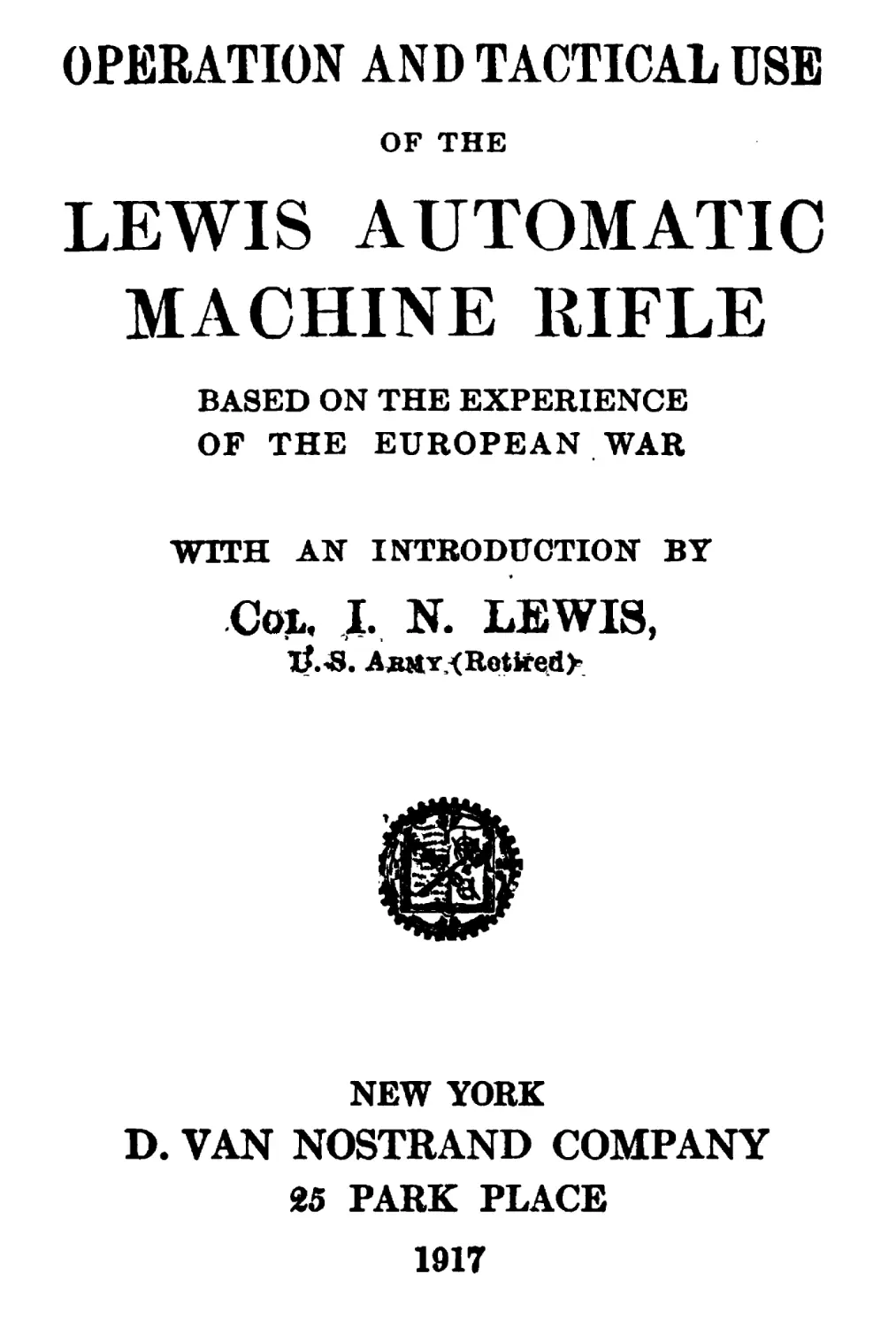
OPEBATION AND TACTICAL DSE
OF THE
LEWIS AUTOMATIC
MACHINE RIFLE
BASED ON THE EXPERIENCE
OF THE EUROPEAN WAR
WITH AN INTRODUCTION BY
Col, I. N. LEWIS,
iL-S. AjutT,<Retirei<l>.
NEW YORK
D. VAN NOSTRAND COMPANY
25 PARK PLACE
1917
GUN COMPLETE, WITH MAGAZINE AND LIGHT BIPUD MOUNT
Frontiepiece
Copyright, 1917, by
D. VAN NOSTRAND COMPANY
INTRODUCTION
I have read carefully the manuscript of
this Instruction pamphlet on the Lewis
Automatic Machine Rifle. The descriptive
text is full and accurate in detail, while
the system of preliminary and practical
field instruction as outlined follows closely
that now employed at the various machine
gun schools and special instruction camps
ir. England and France.
In our own service, the machine gun is as
yet a new and untried weapon, and I there-
fore believe the general principles governing
the present operation and tactical use on
the great battlefield of Europe, as briefly
presented herein, will be of interest to all
officers, non-commissioned officers, and men
of our Army, Navy and Marine Corps.
Colonel U. S. Army
(Retired).
Иттяяит.т, Terrace, Montclair, N. J.
April 29,1917.
v
PREFACE
PART I
In producing this little book on the “Lewis
Gun,” the writer wishes to impress on all
the need for “ proper handling ” of a ma-
chine gun.
This “ proper handling ” can be gained
only by thorough attention to drill, the
novice thereby gaining experience in the
moving of the gun from one position to
another.
The greatest importance should be at-
tached to “ correctness ” in drill. Correct
drill on the parade ground insures proper
discipline and carrying out of orders when
in action, while laxity in this respect may
lead to mistakes being made under fire
which may have the direst effects.
There is often a great tendency to slur
over movements and move quickly at the
expense of accuracy. This is wrong, and
• •
vu
• • •
УШ
PREFACE
should be checked ii
MUI
ediately in the train**
ing of men on a machine gun.
Each beginner should be allowed to strip
and assemble the gun himself; by this means
only can he attain proper familiarity with
the parts and operation of the gun. And at
a later stage he should be asked to explain
to the rest of the class the backward and
forward action of the gun.
These are the only means for checking his
real knowledge of the working of the gun;
for, although he may think he understands
it perfectly when the instructor has ex-
plained it, he will find at once where he is
at fault when he has himself to handle the
gun, or explain its working.
All connected with machine guns should
be so familiar with the gun and its working,
that it should come as second nature to
them to manipulate or fire the gun, and
correct any faults or stoppage that may
occur.
PART II
In Part II the training of machine gun
sections in the tactical handling of machine
guns is briefly considered. Chapters are
given on all the more important questions
of tactical handling.
PREFACE
IX
This subject cannot be dealt with at all
fully in any book of this size; a large book
could be written on “ The Use of Machine
Guns in Trench Warfare ” alone.
It is, however, of the utmost importance
that all members of machine gun companies
should be instructed in these matters.
While this is important, it is still more
so that beginners should first master the
mechanism and drill of the guns, and then
proceed to tactical handling.
If tactical handling is dealt with too early
in the training or course, its value is greatly
decreased, because the men are not able to
“ handle ” the guns properly. The only
way to gain this familiarity with the weapon
is by strict attention to drill and mechanism
(vide Preface to Part I).
N.B.—The “ Characteristics of the Ma-
chine Gun ” (Chapter X), if thoroughly
known and understood by noncommissioned
officers and men, will greatly assist them in
tactical handling.
.CONTENTS
PAGE
Introduction by Cql. I. N. Lewis,
U. S, A..........................v
Preface........................vii
PART I
MECHANISM AND DRILL
CHAPTER
I. The Chief Features of the
Gun.......................1
- II. The Parts of the Gun . . 7
III. Operation of the Gun . 40
IV. Stripping and Assembling
the Gun.......................45
V. Tension of the Mainspring 50
VI. Gas Regulator .... 53
VII. Points before and after Fir-
ing .....................54
xi •
CONTENTS
XI’
VIII. Stoppages.................56
IX. Gun Drill for the Lewis
Automatic Machine Rifle . 60
PART II
THE HANDLING OF THE GUN
CHAPTER PAGE
X. Characteristics of the Ma-
chine Gun .... 67
XI. Allocation of Duties . 71
XII. Indication and Recognition
of Targets- .... 77
XIII. Signals..................80
XIV. Methods of Fire ... 82
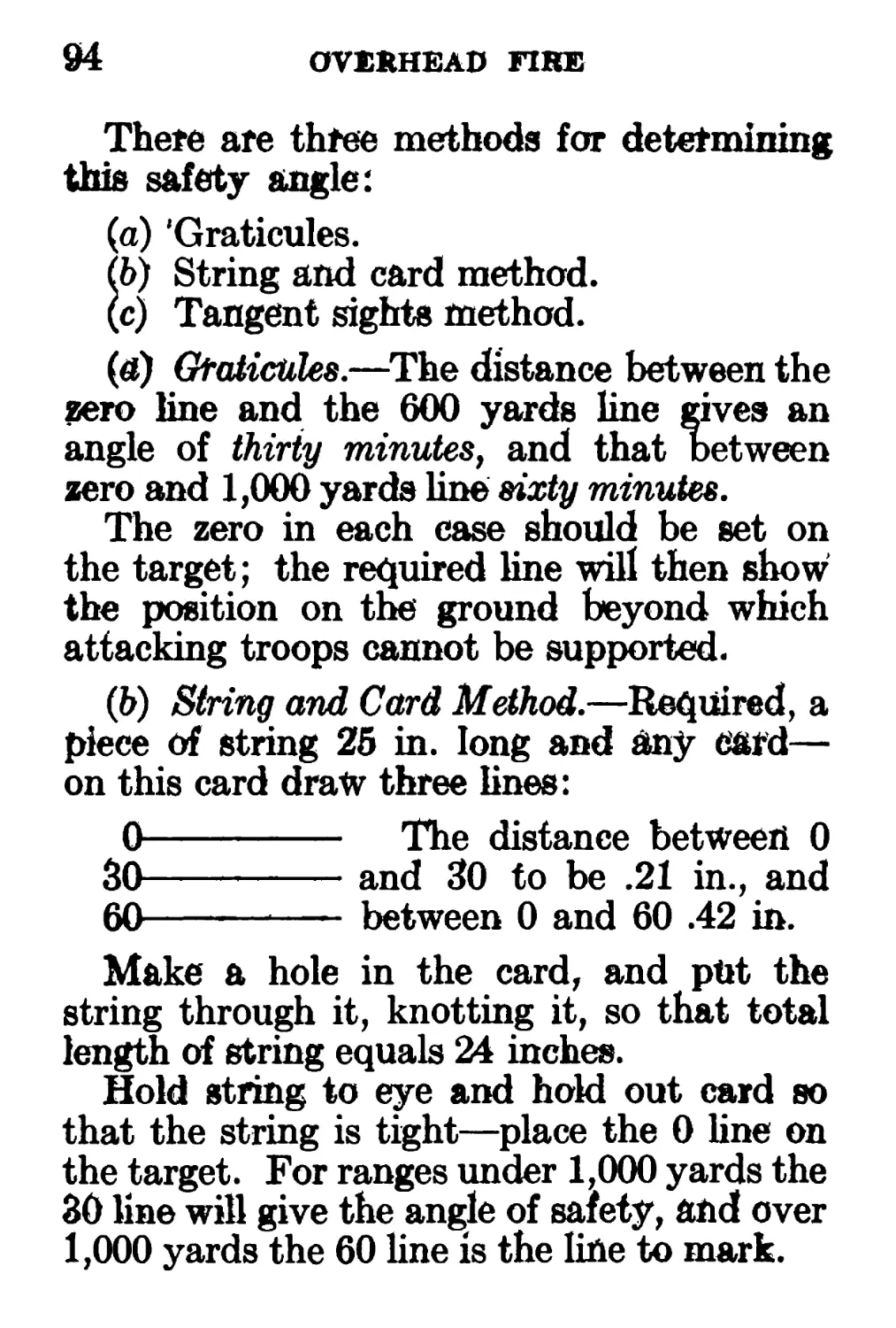
XV. Overhead Fire ... 92
XVI. Indirect Fire .... 96
XVII. Use of the Machine Gun
in Trench Warfare . . 100
XVIII. Use of the Machine Gun
in Open Warfare . . 105
XIX. The Brigading of Machine
Guns..........................116
CONTENTS xiii
XX. Range Finding . . . 121
XXI. Programme of Training for
Machine Gun Units . . 142'
XXII. Emplacements for Lewis
Gun...........................148
LIST OF ILLUSTRATIONS
PAGC
GUN COMPLETE, WITH MAGAZINE AND LIGHT
bipod mount..................Frontispiece
GUN COMPLETE, WITH MAGAZINE AND RIFLE
BUTTSTOCK...........................11
GUN PARTS: BARREL GROUP AND OPERATING ROD . 25
GUN parts: receiver group, mainspring, and
TRIGGER MECHANISM...................27
GUN parts: feed mechanism, bolt, extrac-
tors, AND EJECTOR...................29
MAGAZINE, TOP AND BOTTOM VIEWS . . 31
BUTTSTOCKS AND MAGAZINE FILLING HANDLE . 33
4.
SHELL DEFLECTOR . . . .35
MOUNTING YOKE AND STANDARD. ... 37
LIGHT FOLDING FIELD MOUNT .... 39
Operation and Tactical Use of the
Lewis Automatic Machine Rifle
PART I
MECHANISM AND DRILL
CHAPTER I
THE CHIEF FEATURES OF THE GUN
1. Simplicity. — The mechanism and
working of the gun are so simple that they
can easily be understood, after explanation,
by any one, however unaccustomed he may
be to the handling of machine guns.
Three days’ instruction at most should
suffice for the novice to understand thor-
oughly the working of all parts of the gun.
2. Few Parts.—The parts are very few
in number and cannot be wrongly assembled.
Including every stud and smallest piece
there are but sixty-two to the gun.
2 THE CHIEF FEATURES OF THE GUN
It should always be remembered that no
force is needed in assembling or stripping
the gun. If force is necessary something
is wrong.
3. Operation.—The Lewis Gun is oper-
ated by the trapping of a portion of the
powder gases formed by the explosion of
each cartridge.
These gases follow the bullet down the
barrel and a part of them escape through a
port in the barrel, and after being cleansed,
into a gas cylinder on the underside of the
barrel, where they impinge upon a cup-
faced piston, driving it to the rear.
The piston rod has on its lower side a
rack, which in moving to the rear, engages
with a pinion wheel; causing it to rotate
and so wind up a circular spring inside it.
The gases having expended their energy,
the spring unwinds and drives the piston
forward by means of the pinion engaging
with the rack of the piston.
4. Cooling.—The gun is cooled by air and
not by water, this being an advantage, in
that water is not always easily obtainable;
it also considerably lightens the gun for
purposes of carrying.
Closely fitting round the barrel is an
THE chief features of the gun 3
aluminium radiator, with fins running the
length of the barrel.
5. Radiator.—Aluminium, while being a
very light metal, is also a very good con-
ductor of heat, and this enables the barrel
to give off a great amount of the heat caused
by the explosion of the powder gases.
This radiator is secured to the barrel
by means of a barrel mouthpiece (screwed on
to the muzzle). The shape of this barrel
mouthpiece, and of a steel tube, called the
front radiator casing, causes a draught to
be set up by the gases as they rush for-
ward.
This draught sucks cool air from the
breech end of the radiator, under the rear
radiator casing, towards the muzzle, thus
cooling the gun.
6. Velocity.—This system of cooling, in
addition to its other advantages, prolongs
the pressure of the gases on the bullet, after
it has left the barrel; while it passes through
the barrel mouthpiece, and to a lesser extent,
through the front radiator casing. This
increases the velocity of the bullet and
more than compensates for the small por-
tion of gases used to operate the gun.
The bullet is found to have a greater
4 THE CHIEF FEATURES OF THE GUN
velocity than is the case with a rifle of the
same length of barrel.
7. Recoil.—The design of the barrel
mouthpiece and front radiator casing are
found, while producing a satisfactory cool-
ing system, to reduce the recoil of the gun
to a minimum, owing to the gases as they
rush forward striking against them.
8. Mounting of the Gun.—Owing to
the almost entire absence of recoil the gun
may be fired from the shoulder, with or
without a rest, by a powerfully built man.
For the same reason any tripod or mounting
used for this gun need not be so strong, and
so not so heavy, as is the case with other
machine gun mountings.
Owing to the ejection opening being at
the side, the gun may be rested in the
lowest positions, without in any way inter-
fering with the ejection.
9. Grouping.—The absence of recoil in-
sures the best grouping results when firing.
A complete novice may obtain an excellent
group, where in the case of an ordinary
machine gun much practice in holding would
be necessary.
10. Portability.—The gun weighs only
THE CHIEF FEATURES OF THE GUN 5
26 pounds, and so may be easily carried
from one position to another by one man.
11. Buttstocks.—Two types of butt-
stock are issued with the gun:
1. The ordinary rifle buttstock, which en-
ables the firer to keep a good hold on the
gun, and to fire it with ease from the
shoulder.
2. The spade-grip, which is of use in
confined positions where it is required to
reduce the length of the gun, as in an air-
plane.
12. Feed by Magazines.—The feeding of
the cartridges into the gun is carried out by
means of circular steel magazines holding
forty-seven rounds each. The walls of
these magazines are corrugated, partly for
strength and also to enable the magazine
to be rotated mechanically by a step-by-
step motion, thus feeding the cartridges
into the feed way in turn.
The shape of the magazine insures balance
and satisfactory feeding for any position of
the gun.
As each cartridge arrives in position in its
turn, the magazine is securely locked by
the stop and rebound pawls catching
against the corrugations in the magazine
0 THE CHIEF FEATURES OF THE GUN
walls. These prevent the magazine from
rebounding or rotating too far.
Each cartridge is firmly held in position
in the magazine. And once a magazine is
properly filled and in good order it cannot
give trouble.
[CHAPTER II
THE PARTS OF THE GUN
The parts of the gun may be conveniently
divided into four headings or “ Groups
1. Barrel group (six parts).
2. Receiver group (four partsX
3. Working parts (nine parts).
4. Buttstock (two parts).
1. Barrel Group
1. The Barrel is round in section, taper-
ing towards the muzzle, where it is tnreaded
to allow of the barrel mouthpiece being
screwed on.
The chamber end of the barrel is also
threaded, to permit its being screwed into
the receiver.
About four inches from the muzzle the
barrel has a small hole, called the “ gas
port,” on its underside to allow the gas to
pass through into the gas cylinder.
2. Barrel Mouthpiece.—This screws on
to the muzzle and is a tubular Hut of special
7
8
THE PARTS OF THE GUN
shape. It is so designed that it causes the
gases to produce the draught (referred to in
Chapter I) for cooling purposes, and also to
check the recoil. It also secures the radia-
tor in position.
3. Radiator is made of aluminium, a
very light metal, but a good conductor of
heat. It fits closely over the barrel, and has
fins running the length of the barrel, along
which the cooling air is drawn.
4. Radiator Casing.—This consists of
three parts. Parts 1 and 2 are made of thin
tubular steel, slightly checked to prevent it
shining in the sun.
1. The front radiator casing, which in
conjunction with the barrel mouthpiece
aids in the cooling system.
2. The rear radiator casing, which covers
the aluminium radiator, and confines the
cooling air to the radiator fins.
This part is permanently fixed to:
3. The rear locking piece, which on the
top has a flat platform over which the
magazine passes, and underneath a recess
for the receiver locking pin, which by this
means locks the barrel group.
It also has a hole underneath, into which
THE PARTS OF THE GUN
9
the gas cylinder fits, and is thereby kept in
position.
6. Rear Mounting Band.—The rear
radiator casing has upon it three inches from
the rear a metal band for mounting the
gun. This band is necessary, as the thin
radiator casing would not be strong enough.
6. Clamp Ring.—This fastens or clamps
together the front and rear radiator casings.
Front Sight-adjusting Screw.—It also con-
tains the front sight with its adjusting
screw, for correcting errors in the sighting
of the gun.
Clamp Ring Screw:—It is clamped by
means of the damp ring screw.
This damp ring can be used as a front
mounting band.
Gas Fittings
- 7. Barrel Band and Gas Chamber.—
Over the “ gas port ” in the barrel fits a
band called the “ barrel band into this
screws the gas chamber.
8. Gas Regulator.—Into the bottom of
the gas chamber is screwed the gas regulator,
which is turned or held in position at will,
by the gas regulator key. It has two holes *
♦ Four in some models.
10
THE PARTS OF THE GUN
marked L. and 8. (“ Large ” and “ Small ”).
These marks are put on the underside of the
gas regulator to make it easy to see which
hole is in use.
The gas regulator serves as a repository
for all foreign solid matter which the gases
may hold.
9. Gas Cylinder.—On to the rear of the
gas chamber is screwed the gas cylinder.
2. Receiver Group
The receiver has two bores cut in it, run-
ning parallel to each other; these bores
are connected for the greater part of their
length by the slot in which the striker post
moves.
1. Bolt Way.—The upper bore forms the
bearing along which the bolt moves, and at
the rear end has four key-ways cut, acting
as paths for the cruciform lugs. These
key-ways are called the Cruciform Ways.
At the front end of the cruciform ways is
a recess called the Locking Recess into
which the cruciform lugs turn, thereby lock-
ing the bolt.
The top of the receiver has a slot cut in it,
to form a passage for the feed operating arm
stud.
GUN COMPLETE WITH MAGAZINE AND RIFLE BUTTSTOCK
12 THE PARTS OF THE GUN
Also in front of this slot is cut the feed-
way slot through which the cartridges pass
from the magazine to the chamber.
The top of the receiver has on its left side
a recess which forms the seat for the ejector,
which operates through two small slots in
the front and rear of the bolt way. There
is also a small recess to receive the ejector
stud, which is thereby held and pivoted.
The lower bore in the body forms a path
for the piston rod.
The Magazine Post is also on top of the
body and has a feather cut upon it (called
the centre key) to enable the magazine to be
firmly secured in the correct position.
The Cartridge Guide and Cartridge
Guide Spring are on the left side of the
feed ways, and hold the cartridge in posi-
tion, until the bolt pushes it down and into
the chamber.
The Ejector Opening is on the right-
hand side of the bolt way.
The charging handle operates in a slot,
on the left side of the piston rod way.
2. The Hand Grip and side pieces carry
the trigger mechanism and serve as a grip
for the firer.
THE PARTS OF THE GUN 13
3. Feed Cover fifs the top of the re-
ceiver and forms a covet for the feed
mechanism; it has upon it the stop and
rebound pawls.
4. Gear Casing.—This forms a casing
for the gear of the mainspring, and has upon
its front end a hook which attaches it to
the receiver when fitted over the gear
casing hinge pin.
3. Working Parts
1. Piston Rod.—This has assembled on it
the piston, the rack, the striker post, and
striker.
The sear is cut in the flat surface at the
rear of the rack.
The striker is attached by the striker
fixing pin to the top of the striker post.
2. The Bolt is cylindrical in form. It
is fitted at the rear end with four cruciform
lugs, which, when turned into the locking
recess, resist the shock of discharge.
It is threaded internally at its rear end
to receive the feed operating arm stud.
On the underside is cut the curved cam
slot, which serves as a way for the striker
post.
There are two longitudinal recesses in the
14
THE PARTS OF THE GUN
front of the bolt, which take the two extrac-
tors. These are strips of metal, which are
notched at the end in order that they may
grip the base of the cartridge and over which
they are sprung when the bolt forces the
cartridge into the chamber.
The front end of the bolt is recessed like
the bolt of a rifle, to form a seat for the
cartridge; there is a gap in the wall of the
recess, through which the ejector strikes the
cartridge and ejects it.
Feed Operating Arm Stud screws into
the rear end of the bolt, and has upon it four
cruciform lugs corresponding to the lugs on
the bolt. These lugs are purely for guiding
the stud, and are not a means of locking the
stud, as are the lugs on the bolt.
The stud does not turn when the bolt turns.
The top lug is called the/eed operating arm
stud, and, working in the groove on the
underside of the curved finger of the feed
arm, causes it to have a transverse motion.
3. Feed Arm is fitted over the magazine
post and is there pivoted; it is secured to
the post by the feed latch.
The curved finger of the feed arm has
on its underside a groove, along which the
boss of the feed operating arm stud works.
THE PARTS OF THE GUN
15
The main surface of the arm has a slot
cut in it, through which the cartridge passes
from the magazine to the chamber.
On the left side of this slot is a raised
strip of metal called the “ projection,” which
assists in the guiding of the cartridge. Also
on the feed arm are assembled:
1. The feed pawl, which is pivoted in the
right stud.
2. The feed pawl spring, which is fastened
to the left stud.
3. The left stud, which works the stop
pawl.
4. Stop and Rebound Pawls.—These
are fitted on studs inside the feed cover,
and are pressed outwards by the magazine
pawls spring and engage in corrugations in
the magazine.
The stop pawl, which is worked by
the left stud, prevents the magazine from
being rotated too far.
The rebound pawl prevents the magazine
from rebounding.
5. Mainspring. — This is a circular
spring, and fits inside the mainspring
casing, which in turn fits inside the pinion,
which is fitted inside the gear-casing.
One end of the spring is fixed by means
16
THE PARTS OF THE GUN
of the mainspring rivets, and the other
end by the mainspring collet, into which
fits the tension screw.
The gear is held by the gear stop vhen
the hand grip is not on, and the rack not
in mesh with the pinion.
6. The Trigger Mechanism.—The trig-
ger is enclosed in the guard and is secured
by the trigger pin.
At the front end is the plunger and spring;
this holds up the sear unless trigger is
pulled.
At the rear end is a knuckle joint which
operates the sear, which is at the rear end
of the hand grip, and attached to it by the
sear pin.
7. Charging Handle.—This fits into the
rear end of the piston rod on the left side,
and works backwards and forwards along a
narrow slot cut in the side of the receiver.
It can only be fitted on when the piston
rod is in the farthest back position.
8. Safety Slide.—This is on the left
side of the body, and is a narrow strip of
steel, which can be slid over the slot, which
forms a way for the charging handle; it
then forms a protection against dust.
THE PARTS OF THE GUN 17
It has a slot cut in it so that the charging
handle can be firmly held in the ready-to-
fire position; it then forms a safety catch.
4. Buttstocks
1. Rifle Buttstock.—This part need
never be stripped. It fits into the body,
and is held there in position by the butt-
stock catch.
The tang of the buttstock stops the piston
rod from going too far back.
2. Spade Grip, which can be used instead
of the rifle buttstock, consists of a single
hand grip, made of wood. In all other
respects it is the same as the rifle butt-
stock.
It is used in confined places and од
airplanes.
5. Magazine
The magazine, which holds forty-seven
rounds, and feeds them into the gun as
required, consists of the following parts: .
1. The magazine pan. This holds the
interior spacer ring, which is fastened to it
by rivets, and holds the interior separators;
these are pins which keep the front ends
of the cartridges apart.
18
THE PARTS OF THE GUN
2. The wall of the magazine is corru-
gated: on the inside these corrugations hold
in position the bases of the cartridges, while
on the outside they enable the feed pawl
to rotate the magazine, and the stop and
rebound pawls to prevent too much rota-
tion, or rebound.
3. The magazine centre is made of alu-
minium, and is fastened to the pan by means
of the magazine top plate.
4. The magazine latch, which is operated
by the magazine latch spring, holds the
magazine on the magazine post, once it is in
position.
It has a deep turned cut in it to enable
two rows of cartridges being held in the
magazine, and fed in turn into the feed
way.
5. The magazine centre fits over the maga-
zine post, and is held there by the centre
key and spring. It remains stationary while
the magazine rotates.
For purposes of testing and filling the
magazine, a ° filling handle ” is supplied.
Before filling, the magazine should be
turned several times on the filling handle,
to see that it rotates freely. If it shows
signs of having grit in it, it should be thor-
oughly washed in paraffin and then oiled.
THE PARTS OP THE GUN
19
6. Light Folding Field Mount.—This
is a three-and-a-half pound folding mount
adapted for general use with infantry and
cavalry in the field. The mount is sur-
prisingly rigid and permits of very accurate
shooting. Both front and rear mounting
yokes, connected through the centre post
and rear brace, are pivoted about the axis
of the centre post so that the gun is always
free to traverse. The gun is also free to
turn within the yokes, so that the sights
may always be kept vertical no matter what
the position of the feet. When the mount is
attached, it is often convenient to use the
rear brace as a handle for carrying the gun.
The Mounting Yoke is the device adopt-
ed to secure the gun on any desired form of
mounting.
The Shell Deflector is an attachment
for controlling the ejection of the empty
cartridge cases. It is very readily and
quickly attached and when in position can
be instantly swung back out of the way
so that the inside of the gun may be exam-
ined or any part of the mechanism reached.
NUMBERED LIST OF PARTS
1. Butt Plate.
2. Butt Plate Screws
(2).
3. Buttstock.
4. Butt Tang Screw.
5. Butt Tang.
7. Butt Latch.
8. Back Sight Bed
Spring.
9. Back Sight Bed
Spring Screw.
ю 10. Butt Latch Spring.
° 11. Back Sight Bed.
13. Feed Cover.
14. Back Sight Leaf.
20. Back Sight Slide.
21. Ejector.
22. Guard Side Pieces
(2)
23. Back Sight Axis Pin
asher
24. Back Sight Axis Pin.
26. Receiver.
27. Magazine Pawls
Spring.
28. Stop Pawl.
29. Rebound Pawl.
30. Trigger.
31. Feed Operating
Stud.
32. Safety.
33. Trigger Pin.
34. Feed Operating Arm.
35. Feed Pawl.
36. Feed Pawl Spring.
37. Bolt.
38. Charging Handle.
39. Guard.
40}. Cartridge Guide
Complete.
40. Cartridge Guide
Spring.
40a. Cartridge Guide
Lever.
405. Cartridge Guide
Pin.
41. Sear Spring.
42. Sear Spring Box
43. Magazine Pan.
44. Ejector Cover.
45. Extractors (2).
46. Gear Stop.
47. Striker Fixing Pin.
48. Gear Stop Pin.
49. Gear Stop Spring.
50. Striker.
51. Cartridge Spacer
Ring.
52. Gear.
53.. Mainspring Casing.
54. Magazine Top Plate
Rivets (6).
55. Mainspring.
56. Collet Pin.
57. Mainspring Collet.
58. Magazine Centre.
59. Mainspring Rivets
(2).
60. Magazine Latch
Spring.
61. Gear Casing.
62. Magazine Latch.
63. Centre Key.
65. Gear Case Hinge
Pin.
66. Feed Operating Arm
Latch.
67. Magazine Top Plate.
68. Receiver Lock Pin. .
69. Spacer Ring Rivets
T (5)-
70. Intenor Separator
Pin.
71. Radiator Casing
Rear Locking
Piece.
72. Rack.
74. Radiator Casing
Rear.
75. Piston Connecting
Pin.
76. Barrel.
77. Gas Cylinder.
78. Radiator.
79. Piston.
80. Regulator Key Stud.
81. Gas Regulator Key.
82. Gas Chamber.
83. Gas Chamber Band.
84. Gas Regulator Cup.
85. Clamp Ring.
86. Front Sight.
87. Clamp Ring Po-
sitioning Screw.
88. Clamp Ring
Screw.
89. Barrel Mouthpiece.
90. Radiator Casing
Front.
91. Sear Rear.
92. Hand Grip.
96. Spade Grip Butt
Tang.
97. Deflector.
98. Deflector Arm.
99. Deflector Arm Joint
Pin.
100. Deflector Clip.
101. Deflector Clip Joint
[2 Pin.
102. Deflector Bracket.
103. Deflector Clamp
Screw.
104. Deflector Latch.
105. Deflector Latch
Screw.
106. Deflector Clamp
Screw Washer.
107. Deflector Clamp
Screw Stop Nut.
108. Shell Catcher Bag.
109. Mounting Yoke.
110. Mounting Yoke
Clamp.
111. Mounting Yoke
Pillar.
112. Mounting Yoke
Pillar Screw.
113. Mounting Yoke
Clamp Hinge Pin.
114. Mounting Yoke
Clamp Pin.
115. Mounting Yoke
Clamp Key.
116. Back Sight Elevat-
ing Screw.
117. Back Sight Elevat-
ing Screw Head.
118. Back Sight Elevat-
ing Screw Head
Pin.
119. Back Sight Elevat-
ing Screw Head
Spring.
120. Sear Pin.
121. Butt Latch Pin.
122. Mounting Yoke
Pillar Hinge Pin.
123. Mounting Yoke
Spring.
124. Mounting Stand-
ard.
125. Light Field Mount
Bottom Cross-
brace.
126. L. F. M. Center
Post.
127. L. F. M. Feet (2).
128. L. F. M. Front Legs
129. L. F. M. Front
Yoke.
130. L. F. M. Knuckle-
Joint.
131. L. F. M. Knuckle
Joint Pin.
132. L. ’ F. M. Rear
Prn.ee
133. L. F. M. T. Joint,
Centre.
134. L. F. M. T. Joint,
Side (2).
135. L. F. M. Top Lug.
136. Barrel Mouthpiece
Spanner.
137. Magasine Filling
Handle.
138. Shell Extractor*
ALPHABETICAL LIST OF PARTS
76. Barrel.
89. Barrel Mouth-
piece.
37. Bolt.
7. Butt Latch.
121. Butt Latch Pin.
10. Butt Latch Spring.
1. Butt Plate.
2. Burr Plate Screws.
(2)
ьэ 3. Buttstock.
w 5. Butt Tang.
4. Butt Tang Screw.
40). Cartridge Guide
Complete.
40. Cartridge Guide
Spring.
40a. Cartridge Guide
Lever.
40b. Cartridge Guide
Pin.
63. Centre Key.
38. Charging Handle.
85. Clamp King.
87. Clamp Ring Po- ^52. Gear. 65. Gear Case Hinge 90.
sitioning Screw.
88. Clamp Ring Screw. Pin. 74.
56. Collet Pin. * 61. Gear Casing.
21. Ejector. 46. Gear Stop. 71.
44. Ejector Cover. 48. Gear Stop Pin.
45. Extractors (2). 49. Gear Stop Spring.
13. Feed Cover. 39. Guard. 29.
34. Feed Operating Arm. 22. Guard Side Pieces (2). 26. 68.
66. Feed Operating Arm Latch. 27. Magazine Pawls Spring. 32.
31. Feed Operating Arm Stud. 55. Mainspring. 91.
53. Mainspring С a s - 120.
35. Feed Pawl. ing. 41.
36. Feed Pawl Spring. 57. Mainspring Collet. 42.
86. Front Sight. 59. Mainspring Rivets 28.
82. Gas Chamber. (2). 50.
83. Gas Chamber 79. Piston. 47.
Band. 75. Rack Assembling 30.
77. Gas Cylinder. Spring. 33.
84. Gas Regulator Cup. 72. Rack.
81. Gas Regulator Key. 78. Radiator.
Radiator Casing
Front.
Radiator C a s in g
Rear.
Radiator Casing
Rear Locking
Piece.
Rebound Pawl.
Receiver.
Receiver Lock Pin.
Safety (Right and
Left).
Sear.
Sear Pin.
Sear Spring.
Sear Spring Box.
Stop Pawl.
Striker.
Striker Fixing Pin.
Trigger.
Trigger Pin.
24
THE PARTS OF THE GUN
PLATE II
Barrel Group and Operating Rod
76^ Barrel.
89. Barrel Mouthpiece.
83. Gas Chambei Band.
78. Radiator.
90. Radiator Casing, Front.
74. Radiator Casing, Rear.
71. Radiator Casing, Rear, Locking Piece.
136. Barrel Mouthpiece Spanner.
84. Gas Regulator.
81. Gas Regulator Key.
86. Front Sight.
88. Clamp Ring Screw.
87. Clamp Ring Positioning Screw.
85. Clamp Ring.
77. Gas Cylinder.
79. Piston.
75. Piston Connecting Pin.
72. Rack.
50. Striker.
47. Striker Fixing Pin.
6. Rear Mounting Band.
gun parts: barrel group and operating bod
26
THE PARTS OF THE GUN
PLATE III
Receiver Group and Mainspring and Trxggsb
Mechanism
26. Receiver.
11. Magazine Post.
63. Centre Key.
32. Safety.
91. Sear.
65. Gear Casing Hiage Pin.
68. Body Locking Pin.
Gear and Mainspring
56. Tension Screw.
46. Gear Stop.
49. Gear Stop Spring.
61. Gear Casing.
52. Pinion.
55. Mainspring.
57. Mainspring Collet.
53. Mainspring Casing.
59. Mainspring Rivets.
48. Gear Stop Pin.
Hand Grip and Trigger Mechanism
121. Butt Latch Pin.
7. Butt Latch.
91. Sear.
120. Sear Pin.
33. Trigger Pin.
42. Sear Spring Box.
30. Trigger.
39. Hand Grip.
22. Guard Side Pieces.
gun parts: receiver group, mainspring, and trigger mechanism
28
THE PARTS OF THE GUN
PLATE IV
Fbbd Mechanism, Bolt, Extractors, and Ejector. Back
Sight
37. Bolt.
45. Extractors (2).
31. Feed Operating Arm Stud.
3tx. Feed Operating Arm Stud BottK
34. Feed Arm Fiuger.
q. Left Stud.
r. Right Stud.
p, Feed Way.
35. Feed Pawl.
36. Feed Pawl Spring.
«Т Projection of Feed Arm.
66. Feed Operating Arm Latch.
21. Ejector.
44. Ejector Cover.
40. Cartridge Guide Spring.
27. Magazine Pawls Spring.
28. Stop Pawl.
29. Rebound Pawl.
13. Feed Cover.
Back Sight
9. Back Sight Bed Spring Screw.
8. Back Sight Bed Spring
11. Back Sight Bed.
24. Back Sight Axis Pin.
23. Back Sight Axis Pin Washer.
20. Back Sight Slide
14. Back Sight Leaf.
116. Back Sight Elevating Screw.
117. Back Sight Elevating Screw Head.
117
30
THE PARTS OF THE GUN
PLATE V
The Magazine (Plate V) is an assembled unit composed of
the following parts:
51. Cartridge Space Ring.
70. Interior Separators (25).
58. Magazine Centre.
62. Magazine Latch.
60. Magazine Latch Spring.
43. Magazine Pan.
67. Magazine Top Plate.
54. Top Plate Rivets (6).
69. Spacer Ring Rivets (5).
MAGAZINE, TOP VIEW
MAGAZINE, BOTTOM VIEW
32
THE PARTS OF THE GUN
PLATE VI
Buttstock Group
The Rifle Buttstock is a single assembled piece composed of:
1. Butt Plate.
2. Butt Plate Screws (2).
3. Buttstock.
4. Butt Tang Screw.
5. Butt Tang.
The Spade Grip is for use when preferred to ordinary Butt *
stock.
92. Hand Grip.
96. Spade Grip Butt Tang.
136. Magazine Filling Handle.
BUTTSTOCKS AND MAGAZINE FILLING HANDLE
34
THE PARTS OF THE GUN
PLATE VII
Shell Deflector
97. Deflector.
98. Deflector Arm.
99. Deflector Arm Joint Pin.
102. Deflector Bracket.
103. Deflector Clamp Screw.
107. Deflector Clamp Screw Stop Nut»
106. Deflector Clamp Screw Washer.
100. Deflector Clip.
101. Deflector Clip Joint Pin.
104. Deflector Latch.
105. Deflector Latch Screw.
108. Shell Catcher Bag.
102
98
SHELL DEFLECTOR
36
THE PABTS OF THE GUN
PLATE VIII
Mounting Yoke and Stand ajld
109. Mounting Yoke
111. M. Y. Bronee Pillar.
123. M. Y. Spring.
110. M. Y. Clamp.
113. M. Y. Clamp Hinge Pin.
115. M. Y. Clamp Key.
114. M. Y. Clamp Pin.
122. M. Y. Pillar Hinge Pin.
112. M. Y. Pillar Screw.
124. Mounting Standard.
MOUNTING YOKE AND STANDARD
38
THE PARTS OF THE GUN
PLATE IX
Light Folding Field Mount
125. Light Field Mount Bottom Crossbrace.
126. L. F. M. Centre Post.
127. L. F. M. Feet (2).
128. L. F. M. Front Legs (2).
129. L. F. M. Front Yoke.
130. L. F. M. Knuckle Joint.
131. L. F. M. Knuckle Joint Pin.
132. L. F. M. Rear Brace.
133. L. F. M. T Joint, Centre.
134. L. F; M. T Joint, Side (2).
135. L. F. M. Top Lug.
Also 1 mounting Yoke Complete.
LIGHT FOLDING FIELD MOUNT
CHAPTER III
OPERATION OF THE GUN
Place a full magazine on the magazine
post, with the catch to the right, and draw
back the charging handle.
.• If the trigger is pressed, the gun will
commence to fire.
Single shots may be fired by pressing
and rapidly releasing the trigger.
To Unload
1. Remove magazine^ This leaves one
cartridge in the feed w^y.
Pull trigger and fire last round, pull
trigger again.
2. If the last round must not be fired,
remove magazine, take hold of charging
handle, pull trigger and ease cartridge for-
ward until it is in the bolt way. Pull back
charging handle, raise safety. Push car-
tridge from bolt way with bullet point.
40
OPERATION OF THE GUN
41
THE BACKWARD AND FORWARD
MOVEMENT
The mechanical or automatic working of
the gun may be divided under two headings:
I. The Forward Movement.
II. The Backward Movement.
I. The Forward Movement
Assuming that the gun is in the ready-to-
fire position with “ charging handle ” pulled
back.
1. Trigger.—The trigger is pulled, de-
pressing the nose of the sear, thus releasing
it from the bent on the piston.
2. Mainspring.—This enables the main*
spring to unwind itself, carrying forward the
piston, through the pinion acting on the
rack.
3. Bolt.—The left side of the sinker
post, bearing upon the left side of the curve
in the cam dot, drives the bolt forward.
4. Feed Arm.—The feed arm is imme-
diately moved from left to right by the feed
operating arm stud boss working under the
finger of the feed arm.
42
OPERATION OF THE GUN
6. Feed Pawl.—This causes the feed
pawl to slide over and engage in the next
corrugation in the magazine.
6. Left Stud.—The left stud also with-
draws the stop pawl.
7. Next Cartridge.—The top of the
fore part of the bolt, striking the bottom
of the base of the cartridge, forces it down
into the feed way, assisted by the cartridge
guide spring, as the bolt moves forward
into the chamber.
8. Ejector.—The fore part of the bolt
knocks against the fore part of the ejector,
knocking it in, and causing the rear part
of the ejector to protrude.
9. Cruciform Lugs and Locking Re-
cesses.—When the cruciform lugs reach
the locking recesses, the curve in the cam
slot forces the striker post to turn the bolt
one-eighth turn to the right, thus locking
the bolt.
10. Extractors.—The extractors spring
over the rim of the cartridge.
11. Striker.—The striker is now in the
straight part of the cam slot, and travels
the last 1| in. (the bolt being stationary)
OPERATION OF THE GUN
43
and fires the cap, still driven by the main-
spring.
II. Backward Movement
Assuming that the cartridge has just been
fired:
1. Gas.—The powder gases follow the
bullet down the barrel until 4 in. from the
barrel mouthpiece. Part of them escape
through (1) the gas port into (2) the gas
chamber into (3) the gas regulator, where
any sediment is deposited, back into (4)
the gas chamber and (5) into the gas cylin-
der, where hitting against the cup-shaped
front end of the piston they drive it back.
2. Mainspring.—The piston in going
back winds up the mainspring, through the
rack engaging on the pinion.
3. Bolt.—The striker post travelling back
1J in. in straight part of the cam slot,
bears with its right side on the right side
of the curve on the cam slot, rotating the
bolt to the left, and bringing the cruciform
lugs opposite the cruciform ways, and free-
ing them from the locking recesses.
From now onwards, the bolt takes part
in the backward movement.
44 OPERATION OF THE GUN
4. Extractors.—The extractors with-
draw the cartridge case from the chamber.
5. Ejector.—The rear end of the feed
operating arm stud, knocking in the rear
end of the ejector, causes the front end of
the ejector to knock against the cartridge
case, sending it from the extractors through
the ejector way in the receiver.
6. Feed Arm, Feed Pawl.—Directly the
bolt moves back, the feed operating arm
stud boss moves the feed arm from right to
left, causing the feed pawl to rotate the
magazine (clockwise), and to place another
cartridge under the cartridge guide spring.
7. Left Stud.—The left stud, which is
also on the feed arm, disengages the stop
pawl, thus allowing it to stop the magazine
from rotating too far.
8. The piston reaching its backward posi-
tion, the nose of the sear engages in the
bent on the piston unless the trigger be
held, in which case “ rapid fire ” will con-
tinue.
CHAPTER IV
STRIPPING AND ASSEMBLING
THE GUN
The gun can be stripped with the charg-
ing handle in any position. It is best that
the magazine should be taken off, the
chamber cleared, and the charging handle
put in the forward position to start with.
To Strip
1. Push forward the butt latch with the
point of a bullet, at the same time give the
buttstock a twist to the left. It is now
possible to withdraw the buttstock by
pulling it to the rear.
This removes the buttstock group, which
need not be stripped further.
2. Pull back the trigger and slide back
the hand grip until clear of the body, thus
removing the trigger mechanism.
3. Pull down the gear casing so that it
is clear from the rack, though it will usually
fall down of its own accord.
4. Remove the feed cover by sliding it to
the rear, until it is clear of the locking pro-
jections.
5. Pull back the charging handle, until it
45
46 STRIPPING AND ASSEMBLING THE GUN
reaches the rear of its slot way, and then
pull it out.
6. Remove the feed arm, by forcing back
the feed arm latch with a point of a bullet,
and lifting it from the magazine post.
7. Draw out the piston rod, and the bolt
which will be on the striker post. Take bolt
off striker post.
8. With the point of a bullet force back
the receiver locking pin and give the receiver
a turn to the left.
9. Unscrew the receiver from the barrel.
10. Unscrew the clamping screw by means
of gas regulator key. Remove clamp ring
and front radiator casing.
The receiver locking pin may be re-
moved, and the gear casing unhooked.
11. Unscrew and remove gas regulator.
12. Slide off (to the rear) the rear radiator
casing. A slight tap may be necessary.
13. Unscrew the gas cylinder from the
gas chamber; if stiff, the piston rod may be
re-inserted and used as a key.
14. Unscrew gas chamber; a spanner is
provided for this.
15. By unscrewing the barrel mouthpiece
slightly and dropping barrel and radiator on
to a block of wood (barrel mouthpiece down-
wards), it is possible to remove radiator
STRIPPING AND ASSEMBLING THE GUN 47
from barrel. The .radiator slides down
towards the muzzle. The barrel being
tapered, the barrel band slides with it.
This should not be done more often than is
absolutely necessary, as in renewing barrels.
Detailed Stripping
Receiver
Back Sight.—This can be removed by un-
screwing and withdrawing the bed spring
screw.
Ejector.—Push the point of a bullet into
the hole in the rear end of the ejector cover,
and lift cover up and push back. The
ejector can now be taken out.
In replacing ejector, it is most important
that the cover should be securely in place,
otherwise it projects and prevents the feed
arm finger from moving over to the left,
thereby stopping the charging handle from
coming right back.
Safety Slide can be forced from the side
of the body with a bullet point.
Mainspring
1. Push up gear stop, thereby allowing
spring to unwind itself by turning the
pinion wheel.
48 STRIPPING AND ASSEMBLING THE GUN
2. Unscrew and take out tension screw.
3. Shake pinion from gear casing.
4. Shake spring case from pinion.
. 5. The mainspring may be removed with
the point of a bullet.
Gear stop should not be stripped; this
can be done in case of necessity by driving
out the gear stop pin.
Hand Grip.—Drive out trigger pin and
sear pin, by means of a drift.
Draw back and remove trigger. Remove
plunger, spring and gear.
Bait Latch.—Drive out butt latch pin and
remove butt latch and butt spring.
In the ordinary course of events the
hand grip does not need to be stripped.
In assembling, care should be taken to
see that the axis pins are driven home,
otherwise the hand grip will not slide on to
the receiver.
The Striker may be removed from the
striker post by driving out the striker fix-
ing pin.
Bolt
Feed Operating Arm Stud.—Unscrew and
remove from bolt.
Extractors.—These are sprung into posi-
STRIPPING AND ASSEMBLING THE GUN 49
tion. To remove, place point of bullet
under groove and push away from centre
of bolt, at the same time pulling forwards.
Piston.—The forward end of the piston
connecting pin may be pressed out of its
notch in the piston by the point of a bullet
and piston can then be readily turned out
of the rack.
Assembling
The gun should be assembled, the parts
being put together in the reverse order to
that in which they are stripped.
The following points require attention:
1. The barrel band must be in proper
position with its hole over the gas port in
the barrel.
2. The gas chamber must be screwed so
that when the gas cylinder is screwed in,
it is true with the barrel.
3. The receiver locking pin. should be
well forward. This can easily be accom-
plished by raising the gear casing and letting
it fall again.
4. The charging handle having been in-
serted the piston should be pushed home,
the gear should then be engaged, and the
hand grip pushed up into place.
CHAPTER V
TENSION OF THE MAINSPRING
The tension of the mainspring must be
sufficient to counteract the pressure of the
powder-gases against the piston when it is
in its backward position and to drive it
forward again.
The ideal tension is of course that which
exactly balances’the pressure of these gases.
This is usually between 14 and 16 pounds.
The gun is found to fire very well with
the tension at 10| lb. however. This is
when the small hole of the gas regulator is
used. When the large hole is in use, a
greater tension will be required.
If the tension is too small miss-fires will
occur, and the back end of the piston rod
will hammer too hard against the tang of
the buttstock.
If the tension is correct, the bolt and rod
barely touch the tang.
If the tension is a little too high, the gun
will fire faster than usual.
If the tension is much too high, the force
50
TENSION OF THE MAINSPRING
51
of the gas will not be sufficient to drive
the piston back far enough to allow of the
base of the next cartridge being engaged by
the front of the bolt.
To Weigh the Tension
Take the spring balance issued with the
gun and fasten one end round the charging
handle. Hold the other end in one hand,
and pull the charging handle backwards and
forwards once or twice. Then retain charg-
ing handle about 1 in. from front position,
and read the spring balance.
To Increase Tension
Remove buttstock.
Slide hand grip back a short distance.
Hold gear casing up firmly, so that pinion
engages in rack, and pull back charging
handle.
Let gear case drop.
Push forward charging handle.
Push up gear case.
Engage hand grip.
If spring tension is correctly increased,
replace buttstock.
52
TENSION OF THE MAINSPRING
To Decrease Tension
Remove buttstock.
Draw back hand grip a short distance.
Let gear case drop.
Draw back charging handle.
Raise gear casing.
Push home hand grip.
This will release gear stop and cause
spring to unwind and carry home the piston
rack.
If decrease is sufficient, replace buttstock.
N.B.—For instructional purposes the re-
turn spring tension should be as light as
possible when not on the range, as the
constant release of the mechanism without
anything in the chamber if the tension is
high, is very apt to wear out the striker.
CHAPTER VI
GAS REGULATOR
Under ordinary circumstances the small
hole of the gas regulator should be used
(i.e., the “ S ” on the gas regulator turned to
the rear).
If after a long period of firing the gun
begins to fire slower than usual, the maga-
zine should be removed at the first oppor-
tunity, and the gas regulator taken out and
cleaned, also a single shot should be fired.
This will clear the gas port.
Firing should be resumed with the large
hole of the gas regulator turned towards the
rear.
53
CHAPTER VII
POINTS BEFORE AND AFTER FIRING
Before Firing
1. See that the bore is clean.
2. Weigh tension of mainspring, and see
that it is correct.
3. Clean and oil:
Gas regulator.
Gas cylinder.
Piston and bolt.
Rack and pinion.
Feed arm.
Feed pawl.
Stop and rebound pawls.
Hand grip.
4. See that magazines to be used are
properly filled, and that they are not bent
or damaged in any way.
After Firing
1. Unload immediately.
2. Clean and oil barrel.
54
POINTS BEFORE AND AFTER FIRING 55
3. Clean and oil gas chamber, gas regu-
lator, gas piston.
These may have a hard deposit upon
them; in this case it may have to be scraped
off with emery paper or a pen-knife.
Proceed as in “ Before Firing.”
Any part that may have been burred
should be smoothed with emery paper or a
file.
During Firing
Every opportunity should be taken to
clean and oil all working parts.
CHAPTER VIII
STOPPAGES
Position of Charging Handle. Immediate Action. Remedy in Detail. G Prbbable Cause. Method of Prep- aration for Instructional Purposes.
1st Position— Charging Handle. Forward. s 1. Try magazine. If it rotates freely to left, change it. 2. If magazine is fixed,pull back charging handle, and continue firing. 3. If 2 fails, change maga- zine. 4. If stoppage recurs, ex- amine feed pawl and scop and rebound pawls. If feed pawl is broken, magazine will not rotate. 5. If 3 fails and trigger be- ing pressed gun does not fire, examine mainspring. If light, tighten; if broken, change pinion Empty magazine, no round in chamber. (a) Missfire. (6) Space in mag- azine. c) Insufficient ro- tation of maga- zine. Damaged maga- zine. Damaged feed pawl or stop pawl. (a) W e a к or broken main- spring. (6) Broken or damaged striker Empty magazine on post. Charging handle forward On Range. Leave space in magazine. Dummy. Live round Dummy. •»
сл
2nd Position—
Less than a cart-
ridge length
from forward
position.
and casing. If main-
spring all right, change
piston rod.
6. If charging handle will
not come back, use
wooden handle or double
pull through. If stop-
page recurs, examine
chamber.
Use wooden handle or
double pull through and
pull back handle. Ex-
amine round ejected, if—
(a) Damaged or too large
round, contim e firing.
(b) If correct, take off
magazine, intei - clear-
ing plug into стмпЬег,
and push home with
bolt and withdraw witu.
front portion of sepa-
rated case.
(c) Separated case is tele-
scoped on to cartridge,
continue firing.
N.B.—In nine cases out of
ten, the next cartridge
pulls out the separation.
(d) If separation recurs
shortly, change bolt.
Hard extraction.
(a) Expansion of
empty' case.
(b) Grit or rust in
chamber.
On Range
Put damaged
dummy in
chamber, pull
trigger ana put
full magazine
on post.
Damaged round.
Separated case in
chamber.
File a groove
round cartridge
case 1 in. from
base.
Separated case
teteseoped о n
t- next cart-
ridge.
Ditto 1 in. from
shoulder.
Too sharp extrac-
tors, which cut
cartridge case
at base.
Position of Charging Handle. Immediate Action.
3rd Position— More than 3 in. back. 1. Examine ejection open- ing; if there is no ob- struction, pull back charging handle, con- tinue firing. If recurs, take out gas reg- ulator, remove maga- zine and fire one round, replace regulator large hole “ L ” to rear. 2. If on pulling back
СЛ QO handle there is little or no resistance, if main- spring is light, tighten; if broken, change. 3. If an empty case is in chamber or ejection opening, take off maga- zine, draw back charg- ing handle, and unload without firing. If empty case is in cham- ber, force out with clean- ing rod from muzzle end. If there are no signs of ex- tractors or only one ex- tractor gripping it, change bolt; otherwise continue firing.
Remedy in Detail. Probable Cause. Method pf Prep- aration for Instructional Purposes.
Clean out gas cylinder, oil working parts; if any roughness on striker post or cam slot in bolt, change them. Bolt has not gone back far enough to get behind base of cart- ridge. (a) Friction in gas cylinder. (b) Hard extrac- tion. Weak or broken mainspring. On Range. Weaken main- spring.
(a) Bad extractors (b) Hard extract*n (c) If empty case is in body, weak extractors о r broken ejector. On Range. Place empty case in cham- ber; magazine о n post, and pull trigger.
СЛ CD 4. If stoppage recurs, ex- amine ejector, exchange whichever is faulty. 5. If charging handle can- not be moved, remove magazine. If charging handle flies for- f or ward, change maga- zine. 6. If on removing maga- zine, charging handle re- mains in position as be- fore: (a) Help cartridge into correct position on feed way. (b) Test cartridge guide spring. (c) Test mainspring. (a) Damaged magazine jammed. (b) Magazine not properly on magazine post. (c) Broken maga- zine latch spring. (d) Broken or damaged mag- azine ring caus- ing it to jam. (a) Weak or bro- ken cartridge guide spring. (b) Too weak mainspring. (с) T о о much gas. On Range. Do not push mag- azine properly home.
(I) The tension of the mainspring can easily be told by pulling back the charging handle.
If the mainspring is broken, the tension screw will be ” out.”
Note.—If the gun continues to fire after the trigger is released, push forward trigger with hand on
opposite side to charging handle.
This will be caused by broken or weak spring, or damaged sear.
CHAPTER IX
GUN DRILL FOR THE LEWIS
AUTOMATIC MACHINE RIFLE
Part I
Gun Drill is a most important item in the
training of a Machine Gun Company. It
teaches discipline and steadiness, which may
be of the greatest value in an emergency,
and at the same time makes the Company
accustomed to the “ handling ” of the gun.
Attention should be paid to both smart-
ness and correctness in drill; without these
two qualities the gun drill of a company has
very little value.
It is important that the following points
should be observed:
(1) No. 1 must repeat all orders.
(2) All numbers working with the gun
must keep perfectly still until the command
“ at ease ” is given.
A man lying still is difficult to see, where
a man moving about may be observed with
the greatest of ease.
60
GUN DRILL 61
The sights should always be adjusted with
the left hand, as this preserves the balance
of the firer.
Mounting Gun
Command.—“ Take Post.”—(The gun
should be attached to the spade mounting
beforehand.)
No. 1 lies on the left of and beside the gun
and mounting.
No. 2 lies on the left and to the rear of the
gun with a magazine.
No. 3 lies to the right and to the rear of the
gun vzith a case of magazines.
Directly they have taken up their posi-
tions they should number again.
Nos. 2 and 3 look and see that all is cor-
rect and report “ all correct ” to No. 1, who
having looked round his gun shouts “ up.”
No. 2 holds up his hand.
“ Mount Gun.”—No. 1 grips the spade
mounting and the small of the buttstock and
doubles into position, and lies down, plac-
ing the buttstock to his shoulder and holding
it there with the left hand, while his right
is on the hand grip.
Directly he is ready he raises his tangent
sight, and when magazine is on pulls back
the cocking handle.
62
GUN DRILL
No. 2 doubles up, and lies down on the
left of the gun.
Directly No. 1 raises the tangent sight he
places the magazine on the magazine post
(catch to the right).
No. 3 doubles up, and places a case of
magazines in front of No. 2, in his reach.
And then doubles back and assumes a prone
position to the rear and to a flank.
Directly all is ready to open fire No. 1
shouts “ up ” and No. 2 holds up his hand, as
a signal to the machine gun officer.
No. 2 watches the machine gun officer for
signals.
“ Dismount Gun.”—No. 2 releases the
magazine catch and removes magazine, and
doubles back with it to his former position,
and lies down.
No. 1 taps down his sight while No. 2 is
removing the magazine, and directly maga-
zine is off, he puffs the trigger.
He then doubles back with gun to his
former position and lies down.
No. 3 doubles up and takes magazine case
back to his old position.
As soon as all are back correctly No. 1
shouts “ up ” and No. 2 holds up his
hand.
GUN DRILL
63
“ Change Round.”—No. 1 falls out.
No. 2 takes No. I’s place.
No. 3 takes No. 2’s place.
No. 4t takes No. 3’s place.
Directly they are down they number off,
and go ahead as in “ Take Post.”
“ Action.”—Same as “ Mount Gun ” only
No. 1 is given the range and object first, and
puts his sights to correct range before
doubling up.
“ Out of Action.”—Same as in “ Dismount
Gun.”
Part II
Orders.—The range should be given, then
some outstanding feature in the landscape,
or on the target, and lastly the actual ob-
jective. (Vide Chapter XII.)
On a practice target “ Range 700, left
hand group of skirmishers, left-hand figure.”
Horizontal Traverse
This method of fire is used for sweeping a
target of some considerable depth, and may
be done for practice on an ordinary practice
target at 25 yards.
On the command “ Traverse to right ” or
“ left ” No. 1 fires a burst, and then moves
64
GUN DRILL
his shoulders and fires another burst.
For practice purposes he should fire six
bursts, which means that he will make five
movements.
At 25 yards each of these movements
should be equivalent to 2 in., which at 100
yards would be 8 in., and at 600 yards would
be 4 ft.
At this range, allowing for cones of fire
(vide diagram page 85), the whole target
should be properly swept. This also applies
to 1,000 and 1,500 yards.
At 25 yards the first burst will hit a
figure, the second a gap, the third a figure,
and so on until the sixth burst will hit the
third gap from the figure where he started.
No. 2 should count the bursts, and when
six have been fired he should tap No. 1 on
the shoulder to tell him to “ cease fire.”
No. 1 should check the correctness of his
traversing by glancing through his sight.
Swinging Traverse
In this method of fire, the gun is used in a
similar way to a water hose pipe.
It may be used against an enemy ad-
vancing in massed formation, at a close
range.
GUN DRILL
65
No. 1 sweeps down the length of the target
offered with or without interruption.
For practice purposes two-thirds of a
practice target should be traversed. This
can be done without moving the body
enough to make a movement of the elbows
necessary.
Vertical Searching
This method of fire is used—
1. For obtaining correct range in con-
junction with observation.
2. For firing on retreating or advancing
troops.
3. In positions where the enemy are
enfiladed, for searching their whole posi-
tion.
This also can be practised to advantage
with an ordinary practice target in a 25
yards’ range.
, 1. On the command “ Range 800
No. 1 raises his sight and sets at 800 yards,
and lays gun on specified target.
2. “ From 800 to 1,250 vertical search
He raises his sight to 1,250 and taps it
down.
On the command “ fire
No. 1 fires ten bursts, and elevates nine
times.
66
GUN DRILL
No. 2 counts ten bursts and checks No. 1
after tenth burst.
No. 1 then raises his sight, and if he has
elevated correctly with the new position of
the sight, he will be arriving at the same
object as before, where his sight was at 800.
This means that in nine elevations he has
searched 450 yards, or roughly 50 yards
per elevation.
(The figure is not exactly 50, for obvious
reasons.)
But allowing for the “ cone of fire,” this
means that this distance has been thoroughly
swept.
This method of fire is very difficult to
carry out with the regular mount of the
Lewis Gun.
It may, however, be found useful to prac-
tise the company at this work, as it accus-
toms a man to the elevating and depressing
of the gun; and also teaches him to give the
necessary elevation or depression mechanic-
ally.
It is, of course, not so important as the
ordinary traverse, or swinging traverse
methods of fire.
PART II
THE HANDLING OF THE GUN
CHAPTER X
CHARACTERISTICS OF THE MACHINE
GUN
I. Fixed Platform*
(a) The human element is greatly re-
duced, and the results obtained should be
nearly the same, both on the range and in
action.
With a rifle a man’s nervousness may
make him an abominable shot in action,
although when shooting on the range he was
an excellent shot.
(b) Owing to this in any crisis, e.g., in an
attack, the machine gun is particularly
valuable. It has been found in the present
* The spade mounting loses to a great extent the
advantage of a “ fixed platform.” The gun may,
however, be made secure to a certain extent with
sandbags.
67
68 CHARACTERISTICS OF THE MACHINE GUN
war that a machine gun gives confidence to
the men around it.
(c) Close Grouping of Fire, particularly
with the Lewis gun.
1. This enables a steady fire to be
suddenly concentrated on any point,
causing great surprise to the enemy,
and often causing panic.
2. Owing to this the fire can easily
be observed by the splash of bullets on
the ground.
3. It makes overhead fire possible,
where rifle fire would be extremely
dangerous.
(d) The gun can be laid and clamped for:
1. Indirect fire.
2. Night firing (for this the gun
should be laid in daylight, and if prac-
ticable a Night Firing Box put out).
II. Accurate fire in large volume can
quickly be brought to bear on any target.
(a) The gun can be laid in anticipation of
a good target being offered at a particular
spot.
(b) Direction and control of fire is easier
for its volume than rifle fire would be. It
CHARACTERISTICS OF THE MACHINE GUN 69
is easier to make four men pick up a target
and cease fire than it is 200 men with rifles.
III. The gun occupies far less space than
the riflemen equivalent to a machine gun
would do. It can thus be used in:
1. Villages, houses, narrow spaces, such as
passages in towns, or roads.
2. Enfilade fire.
3. This characteristic makes the gun very
difficult to locate.
IV. The gun can be quickly traversed.
1. The gun can quickly change from one
target to another.
2. The pm is of great service against
an enveloping attack.
V. Invulnerability.
This is a most important characteristic.
If casualties occur, another member of the
section can take the injured man’s place.
If many casualties occur, one man can
continue to fire the gun.
The greatest care should be taken to avoid
unnecessary casualties. Good machine gun-
ners are not easily or quickly trained.
70 CHARACTERISTICS OF THE MACHINE GUN
VI. Mobility.—The gun is easily moved
from place to place, and can follow infantry
closely in an attack.
The guns can be kept in the background,
and used as a mobile reserve in case of
hostile attack.
VII. The gun is suited best for short
bursts of rapid firing, and should only be
used where an excellent target is offered.
VIII. The noise of firing is apt to make
it more or less easy to locate the gun.
Thus good cover is necessary, also good
alternative positions should be chosen before
firing, and not after.
For this reason the ground near the
machine guns should be explored, if possible,
by the machine gun officer, in order that he
may know his way about in the event of
a retreat being necessary.
CHAPTER XI
ALLOCATION OF DUTIES
1. Machine Gun Officer.—It is his duty to
carry out such orders $s he may receive, or
to use his guns at his own discretion, guided
by the state of affairs and the tactical situa-
tion. He must possess himself of a good
pair of field glasses or a telescope, and
observe his fire. He should also make
himself familiar, as far as possible, with the
enemy’s position or trenches.
He should, as far as possible, make himself
conversant with the tactical situation.
He must control the fire of his machine
guns; and, if possible, ascertain the posi-
tion of the enemy’s machine guns by their
fire.
He should choose the best available posi-
tions for his guns and alternative positions,
one or more for each gun.
He should arrange for the supply of am-
munition to his guns, choosing a suitable
place for his limbers.
In open warfare especially he should
71
72
ALLOCATION OF DUTIES
always plan out a way of advance or retreat,
which should be under cover as far as is
possible.
When guns are brigaded, he will act
under orders received from the brigade
machine gun officer, and will watch for any
signals the brigade machine gun officer
may send him.
The training of the machine gun company
and reserve section are especially under his
care, and he will be well repaid if he gives
much care and thought to this work.
2. The Sergeant.—There are often two
sergeants. The senior of these will work
with the machine gun officer, and will act
as his second in command.
The junior sergeant will see that the guns
come into action properly, and will see that
they take up positions in compliance with
the machine gun officer’s orders. Where
there is only one sergeant, these duties have
to be performed by him alone.
3. The Corporal.—There should be, if
possible, two corporals to a section of four
guns.
The junior of these will be with the guns
in the gun position—and if there are more
ALLOCATION OF DUTIES
73
than two corporals the juniors will always go
with the guns.
It is an excellent arrangement to have a
issioned officer with each gun if
nonco:
IIIH
possible.
The Senior Corporal is responsible for the
packing of the limbers, and when guns are
in action, he is in command of the limbers.
He will also be responsible to the machine
gun officer, and see that when the guns go
up into the firing line, they have the correct
amount of ammunition, etc.
He is responsible for the filling of maga-
zines, and for the ammunition supply.
In open warfare he should take up a
position so that he can see if ammunition is
required by any of the guns.
He will also see that the rifles of the gun
Nos. (1, 2, 3, 4) are in the limbers.
4. No. 1 fires the gun, and should be an
experienced gunner, as well as a thoroughly
trustworthy and reliable man.
He is personally responsible for the clean-
ing of his gun, and its condition.
On going into action he will carry the
tripod, and will assist No. 2 in the mounting
of the gun.
When an order is given he should repeat
74
ALLOCATION OF DUTIES
it, as this is the only way the machine gun
officer can tell whether or not he under-
stands.
This last point should be emphasized in
the training of a company.
No. 1 should also observe the fire of his
gun as far as possible, and check his direc-
tion or elevation accordingly. He will find
it easier to do this if he knocks down his
tangent sight.
5. No. 2 is the understudy of No. 1, and
takes his place if he becomes a casualty.
He carries the gun into position, and
mounts it, assisted by No. 1.
He will see that the magazine is properly
filled and fits properly on to the gun.
It is his especial duty to watch for any
signals which his section officer, or the
noncommissioned officer in charge of the gun,
may make.
This cannot be too strongly emphasized
in the training of a company.
If any stop or jam occur, he should assist
No. 1 and be ready with the wooden handle
or double pull through.
6. Nos. 3 and 4 are always “ ammunition
men ”—where four guns are in use, No. 5
is also an ammunition .man. On the gun
ALLOCATION OF DUTIES
75
coming into action, No. 3 hands a magazine
to No. 2, who puts it on the post, and then
carries up a case of nine magazines. He will
also take more magazines to the gun if
required.
No. 4 must keep No. 3 supplied with
ammunition where four guns are in action.
No. 5 will assist No. 4. If only two guns are
in action, No. 5 acts as orderly to the officer.
No. 6 acts as Range Taker.
In modern warfare, where four guns are
nearly always in action (there are therefore
four Nos. 6), two Nos. 6 act as orderlies to
the officer, while two act as range takers.
Casualties are so frequent that a single
orderly or range taker is very apt to be
rendered hors de combat, and if there are two,
the second can “ carry on.”
The Barr & Stroud “ one-man ” range
finder is well adapted to this class of work,
and with only one range taker at a time is
absolutely necessary.
In trench warfare, range finders are of
very little use, as trenches are rarely more
than 200 yards apart.
The orderlies should, if possible, be trained
signallers and will accompany the officer,
should he require it, at sufficient distance
to avoid the dangers of creating a group.
76
ALLOCATION OF DUTIES
They can also be used as connecting file for
passing messages.
In selecting his numbers, the section
officer should take into account the capa-
bilities and temperament of his men.
In training a section, the intelligent men
are soon and easily picked out.
AU numbers should, in case of casualties, be
interchangeable, and should take turns in
performing the various duties. Far too
often this is forgotten.
Many officers keep a roster to insure that
each man in the company performs the
various duties in his proper turn.
CHAPTER XII
INDICATION AND RECOGNITION OF
TARGETS
Much practice is necessary, both for the
machine gun officer in indicating the target
at which he wishes his guns to fire, and also
to the gun numbers, in recognizing and
quickly picking up these targets.
For elementary training, a Hill-Siffkins
target on the parade ground is all that is
required. But later the section should be
taken out, if possible, to some likely machine
gun position in the country.
1. In either case, any clear and out-
standing target should be given, without any
delay, or reference to other features of the
landscape.
2. In the case of less outstanding targets,
it is found best to pick some outstanding
feature of the landscape, and give the posi-
tion of the target as relative to that.
If time allows, two or three outstanding
features in the landscape may be chosen for
future reference. Three is the maximum
77
78 INDICATION AND RECOGNITION OF TARGETS
number under all ordinary conditions, as
more than this is apt to lead to confusion.
The eye may be guided from these refer-
ence points to less obvious targets.
Two methods are usually used:
1. The Clock Method.—A. clock face is
imagined to be set on the base of the refer-
ence point, and any other object given by
the hour at which it stands on the clock
face.
2. The Finger Method.—Where targets are
directly to right, left, above or below refer-
ence points, they may be indicated by
holding the left arm at its full length and
holding the fingers vertically—one finger
should be set against the reference point,
and the number of fingers necessary to reach
the target required should be counted.
For Objects above or below the reference
point the fingers should be held horizontally.
This method is necessarily rough and
inaccurate.
Any hard-and-fast rule for the indication
of targets cannot be given, as section officers
must be largely guided by circumstances.
The orders given for the indication of
targets should be as short and concise as
possible.
The Range should be given first, as No. 1
INDICATION AND RECOGNITION OF TARGETS 79
can put up his sights to this and register the
range, and be no longer troubled by this
question. It also acts as some indication of
the distance of his target.
In the case of an obvious target, the
indication order might be:
(A) “ Range 500. Left front. Bend in
road.”
Or:
tB) “ Range 1,000. Right front. Bot-
tom of line of trees, left-hand edge.”
For less obvious targets:
(C) “ Range 700. Church (indication
point), seven o’clock, corn-field, hedge on
far side. Left-hand corner.”
Or:
(D) “ Range 900. Cottage, three fingers
right, bushes. Right edge.”
In all cases the actual target should be
given last.
Much practice at this is necessary in
order to train the men to recognise targets
quickly and without mistakes.
CHAPTER XIII
SIGNALS
Ат no time more than in the present war
has the need for signalling been more keenly
felt. The noise is often so great that a man
can hardly hear himself shout, let alone
convey his wishes to his No. 2’s or non-
commissioned officers. A proper system
of signalling should therefore be arranged
and practised, in order that communication
can be correctly carried out.
The following signals may act as a basis
on which to go:
The arms raised from the sides to the
height of the shoulders until seen = “ Ac-
tion.”
Arm swung in circular motion shoulder
high = “ Out of Action.”
Hand up, No. 2 = “ Ready to Fire.”
Hand up, machine gun officer = ‘ ‘ Prepare
to Fire.”
Hand down, machine gun officer = “ Open
Fire.”
80
SIGNALS
81
Anns into side, hand moved backwards
and forwards horizontally in front of body
= “ Cease Fire.”
A = More ammunition required.
P = Fire observed not less than 50 yards
beyond target.
M=Fire observed not less than 50 yards
short of target.
R = Correct range.
T = Fire observed to right of target.
L = Fire observed to left of target.
C = Direction correct.
U = Unobserved, repeat in order that
observation may be made.
Q=Fire observed, uncertain.
CHAPTER XIV
METHODS OF FIRE
I. Ranging Fire.—This is used on occa-
sions when the correct range to target can-
not be obtained, owing to the absence of a
range finder. This method is never neces-
sary in trench warfare, but is used for open
warfare—only when absolutely necessary.
The chief disadvantages of ranging fire are:
1. It destroys the element of surprise,
which is very valuable.
2. It is likely to reveal to the enemy the
position of your machine gun or guns.
Bursts of ten rounds should be fired, and the
strike of the bullets observed. Under
ordinary conditions ten rounds should be
ample, but on ground where observation
is difficult bursts of twenty may be neces-
sary.
By observation and alteration of elevation
’the correct range is ultimately found.
It is best to start with range short, as
shots falling short are easier to observe than
shots going beyond the target.
82
METHODS Of tlllfc
83
II. Rapid Fire.—This is the normal
method of fire with Machine guns. It does
not mean that a whole magazine of forty-
seven rounds should be fired at a time;
bursts of from twenty to thirty rounds should
be ample.
Between bursts, No. 1 should relay his
gun, and will continue to fire so, until he
receives the order to cease fire.
III. Single Shot Firing.—This method
is seldom used. Single shots may be fired
by pressing the trigger and quickly releasing.
The gun may be laid and clamped on
some spot where the enemy are likely to
pass at night, and occasional single shots
fired.
IV. Traversing Fire.—(a) Vide Chap-
ter IX for this method of fire. Bursts of
five to ten rounds should be ainple—& rate
of 250 rounds per minute is all that is re-
quired at most.
(6) Swinging Traverse.—During the pres-
ent war this method has been considerably
used against massed infantry attacks. This
method should only be used against excep-
tional targets at short range.
84
METHODS OF FIRE
Cones of Fire
Range Finding.—Owing to the close group-
ing obtained with machine guns, it is most
important that the correct range should be
found.
The following methods of range finding are
found to have the following probable errors:
1. Range finding with instrument, prob-
able error, 5%.
2. Range finding from key ranges, and
range charts, probable error, 10%.
3. Range finding by judging distance,
probable error, 15%.
With a machine gun 75% of shots fired
will fall in a certain area called the effective
beaten zone (E.B.Z.). At:—
500 yards E.B.Z. = 220 yards in depth.
1,000 “ “ =140 “ “
1,500 f‘ M = 70 “ “
METHODS OF FIRE
85
CONE OF FIRE (CONTAINING 75% OF SHOTS FIRED)
At 500 yards. Length —220 yards. Breadth — 2 ft. 6 in.
“ 1000 “ “ =140 “ “ - 5 “ 0 "
“ 1500 “ “ = 70 “ “ =10 “ 0 “
The permissible error in ranging is half the
E.B.Z. at that range. Thus:
500 yards permissible error == 110 yards.
1,000 “ 11 = 70 “
1,500 “ “ - 35 “
G A 70* T 70* В
I.OOO*
If G=gun, T=target 1,000 yards range,
86
METHODS OF FIB®
AT=70 yards, ТВ = 70 yards, 1B =
E.B.Z.
If error in ranging of 70 yards either way
is made, a certain percentage of shots will
strike the target.
At 1,000 yards the probable errors in
range-finding would be: Method (1) 50 yards,
(2) 100 yards, (3) 150 yards.
To counteract this error in range, three
methods of fire may be used:
I. Combined sights.
II. Bracketing fire.
III. Vertical searching (vide Chap. IX).
I. Combined Sights
By this method, which is used with two or
more guns, each gun is given a different
range, thus increasing the total E.B.Z,
If R=correct range = 1,000 yards,
No. 1 gun might be given 930 yards for
range.
No. 2 gun might be given 1,070 yards for
range.
G 93Q* T 1070х
I 000"
No. 1 gun will hit T with its extreme shots.
No, 2 gun will hit T with its shortest shots.
METHODS OF FIRE
87
But the density of fire at T will be small. In
this case the difference between two given
ranges = 140 yards.
If, however, the difference is reduced to
100 yards, No. 1 gun fires at 950 yards and
No. 2 gun at 1,050 yards, the zones will
overlap by 40 yards.
. Э8О tO2O .
G 950 T M>5O
• 000м
The density of fire is thereby greatly
increased.
From 800 yards to 1,200 yards, differences
of 100 yards may be used. From 1,200 (in-
clusive) upwards, 50 yards is the maximum
difference allowable. -
If more than the necessary number of
guns are available, the following formula
may be used:
(N—1) XD+E.B.Z. = depth of total beat-
en zone. N = No. of guns. D = Differences.
E.B.Z. = Effective beaten zone. Supposing
range=approx. 1,000 yards.
Probable error of 10% = 100 yards.
200 yards must be depth of total beaten
zone.
Let No. of guns=4.
E.B.Z. for 1,000 yards = 140 yards.
88
METHODS OF FIRE
We get the equation—
(4-l)XD+140 = 200
Or 3D = 200-140
3D = 60
D=20.
Therefore necessary difference=20.
From this formula:
No. of guns required
Total beaten zone
or difference
► may be calculated.
4
Another method is to divide zone to be
beaten by difference for that range. This
gives number of guns required.
The combined sights method of fire has
disadvantages, the greatest of which is that
only a limited amount of fire is brought to
bear on target. If, however, it is possible
to observe fire, after a few bursts “ Cease
fire ” may be given, and all guns elevated
or depressed to correct range.
The advantages of this method of fire are:
1. It insures the correct range being
obtained.
2. Is therefore useful for surprise fire on
a good target, although not so effective as if
correct range can be given to all guns.
METHODS OF FIRE
89
. Orders.—The difference having been given
out (suppose it is 50 yards and that there
are four guns), the officer will give his range
to the left-hand No. 1, who will pass to the
next No. 1 the range he is using, thus:
“ Using 850.”
This No. 1 will pass on “ Using 900,” and
so on, till the fourth No. 1 gets the intima-
tion that he is to use 1,000 yards.
Combined sights are never used for ranges
below 800 yards.
II. Bracketing Fire
For this method of fire two or more guns
are required.
If estimated range is 1,000 yards, and
probable error in range-taking 10% = 100
yards, it is necessary to cover with fire the
ground from 900 yards to 1,100 yards.
The left gun will fire at 900 yards, and
the right at 1,100 yards.
A burst will be fired by both guns, who
wifi then alter their sights to 950 yards
and 1,050 yards respectively, and so on
until they reach 1,100 yards and 900
yards.
90
methods of jtbb
И observation is obtained before this,
“ Cease Fire ” will be given and observed
range given.
III. For Vertical Searching
(Vide Chapter IX)
Nlgijt Firing
This method of fire is used at night, when
darkness prevents the target from being
clearly defined.
A machine gun put to guard a bridge will
require some method of insuring that it will
hit the bridge, although it cannot be seen,
and also to relay after firing.
The gun is laid as required by daylight,
and a box, inside of which a candle or elec-
tric light can be placed, and which has one
side lined to allow light to come out, is
placed 10 yards in front of gun, and in a line
with gun and target. (A wooden box with
parchment side will satisfy conditions in
case of emergency.)
The gun having been correctly laid, the
sights are put up, out the elevation not altered,
until sights are on the intersection of the
centre fines, В and Y.
METHODS OF FIRE
91
A, B, and C are parallel, and 2| in. apart.
X, Y, and Z are also parallel, and 1 in.
apart.
Vertical searching may be done by alter-
ing aim between X and Z, while Y is always
the checking line for elevation.
*
Traversing may be done between A and C,
В being direction checking line.
in. at 10 yards = a traverse each side
of 10 ft. at 500 yards. This is ample.
tn trenches the white stump of a fallen
tree or an old biscuit tin acts as a very good
cheeking mark for night firing.
Note,—The figures given $re those in use for the
Vickers Light Gun. In the case of the Lewis Gun,
whose grouping is closer, it is probable that more
than 75% oi shots fired will fall in the E.B.Z.’s given.
CHAPTER XV
OVERHEAD FIRE
This method of fire may be used to cover
the advance, or retreat, of friendly troops.
In either case the gun must be in such a
position that the target, the troops advanc-
ing, and the gun are not in the same
plane.
Supposing that our trenches were on one
side of a valley and the enemy’s on the
opposite hill; then in the event of our
making an attack, overhead fire could be
used to advantage.
It is obvious that it is only possible to
support the attack up to a certain point
and after that there would be a great danger
of shooting our own men. Therefore an
imaginary line must be drawn, and after
the advancing troops have passed this line
the supporting machine guns must cease
fire or elevate, and so create a “ curtain of'
fire.”
Before using this method of fire, great care
92
OVERHEAD FIRE
93
should be taken to see that the tripod is on
firm ground, and that the elevating gear
is well adjusted.*
A bad mounting or much play in the
tripod will of course greatly increase the
safety angle necessary. ,
All angles given are as used for the Vick-
ers Light Gun, for which they are considered
safe.
For the Lewis gun, whose grouping is as
good if not better, these angles should be
absolutely without the slightest risk.
The angle between this line and the target
is called the angle of safety.
This method of fire cannot be used for
ranges over 1,500 yards, owing to the likeli-
hood of many shots flying wide.
It is also most important that No. 1 should
be a thoroughly experienced and trustworthy
firer.
For ranges up to 1,000 yards the angle
of safety must not be less than thirty
minutes.
For ranges up to 1,500 and over 1,000,
the angle, of safety must not be less than
sixty minutes.
* By means of adapters the Lewis gun may be
mounted on tripods having elevating and traversing
mechanisms.
94
OVERHEAD FIRE
There are three methods for determining
this safety angle:
(a) 'Graticules.
(b) String and card method.
(c) Tangent sights method.
(d) Gfaiicules.—The distance between the
zero line and the 600 yards line gives an
angle of thirty minutes, and that between
zero and 1,000 yards line sixty minutes.
The zero in each case should be set on
the target; the required line will then show’
the position on the ground beyond which
attacking troops cannot be supported.
(h) String and Card Method.—Required, a
piece of string 25 in. long and any card—
on this card draw three lines:
0----------- The distance between 0
30-----------and 30 to be .21 in., and
60-----------between 0 and 60 .42 in.
Make a hole in the card, and put the
string through it, knotting it, so that total
length of string equals 24 inches.
Hold string to eye and hold out card so
that the string is tight—place the 0 line on
the target. For ranges under 1,000 yards the
30 line will give the angle of safety, and over
1,000 yards the 60 line is the line to mark.
OVERHEAD FIRE
95
T = Target.
S = Safety line.
A = Attackers.
G = Gun.
Thus from this diagram the machine gun
officer’s card has its zero line at T, and his
30 or 60 line at S, according to range.
Beyond S it is dangerous to support
attackers.
(c) Tangent Sight Method.—Take the
range accurately, and lay the gun on target
With correct range.
If the range is under 900 yards, raise it
400 yards; if range is 900 yards or over,
raise it 250 yards. This will cause the line
(Л sight to be at some point short of the
target.
By this method S (see diagram) can be
obtained.
Note.—The error in range must, not Exceed i%
for this method of fife.
CHAPTER XVI
INDIRECT FIRE
This method of fire is used when the gun
can, with advantage, be behind a hill or
some other obstacle, and is thus entirely out
of sight of the enemy.
No. 1 cannot see the target, but the
machine gun officer goes to a flank or to the
rear, and observes the result of the bursts
of fire, and signals to No. 2 or the sergeant
{vide Chapter XIII), who communicates
with No. 1.
The advantage of this method of fire is
that the gun is entirely hidden; but for all
ordinary purposes the necessarily slow firing,
and the preparation necessary, quite out-
weigh the advantages.
It has, however, been used for searching
hollows or woods to see if any of the enemy
are lurking there.
There are two methods:
(A) Graticules.
(B) Spirit level method.
96
INDIRECT FIRE
97
Under no circumstances must the observer
be more than 6 ft. above or below the gun
for former method.
(A) Graticules
Obtain range of the target, and, having
done this, take a graticule, and from a
position where the target can easily be
seen.
Place the correct range line on the grati-
cule, on the target, and see if any other
line cuts a convenient aiming point, e.g. the
fork in the branch of a tree. Care must be
taken to see that this aiming point is easily
visible from the gun position, and also that
aiming mark is approximately vertically
above target; when viewed from gun posi-
tion.
Order No. 1 to set his sights at the range
which is marked on the graticule by the line
cutting the aiming mark.
Supposing correct range to target is 1,200
and range of line is 600, No. 1 will then
aim at the aiming mark with sights at 600,
and he will then strike the target.
Fire can be observed and corrected, if
necessary, either by message or by sig-
nals.
98
INDIRECT FIRE
L. of S. to A.M. = Line of sight to aiming
mark cut by line on
graticule.
A. M. = Aiming mark.
T.=Target.
S. of G.=Sighting of gun on aiming
mark.
C. of F. = Cone of fire striking tar-
get.
(B) Spirit Level Method
The gun having been mounted, a spirit
level is then put upon it.
The sights are at range zero.
Having made the gun absolutely level,
send a man out with a cap or some obvious
object, e.g. a handkerchief, and make him
put it so that the gun in its level position
is aiming at it.
This object must also be in a direct line
between the gun and the target.
Next obtain range of target and put sights
at that range, and elevate gun so that it
still is sighted on the aiming mark.
INDIRECT FIRE
99
It will now hit the target.
It is important that the gun having been
elevated, the sights should be put down to
zero, and checked to see whether the shots
will clear the obstacle.
If it is found that they will not, then the
gun must be taken further back.
If the aiming mark is placed on summit
of obstacle, this can be easily checked before
gun is elevated.
For this method the gun and target must
be roughly on the same level.
Spirit Level Method
A.M. level with gun at range on sight at O.
C. of F=Cone of fire striking target,
with sights at range of target and gun
elevated to sight on aiming mark.
CHAPTER XVII
USE OF THE MACHINE GUN IN
TRENCH WARFARE
In going up to the trenches, take the gun,
tripod, ammunition, as far as possible,
either on the pack or in limbers. A pack
horse or mule can get much nearer than a
limber, which makes a noise.
The nearer you can get the limber or
pack, the more you save your men.
When not under a brigade machine gun
officer, ask the outgoing machine gun officer
to explain to you where he placed his guns,
and where they fired if necessary.
Get your guns mounted as quickly as
possible; it is usually best to follow the
outgoing machine gun officer’s advice, at
any rate for the first night, as he has greater
experience of the position than you have.
Having put your guns in position, see that
each has at least a case of magazines ready
beside it, and a magazine on the magazine
post.
100
USE IN TRENCH WARFARE
101
If the gun is pointed through a loop-hole,
when it is growing light either the gun
should be taken from tripod or the loophole
stopped up with sandbags, which can easily
be removed in case of attack. The latter is
the better method.
When it becomes light, the machine gun
officer should walk round the trenches of
his battalion, and, if he thinks fit, should
place his guns in different positions from
those which they held during the night.
In doing this he must be careful not to
do any digging or obvious building work
during the day time; if he does, he is almost
sure to be heavily shelled.
The advantage of changing the position is
that, if the past machine gun officer has not
been wise in his control of fire, the enemy
have very likely marked down the position,
and in due time will shell it heavily.
Alternative positions should always be
chosen, in case one position becomes un-
tenable or is found out.
Noncommissioned officers and No. 1’s
should have it clearly explained to them
what portion of the front is most likely
to provide a target; if possible, place each
gun so that it can be laid on any point in
the front.
102
USE IN TRENCH WARFARE
In choosing positions or alternative posi-
tions, if possible have them on a flank, as
in this case they are useful for enfilade fire,
and can all sweep down the entire length of
trench occupied by the battalion.
Do not have guns dose together in trenches
unless absolutely necessary, as one shell will
then only injure one gun, instead of two.
The gun position should be as invisible as
possible to the enemy; a curved emplace-
ment in a straight trench is very obviously
a place for machine guns in the enemy’s
eyes, and will be treated as such.
Do not fire the machine guns unless:
1. There is a very good target, with which
rifle fire cannot properly deal.
2. The enemy attack your trench in large
numbers so that you are really needed.
3. Your own men are attacking.
To fire otherwise is to give away your
position and play into the hands of the
enemy.
Often the enemy will fire their guns at
night in the hope that your men will fire in
return. Impress this very strongly on your
men, and if possible mark down where the
enemy machine guns are.
Make it a rule with your men that they
USE IN TRENCH WARFARE 103
shall not open fire under ordinary circum-
stances unless:
1. You order it.
2. An officer known to them orders it.
Directly your guns have fired, take them
to alternative positions, as your old position
is almost certain to be shelled.
Machine guns can often be used to advan-
tage from trenches behind the front line
trench, if from these they can fire over the
front line trench. In case of a heavy attack
the rear positions is nearly always best for
the machine guns—or if some are in the
front line, place some in support.
This is a matter which brigade machine
gun officers should consider.
Ammunition Supply.—If there are good
communication trenches, do not have too
large a supply of ammunition in the front
line trench, as a loss of the trench will mean
the loss of a large and perhaps valuable
number of magazines.
Three cases of magazines per gun should
be ample in the front line trench (nine
magazines per case).
In case of an attack, teach your gun
numbers not to waste ammunition on bad
104
USE IN TRENCH WARFARE
targets, but to pick out good targets—100
rounds well expended are better than 1,000
fired at random.
A depot for ammunition should be made
in the support trench.
The machine gun officer’s position should
be as far as possible such that he can easily
communicate with any or all of his guns.
He should have an orderly with him always
—in case he may need to send a message to
any gun.
CHAPTER XVIII
USE OF THE MACHINE GUN IN OPEN
WARFARE
Тце machine gun in open warfare is essen-
tially “ a weapon of opportunity.” In the
hands of a good machine gun section it
can be used with great effect either offen-
sively or defensively.
I. Offensively
1. It can cover the advance of friendly
troops.
2. It can be easily taken up with the
advancing troops, and can materially assist
in their assault, having found a suitable
position.
3. It is a weapon which can be used for
surprising large or closely formed bodies of
the enemy; and through this element of
surprise it is capable of producing panic
among them.
105
106
USE IN OPEN WARFARE
A large volume of fire suddenly brought to
bear on an enemy in close formation will do
great damage before they can disperse or
take cover.
During the present war very little real
open warfare has taken place since the be-
ginning of October, 1914.
The most important factor in the use of
machine guns offensively is probably quick-
ness of movement combined with accuracy:
(a) In bringing the gun into action.
(b) In the recognition and picking up of
targets.
(c) In changing from one target to an-
other.
To attain these qualities it is necessary for
a section to be thoroughly trained in the:
1. Duties of each man.
2. The control of fire.
3. Choice of positions.
Positions.—For a sudden surprise it may
be found possible to obtain a good place of
concealment for machine guns; but if there
is no adequate cover, a gun may be brought
into action in the open.
USE IN OPEN WARFARE
107
The less movement there is, once the gun
is in position, the better.
The surprise felt by the enemy will prob-
ably be so great that he will, not be able
to see the section for a considerable time.
By which time the gun should have done its
work and retired under cover.
To cover an advance, a flank position or
commanding position should be taken.
Ammunition.—For purposes of advance in
attack or surprise tactics three cases of nine
magazines per gun should be sufficient.
The position of this ammunition with
respect to the gun must be decided by cir-
cumstances.
One case should always be beside the gun,
when it is in position.
For an advance with infantry—on account
of the possibility of casualties—the section
should be spread out, and made to look as
much like ordinary infantry as possible.
In case of No. 1 becoming a casualty,
No. 3 should be prepared to take on the
gun-mounting or tripod. In case of No. 2
becoming a casualty, Nos. 4 and 5 should be
prepared to follow up with the gun.
For advancing in the open, the following
diagram may be found to be of assistance:
108
USE IN OPEN WARFARE
’ Ifangt nndf Officer fbngt F'lttfr
О О О О О
&/умюг Orderly S
О Orderly $
Sergeant
t 3 4 2 5
l О О ООО
Tripod Сип.
Thus No. 3 is close to No. 1, and Nos. 4
and 5 are close to No. 2.
No. 1 carries tripod.
“2 “ gun.
“3 “ case of nine magazines.
ll 4 ll ll ll ll ll
ii g ii ii ii ii ii
Directly the position is reached, the gun
should be placed and mounted ready to
fire.
Range Chart.—Before the advance is
made, the range taker should make out an
offensive range chart. This should be made
thus:
USE IN OPEJf WARFARE
109
Position = P. 1st R in flUSHMORE.
W. of----to ----Road.
Date...........
The range taker thus chooses likely
places for machine gun positions under
cover, in the line of attack, and finds their
range. This he writes opposite to them
in right-hand margin. Having taken all
ranges, he then calculates from range of
objective the distance of the various points
from the objective. These he writes on the
left-hand margin, and crosses out the ranges
on the right margin.
He then hands the card to the section
officer, who, on reaching any of the points
110
USE IN OPEN WARFARE
ШП
given, during the advance, can immediately
read off his range from the objective point
by glancing at the left-hand margin.
II. Defensively
1. It can defend stretches of open ground,
and so relieve infantry for other and more
closed-in places.
2. Owing to its small size proportionate
to its power of fire, it can be used in defiles
and streets, or to guard roads.
3. It can be laid on the gap in a hedge or
wall by which the enemy must pass, and
so prevent their passage.
4. It can be used to surprise the oncoming
enemy. The use of the machine gun for
surprise cannot be too strongly emphasized.
The enemy may be allowed to advance
unsuspectingly, and when they are in the
middle of an open space, a withering fire
may suddenly be brought to bear. In many
cases this has been known to break up the
attack entirely.
Positions.—For defensive work the
tion of the gun requires more careful con-
sideration than in the case of offensive work.
USE IN OPEN WARFARE
111
The greatest consideration to be taken into
account is the probability of the enemy
having artillery or otherwise. In nearly
every case they will.
If circumstances are such that they can
reasonably be supposed to be without artil-
lery, a window in a house or cottage, or a
sandbagged position in the door of a loft
over a bam, can be used.
A hedge also forms good cover.
These positions will, however, be easily
picked out by artillery, and should in ordi-
nary circumstances be avoided.
A position near:
1. A road marked on a map,
2. A house,
3. A haystack;
in fact, any outstanding landmark, or place
easily ranged upon, should be avoided.
Where possible, an emplacement, or gun-
pit, should be dug, thus giving good cover
for gun numbers.
Such an emplacement should be dug in;
1. Broken ground, so that any new dis-
turbance of the ground is not easily seen.
2. Cover in the foreground is valuable
and should be obtained.
112
USE IN OPEN WARFARE
3. Attention should be paid to back-
ground, which is a most important consider-
ation.
4. Retreat or movement to an alternative
position should be, if practicable, able to be
made under cover.
5. Ammunition should be able to be
brought up under cover. In Flanders a
ditch is very often the best way for ammuni-
tion carriers.
The position of the limbers requires atten-
tion. A position close under a house or
bam is often available, otherwise a bank or
mound should serve as cover. These should
not be too far from guns.
It has been found wisest to have guns
from 50 yards to 80 yards apart in open
warfare, thus reducing the risk of one shell
disabling more than one gun.
An alternative position should always be
chosen immediately gun is in position.
This should be able to be reached under
cover, and should be well concealed; as
otherwise it will be no better than the first
position, the enemy having seen the retire-
ment to it.
Concealment of guns.—The following points
are worthy of consideration:
1. It is essential that the movements of
USE IN OPEN WARFARE 113
Nos. 1, 2, and 3 shall be reduced to a mini-
mum.
While still, a man is often difficult to see
with even the most meagre cover; but
directly he moves, he is obvious to any one
searching for him.
2. The emplacement should be made as
far as possible to be like other irregularities
in the ground, e.g.t if there are a large
number of manure heaps in a field, an extra
one will not be noticed, and will be difficult
to locate.
3. Background.—This is a most important
matter, and should receive the closest study
from all section officers and non-commis-
sioned officers.
The background should, if possible, be
dark, and as near khaki color as possible.
Background should also be broken, and
not regular.
4. Machine gun officers sometimes paint
their guns all sorts of colors, in patches.
The following colors have been found
useful: fight blue, light green, dark green,
very dark brown.
Patches of varying sizes of these colors
destroy the hard outline of the gun.
5. The stiff service cap is easy to see.
The wire should be removed from the rim.
114
USE IN OPEN WARFARE
For defensive work the range taker will
make out a “ defensive range chart,” and
will hand it to his section officers.
This range chart should be made as per
diagram:
A=Left gable farmhouse.
В = Haystack.
C = Left edge thatched cottage.
D = Cross roads.
E = Telegraph post.
F=Left edge line poplar trees.
G = Right corner wood.
P = Position.
Ref. Map................
P = lst R in RUSHMORE. N.N.W. of
cross roads----to-----and------to-----.
Date................
Signed................
USE IN OPEN WARFARE
115
' In this diagram, the line PA is a sighting
line from which all other points whose
ranges are to be found are sighted. A
double line should always be drawn.
For both offensive and defensive work a
machine gun section should always have
an escort, from a section upwards.
The machine gun officer should always
thoroughly understand the tactical situa-
tion, and should insist on knowing this.
For it is only by this that proper coopera-
tion between the infantry and machine
gun section can take place.
This cooperation is of the utmost impor-
tance. During the training of a section,
little schemes should be given to the learn-
ers to think out for themselves, aided by the
instructor.
Practice in getting the gun into a position
with a minimum amount of movement
visible to the enemy should also be thor-
oughly practised.
CHAPTER XIX
THE BRIGADING OF MACHINE GUNS
I. In Trench Warfare
It is obvious that cooperation between the
machine gun officers of neighboring sec-
tions of trenches is essential for the most
advantageous employment of machine guns.
This cooperation can be obtained most
easily by the machine gun sections of a bri-
gade being under the command of one man.
This officer, the “ Brigade Machine Gun
Officer,” should be responsible for the
placing of the machine guns in the section
of trenches held by his brigade; while the
section officers are responsible to him for
the proper working of their guns in their
positions.
The Brigade M.G.O., through living at
the headquarters of the brigade, will have a
better knowledge of the tactical situation
than the section officers of the various
regiments in the brigade.
He will, if he is able, go round the trenches
116
THE BRIGADING OF MACHINE GUNS 117
to be “ taken over ” the day before “ re-
lieving,” if possible with the outgoing
B.M.G.O., and will gather from him where
machine guns have been placed in the past;
and also what arrangements have been made
with the machine gun officers of brigades
on either flank.
If no arrangements have been made, he
should try to see the B.M.G.O.’s and arrange
with them, as to the use of the machine
guns on his immediate right and left.
Very often it is quite unnecessary to
have more than one or two machine guns
in one part of the line; while another part
will want as many as possible.
If machine guns are not “ brigaded,”
there is always a tendency for the machine
guns to go into the trenches with their
battalion quite regardless of whether or not
they are required; while another part of
the line, which seriously needs them, has
to go without.
If machine guns are merely under the
command of battalion commanders, unless
there is a very unusual understanding
between the machine gun officers of the
battalions in the Brigade, the guns are used
merely to guard the frontage of their par-
ticular battalion.
118 THE BRIGADING OF MACHINE GUNS
With a Brigade Machine Gun Officer the
guns can very likely be employed entirely
for enfilade fire, one battalion’s guns being
used to cover the frontage of another
battalion.
In accompanying Plan of Trenches it is
shown how a frontage of 600 yards could
easily be held by six guns in the front line
and four in the support line.
Supposing that twelve guns are available,
th} plan will leave two in reserve.
лфезе can be kept in reserve by the
General for use in emergency, or placed in
such positions in the second line as may be
laid down in the orders for the defence of
that part of the line, e.g. a house.
The plan also shows how a B.M.G.O.
can arrange to have the fire of several guns
laid on a particular point whence an attack
might spring.
The sap head can be fired on by В. E.
and G. guns.. (See Plan.)
The B.M.G.O. should also arrange for
the forming of an ammunition depot, in
such a place as is in his opinion the best.
Through only having six guns in the front
line, we are left with four in the support
line. In the event of the front line being
THE BRIGADING OF MACHINE GUNS 119
taken by the епетугйяь4ИШИ|1И1В..
118 THE BRIGADING OF MACHINE GUNS
Gun Officer
THE BRIGADING OF MACHINE GUNS 119
taken by the enemy, these guns could be
used to make it difficult for the enemy to
advance farther, or retain the front line
trenches, without serious losses.
It should be clearly understood that in
trenches the B.M.G.O. cannot attempt to
control the fire of sections; this must be
left to the discretion of section officers, and
even they will find this most difficult, on
account of it being nearly always im-
possible to see all the guns from any one
position.
II. In Open Warfare
Machine guns may be brigaded, in order
to produce an enormous volume of fire sud-
denly, thus greatly increasing the surprise
effect. This method, under certain circum-
stances, is certainly superior to a method
by which first one section would open fire,
and then another, and so on until all the
sections of a ‘brigade had opened fire.
At long ranges, where the E.B.Z. is
greatly reduced, much more certainty of
securing a certain percentage of hits may be
obtained by the cooperation of the sections,
than by each section acting independently.
In open warfare the circumstances of the
120 THE BRIGADING OF MACHINE GUNS
case alone can guide the B.M.G.O., as to
whether he takes command or allows each
section officer to work separately.
In taking up a temporary line the
B.M.G.O. can, if time allows, place his
guns in the most advantageous positions.
The proper passing of orders is essential
to the successful brigading of machine guns
in open warfare.
CHAPTER XX
RANGE FINDING
It is desirable that all members of Ma-
chine Gun Section should be practised in
judging distance, and competitions in this
should be encouraged by section officers,
who should also train themselves to be able
to judge a distance as quickly and accurately
as possible.
Where a range-finder is not available and
time allows, greater accuracy can be obtained
by getting the opinions of several men as to
the range of an object, and taking the average.
A good working knowledge of the range-
finder and its use should be had by all
members of a section; more especially in
the cases of the officer and Nos. 6 (vide
Chapter XIX).
No. 6 usually called “ range taker/’*
should have special training and practice
in this work, as it is only by experience that
the range taker learns to pick out those
* This term, though not now in general use in the United
States, seems desirable and distinctive.
121
122
RANGE FINDING
objects whose range can be found most
accurately, on account of their shape and
outline.
The qualifications necessary for a good
range taker are good eyesight, quick intelli-
gence, and ability in the recognition of
targets (Chapter XII). It is most neces-
sary to choose range takers with care, as an
untrustworthy range taker is worse than
useless. The choice of objects for range-
finding purposes is, of course, mainly gov-
erned by the circumstances of the case, and
it is the choosing of objects whose ranges are
most likely to be needed that enables a
range taker to show skill or the reverse.
The following points may, however, be
of assistance:
1. Choose objects whose outline is dis-
tinct, straight and regular, if possible.
2. An object of vertical or horizontal
outline can be more accurately ranged upon
than one whose outline is diagonal.
3. Where range of an object of diagonal
outline has to be found, choose its summit,
if possible; e.g. a pointed church spire, or
roof gable.
4. In cases where ranges have to be found
RANGE FINDING
123
along a road, if possible make use of tele-
graph posts, or failing them the trunks of
trees.
5. If the ranges of various points in a
hedge are required, search out as far as
possible any small trees in the hedge, and
use their trunks. It is almost impossible
to find the range of a bush with any degree
of accuracy.
6. Where the range of infantry or cavalry
is required, it is often easiest to choose the
legs of a man or a horse.
7. Where the roof of a building is prac-
tically parallel to the base of a range taker,
take the whole ridge of the roof in the case
of a one-man Barr & Stroud range-finder.
But where the roof does not run parallel,
the apex of a gable or chimney should be
used.
8. Always, in making out a range chart, be
quite dear in the description of the objects
whose ranges have been taken.
RANGE-FINDERS
These instruments may be divided into
two headings:
I. “ One-man ” range-finders.
II. Range-finders which cannot be used
by a single range taker.
124
RANGE FINDING
I. “ One-Man ” Range-Finders
The Barr & Stroud.—The range-finder
most used for machine-gun work in the
European war is without doubt the “ Barr &
Stroud One-Man Range-Finder.”
This instrument can be easily carried in
its canvas case by one man, and takes up
very little room.
1. This instrument has a fixed “ Base ”
of 31.5 inches.
2. The elementary working of the instru-
ment may be explained by the following
diagram (Fig. 1):
Base 31'5 inches
Fig. 1.
To face page 194
RANGE FINDING 125
I *
L
AB=the base = 3J ф in.
C and D are two objects whose ranges are
required.
For a fixed base the range of an object
along the line ACD will be proportional to
the angle at B, e.g. the angles DBA and
CBA.
So that the angle at В is a method of
deciding the range of any point such as
C or D.
The instrument has two eye-pieces.
The right looks upon the object (vide
Fig. 2), and the left at an indicator.
Fig. 2.
The vision in the right eye-piece is divided
across by a line AB.
Above AB the object (F) will appear in a
126
RANGE FINDING
reversed position, while below the line it
will be the right side up.
In Fig. 2 the vision is shown when the
instrument has not been adjusted to the
proper range.
By the turning of the working head the
objects should be brought so that they
coincide.
Fig. 3.
The indicator, read with the left eye, will
now give the correct range.
Three readings should always be taken,
the average being the correct range.
The indicator appears as in Fig. 4.
The indicator may also be read by raising
the “ scale window cover ” in front of the
left eye-piece and reading another scale,
which will be seen there. Thus a second
person is able to read the range.
RANGE FINDING
127
600
Suppose that the images are not touching
the line, but are as in Fig. 5.
The two handles should be
turned towards the range taker,
thus depressing the line of vision
until the two images touch the
line.
In the same way the trunk of
a tree should be brought on to
the line AB.
If an object is vertical, care
should be taken to keep the range-finder
horizontal, thus insuring that the two images
<—650
J—550
Fig. 4.
П-ГЪГ!
Fig. 5.
will be at right angles to the line AB, and
not as in Fig. 6.
128 RANGE FINDING
This can be done easily by pushing one
of the handles up or down so that the clamp
Fig. 6.
to the tripod allows the finder to become
horizontal.
If, however, an object is not vertical, the
Fig. 7.
range-finder should be tilted until the images
are perpendicular to the line AB.
The range of the horizon may be found
RANGE FINDING
129
holding the instrument vertically, so that
the horizon appears as in accompanying
drawing, and the images brought to coincide
on AB as before (Fig. 7).
The Height of Image—It may be found
that the two images are not of the $ame
level in the two mirrors, as in Fig. 8. This
Fig. 8.
can easily be remedied by turning the
halving adjusting head cover ring until the
halving adjusting head is laid bare. Turn
this while looking through the eye-piece,
until the images are of the same height in
the mirrors.
Arrows on the outside show which way
the head should be turned to raise or lower
the image.
130
RANGE FINDING
Focussing the Images.—This is done by
the focussing lever on the right eye-piece.
Before reading the range the object should
always be properly focussed, as otherwise a
correct reading is difficult to obtain.
Where it is necessary to find the range
of objects which are shining in the sun, e.g.
a window, or a piece of glass in a field,
the astigmatiser may be used; this elongates
the images so that it is easier to make them
coincide on the line AB. This is done by
the astigmatiser lever.
To Test and Adjust Zero.—It is advisable
to check the correctness and accuracy of
the range-finder constantly.
To do this the height of image must be
properly adjusted beforehand.
There are four methods of adjusting and
testing zero.
1. On the rods in the wooden case.
2. On an accurately measured distance.
3. On the moon or a star.
4. On two points in opposite directions at
unknown distance.
Method 1: On the Rods in the Wooden
Case.—For this a piece of ground giving a
clear view of not less than 300 yards is
RANGE FINDING
131
required, the most effective distances being
between 400 and 500 yards.
A man should be sent out with the wooden
Range
fmeter
Nat /ess t/tart
-- зоо**--
Fib. 9.
Rod
Box
Rod
box; he will place it so that it can clearly be
seen from the range-finder.
He will then put the two black and white
rods into their sockets in the box.
В
A
Fig. 10.
The range-finder having Ьеэп placed upon
its stand, he should then place the case so
132
RANGE FINDING
that the rods are parallel to the range-
finder.
This can be done by aligning the two
corners of one end of the case on to the end
of the corresponding end of the range-
finder.
In Fig. 9 he would align Y, X, and Z.
The method of testing is to take six
readings, making coincidence as in Fig. 10.
Should the average of these readings
bring the reader apex of the indicator to
such a position that the infinity mark is
opposite the base of the reader, Fig. 9, note
this fact and allow for it in reading the
indicator in future.
Should this not be the case,
and the average not bring the
reader to such a position, set the
range scale at infinity, and again
look at the two images.
Turn the zero adjusting head
cover ring until the zero adjust-
Fig. 11. ing head is bare, and turn the
zero adjusting head until coin-
cidence, as in Fig. 10, is obtained.
The following points should receive atten-
tion:
1. The images should be at right angles
to the line AB.
RANGE FINDING
133
2. A piece of ground should be chosen,
such that the rods can be clearly seen.
3. The range taker when he is making his
adjustment should not try to observe at the
same time; as he will very likely turn the
adjusting head the wrong way.
4. The coincidence of the images should
be made low down on the rods. This
minimises the errors made owing to the rods
not being parallel.
Method 2: On an Accurately Measured
Distance.—Such a distance should be known
to be accurate, the tester should not be
guided by mere hearsay.
The distance should not be less than 800
yards.
If correct range is 900 yards, make the
images coincide by means of zero adjusting
screw head.
Several readings should then be taken to
test the accuracy of the adjustment.
Method 3: (a) On the Moon, (b) On a
Star—(a) Readings should be taken on the
moon, care first being taken to insure that
the height of image is in proper adjustment.
134 RANGE FINDING
Take six ranges on the moon, and proceed
as in Method 1.
This is not a good method of testing unless
carried out by experienced range takers.
(b) On a star, (a) The star will appear
as a point of light. Six readings should be
taken and adjustment carried out as in
Method 1. (6) Using the astigmatiser will
cause the "star to appear as a line of light
(procedure as before).
Method 4: On Two Objects in Opposite
Directions at Unknown Distance.—This must
be carried out between two objects not less
than 600 yards apart. It is better to use
two objects about 1,000 yards apart.
-------------------/ООО’---------------------♦
X.--------6Of‘---------*0^----------------------- Y
-----------------------1----------------------1
Fig. 12.
Set up the range-finder at O, and first
take range of X, and then of Y. Six read-
ings of each should be taken (Fig. 12).
Supposing OX to be 601 yards,
and OY to be 399 ‘1
The total will be 1,000 ‘ ‘
RANGE FINDING
135
The two distances should be approxi-
mately the same; if this is not so, the in-
strument should be moved (Fig. 13).
So proceed to 0':
x >
- - 5Ю "--------
1
О O'
---------ЮОО*--
490*-
Fig. 13.
Take readings again, suppose that
OX = 510 yards.
O'Y=490 yards.
Total = 1,000 yards.
The proceed to X or Y, and take the
range of the other.
Suppose X’s range is taken and is found
to be 1,050 yards.
But OX and O'Y = 1,000 yards.
This gives a difference of 50 yards. Mul-
tiply this difference by 2.
50 X2 = 100.
Subtract this from the second reading, i.e.
1,050. This gives
1,050-100 = 950.
950 yards is the correct range.
136
RANGE FINDING
Procedure may now be the same as in
Method 2.
Of these methods, Method 1 is the easiest
to perform under active service conditions,
when the range-finder may be tested while
the battalion is in camp.
The Marindin One-Man Range-Finder.—
The principle of the working of this instru-
ment is the same as that of the Barr &
Stroud (vide 1).
The images are, however, set differently
(vide Fig. 14).
A
в
Fig. 14.
The two images are both the same way
up; it is therefore necessary to range on
an object which has a distinct outline for
some depth.
As in Fig. 13, coincidence should be
obtained at a point about the centre of a
vertical object.
The horizon may be ranged upon by
holding the instrument vertically.
RANGE FINDING 137
The halving test may be carried out as in
Fig. 15.
the Barr & Stroud; the gable of a house
forms a convenient object for illustration.
Fig. 16.
In (1) Fig. 16, the halving is correct;
in (2) Fig. 16, the halving is too high; in
(3) Fig. 16, the halving is too low.
138
RANGE FINDING
To Adjust.—Either of the revolving rings
should be turned until a plug is exposed.
This plug can be screwed inwards by means
of a key, until a hole is disclosed.
This hole contains a screw, which may be
turned by the key.
A very slight turn of this screw will rectify
any error.
In the case of image being too high, adjust
the left prism by turning the screw outwards.
In case of image being too low, adjust right
prism by turning screw inwards.
Zero Adjustments.—The methods for the
adjustment for zero are the same as for
Barr & Stroud, viz.:
1. On the rods in the wooden case.'
2. On an accurately measured distance.
3. Oh the moon or a star.
4. Two points in opposite directions at
unknown distances.
Method 1: Proceed as in (1) of Barr &
Stroud, and if error is slight, note in the
reading of future ranges. If it is great, set
the drum to infinity, unscrew the zero
adjusting screw cover. If the images appear
as in Fig. 17, turn the adjusting screw to left
RANGE FINDING
139
with the key until the images appear as
in Fig. 18. Then check the correctness of
A i r*
Fig. 18.
Fig. 17.
"S/WS/W/S/.
В
В
the adjustment by taking six readings and
taking the average.
The adjusting screw cover should then be
replaced.
As in the case of the Barr & Stroud the
following points require attention:
(a) The images should be at right angles
to the line AB.
(6) The length of base of instruments
varies. The case belonging to the instru-
ment about to be tested should therefore be
used.
(c) The rods should be placed with a view
to their being easily seen. A good back-
ground is required.
(d) The range taker should not look
through the instrument while carrying out
the adjustment.
(e) The coincidence should be made low
down on the rods in case the rods are not
parallel.
140
RANGE FINDING
Method 2: As in Barr & Stroud.
Adjustment being done by key.
Method 3: (a) As in Barr & Stroud.
Adjustment being done with key. (6) Pat-
terns, Mark II and III, are fitted with
astigmatic glasses.
Method 4: The same as for Barr &
Stroud.
There are other one-man range-finders.
In most cases these are light instruments,
capable of being carried in the pocket.
In nearly every case it is necessary to
Dace out a base of 10 yards or more with
these instruments.
The base is longer as the range increases.
Mr. Charles Hymans, optician, of Cam-
bridge, has produced a reliable little range-
finder of this description that can be recom-
mended safely.
II. Range-Finders Requiring Two or
More Men
The best-known of these is the mekom-
eter. It is, however, rarely if ever used
for machine gun work now. For instruc-
tions readers are referred to “ The Handbook
RANGE FINDING
141
of the Mekometer,” 1911, an English publi-
cation.
The mekometer consists of two instru-
ments: the “ Right Angle ” instrument and
the “ Reading ” instrument.
For this instrument a 25-yards base is
sufficient for all machine-gun work.
This base is obtained from a reel which
contains 25 yards of cord. One end of this
cord is held by one range taker, while the
other extends it till taut.
Where ground does not permit, a base of
12| yards may be used; readings will,
however, not be so accurate»
CHAPTER XXI
PROGRAMME OF TRAINING FOR
MACHINE GUN UNITS
1st Day.—Physical Exercise.
Lecture on the Importance of
Machine Guns in War.
Mechanism.—The Principles of
the Gun.
Stripping the Gun; names
of Parts (Chapter II).
Gun Drill.—Correct* positions
(Chapter IX).
2nd Day.—Physical Exercise.
Lecture on the Characteristics
of the Machine Gun (Chap-
, ter X) .
Mechanism.—Names of Parts.
Stripping.
Gun Drill.—Mounting Gun.
3rd Day.—Physical Exercise.
Lecture on the Allocation of
Duties (Chapter XI).
Mechanism.—The working of
the Gun.
Stripping.
142
PROGRAMME OF TRAINING
143
Gun Drill.—Mounting Gun and
Loading with Empty Maga-
zine.
4th Day.—Physical Exercise.
Lecture on the Indication and
Recognition of. Targets
(Chapter XII).
Mechanism.—The Backward
Movement (Chapter III).
Stripping.
Gun Drill.
5th Day.—Physical Exercise.
Lecture and Practice in Indica-
tion and Recognition of Tar-
gets (Hill-Siffkins Target).
Mechanism.—The Backward
Movement.
Explained by members of the
Class.
Stripping by members of the
Class.
Gun Drill.
6th Day.—Physical Exercise.
R6sum& of Lectures given so far.
Examination on the Parts of
the Gun, and Backward
Movement.
Gun Drill. Times taken of
Mounting Gun, etc.
144 PROGRAMME OF TRAINING
7th Day.—Physical Exercise.
R6sum6 of Lectures of first six
days.
Rtsume of Mechanism of first
six days.
'Gun Drill.
8th Day.—Physical Exercise.
Visual Training.
Mechanism.—Forward Move-
ment.
Stripping by members of the
Class.
Gun Drill.—With Hill-Siffkins
Target. Indication and Rec-
ognition of Targets. Aim
checked with “ Aim Correc-
tor ” on the small of the butt.
9th Day.—Physical Exercise.
Lecture on Methods of Fire.
(Rapid, Ranging, Traversing)
(Chapter XIV).
Mechanism. — The Forward
Movement explained by
members of the class.
Gun Drill.—Traversing on In-
structional Target.
FOR MACHINE GUN UNITS
145
10th Day.—Physical Exercise.
Lecture on Machine Gun Sig-
nals (Chapter XIII).
Mechanism.—First Stoppage
(Chapter VIII).
Backward and Forward
Movement.
Gun Drift.—Traversing (as be-
fore).
11th Day.—Physical Exercise.
Semaphore Class.
Mechanism.—First Stoppage.
First Stoppage remedied by
class.
12th Day.—Physical Exercise.
Semaphore Class.
Лёзитё of Lectures.
Examination on Mechanism up
to date.
13th Day.—Physical Exercise.
Semaphore Class.
Mechanism.—Лёситё.
Second Stoppage.
Gun Drift.
14th Day.—Physical Exercise.
Lecture on Emplacement Mak-
ing (Chapter XXII).
146 PROGRAMME OF TRAINING
14тц Day.—Mechanism.—Backward and
(«mid.) Forward Action by Class.
Second Stoppage.
Emplacement Making.
15th Day.—Physical Exercise.
Semaphore Class.
Mechanism. — Second Stop-
page. Third Stoppage.
Gun Drill in conjunction with
Machine Gun Signals.
16th Day.—Physical Exercise.
Semaphore.
Mechanism.—Third Stoppage.
Stripping.
Gun Drill m conjunction with
Machine Gun Signals.
17th Day.—Physical Exercise.
R£sum& of Lectures.
Mechanism.—First, Second and
Third Stoppages.
The Backward and Forward
Movements.
Gun Drill.—Traversing as be-
fore.
18th Day.—Physical Exercise.
Examination on all work done.
19th Day.—Physical Exercise.
Lecture on Cones of Fire.
Mechanism.
Gun Drill.—Traversing.
FOR MACHINE GUN UNITS
147
20th Day.—Physical Exercise.
Lecture on Cones of Fire in
conjunction with Traversing.
Mechanism.—Remedy of all
stoppages by members of
class.
Stripping by members of
class.
Gun Drill.
2 1st Day.—Physical Exercise.
Work in the Field (Chapter
XVIII).
Mechanism.
Work in the Field.—Bringing
guns into action.
22nd Day.—-Physical Exercise.
Emplacement Making.
Mechanism.
Gun Drill.
23rd Day.—Physical Exercise.
Lecture on Trench Warfare
(Chapter XVII).
Mechanism.
Gun Drill or Emplacement
Making.
24th Day.—Physical Exercise.
Examinations on all work done
so far.
Subsequent Days.—Repetition.
CHAPTER XXII
EMPLACEMENTS FOR LEWIS GUN
A great amount of practice is necessary
before emplacements can be made correctly
in the daylight. It is therefore necessary to
pay a great amount of attention to this type
of work, in order that the work can be done
correctly at night, and under active service
conditions.
The following points are of the greatest
importance:—
I. A good field of fire.
II. Fire to a flank.
III. Good concealment.
The accompanying sketch of a machine
gun emplacement may be of value.
The dimensions of sandbags used are
20"X10"X5".
148
SECTION
ON
C.D.