/


Text
LEWIS MACHINE GUN
(AIRPLANE TYPE)
MANUFACTURED BY
SAVAGE ARMS CORPORATION
UTICA, NEW YORK, U.S.A.
TABLE of CONTENTS
PAGE
General Description..............................7
Weights and Measurements.........................9
Dismounting and Stripping . . ...................11
Assembling........................................22
Operation..................................... 25
To Fire.........................................29
Safety.....................'......................37
Care and Adjustment . 39
Points before Flight . . .................42
Points during Flight ... 43
Points after Flight................ . . . . 44
Notice to Armorers . 45
Cleaning and Oiling ..............................51
Stoppages.........................................52
Sequence of Immediate Action......................56
Immediate Action in Replacing Parts...............58
Parts for Lewis Machine Gun . . .... 60
5
LIST of ILLUSTRATIONS
PLATE PAGE
1—Lewis Machine (inn ( AirplaneType) Frontispiece
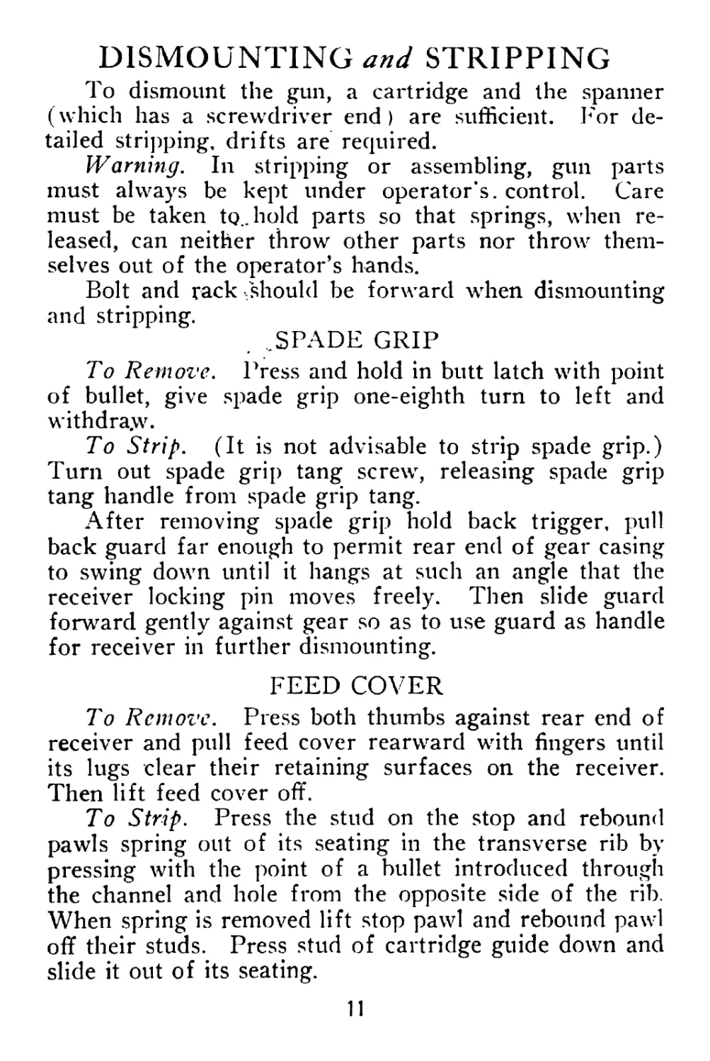
1J—Gun Complete, showing Right and Left Sides 12
III—Barrel Group..........................16
IV—Feed Mechanism Group................18
A’—Spade Grip............................20
VI—Magazine . ............................32
VII—Loading Tool...........................34
VIII—Shell Deflector.......................40
IX—Back Sight.............................46
X—Accessories ...........................48
XI—Gun Box and Magazine Container .... 50
6
GENERAL DESCRIPTION
MODERN machine guns are classified by feeding
means, operating means and cooling means.
The Lewis Machine Gun is magazine-fed, gas-
operated and air-cooled.
.The magazine is a circular drum in which the car-
tridges are arranged radially, bullet ends toward the
center. The magazine center has a deep spiral groove
in which the bullet ends of the cartridges engage and by
which they are controlled. The other parts of the maga-
zine are rotated around the center during the operation
of the gun, thus driving the spirally arranged column of
cartridges down the helical groove of the magazine center
until they are successively reached by the feed operating
arm.
Motive power for the operation of the mechanism is
obtained from gas pressure produced in the barrel by
the exploding cartridge. This gas is taken through a
hole near the muzzle of the barrel into a cylinder under
the barrel, in which it drives a piston rearward. This
directly produces the opening stroke of the action and,
by winding the mainspring, stores the motive power to
be used in the closing stroke.
Cooling in the Lewis Machine Gun, Airplane Type,
is by air, but the conditions of its use make the positive
air cooling device with which the Standard Type gun is
equipped unnecessary.
The Airplane Type gun is moved through the air at
the rate of from 90 to 140 miles per hour. This corre-
7
sponds to a continuous air-blast on the gun, whether it
is firing or not, of from 132 to 308 feet per second. The
gun is in action generally at great altitudes, where the
cold is intense. Also there is no opportunity in aerial
warfare for sustained machine gun fire and the firing
consists of short, infrequent bursts.
8
WEIGHTS and MEASUREMENTS
The weights and measurements of the Lewis Machine
Gun, Airplane Type, are as follows:
W eight of gun without mounting
yoke, magazine or shell deflec-
tor ...........................17 lbs. 4 oz.
Weight of mounting yoke ... 1 lb. 1 oz.
Weight of shell deflector . . . 1 lb. 15 oz.
Weight of 97 round magazine
(empty)......................2 lbs. 14 oz.
Weight of 97 round magazine
(filled).....................Bibs. 2 oz.
Length of gun with spade grip 41.80"
Length of barrel............. 26.056"
Distance between front sight
and ring sight...............17.50"
Distance between front sight
and back sight............... 32.02"
Trigger pull.................12 to 14 lbs.
Diameter of bore.............0.30"
Rifling, number of grooves . . 4
Twist uniform—one turn in ten inches
Weight—Bullet................150 gr.
Weight—Powder................48 to 50 gr.
Weight—Cartridge.............About 395 gr.
Muzzle velocity .... 2700 ft. per second
Chamber pressure About 51,000 lbs. to sq. in.
In the Lewis Machine Gun cartridges are under posi-
tive mechanical control at all times. The gun will func-
tion perfectly at any angle of elevation or depression
and when turned on either side or upside down.
In this hand-book, instructions as to manual opera-
tion and description of the corresponding mechanical
functioning of the gun are so combined as to associate
9
the effect with the cause, and to lead in the most direct
way to actual familiarity with the gun.
To handle a machine gun properly, the operator must
know it as he knows himself. He must know its parts,
their functions, relations and adjustment, their character-
istics and their tendencies so well that it is not necessary
to stop to think about them.
He must be able to dismount and assemble the gun
as naturally and easily as he would handle his rifle.
The slightest unusual symptom when the gun is fir-
ing must tell the operator at once not only what is the
matter, but how to fix it. And he must fix it at once as
naturally and subconsciously as he would extract a fired
shell from his rifle. Recognition should be immediate
and instinctive—correction, immediate and reflexive.
10
DISMOUNTING and STRIPPING
To dismount the gun, a cartridge and the spanner
(which has a screwdriver end ) are sufficient. For de-
tailed stripping, drifts are required.
Warning. In stripping or assembling, gun parts
must always be kept under operator’s, control. Care
must be taken to., hold parts so that springs, when re-
leased, can neither throw other parts nor throw them-
selves out of the operator’s hands.
Bolt and rack /should be forward when dismounting
and stripping.
. ..SPADE GRIP
To Remove. Press and hold in butt latch with point
of bullet, give spade grip one-eighth turn to left and
withdra.w.
To Strip. (It is not advisable to strip spade grip.)
Turn out spade grip tang screw, releasing spade grip
tang handle from spade grip tang.
After removing spade grip hold back trigger, pull
back guard far enough to permit rear end of gear casing
to swing down until it hangs at such an angle that the
receiver locking pin moves freely. Then slide guard
forward gently against gear so as to use guard as handle
for receiver in further dismounting.
FEED COVER
To Remove. Press both thumbs against rear end of
receiver and pull feed cover rearward with fingers until
its lugs clear their retaining surfaces on the receiver.
Then lift feed cover off.
To Strip. Press the stud on the stop and rebound
pawls spring out of its seating in the transverse rib by
pressing with the point of a bullet introduced through
the channel and hole from the opposite side of the rib.
When spring is removed lift stop pawl and rebound pawl
off their studs. Press stud of cartridge guide down and
slide it out of its seating.
11
PLATE II—VIEW SHOWING RIGHT AND LEFT SIDES OF GUN
FEED OPERATING ARM
To Remove. Swing feed operating arm forward to
right around magazine post until front edge of feed op-
erating arm clears its cut in receiver. Slide feed oper-
ating arm up magazine post against key. Then swing
feed operating arm back until key way is in line with
key. Then lift feed operating arm off magazine post.
To Strip. Lift feed pawl spring and feed pawl off
their posts.
CHARGING HANDLE
To Remove. Draw back until rear end of rack
reaches rear of receiver and pull charging handle out to
side.
PISTON AND RACK AND BOLT
To Remove. After rear end of gear casing is re-
leased and charging handle is removed as above, draw
the rack (carrying bolt on striker post) and piston back
entirely out of receiver. Lift bolt off striker post.
To Strip Piston and Rack. To remove striker, drive
out striker fixing pin. It is not advisable to separate
piston from rack. To do so, drive out piston connecting
pin, unscrew piston from rack.
To Strip Bolt. Unscrew and remove feed operating
stud. To remove either extractor, lift hook of extractor
with point of bullet until stud on shank of extractor is
clear of its recess in bolt. Then pull extractor forward
out of its slot.
RECEIVER
To Remove. Push receiver locking pin to the rear
with point of bullet until it clears its hole in the locking
piece. Turn receiver off barrel (right-handed thread),
using guard as handle.
13
GEAR CASING
(Note.—The ,/\irplane Type gun is equipped with
improved gear casing, which has a longitudinal groove
in the back of its hook at the front end. This groove is
designed to clear the receiver locking pin, when the gear
case is swung down, enough to permit removal and in-
sertion of gear assembled. It permits changing gear and
mainspring without removing gear casing.)
To Remove. Push receiver locking pin forward out
of receiver and unhook gear casing from the gear case
hinge pin.
To Strip. Press up gear stop with point of bullet
and allow mainspring to unwind. Unscrew collet pin
and shake out gear. Press through the gear against the
mainspring collet with point of bullet so as to force out
mainspring casing. The mainspring collet may be re-
moved from the mainspring casing with the point of a
bullet. Mainspring must not be taken out of mainspring
casing except when new mainspring is to be put in.
GUARD
To Remove. Hold back trigger and pull guard off
to the rear.
. To Strip. Punch out trigger pin and sear pin. Pull
back trigger and lift out trigger and sear.
EJECTOR
Pry up rear end of ejector cover with point of bullet
and draw out. Insert point of bullet in hole in receiver
for ejector hub, so as to raise rear end of ejector out of
recess, and lift out with fingers.
GAS REGULATOR CUP
Lift end of gas regulator key with point of bullet
until it clears gas cylinder casing. Unscrew and remove
gas regulator cup.
14
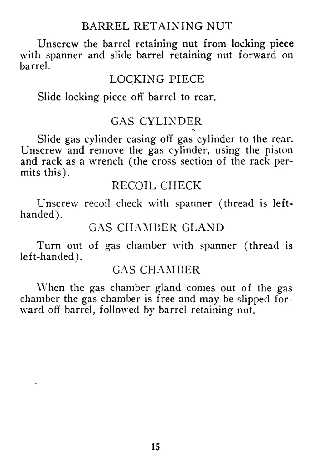
BARREL RETAINING NUT
Unscrew the barrel retaining nut from locking piece
with spanner and slide barrel retaining nut forward on
barrel.
LOCKING PIECE
Slide locking piece off barrel to rear.
GAS CYLINDER
Slide gas cylinder casing off gas cylinder to the rear.
Unscrew and remove the gas cylinder, using the piston
and rack as a wrench (the cross section of the rack per-
mits this).
RECOIL CHECK
Unscrew recoil check with spanner (thread is left-
handed).
GAS CHAMBER GLAND
Turn out of gas chamber with spanner (thread is
left-handed).
GAS CHAMBER
When the gas chamber gland comes out of the gas
chamber the gas chamber is free and may be slipped for-
ward off barrel, followed by barrel retaining nut.
15
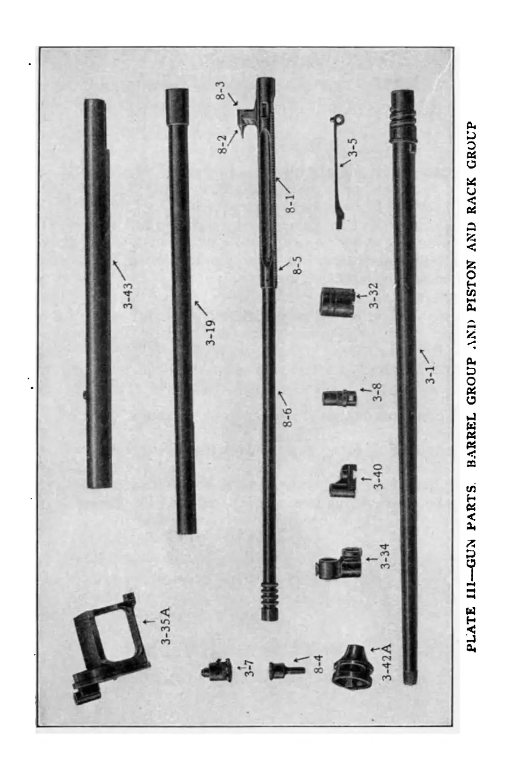
PLATE Ill—GUN PARTS. BARREL GROUP AND PISTON AND RACK GROUP
PLATE III
Barrel Group (3) and Rack and Piston Group (8)
3-1 Barrel
3-5 Gas Regulator Key
3-7 Gas Chamber Gland
3-8 Gas Regulator Cup
3-19 Gas Cylinder
3-32 Barrel Retaining Nut
3-34 Gas Chamber
3-35a Locking Piece (assembled)
3-36 Rear Sight Base
3-37 Rear Sight Base Rivet
3-38 Sight Retaining Spring
3-40 Front Sight Base
3-41 Front Sight Base Screw
3-42a Recoil Check (assembled)
3-43 Gas Cylinder Casing
8-1 Rack
8-2 Striker
8-3 Striker Fixing Pin
8-4 Charging Handle
8-5 Piston Connecting Pin
8-6 Piston
17
PLATE IV—GUN PARTS. FEED MECHANISM. BOLT AND EXTRACTORS .
PLATE IV
Feed Mechanism Group (6 and 7) Bolt (4)
6-1 Back Sight Axis Pin
6-2 Back Sight Axis Pin Washer
6-3 Back Sight Axis Pin Split Keeper
6-4 Back Sight Bed Spring
6-5 Feed Cover
6-6 Pawls Spring (Stop and Rebound)
6-7 Stop Pawl
6-8 Rebound Pawl
6-24a Cartridge Guide (assembled)
6-30 Back Sight Body
6-31 Back Sight Stem
6-32 Back Sight Stem Nut
7-1 Feed Operating Arm
7-2 Feed Pawl
7-3 Feed Pawl Spring
7-4 Feed Pawl Retaining Pin
7-5a Feed Operating Arm (assembled)
4-1 Feed Operating Stud
4-2 Bolt
4-3 Extractor
4-4a Bolt (assembled)
19
12-49
PLATE V—SPADE GRIP, WITH MOUNTING YOKE r
PLATE V
Spade Grip (1) with Mounting Yoke
1-10a Spade Grip (assembled)
12-65 Mounting Yoke Clamp Key
12-60л Mounting Yoke (assembled)
12-49 Magazine Filling Handle
21
ASSEMBLING
The gun is assembled by reversing the operations just
given for dismounting. When completely dismounted it
is advisable to assemble in the following order:
1. Barrel group:
a. Barrel retaining nut on barrel.
b. Gas chamber on barrel.
c. Gas chamber gland.
d. Recoil check on barrel.
e. Gas cylinder and gas cylinder casing.
f. Locking piece on barrel and barrel retaining
nut screwed in.
g. Gas regulator cup.
h. Gas regulator key.
2. Ejector.
3. Ejector cover.
4. Gear, gear casing and receiver locking pin.
a. Mainspring collet into mainspring.
b. Mainspring casing assembled into gear.
c. Gear into gear casing.
d. Collet pin turned in and gear wound up to
hold it.
e. Gear casing hooked onto receiver and re-
ceiver locking pin slipped in to hold it.
5. Guard (merely slipping it on receiver and up
against gear to act as handle).
6. Receiver and barrel (screw receiver onto bar-
rel).
7. Feed operating arm (pressed fully over to left).
Make sure front edge is engaged under projection in re-
ceiver.
8. Piston and rack with bolt on striker post. (In
pushing bolt and rack into receiver, apply pressure on
bolt only.)
9. Charging handle. Be sure it is fully inserted.
To test, push it forward and then try to pull it out.
22
10. Feed cover.
11. Lock gear by raising gear casing and pushing
guard forward to engage it.
12. Replace spade grip.
Care should be taken :
(1) To avoid damaging the threads of the threaded
parts, especially the gas chamber gland, gas cylinder, re-
coil check and barrel retaining nut, or allowing sand,
dust or grit to get into threads.
(2) To see that the gas chamber is correctly located
on barrel. The barrel loop of the gas chamber is tapered
and its smallest diameter must be toward the front end
of the barrel. The hole in the gas chamber must be
centered over the gas port in the barrel so that when the
gas chamber gland is put in it will center properly in
gas port in barrel.
(3) In replacing feed cover, thdt the feed operating
arm is over to the right.
(4) That the feed operating stud is screwed into
the bolt as far as it will go and that the cam slot in the
bolt is slipped over the striker before putting piston and
bolt in gun.
(5) That when replacing bolt the feed operating
arm is over to the left so that the feed operating stud
will engage its groove.
(6) That after inserting bolt, piston and charging
handle, the charging handle is brought to the extreme
forward end of its stroke before the gear casing is swung
up into place and the gear engaged with the rack.
(7) That the tension of the mainspring is correct—
from ten to fourteen pounds. If the tension is too low
the rack will strike the spade grip tang too hard in open-
ing and the action may fail to close or the gun may mis-
fire. If it is too high the gun will fire too fast; if much
too high the gun will not open far enough to feed the
next cartridge.
23
TO ALTER MAINSPRING TENSION
Remove spade grip and draw guard back enough to
disengage gear casing.
To increase tension hold up gear casing so as to
keep gear engaged with rack and draw back charging
handle. Draw down gear casing so that gear does not
engage rack and push charging handle fully forward.
Raise gear casing again, slide guard forward to engage
it, and replace spade grip.
To decrease tension hold gear casing down so that
gear is not engaged with rack and draw back charging
handle. Then raise gear casing, engage gear with rack
and slide guard forward to engage gear casing, which
will cause the charging handle to snap forward and the
action to close.
The average working tension of the mainspring of
the Lewis Machine Gun, Airplane Type, is from ten to
fourteen pounds. To weigh it, engage hook of spring
balance (supplied with gun) with charging handle; hold
back trigger; draw back charging handle by means of
spring balance so that it is just started to the rear. Hold
spring balance so as to keep charging handle at this
point, and record reading. (If tension of spring is
weighed when charging handle is at extreme rear and
sear is engaged it should not exceed 22 pounds.)
When the gun is not about to be fired the mainspring
should not be in tension. To obtain 12 pound spring
tension in the dark or without weighing, manipulate gear
stop and gear so that there is no tension on spring but
spring is wound up just enough so that collet pin will
stay in flush. Then push charging handle fully forward,
hold up gear casing to engage gear with rack and draw
charging handle fully to rear, so that rear end of feed
operating stud is even with rear end of receiver. Drop
gear casing, push charging handle fully forward, raise
gear casing so gear engages rack, push guard forward
to lock gear casing and replace spade grip.
24
OPERATION
TO FILL MAGAZINE WITH LOADING HANDLE
Turn magazine upside down.
Insert loading handle in socket in magazine center.
This holds magazine latch out of engagement and per-
mits rotating magazine center independently of the rest
of the magazine.
Spin magazine on loading handle to see that it is not
distorted. Inspection of magazine and cartridges should
always precede filling of magazine.
Rotate the magazine center and at the same time
place cartridges successively between the separator pins
so that their bullet ends will pass into the spiral groove
in the magazine center. Do not leave an empty space
between cartridges, as in firing this would cause a stop-
page. The magazine holds ninety-seven cartridges, and
when ‘it is filled remove loading handle and turn maga-
zine center back until it snaps. This locks magazine.
TO FILL MAGAZINE WITH LOADING TOOL
Attach loading tool to table or other base.
Turn magazine upside down.
Slip hole in magazine center up over magazine post
under loading tool until magazine latch engages post.
Spin magazine to see that it rotates freely.
Place a clip full, of cartridges in top of chute and in-
sert clip in clip ejector (at right), bullet ends to left (to-
ward magazine center).
Press cartridges down, stripping them out of clips
into chute by putting pressure close to heads of car-
tridges so not to depress points.
If cartridges have not been replaced in clips after
inspection, drop cartridges, bullet ends to left (toward
magazine center) into chute.
Repeat often enough to keep chute full of cartridges.
25
Rotate magazine from left to right (clockwise).
Cartridges will feed into magazine.
If a space in magazine is skipped, rotate magazine
backward past vacant space and then rotate forward
again.
When magazine is filled, unlatch and remove from
post.
Turn back magazine center until it snaps. This locks
magazine.
TO LOAD GUN
See that the charging handle is fully forward.
Pick up magazine by slipping the fingers of right
hand, palm down, under the strap, the thumb on the
thumb piece, place magazine on magazine post and press
it down.
Rotate it very slightly in both directions, until the
stop and rebound pawls engage serrations on magazine
pan.
Draw back the charging handle fully so that it is en-
gaged and held back. This draws back the piston and
rack and performs by hand what the gas pressure of
firing does. Drawing the rack teeth back over the gear
teeth with which they are meshed rotates the gear and
winds the mainspring during the entire opening move-
ment. During the first 1 1/3 inches of rearward travel
the striker post moves back through the longitudinal part
of its cut in the bolt and merely draw's back the point of
the striker from the face of the bolt. The bolt itself
remains in its locked position and does not move.
In the next tw'o-thirds of an inch of rearwrard travel,
the striker post, driven still further rearward in the bolt,
strikes with its right side the cam surface in the right
side of its slot in the bolt and causes the bolt to rotate
from right to left, turning the locking lugs out of their
recesses 1n the receiver.
As soon as the bolt is unlocked, the striker post
26
reaches the rear end of its cut in the bolt, and in its
further travel carries the bolt directly back with it.
The top lug of the feed operating stud, traveling in
the groove in the under side of the feed operating arm,
cams the feed operating arm so that it swings across the
top of the receiver from right to left.
The feed pawl, acting against one of the outer pro-
jections of the magazine pan, carries the magazine
around sufficiently to drive the first cartridge down into
the cartridge opening in the feed operating arm by the
rotation of the magazine pan and separator pins around
the stationary spirally grooved center.
At this point in the leftward travel of the feed op-
erating arm, its cartridge opening (and in it the car-
tridge it has just received) commences to pass under the
upward projecting arm of the feed cover which carries
the cartridge guide, and this arm commences to control
the cartridge as soon as it leaves the magazine.
Further leftward travel of the feed operating arm
brings the cartridge under control of the cartridge guide
and the downward pressure of its spring tension.
At this point the spring stud on the feed operating
arm clears the stop pawl, which is then pressed forward
by its spring and prevents further rotation of the maga-
zine.
When the bolt strikes the rear end of the ejector it
drives it into its slot, thus pivoting the ejector head out.
Toward the end of the rearward travel of the piston
the lower surface of the rack at the rear of the cocking
notch rides over the nose of the sear, temporarily de-
pressing it against the tension of the sear spring, which
immediately raises it again.
The rear end of the rack then strikes the spade grip
tang, terminating the opening stroke.
The feed operating arm is now at the extreme left,
the cartridge has been brought over the cartridge open-
ing in the top of the receiver into which the cartridge
27
guide presses it, the rebound pawl presses against an ex-
terior projection of the magazine so as to prevent back-
ward rotation and the mainspring is fully wound up.
Both pawls are now in.
The mainspring now rotates the gear, whose teeth,
meshed with those of the rack, drive the rack forward
a trifle till the nose of the sear engages with the cocking
notch in the lower edge of the rack and suspends the
operation.
The gun is now ready to fire.
28
TO FIRE
FULL AUTOMATIC FIRE
Press trigger and hold back. Gun will fire automati-
cally as long as trigger is held back until magazine is
empty. When trigger is released gun stops firing.
SEMI-AUTOMATIC FIRE
To fire single shots press trigger and release im-
mediately. To release quickly enough for a single shot
requires some practice. It is most easily done by alter-
nately contracting and relaxing the whole hand, not
merely the trigger finger. Bursts of any desired length
may be fired by holding back the trigger the required
period of time and releasing.
When the trigger is pressed the sear is drawn down
out of engagement with the notch in the rack. The rack
ig driven forward by the pressure of the mainspring,
which unwinds, and consequently rotates the gear, whose
teeth are meshed with those of the rack. The striker
post is at the rear end of the cam slot in the bolt. Its
left side is pressing against the left side of the cam slot,
but it now simply drives the bolt forward without ro-
tating it because the bolt is prevented from rotation by
the cruciform shape of the bolt-way in the receiver at
this point.
The feed operating stud, carried forward with the
bolt and traveling forward in its cut in the underside of
the feed operating arm, cams the feed operating arm to
the right.
The feed pawl slips over the projection on the rim
of the magazine and engages behind it.
The spring stud on the feed operating arm presses
the stop pawl back to prevent its intercepting a magazine
projection.
The face of the bolt now strikes the base of the car-
tridge which is held ready for it in the loading ramps of
29
the receiver, and it drives the cartridge before it into the
chamber.
The head of the bolt now reaches the head of the
ejector, which it presses back into the ejector cut, caus-
ing the rear of the ejector to be pivoted out into the
bolt-way behind the bolt.
The extractors spring over the rim as soon as the
cartridge seats.
Just as the cartridge seats, the locking lugs of the
bolt clear the front of the cruciform part of the bolt-way
formed by their guide grooves and reach their locking
recess.
Further forward movement of the bolt is not possible.
The bolt face rests against the rear end of the barrel and
the head of the cartridge. The pressure of the main-
spring which still drives the striker post forward causes
the striker post, which is pressing against the left side
of the cam slot in the bolt, to rotate the bolt to the right.
This turns the locking lugs fully into the locking recess
of the receiver.
As the bolt locking is completed the striker post enters
the longitudinal front part of its cut, carries the striker
against the primer of the cartridge in the chamber, and
fires the cartridge.
The firing of the cartridge now develops the power
for another cycle of operation.
When the bullet passes the gas port near the muzzle
of the barrel, gas under high pressure is driven through
the gas port into the gas chamber and through the hole
in the gas regulator cup onto the head of the piston.
This drives the piston back and produces the same
operation of parts described above where the opening
stroke was made by hand, except for the disposition of
the fired shell.
The shell, in the grip of the extractors, is drawn back
with the bolt, and is carried on the face of the bolt until
the bolt strikes the rear end of the ejector, as previously
30
described. The pivoting of the head of the ejector,
which swings sharply against the left side of the ex-
tracted shell, throws the shell out of the ejector port.
Whether the gun will fire again or will remain in the
“ready to feed” position depends upon whether or not
the trigger is still held back.
If the trigger is still held back, and the sear conse-
quently depressed, at the beginning of the closing stroke
of the action the gun will continue firing.
If the trigger has been released so that the sear en-
gages the cocking notch in the rack, the gun is left
“ready to feed.”
The cycle of operation may be briefly summarized as
follows:
31
PLATE VI—MAGAZINE. TOP VIEW AND BOTTOM VIEW
PLATE VI
10-1л Magazine
(Assembled)
The magazine holds ninety-seven car-
tridges. Instructions for loading are
given on page 25.
33
PLATE VII—LOADING TOOL WITH MAGAZINE IN POSITION
PLATE VII
12-30a Loading Tool
(Assembled)
Instructions for the use of loading tool
are given on pages 25 and 26.
35
ger. This will fire the cartridge which was in position
in the loading ramps in the receiver.
When it is necessary to unload without firing car-
tridge in receiver, press over magazine latch and remove
magazine, hold charging handle with left hand, press
trigger with right hand and ease charging handle for-
ward slowly so as to push cartridge from loading ramps
into bolt-way in receiver.
Then pull back charging handle fully so that sear en-
gages and raise safety. With point of bullet of another
cartridge press down through loading slot in top of re-
ceiver against cartridge so that it can be removed
through ejector port.
After unloading gun always snap (by drawing back
charging handle to cock and pulling trigger), to make
certain that gun is empty and that there is no cartridge
in the receiver.
38
CARE and ADJUSTMENT
It is necessary to keep continually informed of the
condition of each part of the gun. Adjustment by use
of file, oil-stone or emery should be made only by an
armorer. Examination should include the following
points:
Barrel. Inspect the interior of barrel and chamber
and the thread on the muzzle.
Gear, Casing and Mainspring. See that gear teeth,
stop and spring are not damaged, that gear case hinge
pin is secure and that mainspring is not broken.
Ejector. See that it is not damaged.
Feed Operating Arm. Observe that the feed pawl
and feed pawl spring are properly assembled.
Feed Cover. Notice whether the pawls and spring
are damaged and whether the cartridge guide is properly
assembled.
Piston. See that the piston connecting pin is not
loose, that the teeth and the cocking notch of the rack
are not damaged, and that the working surfaces of the
striker post are not burred or rough. Note whether the
striker is damaged.
Bolt. The edges of the cam slot and the locking lugs
of the bolt should be smooth. Any burrs or roughness
should be removed by an armorer with oil-stone or fine
emery cloth.
Examine lugs on feed operating stud for burrs or
other injury.
Examine extractors carefully for breakage or any
deformation.
Weigh each extractor by engaging hook of spring
balance with extractor hook and pulling at right angles
to bolt. Read balance when extractor moves. If under
three pounds exchange extractor..
Guard. Inspect nose of sear for wear or breakage.
Safety. See that the charging handle is properly en-
39
PLATE VIII—SHELL DEFLECTOR
gaged and held when the gun is at “Safe,” and released
when safety is depressed.
Sight Bases. Inspect for looseness or injury.
Gas Regulator Cup. See that it is not stuck. If it
is, apply a little kerosene at the thread and allow it to
soak in. Use No. 4 (the largest) port of the gas regu-
lator cup. There is a projection on the bottom of the
gas regulator cup which locates the No. 1 (smallest)
hole. This permits any desired adjustment of the gas
regulator cup in the dark.
Magazine. To see that the feed mechanism is work-
ing properly, place an empty magazine on the gun and
work the charging handle. Before filling each magazine,
take care that the separator pins are not bent or broken
and spin each magazine on the loading handle to ascer-
tain that it is not distorted. Fill magazine with care. If
cartridges jam in filling, empty magazine to determine
cause.
INSPECTION OF CARTRIDGES
Every cartridge for aviation use must be inspected.
Where gauges are not supplied the following method
will serve:
(1) Weigh each cartridge to detect underloads. Re-
ject those weighing less than 393 grains.
(2) Inspect for low primer (primer seated too
deeply ) by laying straight-edge across head of shell.
Reject cartridges having low primers.
(3) Inspect dimensions of cartridges by removing
striker (or putting in spare piston and rack without
striker) in gun in which they are to be fired and work-
ing them through the action by hand. The chamber of
the gun is used as a gauge. Do not allow ejected car-
tridges to be deformed by being thrown against a hard
surface. Catch them in a hat or in shell deflector.
41
SHELL DEFLECTOR
To attach shell deflector to gun turn out shell de-
flector clamp screw and pull out shell deflector clip.
Slide clip and bracket up around receiver in front of
gear case, clip on left side of receiver, deflector and
bracket on right, so that hole in arm of deflector covers
ejector port. Turn in .deflector clamp screw.
To get at ejector port, push deflector latch to rear
and swing deflector out to side. To return swing de-
flector back against ejector port and push deflector latch
forward to lock.
To remove shell deflector from gun turn out shell
deflector clamp screw and pull deflector down.
POINTS BEFORE FLIGHT
Make sure that gun has been dismounted, all parts
inspected and all oil removed (except light film in cam
slot of bolt, in bolt-way of receiver, on striker post and
on rack).
Mount and inspect sights.
See that bore is clear.
Make sure that all cartridges have been inspected and
gauged before filling magazines.
Weigh mainspring and correct tension, if necessary.
See that all tools and spare parts are in place and
that they and magazines are properly secured against
loss or damage.
See that oil can is full.
Final Test: See that charging handle moves freely,
that feed operating arm moves when it does. Weigh
mainspring. Test ejection with dummy cartridge. Place
42
empty magazine on post. Hold it with right hand and
work charging handle to prove that feed mechanism ro-
tates magazine. If possible fire one or two single shots
to make sure gun blows back far enough to engage sear.
POINTS DURING FLIGHT
Fire several rounds into ground at once after start-
ing.
During temporary cessation of fire, raise safety.
Weigh spring and adjust tension if necessary. Do not
allow tension to drop under ten pounds.
If gun misfires, wait a few seconds before drawing
back charging handle.
In cold weather fire a burst of 3 to 5 shots every
fifteen minutes to make sure that gun is working
properly.
Empty magazines should be replaced in container
when removed from gun. Deformation of rim of maga-
zine, entry of dirt or grit in the bullet groove in the
magazine center or deformation of its lip should be care-
fully guarded against.
See that shell deflector does not become full of empty
cartridge cases.
When possible between bursts raise safety.
43
POINTS AFTER FLIGHT
Unload (and snap).
Relax mainspring tension.
Remove sights.
Dismount, examine, clean and oil all parts of gun at
once.
POINTS WHEN MACHINE GUN IS PLACED IN
BOX
1. Bore oily.
2. Exterior and working parts oily.
3. Nothing in bore.
4. Sight down.
5. Spare parts in box.
6. Cleaning material and oil in box.
7. Mainspring released.
8. Charging handle forward and safety up.
44
NOTICE TO ARMORERS IN CHARGE
OF LEWIS MACHINE GUNS
The efficient working of the Lewis machine gun
largely depends upon the bearing surfaces between the
sides of the striker post and the sides of the cam-shaped
slot in the bolt being kept perfectly smooth. In most
guns, the action of the gun itself continues to keep the
surface of this sliding contact properly smooth, provided
the parts are kept well oiled. Sometimes, however, in
the case of new guns, slight “burring” may occur and
prevent the smooth working of the gun. Any such
roughness or “burring” caused by wear on either of the
sides of the striker post (generally on the right-hand
side) or on the bearing edges of the cam-shaped slot in
the bolt (generally on the left-hand side) must at once
be carefully smoothed as follows:
* Use either a very fine oil-stone, or very fine emery
cloth, and thus remove any roughness and secure per-
fectly smooth bearing surfaces between both sides of the
striker post and both edges of the cam-shaped slot in the
bolt.
Careful attention must, however, always regularly be
given to these most important bearing surfaces; but after
the sides of the striker post and cam slot edges have
once been carefully smoothed this roughness seldom oc-
curs.
If either too coarse materials or too much careless
force is used to smooth these surfaces, the angle of slid-
ing contact may become slightly altered and more rough-
ness or “burring” may be caused.
45
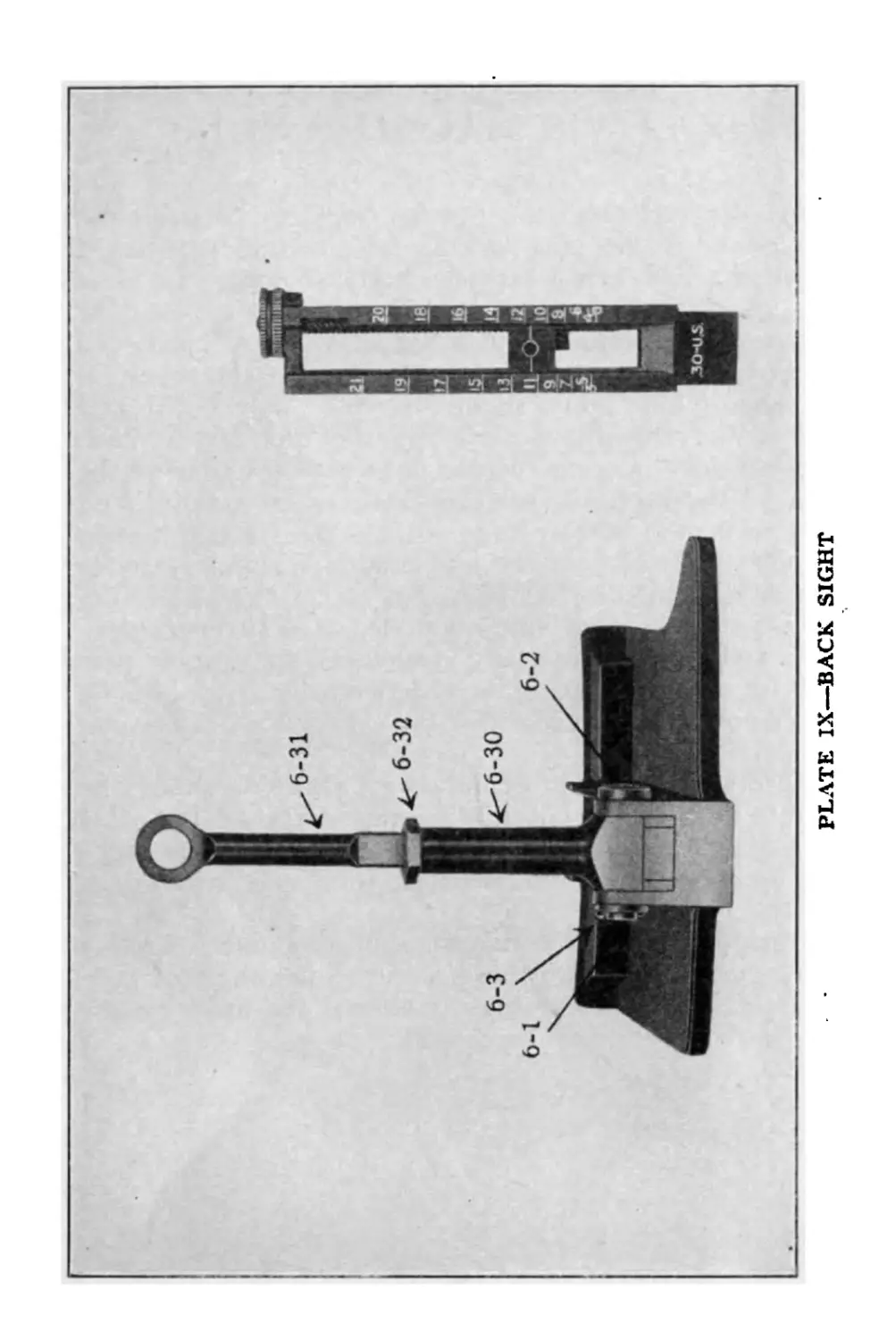
PLATE IX—BACK SIGHT
PLATE IX
Влек Sight
6-1 Back Sight Axis Pin
6-2 Back Sight Axis Pin Washer
6-3 Back Sight Axis Pin Split Keeper
6-30 Back Sight Body
6-31 Back Sight Stem
6-32 . Back Sight Stem Nut
47
12-24А
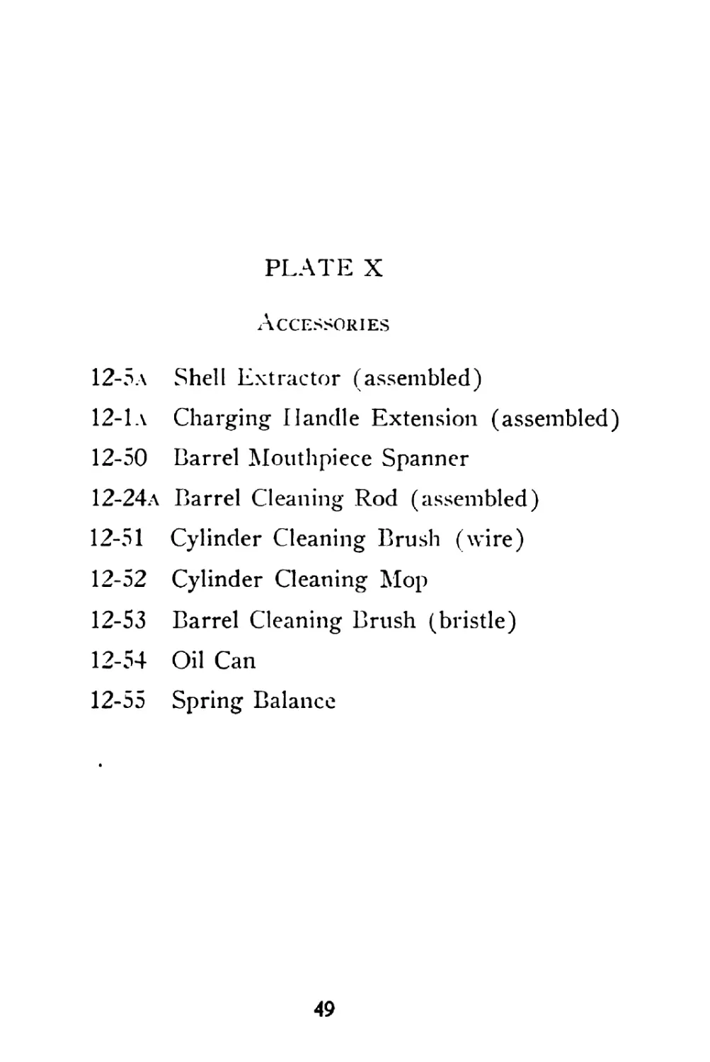
PLAT® X—ACCESSORIES
PLATE X
Accessories
12-5a Shell Extractor (assembled)
12-1a Charging Handle Extension (assembled)
12-50 Barrel Mouthpiece Spanner
12-24a Barrel Cleaning Rod (assembled)
12-51 Cylinder Cleaning Brush (wire)
12-52 Cylinder Cleaning Mop
12-53 Barrel Cleaning Brush (bristle)
12-54 Oil Can
12-55 Spring Balance
49
PLATE XI—GUN BOX AND MAGAZINE CONTAINER
CLEANING and OILING
The Lewis Machine Gun, Airplane Type, should be
completely stripped after each flight.
Clean each part thoroughly with gasoline. Dry and
inspect each part and bearing surface for breakage,
burrs, wear or other injury.
To Clean Barrel. Follow the same methods pre-
scribed and use the cleaning solutions issued for cleaning
the U. S. magazine rifles, models of 1903 and 1917.
Cleaning with nitro-solvent on patches of cloth does not
require dismounting the gun. The charging handle may
merely be drawn back until the sear engages the rack.
Cleaning the barrel should be repeated every day for
several days after the gun has been fired and until the
acids driven into the pores of the steel by the pressures
of firing have been completely neutralized. The am-
monia metal fouling solution neutralizes acid residue at
one application.
To Clean Gas Cylinder. Clean first with wire brush
and gasoline, then with mop and oil.
Special attention must be given to very thorough
cleaning of the gas regulator cup.*
Immediately after cleaning and inspection, oil each
part liberally and assemble to prevent rust or loss of
parts between flights.
Just before the next flight the gun should be stripped
again, the oil wiped off each part and each part again
inspected and the gun assembled.
No oil should be left on any part of the gun when
ready for flight except the very thin film left by wiping
with a lightly oiled cloth in the cam slot in the bolt, on
striker post, in bolt-way in receiver and on teeth of rack.
51
Second Position—
Less than a car-
tridge length from
forward position.
Use charging handle extension
or double pull through and
pull back handle. Examine
round ejected, if—
(a) Damaged or too large
round continue firing.
(b) If correct, take off maga-
zine, insert shell extractor
into chamber and push home
with bolt and withdraw
with front portion of sepa-
rated case.
(c) If separation recurs
shortly, change barrel.
Ln
Third P о s i t i о n—
More than 3 inches
back.
1. Examine ejection opening;
if there is no obstruction,
pull back charging handle,
continue firing.
If recurs, take out gas regu-
lator cup, remove magazine
and fire one round; replace
regulator cup large hole to
rear. Clean out gas cyl-
inder, oil working parts; if
any roughness on striker
post or cam slot in bolt
change them.
Damaged round.
Separated case in
chamber.
File a groove
around cartridge
case 1 inch from
base.
Separated case
telescoped on to
next cartridge.
Too sharp extrac-
tors, which cut
cartridge c'ase
at base.
Bolt has not gone
back far enough
to get behind
base of car-
tridge.
(a) Friction in
gas cylinder.
(b) Hard extrac-
tion.
Ditto one inch
f rom shoulder.
STOPPA
POSITION OF
CHARGING HANDLE
REMEDY
First Position — Charging Handle forward. 1. Try magazine. If it ro- tates freely to left, change it. 2. If magazine is fixed, pull back charging handle and continue firing. 3. If 2 fails, change maga- zine. 4. If stoppage recurs, ex-
tn N) amine feed pawl and stop and rebound pawls. If feed pawl • is broken magazine ’ will not rotate. 5. If 3 fails and trigger be- ing pressed gun does not fi r e, examine mainspring. If light, tighten; if broken, change gear and casing. If mainspring all right, change piston and rack. 6. If charging handle will not come back, use charging handle extension. If stop- page recurs, examine cham- ber.
ES
PROBABLE CAUSE
Empty magazine,
no round in
chamber.
(a) Misfire.
(b) Space in maga-
zine.
(c) Insufficient ro-
tation of maga-
zine.
Damaged m a g a-
zine.
Damaged feed
pawl or stop or
rebound pawl.
(a) Weak or
broken m a i n-
spring.
(b) Broken or
damaged striker.
PREPARATION FOR
INSTRUCTION
Empty magazine
on post.
Charging handle
forward on
range.
Leave space in
magazine.
Dummy. Live
round. Dummy.
Hard extraction,
(a) Expansion of
empty case.
(b) Grit or rust
in chamber.
On Range.
Put damaged
dummy in cham-
ber, pull trigger
and put full
magazine on
post
6. If on removing magazine,
charging handle remains in
position as before—
(a) Help cartridge into cor-
rect position on feed way.
(b) Test cartridge guide
spring.
(c) Test mainspring.
tn
(c) Broken maga-
zine catch spring.
(d) Broken or
damaged maga-
zine spacer ring
c a u s in g it to
jam.
(a) Weak or
broken cartridge
guide spring.
(b) Too weak
mainspring.
(c) Too much gas.
(1) The tension of the mainspring can easily be told by pulling back the charging handle.
If the mainspring is broken, the collet pin will usually be “out.”
Note—If the gun continues to fire after the trigger is released, remove magazine.
This Will be caused by broken or weak spring, or damaged sear.
If gun fails to eject, it usually means that the action is not being blown open fully. The
remedy is to use a larger hole in the gas regulator cup. If already using the largest, then re-
duce spring tension.
Failures to extract may be caused by top extractor failing to hold shell until ejector hits
it. Then if the gun does not blow back the forward stroke will drive the shell into the cham-
ber again.
STOPPAGE S—Continued
POSITION OF
CHARGING HANDLE
Third Position—Con-
tinued.
REMEDY
PROBABLE CAUSE
2. If oil pulling back handle
there is little or no resist-
ance, if mainspring is light,
tighten; if broken, change.
3. If an empty case is in
chamber or ejection opening,
take off magazine, draw
back charging handle, and
unload without firing.
If empty case is in chamber,
force out with cleaning rod
from muzzle end.
If there are no signs of ex-
tractors, or only one ex-
tractor gripping it, change
bolt; otherwise continue fir-
ing.
4. If stoppage recurs, ex-
amine extractor, exchange
whichever is faulty.
5. If charging handle cannot
be moved, remove magazine.
If charging handle'flies for-
ward, change magazine.
Weak or broken
mainspring.
(a) Bad extrac-
tors.
(b) Hard extrac-
tion.
(c) If empty case
is in receiver,
weak extractors
or broken ejec-
tors.
PREPARATION FOR
INSTRUCTION
Oh Range.
W e a к e n main-
spring.
On Range.
Place empty case
chamber. Maga
zine on post and
pull trigger.
(a) Damaged
magazine
jammed.
(b) Magazine not
properly on
magazine post
On Range.
Do not push
magazine proper-
ly home.
No. 2 POSITION
(Charging Handle between thumb-piece of safety and forward position)
FORCE BACK CHARGING HANDLE
IF STOPPAGE RECURS
Take out gas regulator, fire a shot. Insert with large hole to rear. Clean and oil.
No. 3 POSITION
(Charging Handle behind thumb-piece of safety.) Examine ejection opening.
IF CLEAR
Pull C. H.
IF CASE IN
BOLT-WAY
Examine ejector
Replace if necessary
IF-CHAMBER OBSTRUCTED
Pull С. H. Raise safety, remove
magazine, clean and examine rim
of cartridge
IF С. H. DOES
NOT COME BACK
Change magazine, reload,
relay and fire
IF С. H. COMES
BACK
Relay and fire
IF RIM CUT IN
TWO PLACES
Reload, relay and
fire
IF RIM NOT
CUT
Change bolt
IF С. H. DOES NOT
GO FORWARD
Change gear casing
(complete)
IF С. H. STARTS FORWARD
AND STICKS
Pull С. H. Raise safety
Remove magazine
Inspect cartridge guide
Replace if necessary
TROUBLE CHART
SEQUENCE OF IMMEDIATE ACTION
Lewis Machine Gun—Airplane Type
No. 1 POSITION
(Charging Handle Forward)
Try Magazine
IF FREE TO ROTATE c Change it O' Reload, relay and (ire IF FIXED (will not rotate) Pull charging handle
r - V IF GUN DOES NOT IF GUN i-lRES IF CHARGING U.
FIRE SINGLE SHOTS WILL NOT GO BACK
Pull С. H. Watch ej ec- Examine gas Remove maga-
tion opening regulator zine 1
IF CARTRIDGE IF NO CARTRIDGE IS IF С. H. THEN IF C. IL
IS EJECTED EJECTED COMES EASILY STICKY
Examine primer Examine feed mechanism Put on new magazine Relay and
1 Repair if necessary Reload, relay and fire lire
11- STRUCK IF PRIMER NOT STRUCK
Pull C. IL, relay, lire Change piston and rac k, reload, relay and lire
IMMEDIATE ACTION
IN
REPLACING
PARTS
□
TO CHANGE CARTRIDGE GUIDE
Remove magazine.
TO CHANGE MAGAZINE PAWLS
(stop and rebound)
Remove magazine, spade grip and feed
cover.
TO CHANGE FEED PAWL
Remove magazine, spade grip and feed
cover.
TO CHANGE EXTRACTORS
Remove magazine, spade grip; release
gear, removing charging handle and
bolt.
58
TO CHANGE GEAR COMPLETE
Remove magazine, spade grip; draw
back guard. Pull gear casing down
and forward; release gear stop; re-
move collet pin; lift out gear complete.
TO CHANGE RECEIVER LOCKING PIN
Remove magazine, spade grip; release
gear; remove charging handle, bolt and
piston and rack. Force back receiver
locking pin and remove toward rear.
TO CHANGE CHARGING HANDLE
Remove magazine, spade grip; drop
gear.
TO CHANGE EJECTOR
Remove magazine, spade grip; feed
cover. Remove ejector cover, raise
ejector, by inserting point of cartridge
underneath, through hole in receiver.
Slip ejector cover under ejector from
left side. Press ejector down against
ejector cover with finger and lift
ejector out toward left.
59
PARTS FOR
LEWIS MACHINE GUN
(AIRPLANE TYPE)
1-7 Spade Grip Tang
1-8 Spade Grip Tang Han-
dle
1-9 Spade Grip Tang
Screw
1-10a Spade Grip (assem-
bled)
2-1 Receiver
2-2 Ejector Cover
2-3 Ejector
2-4 Safety
2-5 Center Key
2-6 Receiver Locking Pin
2-7 Gear Case Hinge Pin
3-1 Barrel
3-5 Gas Regulator Key
3-7 Gas Chamber Gland
3-8 Gas Regulator Cup
3-19 Gas Cylinder
3-32 Barrel Retaining Nut
3-34 Gas Chamber
3-35л Locking Piece (assem-
bled)
3-36 Rear Sight Base
3-37 Rear Sight Base Rivet
3-38 Sight Retaining Spring
3-40 Front Sight Base
3-41 Front Sight Base
Screw
3-42a Recoil Check (assem-
bled)
3-43 Gas Cylinder Casing
4-1 Feed Operating Stud
4-2 Bolt
4-3 Extractor
4-4a Bolt (assembled)
5-1 Guard
5-2 Butt Latch
5-3 Butt Latch Spring
5-4 Butt Latch Pin
5-5 Guard Side Piece
(right)
5-6 Guard Side Piece
(left)
5-7 Guard Rivets
5-8 Sear
5-9 Sear Spring
5-10 Sear Pin
5-11 Trigger
5-10 Trigger Pin
5-12a Guard (assembled)
60
PARTS FOR
LEWIS MACHINE GUN
(AIRPLANE TYPE)
CONTINUED
6-1 Back Sight Axis Pin 8-1 6-2 Back Sight Axis Pin 8-2 Washer g j 6-3 Back Sight Axis Pin g Split Keeper 8-5 6-4 Back Sight Bed Spring 8’6 6-Э г eed Cover 6-6 Pawls Spring (stop and 9-1 rebound) ? 6-7 Stop Pawl 6-8 Rebound Pawl 6-24a Cartridge Guide (as- sembled) 6-30 Back Sight Bodj’ 6-31 Back Sight Stem 6-32 Back Sight Stem Nut 9-9 7-1 Feed Operating Arm р.ц 7-2 Feed Pawl 7-3 Feed Pawl Spring 7-4 Feed Pawl Retaining „ „ Pin 1W2 7-5A Feed Operating Arm ^-30 (assembled) 10-31 Rack Striker Striker Fixing Pin Charging Handle' Piston Connecting Pin Piston Gear Casing Gear Stop Gear Stop Spring Gear Stop Pin Gear Case Disc (Mainspring) Collet Pin Gear Mainspring Casing Mainspring Mainspring Collet Magazine Top Plate Rivets Spacer Ring Magazine Pan Magazine Top Plate
61
PARTS FOR
LEWIS MACHINE GUN
(AIRPLANE TYPE)
CONTINUED
10-32 Magazine Latch 12-49 Magazine Filling Handle
10-33 Magazine Latch Spring 12-60a Mounting Yoke (as-
ь sembled)
10-34 Cartridge Separator 12-65 Mounting Yoke Clamp
Pin Key
PLATE XII
Receiver Group (2) Mainspring Group (9)
Guard Group (5)
2-1 Receiver 9-11 Mainspring Collet
2-2 Ejector Cover 5-1 Guard
2-3 Ejector 5-2 Butt Latch
2-4 Safety 5-3 Butt Latch Spring
2-6 Receiver Locking Pin 5-4 Butt Latch Pin
9-1 Gear Casing 5-5 Guard Side Piece
9-2 Gear Stop (right)
9-3 Gear Stop Spring 5-6 Guard Side Piece
9-4 Gear Stop Pin (left)
9-6 Mainspring Collet 5-8 Sear
Pin 5-9 Sear Spring
9-7 Gear 5-10 Sear Pin (used als<
9-8 Mainspring Casing for Trigger Pin)
9-9 Mainspring 5-11 Trigger
62
PLATE XII—GUN PARTS. RECEIVER GROUP, MAINSPRING AND TRIGGER MECHANISM
LEWIS MACHINE GUN 3O-U.S.GOV
* «I
-7-SPADE GRP TANG
i
э
EJECTION
EXTRACTION
ASSEMBLED
&A-5PA YE GRIP
TANGHANDLE 5-2 BUTT LATCH '
5 3 BUTT LATCH SPRG/
5-4-0UTT LATCH PIN'
MODEL 1918
MFD BY SAVAGE ARMS CORPORATION
10-12-CARTRIDGE SPACER. RlNu
10-34 CTDG SEPARATOR PIN
NORMAN REAR SIGHT
6 7 STOP PAV.
6-6-STOP & REBOUND-
PAWLS SPRING
—,rttD PAWL
6 B-REBOUND PAWL
6-2ДЛ CARTRIDGE GUIDE
6-32 BACKSIGHT STEM NUT
6 3OEACKSIGHT ВООЧ
6-iBAC.KSIGT AXIS P'N
I-I0-A
SPADE GRIP I
• V .A.1NE TOP Pl
MAGAZ’NE i ' - "PR NG
4'
6 51 BACKLIGHT ST l M
;R
!(. M Ли A£ -.-4
IG 32 MAGAZINE LATCH 4
\ 10-3 MAGAZINE TOP PLATE RWET4
0-1 BACK SIGH г LEAF SPRING € ч LID COVER AS^MBUK
I FEED OPtRATING STUD
4 2-90LT .8-2 STRIKER
1 fl-StAe
5 9-SEAR I- •
S C-SEAR Pin
5'i i-1 rigger
9-2-GEAR5TCP
9-4 GEAR STOP PIN
19-3-GE AR STOP SPRING
‘ 5-7- GUARD RIVE I S
-5 5-guard side p<Gf RfGkT I
gi a- y
'M? ; IlhT QFTAIM'NG SPRING
S 37-OEAR SIGHT BASE RIVET
it-65-MOUNTING tOkE CLAMP KEY 1
I'Z-T- M -Lf л• K£ - . ,L Mt-uFl
WIND VANE FRONTSIGHT
A
' Л I . KING PIECE
3-36-REAR SIGHT BASE
5 52 BARREL RETAINING NUT
SECTION ON LINE A-A
3-1 BARREL
• -;i FRl -LT - PA-'P SCiaEW
-5-iO FRONT SIGHT BASE
--PISTON-
sECTING PIN
GAS
CYLINDER.CASING -3H9-GAS CYLINDER
3-5-GAS REGULATOR KEY
RECEIVER. LOCKING PIN
42-~ de AR. CASE HINGE PIN
9-&C0LLET PIN
9 " GLA* J <fl
’.Г, SPRING CASIT J nJ
9-9 MAIN SPRING
j 11 MAIN SPk ING c “L.-
7 3’EJt -TOP
4G f KTRACTOR
3-3'. GAS CHAMBER.
AS CHAMRE G. GLAND
—3-SGAS REGULATOR.CUP