/

Tags: weapons military affairs machine gun patent
Year: 1935
Text
March 8, 1938.
F. T. MOORE
MACHINE GUN
2,110,165
Filed Nov. 18, 1935
2 Sheets-Sheet 1
March 8, 1938.
F. T. MOORE
2,110,165
MACHINE GUN
Filed Nov. 18, 1935
2 Sheets-Sheet 2
Patented Mar. 8, 1938
2,110,165
UNITED STATES PATENT OFFICE
2,110,165
MACHINE GUN
Frederick T. Moore, West Hartford, Conn., as-
signor to Colt’s Patent Fire Arms Manufactur-
ing1 Co., Hartford, Conn., a corporation of
Connecticut
Application November 18, 1935, Serial No. 50,387
17 Claims. (Cl. 42—75)
5
10
15
20
25
30
35
40
45
50
55
The invention relates to a machine gun, par-
ticularly to air-cooled machine gun, having a
readily detachable barrel. One of the objects of
the invention is to provide a machine gun of the
reciprocating barrel type, wherein the barrel may
be readily put in place or removed from the front
of the gun without disturbing or disassembling
any other essential gun part. A machine gun
embodying the invention has the advantage that
the barrel, upon becoming heated during use,
may be easily taken out and replaced by an-
other similar barrel with a minimum loss of time,
and, in some embodiments it has the further ad-
vantage that the barrel may be conveniently re-
moved to facilitate transportation.
A more specific object of the invention is to
provide certain novel details of construction
whereby the ready detachability of the barrel
is attained.
A further object of the invention is to provide
a gun of the type referred to having a barrel
jacket or guide and having a barrel guiding bear-
ing on the guide which is readily detachable to
permit forward removal of the barrel. There may
also be provided in association with the bearing
a means forming a gas chamber at the front of
the barrel for augmenting the recoil action of the
barrel.
A still further object of the invention is to
provide certain novel details of construction
which make possible the ready detachability of
the barrel bearing from the jacket.
Other objects of the invention will be apparent
from the following specification and claims.
This application constitutes a continuation-in-
part of my copending application for Machine gun,
Serial No. 638,632, filed October 19, 1932.
In the accompanying drawings I have shown
two principal embodiments of the, invention and
also certain alternative details, but it will be un-
derstood that the drawings are intended for illus-
trative purposes only and are not to be construed
as defining or limiting the scope of the invention,
the claims forming a part of this specification
being relied upon for that purpose.
Of the drawings:
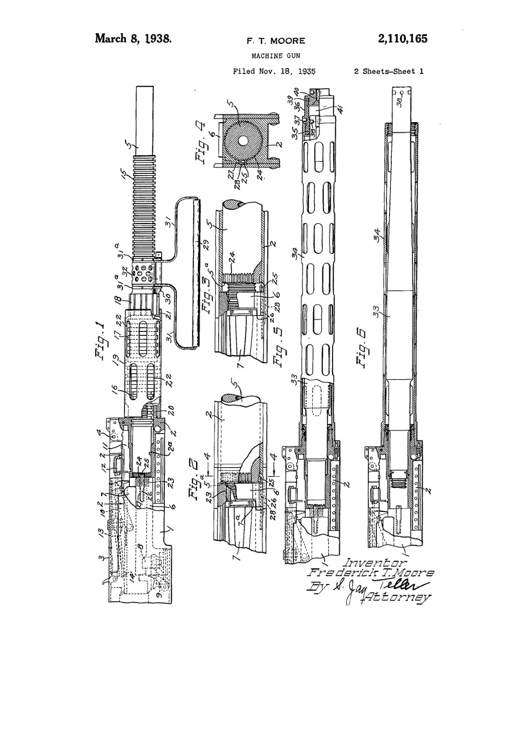
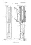
Fig. 1 is a fragmentary side view showing the
front portion of a machine gun embodying my
invention.
Fig. 2 is an enlarged fragmentary plan view
showing parts of the barrel, barrel extension and
breech bolt, this view being partly in section along
the line 2—2 of Fig. 1.
Fig. 3 is a fragmentary view similar to Fig. 2
but showing the barrel partly unscrewed from
the barrel extension.
Fig. 4 is a fragmentary transverse sectional
view taken along the line 4—4 of Fig. 2.
Fig. 5 is a fragmentary side view somewhat 5
similar to Fig. 1 but showing an alternative em-
bodiment of the invention.
Fig. 6 is a fragmentary view similar to Fig. 5
but omitting the barrel guiding bearing and show-
ing the barrel partly removed. In this view the 10
jacket Isshown in section.
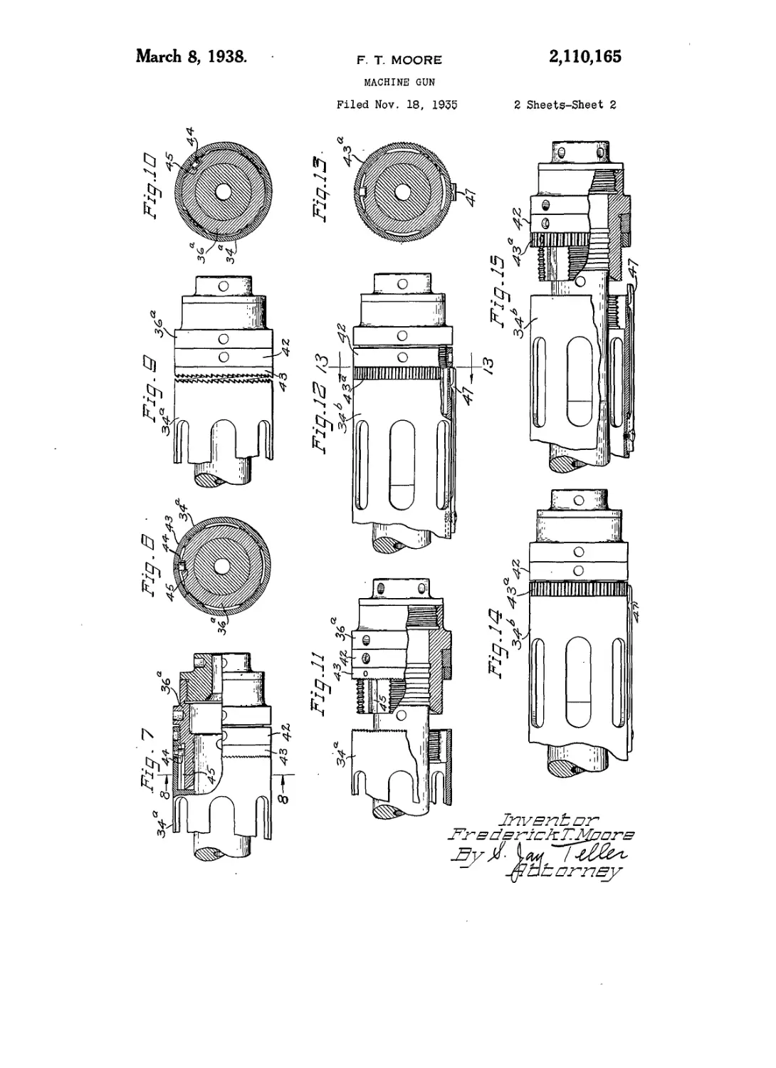
Fig. 7 is an enlarged fragmentary view show-
ing an alternative barrel guiding bearing and the
parts associated therewith.
Fig. 8 is a transverse sectional view taken along 15
the line 8—8 of Fig. 7.
Fig. 9 is a view similar to Fig. 7 but showing
the lock nut and the lock ring in their forward
positions.
Fig. 10 is a view similar to Fig. 8 but showing 20
the parts in the relative positions which they oc-
cupy prior to disassembly.
Fig. 11 is a view similar to Figs. 7 and 9 but
showing the bearing sleeve and associated parts
removed from the barrel jacket. 25
Fig. 12 is a view similar to Fig. 7 but showing
another alternative embodiment of the invention.
Fig. 13 is a transverse sectional view taken
along the line i3—13 of Fig. 12.
Fig. 14 is a view similar to Fig. 12 but showing 30
the lock nut in its forward position.
Fig. 15 is a view similar to Figs. 12 and 14 but
showing the bearing sleeve and associated parts
removed from the barrel jacket.
While not so limited, the invention is well 35
adapted for use with a machine gun of the type
disclosed in the Browning Pat. No. 1,293,021,
dated February 4, 1919. Reference may be had
to the said patent for details of mechanism not
herein fully disclosed. 40
Referring particularly to Fig. 1 of the drawings,
I represents the breech casing of the gun and
2 the trunnion block constituting the forward
end of the casing. The said trunnion block is
formed with an opening for receiving the barrel 45
of the gun, and the walls 2s of the said opening
constitute a bearing at the front of the casing
for engaging a corresponding bearing surface of
the barrel near the rear end thereof. The breech
casing is provided with a cover 3 hinged at 4 to 50
the trunnion block. Projecting from the casing
at the front is a barrel 5 which, upon recoil, is
movable rearward to a limited extent. Connected
with the barrel at the rear end thereof and lo-
cated within the casing is a bodily movable bar- 55
3,110,160
5
10
15
20
25
30
35
40
45
50
55
60
65
70
7fi
2
rel extension 6. It will be understood that the
barrel and extension are both longitudinally re-
ciprocable in unison during normal operation of
the gun.
Mounted on the barrel extension for longitudi-
nal movement independently thereof is a breech
bolt 7. The breech bolt is normally held in fixed
relationship with the barrel extension by means
of the lock 8. Upon recoil, the barrel extension
6 moves rearward, carrying the breech bolt with
it. The lock 8 is automatically withdrawn and
thereafter the action of the barrel extension on
the pivoted accelerator 9 serves to move the
breech bolt rearward independently against the
resistance of a reaction spring which is not shown.
This reaction spring serves to immediately return
the breech bolt to its normal relationship with the
barrel extension, whereupon it is again locked.
Carried by the breech bolt 7 is a pivoted ex-
tractor iO which serves during rearward move-
ment of the breech bolt to extract a cartridge
from a cartridge belt positioned in the transverse
feed channel f i. As the bolt moves rearward and
again moves forward, the cartridge is transfer-
red downward into alignment with the chamber
of the barrel and is pushed into the chamber as
the breech bolt reaches its normal forward posi-
tion. The extractor is automatically returned to
its elevated position so as to engage another cart-
ridge in the feed belt.
The feed belt is successively fed forward so that
the cartridges thereof may be engaged by the ex-
tractor iO, such feedirtg being effected by the
transversely movable feed slide i2. This feed
slide is reciprocated by means of a feed lever i3
pivoted to the top cover of the casing and oscil-
lated by means of a stud i4 which fits within a
cam groove (not shown) in the top surface of the
breech bolt.
As already stated, the gun is preferably air-
cooled. In order to provide a relatively large body
of metal for the absorption of heat the barrel is
made relatively heavy, and in order that the heat
may be rapidly dissipated, the barrel may be pro-
vided with a plurality of cooling ribs. As shown,
there is a series of circumferentially extending
ribs i5 on the front portion of the barrel and a
series of similar ribs i6 near the rear portion of
the barrel. Between the said ribs i5 and i6 the
barrel is enlarged, the enlarged portion being pro-
vided with a series of circumferentially extending
ribs i7 and a series of longitudinally extending
ribs i8.
For supporting and guiding the barrel there is
provided a barrel guide in the form of a jacket i9
projecting forward from the casing and sur-
rounding the barrel. Preferably the trunnion
block 2 is provided with a forward projecting
threaded flange 20 and the jacket i 9 is provided
with internal threads adapted to be screwed onto
the threaded flange 20. The guide or jacket i9
is provided adjacent its forward end with a
bearing 2 i and the barrel is provided with a bear-
ing surface spaced longitudinally forward from
the aforesaid rear bearing surface thereof at 2a
and adapted to engage the bearing 2i on the
jacket i9. As shown the bearing 2 i is formed in-
tegrally with the guide or jacket f 9, but this is not
essential. Preferably the outer faces of the be-
fore-mentioned longitudinally extending ribs i8
are so positioned and are of such size that their
outer surfaces engage the said bearing surface 2i.
The jacket i9 is provided with a plurality of open-
ings 22, 22 which permit air to freely circulate
through the interior of the sleeve and to contact
with the cooling ribs i8. By reason of the con-
struction described the guide i9 and its bearing
2f serve to guide and support the barrel with-
out, however, seriously reducing the cooling effect
of the several series of ribs on the barrel. The ribs 5
18 are partly exposed when the barrel is in its nor-
mal forward position and even when the barrel
moves rearward there is still opportunity for air
to circulate through the spaces or grooves be-
tween the ribs i8. Inasmuch as the ribs i8 ex- 10
tend longitudinally wear on the bearing surface
2 i is reduced to a minimum.
The barrel 5 may be put in place or removed
from the front without disturbing any other parts
of the gun mechanism. To this end the barrel 15
has an engagement with the barrel extension 6
which permits engagement and disengagement by
rotative movement of the barrel. Preferably the
extension has a threaded barrel receiving open-
ing and the barrel has threads 23 at its rear por- 20
tion adapting it to be screwed into the opening
in the extension. The bearings 2a and 2 i not only
permit the normal reciprocating movements of
the barrel, but they also permit the rotative move-
ments that are necessary to connect the barrel 25
with or disconnect it from the barrel extension.
The said' bearings are also constructed and ar-
ranged to permit the barrel to be inserted into or
removed from the gun at the front thereof. With
respect to the front bearing carried by the guide 30
I do not limit myself, but as shown in Fig. 1 the
integral bearing 21 and the corresponding bear-
ing surface on the barrel have a diameter at least
equal to that of any portion of the barrel behind
the said bearing surfaces. The barrel can, there- 35
fore, be inserted or removed through the bearing
2 i with the guide and bearing both in place.
A portion of the barrel is adapted for engage-
ment by a wrench or other suitable tool to effect
rotation thereof so as to connect it with or dis- 40
connect it from the barrel extension. Inasmuch
as the barrel is removable from the front of the
gun, the said portion adapted to be engaged to
effect rotation is so related to the said guide as to
be accessible with the guide in place. In the con- 45
struction shown in Fig. 1, the ribs f8, with the
longitudinal grooves between them, constitute the
portion of the barrel adapted to be engaged to
effect rotation.
In order that the barrel may be firmly held in 50
place, there is provided a means for resisting the
rotation thereof, which means is additional to
the means, such as the threads, which connect the
barrel and the extension. The means for re-
sisting rotation is so constructed that rotation 55
may be permitted when desired while the barrel
and extension are in place in the casing. Pref-
erably and as shown, the barrel has a shoulder 5tt
adjacent the threads and is provided with an an-
nular or peripheral series of notches 24. There go
is provided a latch 25 adapted to enter any one
of the notches 24 to thus hold the barrel in its
adjusted position. Preferably the notches 24 are
V-shaped and the latch 25 is spring-pressed and
is radially movable so as to automatically move 65
into and out of the notches 24 successively as the
barrel is rotated.
The latch 25 is preferably in the form of a tooth
at the forward end of a spring member 28. This
spring member is seated in a longitudinal slot 27 70
formed in one side of the barrel extension 6.
The rear portion of this slot is shaped to fit and
hold the rear portion of the spring 26, leaving the
forward portion free to flex so that the tooth or
latch 25 may enter the notches 24 as described. 75
2,110,160
5
10
15
20
25
30
35
40
45
50
55
60
65
70
76
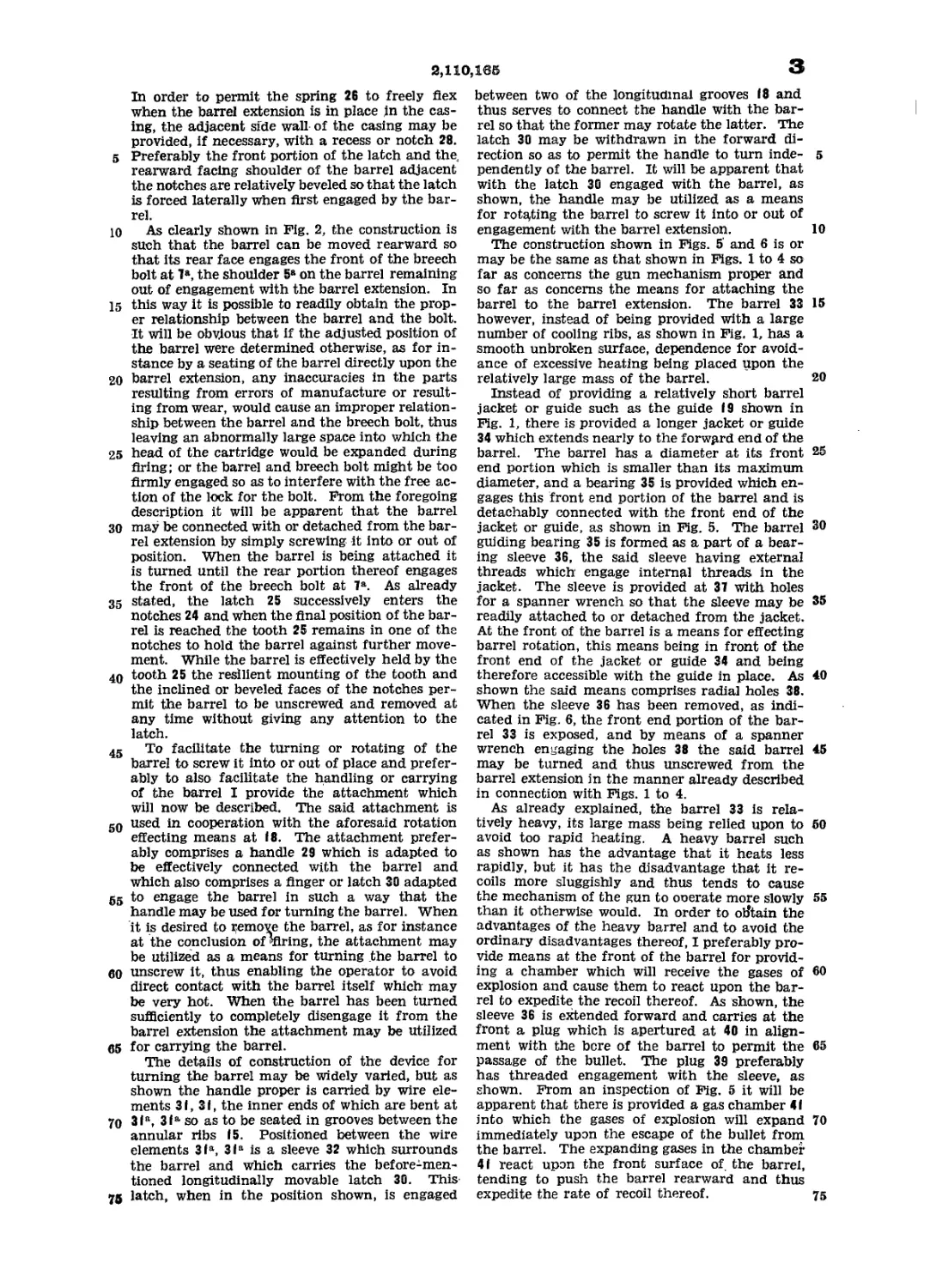
In order to permit the spring 26 to freely flex
when the barrel extension is in place in the cas-
ing, the adjacent side wall of the casing may be
provided, if necessary, with a recess or notch 28.
Preferably the front portion of the latch and the,
rearward facing shoulder of the barrel adjacent
the notches are relatively beveled so that the latch
is forced laterally when first engaged by the bar-
rel.
As clearly shown in Pig. 2, the construction is
such that the barrel can be moved rearward so
that its rear face engages the front of the breech
bolt at 7a, the shoulder 5a on the barrel remaining
out of engagement with the barrel extension. In
this way it is possible to readily obtain the prop-
er relationship between the barrel and the bolt.
It will be obvious that if the adjusted position of
the barrel were determined otherwise, as for in-
stance by a seating of the barrel directly upon the
barrel extension, any inaccuracies in the parts
resulting from errors of manufacture or result-
ing from wear, would cause an improper relation-
ship between the barrel and the breech bolt, thus
leaving an abnormally large space into which the
head of the cartridge would be expanded during
firing; or the barrel and breech bolt might be too
firmly engaged so as to interfere with the free ac-
tion of the lock for the bolt. From the foregoing
description it will be apparent that the barrel
may be connected with or detached from the bar-
rel extension by simply screwing it into or out of
position. When the barrel is being attached it
is turned until the rear portion thereof engages
the front of the breech bolt at 7a. As already
stated, the latch 25 successively enters the
notches 24 and when the final position of the bar-
rel is reached the tooth 25 remains in one of the
notches to hold the barrel against further move-
ment. While the barrel is effectively held by the
tooth 25 the resilient mounting of the tooth and
the inclined or beveled faces of the notches per-
mit the barrel to be unscrewed and removed at
any time without giving any attention to the
latch.
To facilitate the turning or rotating of the
barrel to screw it into or out of place and prefer-
ably to also facilitate the handling or carrying
of the barrel I provide the attachment which
will now be described. The said attachment is
used in cooperation with the aforesaid rotation
effecting means at i8. The attachment prefer-
ably comprises a handle 29 which is adapted to
be effectively connected with the barrel and
which also comprises a finger or latch 30 adapted
to engage the barrel in such a way that the
handle may be used for turning the barrel. When
it is desired to Remove the barrel, as for instance
at the conclusion of ^firing, the attachment may
be utilized as a means for turning the barrel to
unscrew it, thus enabling the operator to avoid
direct contact with the barrel itself which may
be very hot. When the barrel has been turned
sufficiently to completely disengage it from the
barrel extension the attachment may be utilized
for carrying the barrel.
The details of construction of the device for
turning the barrel may be widely varied, but as
shown the handle proper is carried by wire ele-
ments 3 i, 3 i, the inner ends of which are bent at
3 itt, 3ia so as to be seated in grooves between the
annular ribs i5. Positioned between the wire
elements 3itt, 3itt is a sleeve 32 which surrounds
the barrel and which carries the before-men-
tioned longitudinally movable latch 30. This
latch, when in the position shown, is engaged
3
between two of the longitudinal grooves i8 and
thus serves to connect the handle with the bar-
rel so that the former may rotate the latter. The
latch 30 may be withdrawn in the forward di-
rection so as to permit the handle to turn inde- 5
pendently of the barrel. It will be apparent that
with the latch 30 engaged with the barrel, as
shown, the handle may be utilized as a means
for rotating the barrel to screw it into or out of
engagement with the barrel extension. 10
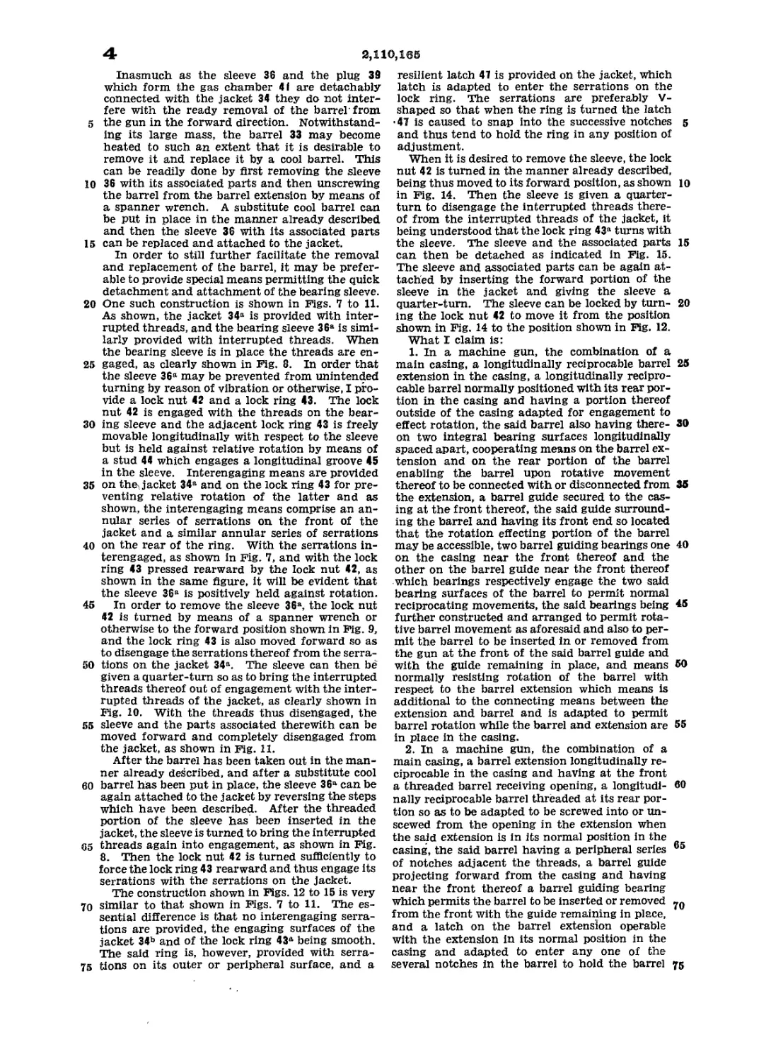
The construction shown in Figs. 5' and 6 is or
may be the same as that shown in Figs. 1 to 4 so
far as concerns the gun mechanism proper and
so far as concerns the means for attaching the
barrel to the barrel extension. The barrel 33 15
however, instead of being provided with a large
number of cooling ribs, as shown in Fig. 1, has a
smooth unbroken surface, dependence for avoid-
ance of excessive heating being placed upon the
relatively large mass of the barrel. 20
Instead of providing a relatively short barrel
jacket or guide such as the guide i9 shown in
Fig. 1, there is provided a longer jacket or guide
34 which extends nearly to the forward end of the
barrel. The barrel has a diameter at its front 25
end portion which is smaller than its maximum
diameter, and a bearing 35 is provided which en-
gages this front end portion of the barrel and is
detachably connected with the front end of the
jacket or guide, as shown in Fig. 5. The barrel 3°
guiding bearing 35 is formed as a part of a bear-
ing sleeve 36, the said sleeve having external
threads which engage internal threads in the
jacket. The sleeve is provided at 37 with holes
for a spanner wrench so that the sleeve may be 35
readily attached to or detached from the jacket.
At the front of the barrel is a means for effecting
barrel rotation, this means being in front of the
front end of the jacket or guide 34 and being
therefore accessible with the guide in place. As 40
shown the said means comprises radial holes 38.
When the sleeve 36 has been removed, as indi-
cated in Fig. 6, the front end portion of the bar-
rel 33 is exposed, and by means of a spanner
wrench engaging the holes 38 the said barrel 45
may be turned and thus unscrewed from the
barrel extension in the manner already described
in connection with Figs. 1 to 4.
As already explained, the barrel 33 is rela-
tively heavy, its large mass being relied upon to 50
avoid too rapid heating. A heavy barrel such
as shown has the advantage that it heats less
rapidly, but it has the disadvantage that it re-
coils more sluggishly and thus tends to cause
the mechanism of the gun to ouerate more slowly 55
than it otherwise would. In order to otftain the
advantages of the heavy barrel and to avoid the
ordinary disadvantages thereof, I preferably pro-
vide means at the front of the barrel for provid-
ing a chamber which will receive the gases of 60
explosion and cause them to react upon the bar-
rel to expedite the recoil thereof. As shown, the
sleeve 36 is extended forward and carries at the
front a plug which is apertured at 40 in align-
ment with the bore of the barrel to permit the 65
passage of the bullet. The plug 39 preferably
has threaded engagement with the sleeve, as
shown. From an inspection of Fig. 5 it will be
apparent that there is provided a gas chamber 4 i
into which the gases of explosion will expand 70
immediately upon the escape of the bullet from
the barrel. The expanding gases in the chamber
4i react upon the front surface of. the barrel,
tending to push the barrel rearward and thus
expedite the rate of recoil thereof. 75
2,110,160
5
10
15
20
25
30
35
40
45
50
55
60
65
70
75
4
Inasmuch as the sleeve 36 and the plug 39
which form the gas chamber 4i are detachably
connected with the jacket 34 they do not inter-
fere with the ready removal of the barrel'from
the gun in the forward direction. Notwithstand-
ing its large mass, the barrel 33 may become
heated to such an extent that it is desirable to
remove it and replace it by a cool barrel. This
can be readily done by first removing the sleeve
36 with its associated parts and then unscrewing
the barrel from the barrel extension by means of
a spanner wrench. A substitute cool barrel can
be put in place in the manner already described
and then the sleeve 36 with its associated parts
can be replaced and attached to the jacket.
In order to still further facilitate the removal
and replacement of the barrel, it may be prefer-
able to provide special means permitting the quick
detachment and attachment of the bearing sleeve.
One such construction is shown in Figs. 7 to 11.
As shown, the jacket 34tt is provided with inter-
rupted threads, and the bearing sleeve 36» is simi-
larly provided with interrupted threads. When
the bearing sleeve is in place the threads are en-
gaged, as clearly shown in Fig. 8. In order that
the sleeve 36» may be prevented from unintended
turning by reason of vibration or otherwise, I pro-
vide a lock nut 42 and a lock ring 43. The lock
nut 42 is engaged with the threads on the bear-
ing sleeve and the adjacent lock ring 43 is freely
movable longitudinally with respect to the sleeve
but is held against relative rotation by means of
a stud 44 which engages a longitudinal groove 45
in the sleeve. Interengaging means are provided
on the jacket 34» and on the lock ring 43 for pre-
venting relative rotation of the latter and as
shown, the interengaging means comprise an an-
nular series of serrations on the front of the
jacket and a similar annular series of serrations
on the rear of the ring. With the serrations in-
terengaged, as shown in Fig. 7, and with the lock
ring 43 pressed rearward by the lock nut 42, as
shown in the same figure, it will be evident that
the sleeve 36» is positively held against rotation.
In order to remove the sleeve 36», the lock nut
42 is turned by means of a spanner wrench or
otherwise to the forward position shown in Fig. 9,
and the lock ring 43 is also moved forward so as
to disengage the serrations thereof from the serra-
tions on the jacket 34». The sleeve can then be
given a quarter-turn so as to bring the interrupted
threads thereof out of engagement with the inter-
rupted threads of the jacket, as clearly shown in
Fig. 10. With the threads thus disengaged, the
sleeve and the parts associated therewith can be
moved forward and completely disengaged from
the jacket, as shown in Fig. IX.
After the barrel has been taken out in the man-
ner already described, and after a substitute cool
barrel has been put in place, the sleeve 36» can be
again attached to the jacket by reversing the steps
which have been described. After the threaded
portion of the sleeve has been inserted in the
jacket, the sleeve is turned to bring the interrupted
threads again into engagement, as shown in Fig.
8. Then the lock nut 42 is turned sufficiently to
force the lock ring 43 rearward and thus engage its
serrations with the serrations on the jacket.
The construction shown in Figs. 12 to 15 is very
similar to that shown in Figs. 7 to 11. The es-
sential difference is that no interengaging serra-
tions are provided, the engaging surfaces of the
jacket 34ъ and of the lock ring 43» being smooth.
The said ring is, however, provided with serra-
tions on its outer or peripheral surface, and a
resilient latch 47 is provided on the jacket, which
latch is adapted to enter the serrations on the
lock ring. The serrations are preferably V-
shaped so that when the ring is turned the latch
47 is caused to snap into the successive notches 5
and thus tend to hold the ring in any position of
adjustment.
When it is desired to remove the sleeve, the lock
nut 42 is turned in the manner already described,
being thus moved to its forward position, as shown 10
in Fig. 14. Then the sleeve is given a quarter-
turn to disengage the interrupted threads there-
of from the interrupted threads of the jacket, it
being understood that the lock ring 43» turns with
the sleeve. The sleeve and the associated parts 15
can then be detached as indicated in Fig. 15.
The sleeve and associated parts can be again at-
tached by inserting the forward portion of the
sleeve in the jacket and giving the sleeve a
quarter-turn. The sleeve can be locked by turn- 20
ing the lock nut 42 to move it from the position
shown in Fig. 14 to the position shown in Fig. 12.
What I claim is:
1. In a machine gun, the combination of a
main casing, a longitudinally reciprocable barrel 25
extension in the casing, a longitudinally recipro-
cable barrel normally positioned with its rear por-
tion in the casing and having a portion thereof
outside of the casing adapted for engagement to
effect rotation, the said barrel also having there- 30
on two integral bearing surfaces longitudinally
spaced apart, cooperating means on the barrel ex-
tension and on the rear portion of the barrel
enabling the barrel upon rotative movement
thereof to be connected with or disconnected from 36
the extension, a barrel guide secured to the cas-
ing at the front thereof, the said guide surround-
ing the barrel and having its front end so located
that the rotation effecting portion of the barrel
may be accessible, two barrel guiding bearings one 40
on the casing near the front thereof and the
other on the barrel guide near the front thereof
which bearings respectively engage the two said
bearing surfaces of the barrel to permit normal
reciprocating movemerits, the said bearings being 45
further constructed and arranged to permit rota-
tive barrel movement as aforesaid and also to per-
mit the barrel to be inserted in or removed from
the gun at the front of the said barrel guide and
with the guide remaining in place, and means 50
normally resisting rotation of the barrel with
respect to the barrel extension which means is
additional to the connecting means between the
extension and barrel and is adapted to permit
barrel rotation while the barrel and extension are 55
in place in the casing.
2. In a machine gun, the combination of a
main casing, a barrel extension longitudinally re-
ciprocable in the casing and having at the front
a threaded barrel receiving opening, a longitudi- 60
nally reciprocable barrel threaded at its rear por-
tion so as to be adapted to be screwed into or un-
scewed from the opening in the extension when
the said extension is in its normal position in the
casing, the said barrel having a peripheral series 65
of notches adjacent the threads, a barrel guide
projecting forward from the casing and having
near the front thereof a ban-el guiding bearing
which permits the barrel to be inserted or removed
from the front with the guide remaining in place,
and a latch on the barrel extension operable
with the extension in its normal position in the
casing and adapted to enter any one of the
several notches in the barrel to hold the barrel 75
2,110,166
against relative rotation with respect to the barrel
extension.
3. In a machine gun, the combination of a main
casing, a longitudinally reciprocable barrel ex-
5 tension in the casing having a threaded barrel
receiving opening, a longitudinally reciprocable
barrel threaded at its rear portion to engage the
threaded portion of the barrel extension and hav-
ing a peripheral series of V-shaped notches ad-
10 jacent the threads, the said barrel having a por-
tion thereof outside of the casing adapted for
engagement to effect rotative movement so as
to screw it into or out of the barrel extension and
the said barrel also having thereon two integral
15 bearing surfaces longitudinally spaced apart, a
barrel guide secured to the casing at the front
thereof, the said guide surrounding the barrel and
having its front end so located that the rotation
effecting thereof the barrel may be accessible,
20 two barrel guiding bearings one on the casing
near the front thereof and the other on the bar-
rel guide near the front thereof which bearings
respectively engage the two said bearing surfaces
of the barrel to permit normal reciprocating
25 movements, the said bearings being further con-
structed and arranged to permit rotative barrel
movement as aforesaid and also to permit the
barrel to be inserted in or removed from the gun
at the front of the said barrel guide and with the
30 guide remaining in place, and a spring-pressed
latch on the barrel extension automatically mov-
able into and out of the several notches succes-
sively as the barrel is rotated and free to so move
when the barrel extension is in its normal posi-
35 tion in the casing.
4. In a machine gun, the combination of a main
casing, a barrel extension longitudinally recipro-
cable in the casing and having a threaded barrel
receiving opening, a reciprocable breech bolt in
40 the casing, means for locking the breech bolt in
its forward position and in operative relation to
the barrel extension, a longitudinally reciproca-
ble barrel threaded at its rear portion so as to be
adapted to be screwed into or unscrewed from the
45 opening in the barrel extension when the said
extension is in its normal position in the casing,
the said barrel having its rear face in engage-
ment with the breech bolt when the latter is in
locked position and the extent of threaded en-
50 gagement of the barrel with the barrel extension
being limited and determined solely by the said
breech bolt, a barrel guide projecting forward
from the casing and having near the front there-
of a barrel guiding bearing which permits the
55 barrel to be inserted or removed from the front
with the guide remaining in place, and a releas-
able means on the barrel extension adapted to
hold the barrel in adjusted position and to prevent
relative rotation with respect to the barrel ex-
co tension.
5. In a machine gun, the combination of a
main casing, a longitudinally reciprocable barrel
extension in the casing having a threaded barrel
receiving opening, a reciprocable breech bolt in
c- the casing, means for locking the bolt in its for-
’’ ward position and in operative relation to the
barrel extension, a longitudinally reciprocable
barrel having its rear portion threaded to engage
the threaded portion of the barrel extension and
having its rear face substantially in engagement
with the breech bolt when the latter is in locked
position so that the extent of threaded engage-
ment of the barrel with the barrel extension is
determined solely by the said breech bolt, the
75 said barrel having a portion thereof outside of
5
the casing adapted for engagement to effect ro-
tative movement so as to screw it into or out of
the barrel extension and the said barrel also hav-
ing thereon two integral bearing- surfaces lon-
gitudinally spaced apart, a barrel guide secured 5
to the casing at the front thereof, the said guide
surrounding the barrel and having its front end
so located that the rotation effecting portion of
the barrel may be accessible, two barrel guiding
bearings one on the casing near the front there- ю
of and the other on the barrel guide near the
front thereof which bearings respectively engage
the two said bearing surfaces of the barrel to
permit normal reciprocating movements, the said
bearings being further constructed and arranged 15
to permit rotative barrel movement as aforesaid
and also to permit the barrel to be inserted in
or removed from the gun at the front of the said
barrel guide and with the said guide remaining in
place, and means normally resisting rotation of 20
the barrel with respect to the barrel extension
which means is additional to the engaging thread-
ed portions of the extension and barrel and is
adapted to permit barrel rotation while the bar-
rel ana extension are in place in the casing. «5
6. In a machine gun, the combination of a
main casing, a longitudinally reciprocable bar-
rel extension in the casing having a threaded
barrel receiving opening, a longitudinally recipro-
cable barrel threaded at its rear portion to en- go
gage the threaded portion of the barrel extension
and having a peripheral series of V-shaped
notches adjacent the threads, the said barrel
having its rear face substantially in engagement
with the breech bolt when the latter is in locked 35
position so that the extent of threaded engage-
ment of the barrel with the barrel extension is
determined solely by the said breech bolt and the
said barrel having a portion thereof outside of
the casing adapted for engagement to effect ro-
tative movement so as to screw it into or out of
the barrel extension and the said barrel also hav-
ing thereon two integral bearing surfaces longi-
tudinally spaced apart, a barrel guide secured to
the casing at the front thereof, the said guide 45
surrounding the barrel and having its front
end so located that the rotation effecting portion
of the barrel may be accessible, two barrel guid-
ing bearings one on the casing near the front
thereof and the other on the barrel guide near the c0
front thereof which bearings respectively engage
the two said bearing surfaces of the barrel to per-
mit normal reciprocating movements, the said
bearings being further constructed and arranged
to permit rotative barrel movement as aforesaid СГ)
and also to permit the barrel to be inserted in or
removed from the gun at the front of the said bar-
rel guide and with the guide remaining in place,
and a spring-pressed latch on the barrel exten-
sion automatically movable into and out of the
several notches successively as the barrel is rotat-
ed and free to so move when the barrel extension
is in its normal position in the casing.
7. In a machine gun, the combination of a
main casing, a barrel extension longitudinally C5
reciprocable in the casing and having at the ’’
front a threaded barrel receiving opening, a lon-
gitudinally reciprocable barrel threaded at its
rear portion so as to be adapted to be screwed
into or unscrewed from the opening in the barrel 75
extension when the said extension is in its nor-
mal position in the casing, the said barrel hav-
ing a rearward facing annular shoulder at the
front of the threads and having a peripheral
series of V-shaped notches adjacent the shoulder, 75
гдюдв»
5
10
15
20
25
30
35
40
45
50
55
00
65
70
75
6
and a spring-pressed latch on the barrel exten-
sion automatically movable radially into and out
of the several notches successively as the barrel
is rotated and free to so move when the barrel
extension is in its normal position in the casing,
the front portion of the latch and the rearward
facing shoulder of the barrel being relatively
beveled to cause the latch to be moved outward as
the barrel is moved rearward.
8. In a machine gun, the combination of a
main casing, a barrel extension longitudinally
reciprocable in the casing and having at the front
a threaded barrel receiving opening, a longitu-
dinally reciprocable barrel threaded at its rear
portion so as to be adapted to be screwed into or
unscrewed from the opening in the extension
when the said extension is in its normal position
in the casing, the said barrel having a rearward
facing annular shoulder at the front of the
threads and having a peripheral series of V-
shaped notches adjacent the shoulder, a barrel
guide projecting forward from the casing and
having near the front thereof a barrel guiding
bearing which permits the barrel to be inserted or
removed from the front, and a spring-pressed
latch on the barrel extension automatically mov-
able radially into and out of the several notches
successively as the barrel is rotated and free to
so move when the barrel extension is in its nor-
mal position in the casing, the front portion of
the latch and the rearward facing shoulder of the
barrel being relatively beveled to cause the latch
to be moved outward as the barrel is moved rear-
ward.
9. In a machine gun, the combination of a
main casing, a barrel extension longitudinally
reciprocable in the casing and having a threaded
barrel receiving opening, a reciprocable breech
bolt in the casing, means for locking the breech
bolt in its forward position and in operative rela-
tion to the barrel extension, a longitudinally re-
ciprocable barrel threaded at its rear portion so
as to be adapted to be screwed into or unscrewed
from the opening in the barrel extension when
the said extension is in its normal position in
the casing, the said barrel having its rear face
in engagement .with the breech bolt when the
latter is in locked position and the extent of
threaded engagement of the barrel with the
barrel extension being limited and determined
solely by the said breech bolt and the said bar-
rel having a rearward facing shoulder at the
front of the threads and having a series of
peripheral V-shaped notches adjacent the
shoulder, and a spring-pressed latch on the barrel
extension automatically movable radially into
and out of the several notches successively as the
barrel is rotated arid free to so move when the
barrel extension is in its normal position in the
casing, the front portion of the latch and the
rearward facing shoulder of the barrel being rel-
atively beveled to cause the latch to be moved
outward as the barrel is moved rearward.
10. In a machine gun, the combination of a
main casing, a barrel extension longitudinally
reciprocable in the casing and having a barrel
receiving opening at the front, a longitudinally
reciprocable barrel adapted at the rear to enter
the opening in the extension and having means
adapted upon rotation to engage the barrel ex-
tension to prevent longitudinal movement rela-
tive thereto, the said barrel being provided with
a bearing surface spaced forward from the rear
end thereof and having a diameter at least equal
to that of any portion of the barrel behind the
bearing surface, a barrel guide projecting for-
ward from the casing and having a barrel guid-
ing bearing in engagement with the said bearing
surface of the barrel and permitting the barrel
to be inserted or removed from the front with the 5
guide remaining in place, and a releasable means
on the barrel extension adapted to hold the bar-
rel against relative rotation with respect to the
barrel extension.
IX. In a machine gun, the combination of а ю
main casing, a longitudinally reciprocable barrel
extension in the casing, a longitudinally recipro-
cable barrel normally positioned with its rear
portion in the casing and having a portion there-
on outside of the casing adapted for engagement ]5
to effect rotation, the said barrel also having
thereon two integral bearing surfaces longitu-
dinally spaced apart the forward of which bear-
ing surfaces has a diameter at least as great as
that of any part of the barrel at the rear thereof, 20
cooperating means on the barrel extension and
on the rear portion of the barrel enabling the
barrel upon rotative movement thereof to be con-
nected with or disconnected from the extension,
a barrel guide secured to the casing at the front 25
thereof and surrounding the barrel, and two bar-
rel guiding bearings one on the casing near the
front thereof and engaging the rear bearing sur-
face of the barrel and the other on the barrel
guide near the front thereof and engaging the 30
forward bearing surface of the barrel so as to
leave the rotation effecting portion thereof ac-
cessible, the said bearings being further con-
structed and arranged to also permit rotative
barrel movement as aforesaid and also to permit 35
the barrel to be inserted in or removed from the
gun at the front of the said barrel guide and the
bearing thereon and with the guide and the bear-
ing both remaining in place.
12. In a machine gun, the combination of a 40
main casing, a barrel extension longitudinally
reciprocable in the casing and having at the
front a threaded barrel receiving opening, a lon-
gitudinally reciprocable barrel threaded at its
rear portion so as to be adapted to be screwed 45
into or unscrewed from the opening in the ex-
tension when the said extension is in its normal
position in the casing, the said barrel having a
peripheral series of notches adjacent the threads
and also having a bearing surface spaced for- co
ward from the threads and having a diameter at
least equal to that of any portion of the barrel
behind the bearing surface, a barrel guide pro-
jecting forward from the casing and having a
barrel guiding bearing in engagement with the 55
said bearing surface of the barrel and permitting
the barrel to be inserted or removed from the
front with the guide' remaining in place, and a
latch on the barrel extension operable with the
extension in its normal position in the casing CO
and adapted to enter any one of the several
notches in the barrel to hold the barrel against
relative rotation with respect to the barrel ex-
tension.
13. In a machine gun, the combination of a C5
main casing, a longitudinally reciprocable barrel
extension in the casing having a threaded barrel
receiving opening, a reciprocable breech bolt in
the casing, means for locking the bolt in its for-
ward position and in operative relation to the bar- 70
rel extension, a longitudinally reciprocable barrel
having its rear portion threaded to engage the
threaded portion of the barrel extension and
having its rear face substantially in engagement
with the breech bolt when the latter is in locked 75
2,110,163
position so that the extent of threaded engage-
ment of the barrel with the barrel extension is
determined solely by the said breech bolt, the
said barrel having a portion thereof outside of
6 the casing adapted for engagement to effect ro-
tative movement so as to screw it into or out of
the barrel extension and the said barrel also
having thereon two integral bearing surfaces
longitudinally spaced apart, the forward of which
10 bearing surfaces has a diameter at least as great
as that of any part of the barrel at the rear
thereof, a barrel guide secured to the casing at
the front thereof and surrounding the barrel, and
two barrel guiding bearings one on the casing
15 near the front thereof and engaging the rear
bearing surface of the barrel the other on the
barrel guide near the front thereof and engag-
ing the forward bearing surface of the barrel so
as to leave the rotation effecting portion thereof
20 accessible, the said bearings being further con-
structed and arranged to also permit rotative
barrel movement as aforesaid and also to permit
the barrel to be inserted in or removed from the
gun at the front of the said barrel guide and the
25 bearing thereon and with the guide and bearing
both remaining in place, and means normally re-
sisting rotation of the barrel with respect to the
barrel extension which means is additional to the
engaging threaded portions of the extension and
30 barrel and is adapted to permit barrel rotation
while the barrel and extension are in place in
the casing.
14. In a machine gun, the combination of a
main casing, a barrel extension longitudinally
35 reciprocable in the casing and having a threaded
barrel receiving opening, a reciprocable breech
bolt in the casing, means for locking the breech
bolt in its forward position and in operative rela-
tion to the barrel extension, a longitudinally re-
40 ciprocable barrel threaded at its rear portion
so as to be adapted to be screwed into or un-
screwed from the opening in the barrel extension
when the said extension is in its normal position
in the casing, the said barrel having its rear face
45 in engagement with the breech bolt when the
latter is in locked position and the extent of
threaded engagement of the barrel with the barrel
extension being limited and determined solely by
the said breech bolt and the said barrel having a
5Q peripheral series of notches adjacent the threads,
a barrel guide projecting forward from the cas-
ing and having near the front thereof a barrel
guiding bearing which permits the barrel to be
inserted or removed from the front with the guide
55 remaining in place, and a latch on the barrel ex-
tension operable with the extension in its normal
position in the casing and adapted to enter any
one of the several notches in the barrel to hold
the barrel against relative rotation with respect
gg to the barrel extension.
15. In a machine gun, the combination of a
main casing, a longitudinally reciprocable barrel
extension in the casing, a longitudinally recip-
rocable barrel normally positioned with its rear
85 portion in the casing and having a portion thereof
outside of the casing adapted for engagement to
effect rotation, the said barrel also having thereon
two integral bearing surfaces longitudinally
spaced apart the forward of which bearing sur-
J0 faces has a diameter smaller than the diameter of
portions of the barrel at the rear thereof, cooper-
ating means on the barrel extension and on the
rear portion of the barrel enabling the barrel upon
rotative movement thereof to be connected with
M or disconnected from the extension, a barrel guide
7
secured to the casing at the front thereof, the said
guide surrounding the barrel and having its front
end so located that the rotation effecting portion
of the barrel may be accessible, a barrel guiding
bearing on the casing near the front thereof en- 5
gaging the rear bearing surface of the barrel, and
a barrel guiding bearing on the barrel guide at
the front thereof and engaging the forward bear-
ing surface of the barrel, the last said bearing be-
ing readily detachable to permit the barrel to be
inserted in or removed from the gun at the front
of the barrel guide and with the guide remaining
in place.
16. In a machine gun, the combination of a
main casing, a longitudinally reciprocable barrel 15
extension in the casing having a threaded barrel
receiving opening, a reciprocable breech bolt in
the casing, means for locking the bolt in its for-
ward position and in operative relation to the
bjarrel extension, a longitudinally reciprocable 20
barrel having its rear portion threaded to engage
the threaded portion of the barrel extension and
having its rear face substantially in engagement
with the breech bolt when the latter is in locked
position so that the extent of threaded engage- 25
ment of the barrel with the barrel extension is
determined solely by the said breech bolt, the said
barrel having a portion thereof outside of the
casing adapted for engagement to effect rotative
movement so as to screw it into or out of the 30
barrel extension and the said barrel also hav-
ing thereon two integral bearing surfaces longi-
tudinally spaced apart the forward of which
bearing surfaces has a diameter smaller than the
diameter of portions of the barrel at the rear gg
thereof, a barrel guide secured to the casing at
the front thereof, the said guide surrounding the
barrel and having its front end so located that the
rotation effecting portion of the barrel may be
accessible, a barrel guiding bearing on the cas- 40
ing near the front thereof engaging the rear bear-
ing surface of the barrel, a barrel guiding bear-
ing on the barrel guide at the front thereof and
engaging the forward bearing surface of the bar-
rel, the last said bearing being readily detachable 45
to permit the barrel to be inserted in or removed
from the gun at the front of the barrel guide and
with the guide remaining in place, and means
normally resisting rotation of the barrel with re-
spect to the barrel extension which means is ad- g0
ditional to the engaging threaded portions of the
extension and barrel and is adapted to permit
barrel rotation while the barrel and extension are
in place in the casing.
17. In a machine gun, the combination of a 55
main casing, a longitudinally reciprocable barrel
extension in the casing, a longitudinally recip-
rocable heavy barrel normally positioned with its
rear portion in the casing and having a portion
thereof outside of the casing adapted for engage- e0
ment to effect rotation, the said barrel also hav-
ing thereon two integral bearing surfaces longi-
tudinally spaced apart the forward of which bear-
ing surfaces has a diameter smaller than the di-
ameter of portions of the barrel at the rear e5
thereof, cooperating means on the barrel exten-
sion and on the rear portion of the barrel enabling
the barrel upon rotative movement thereof to be
connected with or disconnected from the exten-
sion, a barrel guide secured to the casing at the 70
front thereof, the said guide surrounding the
barrel and having its front end so located that
the rotation effecting portion of the barrel may
be accessible, a barrel guiding bearing on the cas-
ing near the front thereof and engaging the rear 75
3,110,168
8
bearing surface of the barrel, a barrel guiding
bearing sleeve on the barrel guide at the front
thereof and engaging the forward bearing sur-
face of the barrel, the said bearing sleeve being
5 readily detachable to permit the barrel to be in-
serted in or removed from the gun at the front
thereof with the barrel guide remaining in place,
and a plug at the front of the barrel carried by
the said bearing sleeve and removable therewith,
the said plug having an aperture in alignment
with the bore of the barrel and serving in con-
junction with the sleeve to form a gas chamber 5
at the front of the barrel.
FREDERICK T. MOORE.