/


Tags: weapons military affairs machine gun patent
Year: 1893
Text
3 Sheets—Sheet 1.
(No Model.)
R. J. GATLING.
MACHINE GUN.
No. 502,185.
Patented July 25, 1893.
3 Sheets—Sheet 2,
No Model.)
R. J. GATLING.
MACHINE GUN.
(No Model.)
3 Sheets—Sheet 3.
E. J. GATLING.
MACHINE GUN.
No. 502,185. Patented July 25, 1893.
United States Patent Office.
RICHARD J. GATLING, OF HARTFORD, CONNECTICUT.
MACHINE-GUN.
SPECIFICATION forming part of LettersPatent No. 502,185, dated July 25,1893.
Application filed September 10,1892, Serial No, 445,492. (No model.).
To all whom it таи сотрсвгп:
_ Be it known That I, RiciiARfr J.- Gatling, a
citizen of the United States residing at Hart-
ford, in the county of Hartford and State of
5 .Connecticut, have invented certain new and
useful Improvements in Machine-Guns, of
which the following is a full, clear, and ex-
act specification.
The invention relates to the class of ma-
ro chine guns commonly known as Gatling guns,
the object being to provide a gun of this class
which can be readily changed so as to be fired
with great rapidity either by hand or by pow-
er, thexpower driving-'mechanism being so
15 constructed that it may be quickly removed,
or attached in sii'ch manner that it is out of
sight and not a mark for hostile projectiles or
in the way of the gunners; and further to so
construct the mechanism of the gun that the
го parts may be quickly removed and assembled,
and enable cartridges of Small caliber to be
11 sed and posi ti vely ext rac ted af ter bei n g fi red.
To this end the invention resides in a gun
having a frame or casing supporting a cylin-
25 drical cam and a central revolving shaft bear-
ing coils of wire, a group of barrels and a cyl-
inder with reciprocating locks, and in details
of the construction of these parts, as more
particularly hereinafter described and point,-
30 ed out in the claims.
Referring to the accompanying drawings:—
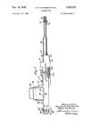
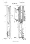
Figure 1 is a side view of one of these guns
of the class known as the “army gun.” Fig.
2 is a plan of the same. Fig. 3 is a side view
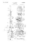
35 of one of these guns of. the class known as
the “navy gun.” Fig. 4 is a plan of this lat-
ter gun. Fig. 5 is a plan of the revolving
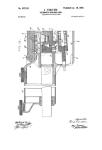
parts of one of the guns. Fig. 6 is an enlarged
central longitudinal vertical section of the
40 butt of the gun shown in Fig. 1. Fig. 7 is a
section on plane denoted by the broke и line a
a. Fig. 8 is a section on plane denoted by Ъ
- Ъ. Fig. 9 is a section on plane c c. Fig. 10
is a section on cl cl.. Fig. 11 is a view of the
45 breech’of the barrels and their holder. Fig.
12 is a section of a portion of the same. Fig.
13 is a section of the cain cylinder; and Fig.
14 shows top, bottom, side, sectional and end
views of one oFthe locks. >
50 In the views 1 indicates the trunnion frame
which consists of a pair of metallic bars con-
nected together at their front ends by a cross-
piece 2, and at their rear ends by the. casing
I 3. This cylindrical casing 3 is divided dia-
metrically and the upper part hinged to the 55
lower so that it may be thrown open to expose
the interior when its catch is released and
the casing4,that isscrewed upon a mutilated
thread on the end of this casing, is removed.
A shaft 5 passing through the center from 60
end to end of the gun is supported at the front
by the cross-piece of the frame and at the
rear end by the cascabel plate or a bearing in
the cascabel. It is preferred that this shaft
be formed in two sections joined back of the 65
casing 3 by means of a coupling G so that
the rear portion of the shaft may be sepa-
rated from the forward portion and removed.
Keyed to the shaft are the barrel disks, the
front disk, 7, being perforated and holding 70 '
the barrels near their muzzles, while the rear
disk, 8, is perforated and holds the butts of
the barrels which are provided with lugs 9.
The disk 8 is chambered and in the chamber is
placedadisk lOof hardsteel,havinganumber 75
of mortises in its periphery to receive and
hold the lugs projecting from the ends of the
barrels, so that the barrels are prevented from
twisting or turning under the strain of the
bullets as they pass through the rifling. The 80
lock carrier cylinder 11 is keyed to the shaft
directly back of this disk 10 so as to hold the
disk is place, and in grooves in this cylinder
slide the locks 12 as they are reciprocated by
the cam cut in the interior of the cylinder 13 85
that fits into the casing 3 which has a, socket
to receive a pin 14 that projectsfroimthe cyl-
inder so as to insure the correct location of
the parts.
Each of the locks 12 consists of a block 15 90
whieh forms a breech block, having a tongue
1G that runs in a groove in the carrier block
and a lug 17 that fits the cam groove so that
the locks are reciprocated by the cam as the
carrier revolves with the locks as in the com- 95
mon Gatling gun. In a central perforation
through each lock-block is placed a spring
firing pin 18 having a head 19 adapted to en-
gage the cocking switch 20 located on the
interior of the cam cylinder back of the re- ico
coil block 40, as in the common construction,
while in a longitudinal mortise in the top of
the block is an extractor 21, having a hooked
forward end adapted to engage the upper por-
tion of the rim of a cartridge, and in a mor- 105
tise in the bottom of this block is an ex-
2
502,185
tractor 22 having a hooked end adapted to
engage the lower part of the rim of the car-
tridge to withdraw it from the barrel after it
has been fired. The extractor 21 is formed of
5 a piece of spring steel, and has a small recip-
rocation in the mortise on its holding pin,
while the extractor 22 has a longitudinal
movement on its holding pin, and is thrust
forward by means of the spring 23, the elastic
to tail of this extractor riding on a roll in The
bottom of the mortise.
A diaphragm 24 with a bearing for th6 cen-
ter shaft is located in the rear of the casing
3 behind the cam cylinder, and this diaphragm
15 is divided, the upper part 25 being hinged to
the lower so that it may be lifted when the top
of the casing is lifted, to allow a free removal
of the locks from the grooves in the carrier
block.
20 In the construction shown, to the central
shaft 5 is keyed a core 26 of magnetic ma-
terial with a common windingof wire 27form-
ing an armature of an electric motor which
when electrically excited rotates the shaft,
25 while loosely mounted upon the shaft is a
frame 28 which bears an electro field magnet
29. To the frame 28 of this field magnet is
secured a gear 30 that meshes into gears 31
secured to shafts 32 which are journaled in
30 the ends of a coupling 33 and which bear
gears 34 in mesh with a gear 35 secured to a
diaphragm 3G extending across the forward
end of this easing. The coupling 33 is--re-
movably secured to the end of the shaft of
35 the gun where the usual crank-handle would
be attached, and also to the extension of the
shaft which bears the armature of the electric
motor.
The field magnet is wound iu the custom-
40 ary manner and connected with its source of
excitation in any common manner, and the
armature is also wound as usual and connected
in the ordinary way with any suitable source
of electrical supply.
45 To start the gun into action the motor is ex-
cited by a current of electricity. The con-
struction and arrangement described are such
that the armature revolves in one direction,
and being connected with the main shaft rp-
50 volves it and operates the gun, while through
the medium of the intermeshing gears the
field revolves in au opposite direction in order
that the revolutions of the armature may be
slower so that the speed of the firing may- be
55 better regulated.
At the forward end of the chsing 3 in the
frame of the gun shown and described, in
Figs. 1 and 2-, a hopper 37’ made of a form to
receive a cartridge feed' slide of the class
60 known as the “Bruce feed,” is hinged to the
frame on one side and provided with a catch '
on the opposite side to permit of its being
opened or closed. Formed on or secured to
the under side of this hopperare the plows
65 38 (Figs.fi and 10) which extend into thfrpath
of the exploded cartridge shells after they
have been extracted from the barrels, to eject
; them from the gun, as in the Gatling gun in
common use.
In the form of gun shown in Figs. 3 and 70
4, the barrels are surrounded by a shell 39
for nearly their entire length, and in this
shell water or any suitable cooling liquid may
be placed to keep down the temperature of
the barrels. In this form the upper part of 75
the. rear end of the casing and the hopper are
hinged" to a portion of the shell, the hopper
shown in this connection being that of com-
mon form which is designed to receive the
ordinary “drum feed” used with guns of this So
class.
I claim as my invention—
1. In combination with the frame of a ma-
chine gun, a revolving shaft bearing an ar-
mature a group1 of barrels and a mortised 85
cylinder holding reciprocating locks, a casing
inclosing a field magnet adjacent to the ar-
mature, and a cylindrical cam in the path of
the locks, substantially as specified.
2. In combination with the frame of a ma- 90
chine gun, a revolving shaft bearing an ar-
mature a group of barrels and a mortised
cylinder holding reciprocatinglocks, a casing
supporting a cylindrical cam in the path of
the locks, and ar casing detachably,seen red 95
to the former casing and inclosing a field
magnet adjacent to the armature, substan-
tially as specified.
3. In combination with the frame of a ma-
chine gun, a revolving shaft bearing a group 100
of barrels and a mortised cylinder holding
reciprocating locks, a sectional hinged casing
supporting a cylindrical cam in the path of
the locks, a hopper hinged to the frame adja-
cent to the breech of the barrels, and means 105
for revolving the shaft, substantially as speci-
fied. •
4. In combination with the frame of a ma-
chine gun, a revolving shaft bearing a group
of barrels and a mortised cylinder holding no
reciprocating locks, a sectional hinged casing
supporting a cylindrical-cam in the path of
the locks, a sectional hinged diaphragm at
the rear of said casing, a hopper hinged to the
frame adjacent to the breech of the barrels, r 15
and means for revolving the shaft, substan-
tially as specified.
5. In combination with the frame of a ma-
chine gun, a revolving shaft bearing a mor-
tised cylinder holding reciprocating locks, 120
and disks holding a group of barrels, the rear
one of said .disks being formed of a portion
with circular perforations and a portion of
harder metal halving mortises adjacent to the
circular perforations, barrels with lugs pro- 125
jecting’frony their rear ends into said mor-
tises, a casing supporting a cylindrical cam
in the path of'the locks, and means for re-
volving the shaft, substantially as specified.
RICHARD J. GATLING.
Witnesses:
II. R. Williams,
Clarence E. Bucklanp.