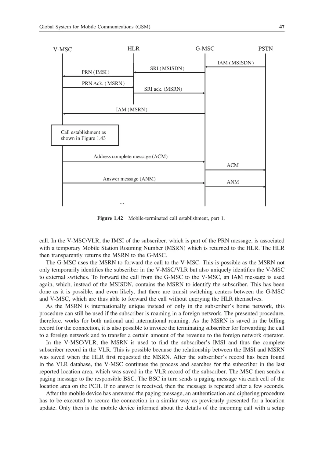
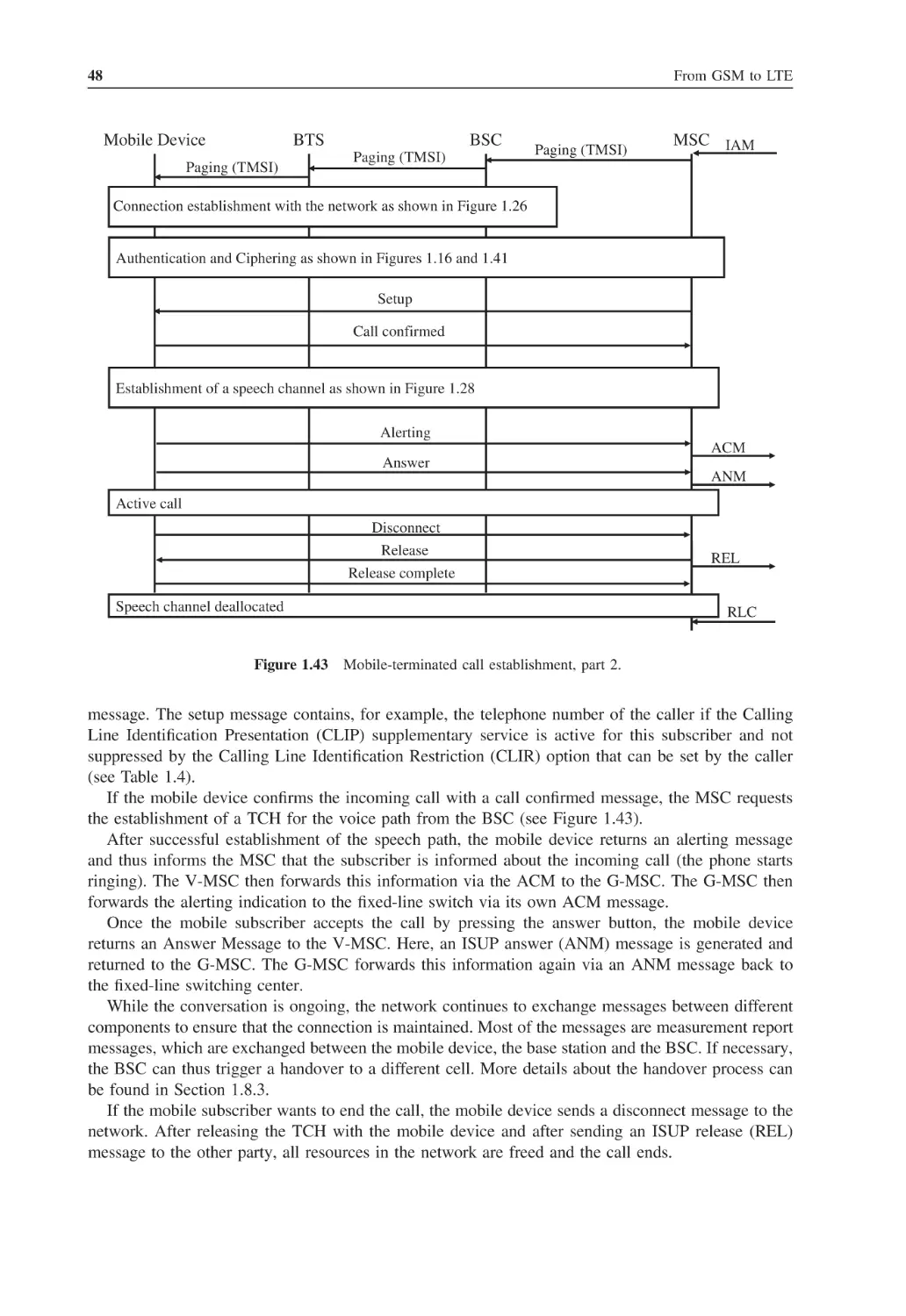
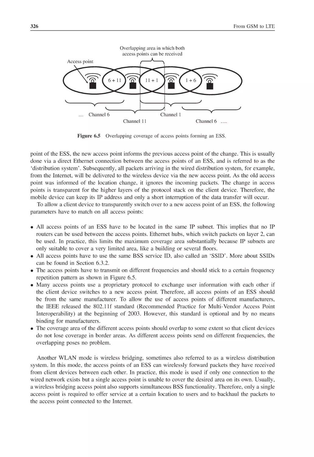
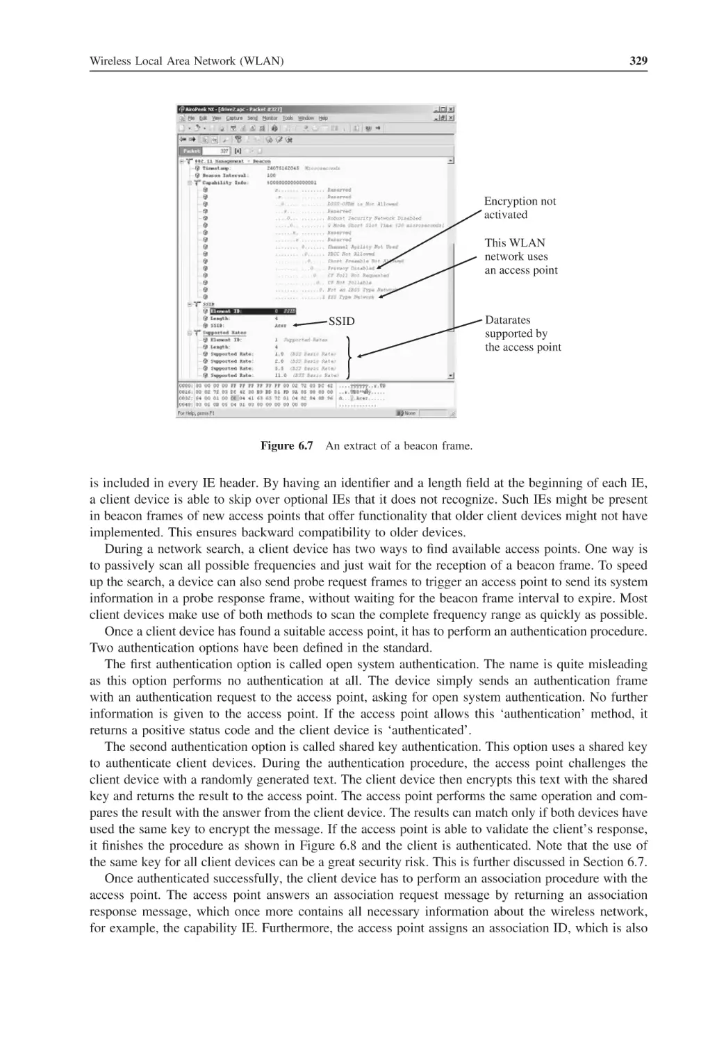
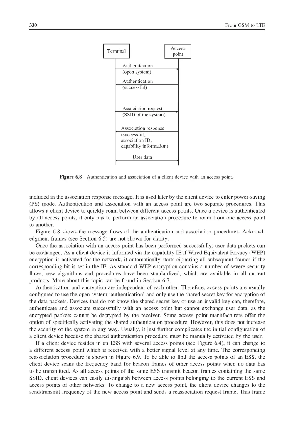
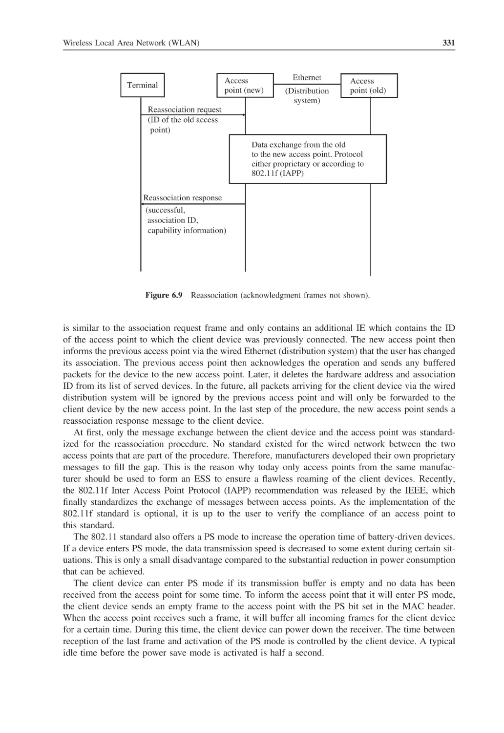
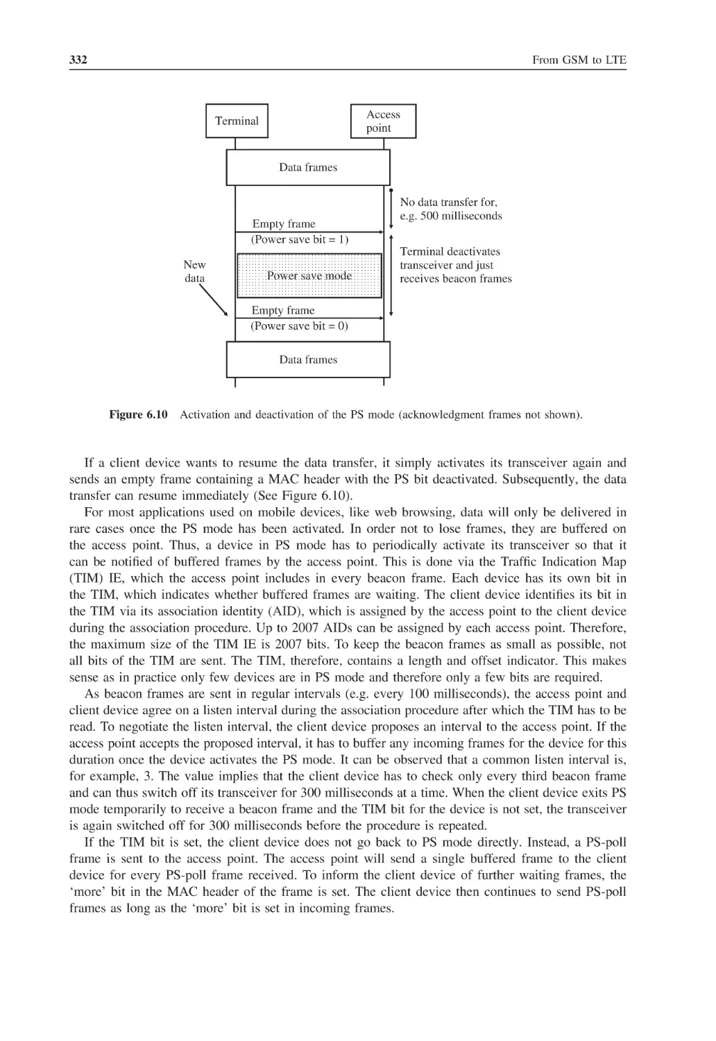
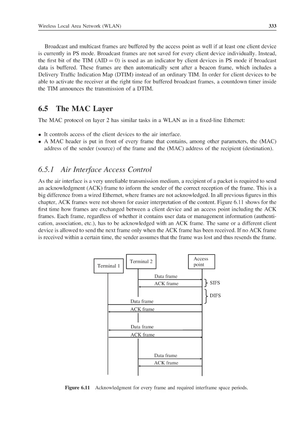
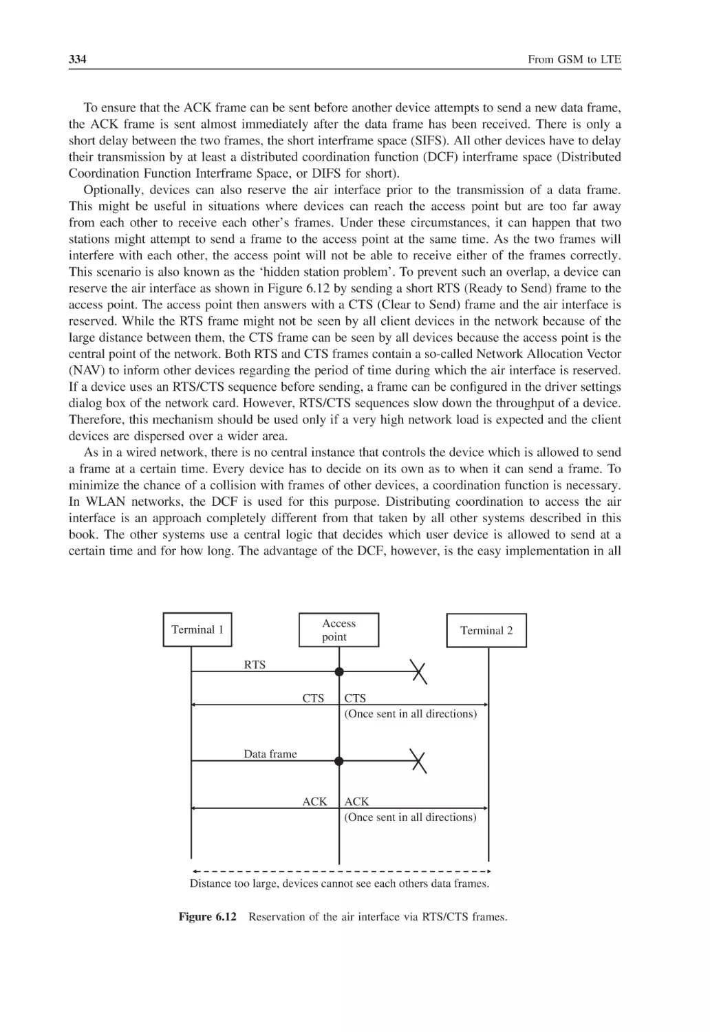
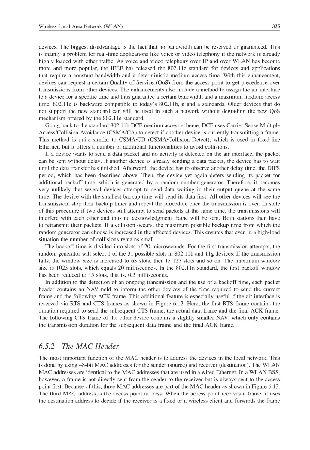
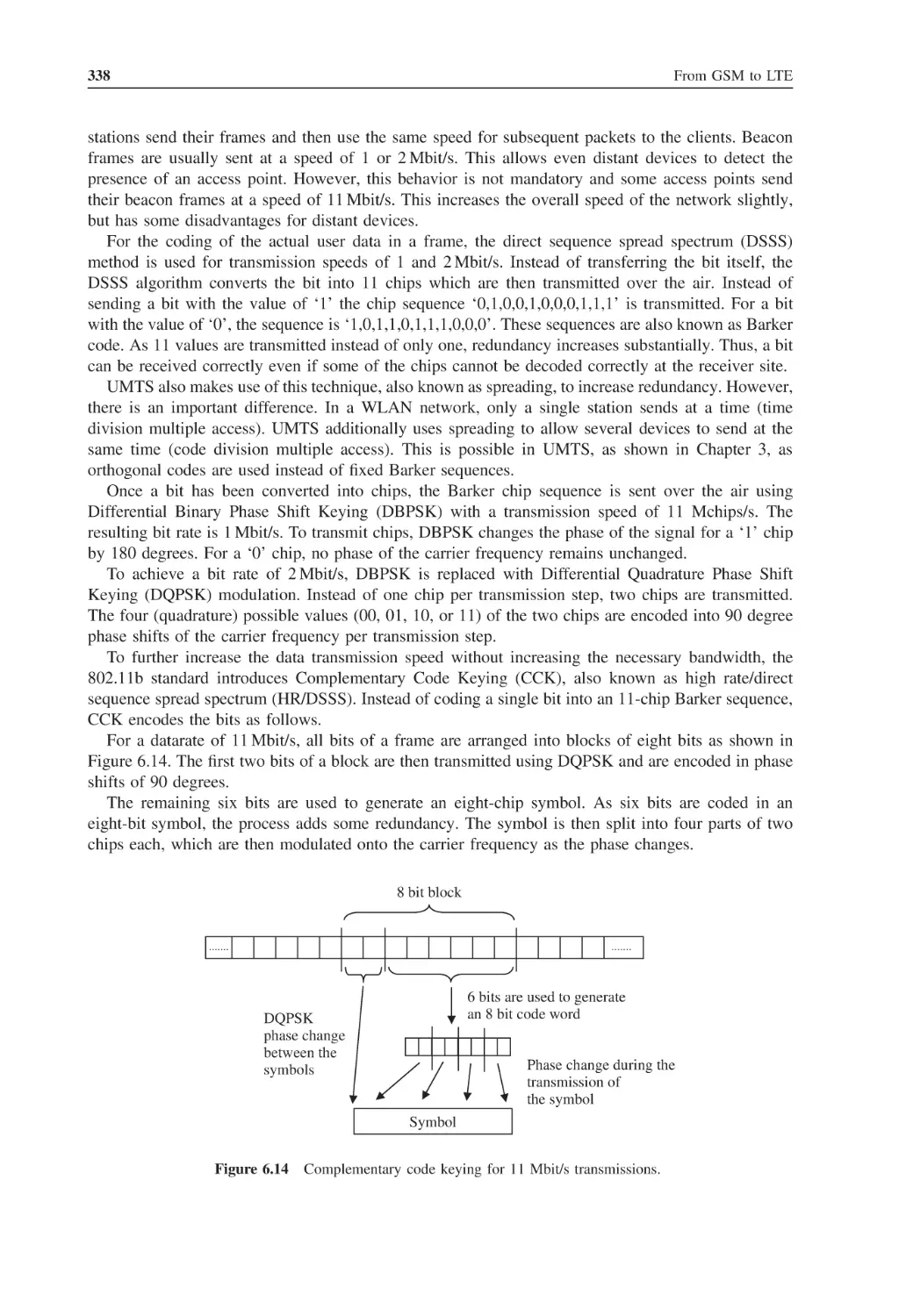
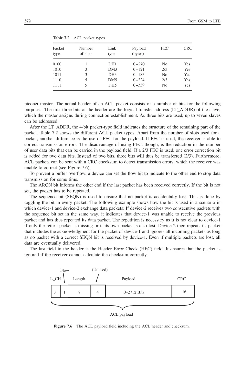
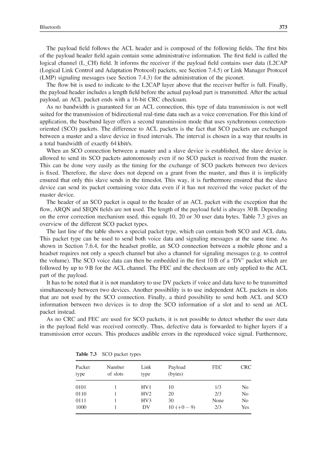
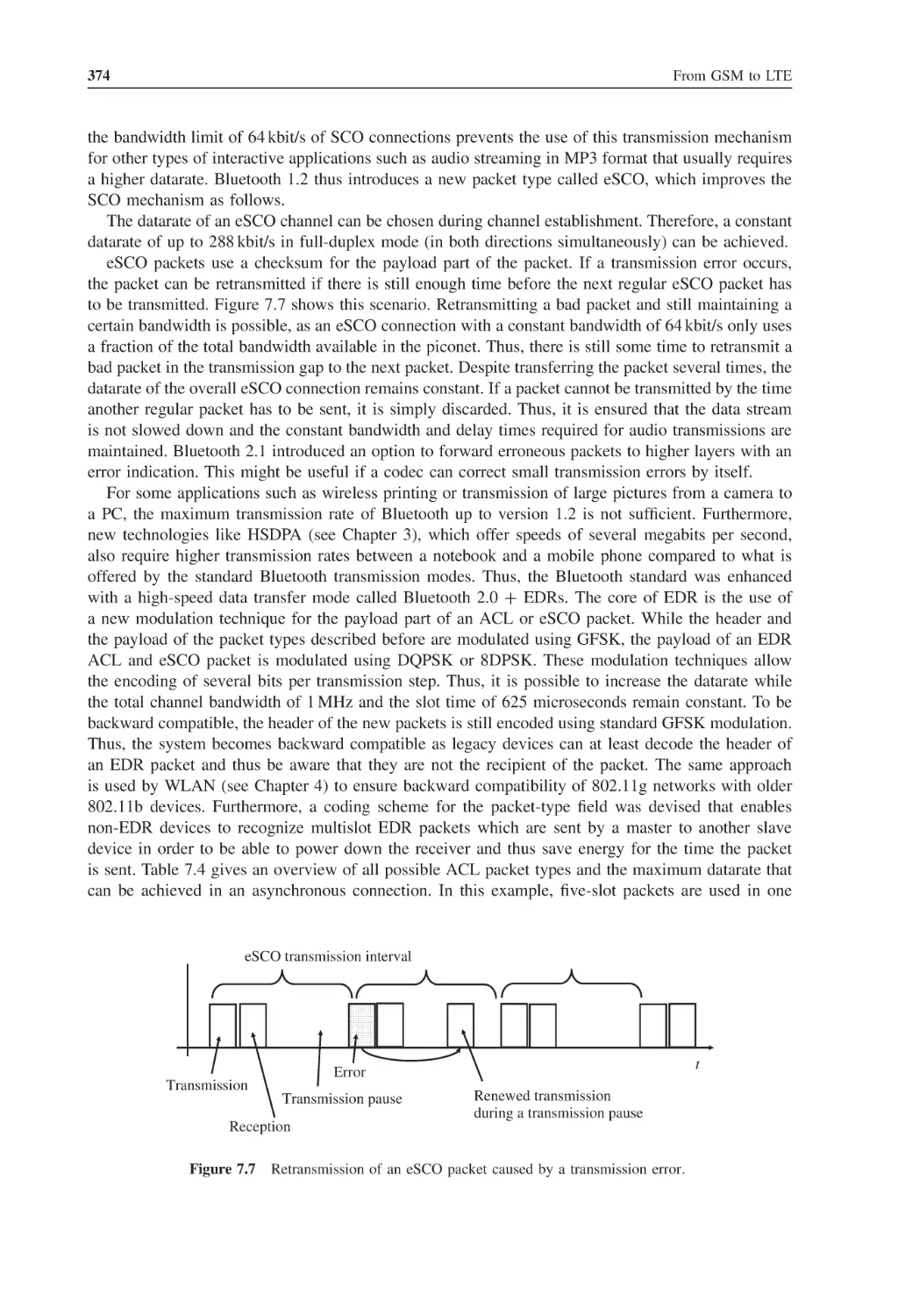
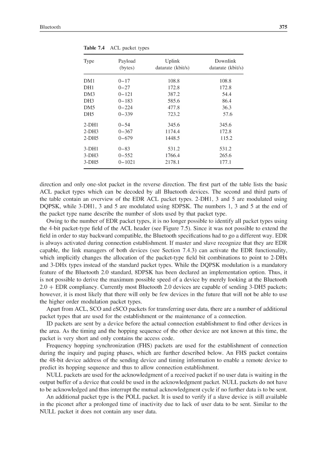
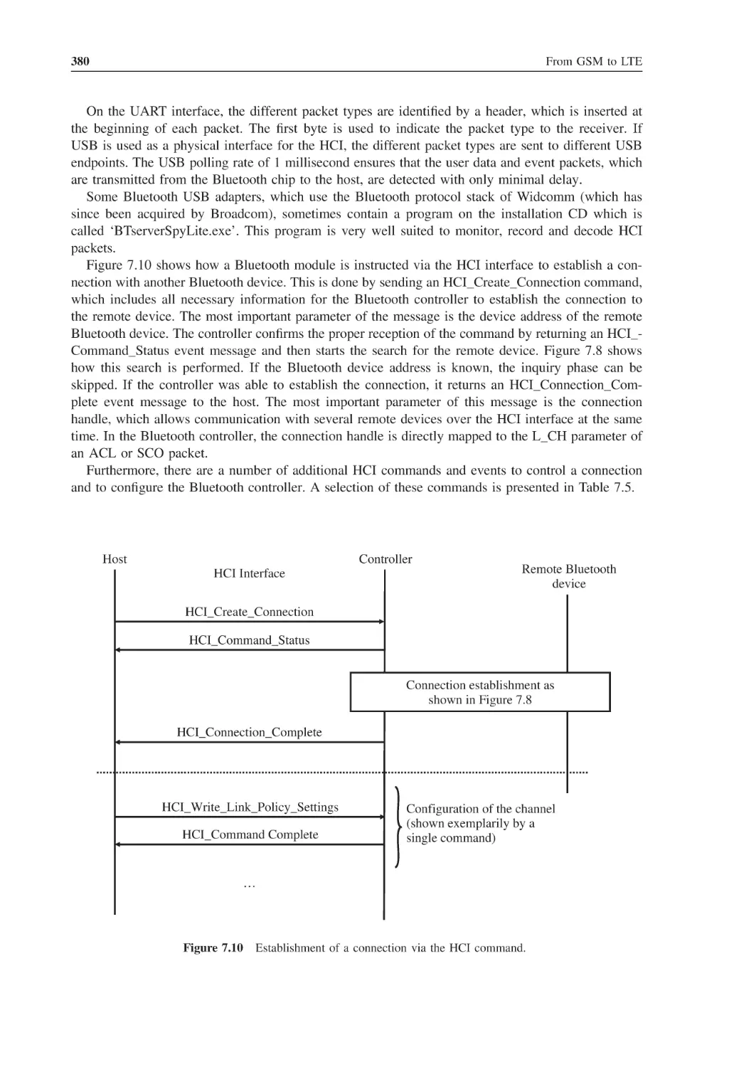
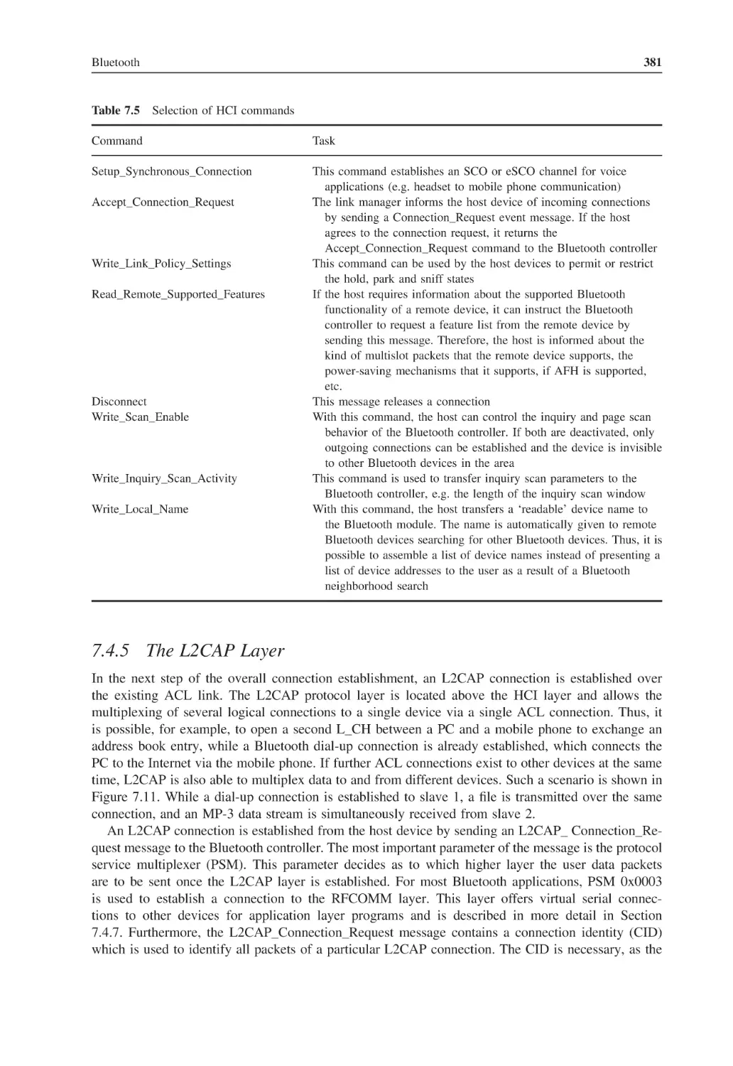
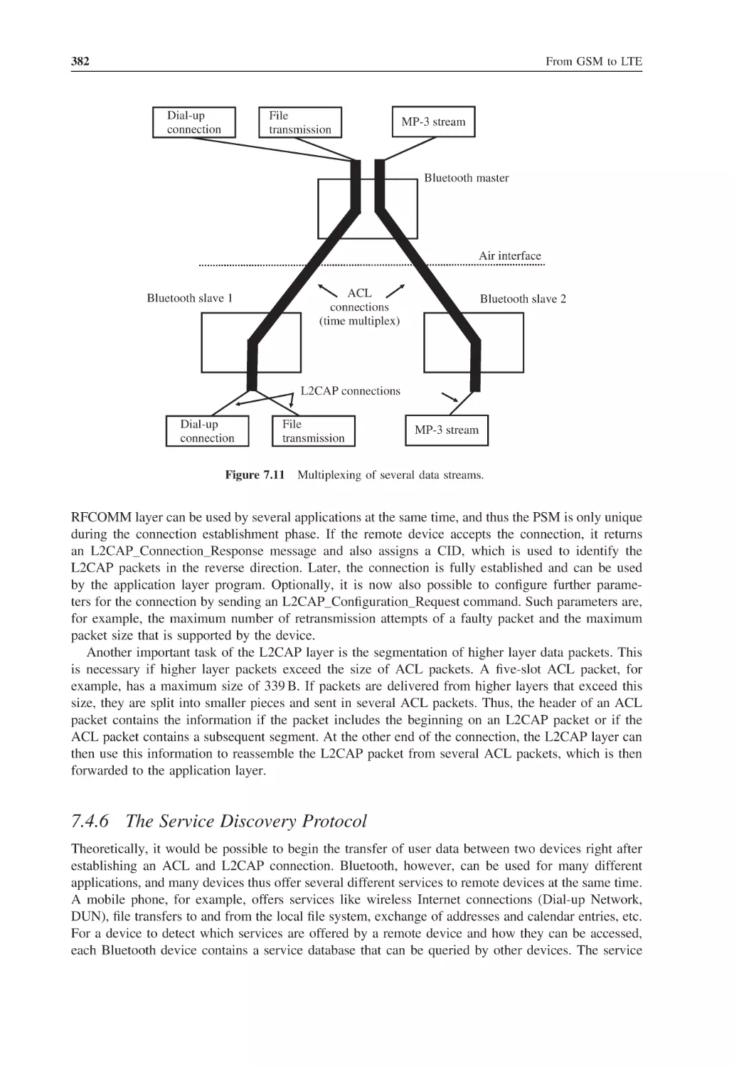
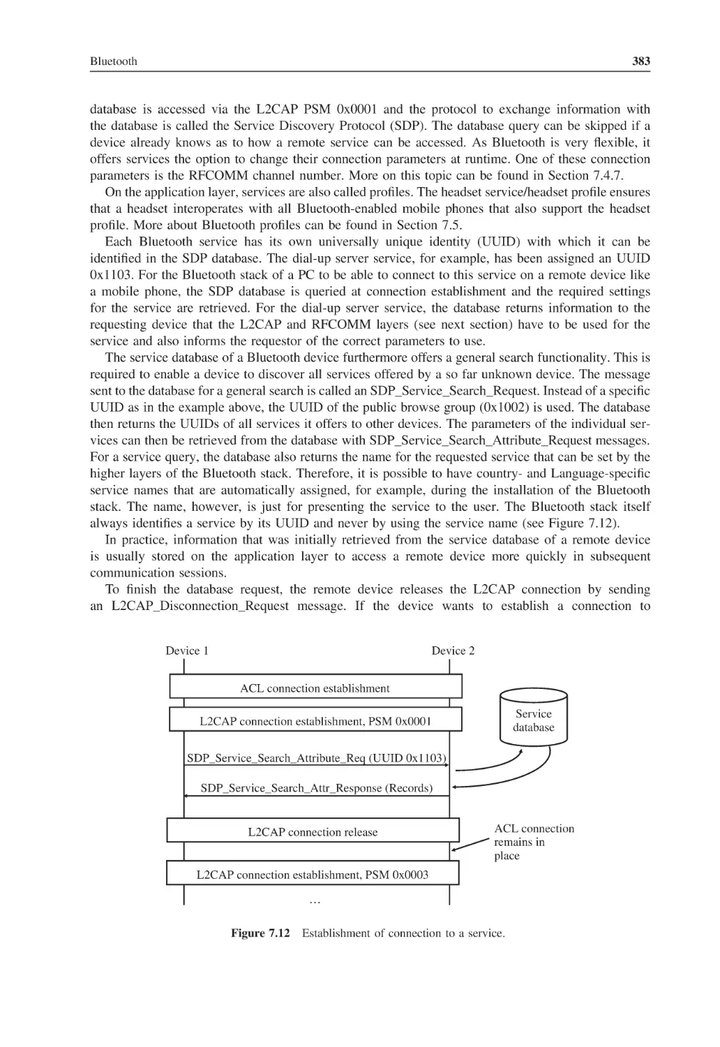
/


Text
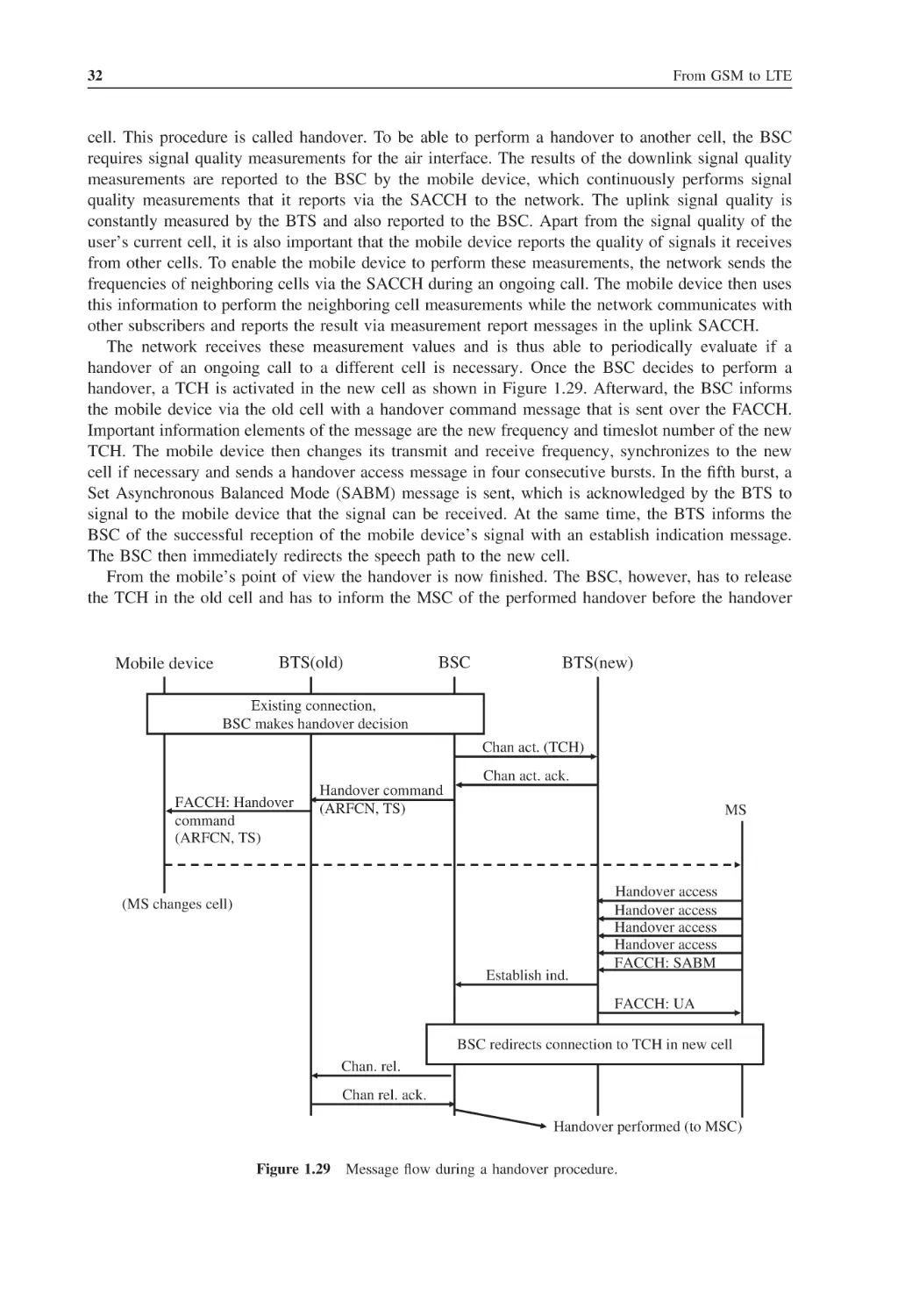
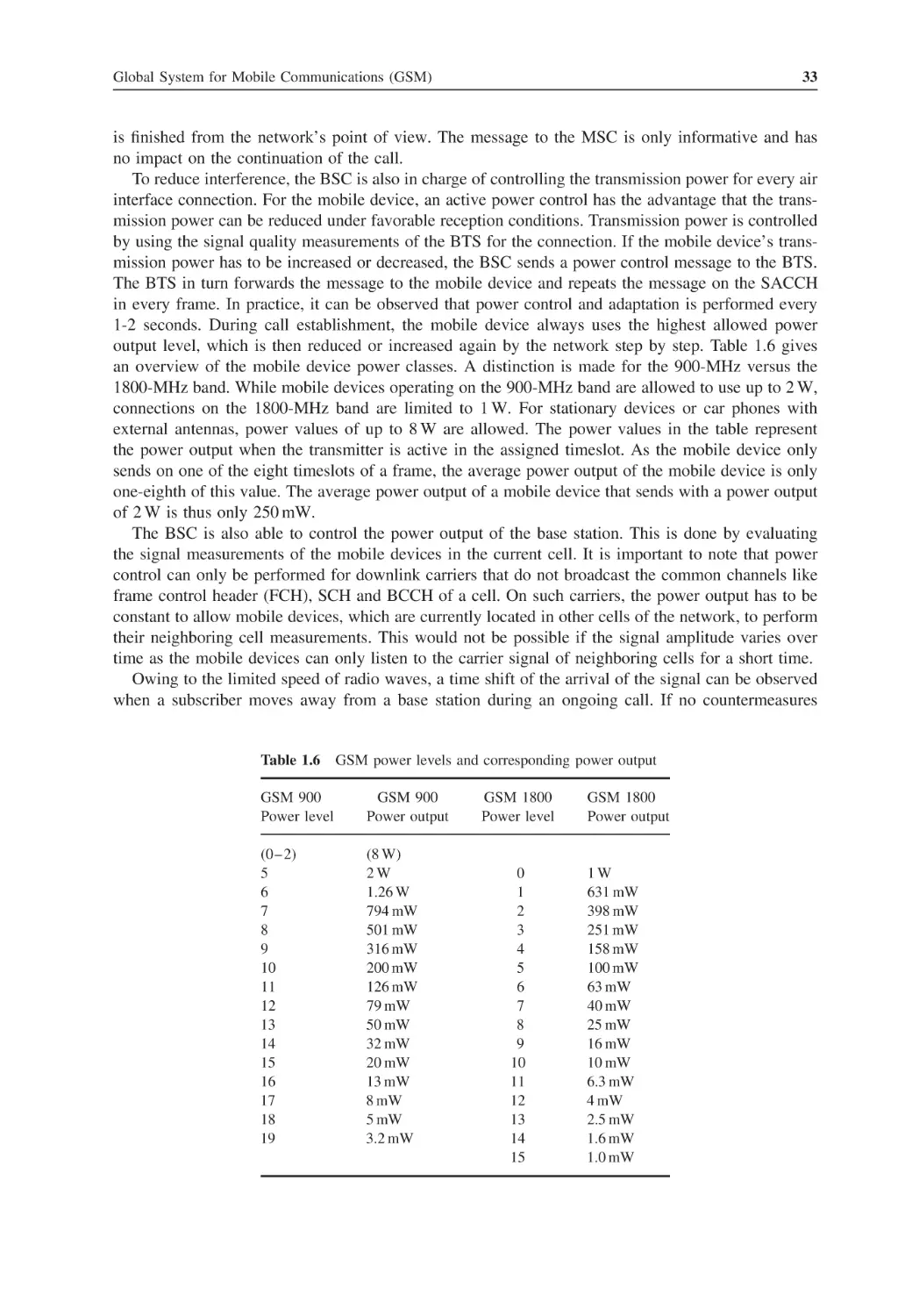
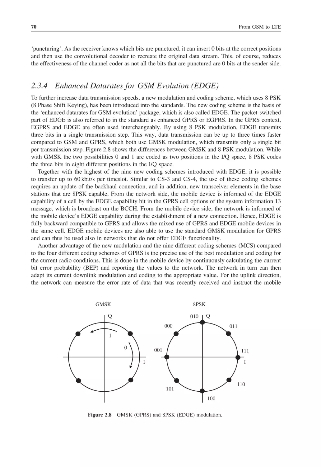
FROM GSM TO LTE
FROM GSM TO LTE
AN INTRODUCTION TO MOBILE
NETWORKS AND MOBILE
BROADBAND
Martin Sauter
WirelessMoves, Germany
A John Wiley and Sons, Ltd., Publication
This edition first published 2011
2011 John Wiley & Sons, Ltd
Registered office
John Wiley & Sons Ltd, The Atrium, Southern Gate, Chichester, West Sussex, PO19 8SQ, United Kingdom
For details of our global editorial offices, for customer services and for information about how to apply for
permission to reuse the copyright material in this book please see our website at www.wiley.com.
The right of the author to be identified as the author of this work has been asserted in accordance with the
Copyright, Designs and Patents Act 1988.
All rights reserved. No part of this publication may be reproduced, stored in a retrieval system, or transmitted, in
any form or by any means, electronic, mechanical, photocopying, recording or otherwise, except as permitted by
the UK Copyright, Designs and Patents Act 1988, without the prior permission of the publisher.
Wiley also publishes its books in a variety of electronic formats. Some content that appears in print may not be
available in electronic books.
Designations used by companies to distinguish their products are often claimed as trademarks. All brand names
and product names used in this book are trade names, service marks, trademarks or registered trademarks of their
respective owners. The publisher is not associated with any product or vendor mentioned in this book. This
publication is designed to provide accurate and authoritative information in regard to the subject matter covered.
It is sold on the understanding that the publisher is not engaged in rendering professional services. If professional
advice or other expert assistance is required, the services of a competent professional should be sought.
Library of Congress Cataloging-in-Publication Data
Sauter, Martin.
From GSM to LTE : an introduction to mobile networks and mobile broadband / by Martin Sauter.
p. cm.
Includes bibliographical references and index.
ISBN 978-0-470-66711-8 (cloth)
1. Mobile communication systems. 2. Wireless metropolitan area networks. 3. Wireless LANs. I. Title.
TK5103.2.S28 2011
621.382 – dc22
2010038166
A catalogue record for this book is available from the British Library.
Print ISBN: 978-0-470-66711-8
ePDF ISBN: 978-0-470-97824-5
oBook ISBN: 978-0-470-97823-8
ePub ISBN: 978-0-470-97822-1
Typeset in 9/11pt Times by Laserwords Private Limited, Chennai, India
Contents
Preface
List of Figures
List of Tables
List of Abbreviations
1
1.1
1.2
1.3
1.4
1.5
1.6
1.7
1.8
Global System for Mobile Communications (GSM)
Circuit-Switched Data Transmission
1.1.1
Classic Circuit Switching
1.1.2
Virtual Circuit Switching over IP
Standards
Transmission Speeds
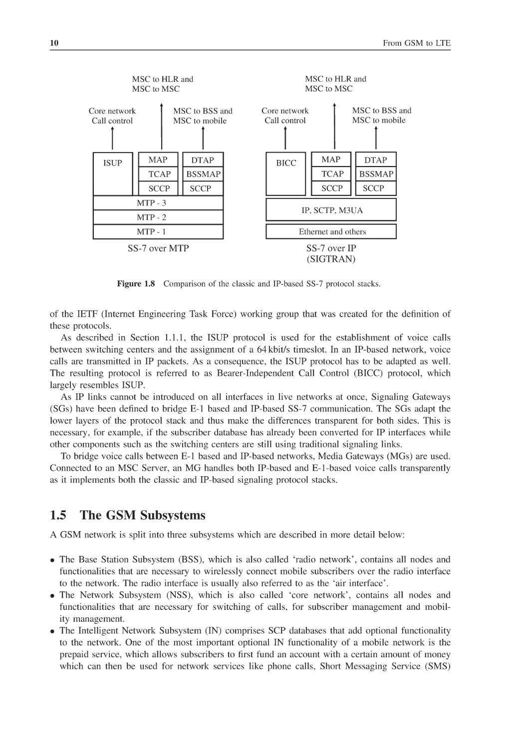
The Signaling System Number 7
1.4.1
The Classic SS-7 Protocol Stack
1.4.2
SS-7 Protocols for GSM
1.4.3
IP-Based SS-7 Protocol Stack
The GSM Subsystems
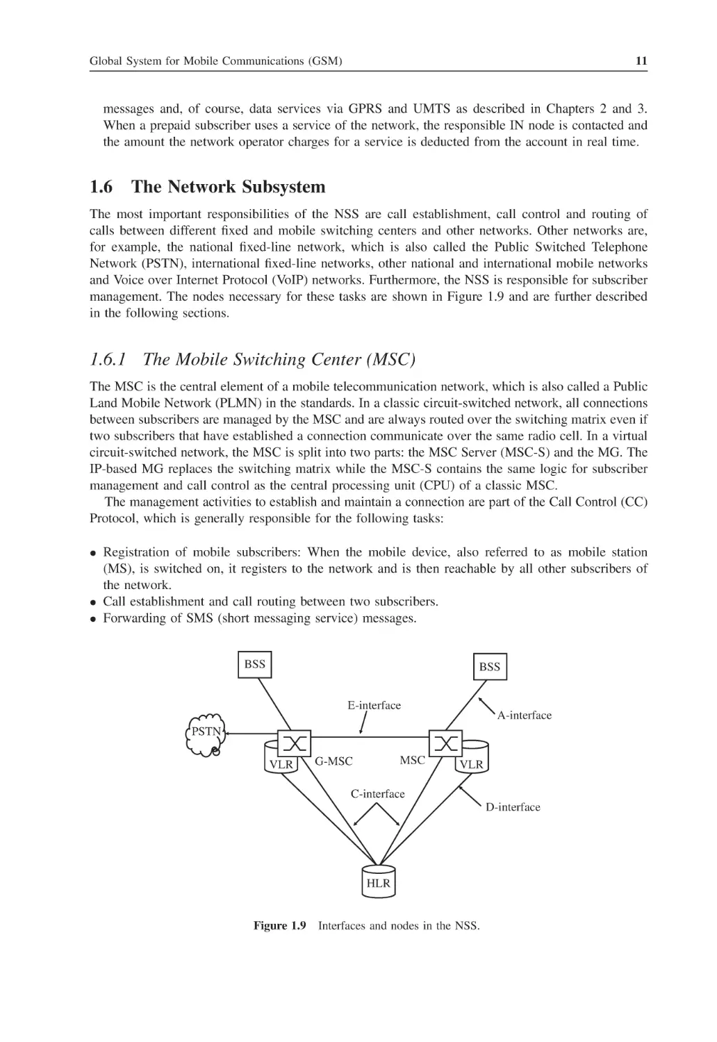
The Network Subsystem
1.6.1
The Mobile Switching Center (MSC)
1.6.2
The Visitor Location Register (VLR)
1.6.3
The Home Location Register (HLR)
1.6.4
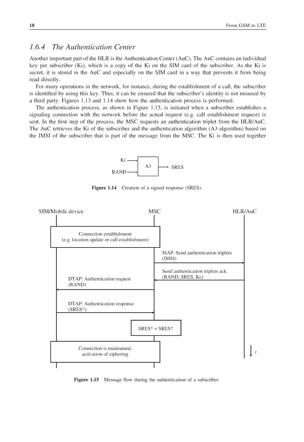
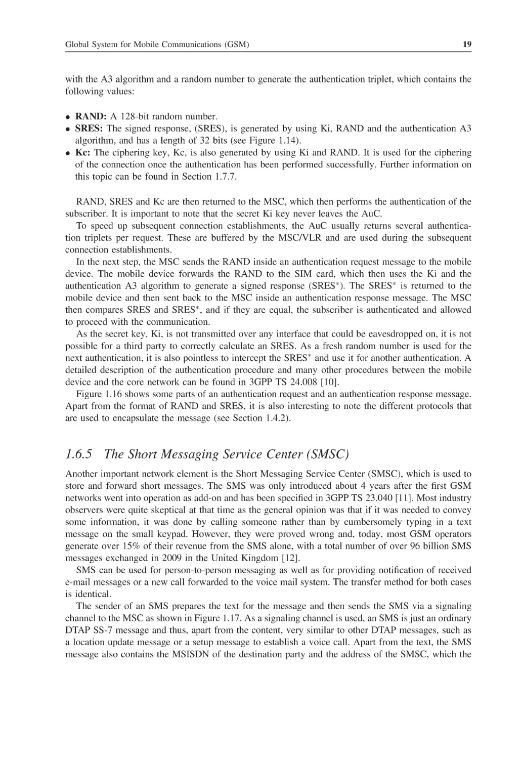
The Authentication Center
1.6.5
The Short Messaging Service Center (SMSC)
The Base Station Subsystem (BSS) and Voice Processing
1.7.1
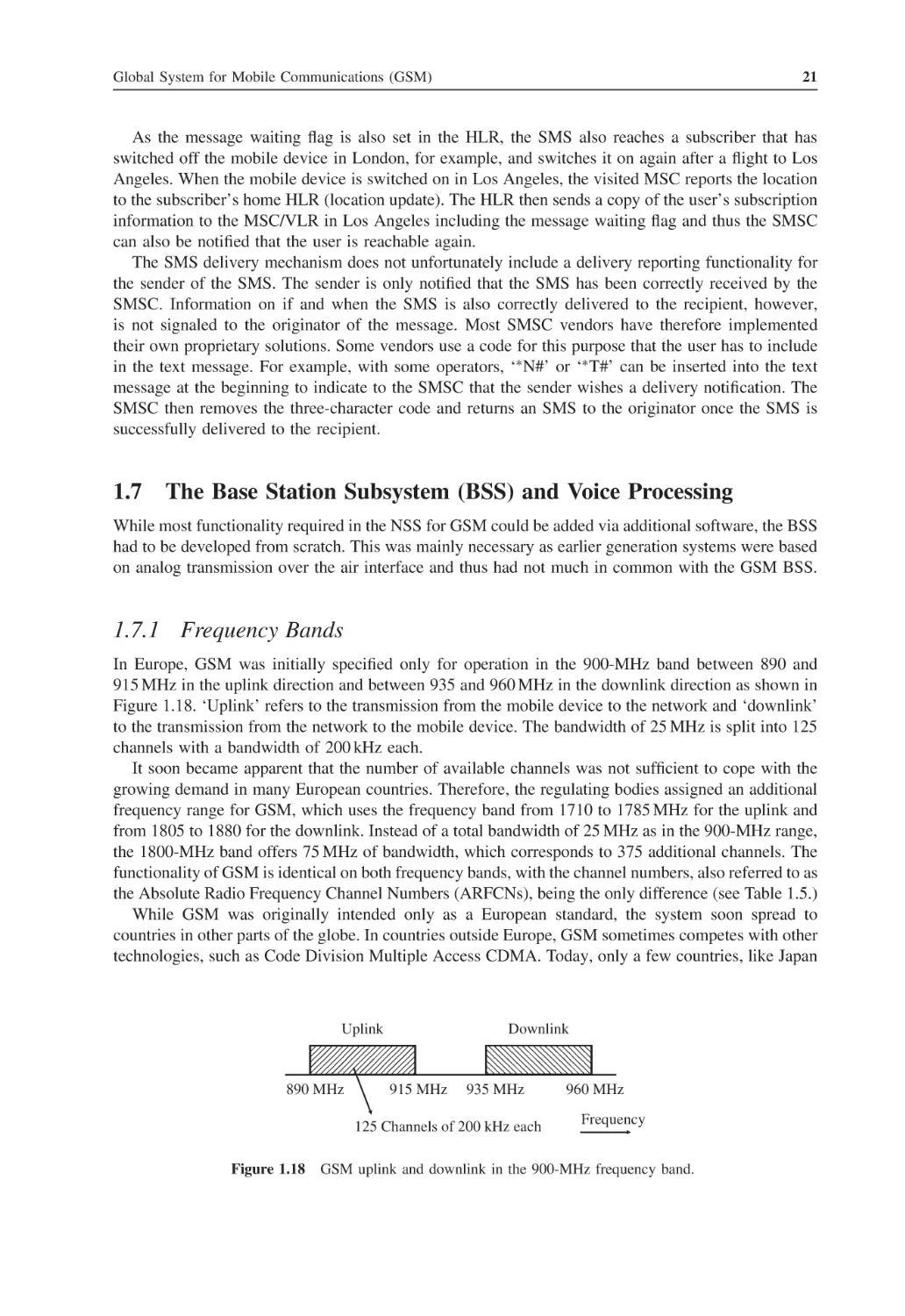
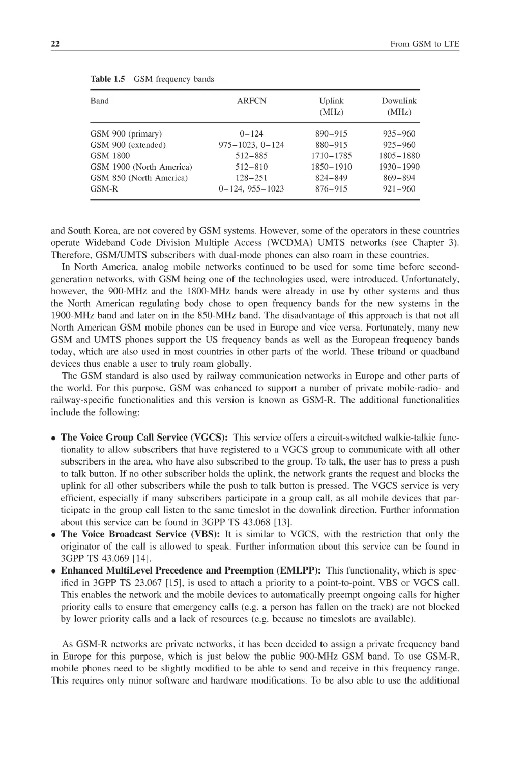
Frequency Bands
1.7.2
The Base Transceiver Station (BTS)
1.7.3
The GSM Air Interface
1.7.4
The Base Station Controller (BSC)
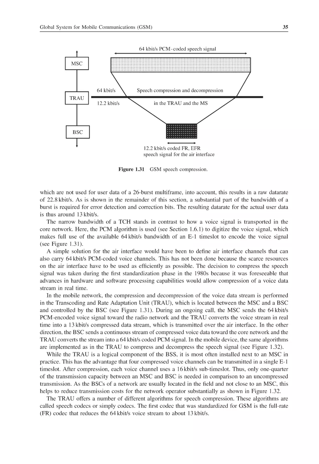
1.7.5
The TRAU for Voice Encoding
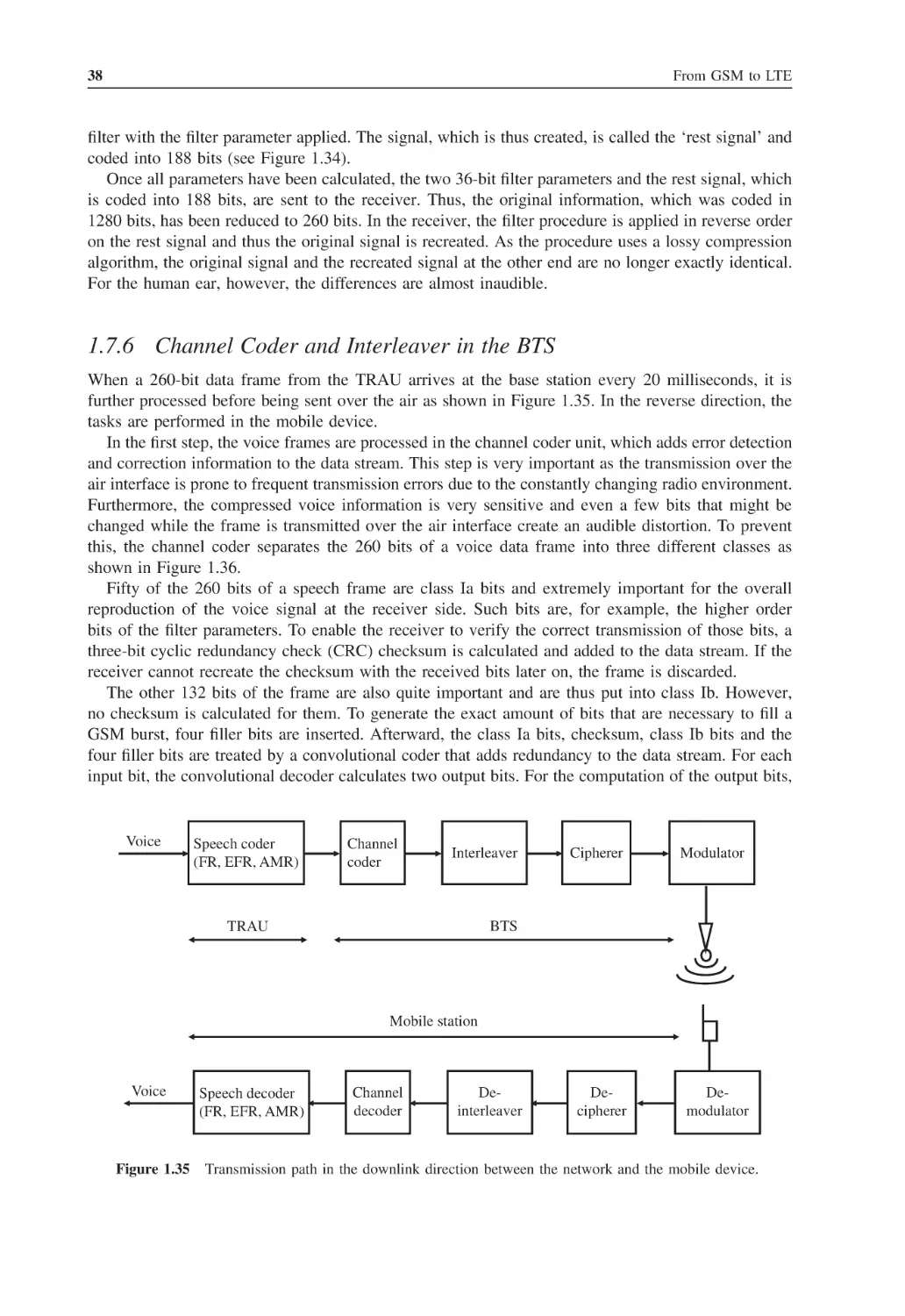
1.7.6
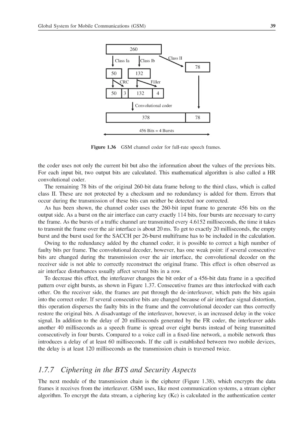
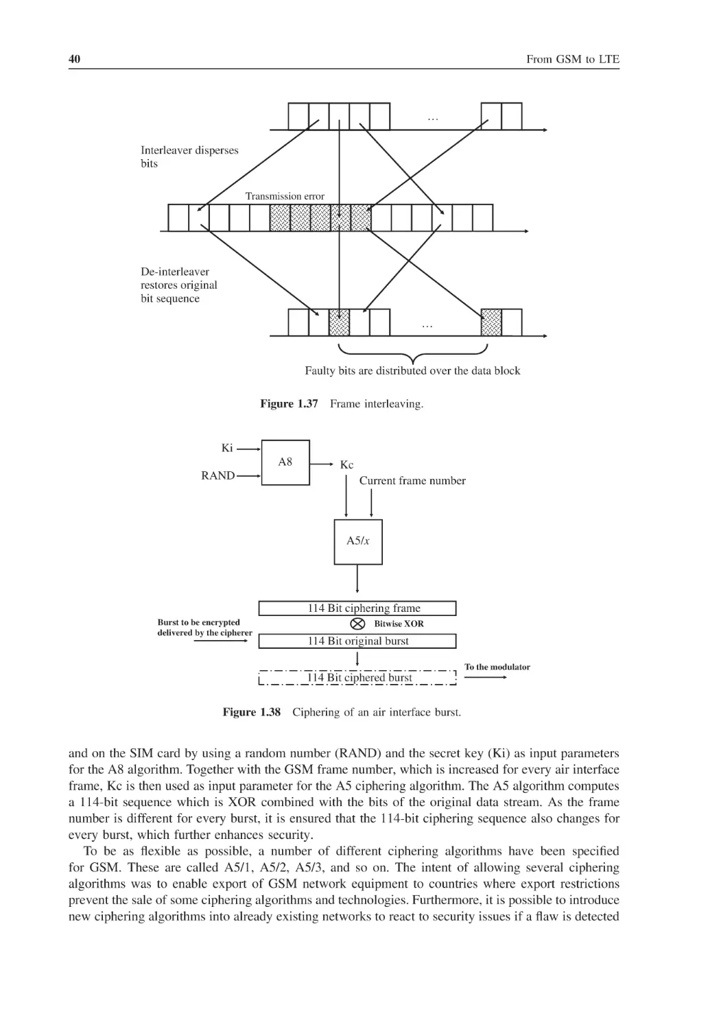
Channel Coder and Interleaver in the BTS
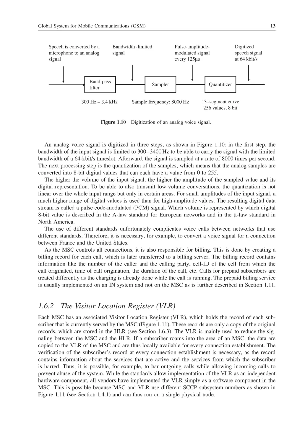
1.7.7
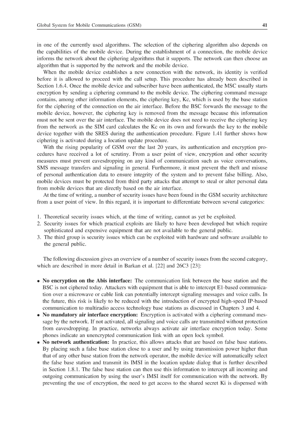
Ciphering in the BTS and Security Aspects
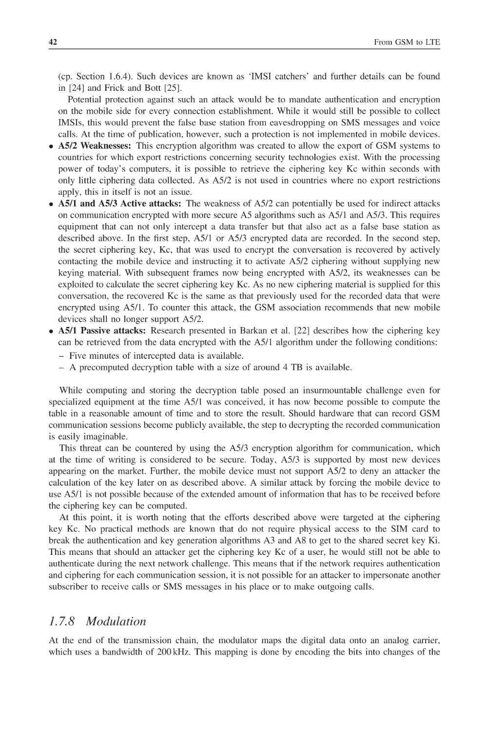
1.7.8
Modulation
1.7.9
Voice Activity Detection
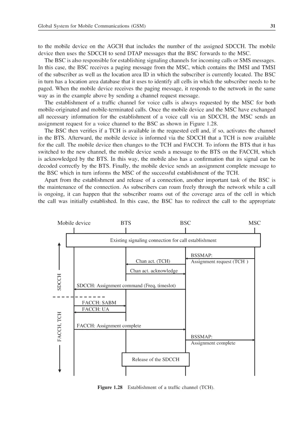
Mobility Management and Call Control
1.8.1
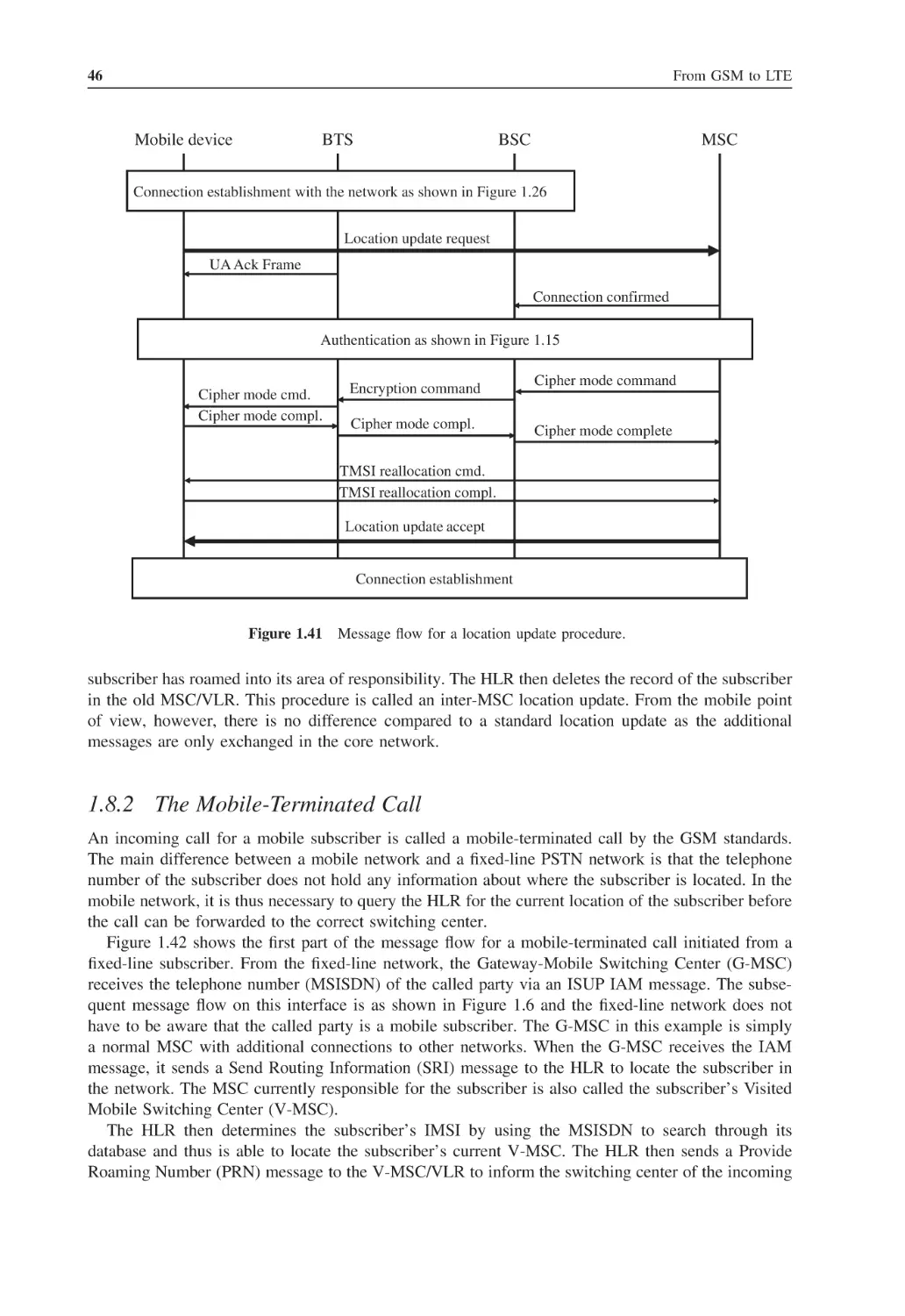
Call Reselection and Location Area Update
xiii
xv
xxiii
xxv
1
1
1
3
4
4
5
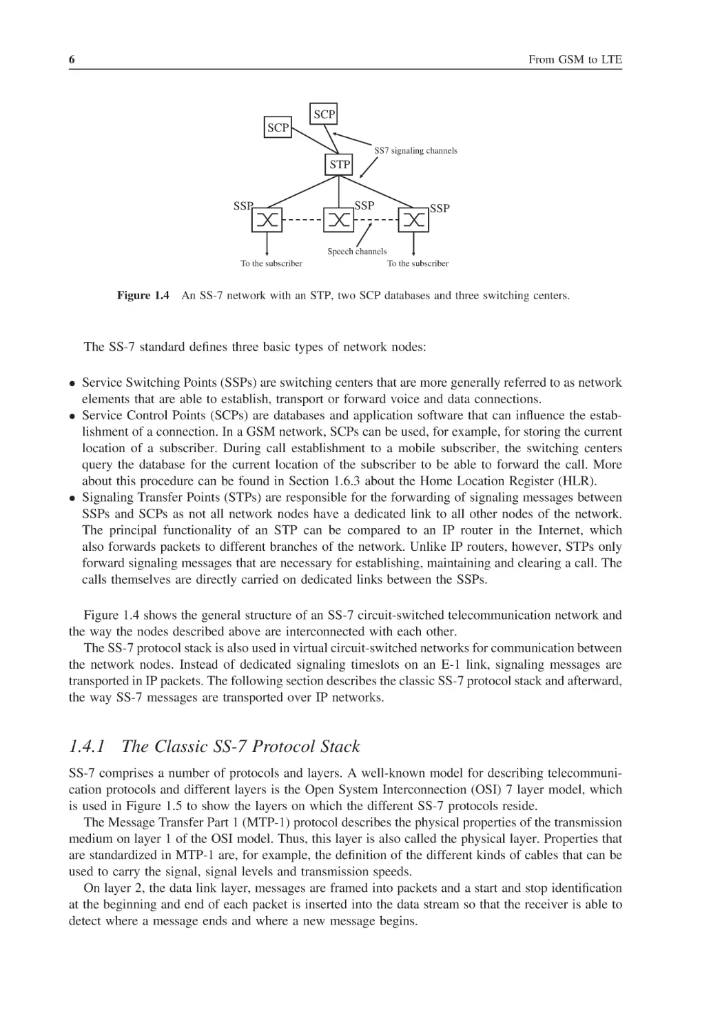
6
8
9
10
11
11
13
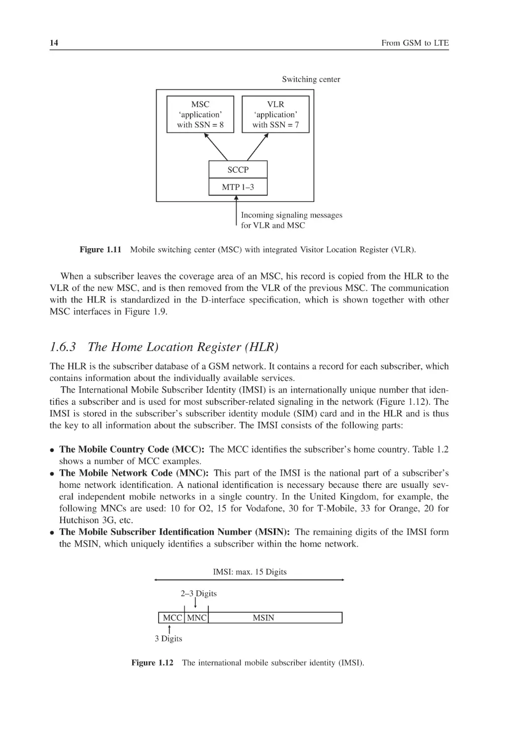
14
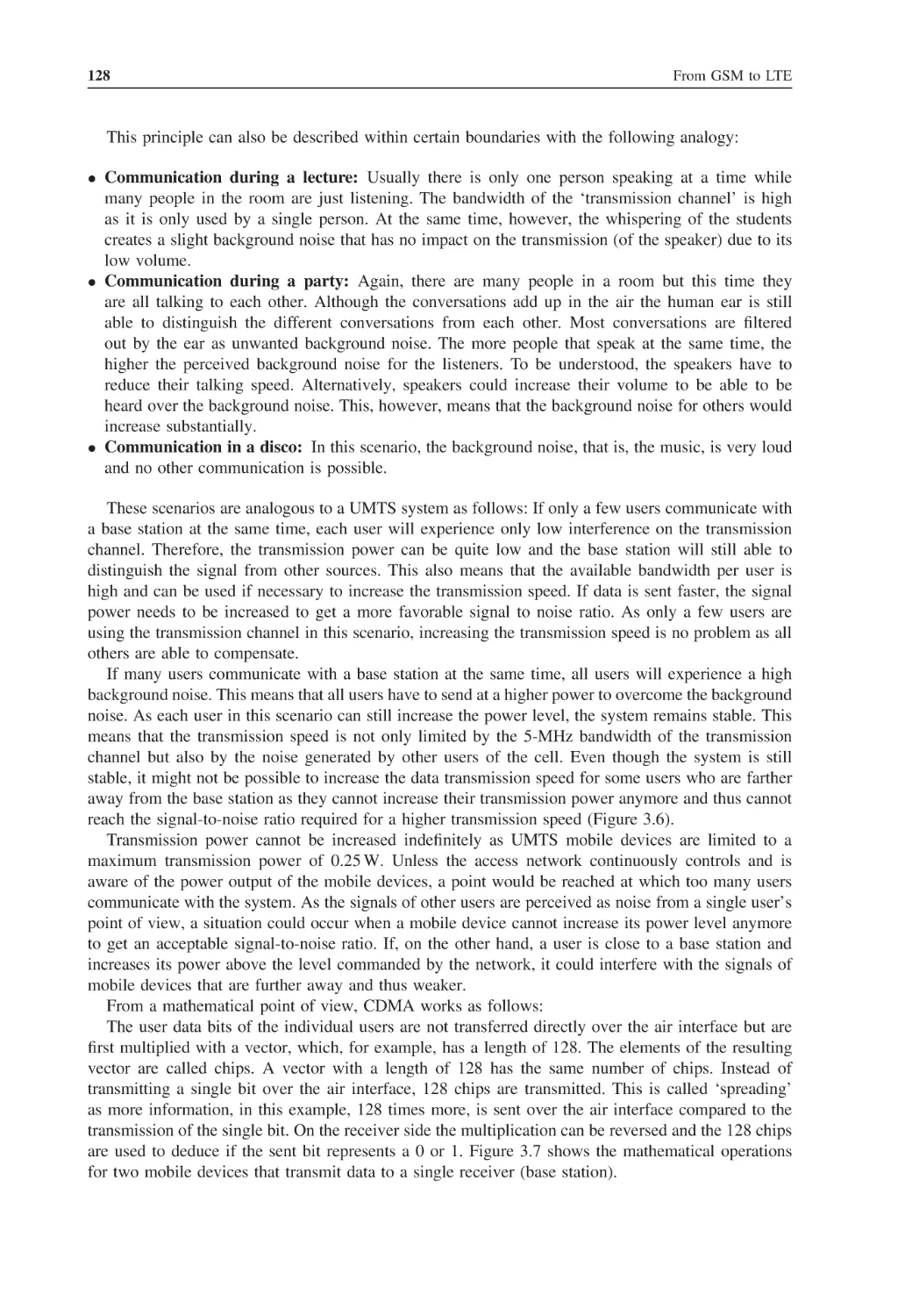
18
19
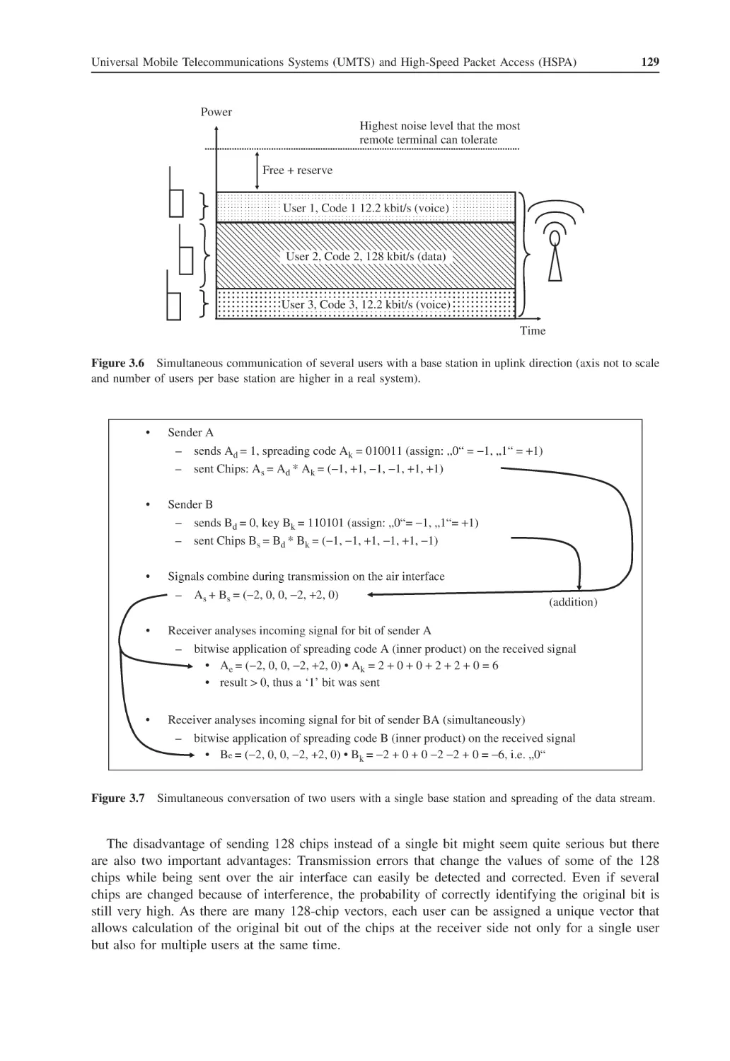
21
21
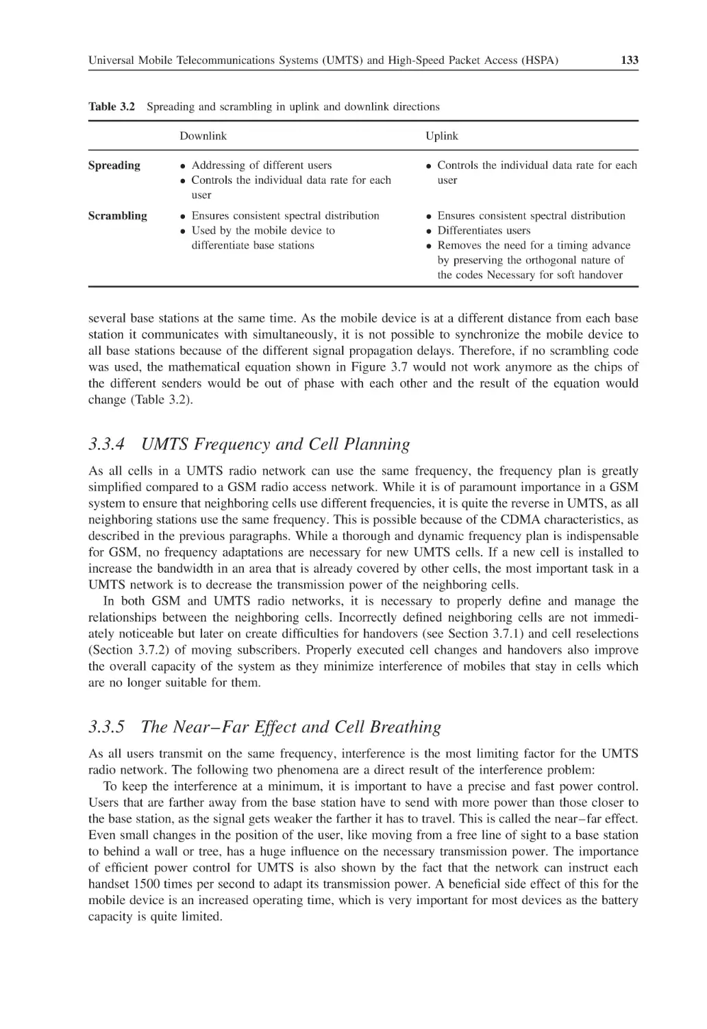
23
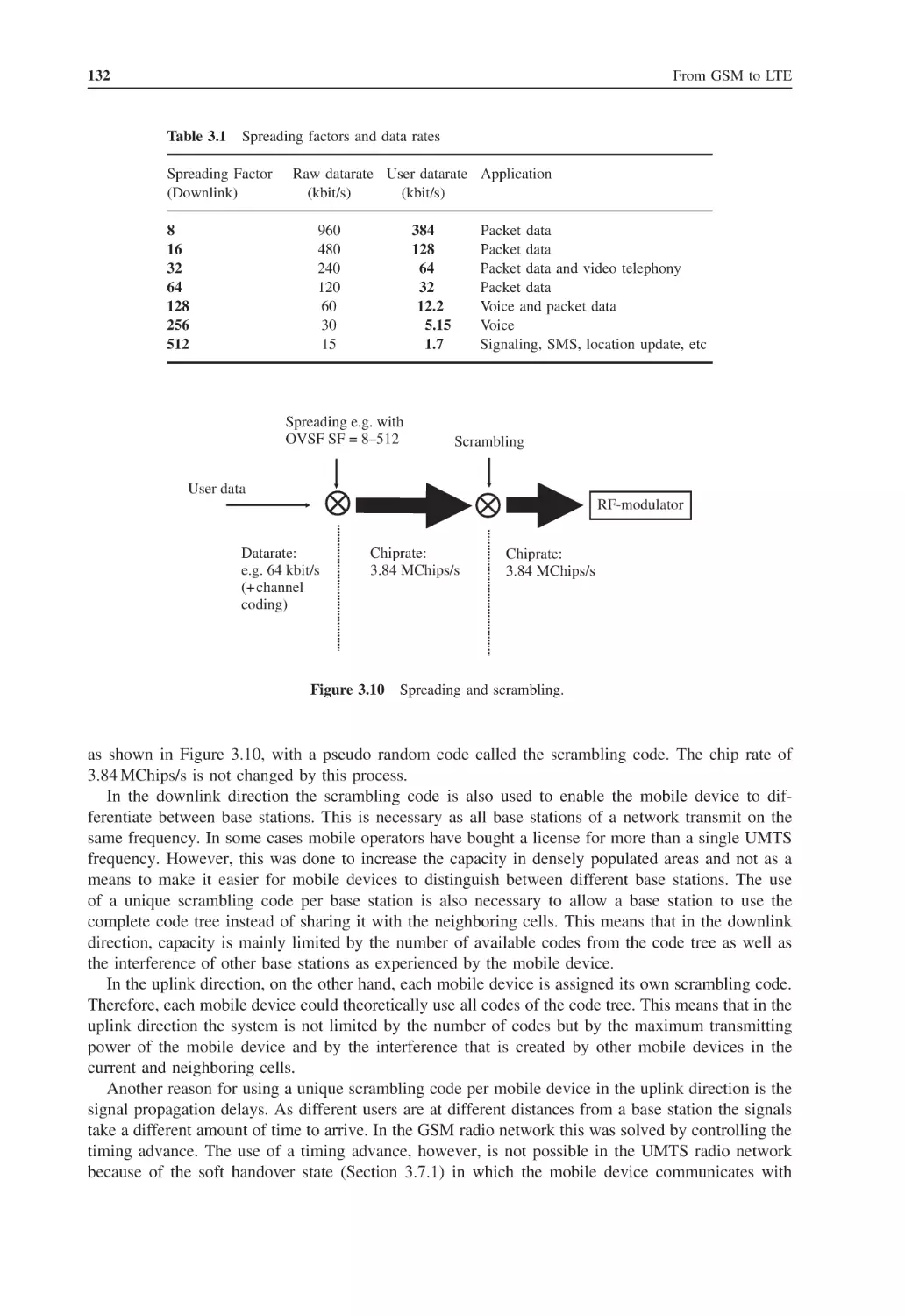
24
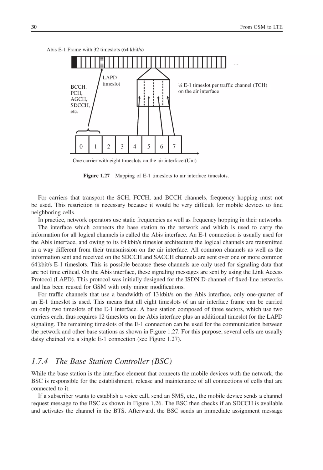
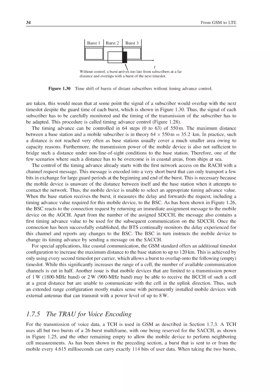
30
34
38
39
42
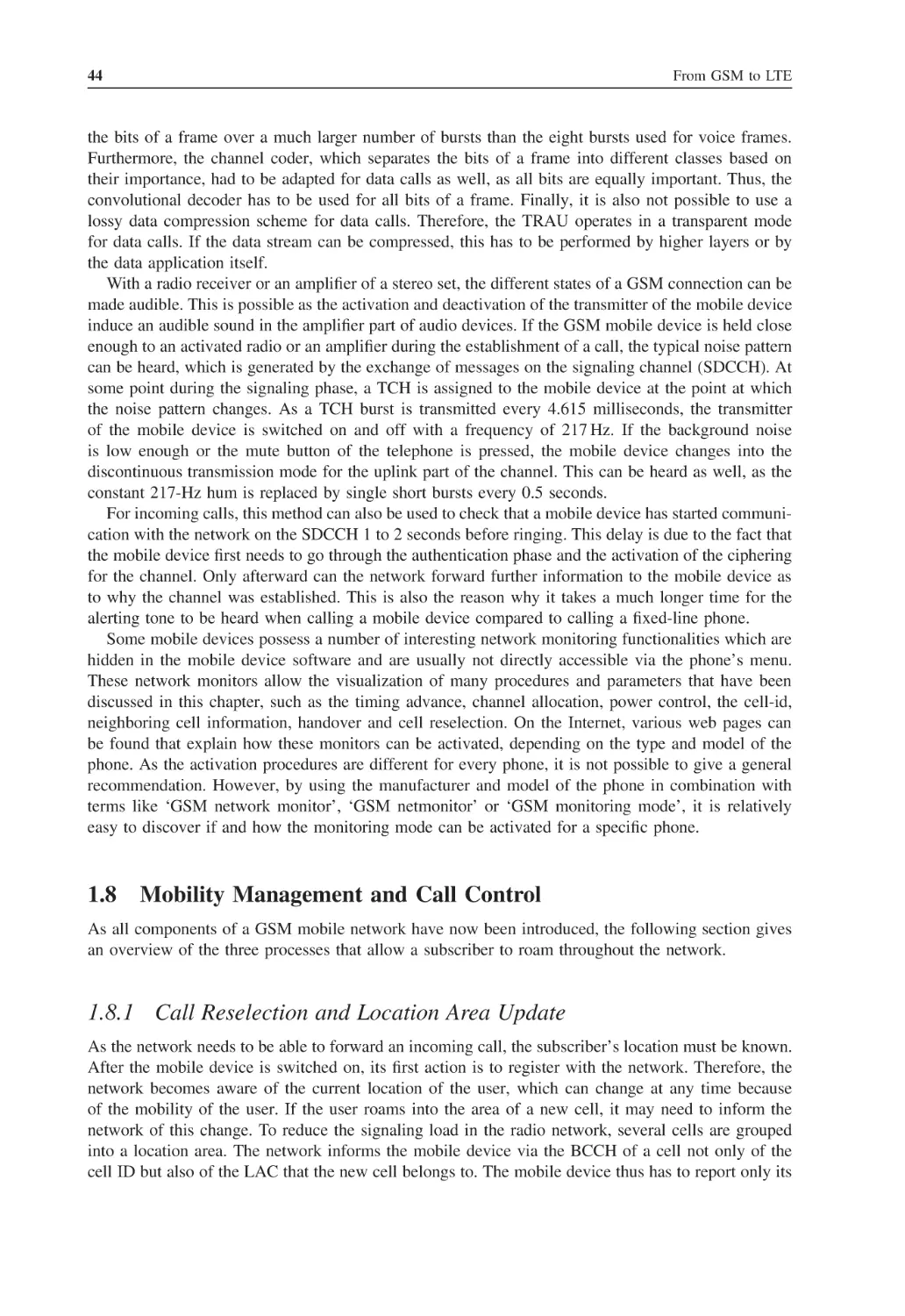
43
44
44
vi
1.9
1.10
1.11
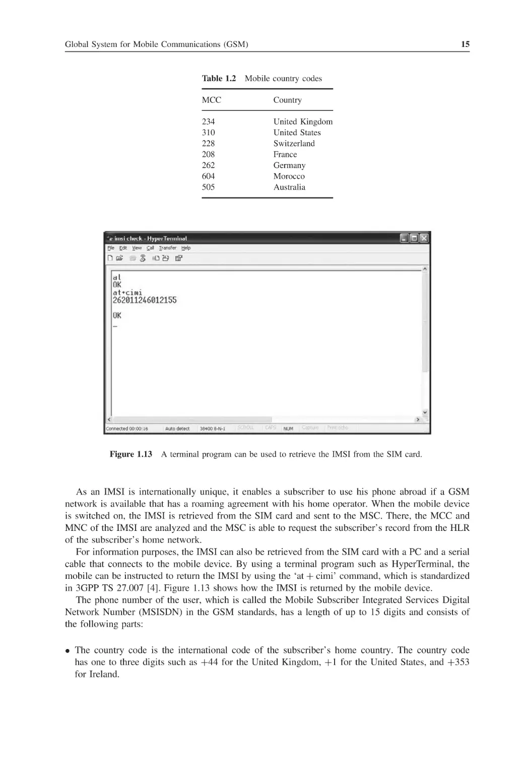
1.12
2
2.1
2.2
2.3
2.4
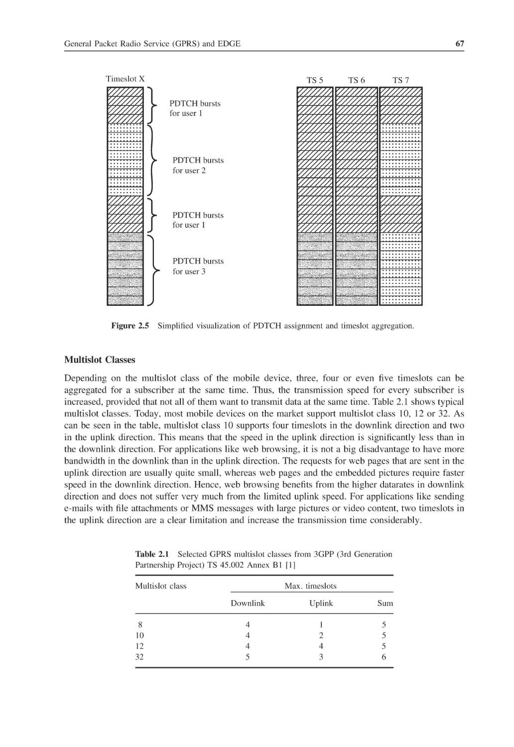
2.5
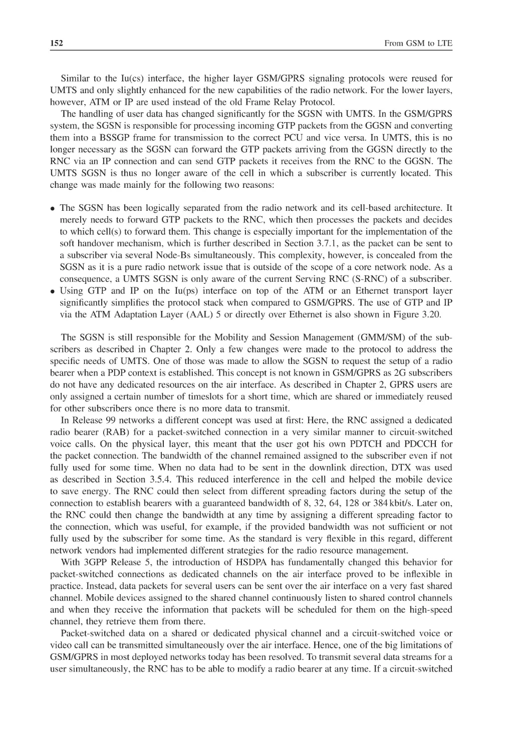
2.6
2.7
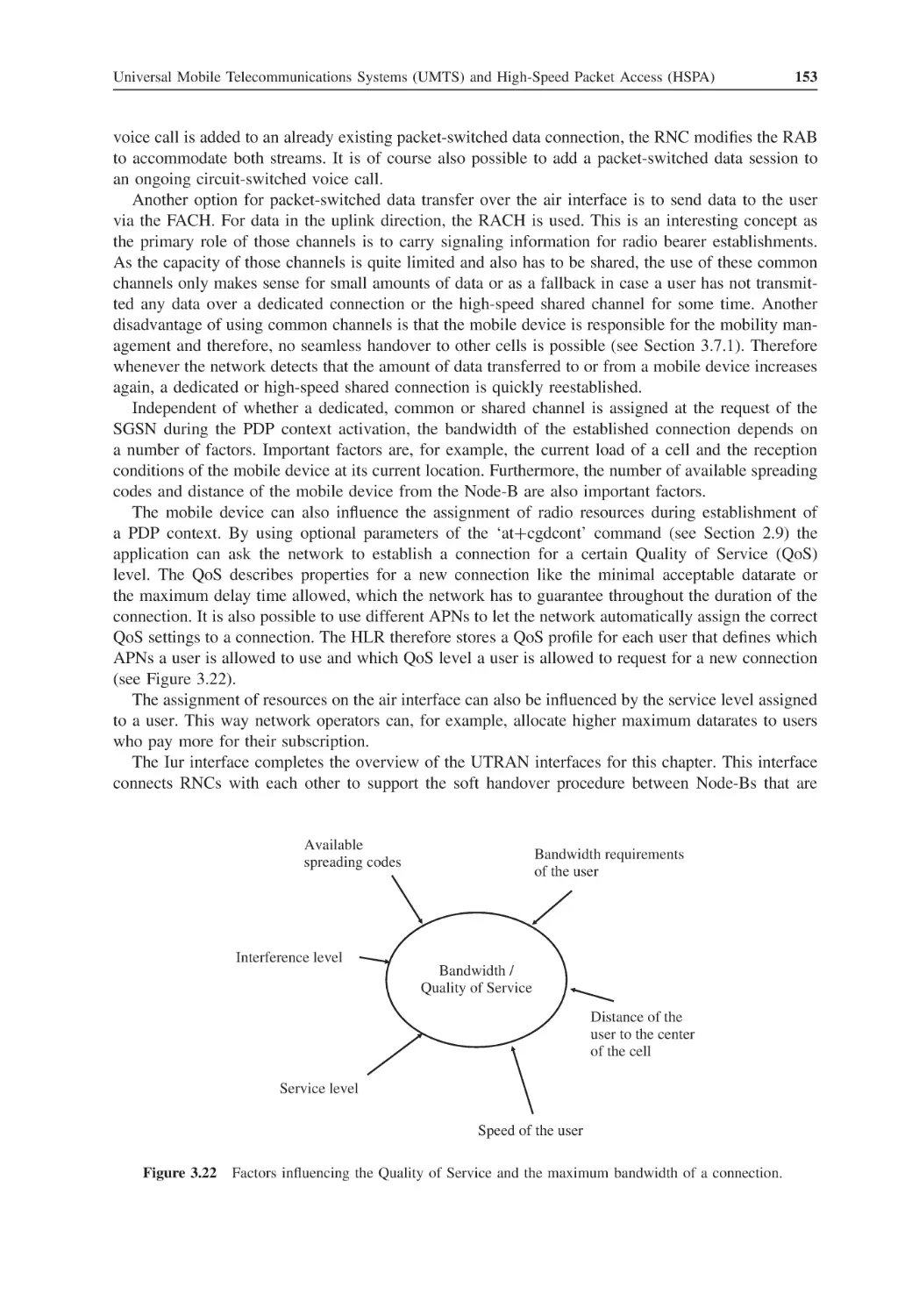
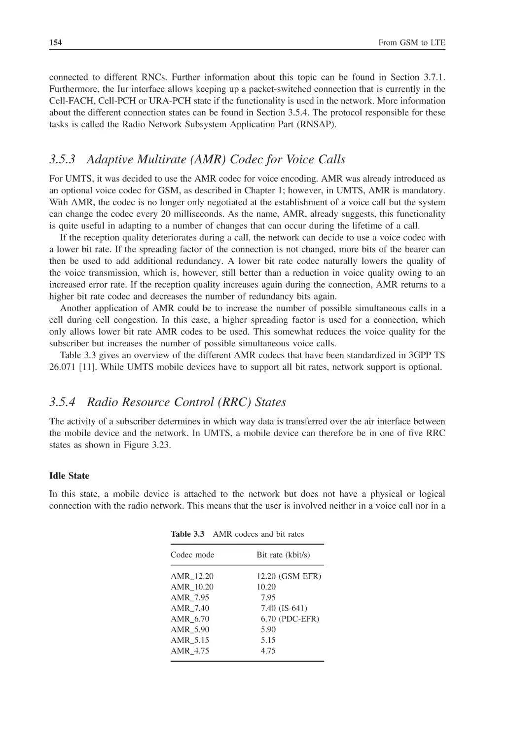
2.8
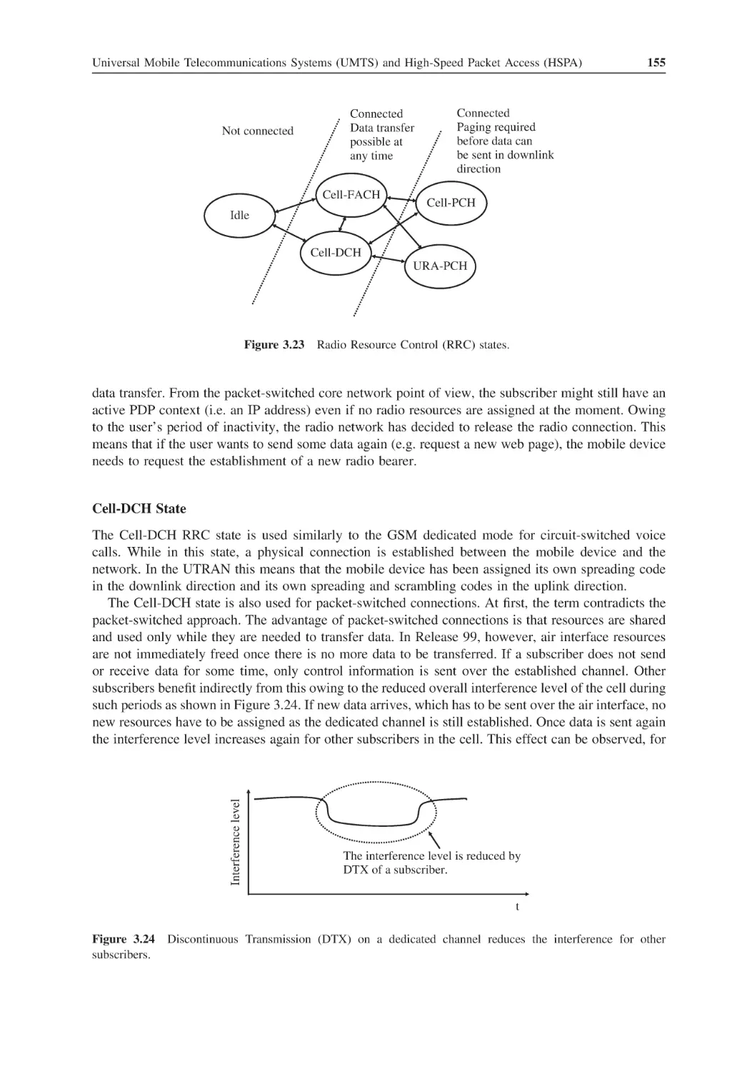
2.9
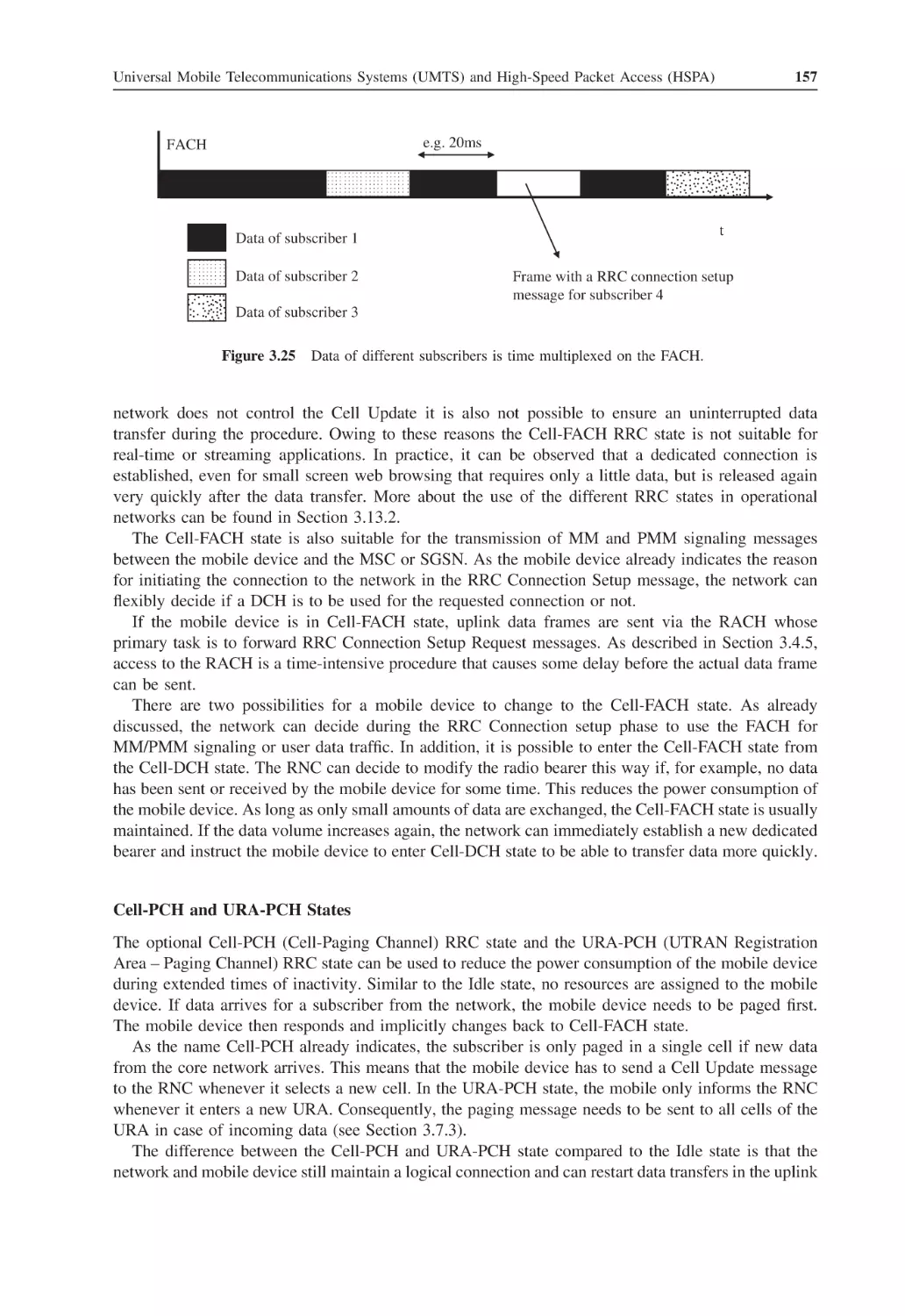
2.10
2.11
2.12
2.13
3
3.1
Contents
1.8.2
The Mobile-Terminated Call
1.8.3
Handover Scenarios
The Mobile Device
The SIM Card
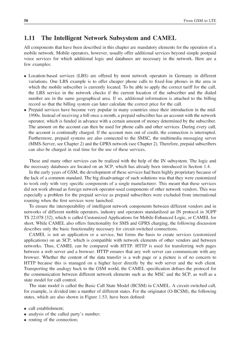
The Intelligent Network Subsystem and CAMEL
Questions
References
46
49
51
53
58
60
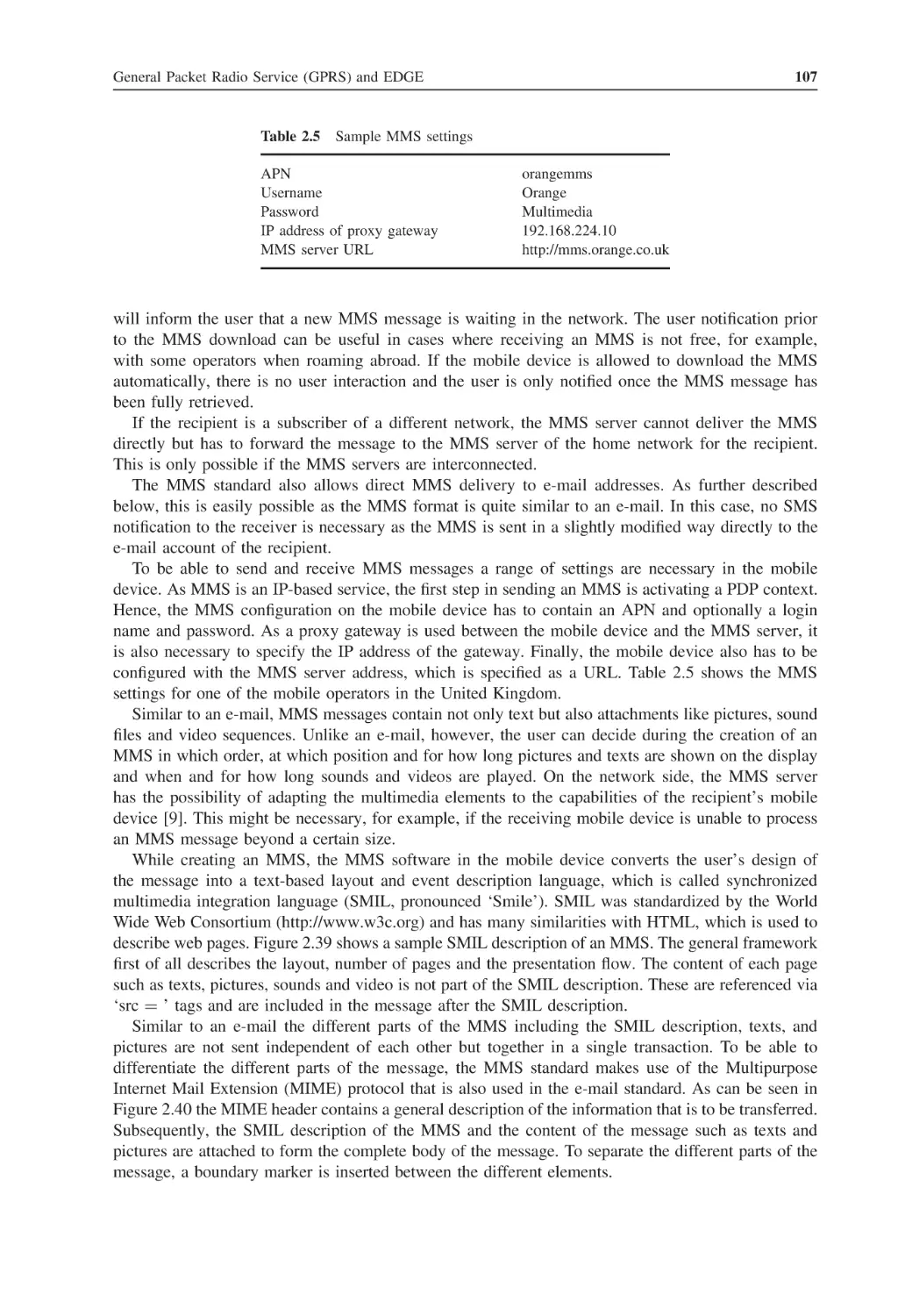
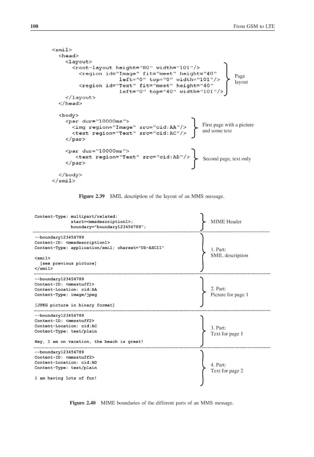
60
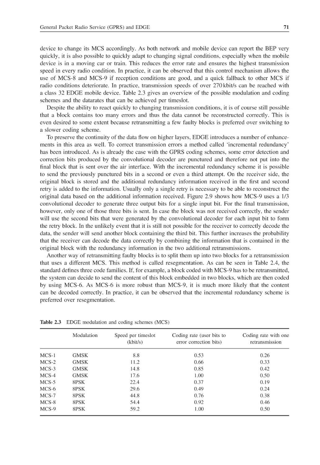
General Packet Radio Service (GPRS) and EDGE
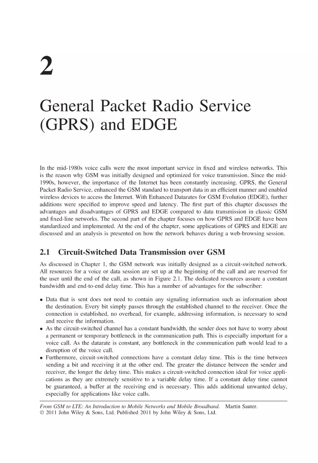
Circuit-Switched Data Transmission over GSM
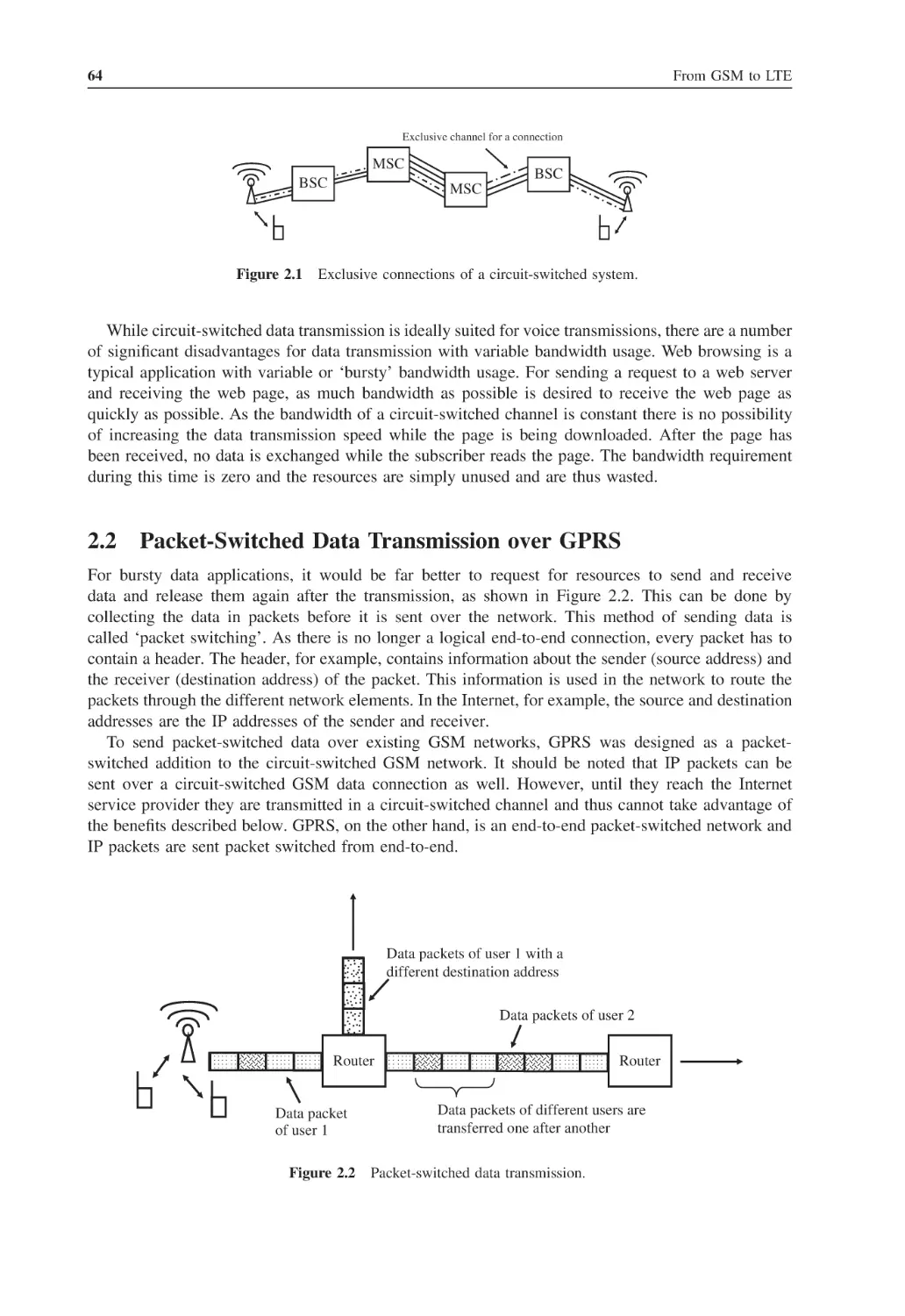
Packet-Switched Data Transmission over GPRS
The GPRS Air Interface
2.3.1
GPRS vs. GSM Timeslot Usage on the Air Interface
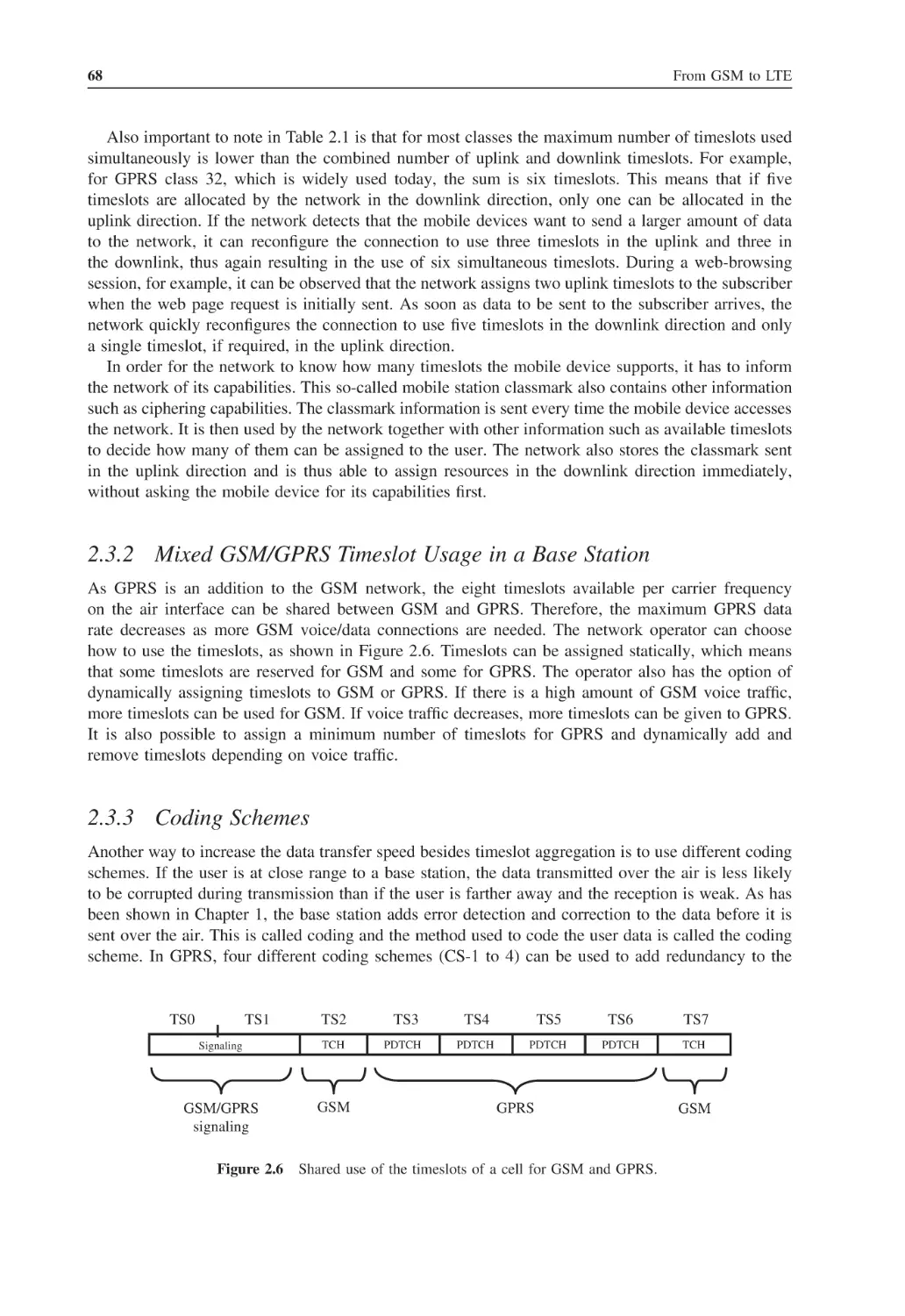
2.3.2
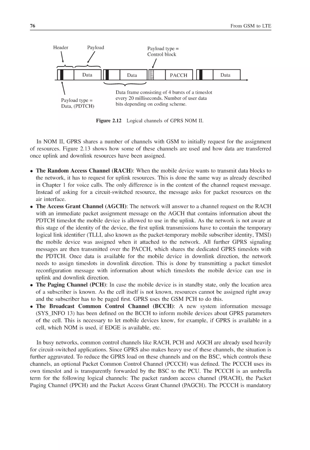
Mixed GSM/GPRS Timeslot Usage in a Base Station
2.3.3
Coding Schemes
2.3.4
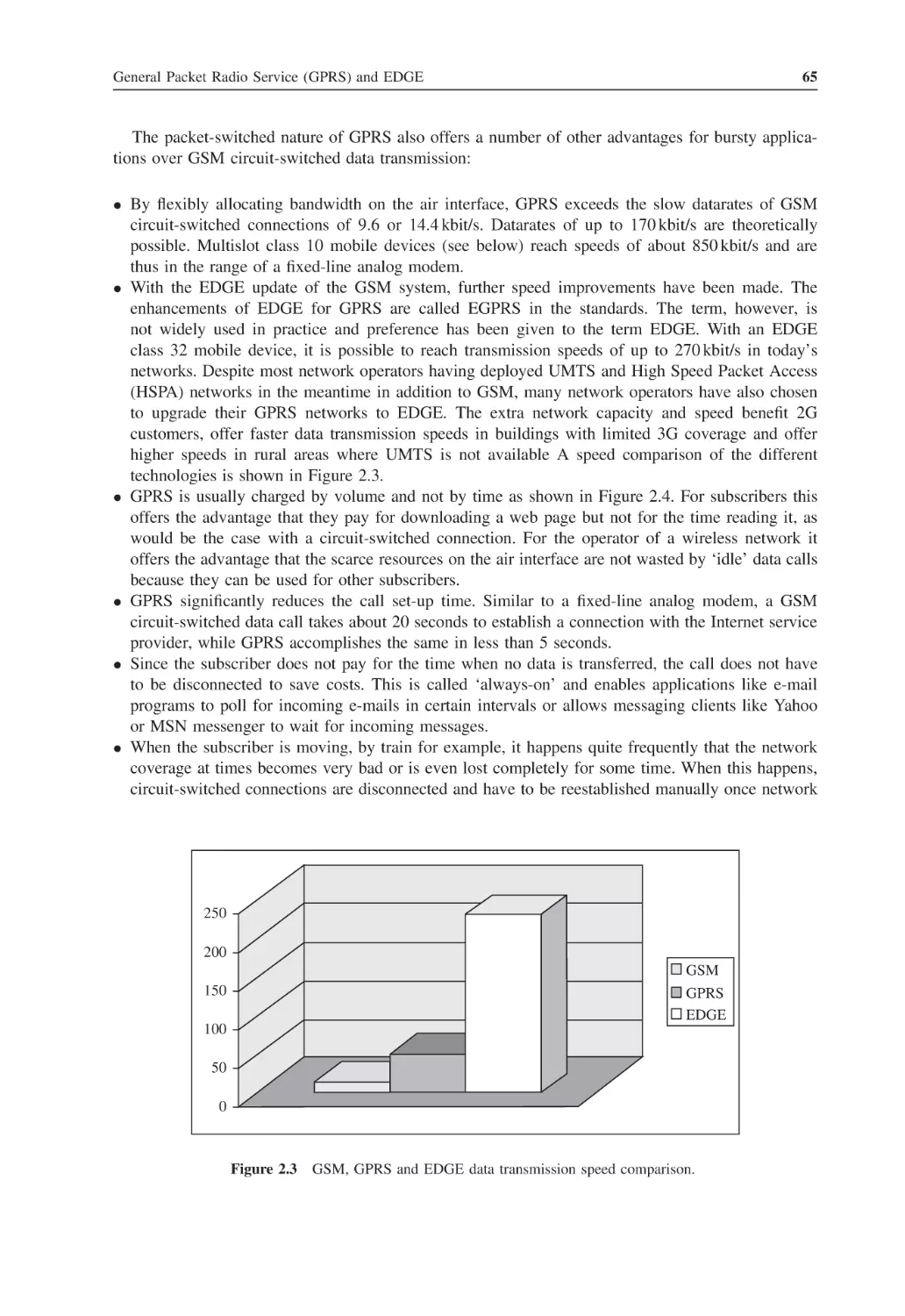
Enhanced Datarates for GSM Evolution (EDGE)
2.3.5
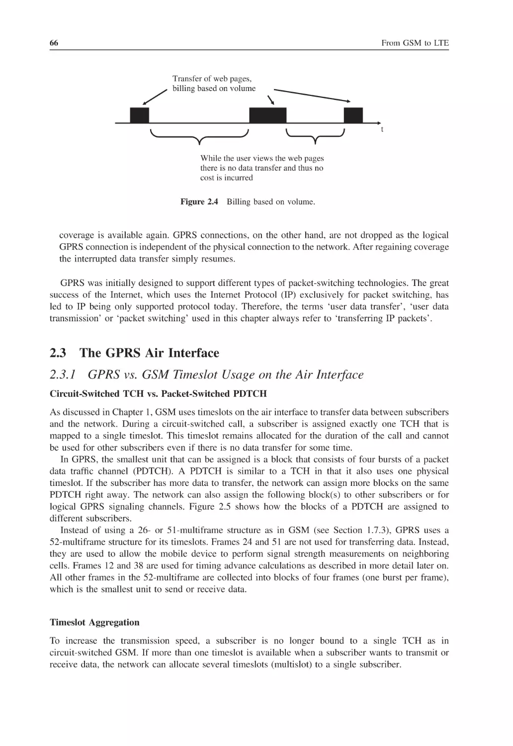
Mobile Device Classes
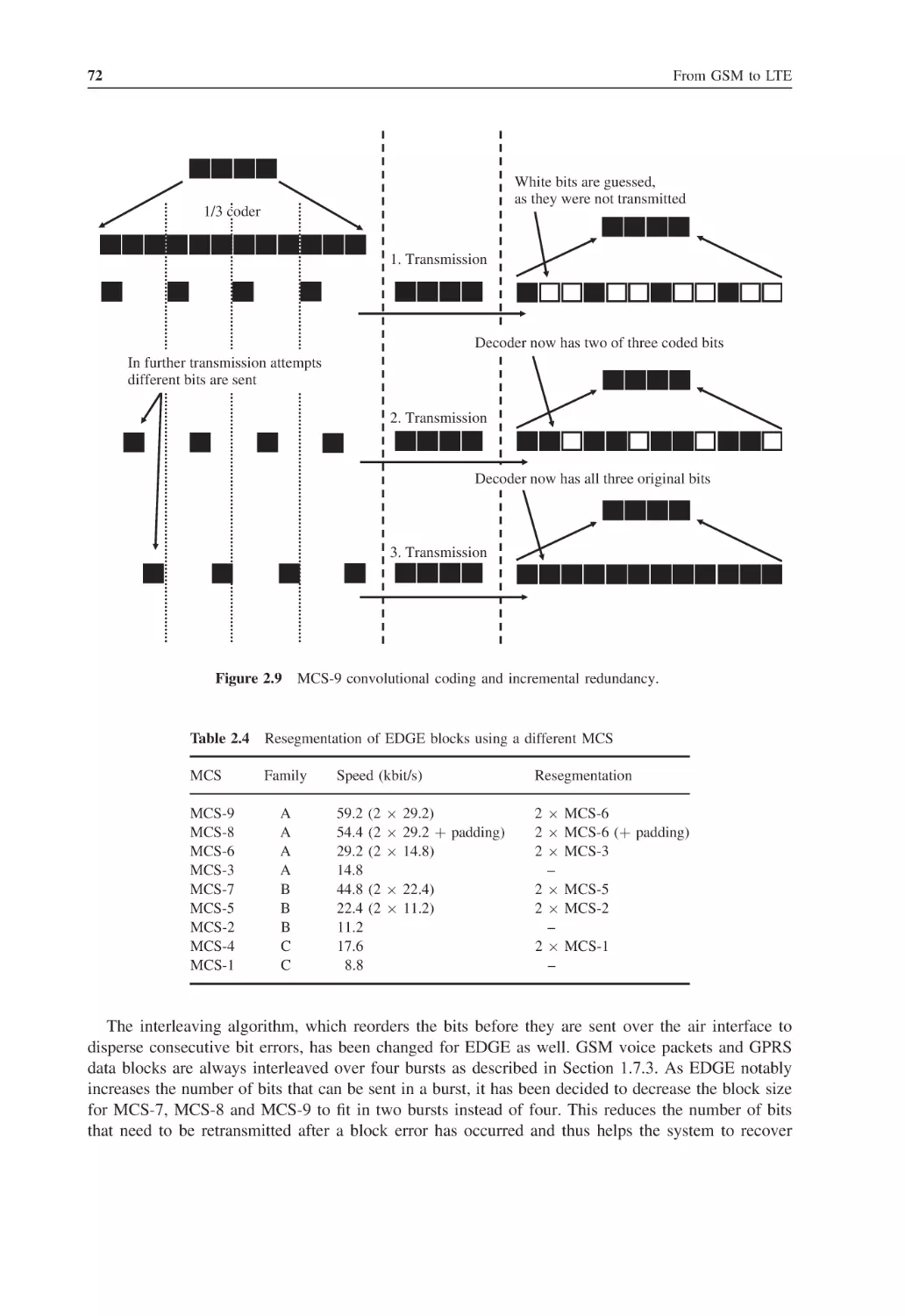
2.3.6
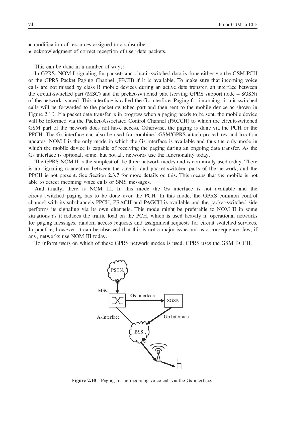
Network Mode of Operation
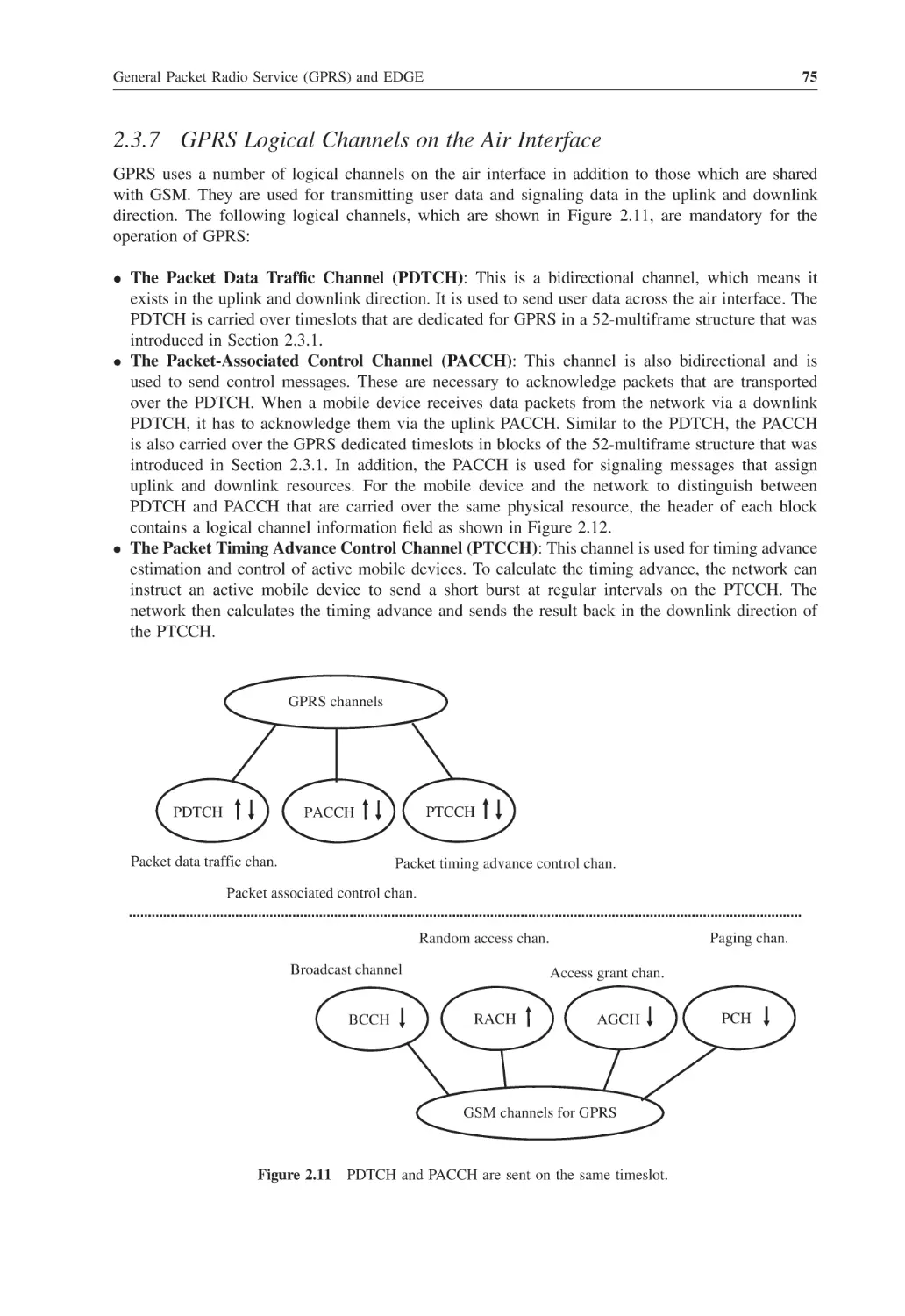
2.3.7
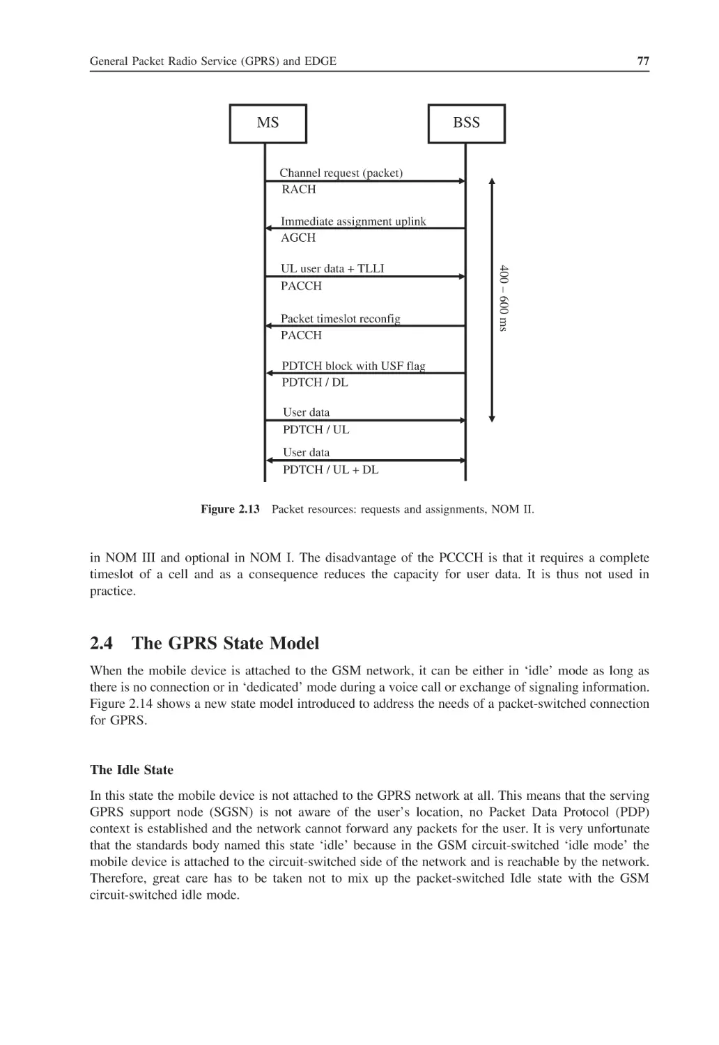
GPRS Logical Channels on the Air Interface
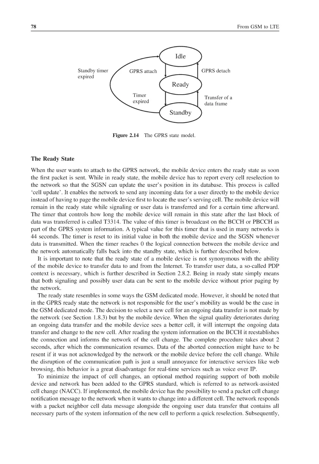
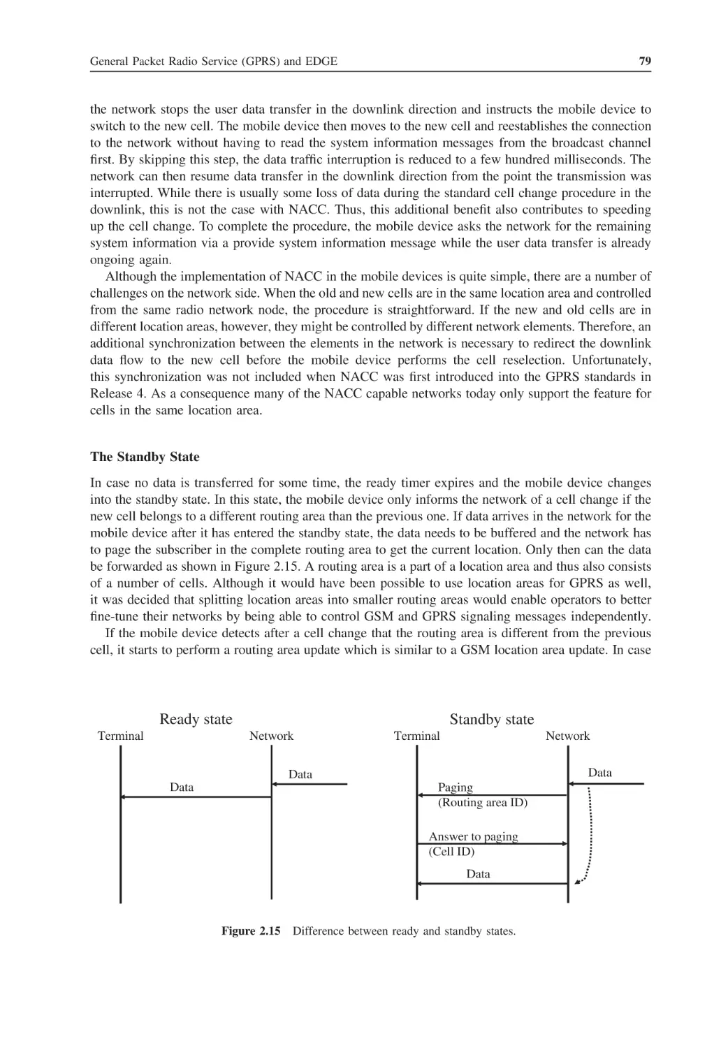
The GPRS State Model
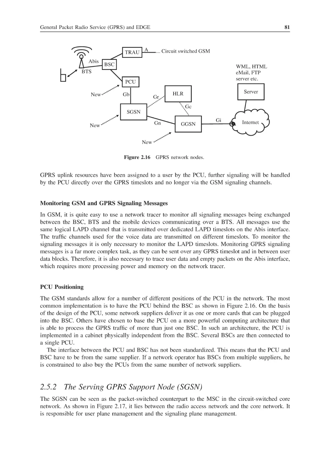
GPRS Network Elements
2.5.1
The Packet Control Unit (PCU)
2.5.2
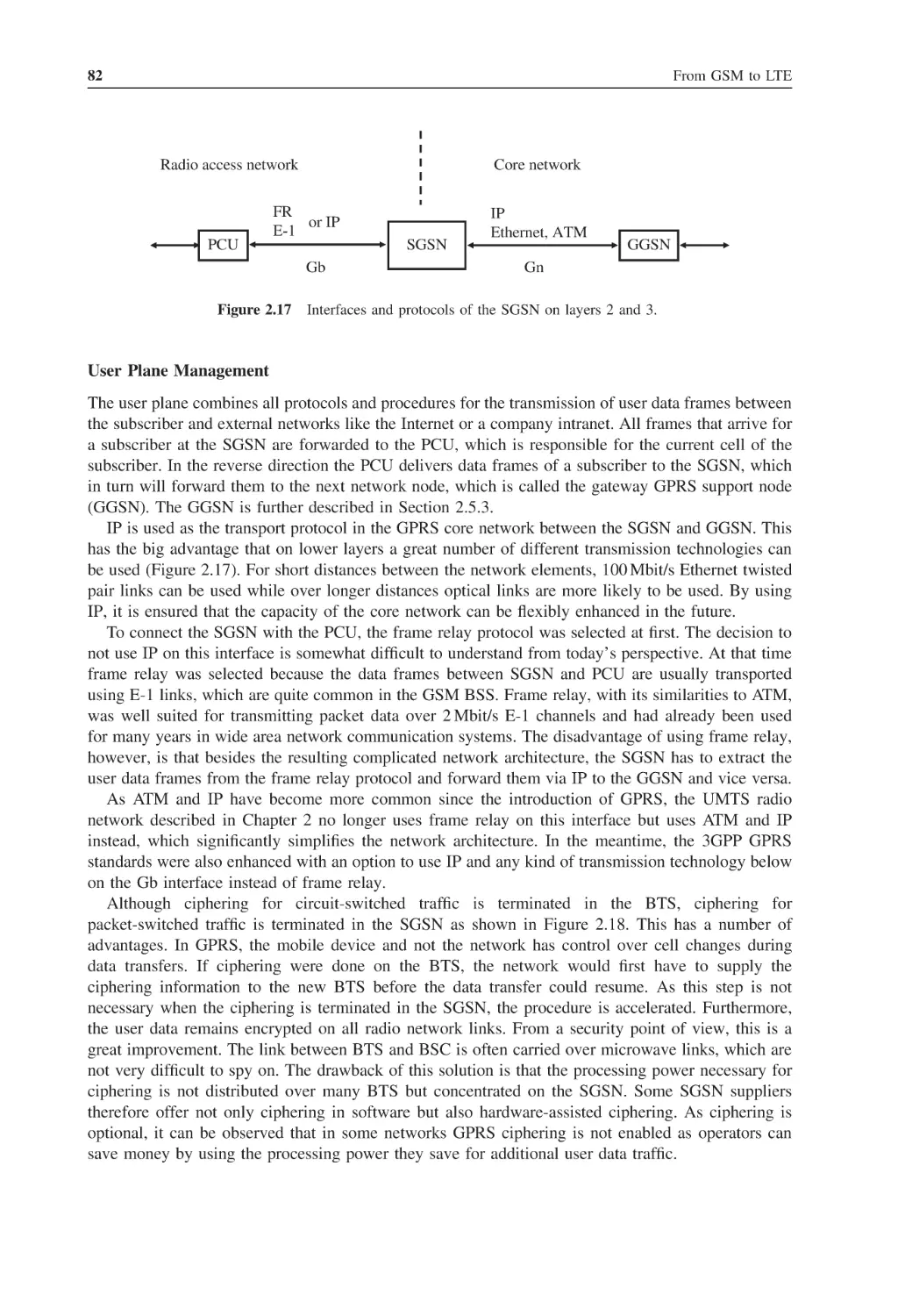
The Serving GPRS Support Node (SGSN)
2.5.3
The Gateway GPRS Support Node (GGSN)
GPRS Radio Resource Management
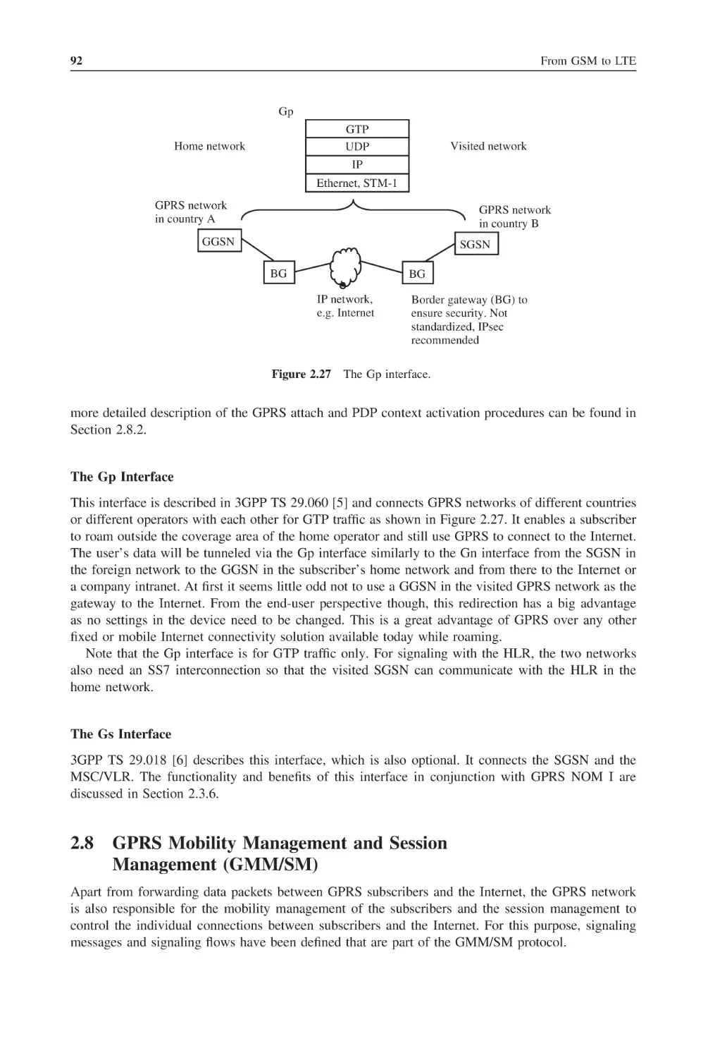
GPRS Interfaces
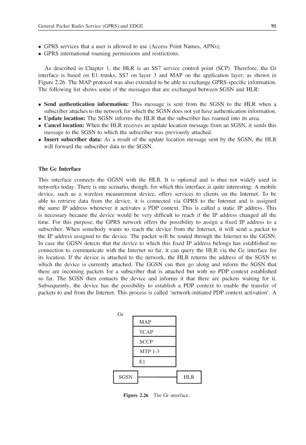
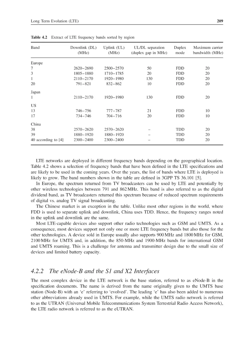
GPRS Mobility Management and Session Management (GMM/SM)
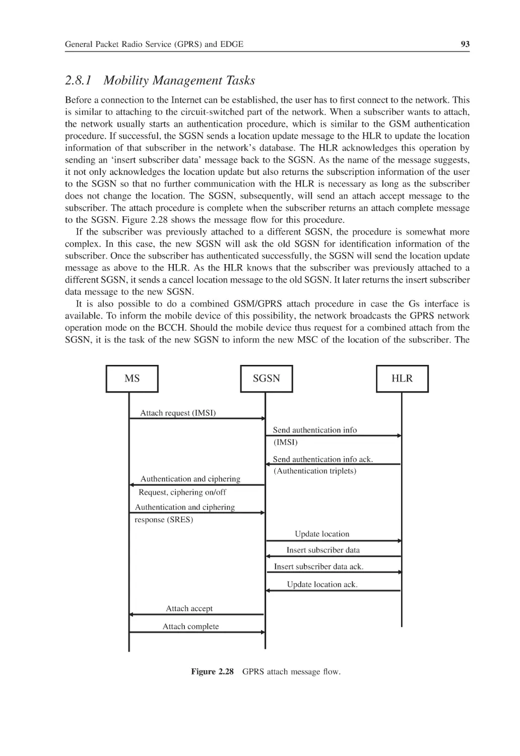
2.8.1
Mobility Management Tasks
2.8.2
GPRS Session Management
Session Management from a User Point of View
Small Screen Web Browsing over GPRS and EDGE
2.10.1
WAP 1.1 Used in Early GPRS Devices
2.10.2
WAP 2.0
2.10.3
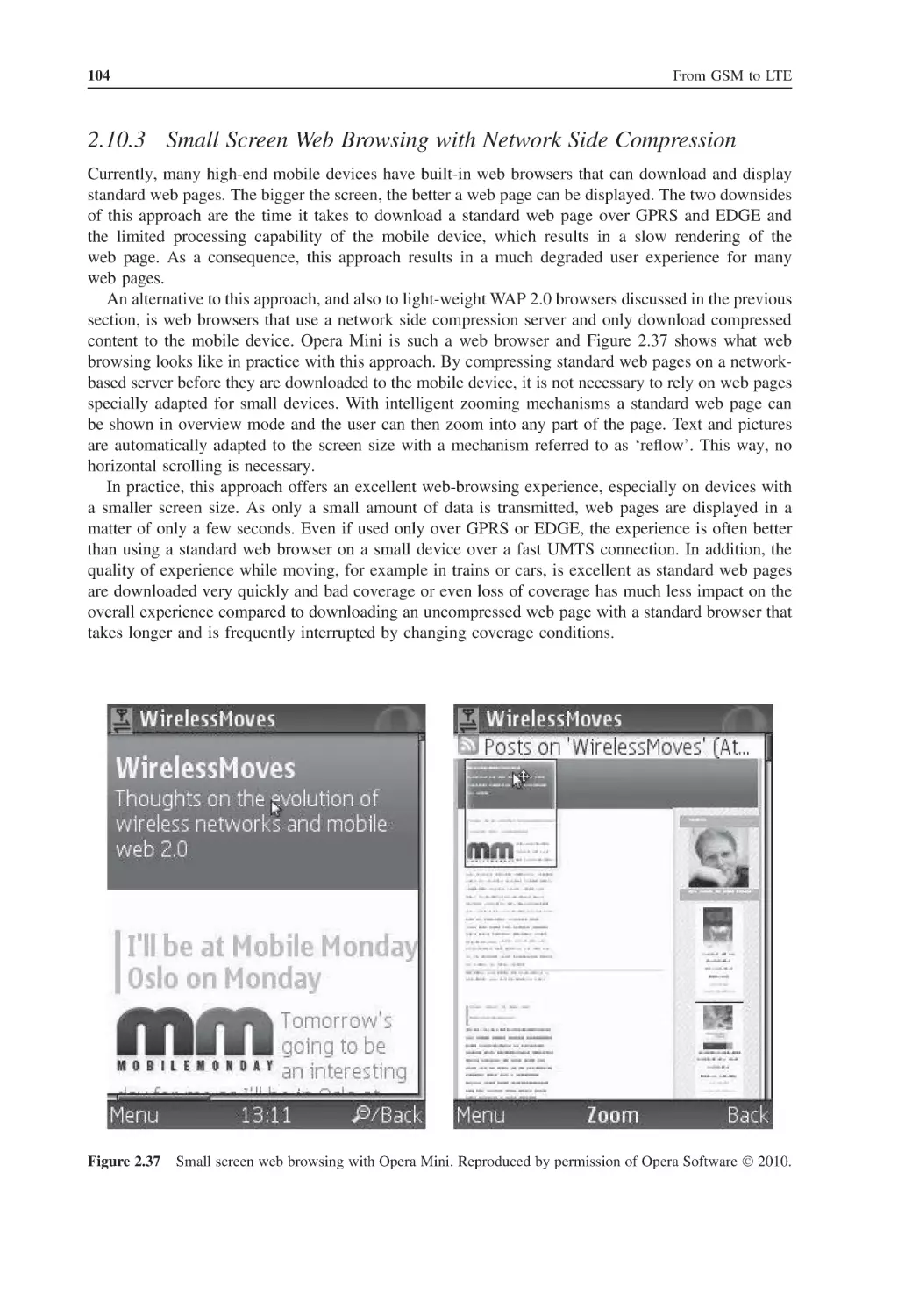
Small Screen Web Browsing with Network Side Compression
2.10.4
Small Screen Web Browsing – Quality of Experience
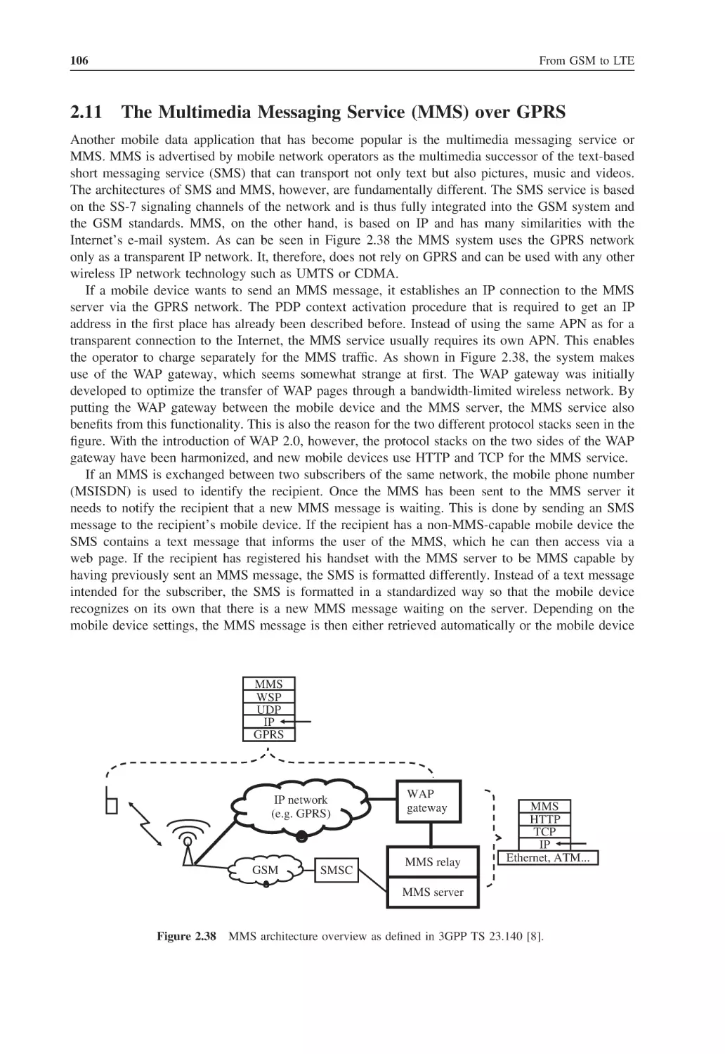
The Multimedia Messaging Service (MMS) over GPRS
Web Browsing via GPRS
2.12.1
Impact of Delay on the Web-Browsing Experience
2.12.2
Web Browser Optimization for Mobile Web Browsing
Questions
References
63
63
64
66
66
68
68
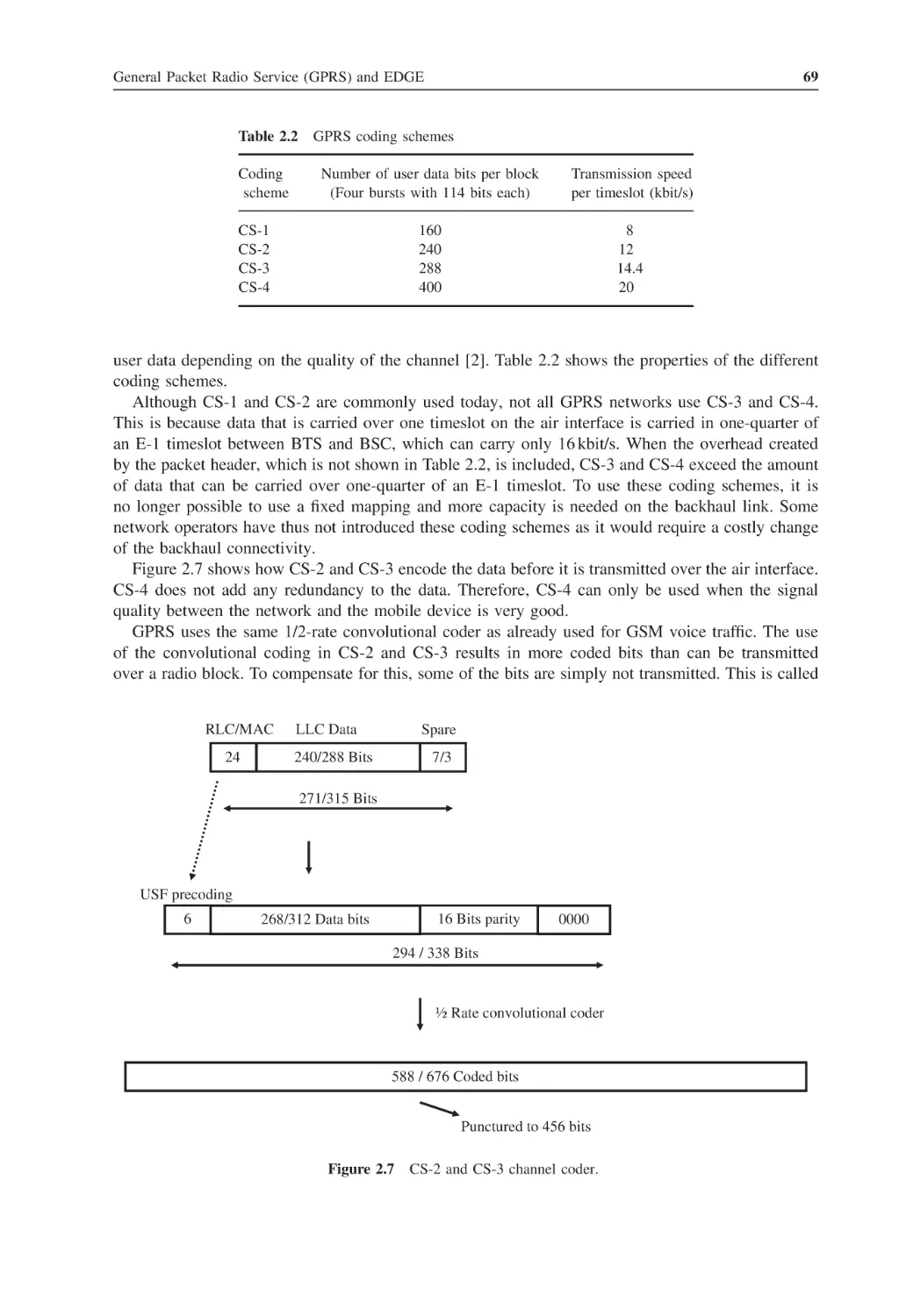
70
73
73
75
77
80
80
81
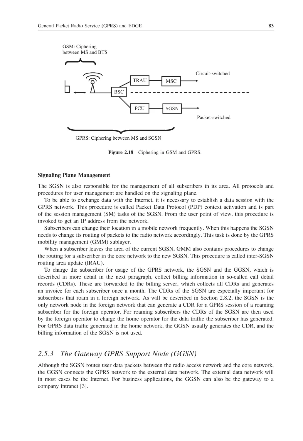
83
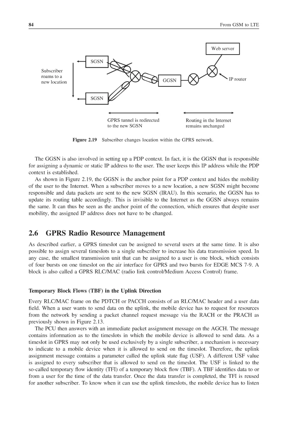
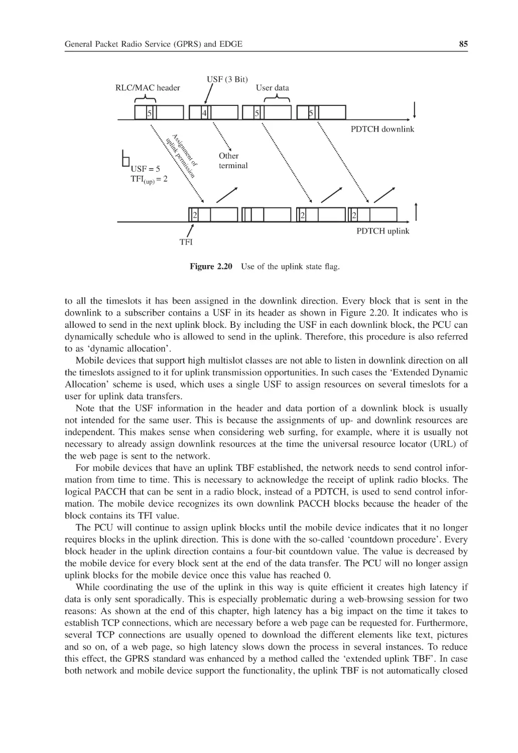
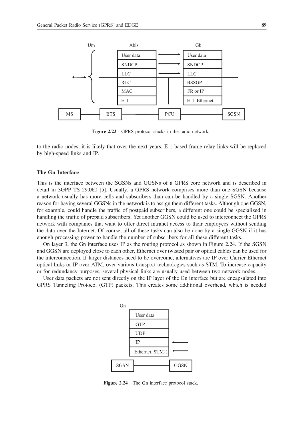
84
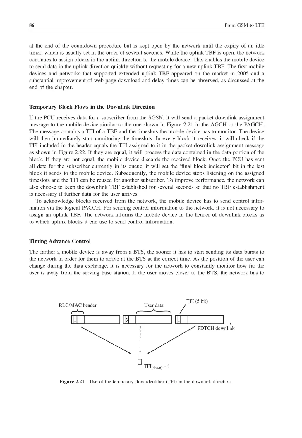
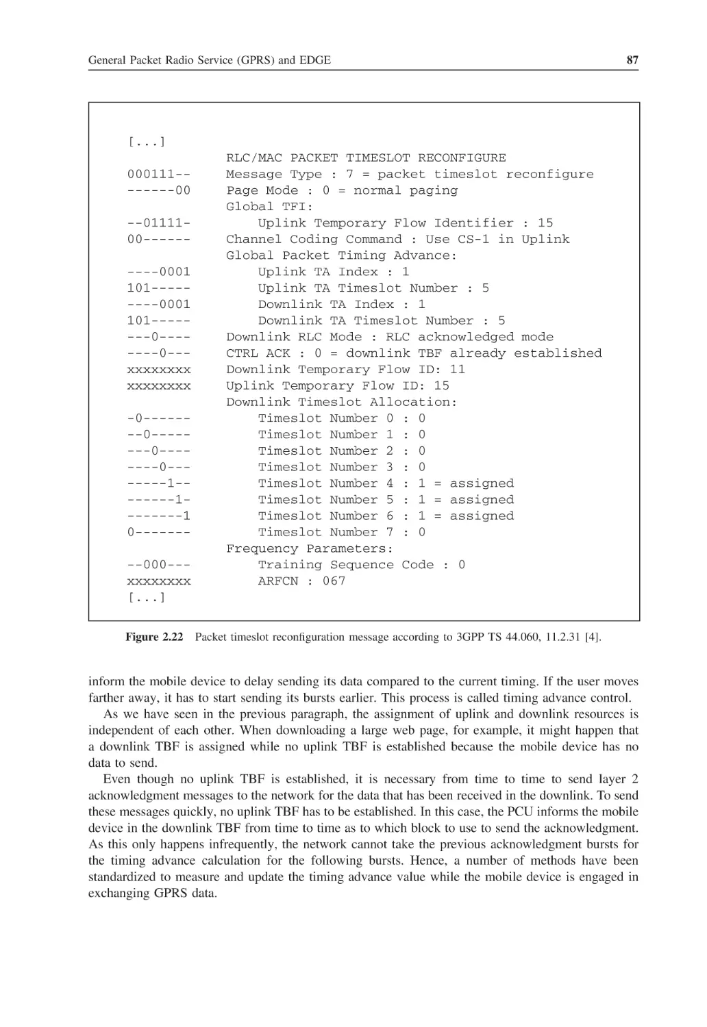
88
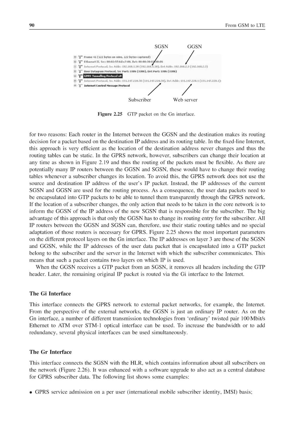
92
93
94
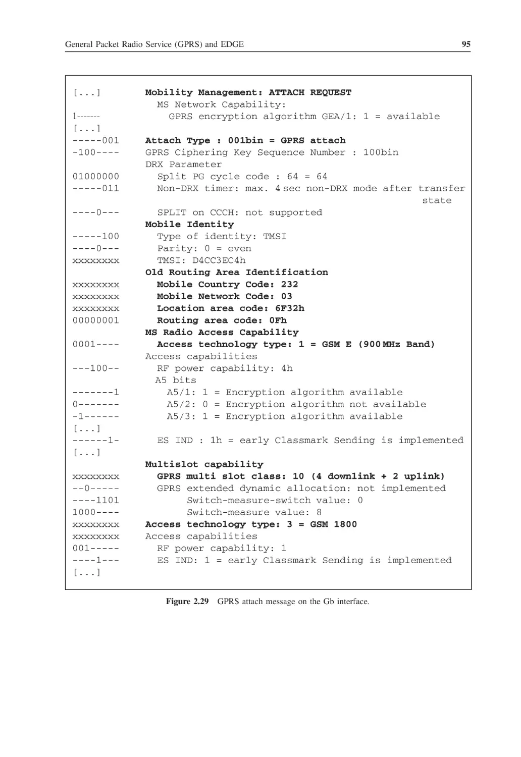
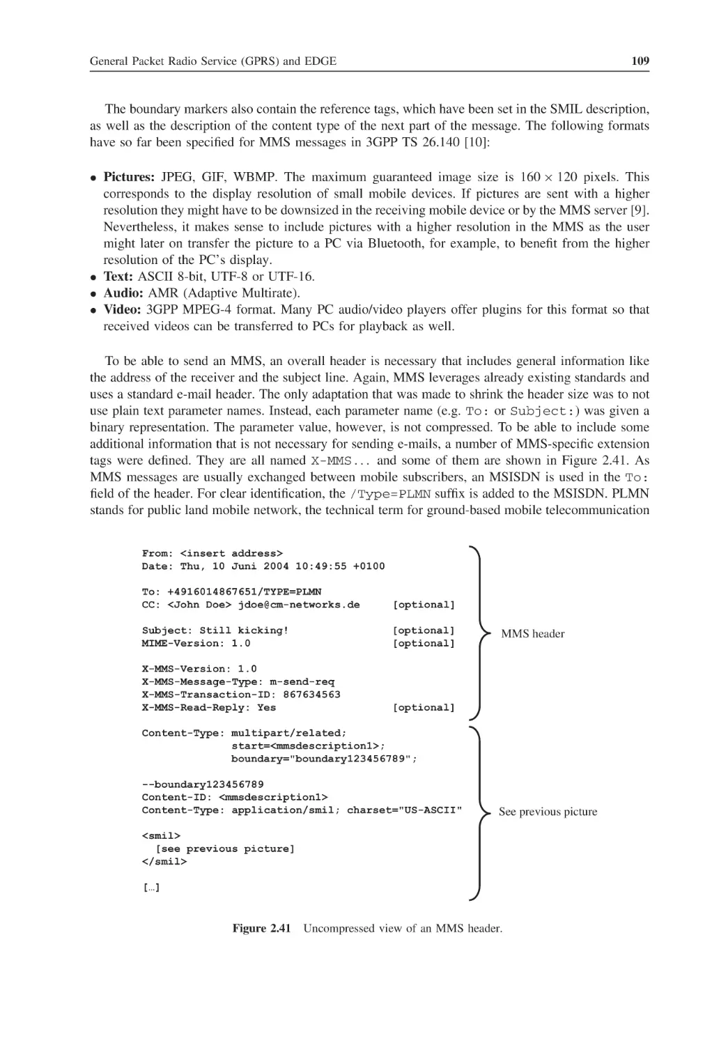
97
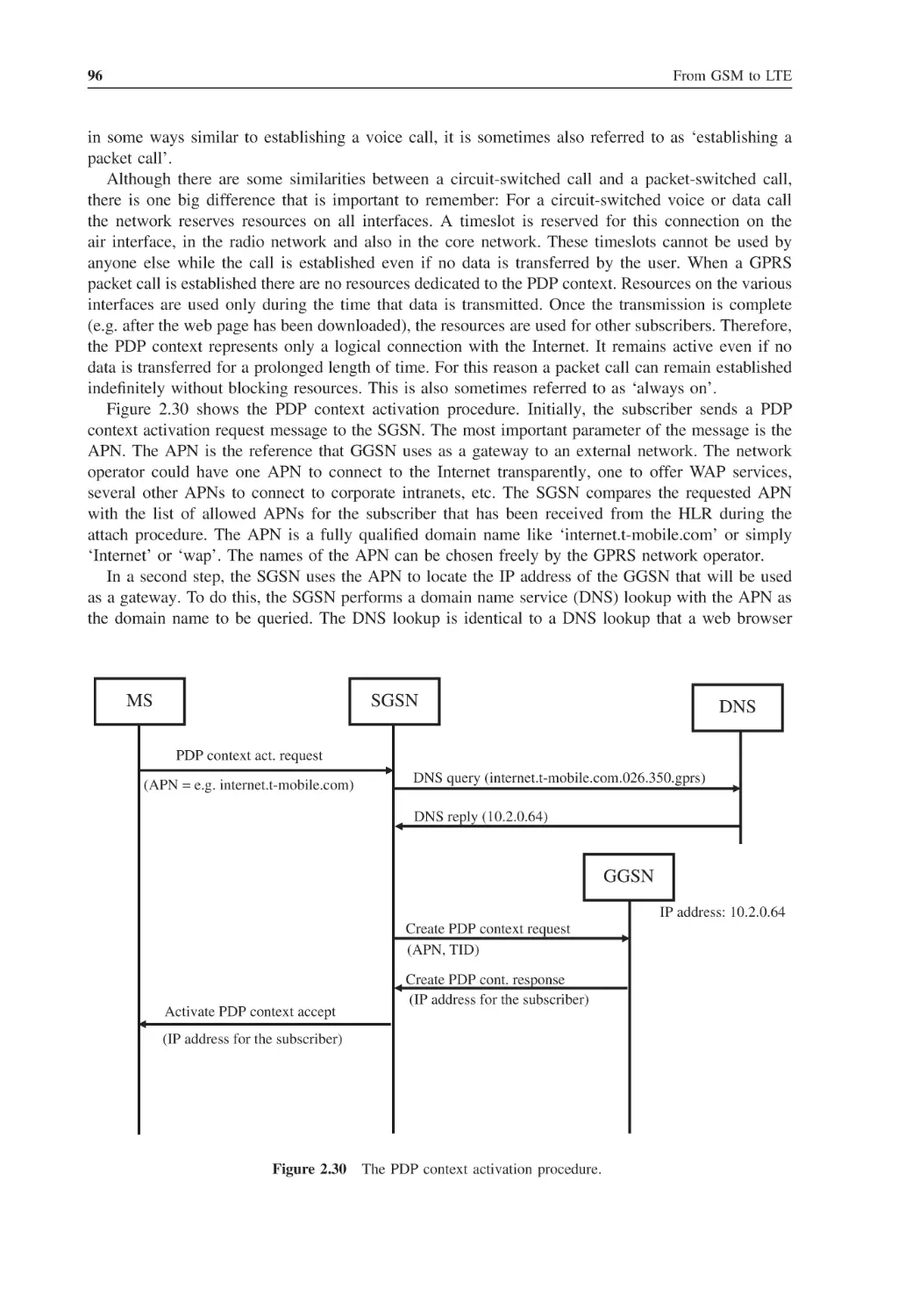
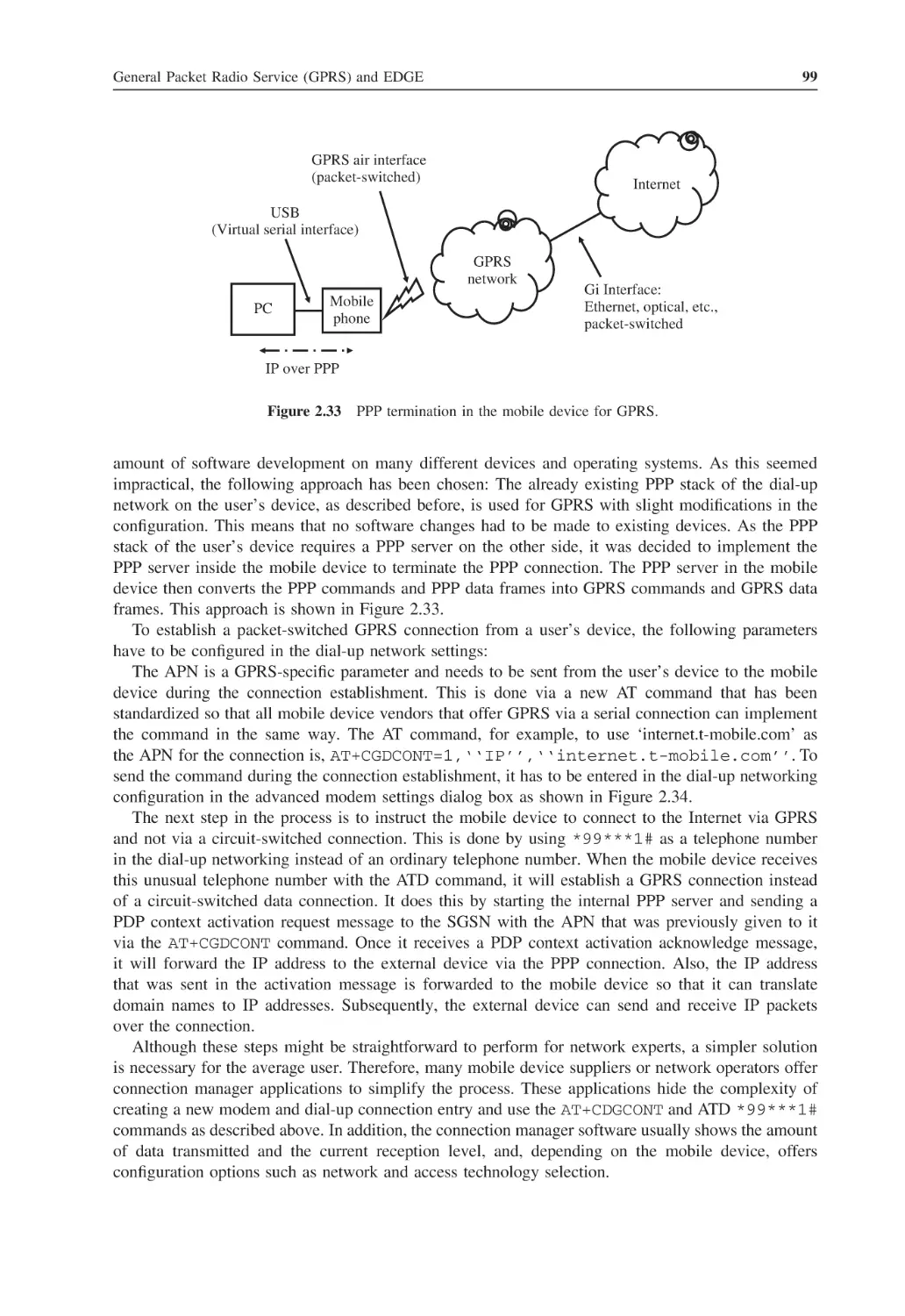
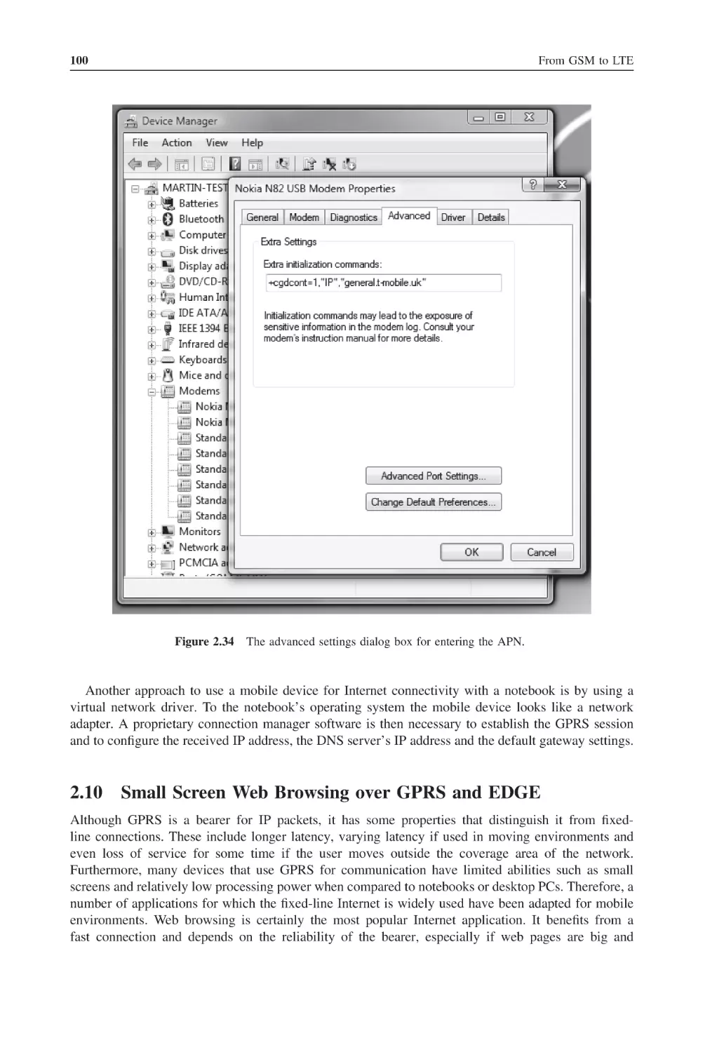
100
101
103
104
105
106
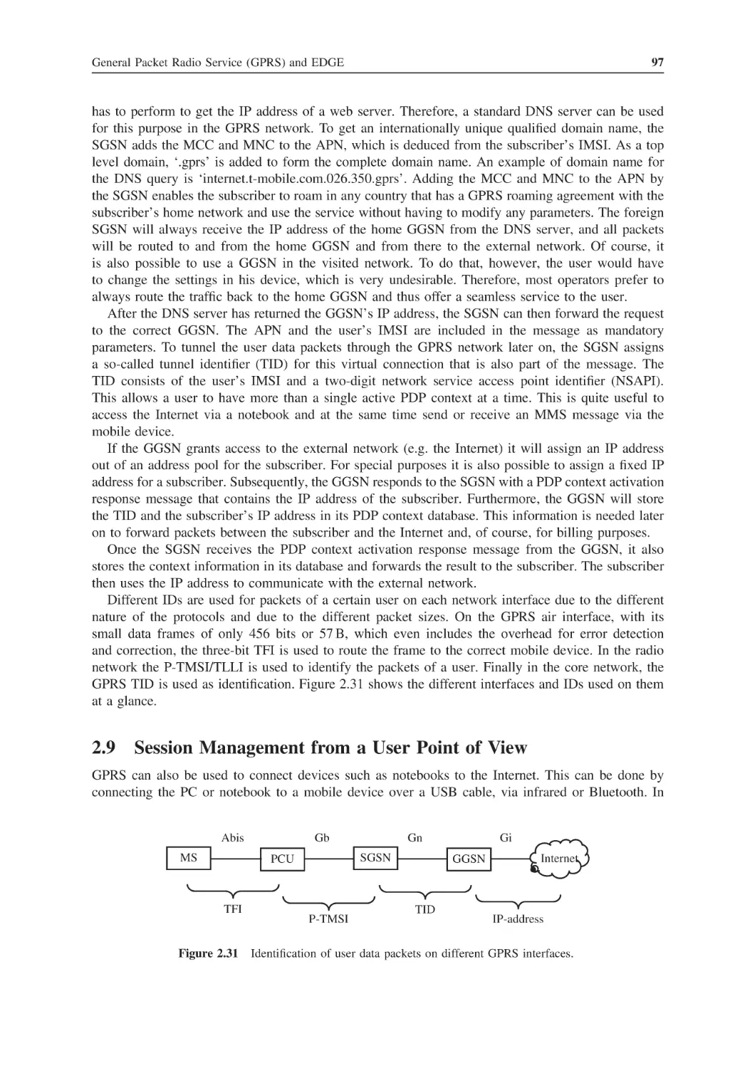
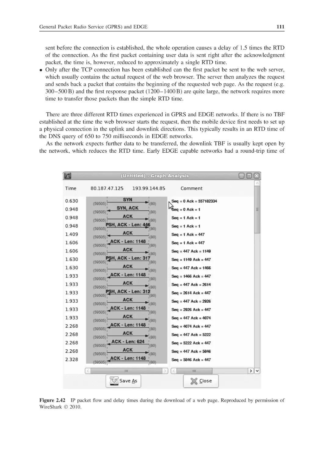
110
110
112
113
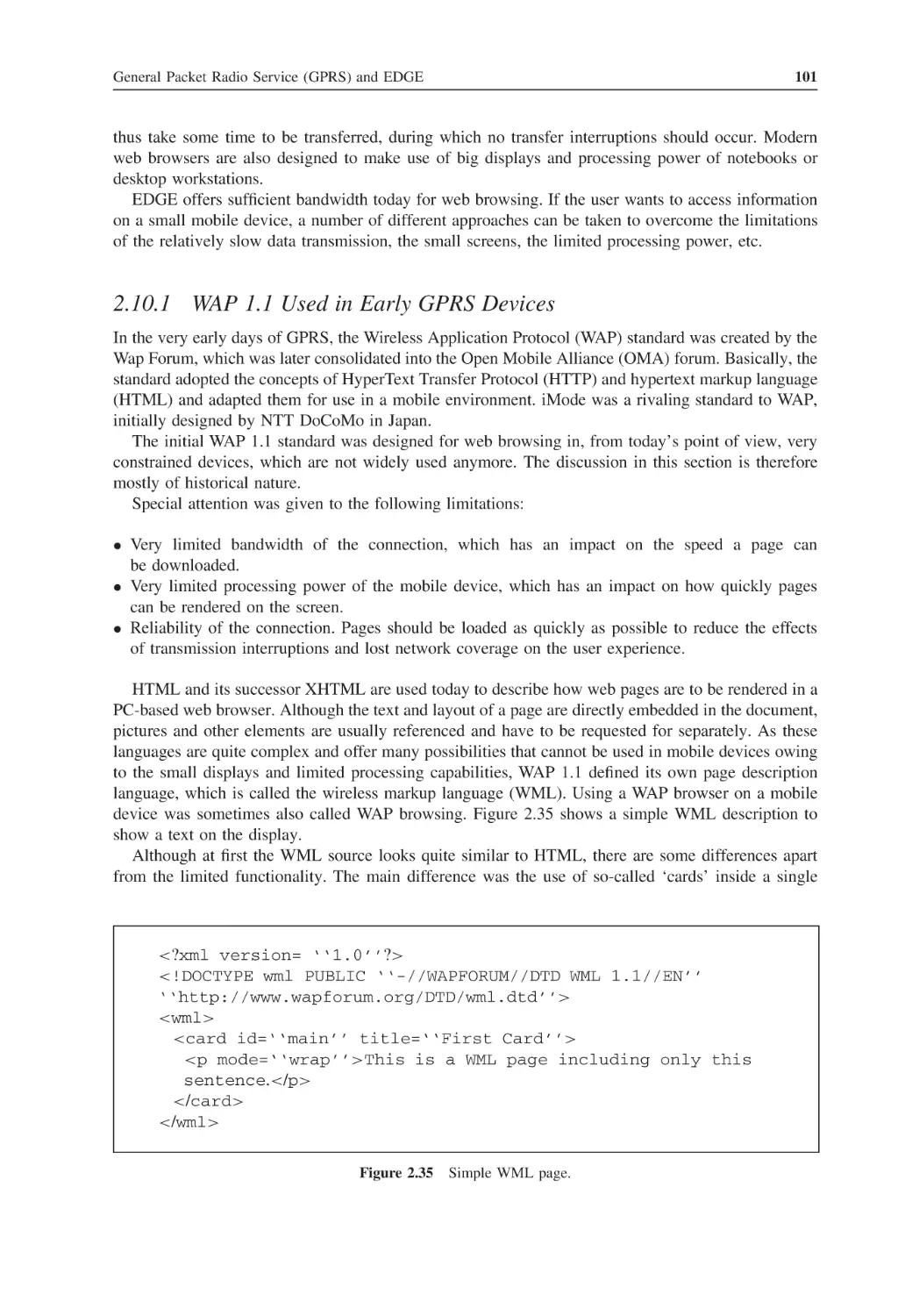
113
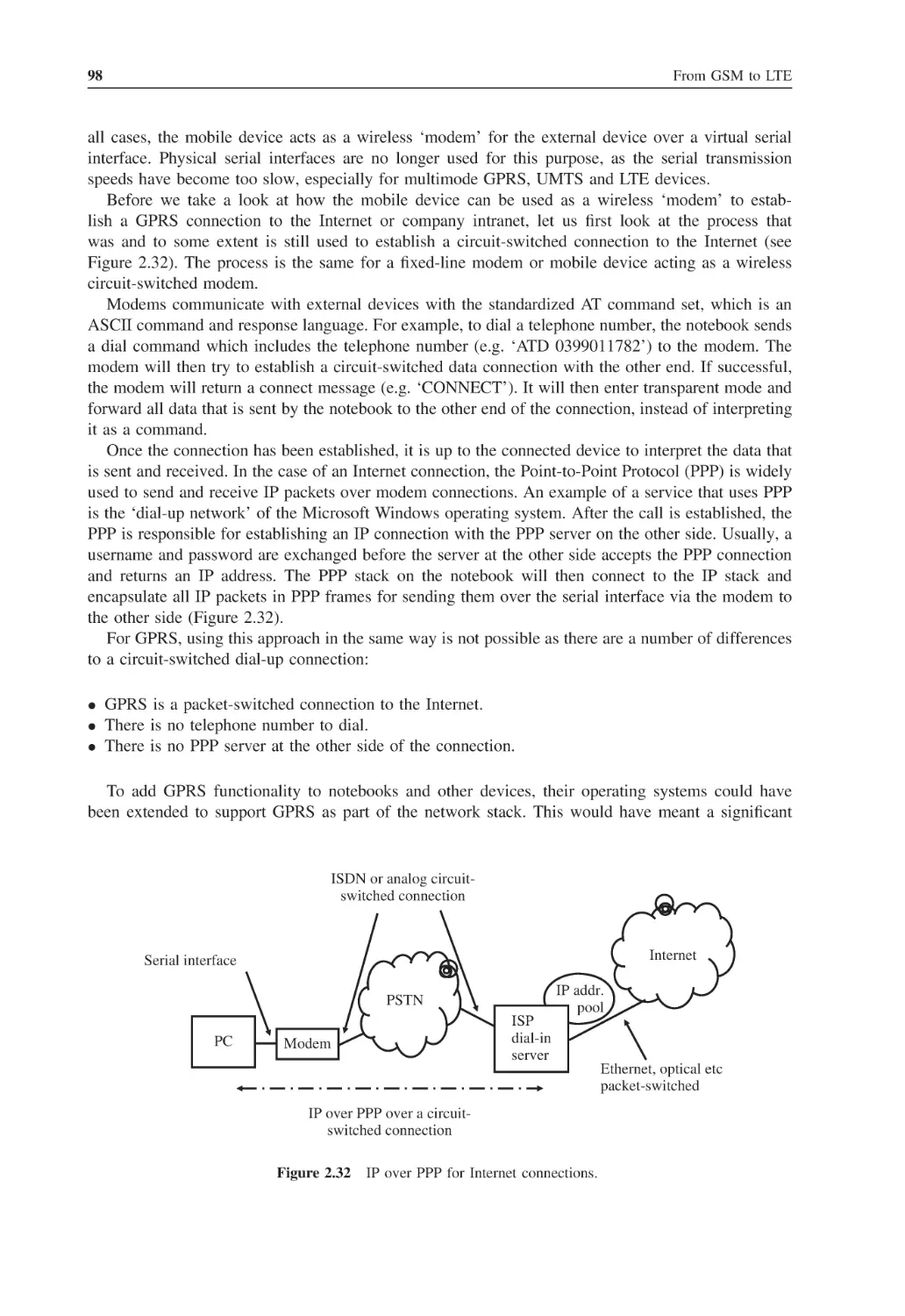
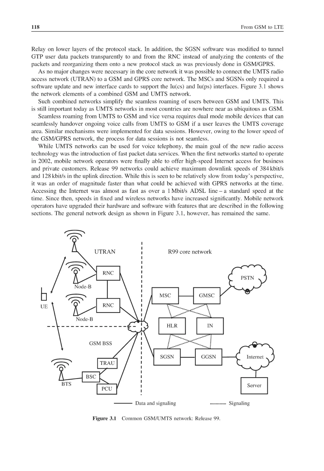
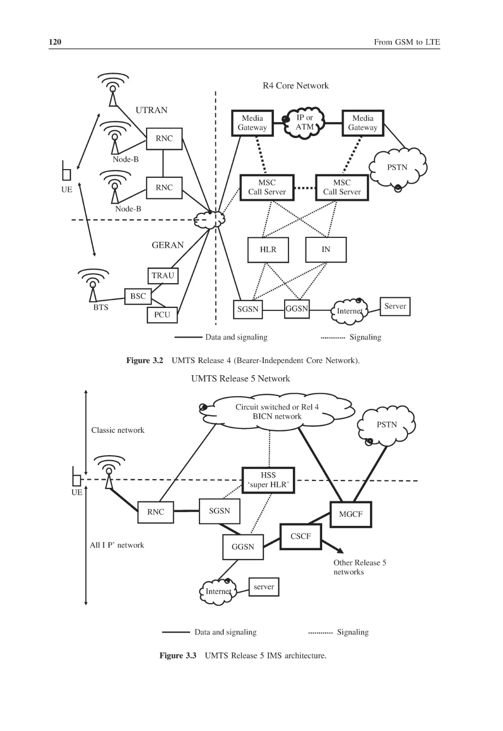
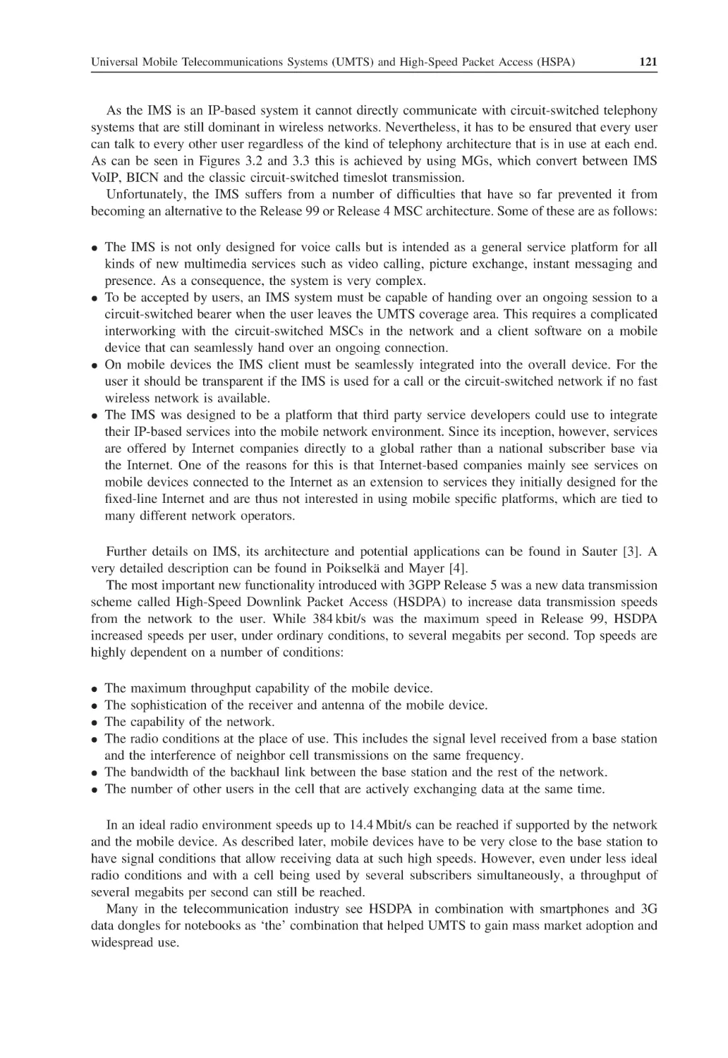
Universal Mobile Telecommunications Systems (UMTS) and High-Speed
Packet Access (HSPA)
Overview, History and Future
3.1.1
3GPP Release 99: The First UMTS Access Network Implementation
3.1.2
3GPP Release 4: Enhancements for the Circuit-Switched Core Network
3.1.3
3GPP Release 5: IMS and High-Speed Downlink Packet Access
3.1.4
3GPP Release 6: High-Speed Uplink Packet Access (HSUPA)
3.1.5
3GPP Release 7: Even Faster HSPA and Continued Packet Connectivity
115
115
116
119
119
122
122
Contents
3.2
3.3
3.4
3.5
3.6
3.7
3.8
3.9
3.10
3.11
3.12
3.1.6
3GPP Release 8: LTE, Further HSPA and Enhancements and Femtocells
3.1.7
3GPP Release 9: Digital Dividend and Dual Cell Improvements
3.1.8
3GPP Release 10: LTE-Advanced
Important New Concepts of UMTS
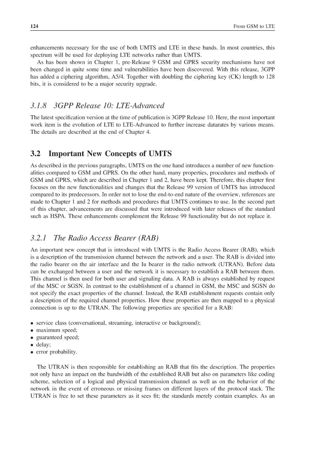
3.2.1
The Radio Access Bearer (RAB)
3.2.2
The Access Stratum and Nonaccess Stratum
3.2.3
Common Transport Protocols for CS and PS
Code Division Multiple Access (CDMA)
3.3.1
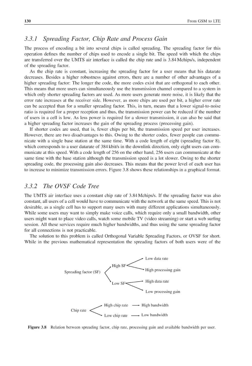
Spreading Factor, Chip Rate and Process Gain
3.3.2
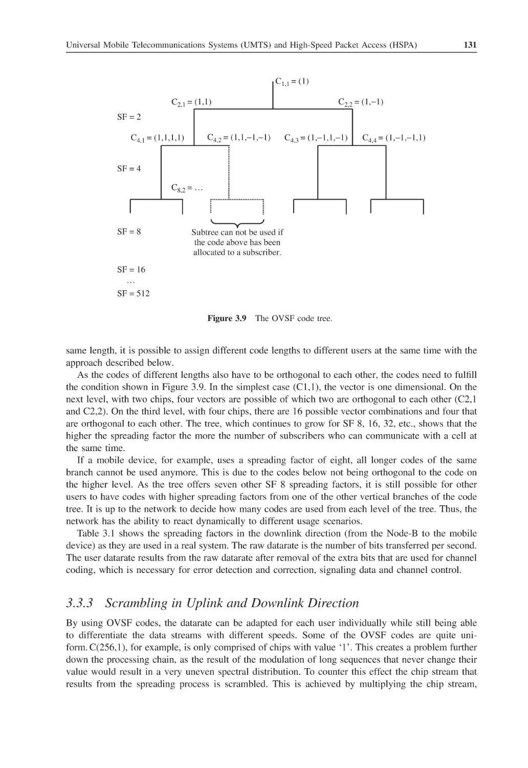
The OVSF Code Tree
3.3.3
Scrambling in Uplink and Downlink Direction
3.3.4
UMTS Frequency and Cell Planning
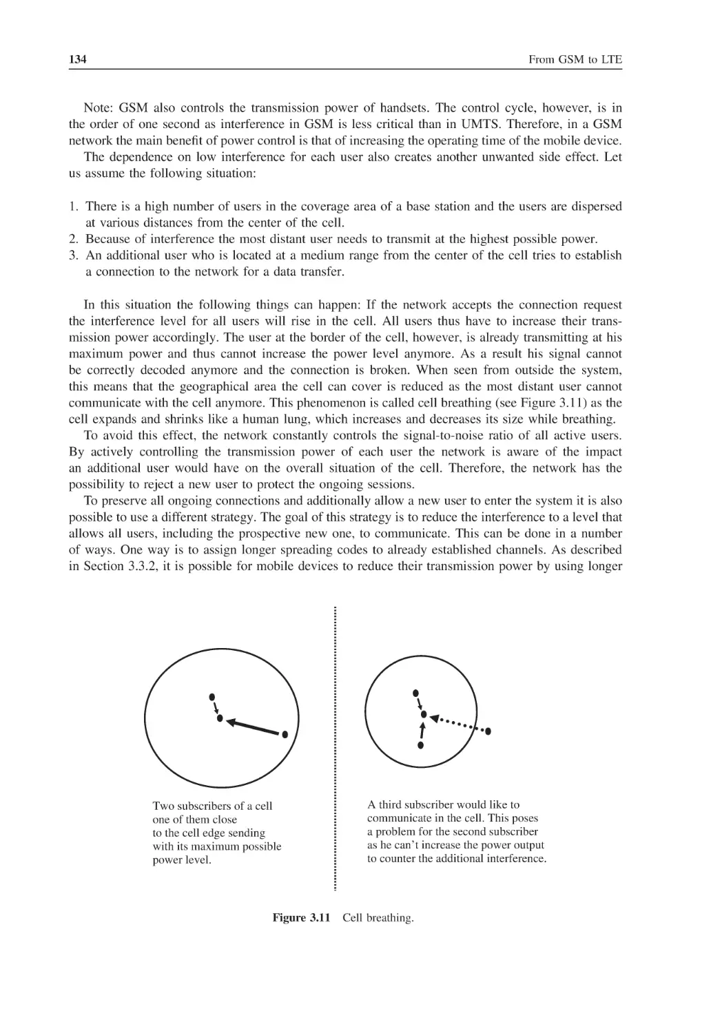
3.3.5
The Near–Far Effect and Cell Breathing
3.3.6
Advantages of the UMTS Radio Network Compared to GSM
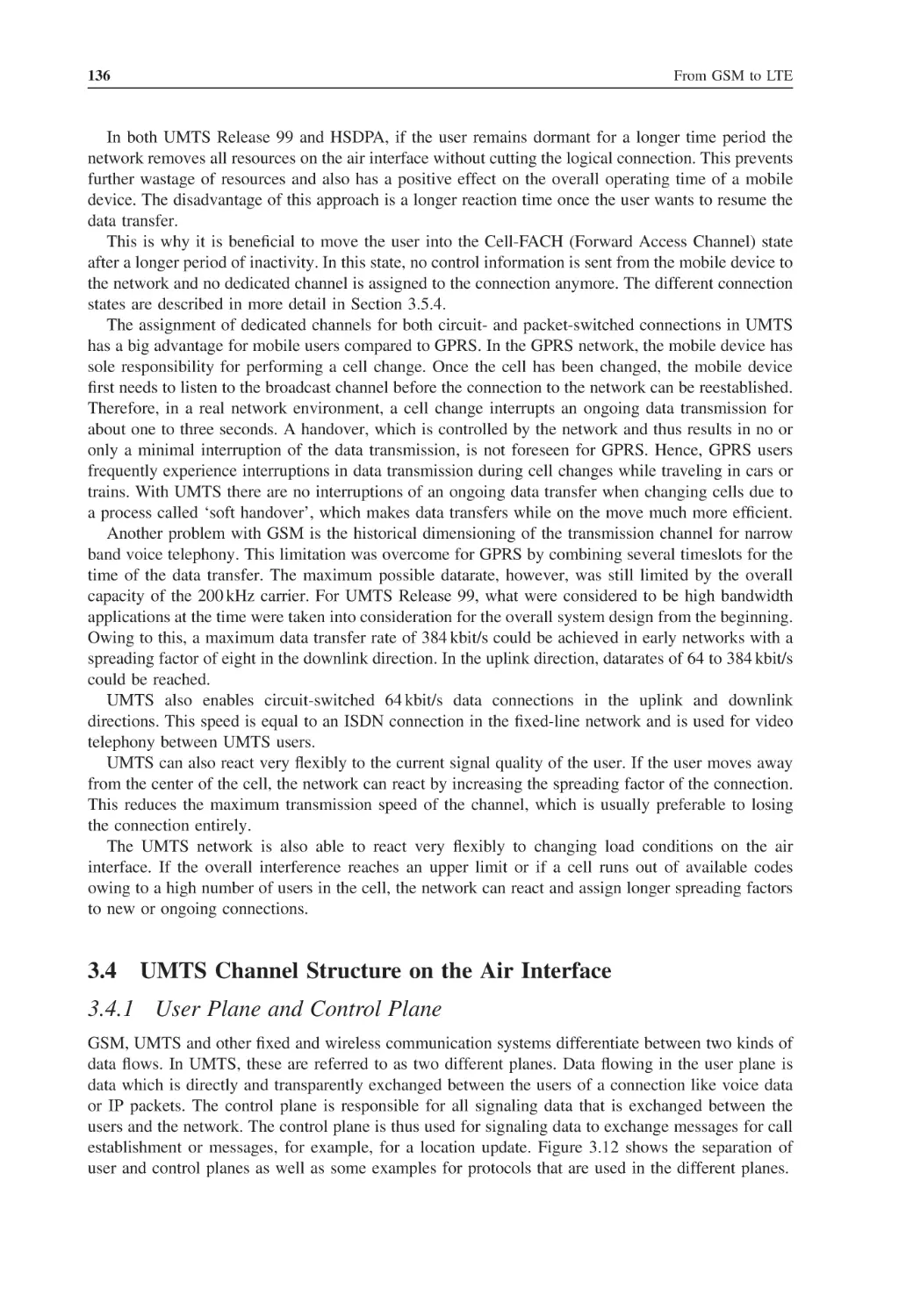
UMTS Channel Structure on the Air Interface
3.4.1
User Plane and Control Plane
3.4.2
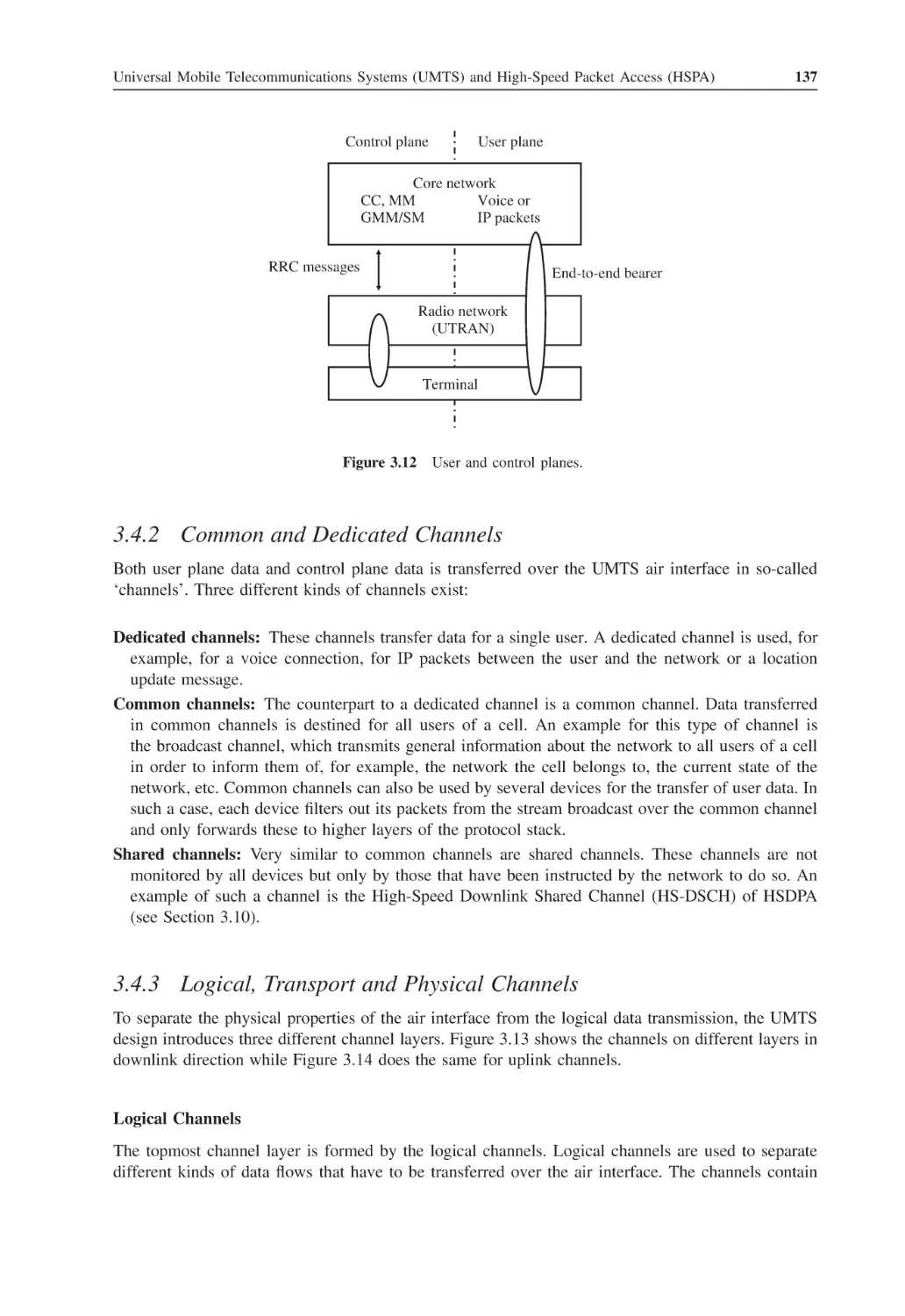
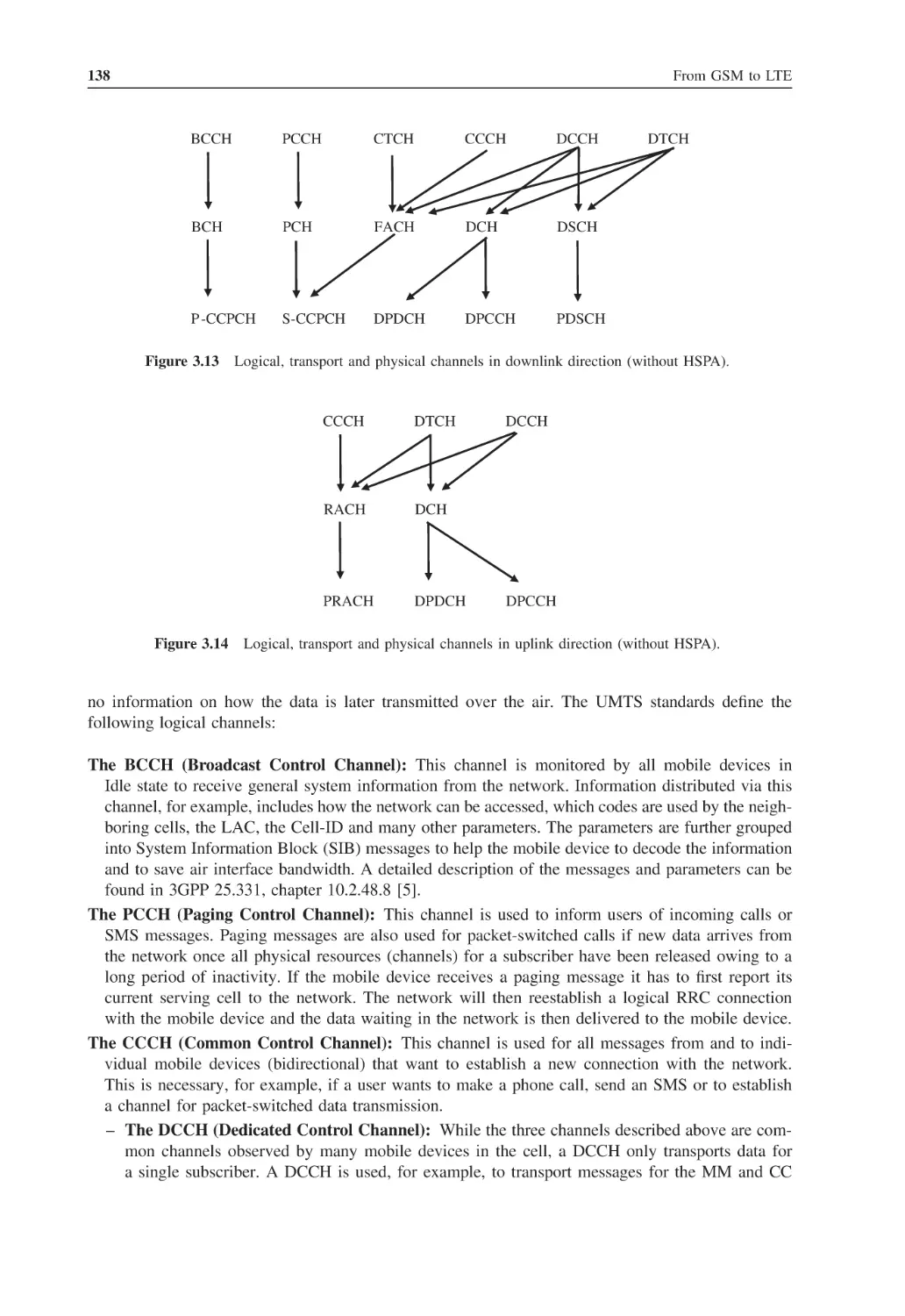
Common and Dedicated Channels
3.4.3
Logical, Transport and Physical Channels
3.4.4
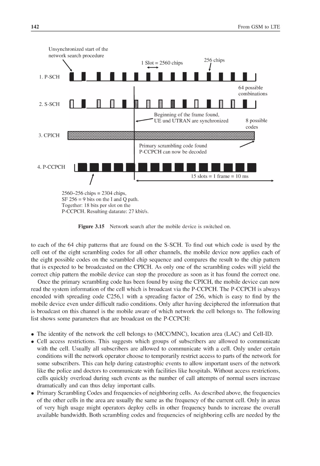
Example: Network Search
3.4.5
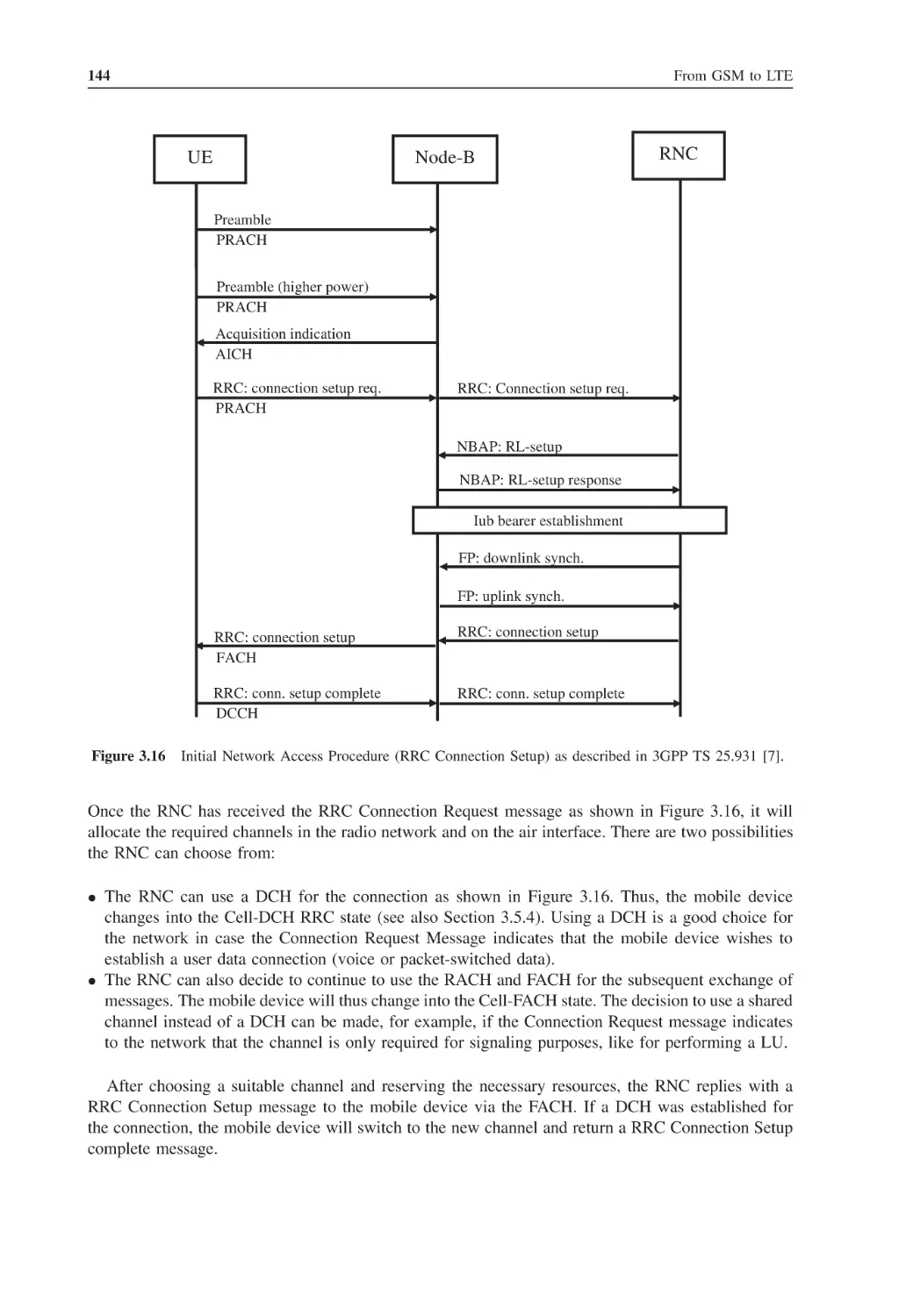
Example: Initial Network Access Procedure
3.4.6
The Uu Protocol Stack
The UMTS Terrestrial Radio Access Network (UTRAN)
3.5.1
Node-B, Iub Interface, NBAP and FP
3.5.2
The RNC, Iu, Iub and Iur Interfaces, RANAP and RNSAP
3.5.3
Adaptive Multirate (AMR) Codec for Voice Calls
3.5.4
Radio Resource Control (RRC) States
Core Network Mobility Management
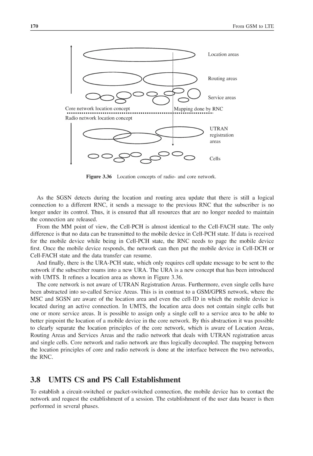
Radio Network Mobility Management
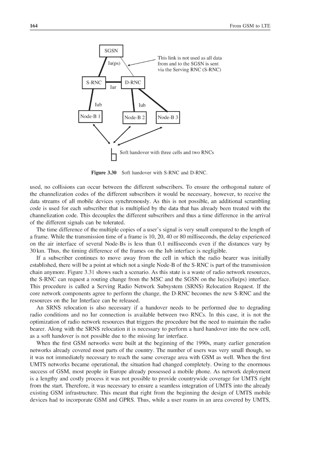
3.7.1
Mobility Management in the Cell-DCH State
3.7.2
Mobility Management in Idle State
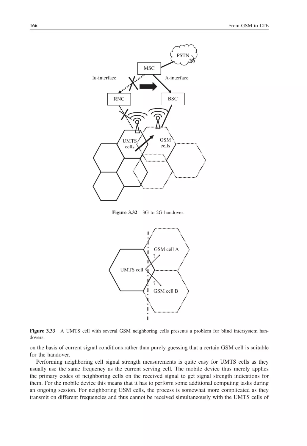
3.7.3
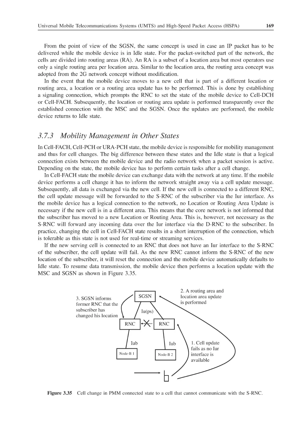
Mobility Management in Other States
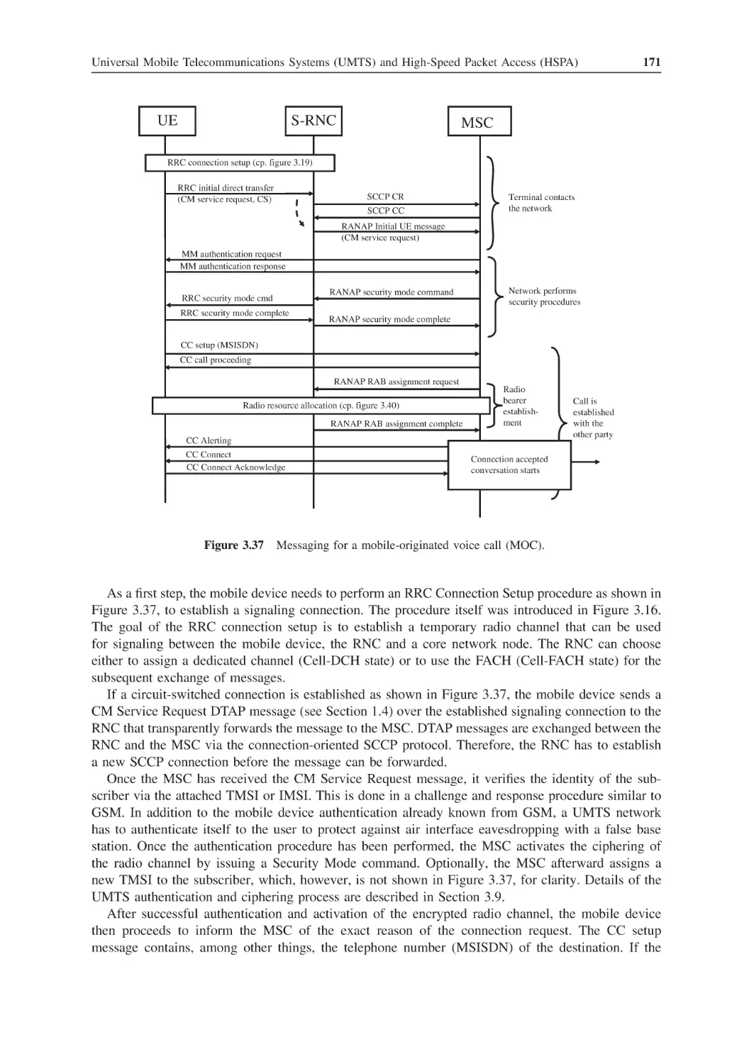
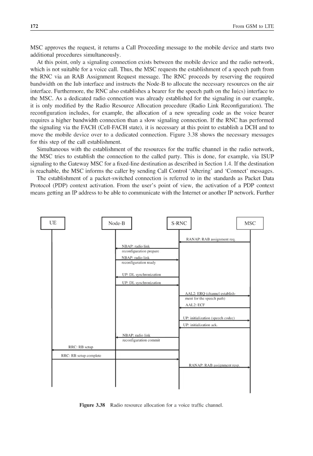
UMTS CS and PS Call Establishment
UMTS Security
High-Speed Downlink Packet Access (HSDPA) and HSPA+
3.10.1
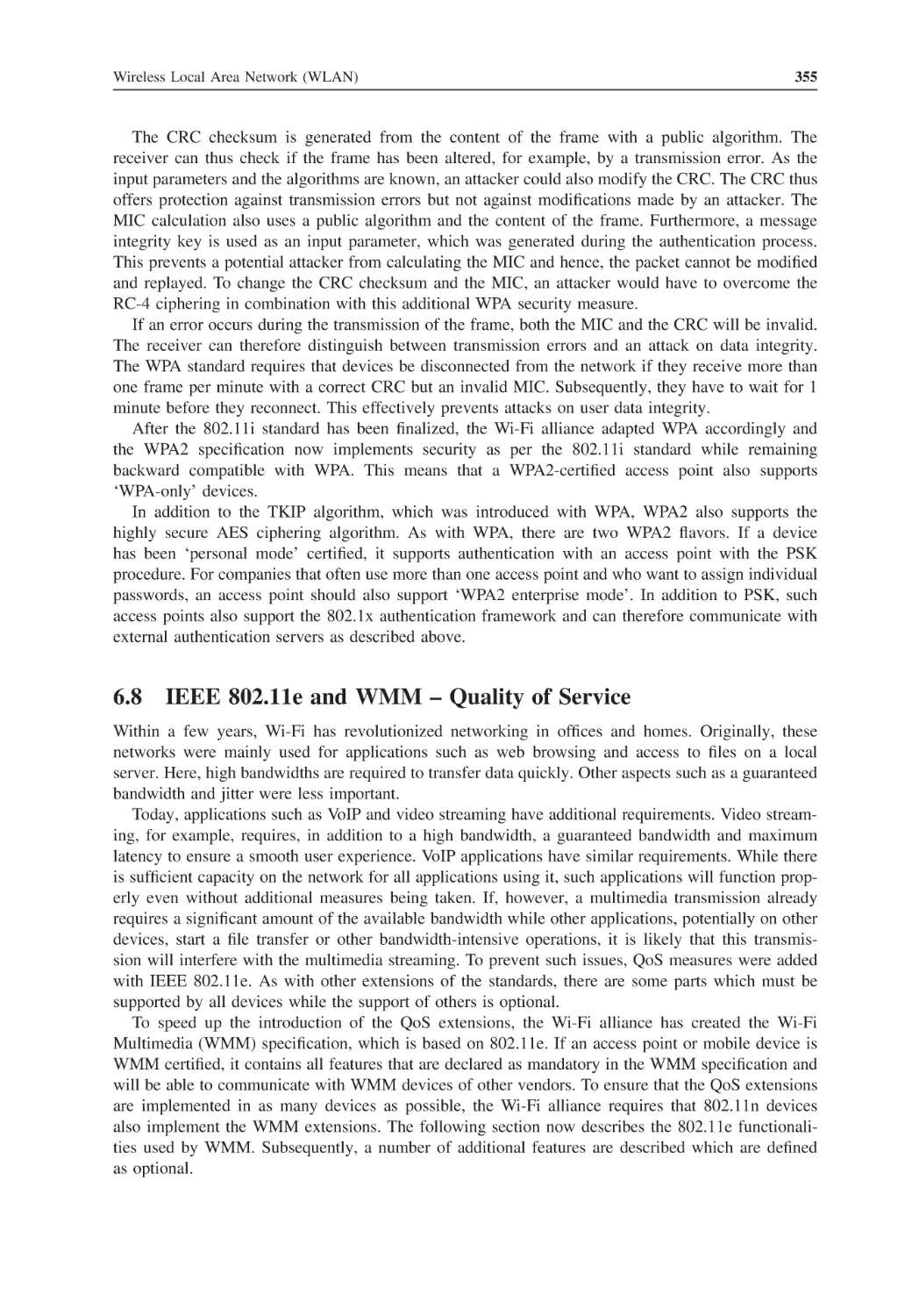
HSDPA Channels
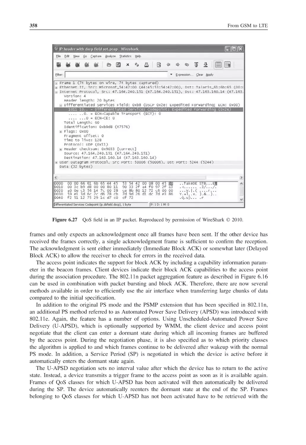
3.10.2
Shorter Delay Times and Hybrid ARQ (HARQ)
3.10.3
Node-B Scheduling
3.10.4
Adaptive Modulation and Coding, Transmission Rates and Multicarrier
Operation
3.10.5
Establishment and Release of an HSDPA Connection
3.10.6
HSDPA Mobility Management
High-Speed Uplink Packet Access (HSUPA)
3.11.1
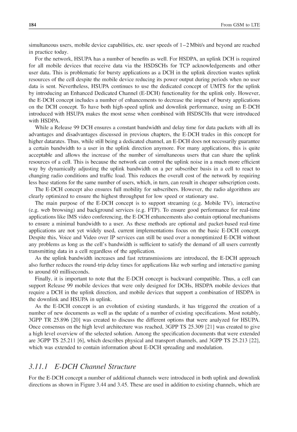
E-DCH Channel Structure
3.11.2
The E-DCH Protocol Stack and Functionality
3.11.3
E-DCH Scheduling
3.11.4
E-DCH Mobility
3.11.5
E-DCH-Capable Devices
Radio and Core Network Enhancements: CPC and One Tunnel
3.12.1
A New Uplink Control Channel Slot Format
3.12.2
CQI Reporting Reduction and DTX and DRX
vii
123
123
124
124
124
125
126
126
130
130
131
133
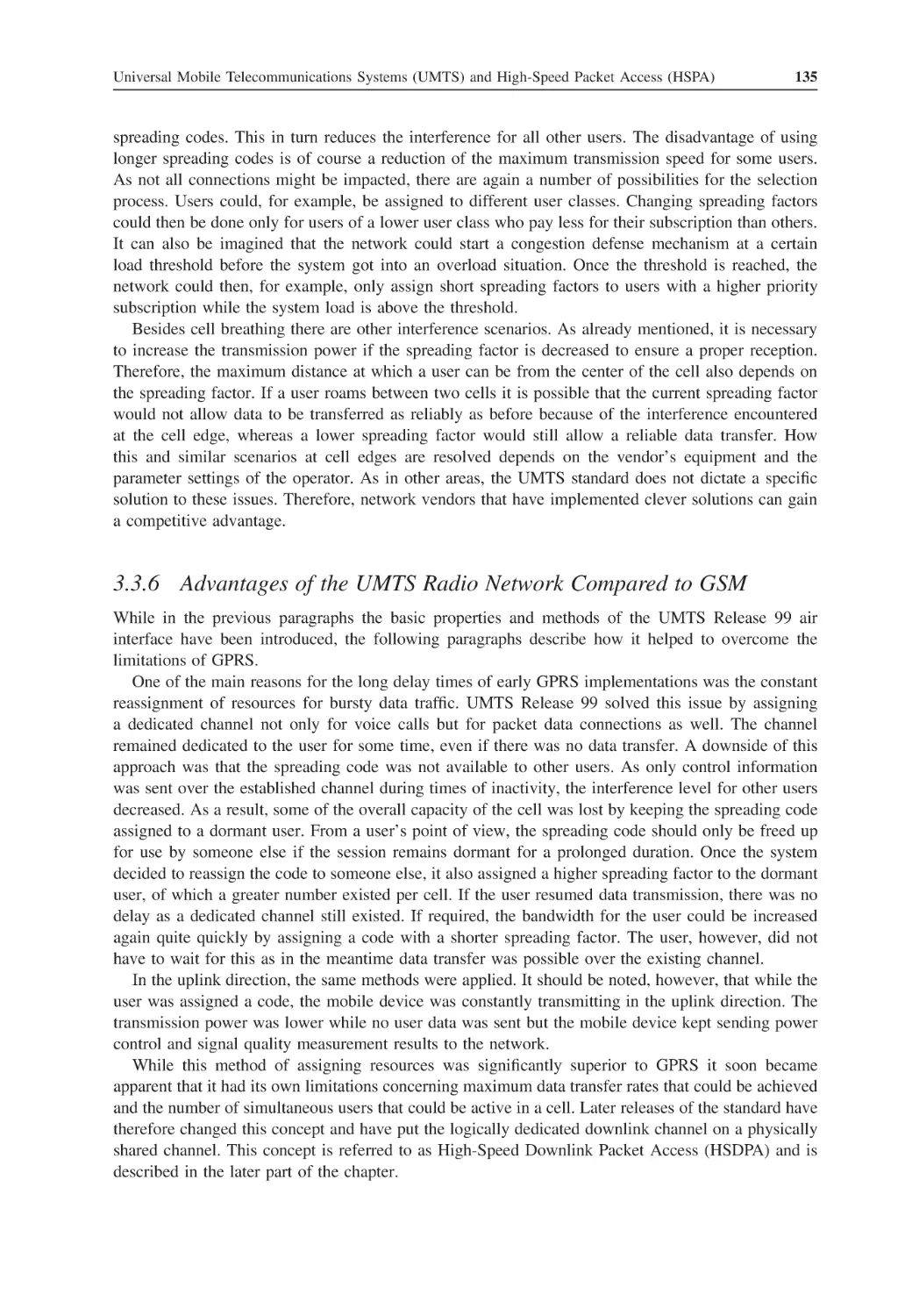
133
135
136
136
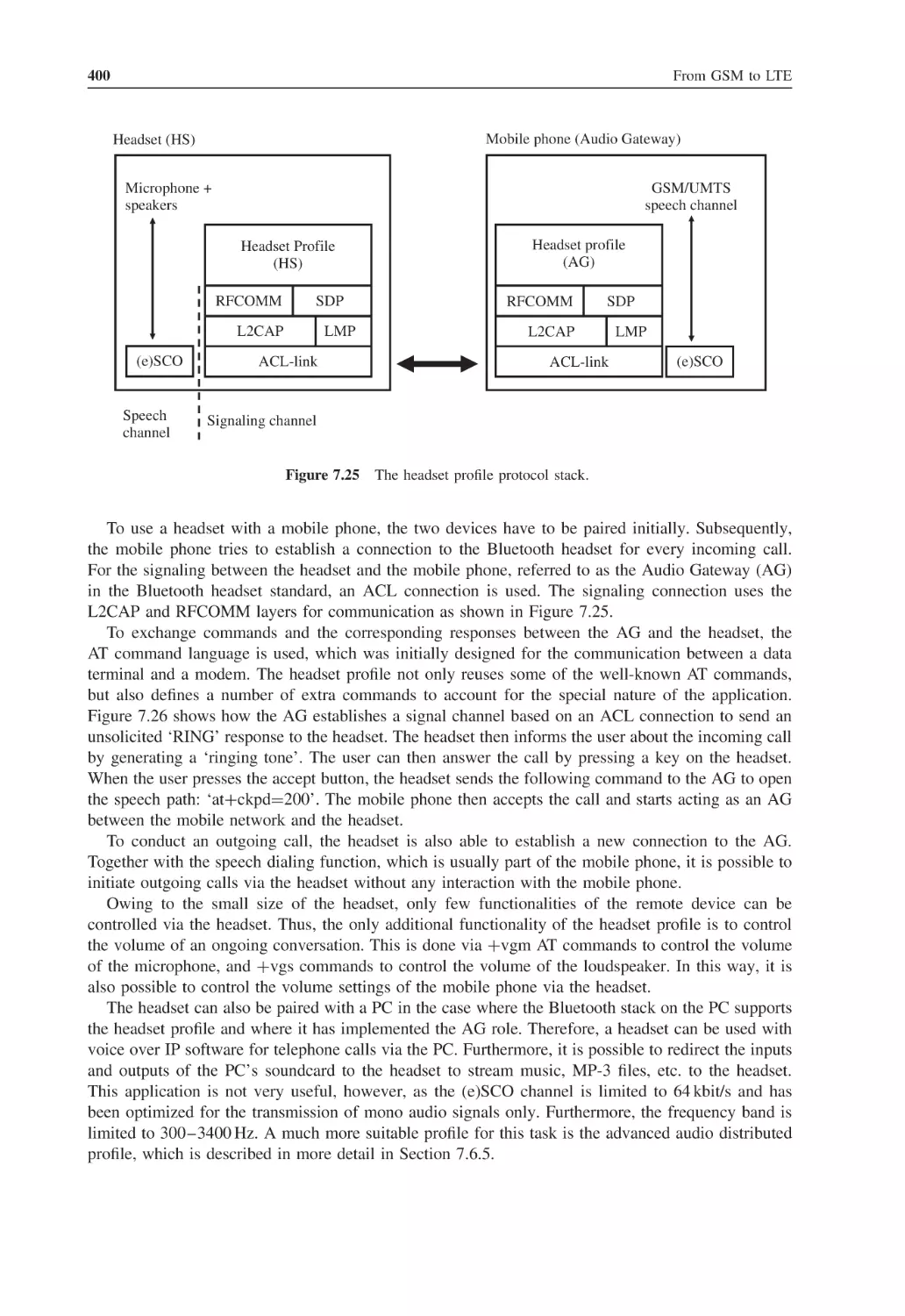
137
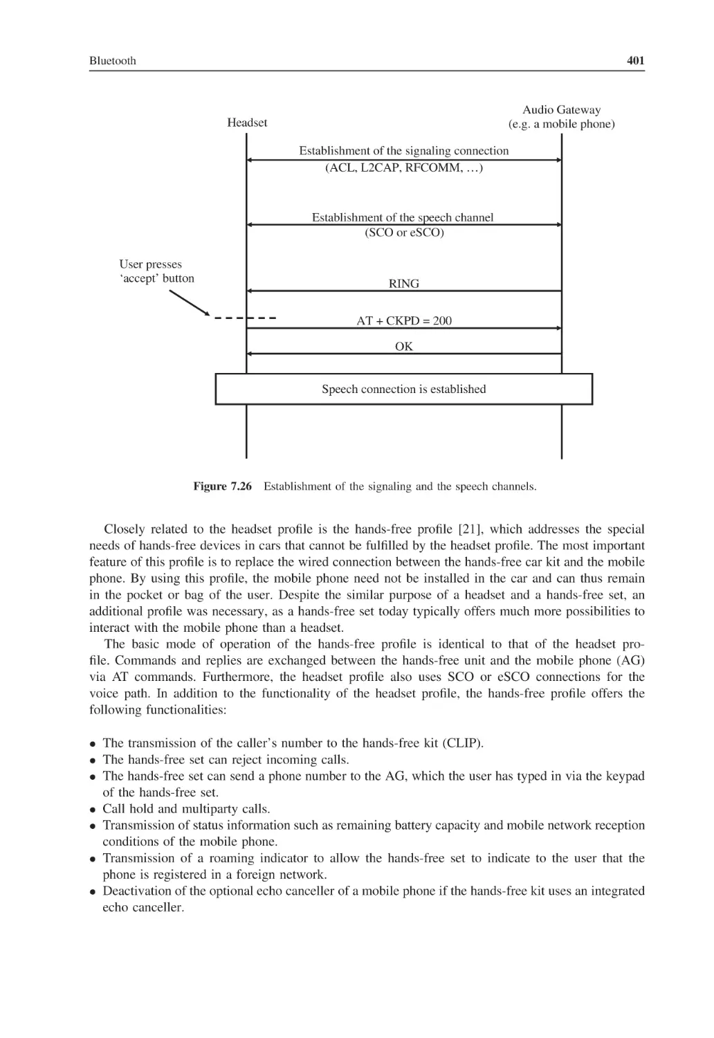
137
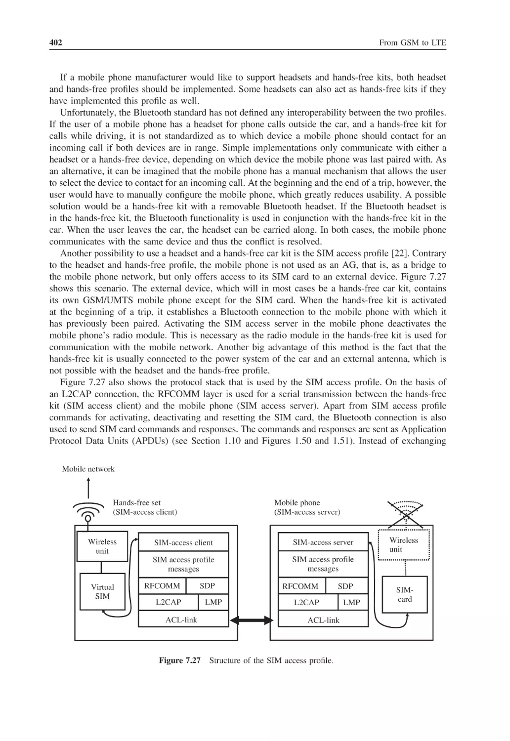
141
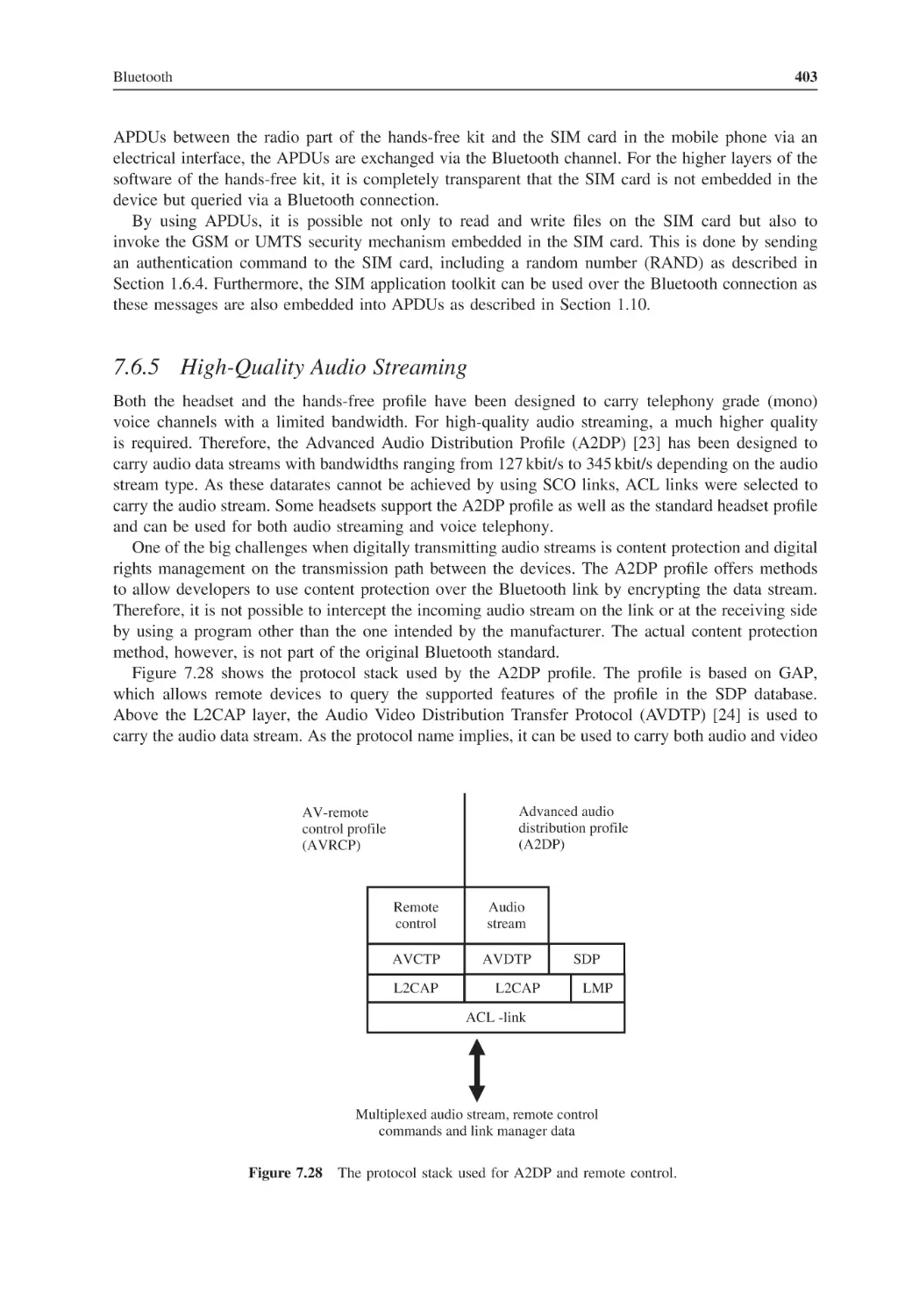
143
145
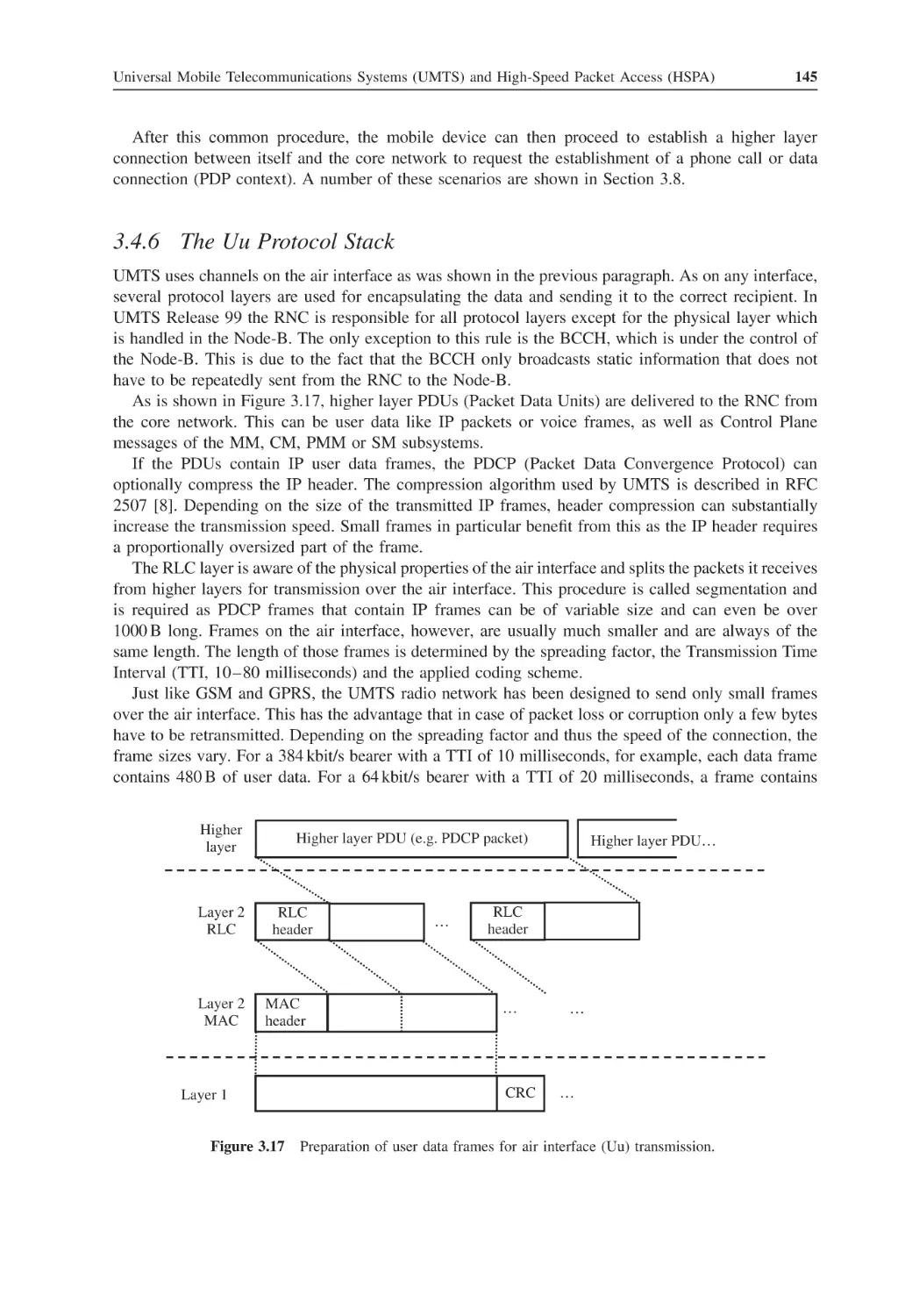
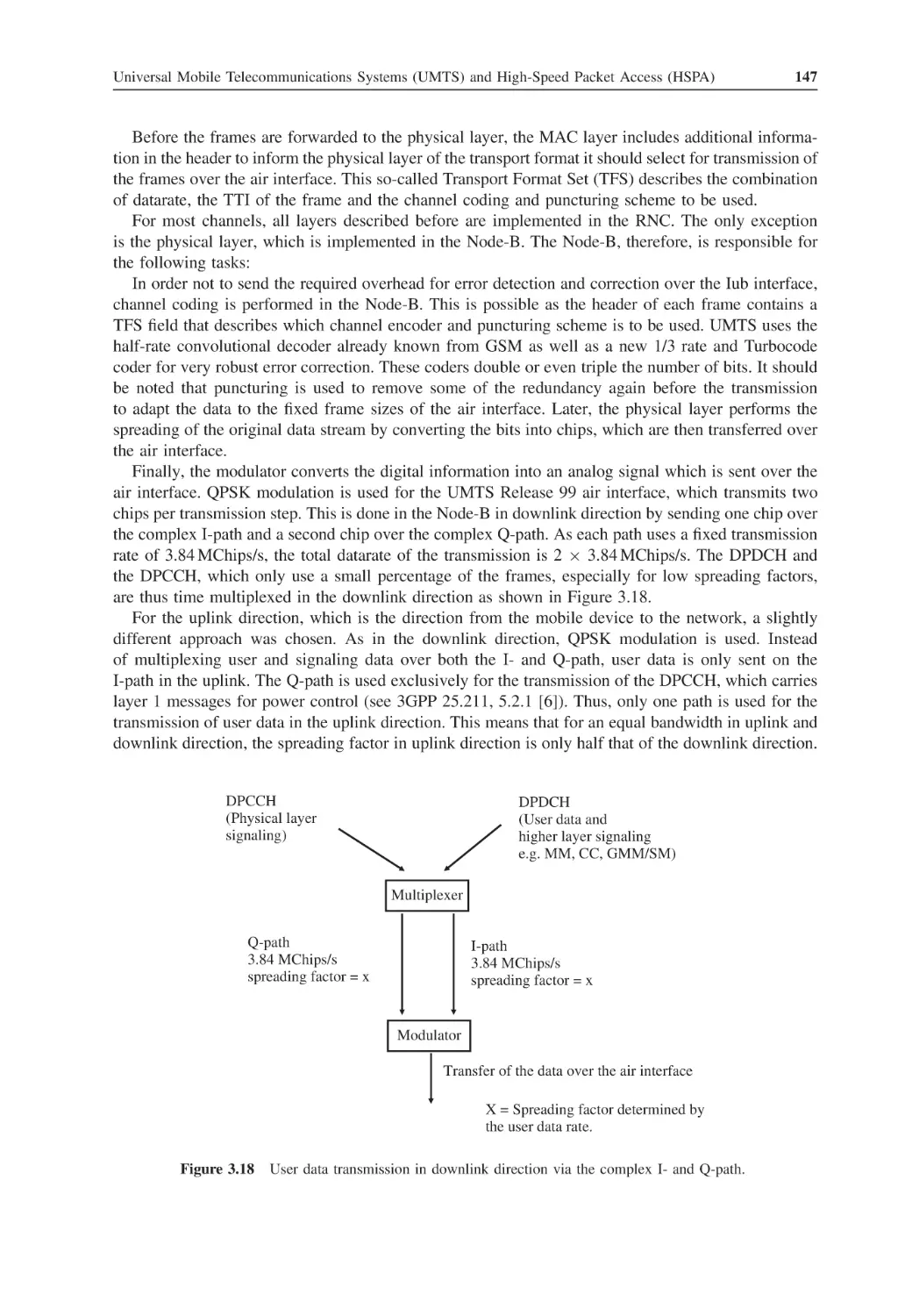
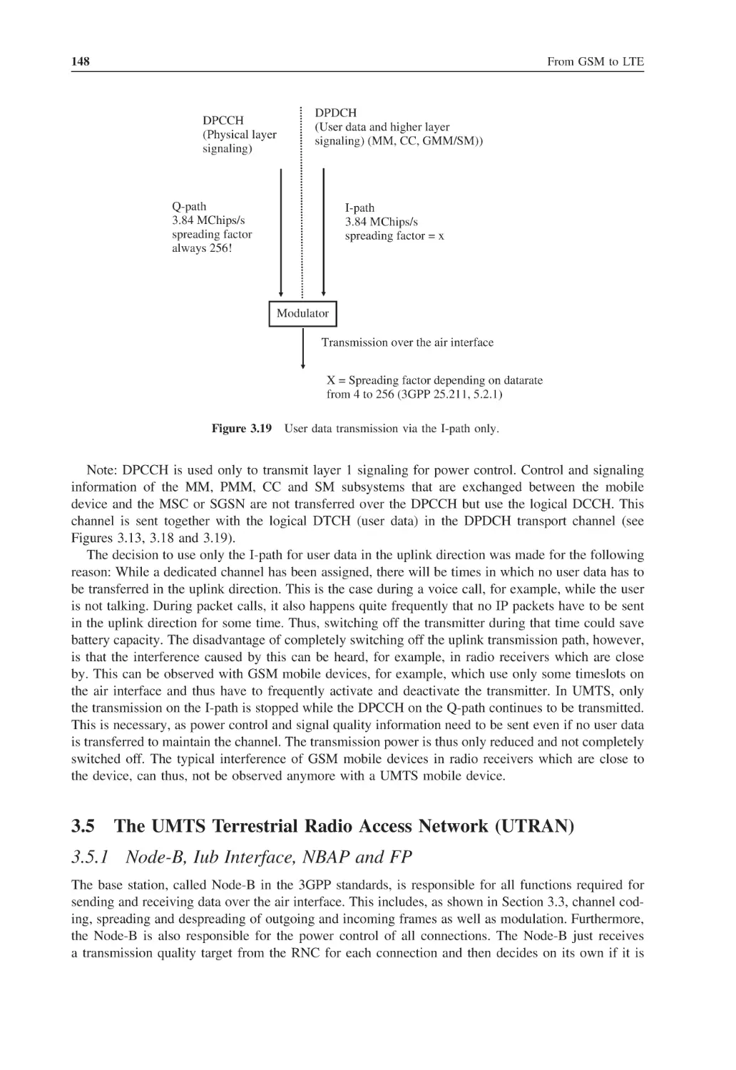
148
148
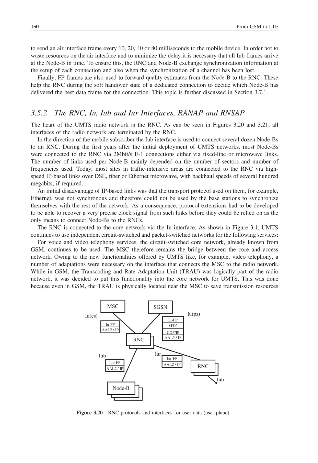
150
154
154
158
159
159
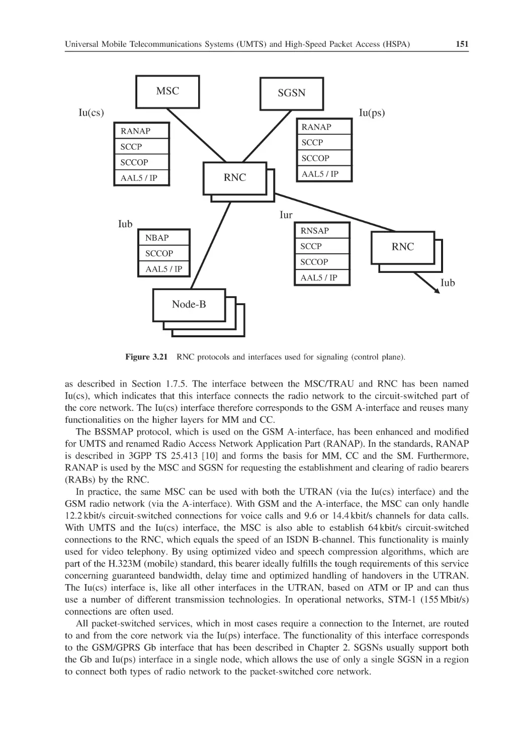
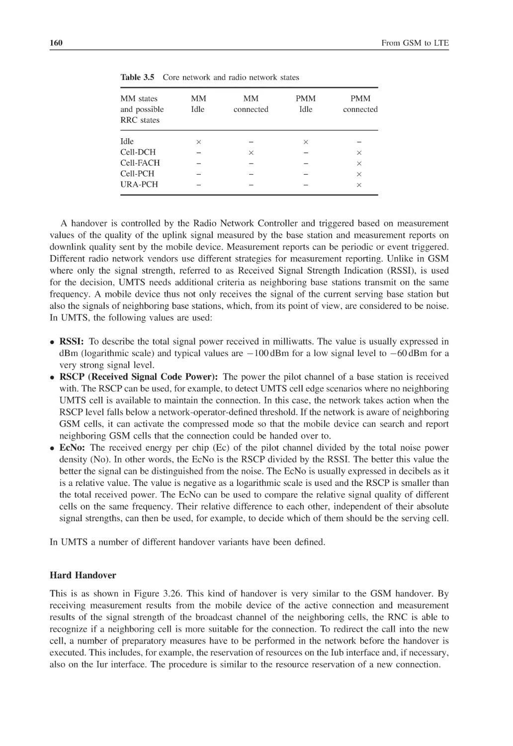
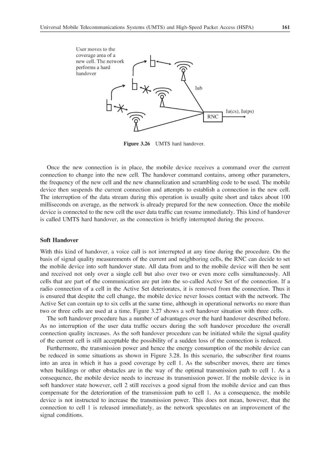
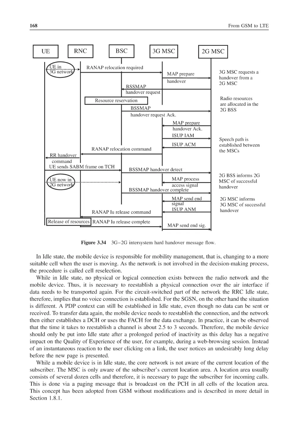
167
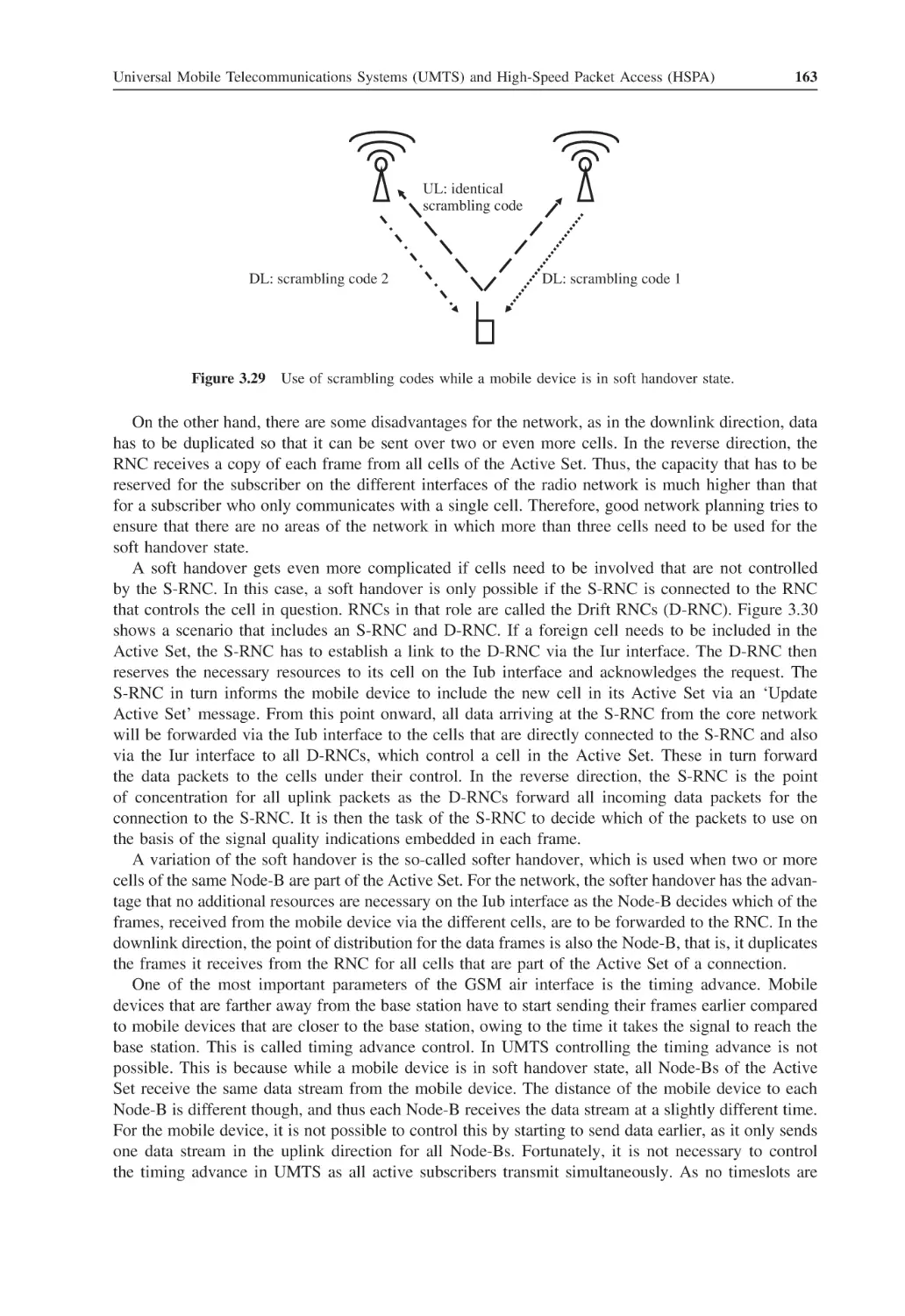
169
170
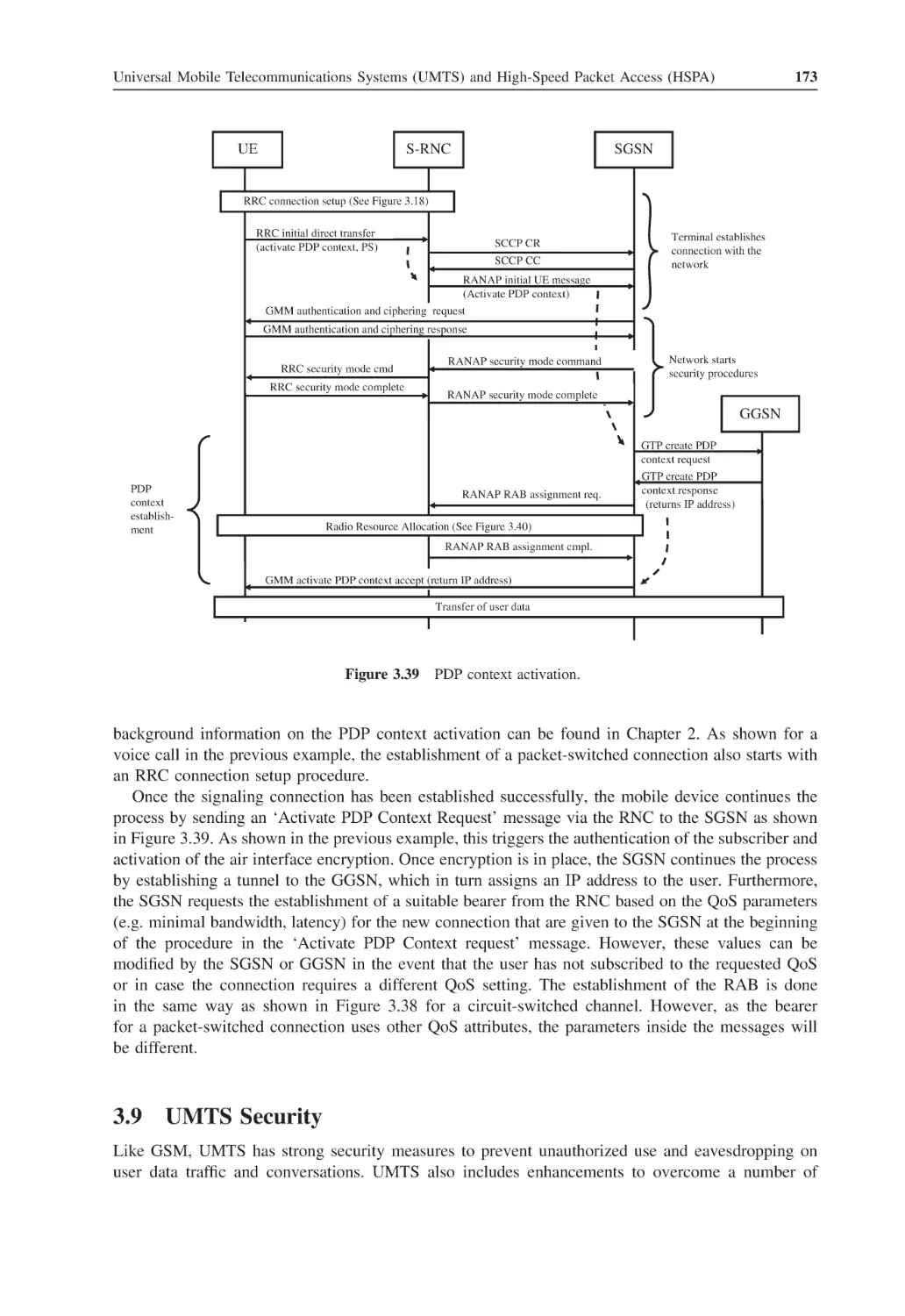
173
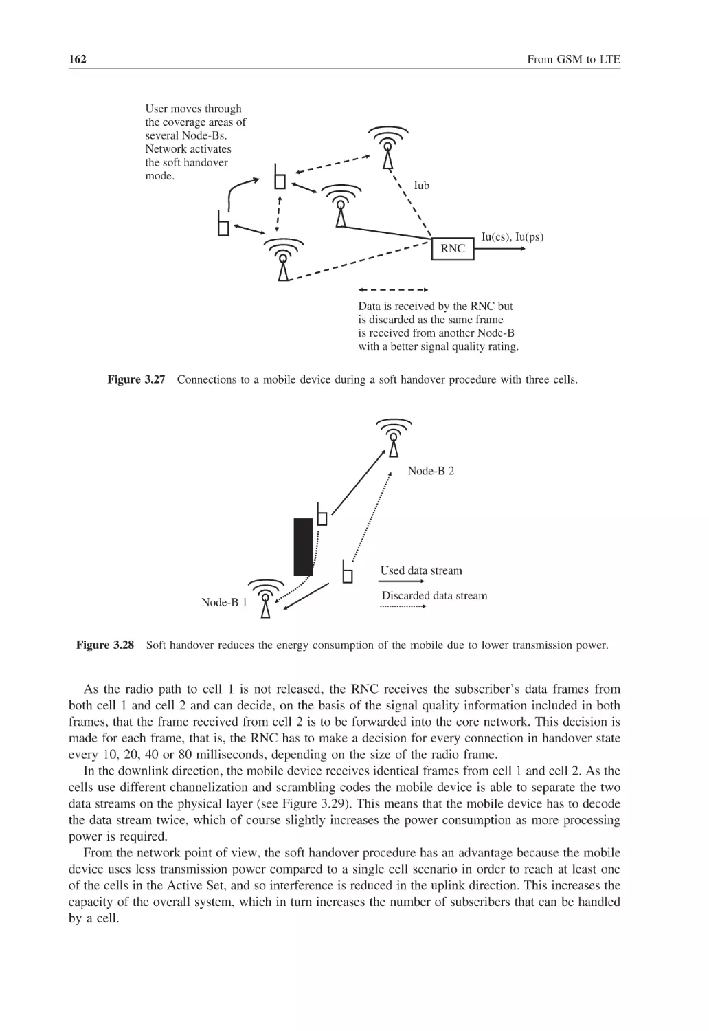
175
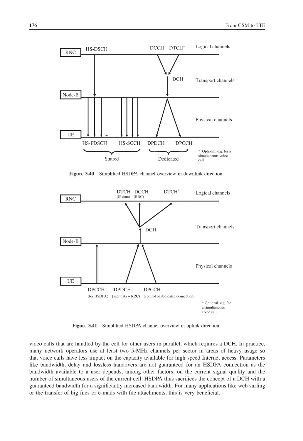
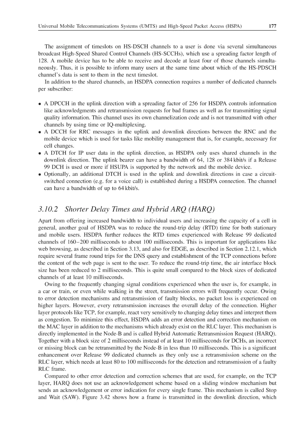
175
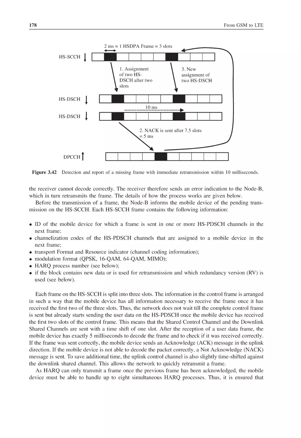
177
179
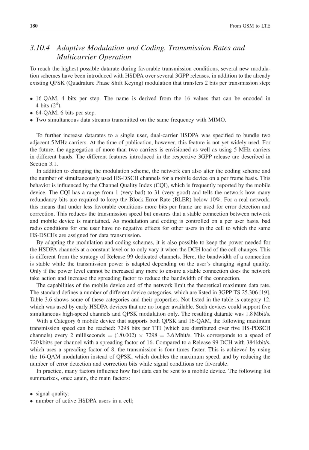
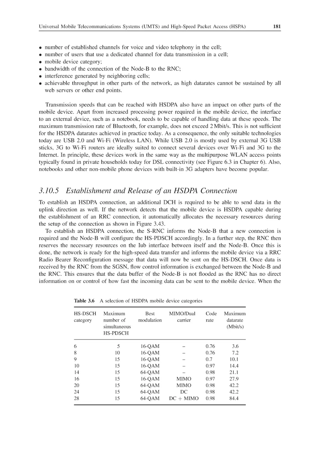
180
181
182
183
184
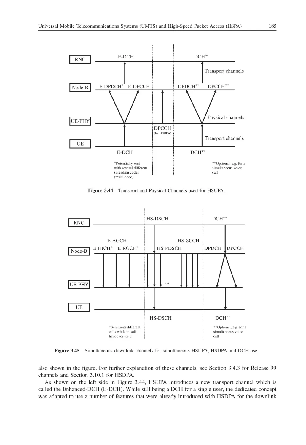
187
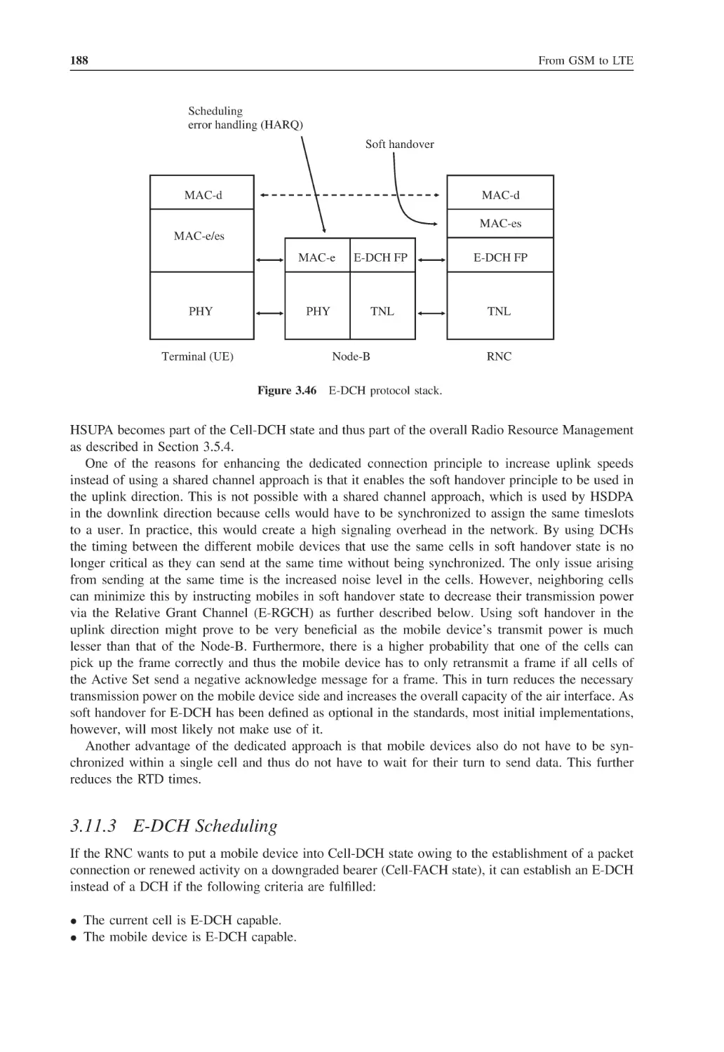
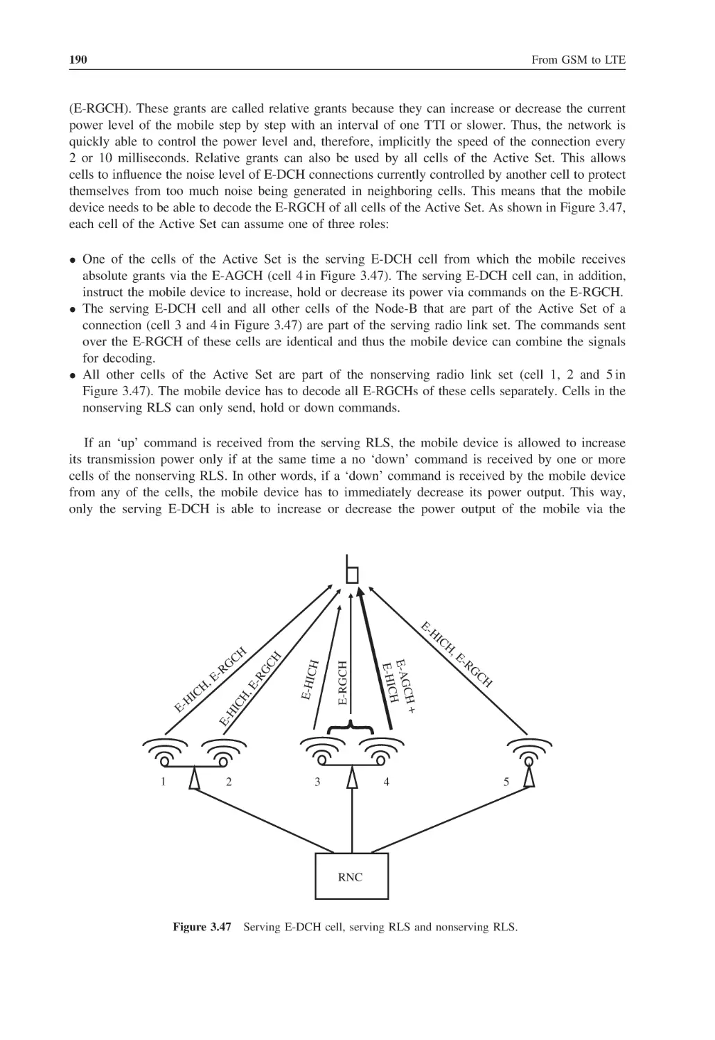
188
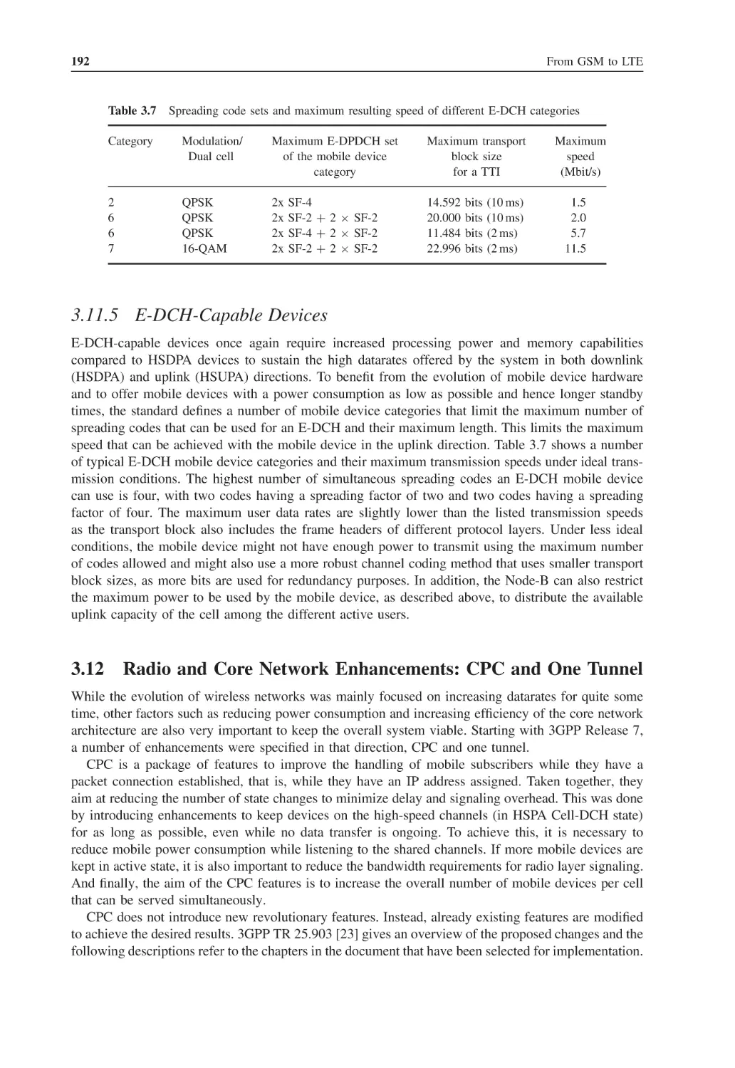
191
192
192
193
193
viii
3.13
3.14
3.15
4
4.1
4.2
4.3
4.4
4.5
4.6
4.7
4.8
4.9
Contents
3.12.3
HS-SCCH Discontinuous Reception
3.12.4
HS-SCCH-less Operation
3.12.5
Enhanced Cell-FACH and Cell-/URA-PCH States
3.12.6
Radio Network Enhancement: One Tunnel
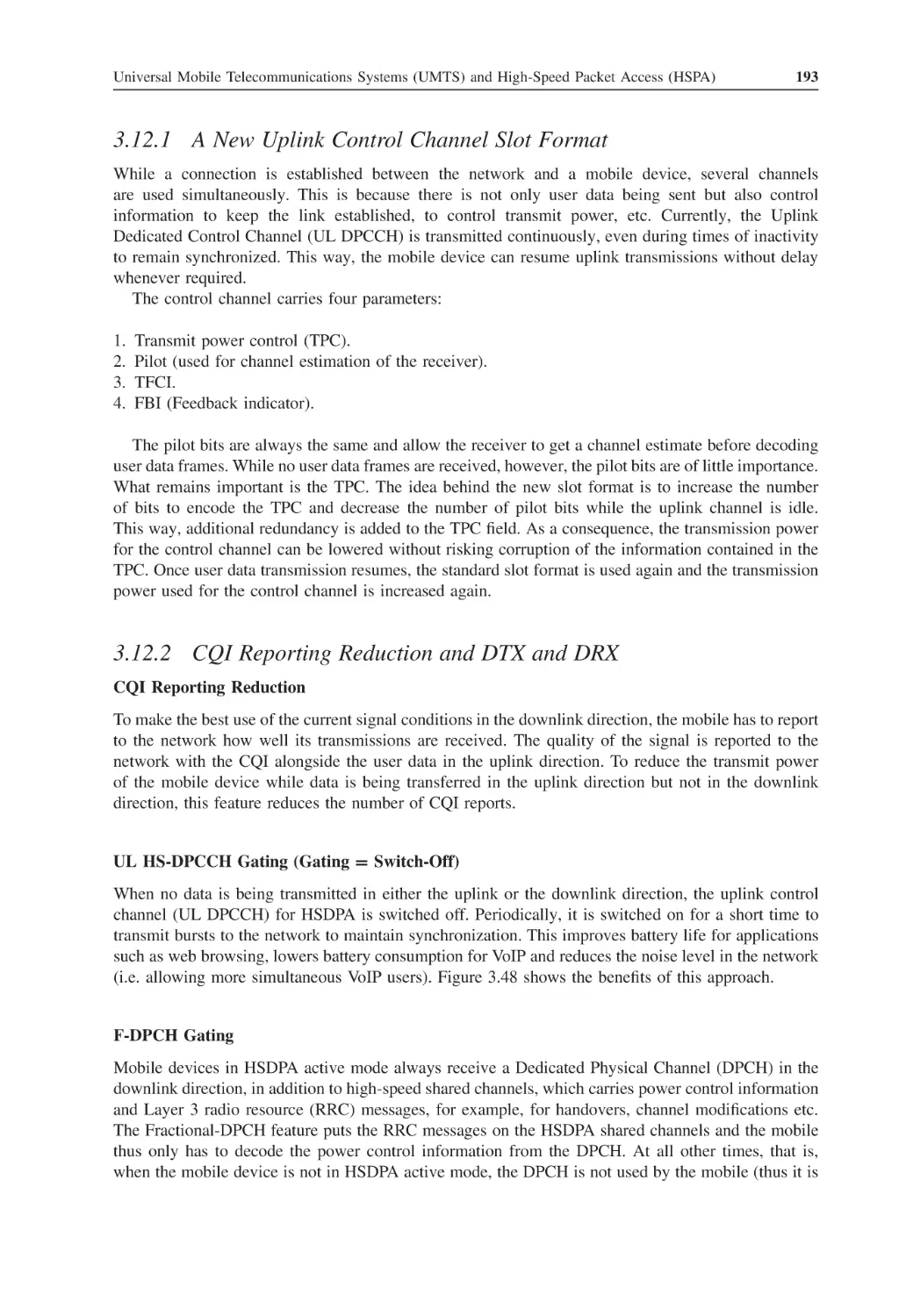
HSPA Performance in Practice
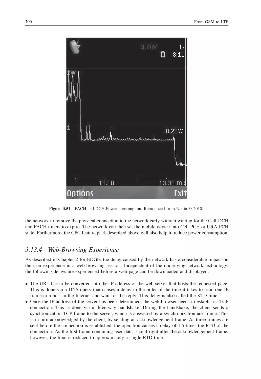
3.13.1
Throughput in Practice
3.13.2
Radio Resource State Management
3.13.3
Power Consumption
3.13.4
Web-Browsing Experience
UMTS and CDMA2000
Questions
References
194
194
195
196
197
198
198
199
200
201
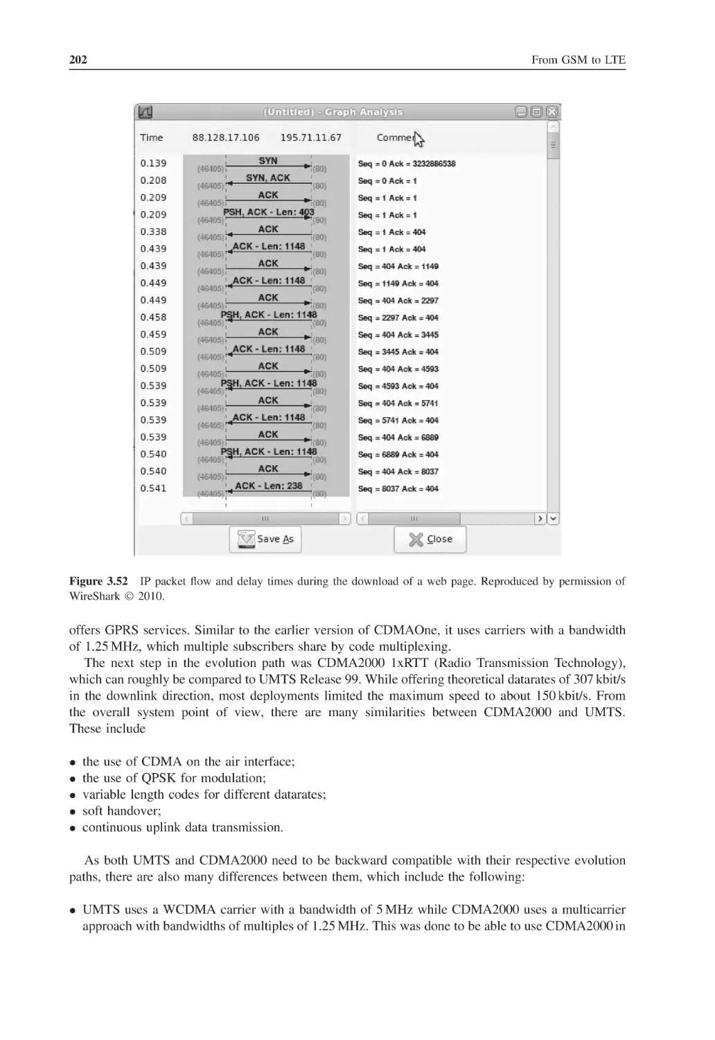
203
204
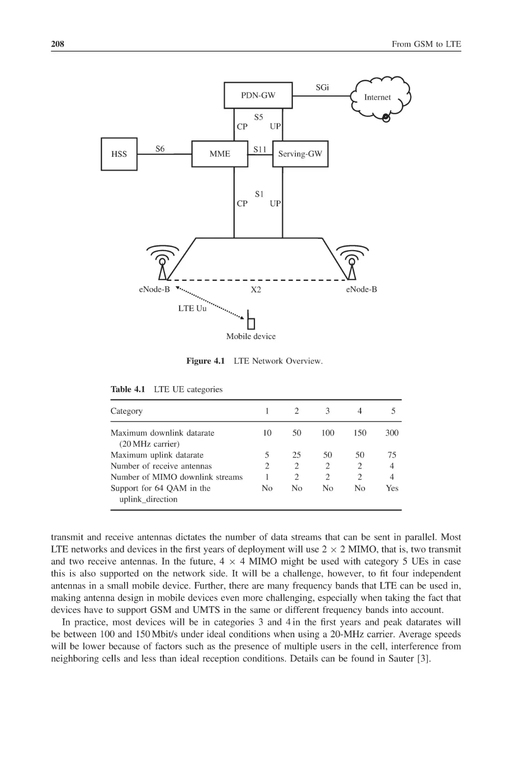
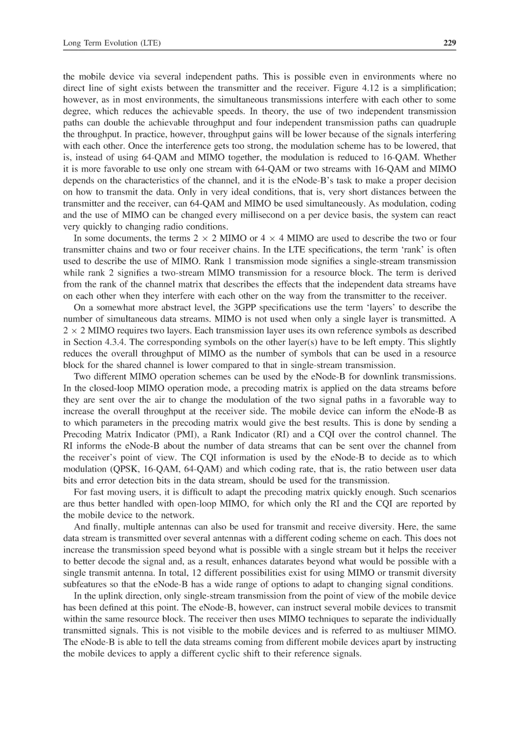
Long Term Evolution (LTE)
Introduction and Overview
Network Architecture and Interfaces
4.2.1
LTE Mobile Devices and the LTE Uu Interface
4.2.2
The eNode-B and the S1 and X2 Interfaces
4.2.3
The Mobility Management Entity (MME)
4.2.4
The Serving Gateway (S-GW)
4.2.5
The PDN-Gateway
4.2.6
The Home Subscriber Server (HSS)
4.2.7
Billing, Prepaid and Quality of Service
FDD Air Interface and Radio Network
4.3.1
OFDMA for Downlink Transmission
4.3.2
SC-FDMA for Uplink Transmission
4.3.3
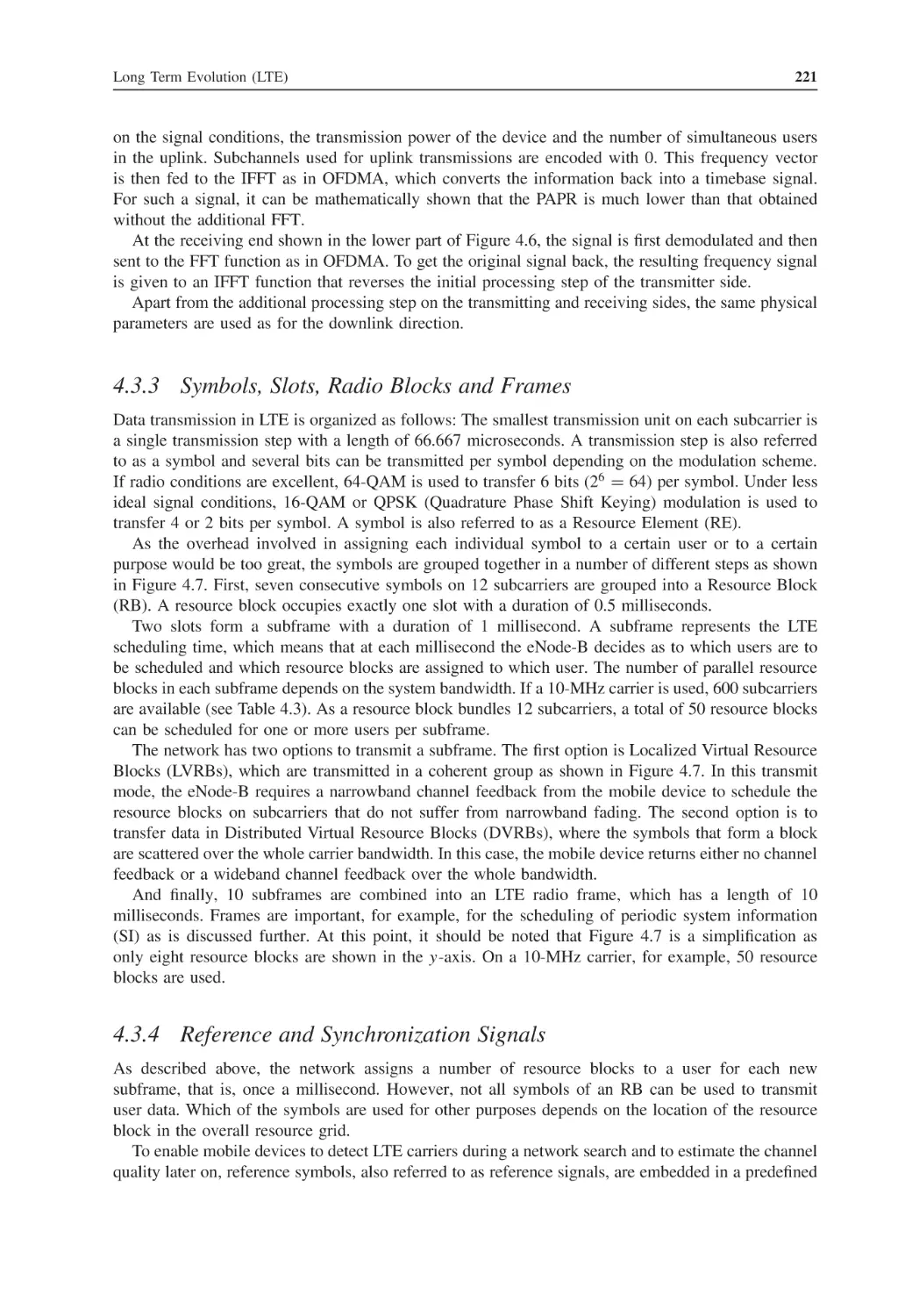
Symbols, Slots, Radio Blocks and Frames
4.3.4
Reference and Synchronization Signals
4.3.5
The LTE Channel Model in Downlink Direction
4.3.6
Downlink Management Channels
4.3.7
System Information Messages
4.3.8
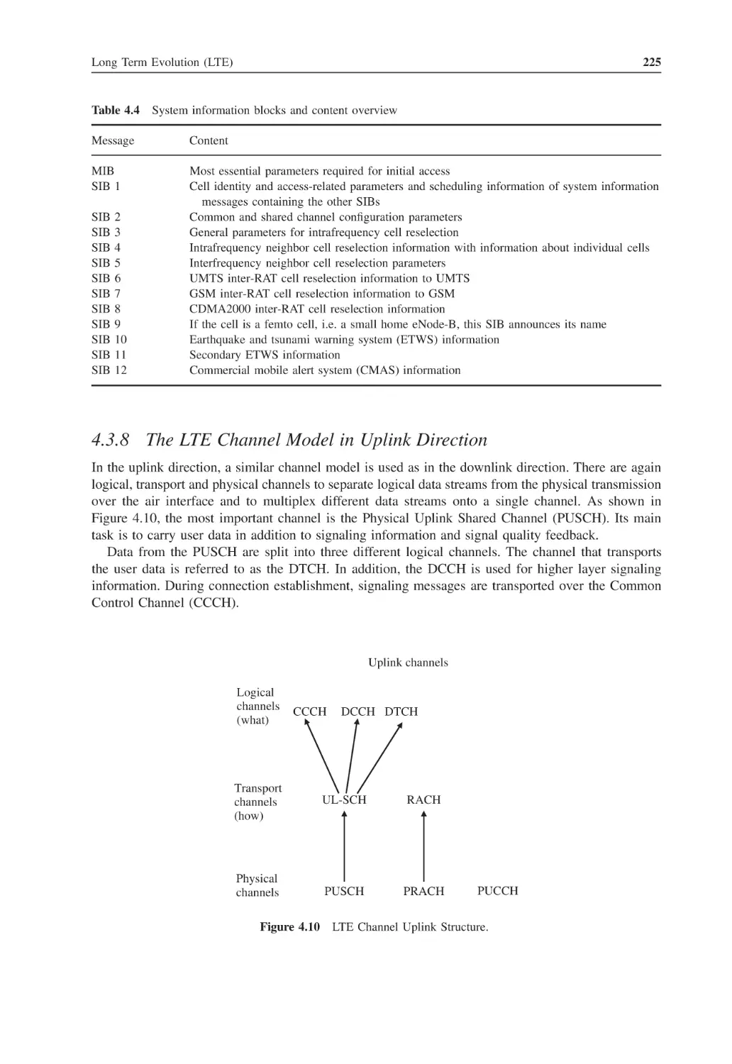
The LTE Channel Model in Uplink Direction
4.3.9
MIMO Transmission
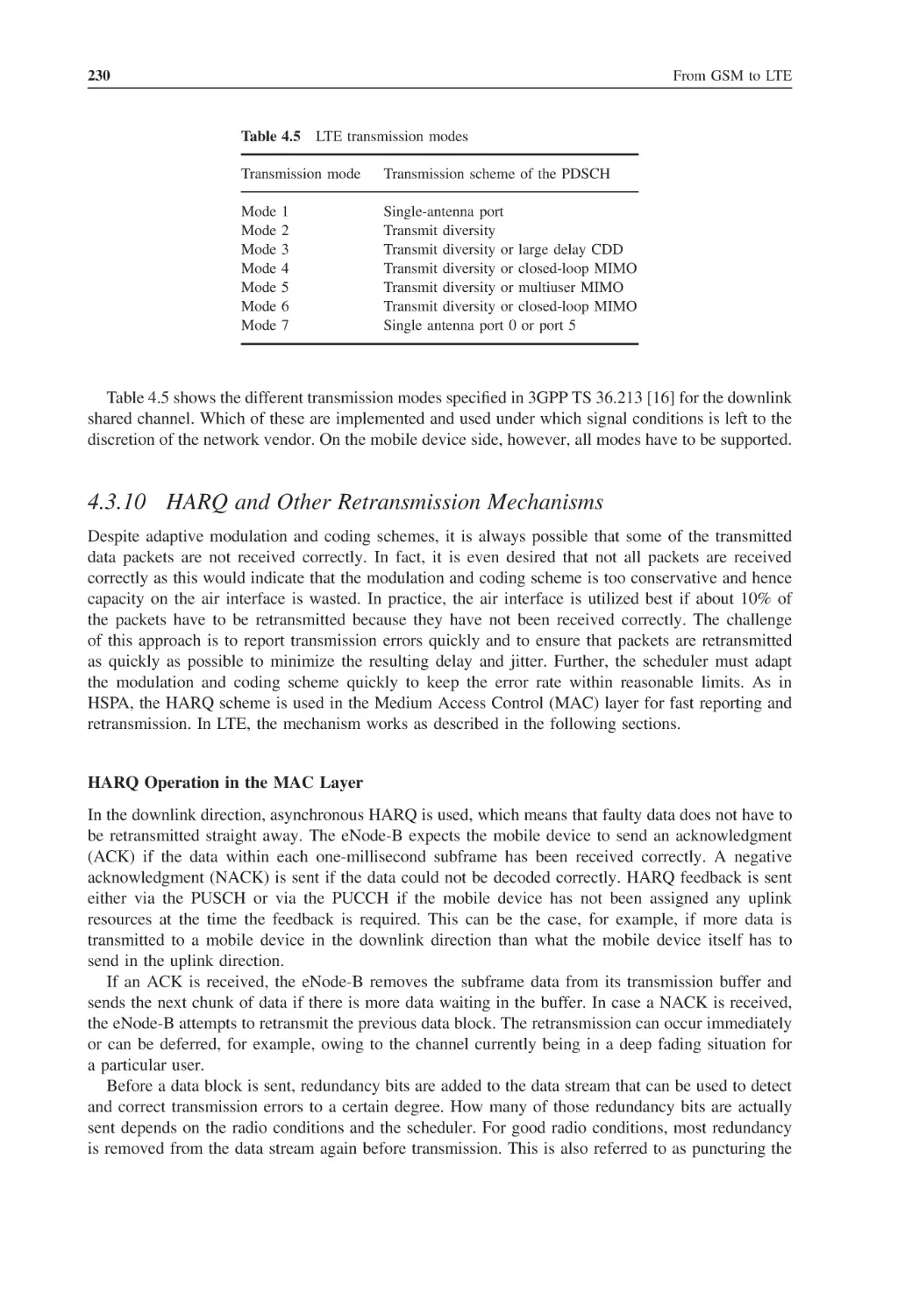
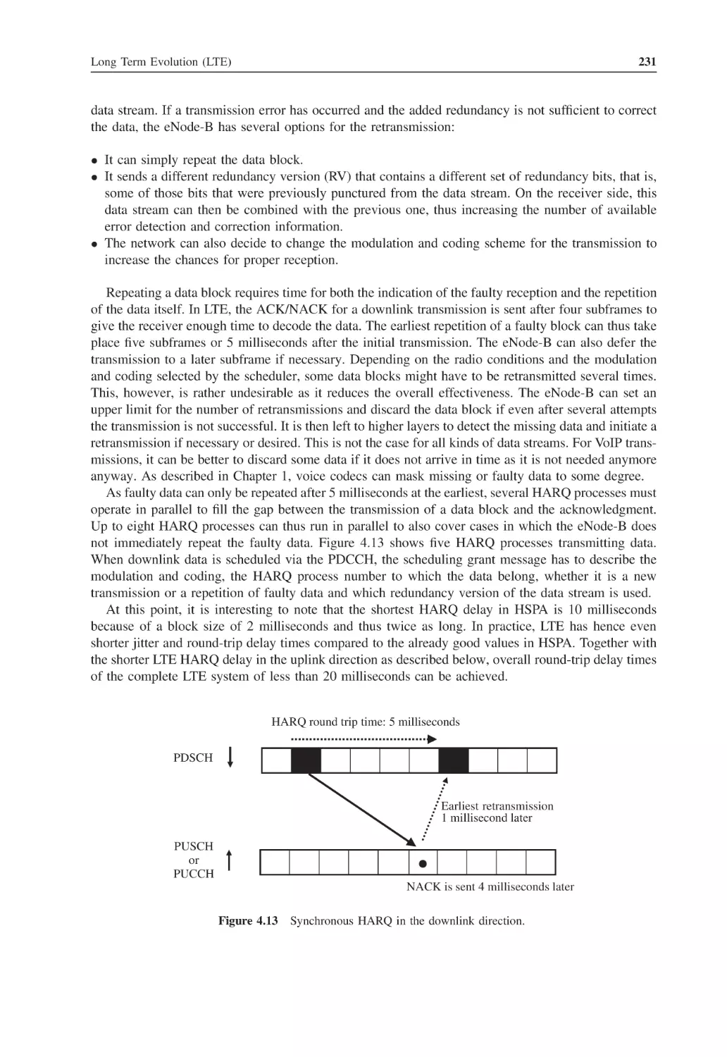
4.3.10
HARQ and Other Retransmission Mechanisms
4.3.11
PDCP Compression and Ciphering
4.3.12
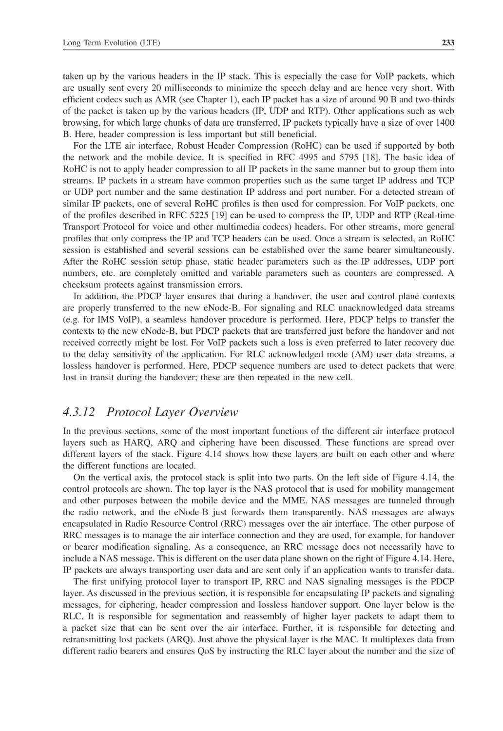
Protocol Layer Overview
TD-LTE Air Interface
Scheduling
4.5.1
Downlink Scheduling
4.5.2
Uplink Scheduling
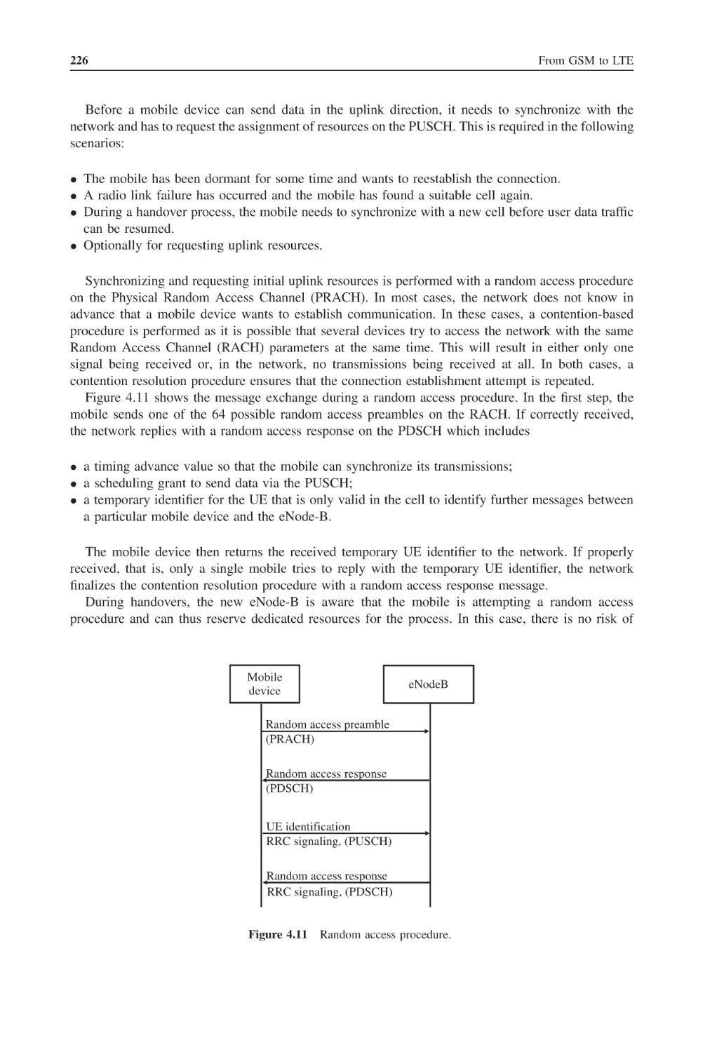
Basic Procedures
4.6.1
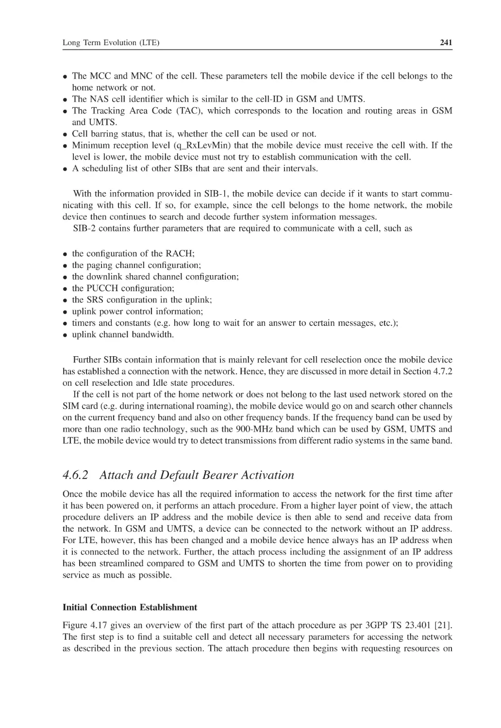
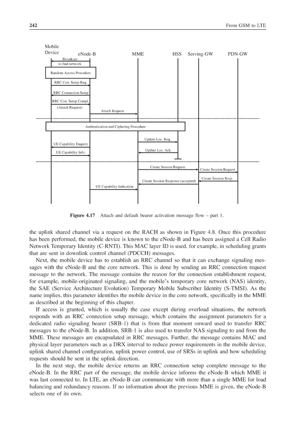
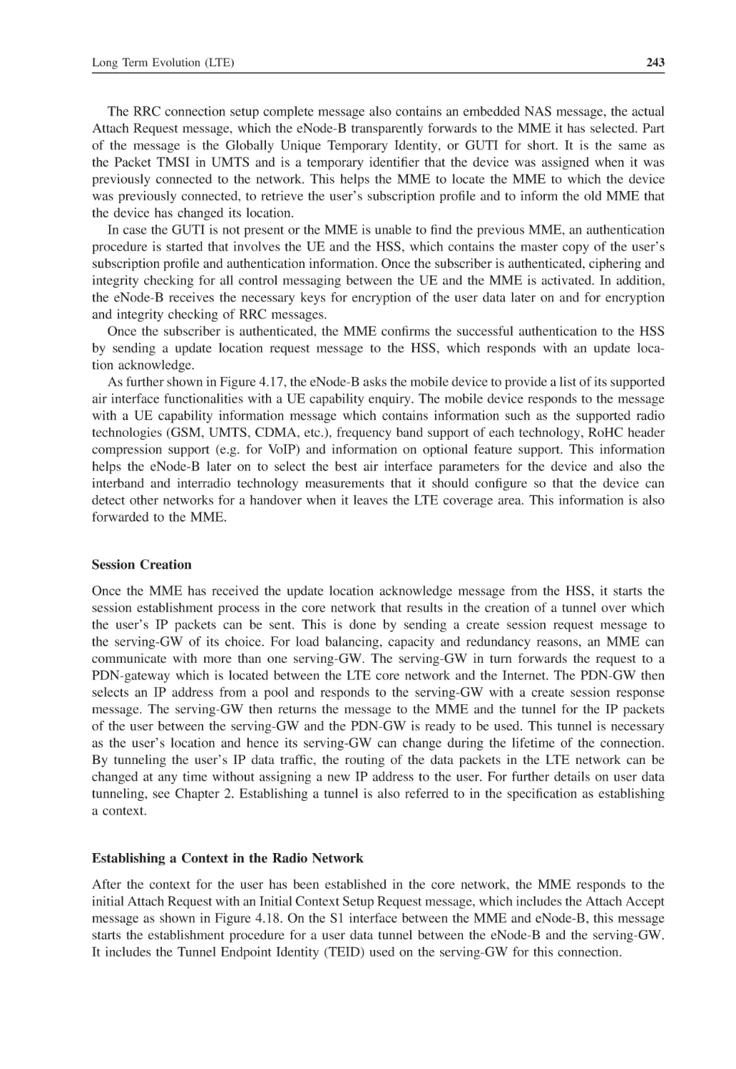
Cell Search
4.6.2
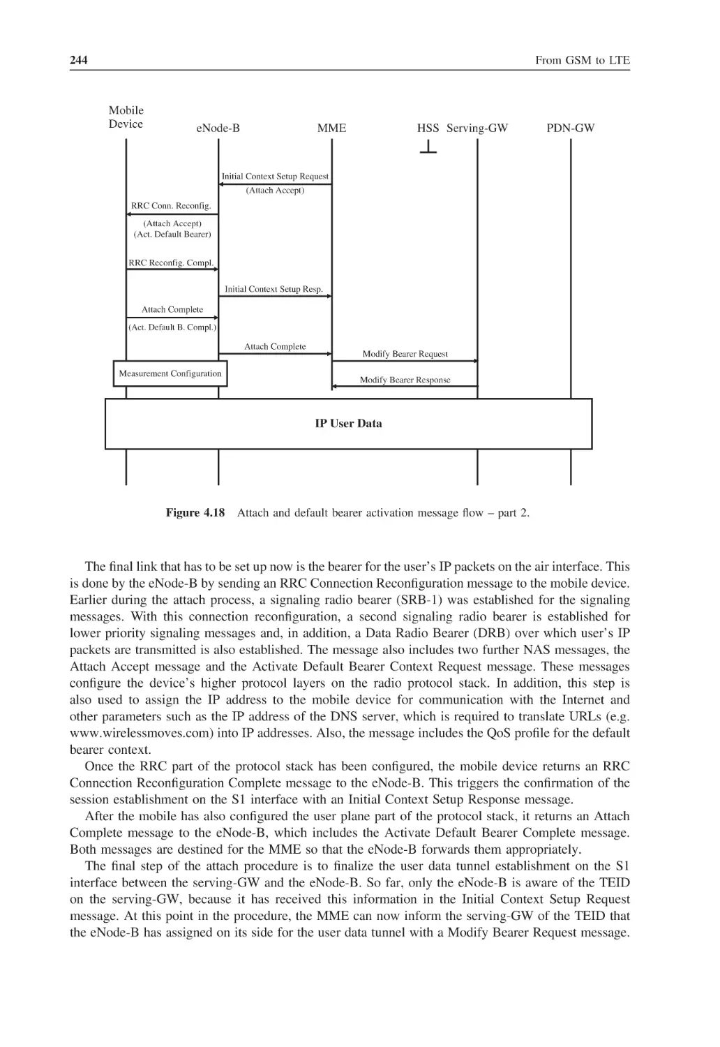
Attach and Default Bearer Activation
4.6.3
Handover Scenarios
4.6.4
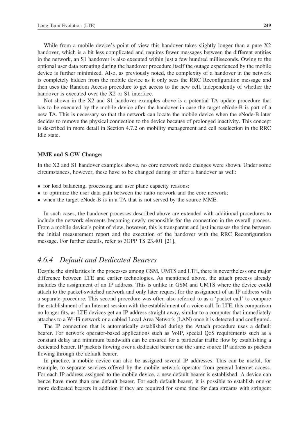
Default and Dedicated Bearers
Mobility Management and Power Optimization
4.7.1
Mobility Management in Connected State
4.7.2
Mobility Management in Idle State
LTE Security Architecture
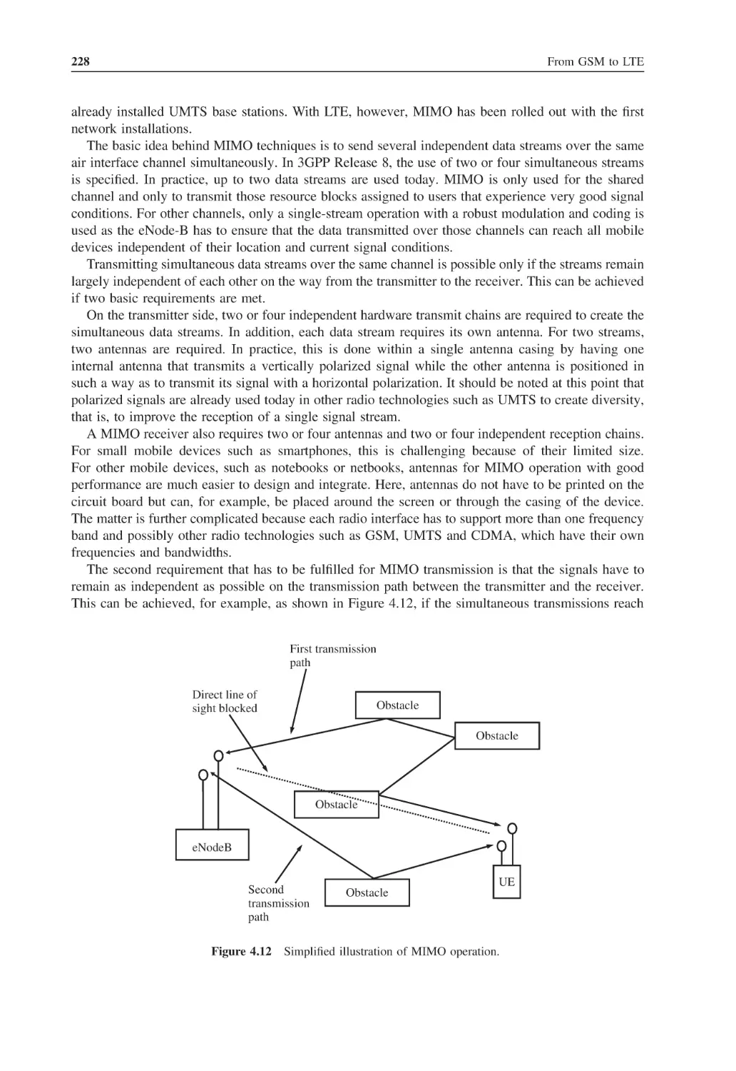
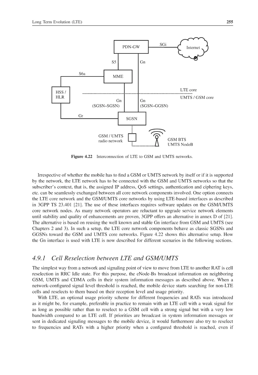
Interconnection with UMTS and GSM
205
205
207
207
209
212
214
214
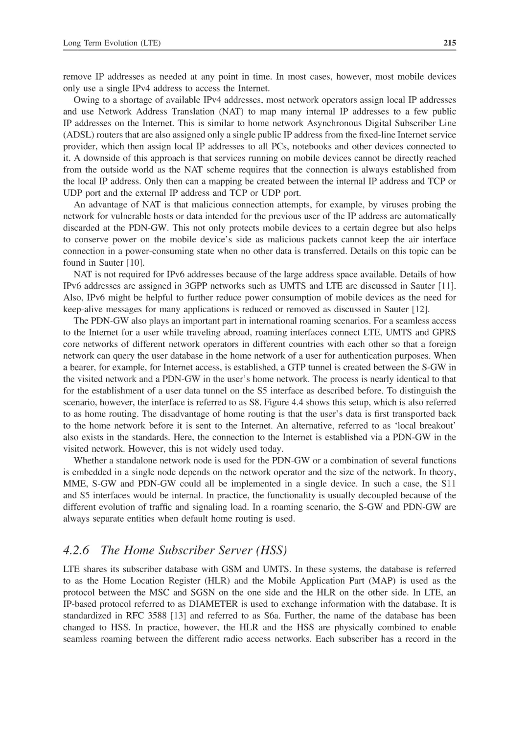
215
217
217
218
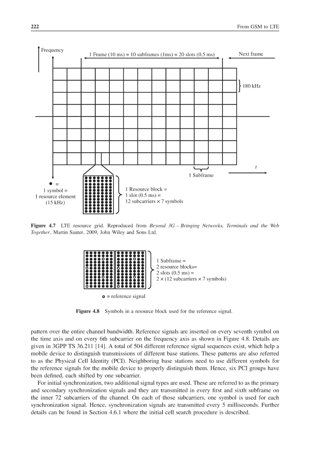
220
221
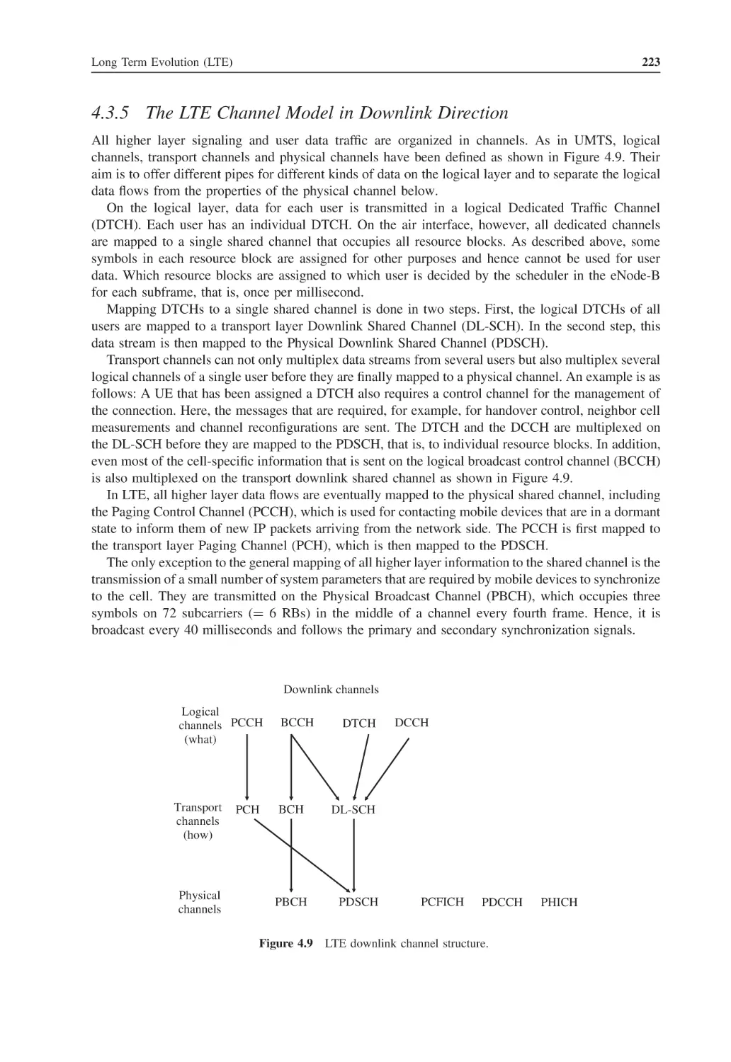
221
223
224
224
225
227
230
232
233
234
235
235
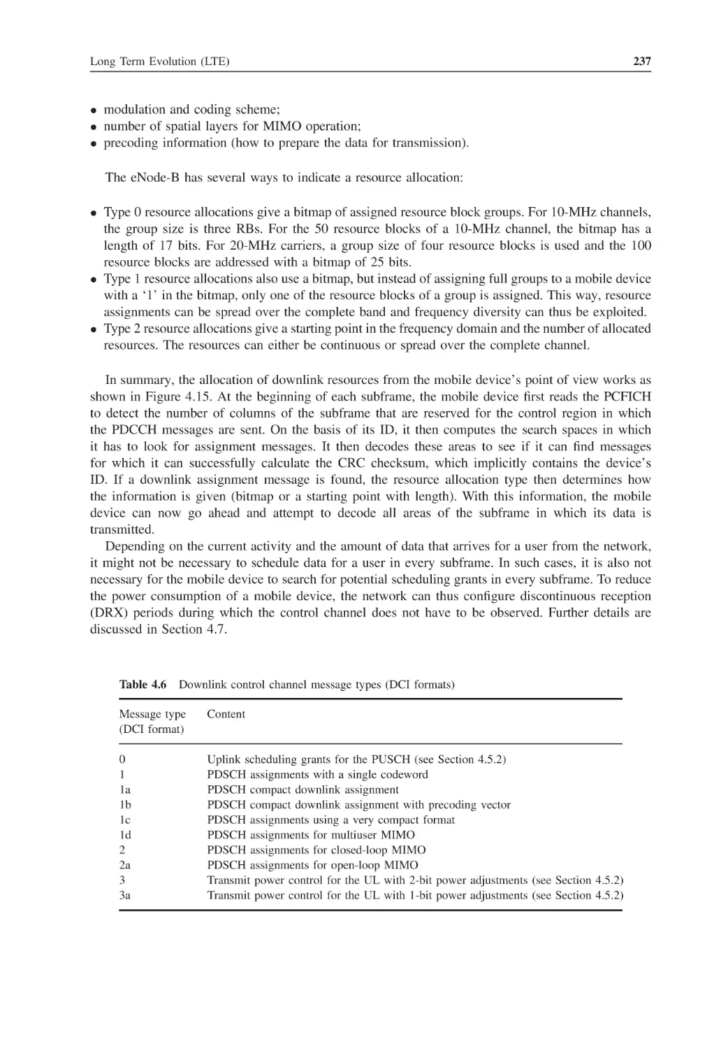
238
239
239
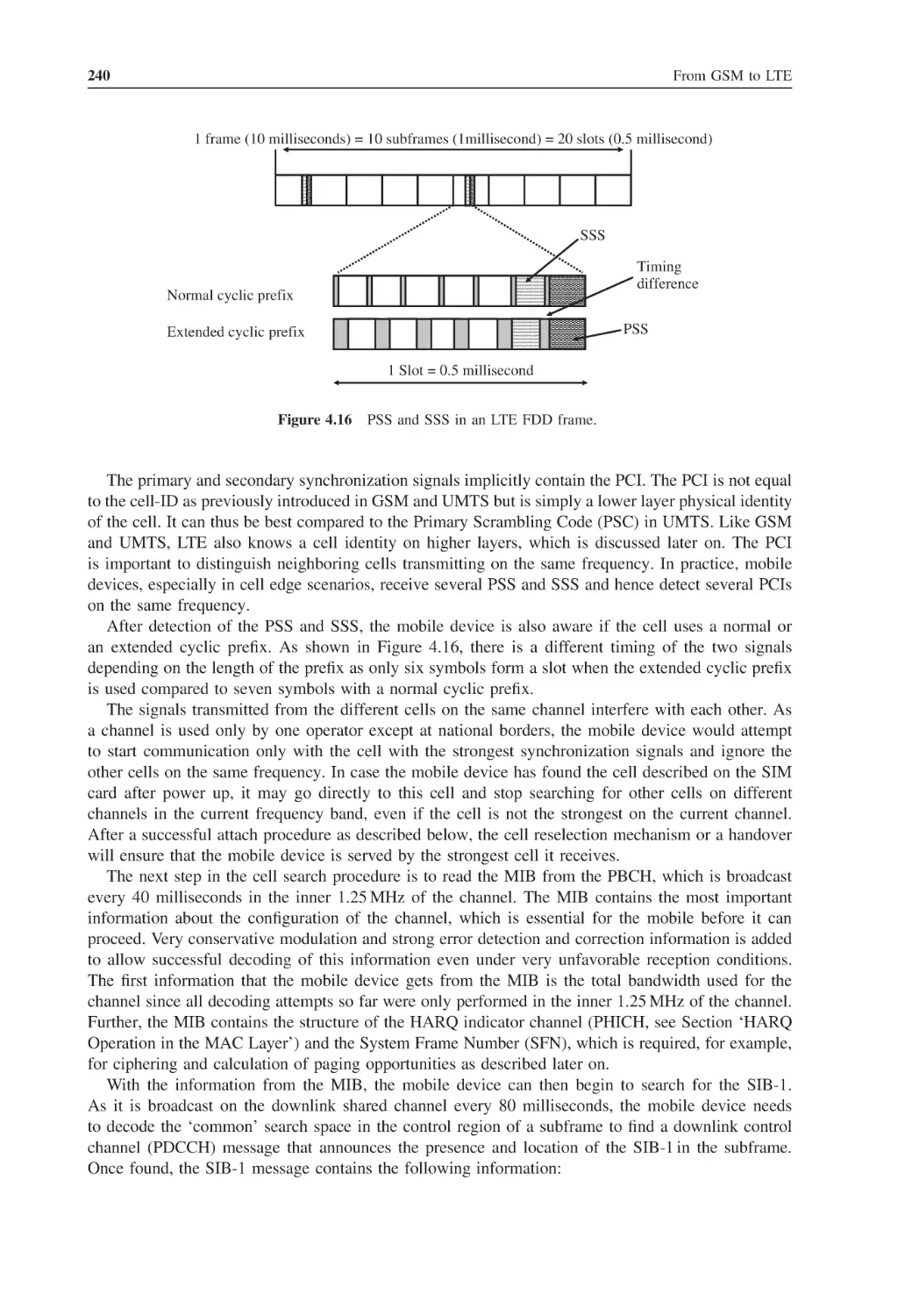
241
245
249
250
250
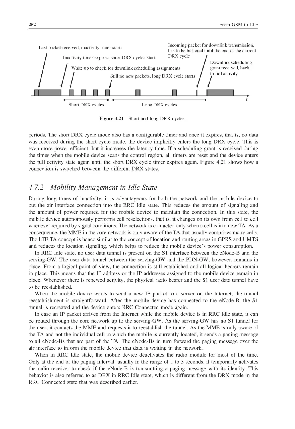
252
254
254
Contents
4.10
4.11
4.12
4.13
4.14
4.15
5
5.1
5.2
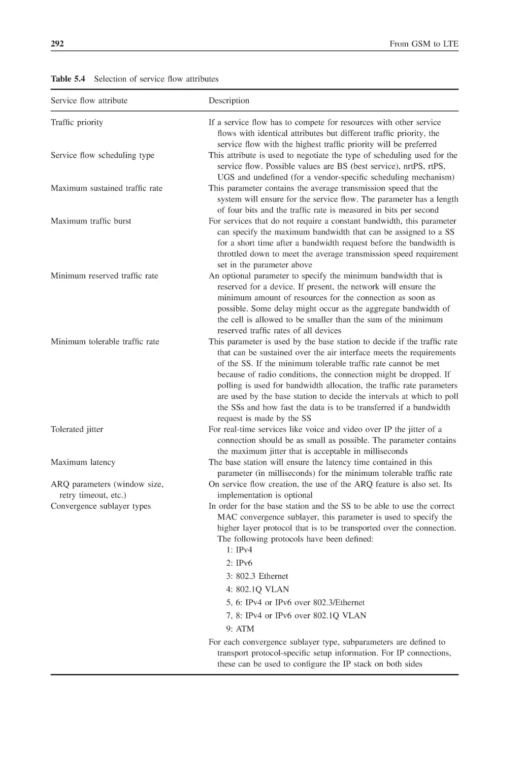
5.3
5.4
5.5
5.6
5.7
5.8
ix
4.9.1
Cell Reselection between LTE and GSM/UMTS
4.9.2
RRC Connection Release with Redirect between LTE and GSM/UMTS
4.9.3
Handover between LTE and GSM/UMTS
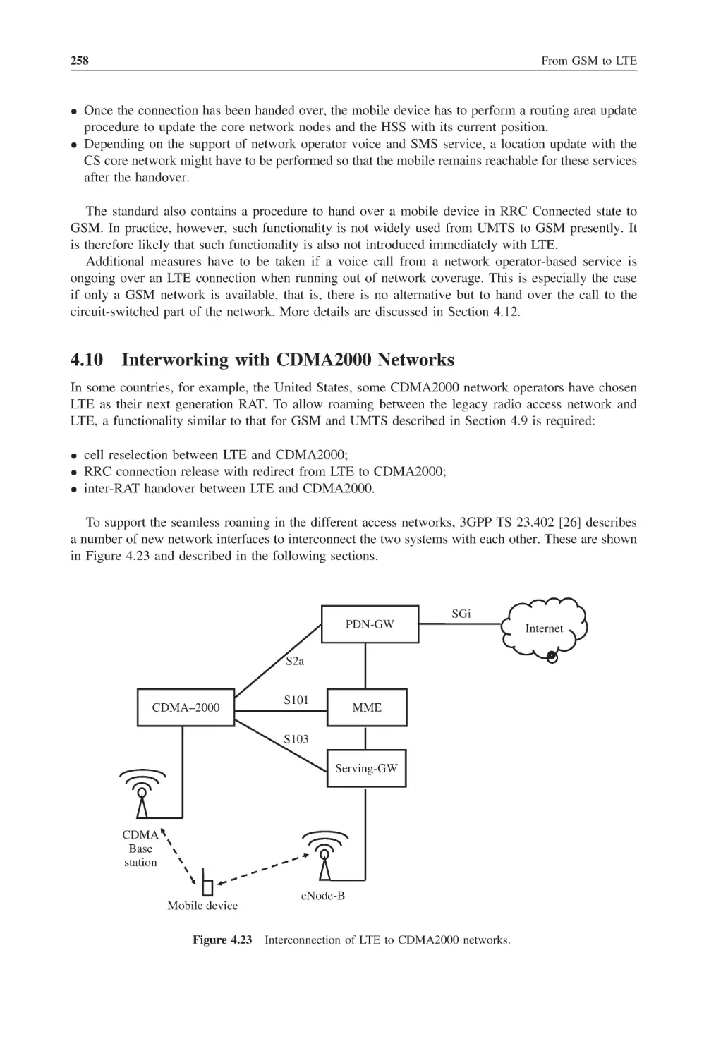
Interworking with CDMA2000 Networks
4.10.1
Cell Reselection between LTE and CDMA2000 Networks
4.10.2
RRC Connection Release with Redirect between LTE and CDMA2000
4.10.3
Handover between LTE and CDMA2000
Network Planning Aspects
4.11.1
Single Frequency Network
4.11.2
Cell Edge Performance
4.11.3
Self-Organizing Network Functionality
Voice and SMS over LTE
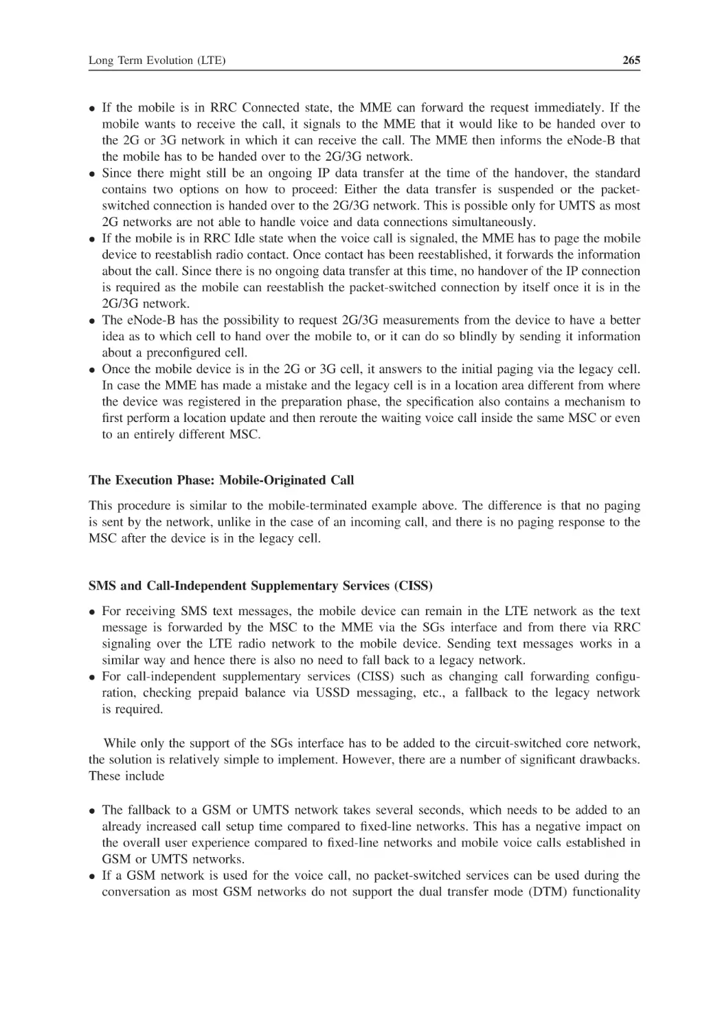
4.12.1
SMS over SGs
4.12.2
CS Fallback
4.12.3
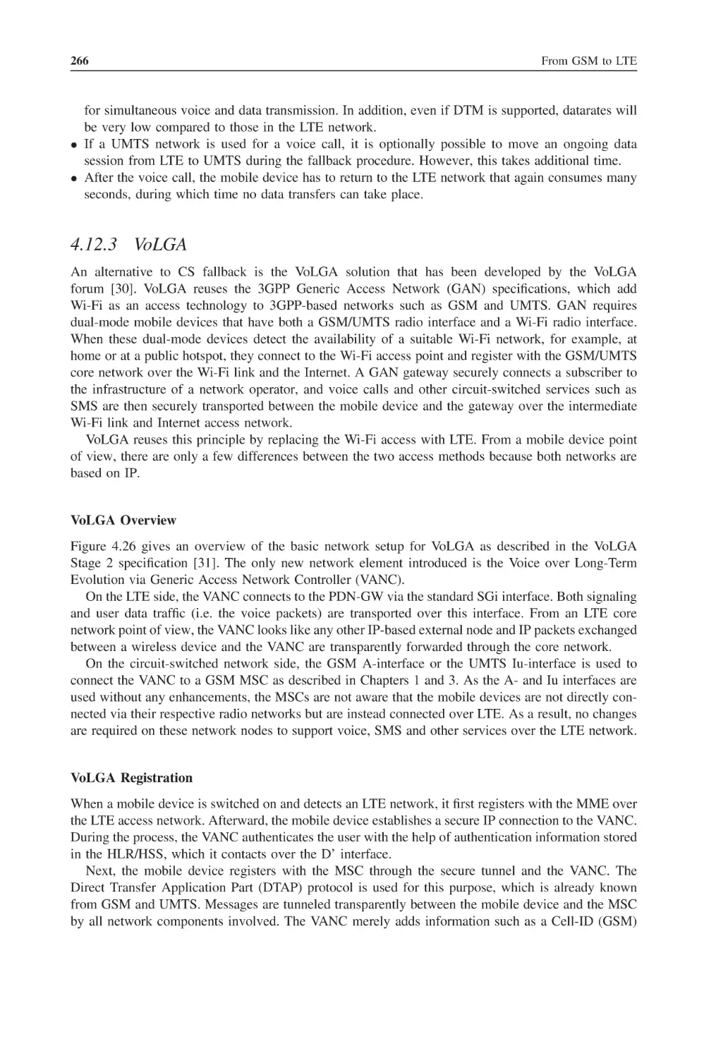
VoLGA
4.12.4
IMS and the One Voice Profile
4.12.5
Internet-Based Alternatives
4.12.6
LTE Bearer Configurations for VoIP
Backhaul Considerations
LTE-Advanced (3GPP Release 10)
4.14.1
Latency Reduction
4.14.2
Carrier Aggregation
4.14.3
8 × 8 Downlink and 4 × 4 Uplink MIMO
4.14.4
Relays
4.14.5
Study on Coordinated Multipoint Operation
Questions
References
255
256
257
258
259
259
259
260
260
260
261
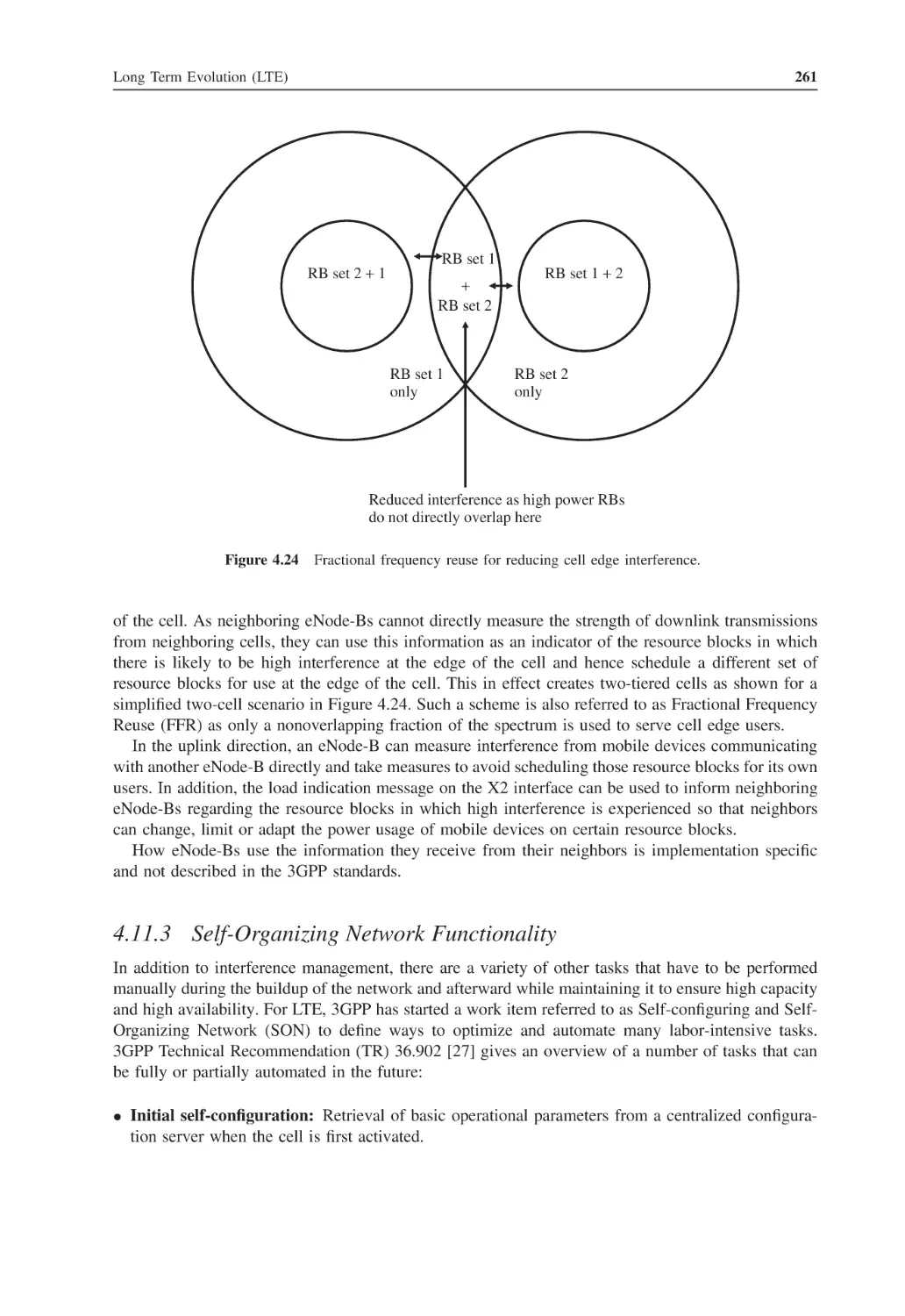
262
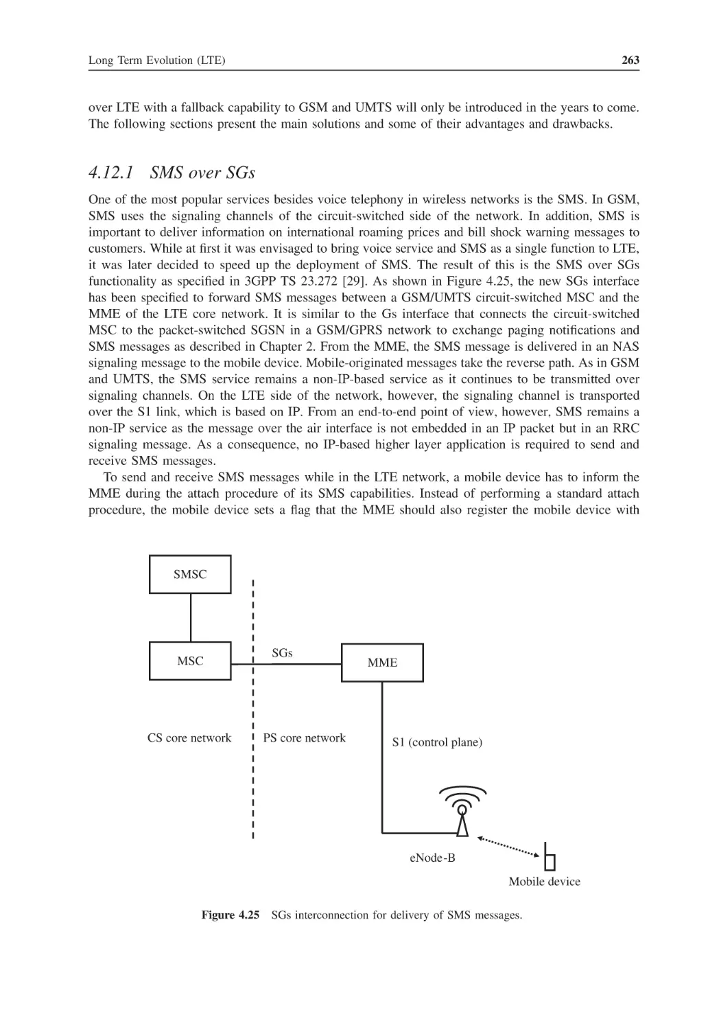
263
264
266
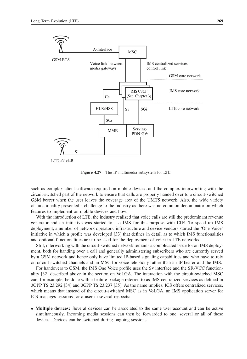
268
270
270
271
272
272
273
273
273
274
274
275
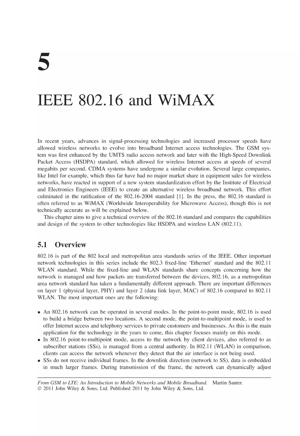
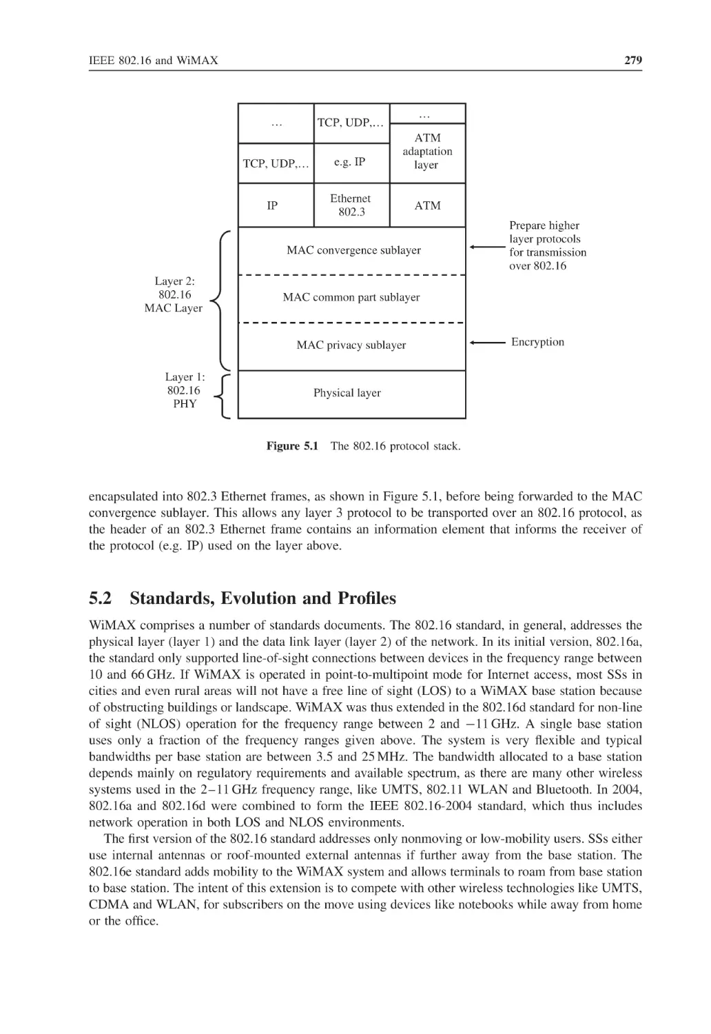
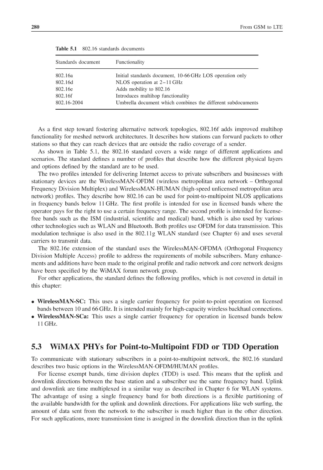
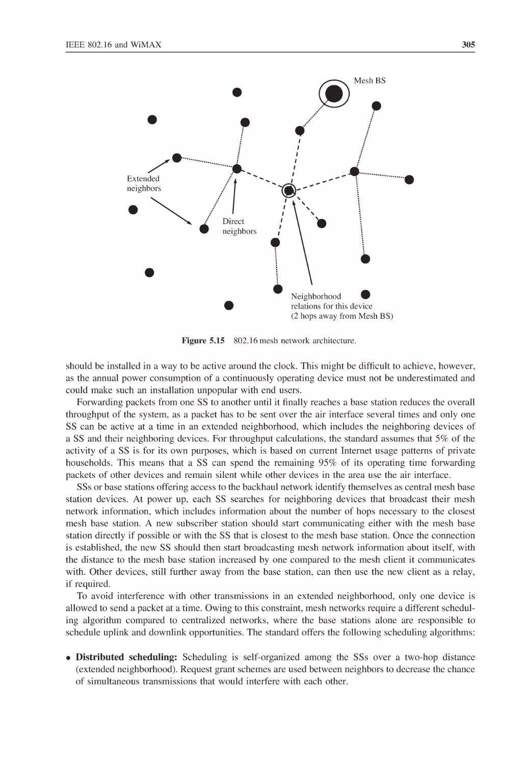
IEEE 802.16 and WiMAX
Overview
Standards, Evolution and Profiles
WiMAX PHYs for Point-to-Multipoint FDD or TDD Operation
5.3.1
Adaptive OFDM Modulation and Coding
5.3.2
Physical Layer Speed Calculations
5.3.3
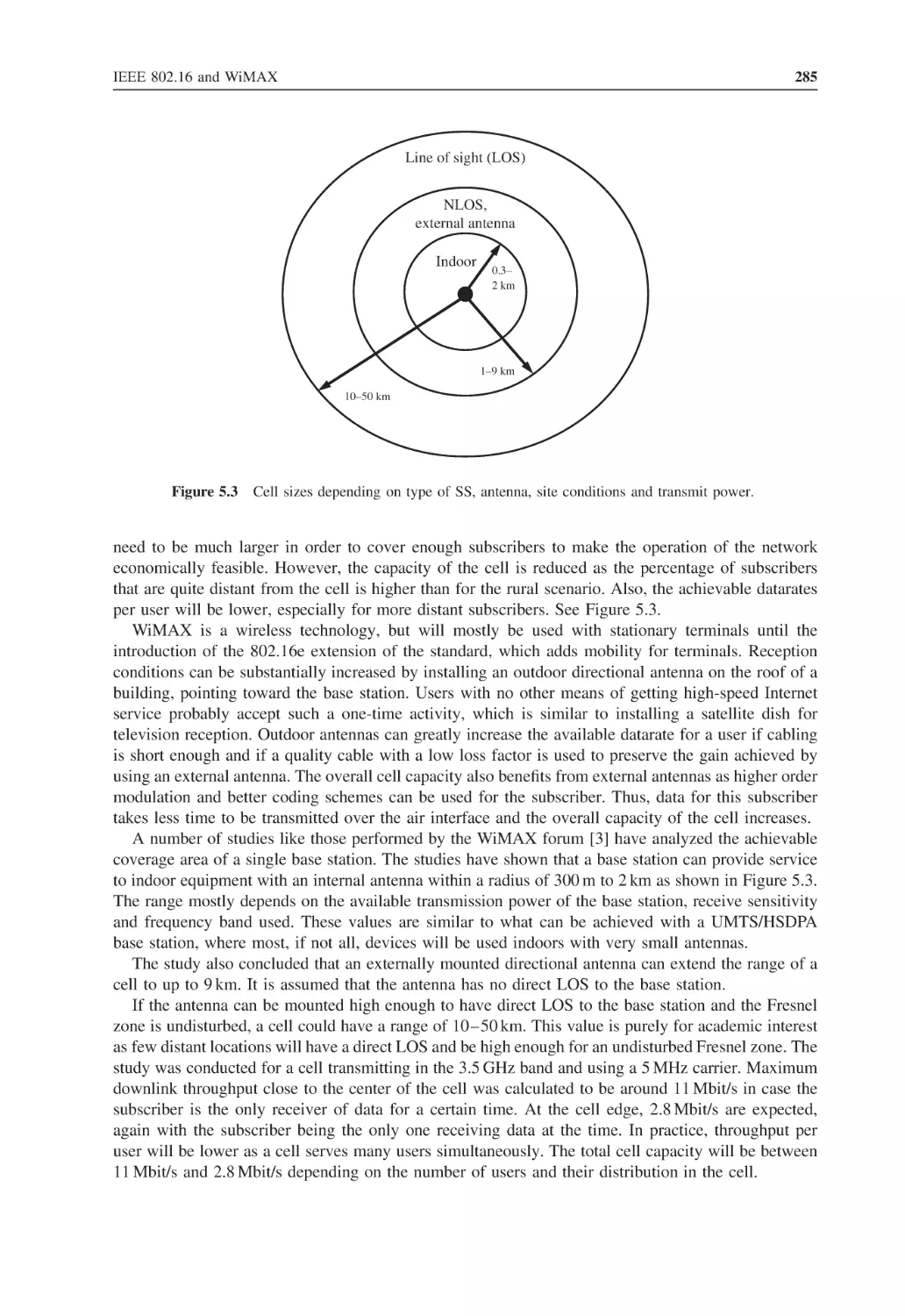
Cell Sizes
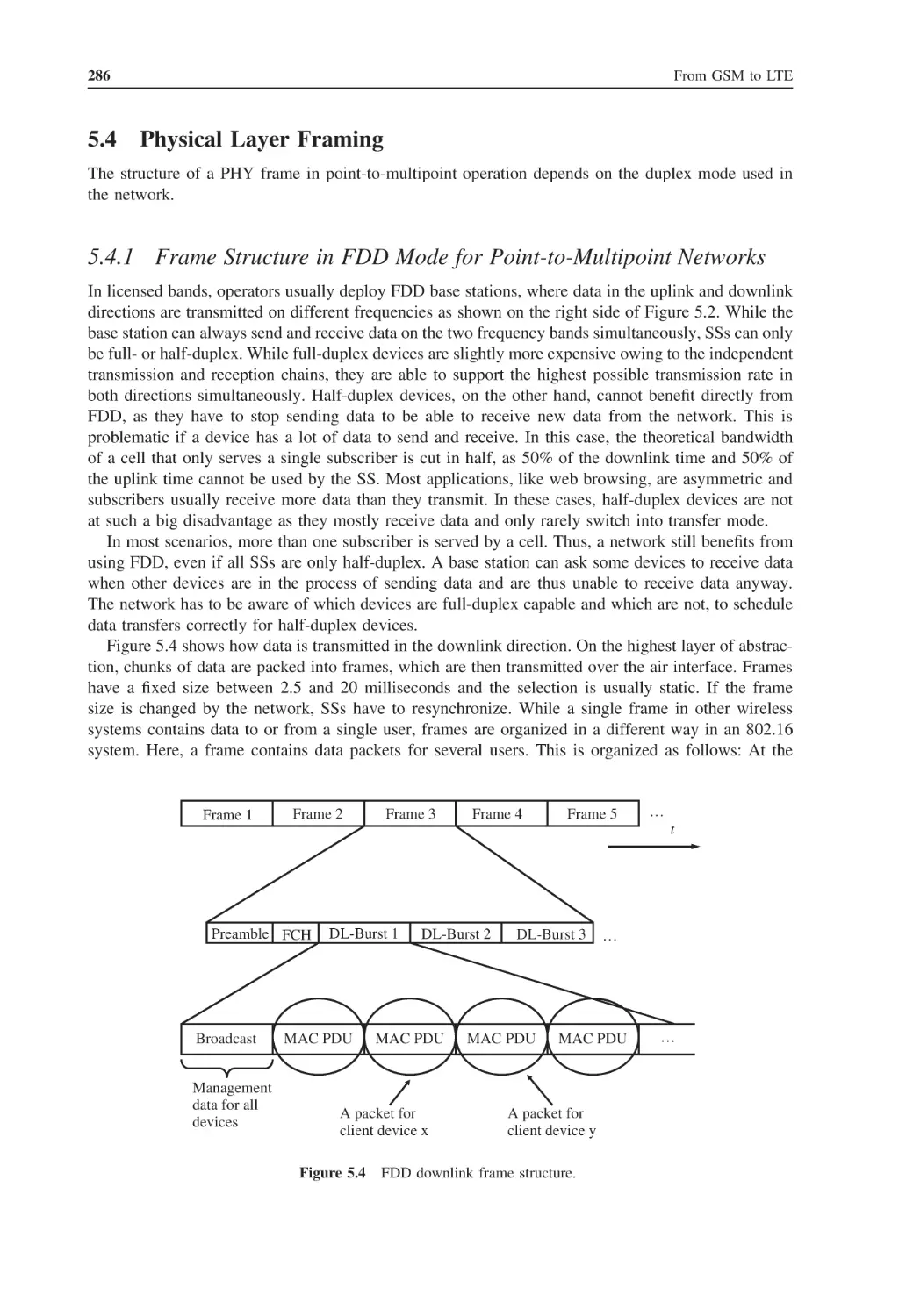
Physical Layer Framing
5.4.1
Frame Structure in FDD Mode for Point-to-Multipoint Networks
5.4.2
Frame Structure in TDD Mode for Point-to-Multipoint Networks
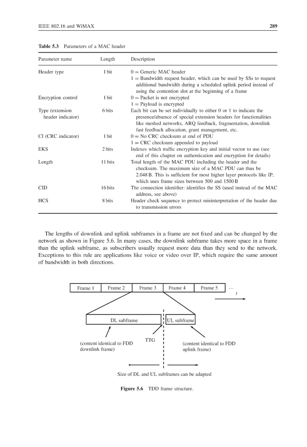
Ensuring Quality of Service
MAC Management Functions
5.6.1
Connecting to the Network
5.6.2
Power, Modulation and Coding Control
5.6.3
Dynamic Frequency Selection
MAC Management of User Data
5.7.1
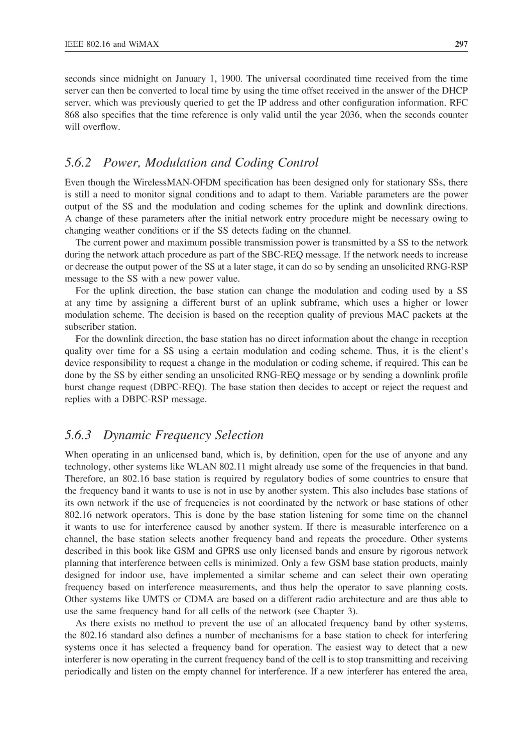
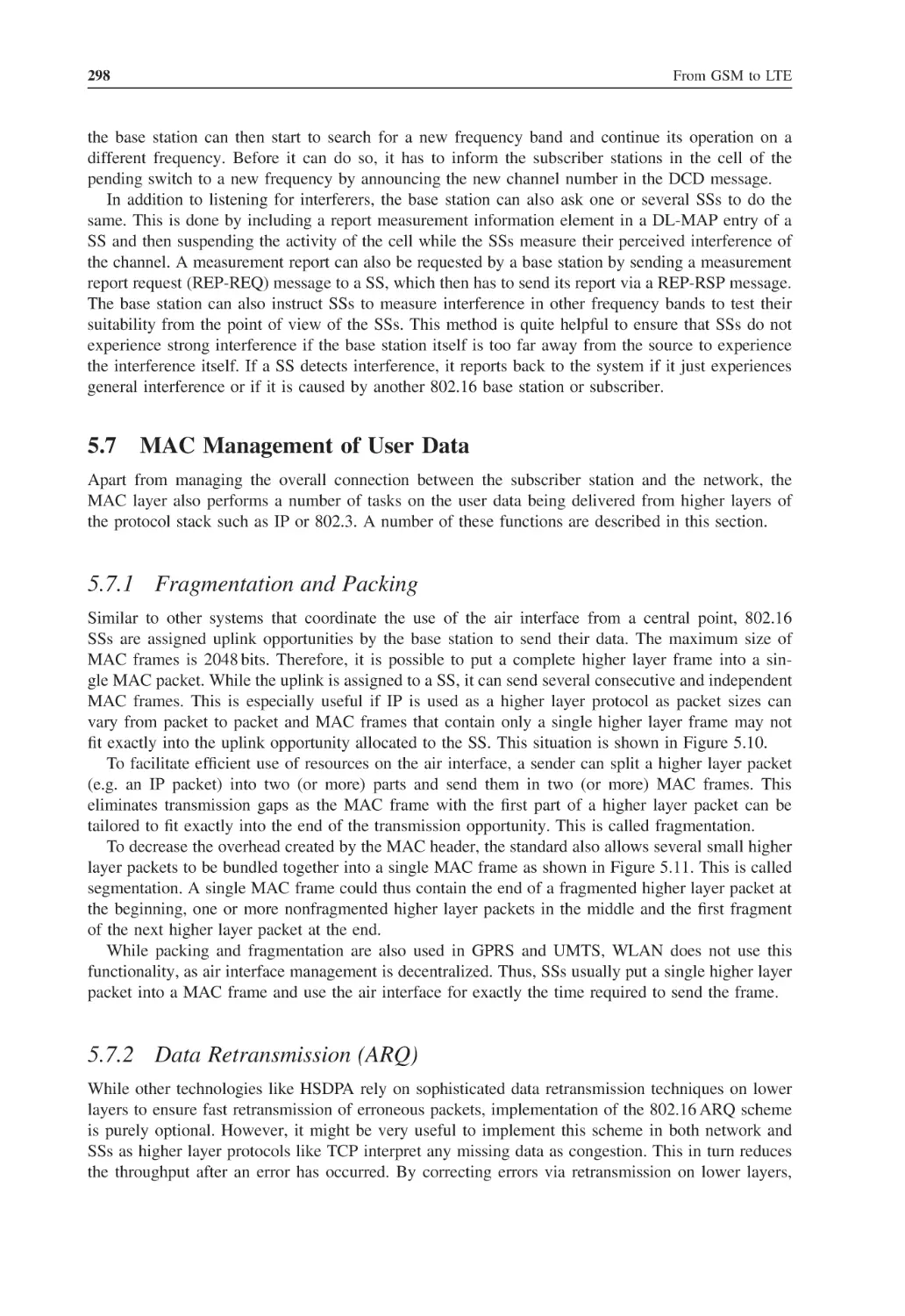
Fragmentation and Packing
5.7.2
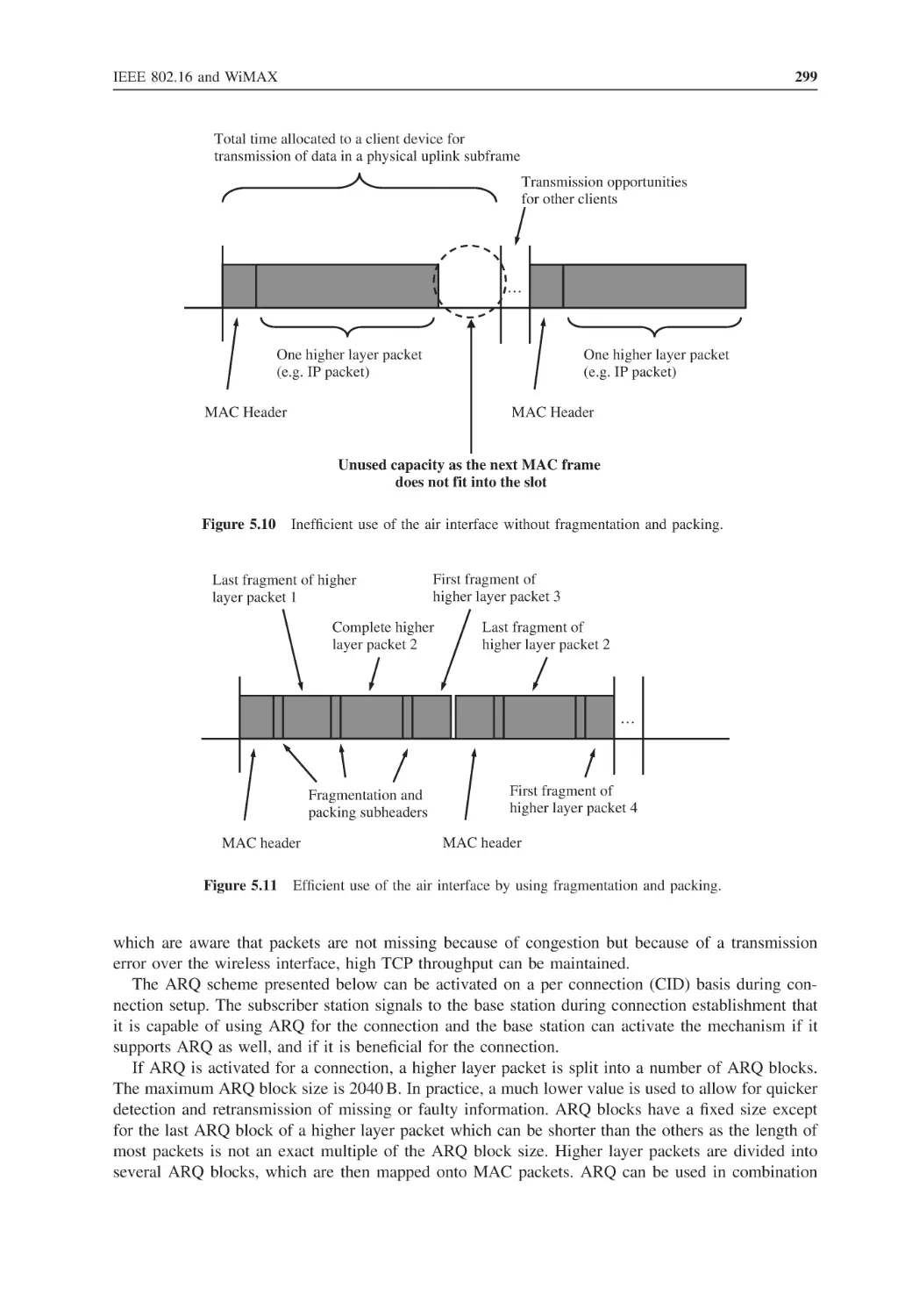
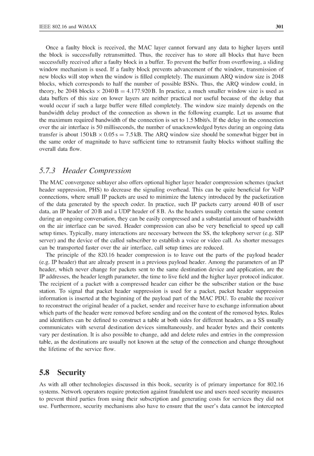
Data Retransmission (ARQ)
5.7.3
Header Compression
Security
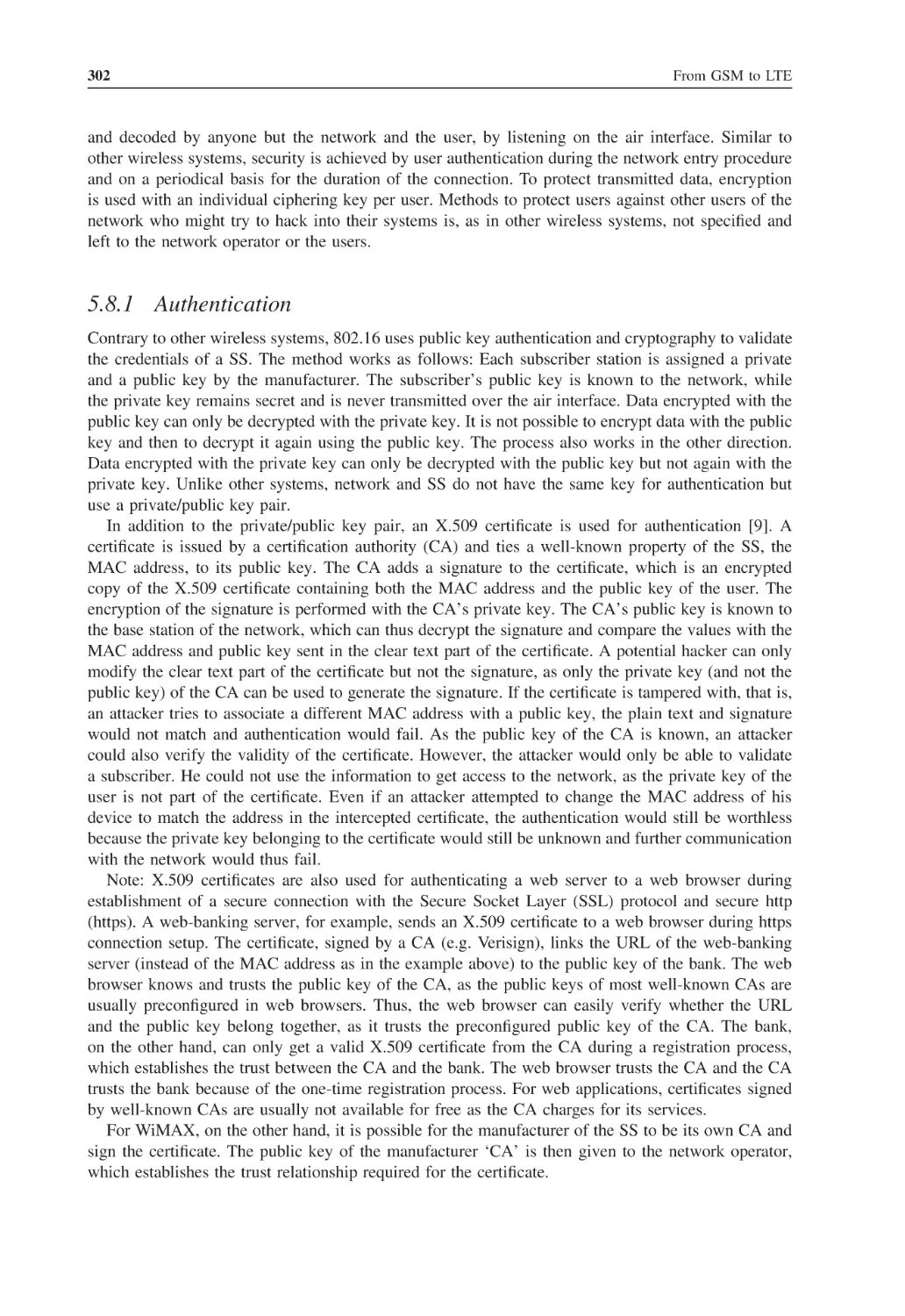
5.8.1
Authentication
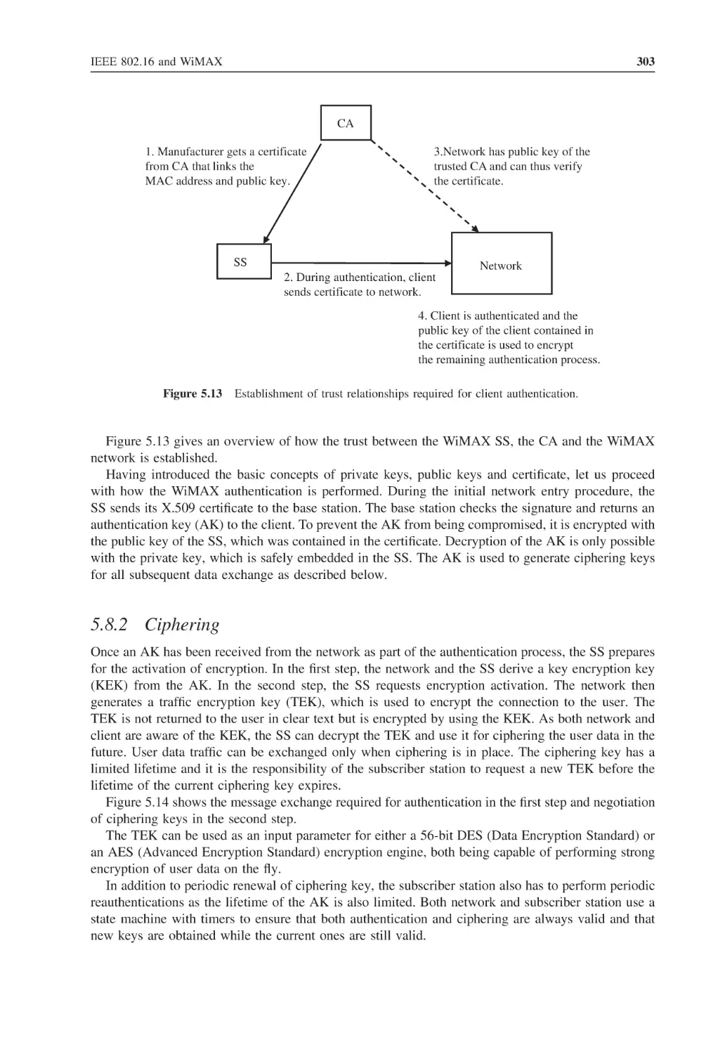
5.8.2
Ciphering
277
277
279
280
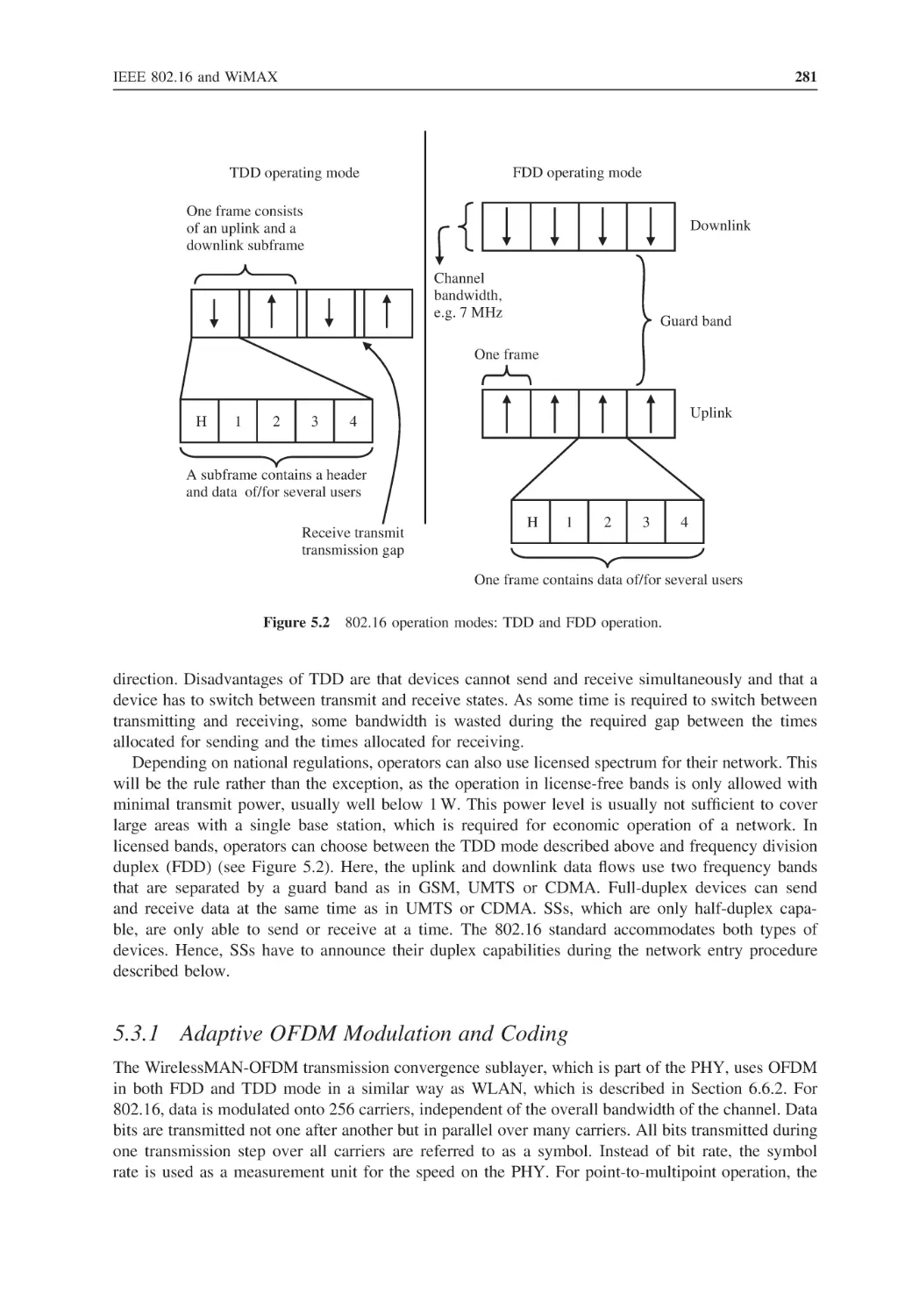
281
283
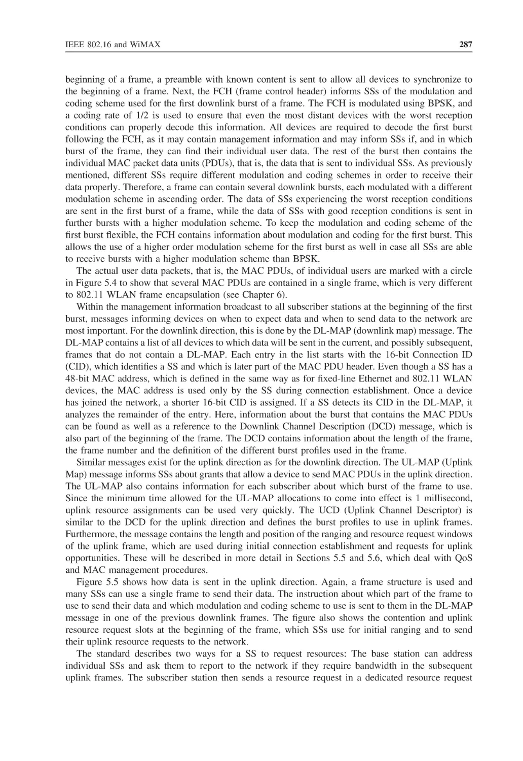
284
286
286
288
290
293
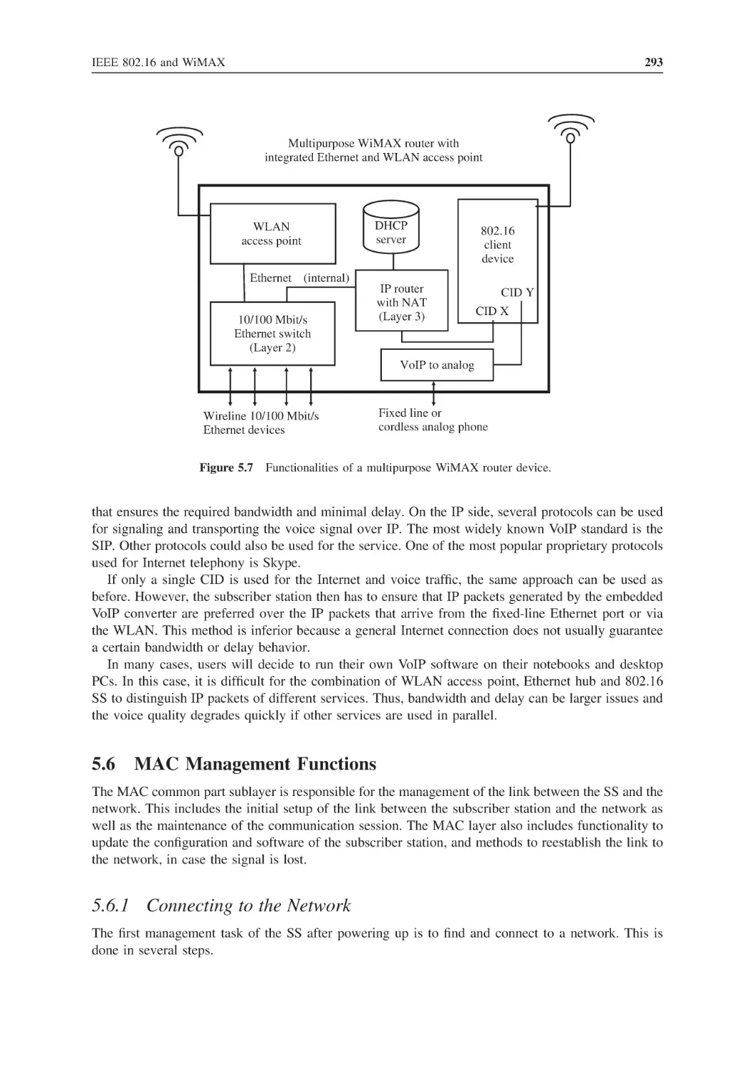
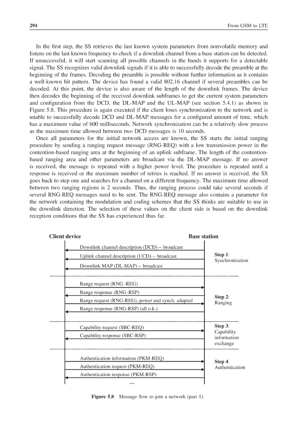
293
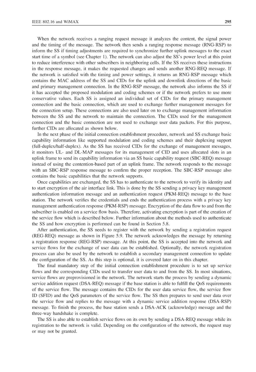
297
297
298
298
298
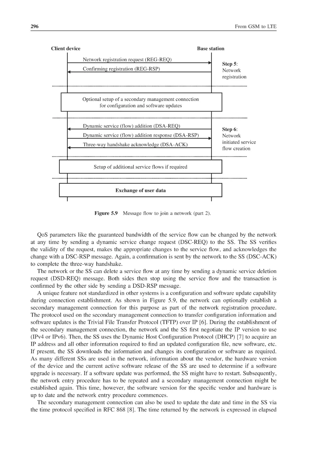
301
301
302
303
x
5.9
5.10
5.11
5.12
6
6.1
6.2
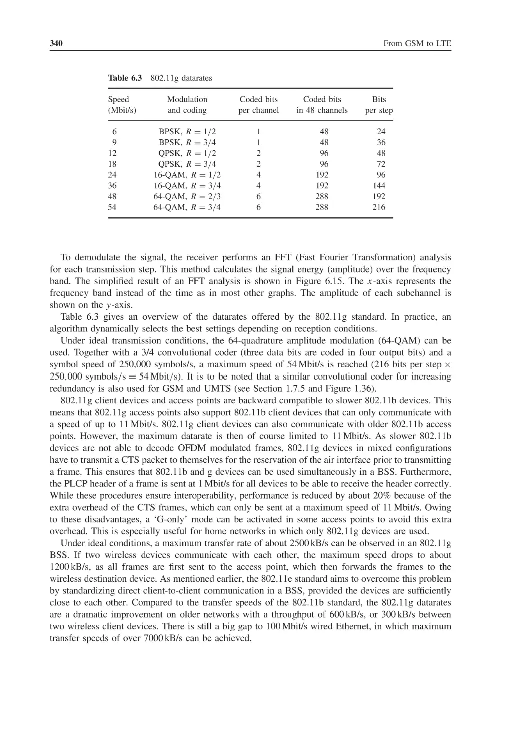
6.3
6.4
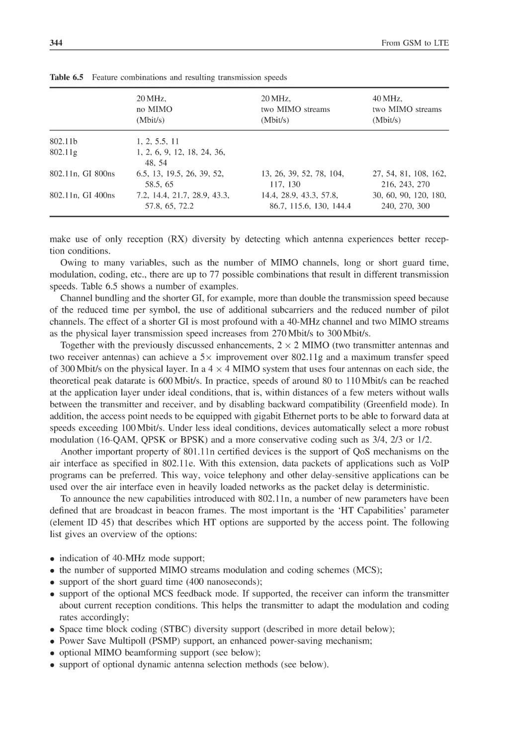
6.5
6.6
6.7
6.8
6.9
6.10
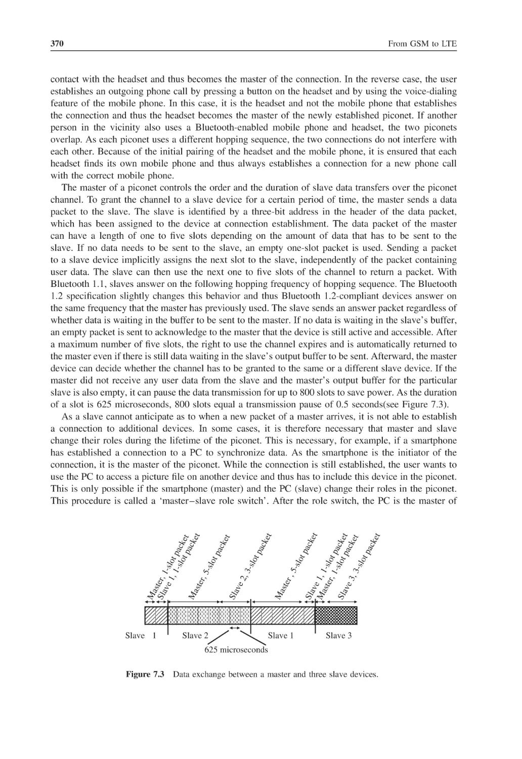
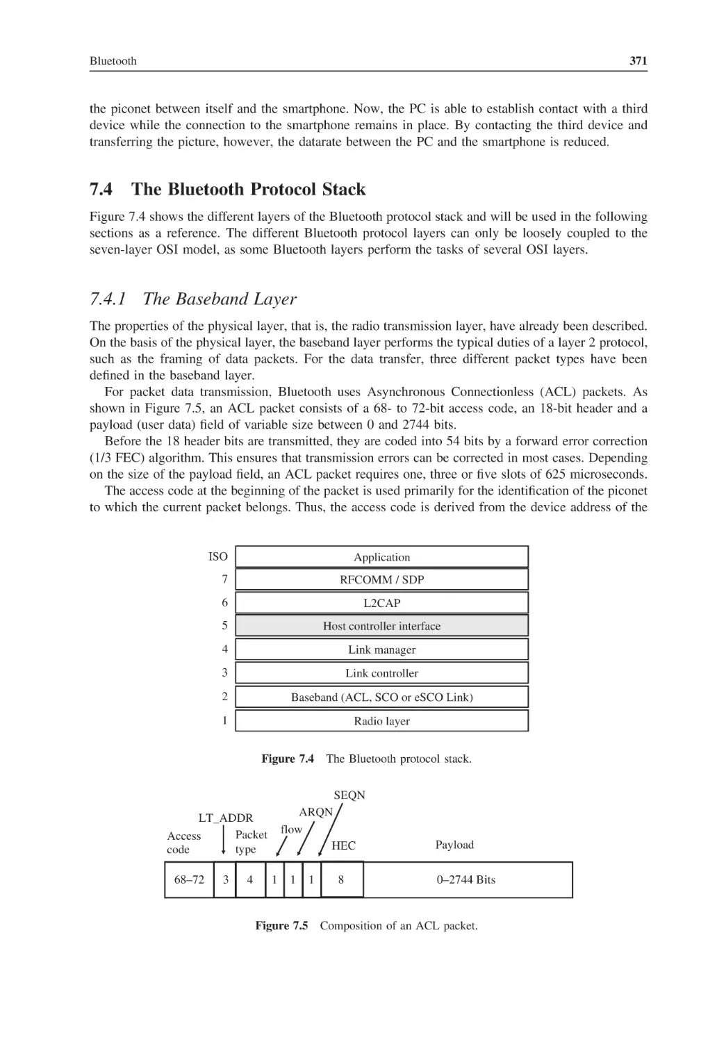
7
7.1
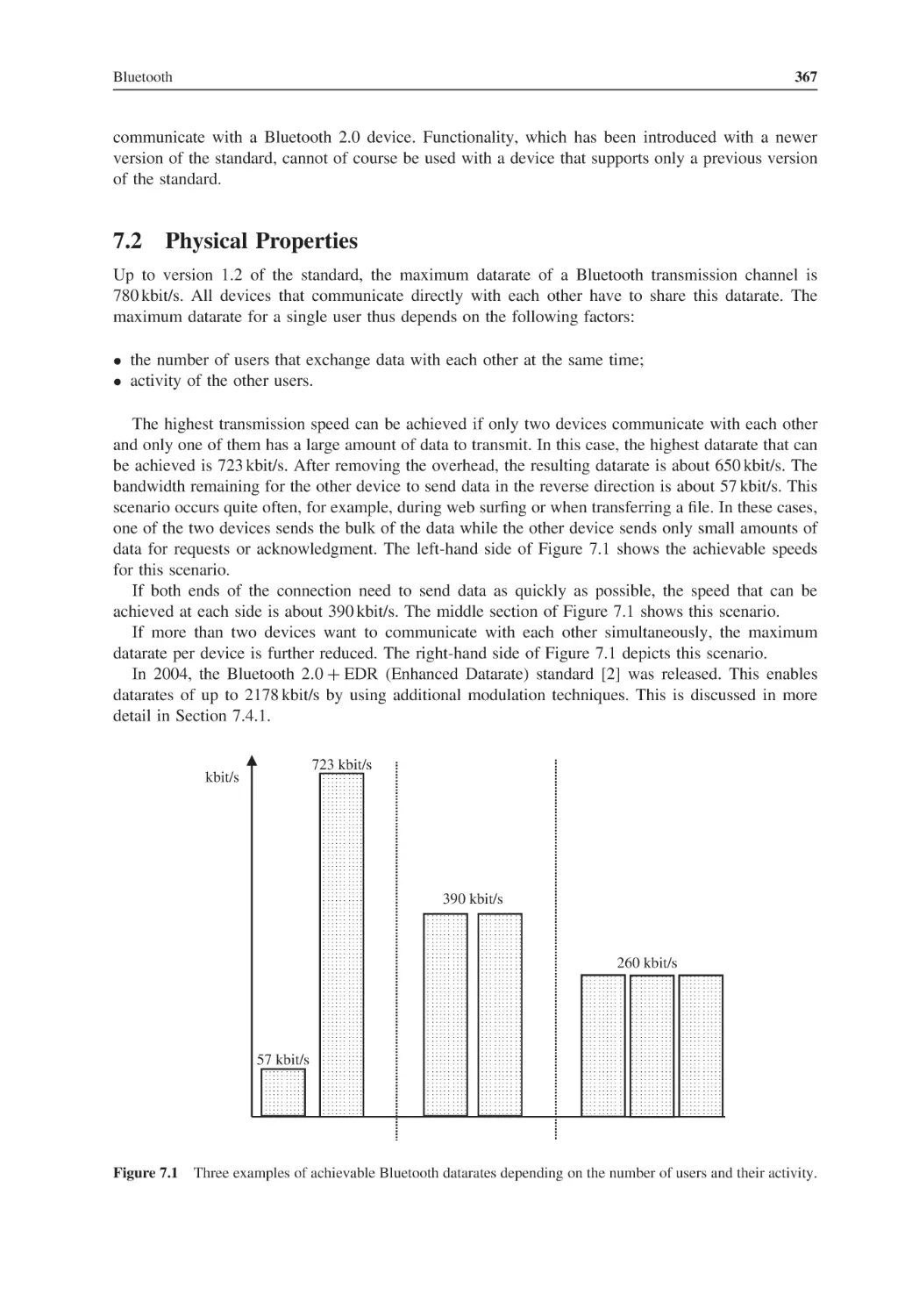
7.2
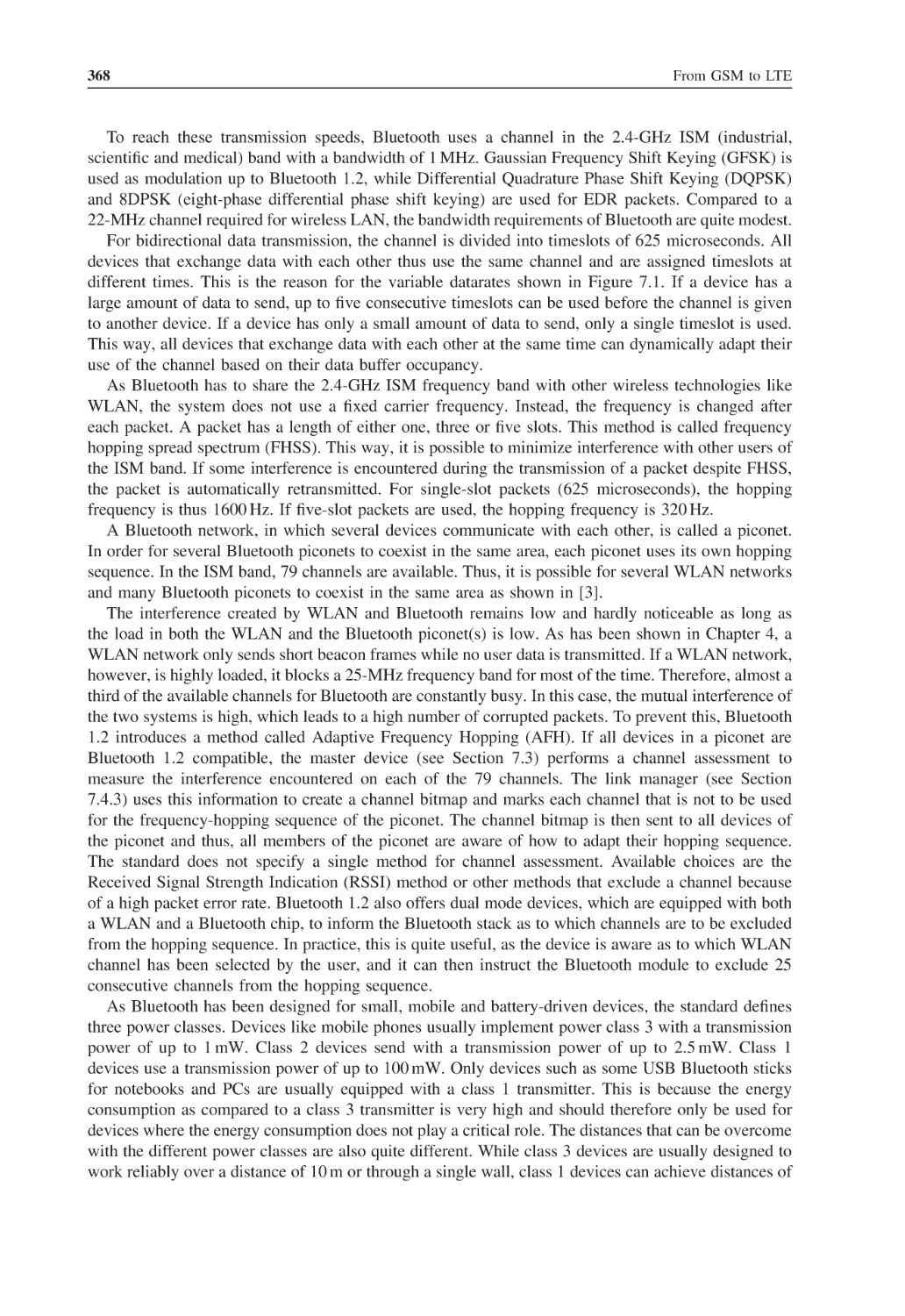
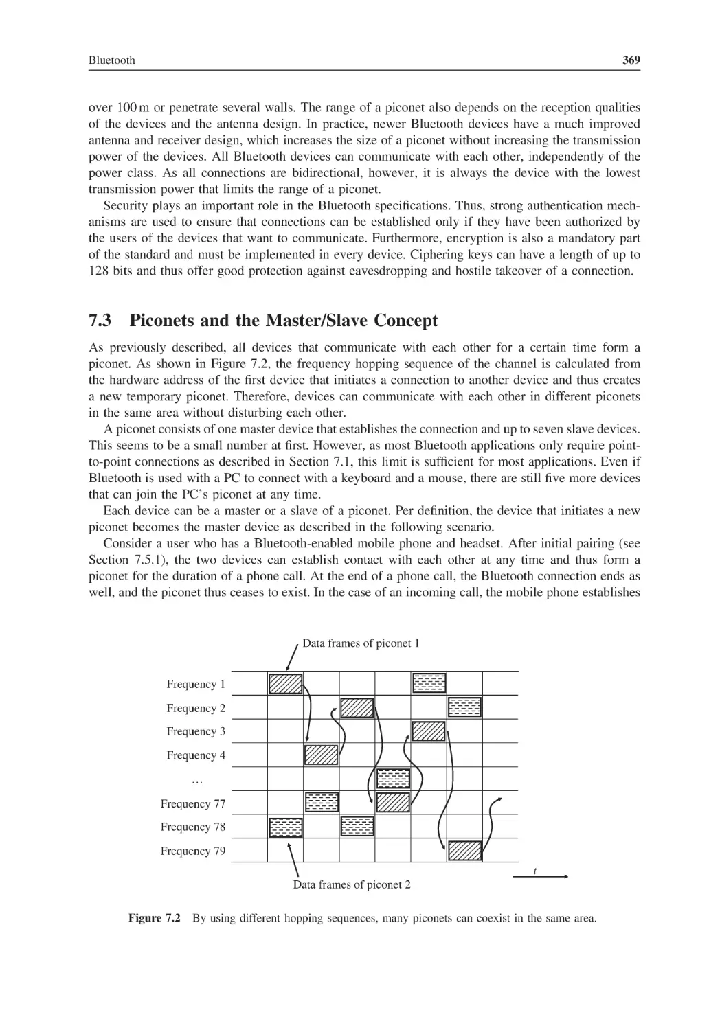
7.3
7.4
Contents
Advanced 802.16 Functionalities
5.9.1
Mesh Network Topology
5.9.2
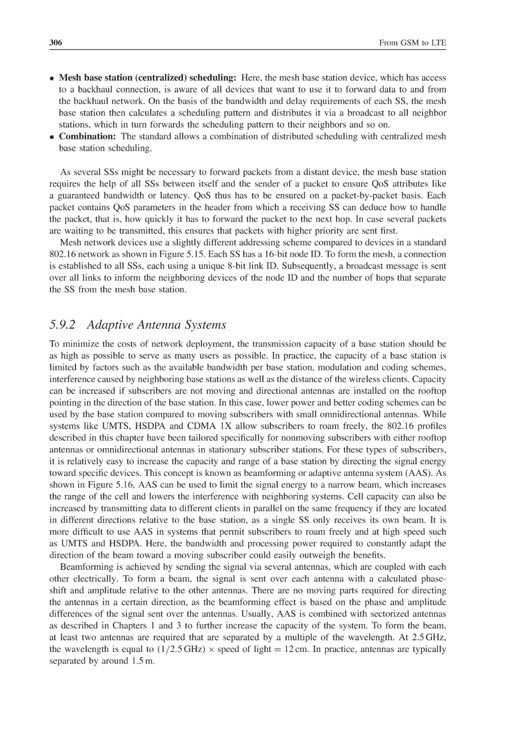
Adaptive Antenna Systems
Mobile WiMAX: 802.16e
5.10.1
OFDM Multiple Access for 802.16e Networks
5.10.2
MIMO
5.10.3
Handover
5.10.4
Power-Saving Functionality
5.10.5
Idle Mode
WiMAX Network Infrastructure
5.11.1
Network Reference Architecture
5.11.2
Micro Mobility Management
5.11.3
Macro Mobility Management
Questions
References
304
304
306
308
308
309
310
313
314
315
315
317
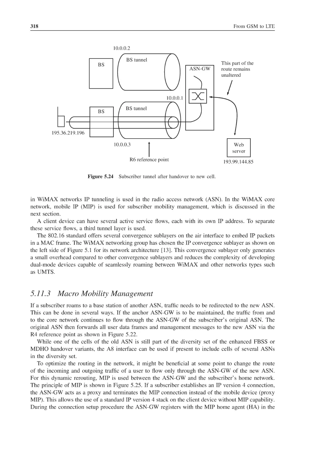
318
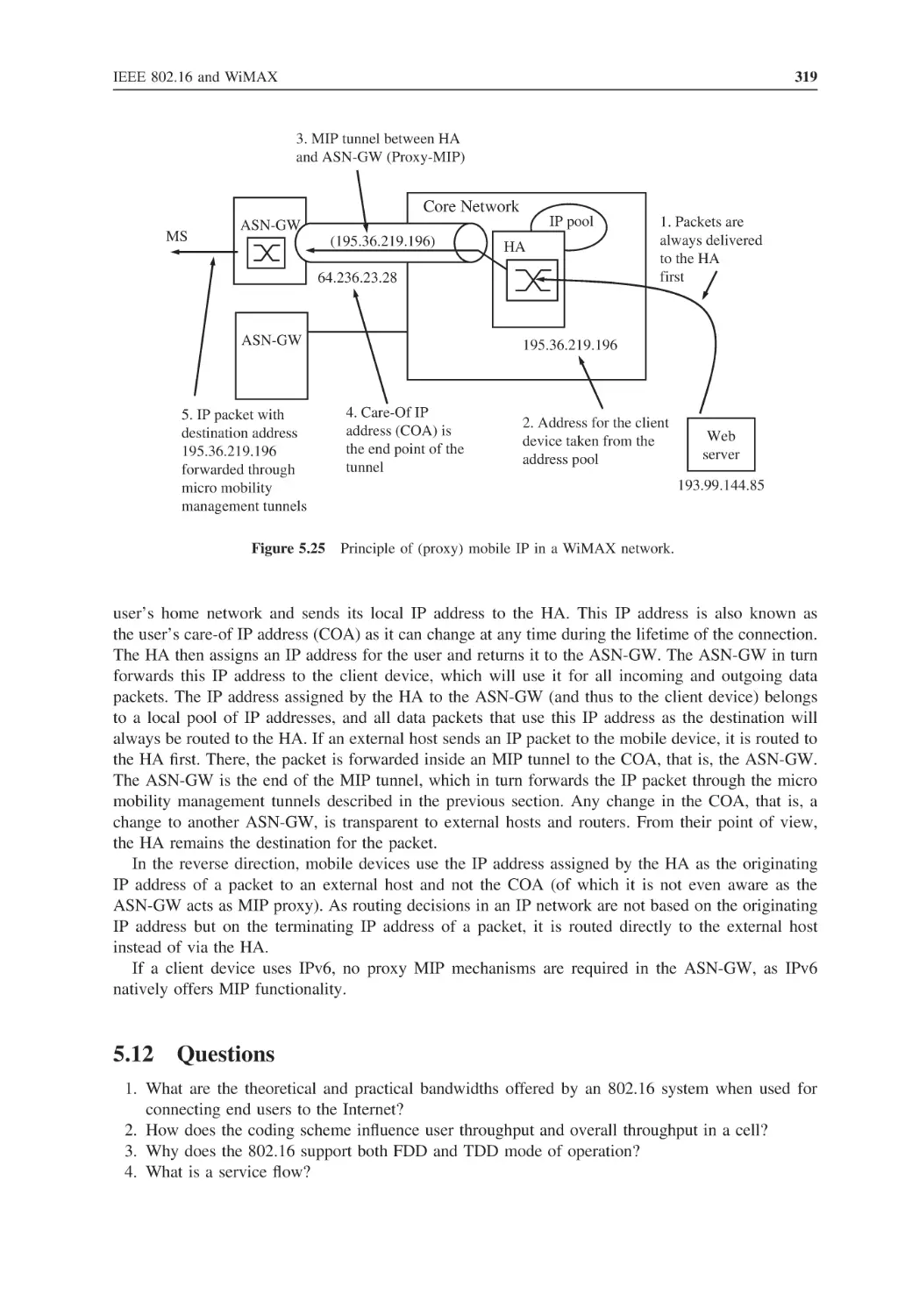
319
320
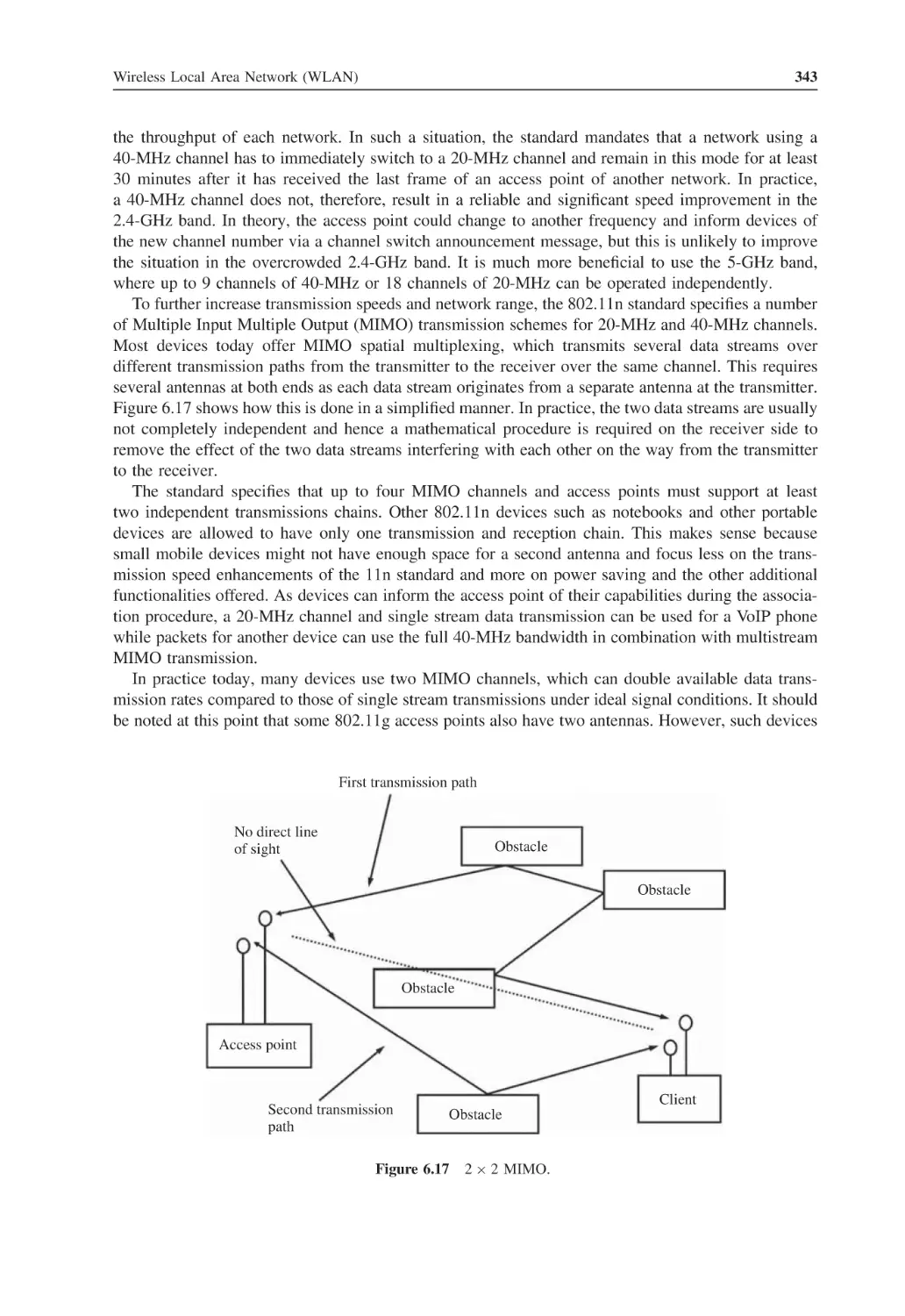
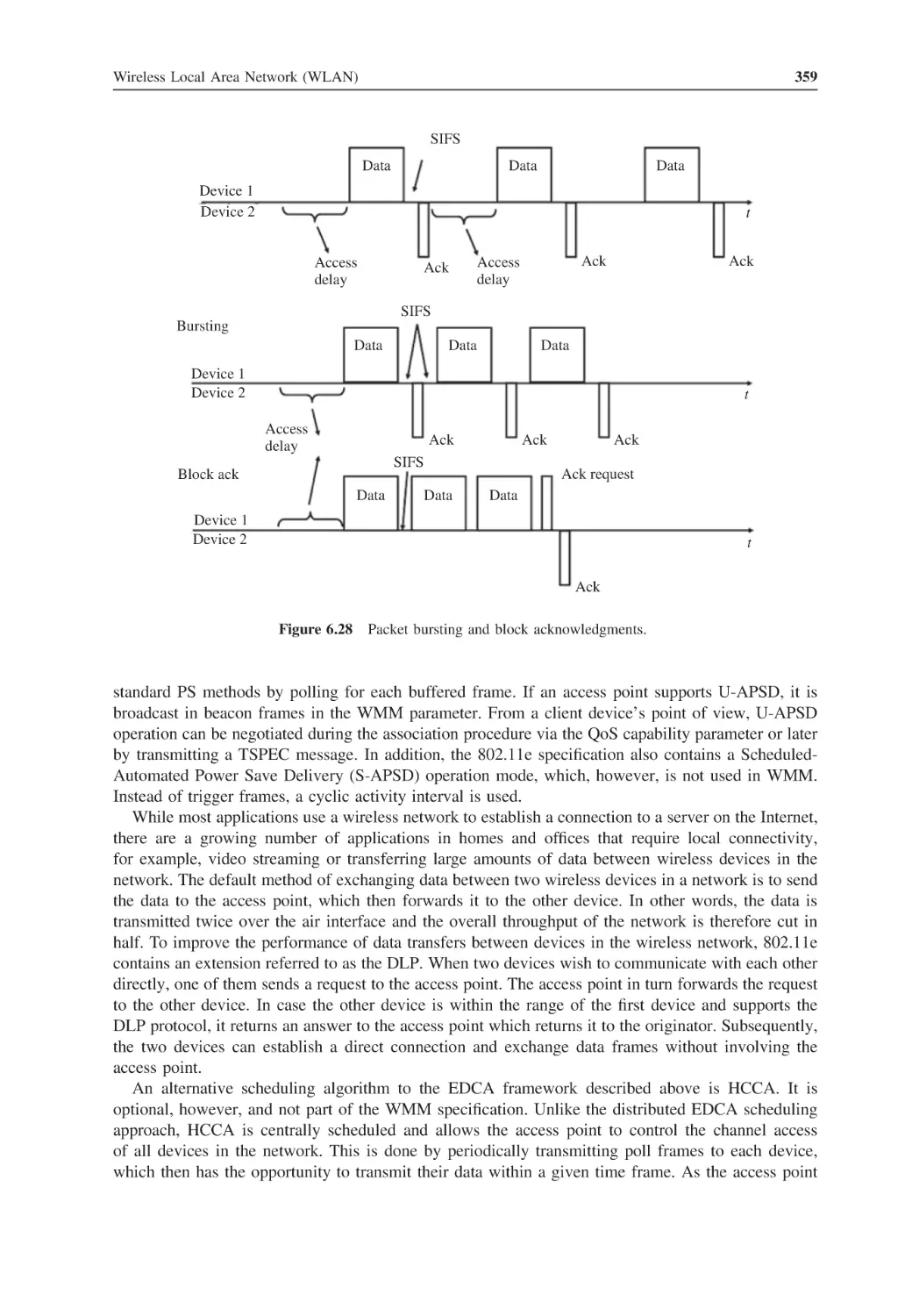
Wireless Local Area Network (WLAN)
Wireless LAN Overview
Transmission Speeds and Standards
WLAN Configurations: From Ad Hoc to Wireless Bridging
6.3.1
Ad Hoc, BSS, ESS and Wireless Bridging
6.3.2
SSID and Frequency Selection
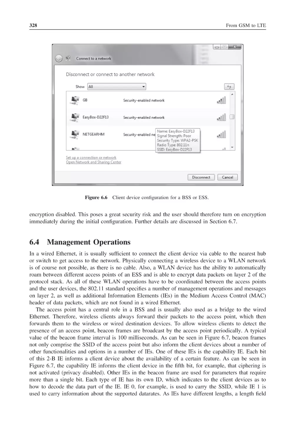
Management Operations
The MAC Layer
6.5.1
Air Interface Access Control
6.5.2
The MAC Header
The Physical Layer and MAC Extensions
6.6.1
IEEE 802.11b – 11 Mbit/s
6.6.2
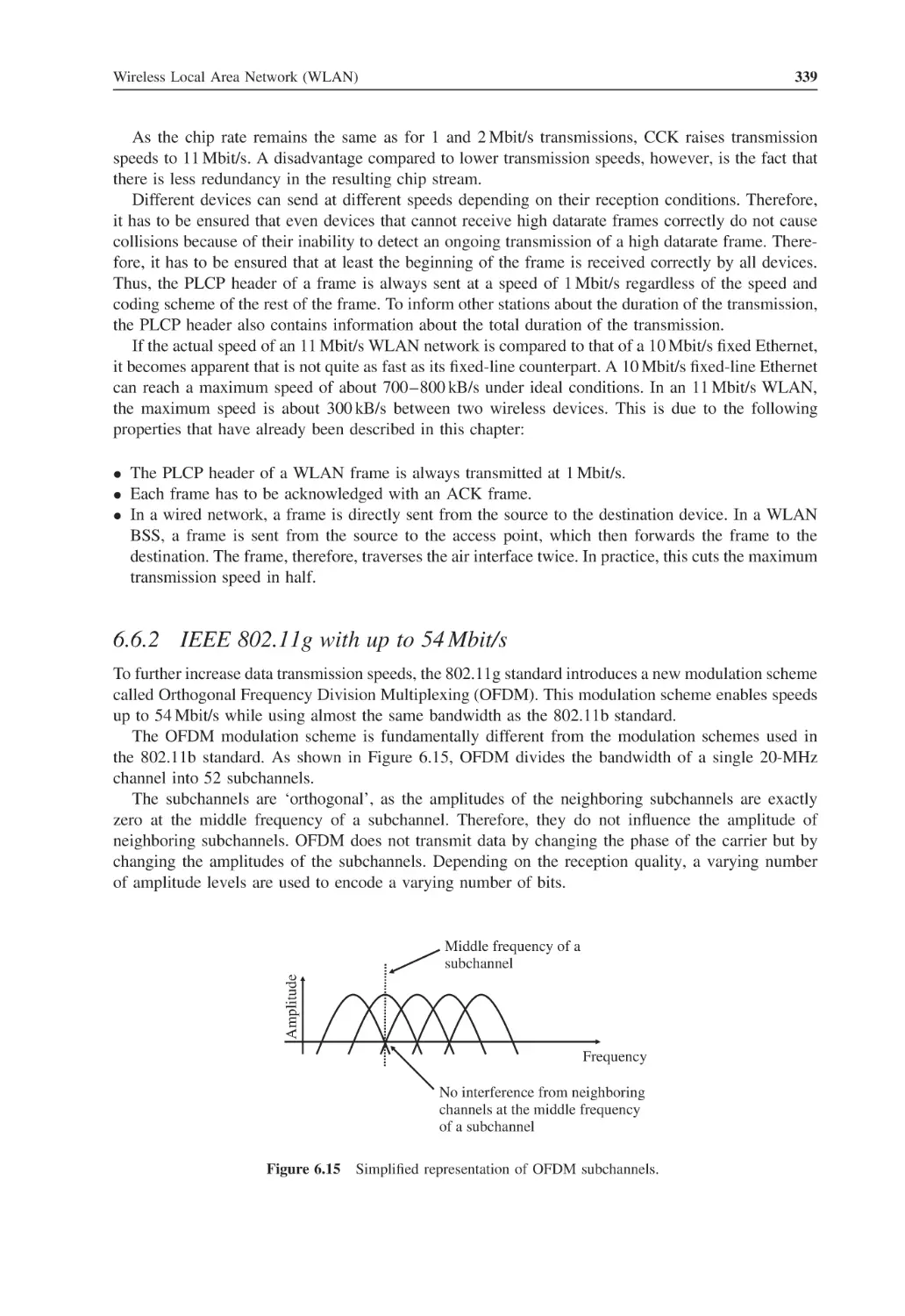
IEEE 802.11g with up to 54 Mbit/s
6.6.3
IEEE 802.11a with up to 54 Mbit/s
6.6.4
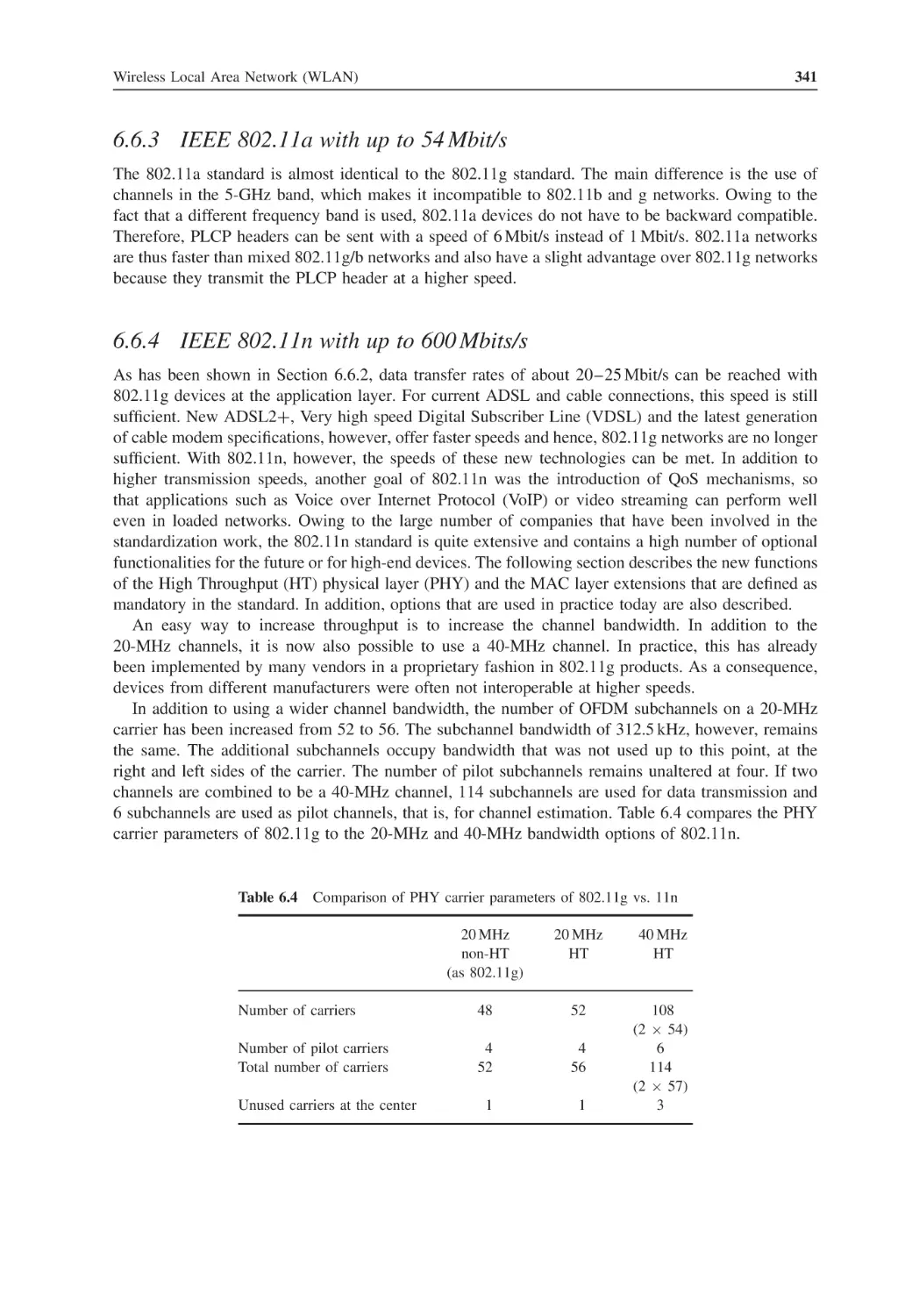
IEEE 802.11n with up to 600 Mbits/s
Wireless LAN Security
6.7.1
Wired Equivalent Privacy (WEP)
6.7.2
WPA and WPA Personal Mode Authentication
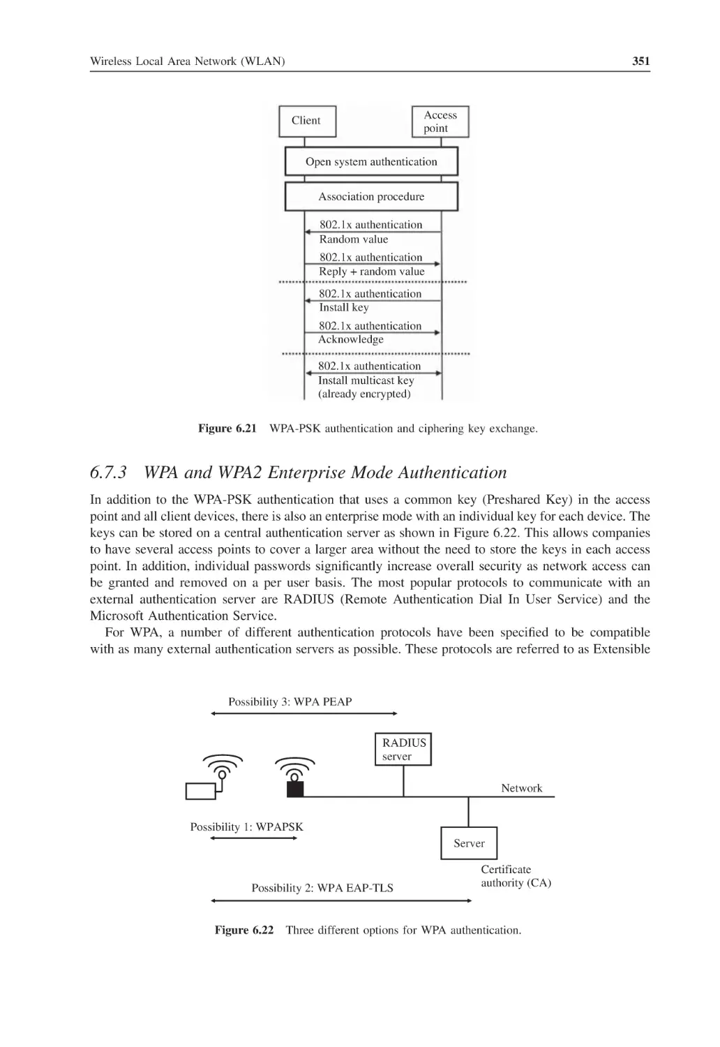
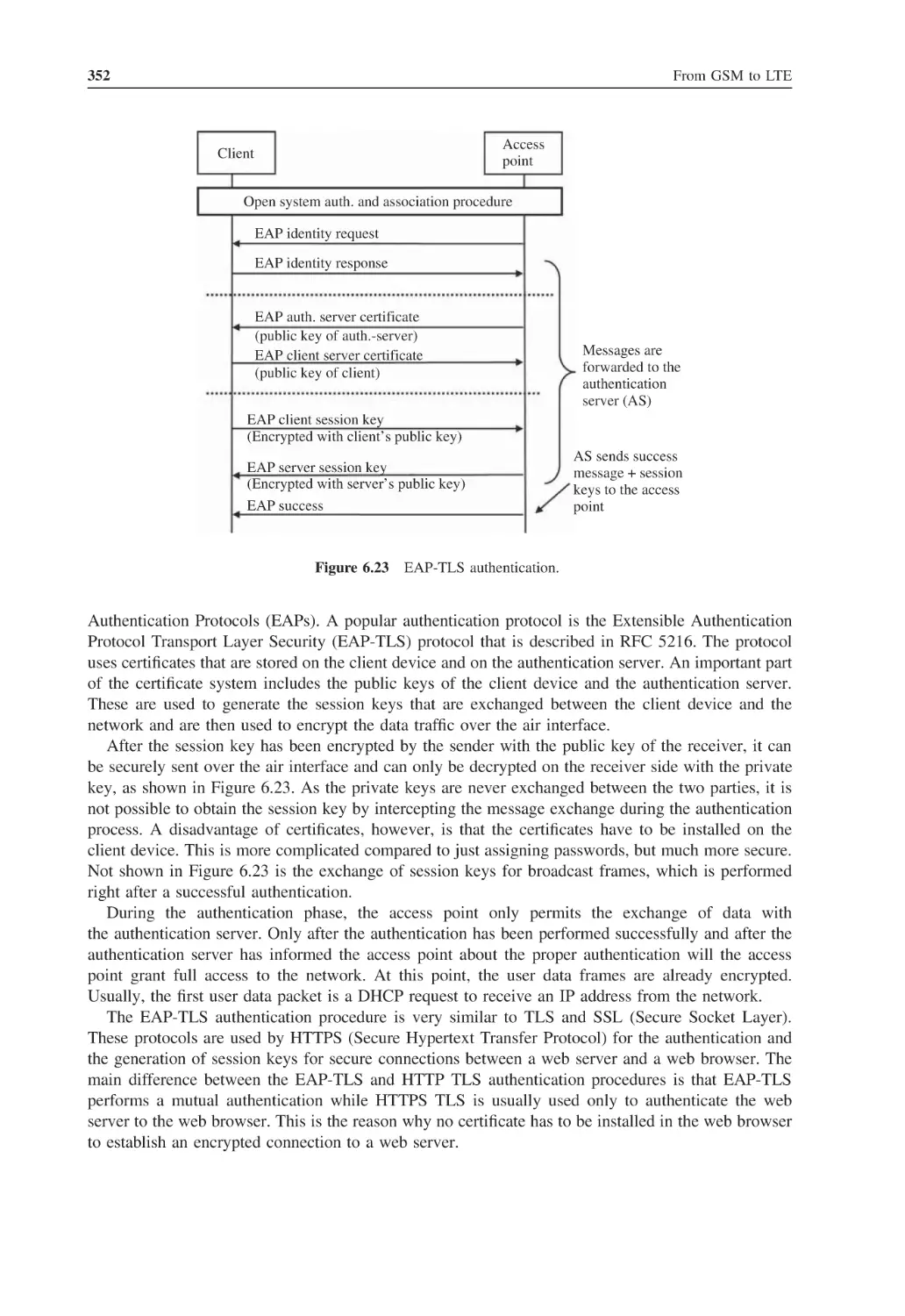
6.7.3
WPA and WPA2 Enterprise Mode Authentication
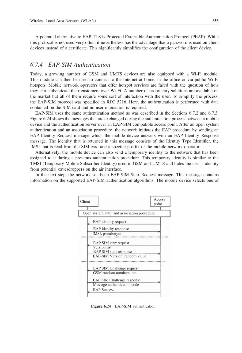
6.7.4
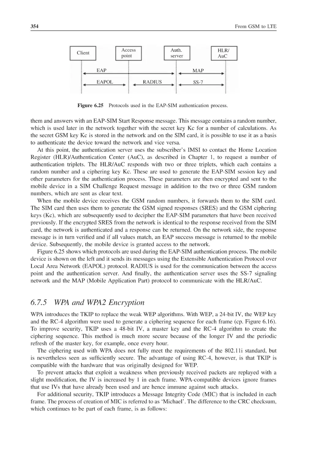
EAP-SIM Authentication
6.7.5
WPA and WPA2 Encryption
IEEE 802.11e and WMM – Quality of Service
Comparison of Wireless LAN and UMTS
Questions
References
321
321
321
323
323
327
328
333
333
335
337
337
339
341
341
348
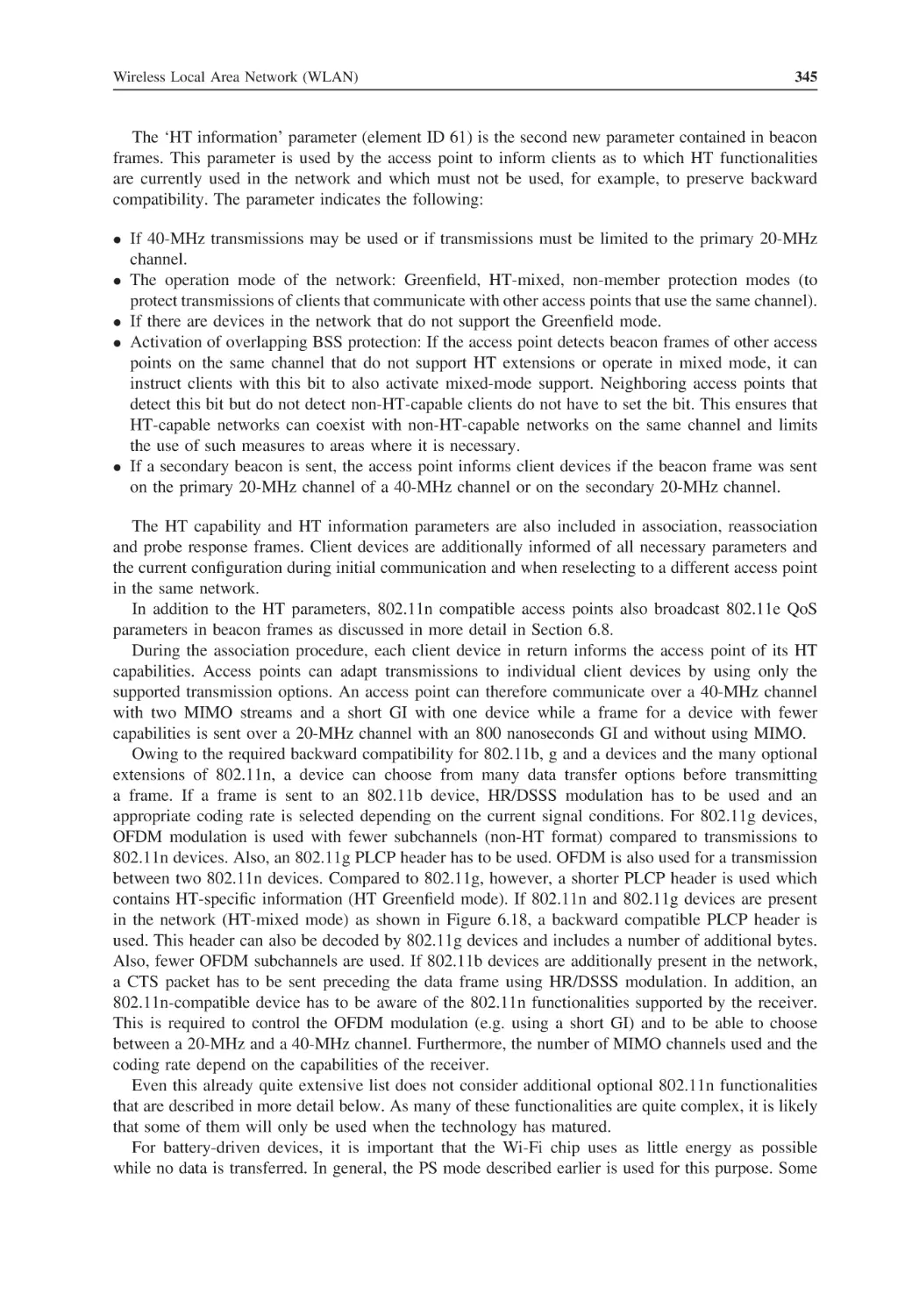
349
350
351
353
354
355
360
362
363
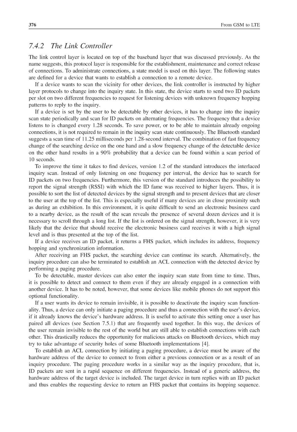
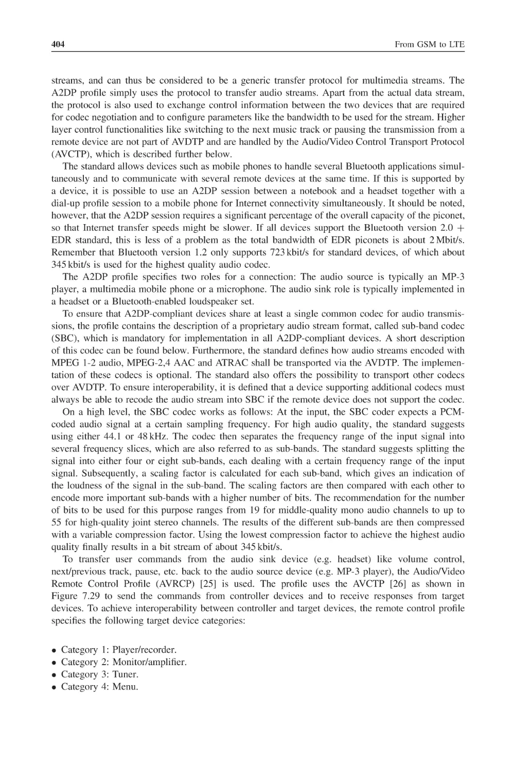
Bluetooth
Overview and Applications
Physical Properties
Piconets and the Master/Slave Concept
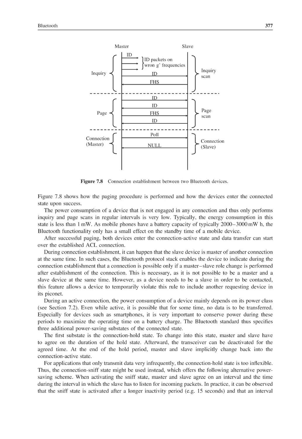
The Bluetooth Protocol Stack
7.4.1
The Baseband Layer
7.4.2
The Link Controller
7.4.3
The Link Manager
365
365
367
369
371
371
376
378
Contents
7.5
7.6
7.7
7.8
Index
7.4.4
The HCI Interface
7.4.5
The L2CAP Layer
7.4.6
The Service Discovery Protocol
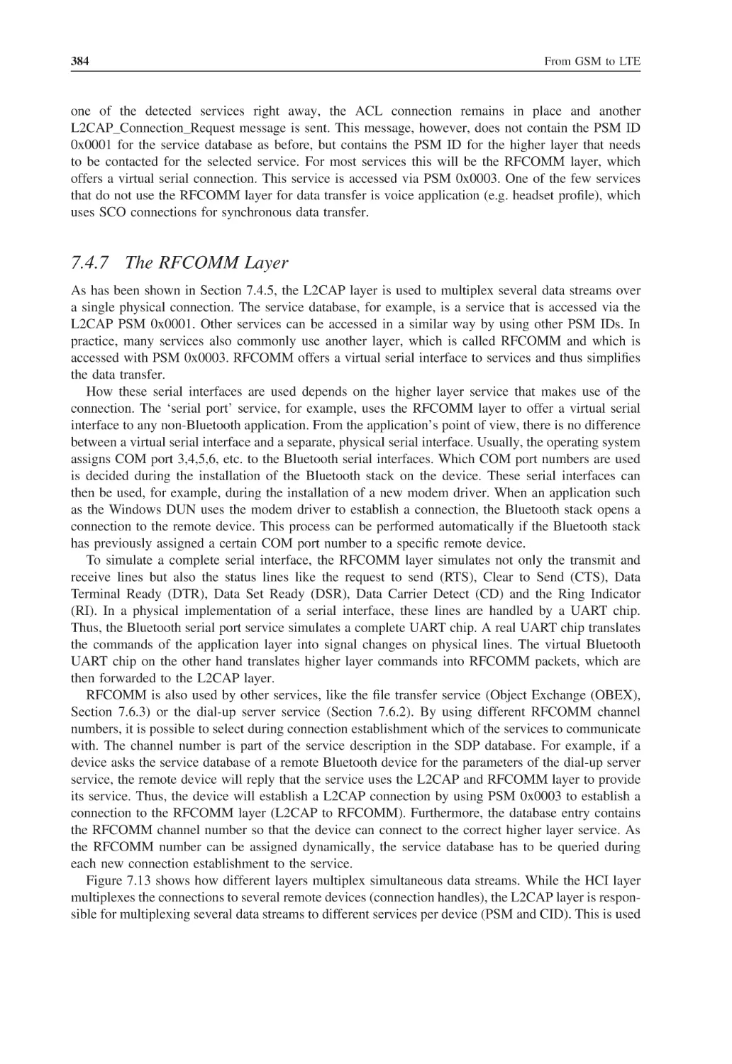
7.4.7
The RFCOMM Layer
7.4.8
Overview of Bluetooth Connection Establishment
Bluetooth Security
7.5.1
Pairing up to Bluetooth 2.0
7.5.2
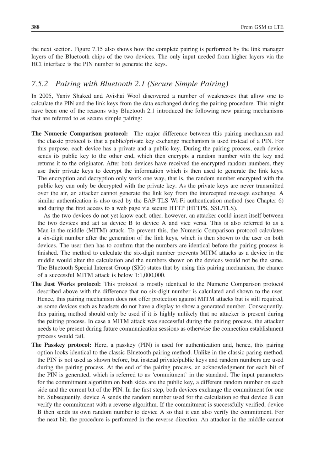
Pairing with Bluetooth 2.1 (Secure Simple Pairing)
7.5.3
Authentication
7.5.4
Encryption
7.5.5
Authorization
7.5.6
Security Modes
Bluetooth Profiles
7.6.1
Basic Profiles: GAP, SDP and the Serial Profile
7.6.2
The Network Profiles: DUN, LAP and PAN
7.6.3
Object Exchange Profiles: FTP, Object Push and Synchronize
7.6.4
Headset, Hands-Free and SIM Access Profile
7.6.5
High-Quality Audio Streaming
Comparison between Bluetooth and Wireless LAN
Questions
References
xi
378
381
382
384
385
386
386
388
389
389
391
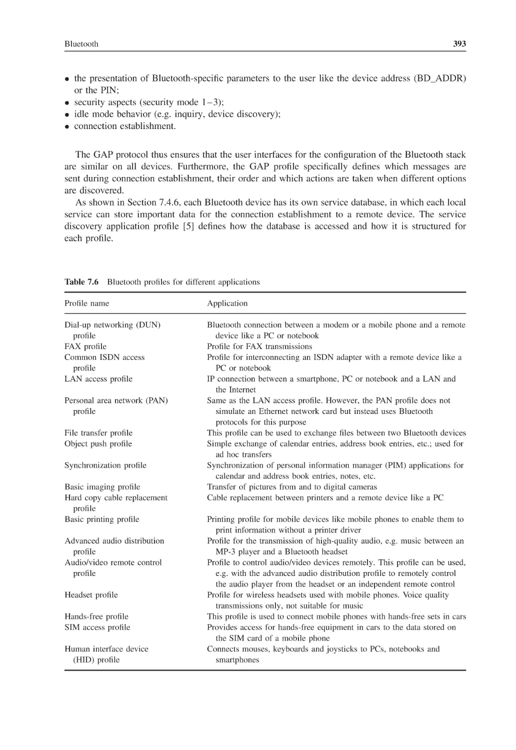
391
392
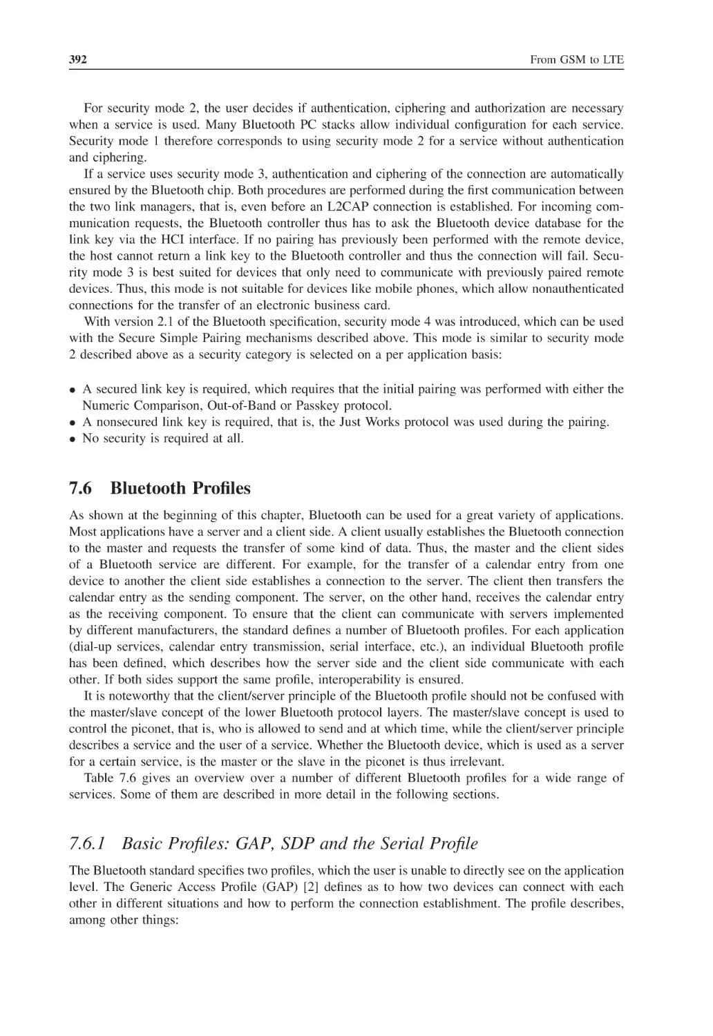
392
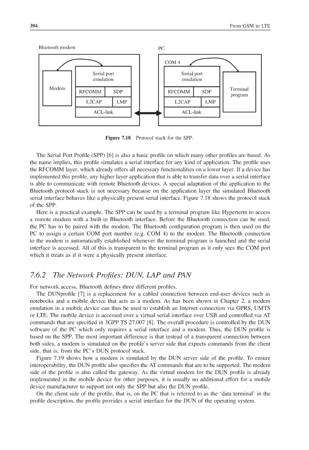
394
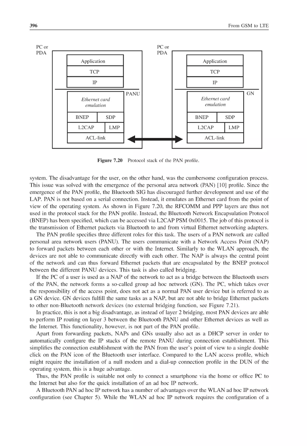
397
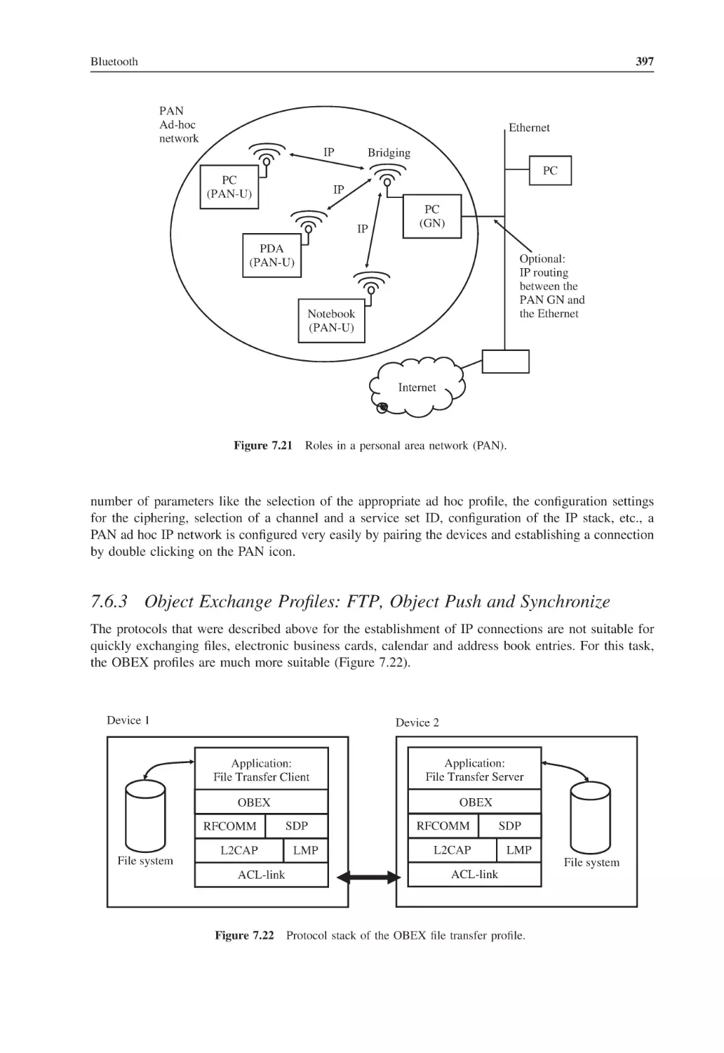
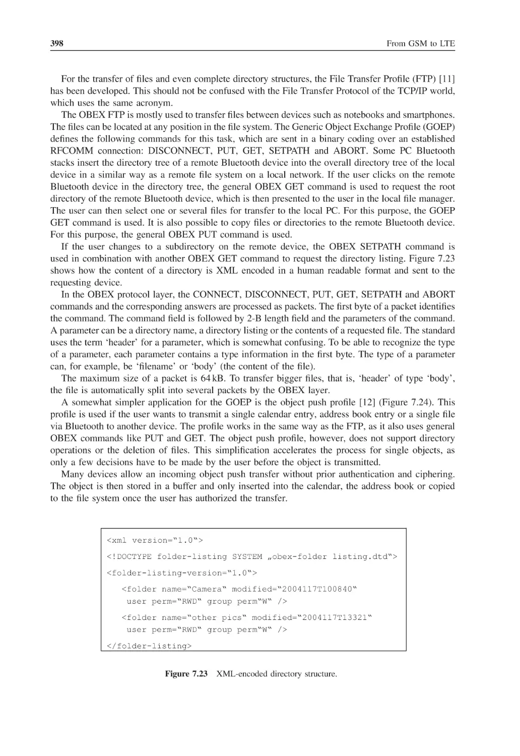
399
403
405
406
406
409
Preface
Wireless technologies like GSM, UMTS, LTE, WiMAX, Wireless LAN and Bluetooth have revolutionized the way we communicate and exchange data by making services like telephony and Internet
access available anytime and from almost anywhere. Today, a great variety of technical publications
offer background information about these technologies but they all fall short in one way or another.
Books covering these technologies usually describe only one of the systems in detail and are generally
too complex as a first introduction. The Internet is also a good source, but the articles one finds are
usually too short and superficial or only deal with a specific mechanism of one of the systems. Because
of this, it was difficult for me to recommend a single publication to students in my telecommunication classes, which I have been teaching in addition to my work in the wireless telecommunication
industry. This book aims to change this.
Each of the seven chapters in this book gives a detailed introduction and overview of one of the
wireless systems mentioned above. Special emphasis has also been put into explaining the thoughts
and reasoning behind the development of each system. Not only the ‘how’ but also the ‘why’ is
of central importance in each chapter. Furthermore, comparisons are made to show the differences
and commonalities between the technologies. For some applications, several technologies compete
directly with each other, while in other cases only a combination of different wireless technologies
creates a practical application for the end user. For readers who want to test their understanding of a
system, each chapter concludes with a list of questions. For further investigation, all chapters contain
references to the relevant standards and other documents. These provide an ideal additional source
to find out more about a specific system or topic. Please note there is a companion website for this
book. Please go to http://www.wirelessmoves.com.
While working on the book, I have tremendously benefited from wireless technologies that are
already available today. Whether at home or while traveling, Wireless LAN, Bluetooth, UMTS and
EDGE have provided reliable connectivity for my research and have allowed me to communicate with
friends and loved ones at anytime, from anywhere. In a way, the book is a child of the technologies
it describes.
Many people have been involved in revising the different chapters and have given invaluable
suggestions on content, style and grammar. I would therefore like to thank Prashant John, Timothy
Longman, Tim Smith, Peter van den Broek, Prem Jayaraj, Kevin Wriston, Gregg Beyer, Ed Illidge,
Debby Maxwell and John Edwards for their kind help and good advice.
Furthermore, my sincere thanks go to Berenike, who has stood by me during this project with her
love, friendship and good advice.
Martin Sauter
Cologne
July 2010
List of Figures
1.1
Switching matrix in a switching center
2
1.2
Necessary software changes to adapt a fixed-line switching center for a wireless network
3
1.3
Timeslot architecture of an E-1 connection
5
1.4
An SS-7 network with an STP, two SCP databases and three switching centers
6
1.5
Comparison of the SS-7, OSI and TCP/IP protocol stacks
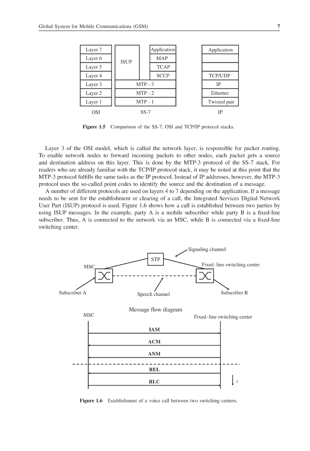
7
1.6
Establishment of a voice call between two switching centers
7
1.7
Enhancement of the SS-7 protocol stack for GSM
1.8
Comparison of the classic and IP-based SS-7 protocol stacks
1.9
Interfaces and nodes in the NSS
11
1.10 Digitization of an analog voice signal
13
9
10
1.11 Mobile switching center (MSC) with integrated Visitor Location Register (VLR)
14
1.12 The international mobile subscriber identity (IMSI)
14
1.13 A terminal program can be used to retrieve the IMSI from the SIM card
15
1.14 Creation of a signed response (SRES)
18
1.15 Message flow during the authentication of a subscriber
18
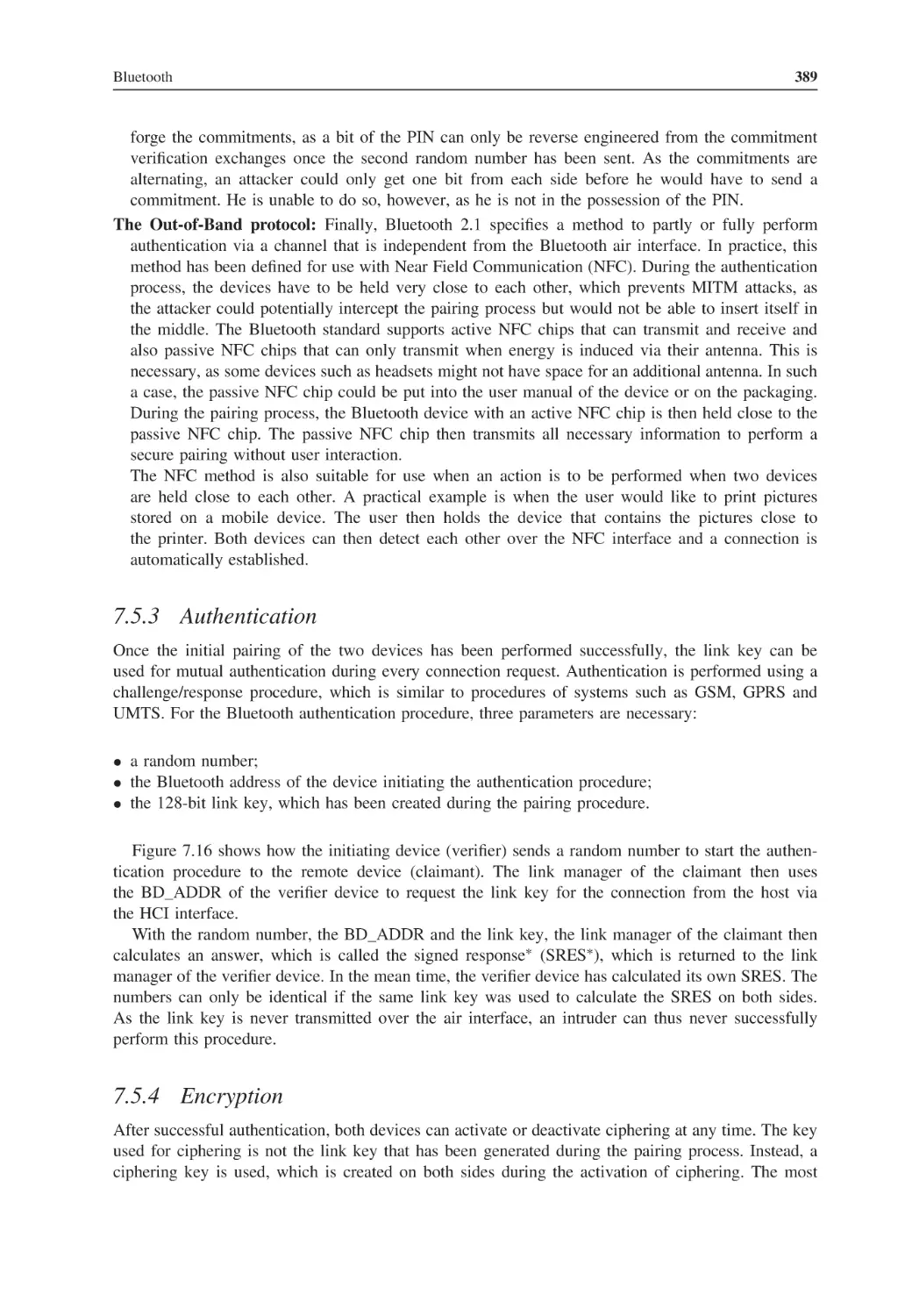
1.16 Authentication between network and mobile device
20
1.17 SMS delivery principle
20
1.18 GSM uplink and downlink in the 900-MHz frequency band
21
1.19 A typical antenna of a GSM base station. The optional microwave directional antenna
(round antenna at the bottom of the mast) connects the base station with the GSM network 23
1.20 Cellular structure of a GSM network
24
1.21 Sectorized cell configurations
24
1.22 A GSM TDMA frame
24
1.23 A GSM burst
25
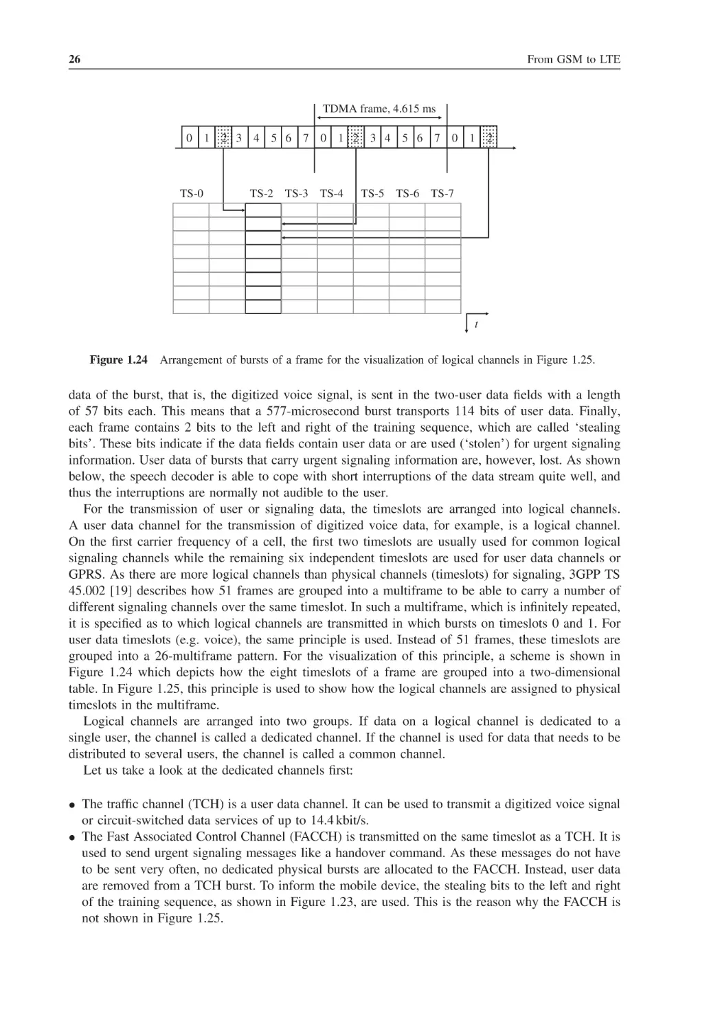
1.24 Arrangement of bursts of a frame for the visualization of logical channels in Figure 1.25
26
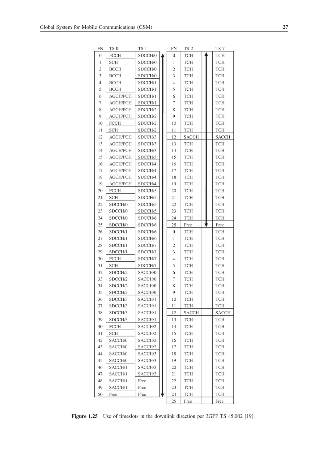
1.25 Use of timeslots in the downlink direction per 3GPP TS 45.002
27
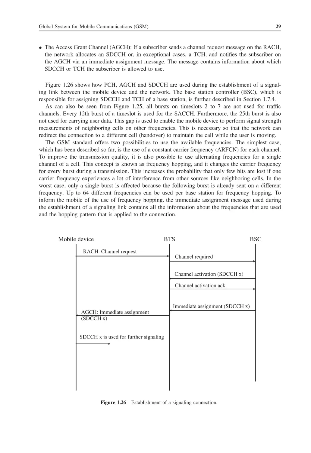
1.26 Establishment of a signaling connection
29
1.27 Mapping of E-1 timeslots to air interface timeslots
30
1.28 Establishment of a traffic channel (TCH)
31
xvi
List of Figures
1.29 Message flow during a handover procedure
32
1.30 Time shift of bursts of distant subscribers without timing advance control
34
1.31 GSM speech compression
35
1.32 Speech compression with a 4:1 compression ratio in the TRAU
36
1.33 Source–filter model of the GSM FR codec
37
1.34 Complete transmission chain with the transmitter and receiver of the GSM FR codec
37
1.35 Transmission path in the downlink direction between the network and the mobile device
38
1.36 GSM channel coder for full-rate speech frames
39
1.37 Frame interleaving
40
1.38 Ciphering of an air interface burst
40
1.39 Discontinuous transmission (DTX)
43
1.40 Cells in different location areas
45
1.41 Message flow for a location update procedure
46
1.42 Mobile-terminated call establishment, part 1
47
1.43 Mobile-terminated call establishment, part 2
48
1.44 Inter-MSC handover
50
1.45 Subsequent inter-MSC handover
50
1.46 Basic architecture of a mobile phone
51
1.47 Overview of RISC and DSP functionalities
53
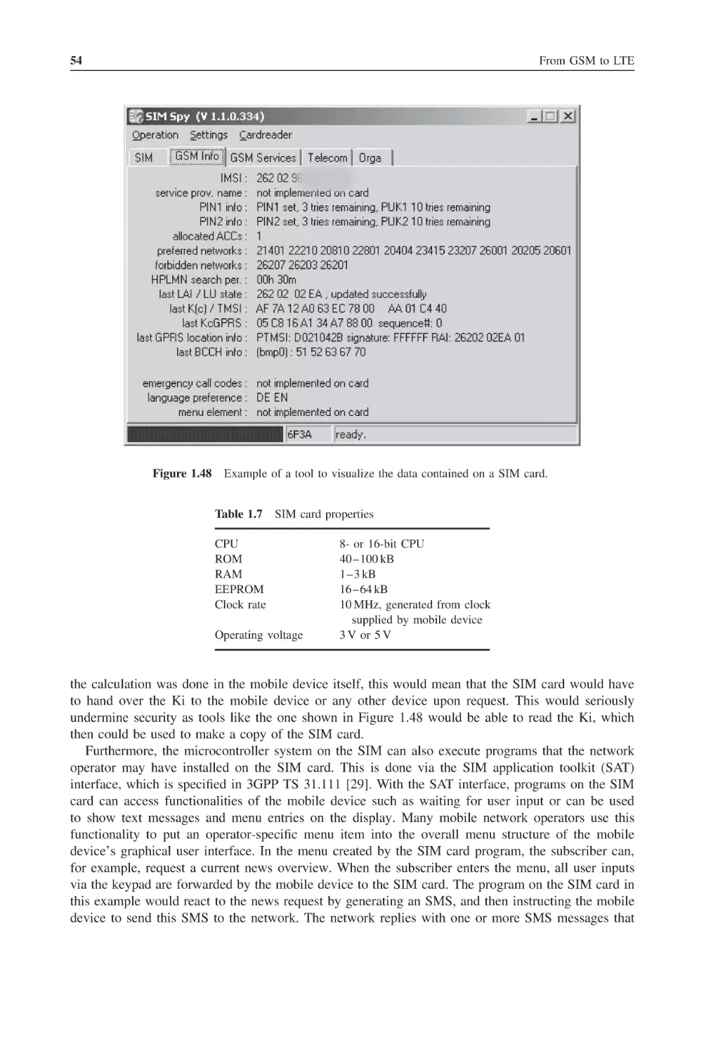
1.48 Example of a tool to visualize the data contained on a SIM card
54
1.49 Block diagram of SIM card components
55
1.50 Structure of a command APDU
56
1.51 Response APDU
57
1.52 Structure of the SELECT command APDU
57
1.53 Simplified state model for an originator (O-BCSM) according to 3GPP TS 23.078
59
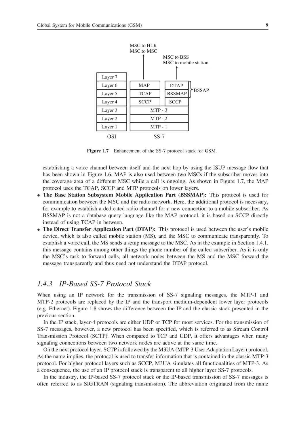
2.1
Exclusive connections of a circuit-switched system
64
2.2
Packet-switched data transmission
64
2.3
GSM, GPRS and EDGE data transmission speed comparison
65
2.4
Billing based on volume
66
2.5
Simplified visualization of PDTCH assignment and timeslot aggregation
67
2.6
Shared use of the timeslots of a cell for GSM and GPRS
68
2.7
CS-2 and CS-3 channel coder
69
2.8
GMSK (GPRS) and 8PSK (EDGE) modulation
70
2.9
MCS-9 convolutional coding and incremental redundancy
72
2.10 Paging for an incoming voice call via the Gs interface
74
2.11 PDTCH and PACCH are sent on the same timeslot
75
2.12 Logical channels of GPRS NOM II
76
2.13 Packet resources: requests and assignments, NOM II
77
2.14 The GPRS state model
78
2.15 Difference between ready and standby states
79
List of Figures
xvii
2.16 GPRS network nodes
81
2.17 Interfaces and protocols of the SGSN on layers 2 and 3
82
2.18 Ciphering in GSM and GPRS
83
2.19 Subscriber changes location within the GPRS network
84
2.20 Use of the uplink state flag
85
2.21 Use of the temporary flow identifier (TFI) in the downlink direction
86
2.22 Packet timeslot reconfiguration message according to 3GPP TS 44.060, 11.2.31
87
2.23 GPRS protocol stacks in the radio network
89
2.24 The Gn interface protocol stack
89
2.25 GTP packet on the Gn interface
90
2.26 The Gr interface
91
2.27 The Gp interface
92
2.28 GPRS attach message flow
93
2.29 GPRS attach message on the Gb interface
95
2.30 The PDP context activation procedure
96
2.31 Identification of user data packets on different GPRS interfaces
97
2.32 IP over PPP for Internet connections
98
2.33 PPP termination in the mobile device for GPRS
99
2.34 The advanced settings dialog box for entering the APN
100
2.35 Simple WML page
101
2.36 Different protocol stacks on the two sides of the WAP gateway
102
2.37 Small screen web browsing with Opera Mini
104
2.38 MMS architecture overview as defined in 3GPP TS 23.140
106
2.39 SMIL description of the layout of an MMS message
108
2.40 MIME boundaries of the different parts of an MMS message
108
2.41 Uncompressed view of an MMS header
109
2.42 IP packet flow and delay times during the download of a web page
111
3.1
Common GSM/UMTS network: Release 99
118
3.2
UMTS Release 4 (Bearer-Independent Core Network)
120
3.3
UMTS Release 5 IMS architecture
120
3.4
Separation of protocols between the core and radio network into Access Stratum (AS)
and Nonaccess Stratum (NAS)
125
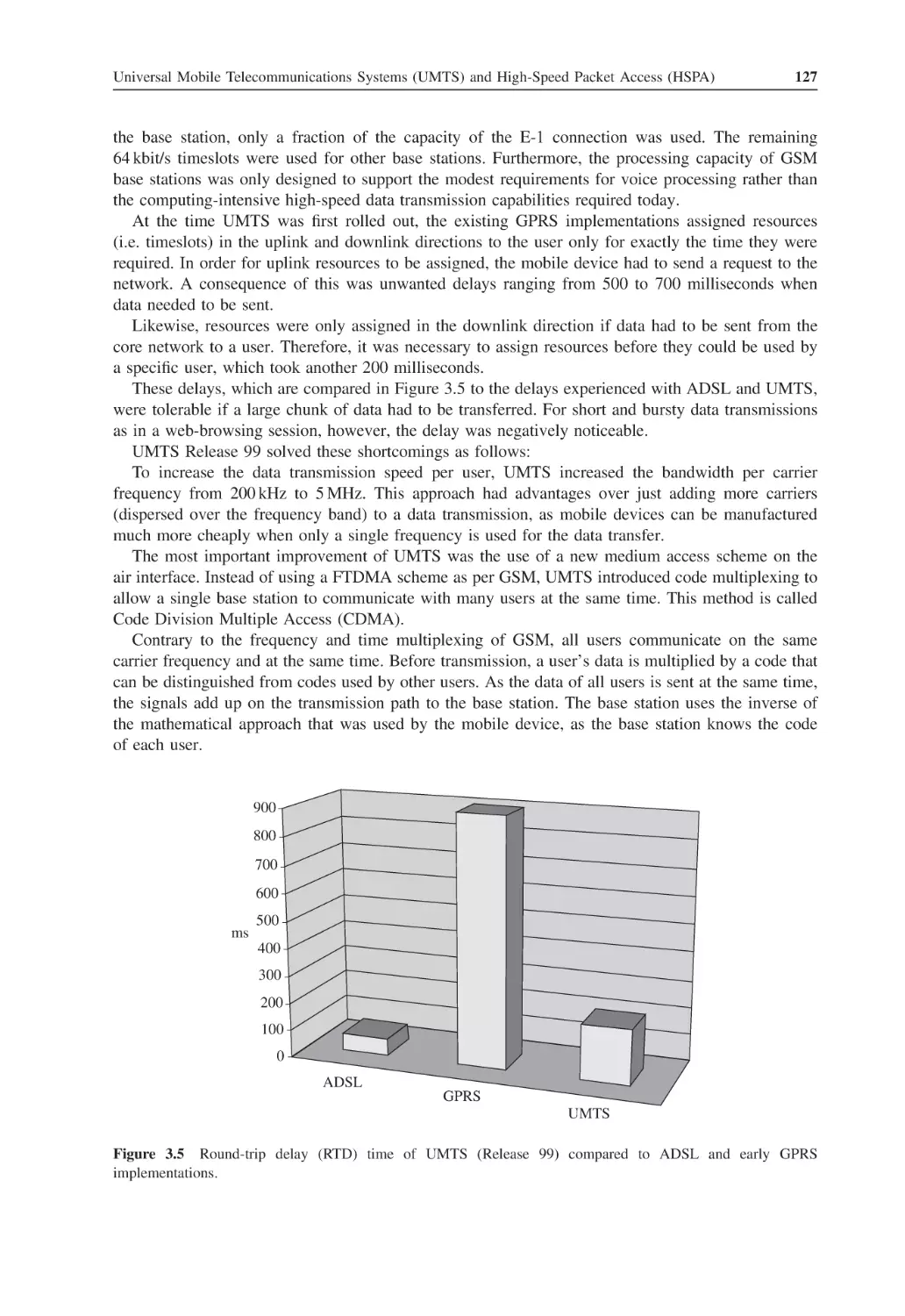
3.5
Round-trip delay (RTD) time of UMTS (Release 99) compared to ADSL and early GPRS
implementations
127
3.6
Simultaneous communication of several users with a base station in uplink direction (axis
not to scale and number of users per base station are higher in a real system)
129
Simultaneous conversation of two users with a single base station and spreading of the
data stream
129
3.8
Relation between spreading factor, chip rate, processing gain and available bandwidth
per user
130
3.9
The OVSF code tree
131
3.7
xviii
List of Figures
3.10 Spreading and scrambling
132
3.11 Cell breathing
134
3.12 User and control planes
137
3.13 Logical, transport and physical channels in downlink direction (without HSPA)
138
3.14 Logical, transport and physical channels in uplink direction (without HSPA)
138
3.15 Network search after the mobile device is switched on
142
3.16 Initial Network Access Procedure (RRC Connection Setup) as described in 3GPP
TS 25.931
144
3.17 Preparation of user data frames for air interface (Uu) transmission
145
3.18 User data transmission in downlink direction via the complex I- and Q-path
147
3.19 User data transmission via the I-path only
148
3.20 RNC protocols and interfaces for user data (user plane)
150
3.21 RNC protocols and interfaces used for signaling (control plane)
151
3.22 Factors influencing the Quality of Service and the maximum bandwidth of a connection
153
3.23 Radio Resource Control (RRC) states
155
3.24 Discontinuous Transmission (DTX) on a dedicated channel reduces the interference for
other subscribers
155
3.25 Data of different subscribers is time multiplexed on the FACH
157
3.26 UMTS hard handover
161
3.27 Connections to a mobile device during a soft handover procedure with three cells
162
3.28 Soft handover reduces the energy consumption of the mobile due to lower transmission
power
162
3.29 Use of scrambling codes while a mobile device is in soft handover state
163
3.30 Soft handover with S-RNC and D-RNC
164
3.31 SRNS relocation procedure
165
3.32 3G to 2G handover
166
3.33 A UMTS cell with several GSM neighboring cells presents a problem for blind intersystem
handovers
166
3.34 3G–2G intersystem hard handover message flow
168
3.35 Cell change in PMM connected state to a cell that cannot communicate with the S-RNC 169
3.36 Location concepts of radio- and core network
170
3.37 Messaging for a mobile-originated voice call (MOC)
171
3.38 Radio resource allocation for a voice traffic channel
172
3.39 PDP context activation
173
3.40 Simplified HSDPA channel overview in downlink direction
176
3.41 Simplified HSDPA channel overview in uplink direction
176
3.42 Detection and report of a missing frame with immediate retransmission within
10 milliseconds
178
3.43 Establishment of an HSDPA connection
182
3.44 Transport and Physical Channels used for HSUPA
185
3.45 Simultaneous downlink channels for simultaneous HSUPA, HSDPA and DCH use
185
List of Figures
xix
3.46 E-DCH protocol stack
188
3.47 Serving E-DCH cell, serving RLS and nonserving RLS
190
3.48 Control channel switch-off during times with little activity
194
3.49 Message exchange to move a mobile device from URA-PCH state back to Cell-DCH
state when IP packets arrive from the network
196
3.50 Current network architecture vs. the one-tunnel enhancement
197
3.51 FACH and DCH Power consumption
200
3.52 IP packet flow and delay times during the download of a web page
202
4.1
LTE Network Overview
208
4.2
S1 control (a) and user (b) plane protocol stack
211
4.3
Physical routing of the S1 and the X2 interface
212
4.4
LTE international roaming with home routing
216
4.5
Principles of OFDMA for downlink transmission
219
4.6
Principles of SC-FDMA for uplink transmission
220
4.7
LTE resource grid
222
4.8
Symbols in a resource block used for the reference signal
222
4.9
LTE downlink channel structure
223
4.10 LTE Channel Uplink Structure
225
4.11 Random access procedure
226
4.12 Simplified illustration of MIMO operation
228
4.13 Synchronous HARQ in the downlink direction
231
4.14 Air interface protocol stack and main functions
234
4.15 Downlink data reception overview
238
4.16 PSS and SSS in an LTE FDD frame
240
4.17 Attach and default bearer activation message flow – part 1
242
4.18 Attach and default bearer activation message flow – part 2
244
4.19 X2-based handover message flow
246
4.20 Basic S1-based handover
248
4.21 Short and long DRX cycles
252
4.22 Interconnection of LTE to GSM and UMTS networks
255
4.23 Interconnection of LTE to CDMA2000 networks
258
4.24 Fractional frequency reuse for reducing cell edge interference
261
4.25 SGs interconnection for delivery of SMS messages
263
4.26 VoLGA access network controller between the PS and CS core networks
267
4.27 The IP multimedia subsystem for LTE
269
5.1
The 802.16 protocol stack
279
5.2
802.16 operation modes: TDD and FDD operation
281
5.3
Cell sizes depending on type of SS, antenna, site conditions and transmit power
285
5.4
FDD downlink frame structure
286
5.5
FDD uplink frame structure
288
xx
5.6
List of Figures
TDD frame structure
289
5.7
Functionalities of a multipurpose WiMAX router device
293
5.8
Message flow to join a network (part 1)
294
5.9
Message flow to join a network (part 2)
296
5.10 Inefficient use of the air interface without fragmentation and packing
299
5.11 Efficient use of the air interface by using fragmentation and packing
299
5.12 ARQ with fragmentation and segmentation
300
5.13 Establishment of trust relationships required for client authentication
303
5.14 Authentication and exchange of ciphering keys
304
5.15 802.16 mesh network architecture
305
5.16 Adaptive antenna systems and beamforming
307
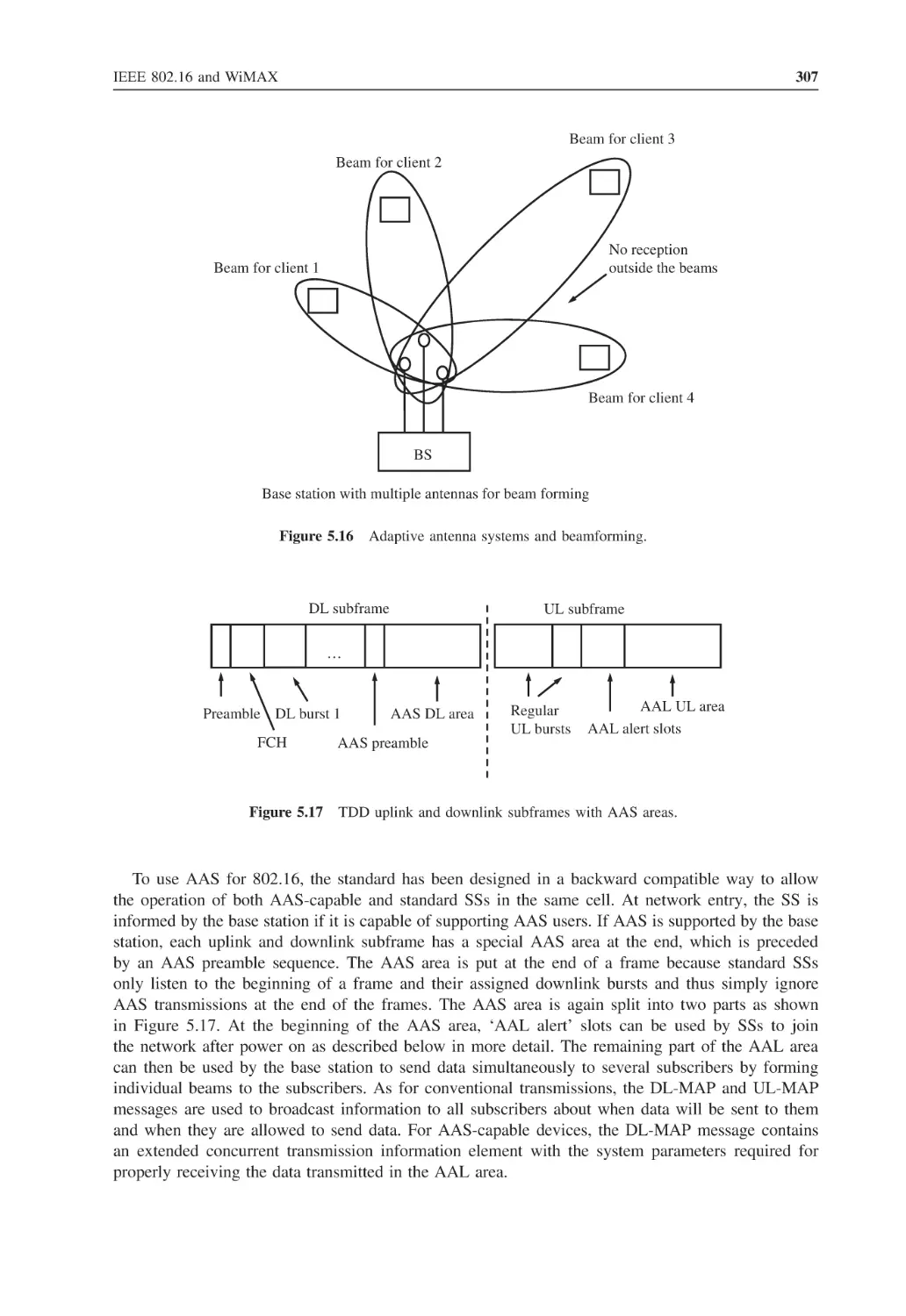
5.17 TDD uplink and downlink subframes with AAS areas
307
5.18 OFDMA subchannelization in the uplink and the downlink direction
309
5.19 A signal is split into multiple paths by objects in the transmission path
310
5.20 Optimized handover
312
5.21 Overlapping paging groups
314
5.22 WiMAX network reference architecture
316
5.23 Micro mobility management inside an ASN
317
5.24 Subscriber tunnel after handover to new cell
318
5.25 Principle of (proxy) mobile IP in a WiMAX network
319
6.1
The WLAN protocol stack
322
6.2
Infrastructure BSS
324
6.3
Access point, IP router and DSL modem in a single device
325
6.4
ESS with three access points
325
6.5
Overlapping coverage of access points forming an ESS
326
6.6
Client device configuration for a BSS or ESS
328
6.7
An extract of a beacon frame
329
6.8
Authentication and association of a client device with an access point
330
6.9
Reassociation (acknowledgment frames not shown)
331
6.10 Activation and deactivation of the PS mode (acknowledgment frames not shown)
332
6.11 Acknowledgment for every frame and required interframe space periods
333
6.12 Reservation of the air interface via RTS/CTS frames
334
6.13 MAC and LLC header of a WLAN frame
336
6.14 Complementary code keying for 11 Mbit/s transmissions
338
6.15 Simplified representation of OFDM subchannels
339
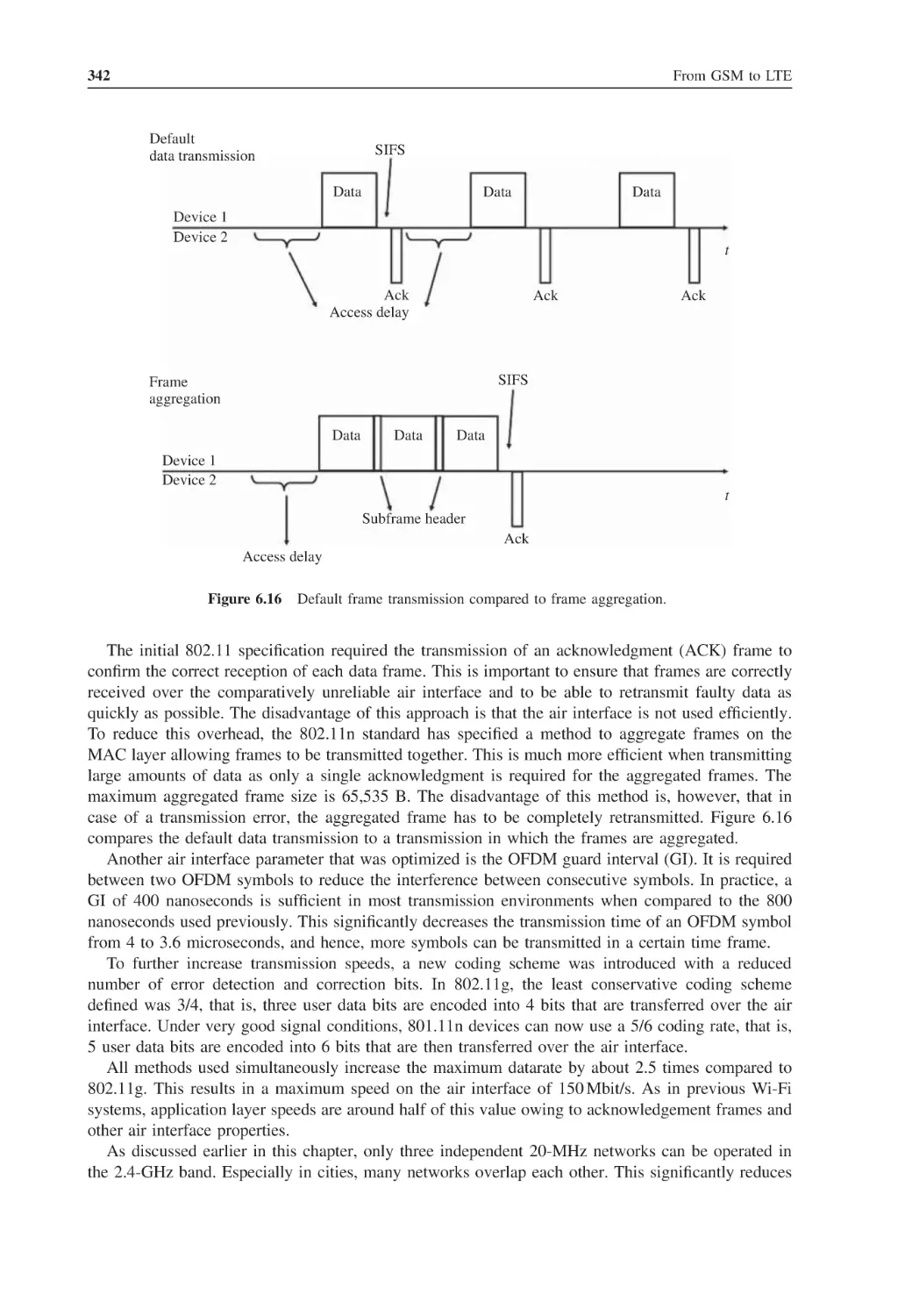
6.16 Default frame transmission compared to frame aggregation
342
6.17 2 × 2 MIMO
343
6.18 Different PLCP header variants
346
6.19 A Power Save Multipoll (PSMP) window in which several clients transmit and receive
data
347
List of Figures
6.20 WEP encryption
xxi
349
6.21 WPA-PSK authentication and ciphering key exchange
351
6.22 Three different options for WPA authentication
351
6.23 EAP-TLS authentication
352
6.24 EAP-SIM authentication
353
6.25 Protocols used in the EAP-SIM authentication process
354
6.26 WMM priority classes with example values for CWmin, CWmax and TXOP
357
6.27 QoS field in an IP packet
358
6.28 Packet bursting and block acknowledgments
359
7.1
Three examples of achievable Bluetooth datarates depending on the number of users and
their activity
367
7.2
By using different hopping sequences, many piconets can coexist in the same area
369
7.3
Data exchange between a master and three slave devices
370
7.4
The Bluetooth protocol stack
371
7.5
Composition of an ACL packet
371
7.6
The ACL payload field including the ACL header and checksum
372
7.7
Retransmission of an eSCO packet caused by a transmission error
374
7.8
Connection establishment between two Bluetooth devices
377
7.9
Communication between two link managers via the LMP
379
7.10 Establishment of a connection via the HCI command
380
7.11 Multiplexing of several data streams
382
7.12 Establishment of connection to a service
383
7.13 Multiplexing on different protocol layers
385
7.14 The different steps of a Bluetooth connection establishment
386
7.15 Pairing procedure between two Bluetooth devices
387
7.16 Authentication of a Bluetooth remote device
390
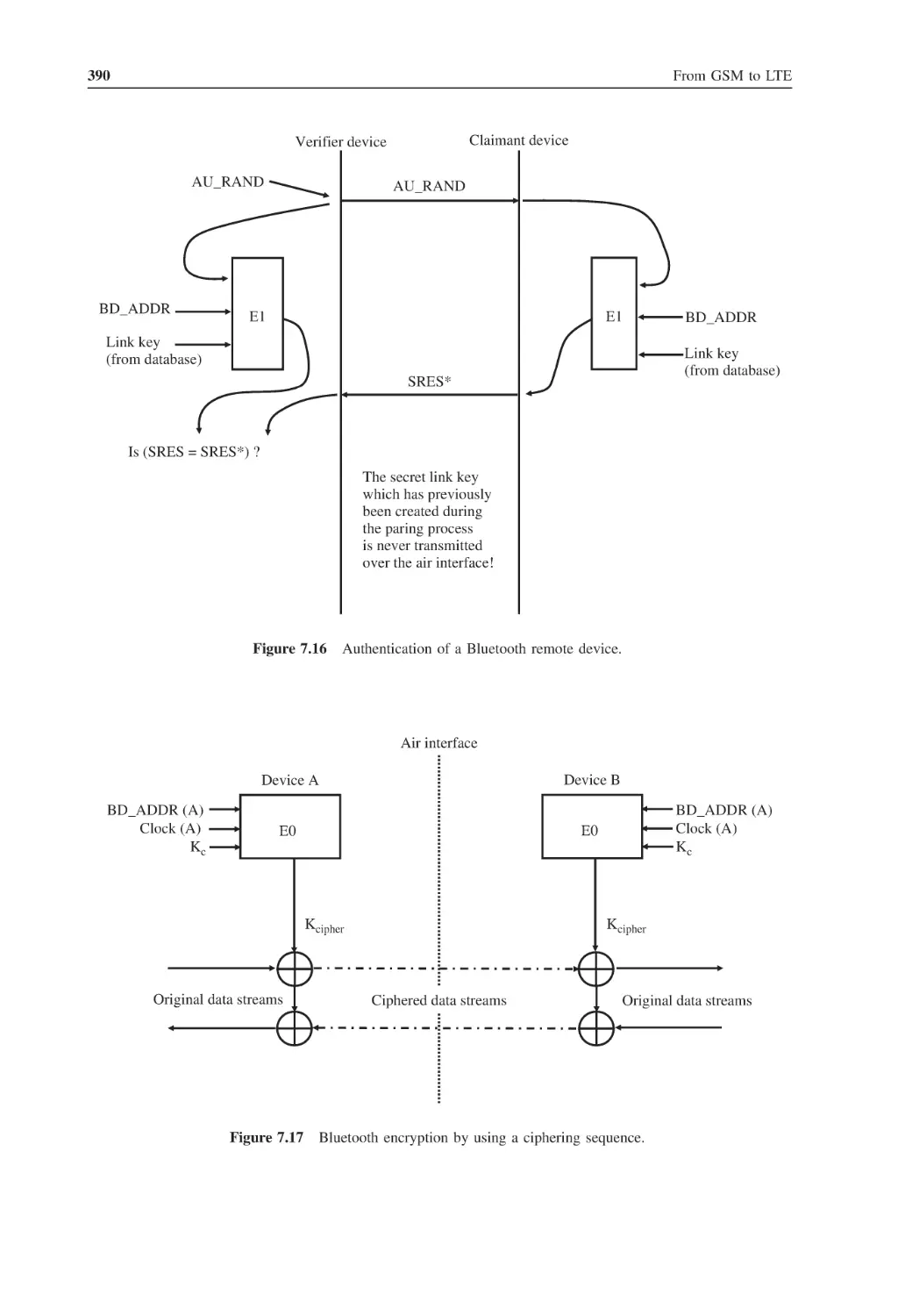
7.17 Bluetooth encryption by using a ciphering sequence
390
7.18 Protocol stack for the SPP
394
7.19 Protocol layers used by the DUN profile
395
7.20 Protocol stack of the PAN profile
396
7.21 Roles in a personal area network (PAN)
397
7.22 Protocol stack of the OBEX file transfer profile
397
7.23 XML-encoded directory structure
398
7.24 The FTP, object push and synchronization profiles are based on GOEP
399
7.25 The headset profile protocol stack
400
7.26 Establishment of the signaling and the speech channels
401
7.27 Structure of the SIM access profile
402
7.28 The protocol stack used for A2DP and remote control
403
7.29 Simultaneous audio streaming and control connections to different devices
405
List of Tables
1.1
STM transmission speeds and number of DS0s
1.2
Mobile country codes
5
1.3
Basic services of a GSM network
16
1.4
Supplementary services of a GSM network
17
1.5
GSM frequency bands
22
1.6
GSM power levels and corresponding power output
33
1.7
SIM card properties
54
1.8
Examples for APDU commands
57
1.9
Some fields of the response APDU for a SELECT command
57
2.1
Selected GPRS multislot classes from 3GPP (3rd Generation Partnership Project)
TS 45.002 Annex B1
67
15
2.2
GPRS coding schemes
69
2.3
EDGE modulation and coding schemes (MCS)
71
2.4
Resegmentation of EDGE blocks using a different MCS
2.5
Sample MMS settings
3.1
Spreading factors and data rates
132
3.2
Spreading and scrambling in uplink and downlink directions
133
3.3
AMR codecs and bit rates
154
3.4
RNC and SGSN states
158
3.5
Core network and radio network states
160
3.6
A selection of HSDPA mobile device categories
181
3.7
Spreading code sets and maximum resulting speed of different E-DCH categories
192
4.1
LTE UE categories
208
4.2
Extract of LTE frequency bands sorted by region
209
4.3
Defined bandwidths for LTE
218
4.4
System information blocks and content overview
225
4.5
LTE transmission modes
230
4.6
Downlink control channel message types (DCI formats)
237
5.1
802.16 standards documents
280
72
107
xxiv
List of Tables
5.2
802.16 modulation schemes
282
5.3
Parameters of a MAC header
289
5.4
Selection of service flow attributes
292
6.1
Different PHY standards
322
6.2
Additional 802.11 standard documents that describe optional functionality
323
6.3
802.11g datarates
340
6.4
Comparison of PHY carrier parameters of 802.11g vs. 11n
341
6.5
Feature combinations and resulting transmission speeds
344
7.1
Bluetooth versions
366
7.2
ACL packet types
372
7.3
SCO packet types
373
7.4
ACL packet types
375
7.5
Selection of HCI commands
381
7.6
Bluetooth profiles for different applications
393
List of Abbreviations
3GPP
8-DPSK
A2DP
AAL
ACK
ACL
ACM
ADDTS
ADSL
AES
AFH
AG
AGCH
AICH
AID
AIFSN
AKA
AM
AMR
A-MSC
ANM
ANR
AP
APDUs
APNs
APSD
ARFCN
ARQ
ARQN
AS
ATM
AuC
AUTN
AVCTP
Third Generation Partnership Project
Eight-phase differential phase shift keying
Advanced Audio Distribution Profile
TM Adaptation Layer
Acknowledge
Asynchronous Connectionless
Address Complete Message
Add Traffic Specification
Asymmetric Digital Subscriber Line
Advanced Encryption Standard
Adaptive Frequency Hopping
Audio Gateway
Access Grant Channel
Acquisition Indication Channel
Association identity
Arbitration Interframe Space Number
Authentication and key agreement
Acknowledged mode
Adaptive Multirate
Anchor-Mobile Switching Center
Answer Message
Automatic Neighbor Relation
Access point
Application Protocol Data Units
Access Point Names
Automated Power Save Delivery
Absolute Radio Frequency Channel Number
Automatic Retransmission Request
Automatic Retransmission Request Notification
Access Stratum
Asynchronous transfer mode
Authentication Center
Authentication token
Audio/Video Control Transport Protocol
xxvi
AVDTP
AVRCP
BCCH
BCCH
BCH
BCSM
BEP
BICC
BICN
BLER
BNEP
BQTF
BS
BS
BSC
BSS
BSS
BSSGP
BSSMAP
BTS
CAMEL
CC
CC
CCCH
CCEs
CCK
CD
CDMA
CDR
CFU
CID
CISS
CK
CLIP
CLIR
CoMP
CPC
CPICH
CQI
CRC
C-RNTI
CS
CS
CSCF
CSMA/CA
CTCH
CTS
DBPSK
DC
DCCH
List of Abbreviations
Audio Video Distribution Transfer Protocol
Audio/Video Remote Control Profile
Broadcast common control channel
Broadcast Control Channel
Broadcast Channel
Basic Call State Model
Bit error probability
Bearer-Independent Call Control
Bearer-Independent Core Network
Block error rates
Bluetooth Network Encapsulation Protocol
Bluetooth Qualification Test Facility
Base station
Best effort service
Base station controller
Base Station Subsystem
Basic service set
Base Station System GPRS Protocol
Base Station Subsystem Mobile Application Part
Base transceiver station
Customized Applications for Mobile-Enhanced Logic
Call Control
Component carrier
Common Control Channel
Control Channel Elements
Complementary Code Keying
Collision Detect/Data Carrier Detect
Code Division Multiple Access
Call detail record
Call Forward Unreachable
Connection identity
Call-independent supplementary services
Ciphering key
Calling Line Identification Presentation
Calling Line Identification Restriction
Coordinated Multipoint Operation
Continuous Packet Connectivity
Common Pilot Channel
Channel Quality Indicator
Cyclic redundancy check
Cell-Radio Network Temporary Identity
Convergence sublayer
Circuit-switched
Call Session Control Function
Carrier Sense Multiple Access/Collision Avoidance
Common Traffic Channel
Clear to Send
Differential Binary Phase Shift Keying
Dedicated control
Dedicated Control Channel
List of Abbreviations
DCD
DCF
DCH
DCI
DF
DHCP
DIFS
DLP
DL-SCH
DNS
DP
DPCCH
DPCH
DPDCH
DQPSK
DRB
D-RNC
DRS
DRX
DSCP
DSL
DSP
DSR
DSSS
DTAP
DTCH
DTIM
DTM
DTMF
DTR
DTX
DUN
DVRBs
E-AGCH
EAPs
EAPOL
EAP-TLS
ED
EDCA
E-DCH
EDGE
E-DPDCH
EEPROM
EF
EFR
EGPRS
E-HICH
EMLPP
EPC
E-RGCH
Downlink channel description
Distributed coordination function
Dedicated Channel
Downlink Control Information
Dedicated files
Dynamic Host Configuration Protocol
Distributed Coordination Function Interframe Space
Direct link protocol
Downlink Shared Channel
Domain name service
Detection point
Dedicated Physical Control Channel
Dedicated Physical Channel
Dedicated Physical Data Channel
Differential Quadrature Phase Shift Keying
Data Radio Bearer
Drift RNC
Demodulation Reference Signals
Discontinuous reception
Differentiated Services Code Point
Digital Subscriber Line
Digital signal processor
Data Set Ready
Direct sequence spread spectrum
Direct Transfer Application Part
Dedicated Traffic Channel
Delivery Traffic Indication Map
Dual transfer mode
Dual tone multifrequency
Data Terminal Ready
Discontinuous transmission
Dial-up Network
Distributed Virtual Resource Blocks
Enhanced Access Grant Channel
Extensible Authentication Protocols
EAP over LAN
Extensible Authentication Protocol Transport Layer Security
Enhanced Datarate
Enhanced Distributed Channel Access
Enhanced-DCH
Enhanced Datarates for GSM Evolution
Enhanced Dedicated Physical Data Channel
Electrically Erasable Programmable Read-Only Memory
Elementary files
Enhanced full-rate
Enhanced General Packet Radio Service
Enhanced HARQ Information Channel
Enhanced Multilevel Precedence and Preemption
Evolved Packet Core
Enhanced Relative Grant Channel
xxvii
xxviii
E-RNTI
eSCO
ESS
ETSI
EUL
E-UTRA
EvDO
FACCH
FACH
FBI
FCCH
FCH
FCI
FDD
FDD
FDMA
FEC
FFR
FFT
FHS
FHSS
FP
FR
FTDMA
FTP
FTP
GAN
GAP
GC
GFSK
GGSN
GI
GIF
GMM
G-MSC
GMSK
GOEP
GPC
GPRS
GPS
GPSS
GSM
GTP
GUTI
HA
HARQ
HCCA
HCF
HCI
HCS
List of Abbreviations
Enhanced Radio Network Temporary ID
Enhanced-synchronous connection oriented
Extended Service Set
European Telecommunication Standards Institute
Enhanced Uplink
Evolved-UMTS Terrestrial Radio Access
Evolution Data Only
Fast Associated Control Channel
Forward Access Channel
Feedback indicator
Frequency Correction Channel
Frame control header
Furnish Charging Information
Frequency division duplex
Full-duplex devices
Frequency division multiple access
Forward error correction
Fractional Frequency Reuse
Fast Fourier Transformation
Frequency hopping synchronization
Frequency hopping spread spectrum
Frame Protocol
Full-rate
Frequency and Time Division Multiple Access
File Transfer Protocol
File Transfer Profile
Generic Access Network
Generic Access Profile
General control
Gaussian Frequency Shift Keying
Gateway GPRS Support Node
Guard interval
Graphics interchange format
GPRS mobility management
Gateway Mobile Switching Center
Gaussian minimum shift keying
Generic Object Exchange Profile
Grant uplink bandwidth per connection
General Packet Radio Service
Global Positioning System
Grant uplink bandwidth per subscriber station
Global System for Mobile Communication
GPRS Tunneling Protocol
Globally Unique Temporary Identity
Home Agent
Hybrid Automatic Retransmission Request
Hybrid Coordination Function Controlled Channel Access
Hybrid Coordination Function
Host Controller Interface
Header check sequence
List of Abbreviations
HEC
HIDs
HLR
HR
HR/DSSS
HSC
HSDPA
HS-DSCH
HSPA
HS-PDSCH
HS-SCCH
HSUPA
HT
HTML
HTTP
HTTPS
IAM
IAPP
IBSS
ICE
ICIC
IEEE
IEs
IETF
IFFT
IK
IM
IMAP
IMS
IMSI
IN
IP
IRAU
ISDN
ISM
ISUP
ITU
IV
L_CH
L2CAP
LAC
LAI
LAN
LAPD
LBS
LLC
LMP
LOS
LT_ADDR
LTE
Header Error Check
Human interface devices
Home Location Register
Half-rate
High-rate/direct sequence spread spectrum
Home Subscriber Server
High-Speed Downlink Packet Access
High-Speed Downlink Shared Channel of HSDPA
High-Speed Packet Access
High-Speed Physical Downlink Shared Channel
High-Speed Shared Control Channel
High-Speed Uplink Packet Access
High Throughput
Hypertext markup language
HyperText Transfer Protocol
Secure HyperText Transfer Protocol
Initial Address Message
Inter Access Point Protocol
Independent Basic Service Set
In Case of Emergency
Intercell Interference Coordination
Institute of Electrical and Electronics Engineers
Information Elements
Internet Engineering Task Force
Inverse Fast Fourier Transformation
Integrity key
Instant messaging
Internet Message Access Protocol
IP Multimedia Subsystem
International Mobile Subscriber Identity
Intelligent Network Subsystem
Internet Protocol
Inter SGSN routing area update
Integrated Services Digital Network
Industrial, scientific, and medical
Integrated Services Digital Network User Part
International Telecommunication Union
Initialization vector
Logical channel
Logical Link Control and Adaptation Protocol
Location area code
Location Area Identity
Local area network
Link Access Protocol
Location-based services
Logical Link Control
Link Manager Protocol
Line of sight
Logical transfer address
Long Term Evolution
xxix
xxx
LU
LVRBs
M3UA
MAC
MAN
MAP
MCC
MCS
MF
MG
MIB
MIC
MIME
MIMO
MITM
MM
MME
MMS
MNC
MNP
MOC
MRC
MS
MSC
MSC-S
MSIN
MSISDN
MSRN
MTP-1
MTS
NACC
NACK
NAP
NAS
NAT
NAV
NBAP
NDC
NFC
NOM
NSAPI
NSS
OBEX
OFDM
OFDMA
OMA
OSI
OVSF
PACCH
PAGCH
List of Abbreviations
Location update
Localized Virtual Resource Blocks
MTP-3 User Adaptation Layer
Medium Access Control
Metropolitan area network
Mobile Application Part
Mobile Country Code
Modulation and coding schemes
Main file
Media Gateway
Master Information Block
Message Integrity Code
Multipurpose Internet Mail Extension
Multiple Input Multiple Output
Man-in-the-middle
Mobility Management
Mobility Management Entity
Multimedia messaging service
Mobile Network Code
Mobile number portability
Mobile originated voice call
Maximum Ratio Combining
mobile station
Mobile Switching Center
MSC Server
Mobile Subscriber Identification Number
Mobile Subscriber Integrated Services Digital Network Number
Mobile Station Roaming Number
Message Transfer Part 1
Mobile TeleSystems
Network assisted cell change
Not Acknowledge
Network Access Point
Nonaccess Stratum
Network Address Translation
Network Allocation Vector
Node-B Application Part
National destination code
Near Field Communication
Network operation mode
Network subsystem access point identifier
Network Subsystem
Object Exchange
Orthogonal Frequency Division Multiplexing
Orthogonal Frequency Division Multiple Access
Open Mobile Alliance
Open System Interconnection
Orthogonal Variable Spreading Factor
Packet-Associated Control Channel
Packet Access Grant Channel
List of Abbreviations
PAN
PANU
PAPR
PBCCH
PBCH
PCCCH
PCCH
P-CCPCH
PCFICH
PCH
PCI
PCM
PCRF
PCU
PDCCH
PDCP
PDN-GW
PDP
PDSCH
PDTCH
PDU
PEAP
PHICH
PLCP
PLMN
PMI
PMM
POP
PPCH
PPP
PPTP
PRACH
PRN
PSC
P-SCH
PSK
PSM
PSMP
PSS
PSTN
PTCCH
P-TMSI
PUCCH
PUSCH
QAM
QoS
QPSK
RAB
RACH
RADIUS
Personal area network
Personal area network users
Peak to Average Power Ratio
Packet Broadcast Control Channel
Physical Broadcast Channel
Packet Common Control Channel
Paging Control Channel
Primary Common Control Physical Channel
Physical Control Format Indicator Channel
Paging Channel
Physical Cell Identity
Pulse code-modulated
Policy Control Resource Function
Packet Control Unit
Physical Downlink Control Channel
Packet Data Convergence Protocol
Packet Data Network Gateway
Packet Data Protocol
Physical Downlink Shared Channel
Packet data traffic channel
Packet data unit
Protected Extensible Authentication Protocol
Physical Hybrid Automatic Retransmission Request Indicator Channel
Physical Layer Convergence Procedure
Public Land Mobile Network
Precoding Matrix Indicator
Packet Mobility Management
Post Office Protocol
Packet paging channel
Point-to-point protocol
Point-to-Point Tunneling Protocol
Physical Random Access Channel
Provide Roaming Number
Primary Scrambling Code
Primary Synchronization Channels
Preshared Key
Protocol service multiplexer
Power Save Multipoll
Primary synchronization signal
Public Standard Telephone Network
Packet timing advance control channel
Packet-temporary mobile subscriber identity
Physical Uplink Control Channel
Physical Uplink Shared Channel
Quadrature Amplitude Modulation
Quality of Service
Quadrature Phase Shift Keying
Radio Access Bearer
Random Access Channel
Remote Authentication Dial In User Service
xxxi
xxxii
RANAP
RAND
RAT
RAU
RB
RE
REG
REL
RI
RIFS
RISC
RLC
RLC
R-MSC
RNC
RNSAP
RoHC
RRC
RRH
RSCP
RSN
RSRP
RSRQ
RSSI
RTD
RTG
RTP
RTS
RV
RX
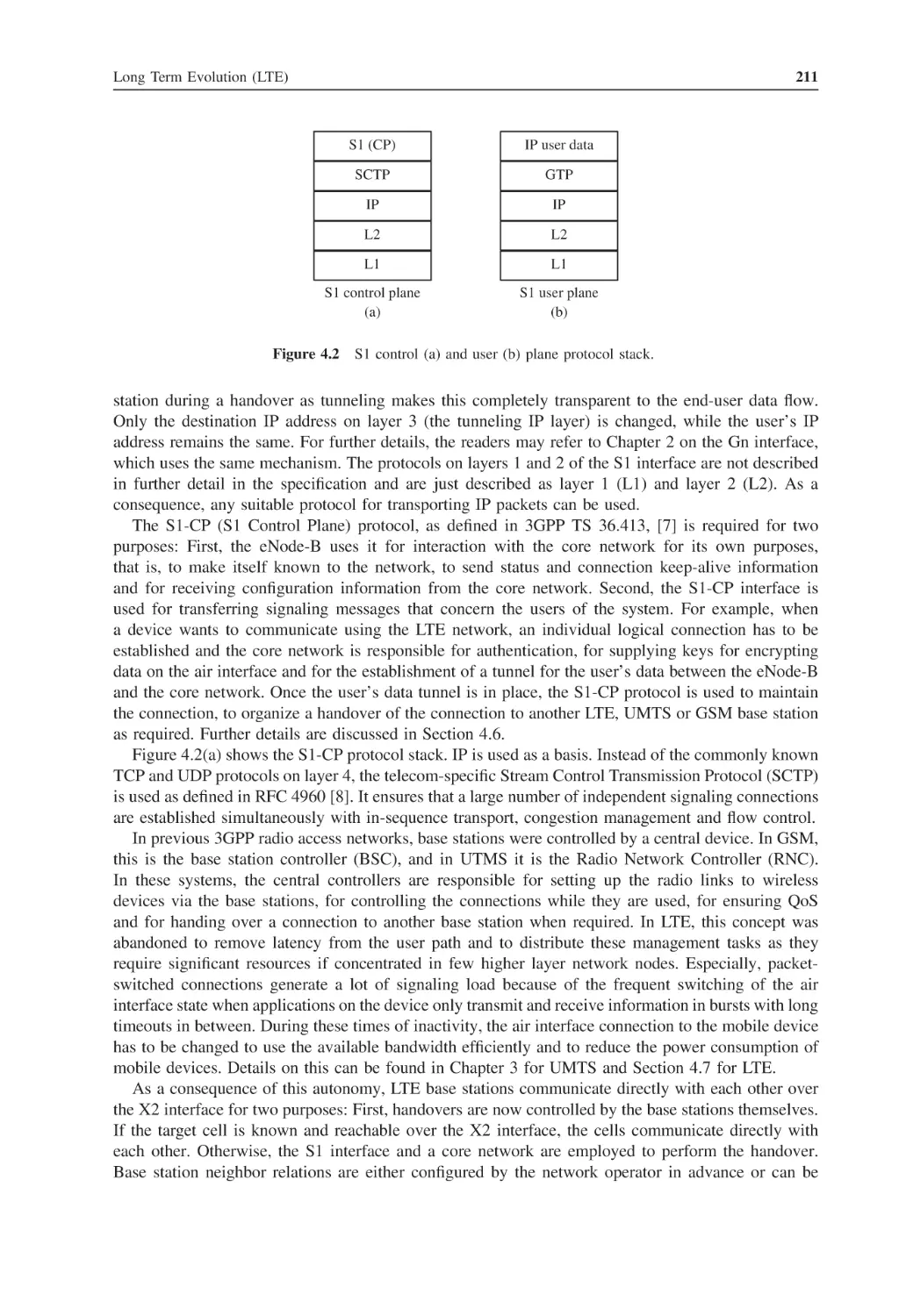
S1-CP
S1-UP
SABM
SACCH
SAE
SAFER
SAP
S-APSD
SAT
SAW
SBC
SCC AS
SCCP
S-CCPCH
SC-FDMA
SCH
SCO
SCP
SCTP
SDCCH
List of Abbreviations
Radio Access Network Application Part
Random number
Radio Access Technology
Routing area update
Resource Block
Resource Element
Resource Element Group
Release
Rank Indicator
Reduced Interframe Space
Reduced instruction set
Radio link control
Release Complete
Relay-Mobile Switching Center
Radio Network Controller
Radio Network Subsystem Application Part
Robust Header Compression
Radio Resource Control
Remote Radio Head
Received Signal Code Power
Retransmission Sequence Num
Reference Signal Received Power
Reference Signal Received Quality
Received Signal Strength Indication
Round-trip delay
Receive transition gap
Real-time Transport Protocol
Request to send
Redundancy version
Reception
S1 Control Plane
S1 User Plane
Set Asynchronous Balanced Mode
Slow Associated Control Channel
Service Architecture Evolution
Secure and Fast Encryption Routine
Service access point
Scheduled-Automated Power Save Delivery
SIM application toolkit
Stop and Wait
Sub-band codec
Service Centralization and Continuity Application Server
Signaling Connection and Control Part
Secondary Common Control Physical Channel
Single-Carrier Frequency Division Multiple Access
Synchronization Channel
Synchronous connection-oriented
Service Control Point
Stream Control Transmission Protocol
Standalone Dedicated Control Channel
List of Abbreviations
SDP
SFN
SG
SGSN
S-GW
SI
SIB
SIFS
SIG
SIGTRAN
SIP
SM
SMIL
SMS
SMSC
SMSCB
SMTP
SNDCP
SON
SP
SPP
SRES
SRI
S-RNC
SRNS
S-RNTI
SRS
SR-VCC
SS
SS-7
S-SCH
SSID
SSL
SSN
SSP
SSS
STBC
STM
STP
TA
TAC
TAI
T-BCSM
TBF
TCAP
TCH
TCP
TDD
TD-LTE
TDMA
Service Discovery Protocol
System Frame Number
Signaling Gateway
Serving GPRS Support Node
Serving Gateway
System information
System Information Block
Short interframe space
Special Interest Group
Signaling transmission
Session Initiation Protocol
Session management
Synchronized multimedia integration language
Short Messaging Service
Short Message Service Center
Short Message Service Broadcast Channel
Simple mail transfer protocol
Subnetwork dependent convergence protocol
Self-Organizing Network
Service Period
Serial Port Profile
Signed response
Send Routing Information
Serving RNC
Serving Radio Network Subsystem
Serving-Radio Network Temporary ID
Sounding Reference Signal
Single Radio Voice Call Continuity
Subscriber station
Signaling System Number 7
Secondary Synchronization Channel
Service Set Identity
Secure Socket Layer
Subsystem Number
Service Switching Point
Secondary synchronization signal
Space time block coding
Synchronous transfer mode
Signaling Transfer Point
Tracking Area
Tracking Area Code
Tracking Area Identity
Terminating Basic Call State Model
Temporary Block Flows
Transaction Capability Application Part
Traffic channel
Transmission Control Protocol
Time Division Duplex
Time Division Long Term Evolution
Time division multiple access
xxxiii
xxxiv
TEID
TFCI
TFCS
TFI
TFI
TFS
TID
TIM
TKIP
TLLI
TMSI
TPC
TR
TRAU
TS
TSPEC
TTG
TTI
TXOP
U-APSD
UART
UCD
UDP
UE
UGS
UL-MAP
UM DRB
UMTS
URA-PCH
URL
USB
USF
USSD
UTRAN
UUID
VAD
VANC
VBS
VDSL
VGCS
VLAN
VLR
V-MSC
VoIP
VoLGA
VPN
WAP
WBMP
WCDMA
WEP
List of Abbreviations
Tunnel Endpoint Identity
Traffic Format Combination ID
Transport Format Combination Set
Temporary flow identifier
Traffic Format Identifier
Transport Format Set
Tunnel identifier
Traffic Indication Map
Temporal Key Integrity Protocol
Temporary Logical Link Identifier
Temporary Mobile Subscriber Identity
Transmit Power Control
Technical Recommendation
Transcoding and Rate Adaptation Unit
Technical specification
Traffic Specification
Transmit–receive transition gap
Transmission Time Interval
Transmit Opportunity
Unscheduled-Automated Power Save Delivery
Universal asynchronous receiver and transmitter
Uplink channel descriptor
User Datagram Protocol
User Equipment
Unsolicited grant service
Uplink Map
Unacknowledged Mode Data Radio Bearer
Universal Mobile Telecommunications System
UTRAN Registration Area-Paging Channel
Universal resource locator
Universal Serial Bus
Uplink state flag
Unstructured Supplementary Service Data
UMTS terrestrial radio access network
Universally unique identity
Voice activity detection
Voice over Long Term Evolution via Generic Access Network Controller
Voice Broadcast Service
Very-high-bitrate Digital Subscriber Line
Voice Group Call Service
Virtual Local Area Network
Visitor Location Register
Visited Mobile Switching Center
Voice over Internet Protocol
Voice over Long Term Evolution via Generic Access Network
Virtual Private Network
Wireless application protocol
Wireless application bitmap protocol
Wideband Code Division Multiple Access
Wired Equivalent Privacy
List of Abbreviations
WLAN
WML
WMM
WPA
WSP
WTP
XHTML
XRES
Wireless Local Area Network
Wireless markup language
Wi-Fi Multimedia
Wireless Protected Access
Wireless session protocol
Wireless transaction protocol
Extensible hypertext markup language
Expected response
xxxv
1
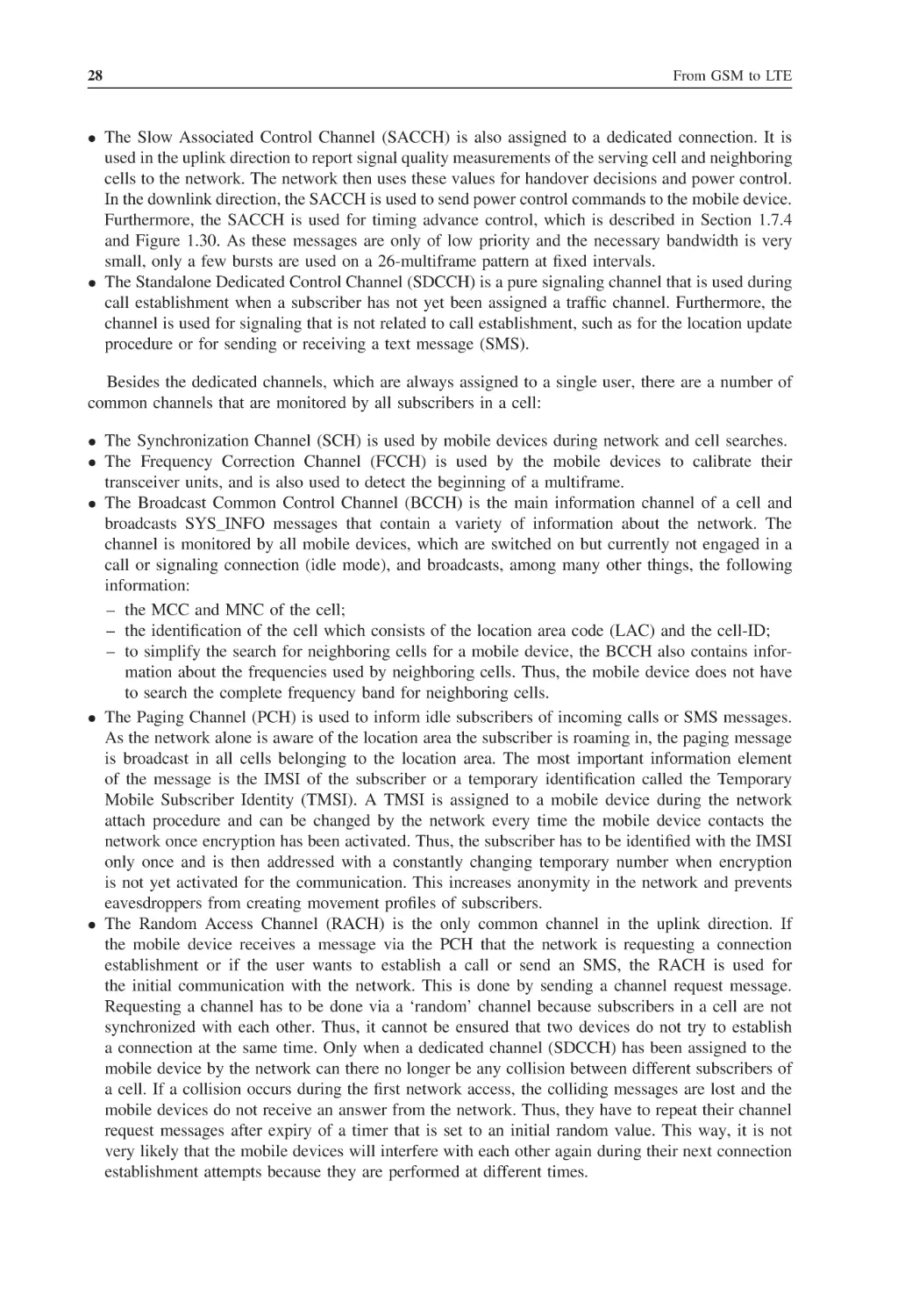
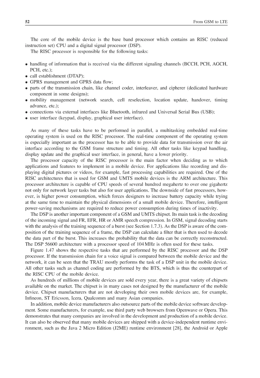
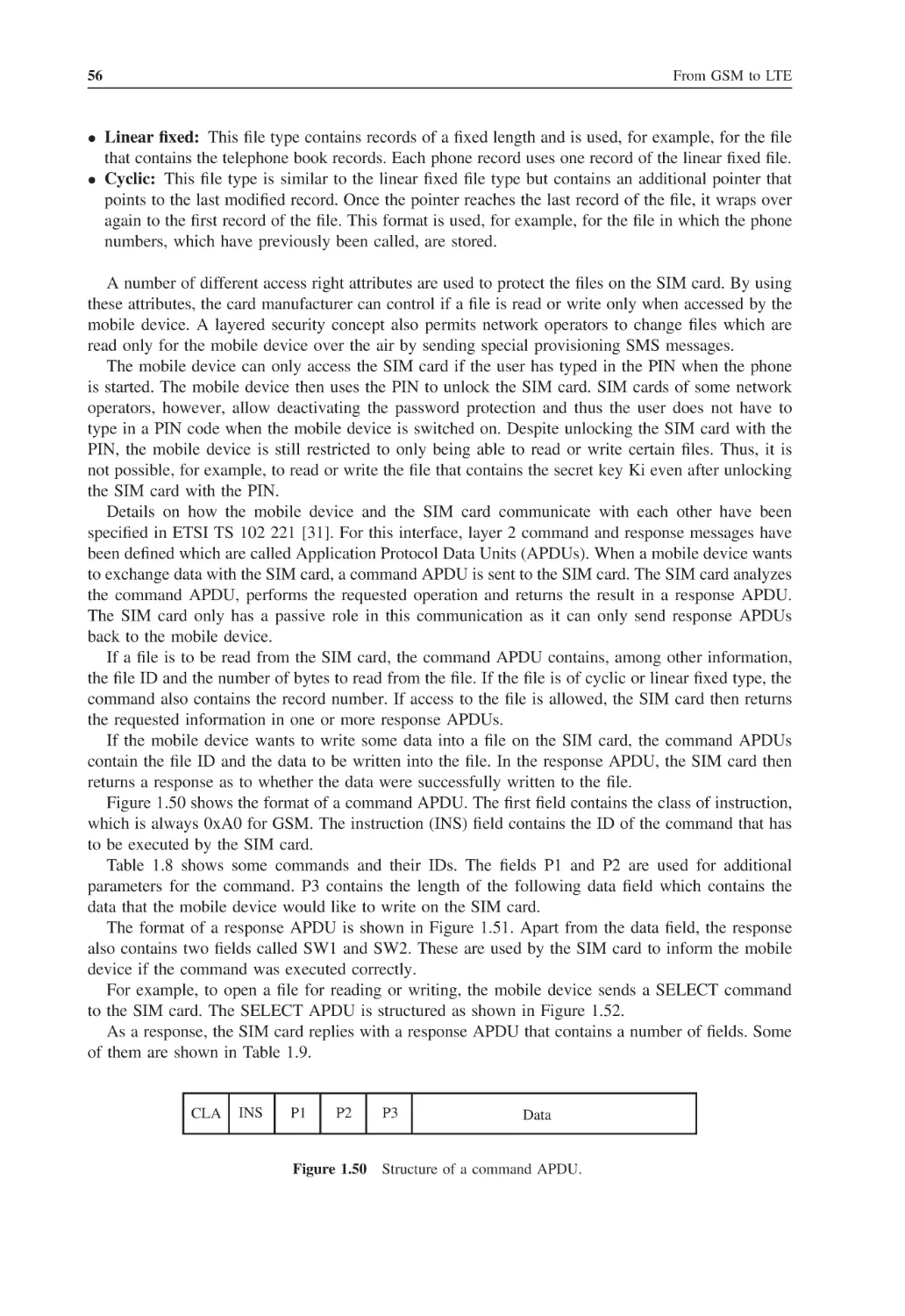
Global System for Mobile
Communications (GSM)
At the beginning of the 1990s, GSM, the Global System for Mobile Communications triggered an
unprecedented change in the way people communicate with each other. While earlier analog wireless
systems were used by only a few people, GSM is used by over 3 billion subscribers worldwide in
2010. This has mostly been achieved by the steady improvements in all areas of telecommunication
technology and the resulting steady price reductions for both infrastructure equipment and mobile
devices. This chapter discusses the architecture of this system, which also forms the basis for the
packet-switched extension called General Packet Radio Service (GPRS), discussed in Chapter 2, for
the Universal Mobile Telecommunications System (UMTS), which is described in Chapter 3 and LongTerm Evolution (LTE), which is discussed in Chapter 4. While the first designs of GSM date back to
the middle of the 1980s, GSM is still the most widely used wireless technology worldwide and it is
not expected to change any time soon. Despite its age and the evolution toward UMTS and LTE, GSM
itself continues to be developed. As shown in this chapter, GSM has been enhanced with many new
features in recent years. Therefore, many operators continue to invest in their GSM networks in addition
to their UMTS and LTE activities to introduce new functionality and to lower their operational cost.
1.1 Circuit-Switched Data Transmission
Initially, GSM was designed as a circuit-switched system that establishes a direct and exclusive connection between two users on every interface between all network nodes of the system. Section 1.1.1
gives a first overview of this traditional architecture. Over time, this physical circuit switching has
been virtualized and many network nodes are connected over IP-based broadband connections today.
The reasons for this and further details on virtual circuit switching can be found in Section 1.1.2.
1.1.1 Classic Circuit Switching
The GSM mobile telecommunication network has been designed as a circuit-switched network in
a similar way to fixed-line phone networks. At the beginning of a call, the network establishes a
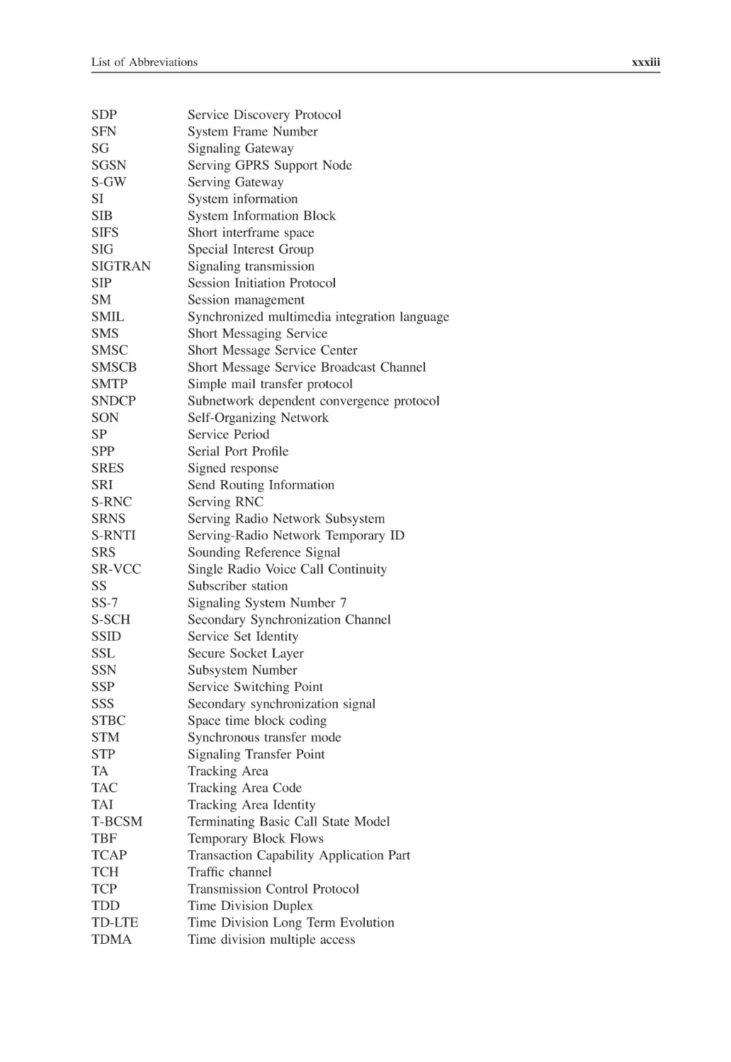
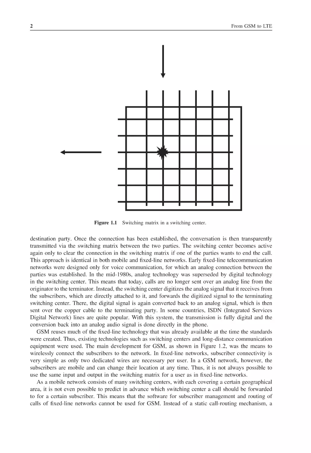
direct connection between two parties, which is then used exclusively for this conversation. As shown
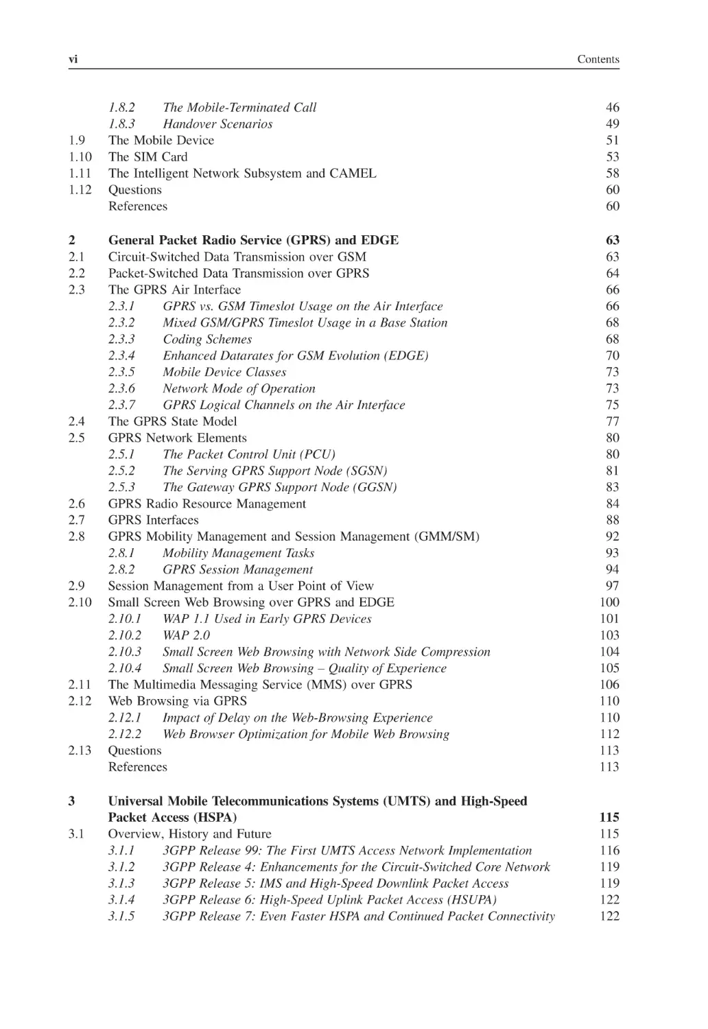
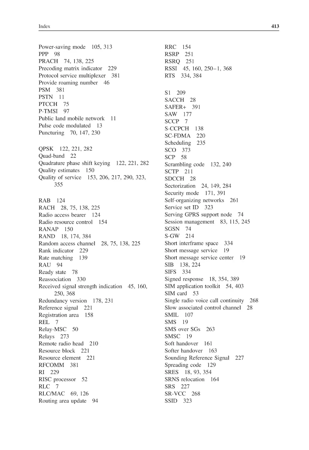
in Figure 1.1, the switching center uses a switching matrix to connect any originating party to any
From GSM to LTE: An Introduction to Mobile Networks and Mobile Broadband.
2011 John Wiley & Sons, Ltd. Published 2011 by John Wiley & Sons, Ltd.
Martin Sauter.
2
From GSM to LTE
Figure 1.1
Switching matrix in a switching center.
destination party. Once the connection has been established, the conversation is then transparently
transmitted via the switching matrix between the two parties. The switching center becomes active
again only to clear the connection in the switching matrix if one of the parties wants to end the call.
This approach is identical in both mobile and fixed-line networks. Early fixed-line telecommunication
networks were designed only for voice communication, for which an analog connection between the
parties was established. In the mid-1980s, analog technology was superseded by digital technology
in the switching center. This means that today, calls are no longer sent over an analog line from the
originator to the terminator. Instead, the switching center digitizes the analog signal that it receives from
the subscribers, which are directly attached to it, and forwards the digitized signal to the terminating
switching center. There, the digital signal is again converted back to an analog signal, which is then
sent over the copper cable to the terminating party. In some countries, ISDN (Integrated Services
Digital Network) lines are quite popular. With this system, the transmission is fully digital and the
conversion back into an analog audio signal is done directly in the phone.
GSM reuses much of the fixed-line technology that was already available at the time the standards
were created. Thus, existing technologies such as switching centers and long-distance communication
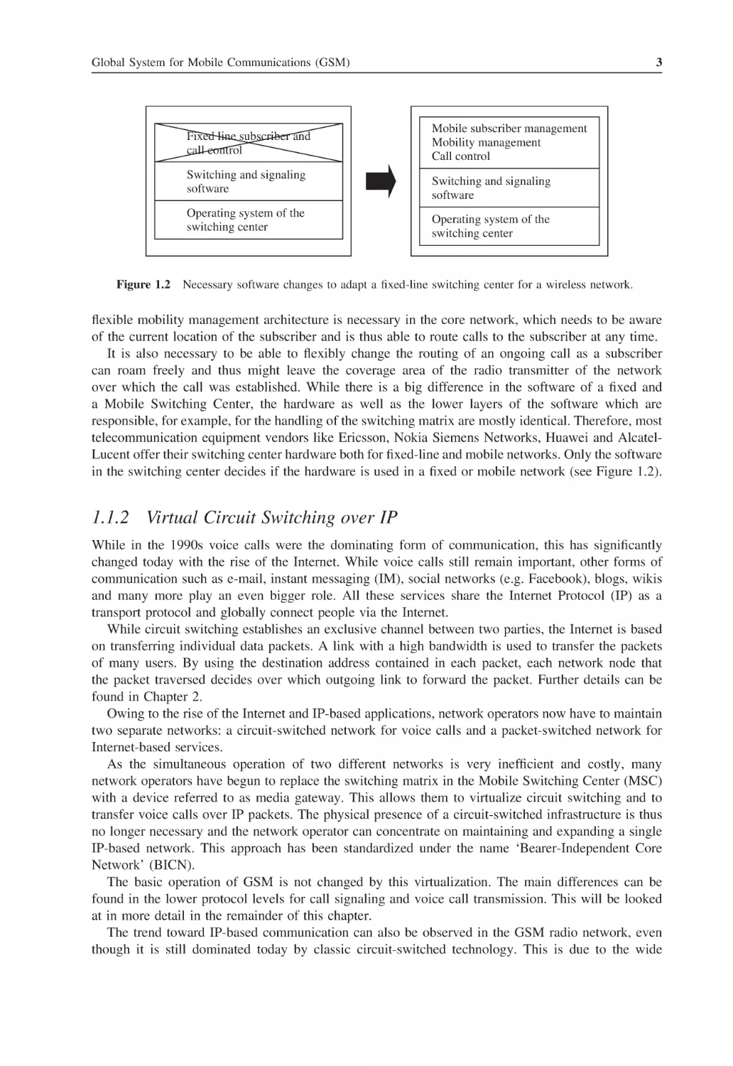
equipment were used. The main development for GSM, as shown in Figure 1.2, was the means to
wirelessly connect the subscribers to the network. In fixed-line networks, subscriber connectivity is
very simple as only two dedicated wires are necessary per user. In a GSM network, however, the
subscribers are mobile and can change their location at any time. Thus, it is not always possible to
use the same input and output in the switching matrix for a user as in fixed-line networks.
As a mobile network consists of many switching centers, with each covering a certain geographical
area, it is not even possible to predict in advance which switching center a call should be forwarded
to for a certain subscriber. This means that the software for subscriber management and routing of
calls of fixed-line networks cannot be used for GSM. Instead of a static call-routing mechanism, a
Global System for Mobile Communications (GSM)
Fixed line subscriber and
call control
Switching and signaling
software
Operating system of the
switching center
Figure 1.2
3
Mobile subscriber management
Mobility management
Call control
Switching and signaling
software
Operating system of the
switching center
Necessary software changes to adapt a fixed-line switching center for a wireless network.
flexible mobility management architecture is necessary in the core network, which needs to be aware
of the current location of the subscriber and is thus able to route calls to the subscriber at any time.
It is also necessary to be able to flexibly change the routing of an ongoing call as a subscriber
can roam freely and thus might leave the coverage area of the radio transmitter of the network
over which the call was established. While there is a big difference in the software of a fixed and
a Mobile Switching Center, the hardware as well as the lower layers of the software which are
responsible, for example, for the handling of the switching matrix are mostly identical. Therefore, most
telecommunication equipment vendors like Ericsson, Nokia Siemens Networks, Huawei and AlcatelLucent offer their switching center hardware both for fixed-line and mobile networks. Only the software
in the switching center decides if the hardware is used in a fixed or mobile network (see Figure 1.2).
1.1.2 Virtual Circuit Switching over IP
While in the 1990s voice calls were the dominating form of communication, this has significantly
changed today with the rise of the Internet. While voice calls still remain important, other forms of
communication such as e-mail, instant messaging (IM), social networks (e.g. Facebook), blogs, wikis
and many more play an even bigger role. All these services share the Internet Protocol (IP) as a
transport protocol and globally connect people via the Internet.
While circuit switching establishes an exclusive channel between two parties, the Internet is based
on transferring individual data packets. A link with a high bandwidth is used to transfer the packets
of many users. By using the destination address contained in each packet, each network node that
the packet traversed decides over which outgoing link to forward the packet. Further details can be
found in Chapter 2.
Owing to the rise of the Internet and IP-based applications, network operators now have to maintain
two separate networks: a circuit-switched network for voice calls and a packet-switched network for
Internet-based services.
As the simultaneous operation of two different networks is very inefficient and costly, many
network operators have begun to replace the switching matrix in the Mobile Switching Center (MSC)
with a device referred to as media gateway. This allows them to virtualize circuit switching and to
transfer voice calls over IP packets. The physical presence of a circuit-switched infrastructure is thus
no longer necessary and the network operator can concentrate on maintaining and expanding a single
IP-based network. This approach has been standardized under the name ‘Bearer-Independent Core
Network’ (BICN).
The basic operation of GSM is not changed by this virtualization. The main differences can be
found in the lower protocol levels for call signaling and voice call transmission. This will be looked
at in more detail in the remainder of this chapter.
The trend toward IP-based communication can also be observed in the GSM radio network, even
though it is still dominated today by classic circuit-switched technology. This is due to the wide
4
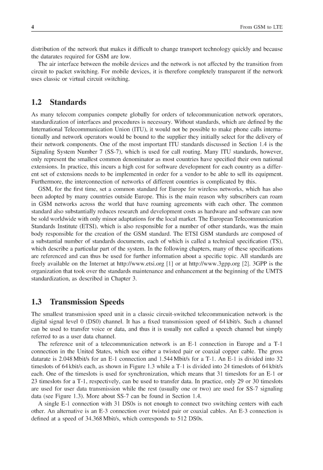
From GSM to LTE
distribution of the network that makes it difficult to change transport technology quickly and because
the datarates required for GSM are low.
The air interface between the mobile devices and the network is not affected by the transition from
circuit to packet switching. For mobile devices, it is therefore completely transparent if the network
uses classic or virtual circuit switching.
1.2 Standards
As many telecom companies compete globally for orders of telecommunication network operators,
standardization of interfaces and procedures is necessary. Without standards, which are defined by the
International Telecommunication Union (ITU), it would not be possible to make phone calls internationally and network operators would be bound to the supplier they initially select for the delivery of
their network components. One of the most important ITU standards discussed in Section 1.4 is the
Signaling System Number 7 (SS-7), which is used for call routing. Many ITU standards, however,
only represent the smallest common denominator as most countries have specified their own national
extensions. In practice, this incurs a high cost for software development for each country as a different set of extensions needs to be implemented in order for a vendor to be able to sell its equipment.
Furthermore, the interconnection of networks of different countries is complicated by this.
GSM, for the first time, set a common standard for Europe for wireless networks, which has also
been adopted by many countries outside Europe. This is the main reason why subscribers can roam
in GSM networks across the world that have roaming agreements with each other. The common
standard also substantially reduces research and development costs as hardware and software can now
be sold worldwide with only minor adaptations for the local market. The European Telecommunication
Standards Institute (ETSI), which is also responsible for a number of other standards, was the main
body responsible for the creation of the GSM standard. The ETSI GSM standards are composed of
a substantial number of standards documents, each of which is called a technical specification (TS),
which describe a particular part of the system. In the following chapters, many of these specifications
are referenced and can thus be used for further information about a specific topic. All standards are
freely available on the Internet at http://www.etsi.org [1] or at http://www.3gpp.org [2]. 3GPP is the
organization that took over the standards maintenance and enhancement at the beginning of the UMTS
standardization, as described in Chapter 3.
1.3 Transmission Speeds
The smallest transmission speed unit in a classic circuit-switched telecommunication network is the
digital signal level 0 (DS0) channel. It has a fixed transmission speed of 64 kbit/s. Such a channel
can be used to transfer voice or data, and thus it is usually not called a speech channel but simply
referred to as a user data channel.
The reference unit of a telecommunication network is an E-1 connection in Europe and a T-1
connection in the United States, which use either a twisted pair or coaxial copper cable. The gross
datarate is 2.048 Mbit/s for an E-1 connection and 1.544 Mbit/s for a T-1. An E-1 is divided into 32
timeslots of 64 kbit/s each, as shown in Figure 1.3 while a T-1 is divided into 24 timeslots of 64 kbit/s
each. One of the timeslots is used for synchronization, which means that 31 timeslots for an E-1 or
23 timeslots for a T-1, respectively, can be used to transfer data. In practice, only 29 or 30 timeslots
are used for user data transmission while the rest (usually one or two) are used for SS-7 signaling
data (see Figure 1.3). More about SS-7 can be found in Section 1.4.
A single E-1 connection with 31 DS0s is not enough to connect two switching centers with each
other. An alternative is an E-3 connection over twisted pair or coaxial cables. An E-3 connection is
defined at a speed of 34.368 Mbit/s, which corresponds to 512 DS0s.
Global System for Mobile Communications (GSM)
5
31 timeslots with 8 bits (1B) each for user data or
SS-7 signaling
Synchronization
…
Repetition interval: 8000 Hz
Speed: 32 timeslots × 8 Bit × 8000 1/s = 2.048 Mbit/s
Figure 1.3
Timeslot architecture of an E-1 connection.
Table 1.1 STM transmission speeds and number
of DS0s
STM level
Speed
(Mbit/s)
Approximate number of
DS0 connections
STM-1
STM-4
STM-16
STM-64
155.52
622.08
2488.32
9953.28
2300
9500
37,000
148,279
For higher transmission speeds and for long distances, optical systems that use the synchronous
transfer mode (STM) standard are used. Table 1.1 shows some datarates and the number of 64-kbit/s
DS0 channels that are transmitted per pair of fiber.
For virtual circuit switching over IP, optical Ethernet links are often used between network nodes at
the same location. Transmission speeds of 1 Gbit/s or more are used on these links. Unlike the circuitswitched technology described above, Ethernet is the de facto standard for IP-based communication
over fiber and copper cables and is widely used. As a consequence, network equipment can be built
much cheaper.
1.4 The Signaling System Number 7
For establishing, maintaining and clearing a connection, signaling information needs to be exchanged
between the end user and network devices. In the fixed-line network, analog phones signal their
connection request when the receiver is lifted off the hook and by dialing a phone number that is
sent to the network either via pulses (pulse dialing) or via tone dialing, which is called dual tone
multifrequency (DTMF) dialing. With fixed-line ISDN phones and GSM mobile phones, the signaling
is done via a separate dedicated signaling channel, and information such as the destination phone
number is sent as messages.
If several components in the network are involved in the call establishment, for example, if originating and terminating parties are not connected to the same switching center, it is also necessary that
the different nodes in the network exchange information with each other. This signaling is transparent
for the user, and a protocol called the signaling system number 7 (SS-7) is used for this purpose.
SS-7 is also used in GSM networks and the standard has been enhanced by ETSI to fulfill the special
requirements of mobile networks, for example, subscriber mobility management.
6
From GSM to LTE
SCP
SCP
SS7 signaling channels
STP
SSP
SSP
SSP
Speech channels
To the subscriber
To the subscriber
Figure 1.4 An SS-7 network with an STP, two SCP databases and three switching centers.
The SS-7 standard defines three basic types of network nodes:
• Service Switching Points (SSPs) are switching centers that are more generally referred to as network
elements that are able to establish, transport or forward voice and data connections.
• Service Control Points (SCPs) are databases and application software that can influence the establishment of a connection. In a GSM network, SCPs can be used, for example, for storing the current
location of a subscriber. During call establishment to a mobile subscriber, the switching centers
query the database for the current location of the subscriber to be able to forward the call. More
about this procedure can be found in Section 1.6.3 about the Home Location Register (HLR).
• Signaling Transfer Points (STPs) are responsible for the forwarding of signaling messages between
SSPs and SCPs as not all network nodes have a dedicated link to all other nodes of the network.
The principal functionality of an STP can be compared to an IP router in the Internet, which
also forwards packets to different branches of the network. Unlike IP routers, however, STPs only
forward signaling messages that are necessary for establishing, maintaining and clearing a call. The
calls themselves are directly carried on dedicated links between the SSPs.
Figure 1.4 shows the general structure of an SS-7 circuit-switched telecommunication network and
the way the nodes described above are interconnected with each other.
The SS-7 protocol stack is also used in virtual circuit-switched networks for communication between
the network nodes. Instead of dedicated signaling timeslots on an E-1 link, signaling messages are
transported in IP packets. The following section describes the classic SS-7 protocol stack and afterward,
the way SS-7 messages are transported over IP networks.
1.4.1 The Classic SS-7 Protocol Stack
SS-7 comprises a number of protocols and layers. A well-known model for describing telecommunication protocols and different layers is the Open System Interconnection (OSI) 7 layer model, which
is used in Figure 1.5 to show the layers on which the different SS-7 protocols reside.
The Message Transfer Part 1 (MTP-1) protocol describes the physical properties of the transmission
medium on layer 1 of the OSI model. Thus, this layer is also called the physical layer. Properties that
are standardized in MTP-1 are, for example, the definition of the different kinds of cables that can be
used to carry the signal, signal levels and transmission speeds.
On layer 2, the data link layer, messages are framed into packets and a start and stop identification
at the beginning and end of each packet is inserted into the data stream so that the receiver is able to
detect where a message ends and where a new message begins.
Global System for Mobile Communications (GSM)
7
Layer 7
Application
Layer 6
MAP
ISUP
Layer 5
TCAP
Layer 4
SCCP
Application
TCP/UDP
Layer 3
MTP - 3
Layer 2
MTP - 2
Ethernet
Layer 1
MTP - 1
Twisted pair
SS-7
IP
OSI
Figure 1.5
IP
Comparison of the SS-7, OSI and TCP/IP protocol stacks.
Layer 3 of the OSI model, which is called the network layer, is responsible for packet routing.
To enable network nodes to forward incoming packets to other nodes, each packet gets a source
and destination address on this layer. This is done by the MTP-3 protocol of the SS-7 stack. For
readers who are already familiar with the TCP/IP protocol stack, it may be noted at this point that the
MTP-3 protocol fulfills the same tasks as the IP protocol. Instead of IP addresses, however, the MTP-3
protocol uses the so-called point codes to identify the source and the destination of a message.
A number of different protocols are used on layers 4 to 7 depending on the application. If a message
needs to be sent for the establishment or clearing of a call, the Integrated Services Digital Network
User Part (ISUP) protocol is used. Figure 1.6 shows how a call is established between two parties by
using ISUP messages. In the example, party A is a mobile subscriber while party B is a fixed-line
subscriber. Thus, A is connected to the network via an MSC, while B is connected via a fixed-line
switching center.
Signaling channel
STP
Fixed - line switching center
MSC
Subscriber A
Speech channel
Subscriber B
Message flow diagram
MSC
Fixed - line switching center
IAM
ACM
ANM
REL
RLC
Figure 1.6
t
Establishment of a voice call between two switching centers.
8
From GSM to LTE
To call B, the phone number of B is sent by A to the MSC. The MSC then analyzes the national
destination code of the phone number, which usually comprises the first two to four digits of the
number, and detects that the number belongs to a subscriber in the fixed-line network. In the example
shown in Figure 1.6, the MSC and the fixed-line switching center are directly connected with each
other. Therefore, the call can be directly forwarded to the terminating switching center. This is quite
a realistic scenario as direct connections are often used if, for example, a mobile subscriber calls a
fixed-line phone in the same city.
As B is a fixed-line subscriber, the next step for the MSC is to establish a voice channel to the fixedline switching center. This is done by sending an ISUP Initial Address Message (IAM). The message
contains, among other data, the phone number of B and informs the fixed-line switching center and
the channel that the MSC would like to use for the voice path. In the example, the IAM message is
not sent directly to the fixed-line switching center. Instead, an STP is used to forward the message.
At the other end, the fixed-line switching center receives the message, analyzes the phone number,
and establishes a connection via its switching matrix to subscriber B. Once the connection is established
via the switching matrix, the switch applies a periodic current to the line of the fixed-line subscriber
so that the fixed-line phone can generate an alerting tone. To indicate to the originating subscriber that
the phone number is complete and the destination party has been found, the fixed-line switch sends
back an Address Complete Message (ACM). The MSC then knows that the number is complete and
that the terminating party is being alerted of the incoming call.
If B answers the call, the fixed-line switching center sends an Answer Message (ANM) to the MSC
and conversation can start.
When B ends the call, the fixed-line switching center resets the connection in the switching matrix
and sends a release (REL) message to the MSC. The MSC confirms the termination of the connection
by sending back a Release Complete (RLC) message. If A had terminated the call, the messages
would have been identical, with only the direction of the REL and RLC reversed.
For the communication between the switching centers (SSPs) and the databases (SCPs), the Signaling Connection and Control Part (SCCP) is used on layer 4. SCCP is very similar to Transmission
Control Protocol (TCP) and User Datagram Protocol (UDP) in the IP world. Protocols on layer 4 of
the protocol stack enable the distinction of different applications on a single system. TCP and UDP
use ports to do this. If a personal computer (PC), for example, is used as both a web server and a
File Transfer Protocol (FTP) server at the same time, both applications would be accessed over the
network via the same IP address. However, while the web server can be reached via port 80, the FTP
server waits for the incoming data on port 21. Therefore, it is quite easy for the network protocol stack
to decide the application to which incoming data packets should be forwarded. In the SS-7 world,
the task of forwarding incoming messages to the right application is done by SCCP. Instead of port
numbers, SCCP uses Subsystem Numbers (SSNs).
For database access, the Transaction Capability Application Part (TCAP) protocol has been designed
as part of the SS-7 family of protocols. TCAP defines a number of different modules and messages
that can be used to query all kinds of different databases in a uniform way.
1.4.2 SS-7 Protocols for GSM
Apart from the fixed-line network SS-7 protocols, the following additional protocols were defined to
address the special needs of a GSM network.
• The Mobile Application Part (MAP): This protocol has been standardized in 3GPP TS 29.002 [3]
and is used for the communication between an MSC and the HLR, which maintains subscriber
information. The HLR is queried, for example, if the MSC wants to establish a connection to a
mobile subscriber. In this case, the HLR returns the information about the current location of the
subscriber. The MSC is then able to forward the call to the mobile subscriber’s switching center
Global System for Mobile Communications (GSM)
9
MSC to HLR
MSC to MSC
MSC to BSS
MSC to mobile station
Layer 7
Layer 6
MAP
DTAP
Layer 5
TCAP
BSSMAP
Layer 4
SCCP
SCCP
Layer 3
MTP - 3
Layer 2
MTP - 2
Layer 1
MTP - 1
OSI
Figure 1.7
BSSAP
SS-7
Enhancement of the SS-7 protocol stack for GSM.
establishing a voice channel between itself and the next hop by using the ISUP message flow that
has been shown in Figure 1.6. MAP is also used between two MSCs if the subscriber moves into
the coverage area of a different MSC while a call is ongoing. As shown in Figure 1.7, the MAP
protocol uses the TCAP, SCCP and MTP protocols on lower layers.
• The Base Station Subsystem Mobile Application Part (BSSMAP): This protocol is used for
communication between the MSC and the radio network. Here, the additional protocol is necessary,
for example to establish a dedicated radio channel for a new connection to a mobile subscriber. As
BSSMAP is not a database query language like the MAP protocol, it is based on SCCP directly
instead of using TCAP in between.
• The Direct Transfer Application Part (DTAP): This protocol is used between the user’s mobile
device, which is also called mobile station (MS), and the MSC to communicate transparently. To
establish a voice call, the MS sends a setup message to the MSC. As in the example in Section 1.4.1,
this message contains among other things the phone number of the called subscriber. As it is only
the MSC’s task to forward calls, all network nodes between the MS and the MSC forward the
message transparently and thus need not understand the DTAP protocol.
1.4.3 IP-Based SS-7 Protocol Stack
When using an IP network for the transmission of SS-7 signaling messages, the MTP-1 and
MTP-2 protocols are replaced by the IP and the transport medium-dependent lower layer protocols
(e.g. Ethernet). Figure 1.8 shows the difference between the IP and the classic stack presented in the
previous section.
In the IP stack, layer-4 protocols are either UDP or TCP for most services. For the transmission of
SS-7 messages, however, a new protocol has been specified, which is referred to as Stream Control
Transmission Protocol (SCTP). When compared to TCP and UDP, it offers advantages when many
signaling connections between two network nodes are active at the same time.
On the next protocol layer, SCTP is followed by the M3UA (MTP-3 User Adaptation Layer) protocol.
As the name implies, the protocol is used to transfer information that is contained in the classic MTP-3
protocol. For higher protocol layers such as SCCP, M3UA simulates all functionalities of MTP-3. As
a consequence, the use of an IP protocol stack is transparent to all higher layer SS-7 protocols.
In the industry, the IP-based SS-7 protocol stack or the IP-based transmission of SS-7 messages is
often referred to as SIGTRAN (signaling transmission). The abbreviation originated from the name
10
From GSM to LTE
MSC to HLR and
MSC to MSC
MSC to HLR and
MSC to MSC
MSC to BSS and
MSC to mobile
Core network
Call control
MAP
DTAP
BICC
TCAP
BSSMAP
Core network
Call control
ISUP
SCCP
SCCP
MTP - 3
MTP - 2
MTP - 1
SS-7 over MTP
Figure 1.8
MSC to BSS and
MSC to mobile
MAP
DTAP
TCAP
BSSMAP
SCCP
SCCP
IP, SCTP, M3UA
Ethernet and others
SS-7 over IP
(SIGTRAN)
Comparison of the classic and IP-based SS-7 protocol stacks.
of the IETF (Internet Engineering Task Force) working group that was created for the definition of
these protocols.
As described in Section 1.1.1, the ISUP protocol is used for the establishment of voice calls
between switching centers and the assignment of a 64 kbit/s timeslot. In an IP-based network, voice
calls are transmitted in IP packets. As a consequence, the ISUP protocol has to be adapted as well.
The resulting protocol is referred to as Bearer-Independent Call Control (BICC) protocol, which
largely resembles ISUP.
As IP links cannot be introduced on all interfaces in live networks at once, Signaling Gateways
(SGs) have been defined to bridge E-1 based and IP-based SS-7 communication. The SGs adapt the
lower layers of the protocol stack and thus make the differences transparent for both sides. This is
necessary, for example, if the subscriber database has already been converted for IP interfaces while
other components such as the switching centers are still using traditional signaling links.
To bridge voice calls between E-1 based and IP-based networks, Media Gateways (MGs) are used.
Connected to an MSC Server, an MG handles both IP-based and E-1-based voice calls transparently
as it implements both the classic and IP-based signaling protocol stacks.
1.5 The GSM Subsystems
A GSM network is split into three subsystems which are described in more detail below:
• The Base Station Subsystem (BSS), which is also called ‘radio network’, contains all nodes and
functionalities that are necessary to wirelessly connect mobile subscribers over the radio interface
to the network. The radio interface is usually also referred to as the ‘air interface’.
• The Network Subsystem (NSS), which is also called ‘core network’, contains all nodes and
functionalities that are necessary for switching of calls, for subscriber management and mobility management.
• The Intelligent Network Subsystem (IN) comprises SCP databases that add optional functionality
to the network. One of the most important optional IN functionality of a mobile network is the
prepaid service, which allows subscribers to first fund an account with a certain amount of money
which can then be used for network services like phone calls, Short Messaging Service (SMS)
Global System for Mobile Communications (GSM)
11
messages and, of course, data services via GPRS and UMTS as described in Chapters 2 and 3.
When a prepaid subscriber uses a service of the network, the responsible IN node is contacted and
the amount the network operator charges for a service is deducted from the account in real time.
1.6 The Network Subsystem
The most important responsibilities of the NSS are call establishment, call control and routing of
calls between different fixed and mobile switching centers and other networks. Other networks are,
for example, the national fixed-line network, which is also called the Public Switched Telephone
Network (PSTN), international fixed-line networks, other national and international mobile networks
and Voice over Internet Protocol (VoIP) networks. Furthermore, the NSS is responsible for subscriber
management. The nodes necessary for these tasks are shown in Figure 1.9 and are further described
in the following sections.
1.6.1 The Mobile Switching Center (MSC)
The MSC is the central element of a mobile telecommunication network, which is also called a Public
Land Mobile Network (PLMN) in the standards. In a classic circuit-switched network, all connections
between subscribers are managed by the MSC and are always routed over the switching matrix even if
two subscribers that have established a connection communicate over the same radio cell. In a virtual
circuit-switched network, the MSC is split into two parts: the MSC Server (MSC-S) and the MG. The
IP-based MG replaces the switching matrix while the MSC-S contains the same logic for subscriber
management and call control as the central processing unit (CPU) of a classic MSC.
The management activities to establish and maintain a connection are part of the Call Control (CC)
Protocol, which is generally responsible for the following tasks:
• Registration of mobile subscribers: When the mobile device, also referred to as mobile station
(MS), is switched on, it registers to the network and is then reachable by all other subscribers of
the network.
• Call establishment and call routing between two subscribers.
• Forwarding of SMS (short messaging service) messages.
BSS
BSS
E-interface
A-interface
PSTN
VLR
MSC
G-MSC
VLR
C-interface
D-interface
HLR
Figure 1.9
Interfaces and nodes in the NSS.
12
From GSM to LTE
As subscribers can roam freely in the network, the MSC is also responsible for the Mobility
Management (MM) of subscribers. This activity comprises the following tasks:
• Authentication of subscribers at connection establishment is necessary because a subscriber cannot
be identified as in the fixed network by the pair of copper cables over which the signal arrives.
Authentication of subscribers and the authentication center are further discussed in Section 1.6.4.
• If no active connection exists between the network and the mobile device, the MSC has to report
a change of location to the network to be reachable for incoming calls and SMS messages. This
procedure is called location update and is further described in Section 1.8.1.
• If the subscriber changes its location while a connection is established with the network, the MSC
is part of the process that ensures that the connection is not interrupted and is rerouted to the next
cell. This procedure is called handover and is described in more detail in Section 1.8.3.
To enable the MSC to communicate with other nodes of the network, it is connected to them via
standardized interfaces as shown in Figure 1.9. This allows network operators to acquire different
components for the network from different network vendors. The interfaces discussed below are
either transmitted over timeslots in circuit-switched E-1 lines or over an IP-based network. As
described earlier, only the lower protocol layers are affected by this. On the application layer, both
variants are identical.
The BSS, which connects all subscribers to the core network, is connected to the MSCs via a
number of 2-Mbit/s E-1 connections. This interface is called the A-interface. As has been shown
in Section 1.4, the BSSMAP and DTAP protocols are used over the A-interface for communication
between the MSC, the BSS and the mobile devices. As an E-1 connection can only carry 31 channels,
many E-1 connections are necessary to connect an MSC to the BSS. In practice, this means that many
E-1s are bundled and sent over optical connections such as STM-1 to the BSS. Another reason to
use an optical connection is that electrical signals can only be carried over long distances with great
effort and it is not unusual that an MSC is over 100 km away from the next BSS node.
As an MSC only has a limited switching capacity and processing power, a PLMN is usually
composed of dozens of independent MSCs. Each MSC thus covers only a certain area of the network.
To ensure connectivity beyond the immediate coverage area of an MSC, E-1s, which are again bundled
into optical connections, are used to interconnect the different MSCs of a network. As a subscriber can
roam into the area that is controlled by a different MSC while a connection is active, it is necessary
to change the route of an active connection to the new MSC (handover). The necessary signaling
connection is called the E-interface. ISUP is used for the establishment of the speech path between
different MSCs and the MAP protocol is used for the handover signaling between the MSCs. Further
information on the handover process can be found in Section 1.8.3.
The C-interface is used to connect the MSCs of a network with the HLR of the mobile network. While the A-and E-interfaces that were described previously always consist of signaling and
speech path links, the C-interface is a pure signaling link. Speech channels are not necessary for the
C-interface as the HLR is a pure database that cannot accept or forward calls. Despite being only a
signaling interface, E-1 connections are used for this interface. All timeslots are used for signaling
purposes or are unused.
As has been shown in Section 1.3, a voice connection is carried over a 64 kbit/s E-1 timeslot in
a classic circuit-switched fixed-line or mobile network. Before the voice signal can be forwarded, it
needs to be digitized. For an analog fixed-line connection, this is done in the switching center, while
an ISDN fixed-line phone or a GSM mobile phone digitizes the voice signal by itself.
On IP-based interfaces, a virtualized circuit-switched voice call is also transferred with a user data
speed of 64 kbit/s. Instead of having an exclusive timeslot for itself, however, it shares a broadband
channel with other calls or IP data streams from other applications. The encoding of the speech data
is identical to the encoding used before the data are transmitted over a classic circuit; so it is simple
for MGs to bridge networks that use different systems.
Global System for Mobile Communications (GSM)
Speech is converted by a
microphone to an analog
signal
13
Bandwidth- limited
signal
Pulse-amplitudemodulated signal
every 125µs
Digitized
speech signal
at 64 kbit/s
Band-pass
filter
Sampler
Quantitizer
300 Hz – 3.4 kHz
Sample frequency: 8000 Hz
13 - segment curve
256 values, 8 bit
Figure 1.10
Digitization of an analog voice signal.
An analog voice signal is digitized in three steps, as shown in Figure 1.10: in the first step, the
bandwidth of the input signal is limited to 300–3400 Hz to be able to carry the signal with the limited
bandwidth of a 64-kbit/s timeslot. Afterward, the signal is sampled at a rate of 8000 times per second.
The next processing step is the quantization of the samples, which means that the analog samples are
converted into 8-bit digital values that can each have a value from 0 to 255.
The higher the volume of the input signal, the higher the amplitude of the sampled value and its
digital representation. To be able to also transmit low-volume conversations, the quantization is not
linear over the whole input range but only in certain areas. For small amplitudes of the input signal, a
much higher range of digital values is used than for high-amplitude values. The resulting digital data
stream is called a pulse code-modulated (PCM) signal. Which volume is represented by which digital
8-bit value is described in the A-law standard for European networks and in the µ-law standard in
North America.
The use of different standards unfortunately complicates voice calls between networks that use
different standards. Therefore, it is necessary, for example, to convert a voice signal for a connection
between France and the United States.
As the MSC controls all connections, it is also responsible for billing. This is done by creating a
billing record for each call, which is later transferred to a billing server. The billing record contains
information like the number of the caller and the calling party, cell-ID of the cell from which the
call originated, time of call origination, the duration of the call, etc. Calls for prepaid subscribers are
treated differently as the charging is already done while the call is running. The prepaid billing service
is usually implemented on an IN system and not on the MSC as is further described in Section 1.11.
1.6.2 The Visitor Location Register (VLR)
Each MSC has an associated Visitor Location Register (VLR), which holds the record of each subscriber that is currently served by the MSC (Figure 1.11). These records are only a copy of the original
records, which are stored in the HLR (see Section 1.6.3). The VLR is mainly used to reduce the signaling between the MSC and the HLR. If a subscriber roams into the area of an MSC, the data are
copied to the VLR of the MSC and are thus locally available for every connection establishment. The
verification of the subscriber’s record at every connection establishment is necessary, as the record
contains information about the services that are active and the services from which the subscriber
is barred. Thus, it is possible, for example, to bar outgoing calls while allowing incoming calls to
prevent abuse of the system. While the standards allow implementation of the VLR as an independent
hardware component, all vendors have implemented the VLR simply as a software component in the
MSC. This is possible because MSC and VLR use different SCCP subsystem numbers as shown in
Figure 1.11 (see Section 1.4.1) and can thus run on a single physical node.
14
From GSM to LTE
Switching center
MSC
‘application’
with SSN = 8
VLR
‘application’
with SSN = 7
SCCP
MTP 1–3
Incoming signaling messages
for VLR and MSC
Figure 1.11
Mobile switching center (MSC) with integrated Visitor Location Register (VLR).
When a subscriber leaves the coverage area of an MSC, his record is copied from the HLR to the
VLR of the new MSC, and is then removed from the VLR of the previous MSC. The communication
with the HLR is standardized in the D-interface specification, which is shown together with other
MSC interfaces in Figure 1.9.
1.6.3 The Home Location Register (HLR)
The HLR is the subscriber database of a GSM network. It contains a record for each subscriber, which
contains information about the individually available services.
The International Mobile Subscriber Identity (IMSI) is an internationally unique number that identifies a subscriber and is used for most subscriber-related signaling in the network (Figure 1.12). The
IMSI is stored in the subscriber’s subscriber identity module (SIM) card and in the HLR and is thus
the key to all information about the subscriber. The IMSI consists of the following parts:
• The Mobile Country Code (MCC): The MCC identifies the subscriber’s home country. Table 1.2
shows a number of MCC examples.
• The Mobile Network Code (MNC): This part of the IMSI is the national part of a subscriber’s
home network identification. A national identification is necessary because there are usually several independent mobile networks in a single country. In the United Kingdom, for example, the
following MNCs are used: 10 for O2, 15 for Vodafone, 30 for T-Mobile, 33 for Orange, 20 for
Hutchison 3G, etc.
• The Mobile Subscriber Identification Number (MSIN): The remaining digits of the IMSI form
the MSIN, which uniquely identifies a subscriber within the home network.
IMSI: max. 15 Digits
2–3 Digits
MCC MNC
MSIN
3 Digits
Figure 1.12
The international mobile subscriber identity (IMSI).
Global System for Mobile Communications (GSM)
Table 1.2
Figure 1.13
15
Mobile country codes
MCC
Country
234
310
228
208
262
604
505
United Kingdom
United States
Switzerland
France
Germany
Morocco
Australia
A terminal program can be used to retrieve the IMSI from the SIM card.
As an IMSI is internationally unique, it enables a subscriber to use his phone abroad if a GSM
network is available that has a roaming agreement with his home operator. When the mobile device
is switched on, the IMSI is retrieved from the SIM card and sent to the MSC. There, the MCC and
MNC of the IMSI are analyzed and the MSC is able to request the subscriber’s record from the HLR
of the subscriber’s home network.
For information purposes, the IMSI can also be retrieved from the SIM card with a PC and a serial
cable that connects to the mobile device. By using a terminal program such as HyperTerminal, the
mobile can be instructed to return the IMSI by using the ‘at + cimi’ command, which is standardized
in 3GPP TS 27.007 [4]. Figure 1.13 shows how the IMSI is returned by the mobile device.
The phone number of the user, which is called the Mobile Subscriber Integrated Services Digital
Network Number (MSISDN) in the GSM standards, has a length of up to 15 digits and consists of
the following parts:
• The country code is the international code of the subscriber’s home country. The country code
has one to three digits such as +44 for the United Kingdom, +1 for the United States, and +353
for Ireland.
16
From GSM to LTE
• The national destination code (NDC) usually represents the code with which the network operator
can be reached. It is normally three digits in length. It should be noted that mobile networks in
the United States use the same NDCs as fixed-line networks. Thus, it is not possible for a user to
distinguish if he is calling a fixed-line or a mobile phone. This impacts both billing and routing, as
the originating network cannot deduct which tariff to apply from the NDC.
• The remainder of the MSISDN is the subscriber number, which is unique in the network.
There is usually a 1:1 or 1:N relationship in the HLR between the IMSI and the MSISDN. Furthermore, a mobile subscriber is normally assigned only a single MSISDN. However, as the IMSI is the
unique identifier of a subscriber in the mobile network, it is also possible to assign several numbers
to a single subscriber.
Another advantage of using the IMSI as the key to all subscriber information instead of the MSISDN
is that the phone number of the subscriber can be changed without replacing the user’s SIM card or
changing any information on it. To change the MSISDN, only the HLR record of the subscriber needs
to be changed. In effect, this means that the mobile device is not aware of its own phone number.
This is not necessary because the MSC automatically adds the user’s MSISDN to the message flow
for a mobile-originated call establishment so that it can be presented to the called party.
Many countries have introduced a functionality called mobile number portability (MNP), which
allows a subscriber to retain his MSISDN even if he wants to change his mobile network operator.
This is a great advantage for subscribers and for the competition between mobile operators, but it also
implies that it is no longer possible to discern the mobile network to which the call will be routed
from the NDC. Furthermore, the introduction of MNP also increased the complexity of call routing
and billing in both fixed-line and mobile networks, because it is no longer possible to use the NDC
to decide which tariff to apply to a call. Instead of a simple call-routing scheme based on the NDC,
the networks now have to query a mobile number portability database for every call to a mobile
subscriber to find out if the call can be routed inside the network or if it has to be forwarded to a
different national mobile network.
Apart from the IMSI and MSISDN, the HLR contains a variety of information about each subscriber,
such as which services he is allowed to use. Table 1.3 shows a number of ‘basic services’ that can
be activated on a per subscriber basis.
In addition to the basic services described above, the GSM network offers a number of other
services that can also be activated on a per subscriber basis. These services are called supplementary
services and are shown in Table 1.4.
Most supplementary services can be activated by the network operator on a per subscriber basis and
allow the operator to charge an additional monthly fee for some services if desired. Other services,
like multiparty, can be charged on a per use basis. Most services can be configured by the subscriber
via a menu on the mobile device. The menu, however, is just a graphical front end for the user and the
Table 1.3
Basic services of a GSM network
Basic service
Description
Telephony
If this basic service is activated, a subscriber can use the voice telephony
services of the network. This can be partly restricted by other
supplementary services that are described below
If activated, a subscriber is allowed to use the SMS
Different circuit-switched data services can be activated for a subscriber
with speeds of 2.4, 4.8, 9.6 and 14.4 kbit/s data calls
Allows or denies a subscriber the use of the FAX service that can be used to
exchange FAX messages with fixed-line or mobile devices
Short messaging service (SMS)
Data service
FAX
Global System for Mobile Communications (GSM)
Table 1.4
17
Supplementary services of a GSM network
Supplementary service
Description
Call forward unconditional
(CFU)
If this service is activated, a number can be configured to which all
incoming calls are forwarded immediately [5]. This means that the
mobile device will not even be notified of the incoming call even if it
is switched on
This service allows a subscriber to define a number to which calls are
forwarded if he is already engaged in a call when a second call
comes in
If this service is activated, it is possible to forward the call to a
user-defined number if the subscriber does not answer the call within
a certain time. The subscriber can change the number to which to
forward the call as well as the timeout value (e.g. 25 seconds)
This service forwards the call if the mobile device is attached to the
network but is not reachable momentarily (e.g. temporary loss of
network coverage)
This functionality can be activated by the network operator if, for
example the subscriber has not paid his monthly invoice in time. It is
also possible for the network operator to allow the subscriber to
change the state of this feature together with a PIN (personal
identification number) so that the subscriber can lend the phone to
another person for incoming calls only [6]
Same functionality as provided by BAOC for incoming calls [6]
Call forward busy (CFB)
Call forward no reply
(CFNRY)
Call forward not reachable
(CFNR)
Barring of all outgoing
calls (BAOC)
Barring of all incoming calls
(BAIC)
Call waiting (CW)
Call hold (HOLD)
Calling Line Identification
Presentation (CLIP)
Calling Line Identification
Restriction (CLIR)
Connected line presentation
(COLP)
Connected line presentation
restriction (COLR)
Multiparty (MPTY)
This feature allows signaling an incoming call to a subscriber while he is
already engaged in another call [7]. The first call can then be put on
hold to accept the incoming call. The feature can be activated or
barred by the operator and switched on or off by the subscriber
This functionality is used to accept an incoming call during an already
active call or to start a second call [7]
If activated by the operator for a subscriber, the functionality allows the
switching center to forward the number of the caller
If allowed by the network, the caller can instruct the network not to
show his phone number to the called party
Shows the calling party the MSISDN to which a call is forwarded, if call
forwarding is active at the called party side
If COLR is activated at the called party, the calling party will not be
notified of the MSISDN to which the call is forwarded
Allows subscribers to establish conference bridges with up to six
subscribers [8]
mobile device translates the user’s commands into numerical strings which start with a ‘∗ ’ character.
These strings are then sent to the network by using an Unstructured Supplementary Service Data
(USSD) message. The codes are standardized in 3GPP TS 22.030 [9] and are thus identical in all
networks. As the menu is only a front end for the USSD service, the user can also input the USSD
strings himself via the keypad. After pressing the ‘send’ button, which is usually the button that is
also used to start a phone call after typing in a phone number, the mobile device sends the string to
the HLR via the MSC, where the string is analyzed and the requested operation is performed. For
example, call forwarding to another phone (e.g. 0782 192 8355), while a user is already engaged in
another call, call forward busy (CFB) is activated with the following string: ∗∗ 67∗ 07821928355# +
call button.
18
From GSM to LTE
1.6.4 The Authentication Center
Another important part of the HLR is the Authentication Center (AuC). The AuC contains an individual
key per subscriber (Ki), which is a copy of the Ki on the SIM card of the subscriber. As the Ki is
secret, it is stored in the AuC and especially on the SIM card in a way that prevents it from being
read directly.
For many operations in the network, for instance, during the establishment of a call, the subscriber
is identified by using this key. Thus, it can be ensured that the subscriber’s identity is not misused by
a third party. Figures 1.13 and 1.14 show how the authentication process is performed.
The authentication process, as shown in Figure 1.15, is initiated when a subscriber establishes a
signaling connection with the network before the actual request (e.g. call establishment request) is
sent. In the first step of the process, the MSC requests an authentication triplet from the HLR/AuC.
The AuC retrieves the Ki of the subscriber and the authentication algorithm (A3 algorithm) based on
the IMSI of the subscriber that is part of the message from the MSC. The Ki is then used together
Ki
A3
RAND
Figure 1.14
SRES
Creation of a signed response (SRES).
SIM/Mobile device
MSC
HLR/AuC
Connection establishment
(e.g. location update or call establishment)
MAP: Send authentication triplets
(IMSI)
DTAP: Authentication request
(RAND)
Send authentication triplets ack.
(RAND, SRES, Kc)
DTAP: Authentication response
(SRES*)
SRES* = SRES?
Connection is maintained,
activation of ciphering
Figure 1.15
Message flow during the authentication of a subscriber.
t
Global System for Mobile Communications (GSM)
19
with the A3 algorithm and a random number to generate the authentication triplet, which contains the
following values:
• RAND: A 128-bit random number.
• SRES: The signed response, (SRES), is generated by using Ki, RAND and the authentication A3
algorithm, and has a length of 32 bits (see Figure 1.14).
• Kc: The ciphering key, Kc, is also generated by using Ki and RAND. It is used for the ciphering
of the connection once the authentication has been performed successfully. Further information on
this topic can be found in Section 1.7.7.
RAND, SRES and Kc are then returned to the MSC, which then performs the authentication of the
subscriber. It is important to note that the secret Ki key never leaves the AuC.
To speed up subsequent connection establishments, the AuC usually returns several authentication triplets per request. These are buffered by the MSC/VLR and are used during the subsequent
connection establishments.
In the next step, the MSC sends the RAND inside an authentication request message to the mobile
device. The mobile device forwards the RAND to the SIM card, which then uses the Ki and the
authentication A3 algorithm to generate a signed response (SRES∗ ). The SRES∗ is returned to the
mobile device and then sent back to the MSC inside an authentication response message. The MSC
then compares SRES and SRES∗ , and if they are equal, the subscriber is authenticated and allowed
to proceed with the communication.
As the secret key, Ki, is not transmitted over any interface that could be eavesdropped on, it is not
possible for a third party to correctly calculate an SRES. As a fresh random number is used for the
next authentication, it is also pointless to intercept the SRES∗ and use it for another authentication. A
detailed description of the authentication procedure and many other procedures between the mobile
device and the core network can be found in 3GPP TS 24.008 [10].
Figure 1.16 shows some parts of an authentication request and an authentication response message.
Apart from the format of RAND and SRES, it is also interesting to note the different protocols that
are used to encapsulate the message (see Section 1.4.2).
1.6.5 The Short Messaging Service Center (SMSC)
Another important network element is the Short Messaging Service Center (SMSC), which is used to
store and forward short messages. The SMS was only introduced about 4 years after the first GSM
networks went into operation as add-on and has been specified in 3GPP TS 23.040 [11]. Most industry
observers were quite skeptical at that time as the general opinion was that if it was needed to convey
some information, it was done by calling someone rather than by cumbersomely typing in a text
message on the small keypad. However, they were proved wrong and, today, most GSM operators
generate over 15% of their revenue from the SMS alone, with a total number of over 96 billion SMS
messages exchanged in 2009 in the United Kingdom [12].
SMS can be used for person-to-person messaging as well as for providing notification of received
e-mail messages or a new call forwarded to the voice mail system. The transfer method for both cases
is identical.
The sender of an SMS prepares the text for the message and then sends the SMS via a signaling
channel to the MSC as shown in Figure 1.17. As a signaling channel is used, an SMS is just an ordinary
DTAP SS-7 message and thus, apart from the content, very similar to other DTAP messages, such as
a location update message or a setup message to establish a voice call. Apart from the text, the SMS
message also contains the MSISDN of the destination party and the address of the SMSC, which the
20
From GSM to LTE
Extract of a decoded authentication request message
SCCP MSG: Data Form 1
DEST. REF ID: 0B 02 00
DTAP MSG
LENGTH: 19
PROTOCOL DISC.: Mobility Management
DTAP MM MSG: Auth. Request
Ciphering Key Seq.: 0
RAND in hex: 12 27 33 49 11 00 98 45
87 49 12 51 22 89 18 81 (16 B = 128 bit)
Extract of a decoded authentication response message
SCCP MSG: Data Form 1
DEST. REF ID: 00 25 FE
DTAP MSG
LENGTH: 6
PROTOCOL DISC.: Mobility Management
DTAP MM MSG: Auth. Response
SRES in hex: 37 21 77 61 (4 B = 32 bit)
Figure 1.16
Authentication between network and mobile device.
1. SMS is forwarded to
the SMSC
3. SMSC delivers SMS to
subscriber B
SMSC
MSC
MSC
Subscriber A
Subscriber B
2. SMSC determines
location of
subscriber B
SS-7 signaling
HLR
Figure 1.17
SMS delivery principle.
mobile device has retrieved from the SIM card. When the MSC receives an SMS from a subscriber,
it transparently forwards the SMS to the SMSC. As the message from the mobile device contains the
address of the subscriber’s SMSC, international roaming is possible and the foreign MSC can forward
the SMS to the home SMSC without the need for an international SMSC database (see Figure 1.17).
To deliver a message, the SMSC analyses the MSISDN of the recipient and retrieves its current
location (the MSC concerned) from the HLR. The SMS is then forwarded to the MSC concerned. If
the subscriber is currently attached, the MSC tries to contact the mobile device, and if an answer is
received, the SMS is forwarded. Once the mobile device has confirmed the proper reception of the
SMS, the MSC notifies the SMSC as well and the SMS is deleted from the SMSC’s data storage.
If the subscriber is not reachable because the battery of the mobile device is empty, the network
coverage has been lost temporarily, or if the device is simply switched off, it is not possible to deliver
the SMS. In this case, the message waiting flag is set in the VLR and the SMSC is stored in the SMSC.
Once the subscriber communicates with the MSC, the MSC notifies the SMSC to reattempt delivery.
Global System for Mobile Communications (GSM)
21
As the message waiting flag is also set in the HLR, the SMS also reaches a subscriber that has
switched off the mobile device in London, for example, and switches it on again after a flight to Los
Angeles. When the mobile device is switched on in Los Angeles, the visited MSC reports the location
to the subscriber’s home HLR (location update). The HLR then sends a copy of the user’s subscription
information to the MSC/VLR in Los Angeles including the message waiting flag and thus the SMSC
can also be notified that the user is reachable again.
The SMS delivery mechanism does not unfortunately include a delivery reporting functionality for
the sender of the SMS. The sender is only notified that the SMS has been correctly received by the
SMSC. Information on if and when the SMS is also correctly delivered to the recipient, however,
is not signaled to the originator of the message. Most SMSC vendors have therefore implemented
their own proprietary solutions. Some vendors use a code for this purpose that the user has to include
in the text message. For example, with some operators, ‘∗ N#’ or ‘∗ T#’ can be inserted into the text
message at the beginning to indicate to the SMSC that the sender wishes a delivery notification. The
SMSC then removes the three-character code and returns an SMS to the originator once the SMS is
successfully delivered to the recipient.
1.7 The Base Station Subsystem (BSS) and Voice Processing
While most functionality required in the NSS for GSM could be added via additional software, the BSS
had to be developed from scratch. This was mainly necessary as earlier generation systems were based
on analog transmission over the air interface and thus had not much in common with the GSM BSS.
1.7.1 Frequency Bands
In Europe, GSM was initially specified only for operation in the 900-MHz band between 890 and
915 MHz in the uplink direction and between 935 and 960 MHz in the downlink direction as shown in
Figure 1.18. ‘Uplink’ refers to the transmission from the mobile device to the network and ‘downlink’
to the transmission from the network to the mobile device. The bandwidth of 25 MHz is split into 125
channels with a bandwidth of 200 kHz each.
It soon became apparent that the number of available channels was not sufficient to cope with the
growing demand in many European countries. Therefore, the regulating bodies assigned an additional
frequency range for GSM, which uses the frequency band from 1710 to 1785 MHz for the uplink and
from 1805 to 1880 for the downlink. Instead of a total bandwidth of 25 MHz as in the 900-MHz range,
the 1800-MHz band offers 75 MHz of bandwidth, which corresponds to 375 additional channels. The
functionality of GSM is identical on both frequency bands, with the channel numbers, also referred to as
the Absolute Radio Frequency Channel Numbers (ARFCNs), being the only difference (see Table 1.5.)
While GSM was originally intended only as a European standard, the system soon spread to
countries in other parts of the globe. In countries outside Europe, GSM sometimes competes with other
technologies, such as Code Division Multiple Access CDMA. Today, only a few countries, like Japan
Uplink
890 MHz
Downlink
915 MHz
935 MHz
125 Channels of 200 kHz each
Figure 1.18
960 MHz
Frequency
GSM uplink and downlink in the 900-MHz frequency band.
22
From GSM to LTE
Table 1.5
GSM frequency bands
Band
GSM 900 (primary)
GSM 900 (extended)
GSM 1800
GSM 1900 (North America)
GSM 850 (North America)
GSM-R
ARFCN
Uplink
(MHz)
Downlink
(MHz)
0–124
975– 1023, 0–124
512– 885
512– 810
128– 251
0–124, 955–1023
890–915
880–915
1710– 1785
1850– 1910
824–849
876–915
935–960
925–960
1805– 1880
1930– 1990
869–894
921–960
and South Korea, are not covered by GSM systems. However, some of the operators in these countries
operate Wideband Code Division Multiple Access (WCDMA) UMTS networks (see Chapter 3).
Therefore, GSM/UMTS subscribers with dual-mode phones can also roam in these countries.
In North America, analog mobile networks continued to be used for some time before secondgeneration networks, with GSM being one of the technologies used, were introduced. Unfortunately,
however, the 900-MHz and the 1800-MHz bands were already in use by other systems and thus
the North American regulating body chose to open frequency bands for the new systems in the
1900-MHz band and later on in the 850-MHz band. The disadvantage of this approach is that not all
North American GSM mobile phones can be used in Europe and vice versa. Fortunately, many new
GSM and UMTS phones support the US frequency bands as well as the European frequency bands
today, which are also used in most countries in other parts of the world. These triband or quadband
devices thus enable a user to truly roam globally.
The GSM standard is also used by railway communication networks in Europe and other parts of
the world. For this purpose, GSM was enhanced to support a number of private mobile-radio- and
railway-specific functionalities and this version is known as GSM-R. The additional functionalities
include the following:
• The Voice Group Call Service (VGCS): This service offers a circuit-switched walkie-talkie functionality to allow subscribers that have registered to a VGCS group to communicate with all other
subscribers in the area, who have also subscribed to the group. To talk, the user has to press a push
to talk button. If no other subscriber holds the uplink, the network grants the request and blocks the
uplink for all other subscribers while the push to talk button is pressed. The VGCS service is very
efficient, especially if many subscribers participate in a group call, as all mobile devices that participate in the group call listen to the same timeslot in the downlink direction. Further information
about this service can be found in 3GPP TS 43.068 [13].
• The Voice Broadcast Service (VBS): It is similar to VGCS, with the restriction that only the
originator of the call is allowed to speak. Further information about this service can be found in
3GPP TS 43.069 [14].
• Enhanced MultiLevel Precedence and Preemption (EMLPP): This functionality, which is specified in 3GPP TS 23.067 [15], is used to attach a priority to a point-to-point, VBS or VGCS call.
This enables the network and the mobile devices to automatically preempt ongoing calls for higher
priority calls to ensure that emergency calls (e.g. a person has fallen on the track) are not blocked
by lower priority calls and a lack of resources (e.g. because no timeslots are available).
As GSM-R networks are private networks, it has been decided to assign a private frequency band
in Europe for this purpose, which is just below the public 900-MHz GSM band. To use GSM-R,
mobile phones need to be slightly modified to be able to send and receive in this frequency range.
This requires only minor software and hardware modifications. To be also able to use the additional
Global System for Mobile Communications (GSM)
23
functionalities described above, further extensions of the mobile device software are necessary. More
about GSM-R can be found at http://gsm-r.uic.asso.fr [16].
1.7.2 The Base Transceiver Station (BTS)
Base stations, which are also called base transceiver stations (BTSs), are the most visible network
elements of a GSM system (Figure 1.19). Compared to fixed-line networks, the base stations replace
the wired connection to the subscriber with a wireless connection, which is also referred to as the air
interface. The base stations are also the most numerous components of a mobile network. In Germany,
for example, Vodafone has over 20,000 GSM base stations and the other three network operators are
likely to have deployed similar numbers [17]. Figure 1.19 shows a typical base station antenna.
In theory, a base station can cover an area with a radius of up to 35 km. This area is also called a
cell. As a base station can only serve a limited number of simultaneous users, cells are much smaller
in practice, especially in dense urban environments. In these environments, cells cover areas within
a radius between 3 and 4 km in residential and business areas, and down to only several 100 m with
minimal transmission power in heavily frequented areas like shopping centers and downtown streets.
Even in rural areas, a cell’s coverage area is usually less than 15 km as the transmission power of the
mobile device of 1 or 2 W is the limiting factor in this case.
As the emissions of different base stations of the network must not interfere with each other, all
neighboring cells have to send on different frequencies. As can be seen from Figure 1.20, a single
base station usually has quite a number of neighboring sites. Therefore, only a limited number of
different frequencies can be used per base station to increase capacity.
To increase the capacity of a base station, the coverage area is usually split into two or three sectors,
as shown in Figure 1.21, which are then covered on different frequencies by a dedicated transmitter.
This allows a better reuse of frequencies in two-dimensional space than in the case where only a
single frequency is used for the whole base station. Each sector of the base station, therefore, forms
its own independent cell (Figure 1.21).
Figure 1.19 A typical antenna of a GSM base station. The optional microwave directional antenna (round antenna
at the bottom of the mast) connects the base station with the GSM network. Reproduced by permission of Martin
Sauter.
24
From GSM to LTE
Adjacent cells that
have to send on a different
frequency
Neighbor cells
that are further
away
Figure 1.20
Cellular structure of a GSM network.
1
3
2
1
2
Figure 1.21
Sectorized cell configurations.
1.7.3 The GSM Air Interface
The transmission path between the BTS and the mobile device is referred to, in the GSM specifications,
as the air interface or the Um interface. To allow the base station to communicate with several
subscribers simultaneously, two methods are used. The first method is frequency division multiple
access (FDMA), which means that users communicate with the base station on different frequencies.
The second method used is time division multiple access (TDMA) (see Figure 1.22). GSM uses carrier
frequencies with a bandwidth of 200 kHz over which up to eight subscribers can communicate with
the base station simultaneously as shown in Figure 1.22.
Subscribers are time multiplexed by dividing the carrier into frames with durations of 4.615 milliseconds. Each frame contains eight physically independent timeslots, each for communication with
a different subscriber. The time frame of a timeslot is called a burst and the burst duration is 577
microseconds. For example, if a mobile device is allocated timeslot number 2 for a voice call, then
the mobile device will send and receive only during this burst. Afterward, it has to wait until the next
frame before it is allowed to send again.
By combining the two multiple access schemes it is possible to approximately calculate the total
capacity of a base station. For the following example, it is assumed that the base station is split into
Burst, 577µs
0
1
2
3 4
5
6 7
0
1 2 3
4
5
6 7
TDMA frame, 4.615 ms
Figure 1.22
A GSM TDMA frame.
0
1
2
Global System for Mobile Communications (GSM)
25
three sectors and each sector is covered by an independent cell. Each cell is typically equipped with
two transmitters and receivers (transceivers). In each sector, 2 × 8 = 16 timeslots are thus available.
Two timeslots are usually assigned for signaling purposes, which leaves 14 timeslots per sector for user
channels. Let us further assume that four or more timeslots are used for the packet-switched GPRS
service (see Chapter 2). Therefore, 10 timeslots are left for voice calls per sector, which amounts to
30 channels for all sectors of the base station. In other words, this means that 30 subscribers per base
station can communicate simultaneously.
A single BTS, however, provides service to a much higher number of subscribers, as all of them do
not communicate at the same time. Mobile operators, therefore, base their network dimensioning on
a theoretical call profile model in which the number of minutes per hour that a subscriber statistically
uses the system is one of the most important parameters. A commonly used value for the number
of minutes per hour that a subscriber uses the system is 1. This means that a base station is able to
provide service to 60 times the number of active subscribers. In this example, a base station with 30
channels is, therefore, able to provide service to about 1800 subscribers.
This number is quite realistic as the following calculation shows: Vodafone Germany has a subscriber base of about 36 million in 2010 [18]. If this value is divided by the number of subscribers
per cell, the total number of base stations required to serve such a large subscriber base can be determined. With our estimation above, the number of base stations required for the network would be
about 20,000. This value is in line with the numbers published by the operator [17]. In practice, it can
be observed today that the voice minutes per subscriber per month are increasing because of falling
prices. To compensate, network operators can either increase the number of base stations in the areas
of high demand or add additional transceivers to the existing base stations and increase capacity on
the backhaul link to the network.
Each burst of a TDMA frame is divided into a number of different sections as shown in Figure 1.23.
Each burst is encapsulated by a guard time in which no data is sent. This is necessary because the
distance of the different subscribers relative to the base station can change while they are active. As
airwaves propagate ‘only’ through space at the speed of light, the signal of a far away subscriber takes
a longer time to reach the base station compared to a subscriber that is closer to the base station. To prevent any overlap, guard times were introduced. These parts of the burst are very short, as the network
actively controls the timing advance of the mobile device. More about this topic can be found below.
The training sequence in the middle of the burst always contains the same bit pattern. It is used to
compensate for interference caused, for example, by reflection, absorption and multipath propagation.
On the receiver side, these effects are countered by comparing the received signal with the training
sequence and thus adapting the analog filter parameters for the signal. The filter parameters calculated
this way can then be used to modify the rest of the signal and thus to better recreate the original signal.
At the beginning and end of each burst, another well-known bit pattern is sent to enable the receiver
to detect the beginning and end of a burst correctly. These fields are called ‘tails’. The actual user
0
1
2
3
4
5
6
7
t
Guard Tail
time
Data
Training
S sequence S
Data
Tail Guard
time
t
Figure 1.23
A GSM burst.
26
From GSM to LTE
TDMA frame, 4.615 ms
0
TS-0
1
2 3
4
5 6
TS-2
7
TS-3
0
1 2
TS-4
3 4
TS-5
5 6
TS-6
7
0
1
2
TS-7
t
Figure 1.24
Arrangement of bursts of a frame for the visualization of logical channels in Figure 1.25.
data of the burst, that is, the digitized voice signal, is sent in the two-user data fields with a length
of 57 bits each. This means that a 577-microsecond burst transports 114 bits of user data. Finally,
each frame contains 2 bits to the left and right of the training sequence, which are called ‘stealing
bits’. These bits indicate if the data fields contain user data or are used (‘stolen’) for urgent signaling
information. User data of bursts that carry urgent signaling information are, however, lost. As shown
below, the speech decoder is able to cope with short interruptions of the data stream quite well, and
thus the interruptions are normally not audible to the user.
For the transmission of user or signaling data, the timeslots are arranged into logical channels.
A user data channel for the transmission of digitized voice data, for example, is a logical channel.
On the first carrier frequency of a cell, the first two timeslots are usually used for common logical
signaling channels while the remaining six independent timeslots are used for user data channels or
GPRS. As there are more logical channels than physical channels (timeslots) for signaling, 3GPP TS
45.002 [19] describes how 51 frames are grouped into a multiframe to be able to carry a number of
different signaling channels over the same timeslot. In such a multiframe, which is infinitely repeated,
it is specified as to which logical channels are transmitted in which bursts on timeslots 0 and 1. For
user data timeslots (e.g. voice), the same principle is used. Instead of 51 frames, these timeslots are
grouped into a 26-multiframe pattern. For the visualization of this principle, a scheme is shown in
Figure 1.24 which depicts how the eight timeslots of a frame are grouped into a two-dimensional
table. In Figure 1.25, this principle is used to show how the logical channels are assigned to physical
timeslots in the multiframe.
Logical channels are arranged into two groups. If data on a logical channel is dedicated to a
single user, the channel is called a dedicated channel. If the channel is used for data that needs to be
distributed to several users, the channel is called a common channel.
Let us take a look at the dedicated channels first:
• The traffic channel (TCH) is a user data channel. It can be used to transmit a digitized voice signal
or circuit-switched data services of up to 14.4 kbit/s.
• The Fast Associated Control Channel (FACCH) is transmitted on the same timeslot as a TCH. It is
used to send urgent signaling messages like a handover command. As these messages do not have
to be sent very often, no dedicated physical bursts are allocated to the FACCH. Instead, user data
are removed from a TCH burst. To inform the mobile device, the stealing bits to the left and right
of the training sequence, as shown in Figure 1.23, are used. This is the reason why the FACCH is
not shown in Figure 1.25.
Global System for Mobile Communications (GSM)
FN
Figure 1.25
27
TS-0
TS-1
FN
TS-2
0
FCCH
SDCCH/0
0
TCH
TS-7
TCH
1
SCH
SDCCH/0
1
TCH
TCH
2
3
BCCH
BCCH
SDCCH/0
SDCCH/0
2
3
TCH
TCH
TCH
TCH
4
5
BCCH
BCCH
SDCCH/1
SDCCH/1
4
5
TCH
TCH
TCH
TCH
6
7
AGCH/PCH
AGCH/PCH
SDCCH/1
SDCCH/1
6
7
TCH
TCH
TCH
TCH
8
9
AGCH/PCH
AGCH/PCH
SDCCH/2
SDCCH/2
8
9
TCH
TCH
TCH
TCH
10
FCCH
SDCCH/2
10
TCH
TCH
11
SCH
SDCCH/2
11
TCH
TCH
12
AGCH/PCH
SDCCH/3
12
SACCH
SACCH
13
14
15
AGCH/PCH
AGCH/PCH
AGCH/PCH
SDCCH/3
SDCCH/3
SDCCH/3
13
14
15
TCH
TCH
TCH
TCH
TCH
TCH
16
17
18
19
AGCH/PCH
AGCH/PCH
AGCH/PCH
AGCH/PCH
SDCCH/4
SDCCH/4
SDCCH/4
SDCCH/4
16
17
18
19
TCH
TCH
TCH
TCH
TCH
TCH
TCH
TCH
20
FCCH
SDCCH/5
20
TCH
TCH
21
SCH
SDCCH/5
21
TCH
TCH
22
23
SDCCH/0
SDCCH/0
SDCCH/5
SDCCH/5
22
23
TCH
TCH
TCH
TCH
24
SDCCH/0
SDCCH/6
24
TCH
TCH
25
SDCCH/0
SDCCH/6
25
Free
Free
26
27
SDCCH/1
SDCCH/1
SDCCH/6
SDCCH/6
0
1
TCH
TCH
TCH
TCH
28
29
SDCCH/1
SDCCH/1
SDCCH/7
SDCCH/7
2
3
TCH
TCH
TCH
TCH
TCH
30
FCCH
SDCCH/7
4
TCH
31
SCH
SDCCH/7
5
TCH
TCH
32
33
34
35
SDCCH/2
SDCCH/2
SDCCH/2
SDCCH/2
SACCH/0
SACCH/0
SACCH/0
SACCH/0
6
7
8
9
TCH
TCH
TCH
TCH
TCH
TCH
TCH
TCH
36
37
SDCCH/3
SDCCH/3
SACCH/1
SACCH/1
10
11
TCH
TCH
TCH
TCH
38
SDCCH/3
SACCH/1
12
SACCH
SACCH
39
SDCCH/3
SACCH/1
13
TCH
TCH
40
FCCH
SACCH/2
14
TCH
TCH
41
SCH
SACCH/2
15
TCH
TCH
42
43
SACCH/0
SACCH/0
SACCH/2
SACCH/2
16
17
TCH
TCH
TCH
TCH
44
45
SACCH/0
SACCH/0
SACCH/3
SACCH/3
18
19
TCH
TCH
TCH
TCH
46
47
SACCH/1
SACCH/1
SACCH/3
SACCH/3
20
21
TCH
TCH
TCH
TCH
48
49
SACCH/1
SACCH/1
Free
Free
22
23
TCH
TCH
TCH
TCH
50
Free
Free
24
TCH
TCH
25
Free
Free
Use of timeslots in the downlink direction per 3GPP TS 45.002 [19].
28
From GSM to LTE
• The Slow Associated Control Channel (SACCH) is also assigned to a dedicated connection. It is
used in the uplink direction to report signal quality measurements of the serving cell and neighboring
cells to the network. The network then uses these values for handover decisions and power control.
In the downlink direction, the SACCH is used to send power control commands to the mobile device.
Furthermore, the SACCH is used for timing advance control, which is described in Section 1.7.4
and Figure 1.30. As these messages are only of low priority and the necessary bandwidth is very
small, only a few bursts are used on a 26-multiframe pattern at fixed intervals.
• The Standalone Dedicated Control Channel (SDCCH) is a pure signaling channel that is used during
call establishment when a subscriber has not yet been assigned a traffic channel. Furthermore, the
channel is used for signaling that is not related to call establishment, such as for the location update
procedure or for sending or receiving a text message (SMS).
Besides the dedicated channels, which are always assigned to a single user, there are a number of
common channels that are monitored by all subscribers in a cell:
• The Synchronization Channel (SCH) is used by mobile devices during network and cell searches.
• The Frequency Correction Channel (FCCH) is used by the mobile devices to calibrate their
transceiver units, and is also used to detect the beginning of a multiframe.
• The Broadcast Common Control Channel (BCCH) is the main information channel of a cell and
broadcasts SYS_INFO messages that contain a variety of information about the network. The
channel is monitored by all mobile devices, which are switched on but currently not engaged in a
call or signaling connection (idle mode), and broadcasts, among many other things, the following
information:
– the MCC and MNC of the cell;
– the identification of the cell which consists of the location area code (LAC) and the cell-ID;
– to simplify the search for neighboring cells for a mobile device, the BCCH also contains information about the frequencies used by neighboring cells. Thus, the mobile device does not have
to search the complete frequency band for neighboring cells.
• The Paging Channel (PCH) is used to inform idle subscribers of incoming calls or SMS messages.
As the network alone is aware of the location area the subscriber is roaming in, the paging message
is broadcast in all cells belonging to the location area. The most important information element
of the message is the IMSI of the subscriber or a temporary identification called the Temporary
Mobile Subscriber Identity (TMSI). A TMSI is assigned to a mobile device during the network
attach procedure and can be changed by the network every time the mobile device contacts the
network once encryption has been activated. Thus, the subscriber has to be identified with the IMSI
only once and is then addressed with a constantly changing temporary number when encryption
is not yet activated for the communication. This increases anonymity in the network and prevents
eavesdroppers from creating movement profiles of subscribers.
• The Random Access Channel (RACH) is the only common channel in the uplink direction. If
the mobile device receives a message via the PCH that the network is requesting a connection
establishment or if the user wants to establish a call or send an SMS, the RACH is used for
the initial communication with the network. This is done by sending a channel request message.
Requesting a channel has to be done via a ‘random’ channel because subscribers in a cell are not
synchronized with each other. Thus, it cannot be ensured that two devices do not try to establish
a connection at the same time. Only when a dedicated channel (SDCCH) has been assigned to the
mobile device by the network can there no longer be any collision between different subscribers of
a cell. If a collision occurs during the first network access, the colliding messages are lost and the
mobile devices do not receive an answer from the network. Thus, they have to repeat their channel
request messages after expiry of a timer that is set to an initial random value. This way, it is not
very likely that the mobile devices will interfere with each other again during their next connection
establishment attempts because they are performed at different times.
Global System for Mobile Communications (GSM)
29
• The Access Grant Channel (AGCH): If a subscriber sends a channel request message on the RACH,
the network allocates an SDCCH or, in exceptional cases, a TCH, and notifies the subscriber on
the AGCH via an immediate assignment message. The message contains information about which
SDCCH or TCH the subscriber is allowed to use.
Figure 1.26 shows how PCH, AGCH and SDCCH are used during the establishment of a signaling link between the mobile device and the network. The base station controller (BSC), which is
responsible for assigning SDCCH and TCH of a base station, is further described in Section 1.7.4.
As can also be seen from Figure 1.25, all bursts on timeslots 2 to 7 are not used for traffic
channels. Every 12th burst of a timeslot is used for the SACCH. Furthermore, the 25th burst is also
not used for carrying user data. This gap is used to enable the mobile device to perform signal strength
measurements of neighboring cells on other frequencies. This is necessary so that the network can
redirect the connection to a different cell (handover) to maintain the call while the user is moving.
The GSM standard offers two possibilities to use the available frequencies. The simplest case,
which has been described so far, is the use of a constant carrier frequency (ARFCN) for each channel.
To improve the transmission quality, it is also possible to use alternating frequencies for a single
channel of a cell. This concept is known as frequency hopping, and it changes the carrier frequency
for every burst during a transmission. This increases the probability that only few bits are lost if one
carrier frequency experiences a lot of interference from other sources like neighboring cells. In the
worst case, only a single burst is affected because the following burst is already sent on a different
frequency. Up to 64 different frequencies can be used per base station for frequency hopping. To
inform the mobile of the use of frequency hopping, the immediate assignment message used during
the establishment of a signaling link contains all the information about the frequencies that are used
and the hopping pattern that is applied to the connection.
Mobile device
BTS
BSC
RACH: Channel request
Channel required
Channel activation (SDCCH x)
Channel activation ack.
Immediate assignment (SDCCH x)
AGCH: Immediate assignment
(SDCCH x)
SDCCH x is used for further signaling
Figure 1.26
Establishment of a signaling connection.
30
From GSM to LTE
Abis E-1 Frame with 32 timeslots (64 kbit/s)
…
LAPD
timeslot
BCCH,
PCH,
AGCH,
SDCCH,
etc.
0
1
2
¼ E-1 timeslot per traffic channel (TCH)
on the air interface
3
4
5
6
7
One carrier with eight timeslots on the air interface (Um)
Figure 1.27
Mapping of E-1 timeslots to air interface timeslots.
For carriers that transport the SCH, FCCH, and BCCH channels, frequency hopping must not
be used. This restriction is necessary because it would be very difficult for mobile devices to find
neighboring cells.
In practice, network operators use static frequencies as well as frequency hopping in their networks.
The interface which connects the base station to the network and which is used to carry the
information for all logical channels is called the Abis interface. An E-1 connection is usually used for
the Abis interface, and owing to its 64 kbit/s timeslot architecture the logical channels are transmitted
in a way different from their transmission on the air interface. All common channels as well as the
information sent and received on the SDCCH and SACCH channels are sent over one or more common
64 kbit/s E-1 timeslots. This is possible because these channels are only used for signaling data that
are not time critical. On the Abis interface, these signaling messages are sent by using the Link Access
Protocol (LAPD). This protocol was initially designed for the ISDN D-channel of fixed-line networks
and has been reused for GSM with only minor modifications.
For traffic channels that use a bandwidth of 13 kbit/s on the Abis interface, only one-quarter of
an E-1 timeslot is used. This means that all eight timeslots of an air interface frame can be carried
on only two timeslots of the E-1 interface. A base station composed of three sectors, which use two
carriers each, thus requires 12 timeslots on the Abis interface plus an additional timeslot for the LAPD
signaling. The remaining timeslots of the E-1 connection can be used for the communication between
the network and other base stations as shown in Figure 1.27. For this purpose, several cells are usually
daisy chained via a single E-1 connection (see Figure 1.27).
1.7.4 The Base Station Controller (BSC)
While the base station is the interface element that connects the mobile devices with the network, the
BSC is responsible for the establishment, release and maintenance of all connections of cells that are
connected to it.
If a subscriber wants to establish a voice call, send an SMS, etc., the mobile device sends a channel
request message to the BSC as shown in Figure 1.26. The BSC then checks if an SDCCH is available
and activates the channel in the BTS. Afterward, the BSC sends an immediate assignment message
Global System for Mobile Communications (GSM)
31
to the mobile device on the AGCH that includes the number of the assigned SDCCH. The mobile
device then uses the SDCCH to send DTAP messages that the BSC forwards to the MSC.
The BSC is also responsible for establishing signaling channels for incoming calls or SMS messages.
In this case, the BSC receives a paging message from the MSC, which contains the IMSI and TMSI
of the subscriber as well as the location area ID in which the subscriber is currently located. The BSC
in turn has a location area database that it uses to identify all cells in which the subscriber needs to be
paged. When the mobile device receives the paging message, it responds to the network in the same
way as in the example above by sending a channel request message.
The establishment of a traffic channel for voice calls is always requested by the MSC for both
mobile-originated and mobile-terminated calls. Once the mobile device and the MSC have exchanged
all necessary information for the establishment of a voice call via an SDCCH, the MSC sends an
assignment request for a voice channel to the BSC as shown in Figure 1.28.
The BSC then verifies if a TCH is available in the requested cell and, if so, activates the channel
in the BTS. Afterward, the mobile device is informed via the SDCCH that a TCH is now available
for the call. The mobile device then changes to the TCH and FACCH. To inform the BTS that it has
switched to the new channel, the mobile device sends a message to the BTS on the FACCH, which
is acknowledged by the BTS. In this way, the mobile also has a confirmation that its signal can be
decoded correctly by the BTS. Finally, the mobile device sends an assignment complete message to
the BSC which in turn informs the MSC of the successful establishment of the TCH.
Apart from the establishment and release of a connection, another important task of the BSC is
the maintenance of the connection. As subscribers can roam freely through the network while a call
is ongoing, it can happen that the subscriber roams out of the coverage area of the cell in which
the call was initially established. In this case, the BSC has to redirect the call to the appropriate
Mobile device
BTS
BSC
Existing signaling connection for call establishment
Chan act. (TCH)
BSSMAP:
Assignment request (TCH )
FACCH, TCH
SDCCH
Chan act. acknowledge
SDCCH: Assignment command (Freq, timeslot)
FACCH: SABM
FACCH: UA
FACCH: Assignment complete
BSSMAP:
Assignment complete
Release of the SDCCH
Figure 1.28
Establishment of a traffic channel (TCH).
MSC
32
From GSM to LTE
cell. This procedure is called handover. To be able to perform a handover to another cell, the BSC
requires signal quality measurements for the air interface. The results of the downlink signal quality
measurements are reported to the BSC by the mobile device, which continuously performs signal
quality measurements that it reports via the SACCH to the network. The uplink signal quality is
constantly measured by the BTS and also reported to the BSC. Apart from the signal quality of the
user’s current cell, it is also important that the mobile device reports the quality of signals it receives
from other cells. To enable the mobile device to perform these measurements, the network sends the
frequencies of neighboring cells via the SACCH during an ongoing call. The mobile device then uses
this information to perform the neighboring cell measurements while the network communicates with
other subscribers and reports the result via measurement report messages in the uplink SACCH.
The network receives these measurement values and is thus able to periodically evaluate if a
handover of an ongoing call to a different cell is necessary. Once the BSC decides to perform a
handover, a TCH is activated in the new cell as shown in Figure 1.29. Afterward, the BSC informs
the mobile device via the old cell with a handover command message that is sent over the FACCH.
Important information elements of the message are the new frequency and timeslot number of the new
TCH. The mobile device then changes its transmit and receive frequency, synchronizes to the new
cell if necessary and sends a handover access message in four consecutive bursts. In the fifth burst, a
Set Asynchronous Balanced Mode (SABM) message is sent, which is acknowledged by the BTS to
signal to the mobile device that the signal can be received. At the same time, the BTS informs the
BSC of the successful reception of the mobile device’s signal with an establish indication message.
The BSC then immediately redirects the speech path to the new cell.
From the mobile’s point of view the handover is now finished. The BSC, however, has to release
the TCH in the old cell and has to inform the MSC of the performed handover before the handover
BTS(old)
Mobile device
BSC
BTS(new)
Existing connection,
BSC makes handover decision
Chan act. (TCH)
Chan act. ack.
FACCH: Handover
command
(ARFCN, TS)
Handover command
(ARFCN, TS)
MS
(MS changes cell)
Establish ind.
Handover access
Handover access
Handover access
Handover access
FACCH: SABM
FACCH: UA
BSC redirects connection to TCH in new cell
Chan. rel.
Chan rel. ack.
Handover performed (to MSC)
Figure 1.29
Message flow during a handover procedure.
Global System for Mobile Communications (GSM)
33
is finished from the network’s point of view. The message to the MSC is only informative and has
no impact on the continuation of the call.
To reduce interference, the BSC is also in charge of controlling the transmission power for every air
interface connection. For the mobile device, an active power control has the advantage that the transmission power can be reduced under favorable reception conditions. Transmission power is controlled
by using the signal quality measurements of the BTS for the connection. If the mobile device’s transmission power has to be increased or decreased, the BSC sends a power control message to the BTS.
The BTS in turn forwards the message to the mobile device and repeats the message on the SACCH
in every frame. In practice, it can be observed that power control and adaptation is performed every
1-2 seconds. During call establishment, the mobile device always uses the highest allowed power
output level, which is then reduced or increased again by the network step by step. Table 1.6 gives
an overview of the mobile device power classes. A distinction is made for the 900-MHz versus the
1800-MHz band. While mobile devices operating on the 900-MHz band are allowed to use up to 2 W,
connections on the 1800-MHz band are limited to 1 W. For stationary devices or car phones with
external antennas, power values of up to 8 W are allowed. The power values in the table represent
the power output when the transmitter is active in the assigned timeslot. As the mobile device only
sends on one of the eight timeslots of a frame, the average power output of the mobile device is only
one-eighth of this value. The average power output of a mobile device that sends with a power output
of 2 W is thus only 250 mW.
The BSC is also able to control the power output of the base station. This is done by evaluating
the signal measurements of the mobile devices in the current cell. It is important to note that power
control can only be performed for downlink carriers that do not broadcast the common channels like
frame control header (FCH), SCH and BCCH of a cell. On such carriers, the power output has to be
constant to allow mobile devices, which are currently located in other cells of the network, to perform
their neighboring cell measurements. This would not be possible if the signal amplitude varies over
time as the mobile devices can only listen to the carrier signal of neighboring cells for a short time.
Owing to the limited speed of radio waves, a time shift of the arrival of the signal can be observed
when a subscriber moves away from a base station during an ongoing call. If no countermeasures
Table 1.6
GSM power levels and corresponding power output
GSM 900
Power level
GSM 900
Power output
(0–2)
5
6
7
8
9
10
11
12
13
14
15
16
17
18
19
(8 W)
2W
1.26 W
794 mW
501 mW
316 mW
200 mW
126 mW
79 mW
50 mW
32 mW
20 mW
13 mW
8 mW
5 mW
3.2 mW
GSM 1800
Power level
0
1
2
3
4
5
6
7
8
9
10
11
12
13
14
15
GSM 1800
Power output
1W
631 mW
398 mW
251 mW
158 mW
100 mW
63 mW
40 mW
25 mW
16 mW
10 mW
6.3 mW
4 mW
2.5 mW
1.6 mW
1.0 mW
34
From GSM to LTE
Burst 1
Burst 2
Burst 3
t
Without control, a burst arrives too late from subscribers at a far
distance and overlaps with a burst of the next timeslot.
Figure 1.30
Time shift of bursts of distant subscribers without timing advance control.
are taken, this would mean that at some point the signal of a subscriber would overlap with the next
timeslot despite the guard time of each burst, which is shown in Figure 1.30. Thus, the signal of each
subscriber has to be carefully monitored and the timing of the transmission of the subscriber has to
be adapted. This procedure is called timing advance control (Figure 1.28).
The timing advance can be controlled in 64 steps (0 to 63) of 550 m. The maximum distance
between a base station and a mobile subscriber is in theory 64 × 550 m = 35.2 km. In practice, such
a distance is not reached very often as base stations usually cover a much smaller area owing to
capacity reasons. Furthermore, the transmission power of the mobile device is also not sufficient to
bridge such a distance under non-line-of-sight conditions to the base station. Therefore, one of the
few scenarios where such a distance has to be overcome is in coastal areas, from ships at sea.
The control of the timing advance already starts with the first network access on the RACH with a
channel request message. This message is encoded into a very short burst that can only transport a few
bits in exchange for large guard periods at the beginning and end of the burst. This is necessary because
the mobile device is unaware of the distance between itself and the base station when it attempts to
contact the network. Thus, the mobile device is unable to select an appropriate timing advance value.
When the base station receives the burst, it measures the delay and forwards the request, including a
timing advance value required for this mobile device, to the BSC. As has been shown in Figure 1.26,
the BSC reacts to the connection request by returning an immediate assignment message to the mobile
device on the AGCH. Apart from the number of the assigned SDCCH, the message also contains a
first timing advance value to be used for the subsequent communication on the SDCCH. Once the
connection has been successfully established, the BTS continually monitors the delay experienced for
this channel and reports any changes to the BSC. The BSC in turn instructs the mobile device to
change its timing advance by sending a message on the SACCH.
For special applications, like coastal communication, the GSM standard offers an additional timeslot
configuration to increase the maximum distance to the base station to up to 120 km. This is achieved by
only using every second timeslot per carrier, which allows a burst to overlap onto the following (empty)
timeslot. While this significantly increases the range of a cell, the number of available communication
channels is cut in half. Another issue is that mobile devices that are limited to a transmission power
of 1 W (1800-MHz band) or 2 W (900-MHz band) may be able to receive the BCCH of such a cell
at a great distance but are unable to communicate with the cell in the uplink direction. Thus, such
an extended range configuration mostly makes sense with permanently installed mobile devices with
external antennas that can transmit with a power level of up to 8 W.
1.7.5 The TRAU for Voice Encoding
For the transmission of voice data, a TCH is used in GSM as described in Section 1.7.3. A TCH
uses all but two bursts of a 26-burst multiframe, with one being reserved for the SACCH, as shown
in Figure 1.25, and the other remaining empty to allow the mobile device to perform neighboring
cell measurements. As has been shown in the preceding section, a burst that is sent to or from the
mobile every 4.615 milliseconds can carry exactly 114 bits of user data. When taking the two bursts,
Global System for Mobile Communications (GSM)
35
64 kbit/s PCM - coded speech signal
MSC
Speech compression and decompression
64 kbit/s
TRAU
in the TRAU and the MS
12.2 kbit/s
BSC
12.2 kbit/s coded FR, EFR
speech signal for the air interface
Figure 1.31
GSM speech compression.
which are not used for user data of a 26-burst multiframe, into account, this results in a raw datarate
of 22.8 kbit/s. As is shown in the remainder of this section, a substantial part of the bandwidth of a
burst is required for error detection and correction bits. The resulting datarate for the actual user data
is thus around 13 kbit/s.
The narrow bandwidth of a TCH stands in contrast to how a voice signal is transported in the
core network. Here, the PCM algorithm is used (see Section 1.6.1) to digitize the voice signal, which
makes full use of the available 64 kbit/s bandwidth of an E-1 timeslot to encode the voice signal
(see Figure 1.31).
A simple solution for the air interface would have been to define air interface channels that can
also carry 64 kbit/s PCM-coded voice channels. This has not been done because the scarce resources
on the air interface have to be used as efficiently as possible. The decision to compress the speech
signal was taken during the first standardization phase in the 1980s because it was foreseeable that
advances in hardware and software processing capabilities would allow compression of a voice data
stream in real time.
In the mobile network, the compression and decompression of the voice data stream is performed
in the Transcoding and Rate Adaptation Unit (TRAU), which is located between the MSC and a BSC
and controlled by the BSC (see Figure 1.31). During an ongoing call, the MSC sends the 64 kbit/s
PCM-encoded voice signal toward the radio network and the TRAU converts the voice stream in real
time into a 13 kbit/s compressed data stream, which is transmitted over the air interface. In the other
direction, the BSC sends a continuous stream of compressed voice data toward the core network and the
TRAU converts the stream into a 64 kbit/s coded PCM signal. In the mobile device, the same algorithms
are implemented as in the TRAU to compress and decompress the speech signal (see Figure 1.32).
While the TRAU is a logical component of the BSS, it is most often installed next to an MSC in
practice. This has the advantage that four compressed voice channels can be transmitted in a single E-1
timeslot. After compression, each voice channel uses a 16 kbit/s sub-timeslot. Thus, only one-quarter
of the transmission capacity between an MSC and BSC is needed in comparison to an uncompressed
transmission. As the BSCs of a network are usually located in the field and not close to an MSC, this
helps to reduce transmission costs for the network operator substantially as shown in Figure 1.32.
The TRAU offers a number of different algorithms for speech compression. These algorithms are
called speech codecs or simply codecs. The first codec that was standardized for GSM is the full-rate
(FR) codec that reduces the 64 kbit/s voice stream to about 13 kbit/s.
36
From GSM to LTE
BSC
1 × E-1
FR (ca. 13kbit/s),
EFR (ca. 13 kbit/s),
HR (ca. 7kbit/s)
Figure 1.32
4 × E-1
TRAU
MSC
64 kbit/s PCM
Speech compression with a 4:1 compression ratio in the TRAU.
At the end of the 1990s, the enhanced full-rate (EFR) codec was introduced and is still the most
widely used codec in operational GSM networks today. The EFR codec not only compresses the
speech signal to about 13 kbit/s but also offers a superior voice quality compared to the FR codec. The
disadvantage of the EFR codec is the higher complexity of the compression algorithm that requires
more processing power. However, the processing power available in mobile devices has increased
significantly in recent years, and thus modern GSM phones easily cope with the additional complexity.
Besides those two codecs, a half-rate (HR) codec has been defined for GSM that only requires
a bandwidth of 7 kbit/s. While there is almost no audible difference between the EFR codec and a
PCM-coded speech signal, the voice quality of the HR codec is noticeably inferior. The advantage for
the network operator of the HR codec is that the number of simultaneous voice connections per carrier
can be doubled. With HR codec, a single timeslot, which is used for a single EFR voice channel,
can carry two TCH (HR). In practice, however, operators do not use the HR codec very often. Even
during big events like fairs, operators still assign a TCH (FR) or TCH (EFR) to the subscriber for a
voice call.
The latest speech codec development is the Adaptive Multirate (AMR) algorithm [20]. Instead of
using a single codec, which is selected at the beginning of the call, AMR allows a change to the
codec during a call. The considerable advantage of this approach is the ability to switch to a speech
codec with a higher compression rate during bad radio signal conditions to increase the number of
error detection and correction bits. If signal conditions permit, a lower rate codec can be used, which
only uses every second burst of a frame for the call. This in effect doubles the capacity of the cell as a
single timeslot can be shared by two calls in a similar manner to the HR codec. Unlike the HR codec,
however, the AMR codecs, which only use every second burst and which are thus called HR AMR
codecs, still have a voice quality which is comparable to that of the EFR codec. While AMR is optional
for GSM, it has been chosen for the UMTS system as a mandatory feature. In the United States, AMR
is used by some network operators to increase the capacity of their network, especially in very dense
traffic areas like New York, where it has become very difficult to increase the capacity of the network
any further with over half a dozen carrier frequencies per sector already used. In Europe, however, it is
not certain that AMR will be widely deployed as most operators invested heavily on the deployments
of their UMTS networks which offer ample capacity for both voice and data communication, even in
high-density traffic areas. Further information about AMR can also be found in Chapter 3.
While the PCM algorithm digitizes analog volume levels by statically mapping them to digital
values, the GSM speech digitization is much more complex to reach the desired compression rate. In
the case of the FR codec, which is specified in 3GPP TS 46.010 [21], the compression is achieved by
emulating the human vocal system. This is done by using a source–filter model (Figure 1.33). In the
human vocal system, speech is created in the larynx and by the vocal cords. This is emulated in
the mathematical model in the signal creation part, while the filters represent the signal formation that
occurs in the human throat and mouth.
Global System for Mobile Communications (GSM)
37
Signal forming
Signal creation
Source
Vocal tract
filter
Period filter
Voice
Filter parameters
Figure 1.33
Source–filter model of the GSM FR codec.
On a mathematical level, speech formation is simulated by using two time-invariant filters. The
period filter creates the periodic vibrations of the human voice while the vocal tract filter simulates
the envelope. The filter parameters are generated from the human voice, which is the input signal into
the system. To digitize and compress the human voice, the model is used in the reverse direction as
shown in Figure 1.33. As time-variant filters are hard to model, the system is simplified by generating
a pair of filter parameters for an interval of 20 milliseconds as shown in Figure 1.34. A speech
signal that has previously been converted into an 8- or 13-bit PCM codec is used as an input to
the algorithm. As the PCM algorithm delivers 8000 values per second, the FR codec requires 160
values for a 20 milliseconds interval to calculate the filter parameters. As 8 bits are used per value,
8 bits × 160 values = 1280 input bits are used per 20-millisecond interval. For the period filter, the
input bits are used to generate a filter parameter with a length of 36 bits. Afterward, the filter is applied
to the original input signal. The resulting signal is then used to calculate another filter parameter with
a length of 36 bits for the vocal tract filter. Afterward, the signal is again sent through the vocal tract
Signal forming
Voice,
PCM coded
20 ms,
160 values,
1280 bit
Determination of
filter parameters
for the vocal
tract filter
Determination of
filter parameters
for the period
filter
36 Bit
36 Bit
Coding of
the ‘rest
signal’
188 Bit
Sender
Frame (260 bits) for transmission every 20 milliseconds
Receiver
Signal forming
Voice,
PCM coded
20 ms,
160 values,
1280 bit
Figure 1.34
Vocal tract
filter
Period filter
Excitation
signal
Complete transmission chain with the transmitter and receiver of the GSM FR codec.
38
From GSM to LTE
filter with the filter parameter applied. The signal, which is thus created, is called the ‘rest signal’ and
coded into 188 bits (see Figure 1.34).
Once all parameters have been calculated, the two 36-bit filter parameters and the rest signal, which
is coded into 188 bits, are sent to the receiver. Thus, the original information, which was coded in
1280 bits, has been reduced to 260 bits. In the receiver, the filter procedure is applied in reverse order
on the rest signal and thus the original signal is recreated. As the procedure uses a lossy compression
algorithm, the original signal and the recreated signal at the other end are no longer exactly identical.
For the human ear, however, the differences are almost inaudible.
1.7.6 Channel Coder and Interleaver in the BTS
When a 260-bit data frame from the TRAU arrives at the base station every 20 milliseconds, it is
further processed before being sent over the air as shown in Figure 1.35. In the reverse direction, the
tasks are performed in the mobile device.
In the first step, the voice frames are processed in the channel coder unit, which adds error detection
and correction information to the data stream. This step is very important as the transmission over the
air interface is prone to frequent transmission errors due to the constantly changing radio environment.
Furthermore, the compressed voice information is very sensitive and even a few bits that might be
changed while the frame is transmitted over the air interface create an audible distortion. To prevent
this, the channel coder separates the 260 bits of a voice data frame into three different classes as
shown in Figure 1.36.
Fifty of the 260 bits of a speech frame are class Ia bits and extremely important for the overall
reproduction of the voice signal at the receiver side. Such bits are, for example, the higher order
bits of the filter parameters. To enable the receiver to verify the correct transmission of those bits, a
three-bit cyclic redundancy check (CRC) checksum is calculated and added to the data stream. If the
receiver cannot recreate the checksum with the received bits later on, the frame is discarded.
The other 132 bits of the frame are also quite important and are thus put into class Ib. However,
no checksum is calculated for them. To generate the exact amount of bits that are necessary to fill a
GSM burst, four filler bits are inserted. Afterward, the class Ia bits, checksum, class Ib bits and the
four filler bits are treated by a convolutional coder that adds redundancy to the data stream. For each
input bit, the convolutional decoder calculates two output bits. For the computation of the output bits,
Voice
Speech coder
(FR, EFR, AMR)
Channel
coder
Interleaver
Cipherer
Modulator
Decipherer
Demodulator
BTS
TRAU
Mobile station
Voice
Figure 1.35
Speech decoder
(FR, EFR, AMR)
Channel
decoder
Deinterleaver
Transmission path in the downlink direction between the network and the mobile device.
Global System for Mobile Communications (GSM)
39
260
Class Ia
Class II
Class Ib
78
50
132
CRC
50
3
Filler
132
4
Convolutional coder
378
78
456 Bits = 4 Bursts
Figure 1.36
GSM channel coder for full-rate speech frames.
the coder uses not only the current bit but also the information about the values of the previous bits.
For each input bit, two output bits are calculated. This mathematical algorithm is also called a HR
convolutional coder.
The remaining 78 bits of the original 260-bit data frame belong to the third class, which is called
class II. These are not protected by a checksum and no redundancy is added for them. Errors that
occur during the transmission of these bits can neither be detected nor corrected.
As has been shown, the channel coder uses the 260-bit input frame to generate 456 bits on the
output side. As a burst on the air interface can carry exactly 114 bits, four bursts are necessary to carry
the frame. As the bursts of a traffic channel are transmitted every 4.6152 milliseconds, the time it takes
to transmit the frame over the air interface is about 20 ms. To get to exactly 20 milliseconds, the empty
burst and the burst used for the SACCH per 26-burst multiframe has to be included in the calculation.
Owing to the redundancy added by the channel coder, it is possible to correct a high number of
faulty bits per frame. The convolutional decoder, however, has one weak point: if several consecutive
bits are changed during the transmission over the air interface, the convolutional decoder on the
receiver side is not able to correctly reconstruct the original frame. This effect is often observed as
air interface disturbances usually affect several bits in a row.
To decrease this effect, the interleaver changes the bit order of a 456-bit data frame in a specified
pattern over eight bursts, as shown in Figure 1.37. Consecutive frames are thus interlocked with each
other. On the receiver side, the frames are put through the de-interleaver, which puts the bits again
into the correct order. If several consecutive bits are changed because of air interface signal distortion,
this operation disperses the faulty bits in the frame and the convolutional decoder can thus correctly
restore the original bits. A disadvantage of the interleaver, however, is an increased delay in the voice
signal. In addition to the delay of 20 milliseconds generated by the FR coder, the interleaver adds
another 40 milliseconds as a speech frame is spread over eight bursts instead of being transmitted
consecutively in four bursts. Compared to a voice call in a fixed-line network, a mobile network thus
introduces a delay of at least 60 milliseconds. If the call is established between two mobile devices,
the delay is at least 120 milliseconds as the transmission chain is traversed twice.
1.7.7 Ciphering in the BTS and Security Aspects
The next module of the transmission chain is the cipherer (Figure 1.38), which encrypts the data
frames it receives from the interleaver. GSM uses, like most communication systems, a stream cipher
algorithm. To encrypt the data stream, a ciphering key (Kc) is calculated in the authentication center
40
From GSM to LTE
…
Interleaver disperses
bits
Transmission error
De-interleaver
restores original
bit sequence
…
Faulty bits are distributed over the data block
Figure 1.37
Frame interleaving.
Ki
A8
RAND
Kc
Current frame number
A5/x
114 Bit ciphering frame
Burst to be encrypted
delivered by the cipherer
Bitwise XOR
114 Bit original burst
To the modulator
114 Bit ciphered burst
Figure 1.38
Ciphering of an air interface burst.
and on the SIM card by using a random number (RAND) and the secret key (Ki) as input parameters
for the A8 algorithm. Together with the GSM frame number, which is increased for every air interface
frame, Kc is then used as input parameter for the A5 ciphering algorithm. The A5 algorithm computes
a 114-bit sequence which is XOR combined with the bits of the original data stream. As the frame
number is different for every burst, it is ensured that the 114-bit ciphering sequence also changes for
every burst, which further enhances security.
To be as flexible as possible, a number of different ciphering algorithms have been specified
for GSM. These are called A5/1, A5/2, A5/3, and so on. The intent of allowing several ciphering
algorithms was to enable export of GSM network equipment to countries where export restrictions
prevent the sale of some ciphering algorithms and technologies. Furthermore, it is possible to introduce
new ciphering algorithms into already existing networks to react to security issues if a flaw is detected
Global System for Mobile Communications (GSM)
41
in one of the currently used algorithms. The selection of the ciphering algorithm also depends on
the capabilities of the mobile device. During the establishment of a connection, the mobile device
informs the network about the ciphering algorithms that it supports. The network can then choose an
algorithm that is supported by the network and the mobile device.
When the mobile device establishes a new connection with the network, its identity is verified
before it is allowed to proceed with the call setup. This procedure has already been described in
Section 1.6.4. Once the mobile device and subscriber have been authenticated, the MSC usually starts
encryption by sending a ciphering command to the mobile device. The ciphering command message
contains, among other information elements, the ciphering key, Kc, which is used by the base station
for the ciphering of the connection on the air interface. Before the BSC forwards the message to the
mobile device, however, the ciphering key is removed from the message because this information
must not be sent over the air interface. The mobile device does not need to receive the ciphering key
from the network as the SIM card calculates the Kc on its own and forwards the key to the mobile
device together with the SRES during the authentication procedure. Figure 1.41 further shows how
ciphering is activated during a location update procedure.
With the rising popularity of GSM over the last 20 years, its authentication and encryption procedures have received a lot of scrutiny. From a user point of view, encryption and other security
measures must prevent eavesdropping on any kind of communication such as voice conversations,
SMS message transfers and signaling in general. Furthermore, it must prevent the theft and misuse
of personal authentication data to ensure integrity of the system and to prevent false billing. Also,
mobile devices must be protected from third party attacks that attempt to steal or alter personal data
from mobile devices that are directly based on the air interface.
At the time of writing, a number of security issues have been found in the GSM security architecture
from a user point of view. In this regard, it is important to differentiate between several categories:
1. Theoretical security issues which, at the time of writing, cannot as yet be exploited.
2. Security issues for which practical exploits are likely to have been developed but which require
sophisticated and expensive equipment that are not available to the general public.
3. The third group is security issues which can be exploited with hardware and software available to
the general public.
The following discussion gives an overview of a number of security issues from the second category,
which are described in more detail in Barkan et al. [22] and 26C3 [23]:
• No encryption on the Abis interface: The communication link between the base station and the
BSC is not ciphered today. Attackers with equipment that is able to intercept E1-based communication over a microwave or cable link can potentially intercept signaling messages and voice calls. In
the future, this risk is likely to be reduced with the introduction of encrypted high-speed IP-based
communication to multiradio access technology base stations as discussed in Chapters 3 and 4.
• No mandatory air interface encryption: Encryption is activated with a ciphering command message by the network. If not activated, all signaling and voice calls are transmitted without protection
from eavesdropping. In practice, networks always activate air interface encryption today. Some
phones indicate an unencrypted communication link with an open lock symbol.
• No network authentication: In practice, this allows attacks that are based on false base stations.
By placing such a false base station close to a user and by using transmission power higher than
that of any other base station from the network operator, the mobile device will automatically select
the false base station and transmit its IMSI in the location update dialog that is further described
in Section 1.8.1. The false base station can then use this information to intercept all incoming and
outgoing communication by using the user’s IMSI itself for communication with the network. By
preventing the use of encryption, the need to get access to the shared secret Ki is dispensed with
42
From GSM to LTE
(cp. Section 1.6.4). Such devices are known as ‘IMSI catchers’ and further details can be found
in [24] and Frick and Bott [25].
Potential protection against such an attack would be to mandate authentication and encryption
on the mobile side for every connection establishment. While it would still be possible to collect
IMSIs, this would prevent the false base station from eavesdropping on SMS messages and voice
calls. At the time of publication, however, such a protection is not implemented in mobile devices.
• A5/2 Weaknesses: This encryption algorithm was created to allow the export of GSM systems to
countries for which export restrictions concerning security technologies exist. With the processing
power of today’s computers, it is possible to retrieve the ciphering key Kc within seconds with
only little ciphering data collected. As A5/2 is not used in countries where no export restrictions
apply, this in itself is not an issue.
• A5/1 and A5/3 Active attacks: The weakness of A5/2 can potentially be used for indirect attacks
on communication encrypted with more secure A5 algorithms such as A5/1 and A5/3. This requires
equipment that can not only intercept a data transfer but that also act as a false base station as
described above. In the first step, A5/1 or A5/3 encrypted data are recorded. In the second step,
the secret ciphering key, Kc, that was used to encrypt the conversation is recovered by actively
contacting the mobile device and instructing it to activate A5/2 ciphering without supplying new
keying material. With subsequent frames now being encrypted with A5/2, its weaknesses can be
exploited to calculate the secret ciphering key Kc. As no new ciphering material is supplied for this
conversation, the recovered Kc is the same as that previously used for the recorded data that were
encrypted using A5/1. To counter this attack, the GSM association recommends that new mobile
devices shall no longer support A5/2.
• A5/1 Passive attacks: Research presented in Barkan et al. [22] describes how the ciphering key
can be retrieved from the data encrypted with the A5/1 algorithm under the following conditions:
– Five minutes of intercepted data is available.
– A precomputed decryption table with a size of around 4 TB is available.
While computing and storing the decryption table posed an insurmountable challenge even for
specialized equipment at the time A5/1 was conceived, it has now become possible to compute the
table in a reasonable amount of time and to store the result. Should hardware that can record GSM
communication sessions become publicly available, the step to decrypting the recorded communication
is easily imaginable.
This threat can be countered by using the A5/3 encryption algorithm for communication, which
at the time of writing is considered to be secure. Today, A5/3 is supported by most new devices
appearing on the market. Further, the mobile device must not support A5/2 to deny an attacker the
calculation of the key later on as described above. A similar attack by forcing the mobile device to
use A5/1 is not possible because of the extended amount of information that has to be received before
the ciphering key can be computed.
At this point, it is worth noting that the efforts described above were targeted at the ciphering
key Kc. No practical methods are known that do not require physical access to the SIM card to
break the authentication and key generation algorithms A3 and A8 to get to the shared secret key Ki.
This means that should an attacker get the ciphering key Kc of a user, he would still not be able to
authenticate during the next network challenge. This means that if the network requires authentication
and ciphering for each communication session, it is not possible for an attacker to impersonate another
subscriber to receive calls or SMS messages in his place or to make outgoing calls.
1.7.8 Modulation
At the end of the transmission chain, the modulator maps the digital data onto an analog carrier,
which uses a bandwidth of 200 kHz. This mapping is done by encoding the bits into changes of the
Global System for Mobile Communications (GSM)
43
carrier frequency. As the frequency change takes a finite amount of time, a method called Gaussian
minimum shift keying (GMSK) is used, which smoothes the flanks created by the frequency changes.
GMSK has been selected for GSM as its modulation and demodulation properties are easy to handle
and implement into hardware and as it interferes only slightly with neighboring channels.
1.7.9 Voice Activity Detection
To reduce the interference on the air interface and to increase the operating time of the mobile device,
data bursts are only sent if a speech signal is detected. This method is called discontinuous transmission
(DTX) and can be activated independently in the uplink and downlink directions (Figure 1.39). Since
only one person speaks at a time during a conversation, one of the two speech channels can usually be
deactivated. In the downlink direction, this is managed by the voice activity detection (VAD) algorithm
in the TRAU, while in the uplink direction the VAD is implemented in the mobile device.
Simply deactivating a speech channel, however, creates a very undesirable side effect. As no
speech signal is transmitted anymore, the receiver no longer hears the background noise on the other
side. This can be very irritating, especially for high-volume background noise levels such as when
a person is driving a car or sitting in a train. Therefore, it is necessary to generate artificial noise,
called comfort noise, which simulates the background noise of the other party for the listener. As the
background noise can change over time, the mobile device or the network, respectively, analyzes
the background noise of the channel and calculates an approximation for the current situation. This
approximation is then exchanged between the mobile device and the TRAU every 480 milliseconds.
Additional benefits for the network and mobile device are the ability to perform periodic signal quality
measurements of the channel and the ability to use these frames to get an estimation on the current
signal timing to adapt the timing advance for the call if necessary. How well this method performs is
clear from the audibility as this procedure is used in all mobile device calls today and the simulation
of the background noise in most cases cannot be differentiated from the original signal.
Despite using sophisticated methods for error correction, it is still possible that parts of a frame
are destroyed beyond repair during the transmission on the air interface. In these cases, the complete
20-millisecond voice frame is discarded by the receiver and the previous data block is used instead
to generate an output signal. Most errors that are repaired this way remain undetected by the listener.
This trick, however, cannot be used indefinitely. If after 320 milliseconds still no valid data block has
been received, the channel is muted and the decoder keeps trying to decode the subsequent frames.
If, during the following few seconds no valid data frame is received, the connection is terminated and
the call drops.
Many of the previously mentioned procedures have specifically been developed for the transmission
of voice frames. For circuit-switched data connections, however, a number of modifications are necessary. While it is possible to tolerate a number of faulty bits for voice frames or discard frames if a
CRC error is detected, this is not possible for data calls. If even a single bit is faulty, a retransmission
of at least a single frame has to be performed as most applications cannot tolerate a faulty data stream.
To increase the likelihood of correctly reconstructing the initial data stream, the interleaver spreads
TCH
Normal voice
transmission
t
DTX period
Figure 1.39
Transmission of information
for the comfort noise simulation
during DTX periods
Discontinuous transmission (DTX).
44
From GSM to LTE
the bits of a frame over a much larger number of bursts than the eight bursts used for voice frames.
Furthermore, the channel coder, which separates the bits of a frame into different classes based on
their importance, had to be adapted for data calls as well, as all bits are equally important. Thus, the
convolutional decoder has to be used for all bits of a frame. Finally, it is also not possible to use a
lossy data compression scheme for data calls. Therefore, the TRAU operates in a transparent mode
for data calls. If the data stream can be compressed, this has to be performed by higher layers or by
the data application itself.
With a radio receiver or an amplifier of a stereo set, the different states of a GSM connection can be
made audible. This is possible as the activation and deactivation of the transmitter of the mobile device
induce an audible sound in the amplifier part of audio devices. If the GSM mobile device is held close
enough to an activated radio or an amplifier during the establishment of a call, the typical noise pattern
can be heard, which is generated by the exchange of messages on the signaling channel (SDCCH). At
some point during the signaling phase, a TCH is assigned to the mobile device at the point at which
the noise pattern changes. As a TCH burst is transmitted every 4.615 milliseconds, the transmitter
of the mobile device is switched on and off with a frequency of 217 Hz. If the background noise
is low enough or the mute button of the telephone is pressed, the mobile device changes into the
discontinuous transmission mode for the uplink part of the channel. This can be heard as well, as the
constant 217-Hz hum is replaced by single short bursts every 0.5 seconds.
For incoming calls, this method can also be used to check that a mobile device has started communication with the network on the SDCCH 1 to 2 seconds before ringing. This delay is due to the fact that
the mobile device first needs to go through the authentication phase and the activation of the ciphering
for the channel. Only afterward can the network forward further information to the mobile device as
to why the channel was established. This is also the reason why it takes a much longer time for the
alerting tone to be heard when calling a mobile device compared to calling a fixed-line phone.
Some mobile devices possess a number of interesting network monitoring functionalities which are
hidden in the mobile device software and are usually not directly accessible via the phone’s menu.
These network monitors allow the visualization of many procedures and parameters that have been
discussed in this chapter, such as the timing advance, channel allocation, power control, the cell-id,
neighboring cell information, handover and cell reselection. On the Internet, various web pages can
be found that explain how these monitors can be activated, depending on the type and model of the
phone. As the activation procedures are different for every phone, it is not possible to give a general
recommendation. However, by using the manufacturer and model of the phone in combination with
terms like ‘GSM network monitor’, ‘GSM netmonitor’ or ‘GSM monitoring mode’, it is relatively
easy to discover if and how the monitoring mode can be activated for a specific phone.
1.8 Mobility Management and Call Control
As all components of a GSM mobile network have now been introduced, the following section gives
an overview of the three processes that allow a subscriber to roam throughout the network.
1.8.1 Call Reselection and Location Area Update
As the network needs to be able to forward an incoming call, the subscriber’s location must be known.
After the mobile device is switched on, its first action is to register with the network. Therefore, the
network becomes aware of the current location of the user, which can change at any time because
of the mobility of the user. If the user roams into the area of a new cell, it may need to inform the
network of this change. To reduce the signaling load in the radio network, several cells are grouped
into a location area. The network informs the mobile device via the BCCH of a cell not only of the
cell ID but also of the LAC that the new cell belongs to. The mobile device thus has to report only its
Global System for Mobile Communications (GSM)
45
Location area 2708
Location area 5578
Normal cell change,
no location area update
necessary
Figure 1.40
Location area has changed,
location area update procedure
started
Cells in different location areas.
new location if the new cell belongs to a new location area. Grouping several cells into location areas
not only reduces the signaling load in the network but also the power consumption of the mobile. A
disadvantage of this method is that the network operator is only aware of the current location area of
the subscriber but not of the exact cell. Therefore, the network has to search for the mobile device in
all cells of a location area for an incoming call or SMS. This procedure is called paging. The size of
a location area can be set by the operator depending on his particular needs. In operational networks,
usually 20 to 30 cells are grouped into a location area (Figure 1.40).
Figure 1.41 shows how a location area update procedure is performed. While idle, the mobile
measures the signal strengths of the serving cell and of the neighboring cells. Neighboring cells can
be found because their transmission frequency is announced on the broadcast channel (BCCH) of the
serving cell. Typical values that a signal is received with are −100 dBm, which indicates that it is very
far away from the base station, and −60 dBm, which indicates that it is very close to the base station.
This value is also referred to as the received signal strength indication (RSSI). Once the signal of a
neighboring cell becomes stronger than the signal of the current cell by a value that can be set by the
network operator, the mobile reselects the new cell and reads the broadcast channel. If the LAC that
is broadcast is different from that of the previous cell a location update procedure is started. After a
signaling connection has been established, the mobile device sends a location update request message
to the MSC, which is transparently forwarded by the radio network. Before the message can be sent,
however, the mobile device needs to authenticate itself and ciphering is usually activated as well.
Once the connection is secured against eavesdropping, the mobile device is usually assigned a
new TMSI by the network, which it uses for the next connection establishment to identify itself
instead of the IMSI. By using a constantly changing temporary ID, the identity of a subscriber is not
revealed to listeners during the first phase of the call which is not ciphered. Once TMSI reallocation
has been performed, the location area update message is sent to the network which acknowledges the
correct reception. After receiving the acknowledgment, the connection is terminated and the mobile
device returns to idle state.
If the old and new location areas are under the administration of two different MSC/VLRs, a number
of additional steps are necessary. In this case, the new MSC/VLR has to inform the HLR that the
46
From GSM to LTE
Mobile device
BTS
BSC
MSC
Connection establishment with the network as shown in Figure 1.26
Location update request
UA Ack Frame
Connection confirmed
Authentication as shown in Figure 1.15
Cipher mode cmd.
Cipher mode compl.
Encryption command
Cipher mode compl.
Cipher mode command
Cipher mode complete
TMSI reallocation cmd.
TMSI reallocation compl.
Location update accept
Connection establishment
Figure 1.41
Message flow for a location update procedure.
subscriber has roamed into its area of responsibility. The HLR then deletes the record of the subscriber
in the old MSC/VLR. This procedure is called an inter-MSC location update. From the mobile point
of view, however, there is no difference compared to a standard location update as the additional
messages are only exchanged in the core network.
1.8.2 The Mobile-Terminated Call
An incoming call for a mobile subscriber is called a mobile-terminated call by the GSM standards.
The main difference between a mobile network and a fixed-line PSTN network is that the telephone
number of the subscriber does not hold any information about where the subscriber is located. In the
mobile network, it is thus necessary to query the HLR for the current location of the subscriber before
the call can be forwarded to the correct switching center.
Figure 1.42 shows the first part of the message flow for a mobile-terminated call initiated from a
fixed-line subscriber. From the fixed-line network, the Gateway-Mobile Switching Center (G-MSC)
receives the telephone number (MSISDN) of the called party via an ISUP IAM message. The subsequent message flow on this interface is as shown in Figure 1.6 and the fixed-line network does not
have to be aware that the called party is a mobile subscriber. The G-MSC in this example is simply
a normal MSC with additional connections to other networks. When the G-MSC receives the IAM
message, it sends a Send Routing Information (SRI) message to the HLR to locate the subscriber in
the network. The MSC currently responsible for the subscriber is also called the subscriber’s Visited
Mobile Switching Center (V-MSC).
The HLR then determines the subscriber’s IMSI by using the MSISDN to search through its
database and thus is able to locate the subscriber’s current V-MSC. The HLR then sends a Provide
Roaming Number (PRN) message to the V-MSC/VLR to inform the switching center of the incoming
Global System for Mobile Communications (GSM)
HLR
V-MSC
47
G-MSC
PSTN
IAM ( MSISDN )
SRI ( MSISDN )
PRN ( IMSI )
PRN Ack. ( MSRN )
SRI ack. (MSRN)
IAM ( MSRN )
Call establishment as
shown in Figure 1.43
Address complete message (ACM)
ACM
Answer message (ANM)
ANM
…
Figure 1.42
Mobile-terminated call establishment, part 1.
call. In the V-MSC/VLR, the IMSI of the subscriber, which is part of the PRN message, is associated
with a temporary Mobile Station Roaming Number (MSRN) which is returned to the HLR. The HLR
then transparently returns the MSRN to the G-MSC.
The G-MSC uses the MSRN to forward the call to the V-MSC. This is possible as the MSRN not
only temporarily identifies the subscriber in the V-MSC/VLR but also uniquely identifies the V-MSC
to external switches. To forward the call from the G-MSC to the V-MSC, an IAM message is used
again, which, instead of the MSISDN, contains the MSRN to identify the subscriber. This has been
done as it is possible, and even likely, that there are transit switching centers between the G-MSC
and V-MSC, which are thus able to forward the call without querying the HLR themselves.
As the MSRN is internationally unique instead of only in the subscriber’s home network, this
procedure can still be used if the subscriber is roaming in a foreign network. The presented procedure,
therefore, works for both national and international roaming. As the MSRN is saved in the billing
record for the connection, it is also possible to invoice the terminating subscriber for forwarding the call
to a foreign network and to transfer a certain amount of the revenue to the foreign network operator.
In the V-MSC/VLR, the MSRN is used to find the subscriber’s IMSI and thus the complete
subscriber record in the VLR. This is possible because the relationship between the IMSI and MSRN
was saved when the HLR first requested the MSRN. After the subscriber’s record has been found
in the VLR database, the V-MSC continues the process and searches for the subscriber in the last
reported location area, which was saved in the VLR record of the subscriber. The MSC then sends a
paging message to the responsible BSC. The BSC in turn sends a paging message via each cell of the
location area on the PCH. If no answer is received, then the message is repeated after a few seconds.
After the mobile device has answered the paging message, an authentication and ciphering procedure
has to be executed to secure the connection in a similar way as previously presented for a location
update. Only then is the mobile device informed about the details of the incoming call with a setup
48
From GSM to LTE
Mobile Device
BTS
Paging (TMSI)
BSC
Paging (TMSI)
Paging (TMSI)
MSC IAM
Connection establishment with the network as shown in Figure 1.26
Authentication and Ciphering as shown in Figures 1.16 and 1.41
Setup
Call confirmed
Establishment of a speech channel as shown in Figure 1.28
Alerting
ACM
Answer
ANM
Active call
Disconnect
Release
REL
Release complete
Speech channel deallocated
Figure 1.43
RLC
Mobile-terminated call establishment, part 2.
message. The setup message contains, for example, the telephone number of the caller if the Calling
Line Identification Presentation (CLIP) supplementary service is active for this subscriber and not
suppressed by the Calling Line Identification Restriction (CLIR) option that can be set by the caller
(see Table 1.4).
If the mobile device confirms the incoming call with a call confirmed message, the MSC requests
the establishment of a TCH for the voice path from the BSC (see Figure 1.43).
After successful establishment of the speech path, the mobile device returns an alerting message
and thus informs the MSC that the subscriber is informed about the incoming call (the phone starts
ringing). The V-MSC then forwards this information via the ACM to the G-MSC. The G-MSC then
forwards the alerting indication to the fixed-line switch via its own ACM message.
Once the mobile subscriber accepts the call by pressing the answer button, the mobile device
returns an Answer Message to the V-MSC. Here, an ISUP answer (ANM) message is generated and
returned to the G-MSC. The G-MSC forwards this information again via an ANM message back to
the fixed-line switching center.
While the conversation is ongoing, the network continues to exchange messages between different
components to ensure that the connection is maintained. Most of the messages are measurement report
messages, which are exchanged between the mobile device, the base station and the BSC. If necessary,
the BSC can thus trigger a handover to a different cell. More details about the handover process can
be found in Section 1.8.3.
If the mobile subscriber wants to end the call, the mobile device sends a disconnect message to the
network. After releasing the TCH with the mobile device and after sending an ISUP release (REL)
message to the other party, all resources in the network are freed and the call ends.
Global System for Mobile Communications (GSM)
49
In this example, it has been assumed that the mobile subscriber is not in the area that is covered by the
G-MSC. Such a scenario, however, is quite likely if a call is initiated by a fixed-line subscriber to a mobile
subscriber which currently roams in the same region. As the fixed-line network usually forwards the call
to the closest MSC to save costs, the G-MSC will, in many cases, also be the V-MSC for the connection.
The G-MSC recognizes such a scenario if the MSRN returned by the HLR in the SRI acknowledge
message contains a number, which is from the MSRN pool of the G-MSC. In this case, the call is treated
in the G-MSC right away and the ISUP signaling inside the mobile network (IAM, ACM, and ANM) is
left out. More details about call establishment procedures in GSM networks can be found in 3GPP TS
23.018 [26].
1.8.3 Handover Scenarios
If reception conditions deteriorate during a call because of a change in the location of the subscriber,
the BSC has to initiate a handover procedure. The basic procedure and the necessary messages have
already been shown in Figure 1.29. Depending on the parts of the network that are involved in the
handover, one of the following handover scenarios is used to ensure that the connection remains
established:
• Intra-BSC handover: In this scenario, the current cell and the new cell are connected to the same
BSC. This scenario is shown in Figure 1.29.
• Inter-BSC handover: If a handover has to be performed to a cell which is connected to a second
BSC, the current BSC is not able to control the handover itself as no direct signaling connection
exists between the BSCs of a network. Thus, the current BSC requests the MSC to initiate a
handover to the other cell by sending a handover request message. Important parameters of the
message are the cell ID and the LAC of the new cell. As the MSC administers a list of all LACs
and cells under its control, it can find the correct BSC and request the establishment of a TCH
for the handover in a subsequent step. Once the new BSC has prepared the speech channel (TCH)
in the new cell, the MSC returns a handover command to the mobile device via the still existing
connection over the current BSC. The mobile device then performs the handover to the new cell.
Once the new cell and BSC have detected the successful handover, the MSC can switch over the
speech path and inform the old BSC that the TCH for this connection can be released.
• Inter-MSC handover: If the current and new cells for a handover procedure are not connected to
the same MSC, the handover procedure is even more complicated. As in the previous example, the
BSC detects that the new cell is not in its area of responsibility and thus forwards the handover
request to the MSC. The MSC also detects that the LAC of the new cell is not part of its coverage
area. Therefore, the MSC looks into another table that lists all LACs of the neighboring MSCs. As
the MSC in the next step contacts a second MSC, the following terminology is introduced to unambiguously identify the two MSCs: the MSC which has assigned an MSRN at the beginning of the call
is called the Anchor-Mobile Switching Center (A-MSC) of the connection. The MSC that receives
the call during a handover is called the Relay-Mobile Switching Center (R-MSC) (see Figure 1.44).
To perform the handover, the A-MSC sends an MAP (see Section 1.4.2) handover message to
the R-MSC. The R-MSC then asks the responsible BSC to establish a TCH in the requested cell
and reports back to the A-MSC. The A-MSC then instructs the mobile device via the still existing
connection over the current cell to perform the handover. Once the handover has been performed
successfully, the R-MSC reports the successful handover to the A-MSC. The A-MSC can then switch
the voice path toward the R-MSC. Afterward, the resources in the old BSC and cell are released.
If the subscriber yet again changes to another cell during the call, which is controlled by yet another
MSC, a subsequent inter-MSC handover has to be performed as shown in Figure 1.45.
50
From GSM to LTE
G-MSC
G-MSC
A-MSC
R-MSC 1
BSC
BSC
BSC
Figure 1.44
G-MSC
A-MSC
BSC
A-MSC
G-MSC
A-MSC
R-MSC 1
Figure 1.45
BSC
Inter-MSC handover.
R-MSC 2
BSC
R-MSC 1
BSC
BSC
R-MSC 2
R-MSC 1
BSC
BSC
Subsequent inter-MSC handover.
For this scenario, the current relay-MSC (R-MSC 1) reports to the A-MSC that a subsequent interMSC handover to R-MSC 2 is required to maintain the call. The A-MSC then instructs R-MSC 2 to
establish a channel in the requested cell. Once the speech channel is ready in the new cell, the A-MSC
sends the handover command message via R-MSC 1. The mobile device then performs the handover
to R-MSC 2 and reports the successful execution to the A-MSC. The A-MSC can then redirect the
speech path to R-MSC 2 and instruct R-MSC 1 to release the resources. By having the A-MSC in
command in all the different scenarios, it is ensured that during the lifetime of a call only the GMSC, the A-MSC and at most one R-MSC are part of a call. In addition, tandem switches might be
necessary to route the call through the network or to a roaming network. However, these switches
purely forward the call and are thus transparent in this procedure.
Finally, there is also a handover case in which the subscriber, who is served by an R-MSC, returns
to a cell which is connected to the A-MSC. Once this handover is performed, no R-MSC is part of the
call. Therefore, this scenario is called a subsequent handback. Further details can be found in 3GPP
TS 23.009 [27].
From the mobile device point of view, all handover variants are performed in the same way, as
the handover messages are identical for all scenarios. To perform a handover as quickly as possible,
however, GSM can send synchronization information for the new cell in the handover message.
Global System for Mobile Communications (GSM)
51
This allows the mobile device to immediately switch to the allocated timeslot instead of having to
synchronize first. This can only be done, however, if the current and the new cells are synchronized
with each other, which is not possible, for example, if they are controlled by different BSCs. As
two cells that are controlled by the same BSC may not necessarily be synchronized, synchronization
information is by no means an indication of what kind of handover is being performed in the radio
and core network.
1.9 The Mobile Device
Owing to the progress of miniaturization of electronic components during the mid-1980s, it was
possible to integrate all components of a mobile device into a single portable device. A few years
later, mobile devices have shrunk to such a small size that the limiting factor in future miniaturization
is no longer the size of the electronic components. Instead, the space required for user interface
components like display and keypad limit a further reduction. Owing to the continuous improvement
and miniaturization of electronic components, it is possible to integrate more and more functionalities
into a mobile device and to improve the ease of use. While mobile devices were at first used only for
voice calls, the trend today is toward devices known as ‘integrated mobile phones’ for different user
groups, such as
• smartphones for voice and data communication;
• mobile devices specialized in camera replacement; and
• touchscreen devices with application frameworks and sophisticated mobile web-browsing
capabilities.
Irrespective of the size and variety of different functionalities, the basic architecture of all mobile
devices is very similar and is shown in Figure 1.46.
Memory
(RAM, FLASH)
Base band
processor
Analog module,
modulator,…
Display
Keypad
Power
management
External
interfaces
Loudspeaker
Microphone
Vibration alarm
Charger
Battery
SIM -card
Figure 1.46
Data interfaces
(e.g. USB, Bluetooth, infrared)
Basic architecture of a mobile phone.
52
From GSM to LTE
The core of the mobile device is the base band processor which contains an RISC (reduced
instruction set) CPU and a digital signal processor (DSP).
The RISC processor is responsible for the following tasks:
• handling of information that is received via the different signaling channels (BCCH, PCH, AGCH,
PCH, etc.);
• call establishment (DTAP);
• GPRS management and GPRS data flow;
• parts of the transmission chain, like channel coder, interleaver, and cipherer (dedicated hardware
component in some designs);
• mobility management (network search, cell reselection, location update, handover, timing
advance, etc.);
• connections via external interfaces like Bluetooth, infrared and Universal Serial Bus (USB);
• user interface (keypad, display, graphical user interface).
As many of these tasks have to be performed in parallel, a multitasking embedded real-time
operating system is used on the RISC processor. The real-time component of the operating system
is especially important as the processor has to be able to provide data for transmission over the air
interface according to the GSM frame structure and timing. All other tasks like keypad handling,
display update and the graphical user interface, in general, have a lower priority.
The processor capacity of the RISC processor is the main factor when deciding as to which
applications and features to implement in a mobile device. For applications like recording and displaying digital pictures or videos, for example, fast processing capabilities are required. One of the
RISC architectures that is used for GSM and UMTS mobile devices is the ARM architecture. This
processor architecture is capable of CPU speeds of several hundred megahertz to over one gigahertz
not only for network layer tasks but also for user applications. The downside of fast processors, however, is higher power consumption, which forces designers to increase battery capacity while trying
at the same time to maintain the physical dimensions of a small mobile device. Therefore, intelligent
power-saving mechanisms are required to reduce power consumption during times of inactivity.
The DSP is another important component of a GSM and UMTS chipset. Its main task is the decoding
of the incoming signal and FR, EFR, HR or AMR speech compression. In GSM, signal decoding starts
with the analysis of the training sequence of a burst (see Section 1.7.3). As the DSP is aware of the composition of the training sequence of a frame, the DSP can calculate a filter that is then used to decode
the data part of the burst. This increases the probability that the data can be correctly reconstructed.
The DSP 56600 architecture with a processor speed of 104 MHz is often used for these tasks.
Figure 1.47 shows the respective tasks that are performed by the RISC processor and the DSP
processor. If the transmission chain for a voice signal is compared between the mobile device and the
network, it can be seen that the TRAU mostly performs the task of a DSP unit in the mobile device.
All other tasks such as channel coding are performed by the BTS, which is thus the counterpart of
the RISC CPU of the mobile device.
As hundreds of millions of mobile devices are sold every year, there is a great variety of chipsets
available on the market. The chipset is in many cases not designed by the manufacturer of the mobile
device. Chipset manufacturers that are not developing their own mobile devices are, for example,
Infineon, ST Ericsson, Icera, Qualcomm and many Asian companies.
In addition, mobile device manufacturers also outsource parts of the mobile device software development. Some manufacturers, for example, use third party web browsers from Openwave or Opera. This
demonstrates that many companies are involved in the development and production of a mobile device.
It can also be observed that many mobile devices are shipped with a device-independent runtime environment, such as the Java 2 Micro Edition (J2ME) runtime environment [28], the Android or Apple
Global System for Mobile Communications (GSM)
53
DSP
RISC
Signal
encoding
Cipherer
Inter leaver
Channel
coder
Speech
encoder
Signal
decoding
Decipherer
De - interleaver
Channel
decoder
Speech
decoder
MMI
GSM/GRPS
Control
User
programs
External
interfaces
Operating system
Figure 1.47
Serial
USB
Bluetooth
IrDA
Overview of RISC and DSP functionalities.
development environment, etc. Most games, which are available on low- to mid-tier GSM and UMTS
mobile devices, are based on J2ME, and many other applications like e-mail and other office software
are available via the mobile network operator, from ‘App Stores’ or directly via the Internet.
1.10 The SIM Card
Despite its small size, the SIM card is one of the most important parts of a GSM network because
it contains all the subscription information of a subscriber. Since it is standardized, a subscriber can
use any GSM or UMTS phone by simply inserting the SIM card. Exceptions are phones that contain
a ‘SIM lock’ and thus only work with a single SIM card or only with the SIM card of a certain
operator. However, this is not a GSM restriction. It was introduced by mobile network operators to
ensure that a subsidized phone is used only with SIM cards of their network.
The most important parameters on the SIM card are the IMSI and the secret key (Ki), which is used
for authentication and the generation of ciphering keys (Kc). With a number of tools, which are generally available on the Internet free of charge, it is possible to read out most parameters from the SIM
card, except for sensitive parameters that are read protected. Figure 1.48 shows such a tool. Protected
parameters can only be accessed with a special unlock code that is not available to the end user.
Astonishingly, a SIM card is much more than just a simple memory card as it contains a complete
microcontroller system that can be used for a number of additional purposes. The typical properties
of a SIM card are shown in Table 1.7.
As shown in Figure 1.49, the mobile device cannot access the information on the Electrically
Erasable Programmable Read-Only Memory (EEPROM) directly, but has to request the information
from the SIM’s CPU. Therefore, direct access to sensitive information is prohibited. The CPU is also
used to generate the SRES during the network authentication procedure based on the RAND, which
is supplied by the authentication center (see Section 1.6.4). It is imperative that the calculation of the
SRES is done on the SIM card itself and not in the mobile device to protect the secret Ki key. If
54
From GSM to LTE
Figure 1.48
Example of a tool to visualize the data contained on a SIM card.
Table 1.7
SIM card properties
CPU
ROM
RAM
EEPROM
Clock rate
Operating voltage
8- or 16-bit CPU
40–100 kB
1–3 kB
16–64 kB
10 MHz, generated from clock
supplied by mobile device
3 V or 5 V
the calculation was done in the mobile device itself, this would mean that the SIM card would have
to hand over the Ki to the mobile device or any other device upon request. This would seriously
undermine security as tools like the one shown in Figure 1.48 would be able to read the Ki, which
then could be used to make a copy of the SIM card.
Furthermore, the microcontroller system on the SIM can also execute programs that the network
operator may have installed on the SIM card. This is done via the SIM application toolkit (SAT)
interface, which is specified in 3GPP TS 31.111 [29]. With the SAT interface, programs on the SIM
card can access functionalities of the mobile device such as waiting for user input or can be used
to show text messages and menu entries on the display. Many mobile network operators use this
functionality to put an operator-specific menu item into the overall menu structure of the mobile
device’s graphical user interface. In the menu created by the SIM card program, the subscriber can,
for example, request a current news overview. When the subscriber enters the menu, all user inputs
via the keypad are forwarded by the mobile device to the SIM card. The program on the SIM card in
this example would react to the news request by generating an SMS, and then instructing the mobile
device to send this SMS to the network. The network replies with one or more SMS messages that
Global System for Mobile Communications (GSM)
55
SIM-card
Data bus
RAM
(1–3kB)
System clock
Processor
EEPROM
(16–64 kB)
Terminal
ROM
(50 kB)
I/O-interface
Address bus
Figure 1.49
Block diagram of SIM card components.
contain a news overview. The SIM card can then extract the information from the SMS messages and
present the content to the subscriber.
A much more complex application of the SAT is in use by O2 Germany for a service referred to
as ‘Home Zone’ and ‘City Zone’. If a user has subscribed to a ‘Home Zone’ or ‘City Zone’, cheaper
calls to fixed-line phones can be made when located in one of these geographical zones. To define
the zones, the SIM card contains information about their size and geographical location. To inform
the user if he is currently located in one of these zones, the SIM card receives information about the
geographical position of the current serving cell. This information is broadcast to the mobile device
via the Short Message Service Broadcast Channel (SMSCB) of the cell. When the program on the SIM
card receives this information, it compares the geographical location contained on the SIM card with
the coordinates received from the network. If the user is inside one of the zones, the SIM card then
instructs the mobile device to present a text string (‘home’ or ‘city’) in the display for the user.
From a logical point of view, data are stored on a GSM SIM card in directories and files, in a
manner similar to the storage on a PC’s hard drive. The file and folder structures are specified in 3GPP
TS 31.102 [30]. In the specification, the root directory is called the main file (MF), which is somewhat
confusing at first. Subsequent directories are called dedicated files (DF), and normal files are called
elementary files (EF). As there is only a very limited amount of memory on the SIM card, files are
not identified via file and directory names. Instead, hexadecimal numbers with a length of four digits
are used, which require only 2 B memory. The standard nevertheless assigns names to these numbers,
which are, however, not stored on the SIM card. The root directory, for example, is identified via ID
0x3F00, the GSM directory is identified by ID 0x7F20 and the file containing the IMSI, for example,
is identified via ID 0x6F07. To read the IMSI from the SIM card, the mobile device thus has to open
the following path and file: 0x3F00 0x7F20 0x6F07.
To simplify access to the data contained on the SIM card for the mobile device, a file can have
one of the following three file formats:
• Transparent: The file is seen as a sequence of bytes. The file for the IMSI, for example, is of this
format. How the mobile device has to interpret the content of the files is again specified in 3GPP
TS 31.002 [30].
56
From GSM to LTE
• Linear fixed: This file type contains records of a fixed length and is used, for example, for the file
that contains the telephone book records. Each phone record uses one record of the linear fixed file.
• Cyclic: This file type is similar to the linear fixed file type but contains an additional pointer that
points to the last modified record. Once the pointer reaches the last record of the file, it wraps over
again to the first record of the file. This format is used, for example, for the file in which the phone
numbers, which have previously been called, are stored.
A number of different access right attributes are used to protect the files on the SIM card. By using
these attributes, the card manufacturer can control if a file is read or write only when accessed by the
mobile device. A layered security concept also permits network operators to change files which are
read only for the mobile device over the air by sending special provisioning SMS messages.
The mobile device can only access the SIM card if the user has typed in the PIN when the phone
is started. The mobile device then uses the PIN to unlock the SIM card. SIM cards of some network
operators, however, allow deactivating the password protection and thus the user does not have to
type in a PIN code when the mobile device is switched on. Despite unlocking the SIM card with the
PIN, the mobile device is still restricted to only being able to read or write certain files. Thus, it is
not possible, for example, to read or write the file that contains the secret key Ki even after unlocking
the SIM card with the PIN.
Details on how the mobile device and the SIM card communicate with each other have been
specified in ETSI TS 102 221 [31]. For this interface, layer 2 command and response messages have
been defined which are called Application Protocol Data Units (APDUs). When a mobile device wants
to exchange data with the SIM card, a command APDU is sent to the SIM card. The SIM card analyzes
the command APDU, performs the requested operation and returns the result in a response APDU.
The SIM card only has a passive role in this communication as it can only send response APDUs
back to the mobile device.
If a file is to be read from the SIM card, the command APDU contains, among other information,
the file ID and the number of bytes to read from the file. If the file is of cyclic or linear fixed type, the
command also contains the record number. If access to the file is allowed, the SIM card then returns
the requested information in one or more response APDUs.
If the mobile device wants to write some data into a file on the SIM card, the command APDUs
contain the file ID and the data to be written into the file. In the response APDU, the SIM card then
returns a response as to whether the data were successfully written to the file.
Figure 1.50 shows the format of a command APDU. The first field contains the class of instruction,
which is always 0xA0 for GSM. The instruction (INS) field contains the ID of the command that has
to be executed by the SIM card.
Table 1.8 shows some commands and their IDs. The fields P1 and P2 are used for additional
parameters for the command. P3 contains the length of the following data field which contains the
data that the mobile device would like to write on the SIM card.
The format of a response APDU is shown in Figure 1.51. Apart from the data field, the response
also contains two fields called SW1 and SW2. These are used by the SIM card to inform the mobile
device if the command was executed correctly.
For example, to open a file for reading or writing, the mobile device sends a SELECT command
to the SIM card. The SELECT APDU is structured as shown in Figure 1.52.
As a response, the SIM card replies with a response APDU that contains a number of fields. Some
of them are shown in Table 1.9.
CLA
INS
P1
P2
Figure 1.50
P3
Data
Structure of a command APDU.
Global System for Mobile Communications (GSM)
Table 1.8
57
Examples for APDU commands
Command
ID
P1
P2
Length
Select (open file)
Read binary (read file)
Update binary (write file)
Verify CHV (check PIN)
Change CHV (change PIN)
Run GSM algorithm (RAND, SRES, Kc, . . .)
A4
B0
D6
20
24
88
00
Offset high
Offset high
00
00
00
00
Offset low
Offset low
ID
ID
00
02
Length
Length
08
10
10
SW1 SW2
Data
Figure 1.51
Instruction
(SELECT)
A0
A4
Response APDU.
Length of the data field
00
00
02
6F 02
File ID, e.g. 0x6F02 for EF IMSI
Figure 1.52
Structure of the SELECT command APDU.
Table 1.9 Some fields of the response APDU for a SELECT command
Byte
Description
3–4
5–6
7
9–11
12
File size
File ID
Type of file (transparent, linear fixed, cyclic)
Access rights
File status
Length
2
2
1
3
1
For a complete list of information returned for the example, see [31]. In the next step, the READ
BINARY or WRITE BINARY APDU can be used to read or modify the file.
To physically communicate with the SIM card, there are six contact areas on the top side of the
SIM card. Only four of those contacts are required:
•
•
•
•
C1:
C2:
C3:
C7:
power supply;
reset;
clock;
input/output.
As only a single line is used for the input and output of command and status APDUs, the data
are transferred in half-duplex mode only. The clock speed for the transmission has been defined as
C3/327. At a clock speed of 5 MHz on C3, the transmission speed is thus 13,440 bit/s.
58
From GSM to LTE
1.11 The Intelligent Network Subsystem and CAMEL
All components that have been described in this chapter are mandatory elements for the operation of a
mobile network. Mobile operators, however, usually offer additional services beyond simple postpaid
voice services for which additional logic and databases are necessary in the network. Here are a
few examples:
• Location-based services (LBS) are offered by most network operators in Germany in different
variations. One LBS example is to offer cheaper phone calls to fixed-line phones in the area in
which the mobile subscriber is currently located. To be able to apply the correct tariff for the call,
the LBS service in the network checks if the current location of the subscriber and the dialed
number are in the same geographical area. If so, additional information is attached to the billing
record so that the billing system can later calculate the correct price for the call.
• Prepaid services have become very popular in many countries since their introduction in the mid1990s. Instead of receiving a bill once a month, a prepaid subscriber has an account with the network
operator, which is funded in advance with a certain amount of money determined by the subscriber.
The amount on the account can then be used for phone calls and other services. During every call,
the account is continually charged. If the account runs out of credit, the connection is interrupted.
Furthermore, prepaid systems are also connected to the SMSC, the multimedia messaging server
(MMS-Server, see Chapter 2) and the GPRS network (see Chapter 2). Therefore, prepaid subscribers
can also be charged in real time for the use of these services.
These and many other services can be realized with the help of the IN subsystem. The logic and
the necessary databases are located on an SCP, which has already been introduced in Section 1.4.
In the early years of GSM, the development of these services had been highly proprietary because of
the lack of a common standard. The big disadvantage of such solutions was that they were customized
to work only with very specific components of a single manufacturer. This meant that these services
did not work abroad as foreign network operator-used components of other network vendors. This was
especially a problem for the prepaid service as prepaid subscribers were excluded from international
roaming when the first services were launched.
To ensure the interoperability of intelligent network components between different vendors and in
networks of different mobile operators, industry and operators standardized an IN protocol in 3GPP
TS 22.078 [32], which is called Customized Applications for Mobile-Enhanced Logic, or CAMEL for
short. While CAMEL also offers functionality for SMS and GPRS charging, the following discussion
describes only the basic functionality necessary for circuit-switched connections.
CAMEL is not an application or a service, but forms the basis to create services (customized
applications) on an SCP, which is compatible with network elements of other vendors and between
networks. Thus, CAMEL can be compared with HTTP. HTTP is used for transferring web pages
between a web server and a browser. HTTP ensures that any web server can communicate with any
browser. Whether the content of the data transfer is a web page or a picture is of no concern to
HTTP because this is managed on a higher layer directly by the web server and the web client.
Transporting the analogy back to the GSM world, the CAMEL specification defines the protocol for
the communication between different network elements such as the MSC and the SCP, as well as a
state model for call control.
The state model is called the Basic Call State Model (BCSM) in CAMEL. A circuit-switched call,
for example, is divided into a number of different states. For the originator (O-BCSM), the following
states, which are also shown in Figure 1.53, have been defined:
• call establishment;
• analysis of the called party’s number;
• routing of the connection;
Global System for Mobile Communications (GSM)
•
•
•
•
•
59
notification of the called party (alerting);
ongoing call (active);
disconnection of the call;
no answer from the called party;
called party busy.
For a called subscriber, CAMEL also defines a state model which is called the Terminating Basic
Call State Model (T-BCSM). T-BCSM can be used for prepaid subscribers who are currently roaming
in a foreign network to control the call to the foreign network and to apply real-time charging.
For every state change in the state model, CAMEL defines a detection point (DP). If a DP is
activated for a subscriber, the SCP is informed of the particular state change. Information contained in
this message includes the IMSI of the subscriber, the current position (MCC, MNC, LAC and cell ID)
and the number that was called. Whether a detection point is activated is part of the subscriber’s HLR
entry. This allows the creation of specific services on a per subscriber basis. When the SCP is notified
that the state model has triggered a detection point, the SCP is able to influence the way the call should
proceed. The SCP can take the call down, change the number that was called or return information
to the MSC, which is put into the billing record of the call for later analysis on the billing system.
For the prepaid service, for example, the CAMEL protocol can be used between the MSC and the
SCP as follows.
If a subscriber wants to establish a call, the MSC detects during the setup of the call that the
‘authorize origination’ detection point is activated in the subscriber’s HLR entry. Therefore, the MSC
sends a message to the SCP and waits for a reply. As the message contains the IMSI of the subscriber
as well as the CAMEL service number, the SCP recognizes that the request is for a prepaid subscriber.
Originator terminates call
Initial state
Error condition
Outgoing call authorized
by the SCP
Busy
Call establishment
No reply
Error
Call is accepted
Call is
terminated
Figure 1.53
Active call
Error
Simplified state model for an originator (O-BCSM) according to 3GPP TS 23.078 [33].
60
From GSM to LTE
By using the destination number, the current time and other information, the SCP calculates the price
per minute for the connection. If the subscriber’s balance is sufficient, then the SCP allows the call to
proceed and informs the MSC about the duration for which the authorization is valid. The MSC then
continues and connects the call. At the end of the call, the MSC sends another message to the SCP to
inform it of the total duration of the call. The SCP then modifies the subscriber’s balance. If the time
that the SCP initially granted for the call expires, the MSC has to contact the SCP again. The SCP
then has the possibility to send an additional authorization to the MSC which is again limited to a
certain duration. Other options for the SCP to react are to send a reply in which the MSC is asked to
terminate the call or to return a message in which the MSC is asked to play a tone as an indication
to the user that the balance on the account is almost depleted.
LBS are another application of CAMEL. Again, the HLR entry of a subscriber contains information
about the detection points at which the CAMEL service is to be invoked. For LBS, the ‘authorize
origination’ DP is activated. In this case, the SCP determines, by analyzing the IMSI and the CAMEL
service ID, that the call has been initiated by a user that has subscribed to an LBS service. The service
on the SCP then deduces from the current location of the subscriber and the national destination code
of the dialed number which tariff to apply for the connection. The SCP then informs the MSC of the
correct tariff by returning a ‘Furnish Charging Information’ (FCI) message. At the end of the call, the
MSC includes the FCI information in the billing record and thus enables the billing system to apply
the correct tariff for the call.
1.12 Questions
1. Which algorithm is used to digitize a voice signal for transmission in a digital circuit-switched
network and at which datarate is the voice signal transmitted?
2. Name the most important components of the GSM Network Subsystem (NSS) and their tasks.
3. Name the most important components of the GSM radio network (BSS) and their tasks.
4. How is a BTS able to communicate with several subscribers at the same time?
5. Which steps are necessary to digitize a speech signal in a mobile device before it can be sent
over the GSM air interface?
6. What is a handover and which network components are involved?
7. How is the current location of a subscriber determined for a mobile-terminated call and how is
the call forwarded through the network?
8. How is a subscriber authenticated in the GSM network? Why is an authentication necessary?
9. How is an SMS message exchanged between two subscribers?
10. Which tasks are performed by the RISC processor and which tasks are performed by the DSP in
a mobile device?
11. How are data stored on the SIM card?
12. What is CAMEL and for which services can it be used?
Answers to these questions can be found on the companion website for this book at http://www
.wirelessmoves.com.
References
[1]
[2]
[3]
[4]
[5]
[6]
European Technical Standards Institute (ETSI), website, http://www.etsi.org.
The 3rd Generation Partnership Project, website, http://www.3gpp.org.
3GPP, ‘Mobile Application Part (MAP) Specification’, TS 29.002.
3GPP, ‘AT Command Set for 3G User Equipment’, TS 27.007.
3GPP, ‘Call Forwarding (CF) Supplementary Services – Stage 1’, TS 22.082.
3GPP, ‘Call Barring (CB) Supplementary Services – Stage 1’, TS 22.088.
Global System for Mobile Communications (GSM)
[7]
[8]
[9]
[10]
[11]
[12]
[13]
[14]
[15]
[16]
[17]
[18]
[19]
[20]
[21]
[22]
[23]
[24]
[25]
[26]
[27]
[28]
[29]
[30]
[31]
[32]
[33]
61
3GPP, ‘Call Waiting (CW) and Call Hold (HOLD) Supplementary Services – Stage 1’, TS 22.083.
3GPP, ‘Multi Party (MPTY) Supplementary Services – Stage 1’, TS 22.084.
3GPP, ‘Man – Machine Interface (MMI) of the User Equipment (UE)’, TS 22.030.
3GPP, ‘Mobile Radio Interface Layer 3 Specification; Core Network Protocols – Stage 3’, TS 24.008.
3GPP, ‘Technical Realisation of Short Message Service (SMS)’, TS 23.040.
The Mobile Data Association, ‘The Q4 2009 UK Mobile Trends Report’, 2009, http://www.themda.org/
mda-press-releases/the-q4-2009-uk-mobile-trends-report.php.
3GPP, ‘Voice Group Call Service (VGCS) – Stage 2’, TS 43.068.
3GPP, ‘Voice Broadcast Service (VGS) – Stage 2’, TS 43.069.
3GPP, ‘Enhanced Multi-Level Precedence and Preemption Service (eMLPP) – Stage 2’, TS 23.067.
Union Internationale des Chemins de Fer, GSM-R website, http://gsm-r.uic.asso.fr.
‘Vodafone Press Release on Number of Base Stations’, January 2010, http://www.vodafone.de/
unternehmen/presse/138912_141494.html.
‘Daten und Fakten – Vodafone D2’, January 2010, http://www.vodafone.de/unternehmen/ueber-vodafone/
97807.html.
3GPP, ‘Multiplexing and Multiple Access on the Radio Path’, TS 45.002.
3GPP, ‘AMR Speech CODEC: General Description’, TS 26.071.
3GPP, ‘Full Speech Transcoding’, TS 46.010.
E. Barkan, E. Biham, and Keller, N., ‘Instant Ciphertext-Only Cryptanalysis of GSM Encrypted Communication’, 2003, http://cryptome.org/gsm-crack-bbk.pdf.
26C3, ‘GSM Related Activities and Presentations’, December 2009, http://events.ccc.de/congress/
2009/wiki/GSM.
Wikipedia – IMSI-Catcher, 5 October 2009, http://en.wikipedia.org/wiki/IMSI_catcher.
J. Frick and R. Bott, ‘Method for Identifying a Mobile Phone User for Eavesdropping on Outgoing
Calls’, European Patent Office, EP1051053, November 2009, http://v3.espacenet.com/publicationDetails/
biblio?CC=DE&NR=19920222A1&KC=A1&FT=D&date=20001109&DB=&locale=.
3GPP, ‘Basic Call Handling: Technical Realization’, TS 23.018.
3GPP, ‘Handover Procedures’, TS 23.009.
Sun Microsystems, ‘The Java 2 Micro Edition’, http://java.sun.com/j2me/.
3GPP, ‘USIM Application Toolkit’, TS 31.111.
3GPP, ‘Characteristics of the USIM Application’, TS 31.102.
ETSI, ‘Smart Cards; UICC-Terminal Interface; Physical and Logical Characteristics’, TS 102 221.
3GPP, ‘Customised Applications for Mobile Network Enhanced Logic (CAMEL): Service Description –
Stage 1’, TS 22.078.
3GPP, ‘Customised Applications for Mobile Network Enhanced Logic (CAMEL): Service Description –
Stage 2’, TS 23.078.
2
General Packet Radio Service
(GPRS) and EDGE
In the mid-1980s voice calls were the most important service in fixed and wireless networks. This
is the reason why GSM was initially designed and optimized for voice transmission. Since the mid1990s, however, the importance of the Internet has been constantly increasing. GPRS, the General
Packet Radio Service, enhanced the GSM standard to transport data in an efficient manner and enabled
wireless devices to access the Internet. With Enhanced Datarates for GSM Evolution (EDGE), further
additions were specified to improve speed and latency. The first part of this chapter discusses the
advantages and disadvantages of GPRS and EDGE compared to data transmission in classic GSM
and fixed-line networks. The second part of the chapter focuses on how GPRS and EDGE have been
standardized and implemented. At the end of the chapter, some applications of GPRS and EDGE are
discussed and an analysis is presented on how the network behaves during a web-browsing session.
2.1 Circuit-Switched Data Transmission over GSM
As discussed in Chapter 1, the GSM network was initially designed as a circuit-switched network.
All resources for a voice or data session are set up at the beginning of the call and are reserved for
the user until the end of the call, as shown in Figure 2.1. The dedicated resources assure a constant
bandwidth and end-to-end delay time. This has a number of advantages for the subscriber:
• Data that is sent does not need to contain any signaling information such as information about
the destination. Every bit simply passes through the established channel to the receiver. Once the
connection is established, no overhead, for example, addressing information, is necessary to send
and receive the information.
• As the circuit-switched channel has a constant bandwidth, the sender does not have to worry about
a permanent or temporary bottleneck in the communication path. This is especially important for a
voice call. As the datarate is constant, any bottleneck in the communication path would lead to a
disruption of the voice call.
• Furthermore, circuit-switched connections have a constant delay time. This is the time between
sending a bit and receiving it at the other end. The greater the distance between the sender and
receiver, the longer the delay time. This makes a circuit-switched connection ideal for voice applications as they are extremely sensitive to a variable delay time. If a constant delay time cannot
be guaranteed, a buffer at the receiving end is necessary. This adds additional unwanted delay,
especially for applications like voice calls.
From GSM to LTE: An Introduction to Mobile Networks and Mobile Broadband.
2011 John Wiley & Sons, Ltd. Published 2011 by John Wiley & Sons, Ltd.
Martin Sauter.
64
From GSM to LTE
Exclusive channel for a connection
MSC
BSC
Figure 2.1
BSC
MSC
Exclusive connections of a circuit-switched system.
While circuit-switched data transmission is ideally suited for voice transmissions, there are a number
of significant disadvantages for data transmission with variable bandwidth usage. Web browsing is a
typical application with variable or ‘bursty’ bandwidth usage. For sending a request to a web server
and receiving the web page, as much bandwidth as possible is desired to receive the web page as
quickly as possible. As the bandwidth of a circuit-switched channel is constant there is no possibility
of increasing the data transmission speed while the page is being downloaded. After the page has
been received, no data is exchanged while the subscriber reads the page. The bandwidth requirement
during this time is zero and the resources are simply unused and are thus wasted.
2.2 Packet-Switched Data Transmission over GPRS
For bursty data applications, it would be far better to request for resources to send and receive
data and release them again after the transmission, as shown in Figure 2.2. This can be done by
collecting the data in packets before it is sent over the network. This method of sending data is
called ‘packet switching’. As there is no longer a logical end-to-end connection, every packet has to
contain a header. The header, for example, contains information about the sender (source address) and
the receiver (destination address) of the packet. This information is used in the network to route the
packets through the different network elements. In the Internet, for example, the source and destination
addresses are the IP addresses of the sender and receiver.
To send packet-switched data over existing GSM networks, GPRS was designed as a packetswitched addition to the circuit-switched GSM network. It should be noted that IP packets can be
sent over a circuit-switched GSM data connection as well. However, until they reach the Internet
service provider they are transmitted in a circuit-switched channel and thus cannot take advantage of
the benefits described below. GPRS, on the other hand, is an end-to-end packet-switched network and
IP packets are sent packet switched from end-to-end.
Data packets of user 1 with a
different destination address
Data packets of user 2
Router
Data packet
of user 1
Figure 2.2
Router
Data packets of different users are
transferred one after another
Packet-switched data transmission.
General Packet Radio Service (GPRS) and EDGE
65
The packet-switched nature of GPRS also offers a number of other advantages for bursty applications over GSM circuit-switched data transmission:
• By flexibly allocating bandwidth on the air interface, GPRS exceeds the slow datarates of GSM
circuit-switched connections of 9.6 or 14.4 kbit/s. Datarates of up to 170 kbit/s are theoretically
possible. Multislot class 10 mobile devices (see below) reach speeds of about 850 kbit/s and are
thus in the range of a fixed-line analog modem.
• With the EDGE update of the GSM system, further speed improvements have been made. The
enhancements of EDGE for GPRS are called EGPRS in the standards. The term, however, is
not widely used in practice and preference has been given to the term EDGE. With an EDGE
class 32 mobile device, it is possible to reach transmission speeds of up to 270 kbit/s in today’s
networks. Despite most network operators having deployed UMTS and High Speed Packet Access
(HSPA) networks in the meantime in addition to GSM, many network operators have also chosen
to upgrade their GPRS networks to EDGE. The extra network capacity and speed benefit 2G
customers, offer faster data transmission speeds in buildings with limited 3G coverage and offer
higher speeds in rural areas where UMTS is not available A speed comparison of the different
technologies is shown in Figure 2.3.
• GPRS is usually charged by volume and not by time as shown in Figure 2.4. For subscribers this
offers the advantage that they pay for downloading a web page but not for the time reading it, as
would be the case with a circuit-switched connection. For the operator of a wireless network it
offers the advantage that the scarce resources on the air interface are not wasted by ‘idle’ data calls
because they can be used for other subscribers.
• GPRS significantly reduces the call set-up time. Similar to a fixed-line analog modem, a GSM
circuit-switched data call takes about 20 seconds to establish a connection with the Internet service
provider, while GPRS accomplishes the same in less than 5 seconds.
• Since the subscriber does not pay for the time when no data is transferred, the call does not have
to be disconnected to save costs. This is called ‘always-on’ and enables applications like e-mail
programs to poll for incoming e-mails in certain intervals or allows messaging clients like Yahoo
or MSN messenger to wait for incoming messages.
• When the subscriber is moving, by train for example, it happens quite frequently that the network
coverage at times becomes very bad or is even lost completely for some time. When this happens,
circuit-switched connections are disconnected and have to be reestablished manually once network
250
200
GSM
150
GPRS
EDGE
100
50
0
Figure 2.3
GSM, GPRS and EDGE data transmission speed comparison.
66
From GSM to LTE
Transfer of web pages,
billing based on volume
t
While the user views the web pages
there is no data transfer and thus no
cost is incurred
Figure 2.4
Billing based on volume.
coverage is available again. GPRS connections, on the other hand, are not dropped as the logical
GPRS connection is independent of the physical connection to the network. After regaining coverage
the interrupted data transfer simply resumes.
GPRS was initially designed to support different types of packet-switching technologies. The great
success of the Internet, which uses the Internet Protocol (IP) exclusively for packet switching, has
led to IP being only supported protocol today. Therefore, the terms ‘user data transfer’, ‘user data
transmission’ or ‘packet switching’ used in this chapter always refer to ‘transferring IP packets’.
2.3 The GPRS Air Interface
2.3.1 GPRS vs. GSM Timeslot Usage on the Air Interface
Circuit-Switched TCH vs. Packet-Switched PDTCH
As discussed in Chapter 1, GSM uses timeslots on the air interface to transfer data between subscribers
and the network. During a circuit-switched call, a subscriber is assigned exactly one TCH that is
mapped to a single timeslot. This timeslot remains allocated for the duration of the call and cannot
be used for other subscribers even if there is no data transfer for some time.
In GPRS, the smallest unit that can be assigned is a block that consists of four bursts of a packet
data traffic channel (PDTCH). A PDTCH is similar to a TCH in that it also uses one physical
timeslot. If the subscriber has more data to transfer, the network can assign more blocks on the same
PDTCH right away. The network can also assign the following block(s) to other subscribers or for
logical GPRS signaling channels. Figure 2.5 shows how the blocks of a PDTCH are assigned to
different subscribers.
Instead of using a 26- or 51-multiframe structure as in GSM (see Section 1.7.3), GPRS uses a
52-multiframe structure for its timeslots. Frames 24 and 51 are not used for transferring data. Instead,
they are used to allow the mobile device to perform signal strength measurements on neighboring
cells. Frames 12 and 38 are used for timing advance calculations as described in more detail later on.
All other frames in the 52-multiframe are collected into blocks of four frames (one burst per frame),
which is the smallest unit to send or receive data.
Timeslot Aggregation
To increase the transmission speed, a subscriber is no longer bound to a single TCH as in
circuit-switched GSM. If more than one timeslot is available when a subscriber wants to transmit or
receive data, the network can allocate several timeslots (multislot) to a single subscriber.
General Packet Radio Service (GPRS) and EDGE
67
Timeslot X
TS 5
TS 6
TS 7
PDTCH bursts
for user 1
PDTCH bursts
for user 2
PDTCH bursts
for user 1
PDTCH bursts
for user 3
Figure 2.5
Simplified visualization of PDTCH assignment and timeslot aggregation.
Multislot Classes
Depending on the multislot class of the mobile device, three, four or even five timeslots can be
aggregated for a subscriber at the same time. Thus, the transmission speed for every subscriber is
increased, provided that not all of them want to transmit data at the same time. Table 2.1 shows typical
multislot classes. Today, most mobile devices on the market support multislot class 10, 12 or 32. As
can be seen in the table, multislot class 10 supports four timeslots in the downlink direction and two
in the uplink direction. This means that the speed in the uplink direction is significantly less than in
the downlink direction. For applications like web browsing, it is not a big disadvantage to have more
bandwidth in the downlink than in the uplink direction. The requests for web pages that are sent in the
uplink direction are usually quite small, whereas web pages and the embedded pictures require faster
speed in the downlink direction. Hence, web browsing benefits from the higher datarates in downlink
direction and does not suffer very much from the limited uplink speed. For applications like sending
e-mails with file attachments or MMS messages with large pictures or video content, two timeslots in
the uplink direction are a clear limitation and increase the transmission time considerably.
Table 2.1 Selected GPRS multislot classes from 3GPP (3rd Generation
Partnership Project) TS 45.002 Annex B1 [1]
Multislot class
8
10
12
32
Max. timeslots
Downlink
Uplink
Sum
4
4
4
5
1
2
4
3
5
5
5
6
68
From GSM to LTE
Also important to note in Table 2.1 is that for most classes the maximum number of timeslots used
simultaneously is lower than the combined number of uplink and downlink timeslots. For example,
for GPRS class 32, which is widely used today, the sum is six timeslots. This means that if five
timeslots are allocated by the network in the downlink direction, only one can be allocated in the
uplink direction. If the network detects that the mobile devices want to send a larger amount of data
to the network, it can reconfigure the connection to use three timeslots in the uplink and three in
the downlink, thus again resulting in the use of six simultaneous timeslots. During a web-browsing
session, for example, it can be observed that the network assigns two uplink timeslots to the subscriber
when the web page request is initially sent. As soon as data to be sent to the subscriber arrives, the
network quickly reconfigures the connection to use five timeslots in the downlink direction and only
a single timeslot, if required, in the uplink direction.
In order for the network to know how many timeslots the mobile device supports, it has to inform
the network of its capabilities. This so-called mobile station classmark also contains other information
such as ciphering capabilities. The classmark information is sent every time the mobile device accesses
the network. It is then used by the network together with other information such as available timeslots
to decide how many of them can be assigned to the user. The network also stores the classmark sent
in the uplink direction and is thus able to assign resources in the downlink direction immediately,
without asking the mobile device for its capabilities first.
2.3.2 Mixed GSM/GPRS Timeslot Usage in a Base Station
As GPRS is an addition to the GSM network, the eight timeslots available per carrier frequency
on the air interface can be shared between GSM and GPRS. Therefore, the maximum GPRS data
rate decreases as more GSM voice/data connections are needed. The network operator can choose
how to use the timeslots, as shown in Figure 2.6. Timeslots can be assigned statically, which means
that some timeslots are reserved for GSM and some for GPRS. The operator also has the option of
dynamically assigning timeslots to GSM or GPRS. If there is a high amount of GSM voice traffic,
more timeslots can be used for GSM. If voice traffic decreases, more timeslots can be given to GPRS.
It is also possible to assign a minimum number of timeslots for GPRS and dynamically add and
remove timeslots depending on voice traffic.
2.3.3 Coding Schemes
Another way to increase the data transfer speed besides timeslot aggregation is to use different coding
schemes. If the user is at close range to a base station, the data transmitted over the air is less likely
to be corrupted during transmission than if the user is farther away and the reception is weak. As has
been shown in Chapter 1, the base station adds error detection and correction to the data before it is
sent over the air. This is called coding and the method used to code the user data is called the coding
scheme. In GPRS, four different coding schemes (CS-1 to 4) can be used to add redundancy to the
TS0
TS2
TS3
Signaling
TS1
TCH
PDTCH
GSM/GPRS
signaling
GSM
Figure 2.6
TS4
TS5
TS6
TS7
PDTCH
PDTCH
PDTCH
TCH
GPRS
Shared use of the timeslots of a cell for GSM and GPRS.
GSM
General Packet Radio Service (GPRS) and EDGE
Table 2.2
Coding
scheme
69
GPRS coding schemes
Number of user data bits per block
(Four bursts with 114 bits each)
Transmission speed
per timeslot (kbit/s)
160
240
288
400
8
12
14.4
20
CS-1
CS-2
CS-3
CS-4
user data depending on the quality of the channel [2]. Table 2.2 shows the properties of the different
coding schemes.
Although CS-1 and CS-2 are commonly used today, not all GPRS networks use CS-3 and CS-4.
This is because data that is carried over one timeslot on the air interface is carried in one-quarter of
an E-1 timeslot between BTS and BSC, which can carry only 16 kbit/s. When the overhead created
by the packet header, which is not shown in Table 2.2, is included, CS-3 and CS-4 exceed the amount
of data that can be carried over one-quarter of an E-1 timeslot. To use these coding schemes, it is
no longer possible to use a fixed mapping and more capacity is needed on the backhaul link. Some
network operators have thus not introduced these coding schemes as it would require a costly change
of the backhaul connectivity.
Figure 2.7 shows how CS-2 and CS-3 encode the data before it is transmitted over the air interface.
CS-4 does not add any redundancy to the data. Therefore, CS-4 can only be used when the signal
quality between the network and the mobile device is very good.
GPRS uses the same 1/2-rate convolutional coder as already used for GSM voice traffic. The use
of the convolutional coding in CS-2 and CS-3 results in more coded bits than can be transmitted
over a radio block. To compensate for this, some of the bits are simply not transmitted. This is called
RLC/MAC
24
LLC Data
Spare
240/288 Bits
7/3
271/315 Bits
USF precoding
6
16 Bits parity
268/312 Data bits
0000
294 / 338 Bits
½ Rate convolutional coder
588 / 676 Coded bits
Punctured to 456 bits
Figure 2.7
CS-2 and CS-3 channel coder.
70
From GSM to LTE
‘puncturing’. As the receiver knows which bits are punctured, it can insert 0 bits at the correct positions
and then use the convolutional decoder to recreate the original data stream. This, of course, reduces
the effectiveness of the channel coder as not all the bits that are punctured are 0 bits at the sender side.
2.3.4 Enhanced Datarates for GSM Evolution (EDGE)
To further increase data transmission speeds, a new modulation and coding scheme, which uses 8 PSK
(8 Phase Shift Keying), has been introduced into the standards. The new coding scheme is the basis of
the ‘enhanced datarates for GSM evolution’ package, which is also called EDGE. The packet-switched
part of EDGE is also referred to in the standard as enhanced GPRS or EGPRS. In the GPRS context,
EGPRS and EDGE are often used interchangeably. By using 8 PSK modulation, EDGE transmits
three bits in a single transmission step. This way, data transmission can be up to three times faster
compared to GSM and GPRS, which both use GMSK modulation, which transmits only a single bit
per transmission step. Figure 2.8 shows the differences between GMSK and 8 PSK modulation. While
with GMSK the two possibilities 0 and 1 are coded as two positions in the I/Q space, 8 PSK codes
the three bits in eight different positions in the I/Q space.
Together with the highest of the nine new coding schemes introduced with EDGE, it is possible
to transfer up to 60 kbit/s per timeslot. Similar to CS-3 and CS-4, the use of these coding schemes
requires an update of the backhaul connection, and in addition, new transceiver elements in the base
stations that are 8PSK capable. From the network side, the mobile device is informed of the EDGE
capability of a cell by the EDGE capability bit in the GPRS cell options of the system information 13
message, which is broadcast on the BCCH. From the mobile device side, the network is informed of
the mobile device’s EDGE capability during the establishment of a new connection. Hence, EDGE is
fully backward compatible to GPRS and allows the mixed use of GPRS and EDGE mobile devices in
the same cell. EDGE mobile devices are also able to use the standard GMSK modulation for GPRS
and can thus be used also in networks that do not offer EDGE functionality.
Another advantage of the new modulation and the nine different coding schemes (MCS) compared
to the four different coding schemes of GPRS is the precise use of the best modulation and coding for
the current radio conditions. This is done in the mobile device by continuously calculating the current
bit error probability (BEP) and reporting the values to the network. The network in turn can then
adapt its current downlink modulation and coding to the appropriate value. For the uplink direction,
the network can measure the error rate of data that was recently received and instruct the mobile
8PSK
GMSK
Q
010
Q
000
011
1
0
001
111
I
I
110
101
100
Figure 2.8
GMSK (GPRS) and 8PSK (EDGE) modulation.
General Packet Radio Service (GPRS) and EDGE
71
device to change its MCS accordingly. As both network and mobile device can report the BEP very
quickly, it is also possible to quickly adapt to changing signal conditions, especially when the mobile
device is in a moving car or train. This reduces the error rate and ensures the highest transmission
speed in every radio condition. In practice, it can be observed that this control mechanism allows the
use of MCS-8 and MCS-9 if reception conditions are good, and a quick fallback to other MCS if
radio conditions deteriorate. In practice, transmission speeds of over 270 kbit/s can be reached with
a class 32 EDGE mobile device. Table 2.3 gives an overview of the possible modulation and coding
schemes and the datarates that can be achieved per timeslot.
Despite the ability to react quickly to changing transmission conditions, it is of course still possible
that a block contains too many errors and thus the data cannot be reconstructed correctly. This is
even desired to some extent because retransmitting a few faulty blocks is preferred over switching to
a slower coding scheme.
To preserve the continuity of the data flow on higher layers, EDGE introduces a number of enhancements in this area as well. To correct transmission errors a method called ‘incremental redundancy’
has been introduced. As is already the case with the GPRS coding schemes, some error detection and
correction bits produced by the convolutional decoder are punctured and therefore not put into the
final block that is sent over the air interface. With the incremental redundancy scheme it is possible
to send the previously punctured bits in a second or even a third attempt. On the receiver side, the
original block is stored and the additional redundancy information received in the first and second
retry is added to the information. Usually only a single retry is necessary to be able to reconstruct the
original data based on the additional information received. Figure 2.9 shows how MCS-9 uses a 1/3
convolutional decoder to generate three output bits for a single input bit. For the final transmission,
however, only one of those three bits is sent. In case the block was not received correctly, the sender
will use the second bits that were generated by the convolutional decoder for each input bit to form
the retry block. In the unlikely event that it is still not possible for the receiver to correctly decode the
data, the sender will send another block containing the third bit. This further increases the probability
that the receiver can decode the data correctly by combining the information that is contained in the
original block with the redundancy information in the two additional retransmissions.
Another way of retransmitting faulty blocks is to split them up into two blocks for a retransmission
that uses a different MCS. This method is called resegmentation. As can be seen in Table 2.4, the
standard defines three code families. If, for example, a block coded with MCS-9 has to be retransmitted,
the system can decide to send the content of this block embedded in two blocks, which are then coded
by using MCS-6. As MCS-6 is more robust than MCS-9, it is much more likely that the content
can be decoded correctly. In practice, it can be observed that the incremental redundancy scheme is
preferred over resegmentation.
Table 2.3
EDGE modulation and coding schemes (MCS)
Modulation
MCS-1
MCS-2
MCS-3
MCS-4
MCS-5
MCS-6
MCS-7
MCS-8
MCS-9
GMSK
GMSK
GMSK
GMSK
8PSK
8PSK
8PSK
8PSK
8PSK
Speed per timeslot
(kbit/s)
Coding rate (user bits to
error correction bits)
Coding rate with one
retransmission
8.8
11.2
14.8
17.6
22.4
29.6
44.8
54.4
59.2
0.53
0.66
0.85
1.00
0.37
0.49
0.76
0.92
1.00
0.26
0.33
0.42
0.50
0.19
0.24
0.38
0.46
0.50
72
From GSM to LTE
White bits are guessed,
as they were not transmitted
1/3 coder
1. Transmission
Decoder now has two of three coded bits
In further transmission attempts
different bits are sent
2. Transmission
Decoder now has all three original bits
3. Transmission
Figure 2.9
MCS-9 convolutional coding and incremental redundancy.
Table 2.4 Resegmentation of EDGE blocks using a different MCS
MCS
MCS-9
MCS-8
MCS-6
MCS-3
MCS-7
MCS-5
MCS-2
MCS-4
MCS-1
Family
A
A
A
A
B
B
B
C
C
Speed (kbit/s)
59.2
54.4
29.2
14.8
44.8
22.4
11.2
17.6
8.8
(2 × 29.2)
(2 × 29.2 + padding)
(2 × 14.8)
(2 × 22.4)
(2 × 11.2)
Resegmentation
2 × MCS-6
2 × MCS-6 (+ padding)
2 × MCS-3
–
2 × MCS-5
2 × MCS-2
–
2 × MCS-1
–
The interleaving algorithm, which reorders the bits before they are sent over the air interface to
disperse consecutive bit errors, has been changed for EDGE as well. GSM voice packets and GPRS
data blocks are always interleaved over four bursts as described in Section 1.7.3. As EDGE notably
increases the number of bits that can be sent in a burst, it has been decided to decrease the block size
for MCS-7, MCS-8 and MCS-9 to fit in two bursts instead of four. This reduces the number of bits
that need to be retransmitted after a block error has occurred and thus helps the system to recover
General Packet Radio Service (GPRS) and EDGE
73
more quickly. The block length reduction is especially useful if frequency hopping is used in the
system. When frequency hopping is used, every burst is sent on a different frequency to avoid using
a constantly jammed channel. Although the approach is good for voice services that can hide badly
damaged blocks from the user up to a certain extent, it poses a retransmission risk for packet data if
one of the frequencies used in the hopping sequence performs very badly. Thus, limiting the size of
MCS-7, MCS-8 and MCS-9 blocks to two bursts helps to cope better with such a situation.
2.3.5 Mobile Device Classes
The GPRS standard defines three different classes of mobile Devices, namely class A, class B and
class C. The class C mobiles can only be attached to GPRS or GSM at a time. As this is quite
inconvenient for a user, class C mobiles are suited only for embedded applications that only need
either GSM or GPRS to transfer data.
Today, all mobile devices that are available on the market are class B devices. They can be attached
to both GPRS and GSM at the same time. However, there is one important limitation: GSM and GPRS
cannot be used at the same time. This means that during an ongoing voice call it is not possible to
transfer data via GPRS. Similarly, during data transmission no voice call is possible. For outgoing
calls this is not a problem. If a GPRS data transmission is ongoing, it will be interrupted when the
user starts a telephone call and is automatically resumed once the call is terminated. There is no need
to reconnect to GPRS as only the data transfer is interrupted. The logical GPRS connection remains
in place during the voice call.
During data transmission, the mobile device is unable to listen to the GSM paging channel. This
means that the mobile device is not able to detect incoming voice calls or SMS messages. However,
when applications are used that only generate bursty data traffic, this is not a problem. Once the current
data transfer is completed, the PDTCHs are released and the mobile device is again able to listen to the
paging channel. As the paging message is usually repeated after a couple of seconds, the probability
of overhearing a paging message and thus missing a call depends on the ratio between active data
transmission time and idle time. Optionally, the circuit-switched and packet-switched core networks
can exchange information about incoming calls or SMS messages (NOM I (network operation mode),
see Section 2.3.6). This way, no paging message is lost during an ongoing data transfer.
The GPRS standard has also foreseen class A mobile devices that can be active in both GSM and
GPRS at the same time. This means that a GPRS data transfer and a GSM voice call can be active at
the same time. Today, there are no such devices on the market as the practical implementation would
require two sets of independent transceivers in the mobile device. As this has been deemed impractical,
an enhancement was put into the GPRS standard that is referred to as ‘dual transfer mode’, or DTM for
short. DTM synchronizes the circuit- and packet-switched parts of the GSM/GPRS network and thus
allows using GSM and GPRS functionality in the handset simultaneously with a single transceiver.
Even though many mobile devices support DTM today, there is no widespread use of it on the network
side. One reason for this may be that network operators are content with their UMTS networks being
capable of simultaneous voice and data transmission.
2.3.6 Network Mode of Operation
Similar to GSM, the data transferred over the GPRS network can be both user data and signaling data.
Signaling data is exchanged, for example, during the following procedures:
• the network pages the mobile device to inform it of incoming packets;
• the mobile device accesses the network to request for resources (PDTCHs) to send packets;
74
From GSM to LTE
• modification of resources assigned to a subscriber;
• acknowledgment of correct reception of user data packets.
This can be done in a number of ways:
In GPRS, NOM I signaling for packet- and circuit-switched data is done either via the GSM PCH
or the GPRS Packet Paging Channel (PPCH) if it is available. To make sure that incoming voice
calls are not missed by class B mobile devices during an active data transfer, an interface between
the circuit-switched part (MSC) and the packet-switched part (serving GPRS support node – SGSN)
of the network is used. This interface is called the Gs interface. Paging for incoming circuit-switched
calls will be forwarded to the packet-switched part and then sent to the mobile device as shown in
Figure 2.10. If a packet data transfer is in progress when a paging needs to be sent, the mobile device
will be informed via the Packet-Associated Control Channel (PACCH) to which the circuit-switched
GSM part of the network does not have access. Otherwise, the paging is done via the PCH or the
PPCH. The Gs interface can also be used for combined GSM/GPRS attach procedures and location
updates. NOM I is the only mode in which the Gs interface is available and thus the only mode in
which the mobile device is capable of receiving the paging during an ongoing data transfer. As the
Gs interface is optional, some, but not all, networks use the functionality today.
The GPRS NOM II is the simplest of the three network modes and is commonly used today. There
is no signaling connection between the circuit- and packet-switched parts of the network, and the
PPCH is not present. See Section 2.3.7 for more details on this. This means that the mobile is not
able to detect incoming voice calls or SMS messages.
And finally, there is NOM III. In this mode the Gs interface is not available and the
circuit-switched paging has to be done over the PCH. In this mode, the GPRS common control
channel with its subchannels PPCH, PRACH and PAGCH is available and the packet-switched side
performs its signaling via its own channels. This mode might be preferable to NOM II in some
situations as it reduces the traffic load on the PCH, which is used heavily in operational networks
for paging messages, random access requests and assignment requests for circuit-switched services.
In practice, however, it can be observed that this is not a major issue and as a consequence, few, if
any, networks use NOM III today.
To inform users on which of these GPRS network modes is used, GPRS uses the GSM BCCH.
PSTN
MSC
Gs Interface
SGSN
Gb Interface
A-Interface
BSS
Figure 2.10
Paging for an incoming voice call via the Gs interface.
General Packet Radio Service (GPRS) and EDGE
75
2.3.7 GPRS Logical Channels on the Air Interface
GPRS uses a number of logical channels on the air interface in addition to those which are shared
with GSM. They are used for transmitting user data and signaling data in the uplink and downlink
direction. The following logical channels, which are shown in Figure 2.11, are mandatory for the
operation of GPRS:
• The Packet Data Traffic Channel (PDTCH): This is a bidirectional channel, which means it
exists in the uplink and downlink direction. It is used to send user data across the air interface. The
PDTCH is carried over timeslots that are dedicated for GPRS in a 52-multiframe structure that was
introduced in Section 2.3.1.
• The Packet-Associated Control Channel (PACCH): This channel is also bidirectional and is
used to send control messages. These are necessary to acknowledge packets that are transported
over the PDTCH. When a mobile device receives data packets from the network via a downlink
PDTCH, it has to acknowledge them via the uplink PACCH. Similar to the PDTCH, the PACCH
is also carried over the GPRS dedicated timeslots in blocks of the 52-multiframe structure that was
introduced in Section 2.3.1. In addition, the PACCH is used for signaling messages that assign
uplink and downlink resources. For the mobile device and the network to distinguish between
PDTCH and PACCH that are carried over the same physical resource, the header of each block
contains a logical channel information field as shown in Figure 2.12.
• The Packet Timing Advance Control Channel (PTCCH): This channel is used for timing advance
estimation and control of active mobile devices. To calculate the timing advance, the network can
instruct an active mobile device to send a short burst at regular intervals on the PTCCH. The
network then calculates the timing advance and sends the result back in the downlink direction of
the PTCCH.
GPRS channels
PDTCH
PTCCH
PACCH
Packet data traffic chan.
Packet timing advance control chan.
Packet associated control chan.
Paging chan.
Random access chan.
Broadcast channel
BCCH
Access grant chan.
RACH
AGCH
GSM channels for GPRS
Figure 2.11
PDTCH and PACCH are sent on the same timeslot.
PCH
76
From GSM to LTE
Header
Payload
Payload type =
Control block
Data
Payload type =
Data, (PDTCH)
Data
PACCH
Data
Data frame consisting of 4 bursts of a timeslot
every 20 milliseconds. Number of user data
bits depending on coding scheme.
Figure 2.12
Logical channels of GPRS NOM II.
In NOM II, GPRS shares a number of channels with GSM to initially request for the assignment
of resources. Figure 2.13 shows how some of these channels are used and how data are transferred
once uplink and downlink resources have been assigned.
• The Random Access Channel (RACH): When the mobile device wants to transmit data blocks to
the network, it has to request for uplink resources. This is done the same way as already described
in Chapter 1 for voice calls. The only difference is in the content of the channel request message.
Instead of asking for a circuit-switched resource, the message asks for packet resources on the
air interface.
• The Access Grant Channel (AGCH): The network will answer to a channel request on the RACH
with an immediate packet assignment message on the AGCH that contains information about the
PDTCH timeslot the mobile device is allowed to use in the uplink. As the network is not aware at
this stage of the identity of the device, the first uplink transmissions have to contain the temporary
logical link identifier (TLLI, also known as the packet-temporary mobile subscriber identity, TMSI)
the mobile device was assigned when it attached to the network. All further GPRS signaling
messages are then transmitted over the PACCH, which shares the dedicated GPRS timeslots with
the PDTCH. Once data is available for the mobile device in downlink direction, the network
needs to assign timeslots in downlink direction. This is done by transmitting a packet timeslot
reconfiguration message with information about which timeslots the mobile device can use in
uplink and downlink direction.
• The Paging Channel (PCH): In case the mobile device is in standby state, only the location area
of a subscriber is known. As the cell itself is not known, resources cannot be assigned right away
and the subscriber has to be paged first. GPRS uses the GSM PCH to do this.
• The Broadcast Common Control Channel (BCCH): A new system information message
(SYS_INFO 13) has been defined on the BCCH to inform mobile devices about GPRS parameters
of the cell. This is necessary to let mobile devices know, for example, if GPRS is available in a
cell, which NOM is used, if EDGE is available, etc.
In busy networks, common control channels like RACH, PCH and AGCH are already used heavily
for circuit-switched applications. Since GPRS also makes heavy use of these channels, the situation is
further aggravated. To reduce the GPRS load on these channels and on the BSC, which controls these
channels, an optional Packet Common Control Channel (PCCCH) was defined. The PCCCH uses its
own timeslot and is transparently forwarded by the BSC to the PCU. The PCCCH is an umbrella
term for the following logical channels: The packet random access channel (PRACH), the Packet
Paging Channel (PPCH) and the Packet Access Grant Channel (PAGCH). The PCCCH is mandatory
General Packet Radio Service (GPRS) and EDGE
MS
77
BSS
Channel request (packet)
RACH
Immediate assignment uplink
AGCH
Packet timeslot reconfig
PACCH
400 – 600 ms
UL user data + TLLI
PACCH
PDTCH block with USF flag
PDTCH / DL
User data
PDTCH / UL
User data
PDTCH / UL + DL
Figure 2.13
Packet resources: requests and assignments, NOM II.
in NOM III and optional in NOM I. The disadvantage of the PCCCH is that it requires a complete
timeslot of a cell and as a consequence reduces the capacity for user data. It is thus not used in
practice.
2.4 The GPRS State Model
When the mobile device is attached to the GSM network, it can be either in ‘idle’ mode as long as
there is no connection or in ‘dedicated’ mode during a voice call or exchange of signaling information.
Figure 2.14 shows a new state model introduced to address the needs of a packet-switched connection
for GPRS.
The Idle State
In this state the mobile device is not attached to the GPRS network at all. This means that the serving
GPRS support node (SGSN) is not aware of the user’s location, no Packet Data Protocol (PDP)
context is established and the network cannot forward any packets for the user. It is very unfortunate
that the standards body named this state ‘idle’ because in the GSM circuit-switched ‘idle mode’ the
mobile device is attached to the circuit-switched side of the network and is reachable by the network.
Therefore, great care has to be taken not to mix up the packet-switched Idle state with the GSM
circuit-switched idle mode.
78
From GSM to LTE
Idle
Standby timer
expired
GPRS detach
GPRS attach
Ready
Timer
expired
Transfer of a
data frame
Standby
Figure 2.14
The GPRS state model.
The Ready State
When the user wants to attach to the GPRS network, the mobile device enters the ready state as soon
the first packet is sent. While in ready state, the mobile device has to report every cell reselection to
the network so that the SGSN can update the user’s position in its database. This process is called
‘cell update’. It enables the network to send any incoming data for a user directly to the mobile device
instead of having to page the mobile device first to locate the user’s serving cell. The mobile device will
remain in the ready state while signaling or user data is transferred and for a certain time afterward.
The timer that controls how long the mobile device will remain in this state after the last block of
data was transferred is called T3314. The value of this timer is broadcast on the BCCH or PBCCH as
part of the GPRS system information. A typical value for this timer that is used in many networks is
44 seconds. The timer is reset to its initial value in both the mobile device and the SGSN whenever
data is transmitted. When the timer reaches 0 the logical connection between the mobile device and
the network automatically falls back into the standby state, which is further described below.
It is important to note that the ready state of a mobile device is not synonymous with the ability
of the mobile device to transfer data to and from the Internet. To transfer user data, a so-called PDP
context is necessary, which is further described in Section 2.8.2. Being in ready state simply means
that both signaling and possibly user data can be sent to the mobile device without prior paging by
the network.
The ready state resembles in some ways the GSM dedicated mode. However, it should be noted that
in the GPRS ready state the network is not responsible for the user’s mobility as would be the case in
the GSM dedicated mode. The decision to select a new cell for an ongoing data transfer is not made by
the network (see Section 1.8.3) but by the mobile device. When the signal quality deteriorates during
an ongoing data transfer and the mobile device sees a better cell, it will interrupt the ongoing data
transfer and change to the new cell. After reading the system information on the BCCH it reestablishes
the connection and informs the network of the cell change. The complete procedure takes about 2
seconds, after which the communication resumes. Data of the aborted connection might have to be
resent if it was not acknowledged by the network or the mobile device before the cell change. While
the disruption of the communication path is just a small annoyance for interactive services like web
browsing, this behavior is a great disadvantage for real-time services such as voice over IP.
To minimize the impact of cell changes, an optional method requiring support of both mobile
device and network has been added to the GPRS standard, which is referred to as network-assisted
cell change (NACC). If implemented, the mobile device has the possibility to send a packet cell change
notification message to the network when it wants to change into a different cell. The network responds
with a packet neighbor cell data message alongside the ongoing user data transfer that contains all
necessary parts of the system information of the new cell to perform a quick reselection. Subsequently,
General Packet Radio Service (GPRS) and EDGE
79
the network stops the user data transfer in the downlink direction and instructs the mobile device to
switch to the new cell. The mobile device then moves to the new cell and reestablishes the connection
to the network without having to read the system information messages from the broadcast channel
first. By skipping this step, the data traffic interruption is reduced to a few hundred milliseconds. The
network can then resume data transfer in the downlink direction from the point the transmission was
interrupted. While there is usually some loss of data during the standard cell change procedure in the
downlink, this is not the case with NACC. Thus, this additional benefit also contributes to speeding
up the cell change. To complete the procedure, the mobile device asks the network for the remaining
system information via a provide system information message while the user data transfer is already
ongoing again.
Although the implementation of NACC in the mobile devices is quite simple, there are a number of
challenges on the network side. When the old and new cells are in the same location area and controlled
from the same radio network node, the procedure is straightforward. If the new and old cells are in
different location areas, however, they might be controlled by different network elements. Therefore, an
additional synchronization between the elements in the network is necessary to redirect the downlink
data flow to the new cell before the mobile device performs the cell reselection. Unfortunately,
this synchronization was not included when NACC was first introduced into the GPRS standards in
Release 4. As a consequence many of the NACC capable networks today only support the feature for
cells in the same location area.
The Standby State
In case no data is transferred for some time, the ready timer expires and the mobile device changes
into the standby state. In this state, the mobile device only informs the network of a cell change if the
new cell belongs to a different routing area than the previous one. If data arrives in the network for the
mobile device after it has entered the standby state, the data needs to be buffered and the network has
to page the subscriber in the complete routing area to get the current location. Only then can the data
be forwarded as shown in Figure 2.15. A routing area is a part of a location area and thus also consists
of a number of cells. Although it would have been possible to use location areas for GPRS as well,
it was decided that splitting location areas into smaller routing areas would enable operators to better
fine-tune their networks by being able to control GSM and GPRS signaling messages independently.
If the mobile device detects after a cell change that the routing area is different from the previous
cell, it starts to perform a routing area update which is similar to a GSM location area update. In case
Ready state
Terminal
Standby state
Network
Terminal
Network
Data
Data
Data
Paging
(Routing area ID)
Answer to paging
(Cell ID)
Data
Figure 2.15
Difference between ready and standby states.
80
From GSM to LTE
the location area has changed as well, the mobile device needs to perform both a location update and
a routing area update.
The advantage of the standby state for the network is the reduced signaling overhead as not every
cell change has to be reported. Thus, scarce resources on the RACH, the AGCH and the PDTCH can
be saved. For the mobile device, the advantage of the standby state is that it can stop the continuous
monitoring of the AGCH and only infrequently monitor the PCH as described in more detail below.
Most operators have set the PCH monitoring interval to around 1.5 seconds (e.g. 6–8 multiframes),
which helps to significantly reduce power consumption.
In the uplink direction, there is no difference between ready and standby states. If a mobile device
wants to send data while being in standby state, it implicitly switches back to ready state once the
first frame is sent to the network.
2.5 GPRS Network Elements
As discussed in the previous paragraphs, GPRS works in a very different way compared to the
circuit-switched GSM network. This is why three new network components were introduced into
the mobile network and software updates had to be made for some of the existing components.
Figure 2.16 gives an overview of the components of a GPRS network, which are described in more
detail below.
2.5.1 The Packet Control Unit (PCU)
The BSC has been designed to switch 16 kbit/s circuit-switched channels between the MSC and the
subscribers. It is also responsible for the handover decisions for those calls. As GPRS subscribers
no longer have a dedicated connection to the network, the BSC and its switching matrix are not
suited to handle packet-switched GPRS traffic. Therefore, this task has been assigned to a new network component, the PCU. The PCU is the packet-switched counterpart of the BSC and fulfills the
following tasks:
• assignment of timeslots to subscribers in the uplink direction when requested for by the mobile
device via the RACH or the PRACH;
• assignment of timeslots to subscribers in the downlink direction for data arriving from the
core network;
• flow control of data in the uplink and downlink directions and prioritization of traffic;
• error checking and retransmission of lost or faulty frames;
• subscriber paging;
• supervising entity for subscriber timing advance during data transmission.
In order for the PCU to control the GPRS traffic, the BSC turns over control for some of the
timeslots to the PCU. This is done by redirecting timeslots in the BSC switching matrix away from
the MSC and TRAU toward the PCU. The BSC then simply forwards all data contained in these
timeslots to and from the PCU without any processing.
As GPRS uses GSM signaling channels like the RACH, PCH and AGCH to establish the initial
communication, a control connection has to exist between the PCU and the BSC. When the mobile
device requests for GPRS resources from the network, the BSC receives a channel request message for
packet access. The BSC forwards such packet access request messages straight to the PCU without
further processing. It is then the PCU’s task to assign uplink blocks on a PDTCH and return an
immediate packet assignment command, which contains a packet uplink assignment for the subscriber.
The BSC just forwards this return message from the PCU to the BTS without further processing. Once
General Packet Radio Service (GPRS) and EDGE
TRAU A
Abis
81
... Circuit switched GSM
BSC
WML, HTML
eMail, FTP
server etc.
BTS
PCU
New
Gb
Gr
Server
HLR
Gc
SGSN
Gn
New
GGSN
Gi
Internet
New
Figure 2.16
GPRS network nodes.
GPRS uplink resources have been assigned to a user by the PCU, further signaling will be handled
by the PCU directly over the GPRS timeslots and no longer via the GSM signaling channels.
Monitoring GSM and GPRS Signaling Messages
In GSM, it is quite easy to use a network tracer to monitor all signaling messages being exchanged
between the BSC, BTS and the mobile devices communicating over a BTS. All messages use the
same logical LAPD channel that is transmitted over dedicated LAPD timeslots on the Abis interface.
The traffic channels used for the voice data are transmitted on different timeslots. To monitor the
signaling messages it is only necessary to monitor the LAPD timeslots. Monitoring GPRS signaling
messages is a far more complex task, as they can be sent over any GPRS timeslot and in between user
data blocks. Therefore, it is also necessary to trace user data and empty packets on the Abis interface,
which requires more processing power and memory on the network tracer.
PCU Positioning
The GSM standards allow for a number of different positions of the PCU in the network. The most
common implementation is to have the PCU behind the BSC as shown in Figure 2.16. On the basis
of the design of the PCU, some network suppliers deliver it as one or more cards that can be plugged
into the BSC. Others have chosen to base the PCU on a more powerful computing architecture that
is able to process the GPRS traffic of more than just one BSC. In such an architecture, the PCU is
implemented in a cabinet physically independent from the BSC. Several BSCs are then connected to
a single PCU.
The interface between the PCU and BSC has not been standardized. This means that the PCU and
BSC have to be from the same supplier. If a network operator has BSCs from multiple suppliers, he
is constrained to also buy the PCUs from the same number of network suppliers.
2.5.2 The Serving GPRS Support Node (SGSN)
The SGSN can be seen as the packet-switched counterpart to the MSC in the circuit-switched core
network. As shown in Figure 2.17, it lies between the radio access network and the core network. It
is responsible for user plane management and the signaling plane management.
82
From GSM to LTE
Radio access network
PCU
Core network
FR
or IP
E-1
Gb
Figure 2.17
SGSN
IP
Ethernet, ATM
GGSN
Gn
Interfaces and protocols of the SGSN on layers 2 and 3.
User Plane Management
The user plane combines all protocols and procedures for the transmission of user data frames between
the subscriber and external networks like the Internet or a company intranet. All frames that arrive for
a subscriber at the SGSN are forwarded to the PCU, which is responsible for the current cell of the
subscriber. In the reverse direction the PCU delivers data frames of a subscriber to the SGSN, which
in turn will forward them to the next network node, which is called the gateway GPRS support node
(GGSN). The GGSN is further described in Section 2.5.3.
IP is used as the transport protocol in the GPRS core network between the SGSN and GGSN. This
has the big advantage that on lower layers a great number of different transmission technologies can
be used (Figure 2.17). For short distances between the network elements, 100 Mbit/s Ethernet twisted
pair links can be used while over longer distances optical links are more likely to be used. By using
IP, it is ensured that the capacity of the core network can be flexibly enhanced in the future.
To connect the SGSN with the PCU, the frame relay protocol was selected at first. The decision to
not use IP on this interface is somewhat difficult to understand from today’s perspective. At that time
frame relay was selected because the data frames between SGSN and PCU are usually transported
using E-1 links, which are quite common in the GSM BSS. Frame relay, with its similarities to ATM,
was well suited for transmitting packet data over 2 Mbit/s E-1 channels and had already been used
for many years in wide area network communication systems. The disadvantage of using frame relay,
however, is that besides the resulting complicated network architecture, the SGSN has to extract the
user data frames from the frame relay protocol and forward them via IP to the GGSN and vice versa.
As ATM and IP have become more common since the introduction of GPRS, the UMTS radio
network described in Chapter 2 no longer uses frame relay on this interface but uses ATM and IP
instead, which significantly simplifies the network architecture. In the meantime, the 3GPP GPRS
standards were also enhanced with an option to use IP and any kind of transmission technology below
on the Gb interface instead of frame relay.
Although ciphering for circuit-switched traffic is terminated in the BTS, ciphering for
packet-switched traffic is terminated in the SGSN as shown in Figure 2.18. This has a number of
advantages. In GPRS, the mobile device and not the network has control over cell changes during
data transfers. If ciphering were done on the BTS, the network would first have to supply the
ciphering information to the new BTS before the data transfer could resume. As this step is not
necessary when the ciphering is terminated in the SGSN, the procedure is accelerated. Furthermore,
the user data remains encrypted on all radio network links. From a security point of view, this is a
great improvement. The link between BTS and BSC is often carried over microwave links, which are
not very difficult to spy on. The drawback of this solution is that the processing power necessary for
ciphering is not distributed over many BTS but concentrated on the SGSN. Some SGSN suppliers
therefore offer not only ciphering in software but also hardware-assisted ciphering. As ciphering is
optional, it can be observed that in some networks GPRS ciphering is not enabled as operators can
save money by using the processing power they save for additional user data traffic.
General Packet Radio Service (GPRS) and EDGE
83
GSM: Ciphering
between MS and BTS
Circuit-switched
TRAU
MSC
PCU
SGSN
BSC
Packet-switched
GPRS: Ciphering between MS and SGSN
Figure 2.18
Ciphering in GSM and GPRS.
Signaling Plane Management
The SGSN is also responsible for the management of all subscribers in its area. All protocols and
procedures for user management are handled on the signaling plane.
To be able to exchange data with the Internet, it is necessary to establish a data session with the
GPRS network. This procedure is called Packet Data Protocol (PDP) context activation and is part
of the session management (SM) tasks of the SGSN. From the user point of view, this procedure is
invoked to get an IP address from the network.
Subscribers can change their location in a mobile network frequently. When this happens the SGSN
needs to change its routing of packets to the radio network accordingly. This task is done by the GPRS
mobility management (GMM) sublayer.
When a subscriber leaves the area of the current SGSN, GMM also contains procedures to change
the routing for a subscriber in the core network to the new SGSN. This procedure is called inter-SGSN
routing area update (IRAU).
To charge the subscriber for usage of the GPRS network, the SGSN and the GGSN, which is
described in more detail in the next paragraph, collect billing information in so-called call detail
records (CDRs). These are forwarded to the billing server, which collects all CDRs and generates
an invoice for each subscriber once a month. The CDRs of the SGSN are especially important for
subscribers that roam in a foreign network. As will be described in Section 2.8.2, the SGSN is the
only network node in the foreign network that can generate a CDR for a GPRS session of a roaming
subscriber for the foreign operator. For roaming subscribers the CDRs of the SGSN are then used
by the foreign operator to charge the home operator for the data traffic the subscriber has generated.
For GPRS data traffic generated in the home network, the GGSN usually generates the CDR, and the
billing information of the SGSN is not used.
2.5.3 The Gateway GPRS Support Node (GGSN)
Although the SGSN routes user data packets between the radio access network and the core network,
the GGSN connects the GPRS network to the external data network. The external data network will
in most cases be the Internet. For business applications, the GGSN can also be the gateway to a
company intranet [3].
84
From GSM to LTE
Web server
SGSN
Subscriber
roams to a
new location
IP router
GGSN
SGSN
GPRS tunnel is redirected
to the new SGSN
Figure 2.19
Routing in the Internet
remains unchanged
Subscriber changes location within the GPRS network.
The GGSN is also involved in setting up a PDP context. In fact, it is the GGSN that is responsible
for assigning a dynamic or static IP address to the user. The user keeps this IP address while the PDP
context is established.
As shown in Figure 2.19, the GGSN is the anchor point for a PDP context and hides the mobility
of the user to the Internet. When a subscriber moves to a new location, a new SGSN might become
responsible and data packets are sent to the new SGSN (IRAU). In this scenario, the GGSN has to
update its routing table accordingly. This is invisible to the Internet as the GGSN always remains
the same. It can thus be seen as the anchor point of the connection, which ensures that despite user
mobility, the assigned IP address does not have to be changed.
2.6 GPRS Radio Resource Management
As described earlier, a GPRS timeslot can be assigned to several users at the same time. It is also
possible to assign several timeslots to a single subscriber to increase his data transmission speed. In
any case, the smallest transmission unit that can be assigned to a user is one block, which consists
of four bursts on one timeslot on the air interface for GPRS and two bursts for EDGE MCS 7-9. A
block is also called a GPRS RLC/MAC (radio link control/Medium Access Control) frame.
Temporary Block Flows (TBF) in the Uplink Direction
Every RLC/MAC frame on the PDTCH or PACCH consists of an RLC/MAC header and a user data
field. When a user wants to send data on the uplink, the mobile device has to request for resources
from the network by sending a packet channel request message via the RACH or the PRACH as
previously shown in Figure 2.13.
The PCU then answers with an immediate packet assignment message on the AGCH. The message
contains information as to the timeslots in which the mobile device is allowed to send data. As a
timeslot in GPRS may not only be used exclusively by a single subscriber, a mechanism is necessary
to indicate to a mobile device when it is allowed to send on the timeslot. Therefore, the uplink
assignment message contains a parameter called the uplink state flag (USF). A different USF value
is assigned to every subscriber that is allowed to send on the timeslot. The USF is linked to the
so-called temporary flow identity (TFI) of a temporary block flow (TBF). A TBF identifies data to or
from a user for the time of the data transfer. Once the data transfer is completed, the TFI is reused
for another subscriber. To know when it can use the uplink timeslots, the mobile device has to listen
General Packet Radio Service (GPRS) and EDGE
85
USF (3 Bit)
RLC/MAC header
User data
4
5
5
5
PDTCH downlink
f
t o on
en ssi
nm rmi
sig pe
As link
up
USF = 5
TFI(up) = 2
Other
terminal
2
2
2
PDTCH uplink
TFI
Figure 2.20
Use of the uplink state flag.
to all the timeslots it has been assigned in the downlink direction. Every block that is sent in the
downlink to a subscriber contains a USF in its header as shown in Figure 2.20. It indicates who is
allowed to send in the next uplink block. By including the USF in each downlink block, the PCU can
dynamically schedule who is allowed to send in the uplink. Therefore, this procedure is also referred
to as ‘dynamic allocation’.
Mobile devices that support high multislot classes are not able to listen in downlink direction on all
the timeslots assigned to it for uplink transmission opportunities. In such cases the ‘Extended Dynamic
Allocation’ scheme is used, which uses a single USF to assign resources on several timeslots for a
user for uplink data transfers.
Note that the USF information in the header and data portion of a downlink block is usually
not intended for the same user. This is because the assignments of up- and downlink resources are
independent. This makes sense when considering web surfing, for example, where it is usually not
necessary to already assign downlink resources at the time the universal resource locator (URL) of
the web page is sent to the network.
For mobile devices that have an uplink TBF established, the network needs to send control information from time to time. This is necessary to acknowledge the receipt of uplink radio blocks. The
logical PACCH that can be sent in a radio block, instead of a PDTCH, is used to send control information. The mobile device recognizes its own downlink PACCH blocks because the header of the
block contains its TFI value.
The PCU will continue to assign uplink blocks until the mobile device indicates that it no longer
requires blocks in the uplink direction. This is done with the so-called ‘countdown procedure’. Every
block header in the uplink direction contains a four-bit countdown value. The value is decreased by
the mobile device for every block sent at the end of the data transfer. The PCU will no longer assign
uplink blocks for the mobile device once this value has reached 0.
While coordinating the use of the uplink in this way is quite efficient it creates high latency if
data is only sent sporadically. This is especially problematic during a web-browsing session for two
reasons: As shown at the end of this chapter, high latency has a big impact on the time it takes to
establish TCP connections, which are necessary before a web page can be requested for. Furthermore,
several TCP connections are usually opened to download the different elements like text, pictures
and so on, of a web page, so high latency slows down the process in several instances. To reduce
this effect, the GPRS standard was enhanced by a method called the ‘extended uplink TBF’. In case
both network and mobile device support the functionality, the uplink TBF is not automatically closed
86
From GSM to LTE
at the end of the countdown procedure but is kept open by the network until the expiry of an idle
timer, which is usually set in the order of several seconds. While the uplink TBF is open, the network
continues to assign blocks in the uplink direction to the mobile device. This enables the mobile device
to send data in the uplink direction quickly without requesting for a new uplink TBF. The first mobile
devices and networks that supported extended uplink TBF appeared on the market in 2005 and a
substantial improvement of web page download and delay times can be observed, as discussed at the
end of the chapter.
Temporary Block Flows in the Downlink Direction
If the PCU receives data for a subscriber from the SGSN, it will send a packet downlink assignment
message to the mobile device similar to the one shown in Figure 2.21 in the AGCH or the PAGCH.
The message contains a TFI of a TBF and the timeslots the mobile device has to monitor. The device
will then immediately start monitoring the timeslots. In every block it receives, it will check if the
TFI included in the header equals the TFI assigned to it in the packet downlink assignment message
as shown in Figure 2.22. If they are equal, it will process the data contained in the data portion of the
block. If they are not equal, the mobile device discards the received block. Once the PCU has sent
all data for the subscriber currently in its queue, it will set the ‘final block indicator’ bit in the last
block it sends to the mobile device. Subsequently, the mobile device stops listening on the assigned
timeslots and the TFI can be reused for another subscriber. To improve performance, the network can
also choose to keep the downlink TBF established for several seconds so that no TBF establishment
is necessary if further data for the user arrives.
To acknowledge blocks received from the network, the mobile device has to send control information via the logical PACCH. For sending control information to the network, it is not necessary to
assign an uplink TBF. The network informs the mobile device in the header of downlink blocks as
to which uplink blocks it can use to send control information.
Timing Advance Control
The farther a mobile device is away from a BTS, the sooner it has to start sending its data bursts to
the network in order for them to arrive at the BTS at the correct time. As the position of the user can
change during the data exchange, it is necessary for the network to constantly monitor how far the
user is away from the serving base station. If the user moves closer to the BTS, the network has to
RLC/MAC header
1
TFI (5 bit)
User data
3
1
PDTCH downlink
TFI(down) = 1
Figure 2.21
Use of the temporary flow identifier (TFI) in the downlink direction.
General Packet Radio Service (GPRS) and EDGE
87
[...]
000111-------00
--0111100---------0001
101--------0001
101-------0-------0--xxxxxxxx
xxxxxxxx
-0-------0-------0-------0-------1-------1-------1
0--------000--xxxxxxxx
[...]
Figure 2.22
RLC/MAC PACKET TIMESLOT RECONFIGURE
Message Type : 7 = packet timeslot reconfigure
Page Mode : 0 = normal paging
Global TFI:
Uplink Temporary Flow Identifier : 15
Channel Coding Command : Use CS-1 in Uplink
Global Packet Timing Advance:
Uplink TA Index : 1
Uplink TA Timeslot Number : 5
Downlink TA Index : 1
Downlink TA Timeslot Number : 5
Downlink RLC Mode : RLC acknowledged mode
CTRL ACK : 0 = downlink TBF already established
Downlink Temporary Flow ID: 11
Uplink Temporary Flow ID: 15
Downlink Timeslot Allocation:
Timeslot Number 0 : 0
Timeslot Number 1 : 0
Timeslot Number 2 : 0
Timeslot Number 3 : 0
Timeslot Number 4 : 1 = assigned
Timeslot Number 5 : 1 = assigned
Timeslot Number 6 : 1 = assigned
Timeslot Number 7 : 0
Frequency Parameters:
Training Sequence Code : 0
ARFCN : 067
Packet timeslot reconfiguration message according to 3GPP TS 44.060, 11.2.31 [4].
inform the mobile device to delay sending its data compared to the current timing. If the user moves
farther away, it has to start sending its bursts earlier. This process is called timing advance control.
As we have seen in the previous paragraph, the assignment of uplink and downlink resources is
independent of each other. When downloading a large web page, for example, it might happen that
a downlink TBF is assigned while no uplink TBF is established because the mobile device has no
data to send.
Even though no uplink TBF is established, it is necessary from time to time to send layer 2
acknowledgment messages to the network for the data that has been received in the downlink. To send
these messages quickly, no uplink TBF has to be established. In this case, the PCU informs the mobile
device in the downlink TBF from time to time as to which block to use to send the acknowledgment.
As this only happens infrequently, the network cannot take the previous acknowledgment bursts for
the timing advance calculation for the following bursts. Hence, a number of methods have been
standardized to measure and update the timing advance value while the mobile device is engaged in
exchanging GPRS data.
88
From GSM to LTE
The Continuous Timing Advance Update Procedure
In a GPRS 52-multiframe, frames 12 and 38 are dedicated to the logical PTCCH uplink and downlink.
The PTCCH is further divided into 16 subchannels. When the PCU assigns a TBF to a mobile device,
the assignment message also contains an information element that instructs the mobile device to send
access bursts on one of the 16 subchannels in the uplink with a timing advance 0. These bursts
can be sent without a timing advance because they are much shorter than a normal burst. For more
information about the access burst, see Chapter 1. The BTS monitors frames 12 and 38 for access
bursts and calculates the timing advance value for every subchannel. The result of the calculation is
sent on the PTCCH in the following downlink block. As the PTCCH is divided into 16 subchannels, the
mobile device sends an access burst on the PTCCH and receives an updated value every 1.92 seconds.
2.7 GPRS Interfaces
The GPRS standards define a number of interfaces between components. Apart from the PCU, which
has to be from the same manufacturer as the BSC, all other components can be selected freely. Thus,
it is possible, for example, to connect a Nokia-Siemens Networks PCU to an Ericsson SGSN, which
is in turn connected to a Cisco GGSN.
The Abis Interface
The Abis interface connects the BTS with the BSC. The protocol stack as shown in Figure 2.23 is used
on all timeslots of the radio network which are configured as (E)GPRS PDTCHs. Usually, all data on
these timeslots is sent transparently over the nonstandardized interface between the BSC and PCU.
However, as the link is also used to coordinate the BSC and PCU with each other, it is still not possible
to connect the BSC and PCUs of two different vendors. On the lower layers of the protocol stack, the
RLC/MAC protocol is used for the radio resource management. On the next protocol layer, the Logical
Link Control (LLC) protocol is responsible for the framing of the user data packets and signaling
messages of the mobility management and session management subsystems of the SGSN. Optionally,
the LLC protocol can also ensure a reliable connection between the mobile device and the SGSN
by using an acknowledgment mechanism for the correctly received blocks (acknowledged mode). On
the next higher layer, the Subnetwork-Dependent Convergence Protocol (SNDCP) is responsible for
framing IP user data to send it over the radio network. Optionally, SNDCP can also compress the
user data stream. The LLC layer and all layers above are transparent for the PCU, BSC and BTS as
they are terminated in the SGSN and the mobile device, respectively.
The Gb Interface
The Gb interface connects the SGSN with the PCU as shown in Figure 2.23. On layer 1, mostly 2 Mbit/s
E-1 connections are used. An SGSN is usually responsible for several PCUs in an operational network
and they are usually connected by several 2 Mbit/s connections to the SGSN. On layers 2 and 3 of the
protocol stack, the frame relay protocol is used, which is a standard packet-switched protocol used
for many years in the telecom world. Frame relay is also a predecessor of the ATM protocol which
has gained a lot of popularity for packet-based long-distance transmission in the telecom world and
which is heavily used in the UMTS network as will be described in Chapter 3. Thus, its properties
were very well known at the time of standardization, especially for packet-switched data transfer over
2 Mbit/s E-1 connections. The disadvantage is that the user data has to be encapsulated into frame
relay packets, which make the overall protocol stack more complex as in the wireless world it is only
used on the Gb interface. In newer versions of the 3GPP standards, a feature was specified to also
use IP as a lower layer protocol for the Gb interface. With a move to IP also in the transport network
General Packet Radio Service (GPRS) and EDGE
Um
MS
89
Abis
Gb
User data
User data
SNDCP
SNDCP
LLC
LLC
RLC
BSSGP
MAC
FR or IP
E-1
E-1, Ethernet
BTS
PCU
Figure 2.23
SGSN
GPRS protocol stacks in the radio network.
to the radio nodes, it is likely that over the next years, E-1 based frame relay links will be replaced
by high-speed links and IP.
The Gn Interface
This is the interface between the SGSNs and GGSNs of a GPRS core network and is described in
detail in 3GPP TS 29.060 [5]. Usually, a GPRS network comprises more than one SGSN because
a network usually has more cells and subscribers than can be handled by a single SGSN. Another
reason for having several GGSNs in the network is to assign them different tasks. Although one GGSN,
for example, could handle the traffic of postpaid subscribers, a different one could be specialized in
handling the traffic of prepaid subscribers. Yet another GGSN could be used to interconnect the GPRS
network with companies that want to offer direct intranet access to their employees without sending
the data over the Internet. Of course, all of these tasks can also be done by a single GGSN if it has
enough processing power to handle the number of subscribers for all these different tasks.
On layer 3, the Gn interface uses IP as the routing protocol as shown in Figure 2.24. If the SGSN
and GGSN are deployed close to each other, Ethernet over twisted pair or optical cables can be used for
the interconnection. If larger distances need to be overcome, alternatives are IP over Carrier Ethernet
optical links or IP over ATM, over various transport technologies such as STM. To increase capacity
or for redundancy purposes, several physical links are usually used between two network nodes.
User data packets are not sent directly on the IP layer of the Gn interface but are encapsulated into
GPRS Tunneling Protocol (GTP) packets. This creates some additional overhead, which is needed
Gn
User data
GTP
UDP
IP
Ethernet, STM-1
SGSN
Figure 2.24
GGSN
The Gn interface protocol stack.
90
From GSM to LTE
SGSN
Subscriber
Figure 2.25
GGSN
Web server
GTP packet on the Gn interface.
for two reasons: Each router in the Internet between the GGSN and the destination makes its routing
decision for a packet based on the destination IP address and its routing table. In the fixed-line Internet,
this approach is very efficient as the location of the destination address never changes and thus the
routing tables can be static. In the GPRS network, however, subscribers can change their location at
any time as shown in Figure 2.19 and thus the routing of the packets must be flexible. As there are
potentially many IP routers between the GGSN and SGSN, these would have to change their routing
tables whenever a subscriber changes its location. To avoid this, the GPRS network does not use the
source and destination IP address of the user’s IP packet. Instead, the IP addresses of the current
SGSN and GGSN are used for the routing process. As a consequence, the user data packets need to
be encapsulated into GTP packets to be able to tunnel them transparently through the GPRS network.
If the location of a subscriber changes, the only action that needs to be taken in the core network is to
inform the GGSN of the IP address of the new SGSN that is responsible for the subscriber. The big
advantage of this approach is that only the GGSN has to change its routing entry for the subscriber. All
IP routers between the GGSN and SGSN can, therefore, use their static routing tables and no special
adaptation of those routers is necessary for GPRS. Figure 2.25 shows the most important parameters
on the different protocol layers on the Gn interface. The IP addresses on layer 3 are those of the SGSN
and GGSN, while the IP addresses of the user data packet that is encapsulated into a GTP packet
belong to the subscriber and the server in the Internet with which the subscriber communicates. This
means that such a packet contains two layers on which IP is used.
When the GGSN receives a GTP packet from an SGSN, it removes all headers including the GTP
header. Later, the remaining original IP packet is routed via the Gi interface to the Internet.
The Gi Interface
This interface connects the GPRS network to external packet networks, for example, the Internet.
From the perspective of the external networks, the GGSN is just an ordinary IP router. As on the
Gn interface, a number of different transmission technologies from ‘ordinary’ twisted pair 100 Mbit/s
Ethernet to ATM over STM-1 optical interface can be used. To increase the bandwidth or to add
redundancy, several physical interfaces can be used simultaneously.
The Gr Interface
This interface connects the SGSN with the HLR, which contains information about all subscribers on
the network (Figure 2.26). It was enhanced with a software upgrade to also act as a central database
for GPRS subscriber data. The following list shows some examples:
• GPRS service admission on a per user (international mobile subscriber identity, IMSI) basis;
General Packet Radio Service (GPRS) and EDGE
91
• GPRS services that a user is allowed to use (Access Point Names, APNs);
• GPRS international roaming permissions and restrictions.
As described in Chapter 1, the HLR is an SS7 service control point (SCP). Therefore, the Gr
interface is based on E1 trunks, SS7 on layer 3 and MAP on the application layer, as shown in
Figure 2.26. The MAP protocol was also extended to be able to exchange GPRS-specific information.
The following list shows some of the messages that are exchanged between SGSN and HLR:
• Send authentication information: This message is sent from the SGSN to the HLR when a
subscriber attaches to the network for which the SGSN does not yet have authentication information.
• Update location: The SGSN informs the HLR that the subscriber has roamed into its area.
• Cancel location: When the HLR receives an update location message from an SGSN, it sends this
message to the SGSN to which the subscriber was previously attached.
• Insert subscriber data: As a result of the update location message sent by the SGSN, the HLR
will forward the subscriber data to the SGSN.
The Gc Interface
This interface connects the GGSN with the HLR. It is optional and is thus not widely used in
networks today. There is one scenario, though, for which this interface is quite interesting: A mobile
device, such as a wireless measurement device, offers services to clients on the Internet. To be
able to retrieve data from the device, it is connected via GPRS to the Internet and is assigned
the same IP address whenever it activates a PDP context. This is called a static IP address. This
is necessary because the device would be very difficult to reach if the IP address changed all the
time. For this purpose, the GPRS network offers the possibility to assign a fixed IP address to a
subscriber. When somebody wants to reach the device from the Internet, it will send a packet to
the IP address assigned to the device. The packet will be routed through the Internet to the GGSN.
In case the GGSN detects that the device to which this fixed IP address belongs has established no
connection to communicate with the Internet so far, it can query the HLR via the Gc interface for
its location. If the device is attached to the network, the HLR returns the address of the SGSN to
which the device is currently attached. The GGSN can then go along and inform the SGSN that
there are incoming packets for a subscriber that is attached but with no PDP context established
so far. The SGSN then contacts the device and informs it that there are packets waiting for it.
Subsequently, the device has the possibility to establish a PDP context to enable the transfer of
packets to and from the Internet. This process is called ‘network-initiated PDP context activation’. A
Gr
MAP
TCAP
SCCP
MTP 1-3
E1
SGSN
Figure 2.26
HLR
The Gr interface.
92
From GSM to LTE
Gp
GTP
UDP
Home network
Visited network
IP
Ethernet, STM-1
GPRS network
in country A
GPRS network
in country B
GGSN
SGSN
BG
BG
IP network,
e.g. Internet
Figure 2.27
Border gateway (BG) to
ensure security. Not
standardized, IPsec
recommended
The Gp interface.
more detailed description of the GPRS attach and PDP context activation procedures can be found in
Section 2.8.2.
The Gp Interface
This interface is described in 3GPP TS 29.060 [5] and connects GPRS networks of different countries
or different operators with each other for GTP traffic as shown in Figure 2.27. It enables a subscriber
to roam outside the coverage area of the home operator and still use GPRS to connect to the Internet.
The user’s data will be tunneled via the Gp interface similarly to the Gn interface from the SGSN in
the foreign network to the GGSN in the subscriber’s home network and from there to the Internet or
a company intranet. At first it seems little odd not to use a GGSN in the visited GPRS network as the
gateway to the Internet. From the end-user perspective though, this redirection has a big advantage
as no settings in the device need to be changed. This is a great advantage of GPRS over any other
fixed or mobile Internet connectivity solution available today while roaming.
Note that the Gp interface is for GTP traffic only. For signaling with the HLR, the two networks
also need an SS7 interconnection so that the visited SGSN can communicate with the HLR in the
home network.
The Gs Interface
3GPP TS 29.018 [6] describes this interface, which is also optional. It connects the SGSN and the
MSC/VLR. The functionality and benefits of this interface in conjunction with GPRS NOM I are
discussed in Section 2.3.6.
2.8 GPRS Mobility Management and Session
Management (GMM/SM)
Apart from forwarding data packets between GPRS subscribers and the Internet, the GPRS network
is also responsible for the mobility management of the subscribers and the session management to
control the individual connections between subscribers and the Internet. For this purpose, signaling
messages and signaling flows have been defined that are part of the GMM/SM protocol.
General Packet Radio Service (GPRS) and EDGE
93
2.8.1 Mobility Management Tasks
Before a connection to the Internet can be established, the user has to first connect to the network. This
is similar to attaching to the circuit-switched part of the network. When a subscriber wants to attach,
the network usually starts an authentication procedure, which is similar to the GSM authentication
procedure. If successful, the SGSN sends a location update message to the HLR to update the location
information of that subscriber in the network’s database. The HLR acknowledges this operation by
sending an ‘insert subscriber data’ message back to the SGSN. As the name of the message suggests,
it not only acknowledges the location update but also returns the subscription information of the user
to the SGSN so that no further communication with the HLR is necessary as long as the subscriber
does not change the location. The SGSN, subsequently, will send an attach accept message to the
subscriber. The attach procedure is complete when the subscriber returns an attach complete message
to the SGSN. Figure 2.28 shows the message flow for this procedure.
If the subscriber was previously attached to a different SGSN, the procedure is somewhat more
complex. In this case, the new SGSN will ask the old SGSN for identification information of the
subscriber. Once the subscriber has authenticated successfully, the SGSN will send the location update
message as above to the HLR. As the HLR knows that the subscriber was previously attached to a
different SGSN, it sends a cancel location message to the old SGSN. It later returns the insert subscriber
data message to the new SGSN.
It is also possible to do a combined GSM/GPRS attach procedure in case the Gs interface is
available. To inform the mobile device of this possibility, the network broadcasts the GPRS network
operation mode on the BCCH. Should the mobile device thus request for a combined attach from the
SGSN, it is the task of the new SGSN to inform the new MSC of the location of the subscriber. The
MS
SGSN
HLR
Attach request (IMSI)
Send authentication info
(IMSI)
Send authentication info ack.
(Authentication triplets)
Authentication and ciphering
Request, ciphering on/off
Authentication and ciphering
response (SRES)
Update location
Insert subscriber data
Insert subscriber data ack.
Update location ack.
Attach accept
Attach complete
Figure 2.28
GPRS attach message flow.
94
From GSM to LTE
new MSC will then send an update location to the HLR for the circuit-switched part of the network.
The HLR will then cancel the location in the old MSC and send an insert subscriber data back to
the new MSC. Once all operations have been performed, the new MSC sends back a location update
accept to the SGSN, which will then finally return the attach accept message to the mobile device.
Although this message flow is more complex from the point of view of the core network, it allows
the mobile device to attach to both circuit- and packet-switched network parts with only a single
procedure. This speeds up the process for the mobile device and reduces the signaling load in the
radio network.
Once the attach procedure is complete, the mobile device is authenticated and known to the network.
In the circuit-switched part of the network, the user can now go ahead and establish a voice call by
dialing a number. In the GPRS packet-switched part of the network, the mobile device can now go
ahead and establish a data session. This so-called PDP context activation procedure is described in
the next paragraph.
Figure 2.29 shows an example of a GPRS attach message that was traced on the Gb interface.
Some interesting parameters are highlighted in bold. As can be seen in the message, the mobile
device does not only inform the network about its identity, but it also includes its capabilities such as
its multislot capabilities and which frequencies bands it supports (900, 1800, 1900 MHz). Although
standards evolve quickly, mobile device developers often only implement a subset of functionality at
the beginning and add more features over time in new software versions or even only in new models.
This flexibility and thus fast time to market are only possible if networks and mobile devices are able
to exchange information about their capabilities.
A good example of such an approach is the multislot capability. Early GPRS mobile devices
were able to aggregate only two downlink timeslots and use only a single one in the uplink. Current
mobile devices support up to five timeslots in the downlink and three in the uplink (multislot
class 32).
Once the mobile device is attached, the network has to keep track of the location of the mobile
device. As discussed in Chapter 1, this is done by dividing the GSM network into location areas.
When a mobile device in idle mode changes to a cell in a different location area, it has to do
a so-called location update (LU). This is necessary so that the network will be able to find the
subscriber for incoming calls or SMS messages. In GPRS, the same principle exists. To be more
flexible, the location areas are subdivided into GPRS routing areas. If a mobile device in ready or
standby state crosses a routing area border, it reports to the SGSN. This procedure is called routing
area update (RAU).
If the new routing area is administered by a new SGSN the process is called IRAU. Although from
the mobile device point of view there is no difference between a RAU and IRAU, there is quite a
difference from the network point of view. This is because the new SGSN does not yet know the
subscriber. Therefore, the first task of the new SGSN is to get the subscriber’s authentication and
subscription data. As the routing area update contains information about the previous routing area,
the SGSN can then contact the previous SGSN and ask for this information. At the same time this
procedure also prompts the previous SGSN to forward all incoming data packets to the new SGSN in
order not to lose any user data while the procedure is ongoing. Subsequently, the GGSN is informed
about the new location of the subscriber so that, henceforth, further incoming data is sent directly to
the new SGSN. Finally, the HLR is also informed about the new location of the subscriber and this
information is deleted in the old SGSN. Further information about this procedure can be found in
3GPP TS 23.060, 6.9.1.2.2 [7].
2.8.2 GPRS Session Management
To communicate with the Internet, a PDP context has to be requested for after the attach procedure.
For the end user, this in effect means getting an IP address from the network. As this procedure is
General Packet Radio Service (GPRS) and EDGE
[...]
1------[...]
-----001
-100---01000000
-----011
----0-------100
----0--xxxxxxxx
xxxxxxxx
xxxxxxxx
xxxxxxxx
00000001
0001------100--------1
0-------1-----[...]
------1[...]
xxxxxxxx
--0--------1101
1000---xxxxxxxx
xxxxxxxx
001--------1--[...]
95
Mobility Management: ATTACH REQUEST
MS Network Capability:
GPRS encryption algorithm GEA/1: 1 = available
Attach Type : 001bin = GPRS attach
GPRS Ciphering Key Sequence Number : 100bin
DRX Parameter
Split PG cycle code : 64 = 64
Non-DRX timer: max. 4 sec non-DRX mode after transfer
state
SPLIT on CCCH: not supported
Mobile Identity
Type of identity: TMSI
Parity: 0 = even
TMSI: D4CC3EC4h
Old Routing Area Identification
Mobile Country Code: 232
Mobile Network Code: 03
Location area code: 6F32h
Routing area code: 0Fh
MS Radio Access Capability
Access technology type: 1 = GSM E (900 MHz Band)
Access capabilities
RF power capability: 4h
A5 bits
A5/1: 1 = Encryption algorithm available
A5/2: 0 = Encryption algorithm not available
A5/3: 1 = Encryption algorithm available
ES IND : 1h = early Classmark Sending is implemented
Multislot capability
GPRS multi slot class: 10 (4 downlink + 2 uplink)
GPRS extended dynamic allocation: not implemented
Switch-measure-switch value: 0
Switch-measure value: 8
Access technology type: 3 = GSM 1800
Access capabilities
RF power capability: 1
ES IND: 1 = early Classmark Sending is implemented
Figure 2.29
GPRS attach message on the Gb interface.
96
From GSM to LTE
in some ways similar to establishing a voice call, it is sometimes also referred to as ‘establishing a
packet call’.
Although there are some similarities between a circuit-switched call and a packet-switched call,
there is one big difference that is important to remember: For a circuit-switched voice or data call
the network reserves resources on all interfaces. A timeslot is reserved for this connection on the
air interface, in the radio network and also in the core network. These timeslots cannot be used by
anyone else while the call is established even if no data is transferred by the user. When a GPRS
packet call is established there are no resources dedicated to the PDP context. Resources on the various
interfaces are used only during the time that data is transmitted. Once the transmission is complete
(e.g. after the web page has been downloaded), the resources are used for other subscribers. Therefore,
the PDP context represents only a logical connection with the Internet. It remains active even if no
data is transferred for a prolonged length of time. For this reason a packet call can remain established
indefinitely without blocking resources. This is also sometimes referred to as ‘always on’.
Figure 2.30 shows the PDP context activation procedure. Initially, the subscriber sends a PDP
context activation request message to the SGSN. The most important parameter of the message is the
APN. The APN is the reference that GGSN uses as a gateway to an external network. The network
operator could have one APN to connect to the Internet transparently, one to offer WAP services,
several other APNs to connect to corporate intranets, etc. The SGSN compares the requested APN
with the list of allowed APNs for the subscriber that has been received from the HLR during the
attach procedure. The APN is a fully qualified domain name like ‘internet.t-mobile.com’ or simply
‘Internet’ or ‘wap’. The names of the APN can be chosen freely by the GPRS network operator.
In a second step, the SGSN uses the APN to locate the IP address of the GGSN that will be used
as a gateway. To do this, the SGSN performs a domain name service (DNS) lookup with the APN as
the domain name to be queried. The DNS lookup is identical to a DNS lookup that a web browser
MS
SGSN
DNS
PDP context act. request
(APN = e.g. internet.t-mobile.com)
DNS query (internet.t-mobile.com.026.350.gprs)
DNS reply (10.2.0.64)
GGSN
IP address: 10.2.0.64
Create PDP context request
(APN, TID)
Activate PDP context accept
Create PDP cont. response
(IP address for the subscriber)
(IP address for the subscriber)
Figure 2.30
The PDP context activation procedure.
General Packet Radio Service (GPRS) and EDGE
97
has to perform to get the IP address of a web server. Therefore, a standard DNS server can be used
for this purpose in the GPRS network. To get an internationally unique qualified domain name, the
SGSN adds the MCC and MNC to the APN, which is deduced from the subscriber’s IMSI. As a top
level domain, ‘.gprs’ is added to form the complete domain name. An example of domain name for
the DNS query is ‘internet.t-mobile.com.026.350.gprs’. Adding the MCC and MNC to the APN by
the SGSN enables the subscriber to roam in any country that has a GPRS roaming agreement with the
subscriber’s home network and use the service without having to modify any parameters. The foreign
SGSN will always receive the IP address of the home GGSN from the DNS server, and all packets
will be routed to and from the home GGSN and from there to the external network. Of course, it
is also possible to use a GGSN in the visited network. To do that, however, the user would have
to change the settings in his device, which is very undesirable. Therefore, most operators prefer to
always route the traffic back to the home GGSN and thus offer a seamless service to the user.
After the DNS server has returned the GGSN’s IP address, the SGSN can then forward the request
to the correct GGSN. The APN and the user’s IMSI are included in the message as mandatory
parameters. To tunnel the user data packets through the GPRS network later on, the SGSN assigns
a so-called tunnel identifier (TID) for this virtual connection that is also part of the message. The
TID consists of the user’s IMSI and a two-digit network service access point identifier (NSAPI).
This allows a user to have more than a single active PDP context at a time. This is quite useful to
access the Internet via a notebook and at the same time send or receive an MMS message via the
mobile device.
If the GGSN grants access to the external network (e.g. the Internet) it will assign an IP address
out of an address pool for the subscriber. For special purposes it is also possible to assign a fixed IP
address for a subscriber. Subsequently, the GGSN responds to the SGSN with a PDP context activation
response message that contains the IP address of the subscriber. Furthermore, the GGSN will store
the TID and the subscriber’s IP address in its PDP context database. This information is needed later
on to forward packets between the subscriber and the Internet and, of course, for billing purposes.
Once the SGSN receives the PDP context activation response message from the GGSN, it also
stores the context information in its database and forwards the result to the subscriber. The subscriber
then uses the IP address to communicate with the external network.
Different IDs are used for packets of a certain user on each network interface due to the different
nature of the protocols and due to the different packet sizes. On the GPRS air interface, with its
small data frames of only 456 bits or 57 B, which even includes the overhead for error detection
and correction, the three-bit TFI is used to route the frame to the correct mobile device. In the radio
network the P-TMSI/TLLI is used to identify the packets of a user. Finally in the core network, the
GPRS TID is used as identification. Figure 2.31 shows the different interfaces and IDs used on them
at a glance.
2.9 Session Management from a User Point of View
GPRS can also be used to connect devices such as notebooks to the Internet. This can be done by
connecting the PC or notebook to a mobile device over a USB cable, via infrared or Bluetooth. In
Abis
MS
Gb
TFI
Figure 2.31
Gn
SGSN
PCU
P-TMSI
Gi
GGSN
TID
Internet
IP-address
Identification of user data packets on different GPRS interfaces.
98
From GSM to LTE
all cases, the mobile device acts as a wireless ‘modem’ for the external device over a virtual serial
interface. Physical serial interfaces are no longer used for this purpose, as the serial transmission
speeds have become too slow, especially for multimode GPRS, UMTS and LTE devices.
Before we take a look at how the mobile device can be used as a wireless ‘modem’ to establish a GPRS connection to the Internet or company intranet, let us first look at the process that
was and to some extent is still used to establish a circuit-switched connection to the Internet (see
Figure 2.32). The process is the same for a fixed-line modem or mobile device acting as a wireless
circuit-switched modem.
Modems communicate with external devices with the standardized AT command set, which is an
ASCII command and response language. For example, to dial a telephone number, the notebook sends
a dial command which includes the telephone number (e.g. ‘ATD 0399011782’) to the modem. The
modem will then try to establish a circuit-switched data connection with the other end. If successful,
the modem will return a connect message (e.g. ‘CONNECT’). It will then enter transparent mode and
forward all data that is sent by the notebook to the other end of the connection, instead of interpreting
it as a command.
Once the connection has been established, it is up to the connected device to interpret the data that
is sent and received. In the case of an Internet connection, the Point-to-Point Protocol (PPP) is widely
used to send and receive IP packets over modem connections. An example of a service that uses PPP
is the ‘dial-up network’ of the Microsoft Windows operating system. After the call is established, the
PPP is responsible for establishing an IP connection with the PPP server on the other side. Usually, a
username and password are exchanged before the server at the other side accepts the PPP connection
and returns an IP address. The PPP stack on the notebook will then connect to the IP stack and
encapsulate all IP packets in PPP frames for sending them over the serial interface via the modem to
the other side (Figure 2.32).
For GPRS, using this approach in the same way is not possible as there are a number of differences
to a circuit-switched dial-up connection:
• GPRS is a packet-switched connection to the Internet.
• There is no telephone number to dial.
• There is no PPP server at the other side of the connection.
To add GPRS functionality to notebooks and other devices, their operating systems could have
been extended to support GPRS as part of the network stack. This would have meant a significant
ISDN or analog circuitswitched connection
Internet
Serial interface
PSTN
PC
ISP
dial-in
server
Modem
IP addr.
pool
IP over PPP over a circuitswitched connection
Figure 2.32
IP over PPP for Internet connections.
Ethernet, optical etc
packet-switched
General Packet Radio Service (GPRS) and EDGE
99
GPRS air interface
(packet-switched)
Internet
USB
(Virtual serial interface)
GPRS
network
PC
Mobile
phone
Gi Interface:
Ethernet, optical, etc.,
packet-switched
IP over PPP
Figure 2.33
PPP termination in the mobile device for GPRS.
amount of software development on many different devices and operating systems. As this seemed
impractical, the following approach has been chosen: The already existing PPP stack of the dial-up
network on the user’s device, as described before, is used for GPRS with slight modifications in the
configuration. This means that no software changes had to be made to existing devices. As the PPP
stack of the user’s device requires a PPP server on the other side, it was decided to implement the
PPP server inside the mobile device to terminate the PPP connection. The PPP server in the mobile
device then converts the PPP commands and PPP data frames into GPRS commands and GPRS data
frames. This approach is shown in Figure 2.33.
To establish a packet-switched GPRS connection from a user’s device, the following parameters
have to be configured in the dial-up network settings:
The APN is a GPRS-specific parameter and needs to be sent from the user’s device to the mobile
device during the connection establishment. This is done via a new AT command that has been
standardized so that all mobile device vendors that offer GPRS via a serial connection can implement
the command in the same way. The AT command, for example, to use ‘internet.t-mobile.com’ as
the APN for the connection is, AT+CGDCONT=1,‘‘IP’’,‘‘internet.t-mobile.com’’. To
send the command during the connection establishment, it has to be entered in the dial-up networking
configuration in the advanced modem settings dialog box as shown in Figure 2.34.
The next step in the process is to instruct the mobile device to connect to the Internet via GPRS
and not via a circuit-switched connection. This is done by using *99***1# as a telephone number
in the dial-up networking instead of an ordinary telephone number. When the mobile device receives
this unusual telephone number with the ATD command, it will establish a GPRS connection instead
of a circuit-switched data connection. It does this by starting the internal PPP server and sending a
PDP context activation request message to the SGSN with the APN that was previously given to it
via the AT+CGDCONT command. Once it receives a PDP context activation acknowledge message,
it will forward the IP address to the external device via the PPP connection. Also, the IP address
that was sent in the activation message is forwarded to the mobile device so that it can translate
domain names to IP addresses. Subsequently, the external device can send and receive IP packets
over the connection.
Although these steps might be straightforward to perform for network experts, a simpler solution
is necessary for the average user. Therefore, many mobile device suppliers or network operators offer
connection manager applications to simplify the process. These applications hide the complexity of
creating a new modem and dial-up connection entry and use the AT+CDGCONT and ATD *99***1#
commands as described above. In addition, the connection manager software usually shows the amount
of data transmitted and the current reception level, and, depending on the mobile device, offers
configuration options such as network and access technology selection.
100
From GSM to LTE
Figure 2.34
The advanced settings dialog box for entering the APN.
Another approach to use a mobile device for Internet connectivity with a notebook is by using a
virtual network driver. To the notebook’s operating system the mobile device looks like a network
adapter. A proprietary connection manager software is then necessary to establish the GPRS session
and to configure the received IP address, the DNS server’s IP address and the default gateway settings.
2.10 Small Screen Web Browsing over GPRS and EDGE
Although GPRS is a bearer for IP packets, it has some properties that distinguish it from fixedline connections. These include longer latency, varying latency if used in moving environments and
even loss of service for some time if the user moves outside the coverage area of the network.
Furthermore, many devices that use GPRS for communication have limited abilities such as small
screens and relatively low processing power when compared to notebooks or desktop PCs. Therefore, a
number of applications for which the fixed-line Internet is widely used have been adapted for mobile
environments. Web browsing is certainly the most popular Internet application. It benefits from a
fast connection and depends on the reliability of the bearer, especially if web pages are big and
General Packet Radio Service (GPRS) and EDGE
101
thus take some time to be transferred, during which no transfer interruptions should occur. Modern
web browsers are also designed to make use of big displays and processing power of notebooks or
desktop workstations.
EDGE offers sufficient bandwidth today for web browsing. If the user wants to access information
on a small mobile device, a number of different approaches can be taken to overcome the limitations
of the relatively slow data transmission, the small screens, the limited processing power, etc.
2.10.1 WAP 1.1 Used in Early GPRS Devices
In the very early days of GPRS, the Wireless Application Protocol (WAP) standard was created by the
Wap Forum, which was later consolidated into the Open Mobile Alliance (OMA) forum. Basically, the
standard adopted the concepts of HyperText Transfer Protocol (HTTP) and hypertext markup language
(HTML) and adapted them for use in a mobile environment. iMode was a rivaling standard to WAP,
initially designed by NTT DoCoMo in Japan.
The initial WAP 1.1 standard was designed for web browsing in, from today’s point of view, very
constrained devices, which are not widely used anymore. The discussion in this section is therefore
mostly of historical nature.
Special attention was given to the following limitations:
• Very limited bandwidth of the connection, which has an impact on the speed a page can
be downloaded.
• Very limited processing power of the mobile device, which has an impact on how quickly pages
can be rendered on the screen.
• Reliability of the connection. Pages should be loaded as quickly as possible to reduce the effects
of transmission interruptions and lost network coverage on the user experience.
HTML and its successor XHTML are used today to describe how web pages are to be rendered in a
PC-based web browser. Although the text and layout of a page are directly embedded in the document,
pictures and other elements are usually referenced and have to be requested for separately. As these
languages are quite complex and offer many possibilities that cannot be used in mobile devices owing
to the small displays and limited processing capabilities, WAP 1.1 defined its own page description
language, which is called the wireless markup language (WML). Using a WAP browser on a mobile
device was sometimes also called WAP browsing. Figure 2.35 shows a simple WML description to
show a text on the display.
Although at first the WML source looks quite similar to HTML, there are some differences apart
from the limited functionality. The main difference was the use of so-called ‘cards’ inside a single
<?xml version= ‘‘1.0’’?>
<!DOCTYPE wml PUBLIC ‘‘-//WAPFORUM//DTD WML 1.1//EN’’
‘‘http://www.wapforum.org/DTD/wml.dtd’’>
<wml>
<card id=‘‘main’’ title=‘‘First Card’’>
<p mode=‘‘wrap’’>This is a WML page including only this
sentence.</p>
</card>
</wml>
Figure 2.35
Simple WML page.
102
From GSM to LTE
page. Inside the text of each card a link to other cards can be included so that a user can navigate
between the cards. The advantage of this approach was to download several cards that are related to
each other in a single transaction rather than having to access the network every time the user clicked
on a link. This was helpful to break down long texts into several cards and bind them together with
a referring link at the bottom of each card. Devices with small displays benefited from this approach
as the user didn’t have to scroll down a lot of text but could click on a link. Separating a long text
into several cards also sped up the embedded WAP browser as only a single card of the downloaded
document needed to be rendered when downloading a page. Apart from formatted text and hyperlinks,
WML also supported references to images. WAP 1.1 only supported black and white images in the
Wireless Application Bitmap Protocol (WBMP) format as mobile devices at the time were limited to
black and white screens. Like HTML, WML also supported ‘forms’ elements to enable users to type
in text that could then be used on a server for processing.
To transfer WML pages, the Wireless Session Protocol (WSP) was created instead of using the
well-known HTTP. To be able to request for WML pages from ordinary web servers, a gateway was
necessary that acted as a translator between the WSP and the HTTP world. The concept of the WAP
gateway, which was sometimes also referred to as WAP proxy, is shown in Figure 2.36. Between the
mobile device and the WAP gateway, WSP was used for requesting the web page, while HTTP was
used to request for the WML page from a web server on the Internet.
The differences between WSP and HTTP lie in the speed with which a page is requested and the
subsequent data transfer happens:
• While HTTP uses the session-oriented TCP on layer 4 of the protocol stack, WSP used UDP
and the Wireless Transaction Protocol (WTP) to compensate for some of the functionality of TCP
that cannot be found in UDP. To simplify the mobile device configuration, UDP port 9201 was
standardized for the use of UDP/WTP. This way, WAP 1.1 avoided the three-way TCP handshake
for the session establishment, which saved a lot of time in wireless environments with long roundtrip delay times. To ensure that no data is lost during the download of a WAP page, WTP included a
packet number in each packet. Thus, the receiver could reassemble the arriving UDP/WTP packets
in the correct order and could ask for a retransmission of missing packets.
• Every time an ordinary web browser requests for a web page, it includes a lot of information in the
request such as a list of supported file formats. This takes a lot of space and increases the overall
transaction time for every request. WSP used a different approach. At the beginning of a WAP
WML
HTTP
TCP
IP
Ethernet, ATM...
WML
WSP
UDP
IP
GPRS
IP network
(e.g. GPRS)
Figure 2.36
WAP
gateway
IP network
(Internet)
Different protocol stacks on the two sides of the WAP gateway.
Web
server
General Packet Radio Service (GPRS) and EDGE
103
session, the WAP client registered with the WAP gateway and informed the gateway once about
its capabilities. When requesting for WAP pages afterward, only the URL needed to be included in
the request. This reduced the size of the page request from over 1000 B, which are typically needed
for a HTTP request, to about 100 B for a WSP request.
2.10.2 WAP 2.0
Since the adoption of the WAP 1.1 standard, capabilities of both the networks and the mobile devices
have improved significantly. The mobile device processing power has increased, which allows, among
other things, fast data downloads by aggregating several GPRS timeslots. Mobile device manufacturers
have also moved to color displays and their size and resolution have increased compared to early WAP
phones as well. As a consequence, the WAP standard was adapted and WAP 2.0, which was approved
in 2002, takes advantage of the enhanced capabilities of mobile devices and networks. Today, WAP
2.0-based browsers are still used but usually only in low-end phones.
Instead of using a proprietary language for describing WAP pages, WAP 2.0 makes use of a subset
of XHTML called XHTML Mobile Profile. As XHTML is backward compatible to HTML, ordinary
web pages can be viewed as well. It still makes sense to adapt standard web pages for the smaller
screens of mobile devices but development of these pages has been greatly simplified by this change
as standard development tools can now be used. Some WAP browsers such as the Opera mobile device
web browser even support the complete XHTML syntax and intelligently reflow the layout to adapt
standard web pages to the smaller screen of a mobile device.
WAP 2.0 browsers also support additional graphics formats such as the widely used graphics interchange format (GIF). Again, standard graphics formats are used compared to the previous proprietary
approach. This reduces the overhead of the page creation as pictures no longer have to be converted
into a special format and color images are now used instead of black and white images.
The protocol stack between the mobile device and the WAP gateway has also changed with WAP
2.0. As today’s networks offer higher bandwidths it was decided to use TCP and HTTP instead of
the proprietary WSP and WTP. The concept of the WAP gateway was preserved so that operators
can continue to charge for WAP usage as before such as rate per page or by applying different tariffs
depending on whether the user accesses content provided by the network operator or from external
servers on the Internet. Apart from the billing and control functionality, which is transparent for the
connection, the WAP 2.0 gateway acts as a simple HTTP proxy. TCP port 8080 has been standardized
for this use. From the mobile device point of view, the WAP gateway is no longer strictly necessary
and most mobile devices allow skipping of the gateway settings in the WAP set up completely. If no
gateway is configured, the WAP browser directly communicates with the server in the Internet. As
some operators charge more for WAP traffic via the gateway as compared to the direct Internet access
via a different APN, it makes sense in these cases to remove the gateway settings in the mobile device
and to change the APN. If the gateway entry cannot be removed, another option to save money is to
set the IP address of the gateway to that of a public HTTP proxy that supports TCP port 8080. Some
phones allow setting up the gateway port so that any free HTTP proxy can be used.
Changing the proprietary gateway approach in WAP 1.1 to standard HTTP proxy functionality has
one disadvantage: Instead of registering once with the gateway and including all capability information
only at the beginning of a session, the HTTP proxy concept requires sending the capability information
in every request. As HTTP requests with capability information easily use more than 1000 B compared
to the small WAP 1.1 requests, which use around 100 B, the data volume consumed during a WAP
session increases significantly, especially when viewing only small pages. From a technical point of
view, there is only a small impact to the page load time due to the enhanced transmission speeds of
GPRS and EDGE. Depending on the amount an operator charges per transferred kilobyte via GPRS,
however, the increased request size could have a more notable impact.
104
From GSM to LTE
2.10.3 Small Screen Web Browsing with Network Side Compression
Currently, many high-end mobile devices have built-in web browsers that can download and display
standard web pages. The bigger the screen, the better a web page can be displayed. The two downsides
of this approach are the time it takes to download a standard web page over GPRS and EDGE and
the limited processing capability of the mobile device, which results in a slow rendering of the
web page. As a consequence, this approach results in a much degraded user experience for many
web pages.
An alternative to this approach, and also to light-weight WAP 2.0 browsers discussed in the previous
section, is web browsers that use a network side compression server and only download compressed
content to the mobile device. Opera Mini is such a web browser and Figure 2.37 shows what web
browsing looks like in practice with this approach. By compressing standard web pages on a networkbased server before they are downloaded to the mobile device, it is not necessary to rely on web pages
specially adapted for small devices. With intelligent zooming mechanisms a standard web page can
be shown in overview mode and the user can then zoom into any part of the page. Text and pictures
are automatically adapted to the screen size with a mechanism referred to as ‘reflow’. This way, no
horizontal scrolling is necessary.
In practice, this approach offers an excellent web-browsing experience, especially on devices with
a smaller screen size. As only a small amount of data is transmitted, web pages are displayed in a
matter of only a few seconds. Even if used only over GPRS or EDGE, the experience is often better
than using a standard web browser on a small device over a fast UMTS connection. In addition, the
quality of experience while moving, for example in trains or cars, is excellent as standard web pages
are downloaded very quickly and bad coverage or even loss of coverage has much less impact on the
overall experience compared to downloading an uncompressed web page with a standard browser that
takes longer and is frequently interrupted by changing coverage conditions.
Figure 2.37
Small screen web browsing with Opera Mini. Reproduced by permission of Opera Software 2010.
General Packet Radio Service (GPRS) and EDGE
105
2.10.4 Small Screen Web Browsing – Quality of Experience
The quality of experience of a small screen web-browsing session from the user’s point of view
mainly consists of short page load times and a high click success rate. The click success rate is
defined in this context as the percentage of pages that start getting displayed within a certain amount
of time after the user has selected a link to another page. A typical maximum value for this reaction
time is 7 seconds. For an excellent experience, a reaction time of not more than 3 to 4 seconds is
essential and can be reached with the network side compression discussed in the previous section.
Beyond that time, the user will get the impression that there is a problem and either abort or repeat
the request.
The transmission speed on the air interface is one factor that influences the user’s quality of
experience. In addition, there are a number of other factors that have to be optimized in the network
and handset to increase the user’s quality of experience:
• Screen size: As web browsers are included even in very small phones today, user experience is
limited by small displays that require the user to scroll through pages a lot more often than on bigger
displays. A good approach for a page design optimized for mobile devices is to find a compromise
that suits both big and small mobile device displays.
• A fast processor can render pages a lot faster than a slower one. A processor architecture that offers
high processing power and a good power-saving mode once the page has been rendered greatly
increases the user experience while preserving battery power. Processor speed also has an influence
on how fast pages can be scrolled up and down.
• Good integration of the web browser into the mobile device operating system and wireless stack.
As discussed in Chapter 1, different companies produce different parts of the overall software of a
mobile device. The web browser, for example, is one of the most visible parts of the mobile device
software that is often outsourced by phone manufacturers to third-party companies. To quickly react
to user input, the browser should be integrated very tightly with the phone’s operating system and
especially the GPRS stack.
• Sufficient capacity in the radio network. Especially during busy hours, resources are scarce as voice
calls usually take precedence over GPRS traffic if the radio network is not dimensioned correctly.
This reduces the available bandwidth that has to be shared by all GPRS users of a cell and thus
increases the page load times.
• Good network coverage is essential for a good web-browsing experience, especially if the mobile
device is used in cars, trains, buses or the subway. While roads are usually covered quite well, the
same cannot be often said of train tracks, especially inside tunnels. Also, subways are either only
partly covered like the stations themselves or not at all.
• To minimize the impact of a cell change, the network and mobile device should implement the
network-assisted cell change functionality to decrease the time the data transfer is interrupted. As
cell changes happen quite often in moving environments, this optimization has a big impact on the
click success rate.
• Sufficient capacity on the WAP gateway, if used, to handle incoming requests quickly. Especially
during busy hours, under-dimensioned gateways are unable to cope with the traffic, which also
results in requests being delayed or dropped.
• Sufficient capacity on the operator’s content platform to be able to quickly process the large number
of simultaneous requests during busy hours.
• Sufficient capacity on the Gi and Gp interfaces of the GPRS network as these points of interconnection with other networks can quickly become a bottleneck if not dimensioned properly.
• The size of the web or WAP page also has an influence on the quality of experience, especially
in moving environments with bad network coverage. The smaller the page to be downloaded, the
higher the chance that the complete page is downloaded before a coverage degradation interrupts
the ongoing data transfer.
106
From GSM to LTE
2.11 The Multimedia Messaging Service (MMS) over GPRS
Another mobile data application that has become popular is the multimedia messaging service or
MMS. MMS is advertised by mobile network operators as the multimedia successor of the text-based
short messaging service (SMS) that can transport not only text but also pictures, music and videos.
The architectures of SMS and MMS, however, are fundamentally different. The SMS service is based
on the SS-7 signaling channels of the network and is thus fully integrated into the GSM system and
the GSM standards. MMS, on the other hand, is based on IP and has many similarities with the
Internet’s e-mail system. As can be seen in Figure 2.38 the MMS system uses the GPRS network
only as a transparent IP network. It, therefore, does not rely on GPRS and can be used with any other
wireless IP network technology such as UMTS or CDMA.
If a mobile device wants to send an MMS message, it establishes an IP connection to the MMS
server via the GPRS network. The PDP context activation procedure that is required to get an IP
address in the first place has already been described before. Instead of using the same APN as for a
transparent connection to the Internet, the MMS service usually requires its own APN. This enables
the operator to charge separately for the MMS traffic. As shown in Figure 2.38, the system makes
use of the WAP gateway, which seems somewhat strange at first. The WAP gateway was initially
developed to optimize the transfer of WAP pages through a bandwidth-limited wireless network. By
putting the WAP gateway between the mobile device and the MMS server, the MMS service also
benefits from this functionality. This is also the reason for the two different protocol stacks seen in the
figure. With the introduction of WAP 2.0, however, the protocol stacks on the two sides of the WAP
gateway have been harmonized, and new mobile devices use HTTP and TCP for the MMS service.
If an MMS is exchanged between two subscribers of the same network, the mobile phone number
(MSISDN) is used to identify the recipient. Once the MMS has been sent to the MMS server it
needs to notify the recipient that a new MMS message is waiting. This is done by sending an SMS
message to the recipient’s mobile device. If the recipient has a non-MMS-capable mobile device the
SMS contains a text message that informs the user of the MMS, which he can then access via a
web page. If the recipient has registered his handset with the MMS server to be MMS capable by
having previously sent an MMS message, the SMS is formatted differently. Instead of a text message
intended for the subscriber, the SMS is formatted in a standardized way so that the mobile device
recognizes on its own that there is a new MMS message waiting on the server. Depending on the
mobile device settings, the MMS message is then either retrieved automatically or the mobile device
MMS
WSP
UDP
IP
GPRS
IP network
(e.g. GPRS)
GSM
SMSC
WAP
gateway
MMS relay
MMS
HTTP
TCP
IP
Ethernet, ATM...
MMS server
Figure 2.38
MMS architecture overview as defined in 3GPP TS 23.140 [8].
General Packet Radio Service (GPRS) and EDGE
Table 2.5
107
Sample MMS settings
APN
Username
Password
IP address of proxy gateway
MMS server URL
orangemms
Orange
Multimedia
192.168.224.10
http://mms.orange.co.uk
will inform the user that a new MMS message is waiting in the network. The user notification prior
to the MMS download can be useful in cases where receiving an MMS is not free, for example,
with some operators when roaming abroad. If the mobile device is allowed to download the MMS
automatically, there is no user interaction and the user is only notified once the MMS message has
been fully retrieved.
If the recipient is a subscriber of a different network, the MMS server cannot deliver the MMS
directly but has to forward the message to the MMS server of the home network for the recipient.
This is only possible if the MMS servers are interconnected.
The MMS standard also allows direct MMS delivery to e-mail addresses. As further described
below, this is easily possible as the MMS format is quite similar to an e-mail. In this case, no SMS
notification to the receiver is necessary as the MMS is sent in a slightly modified way directly to the
e-mail account of the recipient.
To be able to send and receive MMS messages a range of settings are necessary in the mobile
device. As MMS is an IP-based service, the first step in sending an MMS is activating a PDP context.
Hence, the MMS configuration on the mobile device has to contain an APN and optionally a login
name and password. As a proxy gateway is used between the mobile device and the MMS server, it
is also necessary to specify the IP address of the gateway. Finally, the mobile device also has to be
configured with the MMS server address, which is specified as a URL. Table 2.5 shows the MMS
settings for one of the mobile operators in the United Kingdom.
Similar to an e-mail, MMS messages contain not only text but also attachments like pictures, sound
files and video sequences. Unlike an e-mail, however, the user can decide during the creation of an
MMS in which order, at which position and for how long pictures and texts are shown on the display
and when and for how long sounds and videos are played. On the network side, the MMS server
has the possibility of adapting the multimedia elements to the capabilities of the recipient’s mobile
device [9]. This might be necessary, for example, if the receiving mobile device is unable to process
an MMS message beyond a certain size.
While creating an MMS, the MMS software in the mobile device converts the user’s design of
the message into a text-based layout and event description language, which is called synchronized
multimedia integration language (SMIL, pronounced ‘Smile’). SMIL was standardized by the World
Wide Web Consortium (http://www.w3c.org) and has many similarities with HTML, which is used to
describe web pages. Figure 2.39 shows a sample SMIL description of an MMS. The general framework
first of all describes the layout, number of pages and the presentation flow. The content of each page
such as texts, pictures, sounds and video is not part of the SMIL description. These are referenced via
‘src = ’ tags and are included in the message after the SMIL description.
Similar to an e-mail the different parts of the MMS including the SMIL description, texts, and
pictures are not sent independent of each other but together in a single transaction. To be able to
differentiate the different parts of the message, the MMS standard makes use of the Multipurpose
Internet Mail Extension (MIME) protocol that is also used in the e-mail standard. As can be seen in
Figure 2.40 the MIME header contains a general description of the information that is to be transferred.
Subsequently, the SMIL description of the MMS and the content of the message such as texts and
pictures are attached to form the complete body of the message. To separate the different parts of the
message, a boundary marker is inserted between the different elements.
108
From GSM to LTE
Page
layout
First page with a picture
and some text
Second page, text only
Figure 2.39
SMIL description of the layout of an MMS message.
Content-Type: multipart/related;
start=<mmsdescription1>;
boundary="boundary123456789";
--boundary123456789
Content-ID: <mmsdescription1>
Content-Type: application/smil; charset="US-ASCII"
<smil>
[see previous picture]
</smil>
--boundary123456789
Content-ID: <mmsstuff1>
Content-Location: cid:AA
Content-Type: image/jpeg
MIME Header
1. Part:
SMIL description
2. Part:
Picture for page 1
[JPEG picture in binary format]
--boundary123456789
Content-ID: <mmsstuff2>
Content-Location: cid:AC
Content-Type: text/plain
3. Part:
Text for page 1
Hey, I am on vacation, the beach is great!
--boundary123456789
Content-ID: <mmsstuff2>
Content-Location: cid:AD
Content-Type: text/plain
4. Part:
Text for page 2
I am having lots of fun!
Figure 2.40
MIME boundaries of the different parts of an MMS message.
General Packet Radio Service (GPRS) and EDGE
109
The boundary markers also contain the reference tags, which have been set in the SMIL description,
as well as the description of the content type of the next part of the message. The following formats
have so far been specified for MMS messages in 3GPP TS 26.140 [10]:
• Pictures: JPEG, GIF, WBMP. The maximum guaranteed image size is 160 × 120 pixels. This
corresponds to the display resolution of small mobile devices. If pictures are sent with a higher
resolution they might have to be downsized in the receiving mobile device or by the MMS server [9].
Nevertheless, it makes sense to include pictures with a higher resolution in the MMS as the user
might later on transfer the picture to a PC via Bluetooth, for example, to benefit from the higher
resolution of the PC’s display.
• Text: ASCII 8-bit, UTF-8 or UTF-16.
• Audio: AMR (Adaptive Multirate).
• Video: 3GPP MPEG-4 format. Many PC audio/video players offer plugins for this format so that
received videos can be transferred to PCs for playback as well.
To be able to send an MMS, an overall header is necessary that includes general information like
the address of the receiver and the subject line. Again, MMS leverages already existing standards and
uses a standard e-mail header. The only adaptation that was made to shrink the header size was to not
use plain text parameter names. Instead, each parameter name (e.g. To: or Subject:) was given a
binary representation. The parameter value, however, is not compressed. To be able to include some
additional information that is not necessary for sending e-mails, a number of MMS-specific extension
tags were defined. They are all named X-MMS . . . and some of them are shown in Figure 2.41. As
MMS messages are usually exchanged between mobile subscribers, an MSISDN is used in the To:
field of the header. For clear identification, the /Type=PLMN suffix is added to the MSISDN. PLMN
stands for public land mobile network, the technical term for ground-based mobile telecommunication
From: <insert address>
Date: Thu, 10 Juni 2004 10:49:55 +0100
To: +4916014867651/TYPE=PLMN
CC: <John Doe> jdoe@cm-networks.de
[optional]
Subject: Still kicking!
MIME-Version: 1.0
[optional]
[optional]
X-MMS-Version: 1.0
X-MMS-Message-Type: m-send-req
X-MMS-Transaction-ID: 867634563
X-MMS-Read-Reply: Yes
[optional]
MMS header
Content-Type: multipart/related;
start=<mmsdescription1>;
boundary="boundary123456789";
--boundary123456789
Content-ID: <mmsdescription1>
Content-Type: application/smil; charset="US-ASCII"
See previous picture
<smil>
[see previous picture]
</smil>
[…]
Figure 2.41
Uncompressed view of an MMS header.
110
From GSM to LTE
network. As can also be seen in the figure, the From: field of the header does not contain the sender’s
identification. This was done on purpose to prevent the sender from using a random originator address
and thus conceal his true identity. The MMS server therefore has to query the GPRS network for the
identification of the user.
While there are many similarities between MMS and e-mail, they use different protocols for the
actual transfer of the message. While e-mail uses the Simple Mail Transfer Protocol (SMTP) it was
decided to use the HTTP POST method for MMS. This protocol was initially designed to send the
user-supplied content of input boxes on web pages to the web server for processing. Using HTTP
POST for the MMS transfer has the advantage that no handshake procedure is necessary on the
application layer when the MMS server is contacted, which speeds up the MMS transaction.
As discussed above, the MMS sever uses an SMS message to notify the receiver of a waiting
message. The message contains a URL that identifies the stored MMS. To save time, it was decided
not to use the POP3 or IMAP protocols which are used for retrieving e-mail but to retrieve the MMS
via the HTTP GET protocol. HTTP GET was initially designed to allow web browsers to request for
web pages from a server.
Owing to the many similarities between MMS and e-mail messages, it is quite simple to forward
an MMS to an e-mail address as well. As SMIL is not understood by the majority of e-mail readers
today, the MMS server removes the SMIL description of the message and sends the user’s multimedia
content (text, pictures, etc.) as file attachments. More sophisticated MMS server implementations even
use HTML formatting for the presentation of the converted MMS and allow the recipient to return
an e-mail to the sender, which is then converted back into an MMS message and delivered to the
mobile device.
As MMS is a pure IP application and only uses open standards, the bearer over which it is transferred
is no longer relevant. This means that theoretically MMS messages could also be used for messaging
purposes between PCs in the Internet. Practically this does not make a lot of sense as the enhancements
over the e-mail standard that were put into the MMS specification do not entail many advantages for
fixed-line use. In Europe, MMS is used in both GSM and UMTS networks, which are based on the
same core architecture. The use of IP and open standards also allows using the MMS system with
mobile networks that use a different network architecture, like CDMA. Unlike SMS messages, which
require a special gateway to allow message exchange between networks that use different standards,
MMS messages can be exchanged between different network standards like UMTS and CDMA with
only minor adaptations for some multimedia elements.
2.12 Web Browsing via GPRS
2.12.1 Impact of Delay on the Web-Browsing Experience
While a high bandwidth connection is certainly one of the most important factors for a good
web-browsing experience, the round-trip delay (RTD) time of the connection must also not be
underestimated [11, 12]. The RTD time is defined in this context as the time it takes to receive a
response to a transmitted frame. This RTD can be measured, for example, with the ping command.
The following example shows how delay impacts the web-browsing experience. When requesting for
a new page, the following delays are experienced before the page can be downloaded and displayed:
• The URL has to be converted into the IP address of the web server that hosts the requested page.
This is done via a DNS query that causes a delay of one RTD of the connection.
• Once the IP address of the server has been determined, the web browser needs to establish a TCP
connection. This is done via a three-way handshake. During this handshake, the client sends a
synchronization packet to the server, which is answered by a synchronization-ack packet. This in
turn is acknowledged by the client by sending an acknowledgment packet. As three packets are
General Packet Radio Service (GPRS) and EDGE
111
sent before the connection is established, the whole operation causes a delay of 1.5 times the RTD
of the connection. As the first packet containing user data is sent right after the acknowledgment
packet, the time is, however, reduced to approximately a single RTD time.
• Only after the TCP connection has been established can the first packet be sent to the web server,
which usually contains the actual request of the web browser. The server then analyzes the request
and sends back a packet that contains the beginning of the requested web page. As the request (e.g.
300–500 B) and the first response packet (1200–1400 B) are quite large, the network requires more
time to transfer those packets than the simple RTD time.
There are three different RTD times experienced in GPRS and EDGE networks. If there is no TBF
established at the time the web browser starts the request, then the mobile device first needs to set up
a physical connection in the uplink and downlink directions. This typically results in an RTD time of
the DNS query of 650 to 750 milliseconds in EDGE networks.
As the network expects further data to be transferred, the downlink TBF is usually kept open by
the network, which reduces the RTD time. Early EDGE capable networks had a round-trip time of
Figure 2.42 IP packet flow and delay times during the download of a web page. Reproduced by permission of
WireShark 2010.
112
From GSM to LTE
about 550 milliseconds for any subsequent communication. In current networks the round-trip time
has been further reduced to 180–250 milliseconds (Section 2.6), the exact value depending on the
radio network equipment vendor. This has been achieved with the extended uplink TBF functionality
discussed in Section 2.6 and by enhancing internal procedures for TBF assignments.
The third delay time can be experienced when large frames are sent and received. As transmitting
large frames takes some time by itself, the time before the first packet that contains a part of the web
page arrives is somewhat longer than the RTD time. Figure 2.42 shows an IP packet trace without the
initial DNS query.
As per the processes presented above, the time between entering a URL and being shown the first
part of the web page can be estimated as follows:
Total Delay (EDGE) = Delay DNS query + Delay TCP Establish
+ Delay Request/Response
= 750 ms + 320 ms + 660 ms
= 1730 ms
After this time, the page is not fully loaded but the browser usually starts to present the text of the
main page. If the user then clicks on a link to a different page of the same website, no further DNS
query is necessary as the IP address of the server is still stored in the DNS cache. Hence, the delay
time for loading subsequent pages is reduced by about 750 milliseconds.
Compared to the page download delay of less than 100 milliseconds of a high-speed fixed-line
DSL connection, the EDGE delay appears to be rather long. This difference is caused by the fact
that no uplink and downlink connections have to be established prior to the transfer of data when
using a DSL connection. The higher bandwidth of the DSL connection also allows downloading the
remainder of the page faster than via EDGE. Nevertheless, a delay of less than 2 seconds before the
first parts of a page are displayed is still acceptable. Together with the higher bandwidth offered by
EDGE as compared to the standard GPRS network, it is possible to use the wireless connection for
full screen web browsing.
An excellent source for further information about EDGE and performance aspects can be found in
Benko et al. [11].
2.12.2 Web Browser Optimization for Mobile Web Browsing
As discussed earlier, GPRS and EDGE connections behave differently when used for web surfing
compared to fixed-line connections. As most users access the Internet via fixed-line connections, web
browsers are usually optimized for short latency and very high bandwidth connections. However,
some browsers allow changing their network access settings, which can help improve the download
times. The Firefox browser, for example, allows changing the values for pipelining of web requests.
Pipelining is a method that was introduced with HTTP 1.1 to request for several elements of a
page at once in a single TCP connection instead of only sending the next request once the previous
element was downloaded. In this way, it is possible to reduce the effect of the higher latency of the
wireless connection.
Pipelining is activated in the Firefox browser as follows:
• In the URL field, about:config has to be entered to get the list of all parameters that can
be changed.
• Pipelining is activated by setting the network.http.pipelining parameter to TRUE.
• A good value for the number of accumulated requests that should be set in network.http.
pipelining.maxrequests is eight.
General Packet Radio Service (GPRS) and EDGE
113
When comparing the page download times of a large web page with and without pipelining in an
EDGE network a big difference can be observed. While the delay to display the first parts of such a
page is almost unchanged, the time to download the complete page including all images was reduced
from 60 seconds to 40 seconds.
2.13 Questions
1.
2.
3.
4.
5.
6.
7.
8.
9.
10.
11.
12.
13.
14.
What are the differences between circuit-switched and packet-switched data transmission?
What are the advantages of the data transmission over GPRS compared to GSM?
Why are different modulation and coding schemes used?
What is the difference between the GPRS ready state and the GPRS standby state?
Does the GPRS network perform a handover if a cell change is required while data is transferred?
Which are the new network elements that have been introduced with GPRS and what are their
responsibilities?
What is a temporary block flow?
What actions are performed during an inter-SGSN routing area update (IRAU)?
Why is IP used twice in the protocol stack of the Gn interface?
Why is it not necessary to change any settings on the mobile device for GPRS when roaming
abroad?
What is the difference between a GPRS attach and a PDP context activation?
Why is an Access Point Name (APN) necessary for the PDP context activation procedure?
How are MMS messages sent and received via GPRS?
Name the different parts of an MMS message.
Answers to these questions can be found on the companion website for this book at http://www
.wirelessmoves.com.
References
[1] 3GPP, ‘Multiplexing and Multiple Access on the Radio Path’, TS 45.002, Annex B1.
[2] 3GPP, ‘Radio Access Network: Channel Coding’, TS 45.003.
[3] Y.-K. Chen and Y.-B. Lin, ‘IP Connectivity for Gateway GPRS Support Node’, IEEE Wireless Communications Magazine, 12, 37 – 46, February 2005.
[4] 3GPP, ‘General Packet Radio Service (GPRS); Mobile Station (MS) – Base Station System (BSS) Interface;
Radio Link Control/Medium Access Control (RLC/MAC) protocol’, TS 44.060.
[5] 3GPP, ‘General Packet Radio Service (GPRS); GPRS Tunneling Protocol (GTP) across the Gn and Gp
Interface’, TS 29.060.
[6] 3GPP, ‘General Packet Radio Service (GPRS); Serving GPRS Support Node (SGSN) – Visitors Location
Register (VLR); Gs Interface Layer 3 Specification’, TS 29.018.
[7] 3GPP, ‘General Packet Radio Service (GPRS); Service Description; Stage 2’, TS 23.060.
[8] 3GPP, ‘Multimedia Messaging Service (MMS); Functional Description; Stage 2’, TS 23.140.
[9] S. Coulombe and G. Grassel, ‘Multimedia Adaptation for the Multimedia Messaging Service’, IEEE Communications Magazine, 120 – 126, July 2004.
[10] 3GPP, ‘Multimedia Messaging Service (MMS); Media Formats and Codecs’, TS 26.140.
[11] P. Benko, G. Malicsko, and A. Veres, ‘A Large-scale, Passive Analysis of End-to-End TCP Performance
over GPRS’, IEEE Infocom Conference, Hong Kong, 2004.
[12] R. Chakravorty, J. Cartwright, and I. Pratt, ‘Practical Experience with TCP over GPRS’, IEEE Globecom,
Taipei, Taiwan, 2002.
3
Universal Mobile
Telecommunications Systems
(UMTS) and High-Speed Packet
Access (HSPA)
The Universal Mobile Telecommunications System (UMTS) is a third generation wireless
telecommunication system and follows in the footsteps of GSM and GPRS. Since GSM was
standardized in the 1980s, huge progress has been made in many areas of telecommunication. This
allowed system designers at the end of the 1990s to design a new system that went far beyond
the capabilities of GSM and GPRS. UMTS combines the properties of the circuit-switched voice
network with the properties of the packet-switched data network and offers a multitude of new
possibilities compared to the earlier systems. UMTS was not defined from scratch and reuses a lot of
GSM and GPRS. Therefore, this chapter first gives an overview of the advantages and enhancements
of UMTS compared to its predecessors, which have been described in the previous chapters. After
an end-to-end system overview, the focus of the chapter is then on the functionality of the UMTS
radio access network. New concepts like the Radio Resource Control (RRC) mechanisms as well as
changes in mobility, call control and session management are also described in detail.
Over the years, the UMTS radio network system has been significantly enhanced and now offers
broadband speeds far beyond the original design. These high-speed enhancements are referred to as
High-Speed Packet Access (HSPA). An overview of the various enhancements over time is given in
Section 3.1 and a more detailed look at the key features for broadband Internet access follows in the
second part of this chapter. At the end of the chapter, an analysis is made of the performance of HSPA
in deployed networks today and how the functionalities described in this chapter are used in practice.
3.1 Overview, History and Future
The trends and developments seen in fixed-line networks are also appearing in mobile networks albeit
with a delay of about 5 years. In fixed networks, the number of people using the network not only
for voice telephony but also to connect to the Internet is increasing as steadily as the transmission
speeds. When the Internet first became popular, circuit-switched modems were used to establish a
dial-up connection to the network. While the first modems that were used in the middle of the 1990s
From GSM to LTE: An Introduction to Mobile Networks and Mobile Broadband.
2011 John Wiley & Sons, Ltd. Published 2011 by John Wiley & Sons, Ltd.
Martin Sauter.
116
From GSM to LTE
featured speeds of about 14.4 kbit/s, later models achieved around 50 kbit/s in the downlink (network
to user) direction. Another incredible step forward was made around the year 2002 when technologies
like cable and Asymmetric Digital Subscriber Line (ADSL) modems reached the mass market and
dramatically increased transmission speeds for end users. With these technologies, transmission speeds
of several megabits per second are easily achieved. In many countries, fixed-line network operators
are now rolling out high-speed connections based on optical fibers that are either directly deployed
into the basements of buildings (fiber to the building) or to street-side equipment cabinets (fiber to
the curb). The last few meters into buildings or apartments are then bridged with copper technologies
such as Ethernet or Very-high-bitrate Digital Subscriber Line (VDSL). This way a shorter length of
copper cable is used for the last leg of the connection, which helps to enable speeds of 25, 50 and
100 Mbit/s per line. TV cable operators are also upgrading their networks to achieve similar speeds.
In the mobile world, GPRS (see Chapter 2) with its packet-oriented transmission scheme was the
first step toward the mobile Internet. With datarates of about 50 kbit/s in the downlink direction in
operational networks, similar speeds to those of contemporary fixed-line modems were achieved. New
air interface modulation schemes like EDGE have since increased the speed to about 150–250 kbit/s
per user in operational networks. However, even with EDGE, some limitations of the radio network
such as the timeslot nature of a 200-kHz narrowband transmission channel, GSM medium access
schemes and longer transmission delays compared to fixed-line data transmission cannot be overcome.
Therefore, further increase in transmission speed is difficult to achieve with the GSM air interface.
Since the first GSM networks went into service at the beginning of the 1990s, the increase in
computing power and memory capacity has not stopped. According to Moore’s law, the number
of transistors in integrated circuits grows exponentially. Therefore, the processing power of today’s
processors used in mobile networks is orders of magnitude more than that of the processors of the early
GSM days. This in turn enables the use of much more computing-intensive air interface transmission
methods that utilize the scarce bandwidth on the air interface more effectively than the comparatively
simple GSM air interface.
For UMTS, these advances were consistently used. While voice communication was the most
important application for a wireless communication system when GSM was designed, data services
are now playing an ever more important role in wireless networks. Therefore, the convergence of voice
and high-speed data services into a single system has been a driving force in the UMTS standardization
from the beginning.
As will be shown in this chapter, UMTS is as much an evolution as it is a revolution. While the
UMTS radio access network (UTRAN) was a completely new development, many components of
the GSM core network were reused, with only a few changes, for the first step of UMTS. New core
and radio network enhancements were then specified in subsequent steps. Today, this process still
continues, not only in the UMTS stream but also with the new LTE and LTE-Advanced radio access
networks and an evolved packet core, which are discussed in Chapter 4.
The Third Generation Partnership Project (3GPP) is responsible for evolving the GSM, UMTS
and LTE standards and refers to the different versions as ‘Releases’. Within a certain timeframe all
enhancements and changes to the standards documents are collected and once frozen, a new version
is officially released. Each 3GPP release of the specifications includes many new features for each
of the three radio access technologies, some large and some small. As it is impossible to discuss all of
them in this book the following sections give a quick introduction to the most important features of
each release. These are then discussed in more detail in the remainder of this chapter. For a complete
overview of all features of each release refer to [1].
3.1.1 3GPP Release 99: The First UMTS Access Network Implementation
Initially, 3GPP specification releases were named after the year of ratification, while later on a version
number was used. This is why the first combined 3GPP GSM/UMTS release was called Release 99,
Universal Mobile Telecommunications Systems (UMTS) and High-Speed Packet Access (HSPA)
117
while subsequent versions were called Release 4, Release 5, Release 6 and so on. At the time of
publication, 3GPP is in the process of working on Release 10, which combines GSM, UMTS, LTE
and LTE-Advanced.
Release 99 contains all the specifications for the first release of UMTS. The main improvement
of UMTS compared to GSM in this first step was the completely redesigned radio access network,
which the UMTS standards refer to as the UMTS Terrestrial Radio Access Network (UTRAN). Instead
of using the time- and frequency-multiplexing method of the GSM air interface, a new method
called Wideband Code Division Multiple Access (WCDMA) was introduced. In WCDMA, users
are no longer separated from each other by timeslots and frequencies but are assigned a unique
code. Furthermore, the bandwidth of a single carrier was significantly increased compared to GSM,
enabling a much faster data transfer than previously possible. This allowed a Release 99 UTRAN
to send data with a speed of up to 384 kbit/s per user in the downlink direction and also up to
384 kbit/s in the uplink direction. In the first few years, however, uplink speeds were limited to
64–128 kbit/s.
For the overall design of the UTRAN, the concept of base stations and controllers was adopted from
GSM. While these network elements are called BTS and BSC in the GSM network, the corresponding
UTRAN network elements are called Node-B and Radio Network Controller (RNC). Furthermore, the
mobile station (MS) also received a new name and is now referred to as the User Equipment (UE).
In this chapter, the UE is commonly referred to as the mobile device.
In Europe and Asia, 12 blocks of 5 MHz each have been assigned to UMTS for the uplink direction
in the frequency range between 1920 MHz and 1980 MHz. This frequency range is just above the range
used by DECT cordless phones in Europe. For the downlink direction, that is, from the network to the
user, another 12 blocks of 5 MHz each have been assigned in the frequency range between 2110 MHz
and 2170 MHz.
In North America, no dedicated frequency blocks were initially assigned for third generation networks. Instead, UMTS networks shared the frequency band between 1850 MHz and 1910 MHz in the
uplink direction and between 1930 MHz and 1990 MHz in the downlink direction with 2G networks
such as GSM and CDMA networks. More recently, additional spectrum has been assigned for 3G in
the range of 1710–1755 MHz in the uplink direction and 2110–2155 MHz in the downlink direction.
While the downlink of this frequency allocation overlaps with the downlink in Europe and Asia, a
completely different frequency range is used for the uplink.
Over time, many more bands have been opened to wireless networks around the world. An up-todate list of these can be found in the latest version of 3GPP TS 25.101 [2]. Except for the digital
dividend bands in the 700–900 MHz range, which are discussed in more detail below, it is unlikely
that these bands will receive as widespread a support as the ones listed above. This is because in
most cases each band requires additional circuitry in the mobile device. This makes the design and
production of devices more costly and the receiver less sensitive.
Despite being in use for many years the technology for the GSM circuit-switched core network was
chosen as the basis for voice and video calls in UMTS. It was decided not to specify major changes
in this area but to rather concentrate on the access network. The changes in the circuit core network
to support UMTS Release 99 were therefore mainly software enhancements to support the new Iu(cs)
interface between the MSC and the UTRAN. While the Iu(cs) interface is quite similar to the GSM
A-Interface on the upper layers, the lower layers were completely redesigned and are now based on
ATM. Furthermore, the HLR and Authentication Center (AuC) software were enhanced to support the
new UMTS features.
The GPRS packet core network, which connects users to the Internet or a company intranet, was
adopted from GSM with only minor changes. No major changes were necessary for the packet core
because GPRS was a relatively new technology at the time of the Release 99 specification, and was
already ideally suited to a high-speed packet-oriented access network. Changes mostly impact the
interface between the SGSN and the radio access network, which is called the Iu(ps) interface. The
biggest difference to its GSM/GPRS counterpart, the Gb interface, is the use of ATM instead of Frame
118
From GSM to LTE
Relay on lower layers of the protocol stack. In addition, the SGSN software was modified to tunnel
GTP user data packets transparently to and from the RNC instead of analyzing the contents of the
packets and reorganizing them onto a new protocol stack as was previously done in GSM/GPRS.
As no major changes were necessary in the core network it was possible to connect the UMTS radio
access network (UTRAN) to a GSM and GPRS core network. The MSCs and SGSNs only required a
software update and new interface cards to support the Iu(cs) and Iu(ps) interfaces. Figure 3.1 shows
the network elements of a combined GSM and UMTS network.
Such combined networks simplify the seamless roaming of users between GSM and UMTS. This
is still important today as UMTS networks in most countries are nowhere near as ubiquitous as GSM.
Seamless roaming from UMTS to GSM and vice versa requires dual mode mobile devices that can
seamlessly handover ongoing voice calls from UMTS to GSM if a user leaves the UMTS coverage
area. Similar mechanisms were implemented for data sessions. However, owing to the lower speed of
the GSM/GPRS network, the process for data sessions is not seamless.
While UMTS networks can be used for voice telephony, the main goal of the new radio access
technology was the introduction of fast packet data services. When the first networks started to operate
in 2002, mobile network operators were finally able to offer high-speed Internet access for business
and private customers. Release 99 networks could achieve maximum downlink speeds of 384 kbit/s
and 128 kbit/s in the uplink direction. While this is seen to be relatively slow from today’s perspective,
it was an order of magnitude faster than what could be achieved with GPRS networks at the time.
Accessing the Internet was almost as fast as over a 1 Mbit/s ADSL line – a standard speed at the
time. Since then, speeds in fixed and wireless networks have increased significantly. Mobile network
operators have upgraded their hardware and software with features that are described in the following
sections. The general network design as shown in Figure 3.1, however, has remained the same.
UTRAN
R99 core network
RNC
PSTN
Node-B
MSC
GMSC
RNC
UE
Node-B
HLR
IN
GSM BSS
SGSN
GGSN
Internet
TRAU
BSC
BTS
Server
PCU
Data and signaling
Figure 3.1 Common GSM/UMTS network: Release 99.
Signaling
Universal Mobile Telecommunications Systems (UMTS) and High-Speed Packet Access (HSPA)
119
3.1.2 3GPP Release 4: Enhancements for the Circuit-Switched
Core Network
A major enhancement for circuit-switched voice and data services has been specified with 3GPP
Release 4. Up to and including Release 99, all circuit-switched voice calls were routed through the
GSM and UMTS core network via E1 connections inside 64 kbit/s timeslots. The most important
enhancement of Release 4 is a new concept called the Bearer-Independent Core Network, or BICN
for short. Instead of using circuit-switched 64 kbit/s timeslots, traffic is now carried inside IP packets.
For this purpose, the MSC has been split into an MSC-Server (MSC-S), which is responsible for Call
Control (CC) and Mobility Management (MM), and a Media Gateway (MG), which is responsible for
handling the actual bearer (user traffic). The MG is also responsible for the transcoding of the user
data for different transmission methods. This way it is possible, for example, to receive voice calls via
the GSM A-Interface via E-1 64 kbit/s timeslots at the MSC Media Gateway, which will then convert
the digital voice data stream onto a packet-switched IP connection toward another MG in the network.
The remote MG will then again convert the incoming user data packets to send it, for example, to a
remote party via the UMTS radio access network (Iu(cs) interface) or back to a circuit-switched E-1
timeslot in case a connection is established to the fixed-line telephone network. Further details on the
classic and IP-based circuit-switching of voice calls can be found in Chapter 1.
The introduction of this new architecture was driven by the desire to combine the circuit- and
packet-switched core networks into a single converged network for all traffic. As the amount of
packet-switched data continues to increase so does the need for investment into the packet-switched
core network. By using the packet-switched core network for voice traffic as well, network operators
can reduce their costs. At the time of publication, many network operators have finished the transition
of their circuit-switched core networks to Release 4 MSC-Servers and MGs. Figure 3.2 shows what
this setup looks like in practice.
3.1.3 3GPP Release 5: IMS and High-Speed Downlink Packet Access
A further step toward an all IP wireless network is the IP Multimedia Subsystem (IMS). The groundwork for IMS was laid in 3GPP Release 5. Subsequent versions of the standard have extended it with
new functionalities. Instead of using the circuit-switched part of the radio network, the IMS handles
voice calls and other services via the packet-switched part of the network as shown in Figure 3.3.
The core of the IMS consists of a number of nodes that form the Call Session Control Function
(CSCF). The CSCF is basically an SIP (Session Initiation Protocol) architecture that was initially
developed for the fixed-line world and is one of the core protocols for most VoIP telephony services
available in the market today. The CSCF takes the concept one step further and enhances the SIP
standard with a number of functionalities necessary for mobile networks. This way, the IMS can
transport voice calls over IP not only in the core network but from end to end, that is, from mobile
device to mobile device. While the CSCF is responsible for the call setup and call control, the user
data packets which, for example, include voice or video conversations, are directly exchanged between
the end-user devices.
With the UMTS radio access network, it became possible to implement an IP-based mobile voice
and video transmission architecture. This was not only because UMTS offered sufficient bandwidth
on the air interface for such applications but also because of the way cell changes are handled for
active packet connections. With GPRS, roaming from one cell to another (mobility management) for
packet-switched connections is controlled by the mobile device. This results in an interruption of
packet traffic of 1–3 seconds at every cell change. For voice or video calls this is not acceptable.
With UMTS, the mobility management for active packet-switched connections is now controlled
by the network. This ensures uninterrupted packet traffic even while the user is roaming from one
cell to another.
120
From GSM to LTE
R4 Core Network
UTRAN
IP or
ATM
Media
Gateway
Media
Gateway
RNC
Node-B
PSTN
MSC
Call Server
RNC
UE
MSC
Call Server
Node-B
GERAN
IN
HLR
TRAU
BSC
BTS
SGSN
PCU
GGSN
Data and signaling
Figure 3.2
Server
Internet
Signaling
UMTS Release 4 (Bearer-Independent Core Network).
UMTS Release 5 Network
Circuit switched or Rel 4
BICN network
PSTN
Classic network
HSS
‘super HLR’
UE
SGSN
RNC
MGCF
CSCF
All I P’ network
GGSN
Other Release 5
networks
Internet
server
Data and signaling
Figure 3.3
UMTS Release 5 IMS architecture.
Signaling
Universal Mobile Telecommunications Systems (UMTS) and High-Speed Packet Access (HSPA)
121
As the IMS is an IP-based system it cannot directly communicate with circuit-switched telephony
systems that are still dominant in wireless networks. Nevertheless, it has to be ensured that every user
can talk to every other user regardless of the kind of telephony architecture that is in use at each end.
As can be seen in Figures 3.2 and 3.3 this is achieved by using MGs, which convert between IMS
VoIP, BICN and the classic circuit-switched timeslot transmission.
Unfortunately, the IMS suffers from a number of difficulties that have so far prevented it from
becoming an alternative to the Release 99 or Release 4 MSC architecture. Some of these are as follows:
• The IMS is not only designed for voice calls but is intended as a general service platform for all
kinds of new multimedia services such as video calling, picture exchange, instant messaging and
presence. As a consequence, the system is very complex.
• To be accepted by users, an IMS system must be capable of handing over an ongoing session to a
circuit-switched bearer when the user leaves the UMTS coverage area. This requires a complicated
interworking with the circuit-switched MSCs in the network and a client software on a mobile
device that can seamlessly hand over an ongoing connection.
• On mobile devices the IMS client must be seamlessly integrated into the overall device. For the
user it should be transparent if the IMS is used for a call or the circuit-switched network if no fast
wireless network is available.
• The IMS was designed to be a platform that third party service developers could use to integrate
their IP-based services into the mobile network environment. Since its inception, however, services
are offered by Internet companies directly to a global rather than a national subscriber base via
the Internet. One of the reasons for this is that Internet-based companies mainly see services on
mobile devices connected to the Internet as an extension to services they initially designed for the
fixed-line Internet and are thus not interested in using mobile specific platforms, which are tied to
many different network operators.
Further details on IMS, its architecture and potential applications can be found in Sauter [3]. A
very detailed description can be found in Poikselkä and Mayer [4].
The most important new functionality introduced with 3GPP Release 5 was a new data transmission
scheme called High-Speed Downlink Packet Access (HSDPA) to increase data transmission speeds
from the network to the user. While 384 kbit/s was the maximum speed in Release 99, HSDPA
increased speeds per user, under ordinary conditions, to several megabits per second. Top speeds are
highly dependent on a number of conditions:
•
•
•
•
The maximum throughput capability of the mobile device.
The sophistication of the receiver and antenna of the mobile device.
The capability of the network.
The radio conditions at the place of use. This includes the signal level received from a base station
and the interference of neighbor cell transmissions on the same frequency.
• The bandwidth of the backhaul link between the base station and the rest of the network.
• The number of other users in the cell that are actively exchanging data at the same time.
In an ideal radio environment speeds up to 14.4 Mbit/s can be reached if supported by the network
and the mobile device. As described later, mobile devices have to be very close to the base station to
have signal conditions that allow receiving data at such high speeds. However, even under less ideal
radio conditions and with a cell being used by several subscribers simultaneously, a throughput of
several megabits per second can still be reached.
Many in the telecommunication industry see HSDPA in combination with smartphones and 3G
data dongles for notebooks as ‘the’ combination that helped UMTS to gain mass market adoption and
widespread use.
122
From GSM to LTE
3.1.4 3GPP Release 6: High-Speed Uplink Packet Access (HSUPA)
The HSPA functionality continued to evolve in 3GPP Release 6. This revision of the specification
brought the introduction of methods to increase uplink speeds, which have remained the same since
Release 99. This feature set, referred to as HSUPA (High-Speed Uplink Packet Access) in public,
enables uplink datarates of several megabits per second for a single user under ideal conditions. Taking
realistic signal conditions into account, the number of users per cell and mobile device capabilities,
HSUPA enabled devices can still achieve significantly higher uplink speeds than was possible with
Release 99. Furthermore, HSUPA also increases the maximum number of users that can simultaneously
send data via the same cell and thus further reduces the overall cost of the network. The combination
of HSDPA and HSUPA is sometimes also referred to as high-speed Packet Access (HSPA). The details
on achievable speeds and behavior in practice can be found later in this chapter.
3.1.5 3GPP Release 7: Even Faster HSPA and Continued
Packet Connectivity
One of the shortcomings of UMTS and HSPA compared to GSM is the high power consumption
during transmission gaps, for example, between the downloads of two web pages. Even though no
user data is transmitted or received during this time, a significant amount of energy is required to
send control information to keep the link established and to scan for new incoming data. Only after
some time, usually in the order of 15–30 seconds, does the system put the connection into a more
power-efficient state. But even this state still requires a significant amount of power and the battery
continues to be drained until the point where the network finally puts the air interface connection into
a sleep state. In a typical setup, this happens after an additional 30 to 60 seconds. It takes around 2–3
seconds to wake up from this state, which the user notices, for example, when he clicks on a link
on a web page after the air interface connection gets into sleep mode. Reducing power consumption
and a fast return to full active state have been the goals of Release 7 feature package referred to as
Continuous Packet Connectivity (CPC). A detailed analysis of the issues that appear in practice and
how these are addressed with CPC are described later in this chapter.
In addition, 3GPP Release 7 once again increased the maximum possible data transfer speeds in
the downlink direction with the introduction of
• the use of several antennas and Multiple Input Multiple Output (MIMO) transmission schemes;
• 64 Quadrature Amplitude Modulation (64-QAM).
The maximum speeds reached with these enhancements under ideal signal conditions are 21 Mbit/s
with 64 QAM modulation and 28 Mbit/s with MIMO.
In the uplink direction, the HSUPA functionality was also extended in this release. In addition to the
Quadrature Phase Shift Keying (QPSK) modulation scheme, 16-QAM is now also specified for uplink
operation, which further increases peak datarates to 11.5 Mbit/s under very good signal conditions.
The rising transmission speeds over the past few years has significantly increased bandwidth and
processing requirements in the network. To ease this burden, it was decided to simplify the transmission
path of user data through the UMTS network as much as possible. As a result, the SGSN (see Chapter
2) can be removed from the user data transmission path with the one-tunnel functionality.
In cities, UMTS cells usually cover an area with a diameter of only a few kilometers or even less.
This is due to the higher frequencies used compared to GSM and because of the high population
density in such areas. In some countries, for example Australia, where the population density is very
low in rural areas, UMTS is used by some operators in the 850 MHz band, which allows for very
large coverage areas. However, where the landscape is flat, the maximum cell range of 60 km is no
Universal Mobile Telecommunications Systems (UMTS) and High-Speed Packet Access (HSPA)
123
longer sufficient, so that in Release 7 the 3GPP standards were extended to allow for cell ranges of
up to 180 km.
3.1.6 3GPP Release 8: LTE, Further HSPA and Enhancements
and Femtocells
In 3GPP Release 8, a number of features were introduced that will have a significant impact on
wireless networks in the years to come. First, Release 8 introduces the successor of the UMTS radio
network, the eUTRAN, and the successor architecture of the core network, the Evolved Packet Core
(EPC). Together they are commonly known as LTE, although technically this is not quite correct. As
LTE is a revolution in many ways it is discussed separately in Chapter 4.
In the UMTS domain, this release of the standard also contains some notable enhancements to keep
pace with the rising data traffic. To reach even higher data speeds, it is now possible to aggregate two
adjacent UMTS carriers to get a total bandwidth of 10 MHz. Also, the simultaneous use of 64-QAM
and MIMO has entered the standards for single carrier operation. Under ideal radio conditions, a peak
throughput of 42 Mbit/s in the downlink direction can be reached.
For VoIP applications, an enhancement has been specified that allows the network to prepare a
circuit-switched channel in GSM in order to handover a packet-switched VoIP call when the user
roams out of the UMTS or LTE coverage area. In previous releases this required the mobile device to
communicate simultaneously with the UMTS or LTE network and the GSM network. As such devices
do not exist in practice, the Single Radio Voice Call Continuity (SR-VCC) feature was introduced.
This is discussed in more detail in Chapter 4 on VoIP options in LTE.
One small but important functionality specified in 3GPP Release 8 is ‘In Case of Emergency’ (ICE).
Devices that implement this functionality allow the user to store information on the SIM card that can
be accessed in a standardized way in emergency situations where the user of the phone is unable to
identify himself or contact his relatives.
And finally, 3GPP Release 8 laid the groundwork for Femtocells management, referred to as Home
Node-Bs in the standard and Self-Organizing Network (SON) functionality, to ease deployment and
maintenance of radio networks.
3.1.7 3GPP Release 9: Digital Dividend and Dual Cell Improvements
From an LTE point of view, 3GPP Release 9 is mostly a maintenance Release, which includes
features and corrections that were not considered essential for the first launch of LTE. The SON and
Femtocell architecture (Home Node-B and Home eNode-B) specifications started in Release 8 have
been continued in this release.
For UMTS, Release 9 brings a number of further speed enhancements in both uplink and downlink
directions. In the uplink direction, aggregation of two adjacent 5 MHz carriers has been specified in
a similar way as in the downlink direction in the previous release. This in effect again doubles the
theoretical peak uplink datarate to over 20 Mbit/s. In the downlink direction, dual-carrier operation can
now be combined with MIMO operation, increasing the peak throughput to 82 Mbit/s. Furthermore,
a new work item removed the dual-carrier limitation that the two carriers had to be adjacent to each
other. With this addition, carriers can now be in different frequency bands. In Europe, the bands
selected for this operation are 900 and 2100 MHz. Mobility is allowed only in one of the two bands,
that is, neighbor cell measurements, and the decision to change cells is made with respect to one of
the two bands.
In many parts of the world frequencies previously used for analog television have been freed up by
the introduction of digital standards. These frequency bands, sometimes also referred to as the digital
dividend bands, are now reassigned for wireless broadband Internet use. 3GPP Release 9 contains
124
From GSM to LTE
enhancements necessary for the use of both UMTS and LTE in these bands. In most countries, this
spectrum will be used for deploying LTE networks rather than UMTS.
As has been shown in Chapter 1, pre-Release 9 GSM and GPRS security mechanisms have not
been changed in quite some time and vulnerabilities have been discovered. With this release, 3GPP
has added a ciphering algorithm, A5/4. Together with doubling the ciphering key (CK) length to 128
bits, it is considered to be a major security upgrade.
3.1.8 3GPP Release 10: LTE-Advanced
The latest specification version at the time of publication is 3GPP Release 10. Here, the most important
work item is the evolution of LTE to LTE-Advanced to further increase datarates by various means.
The details are described at the end of Chapter 4.
3.2 Important New Concepts of UMTS
As described in the previous paragraphs, UMTS on the one hand introduces a number of new functionalities compared to GSM and GPRS. On the other hand, many properties, procedures and methods of
GSM and GPRS, which are described in Chapter 1 and 2, have been kept. Therefore, this chapter first
focuses on the new functionalities and changes that the Release 99 version of UMTS has introduced
compared to its predecessors. In order not to lose the end-to-end nature of the overview, references are
made to Chapter 1 and 2 for methods and procedures that UMTS continues to use. In the second part
of this chapter, advancements are discussed that were introduced with later releases of the standard
such as HSPA. These enhancements complement the Release 99 functionality but do not replace it.
3.2.1 The Radio Access Bearer (RAB)
An important new concept that is introduced with UMTS is the Radio Access Bearer (RAB), which
is a description of the transmission channel between the network and a user. The RAB is divided into
the radio bearer on the air interface and the Iu bearer in the radio network (UTRAN). Before data
can be exchanged between a user and the network it is necessary to establish a RAB between them.
This channel is then used for both user and signaling data. A RAB is always established by request
of the MSC or SGSN. In contrast to the establishment of a channel in GSM, the MSC and SGSN do
not specify the exact properties of the channel. Instead, the RAB establishment requests contain only
a description of the required channel properties. How these properties are then mapped to a physical
connection is up to the UTRAN. The following properties are specified for a RAB:
•
•
•
•
•
service class (conversational, streaming, interactive or background);
maximum speed;
guaranteed speed;
delay;
error probability.
The UTRAN is then responsible for establishing an RAB that fits the description. The properties
not only have an impact on the bandwidth of the established RAB but also on parameters like coding
scheme, selection of a logical and physical transmission channel as well as on the behavior of the
network in the event of erroneous or missing frames on different layers of the protocol stack. The
UTRAN is free to set these parameters as it sees fit; the standards merely contain examples. As an
Universal Mobile Telecommunications Systems (UMTS) and High-Speed Packet Access (HSPA)
125
Non-access Stratum (NAS)
(Mobility Management, Session Management, GMM/SM)
SAP
SAP
Access Stratum (AS)
Access Stratum (AS)
Protocols for the establishment
of a radio channel
Network
Protocols for the establishment
of a radio channel
Radio network (UTRAN)
Terminal
Figure 3.4 Separation of protocols between the core and radio network into Access Stratum (AS) and Nonaccess
Stratum (NAS).
example, for a voice call (service class conversational) it does not make much sense to repeat lost
frames. For other services, like web browsing, such behavior is beneficial as delay times are shorter
if lost packets are only retransmitted in the radio network instead of end to end.
3.2.2 The Access Stratum and Nonaccess Stratum
UMTS aims to separate functionalities of the core network from the access network as much as
possible, in order to be able to independently evolve the two parts of the network in the future.
Therefore, UMTS strictly differentiates between functionalities of the Access Stratum (AS) and the
Nonaccess Stratum (NAS) as shown in Figure 3.4.
The AS contains all functionalities that are associated with the radio network (‘the access’) and
the control of active connections between a user and the radio network. The handover control, for
example, for which the RNC is responsible in the UTRAN, is part of the AS.
The NAS contains all functionalities and protocols that are used directly between the mobile device
(UE) and the core network. These have no direct influence on the properties of the established RAB and
its maintenance. Furthermore, NAS protocols are transparent to the access network. Functionalities
like call control, mobility and session management as well as supplementary services (e.g. SMS),
which are controlled via the MSC and SGSN, are considered NAS functionalities.
While the NAS protocols have no direct influence on an existing RAB, it is nevertheless necessary
for NAS protocols like call control or session management to request the establishment, modification
or termination of a bearer. To enable this, three different service access points (SAPs) have been
defined between the NAS and the AS:
• notification SAP (Nt, e.g. for paging);
• dedicated control SAP (DC, e.g. for RAB setup);
• general control SAP (GC, e.g. for modification of broadcast messages, optional).
126
From GSM to LTE
3.2.3 Common Transport Protocols for CS and PS
In GSM networks, data is transferred between the different nodes of the radio network with three
different protocols. The most important task of these protocols is to split incoming data into smaller
frames, which can be transferred over the air interface. While these protocols are described in more
detail in Chapter 1 (GSM) and 2 (GPRS), a short overview is given below:
• Circuit-switched data (e.g. voice calls): The TRAU converts the PCM-coded voice data, which
it receives from the MSC, via optimized codecs like EFR, HR or AMR. These codecs are much
more suitable for data transmission over the air interface as they compress voice data much better
than PCM. This data is then sent transparently through the radio network to the BTS. Before the
data is sent over the air interface, the BTS only has to perform some additional channel coding
(e.g. increase of redundancy by adding error detection and correction bits).
• Signaling data (circuit-switched signaling as well as some GPRS channel request messaging
and paging): This data is transferred via the LAPD protocol, which is already known from the
ISDN world and which has been extended for GSM.
• Packet-switched user and signaling data for GPRS: While user and signaling data are separated
in GSM, GPRS combines the two data streams into a single lower layer protocol called RLC/MAC.
In UMTS, these different kinds of data streams are combined into a single lower layer protocol
called the RLC/MAC protocol. Giving this protocol the same name as a protocol in the GPRS network
was intentional. Both protocols work quite similarly in areas like breaking up large data packets
from higher layers into smaller chunks for transmission over the air interface. However, due to the
completely different transmission methods of the UMTS air interface compared to GSM/GPRS, there
are also big differences, which are discussed in the next section.
3.3 Code Division Multiple Access (CDMA)
To show the differences between the UMTS radio access network and its predecessors, the next
paragraph gives another short overview of the basic principles of the GSM/GPRS network and its
limitations at the time Release 99 UMTS networks were rolled out. As discussed in Chapter 2, some
of those limitations have been reduced or overcome in the meantime and are now not as severe as the
description below.
In GSM, data for different users is simultaneously transferred by multiplexing them on different
frequencies and timeslots (Frequency and Time Division Multiple Access, FTDMA). A user is assigned
one of eight timeslots on a specific frequency. To increase the number of users that can simultaneously
communicate with a base station the number of simultaneously used frequencies can be increased.
However, it must be ensured that two neighboring base stations do not use the same frequencies as
they would otherwise interfere with each other. As the achievable speed with only a single timeslot
is limited, GPRS introduced the concept of timeslot bundling on the same carrier frequency. While
this concept enabled the network to transfer data to a user much faster than before, there were still a
number of shortcomings, which were resolved by UMTS.
With GPRS, it was only possible to bundle timeslots on a single carrier frequency. Therefore, it
was theoretically possible to bundle up to eight timeslots. In an operational network, however, it was
rare that a mobile device was assigned more than four to five timeslots, as some of the timeslots of
a carrier were used for the voice calls of other users. Furthermore, on the mobile device side, most
phones could only handle four or five timeslots at a time in the downlink direction.
A GSM base station was initially designed for voice traffic, which only required a modest amount
of transmission capacity. This is why GSM base stations were usually connected to the BSC via
a single 2 Mbit/s E-1 connection. Depending on the number of carrier frequencies and sectors of
Universal Mobile Telecommunications Systems (UMTS) and High-Speed Packet Access (HSPA)
127
the base station, only a fraction of the capacity of the E-1 connection was used. The remaining
64 kbit/s timeslots were used for other base stations. Furthermore, the processing capacity of GSM
base stations was only designed to support the modest requirements for voice processing rather than
the computing-intensive high-speed data transmission capabilities required today.
At the time UMTS was first rolled out, the existing GPRS implementations assigned resources
(i.e. timeslots) in the uplink and downlink directions to the user only for exactly the time they were
required. In order for uplink resources to be assigned, the mobile device had to send a request to the
network. A consequence of this was unwanted delays ranging from 500 to 700 milliseconds when
data needed to be sent.
Likewise, resources were only assigned in the downlink direction if data had to be sent from the
core network to a user. Therefore, it was necessary to assign resources before they could be used by
a specific user, which took another 200 milliseconds.
These delays, which are compared in Figure 3.5 to the delays experienced with ADSL and UMTS,
were tolerable if a large chunk of data had to be transferred. For short and bursty data transmissions
as in a web-browsing session, however, the delay was negatively noticeable.
UMTS Release 99 solved these shortcomings as follows:
To increase the data transmission speed per user, UMTS increased the bandwidth per carrier
frequency from 200 kHz to 5 MHz. This approach had advantages over just adding more carriers
(dispersed over the frequency band) to a data transmission, as mobile devices can be manufactured
much more cheaply when only a single frequency is used for the data transfer.
The most important improvement of UMTS was the use of a new medium access scheme on the
air interface. Instead of using a FTDMA scheme as per GSM, UMTS introduced code multiplexing to
allow a single base station to communicate with many users at the same time. This method is called
Code Division Multiple Access (CDMA).
Contrary to the frequency and time multiplexing of GSM, all users communicate on the same
carrier frequency and at the same time. Before transmission, a user’s data is multiplied by a code that
can be distinguished from codes used by other users. As the data of all users is sent at the same time,
the signals add up on the transmission path to the base station. The base station uses the inverse of
the mathematical approach that was used by the mobile device, as the base station knows the code
of each user.
900
800
700
600
ms
500
400
300
200
100
0
ADSL
GPRS
UMTS
Figure 3.5 Round-trip delay (RTD) time of UMTS (Release 99) compared to ADSL and early GPRS
implementations.
128
From GSM to LTE
This principle can also be described within certain boundaries with the following analogy:
• Communication during a lecture: Usually there is only one person speaking at a time while
many people in the room are just listening. The bandwidth of the ‘transmission channel’ is high
as it is only used by a single person. At the same time, however, the whispering of the students
creates a slight background noise that has no impact on the transmission (of the speaker) due to its
low volume.
• Communication during a party: Again, there are many people in a room but this time they
are all talking to each other. Although the conversations add up in the air the human ear is still
able to distinguish the different conversations from each other. Most conversations are filtered
out by the ear as unwanted background noise. The more people that speak at the same time, the
higher the perceived background noise for the listeners. To be understood, the speakers have to
reduce their talking speed. Alternatively, speakers could increase their volume to be able to be
heard over the background noise. This, however, means that the background noise for others would
increase substantially.
• Communication in a disco: In this scenario, the background noise, that is, the music, is very loud
and no other communication is possible.
These scenarios are analogous to a UMTS system as follows: If only a few users communicate with
a base station at the same time, each user will experience only low interference on the transmission
channel. Therefore, the transmission power can be quite low and the base station will still able to
distinguish the signal from other sources. This also means that the available bandwidth per user is
high and can be used if necessary to increase the transmission speed. If data is sent faster, the signal
power needs to be increased to get a more favorable signal to noise ratio. As only a few users are
using the transmission channel in this scenario, increasing the transmission speed is no problem as all
others are able to compensate.
If many users communicate with a base station at the same time, all users will experience a high
background noise. This means that all users have to send at a higher power to overcome the background
noise. As each user in this scenario can still increase the power level, the system remains stable. This
means that the transmission speed is not only limited by the 5-MHz bandwidth of the transmission
channel but also by the noise generated by other users of the cell. Even though the system is still
stable, it might not be possible to increase the data transmission speed for some users who are farther
away from the base station as they cannot increase their transmission power anymore and thus cannot
reach the signal-to-noise ratio required for a higher transmission speed (Figure 3.6).
Transmission power cannot be increased indefinitely as UMTS mobile devices are limited to a
maximum transmission power of 0.25 W. Unless the access network continuously controls and is
aware of the power output of the mobile devices, a point would be reached at which too many users
communicate with the system. As the signals of other users are perceived as noise from a single user’s
point of view, a situation could occur when a mobile device cannot increase its power level anymore
to get an acceptable signal-to-noise ratio. If, on the other hand, a user is close to a base station and
increases its power above the level commanded by the network, it could interfere with the signals of
mobile devices that are further away and thus weaker.
From a mathematical point of view, CDMA works as follows:
The user data bits of the individual users are not transferred directly over the air interface but are
first multiplied with a vector, which, for example, has a length of 128. The elements of the resulting
vector are called chips. A vector with a length of 128 has the same number of chips. Instead of
transmitting a single bit over the air interface, 128 chips are transmitted. This is called ‘spreading’
as more information, in this example, 128 times more, is sent over the air interface compared to the
transmission of the single bit. On the receiver side the multiplication can be reversed and the 128 chips
are used to deduce if the sent bit represents a 0 or 1. Figure 3.7 shows the mathematical operations
for two mobile devices that transmit data to a single receiver (base station).
Universal Mobile Telecommunications Systems (UMTS) and High-Speed Packet Access (HSPA)
129
Power
Highest noise level that the most
remote terminal can tolerate
Free + reserve
User 1, Code 1 12.2 kbit/s (voice)
User 2, Code 2, 128 kbit/s (data)
User 3, Code 3, 12.2 kbit/s (voice)
Time
Figure 3.6 Simultaneous communication of several users with a base station in uplink direction (axis not to scale
and number of users per base station are higher in a real system).
Figure 3.7
•
Sender A
– sends Ad = 1, spreading code Ak = 010011 (assign: „0“ = −1, „1“ = +1)
– sent Chips: As = Ad * Ak = (−1, +1, −1, −1, +1, +1)
•
Sender B
– sends Bd = 0, key Bk = 110101 (assign: „0“= −1, „1“= +1)
– sent Chips Bs = Bd * Bk = (−1, −1, +1, −1, +1, −1)
•
Signals combine during transmission on the air interface
– As + Bs = (−2, 0, 0, −2, +2, 0)
(addition)
•
Receiver analyses incoming signal for bit of sender A
– bitwise application of spreading code A (inner product) on the received signal
• Ae = (−2, 0, 0, −2, +2, 0) • Ak = 2 + 0 + 0 + 2 + 2 + 0 = 6
• result > 0, thus a ‘1’ bit was sent
•
Receiver analyses incoming signal for bit of sender BA (simultaneously)
– bitwise application of spreading code B (inner product) on the received signal
• Be = (−2, 0, 0, −2, +2, 0) • Bk = −2 + 0 + 0 −2 −2 + 0 = −6, i.e. „0“
Simultaneous conversation of two users with a single base station and spreading of the data stream.
The disadvantage of sending 128 chips instead of a single bit might seem quite serious but there
are also two important advantages: Transmission errors that change the values of some of the 128
chips while being sent over the air interface can easily be detected and corrected. Even if several
chips are changed because of interference, the probability of correctly identifying the original bit is
still very high. As there are many 128-chip vectors, each user can be assigned a unique vector that
allows calculation of the original bit out of the chips at the receiver side not only for a single user
but also for multiple users at the same time.
130
From GSM to LTE
3.3.1 Spreading Factor, Chip Rate and Process Gain
The process of encoding a bit into several chips is called spreading. The spreading factor for this
operation defines the number of chips used to encode a single bit. The speed with which the chips
are transferred over the UMTS air interface is called the chip rate and is 3.84 Mchips/s, independent
of the spreading factor.
As the chip rate is constant, increasing the spreading factor for a user means that his datarate
decreases. Besides a higher robustness against errors, there are a number of other advantages of a
higher spreading factor: The longer the code, the more codes exist that are orthogonal to each other.
This means that more users can simultaneously use the transmission channel compared to a system in
which only shorter spreading factors are used. As more users generate more noise, it is likely that the
error rate increases at the receiver side. However, as more chips are used per bit, a higher error rate
can be accepted than for a smaller spreading factor. This, in turn, means that a lower signal-to-noise
ratio is required for a proper reception and thus, the transmission power can be reduced if the number
of users in a cell is low. As less power is required for a slower transmission, it can also be said that
a higher spreading factor increases the gain of the spreading process (processing gain).
If shorter codes are used, that is, fewer chips per bit, the transmission speed per user increases.
However, there are two disadvantages to this. Owing to the shorter codes, fewer people can communicate with a single base station at the same time. With a code length of eight (spreading factor 8),
which corresponds to a user datarate of 384 kbit/s in the downlink direction, only eight users can communicate at this speed. With a code length of 256 on the other hand, 256 users can communicate at the
same time with the base station although the transmission speed is a lot slower. Owing to the shorter
spreading code, the processing gain also decreases. This means that the power level of each user has
to increase to minimize transmission errors. Figure 3.8 shows these relationships in a graphical format.
3.3.2 The OVSF Code Tree
The UMTS air interface uses a constant chip rate of 3.84 Mchips/s. If the spreading factor was also
constant, all users of a cell would have to communicate with the network at the same speed. This is not
desirable, as a single cell has to support many users with many different applications simultaneously.
While some users may want to simply make voice calls, which require only a small bandwidth, other
users might want to place video calls, watch some mobile TV (video streaming) or start a web surfing
session. All these services require much higher bandwidths, and thus using the same spreading factor
for all connections is not practicable.
The solution to this problem is called Orthogonal Variable Spreading Factors, or OVSF for short.
While in the previous mathematical representation the spreading factors of both users were of the
Low data rate
High SF
High processing gain
Spreading factor (SF)
Low SF
High data rate
Low processing gain
High chip rate
High bandwidth
Low chip rate
Low bandwidth
Chip rate
Figure 3.8
Relation between spreading factor, chip rate, processing gain and available bandwidth per user.
Universal Mobile Telecommunications Systems (UMTS) and High-Speed Packet Access (HSPA)
131
C1,1 = (1)
C2,1 = (1,1)
C2,2 = (1,−1)
SF = 2
C4,2 = (1,1,−1,−1)
C4,1 = (1,1,1,1)
C4,3 = (1,−1,1,−1)
C4,4 = (1,−1,−1,1)
SF = 4
C8,2 = …
SF = 8
Subtree can not be used if
the code above has been
allocated to a subscriber.
SF = 16
…
SF = 512
Figure 3.9
The OVSF code tree.
same length, it is possible to assign different code lengths to different users at the same time with the
approach described below.
As the codes of different lengths also have to be orthogonal to each other, the codes need to fulfill
the condition shown in Figure 3.9. In the simplest case (C1,1), the vector is one dimensional. On the
next level, with two chips, four vectors are possible of which two are orthogonal to each other (C2,1
and C2,2). On the third level, with four chips, there are 16 possible vector combinations and four that
are orthogonal to each other. The tree, which continues to grow for SF 8, 16, 32, etc., shows that the
higher the spreading factor the more the number of subscribers who can communicate with a cell at
the same time.
If a mobile device, for example, uses a spreading factor of eight, all longer codes of the same
branch cannot be used anymore. This is due to the codes below not being orthogonal to the code on
the higher level. As the tree offers seven other SF 8 spreading factors, it is still possible for other
users to have codes with higher spreading factors from one of the other vertical branches of the code
tree. It is up to the network to decide how many codes are used from each level of the tree. Thus, the
network has the ability to react dynamically to different usage scenarios.
Table 3.1 shows the spreading factors in the downlink direction (from the Node-B to the mobile
device) as they are used in a real system. The raw datarate is the number of bits transferred per second.
The user datarate results from the raw datarate after removal of the extra bits that are used for channel
coding, which is necessary for error detection and correction, signaling data and channel control.
3.3.3 Scrambling in Uplink and Downlink Direction
By using OVSF codes, the datarate can be adapted for each user individually while still being able
to differentiate the data streams with different speeds. Some of the OVSF codes are quite uniform. C(256,1), for example, is only comprised of chips with value ‘1’. This creates a problem further
down the processing chain, as the result of the modulation of long sequences that never change their
value would result in a very uneven spectral distribution. To counter this effect the chip stream that
results from the spreading process is scrambled. This is achieved by multiplying the chip stream,
132
From GSM to LTE
Table 3.1
Spreading factors and data rates
Spreading Factor
(Downlink)
8
16
32
64
128
256
512
Raw datarate User datarate Application
(kbit/s)
(kbit/s)
960
480
240
120
60
30
15
384
128
64
32
12.2
5.15
1.7
Spreading e.g. with
OVSF SF = 8–512
Packet data
Packet data
Packet data and video telephony
Packet data
Voice and packet data
Voice
Signaling, SMS, location update, etc
Scrambling
User data
RF-modulator
Datarate:
e.g. 64 kbit/s
(+ channel
coding)
Chiprate:
3.84 MChips/s
Figure 3.10
Chiprate:
3.84 MChips/s
Spreading and scrambling.
as shown in Figure 3.10, with a pseudo random code called the scrambling code. The chip rate of
3.84 MChips/s is not changed by this process.
In the downlink direction the scrambling code is also used to enable the mobile device to differentiate between base stations. This is necessary as all base stations of a network transmit on the
same frequency. In some cases mobile operators have bought a license for more than a single UMTS
frequency. However, this was done to increase the capacity in densely populated areas and not as a
means to make it easier for mobile devices to distinguish between different base stations. The use
of a unique scrambling code per base station is also necessary to allow a base station to use the
complete code tree instead of sharing it with the neighboring cells. This means that in the downlink
direction, capacity is mainly limited by the number of available codes from the code tree as well as
the interference of other base stations as experienced by the mobile device.
In the uplink direction, on the other hand, each mobile device is assigned its own scrambling code.
Therefore, each mobile device could theoretically use all codes of the code tree. This means that in the
uplink direction the system is not limited by the number of codes but by the maximum transmitting
power of the mobile device and by the interference that is created by other mobile devices in the
current and neighboring cells.
Another reason for using a unique scrambling code per mobile device in the uplink direction is the
signal propagation delays. As different users are at different distances from a base station the signals
take a different amount of time to arrive. In the GSM radio network this was solved by controlling the
timing advance. The use of a timing advance, however, is not possible in the UMTS radio network
because of the soft handover state (Section 3.7.1) in which the mobile device communicates with
Universal Mobile Telecommunications Systems (UMTS) and High-Speed Packet Access (HSPA)
Table 3.2
133
Spreading and scrambling in uplink and downlink directions
Downlink
Uplink
Spreading
• Addressing of different users
• Controls the individual data rate for each
user
• Controls the individual data rate for each
user
Scrambling
• Ensures consistent spectral distribution
• Used by the mobile device to
differentiate base stations
• Ensures consistent spectral distribution
• Differentiates users
• Removes the need for a timing advance
by preserving the orthogonal nature of
the codes Necessary for soft handover
several base stations at the same time. As the mobile device is at a different distance from each base
station it communicates with simultaneously, it is not possible to synchronize the mobile device to
all base stations because of the different signal propagation delays. Therefore, if no scrambling code
was used, the mathematical equation shown in Figure 3.7 would not work anymore as the chips of
the different senders would be out of phase with each other and the result of the equation would
change (Table 3.2).
3.3.4 UMTS Frequency and Cell Planning
As all cells in a UMTS radio network can use the same frequency, the frequency plan is greatly
simplified compared to a GSM radio access network. While it is of paramount importance in a GSM
system to ensure that neighboring cells use different frequencies, it is quite the reverse in UMTS, as all
neighboring stations use the same frequency. This is possible because of the CDMA characteristics, as
described in the previous paragraphs. While a thorough and dynamic frequency plan is indispensable
for GSM, no frequency adaptations are necessary for new UMTS cells. If a new cell is installed to
increase the bandwidth in an area that is already covered by other cells, the most important task in a
UMTS network is to decrease the transmission power of the neighboring cells.
In both GSM and UMTS radio networks, it is necessary to properly define and manage the
relationships between the neighboring cells. Incorrectly defined neighboring cells are not immediately noticeable but later on create difficulties for handovers (see Section 3.7.1) and cell reselections
(Section 3.7.2) of moving subscribers. Properly executed cell changes and handovers also improve
the overall capacity of the system as they minimize interference of mobiles that stay in cells which
are no longer suitable for them.
3.3.5 The Near–Far Effect and Cell Breathing
As all users transmit on the same frequency, interference is the most limiting factor for the UMTS
radio network. The following two phenomena are a direct result of the interference problem:
To keep the interference at a minimum, it is important to have a precise and fast power control.
Users that are farther away from the base station have to send with more power than those closer to
the base station, as the signal gets weaker the farther it has to travel. This is called the near–far effect.
Even small changes in the position of the user, like moving from a free line of sight to a base station
to behind a wall or tree, has a huge influence on the necessary transmission power. The importance
of efficient power control for UMTS is also shown by the fact that the network can instruct each
handset 1500 times per second to adapt its transmission power. A beneficial side effect of this for the
mobile device is an increased operating time, which is very important for most devices as the battery
capacity is quite limited.
134
From GSM to LTE
Note: GSM also controls the transmission power of handsets. The control cycle, however, is in
the order of one second as interference in GSM is less critical than in UMTS. Therefore, in a GSM
network the main benefit of power control is that of increasing the operating time of the mobile device.
The dependence on low interference for each user also creates another unwanted side effect. Let
us assume the following situation:
1. There is a high number of users in the coverage area of a base station and the users are dispersed
at various distances from the center of the cell.
2. Because of interference the most distant user needs to transmit at the highest possible power.
3. An additional user who is located at a medium range from the center of the cell tries to establish
a connection to the network for a data transfer.
In this situation the following things can happen: If the network accepts the connection request
the interference level for all users will rise in the cell. All users thus have to increase their transmission power accordingly. The user at the border of the cell, however, is already transmitting at his
maximum power and thus cannot increase the power level anymore. As a result his signal cannot
be correctly decoded anymore and the connection is broken. When seen from outside the system,
this means that the geographical area the cell can cover is reduced as the most distant user cannot
communicate with the cell anymore. This phenomenon is called cell breathing (see Figure 3.11) as the
cell expands and shrinks like a human lung, which increases and decreases its size while breathing.
To avoid this effect, the network constantly controls the signal-to-noise ratio of all active users.
By actively controlling the transmission power of each user the network is aware of the impact
an additional user would have on the overall situation of the cell. Therefore, the network has the
possibility to reject a new user to protect the ongoing sessions.
To preserve all ongoing connections and additionally allow a new user to enter the system it is also
possible to use a different strategy. The goal of this strategy is to reduce the interference to a level that
allows all users, including the prospective new one, to communicate. This can be done in a number
of ways. One way is to assign longer spreading codes to already established channels. As described
in Section 3.3.2, it is possible for mobile devices to reduce their transmission power by using longer
Two subscribers of a cell
one of them close
to the cell edge sending
with its maximum possible
power level.
Figure 3.11
A third subscriber would like to
communicate in the cell. This poses
a problem for the second subscriber
as he can’t increase the power output
to counter the additional interference.
Cell breathing.
Universal Mobile Telecommunications Systems (UMTS) and High-Speed Packet Access (HSPA)
135
spreading codes. This in turn reduces the interference for all other users. The disadvantage of using
longer spreading codes is of course a reduction of the maximum transmission speed for some users.
As not all connections might be impacted, there are again a number of possibilities for the selection
process. Users could, for example, be assigned to different user classes. Changing spreading factors
could then be done only for users of a lower user class who pay less for their subscription than others.
It can also be imagined that the network could start a congestion defense mechanism at a certain
load threshold before the system got into an overload situation. Once the threshold is reached, the
network could then, for example, only assign short spreading factors to users with a higher priority
subscription while the system load is above the threshold.
Besides cell breathing there are other interference scenarios. As already mentioned, it is necessary
to increase the transmission power if the spreading factor is decreased to ensure a proper reception.
Therefore, the maximum distance at which a user can be from the center of the cell also depends on
the spreading factor. If a user roams between two cells it is possible that the current spreading factor
would not allow data to be transferred as reliably as before because of the interference encountered
at the cell edge, whereas a lower spreading factor would still allow a reliable data transfer. How
this and similar scenarios at cell edges are resolved depends on the vendor’s equipment and the
parameter settings of the operator. As in other areas, the UMTS standard does not dictate a specific
solution to these issues. Therefore, network vendors that have implemented clever solutions can gain
a competitive advantage.
3.3.6 Advantages of the UMTS Radio Network Compared to GSM
While in the previous paragraphs the basic properties and methods of the UMTS Release 99 air
interface have been introduced, the following paragraphs describe how it helped to overcome the
limitations of GPRS.
One of the main reasons for the long delay times of early GPRS implementations was the constant
reassignment of resources for bursty data traffic. UMTS Release 99 solved this issue by assigning
a dedicated channel not only for voice calls but for packet data connections as well. The channel
remained dedicated to the user for some time, even if there was no data transfer. A downside of this
approach was that the spreading code was not available to other users. As only control information
was sent over the established channel during times of inactivity, the interference level for other users
decreased. As a result, some of the overall capacity of the cell was lost by keeping the spreading code
assigned to a dormant user. From a user’s point of view, the spreading code should only be freed up
for use by someone else if the session remains dormant for a prolonged duration. Once the system
decided to reassign the code to someone else, it also assigned a higher spreading factor to the dormant
user, of which a greater number existed per cell. If the user resumed data transmission, there was no
delay as a dedicated channel still existed. If required, the bandwidth for the user could be increased
again quite quickly by assigning a code with a shorter spreading factor. The user, however, did not
have to wait for this as in the meantime data transfer was possible over the existing channel.
In the uplink direction, the same methods were applied. It should be noted, however, that while the
user was assigned a code, the mobile device was constantly transmitting in the uplink direction. The
transmission power was lower while no user data was sent but the mobile device kept sending power
control and signal quality measurement results to the network.
While this method of assigning resources was significantly superior to GPRS it soon became
apparent that it had its own limitations concerning maximum data transfer rates that could be achieved
and the number of simultaneous users that could be active in a cell. Later releases of the standard have
therefore changed this concept and have put the logically dedicated downlink channel on a physically
shared channel. This concept is referred to as High-Speed Downlink Packet Access (HSDPA) and is
described in the later part of the chapter.
136
From GSM to LTE
In both UMTS Release 99 and HSDPA, if the user remains dormant for a longer time period the
network removes all resources on the air interface without cutting the logical connection. This prevents
further wastage of resources and also has a positive effect on the overall operating time of a mobile
device. The disadvantage of this approach is a longer reaction time once the user wants to resume the
data transfer.
This is why it is beneficial to move the user into the Cell-FACH (Forward Access Channel) state
after a longer period of inactivity. In this state, no control information is sent from the mobile device to
the network and no dedicated channel is assigned to the connection anymore. The different connection
states are described in more detail in Section 3.5.4.
The assignment of dedicated channels for both circuit- and packet-switched connections in UMTS
has a big advantage for mobile users compared to GPRS. In the GPRS network, the mobile device has
sole responsibility for performing a cell change. Once the cell has been changed, the mobile device
first needs to listen to the broadcast channel before the connection to the network can be reestablished.
Therefore, in a real network environment, a cell change interrupts an ongoing data transmission for
about one to three seconds. A handover, which is controlled by the network and thus results in no or
only a minimal interruption of the data transmission, is not foreseen for GPRS. Hence, GPRS users
frequently experience interruptions in data transmission during cell changes while traveling in cars or
trains. With UMTS there are no interruptions of an ongoing data transfer when changing cells due to
a process called ‘soft handover’, which makes data transfers while on the move much more efficient.
Another problem with GSM is the historical dimensioning of the transmission channel for narrow
band voice telephony. This limitation was overcome for GPRS by combining several timeslots for the
time of the data transfer. The maximum possible datarate, however, was still limited by the overall
capacity of the 200 kHz carrier. For UMTS Release 99, what were considered to be high bandwidth
applications at the time were taken into consideration for the overall system design from the beginning.
Owing to this, a maximum data transfer rate of 384 kbit/s could be achieved in early networks with a
spreading factor of eight in the downlink direction. In the uplink direction, datarates of 64 to 384 kbit/s
could be reached.
UMTS also enables circuit-switched 64 kbit/s data connections in the uplink and downlink
directions. This speed is equal to an ISDN connection in the fixed-line network and is used for video
telephony between UMTS users.
UMTS can also react very flexibly to the current signal quality of the user. If the user moves away
from the center of the cell, the network can react by increasing the spreading factor of the connection.
This reduces the maximum transmission speed of the channel, which is usually preferable to losing
the connection entirely.
The UMTS network is also able to react very flexibly to changing load conditions on the air
interface. If the overall interference reaches an upper limit or if a cell runs out of available codes
owing to a high number of users in the cell, the network can react and assign longer spreading factors
to new or ongoing connections.
3.4 UMTS Channel Structure on the Air Interface
3.4.1 User Plane and Control Plane
GSM, UMTS and other fixed and wireless communication systems differentiate between two kinds of
data flows. In UMTS, these are referred to as two different planes. Data flowing in the user plane is
data which is directly and transparently exchanged between the users of a connection like voice data
or IP packets. The control plane is responsible for all signaling data that is exchanged between the
users and the network. The control plane is thus used for signaling data to exchange messages for call
establishment or messages, for example, for a location update. Figure 3.12 shows the separation of
user and control planes as well as some examples for protocols that are used in the different planes.
Universal Mobile Telecommunications Systems (UMTS) and High-Speed Packet Access (HSPA)
Control plane
137
User plane
Core network
CC, MM
Voice or
GMM/SM
IP packets
RRC messages
End-to-end bearer
Radio network
(UTRAN)
Terminal
Figure 3.12
User and control planes.
3.4.2 Common and Dedicated Channels
Both user plane data and control plane data is transferred over the UMTS air interface in so-called
‘channels’. Three different kinds of channels exist:
Dedicated channels: These channels transfer data for a single user. A dedicated channel is used, for
example, for a voice connection, for IP packets between the user and the network or a location
update message.
Common channels: The counterpart to a dedicated channel is a common channel. Data transferred
in common channels is destined for all users of a cell. An example for this type of channel is
the broadcast channel, which transmits general information about the network to all users of a cell
in order to inform them of, for example, the network the cell belongs to, the current state of the
network, etc. Common channels can also be used by several devices for the transfer of user data. In
such a case, each device filters out its packets from the stream broadcast over the common channel
and only forwards these to higher layers of the protocol stack.
Shared channels: Very similar to common channels are shared channels. These channels are not
monitored by all devices but only by those that have been instructed by the network to do so. An
example of such a channel is the High-Speed Downlink Shared Channel (HS-DSCH) of HSDPA
(see Section 3.10).
3.4.3 Logical, Transport and Physical Channels
To separate the physical properties of the air interface from the logical data transmission, the UMTS
design introduces three different channel layers. Figure 3.13 shows the channels on different layers in
downlink direction while Figure 3.14 does the same for uplink channels.
Logical Channels
The topmost channel layer is formed by the logical channels. Logical channels are used to separate
different kinds of data flows that have to be transferred over the air interface. The channels contain
138
From GSM to LTE
BCCH
PCCH
CTCH
CCCH
DCCH
BCH
PCH
FACH
DCH
DSCH
P -CCPCH
S-CCPCH
DPDCH
DPCCH
PDSCH
Figure 3.13
Figure 3.14
DTCH
Logical, transport and physical channels in downlink direction (without HSPA).
CCCH
DTCH
RACH
DCH
PRACH
DPDCH
DCCH
DPCCH
Logical, transport and physical channels in uplink direction (without HSPA).
no information on how the data is later transmitted over the air. The UMTS standards define the
following logical channels:
The BCCH (Broadcast Control Channel): This channel is monitored by all mobile devices in
Idle state to receive general system information from the network. Information distributed via this
channel, for example, includes how the network can be accessed, which codes are used by the neighboring cells, the LAC, the Cell-ID and many other parameters. The parameters are further grouped
into System Information Block (SIB) messages to help the mobile device to decode the information
and to save air interface bandwidth. A detailed description of the messages and parameters can be
found in 3GPP 25.331, chapter 10.2.48.8 [5].
The PCCH (Paging Control Channel): This channel is used to inform users of incoming calls or
SMS messages. Paging messages are also used for packet-switched calls if new data arrives from
the network once all physical resources (channels) for a subscriber have been released owing to a
long period of inactivity. If the mobile device receives a paging message it has to first report its
current serving cell to the network. The network will then reestablish a logical RRC connection
with the mobile device and the data waiting in the network is then delivered to the mobile device.
The CCCH (Common Control Channel): This channel is used for all messages from and to individual mobile devices (bidirectional) that want to establish a new connection with the network.
This is necessary, for example, if a user wants to make a phone call, send an SMS or to establish
a channel for packet-switched data transmission.
– The DCCH (Dedicated Control Channel): While the three channels described above are common channels observed by many mobile devices in the cell, a DCCH only transports data for
a single subscriber. A DCCH is used, for example, to transport messages for the MM and CC
Universal Mobile Telecommunications Systems (UMTS) and High-Speed Packet Access (HSPA)
139
protocols for circuit-switched services, Packet Mobility Management (PMM) and SM messages
for packet-switched services from and to the MSC and SGSN. These protocols are described in
more detail in Sections 3.6 and 3.7.
– The DTCH (Dedicated Traffic Channel): This channel is used for user data transfer between
the network and a single user. User data can, for example, be a digitized voice signal or IP packets
of a packet-switched connection. If a dedicated logical channel carries a traditional voice call,
the channel is mapped to a dedicated physical channel. If the dedicated logical channel carries
packet-switched data, it is also possible to map the dedicated logical connection to a common
or shared physical channel as shown in Figure 3.13. In practice, a packet-switched connection is
mapped to a common channel after some time of inactivity or if only little user data is transferred.
The shared channel introduced with Release 99 was never used. Instead, it was replaced with
the HSDSCH introduced with HSDPA in Release 5.
– The CTCH (Common Traffic Channel): This channel is used for cell broadcast information.
In GSM, the same mechanism is used by some network operators to inform subscribers of fixedline phone network area codes which are used around the current cell that can be called from
the mobile device for a cheaper tariff, to inform about the location of the cell, for broadcasting
news, etc. In UMTS, however, few, if any operators have chosen to use it for services.
Transport Channels
Transport channels prepare downlink data frames for transmission over the air interface by splitting
them up into smaller parts, which are encapsulated into RLC/MAC-frames that are more suitable
for transmission over the air interface. The RLC/MAC header that is placed in front of each frame
contains, among other things, the following information:
•
•
•
•
•
length of the frame (10, 20, 40 or 80 milliseconds);
type of integrity checking mechanism (CRC checksum);
channel coding format for error detection and correction;
rate matching in case the speed of the physical channel and the layers above do not match;
control information for detection of discontinuous transmission (DTX) in case the other end has no
data to send at a particular time.
All of these properties are combined into a so-called transport format. The actual channel coding,
however, is only performed on the physical layer on the Node-B. This is very important as channel
coding includes the addition of error detection and correction bits to the data stream, which can be
a huge overhead. In Chapter 1, for example, the half-rate convolutional decoder for channel coding
was introduced, which practically doubles the datarate. UMTS also makes use of this channel coder
and further introduces a number of additional ones.
Logical channels are mapped to the following transport channels:
• The BCH (Broadcast Channel): Transport channel variant of the logical BCCH.
• The DCH (Dedicated Channel): This transport channel combines data from the logical DTCH and
the logical DCCH. The channel exists in both uplink and downlink directions as data is exchanged
in both directions.
• The PCH (Paging Channel): Transport channel variant of the logical PCCH.
• The RACH (Random Access Channel): The bidirectional logical CCCH is called RACH on the
transport layer in uplink direction. This channel is used by mobile devices to send RRC Connection
Request messages to the network if they wish to establish a dedicated connection with the network
(e.g. to establish a voice call). Furthermore, the channel is used by mobile devices to send user
packet data (in Cell-FACH state, see Section 3.5.4) if no dedicated channel exists between the
140
From GSM to LTE
mobile device and the network. It should be noted, however, that this channel is only suitable for
small amounts of data.
• The FACH (Forward Access Channel): This channel is used by the network to send RRC Connection Setup messages to mobile devices, which have indicated via the RACH that they wish to
establish a connection with the network. The message contains information for the mobile device on
how to access the network. If the network has assigned a dedicated channel, the message contains,
for example, information on which spreading codes will be used in uplink and downlink directions.
The FACH can also be used by the network to send user data to a mobile device in case no dedicated
channel has been allocated for a data transfer. The mobile device is then in the Cell-FACH state,
which is further described in Section 3.5.4. A typical channel capacity of the FACH is 32 kbit/s. In
the uplink direction data is transferred via the RACH.
Physical Channels
Finally, physical channels are responsible for offering a physical transmission medium for one or
more transport channels. Furthermore, physical channels are responsible for channel coding, that is,
the addition of redundancy and error detection bits to the data stream.
The intermediate products between transport channels and physical channels are called Composite
Coded Transport Channels (CCTrCh) and are a combination of several transport channels, which are
subsequently transmitted over one or more physical channels. This intermediate step was introduced
because it is not only possible to map several transport channels onto a single physical channel (e.g.
the PCH and FACH on the S-CCPCH) but also to map several physical channels onto a single transport
channel (e.g. the DPDCH and DPCCH onto the DCH).
The following physical channels are used in a cell:
• The P-CCPCH (Primary Common Control Physical Channel): This channel is used for distributing broadcast information in a cell.
• The S-CCPCH (Secondary Common Control Physical Channel): This channel is used to broadcast the PCH and the FACH.
• The PRACH (Physical Random Access Channel): The physical implementation of the RACH.
• The AICH (Acquisition Indication Channel): This channel is not shown in the channel overview
figures as there is no mapping of this channel to a transport channel. The channel is used exclusively
together with the PRACH during the connection establishment of a mobile device with the network.
More about this channel and the process of establishing a connection can be found in Section 3.4.5.
• The DPDCH (Dedicated Physical Data Channel): This channel is the physical counterpart of a
dedicated channel to a single mobile device. The channel combines user data and signaling messages
from (Packet) MM, CC and SM.
• The DPCCH (Dedicated Physical Control Channel): This channel is used in addition to a
DPDCH in both uplink and downlink directions. It contains layer 1 information like Transmit
Power Control (TPC) bits for adjusting the transmission power. Furthermore, the channel is also
used to transmit the so-called pilot bits. These bits always have the same value and can thus be
used by the receiver to generate a channel estimation, which is used to decode the remaining bits
of the DPCCH and the DPDCH. More information about the DPCCH can be found in 3GPP TS
25.211 Section 5.2.1 [6].
While the separation of channels in GSM into logical and physical channels is quite easy to
understand, the UMTS concept of logical, transport and physical channels and the mappings between
them is somewhat difficult to understand at first. Therefore, the following list summarizes the different
kinds of channels and their main tasks:
Universal Mobile Telecommunications Systems (UMTS) and High-Speed Packet Access (HSPA)
141
• Logical Channels: These channels describe different flows of information like user data and
signaling data. Logical channels contain no information about the characteristics of the transmission
channel.
• Transport Channels: These channels prepare data packets that are received from logical channels
for transmission over the air interface. Furthermore, this layer defines which channel coding schemes
(e.g. error correction methods) are to be applied on the physical layer.
• Physical Channels: These channels describe how data from transport channels is sent over the air
interface and apply channel coding and decoding to the incoming data streams.
The next paragraph gives an idea of the way the channels are used for two different procedures.
3.4.4 Example: Network Search
When a mobile device is switched on, one part of the start up procedure is the search for available
networks. Once a suitable network has been found, the mobile device performs an attach procedure.
Next, the mobile device is known to the network and ready to accept incoming calls, short messages,
etc. When the user switches the mobile device off, the current information about the network (e.g. the
frequency, scrambling code and Cell-ID of the current cell) is saved to the SIM card. This enables
the mobile device to skip most activities required for the network search once it is powered on again,
which substantially reduces the time it takes to find and attach to the network again. In this example,
it is assumed that the mobile device has no or only invalid information about the last used cell when
it is powered on. This can be the case if the SIM card is used for the first time or if the cell for which
information was stored on the SIM card is not found anymore.
Like in all communication systems, it is also necessary in UMTS to synchronize the mobile devices
with the network. Without correct synchronization it is not possible to send an RRC Connection
Request message at the correct time or to detect the beginning of an incoming data frame. Therefore,
the mobile device’s first task after it is switched on is to synchronize to the cells of the networks around
it. This is done by searching all frequency bands assigned to UMTS for Primary Synchronization
Channels (P-SCH). As can be seen in Figure 3.15, a UMTS data frame consists of 15 slots in which
2560 chips per slot are usually transported. On the P-SCH only the first 256 chips per slot are sent
and all base stations use the same code. If several signals (originating from several base stations) are
detected by the mobile at different times owing to the different distances of the mobile device to the
various cells, the mobile device synchronizes to the timing of the burst with the best signal quality.
Once a P-SCH is found, the mobile device is synchronized to the beginning of a slot. In the next
step, the mobile device then has to synchronize itself with the beginning of a frame. To do this, the
mobile device will search for the Secondary Synchronization Channel (S-SCH). Again only 256 chips
per slot are sent on this channel. However, on this channel each slot has a different chip pattern. As
the patterns and the order of the patterns are known, the mobile device is able to determine the slot
that contains the beginning of a frame.
If an operator only has a license for a single channel, all cells of the network operator send on the
same frequency. The only way to distinguish them from each other is by using a different scrambling
code for each cell. The scrambling code is used to encode all downlink channels of a cell including
the P-CCPCH, which contains the system broadcast information. The next step of the process is
therefore to determine the primary scrambling code of the selected cell. The first part of this process
was already started with the correct identification of the S-SCH and the chip pattern. Altogether, 64
different S-SCH chip patterns are specified in the standard. This means that in theory the mobile
device could distinguish up to 64 individual cells at its current location. In an operational network,
however, it is very unlikely that the mobile device would receive more than a few cells at a time. To
determine the primary scrambling code, the mobile device then decodes the Common Pilot Channel
(CPICH), which broadcasts another known chip pattern. Eight possible scrambling codes are assigned
142
From GSM to LTE
Unsynchronized start of the
network search procedure
1 Slot = 2560 chips
256 chips
1. P-SCH
64 possible
combinations
2. S-SCH
Beginning of the frame found,
UE und UTRAN are synchronized
8 possible
codes
3. CPICH
Primary scrambling code found
P-CCPCH can now be decoded
4. P-CCPCH
15 slots = 1 frame = 10 ms
2560–256 chips = 2304 chips,
SF 256 = 9 bits on the I and Q path.
Together: 18 bits per slot on the
P-CCPCH. Resulting datarate: 27 kbit/s.
Figure 3.15
Network search after the mobile device is switched on.
to each of the 64 chip patterns that are found on the S-SCH. To find out which code is used by the
cell out of the eight scrambling codes for all other channels, the mobile device now applies each of
the eight possible codes on the scrambled chip sequence and compares the result to the chip pattern
that is expected to be broadcasted on the CPICH. As only one of the scrambling codes will yield the
correct chip pattern the mobile device can stop the procedure as soon as it has found the correct one.
Once the primary scrambling code has been found by using the CPICH, the mobile device can now
read the system information of the cell which is broadcast via the P-CCPCH. The P-CCPCH is always
encoded with spreading code C256,1 with a spreading factor of 256, which is easy to find by the
mobile device even under difficult radio conditions. Only after having deciphered the information that
is broadcast on this channel is the mobile aware of which network the cell belongs to. The following
list shows some parameters that are broadcast on the P-CCPCH:
• The identity of the network the cell belongs to (MCC/MNC), location area (LAC) and Cell-ID.
• Cell access restrictions. This suggests which groups of subscribers are allowed to communicate
with the cell. Usually all subscribers are allowed to communicate with a cell. Only under certain
conditions will the network operator choose to temporarily restrict access to parts of the network for
some subscribers. This can help during catastrophic events to allow important users of the network
like the police and doctors to communicate with facilities like hospitals. Without access restrictions,
cells quickly overload during such events as the number of call attempts of normal users increase
dramatically and can thus delay important calls.
• Primary Scrambling Codes and frequencies of neighboring cells. As described above, the frequencies
of the other cells in the area are usually the same as the frequency of the current cell. Only in areas
of very high usage might operators deploy cells in other frequency bands to increase the overall
available bandwidth. Both scrambling codes and frequencies of neighboring cells are needed by the
Universal Mobile Telecommunications Systems (UMTS) and High-Speed Packet Access (HSPA)
•
•
•
•
143
mobile device to be able to easily find and measure the reception quality of other cells while they
are in idle mode for cell reselection purposes.
Frequency information of neighboring GSM cells. This information is used by the mobile to be
able to reselect a GSM cell in case the signal quality of the current cell deteriorates and no suitable
neighboring UMTS cell can be received.
Parameters that influence the Cell Reselection Algorithm. This way the network is able to instruct
the mobile device to prefer some cells over others.
Maximum transmission power the mobile is allowed to use when sending a message on the RACH.
Information about the configuration of the PRACH and S-CCPCH which transport the RACH
and FACH, respectively. This is necessary because some parameters, like the spreading factor are
variable to allow the operator to control the bandwidth of these channels. This is quite important as
they do not only transport signaling information but also transport user data, as described below.
If the cell belongs to the network the mobile device wants to attach to, the next step in the process
is to connect to the network by performing a circuit-switched LU or a GPRS attach or both. These
procedures use the higher protocol layers of the MM and PMM, respectively, which are also used in
GSM and GPRS. For UMTS, both protocol stacks were only slightly adapted. Further information on
these procedures is described in Sections 1.8.1 and 2.8.1.
3.4.5 Example: Initial Network Access Procedure
If the mobile device is in Idle state and wants to establish a connection with the network, it has to
perform an initial network access procedure. This may be done for the following reasons:
•
•
•
•
•
to perform a location update;
for a mobile-originated call;
to react to a paging message;
to start a data session (PDP context activation);
to access the network during an ongoing data session for which the physical air interface connection
was released by the network owing to long inactivity.
For all scenarios above, the mobile device needs to access the network to request a connection over
which further signaling messages can be exchanged. As can be seen in Figure 3.16, the mobile device
starts the initial network access procedure by sending several preambles with a length of 4096 chips.
The time required to transmit the 4096 chips is exactly 1 millisecond. If the mobile device receives
no answer from the network, it increases the transmission power and repeats the request. The mobile
device keeps increasing the transmission power for the preambles until a response is received or the
maximum transmission power and number of retries have been reached without a response. This is
necessary as the mobile device does not know which transmission power level is sufficient to access
the network. Thus the power level is very low at the beginning, which on the one hand creates only
low interference for other subscribers in the cell but on the other hand does not guarantee success. To
allow the network to answer, the preambles are spaced three slots apart. Once the preamble is received
correctly, the network then answers on the AICH. If the mobile device receives the message correctly,
it is then aware of the transmission power to use and proceeds by sending a 10- or 20-millisecond
frame on the PRACH, which contains an RRC Connection Request message. As the spreading factor
of the PRACHs is variable, the message can contain between 9 and 75 B of information.
To avoid collisions of different mobile devices, the PRACH is divided into 15 slots. Furthermore,
there are 16 different codes for the preamble. Thus, it is very unlikely that two mobile devices use
the same slot with the same code at the same time. Nevertheless, in case this happens, the connection
request will fail and has to be repeated by the mobile devices as their requests cancel out each other.
144
From GSM to LTE
UE
Node-B
RNC
Preamble
PRACH
Preamble (higher power)
PRACH
Acquisition indication
AICH
RRC: connection setup req.
PRACH
RRC: Connection setup req.
NBAP: RL-setup
NBAP: RL-setup response
Iub bearer establishment
FP: downlink synch.
FP: uplink synch.
Figure 3.16
RRC: connection setup
FACH
RRC: connection setup
RRC: conn. setup complete
DCCH
RRC: conn. setup complete
Initial Network Access Procedure (RRC Connection Setup) as described in 3GPP TS 25.931 [7].
Once the RNC has received the RRC Connection Request message as shown in Figure 3.16, it will
allocate the required channels in the radio network and on the air interface. There are two possibilities
the RNC can choose from:
• The RNC can use a DCH for the connection as shown in Figure 3.16. Thus, the mobile device
changes into the Cell-DCH RRC state (see also Section 3.5.4). Using a DCH is a good choice for
the network in case the Connection Request Message indicates that the mobile device wishes to
establish a user data connection (voice or packet-switched data).
• The RNC can also decide to continue to use the RACH and FACH for the subsequent exchange of
messages. The mobile device will thus change into the Cell-FACH state. The decision to use a shared
channel instead of a DCH can be made, for example, if the Connection Request message indicates
to the network that the channel is only required for signaling purposes, like for performing a LU.
After choosing a suitable channel and reserving the necessary resources, the RNC replies with a
RRC Connection Setup message to the mobile device via the FACH. If a DCH was established for
the connection, the mobile device will switch to the new channel and return a RRC Connection Setup
complete message.
Universal Mobile Telecommunications Systems (UMTS) and High-Speed Packet Access (HSPA)
145
After this common procedure, the mobile device can then proceed to establish a higher layer
connection between itself and the core network to request the establishment of a phone call or data
connection (PDP context). A number of these scenarios are shown in Section 3.8.
3.4.6 The Uu Protocol Stack
UMTS uses channels on the air interface as was shown in the previous paragraph. As on any interface,
several protocol layers are used for encapsulating the data and sending it to the correct recipient. In
UMTS Release 99 the RNC is responsible for all protocol layers except for the physical layer which
is handled in the Node-B. The only exception to this rule is the BCCH, which is under the control of
the Node-B. This is due to the fact that the BCCH only broadcasts static information that does not
have to be repeatedly sent from the RNC to the Node-B.
As is shown in Figure 3.17, higher layer PDUs (Packet Data Units) are delivered to the RNC from
the core network. This can be user data like IP packets or voice frames, as well as Control Plane
messages of the MM, CM, PMM or SM subsystems.
If the PDUs contain IP user data frames, the PDCP (Packet Data Convergence Protocol) can
optionally compress the IP header. The compression algorithm used by UMTS is described in RFC
2507 [8]. Depending on the size of the transmitted IP frames, header compression can substantially
increase the transmission speed. Small frames in particular benefit from this as the IP header requires
a proportionally oversized part of the frame.
The RLC layer is aware of the physical properties of the air interface and splits the packets it receives
from higher layers for transmission over the air interface. This procedure is called segmentation and
is required as PDCP frames that contain IP frames can be of variable size and can even be over
1000 B long. Frames on the air interface, however, are usually much smaller and are always of the
same length. The length of those frames is determined by the spreading factor, the Transmission Time
Interval (TTI, 10–80 milliseconds) and the applied coding scheme.
Just like GSM and GPRS, the UMTS radio network has been designed to send only small frames
over the air interface. This has the advantage that in case of packet loss or corruption only a few bytes
have to be retransmitted. Depending on the spreading factor and thus the speed of the connection, the
frame sizes vary. For a 384 kbit/s bearer with a TTI of 10 milliseconds, for example, each data frame
contains 480 B of user data. For a 64 kbit/s bearer with a TTI of 20 milliseconds, a frame contains
Higher
layer
Layer 2
RLC
Layer 2
MAC
Higher layer PDU (e.g. PDCP packet)
RLC
header
MAC
header
Layer 1
Figure 3.17
…
Higher layer PDU…
RLC
header
…
CRC
…
…
Preparation of user data frames for air interface (Uu) transmission.
146
From GSM to LTE
only 160 B. For a voice call with a TTI of 20 milliseconds and a datarate of 12.2 kbit/s, a frame
contains only 30 B.
If RLC frames are smaller than a frame on the air interface, it is also possible to concatenate several
RLC frames for a single TTI. In the event that there is not enough data arriving from higher layers
to fill an air interface frame, padding is used to fill the frame. Instead of padding the frame, it is also
possible to use the remaining bits for RLC control messages.
Depending on the kind of user data one of three different RLC modes is used:
• The RLC transparent mode is used primarily for the transmission of circuit-switched voice channels
and for the information that is broadcast on the BCCH and the PCCH. As the length of voice frames
does not vary and as they are sent in a predefined format every 20 milliseconds, padding is also
not necessary. Therefore, no adaptation or control functionality is required on the RLC layer, hence
the use of the RLC transparent mode.
• The RLC nonacknowledged mode offers segmentation and concatenation of higher layer frames as
described above. Furthermore, this mode allows marking of the beginning and end of layer 3 user
data frames. Thus, it is possible to always completely fill an air interface frame regardless of the
higher layer frames. As no acknowledgement for RLC frames is required in this mode, frames that
are not received correctly or lost cannot be recovered on this layer.
• The third mode is the RLC acknowledged mode (AM), which is mostly used to transfer IP frames.
In addition to the services offered by the nonacknowledged mode, this mode offers flow control
and automatic retransmission of erroneous or missing blocks. Similar to TCP, a window scheme
is used to acknowledge the correct reception of a block. By using an acknowledgement window
it is not necessary to wait for a reply for every transmitted block. Instead, further blocks can be
transmitted up to the maximum window size. Up to this time, the receiver has the possibility to
acknowledge frames, which in turn advances the window. If a block was lost, the acknowledgement
bit in the window will not be set, which automatically triggers a retransmission. The advantage of
this method is that the data flow, in general, is not interrupted by a transmission error. The RLC
window size can be set between 1 and 212 frames and is negotiated between the mobile device
and RNC. This flexibility is the result of the experience gained with GPRS. There, the window
size was static; it offered only enough acknowledgement bits for 64 frames. In GPRS, this proved
to be problematic, especially for coding schemes three and four during phases of increased block
error rates (BLER), which lead to interrupted data flows as frames cannot be retransmitted quickly
enough to advance the acknowledgement window.
Once the RLC layer has segmented the frames for transmission over the air interface and has added
any necessary control information, the MAC layer performs the following operations:
• Selection of a suitable transport channel: As was shown in Figure 3.13, logical channels can be
mapped onto different transport channels. User data of a DTCH can, for example, be transferred
either on a DCH or on the FACH. The selection of the transport channel can be changed by the
network at any time during the connection to increase or decrease the speed of the connection.
• Multiplexing of data on common and shared channels: The FACH can not only be used to transport
RRC messages for different users but can also carry user data frames. The MAC layer is responsible
for mapping all logical channels selected on a single transport channel and for adding a MAC header.
The header describes, among other things, the subscriber for whom the MAC-frame is intended.
This part of the MAC layer is called MAC c/sh (common/shared).
• For DCHs, the MAC layer is also responsible for multiplexing several data streams on a single
transport channel. As can be seen in Figure 3.13, several logical user data channels (DTCH) and
the logical signaling channel (DCCH) of a user are mapped onto a single transport channel. This
permits the system to send user data and signaling information of the MM, PMM, CC and SM
subsystems in parallel. This part of the MAC layer is called the MAC-d (dedicated).
Universal Mobile Telecommunications Systems (UMTS) and High-Speed Packet Access (HSPA)
147
Before the frames are forwarded to the physical layer, the MAC layer includes additional information in the header to inform the physical layer of the transport format it should select for transmission of
the frames over the air interface. This so-called Transport Format Set (TFS) describes the combination
of datarate, the TTI of the frame and the channel coding and puncturing scheme to be used.
For most channels, all layers described before are implemented in the RNC. The only exception
is the physical layer, which is implemented in the Node-B. The Node-B, therefore, is responsible for
the following tasks:
In order not to send the required overhead for error detection and correction over the Iub interface,
channel coding is performed in the Node-B. This is possible as the header of each frame contains a
TFS field that describes which channel encoder and puncturing scheme is to be used. UMTS uses the
half-rate convolutional decoder already known from GSM as well as a new 1/3 rate and Turbocode
coder for very robust error correction. These coders double or even triple the number of bits. It should
be noted that puncturing is used to remove some of the redundancy again before the transmission
to adapt the data to the fixed frame sizes of the air interface. Later, the physical layer performs the
spreading of the original data stream by converting the bits into chips, which are then transferred over
the air interface.
Finally, the modulator converts the digital information into an analog signal which is sent over the
air interface. QPSK modulation is used for the UMTS Release 99 air interface, which transmits two
chips per transmission step. This is done in the Node-B in downlink direction by sending one chip over
the complex I-path and a second chip over the complex Q-path. As each path uses a fixed transmission
rate of 3.84 MChips/s, the total datarate of the transmission is 2 × 3.84 MChips/s. The DPDCH and
the DPCCH, which only use a small percentage of the frames, especially for low spreading factors,
are thus time multiplexed in the downlink direction as shown in Figure 3.18.
For the uplink direction, which is the direction from the mobile device to the network, a slightly
different approach was chosen. As in the downlink direction, QPSK modulation is used. Instead
of multiplexing user and signaling data over both the I- and Q-path, user data is only sent on the
I-path in the uplink. The Q-path is used exclusively for the transmission of the DPCCH, which carries
layer 1 messages for power control (see 3GPP 25.211, 5.2.1 [6]). Thus, only one path is used for the
transmission of user data in the uplink direction. This means that for an equal bandwidth in uplink and
downlink direction, the spreading factor in uplink direction is only half that of the downlink direction.
DPCCH
(Physical layer
signaling)
DPDCH
(User data and
higher layer signaling
e.g. MM, CC, GMM/SM)
Multiplexer
Q-path
3.84 MChips/s
spreading factor = x
I-path
3.84 MChips/s
spreading factor = x
Modulator
Transfer of the data over the air interface
X = Spreading factor determined by
the user data rate.
Figure 3.18
User data transmission in downlink direction via the complex I- and Q-path.
148
From GSM to LTE
DPCCH
(Physical layer
signaling)
DPDCH
(User data and higher layer
signaling) (MM, CC, GMM/SM))
Q-path
3.84 MChips/s
spreading factor
always 256!
I-path
3.84 MChips/s
spreading factor = x
Modulator
Transmission over the air interface
X = Spreading factor depending on datarate
from 4 to 256 (3GPP 25.211, 5.2.1)
Figure 3.19
User data transmission via the I-path only.
Note: DPCCH is used only to transmit layer 1 signaling for power control. Control and signaling
information of the MM, PMM, CC and SM subsystems that are exchanged between the mobile
device and the MSC or SGSN are not transferred over the DPCCH but use the logical DCCH. This
channel is sent together with the logical DTCH (user data) in the DPDCH transport channel (see
Figures 3.13, 3.18 and 3.19).
The decision to use only the I-path for user data in the uplink direction was made for the following
reason: While a dedicated channel has been assigned, there will be times in which no user data has to
be transferred in the uplink direction. This is the case during a voice call, for example, while the user
is not talking. During packet calls, it also happens quite frequently that no IP packets have to be sent
in the uplink direction for some time. Thus, switching off the transmitter during that time could save
battery capacity. The disadvantage of completely switching off the uplink transmission path, however,
is that the interference caused by this can be heard, for example, in radio receivers which are close
by. This can be observed with GSM mobile devices, for example, which use only some timeslots on
the air interface and thus have to frequently activate and deactivate the transmitter. In UMTS, only
the transmission on the I-path is stopped while the DPCCH on the Q-path continues to be transmitted.
This is necessary, as power control and signal quality information need to be sent even if no user data
is transferred to maintain the channel. The transmission power is thus only reduced and not completely
switched off. The typical interference of GSM mobile devices in radio receivers which are close to
the device, can thus, not be observed anymore with a UMTS mobile device.
3.5 The UMTS Terrestrial Radio Access Network (UTRAN)
3.5.1 Node-B, Iub Interface, NBAP and FP
The base station, called Node-B in the 3GPP standards, is responsible for all functions required for
sending and receiving data over the air interface. This includes, as shown in Section 3.3, channel coding, spreading and despreading of outgoing and incoming frames as well as modulation. Furthermore,
the Node-B is also responsible for the power control of all connections. The Node-B just receives
a transmission quality target from the RNC for each connection and then decides on its own if it is
Universal Mobile Telecommunications Systems (UMTS) and High-Speed Packet Access (HSPA)
149
necessary to increase or decrease the transmission power in both uplink and downlink directions to
meet the target.
Size and capacity of a Node-B are variable. For locations with a high number of data and voice
calls, the Node-B is used in a sectorized configuration. This means that the 360 degrees coverage
area of a Node-B is divided into several independent cells, each covering a certain area. Each cell has
its own Cell-ID, scrambling code and OVSF tree. Each cell also uses its own directional antennas,
which cover either 180 degrees (2 sector configuration) or 120 degrees (3 sector configuration). The
capacity of the Iub interface, which connects the Node-B to an RNC, depends mainly on the number
of sectors of the Node-B.
While GSM only uses some of the 64 kbit/s timeslots on an E-1 link to the base station, UMTS base
stations require a much higher bandwidth. To deliver high datarates, Node-Bs were initially connected
to the RNC with at least one E-1 connection (2 Mbit/s). If a Node-B served several sectors, multiple
E-1 links were required. Owing to the rising datarates enabled by HSPA, even the aggregation of
several E-1 lines has become insufficient. E-1 lines are also quite expensive, which is another limiting
factor. In the meantime, however, high-speed DSL connections, fiber and microwave Ethernet lines
have become available in most places where high-capacity wireless networks are required as well.
Therefore, in many places, E-1 connections to Node-Bs have been replaced by links based on these
technologies, with the IP protocol replacing the ATM transport protocol that was used over E-1 lines.
For regions with low voice and data traffic, a Node-B may only have a single cell. To decrease
costs, transmission power is increased to cover a larger omnidirectional geographical area. From the
outside, it is not always possible to distinguish between different configurations, as even a single
cell can use a sectorized antenna installation. In the downlink direction, the signal is sent over all
antennas and thus the total capacity of the base station is identical to a configuration that uses an
omnidirectional antenna. In the uplink direction, a sectorized antenna installation has a big advantage,
as the signal coming from the subscriber can be more easily received owing to the much higher gain
of a sectorized antenna.
For very dense traffic areas, like streets in a downtown area, a Node-B microcell can be an alternative
to a sectorized configuration. A microcell is usually equipped only with a single transceiver that covers
only a very small area, for example, several hundred meters of a street. As the necessary transmission
power for such a small coverage area is very low, most network vendors have specialized micro
Node-Bs with very compact dimensions. Usually, such micro Node-Bs are not much bigger than a
PC workstation.
For the exchange of control and configuration messages on the Iub interface, the Node-B Application
Part (NBAP) is used between the RNC and the Node-B. It has the following tasks:
•
•
•
•
cell configuration;
common channel management;
dedicated channel management such as the establishment of a new connection to a subscriber;
forwarding of signal and interference measurement values of common and dedicated channels to
the RNC;
• control of the compressed mode, which is further explained in Section 3.7.1.
User data is exchanged between the RNC and the Node-Bs via the Frame Protocol (FP), which
has been standardized for dedicated channels in 3GPP 25.427 [9]. The FP is responsible for the
correct transmission and reception of user data over the Iub interface and transports user data frames
in a format that the Node-B can directly transform into a Uu (air interface) frame. This is done by
evaluating the Traffic Format Identifier (TFI), which is part of every FP frame. The TFI, among other
things, instructs the Node-B to use a certain frame length (e.g. 10 milliseconds) and which channel
coding algorithm to apply.
The FP is also used for the synchronization of the user data connection between the RNC and the
Node-B. This is especially important for the data transfer in the downlink direction, as the Node-B has
150
From GSM to LTE
to send an air interface frame every 10, 20, 40 or 80 milliseconds to the mobile device. In order not to
waste resources on the air interface and to minimize the delay it is necessary that all Iub frames arrive
at the Node-B in time. To ensure this, the RNC and Node-B exchange synchronization information at
the setup of each connection and also when the synchronization of a channel has been lost.
Finally, FP frames are also used to forward quality estimates from the Node-B to the RNC. These
help the RNC during the soft handover state of a dedicated connection to decide which Node-B has
delivered the best data frame for the connection. This topic is further discussed in Section 3.7.1.
3.5.2 The RNC, Iu, Iub and Iur Interfaces, RANAP and RNSAP
The heart of the UMTS radio network is the RNC. As can be seen in Figures 3.20 and 3.21, all
interfaces of the radio network are terminated by the RNC.
In the direction of the mobile subscriber the Iub interface is used to connect several dozen Node-Bs
to an RNC. During the first years after the initial deployment of UMTS networks, most Node-Bs
were connected to the RNC via 2Mbit/s E-1 connections either via fixed-line or microwave links.
The number of links used per Node-B mainly depended on the number of sectors and number of
frequencies used. Today, most sites in traffic-intensive areas are connected to the RNC via highspeed IP-based links over DSL, fiber or Ethernet microwave, with backhaul speeds of several hundred
megabits, if required.
An initial disadvantage of IP-based links was that the transport protocol used on them, for example,
Ethernet, was not synchronous and therefore could not be used by the base stations to synchronize
themselves with the rest of the network. As a consequence, protocol extensions had to be developed
to be able to recover a very precise clock signal from such links before they could be relied on as the
only means to connect Node-Bs to the RNCs.
The RNC is connected to the core network via the Iu interface. As shown in Figure 3.1, UMTS
continues to use independent circuit-switched and packet-switched networks for the following services:
For voice and video telephony services, the circuit-switched core network, already known from
GSM, continues to be used. The MSC therefore remains the bridge between the core and access
network. Owing to the new functionalities offered by UMTS like, for example, video telephony, a
number of adaptations were necessary on the interface that connects the MSC to the radio network.
While in GSM, the Transcoding and Rate Adaptation Unit (TRAU) was logically part of the radio
network, it was decided to put this functionality into the core network for UMTS. This was done
because even in GSM, the TRAU is physically located near the MSC to save transmission resources
MSC
SGSN
Iu(ps)
Iu(cs)
Iu-FP
GTP
Iu-FP
AAL2 / IP
UDP/IP
AAL5 / IP
RNC
Iur
Iub
Iub-FP
AAL2 / IP
Iur-FP
AAL2 / IP
RNC
Iub
Node-B
Figure 3.20
RNC protocols and interfaces for user data (user plane).
Universal Mobile Telecommunications Systems (UMTS) and High-Speed Packet Access (HSPA)
MSC
151
SGSN
Iu(cs)
Iu(ps)
RANAP
RANAP
SCCP
SCCP
SCCOP
SCCOP
AAL5 / IP
RNC
AAL5 / IP
Iur
Iub
RNSAP
NBAP
SCCP
SCCOP
AAL5 / IP
RNC
SCCOP
AAL5 / IP
Iub
Node-B
Figure 3.21
RNC protocols and interfaces used for signaling (control plane).
as described in Section 1.7.5. The interface between the MSC/TRAU and RNC has been named
Iu(cs), which indicates that this interface connects the radio network to the circuit-switched part of
the core network. The Iu(cs) interface therefore corresponds to the GSM A-interface and reuses many
functionalities on the higher layers for MM and CC.
The BSSMAP protocol, which is used on the GSM A-interface, has been enhanced and modified
for UMTS and renamed Radio Access Network Application Part (RANAP). In the standards, RANAP
is described in 3GPP TS 25.413 [10] and forms the basis for MM, CC and the SM. Furthermore,
RANAP is used by the MSC and SGSN for requesting the establishment and clearing of radio bearers
(RABs) by the RNC.
In practice, the same MSC can be used with both the UTRAN (via the Iu(cs) interface) and the
GSM radio network (via the A-interface). With GSM and the A-interface, the MSC can only handle
12.2 kbit/s circuit-switched connections for voice calls and 9.6 or 14.4 kbit/s channels for data calls.
With UMTS and the Iu(cs) interface, the MSC is also able to establish 64 kbit/s circuit-switched
connections to the RNC, which equals the speed of an ISDN B-channel. This functionality is mainly
used for video telephony. By using optimized video and speech compression algorithms, which are
part of the H.323M (mobile) standard, this bearer ideally fulfills the tough requirements of this service
concerning guaranteed bandwidth, delay time and optimized handling of handovers in the UTRAN.
The Iu(cs) interface is, like all other interfaces in the UTRAN, based on ATM or IP and can thus
use a number of different transmission technologies. In operational networks, STM-1 (155 Mbit/s)
connections are often used.
All packet-switched services, which in most cases require a connection to the Internet, are routed
to and from the core network via the Iu(ps) interface. The functionality of this interface corresponds
to the GSM/GPRS Gb interface that has been described in Chapter 2. SGSNs usually support both
the Gb and Iu(ps) interface in a single node, which allows the use of only a single SGSN in a region
to connect both types of radio network to the packet-switched core network.
152
From GSM to LTE
Similar to the Iu(cs) interface, the higher layer GSM/GPRS signaling protocols were reused for
UMTS and only slightly enhanced for the new capabilities of the radio network. For the lower layers,
however, ATM or IP are used instead of the old Frame Relay Protocol.
The handling of user data has changed significantly for the SGSN with UMTS. In the GSM/GPRS
system, the SGSN is responsible for processing incoming GTP packets from the GGSN and converting
them into a BSSGP frame for transmission to the correct PCU and vice versa. In UMTS, this is no
longer necessary as the SGSN can forward the GTP packets arriving from the GGSN directly to the
RNC via an IP connection and can send GTP packets it receives from the RNC to the GGSN. The
UMTS SGSN is thus no longer aware of the cell in which a subscriber is currently located. This
change was made mainly for the following two reasons:
• The SGSN has been logically separated from the radio network and its cell-based architecture. It
merely needs to forward GTP packets to the RNC, which then processes the packets and decides
to which cell(s) to forward them. This change is especially important for the implementation of the
soft handover mechanism, which is further described in Section 3.7.1, as the packet can be sent to
a subscriber via several Node-Bs simultaneously. This complexity, however, is concealed from the
SGSN as it is a pure radio network issue that is outside of the scope of a core network node. As a
consequence, a UMTS SGSN is only aware of the current Serving RNC (S-RNC) of a subscriber.
• Using GTP and IP on the Iu(ps) interface on top of the ATM or an Ethernet transport layer
significantly simplifies the protocol stack when compared to GSM/GPRS. The use of GTP and IP
via the ATM Adaptation Layer (AAL) 5 or directly over Ethernet is also shown in Figure 3.20.
The SGSN is still responsible for the Mobility and Session Management (GMM/SM) of the subscribers as described in Chapter 2. Only a few changes were made to the protocol to address the
specific needs of UMTS. One of those was made to allow the SGSN to request the setup of a radio
bearer when a PDP context is established. This concept is not known in GSM/GPRS as 2G subscribers
do not have any dedicated resources on the air interface. As described in Chapter 2, GPRS users are
only assigned a certain number of timeslots for a short time, which are shared or immediately reused
for other subscribers once there is no more data to transmit.
In Release 99 networks a different concept was used at first: Here, the RNC assigned a dedicated
radio bearer (RAB) for a packet-switched connection in a very similar manner to circuit-switched
voice calls. On the physical layer, this meant that the user got his own PDTCH and PDCCH for
the packet connection. The bandwidth of the channel remained assigned to the subscriber even if not
fully used for some time. When no data had to be sent in the downlink direction, DTX was used
as described in Section 3.5.4. This reduced interference in the cell and helped the mobile device
to save energy. The RNC could then select from different spreading factors during the setup of the
connection to establish bearers with a guaranteed bandwidth of 8, 32, 64, 128 or 384 kbit/s. Later on,
the RNC could then change the bandwidth at any time by assigning a different spreading factor to
the connection, which was useful, for example, if the provided bandwidth was not sufficient or not
fully used by the subscriber for some time. As the standard is very flexible in this regard, different
network vendors had implemented different strategies for the radio resource management.
With 3GPP Release 5, the introduction of HSDPA has fundamentally changed this behavior for
packet-switched connections as dedicated channels on the air interface proved to be inflexible in
practice. Instead, data packets for several users can be sent over the air interface on a very fast shared
channel. Mobile devices assigned to the shared channel continuously listen to shared control channels
and when they receive the information that packets will be scheduled for them on the high-speed
channel, they retrieve them from there.
Packet-switched data on a shared or dedicated physical channel and a circuit-switched voice or
video call can be transmitted simultaneously over the air interface. Hence, one of the big limitations of
GSM/GPRS in most deployed networks today has been resolved. To transmit several data streams for a
user simultaneously, the RNC has to be able to modify a radio bearer at any time. If a circuit-switched
Universal Mobile Telecommunications Systems (UMTS) and High-Speed Packet Access (HSPA)
153
voice call is added to an already existing packet-switched data connection, the RNC modifies the RAB
to accommodate both streams. It is of course also possible to add a packet-switched data session to
an ongoing circuit-switched voice call.
Another option for packet-switched data transfer over the air interface is to send data to the user
via the FACH. For data in the uplink direction, the RACH is used. This is an interesting concept as
the primary role of those channels is to carry signaling information for radio bearer establishments.
As the capacity of those channels is quite limited and also has to be shared, the use of these common
channels only makes sense for small amounts of data or as a fallback in case a user has not transmitted any data over a dedicated connection or the high-speed shared channel for some time. Another
disadvantage of using common channels is that the mobile device is responsible for the mobility management and therefore, no seamless handover to other cells is possible (see Section 3.7.1). Therefore
whenever the network detects that the amount of data transferred to or from a mobile device increases
again, a dedicated or high-speed shared connection is quickly reestablished.
Independent of whether a dedicated, common or shared channel is assigned at the request of the
SGSN during the PDP context activation, the bandwidth of the established connection depends on
a number of factors. Important factors are, for example, the current load of a cell and the reception
conditions of the mobile device at its current location. Furthermore, the number of available spreading
codes and distance of the mobile device from the Node-B are also important factors.
The mobile device can also influence the assignment of radio resources during establishment of
a PDP context. By using optional parameters of the ‘at+cgdcont’ command (see Section 2.9) the
application can ask the network to establish a connection for a certain Quality of Service (QoS)
level. The QoS describes properties for a new connection like the minimal acceptable datarate or
the maximum delay time allowed, which the network has to guarantee throughout the duration of the
connection. It is also possible to use different APNs to let the network automatically assign the correct
QoS settings to a connection. The HLR therefore stores a QoS profile for each user that defines which
APNs a user is allowed to use and which QoS level a user is allowed to request for a new connection
(see Figure 3.22).
The assignment of resources on the air interface can also be influenced by the service level assigned
to a user. This way network operators can, for example, allocate higher maximum datarates to users
who pay more for their subscription.
The Iur interface completes the overview of the UTRAN interfaces for this chapter. This interface
connects RNCs with each other to support the soft handover procedure between Node-Bs that are
Available
spreading codes
Interference level
Bandwidth requirements
of the user
Bandwidth /
Quality of Service
Distance of the
user to the center
of the cell
Service level
Speed of the user
Figure 3.22
Factors influencing the Quality of Service and the maximum bandwidth of a connection.
154
From GSM to LTE
connected to different RNCs. Further information about this topic can be found in Section 3.7.1.
Furthermore, the Iur interface allows keeping up a packet-switched connection that is currently in the
Cell-FACH, Cell-PCH or URA-PCH state if the functionality is used in the network. More information
about the different connection states can be found in Section 3.5.4. The protocol responsible for these
tasks is called the Radio Network Subsystem Application Part (RNSAP).
3.5.3 Adaptive Multirate (AMR) Codec for Voice Calls
For UMTS, it was decided to use the AMR codec for voice encoding. AMR was already introduced as
an optional voice codec for GSM, as described in Chapter 1; however, in UMTS, AMR is mandatory.
With AMR, the codec is no longer only negotiated at the establishment of a voice call but the system
can change the codec every 20 milliseconds. As the name, AMR, already suggests, this functionality
is quite useful in adapting to a number of changes that can occur during the lifetime of a call.
If the reception quality deteriorates during a call, the network can decide to use a voice codec with
a lower bit rate. If the spreading factor of the connection is not changed, more bits of the bearer can
then be used to add additional redundancy. A lower bit rate codec naturally lowers the quality of
the voice transmission, which is, however, still better than a reduction in voice quality owing to an
increased error rate. If the reception quality increases again during the connection, AMR returns to a
higher bit rate codec and decreases the number of redundancy bits again.
Another application of AMR could be to increase the number of possible simultaneous calls in a
cell during cell congestion. In this case, a higher spreading factor is used for a connection, which
only allows lower bit rate AMR codes to be used. This somewhat reduces the voice quality for the
subscriber but increases the number of possible simultaneous voice calls.
Table 3.3 gives an overview of the different AMR codecs that have been standardized in 3GPP TS
26.071 [11]. While UMTS mobile devices have to support all bit rates, network support is optional.
3.5.4 Radio Resource Control (RRC) States
The activity of a subscriber determines in which way data is transferred over the air interface between
the mobile device and the network. In UMTS, a mobile device can therefore be in one of five RRC
states as shown in Figure 3.23.
Idle State
In this state, a mobile device is attached to the network but does not have a physical or logical
connection with the radio network. This means that the user is involved neither in a voice call nor in a
Table 3.3
AMR codecs and bit rates
Codec mode
Bit rate (kbit/s)
AMR_12.20
AMR_10.20
AMR_7.95
AMR_7.40
AMR_6.70
AMR_5.90
AMR_5.15
AMR_4.75
12.20 (GSM EFR)
10.20
7.95
7.40 (IS-641)
6.70 (PDC-EFR)
5.90
5.15
4.75
Universal Mobile Telecommunications Systems (UMTS) and High-Speed Packet Access (HSPA)
Not connected
Connected
Data transfer
possible at
any time
Cell-FACH
155
Connected
Paging required
before data can
be sent in downlink
direction
Cell-PCH
Idle
Cell-DCH
URA-PCH
Figure 3.23
Radio Resource Control (RRC) states.
data transfer. From the packet-switched core network point of view, the subscriber might still have an
active PDP context (i.e. an IP address) even if no radio resources are assigned at the moment. Owing
to the user’s period of inactivity, the radio network has decided to release the radio connection. This
means that if the user wants to send some data again (e.g. request a new web page), the mobile device
needs to request the establishment of a new radio bearer.
Cell-DCH State
Interference level
The Cell-DCH RRC state is used similarly to the GSM dedicated mode for circuit-switched voice
calls. While in this state, a physical connection is established between the mobile device and the
network. In the UTRAN this means that the mobile device has been assigned its own spreading code
in the downlink direction and its own spreading and scrambling codes in the uplink direction.
The Cell-DCH state is also used for packet-switched connections. At first, the term contradicts the
packet-switched approach. The advantage of packet-switched connections is that resources are shared
and used only while they are needed to transfer data. In Release 99, however, air interface resources
are not immediately freed once there is no more data to be transferred. If a subscriber does not send
or receive data for some time, only control information is sent over the established channel. Other
subscribers benefit indirectly from this owing to the reduced overall interference level of the cell during
such periods as shown in Figure 3.24. If new data arrives, which has to be sent over the air interface, no
new resources have to be assigned as the dedicated channel is still established. Once data is sent again
the interference level increases again for other subscribers in the cell. This effect can be observed, for
The interference level is reduced by
DTX of a subscriber.
t
Figure 3.24
subscribers.
Discontinuous Transmission (DTX) on a dedicated channel reduces the interference for other
156
From GSM to LTE
example, during web surfing sessions. For this application, the page requests of different subscribers
are statistically multiplexed, which helps to counter the effect of the dedicated bearer approach without
the negative effects of resource assignments as is the case in a GSM/GPRS radio network.
A mobile device that is assigned resources on the HSDSCH is also considered to be in Cell-DCH
state, even though no dedicated resources for user data transfer exist on the air interface. Instead, the
device has to share the high-speed channel with other users. The dedicated control of the connection,
however, is very similar to that for subscribers who have dedicated air interface resources for circuitswitched voice and video calls and packet-switched data transfers. Hence, the following section on
mobility management in dedicated mode is valid for both setups.
By using signal measurements of the mobile device and the Node-B, it is possible to control the
power level of each mobile device in a cell, which is a task that is shared between the Node-B and
the RNC. By using the downlink of the PDCCH the network is able to instruct the mobile device to
adapt its transmission power to the current conditions, that is, 1500 times a second. The rate at which
power control is performed shows the importance of this factor for UMTS, interference being the
major limiting factor in the number of connections that can be established simultaneously in a cell.
While in the Cell-DCH state, the mobile continuously measures the reception quality of neighboring
cells and reports the results to the network. On the basis of these values the RNC can then decide
to start a handover procedure when required. While the GSM radio network uses a static reporting
interval, a much more flexible approach was selected for UMTS. On the one hand, the RNC can
instruct the mobile device similar to the GSM approach, to send periodic measurement reports. The
measurement interval is now flexible and can be set by the network between 0.25 and 64 seconds.
On the other hand, the network can also instruct the mobile device to send measurement reports only
if certain conditions are met. Measurement reports for neighboring cells are then sent only to the
network if the measurement values reach a certain threshold. This removes some signaling overhead.
Another advantage of this method for the RNC is that it has to process fewer messages for each
connection compared to periodical measurement reports. In practice, both periodic and event-based
measurement reports are used depending on the network vendor.
Cell-FACH State
The Cell-FACH state is mainly used when only a small amount of data needs to be transferred to or
from a subscriber. In this mode, the subscriber does not get a dedicated channel but uses the FACH to
receive data. As described in Section 3.4.5, the FACH is also used for carrying signaling data such as
RRC connection setup messages for devices that have requested access to the network via the RACH.
The FACH is a ‘Common Channel’ as it is not exclusively assigned to a single user. Therefore, the
MAC header of each FACH data frame has to contain a destination ID consisting of the S-RNTI
(Serving – Radio Network Temporary ID), which was assigned to a mobile device during connection
establishment, and the ID of the S-RNC. The mobile devices have to inspect the header of each
FACH data frame and only forward those frames to higher layers of the protocol stack that contain
the mobile device’s ID (see Figure 3.25). The approach of Cell-FACH RRC state is thus similar to
Ethernet (802.11) and GSM/GPRS for packet-switched data transmission. If data is received in the
downlink direction, no resources have to be assigned and the data can be sent to the subscriber more
or less quickly depending on the current traffic load of the FACH. As several subscribers share the
same channel, the network cannot ensure a certain datarate and constant delay time for any mobile
device in the Cell-FACH state. Furthermore, it should be noted that the FACH usually uses a high
spreading factor, which limits the total available bandwidth for subscribers on this channel. Typically,
the FACH is configured as a 32 kbit/s channel.
Compared to the Cell-DCH state in which the mobility of the subscriber is controlled by the network,
no such control has been foreseen for the Cell-FACH state. In the Cell-FACH state the mobile device
itself is responsible for changing cells and this is called Cell Update instead of Handover. As the
Universal Mobile Telecommunications Systems (UMTS) and High-Speed Packet Access (HSPA)
157
e.g. 20ms
FACH
t
Data of subscriber 1
Data of subscriber 2
Frame with a RRC connection setup
message for subscriber 4
Data of subscriber 3
Figure 3.25
Data of different subscribers is time multiplexed on the FACH.
network does not control the Cell Update it is also not possible to ensure an uninterrupted data
transfer during the procedure. Owing to these reasons the Cell-FACH RRC state is not suitable for
real-time or streaming applications. In practice, it can be observed that a dedicated connection is
established, even for small screen web browsing that requires only a little data, but is released again
very quickly after the data transfer. More about the use of the different RRC states in operational
networks can be found in Section 3.13.2.
The Cell-FACH state is also suitable for the transmission of MM and PMM signaling messages
between the mobile device and the MSC or SGSN. As the mobile device already indicates the reason
for initiating the connection to the network in the RRC Connection Setup message, the network can
flexibly decide if a DCH is to be used for the requested connection or not.
If the mobile device is in Cell-FACH state, uplink data frames are sent via the RACH whose
primary task is to forward RRC Connection Setup Request messages. As described in Section 3.4.5,
access to the RACH is a time-intensive procedure that causes some delay before the actual data frame
can be sent.
There are two possibilities for a mobile device to change to the Cell-FACH state. As already
discussed, the network can decide during the RRC Connection setup phase to use the FACH for
MM/PMM signaling or user data traffic. In addition, it is possible to enter the Cell-FACH state from
the Cell-DCH state. The RNC can decide to modify the radio bearer this way if, for example, no data
has been sent or received by the mobile device for some time. This reduces the power consumption of
the mobile device. As long as only small amounts of data are exchanged, the Cell-FACH state is usually
maintained. If the data volume increases again, the network can immediately establish a new dedicated
bearer and instruct the mobile device to enter Cell-DCH state to be able to transfer data more quickly.
Cell-PCH and URA-PCH States
The optional Cell-PCH (Cell-Paging Channel) RRC state and the URA-PCH (UTRAN Registration
Area – Paging Channel) RRC state can be used to reduce the power consumption of the mobile device
during extended times of inactivity. Similar to the Idle state, no resources are assigned to the mobile
device. If data arrives for a subscriber from the network, the mobile device needs to be paged first.
The mobile device then responds and implicitly changes back to Cell-FACH state.
As the name Cell-PCH already indicates, the subscriber is only paged in a single cell if new data
from the core network arrives. This means that the mobile device has to send a Cell Update message
to the RNC whenever it selects a new cell. In the URA-PCH state, the mobile only informs the RNC
whenever it enters a new URA. Consequently, the paging message needs to be sent to all cells of the
URA in case of incoming data (see Section 3.7.3).
The difference between the Cell-PCH and URA-PCH state compared to the Idle state is that the
network and mobile device still maintain a logical connection and can restart data transfers in the uplink
158
From GSM to LTE
Table 3.4
Idle
Cell–DCH
Cell-FACH
Cell-PCH
URA-PCH
RNC and SGSN states
RNC state
SGSN state
Not connected
Connected, data is sent via the DCH or HS-DSCH
Connected, incoming data is sent immediately via the
FACH (Common Channel)
Connected, but subscriber has to be paged and needs
to reply before data can be forwarded. Once the
answer to the paging has been received, the
subscriber is put in either Cell-FACH or Cell-DCH
state
Same as Cell-PCH. Furthermore, the network only
needs to be informed of a cell change in case the
mobile device is moved into a cell, which is part of
a different UTRAN Registration Area
Not connected
Connected
Connected
Connected
Connected
direction much quicker as no reestablishment of the core network connection, no new authentication
procedure and no reactivation of ciphering is necessary. As the RRC states are managed by the RNC,
the SGSN, as a core network component, has no information on the RRC state of the mobile device.
Therefore, the SGSN simply forwards all incoming data packets from the GGSN to the RNC regardless
of the current state of the mobile. If the mobile is currently in either the Cell-PCH or the URA-PCH
state the RNC needs to buffer the packets, page the mobile device, wait for an answer and then establish
a physical connection to the mobile device again. If the mobile device is in Cell-DCH or Cell-FACH
state, on the other hand, the RNC can directly forward any incoming packets. The distinction between
a logical and a physical connection has been made to separate the connection between the mobile
device and core network (SGSN and MSC) on the one hand and the connection between the mobile
device and the RNC on the other. The advantage of this concept is the decoupling of the MSC and
SGSN from the properties and functionality of the radio network. Hence, it is possible to evolve the
radio network and core network independently from each other.
At the time of publication, some networks have started to use the Cell-PCH and URA-PCH state
to reduce battery consumption and signaling traffic.
As described in Chapter 2, the GSM/GPRS SGSN is aware of the state of a mobile device as
the Idle, Ready and Standby states as well as the Ready timer is administered by the SGSN. Thus,
a core network component performs radio network tasks like Cell Updates. This has the advantage
that the SGSN is aware of the cell in which a subscriber is currently located, which can be used
for supplementary location-dependent functionalities. The advantage of implementing the UMTS state
management in the RNC is the distribution of this task over several RNCs and thus a reduction of
the signaling load of the SGSN, as well as a clear separation between core network and radio access
network responsibilities (Table 3.4).
3.6 Core Network Mobility Management
From the point of view of the MSC and the SGSN, the mobile device can be in any of the MM or
PMM states described below. The MSC knows the following MM states:
• MM Detached: The mobile device is switched off and the current location of the subscriber is
unknown. Incoming calls for the subscriber cannot be forwarded to the subscriber and are either
rejected or forwarded to another destination if the Call Forward Unreachable (CFU) supplementary
service is activated.
Universal Mobile Telecommunications Systems (UMTS) and High-Speed Packet Access (HSPA)
159
• MM Idle: The mobile device is powered on and has successfully attached to the MSC (see Attach
procedure). The subscriber can at any time start an outgoing call. For incoming calls, the mobile
device is paged in its current Location Area.
• MM Connected: The mobile device and MSC have an active signaling and communication connection. Furthermore, the connection is used for a voice or a video call. From the point of view
of the RNC, the subscriber is in the Cell-DCH RRC state as this is the only bearer that supports
circuit-switched connections.
The SGSN implements the following PMM states:
• PMM Detached: The mobile device is switched off and the location of the subscriber is unknown
to the SGSN. Furthermore, the mobile device cannot have an active PDP context, that is, no IP
address is currently assigned to the subscriber.
• PMM Connected: The mobile device and the SGSN have an active signaling and communication
connection. The PMM connected state is only maintained while the subscriber has an active PDP
context, which effectively means that the GGSN has assigned an IP address for the connection.
In this state, the SGSN simply forwards all incoming data packets to the Serving RNC (S-RNC).
In contrast to GSM/GPRS, the UMTS SGSN is aware only of the S-RNC for the subscriber and
not of the current cell. This is due to the desired separation of radio network and core network
functionality and also due to the soft handover mechanism (see Section 3.7). The SGSN is also not
aware of the current RRC state of the mobile device. Depending on the QoS profile, the network
load, the current data transfer activity and the required bandwidth, the mobile device can be either
in Cell-DCH, Cell-FACH, Cell-PCH or URA-PCH state.
• PMM Idle: In this state, the mobile device is attached to the network but no logical signaling
connection is established with the SGSN. This can be the case, for example, if no PDP context is
active for the subscriber. Furthermore, the RNC has the possibility to modify the RRC state of a
connection at any time. This means, that the RNC, for example, can decide after a period of inactivity
of the connection to set the mobile device into the RRC Idle state. Subsequently, as the RNC no
longer controls the mobility of the subscriber, it requests the SGSN to set the connection into PMM
Idle State as well. Therefore, even though the subscriber no longer has a logical connection to either
the RNC or the SGSN, the PDP context remains active and the subscriber can keep the assigned
IP address. For the SGSN, this means that if new data arrives for the subscriber from the GGSN, a
new signaling and user data connection has to be established before the data can be forwarded to
the mobile device.
3.7 Radio Network Mobility Management
Depending on the MM state of the core network, the radio network can be in a number of different RRC
states. How the mobility management is handled in the radio network depends on the respective state.
Table 3.5 gives an overview of the MM and PMM states in the core network and the corresponding
RRC states in the radio network.
3.7.1 Mobility Management in the Cell-DCH State
For services like voice or video communication it is very important that little or no interruption of
the data stream occurs during a cell change. For these services, only the Cell-DCH state can be used.
In this state, the network constantly controls the quality of the connection and is able to redirect the
connection to other cells if the subscriber is moving. This procedure is called handover or handoff.
160
From GSM to LTE
Table 3.5
Core network and radio network states
MM states
and possible
RRC states
MM
Idle
MM
connected
PMM
Idle
PMM
connected
Idle
Cell-DCH
Cell-FACH
Cell-PCH
URA-PCH
×
–
–
–
–
–
×
–
–
–
×
–
–
–
–
–
×
×
×
×
A handover is controlled by the Radio Network Controller and triggered based on measurement
values of the quality of the uplink signal measured by the base station and measurement reports on
downlink quality sent by the mobile device. Measurement reports can be periodic or event triggered.
Different radio network vendors use different strategies for measurement reporting. Unlike in GSM
where only the signal strength, referred to as Received Signal Strength Indication (RSSI), is used
for the decision, UMTS needs additional criteria as neighboring base stations transmit on the same
frequency. A mobile device thus not only receives the signal of the current serving base station but
also the signals of neighboring base stations, which, from its point of view, are considered to be noise.
In UMTS, the following values are used:
• RSSI: To describe the total signal power received in milliwatts. The value is usually expressed in
dBm (logarithmic scale) and typical values are −100 dBm for a low signal level to −60 dBm for a
very strong signal level.
• RSCP (Received Signal Code Power): The power the pilot channel of a base station is received
with. The RSCP can be used, for example, to detect UMTS cell edge scenarios where no neighboring
UMTS cell is available to maintain the connection. In this case, the network takes action when the
RSCP level falls below a network-operator-defined threshold. If the network is aware of neighboring
GSM cells, it can activate the compressed mode so that the mobile device can search and report
neighboring GSM cells that the connection could be handed over to.
• EcNo: The received energy per chip (Ec) of the pilot channel divided by the total noise power
density (No). In other words, the EcNo is the RSCP divided by the RSSI. The better this value the
better the signal can be distinguished from the noise. The EcNo is usually expressed in decibels as it
is a relative value. The value is negative as a logarithmic scale is used and the RSCP is smaller than
the total received power. The EcNo can be used to compare the relative signal quality of different
cells on the same frequency. Their relative difference to each other, independent of their absolute
signal strengths, can then be used, for example, to decide which of them should be the serving cell.
In UMTS a number of different handover variants have been defined.
Hard Handover
This is as shown in Figure 3.26. This kind of handover is very similar to the GSM handover. By
receiving measurement results from the mobile device of the active connection and measurement
results of the signal strength of the broadcast channel of the neighboring cells, the RNC is able to
recognize if a neighboring cell is more suitable for the connection. To redirect the call into the new
cell, a number of preparatory measures have to be performed in the network before the handover is
executed. This includes, for example, the reservation of resources on the Iub interface and, if necessary,
also on the Iur interface. The procedure is similar to the resource reservation of a new connection.
Universal Mobile Telecommunications Systems (UMTS) and High-Speed Packet Access (HSPA)
161
User moves to the
coverage area of a
new cell. The network
performs a hard
handover
Iub
Iu(cs), Iu(ps)
RNC
Figure 3.26
UMTS hard handover.
Once the new connection is in place, the mobile device receives a command over the current
connection to change into the new cell. The handover command contains, among other parameters,
the frequency of the new cell and the new channelization and scrambling code to be used. The mobile
device then suspends the current connection and attempts to establish a connection in the new cell.
The interruption of the data stream during this operation is usually quite short and takes about 100
milliseconds on average, as the network is already prepared for the new connection. Once the mobile
device is connected to the new cell the user data traffic can resume immediately. This kind of handover
is called UMTS hard handover, as the connection is briefly interrupted during the process.
Soft Handover
With this kind of handover, a voice call is not interrupted at any time during the procedure. On the
basis of signal quality measurements of the current and neighboring cells, the RNC can decide to set
the mobile device into soft handover state. All data from and to the mobile device will then be sent
and received not only over a single cell but also over two or even more cells simultaneously. All
cells that are part of the communication are put into the so-called Active Set of the connection. If a
radio connection of a cell in the Active Set deteriorates, it is removed from the connection. Thus it
is ensured that despite the cell change, the mobile device never losses contact with the network. The
Active Set can contain up to six cells at the same time, although in operational networks no more than
two or three cells are used at a time. Figure 3.27 shows a soft handover situation with three cells.
The soft handover procedure has a number of advantages over the hard handover described before.
As no interruption of the user data traffic occurs during the soft handover procedure the overall
connection quality increases. As the soft handover procedure can be initiated while the signal quality
of the current cell is still acceptable the possibility of a sudden loss of the connection is reduced.
Furthermore, the transmission power and hence the energy consumption of the mobile device can
be reduced in some situations as shown in Figure 3.28. In this scenario, the subscriber first roams
into an area in which it has a good coverage by cell 1. As the subscriber moves, there are times
when buildings or other obstacles are in the way of the optimal transmission path to cell 1. As a
consequence, the mobile device needs to increase its transmission power. If the mobile device is in
soft handover state however, cell 2 still receives a good signal from the mobile device and can thus
compensate for the deterioration of the transmission path to cell 1. As a consequence, the mobile
device is not instructed to increase the transmission power. This does not mean, however, that the
connection to cell 1 is released immediately, as the network speculates on an improvement of the
signal conditions.
162
From GSM to LTE
User moves through
the coverage areas of
several Node-Bs.
Network activates
the soft handover
mode.
Iub
Iu(cs), Iu(ps)
RNC
Data is received by the RNC but
is discarded as the same frame
is received from another Node-B
with a better signal quality rating.
Figure 3.27
Connections to a mobile device during a soft handover procedure with three cells.
Node-B 2
Used data stream
Node-B 1
Figure 3.28
Discarded data stream
Soft handover reduces the energy consumption of the mobile due to lower transmission power.
As the radio path to cell 1 is not released, the RNC receives the subscriber’s data frames from
both cell 1 and cell 2 and can decide, on the basis of the signal quality information included in both
frames, that the frame received from cell 2 is to be forwarded into the core network. This decision is
made for each frame, that is, the RNC has to make a decision for every connection in handover state
every 10, 20, 40 or 80 milliseconds, depending on the size of the radio frame.
In the downlink direction, the mobile device receives identical frames from cell 1 and cell 2. As the
cells use different channelization and scrambling codes the mobile device is able to separate the two
data streams on the physical layer (see Figure 3.29). This means that the mobile device has to decode
the data stream twice, which of course slightly increases the power consumption as more processing
power is required.
From the network point of view, the soft handover procedure has an advantage because the mobile
device uses less transmission power compared to a single cell scenario in order to reach at least one
of the cells in the Active Set, and so interference is reduced in the uplink direction. This increases the
capacity of the overall system, which in turn increases the number of subscribers that can be handled
by a cell.
Universal Mobile Telecommunications Systems (UMTS) and High-Speed Packet Access (HSPA)
163
UL: identical
scrambling code
DL: scrambling code 2
Figure 3.29
DL: scrambling code 1
Use of scrambling codes while a mobile device is in soft handover state.
On the other hand, there are some disadvantages for the network, as in the downlink direction, data
has to be duplicated so that it can be sent over two or even more cells. In the reverse direction, the
RNC receives a copy of each frame from all cells of the Active Set. Thus, the capacity that has to be
reserved for the subscriber on the different interfaces of the radio network is much higher than that
for a subscriber who only communicates with a single cell. Therefore, good network planning tries to
ensure that there are no areas of the network in which more than three cells need to be used for the
soft handover state.
A soft handover gets even more complicated if cells need to be involved that are not controlled
by the S-RNC. In this case, a soft handover is only possible if the S-RNC is connected to the RNC
that controls the cell in question. RNCs in that role are called the Drift RNCs (D-RNC). Figure 3.30
shows a scenario that includes an S-RNC and D-RNC. If a foreign cell needs to be included in the
Active Set, the S-RNC has to establish a link to the D-RNC via the Iur interface. The D-RNC then
reserves the necessary resources to its cell on the Iub interface and acknowledges the request. The
S-RNC in turn informs the mobile device to include the new cell in its Active Set via an ‘Update
Active Set’ message. From this point onward, all data arriving at the S-RNC from the core network
will be forwarded via the Iub interface to the cells that are directly connected to the S-RNC and also
via the Iur interface to all D-RNCs, which control a cell in the Active Set. These in turn forward
the data packets to the cells under their control. In the reverse direction, the S-RNC is the point
of concentration for all uplink packets as the D-RNCs forward all incoming data packets for the
connection to the S-RNC. It is then the task of the S-RNC to decide which of the packets to use on
the basis of the signal quality indications embedded in each frame.
A variation of the soft handover is the so-called softer handover, which is used when two or more
cells of the same Node-B are part of the Active Set. For the network, the softer handover has the advantage that no additional resources are necessary on the Iub interface as the Node-B decides which of the
frames, received from the mobile device via the different cells, are to be forwarded to the RNC. In the
downlink direction, the point of distribution for the data frames is also the Node-B, that is, it duplicates
the frames it receives from the RNC for all cells that are part of the Active Set of a connection.
One of the most important parameters of the GSM air interface is the timing advance. Mobile
devices that are farther away from the base station have to start sending their frames earlier compared
to mobile devices that are closer to the base station, owing to the time it takes the signal to reach the
base station. This is called timing advance control. In UMTS controlling the timing advance is not
possible. This is because while a mobile device is in soft handover state, all Node-Bs of the Active
Set receive the same data stream from the mobile device. The distance of the mobile device to each
Node-B is different though, and thus each Node-B receives the data stream at a slightly different time.
For the mobile device, it is not possible to control this by starting to send data earlier, as it only sends
one data stream in the uplink direction for all Node-Bs. Fortunately, it is not necessary to control
the timing advance in UMTS as all active subscribers transmit simultaneously. As no timeslots are
164
From GSM to LTE
SGSN
This link is not used as all data
from and to the SGSN is sent
via the Serving RNC (S-RNC)
Iu(ps)
S-RNC
Iur
D-RNC
Iub
Iub
Node-B 1
Node-B 2
Node-B 3
Soft handover with three cells and two RNCs
Figure 3.30
Soft handover with S-RNC and D-RNC.
used, no collisions can occur between the different subscribers. To ensure the orthogonal nature of
the channelization codes of the different subscribers it would be necessary, however, to receive the
data streams of all mobile devices synchronously. As this is not possible, an additional scrambling
code is used for each subscriber that is multiplied by the data that has already been treated with the
channelization code. This decouples the different subscribers and thus a time difference in the arrival
of the different signals can be tolerated.
The time difference of the multiple copies of a user’s signal is very small compared to the length of
a frame. While the transmission time of a frame is 10, 20, 40 or 80 milliseconds, the delay experienced
on the air interface of several Node-Bs is less than 0.1 milliseconds even if the distances vary by
30 km. Thus, the timing difference of the frames on the Iub interface is negligible.
If a subscriber continues to move away from the cell in which the radio bearer was initially
established, there will be a point at which not a single Node-B of the S-RNC is part of the transmission
chain anymore. Figure 3.31 shows such a scenario. As this state is a waste of radio network resources,
the S-RNC can request a routing change from the MSC and the SGSN on the Iu(cs)/Iu(ps) interface.
This procedure is called a Serving Radio Network Subsystem (SRNS) Relocation Request. If the
core network components agree to perform the change, the D-RNC becomes the new S-RNC and the
resources on the Iur Interface can be released.
An SRNS relocation is also necessary if a handover needs to be performed due to degrading
radio conditions and no Iur connection is available between two RNCs. In this case, it is not the
optimization of radio network resources that triggers the procedure but the need to maintain the radio
bearer. Along with the SRNS relocation it is necessary to perform a hard handover into the new cell,
as a soft handover is not possible due to the missing Iur interface.
When the first GSM networks were built at the beginning of the 1990s, many earlier generation
networks already covered most parts of the country. The number of users was very small though, so
it was not immediately necessary to reach the same coverage area with GSM as well. When the first
UMTS networks became operational, the situation had changed completely. Owing to the enormous
success of GSM, most people in Europe already possessed a mobile phone. As network deployment
is a lengthy and costly process it was not possible to provide countrywide coverage for UMTS right
from the start. Therefore, it was necessary to ensure a seamless integration of UMTS into the already
existing GSM infrastructure. This meant that right from the beginning the design of UMTS mobile
devices had to incorporate GSM and GPRS. Thus, while a user roams in an area covered by UMTS,
Universal Mobile Telecommunications Systems (UMTS) and High-Speed Packet Access (HSPA)
All user data is sent via two RNCs
and the Iur interface
After the SRNS relocation
only a single RNC is used
SGSN
SGSN
Iu(ps)
Iu(ps)
RNC 1
Iur
RNC 2
RNC 1
Iur RNC 2
Iub
Node-B 1
165
Node-B 2
Iub
Node-B 3
Figure 3.31
Node-B 1
Node-B 2
Node-B 3
SRNS relocation procedure.
both voice calls and packet data are handled by the UMTS network. If the user roams into an area
that is only covered by a 2G network, the mobile device automatically switches over to GSM, and
packet-switched connections use the GPRS network. In order not to interrupt ongoing voice or data
calls, the UMTS standards also include procedures to handover an active connection to a 2G network.
This handover procedure is called intersystem handover (see Figure 3.32).
In UMTS there are a number of different possibilities to perform an intersystem handover.
The first intersystem handover method is the blind intersystem handover. In this scenario, the RNC
is aware of GSM neighboring cells for certain UMTS cells. In the event of severe signal quality
degradation, the RNC reports to the MSC or SGSN that a handover into a 2G cell is necessary. The
procedure is called a ‘blind handover’ because no measurement reports of the GSM cell are available
for the handover decision.
The advantage of this procedure is the simple implementation in the network and in the mobile
devices. However, there are a number of downsides as well:
• The network does not know if the GSM cell can be found by the mobile device.
• The mobile device and the target GSM cell are not synchronized. This considerably increases the
time it takes for the mobile device to contact the new cell once the handover command has been
issued by the network. For the user, this means that during a voice call he might notice a short
interruption of the voice path.
• If a UMTS cell has several GSM neighboring cells, as shown in Figure 3.33, the RNC has no
means to distinguish which would be the best one for the handover. Thus, such a network layout
should be avoided. In practice, however, this is often not possible.
To improve the success rate and quality of intersystem handovers, the UMTS standards also contain
a controlled intersystem handover procedure. To perform a controlled handover, UMTS cells at the
border of the coverage area inform mobile devices about both UMTS and GSM neighboring cells.
A mobile device can thus measure the signal quality of neighboring cells of both systems during an
active connection. As described before, there are several ways to report the measurement values to the
RNC. The RNC, in turn, can then decide to request an intersystem handover from the core network
166
From GSM to LTE
PSTN
MSC
Iu-interface
A-interface
BSC
RNC
GSM
cells
UMTS
cells
Figure 3.32
3G to 2G handover.
GSM cell A
?
UMTS cell
?
GSM cell B
Figure 3.33
dovers.
A UMTS cell with several GSM neighboring cells presents a problem for blind intersystem han-
on the basis of current signal conditions rather than purely guessing that a certain GSM cell is suitable
for the handover.
Performing neighboring cell signal strength measurements is quite easy for UMTS cells as they
usually use the same frequency as the current serving cell. The mobile device thus merely applies
the primary codes of neighboring cells on the received signal to get signal strength indications for
them. For the mobile device this means that it has to perform some additional computing tasks during
an ongoing session. For neighboring GSM cells, the process is somewhat more complicated as they
transmit on different frequencies and thus cannot be received simultaneously with the UMTS cells of
Universal Mobile Telecommunications Systems (UMTS) and High-Speed Packet Access (HSPA)
167
the Active Set. The same problem occurs when signal quality measurements need to be made for UMTS
cells that operate on a different frequency to increase the capacity of the radio network. The only way
for the mobile device to perform measurements for such cells, therefore, is to stop transmitting and
receiving frames in a predefined pattern to perform measurements on other frequencies. This mode of
operation is referred to as compressed mode and is activated by the RNC, if necessary, in the mobile
device and all cells of the Active Set of a connection. The standard defines three possibilities for
implementing compressed mode. While network vendors can choose which of the options described
below they want to implement, the support of all options is required in the mobile device:
• Reduction of the spreading factor: For this option, the spreading factor is reduced for some
frames. Thus, more data can be transmitted during these periods, which increases the speed of the
connection. This allows the insertion of short transmission gaps for interfrequency measurement
purposes without reducing the overall speed of the connection. As the spreading factor changes, the
transmission power has to be increased to ensure an acceptable error rate.
• Puncturing: After the channel coder has added error correction and error detection bits to the
original data stream, some of them are removed again to have time for interfrequency measurements.
To keep the error rate of the radio bearer within acceptable limits, the transmission power has to
be increased.
• Reduction of the number of user data bits per frame: As fewer bits are sent per frame, the
transmission power does not have to be increased. The disadvantage is the reduced user datarate
while operating in compressed mode.
The goal of the measurements while in compressed mode is to be able to successfully decode the
Frequency Correction Channel (FCCH) and the Synch Channel (SCH) of the surrounding GSM cells.
For further information on these channels see Section 1.7.3.
Figure 3.34 shows how an intersystem handover from UMTS to GSM is performed. The procedure
starts on the UTRAN side just like a normal inter-MSC handover by the RNC sending an SRNS
relocation request. As the SRNS relocation is not known in GSM, the 3G MSC uses a standard 2G
prepare handover message to initiate the communication with the 2G MSC. Thus, for the 2G MSC,
the handover looks like a normal GSM to GSM handover and is treated accordingly.
3.7.2 Mobility Management in Idle State
While in Idle state, the mobile device is passive, that is, no data is sent or received. Nevertheless,
there are a number of tasks that have to be performed periodically by the mobile device.
To be able to respond to incoming voice calls, short messages, MMS messages, etc., the PCH is
monitored. If a paging message is received that contains the subscribers IMSI or TMSI, the mobile
device reacts and establishes a connection with the network. As the monitoring of the paging channel
consumes some power, subscribers are split into a number of groups based on their IMSI (paging
group). Paging messages for a subscriber of each group are then broadcast at certain intervals. Thus, a
mobile device does not have to listen for incoming paging messages all the time but only at a certain
interval. At all other times, the receiver can be deactivated and thus battery capacity can be saved.
A slight disadvantage of this approach is, however, that the paging procedure takes a little bit longer
than if the PCH was constantly monitored by the mobile device.
In the event that the subscriber has an active PDP context while the mobile device is in Idle state,
the network will also need to send a paging message in case of an incoming IP frame. Such a frame
could, for example, originate from a messaging application. When the mobile device receives a paging
message for such an event, it has to reestablish a logical connection with the network before the IP
frame can be forwarded.
168
From GSM to LTE
UE
UE in
3G network
BSC
RNC
3G MSC
2G MSC
RANAP relocation required
MAP prepare
handover
BSSMAP
handover request
Resource reservation
BSSMAP
handover request Ack.
MAP prepare
handover Ack.
ISUP IAM
ISUP ACM
RANAP relocation command
RR handover
command
UE sends SABM frame on TCH
BSSMAP handover detect
MAP process
access signal
BSSMAP handover complete
UE now in
2G network
RANAP Iu release command
Release of resources RANAP Iu release complete
Figure 3.34
MAP send end
signal
ISUP ANM
3G MSC requests a
handover from a
2G MSC
Radio resources
are allocated in the
2G BSS
Speech path is
established between
the MSCs
2G BSS informs 2G
MSC of successful
handover
2G MSC informs
3G MSC of successful
handover
MAP send end sig.
3G–2G intersystem hard handover message flow.
In Idle state, the mobile device is responsible for mobility management, that is, changing to a more
suitable cell when the user is moving. As the network is not involved in the decision-making process,
the procedure is called cell reselection.
While in Idle state, no physical or logical connection exists between the radio network and the
mobile device. Thus, it is necessary to reestablish a physical connection over the air interface if
data needs to be transported again. For the circuit-switched part of the network the RRC Idle state,
therefore, implies that no voice connection is established. For the SGSN, on the other hand the situation
is different. A PDP context can still be established in Idle state, even though no data can be sent or
received. To transfer data again, the mobile device needs to reestablish the connection, and the network
then either establishes a DCH or uses the FACH for the data exchange. In practice, it can be observed
that the time it takes to reestablish a channel is about 2.5 to 3 seconds. Therefore, the mobile device
should only be put into Idle state after a prolonged period of inactivity as this delay has a negative
impact on the Quality of Experience of the user, for example, during a web-browsing session. Instead
of an instantaneous reaction to the user clicking on a link, the user notices an undesirably long delay
before the new page is presented.
While a mobile device is in Idle state, the core network is not aware of the current location of the
subscriber. The MSC is only aware of the subscriber’s current location area. A location area usually
consists of several dozen cells and therefore, it is necessary to page the subscriber for incoming calls.
This is done via a paging message that is broadcast on the PCH in all cells of the location area.
This concept has been adopted from GSM without modifications and is described in more detail in
Section 1.8.1.
Universal Mobile Telecommunications Systems (UMTS) and High-Speed Packet Access (HSPA)
169
From the point of view of the SGSN, the same concept is used in case an IP packet has to be
delivered while the mobile device is in Idle state. For the packet-switched part of the network, the
cells are divided into routing areas (RA). An RA is a subset of a location area but most operators use
only a single routing area per location area. Similar to the location area, the routing area concept was
adopted from the 2G network concept without modification.
In the event that the mobile device moves to a new cell that is part of a different location or
routing area, a location or a routing area update has to be performed. This is done by establishing
a signaling connection, which prompts the RNC to set the state of the mobile device to Cell-DCH
or Cell-FACH. Subsequently, the location or routing area update is performed transparently over the
established connection with the MSC and the SGSN. Once the updates are performed, the mobile
device returns to Idle state.
3.7.3 Mobility Management in Other States
In Cell-FACH, Cell-PCH or URA-PCH state, the mobile device is responsible for mobility management
and thus for cell changes. The big difference between these states and the Idle state is that a logical
connection exists between the mobile device and the radio network when a packet session is active.
Depending on the state, the mobile device has to perform certain tasks after a cell change.
In Cell-FACH state the mobile device can exchange data with the network at any time. If the mobile
device performs a cell change it has to inform the network straight away via a cell update message.
Subsequently, all data is exchanged via the new cell. If the new cell is connected to a different RNC,
the cell update message will be forwarded to the S-RNC of the subscriber via the Iur interface. As
the mobile device has a logical connection to the network, no Location or Routing Area Update is
necessary if the new cell is in a different area. This means that the core network is not informed that
the subscriber has moved to a new Location or Routing Area. This is, however, not necessary as the
S-RNC will forward any incoming data over the Iur interface via the D-RNC to the subscriber. In
practice, changing the cell in Cell-FACH state results in a short interruption of the connection, which
is tolerable as this state is not used for real-time or streaming services.
If the new serving cell is connected to an RNC that does not have an Iur interface to the S-RNC
of the subscriber, the cell update will fail. As the new RNC cannot inform the S-RNC of the new
location of the subscriber, it will reset the connection and the mobile device automatically defaults to
Idle state. To resume data transmission, the mobile device then performs a location update with the
MSC and SGSN as shown in Figure 3.35.
Iu(ps)
RNC
Iub
Node-B 1
Figure 3.35
2. A routing area and
location area update
is performed
SGSN
3. SGSN informs
former RNC that the
subscriber has
changed his location
RNC
Iub
Node-B 2
1. Cell update
fails as no Iur
interface is
available
Cell change in PMM connected state to a cell that cannot communicate with the S-RNC.
170
From GSM to LTE
Location areas
Routing areas
Service areas
Core network location concept
Mapping done by RNC
Radio network location concept
UTRAN
registration
areas
Cells
Figure 3.36
Location concepts of radio- and core network.
As the SGSN detects during the location and routing area update that there is still a logical
connection to a different RNC, it sends a message to the previous RNC that the subscriber is no
longer under its control. Thus, it is ensured that all resources that are no longer needed to maintain
the connection are released.
From the MM point of view, the Cell-PCH is almost identical to the Cell-FACH state. The only
difference is that no data can be transmitted to the mobile device in Cell-PCH state. If data is received
for the mobile device while being in Cell-PCH state, the RNC needs to page the mobile device
first. Once the mobile device responds, the network can then put the mobile device in Cell-DCH or
Cell-FACH state and the data transfer can resume.
And finally, there is the URA-PCH state, which only requires cell update message to be sent to the
network if the subscriber roams into a new URA. The URA is a new concept that has been introduced
with UMTS. It refines a location area as shown in Figure 3.36.
The core network is not aware of UTRAN Registration Areas. Furthermore, even single cells have
been abstracted into so-called Service Areas. This is in contrast to a GSM/GPRS network, where the
MSC and SGSN are aware of the location area and even the cell-ID in which the mobile device is
located during an active connection. In UMTS, the location area does not contain single cells but
one or more service areas. It is possible to assign only a single cell to a service area to be able to
better pinpoint the location of a mobile device in the core network. By this abstraction it was possible
to clearly separate the location principles of the core network, which is aware of Location Areas,
Routing Areas and Services Areas and the radio network that deals with UTRAN registration areas
and single cells. Core network and radio network are thus logically decoupled. The mapping between
the location principles of core and radio network is done at the interface between the two networks,
the RNC.
3.8 UMTS CS and PS Call Establishment
To establish a circuit-switched or packet-switched connection, the mobile device has to contact the
network and request the establishment of a session. The establishment of the user data bearer is then
performed in several phases.
Universal Mobile Telecommunications Systems (UMTS) and High-Speed Packet Access (HSPA)
UE
S-RNC
171
MSC
RRC connection setup (cp. figure 3.19)
RRC initial direct transfer
(CM service request, CS)
SCCP CR
SCCP CC
Terminal contacts
the network
RANAP Initial UE message
(CM service request)
MM authentication request
MM authentication response
RANAP security mode command
RRC security mode cmd
RRC security mode complete
Network performs
security procedures
RANAP security mode complete
CC setup (MSISDN)
CC call proceeding
RANAP RAB assignment request
Radio resource allocation (cp. figure 3.40)
RANAP RAB assignment complete
Radio
bearer
establishment
CC Alerting
CC Connect
CC Connect Acknowledge
Figure 3.37
Call is
established
with the
other party
Connection accepted
conversation starts
Messaging for a mobile-originated voice call (MOC).
As a first step, the mobile device needs to perform an RRC Connection Setup procedure as shown in
Figure 3.37, to establish a signaling connection. The procedure itself was introduced in Figure 3.16.
The goal of the RRC connection setup is to establish a temporary radio channel that can be used
for signaling between the mobile device, the RNC and a core network node. The RNC can choose
either to assign a dedicated channel (Cell-DCH state) or to use the FACH (Cell-FACH state) for the
subsequent exchange of messages.
If a circuit-switched connection is established as shown in Figure 3.37, the mobile device sends a
CM Service Request DTAP message (see Section 1.4) over the established signaling connection to the
RNC that transparently forwards the message to the MSC. DTAP messages are exchanged between the
RNC and the MSC via the connection-oriented SCCP protocol. Therefore, the RNC has to establish
a new SCCP connection before the message can be forwarded.
Once the MSC has received the CM Service Request message, it verifies the identity of the subscriber via the attached TMSI or IMSI. This is done in a challenge and response procedure similar to
GSM. In addition to the mobile device authentication already known from GSM, a UMTS network
has to authenticate itself to the user to protect against air interface eavesdropping with a false base
station. Once the authentication procedure has been performed, the MSC activates the ciphering of
the radio channel by issuing a Security Mode command. Optionally, the MSC afterward assigns a
new TMSI to the subscriber, which, however, is not shown in Figure 3.37, for clarity. Details of the
UMTS authentication and ciphering process are described in Section 3.9.
After successful authentication and activation of the encrypted radio channel, the mobile device
then proceeds to inform the MSC of the exact reason of the connection request. The CC setup
message contains, among other things, the telephone number (MSISDN) of the destination. If the
172
From GSM to LTE
MSC approves the request, it returns a Call Proceeding message to the mobile device and starts two
additional procedures simultaneously.
At this point, only a signaling connection exists between the mobile device and the radio network,
which is not suitable for a voice call. Thus, the MSC requests the establishment of a speech path from
the RNC via an RAB Assignment Request message. The RNC proceeds by reserving the required
bandwidth on the Iub interface and instructs the Node-B to allocate the necessary resources on the air
interface. Furthermore, the RNC also establishes a bearer for the speech path on the Iu(cs) interface to
the MSC. As a dedicated radio connection was already established for the signaling in our example,
it is only modified by the Radio Resource Allocation procedure (Radio Link Reconfiguration). The
reconfiguration includes, for example, the allocation of a new spreading code as the voice bearer
requires a higher bandwidth connection than a slow signaling connection. If the RNC has performed
the signaling via the FACH (Cell-FACH state), it is necessary at this point to establish a DCH and to
move the mobile device over to a dedicated connection. Figure 3.38 shows the necessary messages
for this step of the call establishment.
Simultaneous with the establishment of the resources for the traffic channel in the radio network,
the MSC tries to establish the connection to the called party. This is done, for example, via ISUP
signaling to the Gateway MSC for a fixed-line destination as described in Section 1.4. If the destination
is reachable, the MSC informs the caller by sending Call Control ‘Altering’ and ‘Connect’ messages.
The establishment of a packet-switched connection is referred to in the standards as Packet Data
Protocol (PDP) context activation. From the user’s point of view, the activation of a PDP context
means getting an IP address to be able to communicate with the Internet or another IP network. Further
UE
Node-B
S-RNC
MSC
RANAP: RAB assignment req.
NBAP: radio link
reconfiguration prepare
NBAP: radio link
reconfiguration ready
UP: DL synchronization
UP: DL synchronization
AAL2: ERQ (channel establishment for the speech path)
AAL2: ECF
UP: initialization (speech codec)
UP: initialization ack.
NBAP: radio link
reconfiguration commit
RRC: RB setup
RRC: RB setup complete
RANAP: RAB assignment resp.
Figure 3.38
Radio resource allocation for a voice traffic channel.
Universal Mobile Telecommunications Systems (UMTS) and High-Speed Packet Access (HSPA)
UE
S-RNC
173
SGSN
RRC connection setup (See Figure 3.18)
RRC initial direct transfer
(activate PDP context, PS)
SCCP CR
SCCP CC
Terminal establishes
connection with the
network
RANAP initial UE message
(Activate PDP context)
GMM authentication and ciphering request
GMM authentication and ciphering response
RRC security mode cmd
RRC security mode complete
RANAP security mode command
Network starts
security procedures
RANAP security mode complete
GGSN
PDP
context
establishment
RANAP RAB assignment req.
GTP create PDP
context request
GTP create PDP
context response
(returns IP address)
Radio Resource Allocation (See Figure 3.40)
RANAP RAB assignment cmpl.
GMM activate PDP context accept (return IP address)
Transfer of user data
Figure 3.39
PDP context activation.
background information on the PDP context activation can be found in Chapter 2. As shown for a
voice call in the previous example, the establishment of a packet-switched connection also starts with
an RRC connection setup procedure.
Once the signaling connection has been established successfully, the mobile device continues the
process by sending an ‘Activate PDP Context Request’ message via the RNC to the SGSN as shown
in Figure 3.39. As shown in the previous example, this triggers the authentication of the subscriber and
activation of the air interface encryption. Once encryption is in place, the SGSN continues the process
by establishing a tunnel to the GGSN, which in turn assigns an IP address to the user. Furthermore,
the SGSN requests the establishment of a suitable bearer from the RNC based on the QoS parameters
(e.g. minimal bandwidth, latency) for the new connection that are given to the SGSN at the beginning
of the procedure in the ‘Activate PDP Context request’ message. However, these values can be
modified by the SGSN or GGSN in the event that the user has not subscribed to the requested QoS
or in case the connection requires a different QoS setting. The establishment of the RAB is done
in the same way as shown in Figure 3.38 for a circuit-switched channel. However, as the bearer
for a packet-switched connection uses other QoS attributes, the parameters inside the messages will
be different.
3.9 UMTS Security
Like GSM, UMTS has strong security measures to prevent unauthorized use and eavesdropping on
user data traffic and conversations. UMTS also includes enhancements to overcome a number of
174
From GSM to LTE
weaknesses that have been found, over the years, in the way GSM protects networks and users. The
following are the main weaknesses:
• The GSM circuit-switched part does not protect the link between the base station and the BSC. In
many cases microwave links are used, which are vulnerable to third party monitoring.
• GSM allows man-in-the-middle attacks with equipment that masquerades as a GSM base station.
• The CK length used in GSM is 64 bits. Although secure when GSM was first developed in the
early 1990s, the length is considered insufficient today.
• A number of weaknesses with the A5/1 stream cipher have been detected, as described in Chapter 1,
which allow decryption of a voice conversation with the appropriate equipment.
UMTS addresses these weaknesses in a number of ways. Like in GSM, a one-pass authentication
and key agreement (AKA) procedure is used with immediate activation of ciphering after successful
authentication. The general principle is described in Chapter 1. When a mobile device attaches to the
network after power-up, it tries to register with the network by initiating location and routing area
update procedures. At the beginning of the message exchange the mobile device transmits its identity
(IMSI or TMSI and PTMSI), which it retrieved from the SIM. If the subscriber is not known by the
MSC/VLR and/or the SGSN, authentication information has to be requested from the authentication
center, which is part of the HLR. In addition to the random number (RAND), the expected response
(XRES) and the CK, which are also used in GSM, two additional values are returned. These are
the integrity key (IK) and the authentication token (AUTN). Together, these five values form an
authentication vector.
The AUTN serves two purposes. The AuC generates the AUTN from a random number and the
secret key of the subscriber. It is then forwarded together with the random number to the mobile device
in an MM authentication request message. The mobile device then uses the AUTN to verify that the
authentication procedure was initiated by an authorized network. The authentication token additionally
includes a sequence number, which is increased in both the network and the mobile device after every
successful authentication. This prevents attackers from using intercepted authentication vectors for
fake authentications later on.
Like in GSM, a UMTS device has to generate a response value that it returns to the network in the
MM authentication response message. The MSC/VLR or SGSN then compares the response value to
the XRES value, which they received as part of the authentication vector from the HLR/AuC. If both
values match, the subscriber is authenticated.
In a further step, ciphering between the mobile device and the network is activated when the network
sends a RANAP Security Mode Command message to the RNC. This message contains the 128-bit
CK. While in GSM, ciphering for circuit-switched calls is a functionality of the base station, UMTS
calls are ciphered by the RNC. This prevents eavesdropping on the Iub interface between the RNC and
the base station. An RRC security mode command message informs the mobile device that ciphering
is to be activated. Like in GSM, the CK is not sent to the mobile, as this would compromise security.
Instead, the mobile calculates the CK itself by using, among other values, its secret key and the
random number.
Security mode command messages activate not only ciphering but also integrity checking for
signaling messages, which was not performed in GSM. While ciphering is optional, it is mandatory
for integrity checking to be activated after authentication. Integrity checking is performed for RRC, CC,
SM, MM and GMM messages between the mobile device and the network. User data, on the other
hand, has to be verified by the application layer, if required. To allow the receiver to check the
validity of a message, an integrity stamp field is added to the signaling messages. The most important
parameters for the RNC to calculate the stamp are the content of the signaling message and the IK,
which is part of the authentication vector. Integrity checking is done for both uplink and downlink
signaling messages. To perform integrity checking for incoming messages and to be able to append
Universal Mobile Telecommunications Systems (UMTS) and High-Speed Packet Access (HSPA)
175
the stamp for outgoing messages, the mobile device calculates the IK itself after the authentication
procedure. The calculation of the key is performed by the SIM card, using the secret key and the
random number which were part of the authentication request message. This way, the IK is also never
exchanged between the mobile device and the network.
Keys for ciphering and integrity checking have a limited lifetime to prevent attempts to break the
cipher or integrity protection by brute force during long duration monitoring attacks. The values of
the expiry timers are variable and are sent to the mobile device during connection establishment.
Upon expiry, a new set of ciphering and IKs are generated with a reauthentication between the mobile
device and the network.
Authentication, ciphering and integrity checking are performed independently for circuit-switched
and packet-switched connections. This is because the MSC handles circuit-switched calls while the
SGSN is responsible for packet sessions. As these devices are independent they have to use different
sets of authentication vectors and sequence numbers.
UMTS also introduces new algorithms to calculate the different parameters used for authentication,
ciphering and integrity checking. These are referred to as f0–f9. Details on the purpose and use of
these algorithms can be found in 3GPP TS 33.102 [12].
On the user side, all actions that require the secret key are performed on the SIM card, to protect
the secret key. As older GSM SIM cards cannot perform the new UMTS authentication procedures,
a backward compatibility mode has been specified to enable UMTS-capable mobile devices to use
UMTS networks with an old GSM SIM card. When the mobile device detects an old GSM SIM card it
informs the network during connection establishment that a GSM-backward-compatible authentication
procedure is required. Instead of requesting an authentication vector from the authentication center,
the MSC/VLR or SGSN then requests a GSM-compatible authentication triplet. The UMTS ciphering
and IKs are then computed by the mobile device based on the GSM CK (note: not the secret key!)
that is returned by the SIM card.
3.10 High-Speed Downlink Packet Access (HSDPA) and HSPA+
UMTS networks today no longer use DCHs for high-speed packet transfer. With 3GPP Release 5,
HSDPA was introduced to be more flexible for bursty data transmissions and to deliver much higher
datarates per cell and per user than before. As described in more detail in Section 3.13, speeds of
several megabits per second or even higher can be reached when the user is close to the base station
and has very good signal conditions.
Important standards documents that were newly created or enhanced for HSDPA are the overall
system description Stage 2 in 3GPP TS 25.308 [13], the physical layer description TR 25.858 [14],
physical layer procedures in TS 25.214 [15], Iub and Iur interface enhancements in TR 25.877 [16],
RRC extensions in TS 25.331 [5] and signaling procedure examples in TS 25.931 [7].
3.10.1 HSDPA Channels
Figures 3.40 and 3.41 show how HSDPA combines the concepts of dedicated and shared channels.
For user data in the downlink direction one or more High-Speed Physical Downlink Shared Channels
(HS-PDSCH) are used. These can be shared between several users. Hence, it is possible to send data
to several subscribers simultaneously or to increase the transmission speed for a single subscriber by
bundling several HS-PDSCH where each uses a different code.
Each HS-PDSCH uses a spreading factor length of 16, which means that in theory, up to 15
simultaneous HS-PDSCH channels can be used in a single cell. When reception conditions permit,
higher order modulation and coding can be used to increase the transmission speed. In operational
networks, the number of HS-PDSCH channels available per cell depends on the number of voice and
176
From GSM to LTE
RNC
DCCH
HS-DSCH
DTCH*
DCH
Logical channels
Transport channels
Node-B
Physical channels
...
UE
HS-SCCH
HS-PDSCH
DPDCH
Shared
Figure 3.40
DPCCH
Dedicated
* Optional, e.g. for a
simultaneous voice
call
Simplified HSDPA channel overview in downlink direction.
DTCH DCCH
(IP data)
RNC
DTCH*
(RRC)
DCH
Logical channels
Transport channels
Node-B
Physical channels
UE
DPCCH
(for HSDPA)
DPDCH
(user data + RRC)
DPCCH
(control of dedicated connection)
* Optional, e.g. for
a simultaneous
voice call
Figure 3.41
Simplified HSDPA channel overview in uplink direction.
video calls that are handled by the cell for other users in parallel, which requires a DCH. In practice,
many network operators use at least two 5-MHz channels per sector in areas of heavy usage so
that voice calls have less impact on the capacity available for high-speed Internet access. Parameters
like bandwidth, delay and lossless handovers are not guaranteed for an HSDPA connection as the
bandwidth available to a user depends, among other factors, on the current signal quality and the
number of simultaneous users of the current cell. HSDPA thus sacrifices the concept of a DCH with a
guaranteed bandwidth for a significantly increased bandwidth. For many applications like web surfing
or the transfer of big files or e-mails with file attachments, this is very beneficial.
Universal Mobile Telecommunications Systems (UMTS) and High-Speed Packet Access (HSPA)
177
The assignment of timeslots on HS-DSCH channels to a user is done via several simultaneous
broadcast High-Speed Shared Control Channels (HS-SCCHs), which use a spreading factor length of
128. A mobile device has to be able to receive and decode at least four of those channels simultaneously. Thus, it is possible to inform many users at the same time about which of the HS-PDSCH
channel’s data is sent to them in the next timeslot.
In addition to the shared channels, an HSDPA connection requires a number of dedicated channels
per subscriber:
• A DPCCH in the uplink direction with a spreading factor of 256 for HSDPA controls information
like acknowledgments and retransmission requests for bad frames as well as for transmitting signal
quality information. This channel uses its own channelization code and is not transmitted with other
channels by using time or IQ-multiplexing.
• A DCCH for RRC messages in the uplink and downlink directions between the RNC and the
mobile device which is used for tasks like mobility management that is, for example, necessary for
cell changes.
• A DTCH for IP user data in the uplink direction, as HSDPA only uses shared channels in the
downlink direction. The uplink bearer can have a bandwidth of 64, 128 or 384 kbit/s if a Release
99 DCH is used or more if HSUPA is supported by the network and the mobile device.
• Optionally, an additional DTCH is used in the uplink and downlink directions in case a circuitswitched connection (e.g. for a voice call) is established during a HSDPA connection. The channel
can have a bandwidth of up to 64 kbit/s.
3.10.2 Shorter Delay Times and Hybrid ARQ (HARQ)
Apart from offering increased bandwidth to individual users and increasing the capacity of a cell in
general, another goal of HSDPA was to reduce the round-trip delay (RTD) time for both stationary
and mobile users. HSDPA further reduces the RTD times experienced with Release 99 dedicated
channels of 160–200 milliseconds to about 100 milliseconds. This is important for applications like
web browsing, as described in Section 3.13, and also for EDGE, as described in Section 2.12.1, which
require several frame round trips for the DNS query and establishment of the TCP connections before
the content of the web page is sent to the user. To reduce the round-trip time, the air interface block
size has been reduced to 2 milliseconds. This is quite small compared to the block sizes of dedicated
channels of at least 10 milliseconds.
Owing to the frequently changing signal conditions experienced when the user is, for example, in
a car or train, or even while walking in the street, transmission errors will frequently occur. Owing
to error detection mechanisms and retransmission of faulty blocks, no packet loss is experienced on
higher layers. However, every retransmission increases the overall delay of the connection. Higher
layer protocols like TCP, for example, react very sensitively to changing delay times and interpret them
as congestion. To minimize this effect, HSDPA adds an error detection and correction mechanism on
the MAC layer in addition to the mechanisms which already exist on the RLC layer. This mechanism is
directly implemented in the Node-B and is called Hybrid Automatic Retransmission Request (HARQ).
Together with a block size of 2 milliseconds instead of at least 10 milliseconds for DCHs, an incorrect
or missing block can be retransmitted by the Node-B in less than 10 milliseconds. This is a significant
enhancement over Release 99 dedicated channels as they only use a retransmission scheme on the
RLC layer, which needs at least 80 to 100 milliseconds for the detection and retransmission of a faulty
RLC frame.
Compared to other error detection and correction schemes that are used, for example, on the TCP
layer, HARQ does not use an acknowledgement scheme based on a sliding window mechanism but
sends an acknowledgement or error indication for every single frame. This mechanism is called Stop
and Wait (SAW). Figure 3.42 shows how a frame is transmitted in the downlink direction, which
178
From GSM to LTE
2 ms = 1 HSDPA Frame = 3 slots
HS-SCCH
1. Assignment
of two HSDSCH after two
slots
3. New
assignment of
two HS-DSCH
HS-DSCH
10 ms
HS-DSCH
2. NACK is sent after 7.5 slots
= 5 ms
DPCCH
Figure 3.42
Detection and report of a missing frame with immediate retransmission within 10 milliseconds.
the receiver cannot decode correctly. The receiver therefore sends an error indication to the Node-B,
which in turn retransmits the frame. The details of how the process works are given below.
Before the transmission of a frame, the Node-B informs the mobile device of the pending transmission on the HS-SCCH. Each HS-SCCH frame contains the following information:
• ID of the mobile device for which a frame is sent in one or more HS-PDSCH channels in the
next frame;
• channelization codes of the HS-PDSCH channels that are assigned to a mobile device in the
next frame;
• transport Format and Resource indicator (channel coding information);
• modulation format (QPSK, 16-QAM, 64-QAM, MIMO);
• HARQ process number (see below);
• if the block contains new data or is used for retransmission and which redundancy version (RV) is
used (see below).
Each frame on the HS-SCCH is split into three slots. The information in the control frame is arranged
in such a way that the mobile device has all information necessary to receive the frame once it has
received the first two of the three slots. Thus, the network does not wait till the complete control frame
is sent but already starts sending the user data on the HS-PDSCH once the mobile device has received
the first two slots of the control frame. This means that the Shared Control Channel and the Downlink
Shared Channels are sent with a time shift of one slot. After the reception of a user data frame, the
mobile device has exactly 5 milliseconds to decode the frame and to check if it was received correctly.
If the frame was sent correctly, the mobile device sends an Acknowledge (ACK) message in the uplink
direction. If the mobile device is not able to decode the packet correctly, a Not Acknowledge (NACK)
message is sent. To save additional time, the uplink control channel is also slightly time-shifted against
the downlink shared channel. This allows the network to quickly retransmit a frame.
As HARQ can only transmit a frame once the previous frame has been acknowledged, the mobile
device must be able to handle up to eight simultaneous HARQ processes. Thus, it is ensured that
Universal Mobile Telecommunications Systems (UMTS) and High-Speed Packet Access (HSPA)
179
the data flow is not interrupted by a problem with a single frame. As higher layers of the protocol
stack expect the data in the right order, the data stream can only be forwarded once a frame has been
received correctly. Therefore, the mobile device has to have a buffer to store frames of other HARQ
processes that need to be reassembled with other frames that have not yet been received correctly.
For the network, there are two options for retransmitting a frame. If the Incremental Redundancy
method is used, the network uses error correction information that was punctured out after channel
coding to make data fit into the MAC-frame. Puncturing is a method that is already used in UMTS
Release 99, GPRS and EDGE, and further information can be obtained in Section 2.3.3. If a frame
needs to be retransmitted, the network sends different redundancy bits and the frame is thus said
to have a different redundancy version (RV) of the data. By combining the two frames, the overall
redundancy is increased on the receiving side and the chance that the frame can be decoded correctly
increases. If the frame still cannot be decoded, there is still enough redundancy information left that
has not yet been sent to assemble a third version of the frame.
The second retransmission method is called Chase Combining and it retransmits a frame with
the same RV as before. Instead of combining the two frames on the MAC layer, this method combines the signal energy of the two frames on the physical layer before attempting to decode the
frame again. The method that is used for retransmission is controlled by the network. However,
the mobile device can indicate to the network during bearer establishment which of the two methods
it supports.
3.10.3 Node-B Scheduling
The HS-DSCH channels have been designed in a way that different channels can be assigned to different users at the same time. The network then decides for each frame which channels to assign to
which users. As shown before, the HS-SCCH channels are used to inform the mobile devices on which
channels to listen for their data. This task is called scheduling. To quickly react to changing radio
conditions of each subscriber, the scheduling for HSDPA has not been implemented on the RNC as
for other channels but directly on the Node-B. This can also be seen in Figure 3.40 as the HS-SCCHs
originate from the Node-B. This means that for HSDPA, yet another task that was previously located
in the RNC for DCHs has been moved to the border node of the network. This way, the scheduler can,
for example, react very quickly to deteriorating radio conditions (fading) of a mobile device. Instead
of sending frames to a mobile device while it is in a deep fading situation and thus most likely unable
to receive the frame correctly, the scheduler can use the frames during this time for other mobile
devices. This helps to increase the total bandwidth available in the cell as less frames have to be used
for retransmission of bad or missing blocks. Studies like [17] and [18] have shown that a scheduler
that takes channel conditions into consideration can increase the overall cell capacity by about 30%
for stationary users. Apart from the signal quality of the radio link to the user, the scheduling is
also influenced by other factors like the priority of the user. As with many other functionalities, the
standard does not say which factors should influence the scheduling in which way, and thus a good
scheduling implementation of a vendor can lead to an advantage.
As the RNC has no direct influence on the resource assignment for a subscriber, it is also not
aware how quickly data can be sent. Hence, a flow control mechanism is required on the Iub interface
between the RNC and the Node-B. For this reason, the Node-B has a data buffer for each user priority
from which the scheduler then takes the data to be transmitted over the air interface. In order for the
RNC to find out how much space is left in those buffers, it can send a Capacity Request message to
the Node-B, which reports to the RNC the available buffer sizes using a Capacity Allocation message.
It should be noted that a Node-B does not administer a data buffer per user but only one data buffer
per user priority.
180
From GSM to LTE
3.10.4 Adaptive Modulation and Coding, Transmission Rates and
Multicarrier Operation
To reach the highest possible datarate during favorable transmission conditions, several new modulation schemes have been introduced with HSDPA over several 3GPP releases, in addition to the already
existing QPSK (Quadrature Phase Shift Keying) modulation that transfers 2 bits per transmission step:
• 16-QAM, 4 bits per step. The name is derived from the 16 values that can be encoded in
4 bits (24 ).
• 64-QAM, 6 bits per step.
• Two simultaneous data streams transmitted on the same frequency with MIMO.
To further increase datarates to a single user, dual-carrier HSDPA was specified to bundle two
adjacent 5 MHz carriers. At the time of publication, however, this feature is not yet widely used. For
the future, the aggregation of more than two carriers is envisioned as well as using 5-MHz carriers
in different bands. The different features introduced in the respective 3GPP release are described in
Section 3.1.
In addition to changing the modulation scheme, the network can also alter the coding scheme and
the number of simultaneously used HS-DSCH channels for a mobile device on a per frame basis. This
behavior is influenced by the Channel Quality Index (CQI), which is frequently reported by the mobile
device. The CQI has a range from 1 (very bad) to 31 (very good) and tells the network how many
redundancy bits are required to keep the Block Error Rate (BLER) below 10%. For a real network,
this means that under less favorable conditions more bits per frame are used for error detection and
correction. This reduces the transmission speed but ensures that a stable connection between network
and mobile device is maintained. As modulation and coding is controlled on a per user basis, bad
radio conditions for one user have no negative effects for other users in the cell to which the same
HS-DSCHs are assigned for data transmission.
By adapting the modulation and coding schemes, it is also possible to keep the power needed for
the HSDPA channels at a constant level or to only vary it when the DCH load of the cell changes. This
is different from the strategy of Release 99 dedicated channels. Here, the bandwidth of a connection
is stable while the transmission power is adapted depending on the user’s changing signal quality.
Only if the power level cannot be increased any more to ensure a stable connection does the network
take action and increase the spreading factor to reduce the bandwidth of the connection.
The capabilities of the mobile device and of the network limit the theoretical maximum data rate.
The standard defines a number of different device categories, which are listed in 3GPP TS 25.306 [19].
Table 3.6 shows some of these categories and their properties. Not listed in the table is category 12,
which was used by early HSDPA devices that are no longer available. Such devices could support five
simultaneous high-speed channels and QPSK modulation only. The resulting datarate was 1.8 Mbit/s.
With a Category 6 mobile device that supports both QPSK and 16-QAM, the following maximum
transmission speed can be reached: 7298 bits per TTI (which are distributed over five HS-PDSCH
channels) every 2 milliseconds = (1/0.002) × 7298 = 3.6 Mbit/s. This corresponds to a speed of
720 kbit/s per channel with a spreading factor of 16. Compared to a Release 99 DCH with 384 kbit/s,
which uses a spreading factor of 8, the transmission is four times faster. This is achieved by using
the 16-QAM modulation instead of QPSK, which doubles the maximum speed, and by reducing the
number of error detection and correction bits while signal conditions are favorable.
In practice, many factors influence how fast data can be sent to a mobile device. The following list
summarizes, once again, the main factors:
• signal quality;
• number of active HSDPA users in a cell;
Universal Mobile Telecommunications Systems (UMTS) and High-Speed Packet Access (HSPA)
•
•
•
•
•
•
181
number of established channels for voice and video telephony in the cell;
number of users that use a dedicated channel for data transmission in a cell;
mobile device category;
bandwidth of the connection of the Node-B to the RNC;
interference generated by neighboring cells;
achievable throughput in other parts of the network, as high datarates cannot be sustained by all
web servers or other end points.
Transmission speeds that can be reached with HSDPA also have an impact on other parts of the
mobile device. Apart from increased processing power required in the mobile device, the interface
to an external device, such as a notebook, needs to be capable of handling data at these speeds. The
maximum transmission rate of Bluetooth, for example, does not exceed 2 Mbit/s. This is not sufficient
for the HSDPA datarates achieved in practice today. As a consequence, the only suitable technologies
today are USB 2.0 and Wi-Fi (Wireless LAN). While USB 2.0 is mostly used by external 3G USB
sticks, 3G to Wi-Fi routers are ideally suited to connect several devices over Wi-Fi and 3G to the
Internet. In principle, these devices work in the same way as the multipurpose WLAN access points
typically found in private households today for DSL connectivity (see Figure 6.3 in Chapter 6). Also,
notebooks and other non-mobile phone devices with built-in 3G adapters have become popular.
3.10.5 Establishment and Release of an HSDPA Connection
To establish an HSDPA connection, an additional DCH is required to be able to send data in the
uplink direction as well. If the network detects that the mobile device is HSDPA capable during
the establishment of an RRC connection, it automatically allocates the necessary resources during
the setup of the connection as shown in Figure 3.43.
To establish an HSDPA connection, the S-RNC informs the Node-B that a new connection is
required and the Node-B will configure the HS-PDSCH accordingly. In a further step, the RNC then
reserves the necessary resources on the Iub interface between itself and the Node-B. Once this is
done, the network is ready for the high-speed data transfer and informs the mobile device via a RRC
Radio Bearer Reconfiguration message that data will now be sent on the HS-DSCH. Once data is
received by the RNC from the SGSN, flow control information is exchanged between the Node-B and
the RNC. This ensures that the data buffer of the Node-B is not flooded as the RNC has no direct
information on or control of how fast the incoming data can be sent to the mobile device. When the
Table 3.6 A selection of HSDPA mobile device categories
HS-DSCH
category
6
8
9
10
14
16
20
24
28
Maximum
number of
simultaneous
HS-PDSCH
Best
modulation
5
10
15
15
15
15
15
15
15
16-QAM
16-QAM
16-QAM
16-QAM
64-QAM
16-QAM
64-QAM
64-QAM
64-QAM
MIMO/Dual
carrier
Code
rate
Maximum
datarate
(Mbit/s)
–
–
–
–
–
MIMO
MIMO
DC
DC + MIMO
0.76
0.76
0.7
0.97
0.98
0.97
0.98
0.98
0.98
3.6
7.2
10.1
14.4
21.1
27.9
42.2
42.2
84.4
182
From GSM to LTE
UE
Node-B
S-RNC
Radio link reconfiguration prepare
Radio link reconfiguration ready
Radio link reconfiguration commit
Transport bearer setup
DCCH, RRC message: radio bearer reconfiguration
DCCH, RRC message: radio bearer reconfiguration complete
Incoming data
for user
Flow control: capacity request
Flow control: capacity allocation
User data
Bandwidth allocation via HS-SCCH
User data
Figure 3.43
Establishment of an HSDPA connection.
Node-B receives data for a user, it is then the task of the HSDPA scheduler in the Node-B to allocate
resources on the air interface and to inform the user’s mobile device via the shared control channels
whenever it sends data on one or more HS-PDSCHs.
While the mobile device is in HSDPA reception mode, it has to constantly monitor all assigned
HS-SCCH channels and also maintain the necessary DCHs. This of course results in higher power
consumption, which is acceptable while data is transferred. If no data is transferred for some time,
this state is quite unfavorable as the power consumption remains high and thus the runtime of the
mobile device decreases. This state is also not ideal for the network as bandwidth on the air interface
is wasted for the dedicated channel of the HSDPA connection. Thus, the network can decide to release
the HSDPA connection after a period of time and put the subscriber into the Cell-FACH state (see
Section 3.5.4). In this state, the mobile device can still send and receive data, but the bandwidth
is very small. Nevertheless, this is quite acceptable as an HSDPA connection can be reestablished
again very quickly, when required.
3.10.6 HSDPA Mobility Management
HSDPA has been designed for both stationary and mobile users. Therefore, it is necessary to maintain
the connection while the user is moving from cell to cell. For this reason, the mobile device keeps a
so-called Active Set for the DCH of the HSDPA connection, which is required for the soft handover
mechanism, as described in Section 3.7.1. In contrast to a pure dedicated connection, the mobile device
only receives its data over one of the Node-Bs of the Active Set. On the basis of the configuration of
the network, the mobile device then reports to the RNC if a different cell of the Active or Candidate
Universal Mobile Telecommunications Systems (UMTS) and High-Speed Packet Access (HSPA)
183
Sets would provide better signal quality than the current cell. The RNC can then decide to redirect the
data stream to a different cell. As the concept is different from the UMTS soft handover, the standards
refer to this operation as cell change procedure.
Compared to the Cell Update procedure of (E)GPRS, the cell change procedure of HSDPA is
controlled by the network and not by the mobile device. As the mobile device is already synchronized with the new cell, a cell change only leads to a short interruption of the data transfer on
the HS-PDSCHs.
Depending on the relationship between the old and the new cell, there are several different kinds
of cell changes:
• Intra Node-B cell change: Old and new cell are controlled by the same Node-B. This is the
simplest version of the operation as data that is still available in the buffer of the Node-B can
simply be sent over the new cell.
• Inter Node-B cell change: Old and new cells belong to different Node-Bs. In this scenario, the
RNC has to instruct the new Node-B to allocate resources for the HSDPA connection. This is done
in a similar way to establishing a new connection as shown in Figure 3.43. User data that is still
buffered in the old Node-B is lost and has to be retransmitted by the RLC layer which is controlled
in the RNC.
• Cell change with Iur interface: If the old and new cells are under the control of different RNCs,
the HSDPA connection has to be established over the Iur interface.
• Cell change without Iur interface: If the old and new cells are under the control of different
RNCs which are not connected via the Iur interface, an SRNS relocation has to be performed,
which also involves core network components (SGSN and possibly also the MSC).
• Old and new cells use different frequencies (interfrequency cell change): In this scenario additional steps are required in the mobile device to find cells on different frequencies and to synchronize
them before data transmission can resume.
• New cell does not support HSDPA: In this scenario, the network can allocate a DCH in the new
cell and then handover the mobile device to this channel in the new cell. The user will notice that
the maximum speed of the connection decreases but the overall connection is maintained.
• Inter-RAT cell change: If the subscriber leaves the UMTS coverage area completely, a handover
from UMTS/HSDPA to GSM has also been specified. Similar to the interfrequency cell change
described above, HSDPA connections can use a compressed mode similar to that of dedicated
channels to allow the mobile device to search for cells on other frequencies.
During all scenarios it is, of course, also possible that an additional voice or video call is established.
This further complicates the cell change/handover as this connection also has to be maintained next
to the data connection and handed over into a new cell.
3.11 High-Speed Uplink Packet Access (HSUPA)
Owing to the emergence of peer-to-peer applications like multimedia calls, video conferencing and
social networking applications, the demand for uplink bandwidth is continually increasing. Other
applications like sending e-mails with large file attachments or large MMS messages sent by a user
also benefit from higher uplink datarates. UMTS uplink speeds have not been enhanced until 3GPP
Release 6. Hence, for a long time the uplink was still limited to 64–128 kbit/s and to 384 kbit/s
in some networks under ideal conditions despite the introduction of HSDPA in 3GPP Release 5.
The solution to satisfy the increasing demand in the uplink direction is referred to as Enhanced
Uplink (EUL) in 3GPP. In the public, the feature is referred to as High-Speed Uplink Packet Access
(HSUPA). HSUPA increases theoretical uplink user datarates up to 5.76 Mbit/s in 3GPP Release 6 and
11.5 Mbit/s in 3GPP Release 7. When taking realistic radio conditions into account, the number of
184
From GSM to LTE
simultaneous users, mobile device capabilities, etc. user speeds of 1–2 Mbit/s and beyond are reached
in practice today.
For the network, HSUPA has a number of benefits as well. For HSDPA, an uplink DCH is required
for all mobile devices that receive data via the HSDSCHs for TCP acknowledgements and other
user data. This is problematic for bursty applications as a DCH in the uplink direction wastes uplink
resources of the cell despite the mobile device reducing its power output during periods when no user
data is sent. Nevertheless, HSUPA continues to use the dedicated concept of UMTS for the uplink
by introducing an Enhanced Dedicated Channel (E-DCH) functionality for the uplink only. However,
the E-DCH concept includes a number of enhancements to decrease the impact of bursty applications
on the DCH concept. To have both high-speed uplink and downlink performance, using an E-DCH
introduced with HSUPA makes the most sense when combined with HSDSCHs that were introduced
with HSDPA.
While a Release 99 DCH ensures a constant bandwidth and delay time for data packets with all its
advantages and disadvantages discussed in previous chapters, the E-DCH trades in this concept for
higher datarates. Thus, while still being a dedicated channel, an E-DCH does not necessarily guarantee
a certain bandwidth to a user in the uplink direction anymore. For many applications, this is quite
acceptable and allows the increase of the number of simultaneous users that can share the uplink
resources of a cell. This is because the network can control the uplink noise in a much more efficient
way by dynamically adjusting the uplink bandwidth on a per subscriber basis in a cell to react to
changing radio conditions and traffic load. This reduces the overall cost of the network by requiring
less base stations for the same number of users, which, in turn, can result in cheaper subscription costs.
The E-DCH concept also ensures full mobility for subscribers. However, the radio algorithms are
clearly optimized to ensure the highest throughput for low speed or stationary use.
The main purpose of the E-DCH concept is to support streaming (e.g. Mobile TV), interactive
(e.g. web browsing) and background services (e.g. FTP). To ensure good performance for real-time
applications like IMS video conferencing, the E-DCH enhancements also contain optional mechanisms
to ensure a minimal bandwidth to a user. As these methods are optional and packet-based real-time
applications are not yet widely used, current implementations focus on the basic E-DCH concept.
Despite this, Voice and Video over IP services can still be used over a nonoptimized E-DCH without
any problems as long as the cell’s bandwidth is sufficient to satisfy the demand of all users currently
transmitting data in a cell regardless of the application.
As the uplink bandwidth increases and fast retransmissions are introduced, the E-DCH approach
also further reduces the round-trip delay times for applications like web surfing and interactive gaming
to around 60 milliseconds.
Finally, it is important to note that the E-DCH concept is backward compatible. Thus, a cell can
support Release 99 mobile devices that were only designed for DCHs, HSDPA mobile devices that
require a DCH in the uplink direction, and mobile devices that support a combination of HSDPA in
the downlink and HSUPA in uplink.
As the E-DCH concept is an evolution of existing standards, it has triggered the creation of a
number of new documents as well as the update of a number of existing specifications. Most notably,
3GPP TR 25.896 [20] was created to discuss the different options that were analyzed for HSUPA.
Once consensus on the high level architecture was reached, 3GPP TS 25.309 [21] was created to give
a high level overview of the selected solution. Among the specification documents that were extended
are 3GPP TS 25.211 [6], which describes physical and transport channels, and 3GPP TS 25.213 [22],
which was extended to contain information about E-DCH spreading and modulation.
3.11.1 E-DCH Channel Structure
For the E-DCH concept a number of additional channels were introduced in both uplink and downlink
directions as shown in Figure 3.44 and 3.45. These are used in addition to existing channels, which are
Universal Mobile Telecommunications Systems (UMTS) and High-Speed Packet Access (HSPA)
DCH**
E-DCH
RNC
185
Transport channels
Node-B
DPCCH**
DPDCH**
E-DPDCH* E-DPCCH
Physical channels
UE-PHY
DPCCH
(for HSDPA)
Transport channels
UE
DCH**
E-DCH
**Optional, e.g. for a
simultaneous voice
call
*Potentially sent
with several different
spreading codes
(multi-code)
Figure 3.44
Transport and Physical Channels used for HSUPA.
HS-DSCH
RNC
Node-B
E-AGCH
E-HICH* E-RGCH*
DCH**
HS-SCCH
HS-PDSCH
DPDCH
DPCCH
...
UE-PHY
UE
HS-DSCH
*Sent from different
cells while in softhandover state
Figure 3.45
DCH**
**Optional, e.g. for a
simultaneous voice
call
Simultaneous downlink channels for simultaneous HSUPA, HSDPA and DCH use.
also shown in the figure. For further explanation of these channels, see Section 3.4.3 for Release 99
channels and Section 3.10.1 for HSDPA.
As shown on the left side in Figure 3.44, HSUPA introduces a new transport channel which is
called the Enhanced-DCH (E-DCH). While still being a DCH for a single user, the dedicated concept
was adapted to use a number of features that were already introduced with HSDPA for the downlink
186
From GSM to LTE
direction. Therefore, the following overview just gives a short introduction to the feature and the
changes required to address the needs of a dedicated channel:
• Node-B scheduling: While standard DCHs are managed by the RNC, E-DCHs are managed by
the Node-B. This allows a much quicker reaction to transmission errors, which in turn decreases the
overall RTD time of the connection. Furthermore, the Node-B is able to react much more quickly to
changing conditions of the radio environment and variations of user demands for uplink resources,
which helps to better utilize the limited bandwidth of the air interface.
• HARQ: Instead of leaving the error detection and correction to the RLC layer alone, the E-DCH
concept uses the HARQ scheme, which is also used by HSDPA in the downlink direction. This way,
errors can be detected on a per MAC-frame basis by the Node-B. For further details see Section
3.10.2, which describes the HARQ functionality of HSDPA in the downlink direction. While the
principle of HARQ in the uplink direction is generally the same, it should be noted that the signaling
of acknowledgements is done in a slightly different way due to the nature of the DCH approach.
• Chase Combining and Incremental Redundancy: These are used in a similar way for E-DCH as
described in Section 3.10.5 for HSDPA to retransmit a frame when the HARQ mechanism reports
a transmission error.
On the physical layer, the E-DCH is split into two channels: The Enhanced Dedicated Physical
Data Channel (E-DPDCH) is the main transport channel and is used for user data (IP frames carried
over RLC/MAC-frames) and layer 3 RRC signaling between the mobile device on the one side and the
RNC on the other. As described below, the spreading factor used for this channel is quite flexible and
can be dynamically adapted from 64 to 2 depending on the current signal conditions and the amount
of data the mobile device wants to send. It is even possible to use several channelization codes at
the same time to increase the overall speed. This concept is called a multicode channel and is similar
to the HSDPA concept of assigning frames on several downlink shared channels to a single mobile
device. As described in more detail below, the maximum number of simultaneous code channels has
been limited to four per mobile device, with two channels being used with SF = 2 and the other two
with SF = 4. In terms of frame length, 10 milliseconds are used for the E-DPDCH by default with 2
millisecond frames being standardized as optional.
The Enhanced Dedicated Physical Control Channel (E-DPCCH) is used for physical layer control
information. For each E-DPDCH frame, a control frame is sent on the E-DPCCH to the Node-B,
which most importantly contains the 7-bit Traffic Format Combination ID (TFCI). Only by analyzing
the TFCI is the Node-B able to decode the MAC-frame on the E-DPDCH as the mobile device can
choose the spreading factor and coding of the frame from a set given to it by the Node-B to adapt
to the current signal conditions and uplink user data buffer state. Furthermore, each frame on the
E-DPCCH contains a 2-bit Retransmission Sequence Number (RSN) to signal HARQ retransmissions
and the RV (see Section 3.10.2) of the frame. Finally, the control frame contains a so-called ‘Happy’
bit to indicate to the network if the maximum bandwidth currently allocated to the mobile device is
sufficient or if the mobile device would like the network to increase it. While the spreading factor of
the physical data channel is variable, a constant spreading factor of 256 is used for the E-DPCCH.
A number of existing channels, which might also be used together with an E-DCH, are shown
in the middle and on the right of Figure 3.44. Most of the time, an E-DCH is used together with
HSDPA HSDSCHs, which require a separate DPCCH to send control information for downlink HARQ
processes. To enable applications like voice and video telephony during an E-DCH session a mobile
must also support simultaneous Release 99 dedicated data and control channels in the uplink as well.
This is necessary as these applications require a fixed and constant bandwidth of 12.2 and 64 kbit/s,
respectively. In total, an E-DCH-capable mobile device must therefore be able to simultaneously
encode the data streams of at least five uplink channels. If multicode operation for the E-DPDCH is
used, up to eight code channels are used in the uplink direction at once.
Universal Mobile Telecommunications Systems (UMTS) and High-Speed Packet Access (HSPA)
187
In the downlink direction, HSUPA additionally introduces two mandatory and one optional channel
to the other already numerous channels that have to be monitored in the downlink direction. Figure 3.45
shows all channels that a mobile device has to decode while having an E-DCH assigned in the uplink
direction, HSDPA channels in the downlink direction and an additional DCH for a simultaneous voice
or video session via a circuit-switched bearer.
While HSUPA only carries user data in the uplink direction, a number of control channels in the
downlink direction are nevertheless necessary. For the network to be able to return acknowledgements
for received uplink data frames to the mobile device, the Enhanced HARQ Information Channel
(E-HICH) is introduced. The E-HICH is a dedicated channel, which means that the network needs to
assign a separate E-HICH to each mobile device currently in E-DCH state.
To dynamically assign and remove bandwidth to and from individual users quickly, a shared channel
called the Enhanced Access Grant Channel (E-AGCH) is used by the network that must be monitored
by all mobile devices in a cell. A fixed spreading factor of 256 is used for this channel. Further details
about how this channel is used to issue grants (bandwidth) to the individual mobile devices are given
in Section 3.11.3.
Finally, the network can also assign an Enhanced Relative Grant Channel (E-RGCH) to individual
mobile devices to increase or decrease an initial grant that was given on the E-AGCH. The E-RGCH
is again a dedicated channel, which means that the network has to assign a separate E-RGCH to every
active E-DCH mobile device. The E-RGCH is optional, however, and depending on the solutions of
the different network vendors there might be networks in which this channel is not used. If not used,
only the E-AGCH is used to control uplink access to the network. Note that although all channels are
called ‘enhanced’, none of these channels have a Release 99 predecessor.
Besides these three control channels, an E-DCH mobile device must also be able to decode a
number of additional downlink channels simultaneously. As HSUPA will normally be used together
with HSDPA, the mobile device also needs to be able to simultaneously decode the HS-DSCHs as well
as up to four HS-SCCH. If a voice or video call is established besides the high-speed packet session,
the network will add another two channels in the downlink direction as shown in Figure 3.45 on the
right hand side. In total, an E-DCH mobile must, therefore, be capable of decoding 10–15 downlink
channels at the same time. If the mobile device is put into soft handover state by the network (see
Section 3.7.1) the number of simultaneous channels increases even further as some of these channels
are then broadcast via different cells of the mobile device’s Active Set.
3.11.2 The E-DCH Protocol Stack and Functionality
To reduce the complexity of the overall solution, the E-DCH concept introduces two new layers called
the MAC-e and MAC-es. Both layers are below the existing MAC-d layer. As shown in Figure 3.46,
higher layers are not affected by the enhancements and thus the required changes and enhancements
for HSUPA in both the network and the mobile devices are minimized.
While on the mobile device the MAC-e/es layers are combined, the functionality is split on the
network side between the Node-B and the RNC. The lower layer MAC-e functionality is implemented
on the Node-B in the network. It is responsible for scheduling, which is further described below, and
the retransmission (HARQ) of faulty frames.
The MAC-es layer in the RNC on the other hand is responsible for recombining frames received
from different Node-Bs in case an E-DCH connection is in soft handover state. Furthermore, the RNC
is also responsible for setting up the E-DCH connection with the mobile device at the beginning. This
is not part of the MAC-es layer but part of the RRC algorithm, which has to be enhanced for HSUPA
as well. As the RNC treats an E-DCH channel like a DCH, the mobile device is in Cell-DCH state
while an E-DCH is assigned. While scheduling of the data is part of the Node-B’s job, overall control
of the connection rests with the RNC. Thus, the RNC can decide to release the E-DCH to a mobile
device after some period of inactivity and put the mobile device into Cell-FACH state. Therefore,
188
From GSM to LTE
Scheduling
error handling (HARQ)
Soft handover
MAC-d
MAC-d
MAC-es
MAC-e/es
PHY
MAC-e
E-DCH FP
E-DCH FP
PHY
TNL
TNL
Terminal (UE)
Node-B
Figure 3.46
RNC
E-DCH protocol stack.
HSUPA becomes part of the Cell-DCH state and thus part of the overall Radio Resource Management
as described in Section 3.5.4.
One of the reasons for enhancing the dedicated connection principle to increase uplink speeds
instead of using a shared channel approach is that it enables the soft handover principle to be used in
the uplink direction. This is not possible with a shared channel approach, which is used by HSDPA
in the downlink direction because cells would have to be synchronized to assign the same timeslots
to a user. In practice, this would create a high signaling overhead in the network. By using DCHs
the timing between the different mobile devices that use the same cells in soft handover state is no
longer critical as they can send at the same time without being synchronized. The only issue arising
from sending at the same time is the increased noise level in the cells. However, neighboring cells
can minimize this by instructing mobiles in soft handover state to decrease their transmission power
via the Relative Grant Channel (E-RGCH) as further described below. Using soft handover in the
uplink direction might prove to be very beneficial as the mobile device’s transmit power is much
lesser than that of the Node-B. Furthermore, there is a higher probability that one of the cells can
pick up the frame correctly and thus the mobile device has to only retransmit a frame if all cells of
the Active Set send a negative acknowledge message for a frame. This in turn reduces the necessary
transmission power on the mobile device side and increases the overall capacity of the air interface. As
soft handover for E-DCH has been defined as optional in the standards, most initial implementations,
however, will most likely not make use of it.
Another advantage of the dedicated approach is that mobile devices also do not have to be synchronized within a single cell and thus do not have to wait for their turn to send data. This further
reduces the RTD times.
3.11.3 E-DCH Scheduling
If the RNC wants to put a mobile device into Cell-DCH state owing to the establishment of a packet
connection or renewed activity on a downgraded bearer (Cell-FACH state), it can establish an E-DCH
instead of a DCH if the following criteria are fulfilled:
• The current cell is E-DCH capable.
• The mobile device is E-DCH capable.
Universal Mobile Telecommunications Systems (UMTS) and High-Speed Packet Access (HSPA)
189
• The QoS requirements allow the use of an E-DCH. Some E-DCH implementations might require the
use of a standard DCH instead of an E-DCH for packet connections that are established for real-time
services like VoIP or packet-switched video calls. However, more advanced E-DCH implementations
will be able to also manage such connections over an E-DCH as well and still ensure a minimal
bandwidth and constant delay time by using nonscheduled grants as described further below.
If the decision is made by the RNC to assign an E-DCH to the mobile device, the bearer establishment or modification messaging is very similar to establishing a standard DCH. During the E-DCH
establishment procedure, the RNC informs the mobile device of the Transport Format Combination
Set (TFCS) that can be used for the E-DCH. A TFCS is a list (set) of datarate combinations, coding
schemes and puncturing patterns for different transport channels that can be mapped on to the physical
channel. In practice, at least two channels, a DTCH for user data and a DCCH for RRC messages,
are multiplexed over the same physical channel (E-DPDCH). This is done in the same way as for
a standard dedicated channel. By using this list, the mobile device can later select a suitable TFC
for each frame depending on how much data is currently waiting in the transmission buffer and the
current signal conditions. By allowing the RNC to flexibly assign a TFC set to each connection, it is
possible to restrict the maximum speed on a per subscriber basis based on the subscription parameters.
During the E-DCH setup procedure, the mobile device is also informed of which of the cells of the
Active Set will be the serving E-DCH cell. The serving cell is defined as being the cell over which
the network later controls the bandwidth allocations to the mobile device.
Once the E-DCH has been successfully established, the mobile device has to request a bandwidth
allocation from the Node-B. This is done by sending a message via the E-DCH, even though no
bandwidth has so far been allocated. The bandwidth request contains the following information for
the Node-B:
• UE estimation of the available transmit power after subtracting the transmit power already necessary
for the DPCCH and other currently active DCHs;
• indication of the priority level of the highest priority logical channel currently established with the
network for use via the E-DCH;
• buffer status for the highest priority logical channel;
• total buffer status (taking into account buffers for lower priority logical channels).
Once the Node-B receives the bandwidth request, it takes the mobile device’s information into
account together with its own information about the current noise level, bandwidth requirements of
other mobile devices in the cell and the priority information for the subscriber it has received from the
RNC when the E-DCH was initially established. The Node-B then issues an absolute grant, also called
a scheduling grant, via the E-AGCH, which contains information about the maximum power ratio the
mobile can use between the E-DPDCH and the E-DPCCH. As the mobile has to send the E-DPCCH
with enough power to be correctly received at the Node-B, the maximum power ratio between the
two channels implicitly limits the maximum power that can be used for the E-DPDCH. This in turn
limits the number of choices the mobile device can make from the TFC set that was initially assigned
by the RNC. Therefore, as some TFCs cannot be selected anymore, the overall speed in the uplink
direction is implicitly limited.
Furthermore, an absolute grant can be addressed to a single mobile device only or to several mobile
devices simultaneously. If the network wants to address several mobile devices at once, it has to issue
the same Enhanced Radio Network Temporary ID (E-RNTI) to all group members when their E-DCH
is established. This approach minimizes signaling when the network wants to schedule mobile devices
in the code domain.
Another way to dynamically increase or decrease a grant given to a mobile device or a group of
mobile devices is the use of relative grants, which are issued via the optional relative grant channel
190
From GSM to LTE
(E-RGCH). These grants are called relative grants because they can increase or decrease the current
power level of the mobile step by step with an interval of one TTI or slower. Thus, the network is
quickly able to control the power level and, therefore, implicitly the speed of the connection every
2 or 10 milliseconds. Relative grants can also be used by all cells of the Active Set. This allows
cells to influence the noise level of E-DCH connections currently controlled by another cell to protect
themselves from too much noise being generated in neighboring cells. This means that the mobile
device needs to be able to decode the E-RGCH of all cells of the Active Set. As shown in Figure 3.47,
each cell of the Active Set can assume one of three roles:
• One of the cells of the Active Set is the serving E-DCH cell from which the mobile receives
absolute grants via the E-AGCH (cell 4 in Figure 3.47). The serving E-DCH cell can, in addition,
instruct the mobile device to increase, hold or decrease its power via commands on the E-RGCH.
• The serving E-DCH cell and all other cells of the Node-B that are part of the Active Set of a
connection (cell 3 and 4 in Figure 3.47) are part of the serving radio link set. The commands sent
over the E-RGCH of these cells are identical and thus the mobile device can combine the signals
for decoding.
• All other cells of the Active Set are part of the nonserving radio link set (cell 1, 2 and 5 in
Figure 3.47). The mobile device has to decode all E-RGCHs of these cells separately. Cells in the
nonserving RLS can only send, hold or down commands.
If an ‘up’ command is received from the serving RLS, the mobile device is allowed to increase
its transmission power only if at the same time a no ‘down’ command is received by one or more
cells of the nonserving RLS. In other words, if a ‘down’ command is received by the mobile device
from any of the cells, the mobile device has to immediately decrease its power output. This way,
only the serving E-DCH is able to increase or decrease the power output of the mobile via the
E-
HI
H
GC
E-RGCH
CH
HI
,E
-R
GC
H
E-
E-
,E
H
C
HI
-R
,E
CH +
E-AG
H
E-HIC
RG
E-HIC
H
CH
CH
1
2
3
4
5
RNC
Figure 3.47
Serving E-DCH cell, serving RLS and nonserving RLS.
Universal Mobile Telecommunications Systems (UMTS) and High-Speed Packet Access (HSPA)
191
relative grant channels while all other cells of the nonserving RLS are only permitted to decrease the
power level.
It should be noted that in a real environment, it is unlikely that five cells as shown in Figure 3.47
are part of the Active Set of a connection, as the benefit of the soft handover would be compromised
by the excessive use of air interface and Iub link resources. Thus, in a normal environment, it is the
goal of radio engineering to have two or at most three cells in the Active Set of a connection in soft
handover state.
As has been shown, the Node-B has quite a number of different pieces of information to base its
scheduling decision on. The standard, however, does not describe how these pieces of information are
used to ensure a certain QoS level for the different connections and leaves it to the network vendors to
implement their own algorithms for this purpose. Again, the standards encourage competition between
different vendors, which unfortunately increases the overall complexity of the solution.
To enable the use of the E-DCH concept for real-time applications like voice and video over IP,
the standard contains an optional scheduling method, which is called a nonscheduled grant. If the
RNC decides that a certain constant bandwidth and delay time is required for an uplink connection, it
can instruct the Node-B to reserve a sufficiently large power margin for the required bandwidth. The
mobile device is then free to send data at this speed to the Node-B without prior bandwidth requests.
If such E-DCH connections are used, which is again implementation dependent, the Node-B has to
ensure that even peaks of scheduled E-DCH connections do not endanger the correct reception of the
nonscheduled transmissions.
3.11.4 E-DCH Mobility
Very high E-DCH datarates can only be achieved for stationary or low-mobility scenarios owing to
the use of low spreading factors and few redundancy bits. Nevertheless, the E-DCH concept uses a
number of features to enable high datarates also in high-speed mobility scenarios. To this end, macro
diversity (soft handover) can be used as shown in Figure 3.47. This means that the uplink data is
received by several cells, which forward the received frames to the RNC. Each cell can then indicate
to the mobile device if the frame has been received correctly and thus, only the frame has to be
repeated if none of the cells were able to decode the frame correctly. This is especially beneficial for
mobility scenarios in which reception levels change quickly because of obstacles suddenly appearing
in between the mobile device and one of the cells of the Active Set as shown earlier. Furthermore,
the use of soft handover ensures that no interruptions in the uplink occur while the user is moving
through the network with the mobile device.
Interfrequency and inter-RAT (Radio Access Technology) handovers have also been enhanced for
HSUPA to be able to maintain the connection for the following scenarios:
• The mobile device moves into the area of a cell that only supports Release 99 dedicated channels.
In this case, the network can instruct the mobile device to perform a handover into the new cell and
establish a DCH instead of an E-DCH. As an uplink DCH is limited to 64–128 kbit/s or 384 kbit/s
in certain cases, the user might notice that the uplink speed has decreased.
• Owing to capacity reasons, an operator can use several 5-MHz carriers per cell. One carrier might be
used by the operator to handle voice and video calls while high-speed packet users are redirected to
the second carrier that is reserved for HSDPA and HSUPA. When setting up a high-speed connection,
the network can instruct the mobile device to change to a different carrier. If the mobile device
then moves to a cell in which only a single carrier is used, an interfrequency handover is necessary
to jump back to the basic carrier.
• In the worst case, a user might roam outside the coverage area of the UMTS network altogether.
If a GSM network is available in this area, the network will then perform a handover into the
GSM/GPRS network. This is called an inter-RAT handover.
192
From GSM to LTE
Table 3.7
Spreading code sets and maximum resulting speed of different E-DCH categories
Category
Modulation/
Dual cell
Maximum E-DPDCH set
of the mobile device
category
Maximum transport
block size
for a TTI
2
6
6
7
QPSK
QPSK
QPSK
16-QAM
2x
2x
2x
2x
14.592
20.000
11.484
22.996
SF-4
SF-2 + 2 × SF-2
SF-4 + 2 × SF-2
SF-2 + 2 × SF-2
bits
bits
bits
bits
(10 ms)
(10 ms)
(2 ms)
(2 ms)
Maximum
speed
(Mbit/s)
1.5
2.0
5.7
11.5
3.11.5 E-DCH-Capable Devices
E-DCH-capable devices once again require increased processing power and memory capabilities
compared to HSDPA devices to sustain the high datarates offered by the system in both downlink
(HSDPA) and uplink (HSUPA) directions. To benefit from the evolution of mobile device hardware
and to offer mobile devices with a power consumption as low as possible and hence longer standby
times, the standard defines a number of mobile device categories that limit the maximum number of
spreading codes that can be used for an E-DCH and their maximum length. This limits the maximum
speed that can be achieved with the mobile device in the uplink direction. Table 3.7 shows a number
of typical E-DCH mobile device categories and their maximum transmission speeds under ideal transmission conditions. The highest number of simultaneous spreading codes an E-DCH mobile device
can use is four, with two codes having a spreading factor of two and two codes having a spreading
factor of four. The maximum user data rates are slightly lower than the listed transmission speeds
as the transport block also includes the frame headers of different protocol layers. Under less ideal
conditions, the mobile device might not have enough power to transmit using the maximum number
of codes allowed and might also use a more robust channel coding method that uses smaller transport
block sizes, as more bits are used for redundancy purposes. In addition, the Node-B can also restrict
the maximum power to be used by the mobile device, as described above, to distribute the available
uplink capacity of the cell among the different active users.
3.12 Radio and Core Network Enhancements: CPC and One Tunnel
While the evolution of wireless networks was mainly focused on increasing datarates for quite some
time, other factors such as reducing power consumption and increasing efficiency of the core network
architecture are also very important to keep the overall system viable. Starting with 3GPP Release 7,
a number of enhancements were specified in that direction, CPC and one tunnel.
CPC is a package of features to improve the handling of mobile subscribers while they have a
packet connection established, that is, while they have an IP address assigned. Taken together, they
aim at reducing the number of state changes to minimize delay and signaling overhead. This was done
by introducing enhancements to keep devices on the high-speed channels (in HSPA Cell-DCH state)
for as long as possible, even while no data transfer is ongoing. To achieve this, it is necessary to
reduce mobile power consumption while listening to the shared channels. If more mobile devices are
kept in active state, it is also important to reduce the bandwidth requirements for radio layer signaling.
And finally, the aim of the CPC features is to increase the overall number of mobile devices per cell
that can be served simultaneously.
CPC does not introduce new revolutionary features. Instead, already existing features are modified
to achieve the desired results. 3GPP TR 25.903 [23] gives an overview of the proposed changes and the
following descriptions refer to the chapters in the document that have been selected for implementation.
Universal Mobile Telecommunications Systems (UMTS) and High-Speed Packet Access (HSPA)
193
3.12.1 A New Uplink Control Channel Slot Format
While a connection is established between the network and a mobile device, several channels
are used simultaneously. This is because there is not only user data being sent but also control
information to keep the link established, to control transmit power, etc. Currently, the Uplink
Dedicated Control Channel (UL DPCCH) is transmitted continuously, even during times of inactivity
to remain synchronized. This way, the mobile device can resume uplink transmissions without delay
whenever required.
The control channel carries four parameters:
1.
2.
3.
4.
Transmit power control (TPC).
Pilot (used for channel estimation of the receiver).
TFCI.
FBI (Feedback indicator).
The pilot bits are always the same and allow the receiver to get a channel estimate before decoding
user data frames. While no user data frames are received, however, the pilot bits are of little importance.
What remains important is the TPC. The idea behind the new slot format is to increase the number
of bits to encode the TPC and decrease the number of pilot bits while the uplink channel is idle.
This way, additional redundancy is added to the TPC field. As a consequence, the transmission power
for the control channel can be lowered without risking corruption of the information contained in the
TPC. Once user data transmission resumes, the standard slot format is used again and the transmission
power used for the control channel is increased again.
3.12.2 CQI Reporting Reduction and DTX and DRX
CQI Reporting Reduction
To make the best use of the current signal conditions in the downlink direction, the mobile has to report
to the network how well its transmissions are received. The quality of the signal is reported to the
network with the CQI alongside the user data in the uplink direction. To reduce the transmit power
of the mobile device while data is being transferred in the uplink direction but not in the downlink
direction, this feature reduces the number of CQI reports.
UL HS-DPCCH Gating (Gating = Switch-Off)
When no data is being transmitted in either the uplink or the downlink direction, the uplink control
channel (UL DPCCH) for HSDPA is switched off. Periodically, it is switched on for a short time to
transmit bursts to the network to maintain synchronization. This improves battery life for applications
such as web browsing, lowers battery consumption for VoIP and reduces the noise level in the network
(i.e. allowing more simultaneous VoIP users). Figure 3.48 shows the benefits of this approach.
F-DPCH Gating
Mobile devices in HSDPA active mode always receive a Dedicated Physical Channel (DPCH) in the
downlink direction, in addition to high-speed shared channels, which carries power control information
and Layer 3 radio resource (RRC) messages, for example, for handovers, channel modifications etc.
The Fractional-DPCH feature puts the RRC messages on the HSDPA shared channels and the mobile
thus only has to decode the power control information from the DPCH. At all other times, that is,
when the mobile device is not in HSDPA active mode, the DPCH is not used by the mobile (thus it is
194
From GSM to LTE
Sporadically sent data packets
Default HSPA
Control channel
HSPA+ CPC
Control channel is switched off
t
Figure 3.48
Control channel switch-off during times with little activity.
fractional). During these times, power control information is transmitted for other mobiles using the
same spreading code. Hence, several mobile devices use the same spreading code for the dedicated
physical channel but listen to it at different times. This means that fewer spreading codes are used
by the system for this purpose, which in turn leaves more resources for the high-speed downlink
channels or allows more users to be kept in HSPA Cell-DCH state simultaneously. In practice, this
feature is especially useful to support many simultaneous users who use applications that require little
bandwidth but which are continuously active, for example, VoIP applications.
3.12.3 HS-SCCH Discontinuous Reception
While a mobile is in HSPA mode, it has to monitor one or more HS-SCCHs to see when packets are
delivered to it on the high-speed shared channels. This monitoring is continuous, that is, the receiver
can never be switched off. For situations when no data is transmitted or the average data transfer rate
is much lower than that which could be delivered over the high-speed shared channels, the Node-B
can instruct the mobile device to only listen to selected slots of the shared control channel. The slots
that the mobile does not have to observe are aligned as much as possible with the uplink control
channel gating (switch-off) times. Therefore, there are times when the mobile device can power down
its receiver to conserve energy. Should more data were to arrive again from the network than what
can be delivered with the selected DRX cycle at some point, the DRX mode is switched off and the
network can once again schedule data in the downlink continuously.
3.12.4 HS-SCCH-less Operation
This feature is not intended to improve battery performance but to increase the number of simultaneous real-time VoIP users in the network. VoIP service, for example via the IMS, requires relatively
little bandwidth per user and hence the number of simultaneous users can be high. On the radio link,
however, each connection has a certain signaling overhead. Therefore, more users means more signaling overhead, which decreases the overall available bandwidth for user data. In the case of HSPA,
the main signaling resources are the HS-SCCHs. The more the number of active users, the more will
be their proportional requirement of the available bandwidth.
HS-SCCH-less operation aims at reducing this overhead. For real-time users that require only
limited bandwidth, the network can schedule data on high-speed downlink channels without prior
announcements on a shared control channel. This is done as follows: The network instructs the
Universal Mobile Telecommunications Systems (UMTS) and High-Speed Packet Access (HSPA)
195
mobile to listen to not only the HS-SCCH but, in addition, to all packets being transmitted on one of
the HSDSCHs. The mobile device then attempts to blindly decode all packets received on that shared
channel. To make blind decoding easier, packets which are not announced on a shared control channel
can only have one of four transmission formats (number of data bits) and are always modulated using
QPSK. These restrictions are not an issue for performance, since HS-SCCH-less operation is only
intended for low bandwidth real-time services.
The checksum of a packet is additionally used to identify the device for which the packet is
intended. This is done by using the mobile device’s MAC address as an input parameter for the
checksum algorithm in addition to the data bits. If the device can decode a packet correctly and if it
can reconstruct the checksum, it is the intended recipient. If the checksum does not match then either
the packet is intended for a different mobile device or a transmission error has occurred. In both cases,
the packet is discarded.
In case of a transmission error, the packet is automatically retransmitted since the mobile device did
not send an acknowledgement (HARQ ACK). Retransmissions are announced on the shared control
channel, which requires additional resources, but should not happen frequently as most packets should
be delivered properly on the first attempt.
3.12.5 Enhanced Cell-FACH and Cell-/URA-PCH States
The CPC features described above aim to reduce power consumption and signaling overhead in HSPA
Cell-DCH state. The CPC measures therefore increase the number of mobile devices that can be in
Cell-DCH state simultaneously and allow a mobile device to remain in this state for a longer period
of time even if there is little or no data being transferred. Eventually, however, there is so little
data transferred that it no longer makes sense to keep the mobile in Cell-DCH state, that is, it does
not justify even the reduced signaling overhead and power consumption. In this case, the network
can put the connection into Cell-FACH or even into Cell-PCH or URA-PCH state to reduce energy
consumption even further. The downside of this is that a state change back into Cell-DCH state takes
much longer and that little or no data can be transferred during the state change. In Release 7 and
8, the 3GPP standards were thus extended to also use the HSDSCHs for these states as described in
3GPP TR 25.903 [23] and Rao [24]. In practice, this is done as follows:
• Enhanced Cell-FACH: In the standard Cell-FACH state, the mobile device listens to the secondary
common control physical channel in the downlink direction for incoming RRC messages from the
RNC and for user data (IP packets). With the Enhanced Cell-FACH feature, the network can instruct
a mobile device to observe a high-speed downlink control channel or the shared data channel directly
for incoming RRC messages from the RNC and for user data. The advantage of this approach is that
in the downlink direction, information can be sent much faster. This reduces latency and speeds up
the Cell-FACH to Cell-DCH state change procedure. Unlike in Cell-DCH state, no other uplink or
downlink control channels are used. In the uplink direction, data packets can be sent in two ways.
The first method is to use the RACH as before to respond to RRC messages from the RNC and to
send its IP packets. An additional method was introduced with 3GPP Release 8, which foresees a
special E-DCH for faster data transmission. Both methods limit the use of adaptive modulation and
coding since the mobile cannot send frequent measurement reports to the base station to indicate
the downlink reception quality. Furthermore, it is also not possible to acknowledge proper receipt
of frames. Instead, the RNC informs the base station when it receives measurement information in
radio resource messages from the mobile device.
• Enhanced Cell-/URA-PCH states: In these two states, the mobile device is in a deep sleep state
and only observes the paging information channel so as to be alerted of an incoming paging
message that is transmitted on the PCH. To transfer data, the mobile device moves back to CellFACH state. If the mobile device and the network support Enhanced Cell-/URA-PCH states, the
196
From GSM to LTE
network can instruct the mobile device not to use the slow PCH to receive paging information but
to use a HSDSCH instead. The high-speed downlink channel is then also used for subsequent RRC
commands, which are required to move the device back into a more active state. Like the measure
above, this significantly decreases the wakeup time.
Figure 3.49 shows how this works in practice. While the message exchange to notify the mobile
device of incoming data and to move it to another activity state remains the same, using the HSDSCHs
for the purpose speeds up the procedure by several hundred milliseconds.
Of the described enhancements, which of them will make it into networks in the future remains
to be seen and will also depend on how quickly LTE and other competing network technologies
are rolled out. While CPC and enhanced mobility management states increase the efficiency of the
system, they also significantly increase the complexity of the air interface, as both old and new mobile
devices have to be supported simultaneously. This rising complexity is especially challenging for the
development of devices and networks, as it creates additional interaction scenarios that become more
and more difficult to test and debug. Today, devices are already tested with network equipment of
several vendors and different software versions. Adding yet another layer of features will make this
even more complex in the future.
3.12.6 Radio Network Enhancement: One Tunnel
In the core network, one particular feature has been standardized to decrease latency and processing
load on network nodes that do not necessarily have to be in the transmission path for user data.
Network
UE
URA-PCH
IP packets arrive from
the network but cannot be delivered
as no bearer is established
Paging
Paging response
Cell-FACH
High Speed Downlink Channels
used for transmitting RRC messages
to speed up the procedure
Reestablish bearers
Cell-DCH
Data exchanged
Time
Figure 3.49 Message exchange to move a mobile device from URA-PCH state back to Cell-DCH state when IP
packets arrive from the network.
Universal Mobile Telecommunications Systems (UMTS) and High-Speed Packet Access (HSPA)
Default network setup
One tunnel SGSN bypass
GGSN
Signaling
(e.g. mobility
management)
Figure 3.50
SGSN
197
GGSN
User data
tunnels
SGSN
RNC
RNC
Node-B
Node-B
One tunnel
for user
data
Current network architecture vs. the one-tunnel enhancement.
Figure 3.50 shows the default path of user data between a mobile device and the Internet through
the UMTS network. In the default architecture, the packet is sent through the GGSN, the SGSN,
RNC and the base station. All user data packets are tunneled through the network as described above,
since the user’s location can change at any time. The current architecture uses a tunnel between the
GGSN and the SGSN and a second tunnel between the SGSN and the RNC. All data packets therefore
have to pass through the SGSN, which terminates one tunnel, extracts the packets and puts them into
another tunnel. This requires both time and processing power.
Since both the RNC and the GGSN are IP routers, this process is not required in most cases. The
one-tunnel approach, now standardized in 3GPP (see [25] and [26]), allows the SGSN to create a
direct tunnel between the RNC and the GGSN. This way it removes itself from the transmission path.
Mobility and Session Management, however, remain on the SGSN, which means, for example, that
it continues to be responsible for mobility management and tunnel modifications in case the mobile
device moves to an area served by another RNC. For the user, this approach has the advantage that
the packet delay is reduced. From a network point of view, the advantage is that the SGSN requires
less processing resources per active user, which helps to reduce equipment costs. This is especially
important as the amount of data traversing the packet-switched core network is rising significantly.
A scenario where the one-tunnel option is not applicable is international roaming. Here, the SGSN
has to be in the loop to count the traffic for interoperator billing purposes. Another case where the onetunnel option cannot be used is when the SGSN is asked by a prepaid system to monitor the traffic
flow. This is only a small limitation, however, since in practice it is also possible to perform prepaid
billing via the GGSN.
Proprietary enhancements even aim to terminate the user data tunnel at the Node-B, bypassing the
RNC as well. However, this has not found the widespread support in 3GPP.
3.13 HSPA Performance in Practice
After the introduction of how UMTS works from a technical point of view, this section takes a look
at which features are used in practice and how. Looking back at early networks, voice calls are still
198
From GSM to LTE
handled the same way now as then. The way packet data is transferred, however, has completely
changed with HSPA. This section is therefore a snapshot of how the system performs in practice
at the time of publication. It is likely that features, which have been standardized but not yet been
deployed, such as, for example, CPC or multicarrier HSPA over different bands, will again change
use cases and performance in the future.
3.13.1 Throughput in Practice
In practice, the experienced throughput depends on a variety of different factors:
•
•
•
•
The maximum throughput capability of the mobile device.
The sophistication of the receiver and antenna of the mobile device.
The capability of the network.
The radio conditions at the place of use. This includes the signal level received from a base station
and the interference of neighbor cell transmissions on the same frequency.
• The bandwidth of the backhaul link between the base station and the rest of the network.
• The number of other users in the cell that actively exchange data at the same time.
With a HSDPA category 8 and HSUPA category 6 device, downlink speeds of 6 Mbit/s and uplink
speeds of around 1.5 Mbit/s can be reached in practice under very good signal conditions. But even
under less favorable conditions, speeds between 1–3 Mbit/s can be achieved. It can be observed that
even small changes in the position of the device or rotation of the antenna can have a significant impact
on the overall transmission speed. For example, by moving the device only by a few of centimeters,
throughput can easily change from 2 to 4 Mbit/s. When using a 3G USB stick indoors in stationary
situations, it is often advisable to use a USB extension cable and put the USB stick closer to a window
to increase data transfer speeds. Also, increasing the height of the location of the USB stick improves
reception, especially under very weak signal conditions. This way it is possible to reach speeds well
over 1 Mbit/s, even if the device receives the network with a very low signal.
At the same time theoretical peak data rates are rising in the standards, the areas in which they can
be reached are shrinking. A study published in Bergman [27] shows that transmission modes requiring
MIMO and 64-QAM modulation can only be used close to the base stations. In the majority of the
coverage area the same lower order modulation and coding schemes are used as before. However,
subscribers in those areas can still benefit from higher data rates close to the base station. As subscribers
close to the base stations can transmit and receive data faster, more time is available to send data
to other subscribers. In other words, the overall throughput that can be reached in the cell increases,
which in turn benefits all subscribers in the cell.
Another significant impact on individual speeds and overall cell throughput is advanced receivers
in the mobile devices. Advanced HSPA devices use reception (RX) diversity, that is, two antennas and
two receiver chains, significantly enhancing the device’s ability to receive a data stream. Even more
advanced HSPA devices use interference cancellation algorithms that are able to distinguish between
noise created by neighboring base stations transmitting on the same frequency and the signal received
from the serving base stations. This is especially beneficial at the cell edge.
A detailed analysis of current and future network capacity and throughput for HSPA and other
technologies can be found in Sauter [3].
3.13.2 Radio Resource State Management
From a throughput point of view an ideal mobile device would always be instantly reachable and
always ready to transfer data whenever something is put into the transmission buffer from higher
Universal Mobile Telecommunications Systems (UMTS) and High-Speed Packet Access (HSPA)
199
protocol layers. The downside of this is a high power consumption that, as will be shown in the next
section, would drain the battery within only a few hours. Therefore, a compromise is necessary.
In practice today, mobile devices are in the RRC Idle state when not transferring any data. In this
state, the mobile only listens to the PCH and only reestablishes a physical connection when it receives
a paging message or when new data packets arrive from applications running on the device. The time
it takes to switch from RRC Idle to Cell-DCH on the high-speed shared channel is around 2.5 seconds
and is the major source of delay noticeable to a user when surfing the web. A faster alternative is the
Cell-PCH and URA-PCH states that some networks have begun to use lately.
Once in Cell-DCH state, the mobile device can transmit and receive at any time and round-trip
packet delay is in the order of 75–85 milliseconds with a category 8 HSDPA and category 6 HSUPA
device. As the Cell-DCH state requires a significant amount of power on the mobile device’s side even
if no data is transferred, UMTS uses an intermediate state, the Cell-FACH state. Here, only a narrow
downlink channel is observed and no control and channel feedback information is sent or received
from the network. As the channel is relatively narrow, RTD times are around 300 milliseconds. The
mobile device leaves the Cell-FACH state when more data is transferred again or if the network sets
the connection to Idle state, after some delay, if no more data is received.
When and how the mobile is put into the different states is controlled by the network. In practice,
networks leave the connection in Cell-DCH state for 10 to 30 seconds after the last packet has been
received. The connection is moved into Cell-FACH state for 30 to 90 seconds. If no further packets
are received, the physical connection is released while the IP address is kept. In the reverse direction,
networks usually send mobile devices straight from Idle to Cell-DCH state when renewed activity
is detected.
3.13.3 Power Consumption
Figure 3.51 shows the power consumption in the different states. On the left, the mobile device is in
Cell-DCH state on high-speed channels. Power consumption is very high and ranges between 1.5 and
2 W. Typical mobile device batteries have a capacity of around 4 watt hours. Therefore, the Cell-DCH
state would drain the battery in about 2 hours.
In the middle of Figure 3.51, the mobile device is in Cell-FACH state and power consumption
is reduced to about 0.8 W. In the example, the idle timer in the network is set to 45 seconds and
after expiry the mobile is set into Idle state. Here, the power requirements go down to 0.3 W. Most
of it, however, is used for the background light of the display. Once the light is turned off, power
requirements are reduced to less than 0.1 W.
The autonomy time of a mobile device is mainly influenced by the type of applications running on
a device and the timer settings in the network. If, for example, an e-mail client is used on a device that
checks the inbox in the network once every 10 minutes or requires a keep-alive message to be sent in
this interval to keep the logical connection to the server open, a radio connection has to be established
six times an hour. If the Cell-DCH timer is set to 15 seconds, the mobile device remains in this highly
power-consuming state for 1.5 minutes per hour in addition to the time it takes to communicate with
the server, usually a few seconds per attempt. Further, typical networks have a Cell-FACH timer of
30 to 90 seconds. If the lower value is used for this example, the mobile device will be in this state
for 3 minutes per hour. Together, the mobile device will be in a heightened power consumption state
for around 4.5 minutes. Over the course of a day, the total time amounts to over 1.5 hours and as a
consequence uses a significant part of a battery charge. Longer timeout values generate an even less
favorable result.
To reduce power requirements of always-on applications on mobile devices, a number of solutions
exist. Some device vendors use proprietary mechanisms and deactivate the air interface connection
themselves when background applications only periodically communicate with the network. For the
future, a feature has been specified in 3GPP Release 8 [28] to enable mobile devices to send a request to
200
From GSM to LTE
Figure 3.51
FACH and DCH Power consumption. Reproduced from Nokia 2010.
the network to remove the physical connection to the network early without waiting for the Cell-DCH
and FACH timers to expire. The network can then set the mobile device into Cell-PCH or URA-PCH
state. Furthermore, the CPC feature pack described above will also help to reduce power consumption.
3.13.4 Web-Browsing Experience
As described in Chapter 2 for EDGE, the delay caused by the network has a considerable impact on
the user experience in a web-browsing session. Independent of the underlying network technology,
the following delays are experienced before a web page can be downloaded and displayed:
• The URL has to be converted into the IP address of the web server that hosts the requested page.
This is done via a DNS query that causes a delay in the order of the time it takes to send one IP
frame to a host in the Internet and wait for the reply. This delay is also called the RTD time.
• Once the IP address of the server has been determined, the web browser needs to establish a TCP
connection. This is done via a three-way handshake. During the handshake, the client sends a
synchronization TCP frame to the server, which is answered by a synchronization-ack frame. This
is in turn acknowledged by the client, by sending an acknowledgement frame. As three frames are
sent before the connection is established, the operation causes a delay of 1.5 times the RTD of the
connection. As the first frame containing user data is sent right after the acknowledgement frame,
however, the time is reduced to approximately a single RTD time.
Universal Mobile Telecommunications Systems (UMTS) and High-Speed Packet Access (HSPA)
201
• Only after the TCP connection has been established can the first frame be sent to the web server,
which usually contains the actual web page request. The server then analyzes the request and sends
back a frame that contains the beginning of the requested web page. As the request (e.g. 300–500 B)
and the first response frame (1400 B) are quite large, the network requires somewhat more time to
transfer these packets than the single RTD time.
As described above, the RTD times of a UMTS Release 6 radio access network with a Category 8
device are in the order of 300–350 milliseconds for the Cell-FACH, 70–80 milliseconds for the
Cell-DCH state and around 3 seconds if the mobile device is in Idle state and a radio bearer has to
be established first. Owing to the keep-alive messaging of PCs, the connection is rarely in Idle state,
though. Therefore, assuming an average RTD time of about 300 milliseconds for Cell-FACH state and
75 milliseconds for the Cell-DCH state, the time required between requesting a page and the browser
showing the first parts of the page can be roughly calculated as follows:
Total Delay (UMTS Release 6)
= Delay DNS query (Cell-FACH) + Delay TCP Establish (Cell-DCH/FACH)
+ Delay Request/Response
= 300 ms + 70 ms + 100 ms = 470 ms
The request/response delay time is slightly larger than the normal RTD time due to the bigger
packet size of the first web server response packet, which already contains a part of the web page
and usually has a size of about 1400 B. Figure 3.52 shows the timing of a sample request for a web
page in the same way as that presented in Chapter 2 for EDGE, again without the initial DNS query,
which is not part of the TCP connection establishment for the actual web page. In the flow chart,
the request for the web page is sent to the web server in the fourth packet, that is, the packet with a
packet length of 403 B in the graph.
When compared to loading the same page over a high-speed DSL line, the difference is almost
unnoticeable. In a side-by-side comparison, the same web page downloads in almost the same time
over both connections if the radio link is already in Cell-DCH state when the web page is requested.
If the radio link is in Idle state, however, the download over UMTS only starts after a noticeable
delay of several seconds due to the required state change from Idle to Cell-DCH.
3.14 UMTS and CDMA2000
While UMTS is the dominant 3G technology in Europe, it shares the market with a similar system
called CDMA2000 in other parts of the world, for example, in North America. This section compares
CDMA2000 and its evolution path to the GSM, GPRS and UMTS evolution path that has been
discussed in Chapters 1 to 3.
IS-95A, which is also referred to as CDMAOne, was designed similar to GSM to be mostly a
voice-centric mobile network. Like GSM, it offers voice and circuit-switched data services of speeds
up to 14.4 kbit/s. However, IS-95A and all evolutions of that standard are not based on GSM and as
a consequence both radio and core network infrastructure and protocols are fundamentally different.
In particular, the radio network is fundamentally different than GSM as it is not based on FTDMA.
IS-95A was the first system to use the CDMA approach for the air interface that was later also
used in the UMTS standards where it is referred to as Wideband Code Division Multiple Access or
WCDMA for short.
IS-95B is a backward compatible evolution of the system which offers increased user datarates and
packet data transmission of up to 64 kbit/s. Thus, it can be roughly compared to a GSM network that
202
From GSM to LTE
Figure 3.52 IP packet flow and delay times during the download of a web page. Reproduced by permission of
WireShark 2010.
offers GPRS services. Similar to the earlier version of CDMAOne, it uses carriers with a bandwidth
of 1.25 MHz, which multiple subscribers share by code multiplexing.
The next step in the evolution path was CDMA2000 1xRTT (Radio Transmission Technology),
which can roughly be compared to UMTS Release 99. While offering theoretical datarates of 307 kbit/s
in the downlink direction, most deployments limited the maximum speed to about 150 kbit/s. From
the overall system point of view, there are many similarities between CDMA2000 and UMTS.
These include
•
•
•
•
•
the use of CDMA on the air interface;
the use of QPSK for modulation;
variable length codes for different datarates;
soft handover;
continuous uplink data transmission.
As both UMTS and CDMA2000 need to be backward compatible with their respective evolution
paths, there are also many differences between them, which include the following:
• UMTS uses a WCDMA carrier with a bandwidth of 5 MHz while CDMA2000 uses a multicarrier
approach with bandwidths of multiples of 1.25 MHz. This was done to be able to use CDMA2000 in
Universal Mobile Telecommunications Systems (UMTS) and High-Speed Packet Access (HSPA)
•
•
•
•
•
203
the already available spectrum for IS-95, while UMTS had no such restriction due to the completely
new implementation of the air interface and availability of a dedicated frequency band for the
new technology.
UMTS uses a chip rate of 3.84 MChip/s while CDMA2000 uses a chip rate of 1.2288 MChip/s. To
increase capacity, a base station can use several 1.25-MHz carriers. Up to the latest revision of the
standard described in this book (1×EV-DO see below), a subscriber is limited to a single carrier.
UMTS uses a power control frequency of 1500 Hz compared to CDMA2000 that uses an
800 Hz cycle.
UMTS uses unsynchronized base stations, while in CDMA2000 all base stations are synchronized
using the Global Positioning System (GPS) clock.
As UMTS uses unsynchronized base stations, a three-step synchronization process is used between
the mobile device and the network, as described in Section 3.4.4. CDMA2000 achieves synchronization on the basis of a time shift process that adapts the clock of the mobile device to
the network.
While UMTS has a minimal frame length of 10 milliseconds, CDMA2000 uses 20-millisecond
frames for user data and signaling and 5-millisecond frames if only signaling has to be sent.
As discussed earlier, UMTS has evolved to higher datarates with HSDPA. The corresponding
upgrade path of CDMA2000 is referred to as 1×EV-DO (Evolution-Data Only) Revision 0 and uses
one or more 1.25-MHz carriers exclusively for high-speed packet data transmission. Datarates in
practice range between several hundred kilobits and a few megabits. As only 1.25-MHz carriers are
used, top speeds are not as high as for HSDPA or HSPA+.
In a further evolution of the standards, referred to as Revision A, uplink performance is improved
to a level similar to UMTS HSUPA. Additional QoS features enabling the use of VoIP and other
real-time applications over the packet-switched networks further extends the functionality.
Further enhancements of the CDMA standard were initially foreseen but at some point it was
decided by network vendors and network operators that the 3GPP LTE system should become the
common successor of UMTS and EV-DO. For this purpose, extensions in the LTE specifications were
defined to have a standardized interface to the EV-DO core network. These enable dual mode devices
to access both systems and to be able to handover ongoing sessions between the two radio network
technologies in a similar way as between UMTS and LTE.
3.15 Questions
1. What are the main differences between the GSM and UMTS radio network?
2. What advantages does the UMTS radio network have compared to previous technologies for
users and network operators?
3. What were the datarates for a packet-switched connection that were offered by early Release 99
UMTS networks?
4. What does OVSF mean?
5. Why is a scrambling code used in addition to the spreading code?
6. What does ‘cell breathing’ mean?
7. What are the differences between the Cell-DCH and the Cell-FACH RRC states?
8. In which RRC states can a mobile device be in PMM connected mode?
9. How is a UMTS soft handover performed and what are the advantages and disadvantages?
10. What is an SRNS relocation?
11. How is the mobility of a user managed in Cell-FACH state?
12. What is the compressed mode used for?
13. What are the basic HSDPA concepts to increase the user datarate?
14. How is a circuit-switched voice connection handled during an ongoing HSDPA session?
204
From GSM to LTE
15. What are the advantages of the Enhanced-DCH (E-DCH) concept?
16. Which options does the Node-B have to schedule the uplink traffic of different E-DCH mobile
devices in a cell?
Answers to these questions can be found on the website to this book at http://www.wirelessmoves.
com
References
[1] 3GPP Release Descriptions, 3GPP, Release Descriptions.http://www.3gpp.org/ftp/Information/WORK_
PLAN/Description_Releases/Accessed in 2010.
[2] 3GPP, ‘User Equipment (UE) Radio Transmission and Reception (FDD)’, TS 25.101.
[3] M. Sauter, ‘Beyond 3G – Bringing Network Terminals and the Web Together’, John Wiley & Sons Ltd,
ISBN 978-0470751886, February 2009.
[4] M. Poikselkä and G. Mayer, ‘IMS – IP Multimedia Concepts and Services’, 3rd edition, John Wiley and
Sons Ltd, ISBN 978-0470721964, March 2009.
[5] 3GPP, ‘Radio Resource Control (RRC) Protocol Specification’, TS 25.331.
[6] 3GPP, ‘Physical Channels and Mapping of Transport Channels Onto Physical Channels (FDD)’, TS 25.211.
[7] 3GPP, ‘UTRAN Functions, Examples on Signaling Procedures’, TS 25.931.
[8] M. Degermar et al, IP Header Compression, Internet Engineering Task Force, February 1999 RFC 2507.
[9] 3GPP, ‘UTRAN Iur and Iub Interface user Plan Protocols for DCH Data Streams’, TS 25.427.
[10] 3GPP, ‘UTRAN Iu Interface Radio Access Network Application Part (RANAP) Signaling’, TS 25.413.
[11] 3GPP, ‘AMR Speech Codec; General Description’, TS 26.071.
[12] 3GPP, ‘3G Security; Security Architecture’, TS 33.102.
[13] 3GPP, ‘UTRA High Speed Downlink Packet Access (HSDPA); Overall Description; Stage 2’, TS 25.308.
[14] 3GPP, ‘Physical Layer Aspects of UTRA High Speed Downlink Packet Access’, TR 25.858 Accessed in
2010.
[15] 3GPP, ‘Physical Layer Procedures’, TS 25.214.
[16] 3GPP, ‘High Speed Downlink Packet Access (HSDPA) Iub/Iur Protocol Aspects’, TR 25.877.
[17] R. Ferrús et al., ‘Cross Layer Scheduling Strategy for UMTS Downlink Enhancement’, IEEE Radio
Communications, 43 (6): S24–S26, June 2005.
[18] L. Caponi, F. Chiti, and R. Fantacci, ‘A Dynamic Rate Allocation Technique for Wireless Communication
Systems’, IEEE International Conference on Communications, Paris, vol. 7, 20-24 June 2004.
[19] 3GPP, ‘UE Radio Access Capabilities Definition’, TS 25.306.
[20] 3GPP, ‘Feasibility Study for Enhanced Uplink for UTRA FDD’, TR 25.896.
[21] 3GPP TS 25.309, ‘FDD Enhanced Uplink; Overall Description; Stage 2’.
[22] 3GPP, ‘Spreading and Modulation (FDD)’, TS 25.213.
[23] 3GPP, ‘Continuous Connectivity for Packet Users, 3GPP TR 25.903 Version 7.0.0’, 2007.
[24] A.M. Rao, ‘(82007) HSPA+: Extending the HSPA Roadmap’, Alcatel Lucent, 2007,
http://3gamericas.com/PDFs/Lucent_RAO-MBA-Nov14-2007.pdf.
[25] 3GPP, ‘One Tunnel Solution for Optimisation of Packet Data Traffic’, TR 23.809, 2006.
[26] 3GPP, ‘General Packet Radio Service (GPRS); Service Description; Stage 2’, TS 23.060 v7.6.0, 2007.
[27] J. Bergman et al., ‘Continued HSPA Evolution of Mobile Broadband, Ericsson Review 1/2009’,
2009, http://www.ericsson.com/ericsson/corpinfo/publications/review/2009_01/files/HSPA.pdf. Accessed in
2010.
[28] 3GPP, ‘Enhanced SCRI Approach for Fast Dormancy’, 3GPP TS 25.331 Change Request 3483, 2008.
4
Long Term Evolution (LTE)
4.1 Introduction and Overview
Despite constant evolution, UMTS, as described in Chapter 3, is approaching a number of inherent
design limitations in a manner similar to what GSM and GPRS did a decade ago. The Third Generation
Partnership Project (3GPP) hence decided to once again redesign both the radio network and the core
network. The result is commonly referred to as ‘Long-Term Evolution’ or LTE for short. The main
improvements over UMTS are in the following areas:
When UMTS was designed, it was a bold approach to specify an air interface with a carrier
bandwidth of 5 MHz. Wideband Code Division Multiple Access (WCDMA), the air interface chosen
at that time, performed very well within this limit. Unfortunately, it does not scale very well. If
the bandwidth of the carrier is increased to attain higher transmission speeds, the time between
two transmission steps has to decrease. The shorter a transmission step, the greater the impact of
multipath fading on the received signal. Multipath fading can be observed when radio waves bounce
off objects on the way from transmitter to receiver, and hence the receiver does not see one signal but
several copies arriving at different times. As a result, parts of the signal of a previous transmission
step that has bounced off objects and thus took longer to travel to the receiver overlap with the
radio signal of the current transmission step that was received via a more direct path. The shorter
a transmission step, the more the overlap that can be observed and the more difficult it gets for
the receiver to correctly interpret the received signal. With LTE, a completely different air interface
has been specified to overcome the effects of multipath fading. Instead of spreading one signal over
the complete carrier bandwidth (e.g. 5 MHz), LTE uses Orthogonal Frequency Division Multiplexing
(OFDM) that transmits the data over many narrowband carriers of 180 kHz each. Instead of a single fast
transmission, a data stream is split into many slower data streams that are transmitted simultaneously.
As a consequence, the attainable datarate compared to UMTS is similar in the same bandwidth but
the multipath effect is greatly reduced because of the longer transmission steps.
To increase the overall transmission speed, the transmission channel is enlarged by increasing
the number of narrowband carriers without changing the parameters for the narrowband channels
themselves. If a less than 5 MHz bandwidth is available, LTE can easily adapt and the number
of narrowband carriers is simply reduced. Several bandwidths have been specified for LTE: from
1.25 MHz up to 20 MHz. All LTE devices must support all bandwidths and which one is used in
practice depends on the frequency band and the amount of spectrum available with a network operator.
In a 20-MHz carrier, datarates beyond 100 Mbit/s can be achieved under very good signal conditions.
From GSM to LTE: An Introduction to Mobile Networks and Mobile Broadband.
2011 John Wiley & Sons, Ltd. Published 2011 by John Wiley & Sons, Ltd.
Martin Sauter.
206
From GSM to LTE
Unlike in HSPA, the baseline for LTE device has been set very high. In addition to the flexible bandwidth support, all LTE devices have to support Multiple Input Multiple Output (MIMO) transmissions,
which allows the base station to transmit several data streams over the same carrier simultaneously.
Under very good signal conditions, the datarates that can be achieved this way are beyond those that
can be achieved with a single-stream transmission.
In most parts of the world including Europe and the Americas, LTE uses frequency division
duplex (FDD) to separate uplink and downlink transmissions. In some parts of the world, spectrum
for Time Division Duplex (TDD) has been assigned to network operators. Here, the uplink and
downlink transmissions use the same carrier and are separated in time. While a TDD mode already
exists for UMTS, it has come to market many years after the FDD version and there are significant
differences between the two air interface architectures. Hence, it has not become very popular. With
LTE, both FDD and TDD have been specified in a single standard and the deployment of both air
interface types has started at roughly the same time. The differences between the two modes are
mostly limited to layers 1 and 2 on the air interface. All higher layers are not affected and a higher
reuse of both hardware and software on the network side is possible. On the mobile device side,
early LTE devices are either FDD or TDD capable.
The second major change of LTE compared to previous systems is the adoption of an all-IP
approach. While UMTS used a traditional circuit-switched packet core for voice services, for SMS
and other services inherited from GSM, LTE solely relies on an IP-based core network. The single
exception is SMS, which is transported over signaling messages. An all-IP network architecture greatly
simplifies the design and implementation of the LTE air interface, the radio network and the core. With
LTE, the wireless industry takes the same path as fixed-line networks with DSL, fiber and broadband
IP over TV cable, where voice telephony is also transitioned to the IP side. Quality of Service (QoS)
mechanisms have been standardized on all interfaces to ensure that the requirements of voice calls
for a constant delay and bandwidth can still be met when capacity limits are reached. While from
an architectural point of view, this is a significant advance, it is still not clear when and how voice
services will be offered over LTE as there are several different options, each with advantages and
disadvantages. The capability of handing over an ongoing call to a legacy circuit-switched connection
network when the user leaves the LTE coverage area is one of the main issues. More details on Voice
over Internet Protocol (VoIP) can be found at the end of this chapter.
Also, all interfaces between network nodes in LTE are now based on IP, including the backhaul
connection to the radio base stations. Again, this is a great simplification compared to earlier technologies that were initially based on E-1, ATM and frame relay links, with most of them being narrowband
and expensive. The standard leaves the choice of protocols to be used below the IP layer open, which
means that the physical infrastructure becomes completely transparent and interchangeable. To further
simplify the network architecture and to reduce user data delay, fewer logical and physical network
components have been defined in LTE. In practice, this has resulted in round-trip delay times of less
than 25–30 milliseconds. Optimized signaling for connection establishment and other air interface
and mobility management procedures have further improved the user experience. The time required
to connect to the network is in the range of only a few hundred milliseconds and power-saving states
can now be entered and exited very quickly.
To be universal, LTE-capable devices must also support GSM, GPRS, EDGE and UMTS. On the
network side, interfaces and protocols have been put in place so that data sessions can be moved seamlessly between GSM, UMTS and LTE when the user roams in and out of areas covered by different air
interface technologies. While in the early years of deployment, LTE core network and access network
nodes have often been deployed independent of the already existing GSM and UMTS network infrastructure, integrated GSM, UMTS and LTE nodes are likely to be used once the technology has matured.
LTE is the successor technology not only of UMTS but also of CDMA2000, mostly used in the
Americas. To enable seamless roaming between Code Division Multiple Access (CDMA) and LTE,
interfaces between the two core networks have been specified. In practice, the user can thus also roam
Long Term Evolution (LTE)
207
between these two types of access networks while maintaining his IP address and hence all established
communication sessions.
Many of the ideas that have gone into the LTE standardization process have also been introduced into
the evolution of UMTS. Good examples are the use of MIMO, specified for HSPA+ in 3GPP Release 7,
the One-Tunnel solution to reduce the number of network nodes in the user data path and the use of
IP on all interfaces. These and many more features are optional in UMTS and will help satisfy the
demand for higher speeds in the spectrum used for UMTS until and beyond the time LTE is available
in more places. Also, it helps to combine GSM, UMTS and LTE functionalities in single nodes over
time. Combined base stations with a single broadband backhaul based on IP are just one example of
how the cost of operating all three radio networks simultaneously can be reduced in the future.
LTE, as specified in 3GPP Release 8, is a new beginning and also a foundation for further enhancements. With 3GPP Release 10, new ideas to further push the limits are specified as part of the
LTE-Advanced project to comply with the International Telecommunication Union’s (ITU’s) IMTAdvanced requirements for 4G wireless networks [1].
This chapter is structured as follows: First, the general network architecture and interfaces of LTE
are described. Next, the new air interface is described for both FDD and TDD systems. This is followed
by a description of how user data is scheduled on the air interface as it is a major task of the LTE
base station. Afterward, basic procedures are discussed to establish and maintain a data connection
between a mobile device and the network, followed by an overview of mobility management and power
management considerations. Network planning aspects, interconnection to GSM, UMTS and CDMA
are discussed afterward, before concluding the chapter with operational topics such as voice over LTE
and suitability and use of different backhaul technologies for LTE.
4.2 Network Architecture and Interfaces
The general LTE network architecture is similar to that of GSM and UMTS. In principle, the network
is separated into a radio network part and a core network part. The number of logical network nodes,
however, has been reduced to streamline the overall architecture and reduce cost and latency in the
network. Figure 4.1 gives an overview of the LTE network and its components and the following
sections give a detailed overview of the tasks of the different nodes and how they interact with each
other. The subsequent sections then go on to describe the most important functionality in more detail.
4.2.1 LTE Mobile Devices and the LTE Uu Interface
In the LTE specifications, as in UMTS, the mobile device is referred to as the User Equipment (UE).
In 3GPP Release 8, five different UE classes have been defined as shown in Table 4.1 and as defined
in 3GPP TS 36.306 [2]. Unlike in HSPA where devices support a wide range of different modulation
and coding schemes because of the continuing evolution of the standard, LTE UEs support the very
fast 64-QAM (Quadrature Amplitude Modulation) in the downlink direction and antenna diversity.
In addition, all device classes except for the lowest support MIMO transmission, a multistream data
transmission method that is discussed in more detail below.
In the uplink direction, only the support of the slower but more reliable 16-QAM is required for
terminal classes 1 to 4. Class 5 devices are an exception as they have to support 64-QAM.
Except for UE category 1, all mobile devices have to support MIMO transmission. With this
advanced transmission scheme, several data streams are transmitted on the same carrier frequency
from multiple antennas from the base station to multiple antennas in the mobile device. If the signals
reach the receiver via different paths, for example, because of reflections at different angles from
objects owing to the spatial separation of the transmitter and receiver antennas, the receiver can
distinguish between the different transmissions and recreate the original data streams. The number of
208
From GSM to LTE
SGi
PDN-GW
Internet
S5
UP
CP
S6
HSS
S11
MME
Serving-GW
S1
CP
eNode-B
UP
eNode-B
X2
LTE Uu
Mobile device
Figure 4.1
LTE Network Overview.
Table 4.1 LTE UE categories
Category
1
2
3
4
5
Maximum downlink datarate
(20 MHz carrier)
Maximum uplink datarate
Number of receive antennas
Number of MIMO downlink streams
Support for 64 QAM in the
uplink_direction
10
50
100
150
300
5
2
1
No
25
2
2
No
50
2
2
No
50
2
2
No
75
4
4
Yes
transmit and receive antennas dictates the number of data streams that can be sent in parallel. Most
LTE networks and devices in the first years of deployment will use 2 × 2 MIMO, that is, two transmit
and two receive antennas. In the future, 4 × 4 MIMO might be used with category 5 UEs in case
this is also supported on the network side. It will be a challenge, however, to fit four independent
antennas in a small mobile device. Further, there are many frequency bands that LTE can be used in,
making antenna design in mobile devices even more challenging, especially when taking the fact that
devices have to support GSM and UMTS in the same or different frequency bands into account.
In practice, most devices will be in categories 3 and 4 in the first years and peak datarates will
be between 100 and 150 Mbit/s under ideal conditions when using a 20-MHz carrier. Average speeds
will be lower because of factors such as the presence of multiple users in the cell, interference from
neighboring cells and less than ideal reception conditions. Details can be found in Sauter [3].
Long Term Evolution (LTE)
Table 4.2
209
Extract of LTE frequency bands sorted by region
Band
Downlink (DL)
(MHz)
Uplink (UL)
(MHz)
UL/DL separation
(duplex gap in MHz)
Duplex
mode
Maximum carrier
bandwidth (MHz)
Europe
7
3
1
20
2620– 2690
1805– 1880
2110– 2170
791– 821
2500– 2570
1710– 1785
1920– 1980
832– 862
50
20
130
10
FDD
FDD
FDD
FDD
20
20
20
20
Japan
1
2110– 2170
1920– 1980
130
FDD
20
746– 756
734– 746
777– 787
704– 716
21
20
FDD
FDD
10
10
2570– 2620
1880– 1920
2300– 2400
2570– 2620
1880– 1920
2300– 2400
–
–
–
TDD
TDD
TDD
20
20
20
US
13
17
China
38
39
40 according to [4]
LTE networks are deployed in different frequency bands depending on the geographical location.
Table 4.2 shows a selection of frequency bands that have been defined in the LTE specifications and
are likely to be used in the coming years. Over the years, the list of bands where LTE is deployed is
likely to grow. The band numbers shown in the table are defined in 3GPP TS 36.101 [5].
In Europe, the spectrum returned from TV broadcasters can be used by LTE and potentially by
other wireless technologies between 791 and 862 MHz. This band is also referred to as the digital
dividend band, as TV broadcasters returned this spectrum because of reduced spectrum requirements
of digital vs. analog TV signal broadcasting.
The Chinese market is an exception in the table. Unlike most other regions in the world, where
FDD is used to separate uplink and downlink, China uses TDD. Hence, the frequency ranges noted
in the uplink and downlink are the same.
Most LTE-capable devices also support other radio technologies such as GSM and UMTS. As a
consequence, most devices support not only one or more LTE frequency bands but also those for the
other technologies. A device sold in Europe usually also supports 900 MHz and 1800 MHz for GSM,
2100 MHz for UMTS and, in addition, the 850-MHz and 1900-MHz bands for international GSM
and UMTS roaming. This is a challenge for antenna and transmitter design due to the small size of
devices and limited battery capacity.
4.2.2 The eNode-B and the S1 and X2 Interfaces
The most complex device in the LTE network is the base station, referred to as eNode-B in the
specification documents. The name is derived from the name originally given to the UMTS base
station (Node-B) with an ‘e’ referring to ‘evolved’. The leading ‘e’ has also been added to numerous
other abbreviations already used in UMTS. For example, while the UMTS radio network is referred
to as the UTRAN (Universal Mobile Telecommunications System Terrestrial Radio Access Network),
the LTE radio network is referred to as the eUTRAN.
210
From GSM to LTE
eNode-Bs consist of three major elements:
• the antennas, which are the most visible parts of a mobile network;
• radio modules that modulate and demodulate all signals transmitted or received on the air interface;
• digital modules that process all signals transmitted and received on the air interface and that act as
an interface to the core network over a high-speed backhaul connection.
Many vendors use an optical connection between the radio module and the digital module. This
way, the radio module can be installed close to the antennas, which reduces the length of costly
coaxial copper cables to the antennas. This concept is also referred to as Remote Radio Head (RRH),
and significant savings can be achieved, especially if the antennas and the base station cabinet can
not be installed close to each other.
Unlike in UMTS where the base station at the beginning was little more than an intelligent modem,
LTE base stations are autonomous units. Here, it was decided to integrate most of the functionality that
was previously part of the radio network controller into the base station itself. Hence, the eNode-B is
not only responsible for the air interface but also for
• user management in general and scheduling air interface resources;
• for ensuring QoS such as ensuring latency and minimum bandwidth requirements for real-time
bearers and maximum throughput for background applications depending on the user profile;
• for load balancing between the different simultaneous radio bearers to different users;
• mobility management;
• for interference management, that is, to reduce the impact of its downlink transmissions on neighboring base stations in cell edge scenarios. Further details are described below.
For example, the eNode-B decides on its own to hand over ongoing data transfers to a neighboring
eNode-B, a novelty in 3GPP systems. It also executes the handover autonomously from higher layer
nodes of the network, which are only informed of the procedure once it has taken place.
The air interface is referred to as the LTE Uu interface and is the only interface in wireless networks
that is always wireless. The theoretical peak datarates that can be achieved over the air depends on
the amount of spectrum used by the cell. LTE is very flexible in this regard and allows bandwidth
allocations between 1.25 and 20 MHz. In 20 MHz and 2 × 2 MIMO configuration that is typical for
current LTE networks and mobile devices, peak speeds of up to 150 Mbit/s can be reached. Speeds that
can be achieved in practice depend on many factors such as the distance of a mobile device from the
base station, transmission power used by the base station, interference from neighboring base stations,
etc. Achievable speeds in practice are hence much lower. A full discussion can be found in Sauter [3].
The interface between the base station and the core network is referred to as the S1 interface. It
is usually carried either over a high-speed copper or fiber cable, or alternatively over a high-speed
microwave link. Microwave links are, for example, based on Ethernet. Transmission speeds of several
hundred megabits per second or even gigabits per second are required for most eNode-Bs as they
usually consist of three or more sectors. In addition, a single backhaul link might also carry traffic
from colocated GSM and UMTS installations. Transmission capacity requirements for backhaul links
can thus far exceed the capacity of a single sector.
The S1 interface is split into two logical parts, which are both transported over the same physical connection.
User data is transported over the S1-UP (S1 User Plane) part of the interface. IP packets of a user
are tunneled through an IP link in a manner similar to that already described for GPRS to enable
seamless handovers between different LTE base stations and UMTS or GPRS/EDGE. In fact, the
General Packet Radio Service Tunneling Protocol (GTP) is reused for this purpose [6] as shown in
Figure 4.2(b). By tunneling the user’s IP data packets, they can easily be redirected to a different base
Long Term Evolution (LTE)
211
S1 (CP)
IP user data
SCTP
GTP
IP
IP
L2
L2
L1
L1
S1 control plane
(a)
S1 user plane
(b)
Figure 4.2
S1 control (a) and user (b) plane protocol stack.
station during a handover as tunneling makes this completely transparent to the end-user data flow.
Only the destination IP address on layer 3 (the tunneling IP layer) is changed, while the user’s IP
address remains the same. For further details, the readers may refer to Chapter 2 on the Gn interface,
which uses the same mechanism. The protocols on layers 1 and 2 of the S1 interface are not described
in further detail in the specification and are just described as layer 1 (L1) and layer 2 (L2). As a
consequence, any suitable protocol for transporting IP packets can be used.
The S1-CP (S1 Control Plane) protocol, as defined in 3GPP TS 36.413, [7] is required for two
purposes: First, the eNode-B uses it for interaction with the core network for its own purposes,
that is, to make itself known to the network, to send status and connection keep-alive information
and for receiving configuration information from the core network. Second, the S1-CP interface is
used for transferring signaling messages that concern the users of the system. For example, when
a device wants to communicate using the LTE network, an individual logical connection has to be
established and the core network is responsible for authentication, for supplying keys for encrypting
data on the air interface and for the establishment of a tunnel for the user’s data between the eNode-B
and the core network. Once the user’s data tunnel is in place, the S1-CP protocol is used to maintain
the connection, to organize a handover of the connection to another LTE, UMTS or GSM base station
as required. Further details are discussed in Section 4.6.
Figure 4.2(a) shows the S1-CP protocol stack. IP is used as a basis. Instead of the commonly known
TCP and UDP protocols on layer 4, the telecom-specific Stream Control Transmission Protocol (SCTP)
is used as defined in RFC 4960 [8]. It ensures that a large number of independent signaling connections
are established simultaneously with in-sequence transport, congestion management and flow control.
In previous 3GPP radio access networks, base stations were controlled by a central device. In GSM,
this is the base station controller (BSC), and in UTMS it is the Radio Network Controller (RNC).
In these systems, the central controllers are responsible for setting up the radio links to wireless
devices via the base stations, for controlling the connections while they are used, for ensuring QoS
and for handing over a connection to another base station when required. In LTE, this concept was
abandoned to remove latency from the user path and to distribute these management tasks as they
require significant resources if concentrated in few higher layer network nodes. Especially, packetswitched connections generate a lot of signaling load because of the frequent switching of the air
interface state when applications on the device only transmit and receive information in bursts with long
timeouts in between. During these times of inactivity, the air interface connection to the mobile device
has to be changed to use the available bandwidth efficiently and to reduce the power consumption of
mobile devices. Details on this can be found in Chapter 3 for UMTS and Section 4.7 for LTE.
As a consequence of this autonomy, LTE base stations communicate directly with each other over
the X2 interface for two purposes: First, handovers are now controlled by the base stations themselves.
If the target cell is known and reachable over the X2 interface, the cells communicate directly with
each other. Otherwise, the S1 interface and a core network are employed to perform the handover.
Base station neighbor relations are either configured by the network operator in advance or can be
212
From GSM to LTE
detected by base stations themselves with the help of neighbor cell information being sent to the base
station by mobile devices. This feature is referred to as Automatic Neighbor Relation (ANR) and
requires the active support of mobile devices as the base stations themselves cannot directly detect
each other over the air interface.
The second use of the X2 interface is for interference coordination. As in UMTS, neighboring
LTE base stations use the same carrier frequency so that there are areas in the network where mobile
devices can receive the signals of several base stations. If the signals of two or more base stations have
a similar strength, the signals of the base stations that the mobile device does not communicate with
at that moment are perceived as noise and the resulting throughput suffers significantly. As mobile
devices can report the noise level at their current location and the perceived source to their serving
base station, the X2 interface can then be used by that base station to contact the neighboring base
station and agree on methods to mitigate or reduce the problem. Details are discussed in Section 4.8
on network planning aspects.
Like the S1 interface, the X2 interface is independent of the underlying transport network technology
and IP is used on layer 3. SCTP is used for connection management, and the X2 application protocol
defined in 3GPP TS 36.423 [9] encapsulates the signaling messages between the base stations. During
a handover, user data packets can be forwarded between the two base stations involved in the process.
For this, the GTP is used. While the X2 interface directly connects base stations with each other from
a logical point of view as shown in Figure 4.1, the practical implementation is different. Here, the X2
interface is transported over the same backhaul link as the S1 interface up to the first IP aggregation
router. From there, the S1 data packets are routed to the core network while X2 data packets are routed
back to the radio network as shown in Figure 4.3. The main purpose of the aggregation router is to
combine the traffic of many base stations into a single traffic flow. This reduces the number of links
required in the field. In addition, the combined traffic flow is lower than the combined peak capacity
of the backhaul links to the base stations, as in practice, the utilization of different base stations at
any one time is different and variable over time.
4.2.3 The Mobility Management Entity (MME)
While the eNode-Bs autonomously handle users and their radio bearers once they are established,
overall user control is centralized in the core network. This is necessary as there needs to be a single
Core network
Internet
Aggregation router
X2
Figure 4.3
Physical routing of the S1 and the X2 interface.
Long Term Evolution (LTE)
213
point over which data flows between the user and the Internet. Further, a centralized user database is
required, which can be accessed from anywhere in the home network and also from networks abroad
in case the user is roaming.
The network node responsible for all signaling exchanges between the base stations and the core
network and between the users and the core network is the Mobility Management Entity (MME).
Figure 4.1 shows its location in the overall network architecture. In large networks, there are usually
many MMEs to cope with the amount of signaling and for redundancy reasons. As the MMEs are not
involved in air interface matters, the signaling it exchanges with the radio network is referred to as
Non-access Stratum (NAS) signaling. In particular, the MME is responsible for the following tasks:
• Authentication: When a subscriber first attaches to the LTE network, the eNode-B communicates
with the MME over the S1 interface and helps to exchange authentication information between
the mobile device and the MME. The MME then requests authentication information from Home
Subscriber Server (HSS), which is discussed in more detail below, and authenticates the subscriber.
Once done, it forwards encryption keys to the eNode-B so that further signaling and data exchanges
over the air interface can be ciphered. Further details can be found in Section 4.6.2 on the attach
procedure and default bearer activation.
• Establishment of bearers: The MME itself is not directly involved in the exchange of user data
packets between the mobile device and the Internet. Instead, it communicates with other core
network components to establish an IP tunnel between the eNode-B and the gateway to the Internet.
However, it is responsible for selecting a gateway router to the Internet, if there is more than one
gateway available.
• NAS mobility management: In case a mobile device is dormant for a prolonged duration of time,
the air interface connection and resources in the radio network are released. The mobile device is
then free to roam between different base stations in the same Tracking Area (TA) without notifying
the network to save battery capacity and signaling overhead in the network. Should new data
packets from the Internet arrive for this device while it is in this state, the MME has to send paging
messages to all eNode-Bs that are part of the current TA of the mobile device. Once the device
responds to the paging, the bearer(s) is(are) reestablished.
• Handover support: In case no X2 interface is available, the MME helps to forward the handover
messages between the two eNode-Bs involved. The MME is also responsible for the modification of
the user data IP tunnel after a handover in case different core network routers become responsible.
• Interworking with other radio networks: When a mobile device reaches the limit of the LTE
coverage area, the eNode-B can decide to hand over the mobile device to a GSM or UMTS network
or instruct it to perform a cell change to suitable cell. In both cases, described in more detail in
Section 4.9, the MME is the overall managing instance and communicates with the GSM or UMTS
network components during this operation.
• SMS and voice Support: Despite LTE being a pure IP network, some functionality is required to
support traditional services such as voice calls and SMS, which were so far part of the GSM and
UMTS circuit-switched core networks and cannot thus simply be mapped to LTE. This is discussed
in more detail in Section 4.11.
For these tasks, a number of different interfaces such as the S5, S6a, S11 and SGs are used. These
are shown in Figure 4.1 at the beginning of this chapter and described in the following sections.
When compared to GPRS and UMTS, the tasks of MMEs are the same as those of the SGSN. The
big difference between the two entities is that while the SGSN is also responsible for forwarding
the user data between the core network and the radio network, the MME deals only with the signaling
tasks described above and leaves the user data to the Serving Gateway (S-GW), which is described
in the next section.
Owing to this similarity, nodes that combine the functionality of a 2G SGSN, a 3G SGSN and an
MME are likely to be used in networks once network operators have gained confidence in the stability
214
From GSM to LTE
of the new hardware and software. Further, the one-tunnel enhancement described in Chapter 3 also
removes the user plane functionality from the SGSN, making a combined node a pure integrated
signaling platform that lies between the access networks and a single core network for all radio
technologies in the future.
4.2.4 The Serving Gateway (S-GW)
The S-GW is responsible for managing user data tunnels between the eNode-Bs in the radio network
and the Packet Data Network Gateway PDN-GW, which is the gateway router to the Internet, and is
discussed in the next section. On the radio network side, it terminates the S1-UP GTP tunnels, and on
the core network side, it terminates the S5-UP GTP tunnels to the gateway to the Internet. S1 and
S5 tunnels for a single user are independent of each other and can be changed as required. If, for
example, a handover is performed to an eNode-B under the control of the same MME and S-GW,
only the S1 tunnel needs to be modified to redirect the user’s data stream to and from the new base
station. If the connection is handed over to an eNode-B that is under the control of a new MME and
S-GW, the S5 tunnel has to be modified as well.
Tunnel creation and modification are controlled by the MME, and commands to the S-GW are sent
over the S11 interface as shown in Figure 4.1. The S11 interface reuses the GTP-C (control) protocol
of GPRS and UMTS by introducing new messages. The simpler UDP protocol is used as the transport
protocol below instead of SCTP, and the IP protocol is used on the network layer.
In the standards, the S-GW and the MME are defined independently. Hence, the two functions can,
in practice, be run on the same or different network nodes. This allows an independent evolution of
signaling capacity and user data traffic. This was done because additional signaling mainly increases
the processor load, while rising data consumption of users requires a continuous evolution of routing
capacity and an evolution of the number and types of network interfaces that are used.
4.2.5 The PDN-Gateway
The third LTE core network node is the PDN-GW. In practice, this node is the gateway to the
Internet and some network operators also use it to interconnect to intranets of large companies over
an encrypted tunnel to offer employees of those companies direct access to their private internal
networks. As mentioned in the previous section, the PDN-GW terminates the S5 interface.
On the user plane, this means that data packets for a user are encapsulated into an S5 GTP tunnel
and forwarded to the S-GW, which is currently responsible for this user. The S-GW then forwards
the data packets over the S1 interface to the eNode-B that currently serves the user, from which it is
then sent over the air interface to the user’s mobile device.
The PDN-GW is also responsible for assigning IP addresses to mobile devices. When a mobile
device connects to the network after being switched on, the eNode-B contacts the MME as described
above. The MME then authenticates the subscriber and requests an IP address from the PDN-GW for
the device. For this purpose, the S5 control plane protocol is used. The procedure is similar to the
procedure in GPRS and UMTS, where the SGSN requests an IP address from the GGSN as described
in Chapters 2 and 3. If the PDN-GW grants access to the network, it returns the IP address to the
MME, which in turn forwards it to the subscriber. Part of the process is also the establishment of
corresponding S1 and S5 user data tunnels. A full message flow is presented in Section 4.6.2.
In practice, a mobile device can be assigned several IP addresses simultaneously. Several IP
addresses might be necessary in cases where the device uses services that are part of the network
operator’s internal network such as the IP Multimedia Subsystem (IMS). A mobile device can also
request the assignment of simultaneous IPv4 and IPv6 addresses. Further, it is possible to add or
Long Term Evolution (LTE)
215
remove IP addresses as needed at any point in time. In most cases, however, most mobile devices
only use a single IPv4 address to access the Internet.
Owing to a shortage of available IPv4 addresses, most network operators assign local IP addresses
and use Network Address Translation (NAT) to map many internal IP addresses to a few public
IP addresses on the Internet. This is similar to home network Asynchronous Digital Subscriber Line
(ADSL) routers that are also assigned only a single public IP address from the fixed-line Internet service
provider, which then assign local IP addresses to all PCs, notebooks and other devices connected to
it. A downside of this approach is that services running on mobile devices cannot be directly reached
from the outside world as the NAT scheme requires that the connection is always established from
the local IP address. Only then can a mapping be created between the internal IP address and TCP or
UDP port and the external IP address and TCP or UDP port.
An advantage of NAT is that malicious connection attempts, for example, by viruses probing the
network for vulnerable hosts or data intended for the previous user of the IP address are automatically
discarded at the PDN-GW. This not only protects mobile devices to a certain degree but also helps
to conserve power on the mobile device’s side as malicious packets cannot keep the air interface
connection in a power-consuming state when no other data is transferred. Details on this topic can be
found in Sauter [10].
NAT is not required for IPv6 addresses because of the large address space available. Details of how
IPv6 addresses are assigned in 3GPP networks such as UMTS and LTE are discussed in Sauter [11].
Also, IPv6 might be helpful to further reduce power consumption of mobile devices as the need for
keep-alive messages for many applications is reduced or removed as discussed in Sauter [12].
The PDN-GW also plays an important part in international roaming scenarios. For a seamless access
to the Internet for a user while traveling abroad, roaming interfaces connect LTE, UMTS and GPRS
core networks of different network operators in different countries with each other so that a foreign
network can query the user database in the home network of a user for authentication purposes. When
a bearer, for example, for Internet access, is established, a GTP tunnel is created between the S-GW in
the visited network and a PDN-GW in the user’s home network. The process is nearly identical to that
for the establishment of a user data tunnel on the S5 interface as described before. To distinguish the
scenario, however, the interface is referred to as S8. Figure 4.4 shows this setup, which is also referred
to as home routing. The disadvantage of home routing is that the user’s data is first transported back
to the home network before it is sent to the Internet. An alternative, referred to as ‘local breakout’
also exists in the standards. Here, the connection to the Internet is established via a PDN-GW in the
visited network. However, this is not widely used today.
Whether a standalone network node is used for the PDN-GW or a combination of several functions
is embedded in a single node depends on the network operator and the size of the network. In theory,
MME, S-GW and PDN-GW could all be implemented in a single device. In such a case, the S11
and S5 interfaces would be internal. In practice, the functionality is usually decoupled because of the
different evolution of traffic and signaling load. In a roaming scenario, the S-GW and PDN-GW are
always separate entities when default home routing is used.
4.2.6 The Home Subscriber Server (HSS)
LTE shares its subscriber database with GSM and UMTS. In these systems, the database is referred
to as the Home Location Register (HLR) and the Mobile Application Part (MAP) is used as the
protocol between the MSC and SGSN on the one side and the HLR on the other side. In LTE, an
IP-based protocol referred to as DIAMETER is used to exchange information with the database. It is
standardized in RFC 3588 [13] and referred to as S6a. Further, the name of the database has been
changed to HSS. In practice, however, the HLR and the HSS are physically combined to enable
seamless roaming between the different radio access networks. Each subscriber has a record in the
216
From GSM to LTE
SGi
PDN-GW
HSS
Internet
CP S8 UP
S6a
Home network
GRX
Visited network
S11
MME
CP
S1
S-GW
UP
eNode-B
Mobile device
Figure 4.4
LTE international roaming with home routing.
HLR/HSS and most properties are applicable for communicating over all radio access networks. The
most important user parameters in the HSS are
• the user’s International Mobile Subscriber Identity (IMSI), which uniquely identifies a subscriber.
The IMSI implicitly includes the Mobile Country Code (MCC) and Mobile Network Code (MNC)
and is thus used when the user is roaming abroad to find the home network of the user to contact
the HSS. A copy of the IMSI is stored on the SIM card of the subscriber;
• authentication information that is used to authenticate the subscriber and to generate encryption
keys on a session basis;
• circuit-switched service properties such as the user’s telephone number, referred to as the Mobile
Subscriber Integrated Services Digital Network (MSISDN) number, and the services the user is
allowed to use, such as SMS, call forwarding, etc. While the MSISDN is used for some purposes
in LTE, the other values are mainly of interest while the user is connected to GSM or UMTS;
• packet-switched service properties such as the Access Point Names (APNs) the subscriber is allowed
to use, which in turn references the properties of a connection to the Internet or other external packet
data network such as the maximum throughput;
• IMS-specific information (see Chapter 3);
• the ID of the current serving MSC so that incoming circuit-switched calls and SMS messages can
be routed correctly;
• the ID of the SGSN or MME, which is used in case the user’s HSS profile is updated to push the
changes to those network elements.
Long Term Evolution (LTE)
217
4.2.7 Billing, Prepaid and Quality of Service
The network nodes and interfaces described in the previous sections are the main components required
to offer wireless connectivity to the user. In addition, several other supporting network components
and interfaces are usually deployed in practice to complement the network with additional services.
To charge mobile subscribers for their use of the system, billing records are created, for example,
on the MME. These are collected and sent to a charging system, which once a month generates an
invoice that is then sent to the customer. This is also referred to as offline billing or postpaid billing.
Another billing method is online charging, which lets subscribers buy vouchers for certain services
or a certain amount of data to be transferred within a certain time. This is also referred to as prepaid
billing and originally became popular for circuit-switched voice calls. In UMTS and LTE, network
operators can offer prepaid billing and usage tracking in real time or near real time, which requires
interaction with core network components such as the MME, S-GW or PDN-GW. As such services are
not standardized, user interaction depends on the particular implementation. A popular implementation
is to offer ‘landing pages’ that are automatically displayed to the user once he connects to the network
for session-based billing or once the amount of data has been used up. Through the landing page, the
user can then buy additional credit or enter an ID from a voucher that was previously bought in a shop.
For real-time applications such as VoIP, ensuring constant delay and a minimal bandwidth on
all interfaces within the LTE network are crucial during times of high traffic load. This can be
done via a standardized QoS node, the Policy Control Resource Function (PCRF). Applications
can use the standardized Rx interface to request a certain QoS profile for a data flow. The PCRF
then translates this request and sends commands to the PDN-GW and the S-GW, which in turn
enforce the QoS request in the core and access network. The PCRF is part of the 3GPP IMS
specifications and was originally intended for use by IMS services. In practice, it can also be used
by other network operator-deployed services, but is rarely used currently. It is important to note
that only network operator services can access the PCRF. Internet-based services have no means to
request any kind of QoS from the LTE network.
4.3 FDD Air Interface and Radio Network
The major evolution in LTE compared to previous 3GPP wireless systems is the completely revised
air interface. To understand why a new approach was taken, a quick look back at how data was
transmitted in previous generation systems is necessary:
GSM is based on narrow 200-kHz carriers that are split into eight repeating timeslots for voice
calls. One timeslot carries the data of one voice call, thus limiting the number of simultaneous
voice calls on one carrier to a maximum of eight. Base stations use several carriers to increase the
number of simultaneous calls. Later on, the system was enhanced with GPRS for packet-switched
data transmission. The decision to use 200-kHz carriers, however, remained the limiting factor.
With UMTS, this restriction was lifted by the introduction of carriers with a bandwidth of 5 MHz.
Instead of using dedicated timeslots, CDMA, where data streams are continuous and separated with
different codes, was used. At the receiving end, the transmission codes are known and the different
streams can hence be separated again. With HSPA, the CDMA approach was continued but a timeslot
structure was introduced again to improve user data scheduling. The timeslots, however, were not
optimized for voice calls but for quickly transporting packet-switched data traffic.
With today’s hardware and processing capabilities, higher datarates can be achieved by using
an increased carrier bandwidth. UMTS, however, is very inflexible in this regard as the CDMA
transmission scheme is not ideal for wider channels. When the carrier bandwidth is increased, the
transmission steps need to become shorter to take advantage of the additional bandwidth. While this can
be done from a signal processing point of view, this is very disadvantageous in a practical environment
218
From GSM to LTE
where the radio signal is reflected by objects, and the signal reaches the receiver via several paths. As
a result, the receiver sees not one signal per transmission step but several, each arriving at a slightly
different time. When increasing the transmission speed, which results in a decrease in the time of
each transmission step, the negative effect of the delayed signal paths increases. As a consequence,
CDMA is not suitable for carrier bandwidths beyond 5 MHz. Multicarrier operation has been defined
for UMTS to mitigate the problem to some degree at the expense of rising complexity.
The following sections now describe how LTE enables the use of much larger bandwidths in the
downlink and the uplink directions.
4.3.1 OFDMA for Downlink Transmission
In the downlink direction, LTE uses Orthogonal Frequency Division Multiple Access (OFDMA).
Instead of sending a data stream at a very high speed over a single carrier as in UMTS, OFDMA splits
the data stream into many slower data streams that are transported over many carriers simultaneously.
The advantage of many slow but parallel data streams is that transmission steps can be sufficiently
long to avoid the issues of multipath transmission on fast data streams as discussed above. Table 4.3
shows the number of subcarriers (i.e. data streams) used, depending on the bandwidth used for LTE.
Not included in the count is the center carrier, which is always left empty. The more the bandwidth
available for the overall LTE carrier, the more the number of subcarriers used. As an example, a total
of 600 subcarriers are used with an overall signal bandwidth of 10 MHz. In other words, the overall
datarate can be up to 600 times the datarate of each subcarrier.
To save bandwidth, the subcarriers are spaced in such a way that the side lobes of each subcarrier
wave are exactly zero at the center of the neighboring subcarrier. This property is referred to as ‘orthogonality’. To decode data transmitted in this way, a mathematical function referred to as Inverse Fast
Fourier Transformation (IFFT) is used. In essence, the input to an IFFT is a frequency domain signal
that is converted into a time domain signal. As each subcarrier uses a different frequency, the receiver
uses an FFT that shows which signal was sent in each of the subcarriers at a specific instant in time.
Figure 4.5 shows how the concept works in practice. At the top left, the digital data stream is
delivered to the transmitter. The data stream is then put on parallel streams, each of which is then
mapped to subcarriers in the frequency domain. An IFFT function is then used to convert the result
into a time domain signal, which can then be modulated and sent over the air to the receiver. The
receiving end is shown in the lower part of the figure. After demodulation of the signal, it is fed into
the FFT function that converts the time domain signal back into a frequency domain representation
in which the individual subcarrier frequencies can then be detected. Finally, the slow data streams
from each subcarrier are assembled again into the single fast data stream, which is then forwarded to
higher layers of the protocol stack.
Table 4.3
LTE
Bandwidth
(MHz)
1.25
2.5
5
10
15
20
Defined bandwidths for
Number of
subcarriers
FFT
size
76
150
300
600
900
1200
128
256
512
1024
1536
2048
Long Term Evolution (LTE)
219
f
OFDM(A)
1101110001
a
11
b
01
c
11
d
00
e
01
t
IFFT
A
Modulation and
amplification
t
A
a bc de
f
f
1101110001
a
detect
b
detect
c
detect
d
detect
e
detect
t
FFT
A
Amplification and
demodulation
t
A
a bc de
f
Figure 4.5 Principles of OFDMA for downlink transmission. Reproduced from Beyond 3G – Bringing Networks,
Terminals and the Web Together, Martin Sauter, 2009, John Wiley and Sons Ltd.
LTE uses the following physical parameters for the subcarriers:
• subcarrier spacing: 15 kHz;
• length of each transmission step (OFDM symbol duration): 66.667 microseconds;
• standard cyclic prefix: 4.7 microseconds. The cyclic prefix is transmitted before each OFDM
symbol to prevent intersymbol interference due to different lengths of several transmission paths.
For difficult environments with highly diverse transmission paths, a longer cyclic prefix of 16.67
microseconds has been specified as well. The downside of using a longer cyclic prefix is a reduced
user data speed since the symbol duration remains the same and, hence, fewer symbols can be sent
per time interval.
It is interesting to compare the very narrow subcarrier spacing of 15 kHz to the 200-kHz channels
used in GSM to see just how narrow the individual subcarriers are. Further the subcarrier spacing
remains the same regardless of the overall channel bandwidth. For a wider channel, the number
of subcarriers is increased while the individual subcarrier bandwidth remains the same. This is an
important concept as this enables and preserves the channel bandwidth flexibility even beyond the
maximum of 20 MHz specified for LTE in 3GPP Release 8.
In UMTS, users are scheduled in the code domain and, with HSPA, additionally in the time domain.
In LTE, users are scheduled in the frequency domain, that is, at a certain point in time several users
can receive data on a different set of subcarriers. In addition, users are scheduled in the time domain.
220
From GSM to LTE
4.3.2 SC-FDMA for Uplink Transmission
For uplink data transmissions, the use of OFDMA is not ideal because of its high Peak to Average
Power Ratio (PAPR) when the signals from multiple subcarriers are combined. In practice, the amplifier
in a radio transmitter circuit has to support the peak power output required to transmit the data and this
value defines the power consumption of the PA device regardless of the current transmission power
level required.
With OFDM, the maximum power is seldom used and the average output power required for the
signal to reach the base station is much lower. Hence, it can be said that the PAPR is very high.
The overall throughput of the device, however, does not correspond to the peak power but instead
corresponds to the average power, as this reflects the average throughput. Therefore, a low PAPR
would be beneficial to balance power requirements of the transmitter with the achievable datarates.
For a base station, a high PAPR can be tolerated as power is abundant. For a mobile device that
is battery driven, however, the transmitter should be as efficient as possible. 3GPP has hence decided
to use a different transmission scheme, referred to as Single-Carrier Frequency Division Multiple
Access (SC-FDMA). SC-FDMA is similar to OFDMA but contains additional processing steps as
shown in Figure 4.6. In the first step, shown in the top left of the figure, the input signal is delivered.
Instead of dividing the data stream and putting the resulting substreams directly on the individual
subcarriers, the time-based signal is converted to a frequency-based signal with an FFT function. This
distributes the information of each bit onto all subcarriers that will be used for the transmission and
thus reduces the power differences between the subcarriers. The number of subcarriers used depends
f
SC-FDMA
FFT
0
t
IFFT
Modulation and
amplification
A
0
1101110001
c
01
d
10
t
0
A
a bc de
f
f
IFFT
t
FFT
A
Detect
c
01
d
10
Amplification and
de-modulation
t
1101110001
A
a bc de
f
Figure 4.6 Principles of SC-FDMA for uplink transmission. Reproduced from Beyond 3G – Bringing Networks,
Terminals and the Web Together , Martin Sauter, 2009, John Wiley and Sons Ltd.
Long Term Evolution (LTE)
221
on the signal conditions, the transmission power of the device and the number of simultaneous users
in the uplink. Subchannels used for uplink transmissions are encoded with 0. This frequency vector
is then fed to the IFFT as in OFDMA, which converts the information back into a timebase signal.
For such a signal, it can be mathematically shown that the PAPR is much lower than that obtained
without the additional FFT.
At the receiving end shown in the lower part of Figure 4.6, the signal is first demodulated and then
sent to the FFT function as in OFDMA. To get the original signal back, the resulting frequency signal
is given to an IFFT function that reverses the initial processing step of the transmitter side.
Apart from the additional processing step on the transmitting and receiving sides, the same physical
parameters are used as for the downlink direction.
4.3.3 Symbols, Slots, Radio Blocks and Frames
Data transmission in LTE is organized as follows: The smallest transmission unit on each subcarrier is
a single transmission step with a length of 66.667 microseconds. A transmission step is also referred
to as a symbol and several bits can be transmitted per symbol depending on the modulation scheme.
If radio conditions are excellent, 64-QAM is used to transfer 6 bits (26 = 64) per symbol. Under less
ideal signal conditions, 16-QAM or QPSK (Quadrature Phase Shift Keying) modulation is used to
transfer 4 or 2 bits per symbol. A symbol is also referred to as a Resource Element (RE).
As the overhead involved in assigning each individual symbol to a certain user or to a certain
purpose would be too great, the symbols are grouped together in a number of different steps as shown
in Figure 4.7. First, seven consecutive symbols on 12 subcarriers are grouped into a Resource Block
(RB). A resource block occupies exactly one slot with a duration of 0.5 milliseconds.
Two slots form a subframe with a duration of 1 millisecond. A subframe represents the LTE
scheduling time, which means that at each millisecond the eNode-B decides as to which users are to
be scheduled and which resource blocks are assigned to which user. The number of parallel resource
blocks in each subframe depends on the system bandwidth. If a 10-MHz carrier is used, 600 subcarriers
are available (see Table 4.3). As a resource block bundles 12 subcarriers, a total of 50 resource blocks
can be scheduled for one or more users per subframe.
The network has two options to transmit a subframe. The first option is Localized Virtual Resource
Blocks (LVRBs), which are transmitted in a coherent group as shown in Figure 4.7. In this transmit
mode, the eNode-B requires a narrowband channel feedback from the mobile device to schedule the
resource blocks on subcarriers that do not suffer from narrowband fading. The second option is to
transfer data in Distributed Virtual Resource Blocks (DVRBs), where the symbols that form a block
are scattered over the whole carrier bandwidth. In this case, the mobile device returns either no channel
feedback or a wideband channel feedback over the whole bandwidth.
And finally, 10 subframes are combined into an LTE radio frame, which has a length of 10
milliseconds. Frames are important, for example, for the scheduling of periodic system information
(SI) as is discussed further. At this point, it should be noted that Figure 4.7 is a simplification as
only eight resource blocks are shown in the y-axis. On a 10-MHz carrier, for example, 50 resource
blocks are used.
4.3.4 Reference and Synchronization Signals
As described above, the network assigns a number of resource blocks to a user for each new
subframe, that is, once a millisecond. However, not all symbols of an RB can be used to transmit
user data. Which of the symbols are used for other purposes depends on the location of the resource
block in the overall resource grid.
To enable mobile devices to detect LTE carriers during a network search and to estimate the channel
quality later on, reference symbols, also referred to as reference signals, are embedded in a predefined
222
From GSM to LTE
Frequency
1 Frame (10 ms) = 10 subframes (1ms) = 20 slots (0.5 ms)
Next frame
180 kHz
t
1 Subframe
=
1 symbol =
1 resource element
(15 kHz)
1 Resource block =
1 slot (0.5 ms) =
12 subcarriers × 7 symbols
Figure 4.7 LTE resource grid. Reproduced from Beyond 3G – Bringing Networks, Terminals and the Web
Together, Martin Sauter, 2009, John Wiley and Sons Ltd.
1 Subframe =
2 resource blocks=
2 slots (0.5 ms) =
2 × (12 subcarriers × 7 symbols)
= reference signal
Figure 4.8
Symbols in a resource block used for the reference signal.
pattern over the entire channel bandwidth. Reference signals are inserted on every seventh symbol on
the time axis and on every 6th subcarrier on the frequency axis as shown in Figure 4.8. Details are
given in 3GPP TS 36.211 [14]. A total of 504 different reference signal sequences exist, which help a
mobile device to distinguish transmissions of different base stations. These patterns are also referred
to as the Physical Cell Identity (PCI). Neighboring base stations need to use different symbols for
the reference signals for the mobile device to properly distinguish them. Hence, six PCI groups have
been defined, each shifted by one subcarrier.
For initial synchronization, two additional signal types are used. These are referred to as the primary
and secondary synchronization signals and they are transmitted in every first and sixth subframe on
the inner 72 subcarriers of the channel. On each of those subcarriers, one symbol is used for each
synchronization signal. Hence, synchronization signals are transmitted every 5 milliseconds. Further
details can be found in Section 4.6.1 where the initial cell search procedure is described.
Long Term Evolution (LTE)
223
4.3.5 The LTE Channel Model in Downlink Direction
All higher layer signaling and user data traffic are organized in channels. As in UMTS, logical
channels, transport channels and physical channels have been defined as shown in Figure 4.9. Their
aim is to offer different pipes for different kinds of data on the logical layer and to separate the logical
data flows from the properties of the physical channel below.
On the logical layer, data for each user is transmitted in a logical Dedicated Traffic Channel
(DTCH). Each user has an individual DTCH. On the air interface, however, all dedicated channels
are mapped to a single shared channel that occupies all resource blocks. As described above, some
symbols in each resource block are assigned for other purposes and hence cannot be used for user
data. Which resource blocks are assigned to which user is decided by the scheduler in the eNode-B
for each subframe, that is, once per millisecond.
Mapping DTCHs to a single shared channel is done in two steps. First, the logical DTCHs of all
users are mapped to a transport layer Downlink Shared Channel (DL-SCH). In the second step, this
data stream is then mapped to the Physical Downlink Shared Channel (PDSCH).
Transport channels can not only multiplex data streams from several users but also multiplex several
logical channels of a single user before they are finally mapped to a physical channel. An example is as
follows: A UE that has been assigned a DTCH also requires a control channel for the management of
the connection. Here, the messages that are required, for example, for handover control, neighbor cell
measurements and channel reconfigurations are sent. The DTCH and the DCCH are multiplexed on
the DL-SCH before they are mapped to the PDSCH, that is, to individual resource blocks. In addition,
even most of the cell-specific information that is sent on the logical broadcast control channel (BCCH)
is also multiplexed on the transport downlink shared channel as shown in Figure 4.9.
In LTE, all higher layer data flows are eventually mapped to the physical shared channel, including
the Paging Control Channel (PCCH), which is used for contacting mobile devices that are in a dormant
state to inform them of new IP packets arriving from the network side. The PCCH is first mapped to
the transport layer Paging Channel (PCH), which is then mapped to the PDSCH.
The only exception to the general mapping of all higher layer information to the shared channel is the
transmission of a small number of system parameters that are required by mobile devices to synchronize
to the cell. They are transmitted on the Physical Broadcast Channel (PBCH), which occupies three
symbols on 72 subcarriers (= 6 RBs) in the middle of a channel every fourth frame. Hence, it is
broadcast every 40 milliseconds and follows the primary and secondary synchronization signals.
Downlink channels
Logical
channels PCCH
(what)
Transport
channels
(how)
Physical
channels
PCH
BCCH
DTCH
BCH
DL-SCH
PBCH
PDSCH
DCCH
PCFICH
PDCCH
Figure 4.9 LTE downlink channel structure.
PHICH
224
From GSM to LTE
4.3.6 Downlink Management Channels
As discussed in the previous section, most channels are mapped to a single PDSCH, which occupies
all resource blocks in the downlink direction except for those symbols in each resource block which
are statically assigned for other purposes. Consequently, a mechanism is required to indicate to each
mobile device as to when, where and what kind of data is scheduled for them on the shared channel
and which resource blocks they are allowed to use in the uplink direction. This is done via Physical
Downlink Control Channel (PDCCH) messages.
The downlink control information occupies the first one to four symbols over the whole channel
bandwidth in each subframe. The number of symbols that are used for this purpose is broadcast via the
Physical Control Format Indicator Channel (PCFICH), which occupies 16 symbols. This flexibility was
introduced so that the system can react on changing signaling bandwidth requirements, that is, the number of users that are to be scheduled in a subframe. This topic is discussed in more detail in Section 4.5.
Downlink control data is organized in Control Channel Elements (CCEs). One or more CCEs contain
one signaling message that is either addressed to one device, or, in the case of broadcast information,
to all mobile devices in the cell. To reduce the processing requirements and power consumption of
mobile devices for decoding the control information, the control region is split into search spaces. A
mobile device therefore does not have to decode all CCEs to find a message addressed to itself but
only those in the search spaces assigned to it.
And finally, some symbols are reserved to acknowledge the proper reception of uplink data blocks
or to signal to the mobile device that a block was not received correctly. This functionality is referred to
as Hybrid Automatic Retransmission Request (HARQ) and the corresponding channel is the Physical
Hybrid Automatic Retransmission Request Indicator Channel (PHICH).
In summary, it can be said that the PDSCH is transmitted in all resource blocks over the complete
system bandwidth. In each resource block, however, some symbols are reserved for other purposes such
as the reference signals, the synchronization signals, the broadcast channel, the control channel, the
physical control format indicator channel and the HARQ indicator channel. The number of symbols
that are not available to the shared channel depends on the resource block and its location in the
resource grid. For each signal and channel, a mathematical formula is given in 3GPP TS 36.211 [14]
so that the mobile device can calculate where it can find a particular kind of information.
4.3.7 System Information Messages
As in GSM and UMTS, LTE uses system information messages to convey information that is required
by all mobile devices that are currently in the cell. Unlike in previous systems, however, only the
Master Information Block (MIB) is transported over the broadcast channel. All other SI is scheduled in
the PDSCH and their presence is announced on the PDCCH in a search space that has to be observed
by all mobile devices.
Table 4.4 gives an overview of the different system information blocks, their content and example
repetition periods as described in 3GPP TS 36.331 [15]. The most important SI is contained in the MIB
and is repeated every 40 milliseconds. Cell-related parameters are contained in the system information
block 1 that is repeated every 80 milliseconds. All other System Information Blocks SIBs are grouped
into SI messages whose periodicities are variable. Which SIBs are contained in which SI message and
their periodicities are announced in SIB 1.
Not all of the SIBs shown in Table 4.4 are usually broadcast as some of them are functionality
dependent. In practice, the MIB and, in addition, SIB-1 and SIB-2 are always broadcast because they
are mandatory. They are followed by SIB-3 and optionally SIB-4. SIB-5 is required only if the LTE
network uses more than one carrier frequency. The broadcast of SIB-5 to -7 then depends on the other
radio technologies used by the network operator.
Long Term Evolution (LTE)
Table 4.4
225
System information blocks and content overview
Message
Content
MIB
SIB 1
Most essential parameters required for initial access
Cell identity and access-related parameters and scheduling information of system information
messages containing the other SIBs
Common and shared channel configuration parameters
General parameters for intrafrequency cell reselection
Intrafrequency neighbor cell reselection information with information about individual cells
Interfrequency neighbor cell reselection parameters
UMTS inter-RAT cell reselection information to UMTS
GSM inter-RAT cell reselection information to GSM
CDMA2000 inter-RAT cell reselection information
If the cell is a femto cell, i.e. a small home eNode-B, this SIB announces its name
Earthquake and tsunami warning system (ETWS) information
Secondary ETWS information
Commercial mobile alert system (CMAS) information
SIB
SIB
SIB
SIB
SIB
SIB
SIB
SIB
SIB
SIB
SIB
2
3
4
5
6
7
8
9
10
11
12
4.3.8 The LTE Channel Model in Uplink Direction
In the uplink direction, a similar channel model is used as in the downlink direction. There are again
logical, transport and physical channels to separate logical data streams from the physical transmission
over the air interface and to multiplex different data streams onto a single channel. As shown in
Figure 4.10, the most important channel is the Physical Uplink Shared Channel (PUSCH). Its main
task is to carry user data in addition to signaling information and signal quality feedback.
Data from the PUSCH are split into three different logical channels. The channel that transports
the user data is referred to as the DTCH. In addition, the DCCH is used for higher layer signaling
information. During connection establishment, signaling messages are transported over the Common
Control Channel (CCCH).
Uplink channels
Logical
channels
(what)
CCCH
DCCH DTCH
Transport
channels
(how)
UL-SCH
RACH
Physical
channels
PUSCH
PRACH
Figure 4.10
PUCCH
LTE Channel Uplink Structure.
226
From GSM to LTE
Before a mobile device can send data in the uplink direction, it needs to synchronize with the
network and has to request the assignment of resources on the PUSCH. This is required in the following
scenarios:
• The mobile has been dormant for some time and wants to reestablish the connection.
• A radio link failure has occurred and the mobile has found a suitable cell again.
• During a handover process, the mobile needs to synchronize with a new cell before user data traffic
can be resumed.
• Optionally for requesting uplink resources.
Synchronizing and requesting initial uplink resources is performed with a random access procedure
on the Physical Random Access Channel (PRACH). In most cases, the network does not know in
advance that a mobile device wants to establish communication. In these cases, a contention-based
procedure is performed as it is possible that several devices try to access the network with the same
Random Access Channel (RACH) parameters at the same time. This will result in either only one
signal being received or, in the network, no transmissions being received at all. In both cases, a
contention resolution procedure ensures that the connection establishment attempt is repeated.
Figure 4.11 shows the message exchange during a random access procedure. In the first step, the
mobile sends one of the 64 possible random access preambles on the RACH. If correctly received,
the network replies with a random access response on the PDSCH which includes
• a timing advance value so that the mobile can synchronize its transmissions;
• a scheduling grant to send data via the PUSCH;
• a temporary identifier for the UE that is only valid in the cell to identify further messages between
a particular mobile device and the eNode-B.
The mobile device then returns the received temporary UE identifier to the network. If properly
received, that is, only a single mobile tries to reply with the temporary UE identifier, the network
finalizes the contention resolution procedure with a random access response message.
During handovers, the new eNode-B is aware that the mobile is attempting a random access
procedure and can thus reserve dedicated resources for the process. In this case, there is no risk of
Mobile
device
eNodeB
Random access preamble
(PRACH)
Random access response
(PDSCH)
UE identification
RRC signaling, (PUSCH)
Random access response
RRC signaling, (PDSCH)
Figure 4.11
Random access procedure.
Long Term Evolution (LTE)
227
several devices using the same resources for the random access procedure and no contention resolution
is required. As this random access procedure is contention free, only the first two messages shown in
Figure 4.11 are required.
On the network side, the eNode-B measures the time of the incoming transmission relative to its
own timing. The farther the mobile device is from the base station, the later the signal arrives. As
in GSM, the network then informs the mobile device to adjust its transmission time. The farther the
mobile device is from the base station, the earlier it has to start its transmissions for the signal to
reach the base station at the right time. This is also referred to as the timing advance and the system
can compensate transmission distances of up to 100 km.
When a mobile device has been granted resources, that is, it has been assigned resource blocks
on the PUSCH, the shared channel is used for transmitting user data and also for transmitting lower
layer signaling data, which is required to keep the uplink connection in place and to optimize the data
transmission over it. The following lower layer information is sent alongside user data packets:
• The Channel Quality Indicator (CQI) that the eNode-B uses to adapt the modulation and coding
scheme for the downlink direction.
• MIMO-related parameters (see Section 4.3.9).
• HARQ acknowledgments so that the network can quickly retransmit faulty packets (see
Section 4.3.10).
In some cases, lower layer signaling information has to be transferred in the uplink direction, while
no resources are assigned to a mobile device on the uplink shared channel. In this case, the mobile
can send its signaling data such as HARQ acknowledgments and scheduling requests on the Physical
Uplink Control Channel (PUCCH), which uses the first and the last resource blocks of a carrier. In
other words, the PUCCH is located at the edges of the transmission channel.
As in the downlink direction, some information is required for the receiver, in this case the
eNode-B, to estimate the uplink channel characteristics per mobile device. This is done in two ways:
During uplink transmissions, Demodulation Reference Signals (DRS) are embedded in all resource
blocks for which a mobile has received uplink scheduling grants. The symbols use the fourth symbol
row of resource block for the purpose. As the eNode-B knows the content of the DRS symbols, it
can estimate the way the data transmission on each subcarrier is altered by the transmission path.
As the same frequency is used by all mobile devices, independent of the eNode-B with which they
communicate, different phase shifts are used for the DRS symbols depending on the eNode-B for
which the transmission is intended. This way, the eNode-B can filter out transmissions intended for
other eNode-Bs, which are, from its point of view, noise.
A second optional reference is the Sounding Reference Signal (SRS) that allows the network to
estimate the uplink channel quality in different parts of the overall channel for each mobile device. As
the uplink quality is not necessarily homogeneous for a mobile device over the complete channel, this
can help the scheduler to select the best RBs for each mobile device. When activated by the network,
mobile devices transmit the SRS in every last symbol of a configured subframe. The bandwidth and
number of SRS stripes for a UE can be chosen by the network. Further, the SRS interval can be
configured between 2 and 160 milliseconds.
4.3.9 MIMO Transmission
In addition to higher order modulation schemes such as 64-QAM, which encodes 6 bits in a single transmission step, 3GPP Release 8 specifies and requires the use of multiantenna techniques,
also referred to as Multiple Input Multiple Output (MIMO) in the downlink direction. While this
functionality has also been specified for HSPA in the meantime, it is not yet widely used for this
technology because of backward compatibility issues and the necessity to upgrade the hardware of
228
From GSM to LTE
already installed UMTS base stations. With LTE, however, MIMO has been rolled out with the first
network installations.
The basic idea behind MIMO techniques is to send several independent data streams over the same
air interface channel simultaneously. In 3GPP Release 8, the use of two or four simultaneous streams
is specified. In practice, up to two data streams are used today. MIMO is only used for the shared
channel and only to transmit those resource blocks assigned to users that experience very good signal
conditions. For other channels, only a single-stream operation with a robust modulation and coding is
used as the eNode-B has to ensure that the data transmitted over those channels can reach all mobile
devices independent of their location and current signal conditions.
Transmitting simultaneous data streams over the same channel is possible only if the streams remain
largely independent of each other on the way from the transmitter to the receiver. This can be achieved
if two basic requirements are met.
On the transmitter side, two or four independent hardware transmit chains are required to create the
simultaneous data streams. In addition, each data stream requires its own antenna. For two streams,
two antennas are required. In practice, this is done within a single antenna casing by having one
internal antenna that transmits a vertically polarized signal while the other antenna is positioned in
such a way as to transmit its signal with a horizontal polarization. It should be noted at this point that
polarized signals are already used today in other radio technologies such as UMTS to create diversity,
that is, to improve the reception of a single signal stream.
A MIMO receiver also requires two or four antennas and two or four independent reception chains.
For small mobile devices such as smartphones, this is challenging because of their limited size.
For other mobile devices, such as notebooks or netbooks, antennas for MIMO operation with good
performance are much easier to design and integrate. Here, antennas do not have to be printed on the
circuit board but can, for example, be placed around the screen or through the casing of the device.
The matter is further complicated because each radio interface has to support more than one frequency
band and possibly other radio technologies such as GSM, UMTS and CDMA, which have their own
frequencies and bandwidths.
The second requirement that has to be fulfilled for MIMO transmission is that the signals have to
remain as independent as possible on the transmission path between the transmitter and the receiver.
This can be achieved, for example, as shown in Figure 4.12, if the simultaneous transmissions reach
First transmission
path
Direct line of
sight blocked
Obstacle
Obstacle
Obstacle
eNodeB
Second
transmission
path
Figure 4.12
Obstacle
UE
Simplified illustration of MIMO operation.
Long Term Evolution (LTE)
229
the mobile device via several independent paths. This is possible even in environments where no
direct line of sight exists between the transmitter and the receiver. Figure 4.12 is a simplification;
however, as in most environments, the simultaneous transmissions interfere with each other to some
degree, which reduces the achievable speeds. In theory, the use of two independent transmission
paths can double the achievable throughput and four independent transmission paths can quadruple
the throughput. In practice, however, throughput gains will be lower because of the signals interfering
with each other. Once the interference gets too strong, the modulation scheme has to be lowered, that
is, instead of using 64-QAM and MIMO together, the modulation is reduced to 16-QAM. Whether
it is more favorable to use only one stream with 64-QAM or two streams with 16-QAM and MIMO
depends on the characteristics of the channel, and it is the eNode-B’s task to make a proper decision
on how to transmit the data. Only in very ideal conditions, that is, very short distances between the
transmitter and the receiver, can 64-QAM and MIMO be used simultaneously. As modulation, coding
and the use of MIMO can be changed every millisecond on a per device basis, the system can react
very quickly to changing radio conditions.
In some documents, the terms 2 × 2 MIMO or 4 × 4 MIMO are used to describe the two or four
transmitter chains and two or four receiver chains. In the LTE specifications, the term ‘rank’ is often
used to describe the use of MIMO. Rank 1 transmission mode signifies a single-stream transmission
while rank 2 signifies a two-stream MIMO transmission for a resource block. The term is derived
from the rank of the channel matrix that describes the effects that the independent data streams have
on each other when they interfere with each other on the way from the transmitter to the receiver.
On a somewhat more abstract level, the 3GPP specifications use the term ‘layers’ to describe the
number of simultaneous data streams. MIMO is not used when only a single layer is transmitted. A
2 × 2 MIMO requires two layers. Each transmission layer uses its own reference symbols as described
in Section 4.3.4. The corresponding symbols on the other layer(s) have to be left empty. This slightly
reduces the overall throughput of MIMO as the number of symbols that can be used in a resource
block for the shared channel is lower compared to that in single-stream transmission.
Two different MIMO operation schemes can be used by the eNode-B for downlink transmissions.
In the closed-loop MIMO operation mode, a precoding matrix is applied on the data streams before
they are sent over the air to change the modulation of the two signal paths in a favorable way to
increase the overall throughput at the receiver side. The mobile device can inform the eNode-B as
to which parameters in the precoding matrix would give the best results. This is done by sending a
Precoding Matrix Indicator (PMI), a Rank Indicator (RI) and a CQI over the control channel. The
RI informs the eNode-B about the number of data streams that can be sent over the channel from
the receiver’s point of view. The CQI information is used by the eNode-B to decide as to which
modulation (QPSK, 16-QAM, 64-QAM) and which coding rate, that is, the ratio between user data
bits and error detection bits in the data stream, should be used for the transmission.
For fast moving users, it is difficult to adapt the precoding matrix quickly enough. Such scenarios
are thus better handled with open-loop MIMO, for which only the RI and the CQI are reported by
the mobile device to the network.
And finally, multiple antennas can also be used for transmit and receive diversity. Here, the same
data stream is transmitted over several antennas with a different coding scheme on each. This does not
increase the transmission speed beyond what is possible with a single stream but it helps the receiver
to better decode the signal and, as a result, enhances datarates beyond what would be possible with a
single transmit antenna. In total, 12 different possibilities exist for using MIMO or transmit diversity
subfeatures so that the eNode-B has a wide range of options to adapt to changing signal conditions.
In the uplink direction, only single-stream transmission from the point of view of the mobile device
has been defined at this point. The eNode-B, however, can instruct several mobile devices to transmit
within the same resource block. The receiver then uses MIMO techniques to separate the individually
transmitted signals. This is not visible to the mobile devices and is referred to as multiuser MIMO.
The eNode-B is able to tell the data streams coming from different mobile devices apart by instructing
the mobile devices to apply a different cyclic shift to their reference signals.
230
From GSM to LTE
Table 4.5
LTE transmission modes
Transmission mode
Transmission scheme of the PDSCH
Mode
Mode
Mode
Mode
Mode
Mode
Mode
Single-antenna port
Transmit diversity
Transmit diversity or large delay CDD
Transmit diversity or closed-loop MIMO
Transmit diversity or multiuser MIMO
Transmit diversity or closed-loop MIMO
Single antenna port 0 or port 5
1
2
3
4
5
6
7
Table 4.5 shows the different transmission modes specified in 3GPP TS 36.213 [16] for the downlink
shared channel. Which of these are implemented and used under which signal conditions is left to the
discretion of the network vendor. On the mobile device side, however, all modes have to be supported.
4.3.10 HARQ and Other Retransmission Mechanisms
Despite adaptive modulation and coding schemes, it is always possible that some of the transmitted
data packets are not received correctly. In fact, it is even desired that not all packets are received
correctly as this would indicate that the modulation and coding scheme is too conservative and hence
capacity on the air interface is wasted. In practice, the air interface is utilized best if about 10% of
the packets have to be retransmitted because they have not been received correctly. The challenge
of this approach is to report transmission errors quickly and to ensure that packets are retransmitted
as quickly as possible to minimize the resulting delay and jitter. Further, the scheduler must adapt
the modulation and coding scheme quickly to keep the error rate within reasonable limits. As in
HSPA, the HARQ scheme is used in the Medium Access Control (MAC) layer for fast reporting and
retransmission. In LTE, the mechanism works as described in the following sections.
HARQ Operation in the MAC Layer
In the downlink direction, asynchronous HARQ is used, which means that faulty data does not have to
be retransmitted straight away. The eNode-B expects the mobile device to send an acknowledgment
(ACK) if the data within each one-millisecond subframe has been received correctly. A negative
acknowledgment (NACK) is sent if the data could not be decoded correctly. HARQ feedback is sent
either via the PUSCH or via the PUCCH if the mobile device has not been assigned any uplink
resources at the time the feedback is required. This can be the case, for example, if more data is
transmitted to a mobile device in the downlink direction than what the mobile device itself has to
send in the uplink direction.
If an ACK is received, the eNode-B removes the subframe data from its transmission buffer and
sends the next chunk of data if there is more data waiting in the buffer. In case a NACK is received,
the eNode-B attempts to retransmit the previous data block. The retransmission can occur immediately
or can be deferred, for example, owing to the channel currently being in a deep fading situation for
a particular user.
Before a data block is sent, redundancy bits are added to the data stream that can be used to detect
and correct transmission errors to a certain degree. How many of those redundancy bits are actually
sent depends on the radio conditions and the scheduler. For good radio conditions, most redundancy
is removed from the data stream again before transmission. This is also referred to as puncturing the
Long Term Evolution (LTE)
231
data stream. If a transmission error has occurred and the added redundancy is not sufficient to correct
the data, the eNode-B has several options for the retransmission:
• It can simply repeat the data block.
• It sends a different redundancy version (RV) that contains a different set of redundancy bits, that is,
some of those bits that were previously punctured from the data stream. On the receiver side, this
data stream can then be combined with the previous one, thus increasing the number of available
error detection and correction information.
• The network can also decide to change the modulation and coding scheme for the transmission to
increase the chances for proper reception.
Repeating a data block requires time for both the indication of the faulty reception and the repetition
of the data itself. In LTE, the ACK/NACK for a downlink transmission is sent after four subframes to
give the receiver enough time to decode the data. The earliest repetition of a faulty block can thus take
place five subframes or 5 milliseconds after the initial transmission. The eNode-B can also defer the
transmission to a later subframe if necessary. Depending on the radio conditions and the modulation
and coding selected by the scheduler, some data blocks might have to be retransmitted several times.
This, however, is rather undesirable as it reduces the overall effectiveness. The eNode-B can set an
upper limit for the number of retransmissions and discard the data block if even after several attempts
the transmission is not successful. It is then left to higher layers to detect the missing data and initiate a
retransmission if necessary or desired. This is not the case for all kinds of data streams. For VoIP transmissions, it can be better to discard some data if it does not arrive in time as it is not needed anymore
anyway. As described in Chapter 1, voice codecs can mask missing or faulty data to some degree.
As faulty data can only be repeated after 5 milliseconds at the earliest, several HARQ processes must
operate in parallel to fill the gap between the transmission of a data block and the acknowledgment.
Up to eight HARQ processes can thus run in parallel to also cover cases in which the eNode-B does
not immediately repeat the faulty data. Figure 4.13 shows five HARQ processes transmitting data.
When downlink data is scheduled via the PDCCH, the scheduling grant message has to describe the
modulation and coding, the HARQ process number to which the data belong, whether it is a new
transmission or a repetition of faulty data and which redundancy version of the data stream is used.
At this point, it is interesting to note that the shortest HARQ delay in HSPA is 10 milliseconds
because of a block size of 2 milliseconds and thus twice as long. In practice, LTE has hence even
shorter jitter and round-trip delay times compared to the already good values in HSPA. Together with
the shorter LTE HARQ delay in the uplink direction as described below, overall round-trip delay times
of the complete LTE system of less than 20 milliseconds can be achieved.
HARQ round trip time: 5 milliseconds
PDSCH
Earliest retransmission
1 millisecond later
PUSCH
or
PUCCH
NACK is sent 4 milliseconds later
Figure 4.13
Synchronous HARQ in the downlink direction.
232
From GSM to LTE
For the data stream in the uplink direction, synchronous HARQ is used where the repetition of a
faulty data block follows the initial transmission after a fixed amount of time. If uplink data of a 1millisecond subframe has been received by the eNode-B correctly, it acknowledges the proper receipt
to the mobile device four subframes later. The acknowledgment (ACK) is given via the PHICH,
which is transmitted over a number of symbols in the first symbol row of each subframe. As several
mobile devices can get a scheduling grant for different resource blocks during a subframe interval,
a mathematical function is used to describe which symbols of the PHICH contain the feedback for
which mobile device. Once the positive acknowledgment has been received by the mobile device, the
next data block of a HARQ process can be sent in the uplink direction.
If the network did not receive the data of a subframe correctly, it has to request a retransmission.
This can be done in two ways. The first possibility for the network is to send a NACK and order a
retransmission in a new format and possibly different location of the resource grid via a scheduling
grant on the PDCCH. The second option is to send only a NACK without any further information
given via the PDCCH. In this case, the mobile device repeats the transmission on the same resources
that were assigned for the original transmission.
ARQ on the RLC layer
Packets lost despite the HARQ mechanism can be recovered via the Automatic Retransmission Request
(ARQ) feature on the next higher protocol layer, the radio link control (RLC) layer which is specified
in 3GPP TS 36.322 [17]. While used for most bearers, its use is optional and might not be activated,
for example, for radio bearers used by VoIP applications such as the IMS. ARQ is split into two
main functions:
• When the receiver detects a transmission failure, it sends a report to the transmitting side which
then repeats the missing RLC frame. A sliding window approach is used so that the transfer of
frames is not interrupted if a frame is not received. Only if the missing frame has not been received
when the window size is met, the overall transmission is stopped until the missing RLC frame has
been received. This ensures that the RLC buffer on the receiver side, that is, either in the eNode-B
or in the UE, does not overrun.
• During normal operation, the sender periodically requests an ARQ status report by setting the
polling indicator bit in the RLC header of a data frame. This way, unnecessary status reports do
not have to be sent while it ensures that no RLC error message is missed.
While HARQ and ARQ ensure the correct delivery of data over the air interface, higher layer
protocols also have functionality built in to ensure the correct delivery from an end-to-end perspective.
The IP protocol, for example, contains a CRC field so that each router in the path between sender and
receiver can check the integrity of the packet. And finally, the Transmission Control Protocol (TCP)
uses a sliding window mechanism similar to that of ARQ to detect missing IP packets and to request
a retransmission.
4.3.11 PDCP Compression and Ciphering
Above the MAC and RLC layers, discussed in the previous sections, is the Packet Data Convergence
Protocol (PDCP) layer. Its main task is to cipher user and signaling traffic over the air interface.
Further, it ensures the integrity of signaling messages by protecting against various man-in-the-middle
attack scenarios. Several ciphering algorithms have been defined for LTE and the network decides the
one to use during the bearer establishment procedure.
Another important task of the PDCP layer is IP header compression. Depending on the size of
the user data in a packet, a more or less significant percentage of the overall air interface capacity is
Long Term Evolution (LTE)
233
taken up by the various headers in the IP stack. This is especially the case for VoIP packets, which
are usually sent every 20 milliseconds to minimize the speech delay and are hence very short. With
efficient codecs such as AMR (see Chapter 1), each IP packet has a size of around 90 B and two-thirds
of the packet is taken up by the various headers (IP, UDP and RTP). Other applications such as web
browsing, for which large chunks of data are transferred, IP packets typically have a size of over 1400
B. Here, header compression is less important but still beneficial.
For the LTE air interface, Robust Header Compression (RoHC) can be used if supported by both
the network and the mobile device. It is specified in RFC 4995 and 5795 [18]. The basic idea of
RoHC is not to apply header compression to all IP packets in the same manner but to group them into
streams. IP packets in a stream have common properties such as the same target IP address and TCP
or UDP port number and the same destination IP address and port number. For a detected stream of
similar IP packets, one of several RoHC profiles is then used for compression. For VoIP packets, one
of the profiles described in RFC 5225 [19] can be used to compress the IP, UDP and RTP (Real-time
Transport Protocol for voice and other multimedia codecs) headers. For other streams, more general
profiles that only compress the IP and TCP headers can be used. Once a stream is selected, an RoHC
session is established and several sessions can be established over the same bearer simultaneously.
After the RoHC session setup phase, static header parameters such as the IP addresses, UDP port
numbers, etc. are completely omitted and variable parameters such as counters are compressed. A
checksum protects against transmission errors.
In addition, the PDCP layer ensures that during a handover, the user and control plane contexts
are properly transferred to the new eNode-B. For signaling and RLC unacknowledged data streams
(e.g. for IMS VoIP), a seamless handover procedure is performed. Here, PDCP helps to transfer the
contexts to the new eNode-B, but PDCP packets that are transferred just before the handover and not
received correctly might be lost. For VoIP packets such a loss is even preferred to later recovery due
to the delay sensitivity of the application. For RLC acknowledged mode (AM) user data streams, a
lossless handover is performed. Here, PDCP sequence numbers are used to detect packets that were
lost in transit during the handover; these are then repeated in the new cell.
4.3.12 Protocol Layer Overview
In the previous sections, some of the most important functions of the different air interface protocol
layers such as HARQ, ARQ and ciphering have been discussed. These functions are spread over
different layers of the stack. Figure 4.14 shows how these layers are built on each other and where
the different functions are located.
On the vertical axis, the protocol stack is split into two parts. On the left side of Figure 4.14, the
control protocols are shown. The top layer is the NAS protocol that is used for mobility management
and other purposes between the mobile device and the MME. NAS messages are tunneled through
the radio network, and the eNode-B just forwards them transparently. NAS messages are always
encapsulated in Radio Resource Control (RRC) messages over the air interface. The other purpose of
RRC messages is to manage the air interface connection and they are used, for example, for handover
or bearer modification signaling. As a consequence, an RRC message does not necessarily have to
include a NAS message. This is different on the user data plane shown on the right of Figure 4.14. Here,
IP packets are always transporting user data and are sent only if an application wants to transfer data.
The first unifying protocol layer to transport IP, RRC and NAS signaling messages is the PDCP
layer. As discussed in the previous section, it is responsible for encapsulating IP packets and signaling
messages, for ciphering, header compression and lossless handover support. One layer below is the
RLC. It is responsible for segmentation and reassembly of higher layer packets to adapt them to
a packet size that can be sent over the air interface. Further, it is responsible for detecting and
retransmitting lost packets (ARQ). Just above the physical layer is the MAC. It multiplexes data from
different radio bearers and ensures QoS by instructing the RLC layer about the number and the size of
234
From GSM to LTE
UE–MME
signaling messages
NAS
Application
RRC
IP User data
UE–eNodeB
signaling
• Encapsulation of higher layer
protocols
• Ciphering
• Header compression
• Lossless handover support
PDCP
RLC
MAC
Physical layer
• Multiplexing of radio bearers
• QoS management
• HARQ
• Fast signaling
(e.g. bandwidth requests / grants)
Figure 4.14
• Segmentation
• Reassembly
• ARQ
Air interface protocol stack and main functions.
packets to be provided. In addition, the MAC layer is responsible for the HARQ packet retransmission
functionality. And finally, the MAC header provides fields for addressing individual mobile devices and
for functionalities such as bandwidth requests and grants, power management and time advance control.
4.4 TD-LTE Air Interface
Most initial LTE deployments around the world use FDD, which means that data is transmitted and
received simultaneously on two separate channels. In addition, a TDD variant of the LTE air interface
has been specified. It is used, for example, in China. Apart from using a single channel for both
uplink and downlink transmissions, most other parameters of the air interface are identical to the FDD
implementation described earlier. Some differences exist, however, which are described in this section.
As Time Division Long-Term Evolution (TD-LTE) only uses a single channel, a transmission gap
is required when switching from transmission mode to reception mode. This is also referred to as
the guard period and its length is determined by the time it takes to switch the operation mode of
the transceiver unit and the maximum timing advance that can be encountered in a cell. The timing
advance influences the guard period because the more distant a mobile device is from the center of the
cell, the earlier it has to start its transmissions so that they are synchronized with the transmissions of
devices that are closer to the center of the cell. The guard period has to be long enough to accommodate
such earlier transmissions in relation to mobile devices closer to the cell. The guard period can be
up to 10 OFDM symbol durations. In urban environments with a cell radius of 2 km or less, a single
OFDM symbol duration is usually sufficient and only little capacity is wasted.
Two switching intervals between transmission and reception have been defined in the specifications:
5 milliseconds and 10 milliseconds. These correspond to 5 and 10 subframes, respectively. After each
interval, a guard period is inserted. Four TDD configurations exist for the 5-milliseconds interval and
three for the 10-milliseconds interval to flexibly assign subframes to the uplink and the downlink
direction. TDD configuration 3, for example, assigns three subframes for the uplink direction and
six subframes for the downlink direction. The 10th subframe is special as the first part is used for
downlink transmissions of the previous frame, the middle part is used for the guard period and the
remainder is used for uplink transmissions of the next frame. This way, the 10-milliseconds timing of
Long Term Evolution (LTE)
235
a radio frame, which comprises 10 subframes, is kept the same as in the FDD version, independent
of the number of OFDM symbols used for the guard period.
Owing to the different number of uplink and downlink subframes, it was necessary to introduce a
flexible resource assignment concept. In FDD, where the number of uplink and downlink subframes
are identical owing to the simultaneous transmission and reception on two channels, an uplink transmission opportunity assigned in a certain downlink subframe implicitly grants access to the uplink
four subframes later. As the number of uplink and downlink subframes is not necessarily the same in
TDD, it is necessary to specify individual allocation schemes for each TDD configuration.
A similar complication exists for the HARQ mechanism. Owing to the nonsymmetric configuration of uplink and downlink subframes, some subframes have to contain the ACK/NACK for
transmissions in several subframes of the other direction. How this is done again depends on the
TDD configuration used.
4.5 Scheduling
Data transmissions in LTE in both the uplink and the downlink directions are controlled by the network.
This is similar to other technologies such as GSM and UMTS. In these systems, some or all of the
scheduling control is located in centralized network components such as the PCU (see Chapter 2)
or the RNC (see Chapter 3). In LTE, the scheduling is fully controlled by the eNode-Bs as higher
layer radio network control instances were removed from the overall network design. Some of the
advantages of network-based scheduling are as follows:
• The network can react to changing radio conditions of each user and optimize the overall throughput.
• The network can ensure the QoS for each user.
• Overload situations can be dealt with.
Other technologies such as Wi-Fi do not use centralized control and leave it to the devices communicating in the network to cooperatively use the air interface. Here, central control is not necessary as
the number of devices simultaneously communicating over a Wi-Fi access point is much lower and
the coverage area is much smaller. Details are discussed in Chapter 5.
4.5.1 Downlink Scheduling
In the downlink direction, the eNode-B’s scheduler is responsible for forwarding the data that it
receives from the network, for all users it serves, over the air interface. In practice, a single logical
default bearer is usually assigned to a mobile device, over which the data is transported. To ensure
QoS for applications such as VoIP via the IMS (see Chapter 3), it is also possible to assign more
than one logical bearer to a mobile device. The VoIP data stream then uses a dedicated bearer for
which the requested bandwidth and a low time variation between two packets (jitter) is ensured by
the network.
Dynamic Scheduling
Scheduling is a simple task if there is only one user and if there is less data waiting in the transmission
buffer than can be sent over the air interface. When the eNode-B serves several users, or several bearers
to be precise, and the amount of data in the downlink buffer exceeds that which can be sent in a
subframe, then the scheduler has to decide which users and bearers are given an assignment grant
for the next subframe and how much capacity is allocated to each. This decision is influenced by
several factors.
236
From GSM to LTE
If a certain bandwidth, delay and jitter have been granted for a bearer to a particular user then
the scheduler has to ensure that this is met. The data of this bearer is then given preference over
the data arriving from the network for other bearers for the same or a different user. In practice,
however, such QoS attributes are not widely used and most bearers have hence the same priority on
the radio interface.
For bearers with the same priority, other factors may influence the scheduler’s decision: when to
schedule a user and how many resource blocks are allocated to him in each subframe. If each bearer
of the same priority was treated equally, some capacity on the air interface would be wasted. With this
approach, mobile devices that currently or permanently experience bad radio conditions, for example,
at the cell edge, would have to be assigned a disproportional number of resource blocks because of
the low modulation and coding scheme required. The other extreme is to always prefer users that
experience very good radio conditions as this would lead to very low datarates for users experiencing
bad radio conditions. As a consequence, proportional fair schedulers take the overall radio conditions
into account, observe changes for each user over time and try to find a balance between the best use
of the cell’s overall capacity and the throughput for each user.
Scheduling downlink data for a user works as follows: For each subframe the eNode-B decides
the number of users it wants to schedule and the number of resource blocks that are assigned to each
user. This then determines the required number of symbols on the time axis in each subframe for the
control region. As shown in Figure 4.7, there are a total of 2 × 7 = 14 symbols available on the time
axis if a short cyclic prefix is used. Depending on the system configuration and the number of users to
schedule, one to four symbols are used across the complete carrier bandwidth for the control region.
The number of symbols can either be fixed or changed as per the demand.
The eNode-B informs mobile devices about the size of the control region via the PCFICH, which
is broadcast with a very robust modulation and coding scheme. The 2 bits describing the length of the
control region are secured with a code rate of 1/16, which results in 32 output bits. QPSK modulation
is then used to map these bits to 16 symbols in the first symbol column of each subframe.
With the mobile device aware of the length of the control region, it can then calculate where
its search spaces are located. As described above, search spaces have been introduced to reduce the
mobile device’s processing load to save battery capacity. In mobile device (UE) specific search spaces
that are shared by a subset of mobile devices or in common search spaces that have to be observed by
all mobile devices for broadcast messages, the mobile decodes all PDCCH messages. Each message
has a checksum in which the mobile’s identity is implicitly embedded. If the mobile can correctly
calculate the checksum, it knows that the message is for it. Otherwise the message is discarded.
The length of a PDCCH message is variable and depends on the content. For easier decoding, a
number of fixed-length PDCCH messages have been defined. A message is assembled as follows:
On the lowest layer, four symbols on the frequency axis are grouped into a Resource Element Group
(REG). Nine REGs form a CCE. These are further aggregated into PDCCH messages, which can
consist of 1, 2, 4 or 8 CCEs. A PDCCH message consisting of two CCEs, for example, contains 18
REGs and 18 × 4 = 72 symbols. In other words, it occupies 72 subcarriers. With QPSK modulation, the
message has a length of 144 bits. The largest PDCCH message with eight CCEs has a length of 576 bits.
A PDCCH message can be used for several purposes and as their lengths differ, several message
types exist. In the standards, the message type is referred to as Downlink Control Information (DCI)
format. Table 4.6 shows the 10 different message types or DCI formats that have been defined.
If the message describes a downlink assignment for a mobile device on the downlink shared channel,
the message contains the following information:
• the type of resource allocation (see below);
• a power control command for the PUCCH;
• HARQ information (new data bit, redundancy version);
Long Term Evolution (LTE)
237
• modulation and coding scheme;
• number of spatial layers for MIMO operation;
• precoding information (how to prepare the data for transmission).
The eNode-B has several ways to indicate a resource allocation:
• Type 0 resource allocations give a bitmap of assigned resource block groups. For 10-MHz channels,
the group size is three RBs. For the 50 resource blocks of a 10-MHz channel, the bitmap has a
length of 17 bits. For 20-MHz carriers, a group size of four resource blocks is used and the 100
resource blocks are addressed with a bitmap of 25 bits.
• Type 1 resource allocations also use a bitmap, but instead of assigning full groups to a mobile device
with a ‘1’ in the bitmap, only one of the resource blocks of a group is assigned. This way, resource
assignments can be spread over the complete band and frequency diversity can thus be exploited.
• Type 2 resource allocations give a starting point in the frequency domain and the number of allocated
resources. The resources can either be continuous or spread over the complete channel.
In summary, the allocation of downlink resources from the mobile device’s point of view works as
shown in Figure 4.15. At the beginning of each subframe, the mobile device first reads the PCFICH
to detect the number of columns of the subframe that are reserved for the control region in which
the PDCCH messages are sent. On the basis of its ID, it then computes the search spaces in which
it has to look for assignment messages. It then decodes these areas to see if it can find messages
for which it can successfully calculate the CRC checksum, which implicitly contains the device’s
ID. If a downlink assignment message is found, the resource allocation type then determines how
the information is given (bitmap or a starting point with length). With this information, the mobile
device can now go ahead and attempt to decode all areas of the subframe in which its data is
transmitted.
Depending on the current activity and the amount of data that arrives for a user from the network,
it might not be necessary to schedule data for a user in every subframe. In such cases, it is also not
necessary for the mobile device to search for potential scheduling grants in every subframe. To reduce
the power consumption of a mobile device, the network can thus configure discontinuous reception
(DRX) periods during which the control channel does not have to be observed. Further details are
discussed in Section 4.7.
Table 4.6
Downlink control channel message types (DCI formats)
Message type
(DCI format)
Content
0
1
1a
1b
1c
1d
2
2a
3
3a
Uplink scheduling grants for the PUSCH (see Section 4.5.2)
PDSCH assignments with a single codeword
PDSCH compact downlink assignment
PDSCH compact downlink assignment with precoding vector
PDSCH assignments using a very compact format
PDSCH assignments for multiuser MIMO
PDSCH assignments for closed-loop MIMO
PDSCH assignments for open-loop MIMO
Transmit power control for the UL with 2-bit power adjustments (see Section 4.5.2)
Transmit power control for the UL with 1-bit power adjustments (see Section 4.5.2)
238
From GSM to LTE
1. Read the PCFICH
to get size of control region
2. Decode PDCCH to find
DL scheduling grants
3. Get data from PDSCH
Figure 4.15
Downlink data reception overview.
Semipersistent Scheduling
While dynamic scheduling is great for bursty, infrequent and bandwidth-consuming data transmissions
such as web surfing, video streaming and e-mails, it is less suited for real-time streaming applications
such as voice calls. Here, data is sent in short bursts at regular intervals. If the datarate of the stream is
very low, as is the case for voice calls, the overhead of the dynamic scheduling messages is very high as
only little data is sent for each scheduling message. The solution for this is semipersistent scheduling.
Instead of scheduling each uplink or downlink transmission, a transmission pattern is defined instead
of single transmission opportunities. This significantly reduces the scheduling assignment overhead.
During silence periods, wireless voice codecs stop transmitting voice data and only send silence
description information with much longer time intervals in between. During these silence times persistent scheduling can be switched off. Hence, grants are semipersistent. In the uplink direction, the
semipersistent grant scheme is implicitly canceled if no data is sent for a network-configured number
of empty uplink transmission opportunities. In the downlink direction, semipersistent scheduling is
canceled with an RRC message. Details can be found in Section 5.10 of the LTE MAC protocol
specification [20].
In practice, it is left to the network vendor to decide when to use which scheduling type. The
challenge with semipersistent scheduling for the network is to detect when it can be used. For network operator-based VoIP services such as Voice over Long-Term Evolution via Generic Access
Network (VoLGA) or IMS (see Section 4.11), the voice service can request the LTE network to establish a logical dedicated bearer for the data flow. All IP packets that meet certain criteria such as source
and destination IP addresses or certain UDP port numbers are then always sent over the air interface
in this logical dedicated bearer for which a certain bandwidth, delay and priority are ensured by the
network. On the air interface, packets flowing through this dedicated bearer can then be scheduled
using semipersistent grants. All other data to and from the device would continue to use the default
bearer for which the eNode-B uses dynamic scheduling. Internet-based voice services such as Skype,
however, have no means to interact with the LTE network to request a certain QoS. For such services,
the IP transport channel is transparent and VoIP packets use the same default bearer together with IP
packets to and from all other connected services on the mobile device. A potential solution for the
future to optimize the use of scheduling grants might thus be that the network analyzes the traffic
flow and then adapts its use of the different types of scheduling methods accordingly.
4.5.2 Uplink Scheduling
To get resources assigned on the PUSCH, the mobile device has to send an assignment request to
the eNode-B. If no physical connection currently exists with the eNode-B, the mobile first needs to
reestablish the link. This is done as already described above by sending an RRC connection request
message on the random access channel. The network then establishes a channel and assigns resources
on the PUSCH so that the mobile device can transmit signaling and user data in the uplink direction.
Long Term Evolution (LTE)
239
The assignment of uplink resources is performed via PDCCH messages in the control section of
each subframe.
While a mobile device is in active communication with the network and has resources assigned
on the uplink shared channel, it includes buffer status reports in the header of each packet. This
information is then used by the eNode-B to assign uplink resources in the following subframes. If the
connection is active but the mobile device currently has no resources on the uplink shared channel, it
has to send its bandwidth requests via the PUCCH as described earlier.
Uplink scheduling grants are sent as PDCCH messages in the same way as described earlier for
downlink scheduling grants. For this purpose, DCI messages of type 0 are used as shown above in
Table 4.6. In fact, while scanning the search spaces in the control section of each subframe, both
uplink and downlink scheduling grants that can be given as full-duplex FDD devices can transmit and
receive data at the same time.
To make the best use of the resources of the uplink physical shared channel, the eNode-B must
be aware of how much transmission power a mobile device has left compared to its current power
output. It can then select an appropriate modulation and coding scheme and the number of resource
blocks on the frequency axis. This is done via power headroom reports, which are periodically sent
by the mobile device in the uplink direction.
4.6 Basic Procedures
After the introduction of various reference signals and channels of the air interface, the following
sections now give an overview of the different procedures required for communication with the
network with references to the previous section for details on the channels.
4.6.1 Cell Search
When a mobile device is powered on, its first task from a radio point of view is to search for a
suitable network and then attempt to register. To shorten the search process, the mobile device stores
the parameters of the last cell on the SIM card before it is switched off. After the device is powered
on, it can go straight to the last known band and use the last known cell parameters to see if the cell
can still be found. This is the case when the mobile device has not been carried to another place while
it was switched off.
In case the previous cell was not found with the information stored on the SIM card or if the SIM
card does not contain information about the last used cell, the mobile device performs a full search.
Voice-centric devices might start their search on GSM bands first as such networks are the most
widely deployed and hence there is the highest probability to find a cell of a suitable network there.
LTE devices that are more data centric might start the search by looking for LTE cells and fall back
to UMTS and GSM cell search if not successful. UMTS and GSM cell search has been described in
the previous chapters; so, this section focuses only on the LTE cell search mechanism.
For the first step, the mobile device searches on all channels in all supported frequency bands for
an initial signal and tries to pick up a primary synchronization signal (PSS) that is broadcast every
5 milliseconds, that is, twice per air interface frame. Once found, the device remains on the channel and
locates the secondary synchronization signal (SSS), which is also broadcast once every 5 milliseconds.
While the content of the PSS is always the same, the content of the SSS is alternated in every frame
so that the mobile device can detect from the pattern as to where to find the beginning of the frame.
Figure 4.16 shows where the synchronization signals can be found in a frame on the time axis.
To make cell detection easier, the PSS and SSS are broadcast only on the inner 1.25 MHz of
the channel, irrespective of the total channel bandwidth. This way, a simpler FFT analysis can be
performed to detect the signals. Also, the initial cell search is not dependent on the channel bandwidth.
Hence, this speeds up the cell search process.
240
From GSM to LTE
1 frame (10 milliseconds) = 10 subframes (1millisecond) = 20 slots (0.5 millisecond)
SSS
Timing
difference
Normal cyclic prefix
PSS
Extended cyclic prefix
1 Slot = 0.5 millisecond
Figure 4.16
PSS and SSS in an LTE FDD frame.
The primary and secondary synchronization signals implicitly contain the PCI. The PCI is not equal
to the cell-ID as previously introduced in GSM and UMTS but is simply a lower layer physical identity
of the cell. It can thus be best compared to the Primary Scrambling Code (PSC) in UMTS. Like GSM
and UMTS, LTE also knows a cell identity on higher layers, which is discussed later on. The PCI
is important to distinguish neighboring cells transmitting on the same frequency. In practice, mobile
devices, especially in cell edge scenarios, receive several PSS and SSS and hence detect several PCIs
on the same frequency.
After detection of the PSS and SSS, the mobile device is also aware if the cell uses a normal or
an extended cyclic prefix. As shown in Figure 4.16, there is a different timing of the two signals
depending on the length of the prefix as only six symbols form a slot when the extended cyclic prefix
is used compared to seven symbols with a normal cyclic prefix.
The signals transmitted from the different cells on the same channel interfere with each other. As
a channel is used only by one operator except at national borders, the mobile device would attempt
to start communication only with the cell with the strongest synchronization signals and ignore the
other cells on the same frequency. In case the mobile device has found the cell described on the SIM
card after power up, it may go directly to this cell and stop searching for other cells on different
channels in the current frequency band, even if the cell is not the strongest on the current channel.
After a successful attach procedure as described below, the cell reselection mechanism or a handover
will ensure that the mobile device is served by the strongest cell it receives.
The next step in the cell search procedure is to read the MIB from the PBCH, which is broadcast
every 40 milliseconds in the inner 1.25 MHz of the channel. The MIB contains the most important
information about the configuration of the channel, which is essential for the mobile before it can
proceed. Very conservative modulation and strong error detection and correction information is added
to allow successful decoding of this information even under very unfavorable reception conditions.
The first information that the mobile device gets from the MIB is the total bandwidth used for the
channel since all decoding attempts so far were only performed in the inner 1.25 MHz of the channel.
Further, the MIB contains the structure of the HARQ indicator channel (PHICH, see Section ‘HARQ
Operation in the MAC Layer’) and the System Frame Number (SFN), which is required, for example,
for ciphering and calculation of paging opportunities as described later on.
With the information from the MIB, the mobile device can then begin to search for the SIB-1.
As it is broadcast on the downlink shared channel every 80 milliseconds, the mobile device needs
to decode the ‘common’ search space in the control region of a subframe to find a downlink control
channel (PDCCH) message that announces the presence and location of the SIB-1 in the subframe.
Once found, the SIB-1 message contains the following information:
Long Term Evolution (LTE)
241
• The MCC and MNC of the cell. These parameters tell the mobile device if the cell belongs to the
home network or not.
• The NAS cell identifier which is similar to the cell-ID in GSM and UMTS.
• The Tracking Area Code (TAC), which corresponds to the location and routing areas in GSM
and UMTS.
• Cell barring status, that is, whether the cell can be used or not.
• Minimum reception level (q_RxLevMin) that the mobile device must receive the cell with. If the
level is lower, the mobile device must not try to establish communication with the cell.
• A scheduling list of other SIBs that are sent and their intervals.
With the information provided in SIB-1, the mobile device can decide if it wants to start communicating with this cell. If so, for example, since the cell belongs to the home network, the mobile
device then continues to search and decode further system information messages.
SIB-2 contains further parameters that are required to communicate with a cell, such as
•
•
•
•
•
•
•
•
the configuration of the RACH;
the paging channel configuration;
the downlink shared channel configuration;
the PUCCH configuration;
the SRS configuration in the uplink;
uplink power control information;
timers and constants (e.g. how long to wait for an answer to certain messages, etc.);
uplink channel bandwidth.
Further SIBs contain information that is mainly relevant for cell reselection once the mobile device
has established a connection with the network. Hence, they are discussed in more detail in Section 4.7.2
on cell reselection and Idle state procedures.
If the cell is not part of the home network or does not belong to the last used network stored on the
SIM card (e.g. during international roaming), the mobile device would go on and search other channels
on the current frequency band and also on other frequency bands. If the frequency band can be used by
more than one radio technology, such as the 900-MHz band which can be used by GSM, UMTS and
LTE, the mobile device would try to detect transmissions from different radio systems in the same band.
4.6.2 Attach and Default Bearer Activation
Once the mobile device has all the required information to access the network for the first time after
it has been powered on, it performs an attach procedure. From a higher layer point of view, the attach
procedure delivers an IP address and the mobile device is then able to send and receive data from
the network. In GSM and UMTS, a device can be connected to the network without an IP address.
For LTE, however, this has been changed and a mobile device hence always has an IP address when
it is connected to the network. Further, the attach process including the assignment of an IP address
has been streamlined compared to GSM and UMTS to shorten the time from power on to providing
service as much as possible.
Initial Connection Establishment
Figure 4.17 gives an overview of the first part of the attach procedure as per 3GPP TS 23.401 [21].
The first step is to find a suitable cell and detect all necessary parameters for accessing the network
as described in the previous section. The attach procedure then begins with requesting resources on
242
From GSM to LTE
Mobile
Device
eNode-B
MME
HSS
Serving-GW
PDN-GW
Broadcast
to find network
Random Access Procedure
RRC Con. Setup Req.
RRC Connection Setup
RRC Con. Setup Compl.
(Attach Request)
Attach Request
Authentication and Ciphering Procedure
Update Loc. Req.
UE Capability Enquiry
Update Loc. Ack.
UE Capability Info.
Create Session Request
Create Session Response (accepted)
Create Session Request
Create Session Resp.
UE Capability Indication
Figure 4.17
Attach and default bearer activation message flow – part 1.
the uplink shared channel via a request on the RACH as shown in Figure 4.8. Once this procedure
has been performed, the mobile device is known to the eNode-B and has been assigned a Cell Radio
Network Temporary Identity (C-RNTI). This MAC layer ID is used, for example, in scheduling grants
that are sent in downlink control channel (PDCCH) messages.
Next, the mobile device has to establish an RRC channel so that it can exchange signaling messages with the eNode-B and the core network. This is done by sending an RRC connection request
message to the network. The message contains the reason for the connection establishment request,
for example, mobile-originated signaling, and the mobile’s temporary core network (NAS) identity,
the SAE (Service Architecture Evolution) Temporary Mobile Subscriber Identity (S-TMSI). As the
name implies, this parameter identifies the mobile device in the core network, specifically in the MME
as described at the beginning of this chapter.
If access is granted, which is usually the case except during overload situations, the network
responds with an RRC connection setup message, which contains the assignment parameters for a
dedicated radio signaling bearer (SRB-1) that is from that moment onward used to transfer RRC
messages to the eNode-B. In addition, SRB-1 is also used to transfer NAS signaling to and from the
MME. These messages are encapsulated in RRC messages. Further, the message contains MAC and
physical layer parameters such as a DRX interval to reduce power requirements in the mobile device,
uplink shared channel configuration, uplink power control, use of SRSs in uplink and how scheduling
requests should be sent in the uplink direction.
In the next step, the mobile device returns an RRC connection setup complete message to the
eNode-B. In the RRC part of the message, the mobile device informs the eNode-B which MME it
was last connected to. In LTE, an eNode-B can communicate with more than a single MME for load
balancing and redundancy reasons. If no information about the previous MME is given, the eNode-B
selects one of its own.
Long Term Evolution (LTE)
243
The RRC connection setup complete message also contains an embedded NAS message, the actual
Attach Request message, which the eNode-B transparently forwards to the MME it has selected. Part
of the message is the Globally Unique Temporary Identity, or GUTI for short. It is the same as
the Packet TMSI in UMTS and is a temporary identifier that the device was assigned when it was
previously connected to the network. This helps the MME to locate the MME to which the device
was previously connected, to retrieve the user’s subscription profile and to inform the old MME that
the device has changed its location.
In case the GUTI is not present or the MME is unable to find the previous MME, an authentication
procedure is started that involves the UE and the HSS, which contains the master copy of the user’s
subscription profile and authentication information. Once the subscriber is authenticated, ciphering and
integrity checking for all control messaging between the UE and the MME is activated. In addition,
the eNode-B receives the necessary keys for encryption of the user data later on and for encryption
and integrity checking of RRC messages.
Once the subscriber is authenticated, the MME confirms the successful authentication to the HSS
by sending a update location request message to the HSS, which responds with an update location acknowledge.
As further shown in Figure 4.17, the eNode-B asks the mobile device to provide a list of its supported
air interface functionalities with a UE capability enquiry. The mobile device responds to the message
with a UE capability information message which contains information such as the supported radio
technologies (GSM, UMTS, CDMA, etc.), frequency band support of each technology, RoHC header
compression support (e.g. for VoIP) and information on optional feature support. This information
helps the eNode-B later on to select the best air interface parameters for the device and also the
interband and interradio technology measurements that it should configure so that the device can
detect other networks for a handover when it leaves the LTE coverage area. This information is also
forwarded to the MME.
Session Creation
Once the MME has received the update location acknowledge message from the HSS, it starts the
session establishment process in the core network that results in the creation of a tunnel over which
the user’s IP packets can be sent. This is done by sending a create session request message to
the serving-GW of its choice. For load balancing, capacity and redundancy reasons, an MME can
communicate with more than one serving-GW. The serving-GW in turn forwards the request to a
PDN-gateway which is located between the LTE core network and the Internet. The PDN-GW then
selects an IP address from a pool and responds to the serving-GW with a create session response
message. The serving-GW then returns the message to the MME and the tunnel for the IP packets
of the user between the serving-GW and the PDN-GW is ready to be used. This tunnel is necessary
as the user’s location and hence its serving-GW can change during the lifetime of the connection.
By tunneling the user’s IP data traffic, the routing of the data packets in the LTE network can be
changed at any time without assigning a new IP address to the user. For further details on user data
tunneling, see Chapter 2. Establishing a tunnel is also referred to in the specification as establishing
a context.
Establishing a Context in the Radio Network
After the context for the user has been established in the core network, the MME responds to the
initial Attach Request with an Initial Context Setup Request message, which includes the Attach Accept
message as shown in Figure 4.18. On the S1 interface between the MME and eNode-B, this message
starts the establishment procedure for a user data tunnel between the eNode-B and the serving-GW.
It includes the Tunnel Endpoint Identity (TEID) used on the serving-GW for this connection.
244
From GSM to LTE
Mobile
Device
eNode-B
MME
HSS Serving-GW
PDN-GW
Initial Context Setup Request
(Attach Accept)
RRC Conn. Reconfig.
(Attach Accept)
(Act. Default Bearer)
RRC Reconfig. Compl.
Initial Context Setup Resp.
Attach Complete
(Act. Default B. Compl.)
Attach Complete
Measurement Configuration
Modify Bearer Request
Modify Bearer Response
IP User Data
Figure 4.18
Attach and default bearer activation message flow – part 2.
The final link that has to be set up now is the bearer for the user’s IP packets on the air interface. This
is done by the eNode-B by sending an RRC Connection Reconfiguration message to the mobile device.
Earlier during the attach process, a signaling radio bearer (SRB-1) was established for the signaling
messages. With this connection reconfiguration, a second signaling radio bearer is established for
lower priority signaling messages and, in addition, a Data Radio Bearer (DRB) over which user’s IP
packets are transmitted is also established. The message also includes two further NAS messages, the
Attach Accept message and the Activate Default Bearer Context Request message. These messages
configure the device’s higher protocol layers on the radio protocol stack. In addition, this step is
also used to assign the IP address to the mobile device for communication with the Internet and
other parameters such as the IP address of the DNS server, which is required to translate URLs (e.g.
www.wirelessmoves.com) into IP addresses. Also, the message includes the QoS profile for the default
bearer context.
Once the RRC part of the protocol stack has been configured, the mobile device returns an RRC
Connection Reconfiguration Complete message to the eNode-B. This triggers the confirmation of the
session establishment on the S1 interface with an Initial Context Setup Response message.
After the mobile has also configured the user plane part of the protocol stack, it returns an Attach
Complete message to the eNode-B, which includes the Activate Default Bearer Complete message.
Both messages are destined for the MME so that the eNode-B forwards them appropriately.
The final step of the attach procedure is to finalize the user data tunnel establishment on the S1
interface between the serving-GW and the eNode-B. So far, only the eNode-B is aware of the TEID
on the serving-GW, because it has received this information in the Initial Context Setup Request
message. At this point in the procedure, the MME can now inform the serving-GW of the TEID that
the eNode-B has assigned on its side for the user data tunnel with a Modify Bearer Request message.
Long Term Evolution (LTE)
245
The serving-GW stores the TEID of the eNode-B for this tunnel and can now forward any incoming
IP packets for the user over the correct tunnel to the eNode-B.
At this point, the connection is fully established and the mobile device can now send and receive
IP packets to and from the Internet via the eNode-B, the serving-GW and the PDN-GW as shown in
Figure 4.18. As the MME is only responsible for the overall session management, it is not part of
the user data path. Despite the overall complexity of the procedure it is usually executed in only a
fraction of a second and is thus performed more quickly than similar procedures in GSM and UMTS.
This is due to simplification on all network interfaces and bundling of messages of several protocol
layers into a single message that is then sent over the air interface.
Once the connection is established, the eNode-B exchanges a number of additional RRC Reconfiguration messages to configure measurements and reporting of neighbor cells so that the connection
can be handed over to a different cell later on if required. This is not part of the attach procedure as
such but is mentioned here anyway to give a complete picture of the overall process.
4.6.3 Handover Scenarios
On the basis of the measurement and reporting configuration that the mobile device has received
from the eNode-B, it starts measuring the signal strength of neighboring cells. Once a configured
reporting criterion has been met, it reports the current values for the signal strength of the active
cells and neighboring cells to the eNode-B. Details on measurements and reporting are discussed in
Section 4.7. On the basis of this input, the eNode-B can take a decision if a handover of the connection
to a neighboring cell with a better signal is necessary. Apart from ensuring that the connection does
not drop, a handover usually also improves the data throughput of the mobile device in the uplink
direction as well as in the downlink direction. At the same time, it also reduces the amount of power
required for uplink transmissions and hence decreases the overall interference.
In LTE, there are two types of handovers. The most efficient one is a handover where the source
eNode-B and the target eNode-B directly communicate with each other over the X2 interface. This
handover is referred to as an X2 handover. If for some reason the two eNode-Bs cannot communicate
with each other, for example, because they have not been configured for direct communication, the
handover signaling will take place over the S1 interface and the MME assists in the process. Such a
handover is referred to as an S1 handover.
X2 Handover
On the basis of the measurement reports from the mobile device on the reception level of the current
cell and the neighboring cells, the eNode-B can take the decision to hand over the ongoing connection
to another eNode-B. As shown in Figure 4.19, the first step in this process is a Handover Request
message from the source eNode-B to the target eNode-B, which contains all relevant information about
the subscriber and all relevant information about the connection to the mobile device as described in
3GPP TS 36.423 [22]. The target eNode-B then checks if it still has the resources required to handle
the additional subscriber. Especially, if the connection of the subscriber requires a certain QoS, the
target eNode-B might not have enough capacity on the air interface left during a congestion situation
and might thus reject the request. In a well-dimensioned network, however, this should rarely, if at
all, be the case. Also, it should be noted at this point that in practice, no specific QoS requirements
are used except for network operator-based voice calls.
If the target eNode-B grants access, it prepares itself by selecting a new C-RNTI for the mobile
device and reserves resources on the uplink so that the mobile device can perform a noncontentionbased random access procedure once it tries to access the new cell. This is necessary as the mobile
device is not synchronized, that is, it is not yet aware of the timing advance necessary to communicate
with the new cell. Afterward, the target eNode-B confirms the request to the source eNode-B with
246
From GSM to LTE
Mobile
Device
target
eNodeB
source
eNodeB
X2
MME
S-GW
PDN-GW
S1
Measurement Report
Handover Request
Handover Req. Ack.
RRC Con. Reconfig.
SN Status Transfer
Random Access
(Dedicated resources)
Uplink user data
Downlink user data
Forwarding
Path Switch Request
Modify Bearer Req.
Mod. Bear. Req. Ack
Release Resource
Path Sw. Req. Ack
Up/downlink data
Figure 4.19
X2-based handover message flow.
a Handover Request Acknowledge message. The message contains all information that the mobile
device requires to access the new cell. As the handover needs to be executed as fast as possible, the
mobile device should not be required to read the system information messages in the target cell. Hence,
the confirmation message contains all system parameters that the mobile device needs to configure
itself to communicate with the target cell. As was described in more detail earlier in this chapter, the
required information includes the PCI, the carrier bandwidth, RACH parameters, the uplink shared
channel configuration, reference signal configuration, PHICH configuration, SRS parameters, etc.
Once the source eNode-B receives the confirmation, it immediately issues a handover command to
the mobile device and ceases to transmit user data in the downlink direction. Data arriving from the
network over the S1 interface after the handover command has been issued is forwarded over the X2
interface to the target eNode-B.
In LTE, there is no dedicated handover command. Instead, an RRC Connection Reconfiguration
message is used that contains all necessary parameters to connect to the new cell. Upon receiving the
reconfiguration message, the mobile device stops sending data in the uplink direction and reconfigures
itself for communication with the new eNode-B. At the same time, the source eNode-B stops accepting
uplink data traffic and sends an SN Status Transfer message to the target eNode-B with the sequence
number of the last valid uplink data block. This helps the target eNode-B to request an uplink retransmission if it detects that there are some data blocks missing and allows for data transmission continuity.
As the mobile device has already performed measurements, there is no need to search for the new
cell. Hence, the device can immediately transmit a random access preamble on the PRACH as shown
in Figure 4.11. As dedicated resources are used for the RACH sequence, the device does not have to
identify itself and only the first two messages shown in the figure are required.
The Random Access Response message from the new eNode-B ends the handover procedure from
the mobile point of view, and it can immediately resume transmitting data in the uplink direction.
Long Term Evolution (LTE)
247
As the eNode-B was given the serving-GW’s IP address and the TEID for the connection in the
initial handover request, it can forward all uplink data directly to the serving-GW without any detour
over the source eNode-B. Downlink data that continues to be forwarded from the source eNode-B to
the target eNode-B can now also be delivered to the mobile device. In the radio and core network,
however, additional steps are required to redirect the S1 tunnel from the source eNode-B to the target
eNode-B. Figure 4.19 shows the simplest variant in which the MME and serving-GW do not change
in the process.
The S1 user data tunnel redirection and an MME context update are invoked with a Path Switch
Request message that the target eNode-B sends to the MME. The MME then updates the subscriber’s
mobility management record and checks if the target eNode-B should continue to be served by the
current serving-GW or if this should be changed as well, for example, for a better load balancing or to
optimize the path between the core network and the radio network. In this example, the serving-GW
remains the same; so only a Modify Bearer Request message has to be sent to the current serving-GW
to inform it of the new tunnel endpoint of the target eNode-B. The serving-GW makes the necessary
changes and returns a Modify Bearer Response message to the MME. The MME in turn confirms
the operation to the target eNode-B with a Path Switch Request Acknowledge message. Finally, the
target eNode-B informs the source eNode-B that the handover has been performed successfully and
that the user data tunnel on the S1 interface has been redirected with a Release Resource message.
The source eNode-B can then delete the user’s context from its database and release all resources for
the connection.
S1 Handover
It is also possible that the source eNode-B is not directly connected to the target eNode-B; so a direct
X2 handover is not possible. In such cases, the source eNode-B requests the help of the MME. All
signaling exchanges and user data forwarding are then performed over the S1 interface as shown in
Figure 4.20. Consequently, such a handover is referred to as an S1 handover.
From a mobile device point of view, there is no difference between an X2 and an S1 handover.
When radio conditions trigger a measurement report, the source eNode-B can decide to initiate the
handover. As the X2 link is missing, it will send a Handover Request message to the MME. On the
basis of the TA ID of the new eNode-B, the MME can decide if it is responsible by itself for the new
cell or if another MME should take over the connection. In the scenario shown in Figure 4.20, the
same MME remains responsible for the connection so that no further messaging is required at this
stage to contact another MME. In this example, the MME also decides that the current serving-GW
remains in the user data path after the handover so that no further signaling is required.
In the next step, the MME contacts the target eNode-B with a Handover Request message. If the
eNode-B has enough capacity to handle the additional connection, it returns a Handover Request
Acknowledge message to the MME which, as in the previous examples, contains all parameters
required for the mobile device to make the handover. This includes information on dedicated resources
in the uplink direction to perform a noncontention-based random access procedure to speed up the
handover. For details, see the description of the X2 handover above.
Before the handover can be executed, a temporary tunnel for downlink user data is established to
ensure that no packets are lost during the handover. There are two options to forward data during an
S1 handover. Even if no signaling message exchange is possible over the X2 interface between the
source and the target eNode-B, it might still be possible that the user data can be forwarded directly.
This is called direct forwarding. This is not the case in the scenario shown in Figure 4.20 and hence the
MME requests a serving-GW to create a temporary indirect tunnel between the source and the target
eNode-B with a Create Indirect Forward Tunnel Request message. The serving-GW that supports the
indirect tunnel does not have to be the same gateway that is responsible for the default tunnel of the
user. In this example, however, this is the case to reduce complexity, and the serving-GW responds
with a Create Indirect Forward Tunnel Request Acknowledge message.
248
From GSM to LTE
Mobile
Device
source
eNodeB
target
eNodeB
S-GW
MME
PDN-GW
S1
Measurement Report
Handover Request
Handover Request
Handover Req. Ack.
Create Indirect
Forward Tunnel Req.
Create Indirect
Handover Command
RRC Con. Reconfig.
Forw. Tun. Req. Ack.
eNodeB Status Transfer
Random Access
eNodeB Status Tr.
(Dedicated resources)
Uplink user data
Downlink user data
Forwarding
Forwarding
Handover Notify
UE Context Release
Mod. Bearer Req.
Mod. Bearer Resp.
UE Context Release Ack.
Del Indir. Tun.
Up/downlink data
Figure 4.20
Del Indir. Tun. Rsp.
Basic S1-based handover.
Once the indirect tunnel is created, the MME confirms the handover with a Handover Command
to the source eNode-B. The source eNode-B then executes the handover by issuing an RRC Reconfiguration Command to the mobile device, which includes the parameters of the target eNode-B. It
then stops forwarding downlink data to the mobile device and sends its current user plane state such
as the packet counter to the target eNode-B via the MME in an eNode-B Status Transfer message.
User data packets still received in the uplink direction are forwarded directly to the serving-GW.
User data in the downlink direction, arriving from the current serving-GW, is sent back to the core
network to the serving-GW that supports the indirect forward tunnel. This serving-GW then forwards
the user data packets to the target eNode-B, where they are buffered until the radio connection to the
mobile device has been restored. Redirecting the downlink user data in this way creates additional
traffic on the S1 interface, but as only the eNode-B is exactly aware of the time the handover takes
place it ensures the smoothest handover possible.
Once the mobile device has contacted the target eNode-B with a contention-free Random Access
procedure, that is, the resources allocated for the Random Access are dedicated to the mobile device
and hence no identification of the mobile is necessary, the target eNode-B contacts the MME and
confirms the handover with a Handover Notify message. The MME then redirects the downlink user
data tunnel to the target eNode-B by modifying eNode-B tunnel ID of the bearer context on the
serving-GW with a Modify Bearer Request message. Once the operation is confirmed, the MME then
releases the user’s context in the source eNode-B with a UE Context Release message, which is
answered with a UE Context Release Acknowledge message.
In the final step, the indirect forwarding tunnel on the serving-GW is also removed. At this point,
all resources that are no longer needed are removed and the user data directly flows to and from the
target eNode-B.
Long Term Evolution (LTE)
249
While from a mobile device’s point of view this handover takes slightly longer than a pure X2
handover, which is a bit less complicated and requires fewer messages between the different entities
in the network, an S1 handover is also executed within just a few hundred milliseconds. Owing to the
optional user data rerouting during the handover procedure itself the outage experienced by the mobile
device is further minimized. Also, as previously noted, the complexity of a handover in the network
is completely hidden from the mobile device as it only sees the RRC Reconfiguration message and
then uses the Random Access procedure to get access to the new cell, independently of whether the
handover is executed over the X2 or S1 interface.
Not shown in the X2 and S1 handover examples above is a potential TA update procedure that
has to be executed by the mobile device after the handover in case the target eNode-B is part of a
new TA. This is necessary so that the network can locate the mobile device when the eNode-B later
decides to remove the physical connection to the device because of prolonged inactivity. This concept
is described in more detail in Section 4.7.2 on mobility management and cell reselection in the RRC
Idle state.
MME and S-GW Changes
In the X2 and S1 handover examples above, no core network node changes were shown. Under some
circumstances, however, these have to be changed during or after a handover as well:
• for load balancing, processing and user plane capacity reasons;
• to optimize the user data path between the radio network and the core network;
• when the target eNode-B is in a TA that is not served by the source MME.
In such cases, the handover processes described above are extended with additional procedures to
include the network elements becoming newly responsible for the connection in the overall process.
From a mobile device’s point of view, however, this is transparent and just increases the time between
the initial measurement report and the execution of the handover with the RRC Reconfiguration
message. For further details, refer to 3GPP TS 23.401 [21].
4.6.4 Default and Dedicated Bearers
Despite the similarities in the processes among GSM, UMTS and LTE, there is nevertheless one major
difference between LTE and earlier technologies. As mentioned above, the attach process already
includes the assignment of an IP address. This is unlike in GSM and UMTS where the device could
attach to the packet-switched network and only later request for the assignment of an IP address with
a separate procedure. This second procedure was often also referred to as a ‘packet call’ to compare
the establishment of an Internet session with the establishment of a voice call. In LTE, this comparison
no longer fits, as LTE devices get an IP address straight away, similar to a computer that immediately
attaches to a Wi-Fi network or a cabled Local Area Network (LAN) once it is detected and configured.
The IP connection that is automatically established during the Attach procedure uses a default
bearer. For network operator-based applications such as VoIP, special QoS requirements such as a
constant delay and minimum bandwidth can be ensured for a particular traffic flow by establishing a
dedicated bearer. IP packets flowing over a dedicated bearer use the same source IP address as packets
flowing through the default bearer.
In practice, a mobile device can also be assigned several IP addresses. This can be useful, for
example, to separate services offered by the mobile network operator from general Internet access.
For each IP address assigned to the mobile device, a new default bearer is established. A device can
hence have more than one default bearer. For each default bearer, it is possible to establish one or
more dedicated bearers in addition if they are required for some time for data streams with stringent
250
From GSM to LTE
QoS requirements. The establishment of dedicated bearers is controlled by the application itself, which
is why only network operator-deployed applications can make use of them at this time.
It is also theoretically possible to allow Internet-based applications to request the establishment
of a dedicated bearer or for the network to detect multimedia streams automatically by analyzing IP
addresses, port numbers, etc., and to act accordingly. This is not standardized, however, and also not
widely used at the time of publication.
4.7 Mobility Management and Power Optimization
After the major LTE procedures have been introduced in the previous sections, the following sections
now take a look at the general mobility management and power consumption optimization functionality. LTE knows two general activity states for mobile devices. These are the RRC Connected state
and the RRC Idle state. This state model is much simpler than the one used in UMTS, which has
many more states such as Cell-DCH, Cell-FACH, Cell-PCH, URA-PCH and Idle.
4.7.1 Mobility Management in Connected State
While the mobile device is in RRC Connected state, it is usually fully synchronized with the network
in the uplink and the downlink directions and can hence transmit and receive data at any time.
While the mobile device is in this state, a user data tunnel is established on the S1 interface between
the eNode-B and the serving-GW and another tunnel is established between the serving-GW and
the PDN-GW. Data arriving for the mobile device can be immediately forwarded to the device. Data
waiting to be transmitted in the uplink direction can also be sent immediately, either over continuously
allocated resource blocks on the uplink shared channel or, during times of lower activities, after a
quick scheduling request via the uplink control channel. Furthermore, the mobile device actively
monitors the signal quality of the serving cell and the signal quality of neighboring cells and reports
the measurements to the network. The network can then perform a handover procedure when another
cell is better suited to serve the mobile device.
Measurements for Handover
A handover is controlled autonomously by each eNode-B and it also decides if and when mobile
devices should send measurement reports either periodically or event triggered. The standard is flexible in this regard so that different eNode-B vendors can use different strategies for measurement
reporting. Measurement report parameters are sent to the mobile device after an RRC connection has
been established as shown in Figure 4.18 and after a handover to a new cell with an RRC Connection Reconfiguration message. The measurement parameter set includes information on how to
measure, it contains report triggers and also basic parameters of neighboring cells so that they can be
found quickly.
While mobile devices can easily measure the signal quality of neighboring cells on the same channel,
transmission gaps are required to measure the signal quality of LTE, UMTS and GSM neighboring
cells on other channels. Such measurements are thus only configured if the eNode-B detects that the
signal quality of the current cell decreases and no other intrafrequency cell is available to take over
the connection.
Unlike in GSM, where only the Received Signal Strength Indication (RSSI) is used for the decision,
LTE uses two criteria. This is necessary as neighboring base stations transmit on the same channel.
A mobile device thus receives not only the signal of the current serving cell but also the signals of
Long Term Evolution (LTE)
251
neighboring cells, which, from its point of view, are noise for the ongoing data transfer. In LTE, the
following criteria are used to describe the current reception conditions:
• RSRP: The Reference Signal Received Power (RSRP), expressed in dBm (the power relative to
one milliwatt on a logarithmic scale). With this parameter, different cells using the same carrier
frequency can be compared and handover or cell reselection decisions can be taken. For example, a
strong and hence very good RSRP value equals −50 dBm on a logarithmic scale or 0.000001 mW
(10−9 W) on a linear scale. A weak RSRP value, which still allows reception in practice but at
lower speeds, is −90 dBm, which equals 0.000000001 mW (10−12 W) on a linear scale.
• RSSI: The Received Signal Strength Indication. This value includes the total power received,
including the interference from neighboring cells and other sources.
• RSRQ: The Reference Signal Received Quality (RSRQ). It equals the RSRP divided by the RSSI.
The better this value the better can the signal of the cell be received compared to the interference
generated by other cells. The RSRQ is usually expressed on a logarithmic scale in decibel (dB)
and is negative as the reference signal power is smaller than the overall power received. The closer
the negative value is to 0, the better the RSRQ. In practice, an RSRQ of −10 results in very low
transmission speeds. An RSRQ of −3 or higher results in very good transmission speeds if the
overall signal strength (RSRP) of the cell is also high.
Network optimizations try to improve both the RSRP and RSRQ values. This means that in as
many places as possible there should always be only one dominant cell with a strong signal. This
means that the RSRP is high (e.g. −50 dBm) and the RSRQ is also high (e.g. −3). If two cells are
received with an equal signal power, the RSRPs of the two cells might be strong while the resulting
RSRQ for each cell is very low (e.g. −8), as the signals interfere with each other.
In practice, both the RSRP and the RSRQ are used for handover decisions. On the one hand, the
observed neighbor cell should have a strong signal, that is, the received reference signals should be
strong. Hence, the RSRP should be high. On the other hand, the interference should be as low as
possible, which means that the quality expressed with the RSRQ should be as high as possible. This
is not always the case. At the edge of the LTE coverage area, for example, the signal quality (RSRQ)
might be high as there are no or only weak neighboring LTE cells that interfere with the signal of an
observed cell. The RSRP of the cell, however, is very low owing to the high attenuation caused by the
distance between the mobile device and the cell. In such a scenario, it does not make sense to hand
over the connection to a cell that only has a better RSRQ if there are other alternatives. Instead, the
eNode-B could decide to redirect the connection to a UMTS access network if the reception conditions
of such a cell are better. This is discussed in more detail in Section 4.9.
Discontinuous Reception (DRX) in the Connected State to Save Power
Continuously scanning for scheduling grants in each subframe once a millisecond is power consuming
and should be avoided if the overall throughput required by a device at a time is far below that which
could be transferred if the device was scheduled in every subframe. In LTE, it is possible to configure
a device to only periodically check for scheduling assignments. This functionality is referred to as
DRX and works as follows.
When the network configures DRX for a device, it defines the value for a timer that starts running
after each data block has been sent. If new data is sent, the timer is restarted. If no data was sent
by the time the timer expires, the device enters DRX mode with a (optional) short DRX cycle. This
means that it will go to sleep and wake up after a short time. If new data arrives from the network,
it can be delivered quite quickly and with relatively little latency as the device only sleeps for short
252
From GSM to LTE
Incoming packet for downlink transmission,
has to be buffered until the end of the current
DRX cycle
Inactivity timer expires, short DRX cycles start
Downlink scheduling
grant received, back
Wake up to check for downlink scheduling assignments
to full activity
Still no new packets, long DRX cycle starts
Last packet received, inactivity timer starts
t
Short DRX cycles
Figure 4.21
Long DRX cycles
Short and long DRX cycles.
periods. The short DRX cycle mode also has a configurable timer and once it expires, that is, no data
was received during the short cycle mode, the device implicitly enters the long DRX cycle. This is
even more power efficient, but it increases the latency time. If a scheduling grant is received during
the times when the mobile device scans the control region, all timers are reset and the device enters
the full activity state again until the short DRX cycle timer expires again. Figure 4.21 shows how a
connection is switched between the different DRX states.
4.7.2 Mobility Management in Idle State
During long times of inactivity, it is advantageous for both the network and the mobile device to
put the air interface connection into the RRC Idle state. This reduces the amount of signaling and
the amount of power required for the mobile device to maintain the connection. In this state, the
mobile device autonomously performs cell reselections, that is, it changes on its own from cell to cell
whenever required by signal conditions. The network is contacted only when a cell is in a new TA. As a
consequence, the MME in the core network is only aware of the TA that usually comprises many cells.
The LTE TA concept is hence similar to the concept of location and routing areas in GPRS and UMTS
and reduces the location signaling, which helps to reduce the mobile device’s power consumption.
In RRC Idle state, no user data tunnel is present on the S1 interface between the eNode-B and the
serving-GW. The user data tunnel between the serving-GW and the PDN-GW, however, remains in
place. From a logical point of view, the connection is still established and all logical bearers remain
in place. This means that the IP address or the IP addresses assigned to the mobile device remain in
place. Whenever there is renewed activity, the physical radio bearer and the S1 user data tunnel have
to be reestablished.
When the mobile device wants to send a new IP packet to a server on the Internet, the tunnel
reestablishment is straightforward. After the mobile device has connected to the eNode-B, the S1
tunnel is recreated and the device enters RRC Connected mode again.
In case an IP packet arrives from the Internet while the mobile device is in RRC Idle state, it can
be routed through the core network up to the serving-GW. As the serving-GW has no S1 tunnel for
the user, it contacts the MME and requests it to reestablish the tunnel. As the MME is only aware of
the TA and not the individual cell in which the mobile is currently located, it sends a paging message
to all eNode-Bs that are part of the TA. The eNode-Bs in turn forward the paging message over the
air interface to inform the mobile device that data is waiting in the network.
When in RRC Idle state, the mobile device deactivates the radio module for most of the time.
Only at the end of the paging interval, usually in the range of 1 to 3 seconds, it temporarily activates
the radio receiver to check if the eNode-B is transmitting a paging message with its identity. This
behavior is also referred to as DRX in RRC Idle state, which is different from the DRX mode in the
RRC Connected state that was described earlier.
Long Term Evolution (LTE)
253
If the mobile device finds a paging message addressed to itself, it reestablishes a connection with
the eNode-B with a random access procedure and requests the reestablishment of the connection. The
eNode-B that receives the mobile’s request then answers the paging message from the MME and both
the air interface connection and the S1 tunnel are reestablished. Once both are in place, the MME
contacts the serving-GW, which then forwards the waiting IP packets to the mobile device. At this
point, the process of moving the device through the different activity states starts from the beginning.
The following list summarizes the different activity states:
• RRC Connected state with an observation of the control region for assignment grants in
every subframe.
• RRC Connected state with an observation of the control region for assignment grants in a short
DRX cycle pattern. The receiver is switched off for short periods of time.
• RRC Connected state with an observation of the control region for assignment grants in a long
DRX cycle pattern. The receiver is switched off for longer periods of time.
• RRC Idle state in which the mobile scans only periodically for incoming paging messages.
While the mobile device is in RRC Idle state, it decides on its own as to when to change the serving
cell. If a new cell is in the same TA as the previous cell, no interaction with the network is required.
If the new cell is in a new TA, the mobile device needs to perform a TA update. For this purpose, a
temporary RRC connection is established with the eNode-B, which is then used to perform the TA
update with the MME. Once the update is finished, the RRC connection is released and the mobile
device goes back into a full RRC Idle state, only observing incoming paging messages at the end of
each paging interval.
While the mobile device decides on its own as to when to change cells without interaction with
the network, the parameters used for the decision are given to the mobile device by the eNode-B via
system information messages. Each eNode-B may have a different cell reselection configuration. When
the device changes from one cell to another, it not only has to check if the new cell is in a new TA but
also has to read the system information messages and decode all messages that contain parameters for
the cell reselection mechanism. Only afterward can it go back to the Idle state and monitor the paging
channel for incoming paging messages. For cell reselection, the following parameters are important:
• Cell barring status in SIB 1: If the cell is barred, the mobile device must not use it as its new
serving cell.
• A serving cell hysteresis in SIB 3: The degree by which the current cell should be preferred to
neighboring cells (in dB).
• Speed state selection in SIB 3: Depending on the speed of the mobile, that is, whether it is
stationary or in a car, train, etc., different cell reselection parameter settings can be defined. When
moving, the cell search mechanism could be started while the reception level is still relatively high
to prevent the loss of coverage due to fast cell changes and not enough time to make appropriate
measurements. When the mobile is stationary, the cell search could be started when reception
levels are lower. Thresholds can be set higher to prevent unnecessary cell changes. As neighbor
cell measurements consume additional power when the mobile device is stationary, there is a good
possibility to reduce the energy consumption when reception conditions are good.
• Start of intrafrequency search in SIB 3: Defines the signal quality level of the serving cell at
which the mobile device should start looking for neighboring cells.
• Start of interfrequency and inter-RAT (Radio Access Technology) search in SIB 3: Defines the
signal quality level of the serving cell at which the mobile device should, in addition, start looking
for neighboring cells on other LTE frequencies and cells of other RATs such as GSM, UMTS and
CDMA. Usually, this is set to a somewhat lower value than the intrafrequency search value as
finding an LTE cell is preferred.
254
From GSM to LTE
• Neighbor cell information in SIB 4 to 8: These system information messages contain further
details about neighboring cells on the same frequency, on another frequency and other RAT cells.
Table 4.4 at the beginning of the chapter contains additional details. SIB 4 with intracell neighbor
information is optional. If not present, the mobile device performs a blind search.
4.8 LTE Security Architecture
The LTE security architecture is similar to the mechanisms already used in UMTS and discussed
in Section 3.9. The architecture is based on a secret key which is stored on the SIM card of the
subscriber and in the HSS in the network. The same key is used for GSM, UMTS and LTE. It is
therefore possible to efficiently move the security context between network nodes when the user roams
between different RATs.
During the initial contact with the LTE network, that is, during the attach procedure described
earlier, security procedures are invoked between the UE, the MME and the HSS. During this process,
the UE authenticates to the network and the network authenticates to the UE. This prevents man-inthe-middle attacks. The authentication algorithms required for the process are stored and executed in
the SIM card and in the HSS. This way, the secret key remains in a protected environment and cannot
be read by potential attackers eavesdropping on the message exchange on an interface between the
SIM and the mobile device or the HSS and the MME. SIM cards must be capable of performing
UMTS authentication. Consequently, old GSM-only SIM cards cannot be used for authentication in
LTE and the attach procedure is rejected with such SIM cards.
Once authentication has been performed, a set of session keys are generated as described in more
detail in [23]. Afterward, ciphering and integrity protection can be activated for all NAS messages
between the UE and the MME. Once the corresponding keys are known by the eNode-B, it will also
activate integrity checking and ciphering for RRC messages and ciphering for the user data bearer
over the air interface. As NAS messages are carried inside RRC messages, they are therefore ciphered
twice and two integrity checks are performed.
When ciphering and integrity checking are activated, the UE, MME and eNode-B can select an
appropriate EPS Encryption Algorithm (eea0, eea1, eea2, etc.) and an EPS Integrity Algorithm (eia1,
eia2, etc.) from a list of supported algorithms that is supported by both sides. Eea0 corresponds to
no encryption being used. In operational networks, the use of eea0 should therefore be the exception.
Integrity checking is always used even if encryption is not activated. This is why eia0 does not exist.
Eea1/eia1 corresponds to the algorithms introduced in 3GPP Release 7 for UMTS (UEA2, SNOW3G).
4.9 Interconnection with UMTS and GSM
When a mobile device is at the border of the coverage area of the LTE network, it should switch
to another network layer such as UMTS and GSM to ensure connectivity. In the worst case, the
mobile device looses the LTE network coverage and if it does not find a suitable LTE cell on the
current channel it will search for LTE cells on other channels and also switch to other frequency bands
and other RATs to regain contact with the network. These actions take a significant amount of time,
typically between 10 and 30 seconds, during which the device is not reachable for services trying to
contact it such as push e-mail or incoming voice calls. It is therefore better if the network supports
the mobile device to find other suitable channels, bands or radio technologies. There are three basic
procedures for these purposes that are described in the following section:
• cell reselection from LTE to UMTS or GSM;
• RRC connection release with redirect from LTE to UMTS or GSM;
• inter-RAT handover from LTE to UMTS or GSM.
Long Term Evolution (LTE)
255
SGi
PDN-GW
S5
S6a
Internet
Gn
MME
LTE core
HSS /
HLR
Gn
(SGSN–SGSN)
Gr
UMTS / GSM core
SGSN
GSM / UMTS
radio network
Figure 4.22
Gn
(SGSN–GGSN)
GSM BTS
UMTS NodeB
Interconnection of LTE to GSM and UMTS networks.
Irrespective of whether the mobile has to find a GSM or UMTS network by itself or if it is supported
by the network, the LTE network has to be connected with the GSM and UMTS networks so that the
subscriber’s context, that is, the assigned IP address, QoS settings, authentication and ciphering keys,
etc. can be seamlessly exchanged between all core network components involved. One option connects
the LTE core network and the GSM/UMTS core networks by using LTE-based interfaces as described
in 3GPP TS 23.401 [21]. The use of these interfaces requires software updates on the GSM/UMTS
core network nodes. As many network operators are reluctant to upgrade service network elements
until stability and quality of enhancements are proven, 3GPP offers an alternative in annex D of [21].
The alternative is based on reusing the well known and stable Gn interface from GSM and UMTS (see
Chapters 2 and 3). In such a setup, the LTE core network components behave as classic SGSNs and
GGSNs toward the GSM and UMTS core networks. Figure 4.22 shows this alternative setup. How
the Gn interface is used with LTE is now described for different scenarios in the following sections.
4.9.1 Cell Reselection between LTE and GSM/UMTS
The simplest way from a network and signaling point of view to move from LTE to another RAT is cell
reselection in RRC Idle state. For this purpose, the eNode-Bs broadcast information on neighboring
GSM, UMTS and CDMA cells in their system information messages as described above. When a
network-configured signal level threshold is reached, the mobile device starts searching for non-LTE
cells and reselects to them based on their reception level and usage priority.
With LTE, an optional usage priority scheme for different frequencies and RATs was introduced
as it might be, for example, preferable in practice to remain with an LTE cell with a weak signal for
as long as possible rather than to reselect to a GSM cell with a strong signal but with a very low
bandwidth compared to an LTE cell. If priorities are broadcast in system information messages or
sent in dedicated signaling messages to the mobile device, it would furthermore also try to reselect
to frequencies and RATs with a higher priority when a configured threshold is reached, even if
256
From GSM to LTE
the current serving cell has a stronger signal. Details of this mechanism are described in 3GPP TS
36.304 [24]. At this point, it should be noted that before the introduction of LTE, a usage priority,
was not necessary for GSM and UMTS, as UMTS cells were generally preferred to GSM cells. With
three radio technologies and the rising number of frequency bands in use, however, LTE cells in one
band might in some situations be preferred to LTE cells in another band, which are preferred over
UMTS cells, which in turn are preferred to GSM cells.
Once the mobile device decides to move from an LTE cell to a GSM or UMTS cell, it performs a
location area update with the circuit-switched side of the core network if it has circuit-switched voice
and SMS capabilities. For details, see Section 4.12. If no operator-based VoIP solution is used in the
LTE network, the MSC will not be able to retrieve the subscription information from a previous MSC
and will hence request the mobile device to identify itself so that it can retrieve the user’s subscription
record from the HLR to complete the location update.
On the packet-switched side of the GSM or UMTS network, the mobile device performs a routing
area update. The request includes information on the previously used MME/S-GW, which, from the
point of view of the GSM/UMTS SGSN, is another SGSN. On the basis of this information, the SGSN
derives the IP address of the previous SGSN (MME) and requests the subscriber’s current context over
the Gn interface as shown in Figure 4.22. From the SGSN’s point of view, this is a standard inter-SGSN
routing area update procedure that is also used to retrieve a subscriber’s context that has performed
a cell reselection from a GSM or UMTS cell connected to a different SGSN. As a consequence, no
software changes are needed in the SGSN to support an LTE inter-RAT cell reselection.
With the information provided in the MME, the SGSN then authenticates the subscriber and requests
a user data tunnel modification from the PDN-GW, which acts as a GGSN over the Gn interface. The
procedure is finished with an update of the subscriber’s location in the HLR and the confirmation of
the routing area update to the mobile device. The device then goes back to the Idle state. The details
of this procedure are described in 3GPP TS 23.060 [25].
When an LTE-capable mobile device roams through a GSM, UMTS or CDMA network, it should
return to an available LTE network as soon as it roams into an LTE-covered area. Again, system
information messages are used to inform the mobile device of nearby LTE cells. In GSM, this information is broadcast in System Information 2-quarter messages and in UMTS in SIB 19. Again, usage
priorities can be used to steer the network selection, in addition to taking signal strength into account,
so that LTE cells with a lower signal level can be preferred to cells of other radio technologies.
Once the mobile device performs a cell reselection to an LTE cell, it performs a TA Update
procedure with the MME. In the TA update message, the mobile device includes information about
the last used location and the routing area so that the MME can determine the previously used SGSN.
It will then contact the SGSN over the Gn interface to request the subscriber’s context to preserve the
session. The 2G/3G SGSN will again see this as a standard inter-SGSN routing area update. Once the
subscriber has been authenticated the MME contacts a serving-GW and the PDN-GW that has so far
acted as an SGSN to redirect the core network user data tunnel. Finally, the MME also contacts the
HSS to inform it of the new location of the subscriber. Afterward, the TA update is confirmed to
the mobile device and it can return to RRC Idle state.
4.9.2 RRC Connection Release with Redirect between LTE
and GSM/UMTS
While the mobile device is in the LTE RRC Connected state, the network is responsible for the
mobility management. The network needs to coordinate times during which the mobile device is not
available to receive data in the downlink direction because of measurements on other channels and on
other frequency bands. Network control of the mobility management process in the connected state is
also important so that no data is lost when the mobile is handed over to a different cell.
Long Term Evolution (LTE)
257
Depending on the capabilities of the mobile device and the network, the eNode-B can instruct the
mobile device to start a search for neighboring LTE, UMTS and GSM cells on other channels and
frequency bands once the mobile device reports a deteriorating signal quality. The eNode-B then sends
the mobile device a list of frequencies and bands in which to search for other cells. Furthermore, a
transmission gap pattern in which the measurements are to be performed is given. The pattern can be
adapted to the number of cells, the types of radio networks and possibly also to the current throughput
required by the user. The more frequent and longer the gaps, the faster can the neighboring cells be
found and reported to the network.
Once the signal level reaches a point where data transfers cannot be sustained any longer, the easiest
method to send the mobile device to a UMTS or GSM cell is to release the RRC connection with a
redirection order. If inter-RAT measurements have taken place the network can select the cell with the
best radio conditions. If no measurements have taken place, the network selects a preconfigured UMTS
or GSM cell. This, however, decreases the chances to find the new cell quickly and successfully, as an
LTE cell usually has more than one inter-RAT neighbor. Once the redirection order has been received,
the mobile device terminates the communication, changes to the new frequency and RAT and tries
to find and synchronize to the new cell. If the new cell is not found, the mobile device performs a
general cell search and selects a suitable cell on the basis of signal strength and the priority given for
certain bands and radio technologies in the system information of the last cell.
Once the mobile device has synchronized to the new cell, it establishes a signaling connection,
and a location area update and a routing area update procedure will be performed as was previously
described for Idle state Inter-RAT cell reselections. If the intended cell is found immediately, the
redirection procedure will typically take less than 6 seconds under ideal conditions.
A similar procedure is used to redirect a mobile device currently served by a UMTS Node-B while
it is in Cell-DCH state. To find neighboring LTE and GSM cells, the RNC instructs the mobile device
regarding what to search for and where and defines a measurement gap pattern. In GSM, the procedure
is a bit different. Here, the mobile device searches autonomously for the inter-RAT cells it knows
about from SI 2-quarter messages even while in GPRS ready state and reselects to LTE or UMTS
without the help of the network.
In all cases, the procedure takes several seconds in which the data transfer is interrupted. In addition,
data that was buffered in the network during the interruption is discarded and the TCP/IP layer or the
applications have to ensure that the packets are repeated.
4.9.3 Handover between LTE and GSM/UMTS
As the outage time during a Cell Change Order procedure is in the range of several seconds, it is
not suitable for a number of applications such as VoIP. For other applications such as web browsing,
outage times of several seconds are acceptable but they have a negative impact on the overall user
experience. As a consequence, the LTE standards also define handover procedures between LTE,
GSM and UMTS in 3GPP TS 23.304 [24] with which almost seamless handovers are possible. From
a network point of view, handovers are much more complicated than Cell Change Orders and hence
the functionality might not be used in early networks.
In general, an inter-RAT handover procedure from LTE is performed in a similar way as a handover
from one LTE cell to another as described in the Section ‘S1 Handover’ and Figure 4.20. In addition
to the steps discussed for an intrafrequency LTE handover, the following actions are required when
handing over an ongoing connection to UMTS:
• For measurements on other frequencies, the eNode-B needs to reconfigure the radio connection so
that reception and transmission gaps for measurements on other channels can be inserted.
• The handover command in the RRC reconfiguration message contains the new frequency, RAT
technologies and other parameters required to change to another RAT.
258
From GSM to LTE
• Once the connection has been handed over, the mobile device has to perform a routing area update
procedure to update the core network nodes and the HSS with its current position.
• Depending on the support of network operator voice and SMS service, a location update with the
CS core network might have to be performed so that the mobile remains reachable for these services
after the handover.
The standard also contains a procedure to hand over a mobile device in RRC Connected state to
GSM. In practice, however, such functionality is not widely used from UMTS to GSM presently. It
is therefore likely that such functionality is also not introduced immediately with LTE.
Additional measures have to be taken if a voice call from a network operator-based service is
ongoing over an LTE connection when running out of network coverage. This is especially the case
if only a GSM network is available, that is, there is no alternative but to hand over the call to the
circuit-switched part of the network. More details are discussed in Section 4.12.
4.10 Interworking with CDMA2000 Networks
In some countries, for example, the United States, some CDMA2000 network operators have chosen
LTE as their next generation RAT. To allow roaming between the legacy radio access network and
LTE, a functionality similar to that for GSM and UMTS described in Section 4.9 is required:
• cell reselection between LTE and CDMA2000;
• RRC connection release with redirect from LTE to CDMA2000;
• inter-RAT handover between LTE and CDMA2000.
To support the seamless roaming in the different access networks, 3GPP TS 23.402 [26] describes
a number of new network interfaces to interconnect the two systems with each other. These are shown
in Figure 4.23 and described in the following sections.
PDN-GW
SGi
S2a
CDMA–2000
S101
MME
S103
Serving-GW
CDMA
Base
station
Mobile device
Figure 4.23
eNode-B
Interconnection of LTE to CDMA2000 networks.
Internet
Long Term Evolution (LTE)
259
4.10.1 Cell Reselection between LTE and CDMA2000 Networks
When the mobile device is in RRC Idle state, it can decide on its own as to when to move between the
two radio access network technologies. On the LTE side, it is supported by neighbor cell information
in the SIB-8 message.
To keep the IP address when changing between the two radio technologies and core networks,
it is necessary that the PDN-GW is selected as a mobile IP home agent (HA) by the CDMA2000
network when the connection is first established. For this purpose, the S2a interface is used as shown
in Figure 4.23.
When reselecting from LTE to CDMA2000, the mobile device logically disconnects from the LTE
network and establishes a signaling connection with the legacy network. The network then contacts
the PDN-GW via the S2a interface and moves the subscriber’s context to the CDMA2000 side.
4.10.2 RRC Connection Release with Redirect between LTE
and CDMA2000
While in LTE RRC Connected state, the network decides as to when to move a connection to another
LTE cell or another radio access system in case the user is at the edge of the LTE coverage area.
If supported by the mobile device, the network can be aided by signal strength measurements. The
simplest form of such a transfer is to issue an RRC connection release with redirect information to a
CDMA2000 cell. Two variants are described in 3GPP TS 23.402 [26]:
• Nonoptimized: The mobile device changes the RAT and performs the same signaling message
exchange as described above for cell reselection.
• Optimized: If supported by the network, the mobile device performs a preregistration with the
CDMA2000 access network at the time it initially registers with the LTE network. This way, a
session is already established in the CDMA2000 access network and then put into dormant state
until the time the mobile device reselects into the CDMA network. This minimizes the delay during
the reselection process, as fewer actions have to be taken at the time the mobile changes from one
radio network technology to the other. As shown in Figure 4.23, the S101 interface has to be in
place for this purpose. This interface is used to transparently tunnel CDMA messages between the
mobile device in the LTE network over the S1 interface to the MME and from there to the CDMA
access network.
4.10.3 Handover between LTE and CDMA2000
To further reduce the interruption time when changing between the two RATs, it is also possible to
perform a handover of the ongoing data session from LTE to CDMA2000 and vice versa. Like in the
previous section, the network can instruct the mobile device to perform signal strength measurements,
for example, once the signal strength or quality of the current cell reaches a certain threshold. Once
a handover has to be made, the eNode-B sends an Evolved-UMTS Terrestrial Radio Access (E-UTRA)
handover preparation request message to the UE. The UE then communicates with the CDMA radio
network over the S101 interface to prepare the other radio network for the incoming connection. As
part of this preparation phase, the MME prepares a transparent indirect user data tunnel between the
current eNode-B, a serving-GW and the CDMA2000 radio network via the S103 interface to forward
any incoming data from the Internet to the CDMA network until the handover has been executed.
When the S103 user data tunnel is in place, the handover is executed and the mobile device moves to
the CDMA network. Once there, the CDMA network informs the MME that the mobile device has
performed the handover successfully. The user data tunnel between the PDN-GW and the S-GW is
260
From GSM to LTE
then redirected to the CDMA access network. In addition, the temporary data forwarding tunnel over
the S103 interface and user’s context in the eNode-B are removed.
4.11 Network Planning Aspects
Like in GSM and UMTS, meticulous network planning is essential to ensure a high performing
network in as many places as possible and to reduce the effect of interference from neighboring cells
and other mobile devices. The following sections describe some of the challenges faced and discuss
potential solutions.
4.11.1 Single Frequency Network
Like UMTS, the LTE radio access network reuses a single carrier for all cells. To extend capacity, it
is possible to operate several carriers in the same frequency band, although network operators usually
take advantage from the up to 20-MHz channel bandwidth that has been specified for LTE. In some
bands, 20-MHz channels might not be feasible, however, for a number of reasons:
• Enough spectrum is not available because of several network operators sharing the available spectrum in a small band. An example is band 20, the European digital dividend band. As shown at the
beginning of this chapter in Table 4.2, only 30 MHz is available for each direction. If used by more
than two operators, the maximum channel bandwidth per network operator is 10 MHz at best.
• Some bands are not suitable for 20-MHz channel, for example, because of a narrow duplex gap
between uplink and downlink. This makes it difficult for filters in mobile devices to properly separate
the uplink and the downlink data streams in the transceiver. In such bands, more than one carrier
might be used if a network operator has been able to acquire more bandwidth.
4.11.2 Cell Edge Performance
Owing to neighboring cells using the same channel, mobile devices can receive the signals of several
cells. While they are close to one cell, the signals of other cells are much lower and hence their
interference is limited. When a mobile device is at the center of the coverage areas of several cells;
however, two or even more cells might be received with similar signal strength. If all cells are also
heavily loaded in the downlink direction, the resulting interference at the location of the mobile device
can be significant. The resulting datarate in the downlink direction to this particular user is then very
limited because a robust modulation and coding scheme with good error protection has to be used.
This also impacts the overall capacity of the cell as more time has to be spent to transmit data to
devices at the cell edge with a low speed that cannot be used to send data much faster to devices that
experience a better signal quality.
To improve cell edge performance and the overall throughput of an eNode-B and the radio network
in general, a load indication message has been defined in 3GPP TS 36.423 [9] for Intercell Interference
Coordination (ICIC). As eNode-Bs autonomously decide as to how they use their air interface, the X2
interface can be used to exchange interference-related information between neighboring eNode-Bs,
which can then be used to configure transmissions in such a way as to reduce the problem.
To reduce interference in the downlink direction, eNode-Bs can inform their neighbors of the power
used for resource blocks on the frequency axis. This way, an eNode-B could, for example, use the
highest power only for a limited number of resource blocks to serve users at the edge of the cell, while
for most other resource blocks, less power would be used to serve users that are closer to the center
Long Term Evolution (LTE)
261
RB set 2 + 1
RB set 1
+
RB set 2
RB set 1
only
RB set 1 + 2
RB set 2
only
Reduced interference as high power RBs
do not directly overlap here
Figure 4.24
Fractional frequency reuse for reducing cell edge interference.
of the cell. As neighboring eNode-Bs cannot directly measure the strength of downlink transmissions
from neighboring cells, they can use this information as an indicator of the resource blocks in which
there is likely to be high interference at the edge of the cell and hence schedule a different set of
resource blocks for use at the edge of the cell. This in effect creates two-tiered cells as shown for a
simplified two-cell scenario in Figure 4.24. Such a scheme is also referred to as Fractional Frequency
Reuse (FFR) as only a nonoverlapping fraction of the spectrum is used to serve cell edge users.
In the uplink direction, an eNode-B can measure interference from mobile devices communicating
with another eNode-B directly and take measures to avoid scheduling those resource blocks for its own
users. In addition, the load indication message on the X2 interface can be used to inform neighboring
eNode-Bs regarding the resource blocks in which high interference is experienced so that neighbors
can change, limit or adapt the power usage of mobile devices on certain resource blocks.
How eNode-Bs use the information they receive from their neighbors is implementation specific
and not described in the 3GPP standards.
4.11.3 Self-Organizing Network Functionality
In addition to interference management, there are a variety of other tasks that have to be performed
manually during the buildup of the network and afterward while maintaining it to ensure high capacity
and high availability. For LTE, 3GPP has started a work item referred to as Self-configuring and SelfOrganizing Network (SON) to define ways to optimize and automate many labor-intensive tasks.
3GPP Technical Recommendation (TR) 36.902 [27] gives an overview of a number of tasks that can
be fully or partially automated in the future:
• Initial self-configuration: Retrieval of basic operational parameters from a centralized configuration server when the cell is first activated.
262
From GSM to LTE
• Automatic Neighbor Relation (ANR): Mobile devices can report cells that are not in the neighbor
list to the base station they are currently served by. This information can then be used by the network
to automatically establish neighbor relationships for handovers.
• Coverage and capacity optimization: Interference between cells due to extensively overlapping
coverage areas and coverage holes is one of the main issues of deployed networks. Such conditions are usually detected with drive tests. Here, SON aims to use mobile device and base station
measurements to detect these issues. While interference can potentially be reduced automatically,
unintended coverage holes can sometimes be fixed only with additional base stations. In such a
case, the equipment could at least notify the network operator.
• Energy saving: Reduction of transmission power in case it is not needed – automatic shutdown
and reinitialization of femtocells when the user arrives in or leaves the coverage area of a femtocell.
• PCI configuration: As described above, every LTE cell has a PCI that is used during the cell
search procedure to distinguish the transmissions of several cells on the same carrier from each
other. Only 504 IDs are available and neighboring base stations should use a certain combination
for easier detection. As it is sometimes difficult to predict all cell neighbors, an auto-configuration
functionality is highly desirable. Again, the mobile is required to report to the network as to which
cells it looks out for the automated configuration process.
• Handover optimization: By analyzing the causes of failure of handovers, coverage holes or wrong
handover decisions can be detected and changed.
• Load balancing: If a cell already experiences high load from many users, users at the cell edge
can be redirected to other nearby cells.
• RACH optimization: The RACH is needed for the initial communication between nonsynchronized
mobile devices and the network. Depending on the load, the number of resources dedicated to the
RACH can be changed dynamically.
Further details and references to specifications on some of these topics can be found in Sauter [28].
4.12 Voice and SMS over LTE
One of the major design choices of LTE was to focus on the development of a packet-based core and
access network infrastructure. The circuit-switched core network and dedicated telephony features of
GSM and UMTS radio access networks have not been adapted for LTE. This significantly reduces the
overall complexity of the network and follows the direction that has been taken in fixed-line networks
many years earlier. Here, a clear trend toward IP and voice services over IP is well underway. At
the homes of customers or in offices, multifunctional gateways that include a DSL modem, a Wi-Fi
access point, fixed-line Ethernet ports and also RJ-11 ports to connect ordinary telephones are now
common. Inside the device, Session Initiation Protocol (SIP)-based IP telephony data streams and
signaling are converted into the classic analog or ISDN format and the user can thus continue to use
his legacy devices.
With LTE, a reuse of legacy equipment is not possible, and hence, other ways have to be found
to offer traditional circuit-switched services over an IP connection. Another major complication that
is not found in fixed-line networks is the necessity for voice and other previously circuit-switched
services such as SMS to be backward compatible to the services offered in fixed-line networks. For
a user, it should be invisible if the service is offered over the circuit-switched part of the GSM or
UMTS network or the packet-switched IP-based LTE network. Also, an ongoing voice call over LTE
should be seamlessly handed over to GSM or UMTS if the user leaves the LTE coverage area. In
other words, the IP-based voice call must be converted to a circuit-switched voice call on the fly as
otherwise the overall user experience will be unsatisfactory.
Several solutions to bring circuit-switched services to LTE have been specified in the meantime.
However, since their implementation, especially on mobile devices, will take some time, voice services
Long Term Evolution (LTE)
263
over LTE with a fallback capability to GSM and UMTS will only be introduced in the years to come.
The following sections present the main solutions and some of their advantages and drawbacks.
4.12.1 SMS over SGs
One of the most popular services besides voice telephony in wireless networks is the SMS. In GSM,
SMS uses the signaling channels of the circuit-switched side of the network. In addition, SMS is
important to deliver information on international roaming prices and bill shock warning messages to
customers. While at first it was envisaged to bring voice service and SMS as a single function to LTE,
it was later decided to speed up the deployment of SMS. The result of this is the SMS over SGs
functionality as specified in 3GPP TS 23.272 [29]. As shown in Figure 4.25, the new SGs interface
has been specified to forward SMS messages between a GSM/UMTS circuit-switched MSC and the
MME of the LTE core network. It is similar to the Gs interface that connects the circuit-switched
MSC to the packet-switched SGSN in a GSM/GPRS network to exchange paging notifications and
SMS messages as described in Chapter 2. From the MME, the SMS message is delivered in an NAS
signaling message to the mobile device. Mobile-originated messages take the reverse path. As in GSM
and UMTS, the SMS service remains a non-IP-based service as it continues to be transmitted over
signaling channels. On the LTE side of the network, however, the signaling channel is transported
over the S1 link, which is based on IP. From an end-to-end point of view, however, SMS remains a
non-IP service as the message over the air interface is not embedded in an IP packet but in an RRC
signaling message. As a consequence, no IP-based higher layer application is required to send and
receive SMS messages.
To send and receive SMS messages while in the LTE network, a mobile device has to inform the
MME during the attach procedure of its SMS capabilities. Instead of performing a standard attach
procedure, the mobile device sets a flag that the MME should also register the mobile device with
SMSC
MSC
CS core network
SGs
PS core network
MME
S1 (control plane)
eNode-B
Mobile device
Figure 4.25
SGs interconnection for delivery of SMS messages.
264
From GSM to LTE
the circuit-switched GSM or UMTS core network. This is also referred to as a ‘combined attach SMS
only’ in the specification documents. There is also a combined voice and SMS procedure which is
discussed below.
If the MME supports delivery of SMS messages over the SGs interface, it registers itself with the
HLR for the delivery of SMS messages during the attach procedure. When a subscriber sends an
SMS message to another subscriber that is currently located in the LTE network, the message is first
delivered to the SMS service center. The SMS center then queries the HLR to get the address of the
network node to which the SMS should be forwarded for delivery over the radio network. In this
case, it will receive the address of the MME and then forward the SMS message to an SGs-capable
MSC. From there, it is routed over the IP-based SGs interface to the MME.
If the subscriber is in RRC Connected state at the time the SMS is delivered to the MME, it can
be forwarded immediately to the mobile device in an NAS signaling message. If the mobile device
is currently in RRC Idle state the MME needs to first page the device in the last reported TA. Once
the mobile device responds and a signaling connection to the MME has been reestablished, the SMS
is forwarded and the device returns to RRC Idle state.
4.12.2 CS Fallback
In addition to SMS messages, the SGs interface can also be used to deliver paging messages that
inform the mobile device of an incoming call. The call itself, however, is not delivered over the LTE
interface and the mobile device has to fall back to a GSM or UMTS network where a circuit-switched
connection is then established for the call. This method of delivering voice calls is therefore referred
to as CS (circuit-switched) fallback and is executed as follows. Further details can be found in 3GPP
TS 23.272 [29].
The Preparation Phase
• When the GSM/UMTS/LTE-capable device first connects to the EPS (that is, to LTE), it indicates to
the network that it wants to perform a ‘combined attach’ in the same way as for the SMS over SGs
functionality described above. In practice, this means that it requests the network to also register
its presence in the 2G/3G circuit-switched network.
• Registration of the mobile in the 2G/3G network is performed on behalf of the mobile device by
the MME. From the MSC point of view, the MME acts as an SGSN. To the MSC, the mobile
device seems to be attached to the 2G/3G network via an SGSN by performing a combined circuitswitched/packet-switched location update.
• For registration in the network, the MME has to inform the MSC of the 2G/3G Location Area
Identity (LAI) in which the mobile device is currently ’theoretically’ located. Since this is only
a theoretical value, it has to be computed out of the Tracking Area Identity (TAI), which is the
corresponding identifier in LTE. In practice, this creates a dependency between the TAI and the
LAI, that is, the location areas that describe a group of base stations in 2G/3G and LTE must be
configured in a geographically similar way for the fallback to work later on.
The Execution Phase: Mobile-Terminated Call
• When a circuit-switched call for a subscriber arrives at the MSC, it signals the incoming call via
the SGs interface to the MME, which is, in its eyes, a 2G or 3G SGSN. From here, the notification
is forwarded to the mobile device. From the MSC point of view, this is a legacy procedure that
already exists.
Long Term Evolution (LTE)
265
• If the mobile is in RRC Connected state, the MME can forward the request immediately. If the
mobile wants to receive the call, it signals to the MME that it would like to be handed over to
the 2G or 3G network in which it can receive the call. The MME then informs the eNode-B that
the mobile has to be handed over to the 2G/3G network.
• Since there might still be an ongoing IP data transfer at the time of the handover, the standard
contains two options on how to proceed: Either the data transfer is suspended or the packetswitched connection is handed over to the 2G/3G network. This is possible only for UMTS as most
2G networks are not able to handle voice and data connections simultaneously.
• If the mobile is in RRC Idle state when the voice call is signaled, the MME has to page the mobile
device to reestablish radio contact. Once contact has been reestablished, it forwards the information
about the call. Since there is no ongoing data transfer at this time, no handover of the IP connection
is required as the mobile can reestablish the packet-switched connection by itself once it is in the
2G/3G network.
• The eNode-B has the possibility to request 2G/3G measurements from the device to have a better
idea as to which cell to hand over the mobile to, or it can do so blindly by sending it information
about a preconfigured cell.
• Once the mobile device is in the 2G or 3G cell, it answers to the initial paging via the legacy cell.
In case the MME has made a mistake and the legacy cell is in a location area different from where
the device was registered in the preparation phase, the specification also contains a mechanism to
first perform a location update and then reroute the waiting voice call inside the same MSC or even
to an entirely different MSC.
The Execution Phase: Mobile-Originated Call
This procedure is similar to the mobile-terminated example above. The difference is that no paging
is sent by the network, unlike in the case of an incoming call, and there is no paging response to the
MSC after the device is in the legacy cell.
SMS and Call-Independent Supplementary Services (CISS)
• For receiving SMS text messages, the mobile device can remain in the LTE network as the text
message is forwarded by the MSC to the MME via the SGs interface and from there via RRC
signaling over the LTE radio network to the mobile device. Sending text messages works in a
similar way and hence there is also no need to fall back to a legacy network.
• For call-independent supplementary services (CISS) such as changing call forwarding configuration, checking prepaid balance via USSD messaging, etc., a fallback to the legacy network
is required.
While only the support of the SGs interface has to be added to the circuit-switched core network,
the solution is relatively simple to implement. However, there are a number of significant drawbacks.
These include
• The fallback to a GSM or UMTS network takes several seconds, which needs to be added to an
already increased call setup time compared to fixed-line networks. This has a negative impact on
the overall user experience compared to fixed-line networks and mobile voice calls established in
GSM or UMTS networks.
• If a GSM network is used for the voice call, no packet-switched services can be used during the
conversation as most GSM networks do not support the dual transfer mode (DTM) functionality
266
From GSM to LTE
for simultaneous voice and data transmission. In addition, even if DTM is supported, datarates will
be very low compared to those in the LTE network.
• If a UMTS network is used for a voice call, it is optionally possible to move an ongoing data
session from LTE to UMTS during the fallback procedure. However, this takes additional time.
• After the voice call, the mobile device has to return to the LTE network that again consumes many
seconds, during which time no data transfers can take place.
4.12.3 VoLGA
An alternative to CS fallback is the VoLGA solution that has been developed by the VoLGA
forum [30]. VoLGA reuses the 3GPP Generic Access Network (GAN) specifications, which add
Wi-Fi as an access technology to 3GPP-based networks such as GSM and UMTS. GAN requires
dual-mode mobile devices that have both a GSM/UMTS radio interface and a Wi-Fi radio interface.
When these dual-mode devices detect the availability of a suitable Wi-Fi network, for example, at
home or at a public hotspot, they connect to the Wi-Fi access point and register with the GSM/UMTS
core network over the Wi-Fi link and the Internet. A GAN gateway securely connects a subscriber to
the infrastructure of a network operator, and voice calls and other circuit-switched services such as
SMS are then securely transported between the mobile device and the gateway over the intermediate
Wi-Fi link and Internet access network.
VoLGA reuses this principle by replacing the Wi-Fi access with LTE. From a mobile device point
of view, there are only a few differences between the two access methods because both networks are
based on IP.
VoLGA Overview
Figure 4.26 gives an overview of the basic network setup for VoLGA as described in the VoLGA
Stage 2 specification [31]. The only new network element introduced is the Voice over Long-Term
Evolution via Generic Access Network Controller (VANC).
On the LTE side, the VANC connects to the PDN-GW via the standard SGi interface. Both signaling
and user data traffic (i.e. the voice packets) are transported over this interface. From an LTE core
network point of view, the VANC looks like any other IP-based external node and IP packets exchanged
between a wireless device and the VANC are transparently forwarded through the core network.
On the circuit-switched network side, the GSM A-interface or the UMTS Iu-interface is used to
connect the VANC to a GSM MSC as described in Chapters 1 and 3. As the A- and Iu interfaces are
used without any enhancements, the MSCs are not aware that the mobile devices are not directly connected via their respective radio networks but are instead connected over LTE. As a result, no changes
are required on these network nodes to support voice, SMS and other services over the LTE network.
VoLGA Registration
When a mobile device is switched on and detects an LTE network, it first registers with the MME over
the LTE access network. Afterward, the mobile device establishes a secure IP connection to the VANC.
During the process, the VANC authenticates the user with the help of authentication information stored
in the HLR/HSS, which it contacts over the D’ interface.
Next, the mobile device registers with the MSC through the secure tunnel and the VANC. The
Direct Transfer Application Part (DTAP) protocol is used for this purpose, which is already known
from GSM and UMTS. Messages are tunneled transparently between the mobile device and the MSC
by all network components involved. The VANC merely adds information such as a Cell-ID (GSM)
Long Term Evolution (LTE)
267
A-interface
MSC
GSM BTS
A-interface
GSM core network
VANC
LTE core network
D’
HLR/HSS
Sv
SGi
S6a
MME
ServingPDN-GW
S1
LTE eNodeB
Figure 4.26
VoLGA access network controller between the PS and CS core networks.
or the Service Area Identifier (UMTS) to the initial registration message as defined in the GSM and
UMTS standards.
Outgoing Voice Calls over LTE
All signaling and control plane messages between the UE and the VANC are transported over the
established IPSec tunnel. To establish a mobile-originated voice call, the mobile device sends a message
to the VANC to change the connection from Idle to dedicated state. Afterward, a standard GSM/UMTS
CM Service Request message is sent to establish a connection to the MSC. As to the MSC, the VANC
is a GSM BSC or UMTS RNC, it then sends an Assignment Request message to the VANC to request
the establishment of a circuit-switched bearer channel. The VANC then translates this message to
prepare the mobile device for the exchange of IP packets containing voice data. The voice path is
then established and the voice conversation can begin.
On the circuit-switched side, the voice signal is either transmitted in a 64 kbit/s TDM timeslot on
the A-interface in the case of a GSM MSC or via an ATM- or IP-based data flow in the case of a
UMTS MSC. The VANC translates the voice data stream into IP packets for transmission over the
LTE network and vice versa.
Incoming Voice Calls over LTE
Incoming voice calls work in a similar way. As from the MSC’s point of view no connection is
currently established to the mobile device, it sends a standard paging message to the VANC that
acts like a BSC or RNC. As the VANC has an established IPSec tunnel to the mobile device, it can
forward the paging message directly to the mobile. All of this is transparent to the LTE network,
268
From GSM to LTE
that is, the paging message sent through the IPSec tunnel is not seen and also not needed by the
LTE network to find the mobile device.
Handovers
A very important functionality of VoLGA is its ability to hand over ongoing calls from the LTE
network to a GSM or UMTS network when the user leaves the LTE coverage area. In practice, this is
one of the most valuable differentiators that network operator-supplied voice services have compared
to over-the-top VoIP services as discussed in the next section. For VoLGA, handover mechanisms are
used, which have been initially specified for IMS Single Radio Voice Call Continuity (SR-VCC) in
3GPP TS 23.216 [32]. The basic handover steps are as follows.
When the mobile registers with the LTE network, it signals its SR-VCC capability to the MME.
The network is thus aware that additional measures have to be taken when the mobile device is about
to leave the LTE coverage area while a bearer is active.
When the eNode-B detects that the mobile device could be better served by a 2G or 3G cell, it
can instruct the mobile device to measure the signal strength of the neighboring cells. On the basis
of these measurement results or preconfigured values, the eNode-B then informs the MME that a
handover to a 2G or 3G cell is required.
The MME then informs the VANC about the handover which is about to be made. The message
includes information such as the target cell-ID and the ID of the subscriber for which the handover
is to be made. For this purpose, the MME uses the SR-VCC interface Sv as shown in Figure 4.25.
In the next step, the VANC uses the information that it has received from the MME to create a
standard GSM or UMTS handover message to the indicated target cell. If the target cell is connected
to the same MSC as the VANC, the target cell is prepared for the handover locally and the handover is
executed as soon as the cell is ready. From an MSC point of view, this is a standard GSM or UTMS
handover. In case the target cell is connected to a different MSC, a standard inter-MSC handover
procedure is initiated.
VoLGA Advantages over CS Fallback
The main advantage of VoLGA over CS fallback is the significantly lower call setup times for both
mobile-originated and mobile-terminated calls. As the packet-switched LTE network and the GSM or
UMTS circuit-switched core network do not have to be modified for VoLGA, it is a straightforward
and simple solution to bring the complete range of circuit-switched services such as voice calls and
SMS to LTE.
4.12.4 IMS and the One Voice Profile
Another option for voice, SMS and multimedia communication in general is to use the IMS, which
was introduced at the beginning of Chapter 3. The IMS is based on the SIP, which has become popular
in fixed-line networks for establishing voice calls over IP, either in companies or over the Internet.
The core of the IMS is formed by a number of logically separate entities that together form the Call
Session Control Function (CSCF) as shown in Figure 4.27. As the IMS is a network-operator-based
platform for voice and multimedia applications, it has direct access to the HLR/HSS and can ensure
the QoS for media flows established over it by directly communicating with the underlying transport
network infrastructure.
The core of the IMS was initially standardized in 3GPP Release 5. Since then, many functionalities
have been added and a number of initiatives have been launched that aim at bringing the IMS to
the market. So far, this has not been very successful unlike in fixed-line networks because of issues
Long Term Evolution (LTE)
269
A-Interface
GSM BTS
MSC
Voice link between
media gateways
IMS centralized services
control link
GSM core network
Cx
HLR/HSS
IMS CSCF
(See. Chapter 3)
Sv
SGi
IMS core network
LTE core network
S6a
MME
ServingPDN-GW
S1
LTE eNodeB
Figure 4.27
The IP multimedia subsystem for LTE.
such as complex client software required on mobile devices and the complex interworking with the
circuit-switched part of the network to ensure that calls are properly handed over to a circuit-switched
GSM bearer when the user leaves the coverage area of the UMTS network. Also, the wide variety
of functionality presented a challenge to the industry as there was no common denominator on which
features to implement on mobile devices and how.
With the introduction of LTE, the industry realized that voice calls are still the predominant revenue
generator and an initiative was started to use IMS for this purpose with LTE. To speed up IMS
deployment, a number of network operators, infrastructure and device vendors started the ‘One Voice’
initiative in which a profile was developed [33] that defines in detail as to which IMS functionalities
and optional functionalities are to be used for the deployment of voice in LTE networks.
Still, interworking with the circuit-switched network remains a complicated issue for an IMS deployment, both for handing over a call and generally administering subscribers who are currently served
by a GSM network and hence only have limited IP-based signaling capabilities and who have to rely
on circuit-switched channels and an MSC for voice telephony rather than an IP bearer and the IMS.
For handovers to GSM, the IMS One Voice profile uses the Sv interface and the SR-VCC functionality [32] described above in the section on VoLGA. The interaction with the circuit-switched MSC
can, for example, be done with a feature package referred to as IMS-centralized services as defined in
3GPP TS 23.292 [34] and 3GPP TS 23.237 [35]. As the name implies, ICS offers centralized services,
which means that instead of the circuit-switched MSC as in VoLGA, an IMS application server for
ICS manages sessions for a user in several respects:
• Multiple devices: Several devices can be associated to the same user account and can be active
simultaneously. Incoming media sessions can then be forwarded to one, several or all of these
devices. Devices can be switched during ongoing sessions.
270
From GSM to LTE
• Circuit-switched interworking: ICS has been designed not only to work with IP- and IMS-capable
devices but also with ‘legacy’ GSM devices without any special software adaptations for IMS. When
a mobile device is switched on, the MSC communicates with the ICS application server (the Service
Centralization and Continuity Application Server (SCC AS)) on behalf of the mobile device.
• Managing supplementary services: The ICS offers a standardized way of implementing services
such as call forwarding, barring, hold, resume and three-way calling.
• Media combinations: ICS is not limited to voice telephony. Video calling, picture sharing and
other media streams can be added or removed from a session at any time.
• Handover: Handover of an IP voice bearer to a 2G or 3G circuit-switched bearer with the SRVCC functionality.
4.12.5 Internet-Based Alternatives
To a certain degree, Internet-based VoIP services or applications in which real-time voice call
functionalities are included are also an alternative to operator-based voice services. Skype and
various instant messengers with voice capabilities such as the Yahoo messenger are also available
on 3G mobile devices today. With LTE, this trend is likely to continue. The main disadvantage
over a network operator-based voice solution is that ongoing voice calls cannot be handed over to
a circuit-switched bearer when the user leaves the coverage area where fast IP connectivity via LTE,
HSPA or EvDO is available. In addition, Internet-based voice service cannot directly interact with
the transport network and it is hence difficult to prefer IP packets that contain voice, especially on
the air interface in loaded cells.
4.12.6 LTE Bearer Configurations for VoIP
Network operator-based voice services can directly interact with the transport network to ensure a low
latency and constant bandwidth for a connection. This also helps the eNode-B to optimize transmission
of VoIP packets over the air interface. With VoLGA and One Voice, the following optimizations can
be activated when requested by the services.
In LTE, a dedicated bearer that is established alongside a default bearer is used to ensure QoS for a
stream of similar IP packets. In HSPA, the concept is referred to as a secondary PDP context. Dedicated
bearers or secondary PDP contexts are established when a service in the network requests a prioritization of IP packets belonging to a specific media stream between two IP addresses and TCP/UDP
ports. In practice, the dedicated bearer then ensures the behaviors described in the following sections.
Unacknowledged Radio Bearers for Voice
For a voice stream, an Unacknowledged Mode Data Radio Bearer (UM DRB) is used. This refers to
the configuration of the layer 3 RLC protocol on the air interface. On this layer, lost data is detected
and repeated if it is configured in AM – the default RLC operating mode for user data in HSPA and
LTE. For a voice data stream, however, lost voice packets should not be repeated as they would
come too late to be useful. This is why a UM DRB is used. In addition to the unacknowledged mode
bearer, other signaling bearers and the default bearer in acknowledged mode are also active during a
voice conversation.
The unacknowledged bearer for the voice stream is established by the voice service sending a
request to the transport network during the establishment of the call to create a dedicated bearer for
IP packets being exchanged between two particular IP addresses and two particular UDP ports. This
stream is then mapped to a radio bearer for which no RLC error correction is used. All other IP
Long Term Evolution (LTE)
271
packets, not matching the IP address and UDP port combination requested above are sent over an AM
DRB without guarantees for latency and bandwidth.
It should be noted at this point that an extra dedicated bearer for the voice call does not require
an additional IP address. Instead, only a single IP address is used as it is the combination of the IP
addresses and UDP ports that distinguishes the packets that go through the UM bearer from those
that use an AM bearer. For the application on top (e.g. an IMS client or a VoLGA client), all of this
is transparent as the protocol stack below automatically decides which IP packet should be sent over
which bearer.
Packet Loss and Guaranteed Bit Rate
To ensure that the packet loss in UM mode stays within reasonable limits, the radio transmission
characteristics (power output, modulation, coding, . . . ) for the UM bearer are configured to ensure
that the packet loss rate does not exceed 1% – a value that the voice codec can still tolerate.
In addition, the UM DRB for voice is configured with a guaranteed bit rate and network resources
are permanently allocated to the user during the call. One of the options to achieve this is to use
semipersistent air interface scheduling as described in Section 4.5.1.2 that enables the mobile device
to periodically send and receive data without requiring bandwidth assignments. This guarantees the
bandwidth for the call and also saves the overhead of dynamic bandwidth assignments.
Header Compression and DRX
The main inefficiency of VoIP data streams is the overhead from the IP headers of each packet. To
compensate, RoHC can be used between the base station and the mobile device.
Finally, reducing power consumption during a voice call during the times when no voice data is
sent or received is also important. This can be achieved by using DRX. During the DRX period,
the UE’s transceiver is put into a sleep state. This is especially important for voice sessions as the
bandwidth required is so small that the time between two IP packets containing voice data is very
long. Keeping the receiver constantly switched on would waste a lot of energy in the mobile device.
To the voice service on top of the protocol stack, the voice optimization of the bearer is transparent.
All that is required is that the voice service in the network requests appropriate QoS parameters to
be used for a data stream via a network interface. In theory, this interface could also be used by the
Internet-based voice services if offered to external services by network operators.
4.13 Backhaul Considerations
Owing to the high peak and average speeds of LTE, high-speed backhaul links are essential to ensure
that the capabilities of the LTE air interface can be fully utilized. A three-sector eNode-B with a
channel bandwidth of 20 MHz in each sector can easily achieve peak datarates that are three times
100 Mbit/s, that is, 300 Mbit/s in total. As eNode-Bs are usually colocated with UMTS and GSM
base stations, the required combined backhaul bandwidth could hence be even higher. Today, three
backhaul technologies are suitable for such high datarates.
Traditionally, copper-based twisted pair cables have been used to connect base station sites to the
network. UMTS networks initially used 2 Mbit/s E-1 links and for some time, the aggregation of
several links was sufficient for providing the necessary backhaul bandwidth. For LTE, this is not an
option since peak datarates far surpass the capabilities of this backhaul technology. An alternative is
very high speed DSL lines (VDSL) that can deliver datarates of the order of 100 Mbit/s. This might
not be enough to cover the peak datarates required for a cell site but is a much better alternative
compared to E-1 link bundling.
272
From GSM to LTE
For higher datarates, copper-based cables have to be replaced with optical fibers. While the datarates
that can be achieved over fibers match the requirements of a multiradio base station, it is costly to
deploy as in many cases new fiber cable deployments are required for buildings and often also
alongside roads. Network operators that own both fixed-line and wireless networks can deploy and
use a common fiber backhaul infrastructure to offer fixed-line VDSL and fiber connectivity to private
and business customers and use the same network for wireless backhaul. This significantly improves
the cost-effectiveness of the overall network deployment.
Wireless network operators that do not have fixed-line assets have two possibilities to connect their
base stations to a fast backhaul link. The first option is to rent backhaul capacity from a fixed-line
network operator. The second option is to use high-speed Ethernet-based microwave solutions that
offer backhaul capabilities of several hundred megabits per second. The latest generation of microwave
equipment is capable of speeds beyond one gigabit per second.
Once high-speed backhaul connectivity is available at a base station site, it can potentially be used
by all equipment at that site. In many cases, this will be GSM, UMTS and LTE. As LTE is purely
based on IP technology, the backhaul link should preferably offer native IP connectivity. UMTS base
stations often require ATM connectivity, which can be simulated over IP. The current generation of
UMTS digital modules in base stations is also capable of natively connecting Node-Bs over an IP
connection to the RNC. GSM technology continues to be based on an E-1 timeslot-based architecture
on the Abis backhaul link. Here, virtualization of E-1 connections can help to transparently tunnel the
backhaul link over the installed IP connection. This way, all three base stations can be backhauled
over a single link. In the future, GSM, UMTS and LTE multimode base stations might only contain
a single digital backhaul module and thus the different traffic types can be transparently routed over
a single IP connection.
4.14 LTE-Advanced (3GPP Release 10)
Most of the LTE functionality discussed in this chapter is specified in Release 8 of the 3GPP standard.
Release 9 only contains minor improvements for LTE, one of the reasons perhaps being that the
industry was still working on the implementation and deployment of the new system when work
started on Release 9 and therefore first had to evaluate the performance of the new system. Major new
features to comply with the IMT-Advanced requirements of the ITU are included in 3GPP Release 10
and are referred to as LTE-Advanced. The major goal of these enhancements is to further reduce cost
and to further increase the maximum datarates per user. It should be noted at this point that at the time
of publication of this book, and for a number of years afterward, it is unlikely that LTE-Advanced
functionality will be used in the field. The following sections list some of the most important new
features of Release 10 and 11. Details can be found in the 3GPP work plan [36] and the feasibility
study for LTE-Advanced [37].
4.14.1 Latency Reduction
LTE-Advanced aims to further reduce control plane and user plane latency in the access and core
network. As latency is already low, a further reduction is quite ambitious. The requirements are
as follows:
• A reduced switching time from RRC Idle to RRC Connected state transfer in less than 50
milliseconds.
• While in RRC connected state, the UE should return from a dormant state to a fully active state in
less than 10 milliseconds.
Long Term Evolution (LTE)
273
The feasibility study lists the following enhancements to achieve these requirements:
•
•
•
•
combined RRC Connection Request and NAS Service Request;
reduced processing delay in network components;
a reduced RACH scheduling period;
a shorter PUCCH cycle for quicker scheduling requests.
4.14.2 Carrier Aggregation
A relatively simple way to further increase individual data transmission speeds is to increase the
channel bandwidth. To remain backward compatible with 3GPP Release 8, the maximum carrier
bandwidth of 20 MHz is not altered. Instead, carrier aggregation is used to combine the capacity of
several individual carriers. The aggregated carriers can be adjacent or nonadjacent, they can be in
a single band and also in different bands. An individual carrier is referred to in the standards as
a component carrier (CC). One configuration, for example, is to combine carriers in LTE bands 7
(2600-MHz band) and 3 (1800-MHz band) to potentially achieve a total carrier bandwidth of 40 MHz
in the downlink direction. Carriers can be aggregated asymmetrically in the downlink and the uplink
directions. In the downlink direction, for example, carriers in two different bands can be aggregated
to a combined 40-MHz channel, while in the uplink direction only a 20-MHz carrier in a single band
is used. For the future, further carrier aggregation configurations are envisaged that would result in
even broader transmission channels.
4.14.3 8 × 8 Downlink and 4 × 4 Uplink MIMO
To further increase the datarates close to the center of the cell, LTE-Advanced introduces an 8 × 8
Single-User MIMO transmission mode. Compared to the 2 × 2 MIMO mode used by LTE in practice
today and the resulting maximum transmission speed of 150 Mbit/s when a 20-MHz carrier is used,
speeds of up to 600 Mbit/s could be reached. Together with the aggregation of two 20-MHz carriers,
theoretical top speeds exceed 1 Gbit/s. In practice, however, it will be challenging to incorporate
eight receive antennas in mobile devices. Similar challenges will be faced on the base station side as
the number of antennas and the antenna sizes are further increased. This is challenging because of
available space on top of the antenna masts and the additional stress on the mast due to additional
wind forces.
In the uplink direction, current mobile devices only transmit a single data stream. The base stations,
however, can use multiuser MIMO methods, as discussed earlier, to increase the overall bandwidth in
the uplink direction of a cell by instructing several mobile devices to transmit simultaneously and then
using MIMO techniques to separate the data streams. LTE-Advanced aims to increase the available
datarates for a single user by introducing single-user MIMO methods with antenna configurations
of up to 4 × 4. In an ideal situation, this results in a peak throughput of 300 Mbit/s in a 20-MHz
carrier and 600 Mbit/s in a 40-MHz aggregated carrier. Again, practical considerations concerning the
placement of four antennas in a small mobile device will limit the application of 4 × 4 MIMO in the
uplink direction to larger mobile devices such as pad computers, netbooks and notebooks.
4.14.4 Relays
Small and inexpensive femtocells connected to a cheap backhaul link such as DSL are one way to
increase throughput and to extend the coverage area of the network. Another complementary approach
is relaying. Relay nodes, as standardized in 3GPP Release 10, act as standard LTE cells with their
274
From GSM to LTE
own physical cell-ID, broadcast channels, etc. Unlike macrocells, however, which use a copper, fiber
or microwave backhaul, relays use the LTE air interface to an LTE macrocell to transport the data via
that cell to the core network. The relaying can take place on a carrier also used by a macro cell to
serve mobile devices. Alternatively, a separate carrier channel that is exclusively reserved for the relay
node can be used. With both options, areas can be covered without additional microwave equipment
and without the need of a fixed-line backhaul connection.
4.14.5 Study on Coordinated Multipoint Operation
In UMTS, the soft handover mechanism, as described in Chapter 3, is used in cell edge situations.
When a connection is in soft handover state, signals sent by a mobile device are received and decoded
by several base stations and combined at the RNC level. In the downlink direction, the soft handover
mechanism is used for dedicated channels but not for HSPA because of the complexity involved
in synchronizing the downlink transmissions of the cells, which act independently for high-speed
transmissions. Even though only used for the uplink direction, soft handovers help to improve cell
edge performance and overall cell capacity, as in such areas, interference is high because of similar
signal strengths of several cells and a low overall signal level. For details, see Chapter 3.
In 3GPP Release 10, a study is performed for a mechanism with a similar effect for LTE-Advanced.
These mechanisms are referred to as Coordinated Multipoint Operation (CoMP). Two CoMP modes
are envisaged. The first CoMP mode uses only transmissions of a single base station with coordinated scheduling between base stations to a single mobile device and beamforming mechanisms to
concentrate the signal energy in the direction of a mobile device at the cell edge (coordinated scheduling/beamforming). In the second mode envisaged, several cells would transmit data simultaneously,
thereby also increasing transmission speeds at the cell edge. As CoMP is only a study item in 3GPP
Release 10, the first functionality will only be standardized in Release 11 of 3GPP.
4.15 Questions
1.
2.
3.
4.
5.
6.
7.
8.
9.
10.
11.
How many subcarriers are used for a 10-MHz FDD LTE channel?
What is the difference between an S1 and an X2 handover?
Describe the differences between the tasks for the MME and the tasks of the Serving Gateway.
What is a resource block (RB)?
How does a mobile device get access to the Physical Uplink Shared Channel?
What are the differences between ARQ and HARQ?
What is the difference between a default and a dedicated bearer?
What is the purpose of DRX in RRC Connected state?
How is mobility controlled in RRC Idle state?
What is the difference between a Cell Change Order and a Handover?
How can the LTE core network be interconnected with legacy core networks and why should this
be done?
12. What is CS fallback?
13. What is the big disadvantage of Internet-based voice services compared to network operator-based
voice services?
14. Describe different options for the backhaul connection of the eNode-B.
Answers to these questions can be found on the website to this book at http://www.wirelessmoves.com.
Long Term Evolution (LTE)
275
References
[1] The International Telecommunication Union, ‘Framework and Overall Objectives of the Future Development of IMT-2000 Systems Beyond IMT-2000’, ITU-R M.1645, 2003.
[2] 3GPP, ‘Evolved Universal Terrestrial Radio Access (E-UTRA); User Equipment (UE) Radio Access
Capabilities Release 8’, TS 36.306.
[3] M. Sauter, ‘Beyond 3G – Bringing Networks, Terminals and the Web Together’, John Wiley & Sons Ltd,
2009, ISBN 978-0-470-75188-6.
[4] ‘Next Generation Mobile Networks, Initial Terminal Device Definition’, June 2nd , 2009.
[5] 3GPP, ‘Evolved Universal Terrestrial Radio Access (E-UTRA); User Equipment (UE) Radio Transmission
and Reception’, version 9.2.0, TS 36.101.
[6] 3GPP, ‘Evolved Universal Terrestrial Radio Access Network (E-UTRAN); S1 Data Transport’, TS 36.414.
[7] 3GPP, ‘Evolved Universal Terrestrial Radio Access Network (E-UTRAN); S1 Application Protocol
(S1AP)’, TS 36.413.
[8] The Internet Engineering Task Force (IETF), ‘Stream Control Transmission Protocol’, RFC 4960, http://
tools.ietf.org/html/rfc4960.
[9] 3GPP, ‘Evolved Universal Terrestrial Radio Access Network (E-UTRAN); X2 Application Protocol
(X2AP)’, TS 36.423.
[10] M. Sauter, ‘How File Sharing of Others Drains Your Battery’, May 2007, http://mobilesociety.typepad
.com/mobile_life/2007/05/how_file_sharin.html. Accessed in 2010.
[11] M. Sauter, ‘IPv6 Crash Course – Part 4’, December 2009, http://mobilesociety.typepad.com/mobile_life/
2009/12/ipv6-crash-course-part-4.html. Accessed in 2010.
[12] M. Sauter, ‘Why IPv6 Will Be Good For Mobile Battery Life’, March 2008, http://mobilesociety.typepad
.com/mobile_life/2008/03/why-ipv6-will-b.html. Accessed in 2010.
[13] P. Calhoun et al., ‘Diameter Base Protocol’, RFC 3588, September 2003.
[14] 3GPP, ‘Evolved Universal Terrestrial Radio Access (E-UTRA); Physical Channels and Modulation’, TS
36.211.
[15] 3GPP, ‘Radio Resource Control (RRC); Protocol Specification’, TS 36.331.
[16] 3GPP, ‘Evolved Universal Terrestrial Radio Access (E-UTRA); Physical Layer Procedures’, TS 36.213.
[17] 3GPP, ‘Evolved Universal Terrestrial Radio Access (E-UTRA); Radio Link Control (RLC) Protocol Specification’, TS 36.322.
[18] L.-E. Johnsson et al., ‘The RObust Header Compression (ROHC) Framework’, IETF RFC 4995 and 5795.
[19] G. Pelletier, ‘RObust Header Compression Version 2 (ROHCv2): Profiles for RTP, UDP, IP, ESP and
UDP-Lite’, IETF RFC 5225.
[20] 3GPP, ‘Evolved Universal Terrestrial Radio Access (E-UTRA); Medium Access Control (MAC) Protocol
Specification’, TS 36.321.
[21] 3GPP, ‘General Packet Radio Service (GPRS) Enhancements for Evolved Universal Terrestrial Radio
Access Network (E-UTRAN) Access’, TS 23.401.
[22] 3GPP, ‘Evolved Universal Terrestrial Radio Access Network (E-UTRAN); X2 Application Protocol
(X2AP)’, TS 36.423.
[23] Agilent, ‘Security in the LTE-SAE Network’, 2009, http://tinyurl.com/2wylrb4. Accessed in 2010.
[24] 3GPP, ‘Evolved Universal Terrestrial Radio Access (E-UTRA); User Equipment (UE) Procedures in Idle
Mode’, TS 36.304.
[25] 3GPP, ‘General Packet Radio Service (GPRS); Service Description; Stage 2’, TS 23.060.
[26] 3GPP, ‘Architecture Enhancements for Non-3GPP Accesses’, TS 23.402.
[27] 3GPP, ‘Self-configuring and Self-optimizing Network (SON) Use Cases and Solutions, (Release 9)’, TS
36.902.
[28] M. Sauter, ‘Update: Self Organizing Networks’, January 2010, http://mobilesociety.typepad.com/mobile_
life/2010/01/update-lte-selforganizing-network.html. Accessed in 2010.
[29] 3GPP, ‘Circuit Switched (CS) Fallback in Evolved Packet System (EPS); Stage 2’, TS 23.272.
[30] The Volga Forum, website, http://www.volga-forum.com/. Accessed in 2010.
[31] Volga Forum,‘Voice over LTE via Generic Access; Stage 2 Specification; Phase 1’, Available at http://
www.volga-forum.com. Accessed in 2010.
[32] 3GPP, ‘Single Radio Voice Call Continuity (SRVCC); Stage 2’, TS 23.216.
276
[33]
[34]
[35]
[36]
From GSM to LTE
AT&T et al., ‘One Voice, Voice over IMS Profile Version 1.0.0’, November 2009.
3GPP, ‘IP Multimedia Subsystem (IMS) Centralized Services; Stage 2’, TS 23.292.
3GPP, ‘IP Multimedia Subsystem (IMS) Service Continuity; Stage 2’, TS 23.237.
3GPP, ‘Release Work Plan’, 2010, http://www.3gpp.org/ftp/Information/WORK_PLAN/Description_
Releases/.
[37] 3GPP, ‘Feasibility Study for Further Advancements for E-UTRA (LTE-Advanced), Release 9’, TR 36.912.
5
IEEE 802.16 and WiMAX
In recent years, advances in signal-processing technologies and increased processor speeds have
allowed wireless networks to evolve into broadband Internet access technologies. The GSM system was first enhanced by the UMTS radio access network and later with the High-Speed Downlink
Packet Access (HSDPA) standard, which allowed for wireless Internet access at speeds of several
megabits per second. CDMA systems have undergone a similar evolution. Several large companies,
like Intel for example, which thus far have had no major market share in equipment sales for wireless
networks, have reacted in support of a new system standardization effort by the Institute of Electrical
and Electronics Engineers (IEEE) to create an alternative wireless broadband network. This effort
culminated in the ratification of the 802.16-2004 standard [1]. In the press, the 802.16 standard is
often referred to as WiMAX (Worldwide Interoperability for Microwave Access), though this is not
technically accurate as will be explained below.
This chapter aims to give a technical overview of the 802.16 standard and compares the capabilities
and design of the system to other technologies like HSDPA and wireless LAN (802.11).
5.1 Overview
802.16 is part of the 802 local and metropolitan area standards series of the IEEE. Other important
network technologies in this series include the 802.3 fixed-line ‘Ethernet’ standard and the 802.11
WLAN standard. While the fixed-line and WLAN standards share concepts concerning how the
network is managed and how packets are transferred between the devices, 802.16, as a metropolitan
area network standard has taken a fundamentally different approach. There are important differences
on layer 1 (physical layer, PHY) and layer 2 (data link layer, MAC) of 802.16 compared to 802.11
WLAN. The most important ones are the following:
• An 802.16 network can be operated in several modes. In the point-to-point mode, 802.16 is used
to build a bridge between two locations. A second mode, the point-to-multipoint mode, is used to
offer Internet access and telephony services to private customers and businesses. As this is the main
application for the technology in the years to come, this chapter focuses mainly on this mode.
• In 802.16 point-to-multipoint mode, access to the network by client devices, also referred to as
subscriber stations (SSs), is managed from a central authority. In 802.11 (WLAN) in comparison,
clients can access the network whenever they detect that the air interface is not being used.
• SSs do not receive individual frames. In the downlink direction (network to SS), data is embedded
in much larger frames. During transmission of the frame, the network can dynamically adjust
From GSM to LTE: An Introduction to Mobile Networks and Mobile Broadband.
2011 John Wiley & Sons, Ltd. Published 2011 by John Wiley & Sons, Ltd.
Martin Sauter.
278
From GSM to LTE
modulation and coding for parts of the frame to serve SSs closer to the base station (BS) with
higher datarates than those available to SSs with less favorable reception conditions. In the uplink
direction, the same concept is used and SSs are assigned individual parts of a frame in which they
are allowed to send their data.
• Most 802.11 WLAN networks today do not offer Quality of Service (QoS) mechanisms for SSs
or single applications like VoIP, which are very sensitive to variations of bandwidth or delay.
Most of the time, the available bandwidth of the network and the low number of users per
access point compensate for this. The 802.16 standard, on the other hand, defines in detail how to
ensure QoS, as metropolitan networks are usually engineered for high loads and many subscribers
per cell.
As in any standardized technology, companies interested in the technology and its success have
set up an organization to promote the adoption of the technology in the market and to ensure that
devices of different manufacturers are compatible with each other. Interoperability is often hard to
achieve, as most standards offer many implementation options and leave things open to interpretation.
802.16 is no exception. The WiMAX forum (http://www.wimaxforum.org) is the organization that aims
to ensure interoperability between 802.16 devices of different manufacturers. Apart from promoting
the technology, it has defined a number of profiles to ensure interoperability and has launched the
WiMAX certification program [2]. Vendors interested in ensuring interoperability with products of
other vendors can certify their equipment in WiMAX test labs. Once certified, they can officially
claim to be WiMAX compliant, which is a basic requirement of most network vendors. The WiMAX
forum for 802.16 therefore fulfills the same tasks as the Wi-Fi alliance (http://www.wi-fi.org) does for
802.11 WLAN. Owing to this relationship, the remainder of this chapter uses the terms 802.16 and
WiMAX interchangeably.
The 802.16 standard uses the protocol layer model shown in Figure 5.1. This chapter will look at
the individual layers as follows: First, the physical layer is discussed with the different options the
standard offers for different usage scenarios. Then, the physical layer frame structure for point-tomultipoint scenarios is discussed, as this operating mode will be used by operators to offer high-speed
Internet access and telephony to consumers and businesses. By comparing the frame structure to the
WLAN architecture described in Chapter 6, it will become apparent how the 802.16 standard deals
with the additional requirements of a metropolitan area network (MAN).
Owing to the many tasks fulfilled by the MAC layer, it has been split into three different sublayers.
The privacy sublayer, which is located above the physical layer, deals with the encryption of user
data that can be activated after a subscriber has been successfully authenticated by the network. This
procedure is described at the end of the chapter.
The MAC common part sublayer deals with the connection establishment of subscribers to the
network, and manages individual connections for their lifetime. Furthermore, this layer is responsible for packing user data received from higher layers into packets that fit into the physical layer
frame structure.
Finally, the MAC (convergence sublayer (CS)) offers higher layer protocols, a standardized interface
to deliver user data to layer 2. The 802.16 standard defines interfaces for three different higher
layer technologies. The ATM (asynchronous transfer mode) convergence sublayer is responsible for
handling the exchange of ATM packets with higher layers. This is mainly used to transparently
transmit ATM connections via an 802.16 link. The applications for sending ATM frames are point-topoint connections for backhauling large amounts of data, like connecting a UMTS base station to the
network. ATM is not used for communication with the user. Therefore, this part of the standard is not
discussed in detail in this chapter, as the chapter concentrates on point-to-multipoint applications for
delivering Internet access and telephony services to end users. For this purpose, the MAC convergence
sublayer offers an interface to directly exchange IP (Internet protocol) packets with higher layers. This
makes sense as the IP is the dominant layer 3 protocol today. Alternatively, higher layer frames can be
IEEE 802.16 and WiMAX
279
…
…
TCP, UDP,…
e.g. IP
TCP, UDP,…
ATM
adaptation
layer
Ethernet
802.3
IP
ATM
MAC convergence sublayer
Layer 2:
802.16
MAC Layer
MAC common part sublayer
MAC privacy sublayer
Layer 1:
802.16
PHY
Prepare higher
layer protocols
for transmission
over 802.16
Encryption
Physical layer
Figure 5.1
The 802.16 protocol stack.
encapsulated into 802.3 Ethernet frames, as shown in Figure 5.1, before being forwarded to the MAC
convergence sublayer. This allows any layer 3 protocol to be transported over an 802.16 protocol, as
the header of an 802.3 Ethernet frame contains an information element that informs the receiver of
the protocol (e.g. IP) used on the layer above.
5.2 Standards, Evolution and Profiles
WiMAX comprises a number of standards documents. The 802.16 standard, in general, addresses the
physical layer (layer 1) and the data link layer (layer 2) of the network. In its initial version, 802.16a,
the standard only supported line-of-sight connections between devices in the frequency range between
10 and 66 GHz. If WiMAX is operated in point-to-multipoint mode for Internet access, most SSs in
cities and even rural areas will not have a free line of sight (LOS) to a WiMAX base station because
of obstructing buildings or landscape. WiMAX was thus extended in the 802.16d standard for non-line
of sight (NLOS) operation for the frequency range between 2 and −11 GHz. A single base station
uses only a fraction of the frequency ranges given above. The system is very flexible and typical
bandwidths per base station are between 3.5 and 25 MHz. The bandwidth allocated to a base station
depends mainly on regulatory requirements and available spectrum, as there are many other wireless
systems used in the 2–11 GHz frequency range, like UMTS, 802.11 WLAN and Bluetooth. In 2004,
802.16a and 802.16d were combined to form the IEEE 802.16-2004 standard, which thus includes
network operation in both LOS and NLOS environments.
The first version of the 802.16 standard addresses only nonmoving or low-mobility users. SSs either
use internal antennas or roof-mounted external antennas if further away from the base station. The
802.16e standard adds mobility to the WiMAX system and allows terminals to roam from base station
to base station. The intent of this extension is to compete with other wireless technologies like UMTS,
CDMA and WLAN, for subscribers on the move using devices like notebooks while away from home
or the office.
280
From GSM to LTE
Table 5.1
802.16 standards documents
Standards document
Functionality
802.16a
802.16d
802.16e
802.16f
802.16-2004
Initial standards document, 10-66 GHz LOS operation only
NLOS operation at 2–11 GHz
Adds mobility to 802.16
Introduces multihop functionality
Umbrella document which combines the different subdocuments
As a first step toward fostering alternative network topologies, 802.16f adds improved multihop
functionality for meshed network architectures. It describes how stations can forward packets to other
stations so that they can reach devices that are outside the radio coverage of a sender.
As shown in Table 5.1, the 802.16 standard covers a wide range of different applications and
scenarios. The standard defines a number of profiles that describe how the different physical layers
and options defined by the standard are to be used.
The two profiles intended for delivering Internet access to private subscribers and businesses with
stationary devices are the WirelessMAN-OFDM (wireless metropolitan area network – Orthogonal
Frequency Division Multiplex) and WirelessMAN-HUMAN (high-speed unlicensed metropolitan area
network) profiles. They describe how 802.16 can be used for point-to-multipoint NLOS applications
in frequency bands below 11 GHz. The first profile is intended for use in licensed bands where the
operator pays for the right to use a certain frequency range. The second profile is intended for licensefree bands such as the ISM (industrial, scientific and medical) band, which is also used by various
other technologies such as WLAN and Bluetooth. Both profiles use OFDM for data transmission. This
modulation technique is also used in the 802.11g WLAN standard (see Chapter 6) and uses several
carriers to transmit data.
The 802.16e extension of the standard uses the WirelessMAN-OFDMA (Orthogonal Frequency
Division Multiple Access) profile to address the requirements of mobile subscribers. Many enhancements and additions have been made to the original profile and radio network and core network designs
have been specified by the WiMAX forum network group.
For other applications, the standard defines the following profiles, which is not covered in detail in
this chapter:
• WirelessMAN-SC: This uses a single carrier frequency for point-to-point operation on licensed
bands between 10 and 66 GHz. It is intended mainly for high-capacity wireless backhaul connections.
• WirelessMAN-SCa: This uses a single carrier frequency for operation in licensed bands below
11 GHz.
5.3 WiMAX PHYs for Point-to-Multipoint FDD or TDD Operation
To communicate with stationary subscribers in a point-to-multipoint network, the 802.16 standard
describes two basic options in the WirelessMAN-OFDM/HUMAN profiles.
For license exempt bands, time division duplex (TDD) is used. This means that the uplink and
downlink directions between the base station and a subscriber use the same frequency band. Uplink
and downlink are time multiplexed in a similar way as described in Chapter 6 for WLAN systems.
The advantage of using a single frequency band for both directions is a flexible partitioning of
the available bandwidth for the uplink and downlink directions. For applications like web surfing, the
amount of data sent from the network to the subscriber is much higher than in the other direction.
For such applications, more transmission time is assigned in the downlink direction than in the uplink
IEEE 802.16 and WiMAX
281
FDD operating mode
TDD operating mode
One frame consists
of an uplink and a
downlink subframe
Downlink
Channel
bandwidth,
e.g. 7 MHz
Guard band
One frame
H
1
2
3
Uplink
4
A subframe contains a header
and data of/for several users
Receive transmit
transmission gap
H
1
2
3
4
One frame contains data of/for several users
Figure 5.2
802.16 operation modes: TDD and FDD operation.
direction. Disadvantages of TDD are that devices cannot send and receive simultaneously and that a
device has to switch between transmit and receive states. As some time is required to switch between
transmitting and receiving, some bandwidth is wasted during the required gap between the times
allocated for sending and the times allocated for receiving.
Depending on national regulations, operators can also use licensed spectrum for their network. This
will be the rule rather than the exception, as the operation in license-free bands is only allowed with
minimal transmit power, usually well below 1 W. This power level is usually not sufficient to cover
large areas with a single base station, which is required for economic operation of a network. In
licensed bands, operators can choose between the TDD mode described above and frequency division
duplex (FDD) (see Figure 5.2). Here, the uplink and downlink data flows use two frequency bands
that are separated by a guard band as in GSM, UMTS or CDMA. Full-duplex devices can send
and receive data at the same time as in UMTS or CDMA. SSs, which are only half-duplex capable, are only able to send or receive at a time. The 802.16 standard accommodates both types of
devices. Hence, SSs have to announce their duplex capabilities during the network entry procedure
described below.
5.3.1 Adaptive OFDM Modulation and Coding
The WirelessMAN-OFDM transmission convergence sublayer, which is part of the PHY, uses OFDM
in both FDD and TDD mode in a similar way as WLAN, which is described in Section 6.6.2. For
802.16, data is modulated onto 256 carriers, independent of the overall bandwidth of the channel. Data
bits are transmitted not one after another but in parallel over many carriers. All bits transmitted during
one transmission step over all carriers are referred to as a symbol. Instead of bit rate, the symbol
rate is used as a measurement unit for the speed on the PHY. For point-to-multipoint operation, the
282
From GSM to LTE
standard defines physical profiles with bandwidths of 1.75, 3, 3.5, 5.5, 7, and 10 MHz. The higher
the bandwidth of the channel, the faster the data is transmitted over the air. As the number of OFDM
carriers is the same for all bandwidths, the number of symbols per second, that is, the time it takes to
transfer a symbol, varies. In a 10 MHz channel, symbols are transmitted much more quickly than in
a 1.75 MHz channel, as the subcarriers are spaced further apart and can thus change their states more
quickly without interfering on neighboring subcarriers.
For 1.75 MHz channels, the symbol transmit time has been defined at 128 microseconds, excluding
the time required to compensate for the delay spread. For a 3.5 MHz channel the symbol transmit time
is 64 microseconds, a 7 MHz channel requires 32 microseconds per symbol, and a 10 MHz channel
requires a symbol transmission time of 22.408 microseconds.
Out of the 256 subcarriers, 193 are used to transfer user data and 55 subcarriers are set aside
for guard bands at the edges of the used frequency band. Eight more subcarriers are used for pilot
information, which is used by the receiver for channel approximation and filter parameter calculation
to counter signal distortions.
For each transmission step, several bits are coded on each subcarrier. Under ideal transmission
conditions, for example, when clear LOS exists between sender and receiver over very short distances,
64-QAM is used, which codes six bits on a single subcarrier. Under harsher conditions, less demanding
modulation schemes like 16-QAM, QPSK and BPSK are used, which code fewer bits on a subcarrier
per transmission step. Table 5.2 lists the different modulation schemes, the signal-to-noise ratio required
for each, and the number of bits coded on a single subcarrier per transmission step. The signal-to-noise
ratio is a figure that describes how much higher the signal energy has to be compared to the noise
level in the frequency band.
The modulation schemes used by 802.16 are also used by the 802.11g and 802.11a standards for
WLAN. Instead of 256 subcarriers, however, WLAN uses only 52 subcarriers, and a fixed bandwidth
of 22 MHz instead of 1.75 to 10 MHz. UMTS and HSDPA also make use of QPSK, 16-QAM and
64-QAM modulation. It is important to note that UMTS and HSDPA use a WCDMA carrier of 5 MHz
with only a single carrier frequency (see Chapter 3) in contrast to the 256 subcarrier transmission
technique used by 802.16 and varying bandwidths of 1.75 to 10 MHz.
The 802.16 standard also keeps the intersymbol guard time very flexible in the range of 3–25% of
the total time required to transfer a symbol over the air. During the guard time at the beginning of the
transmission interval of a symbol, a valid signal is not ensured as it could be distorted by multipath
fading. As different radio environments have different multipath fading behaviors, this flexibility is
useful in environments where only low multipath fading occurs and smaller guard times can be used.
Thus, more signal energy is available at the receiver side to reconstruct the original signal. This, in
turn, reduces the number of transmission errors, and data can be transmitted faster by using higher
order modulation schemes.
Compared to the overall datarate, the actual symbol transfer speed is rather low, as 193 carriers
are used for the data transmission. This means that the intersymbol guard time can be relatively
small. If fading still occurs after the guard time, it only affects a small part of the overall frequency
band. Therefore, only a few OFDM carriers will be affected, which can be more easily detected and
corrected in comparison to a wideband signal that uses only a single carrier frequency [3].
Table 5.2
Modulation
scheme
64-QAM
16-QAM
QPSK
BPSK
802.16 modulation schemes
Required
signal-to-noise ratio
22 dB
16 dB
9 dB
6 dB
Description
6 bits per step, only for LOS and very short distances
4 bits per step
2 bits per step
1 bit per step, very robust, for harsh environments
IEEE 802.16 and WiMAX
283
Another important parameter is the coding rate of the user data stream. The coding rate is the
ratio between the number of user data bits and the number of error correction and detection bits sent
over the air interface. The PHY transmission convergence sublayer uses Reed–Solomon forward error
correction (FEC) schemes similar to those described for GSM, UMTS and HSDPA in Chapters 1 to
3. The lowest coding rate is 3/4. Here, three user data bits are encoded in four bits, which are then
sent over the air interface. This coding rate can only be used for exceptionally good signal conditions.
For less favorable conditions, which are the norm rather than the exception, coding rates of 2/3 or 1/2
are used. 1/2 coding basically cuts the datarate in half.
In a typical WiMAX cell, users are dispersed and signal conditions vary by a great degree. Therefore,
an 802.16 base station needs to adapt modulation and coding schemes per user as described in more
detail below. This ensures the best use of the air interface by allowing higher order modulation schemes
and few FEC bits to be applied to subscribers close to the base station, while a more conservative
combination can be used for distant users and less favorable conditions. Either the network or the user
can change the modulation and coding schemes to adapt to changing signal conditions after the initial
network access procedure, which is always performed with a conservative modulation and a coding
rate of 1/2. Further information on this topic can be found in Section 5.6.2.
As in other systems described in this book, the 802.16 standard makes use of interleaving to disperse
consecutive bits over time to disperse faulty bits generated by temporary interference. This improves
the capabilities of FEC algorithms that are capable of restoring many faulty dispersed bits but do
not work very well for several consecutive erroneous bits. Furthermore, bit randomization is used to
minimize the possibility of long sequences of 1’s or 0’s, which are difficult to decode and complicate
clock synchronization on the receiver side.
In many cases, base stations have a higher transmit power than SSs. This means that the range or
transmission speed of a base station is potentially much higher than that of a SS. To compensate for
this disparity, the 802.16 standard supports SS subchannelization. Instead of using all 193 carriers, the
base station can assign a set of n × 12 carriers to the SS in the uplink direction. Using fewer carrier
frequencies either reduces power consumption of the SS or helps to concentrate the available transmit
power on fewer carrier frequencies, which extends the range of the signal. In both cases, the maximum
datarate is reduced. Using only 12 carriers increases the link budget by 12 dB. Subchannelization is
implementation dependent and the SS has to inform the base station during the first connection
establishment if this functionality is supported.
While other systems like UMTS or HSDPA rely on acknowledged data transfers on lower layers
of the protocol stack, automatic retransmission requests (ARQs) of faulty blocks are only optional in
WiMAX. The profiles for point-to-multipoint connections specifically define ARQs as an implementation option only. While HSDPA accepts block error rates of 10% due to its very efficient ARQ scheme
in exchange for a higher modulation and lower coding scheme, the 802.16 standard has chosen a different route. This means that the system has to ensure a proper modulation scheme and coding setting
for all transmission conditions of a SS in order to minimize TCP retransmissions (layer 4), which
have a severe impact on the throughput and jitter behavior of the connection. As the 802.16-2004
standard is only intended for stationary use, error-free transmissions might be easier to achieve than
with HSDPA, whose mobile subscribers experience far more variability in signal conditions.
In order to reduce both power consumption of SSs and interference, 802.16 networks can instruct
SSs to increase or decrease their power output. This is possible because the base station can measure
the quality of the uplink signal of each SS. This functionality is also part of MAC layer signaling
and is thus performed relatively slowly compared to the fast power adaptations required for CDMA
systems described in Chapter 3.
5.3.2 Physical Layer Speed Calculations
Many marketing articles today claim that transmission speeds of 70 Mbit/s or more can be achieved
with 802.16 systems. As the following calculation shows, this value can theoretically be reached when
284
From GSM to LTE
using a 20 MHz carrier and 64-QAM modulation with a coding rate of 3/4 (three user data bits are
coded in four transmitted bits):
• Symbol rate = 1/Symbol transmit time = 1/11 microseconds = 90, 909 symbols/s
• Raw bit rate = Symbol rate × Number of carriers × bits per carrier = 90, 909 × 193 × 6 =
105.27 Mbit/s
• Bit rate after coding = Raw bit rate × Coding rate = 105.27 Mbit/s × (3/4) = 78 Mbit/s
The values used for this calculation are unlikely to be used for point-to-multipoint connections,
that is, for connecting many users via a single base station to the Internet. The highest bandwidth
profile specified in the 802.16 standard for the WirelessMAN-OFDM profile is 10 MHz, only half
the value used for the calculation above. Furthermore, it is questionable if operators will be able
to obtain sufficient bandwidth from the national regulator to operate a single cell with a bandwidth
of 10 MHz, as neighboring cells must use a different frequency band in order to avoid interference.
Thus, a WiMAX operator has to obtain a license for a much broader frequency band to operate a
larger network. In addition, the 64-QAM modulation and coding rate of 3/4 of the example above
are not realistic for real environments. For a realistic scenario, the next calculation uses the following
parameters: channel bandwidth of 7 MHz, 16-QAM modulation, coding rate of 2/3:
• Symbol rate = 1/Symbol transmit time = 1/32 microseconds = 31, 250 symbols/s
• Raw bit rate = Symbol rate × Number of carriers × Bits per carrier = 31, 250 × 193 × 4 =
24.12 Mbit/s
• Bit rate after coding = Raw bit rate × Coding rate = 24.12 Mbit/s × (2/3) = 16 Mbit/s
Note that the bit rates after coding of the two examples still include the overhead of higher layers
and have been calculated without taking symbol guard times into account.
The two calculations show how much advertised datarates can vary depending on how the system
parameters are chosen. The 16 Mbit/s of a real WiMAX cell as calculated in the second example
are comparable to the achievable datarates of HSDPA and 1xEV-DO per cell (see Chapter 3), taking
into account the slightly higher bandwidth of 7 MHz required compared to 5 MHz for HSDPA. To
increase the total bandwidth per base station, all technologies can use sectorization (SDMA), multiple
transmission bands (FDMA) and separate uplink and downlink frequencies (mandatory in UMTS, FDD
and HSDPA) as already described in Chapter 1. Field trials of 802.16 equipment as those described
in [4] have resulted in achievable datarates similar to those calculated in the second example above.
As the results of these trials were somewhat lower, they might have also taken SSs into account,
which were not able to use 16-QAM coding due to their distance from the base station.
5.3.3 Cell Sizes
Apart from high speeds for individual users and a high overall capacity of a cell, cell size is another
important factor that decides if an 802.16 network can be operated economically. Ideally, a single cell
should be as large as possible and should have a very high capacity to serve many users simultaneously.
However, these goals are mutually exclusive. The larger the area covered by a cell, the more difficult
it is to serve remote subscribers. As a consequence, distant subscribers have to be served with a lower
modulation and higher coding scheme, which reduces the overall capacity of a cell. A cell serving
only users in close proximity can have a much higher capacity, as less time has to be spent sending
data packets with lower modulation schemes, which requires more time than sending data packets of
the same size with 16- or 64-QAM modulation. In urban and suburban areas, cell sizes will be small
because the number of users per square kilometer is high. In rural areas, on the other hand, cell sizes
IEEE 802.16 and WiMAX
285
Line of sight (LOS)
NLOS,
external antenna
Indoor
0.3–
2 km
1–9 km
10–50 km
Figure 5.3
Cell sizes depending on type of SS, antenna, site conditions and transmit power.
need to be much larger in order to cover enough subscribers to make the operation of the network
economically feasible. However, the capacity of the cell is reduced as the percentage of subscribers
that are quite distant from the cell is higher than for the rural scenario. Also, the achievable datarates
per user will be lower, especially for more distant subscribers. See Figure 5.3.
WiMAX is a wireless technology, but will mostly be used with stationary terminals until the
introduction of the 802.16e extension of the standard, which adds mobility for terminals. Reception
conditions can be substantially increased by installing an outdoor directional antenna on the roof of a
building, pointing toward the base station. Users with no other means of getting high-speed Internet
service probably accept such a one-time activity, which is similar to installing a satellite dish for
television reception. Outdoor antennas can greatly increase the available datarate for a user if cabling
is short enough and if a quality cable with a low loss factor is used to preserve the gain achieved by
using an external antenna. The overall cell capacity also benefits from external antennas as higher order
modulation and better coding schemes can be used for the subscriber. Thus, data for this subscriber
takes less time to be transmitted over the air interface and the overall capacity of the cell increases.
A number of studies like those performed by the WiMAX forum [3] have analyzed the achievable
coverage area of a single base station. The studies have shown that a base station can provide service
to indoor equipment with an internal antenna within a radius of 300 m to 2 km as shown in Figure 5.3.
The range mostly depends on the available transmission power of the base station, receive sensitivity
and frequency band used. These values are similar to what can be achieved with a UMTS/HSDPA
base station, where most, if not all, devices will be used indoors with very small antennas.
The study also concluded that an externally mounted directional antenna can extend the range of a
cell to up to 9 km. It is assumed that the antenna has no direct LOS to the base station.
If the antenna can be mounted high enough to have direct LOS to the base station and the Fresnel
zone is undisturbed, a cell could have a range of 10–50 km. This value is purely for academic interest
as few distant locations will have a direct LOS and be high enough for an undisturbed Fresnel zone. The
study was conducted for a cell transmitting in the 3.5 GHz band and using a 5 MHz carrier. Maximum
downlink throughput close to the center of the cell was calculated to be around 11 Mbit/s in case the
subscriber is the only receiver of data for a certain time. At the cell edge, 2.8 Mbit/s are expected,
again with the subscriber being the only one receiving data at the time. In practice, throughput per
user will be lower as a cell serves many users simultaneously. The total cell capacity will be between
11 Mbit/s and 2.8 Mbit/s depending on the number of users and their distribution in the cell.
286
From GSM to LTE
5.4 Physical Layer Framing
The structure of a PHY frame in point-to-multipoint operation depends on the duplex mode used in
the network.
5.4.1 Frame Structure in FDD Mode for Point-to-Multipoint Networks
In licensed bands, operators usually deploy FDD base stations, where data in the uplink and downlink
directions are transmitted on different frequencies as shown on the right side of Figure 5.2. While the
base station can always send and receive data on the two frequency bands simultaneously, SSs can only
be full- or half-duplex. While full-duplex devices are slightly more expensive owing to the independent
transmission and reception chains, they are able to support the highest possible transmission rate in
both directions simultaneously. Half-duplex devices, on the other hand, cannot benefit directly from
FDD, as they have to stop sending data to be able to receive new data from the network. This is
problematic if a device has a lot of data to send and receive. In this case, the theoretical bandwidth
of a cell that only serves a single subscriber is cut in half, as 50% of the downlink time and 50% of
the uplink time cannot be used by the SS. Most applications, like web browsing, are asymmetric and
subscribers usually receive more data than they transmit. In these cases, half-duplex devices are not
at such a big disadvantage as they mostly receive data and only rarely switch into transfer mode.
In most scenarios, more than one subscriber is served by a cell. Thus, a network still benefits from
using FDD, even if all SSs are only half-duplex. A base station can ask some devices to receive data
when other devices are in the process of sending data and are thus unable to receive data anyway.
The network has to be aware of which devices are full-duplex capable and which are not, to schedule
data transfers correctly for half-duplex devices.
Figure 5.4 shows how data is transmitted in the downlink direction. On the highest layer of abstraction, chunks of data are packed into frames, which are then transmitted over the air interface. Frames
have a fixed size between 2.5 and 20 milliseconds and the selection is usually static. If the frame
size is changed by the network, SSs have to resynchronize. While a single frame in other wireless
systems contains data to or from a single user, frames are organized in a different way in an 802.16
system. Here, a frame contains data packets for several users. This is organized as follows: At the
Frame 1
Frame 2
Frame 3
Frame 4
Frame 5
…
t
Preamble FCH
Broadcast
Management
data for all
devices
DL-Burst 1
MAC PDU
DL-Burst 2
MAC PDU
A packet for
client device x
Figure 5.4
DL-Burst 3
MAC PDU
…
MAC PDU
A packet for
client device y
FDD downlink frame structure.
…
IEEE 802.16 and WiMAX
287
beginning of a frame, a preamble with known content is sent to allow all devices to synchronize to
the beginning of a frame. Next, the FCH (frame control header) informs SSs of the modulation and
coding scheme used for the first downlink burst of a frame. The FCH is modulated using BPSK, and
a coding rate of 1/2 is used to ensure that even the most distant devices with the worst reception
conditions can properly decode this information. All devices are required to decode the first burst
following the FCH, as it may contain management information and may inform SSs if, and in which
burst of the frame, they can find their individual user data. The rest of the burst then contains the
individual MAC packet data units (PDUs), that is, the data that is sent to individual SSs. As previously
mentioned, different SSs require different modulation and coding schemes in order to receive their
data properly. Therefore, a frame can contain several downlink bursts, each modulated with a different
modulation scheme in ascending order. The data of SSs experiencing the worst reception conditions
are sent in the first burst of a frame, while the data of SSs with good reception conditions is sent in
further bursts with a higher modulation scheme. To keep the modulation and coding scheme of the
first burst flexible, the FCH contains information about modulation and coding for the first burst. This
allows the use of a higher order modulation scheme for the first burst as well in case all SSs are able
to receive bursts with a higher modulation scheme than BPSK.
The actual user data packets, that is, the MAC PDUs, of individual users are marked with a circle
in Figure 5.4 to show that several MAC PDUs are contained in a single frame, which is very different
to 802.11 WLAN frame encapsulation (see Chapter 6).
Within the management information broadcast to all subscriber stations at the beginning of the first
burst, messages informing devices on when to expect data and when to send data to the network are
most important. For the downlink direction, this is done by the DL-MAP (downlink map) message. The
DL-MAP contains a list of all devices to which data will be sent in the current, and possibly subsequent,
frames that do not contain a DL-MAP. Each entry in the list starts with the 16-bit Connection ID
(CID), which identifies a SS and which is later part of the MAC PDU header. Even though a SS has a
48-bit MAC address, which is defined in the same way as for fixed-line Ethernet and 802.11 WLAN
devices, the MAC address is used only by the SS during connection establishment. Once a device
has joined the network, a shorter 16-bit CID is assigned. If a SS detects its CID in the DL-MAP, it
analyzes the remainder of the entry. Here, information about the burst that contains the MAC PDUs
can be found as well as a reference to the Downlink Channel Description (DCD) message, which is
also part of the beginning of the frame. The DCD contains information about the length of the frame,
the frame number and the definition of the different burst profiles used in the frame.
Similar messages exist for the uplink direction as for the downlink direction. The UL-MAP (Uplink
Map) message informs SSs about grants that allow a device to send MAC PDUs in the uplink direction.
The UL-MAP also contains information for each subscriber about which burst of the frame to use.
Since the minimum time allowed for the UL-MAP allocations to come into effect is 1 millisecond,
uplink resource assignments can be used very quickly. The UCD (Uplink Channel Descriptor) is
similar to the DCD for the uplink direction and defines the burst profiles to use in uplink frames.
Furthermore, the message contains the length and position of the ranging and resource request windows
of the uplink frame, which are used during initial connection establishment and requests for uplink
opportunities. These will be described in more detail in Sections 5.5 and 5.6, which deal with QoS
and MAC management procedures.
Figure 5.5 shows how data is sent in the uplink direction. Again, a frame structure is used and
many SSs can use a single frame to send their data. The instruction about which part of the frame to
use to send their data and which modulation and coding scheme to use is sent to them in the DL-MAP
message in one of the previous downlink frames. The figure also shows the contention and uplink
resource request slots at the beginning of the frame, which SSs use for initial ranging and to send
their uplink resource requests to the network.
The standard describes two ways for a SS to request resources: The base station can address
individual SSs and ask them to report to the network if they require bandwidth in the subsequent
uplink frames. The subscriber station then sends a resource request in a dedicated resource request
288
From GSM to LTE
Frame 1
Frame 2
Frame 3
Frame 4
Frame 5
…
t
Contention
slot
P
MAC PDU
Preamble
UL resource
requests
MAC PDU
UL-Burst
Client 1
MAC PDU
UL-Burst
Client 2
MAC PDU
…
…
All MAC-PDU of a single uplink burst are of the same client device
Figure 5.5
FDD uplink frame structure.
slot. If no resources are required, a resource request for zero bytes has to be sent. The base station can
also assign a part of a frame for contention-based bandwidth requests [5]. This means that a group of
SSs share the same part of the uplink frame to send their resource requests. In this scenario, no zero
byte resource requests have to be sent if no resources are required. In some cases, two or more SSs
might attempt to send their resource requests simultaneously. As the two transmissions interfere with
each other, none of them will get the requested resources and the procedure has to be repeated.
A MAC PDU consists of three parts: the MAC header, the checksum at the end and the payload
part, which is filled with user data of higher layers. The MAC header has a length of 6 B, which
is very small compared to an 802.11 WLAN header, which already requires the same number of
bytes to encode only one of the three MAC addresses required for the delivery of the packet. The
reduction of the header length is due to the centralized nature of the network, which makes many
parameters required in other systems unnecessary (e.g. destination address). Furthermore, many values
have already been agreed upon during connection setup and are only renegotiated when necessary
(e.g. modulation and coding schemes to use). Table 5.3 shows the fields of the MAC header, their
lengths and their meanings.
5.4.2 Frame Structure in TDD Mode for Point-to-Multipoint Networks
In TDD mode, downlink and uplink frames are sent on the same frequency band instead of using
two independent bands as in the FDD mode. This is done by time multiplexing uplink and downlink
transmission. TDD frames are split into a downlink subframe and an uplink subframe. The composition
of the subframes is identical to the composition of the FDD uplink and downlink frames as described
in Section 5.4.1. To allow a subscriber station to switch its transceiver from transmit to receive mode,
a transmit–receive transition gap (TTG) has to be inserted between the downlink and the uplink
subframes. To switch its transceiver from transmit mode back into receive mode for the downlink
subframe of the next frame, a receive/transmit transition gap (RTG) has to be inserted between two
frames. These gaps must have a length of at least 5 microseconds. Compared to the smallest frame
duration of at least 2.5 milliseconds (2500 microseconds), these gaps are very short and thus do not
waste a lot of bandwidth.
IEEE 802.16 and WiMAX
Table 5.3
289
Parameters of a MAC header
Parameter name
Length
Header type
1 bit
Encryption control
1 bit
Type (extension
header indicator)
6 bits
CI (CRC indicator)
1 bit
EKS
2 bits
Length
11 bits
CID
16 bits
HCS
8 bits
Description
0 = Generic MAC header
1 = Bandwidth request header, which can be used by SSs to request
additional bandwidth during a scheduled uplink period instead of
using the contention slot at the beginning of a frame
0 = Packet is not encrypted
1 = Payload is encrypted
Each bit can be set individually to either 0 or 1 to indicate the
presence/absence of special extension headers for functionalities
like meshed networks, ARQ feedback, fragmentation, downlink
fast feedback allocation, grant management, etc.
0 = No CRC checksum at end of PDU
1 = CRC checksum appended to payload
Indexes which traffic encryption key and initial vector to use (see
end of this chapter on authentication and encryption for details)
Total length of the MAC PDU including the header and the
checksum. The maximum size of a MAC PDU can thus be
2.048 B. This is sufficient for most higher layer protocols like IP,
which uses frame sizes between 500 and 1500 B
The connection identifier: identifies the SS (used instead of the MAC
address, see above)
Header check sequence to protect misinterpretation of the header due
to transmission errors
The lengths of downlink and uplink subframes in a frame are not fixed and can be changed by the
network as shown in Figure 5.6. In many cases, the downlink subframe takes more space in a frame
than the uplink subframe, as subscribers usually request more data than they send to the network.
Exceptions to this rule are applications like voice or video over IP, which require the same amount
of bandwidth in both directions.
Frame 1
Frame 2
Frame 3
Frame 4
Frame 5
…
t
UL subframe
DL subframe
(content identical to FDD
downlink frame)
TTG
(content identical to FDD
uplink frame)
Size of DL and UL subframes can be adapted
Figure 5.6
TDD frame structure.
290
From GSM to LTE
5.5 Ensuring Quality of Service
While the PHY supplies the means of transferring data over the air interface, the management and
control functionality of the network is part of the MAC layer. One of the primary goals of the 802.16
standard is to ensure a certain quality of service for a data stream. While some applications require
constant bandwidth, low delay and no jitter (variations in the delay over time), other applications are
delay tolerant but have rapidly changing bandwidth requirements. To accommodate these different
requirements, a connection-oriented model is used that transfers data over unidirectional connections.
A connection is identified via its CID, which is part of the MAC header of each packet as mentioned
in Section 5.4. For an IP session between a user and the network, one CID is used in the downlink
direction and another CID is used in the uplink direction. This allows the network to control the
properties of the downlink and uplink independently. The maximum guaranteed bandwidth is one of
the properties that might be different between the downlink and uplink directions. The 802.16 standard
defines the following QoS classes to accommodate the requirements of different applications.
The Unsolicited Grant Service (UGS)
This service guarantees a fixed bandwidth and constant delay for a connection. The base station
assigns sufficient uplink opportunities to a subscriber station for the allocated bandwidth and ensures
that the SS can use the uplink at the correct times to ensure a minimum jitter due to changing delay
times. In the downlink direction, the UGS in the base station ensures that incoming packets from the
network are forwarded to the subscriber station at the appropriate rate. Applications for this service
are wireless bridges for T1 and E1 services (see Chapter 1) and voice transmission. As the requested
bandwidth is ensured, the SS does not need to send uplink bandwidth requests at the beginning of an
uplink frame. In some cases, the buffer at the SS might grow over time owing to a slight misalignment
of the datarate of the network and the SS. In such cases, the SS can set the slip indicator bit in the
management grant subheader, which is used in MAC frames of UGS connections. The base station
then schedules additional uplink resources to allow the SS to empty its uplink buffer.
The Real-Time Polling Service (rtPS)
This QoS class has been designed to fulfill the needs of streaming applications such as WebTV or
other kinds of MPEG streams. To ensure the required bandwidth, the base station provides sufficient unicast request opportunities to the SS. This means that instead of using the contention-based
uplink resource request area at the beginning of a frame, the network schedules some time in the
second field of an uplink subframe where only the particular device is allowed to send an uplink
bandwidth request.
The Non-Real-Time Polling Service (nrtPS)
Again, the network polls the SS to find out if uplink bandwidth needs to be allocated. However, the
frequency of such polling messages is in the order of one second or less. Thus, a certain bandwidth
and delay time cannot be ensured by the network. In order to speed up the process, the SS is also
allowed to use the area dedicated for contention-based uplink bandwidth requests at the beginning
of an uplink subframe. If there are too many subscribers in the cell for the base station to grant
individual uplink request opportunities to each of them, the base station can group several devices
into a multicast (uplink request) group. Then the base station informs the whole group when they can
send their uplink bandwidth requests. As overlap of bandwidth requests may still occur, devices that
do not get uplink bandwidth grants after their request have to repeat the procedure.
IEEE 802.16 and WiMAX
291
Best Effort Service (BS)
This service does not ensure any bandwidth or delay and SSs have to use the contention area at
the beginning of an uplink subframe for their bandwidth requests. The number of collisions in the
contention area and thus the extent of jitter depend on the number of users of the cell and the length
of the contention area.
If a SS is polled for bandwidth requests or if it has to use the contention-based region and the
beginning of the uplink subframe to send a bandwidth request, an empty MAC frame is sent with a
special bandwidth request header. The main difference between a normal MAC header and a bandwidth
request header is a parameter in which the SS can request uplink bandwidth. The length of the parameter is 19 bits and the amount of required bandwidth is measured in bytes. Consequently, the maximum
number of bytes that can be requested by a subscriber station is 219 B = 524.288 B. Since bandwidth
requests can also be cumulative, a SS can request additional bandwidth later on, if necessary. If a SS is
polled individually for reporting uplink bandwidth requirements and no resources are required, the SS
sends a MAC bandwidth request header with the number of bytes requested set to 0. If the SS is polled
in a polling group (contention-based) and no uplink resources are required, the SS remains silent.
Uplink bandwidth can be granted by the network in two ways. An easy implementation from the
network point of view is to grant uplink bandwidth per subscriber station (GPSS). If the subscriber
station uses several connections to transfer data, it is the responsibility of the SS to distribute the
granted uplink bandwidth among the connections based on their bandwidth requirements and QoS.
The second implementation option is to grant uplink bandwidth per connection (GPC). Here, the base
station is responsible for assigning sufficient bandwidth at the right time for each connection of an
SS. This involves more signaling overhead but relieves the SS of this management task.
The bandwidth request schemes are lower layer mechanisms which by themselves only provide the
means for ensuring QoS. How these mechanisms are used to ensure QoS attributes like a minimum
sustained bandwidth is up to higher layers. Here, service flows are used to describe the QoS parameters
of a connection. As will be described in more detail in Section 5.6.1, service flows are created either
after a SS has joined the network or upon request of the SS later on. The goal of establishing a service
flow is for the network and the SS to negotiate a number of QoS parameters that the network has
to ensure throughout the lifetime of the service flow. In a second step, the base station then has to
decide which of the bandwidth request schemes to use in order to grant the negotiated QoS profile.
Table 5.4 shows the most important QoS attributes of a service flow. These parameters are exchanged
during the service flow establishment so that both the network and the SS are aware of which QoS
parameters have been requested and granted.
A service flow is connected to a CID. As different CIDs are used in the downlink and uplink
directions, QoS attributes can be set differently for each direction. This makes sense as in many
cases, parameters like the maximum sustained traffic rate can and should be higher in the downlink
direction than in the uplink direction, for example, in applications like web browsing, which require
a higher downlink than uplink bandwidth. Furthermore, there is usually more bandwidth available in
the downlink direction than in the uplink direction owing to the higher transmission power of the base
station and a better antenna system.
A single SS can have several active connections/service flows established with the network at a time.
This allows the subscriber to use several services simultaneously with different QoS requirements.
Figure 5.7 shows how this could be used in practice. In the figure, a multifunction SS offers two
services to end users. On the one hand, it offers IP connectivity to the Internet via a number of
Ethernet RJ-45 sockets and via a built-in wireless LAN card that acts as a WLAN access point as
described in Chapter 6. For external devices like notebooks or PCs, it is transparent whether a wireless
802.16 backhaul connection is used instead of a fixed-line connection such as ADSL or a cable modem.
The second service offered to end users by the SS is standard telephony service via one or several
RJ-11 sockets for analog telephones. While the analog line is simulated for the telephone on the RJ-11
connector, an IP connection is used on the other side, which uses its own CID with a QoS setting
292
Table 5.4
From GSM to LTE
Selection of service flow attributes
Service flow attribute
Description
Traffic priority
If a service flow has to compete for resources with other service
flows with identical attributes but different traffic priority, the
service flow with the highest traffic priority will be preferred
This attribute is used to negotiate the type of scheduling used for the
service flow. Possible values are BS (best service), nrtPS, rtPS,
UGS and undefined (for a vendor-specific scheduling mechanism)
This parameter contains the average transmission speed that the
system will ensure for the service flow. The parameter has a length
of four bits and the traffic rate is measured in bits per second
For services that do not require a constant bandwidth, this parameter
can specify the maximum bandwidth that can be assigned to a SS
for a short time after a bandwidth request before the bandwidth is
throttled down to meet the average transmission speed requirement
set in the parameter above
An optional parameter to specify the minimum bandwidth that is
reserved for a device. If present, the network will ensure the
minimum amount of resources for the connection as soon as
possible. Some delay might occur as the aggregate bandwidth of
the cell is allowed to be smaller than the sum of the minimum
reserved traffic rates of all devices
This parameter is used by the base station to decide if the traffic rate
that can be sustained over the air interface meets the requirements
of the SS. If the minimum tolerable traffic rate cannot be met
because of radio conditions, the connection might be dropped. If
polling is used for bandwidth allocation, the traffic rate parameters
are used by the base station to decide the intervals at which to poll
the SSs and how fast the data is to be transferred if a bandwidth
request is made by the SS
For real-time services like voice and video over IP the jitter of a
connection should be as small as possible. The parameter contains
the maximum jitter that is acceptable in milliseconds
The base station will ensure the latency time contained in this
parameter (in milliseconds) for the minimum tolerable traffic rate
On service flow creation, the use of the ARQ feature is also set. Its
implementation is optional
In order for the base station and the SS to be able to use the correct
MAC convergence sublayer, this parameter is used to specify the
higher layer protocol that is to be transported over the connection.
The following protocols have been defined:
1: IPv4
2: IPv6
3: 802.3 Ethernet
Service flow scheduling type
Maximum sustained traffic rate
Maximum traffic burst
Minimum reserved traffic rate
Minimum tolerable traffic rate
Tolerated jitter
Maximum latency
ARQ parameters (window size,
retry timeout, etc.)
Convergence sublayer types
4:
5,
7,
9:
802.1Q VLAN
6: IPv4 or IPv6 over 802.3/Ethernet
8: IPv4 or IPv6 over 802.1Q VLAN
ATM
For each convergence sublayer type, subparameters are defined to
transport protocol-specific setup information. For IP connections,
these can be used to configure the IP stack on both sides
IEEE 802.16 and WiMAX
293
Multipurpose WiMAX router with
integrated Ethernet and WLAN access point
WLAN
access point
DHCP
server
Ethernet (internal)
10/100 Mbit/s
Ethernet switch
(Layer 2)
IP router
with NAT
(Layer 3)
802.16
client
device
CID Y
CID X
VoIP to analog
Wireline 10/100 Mbit/s
Ethernet devices
Figure 5.7
Fixed line or
cordless analog phone
Functionalities of a multipurpose WiMAX router device.
that ensures the required bandwidth and minimal delay. On the IP side, several protocols can be used
for signaling and transporting the voice signal over IP. The most widely known VoIP standard is the
SIP. Other protocols could also be used for the service. One of the most popular proprietary protocols
used for Internet telephony is Skype.
If only a single CID is used for the Internet and voice traffic, the same approach can be used as
before. However, the subscriber station then has to ensure that IP packets generated by the embedded
VoIP converter are preferred over the IP packets that arrive from the fixed-line Ethernet port or via
the WLAN. This method is inferior because a general Internet connection does not usually guarantee
a certain bandwidth or delay behavior.
In many cases, users will decide to run their own VoIP software on their notebooks and desktop
PCs. In this case, it is difficult for the combination of WLAN access point, Ethernet hub and 802.16
SS to distinguish IP packets of different services. Thus, bandwidth and delay can be larger issues and
the voice quality degrades quickly if other services are used in parallel.
5.6 MAC Management Functions
The MAC common part sublayer is responsible for the management of the link between the SS and the
network. This includes the initial setup of the link between the subscriber station and the network as
well as the maintenance of the communication session. The MAC layer also includes functionality to
update the configuration and software of the subscriber station, and methods to reestablish the link to
the network, in case the signal is lost.
5.6.1 Connecting to the Network
The first management task of the SS after powering up is to find and connect to a network. This is
done in several steps.
294
From GSM to LTE
In the first step, the SS retrieves the last known system parameters from nonvolatile memory and
listens on the last known frequency to check if a downlink channel from a base station can be detected.
If unsuccessful, it will start scanning all possible channels in the bands it supports for a detectable
signal. The SS recognizes valid downlink signals if it is able to successfully decode the preamble at the
beginning of the frames. Decoding the preamble is possible without further information as it contains
a well-known bit pattern. The device has found a valid 802.16 channel if several preambles can be
decoded. At this point, the device is also aware of the length of the downlink frames. The device
then decodes the beginning of the received downlink subframes to get the current system parameters
and configuration from the DCD, the DL-MAP and the UL-MAP (see section 5.4.1) as shown in
Figure 5.8. This procedure is again executed if the client loses synchronization to the network and is
unable to successfully decode DCD and DL-MAP messages for a configured amount of time, which
has a maximum value of 600 milliseconds. Network synchronization can be a relatively slow process
as the maximum time allowed between two DCD messages is 10 seconds.
Once all parameters for the initial network access are known, the SS starts the initial ranging
procedure by sending a ranging request message (RNG-REQ) with a low transmission power in the
contention-based ranging area at the beginning of an uplink subframe. The length of the contentionbased ranging area and other parameters are broadcast via the DL-MAP message. If no answer
is received, the message is repeated with a higher power level. The procedure is repeated until a
response is received or the maximum number of retries is reached. If no answer is received, the SS
goes back to step one and searches for a channel on a different frequency. The maximum time allowed
between two ranging regions is 2 seconds. Thus, the ranging process could take several seconds if
several RNG-REQ messages need to be sent. The RNG-REQ message also contains a parameter for
the network containing the modulation and coding schemes that the SS thinks are suitable to use in
the downlink direction. The selection of these values on the client side is based on the downlink
reception conditions that the SS has experienced thus far.
Client device
Base station
Downlink channel description (DCD) – broadcast
Uplink channel description (UCD) – broadcast
Step 1:
Synchronization
Downlink MAP (DL-MAP) – broadcast
Range request (RNG -REG)
Range response (RNG -RSP)
Range request (RNG-REG), power and synch. adapted
Step 2:
Ranging
Range response (RNG-RSP) (all o.k.)
Capability request (SBC-REQ)
Capability response (SBC-RSP)
Authentication information (PKM-REQ)
Authentication request (PKM-REQ)
Authentication response (PKM-RSP)
…
Figure 5.8
Message flow to join a network (part 1).
Step 3:
Capability
information
exchange
Step 4:
Authentication
IEEE 802.16 and WiMAX
295
When the network receives a ranging request message it analyzes the content, the signal power
and the timing of the message. The network then sends a ranging response message (RNG-RSP) to
inform the SS if timing adjustments are required to synchronize further uplink messages to the exact
start time of a symbol (see Chapter 1). The network can also adjust the SS’s power level at this point
to reduce interference with other subscribers in neighboring cells. If the SS receives these instructions
in the response message, it makes the requested changes and sends another RNG-REQ message. If
the network is satisfied with the timing and power settings, it returns an RNG-RSP message which
contains the MAC address of the SS and CIDs for the uplink and downlink directions of the basic
and primary management connection. In the RNG-RSP message, the network also informs the SS if
it has accepted the proposed modulation and coding schemes or if the network prefers to use more
conservative values. Each SS is assigned an individual set of CIDs for the primary management
connection and the basic connection, which are used to exchange further management messages for
the connection setup. These connections are also used later on to exchange management information
between the SS and the network to maintain the connection. The CIDs used for the management
connection and the basic connection are not used to exchange user data packets. For this purpose,
further CIDs are allocated as shown below.
In the next phase of the initial connection establishment procedure, network and SS exchange basic
capability information like supported modulation and coding schemes and their duplexing support
(full-duplex/half-duplex). As the SS has received CIDs for the exchange of management messages,
it monitors UL- and DL-MAP messages for its management of CID and uses allocated slots in an
uplink frame to send its capability information via an SS basic capability request (SBC-REQ) message
instead of using the contention-based part of an uplink frame. The network responds to the message
with an SBC-RSP response message to confirm the proper reception. The SBC-RSP message also
contains the basic capabilities that the network supports.
Once capabilities are exchanged, the SS has to authenticate to the network to verify its identity and
to start encryption of the air interface link. This is done by the SS sending a privacy key management
authentication information message and an authentication request (PKM-REQ) message to the base
station. The network verifies the credentials and ends the authentication process with a privacy key
management authentication response (PKM-RSP) message. Encryption of the data flow to and from the
subscriber is enabled on a service flow basis. Therefore, activating encryption is part of the creation of
the service flow which is described below. Further information about the methods used to authenticate
the SS and how encryption is performed can be found in Section 5.8.
After authentication, the SS needs to register with the network by sending a registration request
(REG-REQ) message as shown in Figure 5.9. The network acknowledges the message by returning
a registration response (REG-RSP) message. At this point, the SS is accepted into the network and
service flows for the exchange of user data can be established. Optionally, the network registration
process can also be used by the network to establish a secondary management connection to update
the configuration of the SS. As this step is optional, it is covered later on in this chapter.
The final mandatory step of the initial connection establishment procedure is to set up service
flows and the corresponding CIDs used to transfer user data to and from the SS. In most situations,
service flows are preprovisioned in the network. The network starts the process by sending a dynamic
service addition request (DSA-REQ) message if the base station is able to fulfill the QoS requirements
of the service flow. The message contains the CIDs for the user data service flow, the service flow
ID (SFID) and the QoS parameters of the service flow. The SS then prepares to send user data over
the service flow and replies to the message with a dynamic service addition response (DSA-RSP)
message. To finish the process, the base station sends a DSA-ACK (acknowledge) message and the
three-way handshake is complete.
The SS is also able to establish service flows on its own by sending a DSA-REQ message while its
registration to the network is valid. Depending on the configuration of the network, the request may
or may not be granted.
296
From GSM to LTE
Client device
Base station
Network registration request (REG-REQ)
Confirming registration (REG-RSP)
Step 5:
Network
registration
Optional setup of a secondary management connection
for configuration and software updates
Dynamic service (flow) addition (DSA-REQ)
Dynamic service (flow) addition response (DSA-RSP)
Three-way handshake acknowledge (DSA-ACK)
Step 6:
Network
initiated service
flow creation
Setup of additional service flows if required
Exchange of user data
Figure 5.9
Message flow to join a network (part 2).
QoS parameters like the guaranteed bandwidth of the service flow can be changed by the network
at any time by sending a dynamic service change request (DSC-REQ) to the SS. The SS verifies
the validity of the request, makes the appropriate changes to the service flow, and acknowledges the
change with a DSC-RSP message. Again, a confirmation is sent by the network to the SS (DSC-ACK)
to complete the three-way handshake.
The network or the SS can delete a service flow at any time by sending a dynamic service deletion
request (DSD-REQ) message. Both sides then stop using the service flow and the transaction is
confirmed by the other side by sending a DSD-RSP message.
A unique feature not standardized in other systems is a configuration and software update capability
during connection establishment. As shown in Figure 5.9, the network can optionally establish a
secondary management connection for this purpose as part of the network registration procedure.
The protocol used on the secondary management connection to transfer configuration information and
software updates is the Trivial File Transfer Protocol (TFTP) over IP [6]. During the establishment of
the secondary management connection, the network and the SS first negotiate the IP version to use
(IPv4 or IPv6). Then, the SS uses the Dynamic Host Configuration Protocol (DHCP) [7] to acquire an
IP address and all other information required to find an updated configuration file, new software, etc.
If present, the SS downloads the information and changes its configuration or software as required.
As many different SSs are used in the network, information about the vendor, the hardware version
of the device and the current active software release of the SS are used to determine if a software
upgrade is necessary. If a software update was performed, the SS might have to restart. Subsequently,
the network entry procedure has to be repeated and a secondary management connection might be
established again. This time, however, the software version for the specific vendor and hardware is
up to date and the network entry procedure commences.
The secondary management connection can also be used to update the date and time in the SS via
the time protocol specified in RFC 868 [8]. The time returned by the network is expressed in elapsed
IEEE 802.16 and WiMAX
297
seconds since midnight on January 1, 1900. The universal coordinated time received from the time
server can then be converted to local time by using the time offset received in the answer of the DHCP
server, which was previously queried to get the IP address and other configuration information. RFC
868 also specifies that the time reference is only valid until the year 2036, when the seconds counter
will overflow.
5.6.2 Power, Modulation and Coding Control
Even though the WirelessMAN-OFDM specification has been designed only for stationary SSs, there
is still a need to monitor signal conditions and to adapt to them. Variable parameters are the power
output of the SS and the modulation and coding schemes for the uplink and downlink directions.
A change of these parameters after the initial network entry procedure might be necessary owing to
changing weather conditions or if the SS detects fading on the channel.
The current power and maximum possible transmission power is transmitted by a SS to the network
during the network attach procedure as part of the SBC-REQ message. If the network needs to increase
or decrease the output power of the SS at a later stage, it can do so by sending an unsolicited RNG-RSP
message to the SS with a new power value.
For the uplink direction, the base station can change the modulation and coding used by a SS
at any time by assigning a different burst of an uplink subframe, which uses a higher or lower
modulation scheme. The decision is based on the reception quality of previous MAC packets at the
subscriber station.
For the downlink direction, the base station has no direct information about the change in reception
quality over time for a SS using a certain modulation and coding scheme. Thus, it is the client’s
device responsibility to request a change in the modulation or coding scheme, if required. This can be
done by the SS by either sending an unsolicited RNG-REQ message or by sending a downlink profile
burst change request (DBPC-REQ). The base station then decides to accept or reject the request and
replies with a DBPC-RSP message.
5.6.3 Dynamic Frequency Selection
When operating in an unlicensed band, which is, by definition, open for the use of anyone and any
technology, other systems like WLAN 802.11 might already use some of the frequencies in that band.
Therefore, an 802.16 base station is required by regulatory bodies of some countries to ensure that
the frequency band it wants to use is not in use by another system. This also includes base stations of
its own network if the use of frequencies is not coordinated by the network or base stations of other
802.16 network operators. This is done by the base station listening for some time on the channel
it wants to use for interference caused by another system. If there is measurable interference on a
channel, the base station selects another frequency band and repeats the procedure. Other systems
described in this book like GSM and GPRS use only licensed bands and ensure by rigorous network
planning that interference between cells is minimized. Only a few GSM base station products, mainly
designed for indoor use, have implemented a similar scheme and can select their own operating
frequency based on interference measurements, and thus help the operator to save planning costs.
Other systems like UMTS or CDMA are based on a different radio architecture and are thus able to
use the same frequency band for all cells of the network (see Chapter 3).
As there exists no method to prevent the use of an allocated frequency band by other systems,
the 802.16 standard also defines a number of mechanisms for a base station to check for interfering
systems once it has selected a frequency band for operation. The easiest way to detect that a new
interferer is now operating in the current frequency band of the cell is to stop transmitting and receiving
periodically and listen on the empty channel for interference. If a new interferer has entered the area,
298
From GSM to LTE
the base station can then start to search for a new frequency band and continue its operation on a
different frequency. Before it can do so, it has to inform the subscriber stations in the cell of the
pending switch to a new frequency by announcing the new channel number in the DCD message.
In addition to listening for interferers, the base station can also ask one or several SSs to do the
same. This is done by including a report measurement information element in a DL-MAP entry of a
SS and then suspending the activity of the cell while the SSs measure their perceived interference of
the channel. A measurement report can also be requested by a base station by sending a measurement
report request (REP-REQ) message to a SS, which then has to send its report via a REP-RSP message.
The base station can also instruct SSs to measure interference in other frequency bands to test their
suitability from the point of view of the SSs. This method is quite helpful to ensure that SSs do not
experience strong interference if the base station itself is too far away from the source to experience
the interference itself. If a SS detects interference, it reports back to the system if it just experiences
general interference or if it is caused by another 802.16 base station or subscriber.
5.7 MAC Management of User Data
Apart from managing the overall connection between the subscriber station and the network, the
MAC layer also performs a number of tasks on the user data being delivered from higher layers of
the protocol stack such as IP or 802.3. A number of these functions are described in this section.
5.7.1 Fragmentation and Packing
Similar to other systems that coordinate the use of the air interface from a central point, 802.16
SSs are assigned uplink opportunities by the base station to send their data. The maximum size of
MAC frames is 2048 bits. Therefore, it is possible to put a complete higher layer frame into a single MAC packet. While the uplink is assigned to a SS, it can send several consecutive and independent
MAC frames. This is especially useful if IP is used as a higher layer protocol as packet sizes can
vary from packet to packet and MAC frames that contain only a single higher layer frame may not
fit exactly into the uplink opportunity allocated to the SS. This situation is shown in Figure 5.10.
To facilitate efficient use of resources on the air interface, a sender can split a higher layer packet
(e.g. an IP packet) into two (or more) parts and send them in two (or more) MAC frames. This
eliminates transmission gaps as the MAC frame with the first part of a higher layer packet can be
tailored to fit exactly into the end of the transmission opportunity. This is called fragmentation.
To decrease the overhead created by the MAC header, the standard also allows several small higher
layer packets to be bundled together into a single MAC frame as shown in Figure 5.11. This is called
segmentation. A single MAC frame could thus contain the end of a fragmented higher layer packet at
the beginning, one or more nonfragmented higher layer packets in the middle and the first fragment
of the next higher layer packet at the end.
While packing and fragmentation are also used in GPRS and UMTS, WLAN does not use this
functionality, as air interface management is decentralized. Thus, SSs usually put a single higher layer
packet into a MAC frame and use the air interface for exactly the time required to send the frame.
5.7.2 Data Retransmission (ARQ)
While other technologies like HSDPA rely on sophisticated data retransmission techniques on lower
layers to ensure fast retransmission of erroneous packets, implementation of the 802.16 ARQ scheme
is purely optional. However, it might be very useful to implement this scheme in both network and
SSs as higher layer protocols like TCP interpret any missing data as congestion. This in turn reduces
the throughput after an error has occurred. By correcting errors via retransmission on lower layers,
IEEE 802.16 and WiMAX
299
Total time allocated to a client device for
transmission of data in a physical uplink subframe
Transmission opportunities
for other clients
…
One higher layer packet
(e.g. IP packet)
One higher layer packet
(e.g. IP packet)
MAC Header
MAC Header
Unused capacity as the next MAC frame
does not fit into the slot
Figure 5.10
Inefficient use of the air interface without fragmentation and packing.
Last fragment of higher
layer packet 1
First fragment of
higher layer packet 3
Complete higher
layer packet 2
Last fragment of
higher layer packet 2
…
Fragmentation and
packing subheaders
MAC header
Figure 5.11
First fragment of
higher layer packet 4
MAC header
Efficient use of the air interface by using fragmentation and packing.
which are aware that packets are not missing because of congestion but because of a transmission
error over the wireless interface, high TCP throughput can be maintained.
The ARQ scheme presented below can be activated on a per connection (CID) basis during connection setup. The subscriber station signals to the base station during connection establishment that
it is capable of using ARQ for the connection and the base station can activate the mechanism if it
supports ARQ as well, and if it is beneficial for the connection.
If ARQ is activated for a connection, a higher layer packet is split into a number of ARQ blocks.
The maximum ARQ block size is 2040 B. In practice, a much lower value is used to allow for quicker
detection and retransmission of missing or faulty information. ARQ blocks have a fixed size except
for the last ARQ block of a higher layer packet which can be shorter than the others as the length of
most packets is not an exact multiple of the ARQ block size. Higher layer packets are divided into
several ARQ blocks, which are then mapped onto MAC packets. ARQ can be used in combination
300
From GSM to LTE
Higher layer packets
ARQ block
3
4
5
7
8
9
10
Fragmentation and
packing to fill a single
MAC frame
MAC frames
3
6
Short ARQ block
4
5
6
7
11
12
13
14
Second fragment of higher
layer frame no. 2 fills
next MAC frame
8
9
10
11
12
13
14
(MAC header not shown)
Fragmentation and packing
subheader (FPS) with BSN = 3
Figure 5.12
FPS with
BSN = 9
FPS with
BSN = 11
ARQ with fragmentation and segmentation.
with fragmentation and packing as shown in Figure 5.12. Here, two higher layer packets are first
split into several ARQ blocks. Smaller ARQ blocks are used for the remaining bytes at the end of
the packets. Fragmentation and packing are then used to fill the first MAC packet with all ARQ
blocks of higher layer packet one and the first two ARQ blocks of higher layer packet two. The
second MAC packet then contains the remainder of the second higher layer packet. The small parts
of the MAC packets in gray are fragmentation and packing subheaders, which mark the beginning of
a new higher layer frame and contain the (ARQ) block sequence numbers (BSNs). Fragmentation and
packing subheaders with BSNs are also inserted at the beginning of a new higher layer packet in a
MAC frame to enable reassembly of the higher layer packets at the receiver.
There are two possibilities for the receiver to return ARQ feedback information to the sender: the
ARQ feedback information is sent either in an ARQ-FEEDBACK message over the basic management
connection or directly on the user data service flow connection. In the latter case, an ARQ extension
header is used, which increases the length of the standard MAC header.
The standard offers several reporting formats to acknowledge correct blocks and to send a negative acknowledgment for bad (CRC checksum error) or missing blocks. The simplest format is a
selective acknowledgment. This means that the receiver acknowledges the reception of each ARQ
block separately.
As single block acknowledgments are not very efficient for most scenarios, a cumulative acknowledgment format has been specified. This format is used to acknowledge all blocks up to a certain
BSN by specifying only the highest BSN to be acknowledged.
If a number of good blocks have been received before a bad block can be reported, the receiver can
use a third format, the selective acknowledgment. This is done by returning a selective ACK message
that contains a bitmap in which each bit corresponds to one block. If the bit is set to 1, the block is
acknowledged. If the bit is set to 0, the block was not received correctly and the sender immediately
reschedules the faulty blocks.
A refinement of the selective acknowledgment is the block sequence acknowledgment. Here,
a bitmap is used in which each bit signals an acknowledgment or negative acknowledgment for
several blocks.
IEEE 802.16 and WiMAX
301
Once a faulty block is received, the MAC layer cannot forward any data to higher layers until
the block is successfully retransmitted. Thus, the receiver has to store all blocks that have been
successfully received after a faulty block in a buffer. To prevent the buffer from overflowing, a sliding
window mechanism is used. If a faulty block prevents advancement of the window, transmission of
new blocks will stop when the window is filled completely. The maximum ARQ window size is 2048
blocks, which corresponds to half the number of possible BSNs. Thus, the ARQ window could, in
theory, be 2048 blocks × 2040 B = 4.177.920 B. In practice, a much smaller window size is used as
data buffers of this size on lower layers are neither practical nor useful because of the delay that
would occur if such a large buffer were filled completely. The window size mainly depends on the
bandwidth delay product of the connection as shown in the following example. Let us assume that
the maximum required bandwidth of the connection is set to 1.5 Mbit/s. If the delay in the connection
over the air interface is 50 milliseconds, the number of unacknowledged bytes during an ongoing data
transfer is about 150 kB × 0.05 s = 7.5 kB. The ARQ window size should be somewhat bigger but in
the same order of magnitude to have sufficient time to retransmit faulty blocks without stalling the
overall data flow.
5.7.3 Header Compression
The MAC convergence sublayer also offers optional higher layer header compression schemes (packet
header suppression, PHS) to decrease the signaling overhead. This can be quite beneficial for VoIP
connections, where small IP packets are used to minimize the latency introduced by the packetization
of the data generated by the speech coder. In practice, such IP packets carry around 40 B of user
data, an IP header of 20 B and a UDP header of 8 B. As the headers usually contain the same content
during an ongoing conversation, they can be easily compressed and a substantial amount of bandwidth
on the air interface can be saved. Header compression can also be very beneficial to speed up call
setup times. Typically, many interactions are necessary between the SS, the telephony server (e.g. SIP
server) and the device of the called subscriber to establish a voice or video call. As shorter messages
can be transported faster over the air interface, call setup times are reduced.
The principle of the 820.16 header compression is to leave out the parts of the payload header
(e.g. IP header) that are already present in a previous payload header. Among the parameters of an IP
header, which never change for packets sent to the same destination device and application, are the
IP addresses, the header length parameter, the time to live field and the higher layer protocol indicator.
The recipient of a packet with a compressed header can either be the subscriber station or the base
station. To signal that packet header suppression is used for a packet, packet header suppression
information is inserted at the beginning of the payload part of the MAC PDU. To enable the receiver
to reconstruct the original header of a packet, sender and receiver have to exchange information about
which parts of the header were removed before sending and on the content of the removed bytes. Rules
and identifiers can be defined to construct a table at both sides for different headers, as a SS usually
communicates with several destination devices simultaneously, and header bytes and their contents
vary per destination. It is also possible to change, add and delete rules and entries in the compression
table, as the destinations are usually not known at the setup of the connection and change throughout
the lifetime of the service flow.
5.8 Security
As with all other technologies discussed in this book, security is of primary importance for 802.16
systems. Network operators require protection against fraudulent use and users need security measures
to prevent third parties from using their subscription and generating costs for services they did not
use. Furthermore, security mechanisms also have to ensure that the user’s data cannot be intercepted
302
From GSM to LTE
and decoded by anyone but the network and the user, by listening on the air interface. Similar to
other wireless systems, security is achieved by user authentication during the network entry procedure
and on a periodical basis for the duration of the connection. To protect transmitted data, encryption
is used with an individual ciphering key per user. Methods to protect users against other users of the
network who might try to hack into their systems is, as in other wireless systems, not specified and
left to the network operator or the users.
5.8.1 Authentication
Contrary to other wireless systems, 802.16 uses public key authentication and cryptography to validate
the credentials of a SS. The method works as follows: Each subscriber station is assigned a private
and a public key by the manufacturer. The subscriber’s public key is known to the network, while
the private key remains secret and is never transmitted over the air interface. Data encrypted with the
public key can only be decrypted with the private key. It is not possible to encrypt data with the public
key and then to decrypt it again using the public key. The process also works in the other direction.
Data encrypted with the private key can only be decrypted with the public key but not again with the
private key. Unlike other systems, network and SS do not have the same key for authentication but
use a private/public key pair.
In addition to the private/public key pair, an X.509 certificate is used for authentication [9]. A
certificate is issued by a certification authority (CA) and ties a well-known property of the SS, the
MAC address, to its public key. The CA adds a signature to the certificate, which is an encrypted
copy of the X.509 certificate containing both the MAC address and the public key of the user. The
encryption of the signature is performed with the CA’s private key. The CA’s public key is known to
the base station of the network, which can thus decrypt the signature and compare the values with the
MAC address and public key sent in the clear text part of the certificate. A potential hacker can only
modify the clear text part of the certificate but not the signature, as only the private key (and not the
public key) of the CA can be used to generate the signature. If the certificate is tampered with, that is,
an attacker tries to associate a different MAC address with a public key, the plain text and signature
would not match and authentication would fail. As the public key of the CA is known, an attacker
could also verify the validity of the certificate. However, the attacker would only be able to validate
a subscriber. He could not use the information to get access to the network, as the private key of the
user is not part of the certificate. Even if an attacker attempted to change the MAC address of his
device to match the address in the intercepted certificate, the authentication would still be worthless
because the private key belonging to the certificate would still be unknown and further communication
with the network would thus fail.
Note: X.509 certificates are also used for authenticating a web server to a web browser during
establishment of a secure connection with the Secure Socket Layer (SSL) protocol and secure http
(https). A web-banking server, for example, sends an X.509 certificate to a web browser during https
connection setup. The certificate, signed by a CA (e.g. Verisign), links the URL of the web-banking
server (instead of the MAC address as in the example above) to the public key of the bank. The web
browser knows and trusts the public key of the CA, as the public keys of most well-known CAs are
usually preconfigured in web browsers. Thus, the web browser can easily verify whether the URL
and the public key belong together, as it trusts the preconfigured public key of the CA. The bank,
on the other hand, can only get a valid X.509 certificate from the CA during a registration process,
which establishes the trust between the CA and the bank. The web browser trusts the CA and the CA
trusts the bank because of the one-time registration process. For web applications, certificates signed
by well-known CAs are usually not available for free as the CA charges for its services.
For WiMAX, on the other hand, it is possible for the manufacturer of the SS to be its own CA and
sign the certificate. The public key of the manufacturer ‘CA’ is then given to the network operator,
which establishes the trust relationship required for the certificate.
IEEE 802.16 and WiMAX
303
CA
1. Manufacturer gets a certificate
from CA that links the
MAC address and public key.
3.Network has public key of the
trusted CA and can thus verify
the certificate.
SS
Network
2. During authentication, client
sends certificate to network.
4. Client is authenticated and the
public key of the client contained in
the certificate is used to encrypt
the remaining authentication process.
Figure 5.13
Establishment of trust relationships required for client authentication.
Figure 5.13 gives an overview of how the trust between the WiMAX SS, the CA and the WiMAX
network is established.
Having introduced the basic concepts of private keys, public keys and certificate, let us proceed
with how the WiMAX authentication is performed. During the initial network entry procedure, the
SS sends its X.509 certificate to the base station. The base station checks the signature and returns an
authentication key (AK) to the client. To prevent the AK from being compromised, it is encrypted with
the public key of the SS, which was contained in the certificate. Decryption of the AK is only possible
with the private key, which is safely embedded in the SS. The AK is used to generate ciphering keys
for all subsequent data exchange as described below.
5.8.2 Ciphering
Once an AK has been received from the network as part of the authentication process, the SS prepares
for the activation of encryption. In the first step, the network and the SS derive a key encryption key
(KEK) from the AK. In the second step, the SS requests encryption activation. The network then
generates a traffic encryption key (TEK), which is used to encrypt the connection to the user. The
TEK is not returned to the user in clear text but is encrypted by using the KEK. As both network and
client are aware of the KEK, the SS can decrypt the TEK and use it for ciphering the user data in the
future. User data traffic can be exchanged only when ciphering is in place. The ciphering key has a
limited lifetime and it is the responsibility of the subscriber station to request a new TEK before the
lifetime of the current ciphering key expires.
Figure 5.14 shows the message exchange required for authentication in the first step and negotiation
of ciphering keys in the second step.
The TEK can be used as an input parameter for either a 56-bit DES (Data Encryption Standard) or
an AES (Advanced Encryption Standard) encryption engine, both being capable of performing strong
encryption of user data on the fly.
In addition to periodic renewal of ciphering key, the subscriber station also has to perform periodic
reauthentications as the lifetime of the AK is also limited. Both network and subscriber station use a
state machine with timers to ensure that both authentication and ciphering are always valid and that
new keys are obtained while the current ones are still valid.
304
From GSM to LTE
Client device
BS
X.509 certificate (public key, certified by CA)
AK encrypted with public key
Decrypt AK with
private key
Generate KEK
from AK
Request TEK for user data
Get TEK (encrypted with KEK)
Decrypt TEK
with KEK
User data (encrypted with TEK)
Periodic refresh messages to get new TEK and AK
Figure 5.14
Authentication and exchange of ciphering keys.
5.9 Advanced 802.16 Functionalities
While most of the functionality described in this chapter so far needs to be implemented in both base
stations and subscriber stations to form a functional network, the 802.16 standard defines a number of
optional and forward-looking functionalities that can extend the range and throughput of a network.
It is unlikely that the functionalities described below will be implemented in the first generation of
products. However, as the technology matures and the market for wireless high-speed Internet access
increases, these functionalities offer possible options for the growth of networks and the customer base.
5.9.1 Mesh Network Topology
One of the biggest problems of wireless networks is the limited coverage area of a single base station.
As described in the beginning of this chapter, the coverage area of 802.16 base stations is limited
to a radius of 2 to 5 km around the base station. This is similar to coverage areas of other systems
like UMTS and HSDPA. The range of a base station in a conventional setup can only be increased
by using directional outdoor antennas for SSs, which is not always possible. A new approach to
this problem is the mesh network. In the 802.16 mesh approach, not all SSs communicate directly
with the base station. Instead, distant subscriber stations communicate with neighboring SSs. These
neighboring devices in turn forward their data packets to the base station or to another SS if they are
too far away from the base station themselves. This principle is shown in Figure 5.15. This approach
allows the coverage area of an 802.16 network to be extended into areas where it is not economically
feasible to install a new base station. The mesh network is self-organized as it cannot be assured that
all SSs are switched on at all times. Thus, subscriber stations independently search for neighboring
devices, which can be used as relays to the device that offers access to the backhaul network. In order
to ensure that a neighboring client capable of forwarding packets to a SS closer to a base station
is always available, the number of neighbors in a network should either be high enough or devices
IEEE 802.16 and WiMAX
305
Mesh BS
Extended
neighbors
Direct
neighbors
Neighborhood
relations for this device
(2 hops away from Mesh BS)
Figure 5.15
802.16 mesh network architecture.
should be installed in a way to be active around the clock. This might be difficult to achieve, however,
as the annual power consumption of a continuously operating device must not be underestimated and
could make such an installation unpopular with end users.
Forwarding packets from one SS to another until it finally reaches a base station reduces the overall
throughput of the system, as a packet has to be sent over the air interface several times and only one
SS can be active at a time in an extended neighborhood, which includes the neighboring devices of
a SS and their neighboring devices. For throughput calculations, the standard assumes that 5% of the
activity of a SS is for its own purposes, which is based on current Internet usage patterns of private
households. This means that a SS can spend the remaining 95% of its operating time forwarding
packets of other devices and remain silent while other devices in the area use the air interface.
SSs or base stations offering access to the backhaul network identify themselves as central mesh base
station devices. At power up, each SS searches for neighboring devices that broadcast their mesh
network information, which includes information about the number of hops necessary to the closest
mesh base station. A new subscriber station should start communicating either with the mesh base
station directly if possible or with the SS that is closest to the mesh base station. Once the connection
is established, the new SS should then start broadcasting mesh network information about itself, with
the distance to the mesh base station increased by one compared to the mesh client it communicates
with. Other devices, still further away from the base station, can then use the new client as a relay,
if required.
To avoid interference with other transmissions in an extended neighborhood, only one device is
allowed to send a packet at a time. Owing to this constraint, mesh networks require a different scheduling algorithm compared to centralized networks, where the base stations alone are responsible to
schedule uplink and downlink opportunities. The standard offers the following scheduling algorithms:
• Distributed scheduling: Scheduling is self-organized among the SSs over a two-hop distance
(extended neighborhood). Request grant schemes are used between neighbors to decrease the chance
of simultaneous transmissions that would interfere with each other.
306
From GSM to LTE
• Mesh base station (centralized) scheduling: Here, the mesh base station device, which has access
to a backhaul connection, is aware of all devices that want to use it to forward data to and from
the backhaul network. On the basis of the bandwidth and delay requirements of each SS, the mesh
base station then calculates a scheduling pattern and distributes it via a broadcast to all neighbor
stations, which in turn forwards the scheduling pattern to their neighbors and so on.
• Combination: The standard allows a combination of distributed scheduling with centralized mesh
base station scheduling.
As several SSs might be necessary to forward packets from a distant device, the mesh base station
requires the help of all SSs between itself and the sender of a packet to ensure QoS attributes like
a guaranteed bandwidth or latency. QoS thus has to be ensured on a packet-by-packet basis. Each
packet contains QoS parameters in the header from which a receiving SS can deduce how to handle
the packet, that is, how quickly it has to forward the packet to the next hop. In case several packets
are waiting to be transmitted, this ensures that packets with higher priority are sent first.
Mesh network devices use a slightly different addressing scheme compared to devices in a standard
802.16 network as shown in Figure 5.15. Each SS has a 16-bit node ID. To form the mesh, a connection
is established to all SSs, each using a unique 8-bit link ID. Subsequently, a broadcast message is sent
over all links to inform the neighboring devices of the node ID and the number of hops that separate
the SS from the mesh base station.
5.9.2 Adaptive Antenna Systems
To minimize the costs of network deployment, the transmission capacity of a base station should be
as high as possible to serve as many users as possible. In practice, the capacity of a base station is
limited by factors such as the available bandwidth per base station, modulation and coding schemes,
interference caused by neighboring base stations as well as the distance of the wireless clients. Capacity
can be increased if subscribers are not moving and directional antennas are installed on the rooftop
pointing in the direction of the base station. In this case, lower power and better coding schemes can be
used by the base station compared to moving subscribers with small omnidirectional antennas. While
systems like UMTS, HSDPA and CDMA 1X allow subscribers to roam freely, the 802.16 profiles
described in this chapter have been tailored specifically for nonmoving subscribers with either rooftop
antennas or omnidirectional antennas in stationary subscriber stations. For these types of subscribers,
it is relatively easy to increase the capacity and range of a base station by directing the signal energy
toward specific devices. This concept is known as beamforming or adaptive antenna system (AAS). As
shown in Figure 5.16, AAS can be used to limit the signal energy to a narrow beam, which increases
the range of the cell and lowers the interference with neighboring systems. Cell capacity can also be
increased by transmitting data to different clients in parallel on the same frequency if they are located
in different directions relative to the base station, as a single SS only receives its own beam. It is
more difficult to use AAS in systems that permit subscribers to roam freely and at high speed such
as UMTS and HSDPA. Here, the bandwidth and processing power required to constantly adapt the
direction of the beam toward a moving subscriber could easily outweigh the benefits.
Beamforming is achieved by sending the signal via several antennas, which are coupled with each
other electrically. To form a beam, the signal is sent over each antenna with a calculated phaseshift and amplitude relative to the other antennas. There are no moving parts required for directing
the antennas in a certain direction, as the beamforming effect is based on the phase and amplitude
differences of the signal sent over the antennas. Usually, AAS is combined with sectorized antennas
as described in Chapters 1 and 3 to further increase the capacity of the system. To form the beam,
at least two antennas are required that are separated by a multiple of the wavelength. At 2.5 GHz,
the wavelength is equal to (1/2.5 GHz) × speed of light = 12 cm. In practice, antennas are typically
separated by around 1.5 m.
IEEE 802.16 and WiMAX
307
Beam for client 3
Beam for client 2
No reception
outside the beams
Beam for client 1
Beam for client 4
BS
Base station with multiple antennas for beam forming
Figure 5.16
Adaptive antenna systems and beamforming.
DL subframe
UL subframe
…
Preamble DL burst 1
FCH
Figure 5.17
AAS DL area
Regular
UL bursts
AAL UL area
AAL alert slots
AAS preamble
TDD uplink and downlink subframes with AAS areas.
To use AAS for 802.16, the standard has been designed in a backward compatible way to allow
the operation of both AAS-capable and standard SSs in the same cell. At network entry, the SS is
informed by the base station if it is capable of supporting AAS users. If AAS is supported by the base
station, each uplink and downlink subframe has a special AAS area at the end, which is preceded
by an AAS preamble sequence. The AAS area is put at the end of a frame because standard SSs
only listen to the beginning of a frame and their assigned downlink bursts and thus simply ignore
AAS transmissions at the end of the frames. The AAS area is again split into two parts as shown
in Figure 5.17. At the beginning of the AAS area, ‘AAL alert’ slots can be used by SSs to join
the network after power on as described below in more detail. The remaining part of the AAL area
can then be used by the base station to send data simultaneously to several subscribers by forming
individual beams to the subscribers. As for conventional transmissions, the DL-MAP and UL-MAP
messages are used to broadcast information to all subscribers about when data will be sent to them
and when they are allowed to send data. For AAS-capable devices, the DL-MAP message contains
an extended concurrent transmission information element with the system parameters required for
properly receiving the data transmitted in the AAL area.
308
From GSM to LTE
There are two possibilities for a SS to join the network: If a SS is located close enough to the
base station, it can use the standard network entry procedures as described in Section 5.6.1. If only
a directed beam allows proper communication with the SS, the SS enters the network by sending a
notification on all available alert slots of the AAS area. The base station receives the transmission and
calculates the parameters required to form a beam toward the SS whenever data is to be transferred.
To optimize the system, a number of MAC management messages are available to control the AAS
parameters for each SS. To keep a beam tuned correctly to a subscriber station, AAS feedback request
and response (AAS-FBCK-REQ + RSP) messages and AAS beam request and response (AAS-BEAMREQ + RSP) messages are used. Their purpose is to request channel measurements and to report their
results to fine-tune the beams. In addition, the AAS beam select (AAS-BEAM-SELECT) message has
been defined to allow a SS to indicate to the base station that it would like to use a different beam.
Such a message might be used if a beam is directed toward several subscribers instead of only one.
5.10 Mobile WiMAX: 802.16e
To improve the position of WiMAX in competition with UMTS and other 3G standards, the IEEE and
the WiMAX forum have decided to enhance the standard with mobility functionality. As described in
the following section, the 802.16e standard introduces a number of enhancements on all layers of the
protocol stack. On the physical layer, a new multiple access scheme is used. On the MAC layer, many
additions were made to enable true mobility for wireless devices in between networks. In addition,
efficient power management functionalities for battery-driven devices have been defined. As client
devices are enabled to roam through the network, they are now referred to as mobile stations. For
national and international roaming, a network infrastructure has been standardized to support mobility
management and subscriber authentication over network boundaries. These functions are outside the
scope of the 802.16 standard, as it only describes the air interface. The WiMAX forum thus extended
its work beyond promoting and certifying the technology and established a networking group to
define and standardize how the network behind the base stations supports roaming and subscriber
management. By specifying an end-to-end network topology, large and even nationwide networks can
be built with components from different vendors.
5.10.1 OFDM Multiple Access for 802.16e Networks
For the 802.16e standard, the IEEE decided not to use the 256-OFDM PHY used in first-generation
networks. Instead, it was decided to evolve the OFDMA PHY. This PHY was already specified in
the previous version of the standard, and functionality has been added to address the requirements of
mobile subscribers. In OFDM networks, subscribers transmit and receive their data packets one after
another by using all available subchannels. OFDMA allows several subscribers to transmit and receive
data simultaneously in different sets of subchannels. This principle is shown in Figure 5.18. Depending
on the total channel bandwidth, 2048, 1024, 512 or 128 subchannels can be used as compared to the
fixed number of 256 subchannels of the OFDM PHY of first-generation networks. In an OFDMA
system, the datarate of users can be adapted not only by varying the length of their bursts as in
OFDM but also by varying the number of allocated subchannels.
The OFDMA physical layer is not backward compatible with the 256-OFDM physical layer used
by first-generation 802.16 networks. In practice, this creates a problem for operators of first-generation
networks. Depending on the capabilities of their base stations and deployed stationary client devices,
they have the following options to update their networks to support mobile devices:
• If base stations of a network operator support both OFDM and OFDMA via software upgrade,
one carrier frequency is used for stationary devices while a second carrier frequency is used for
mobile devices.
IEEE 802.16 and WiMAX
309
• If an operator has deployed stationary client devices that can be upgraded to support OFDMA, the
network and the stationary client devices are updated. Subsequently, the same carrier frequencies
are used to support stationary and mobile devices.
• If stationary client devices cannot be upgraded and the use of additional carriers to support OFDM
and OFDMA devices simultaneously is not desired or is not possible, client devices have to
be replaced.
Similar to HSDPA and other 3G technologies, the 802.16e standard introduces HARQ for fast error
detection and retransmission on the air interface. This is required for mobile devices because mobility
causes quick signal strength changes, which result in higher error rates. These have to be corrected as
quickly as possible to prevent undesired side effects such as increased delay and retransmissions on
the TCP layer that limit the overall throughput. An introduction to HARQ is described in Chapter 3,
where its use in HSDPA is discussed. In 802.16, HARQ can be activated per device or per service flow
and the number of simultaneous HARQ processes are negotiated during basic capabilities exchange
(SBC-REQ/RSP) and service activation (DSA-REQ/RSP). Both chase combining and incremental
redundancy are supported to retransmit faulty data blocks. While HSDPA uses only HARQ to correct
errors in the downlink direction, the 802.16 standard uses HARQ to secure data transmission in both
directions. The response times for ACK and NACK messages are fixed and announced in the UCD and
DCD messages. Retransmissions of faulty HARQ packets are asynchronous, that is, there is no fixed
time window in which faulty packets have to be retransmitted. In addition, the HARQ mechanism can
be combined with adaptive modulation and coding (AMC) techniques to quickly adapt to changing
signal conditions. This reduces the number of retransmissions and increases throughput.
5.10.2 MIMO
To further increase transmission speeds, the 802.16e standard specifies MIMO techniques for the
network and the client devices. This is especially the case in urban environments, where a signal is
Downlink frame
DL-MAP
FCH
DL-MAP
Frequency / subchannels
Time
User 4
User 2
User 6
User 7
User 5
User 1
User 3
User n
Uplink frame
User 1
User 2
User 3
User n
Figure 5.18
OFDMA subchannelization in the uplink and the downlink direction.
310
From GSM to LTE
First transmission
path
Direct line of
sight blocked
Obstacle
Obstacle
Obstacle
BS
Second
transmission
path
Figure 5.19
MS
Obstacle
A signal is split into multiple paths by objects in the transmission path.
often split into several transmission paths due to reflection and refraction caused by objects in the direct
line of sight between the transmitter and the receiver. As the transmission paths have different lengths,
each copy of the signal arrives at a slightly different time at the receiver as shown in Figure 5.19.
For traditional GSM receivers, this phenomenon causes multipath fading due to the quickly changing
paths and the resulting changes in interference of the different paths with each other. Instead of trying
to compensate for the effects of multipath transmissions at the receiver side, MIMO uses the effect
by using multiple antennas at both the transmitter and the receiver to send data on different paths but
on the same frequency. If the same data stream is sent on all paths, robustness of the transmission is
increased. If a different data stream is sent on each path, the datarate is increased. The MIMO variant
used by 802.16 uses the second approach to increase the datarate.
MIMO requires a dedicated antenna for each transmission path both at the receiver (multiple
input) and the transmitter (multiple output). Furthermore, each transmission path requires its own
transmission and reception chain in the base station and the client device. A typical MIMO system
makes use of two or four paths, which requires two or four antennas, respectively. In current systems,
antenna designs are used, which already incorporate two antennas to pick up horizontally and vertically
polarized signals created by reflection and refraction to counter the multipath fading effect (polarized
diversity). An example of such an antenna is shown in Figure 1.18. MIMO reuses this antenna design.
Instead of combining the horizontally and vertically polarized signals for a single reception chain, the
signals remain independent and are fed into independent reception chains. To send four individual
data streams on the same frequency, two such antennas are required and must be separated in space
by at least a quarter of a wavelength. Together with HARQ, AMC and AAS (for beamforming), which
were discussed above, MIMO techniques can multiply the overall bandwidth of a base station and the
achievable datarates per client device [10].
5.10.3 Handover
The physical layer enhancements ensure a stable connection between the network and the user while
roaming through a cell. To ensure connectivity beyond the user’s serving cell, the MAC layer was
enhanced to enable handovers between cells without dropping the client’s context with the network.
IEEE 802.16 and WiMAX
311
As handovers between cells also require routing changes in the network behind the base stations, the
WiMAX radio and core network have to support the new mobility functionality. The required network
functionalities are described in Section 5.11.
The 802.16e standard defines that both the mobile station and the network are allowed to initiate
a handover. This is in contrast to systems like UMTS, where the network is always responsible for
preparing and initiating a handover. For the handover decision, the mobile station and the network must
be aware of neighboring cells and their reception levels at the current location relative to the current
serving cell. The network can assist the mobile station in its search for neighboring cells by sending
neighboring cell information in MOB_NBR-ADV messages. These messages contain the frequencies
used by neighboring cells and the contents of their UCD and DCD messages. If this information is not
available in the current serving cell, the mobile station is also allowed to search for neighboring cells
on its own and also retrieve the UCD and DCD messages by itself. To synchronize with neighboring
cells, a mobile station can then perform an initial synchronization, ranging and association to ensure
that a cell can be used as quickly as possible after a handover. This procedure is called cell reselection.
It should be noted that cell reselection has a different meaning in GSM, GPRS and UMTS. Here, the
term is used for the procedure that is performed by mobile stations in idle mode to move from one
cell to another.
During the time required for the cell reselection procedure, the mobile station cannot receive data
from the cell. To ensure that the cell buffers incoming data during this time, the network assigns
scanning periods to the mobile station. The mobile station can also request scanning periods, if
required. Once the mobile station returns to the current serving cell, it sends a measurement report to
the network. The network can then use this information to prepare a handover into a neighboring cell
in a similar way as described in Chapters 1 and 3 for GSM and UMTS. If the mobile station finishes
cell reselection early, it can exit this state by sending a MAC PDU to the serving cell.
A timer is used in the mobile station to renew its associations to neighboring cells frequently. This
is required as signal conditions change when the subscriber changes its location and the parameters
acquired during the association procedures become invalid. Associations have to be deleted if they
cannot be renewed before the timer expires.
Handover times vary depending on how the handover is performed. Longer data transfer outages
are to be expected if an uncoordinated handover is performed in which the mobile station initiates
the handover on its own, is not synchronized to the new cell and has not informed the network of the
handover. In this case, most steps, as described for normal network entry, have to be performed before
service can be resumed. In order to restore service flow parameters like the IP addresses used by the
mobile terminal, the new cell has to request information about the subscriber from the previous cell.
For this purpose, the handover message of the mobile station includes the ID of the previous cell.
The interruption of an ongoing data transfer is much shorter if the handover is prepared and initiated by the network. Figure 5.20 shows the basic principle of the handover procedure, if the mobile
is already associated with the target cell and the target cell is already prepared for the handover. If
these conditions are met, contention-based initial ranging is not required. In addition, the network can
prepare a target cell for a handover by forwarding all subscriber-related information like authentication
information, encryption information and parameters of active service flows. Once the mobile station
establishes contact with the new cell, basic capability negotiation, PKM authentication, TEK establishment and registration messaging can be skipped, and service flows can be immediately reactivated.
Figure 5.20 shows such an optimized handover procedure, which requires nonstandardized messaging
to exchange subscriber information between the current serving cell and the new cell.
As the CIDs of active service flows are cell-specific, the REG-RSP message at the end of the
handover procedure contains a list that maps the previous service flow identifiers to those of the new
cell. The mobile station can thus keep its IP addresses.
How the traffic to and from the subscriber is rerouted to the new cell in the network is out of scope
of the 802.16 standard and is defined separately by the WiMAX forum networking group. These
mechanisms are described in Section 5.11.
312
From GSM to LTE
MS
Serving cell
Neighbor cells
MOB_NBR -ADV
(2 cells, freq, UCD, DCD)
MOB_SCN-RSP
(unsolicited)
MS receives signal and performs ranging and association procedures
MS receives signal and performs ranging and association procedures
Measurement report
Handover information
MOB_BSHO_REQ
RNG -REQ
RNG-RSP (incl. handover process optimization info)
SBC-RSP (unsolicited)
REG-RSP (unsolicited)
Bandwidth request header (confirmation)
Figure 5.20
Optimized handover.
Despite much optimization, the handover described above still requires the mobile device to
disconnect from the current base station before it starts communication with the new base station. As
the resulting transmission gaps may have a negative impact on real-time applications such as voice
and video over IP, additional enhancements are required to seamlessly handover such connections.
For this purpose, two optional handover procedures have been specified, which can be used if the
network and the mobile device announce in the registration request and response messages that they
support them.
One optional handover procedure is Fast Base Station Switching (FBSS) [11]. If used, the mobile
device frequently scans for neighboring base stations and reports measurement results to the network.
Network and mobile device can then agree on using several base stations simultaneously by putting
several base stations in a diversity set list that is kept in both the network and the client device. Adding
and deleting cells in the diversity set is performed by the mobile sending MOB_MSHO_REQ messages. If the diversity list contains more than a single base station, the mobile station can dynamically
inform the network from which base station it would like to receive data in the downlink direction
via another MOB_MSHO_REQ message. The network is also allowed to trigger the handover process
by sending a MOB_BSHO_REQ message. At any time, only a single base station is responsible for
forwarding data to the mobile device in the downlink direction.
FBSS requires all base stations in the diversity set to be synchronized and to use a synchronized
frame structure. This way, the mobile device must not resynchronize itself to a new base station in the
downlink direction, which minimizes the interruption caused by the handover. In addition, all base
stations included in the diversity set have to operate on the same frequency. As neighboring base stations transmitting on the same frequency interfere with each other, optional beamforming (AAS) and
power adaptation functionality in the downlink direction help to reduce this unwanted side effect.
The base station that is responsible for sending data to the subscriber in the downlink direction
is referred to as the anchor base station. Apart from data transfer, the anchor base station is also
responsible for the administration of the subscriber context. When an FBSS handover is performed,
the new base station assumes control of the context.
IEEE 802.16 and WiMAX
313
In the uplink direction, all base stations of the diversity set listen to transmissions of the mobile
device. This requires a further logical synchronization in the radio network between the base stations
in the diversity set, as all base stations have to schedule uplink opportunities for a mobile device at
the same time. Each base station then forwards only correctly received frames to the core network.
This requires functionality in the radio network to combine the different uplink data streams in order
to forward only a single uplink data stream to the core network.
The macro diversity handover (MDHO) is an even smoother form of handover. Like the FBSS
handover, it is also optional. When MDHO is activated for a connection, for example, due to effects
such as deteriorating signal conditions, all base stations of the diversity set synchronously transmit
the same data frames in the downlink direction. As all base stations transmit on the same frequency,
the mobile device can either use RF energy combining or soft data combining to benefit from the
multiple simultaneous transmissions. If the reception of one of the base stations in the diversity set
becomes too weak, it is removed from the diversity set. Additions and deletions in the diversity set are
performed by the mobile using MOB_MSHO_REQ messages. As several base stations communicate
with the client device simultaneously, only anchor responsibilities have to be transferred to another
base station if the current anchor base station is removed from the diversity set. If only one base station
remains in the diversity set, the MDHO state ends and the handover has been performed without any
interruption of the ongoing data transfer.
In the uplink direction, the MDHO and FBSS handover behavior are identical.
The concept of an anchor base station cannot be found in other systems such as GSM, UMTS or
CDMA. In these systems, handovers are controlled from a central controlling element in the radio
network such as a BSC or an RNC. In 802.16e radio networks on the other hand, the anchor base
station concept has been introduced because the base stations organize themselves. The functionalities
of the radio controller node between the base stations and the gateway to the core network (e.g.
an SGSN) have been partly put into the base stations and partly into the Access Service Network
Gateway (ASN-GW) node, which is described in Section 5.11.
5.10.4 Power-Saving Functionality
While a connection is active, a mobile terminal requires a considerable amount of energy to keep
listening to the network for incoming data. To increase the battery operating time, the mobile can
reduce its energy consumption by entering power-save mode in times of low activity. Several powersaving modes have been defined in the standard and each active service flow can use a different
power-saving mode. As a consequence, the mobile can only deactivate its transceiver at times in
which all active service flows have entered the power-saving state.
Power-saving class I is activated by the mobile station and confirmed by the base station. In this
mode, active periods with a static length alternate with sleeping periods, which increase over time. As
the length of the sleeping periods increase over time up to a predefined value, activity of the mobile
and energy consumption are automatically reduced over time. If data arrives for the mobile station
while in this mode, the network aborts the sleep mode by sending a MOB_TRF-IND message during
an active period. The mobile station also automatically leaves the sleep mode if data has to be sent
in the uplink direction. As no data can be sent or received in this mode, power-saving class I is most
suitable for non-real-time and background service flows.
For real-time services, power-saving class II introduces fixed activity periods that alternate with
predefined sleeping periods. In contrast to class I, data can be exchanged in active phases in both
directions without leaving the overall power-save mode state. This is important for real-time services,
as data with fixed or varying bandwidth requirements is constantly transmitted. By choosing appropriate activity and sleeping periods, the system can ensure sufficient bandwidth for the connection
and required delay times can be met. This is possible because real-time services do not require the
full bandwidth offered by the air interface. Power-saving class II thus offers the system the possibility
314
From GSM to LTE
of limiting transmissions to certain frames, which helps to save battery power by deactivating the
transceiver in a mobile station during frames which are sent in the sleeping periods.
Power-saving class III has been designed for managing connections and broadcast services. When
the mobile requests such a connection to be set into this sleep mode variant, the base station calculates
a sleep window during which no broadcast data or management message needs to be sent in the
downlink direction. The mobile station then enters sleep mode for the granted duration and becomes
active again automatically once the sleeping period has expired.
5.10.5 Idle Mode
To further reduce power consumption during times of longer inactivity, the 802.16e standard introduces
an optional idle mode for mobile stations. Its basic functionality is similar to the concept of a UMTS
UE in idle mode with an active PDP context (see Chapter 3). As in UMTS, the mobile station retains
its service flows, that is, its IP addresses, while no active communication connection is maintained
with the network. If new data is received by the core network for a mobile station in idle mode,
a paging procedure has to be performed in all cells belonging to the same paging group. Paging a
mobile in several cells requires a central paging controller in the network. As the 802.16 standard only
defines the air interface part of the network, the implementation of this function is out of the scope
of the standard and has been left for further standardization by the WiMAX forum networking group.
The concept of a paging group is similar to the UMTS concept of a location area. Unlike location
areas, paging groups can overlap in the network and a cell can belong to several paging groups
simultaneously. This is shown in Figure 5.21. This prevents frequent paging group updates of mobiles
in paging group border areas.
While in idle mode, the mobile station can roam to cells belonging to the same paging group
without performing a handover or notifying the network about the cell change. From time to time,
the mobile station has to send a location update to the network in order to keep the service flows
active. For most of the time, the mobile station’s transceiver is deactivated while in idle mode. In
Overlapping
paging
groups
Figure 5.21
Overlapping paging groups.
IEEE 802.16 and WiMAX
315
order to be able to react to incoming paging messages, the mobile has to periodically reactivate its
transceiver to listen for incoming paging messages in which the mobile is identified via its MAC
address. Furthermore, the mobile station has to periodically check the reception level of the current
serving cell, search for neighboring cells and perform and select a new serving cell if required.
If a mobile station receives a paging message, it has to perform ranging and network entry procedures. As the base station can retrieve the context of the mobile station from the mobility management
controller in the network, most steps of the network entry procedure can be skipped in a similar way as
described above for a handover. The mobility management controller function is typically implemented
together with the paging controller function in a central element in the network.
5.11 WiMAX Network Infrastructure
Many features such as mobility management for handover and idle mode paging require coordination
between different nodes of the network. How these features are implemented is beyond the scope
of the 802.16 specification, as it only deals with the air interface between base stations and client
devices. Other features, such as national and international roaming between networks, user authentication, administration and billing, are also not part of the 802.16 specification. As many vendors
are developing mobile devices and network infrastructure components, a standard is required that
describes these functionalities. This ensures interoperability of networks and components of different
manufacturers within the network.
The main benefits of standardized WiMAX networks for subscribers are standardized hardware and
software that can be mass-produced and can thus be competitively priced and used in any network. For
the operator, standardized components and functionalities ensure competition among vendors resulting
in competitive pricing of network components. In addition, standardized interfaces for roaming enable
operators to offer services to visiting subscribers.
The following sections describe the main aspects of the WiMAX network infrastructure, which is
standardized by the networking group of the WiMAX forum. Members of this body are vendors such
as Intel, Samsung, Motorola, Nortel and many others who are involved in developing products for the
WiMAX ecosystem ranging from chipsets, user devices, base stations and other network infrastructure.
As specification work for the network infrastructure started relatively late in the overall design process,
many first-generation networks are proprietary and not interoperable with each other. In the course
of the evolution of these networks it is expected that they will be upgraded to be compliant with the
WiMAX forum network infrastructure standards to benefit from the advantages listed above.
5.11.1 Network Reference Architecture
The network reference architecture of the WiMAX forum networking group specifies a number of
reference points between logical functions of the network. Therefore, network vendors can choose
between different alternatives of where to put a number of functionalities in the radio and core
network. Figure 5.22 shows one of the possible architectures [12] that is likely to be implemented
by vendors. Similar to other types of wireless wide area networks, a WiMAX network is split into
radio access and core network parts. The radio access network part is referred to as the access service
network. It is connected to the core network via the ASN-GW and the R3 reference point. A large
network can comprise more than a single ASN if several ASN-GWs are required for the management
of the radio access network.
An ASN contains two logical entities, the ASN-GW and the base stations. Compared to GSM and
UMTS, it should be noted that the architecture no longer contains an entity between the gateway
to the core network and the cells such as an RNC. The functionalities of this node, such as radio
channel management and mobility management, were moved partly to the base stations and partly to
the ASN-GW.
316
From GSM to LTE
BS
ASN
R8
R1
BS
ASN-GW
R6
(802.16)
R3
Core network
HA
BS
…
R8
BS
AAA
R4
ASN
R3
IMS
DNS
DHCP
R8
BS
R6
ASN-GW
R5 (roaming)
BS
…
Figure 5.22
WiMAX network reference architecture.
Another difference from networks discussed in Chapters 1 to 3 is the use of the IP on all interfaces
(reference points) between all nodes of the network. This reduces complexity and cost as IP has
become the dominant network protocol and can be used with almost any kind of underlying transport
technology. For short distances between nodes, Ethernet over twisted pair copper cables can be used
as it is a very cheap transport technology. For larger distances, optical technologies are most suitable,
and IP is transported via ATM or via optical Ethernet. As IP is used with all technologies, only a
single WiMAX-specific software stack is required for the different transmission technologies. This
reduces cost and complexity. As WiMAX networks no longer use circuit-switched connections, using
IP on all interfaces is easily possible.
FBSS and MDHO require a close synchronization between base stations. As the basic IP does not
ensure constant latency and bandwidth for a connection, IP QoS mechanisms have to be used over
the R8 reference point. The reference points/interfaces inside the ASN (R6 and R8) have not been
specified in the first version of the WiMAX network infrastructure standard and thus such solutions
are proprietary.
Owing to the use of IP on all interfaces, WiMAX network components can be directly connected
with each other. For longer distances, standard IP routers can be used to forward both user data
and signaling traffic between the components. No special WiMAX software is required in the IP
routers. This enables operators to use cheaply available IP hardware. In addition, operators can lease
IP bandwidth from other companies, for example, to connect base stations to the ASN-GW. To ensure
security and confidentiality, encryption (e.g. IPSec) and tunneling mechanisms should be used on
these interfaces.
Apart from offering direct Internet access, operators may also be interested in offering value-added
services such as voice and video over IP, push to talk, voice and video mail, IP television and other
advanced multimedia services. It is likely that operators will host a variety of multimedia nodes in
their core networks such as the IP multimedia subsystem (IMS, see Chapter 3).
Authentication, authorization and accounting (AAA) is another functionality of the core network.
It is used to flexibly bill services such as Internet access and IMS services used by the subscriber. To
IEEE 802.16 and WiMAX
317
allow subscribers to roam between networks, AAA is another important functionality that has to be
standardized in order to be interoperable. For this purpose, the R5 reference point has been defined
to allow foreign networks to access the AAA server in the home network of a subscriber.
5.11.2 Micro Mobility Management
When establishing a connection to the network, an IP address is assigned to the subscriber device.
When moving between base stations, the IP address has to remain the same to preserve communication
connections established by higher layer applications. As routing decisions in the network are based
on IP addresses and static routing tables, the mobility of the subscriber has to be hidden from most
of the network. This is done in several ways.
While moving between base stations of a single ASN, the mobility of the subscriber is managed
inside the ASN, and the ASN-GW hides the mobility of the subscriber from the core network and the
Internet (R6 mobility). As long as the subscriber roams between base stations connected to the same
ASN-GW, all IP packets flow through the same ASN-GW. Inside the ASN, IP tunnels are used to
direct IP packets to the base station currently serving a subscriber. Three layers of tunnels are used
as shown in Figures 5.23 and 5.24. On the first layer, each base station is connected to the ASN-GW
via a secure and possibly encrypted IP tunnel to protect the data flowing between the two nodes. This
allows the use of third-party networks to forward traffic between a base station and the ASN-GW.
Inside the base station IP tunnel, a further IP tunnel is established per subscriber. When a subscriber
roams from one base station to another, the ASN-GW redirects this tunnel to another base station
tunnel. By tunneling the IP packets through the IP network, only the routing table of the ASN-GW
has to be modified when the subscriber roams to another cell. The routing tables of routers in between
the ASN-GW and the base stations do not have to be altered, as the routing is based on the IP address
of the base stations. The IP packets for a client device including its IP address is embedded in the
payload part and is thus not used for the routing process inside an ASN.
This micro mobility management concept is similar to that of the GTP, which is used in GPRS
and UMTS networks to tunnel user data between the GGSN and the SGSN (see Chapter 2). It should
be noted, however, that in GPRS and UMTS networks IP tunneling is used in the core network while
10.0.0.2
BS tunnel
BS
ASN-GW
195.36.219.196
10.0.0.1
BS tunnel
BS
10.0.0.3
R6 reference point
Figure 5.23
Micro mobility management inside an ASN.
Web
server
193.99.144.85
318
From GSM to LTE
10.0.0.2
BS tunnel
BS
ASN-GW
This part of the
route remains
unaltered
10.0.0.1
BS
BS tunnel
195.36.219.196
10.0.0.3
R6 reference point
Figure 5.24
Web
server
193.99.144.85
Subscriber tunnel after handover to new cell.
in WiMAX networks IP tunneling is used in the radio access network (ASN). In the WiMAX core
network, mobile IP (MIP) is used for subscriber mobility management, which is discussed in the
next section.
A client device can have several active service flows, each with its own IP address. To separate
these service flows, a third tunnel layer is used.
The 802.16 standard offers several convergence sublayers on the air interface to embed IP packets
in a MAC frame. The WiMAX networking group has chosen the IP convergence sublayer as shown on
the left side of Figure 5.1 for its network architecture [13]. This convergence sublayer only generates
a small overhead compared to other convergence sublayers and reduces the complexity of developing
dual-mode devices capable of seamlessly roaming between WiMAX and other networks types such
as UMTS.
5.11.3 Macro Mobility Management
If a subscriber roams to a base station of another ASN, traffic needs to be redirected to the new ASN.
This can be done in several ways. If the anchor ASN-GW is to be maintained, the traffic from and
to the core network continues to flow through the ASN-GW of the subscriber’s original ASN. The
original ASN then forwards all user data frames and management messages to the new ASN via the
R4 reference point as shown in Figure 5.22.
While one of the cells of the old ASN is still part of the diversity set of the enhanced FBSS or
MDHO handover variants, the A8 interface can be used if present to include cells of several ASNs
in the diversity set.
To optimize the routing in the network, it might be beneficial at some point to change the route
of the incoming and outgoing traffic of a user to flow only through the ASN-GW of the new ASN.
For this dynamic rerouting, MIP is used between the ASN-GW and the subscriber’s home network.
The principle of MIP is shown in Figure 5.25. If a subscriber establishes an IP version 4 connection,
the ASN-GW acts as a proxy and terminates the MIP connection instead of the mobile device (proxy
MIP). This allows the use of a standard IP version 4 stack on the client device without MIP capability.
During the connection setup procedure the ASN-GW registers with the MIP home agent (HA) in the
IEEE 802.16 and WiMAX
319
3. MIP tunnel between HA
and ASN-GW (Proxy-MIP)
Core Network
MS
IP pool
ASN-GW
(195.36.219.196)
HA
64.236.23.28
ASN-GW
5. IP packet with
destination address
195.36.219.196
forwarded through
micro mobility
management tunnels
Figure 5.25
1. Packets are
always delivered
to the HA
first
195.36.219.196
4. Care-Of IP
address (COA) is
the end point of the
tunnel
2. Address for the client
device taken from the
address pool
Web
server
193.99.144.85
Principle of (proxy) mobile IP in a WiMAX network.
user’s home network and sends its local IP address to the HA. This IP address is also known as
the user’s care-of IP address (COA) as it can change at any time during the lifetime of the connection.
The HA then assigns an IP address for the user and returns it to the ASN-GW. The ASN-GW in turn
forwards this IP address to the client device, which will use it for all incoming and outgoing data
packets. The IP address assigned by the HA to the ASN-GW (and thus to the client device) belongs
to a local pool of IP addresses, and all data packets that use this IP address as the destination will
always be routed to the HA. If an external host sends an IP packet to the mobile device, it is routed to
the HA first. There, the packet is forwarded inside an MIP tunnel to the COA, that is, the ASN-GW.
The ASN-GW is the end of the MIP tunnel, which in turn forwards the IP packet through the micro
mobility management tunnels described in the previous section. Any change in the COA, that is, a
change to another ASN-GW, is transparent to external hosts and routers. From their point of view,
the HA remains the destination for the packet.
In the reverse direction, mobile devices use the IP address assigned by the HA as the originating
IP address of a packet to an external host and not the COA (of which it is not even aware as the
ASN-GW acts as MIP proxy). As routing decisions in an IP network are not based on the originating
IP address but on the terminating IP address of a packet, it is routed directly to the external host
instead of via the HA.
If a client device uses IPv6, no proxy MIP mechanisms are required in the ASN-GW, as IPv6
natively offers MIP functionality.
5.12 Questions
1. What are the theoretical and practical bandwidths offered by an 802.16 system when used for
connecting end users to the Internet?
2. How does the coding scheme influence user throughput and overall throughput in a cell?
3. Why does the 802.16 support both FDD and TDD mode of operation?
4. What is a service flow?
320
From GSM to LTE
5. What are the difficulties encountered when a license-free band is used for the operation of an
802.16 cell?
6. Why is fragmentation and packing used for transmitting IP packets over the 802.16 air interface?
7. What is the difference between the coordination scheme used in WLAN (802.11) and the one
used in 802.16 systems?
8. Why is the MAC address of a device not used in the header of a MAC packet?
9. What are the steps required for a SS to connect to the network?
10. How can a mesh network extend the range of a base station?
11. What is the advantage of using an adaptive antenna system?
12. What is the basic architectural difference between a WiMAX radio network and other radio
networks described in this book?
13. What is fast base station switching?
14. How can MIMO improve transmission speeds?
Answers to these questions can be found on the companion website for this book at http://www
.wirelessmoves.com.
References
[1] The Institute of Electrical and Electronics Engineers, Inc., ‘IEEE Standard for Local and Metropolitan
Area Networks – Part 16: Air Interface for Fixed Broadband Wireless Access Systems’, IEEE standard
802.16-2004, October 2004.
[2] The Worldwide Interoperability for Microwave Access Forum, ‘Standard and WiMAX Igniting Broadband
Wireless Access’, IEEE 802.16a, white paper, 2006. available at http://www.wimaxforum.org.
[3] WiMAX Forum, E. Crozier and A. Klein, ‘WiMAX’s Technology for LOS and NLOS Environments’,
white paper, 2006. available at http://www.wimaxforum.org.
[4] A. Gosh, D. R. Wolter, J. G. Andrews and R. Chen, ‘Broadband Wireless Access with WiMax/802.16:
Current Performance Benchmarks and Future Potential’, IEEE Communications Magazine, pp. 129–136,
February 2005.
[5] G. Nair et al., ‘IEEE 802.16 Medium Access Control and Service Provisioning’, Intel Technology Journal ,
8(3), pp. 212–228, August 2004.
[6] K. Sollins, ‘The TFTP Protocol (Revision 2)’, Internet RFC Archives RFC 1350, July 1992.
[7] R. Droms, ‘Dynamic Host Configuration Protocol’, Internet RFC Archives RFC 2131, March 1997.
[8] J. Postel and K. Harrenstien, ‘Time Protocol’, Internet RFC Archives RFC 868, May 1983.
[9] R. Housley et al., ‘Internet X.509 Public Key Infrastructure Certificate and CRL Profile’, Internet RFC
Archives RFC 2459, January 1999.
[10] A. Jeffries et al., ‘New Enabling Technologies: Building Blocks for Next-Generation Wireless Solutions’,
Nortel Technical Journal , 2, July 2005, available at http://www.nortel.com.
[11] B. Cage et al., ‘WiMAX: Untethering the Internet User’, Nortel Technical Journal, 2, July 2005, available
at http://www.nortel.com.
[12] P. Yegani, ‘WiMAX Overview’, Presentation for the IETF-64 Conference, Vancouver, November 2005.
[13] M. Riegel, ‘IEEE 802.16 Convergence Sublayer’, Presentation for the IETF-64 Conference, Vancouver,
November 2005.
6
Wireless Local Area Network
(WLAN)
In the mid-1990s, the first Wireless Local Area Network (WLAN) devices appeared on the market,
but they did not get a lot of consumer attention. This changed rapidly at the beginning of this
decade, when the hardware became affordable and WLAN quickly became the standard technology to
interconnect computers wirelessly with each other and the Internet. This chapter takes a closer look at
this system, which was standardized by the IEEE (Institute of Electrical and Electronics Engineers) in
the 802.11 specification [1]. The first part of this chapter describes the fundamentals of the technology.
Apart from wireless Internet access at home and in public hotspots, topics like roaming and wireless
bridging are also discussed. Once the system became popular, a number of inherent security flaws
were discovered. The chapter therefore also focuses on these issues and shows how WLAN can be
used securely. WLAN and UMTS are often compared because they have many things in common.
However, there are many differences as well. Therefore, the two systems are compared at the end of
the chapter to show which applications are best suited for each.
6.1 Wireless LAN Overview
Wireless LAN received its name from the fact that it is primarily based on existing LAN standards.
These standards were initially created by the IEEE for wired interconnection of computers and can
be found in the 802.X standards (e.g. 802.3 [2]). In general, these standards are known as ‘Ethernet’
standards. The wireless variant, which is generally known as Wireless LAN (WLAN), is specified in
the 802.11 standard. As shown in Figure 6.1, its main application today is to transport IP packets
over layer 3 of the OSI model. Layer 2, the data link layer, has been adapted from the wired world
with relatively few changes. To address the wireless nature of the network, a number of management
operations have been defined, which are described in Section 6.2. Only layer 1, the physical layer, is
a new development, as WLAN uses airwaves instead of cables to transport data frames.
6.2 Transmission Speeds and Standards
Since the creation of the 802.11 standard, various enhancements have followed. Therefore, a number
of different physical layers, abbreviated as ‘PHY’, exist today in the standard documents. Each PHY
has been defined in a different document and a letter has been put at the end of the initial 802.11
document name to identify the different PHYs (Table 6.1).
From GSM to LTE: An Introduction to Mobile Networks and Mobile Broadband.
2011 John Wiley & Sons, Ltd. Published 2011 by John Wiley & Sons, Ltd.
Martin Sauter.
322
From GSM to LTE
Application dependent
5-7
4
TCP/UDP
3
IP
2
1
802.2 Logical Link Control (LLC)
802.3
(Ethernet)
Figure 6.1
Table 6.1
802.11b
802.11g
802.11a
802.11n
The WLAN protocol stack.
Different PHY standards
Standard
Frequency band
802.11b [3]
802.11g [4]
802.11a [5]
802.11n
2.4 GHz (2.401– 2.483 GHz)
2.4 GHz (2.401– 2.483 GHz)
5 GHz (5.150– 5.350 GHz and 5.470 to 5.725 GHz)
2.4 GHz (as above)
5 GHz (as above)
Speed (Mbit/s)
1–11
6–54
6–54
6–600
The breakthrough for WLAN was the emergence of the 802.11b standard that offers datarates from
1 to 11 Mbit/s. The maximum datarate that can be achieved in a real environment mainly depends
on the distance between the sender and the receiver as well as on the number and kind of obstacles
between them such as walls or ceilings – 11 Mbit/s can only be achieved over short distances of a
few meters.
To ensure connectivity over a larger distance, the number of bits used for redundancy is automatically adapted. This reduces the speed down to 1 Mbit/s under very bad conditions. Many vendors
specify a maximum range of their WLAN adapters of up to 300 m. In practice, such a distance is only
achieved outdoors where no obstacles absorb signal energy, and only at a speed of 1 Mbit/s.
The 802.11b standard uses the 2.4-GHz ISM (industrial, scientific and medical) band, which can
be used in most countries without a license. One of the most important conditions for the license-free
use of this frequency band is the limitation of the maximum transmission power to 100 mW. It is
also important to know that the ISM band is not technology restricted. Other wireless systems such
as Bluetooth also use this frequency range.
The 802.11g standard specifies a much more complicated PHY as compared to the 802.11b standard
to achieve datarates of up to 54 Mbit/s. This variant of the standard also uses the 2.4-GHz ISM band
and has been designed in a way to be backward compatible to older 802.11b systems. This ensures that
802.11b devices can communicate in new 802.11g networks and vice versa. More about the different
PHYs can be found in Section 6.6.
In addition to the 2.4-GHz ISM band, another frequency range was opened for WLANs in the 5-GHz
band. As with the 802.11g standard, datarates between 6 and 54 Mbit/s were specified. In practice,
however, 802.11a devices never became very popular, as they had to be backward compatible to
802.11b and g, and the support of several frequency bands increased the overall hardware costs.
Owing to the rising datarates in local networks and of Internet connections via cable and ADSL, it
was necessary to further increase the speed of Wi-Fi networks. After several years of standardization
work, the companies involved finally agreed on a new air interface that is now specified in IEEE
802.11n. By doubling the channel bandwidth and by using numerous other improvements that are
described in more detail later in this chapter, data transfer speeds of up to 600 Mbit/s can be achieved.
Wireless Local Area Network (WLAN)
Table 6.2
323
Additional 802.11 standard documents that describe optional functionality
Standard
Content
802.11e [6]
The most important new functionalities of this standard are methods to ensure a certain
Quality of Service (QoS) for a device. Therefore, it is possible to ensure a minimum
bandwidth and fast media access for real-time applications like Voice over Internet Protocol
(VoIP) even during network congestion periods. Furthermore, this standard also specifies the
direct link protocol (DLP), which enables two WLAN devices to exchange data directly
with each other instead of communicating via an access point. DLP can effectively double
the maximum data transfer speed between two devices
This standard specifies the exchange of information between access points to allow seamless
client roaming between cooperating access points. It is used in practice to extend the range
of a WLAN network. More about this topic can be found in Section 6.3.1
This extension adds power control and dynamic frequency selection for WLAN systems in the
5-GHz band. In Europe, only 802.11a devices that comply with the 802.11h extensions can
be sold
This standard describes new authentication and encryption methods for WLAN. The most
important part of 802.11i is 802.1x. More about this topic can be found in Section 6.7
802.11f [7]
802.11h [8]
802.11i [9]
In addition, the specification supports both the 2.4-GHz and the 5-GHz bands. This has become
necessary as the 2.4 GHz is heavily used today, and in cities it is not uncommon to find more than
one network per channel. The 5-MHz band is still much less used today and hence allows higher
datarates in favorable transmission conditions.
Some vendors also offer products with their own proprietary extensions or extensions declared
as optional in 802.11g to increase transmission speeds. These higher speeds can only be achieved,
however, if the transmitter and the receiver are from the same manufacturer. Fortunately, many
proprietary extensions have found their way into 802.11n, which has improved general interoperability
of devices.
Additional 802.11 standards, which are shown in the Table 6.2, specify a number of additional
optional WLAN capabilities.
6.3 WLAN Configurations: From Ad Hoc to Wireless Bridging
All devices that use the same transmission channel to exchange data with each other form a basic
service set (BSS). The definition of the BSS also includes the geographical area covered by the
network. There are a number of different BSS operating modes.
6.3.1 Ad Hoc, BSS, ESS and Wireless Bridging
In ad hoc mode, also referred to as Independent Basic Service Set (IBSS), two or more wireless devices
communicate with each other directly. Every station is equal in the system and data is exchanged
directly between two devices. The ad hoc mode therefore works just like a standard wireline Ethernet,
where all devices are equal and where data packets are exchanged directly between two devices. As
all devices share the same transport medium (the airwaves), the packets are received by all stations
that observe the channel. However, all stations except the intended recipient discard the incoming
packets because the destination address is not equal to their hardware address. All participants of
an ad hoc network have to configure a number of parameters before they can join the network.
The most important parameter is the Service Set Identity (SSID), which serves as the network name.
324
From GSM to LTE
Furthermore, all users have to select the same frequency channel number (some implementations select
a channel automatically) and ciphering key. While it is possible to use an ad hoc network without
ciphering, it poses a great security risk and is therefore not advisable. Finally, an individual IP address
has to be configured in every device, which the participants of the network have to agree on. Owing
to the number of different parameters that have to be set manually, WLAN ad hoc networks are not
very common.
One of the main applications of a WLAN network is the access to a local network and the Internet.
For this purpose, the infrastructure BSS mode is much more suitable than the previously described
ad hoc mode. In contrast to an ad hoc network, it uses an access point (AP), which takes a central
role in the network as shown in Figure 6.2.
The access point can be used as a gateway between the wireless and the wireline networks for all
devices of the BSS. Furthermore, devices in an infrastructure BSS do not communicate directly with
each other. Instead, they always use the access point as a relay. If device A, for example, wants to
send a data packet to device B, the packet is first sent to the access point. The access point analyzes
the destination address of the packet and then forwards the packet to device B. In this way, it is
possible to reach devices in the wireless and wireline networks without the knowledge of where
the client device is. The second advantage of using the access point as a relay is that two wireless
devices can communicate with each other over larger distances, with the AP in the middle. In this
scenario, shown in Figure 6.2, the transmit power of each device is enough to reach the access point
but not the other device because it is too far away. The access point, however, is close enough
to both devices and can thus forward the packet. The disadvantage of this method is that a packet
that is transmitted between two wireless devices has to be transmitted twice over the air. Thus, the
available bandwidth is cut in half. Owing to this reason, the 802.11e standard introduces the direct
link protocol (DLP). With DLP, two wireless devices can communicate directly with each other while
still being members of an infrastructure BSS. However, this functionality is declared as optional in
the standard.
WLAN access points usually fulfill a number of additional tasks. Here are some examples:
• 10/100 Mbit/s ports for wireline Ethernet devices. Thus, the access point also acts as a layer 2 switch.
• At home, a WLAN access point is often used as an IP router to the Internet and can be connected
via Ethernet to a DSL- or cable modem.
• To configure devices automatically, a DHCP (Dynamic Host Configuration Protocol) server [10] is
also usually integrated into an access point. The DHCP server returns all necessary configuration
information like the IP address for the device, the IP address of the DNS server and the IP address
of the Internet gateway.
Wireless users
BSS
1
A
2
B
Ethernet
Access point
Figure 6.2
Infrastructure BSS.
Wireless Local Area Network (WLAN)
325
Multipurpose WLAN Access point
WLAN
access point
100 Mbit/s / 1 Gbit/s
Ethernet switch
(layer 2)
DSL
modem
IP router
with NAT
(layer 3)
Ethernet PPPoE
To DSL splitter
Ethernet (internal)
DHCP
server
Wireline Ethernet devices
Figure 6.3
Access point, IP router and DSL modem in a single device.
Furthermore, WLAN access points can also include a DSL or cable modem. This is quite convenient
as fewer devices have to be connected to each other and only a single power supply is needed to
connect the home network to the Internet. A block diagram of such a fully integrated access point is
shown in Figure 6.3.
The transmission power of a WLAN access point is low and can thus only cover a small area. To
increase the range of a network, several access points that cooperate with each other can be used. If a
mobile user changes his position and the network card detects that a different access point has a better
signal quality, it automatically registers with the new access point. Such a configuration is called an
Extended Service Set (ESS) and is shown in Figure 6.4. When a device registers with another access
Overlapping area of
different access points
Ethernet switch
(layer 2)
IP router
(layer 3)
Figure 6.4 ESS with three access points.
326
From GSM to LTE
Overlapping area in which both
access points can be received
Access point
6 + 11
…
11 + 1
Channel 1
Channel 6
Channel 11
Figure 6.5
1+6
Channel 6 ….
Overlapping coverage of access points forming an ESS.
point of the ESS, the new access point informs the previous access point of the change. This is usually
done via a direct Ethernet connection between the access points of an ESS, and is referred to as the
‘distribution system’. Subsequently, all packets arriving in the wired distribution system, for example,
from the Internet, will be delivered to the wireless device via the new access point. As the old access
point was informed of the location change, it ignores the incoming packets. The change in access
points is transparent for the higher layers of the protocol stack on the client device. Therefore, the
mobile device can keep its IP address and only a short interruption of the data transfer will occur.
To allow a client device to transparently switch over to a new access point of an ESS, the following
parameters have to match on all access points:
• All access points of an ESS have to be located in the same IP subnet. This implies that no IP
routers can be used between the access points. Ethernet hubs, which switch packets on layer 2, can
be used. In practice, this limits the maximum coverage area substantially because IP subnets are
only suitable to cover a very limited area, like a building or several floors.
• All access points have to use the same BSS service ID, also called an ‘SSID’. More about SSIDs
can be found in Section 6.3.2.
• The access points have to transmit on different frequencies and should stick to a certain frequency
repetition pattern as shown in Figure 6.5.
• Many access points use a proprietary protocol to exchange user information with each other if
the client device switches to a new access point. Therefore, all access points of an ESS should
be from the same manufacturer. To allow the use of access points of different manufacturers,
the IEEE released the 802.11f standard (Recommended Practice for Multi-Vendor Access Point
Interoperability) at the beginning of 2003. However, this standard is optional and by no means
binding for manufacturers.
• The coverage area of the different access points should overlap to some extent so that client devices
do not lose coverage in border areas. As different access points send on different frequencies, the
overlapping poses no problem.
Another WLAN mode is wireless bridging, sometimes also referred to as a wireless distribution
system. In this mode, the access points of an ESS can wirelessly forward packets they have received
from client devices between each other. In practice, this mode is used if only one connection to the
wired network exists but a single access point is unable to cover the desired area on its own. Usually,
a wireless bridging access point also supports simultaneous BSS functionality. Therefore, only a single
access point is required to offer service at a certain location to users and to backhaul the packets to
the access point connected to the Internet.
Wireless Local Area Network (WLAN)
327
6.3.2 SSID and Frequency Selection
When an access point is configured for the first time, there are two basic parameters that have to be set.
The first parameter is the basic SSID. The SSID is periodically broadcast over the air interface
by the access point inside beacon frames, which are further discussed in Section 6.4. Note that the
802.11 standard uses the term ‘frame’ synonymously for ‘packet’ and this chapter also makes frequent
use of it. The SSID identifies the access point and allows the operation of several access points at
the same location for access to different networks. Such a configuration of independent access points
should not be confused with an ESS, in which all access points work together and have the same
SSID. Usually, the SSID is a text string in a human readable form because during the configuration
of the client device the user has to select an SSID if several are found. Many configuration programs
on client devices also refer to the SSID as the ‘network name’.
The second parameter is the frequency or channel number. It should be set carefully if several access
points have to coexist in the same area. The ISM band in the 2.4 GHz range uses frequencies from
2.410 MHz to 2.483 MHz. Depending on national regulations, this range is divided into a maximum
of 11 (US) to 13 (Europe) channels of 5 MHz each. As a WLAN channel requires a bandwidth of
25 MHz, different access points at close range should be separated by at least five ISM channels.
As can be seen in Figure 6.5, three infrastructure BSS networks can be supported in the same area
or a single ESS with overlapping areas of three access points. For infrastructure BSS networks, the
overlapping is usually not desired but cannot be prevented if different companies or home users
operate their access points close to each other. To be able to keep the three access points at least five
channels apart from each other, channels 1, 6 and 11 should be used.
In practice, channels 12 and 13 are only allowed for use in Europe. Unfortunately, many WLAN
card drivers do not ask during software installation about the country in which the device is going to
be used and block these channels by default. If it is unclear during the installation of a new access
point as to which devices will be used in the network, channels 12 or 13 should not be selected, to
enable all client devices to communicate with the access point.
802.11a and 11n systems use the spectrum in the 5-GHz range in Europe, between 5.170 and
5.350 GHz and between 5.470 and 5.725 GHz, for data transmission. In this 455 MHz bandwidth,
18 independent networks can be operated. This is quite significant, especially when compared to the
three independent networks that can be operated in the 2.4-GHz band.
On a client device, the basic configuration for joining a BSS or ESS network is a lot simpler.
To join a new network, the device automatically searches for active access points on all possible
frequencies and presents the SSIDs it has discovered to the user. The user can then select the desired
SSID of the network to join. Selecting a frequency is not necessary, as the client device will always
scan all frequencies for the configured SSID during power up. If more than one access point is found
with the same SSID during the network search procedure, the client device assumes that they belong
to the same ESS. If the user wants to join such a network, the device then selects the access point
on the frequency on which the beacon frames are received with the highest signal strength. Further
details about this process can be found in the Section 6.4.
Most operating systems today can store several network configurations. This is especially useful
for mobile devices like smartphones or notebooks, which are often used in different networks.
The user interface for configuring WLAN access is not standardized and thus the implementation
depends on the device and the operating system. Some devices are locked to a specific profile until
the user manually changes to another profile. The WLAN configuration support of the Windows XP
operating system on the other hand behaves quite differently. Here, one of the preconfigured profiles
is automatically selected after activation of the WLAN card depending on the SSIDs found during the
network search procedure (Figure 6.6).
In addition to configuring the SSID and frequency channel, activating encryption for the air interface
is the third important step while setting up a BSS or ESS. Many access points are still shipped with
328
From GSM to LTE
Figure 6.6
Client device configuration for a BSS or ESS.
encryption disabled. This poses a great security risk and the user should therefore turn on encryption
immediately during the initial configuration. Further details are discussed in Section 6.7.
6.4 Management Operations
In a wired Ethernet, it is usually sufficient to connect the client device via cable to the nearest hub
or switch to get access to the network. Physically connecting a wireless device to a WLAN network
is of course not possible, as there is no cable. Also, a WLAN device has the ability to automatically
roam between different access points of an ESS and is able to encrypt data packets on layer 2 of the
protocol stack. As all of these WLAN operations have to be coordinated between the access points
and the user devices, the 802.11 standard specifies a number of management operations and messages
on layer 2, as well as additional Information Elements (IEs) in the Medium Access Control (MAC)
header of data packets, which are not found in a wired Ethernet.
The access point has a central role in a BSS and is usually also used as a bridge to the wired
Ethernet. Therefore, wireless clients always forward their packets to the access point, which then
forwards them to the wireless or wired destination devices. To allow wireless clients to detect the
presence of an access point, beacon frames are broadcast by the access point periodically. A typical
value of the beacon frame interval is 100 milliseconds. As can be seen in Figure 6.7, beacon frames
not only comprise the SSID of the access point but also inform the client devices about a number of
other functionalities and options in a number of IEs. One of these IEs is the capability IE. Each bit
of this 2-B IE informs a client device about the availability of a certain feature. As can be seen in
Figure 6.7, the capability IE informs the client device in the fifth bit, for example, that ciphering is
not activated (privacy disabled). Other IEs in the beacon frame are used for parameters that require
more than a single bit. Each type of IE has its own ID, which indicates to the client devices as to
how to decode the data part of the IE. IE 0, for example, is used to carry the SSID, while IE 1 is
used to carry information about the supported datarates. As IEs have different lengths, a length field
Wireless Local Area Network (WLAN)
329
Encryption not
activated
This WLAN
network uses
an access point
SSID
Figure 6.7
Datarates
supported by
the access point
An extract of a beacon frame.
is included in every IE header. By having an identifier and a length field at the beginning of each IE,
a client device is able to skip over optional IEs that it does not recognize. Such IEs might be present
in beacon frames of new access points that offer functionality that older client devices might not have
implemented. This ensures backward compatibility to older devices.
During a network search, a client device has two ways to find available access points. One way is
to passively scan all possible frequencies and just wait for the reception of a beacon frame. To speed
up the search, a device can also send probe request frames to trigger an access point to send its system
information in a probe response frame, without waiting for the beacon frame interval to expire. Most
client devices make use of both methods to scan the complete frequency range as quickly as possible.
Once a client device has found a suitable access point, it has to perform an authentication procedure.
Two authentication options have been defined in the standard.
The first authentication option is called open system authentication. The name is quite misleading
as this option performs no authentication at all. The device simply sends an authentication frame
with an authentication request to the access point, asking for open system authentication. No further
information is given to the access point. If the access point allows this ‘authentication’ method, it
returns a positive status code and the client device is ‘authenticated’.
The second authentication option is called shared key authentication. This option uses a shared key
to authenticate client devices. During the authentication procedure, the access point challenges the
client device with a randomly generated text. The client device then encrypts this text with the shared
key and returns the result to the access point. The access point performs the same operation and compares the result with the answer from the client device. The results can match only if both devices have
used the same key to encrypt the message. If the access point is able to validate the client’s response,
it finishes the procedure as shown in Figure 6.8 and the client is authenticated. Note that the use of
the same key for all client devices can be a great security risk. This is further discussed in Section 6.7.
Once authenticated successfully, the client device has to perform an association procedure with the
access point. The access point answers an association request message by returning an association
response message, which once more contains all necessary information about the wireless network,
for example, the capability IE. Furthermore, the access point assigns an association ID, which is also
330
From GSM to LTE
Access
point
Terminal
Authentication
(open system)
Authentication
(successful)
Association request
(SSID of the system)
Association response
(successful,
association ID,
capability information)
User data
Figure 6.8
Authentication and association of a client device with an access point.
included in the association response message. It is used later by the client device to enter power-saving
(PS) mode. Authentication and association with an access point are two separate procedures. This
allows a client device to quickly roam between different access points. Once a device is authenticated
by all access points, it only has to perform an association procedure to roam from one access point
to another.
Figure 6.8 shows the message flows of the authentication and association procedures. Acknowledgment frames (see Section 6.5) are not shown for clarity.
Once the association with an access point has been performed successfully, user data packets can
be exchanged. As a client device is informed via the capability IE if Wired Equivalent Privacy (WEP)
encryption is activated for the network, it automatically starts ciphering all subsequent frames if the
corresponding bit is set in the IE. As standard WEP encryption contains a number of severe security
flaws, new algorithms and procedures have been standardized, which are available in all current
products. More about this topic can be found in Section 6.7.
Authentication and encryption are independent of each other. Therefore, access points are usually
configured to use the open system ‘authentication’ and only use the shared secret key for encryption of
the data packets. Devices that do not know the shared secret key or use an invalid key can, therefore,
authenticate and associate successfully with an access point but cannot exchange user data, as the
encrypted packets cannot be decrypted by the receiver. Some access point manufacturers offer the
option of specifically activating the shared authentication procedure. However, this does not increase
the security of the system in any way. Usually, it just further complicates the initial configuration of
a client device because the shared authentication procedure must be manually activated by the user.
If a client device resides in an ESS with several access points (see Figure 6.4), it can change to
a different access point which is received with a better signal level at any time. The corresponding
reassociation procedure is shown in Figure 6.9. To be able to find the access points of an ESS, the
client device scans the frequency band for beacon frames of other access points when no data has
to be transmitted. As all access points of the same ESS transmit beacon frames containing the same
SSID, client devices can easily distinguish between access points belonging to the current ESS and
access points of other networks. To change to a new access point, the client device changes to the
send/transmit frequency of the new access point and sends a reassociation request frame. This frame
Wireless Local Area Network (WLAN)
331
Access
point (new)
Terminal
Ethernet
(Distribution
system)
Access
point (old)
Reassociation request
(ID of the old access
point)
Data exchange from the old
to the new access point. Protocol
either proprietary or according to
802.11f (IAPP)
Reassociation response
(successful,
association ID,
capability information)
Figure 6.9
Reassociation (acknowledgment frames not shown).
is similar to the association request frame and only contains an additional IE which contains the ID
of the access point to which the client device was previously connected. The new access point then
informs the previous access point via the wired Ethernet (distribution system) that the user has changed
its association. The previous access point then acknowledges the operation and sends any buffered
packets for the device to the new access point. Later, it deletes the hardware address and association
ID from its list of served devices. In the future, all packets arriving for the client device via the wired
distribution system will be ignored by the previous access point and will only be forwarded to the
client device by the new access point. In the last step of the procedure, the new access point sends a
reassociation response message to the client device.
At first, only the message exchange between the client device and the access point was standardized for the reassociation procedure. No standard existed for the wired network between the two
access points that are part of the procedure. Therefore, manufacturers developed their own proprietary
messages to fill the gap. This is the reason why today only access points from the same manufacturer should be used to form an ESS to ensure a flawless roaming of the client devices. Recently,
the 802.11f Inter Access Point Protocol (IAPP) recommendation was released by the IEEE, which
finally standardizes the exchange of messages between access points. As the implementation of the
802.11f standard is optional, it is up to the user to verify the compliance of an access point to
this standard.
The 802.11 standard also offers a PS mode to increase the operation time of battery-driven devices.
If a device enters PS mode, the data transmission speed is decreased to some extent during certain situations. This is only a small disadvantage compared to the substantial reduction in power consumption
that can be achieved.
The client device can enter PS mode if its transmission buffer is empty and no data has been
received from the access point for some time. To inform the access point that it will enter PS mode,
the client device sends an empty frame to the access point with the PS bit set in the MAC header.
When the access point receives such a frame, it will buffer all incoming frames for the client device
for a certain time. During this time, the client device can power down the receiver. The time between
reception of the last frame and activation of the PS mode is controlled by the client device. A typical
idle time before the power save mode is activated is half a second.
332
From GSM to LTE
Access
point
Terminal
Data frames
Empty frame
(Power save bit = 1)
New
data
Power save mode
No data transfer for,
e.g. 500 milliseconds
Terminal deactivates
transceiver and just
receives beacon frames
Empty frame
(Power save bit = 0)
Data frames
Figure 6.10
Activation and deactivation of the PS mode (acknowledgment frames not shown).
If a client device wants to resume the data transfer, it simply activates its transceiver again and
sends an empty frame containing a MAC header with the PS bit deactivated. Subsequently, the data
transfer can resume immediately (See Figure 6.10).
For most applications used on mobile devices, like web browsing, data will only be delivered in
rare cases once the PS mode has been activated. In order not to lose frames, they are buffered on
the access point. Thus, a device in PS mode has to periodically activate its transceiver so that it
can be notified of buffered frames by the access point. This is done via the Traffic Indication Map
(TIM) IE, which the access point includes in every beacon frame. Each device has its own bit in
the TIM, which indicates whether buffered frames are waiting. The client device identifies its bit in
the TIM via its association identity (AID), which is assigned by the access point to the client device
during the association procedure. Up to 2007 AIDs can be assigned by each access point. Therefore,
the maximum size of the TIM IE is 2007 bits. To keep the beacon frames as small as possible, not
all bits of the TIM are sent. The TIM, therefore, contains a length and offset indicator. This makes
sense as in practice only few devices are in PS mode and therefore only a few bits are required.
As beacon frames are sent in regular intervals (e.g. every 100 milliseconds), the access point and
client device agree on a listen interval during the association procedure after which the TIM has to be
read. To negotiate the listen interval, the client device proposes an interval to the access point. If the
access point accepts the proposed interval, it has to buffer any incoming frames for the device for this
duration once the device activates the PS mode. It can be observed that a common listen interval is,
for example, 3. The value implies that the client device has to check only every third beacon frame
and can thus switch off its transceiver for 300 milliseconds at a time. When the client device exits PS
mode temporarily to receive a beacon frame and the TIM bit for the device is not set, the transceiver
is again switched off for 300 milliseconds before the procedure is repeated.
If the TIM bit is set, the client device does not go back to PS mode directly. Instead, a PS-poll
frame is sent to the access point. The access point will send a single buffered frame to the client
device for every PS-poll frame received. To inform the client device of further waiting frames, the
‘more’ bit in the MAC header of the frame is set. The client device then continues to send PS-poll
frames as long as the ‘more’ bit is set in incoming frames.
Wireless Local Area Network (WLAN)
333
Broadcast and multicast frames are buffered by the access point as well if at least one client device
is currently in PS mode. Broadcast frames are not saved for every client device individually. Instead,
the first bit of the TIM (AID = 0) is used as an indicator by client devices in PS mode if broadcast
data is buffered. These frames are then automatically sent after a beacon frame, which includes a
Delivery Traffic Indication Map (DTIM) instead of an ordinary TIM. In order for client devices to be
able to activate the receiver at the right time for buffered broadcast frames, a countdown timer inside
the TIM announces the transmission of a DTIM.
6.5 The MAC Layer
The MAC protocol on layer 2 has similar tasks in a WLAN as in a fixed-line Ethernet:
• It controls access of the client devices to the air interface.
• A MAC header is put in front of every frame that contains, among other parameters, the (MAC)
address of the sender (source) of the frame and the (MAC) address of the recipient (destination).
6.5.1 Air Interface Access Control
As the air interface is a very unreliable transmission medium, a recipient of a packet is required to send
an acknowledgment (ACK) frame to inform the sender of the correct reception of the frame. This is a
big difference from a wired Ethernet, where frames are not acknowledged. In all previous figures in this
chapter, ACK frames were not shown for easier interpretation of the content. Figure 6.11 shows for the
first time how frames are exchanged between a client device and an access point including the ACK
frames. Each frame, regardless of whether it contains user data or management information (authentication, association, etc.), has to be acknowledged with an ACK frame. The same or a different client
device is allowed to send the next frame only when the ACK frame has been received. If no ACK frame
is received within a certain time, the sender assumes that the frame was lost and thus resends the frame.
Terminal 1
Access
point
Terminal 2
Data frame
ACK frame
SIFS
DIFS
Data frame
ACK frame
Data frame
ACK frame
Data frame
ACK frame
Figure 6.11
Acknowledgment for every frame and required interframe space periods.
334
From GSM to LTE
To ensure that the ACK frame can be sent before another device attempts to send a new data frame,
the ACK frame is sent almost immediately after the data frame has been received. There is only a
short delay between the two frames, the short interframe space (SIFS). All other devices have to delay
their transmission by at least a distributed coordination function (DCF) interframe space (Distributed
Coordination Function Interframe Space, or DIFS for short).
Optionally, devices can also reserve the air interface prior to the transmission of a data frame.
This might be useful in situations where devices can reach the access point but are too far away
from each other to receive each other’s frames. Under these circumstances, it can happen that two
stations might attempt to send a frame to the access point at the same time. As the two frames will
interfere with each other, the access point will not be able to receive either of the frames correctly.
This scenario is also known as the ‘hidden station problem’. To prevent such an overlap, a device can
reserve the air interface as shown in Figure 6.12 by sending a short RTS (Ready to Send) frame to the
access point. The access point then answers with a CTS (Clear to Send) frame and the air interface is
reserved. While the RTS frame might not be seen by all client devices in the network because of the
large distance between them, the CTS frame can be seen by all devices because the access point is the
central point of the network. Both RTS and CTS frames contain a so-called Network Allocation Vector
(NAV) to inform other devices regarding the period of time during which the air interface is reserved.
If a device uses an RTS/CTS sequence before sending, a frame can be configured in the driver settings
dialog box of the network card. However, RTS/CTS sequences slow down the throughput of a device.
Therefore, this mechanism should be used only if a very high network load is expected and the client
devices are dispersed over a wider area.
As in a wired network, there is no central instance that controls the device which is allowed to send
a frame at a certain time. Every device has to decide on its own as to when it can send a frame. To
minimize the chance of a collision with frames of other devices, a coordination function is necessary.
In WLAN networks, the DCF is used for this purpose. Distributing coordination to access the air
interface is an approach completely different from that taken by all other systems described in this
book. The other systems use a central logic that decides which user device is allowed to send at a
certain time and for how long. The advantage of the DCF, however, is the easy implementation in all
Access
point
Terminal 1
Terminal 2
RTS
CTS
CTS
(Once sent in all directions)
ACK
ACK
(Once sent in all directions)
Data frame
Distance too large, devices cannot see each others data frames.
Figure 6.12
Reservation of the air interface via RTS/CTS frames.
Wireless Local Area Network (WLAN)
335
devices. The biggest disadvantage is the fact that no bandwidth can be reserved or guaranteed. This
is mainly a problem for real-time applications like voice or video telephony if the network is already
highly loaded with other traffic. As voice and video telephony over IP and over WLAN has become
more and more popular, the IEEE has released the 802.11e standard for devices and applications
that require a constant bandwidth and a deterministic medium access time. With this enhancement,
devices can request a certain Quality of Service (QoS) from the access point to get precedence over
transmissions from other devices. The enhancements also include a method to assign the air interface
to a device for a specific time and thus guarantee a certain bandwidth and a maximum medium access
time. 802.11e is backward compatible to today’s 802.11b, g and a standards. Older devices that do
not support the new standard can still be used in such a network without degrading the new QoS
mechanism offered by the 802.11e standard.
Going back to the standard 802.11b DCF medium access scheme, DCF uses Carrier Sense Multiple
Access/Collision Avoidance (CSMA/CA) to detect if another device is currently transmitting a frame.
This method is quite similar to CSMA/CD (CSMA/Collision Detect), which is used in fixed-line
Ethernet, but it offers a number of additional functionalities to avoid collisions.
If a device wants to send a data packet and no activity is detected on the air interface, the packet
can be sent without delay. If another device is already sending a data packet, the device has to wait
until the data transfer has finished. Afterward, the device has to observe another delay time, the DIFS
period, which has been described above. Then, the device yet again defers sending its packet for
additional backoff time, which is generated by a random number generator. Therefore, it becomes
very unlikely that several devices attempt to send data waiting in their output queue at the same
time. The device with the smallest backup time will send its data first. All other devices will see the
transmission, stop their backup timer and repeat the procedure once the transmission is over. In spite
of this procedure if two devices still attempt to send packets at the same time, the transmissions will
interfere with each other and thus no acknowledgment frame will be sent. Both stations then have
to retransmit their packets. If a collision occurs, the maximum possible backup time from which the
random generator can choose is increased in the affected devices. This ensures that even in a high-load
situation the number of collisions remains small.
The backoff time is divided into slots of 20 microseconds. For the first transmission attempts, the
random generator will select 1 of the 31 possible slots in 802.11b and 11g devices. If the transmission
fails, the window size is increased to 63 slots, then to 127 slots and so on. The maximum window
size is 1023 slots, which equals 20 milliseconds. In the 802.11n standard, the first backoff window
has been reduced to 15 slots, that is, 0.3 milliseconds.
In addition to the detection of an ongoing transmission and the use of a backoff time, each packet
header contains an NAV field to inform the other devices of the time required to send the current
frame and the following ACK frame. This additional feature is especially useful if the air interface is
reserved via RTS and CTS frames as shown in Figure 6.12. Here, the first RTS frame contains the
duration required to send the subsequent CTS frame, the actual data frame and the final ACK frame.
The following CTS frame of the other device contains a slightly smaller NAV, which only contains
the transmission duration for the subsequent data frame and the final ACK frame.
6.5.2 The MAC Header
The most important function of the MAC header is to address the devices in the local network. This
is done by using 48-bit MAC addresses for the sender (source) and receiver (destination). The WLAN
MAC addresses are identical to the MAC addresses that are used in a wired Ethernet. In a WLAN BSS,
however, a frame is not directly sent from the sender to the receiver but is always sent to the access
point first. Because of this, three MAC addresses are part of the MAC header as shown in Figure 6.13.
The third MAC address is the access point address. When the access point receives a frame, it uses
the destination address to decide if the receiver is a fixed or a wireless client and forwards the frame
336
From GSM to LTE
Figure 6.13
MAC and LLC header of a WLAN frame.
accordingly. Therefore, a client device does not need to know if the destination device is a wireless
or a fixed Ethernet device.
Other important fields of the MAC header are the frame type and subtype. The frame type field
informs the receiver if the current frame is a user data frame, a management frame (e.g. association
request) or a control frame (e.g. ACK). Depending on the type of frame, the subtype field contains
further information. For management frames, it indicates which management operation is contained
in the frame (e.g. authentication, association, beacon frame, etc.).
The frame control flags are used to exchange additional management information between two
devices. They are used, for example, to indicate to the destination if the user data is encrypted (WEPenabled bit), if the device is about to change into PS mode (power management bit) or if the frame
is intended for an access point (‘to distribution system’ bit).
If the frame contains user data, the Logical Link Control header (LLC header, layer 2) follows the
MAC header. The most important job of the LLC header is to identify which protocol is used on layer 3.
Wireless Local Area Network (WLAN)
337
6.6 The Physical Layer and MAC Extensions
On layer 1, the physical layer, there are different modulation standards, as shown in Section 6.2,
which are defined in the IEEE 802.11b, g, a and n standards.
6.6.1 IEEE 802.11b – 11 Mbit/s
The breakthrough of WLAN in the consumer market was triggered by the introduction of devices
compliant with the 802.11b standard, with a maximum speed of up to 11 Mbit/s. More recent physical
layers described in the 802.11g or 802.11a standards can achieve even higher speeds with the same
bandwidth requirement of 22 MHz. The different physical layers are discussed later in detail. The
following list shows some basic WLAN parameters and compares some of them to similar parameters
of other systems:
• WLAN maximum transmission power is limited to 0.1 W. Mobile phone power, on the other hand,
is limited to 1–2 W. GSM and UMTS base stations have a typical power output of 40–60 W per
sector and frequency.
• Each channel has a bandwidth of 22 MHz. Up to three access points can be used at close range in
the ISM band without interfering with each other. GSM uses 0.2 MHz (200 kHz) per channel, and
UMTS uses 5 MHz.
• Frame size is 4–4095 B. However, IP frames do not usually exceed 1500 B. This value is especially
interesting for comparison with other technologies: A GPRS packet, as shown in Section 2.3.3,
consists of four bursts of 114 bits each and thus can only contain 456 bits. If coding scheme 2
for error detection and correction is used, only 240 bits or 30 B remain for the actual packet.
Therefore, an IP packet can be transmitted over a single WLAN frame, but it has to be split into
several packets if it has to be transmitted over the air interface of a GPRS network.
• Transmission time of a large packet depends on the size of the packet and the transmission speed. If a
large packet with a payload of 1500 B is transmitted with a speed of 1 Mbit/s, the transmission takes
about 12 milliseconds. If reception conditions are good and the packet is sent with a transmission
speed of 11 Mbit/s, the same transmission takes only 1.1 milliseconds. Note that the SIFS and
the time it takes to send a short ACK frame as confirmation have to be added to these values to
calculate the precise transmission time.
• Time between a data frame and an ACK frame (SIFS) is 10 microseconds or 0.01 milliseconds.
• If a transmission error occurs, a backoff procedure is performed as described in the previous
section. A backoff slot (of which 63 exist for the first retry) has a length of 20 microseconds or
0.02 milliseconds.
• At the beginning of the frame, a preamble is sent, which notifies all other devices that the transmission of a frame is about to start. The preamble is necessary to synchronize all listeners to the
start of the frame. The preamble has a length of 144 microseconds or 0.144 milliseconds.
The preamble mentioned in the list above is part of the Physical Layer Convergence Procedure
(PLCP) header, which is sent at the start of every frame. The PLCP header also contains information
about the datarate used for the subsequent MAC frame. With the 802.11b standard, the MAC frame can
be sent with a speed of 1, 2, 5.5 and 11 Mbit/s. This flexibility is necessary, as devices experiencing
bad radio conditions can only send and transmit with a lower speed to compensate unfavorable radio
conditions with a higher redundancy. In practice, the sender decides on its own which coding to use
for a frame. Some devices also offer the possibility for the user to manually lock the speed to a fixed
value (e.g. 5.5 Mbit/s). This helps in situations when the automatic speed selection algorithm cannot
find a good value on its own. Access points by some manufacturers note the speed at which individual
338
From GSM to LTE
stations send their frames and then use the same speed for subsequent packets to the clients. Beacon
frames are usually sent at a speed of 1 or 2 Mbit/s. This allows even distant devices to detect the
presence of an access point. However, this behavior is not mandatory and some access points send
their beacon frames at a speed of 11 Mbit/s. This increases the overall speed of the network slightly,
but has some disadvantages for distant devices.
For the coding of the actual user data in a frame, the direct sequence spread spectrum (DSSS)
method is used for transmission speeds of 1 and 2 Mbit/s. Instead of transferring the bit itself, the
DSSS algorithm converts the bit into 11 chips which are then transmitted over the air. Instead of
sending a bit with the value of ‘1’ the chip sequence ‘0,1,0,0,1,0,0,0,1,1,1’ is transmitted. For a bit
with the value of ‘0’, the sequence is ‘1,0,1,1,0,1,1,1,0,0,0’. These sequences are also known as Barker
code. As 11 values are transmitted instead of only one, redundancy increases substantially. Thus, a bit
can be received correctly even if some of the chips cannot be decoded correctly at the receiver site.
UMTS also makes use of this technique, also known as spreading, to increase redundancy. However,
there is an important difference. In a WLAN network, only a single station sends at a time (time
division multiple access). UMTS additionally uses spreading to allow several devices to send at the
same time (code division multiple access). This is possible in UMTS, as shown in Chapter 3, as
orthogonal codes are used instead of fixed Barker sequences.
Once a bit has been converted into chips, the Barker chip sequence is sent over the air using
Differential Binary Phase Shift Keying (DBPSK) with a transmission speed of 11 Mchips/s. The
resulting bit rate is 1 Mbit/s. To transmit chips, DBPSK changes the phase of the signal for a ‘1’ chip
by 180 degrees. For a ‘0’ chip, no phase of the carrier frequency remains unchanged.
To achieve a bit rate of 2 Mbit/s, DBPSK is replaced with Differential Quadrature Phase Shift
Keying (DQPSK) modulation. Instead of one chip per transmission step, two chips are transmitted.
The four (quadrature) possible values (00, 01, 10, or 11) of the two chips are encoded into 90 degree
phase shifts of the carrier frequency per transmission step.
To further increase the data transmission speed without increasing the necessary bandwidth, the
802.11b standard introduces Complementary Code Keying (CCK), also known as high rate/direct
sequence spread spectrum (HR/DSSS). Instead of coding a single bit into an 11-chip Barker sequence,
CCK encodes the bits as follows.
For a datarate of 11 Mbit/s, all bits of a frame are arranged into blocks of eight bits as shown in
Figure 6.14. The first two bits of a block are then transmitted using DQPSK and are encoded in phase
shifts of 90 degrees.
The remaining six bits are used to generate an eight-chip symbol. As six bits are coded in an
eight-bit symbol, the process adds some redundancy. The symbol is then split into four parts of two
chips each, which are then modulated onto the carrier frequency as the phase changes.
8 bit block
6 bits are used to generate
an 8 bit code word
DQPSK
phase change
between the
symbols
Phase change during the
transmission of
the symbol
Symbol
Figure 6.14
Complementary code keying for 11 Mbit/s transmissions.
Wireless Local Area Network (WLAN)
339
As the chip rate remains the same as for 1 and 2 Mbit/s transmissions, CCK raises transmission
speeds to 11 Mbit/s. A disadvantage compared to lower transmission speeds, however, is the fact that
there is less redundancy in the resulting chip stream.
Different devices can send at different speeds depending on their reception conditions. Therefore,
it has to be ensured that even devices that cannot receive high datarate frames correctly do not cause
collisions because of their inability to detect an ongoing transmission of a high datarate frame. Therefore, it has to be ensured that at least the beginning of the frame is received correctly by all devices.
Thus, the PLCP header of a frame is always sent at a speed of 1 Mbit/s regardless of the speed and
coding scheme of the rest of the frame. To inform other stations about the duration of the transmission,
the PLCP header also contains information about the total duration of the transmission.
If the actual speed of an 11 Mbit/s WLAN network is compared to that of a 10 Mbit/s fixed Ethernet,
it becomes apparent that is not quite as fast as its fixed-line counterpart. A 10 Mbit/s fixed-line Ethernet
can reach a maximum speed of about 700–800 kB/s under ideal conditions. In an 11 Mbit/s WLAN,
the maximum speed is about 300 kB/s between two wireless devices. This is due to the following
properties that have already been described in this chapter:
• The PLCP header of a WLAN frame is always transmitted at 1 Mbit/s.
• Each frame has to be acknowledged with an ACK frame.
• In a wired network, a frame is directly sent from the source to the destination device. In a WLAN
BSS, a frame is sent from the source to the access point, which then forwards the frame to the
destination. The frame, therefore, traverses the air interface twice. In practice, this cuts the maximum
transmission speed in half.
6.6.2 IEEE 802.11g with up to 54 Mbit/s
To further increase data transmission speeds, the 802.11g standard introduces a new modulation scheme
called Orthogonal Frequency Division Multiplexing (OFDM). This modulation scheme enables speeds
up to 54 Mbit/s while using almost the same bandwidth as the 802.11b standard.
The OFDM modulation scheme is fundamentally different from the modulation schemes used in
the 802.11b standard. As shown in Figure 6.15, OFDM divides the bandwidth of a single 20-MHz
channel into 52 subchannels.
The subchannels are ‘orthogonal’, as the amplitudes of the neighboring subchannels are exactly
zero at the middle frequency of a subchannel. Therefore, they do not influence the amplitude of
neighboring subchannels. OFDM does not transmit data by changing the phase of the carrier but by
changing the amplitudes of the subchannels. Depending on the reception quality, a varying number
of amplitude levels are used to encode a varying number of bits.
Amplitude
Middle frequency of a
subchannel
Frequency
No interference from neighboring
channels at the middle frequency
of a subchannel
Figure 6.15
Simplified representation of OFDM subchannels.
340
From GSM to LTE
Table 6.3 802.11g datarates
Speed
(Mbit/s)
6
9
12
18
24
36
48
54
Modulation
and coding
Coded bits
per channel
Coded bits
in 48 channels
Bits
per step
BPSK, R = 1/2
BPSK, R = 3/4
QPSK, R = 1/2
QPSK, R = 3/4
16-QAM, R = 1/2
16-QAM, R = 3/4
64-QAM, R = 2/3
64-QAM, R = 3/4
1
1
2
2
4
4
6
6
48
48
96
96
192
192
288
288
24
36
48
72
96
144
192
216
To demodulate the signal, the receiver performs an FFT (Fast Fourier Transformation) analysis
for each transmission step. This method calculates the signal energy (amplitude) over the frequency
band. The simplified result of an FFT analysis is shown in Figure 6.15. The x -axis represents the
frequency band instead of the time as in most other graphs. The amplitude of each subchannel is
shown on the y-axis.
Table 6.3 gives an overview of the datarates offered by the 802.11g standard. In practice, an
algorithm dynamically selects the best settings depending on reception conditions.
Under ideal transmission conditions, the 64-quadrature amplitude modulation (64-QAM) can be
used. Together with a 3/4 convolutional coder (three data bits are coded in four output bits) and a
symbol speed of 250,000 symbols/s, a maximum speed of 54 Mbit/s is reached (216 bits per step ×
250,000 symbols/s = 54 Mbit/s). It is to be noted that a similar convolutional coder for increasing
redundancy is also used for GSM and UMTS (see Section 1.7.5 and Figure 1.36).
802.11g client devices and access points are backward compatible to slower 802.11b devices. This
means that 802.11g access points also support 802.11b client devices that can only communicate with
a speed of up to 11 Mbit/s. 802.11g client devices can also communicate with older 802.11b access
points. However, the maximum datarate is then of course limited to 11 Mbit/s. As slower 802.11b
devices are not able to decode OFDM modulated frames, 802.11g devices in mixed configurations
have to transmit a CTS packet to themselves for the reservation of the air interface prior to transmitting
a frame. This ensures that 802.11b and g devices can be used simultaneously in a BSS. Furthermore,
the PLCP header of a frame is sent at 1 Mbit/s for all devices to be able to receive the header correctly.
While these procedures ensure interoperability, performance is reduced by about 20% because of the
extra overhead of the CTS frames, which can only be sent at a maximum speed of 11 Mbit/s. Owing
to these disadvantages, a ‘G-only’ mode can be activated in some access points to avoid this extra
overhead. This is especially useful for home networks in which only 802.11g devices are used.
Under ideal conditions, a maximum transfer rate of about 2500 kB/s can be observed in an 802.11g
BSS. If two wireless devices communicate with each other, the maximum speed drops to about
1200 kB/s, as all frames are first sent to the access point, which then forwards the frames to the
wireless destination device. As mentioned earlier, the 802.11e standard aims to overcome this problem
by standardizing direct client-to-client communication in a BSS, provided the devices are sufficiently
close to each other. Compared to the transfer speeds of the 802.11b standard, the 802.11g datarates
are a dramatic improvement on older networks with a throughput of 600 kB/s, or 300 kB/s between
two wireless client devices. There is still a big gap to 100 Mbit/s wired Ethernet, in which maximum
transfer speeds of over 7000 kB/s can be achieved.
Wireless Local Area Network (WLAN)
341
6.6.3 IEEE 802.11a with up to 54 Mbit/s
The 802.11a standard is almost identical to the 802.11g standard. The main difference is the use of
channels in the 5-GHz band, which makes it incompatible to 802.11b and g networks. Owing to the
fact that a different frequency band is used, 802.11a devices do not have to be backward compatible.
Therefore, PLCP headers can be sent with a speed of 6 Mbit/s instead of 1 Mbit/s. 802.11a networks
are thus faster than mixed 802.11g/b networks and also have a slight advantage over 802.11g networks
because they transmit the PLCP header at a higher speed.
6.6.4 IEEE 802.11n with up to 600 Mbits/s
As has been shown in Section 6.6.2, data transfer rates of about 20–25 Mbit/s can be reached with
802.11g devices at the application layer. For current ADSL and cable connections, this speed is still
sufficient. New ADSL2+, Very high speed Digital Subscriber Line (VDSL) and the latest generation
of cable modem specifications, however, offer faster speeds and hence, 802.11g networks are no longer
sufficient. With 802.11n, however, the speeds of these new technologies can be met. In addition to
higher transmission speeds, another goal of 802.11n was the introduction of QoS mechanisms, so
that applications such as Voice over Internet Protocol (VoIP) or video streaming can perform well
even in loaded networks. Owing to the large number of companies that have been involved in the
standardization work, the 802.11n standard is quite extensive and contains a high number of optional
functionalities for the future or for high-end devices. The following section describes the new functions
of the High Throughput (HT) physical layer (PHY) and the MAC layer extensions that are defined as
mandatory in the standard. In addition, options that are used in practice today are also described.
An easy way to increase throughput is to increase the channel bandwidth. In addition to the
20-MHz channels, it is now also possible to use a 40-MHz channel. In practice, this has already
been implemented by many vendors in a proprietary fashion in 802.11g products. As a consequence,
devices from different manufacturers were often not interoperable at higher speeds.
In addition to using a wider channel bandwidth, the number of OFDM subchannels on a 20-MHz
carrier has been increased from 52 to 56. The subchannel bandwidth of 312.5 kHz, however, remains
the same. The additional subchannels occupy bandwidth that was not used up to this point, at the
right and left sides of the carrier. The number of pilot subchannels remains unaltered at four. If two
channels are combined to be a 40-MHz channel, 114 subchannels are used for data transmission and
6 subchannels are used as pilot channels, that is, for channel estimation. Table 6.4 compares the PHY
carrier parameters of 802.11g to the 20-MHz and 40-MHz bandwidth options of 802.11n.
Table 6.4
Comparison of PHY carrier parameters of 802.11g vs. 11n
20 MHz
non-HT
(as 802.11g)
20 MHz
HT
40 MHz
HT
Number of carriers
48
52
Number of pilot carriers
Total number of carriers
4
52
4
56
1
1
108
(2 × 54)
6
114
(2 × 57)
3
Unused carriers at the center
342
From GSM to LTE
Default
data transmission
SIFS
Data
Data
Data
Device 1
Device 2
t
Ack
Access delay
Ack
Ack
SIFS
Frame
aggregation
Data
Data
Data
Device 1
Device 2
t
Subframe header
Ack
Access delay
Figure 6.16
Default frame transmission compared to frame aggregation.
The initial 802.11 specification required the transmission of an acknowledgment (ACK) frame to
confirm the correct reception of each data frame. This is important to ensure that frames are correctly
received over the comparatively unreliable air interface and to be able to retransmit faulty data as
quickly as possible. The disadvantage of this approach is that the air interface is not used efficiently.
To reduce this overhead, the 802.11n standard has specified a method to aggregate frames on the
MAC layer allowing frames to be transmitted together. This is much more efficient when transmitting
large amounts of data as only a single acknowledgment is required for the aggregated frames. The
maximum aggregated frame size is 65,535 B. The disadvantage of this method is, however, that in
case of a transmission error, the aggregated frame has to be completely retransmitted. Figure 6.16
compares the default data transmission to a transmission in which the frames are aggregated.
Another air interface parameter that was optimized is the OFDM guard interval (GI). It is required
between two OFDM symbols to reduce the interference between consecutive symbols. In practice, a
GI of 400 nanoseconds is sufficient in most transmission environments when compared to the 800
nanoseconds used previously. This significantly decreases the transmission time of an OFDM symbol
from 4 to 3.6 microseconds, and hence, more symbols can be transmitted in a certain time frame.
To further increase transmission speeds, a new coding scheme was introduced with a reduced
number of error detection and correction bits. In 802.11g, the least conservative coding scheme
defined was 3/4, that is, three user data bits are encoded into 4 bits that are transferred over the air
interface. Under very good signal conditions, 801.11n devices can now use a 5/6 coding rate, that is,
5 user data bits are encoded into 6 bits that are then transferred over the air interface.
All methods used simultaneously increase the maximum datarate by about 2.5 times compared to
802.11g. This results in a maximum speed on the air interface of 150 Mbit/s. As in previous Wi-Fi
systems, application layer speeds are around half of this value owing to acknowledgement frames and
other air interface properties.
As discussed earlier in this chapter, only three independent 20-MHz networks can be operated in
the 2.4-GHz band. Especially in cities, many networks overlap each other. This significantly reduces
Wireless Local Area Network (WLAN)
343
the throughput of each network. In such a situation, the standard mandates that a network using a
40-MHz channel has to immediately switch to a 20-MHz channel and remain in this mode for at least
30 minutes after it has received the last frame of an access point of another network. In practice,
a 40-MHz channel does not, therefore, result in a reliable and significant speed improvement in the
2.4-GHz band. In theory, the access point could change to another frequency and inform devices of
the new channel number via a channel switch announcement message, but this is unlikely to improve
the situation in the overcrowded 2.4-GHz band. It is much more beneficial to use the 5-GHz band,
where up to 9 channels of 40-MHz or 18 channels of 20-MHz can be operated independently.
To further increase transmission speeds and network range, the 802.11n standard specifies a number
of Multiple Input Multiple Output (MIMO) transmission schemes for 20-MHz and 40-MHz channels.
Most devices today offer MIMO spatial multiplexing, which transmits several data streams over
different transmission paths from the transmitter to the receiver over the same channel. This requires
several antennas at both ends as each data stream originates from a separate antenna at the transmitter.
Figure 6.17 shows how this is done in a simplified manner. In practice, the two data streams are usually
not completely independent and hence a mathematical procedure is required on the receiver side to
remove the effect of the two data streams interfering with each other on the way from the transmitter
to the receiver.
The standard specifies that up to four MIMO channels and access points must support at least
two independent transmissions chains. Other 802.11n devices such as notebooks and other portable
devices are allowed to have only one transmission and reception chain. This makes sense because
small mobile devices might not have enough space for a second antenna and focus less on the transmission speed enhancements of the 11n standard and more on power saving and the other additional
functionalities offered. As devices can inform the access point of their capabilities during the association procedure, a 20-MHz channel and single stream data transmission can be used for a VoIP phone
while packets for another device can use the full 40-MHz bandwidth in combination with multistream
MIMO transmission.
In practice today, many devices use two MIMO channels, which can double available data transmission rates compared to those of single stream transmissions under ideal signal conditions. It should
be noted at this point that some 802.11g access points also have two antennas. However, such devices
First transmission path
No direct line
of sight
Obstacle
Obstacle
Obstacle
Access point
Second transmission
path
Client
Obstacle
Figure 6.17
2 × 2 MIMO.
344
Table 6.5
From GSM to LTE
Feature combinations and resulting transmission speeds
802.11b
802.11g
802.11n, GI 800ns
802.11n, GI 400ns
20 MHz,
no MIMO
(Mbit/s)
20 MHz,
two MIMO streams
(Mbit/s)
40 MHz,
two MIMO streams
(Mbit/s)
1, 2, 5.5, 11
1, 2, 6, 9, 12, 18, 24, 36,
48, 54
6.5, 13, 19.5, 26, 39, 52,
58.5, 65
7.2, 14.4, 21.7, 28.9, 43.3,
57.8, 65, 72.2
13, 26, 39, 52, 78, 104,
117, 130
14.4, 28.9, 43.3, 57.8,
86.7, 115.6, 130, 144.4
27, 54, 81, 108, 162,
216, 243, 270
30, 60, 90, 120, 180,
240, 270, 300
make use of only reception (RX) diversity by detecting which antenna experiences better reception conditions.
Owing to many variables, such as the number of MIMO channels, long or short guard time,
modulation, coding, etc., there are up to 77 possible combinations that result in different transmission
speeds. Table 6.5 shows a number of examples.
Channel bundling and the shorter GI, for example, more than double the transmission speed because
of the reduced time per symbol, the use of additional subcarriers and the reduced number of pilot
channels. The effect of a shorter GI is most profound with a 40-MHz channel and two MIMO streams
as the physical layer transmission speed increases from 270 Mbit/s to 300 Mbit/s.
Together with the previously discussed enhancements, 2 × 2 MIMO (two transmitter antennas and
two receiver antennas) can achieve a 5× improvement over 802.11g and a maximum transfer speed
of 300 Mbit/s on the physical layer. In a 4 × 4 MIMO system that uses four antennas on each side, the
theoretical peak datarate is 600 Mbit/s. In practice, speeds of around 80 to 110 Mbit/s can be reached
at the application layer under ideal conditions, that is, within distances of a few meters without walls
between the transmitter and receiver, and by disabling backward compatibility (Greenfield mode). In
addition, the access point needs to be equipped with gigabit Ethernet ports to be able to forward data at
speeds exceeding 100 Mbit/s. Under less ideal conditions, devices automatically select a more robust
modulation (16-QAM, QPSK or BPSK) and a more conservative coding such as 3/4, 2/3 or 1/2.
Another important property of 801.11n certified devices is the support of QoS mechanisms on the
air interface as specified in 802.11e. With this extension, data packets of applications such as VoIP
programs can be preferred. This way, voice telephony and other delay-sensitive applications can be
used over the air interface even in heavily loaded networks as the packet delay is deterministic.
To announce the new capabilities introduced with 802.11n, a number of new parameters have been
defined that are broadcast in beacon frames. The most important is the ‘HT Capabilities’ parameter
(element ID 45) that describes which HT options are supported by the access point. The following
list gives an overview of the options:
•
•
•
•
•
•
•
•
indication of 40-MHz mode support;
the number of supported MIMO streams modulation and coding schemes (MCS);
support of the short guard time (400 nanoseconds);
support of the optional MCS feedback mode. If supported, the receiver can inform the transmitter
about current reception conditions. This helps the transmitter to adapt the modulation and coding
rates accordingly;
Space time block coding (STBC) diversity support (described in more detail below);
Power Save Multipoll (PSMP) support, an enhanced power-saving mechanism;
optional MIMO beamforming support (see below);
support of optional dynamic antenna selection methods (see below).
Wireless Local Area Network (WLAN)
345
The ‘HT information’ parameter (element ID 61) is the second new parameter contained in beacon
frames. This parameter is used by the access point to inform clients as to which HT functionalities
are currently used in the network and which must not be used, for example, to preserve backward
compatibility. The parameter indicates the following:
• If 40-MHz transmissions may be used or if transmissions must be limited to the primary 20-MHz
channel.
• The operation mode of the network: Greenfield, HT-mixed, non-member protection modes (to
protect transmissions of clients that communicate with other access points that use the same channel).
• If there are devices in the network that do not support the Greenfield mode.
• Activation of overlapping BSS protection: If the access point detects beacon frames of other access
points on the same channel that do not support HT extensions or operate in mixed mode, it can
instruct clients with this bit to also activate mixed-mode support. Neighboring access points that
detect this bit but do not detect non-HT-capable clients do not have to set the bit. This ensures that
HT-capable networks can coexist with non-HT-capable networks on the same channel and limits
the use of such measures to areas where it is necessary.
• If a secondary beacon is sent, the access point informs client devices if the beacon frame was sent
on the primary 20-MHz channel of a 40-MHz channel or on the secondary 20-MHz channel.
The HT capability and HT information parameters are also included in association, reassociation
and probe response frames. Client devices are additionally informed of all necessary parameters and
the current configuration during initial communication and when reselecting to a different access point
in the same network.
In addition to the HT parameters, 802.11n compatible access points also broadcast 802.11e QoS
parameters in beacon frames as discussed in more detail in Section 6.8.
During the association procedure, each client device in return informs the access point of its HT
capabilities. Access points can adapt transmissions to individual client devices by using only the
supported transmission options. An access point can therefore communicate over a 40-MHz channel
with two MIMO streams and a short GI with one device while a frame for a device with fewer
capabilities is sent over a 20-MHz channel with an 800 nanoseconds GI and without using MIMO.
Owing to the required backward compatibility for 802.11b, g and a devices and the many optional
extensions of 802.11n, a device can choose from many data transfer options before transmitting
a frame. If a frame is sent to an 802.11b device, HR/DSSS modulation has to be used and an
appropriate coding rate is selected depending on the current signal conditions. For 802.11g devices,
OFDM modulation is used with fewer subchannels (non-HT format) compared to transmissions to
802.11n devices. Also, an 802.11g PLCP header has to be used. OFDM is also used for a transmission
between two 802.11n devices. Compared to 802.11g, however, a shorter PLCP header is used which
contains HT-specific information (HT Greenfield mode). If 802.11n and 802.11g devices are present
in the network (HT-mixed mode) as shown in Figure 6.18, a backward compatible PLCP header is
used. This header can also be decoded by 802.11g devices and includes a number of additional bytes.
Also, fewer OFDM subchannels are used. If 802.11b devices are additionally present in the network,
a CTS packet has to be sent preceding the data frame using HR/DSSS modulation. In addition, an
802.11n-compatible device has to be aware of the 802.11n functionalities supported by the receiver.
This is required to control the OFDM modulation (e.g. using a short GI) and to be able to choose
between a 20-MHz and a 40-MHz channel. Furthermore, the number of MIMO channels used and the
coding rate depend on the capabilities of the receiver.
Even this already quite extensive list does not consider additional optional 802.11n functionalities
that are described in more detail below. As many of these functionalities are quite complex, it is likely
that some of them will only be used when the technology has matured.
For battery-driven devices, it is important that the Wi-Fi chip uses as little energy as possible
while no data is transferred. In general, the PS mode described earlier is used for this purpose. Some
346
From GSM to LTE
Not-HT short
training field
Not-HT long
training field Non-HT PLCP info
L-STF
L-LTF
L-SIG
8 µs
8 µs
4 µs
Non-HT
PLCP header
L-STF
8 µs
L-LTF
MAC Frame
Data
Non-HT
PLCP Info HT PLCP info HT training fields
L-SIG
8 µs
HT-SIG
HT-S+LTF
8 µs
x*4 µs
4 µs
Data
HT-mixed PLCP header
HT-GT-STF
8 µs
HT-LTF1
HT-SIG
HT-S+LTF
8 µs
8 µs
x*4 µs
Data
HT Greenfield header
Figure 6.18
Different PLCP header variants.
applications that periodically transmit data, such as VoIP, might prevent the use of this PS scheme,
however, as the Wi-Fi chip has to monitor the channel for incoming data and hence, energy is wasted.
For such situations, the optional 802.11n PSMP enhancement has been specified. With PSMP, a client
can negotiate a transmission and reception pattern with the access point. If granted, the access point
establishes a PSMP window and informs the client as to times at which data can be sent and received.
The client then only activates its transceiver during the agreed window to receive data packets. Once the
downlink window expires, an uplink opportunity window can be implicitly used without prior reservation of the channel. During all other times, the client’s receiver can be fully deactivated to save power.
In PSMP mode, frames in both directions do not contain only user data but also acknowledgment
information for the received data frames. During a PSMP window, a device can transmit and receive
several frames. If these are sent individually, an SIFS gap has to be inserted between the frames
or, optionally, a shorter gap that is referred to as RIFS (Reduced Interframe Space) is attached.
Furthermore, data frames can also be aggregated by using the frame aggregation extension described
above to aggregate several frames into a single physical frame.
Figure 6.19 shows how a PSMP window can be used by several devices at the same time. For
this purpose, a PSMP frame is sent at the beginning of each interval that contains information on
which device can transmit and receive data at which times during the PSMP window. According to
the standard, a PSMP window should be inserted every 5 to 40 milliseconds, with a granularity of 5
milliseconds. For example, for VoIP applications, a good interval is 20 milliseconds, as speech codecs
usually compress speech data over such a period and then transmit the result in a short data frame.
The PSMP windows and the transmission times for each client device are optimized for periodical
transmissions with a constant bandwidth requirement. This also optimizes the use of the scarce air
interface resources. In practice, however, a device might sometimes require additional bandwidth, for
example, because of transmission errors or because of an additional frame that has to be sent. Such
transmissions cannot occur during the normal transmission window as there is no space for unexpected
Wireless Local Area Network (WLAN)
347
PSMP downlink window
(PSMP-DTT)
PSMP
AP
Devices
Data
dev.1
Data
dev.2
Data
dev.3
Data
dev.1
Data
dev.2
Data
dev.3
PSMP uplink window
(PSMP-UTT)
Figure 6.19
A Power Save Multipoll (PSMP) window in which several clients transmit and receive data.
transmissions. In such cases, the client device can request for additional uplink capacity via a flag
in the MAC header of a frame. This flag is similar to the HSUPA ‘happy’ bit (Chapter 3). The
access point can then schedule an additional PSMP window and announce this additional transmission
opportunity in the PSMP management frame that precedes the next PSMP window. In case of an
uplink transmission error, the access point returns a negative acknowledgment to a client during the
next PSMP downlink window and also inserts an additional PSMP window.
An additional PSMP functionality is the transmission of frames without requiring an acknowledgment from the receiver. This is an interesting option for applications such as VoIP clients, as voice
transmissions are delay sensitive and it might thus be preferable to ignore a faulty packet rather than
to request a retransmission.
To make the use of MIMO as power efficient as possible, an additional power-saving functionality
has been introduced with 802.11n for MIMO-capable devices. Even if no data is transferred, such
devices must keep both receivers activated, as the access point can transmit a new frame at any time.
To reduce power consumption for battery-driven devices, two optional MIMO SM PS modes have
been specified. In static mode, a device transmits an ‘SM Power Save Management Action Frame’
message to the access point once it activates or deactivates the SM power save mode. Furthermore,
a bit in the ‘HT capabilities’ parameter can be used by a device to indicate to an access point during
the association procedure that it only wants to use a single stream. And finally, a dynamic SM power
save mode is specified. While in this mode, the device deactivates all but one receiver and operates in
single stream mode. Additional receivers are automatically activated once the access point transmits
a frame to the device in single stream mode, for example, a RTS/CTS sequence. Further frames are
then automatically sent over several MIMO streams without further signaling.
While MIMO spatial multiplexing increases the datarate, the range over which frames can be
properly received remains the same as in single stream operations. The standard includes a number
of methods to use the additional transmitter and receiver units (transceivers) to increase the range and
the throughput of the network at certain distances and under less ideal transmission conditions.
One of these methods is MIMO beamforming, where the same data stream is sent over all transceiver
chains. By intelligently combining transmission power and delayed transmissions, the signal energy
can be directed in a desired direction. This way, the energy is not evenly distributed in all directions and
a beamforming effect results. To direct the signal in the proper direction, feedback from the receiver
is required. As a consequence, both the transmitting and the receiving devices need to support MIMO
beamforming for the feature to be used.
Another method to increase the transmission range is STBC. If supported by the transmitter and
receiver, a single data stream is sent over two separate 2 × 2 MIMO paths. With STBC, however,
each data stream is coded differently and in such a way that the signals are orthogonal to each other.
On the receiver side, this increases the signal-to-noise ratio, which helps to increase data transmission
rates or the range or a combination of both as desired.
348
From GSM to LTE
In case the transmitter does not support MIMO, a receiver has additional options to increase the
signal quality. If the receiving device has several antennas, it can analyze which of its antennas
experiences better reception conditions and then use the corresponding receiver chain for receiving
the packet. In practice, even such a relatively simple method can yield significant improvements. If a
device has only a single antenna and is stationary, it is sometimes helpful to move the antenna just a
few centimeters to increase transmission speeds. Automatic antenna selection is not specific to 802.11n
but was already used by 802.11g access points. A somewhat more complicated multiantenna scheme
for single stream transmission is Maximum Ratio Combining (MRC). Here, the receiver analyzes the
data stream it receives via each of its antennas and combines the signal energy of all receivers.
Which type of MIMO is used at a certain time depends on many factors. For devices that are
close to the access point, MIMO spatial multiplexing is ideal to increase transmission speeds. The
transceivers are then used to transmit several data streams in parallel. Under less ideal signal conditions,
beamforming and STBC coding are a better choice to increase transmission speeds when these methods
are supported by both the transmitter and the receiver. The achievable datarates are lower compared
to MIMO spatial multiplexing as only a single data stream is used. Which of the MIMO schemes
is used is a choice of the transmitting side and should be based on its knowledge of current signal
conditions and the methods that are supported by the receiver. If an access point serves several client
devices, the different methods can be used in parallel. The access point can then, for example, use
MIMO spatial multiplexing with one client while a frame to another client is sent with STBC.
Another optional functionality that was specified in the 802.11n working group is MCS feedback.
Without this enhancement, the receiver must either analyze the signal strength with which the last frame
of a device was received or the MCS in that frame to decide which MCS it should use when it wants
to transmit a packet of its own to the other device. Another method is to reduce the MCS when the
number of transmission errors increases. In practice, this is not ideal and data transmissions are slower
than necessary. With the MCS feedback functionality, a transmitter can now request details about the
reception conditions from the receiver. When requested, a device returns its feedback implicitly in
MAC headers of subsequent frames.
Owing to the many optional functionalities specified in 802.11n, it is difficult to decipher a device’s
capabilities from the 802.11n product label on the box. It remains to be seen if at some point the
industry will hence introduce additional labels for functionalities offering additional benefits.
6.7 Wireless LAN Security
WLAN security is a widely discussed topic as using a wireless network without encryption exposes
users to many security risks.
In some cases, access points are still sold with encryption deactivated by default. If encryption is
not configured by the owner of the network, any wireless device can access the network without prior
authorization. This configuration is used in most public hotspots as it allows users to easily find and
use the network. As the frames are not encrypted, however, it is easy to eavesdrop on their activities.
Without protection on the network layer, it is left to the users to use virtual private network (VPN)
tunnels and take other measures to protect themselves.
The use of such an open configuration for private home networks that use the wireless network to
access the Internet is even more critical. If encryption is not activated, neighbors can use the Internet
connection without the knowledge of the owner of the Internet connection. Furthermore, it is possible
to spy on the transmitted frames, for example to collect passwords, in the same way as it is possible
in public Wi-Fi networks. As open access points also allow an eavesdropper to gain access to any PC
that is connected to the wireless network, it potentially allows him to exploit weaknesses of operating
systems which could then enable him to read, modify or destroy information.
Wireless Local Area Network (WLAN)
349
6.7.1 Wired Equivalent Privacy (WEP)
To protect WLANs from unauthorized use and eavesdropping, WEP encryption is part of the 802.11b,
g and a standards. Similar to GSM and UMTS, this encryption method is based on a stream-ciphering
algorithm (Figure 1.37) that encrypts a data stream with a ciphering sequence. The ciphering sequence
is calculated for each frame by using a key and an initial vector (IV) (Figure 6.20). The IV changes
for every frame to prevent easy reconstruction of the secret key by an attacker. In contrast to GSM
or UMTS, however, WEP uses the same key for all users. While a single key is easy to manage,
it creates a big problem especially if a WLAN is used by a company. As the same key has to be
manually configured by all users in their devices, it is not possible to keep the key secret. In GSM or
UMTS, the individual private key of each user is securely stored on the SIM card.
An even more serious problem is the fact that the first bytes of an encrypted frame always contain
the same information for the LLC header. In combination with certain IVs, which are transmitted as
clear text it is possible for an attacker to calculate the key. About 5–6 million frames are necessary
to calculate the key with this approach. The length of the ciphering key plays only a secondary role.
Tools that automate this process are freely available on the Internet. The attacker, therefore, simply has
to bring his eavesdropping device into the range of a WLAN and wait until enough frames have been
collected. The number of required frames sounds very high at first. However, the contrary is the case.
If we assume for a moment that each of the 5 million frames contains about 300 B of user data, the
key can be calculated by collecting 5,000,000 frames * 0.3 kB = 1.5 GB of information. Depending
on the network load, the key can thus be generated in a time frame ranging from several weeks to
only a few hours. It can be assumed that the larger time frame usually applies for home networks
because of their low traffic rates. In company networks, however, many devices usually communicate
with a server and thus create a high traffic volume. Therefore, the WEP encryption will only protect
the network for a short time. Companies should therefore take additional security measures or use
other encryption methods to secure their networks, as described in the following paragraph.
To increase the security of a WLAN network, many access points offer a number of additional
security features. By activating the ‘Hide SSID’ option, an access point leaves the SSID fields of
beacon frames empty. By doing this, the access point is only visible to users who know the SSID of
the network and are able to manually configure the SSID in their device. The MAC address filter,
another security feature, prevents devices from connecting to the network which have not previously
been authorized by the administrator. These features, however, do not prevent an ambitious hacker
User-supplied
key, 40 or 104 bits
WEP key
Initial vector, 24 Bit
IV
RC4
Key stream
Bitwise XOR
Original data
MAC-header
IV
Encrypted data
Figure 6.20
WEP encryption.
FCS
350
From GSM to LTE
with the tools described above to collect and automatically analyze frames to generate the ciphering
key. The hacker can also easily retrieve the SSID that is no longer broadcast in beacon frames during
the association procedure when the client devices send it. Statically defined MAC hardware addresses
in the access point are also an easy measure to circumvent for a hacker, as a network trace reveals
the MAC addresses of devices that are allowed to communicate with the network. This information
can then be used to manually change the MAC address on the hacker’s device to match the MAC
address of a device that was previously used in the network.
6.7.2 WPA and WPA Personal Mode Authentication
Owing to the security problems presented above, the IEEE 802.11i working group created the 802.1x
standard, which offers a solution to all security problems that have been found up to this point. As
the ratification of the 802.11i was considerably delayed, the industry went forward on its own and
created the Wireless Protected Access (WPA) standard. WPA contains all the important features of
802.11i and has been specified in such a way as to allow vendors to implement WPA on hardware
that was originally designed for WEP encryption only.
The security issues of WEP are solved by WPA with an improved authentication scheme during
connection establishment and a new encryption algorithm. As has been shown in Figure 6.8, a client
device performs a pseudoauthentication and an association procedure during the first contact with
the network. With WPA, this is followed by another authentication procedure and a secure exchange
of ciphering keys. The first authentication is therefore no longer necessary but has been kept for
backward compatibility reasons. To inform client devices that a network requires WPA instead of WEP
authentication and encryption, an additional parameter is included in beacon frames. This parameter
also contains additional information about the algorithms to be used for the process. Early WPA
devices only implemented TKIP (Temporal Key Integrity Protocol) for encryption. Current devices
also support AES (Advanced Encryption Standard), which has become mandatory with the introduction
of WPA2. Further details are discussed below.
Figure 6.21 shows the four additional steps that have been introduced by the WPA Preshared Key
(PSK) authentication method with which client devices can authenticate themselves to the network
and vice versa. The method is referred to as PSK authentication, as the same key is stored in the client
devices and in the access point. During the process, the client device and the access point derive a
common key pair for the ciphering of user data, each which is referred to as the session key.
In the first message, the access point sends a random number to the client device. On the client side,
the random number is used in combination with the secret password (PSK) to generate a response.
The password can have a length of 8 to 64 characters. The result is then sent to the access point in a
response message together with another random number. In the next step, the access point compares
the response with the expected value that it has calculated itself. These can only be identical if both
sides have used the same password for the process. The client device is authenticated if the values
match. The access point then creates a session key which it encrypts with the common password and
sends it to the client device. The client device deciphers the session key with the common password
and returns a confirmation to the access point that the message was received correctly. This message
also implicitly activates ciphering in both directions. In the final step, the access point then informs the
client device about the current key to decipher broadcast frames. While there is an individual session
key for each client device, the key for broadcast messages is the same for all devices, as broadcast
frames must be deciphered by all devices simultaneously.
The advantage of the use of individual session keys compared to the use of a password as an input
to the encryption and decryption algorithms is that the session key can be changed during an ongoing
connection. This prevents brute force attacks that try to obtain the key by trying out all different
combinations or by analyzing a large amount of data collected over time. A typical value for the
update of the session key is 1 hour.
Wireless Local Area Network (WLAN)
351
Access
point
Client
Open system authentication
Association procedure
802.1x authentication
Random value
802.1x authentication
Reply + random value
802.1x authentication
Install key
802.1x authentication
Acknowledge
802.1x authentication
Install multicast key
(already encrypted)
Figure 6.21
WPA-PSK authentication and ciphering key exchange.
6.7.3 WPA and WPA2 Enterprise Mode Authentication
In addition to the WPA-PSK authentication that uses a common key (Preshared Key) in the access
point and all client devices, there is also an enterprise mode with an individual key for each device. The
keys can be stored on a central authentication server as shown in Figure 6.22. This allows companies
to have several access points to cover a larger area without the need to store the keys in each access
point. In addition, individual passwords significantly increase overall security as network access can
be granted and removed on a per user basis. The most popular protocols to communicate with an
external authentication server are RADIUS (Remote Authentication Dial In User Service) and the
Microsoft Authentication Service.
For WPA, a number of different authentication protocols have been specified to be compatible
with as many external authentication servers as possible. These protocols are referred to as Extensible
Possibility 3: WPA PEAP
RADIUS
server
Network
Possibility 1: WPAPSK
Server
Possibility 2: WPA EAP-TLS
Figure 6.22
Certificate
authority (CA)
Three different options for WPA authentication.
352
From GSM to LTE
Access
point
Client
Open system auth. and association procedure
EAP identity request
EAP identity response
EAP auth. server certificate
(public key of auth.-server)
EAP client server certificate
(public key of client)
Messages are
forwarded to the
authentication
server (AS)
EAP client session key
(Encrypted with client’s public key)
EAP server session key
(Encrypted with server’s public key)
EAP success
Figure 6.23
AS sends success
message + session
keys to the access
point
EAP-TLS authentication.
Authentication Protocols (EAPs). A popular authentication protocol is the Extensible Authentication
Protocol Transport Layer Security (EAP-TLS) protocol that is described in RFC 5216. The protocol
uses certificates that are stored on the client device and on the authentication server. An important part
of the certificate system includes the public keys of the client device and the authentication server.
These are used to generate the session keys that are exchanged between the client device and the
network and are then used to encrypt the data traffic over the air interface.
After the session key has been encrypted by the sender with the public key of the receiver, it can
be securely sent over the air interface and can only be decrypted on the receiver side with the private
key, as shown in Figure 6.23. As the private keys are never exchanged between the two parties, it is
not possible to obtain the session key by intercepting the message exchange during the authentication
process. A disadvantage of certificates, however, is that the certificates have to be installed on the
client device. This is more complicated compared to just assigning passwords, but much more secure.
Not shown in Figure 6.23 is the exchange of session keys for broadcast frames, which is performed
right after a successful authentication.
During the authentication phase, the access point only permits the exchange of data with
the authentication server. Only after the authentication has been performed successfully and after the
authentication server has informed the access point about the proper authentication will the access
point grant full access to the network. At this point, the user data frames are already encrypted.
Usually, the first user data packet is a DHCP request to receive an IP address from the network.
The EAP-TLS authentication procedure is very similar to TLS and SSL (Secure Socket Layer).
These protocols are used by HTTPS (Secure Hypertext Transfer Protocol) for the authentication and
the generation of session keys for secure connections between a web server and a web browser. The
main difference between the EAP-TLS and HTTP TLS authentication procedures is that EAP-TLS
performs a mutual authentication while HTTPS TLS is usually used only to authenticate the web
server to the web browser. This is the reason why no certificate has to be installed in the web browser
to establish an encrypted connection to a web server.
Wireless Local Area Network (WLAN)
353
A potential alternative to EAP-TLS is Protected Extensible Authentication Protocol (PEAP). While
this protocol is not used very often, it nevertheless has the advantage that a password is used on client
devices instead of a certificate. This significantly simplifies the configuration of the client device.
6.7.4 EAP-SIM Authentication
Today, a growing number of GSM and UMTS devices are also equipped with a Wi-Fi module.
This module can then be used to connect to the Internet at home, in the office or via public Wi-Fi
hotspots. Mobile network operators that offer hotspot services are faced with the question of how
they can authenticate their customers over Wi-Fi. A number of proprietary solutions are available on
the market but all of them require some sort of interaction with the user. To simplify the process,
the EAP-SIM protocol was specified in RFC 5216. Here, the authentication is performed with data
contained on the SIM card and no user interaction is required.
EAP-SIM uses the same authentication method as was described in the Sections 6.7.2 and 6.7.3.
Figure 6.24 shows the messages that are exchanged during the authentication process between a mobile
device and the authentication server over an EAP-SIM compatible access point. After an open system
authentication and an association procedure, the network initiates the EAP procedure by sending an
EAP Identity Request message which the mobile device answers with an EAP Identity Response
message. The identity that is returned in this message consists of the Identity Type Identifier, the
IMSI that is read from the SIM card and a specific postfix of the mobile network operator.
Alternatively, the mobile device can also send a temporary identity to the network that has been
assigned to it during a previous authentication procedure. This temporary identity is similar to the
TMSI (Temporary Mobile Subscriber Identity) used in GSM and UMTS and hides the user’s identity
from potential eavesdroppers on the air interface.
In the next step, the network sends an EAP-SIM Start Request message. This message contains
information on the supported EAP-SIM authentication algorithms. The mobile device selects one of
Access
point
Client
Open system auth. and association procedure
EAP identity request
EAP identity response
IMSI, pseudonym
EAP SIM start request
Version list
EAP SIM start response
EAP-SIM Version, random value
EAP SIM Challenge request
GSM random numbers, etc.
EAP SIM Challenge response
Message authentication code
EAP Success
Figure 6.24
EAP-SIM authentication.
354
From GSM to LTE
Access
point
Client
Auth.
server
EAP
MAP
EAPOL
Figure 6.25
HLR/
AuC
RADIUS
SS-7
Protocols used in the EAP-SIM authentication process.
them and answers with an EAP-SIM Start Response message. This message contains a random number,
which is used later in the network together with the secret key Kc for a number of calculations. As
the secret GSM key Kc is stored in the network and on the SIM card, it is possible to use it as a basis
to authenticate the device toward the network and vice versa.
At this point, the authentication server uses the subscriber’s IMSI to contact the Home Location
Register (HLR)/Authentication Center (AuC), as described in Chapter 1, to request a number of
authentication triplets. The HLR/AuC responds with two or three triplets, which each contains a
random number and a ciphering key Kc. These are used to generate the EAP-SIM session key and
other parameters for the authentication process. These parameters are then encrypted and sent to the
mobile device in a SIM Challenge Request message in addition to the two or three GSM random
numbers, which are sent as clear text.
When the mobile device receives the GSM random numbers, it forwards them to the SIM card.
The SIM card then uses them to generate the GSM signed responses (SRES) and the GSM ciphering
keys (Kc), which are subsequently used to decipher the EAP-SIM parameters that have been received
previously. If the encrypted SRES from the network is identical to the response received from the SIM
card, the network is authenticated and a response can be returned. On the network side, the response
message is in turn verified and if all values match, an EAP success message is returned to the mobile
device. Subsequently, the mobile device is granted access to the network.
Figure 6.25 shows which protocols are used during the EAP-SIM authentication process. The mobile
device is shown on the left and it sends its messages using the Extensible Authentication Protocol over
Local Area Network (EAPOL) protocol. RADIUS is used for the communication between the access
point and the authentication server. And finally, the authentication server uses the SS-7 signaling
network and the MAP (Mobile Application Part) protocol to communicate with the HLR/AuC.
6.7.5 WPA and WPA2 Encryption
WPA introduces the TKIP to replace the weak WEP algorithms. With WEP, a 24-bit IV, the WEP key
and the RC-4 algorithm were used to generate a ciphering sequence for each frame (cp. Figure 6.16).
To improve security, TKIP uses a 48-bit IV, a master key and the RC-4 algorithm to create the
ciphering sequence. This method is much more secure because of the longer IV and the periodic
refresh of the master key, for example, once every hour.
The ciphering used with WPA does not fully meet the requirements of the 802.11i standard, but
is nevertheless seen as sufficiently secure. The advantage of using RC-4, however, is that TKIP is
compatible with the hardware that was originally designed for WEP.
To prevent attacks that exploit a weakness when previously received packets are replayed with a
slight modification, the IV is increased by 1 in each frame. WPA-compatible devices ignore frames
that use IVs that have already been used and are hence immune against such attacks.
For additional security, TKIP introduces a Message Integrity Code (MIC) that is included in each
frame. The process of creation of MIC is referred to as ‘Michael’. The difference to the CRC checksum,
which continues to be part of each frame, is as follows:
Wireless Local Area Network (WLAN)
355
The CRC checksum is generated from the content of the frame with a public algorithm. The
receiver can thus check if the frame has been altered, for example, by a transmission error. As the
input parameters and the algorithms are known, an attacker could also modify the CRC. The CRC thus
offers protection against transmission errors but not against modifications made by an attacker. The
MIC calculation also uses a public algorithm and the content of the frame. Furthermore, a message
integrity key is used as an input parameter, which was generated during the authentication process.
This prevents a potential attacker from calculating the MIC and hence, the packet cannot be modified
and replayed. To change the CRC checksum and the MIC, an attacker would have to overcome the
RC-4 ciphering in combination with this additional WPA security measure.
If an error occurs during the transmission of the frame, both the MIC and the CRC will be invalid.
The receiver can therefore distinguish between transmission errors and an attack on data integrity.
The WPA standard requires that devices be disconnected from the network if they receive more than
one frame per minute with a correct CRC but an invalid MIC. Subsequently, they have to wait for 1
minute before they reconnect. This effectively prevents attacks on user data integrity.
After the 802.11i standard has been finalized, the Wi-Fi alliance adapted WPA accordingly and
the WPA2 specification now implements security as per the 802.11i standard while remaining
backward compatible with WPA. This means that a WPA2-certified access point also supports
‘WPA-only’ devices.
In addition to the TKIP algorithm, which was introduced with WPA, WPA2 also supports the
highly secure AES ciphering algorithm. As with WPA, there are two WPA2 flavors. If a device
has been ‘personal mode’ certified, it supports authentication with an access point with the PSK
procedure. For companies that often use more than one access point and who want to assign individual
passwords, an access point should also support ‘WPA2 enterprise mode’. In addition to PSK, such
access points also support the 802.1x authentication framework and can therefore communicate with
external authentication servers as described above.
6.8 IEEE 802.11e and WMM – Quality of Service
Within a few years, Wi-Fi has revolutionized networking in offices and homes. Originally, these
networks were mainly used for applications such as web browsing and access to files on a local
server. Here, high bandwidths are required to transfer data quickly. Other aspects such as a guaranteed
bandwidth and jitter were less important.
Today, applications such as VoIP and video streaming have additional requirements. Video streaming, for example, requires, in addition to a high bandwidth, a guaranteed bandwidth and maximum
latency to ensure a smooth user experience. VoIP applications have similar requirements. While there
is sufficient capacity on the network for all applications using it, such applications will function properly even without additional measures being taken. If, however, a multimedia transmission already
requires a significant amount of the available bandwidth while other applications, potentially on other
devices, start a file transfer or other bandwidth-intensive operations, it is likely that this transmission will interfere with the multimedia streaming. To prevent such issues, QoS measures were added
with IEEE 802.11e. As with other extensions of the standards, there are some parts which must be
supported by all devices while the support of others is optional.
To speed up the introduction of the QoS extensions, the Wi-Fi alliance has created the Wi-Fi
Multimedia (WMM) specification, which is based on 802.11e. If an access point or mobile device is
WMM certified, it contains all features that are declared as mandatory in the WMM specification and
will be able to communicate with WMM devices of other vendors. To ensure that the QoS extensions
are implemented in as many devices as possible, the Wi-Fi alliance requires that 802.11n devices
also implement the WMM extensions. The following section now describes the 802.11e functionalities used by WMM. Subsequently, a number of additional features are described which are defined
as optional.
356
From GSM to LTE
The core of the QoS enhancements is an extension of the DCF that controls access to the air interface
as described in Section 6.5.1. DCF requires that devices wait for a random time before starting their
transmission to prevent collisions when several devices have data waiting in their transmission buffers
simultaneously. This delay has been specified to be up to 31 slots of 20 microseconds in 802.11b and
g. The value used by a device is determined by generating a random number between 1 and 31. In
case the transmission fails, for example, because of a collision, the delay is increased to 63, 127, etc.
up to a maximum of 1023 slots, which equals 20 milliseconds.
802.11e extends this channel allocation method with the Hybrid Coordination Function (HCF). HCF
describes two channel access methods – Enhanced Distributed Channel Access (EDCA) and Hybrid
Coordination Function Controlled Channel Access (HCCA). HCF is backward compatible to DCF,
which means that both HCF and non-HCF-capable devices can be used in the network simultaneously.
The following section describes EDCA, which is the basis for the WMM specification.
Instead of using the same window length for the random number generator, EDCA specifies four
QoS classes with queues. Each QoS queue is then assigned a different window length before the air
interface can be accessed. WMM defines queues for voice, for video, for background and for best
effort transmissions. Each class with its queue has the following variable parameters:
• The minimum number of slots that a device has to wait for before it is allowed to transmit a frame
(Arbitration Interframe Space Number, AIFSN).
• Shortest Contention Window (CWmin): The minimum number of slots that can be selected with
the random number generator.
• Longest Contention Window (CWmax): Maximum number of slots from which the random number
generator can select a value.
• Transmit Opportunity (TXOP): Maximum transmission time. The granularity of the parameter is
32 microseconds.
• Admission Control: Indicates if devices have to request for permission to use a transmission class.
Further details are discussed below.
Figure 6.26 shows an example of how these values could be set in practice for the different priority
classes. Speech frames, for example, have very stringent requirements concerning delay and jitter.
Therefore, it is important in this QoS class that such frames can be sent after a short backoff time and
are hence preferred over other frames. This is achieved by configuring a short waiting time (AIFSN),
for example, two slots, and setting the contention window size to three slots. The maximum waiting
time is hence only five slots. This way, voice frames will always be transmitted before other devices
(which use best effort frames) have a chance to access the air interface. This is the case in the scenario
shown in Figure 6.26 – best effort frames have to wait at least for seven slots before their contention
window begins. The values for CWmin, CWmax and TXOP are variable and many vendors allow
the user to change these values via the user interface of the access point. If WMM is activated, the
parameters are broadcast in the WMM parameter contained in beacon frames. In addition, these values
are also included in association- and probe response frames.
Furthermore, it is important for the implementation of QoS that applications have an easy method
to use a certain QoS class for their data. In IP packets, for example, the Differentiated Services Code
Point (DSCP) parameter of the IP header is used. If the application does not request a QoS to be
used, the field is set to ‘default’. Figure 6.27 shows an IP header of a voice packet, where the DSCP
parameter is set to ‘expedited forwarding’. The network driver of the wireless card then maps this
field to a QoS class defined in 802.11e and hence, the data is preferred on the air interface as it is put
into the 802.11e ‘voice’ service class queue.
In most cases, the prioritization of data frames on the air interface will be sufficient to ensure all
QoS requirements. If, however, there are too many devices and applications in the network which
transfer data with an elevated EDCA priority, collisions and hence, congestion can occur just as
Wireless Local Area Network (WLAN)
357
SIFS
Voice
2
Video
2
Background
Best Effort
0–3
0 – 7 slots
3 slots
0 – 15 slots
7 slots
Minimum wait
(AIFSN)
Figure 6.26
0 – 15 slots
Minimum contention window
(CWmin)
WMM priority classes with example values for CWmin, CWmax and TXOP.
with the more simple DCF scheme. This means that network access times increase and datarates are
reduced. This can only be prevented if devices register their QoS requirements such as datarate, frame
size, etc. with the access point. The access point can then prevent other devices from using a certain
QoS class once the current network load reaches the limit at which additional streams can no longer be
supported. These devices or applications can then choose to use a lower QoS class. For this purpose,
the 802.11e standard specifies an optional admission control mechanism. Through the beacon frames,
devices are informed if the access point requires access control for certain QoS classes. If a device
does not support the admission control functionality, it must not use a QoS class for which admission
control is used.
A device can register a new data stream by sending a Traffic Specification (TSPEC) in an Add Traffic
Specification (ADDTS) management message to the access point. The access point then verifies if the
network can support the additional traffic load and either grants or denies the request in a response
message. The method by which the access point verifies that enough bandwidth is available for the
application is not defined. In practice, parameters like the remaining bandwidth depend on the current
reception conditions of all devices, and therefore it is not straightforward to conclude if an additional
data stream can still be supported when the network already operates close to its maximum capacity.
In addition to QoS functionality, 802.11e also introduces enhancements to improve air interface
usage efficiency. The most important functionality is packet bursting, which has already been introduced as a proprietary extension by many device vendors in 802.11g networks (Figure 6.28). With
802.11e, these methods are standardized and can therefore be used between clients and access points
of different manufacturers. For packet bursting, several data frames need to be in the transmission
buffer of a device. Instead of waiting for the default DCF backoff period after the acknowledgment
for the frame has been received, the next frame is sent after an SIFS period. In addition, the sender
and receiver can agree on using a block acknowledgment. Here, the sender bundles a number of
358
From GSM to LTE
Figure 6.27
QoS field in an IP packet. Reproduced by permission of WireShark 2010.
frames and only expects an acknowledgment once all frames have been sent. If the other device has
received the frames correctly, a single acknowledgment frame is sufficient to confirm the reception.
The acknowledgment is sent either immediately (Immediate Block ACK) or somewhat later (Delayed
Block ACK) to allow the receiver to check for errors in the received data.
The access point indicates the support for block ACK by including a capability information parameter in the beacon frames. Client devices indicate their block ACK capabilities to the access point
during the association procedure. The 802.11n packet aggregation feature as described in Figure 6.16
can be used in combination with packet bursting and block ACK. Therefore, there are now several
methods available in order to efficiently use the air interface when transferring large chunks of data
compared to the initial specification.
In addition to the original PS mode and the PSMP extension that has been specified in 802.11n,
an additional PS method referred to as Automated Power Save Delivery (APSD) was introduced with
802.11e. Again, the feature has a number of options. Using Unscheduled-Automated Power Save
Delivery (U-APSD), which is optionally supported by WMM, the client device and access point
negotiate that the client can enter a dormant state during which all incoming frames are buffered
by the access point. During the negotiation phase, it is also specified as to which priority classes
the algorithm is applied to and which frames continue to be delivered after wakeup with the normal
PS mode. In addition, a Service Period (SP) is negotiated in which the device is active before it
automatically enters the dormant state again.
The U-APSD negotiation sets no interval value after which the device has to return to the active
state. Instead, a device transmits a trigger frame to the access point as soon as it is available again.
Frames of QoS classes for which U-APSD has been activated will then automatically be delivered
during the SP. The device automatically reenters the dormant state at the end of the SP. Frames
belonging to QoS classes for which U-APSD has not been activated have to be retrieved with the
Wireless Local Area Network (WLAN)
359
SIFS
Data
Data
Data
Device 1
Device 2
t
Access
delay
Ack
Ack
Access
delay
Ack
SIFS
Bursting
Data
Data
Data
Device 1
Device 2
t
Access
delay
Ack
Ack
SIFS
Block ack
Data
Data
Ack
Ack request
Data
Device 1
Device 2
t
Ack
Figure 6.28
Packet bursting and block acknowledgments.
standard PS methods by polling for each buffered frame. If an access point supports U-APSD, it is
broadcast in beacon frames in the WMM parameter. From a client device’s point of view, U-APSD
operation can be negotiated during the association procedure via the QoS capability parameter or later
by transmitting a TSPEC message. In addition, the 802.11e specification also contains a ScheduledAutomated Power Save Delivery (S-APSD) operation mode, which, however, is not used in WMM.
Instead of trigger frames, a cyclic activity interval is used.
While most applications use a wireless network to establish a connection to a server on the Internet,
there are a growing number of applications in homes and offices that require local connectivity,
for example, video streaming or transferring large amounts of data between wireless devices in the
network. The default method of exchanging data between two wireless devices in a network is to send
the data to the access point, which then forwards it to the other device. In other words, the data is
transmitted twice over the air interface and the overall throughput of the network is therefore cut in
half. To improve the performance of data transfers between devices in the wireless network, 802.11e
contains an extension referred to as the DLP. When two devices wish to communicate with each other
directly, one of them sends a request to the access point. The access point in turn forwards the request
to the other device. In case the other device is within the range of the first device and supports the
DLP protocol, it returns an answer to the access point which returns it to the originator. Subsequently,
the two devices can establish a direct connection and exchange data frames without involving the
access point.
An alternative scheduling algorithm to the EDCA framework described above is HCCA. It is
optional, however, and not part of the WMM specification. Unlike the distributed EDCA scheduling
approach, HCCA is centrally scheduled and allows the access point to control the channel access
of all devices in the network. This is done by periodically transmitting poll frames to each device,
which then has the opportunity to transmit their data within a given time frame. As the access point
360
From GSM to LTE
can send the poll frames before other devices can access the air interface on their own because of
the minimal backoff times they have to observe, it is ensured that only devices that have previously
sent an ADDTS message to the network with a TSPEC message can transfer data. HCCA supports
the previously mentioned QoS classes and can hence, in a similar way as EDCA, give precedence to
frames with certain QoS requirements.
To get an idea of how the options described in this section are used in practice, a number of freely
available network analysis tools can be used. A popular tool is Wireshark (http://www.wireshark.org).
With the Linux operating systems, many WLAN adpaters can be set into a mode in which they record
Wi-Fi frames. Wireshark is also available for other operating systems, but a special Wi-Fi card is
required for the recording. The website for the program contains a wide range of traces that can
be downloaded, which can then be analyzed in offline mode. Another alternative is a Wi-Fi access
point like the Linksys WRT54G, for which open source Linux-based software alternatives, such as
OpenWRT and DD-WRT, are available. With programs such as Kismet that can be executed on the
access point, data traffic can be recorded and then viewed offline using Wireshark. Further details can
be found on the OpenWRT Wiki (http://www.openwrt.org).
6.9 Comparison of Wireless LAN and UMTS
In the early days of Wi-Fi and UMTS, the potential competition between the two wireless technologies
was often debated. Today, both technologies have evolved and both have found their respective
usage domains.
While presently Wi-fi is mostly used at homes and in offices and also as a hotspot technology
in public places such as airports and hotels, UMTS has evolved with its HSPA extensions to be a
wide area high-speed connectivity technology. To demonstrate where UMTS and Wi-Fi compete and
cooperate today, the following sections describe the use of the two systems for Internet connectivity
outside the homes and offices.
When comparing peak datarates of Wi-Fi and UMTS outside the homes and offices, a significant
difference can be observed at first. While some hotspots still use the 802.11b standard today with peak
datarates of 11 Mbit/s on the physical layer, many have already been upgraded to 802.11g and hence
their theoretical peak datarate is 54 Mbit/s. In the future, further peak datarate improvements can be
made with 802.11n and WMM QoS extensions can be used to prioritize data streams for applications
such as VoIP. As has been shown in this chapter, peak datarates of 5, 24 and 100 Mbit/s can be reached
at the application layer. This compares to current physical layer datarates of 3G networks between 3
and 20 Mbit/s and achievable datarates in practice between 2 and 8 Mbit/s, and even more under very
favorable transmission conditions. This seems to suggest, at first, that Wi-Fi hotspots have a significant
advantage over UMTS. In public hotspots, however, the limiting factor is not the air interface speed
but the bandwidth of the backhaul connection, usually a DSL line with a bandwidth of a few megabits
per second. This bandwidth must then be shared by all users of the hotspot. The bandwidth offered
by UMTS cells must also be shared by all users in the area. A typical UMTS base station, however,
usually comprises three sectors and hence the total capacity rises to 6–24 Mbit/s. To increase capacity,
additional channels can be used. While a single user is still limited to the capacity of a single sector
and a single channel, this is usually more than enough for web browsing, video streaming, access to
company intranets, etc. As a consequence, users experience only little difference when using a Wi-Fi
hotspot compared to when using a UMTS network. The two types of networks also behave similarly
for data transmissions in the uplink direction. Both offer speeds of a few hundred kilobits to several
megabits (ADSL uplink bandwidth vs. HSUPA).
It should not be forgotten, however, that a base station covers a much larger geographical area than
a Wi-Fi hotspot. In addition, the base station also handles voice calls in its service area, which reduces
the capacity for data transmissions. In areas with a high data traffic density, base stations are, therefore,
often equipped with additional carriers as mentioned above and significant backhaul capacity. Another
Wireless Local Area Network (WLAN)
361
option is to split the coverage area by installing additional base stations. Furthermore, femtocells that
only cover small areas but which are significantly less expensive than macro base stations can also
be used for the purpose.
In recent years, Wi-Fi hotspots have been installed in many public places such as hotels, airports,
and train stations. In the future, it is likely that this trend continues. Owing to their limited range,
however, a suitable hotspot is not necessarily available at all locations desired. This can, for example,
be an issue in hotels if the advertised Wi-Fi access is only available in certain areas.
In many countries, UMTS networks cover significant areas and most cities with more than just a
few thousand inhabitants are usually fully covered. UMTS can also be found in many countries, and
GSM, GPRS and EDGE usually provide almost countrywide connectivity. With roaming agreements,
it is furthermore assured that UMTS and GSM networks can be used in most countries around the
world and it is only pricing that hinders a more global use while traveling. Wi-Fi hotspot operators
also cooperate internationally, which allows, for example, a French customer to use a Wi-Fi hotspot
with the credentials of a hotspot operator in his home country. Often, however, it cannot be assured
in advance that this option is available at a certain hotspot.
As UMTS is an enhancement of GSM and GPRS, international billing is usually in place through
roaming agreements and is an integral part of the system. Some network operators have started to
offer special data roaming tariffs in order to compete with hotspot offers. Wi-Fi hotspots do not have a
standardized charging model and, owing to a missing standard, numerous variants exist, for example,
prepaid top-up cards, online payment via credit cards or charging the use to a postpaid mobile phone
contract. The latter variant is only possible, however, if the hotspot operator is also the operator of
the customer’s GSM/UMTS network or if a special international charging agreement exists. As a
consequence, customers usually have to identify themselves manually and select a payment method
before they get access to the network.
The technical realization of lawful interception for public Wi-Fi hotspots is not yet fully resolved.
For all telecommunication networks including GSM, GPRS and UMTS, laws have been put in place
by most countries that describe which interfaces network operators have to provide to the police and
other security organizations. In many countries, there are no laws yet for small hotspot providers, and
it remains to be seen as to how this will be dealt with in the future.
Wi-Fi has been designed for the coverage of small areas. The coverage area can be somewhat
extended by using several access points that form an ESS as described at the beginning of this
chapter. As all access points are part of the same IP subnet (cp. Section 6.4 and Figure 6.9), the range
of a network is usually limited to a single building. For most Wi-Fi applications, this is sufficient and
devices can seamlessly move between different access points within the same ESS. UMTS networks
have been designed for countrywide coverage. As has been shown in Chapter 3, significant efforts
have been taken to ensure that a connection is maintained while the user roams through the network,
even at high speeds. This way, it is possible to communicate on the move and to maintain a continuous
connection to the Internet.
The different cell ranges of the two systems are also a result of the different maximum transmission
powers. Wi-Fi access points are limited to 0.1 W, and hence their maximum range is a few dozen
meters. Inside buildings, the range of a single access point is even more limited because of the signal
absorption by walls and other obstacles. UMTS base stations have a coverage range of several hundred
meters in urban areas and several kilometers in less densely populated areas. The transmission power
per carrier is usually around 20 W. The coverage area of UMTS femtocells is similar to that of Wi-Fi
access point as their output power is similar.
As has been discussed in this chapter, the initial security measures of Wi-Fi were not sufficient
and more secure authentication and encryption algorithms were only introduced later. Today, WPA
and WPA2 authentication and encryption offer good security for home and office networks. Public
hotspots, however, are usually not encrypted because of the complexity involved in the user obtaining
and entering security credentials. It is uncertain if security measures will be introduced for public
hotspots at some point. If this is not the case, it is easy for attackers to obtain usernames, passwords
362
From GSM to LTE
and cookies if the data transfer is not encrypted on a higher layer, for example, via secure HTTPS
or secure e-mail exchange protocols such as secure Post Office Protocol (POP3S) and secure SMTP.
Hotspot users should therefore use additional security measures such as IPsec or Point to Point
Tunneling Protocol (PPTP) tunnels. These technologies unfortunately require advanced knowledge
and, therefore, only a few users use such products. In UMTS networks, security is part of the system
concept and users do not have to deal with encryption settings. Encryption is automatically activated
and secret keys that are stored on the SIM card of the user and in the AuC, which is part of the HLR
in the network, are used for strong encryption.
The circuit-switched part of UMTS networks has been specifically designed for voice and video
telephony, which are two of the main services of such networks. Wi-Fi networks are usually not used
primarily for voice and video telephony, although there is a growing trend to migrate voice and video
telephony from circuit-switched channels to voice and video over IP. VoIP and video applications such
as Skype are increasingly used via notebooks and smartphones, and Wi-Fi networks are therefore being
increasingly used for this kind of application as well.
Wi-Fi chips are integrated in most smartphones on the market today and some have integrated VoIP
capabilities that can be used over Wi-Fi. While their use is simple at home and in office networks, the
manual authentication and payment process required in many public hotspots makes the use of such
programs on smartphones difficult. Another issue with voice transmission is the lack of QoS measures
on the air interface and on the backhaul link of Wi-Fi hotspots, which do not use the 802.11n standard.
In summary, Wi-Fi is a hotspot technology that gives users access to local devices and the Internet
at a specific location and for a limited amount of time. Owing to the comparatively simple technology when compared with UMTS and owing to the license-free operation, installation is simple
and operation of Wi-Fi networks are much cheaper than those of a UMTS macronetwork. If a fast
backhaul connection is available, Wi-Fi hotspots are an ideal way to connect users to the Internet. For
connectivity in cars and trains and outside heavily frequented areas, where the operation of a Wi-Fi
hotspot is economically not viable, the technology is not the right choice. Consequently, Wi-Fi access
is sometimes also said to offer ‘nomadic’ Internet access, as the user has to remain in a certain area
while using such a network.
UMTS, on the other hand, addresses the needs of mobile users that need to communicate while
being stationary and while moving. With the introduction of HSPA, fast datarates enable users to
communicate at multimegabit speeds at almost any location, that is, without looking for the next hotspot
location. The complex technology that is required for mobility and voice calls makes UMTS networks
much more expensive to deploy than Wi-Fi hotspots. The main usage scenarios for UMTS are,
therefore, mobile voice and video telephony and mobile Internet access, both for notebook connectivity
and for applications on mobile devices such as web browsers, e-mail programs, instant messengers,
etc. UMTS is therefore sometimes also said to offer ‘mobile’ Internet access as connectivity is ensured
even when users move at high speeds.
6.10 Questions
1.
2.
3.
4.
5.
6.
7.
8.
9.
What are the differences between the ‘ad hoc’ and ‘BSS’ modes of a WLAN?
Which additional functionalities can often be found in WLAN access points?
What is an extended service set (ESS)?
What is an SSID and in which frames is it used?
What kinds of power-saving mechanisms exist in the WLAN standard?
Why are acknowledgment frames used in a WLAN?
Why do 802.11g networks use the RTS/CTS mechanism?
Why are three MAC addresses required in BSS frames?
How can a receiving device detect the speed at which the payload part of a frame was sent?
Wireless Local Area Network (WLAN)
363
10. What is the maximum transfer rate that can be reached in a data transfer between two 802.11g
devices in a BSS?
11. What disadvantages does the DCF method have for telephony and video streaming applications?
12. Which security holes exist in the wired equivalent privacy (WEP) procedures and how are they
solved by WPA and WPA2 (802.1x)?
Answers to these questions can be found on the companion website for this book at http://www
.wirelessmoves.com.
References
[1] IEEE, ‘Part 11: Wireless LAN Medium Access Control (MAC) and Physical Layer (PHY) Specifications’,
ANSI/IEEE Std 802.11, 1999 Edition (R2003).
[2] IEEE, ‘Part 3: Carrier Sense Multiple Access with Collision Detection (CSMA/CD) Access Method and
Physical Layer Specifications’, ANSI/IEEE Std 802.3, March 2002 Edition.
[3] IEEE, ‘Part 11: Wireless LAN Medium Access Control (MAC) and Physical Layer (PHY) Specifications:
High-Speed Physical Layer Extensions in the 2.4 GHz Band’, ANSI/IEEE Std 802.11b, 1999 Edition
(R2003).
[4] IEEE, ‘Part 11: Wireless LAN Medium Access Control (MAC) and Physical Layer (PHY)
Specifications – Amendment 4: Further Higher Data Rate Extensions in the 2.4 GHz Band’, ANSI/IEEE
Std 802.11g, 2003.
[5] IEEE, ‘Part 11: Wireless LAN Medium Access Control (MAC) and Physical Layer (PHY)
Specifications – High-Speed Physical Layer Extensions in the 5 GHz Band’, ANSI/IEEE Std 802.11a,
1999.
[6] IEEE, ‘Part 11: Wireless LAN Medium Access Control (MAC) and Physical Layer (PHY)
Specifications – Amendment: Medium Access Control (MAC) Quality of Service Enhancements’, IEEE
Std P802.11e/D13, January 2005.
[7] IEEE, ‘IEEE Trial-Use Recommended Practice for Multi-Vendor Access Point Interoperability via an
Inter-Access Point Protocol Across Distribution Systems Supporting IEEE 802.11 Operation’, IEEE Std
802.11F, 2003.
[8] IEEE, ‘Part 11: Wireless LAN Medium Access Control (MAC) and Physical Layer (PHY)
Specifications – Amendment 5: Spectrum and Transmit Power Management Extensions in the 5 GHz
Band in Europe’, IEEE Std 820.11h, 2003.
[9] IEEE, ‘Part 11: Wireless LAN Medium Access Control (MAC) and Physical Layer (PHY)
Specifications – Amendment 6: Medium Access Control (MAC) Security Enhancements’, IEEE Std
802.11i, 2004.
[10] R. Droms, ‘RFC 2131 – Dynamic Host Configuration Protocol’, RFC 2131, March 1997.
7
Bluetooth
To connect devices such as computers, printers, smartphones and headsets with each other, a number of
cable and infrared technologies have been developed over the years. Wired connections are mostly used
for big or stationary devices, while infrared connections have advantages for small or mobile devices.
In practice, however, the use of wired or infrared connections was, and often still is, complicated and
also not very practical in many situations. The Bluetooth technology offers an ideal solution to this
problem. To show the possibilities of Bluetooth, this chapter provides an overview of the physical
characteristics and the general functionality of the system, as well as the organization and functionality
of the protocol stack. We then discuss the concept of Bluetooth profiles and demonstrate how they can
be used in practice. While Bluetooth and Wireless Local Area Network (WLAN) are two very different
systems, they also have a number of functionalities that are common to both. Thus, a comparison is
made between the two technologies at the end of the chapter to show which technology is the best
choice for a particular application.
7.1 Overview and Applications
Owing to the ongoing miniaturization and integration, more and more small electronic devices are used
in everyday life. Bluetooth enables these devices to wirelessly communicate with each other without a
direct line-of-sight connection. This enables a wide range of new applications and possibilities. Some
of them are described below.
The mobile phone plays a central role in many applications. Today, in addition to normal voice
telephony, mobile phones are also used to connect to the Internet. Apart from the embedded WAP
browser, external devices like notebooks can also use a mobile phone as a gateway to the Internet. To
establish a connection between the devices, the mobile phone simply has to be in range and does not
even have to be taken out of a pocket or case. This is a big advantage especially when traveling in
trains, buses, cars or the metro, where there is usually only limited space and freedom of movement.
The Bluetooth module embedded in a mobile phone can be used for many other things as well.
Calendar entries, addresses, notes, etc., which are stored on a mobile phone, can be quickly exchanged
with other personal devices like other phones and small mobile devices, notebooks or devices of friends
while they are at close range.
Today, most mobile phones are equipped with a photo camera and file systems in order to take and
store pictures. By using Bluetooth, these pictures can be sent quickly and for free to other devices in
the vicinity.
Mobile phone file systems are not only suitable for photos but can also be used for a great variety
of other file types. Thus, it is also possible to send files from a PC or notebook to a mobile phone and
From GSM to LTE: An Introduction to Mobile Networks and Mobile Broadband.
2011 John Wiley & Sons, Ltd. Published 2011 by John Wiley & Sons, Ltd.
Martin Sauter.
366
From GSM to LTE
retrieve the information at another location with another device. This is an alternative to Universal
Serial Bus (USB) memory sticks and the files can be copied to and from the mobile phone without a
cable or without plugging the phone into a USB port of a PC.
Speech transmission between a mobile phone and a headset is another popular application of
Bluetooth. For an incoming call, the user simply accepts the call by pressing a button on the Bluetooth
headset. Some Bluetooth headsets even have a small display in which the number or the name of the
caller is displayed. For outgoing calls, the mobile phone’s voice recognition feature can be used and
thus a single button on the headset is enough to establish an outgoing connection. All this can be done
while the phone remains in your pocket. In recent years, stereo headsets have also become popular in
combination with smartphones for music playback.
Furthermore, Bluetooth is not limited to scenarios that include mobile phones. As great emphasis
has been laid on easy and fast configuration of a new connection, Bluetooth is also ideally suited
for data transmission between PCs, notebooks and other devices. With only minimal configuration of
the devices, it is possible to exchange files, calendar entries and notes and to synchronize calendars
and address books. Also, Bluetooth can be used to connect PCs with peripheral devices such as
Bluetooth-enabled printers, mouses and keyboards to reduce the number of cables on the desktop.
As there are a great number of different Bluetooth devices available from different vendors,
reliable interoperability is of utmost importance for the success of Bluetooth and is a challenge
to achieve in practice. New devices must therefore be approved by a Bluetooth Qualification Test
Facility (BQTF) [1].
Table 7.1 lists the different Bluetooth protocol versions. In general, a new version is always downward compatible to all previous versions. This means that a Bluetooth 1.1 device is still able to
Table 7.1
Version
Bluetooth versions
Approved
1.0B
December 1999
1.1
February 2001
1.2
November 2003
2.0
2004
2.1
2007
Comment
First Bluetooth version, which was only used by a few first-generation
devices
This version corrects a number of errors and ambiguities of the previous
version (errata list). This further increases the interoperability between
devices of different vendors
Introduction of the following new features:
• faster discovery of nearby Bluetooth devices. Devices can now also
be sorted on the signal quality, as described in Section 7.4.2
• fast connection establishment, see Section 7.4.2
• adaptive frequency hopping (AFH), see Section 7.4.2
• improved speech transmission, e.g. for headsets
(enhanced-synchronous connection oriented (eSCO)) as described
in Sections 7.4.1 and 6.6.4
• improved error detection and flow control in the L2CAP protocol
• new security functionality: Anonymous connection establishments
Enhanced datarates extend the Bluetooth 1.2 specification with faster
data transmission modes. Further details can be found in Sections 7.2
and 7.4.1. The complete standard can be found in [2]
Security improvements and some functionality enhancements. The most
important ones are
• Secure simple pairing: Security improvements and simplification of
the pairing process
• Sniff subrating: Additional energy saving options for active
connections with sporadic data exchange
• Erroneous data reporting for eSCO packets
Bluetooth
367
communicate with a Bluetooth 2.0 device. Functionality, which has been introduced with a newer
version of the standard, cannot of course be used with a device that supports only a previous version
of the standard.
7.2 Physical Properties
Up to version 1.2 of the standard, the maximum datarate of a Bluetooth transmission channel is
780 kbit/s. All devices that communicate directly with each other have to share this datarate. The
maximum datarate for a single user thus depends on the following factors:
• the number of users that exchange data with each other at the same time;
• activity of the other users.
The highest transmission speed can be achieved if only two devices communicate with each other
and only one of them has a large amount of data to transmit. In this case, the highest datarate that can
be achieved is 723 kbit/s. After removing the overhead, the resulting datarate is about 650 kbit/s. The
bandwidth remaining for the other device to send data in the reverse direction is about 57 kbit/s. This
scenario occurs quite often, for example, during web surfing or when transferring a file. In these cases,
one of the two devices sends the bulk of the data while the other device sends only small amounts of
data for requests or acknowledgment. The left-hand side of Figure 7.1 shows the achievable speeds
for this scenario.
If both ends of the connection need to send data as quickly as possible, the speed that can be
achieved at each side is about 390 kbit/s. The middle section of Figure 7.1 shows this scenario.
If more than two devices want to communicate with each other simultaneously, the maximum
datarate per device is further reduced. The right-hand side of Figure 7.1 depicts this scenario.
In 2004, the Bluetooth 2.0 + EDR (Enhanced Datarate) standard [2] was released. This enables
datarates of up to 2178 kbit/s by using additional modulation techniques. This is discussed in more
detail in Section 7.4.1.
723 kbit/s
kbit/s
390 kbit/s
260 kbit/s
57 kbit/s
Figure 7.1
Three examples of achievable Bluetooth datarates depending on the number of users and their activity.
368
From GSM to LTE
To reach these transmission speeds, Bluetooth uses a channel in the 2.4-GHz ISM (industrial,
scientific and medical) band with a bandwidth of 1 MHz. Gaussian Frequency Shift Keying (GFSK) is
used as modulation up to Bluetooth 1.2, while Differential Quadrature Phase Shift Keying (DQPSK)
and 8DPSK (eight-phase differential phase shift keying) are used for EDR packets. Compared to a
22-MHz channel required for wireless LAN, the bandwidth requirements of Bluetooth are quite modest.
For bidirectional data transmission, the channel is divided into timeslots of 625 microseconds. All
devices that exchange data with each other thus use the same channel and are assigned timeslots at
different times. This is the reason for the variable datarates shown in Figure 7.1. If a device has a
large amount of data to send, up to five consecutive timeslots can be used before the channel is given
to another device. If a device has only a small amount of data to send, only a single timeslot is used.
This way, all devices that exchange data with each other at the same time can dynamically adapt their
use of the channel based on their data buffer occupancy.
As Bluetooth has to share the 2.4-GHz ISM frequency band with other wireless technologies like
WLAN, the system does not use a fixed carrier frequency. Instead, the frequency is changed after
each packet. A packet has a length of either one, three or five slots. This method is called frequency
hopping spread spectrum (FHSS). This way, it is possible to minimize interference with other users of
the ISM band. If some interference is encountered during the transmission of a packet despite FHSS,
the packet is automatically retransmitted. For single-slot packets (625 microseconds), the hopping
frequency is thus 1600 Hz. If five-slot packets are used, the hopping frequency is 320 Hz.
A Bluetooth network, in which several devices communicate with each other, is called a piconet.
In order for several Bluetooth piconets to coexist in the same area, each piconet uses its own hopping
sequence. In the ISM band, 79 channels are available. Thus, it is possible for several WLAN networks
and many Bluetooth piconets to coexist in the same area as shown in [3].
The interference created by WLAN and Bluetooth remains low and hardly noticeable as long as
the load in both the WLAN and the Bluetooth piconet(s) is low. As has been shown in Chapter 4, a
WLAN network only sends short beacon frames while no user data is transmitted. If a WLAN network,
however, is highly loaded, it blocks a 25-MHz frequency band for most of the time. Therefore, almost a
third of the available channels for Bluetooth are constantly busy. In this case, the mutual interference of
the two systems is high, which leads to a high number of corrupted packets. To prevent this, Bluetooth
1.2 introduces a method called Adaptive Frequency Hopping (AFH). If all devices in a piconet are
Bluetooth 1.2 compatible, the master device (see Section 7.3) performs a channel assessment to
measure the interference encountered on each of the 79 channels. The link manager (see Section
7.4.3) uses this information to create a channel bitmap and marks each channel that is not to be used
for the frequency-hopping sequence of the piconet. The channel bitmap is then sent to all devices of
the piconet and thus, all members of the piconet are aware of how to adapt their hopping sequence.
The standard does not specify a single method for channel assessment. Available choices are the
Received Signal Strength Indication (RSSI) method or other methods that exclude a channel because
of a high packet error rate. Bluetooth 1.2 also offers dual mode devices, which are equipped with both
a WLAN and a Bluetooth chip, to inform the Bluetooth stack as to which channels are to be excluded
from the hopping sequence. In practice, this is quite useful, as the device is aware as to which WLAN
channel has been selected by the user, and it can then instruct the Bluetooth module to exclude 25
consecutive channels from the hopping sequence.
As Bluetooth has been designed for small, mobile and battery-driven devices, the standard defines
three power classes. Devices like mobile phones usually implement power class 3 with a transmission
power of up to 1 mW. Class 2 devices send with a transmission power of up to 2.5 mW. Class 1
devices use a transmission power of up to 100 mW. Only devices such as some USB Bluetooth sticks
for notebooks and PCs are usually equipped with a class 1 transmitter. This is because the energy
consumption as compared to a class 3 transmitter is very high and should therefore only be used for
devices where the energy consumption does not play a critical role. The distances that can be overcome
with the different power classes are also quite different. While class 3 devices are usually designed to
work reliably over a distance of 10 m or through a single wall, class 1 devices can achieve distances of
Bluetooth
369
over 100 m or penetrate several walls. The range of a piconet also depends on the reception qualities
of the devices and the antenna design. In practice, newer Bluetooth devices have a much improved
antenna and receiver design, which increases the size of a piconet without increasing the transmission
power of the devices. All Bluetooth devices can communicate with each other, independently of the
power class. As all connections are bidirectional, however, it is always the device with the lowest
transmission power that limits the range of a piconet.
Security plays an important role in the Bluetooth specifications. Thus, strong authentication mechanisms are used to ensure that connections can be established only if they have been authorized by
the users of the devices that want to communicate. Furthermore, encryption is also a mandatory part
of the standard and must be implemented in every device. Ciphering keys can have a length of up to
128 bits and thus offer good protection against eavesdropping and hostile takeover of a connection.
7.3 Piconets and the Master/Slave Concept
As previously described, all devices that communicate with each other for a certain time form a
piconet. As shown in Figure 7.2, the frequency hopping sequence of the channel is calculated from
the hardware address of the first device that initiates a connection to another device and thus creates
a new temporary piconet. Therefore, devices can communicate with each other in different piconets
in the same area without disturbing each other.
A piconet consists of one master device that establishes the connection and up to seven slave devices.
This seems to be a small number at first. However, as most Bluetooth applications only require pointto-point connections as described in Section 7.1, this limit is sufficient for most applications. Even if
Bluetooth is used with a PC to connect with a keyboard and a mouse, there are still five more devices
that can join the PC’s piconet at any time.
Each device can be a master or a slave of a piconet. Per definition, the device that initiates a new
piconet becomes the master device as described in the following scenario.
Consider a user who has a Bluetooth-enabled mobile phone and headset. After initial pairing (see
Section 7.5.1), the two devices can establish contact with each other at any time and thus form a
piconet for the duration of a phone call. At the end of a phone call, the Bluetooth connection ends as
well, and the piconet thus ceases to exist. In the case of an incoming call, the mobile phone establishes
Data frames of piconet 1
Frequency 1
Frequency 2
Frequency 3
Frequency 4
…
Frequency 77
Frequency 78
Frequency 79
t
Data frames of piconet 2
Figure 7.2
By using different hopping sequences, many piconets can coexist in the same area.
370
From GSM to LTE
Ma
Sla ster, 1
ve -sl
1, ot
1-s pac
lot ke
pac t
Ma
ket
ste
r, 5
-sl
ot
pac
ket
Sla
ve
2,
3-s
lot
pac
ket
Ma
ste
r,
5-s
lot
pac
Sla
ket
ve
Ma 1, 1
ste -sl
r, 1 ot p
-sl ac
Sla
k
ot
pac et
ve
ket
3,
3-s
lot
pac
ket
contact with the headset and thus becomes the master of the connection. In the reverse case, the user
establishes an outgoing phone call by pressing a button on the headset and by using the voice-dialing
feature of the mobile phone. In this case, it is the headset and not the mobile phone that establishes
the connection and thus the headset becomes the master of the newly established piconet. If another
person in the vicinity also uses a Bluetooth-enabled mobile phone and headset, the two piconets
overlap. As each piconet uses a different hopping sequence, the two connections do not interfere with
each other. Because of the initial pairing of the headset and the mobile phone, it is ensured that each
headset finds its own mobile phone and thus always establishes a connection for a new phone call
with the correct mobile phone.
The master of a piconet controls the order and the duration of slave data transfers over the piconet
channel. To grant the channel to a slave device for a certain period of time, the master sends a data
packet to the slave. The slave is identified by a three-bit address in the header of the data packet,
which has been assigned to the device at connection establishment. The data packet of the master
can have a length of one to five slots depending on the amount of data that has to be sent to the
slave. If no data needs to be sent to the slave, an empty one-slot packet is used. Sending a packet
to a slave device implicitly assigns the next slot to the slave, independently of the packet containing
user data. The slave can then use the next one to five slots of the channel to return a packet. With
Bluetooth 1.1, slaves answer on the following hopping frequency of hopping sequence. The Bluetooth
1.2 specification slightly changes this behavior and thus Bluetooth 1.2-compliant devices answer on
the same frequency that the master has previously used. The slave sends an answer packet regardless of
whether data is waiting in the buffer to be sent to the master. If no data is waiting in the slave’s buffer,
an empty packet is sent to acknowledge to the master that the device is still active and accessible. After
a maximum number of five slots, the right to use the channel expires and is automatically returned to
the master even if there is still data waiting in the slave’s output buffer to be sent. Afterward, the master
device can decide whether the channel has to be granted to the same or a different slave device. If the
master did not receive any user data from the slave and the master’s output buffer for the particular
slave is also empty, it can pause the data transmission for up to 800 slots to save power. As the duration
of a slot is 625 microseconds, 800 slots equal a transmission pause of 0.5 seconds(see Figure 7.3).
As a slave cannot anticipate as to when a new packet of a master arrives, it is not able to establish
a connection to additional devices. In some cases, it is therefore necessary that master and slave
change their roles during the lifetime of the piconet. This is necessary, for example, if a smartphone
has established a connection to a PC to synchronize data. As the smartphone is the initiator of the
connection, it is the master of the piconet. While the connection is still established, the user wants to
use the PC to access a picture file on another device and thus has to include this device in the piconet.
This is only possible if the smartphone (master) and the PC (slave) change their roles in the piconet.
This procedure is called a ‘master–slave role switch’. After the role switch, the PC is the master of
Slave 1
Slave 2
Slave 1
Slave 3
625 microseconds
Figure 7.3
Data exchange between a master and three slave devices.
Bluetooth
371
the piconet between itself and the smartphone. Now, the PC is able to establish contact with a third
device while the connection to the smartphone remains in place. By contacting the third device and
transferring the picture, however, the datarate between the PC and the smartphone is reduced.
7.4 The Bluetooth Protocol Stack
Figure 7.4 shows the different layers of the Bluetooth protocol stack and will be used in the following
sections as a reference. The different Bluetooth protocol layers can only be loosely coupled to the
seven-layer OSI model, as some Bluetooth layers perform the tasks of several OSI layers.
7.4.1 The Baseband Layer
The properties of the physical layer, that is, the radio transmission layer, have already been described.
On the basis of the physical layer, the baseband layer performs the typical duties of a layer 2 protocol,
such as the framing of data packets. For the data transfer, three different packet types have been
defined in the baseband layer.
For packet data transmission, Bluetooth uses Asynchronous Connectionless (ACL) packets. As
shown in Figure 7.5, an ACL packet consists of a 68- to 72-bit access code, an 18-bit header and a
payload (user data) field of variable size between 0 and 2744 bits.
Before the 18 header bits are transmitted, they are coded into 54 bits by a forward error correction
(1/3 FEC) algorithm. This ensures that transmission errors can be corrected in most cases. Depending
on the size of the payload field, an ACL packet requires one, three or five slots of 625 microseconds.
The access code at the beginning of the packet is used primarily for the identification of the piconet
to which the current packet belongs. Thus, the access code is derived from the device address of the
ISO
Application
7
RFCOMM / SDP
6
L2CAP
5
Host controller interface
4
Link manager
3
Link controller
2
Baseband (ACL, SCO or eSCO Link)
1
Radio layer
Figure 7.4
SEQN
ARQN
flow
HEC
LT_ADDR
Packet
Access
type
code
68–72
3
4
The Bluetooth protocol stack.
1
1
Figure 7.5
1
8
Payload
0–2744 Bits
Composition of an ACL packet.
372
From GSM to LTE
Table 7.2 ACL packet types
Packet
type
Number
of slots
Link
type
Payload
(bytes)
FEC
CRC
1
3
3
5
5
DH1
DM3
DH3
DM5
DH5
0–270
0–121
0–183
0–224
0–339
No
2/3
No
2/3
No
Yes
Yes
Yes
Yes
Yes
0100
1010
1011
1110
1111
piconet master. The actual header of an ACL packet consists of a number of bits for the following
purposes: The first three bits of the header are the logical transfer address (LT_ADDR) of the slave,
which the master assigns during connection establishment. As three bits are used, up to seven slaves
can be addressed.
After the LT_ADDR, the 4-bit packet-type field indicates the structure of the remaining part of the
packet. Table 7.2 shows the different ACL packet types. Apart from the number of slots used for a
packet, another difference is the use of FEC for the payload. If FEC is used, the receiver is able to
correct transmission errors. The disadvantage of using FEC, though, is the reduction in the number
of user data bits that can be carried in the payload field. If a 2/3 FEC is used, one error correction bit
is added for two data bits. Instead of two bits, three bits will thus be transferred (2/3). Furthermore,
ACL packets can be sent with a CRC checksum to detect transmission errors, which the receiver was
unable to correct (see Figure 7.6).
To prevent a buffer overflow, a device can set the flow bit to indicate to the other end to stop data
transmission for some time.
The ARQN bit informs the other end if the last packet has been received correctly. If the bit is not
set, the packet has to be repeated.
The sequence bit (SEQN) is used to ensure that no packet is accidentally lost. This is done by
toggling the bit in every packet. The following example shows how the bit is used in a scenario in
which device-1 and device-2 exchange data packets: If device-2 receives two consecutive packets with
the sequence bit set in the same way, it indicates that device-1 was unable to receive the previous
packet and has thus repeated its data packet. The repetition is necessary as it is not clear to device-1
if only the return packet is missing or if its own packet is also lost. Device-2 then repeats its packet
that includes the acknowledgment for the packet of device-1 and ignores all incoming packets as long
as no packet with a correct SEQN bit is received by device-1. Even if multiple packets are lost, all
data are eventually delivered.
The last field in the header is the Header Error Check (HEC) field. It ensures that the packet is
ignored if the receiver cannot calculate the checksum correctly.
(Unused)
Flow
L_CH
3
Length
1
8
Payload
4
0–2712 Bits
CRC
16
ACL payload
Figure 7.6
The ACL payload field including the ACL header and checksum.
Bluetooth
373
The payload field follows the ACL header and is composed of the following fields. The first bits
of the payload header field again contain some administrative information. The first field is called the
logical channel (L_CH) field. It informs the receiver if the payload field contains user data (L2CAP
(Logical Link Control and Adaptation Protocol) packets, see Section 7.4.5) or Link Manager Protocol
(LMP) signaling messages (see Section 7.4.3) for the administration of the piconet.
The flow bit is used to indicate to the L2CAP layer above that the receiver buffer is full. Finally,
the payload header includes a length field before the actual payload part is transmitted. After the actual
payload, an ACL packet ends with a 16-bit CRC checksum.
As no bandwidth is guaranteed for an ACL connection, this type of data transmission is not well
suited for the transmission of bidirectional real-time data such as a voice conversation. For this kind of
application, the baseband layer offers a second transmission mode that uses synchronous connectionoriented (SCO) packets. The difference to ACL packets is the fact that SCO packets are exchanged
between a master and a slave device in fixed intervals. The interval is chosen in a way that results in
a total bandwidth of exactly 64 kbit/s.
When an SCO connection between a master and a slave device is established, the slave device is
allowed to send its SCO packets autonomously even if no SCO packet is received from the master.
This can be done very easily as the timing for the exchange of SCO packets between two devices
is fixed. Therefore, the slave does not depend on a grant from the master, and thus it is implicitly
ensured that only this slave sends in the timeslot. This way, it is furthermore ensured that the slave
device can send its packet containing voice data even if it has not received the voice packet of the
master device.
The header of an SCO packet is equal to the header of an ACL packet with the exception that the
flow, ARQN and SEQN fields are not used. The length of the payload field is always 30 B. Depending
on the error correction mechanism used, this equals 10, 20 or 30 user data bytes. Table 7.3 gives an
overview of the different SCO packet types.
The last line of the table shows a special packet type, which can contain both SCO and ACL data.
This packet type can be used to send both voice data and signaling messages at the same time. As
shown in Section 7.6.4, for the headset profile, an SCO connection between a mobile phone and a
headset requires not only a speech channel but also a channel for signaling messages (e.g. to control
the volume). The SCO voice data can then be embedded in the first 10 B of a ‘DV’ packet which are
followed by up to 9 B for the ACL channel. The FEC and the checksum are only applied to the ACL
part of the payload.
It has to be noted that it is not mandatory to use DV packets if voice and data have to be transmitted
simultaneously between two devices. Another possibility is to use independent ACL packets in slots
that are not used by the SCO connection. Finally, a third possibility to send both ACL and SCO
information between two devices is to drop the SCO information of a slot and to send an ACL
packet instead.
As no CRC and FEC are used for SCO packets, it is not possible to detect whether the user data
in the payload field was received correctly. Thus, defective data is forwarded to higher layers if a
transmission error occurs. This produces audible errors in the reproduced voice signal. Furthermore,
Table 7.3 SCO packet types
Packet
type
0101
0110
0111
1000
Number
of slots
Link
type
Payload
(bytes)
FEC
CRC
1
1
1
1
HV1
HV2
HV3
DV
10
20
30
10 (+0 − 9)
1/3
2/3
None
2/3
No
No
No
Yes
374
From GSM to LTE
the bandwidth limit of 64 kbit/s of SCO connections prevents the use of this transmission mechanism
for other types of interactive applications such as audio streaming in MP3 format that usually requires
a higher datarate. Bluetooth 1.2 thus introduces a new packet type called eSCO, which improves the
SCO mechanism as follows.
The datarate of an eSCO channel can be chosen during channel establishment. Therefore, a constant
datarate of up to 288 kbit/s in full-duplex mode (in both directions simultaneously) can be achieved.
eSCO packets use a checksum for the payload part of the packet. If a transmission error occurs,
the packet can be retransmitted if there is still enough time before the next regular eSCO packet has
to be transmitted. Figure 7.7 shows this scenario. Retransmitting a bad packet and still maintaining a
certain bandwidth is possible, as an eSCO connection with a constant bandwidth of 64 kbit/s only uses
a fraction of the total bandwidth available in the piconet. Thus, there is still some time to retransmit a
bad packet in the transmission gap to the next packet. Despite transferring the packet several times, the
datarate of the overall eSCO connection remains constant. If a packet cannot be transmitted by the time
another regular packet has to be sent, it is simply discarded. Thus, it is ensured that the data stream
is not slowed down and the constant bandwidth and delay times required for audio transmissions are
maintained. Bluetooth 2.1 introduced an option to forward erroneous packets to higher layers with an
error indication. This might be useful if a codec can correct small transmission errors by itself.
For some applications such as wireless printing or transmission of large pictures from a camera to
a PC, the maximum transmission rate of Bluetooth up to version 1.2 is not sufficient. Furthermore,
new technologies like HSDPA (see Chapter 3), which offer speeds of several megabits per second,
also require higher transmission rates between a notebook and a mobile phone compared to what is
offered by the standard Bluetooth transmission modes. Thus, the Bluetooth standard was enhanced
with a high-speed data transfer mode called Bluetooth 2.0 + EDRs. The core of EDR is the use of
a new modulation technique for the payload part of an ACL or eSCO packet. While the header and
the payload of the packet types described before are modulated using GFSK, the payload of an EDR
ACL and eSCO packet is modulated using DQPSK or 8DPSK. These modulation techniques allow
the encoding of several bits per transmission step. Thus, it is possible to increase the datarate while
the total channel bandwidth of 1 MHz and the slot time of 625 microseconds remain constant. To be
backward compatible, the header of the new packets is still encoded using standard GFSK modulation.
Thus, the system becomes backward compatible as legacy devices can at least decode the header of
an EDR packet and thus be aware that they are not the recipient of the packet. The same approach
is used by WLAN (see Chapter 4) to ensure backward compatibility of 802.11g networks with older
802.11b devices. Furthermore, a coding scheme for the packet-type field was devised that enables
non-EDR devices to recognize multislot EDR packets which are sent by a master to another slave
device in order to be able to power down the receiver and thus save energy for the time the packet
is sent. Table 7.4 gives an overview of all possible ACL packet types and the maximum datarate that
can be achieved in an asynchronous connection. In this example, five-slot packets are used in one
eSCO transmission interval
Transmission
Transmission pause
Reception
Figure 7.7
t
Error
Renewed transmission
during a transmission pause
Retransmission of an eSCO packet caused by a transmission error.
Bluetooth
375
Table 7.4
ACL packet types
Type
Payload
(bytes)
Uplink
datarate (kbit/s)
Downlink
datarate (kbit/s)
DM1
DH1
DM3
DH3
DM5
DH5
0–17
0–27
0–121
0–183
0–224
0–339
108.8
172.8
387.2
585.6
477.8
723.2
108.8
172.8
54.4
86.4
36.3
57.6
2-DH1
2-DH3
2-DH5
0–54
0–367
0–679
345.6
1174.4
1448.5
345.6
172.8
115.2
3-DH1
3-DH3
3-DH5
0–83
0–552
0–1021
531.2
1766.4
2178.1
531.2
265.6
177.1
direction and only one-slot packet in the reverse direction. The first part of the table lists the basic
ACL packet types which can be decoded by all Bluetooth devices. The second and third parts of
the table contain an overview of the EDR ACL packet types. 2-DH1, 3 and 5 are modulated using
DQPSK, while 3-DH1, 3 and 5 are modulated using 8DPSK. The numbers 1, 3 and 5 at the end of
the packet type name describe the number of slots used by that packet type.
Owing to the number of EDR packet types, it is no longer possible to identify all packet types using
the 4-bit packet-type field of the ACL header (see Figure 7.5). Since it was not possible to extend the
field in order to stay backward compatible, the Bluetooth specifications had to go a different way. EDR
is always activated during connection establishment. If master and slave recognize that they are EDR
capable, the link managers of both devices (see Section 7.4.3) can activate the EDR functionality,
which implicitly changes the allocation of the packet-type field bit combinations to point to 2-DHx
and 3-DHx types instead of the standard packet types. While the DQPSK modulation is a mandatory
feature of the Bluetooth 2.0 standard, 8DPSK has been declared an implementation option. Thus, it
is not possible to derive the maximum possible speed of a device by merely looking at the Bluetooth
2.0 + EDR compliancy. Currently most Bluetooth 2.0 devices are capable of sending 3-DH5 packets;
however, it is most likely that there will only be few devices in the future that will not be able to use
the higher order modulation packet types.
Apart from ACL, SCO and eSCO packets for transferring user data, there are a number of additional
packet types that are used for the establishment or the maintenance of a connection.
ID packets are sent by a device before the actual connection establishment to find other devices in
the area. As the timing and the hopping sequence of the other device are not known at this time, the
packet is very short and only contains the access code.
Frequency hopping synchronization (FHS) packets are used for the establishment of connection
during the inquiry and paging phases, which are further described below. An FHS packet contains
the 48-bit device address of the sending device and timing information to enable a remote device to
predict its hopping sequence and thus to allow connection establishment.
NULL packets are used for the acknowledgment of a received packet if no user data is waiting in the
output buffer of a device that could be used in the acknowledgment packet. NULL packets do not have
to be acknowledged and thus interrupt the mutual acknowledgment cycle if no further data is to be sent.
An additional packet type is the POLL packet. It is used to verify if a slave device is still available
in the piconet after a prolonged time of inactivity due to lack of user data to be sent. Similar to the
NULL packet it does not contain any user data.
376
From GSM to LTE
7.4.2 The Link Controller
The link control layer is located on top of the baseband layer that was discussed previously. As the
name suggests, this protocol layer is responsible for the establishment, maintenance and correct release
of connections. To administrate connections, a state model is used on this layer. The following states
are defined for a device that wants to establish a connection to a remote device.
If a device wants to scan the vicinity for other devices, the link controller is instructed by higher
layer protocols to change into the inquiry state. In this state, the device starts to send two ID packets
per slot on two different frequencies to request for listening devices with unknown frequency hopping
patterns to reply to the inquiry.
If a device is set by the user to be detectable by other devices, it has to change into the inquiry
scan state periodically and scan for ID packets on alternating frequencies. The frequency that a device
listens to is changed every 1.28 seconds. To save power, or to be able to maintain already ongoing
connections, it is not required to remain in the inquiry scan state continuously. The Bluetooth standard
suggests a scan time of 11.25 milliseconds per 1.28-second interval. The combination of fast frequency
change of the searching device on the one hand and a slow frequency change of the detectable device
on the other hand results in a 90% probability that a device can be found within a scan period of
10 seconds.
To improve the time it takes to find devices, version 1.2 of the standard introduces the interlaced
inquiry scan. Instead of only listening on one frequency per interval, the device has to search for
ID packets on two frequencies. Furthermore, this version of the standard introduces the possibility to
report the signal strength (RSSI) with which the ID fame was received to higher layers. Thus, it is
possible to sort the list of detected devices by the signal strength and to present devices that are closer
to the user at the top of the list. This is especially useful if many devices are in close proximity such
as during an exhibition. In this environment, it is quite difficult to send an electronic business card
to a nearby device, as the result of the scan reveals the presence of several dozen devices and it is
necessary to scroll through a long list. If the list is ordered on the signal strength, however, it is very
likely that the device that should receive the electronic business card receives it with a high signal
level and is thus presented at the top of the list.
If a device receives an ID packet, it returns a FHS packet, which includes its address, frequency
hopping and synchronization information.
After receiving an FHS packet, the searching device can continue its search. Alternatively, the
inquiry procedure can also be terminated to establish an ACL connection with the detected device by
performing a paging procedure.
To be detectable, master devices can also enter the inquiry scan state from time to time. Thus,
it is possible to detect and connect to them even if they are already engaged in a connection with
another device. It has to be noted, however, that some devices like mobile phones do not support this
optional functionality.
If a user wants its device to remain invisible, it is possible to deactivate the inquiry scan functionality. Thus, a device can only initiate a paging procedure and thus a connection with the user’s device,
if it already knows the device’s hardware address. It is useful to activate this setting once a user has
paired all devices (see Section 7.5.1) that are frequently used together. In this way, the devices of
the user remain invisible to the rest of the world but are still able to establish connections with each
other. This drastically reduces the opportunity for malicious attacks on Bluetooth devices, which may
try to take advantage of security holes of some Bluetooth implementations [4].
To establish an ACL connection by initiating a paging procedure, a device must be aware of the
hardware address of the device to connect to from either a previous connection or as a result of an
inquiry procedure. The paging procedure works in a similar way as the inquiry procedure, that is,
ID packets are sent in a rapid sequence on different frequencies. Instead of a generic address, the
hardware address of the target device is included. The target device in turn replies with an ID packet
and thus enables the requesting device to return an FHS packet that contains its hopping sequence.
Bluetooth
377
Master
ID
Inquiry
Slave
ID packets on
wron g’ frequencies
ID
Inquiry
scan
FHS
ID
ID
Page
FHS
ID
Connection
(Master)
Figure 7.8
Page
scan
Poll
NULL
Connection
(Slave)
Connection establishment between two Bluetooth devices.
Figure 7.8 shows how the paging procedure is performed and how the devices enter the connected
state upon success.
The power consumption of a device that is not engaged in any connection and thus only performs
inquiry and page scans in regular intervals is very low. Typically, the energy consumption in this
state is less than 1 mW. As mobile phones have a battery capacity of typically 2000–3000 mW h, the
Bluetooth functionality only has a small effect on the standby time of a mobile device.
After successful paging, both devices enter the connection-active state and data transfer can start
over the established ACL connection.
During connection establishment, it can happen that the slave device is master of another connection
at the same time. In such cases, the Bluetooth protocol stack enables the device to indicate during the
connection establishment that a connection is possible only if a master–slave role change is performed
after establishment of the connection. This is necessary, as it is not possible to be a master and a
slave device at the same time. However, as a device needs to be a slave in order to be contacted,
this feature allows a device to temporarily violate this rule to include another requesting device in
its piconet.
During an active connection, the power consumption of a device mainly depends on its power class
(see Section 7.2). Even while active, it is possible that for some time, no data is to be transferred.
Especially for devices such as smartphones, it is very important to conserve power during these
periods to maximize the operating time on a battery charge. The Bluetooth standard thus specifies
three additional power-saving substates of the connected state.
The first substate is the connection-hold state. To change into this state, master and slave have
to agree on the duration of the hold state. Afterward, the transceiver can be deactivated for the
agreed time. At the end of the hold period, master and slave implicitly change back into the
connection-active state.
For applications that only transmit data very infrequently, the connection-hold state is too inflexible.
Thus, the connection-sniff state might be used instead, which offers the following alternative powersaving scheme. When activating the sniff state, master and slave agree on an interval and the time
during the interval in which the slave has to listen for incoming packets. In practice, it can be observed
that the sniff state is activated after a longer inactivity period (e.g. 15 seconds) and that an interval
378
From GSM to LTE
of several seconds (e.g. 2 seconds) is used. This reduces the power consumption of the complete
Bluetooth chip to below 1 mW. If renewed activity is detected, some devices immediately leave the
sniff state even though this is not required by the standard.
With Bluetooth 2.1, an additional sniff-subrating state was introduced to further reduce power
consumption, especially for human interface devices (HIDs). With the new mechanism, devices in
sniff state can agree on a further reduction of the sniff interval after a configurable timeout. Once the
timeout expires, the connection enters the sniff-subrating state. The connection returns to the normal
sniff state once a new packet is received and the timer is reset again.
The connection-park state can be used to even further reduce the power consumption of the device.
In this state, the slave device returns its piconet address (LT_ADDR) to the master and only checks
very infrequently if the master would like to communicate.
7.4.3 The Link Manager
The next layer in the protocol stack (see Figure 7.4) is the link manager layer. While the previously
discussed link controller layer is responsible for sending and receiving data packets depending on the
state of the connection with the remote device, the link manager’s task is to establish and maintain
connections. This includes the following operations:
• establishment of an ACL connection with a slave and assignment of a link address (LT_ADDR);
• release of connections;
• configuration of connections, for example, negotiation of the maximum number of timeslots that
can be used for ACL or eSCO packets;
• activation of the EDR mode if both devices support this extension of the standard;
• conducting a master–slave role switch;
• performing a pairing operation as described in Section 7.5.1;
• activating and controlling authentication and ciphering procedures if requested by higher layers;
• control of AFH, which was introduced with the Bluetooth 1.2 standard;
• management (activation/deactivation) of power-save modes (hold, sniff and park);
• establishment of an SCO or eSCO connection and the negotiation of parameters like error correction
mechanisms, datarates (eSCO only), etc.
The link manager performs these operations either because of a request from a higher layer (see
next section) or because of requests from the link manager of a remote device. Link managers of
two Bluetooth devices communicate using the LMP over an ACL connection as shown in Figure 7.9.
The link manager recognizes if an incoming ACL packet contains user data or an LMP message by
looking at the L_CH field of the ACL header.
To establish a connection with higher layers of the protocol stack after a successful establishment
of an ACL connection, the link manager of the initiating device (master) has to establish a connection
with the link manager of the remote device (slave). This is done by sending an LMP_Host_Connection_Request message. Subsequently, optional configuration messages can be exchanged. The LMP
connection establishment phase is completed by a mutual exchange of an LMP_Setup_Complete message. After this step, it is possible to transfer user data packets between the two devices. Furthermore,
it is still possible at any time to exchange further LMP messages that are required for some of the
operations that were described in the list at the beginning of this section.
7.4.4 The HCI Interface
The next layer of the Bluetooth protocol stack is the Host Controller Interface (HCI). In most Bluetooth
implementations, this interface is used as a physical interface between the Bluetooth chip and the host
Bluetooth
379
HCI commands +
user data
HCI commands +
user data
Bluetooth module 1
Bluetooth module 2
HCI commands
User data
User data
HCI commands
Link manager
LMP packets
Link manager
LMP packets
ACL connection
Time multiplex of LMP packets + user data
Figure 7.9
Communication between two link managers via the LMP.
device. Exceptions are headsets, for example, which implement all Bluetooth protocol layers in a
single chip because of their physical size and the limitation of using Bluetooth only for a single
application, that is, voice transmission.
By using the HCI interface, the device (host) and the Bluetooth chip (controller) can exchange data
and commands for the link manager with each other by using standardized message packets. Two
physical interface types are specified for the HCI.
For devices like notebooks, the USB is used to connect to a Bluetooth chip. USB is the standard
interface that is used in all PC architectures today to interconnect with printers, scanners, mouses and
other peripheral devices. The Bluetooth standard references the USB specifications and defines how
HCI commands and data packets are to be transmitted over this interface.
The second interface for the HCI is a serial connection, the universal asynchronous receiver and
transmitter (UART). Apart from power levels, this interface is identical to the RS-232 interface used
in the PC architecture. While an RS-232 interface is limited to a maximum speed of 115 kbit/s, some
Bluetooth designs use the UART interface to transfer data with a speed of up to 1.5 Mbit/s. This is
necessary, as the maximum Bluetooth datarate far exceeds the ordinary speed of an RS-232 interface
used with other peripheral devices. The bandwidth that is used on the UART interface is left to the
developers of the host device. In practice, some devices are not able to use the maximum bandwidth
offered by the Bluetooth air interface. In such cases, the processing power of the host processor is
sometimes not sufficient to support the full Bluetooth speeds at the UART interface.
The following packet types can be sent over the HCI interface:
• Command packets, which the host sends to the link manager in the Bluetooth chip.
• Response packets, which the Bluetooth controller returns to the host. These packets are also called
events, which are either generated as a response to a command or sent on their own, for example,
to report that another Bluetooth device would like to establish a connection.
• User data packets to and from the Bluetooth chip.
380
From GSM to LTE
On the UART interface, the different packet types are identified by a header, which is inserted at
the beginning of each packet. The first byte is used to indicate the packet type to the receiver. If
USB is used as a physical interface for the HCI, the different packet types are sent to different USB
endpoints. The USB polling rate of 1 millisecond ensures that the user data and event packets, which
are transmitted from the Bluetooth chip to the host, are detected with only minimal delay.
Some Bluetooth USB adapters, which use the Bluetooth protocol stack of Widcomm (which has
since been acquired by Broadcom), sometimes contain a program on the installation CD which is
called ‘BTserverSpyLite.exe’. This program is very well suited to monitor, record and decode HCI
packets.
Figure 7.10 shows how a Bluetooth module is instructed via the HCI interface to establish a connection with another Bluetooth device. This is done by sending an HCI_Create_Connection command,
which includes all necessary information for the Bluetooth controller to establish the connection to
the remote device. The most important parameter of the message is the device address of the remote
Bluetooth device. The controller confirms the proper reception of the command by returning an HCI_Command_Status event message and then starts the search for the remote device. Figure 7.8 shows
how this search is performed. If the Bluetooth device address is known, the inquiry phase can be
skipped. If the controller was able to establish the connection, it returns an HCI_Connection_Complete event message to the host. The most important parameter of this message is the connection
handle, which allows communication with several remote devices over the HCI interface at the same
time. In the Bluetooth controller, the connection handle is directly mapped to the L_CH parameter of
an ACL or SCO packet.
Furthermore, there are a number of additional HCI commands and events to control a connection
and to configure the Bluetooth controller. A selection of these commands is presented in Table 7.5.
Host
Controller
HCI Interface
Remote Bluetooth
device
HCI_Create_Connection
HCI_Command_Status
Connection establishment as
shown in Figure 7.8
HCI_Connection_Complete
HCI_Write_Link_Policy_Settings
HCI_Command Complete
Configuration of the channel
(shown exemplarily by a
single command)
…
Figure 7.10
Establishment of a connection via the HCI command.
Bluetooth
Table 7.5
381
Selection of HCI commands
Command
Task
Setup_Synchronous_Connection
This command establishes an SCO or eSCO channel for voice
applications (e.g. headset to mobile phone communication)
The link manager informs the host device of incoming connections
by sending a Connection_Request event message. If the host
agrees to the connection request, it returns the
Accept_Connection_Request command to the Bluetooth controller
This command can be used by the host devices to permit or restrict
the hold, park and sniff states
If the host requires information about the supported Bluetooth
functionality of a remote device, it can instruct the Bluetooth
controller to request a feature list from the remote device by
sending this message. Therefore, the host is informed about the
kind of multislot packets that the remote device supports, the
power-saving mechanisms that it supports, if AFH is supported,
etc.
This message releases a connection
With this command, the host can control the inquiry and page scan
behavior of the Bluetooth controller. If both are deactivated, only
outgoing connections can be established and the device is invisible
to other Bluetooth devices in the area
This command is used to transfer inquiry scan parameters to the
Bluetooth controller, e.g. the length of the inquiry scan window
With this command, the host transfers a ‘readable’ device name to
the Bluetooth module. The name is automatically given to remote
Bluetooth devices searching for other Bluetooth devices. Thus, it is
possible to assemble a list of device names instead of presenting a
list of device addresses to the user as a result of a Bluetooth
neighborhood search
Accept_Connection_Request
Write_Link_Policy_Settings
Read_Remote_Supported_Features
Disconnect
Write_Scan_Enable
Write_Inquiry_Scan_Activity
Write_Local_Name
7.4.5 The L2CAP Layer
In the next step of the overall connection establishment, an L2CAP connection is established over
the existing ACL link. The L2CAP protocol layer is located above the HCI layer and allows the
multiplexing of several logical connections to a single device via a single ACL connection. Thus, it
is possible, for example, to open a second L_CH between a PC and a mobile phone to exchange an
address book entry, while a Bluetooth dial-up connection is already established, which connects the
PC to the Internet via the mobile phone. If further ACL connections exist to other devices at the same
time, L2CAP is also able to multiplex data to and from different devices. Such a scenario is shown in
Figure 7.11. While a dial-up connection is established to slave 1, a file is transmitted over the same
connection, and an MP-3 data stream is simultaneously received from slave 2.
An L2CAP connection is established from the host device by sending an L2CAP_ Connection_Request message to the Bluetooth controller. The most important parameter of the message is the protocol
service multiplexer (PSM). This parameter decides as to which higher layer the user data packets
are to be sent once the L2CAP layer is established. For most Bluetooth applications, PSM 0x0003
is used to establish a connection to the RFCOMM layer. This layer offers virtual serial connections to other devices for application layer programs and is described in more detail in Section
7.4.7. Furthermore, the L2CAP_Connection_Request message contains a connection identity (CID)
which is used to identify all packets of a particular L2CAP connection. The CID is necessary, as the
382
From GSM to LTE
Dial-up
connection
File
transmission
MP-3 stream
Bluetooth master
Air interface
ACL
connections
(time multiplex)
Bluetooth slave 1
Bluetooth slave 2
L2CAP connections
Dial-up
connection
File
transmission
Figure 7.11
MP-3 stream
Multiplexing of several data streams.
RFCOMM layer can be used by several applications at the same time, and thus the PSM is only unique
during the connection establishment phase. If the remote device accepts the connection, it returns
an L2CAP_Connection_Response message and also assigns a CID, which is used to identify the
L2CAP packets in the reverse direction. Later, the connection is fully established and can be used
by the application layer program. Optionally, it is now also possible to configure further parameters for the connection by sending an L2CAP_Configuration_Request command. Such parameters are,
for example, the maximum number of retransmission attempts of a faulty packet and the maximum
packet size that is supported by the device.
Another important task of the L2CAP layer is the segmentation of higher layer data packets. This
is necessary if higher layer packets exceed the size of ACL packets. A five-slot ACL packet, for
example, has a maximum size of 339 B. If packets are delivered from higher layers that exceed this
size, they are split into smaller pieces and sent in several ACL packets. Thus, the header of an ACL
packet contains the information if the packet includes the beginning on an L2CAP packet or if the
ACL packet contains a subsequent segment. At the other end of the connection, the L2CAP layer can
then use this information to reassemble the L2CAP packet from several ACL packets, which is then
forwarded to the application layer.
7.4.6 The Service Discovery Protocol
Theoretically, it would be possible to begin the transfer of user data between two devices right after
establishing an ACL and L2CAP connection. Bluetooth, however, can be used for many different
applications, and many devices thus offer several different services to remote devices at the same time.
A mobile phone, for example, offers services like wireless Internet connections (Dial-up Network,
DUN), file transfers to and from the local file system, exchange of addresses and calendar entries, etc.
For a device to detect which services are offered by a remote device and how they can be accessed,
each Bluetooth device contains a service database that can be queried by other devices. The service
Bluetooth
383
database is accessed via the L2CAP PSM 0x0001 and the protocol to exchange information with
the database is called the Service Discovery Protocol (SDP). The database query can be skipped if a
device already knows as to how a remote service can be accessed. As Bluetooth is very flexible, it
offers services the option to change their connection parameters at runtime. One of these connection
parameters is the RFCOMM channel number. More on this topic can be found in Section 7.4.7.
On the application layer, services are also called profiles. The headset service/headset profile ensures
that a headset interoperates with all Bluetooth-enabled mobile phones that also support the headset
profile. More about Bluetooth profiles can be found in Section 7.5.
Each Bluetooth service has its own universally unique identity (UUID) with which it can be
identified in the SDP database. The dial-up server service, for example, has been assigned an UUID
0x1103. For the Bluetooth stack of a PC to be able to connect to this service on a remote device like
a mobile phone, the SDP database is queried at connection establishment and the required settings
for the service are retrieved. For the dial-up server service, the database returns information to the
requesting device that the L2CAP and RFCOMM layers (see next section) have to be used for the
service and also informs the requestor of the correct parameters to use.
The service database of a Bluetooth device furthermore offers a general search functionality. This is
required to enable a device to discover all services offered by a so far unknown device. The message
sent to the database for a general search is called an SDP_Service_Search_Request. Instead of a specific
UUID as in the example above, the UUID of the public browse group (0x1002) is used. The database
then returns the UUIDs of all services it offers to other devices. The parameters of the individual services can then be retrieved from the database with SDP_Service_Search_Attribute_Request messages.
For a service query, the database also returns the name for the requested service that can be set by the
higher layers of the Bluetooth stack. Therefore, it is possible to have country- and Language-specific
service names that are automatically assigned, for example, during the installation of the Bluetooth
stack. The name, however, is just for presenting the service to the user. The Bluetooth stack itself
always identifies a service by its UUID and never by using the service name (see Figure 7.12).
In practice, information that was initially retrieved from the service database of a remote device
is usually stored on the application layer to access a remote device more quickly in subsequent
communication sessions.
To finish the database request, the remote device releases the L2CAP connection by sending
an L2CAP_Disconnection_Request message. If the device wants to establish a connection to
Device 1
Device 2
ACL connection establishment
Service
database
L2CAP connection establishment, PSM 0x0001
SDP_Service_Search_Attribute_Req (UUID 0x1103)
SDP_Service_Search_Attr_Response (Records)
L2CAP connection release
ACL connection
remains in
place
L2CAP connection establishment, PSM 0x0003
…
Figure 7.12
Establishment of connection to a service.
384
From GSM to LTE
one of the detected services right away, the ACL connection remains in place and another
L2CAP_Connection_Request message is sent. This message, however, does not contain the PSM ID
0x0001 for the service database as before, but contains the PSM ID for the higher layer that needs
to be contacted for the selected service. For most services this will be the RFCOMM layer, which
offers a virtual serial connection. This service is accessed via PSM 0x0003. One of the few services
that do not use the RFCOMM layer for data transfer is voice application (e.g. headset profile), which
uses SCO connections for synchronous data transfer.
7.4.7 The RFCOMM Layer
As has been shown in Section 7.4.5, the L2CAP layer is used to multiplex several data streams over
a single physical connection. The service database, for example, is a service that is accessed via the
L2CAP PSM 0x0001. Other services can be accessed in a similar way by using other PSM IDs. In
practice, many services also commonly use another layer, which is called RFCOMM and which is
accessed with PSM 0x0003. RFCOMM offers a virtual serial interface to services and thus simplifies
the data transfer.
How these serial interfaces are used depends on the higher layer service that makes use of the
connection. The ‘serial port’ service, for example, uses the RFCOMM layer to offer a virtual serial
interface to any non-Bluetooth application. From the application’s point of view, there is no difference
between a virtual serial interface and a separate, physical serial interface. Usually, the operating system
assigns COM port 3,4,5,6, etc. to the Bluetooth serial interfaces. Which COM port numbers are used
is decided during the installation of the Bluetooth stack on the device. These serial interfaces can
then be used, for example, during the installation of a new modem driver. When an application such
as the Windows DUN uses the modem driver to establish a connection, the Bluetooth stack opens a
connection to the remote device. This process can be performed automatically if the Bluetooth stack
has previously assigned a certain COM port number to a specific remote device.
To simulate a complete serial interface, the RFCOMM layer simulates not only the transmit and
receive lines but also the status lines like the request to send (RTS), Clear to Send (CTS), Data
Terminal Ready (DTR), Data Set Ready (DSR), Data Carrier Detect (CD) and the Ring Indicator
(RI). In a physical implementation of a serial interface, these lines are handled by a UART chip.
Thus, the Bluetooth serial port service simulates a complete UART chip. A real UART chip translates
the commands of the application layer into signal changes on physical lines. The virtual Bluetooth
UART chip on the other hand translates higher layer commands into RFCOMM packets, which are
then forwarded to the L2CAP layer.
RFCOMM is also used by other services, like the file transfer service (Object Exchange (OBEX),
Section 7.6.3) or the dial-up server service (Section 7.6.2). By using different RFCOMM channel
numbers, it is possible to select during connection establishment which of the services to communicate
with. The channel number is part of the service description in the SDP database. For example, if a
device asks the service database of a remote Bluetooth device for the parameters of the dial-up server
service, the remote device will reply that the service uses the L2CAP and RFCOMM layer to provide
its service. Thus, the device will establish a L2CAP connection by using PSM 0x0003 to establish a
connection to the RFCOMM layer (L2CAP to RFCOMM). Furthermore, the database entry contains
the RFCOMM channel number so that the device can connect to the correct higher layer service. As
the RFCOMM number can be assigned dynamically, the service database has to be queried during
each new connection establishment to the service.
Figure 7.13 shows how different layers multiplex simultaneous data streams. While the HCI layer
multiplexes the connections to several remote devices (connection handles), the L2CAP layer is responsible for multiplexing several data streams to different services per device (PSM and CID). This is used
Bluetooth
385
OBEX
Dial up
RFCOMM
Application X …
SDP database
…
Multiplexing of
applications that
are based on
serial interfaces
L2CAP
…
ACL frames
for device 1
Multiplexing of
different data
streams per device
ACL frames
for device 2
HCI layer
Multiplexing of data
frames for several
devices
ACL frames of several devices
Bluetooth controller chip
Figure 7.13
Multiplexing on different protocol layers.
in practice to differentiate between requests to the service database (PSM 0x0001) and the RFCOMM
layer (PSM 0x0003). Apart from the service database, most Bluetooth services use the RFCOMM
layer and thus can only be distinguished because they use different RFCOMM channel numbers.
The RFCOMM channel number also allows the use of up to 30 RFCOMM services between
two devices simultaneously. Thus, it is possible during a dial-up connection to establish a second
connection to transfer files via the OBEX service. As both services use different RFCOMM channel
numbers, the data packets of the two services can be time multiplexed and can thus be delivered to
the right services at the receiving end.
7.4.8 Overview of Bluetooth Connection Establishment
Figure 7.14 gives an overview of how a Bluetooth connection is established through the different layers. To contact an application on a remote Bluetooth device, an ACL connection is initially established.
Once the ACL link is configured, an L2CAP connection to the service database of the device is established by using the corresponding PSM number. Once the connection to the database is established,
the record of the service to be used is retrieved. Then, the L2CAP connection is released while the
ACL connection between the two devices remains in place. In the next step, contact to the application
is established over the still existing ACL connection. This is done by establishing another L2CAP
connection. Most services use the RFCOMM layer for further communication, which provides virtual
serial interfaces. By using the RFCOMM channel number, the Bluetooth stack can finally connect
the remote device to the actual service, for example, the dial-up server. How the two sides of the
application communicate with each other depends on the application itself and is transparent for all
layers described so far, including the RFCOMM layer. To ensure interoperability on the application
layer between devices of different manufacturers, Bluetooth defines the so-called ‘profiles’, which are
described in more detail in Section 7.6.
386
From GSM to LTE
Application
RFCOMM
L2CAP
ACL-link
Remote Bluetooth device
Service
database
t
Figure 7.14
The different steps of a Bluetooth connection establishment.
7.5 Bluetooth Security
As Bluetooth radio waves do not stop at the doorstep, the Bluetooth standard specifies a number of
security functions. All methods are optional and do not have to be used during connection establishment
or for an established connection. The standard has been defined thus: some services do not require
security functionality. Which services are implemented without security is left to the discretion of
the device manufacturer. A mobile phone manufacturer, for example, can decide to allow incoming
file transfers without a prior authentication of the remote device. The incoming file can be held in
a temporary location and the user can then decide to either save the file in a permanent location or
discard it. For services like dial-up data, such an approach is not advisable. Here, authentication should
occur during every connection establishment attempt to prevent unknown devices from establishing
an Internet connection without the user’s knowledge.
Bluetooth uses the SAFER + (Secure and Fast Encryption Routine) security algorithms, which
have been developed by ETH Zurich and are publicly available. So far, no methods have been found
that compromise the encryption itself. However, there have been reports on device-specific Bluetooth
security problems as, for example, discussed in [4] and general weaknesses have been found concerning
the initial key negotiation. If an attacker is able to record the initial pairing process that is described
below, he can calculate the keys and later on decrypt the data. With version 2.1 of the Bluetooth
standard, the new pairing mechanisms were hence introduced, which are described in Section 7.5.2.
7.5.1 Pairing up to Bluetooth 2.0
To automate security procedures during subsequent connection establishment attempts, a procedure
called ‘pairing’ is usually performed during the first connection establishment between the two devices.
Bluetooth
387
Link manager (LM)
device A
Link manager (LM)
device B
LMP_IN_RAND
LMP_ACCEPTED
LMP_COMB_KEY
LMP_COMB_KEY
LMP_AU_RAND
LMP_SRES
LMP_AU_RAND
LMP_SRES
Figure 7.15
Pairing procedure between two Bluetooth devices.
From the user’s point of view, pairing means typing in the same PIN number on both devices. The PIN
number is then used to generate a link key on both sides. The link key is then saved in the Bluetooth
device database of both devices and can be used in the future for authentication and activation of ciphering. The different steps of the paring procedure are shown in Figure 7.15 and are performed as follows.
To invoke the pairing procedure, an LMP_IN_RAND message is sent by the initiating device over
an established ACL connection to the remote device. The message contains a random number. The
random number is used together with the PIN and the device address to generate an initialization key,
which is called Kinit . As the PIN is not exchanged between the two devices, a third device is not able
to calculate Kinit with an intercepted LMP_IN_RAND message.
By using Kinit , which is identical in both devices, each side then creates a different part of a
combination key. The combination key is based on Kinit , the device address of one of the devices
and an additional random number, which is not exchanged over the air interface. Then, the two
combination key halves are XOR combined with Kinit and are exchanged over the air interface by
sending LMP_COMB_KEY messages. The XOR combination is necessary in order not to exchange
the two combination key halves in clear text over the still unencrypted connection.
As Kinit is known to both sides, the XOR combination can be reversed and thus the complete
combination key is then available on both devices to form the final link key. The link key finally
forms the basis for the authentication and ciphering of future connections between the two devices.
As the link key is saved in both devices, a pairing procedure and the input of a PIN by the user are
only necessary during the first connection attempt. By saving the link key together with the device
address of the remote device, the link key can be automatically retrieved from the database during
the next connection establishment procedure. Authentication is then performed without requiring
interaction with the user.
To verify that the link key was created correctly by both sides, a mutual authentication procedure
is performed after the pairing. The way the authentication is performed is described in more detail in
388
From GSM to LTE
the next section. Figure 7.15 also shows how the complete pairing is performed by the link manager
layers of the Bluetooth chips of the two devices. The only input needed from higher layers via the
HCI interface is the PIN number to generate the keys.
7.5.2 Pairing with Bluetooth 2.1 (Secure Simple Pairing)
In 2005, Yaniv Shaked and Avishai Wool discovered a number of weaknesses that allow one to
calculate the PIN and the link keys from the data exchanged during the pairing procedure. This might
have been one of the reasons why Bluetooth 2.1 introduced the following new pairing mechanisms
that are referred to as secure simple pairing:
The Numeric Comparison protocol: The major difference between this pairing mechanism and
the classic protocol is that a public/private key exchange mechanism is used instead of a PIN. For
this purpose, each device has a private and a public key. During the pairing process, each device
sends its public key to the other end, which then encrypts a random number with the key and
returns it to the originator. After both devices have received the encrypted random numbers, they
use their private keys to decrypt the information which is then used to generate the link keys.
The encryption and decryption only work one way, that is, the random number encrypted with the
public key can only be decrypted with the private key. As the private keys are never transmitted
over the air, an attacker cannot generate the link key from the intercepted message exchange. A
similar authentication is also used by the EAP-TLS Wi-Fi authentication method (see Chapter 6)
and during the first access to a web page via secure HTTP (HTTPS, SSL/TLS).
As the two devices do not yet know each other, however, an attacker could insert itself between
the two devices and act as device B to device A and vice versa. This is also referred to as a
Man-in-the-middle (MITM) attack. To prevent this, the Numeric Comparison protocol calculates
a six-digit number after the generation of the link keys, which is then shown to the user on both
devices. The user then has to confirm that the numbers are identical before the pairing process is
finished. The method to calculate the six-digit number prevents MITM attacks as a device in the
middle would alter the calculation and the numbers shown on the devices would not be the same.
The Bluetooth Special Interest Group (SIG) states that by using this pairing mechanism, the chance
of a successful MITM attack is below 1:1,000,000.
The Just Works protocol: This protocol is mostly identical to the Numeric Comparison protocol
described above with the difference that no six-digit number is calculated and shown to the user.
Hence, this pairing mechanism does not offer protection against MITM attacks but is still required,
as some devices such as headsets do not have a display to show a generated number. Consequently,
this pairing method should only be used if it is highly unlikely that no attacker is present during
the pairing process. In case a MITM attack was successful during the pairing process, the attacker
needs to be present during future communication sessions as otherwise the connection establishment
process would fail.
The Passkey protocol: Here, a passkey (PIN) is used for authentication and, hence, this pairing
option looks identical to the classic Bluetooth pairing method. Unlike in the classic paring method,
the PIN is not used as shown before, but instead private/public keys and random numbers are used
during the pairing process. At the end of the pairing process, an acknowledgment for each bit of
the PIN is generated, which is referred to as ‘commitment’ in the standard. The input parameters
for the commitment algorithm on both sides are the public key, a different random number on each
side and the current bit of the PIN. In the first step, both devices exchange the commitment for one
bit. Subsequently, device A sends the random number used for the calculation so that device B can
verify the commitment with a reverse algorithm. If the commitment is successfully verified, device
B then sends its own random number to device A so that it can also verify the commitment. For
the next bit, the procedure is performed in the reverse direction. An attacker in the middle cannot
Bluetooth
389
forge the commitments, as a bit of the PIN can only be reverse engineered from the commitment
verification exchanges once the second random number has been sent. As the commitments are
alternating, an attacker could only get one bit from each side before he would have to send a
commitment. He is unable to do so, however, as he is not in the possession of the PIN.
The Out-of-Band protocol: Finally, Bluetooth 2.1 specifies a method to partly or fully perform
authentication via a channel that is independent from the Bluetooth air interface. In practice, this
method has been defined for use with Near Field Communication (NFC). During the authentication
process, the devices have to be held very close to each other, which prevents MITM attacks, as
the attacker could potentially intercept the pairing process but would not be able to insert itself in
the middle. The Bluetooth standard supports active NFC chips that can transmit and receive and
also passive NFC chips that can only transmit when energy is induced via their antenna. This is
necessary, as some devices such as headsets might not have space for an additional antenna. In such
a case, the passive NFC chip could be put into the user manual of the device or on the packaging.
During the pairing process, the Bluetooth device with an active NFC chip is then held close to the
passive NFC chip. The passive NFC chip then transmits all necessary information to perform a
secure pairing without user interaction.
The NFC method is also suitable for use when an action is to be performed when two devices
are held close to each other. A practical example is when the user would like to print pictures
stored on a mobile device. The user then holds the device that contains the pictures close to
the printer. Both devices can then detect each other over the NFC interface and a connection is
automatically established.
7.5.3 Authentication
Once the initial pairing of the two devices has been performed successfully, the link key can be
used for mutual authentication during every connection request. Authentication is performed using a
challenge/response procedure, which is similar to procedures of systems such as GSM, GPRS and
UMTS. For the Bluetooth authentication procedure, three parameters are necessary:
• a random number;
• the Bluetooth address of the device initiating the authentication procedure;
• the 128-bit link key, which has been created during the pairing procedure.
Figure 7.16 shows how the initiating device (verifier) sends a random number to start the authentication procedure to the remote device (claimant). The link manager of the claimant then uses
the BD_ADDR of the verifier device to request the link key for the connection from the host via
the HCI interface.
With the random number, the BD_ADDR and the link key, the link manager of the claimant then
calculates an answer, which is called the signed response∗ (SRES∗ ), which is returned to the link
manager of the verifier device. In the mean time, the verifier device has calculated its own SRES. The
numbers can only be identical if the same link key was used to calculate the SRES on both sides.
As the link key is never transmitted over the air interface, an intruder can thus never successfully
perform this procedure.
7.5.4 Encryption
After successful authentication, both devices can activate or deactivate ciphering at any time. The key
used for ciphering is not the link key that has been generated during the pairing process. Instead, a
ciphering key is used, which is created on both sides during the activation of ciphering. The most
390
From GSM to LTE
Claimant device
Verifier device
AU_RAND
BD_ADDR
AU_RAND
E1
E1
Link key
(from database)
BD_ADDR
Link key
(from database)
SRES*
Is (SRES = SRES*) ?
The secret link key
which has previously
been created during
the paring process
is never transmitted
over the air interface!
Figure 7.16
Authentication of a Bluetooth remote device.
Air interface
BD_ADDR (A)
Clock (A)
Kc
Device A
Device B
E0
E0
Kcipher
Original data streams
Figure 7.17
BD_ADDR (A)
Clock (A)
Kc
Kcipher
Ciphered data streams
Original data streams
Bluetooth encryption by using a ciphering sequence.
Bluetooth
391
important parameters for the calculation of the ciphering key are the link key of the connection
and a random number, which is exchanged between the two devices when ciphering is activated.
Since ciphering is reactivated for every connection, a new ciphering key is also calculated for each
connection (see Figure 7.17).
The length of the ciphering key is usually 128 bits. Shorter keys can be used as well if Bluetooth
chips are exported to countries for which export restrictions apply for strong encryption keys.
Together with the device address of the master and the lower 26 bits of the master’s real-time clock,
the ciphering key is used as input value for the SAFER+ E0 algorithm, which produces a constant
bit stream. As the current value of the master’s real-time clock is known to the slave as well, both
sides of the connection can generate the same bit stream. The bit stream is then modulo-2 combined
with the clear text data stream. Encryption is applied to the complete ACL packet including the CRC
checksum before the addition of optional FEC bits.
7.5.5 Authorization
Another important concept of the Bluetooth security architecture is the ‘authorization service’ for the
configuration of the behavior of different services for different remote users. This additional step is
required to open services to some but not all remote devices. Thus, it is possible, for example, to
grant access rights to a remote user for a certain directory on the local PC to send or receive files.
This is done by activating the OBEX service for the particular user and his Bluetooth device. Other
services, like the DUN service, are handled in a more restricted manner and thus cannot be used by
this particular remote user.
With the authorization service, it is possible to configure certain access rights for individual external
devices for each service offered by the local device. It is left to the manufacturer of a Bluetooth device
to decide how this functionality is used. Some mobile phone manufacturers, for example, allow all
external devices, which have previously performed a pairing procedure successfully, to use the dial-up
service. Other mobile phone manufacturers have added another security barrier and ask the user for
permission before proceeding with the connection establishment to the service.
Bluetooth stacks for PCs usually offer very flexible authentication functionality for the service
offered by the device. These include the following:
• A service may be used by an external device without prior authentication or authorization by the user.
• A service may be used by all authenticated devices without prior authorization by the user. This
requires a one-time pairing.
• A service may be used once or for a certain duration after authentication and authorization by the
user.
• A service may be used by a certain device after authentication and one-time authorization by the user.
Furthermore, some Bluetooth stacks offer the display of short notices on the screen if a service is
accessed by a remote device. The notice is displayed for informational purposes only, as access is
automatically granted.
7.5.6 Security Modes
The point at which ciphering and authorization is performed during the establishment of an authenticated connection depends on the implementation of the Bluetooth stack and the configuration of the
user. The Bluetooth standard describes four possible configurations:
If security mode 1 is used for a service, no authentication is required and the connection is not
encrypted. This mode is most suitable for the transmission of address book and calendar entries
between two devices. In many cases, the devices used for this purpose have previously not been paired.
392
From GSM to LTE
For security mode 2, the user decides if authentication, ciphering and authorization are necessary
when a service is used. Many Bluetooth PC stacks allow individual configuration for each service.
Security mode 1 therefore corresponds to using security mode 2 for a service without authentication
and ciphering.
If a service uses security mode 3, authentication and ciphering of the connection are automatically
ensured by the Bluetooth chip. Both procedures are performed during the first communication between
the two link managers, that is, even before an L2CAP connection is established. For incoming communication requests, the Bluetooth controller thus has to ask the Bluetooth device database for the
link key via the HCI interface. If no pairing has previously been performed with the remote device,
the host cannot return a link key to the Bluetooth controller and thus the connection will fail. Security mode 3 is best suited for devices that only need to communicate with previously paired remote
devices. Thus, this mode is not suitable for devices like mobile phones, which allow nonauthenticated
connections for the transfer of an electronic business card.
With version 2.1 of the Bluetooth specification, security mode 4 was introduced, which can be used
with the Secure Simple Pairing mechanisms described above. This mode is similar to security mode
2 described above as a security category is selected on a per application basis:
• A secured link key is required, which requires that the initial pairing was performed with either the
Numeric Comparison, Out-of-Band or Passkey protocol.
• A nonsecured link key is required, that is, the Just Works protocol was used during the pairing.
• No security is required at all.
7.6 Bluetooth Profiles
As shown at the beginning of this chapter, Bluetooth can be used for a great variety of applications.
Most applications have a server and a client side. A client usually establishes the Bluetooth connection
to the master and requests the transfer of some kind of data. Thus, the master and the client sides
of a Bluetooth service are different. For example, for the transfer of a calendar entry from one
device to another the client side establishes a connection to the server. The client then transfers the
calendar entry as the sending component. The server, on the other hand, receives the calendar entry
as the receiving component. To ensure that the client can communicate with servers implemented
by different manufacturers, the standard defines a number of Bluetooth profiles. For each application
(dial-up services, calendar entry transmission, serial interface, etc.), an individual Bluetooth profile
has been defined, which describes how the server side and the client side communicate with each
other. If both sides support the same profile, interoperability is ensured.
It is noteworthy that the client/server principle of the Bluetooth profile should not be confused with
the master/slave concept of the lower Bluetooth protocol layers. The master/slave concept is used to
control the piconet, that is, who is allowed to send and at which time, while the client/server principle
describes a service and the user of a service. Whether the Bluetooth device, which is used as a server
for a certain service, is the master or the slave in the piconet is thus irrelevant.
Table 7.6 gives an overview over a number of different Bluetooth profiles for a wide range of
services. Some of them are described in more detail in the following sections.
7.6.1 Basic Profiles: GAP, SDP and the Serial Profile
The Bluetooth standard specifies two profiles, which the user is unable to directly see on the application
level. The Generic Access Profile (GAP) [2] defines as to how two devices can connect with each
other in different situations and how to perform the connection establishment. The profile describes,
among other things:
Bluetooth
393
• the presentation of Bluetooth-specific parameters to the user like the device address (BD_ADDR)
or the PIN;
• security aspects (security mode 1–3);
• idle mode behavior (e.g. inquiry, device discovery);
• connection establishment.
The GAP protocol thus ensures that the user interfaces for the configuration of the Bluetooth stack
are similar on all devices. Furthermore, the GAP profile specifically defines which messages are
sent during connection establishment, their order and which actions are taken when different options
are discovered.
As shown in Section 7.4.6, each Bluetooth device has its own service database, in which each local
service can store important data for the connection establishment to a remote device. The service
discovery application profile [5] defines how the database is accessed and how it is structured for
each profile.
Table 7.6
Bluetooth profiles for different applications
Profile name
Application
Dial-up networking (DUN)
profile
FAX profile
Common ISDN access
profile
LAN access profile
Bluetooth connection between a modem or a mobile phone and a remote
device like a PC or notebook
Profile for FAX transmissions
Profile for interconnecting an ISDN adapter with a remote device like a
PC or notebook
IP connection between a smartphone, PC or notebook and a LAN and
the Internet
Same as the LAN access profile. However, the PAN profile does not
simulate an Ethernet network card but instead uses Bluetooth
protocols for this purpose
This profile can be used to exchange files between two Bluetooth devices
Simple exchange of calendar entries, address book entries, etc.; used for
ad hoc transfers
Synchronization of personal information manager (PIM) applications for
calendar and address book entries, notes, etc.
Transfer of pictures from and to digital cameras
Cable replacement between printers and a remote device like a PC
Personal area network (PAN)
profile
File transfer profile
Object push profile
Synchronization profile
Basic imaging profile
Hard copy cable replacement
profile
Basic printing profile
Advanced audio distribution
profile
Audio/video remote control
profile
Headset profile
Hands-free profile
SIM access profile
Human interface device
(HID) profile
Printing profile for mobile devices like mobile phones to enable them to
print information without a printer driver
Profile for the transmission of high-quality audio, e.g. music between an
MP-3 player and a Bluetooth headset
Profile to control audio/video devices remotely. This profile can be used,
e.g. with the advanced audio distribution profile to remotely control
the audio player from the headset or an independent remote control
Profile for wireless headsets used with mobile phones. Voice quality
transmissions only, not suitable for music
This profile is used to connect mobile phones with hands-free sets in cars
Provides access for hands-free equipment in cars to the data stored on
the SIM card of a mobile phone
Connects mouses, keyboards and joysticks to PCs, notebooks and
smartphones
394
From GSM to LTE
Bluetooth modem
PC
COM 4
Serial port
emulation
Modem
RFCOMM
Serial port
emulation
SDP
L2CAP
LMP
ACL-link
Figure 7.18
RFCOMM
L2CAP
SDP
Terminal
program
LMP
ACL-link
Protocol stack for the SPP.
The Serial Port Profile (SPP) [6] is also a basic profile on which many other profiles are based. As
the name implies, this profile simulates a serial interface for any kind of application. The profile uses
the RFCOMM layer, which already offers all necessary functionalities on a lower layer. If a device has
implemented this profile, any higher layer application that is able to transfer data over a serial interface
is able to communicate with remote Bluetooth devices. A special adaptation of the application to the
Bluetooth protocol stack is not necessary because on the application layer the simulated Bluetooth
serial interface behaves like a physically present serial interface. Figure 7.18 shows the protocol stack
of the SPP.
Here is a practical example. The SPP can be used by a terminal program like Hyperterm to access
a remote modem with a built-in Bluetooth interface. Before the Bluetooth connection can be used,
the PC has to be paired with the modem. The Bluetooth configuration program is then used on the
PC to assign a certain COM port number (e.g. COM 4) to the modem. The Bluetooth connection
to the modem is automatically established whenever the terminal program is launched and the serial
interface is accessed. All of this is transparent to the terminal program as it only sees the COM port
which it treats as if it were a physically present interface.
7.6.2 The Network Profiles: DUN, LAP and PAN
For network access, Bluetooth defines three different profiles.
The DUNprofile [7] is a replacement for a cabled connection between end-user devices such as
notebooks and a mobile device that acts as a modem. As has been shown in Chapter 2, a modem
emulation in a mobile device can thus be used to establish an Internet connection via GPRS, UMTS
or LTE. The mobile device is accessed over a virtual serial interface over USB and controlled via AT
commands that are specified in 3GPP TS 27.007 [8]. The overall procedure is controlled by the DUN
software of the PC which only requires a serial interface and a modem. Thus, the DUN profile is
based on the SPP. The most important difference is that instead of a transparent connection between
both sides, a modem is simulated on the profile’s server side that expects commands from the client
side, that is, from the PC’s DUN protocol stack.
Figure 7.19 shows how a modem is simulated by the DUN server side of the profile. To ensure
interoperability, the DUN profile also specifies the AT commands that are to be supported. The modem
side of the profile is also called the gateway. As the virtual modem for the DUN profile is already
implemented in the mobile device for other purposes, it is usually no additional effort for a mobile
device manufacturer to support not only the SPP but also the DUN profile.
On the client side of the profile, that is, on the PC that is referred to as the ‘data terminal’ in the
profile description, the profile provides a serial interface for the DUN of the operating system.
Bluetooth
395
Mobile phone
PC or PDA
COM 4
GSM/
UMTS
part
Serial port
emulation
Modem
emulation
RFCOMM
SDP
L2CAP
ACL-link
Figure 7.19
LMP
RFCOMM
L2CAP
SDP
Dial-up
network
LMP
ACL-link
Protocol layers used by the DUN profile.
Once the connection to the Internet is established, the PC and the mobile device start their PPP
stacks and the network connection is established (see Chapter 2). The PPP part of the connection
establishment, however, is not part of the DUN profile, as it can also be used to establish a general
circuit-switched modem connection that might not require the establishment of a PPP connection
over the link.
The second Bluetooth network profile is called LAN access profile (LAP) [9], and is used to
interconnect a Bluetooth device with a LAN and the Internet.
The LAP is structured in a similar way as the DUN profile. On the server side of the profile,
however, no modem is simulated on the highest layer of the protocol stack. Instead, the profile defines
a LAN access point component. This component consists of a PPP server, which is responsible for
establishing an IP connection over a serial interface.
The LAN access point can be a self-contained device with an Ethernet interface. Thus, this Bluetooth
profile competes with WLAN, but the highest available datarates of 723 kbit/s, or about 2 Mbit/s with
EDR, limit the application to pure Internet access. If it is compared with WLAN access points that are
able to support speeds of up to 54 Mbit/s, it is obvious that this technology is better suited to support
services like the exchange of large volumes of data between computers in a network.
The role of a Bluetooth LAN access point can also be taken up by a PC, which is connected via
Ethernet, DSL, ISDN, modem, etc., with the LAN and the Internet. The PC can then be used together
with the LAP profile to connect mobile devices like smartphones quickly and cheaply to the LAN
and to the Internet while being at home or in the office.
From the client’s point of view, the establishment of an Internet connection using the LAP is
only slightly different from the establishment of an Internet connection via GPRS or UMTS and
the DUN profile, as the mobile device also implements a PPP server on top of the specified DUN
functionality. Compared to the DUN profile, however, no modem commands are necessary to access
the PPP server (see Chapter 2). If the DUN profile is used, the simulated or real modem at the server
side can be used to establish either an Internet connection or a normal dial-up modem connection.
The LAP, on the other hand, is only used for the establishment of an IP connection over PPP. As no
modem commands are necessary, the operating system’s DUN and a so-called ‘null-modem’ driver
can be used on the client side.
If a PC is used on the server side of the profile, the Bluetooth stack usually either implements a
PPP server itself or alternatively uses the PPP server component of the operating system. On the client
side, the PPP client of the DUN of the operating system is usually used. In this case, no manual steps
have to be taken by the user to install a null-modem driver and to configure the DUN component of
the operating system.
An advantage of the LAP, especially during the development of the first Bluetooth products, was the
simple implementation, as the PPP server and the PPP client were already part of the PC’s operating
396
From GSM to LTE
PC or
PDA
PC or
PDA
Application
Application
TCP
TCP
IP
IP
GN
PANU
Ethernet card
emulation
Ethernet card
emulation
BNEP
SDP
L2CAP
LMP
BNEP
L2CAP
ACL-link
Figure 7.20
SDP
LMP
ACL-link
Protocol stack of the PAN profile.
system. The disadvantage for the user, on the other hand, was the cumbersome configuration process.
This issue was solved with the emergence of the personal area network (PAN) [10] profile. Since the
emergence of the PAN profile, the Bluetooth SIG has discouraged further development and use of the
LAP. PAN is not based on a serial connection. Instead, it emulates an Ethernet card from the point of
view of the operating system. As shown in Figure 7.20, the RFCOMM and PPP layers are thus not
used in the protocol stack for the PAN profile. Instead, the Bluetooth Network Encapsulation Protocol
(BNEP) has been specified, which can be accessed via L2CAP PSM 0x0015. The job of this protocol is
the transmission of Ethernet packets via Bluetooth to and from virtual Ethernet networking adapters.
The PAN profile specifies three different roles for this task. The users of a PAN network are called
personal area network users (PANU). The users communicate with a Network Access Point (NAP)
to forward packets between each other or with the Internet. Similarly to the WLAN approach, the
devices are not able to communicate directly with each other. The NAP is always the central point
of the network and can thus forward Ethernet packets that are encapsulated by the BNEP protocol
between the different PANU devices. This task is also called bridging.
If the PC of a user is used as a NAP of the network to act as a bridge between the Bluetooth users
of the PAN, the network forms a so-called group ad hoc network (GN). The PC, which takes over
the responsibility of the access point, does not act as a normal PAN user device but is referred to as
a GN device. GN devices fulfill the same tasks as a NAP, but are not able to bridge Ethernet packets
to other non-Bluetooth network devices (no external bridging function, see Figure 7.21).
In practice, this is not a big disadvantage, as instead of layer 2 bridging, most PAN devices are able
to perform IP routing on layer 3 between the Bluetooth PANU and other Ethernet devices as well as
the Internet. This functionality, however, is not part of the PAN profile.
Apart from forwarding packets, NAPs and GNs usually also act as a DHCP server in order to
automatically configure the IP stacks of the remote PANU during connection establishment. This
simplifies the connection establishment with the PAN from the user’s point of view to a single double
click on the PAN icon of the Bluetooth user interface. Compared to the LAN access profile, which
might require the installation of a null modem and a dial-up connection profile in the DUN of the
operating system, this is a huge advantage.
Thus, the PAN profile is suitable not only to connect a smartphone via the home or office PC to
the Internet but also for the quick installation of an ad hoc IP network.
A Bluetooth PAN ad hoc IP network has a number of advantages over the WLAN ad hoc IP network
configuration (see Chapter 5). While the WLAN ad hoc IP network requires the configuration of a
Bluetooth
397
PAN
Ad-hoc
network
Ethernet
IP
Bridging
PC
PC
(PAN-U)
IP
IP
PC
(GN)
PDA
(PAN-U)
Optional:
IP routing
between the
PAN GN and
the Ethernet
Notebook
(PAN-U)
Internet
Figure 7.21
Roles in a personal area network (PAN).
number of parameters like the selection of the appropriate ad hoc profile, the configuration settings
for the ciphering, selection of a channel and a service set ID, configuration of the IP stack, etc., a
PAN ad hoc IP network is configured very easily by pairing the devices and establishing a connection
by double clicking on the PAN icon.
7.6.3 Object Exchange Profiles: FTP, Object Push and Synchronize
The protocols that were described above for the establishment of IP connections are not suitable for
quickly exchanging files, electronic business cards, calendar and address book entries. For this task,
the OBEX profiles are much more suitable (Figure 7.22).
Device 1
Device 2
Application:
File Transfer Client
OBEX
OBEX
RFCOMM
File system
L2CAP
Application:
File Transfer Server
SDP
LMP
RFCOMM
L2CAP
SDP
LMP
File system
ACL-link
Figure 7.22
ACL-link
Protocol stack of the OBEX file transfer profile.
398
From GSM to LTE
For the transfer of files and even complete directory structures, the File Transfer Profile (FTP) [11]
has been developed. This should not be confused with the File Transfer Protocol of the TCP/IP world,
which uses the same acronym.
The OBEX FTP is mostly used to transfer files between devices such as notebooks and smartphones.
The files can be located at any position in the file system. The Generic Object Exchange Profile (GOEP)
defines the following commands for this task, which are sent in a binary coding over an established
RFCOMM connection: DISCONNECT, PUT, GET, SETPATH and ABORT. Some PC Bluetooth
stacks insert the directory tree of a remote Bluetooth device into the overall directory tree of the local
device in a similar way as a remote file system on a local network. If the user clicks on the remote
Bluetooth device in the directory tree, the general OBEX GET command is used to request the root
directory of the remote Bluetooth device, which is then presented to the user in the local file manager.
The user can then select one or several files for transfer to the local PC. For this purpose, the GOEP
GET command is used. It is also possible to copy files or directories to the remote Bluetooth device.
For this purpose, the general OBEX PUT command is used.
If the user changes to a subdirectory on the remote device, the OBEX SETPATH command is
used in combination with another OBEX GET command to request the directory listing. Figure 7.23
shows how the content of a directory is XML encoded in a human readable format and sent to the
requesting device.
In the OBEX protocol layer, the CONNECT, DISCONNECT, PUT, GET, SETPATH and ABORT
commands and the corresponding answers are processed as packets. The first byte of a packet identifies
the command. The command field is followed by 2-B length field and the parameters of the command.
A parameter can be a directory name, a directory listing or the contents of a requested file. The standard
uses the term ‘header’ for a parameter, which is somewhat confusing. To be able to recognize the type
of a parameter, each parameter contains a type information in the first byte. The type of a parameter
can, for example, be ‘filename’ or ‘body’ (the content of the file).
The maximum size of a packet is 64 kB. To transfer bigger files, that is, ‘header’ of type ‘body’,
the file is automatically split into several packets by the OBEX layer.
A somewhat simpler application for the GOEP is the object push profile [12] (Figure 7.24). This
profile is used if the user wants to transmit a single calendar entry, address book entry or a single file
via Bluetooth to another device. The profile works in the same way as the FTP, as it also uses general
OBEX commands like PUT and GET. The object push profile, however, does not support directory
operations or the deletion of files. This simplification accelerates the process for single objects, as
only a few decisions have to be made by the user before the object is transmitted.
Many devices allow an incoming object push transfer without prior authentication and ciphering.
The object is then stored in a buffer and only inserted into the calendar, the address book or copied
to the file system once the user has authorized the transfer.
<xml version=“1.0“>
<!DOCTYPE folder-listing SYSTEM „obex-folder listing.dtd“>
<folder-listing-version=“1.0“>
<folder name=“Camera“ modified=“2004117T100840“
user perm=“RWD“ group perm“W“ />
<folder name=“other pics“ modified=“2004117T13321“
user perm=“RWD“ group perm“W“ />
</folder-listing>
Figure 7.23
XML-encoded directory structure.
Bluetooth
399
Application profiles
File transfer
Object push
Synchronization
Application profiles
use OBES commands
like PUT, GET, SETPATH…
OBEX
Figure 7.24
OBEX is defined by the
Generic Object Exchange
Profile (GOEP)
The FTP, object push and synchronization profiles are based on GOEP.
For the transmission of calendar and address book entries, the Bluetooth standard requires the use
of vCalendar and the vCard format, which are standardized in [13–17]. This is a precondition to
exchange address book and calendar entries between any program and any end-user device. For other
objects such as pictures, the file name extension (e.g. .gif, .jpg, etc.) can be used by the receiver to
make a decision on how to treat the received object.
Even though the profile is called ‘object push’, it also defines an optional business card pull
functionality which can be used to send a predefined business card to a remote device upon its request.
The business card exchange feature extends the functionality to automatically send the business card
stored in the retrieving device during a request for a business card to the remote device.
The third profile, which is based on GOEP, is the synchronization profile [18]. It allows automated
synchronization of objects like calendar, address book entries, notes, etc. Again, general OBEX commands like GET and PUT are used. While the object push profile can only transfer a single address
book entry to a remote device, the synchronization profile describes how to synchronize all records
of a database. During the first synchronization attempt, all entries of the database on both devices are
exchanged with each other. During all subsequent synchronizations, only objects that have changed
since the last synchronization session are updated on both sides. This is achieved by recording every
change of an object in a journal. To allow the exchange database records of products of different
vendors, the synchronization profiles also use the standardized vCard and vCalendar formats.
The Bluetooth standard does not itself define how the synchronization is performed, but uses the
synchronization system defined in the IrMC standard [19] of the Infrared Data Association.
7.6.4 Headset, Hands-Free and SIM Access Profile
Wireless headsets for mobile phones were the first Bluetooth devices on the market. To establish a
voice channel between the mobile phone and the headset, the headset profile [20] is used. This profile
is special, as it is one of the few profiles which use SCO packets (see Section 7.4.1) for a connection.
The SCO connection has a bandwidth of 64 kbit/s and carries the bidirectional audio stream between
the headset and the mobile phone. If both devices are Bluetooth 1.2 compatible, eSCO packets are
used for the voice path to add error correction and AFH. These features, which have been introduced
with Bluetooth 1.2, particularly increase the speech quality if the error rate on the Bluetooth link
increases because of an increased distance between the two devices or if there are obstacles in the
transmission path which decrease the channel quality. If one of the two devices is not yet compatible
with Bluetooth 1.2, the link manager layer automatically ensures that only SCO packets are sent and
that AFH remains deactivated.
400
From GSM to LTE
Mobile phone (Audio Gateway)
Headset (HS)
Microphone +
speakers
GSM/UMTS
speech channel
Headset Profile
(HS)
RFCOMM
SDP
LMP
L2CAP
(e)SCO
Speech
channel
ACL-link
Headset profile
(AG)
RFCOMM
SDP
L2CAP
ACL-link
LMP
(e)SCO
Signaling channel
Figure 7.25
The headset profile protocol stack.
To use a headset with a mobile phone, the two devices have to be paired initially. Subsequently,
the mobile phone tries to establish a connection to the Bluetooth headset for every incoming call.
For the signaling between the headset and the mobile phone, referred to as the Audio Gateway (AG)
in the Bluetooth headset standard, an ACL connection is used. The signaling connection uses the
L2CAP and RFCOMM layers for communication as shown in Figure 7.25.
To exchange commands and the corresponding responses between the AG and the headset, the
AT command language is used, which was initially designed for the communication between a data
terminal and a modem. The headset profile not only reuses some of the well-known AT commands,
but also defines a number of extra commands to account for the special nature of the application.
Figure 7.26 shows how the AG establishes a signal channel based on an ACL connection to send an
unsolicited ‘RING’ response to the headset. The headset then informs the user about the incoming call
by generating a ‘ringing tone’. The user can then answer the call by pressing a key on the headset.
When the user presses the accept button, the headset sends the following command to the AG to open
the speech path: ‘at+ckpd=200’. The mobile phone then accepts the call and starts acting as an AG
between the mobile network and the headset.
To conduct an outgoing call, the headset is also able to establish a new connection to the AG.
Together with the speech dialing function, which is usually part of the mobile phone, it is possible to
initiate outgoing calls via the headset without any interaction with the mobile phone.
Owing to the small size of the headset, only few functionalities of the remote device can be
controlled via the headset. Thus, the only additional functionality of the headset profile is to control
the volume of an ongoing conversation. This is done via +vgm AT commands to control the volume
of the microphone, and +vgs commands to control the volume of the loudspeaker. In this way, it is
also possible to control the volume settings of the mobile phone via the headset.
The headset can also be paired with a PC in the case where the Bluetooth stack on the PC supports
the headset profile and where it has implemented the AG role. Therefore, a headset can be used with
voice over IP software for telephone calls via the PC. Furthermore, it is possible to redirect the inputs
and outputs of the PC’s soundcard to the headset to stream music, MP-3 files, etc. to the headset.
This application is not very useful, however, as the (e)SCO channel is limited to 64 kbit/s and has
been optimized for the transmission of mono audio signals only. Furthermore, the frequency band is
limited to 300–3400 Hz. A much more suitable profile for this task is the advanced audio distributed
profile, which is described in more detail in Section 7.6.5.
Bluetooth
401
Audio Gateway
(e.g. a mobile phone)
Headset
Establishment of the signaling connection
(ACL, L2CAP, RFCOMM, …)
Establishment of the speech channel
(SCO or eSCO)
User presses
‘accept’ button
RING
AT + CKPD = 200
OK
Speech connection is established
Figure 7.26
Establishment of the signaling and the speech channels.
Closely related to the headset profile is the hands-free profile [21], which addresses the special
needs of hands-free devices in cars that cannot be fulfilled by the headset profile. The most important
feature of this profile is to replace the wired connection between the hands-free car kit and the mobile
phone. By using this profile, the mobile phone need not be installed in the car and can thus remain
in the pocket or bag of the user. Despite the similar purpose of a headset and a hands-free set, an
additional profile was necessary, as a hands-free set today typically offers much more possibilities to
interact with the mobile phone than a headset.
The basic mode of operation of the hands-free profile is identical to that of the headset profile. Commands and replies are exchanged between the hands-free unit and the mobile phone (AG)
via AT commands. Furthermore, the headset profile also uses SCO or eSCO connections for the
voice path. In addition to the functionality of the headset profile, the hands-free profile offers the
following functionalities:
• The transmission of the caller’s number to the hands-free kit (CLIP).
• The hands-free set can reject incoming calls.
• The hands-free set can send a phone number to the AG, which the user has typed in via the keypad
of the hands-free set.
• Call hold and multiparty calls.
• Transmission of status information such as remaining battery capacity and mobile network reception
conditions of the mobile phone.
• Transmission of a roaming indicator to allow the hands-free set to indicate to the user that the
phone is registered in a foreign network.
• Deactivation of the optional echo canceller of a mobile phone if the hands-free kit uses an integrated
echo canceller.
402
From GSM to LTE
If a mobile phone manufacturer would like to support headsets and hands-free kits, both headset
and hands-free profiles should be implemented. Some headsets can also act as hands-free kits if they
have implemented this profile as well.
Unfortunately, the Bluetooth standard has not defined any interoperability between the two profiles.
If the user of a mobile phone has a headset for phone calls outside the car, and a hands-free kit for
calls while driving, it is not standardized as to which device a mobile phone should contact for an
incoming call if both devices are in range. Simple implementations only communicate with either a
headset or a hands-free device, depending on which device the mobile phone was last paired with. As
an alternative, it can be imagined that the mobile phone has a manual mechanism that allows the user
to select the device to contact for an incoming call. At the beginning and the end of a trip, however, the
user would have to manually configure the mobile phone, which greatly reduces usability. A possible
solution would be a hands-free kit with a removable Bluetooth headset. If the Bluetooth headset is
in the hands-free kit, the Bluetooth functionality is used in conjunction with the hands-free kit in the
car. When the user leaves the car, the headset can be carried along. In both cases, the mobile phone
communicates with the same device and thus the conflict is resolved.
Another possibility to use a headset and a hands-free car kit is the SIM access profile [22]. Contrary
to the headset and hands-free profile, the mobile phone is not used as an AG, that is, as a bridge to
the mobile phone network, but only offers access to its SIM card to an external device. Figure 7.27
shows this scenario. The external device, which will in most cases be a hands-free car kit, contains
its own GSM/UMTS mobile phone except for the SIM card. When the hands-free kit is activated
at the beginning of a trip, it establishes a Bluetooth connection to the mobile phone with which it
has previously been paired. Activating the SIM access server in the mobile phone deactivates the
mobile phone’s radio module. This is necessary as the radio module in the hands-free kit is used for
communication with the mobile network. Another big advantage of this method is the fact that the
hands-free kit is usually connected to the power system of the car and an external antenna, which is
not possible with the headset and the hands-free profile.
Figure 7.27 also shows the protocol stack that is used by the SIM access profile. On the basis of
an L2CAP connection, the RFCOMM layer is used for a serial transmission between the hands-free
kit (SIM access client) and the mobile phone (SIM access server). Apart from SIM access profile
commands for activating, deactivating and resetting the SIM card, the Bluetooth connection is also
used to send SIM card commands and responses. The commands and responses are sent as Application
Protocol Data Units (APDUs) (see Section 1.10 and Figures 1.50 and 1.51). Instead of exchanging
Mobile network
Hands-free set
(SIM-access client)
Wireless
unit
Virtual
SIM
Mobile phone
(SIM-access server)
SIM-access client
SIM-access server
SIM access profile
messages
SIM access profile
messages
RFCOMM
SDP
L2CAP
ACL-link
Figure 7.27
LMP
RFCOMM
SDP
L2CAP
ACL-link
Structure of the SIM access profile.
LMP
Wireless
unit
SIMcard
Bluetooth
403
APDUs between the radio part of the hands-free kit and the SIM card in the mobile phone via an
electrical interface, the APDUs are exchanged via the Bluetooth channel. For the higher layers of the
software of the hands-free kit, it is completely transparent that the SIM card is not embedded in the
device but queried via a Bluetooth connection.
By using APDUs, it is possible not only to read and write files on the SIM card but also to
invoke the GSM or UMTS security mechanism embedded in the SIM card. This is done by sending
an authentication command to the SIM card, including a random number (RAND) as described in
Section 1.6.4. Furthermore, the SIM application toolkit can be used over the Bluetooth connection as
these messages are also embedded into APDUs as described in Section 1.10.
7.6.5 High-Quality Audio Streaming
Both the headset and the hands-free profile have been designed to carry telephony grade (mono)
voice channels with a limited bandwidth. For high-quality audio streaming, a much higher quality
is required. Therefore, the Advanced Audio Distribution Profile (A2DP) [23] has been designed to
carry audio data streams with bandwidths ranging from 127 kbit/s to 345 kbit/s depending on the audio
stream type. As these datarates cannot be achieved by using SCO links, ACL links were selected to
carry the audio stream. Some headsets support the A2DP profile as well as the standard headset profile
and can be used for both audio streaming and voice telephony.
One of the big challenges when digitally transmitting audio streams is content protection and digital
rights management on the transmission path between the devices. The A2DP profile offers methods
to allow developers to use content protection over the Bluetooth link by encrypting the data stream.
Therefore, it is not possible to intercept the incoming audio stream on the link or at the receiving side
by using a program other than the one intended by the manufacturer. The actual content protection
method, however, is not part of the original Bluetooth standard.
Figure 7.28 shows the protocol stack used by the A2DP profile. The profile is based on GAP,
which allows remote devices to query the supported features of the profile in the SDP database.
Above the L2CAP layer, the Audio Video Distribution Transfer Protocol (AVDTP) [24] is used to
carry the audio data stream. As the protocol name implies, it can be used to carry both audio and video
Advanced audio
distribution profile
(A2DP)
AV-remote
control profile
(AVRCP)
Remote
control
Audio
stream
AVCTP
AVDTP
L2CAP
L2CAP
SDP
LMP
ACL -link
Multiplexed audio stream, remote control
commands and link manager data
Figure 7.28
The protocol stack used for A2DP and remote control.
404
From GSM to LTE
streams, and can thus be considered to be a generic transfer protocol for multimedia streams. The
A2DP profile simply uses the protocol to transfer audio streams. Apart from the actual data stream,
the protocol is also used to exchange control information between the two devices that are required
for codec negotiation and to configure parameters like the bandwidth to be used for the stream. Higher
layer control functionalities like switching to the next music track or pausing the transmission from a
remote device are not part of AVDTP and are handled by the Audio/Video Control Transport Protocol
(AVCTP), which is described further below.
The standard allows devices such as mobile phones to handle several Bluetooth applications simultaneously and to communicate with several remote devices at the same time. If this is supported by
a device, it is possible to use an A2DP session between a notebook and a headset together with a
dial-up profile session to a mobile phone for Internet connectivity simultaneously. It should be noted,
however, that the A2DP session requires a significant percentage of the overall capacity of the piconet,
so that Internet transfer speeds might be slower. If all devices support the Bluetooth version 2.0 +
EDR standard, this is less of a problem as the total bandwidth of EDR piconets is about 2 Mbit/s.
Remember that Bluetooth version 1.2 only supports 723 kbit/s for standard devices, of which about
345 kbit/s is used for the highest quality audio codec.
The A2DP profile specifies two roles for a connection: The audio source is typically an MP-3
player, a multimedia mobile phone or a microphone. The audio sink role is typically implemented in
a headset or a Bluetooth-enabled loudspeaker set.
To ensure that A2DP-compliant devices share at least a single common codec for audio transmissions, the profile contains the description of a proprietary audio stream format, called sub-band codec
(SBC), which is mandatory for implementation in all A2DP-compliant devices. A short description
of this codec can be found below. Furthermore, the standard defines how audio streams encoded with
MPEG 1-2 audio, MPEG-2,4 AAC and ATRAC shall be transported via the AVDTP. The implementation of these codecs is optional. The standard also offers the possibility to transport other codecs
over AVDTP. To ensure interoperability, it is defined that a device supporting additional codecs must
always be able to recode the audio stream into SBC if the remote device does not support the codec.
On a high level, the SBC codec works as follows: At the input, the SBC coder expects a PCMcoded audio signal at a certain sampling frequency. For high audio quality, the standard suggests
using either 44.1 or 48 kHz. The codec then separates the frequency range of the input signal into
several frequency slices, which are also referred to as sub-bands. The standard suggests splitting the
signal into either four or eight sub-bands, each dealing with a certain frequency range of the input
signal. Subsequently, a scaling factor is calculated for each sub-band, which gives an indication of
the loudness of the signal in the sub-band. The scaling factors are then compared with each other to
encode more important sub-bands with a higher number of bits. The recommendation for the number
of bits to be used for this purpose ranges from 19 for middle-quality mono audio channels to up to
55 for high-quality joint stereo channels. The results of the different sub-bands are then compressed
with a variable compression factor. Using the lowest compression factor to achieve the highest audio
quality finally results in a bit stream of about 345 kbit/s.
To transfer user commands from the audio sink device (e.g. headset) like volume control,
next/previous track, pause, etc. back to the audio source device (e.g. MP-3 player), the Audio/Video
Remote Control Profile (AVRCP) [25] is used. The profile uses the AVCTP [26] as shown in
Figure 7.29 to send the commands from controller devices and to receive responses from target
devices. To achieve interoperability between controller and target devices, the remote control profile
specifies the following target device categories:
•
•
•
•
Category
Category
Category
Category
1:
2:
3:
4:
Player/recorder.
Monitor/amplifier.
Tuner.
Menu.
Bluetooth
405
MP-3 player
Profiles: A2DP + AVRCP
Protocols: AVDTP + AVCTP
Piconet
Profile: AVRCP
Protocol: AVCTP
Remote
control
Figure 7.29
Profile: A2DP
Protocol: AVDTP
Headset
Simultaneous audio streaming and control connections to different devices.
Depending on the device category, the standard then defines a number of control commands (operation IDs) and indicates for each device category if the support is mandatory or optional. Here are
some examples of standardized control commands: ‘select’, ‘up’, ‘right’, ‘root menu’, ‘setup menu’,
‘channel up’, ‘channel down’, ‘volume up’, ‘volume down’, ‘play’, ‘stop’, ‘pause’, ‘eject’, ‘forward’
and ‘backward’. Vendor-specific control commands can be added to the list of commands which,
however, reduce the interoperability between devices and should therefore only be added with care.
It has to be noted that there is no interaction between the audio streaming session that uses the
A2DP profile and a control session that uses the remote control profile. Thus, it is possible to form a
piconet where an MP-3 player streams audio to a headset while it receives commands (e.g. volume
control commands) from a third device such as a remote control.
7.7 Comparison between Bluetooth and Wireless LAN
Referring to the last sections, which discussed the different Bluetooth profiles, it has become apparent
that WLAN and Bluetooth are not competing but rather complementing technologies.
The big strength of WLAN is communication in a LAN, as it replaces an Ethernet cable with a
wireless connection. The main focus of the evolution of WLAN is to increase achievable transmission
speeds. WLAN integrates perfectly into the network area, as from the point of view of a network
application there is no difference between a wired and a wireless Ethernet. Despite power-saving
mechanisms, the power consumption of a WLAN chip must not be underestimated, as it leads to a
reduction in the operating times of small battery-driven devices. Nevertheless, even smartphones are
equipped with WLAN functionality today, as many homes, companies and public buildings such as
hotels or cafés offer Internet access via a WLAN access point.
Bluetooth can also be used for networking purposes between notebooks, PCs and smartphones.
Owing to the achievable speeds of 723 kbit/s, that is, 0.7 Mbit/s, or about 2 Mbit/s with EDR, Bluetooth
only plays a minor role in this area because of its limited bandwidth in comparison to WLAN. As
has been shown in this chapter, the big advantages of Bluetooth lie elsewhere. These range from
fast and simple transmission of files, business cards, calendar and address book entries, over cable
replacement for Internet connections via mobile phones, to cable replacements for the desktop to
interconnect PCs, printer, mouses, keyboards, etc. For all of these applications, the achievable speeds
406
From GSM to LTE
are by far sufficient, and the integrated power-saving mechanisms are an indispensable precondition
for many applications.
For these reasons, it can be foreseen that in the future, more and more PCs, notebooks and smartphones will use both Bluetooth and WLAN to benefit from the possibilities of both radio technologies.
7.8 Questions
1. What are the maximum speeds that can be achieved by Bluetooth and what do they depend on?
2. What is the frequency hopping spread spectrum (FHSS) and which enhanced functionalities are
available with Bluetooth 1.2 in this regard?
3. What is the difference between inquiry and paging?
4. What kinds of power-saving mechanisms exist for Bluetooth devices?
5. What are the tasks of the link manager?
6. How can several data streams for different applications be transferred simultaneously by the
L2CAP protocol?
7. What are the tasks of the service discovery database?
8. How can several services use the RFCOMM layer simultaneously?
9. What is the difference between authentication and authorization?
10. Why are such a high number of different Bluetooth profiles required?
11. Describe the necessary steps to establish an Internet connection via the dial-up networking (DUN)
profile.
12. Which profiles can be used to quickly transfer files and objects between two Bluetooth devices?
13. What are the differences between the hands-free profile and the SIM access profile?
14. What are the advantages of integrating both wireless LAN and Bluetooth in a single device?
Answers to these questions can be found on the companion website for this book at
http://www.wirelessmoves.com.
References
[1] Bluetooth Qualification Program, website http://qualwebwww.bluetooth.org.
[2] Bluetooth Special Interest Group, ‘Bluetooth Specification Version 2.0 + EDR [vol. 0]’, November 2004,
http://www.bluetooth.org.
[3] J.-H. Jo and N. Jyand, ‘Performance Evaluation of Multiple IEEE 802.11b WLAN Stations in the Presence
of Bluetooth Radio Interference’, IEEE International Conference on Communications, Anchorange, USA,
vol. 26, May 2003, pp. 1163 – 1168.
[4] A. Laurie and B. Laurie, ‘Serious Flaws in Bluetooth Security Lead to Disclosure of Personal Data’, 2003,
http://www.thebunker.net/security/bluetooth.htm.
[5] Bluetooth Special Interest Group, ‘Bluetooth Specification Version 1.1 Part K:2 – Service Discovery
Application Profile’, February 2001, http://www.bluetooth.org.
[6] Bluetooth Special Interest Group, ‘Bluetooth Specification Version 1.1 Part K:5 – Serial Port Profile’,
February 2001, http://www.bluetooth.org.
[7] Bluetooth Special Interest Group, ‘Bluetooth Specification Version 1.1 Part K:7 – Dial-Up Networking
Profile’, February 2001, http://www.bluetooth.org.
[8] 3GPP, ‘AT Command Set for User Equipment (UE)’, TS 27.007.
[9] Bluetooth Special Interest Group, ‘Bluetooth Specification Version 1.1 Part K:9 – The LAN Access
Profile’, February 2001, http://www.bluetooth.org.
[10] Bluetooth Special Interest Group, ‘Personal Area Network Profile Version 1.0’, February 2003,
http://www.bluetooth.org.
[11] Bluetooth Special Interest Group, ‘Bluetooth Specification Version 1.1 Part K:12 – File Transfer Profile’,
February 2001, http://www.bluetooth.org.
Bluetooth
407
[12] Bluetooth Special Interest Group, ‘Bluetooth Specification Version 1.1 Part K:11 – Object Push Profile’,
February 2001, http://www.bluetooth.org.
[13] T. Howes, M. Smith, and F. Dawson, ‘MIME Content Type for Directory Information’, RFC 2425,
September 1998.
[14] F. Dawson, T. Howes, and M. Smith, ‘vCard MIME Directory Profile’, RFC 2426, September 1998.
[15] F. Dawson and D. Stenerson, ‘Internet Calendaring and Scheduling Core Object Specification (iCalendar)’,
RFC 2445, September 1998.
[16] S. Silverberg, S. Mansour, F. Dawson, and R. Hopson, ‘iCalendar Transport Independent Interoperability
Protocol (iTIP) Scheduling Events, BusyTime, To-dos and Journal Entries’, RFC 2446, September 1998.
[17] F. Dawson, S. Silverberg, and S. Mansour, ‘iCalendar Message-Based Interoperability Protocol (iMIP)’,
RFC 2447, November 1998.
[18] Bluetooth Special Interest Group, ‘Bluetooth Specification Version 1.1 Part K:13 – Synchronization
Profile’, February 2001, http://www.bluetooth.org.
[19] Infrared Data Association, ‘Specifications for Ir Mobile Communications (IrMC) V1.1’, March 1999,
http://www.irda.org.
[20] Bluetooth Special Interest Group, ‘Bluetooth Specification Version 1.1 Part K:6 – Headset Profile’,
February 2001, http://www.bluetooth.org.
[21] Bluetooth Special Interest Group, ‘Hands-Free Profile, Version 1.0’, April 2003, http://www.bluetooth.org.
[22] Bluetooth Special Interest Group, ‘SIM Access Profile Interoperability Specification, Revision V10r00’,
May 2005, http://www.bluetooth.org.
[23] Bluetooth Special Interest Group, ‘Advanced Audio Distribution Profile Specification, Version 1.0’, May
2003, http://www.bluetooth.org.
[24] Bluetooth Special Interest Group, ‘Audio/Video Distribution Transfer Protocol Specification, Version 1.0’,
May 2003, http://www.bluetooth.org.
[25] Bluetooth Special Interest Group, ‘Audio/Video Remote Control Profile, Version 1.0’, May 2003,
http://www.bluetooth.org.
[26] Bluetooth Special Interest Group, ‘Audio/Video Control Transport Protocol Specification, Version 1.0’,
May 2003, http://www.bluetooth.org.
Index
16QAM 122, 180, 207, 282, 340
3GPP 4
64-QAM 207
802.11 321
802.11a 322
802.11b 322
802.11e 322
802.11f 323
802.11g 322
802.11h 323
802.11i 323
802.1x 350
8PSK 70
A3 18
A5 40
A8 40
A-bis interface 30
Absolute radio frequency channel number 21
Access grant channel 29, 76
Access point 325
Access stratum 125
ACK Frame 333
ACL 371
Activate PDP context request 96, 173
Active set 161
Adaptive frequency hopping 366
Adaptive multi rate 36, 109, 154
Ad-hoc 397
AFH 366
AGCH 29, 75
AICH 140
AID 332
A-interface 12, 74
Always-on 96, 199
AMR 36, 109, 154
APDU 56, 402
APN 91, 153, 216
ARFCN 21
Association ID 332
Asynchronous connection-less 371
AT+CGDCONT 99, 153
AT command 96, 99, 394
ATM 120
Attach 241
Authentication algorithm 18, 254, 353
Authentication center 18, 117, 354
Authentication triplets 18, 93, 175,
354
Backhaul 271
Base band processor 51
Base station controller 29
Base station subsystem 9, 21
Base transceiver station 23
Basic service set 323
Basic services 16
BCCH 28, 70
Beacon frames 327
Bearer independent core network 3, 119
BICN 3, 119
Billing record 13, 59, 217
Bluetooth network encapsulation protocol 396
BNEP 396
Broadcast common control channel 28, 70
BSC 29
BSS 9, 21
BSSMAP 9, 151
BTS 23
Burst 24
From GSM to LTE: An Introduction to Mobile Networks and Mobile Broadband.
2011 John Wiley & Sons, Ltd. Published 2011 by John Wiley & Sons, Ltd.
Martin Sauter.
410
Call hold 17
Call Session Control Function 119
Call waiting 17
Carrier Aggregation 273
CCCH 138
CCK 338
CCTrCh 140
Cell breathing 133
Cell-DCH 155
Cell-FACH 156
Cell-ID 13, 138
Cell-PCH 158
Cell reselection 44, 78, 176, 225, 252
Cell search 237
Cell selection 255
Cell update 78, 156
Channel Quality Indicator 227
Channel request 28, 76
C-interface 11
Cipherer 38
Ciphering 18, 82, 175, 232, 302, 350, 389
Ciphering algorithms 40, 124, 233
Code division multiple access 126, 338
Coding scheme 68, 180
Command APDU 56
Common channel 26, 137
Complementary code keying 338
Compressed mode 167
Connection-active 377
Connection-hold 377
Connection-park 377
Connection-sniff 377
Control plane 136, 211
Convolutional decoder 38, 70, 139
CQI 227
CS Fallback 264
CSCF 119
CSMA/CA 335
CSMA/CD 335
CTCH 138
CTS 334, 384
DCCH 138, 223
DCF 334
DCH 138
Dedicated channel 26, 135
Dedicated file 55
Default Bearer 241
Demodulation Reference Signals 227
DF 55
Index
DHCP 293, 324, 396
DIFS 334
Digital dividend 209
D-interface 11
Direct link protocol 324
Direct sequence spread spectrum 338
Discontinuous reception 237
Discontinuous transmission 43, 139
Distributed coordination function 334
Distributed virtual resource block 221
Distribution system 326
DLP 324
DNS 96, 177, 245, 316, 324
Domain name service 96, 177, 245, 316, 324
Downlink shared channel 137, 223
DPCCH 138
DPDCH 138
DRS 227
DRX 237
DS0 4
DSCH 137, 223
DSP 51
DSSS 338
DTAP 9, 171, 266
DTCH 138
DTIM 333
DTMF 5
DTX 43, 139
Dual tone multi frequency 5
DVRB 221
EDGE 70
EDR 367
EEPROM 53
EF 56
EFR 35, 154
EGPRS 65
E-interface 11
Elementary file 56
Enhanced data rate 367
Enhanced full-rate codec 35, 154
eNode-B 209
eSCO 366
ESS 323
ETSI 4
Extended service set 323
FACCH 26
FACH 136
Fast associated control channel 26
Index
FCCH 28
FDD 260
FDMA 24
FEC 283, 371
FHS 375
FHSS 368
Final block indicator 193
Flow control 182
Forward access channel 136
Forward error correction 283, 371
FR 35
Frame protocol 149
Frame relay 82
Frequency correction channel 28
Frequency Division Duplex 206
Frequency hopping spread spectrum
Full-rate codec 35
411
HSDPA 175
HS-DSCH 176
HS-PDSCH 175
HSS 215
HS-SCCH 176
368
Gaussian frequency shift keying 368
Gb 74
GFSK 368
GGSN 81, 118, 214
Gi 81
GMM/SM 83, 125
Gn 81
GOEP 398
Gp 92
GPRS mobility management and session
management 83, 125
GPRS roaming 97
Gr 81
Gs 74
GSM-R 22
GTP 89, 118, 210
Guard time 25, 282, 344
Half-rate codec 36
Handoff 159
Handover 12, 80, 210, 245, 310
Hard handover 160
HARQ 177, 224, 230, 309
HCI 378
High speed downlink packet access 175
High speed downlink shared channel 176
HLR 14
Home location register 14
Home subscriber server 215
Host controller interface 378
HR 36
HR/DSSS 338
IAM 7
IAPP 331
Idle state 45, 77, 154, 252
IMS 119
IMSI 14
IN 10, 58
Independent BSS 324
Infrastructure BSS 324
Inquiry 376
Inquiry scan 376
Intelligent network 10, 58
Inter access point protocol 331
Interleaver 38
Inter-MSC handover 49, 167, 268
Inter-RAT handover 254
Intersystem handover 165
Intra-BSC handover 49
IP multimedia subsystem 119
ISDN 2
ISM 280, 322, 368
ISUP 7, 168
ITU 4, 207
Iu(cs) 117
Iub 148
Iur 150
Java
52
Kc 19, 354, 390
Ki 18
L2CAP 371
LAC 28, 138
LAPD 30, 81, 126
Link controller 376
Link key 387
Link manager 378
LLC header 336
Localized virtual resource block 221
Location area 28, 138
Location area code 28, 138
Location area id 28, 138
Location area update 44, 79, 169, 256
Logical channel 26, 75, 137, 223, 373
412
Logical link control and adaptation protocol
373
LTE-Advanced 272
LVRB 221
MAC c/sh 146
MAC-d 146, 188
Main file 55
MAP 8
Master–slave role switch 370
MCC 14
MCS 70, 344
Media gateway control function 120
Message waiting flag 20
MF 55
MGCF 120
MIME 107
MIMO 227
MME 212
MMS 106
MNC 14
Mobile country code 14
Mobile network code 14
Mobile number portability 16
Mobile station 9
Mobile station classmark 68
Mobility management 44, 92, 158, 250, 317
Mobility management entity 212
Modulation 42, 70, 180, 221, 281, 339, 375
MSC 3
MSISDN 15
MSRN 47
MTP 6
Multimedia messaging service 106
Multislot class 67
NACC 78
NAS 125, 213
NAT 215
NBAP 148
Near–far effect 133
Network Address Translation 215
Network allocation vector 334
Network mode of operation 73
Network subsystem 11
Network subsystem access point identifier 97
Node-B application part 148
NOM 73
Non-access stratum 125, 213
NSAPI 97
Index
NSS 11
OBEX 384
OFDM 205, 280, 339
OFDMA 218
One voice profile 268
Open system authentication 329
Orthogonal variable spreading factor 130
OVSF 130
PACCH 74
Packet call 96, 148, 249
Packet control unit 80
Packet data convergence protocol 145, 232
Packet data protocol 77, 143, 270
Packet temporary mobile subscriber identity
97
Packet timing advance control channel 75
Padding 146
Paging 28, 73, 138, 223, 314, 376
Pairing 386
PAPR 220
PBCCH 78
PCCCH 76
PCCH 138
P-CCPCH 138
PCH 28
PCM 13
PCRF 217
PCU 80
PDCP 145, 232
PDN-GW 214
PDP 77, 143, 270
PDP context activation 96, 143
PDSCH 138, 223
PDTCH 66.
Peak to average power ratio 220
Personal area network 394
Physical cell identity 222
Physical channels 26, 138, 223
Piconet 368
PIN 56, 387
PLCP 337
PLMN 11
PMI 229
PMM 139, 159
Point-to-point protocol 98
Policy control resource function 217
Power class 33, 368
Power control 28, 133, 246, 323
Index
Power-saving mode 105, 313
PPP 98
PRACH 74, 138, 225
Precoding matrix indicator 229
Protocol service multiplexer 381
Provide roaming number 46
PSM 381
PSTN 11
PTCCH 75
P-TMSI 97
Public land mobile network 11
Pulse code modulated 13
Puncturing 70, 147, 230
QPSK 122, 221, 282
Quad-band 22
Quadrature phase shift keying 122, 221, 282
Quality estimates 150
Quality of service 153, 206, 217, 290, 323,
355
RAB 124
RACH 28, 75, 138, 225
Radio access bearer 124
Radio resource control 154
RANAP 150
RAND 18, 174, 384
Random access channel 28, 75, 138, 225
Rank indicator 229
Rate matching 139
RAU 94
Ready state 78
Reassociation 330
Received signal strength indication 45, 160,
250, 368
Redundancy version 178, 231
Reference signal 221
Registration area 158
REL 7
Relay-MSC 50
Relays 273
Remote radio head 210
Resource block 221
Resource element 221
RFCOMM 381
RI 229
RISC processor 52
RLC 7
RLC/MAC 69, 126
Routing area update 94
413
RRC 154
RSRP 251
RSRQ 251
RSSI 45, 160, 250–1, 368
RTS 334, 384
S1 209
SACCH 28
SAFER+ 391
SAW 177
SCCP 7
S-CCPCH 138
SC-FDMA 220
Scheduling 235
SCO 373
SCP 58
Scrambling code 132, 240
SCTP 211
SDCCH 28
Sectorization 24, 149, 284
Security mode 171, 391
Self-organizing networks 261
Service set ID 323
Serving GPRS support node 74
Session management 83, 115, 245
SGSN 74
S-GW 214
Short interframe space 334
Short message service 19
Short message service center 19
SIB 138, 224
SIFS 334
Signed response 18, 354, 389
SIM application toolkit 54, 403
SIM card 53
Single radio voice call continuity 268
Slow associated control channel 28
SMIL 107
SMS 19
SMS over SGs 263
SMSC 19
Soft handover 161
Softer handover 163
Sounding Reference Signal 227
Spreading code 129
SRES 18, 93, 354
SRNS relocation 164
SRS 227
SR-VCC 268
SSID 323
414
SSP 6
Standby state 78
Stealing bits 26
STM 5
STP 6
Subsequent handback 50
Subsequent inter-MSC handover 49
Supplementary services 15
Switching matrix 1
Symbol 221
Synchronization channel 28, 141
Synchronized multimedia integration language
107
Synchronous connection oriented 373
TBF 84
TCAP 8, 91
TCH 26
TD-LTE 234
TDMA 24
TDMA Frame 24
Temporary block flow 84
Temporary flow identifier 87
Temporary logical link ID 76
Temporary mobile subscriber identity 28
TFI 87
TIM 332
Timeslot 4, 66
Timing advance 25, 66, 226
TLLI 76
TMSI 28
Traffic channel 26
Traffic format identifier 87
Traffic indication map 332
Index
Training sequence 25
Transcoding and rate adaptation unit 34
Transmit time interval 145
Transport channel 139, 238
TRAU 34
TTI 145
UART 379
UE 207
UE categories 208
Um 24
Universally unique ID 383
Uplink state flag 84
URA-PCH 157
USB 51, 79, 181, 366
User Equipment 207
User plane 81, 136, 210
USF 84
UTRAN 116
Uu 145, 207
UUID 383
Video telephony 150
VLR 11
Voice activity detection 43
Voice over LTE via GAN 266
VoLGA 266
WAP 96, 365
WCDMA 117
Wireless bridging 323
X2 209