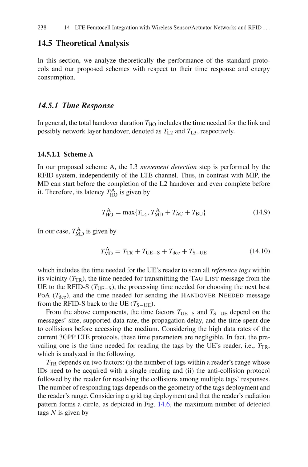
/


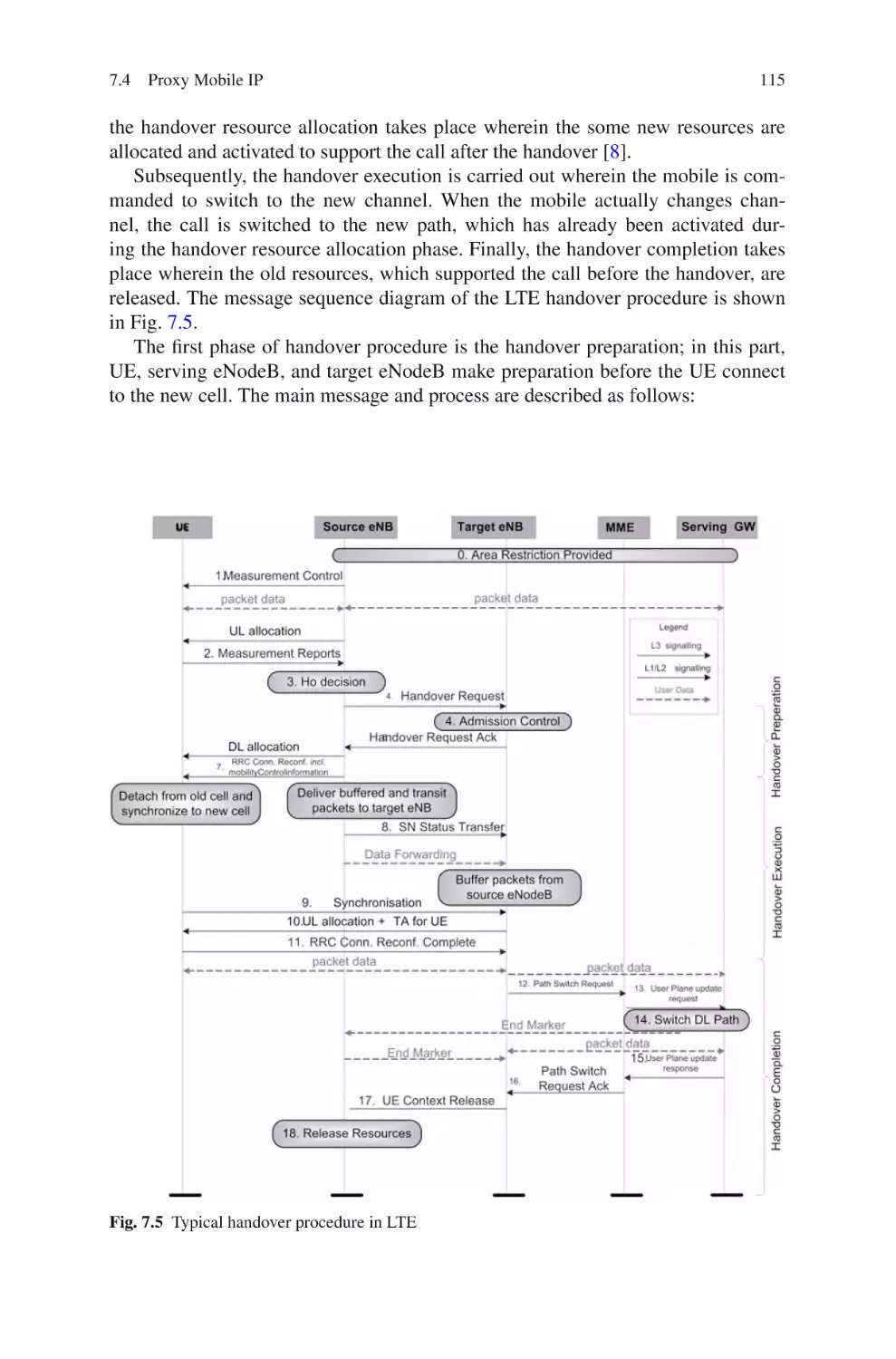
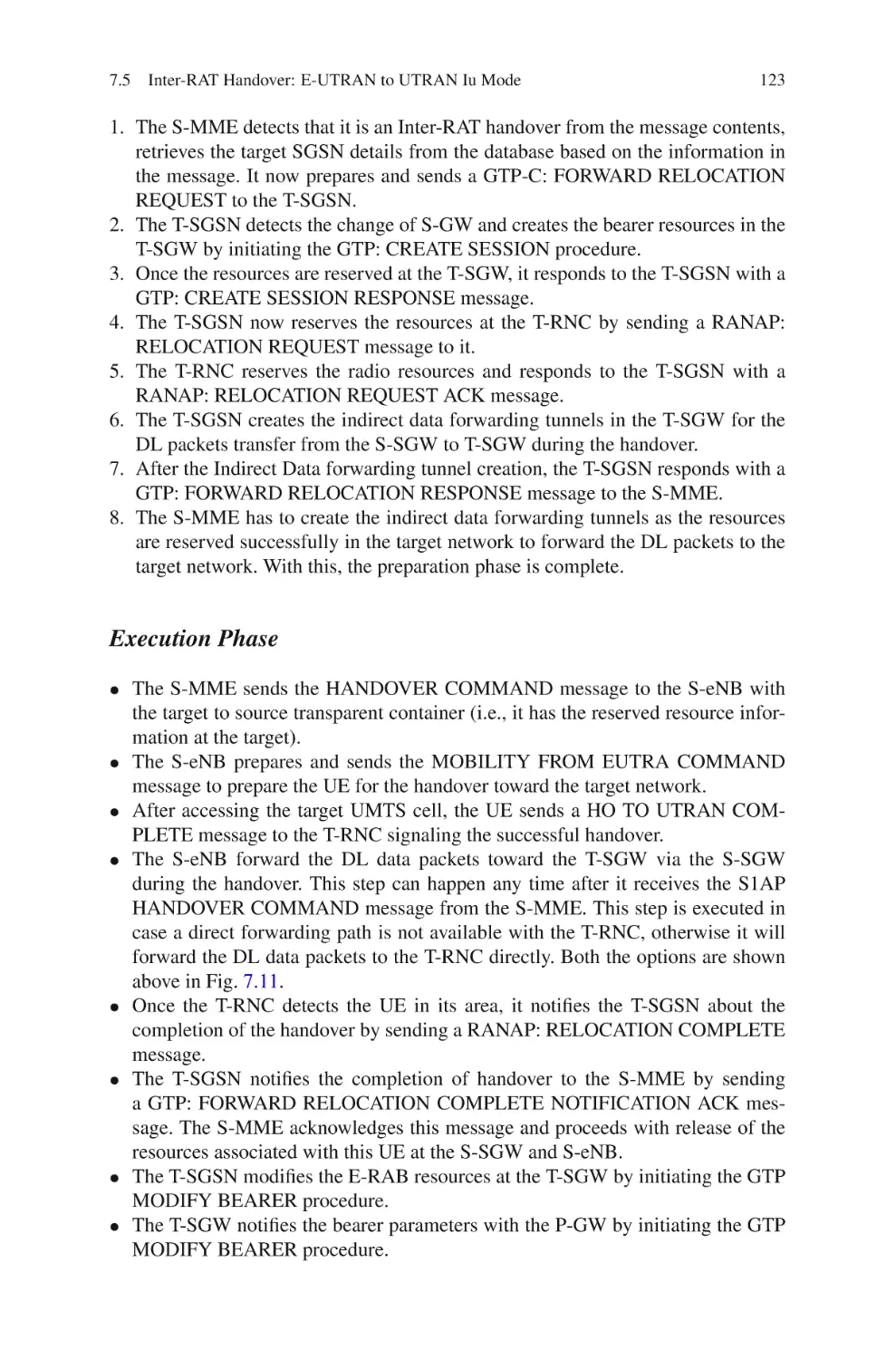


Author: Ali-Yahiya T
Tags: electronics internet wireless networks
ISBN: 978-1-4419-6456-4
Year: 2011


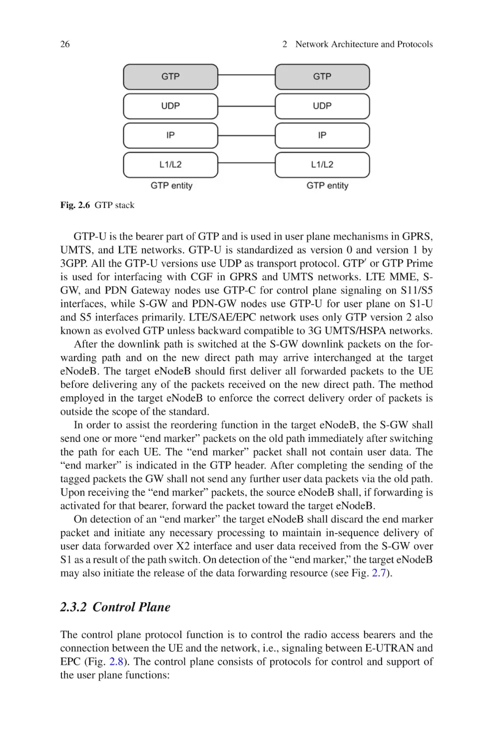
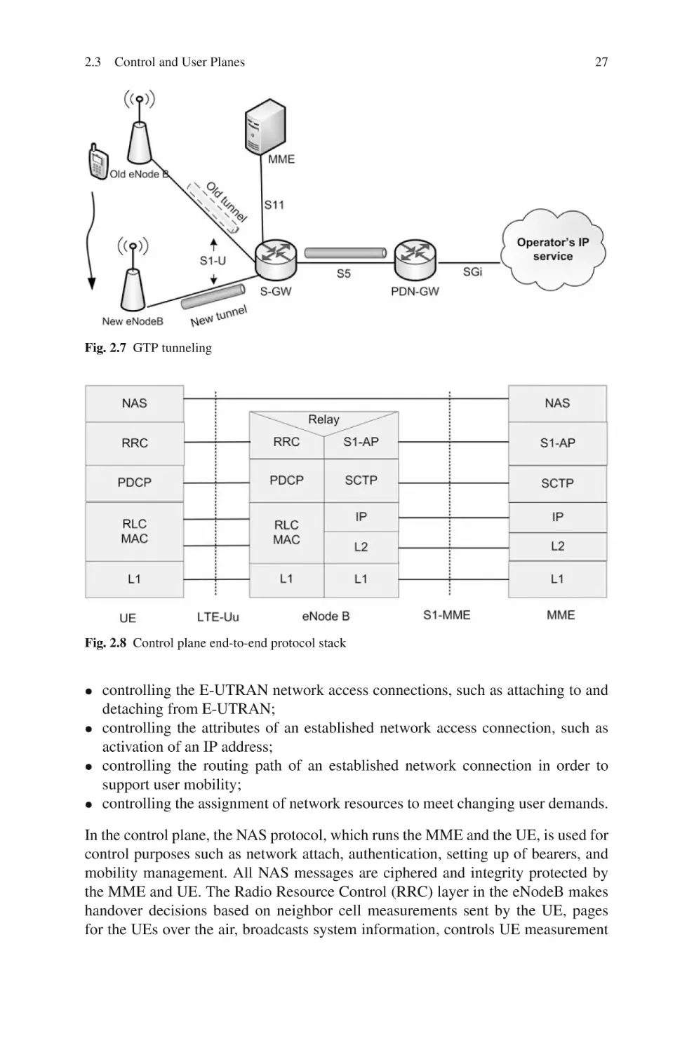
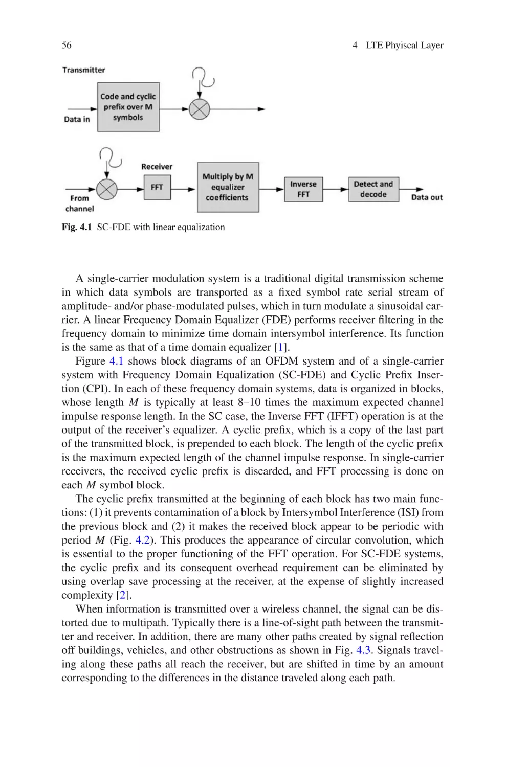
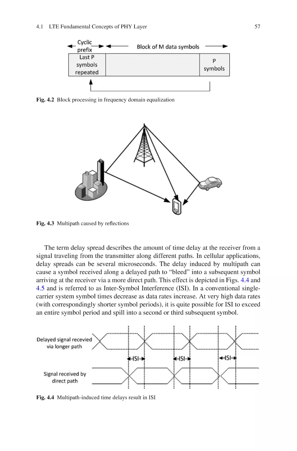
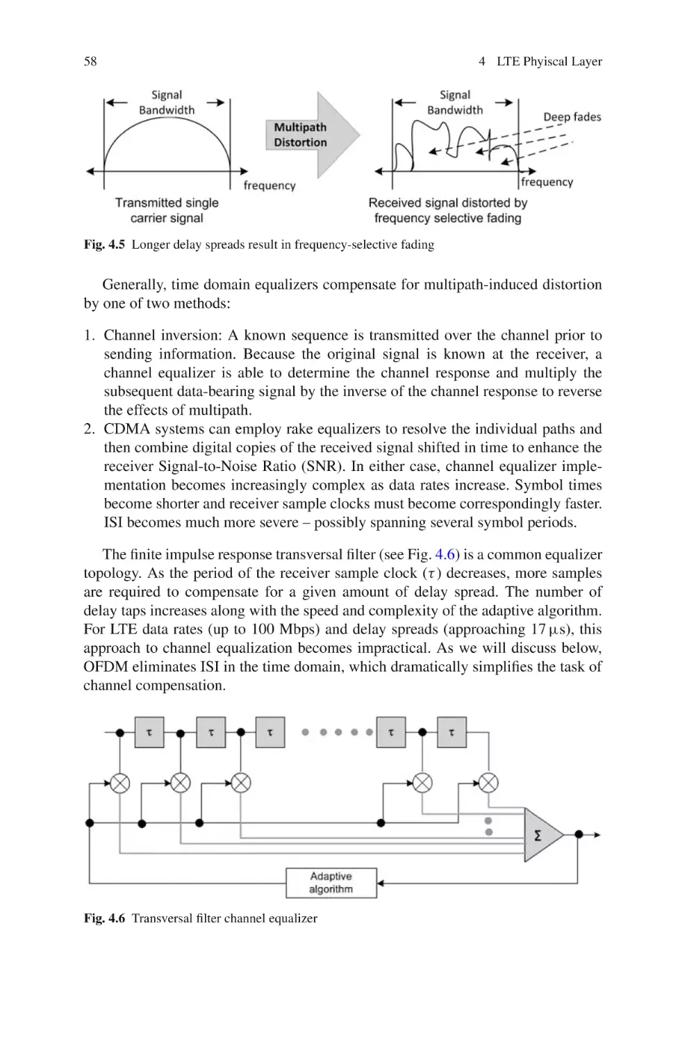
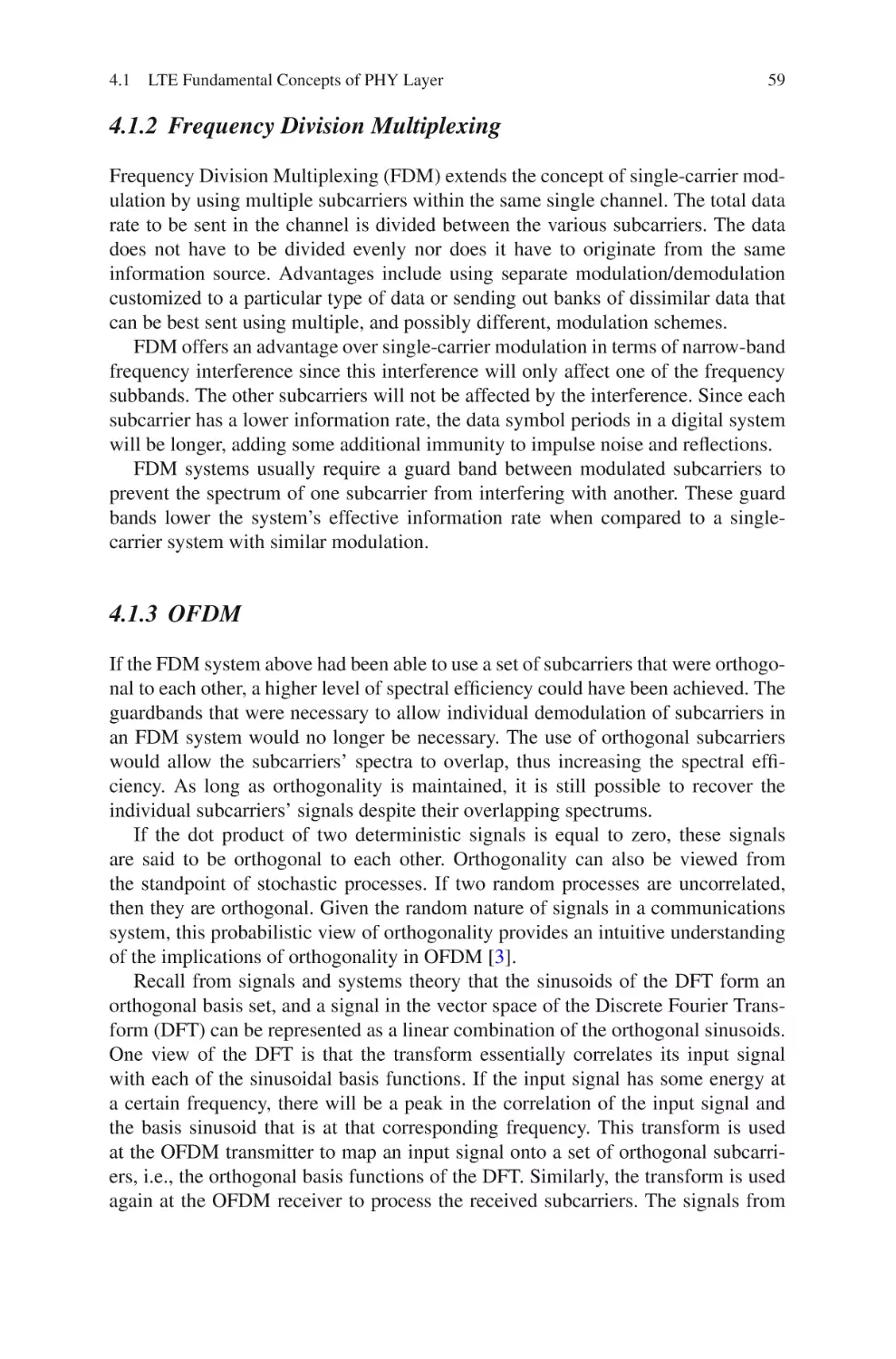
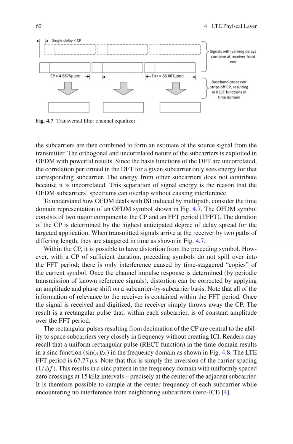
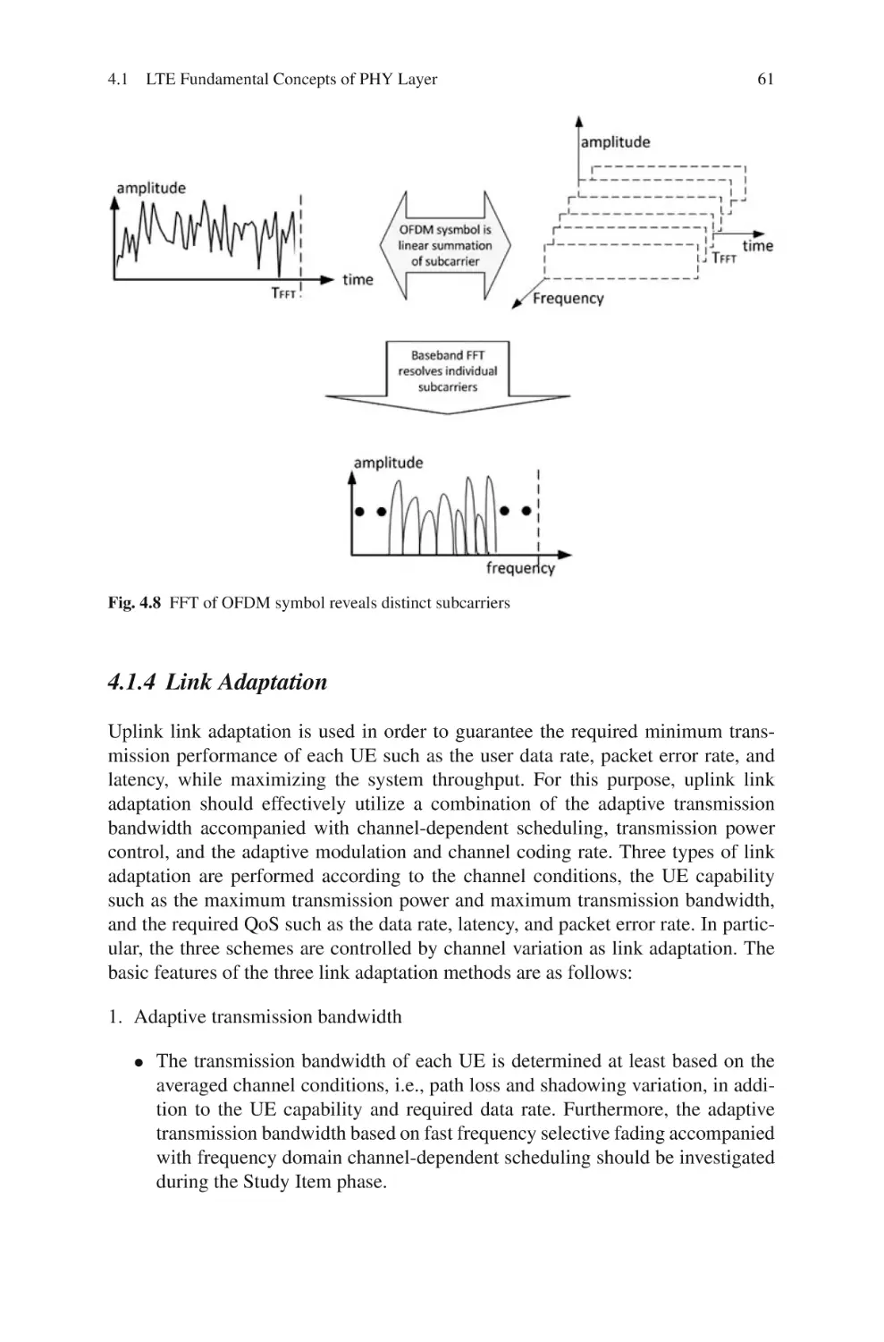
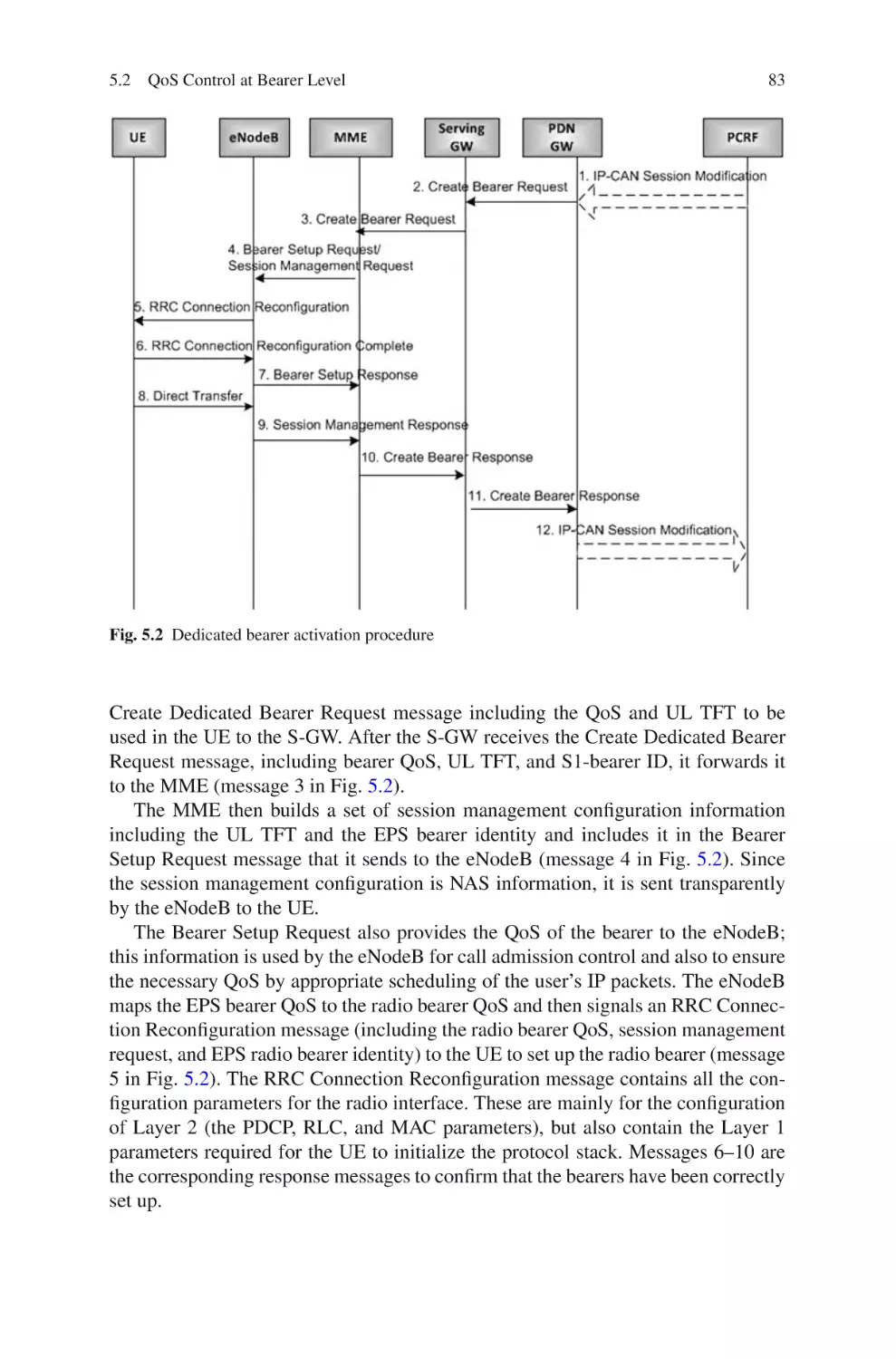
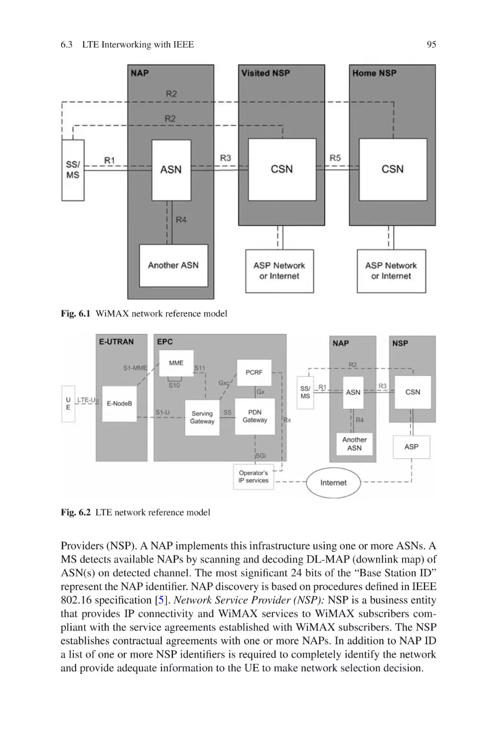
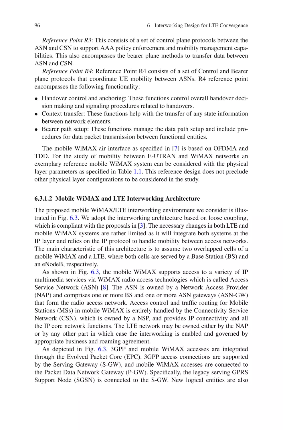
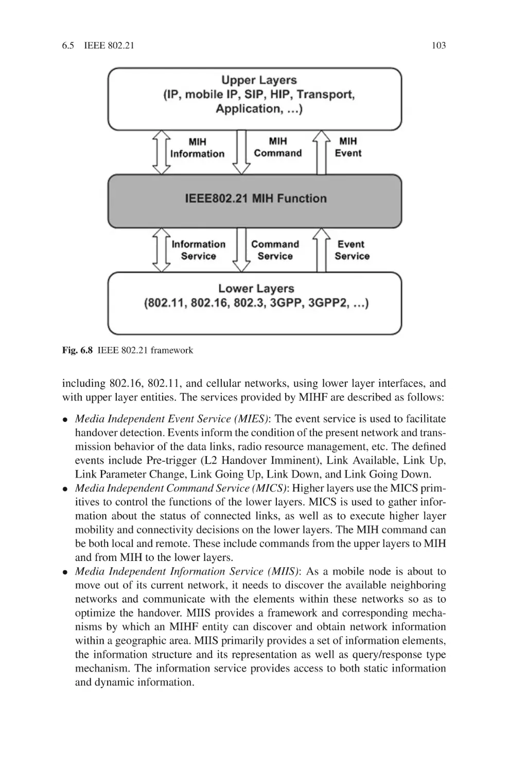
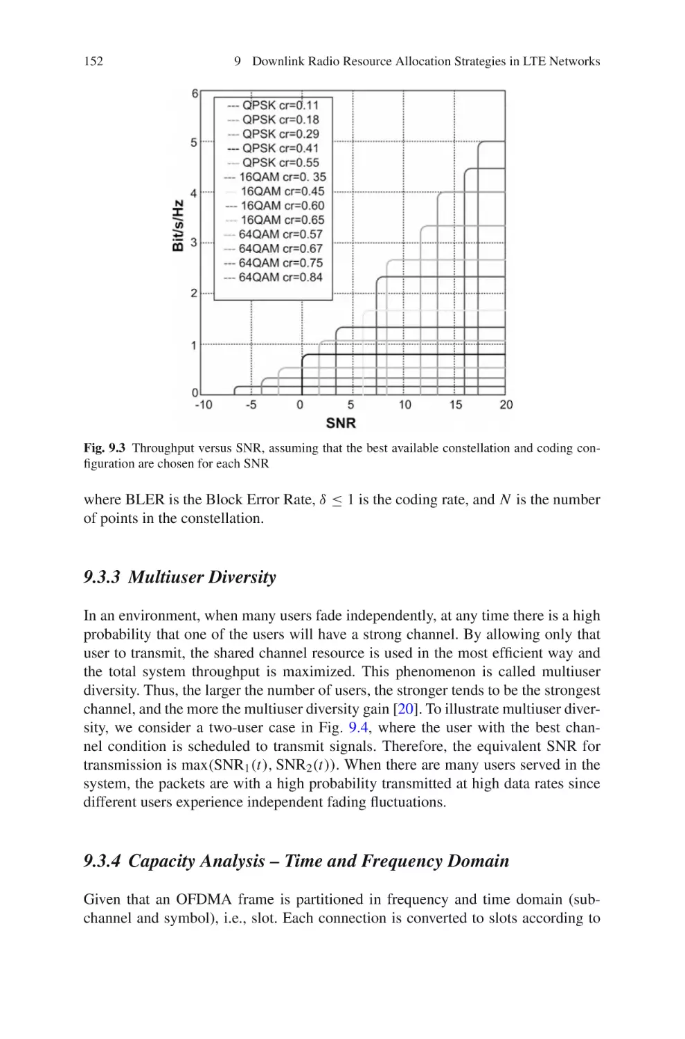
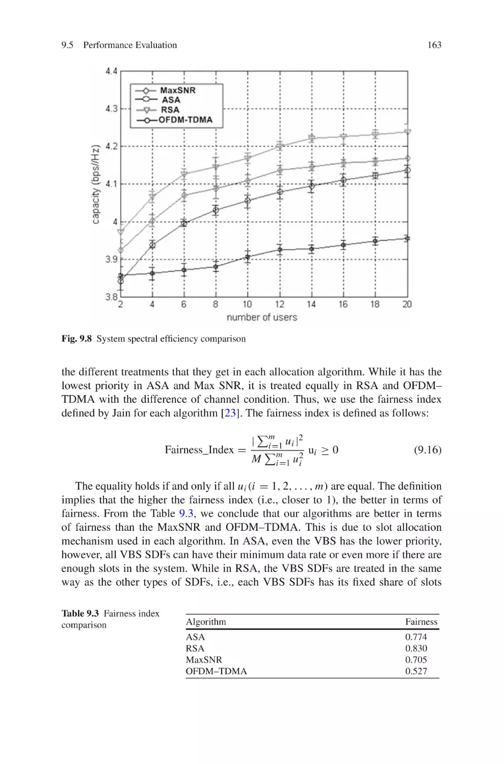
Text
Understanding LTE and its Performance
Tara Ali-Yahiya
Understanding LTE and its
Performance
Foreword by Khaldoun Al Agha
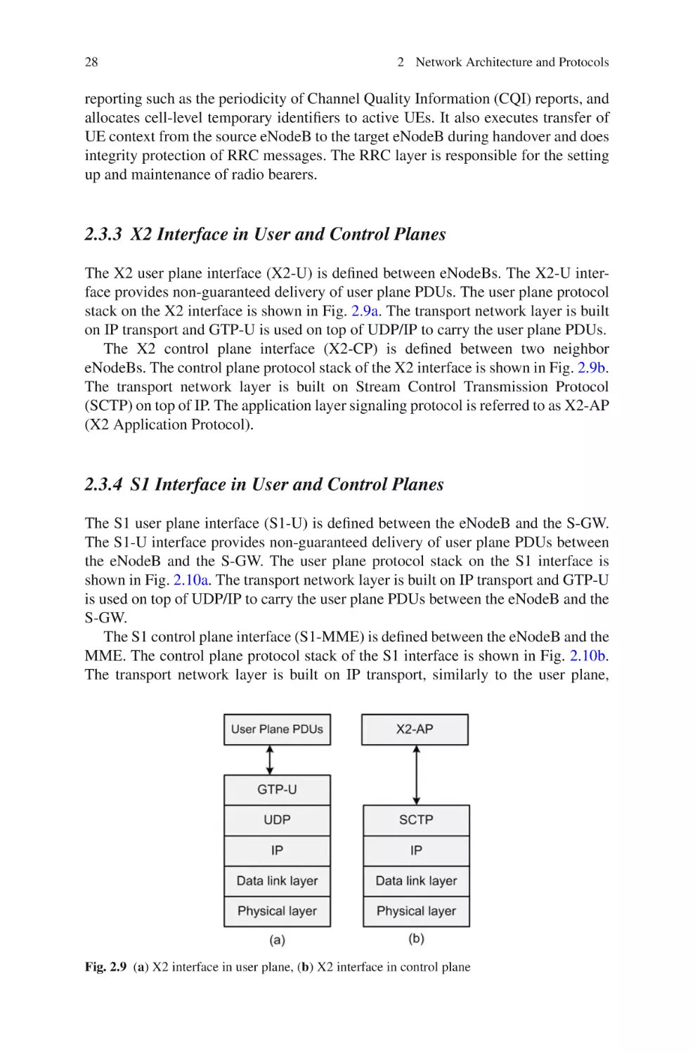
123
Tara Ali-Yahiya
University Paris Stud-11
Laboratoire de Recherche en Informatique
91405 Orsay Cedex, France
tara.ali-yahiya@u-psud.fr
ISBN 978-1-4419-6456-4
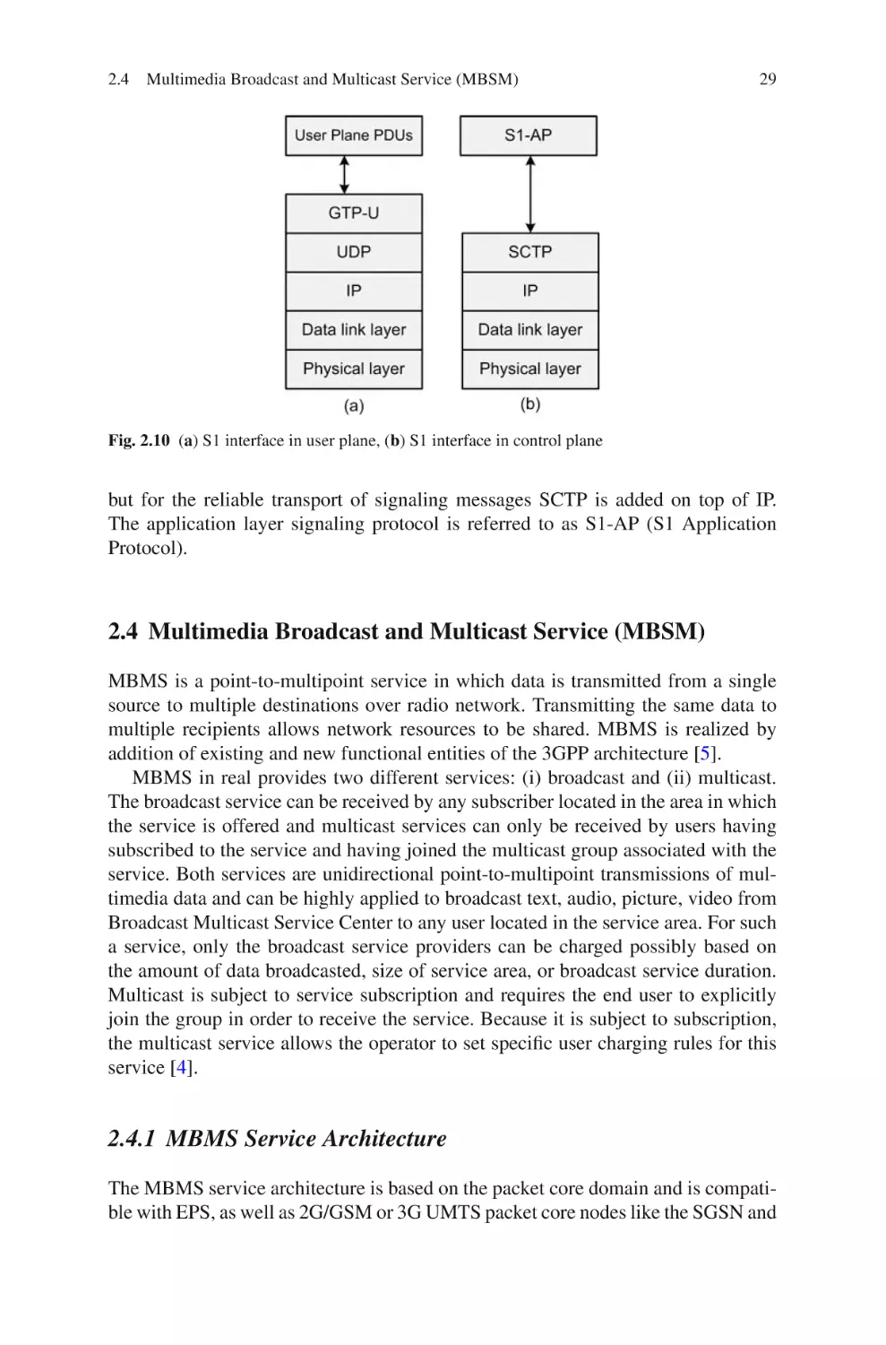
e-ISBN 978-1-4419-6457-1
DOI 10.1007/978-1-4419-6457-1
Springer New York Dordrecht Heidelberg London
Library of Congress Control Number: 2011929037
c Springer Science+Business Media, LLC 2011
All rights reserved. This work may not be translated or copied in whole or in part without the written
permission of the publisher (Springer Science+Business Media, LLC, 233 Spring Street, New York,
NY 10013, USA), except for brief excerpts in connection with reviews or scholarly analysis. Use in
connection with any form of information storage and retrieval, electronic adaptation, computer
software, or by similar or dissimilar methodology now known or hereafter developed is forbidden.
The use in this publication of trade names, trademarks, service marks, and similar terms, even if
they are not identified as such, is not to be taken as an expression of opinion as to whether or not
they are subject to proprietary rights.
Printed on acid-free paper
Springer is part of Springer Science+Business Media (www.springer.com)
To my parents
Mahdia Salih and Ibrahim Ali
Foreword
Mobile communications were largely introduced by GSM at the beginning of the
1990s. A telecommunication revolution was born with the success story of this new
mobile technology. Today, one cannot imagine his life without a mobile phone. The
number of users of GSM in the world now approaches to be five billions.
Since this huge success and the convergence with the IP world, new standards
were created to combine the packet-switched technologies to GSM in order to access
the Internet from any mobile device. From GPRS to 3G and 3G+, we have seen the
evolution of the mobile telecommunication with the ambition to offer the possibility
to surf through the Internet from anywhere and at any time. Again, 3G+ is a huge
success and people change their life by using new devices such as smart phones to
be connected permanently. Regarding this success, new applications are introduced
to offer new services.
However, the like of 3G+ is clearly the limited bandwidth which is not able to
cope with the new multimedia applications. The need of new technology is crucial and the world of telecommunications is going to introduce the LTE and LTEAdvanced standards which are able to offer high bandwidth for the new applications.
The promised bitrates are approaching those offered by the fiber optic local loop.
This book offers to its readers, a complete view of the LTE standard. It permits
employees at telecommunication companies and undergraduate and graduate students to understand this complicated technology. The book covers all the aspects
of the LTE starting from the physical layer and going through MAC layer and convergence with the IP technology. The principle of Femtocell, this new concept of
wireless deployment, is explained also in the book.
The author of the book, Doctor Tara Ali-Yahiya, associate Professor at Paris XI
University, is one of the experts in the LTE and LTE-Advanced. She has done her
PhD in the broadband mobile technologies and published many papers on the LTE
in several very high quality journals and conferences in this area. I hope that you will
enjoy reading this book and learning all the added values of the LTE technologies.
Paris
January 2011
Khaldoun Al Agha
Full Professor, Paris XI University
CTO of Green Communications
vii
Preface
This books attempts to provide an extensive overview on Long-Term Evolution
(LTE) networks. Understanding LTE and its Performance is purposely written to
appeal to a broad audience and to be of value to anyone who is interested in 3GPP
LTE or wireless broadband networks more generally. The aim of this book is to
offer comprehensive coverage of current state-of-the-art theoretical and technological aspects of broadband mobile and wireless networks focusing on LTE. The
presentation starts from basic principles and proceeds smoothly to most advanced
topics. Provided schemes are developed and oriented in the context of very actual
closed standards, the 3 GPPP LTE.
Organization of the Book
The book is organized into 3 parts with a total of 14 chapters. Part I provides an
introduction to broadband wireless and LTE. In Part II, most important features of
LTE are introduced in order to understand principles over which the LTE is built.
Finally, Part III introduces performance study of LTE network regarding different
layers of networking, starting from lower layer till higher layer. In Part I, Chapter 1
tries to describe a comprehensive and a summarized overview of the different mobile
broadband wireless technologies introduced by 3GPP and 3GPP2 organization without forgetting standards proposed by IEEE community. A brief history of precedent
standard by these communities as the path of mobile broadband wireless evolution is described. As well, Chapter 1 describes LTE technology and its related features and recalls the difference between LTE and LTE-Advanced as a step toward
fourth-generation wireless network. The book enlightens especially details about
LTE release 8 which is the basic specification of LTE 3GPP. Chapters 2, 3, and 4
describe the main functionalities of LTE based on different network layers point
of view starting first by higher layers and then by lower layers. The higher layer is
represented by the reference model of LTE architecture, by describing the functional
entities that are composing the architecture. Then Chapter 3 details the role of link
layer and its interaction with higher and lower layers, link layer sub-layers, and
their responsibilities in terms of scheduling, power consumption, ciphering, etc.,
ix
x
Preface
are introduced. Lastly, physical layer is described with its powerful characteristics:
OFDAM, MIMO, different modulation and coding, etc., in Chapter 4.
In Part II, LTE salient features are introduced and classified into four main
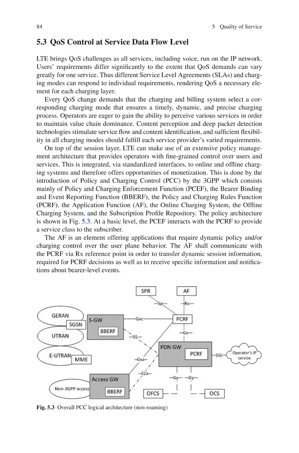
parts: Quality of service, mobility, femtocell, and interworking. Chapter 5 starts
by describing the mechanism of quality of service, the data service flows, rule of
charging, bearer principles. Chapter 6 describes mobility features including basic
mobility architecture, handover, and location management. Chapter 7 describes the
convergence of LTE toward fourth-generation mobile wireless network in terms of
interworking. Different types of interworking architectures with different technologies are described in this chapter, showing that LTE is a technology that is not
isolated and can be integrated with any IP-based technology. Chapter 8 presents
a key characteristic of LTE by introducing femtocell principles, architectures, and
benefits.
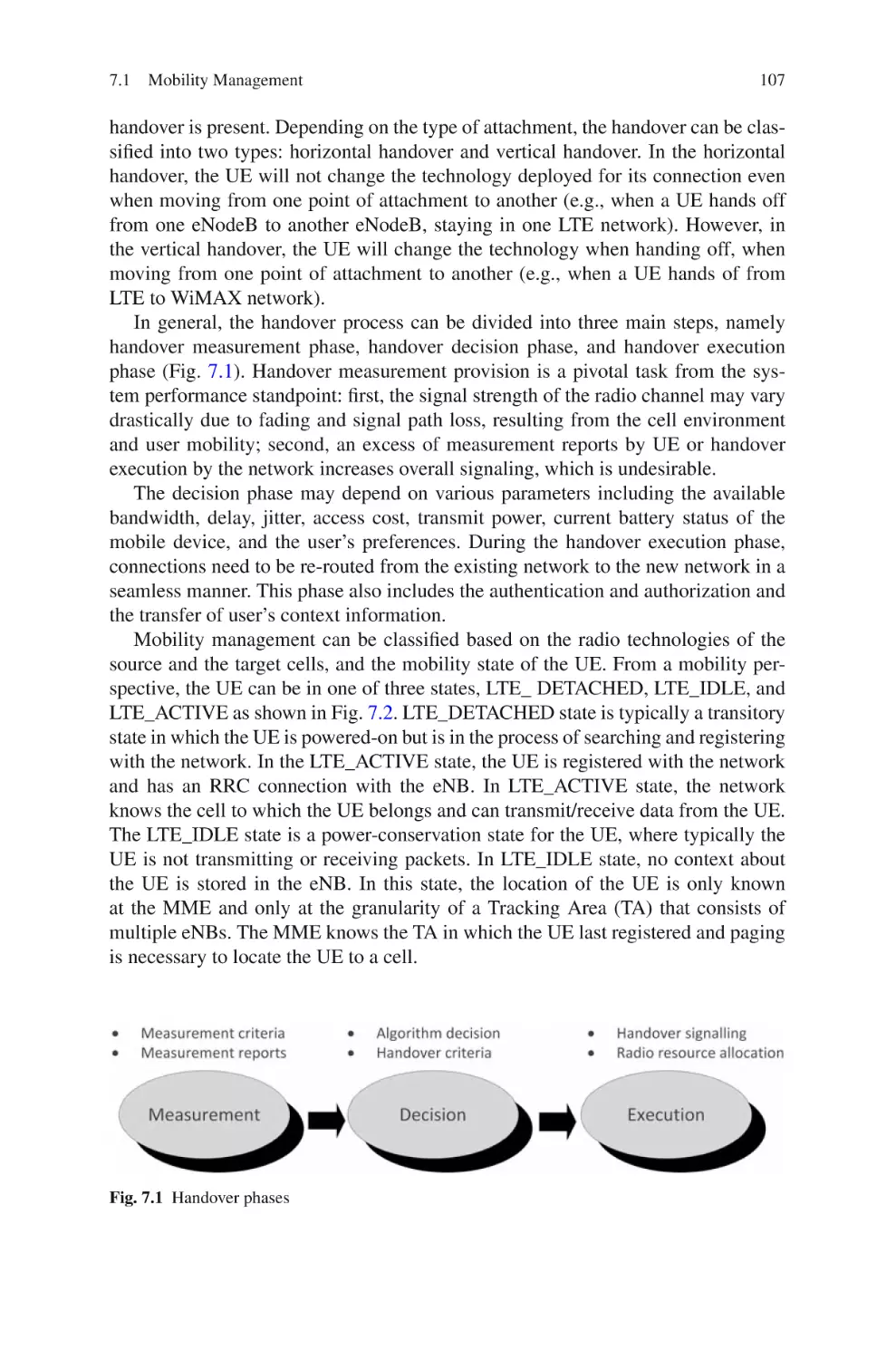
Part III presents some performance studies in different level of conception. Chapters 9 and 10 describe how resources are allocated in LTE based on OFDM modulation. Then two algorithms are proposed and simulated for LTE networks. Chapter 11
presents a cross-layer resource allocation involving MAC and PHY layer for guaranteeing higher layer quality of service as well as lower layer quality of service.
Chapter 12 describes the cell interference in LTE multi-cellular system and proposes a method to overcome the interference while keeping a good quality of service
assurance for different data service flows. Chapter 13 studies the performance of an
interworking architecture as a case study between LTE and mobile WiMAX technology. New architecture and handover decision function are proposed and studied
by means of simulation programs. Finally, Chapter 14 highlights a new and original
method to integrate LTE femtocell with RFID and wireless sensor networks in order
to improve mobility management and enhance network experience when handover
occurs.
Paris, France
Tara Ali-Yahiya
Acknowledgments
I wish to express my sincere gratitude and thank the editor Brett Kurzman in
Springer Science+Business Media, LLC who encouraged me to write this book
even though I knew that the process of writing a book will be hard and will be
time consuming and the energy commitment would be overwhelming.
I appreciate the support of professor Khaldoun Alagha, the head of network
department in Paris Sud 11 University, who strongly supported this project from the
very beginning and provided me with valuable advice and suggestion to improve the
content of the book.
I would like to thank my first PhD student Meriem Abid who contributed
in writing some parts of a chapter, namely related to LTE femtocell. Thanks to
Dr. Apostolia Papapostolu who assisted with her time and in-depth knowledge to
the last chapter of the book, the chapter concerning LTE integration with RFID
technology. Finally, thanks to Mauricio Iturralde, PhD student, who helped to add a
new value to the book by assisting in writing Chapter 10.
In the end, I wish to express my deep acknowledgment to my family who supported me during the period of writing this book. Special thanks to my sister Gara
and my brother Kovan for their encouragement and love.
xi
Contents
Part I Understanding LTE
1 Introduction to Mobile Broadband Wireless . . . . . . . . . . . . . . . . . . . . .
1.1 Mobile Generation Networks . . . . . . . . . . . . . . . . . . . . . . . . . . . . . .
1.1.1
First-Generation Mobile 1G . . . . . . . . . . . . . . . . . . . . . . .
1.1.2
Second-Generation Mobile 2G . . . . . . . . . . . . . . . . . . . . .
1.1.3
Third-Generation Mobile 3G . . . . . . . . . . . . . . . . . . . . . .
1.1.4
The Path Toward 4G . . . . . . . . . . . . . . . . . . . . . . . . . . . . .
1.2 LTE and Other Broadband Wireless Technologies . . . . . . . . . . . . .
1.2.1
Mobile WiMAX . . . . . . . . . . . . . . . . . . . . . . . . . . . . . . . . .
1.2.2
WiFi . . . . . . . . . . . . . . . . . . . . . . . . . . . . . . . . . . . . . . . . . . .
1.3 Overview of LTE . . . . . . . . . . . . . . . . . . . . . . . . . . . . . . . . . . . . . . . .
1.3.1
Relevant Features of LTE . . . . . . . . . . . . . . . . . . . . . . . . .
1.3.2
Relevant Features of LTE-Advanced . . . . . . . . . . . . . . . .
1.4 Summary and Conclusion . . . . . . . . . . . . . . . . . . . . . . . . . . . . . . . . .
References . . . . . . . . . . . . . . . . . . . . . . . . . . . . . . . . . . . . . . . . . . . . . . . . . . .
3
3
4
4
4
5
7
8
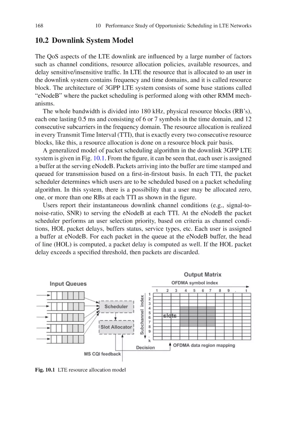
8
9
10
12
14
14
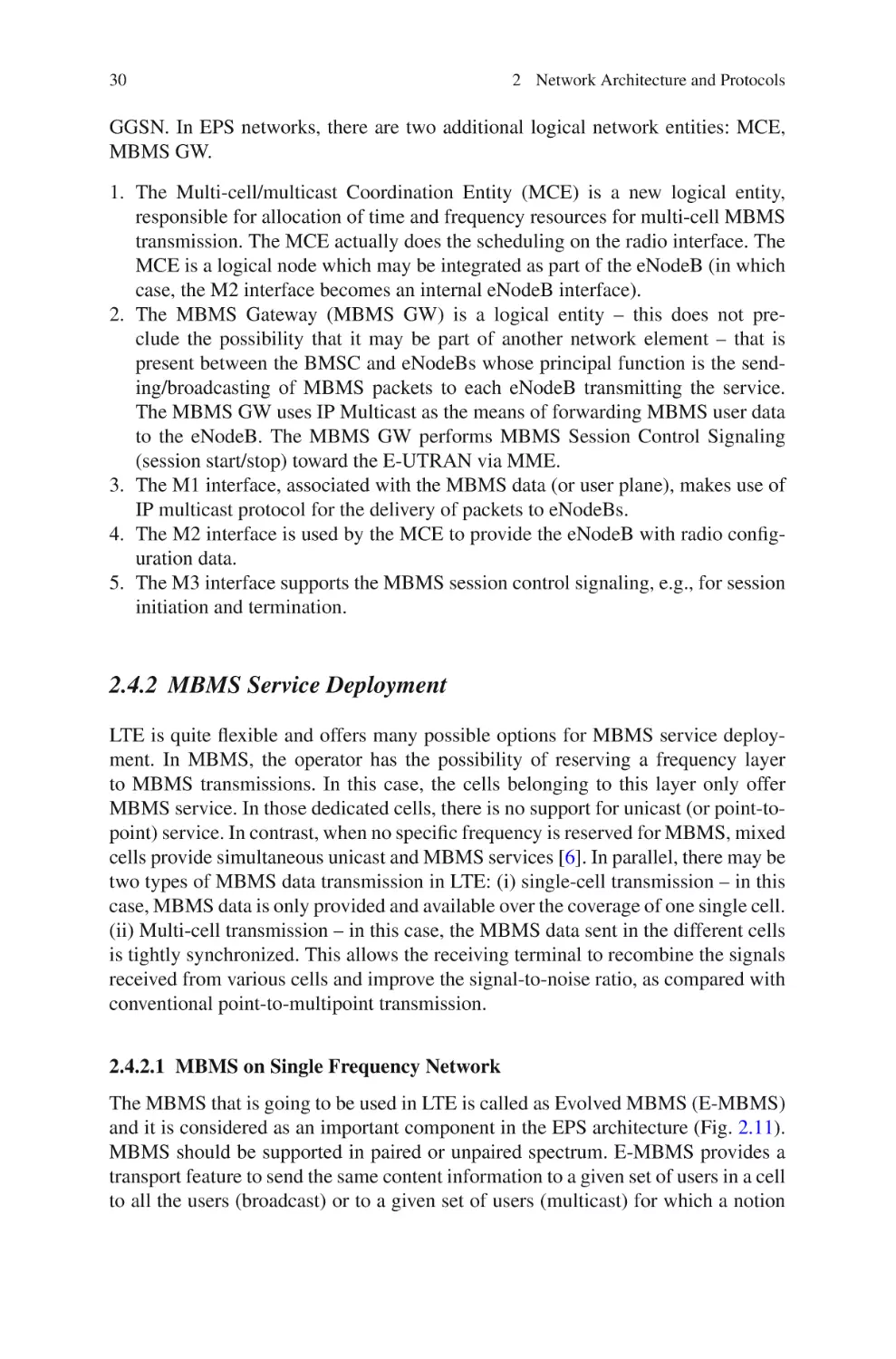
2 Network Architecture and Protocols . . . . . . . . . . . . . . . . . . . . . . . . . . . .
2.1 Architecture Model and Concepts . . . . . . . . . . . . . . . . . . . . . . . . . .
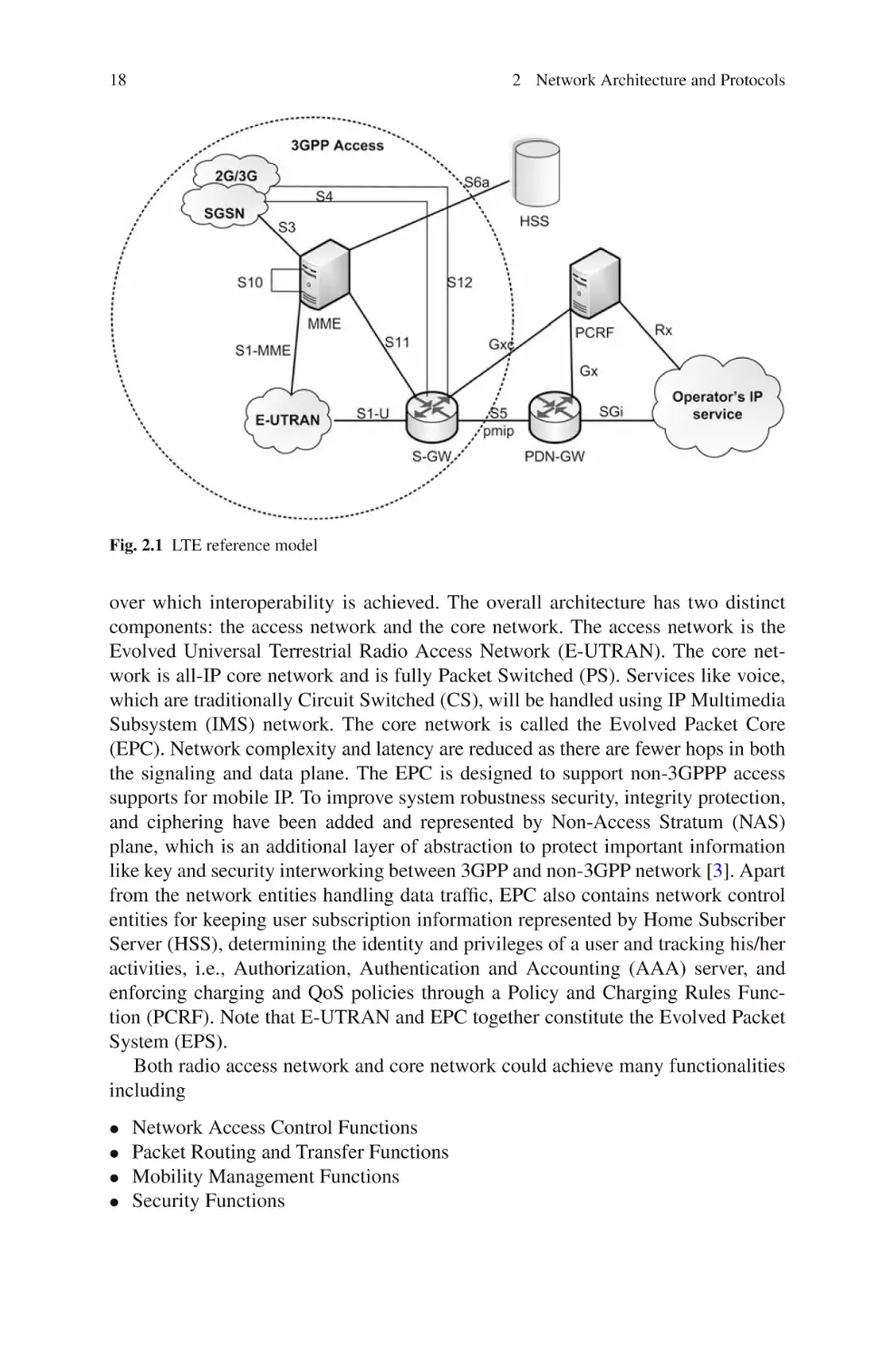
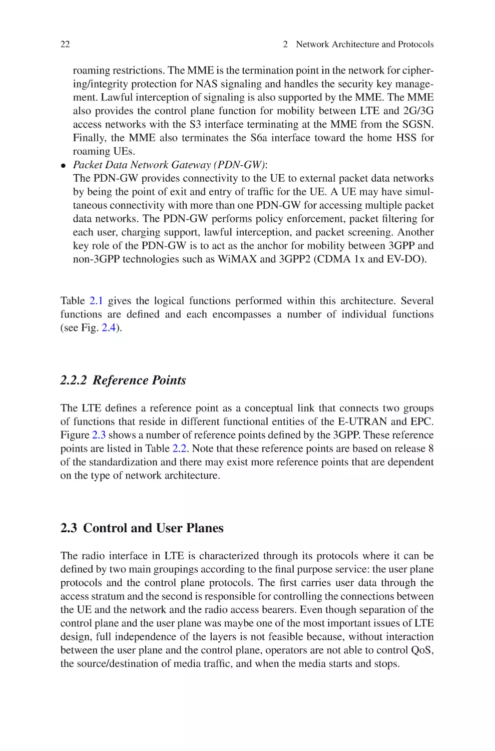
2.2 Architecture Reference Model . . . . . . . . . . . . . . . . . . . . . . . . . . . . .
2.2.1
Functional Description of LTE Network . . . . . . . . . . . . .
2.2.2
Reference Points . . . . . . . . . . . . . . . . . . . . . . . . . . . . . . . . .
2.3 Control and User Planes . . . . . . . . . . . . . . . . . . . . . . . . . . . . . . . . . .
2.3.1
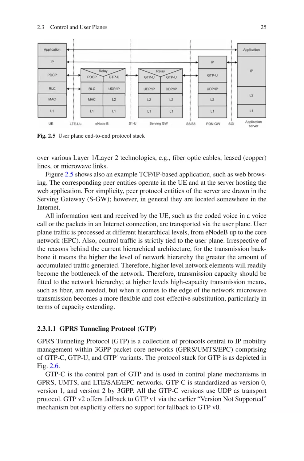
User Plane . . . . . . . . . . . . . . . . . . . . . . . . . . . . . . . . . . . . . .
2.3.2
Control Plane . . . . . . . . . . . . . . . . . . . . . . . . . . . . . . . . . . .
2.3.3
X2 Interface in User and Control Planes . . . . . . . . . . . . .
2.3.4
S1 Interface in User and Control Planes . . . . . . . . . . . . .
2.4 Multimedia Broadcast and Multicast Service (MBSM) . . . . . . . .
2.4.1
MBMS Service Architecture . . . . . . . . . . . . . . . . . . . . . . .
2.4.2
MBMS Service Deployment . . . . . . . . . . . . . . . . . . . . . . .
2.5 Stream Control Transmission Protocol . . . . . . . . . . . . . . . . . . . . . .
2.6 Network Discovery and Selection . . . . . . . . . . . . . . . . . . . . . . . . . .
2.7 Radio Resource Management . . . . . . . . . . . . . . . . . . . . . . . . . . . . . .
17
17
17
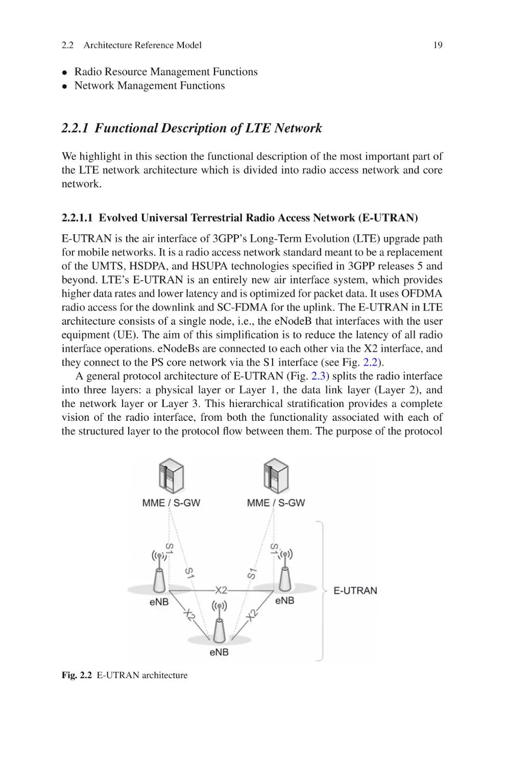
19
22
22
23
26
28
28
29
29
30
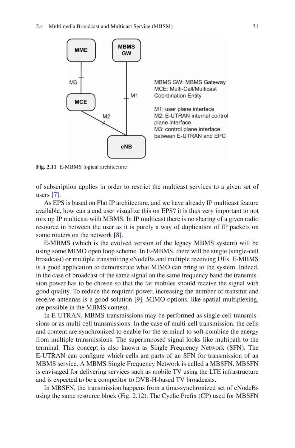
32
33
33
xiii
xiv
Contents
2.7.1
2.7.2
2.7.3
Radio Bearer Control (RBC) . . . . . . . . . . . . . . . . . . . . . . .
Connection Mobility Control (CMC) . . . . . . . . . . . . . . . .
Dynamic Resource Allocation (DRA) – Packet
Scheduling (PS) . . . . . . . . . . . . . . . . . . . . . . . . . . . . . . . . .
2.7.4
Inter-cell Interference Coordination (ICIC) . . . . . . . . . . .
2.7.5
Load Balancing (LB) . . . . . . . . . . . . . . . . . . . . . . . . . . . . .
2.7.6
Inter-RAT Radio Resource Management . . . . . . . . . . . . .
2.7.7
Subscriber Profile ID for RAT/Frequency Priority . . . . .
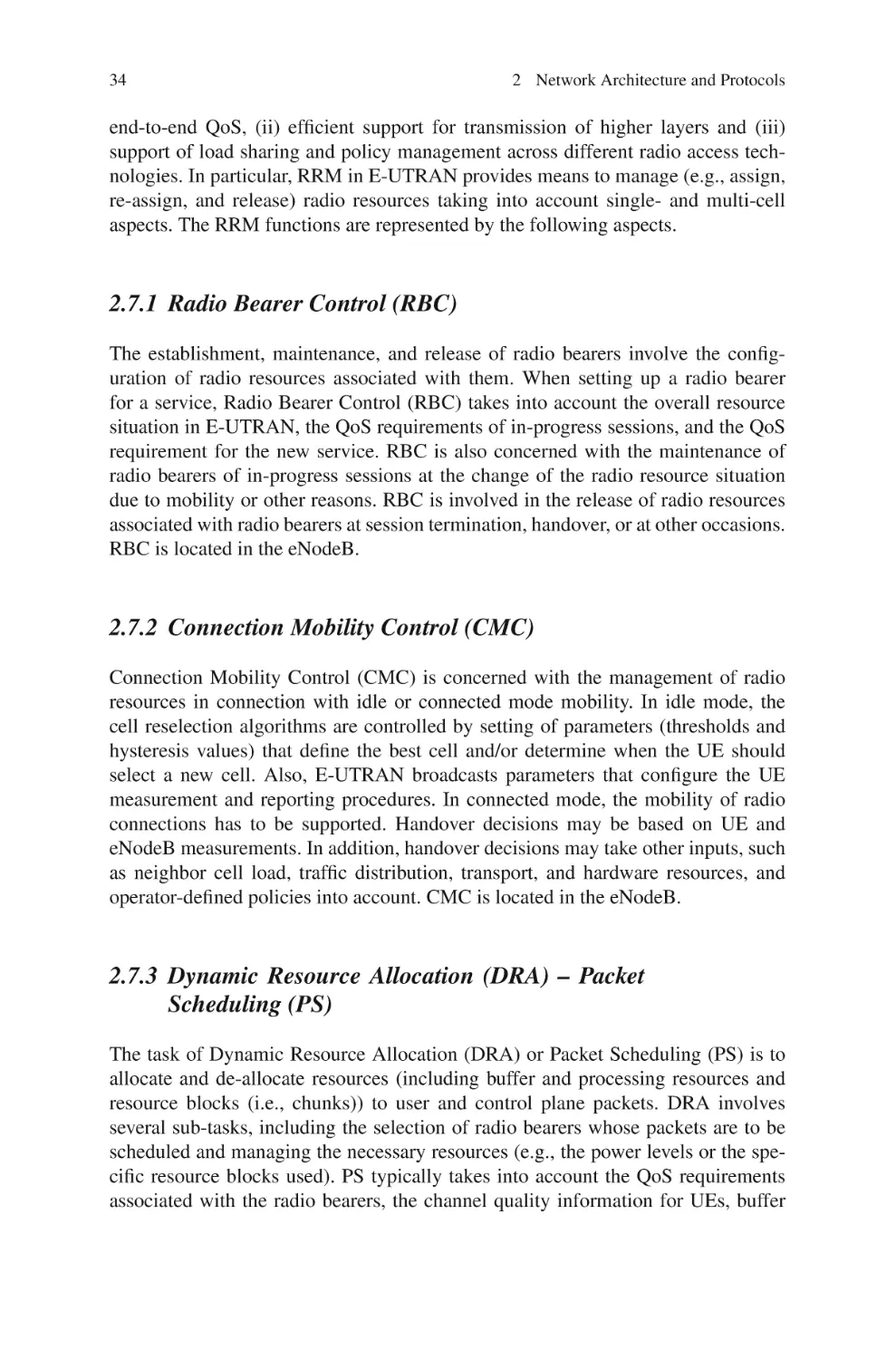
2.8 Authentication and Authorization . . . . . . . . . . . . . . . . . . . . . . . . . .
2.8.1
User Authentication, Key Agreement, and Key
Generation . . . . . . . . . . . . . . . . . . . . . . . . . . . . . . . . . . . . .
2.8.2
Signaling and User-Plane Security . . . . . . . . . . . . . . . . . .
2.9 Summary and Conclusions . . . . . . . . . . . . . . . . . . . . . . . . . . . . . . . .
References . . . . . . . . . . . . . . . . . . . . . . . . . . . . . . . . . . . . . . . . . . . . . . . . . . .
34
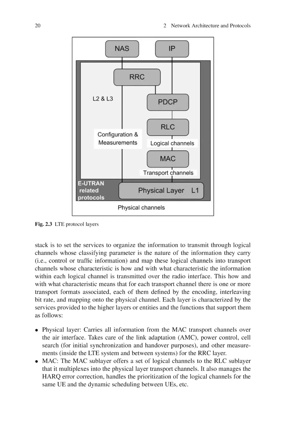
34
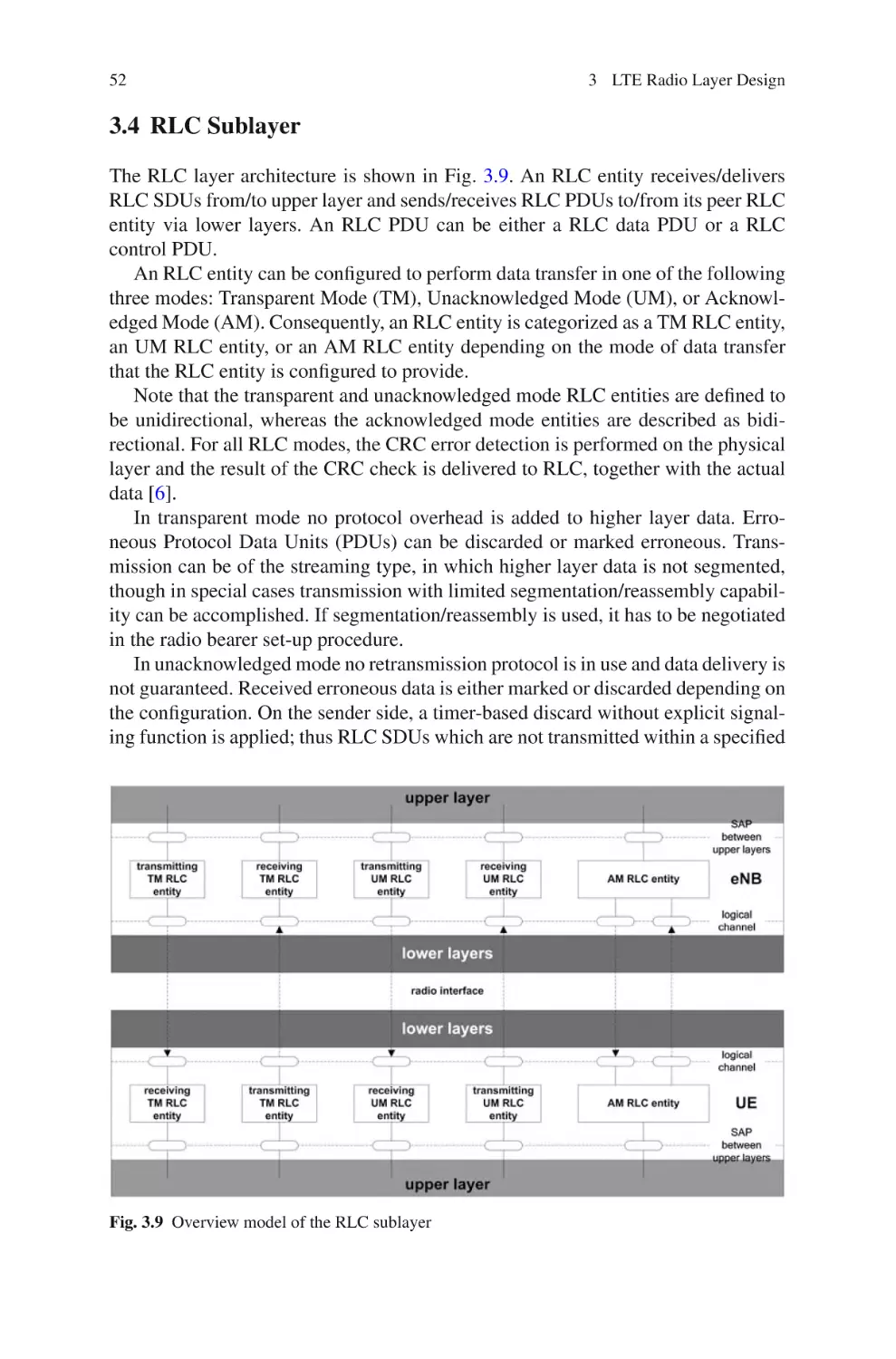
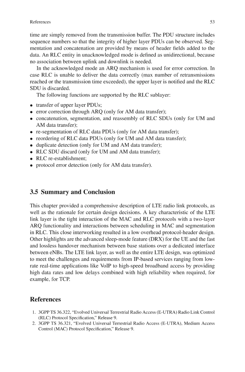
3 LTE Radio Layer Design . . . . . . . . . . . . . . . . . . . . . . . . . . . . . . . . . . . . . .
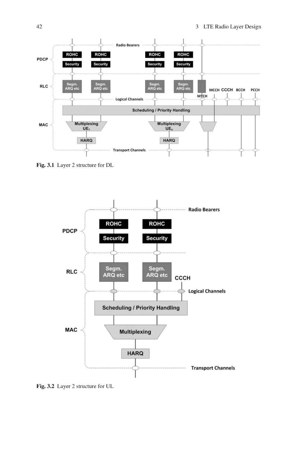
3.1 Layer 2 Design . . . . . . . . . . . . . . . . . . . . . . . . . . . . . . . . . . . . . . . . . .
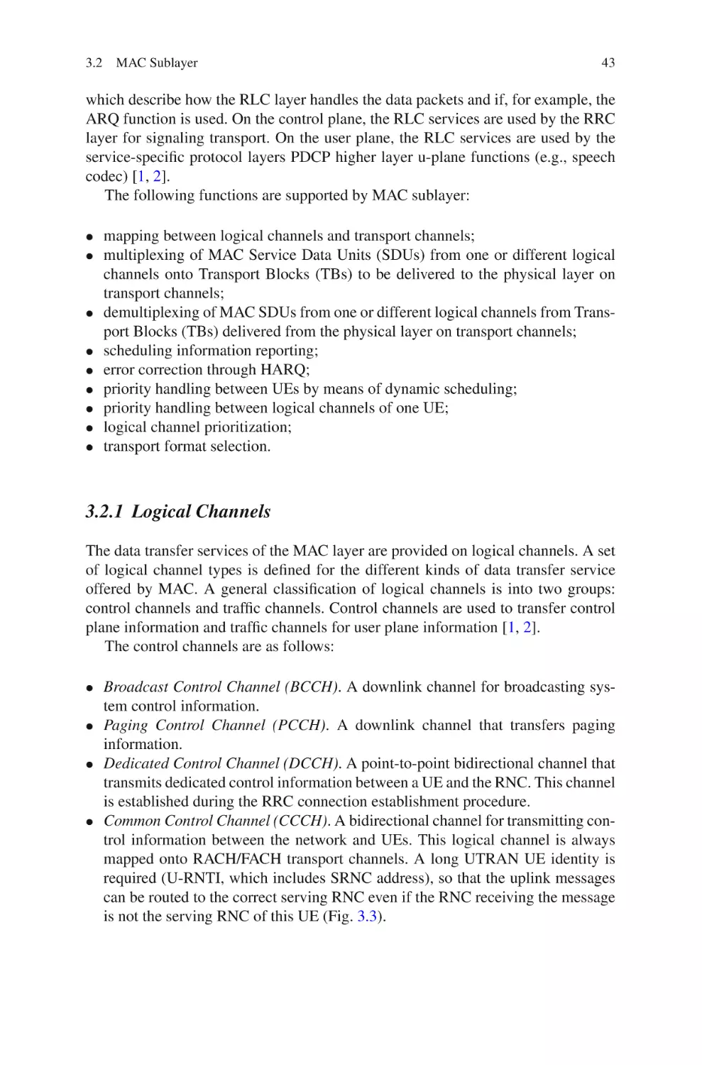
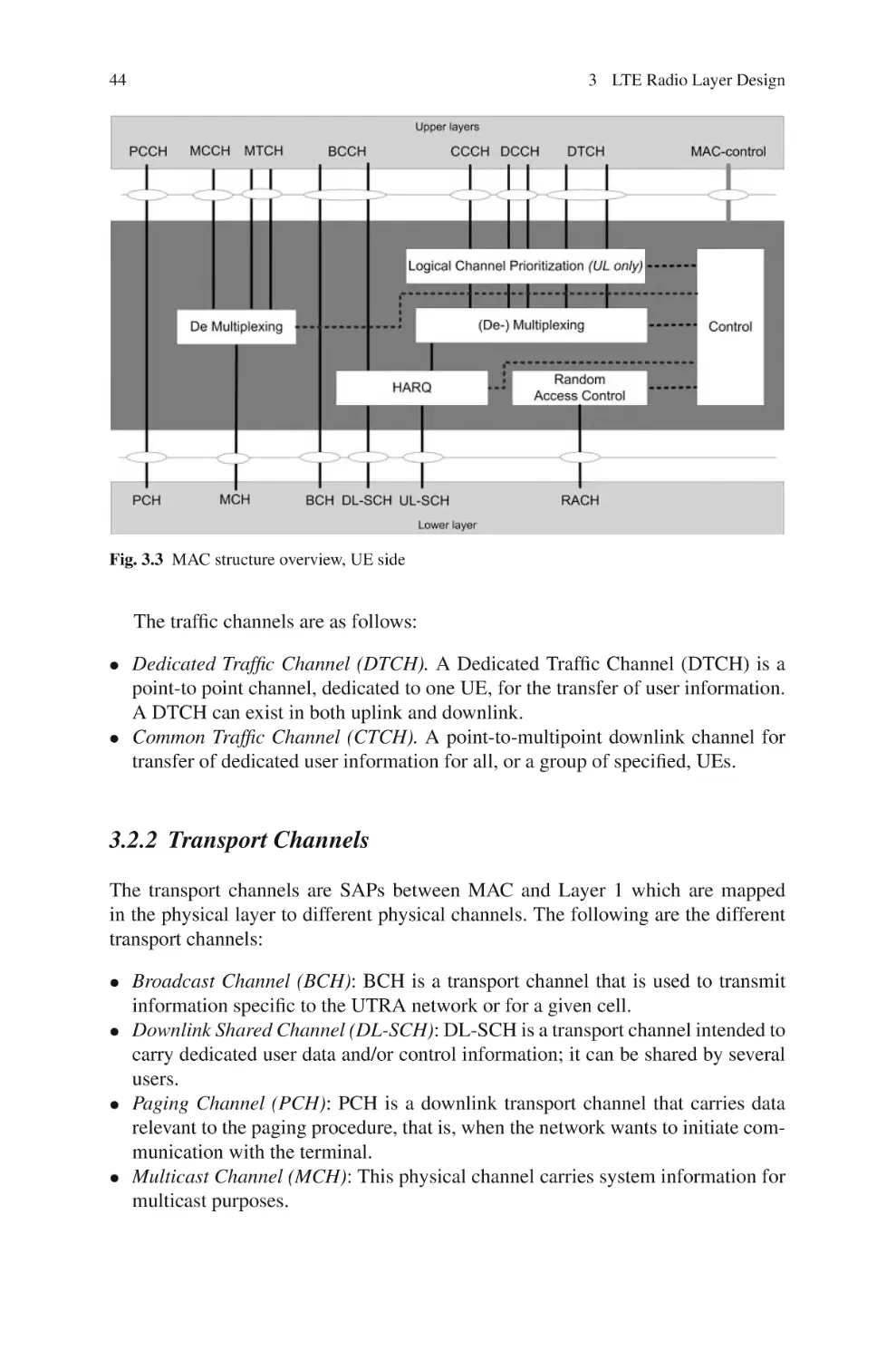
3.2 MAC Sublayer . . . . . . . . . . . . . . . . . . . . . . . . . . . . . . . . . . . . . . . . . .
3.2.1
Logical Channels . . . . . . . . . . . . . . . . . . . . . . . . . . . . . . . .
3.2.2
Transport Channels . . . . . . . . . . . . . . . . . . . . . . . . . . . . . .
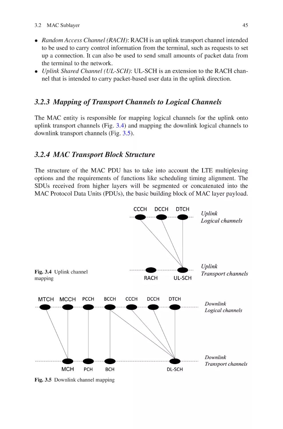
3.2.3
Mapping of Transport Channels to Logical Channels . .
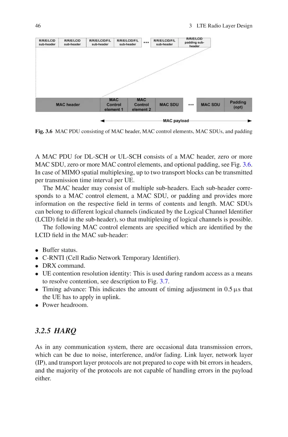
3.2.4
MAC Transport Block Structure . . . . . . . . . . . . . . . . . . . .
3.2.5
HARQ . . . . . . . . . . . . . . . . . . . . . . . . . . . . . . . . . . . . . . . . .
3.2.6
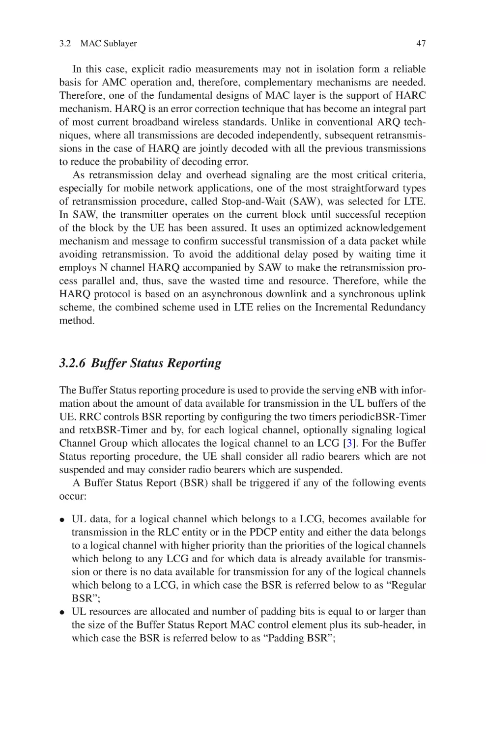
Buffer Status Reporting . . . . . . . . . . . . . . . . . . . . . . . . . . .
3.2.7
Random Access Procedure . . . . . . . . . . . . . . . . . . . . . . . .
3.2.8
Scheduling Request . . . . . . . . . . . . . . . . . . . . . . . . . . . . . .
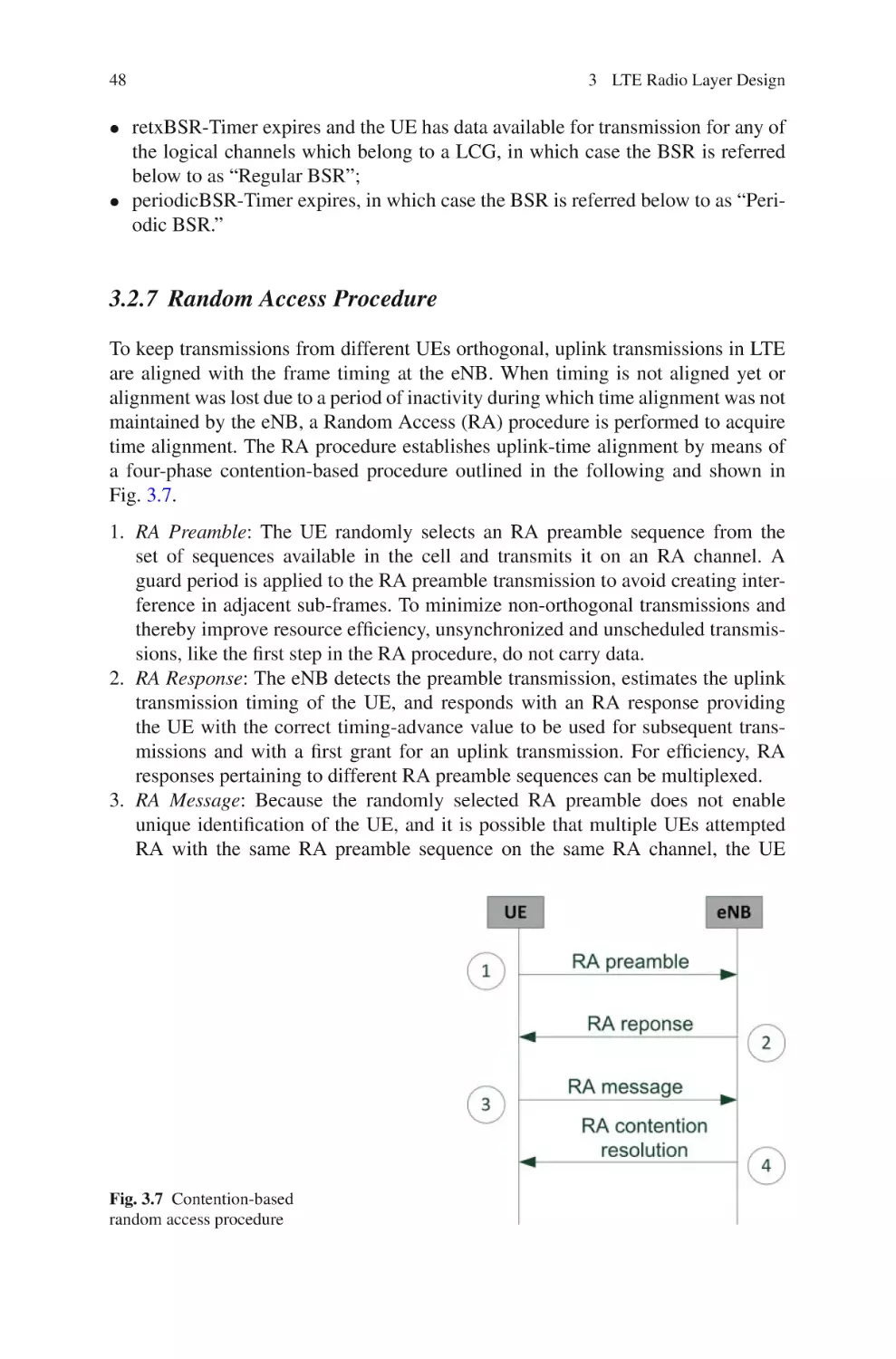
3.3 PDCP Sublayer . . . . . . . . . . . . . . . . . . . . . . . . . . . . . . . . . . . . . . . . .
3.3.1
Header Compression and Decompression . . . . . . . . . . . .
3.3.2
Ciphering and Deciphering . . . . . . . . . . . . . . . . . . . . . . . .
3.3.3
Integrity Protection and Verification . . . . . . . . . . . . . . . . .
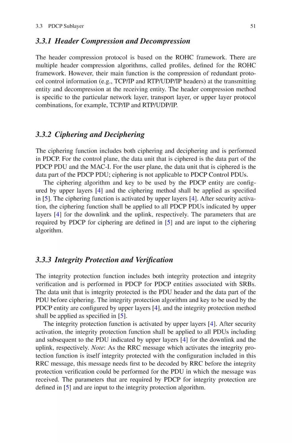
3.4 RLC Sublayer . . . . . . . . . . . . . . . . . . . . . . . . . . . . . . . . . . . . . . . . . .
3.5 Summary and Conclusion . . . . . . . . . . . . . . . . . . . . . . . . . . . . . . . . .
References . . . . . . . . . . . . . . . . . . . . . . . . . . . . . . . . . . . . . . . . . . . . . . . . . . .
41
41
41
43
44
45
45
46
47
48
49
49
51
51
51
52
53
53
4 LTE Phyiscal Layer . . . . . . . . . . . . . . . . . . . . . . . . . . . . . . . . . . . . . . . . . .
4.1 LTE Fundamental Concepts of PHY Layer . . . . . . . . . . . . . . . . . .
4.1.1
Single-Carrier Modulation and Channel Equalization . .
4.1.2
Frequency Division Multiplexing . . . . . . . . . . . . . . . . . . .
4.1.3
OFDM . . . . . . . . . . . . . . . . . . . . . . . . . . . . . . . . . . . . . . . . .
4.1.4
Link Adaptation . . . . . . . . . . . . . . . . . . . . . . . . . . . . . . . . .
4.1.5
Generic Radio Frame Structure . . . . . . . . . . . . . . . . . . . . .
4.1.6
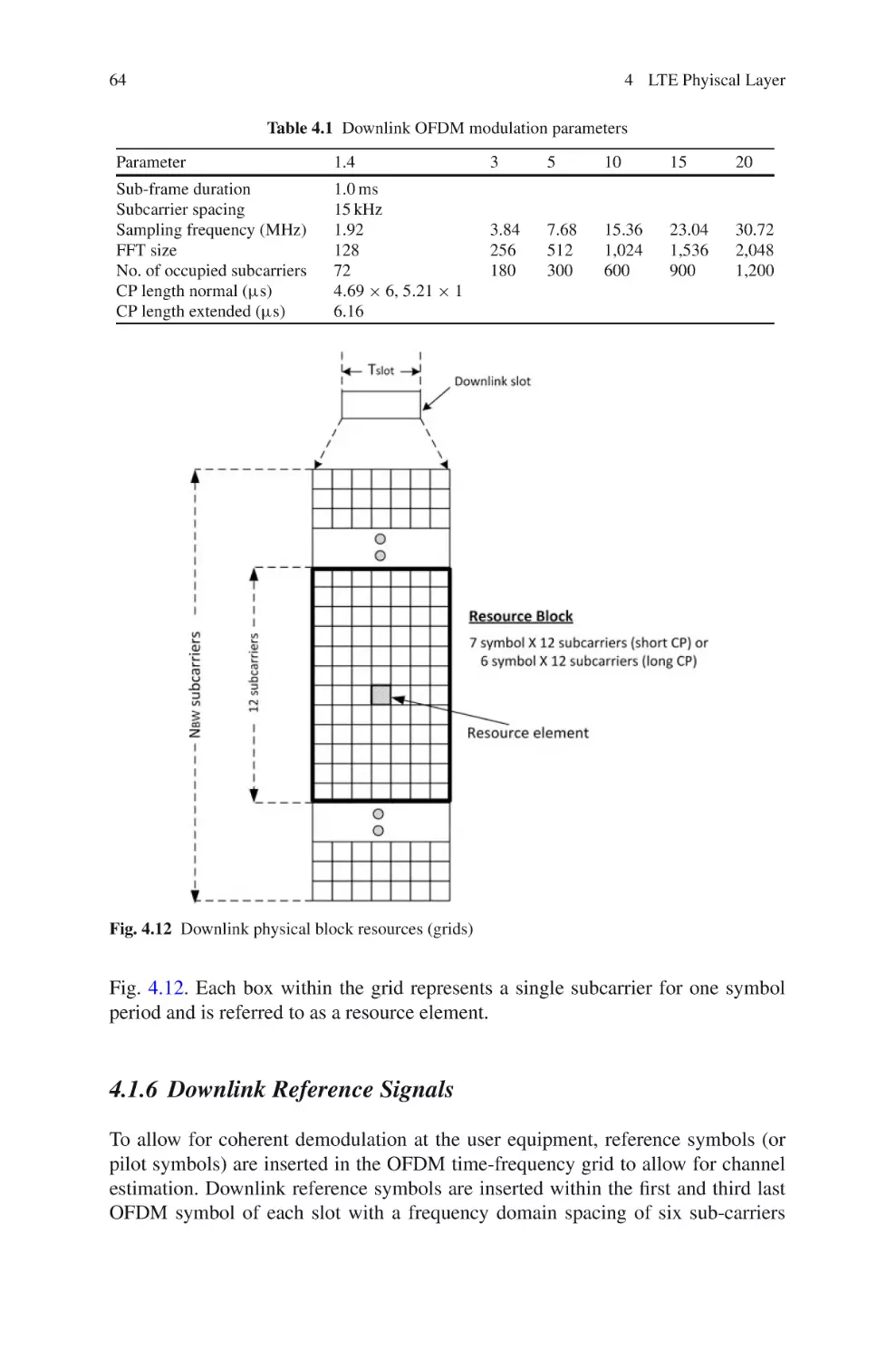
Downlink Reference Signals . . . . . . . . . . . . . . . . . . . . . . .
4.1.7
Uplink Reference Signals . . . . . . . . . . . . . . . . . . . . . . . . .
4.1.8
Downlink Control Channel . . . . . . . . . . . . . . . . . . . . . . . .
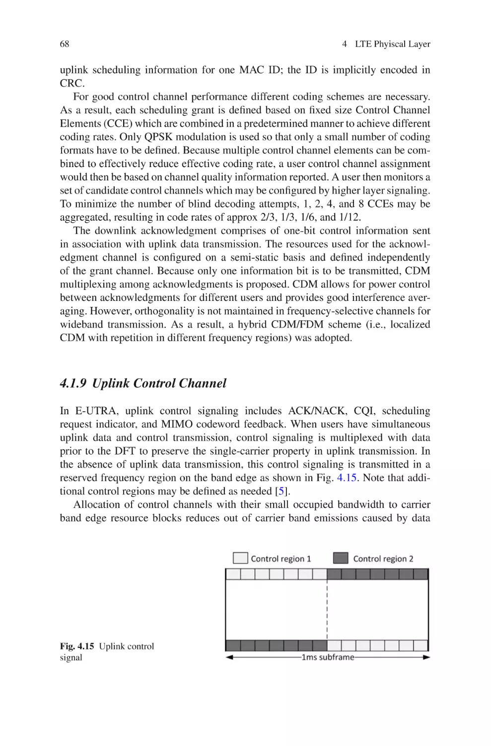
4.1.9
Uplink Control Channel . . . . . . . . . . . . . . . . . . . . . . . . . . .
55
55
55
59
59
61
63
64
65
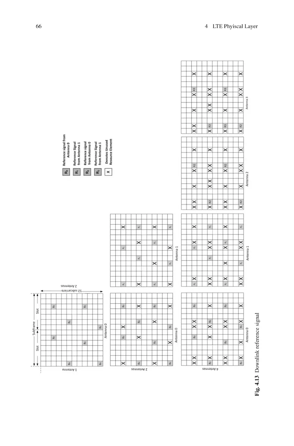
67
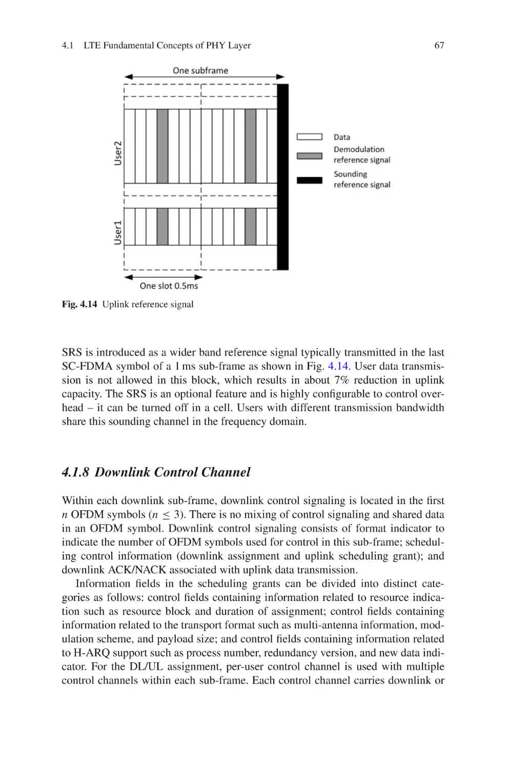
68
34
35
35
35
35
36
37
37
38
38
Contents
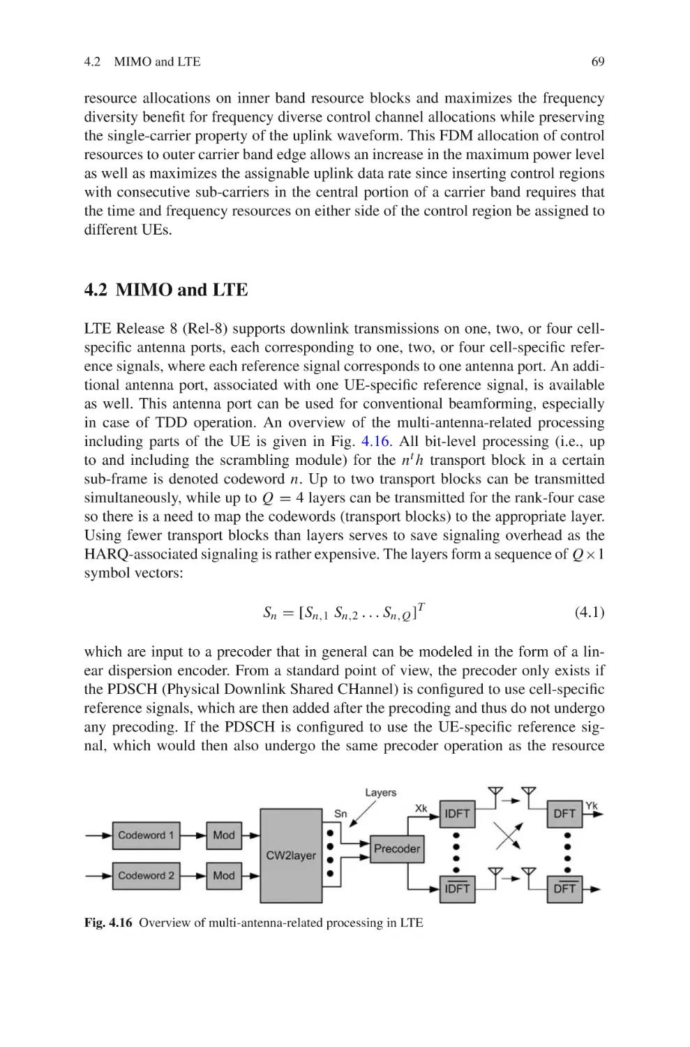
4.2 MIMO and LTE . . . . . . . . . . . . . . . . . . . . . . . . . . . . . . . . . . . . . . . . .
4.3 MIMO and MRC . . . . . . . . . . . . . . . . . . . . . . . . . . . . . . . . . . . . . . . .
4.4 Summary and Conclusions . . . . . . . . . . . . . . . . . . . . . . . . . . . . . . . .
References . . . . . . . . . . . . . . . . . . . . . . . . . . . . . . . . . . . . . . . . . . . . . . . . . . .
xv
69
70
73
73
Part II LTE Key Features
5 Quality of Service . . . . . . . . . . . . . . . . . . . . . . . . . . . . . . . . . . . . . . . . . . . .
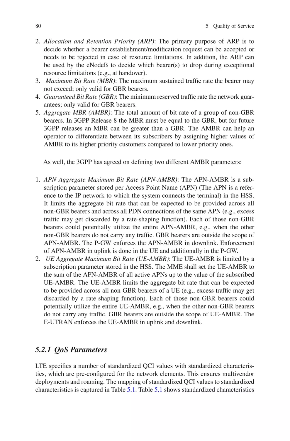
5.1 QoS Mechanisms . . . . . . . . . . . . . . . . . . . . . . . . . . . . . . . . . . . . . . . .
5.2 QoS Control at Bearer Level . . . . . . . . . . . . . . . . . . . . . . . . . . . . . .
5.2.1
QoS Parameters . . . . . . . . . . . . . . . . . . . . . . . . . . . . . . . . .
5.2.2
Network Initiation QoS . . . . . . . . . . . . . . . . . . . . . . . . . . .
5.3 QoS Control at Service Data Flow Level . . . . . . . . . . . . . . . . . . . .
5.3.1
Policy and Charging Control Rule . . . . . . . . . . . . . . . . . .
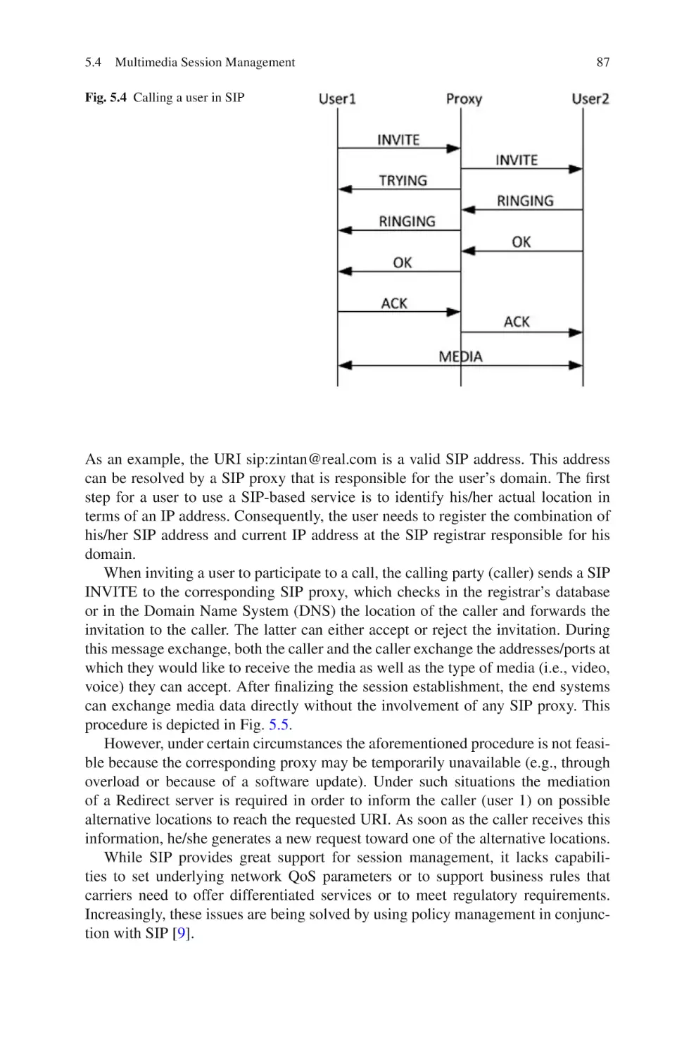
5.4 Multimedia Session Management . . . . . . . . . . . . . . . . . . . . . . . . . .
5.4.1
Session Initiation Protocol . . . . . . . . . . . . . . . . . . . . . . . . .
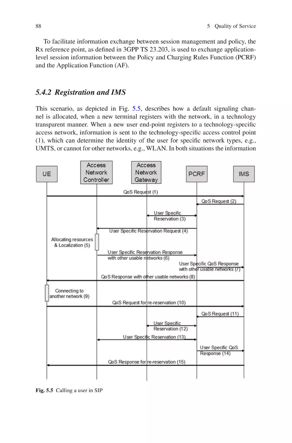
5.4.2
Registration and IMS . . . . . . . . . . . . . . . . . . . . . . . . . . . . .
5.4.3
QoS Provisioning and IMS . . . . . . . . . . . . . . . . . . . . . . . .
5.5 Summary and Conclusions . . . . . . . . . . . . . . . . . . . . . . . . . . . . . . . .
References . . . . . . . . . . . . . . . . . . . . . . . . . . . . . . . . . . . . . . . . . . . . . . . . . . .
77
77
79
80
82
84
85
85
86
88
89
90
90
6 Interworking Design for LTE Convergence . . . . . . . . . . . . . . . . . . . . . .
6.1 General Design Principles of the Interworking Architecture . . . .
6.2 Interworking Scenario . . . . . . . . . . . . . . . . . . . . . . . . . . . . . . . . . . . .
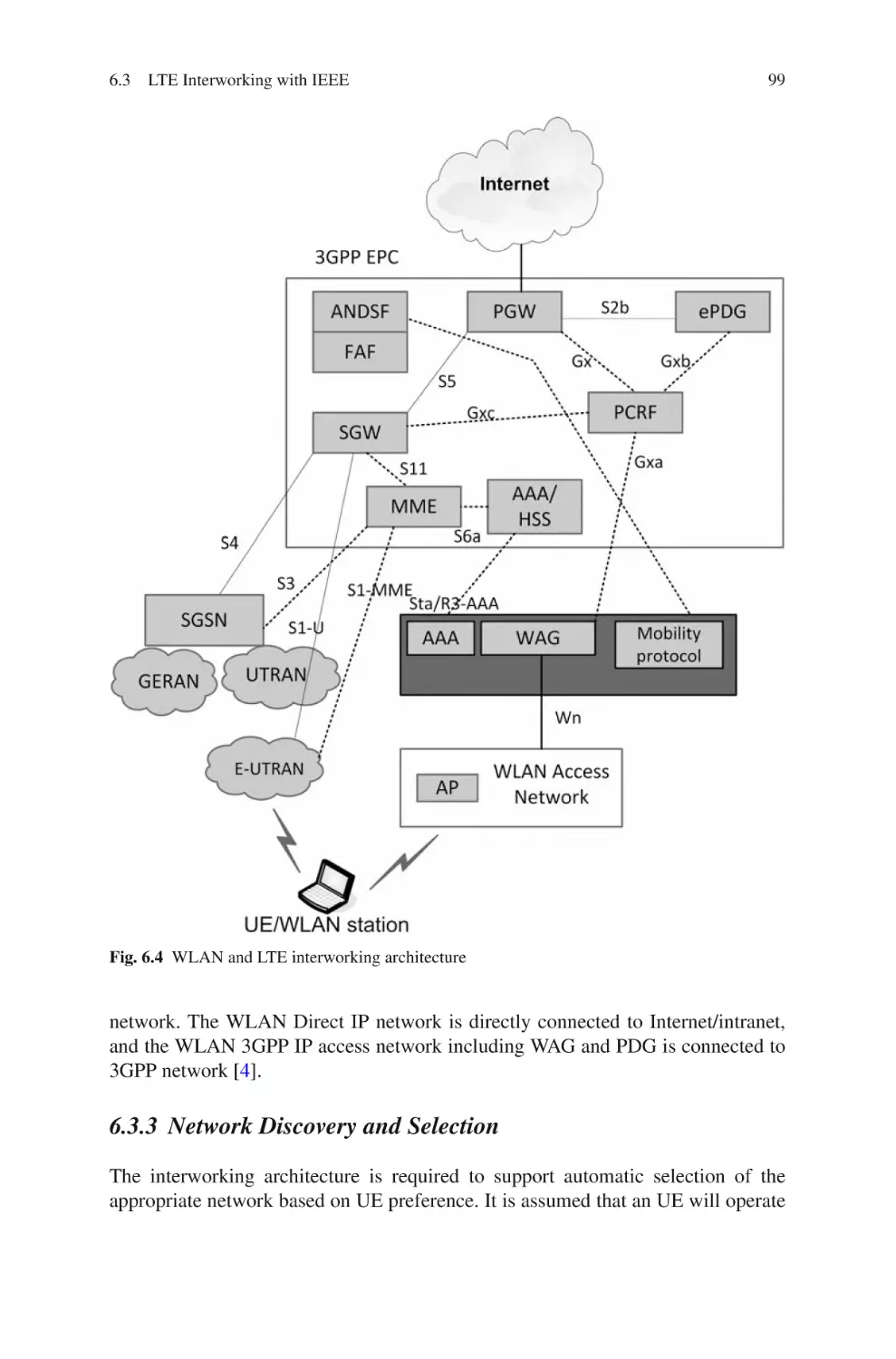
6.3 LTE Interworking with IEEE . . . . . . . . . . . . . . . . . . . . . . . . . . . . . .
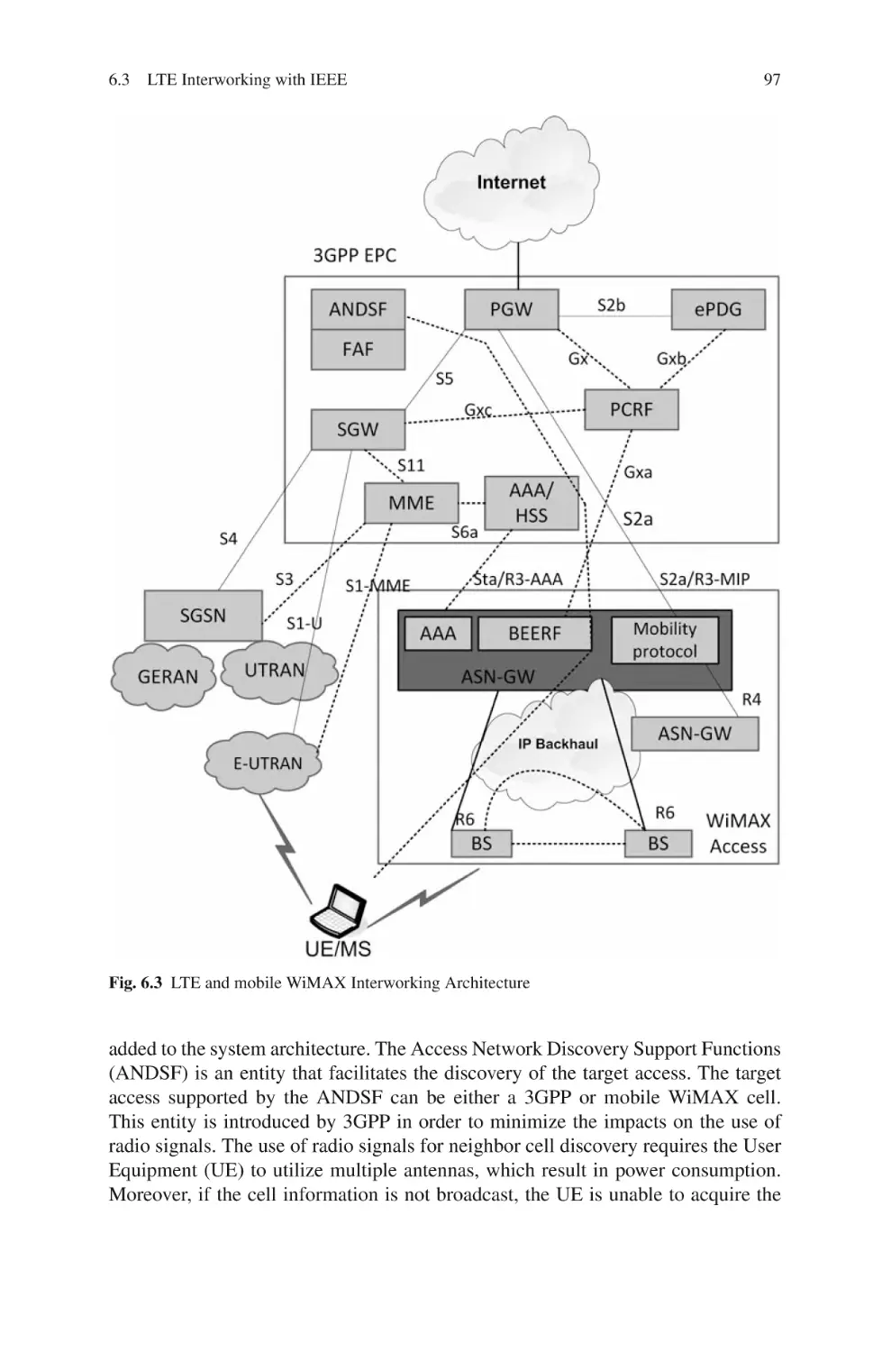
6.3.1
Mobile WiMAX and LTE Interworking Architecture . .
6.3.2
WLAN and LTE Interworking . . . . . . . . . . . . . . . . . . . . .
6.3.3
Network Discovery and Selection . . . . . . . . . . . . . . . . . .
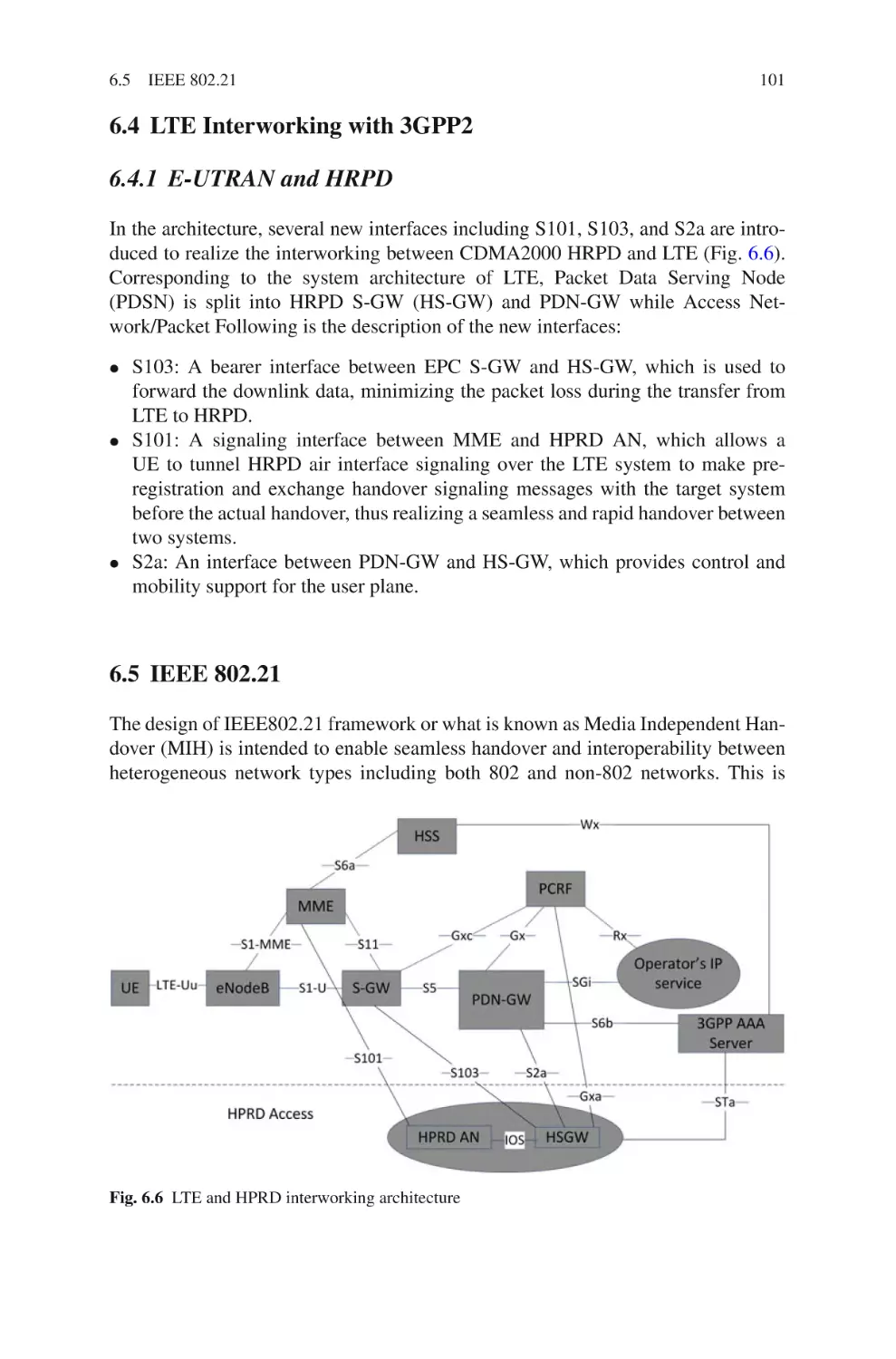
6.4 LTE Interworking with 3GPP2 . . . . . . . . . . . . . . . . . . . . . . . . . . . . .
6.4.1
E-UTRAN and HRPD . . . . . . . . . . . . . . . . . . . . . . . . . . . .
6.5 IEEE 802.21 . . . . . . . . . . . . . . . . . . . . . . . . . . . . . . . . . . . . . . . . . . . .
6.6 Summary and Conclusions . . . . . . . . . . . . . . . . . . . . . . . . . . . . . . . .
References . . . . . . . . . . . . . . . . . . . . . . . . . . . . . . . . . . . . . . . . . . . . . . . . . . .
91
92
92
93
93
98
99
101
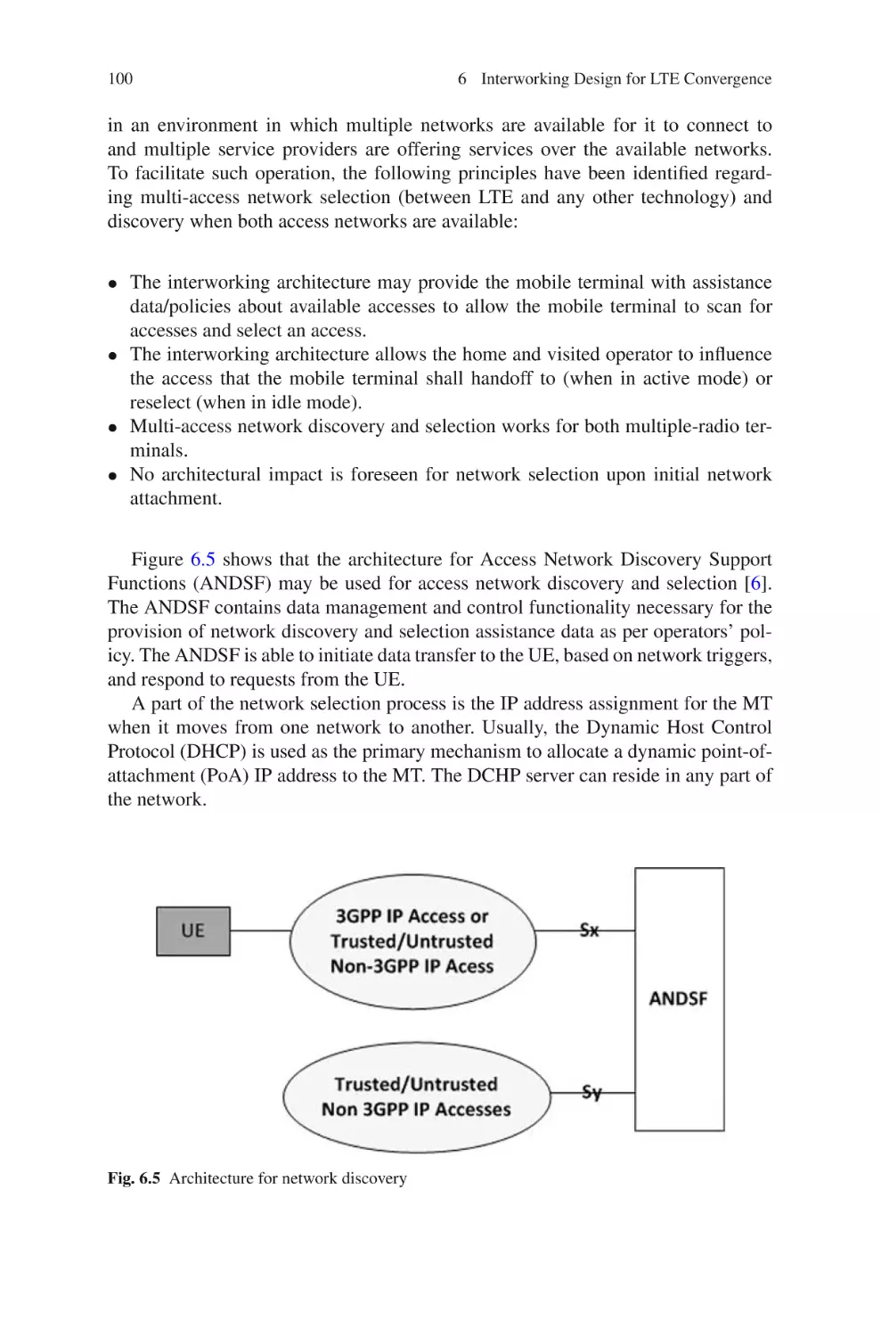
101
101
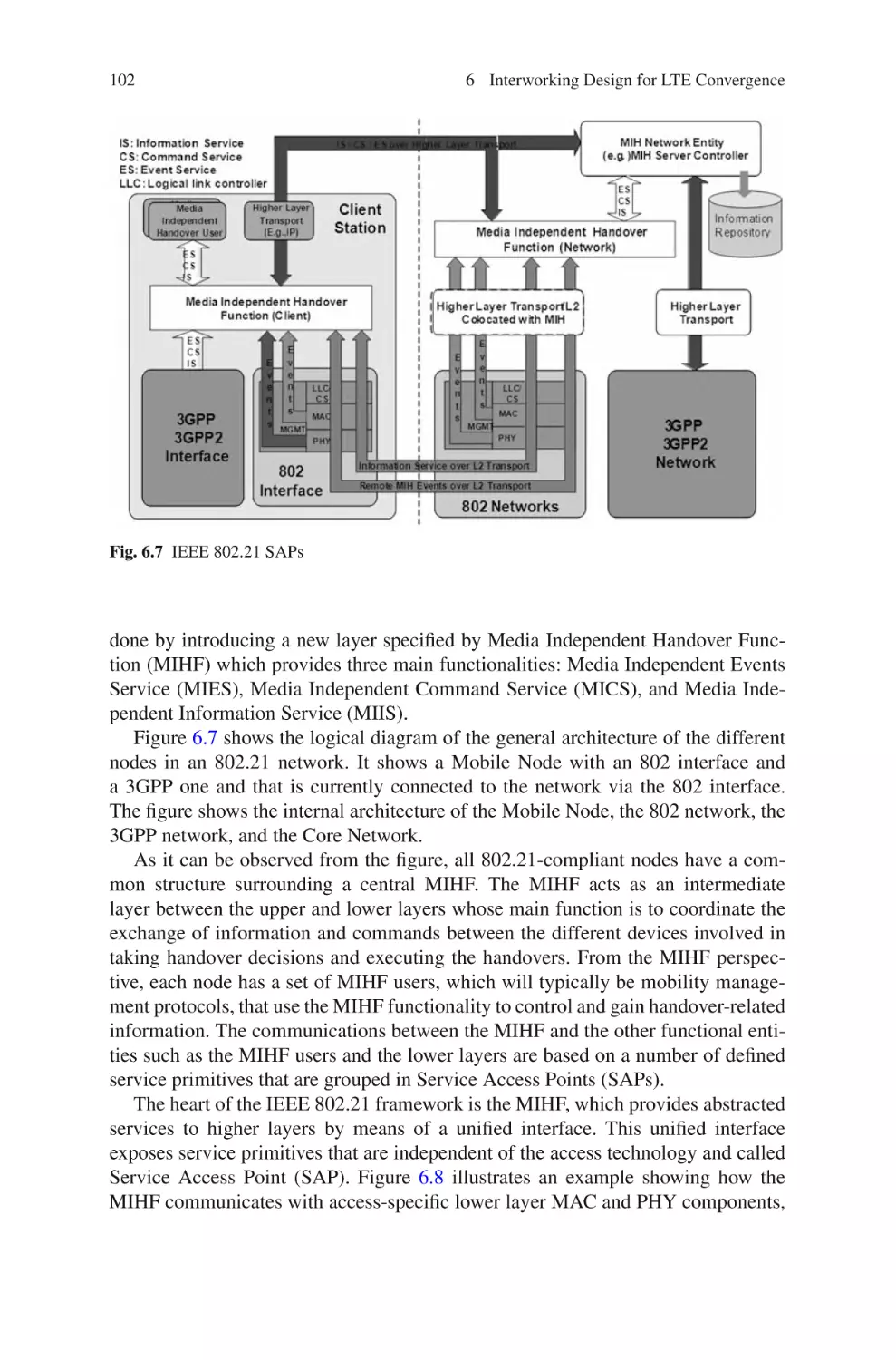
104
104
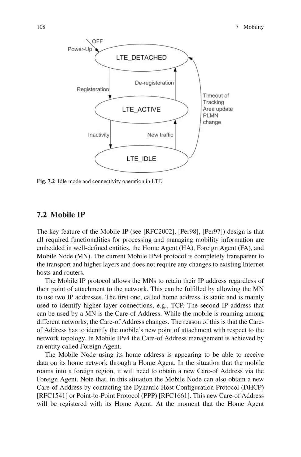
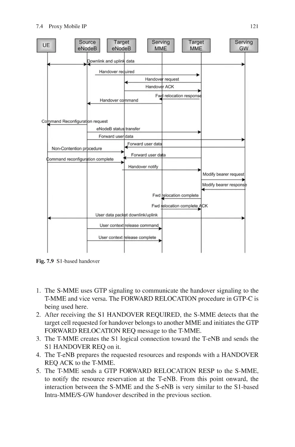
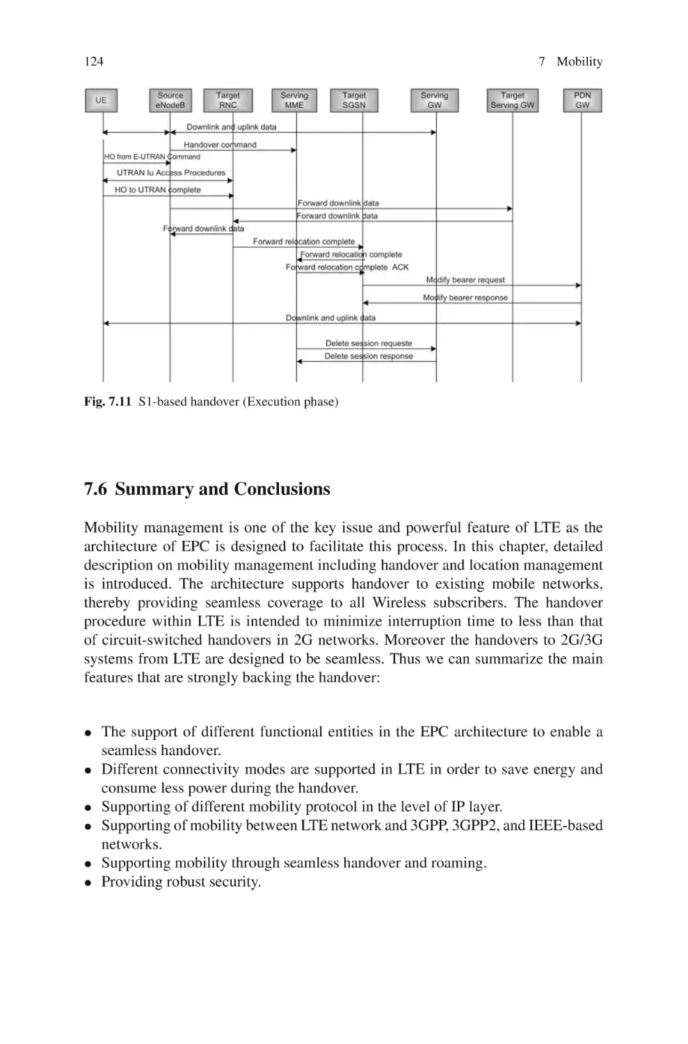
7 Mobility . . . . . . . . . . . . . . . . . . . . . . . . . . . . . . . . . . . . . . . . . . . . . . . . . . . . .
7.1 Mobility Management . . . . . . . . . . . . . . . . . . . . . . . . . . . . . . . . . . . .
7.1.1
Location Management . . . . . . . . . . . . . . . . . . . . . . . . . . . .
7.1.2
Handover Management . . . . . . . . . . . . . . . . . . . . . . . . . . .
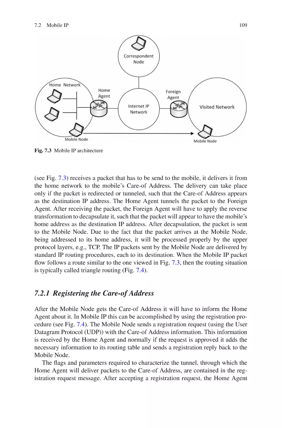
7.2 Mobile IP . . . . . . . . . . . . . . . . . . . . . . . . . . . . . . . . . . . . . . . . . . . . . .
7.2.1
Registering the Care-of Address . . . . . . . . . . . . . . . . . . . .
7.2.2
Automatic Home Agent discovery . . . . . . . . . . . . . . . . . .
7.2.3
Tunneling to the Care-of Address . . . . . . . . . . . . . . . . . . .
7.2.4
Proxy and Gratuitous Address Resolution Protocol
(ARP) . . . . . . . . . . . . . . . . . . . . . . . . . . . . . . . . . . . . . . . . .
105
105
106
106
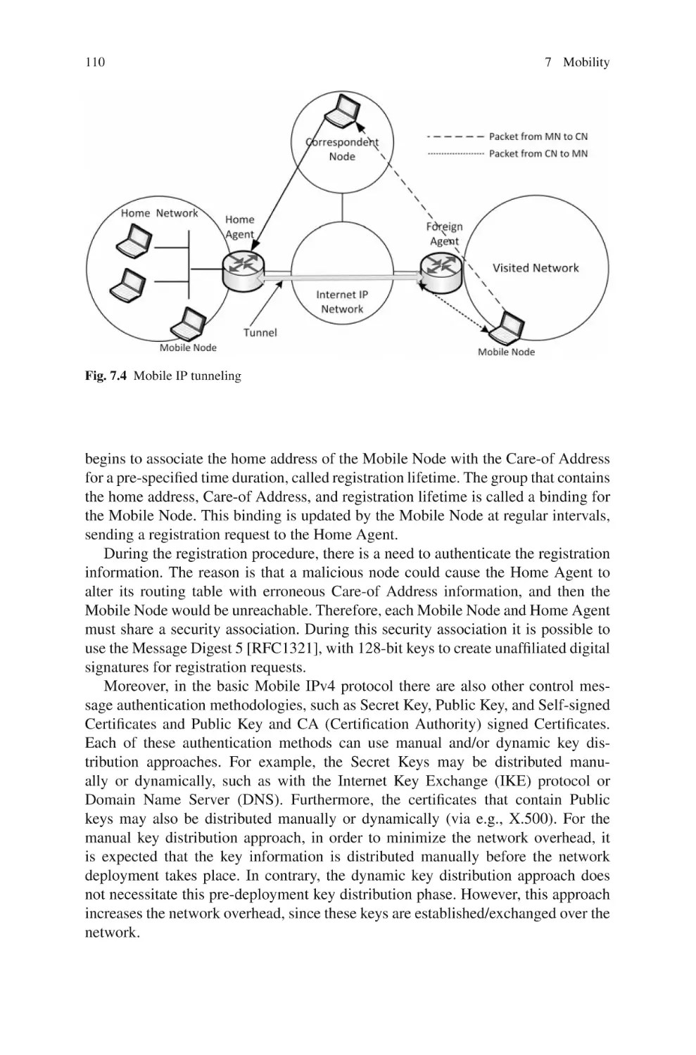
108
109
111
111
111
xvi
Contents
7.3
Differences Between IPv4 and IPv6 . . . . . . . . . . . . . . . . . . . . . . . .
7.3.1
Reverse Tunnels . . . . . . . . . . . . . . . . . . . . . . . . . . . . . . . . .
7.3.2
Use of Route Optimization . . . . . . . . . . . . . . . . . . . . . . . .
7.4 Proxy Mobile IP . . . . . . . . . . . . . . . . . . . . . . . . . . . . . . . . . . . . . . . . .
7.4.1
Idle Mode Mobility . . . . . . . . . . . . . . . . . . . . . . . . . . . . . .
7.4.2
Active Mode Mobility . . . . . . . . . . . . . . . . . . . . . . . . . . . .
7.4.3
Handover Using the S1 Interface . . . . . . . . . . . . . . . . . . .
7.4.4
Inter-MME Handover Using the S1 Interface
(Without Changing S-GW) . . . . . . . . . . . . . . . . . . . . . . .
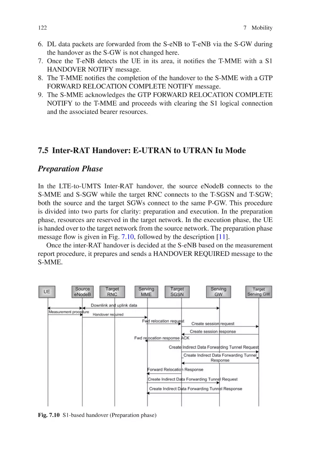
7.5 Inter-RAT Handover: E-UTRAN to UTRAN Iu Mode . . . . . . . . .
7.6 Summary and Conclusions . . . . . . . . . . . . . . . . . . . . . . . . . . . . . . . .
References . . . . . . . . . . . . . . . . . . . . . . . . . . . . . . . . . . . . . . . . . . . . . . . . . . .
112
112
113
113
113
114
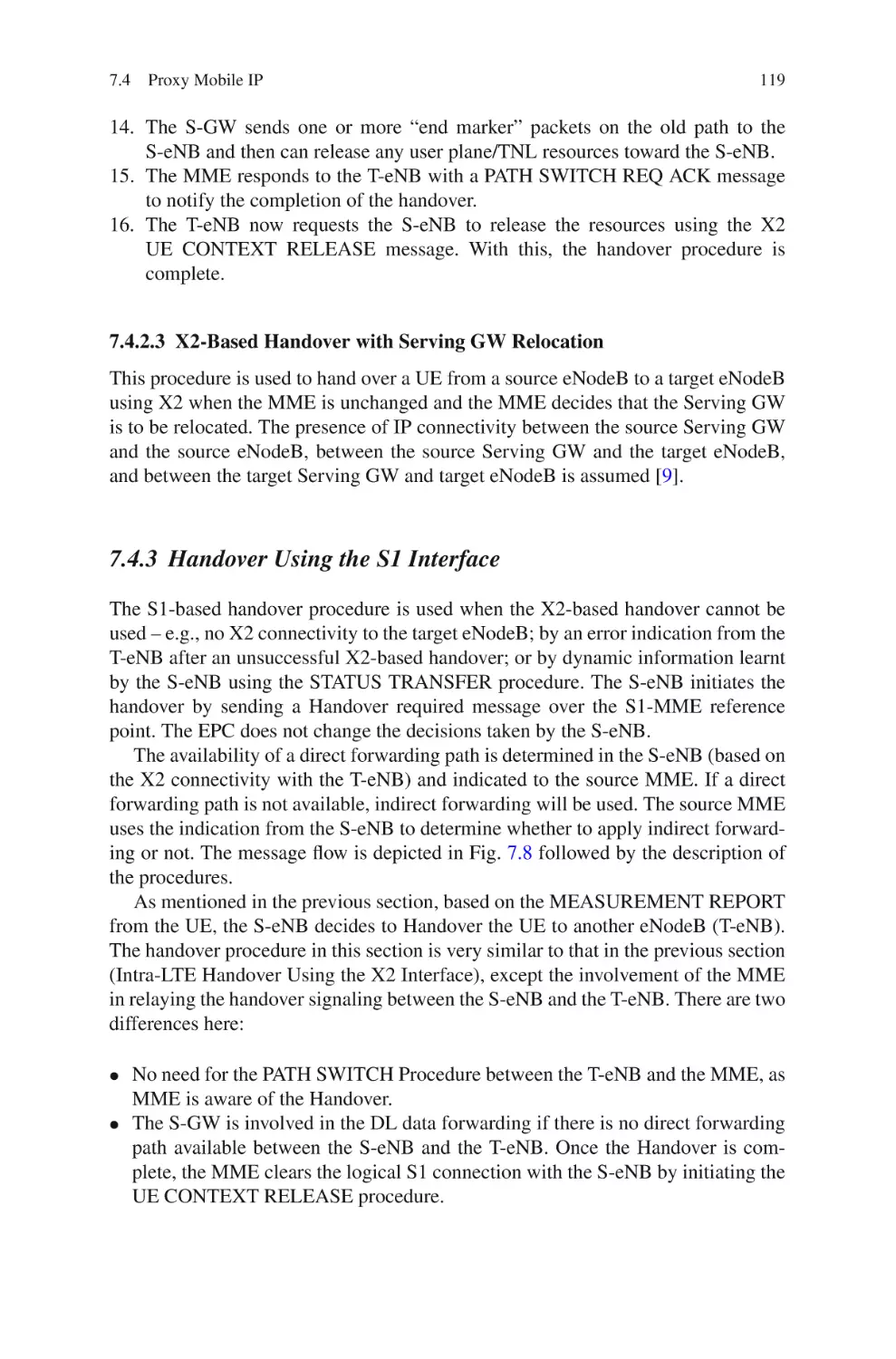
119
120
122
124
125
8 LTE and Femtocell . . . . . . . . . . . . . . . . . . . . . . . . . . . . . . . . . . . . . . . . . . .
8.1 Behind Femtocell Emergence . . . . . . . . . . . . . . . . . . . . . . . . . . . . . .
8.2 Femtocell Technology . . . . . . . . . . . . . . . . . . . . . . . . . . . . . . . . . . . .
8.3 Femtocell Benefits . . . . . . . . . . . . . . . . . . . . . . . . . . . . . . . . . . . . . . .
8.3.1
User Benefits . . . . . . . . . . . . . . . . . . . . . . . . . . . . . . . . . . . .
8.3.2
Operator Benefits . . . . . . . . . . . . . . . . . . . . . . . . . . . . . . . .
8.4 LTE Femtocell Design Issues . . . . . . . . . . . . . . . . . . . . . . . . . . . . . .
8.4.1
LTE Femtocell Architecture . . . . . . . . . . . . . . . . . . . . . . .
8.5 LTE Femtocell Deployment Scenarios . . . . . . . . . . . . . . . . . . . . . .
8.5.1
Scenario 1 . . . . . . . . . . . . . . . . . . . . . . . . . . . . . . . . . . . . . .
8.5.2
Scenario 2 . . . . . . . . . . . . . . . . . . . . . . . . . . . . . . . . . . . . . .
8.5.3
Scenario 3 . . . . . . . . . . . . . . . . . . . . . . . . . . . . . . . . . . . . . .
8.6 Femtocell Access Control Strategy . . . . . . . . . . . . . . . . . . . . . . . . .
8.6.1
CSG Concept . . . . . . . . . . . . . . . . . . . . . . . . . . . . . . . . . . .
8.6.2
Physical Cell Identity . . . . . . . . . . . . . . . . . . . . . . . . . . . . .
8.7 LTE Femtocell Challenges and Technical Issues . . . . . . . . . . . . . .
8.7.1
Interference . . . . . . . . . . . . . . . . . . . . . . . . . . . . . . . . . . . . .
8.7.2
Spectrum Allocation . . . . . . . . . . . . . . . . . . . . . . . . . . . . .
8.7.3
Access Mode Impact . . . . . . . . . . . . . . . . . . . . . . . . . . . . .
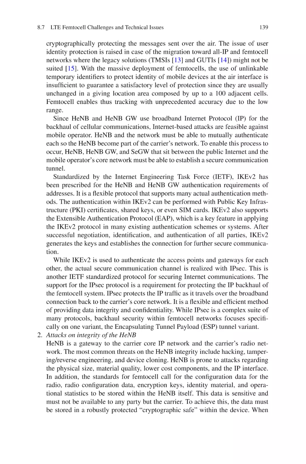
8.7.4
Security and Privacy Challenges . . . . . . . . . . . . . . . . . . . .
8.7.5
Synchronization . . . . . . . . . . . . . . . . . . . . . . . . . . . . . . . . .
8.7.6
Mobility . . . . . . . . . . . . . . . . . . . . . . . . . . . . . . . . . . . . . . . .
8.8 Summary and Conclusion . . . . . . . . . . . . . . . . . . . . . . . . . . . . . . . . .
References . . . . . . . . . . . . . . . . . . . . . . . . . . . . . . . . . . . . . . . . . . . . . . . . . . .
127
128
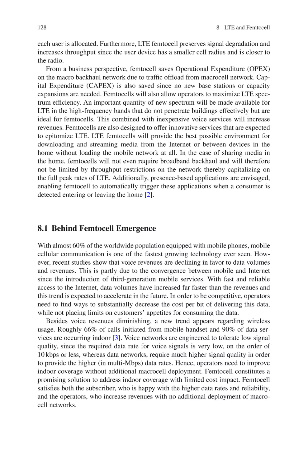
129
130
130
130
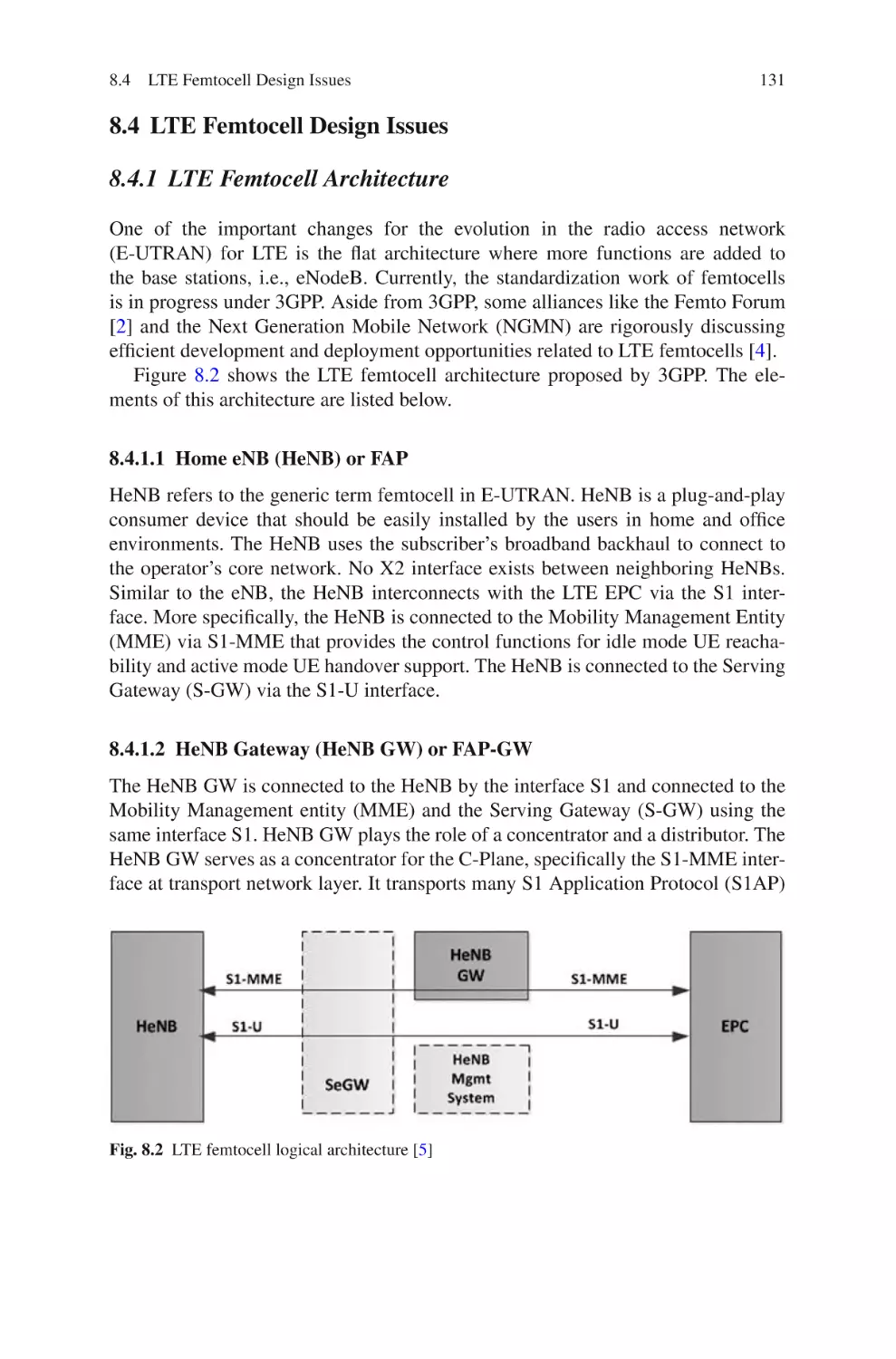
131
131
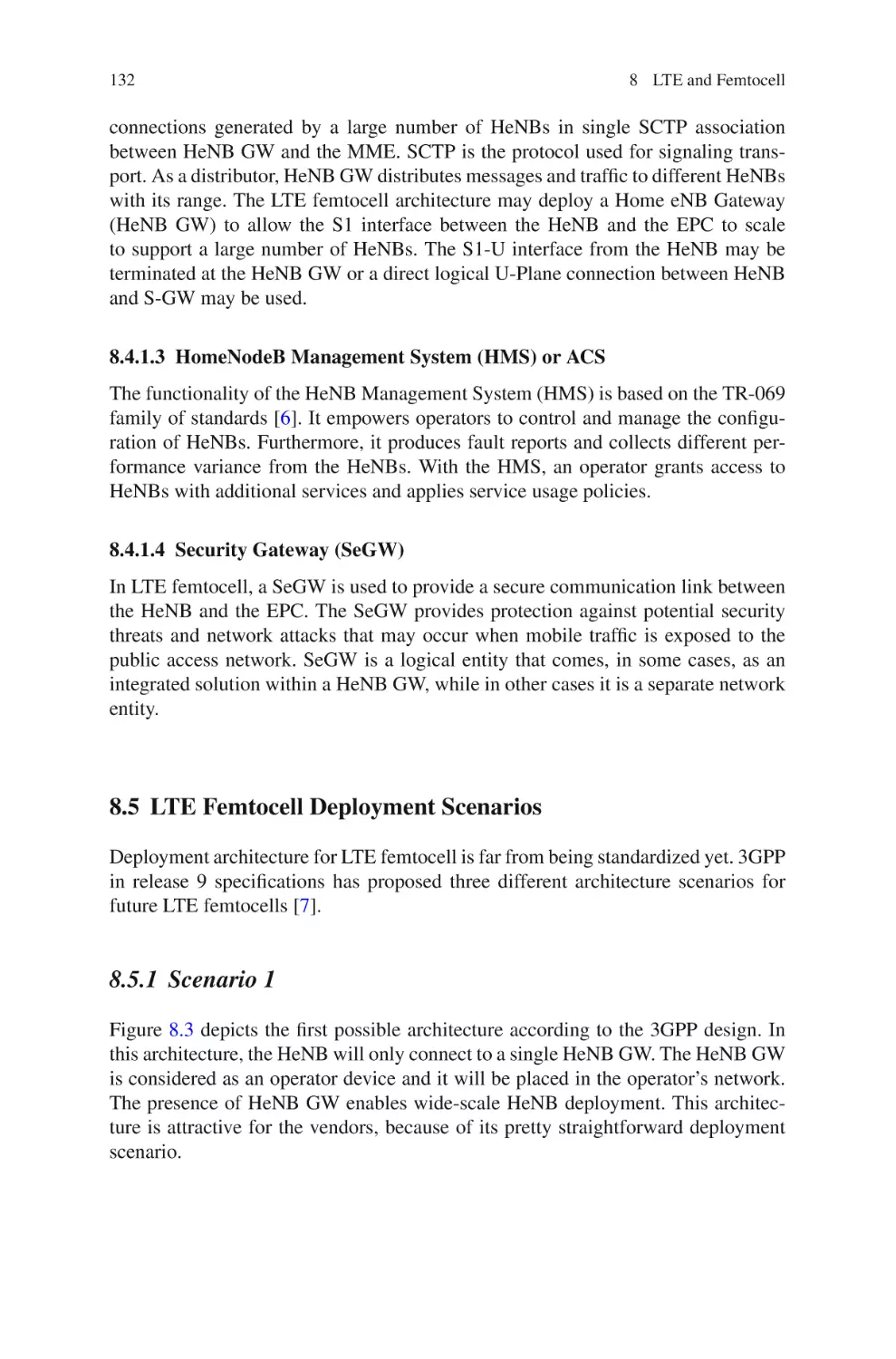
132
132
133
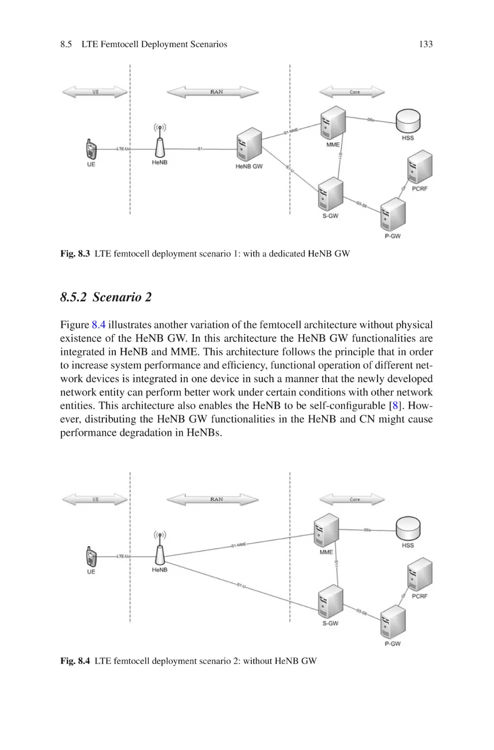
134
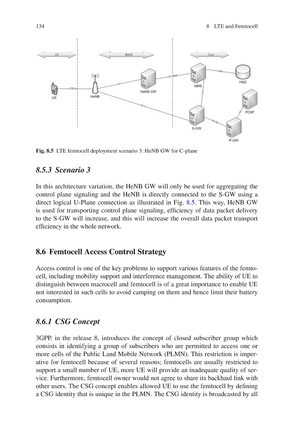
134
134
135
136
136
136
137
138
140
140
142
142
Part III LTE Performance
9 Downlink Radio Resource Allocation Strategies in LTE Networks .
9.1
An Overview of Resource Allocation Techniques
in OFDMA Systems . . . . . . . . . . . . . . . . . . . . . . . . . . . . . . . . . . . . .
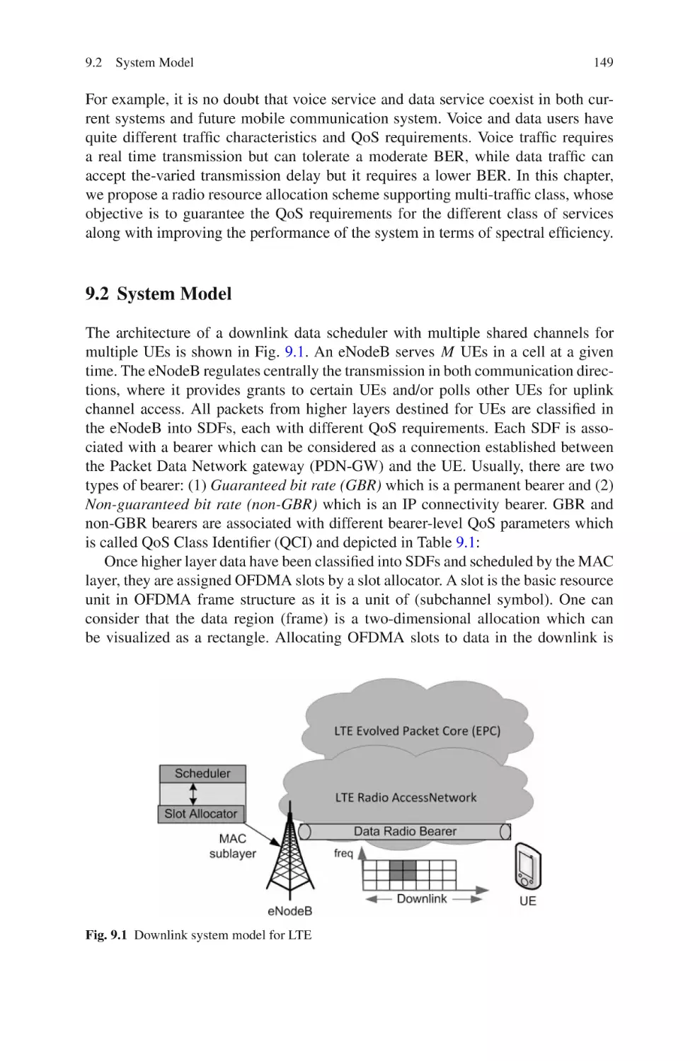
9.2 System Model . . . . . . . . . . . . . . . . . . . . . . . . . . . . . . . . . . . . . . . . . .
147
148
149
Contents
xvii
9.3
OFDMA Key Principles – Analysis and Performance
Characterizations . . . . . . . . . . . . . . . . . . . . . . . . . . . . . . . . . . . . . . . .
9.3.1
OFDMA Slot Structure in LTE Generic Frame . . . . . . . .
9.3.2
Adaptive Modulation and Coding . . . . . . . . . . . . . . . . . . .
9.3.3
Multiuser Diversity . . . . . . . . . . . . . . . . . . . . . . . . . . . . . .
9.3.4
Capacity Analysis – Time and Frequency Domain . . . . .
9.4 Proposed Radio Resource Allocation Strategies . . . . . . . . . . . . . .
9.4.1
Problem Formulation . . . . . . . . . . . . . . . . . . . . . . . . . . . . .
9.4.2
Adaptive Slot Allocation (ASA) Algorithm . . . . . . . . . .
9.4.3
Reservation-Based Slot Allocation (RSA) Algorithm . .
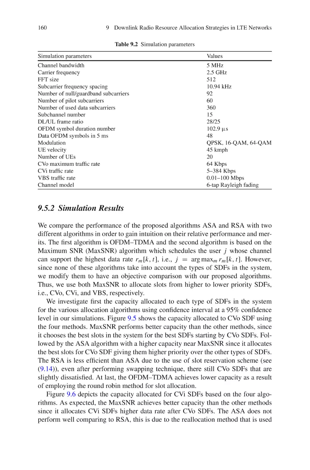
9.5 Performance Evaluation . . . . . . . . . . . . . . . . . . . . . . . . . . . . . . . . . .
9.5.1
Simulation Parameters . . . . . . . . . . . . . . . . . . . . . . . . . . . .
9.5.2
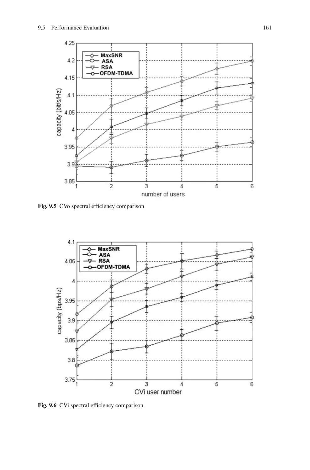
Simulation Results . . . . . . . . . . . . . . . . . . . . . . . . . . . . . . .
9.6 Summary and Conclusions . . . . . . . . . . . . . . . . . . . . . . . . . . . . . . . .
References . . . . . . . . . . . . . . . . . . . . . . . . . . . . . . . . . . . . . . . . . . . . . . . . . . .
150
150
151
152
152
154
155
156
157
159
159
160
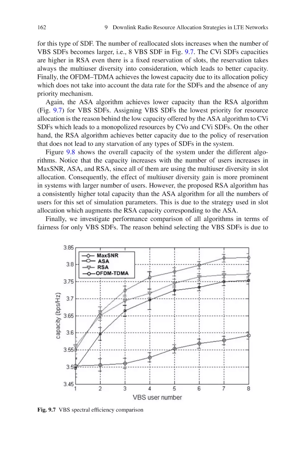
164
164
10 Performance Study of Opportunistic Scheduling in LTE Networks .
10.1 Introduction . . . . . . . . . . . . . . . . . . . . . . . . . . . . . . . . . . . . . . . . . . . .
10.2 Downlink System Model . . . . . . . . . . . . . . . . . . . . . . . . . . . . . . . . .
10.3 Opportunistic Packet Scheduling Algorithms . . . . . . . . . . . . . . . . .
10.3.1 Proportional Fairness (PF) . . . . . . . . . . . . . . . . . . . . . . . . .
10.3.2 Maximum Largest Weighted Delay First (M-LWDF) . .
10.3.3 Exponential Proportional Fairness (EXP/PF) . . . . . . . . .
10.4 Simulation Environment . . . . . . . . . . . . . . . . . . . . . . . . . . . . . . . . . .
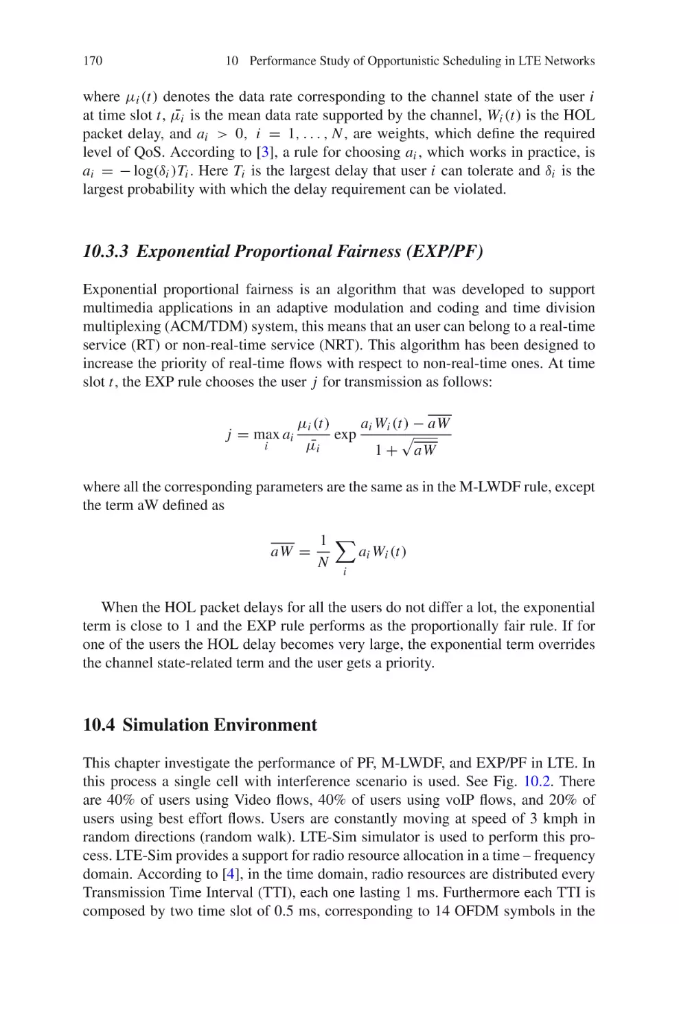
10.5 Traffic Model . . . . . . . . . . . . . . . . . . . . . . . . . . . . . . . . . . . . . . . . . . .
10.6 Simulation Results . . . . . . . . . . . . . . . . . . . . . . . . . . . . . . . . . . . . . . .
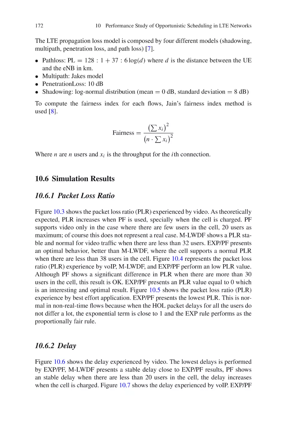
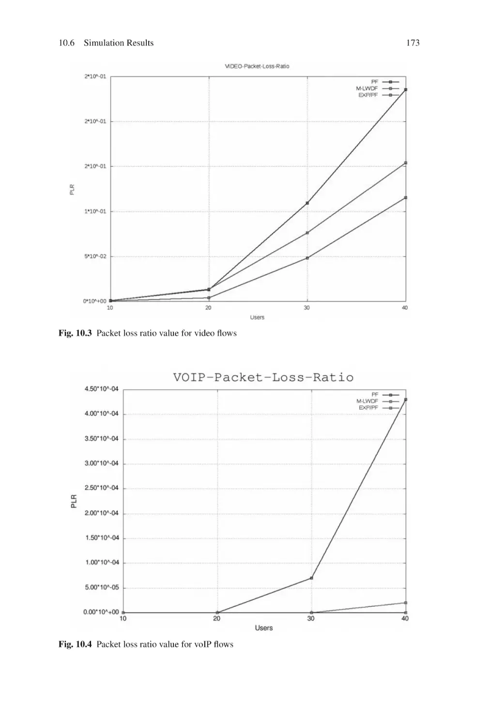
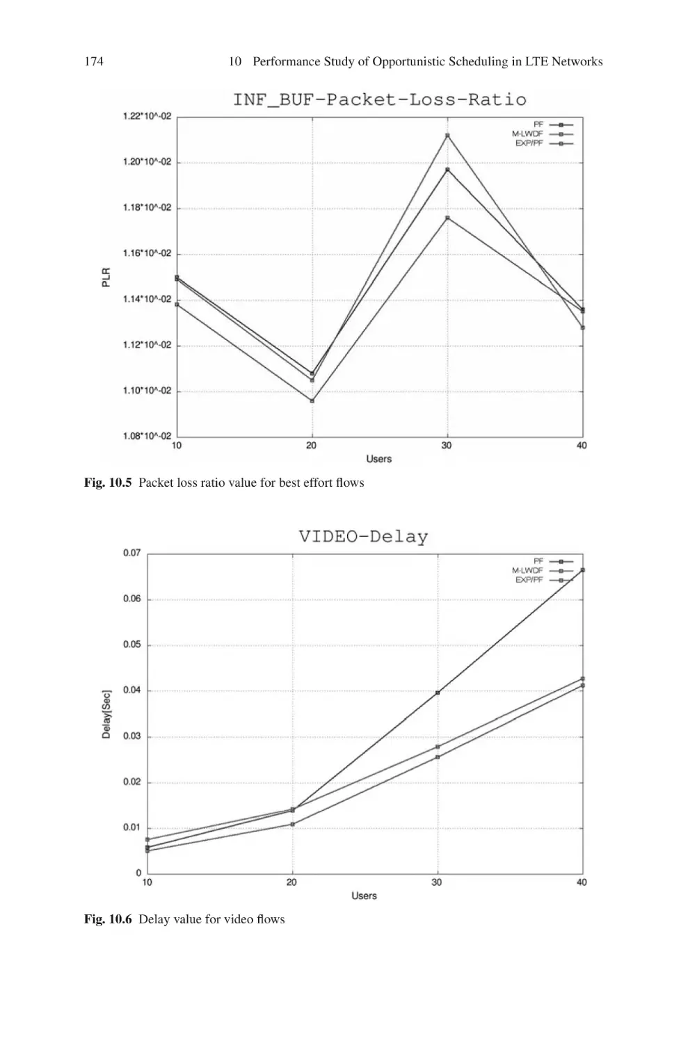
10.6.1 Packet Loss Ratio . . . . . . . . . . . . . . . . . . . . . . . . . . . . . . . .
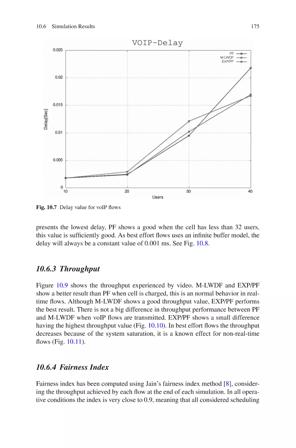
10.6.2 Delay . . . . . . . . . . . . . . . . . . . . . . . . . . . . . . . . . . . . . . . . . .
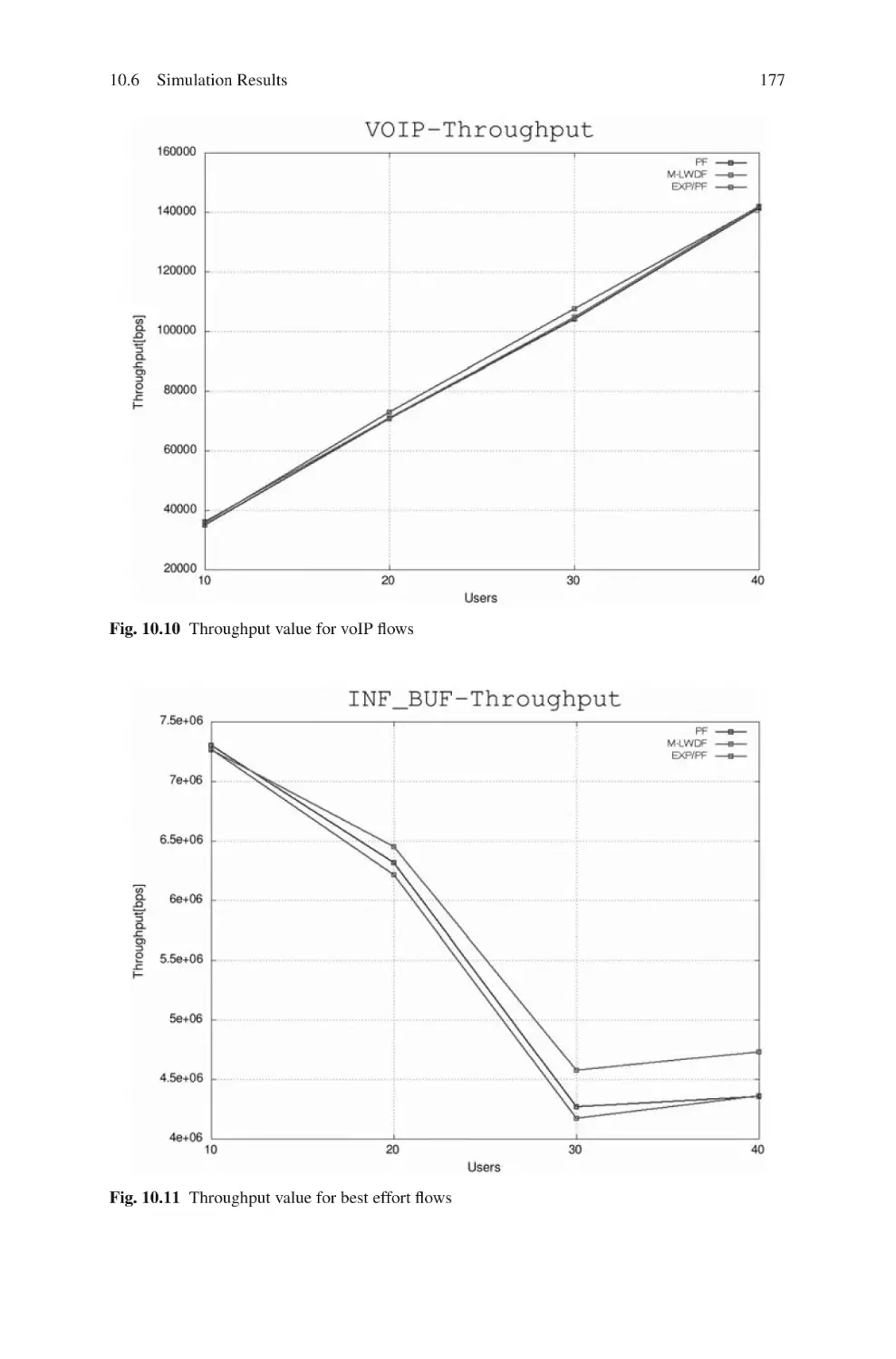
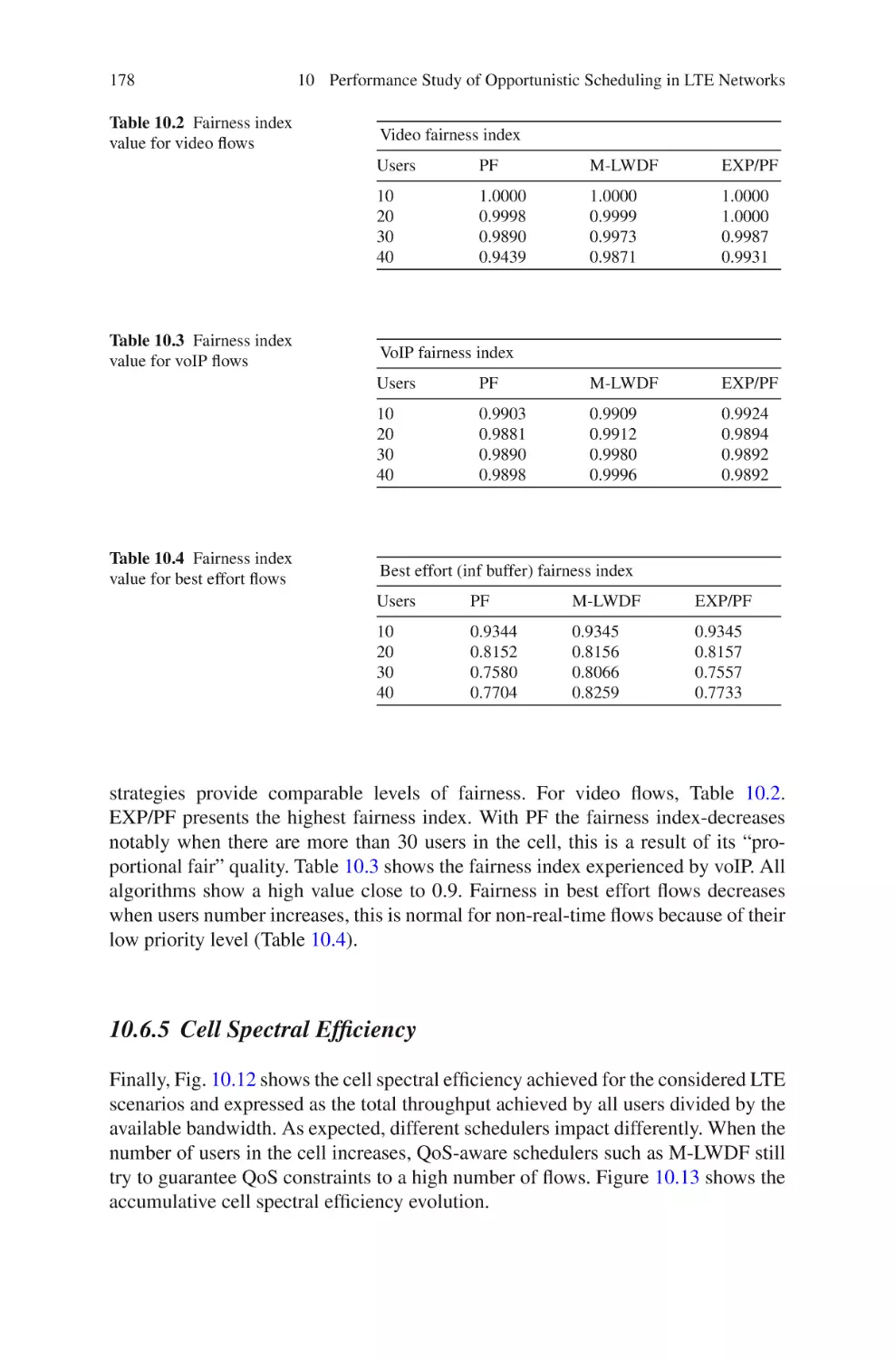
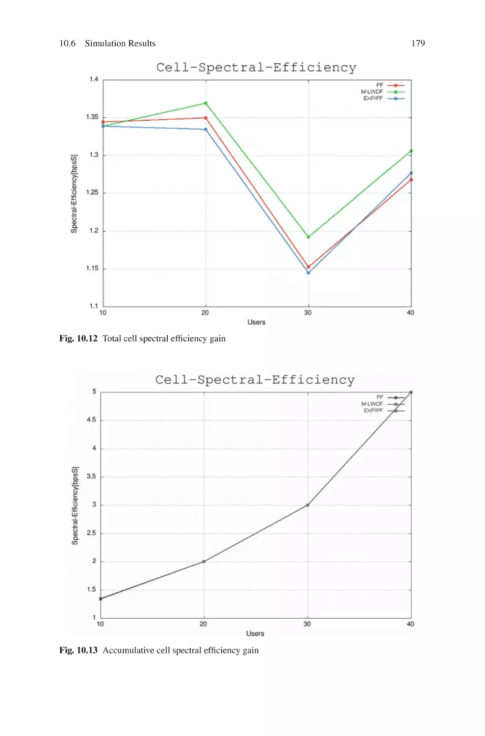
10.6.3 Throughput . . . . . . . . . . . . . . . . . . . . . . . . . . . . . . . . . . . . .
10.6.4 Fairness Index . . . . . . . . . . . . . . . . . . . . . . . . . . . . . . . . . . .
10.6.5 Cell Spectral Efficiency . . . . . . . . . . . . . . . . . . . . . . . . . . .
10.7 Conclusion . . . . . . . . . . . . . . . . . . . . . . . . . . . . . . . . . . . . . . . . . . . . .
References . . . . . . . . . . . . . . . . . . . . . . . . . . . . . . . . . . . . . . . . . . . . . . . . . . .
167
167
168
169
169
169
170
170
171
172
172
172
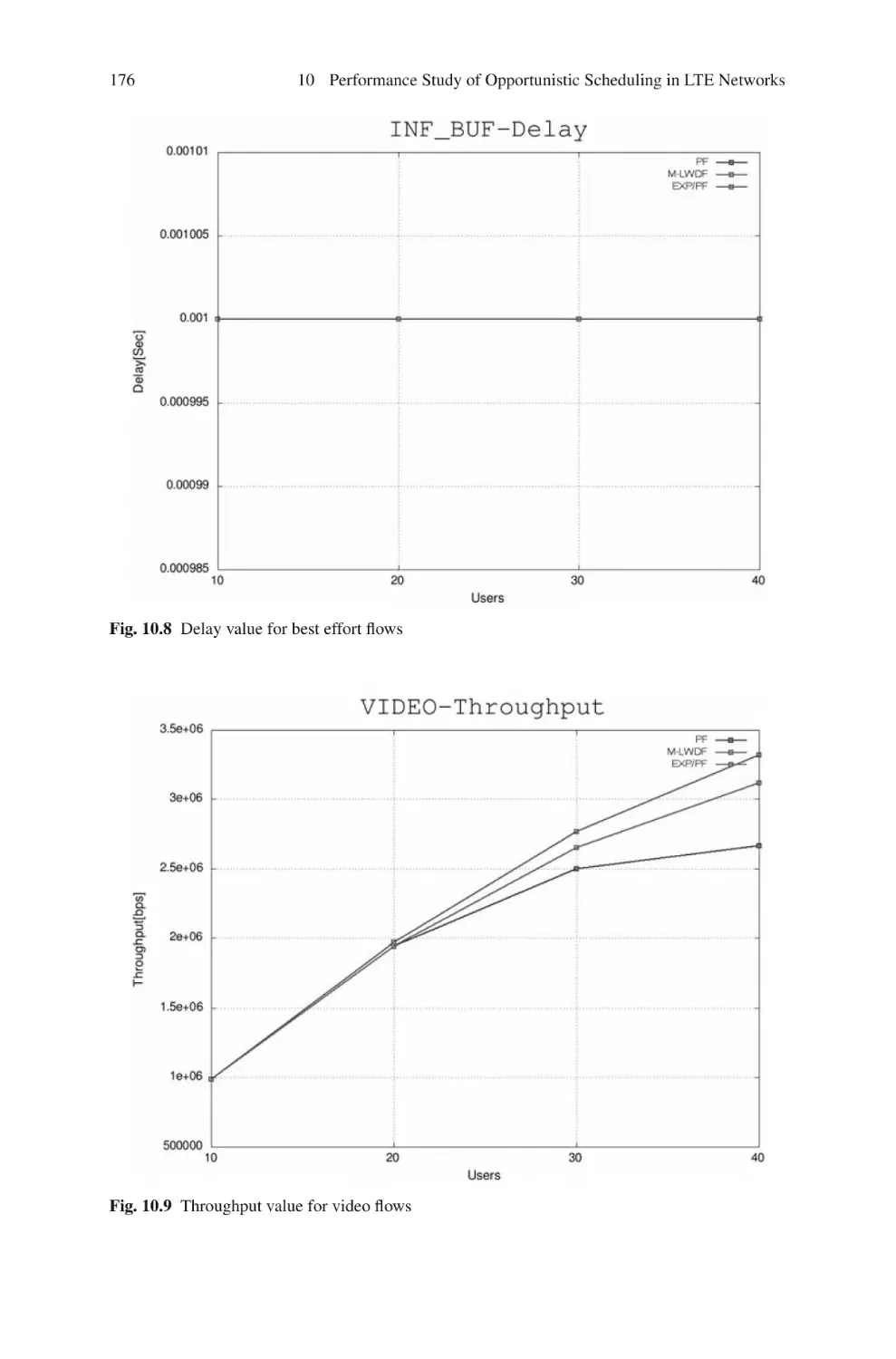
175
175
178
180
180
11 Cross-Layer Multiservice Scheduling for LTE Networks . . . . . . . . .
11.1 Channel-Based Scheduling Solutions . . . . . . . . . . . . . . . . . . . . . . .
11.1.1 Modified Largest Weighted Delay First (M-LWDF)
Algorithm . . . . . . . . . . . . . . . . . . . . . . . . . . . . . . . . . . . . . .
11.1.2 Exponential (EXP) Algorithm . . . . . . . . . . . . . . . . . . . . . .
11.1.3 Delay-Based Utility Optimization Algorithm . . . . . . . . .
11.1.4 Maximum Fairness (MF) Algorithm . . . . . . . . . . . . . . . .
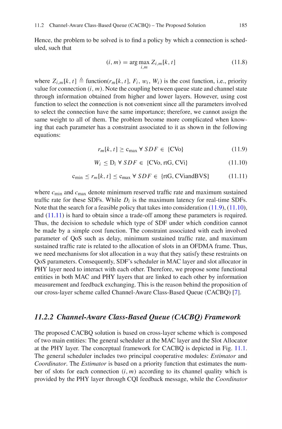
11.2 Channel-Aware Class-Based Queue (CACBQ) – The Proposed
Solution . . . . . . . . . . . . . . . . . . . . . . . . . . . . . . . . . . . . . . . . . . . . . . .
181
181
182
182
183
183
184
xviii
Contents
11.2.1
11.2.2
System Model . . . . . . . . . . . . . . . . . . . . . . . . . . . . . . . . . . .
Channel-Aware Class-Based Queue (CACBQ)
Framework . . . . . . . . . . . . . . . . . . . . . . . . . . . . . . . . . . . . .
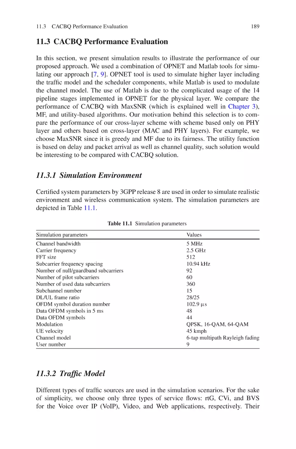
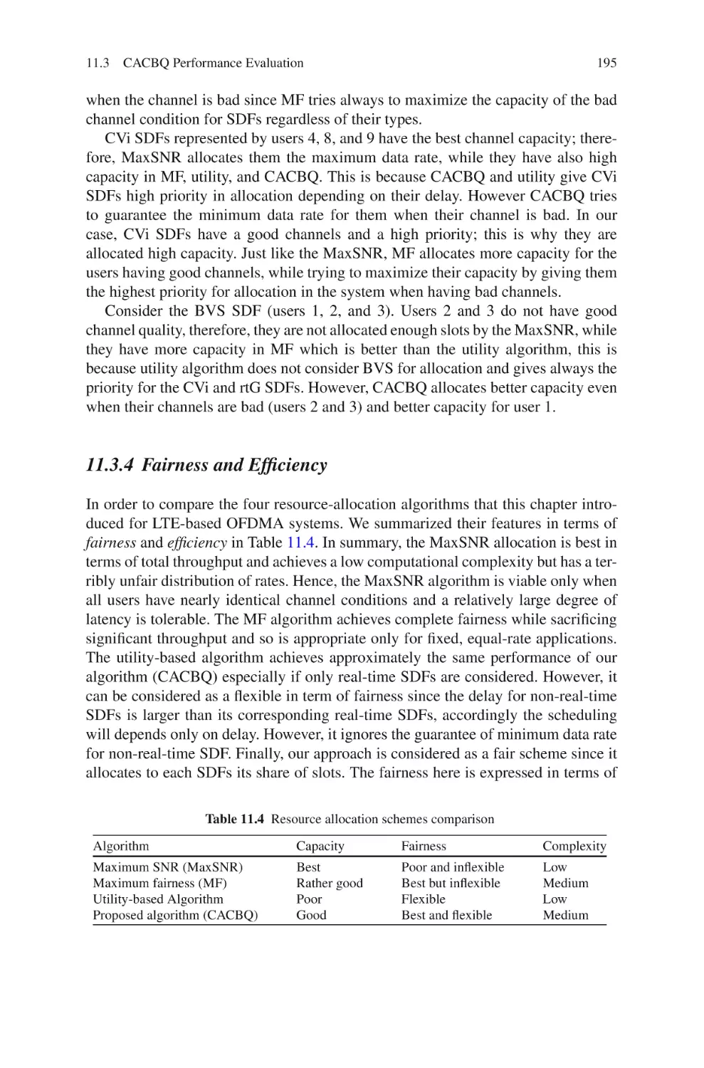
11.3 CACBQ Performance Evaluation . . . . . . . . . . . . . . . . . . . . . . . . . .
11.3.1 Simulation Environment . . . . . . . . . . . . . . . . . . . . . . . . . .
11.3.2 Traffic Model . . . . . . . . . . . . . . . . . . . . . . . . . . . . . . . . . . .
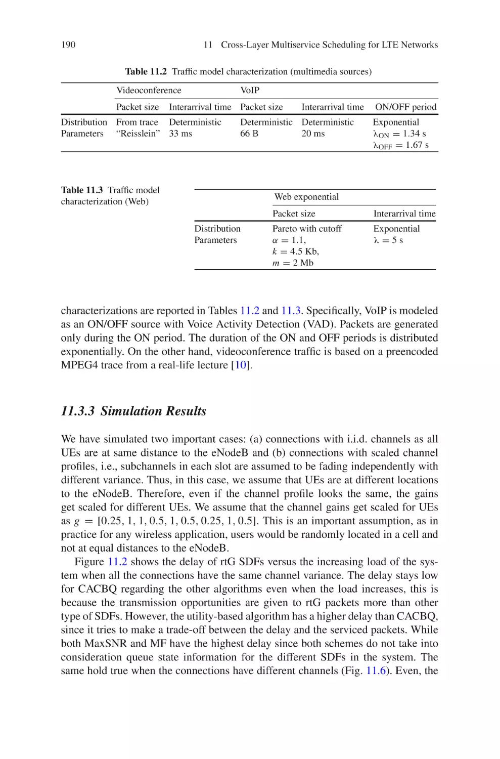
11.3.3 Simulation Results . . . . . . . . . . . . . . . . . . . . . . . . . . . . . . .
11.3.4 Fairness and Efficiency . . . . . . . . . . . . . . . . . . . . . . . . . . .
11.4 Summary and Conclusions . . . . . . . . . . . . . . . . . . . . . . . . . . . . . . . .
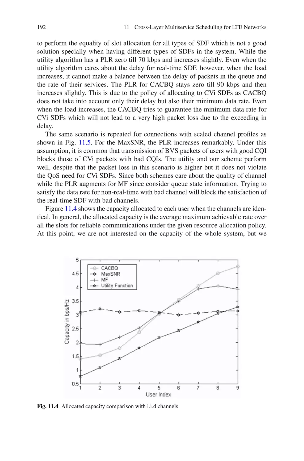
References . . . . . . . . . . . . . . . . . . . . . . . . . . . . . . . . . . . . . . . . . . . . . . . . . . .
184
185
189
189
189
190
195
196
197
12 Fractional Frequency Reuse in LTE Networks . . . . . . . . . . . . . . . . . .
12.1 Introduction . . . . . . . . . . . . . . . . . . . . . . . . . . . . . . . . . . . . . . . . . . . .
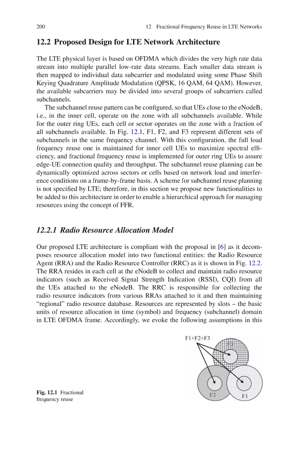
12.2 Proposed Design for LTE Network Architecture . . . . . . . . . . . . . .
12.2.1 Radio Resource Allocation Model . . . . . . . . . . . . . . . . . .
12.2.2 Link Model . . . . . . . . . . . . . . . . . . . . . . . . . . . . . . . . . . . . .
12.2.3 Problem Formulation . . . . . . . . . . . . . . . . . . . . . . . . . . . . .
12.3 Hierarchical Resource Allocation Approach (HRAA) . . . . . . . . .
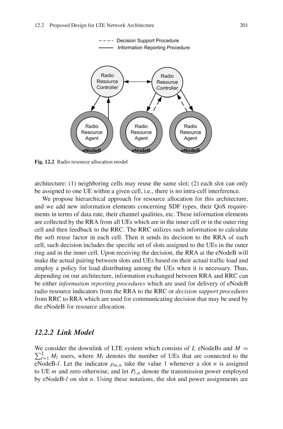
12.3.1 Resource Allocation at RRC . . . . . . . . . . . . . . . . . . . . . . .
12.3.2 Resource Allocation at the eNodeB . . . . . . . . . . . . . . . . .
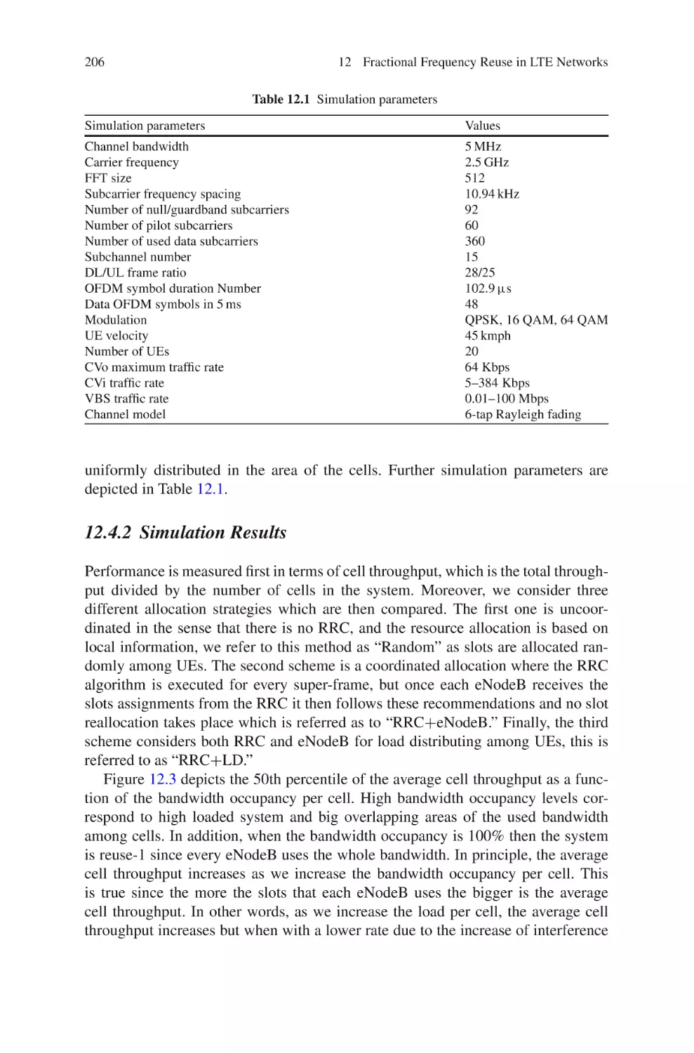
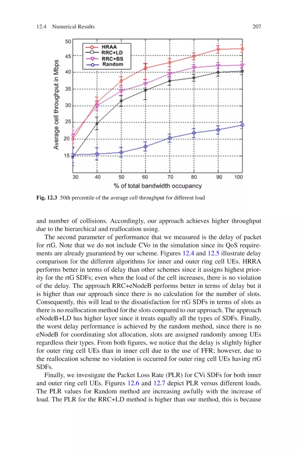
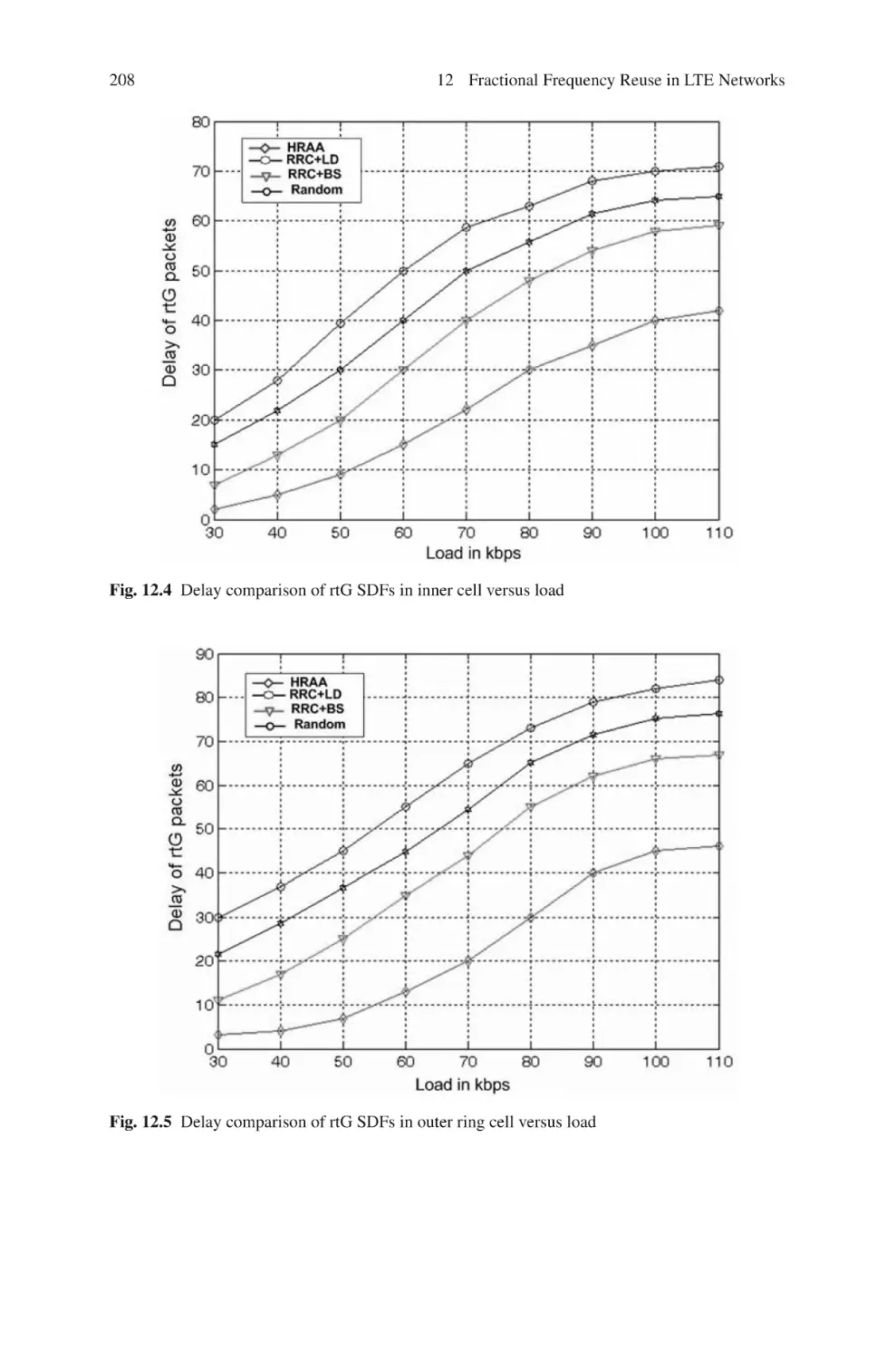
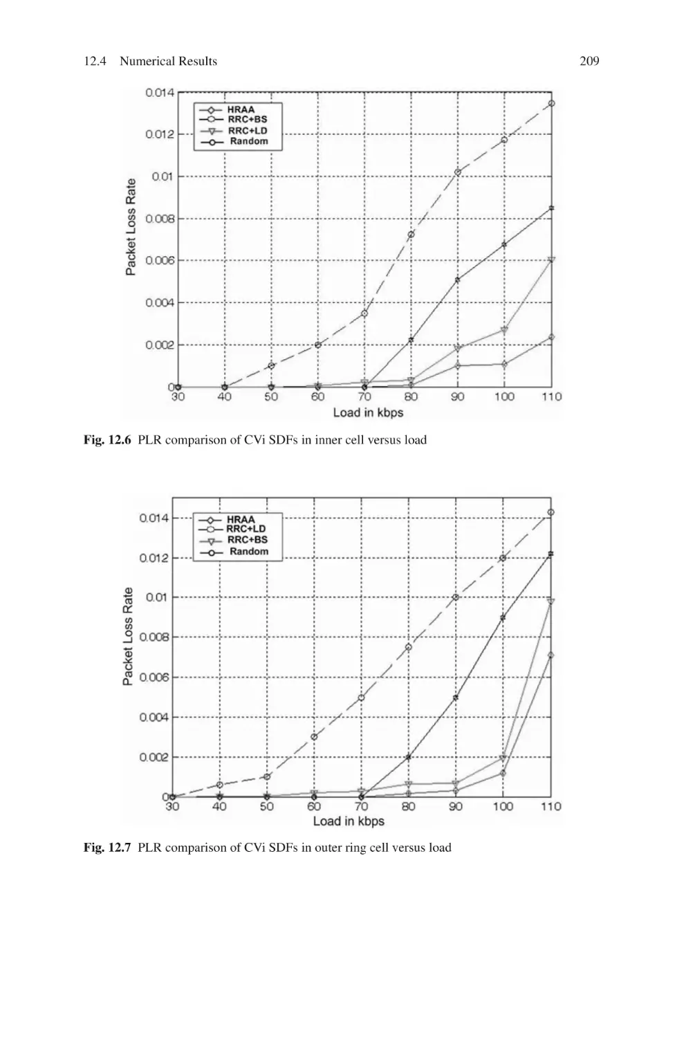
12.4 Numerical Results . . . . . . . . . . . . . . . . . . . . . . . . . . . . . . . . . . . . . . .
12.4.1 Simulation Environment . . . . . . . . . . . . . . . . . . . . . . . . . .
12.4.2 Simulation Results . . . . . . . . . . . . . . . . . . . . . . . . . . . . . . .
12.5 Summary and Conclusions . . . . . . . . . . . . . . . . . . . . . . . . . . . . . . . .
References . . . . . . . . . . . . . . . . . . . . . . . . . . . . . . . . . . . . . . . . . . . . . . . . . . .
199
199
200
200
201
202
203
203
205
205
205
206
210
210
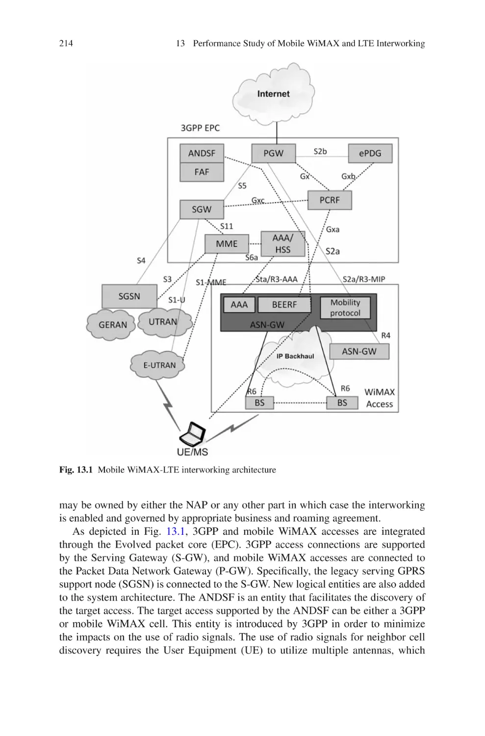
13 Performance Study of Mobile WiMAX and LTE Interworking . . . .
13.1 Introduction . . . . . . . . . . . . . . . . . . . . . . . . . . . . . . . . . . . . . . . . . . . .
13.2 Handover Overview . . . . . . . . . . . . . . . . . . . . . . . . . . . . . . . . . . . . . .
13.3 Mobile WiMAX and LTE Interworking Architecture . . . . . . . . . .
13.4 Handover Decision-Based Neyman–Pearson Lemma . . . . . . . . . .
13.5 Handover Execution Based on FMIPv6 . . . . . . . . . . . . . . . . . . . . .
13.6 Performance Evaluation . . . . . . . . . . . . . . . . . . . . . . . . . . . . . . . . . .
13.6.1 Scenario 1 . . . . . . . . . . . . . . . . . . . . . . . . . . . . . . . . . . . . . .
13.6.2 Scenario 2 . . . . . . . . . . . . . . . . . . . . . . . . . . . . . . . . . . . . . .
13.6.3 Scenario 3 . . . . . . . . . . . . . . . . . . . . . . . . . . . . . . . . . . . . . .
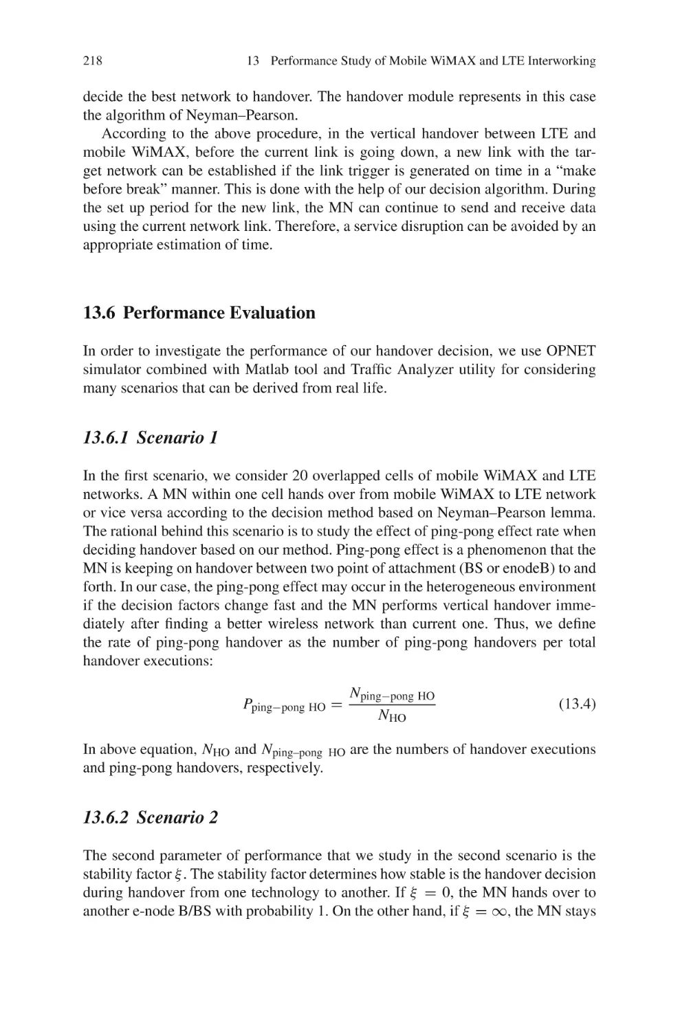
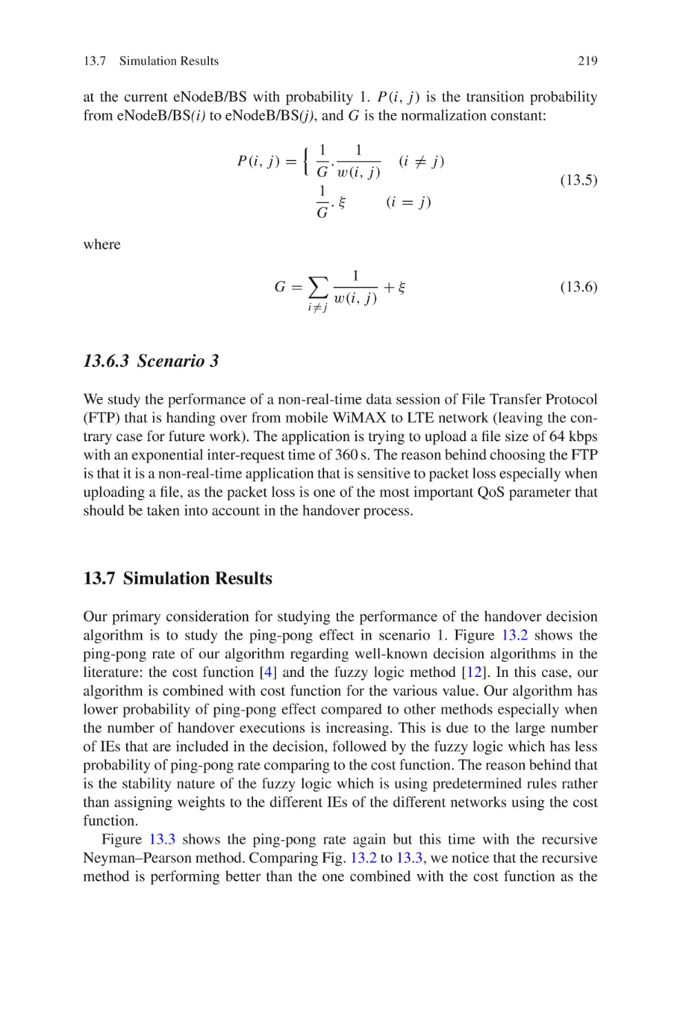
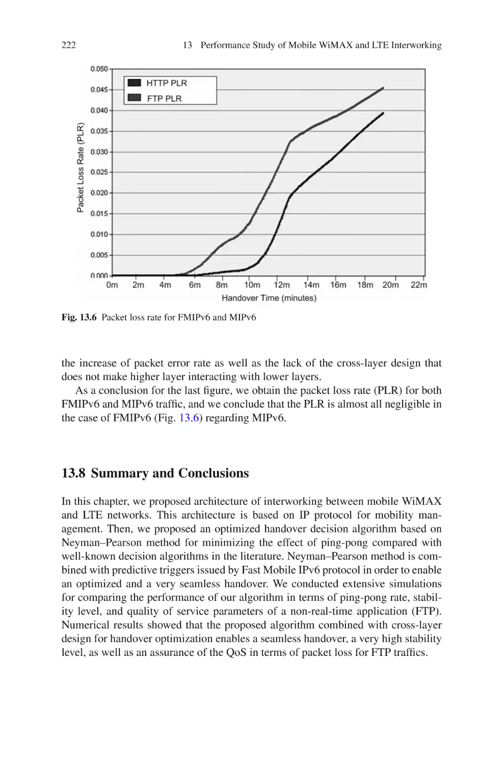
13.7 Simulation Results . . . . . . . . . . . . . . . . . . . . . . . . . . . . . . . . . . . . . . .
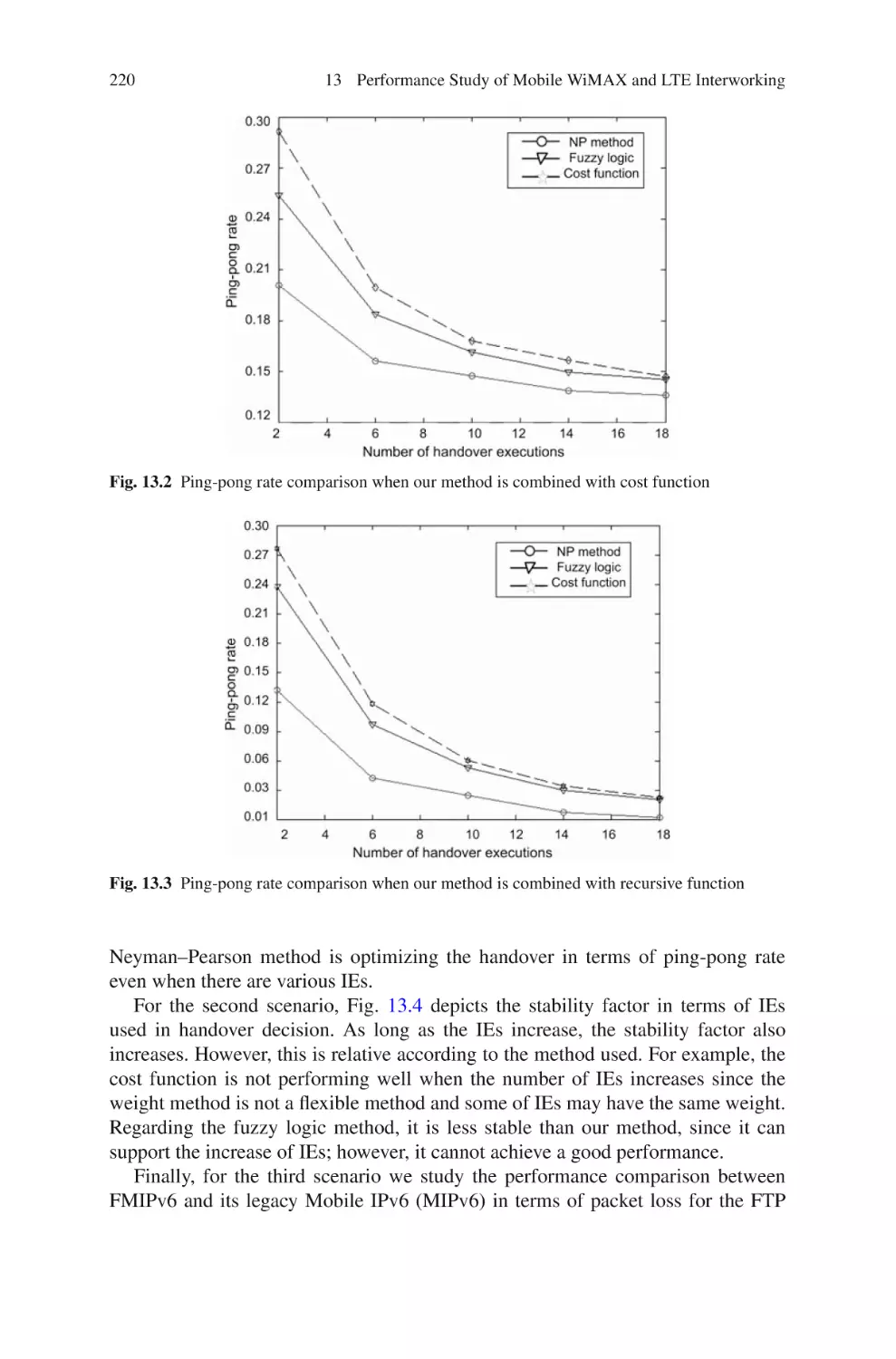
13.8 Summary and Conclusions . . . . . . . . . . . . . . . . . . . . . . . . . . . . . . . .
References . . . . . . . . . . . . . . . . . . . . . . . . . . . . . . . . . . . . . . . . . . . . . . . . . . .
211
211
212
213
215
217
218
218
218
219
219
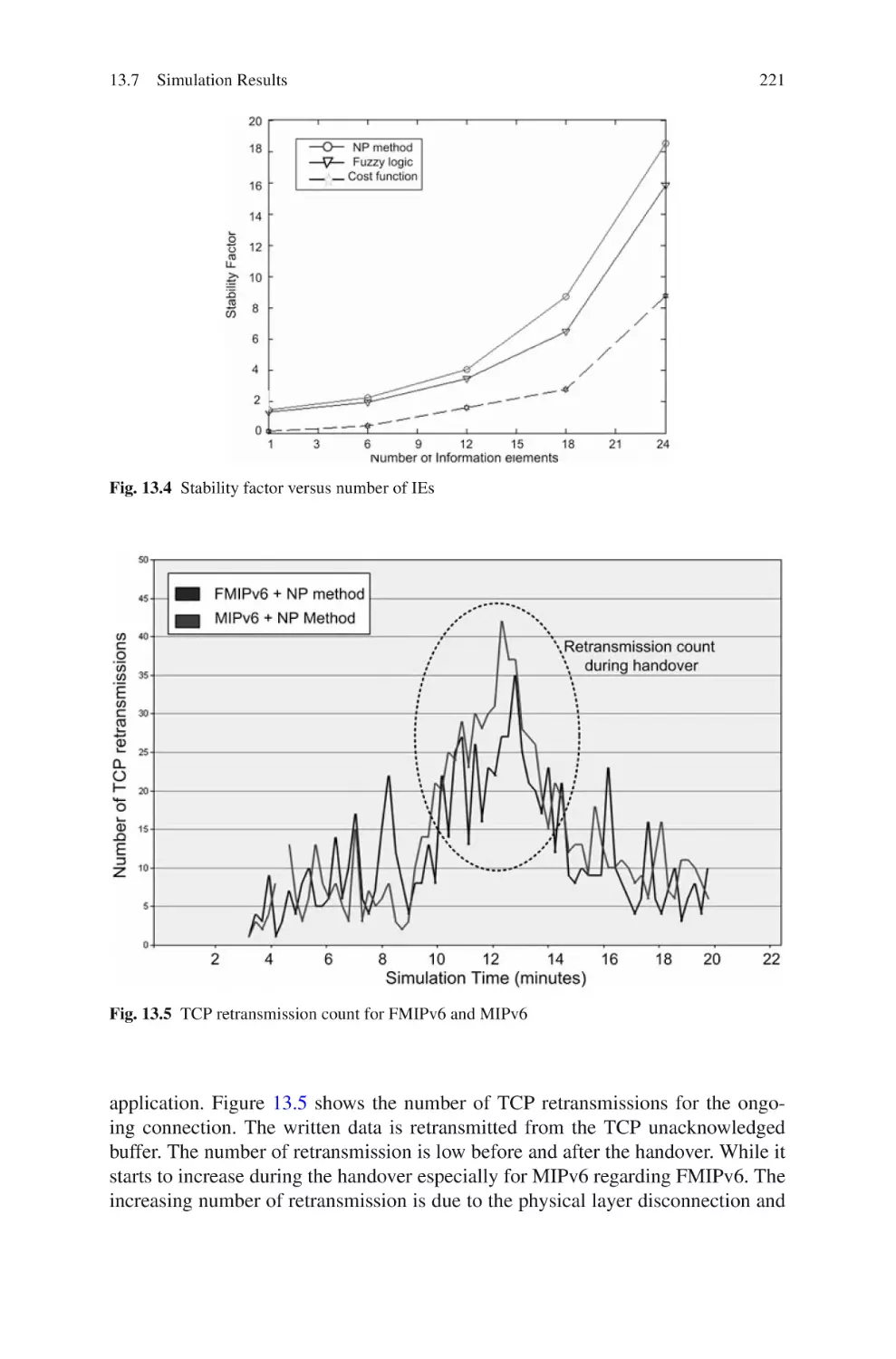
222
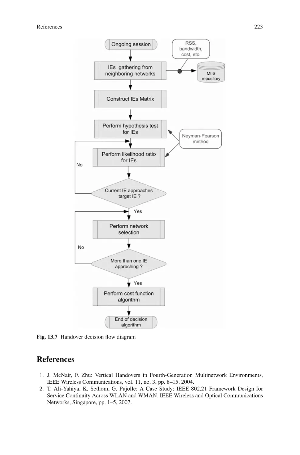
223
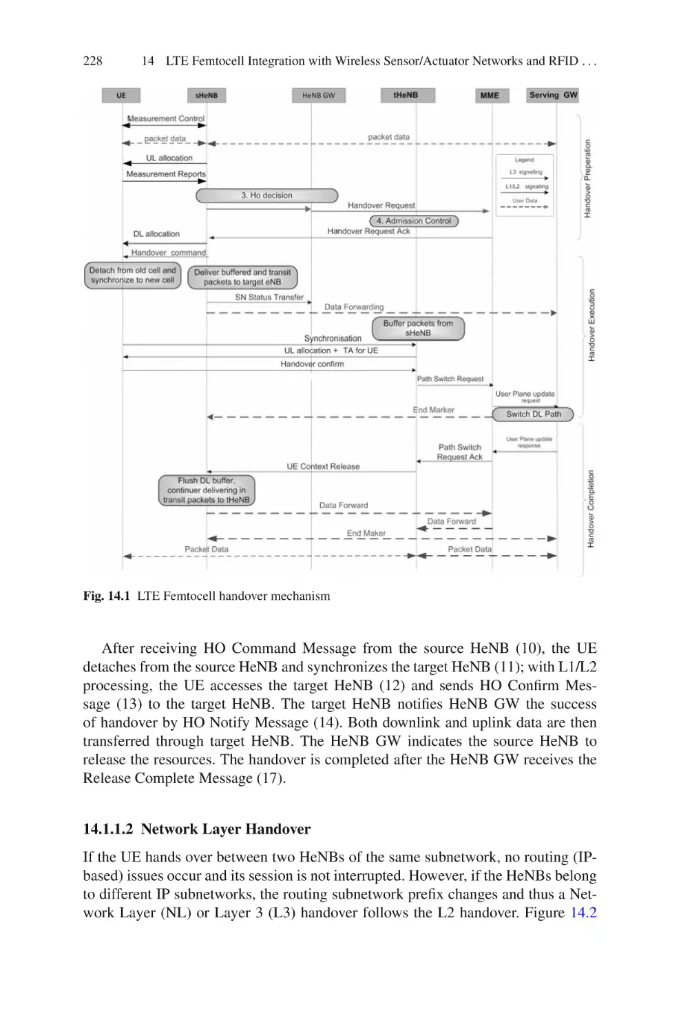
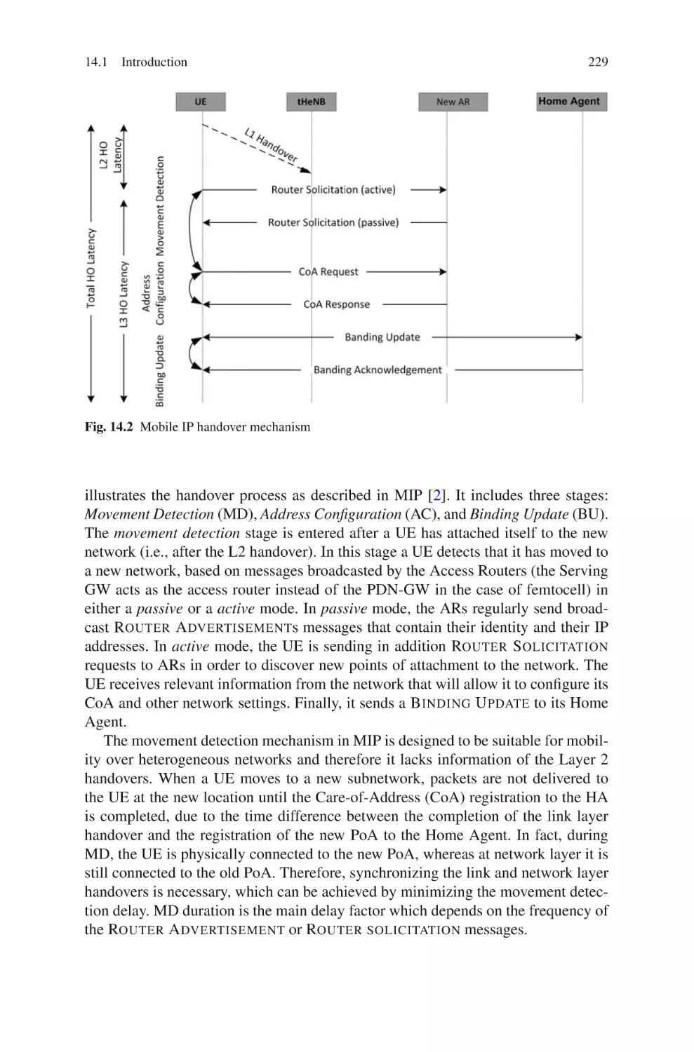
14 LTE Femtocell Integration with Wireless Sensor/Actuator Networks
and RFID Technologies . . . . . . . . . . . . . . . . . . . . . . . . . . . . . . . . . . . . . . .
14.1 Introduction . . . . . . . . . . . . . . . . . . . . . . . . . . . . . . . . . . . . . . . . . . . .
14.1.1 Handover Management . . . . . . . . . . . . . . . . . . . . . . . . . . .
225
225
227
Contents
xix
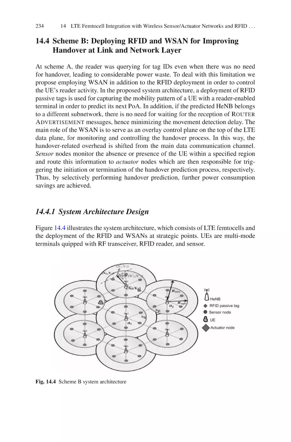
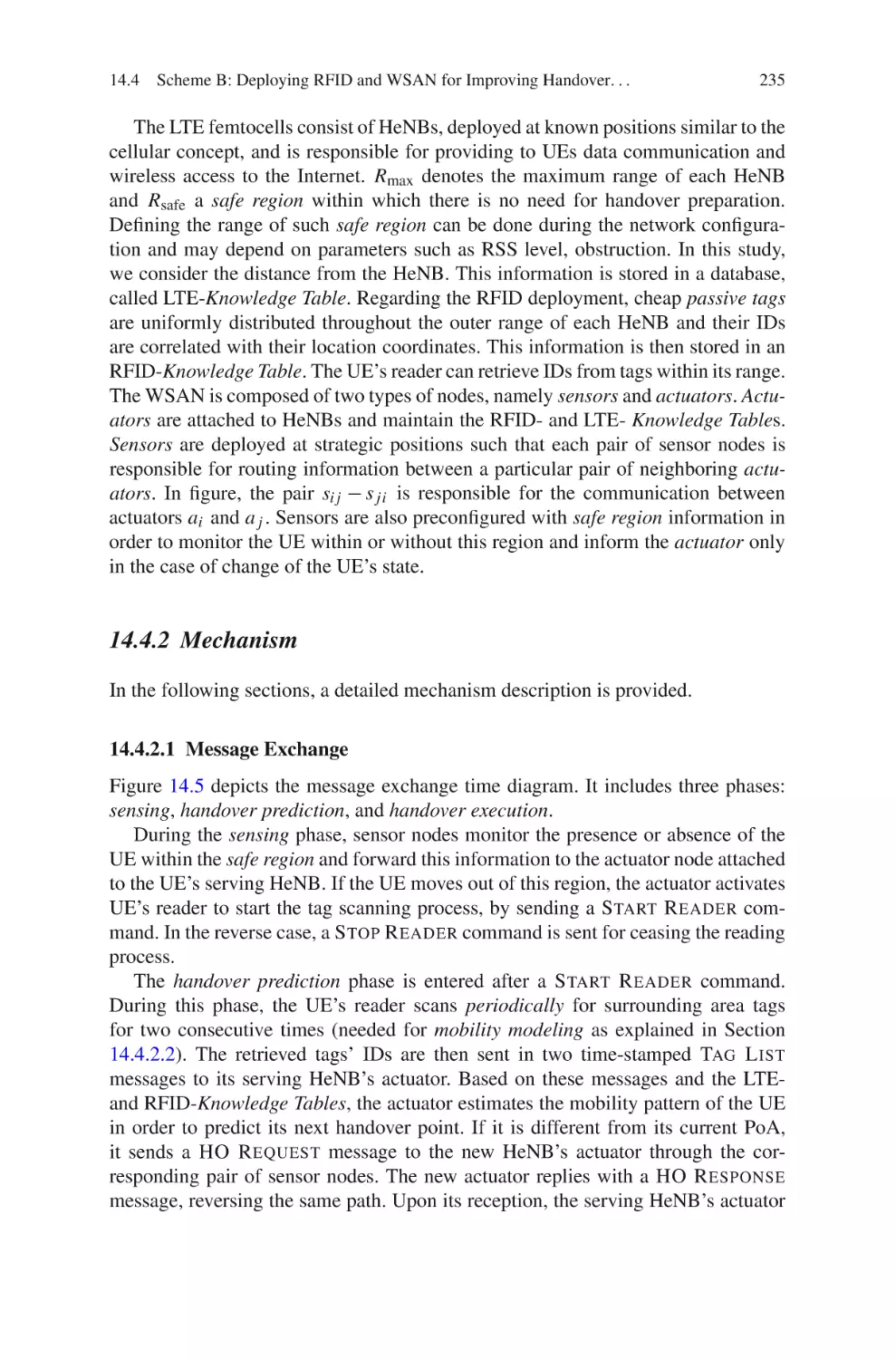
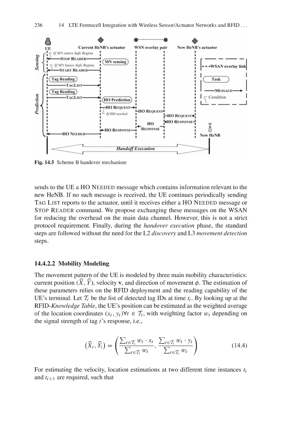
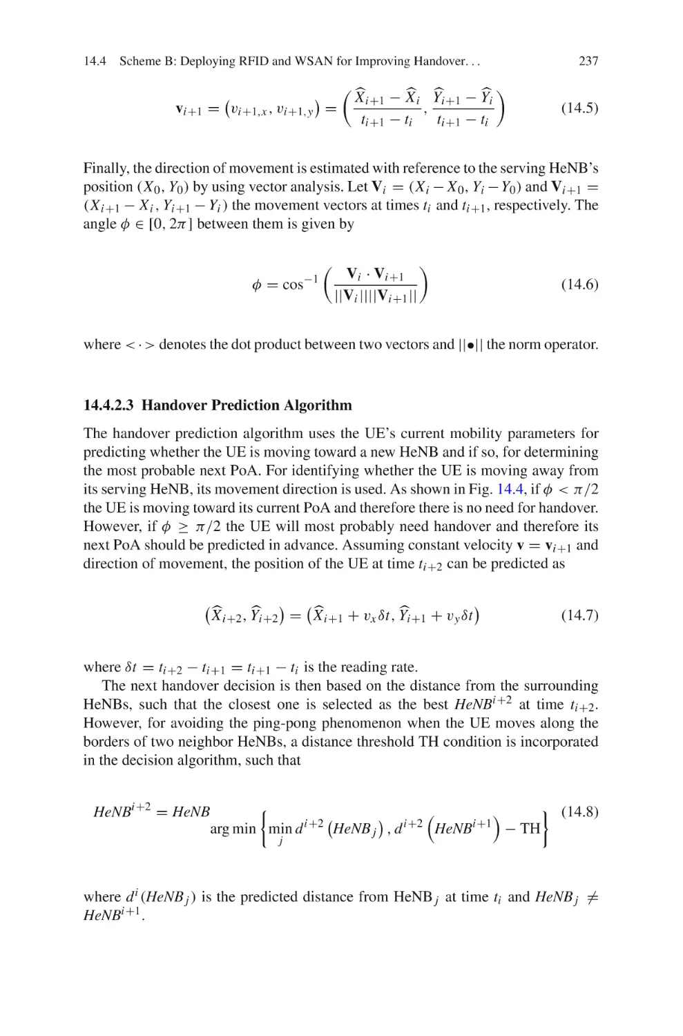
14.2 Motivation and Proposal Overview . . . . . . . . . . . . . . . . . . . . . . . . .
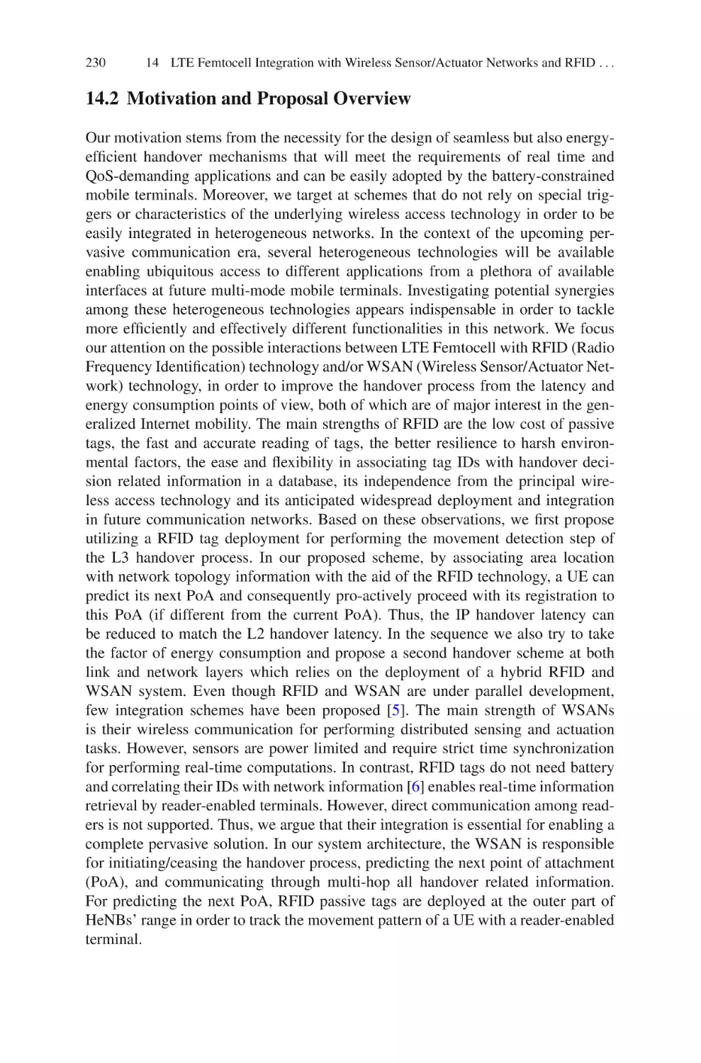
14.3 Scheme A: RFID-Assisted Network Movement Detection . . . . . .
14.3.1 System Architecture Design . . . . . . . . . . . . . . . . . . . . . . .
14.3.2 Mechanism . . . . . . . . . . . . . . . . . . . . . . . . . . . . . . . . . . . . .
14.4 Scheme B: Deploying RFID and WSAN for Improving Handover
at Link and Network Layer . . . . . . . . . . . . . . . . . . . . . . . . . . . . . . .
14.4.1 System Architecture Design . . . . . . . . . . . . . . . . . . . . . . .
14.4.2 Mechanism . . . . . . . . . . . . . . . . . . . . . . . . . . . . . . . . . . . . .
14.5 Theoretical Analysis . . . . . . . . . . . . . . . . . . . . . . . . . . . . . . . . . . . . .
14.5.1 Time Response . . . . . . . . . . . . . . . . . . . . . . . . . . . . . . . . . .
14.6 Performance Analysis . . . . . . . . . . . . . . . . . . . . . . . . . . . . . . . . . . . .
14.6.1 Simulation Setup . . . . . . . . . . . . . . . . . . . . . . . . . . . . . . . .
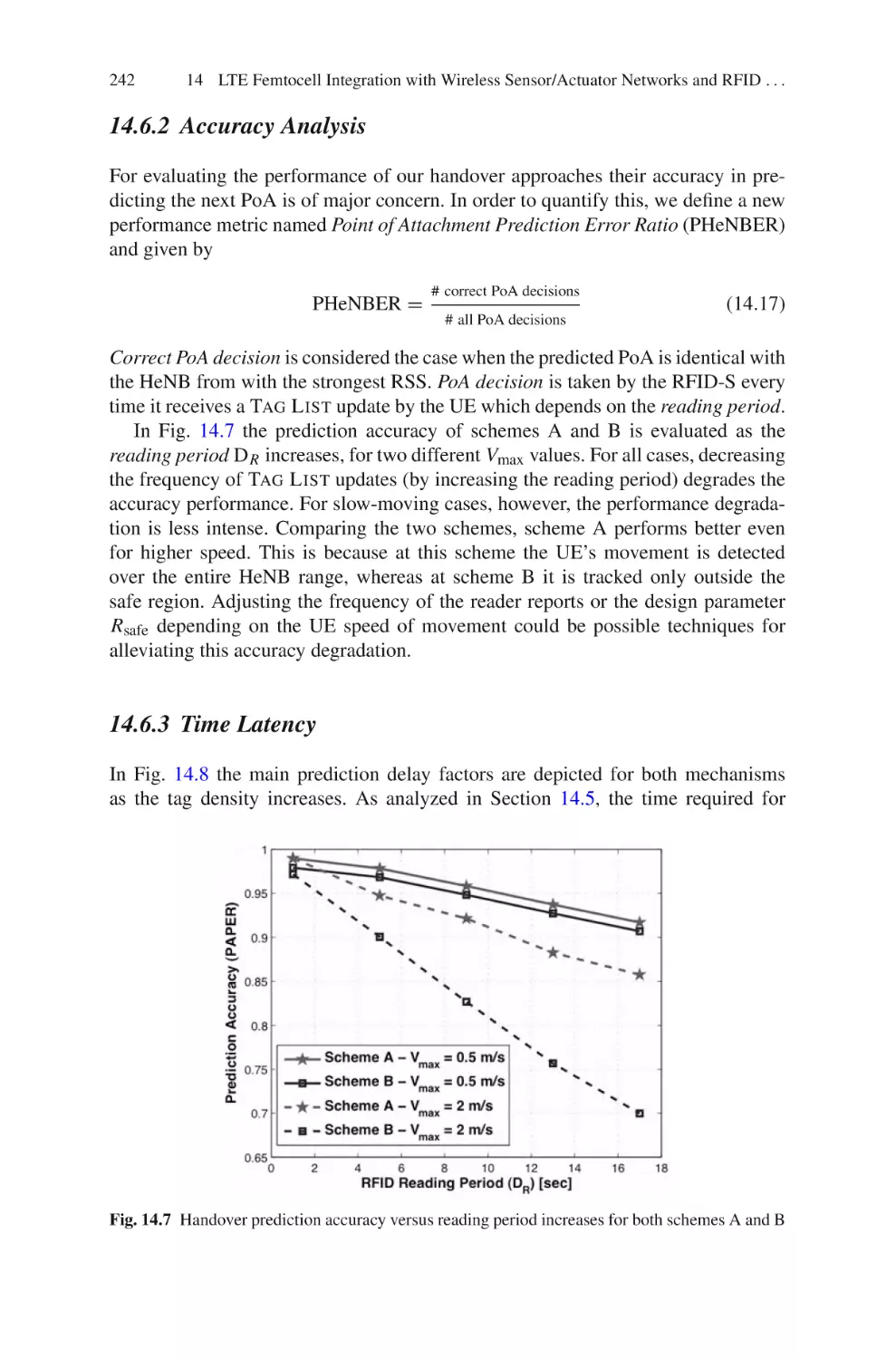
14.6.2 Accuracy Analysis . . . . . . . . . . . . . . . . . . . . . . . . . . . . . . .
14.6.3 Time Latency . . . . . . . . . . . . . . . . . . . . . . . . . . . . . . . . . . .
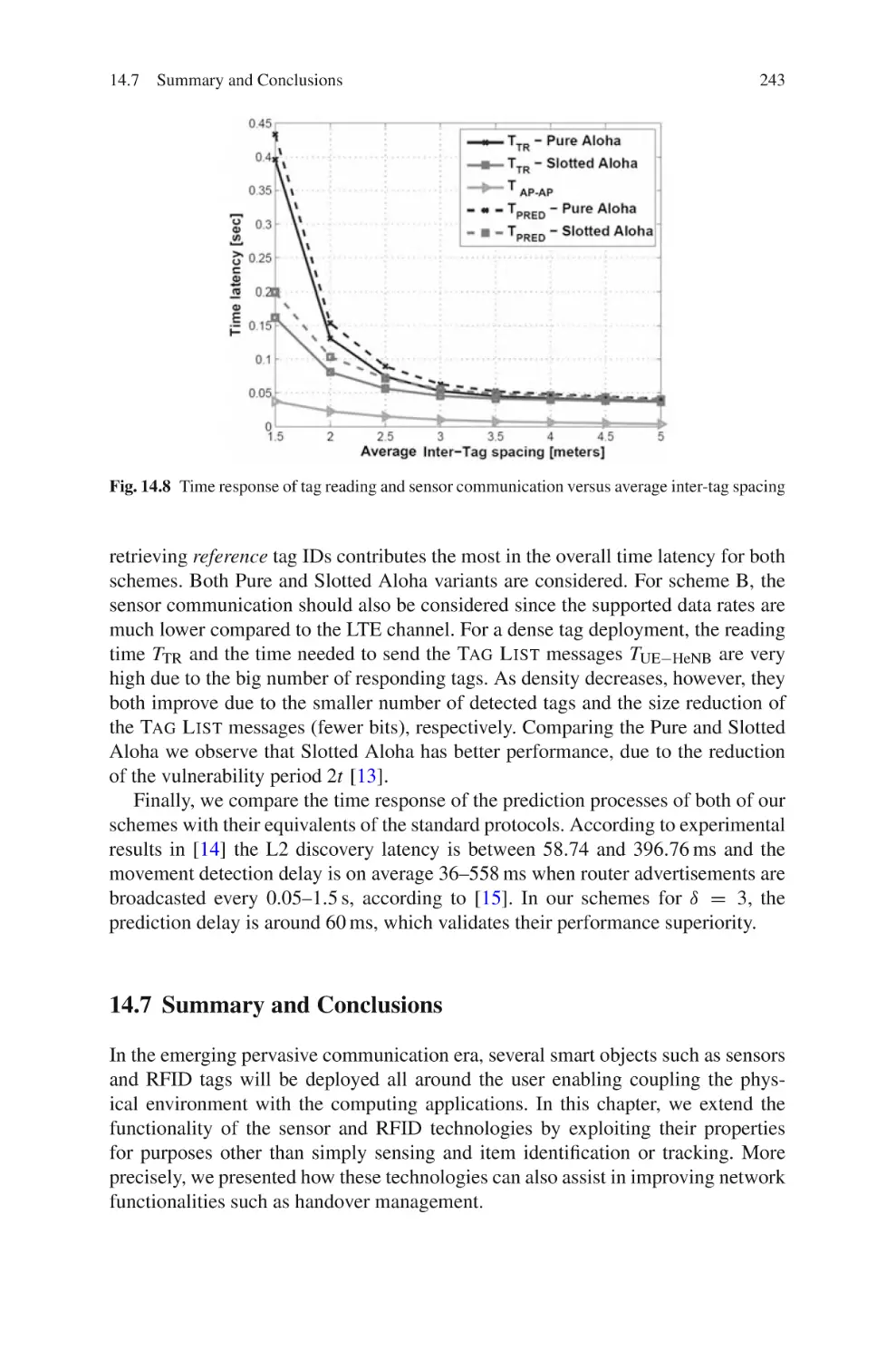
14.7 Summary and Conclusions . . . . . . . . . . . . . . . . . . . . . . . . . . . . . . . .
References . . . . . . . . . . . . . . . . . . . . . . . . . . . . . . . . . . . . . . . . . . . . . . . . . . .
230
231
231
231
Appendix A . . . . . . . . . . . . . . . . . . . . . . . . . . . . . . . . . . . . . . . . . . . . . . . . . . . . . .
245
Index . . . . . . . . . . . . . . . . . . . . . . . . . . . . . . . . . . . . . . . . . . . . . . . . . . . . . . . . . . .
247
234
234
235
238
238
241
241
242
242
243
244
Acronyms
3GPP
3GPP2
AA
ACS
ADSL
AF
AMC
AMPS
ANDSF
API
APN
ARP
ARPU
ARQ
ASA
AWGN
BBERF
BBF
BER
BLER
BU
CACBQ
CAPEX
CCE
CCI
CDMA
CDMA2000
CMC
CN
Third-Generation Partnership Project
Third-Generation Partnership Project 2
Authorization, Authentication, and
Accounting
Autoconfiguration Server
Asymmetric Digital Subscriber Line
Application Function
Adaptive Modulation and Coding
Advanced Mobile Phone System
Access Network Discovery Support
Functions
Application Programming Interface
Access Point Name
Allocation and Retention Priority
Average Revenue Per User
Automatic Repeated Request
Adaptive Slot Allocation
Additive White Gaussian Noise
Bearer Binding and Event Reporting
Function
Bearer Binding Function
Bit Error Rate
Block Error Rate
Binding Update
Channel-Aware Class-Based Queue
Capital Expenditure
Control Channel Elements
Cochannel Interference
Code Division Multiple Access
Code Division Multiple Access Radio
Technology
Connection Mobility Control
Core Network
xxi
xxii
CP
CPI
C-plane
CQI
CS
CSG
CSG ID
CSMA
DFT
DHCP
DMRS
DNS
DPI
DRA
EAP
EDGE
eNodeB
EPC
EPS
E-UTRAN
FAF
FAP
FAP-GW
FBU
FDE
FDM
FFR
FFT
FMC
FTP
GBR
GPRS
GPS
GSM
GTP
GUTI
HeNB
HMS
H-PCEF
HRAA
HRPD
HSCSD
HSDPA
Acronyms
Cyclic Prefix
Cyclic Prefix Insertion
Control plane
Channel Quality Indicator
Circuit Switched
Closed Subscriber Group
Closed Subscriber Group Identity
Carrier Sense Multiple Access
Discrete Fourier Transform
Dynamic Host Control Protocol
Demodulation Reference Signal
Domain Name System
Deep Packet Inspection
Dynamic Resource Allocation
Extensible Authentication Protocol
Enhanced Data Rates for Global Evolution
Enhanced NodeB
Evolved Packet Core
Enhanced Packet System
Evolved UMTS Terrestrial Radio Access
Network
Forward Attachment Function
Femto Access Point
Femtocell Access Point Gateway
Fast Binding Update
Frequency Domain Equalizer
Frequency Division Multiplexing
Fractional Frequency Reuse
Fast Fourier Transform
Fixed Mobile Convergence
File Transfer Protocol
Guaranteed Bit Rate
General Packet Radio Services
Global Positioning System
Global System for Mobile Communication
GPRS Tunneling Protocol
Globally Unique Temporary ID
Home-Enhanced NodeB
Home NodeB Management System
A PCEF in the HPLMN
Hierarchical Resource Allocation Approach
High Rate Packet Data
High-Speed Circuit-Switched Data
High-Speed Downlink Data Packet Access
Acronyms
HS-GW
HSPA
HSS
HSUPA
ICI
ICIC
IE
IEEE
IETF
IFFT
IKE
IKEv2
IMS
IMT-2000
IP CAN
IP
IPsec
ISI
ITU
LAN
LB
LTE
MAC
MBMS GW
MBSM
MCE
MD
MIMO
ML-WDF
MME
NAS
NGMN
NL
NMT
OAMP
OCA
OCS
OFCS
OFDMA
OPEX
PCC
xxiii
HRPD Serving Gateway
High-Speed Packet Access
Home Subscriber Server
High-Speed Uplink Data Packet Access
Inter-cell Interference
Inter-cell Interference Coordination
Information Elements
Institute of Electrical and Electronics
Engineers
Internet Engineering Task Force
Inverse FFT
Internet Key Exchange
Internet Key Exchange Version 2
IP Multimedia System
International Mobile Telecommunications
IP Connectivity Access Network
Internet Protocol
Internet Protocol Security
Inter Symbol Interference
International Telecommunication Union
Local Area Networking
Load Balancing
Long-Term Evolution
Medium Access Control
MBMS Gateway
Multimedia Broadcast and Multicast Service
Multi-cell/Multicast Coordination Entity
Movement Detection
Multiple Input Multiple Output
Modified Largest Weighted Delay First
Mobility Management Entity
Non-access Startum
Next-Generation Mobile Network
Network Layer
Nordic Mobile Telephone System
Operation Administration Maintenance and
Provisioning
Orthogonal Channel Assignment
Online Charging System
Off-line Charging System
Orthogonal Frequency-Division Multiple
Access
Operational Expenditure
Policy and Charging Control
xxiv
PCEF
PCI
PCRF
PDA
PDB
PDG
PELR
PKI
PLMN
PMP
PoA
PRN
QAM
QCI
QoS
QPSK
RF
RFID
RNC
RNC
RRA
RRC
RRM
RSA
RSSI
S1AP
SAP
SBLP
SCTP
SDF
SeGW
SFN
S-GW
SIM
SINR
SIP
SLA
SNR
SOHO
SPID
SPR
SRS
TACS
TCP
TDD
Acronyms
Policy and Charging Enforcement Function
Physical Cell Identity
Policy and Charging Rules Function
Personal Data Assistants
Packet Delay Budget
Packet Data Gateway
Packet Error Loss Rate
Public Key Infrastructure
Public Land Mobile Network
Point-to-Multipoint
Point of Attachment
Pseudo-random Numerical
Quadrature Amplitude Modulation
QoS Class Identifier
Quality of Service
Quadrature Phase Shift Keying
Radio Frequency
Radio Frequency IDentification
Radio Bearer Control
Radio Network Controller
Radio Resource Agent
Radio Resource Controller
Radio Resource Management
Reservation-Based Slot Allocation
Received Signal Strength Indication
S1 Application Protocol
Service Access Points
Service-Based Local Policy
Stream Control Transmission Protocol
Service Data Flow
Security Gateway
Single Frequency Network
Serving Gateway
Subscriber Identity Module
Signal-to-Interference Ratio
Session Initiation Protocol
Service Level Agreements
Signal-to-Noise Ratio
Small Office Home Office
Subscriber Profile ID
Subscription Profile Repository
Sounding Reference Signal
Total Access Communications System
Transmission Control Protocol
Time Division Duplex
Acronyms
TDMA
TFT
TMSI
TrE
UA
UAC
UAS
UDP
UE
UMB
UMTS AKA
UMTS
UTRAN
VAD
VoIP
V-PCEF
WAG
WCDMA
WiFi
WiMAX
WLAN
WSAN
WSN
xxv
Time Division Multiple Access
Traffic Flow Template
Temporary Mobile Subscriber Identity
Trusted Execution
User Agents
User Agent Client
User Agent Server
User Datagram Protocol
User Equipment
Ultra Mobile Broadband
UMTS Authentication and Key Agreement
Universal Mobile Telecommunications
System
UMTS Terrestrial Radio Access Network
Voice Activity Detection
Voice over IP
PCEF in the VPLMN
WLAN Access Gateway
Wideband Code Division Multiple Access
Wireless Fidelity
Worldwide Interoperability for Microwave
Access
Wireless Local Area Network
Wireless Sensor/Actuator Network
Wireless Sensor Network
Part I
Understanding LTE
Chapter 1
Introduction to Mobile Broadband Wireless
The development of mobile communications has traditionally been viewed as a
sequence of successive generations. The first generation of analogue mobile telephony was followed by the second, digital, generation. Then, the third generation
was envisaged to enable full multimedia data transmission as well as voice communications. In parallel to these activities related to the evolution of current wireless technologies, there is also an increased research effort on future radio access,
referred to as fourth-generation (4G) radio access. Such future radio access is anticipated to take the performance and service provisioning of wireless systems a step
further, providing data rates up to 100 Mbps with wide-area coverage and up to 1
Gbps with local-area coverage.
In this chapter, we provide a brief overview of mobile broadband wireless. The
objective is to present the background and context necessary for understanding
Long-Term Evolution (LTE). We review the history of mobile broadband wireless,
enumerate its applications, and compare them to the emergent LTE technology in
order to see the effect of such technology not only on the market drivers but also on
the research domain area.
1.1 Mobile Generation Networks
The International Telecommunication Union (ITU) launched the International
Mobile Telecommunications (IMT-2000) as an initiative to cover high-speed-,
broadband-, and Internet Protocol (IP)-based mobile systems featuring network-tonetwork interconnection, feature/service transparency, global roaming, and seamless services independent of location. IMT-2000 is intended to bring high-quality
mobile multimedia telecommunications to a worldwide mass market by achieving
the goals of increasing the speed and ease of wireless communications, responding
to the problems faced by the increased demand to pass data via telecommunications,
and providing “anytime, anywhere” services. Two partnership organizations were
born from the ITU-IMT-2000 initiative: The Third Generation Partnership project
(www.3gpp.org) and the Third Generation Partnership Project 2 (www.3gpp2.org).
The 3GPP and 3GPP2 developed their own version of 2G, 3G, and even beyond 3G
T. Ali-Yahiya, Understanding LTE and its Performance,
C Springer Science+Business Media, LLC 2011
DOI 10.1007/978-1-4419-6457-1_1,
3
4
1 Introduction to Mobile Broadband Wireless
mobile systems. This is why in this chapter, we will summarize all mobile generations developed by these two organizations as a path to the evolution of LTE system.
1.1.1 First-Generation Mobile 1G
First-generation cellular networks (1G) were analog-based and limited to voice services and capabilities only. 1G technology was vastly inferior to today’s technology.
In the late 1970s and early 1980s, various 1G cellular mobile communication systems were introduced; the first such system, the Advanced Mobile Phone System
(AMPS), was introduced in the USA in the late 1970s [1]. Other 1G systems include
the Nordic Mobile Telephone System (NMT) and the Total Access Communications
System (TACS) [1]. While these systems offer reasonably good voice quality, they
provide limited spectral efficiency. This is why the evolution toward 2G was necessary to overcome the drawback of such technology.
1.1.2 Second-Generation Mobile 2G
The second-generation (2G) digital systems promised higher capacity and better
voice quality than did their analog counterparts. The two widely deployed secondgeneration (2G) cellular systems are GSM (Global System for Mobile Communications) and CDMA (Code Division Multiple Access) which was originally known as
the American interim standard 95, or IS-95, and is now called cdmaOne [2]. Both
the GSM and CDMA camps formed their own separate 3G partnership projects
(3GPP and 3GPP2, respectively) to develop IMT-2000-compliant standards based
on the CDMA technology [3].
GSM differs from 1G by using digital cellular technology and Time Division
Multiple Access (TDMA) transmission methods and slow frequency hopping for
the voice communication. In the USA, 2G cellular standardization process utilized
direct-sequence CDMA with phase shift-keyed modulation and coding.
There was an evolution of main air interface-related enhancements to GSM
which are (1) higher data rates for circuit-switched services through aggregation
of several time slots per TDMA frame with High-Speed Circuit-Switched Data
(HSCSD); (2) General Packet Radio Service (GPRS) which had an efficient support
of non-real-time packet data traffic. GPRS reached peak data rates up to 140 Kbps
when a user aggregates all time slots; and (3) Enhanced Data Rates for Global Evolution (EDGE) has increased data rates up to 384 Kbps with high-level modulation
and coding within the existing carrier bandwidth of 200 kHz.
1.1.3 Third-Generation Mobile 3G
Further evolution of the GSM-based systems is handled under 3GPP to define a
global third-generation Universal Mobile Telecommunications System (UMTS).
The main components of this system are the UMTS Terrestrial Radio Access
1.1
Mobile Generation Networks
5
Network (UTRAN) based on Wideband Code Division Multiple Access (WCDMA)
radio technology since it is using 5 MHz bandwidth and GSM/EDGE Radio Access
Network (GERAN) based on (GSM)-enhanced data rates [4].
On the other hand, 3GPP2 implemented CDMA2000 under 1.25 MHz bandwidth
which increased voice and data services and supported a multitude of enhanced
broadband data applications, such as broadband Internet access and multimedia
downloads. This technology also doubled user capacity over cdmaOne, and with
the advent of 1xRTT, packet data was available for the first time.
As an evolution for CDMA2000, the 3GPP2 first introduced the High-Rate
Packet Data (HRPD) which was referred to as CDMA20001xEV-DO. This standard
enables high-speed, packet-switched techniques designed for high-speed data transmissions, enabling peak data rates beyond 2 Mbps. 1xEV-DO expanded the types of
services and applications available to end users, enabling carriers to broadcast more
media-rich content.
The 3GPP followed a similar direction and introduced an enhancement to the
WCDMA system providing High-Speed Downlink Packet Access (HSDPA) that
brought spectral efficiency for higher speed data services in 2001. Then another
High-Speed Uplink Packet Access (HSUPA) was introduced in 2005. The combination of HSDPA and HSUPA is called HSPA [5].
The last evolution of HSPA is the HSPA+ which was specified resulting from
adding Multiple Input/Multiple Output (MIMO) antenna capability and 16 QAM
(uplink)/64 QAM (downlink) modulation. Coupled with improvements in the radio
access network for continuous packet connectivity, HSPA+ will allow uplink speeds
of 11 Mbps and downlink speeds of 42 Mbps.
As the successor of CDMA2000 1xEV-DO, the CDMA2000 1xEV-DO Release 0
provides peak speeds of up to 2.4 Mbps with an average user throughput of between
400 and 700 Kbps. The average uplink data rate is between 60 and 80 Kbps. Release
0 makes use of existing Internet protocols, enabling it to support IP-based connectivity and software applications. In addition, Release 0 allows users to expand
their mobile experience by enjoying broadband Internet access, music and video
downloads, gaming, and television broadcasts.
A revision of CDMA2000 1xEV-DO Release 0 is CDMA2000 Revision A (RevA) which is an evolution of CDMA2000 1xEV-DO Rel-0 to increase peak rates on
reverse and forward links to support a wide variety of symmetric, delay-sensitive,
real-time, and concurrent voice and broadband data applications. It also incorporates
OFDM technology to enable multicasting (one-to-many) for multimedia content
delivery. As the successor of Rev-A, CDMA2000 1xEV-DO Revision B (Rev-B)
introduces dynamic bandwidth allocation to provide higher performance by aggregating multiple 1.25 MHz Rev-A channels [6].
1.1.4 The Path Toward 4G
4G mobile broadband technologies will allow wireless carriers to take advantage
of greater download and upload speeds to increase the amount and types of content made available through mobile devices. 4G networks are comprehensive IP
3GPP
1.4, 3, 5, 10, 15
and 20 MHz
2 GHz initially
QPSK, 16 QAM,
64 QAM
SC-FDMA/
OFDMA
TDD and FDD
5–62 miles
High
Standards
Bandwidth
Modulation
Duplexing
Coverage
Mobility
Multiplexing
Frequency
LTE
Parameters
TDD initially
<2 miles
Mid
IEEE 802.16e
3.5, 7, 5, 10, and
8.75 MHz
2.3, 2.5, and 3.5 GHz
initially
QPSK, 16 QAM,
64 QAM
TDM/OFDMA
Mobile WiMAX
3GPP2
1.25 MHz
1xEV-DO Rev-A
FDD
1–3 miles
High
FDD
1–3 miles
High
800/900/1,800/
800/900/1,800/
1,900/2,100 MHz
1,900 MHz
QPSK, 16 QAM
QPSK, 8 PSK,
16 QAM
TDM/CDMA
TDM/CDMA
3GPP
5 MHz
HSPA
Table 1.1 Comparison of LTE with other broadband wireless technologies
TDD
<100 ft indoors, <1,000 ft outdoors
Low
CSMA
BPSK, QPSK, 16 QAM, 64 QAM
IEEE 802.11a/g/n
20 MHz for 802.11a/g and 20/40 MHz
for 802.11n
2.4, 5 GHz
WiFi
6
1 Introduction to Mobile Broadband Wireless
1.2
LTE and Other Broadband Wireless Technologies
7
solutions that deliver voice, data, and multimedia content to mobile users anytime and almost anywhere. They offer greatly improved data rates over previous
generations of wireless technology. Faster wireless broadband connections enable
wireless carriers to support higher level data services, including business applications, streamed audio and video, video messaging, video telephony, mobile TV, and
gaming.
As a step toward 4G mobile broadband wireless, the 3GPP body began its initial
investigation of the Long-Term Evolution (LTE) standard as a viable technology in
2004 [7]. The LTE technology is expected to offer a number of distinct advantages
over other wireless technologies. These advantages include increased performance
attributes, such as high peak data rates and low latency and greater efficiencies in
using the wireless spectrum (Table 1.1).
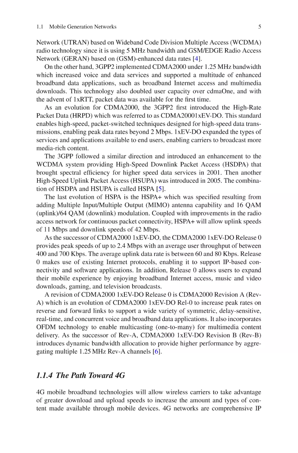
•
•
•
•
•
•
•
•
High spectral efficiency.
Very low latency.
Support of variable bandwidth.
Simple protocol architecture.
Compatibility and interworking with earlier 3GPP releases.
Interworking with other systems, e.g., cdma2000.
FDD and TDD within a single radio access technology.
Efficient multicast/broadcast.
Ultra-Mobile Broadband (UMB) is the name for the next evolution of the
cdma2000 cellular telecommunications system which is run under the auspices of
3GPP2 [8]. The Ultra-Mobile Broadband cellular telecommunications system offers
many new features and techniques that enable it to fulfill the high expectations for
it and to enable it to compete with other new and emerging technologies.
• Data rates of over 275 Mbit/s in the downlink (base station to mobile) and over
75 Mbit/s in the uplink (mobile to base station).
• Uses an OFDM/OFDMA air interface.
• Uses Frequency Division Duplex (FDD).
• Possesses an IP network architecture.
• Has a scalable bandwidth between 1.25 and 20 MHz (OFDM/OFDMA systems
are well suited for wide and scalable bandwidths).
• Supports flat, mixed, and distributed network architectures.
1.2 LTE and Other Broadband Wireless Technologies
LTE is not the only solution for delivering broadband mobile services. Several
proprietary solutions, particularly for fixed applications, are already in the market.
Indeed, there are standards-based alternative solutions that at least partially overlap
with LTE, particularly for the portable and mobile applications. In the near term, the
most significant of these alternatives are third-generation cellular systems and IEEE
8
1 Introduction to Mobile Broadband Wireless
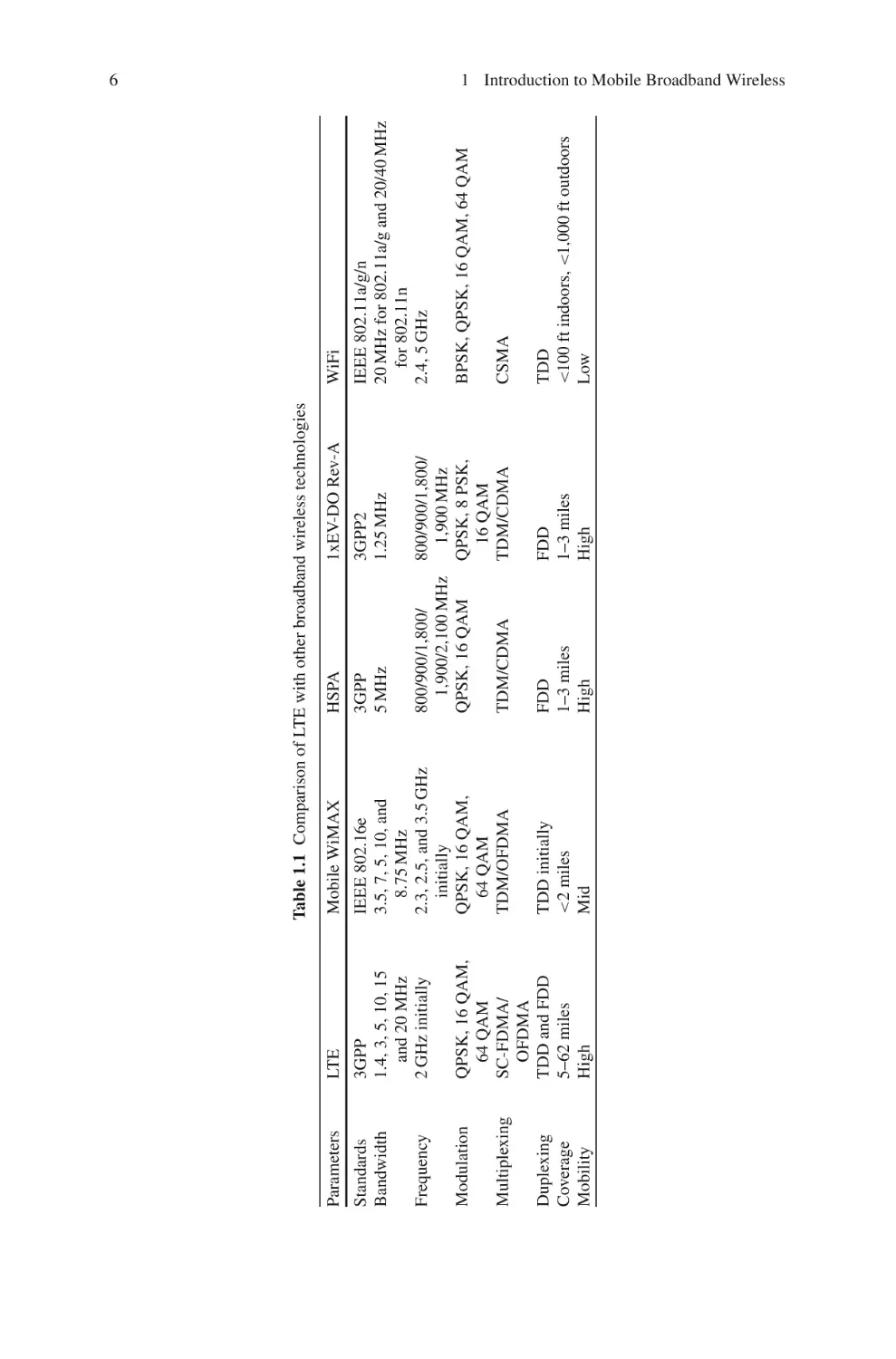
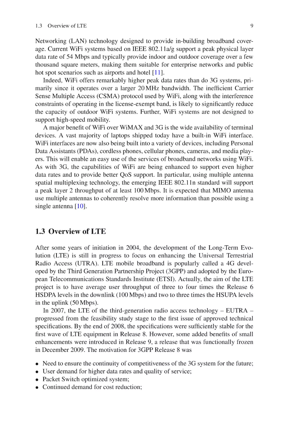
Fig. 1.1 Timing schedule
802.11-based WiFi systems. In this section, we compare and contrast the various
standards-based broadband wireless technologies and highlight the differentiating
aspects of LTE (Fig. 1.1).
1.2.1 Mobile WiMAX
Worldwide Interoperability for Microwave Access (WiMAX) refers to IEEE 802.16,
a standard developed by the Institute of Electrical and Electronics Engineers Inc.
(IEEE) for the global deployment of broadband Wireless Metropolitan Area Networks. WiMAX is available in two versions – fixed and mobile [9]. Fixed WiMAX,
which is based on the IEEE 802.16-2004 standard, is ideally suited for delivering
wireless, last-mile access for fixed broadband services. It is similar to DSL or cable
modem service. Mobile WiMAX, which is based on the IEEE 802.16e standard,
supports both fixed and mobile applications while offering users improved performance, capacity, and mobility.
Mobile WiMAX provides higher data rates with Orthogonal Frequency Division
Multiple Access (OFDMA) support and introduces several key features necessary
for delivering mobility at vehicular speeds with Quality of Service (QoS) comparable to broadband access alternatives [10].
Several features that are used to enhance data throughput are Adaptive Modulation and Coding (AMC), Hybrid Automatic Repeated Request (HARQ), fast
scheduling, and bandwidth efficient handover. Mobile WiMAX is currently Time
Division Duplexing (TDD) operating at 2.5 GHz. Mobile WiMAX has higher tolerance to multipath and self-interference and provides orthogonal uplink multiple
access with frequency-selective scheduling and fractional frequency reuse.
1.2.2 WiFi
Wireless Fidelity (WiFi)-based system is used to provide broadband wireless. It
is based on the IEEE 802.11 family of standards and is primarily a Local Area
1.3
Overview of LTE
9
Networking (LAN) technology designed to provide in-building broadband coverage. Current WiFi systems based on IEEE 802.11a/g support a peak physical layer
data rate of 54 Mbps and typically provide indoor and outdoor coverage over a few
thousand square meters, making them suitable for enterprise networks and public
hot spot scenarios such as airports and hotel [11].
Indeed, WiFi offers remarkably higher peak data rates than do 3G systems, primarily since it operates over a larger 20 MHz bandwidth. The inefficient Carrier
Sense Multiple Access (CSMA) protocol used by WiFi, along with the interference
constraints of operating in the license-exempt band, is likely to significantly reduce
the capacity of outdoor WiFi systems. Further, WiFi systems are not designed to
support high-speed mobility.
A major benefit of WiFi over WiMAX and 3G is the wide availability of terminal
devices. A vast majority of laptops shipped today have a built-in WiFi interface.
WiFi interfaces are now also being built into a variety of devices, including Personal
Data Assistants (PDAs), cordless phones, cellular phones, cameras, and media players. This will enable an easy use of the services of broadband networks using WiFi.
As with 3G, the capabilities of WiFi are being enhanced to support even higher
data rates and to provide better QoS support. In particular, using multiple antenna
spatial multiplexing technology, the emerging IEEE 802.11n standard will support
a peak layer 2 throughput of at least 100 Mbps. It is expected that MIMO antenna
use multiple antennas to coherently resolve more information than possible using a
single antenna [10].
1.3 Overview of LTE
After some years of initiation in 2004, the development of the Long-Term Evolution (LTE) is still in progress to focus on enhancing the Universal Terrestrial
Radio Access (UTRA). LTE mobile broadband is popularly called a 4G developed by the Third Generation Partnership Project (3GPP) and adopted by the European Telecommunications Standards Institute (ETSI). Actually, the aim of the LTE
project is to have average user throughput of three to four times the Release 6
HSDPA levels in the downlink (100 Mbps) and two to three times the HSUPA levels
in the uplink (50 Mbps).
In 2007, the LTE of the third-generation radio access technology – EUTRA –
progressed from the feasibility study stage to the first issue of approved technical
specifications. By the end of 2008, the specifications were sufficiently stable for the
first wave of LTE equipment in Release 8. However, some added benefits of small
enhancements were introduced in Release 9, a release that was functionally frozen
in December 2009. The motivation for 3GPP Release 8 was
•
•
•
•
Need to ensure the continuity of competitiveness of the 3G system for the future;
User demand for higher data rates and quality of service;
Packet Switch optimized system;
Continued demand for cost reduction;
10
1 Introduction to Mobile Broadband Wireless
• Low complexity;
• Avoid unnecessary fragmentation of technologies for paired and unpaired band
operation.
In September 2009 the 3GPP partners made a formal submission to the ITU
proposing that LTE Release 10 and beyond (LTE-Advanced) be evaluated as a candidate for IMT-Advanced. The ITU has coined the term IMT-Advanced to identify
mobile systems whose capabilities go beyond those of IMT-2000. In order to meet
this new challenge, 3GPPs organizational partners have agreed to widen 3GPP’s
scope to include the development of systems beyond 3G. Some of the key features
of IMT-Advanced will be
•
•
•
•
Worldwide functionality and roaming
Compatibility of services
Interworking with other radio access systems
Enhanced peak data rates to support advanced services and applications (100
Mbit/s for high and 1 Gbit/s for low mobility)
In addition to the set of features above, one of the major reasons for aligning LTE
with the call for IMT-Advanced is that IMT conformant systems will be candidates
for future new spectrum bands to be identified at WRC07.
1.3.1 Relevant Features of LTE
LTE is a mobile broadband solution that offers a rich set of features with a lot of
flexibility in terms of deployment options and potential service offerings. Some of
the most important features that deserve highlighting are as follows (Table 1.2):
OFDM for high spectral efficiency is the basis of the physical layer: OFDM
is used in downlink in order to obtain a robustness against multipath interference and high affinity to advanced techniques such as frequency domain
channel-dependent scheduling and MIMO, while Single-Carrier Frequency
Table 1.2 LTE Release 8 major parameters
Parameter
Values
Access Scheme UL
Access Scheme DL
Bandwidth
Minimum TTI
Subcarrier spacing
Cyclic prefix short
Cyclic prefix long
Modulation
Spatial multiplexing
SC-OFDMA
OFDMA
1.4, 3, 5, 10, 15, and 20 MHz
1 ms
15 kHz
4.7 μs
16.7 μs
QPSK, 16 QAM, 64 QAM
Single layer for UL per UE, up to four layers for DL per UE,
MU-MIMO supported for UL and DL
1.3
Overview of LTE
11
Division Multiple Access (SC-FDMA) is used in uplink in order to get a
low Peak-to-Average Power Ratio (PAPR), user orthogonality in frequency
domain, and multi-antenna application.
Support for TDD and FDD: LTE supports both Time Division Duplexing
(TDD) and Frequency Division Duplexing. TDD is favored by a majority of
implementations because of its advantages: (1) flexibility in choosing uplinkto-downlink data rate ratios, (2) ability to exploit channel reciprocity, (3)
ability to implement in non-paired spectrum, and (4) less complex transceiver
design.
Adaptive Modulation and Coding (AMC): LTE supports a number of modulation and Forward Error Correction (FEC) coding schemes and allows the
scheme to be changed on a per user and per frame basis, based on channel
conditions. AMC is an effective mechanism to maximize throughput in a
time-varying channel. The adaptation algorithm typically calls for the use
of the highest modulation and coding scheme that can be supported by the
signal-to-noise and interference ratio at the receiver such that each user is
provided with the highest possible data rate that can be supported in their
respective links.
Support of variable bandwidth: E-UTRA shall operate in spectrum allocations
of different sizes, including 1.25, 1.6, 2.5, 5, 10, 15, and 20 MHz in both
the uplink and downlink (Table 1.3). Operation in paired and unpaired spectrum shall be supported. This scaling may be done dynamically to support
user roaming across different networks that may have different bandwidth
allocations.
Very high peak data rates: LTE is capable of supporting very high peak data
rates. In fact, the peak PHY data rate can be as high as downlink peak data
rate of 100 Mb/s within a 20 MHz downlink spectrum allocation (5 bps/Hz),
while it provides uplink peak data rate of 50 Mb/s (2.5 bps/Hz) within a
20 MHz uplink spectrum allocation.
Mobility: E-UTRAN should be optimized for low mobile speed from 0 to 15
km/h. A higher mobile speed between 15 and 120 km/h should be supported
Table 1.3 LTE and LTE-Advanced comparison
Parameter
LTE
LTE-Advanced
Peak data rate downlink DL
Peak data rate uplink UL
Transmission bandwidth DL
Transmission bandwidth UL
Mobility
300 Mbps
75 Mbps
20 MHz
20 MHz
Optimized for low speeds
(<15 km/h), high performance
at speeds up to 120 km/h, and
maintain links at speeds up to
350 km/h
Full performance up to 5 km
1.4, 3, 5, 10, 15, and 20 MHz
1 Gbps
500 Mbps
100 MHz
40 MHz
Same as that in LTE
Coverage
Scalable bandwidths
Same as LTE requirement
Up to 20–100 MHz
12
1 Introduction to Mobile Broadband Wireless
with high performance. Mobility across the cellular network shall be maintained at speeds from 120 to 350 km/h (or even up to 500 km/h depending
on the frequency band).
Link layer retransmissions: LTE supports Automatic Retransmission Requests
(ARQ) at the link layer. ARQ-enabled connections require each transmitted packet to be acknowledged by the receiver; unacknowledged packets
are assumed to be lost and are retransmitted. LTE also optionally supports
hybrid-ARQ, which is an effective hybrid between FEC and ARQ.
Simultaneous user support: LTE provides the ability to perform twodimensional resource scheduling (in time and frequency), allowing support
of multiple users in a time slot; in contrast, existing 3G technology performs
one-dimensional scheduling, which limits service to one user for each time
slot. This capability of LTE results in a much better always-on experience and
also enables the proliferation of embedded wireless applications/systems.
Security: LTE provides enhanced security through the implementation of UICC
Subscriber Identity Module (SIM) and the associated robust and non-invasive
key storage and symmetric key authentication using 128-bit private keys.
LTE additionally incorporates strong mutual authentication, user identity
confidentiality, integrity protection of all signaling messages between UE
and Mobility Management Entity (MME), and optional multi-level bearer
data encryption.
Efficient worldwide roaming: Because LTE will be the unified 4G standard for
most 3GPP and 3GPP2 carriers worldwide, LTE devices will be fundamentally easier to set up for worldwide roaming. The caveat is that the actual
frequency band used by different carriers will be different (thereby retaining
the need for multiband devices). As a result, the Verizon wireless migration path to LTE will provide greater opportunities for seamless international
roaming and for global device economies of scale as well. Table 1.3 depicts
LTE Release 8 Major Parameters.
1.3.2 Relevant Features of LTE-Advanced
LTE-Advanced should be a real broadband wireless network that provides peak data
rates equal to or greater than those for wired networks, i.e., Fiber To The Home
(FTTH), while providing better QoS. The major high-level requirements of LTE
are reduced network cost (cost per bit), better service provisioning, and compatibility with 3GPP systems [12]. LTE-Advanced being an evolution from LTE is
backward compatible. In addition to the advanced features used by LTE Release 8,
LTE-Advanced enhanced these features that can be found in the following:
The peak data rate: LTE-Advanced should support significantly increased
instantaneous peak data rates. At a minimum, LTE-Advanced should support enhanced peak data rates to support advanced services and applications
1.3
Overview of LTE
13
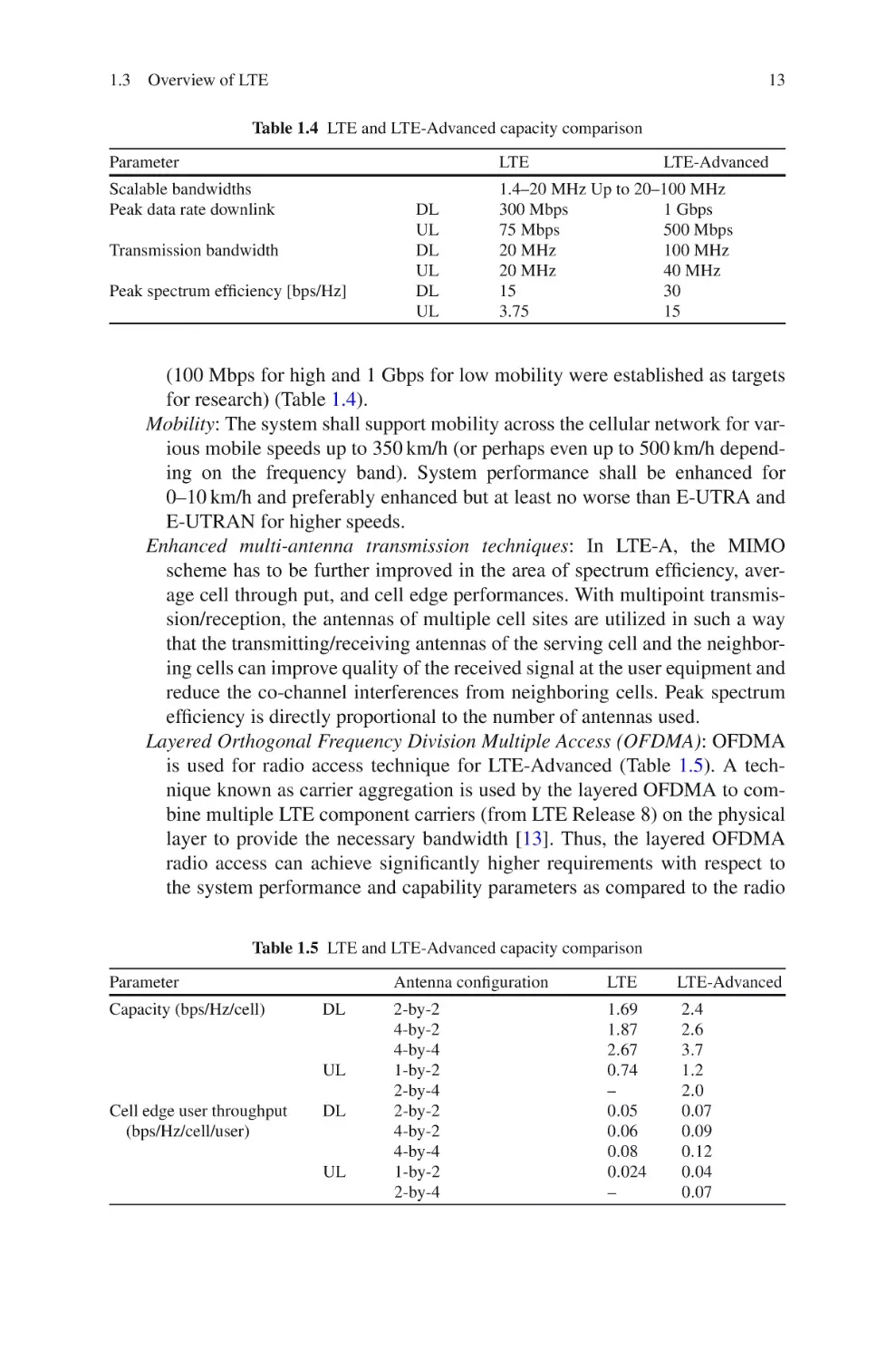
Table 1.4 LTE and LTE-Advanced capacity comparison
Parameter
LTE
Scalable bandwidths
Peak data rate downlink
1.4–20 MHz Up to 20–100 MHz
300 Mbps
1 Gbps
75 Mbps
500 Mbps
20 MHz
100 MHz
20 MHz
40 MHz
15
30
3.75
15
Transmission bandwidth
Peak spectrum efficiency [bps/Hz]
DL
UL
DL
UL
DL
UL
LTE-Advanced
(100 Mbps for high and 1 Gbps for low mobility were established as targets
for research) (Table 1.4).
Mobility: The system shall support mobility across the cellular network for various mobile speeds up to 350 km/h (or perhaps even up to 500 km/h depending on the frequency band). System performance shall be enhanced for
0–10 km/h and preferably enhanced but at least no worse than E-UTRA and
E-UTRAN for higher speeds.
Enhanced multi-antenna transmission techniques: In LTE-A, the MIMO
scheme has to be further improved in the area of spectrum efficiency, average cell through put, and cell edge performances. With multipoint transmission/reception, the antennas of multiple cell sites are utilized in such a way
that the transmitting/receiving antennas of the serving cell and the neighboring cells can improve quality of the received signal at the user equipment and
reduce the co-channel interferences from neighboring cells. Peak spectrum
efficiency is directly proportional to the number of antennas used.
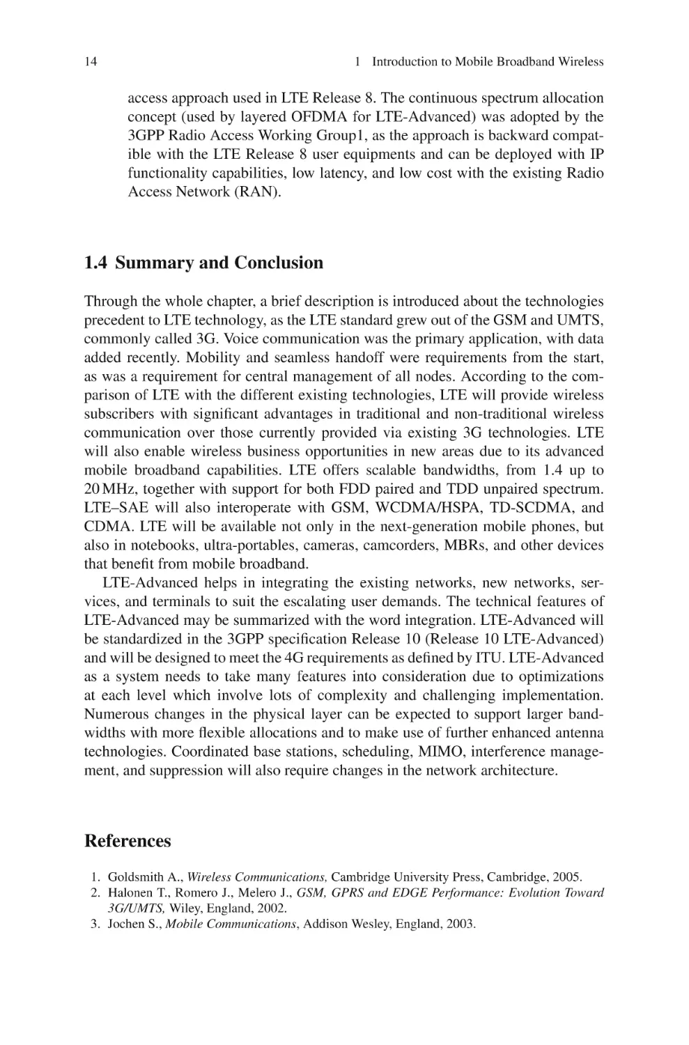
Layered Orthogonal Frequency Division Multiple Access (OFDMA): OFDMA
is used for radio access technique for LTE-Advanced (Table 1.5). A technique known as carrier aggregation is used by the layered OFDMA to combine multiple LTE component carriers (from LTE Release 8) on the physical
layer to provide the necessary bandwidth [13]. Thus, the layered OFDMA
radio access can achieve significantly higher requirements with respect to
the system performance and capability parameters as compared to the radio
Table 1.5 LTE and LTE-Advanced capacity comparison
Parameter
Capacity (bps/Hz/cell)
DL
UL
Cell edge user throughput
(bps/Hz/cell/user)
DL
UL
Antenna configuration
LTE
LTE-Advanced
2-by-2
4-by-2
4-by-4
1-by-2
2-by-4
2-by-2
4-by-2
4-by-4
1-by-2
2-by-4
1.69
1.87
2.67
0.74
–
0.05
0.06
0.08
0.024
–
2.4
2.6
3.7
1.2
2.0
0.07
0.09
0.12
0.04
0.07
14
1 Introduction to Mobile Broadband Wireless
access approach used in LTE Release 8. The continuous spectrum allocation
concept (used by layered OFDMA for LTE-Advanced) was adopted by the
3GPP Radio Access Working Group1, as the approach is backward compatible with the LTE Release 8 user equipments and can be deployed with IP
functionality capabilities, low latency, and low cost with the existing Radio
Access Network (RAN).
1.4 Summary and Conclusion
Through the whole chapter, a brief description is introduced about the technologies
precedent to LTE technology, as the LTE standard grew out of the GSM and UMTS,
commonly called 3G. Voice communication was the primary application, with data
added recently. Mobility and seamless handoff were requirements from the start,
as was a requirement for central management of all nodes. According to the comparison of LTE with the different existing technologies, LTE will provide wireless
subscribers with significant advantages in traditional and non-traditional wireless
communication over those currently provided via existing 3G technologies. LTE
will also enable wireless business opportunities in new areas due to its advanced
mobile broadband capabilities. LTE offers scalable bandwidths, from 1.4 up to
20 MHz, together with support for both FDD paired and TDD unpaired spectrum.
LTE–SAE will also interoperate with GSM, WCDMA/HSPA, TD-SCDMA, and
CDMA. LTE will be available not only in the next-generation mobile phones, but
also in notebooks, ultra-portables, cameras, camcorders, MBRs, and other devices
that benefit from mobile broadband.
LTE-Advanced helps in integrating the existing networks, new networks, services, and terminals to suit the escalating user demands. The technical features of
LTE-Advanced may be summarized with the word integration. LTE-Advanced will
be standardized in the 3GPP specification Release 10 (Release 10 LTE-Advanced)
and will be designed to meet the 4G requirements as defined by ITU. LTE-Advanced
as a system needs to take many features into consideration due to optimizations
at each level which involve lots of complexity and challenging implementation.
Numerous changes in the physical layer can be expected to support larger bandwidths with more flexible allocations and to make use of further enhanced antenna
technologies. Coordinated base stations, scheduling, MIMO, interference management, and suppression will also require changes in the network architecture.
References
1. Goldsmith A., Wireless Communications, Cambridge University Press, Cambridge, 2005.
2. Halonen T., Romero J., Melero J., GSM, GPRS and EDGE Performance: Evolution Toward
3G/UMTS, Wiley, England, 2002.
3. Jochen S., Mobile Communications, Addison Wesley, England, 2003.
References
15
4. Kaaranen H., Ahtiainen A., Laitinen L., Naghian S., Niemi V., UMTS Networks: Architecture,
Mobility and Services, Wiley, England, 2005.
5. Haloma H., Toskala A., HSDPA/HSUPA for UMTS: High Speed Radio Access for Mobile
Communications, Wiley, England, 2006.
6. Vieri V., Aleksandar D., Branimir V., The cdma2000 System for Mobile Communications: 3G
Wireless Evolution, Prentice Hall, USA, 2004.
7. David A., Erik D., Anders F., Ylva J., Magnus L., Stefan, P., “LTE: The Evolution of Mobile
Broadband”, IEEE Communications Magazine, vol. 47, no. 4, pp. 44–52, April 2009.
8. 3GPP2 TSG C.S0084-001-0 v2.0, Physical Layer for Ultra Mobile Broadband (UMB) Air
Interface Specification.
9. IEEE, Standard 802.16e-2005. Partió: Air Interface for Fixed and Mobile Broadband Wireless
Access Systems – Amendment for Physical and Medium Access Control Layers for Combined
Fixed and Mobile Operation in Licensed Band, December 2005.
10. Andrews J. G., Ghosh A., Muhammed R., Fundamentals of WiMAX, Prentice Hall, USA,
2007.
11. Prasad N., Prasad A., 802.11 WLANs and IP Networking: Security, QoS, and Mobility, Artech
House Publishers, 2005.
12. 3GPP, TR 36.913, Requirements for Further Advancements for E-UTRA (LTE-Advanced),
www.3gpp.org
13. Takedaj K., Nagata S., Kishiyama Y., Tanno M., Higuchi K., Sawahashi M., “Investigation on
Optimum Radio Parameter Design in Layered OFDMA for LTE-Advanced”, IEEE Vehicular
Technology Conference, pp. 1–5, Barcelona, April 2009.
Chapter 2
Network Architecture and Protocols
The Third Generation Partnership Project (3GPP) Long-Term Evolution/System
Architecture Evolution (LTE/SAE) seeks to take mobile technology to the next
level through the realization of higher bandwidths, better spectrum efficiency, wider
coverage, and full interworking with other access/backend systems. LTE/SAE proposes to do all this using an all-IP architecture with well-defined interworking
with circuit-switched systems. Additionally, the evolved 3GPP system introduced
a hybrid mobile network architecture supporting radio access technologies and several mobility mechanisms. We begin this chapter by introducing the LTE network
reference model and define its various functional entities and its interconnection
possibilities. Next, we discuss the end-to-end protocol layering in a LTE network,
network selection and discovery, and IP address allocation. Finally, we describe in
more detail the functional architecture and processes associated with security, QoS,
and mobility management.
2.1 Architecture Model and Concepts
The network architecture of LTE is based on functional decomposition principles,
where required features are decomposed into functional entities without specific
implementation assumptions about physical network entities. This is why 3GPP
specified a new packet core, the Evolved Packet Core (EPC), network architecture
to support the E-UTRAN through a reduction in the number of network elements,
simpler functionality, improved redundancy, and most importantly allowing for connections and hand over to other fixed line and wireless access technologies, giving
the service providers the ability to deliver a seamless mobility experience.
2.2 Architecture Reference Model
Figure 2.1 shows the LTE network reference model, which is a logical representation
of the network architecture. The network reference model identifies the functional
entities in the architecture and the reference points between the functional entities
T. Ali-Yahiya, Understanding LTE and its Performance,
C Springer Science+Business Media, LLC 2011
DOI 10.1007/978-1-4419-6457-1_2,
17
18
2 Network Architecture and Protocols
Fig. 2.1 LTE reference model
over which interoperability is achieved. The overall architecture has two distinct
components: the access network and the core network. The access network is the
Evolved Universal Terrestrial Radio Access Network (E-UTRAN). The core network is all-IP core network and is fully Packet Switched (PS). Services like voice,
which are traditionally Circuit Switched (CS), will be handled using IP Multimedia
Subsystem (IMS) network. The core network is called the Evolved Packet Core
(EPC). Network complexity and latency are reduced as there are fewer hops in both
the signaling and data plane. The EPC is designed to support non-3GPPP access
supports for mobile IP. To improve system robustness security, integrity protection,
and ciphering have been added and represented by Non-Access Stratum (NAS)
plane, which is an additional layer of abstraction to protect important information
like key and security interworking between 3GPP and non-3GPP network [3]. Apart
from the network entities handling data traffic, EPC also contains network control
entities for keeping user subscription information represented by Home Subscriber
Server (HSS), determining the identity and privileges of a user and tracking his/her
activities, i.e., Authorization, Authentication and Accounting (AAA) server, and
enforcing charging and QoS policies through a Policy and Charging Rules Function (PCRF). Note that E-UTRAN and EPC together constitute the Evolved Packet
System (EPS).
Both radio access network and core network could achieve many functionalities
including
•
•
•
•
Network Access Control Functions
Packet Routing and Transfer Functions
Mobility Management Functions
Security Functions
2.2
Architecture Reference Model
19
• Radio Resource Management Functions
• Network Management Functions
2.2.1 Functional Description of LTE Network
We highlight in this section the functional description of the most important part of
the LTE network architecture which is divided into radio access network and core
network.
2.2.1.1 Evolved Universal Terrestrial Radio Access Network (E-UTRAN)
E-UTRAN is the air interface of 3GPP’s Long-Term Evolution (LTE) upgrade path
for mobile networks. It is a radio access network standard meant to be a replacement
of the UMTS, HSDPA, and HSUPA technologies specified in 3GPP releases 5 and
beyond. LTE’s E-UTRAN is an entirely new air interface system, which provides
higher data rates and lower latency and is optimized for packet data. It uses OFDMA
radio access for the downlink and SC-FDMA for the uplink. The E-UTRAN in LTE
architecture consists of a single node, i.e., the eNodeB that interfaces with the user
equipment (UE). The aim of this simplification is to reduce the latency of all radio
interface operations. eNodeBs are connected to each other via the X2 interface, and
they connect to the PS core network via the S1 interface (see Fig. 2.2).
A general protocol architecture of E-UTRAN (Fig. 2.3) splits the radio interface
into three layers: a physical layer or Layer 1, the data link layer (Layer 2), and
the network layer or Layer 3. This hierarchical stratification provides a complete
vision of the radio interface, from both the functionality associated with each of
the structured layer to the protocol flow between them. The purpose of the protocol
Fig. 2.2 E-UTRAN architecture
20
2 Network Architecture and Protocols
Fig. 2.3 LTE protocol layers
stack is to set the services to organize the information to transmit through logical
channels whose classifying parameter is the nature of the information they carry
(i.e., control or traffic information) and map these logical channels into transport
channels whose characteristic is how and with what characteristic the information
within each logical channel is transmitted over the radio interface. This how and
with what characteristic means that for each transport channel there is one or more
transport formats associated, each of them defined by the encoding, interleaving
bit rate, and mapping onto the physical channel. Each layer is characterized by the
services provided to the higher layers or entities and the functions that support them
as follows:
• Physical layer: Carries all information from the MAC transport channels over
the air interface. Takes care of the link adaptation (AMC), power control, cell
search (for initial synchronization and handover purposes), and other measurements (inside the LTE system and between systems) for the RRC layer.
• MAC: The MAC sublayer offers a set of logical channels to the RLC sublayer
that it multiplexes into the physical layer transport channels. It also manages the
HARQ error correction, handles the prioritization of the logical channels for the
same UE and the dynamic scheduling between UEs, etc.
2.2
Architecture Reference Model
21
• RLC: It transports the PDCP’s PDUs. It can work in three different modes
depending on the reliability provided. Depending on this mode it can provide
ARQ error correction, segmentation/concatenation of PDUs, reordering for insequence delivery, duplicate detection, etc.
• PDCP: For the RRC layer it provides transport of its data with ciphering and
integrity protection and for the IP layer transport of the IP packets, with ROHC
header compression, ciphering, and depending on the RLC mode in-sequence
delivery, duplicate detection, and retransmission of its own SDUs during handover.
• RRC: Between others it takes care of the broadcasted system information related
to the access stratum and transport of the Non-Access Stratum (NAS) messages,
paging, establishment and release of the RRC connection, security key management, handover, UE measurements related to inter-system (inter-RAT) mobility,
QoS, etc.
On the other hand, interfacing layers to the E-UTRAN protocol stack are
• NAS: Protocol between the UE and the MME on the network side (outside of EUTRAN). Between others performs authentication of the UE and security control
and generates part of the paging messages
• IP layer
2.2.1.2 System Architecture Evolution (SAE)
The main component of the SAE architecture is the Evolved Packet Core (EPC)
which consists of the following functional elements:
• Serving Gateway (S-GW):
The S-GW routes and forwards user data packets, while also acting as the mobility anchor for the user plane during inter-eNodeB handovers and as the anchor
for mobility between LTE and other 3GPP technologies (terminating S4 interface and relaying the traffic between 2G/3G systems and PDN-GW) [4]. For
idle state UEs, the S-GW terminates the downlink data path and triggers paging
when downlink data arrives for the UE. It manages and stores UE contexts, e.g.,
parameters of the IP bearer service and network internal routing information. It
also performs replication of the user traffic in case of lawful interception.
• Mobility Management Entity (MME):
The MME is the key control node for the LTE access network. It is responsible
for idle mode UE tracking and paging procedure including retransmissions. It
is involved in the bearer activation/deactivation process and is also responsible for choosing the S-GW for a UE at the initial attach and at time of intraLTE handover involving Core Network (CN) node relocation. It is responsible
for authenticating the user. The Non-Access Stratum (NAS) signaling terminates at the MME and it is also responsible for generation and allocation of
temporary identities to UEs. It checks the authorization of the UE to camp on
the service provider’s Public Land Mobile Network (PLMN) and enforces UE
22
2 Network Architecture and Protocols
roaming restrictions. The MME is the termination point in the network for ciphering/integrity protection for NAS signaling and handles the security key management. Lawful interception of signaling is also supported by the MME. The MME
also provides the control plane function for mobility between LTE and 2G/3G
access networks with the S3 interface terminating at the MME from the SGSN.
Finally, the MME also terminates the S6a interface toward the home HSS for
roaming UEs.
• Packet Data Network Gateway (PDN-GW):
The PDN-GW provides connectivity to the UE to external packet data networks
by being the point of exit and entry of traffic for the UE. A UE may have simultaneous connectivity with more than one PDN-GW for accessing multiple packet
data networks. The PDN-GW performs policy enforcement, packet filtering for
each user, charging support, lawful interception, and packet screening. Another
key role of the PDN-GW is to act as the anchor for mobility between 3GPP and
non-3GPP technologies such as WiMAX and 3GPP2 (CDMA 1x and EV-DO).
Table 2.1 gives the logical functions performed within this architecture. Several
functions are defined and each encompasses a number of individual functions
(see Fig. 2.4).
2.2.2 Reference Points
The LTE defines a reference point as a conceptual link that connects two groups
of functions that reside in different functional entities of the E-UTRAN and EPC.
Figure 2.3 shows a number of reference points defined by the 3GPP. These reference
points are listed in Table 2.2. Note that these reference points are based on release 8
of the standardization and there may exist more reference points that are dependent
on the type of network architecture.
2.3 Control and User Planes
The radio interface in LTE is characterized through its protocols where it can be
defined by two main groupings according to the final purpose service: the user plane
protocols and the control plane protocols. The first carries user data through the
access stratum and the second is responsible for controlling the connections between
the UE and the network and the radio access bearers. Even though separation of the
control plane and the user plane was maybe one of the most important issues of LTE
design, full independence of the layers is not feasible because, without interaction
between the user plane and the control plane, operators are not able to control QoS,
the source/destination of media traffic, and when the media starts and stops.
2.3
Control and User Planes
23
Table 2.1 Functional decomposition of the EPS
EPS entity name
Function
eNodeB
Radio resource management
IP header compression and encryption of user data stream
Selection of an MME at UE attachment when no routing to an MME can be
determined
Routing of user plane data toward serving gateway
Scheduling and transmission of paging messages
Scheduling and transmission of broadcast information and measurement and
measurement reporting
Scheduling and transmission of PWS messages
MME
NAS signaling
NAS signaling security
AS security control
Inter-CN node signaling for mobility between 3GPP access networks
Idle mode UE reachability
Tracking area list management (for UE in idle and active modes)
PDN-GW and serving GW selection
MME selection for handovers with MME change
SGSN selection for handovers to 2G or 3G 3GPP access networks
Roaming
Authentication
Bearer management functions including dedicated bearer establishment
Support for PWS message transmission
S-GW
The local mobility anchor point for inter-eNodeB handover
Mobility anchoring for inter-3GPP mobility
E-UTRAN idle mode downlink packet buffering and initiation of
network-triggered service request procedure
Lawful interception
Packet routing and forwarding
Transport level packet marking in the uplink and the downlink
Accounting on user and QCI granularity for interoperator charging
UL and DL charging per UE, PDN, and QCI
PDN-GW
Per-user-based packet filtering
Lawful interception
UE IP address allocation
Transport-level packet marking in the downlink
UL and DL service-level charging, gating, and rate enforcement
2.3.1 User Plane
Figure 2.5 shows the user plane protocol stack including the E-UTRAN and the
S1 interface of a conventional, i.e., non-self-backhauled, system. The radio access
uses the protocols MAC, RLC, and PDCP. The user plane part of the S1 interface is
based on the GPRS Tunneling Protocol (GTP), which uses a tunneling mechanism
ensuring that IP packets destined to a given UE are delivered to the eNodeB where
the UE is currently located. GTP encapsulates the original IP packet into an outer IP
packet which is addressed to the proper eNodeB. The S1 interface can be operated
24
2 Network Architecture and Protocols
Fig. 2.4 Functional split between E-UTRAN and EPC
Table 2.2 LTE reference points
Reference
point
End point
Description
S1-U
E-UTRAN and S-GW
S3
MME and SGSN
S4
S-GW and SGSN
S5
S-GW and PDN-GW
S6a
MME and HSS
S10
MME and MME
For the per-bearer user plane tunneling and inter-eNodeB
path switching during handover
It enables user and bearer information exchange for
inter-3GPP access network mobility in idle and/or active
state
It provides related control and mobility support between
GPRS core and the 3GPP anchor function of S-GW
It is used for S-GW relocation due to UE mobility and if
the S-GW needs to connect to a non-collocated
PDN-GW for the required PDN connectivity
It enables transfer of subscription and authentication data
for authenticating and authorizing user access between
MME and HSS
For MME relocation and MME to MME information
transfer
S11
S12
Gx
MME and S-GW
UTRAN and S-GW
PCRF and PDN-GW
SGi
PDN-GW and PDN
Rx
PCRF and PDN
For user plane tunneling when direct tunnel is established
It provides transfer of QoS policy and charging rules to
Policy and Charging Enforcement Function (PCEF) in
the PDN-GW
PDN may be an operator – external public or private packet
data network or an intra-operator packet data network,
e.g., for provision of IMS services
The Rx reference point resides between the AF and the
PCRF
2.3
Control and User Planes
25
Fig. 2.5 User plane end-to-end protocol stack
over various Layer 1/Layer 2 technologies, e.g., fiber optic cables, leased (copper)
lines, or microwave links.
Figure 2.5 shows also an example TCP/IP-based application, such as web browsing. The corresponding peer entities operate in the UE and at the server hosting the
web application. For simplicity, peer protocol entities of the server are drawn in the
Serving Gateway (S-GW); however, in general they are located somewhere in the
Internet.
All information sent and received by the UE, such as the coded voice in a voice
call or the packets in an Internet connection, are transported via the user plane. User
plane traffic is processed at different hierarchical levels, from eNodeB up to the core
network (EPC). Also, control traffic is strictly tied to the user plane. Irrespective of
the reasons behind the current hierarchical architecture, for the transmission backbone it means the higher the level of network hierarchy the greater the amount of
accumulated traffic generated. Therefore, higher level network elements will readily
become the bottleneck of the network. Therefore, transmission capacity should be
fitted to the network hierarchy; at higher levels high-capacity transmission means,
such as fiber, are needed, but when it comes to the edge of the network microwave
transmission becomes a more flexible and cost-effective substitution, particularly in
terms of capacity extending.
2.3.1.1 GPRS Tunneling Protocol (GTP)
GPRS Tunneling Protocol (GTP) is a collection of protocols central to IP mobility
management within 3GPP packet core networks (GPRS/UMTS/EPC) comprising
of GTP-C, GTP-U, and GTP variants. The protocol stack for GTP is as depicted in
Fig. 2.6.
GTP-C is the control part of GTP and is used in control plane mechanisms in
GPRS, UMTS, and LTE/SAE/EPC networks. GTP-C is standardized as version 0,
version 1, and version 2 by 3GPP. All the GTP-C versions use UDP as transport
protocol. GTP v2 offers fallback to GTP v1 via the earlier “Version Not Supported”
mechanism but explicitly offers no support for fallback to GTP v0.
26
2 Network Architecture and Protocols
Fig. 2.6 GTP stack
GTP-U is the bearer part of GTP and is used in user plane mechanisms in GPRS,
UMTS, and LTE networks. GTP-U is standardized as version 0 and version 1 by
3GPP. All the GTP-U versions use UDP as transport protocol. GTP or GTP Prime
is used for interfacing with CGF in GPRS and UMTS networks. LTE MME, SGW, and PDN Gateway nodes use GTP-C for control plane signaling on S11/S5
interfaces, while S-GW and PDN-GW nodes use GTP-U for user plane on S1-U
and S5 interfaces primarily. LTE/SAE/EPC network uses only GTP version 2 also
known as evolved GTP unless backward compatible to 3G UMTS/HSPA networks.
After the downlink path is switched at the S-GW downlink packets on the forwarding path and on the new direct path may arrive interchanged at the target
eNodeB. The target eNodeB should first deliver all forwarded packets to the UE
before delivering any of the packets received on the new direct path. The method
employed in the target eNodeB to enforce the correct delivery order of packets is
outside the scope of the standard.
In order to assist the reordering function in the target eNodeB, the S-GW shall
send one or more “end marker” packets on the old path immediately after switching
the path for each UE. The “end marker” packet shall not contain user data. The
“end marker” is indicated in the GTP header. After completing the sending of the
tagged packets the GW shall not send any further user data packets via the old path.
Upon receiving the “end marker” packets, the source eNodeB shall, if forwarding is
activated for that bearer, forward the packet toward the target eNodeB.
On detection of an “end marker” the target eNodeB shall discard the end marker
packet and initiate any necessary processing to maintain in-sequence delivery of
user data forwarded over X2 interface and user data received from the S-GW over
S1 as a result of the path switch. On detection of the “end marker,” the target eNodeB
may also initiate the release of the data forwarding resource (see Fig. 2.7).
2.3.2 Control Plane
The control plane protocol function is to control the radio access bearers and the
connection between the UE and the network, i.e., signaling between E-UTRAN and
EPC (Fig. 2.8). The control plane consists of protocols for control and support of
the user plane functions:
2.3
Control and User Planes
27
Fig. 2.7 GTP tunneling
Fig. 2.8 Control plane end-to-end protocol stack
• controlling the E-UTRAN network access connections, such as attaching to and
detaching from E-UTRAN;
• controlling the attributes of an established network access connection, such as
activation of an IP address;
• controlling the routing path of an established network connection in order to
support user mobility;
• controlling the assignment of network resources to meet changing user demands.
In the control plane, the NAS protocol, which runs the MME and the UE, is used for
control purposes such as network attach, authentication, setting up of bearers, and
mobility management. All NAS messages are ciphered and integrity protected by
the MME and UE. The Radio Resource Control (RRC) layer in the eNodeB makes
handover decisions based on neighbor cell measurements sent by the UE, pages
for the UEs over the air, broadcasts system information, controls UE measurement
28
2 Network Architecture and Protocols
reporting such as the periodicity of Channel Quality Information (CQI) reports, and
allocates cell-level temporary identifiers to active UEs. It also executes transfer of
UE context from the source eNodeB to the target eNodeB during handover and does
integrity protection of RRC messages. The RRC layer is responsible for the setting
up and maintenance of radio bearers.
2.3.3 X2 Interface in User and Control Planes
The X2 user plane interface (X2-U) is defined between eNodeBs. The X2-U interface provides non-guaranteed delivery of user plane PDUs. The user plane protocol
stack on the X2 interface is shown in Fig. 2.9a. The transport network layer is built
on IP transport and GTP-U is used on top of UDP/IP to carry the user plane PDUs.
The X2 control plane interface (X2-CP) is defined between two neighbor
eNodeBs. The control plane protocol stack of the X2 interface is shown in Fig. 2.9b.
The transport network layer is built on Stream Control Transmission Protocol
(SCTP) on top of IP. The application layer signaling protocol is referred to as X2-AP
(X2 Application Protocol).
2.3.4 S1 Interface in User and Control Planes
The S1 user plane interface (S1-U) is defined between the eNodeB and the S-GW.
The S1-U interface provides non-guaranteed delivery of user plane PDUs between
the eNodeB and the S-GW. The user plane protocol stack on the S1 interface is
shown in Fig. 2.10a. The transport network layer is built on IP transport and GTP-U
is used on top of UDP/IP to carry the user plane PDUs between the eNodeB and the
S-GW.
The S1 control plane interface (S1-MME) is defined between the eNodeB and the
MME. The control plane protocol stack of the S1 interface is shown in Fig. 2.10b.
The transport network layer is built on IP transport, similarly to the user plane,
Fig. 2.9 (a) X2 interface in user plane, (b) X2 interface in control plane
2.4
Multimedia Broadcast and Multicast Service (MBSM)
29
Fig. 2.10 (a) S1 interface in user plane, (b) S1 interface in control plane
but for the reliable transport of signaling messages SCTP is added on top of IP.
The application layer signaling protocol is referred to as S1-AP (S1 Application
Protocol).
2.4 Multimedia Broadcast and Multicast Service (MBSM)
MBMS is a point-to-multipoint service in which data is transmitted from a single
source to multiple destinations over radio network. Transmitting the same data to
multiple recipients allows network resources to be shared. MBMS is realized by
addition of existing and new functional entities of the 3GPP architecture [5].
MBMS in real provides two different services: (i) broadcast and (ii) multicast.
The broadcast service can be received by any subscriber located in the area in which
the service is offered and multicast services can only be received by users having
subscribed to the service and having joined the multicast group associated with the
service. Both services are unidirectional point-to-multipoint transmissions of multimedia data and can be highly applied to broadcast text, audio, picture, video from
Broadcast Multicast Service Center to any user located in the service area. For such
a service, only the broadcast service providers can be charged possibly based on
the amount of data broadcasted, size of service area, or broadcast service duration.
Multicast is subject to service subscription and requires the end user to explicitly
join the group in order to receive the service. Because it is subject to subscription,
the multicast service allows the operator to set specific user charging rules for this
service [4].
2.4.1 MBMS Service Architecture
The MBMS service architecture is based on the packet core domain and is compatible with EPS, as well as 2G/GSM or 3G UMTS packet core nodes like the SGSN and
30
2 Network Architecture and Protocols
GGSN. In EPS networks, there are two additional logical network entities: MCE,
MBMS GW.
1. The Multi-cell/multicast Coordination Entity (MCE) is a new logical entity,
responsible for allocation of time and frequency resources for multi-cell MBMS
transmission. The MCE actually does the scheduling on the radio interface. The
MCE is a logical node which may be integrated as part of the eNodeB (in which
case, the M2 interface becomes an internal eNodeB interface).
2. The MBMS Gateway (MBMS GW) is a logical entity – this does not preclude the possibility that it may be part of another network element – that is
present between the BMSC and eNodeBs whose principal function is the sending/broadcasting of MBMS packets to each eNodeB transmitting the service.
The MBMS GW uses IP Multicast as the means of forwarding MBMS user data
to the eNodeB. The MBMS GW performs MBMS Session Control Signaling
(session start/stop) toward the E-UTRAN via MME.
3. The M1 interface, associated with the MBMS data (or user plane), makes use of
IP multicast protocol for the delivery of packets to eNodeBs.
4. The M2 interface is used by the MCE to provide the eNodeB with radio configuration data.
5. The M3 interface supports the MBMS session control signaling, e.g., for session
initiation and termination.
2.4.2 MBMS Service Deployment
LTE is quite flexible and offers many possible options for MBMS service deployment. In MBMS, the operator has the possibility of reserving a frequency layer
to MBMS transmissions. In this case, the cells belonging to this layer only offer
MBMS service. In those dedicated cells, there is no support for unicast (or point-topoint) service. In contrast, when no specific frequency is reserved for MBMS, mixed
cells provide simultaneous unicast and MBMS services [6]. In parallel, there may be
two types of MBMS data transmission in LTE: (i) single-cell transmission – in this
case, MBMS data is only provided and available over the coverage of one single cell.
(ii) Multi-cell transmission – in this case, the MBMS data sent in the different cells
is tightly synchronized. This allows the receiving terminal to recombine the signals
received from various cells and improve the signal-to-noise ratio, as compared with
conventional point-to-multipoint transmission.
2.4.2.1 MBMS on Single Frequency Network
The MBMS that is going to be used in LTE is called as Evolved MBMS (E-MBMS)
and it is considered as an important component in the EPS architecture (Fig. 2.11).
MBMS should be supported in paired or unpaired spectrum. E-MBMS provides a
transport feature to send the same content information to a given set of users in a cell
to all the users (broadcast) or to a given set of users (multicast) for which a notion
2.4
Multimedia Broadcast and Multicast Service (MBSM)
31
Fig. 2.11 E-MBMS logical architecture
of subscription applies in order to restrict the multicast services to a given set of
users [7].
As EPS is based on Flat IP architecture, and we have already IP multicast feature
available, how can a end user visualize this on EPS? it is thus very important to not
mix up IP multicast with MBMS. In IP multicast there is no sharing of a given radio
resource in between the user as it is purely a way of duplication of IP packets on
some routers on the network [8].
E-MBMS (which is the evolved version of the legacy MBMS system) will be
using some MIMO open loop scheme. In E-MBMS, there will be single (single-cell
broadcast) or multiple transmitting eNodeBs and multiple receiving UEs. E-MBMS
is a good application to demonstrate what MIMO can bring to the system. Indeed,
in the case of broadcast of the same signal on the same frequency band the transmission power has to be chosen so that the far mobiles should receive the signal with
good quality. To reduce the required power, increasing the number of transmit and
receive antennas is a good solution [9]. MIMO options, like spatial multiplexing,
are possible in the MBMS context.
In E-UTRAN, MBMS transmissions may be performed as single-cell transmissions or as multi-cell transmissions. In the case of multi-cell transmission, the cells
and content are synchronized to enable for the terminal to soft-combine the energy
from multiple transmissions. The superimposed signal looks like multipath to the
terminal. This concept is also known as Single Frequency Network (SFN). The
E-UTRAN can configure which cells are parts of an SFN for transmission of an
MBMS service. A MBMS Single Frequency Network is called a MBSFN. MBSFN
is envisaged for delivering services such as mobile TV using the LTE infrastructure
and is expected to be a competitor to DVB-H-based TV broadcasts.
In MBSFN, the transmission happens from a time-synchronized set of eNodeBs
using the same resource block (Fig. 2.12). The Cyclic Prefix (CP) used for MBSFN
32
2 Network Architecture and Protocols
Fig. 2.12 MBSFN visualization
is slightly longer, and this enables the UE to combine transmissions from different
eNodeBs located far away from each other, thus somewhat negating some of the
advantages of SFN operation [10].
2.5 Stream Control Transmission Protocol
The Stream Control Transmission Protocol (SCTP) is a Transport Layer protocol,
serving in a similar role to the popular protocols Transmission Control Protocol
(TCP) and User Datagram Protocol (UDP). It provides some of the same service
features of both: it is message-oriented like UDP and ensures reliable, in-sequence
transport of messages with congestion control like TCP. SCTP is used in LTE to
ensure reliable, in-sequence transport of messages.
LTE uses SCTP, which we view as a layer between the SCTP user application
and an unreliable end-to-end datagram service such as UDP. Thus, the main function of SCTP amounts to reliable transfer of user datagrams between peer SCTP
users. It performs this service within the context of an association between SCTP
nodes, where APIs exist at the boundaries. SCTP has connection-oriented characteristics but with broad concept. It provides means for each SCTP endpoint to
provide the other during association startup with a list of transport addresses (e.g.,
address/UDP port combinations) by which that endpoint can be reached and from
which it will originate messages. The association carries transfers over all possible
source/destination combinations, which may be generated from two end lists. As
result SCTP offers the following services:
•
•
•
•
application-level segmentation;
acknowledged error-free non-duplicated transfer of user data;
sequenced delivery of user datagrams within multiple streams;
enhanced reliability through support of multi-homing at either or both ends of the
association;
• optional multiplexing of user datagram into SCTP datagrams.
2.7
Radio Resource Management
33
SCTP assumes that it is running over an IPv4 or IPv6 network. Even more importantly, it assumes it is running over a well-engineered IP network. This, in practice,
means that there is a diverse routing network underneath so as to avoid a single point
of failure. In LTE, SCTP handles the communications between the eNodeB and the
MME. This communication connection is very important and fragile since it must
be able to detect dropouts very quickly. TCP does not do this, whereas SCTP detects
that immediately and recognizes when a packet is dropped or a link goes down. LTE
providers specifically and telecom networks in general need this ability to insure a
high quality of service.
Additionally SCTP has, as a default, “selective ACK,” which is optional in TCP.
What this means is that a packet will never be resent if it has already been acknowledged as sent. In the LTE world, where every bit counts, using SCTP means no
wasted data. The purpose of the use of SCTP in LTE is to provide a robust and reliable signaling bearer. To achieve this, SCTP provides appropriate congestion control
procedures, fast retransmit in the case of message loss, and enhanced reliability. It
also provides additional security against blind attacks and will be used to increase
security in connecting the LTE networks of different operators.
2.6 Network Discovery and Selection
The Dynamic Host Control Protocol (DHCP) is used as the primary mechanism
to allocate a dynamic Point-of-Attachment (PoA) IP address to the UE. Note that
the EPS bearer supports dual-stack IP addressing, meaning that it is able to transport both native IPv4 and native IPv6 packets. In order to support DHCP-based
IP address configuration (both version IPv4 and IPv6), the PDN-GW shall act as
the DHCP server for HPLMN-assigned dynamic and static and VPLMN-assigned
dynamic IP addressing. When DHCP is used for external PDN-assigned addressing
and parameter configuration, the PDN GW shall act as the DHCP server toward
the UE and it shall act as the DHCP client toward the external DHCP server. The
serving GW does not have any DHCP functionality. It forwards all packets to and
from the UE including DHCP packets as normal.
In the case of IPv6 address allocation mechanism, the IPv6 Stateless Address
autoconfiguration is the basic mechanism to allocate /64 IPv6 prefix to the UE.
Alternatively shorter than /64 IPv6 prefix delegation via DHCPv6, RFC 3633 [11]
may be provided, if it is supported by the PDN-GW. When DHCPv6 prefix delegation is not supported the UE should use stateless address autoconfiguration RFC
4862 [12].
2.7 Radio Resource Management
The purpose of Radio Resource Management (RRM) is to ensure the efficient
use of the available radio resources and to provide mechanisms that enable
E-UTRAN to meet radio resource-related requirements like (i) enhanced support for
34
2 Network Architecture and Protocols
end-to-end QoS, (ii) efficient support for transmission of higher layers and (iii)
support of load sharing and policy management across different radio access technologies. In particular, RRM in E-UTRAN provides means to manage (e.g., assign,
re-assign, and release) radio resources taking into account single- and multi-cell
aspects. The RRM functions are represented by the following aspects.
2.7.1 Radio Bearer Control (RBC)
The establishment, maintenance, and release of radio bearers involve the configuration of radio resources associated with them. When setting up a radio bearer
for a service, Radio Bearer Control (RBC) takes into account the overall resource
situation in E-UTRAN, the QoS requirements of in-progress sessions, and the QoS
requirement for the new service. RBC is also concerned with the maintenance of
radio bearers of in-progress sessions at the change of the radio resource situation
due to mobility or other reasons. RBC is involved in the release of radio resources
associated with radio bearers at session termination, handover, or at other occasions.
RBC is located in the eNodeB.
2.7.2 Connection Mobility Control (CMC)
Connection Mobility Control (CMC) is concerned with the management of radio
resources in connection with idle or connected mode mobility. In idle mode, the
cell reselection algorithms are controlled by setting of parameters (thresholds and
hysteresis values) that define the best cell and/or determine when the UE should
select a new cell. Also, E-UTRAN broadcasts parameters that configure the UE
measurement and reporting procedures. In connected mode, the mobility of radio
connections has to be supported. Handover decisions may be based on UE and
eNodeB measurements. In addition, handover decisions may take other inputs, such
as neighbor cell load, traffic distribution, transport, and hardware resources, and
operator-defined policies into account. CMC is located in the eNodeB.
2.7.3 Dynamic Resource Allocation (DRA) – Packet
Scheduling (PS)
The task of Dynamic Resource Allocation (DRA) or Packet Scheduling (PS) is to
allocate and de-allocate resources (including buffer and processing resources and
resource blocks (i.e., chunks)) to user and control plane packets. DRA involves
several sub-tasks, including the selection of radio bearers whose packets are to be
scheduled and managing the necessary resources (e.g., the power levels or the specific resource blocks used). PS typically takes into account the QoS requirements
associated with the radio bearers, the channel quality information for UEs, buffer
2.7
Radio Resource Management
35
status, interference situation, etc. DRA may also take into account restrictions or
preferences on some of the available resource blocks or resource block sets due to
inter-cell interference coordination considerations. DRA is located in the eNodeB.
2.7.4 Inter-cell Interference Coordination (ICIC)
Inter-Cell Interference Coordination (ICIC) has the task to manage radio resources
(notably the radio resource blocks) such that inter-cell interference is kept under
control. ICIC is inherently a multi-cell RRM function that needs to take into account
information (e.g., the resource usage status and traffic load situation) from multiple
cells. The preferred ICIC method may be different in the uplink and downlink. ICIC
is located in the eNodeB.
2.7.5 Load Balancing (LB)
Load Balancing (LB) has the task to handle uneven distribution of the traffic load
over multiple cells. The purpose of LB is thus to influence the load distribution in
such a manner that radio resources remain highly utilized and the QoS of in-progress
sessions is maintained to the extent possible and call dropping probabilities are kept
sufficiently small. LB algorithms may result in handover or cell reselection decisions
with the purpose of redistributing traffic from highly loaded cells to underutilized
cells. LB is located in the eNodeB.
2.7.6 Inter-RAT Radio Resource Management
Inter-RAT RRM is primarily concerned with the management of radio resources
in connection with inter-RAT mobility, notably inter-RAT handover. At inter-RAT
handover, the handover decision may take into account the involved RAT resource
situation as well as UE capabilities and operator policies. The importance of interRAT RRM may depend on the specific scenario in which E-UTRAN is deployed.
Inter-RAT RRM may also include functionality for inter-RAT load balancing for
idle and connected mode UEs.
2.7.7 Subscriber Profile ID for RAT/Frequency Priority
The RRM strategy in E-UTRAN may be based on user-specific information. The
Subscriber Profile ID for RAT/Frequency Priority (SPID) parameter received by the
eNodeB via the S1 interface is an index referring to user information (e.g., mobility profile and service usage profile). The information is UE specific and applies
to all its radio bearers. This index is mapped by the eNodeB to locally defined
36
2 Network Architecture and Protocols
configuration in order to apply specific RRM strategies (e.g., to define RRC_
IDLE mode priorities and control inter-RAT/inter-frequency handover in RRC_
CONNECTED mode).
2.8 Authentication and Authorization
The trust model in LTE (Fig. 2.13) is similar to that of UMTS. It can roughly be
described as a secure core network while radio access nodes and interfaces between
the core network and the radio access nodes are vulnerable to attack. The system
architecture for LTE is flatter than that of UMTS, having no node that corresponds
to the Radio Network Controller (RNC) in UMTS. Therefore, the UE user plane
security must be terminated either in the LTE eNodeB or in a core network node.
For reasons of efficiency, it has been terminated in the eNodeB. However, because
eNodeBs and backhaul links might be deployed in locations that are vulnerable
to attacks, some new security mechanisms have been added. Security over the LTE
air interface is provided through strong cryptographic techniques. The backhaul link
from the eNodeB to the core network makes use of Internet Key Exchange (IKE) and
the IP Security Protocol (IPsec) when cryptographic protection is needed. Strong
Fig. 2.13 LTE trusted model
2.8
Authentication and Authorization
37
cryptographic techniques provide end-to-end protection for signaling between the
core network and UE. Therefore, the main location where user traffic is threatened
by exposure is in the eNodeB. Moreover, to minimize susceptibility to attacks, the
eNodeB needs to provide a secure environment that supports the execution of sensitive operations, such as the encryption or decryption of user data and the storage
of sensitive data like keys for securing UE communication, long-term cryptographic
secrets, and vital configuration data. Likewise, the use of sensitive data must be confined to this secure environment. Even with the above security measures in place,
one must consider attacks on an eNodeB, because, if successful, they could give
attackers full control of the eNodeB and its signaling to UEs and other nodes. To
limit the effect of a successful attack on one eNodeB, attackers must not be able
to intercept or manipulate user and signaling plane traffic that traverses another
eNodeB – for example, after handover.
2.8.1 User Authentication, Key Agreement, and Key Generation
The subscriber-authentication function in LTE/3GPP Evolved Packet System (EPS)
is based on the UMTS Authentication and Key Agreement (UMTS AKA) protocol.
It provides mutual authentication between the UE and core network, ensuring robust
charging and guaranteeing that no fraudulent entities can pose as a valid network
node. Note that GSM Subscriber Identity Modules (SIMs) are not allowed in LTE
because they do not provide adequate security.
EPS AKA provides a root key from which a key hierarchy is derived. The keys in
this hierarchy are used to protect signaling and user plane traffic between the UE and
network. The key hierarchy is derived using cryptographic functions. For example,
if key2 and key3 (used in two different eNodeBs) are keys derived from key1 by
a mobility management entity (MME), an attacker who gets hold of, say, key2,
still cannot deduce key3 or key1, which is on a higher layer in the key hierarchy.
Furthermore, keys are bound to where, how, and for which purpose they are used.
This ensures, for example, that keys used for one access network cannot be used in
another access network, and that the same key is not used for multiple purposes or
with different algorithms. Because GSM does not have this feature, attackers who
can break one algorithm in GSM can also compromise the offered security when
other algorithms use the same key. Further, the key hierarchy and bindings also
make it possible to routinely and efficiently change the keys used between a UE and
eNodeBs (for example, during handover) without changing the root key or the keys
used to protect signaling between the UE and core network.
2.8.2 Signaling and User-Plane Security
For radio-specific signaling, LTE provides integrity, replay protection, and
encryption between the UE and eNodeB. IKE/IPsec can protect the backhaul
38
2 Network Architecture and Protocols
signaling between the eNodeB and MME. In addition, LTE-specific protocols provide end-to-end protection of signaling between the MME and UE. For user-plane
traffic, IKE/IPsec can similarly protect the backhaul from the eNodeB to the serving
gateway (S-GW). Support for integrity, replay protection, and encryption is mandatory in the eNodeB. The user-plane traffic between the UE and eNodeB is only
protected by encryption as integrity protection would result in expensive bandwidth
overhead. Notwithstanding, it is not possible to intelligently inject traffic on behalf
of another user: attackers are essentially blind in the sense that any traffic they try
to inject would almost certainly decrypt to garbage.
2.9 Summary and Conclusions
We described previously the overall EPS network architecture, giving an overview
of the functions provided by the core network and E-UTRAN. The protocol stack
across the different interfaces is explained, along with an overview of the functions
provided by the different protocol layers. The end-to-end bearer path along with
QoS aspects are also discussed, including a typical procedure for establishing a
bearer. The remainder of this chapter presents the network interfaces in detail, with
particular focus on the E-UTRAN interfaces and the procedures used across these
interfaces, including those for the support of user mobility.
It has been seen that LTE architecture is designed to be simple to deploy and
operate, through flexible technology that can be deployed in a wide variety of frequency bands. The LTE/SAE architecture reduces the number of nodes, supports
flexible network configurations, and provides a high level of service availability. In
parallel with the LTE radio access, packet core networks are also evolving to the
SAE architecture. This new architecture is designed to optimize network performance, improve cost efficiency, and facilitate the uptake of mass market IP-based
services.
References
1. 3GPP TR 25.913: Requirements for Evolved UTRA (E-UTRA) and Evolved UTRAN
(EUTRAN).
2. Motorola, Long Term Evolution (LTE): A Technical Overview, Technical White Paper.
3. 3GPP TS 24.301: Non-Access-Stratum (NAS) Protocol for Evolved Packet System (EPS):
Stage 3.
4. 3GPP TS 22.246: Multimedia Broadcast/Multicast Service (MBMS) User Services: Stage 1.
5. 3GPP TS 22.146: Multimedia Broadcast/Multicast Service (MBMS): Stage 1.
6. 3GPP TS 23.246: Multimedia Broadcast/Multicast Service (MBMS): Architecture and Functional Description.
7. 3GPP TS 26.346: Multimedia Broadcast/Multicast Service (MBMS): Protocols and Codecs.
8. 3GPP TS 33.246: 3G Security: Security of Multimedia Broadcast/Multicast Service (MBMS).
9. 3GPP TS 32.273: Multimedia Broadcast and Multicast Service (MBMS) Charging.
References
39
10. 3GPP TS 36.440: General Aspects and Principles for Interfaces Supporting Multimedia
Broadcast Multicast Service (MBMS) within E-UTRAN.
11. IETF RFC 3633: IPv6 Prefix Options for Dynamic Host Configuration Protocol (DHCP)
version 6.
12. IETF RFC 462: IPv6 Stateless Address Autoconfiguration.
Chapter 3
LTE Radio Layer Design
The LTE link layer protocols are optimized for low delay and low overhead and are
simpler than their counterparts in UTRAN. The state-of-the-art LTE protocol design
is the result of a careful cross-layer approach where the protocols interact with each
other efficiently. This chapter provides a thorough overview of this protocol stack,
including the sublayers and corresponding interactions in between them, referring
always to 3GPP specifications.
3.1 Layer 2 Design
The primary task of the L2 layer is to provide an interface between the higher
transport layers and the physical layer. Generally, the L2 layer of LTE includes
three sublayers that are partly intertwined: The Packet Data Convergence Protocol
(PDCP) is responsible mainly for IP header compression and ciphering. In addition, it supports lossless mobility in case of inter-eNodeB handovers and provides
integrity protection to higher layer control protocols. The Radio Link Control (RLC)
sublayer comprises mainly Automatic Repeated Request (ARQ) functionality and
supports data segmentation and concatenation. The latter too minimizes the protocol
overhead independent of the data rate. Finally, the Medium Access Control (MAC)
sublayer provides Hybrid-ARQ (HARQ) and is responsible for the functionality that
is required for medium access, such as scheduling operation and random access. The
overall PDCP/RLC/MAC architecture for downlink and uplink is shown in Figs. 3.1
and 3.2, respectively.
3.2 MAC Sublayer
The physical layer offers services to the MAC layer via transport channels that
were characterized by how and with what characteristics data is transferred. The
MAC layer, in turn, offers services to the RLC layer by means of logical channels. The logical channels are characterized by what type of data is transmitted.
The RLC layer offers services to higher layers via Service Access Points (SAPs),
T. Ali-Yahiya, Understanding LTE and its Performance,
C Springer Science+Business Media, LLC 2011
DOI 10.1007/978-1-4419-6457-1_3,
41
42
Fig. 3.1 Layer 2 structure for DL
Fig. 3.2 Layer 2 structure for UL
3 LTE Radio Layer Design
3.2
MAC Sublayer
43
which describe how the RLC layer handles the data packets and if, for example, the
ARQ function is used. On the control plane, the RLC services are used by the RRC
layer for signaling transport. On the user plane, the RLC services are used by the
service-specific protocol layers PDCP higher layer u-plane functions (e.g., speech
codec) [1, 2].
The following functions are supported by MAC sublayer:
• mapping between logical channels and transport channels;
• multiplexing of MAC Service Data Units (SDUs) from one or different logical
channels onto Transport Blocks (TBs) to be delivered to the physical layer on
transport channels;
• demultiplexing of MAC SDUs from one or different logical channels from Transport Blocks (TBs) delivered from the physical layer on transport channels;
• scheduling information reporting;
• error correction through HARQ;
• priority handling between UEs by means of dynamic scheduling;
• priority handling between logical channels of one UE;
• logical channel prioritization;
• transport format selection.
3.2.1 Logical Channels
The data transfer services of the MAC layer are provided on logical channels. A set
of logical channel types is defined for the different kinds of data transfer service
offered by MAC. A general classification of logical channels is into two groups:
control channels and traffic channels. Control channels are used to transfer control
plane information and traffic channels for user plane information [1, 2].
The control channels are as follows:
• Broadcast Control Channel (BCCH). A downlink channel for broadcasting system control information.
• Paging Control Channel (PCCH). A downlink channel that transfers paging
information.
• Dedicated Control Channel (DCCH). A point-to-point bidirectional channel that
transmits dedicated control information between a UE and the RNC. This channel
is established during the RRC connection establishment procedure.
• Common Control Channel (CCCH). A bidirectional channel for transmitting control information between the network and UEs. This logical channel is always
mapped onto RACH/FACH transport channels. A long UTRAN UE identity is
required (U-RNTI, which includes SRNC address), so that the uplink messages
can be routed to the correct serving RNC even if the RNC receiving the message
is not the serving RNC of this UE (Fig. 3.3).
44
3 LTE Radio Layer Design
Fig. 3.3 MAC structure overview, UE side
The traffic channels are as follows:
• Dedicated Traffic Channel (DTCH). A Dedicated Traffic Channel (DTCH) is a
point-to point channel, dedicated to one UE, for the transfer of user information.
A DTCH can exist in both uplink and downlink.
• Common Traffic Channel (CTCH). A point-to-multipoint downlink channel for
transfer of dedicated user information for all, or a group of specified, UEs.
3.2.2 Transport Channels
The transport channels are SAPs between MAC and Layer 1 which are mapped
in the physical layer to different physical channels. The following are the different
transport channels:
• Broadcast Channel (BCH): BCH is a transport channel that is used to transmit
information specific to the UTRA network or for a given cell.
• Downlink Shared Channel (DL-SCH): DL-SCH is a transport channel intended to
carry dedicated user data and/or control information; it can be shared by several
users.
• Paging Channel (PCH): PCH is a downlink transport channel that carries data
relevant to the paging procedure, that is, when the network wants to initiate communication with the terminal.
• Multicast Channel (MCH): This physical channel carries system information for
multicast purposes.
3.2
MAC Sublayer
45
• Random Access Channel (RACH): RACH is an uplink transport channel intended
to be used to carry control information from the terminal, such as requests to set
up a connection. It can also be used to send small amounts of packet data from
the terminal to the network.
• Uplink Shared Channel (UL-SCH): UL-SCH is an extension to the RACH channel that is intended to carry packet-based user data in the uplink direction.
3.2.3 Mapping of Transport Channels to Logical Channels
The MAC entity is responsible for mapping logical channels for the uplink onto
uplink transport channels (Fig. 3.4) and mapping the downlink logical channels to
downlink transport channels (Fig. 3.5).
3.2.4 MAC Transport Block Structure
The structure of the MAC PDU has to take into account the LTE multiplexing
options and the requirements of functions like scheduling timing alignment. The
SDUs received from higher layers will be segmented or concatenated into the
MAC Protocol Data Units (PDUs), the basic building block of MAC layer payload.
Fig. 3.4 Uplink channel
mapping
Fig. 3.5 Downlink channel mapping
46
3 LTE Radio Layer Design
Fig. 3.6 MAC PDU consisting of MAC header, MAC control elements, MAC SDUs, and padding
A MAC PDU for DL-SCH or UL-SCH consists of a MAC header, zero or more
MAC SDU, zero or more MAC control elements, and optional padding, see Fig. 3.6.
In case of MIMO spatial multiplexing, up to two transport blocks can be transmitted
per transmission time interval per UE.
The MAC header may consist of multiple sub-headers. Each sub-header corresponds to a MAC control element, a MAC SDU, or padding and provides more
information on the respective field in terms of contents and length. MAC SDUs
can belong to different logical channels (indicated by the Logical Channel Identifier
(LCID) field in the sub-header), so that multiplexing of logical channels is possible.
The following MAC control elements are specified which are identified by the
LCID field in the MAC sub-header:
•
•
•
•
Buffer status.
C-RNTI (Cell Radio Network Temporary Identifier).
DRX command.
UE contention resolution identity: This is used during random access as a means
to resolve contention, see description to Fig. 3.7.
• Timing advance: This indicates the amount of timing adjustment in 0.5 μs that
the UE has to apply in uplink.
• Power headroom.
3.2.5 HARQ
As in any communication system, there are occasional data transmission errors,
which can be due to noise, interference, and/or fading. Link layer, network layer
(IP), and transport layer protocols are not prepared to cope with bit errors in headers,
and the majority of the protocols are not capable of handling errors in the payload
either.
3.2
MAC Sublayer
47
In this case, explicit radio measurements may not in isolation form a reliable
basis for AMC operation and, therefore, complementary mechanisms are needed.
Therefore, one of the fundamental designs of MAC layer is the support of HARC
mechanism. HARQ is an error correction technique that has become an integral part
of most current broadband wireless standards. Unlike in conventional ARQ techniques, where all transmissions are decoded independently, subsequent retransmissions in the case of HARQ are jointly decoded with all the previous transmissions
to reduce the probability of decoding error.
As retransmission delay and overhead signaling are the most critical criteria,
especially for mobile network applications, one of the most straightforward types
of retransmission procedure, called Stop-and-Wait (SAW), was selected for LTE.
In SAW, the transmitter operates on the current block until successful reception
of the block by the UE has been assured. It uses an optimized acknowledgement
mechanism and message to confirm successful transmission of a data packet while
avoiding retransmission. To avoid the additional delay posed by waiting time it
employs N channel HARQ accompanied by SAW to make the retransmission process parallel and, thus, save the wasted time and resource. Therefore, while the
HARQ protocol is based on an asynchronous downlink and a synchronous uplink
scheme, the combined scheme used in LTE relies on the Incremental Redundancy
method.
3.2.6 Buffer Status Reporting
The Buffer Status reporting procedure is used to provide the serving eNB with information about the amount of data available for transmission in the UL buffers of the
UE. RRC controls BSR reporting by configuring the two timers periodicBSR-Timer
and retxBSR-Timer and by, for each logical channel, optionally signaling logical
Channel Group which allocates the logical channel to an LCG [3]. For the Buffer
Status reporting procedure, the UE shall consider all radio bearers which are not
suspended and may consider radio bearers which are suspended.
A Buffer Status Report (BSR) shall be triggered if any of the following events
occur:
• UL data, for a logical channel which belongs to a LCG, becomes available for
transmission in the RLC entity or in the PDCP entity and either the data belongs
to a logical channel with higher priority than the priorities of the logical channels
which belong to any LCG and for which data is already available for transmission or there is no data available for transmission for any of the logical channels
which belong to a LCG, in which case the BSR is referred below to as “Regular
BSR”;
• UL resources are allocated and number of padding bits is equal to or larger than
the size of the Buffer Status Report MAC control element plus its sub-header, in
which case the BSR is referred below to as “Padding BSR”;
48
3 LTE Radio Layer Design
• retxBSR-Timer expires and the UE has data available for transmission for any of
the logical channels which belong to a LCG, in which case the BSR is referred
below to as “Regular BSR”;
• periodicBSR-Timer expires, in which case the BSR is referred below to as “Periodic BSR.”
3.2.7 Random Access Procedure
To keep transmissions from different UEs orthogonal, uplink transmissions in LTE
are aligned with the frame timing at the eNB. When timing is not aligned yet or
alignment was lost due to a period of inactivity during which time alignment was not
maintained by the eNB, a Random Access (RA) procedure is performed to acquire
time alignment. The RA procedure establishes uplink-time alignment by means of
a four-phase contention-based procedure outlined in the following and shown in
Fig. 3.7.
1. RA Preamble: The UE randomly selects an RA preamble sequence from the
set of sequences available in the cell and transmits it on an RA channel. A
guard period is applied to the RA preamble transmission to avoid creating interference in adjacent sub-frames. To minimize non-orthogonal transmissions and
thereby improve resource efficiency, unsynchronized and unscheduled transmissions, like the first step in the RA procedure, do not carry data.
2. RA Response: The eNB detects the preamble transmission, estimates the uplink
transmission timing of the UE, and responds with an RA response providing
the UE with the correct timing-advance value to be used for subsequent transmissions and with a first grant for an uplink transmission. For efficiency, RA
responses pertaining to different RA preamble sequences can be multiplexed.
3. RA Message: Because the randomly selected RA preamble does not enable
unique identification of the UE, and it is possible that multiple UEs attempted
RA with the same RA preamble sequence on the same RA channel, the UE
Fig. 3.7 Contention-based
random access procedure
3.3
PDCP Sublayer
49
provides its identity to the eNB with the first scheduled uplink transmission.
Space remaining in the transport block after including UE identification is used
for data.
4. RA Contention Resolution: The eNB receives the RA message transmitted in
phase 3; only one RA message is typically received even if two or more were
transmitted by contending UEs. The eNB resolves the (potential) contention by
echoing the received UE identity back. The UE, seeing its own identity echoed
back, concludes that the RA was successful and proceeds with time-aligned
operation.
UEs that do not receive an RA response or do not receive their own identity in the
contention resolution must repeat the RA procedure. In the case of congestion, the
eNB can provide a back-off indicator to instruct UEs that did not succeed with their
RA attempt to apply a back-off procedure. The back-off indicator is multiplexed
with the RA responses.
Note that for cases where an RA is anticipated by the network, that is, at handover completion and eNB-triggered uplink re-alignment, LTE also provides a faster
two-phase contention-free RA procedure. In this case the eNB assigns a dedicated
preamble to be used by the UE. Because the UE that corresponds to the received
dedicated preamble is known, phases 3 and 4 are not required.
3.2.8 Scheduling Request
To allow the UE to request uplink-transmission resources from the eNB, LTE provides a Scheduling Request (SR) mechanism. The SR conveys a single bit of information, indicating that the UE has new data to transmit. The SR mechanism is
one of two types: dedicated SR (D-SR), where the SR is conveyed on a dedicated
resource on the Physical Uplink-Control Channel (PUCCH), and Random AccessBased SR (RA-SR), where the SR is indicated by performing an RA procedure. The
D-SR is simpler than the RA-SR but assumes that the uplink of the UE already is
time aligned. If the uplink of the UE is not time aligned, RA-SR must be used to
(re-)establish time alignment. RA-SR also is used, regardless of the uplink-timing
state, when no PUCCH resources for D-SR were assigned to the UE.
Because the SR procedure conveys little detail about the UE resource requirement, a BSR with more detailed information about the amount of data waiting in
the UE is attached to the first uplink transmission following the SR procedure. In
fact, the requirement to transmit a BSR triggers the SR.
3.3 PDCP Sublayer
The PDCP sublayer functional entities are illustrated in Fig. 3.8. Each PDCP entity
carrying user plane data may be configured to use header compression. Each PDCP
entity is carrying the data of Robust Header Compression (ROHC) protocol which is
50
3 LTE Radio Layer Design
Fig. 3.8 PDCP sublayer, functional view
supported by release 8 specification of LTE. A PDCP entity is associated with either
the control plane or the user plane depending on which radio bearer it is carrying
data for.
Generally, the PDCP supports the following functions:
• header compression and decompression of IP data flows using the ROHC protocol;
• transfer of data (user plane or control plane);
• maintenance of PDCP Sequence Numbers (SNs);
• in-sequence delivery of upper layer PDUs at re-establishment of lower layers;
• duplicate elimination of lower layer SDUs at re-establishment of lower layers for
radio bearers mapped on RLC AM;
• ciphering and deciphering of user plane data and control plane data;
• integrity protection and integrity verification of control plane data;
• timer-based discard;
• duplicate discarding.
3.3
PDCP Sublayer
51
3.3.1 Header Compression and Decompression
The header compression protocol is based on the ROHC framework. There are
multiple header compression algorithms, called profiles, defined for the ROHC
framework. However, their main function is the compression of redundant protocol control information (e.g., TCP/IP and RTP/UDP/IP headers) at the transmitting
entity and decompression at the receiving entity. The header compression method
is specific to the particular network layer, transport layer, or upper layer protocol
combinations, for example, TCP/IP and RTP/UDP/IP.
3.3.2 Ciphering and Deciphering
The ciphering function includes both ciphering and deciphering and is performed
in PDCP. For the control plane, the data unit that is ciphered is the data part of the
PDCP PDU and the MAC-I. For the user plane, the data unit that is ciphered is the
data part of the PDCP PDU; ciphering is not applicable to PDCP Control PDUs.
The ciphering algorithm and key to be used by the PDCP entity are configured by upper layers [4] and the ciphering method shall be applied as specified
in [5]. The ciphering function is activated by upper layers [4]. After security activation, the ciphering function shall be applied to all PDCP PDUs indicated by upper
layers [4] for the downlink and the uplink, respectively. The parameters that are
required by PDCP for ciphering are defined in [5] and are input to the ciphering
algorithm.
3.3.3 Integrity Protection and Verification
The integrity protection function includes both integrity protection and integrity
verification and is performed in PDCP for PDCP entities associated with SRBs.
The data unit that is integrity protected is the PDU header and the data part of the
PDU before ciphering. The integrity protection algorithm and key to be used by the
PDCP entity are configured by upper layers [4], and the integrity protection method
shall be applied as specified in [5].
The integrity protection function is activated by upper layers [4]. After security
activation, the integrity protection function shall be applied to all PDUs including
and subsequent to the PDU indicated by upper layers [4] for the downlink and the
uplink, respectively. Note: As the RRC message which activates the integrity protection function is itself integrity protected with the configuration included in this
RRC message, this message needs first to be decoded by RRC before the integrity
protection verification could be performed for the PDU in which the message was
received. The parameters that are required by PDCP for integrity protection are
defined in [5] and are input to the integrity protection algorithm.
52
3 LTE Radio Layer Design
3.4 RLC Sublayer
The RLC layer architecture is shown in Fig. 3.9. An RLC entity receives/delivers
RLC SDUs from/to upper layer and sends/receives RLC PDUs to/from its peer RLC
entity via lower layers. An RLC PDU can be either a RLC data PDU or a RLC
control PDU.
An RLC entity can be configured to perform data transfer in one of the following
three modes: Transparent Mode (TM), Unacknowledged Mode (UM), or Acknowledged Mode (AM). Consequently, an RLC entity is categorized as a TM RLC entity,
an UM RLC entity, or an AM RLC entity depending on the mode of data transfer
that the RLC entity is configured to provide.
Note that the transparent and unacknowledged mode RLC entities are defined to
be unidirectional, whereas the acknowledged mode entities are described as bidirectional. For all RLC modes, the CRC error detection is performed on the physical
layer and the result of the CRC check is delivered to RLC, together with the actual
data [6].
In transparent mode no protocol overhead is added to higher layer data. Erroneous Protocol Data Units (PDUs) can be discarded or marked erroneous. Transmission can be of the streaming type, in which higher layer data is not segmented,
though in special cases transmission with limited segmentation/reassembly capability can be accomplished. If segmentation/reassembly is used, it has to be negotiated
in the radio bearer set-up procedure.
In unacknowledged mode no retransmission protocol is in use and data delivery is
not guaranteed. Received erroneous data is either marked or discarded depending on
the configuration. On the sender side, a timer-based discard without explicit signaling function is applied; thus RLC SDUs which are not transmitted within a specified
Fig. 3.9 Overview model of the RLC sublayer
References
53
time are simply removed from the transmission buffer. The PDU structure includes
sequence numbers so that the integrity of higher layer PDUs can be observed. Segmentation and concatenation are provided by means of header fields added to the
data. An RLC entity in unacknowledged mode is defined as unidirectional, because
no association between uplink and downlink is needed.
In the acknowledged mode an ARQ mechanism is used for error correction. In
case RLC is unable to deliver the data correctly (max number of retransmissions
reached or the transmission time exceeded), the upper layer is notified and the RLC
SDU is discarded.
The following functions are supported by the RLC sublayer:
• transfer of upper layer PDUs;
• error correction through ARQ (only for AM data transfer);
• concatenation, segmentation, and reassembly of RLC SDUs (only for UM and
AM data transfer);
• re-segmentation of RLC data PDUs (only for AM data transfer);
• reordering of RLC data PDUs (only for UM and AM data transfer);
• duplicate detection (only for UM and AM data transfer);
• RLC SDU discard (only for UM and AM data transfer);
• RLC re-establishment;
• protocol error detection (only for AM data transfer).
3.5 Summary and Conclusion
This chapter provided a comprehensive description of LTE radio link protocols, as
well as the rationale for certain design decisions. A key characteristic of the LTE
link layer is the tight interaction of the MAC and RLC protocols with a two-layer
ARQ functionality and interactions between scheduling in MAC and segmentation
in RLC. This close interworking resulted in a low overhead protocol-header design.
Other highlights are the advanced sleep-mode feature (DRX) for the UE and the fast
and lossless handover mechanism between base stations over a dedicated interface
between eNBs. The LTE link layer, as well as the entire LTE design, was optimized
to meet the challenges and requirements from IP-based services ranging from lowrate real-time applications like VoIP to high-speed broadband access by providing
high data rates and low delays combined with high reliability when required, for
example, for TCP.
References
1. 3GPP TS 36.322, “Evolved Universal Terrestrial Radio Access (E-UTRA) Radio Link Control
(RLC) Protocol Specification,” Release 9.
2. 3GPP TS 36.321, “Evolved Universal Terrestrial Radio Access (E-UTRA), Medium Access
Control (MAC) Protocol Specification,” Release 9.
54
3 LTE Radio Layer Design
3. 3GPP TS 36.331, “Evolved Universal Terrestrial Radio Access (E-UTRA); Radio Resource
Control (RRC); Protocol Specification,” Release 9.
4. 3GPP TS 36.323, “Evolved Universal Terrestrial Radio Access (E-UTRA), Packet Data Convergence Protocol (PDCP) Specification,” Release 9.
5. Heikki K., Ahtiainen A., Laitinen L., Naghian S., Niemi V., UMTS Networks: Architecture,
Mobility and Services, Wiley, England, 2005.
6. Harri H., Antti Toskala T., WCDMA for UMTS: Radio Access for Third Generation Mobile
Communications, Wiley, England, 2000.
Chapter 4
LTE Phyiscal Layer
Physical layer of the radio interface is typically the most important argument when
different cellular systems have been compared against each other. The physical
layer structures naturally relate directly to the achievable performance issues when
observing a single link between a terminal station and a base station. For the overall
system performance the protocols in the other layers, such as handover protocols,
also have a great deal of impact. Naturally it is essential to have low Signal-toInterference Ratio (SIR) requirements for sufficient link performance with various
coding and diversity solutions in the physical layer, since the physical layer defines
the fundamental capacity limits. In this chapter, a detailed description of LTE physical layer while focusing on OFDAM technology is given.
4.1 LTE Fundamental Concepts of PHY Layer
The LTE physical layer is based on orthogonal frequency division multiplexing.
OFDM is the transmission scheme of choice to enable high-speed data, video, and
multimedia communications and is used by a variety of commercial broadband
systems, including DSL, WiFi, Digital Video Broadcast-Handheld (DVB-H), and
MediaFLO, besides LTE. OFDM is an elegant and efficient scheme for high data rate
transmission in a non-line-of-sight or multipath radio environment. In this section,
we cover the basics of OFDM and provide an overview of the LTE physical layer.
4.1.1 Single-Carrier Modulation and Channel Equalization
LTE employs mainly OFDM for downlink data transmission and SC-FDMA for
uplink transmission. OFDM is a well-known modulation technique, but is rather
novel in cellular applications. This is why in this section, we will start discussing
briefly how single-carrier systems are equalized and how they are dealing with
multipath-induced channel distortion. This will form a point of reference from
which OFDM systems can be compared and contrasted.
T. Ali-Yahiya, Understanding LTE and its Performance,
C Springer Science+Business Media, LLC 2011
DOI 10.1007/978-1-4419-6457-1_4,
55
56
4 LTE Phyiscal Layer
Fig. 4.1 SC-FDE with linear equalization
A single-carrier modulation system is a traditional digital transmission scheme
in which data symbols are transported as a fixed symbol rate serial stream of
amplitude- and/or phase-modulated pulses, which in turn modulate a sinusoidal carrier. A linear Frequency Domain Equalizer (FDE) performs receiver filtering in the
frequency domain to minimize time domain intersymbol interference. Its function
is the same as that of a time domain equalizer [1].
Figure 4.1 shows block diagrams of an OFDM system and of a single-carrier
system with Frequency Domain Equalization (SC-FDE) and Cyclic Prefix Insertion (CPI). In each of these frequency domain systems, data is organized in blocks,
whose length M is typically at least 8–10 times the maximum expected channel
impulse response length. In the SC case, the Inverse FFT (IFFT) operation is at the
output of the receiver’s equalizer. A cyclic prefix, which is a copy of the last part
of the transmitted block, is prepended to each block. The length of the cyclic prefix
is the maximum expected length of the channel impulse response. In single-carrier
receivers, the received cyclic prefix is discarded, and FFT processing is done on
each M symbol block.
The cyclic prefix transmitted at the beginning of each block has two main functions: (1) it prevents contamination of a block by Intersymbol Interference (ISI) from
the previous block and (2) it makes the received block appear to be periodic with
period M (Fig. 4.2). This produces the appearance of circular convolution, which
is essential to the proper functioning of the FFT operation. For SC-FDE systems,
the cyclic prefix and its consequent overhead requirement can be eliminated by
using overlap save processing at the receiver, at the expense of slightly increased
complexity [2].
When information is transmitted over a wireless channel, the signal can be distorted due to multipath. Typically there is a line-of-sight path between the transmitter and receiver. In addition, there are many other paths created by signal reflection
off buildings, vehicles, and other obstructions as shown in Fig. 4.3. Signals traveling along these paths all reach the receiver, but are shifted in time by an amount
corresponding to the differences in the distance traveled along each path.
4.1
LTE Fundamental Concepts of PHY Layer
57
Fig. 4.2 Block processing in frequency domain equalization
Fig. 4.3 Multipath caused by reflections
The term delay spread describes the amount of time delay at the receiver from a
signal traveling from the transmitter along different paths. In cellular applications,
delay spreads can be several microseconds. The delay induced by multipath can
cause a symbol received along a delayed path to “bleed” into a subsequent symbol
arriving at the receiver via a more direct path. This effect is depicted in Figs. 4.4 and
4.5 and is referred to as Inter-Symbol Interference (ISI). In a conventional singlecarrier system symbol times decrease as data rates increase. At very high data rates
(with correspondingly shorter symbol periods), it is quite possible for ISI to exceed
an entire symbol period and spill into a second or third subsequent symbol.
Fig. 4.4 Multipath-induced time delays result in ISI
58
4 LTE Phyiscal Layer
Fig. 4.5 Longer delay spreads result in frequency-selective fading
Generally, time domain equalizers compensate for multipath-induced distortion
by one of two methods:
1. Channel inversion: A known sequence is transmitted over the channel prior to
sending information. Because the original signal is known at the receiver, a
channel equalizer is able to determine the channel response and multiply the
subsequent data-bearing signal by the inverse of the channel response to reverse
the effects of multipath.
2. CDMA systems can employ rake equalizers to resolve the individual paths and
then combine digital copies of the received signal shifted in time to enhance the
receiver Signal-to-Noise Ratio (SNR). In either case, channel equalizer implementation becomes increasingly complex as data rates increase. Symbol times
become shorter and receiver sample clocks must become correspondingly faster.
ISI becomes much more severe – possibly spanning several symbol periods.
The finite impulse response transversal filter (see Fig. 4.6) is a common equalizer
topology. As the period of the receiver sample clock (τ ) decreases, more samples
are required to compensate for a given amount of delay spread. The number of
delay taps increases along with the speed and complexity of the adaptive algorithm.
For LTE data rates (up to 100 Mbps) and delay spreads (approaching 17 μs), this
approach to channel equalization becomes impractical. As we will discuss below,
OFDM eliminates ISI in the time domain, which dramatically simplifies the task of
channel compensation.
Fig. 4.6 Transversal filter channel equalizer
4.1
LTE Fundamental Concepts of PHY Layer
59
4.1.2 Frequency Division Multiplexing
Frequency Division Multiplexing (FDM) extends the concept of single-carrier modulation by using multiple subcarriers within the same single channel. The total data
rate to be sent in the channel is divided between the various subcarriers. The data
does not have to be divided evenly nor does it have to originate from the same
information source. Advantages include using separate modulation/demodulation
customized to a particular type of data or sending out banks of dissimilar data that
can be best sent using multiple, and possibly different, modulation schemes.
FDM offers an advantage over single-carrier modulation in terms of narrow-band
frequency interference since this interference will only affect one of the frequency
subbands. The other subcarriers will not be affected by the interference. Since each
subcarrier has a lower information rate, the data symbol periods in a digital system
will be longer, adding some additional immunity to impulse noise and reflections.
FDM systems usually require a guard band between modulated subcarriers to
prevent the spectrum of one subcarrier from interfering with another. These guard
bands lower the system’s effective information rate when compared to a singlecarrier system with similar modulation.
4.1.3 OFDM
If the FDM system above had been able to use a set of subcarriers that were orthogonal to each other, a higher level of spectral efficiency could have been achieved. The
guardbands that were necessary to allow individual demodulation of subcarriers in
an FDM system would no longer be necessary. The use of orthogonal subcarriers
would allow the subcarriers’ spectra to overlap, thus increasing the spectral efficiency. As long as orthogonality is maintained, it is still possible to recover the
individual subcarriers’ signals despite their overlapping spectrums.
If the dot product of two deterministic signals is equal to zero, these signals
are said to be orthogonal to each other. Orthogonality can also be viewed from
the standpoint of stochastic processes. If two random processes are uncorrelated,
then they are orthogonal. Given the random nature of signals in a communications
system, this probabilistic view of orthogonality provides an intuitive understanding
of the implications of orthogonality in OFDM [3].
Recall from signals and systems theory that the sinusoids of the DFT form an
orthogonal basis set, and a signal in the vector space of the Discrete Fourier Transform (DFT) can be represented as a linear combination of the orthogonal sinusoids.
One view of the DFT is that the transform essentially correlates its input signal
with each of the sinusoidal basis functions. If the input signal has some energy at
a certain frequency, there will be a peak in the correlation of the input signal and
the basis sinusoid that is at that corresponding frequency. This transform is used
at the OFDM transmitter to map an input signal onto a set of orthogonal subcarriers, i.e., the orthogonal basis functions of the DFT. Similarly, the transform is used
again at the OFDM receiver to process the received subcarriers. The signals from
60
4 LTE Phyiscal Layer
Fig. 4.7 Transversal filter channel equalizer
the subcarriers are then combined to form an estimate of the source signal from the
transmitter. The orthogonal and uncorrelated nature of the subcarriers is exploited in
OFDM with powerful results. Since the basis functions of the DFT are uncorrelated,
the correlation performed in the DFT for a given subcarrier only sees energy for that
corresponding subcarrier. The energy from other subcarriers does not contribute
because it is uncorrelated. This separation of signal energy is the reason that the
OFDM subcarriers’ spectrums can overlap without causing interference.
To understand how OFDM deals with ISI induced by multipath, consider the time
domain representation of an OFDM symbol shown in Fig. 4.7. The OFDM symbol
consists of two major components: the CP and an FFT period (TFFT). The duration
of the CP is determined by the highest anticipated degree of delay spread for the
targeted application. When transmitted signals arrive at the receiver by two paths of
differing length, they are staggered in time as shown in Fig. 4.7.
Within the CP, it is possible to have distortion from the preceding symbol. However, with a CP of sufficient duration, preceding symbols do not spill over into
the FFT period; there is only interference caused by time-staggered “copies” of
the current symbol. Once the channel impulse response is determined (by periodic
transmission of known reference signals), distortion can be corrected by applying
an amplitude and phase shift on a subcarrier-by-subcarrier basis. Note that all of the
information of relevance to the receiver is contained within the FFT period. Once
the signal is received and digitized, the receiver simply throws away the CP. The
result is a rectangular pulse that, within each subcarrier, is of constant amplitude
over the FFT period.
The rectangular pulses resulting from decimation of the CP are central to the ability to space subcarriers very closely in frequency without creating ICI. Readers may
recall that a uniform rectangular pulse (RECT function) in the time domain results
in a sinc function (sin(x)/x) in the frequency domain as shown in Fig. 4.8. The LTE
FFT period is 67.77 μs. Note that this is simply the inversion of the carrier spacing
(1/Δf ). This results in a sinc pattern in the frequency domain with uniformly spaced
zero crossings at 15 kHz intervals – precisely at the center of the adjacent subcarrier.
It is therefore possible to sample at the center frequency of each subcarrier while
encountering no interference from neighboring subcarriers (zero-ICI) [4].
4.1
LTE Fundamental Concepts of PHY Layer
61
Fig. 4.8 FFT of OFDM symbol reveals distinct subcarriers
4.1.4 Link Adaptation
Uplink link adaptation is used in order to guarantee the required minimum transmission performance of each UE such as the user data rate, packet error rate, and
latency, while maximizing the system throughput. For this purpose, uplink link
adaptation should effectively utilize a combination of the adaptive transmission
bandwidth accompanied with channel-dependent scheduling, transmission power
control, and the adaptive modulation and channel coding rate. Three types of link
adaptation are performed according to the channel conditions, the UE capability
such as the maximum transmission power and maximum transmission bandwidth,
and the required QoS such as the data rate, latency, and packet error rate. In particular, the three schemes are controlled by channel variation as link adaptation. The
basic features of the three link adaptation methods are as follows:
1. Adaptive transmission bandwidth
• The transmission bandwidth of each UE is determined at least based on the
averaged channel conditions, i.e., path loss and shadowing variation, in addition to the UE capability and required data rate. Furthermore, the adaptive
transmission bandwidth based on fast frequency selective fading accompanied
with frequency domain channel-dependent scheduling should be investigated
during the Study Item phase.
62
4 LTE Phyiscal Layer
2. Transmission power control
• Transmission power control guarantees the required packet error rate and bit
error rate regardless of the channel conditions.
• The target of the received SINR can be different for different UEs in order to
increase the system throughput by reducing the inter-cell interference. Thus,
the target of the received SINR for the UE at the cell boundary can be smaller
than that for the UE in the cell vicinity. The target for the received SINR
should also be controlled considering fairness among UEs.
3. Adaptive modulation and channel coding rate
• The adaptive modulation and channel coding rate increase the achievable data
rate (frequency efficiency) according to the channel conditions.
• After the transmission bandwidth and transmission power are determined, the
adaptive modulation and channel coding rate control selects the appropriate
modulation and channel coding rate that maximizes the frequency efficiency
while satisfying the required QoS such as the packet error rate and latency.
• The same coding and modulation is applied to all resource units assigned to
the same L2 PDU which is mapped on the shared data channel scheduled for a
user within a TTI. This applies to both localized and distributed transmission.
The overall coding and modulation is illustrated in Fig. 4.9.
Fig. 4.9 Resource unit-common adaptive modulation and resource unit-common channel coding
rate
4.1
LTE Fundamental Concepts of PHY Layer
63
4.1.5 Generic Radio Frame Structure
The LTE frame structure is shown in Fig. 4.10 where one 10 ms radio frame is
comprised of ten 1 ms sub-frames. For FDD, uplink and downlink transmissions
are separated in the frequency domain. For TDD, a sub-frame is either allocated to
downlink or uplink transmission. Note that for TDD, sub-frame 0 and sub-frame 5
are always allocated for downlink transmission.
Transmitted signal in each slot is described by a resource grid of sub-carriers and
available OFDM symbols. Each element in the resource grid is called a resource
element and each resource element corresponds to one complex-valued modulation
symbol. The number of OFDM symbols per sub-frame is 7 for normal cyclic prefix
and 6 for extended cyclic prefix (Fig. 4.11) in the time domain and length of 12
consecutive sub-carriers (180 kHz) in the frequency domain.
The total number of available subcarriers depends on the overall transmission
bandwidth of the system. The LTE specifications define parameters for system bandwidths from 1.25 to 20 MHz as shown in Table 4.1. A Physical Resource Block is
defined as consisting of 12 consecutive subcarriers for one slot (0.5 ms) in duration.
A PRB is the smallest element of resource allocation assigned by the base station
scheduler.
The transmitted downlink signal consists of NBW subcarriers for a duration of
Nsymb OFDM symbols. It can be represented by a resource grid as depicted in
Fig. 4.10 Generic radio frame structure
Fig. 4.11 Slot structure
64
4 LTE Phyiscal Layer
Table 4.1 Downlink OFDM modulation parameters
Parameter
1.4
3
5
10
15
20
Sub-frame duration
Subcarrier spacing
Sampling frequency (MHz)
FFT size
No. of occupied subcarriers
CP length normal (μs)
CP length extended (μs)
1.0 ms
15 kHz
1.92
128
72
4.69 × 6, 5.21 × 1
6.16
3.84
256
180
7.68
512
300
15.36
1,024
600
23.04
1,536
900
30.72
2,048
1,200
Fig. 4.12 Downlink physical block resources (grids)
Fig. 4.12. Each box within the grid represents a single subcarrier for one symbol
period and is referred to as a resource element.
4.1.6 Downlink Reference Signals
To allow for coherent demodulation at the user equipment, reference symbols (or
pilot symbols) are inserted in the OFDM time-frequency grid to allow for channel
estimation. Downlink reference symbols are inserted within the first and third last
OFDM symbol of each slot with a frequency domain spacing of six sub-carriers
4.1
LTE Fundamental Concepts of PHY Layer
65
(this corresponds to the fifth and fourth OFDM symbols of the slot in case of normal
and extended cyclic prefix, respectively) as shown in Fig. 4.13 for an LTE system
with one antenna in normal CP mode. Furthermore, there is a frequency domain
staggering of three sub-carriers between the first and second reference symbols.
Therefore, there are four reference symbols within each Resource Block. The user
equipment will interpolate over multiple reference symbols to estimate the channel.
In case of two transmit antennas, reference signals are inserted from each antenna
where the reference signals on the second antenna are offset in the frequency domain
by three sub-carriers. To allow the user equipment to accurately estimate the channel
coefficients, nothing is transmitted on the other antenna at the same time-frequency
location of reference signals.
The reference symbols have complex values, which are determined according
to the symbol position as well as of the cell. LTE specifications refer to this as
a two-dimensional reference-signal sequence, which indicates the LTE cell identity. There are 510 reference signal sequences corresponding to 510 different cell
identities. The reference signals are derived from the product of a two-dimensional
pseudo-random sequence and a two-dimensional orthogonal sequence. There are
170 different pseudo-random sequences corresponding to 170 cell identity groups
and 3 orthogonal sequences each corresponding to a specific cell identity within the
cell identity group.
Reference signals are generated as the product of an orthogonal sequence
and a Pseudo-Random Numerical (PRN) sequence. Overall, there are 510 unique
reference signals possible. A specified reference signal is assigned to each cell
within a network and acts as a cell-specific identifier.
As shown in Fig. 4.13, reference signals are transmitted on equally spaced subcarriers within the first and third last OFDM symbol of each slot. UE must get an
accurate CIR from each transmitting antenna. Therefore, when a reference signal
is transmitted from one antenna port, the other antenna ports in the cell are idle.
Reference signals are sent on every sixth subcarrier. CIR estimates for subcarriers that do not bear reference signals are computed via interpolation. Changing the
subcarriers that bear reference signals by pseudo-random frequency hopping is also
under consideration.
4.1.7 Uplink Reference Signals
There are two types of reference signals for uplink in LTE. The first is Demodulation
Reference Signals (DMRS) which are used to enable coherent signal demodulation
at the eNodeB. These signals are time multiplexed with uplink data and are transmitted on the fourth or third SC-FDMA symbol of an uplink slot for normal or extended
CP, respectively, using the same bandwidth as the data.
The second is Sounding Reference Signal (SRS) which is used to allow channeldependent (i.e., frequency-selective) uplink scheduling as the DMRS cannot be used
for this purpose since they are assigned over the assigned bandwidth to a UE. The
Fig. 4.13 Downlink reference signal
66
4 LTE Phyiscal Layer
4.1
LTE Fundamental Concepts of PHY Layer
67
Fig. 4.14 Uplink reference signal
SRS is introduced as a wider band reference signal typically transmitted in the last
SC-FDMA symbol of a 1 ms sub-frame as shown in Fig. 4.14. User data transmission is not allowed in this block, which results in about 7% reduction in uplink
capacity. The SRS is an optional feature and is highly configurable to control overhead – it can be turned off in a cell. Users with different transmission bandwidth
share this sounding channel in the frequency domain.
4.1.8 Downlink Control Channel
Within each downlink sub-frame, downlink control signaling is located in the first
n OFDM symbols (n ≤ 3). There is no mixing of control signaling and shared data
in an OFDM symbol. Downlink control signaling consists of format indicator to
indicate the number of OFDM symbols used for control in this sub-frame; scheduling control information (downlink assignment and uplink scheduling grant); and
downlink ACK/NACK associated with uplink data transmission.
Information fields in the scheduling grants can be divided into distinct categories as follows: control fields containing information related to resource indication such as resource block and duration of assignment; control fields containing
information related to the transport format such as multi-antenna information, modulation scheme, and payload size; and control fields containing information related
to H-ARQ support such as process number, redundancy version, and new data indicator. For the DL/UL assignment, per-user control channel is used with multiple
control channels within each sub-frame. Each control channel carries downlink or
68
4 LTE Phyiscal Layer
uplink scheduling information for one MAC ID; the ID is implicitly encoded in
CRC.
For good control channel performance different coding schemes are necessary.
As a result, each scheduling grant is defined based on fixed size Control Channel
Elements (CCE) which are combined in a predetermined manner to achieve different
coding rates. Only QPSK modulation is used so that only a small number of coding
formats have to be defined. Because multiple control channel elements can be combined to effectively reduce effective coding rate, a user control channel assignment
would then be based on channel quality information reported. A user then monitors a
set of candidate control channels which may be configured by higher layer signaling.
To minimize the number of blind decoding attempts, 1, 2, 4, and 8 CCEs may be
aggregated, resulting in code rates of approx 2/3, 1/3, 1/6, and 1/12.
The downlink acknowledgment comprises of one-bit control information sent
in association with uplink data transmission. The resources used for the acknowledgment channel is configured on a semi-static basis and defined independently
of the grant channel. Because only one information bit is to be transmitted, CDM
multiplexing among acknowledgments is proposed. CDM allows for power control
between acknowledgments for different users and provides good interference averaging. However, orthogonality is not maintained in frequency-selective channels for
wideband transmission. As a result, a hybrid CDM/FDM scheme (i.e., localized
CDM with repetition in different frequency regions) was adopted.
4.1.9 Uplink Control Channel
In E-UTRA, uplink control signaling includes ACK/NACK, CQI, scheduling
request indicator, and MIMO codeword feedback. When users have simultaneous
uplink data and control transmission, control signaling is multiplexed with data
prior to the DFT to preserve the single-carrier property in uplink transmission. In
the absence of uplink data transmission, this control signaling is transmitted in a
reserved frequency region on the band edge as shown in Fig. 4.15. Note that additional control regions may be defined as needed [5].
Allocation of control channels with their small occupied bandwidth to carrier
band edge resource blocks reduces out of carrier band emissions caused by data
Fig. 4.15 Uplink control
signal
4.2
MIMO and LTE
69
resource allocations on inner band resource blocks and maximizes the frequency
diversity benefit for frequency diverse control channel allocations while preserving
the single-carrier property of the uplink waveform. This FDM allocation of control
resources to outer carrier band edge allows an increase in the maximum power level
as well as maximizes the assignable uplink data rate since inserting control regions
with consecutive sub-carriers in the central portion of a carrier band requires that
the time and frequency resources on either side of the control region be assigned to
different UEs.
4.2 MIMO and LTE
LTE Release 8 (Rel-8) supports downlink transmissions on one, two, or four cellspecific antenna ports, each corresponding to one, two, or four cell-specific reference signals, where each reference signal corresponds to one antenna port. An additional antenna port, associated with one UE-specific reference signal, is available
as well. This antenna port can be used for conventional beamforming, especially
in case of TDD operation. An overview of the multi-antenna-related processing
including parts of the UE is given in Fig. 4.16. All bit-level processing (i.e., up
to and including the scrambling module) for the n t h transport block in a certain
sub-frame is denoted codeword n. Up to two transport blocks can be transmitted
simultaneously, while up to Q = 4 layers can be transmitted for the rank-four case
so there is a need to map the codewords (transport blocks) to the appropriate layer.
Using fewer transport blocks than layers serves to save signaling overhead as the
HARQ-associated signaling is rather expensive. The layers form a sequence of Q×1
symbol vectors:
Sn = [Sn,1 Sn,2 . . . Sn,Q ]T
(4.1)
which are input to a precoder that in general can be modeled in the form of a linear dispersion encoder. From a standard point of view, the precoder only exists if
the PDSCH (Physical Downlink Shared CHannel) is configured to use cell-specific
reference signals, which are then added after the precoding and thus do not undergo
any precoding. If the PDSCH is configured to use the UE-specific reference signal, which would then also undergo the same precoder operation as the resource
Fig. 4.16 Overview of multi-antenna-related processing in LTE
70
4 LTE Phyiscal Layer
elements for data, then the precoder operation is transparent to the standard and
therefore purely an eNB implementation issue.
The precoder is block based and outputs a block
Xn = [xn L xn L+1 . . . xn L+L−1 ]
(4.2)
of precoded N T ×1 vectors for every symbol vector sn . The parameter NT corresponds to the number of antenna ports if PDSCH is configured to use cell-specific
reference signals. If a transmission mode using UE-specific reference signals is configured, then, similarly as to above, N T is standard transparent and entirely up to the
eNB implementation. But typically it would correspond to the number of transmit
antennas assumed in the baseband implementation.
The vectors xk are distributed over the grid of data resource elements belonging
to the resource block assignment for the PDSCH. Let k denote the resource element
index. The corresponding received NR × 1 vector yk on the UE side after DFT
operation can then be modeled as:
yk = Hk xk + ek
(4.3)
where Hk is an N R ×N T matrix that represents the MIMO channel and ek is an N R×1
vector representing noise and interference. By considering the resource elements
belonging to a certain block X n output from the precoder and making the reasonable
assumption that the channel is constant over the block (the block size L is small
and the used resource elements are well-localized in the resource element grid), the
following block-based received data model is obtained:
Yn = [yn L yn L+1 . . . yn L+L−1 ]
= Hn L [xn L xn L+1 . . . xn L+L−1 ] + [en L en L+1 . . . en L+L−1 ]
= Hn L Xn + En
(4.4)
with obvious notation being introduced. The transmission rank is per definition
given by the average number of complex-valued symbols per resource element.
Thus, since Q symbols are transmitted over L resource elements, the transmission
rank r is obtained as r = Q/L.
4.3 MIMO and MRC
The LTE PHY can optionally exploit multiple transceivers at both the base station
and UE in order to enhance link robustness and increase data rates for the LTE
downlink. In particular, Maximal Ratio Combining (MRC) is used to enhance link
reliability in challenging propagating conditions when signal strength is low and
multipath conditions are challenging. MIMO is a related technique that is used to
increase system data rates.
4.3
MIMO and MRC
71
Fig. 4.17 MRC/MIMO operation requires multiple transceivers
Figure 4.17 shows a conventional single channel receiver with antenna diversity. This receiver structure uses multiple antennas, but it is not capable of supporting MRC/MIMO. The basic receiver topology for both MRC and MIMO is
shown in the second figure. MRC and MIMO are sometimes referred to as “multiple antenna” technologies, but this is a bit of a misnomer. Note that the salient
difference between the receivers shown in the figure is not multiple antennas, but
rather multiple transceivers.
With MRC, a signal is received via two (or more) separate antenna/transceiver
pairs. Note that the antennas are physically separated and therefore have distinct
channel impulse responses. Channel compensation is applied to each received signal
within the baseband processor before being linearly combined to create a single
composite received signal.
When combined in this manner, the received signals add coherently within the
baseband processor. However, the thermal noise from each transceiver is uncorrelated. Thus, linear combination of the channel-compensated signals at the baseband
processor results in an increase in SNR of 3 dB on average for a two-channel MRC
receiver in a noise-limited environment.
Aside from the improvement in SNR due to combining, MRC receivers are robust
in the presence of frequency-selective fading. Recall that physical separation of the
receiver antennas results in distinct channel impulse responses for each receiver
channel. In the presence of frequency-selective fading, it is statistically unlikely
that a given subcarrier will undergo deep fading on both receiver channels. The
possibility of deep frequency-selective fades in the composite signal is therefore
significantly reduced.
MRC enhances link reliability, but it does not increase the nominal system data
rate. In MRC mode, data is transmitted by a single antenna and is processed at the
receiver via two or more receivers. MRC is therefore a form of receiver diversity
rather than more conventional antenna diversity. MIMO, on the other hand, does
increase system data rates. This is achieved by using multiple antennas on both the
transmitting and receiving ends.
In order to successfully receive a MIMO transmission, the receiver must determine the channel impulse response from each transmitting antenna. In LTE, channel
impulse responses are determined by sequentially transmitting known reference signals from each transmitting antenna as shown in Fig. 4.18.
72
4 LTE Phyiscal Layer
Fig. 4.18 Reference signals transmitted sequentially to compute channel responses for MIMO
operation
Referring to the 2×2 MIMO system in Fig. 4.19, there are a total of four channel
impulse responses (C1, C2, C3, and C4). Note that while one transmitter antenna is
sending the reference signal, the other antenna is idle. Once the channel impulse
responses are known, data can be transmitted from both antennas simultaneously.
The linear combination of the two data streams at the two receiver antennas results
in a set of two equations and two unknowns, which is resolvable into the two original
data streams.
Fig. 4.19 MIMO operation requires a priori knowledge of all channel responses
References
73
4.4 Summary and Conclusions
This chapter addressed the advanced radio characteristics of LTE including the following:
• LTE’s use of orthogonal frequency division multiple access (OFDMA) and multiple input multiple output (MIMO) in the downlink transmission effectively
eliminates intra-cell multiuser interference and minimizes inter-cell multiuser
interference, thereby maximizing performance. Similarly, the single-carrier frequency division multiple access (SC-FDMA) uplink transmission allows for user
equipment to transmit low power signals without the need for expensive power
amplifiers.
• Improvement in battery power consumption in UEs is a side-benefit of the coverage and multipath/power performance advantages offered by LTE.
• Providing the ability to perform two-dimensional resource scheduling (in time
and frequency), allowing support of multiple users in a time slot.
• Protecting data against channel errors using adaptive modulation and coding
(AMC) schemes based on channel conditions.
• Multiple antennas at the UE are supported with the two receive and one transmit
antenna configuration being mandatory.
References
1. 3GPP TS 25.814: Physical Layer Aspects for Evolved Universal Terrestrial Radio Access
(UTRA).
2. 3GPP TS 36.302: Evolved Universal Terrestrial Radio Access (E-UTRA); Services Provided
by the Physical Layer.
3. Zyren J., Overview of the 3GPP Long Term Evolution Physical Layer, Freescale Semiconductor, Inc., 2007.
4. Freescale Semiconductor, Inc., Long Term Evolution Protocol Overview, White Paper, 2008.
5. Motorola, Long Term Evolution (LTE): Overview of LTE Air-Interface Technical White Paper,
2007.
Part II
LTE Key Features
Chapter 5
Quality of Service
Quality of Service (QoS) is a broad term used to describe the overall experience a
user or application will receive over a network. QoS involves a broad range of technologies, architecture, and protocols. Network operators achieve end-to-end QoS
by ensuring that network elements apply consistent treatment to traffic flow as they
traverse the network.
LTE promises the support of high throughput, low latency, plug and play, FDD,
and TDD in the same platform. This will enable better and richer quality of experience for users and the ability to provide sophisticated services and applications
such as VoIP, high-definition video streaming, mobile gaming, and peer-to-peer file
exchange. The technology in the backhaul network must efficiently support these
bandwidth-intensive services guaranteeing quality and adherence to persevere endto-end SLAs. The technology must support any service from any point to any point
at any scale at the lowest cost per bit. LTE has been designed with different QoS
frameworks and means to enable delivery of the evolving Internet applications. QoS
specifically for evolving Internet applications is a fundamental requirement to provide satisfactory service delivery to users and also to manage network resources.
A network typically carries many services and service requests from many users
simultaneously. Each of these services has its own requirements. Since network
resources are limited, the aim is to allocate just enough resources for every request –
not too much, but not too little. The LTE introduces a relatively simple QoS concept
consisting of different traffic classes and some QoS attributes to define the traffic
characteristics of the traffic classes. The differentiation of QoS becomes useful for
the network efficiency during high load when there are services with different delay
requirements. If the radio network has knowledge about the delay requirements
of the different services, it will be able to prioritize the services accordingly and
improve the efficiency of the network utilization.
5.1 QoS Mechanisms
Providing end-to-end QoS requires mechanisms in both the control plane and the
user plane. Control plane mechanisms are needed to allow the users and the network
to negotiate and agree on the required QoS specifications, identify which users and
T. Ali-Yahiya, Understanding LTE and its Performance,
C Springer Science+Business Media, LLC 2011
DOI 10.1007/978-1-4419-6457-1_5,
77
78
5 Quality of Service
applications are entitled to what type of QoS, and let the network appropriately
allocate resources to each service. User plane mechanisms are required to enforce
the agreed-on QoS requirements by controlling the amount of network resources
that each application/user can consume.
QoS control at service data flow level: It shall be possible to apply QoS control
on a per service data flow basis in the PCEF. QoS control per service data
flow allows the PCC architecture to provide the PCEF with the authorized
QoS to be enforced for each specific service data flow. Criteria such as the
QoS subscription information may be used together with policy rules such
as service-based, subscription-based, or predefined PCRF internal policies
to derive the authorized QoS to be enforced for a service data flow. It shall
be possible to apply multiple PCC rules, without application-provided information, using different authorized QoS within a single IP CAN session and
within the limits of the subscribed QoS profile.
QoS control at bearer level: It shall be possible for the PCC architecture to
support control of QoS reservation procedures (UE-initiated or networkinitiated) for IP CANs that support such procedures for its IP CAN bearers
in the PCEF or the BBERF, if applicable. It shall be possible to determine
the QoS to be applied in QoS reservation procedures (QoS control) based
on the authorized QoS of the service data flows that are applicable to the
IP CAN bearer and on criteria such as the QoS subscription information,
service-based policies, and/or predefined PCRF internal policies.
QoS control at control plane: The policy and charging resource function in
the network determines how each packet flow for each subscriber must be
handled in terms of the QoS parameters to be associated with the handling of
that packet flow. The policy controller can issue so-called Policy and Charging Control (PCC) rules to the gateway, which in turn are used as a trigger
Fig. 5.1 EPS bearer service architecture
5.2
QoS Control at Bearer Level
79
to establish a new bearer or modify an existing bearer to handle a specific
packet flow or to modify the handling of a packet flow. The packet flow is
described by the UL/DL packet filters.
QoS control at user plane: The user plane QoS functions are carried out by
the configuration of the network nodes through 3GPP-specified signaling
procedures and through an operation and maintenance (O & M) system.
These functions are classified into functions operating at packet flow level,
bearer level (Fig. 5.1), or DSCP level. The packet flow level functions use
deep-packet inspection techniques to identify packet flows and implement
rate policing to regulate the bit rates.
5.2 QoS Control at Bearer Level
The “bearer” is a central element of the EPS QoS concept and is the level of granularity for bearer-level QoS control. It is a packet flow established between the packet
data network gateway (PDN-GW) and the user terminal (UE or MS). The traffic
running between a particular client application and a service can be differentiated
into separate Service Data Flows (SDFs).
All packet flows mapped to the same bearer receive the same packet-forwarding
treatment (e.g., scheduling policy, queue management policy, rate-shaping policy, and link layer configuration). Providing different packet-forwarding treatment
requires separate bearers [1]. LTE supports two types of bearers:
• Guaranteed bit rate (GBR): Dedicated network resources related to a GBR value
associated with the bearer are permanently allocated when a bearer becomes
established or modified.
• Non-guaranteed bit rate (non-GBR): A non-GBR bearer is referred to as the
default bearer, which is also used to establish IP connectivity. Any additional
bearer(s) is referred to as a dedicated bearer and can be GBR or non-GBR.
The operator can control which packet flows are mapped onto the dedicated
bearer as well as the QoS level of the dedicated bearer through policies that are
provisioned into the network Policy and Charging Resource Function (PCRF). The
PCRF defines specific packet flows to be mapped onto a dedicated bearer and typically defines them using an IP five-tuple. The value used in the five-tuple may have
been signaled during application layer signaling, for example, Session Initiation
Protocol (SIP) in the case of an IP multimedia subsystem.
Each EPS bearer (GBR and non-GBR) is associated with the following bearer-level
QoS parameters:
1. QoS Class Identifier (QCI): QCI is a scalar that is used as a reference to access
node-specific parameters that control bearer-level packet-forwarding treatment
(e.g., scheduling weights, admission thresholds, queue management thresholds,
and link layer protocol configuration) and that have been preconfigured by the
operator owning the eNodeB. A one-to-one mapping of standardized QCI values
to standardized characteristics is captured in [2].
80
5 Quality of Service
2. Allocation and Retention Priority (ARP): The primary purpose of ARP is to
decide whether a bearer establishment/modification request can be accepted or
needs to be rejected in case of resource limitations. In addition, the ARP can
be used by the eNodeB to decide which bearer(s) to drop during exceptional
resource limitations (e.g., at handover).
3. Maximum Bit Rate (MBR): The maximum sustained traffic rate the bearer may
not exceed; only valid for GBR bearers.
4. Guaranteed Bit Rate (GBR): The minimum reserved traffic rate the network guarantees; only valid for GBR bearers.
5. Aggregate MBR (AMBR): The total amount of bit rate of a group of non-GBR
bearers. In 3GPP Release 8 the MBR must be equal to the GBR, but for future
3GPP releases an MBR can be greater than a GBR. The AMBR can help an
operator to differentiate between its subscribers by assigning higher values of
AMBR to its higher priority customers compared to lower priority ones.
As well, the 3GPP has agreed on defining two different AMBR parameters:
1. APN Aggregate Maximum Bit Rate (APN-AMBR): The APN-AMBR is a subscription parameter stored per Access Point Name (APN) (The APN is a reference to the IP network to which the system connects the terminal) in the HSS.
It limits the aggregate bit rate that can be expected to be provided across all
non-GBR bearers and across all PDN connections of the same APN (e.g., excess
traffic may get discarded by a rate-shaping function). Each of those non-GBR
bearers could potentially utilize the entire APN-AMBR, e.g., when the other
non-GBR bearers do not carry any traffic. GBR bearers are outside the scope of
APN-AMBR. The P-GW enforces the APN-AMBR in downlink. Enforcement
of APN-AMBR in uplink is done in the UE and additionally in the P-GW.
2. UE Aggregate Maximum Bit Rate (UE-AMBR): The UE-AMBR is limited by a
subscription parameter stored in the HSS. The MME shall set the UE-AMBR to
the sum of the APN-AMBR of all active APNs up to the value of the subscribed
UE-AMBR. The UE-AMBR limits the aggregate bit rate that can be expected
to be provided across all non-GBR bearers of a UE (e.g., excess traffic may get
discarded by a rate-shaping function). Each of those non-GBR bearers could
potentially utilize the entire UE-AMBR, e.g., when the other non-GBR bearers
do not carry any traffic. GBR bearers are outside the scope of UE-AMBR. The
E-UTRAN enforces the UE-AMBR in uplink and downlink.
5.2.1 QoS Parameters
LTE specifies a number of standardized QCI values with standardized characteristics, which are pre-configured for the network elements. This ensures multivendor
deployments and roaming. The mapping of standardized QCI values to standardized
characteristics is captured in Table 5.1. Table 5.1 shows standardized characteristics
5.2
QoS Control at Bearer Level
81
Table 5.1 Standardized QCI characteristics
Resource
QCI type
Packet delay Packet error
Priority budget (ms) loss rate
Example services
1
2
3
4
5
6
7
8
9
2
4
3
5
1
6
7
8
9
GBR
GBR
GBR
GBR
Non-GBR
Non-GBR
Non-GBR
Non-GBR
Non-GBR
100
15
50
300
100
300
100
300
300
10−2
10−3
10−3
10−6
10−6
10−6
10−3
10−6
10−6
Conversational voice
Conversational video (live streaming)
Real-time gaming
Non-conversational video (buffering)
IMS signaling
Video-based buffering, TCP applications
Voice, video, interactive game
Video-based buffering, TCP applications
Video-based buffering, TCP applications
associated with standardized QCI values. The characteristics describe the packetforwarding treatment in terms of the following performance characteristics:
The resource type determines if dedicated network resources related to a service
or bearer-level Guaranteed Bit Rate (GBR) value are permanently allocated (e.g.,
by an admission control function in a radio base station). GBR SDF aggregates
are therefore typically authorized “on demand” which requires dynamic policy and
charging control. A non-GBR SDF aggregate may be pre-authorized through static
policy and charging control [3].
The Packet Delay Budget (PDB) defines an upper bound for the time that a packet
may be delayed between the UE and the PCEF. For a certain QCI the value of the
PDB is the same in uplink and downlink. The purpose of the PDB is to support the
configuration of scheduling and link layer functions (e.g., the setting of scheduling
priority weights and HARQ target operating points). The PDB shall be interpreted
as a maximum delay with a confidence level of 98%.
Services using a non-GBR QCI should be prepared to experience congestionrelated packet drops, and 98% of the packets that have not been dropped due to
congestion should not experience a delay exceeding the QCI’s PDB. This may, for
example, occur during traffic load peaks or when the UE becomes coverage limited.
Services using a GBR QCI and sending at a rate smaller than or equal to GBR
can in general assume that congestion-related packet drops will not occur, and 98%
of the packets shall not experience a delay exceeding the QCI’s PDB. Exceptions
(e.g., transient link outages) can always occur in a radio access system which may
then lead to congestion-related packet drops even for services using a GBR QCI and
sending at a rate smaller than or equal to GBR. Packets that have not been dropped
due to congestion may still be subject to non-congestion-related packet losses (see
PELR below).
Every QCI (GBR and non-GBR) is associated with a priority level. Priority
level 1 is the highest priority level. The priority levels shall be used to differentiate
between SDF aggregates of the same UE, and it shall also be used to differentiate between SDF aggregates from different UEs. Via its QCI an SDF aggregate
is associated with a priority level and a PDB. Scheduling between different SDF
aggregates shall primarily be based on the PDB. If the target set by the PDB can no
82
5 Quality of Service
longer be met for one or more SDF aggregate(s) across all UEs that have sufficient
radio channel quality then priority shall be used as follows: in this case a scheduler
shall meet the PDB of SDF aggregates on priority level N in preference to meeting
the PDB of SDF aggregates on priority level N + 1.
The Packet Error Loss Rate (PELR) defines an upper bound for the rate of SDUs
(e.g., IP packets) that have been processed by the sender of a link layer protocol
(e.g., RLC in E-UTRAN) but that are not successfully delivered by the corresponding receiver to the upper layer (e.g., PDCP in E-UTRAN). Thus, the PELR defines
an upper bound for a rate of non-congestion-related packet losses. The purpose of
the PELR is to allow for appropriate link layer protocol configurations (e.g., RLC
and HARQ in E-UTRAN). For a certain QCI the value of the PELR is the same in
uplink and downlink.
Packet filtering into different bearers is based on Traffic Flow Templates (TFTs).
The TFTs use IP header information such as source and destination IP addresses and
Transmission Control Protocol (TCP) port numbers to filter packets such as VoIP
from web-browsing traffic, so that each can be sent down the respective bearers
with appropriate QoS. An Uplink TFT (UL TFT) associated with each bearer in the
UE filters IP packets to EPS bearers in the uplink direction. A Downlink TFT (DL
TFT) in the P-GW is a similar set of downlink packet filters.
5.2.2 Network Initiation QoS
This section describes a typical end-to-end dedicated bearer establishment procedure across the network nodes, as shown in Fig. 5.2, using the functionality
described in the above sections. When a dedicated bearer is established, the bearers
across each of the interfaces discussed above are established.
Generally, there are two different methods that can be used to establish a dedicated bearer with a specific QoS in EPS [4]: (i) terminal-initiated and networkinitiated QoS control methods. Using network-initiated QoS control, the network
initiates the signal to set up a dedicated bearer with a specific QoS toward the terminal and the RAN. This is triggered by an Application Function (AF) or a Deep
Packet Inspection (DPI) function. However, using a terminal-initiated QoS control
method, the terminal initiates the signal to set up a dedicated bearer with a specific QoS toward the network (which in turn triggers a command to the RAN). The
trigger for this signal is carried over a terminal vendor-specific QoS Application
Programming Interface (API). Note that network-initiated QoS control minimizes
the terminal involvement in QoS and policy control. This is why it is adopted by
the 3GPP for LTE-dedicated bearer activation as a default activation bearer. This is
why in this section, we will describe only the network initiation QoS control for
dedicated bearer which is described in Fig. 5.2.
The PCRF sends a Policy Control and Charging (PCC) decision provision message indicating the required QoS for the bearer to the P-GW. The P-GW uses this
QoS policy to assign the bearer-level QoS parameters. The P-GW then sends a
5.2
QoS Control at Bearer Level
83
Fig. 5.2 Dedicated bearer activation procedure
Create Dedicated Bearer Request message including the QoS and UL TFT to be
used in the UE to the S-GW. After the S-GW receives the Create Dedicated Bearer
Request message, including bearer QoS, UL TFT, and S1-bearer ID, it forwards it
to the MME (message 3 in Fig. 5.2).
The MME then builds a set of session management configuration information
including the UL TFT and the EPS bearer identity and includes it in the Bearer
Setup Request message that it sends to the eNodeB (message 4 in Fig. 5.2). Since
the session management configuration is NAS information, it is sent transparently
by the eNodeB to the UE.
The Bearer Setup Request also provides the QoS of the bearer to the eNodeB;
this information is used by the eNodeB for call admission control and also to ensure
the necessary QoS by appropriate scheduling of the user’s IP packets. The eNodeB
maps the EPS bearer QoS to the radio bearer QoS and then signals an RRC Connection Reconfiguration message (including the radio bearer QoS, session management
request, and EPS radio bearer identity) to the UE to set up the radio bearer (message
5 in Fig. 5.2). The RRC Connection Reconfiguration message contains all the configuration parameters for the radio interface. These are mainly for the configuration
of Layer 2 (the PDCP, RLC, and MAC parameters), but also contain the Layer 1
parameters required for the UE to initialize the protocol stack. Messages 6–10 are
the corresponding response messages to confirm that the bearers have been correctly
set up.
84
5 Quality of Service
5.3 QoS Control at Service Data Flow Level
LTE brings QoS challenges as all services, including voice, run on the IP network.
Users’ requirements differ significantly to the extent that QoS demands can vary
greatly for one service. Thus different Service Level Agreements (SLAs) and charging modes can respond to individual requirements, rendering QoS a necessary element for each charging layer.
Every QoS change demands that the charging and billing system select a corresponding charging mode that ensures a timely, dynamic, and precise charging
process. Operators are eager to gain the ability to perceive various services in order
to maintain value chain dominance. Content perception and deep packet detection
technologies stimulate service flow and content identification, and sufficient flexibility in all charging modes should fulfill each service provider’s varied requirements.
On top of the session layer, LTE can make use of an extensive policy management architecture that provides operators with fine-grained control over users and
services. This is integrated, via standardized interfaces, to online and offline charging systems and therefore offers opportunities of monetization. This is done by the
introduction of Policy and Charging Control (PCC) by the 3GPP which consists
mainly of Policy and Charging Enforcement Function (PCEF), the Bearer Binding
and Event Reporting Function (BBERF), the Policy and Charging Rules Function
(PCRF), the Application Function (AF), the Online Charging System, the Offline
Charging System, and the Subscription Profile Repository. The policy architecture
is shown in Fig. 5.3. At a basic level, the PCEF interacts with the PCRF to provide
a service class to the subscriber.
The AF is an element offering applications that require dynamic policy and/or
charging control over the user plane behavior. The AF shall communicate with
the PCRF via Rx reference point in order to transfer dynamic session information,
required for PCRF decisions as well as to receive specific information and notifications about bearer-level events.
Fig. 5.3 Overall PCC logical architecture (non-roaming)
5.4
Multimedia Session Management
85
The PCRF includes the policy control decision functions. It implements service
flow-based detection, access control, QoS authorization, and flow-based charging
on the PCEF. The PCRF checks whether AF service information is consistent
with an operator’s predefined policy and with the user subscription information
derived from the Subscription Profile Repository (SPR) (the SPR contains all
subscriber/subscription-related information needed for subscription-based policies,
etc.). The PCRF then generates rules according to this information and sends
them to the PCEF. The PCRF should also offer QoS authorization for AF service
information.
The PCEF enables policy execution functions and is located in PDN-GW. The
PCEF controls user plane traffic and QoS, detects and measures service data flows,
and interacts with the Online Charging System (OCS), which is a credit management
system for pre-paid charging method and reporting usage of resources to the Offline
Charging System (OFCS). It executes QoS and access control for service data
flows according to PCC rules and reports related service data flow changes to the
PCRF.
The BBERF performs processing similar to the PCEF, but does not perform
charging processing. The BBERF performs also any processing required to cooperate with access system-specific QoS management. The BBERF controls the QoS
that is provided to a combined set of service data flows. BBERF ensures that the
resources which can be used by an authorized set of service data flows are within
the “authorized resources.”
5.3.1 Policy and Charging Control Rule
The Policy and Charging Control (PCC) rule comprises the information that is
required to enable the user plane detection of the policy control and proper charging for a service data flow. The packets detected by applying the service data flow
template of a PCC rule are designated a service data flow.
Two different types of PCC rules exist: dynamic rules and predefined rules. The
dynamic PCC rules are provisioned by the PCRF via the Gx reference point, while
the predefined PCC rules are directly provisioned into the PCEF and only referenced
by the PCRF. The usage of pre-defined PCC rules for QoS control is possible if
the BBF remains in the PCEF during the lifetime of an IP-CAN session. In addition, predefined PCC rules may be used in a non-roaming situation and if it can be
guaranteed that corresponding predefined QoS rules are configured in the BBF and
activated along with the predefined PCC rules.
5.4 Multimedia Session Management
The IP Multimedia System (IMS) [5] represents today the global service delivery
platform. The IMS is a complete signaling framework, able to integrate different
types of services in a unified manner as seen from the user’s perspective, using as
86
5 Quality of Service
signaling protocol the Session Initiation Protocol (SIP) [6]. The IMS structure also
enables the connectivity of devices using different access networks in a unified manner [6], reducing the management cost of the operators that deploy multiple types
of access technologies. By its ability to integrate multiple services as application
servers, the IMS enables various services to be defined and deployed in a fast and
flexible manner.
The 3GPP IMS has adopted a policy-based approach for QoS provisioning
[5]. Policy-based networking allows a dynamic and automated control of network
resources by the operator, where resource allocation decisions are done based on
session information and local policies, which define the expected behavior of the
network. High-level policies are specified without interfering with IP-CAN-specific
management.
This requirement for QoS provisioning in LTE network was addressed by
Service-Based Local Policy (SBLP) functionality within the IMS domain [5], which
provided bearer-level QoS control and service-level access control. The SBLP architecture was influenced by the policy control framework defined by the Internet Engineering Task Force (IETF) [7] and efficiently connected the IMS and the General
Packet Radio Service (GPRS) domains.
5.4.1 Session Initiation Protocol
SIP stands for Session Initiation Protocol [6]. It is an application layer control protocol which has been developed and designed within the IETF. The protocol has been
designed handling multimedia sessions over the Internet with easy implementation,
good scalability, and flexibility in mind. In a typical SIP-based network infrastructure, the following network elements are involved (as depicted in Fig. 5.4):
• User Agents: User agents (UAs) act on behalf of an end-user terminal. A User
Agent Client (UAC) is responsible to create requests and a User Agent Server
(UAS) processes and responds to each request generated by a UAC.
• Registrar: UAs contact registrar servers to announce their presence in the network. The SIP registrar server is a database containing locations as well as user
preferences as indicated by the UAs.
• Proxy: A proxy server receives a request and forwards it toward the current location of the caller – either directly to the caller or to another server that might be
better informed about the actual location of the caller.
• Redirect: A redirect server receives a request and informs the caller’s UA about
the next hop server. The caller’s UA then contacts the next hop server directly.
Various types of text-based messages have been introduced in SIP following the
http message structure [8]. SIP messages must also identify the requested resource,
which corresponds to a unique address. The SIP address (SIP-URI) is aligned with
the general form of the http addressing scheme, which is address_scheme:resource.”
As a result, a user is identified through a SIP URI in the form of sip:user@domain.
5.4
Multimedia Session Management
87
Fig. 5.4 Calling a user in SIP
As an example, the URI sip:zintan@real.com is a valid SIP address. This address
can be resolved by a SIP proxy that is responsible for the user’s domain. The first
step for a user to use a SIP-based service is to identify his/her actual location in
terms of an IP address. Consequently, the user needs to register the combination of
his/her SIP address and current IP address at the SIP registrar responsible for his
domain.
When inviting a user to participate to a call, the calling party (caller) sends a SIP
INVITE to the corresponding SIP proxy, which checks in the registrar’s database
or in the Domain Name System (DNS) the location of the caller and forwards the
invitation to the caller. The latter can either accept or reject the invitation. During
this message exchange, both the caller and the caller exchange the addresses/ports at
which they would like to receive the media as well as the type of media (i.e., video,
voice) they can accept. After finalizing the session establishment, the end systems
can exchange media data directly without the involvement of any SIP proxy. This
procedure is depicted in Fig. 5.5.
However, under certain circumstances the aforementioned procedure is not feasible because the corresponding proxy may be temporarily unavailable (e.g., through
overload or because of a software update). Under such situations the mediation
of a Redirect server is required in order to inform the caller (user 1) on possible
alternative locations to reach the requested URI. As soon as the caller receives this
information, he/she generates a new request toward one of the alternative locations.
While SIP provides great support for session management, it lacks capabilities to set underlying network QoS parameters or to support business rules that
carriers need to offer differentiated services or to meet regulatory requirements.
Increasingly, these issues are being solved by using policy management in conjunction with SIP [9].
88
5 Quality of Service
To facilitate information exchange between session management and policy, the
Rx reference point, as defined in 3GPP TS 23.203, is used to exchange applicationlevel session information between the Policy and Charging Rules Function (PCRF)
and the Application Function (AF).
5.4.2 Registration and IMS
This scenario, as depicted in Fig. 5.5, describes how a default signaling channel is allocated, when a new terminal registers with the network, in a technology
transparent manner. When a new user end-point registers to a technology-specific
access network, information is sent to the technology-specific access control point
(1), which can determine the identity of the user for specific network types, e.g.,
UMTS, or cannot for other networks, e.g., WLAN. In both situations the information
Fig. 5.5 Calling a user in SIP
5.4
Multimedia Session Management
89
has to be passed to the PCRF (2) in order to reserve a user-specific or a general
minimal default resource as to make the signaling possible. First the resources have
to be reserved on the anchor point of the access networks (3, 4) and then confirmed
as to be reserved and enforced through the network to the user (5, 6).
The user-specific policy might ensure more resources for the default resources
than the anonymous default reservation. Therefore, after the user registers with the
IMS infrastructure (7), a reallocation of the default resources is considered if the
momentary network capacities permit it. The PCRF receives the user information
from the IMS structure (8) and taking into account the information from the QIF it
enforces it on the anchor point and on the access network to the user (9, 10).
By separating the anonymous registration from the user registration a better allocation of the resources is obtained. Also due to the fact that all the traffic passes
through the access gateways a filter could be added. This can help in restricting
the access of anonymous users to other domains than the one controlled by the
operator. Therefore the service provider could secure the network from being used
by unregistered parties.
If in the future the default resource allocation is decided to be used as a bearer of
data for third-party services, the allocation of the resources can be done dynamically,
using a profile inserted in the registration messages and evaluated by the PCRF. For
example, if the operator decides that for a specific connected user, a specific bandwidth should be available for non-signaled services, after the user registers with the
IMS infrastructure, this service can be offered by using this reallocation mechanism.
Also this resource can be dynamically adjusted by subsequent registration requests.
5.4.3 QoS Provisioning and IMS
A typical resource reservation scenario using the same network-oriented QoS provisioning in the access network. When a resource allocation request arrives from
one of the user end points (e.g., a SIP INVITE request) (1), the IMS signaling
infrastructure makes a request to the PCRF (2). The PCRF, after combining the user
information, with the set of policies and with the momentary load of the network
received from the QIF, decides for a specific resource class and enforces it into
the access gateway (3). Also this enforcement request is sent to the access network
controller (4), signaling that the resources that are reserved are less than the user
required, if necessary.
The access network controller allocates the resources to the terminal on the
access network; also if the user has the possibility to use other interfaces and they
are in an inactive state, based on the Tracking Area of the end point it creates a list of
the interfaces which can be found by the terminal (5). The usable networks are then
passed through a filter of the QIF (6), in order to keep only the ones that are highly
probable of sustaining the resources required and sent to the IMS infrastructure
(7). The confirmation for the low-level QoS that was reserved and the information
about other networks that could enhance the service quality are sent back to the
90
5 Quality of Service
user end point (8). At this moment the service could be started with a low resources
allocation.
In the meantime, using the information received in the QoS request, about possible free networks in the vicinity, the end point connects to another network, authenticates, and receives a default reservation as it was previously described (9). This
user end point decision should not consider only the information received, but also
the signal strength of the network it wants to connect to and the mobility of the user
end point. When the connection to the secondary network is completed the UE sends
a new QoS request for the same service session (10). The request is then processed
by the PCRF and QIF and enforced on the complete data path from the user end
point to the access gateway.
5.5 Summary and Conclusions
LTE architecture supports hard QoS with end-to-end quality of service and guaranteed bit rate (GBR) for radio bearers. Different bearers with different QoS are
introduced. This is because of providing the different and appropriate QoS to radio
bearers enabling operators to provide a mix of services. This may include emulating
the QoS associated with 3G circuit-switched radio bearers, i.e., guaranteed throughput and low latency.
The EPS QoS concept is based on two fundamental principles – Network initiated
QoS control and Class-based mapping of operator services to user plane packetforwarding treatment. These two principles provide access network operators and
service operators with a set of tools to enable service and subscriber differentiation.
While the service differentiation includes Public Internet, corporate VPN, peer-topeer (P2P) file sharing, video streaming, IMS and non-IMS voice, and mobile TV,
the subscriber differentiation includes pre-paid/post-paid, business/standard, and
roamers.
References
1. 3GPP TS 23.207: “End-to-End Quality of Service (QoS) Concept and Architecture.”
2. 3GPP TS 23.107: “Quality of Service (QoS) Concept and Architecture.”
3. 3GPP TS 23.401: “Technical Specification Group Services and System Aspects; GPRS
Enhancements for E-UTRAN Access,” Release 9.
4. Ekström H., “QoS Control in the 3GPP Evolved Packet System,” IEEE Communications Magazine, vol. 47, no. 2, pp. 76–83, 2009.
5. 3GPP TS 23.228: “IP Multimedia Subsystem (IMS),” December 2006.
6. Rosenberg J. et al., “SIP: Session Initiated Protocol”, RFC 3261, June 2002.
7. 3GPP TS 29.213: “Policy and Charging Control Signalling Flows and QoS Parameter Mapping,” Release 9.
8. Fielding R. et al., “Hypertext Transfer Protocol – HTTP/1.1,” RFC 2616, June 1999.
9. Geneiatakis D. et al., “Survey of Security Vulnerabilities in Session Initiation Protocol,” IEEE
Communications Surveys & Tutorials, vol. 8, no. 3, pp. 68–81, 2006.
Chapter 6
Interworking Design for LTE Convergence
The aim of future wireless networks is to provide a universal ubiquitous coverage
across different radio technologies through a multi-modal Mobile Node (MN), while
offering a rich range of services with variable bandwidth and Quality of Service
(QoS) anytime and anywhere. These features require connectivity across multiple
networks with different radio technologies, over different geographic areas, with
access to different types of services. Such connectivity can be provided by the 4G
architecture which envisions highly flexible and adaptive integration of diverse radio
technologies to support built-in capabilities for seamless interaction in these environments [1].
The deployment of an architecture that allows users to seamlessly switch between
these different types of networks would present several advantages to both users
and service providers. By offering integrated network services, users would benefit
from the enhanced performance and high data rate of such combined service. For
the providers, this could capitalize on their investment, attract a wider user base,
and ultimately facilitate the ubiquitous introduction of high-speed wireless data.
Any of the required access network may be owned either by any other party, which
then requires proper rules and SLAs set up for smooth interworking on the basis of
business and roaming agreements among different operators.
The process of deciding and executing a vertical handover is rather different from
a horizontal handover. Challenges that complicate smooth interworking in vertical
handover are particularly for the following reasons: (i) the data rate supported by
each network technology can be drastically different, (ii) the power consumption is
rather different, (iii) most access technologies differ significantly in terms of QoS
support. Therefore, it is hard to keep the same QoS metrics and QoS class for all
types of applications when switching between different types of networks [2] and
some sort of QoS mapping strategies must be deployed, and (iv) different networks
may deploy different billing strategies for different QoS classes that may affect the
handover choice. Finally, authentication procedures may vary from one network to
another depending on authentication protocol deployed by the service provider.
T. Ali-Yahiya, Understanding LTE and its Performance,
C Springer Science+Business Media, LLC 2011
DOI 10.1007/978-1-4419-6457-1_6,
91
92
6 Interworking Design for LTE Convergence
6.1 General Design Principles of the Interworking Architecture
The interworking architecture simply enables the support of movement of a device
between differing radio access network types. In particular, the LTE standards body,
3GPP, defines two: Inter-RAT (Radio Access Technology) mobility, which refers to
mobility between LTE and earlier 3GPP technologies, and Inter-Technology mobility which refers to mobility between LTE and non-3GPP technologies.
However, development of any interworking architecture followed several design
tenets, most of them based on 3GPP and 3GPP2 and working on loosely and tightly
coupled architectures. However, some of the important design principles that guided
the development of interworking architecture should include the following:
1. Functional decomposition: The interworking architecture shall be based on functional decomposition principles, where required features are decomposed into
functional entities.
2. Deployment modularity and flexibility: The internetworking architecture shall be
modular and flexible enough to not preclude a broad range of implementation
and deployment options. The access network for both networks may be decomposed in many ways, and multiple types of decomposition topologies may coexist within a single access network. The architecture shall scale from the trivial
case of a single operator with a single base station to a large-scale deployment
by multiple operators with roaming agreements.
3. Support for variety of usage models: The interworking architecture shall support the coexistence of fixed, nomadic, portable, and mobile usage including all
versions of IEEE 802.16e and IEEE 802.11. The interworking architecture shall
also support seamless handover for different levels of mobility and end-to-end
QoS and security support.
4. Extensive use of IETF protocols: The network layer procedures and protocols
used across the architecture shall be based on appropriate IETF RFCs. End-toend security, QoS, mobility, management, provisioning, and other functions shall
rely as much as possible on existing IETF protocols. Extensions may be made to
existing RFCs, if necessary.
6.2 Interworking Scenario
For effective interworking between available Radio Access Technologies a variety
of approaches can be taken, depending on the level of integration that is required
or deemed necessary. The main requirements for interworking that need to be taken
into consideration are as follows:
• Mobility support: the user should be notified of service derogation during
handover.
• Partnership or roaming agreements between a LTE network operator and any
other network: operator should give the user the same benefits as if the interworking was handled within one network operator.
• Subscriber billing and accounting between roaming partners must be handled.
6.3
LTE Interworking with IEEE
93
• Subscriber identification should be such that it can be used in both a pure LTE
and WiMAX environment.
• The subscriber database could either be shared or be separate for the two networks but sharing the subscribers’ security association. The subscriber database
could be a HLR/HSS (3GPP terminology) or an AAA server (IETF terminology).
If the integration between different technologies is close, the provisioning of the
service is more efficient and the choice of the mode in order to find the best radio
access as the well as the handover procedure is faster. However, a high level of integration requires considerable effort in the definition of interfaces and mechanisms
able to support the necessary exchange of data and signaling between different radio
access networks. Based on these trade-off considerations, different types of coupling
and therefore different integration approaches can be classified: (1) Open Coupling,
(2) Loose Coupling, (3) Tight Coupling, and (4) Very Tight Coupling.
Open coupling essentially means that there is no effective integration between
two or more radio access technologies. As reported in [3], in an open coupling
situation, two access networks, for example, in an interworking architecture between
WIMAX and LTE, are considered in an independent way, with only a billing system
being shared between them. Separate authentication procedures are used for each
access network and no vertical handovers take place. In this case, there is only an
interaction between the billing management systems of each network technology,
but there is no interaction between the control procedures related to the QoS and
mobility management.
Loose coupling is complementary integration of generic RAT networks with
3G access networks without any user plane Iu interface and therefore avoiding the
SGSN and GGSN nodes. The operator is still able to make use of the existing subscriber database for the 3G clients and generic RAT(s) clients, allowing centralized
billing and maintenance for different technologies. The main consequence of this
kind of coupling is that during the switchover between the two RATs, the service in
progress is dropped and therefore no seamless vertical handover is available. In this
case, there is an interaction between the billing management systems of each operator. In addition, there is an interaction between the control planes of each operator
regarding the authentication procedure.
In the tight coupling interworking architecture, one system will try to emulate
the other system using a gateway as an interface between both networks. This data
traffic of the first network is injected into the core network of the other system.
Obviously, tight coupling imposes huge requirements on both core networks and
terminals although it provides unified subscriber management and data access.
6.3 LTE Interworking with IEEE
6.3.1 Mobile WiMAX and LTE Interworking Architecture
Currently, mobile WiMAX using IEEE802.16e standard received much attention
because of the high data rate support, the intrinsic quality of service (QoS) and
94
6 Interworking Design for LTE Convergence
mobility capabilities, and the much wider area of coverage that enables ubiquitous
connectivity [4]. The Third Generation Partnership Project (3GPP) most recently
specified the universal Long-Term Evolution (LTE) to meet the increasing performance requirements of mobile broadband [5]. The result includes a flexible and
spectrally efficient radio link protocol design with low overhead, which meets the
challenging targets that were set to ensure good service performance in varying
deployments. An interworking between those two technologies is considered as a
viable option toward realizing the 4G scenario.
Since the mobile WiMAX and the LTE networks have different protocol architectures and QoS support mechanisms, protocol adaptation would be required for
their internetworking. For example, with a Layer 2 approach, adaptation would be
required in the Medium Access Control (MAC) layer for the WiMAX Base Station
(BS) and LTE enhanced NodeB. With a Layer 3 approach, the adaptation would
be performed at the IP layer, and an LTE user would interact only with the corresponding LTE Serving Gateway (S-GW). This Layer 3 approach is preferred for
this WiMAX/LTE integrated network, since LTE S-GW can fully control bandwidth
allocation among the LTE users. Since an LTE S-GW is responsible for protocol
adaptation up to the IP layer, modifications of LTE user equipment and the WiMAX
BS (in hardware and/or software) are not required.
The deployment of an architecture that allows users to seamlessly switch between
these two types of networks would present several advantages to both users and
service providers [6]. By offering integrated LTE/WiMAX services, users would
benefit from the enhanced performance and high data rate of such combined service.
For the providers, this could capitalize on their investment, attract a wider user base,
and ultimately facilitate the ubiquitous introduction of high-speed wireless data. The
required LTE access network may be owned either by the WiMAX operator or by
any other party, which then requires proper rules and Service Level Agreements
(SLAs) set up for smooth interworking on the basis of business and roaming agreements between the LTE and mobile WiMAX operators. Efforts are on the way in
IEEE802.21 WG in order to integrate different types of networks by introducing
MIH (Media Independent Handover) which aims to achieve a seamless handover
among different wireless networks regardless of the type of technology [7].
6.3.1.1 Mobile WiMAX Reference Model
The WiMAX Forum specifies an end-to-end system architecture, comprising three
major functional aggregations: Mobile Station (MS), Access Service Network
(ASN), and Connectivity Service Network (CSN). Figures 6.1 and 6.2 depict the
end-to-end Network Reference Model (NRM) for both mobile WiMAX and LTE
network.
The ASN is a collection of functions described as Base Station and ASN Gateway (ASN-GW), which can be rendered in one or more ASN configurations. The
CSN comprises network elements such as user databases, AAA proxy/servers, and
MIP HA, Network Access Provider (NAP): NAP is a business entity that provides
WiMAX radio access infrastructure to one or more WiMAX Network Service
6.3
LTE Interworking with IEEE
95
Fig. 6.1 WiMAX network reference model
Fig. 6.2 LTE network reference model
Providers (NSP). A NAP implements this infrastructure using one or more ASNs. A
MS detects available NAPs by scanning and decoding DL-MAP (downlink map) of
ASN(s) on detected channel. The most significant 24 bits of the “Base Station ID”
represent the NAP identifier. NAP discovery is based on procedures defined in IEEE
802.16 specification [5]. Network Service Provider (NSP): NSP is a business entity
that provides IP connectivity and WiMAX services to WiMAX subscribers compliant with the service agreements established with WiMAX subscribers. The NSP
establishes contractual agreements with one or more NAPs. In addition to NAP ID
a list of one or more NSP identifiers is required to completely identify the network
and provide adequate information to the UE to make network selection decision.
96
6 Interworking Design for LTE Convergence
Reference Point R3: This consists of a set of control plane protocols between the
ASN and CSN to support AAA policy enforcement and mobility management capabilities. This also encompasses the bearer plane methods to transfer data between
ASN and CSN.
Reference Point R4: Reference Point R4 consists of a set of Control and Bearer
plane protocols that coordinate UE mobility between ASNs. R4 reference point
encompasses the following functionality:
• Handover control and anchoring: These functions control overall handover decision making and signaling procedures related to handovers.
• Context transfer: These functions help with the transfer of any state information
between network elements.
• Bearer path setup: These functions manage the data path setup and include procedures for data packet transmission between functional entities.
The mobile WiMAX air interface as specified in [7] is based on OFDMA and
TDD. For the study of mobility between E-UTRAN and WiMAX networks an
exemplary reference mobile WiMAX system can be considered with the physical
layer parameters as specified in Table 1.1. This reference design does not preclude
other physical layer configurations to be considered in the study.
6.3.1.2 Mobile WiMAX and LTE Interworking Architecture
The proposed mobile WiMAX/LTE interworking environment we consider is illustrated in Fig. 6.3. We adopt the interworking architecture based on loose coupling,
which is compliant with the proposals in [3]. The necessary changes in both LTE and
mobile WiMAX systems are rather limited as it will integrate both systems at the
IP layer and relies on the IP protocol to handle mobility between access networks.
The main characteristic of this architecture is to assume two overlapped cells of a
mobile WiMAX and a LTE, where both cells are served by a Base Station (BS) and
an eNodeB, respectively.
As shown in Fig. 6.3, the mobile WiMAX supports access to a variety of IP
multimedia services via WiMAX radio access technologies which is called Access
Service Network (ASN) [8]. The ASN is owned by a Network Access Provider
(NAP) and comprises one or more BS and one or more ASN gateways (ASN-GW)
that form the radio access network. Access control and traffic routing for Mobile
Stations (MSs) in mobile WiMAX is entirely handled by the Connectivity Service
Network (CSN), which is owned by a NSP, and provides IP connectivity and all
the IP core network functions. The LTE network may be owned either by the NAP
or by any other part in which case the interworking is enabled and governed by
appropriate business and roaming agreement.
As depicted in Fig. 6.3, 3GPP and mobile WiMAX accesses are integrated
through the Evolved Packet Core (EPC). 3GPP access connections are supported
by the Serving Gateway (S-GW), and mobile WiMAX accesses are connected to
the Packet Data Network Gateway (P-GW). Specifically, the legacy serving GPRS
Support Node (SGSN) is connected to the S-GW. New logical entities are also
6.3
LTE Interworking with IEEE
97
Fig. 6.3 LTE and mobile WiMAX Interworking Architecture
added to the system architecture. The Access Network Discovery Support Functions
(ANDSF) is an entity that facilitates the discovery of the target access. The target
access supported by the ANDSF can be either a 3GPP or mobile WiMAX cell.
This entity is introduced by 3GPP in order to minimize the impacts on the use of
radio signals. The use of radio signals for neighbor cell discovery requires the User
Equipment (UE) to utilize multiple antennas, which result in power consumption.
Moreover, if the cell information is not broadcast, the UE is unable to acquire the
98
6 Interworking Design for LTE Convergence
appropriate target cell information. Optionally, the ANDSF can provide additional
information about neighbor cells, such as QoS capabilities, which cannot be distributed by radio signals due to high data demand.
The Forward Attachment Function (FAF) is another logical entity added for
seamless integration of mobile WiMAX and 3GPP accesses. The FAF is a BS-level
entity that is located in the target access. It supports the authentication of the UE
before the execution of handover through the IP tunnel. Depending on the type of
target access, the FAF emulates the BS functionalities of various networks. The
FAF performs the functionalities of WiMAX BS when the UE is moving toward a
WiMAX cell or it may also perform as a 3GPP eNode if the target is 3GPP UTRAN
or E-UTRAN. Although the FAF may have functions of higher level entities, such
as WiMAX ASN-GW, it is proper to consider the FAF as a BS-level logical entity
since only the BS-level entities have the functionalities to directly communicate
with the UE.
6.3.2 WLAN and LTE Interworking
The integration of LTE and WLANs is highly significant to make wireless multimedia and other high-data-rate services a reality for a large population (Fig. 6.4). A
multimedia LTE/WLAN terminal can access high-bandwidth data services where
WLAN coverage is offered, while accessing wide area networks using LTE at
other places. To make multi-access solutions effective, we need an integrated solution to provide seamless mobility between access technologies, allowing continuity
of existing sessions. LTE/WLAN integration promises to offer these capabilities
seamlessly.
The 3GPP has defined an interworking architecture between LTE and non-3GPP,
classifying the non-3GPP as trusted and non-trusted networks. In the context of
WLAN/LTE integration, the 3GPP considers the WLAN as a non-trusted network
since it is using unlicensed radio spectrum. This is why when integrating these two
technologies, more functional entities should be added in order to enforce the security mechanism between them.
Thus, in this network architecture, WLAN is interconnected with 3GPP network
based on LTE network. The network elements are added to WLAN network to link
up with 3GPP network such as WLAN Access Gateway (WAG) and Packet Data
Gateway (PDG). WAG allows visited LTE network to generate charging information
for users accessing via the WLAN access network in the roaming case. WAG filters
out packets based on unencrypted information in the packets. PDG is to directly
connect to 3GPP data service network.
PDG has responsibilities that contains routing information for WLAN-3GPP
connected users and performs address translation and mapping. PDG also accepts or
rejects the requested WLAN access point name (W-APN) according to the decision
made by the 3GPP AAA Server. In the 3GPP standards, they define the additional
WLAN networks as the WLAN Direct IP network and WLAN 3GPP IP access
6.3
LTE Interworking with IEEE
99
Fig. 6.4 WLAN and LTE interworking architecture
network. The WLAN Direct IP network is directly connected to Internet/intranet,
and the WLAN 3GPP IP access network including WAG and PDG is connected to
3GPP network [4].
6.3.3 Network Discovery and Selection
The interworking architecture is required to support automatic selection of the
appropriate network based on UE preference. It is assumed that an UE will operate
100
6 Interworking Design for LTE Convergence
in an environment in which multiple networks are available for it to connect to
and multiple service providers are offering services over the available networks.
To facilitate such operation, the following principles have been identified regarding multi-access network selection (between LTE and any other technology) and
discovery when both access networks are available:
• The interworking architecture may provide the mobile terminal with assistance
data/policies about available accesses to allow the mobile terminal to scan for
accesses and select an access.
• The interworking architecture allows the home and visited operator to influence
the access that the mobile terminal shall handoff to (when in active mode) or
reselect (when in idle mode).
• Multi-access network discovery and selection works for both multiple-radio terminals.
• No architectural impact is foreseen for network selection upon initial network
attachment.
Figure 6.5 shows that the architecture for Access Network Discovery Support
Functions (ANDSF) may be used for access network discovery and selection [6].
The ANDSF contains data management and control functionality necessary for the
provision of network discovery and selection assistance data as per operators’ policy. The ANDSF is able to initiate data transfer to the UE, based on network triggers,
and respond to requests from the UE.
A part of the network selection process is the IP address assignment for the MT
when it moves from one network to another. Usually, the Dynamic Host Control
Protocol (DHCP) is used as the primary mechanism to allocate a dynamic point-ofattachment (PoA) IP address to the MT. The DCHP server can reside in any part of
the network.
Fig. 6.5 Architecture for network discovery
6.5
IEEE 802.21
101
6.4 LTE Interworking with 3GPP2
6.4.1 E-UTRAN and HRPD
In the architecture, several new interfaces including S101, S103, and S2a are introduced to realize the interworking between CDMA2000 HRPD and LTE (Fig. 6.6).
Corresponding to the system architecture of LTE, Packet Data Serving Node
(PDSN) is split into HRPD S-GW (HS-GW) and PDN-GW while Access Network/Packet Following is the description of the new interfaces:
• S103: A bearer interface between EPC S-GW and HS-GW, which is used to
forward the downlink data, minimizing the packet loss during the transfer from
LTE to HRPD.
• S101: A signaling interface between MME and HPRD AN, which allows a
UE to tunnel HRPD air interface signaling over the LTE system to make preregistration and exchange handover signaling messages with the target system
before the actual handover, thus realizing a seamless and rapid handover between
two systems.
• S2a: An interface between PDN-GW and HS-GW, which provides control and
mobility support for the user plane.
6.5 IEEE 802.21
The design of IEEE802.21 framework or what is known as Media Independent Handover (MIH) is intended to enable seamless handover and interoperability between
heterogeneous network types including both 802 and non-802 networks. This is
Fig. 6.6 LTE and HPRD interworking architecture
102
6 Interworking Design for LTE Convergence
Fig. 6.7 IEEE 802.21 SAPs
done by introducing a new layer specified by Media Independent Handover Function (MIHF) which provides three main functionalities: Media Independent Events
Service (MIES), Media Independent Command Service (MICS), and Media Independent Information Service (MIIS).
Figure 6.7 shows the logical diagram of the general architecture of the different
nodes in an 802.21 network. It shows a Mobile Node with an 802 interface and
a 3GPP one and that is currently connected to the network via the 802 interface.
The figure shows the internal architecture of the Mobile Node, the 802 network, the
3GPP network, and the Core Network.
As it can be observed from the figure, all 802.21-compliant nodes have a common structure surrounding a central MIHF. The MIHF acts as an intermediate
layer between the upper and lower layers whose main function is to coordinate the
exchange of information and commands between the different devices involved in
taking handover decisions and executing the handovers. From the MIHF perspective, each node has a set of MIHF users, which will typically be mobility management protocols, that use the MIHF functionality to control and gain handover-related
information. The communications between the MIHF and the other functional entities such as the MIHF users and the lower layers are based on a number of defined
service primitives that are grouped in Service Access Points (SAPs).
The heart of the IEEE 802.21 framework is the MIHF, which provides abstracted
services to higher layers by means of a unified interface. This unified interface
exposes service primitives that are independent of the access technology and called
Service Access Point (SAP). Figure 6.8 illustrates an example showing how the
MIHF communicates with access-specific lower layer MAC and PHY components,
6.5
IEEE 802.21
103
Fig. 6.8 IEEE 802.21 framework
including 802.16, 802.11, and cellular networks, using lower layer interfaces, and
with upper layer entities. The services provided by MIHF are described as follows:
• Media Independent Event Service (MIES): The event service is used to facilitate
handover detection. Events inform the condition of the present network and transmission behavior of the data links, radio resource management, etc. The defined
events include Pre-trigger (L2 Handover Imminent), Link Available, Link Up,
Link Parameter Change, Link Going Up, Link Down, and Link Going Down.
• Media Independent Command Service (MICS): Higher layers use the MICS primitives to control the functions of the lower layers. MICS is used to gather information about the status of connected links, as well as to execute higher layer
mobility and connectivity decisions on the lower layers. The MIH command can
be both local and remote. These include commands from the upper layers to MIH
and from MIH to the lower layers.
• Media Independent Information Service (MIIS): As a mobile node is about to
move out of its current network, it needs to discover the available neighboring
networks and communicate with the elements within these networks so as to
optimize the handover. MIIS provides a framework and corresponding mechanisms by which an MIHF entity can discover and obtain network information
within a geographic area. MIIS primarily provides a set of information elements,
the information structure and its representation as well as query/response type
mechanism. The information service provides access to both static information
and dynamic information.
104
6 Interworking Design for LTE Convergence
6.6 Summary and Conclusions
In this chapter, we described LTE convergence toward 4G using different interworking methods. As we have seen, LTE offers many options for interworking with
different technologies. When these are considered in combination with the wide
array of approaches and variations on those approaches that are available for intratechnology mobility in the LTE standards, the result is a list of possible mobility
scenarios that number well into the thousands.
Interworking offers operators the promise of extracting more value from their
access networks and provides them with a powerful set of tools for matching network resources to application requirements. Interworking is a key facilitator for the
incremental rollout of an LTE network. It can serve as a powerful tool for maximizing the value of existing access resources and assist in quickly realizing revenue
from the deployment of new wireless broadband access technologies. Interworking architecture can help operators who own multiple access network technologies
rationalize their existing applications portfolio and also help them shorten the time
needed to bring new applications to profitability.
References
1. Fodor G., Eriksson A., Tuoriniemi A., “Providing Quality of Service in Always Best Connected Networks,” IEEE Communications Magazine, vol. 41, no. 7, pp. 154–163, 2003.
2. Akyildiz I., Xie J., Mohanty S., “A survey of Mobility Management in Next-Generation All-IP
based Wireless Systems,” IEEE Wireless Communications, vol. 11, no. 4, pp. 16–28, 2004.
3. Friderikos V., Shah Jahan A., Chaouchi H., Pujolle G., Aghvami H., “QoS Challenges in All-IP
based Core and Synergetic Wireless Access Networks,” IEC Annual Review of Communications, vol. 56, November 2003.
4. Ahmavaara K., Haverinen H., Pichna R., Nokia Corporation, “Interworking Architecture
Between 3GPP and WLAN Systems,” IEEE Communications Magazine, vol. 41, no. 11,
pp. 74–81, 2003.
5. Andrews J. G., Ghosh A., Muhamed R., Fundamentals of WiMAX Understanding Broadband
Wireless Networking, Pearson Education, Inc., 2007.
6. Salkintzis A. K., “Interworking Techniques and Architectures for WLAN/3G Integration
Toward 4G Mobile Data Networks,” IEEE Wireless Communications, vol. 11, no. 3,
pp. 50–61, 2004.
7. IEEE Standard 802.16e, IEEE Standard for Local and Metropolitan Area Networks – Part 16:
Air Interface for Fixed and Mobile Broadband Wireless Access Systems, February 2006.
8. Härri J., Bonnet C., “Security in Mobile Telecommunication Networks,” ISTE book chapter,
in Security in Mobile and Wireless Networks, Wiley, England, 2009.
9. McNair J., Zhu F., “Vertical Handoffs in Fourth-Generation Multinetwork Environments,”
IEEE Wireless Communications, vol. 11, no. 3, pp. 8–15, 2004.
10. Khan F., LTE for 4G Mobile Broadband – Air Interface Technologies and Performance, Cambridge University Press, USA, 2009.
11. IEEE Standard P802.21/D02.00, IEEE Standard for Local and Metropolitan Area Networks:
Media Independent Handover Services, September 2006.
Chapter 7
Mobility
Within the worldwide beyond 3G cellular network, mobility is here to stay in communication networks. Understanding the essence of mobility makes the mobile network design significantly different – though more complex as well – from fixed
communications and creates a lot of potential for provision of completely new kinds
of services to end users. One of the main goals of LTE, or any wireless system for
that matter, is to provide fast and seamless handover from one cell (a source cell)
to another (a target cell). This is especially true for LTE system because of the
distributed nature of the LTE radio access network architecture which consists of
just one type of node, the base station, known in LTE as the eNodeB.
For that aim, the LTE 3GPP defines a framework for supporting mobility management including location and handover management. In particular, the standard
defines signaling mechanisms for tracking UEs as they move from the coverage
range of eNodeB to another when active or as they move from one paging group to
another when idle. The standard also has protocols to enable a seamless handover
of ongoing connections from one eNodeB to another. Furthermore, LTE variant of
the system has mechanisms to support secure seamless handovers for delay-tolerant
full-mobility applications, such as Voice over IP (VoIP). The system also has builtin support for power-saving mechanisms that extend the battery life of handheld
subscriber devices.
7.1 Mobility Management
There are two major mechanisms which are required for allowing a UE to communicate from various locations while moving. In any time, to deliver incoming packets
to a UE, there is a need for a mechanism in order to locate all UEs, regardless of
where they are in the network. This process of identifying and tracking a UE’s current point of attachment to the network is called location management. To maintain
an ongoing session as the UE moves out of the coverage area of one eNodeB to that
of another, a mechanism to seamlessly transition, or hand off, the session is required.
The set of procedures to manage this is called handover management. Both location
management and handover management constitute mobility management.
T. Ali-Yahiya, Understanding LTE and its Performance,
C Springer Science+Business Media, LLC 2011
DOI 10.1007/978-1-4419-6457-1_7,
105
106
7 Mobility
7.1.1 Location Management
Location management involves two processes. The first process is called location
registration, or location update, in which the UE periodically informs the network
of its current location, which leads the network to authenticate the user and update
its location profile in a database. The databases are usually placed in one or more
centralized locations within the network. The location is typically defined by an area
that encompasses the coverage area of one or more base stations. A location update
is used to inform the network of a mobile device’s location. This requires the device
to register its new location with the current base station to allow the forwarding of
incoming calls [1].
While mobile devices perform updates according to their location update scheme,
the network needs to be able to precisely determine the current cell location of a user
to be able to route an incoming call. This requires the network to send a paging query
to all cells where the mobile device may be located to inform it of the incoming
transmission. This is the second process related to location management which is
called paging. It is desirable to minimize the size of this paging area to reduce the
cost incurred on the network with each successive paging message [2]. Ideally the
paging area will be restricted to a known group of cells, such as with the currently
implemented location area scheme [2]. An optimum paging area size calculation
involves a trade-off between location update cost and paging cost. This technique
is used in many location management schemes to reduce the location management
costs incurred.
7.1.2 Handover Management
The second process included in mobility management is the handover management.
Handover is one of the essential means to guarantee user mobility in a mobile communications network. Its role is to maintain the traffic connection for a moving UE
with the help of the handover function. The basic concept is simple: when the UE
moves from the coverage area of one cell to another, a new connection with the
target cell has to be set up and the connection with the old cell may be released.
Generally, the reason behind the handover in any mobile network is (1) the deterioration of the quality of received signal strength for the point of attachment. This
is due to user movement out of the serving network and entering a new network
of another overlaying network. Another scenario is possible for the process of handover which is (2) the load balancing, a UE is handing off when the load of its current network is increasing and staying connected to the current point of attachment
will lead to a violation of the quality of service of the current ongoing session. Even
if the received signal from the current point of attachment is good enough, it would
be better to make handover in order to distribute the load over the whole network.
Another potential context of handover is when the UE is handing off when it is (3)
expecting better QoS, cost, bandwidth, etc., in the eventual visited network. If the
new network offers better services than those of the current network, a possibility of
7.1
Mobility Management
107
handover is present. Depending on the type of attachment, the handover can be classified into two types: horizontal handover and vertical handover. In the horizontal
handover, the UE will not change the technology deployed for its connection even
when moving from one point of attachment to another (e.g., when a UE hands off
from one eNodeB to another eNodeB, staying in one LTE network). However, in
the vertical handover, the UE will change the technology when handing off, when
moving from one point of attachment to another (e.g., when a UE hands of from
LTE to WiMAX network).
In general, the handover process can be divided into three main steps, namely
handover measurement phase, handover decision phase, and handover execution
phase (Fig. 7.1). Handover measurement provision is a pivotal task from the system performance standpoint: first, the signal strength of the radio channel may vary
drastically due to fading and signal path loss, resulting from the cell environment
and user mobility; second, an excess of measurement reports by UE or handover
execution by the network increases overall signaling, which is undesirable.
The decision phase may depend on various parameters including the available
bandwidth, delay, jitter, access cost, transmit power, current battery status of the
mobile device, and the user’s preferences. During the handover execution phase,
connections need to be re-routed from the existing network to the new network in a
seamless manner. This phase also includes the authentication and authorization and
the transfer of user’s context information.
Mobility management can be classified based on the radio technologies of the
source and the target cells, and the mobility state of the UE. From a mobility perspective, the UE can be in one of three states, LTE_ DETACHED, LTE_IDLE, and
LTE_ACTIVE as shown in Fig. 7.2. LTE_DETACHED state is typically a transitory
state in which the UE is powered-on but is in the process of searching and registering
with the network. In the LTE_ACTIVE state, the UE is registered with the network
and has an RRC connection with the eNB. In LTE_ACTIVE state, the network
knows the cell to which the UE belongs and can transmit/receive data from the UE.
The LTE_IDLE state is a power-conservation state for the UE, where typically the
UE is not transmitting or receiving packets. In LTE_IDLE state, no context about
the UE is stored in the eNB. In this state, the location of the UE is only known
at the MME and only at the granularity of a Tracking Area (TA) that consists of
multiple eNBs. The MME knows the TA in which the UE last registered and paging
is necessary to locate the UE to a cell.
Fig. 7.1 Handover phases
108
7 Mobility
Fig. 7.2 Idle mode and connectivity operation in LTE
7.2 Mobile IP
The key feature of the Mobile IP (see [RFC2002], [Per98], [Per97]) design is that
all required functionalities for processing and managing mobility information are
embedded in well-defined entities, the Home Agent (HA), Foreign Agent (FA), and
Mobile Node (MN). The current Mobile IPv4 protocol is completely transparent to
the transport and higher layers and does not require any changes to existing Internet
hosts and routers.
The Mobile IP protocol allows the MNs to retain their IP address regardless of
their point of attachment to the network. This can be fulfilled by allowing the MN
to use two IP addresses. The first one, called home address, is static and is mainly
used to identify higher layer connections, e.g., TCP. The second IP address that
can be used by a MN is the Care-of Address. While the mobile is roaming among
different networks, the Care-of Address changes. The reason of this is that the Careof Address has to identify the mobile’s new point of attachment with respect to the
network topology. In Mobile IPv4 the Care-of Address management is achieved by
an entity called Foreign Agent.
The Mobile Node using its home address is appearing to be able to receive
data on its home network through a Home Agent. In the situation that the mobile
roams into a foreign region, it will need to obtain a new Care-of Address via the
Foreign Agent. Note that, in this situation the Mobile Node can also obtain a new
Care-of Address by contacting the Dynamic Host Configuration Protocol (DHCP)
[RFC1541] or Point-to-Point Protocol (PPP) [RFC1661]. This new Care-of Address
will be registered with its Home Agent. At the moment that the Home Agent
7.2
Mobile IP
109
Fig. 7.3 Mobile IP architecture
(see Fig. 7.3) receives a packet that has to be send to the mobile, it delivers it from
the home network to the mobile’s Care-of Address. The delivery can take place
only if the packet is redirected or tunneled, such that the Care-of Address appears
as the destination IP address. The Home Agent tunnels the packet to the Foreign
Agent. After receiving the packet, the Foreign Agent will have to apply the reverse
transformation to decapsulate it, such that the packet will appear to have the mobile’s
home address as the destination IP address. After decapsulation, the packet is sent
to the Mobile Node. Due to the fact that the packet arrives at the Mobile Node,
being addressed to its home address, it will be processed properly by the upper
protocol layers, e.g., TCP. The IP packets sent by the Mobile Node are delivered by
standard IP routing procedures, each to its destination. When the Mobile IP packet
flow follows a route similar to the one viewed in Fig. 7.3, then the routing situation
is typically called triangle routing (Fig. 7.4).
7.2.1 Registering the Care-of Address
After the Mobile Node gets the Care-of Address it will have to inform the Home
Agent about it. In Mobile IP this can be accomplished by using the registration procedure (see Fig. 7.4). The Mobile Node sends a registration request (using the User
Datagram Protocol (UDP)) with the Care-of Address information. This information
is received by the Home Agent and normally if the request is approved it adds the
necessary information to its routing table and sends a registration reply back to the
Mobile Node.
The flags and parameters required to characterize the tunnel, through which the
Home Agent will deliver packets to the Care-of Address, are contained in the registration request message. After accepting a registration request, the Home Agent
110
7 Mobility
Fig. 7.4 Mobile IP tunneling
begins to associate the home address of the Mobile Node with the Care-of Address
for a pre-specified time duration, called registration lifetime. The group that contains
the home address, Care-of Address, and registration lifetime is called a binding for
the Mobile Node. This binding is updated by the Mobile Node at regular intervals,
sending a registration request to the Home Agent.
During the registration procedure, there is a need to authenticate the registration
information. The reason is that a malicious node could cause the Home Agent to
alter its routing table with erroneous Care-of Address information, and then the
Mobile Node would be unreachable. Therefore, each Mobile Node and Home Agent
must share a security association. During this security association it is possible to
use the Message Digest 5 [RFC1321], with 128-bit keys to create unaffiliated digital
signatures for registration requests.
Moreover, in the basic Mobile IPv4 protocol there are also other control message authentication methodologies, such as Secret Key, Public Key, and Self-signed
Certificates and Public Key and CA (Certification Authority) signed Certificates.
Each of these authentication methods can use manual and/or dynamic key distribution approaches. For example, the Secret Keys may be distributed manually or dynamically, such as with the Internet Key Exchange (IKE) protocol or
Domain Name Server (DNS). Furthermore, the certificates that contain Public
keys may also be distributed manually or dynamically (via e.g., X.500). For the
manual key distribution approach, in order to minimize the network overhead, it
is expected that the key information is distributed manually before the network
deployment takes place. In contrary, the dynamic key distribution approach does
not necessitate this pre-deployment key distribution phase. However, this approach
increases the network overhead, since these keys are established/exchanged over the
network.
7.2
Mobile IP
111
7.2.2 Automatic Home Agent discovery
In case the Mobile Node cannot contact its predefined Home Agent, it is possible
that this Mobile Node will register with another unknown Home Agent on its home
network. This method, called automatic Home Agent discovery, works by using a
directed broadcast IP address, that reaches IP nodes on the home network, instead of
the Home Agent’s IP address. The IP nodes in the home network that can operate as
Home Agents will receive the directed broadcast IP packet and will send a rejection
to the Mobile Node. This rejected message will among others contain the IP address
of its source node. The Mobile Node will then be able to use this IP address in a
new attempted registration message.
7.2.3 Tunneling to the Care-of Address
The tunneling to the Care-of Address is accomplished by using encapsulation mechanisms. All mobility agents, i.e., Home Agents and Foreign Agents, using Mobile
IPv4 must be able to use a default encapsulation mechanism included in the IP
within IP protocol [RFC2003]. By using this protocol, the source of the tunnel,
i.e., Home Agent, inserts an IP tunnel header in front of the header of any original
IP packet addressed to the Mobile Node’s home address. The destination of this
tunnel is the Mobile Node’s Care-of Address. In IP within IP [RFC2003] there is a
way to indicate that the next protocol header is again an IP header. This is accomplished by indicating in the tunnel header that the higher level protocol number is
“4.” The entire original IP header is preserved as the first part of the payload of
the packet. By eliminating the tunnel header the original packet can be recovered.
The tunneling procedure can also be performed by other types of encapsulation
mechanisms. These mechanisms are included in different encapsulation protocols
such as the minimal encapsulation protocol [RFC2004] and the Generic Routing
Encapsulation (GRE) protocol [RFC1702]. In the GRE encapsulation protocol a
Source Route Entry (SRE) is provided in the tunnel header. By using the SRE, an
IP source route, that includes the intermediate destinations, can be specified. In the
minimal encapsulation protocol the information from the tunnel header is combined
with the information in the inner minimal encapsulation header to reconstruct the
original IP header. In this manner the header overhead is reduced, but the processing
of the header is slightly more complicated.
7.2.4 Proxy and Gratuitous Address Resolution Protocol (ARP)
The IP nodes located in the home network of a Mobile Node are able to communicate with the Mobile Node while it is at home by using ARP [RFC826] cache
entries for this Mobile Node. When the Mobile Node moves to another subnetwork,
the Home Agent will have to inform all IP nodes in the home network that the
Mobile Node moved away.
112
7 Mobility
7.3 Differences Between IPv4 and IPv6
The key differences between protocols MIPv4 [3] and MIPv6 [4] can be summarized
as follows [5]:
• Mobile IPv4 allows the use of Foreign Agents (FAs) to forward traffic thus requiring one care of address for multiple mobile stations or the use of co-located
Care-of Addresses (COA). In contrast MIPv6 supports co-located COAs only.
• MIPv4 has route optimization as an add-on, whereas it is an integral part of the
MIPv6 specification.
• MIPv4 route optimization still requires traffic to be tunneled between the Correspondent Node (CN) and the mobile station. In MIPv6 packets can be forwarded
without tunneling, i.e., only with the addition of a routing header.
• In MIPv4 the Home Agent (HA) must get involved in the setup of optimized
routes. In MIPv6 the mobile station can initiate an optimized route to a CN
directly (without involving the HA) and therefore more quickly and efficiently.
• In MIPv4 we obtain a COA from a FA or via DHCPv4. In MIPv6 we may obtain
a COA via IPv6 stateless or state-full address autoconfiguration mechanisms.
• In MIPv4 we require separate mobile IP specific messages to communicate with
the FA, HA, and CHs (when employing route optimization). In MIPv6, we can
piggyback mobile IP specific information onto data packets.
• MIPv4 has the ability to provide smoother handover as an add-on feature that
forms part of the route optimization protocol. In contrast support for smoother
handover is an integral part of the MIPv6 specification.
• In MIPv4 we require reverse tunneling to avoid ingress filtering problems (where
firewalls drop the mobile’s outgoing packets) since packets are sent with the
home address as the source. In MIPv6 packets may be sent with the COA as
the source address, hence there should not be any problems with ingress filtering.
• MIPv4 provides its own security mechanisms whereas MIPv6 employs the IPsec
protocol suite.
To adequately assess the evolution and compatibility issues between MIPv4 and
MIPv6 when applying to UMTS networks, we have to address each of the above
differences. We have to address additional issues when preparing the deployment or
migration between IPv4 and IPv6 networks in general [5].
7.3.1 Reverse Tunnels
In Ipv4 we need reverse tunnels (that is tunnels from the FA to the HA), both for
remote network secure access and to avoid packet drops due to ingress filtering.
Ingress filtering allows tracking of malicious users attempting denial of service
attacks based on topologically inconsistent source address spoofing. In mobile IPv6,
we do not need reverse tunnels to avoid problems with ingress filters. However, they
may still be beneficial when the ME is concerned about location privacy. The MN
may use the Care-of Address as sender address but that is not required.
7.4
Proxy Mobile IP
113
7.3.2 Use of Route Optimization
Route optimization reduces delays between the CN and ME, and it also reduces
the load placed on HAs. Nonetheless, in MIPv4 it adds to the complexity of the
HA and requires security associations between the HA and all CHs. Furthermore
it still requires packets to be tunneled from the CN to the FA-COA. In contrast,
route optimization in MIPv6 removes the need to tunnel packets, instead we add
a routing header to each packet. The ME also has more control to decide when
to optimize routes, since it creates the optimized route rather than the HA; thus
resulting in simpler MIPv6 HA. When migrating from MIPv4 to MIPv6, we need to
make changes to CNs to employ route optimization. In contrast, all IPv6 CNs will
support route optimization automatically [6].
7.4 Proxy Mobile IP
Mobile IP as defined in RFC 3344 requires a mobile IP client or MN functionality
in every mobile station. This is a challenging requirement since most IP hosts and
operating systems currently do not have support for a mobile IP client. One way to
get around this problem is to have a node in the network that acts as a proxy to the
mobile IP client. This Mobility Proxy Agent (MPA) could perform registration and
other MIP signaling on behalf of the MN. Like in the case of Client-based Mobile
IP (CMIP), the MPA may include a co-located FA functionality or work with an
external FA entity. This network-based mobility scheme, called Proxy Mobile IP
(PMIP), offers a way to support IP mobility without requiring changes to the IP stack
of the end-user device and has the added advantage of eliminating the need for MIPrelated signaling over the bandwidth-challenged air interface [2]. PMIP requires
only incremental enhancements to the traditional Client-based Mobile (CMIP) and
is designed to coexist well with CMIP.
7.4.1 Idle Mode Mobility
In idle mode, the UE is in power-conservation mode and does not inform the network of each cell change. The network knows the location of the UE to the granularity of a few cells, called the Tracking Area (TA). A tracking area generally covers
multiple eNBs. The Tracking Area Identity (TAI) information indicating which TA
an eNB belongs to is broadcast as part of system information. A UE can detect
change of tracking area when it receives a different TAI than in its current cell. The
UE updates the MME with its new TA information as it moves across TAs. When
there is a UE-terminated call, the UE is paged in its last reported TA [1].
The whole process starts when the UE enters idle mode by turning on its power.
After power-on, the UE attempts to make contact with the E-UTRA. The UE looks
for a suitable cell (in terms of signal strength and quality) in the E-UTRA and
114
7 Mobility
chooses the cell to provide available services and tunes into its control channel.
This is known as “camping on the cell.”
The first cell search for a PLMN is normally the most difficult for the UE, since
it has to scan the E-UTRA frequency bands and for each carrier frequency identifies
the strongest cell. The UE may search each carrier in turn (“initial cell selection”) or
make use of stored information to shorten the search (“stored information cell selection”). Once the UE obtains the necessary information to capture the eNodeB controlled by the corresponding E-UTRA, it can request initial access to the E-UTRAN,
resulting in a transition from idle mode to connected mode.
Cell reselection identifies the cell that the UE should camp on. It is based on
cell reselection criteria which involves measurements of the serving and neighbor
cells [7]:
• Intra-frequency reselection is based on ranking of cells.
• Inter-frequency reselection is based on absolute priorities where UE tries to camp
on highest priority frequency available. Absolute priorities for reselection are
provided only by the RPLMN and valid only within the RPLMN; priorities are
given by the system information and valid for all UEs in a cell; specific priorities
per UE can be signaled in the RRC Connection Release message. A validity time
can be associated with UE-specific priorities.
7.4.2 Active Mode Mobility
IDLE mode for active terminal mobility (also called handover) is completely under
the control of the network. The decision to move as well as the choice for the target
cell and technology (when applicable) is made by the current serving eNodeB, based
on measurements performed by the eNodeB itself and the terminal.
Generally, in the active mode mobility, there are three types of handovers:
• Intra-LTE: Handover happens within the current LTE nodes (intra-MME and
Intra-S-GW).
• Inter-LTE: Handover happens toward the other LTE nodes (inter-MME and InterS-GW).
• Inter-RAT: Handover between different radio technology networks.
7.4.2.1 Handover Procedure
In general, the handover in LTE is executed when the current call needs to be
switched to another radio channel, which is considered more appropriate. The handover procedure is decomposed into several steps. First, a handover initiation is executed, which identifies the need for handover to the related elements. These elements
will need to take some action in order to realize the handover. This is represented by
measuring downlink signal strength by the UE, processing the measurement results
and sends the measurement report to the serving eNodeB. The serving eNodeB then
makes the handover decisions based on the received measurement reports. Then,
7.4
Proxy Mobile IP
115
the handover resource allocation takes place wherein the some new resources are
allocated and activated to support the call after the handover [8].
Subsequently, the handover execution is carried out wherein the mobile is commanded to switch to the new channel. When the mobile actually changes channel, the call is switched to the new path, which has already been activated during the handover resource allocation phase. Finally, the handover completion takes
place wherein the old resources, which supported the call before the handover, are
released. The message sequence diagram of the LTE handover procedure is shown
in Fig. 7.5.
The first phase of handover procedure is the handover preparation; in this part,
UE, serving eNodeB, and target eNodeB make preparation before the UE connect
to the new cell. The main message and process are described as follows:
Fig. 7.5 Typical handover procedure in LTE
116
7 Mobility
• Measurement control/report: The serving eNodeB configures and triggers the UE
measurement procedure and UE sends measurement report message to serving
eNodeB.
• Handover decision: The serving eNodeB offers the handover decision based on
received measurement report message from UE.
• Admission control: The target eNodeB performs the admission control dependent
on the quality of service (QoS) information and prepares handover with Layer 1/
Layer 2.
• Handover command: The serving eNodeB sends the handover command to UE.
The handover execution: on the execution part, the processes are described as
follow:
• Detach from old cell and synchronize to the new cell, UE performs the synchronization to the target cell and accesses the target cell.
Handover completion: This part includes the following processes:
• Handover confirm and path switch: The Serving Gateway switches the path of
downlink data to the target side. For this, the Serving Gateway exchanges massage with Mobility Management Entity (MME).
• Release resource: Upon reception of the release message, the serving eNodeB
can release radio and control of related resources. Subsequently, target eNodeB
can transmit the downlink packet data.
7.4.2.2 X2-Based Handover Without Serving GW Relocation
This procedure is used to hand over a UE from a source eNodeB to a target eNodeB
using X2 when the MME is unchanged and decides that the Serving GW is also
unchanged. The presence of IP connectivity between the Serving GW and the source
eNodeB, as well as between the Serving GW and the target eNodeB is assumed.
The intra-E-UTRAN handover in active mode state is UE-assisted network controlled handover, with handover preparation signaling in E-UTRAN. The handover
procedure is performed without EPC involvement, i.e., preparation messages are
directly exchanged between the eNBs. Figure 7.6 shows the general architecture
of an intra-E-UTRAN mobility case X2-based handover. While Fig. 7.7 shows the
signalling message of handover based X2.
1. A data call is established between the UE, S-eNB, and the network elements.
Data packets are transferred to/from the UE to/from the network in both directions (DL as well as UL).
2. The network sends the MEASUREMENT CONTROL REQ message to the UE
to set the parameters to measure and set thresholds for those parameters. Its
purpose is to instruct the UE to send a measurement report to the network as
soon as it detects the thresholds.
3. The UE sends the MEASUREMENT REPORT to the S-eNB after it meets the
measurement report criteria communicated previously. The S-eNB makes the
decision to hand off the UE to a T-eNB using the handover algorithm; each
network operator could have its own handover algorithm.
7.4
Proxy Mobile IP
117
Fig. 7.6 Overview of intra-E-UTRAN mobility with X2 support
4. The S-eNB issues the RESOURCE STATUS REQUEST message to determine
the load on T-eNB (this is optional). Based on the received RESOURCE STATUS RESPONSE, the S-eNB can make the decision to proceed further in continuing the handover procedure using the X2 interface.
5. The S-eNB issues a HANDOVER REQUEST message to the T-eNB passing
necessary information to prepare the handover at the target side (e.g., UE Context which includes the Security Context and RB Context (including E-RAB to
RB Mapping) and the Target cell info).
6. The T-eNB checks for resource availability and, if available, reserves the
resources and sends back the HANDOVER REQUEST ACKNOWLEDGE
message including a transparent container to be sent to the UE as an RRC
message to perform the handover. The container includes a new C-RNTI,
T-eNB security algorithm identifiers for the selected security algorithms and
may include a dedicated RACH preamble and possibly some other parameters
(i.e., access parameters, SIBs).
7. The S-eNB generates the RRC message to perform the handover, i.e., RRCCONNECTION RECONFIGURATION message including the mobility Control Information. The S-eNB performs the necessary integrity protection and
ciphering of the message and sends it to the UE.
8. The S-eNB sends the eNB STATUS TRANSFER message to the T-eNB to convey the PDCP and HFN status of the E-RABs.
9. The S-eNB starts forwarding the downlink data packets to the T-eNB for all the
data bearers (which are being established in the T-eNB during the HANDOVER
REQ message processing).
118
7 Mobility
Fig. 7.7 X2-based handover
10. In the meantime, the UE tries to access the T-eNB cell using the non-contentionbased Random Access Procedure. If it succeeds in accessing the target cell,
it sends the RRC CONNECTION RECONFIGURATION COMPLETE to the
T-eNB.
11. The T-eNB sends a PATH SWITCH REQUEST message to the MME to inform
it that the UE has changed cells, including the TAI+ECGI of the target. The
MME determines that the S-GW can continue to serve the UE.
12. The MME sends a MODIFY BEARER REQUEST (eNodeB address and
TEIDs for downlink user plane for the accepted EPS bearers) message to the
SGW. If the PDN-GW requested the UE’s location info, the MME also includes
the User Location Information IE in this message.
13. The S-GW sends the downlink packets to the target eNB using the newly
received addresses and TEIDs (path switched in the downlink data path to
T-eNB) and the MODIFY BEARER RESPONSE to the MME.
7.4
Proxy Mobile IP
119
14. The S-GW sends one or more “end marker” packets on the old path to the
S-eNB and then can release any user plane/TNL resources toward the S-eNB.
15. The MME responds to the T-eNB with a PATH SWITCH REQ ACK message
to notify the completion of the handover.
16. The T-eNB now requests the S-eNB to release the resources using the X2
UE CONTEXT RELEASE message. With this, the handover procedure is
complete.
7.4.2.3 X2-Based Handover with Serving GW Relocation
This procedure is used to hand over a UE from a source eNodeB to a target eNodeB
using X2 when the MME is unchanged and the MME decides that the Serving GW
is to be relocated. The presence of IP connectivity between the source Serving GW
and the source eNodeB, between the source Serving GW and the target eNodeB,
and between the target Serving GW and target eNodeB is assumed [9].
7.4.3 Handover Using the S1 Interface
The S1-based handover procedure is used when the X2-based handover cannot be
used – e.g., no X2 connectivity to the target eNodeB; by an error indication from the
T-eNB after an unsuccessful X2-based handover; or by dynamic information learnt
by the S-eNB using the STATUS TRANSFER procedure. The S-eNB initiates the
handover by sending a Handover required message over the S1-MME reference
point. The EPC does not change the decisions taken by the S-eNB.
The availability of a direct forwarding path is determined in the S-eNB (based on
the X2 connectivity with the T-eNB) and indicated to the source MME. If a direct
forwarding path is not available, indirect forwarding will be used. The source MME
uses the indication from the S-eNB to determine whether to apply indirect forwarding or not. The message flow is depicted in Fig. 7.8 followed by the description of
the procedures.
As mentioned in the previous section, based on the MEASUREMENT REPORT
from the UE, the S-eNB decides to Handover the UE to another eNodeB (T-eNB).
The handover procedure in this section is very similar to that in the previous section
(Intra-LTE Handover Using the X2 Interface), except the involvement of the MME
in relaying the handover signaling between the S-eNB and the T-eNB. There are two
differences here:
• No need for the PATH SWITCH Procedure between the T-eNB and the MME, as
MME is aware of the Handover.
• The S-GW is involved in the DL data forwarding if there is no direct forwarding
path available between the S-eNB and the T-eNB. Once the Handover is complete, the MME clears the logical S1 connection with the S-eNB by initiating the
UE CONTEXT RELEASE procedure.
120
7 Mobility
Fig. 7.8 S1-based handover
7.4.4 Inter-MME Handover Using the S1 Interface
(Without Changing S-GW)
In an inter-MME handover, two MMEs are involved in the handover: the source
MME (S-MME) and target MME (T-MME). The S-MME controls the S-eNB and
the T-MME controls the T-eNB; both MMEs are connected to the same S-GW. This
handover is triggered when the UE moves from one MME area to another MME
area [10].
As mentioned in the previous section (Intra-MME/S-GW handover), based on the
MEASUREMENT REPORT from the UE, the S-eNB decides to handover the UE
to another eNodeB (T-eNB). The handover procedure in this section is very similar
to that in the previous section except for the involvement of two MMEs coordinating
the handover signaling between the source and the target eNodeBs (Fig. 7.9).
7.4
Proxy Mobile IP
121
Fig. 7.9 S1-based handover
1. The S-MME uses GTP signaling to communicate the handover signaling to the
T-MME and vice versa. The FORWARD RELOCATION procedure in GTP-C is
being used here.
2. After receiving the S1 HANDOVER REQUIRED, the S-MME detects that the
target cell requested for handover belongs to another MME and initiates the GTP
FORWARD RELOCATION REQ message to the T-MME.
3. The T-MME creates the S1 logical connection toward the T-eNB and sends the
S1 HANDOVER REQ on it.
4. The T-eNB prepares the requested resources and responds with a HANDOVER
REQ ACK to the T-MME.
5. The T-MME sends a GTP FORWARD RELOCATION RESP to the S-MME,
to notify the resource reservation at the T-eNB. From this point onward, the
interaction between the S-MME and the S-eNB is very similar to the S1-based
Intra-MME/S-GW handover described in the previous section.
122
7 Mobility
6. DL data packets are forwarded from the S-eNB to T-eNB via the S-GW during
the handover as the S-GW is not changed here.
7. Once the T-eNB detects the UE in its area, it notifies the T-MME with a S1
HANDOVER NOTIFY message.
8. The T-MME notifies the completion of the handover to the S-MME with a GTP
FORWARD RELOCATION COMPLETE NOTIFY message.
9. The S-MME acknowledges the GTP FORWARD RELOCATION COMPLETE
NOTIFY to the T-MME and proceeds with clearing the S1 logical connection
and the associated bearer resources.
7.5 Inter-RAT Handover: E-UTRAN to UTRAN Iu Mode
Preparation Phase
In the LTE-to-UMTS Inter-RAT handover, the source eNodeB connects to the
S-MME and S-SGW while the target RNC connects to the T-SGSN and T-SGW;
both the source and the target SGWs connect to the same P-GW. This procedure
is divided into two parts for clarity: preparation and execution. In the preparation
phase, resources are reserved in the target network. In the execution phase, the UE
is handed over to the target network from the source network. The preparation phase
message flow is given in Fig. 7.10, followed by the description [11].
Once the inter-RAT handover is decided at the S-eNB based on the measurement
report procedure, it prepares and sends a HANDOVER REQUIRED message to the
S-MME.
Fig. 7.10 S1-based handover (Preparation phase)
7.5
Inter-RAT Handover: E-UTRAN to UTRAN Iu Mode
123
1. The S-MME detects that it is an Inter-RAT handover from the message contents,
retrieves the target SGSN details from the database based on the information in
the message. It now prepares and sends a GTP-C: FORWARD RELOCATION
REQUEST to the T-SGSN.
2. The T-SGSN detects the change of S-GW and creates the bearer resources in the
T-SGW by initiating the GTP: CREATE SESSION procedure.
3. Once the resources are reserved at the T-SGW, it responds to the T-SGSN with a
GTP: CREATE SESSION RESPONSE message.
4. The T-SGSN now reserves the resources at the T-RNC by sending a RANAP:
RELOCATION REQUEST message to it.
5. The T-RNC reserves the radio resources and responds to the T-SGSN with a
RANAP: RELOCATION REQUEST ACK message.
6. The T-SGSN creates the indirect data forwarding tunnels in the T-SGW for the
DL packets transfer from the S-SGW to T-SGW during the handover.
7. After the Indirect Data forwarding tunnel creation, the T-SGSN responds with a
GTP: FORWARD RELOCATION RESPONSE message to the S-MME.
8. The S-MME has to create the indirect data forwarding tunnels as the resources
are reserved successfully in the target network to forward the DL packets to the
target network. With this, the preparation phase is complete.
Execution Phase
• The S-MME sends the HANDOVER COMMAND message to the S-eNB with
the target to source transparent container (i.e., it has the reserved resource information at the target).
• The S-eNB prepares and sends the MOBILITY FROM EUTRA COMMAND
message to prepare the UE for the handover toward the target network.
• After accessing the target UMTS cell, the UE sends a HO TO UTRAN COMPLETE message to the T-RNC signaling the successful handover.
• The S-eNB forward the DL data packets toward the T-SGW via the S-SGW
during the handover. This step can happen any time after it receives the S1AP
HANDOVER COMMAND message from the S-MME. This step is executed in
case a direct forwarding path is not available with the T-RNC, otherwise it will
forward the DL data packets to the T-RNC directly. Both the options are shown
above in Fig. 7.11.
• Once the T-RNC detects the UE in its area, it notifies the T-SGSN about the
completion of the handover by sending a RANAP: RELOCATION COMPLETE
message.
• The T-SGSN notifies the completion of handover to the S-MME by sending
a GTP: FORWARD RELOCATION COMPLETE NOTIFICATION ACK message. The S-MME acknowledges this message and proceeds with release of the
resources associated with this UE at the S-SGW and S-eNB.
• The T-SGSN modifies the E-RAB resources at the T-SGW by initiating the GTP
MODIFY BEARER procedure.
• The T-SGW notifies the bearer parameters with the P-GW by initiating the GTP
MODIFY BEARER procedure.
124
7 Mobility
Fig. 7.11 S1-based handover (Execution phase)
7.6 Summary and Conclusions
Mobility management is one of the key issue and powerful feature of LTE as the
architecture of EPC is designed to facilitate this process. In this chapter, detailed
description on mobility management including handover and location management
is introduced. The architecture supports handover to existing mobile networks,
thereby providing seamless coverage to all Wireless subscribers. The handover
procedure within LTE is intended to minimize interruption time to less than that
of circuit-switched handovers in 2G networks. Moreover the handovers to 2G/3G
systems from LTE are designed to be seamless. Thus we can summarize the main
features that are strongly backing the handover:
• The support of different functional entities in the EPC architecture to enable a
seamless handover.
• Different connectivity modes are supported in LTE in order to save energy and
consume less power during the handover.
• Supporting of different mobility protocol in the level of IP layer.
• Supporting of mobility between LTE network and 3GPP, 3GPP2, and IEEE-based
networks.
• Supporting mobility through seamless handover and roaming.
• Providing robust security.
References
125
References
1. Okasaka S., Onoe S., Yasuda S., Maebara A., “A New Location Updating Method for Digital
Cellular Systems,” IEEE Vehicular Technology Conference. Gateway to the Future Technology in Motion, pp. 345–350, 1991.
2. Akyildiz I. F., Xie J., Mohanty S., “A Survey of Mobility Management in Next-Generation
All-IP based Wireless Systems,” IEEE Wireless Communications Magazine, vol. 11, no. 4,
pp. 16–28, 2004.
3. 3GPP, Combined GSM and Mobile IP Mobility Handling in UMTS IP CN 3G TR 23.923
version 3.0.0, 2000–05.
4. IETF RFC 2002, IP Mobility Support, C. Perkins, 1996.
5. Gudmundson M., “Analysis of Handover Algorithm,” Proceedings of the IEEE Vehicular
Technology Conference, May 1991.
6. Internet Draft, Johson and Perkins, Mobility Support in IPv6, October 1999,
http://www.ietf.org/internet-drafts/draft-ietf-mobileip-ipv6–09.txt
7. Heikki K., Ahtiainen A., Laitinen L., Naghian S., Niemi V., UMTS Networks: Architecture,
Mobility and Services, Wiley, 2005.
8. LTE World, http://lteworld.org/
9. 3GPP TS 36.300, “Evolved Universal Terrestrial Radio Access (E-UTRA) and Evolved Universal Terrestrial Radio Access (E-UTRAN); Overall Description; Stage 2.”
10. Motorola, “Long Term Evolution (LTE): A Technical Overview,” LTE Technical White Paper,
http://www.motorola.com/
11. Dimou K., Wang M., Yang Y., Kazmi M., Larmo A., Pettersson J., Muller W., Timner Y.,
“Handover within 3GPP LTE: Design Principles and Performance,” IEEE Vehicular Technology Conference Fall, pp. 1–5, 2009.
Chapter 8
LTE and Femtocell
Long-term evolution networks promise to change the mobile broadband landscape
with peak data rates of over 100 Mbps, high-speed mobility, reduced latency, and
the support of a variety of real-time applications. However, simply providing LTE
coverage is not enough to fulfill indoor service requirements. Therefore, operators
need to complement macro network with femtocell deployments more tailored to
residential and workplace use. To understand the importance of femtocell for LTE,
it is important to analyze mobile customers’ behaviors and to determine the nature of
this demand and more particularly where it occurs. Traditionally, mobile operators’
mission is to deliver services to mobile users constantly on the move which use
their mobile phones mainly for voice services. With the emergence of technologies
such as UMTS and the Fixed Mobile Convergence (FMC), mobile services usage
are changing and new trends are appearing leveraging indoor importance. In such
context, high data rates and coverage are the two main ingredients that each operator
should offer to remain competitive. However, operators usually fail to provide high
quality of services to home users and 45% of home and 30% of business subscribers
experience problems with poor indoor coverage [1]. With macro cellular network,
it is very difficult for operators to provide high-quality services and cell coverage to
indoor users. Indeed, it is nearly impossible for operators to deploy a huge number
of outdoor base stations in areas densely populated in order to improve indoor coverage. The above-mentioned concerns emphasize the need of femtocells as indoor
solutions.1
The concept of femtocell is simple, making a cheap base station to be deployed in
a high volume for residential use, connected to the core network via broadband. The
principal performance benefit femtocells bring to LTE is that they will ensure more
users receive peak data rates most of the time, especially inside buildings where the
vast majority of mobile broadband data is consumed and where the service quality is lower than outside. In addition, one of the LTE network basis is Orthogonal
Frequency Division Multiple Access (OFDMA), which is a shared channel radio
technology. Hence, LTE Femtocell will offer better performance and more bandwidth to users regarding the fact that the fewer users in a cell the more bandwidth
1
Chapter written with Meriem Abid.
T. Ali-Yahiya, Understanding LTE and its Performance,
C Springer Science+Business Media, LLC 2011
DOI 10.1007/978-1-4419-6457-1_8,
127
128
8 LTE and Femtocell
each user is allocated. Furthermore, LTE femtocell preserves signal degradation and
increases throughput since the user device has a smaller cell radius and is closer to
the radio.
From a business perspective, femtocell saves Operational Expenditure (OPEX)
on the macro backhaul network due to traffic offload from macrocell network. Capital Expenditure (CAPEX) is also saved since no new base stations or capacity
expansions are needed. Femtocells will also allow operators to maximize LTE spectrum efficiency. An important quantity of new spectrum will be made available for
LTE in the high-frequency bands that do not penetrate buildings effectively but are
ideal for femtocells. This combined with inexpensive voice services will increase
revenues. Femtocells are also designed to offer innovative services that are expected
to epitomize LTE. LTE femtocells will provide the best possible environment for
downloading and streaming media from the Internet or between devices in the
home without loading the mobile network at all. In the case of sharing media in
the home, femtocells will not even require broadband backhaul and will therefore
not be limited by throughput restrictions on the network thereby capitalizing on
the full peak rates of LTE. Additionally, presence-based applications are envisaged,
enabling femtocell to automatically trigger these applications when a consumer is
detected entering or leaving the home [2].
8.1 Behind Femtocell Emergence
With almost 60% of the worldwide population equipped with mobile phones, mobile
cellular communication is one of the fastest growing technology ever seen. However, recent studies show that voice revenues are declining in favor to data volumes
and revenues. This is partly due to the convergence between mobile and Internet
since the introduction of third-generation mobile services. With fast and reliable
access to the Internet, data volumes have increased far faster than the revenues and
this trend is expected to accelerate in the future. In order to be competitive, operators
need to find ways to substantially decrease the cost per bit of delivering this data,
while not placing limits on customers’ appetites for consuming the data.
Besides voice revenues diminishing, a new trend appears regarding wireless
usage. Roughly 66% of calls initiated from mobile handset and 90% of data services are occurring indoor [3]. Voice networks are engineered to tolerate low signal
quality, since the required data rate for voice signals is very low, on the order of
10 kbps or less, whereas data networks, require much higher signal quality in order
to provide the higher (in multi-Mbps) data rates. Hence, operators need to improve
indoor coverage without additional macrocell deployment. Femtocell constitutes a
promising solution to address indoor coverage with limited cost impact. Femtocell
satisfies both the subscriber, who is happy with the higher data rates and reliability,
and the operators, who increase revenues with no additional deployment of macrocell networks.
8.2
Femtocell Technology
129
8.2 Femtocell Technology
Femtocell also called Femto Access Point (FAP) or home-enhanced NodeB as designated by the third Generation Partnership Project for E-UTRAN is not a new
concept. It was first investigated in 1999 by Bell Labs. The original design was
to provide a direct equivalent to the WiFi access point but for mobile cellular networks. The idea had been more widely recognized by 2007 when a number of major
companies demonstrated the system at the Mobile World Congress in Barcelona. To
promote femtocell worldwide deployment the Femto Forum was founded in the
same year. It comprises more than 100 telecom hardware and software vendors,
mobile operators, content provider, and start-ups [2].
From a technical view, femtocell is a low-power wireless access point, installed
by customers themselves in a plug and play way for better indoor voice and data
reception. Femtocell operates in licensed spectrum and is connected to a mobile
operator’s network using residential DSL or cable broadband connections as shown
in Fig. 8.1. Femtocell enables thus Fixed Mobile Convergence (FMC) service
by connecting to the cellular network via broadband communications. Femtocell
radiates very low power (< 10 mW) and can typically support 2–8 simultaneous
mobile users. A femtocell network consists of various supporting network elements:
Fig. 8.1 Basic femtocell network [2]
130
8 LTE and Femtocell
Femtocell Access Point (FAP) that provides dedicated coverage to authorized users
over the licensed spectrum, Femtocell Access Point Gateway (FAP-GW) used as
a concentrator for all traffic received from the FAP, and the Autoconfiguration
Server (ACS) used to provide Operation Administration Maintenance and Provisioning (OAMP) management functions. The combination of these elements provides communication, security, network provisioning, network management, and
integration. The femtocell concept can be applied on different radio access technologies. Although the focus is on LTE, the arguments apply equally to existing or
emerging wireless broadband technologies such as 3G and WiMAX.
8.3 Femtocell Benefits
Femtocell promotes a win–win approach where both users and operators could benefit and has attracted strong interests within telecommunication industry just like
following.
8.3.1 User Benefits
From user perspective, femtocell addresses a number of problems inherent in cellular technology. One of the main advantage of femtocell is to increase indoor coverage with a covering radius of 50–200 m. In Small Office Home Office (SOHO)
environment, femtocell will provide plenty coverage and resolve the lack of coverage inside buildings. Femtocell improves user quality of experience with higher data
rate which results in delivering better in-building quality for voice and multimedia
services. The battery life is also improved because of the low power radiation. In
addition, with low deployment cost, femtocell will provide inexpensive voice tariffs.
Indeed, using a femtocell to deliver mobile services is much cheaper for the operator,
opening up the possibility to charge less for service at home.
8.3.2 Operator Benefits
From operator perspective, femtocell will enable operator to deal with the increase
of mobile usage indoor. Femtocell constitutes a solution to increase network capacity by offloading traffic from macrocell. Thanks to femtocell the traffic is backhauled
to the core network over the existing broadband link without any cost to the operator.
The introduction of femtocell has also the advantage of increasing Average Revenue
Per User (ARPU) and reducing the capital spent per user on new macrocell equipment at the same time. Femtocells enable emerging data-intensive applications that
are a challenge to access from the home via today’s cellular networks.
8.4
LTE Femtocell Design Issues
131
8.4 LTE Femtocell Design Issues
8.4.1 LTE Femtocell Architecture
One of the important changes for the evolution in the radio access network
(E-UTRAN) for LTE is the flat architecture where more functions are added to
the base stations, i.e., eNodeB. Currently, the standardization work of femtocells
is in progress under 3GPP. Aside from 3GPP, some alliances like the Femto Forum
[2] and the Next Generation Mobile Network (NGMN) are rigorously discussing
efficient development and deployment opportunities related to LTE femtocells [4].
Figure 8.2 shows the LTE femtocell architecture proposed by 3GPP. The elements of this architecture are listed below.
8.4.1.1 Home eNB (HeNB) or FAP
HeNB refers to the generic term femtocell in E-UTRAN. HeNB is a plug-and-play
consumer device that should be easily installed by the users in home and office
environments. The HeNB uses the subscriber’s broadband backhaul to connect to
the operator’s core network. No X2 interface exists between neighboring HeNBs.
Similar to the eNB, the HeNB interconnects with the LTE EPC via the S1 interface. More specifically, the HeNB is connected to the Mobility Management Entity
(MME) via S1-MME that provides the control functions for idle mode UE reachability and active mode UE handover support. The HeNB is connected to the Serving
Gateway (S-GW) via the S1-U interface.
8.4.1.2 HeNB Gateway (HeNB GW) or FAP-GW
The HeNB GW is connected to the HeNB by the interface S1 and connected to the
Mobility Management entity (MME) and the Serving Gateway (S-GW) using the
same interface S1. HeNB GW plays the role of a concentrator and a distributor. The
HeNB GW serves as a concentrator for the C-Plane, specifically the S1-MME interface at transport network layer. It transports many S1 Application Protocol (S1AP)
Fig. 8.2 LTE femtocell logical architecture [5]
132
8 LTE and Femtocell
connections generated by a large number of HeNBs in single SCTP association
between HeNB GW and the MME. SCTP is the protocol used for signaling transport. As a distributor, HeNB GW distributes messages and traffic to different HeNBs
with its range. The LTE femtocell architecture may deploy a Home eNB Gateway
(HeNB GW) to allow the S1 interface between the HeNB and the EPC to scale
to support a large number of HeNBs. The S1-U interface from the HeNB may be
terminated at the HeNB GW or a direct logical U-Plane connection between HeNB
and S-GW may be used.
8.4.1.3 HomeNodeB Management System (HMS) or ACS
The functionality of the HeNB Management System (HMS) is based on the TR-069
family of standards [6]. It empowers operators to control and manage the configuration of HeNBs. Furthermore, it produces fault reports and collects different performance variance from the HeNBs. With the HMS, an operator grants access to
HeNBs with additional services and applies service usage policies.
8.4.1.4 Security Gateway (SeGW)
In LTE femtocell, a SeGW is used to provide a secure communication link between
the HeNB and the EPC. The SeGW provides protection against potential security
threats and network attacks that may occur when mobile traffic is exposed to the
public access network. SeGW is a logical entity that comes, in some cases, as an
integrated solution within a HeNB GW, while in other cases it is a separate network
entity.
8.5 LTE Femtocell Deployment Scenarios
Deployment architecture for LTE femtocell is far from being standardized yet. 3GPP
in release 9 specifications has proposed three different architecture scenarios for
future LTE femtocells [7].
8.5.1 Scenario 1
Figure 8.3 depicts the first possible architecture according to the 3GPP design. In
this architecture, the HeNB will only connect to a single HeNB GW. The HeNB GW
is considered as an operator device and it will be placed in the operator’s network.
The presence of HeNB GW enables wide-scale HeNB deployment. This architecture is attractive for the vendors, because of its pretty straightforward deployment
scenario.
8.5
LTE Femtocell Deployment Scenarios
133
Fig. 8.3 LTE femtocell deployment scenario 1: with a dedicated HeNB GW
8.5.2 Scenario 2
Figure 8.4 illustrates another variation of the femtocell architecture without physical
existence of the HeNB GW. In this architecture the HeNB GW functionalities are
integrated in HeNB and MME. This architecture follows the principle that in order
to increase system performance and efficiency, functional operation of different network devices is integrated in one device in such a manner that the newly developed
network entity can perform better work under certain conditions with other network
entities. This architecture also enables the HeNB to be self-configurable [8]. However, distributing the HeNB GW functionalities in the HeNB and CN might cause
performance degradation in HeNBs.
Fig. 8.4 LTE femtocell deployment scenario 2: without HeNB GW
134
8 LTE and Femtocell
Fig. 8.5 LTE femtocell deployment scenario 3: HeNB GW for C-plane
8.5.3 Scenario 3
In this architecture variation, the HeNB GW will only be used for aggregating the
control plane signaling and the HeNB is directly connected to the S-GW using a
direct logical U-Plane connection as illustrated in Fig. 8.5. This way, HeNB GW
is used for transporting control plane signaling, efficiency of data packet delivery
to the S-GW will increase, and this will increase the overall data packet transport
efficiency in the whole network.
8.6 Femtocell Access Control Strategy
Access control is one of the key problems to support various features of the femtocell, including mobility support and interference management. The ability of UE to
distinguish between macrocell and femtocell is of a great importance to enable UE
not interested in such cells to avoid camping on them and hence limit their battery
consumption.
8.6.1 CSG Concept
3GPP, in the release 8, introduces the concept of closed subscriber group which
consists in identifying a group of subscribers who are permitted to access one or
more cells of the Public Land Mobile Network (PLMN). This restriction is imperative for femtocell because of several reasons; femtocells are usually restricted to
support a small number of UE, more UE will provide an inadequate quality of service. Furthermore, femtocell owner would not agree to share its backhaul link with
other users. The CSG concept enables allowed UE to use the femtocell by defining
a CSG identity that is unique in the PLMN. The CSG identity is broadcasted by all
8.6
Femtocell Access Control Strategy
135
femtocells that support authorized UE access. Each UE should be able to store a list
of allowed CSG identities.
8.6.1.1 Femtocell Access Control Modes
Femtocells can be used in three different usage models: open, closed, and hybrid
usage models.
• Open access mode: In the open access method, all UE is treated equally from a
camping perspective and also from a charging perspective. A provider deploys a
femtocell to provide coverage in an area where there is a coverage hole. In this
instance, it would be beneficial to allow public access to the femtocell; this is
a hotspot-type scenario like that in a coffee shop or airport. In this model, the
femtocells become another part of the PLMN. The disadvantage of this method
is that it may increase the number of handovers and signaling, it may also face
some security issues.
• Closed access mode: In the closed access mode, only subscribed users belonging
to the CSG are allowed to connect to a privately accessible femtocell. UE that is
not part of the CSG would not get access to the femtocell except for emergency
calls. A closed access mode is also referred to as CSG cell in 3GPP terminology.
• Hybrid access mode: The hybrid access approach also known as hybrid cell in
3GPP terminology is similar to the closed access mode. It allows UE not part of
the CSG to connect to the femtocells, but they will be allowed only a certain part
of the resources with preferential charging and access to the subscribers. This
may mean that services of UE not part of the CSG may be pre-empted or rejected
in favor of subscribers.
8.6.2 Physical Cell Identity
In 3GPP, each LTE cell broadcasts a specific Physical Cell Identity (PCI) that is
normally used to identify a cell for radio purposes; for example, camping/handover
procedures are simplified by explicitly providing the list of PCIs that UE have to
monitor, this list is usually known as the neighboring cell list.
The PCI of a cell does not need to be unique across the entire network; however,
it must be unique on a local scale to avoid confusion with neighboring cells. In the
3GPP radio access technologies, a range that includes PCIs for exclusive use by
femtocell can be signaled [9]. This represents a challenge in femtocell networks,
since they must select their PCIs dynamically after booting or changing their position in order to avoid collision with other macro/femtocells.
Furthermore, in extensive femtocell deployments and due to the limited number of PCIs, 504 in LTE, the reuse of PCIs among femtocells in a given area
may be unavoidable, thus causing PCI confusion [10]. Also, a subset of the PCIs
can be reserved for specific purpose such as identification of the femtocells [11].
For instance, PCI can be used to identify CSG cell without reading the system
136
8 LTE and Femtocell
information by attributing a specific range of PCI to the CSG cells. These set of PCI
will be exclusively used by CSG cells and UE that are not interested in accessing
CSG can avoid camping on them while preserving impact on the battery life [9].
However, if a fixed number of PCIs are reserved for a specific use, the PCI confusion
problem may be severe when the large amount of femtocells is deployed. A dynamic
reservation scheme of PCI could be a good solution to address this issue [12].
8.7 LTE Femtocell Challenges and Technical Issues
The femtocell solutions are overwhelmingly attractive to mobile network operators
as they successfully address coverage and mobile data bandwidth requirements by
leveraging widely available broadband connections without the extraordinary cost
associated with the alternative macrocell deployment. Even though usage of femtocells provides many benefits, it poses serious challenges to deploy LTE femtocell
due to several technical issues.
8.7.1 Interference
A major challenge with the femtocell technology is the interference that can be
caused by a large deployment of HeNBs associated to the existing macrocell. Femtocell deployment can cause severe degradation on the neighboring cells if interferences are not managed properly. Since femtocell and macrocell are located in two
different layers, the resulting network is known as a two-tier network. In two-tier
networks, we distinguish two types of interferences: cross- and co-tier interferences.
The cross-tier interference is caused by an element of the femtocell tier to the macrocell tier and vice versa. The co-tier interference takes place between elements of the
same tier such as neighboring femtocells.
Some techniques have been proposed to overcome interference in femtocell. We
can distinguish hardware-based approaches such as cancellation techniques or the
use of sectorial antennas. However, these techniques usually imply an increase in
the HeNB cost which is contrary to the femtocell essence. Efficient alternatives are
represented by strategies based on interference avoidance and subchannel management. These techniques are often used to mitigate interference in cellular networks
and are of a great importance in femtocell due to cross-tier interference.
8.7.2 Spectrum Allocation
From the point of view of OFDMA spectral resource allocation, different
approaches exist to manage subchannel allocation. An approach that completely
eliminates cross-layer interference is to divide the licensed spectrum into two parts;
this is called Orthogonal Channel Assignment (OCA). This way, a fraction of the
8.7
LTE Femtocell Challenges and Technical Issues
137
subchannels would be used by the macrocell layer while another fraction would
be used by the femtocells. In OCA, the spectrum allocation can be either static or
dynamic, it can be static, depending on the geographic area, or can be made dynamic
depending on the traffic demand and user mobility. Although optimal from a crosslayer interference standpoint, this approach is inefficient in terms of spectrum reuse
and implies that UE should support different frequencies.
Another subchannel assignment consists of sharing the spectrum by both femtocell and macrocell layers; this is called co-channel assignment. Co-channel strategy
seems more efficient and profitable for operators due to the high cost of licensed
spectrum. It enables high-frequency efficiency and easy handover between eNodeB
and HeNB. However, transmissions within femtocell may cause cross interference to
service of macrocell and vice versa. Resources allocation under co-channel deployment is thus of a critical importance. The key for the success of such strategy
assignment is to protect macrocell user services against femtocell interference while
exploiting as high as possible spatial channel reuse.
Two strategies can be employed to mitigate cross- and co-tier interferences. In a
centralized strategy, there would be a central entity that is in charge of intelligently
assigning each cell with the subchannel to use. This entity would collect information
from the femtocells and their user and use it to find an optimal solution within a
short period of time. However, salient features of femtocells such as user installation
and unplanned deployment, this solution seems inappropriate due to hard technical
barriers.
A distributed and self-organizing strategy is also investigated to mitigate crossand co-tier interferences, where each cell manages its own subchannels in cooperative or non-cooperation fashion. In non-cooperative approach, each femtocell would
plan its subchannels in order to maximize the throughput and QoS for its users independently from the effects that its allocation might cause to the neighboring cells.
The access to the subchannels then becomes opportunistic, and the method decays
to greedy.
In cooperative approach, each HeNB gathers information about neighboring femtocells and may perform its allocation taking into account the effect it would cause
to neighbors. In this way, the average femtocell throughput and QoS, as well as
their global performance can be locally optimized. This approach would be very
beneficial in terms both of resource management and interference reduction. But
it has the disadvantage of requiring additional overhead or sensing mechanisms to
gather information about neighboring femtocells and macrocells.
8.7.3 Access Mode Impact
Another factor that plays a key role on the severity of interference is the access
strategy within femtocells. In closed access scenario, non-subscribers can receive
severe jamming from the nearby femtocells. Indeed, non-subscribers are not allowed
to use the femtocell even if the femtocell pilot power is higher than that of the
138
8 LTE and Femtocell
nearest macrocell. The non-subscribers can also jam the uplink of the HeNB if they
are transmitting with high power.
In open access deployment, non-subscribers can also connect to femtocells,
which reduce considerably cross-tier interferences. However, since all users can use
femtocells, the amount of signaling messages increase due to the high number of
handovers; open access can thus creates outages.
8.7.4 Security and Privacy Challenges
Like all communication technologies, femtocells also require robust security. Threat
model for femtocell-enabled mobile network, as illustrated in Fig. 8.6, consists
mainly of attacks on the communication links between UE, HeNB, and carrier’s
core network and attacks on the integrity of the HeNB, which is considered as a
vulnerable point in femtocell network.
1. Attacks on the communication links
Attacks on telecommunication links or third-party attacks on networks intend to
compromise the security between UE and HeNB and/or the HeNB and the SeGW
for the purpose of eavesdropping, service disruption, frauds, and other malicious
activity. This kind of attack includes man-in-the middle, traffic snooping, and
tracking attack. The communication links in femtocell network can be divided
into:
• The link between the UE and the HeNB through the air interface.
• The public link between the HeNB and the SeGW.
Attacks on the air interface can be either passive or active. In the passive
attacks, the attacker passively listens to the communication whereas in active
ones, the attacker injects or modifies the data in addition to the listening.
The ongoing effort for femtocell has addressed attacks on the air interface by
Fig. 8.6 Threat model for femtocell networks
8.7
LTE Femtocell Challenges and Technical Issues
139
cryptographically protecting the messages sent over the air. The issue of user
identity protection is raised in case of the migration toward all-IP and femtocell
networks where the legacy solutions (TMSIs [13] and GUTIs [14]) might not be
suited [15]. With the massive deployment of femtocells, the use of unlinkable
temporary identifiers to protect identity of mobile devices at the air interface is
insufficient to guarantee a satisfactory level of protection since they are usually
unchanged in a giving location area composed by up to a 100 adjacent cells.
Femtocell enables thus tracking with unprecedented accuracy due to the low
range.
Since HeNB and HeNB GW use broadband Internet Protocol (IP) for the
backhaul of cellular communications, Internet-based attacks are feasible against
mobile operator. HeNB and the network must be able to mutually authenticate
each so the HeNB become part of the carrier’s network. To enable this process to
occur, HeNB, HeNB GW, and SeGW that sit between the public Internet and the
mobile operator’s core network must be able to establish a secure communication
tunnel.
Standardized by the Internet Engineering Task Force (IETF), IKEv2 has
been prescribed for the HeNB and HeNB GW authentication requirements of
addresses. It is a flexible protocol that supports many actual authentication methods. The authentication within IKEv2 can be performed with Public Key Infrastructure (PKI) certificates, shared keys, or even SIM cards. IKEv2 also supports
the Extensible Authentication Protocol (EAP), which is a key feature in applying
the IKEv2 protocol in many existing authentication schemes or systems. After
successful negotiation, identification, and authentication of all parties, IKEv2
generates the keys and establishes the connection for further secure communication.
While IKEv2 is used to authenticate the access points and gateways for each
other, the actual secure communication channel is realized with IPsec. This is
another IETF standardized protocol for securing Internet communications. The
support for the IPsec protocol is a requirement for protecting the IP backhaul of
the femtocell system. IPsec protects the IP traffic as it travels over the broadband
connection back to the carrier’s core network. It is a flexible and efficient method
of providing data integrity and confidentiality. While IPsec is a complex suite of
many protocols, backhaul security within femtocell networks focuses specifically on one variant, the Encapsulating Tunnel Payload (ESP) tunnel variant.
2. Attacks on integrity of the HeNB
HeNB is a gateway to the carrier core IP network and the carrier’s radio network. The most common threats on the HeNB integrity include hacking, tampering/reverse engineering, and device cloning. HeNB is prone to attacks regarding
the physical size, material quality, lower cost components, and the IP interface.
In addition, the standards for femtocell call for the configuration data for the
radio, radio configuration data, encryption keys, identity material, and operational statistics to be stored within the HeNB itself. This data is sensitive and
must not be available to any party but the carrier. To achieve this, the data must
be stored in a robustly protected “cryptographic safe” within the device. When
140
8 LTE and Femtocell
the HeNB is physically vulnerable to tampering by malicious users, attacks such
as device impersonation and Internet protocol attacks on the network services
false location report have severe consequences on the quality of service. The
validity of billing, subscription, and device data must be secured. To this end,
HeNB should be equipped with Trusted Execution environment (TrE) [16].
8.7.5 Synchronization
In 3GPP specifications, base station transmit frequencies are very accurate and
closely synchronized. Network time synchronization is particularly important
between macrocells and femtocells in order to minimize multi-access interference,
as well as for the proper performance of handovers. This issue is critical since femtocells are deployed by users, and there is no centralized management of their radio
resources. Without timing, transmission instants would vary between different cells.
This could lead to the uplink period of some cells overlapping with the downlink of
others, thus increasing inter-cell interference in the network. For a low-cost femtocell implementation, synchronization is becoming a significant part of the bill
of material. The manufacture of low-cost femtocells equipped with high precision
oscillators is not trivial, so alternative approaches need to be considered in order to
achieve reliable time synchronization.
One solution is the use of the IEEE-1588 Precision Timing Protocol – a standard
for an accurate clock synchronization protocol between network equipment – as a
feasible method to achieve synchronization [17, 18]. However, some modifications
are necessary in order for it to perform efficiently over asymmetric backhaul links
such as ADSL. An alternative is the use of GPS receivers, which provide accurate
timing over satellite links. Since accurate location information is not required, only a
single satellite is needed. However, their performance depends on the availability of
GPS coverage inside user premises. A third possibility is that the base station could
receive transmissions from the overlaying (highly accurate) macrocellular network
and adjust its timing accordingly (network listen), although this adds the overhead
of another radio and requires that a macrocell be within range of the femtocell.
Finally, there are some innovative, low-cost/high-stability TCXO products coming
on the market which might reach the required stability levels and make the issue
easier [19].
8.7.6 Mobility
In LTE macrocell, the UE mobility support is classified in two states: Idle mode
and Connected mode [20]. In the idle mode, the cell selection and reselection are
done for the mobility management of UE [21]. When a UE is turned on, Public
Land Mobile Network (PLMN) is selected. The UE searches for a suitable cell of
selected PLMN and chooses the cell to provide available services and tunes to its
8.7
LTE Femtocell Challenges and Technical Issues
141
control channel. This choosing is referred as “camping on the cell.” If the UE finds
a more suitable cell, according to the cell reselection criteria, it selects onto that cell
again and camp on it and this mechanism is defined as the cell reselection. When a
call is generated, the idle mode is transited to the connected mode.
The LTE utilizes a network-controlled and the UE-assisted handover procedure
for mobility in connected mode [22]. For the handover between two eNodeBs, the
handover decisions are made by eNodeBs without consulting the MME: the source
eNodeB decides to move the UE to the target eNodeB based on UE measurement
report; the target eNodeB prepares radio resources before accepting the handover;
after a successful handover, the target eNodeB indicates the source eNodeB to
release the resources and sends a path switch message to the MME. The MME
then sends a User Plane Update Request to the S-GW routing information update.
The control messages are exchanged via the X2 interface between the two eNodeBs.
The downlink packet data is also forwarded from the source to the target eNodeB via
the same X2 interface. More details regarding the handover procedure can be found
in [21, 23]. However, in the femtocell architecture, no X2 interface exists between
neighboring HeNBs. Moreover, not every user can access HeNB but only authorized users, while in LTE macrocell handovers are performed without restrictions.
Considering deployment of the HeNB in 3GPP LTE systems, there are two types
of handover for HeNB perspective: inbound handover from macrocell to HeNB and
outbound handover from HeNB to macrocell.
• Inbound handover for HeNB
This scenario is the frequently facing handover scenario for the UE and also complex one. Indeed, with the deployment of thousands of possible target HeNBs,
inbound handover for HeNB is the most challenging issue for LTE femtocell
network. Moreover, if UE belongs to a subscriber group (CSG) cell only UE
belonging to the CSG are permitted to access and receive service from the CSG
femtocell. The authentication is thus checked in preparation for handover, which
results in more complex handovers than that in macrocells.
• Outbound handover for HeNB
In this scenario, UE is currently connected with HeNB and it is important which
entity, i.e., eNodeB and HeNB decide the handover from HeNB to target cell
because it affects the handover procedure. The outbound handover is less challenging than inbound handover because whenever a user move out of femtocell
network, eNodeBs signal strength may be stronger than HeNBs. The selection is
easier, for no complex authorization check and interference calculation comparing to inbound handover.
Considering both handover scenarios, the main problems that they are facing are
summarized as follows:
First, a method for identifying HeNB is needed regarding the large number of
potential femtocell that could be deployed in macrocell, the accessibility of UEs
especially in case of CSG deployment is also of a great importance. If the UE measures all the HeNBs and reports the measurement to the eNodeB, it causes much
142
8 LTE and Femtocell
power consumption for UE and increase handover delay. The quantity of measurements for non-allowed CSG cell should be also avoided.
Second, management of neighboring cell list that represents the group of candidate of target cell for handover is also a complex issue. In LTE system, X2
interface is defined and directly connected between the eNodeBs. Hence, managing the neighboring relation is simplified. However, HeNBs and eNodeBs are not
directly connected and also HeNB is frequently turned on/off. Therefore managing
the neighboring list which consists of both HeNBs and eNodeBs is complex problem. Finally, cross interference between the HeNB and eNodeB is also a key issue
that affects handover support in both handover scenarios.
8.8 Summary and Conclusion
Femtocells constitute a promising solution to address indoor coverage with inexpensive deployment cost. It takes advantage from DSL existing technology and
enables user handset to get new services through online Internet connection. Hence,
it reduces the load on the macrocell and allows subscribers to improve their coverage in SOHO environments. From the operator perspective, femtocells offer many
benefits with less cost comparing to macrocell deployment while off-loading macrocell network. Operators can offer new services with low cost to subscribers without
having to invest huge amounts in modifications of the current deployed system. Due
to these reasons, femtocell is considered as a good solution for the large deployment
of LTE networks.
Even though usage of femtocells provides many benefits, it poses serious challenges to deploy LTE femtocell due to several technical issues. Integration of femtocells into the current architecture, interference with the existing macrocells, and
allocation of spectral resources are immediate challenges faced in the deployment of
femtocells. Other challenges to making such a system are network integration, security, provisioning. In this chapter, we explored femtocell technology from different
angles, in terms of architecture, access mode deployment, and the main technical
issues such as mobility management and interference issue. These obstacles should
be addressed before a worldwide deployment.
References
1.
2.
3.
4.
5.
Internet World Statistics, http://www.internetworldstats.com/
Femto Forum, http://www.femtoforum.org/femto/
GSM Association, “Mobile Data Statistics 2008,” November 2008.
Next Generation Mobile Network, http://www.ngmn.org/
3GPP, Technical Specification Group Services and System Aspects; 3G HNB and LTE HeNB
OAM&P; Release 9, March 2010.
6. TR-069 Amendment 2, “CPE WAN Management Protocol v1.1, Broadband Forum”; http://
www.broadbandforum.org/technical/download/TR-069Amendment2.pdf
References
143
7. 3GPP, Technical Specification Group Services and System Aspects, “Architecture Aspects of
Home NodeB and Home eNodeB,” Release 9, TR 23.830; http://www.3gpp.org/
8. 3GPP, Technical Specification Group Services and System Aspects, Telecommunication Management, “Study of Self-Organizing Networks (SON) Related Operations, Administration and
Maintenance (OAM) for Home Node B (HNB),” Release 9, TR 32.821; http://www.3gpp.org/
9. A. Golaup, M. Mustapha, L. B. Patanapongpibul, “Femtocell Access Control Strategy in
UMTS and LTE,” IEEE Communications Magazine, vol. 47, no. 9, pp. 117–123, 2009.
10. D. López-Pérez, A. Valcarce, G. de la Roche, J. Zhang, “OFDMA Femtocells: A Roadmap
on Interference Avoidance,” IEEE Communications Magazine, vol. 47, no. 9, pp. 41–48,
September 2009.
11. S. Sesia, I. Toufik, M. Barker, LTE, The UMTS Long Term Evolution: From Theory to Practice, Wiley, April 2009.
12. P. Lee, J. Jeong, N. Saxena, J. Shin, “Dynamic Reservation Scheme of Physical Cell Identity
for 3GPP LTE Femtocell Systems,” JIPS, vol. 5, no. 5, pp. 207–220, 2009.
13. 3GPP TS 23.003 v4.9.0, Numbering, Addressing and Identification.
14. 3GPP TS 23.003 v8.6.0, Numbering, Addressing and Identification.
15. I. Bilogrevic, M. Jadliwala, J.-P. Hubaux, “Security Issues in Next Generation Mobile Networks: LTE and Femtocells,” 2nd International Femtocell Workshop, Luton, UK, June 2010.
16. 3GPP TR 33.820 v8.3.0, Technical Specification Group Service and System Aspects; Security
of H(e)NB; http://www.3gpp.org/ftp/Specs/archive/33_{}series/33.820/33820--830.zip
17. S. Lee, “An Enhanced IEEE 1588 Time Synchronization Algorithm for Asymmetric Communication Link Using Block Burst Transmission,” IEEE Communications Letters, vol. 12, no. 9,
pp. 687–689, September 2008.
18. IEEE 1588 Homepage, http://ieee1588.nist.gov/
19. picoChip Designs Ltd., “The Case for Home Base Stations,” Technical White Paper v1.1, April
2007.
20. H. Kwak, P. Lee, Y. Kim, N. Saxena, J. Shin, “Mobility Management Survey for HomeeNB
Based 3GPP LTE Systems,” JIPS vol. 4, no. 4, pp. 145–152, 2008.
21. 3GPP, “Technical Specification Group Radio Access Network; Evolved Universal Terrestrial
Radio Access (E-UTRA); User Equipment (UE) Procedures in Idle Mode, V9.3.0,” 2010–06
(TS36.304).
22. 3GPP, “Technical Specification Group Radio Access Network; Evolved Universal Terrestrial Radio Access (E-UTRA) and Evolved Universal Terrestrial Radio Access Network
(E-UTRAN) V8.5.0,” 2008–05 (TS36.300).
23. 3GPP, “Requirements for Evolved UTRA (E-UTRA) and Evolved UTRAN (E-UTRAN)
V7.3.0,” 2006–03 (TR25.913).
Part III
LTE Performance
Chapter 9
Downlink Radio Resource Allocation Strategies
in LTE Networks
LTE system presents a very challenging multiuser communication problem: Many
User Equipments (UEs) in the same geographic area requiring high on-demand data
rates in a finite bandwidth with low latency. Multiple access techniques allow UEs to
share the available bandwidth by allotting each UE some fraction of the total system
resources [1]. One of these multiple access techniques is Orthogonal Frequency
Division Multiple Access (OFDMA) which is adopted by 3GPP release 8 due to
its flexibility for accommodating many UEs with widely varying applications, data
rates, and QoS requirements. Consequently, this would reveal the need for schemes
of scheduling and resource allocation in LTE Networks.
Generally, there is a strong motivation beyond the scheduling and resource allocation to improve system performance by increasing the spectral efficiency of the
wireless interface, and hence improve the system capacity. However, random fluctuations in the wireless channel preclude the continuous use of highly bandwidth efficient modulation, hence utilizing the Adaptive Modulation and Coding (AMC) technique [2]. Besides, the strategy used to allocate resources in the downlink direction
has further impacts on spectral efficiency improvement. Given that the resources in
LTE-based OFDMA are represented by slots – the basic unit of resource allocation
in time and frequency domain. Thus, in this chapter we are interested on strategies
of slot allocation in the downlink LTE networks which are combined with AMC and
multiuser diversity techniques.
It is worthy to mention that in addition to the spectral efficiency, fairness and QoS
are crucial for resource allocation for wireless networks. Usually, it is impossible
to achieve the optimality for spectral efficiency, fairness, and QoS simultaneously
[3]. For instance, scheduling schemes aiming to maximize the total throughput are
unfair to those UEs far away from the eNodeB or with bad channel conditions. On
the other hand, the absolute fairness may lead to low bandwidth efficiency. Therefore, an effective trade-off among efficiency, fairness, and QoS is desired in wireless
resource allocation including LTE networks [4].
For that reason in this chapter we propose two strategies of scheduling and slot
allocation algorithms in LTE-based 3GPP release 8 where data from higher layers is
scheduled and assigned to slots. In our approach, the scheduling scheme determines
the order of the competing Service Data Flows (SDFs), while the slot allocator
T. Ali-Yahiya, Understanding LTE and its Performance,
C Springer Science+Business Media, LLC 2011
DOI 10.1007/978-1-4419-6457-1_9,
147
148
9 Downlink Radio Resource Allocation Strategies in LTE Networks
assigns the slots to the SDFs by considering the scheduling decision, the Channel
Quality indicator (CQI), and the QoS requirements in terms of data rate and Bit
Error Rate (BER) for each type of SDFs in the system. Our approaches try to make
a trade-off among fairness, QoS requirements, and spectral efficiency.
9.1 An Overview of Resource Allocation Techniques
in OFDMA Systems
Based on the detailed description of subchannalization in OFDMA system in
Chapter 5, we can formulate resource allocation in OFDMA as constrained optimization problem that can be classified into either (1) minimizing the total transmit
power with a constraint on the user data rate [5, 6] or (2) maximizing the total data
rate with a constraint on total transmit power [7–10]. The first objective is appropriate for fixed-rate applications, such as voice, whereas the second is more appropriate
for bursty applications, such as data and other IP applications. Therefore, in this section, we focus on the rate-adaptive algorithms (category 2), which are more relevant
to LTE systems. However, achieving high transmission rates depends on the ability
of the system to provide efficient and flexible resource allocation. Recent studies
[11–13] on resource allocation demonstrate that significant performance gains can
be obtained if frequency hopping and adaptive modulation are used in subchannel
allocation, assuming knowledge of the channel gain in the transmitter, i.e., the Base
Station (eNodeB).
In multiuser environment, a good resource allocation scheme leverages multiuser
diversity and channel fading [14]. It was shown in [15] that the optimal solution is
to schedule the user with the best channel at each time – this is the so-called multiuser diversity. Although in this case, the entire bandwidth is used by the scheduled
user, this idea can also be applied to OFDMA system, where the channel is shared
by the users, each owing a mutually disjoint set of subchannels, by scheduling the
subchannel to a user with the best channel among others. Of course, the procedure
is not simple since the best subchannel of the user may also be the best subchannel
of another user who may not have any other good subchannels. The overall strategy
is to use the peaks of the channel resulting from channel fading. Unlike in the traditional view where the channel fading is considered to be an impairment, here it acts
as a channel randomizer and increases multiuser diversity [14].
Recent studies consider further QoS application requirements in the allocation of
subchannels [16]. QoS requirements are defined here as achieving a specified data
transmission rate and BER of each user’s application in each transmission. In [6]
a Lagrange-based algorithm to achieve a dramatic gain is proposed independently.
However, the prohibitively high computational complexity renders them impractical. To reduce the complexity in [6], a heuristic subcarrier allocation algorithm is
proposed in [17, 18]. The two schemes both assume fixed modulation modes.
However, none of the aforementioned adaptive algorithms have taken into
account the impact of radio resource allocation scheme on different class of services.
9.2
System Model
149
For example, it is no doubt that voice service and data service coexist in both current systems and future mobile communication system. Voice and data users have
quite different traffic characteristics and QoS requirements. Voice traffic requires
a real time transmission but can tolerate a moderate BER, while data traffic can
accept the-varied transmission delay but it requires a lower BER. In this chapter,
we propose a radio resource allocation scheme supporting multi-traffic class, whose
objective is to guarantee the QoS requirements for the different class of services
along with improving the performance of the system in terms of spectral efficiency.
9.2 System Model
The architecture of a downlink data scheduler with multiple shared channels for
multiple UEs is shown in Fig. 9.1. An eNodeB serves M UEs in a cell at a given
time. The eNodeB regulates centrally the transmission in both communication directions, where it provides grants to certain UEs and/or polls other UEs for uplink
channel access. All packets from higher layers destined for UEs are classified in
the eNodeB into SDFs, each with different QoS requirements. Each SDF is associated with a bearer which can be considered as a connection established between
the Packet Data Network gateway (PDN-GW) and the UE. Usually, there are two
types of bearer: (1) Guaranteed bit rate (GBR) which is a permanent bearer and (2)
Non-guaranteed bit rate (non-GBR) which is an IP connectivity bearer. GBR and
non-GBR bearers are associated with different bearer-level QoS parameters which
is called QoS Class Identifier (QCI) and depicted in Table 9.1:
Once higher layer data have been classified into SDFs and scheduled by the MAC
layer, they are assigned OFDMA slots by a slot allocator. A slot is the basic resource
unit in OFDMA frame structure as it is a unit of (subchannel symbol). One can
consider that the data region (frame) is a two-dimensional allocation which can
be visualized as a rectangle. Allocating OFDMA slots to data in the downlink is
Fig. 9.1 Downlink system model for LTE
150
9 Downlink Radio Resource Allocation Strategies in LTE Networks
Table 9.1 Standardized QCI characteristics
QCI
Type
Priority
delay (ms)
ELR
Example
1
2
3
4
5
6
7
GBR
GBR
GBR
GBR
Non-GBR
Non-GBR
Non-GBR
2
4
3
5
1
6
7
100
15
50
300
100
300
100
10−2
10−3
10−3
10−6
10−6
10−6
10−3
Conversational voice (CVo)
Conversational video (CVi)
Real-time gaming (rtG)
Non conversational video (buffering)
IMS signaling
Video-based buffering, TCP applications
Voice, video, interactive game
done by segmenting the data after the modulation process into blocks that fit into
one OFDMA slot. Thus, an OFDMA frame is divided into K subchannels in the
frequency domain and T symbols in the time domain. In each OFDMA frame there
are T × K slots and each UE may be allocated one or more such slots according to
its application requirements. One of the advantage of this model is that a wide range
of data rates can be supported and it is thus very suitable for the the LTE system.
For simplicity we denote the slot on the kth subchannel at the tth symbol as (kth,
tth) slot. We suppose that the CQI of the whole frame is perfectly known at the
eNodeB through messages from UEs. Thus, the eNodeB simultaneously serves M
UEs, each of which has a queue to receive its incoming packets for their different
SDFs. The scheduler with the help of slot allocator at the eNodeB can schedule and
assign effectively slots and allocate power on the downlink OFDMA slots exploiting
knowledge of the wireless channel conditions and the characteristics of the SDFs.
9.3 OFDMA Key Principles – Analysis and Performance
Characterizations
Since system model based on OFDMA technique, it is necessary to provide a discussion on the key principles that enable high performance in OFDMA: AMC and multiuser diversity. Then we analyze the performance characterization of an OFDMA
frame capacity and protocols.
9.3.1 OFDMA Slot Structure in LTE Generic Frame
The LTE frame structure is shown in Fig. 9.2 where one 10 ms radio frame is comprised of ten 1 ms sub-frames. For TDD, a sub-frame is either allocated to downlink
or uplink transmission. Transmitted signal in each slot is described by a resource
grid of subcarriers and available OFDM symbols. Each element in the resource grid
is called a resource element (slot) and each resource element corresponds to one
complex-valued modulation symbol. The number of OFDM symbols per sub-frame
is 7 for normal cyclic prefix and 6 for extended cyclic prefix in the time domain and
length of 12 consecutive sub-carriers (180 kHz) in the frequency domain.
9.3
OFDMA Key Principles – Analysis and Performance Characterizations
151
Fig. 9.2 Generic radio frame structure
9.3.2 Adaptive Modulation and Coding
LTE systems use AMC in order to take advantage of fluctuations in the channel.
The basic idea is quite simple: Transmit as high data rate as possible when the
channel is good, and transmit at a lower rate when the channel is poor, in order to
avoid excessive dropped packets. Lower data rates are achieved by using a small
constellation, such as Quadrature Phase Shift Keying (QPSK), and low-rate errorcorrecting codes, such as rate convolutional or turbo codes. The higher data rates
are achieved with large constellations, such as 64 Quadrature Amplitude Modulation (QAM), and less robust error correcting codes; for example, rate convolutional,
turbo, or QPSK. Figure 9.3 shows that by using different modulations and coding
schemes, it is possible to achieve a large range of spectral efficiencies. This allows
the throughput to increase as the Signal-to-Noise Ratio (SNR) increases following
the trend promised by Shannon’s formula C = log2 (1 + SNR) [19]. In this case,
the lowest offered data rate is QPSK and rate 0.11 turbo codes; the highest data rate
burst profile is with 64 QAM and rate 0.84 turbo codes. The achieved throughput
normalized by the bandwidth is defined as in [1]
Se = (1 − BLER) δ log2 (N ) bps/Hz
(9.1)
152
9 Downlink Radio Resource Allocation Strategies in LTE Networks
Fig. 9.3 Throughput versus SNR, assuming that the best available constellation and coding configuration are chosen for each SNR
where BLER is the Block Error Rate, δ ≤ 1 is the coding rate, and N is the number
of points in the constellation.
9.3.3 Multiuser Diversity
In an environment, when many users fade independently, at any time there is a high
probability that one of the users will have a strong channel. By allowing only that
user to transmit, the shared channel resource is used in the most efficient way and
the total system throughput is maximized. This phenomenon is called multiuser
diversity. Thus, the larger the number of users, the stronger tends to be the strongest
channel, and the more the multiuser diversity gain [20]. To illustrate multiuser diversity, we consider a two-user case in Fig. 9.4, where the user with the best channel condition is scheduled to transmit signals. Therefore, the equivalent SNR for
transmission is max(SNR1 (t), SNR2 (t)). When there are many users served in the
system, the packets are with a high probability transmitted at high data rates since
different users experience independent fading fluctuations.
9.3.4 Capacity Analysis – Time and Frequency Domain
Given that an OFDMA frame is partitioned in frequency and time domain (subchannel and symbol), i.e., slot. Each connection is converted to slots according to
9.3
OFDMA Key Principles – Analysis and Performance Characterizations
153
Fig. 9.4 Multiuser diversity – scheduling for two-user case
the instantaneous SNR value that is derived from the channel model. In order to
analyze the capacity of the two-dimensional frequency – time domain, we use the
Additive White Gaussian Noise (AWGN) capacity or Shannon capacity,
C awgn = log2 (1 + SNR)
(9.2)
where SNR = P0 /(N0 B) is the instantaneous SNR over the whole frequency band
B. P0 and N0 denote the total transmission power and the noise power spectral density, respectively. Radio resources are allocated in both frequency and time domain
with equal power allocation, which fully exploits the channel time variant characteristic, i.e., time diversity as well frequency diversity. In this case, the achievable
data rate for one frame is written as
1
Bk log2 (1 + α ∗ SNR)
T t k
gk,t Pav
1
=
Bk log2 1 + α ∗
T t k
N 0 Bk
1
P0
=
Bk log2 1 + α ∗ gk,t
T t k
(K Bk )N0
1
=
Bk log2 (1 + α ∗ gk,t ∗ SNR)
T t k
R=
(9.3)
where gk,t and Bk determine the channel gain and bandwidth of the kth subchannel,
respectively. While Pav = P0 /N is the equal power allocated over all subchannels
in one slot. The α is the constant BER specified as α = 1.5/ln Pber , and Pber is the
target BER. Then, the capacity is written as
154
9 Downlink Radio Resource Allocation Strategies in LTE Networks
C=
R
1
R
=
log2 (1 + α ∗ gk,t ∗ SNR)
=
B
K ∗ Bk
T ∗K t
(9.4)
k
As shown in Fig. 9.2, the OFDMA frame is partitioned in both frequency and
time domains; therefore, for the slot (k, t), according to [21], the achievable bits of
the mth UE can be written as
gm [k, t]Pm [k, t]
rm [k, t] = ΔB ΔT log2 (1+αm γm [k, t]) = ΔB ΔT log2 1 + αm
N0 ΔB
(9.5)
where ΔB and ΔT are the frequency bandwidth and the symbol length of one slot,
respectively, and γm [k, t] is the instantaneous SNR at symbol t for subchannel k
corresponding to UE m, which can be calculated as
γm [k, t] =
gm,k,t Pm [k, t]
N0 ΔB
(9.6)
Assume that L is the time duration of an OFDMA frame, then the mth connection
achievable data rate (bps) for one frame is
um =
K
T
1
rm [k, t]ρm [k, t]
L
(9.7)
t=1 k=1
Where ρm [k, t] is the slot assignment indicator for the mth UE, ρm [k, t] = 1 indicates that slot (k, t) is allocated to the mth UE otherwise ρm [k, t] = 0 when the slot
is not allocated. Then (9.7) yields an overall throughput of one frame as
Thr =
M T K
1
u m [k, t]ρm [k, t]
L
(9.8)
m=1 t=1 k=1
9.4 Proposed Radio Resource Allocation Strategies
After enlightening the basic elements (OFDMA, slots, multiuser diversity) and
methods (AMC and capacity analysis) needed for radio resource allocation in LTE.
We describe here the main reasons behind our motivation to propose resource allocation schemes for the downlink-based OFDMA:
(1) In the wireless multiuser environment, it is well known that multiuser diversity
is a very important leveraging factor of resource allocation management. Each
UE faces a different fading channel; hence, radio resource management can use
multiuser diversity to maximize system throughput. The difficulty lies in the fact
that radio resource allocation also should satisfy fairness among UEs. Moreover, in slow fading, multiuser diversity hardly satisfies all QoS parameters
9.4
Proposed Radio Resource Allocation Strategies
155
at the same time, especially fairness. Ultimately, radio resource management
should follow a combined form of multiuser diversity and fairness scheduling.
(2) There are a number of ways to take advantage of multiuser diversity and AMC
in OFDMA systems. Algorithms that take advantage of these gains are not
specified by the LTE standard, and all LTE developers are free to develop their
own innovative procedures. The idea is to develop algorithms for determining
which UEs to schedule, how to allocate slots to them, and how to determine the
appropriate power levels for each UE on each subchannel in that slot.
(3) Since LTE supports different types of SDFs, therefore designing an algorithm
for resource allocation should not take only the multiuser diversity and AMC
into account but also the QoS requirements defined for each SDF in the system.
Such QoS parameters are defined by the data rate and BER. Therefore, treating all the SDFs by the same policy of resource allocation would not be fair
especially for real-time SDFs.
9.4.1 Problem Formulation
Referring to the downlink OFDMA system shown in Fig. 9.1, UEs estimate and
feedback the CQI to the centralized eNodeB, where the scheduler resides. The
scheduler allocate slots among the UEs according to their CQIs and the resource
allocation procedure. Once the slots for each UE have been determined, the eNodeB
must inform each UE which slots have been allocated to it. This slot mapping must
be broadcast to all UEs whenever the resource allocation changes. However, in order
to formulate the problem of slot allocation in LTE, we have to consider the following
constraints.
In LTE, CVo SDF has a fixed size grant on a real-time basis, therefore its maximum sustained traffic rate should be equal to its minimum reserved traffic rate,
while the data rate for CVi, rtG, and VBS is bounded by the maximum sustained
traffic rate and the minimum reserved traffic rate. This is due to their tolerance of
some degradation in their QoS requirements. Thus, in our scheme we try to satisfy
the minimum data rate for these SDFs while assuring the maximum for the CVo
SDF. Thus the constrained optimization problem to be solved is
max
rm [k,t],ρm [k,t]
K
M
T
rm [k, t]ρm [k, t]
(9.9)
t=1 k=1 m=1
subject to:
u m ≥ cmax ∀ SDF ∈ CVo
(9.10)
cmin ≤ u m ≤ cmax ∀ SDF ∈ {rtG, CVi, VBS}
(9.11)
If ρm [k, t] = 1, then ρm [k, t] = 0 ∀m = m
(9.12)
156
9 Downlink Radio Resource Allocation Strategies in LTE Networks
The optimal solution to (9.9), (9.10), (9.11), and (9.12) is an NP-hard (nondeterministic polynomial time) problem and it is hard to obtain the optimal solution
since the prohibitively high computational complexity renders the solution impractical [20].
Generally, slot allocation is followed by power allocation for subchannels in that
slot. Thus, power can be either allocated equally to all subchannels or water-filling
which is an optimal power allocation over the subchannels is used [15]. However,
since there is no explicit method to calculate the water-filling level which should be
determined for every symbol period to water-fill over the subchannels, it will be a
heavy computational burden for the scheduler. In [21], it is shown that the system
capacity is almost the same for both power allocation methods (water-filling and
equal power allocation), so in this chapter, we propose equal power allocation for
each slot, such that
pm [k, t] = P0 /K if ρm [k, t] = 1
(9.13)
Given equal power allocation in (9.13), each slot’s transmission bit rm [k, t] can
be obtained through Equation (9.5). The scheduler can use these pre-computed values for the scheduling problem. However, such complexity of the optimal solution
still grows exponentially with the number of constraints and integer variables. To
further reduce the complexity, we decompose resource allocation problem into two
steps. In the first step, the slots are scheduled without rate constraints, afterward,
based on the first step allocation, resource allocation is adjusted step by step to meet
all the constraints (9.10), (9.11), and (9.12). Thus this kind of resource allocation
brings much lower computational complexity. To this aim, two different complexity
resource allocation algorithms – Adaptive Slot Allocation (ASA) and Reservation
Based Slot Allocation (RSA) algorithms, are proposed and described as follows.
9.4.2 Adaptive Slot Allocation (ASA) Algorithm
We propose an adaptive slot allocation with multiple types of SDF, where the UEs
are classified and prioritized according to their active SDFs’ characteristics. Each
UE has one SDF, i.e., there is one-to-one mapping between a UE and its SDF
through a connection. Since CVo SDF has strict QoS constraints, therefore, we
prioritize it over all other types by allocating first the best slots to it. We proceed
in slot allocation as follows:
1. Calculate the achievable data rate u m as in (9.7) for all SDFs in the system
according to their CQIs and their target BERs.
2. Allocate the best slots to all CVo SDFs in the system one by one until the maximum sustained traffic rate is achieved for all of them, then set ρm [k, t] to 1.
3. Allocate the residual slots with ρm [k, t] = 0 to the remaining SDFs prioritizing
the real-time SDFs (CVi and rtG) over the others. First allocate the best slots
9.4
Proposed Radio Resource Allocation Strategies
157
to CVi and rtG until their maximum sustained traffic rates are achieved. Then,
allocate the slots to VBS up to their maximum sustained traffic rate.
4. Initiate the set of the dissatisfied UEs associated with CVi, rtG, and VBS. The
dissatisfaction of these UEs is due to the insufficient resource (slots) as the allocation for CVi, rtG, and VBS is done with the maximum data rate.
5. Reallocate the slots to guarantee the minimum reserved traffic cmin for all dissatisfied SDFs. This is done by searching the slots already allocated to the satisfied
UEs and reallocating them to the dissatisfied ones starting by CVi and rtG SDFs.
If this reallocation does not lead to a violation of minimum reserved data rate for
the satisfied UEs, i.e., u m [k, t] − rm ≥ cmin , then the reallocation will continue
until all the SDFs are satisfied.
Algorithm 9.1 Adaptive Slot Allocation (ASA)
1:
2:
3:
4:
5:
6:
7:
8:
9:
10:
11:
Calculate each active UE’s achievable data rate using (9.7)
for every S D F ∈ {C V o} do
First allocate slots (k,t) to best UE m with CVo SDF
Set ρm [k, t] = 1
end for
for every S D F ∈ {CVi, VBS and rtG } do
Allocate the residual slots at the maximum rate to the remaining SDFs prioritizing CVi and
rtG over VBS and BE
Set ρm [k, t] = 1
end for
Initiate the satisfied UE set M := {m|Δm ≥ 0}, and the dissatisfied UE set M := {m|Δm < 0},
where Δm = u m − rm
Choose the most satisfied UE m such that m = arg max Δ j , then update set M
j∈M
12: Find the worst slot among the slots that are originally allocated to m, i.e., (k ∗ , t ∗ ) =
arg min rm [k, t]
k∈K ,t∈T
13: if this reallocation does not make UE m dissatisfied then
14:
Allocate this slot i.e., (k ∗ , t ∗ ) to the dissatisfied UE m̄ in M̄ which can achieve the best
throughput in that slot
15: end if
16: Continue (10) until UE m becomes dissatisfied or UE m̄ gets satisfied
17: Iterate (11) until M̄ = φ or M = φ
9.4.3 Reservation-Based Slot Allocation (RSA) Algorithm
The second algorithm is based on fixed reservation of slots for the different types of
SDF in the system. It depends mainly on application and physical data rates for the
SDFs in order to determine how many slots should be allocated to them. Note that,
the main difference between both algorithms is that ASA allocates and satisfies all
real-time SDFs before non-real-time SDFs, which lead to monopolized resources
by real-time SDFs. In the contrary, in RSA each SDF has its share (percentage) of
slots which will not exceed it. The second difference is that ASA allocates the best
158
9 Downlink Radio Resource Allocation Strategies in LTE Networks
slot with maximum rate while RSA allocates the slot to the SDF that achieves the
maximum throughput in it. Therefore the allocation of slots in RSA can be described
as follows:
• Calculate the achievable data rate u m as in (9.7) for all SDFs in the system according to their CQIs and their target BER.
• The algorithm starts first by calculating the number of slots for each type of SDFs
in the system, this depends principally on the application and the physical layer
data rates. Thus, the calculation of the number of slots can be achieved by the
following equation:
n=
1
|Mt |
ui
j∈Mt
uj
1
|Mt |
μ̄i
j∈Mt
μ̄ j
(9.14)
where μ̄i is the average traffic rate for connection i. In essence, this allocation
exploits multiuser diversity by allocating more slots to the SDFs with better channels. For instance, let us assume that
the average traffic rate of all connection
is the same, then the factor u i / |M1t | j∈Mt u j is equal to 1. A connection with
relatively good channel conditions, i.e., its μ̄i (t) > j∈Mt μ̄ j (t)/|Mt |, will initially be allocated two or more slots. On the other hand, a UE with relatively bad
channel conditions
will initially be allocated only one slot. The role of weighting
factor u i / |M1t | j∈Mt u j is to weight the allocation proportional to SDF’s average
rate.
• Assemble all SDFs of the same type to belong to the same set. Then, for each set
start allocating by choosing maximum allocation as the initial allocation base,
i.e., allocating only the slot to the SDF that can achieve the largest throughput
in it.
• Initiate the dissatisfied UEs for each set. Then, search in each set the slot that can
achieve possibly maximal throughput, using a cost function which can be defined
as follows:
ςm [k, t] = rm [k, t]/rm ∗ [k, t],
where (m = m ∗ )
(9.15)
This function represents the ratio of the throughput achieved by the mth UE in
the (kth, tth) slot to the maximum achieved throughput in this slot. We use this
function as a trade-off between data rate and fairness to determine in which slot
a UE can achieve the second highest throughput during the reallocation process.
• Search each set the slot which can achieve the largest cost (i.e., ςm [k, t]) and
reallocate this slot to this UE, if this slot is originally allocated UE does not get
dissatisfied after this reallocation.
• Swap the found slot with the actual slot in a way that it will not lead to a dissatisfaction of the UE originally allocated to it.
9.5
Performance Evaluation
159
9.5 Performance Evaluation
In this section, we present simulation results to illustrate the performance of our
proposed algorithms. We use certified system parameters proposed by 3GPP release
8 in order to simulate realistic environment and wireless communication system in
LTE.
9.5.1 Simulation Parameters
We used Matlab tool for modeling system communication link under varying channel conditions [22]. We assumed six independent Rayleigh multipaths, with an exponentially decaying profile. The parameters considered for system and channel model
are summarized in Table 9.2. We assume that the UEs are uniformly distributed
among the cell coverage and each of them has one SDF at a time. The percentage
ratio for each SDF is set as: CVo with an initial percentage of (30%) of overall
connections in the system, both CVi and VBS have (30%) and (40%) respectively.
We suppose in our simulations that the outgoing queue for each UE is full without
taking the queue length or delay constraints into consideration.
Algorithm 9.2 Reservation-Based Slot Allocation (RSA)
1:
2:
3:
4:
5:
6:
7:
8:
9:
Calculate each active UE’s achievable data rate using (9.7)
Calculate the number of slots for each type of SDF in the system according to (9.14)
Initiate a set of slots for each type of SDF
for Each set of slots assigned to the same type of SDF do
Maximum allocation for the slots in each set
Set ρm [k, t] = 1
end for
for All the given sets of slots of the same type do
Initiate the set of all dissatisfied UEs in the current set according to the rate gap: Δm =
u m − rm
10:
Choose the most dissatisfied UE m in each different set, i.e., m = arg min Δm
11:
Choose (k, t) = arg max ςm [k, t]
m∈M
12:
13:
14:
15:
16:
17:
18:
19:
20:
21:
22:
if This reallocation results in a dissatisfaction of UE m ∗ , i.e., u m ∗ − rm ∗ [k, t] < cmin then
update K = K − {k} and T = T − {t}, go to (17)
if u m ∗ − rm ∗ [k, t] > cmin then allocate this slot (k,t) to UE m̄, i.e., ρm̄ [k, t] = 1, update
K = K − {k} and T = T − {t}
Swap between the current slot and the found slot
end if
Iterate (11) and (12) until UE m is satisfied
Iterate (10) for all the set of SDFs
end for
if there exist a UE that is dissatisfied after steps (8) - (19) then
Send a feedback request to the admission control to adjust the number of connection
end if
160
9 Downlink Radio Resource Allocation Strategies in LTE Networks
Table 9.2 Simulation parameters
Simulation parameters
Values
Channel bandwidth
Carrier frequency
FFT size
Subcarrier frequency spacing
Number of null/guardband subcarriers
Number of pilot subcarriers
Number of used data subcarriers
Subchannel number
DL/UL frame ratio
OFDM symbol duration number
Data OFDM symbols in 5 ms
Modulation
UE velocity
Number of UEs
CVo maximum traffic rate
CVi traffic rate
VBS traffic rate
Channel model
5 MHz
2.5 GHz
512
10.94 kHz
92
60
360
15
28/25
102.9 μs
48
QPSK, 16-QAM, 64-QAM
45 kmph
20
64 Kbps
5–384 Kbps
0.01–100 Mbps
6-tap Rayleigh fading
9.5.2 Simulation Results
We compare the performance of the proposed algorithms ASA and RSA with two
different algorithms in order to gain intuition on their relative performance and merits. The first algorithm is OFDM–TDMA and the second algorithm is based on the
Maximum SNR (MaxSNR) algorithm which schedules the user j whose channel
can support the highest data rate rm [k, t], i.e., j = arg maxm rm [k, t]. However,
since none of these algorithms take into account the types of SDFs in the system,
we modify them to have an objective comparison with our proposed algorithms.
Thus, we use both MaxSNR to allocate slots from higher to lower priority SDFs,
i.e., CVo, CVi, and VBS, respectively.
We investigate first the capacity allocated to each type of SDFs in the system
for the various allocation algorithms using confidence interval at a 95% confidence
level in our simulations. Figure 9.5 shows the capacity allocated to CVo SDF using
the four methods. MaxSNR performs better capacity than the other methods, since
it chooses the best slots in the system for the best SDFs starting by CVo SDFs. Followed by the ASA algorithm with a higher capacity near MaxSNR since it allocates
the best slots for CVo SDF giving them higher priority over the other types of SDFs.
The RSA is less efficient than ASA due to the use of slot reservation scheme (see
(9.14)), even after performing swapping technique, there still CVo SDFs that are
slightly dissatisfied. At last, the OFDM–TDMA achieves lower capacity as a result
of employing the round robin method for slot allocation.
Figure 9.6 depicts the capacity allocated for CVi SDFs based on the four algorithms. As expected, the MaxSNR achieves better capacity than the other methods
since it allocates CVi SDFs higher data rate after CVo SDFs. The ASA does not
perform well comparing to RSA, this is due to the reallocation method that is used
9.5
Performance Evaluation
Fig. 9.5 CVo spectral efficiency comparison
Fig. 9.6 CVi spectral efficiency comparison
161
162
9 Downlink Radio Resource Allocation Strategies in LTE Networks
for this type of SDF. The number of reallocated slots increases when the number of
VBS SDFs becomes larger, i.e., 8 VBS SDF in Fig. 9.7. The CVi SDFs capacities
are higher in RSA even there is a fixed reservation of slots, the reservation takes
always the multiuser diversity into consideration, which leads to better capacity.
Finally, the OFDM–TDMA achieves the lowest capacity due to its allocation policy
which does not take into account the data rate for the SDFs and the absence of any
priority mechanism.
Again, the ASA algorithm achieves lower capacity than the RSA algorithm
(Fig. 9.7) for VBS SDFs. Assigning VBS SDFs the lowest priority for resource
allocation is the reason behind the low capacity offered by the ASA algorithm to CVi
SDFs which leads to a monopolized resources by CVo and CVi SDFs. On the other
hand, the RSA algorithm achieves better capacity due to the policy of reservation
that does not lead to any starvation of any types of SDFs in the system.
Figure 9.8 shows the overall capacity of the system under the different algorithms. Notice that the capacity increases with the number of users increases in
MaxSNR, ASA, and RSA, since all of them are using the multiuser diversity in slot
allocation. Consequently, the effect of multiuser diversity gain is more prominent
in systems with larger number of users. However, the proposed RSA algorithm has
a consistently higher total capacity than the ASA algorithm for all the numbers of
users for this set of simulation parameters. This is due to the strategy used in slot
allocation which augments the RSA capacity corresponding to the ASA.
Finally, we investigate performance comparison of all algorithms in terms of
fairness for only VBS SDFs. The reason behind selecting the VBS SDFs is due to
Fig. 9.7 VBS spectral efficiency comparison
9.5
Performance Evaluation
163
Fig. 9.8 System spectral efficiency comparison
the different treatments that they get in each allocation algorithm. While it has the
lowest priority in ASA and Max SNR, it is treated equally in RSA and OFDM–
TDMA with the difference of channel condition. Thus, we use the fairness index
defined by Jain for each algorithm [23]. The fairness index is defined as follows:
Fairness_Index =
|
m
M
i=1
m
u i |2
2
i=1 u i
ui ≥ 0
(9.16)
The equality holds if and only if all u i (i = 1, 2, . . . , m) are equal. The definition
implies that the higher the fairness index (i.e., closer to 1), the better in terms of
fairness. From the Table 9.3, we conclude that our algorithms are better in terms
of fairness than the MaxSNR and OFDM–TDMA. This is due to slot allocation
mechanism used in each algorithm. In ASA, even the VBS has the lower priority,
however, all VBS SDFs can have their minimum data rate or even more if there are
enough slots in the system. While in RSA, the VBS SDFs are treated in the same
way as the other types of SDFs, i.e., each VBS SDFs has its fixed share of slots
Table 9.3 Fairness index
comparison
Algorithm
Fairness
ASA
RSA
MaxSNR
OFDM–TDMA
0.774
0.830
0.705
0.527
164
9 Downlink Radio Resource Allocation Strategies in LTE Networks
which have not exceeded them. The MaxSNR does not allocate fairly the capacity
for all VBS SDFs in the system, since it either overestimates or underestimate the
capacity for VBS since it depends in the allocation on the channel quality rather
than satisfying the data rate for VBS SDFs. Finally, the OFDM–TDMA has the
lowest fairness index since it does take into consideration the channel quality, and
accordingly none of the SDFs types have a satisfied data rate.
9.6 Summary and Conclusions
Multiuser resource allocation which involves OFDMA, AMC and multiuser diversity is proposed for the downlink LTE networks in this chapter. We introduced two
different algorithms for slot allocation: Adaptive Slot Allocation (ASA) and Reservation Slot Allocation (RSA). Both algorithms allocate slots in OFDMA frames for
the different SDFs in the system taking into account not only their channel qualities
but also their QoS requirements in term of data rate. However, the two algorithms
differ in the way they allocate slot as the ASA uses an adaptive slot allocation while
the RSA uses a method of fixed slot reservation for the different SDFs. We compare
both algorithms with two well-known algorithms: the Maximum SNR algorithm
and the OFDM-TDMA algorithm. We investigated the spectral efficiency (capacity)
for each algorithm for the different types of SDFs. Simulation results show that
our proposed algorithms achieve good capacity gains for all types of SDFs. Our
algorithms perform a trade-off between the complexity and the performance since
they simplify the slot allocation into two simple steps.
However, both algorithms do not take into consideration the higher layer QoS
requirement such as delay, packet loss. Therefore in the next chapter we will introduce a cross-layer design that considers higher layer QoS requirements and channel
conditions through an interactive method of scheduling and slot allocation policy
proposed in both MAC and PHY layers.
References
1. A. Ghosh, J. Zhang, J. Andrews, and R. Muhamed, Fundamentals of LTE. Prentice Hall, 2010.
2. S. G. Chua and A. Goldsmith, Adaptive Coded Modulation for Fading Channels, IEEE Transactions on Communications, vol. 46, no. 5, pp. 595–602, May 1998.
3. X. Gui and T. S. Ng, Performance of Asynchronous Orthogonal Multicarrier CDMA System
in a Frequency Selective Fading Channel, IEEE Transactions on Communications, vol. 47,
no. 7, pp. 1084–1091, July 1999.
4. D. Tse and P. Viswanath, Fundamentals of Wireless Communication, Cambridge University
Press, 2005.
5. D. Kivanc, G. Li, and H. Liu, Computationally Efficient Bandwidth Allocation and Power
Control for OFDMA, IEEE Transactions on Communications, vol. 6, no. 2, pp. 1150–1158,
Nov. 2003.
6. C. Wong, R. Cheng, K. Letaief, and R. Murch, Multiuser OFDM with Adaptive Subchannel, Bit, and Power Allocation, IEEE Journal on Selected Areas in Communications, vol. 17,
no. 10, pp. 1747–1758, Oct. 1999.
References
165
7. J. Jang and K. Lee, Transmit Power Adaptation for Multiuser OFDM Systems, IEEE Journal
on Selected Areas in Communications, vol. 21, no. 2, pp. 171–178, Feb. 2003.
8. Y. J. Zhang and K. B. Letaief, Multiuser Adaptive Subchannel-and-Bit Allocation with Adaptive Cell Selection for OFDM Systems,” IEEE Transactions on Communications, vol. 3, no. 4,
pp. 1566–1575, Sept. 2004.
9. C. Mohanram and S. Bhashyam, A Sub-Optimal Joint Subchannel and Power Allocation Algorithm for Multiuser OFDM, IEEE Communications Letters, vol. 9, no. 8, pp. 685–687, Aug.
2005.
10. A. Gyasi-Agyei and S. Kim, Cross-Layer Multiservice Opportunistic Scheduling for Wireless
Networks, IEEE Communications Magazine, vol. 44, no. 6, pp. 50–57, June 2006.
11. X. Zhang and W. Wang, Multiuser Frequency-Time Domain Radio Resource Allocation in
Downlink OFDM Systems: Capacity Analysis and Scheduling Methods, Computers & Electrical Engineering, Elsevier, vol. 32, no. 1, pp. 118–134, Jan. 2006.
12. W. Rhee and J. M. Cioiff, Increase in Capacity of Multiuser OFDM System Using Dynamic
Subchannel Allocation, Proceedings of IEEE VTC-Spring, vol. 2, pp. 1085–1089, May 2000.
13. M. Bohge, J. Gross, A. Wolisz, and M. Meyer, Dynamic Resource Allocation in OFDM Systems: An Overview of Cross-Layer Optimization Principles and Techniques, IEEE Network
Magazine, vol. 21, no. 1, pp. 53–59, Jan. 2007.
14. P. Viswanath, D. Tse, and R. Laroia, Opportunistic Beamforming Using Dumb Antennas,
IEEE Transactions on Information Theory, vol. 48, no. 6, pp. 1277–1294, June 2002.
15. R. Knopp and P. Humblet, Information Capacity and Power Control in Single Cell Multiuser
Communications, Proceedings of IEEE International Conference on Communications (ICC),
vol. 1, pp. 331–335, June 1995.
16. G. Song and Y. G. Li, Adaptive Subcarrier and Power Allocation in OFDM Based on Maximizing Utility, Proceedings of IEEE Vehicular Technology Conference, vol. 2, pp. 905–909,
Apr. 2003.
17. C. Y. Wong, C. Y. Tsui, R. S. Cheng, and K. B. Letaief, A Real-Time Subchannel Allocation
Scheme for Multiple Access Downlink OFDM Transmission, Proceedings of IEEE Vehicular
Technology Conference, vol. 2, pp. 1124–1128, Sept. 1999.
18. S. Pietrzyk and G. J. M. Janssen, Multiuser Subchannel Allocation for QoS Provision in the
OFDMA Systems, Proceedings of IEEE Vehicular Technology Conference, vol. 5, pp. 1077–
1081, Oct. 2002.
19. D. Bultmann, T. Andre, and R. Schoenen, Analysis of 3GPP LTE-Advanced Cell Spectral Efficiency, Proceedings of IEEE Personal, Indoor and Mobile Radio Communications, Istanbul,
pp. 1874–1879, 2010.
20. I. C. Wong, Z. Shen, B. L. Evans, and J. G. Andrews, A Low Complexity Algorithm for
Proportional Resource Allocation in OFDMA Systems, IEEE Workshop on Signal Processing
Systems, pp. 1–6, USA, Oct. 2004.
21. T. Ali-Yahiya, A. L. Beylot, and G. Pujolle, Radio Resource Allocation in Mobile WiMAX
Networks Using Service Flows, Proceedings of IEEE Personal, Indoor and Mobile Radio
Communications, vol. 1, pp. 1–5, Sept. 2007.
22. Matlab, http://www.mathworks.fr/
23. R. Jain, D. Chiu, and W. Hawe, A Quantitative Measure of Fairness and Discrimination for
Resource Allocation in Shared Computer Systems, DEC Research Report TR-301, Sept. 1984.
Chapter 10
Performance Study of Opportunistic Scheduling
in LTE Networks
10.1 Introduction
Long-Term Evolution (LTE) is a new radio access technology proposed by the
third-generation partnership project (3GPP) in order to provide a smooth migration
toward fourth-generation (4G) wireless systems. The 3GPP LTE uses orthogonal
frequency division multiple access (OFDMA) in the downlink. The OFDMA technology divides the available bandwidth into multiple narrow-band subcarriers and
allocates a group of subcarriers to a user based on its requirements, current system
load, and system configuration.
The 3GPP LTE radio network architecture consists of only one node between the
user and the core network known as eNodeB which is responsible to perform all
radio resource management (RRM) functions. Packet scheduling is one of the RRM
functions and it is responsible for intelligent selections of users and transmissions
of their packets such that the radio resources are efficiently utilized and the users’
quality of service (QoS) requirements are satisfied.
This chapter explains the performance of well-known packet scheduling
algorithms, proportional fairness (PF), maximum largest weighted delay first
(M-LWDF), and exponential proportional fairness (EXP/PF) in LTE.1
Multimedia applications become a norm in the future wireless communications
and their QoS must be guaranteed. Real-time services could be delay sensitive (e.g.,
voIP), loss sensitive (e.g., video), or both (e.g., Video conferencing). Non-real-time
services do not have strict requirements and are best effort, they serve when there
are spare resources available.
The aim of this chapter is to investigate the performance of PF, M-LWDF, and
EXP/PF using the most common multimedia flows, video, and voIP. Best effort
flows are tested in this work as well. The performance is conducted in terms of
throughput, packet loss ratio (PLR), delay, cell spectral efficiency, and fairness
index.
1
Chapter written with Mauricio Iturralde.
T. Ali-Yahiya, Understanding LTE and its Performance,
C Springer Science+Business Media, LLC 2011
DOI 10.1007/978-1-4419-6457-1_10,
167
168
10 Performance Study of Opportunistic Scheduling in LTE Networks
10.2 Downlink System Model
The QoS aspects of the LTE downlink are influenced by a large number of factors
such as channel conditions, resource allocation policies, available resources, and
delay sensitive/insensitive traffic. In LTE the resource that is allocated to an user in
the downlink system contains frequency and time domains, and it is called resource
block. The architecture of 3GPP LTE system consists of some base stations called
“eNodeB” where the packet scheduling is performed along with other RMM mechanisms.
The whole bandwidth is divided into 180 kHz, physical resource blocks (RB’s),
each one lasting 0.5 ms and consisting of 6 or 7 symbols in the time domain, and 12
consecutive subcarriers in the frequency domain. The resource allocation is realized
in every Transmit Time Interval (TTI), that is exactly every two consecutive resource
blocks, like this, a resource allocation is done on a resource block pair basis.
A generalized model of packet scheduling algorithm in the downlink 3GPP LTE
system is given in Fig. 10.1. From the figure, it can be seen that, each user is assigned
a buffer at the serving eNodeB. Packets arriving into the buffer are time stamped and
queued for transmission based on a first-in-firstout basis. In each TTI, the packet
scheduler determines which users are to be scheduled based on a packet scheduling
algorithm. In this system, there is a possibility that a user may be allocated zero,
one, or more than one RBs at each TTI as shown in the figure.
Users report their instantaneous downlink channel conditions (e.g., signal-tonoise-ratio, SNR) to serving the eNodeB at each TTI. At the eNodeB the packet
scheduler performs an user selection priority, based on criteria as channel conditions, HOL packet delays, buffers status, service types, etc. Each user is assigned
a buffer at eNodeB. For each packet in the queue at the eNodeB buffer, the head
of line (HOL) is computed, a packet delay is computed as well. If the HOL packet
delay exceeds a specified threshold, then packets are discarded.
Fig. 10.1 LTE resource allocation model
10.3
Opportunistic Packet Scheduling Algorithms
169
10.3 Opportunistic Packet Scheduling Algorithms
The most important objective of LTE scheduling is to satisfy Quality of Service
(QoS) requirements of all users by trying to reach, at the same time, an optimal
trade-off between utilization and fairness. This goal is very challenging, especially
in the presence of real-time multimedia applications, which are characterized by
strict constraints on packet delay and jitter. In the LTE system, the concept of
channel-sensitive scheduling has been introduced. It exploits the independent nature
of fast fading across users. When there are many users that measure a different channel quality, it is highly likely to find a user with good, or relatively good, channel
condition at a given time. Based on this idea, Proportional Fair (PF) has become
the most important well-known scheduling strategy. For LTE networks scheduling
decisions are strictly related to the channel quality experienced by each UE, which
periodically measures such a quality using reference symbols. Bearing in mind HOL
delay sensitive for real flows, M-LWDF and EXP/PF are a good option. Therefore
the scheduling algorithms under consideration in this study are PF, M-LWDF, and
EXP/PF.
10.3.1 Proportional Fairness (PF)
The Proportional Fair algorithm [1] is a very suitable scheduling option for nonreal-time traffic. It assigns radio resources taking into account both the experienced
channel quality and the past user throughput. The goal is to maximize the total
network throughput and to guarantee fairness among flows.
j=
μi (t)
μ̄i
where μi (t) denotes the data rate corresponding to the channel state of the user i at
time slot t and μ̄i is the mean data rate supported by the channel.
10.3.2 Maximum Largest Weighted Delay First (M-LWDF)
M-LWDF is an algorithm designed to support multiple real-time data users in
CDMA-HDR systems [2]. It supports multiple data users with different QoS
requirements. This algorithm takes into account instantaneous channel variations
and delays in the case of video service. The M-LWDF scheduling rule tries to balance the weighted delays of packets and to utilize the knowledge about the channel
state efficiently. At time slot t, it chooses the user j for transmission as follows:
j = max ai
i
μi (t)
Wi (t)
μ̄i
170
10 Performance Study of Opportunistic Scheduling in LTE Networks
where μi (t) denotes the data rate corresponding to the channel state of the user i
at time slot t, μ̄i is the mean data rate supported by the channel, Wi (t) is the HOL
packet delay, and ai > 0, i = 1, . . . , N , are weights, which define the required
level of QoS. According to [3], a rule for choosing ai , which works in practice, is
ai = − log(δi )Ti . Here Ti is the largest delay that user i can tolerate and δi is the
largest probability with which the delay requirement can be violated.
10.3.3 Exponential Proportional Fairness (EXP/PF)
Exponential proportional fairness is an algorithm that was developed to support
multimedia applications in an adaptive modulation and coding and time division
multiplexing (ACM/TDM) system, this means that an user can belong to a real-time
service (RT) or non-real-time service (NRT). This algorithm has been designed to
increase the priority of real-time flows with respect to non-real-time ones. At time
slot t, the EXP rule chooses the user j for transmission as follows:
j = max ai
i
μi (t)
ai Wi (t) − aW
exp
μ̄i
1 + aW
where all the corresponding parameters are the same as in the M-LWDF rule, except
the term aW defined as
aW =
1
ai Wi (t)
N
i
When the HOL packet delays for all the users do not differ a lot, the exponential
term is close to 1 and the EXP rule performs as the proportionally fair rule. If for
one of the users the HOL delay becomes very large, the exponential term overrides
the channel state-related term and the user gets a priority.
10.4 Simulation Environment
This chapter investigate the performance of PF, M-LWDF, and EXP/PF in LTE. In
this process a single cell with interference scenario is used. See Fig. 10.2. There
are 40% of users using Video flows, 40% of users using voIP flows, and 20% of
users using best effort flows. Users are constantly moving at speed of 3 kmph in
random directions (random walk). LTE-Sim simulator is used to perform this process. LTE-Sim provides a support for radio resource allocation in a time – frequency
domain. According to [4], in the time domain, radio resources are distributed every
Transmission Time Interval (TTI), each one lasting 1 ms. Furthermore each TTI is
composed by two time slot of 0.5 ms, corresponding to 14 OFDM symbols in the
10.5
Traffic Model
171
Fig. 10.2 Scenario with multimedia flows
Table 10.1 LTE downlink
simulation’s parameters
Simulation’s parameters
Simulation’s duration
Flows duration
Frame structure
Radius
Bandwidth
Slot duration
Scheduling time (TTI)
Number of RBs
Max delay
Video bitrate
VoIP bitrate
150 s
120 s
FDD
1 km
10 MHz
0.5 ms
1 ms
50
0.1
242 kbps
8.4 kbps
default configuration with short cyclic prefix; 10 consecutive TTIs form the LTE
frame (Table 10.1).
10.5 Traffic Model
A video service with 242 kbps source video data rate is used in the simulation, this
traffic is a trace-based application that sends packets based on realistic video trace
files which are available on [5]. For voIP flows G.729 voice flows are generated by
the voIP application. In particular, the voice flow has been modeled with an ON/OFF
Markov chain, where the ON period is exponentially distributed with mean value 3
s, and the OFF period has a truncated exponential pdf (probability density function)
with an upper limit of 6.9 s and an average value of 3 s [6]. During the ON period,
the source sends 20 bytes sized packets every 20 ms (i.e., the source data rate is
8.4 kbps), while during the OFF period the rate is zero because the presence of a
voice activity detector is assumed. Best effort flows are created by an infinite buffer
application which models an ideal greedy source that always has packets to send.
172
10 Performance Study of Opportunistic Scheduling in LTE Networks
The LTE propagation loss model is composed by four different models (shadowing,
multipath, penetration loss, and path loss) [7].
• Pathloss: PL = 128 : 1 + 37 : 6 log(d) where d is the distance between the UE
and the eNB in km.
• Multipath: Jakes model
• PenetrationLoss: 10 dB
• Shadowing: log-normal distribution (mean = 0 dB, standard deviation = 8 dB)
To compute the fairness index for each flows, Jain’s fairness index method is
used [8].
2
xi
Fairness = 2
n · xi
Where n are n users and xi is the throughput for the ith connection.
10.6 Simulation Results
10.6.1 Packet Loss Ratio
Figure 10.3 shows the packet loss ratio (PLR) experienced by video. As theoretically
expected, PLR increases when PF is used, specially when the cell is charged. PF
supports video only in the case where there are few users in the cell, 20 users as
maximum; of course this does not represent a real case. M-LWDF shows a PLR stable and normal for video traffic when there are less than 32 users. EXP/PF presents
an optimal behavior, better than M-LWDF, where the cell supports a normal PLR
when there are less than 38 users in the cell. Figure 10.4 represents the packet loss
ratio (PLR) experience by voIP, M-LWDF, and EXP/PF perform an low PLR value.
Although PF shows a significant difference in PLR when there are more than 30
users in the cell, this result is OK. EXP/PF presents an PLR value equal to 0 which
is an interesting and optimal result. Figure 10.5 shows the packet loss ratio (PLR)
experience by best effort application. EXP/PF presents the lowest PLR. This is normal in non-real-time flows because when the HOL packet delays for all the users do
not differ a lot, the exponential term is close to 1 and the EXP rule performs as the
proportionally fair rule.
10.6.2 Delay
Figure 10.6 shows the delay experienced by video. The lowest delays is performed
by EXP/PF, M-LWDF presents a stable delay close to EXP/PF results, PF shows
an stable delay when there are less than 20 users in the cell, the delay increases
when the cell is charged. Figure 10.7 shows the delay experienced by voIP. EXP/PF
10.6
Simulation Results
Fig. 10.3 Packet loss ratio value for video flows
Fig. 10.4 Packet loss ratio value for voIP flows
173
174
10 Performance Study of Opportunistic Scheduling in LTE Networks
Fig. 10.5 Packet loss ratio value for best effort flows
Fig. 10.6 Delay value for video flows
10.6
Simulation Results
175
Fig. 10.7 Delay value for voIP flows
presents the lowest delay, PF shows a good when the cell has less than 32 users,
this value is sufficiently good. As best effort flows uses an infinite buffer model, the
delay will always be a constant value of 0.001 ms. See Fig. 10.8.
10.6.3 Throughput
Figure 10.9 shows the throughput experienced by video. M-LWDF and EXP/PF
show a better result than PF when cell is charged, this is an normal behavior in realtime flows. Although M-LWDF shows a good throughput value, EXP/PF performs
the best result. There is not a big difference in throughput performance between PF
and M-LWDF when voIP flows are transmitted. EXP/PF shows a small difference
having the highest throughput value (Fig. 10.10). In best effort flows the throughput
decreases because of the system saturation, it is a known effect for non-real-time
flows (Fig. 10.11).
10.6.4 Fairness Index
Fairness index has been computed using Jain’s fairness index method [8], considering the throughput achieved by each flow at the end of each simulation. In all operative conditions the index is very close to 0.9, meaning that all considered scheduling
176
10 Performance Study of Opportunistic Scheduling in LTE Networks
Fig. 10.8 Delay value for best effort flows
Fig. 10.9 Throughput value for video flows
10.6
Simulation Results
Fig. 10.10 Throughput value for voIP flows
Fig. 10.11 Throughput value for best effort flows
177
178
Table 10.2 Fairness index
value for video flows
Table 10.3 Fairness index
value for voIP flows
Table 10.4 Fairness index
value for best effort flows
10 Performance Study of Opportunistic Scheduling in LTE Networks
Video fairness index
Users
PF
M-LWDF
EXP/PF
10
20
30
40
1.0000
0.9998
0.9890
0.9439
1.0000
0.9999
0.9973
0.9871
1.0000
1.0000
0.9987
0.9931
VoIP fairness index
Users
PF
M-LWDF
EXP/PF
10
20
30
40
0.9903
0.9881
0.9890
0.9898
0.9909
0.9912
0.9980
0.9996
0.9924
0.9894
0.9892
0.9892
Best effort (inf buffer) fairness index
Users
PF
M-LWDF
EXP/PF
10
20
30
40
0.9344
0.8152
0.7580
0.7704
0.9345
0.8156
0.8066
0.8259
0.9345
0.8157
0.7557
0.7733
strategies provide comparable levels of fairness. For video flows, Table 10.2.
EXP/PF presents the highest fairness index. With PF the fairness index-decreases
notably when there are more than 30 users in the cell, this is a result of its “proportional fair” quality. Table 10.3 shows the fairness index experienced by voIP. All
algorithms show a high value close to 0.9. Fairness in best effort flows decreases
when users number increases, this is normal for non-real-time flows because of their
low priority level (Table 10.4).
10.6.5 Cell Spectral Efficiency
Finally, Fig. 10.12 shows the cell spectral efficiency achieved for the considered LTE
scenarios and expressed as the total throughput achieved by all users divided by the
available bandwidth. As expected, different schedulers impact differently. When the
number of users in the cell increases, QoS-aware schedulers such as M-LWDF still
try to guarantee QoS constraints to a high number of flows. Figure 10.13 shows the
accumulative cell spectral efficiency evolution.
10.6
Simulation Results
Fig. 10.12 Total cell spectral efficiency gain
Fig. 10.13 Accumulative cell spectral efficiency gain
179
180
10 Performance Study of Opportunistic Scheduling in LTE Networks
10.7 Conclusion
In this study, the PF, M-LWDF, and EXP rules were investigated in the case of video,
voIP, and best effort services in LTE. The simulations-based comparison indicated
that the modified M-LWDF and EXP rules outperform PF, specially when using
real-time flows. In all simulations, the EXP/PF held an advantage over M-LWDF
and PF. But as stated, the EXP/PF and M-LWDF are able to adapt to an increasing
user diversity and channel variation much better than PF. Clearly PF algorithm is
not considered as good solution for real-time services. Packet loss ratio value is the
highest one, the throughput achieved is the lowest one, and the delay is high when
the cell is charged, therefore this algorithm is a good solution only for non-real-time
flows.
M-LWDF is an algorithm that aims at satisfying the transfer delay of multimedia
packets while utilizing the fast channel quality information represents an interesting
solution for providing real-time services. It is concluded that the M-LWDF algorithm is a rather unfair scheduling principle where the users with poor average radio
propagation conditions suffer from higher delays than the remaining users in the
cell and are not able to fulfill the QoS criterion during high load situations. In order
to provide a significant cell user throughput gain, a low delay, a high fairness index,
and a low packet loss ratio, the EXP/PF scheduling algorithm seems an optimal
possible solution for guaranteeing a good QoS level.
References
1. M. Andrews, K. Kumaran, K. Ramanan, A. Stolyar, R. Vijayakumar, and P. Whiting. Providing quality of service over a shared wireless link. IEEE Communications Magazine, vol. 39,
pp. 150–154, February 2001.
2. P. Ameigeiras, J. Wigard, and P. Mogensen. Performance of the M-LWDF scheduling algorithm
for streaming services in HSDPA. Proceedings of the 60th Vehicular Technology Conference,
Spain, September 20.
3. 3GPP TS 25.814, Technical Specification Group Radio Access Network. Physical Layer Aspect
for Evolved Universal Terrestrial Radio Access (UTRA) (release 7), Technical Report.
4. Video Trace Library. http://trace.eas.asu.edu/.
5. R. Jain. The Art of Computer Systems Performance Analysis. Wiley, 1991.
6. J. U. John, A. M. Trianon, and S. Pillay. A study on the characteristics of the proportional fairness scheduling algorithm in HSDPA. Proceedings of the 4th Student Conference on Research
and Development (SCOReD 2006), Shah Alam, Selangor, Malaysia, June 2006.
7. C. Chuah and R. H. Katz. Characterizing packet audio streams from internet multimedia applications. Proceedings of the International Conference on Communications (ICC), New York,
April 2002.
8. G. Piro, L. A. Grieco, G. Boggia, F. Capozzi, and P. Camarda. Simulating LTE cellular systems:
an open source framework. IEEE Translations on Vehicular Technology, vol. 60, pp. 498–513,
October 2010.
Chapter 11
Cross-Layer Multiservice Scheduling
for LTE Networks
Cross-layer resource allocation is promising for future wireless networks. Mechanism of exploiting channel variations across users should be used in scheduling and
Medium Access Control (MAC) designs to improve system capacity, fairness, and
QoS guarantees. Due to variable data rates and stochastic transmission inherent in
channel-aware networks, the issue of cross-layer is becoming very challenging and
interesting.
Since LTE is based on OFDMA, decisions to which time slot, subchannel, and
power level for communication are determined by the intelligent MAC layer which
seeks to maximize the Signal-to-Interference-Ratio (SINR) for every User Equipment (UE). This allows UEs to operate at the maximum modulation rates obtainable
given the radio frequency conditions at the UE location. Accordingly, this allows
service providers to maximize the number of active users whether they are fixed,
portable, or mobile [1].
The intelligent MAC layer mentioned above requires the adaptability with PHY
layer in response to different application services. The MAC layer has to distinguish the type of Service Data Flow (SDF) and its associated QoS parameters, and
then allocates the SDF to the appropriate physical layer configurations, i.e., Adaptive Modulation and Coding (AMC) mode permutation. Therefore, in this chapter,
we propose a cross-layer scheme with guaranteed QoS for the downlink multiuser
OFDMA-based LTE. The scheme defines an adaptive scheduling for each type of
connection scheduled on OFDMA slots that integrate higher layer QoS requirements, SDF’s types, and PHY layer Channel Quality Indication (CQI). Based on
the adaptive scheduling mechanism (in MAC layer) combined with slot allocation
scheme (in PHY layer), a fair and efficient QoS guarantees in terms of maximum
delay requirement for real-time SDFs and minimum reserved data rate for non-realtime SDFs are achieved.
11.1 Channel-Based Scheduling Solutions
It is increasingly clear that most information traffic would be delivered based on IP
networks because of the efficient bandwidth use and the low-cost infrastructure construction. Thus, the queue state information, such as queue length and packet delay,
T. Ali-Yahiya, Understanding LTE and its Performance,
C Springer Science+Business Media, LLC 2011
DOI 10.1007/978-1-4419-6457-1_11,
181
182
11 Cross-Layer Multiservice Scheduling for LTE Networks
which is a reflection of traffic burstiness, should be utilized in scheduling packets.
On the other hand, since the queue state information is tightly connected with QoS,
wisely controlling queues is one of the most effective ways for QoS provisioning [2].
As compared to channel-aware scheduling, joint channel and queue-aware scheduling would be more beneficial to wireless resource allocation and QoS provisioning.
Therefore, we state in the following some well-known channel-based scheduling
solutions in order to compare them with the one proposed by us.
11.1.1 Modified Largest Weighted Delay First (M-LWDF)
Algorithm
In [3], the M-LWDF scheme is proposed for single-carrier Code Division Multiple
Access (CDMA) networks with a shared downlink channel. For any set of ξm > 0,
we extend it to multichannel version of M-LWDF as
j = arg max ξm rm [k, t]Wm (t)
m
(11.1)
where Wm is the amount of time the Head of line (HOL) packet of user m has spent
at the Base Station (eNodeB). It has been demonstrated that a good choice of ξm
is given by ξm = armm where am > 0, m = 1, 2, .., M, are suitable weights, which
characterize the QoS. This rule performs better, since if a user has a consistent bad
channel, its queues and hence decision argument blow up and it is given preference
over other users with better channel conditions but many packets to transmit.
11.1.2 Exponential (EXP) Algorithm
The EXP scheduling rule is also designed for single-carrier CDMA networks with
a shared downlink channel [4]. The structure of the EXP rule is very similar to the
M-LWDF, but with different weights. The multichannel version of EXP rule can be
expressed as
j = arg max ξm rm [k, t] exp
m
am Wm (t) − aW
1 + aW
(11.2)
1 M
where aW = M
m=0 am Wm (t). For reasonable values for ξm and am , this policy
tries to equalize the weighted delays am Wm (t) of all the queues when their differences are large.
11.1
Channel-Based Scheduling Solutions
183
11.1.3 Delay-Based Utility Optimization Algorithm
The algorithm proposed by [5], which tries to allocate slots by maximizing the
total utility function with respect to the predicted average waiting time for real-time
SDFs. The allocation is done such that
|U j (W j [t])|
Q j [t]
j = max
min r j [t],
(11.3)
r j [t]
T
j∈M
where Q i [t] is the queue length of user j and Ui (.) is the utility function. The
min(x, y) function is to make sure that the service bits of each user should be less
than or equal to the accumulated bits in its queue to avoid bandwidth wastage. The
average waiting time of each user can be estimated by utilizing the information
about queue length and service rate. This algorithm perform well in the case of
delay sensitive traffic and do not take into account non-real-time traffic types.
11.1.4 Maximum Fairness (MF) Algorithm
This algorithm is given in [6] and it tries to maximize the least capacity among all
users in any slot. Let Cm [k, t] be the maximum rate allowed for user m on subcarrier
k in time slot t, which can be expressed as
P
Cm [k, t] =
log2 1 + γm [k, t]
(11.4)
K
k∈Ωm
where Ωm is the set of carriers assigned to user m, and γm [k, t] is the instantaneous
Signal-to-Noise Ratio (SNR) at symbol t for subchannel k corresponding to user m.
Then the algorithm of subcarrier allocation can be expressed as follows:
1. Initialization.
Set Ωm = φ for m = 1, 2, . . . , M and A = {1, 2, .., K }
2. For m = 1 to M,
(a) j = arg max |γm,k |∀k ∈ A
k
(11.5)
(b) Let Ωm = Ωk ∪ { j}, A = A − { j}, and update Rm according to (11.4)
3. While A = φ
(a) m = arg min |γn,k |∀n ∈ {1, 2, . . . , M}
(11.6)
(b) j = arg max |γm,k |∀k ∈ A
(11.7)
n
m
(c) Let Ωm = Ωm ∪ { j}, A = A − { j}, and update Rm according to Equation
(11.4).
This algorithm attempts fairness in subcarrier allocation by ensuring that users
with bad channels also get fair share of the total rate possible. However, this leads
184
11 Cross-Layer Multiservice Scheduling for LTE Networks
to decrease in total capacity and hence a decrease in throughput. Originally, this
algorithm was developed for OFDM systems without allowing for buffering.
11.2 Channel-Aware Class-Based Queue (CACBQ) – The
Proposed Solution
The solutions described in the previous section can be used either for real-time or for
non-real-time class of services. No combination is possible for both types of SDFs.
Besides, users with bad channels are awfully penalized regarding users with good
channels. Therefore, in this section we describe our solution that considers these
two main problems, by introducing two algorithms in both MAC and PHY layers.
Both algorithms interact adaptively to constitute a cross-layer framework that tries
to find a solution for a cost function in order to make a trade-off among channel
quality, application rate, and QoS requirements for each type of SDF.
11.2.1 System Model
In the system model, we consider that at the eNodeB each UE can be backlogged
with packets of different QoS requirements concurrently. Based on QoS requirements all packets transiting the network is classified into c SDF and
indexed by i.
c
wi ≤ 1,
Let wi be the weight assigned to SDFi with wi > w j if i > j and i=1
i.e., SDFi requires better QoS than SDF j . We refer to the tuple (i, m), i.e., U E m to
exchange the HOL packet in queue S D Fi as a connection. The input parameters to
the scheduler for SDFi are (a) delay constraint Wi , (b) weight wi , (c) feedback Fi
to monitor fairness, and (d) predicted instantaneous transmission rm [k, t] of UEm ’s
link with the serving eNodeB. The basic design principles of the scheduler are as
follows:
• Packets belonging to the same SDF but to be scheduled to different UEs are
queued in the different logical queues. Packets in each queue are arranged in the
order of arrival to the queue. Packet (re)ordering in a queue can also be based on
(earliest) delay deadlines specially for real-time SDFs.
• Only H O L packet PHOL in each queue is considered in each scheduling decision.
• wi and Wi of each PHOL,i and rm [k, t] of the UE to receive PHOL,i are jointly
used in the scheduling policy.
We expect higher layer to communicate to the MAC layer the traffic QoS-related
parameters wi and Wi in the IP packet header field. Our goal is to achieve fairness
among the heterogeneous SDFs while assuring their QoS requirements. Since CVo
SDF has a fixed size grant on a real-time basis, its maximum sustained traffic rate is
equal to its minimum reserved traffic rate, while the data rate for CVi, rtG, and BVS
is bounded by the maximum sustained traffic rate and the minimum reserved traffic
rate [7]. This is due to their tolerance of some degradation in their QoS requirements.
11.2
Channel-Aware Class-Based Queue (CACBQ) – The Proposed Solution
185
Hence, the problem to be solved is to find a policy by which a connection is scheduled, such that
(i, m) = arg max Z i,m [k, t]
i,m
(11.8)
where Z i,m [k, t] function(rm [k, t], Fi , wi , Wi ) is the cost function, i.e., priority
value for connection (i, m). Note the coupling between queue state and channel state
through information obtained from higher and lower layers. However, using cost
function to select the connection is not convenient since all the parameters involved
to select the connection have the same importance; therefore, we cannot assign the
same weight to all of them. The problem become more complicated when knowing that each parameter has a constraint associated to it as shown in the following
equations:
rm [k, t] ≥ cmax ∀ S D F ∈ {CVo}
(11.9)
Wi ≤ Di ∀ S D F ∈ {CVo, rtG, CVi}
(11.10)
cmin ≤ rm [k, t] ≤ cmax ∀ S D F ∈ {rtG, CViandBVS}
(11.11)
where cmin and cmax denote minimum reserved traffic rate and maximum sustained
traffic rate for these SDFs. While Di is the maximum latency for real-time SDFs.
Note that the search for a feasible policy that takes into consideration (11.9), (11.10),
and (11.11) is hard to obtain since a trade-off among these parameters is required.
Thus, the decision to schedule which type of SDF under which condition cannot
be made by a simple cost function. The constraint associated with each involved
parameter of QoS such as delay, minimum sustained traffic rate, and maximum
sustained traffic rate is related to the allocation of slots in an OFDMA frame. Thus,
we need mechanisms for slot allocation in a way that they satisfy these restraints on
QoS parameters. Consequently, SDF’s scheduler in MAC layer and slot allocator in
PHY layer need to interact with each other. Therefore, we propose some functional
entities in both MAC and PHY layers that are linked to each other by information
measurement and feedback exchanging. This is the reason behind the proposition of
our cross-layer scheme called Channel-Aware Class-Based Queue (CACBQ) [7].
11.2.2 Channel-Aware Class-Based Queue (CACBQ) Framework
The proposed CACBQ solution is based on cross-layer scheme which is composed
of two main entities: The general scheduler at the MAC layer and the Slot Allocator
at the PHY layer. The conceptual framework for CACBQ is depicted in Fig. 11.1.
The general scheduler includes two principal cooperative modules: Estimator and
Coordinator. The Estimator is based on a priority function that estimates the number of slots for each connection (i, m) according to its channel quality which is
provided by the PHY layer through CQI feedback message, while the Coordinator
186
11 Cross-Layer Multiservice Scheduling for LTE Networks
Fig. 11.1 CACBQ cross-layer scheduler
monitors the decision of the Estimator for the slot allocation and controls the level
of satisfaction for each type of SDFs. Thus, it ensures that the real-time SDFs or the
non-real-time SDF do not monopolize the slots on the OFDMA frame. Generally,
the three functions distinguished by CACBQ can be stated as follows:
(i) An estimation of slot numbers for the SDF through the Estimator.
(ii) A decision making is done to verify whether a SDF is satisfied or not. The
satisfaction should be distinguished between real-time SDF and non-real-time
SDF in terms of delay and throughput. Whenever, the dissatisfaction occurs,
the Coordinator either performs priority changing of the dissatisfied SDF to
the highest one or decrease the number of slots estimated for the SDF with the
lower priority.
(iii) Finally, after determining the number of slots for each user, the Slot Allocator
will determine which slot to be allocated for each SDF through a specified
allocation policy.
A complete flow diagram that describes the proposed framework is depicted in
Fig. 11.8 at the end of the chapter, and its main functional elements are described as
follows.
11.2.2.1 Estimator
The estimator estimates the number of slots used by each SDF over appropriate time
interval, to determine whether or not each SDF has been receiving its slot sharing
bandwidth. In each turn, the scheduler selects a SDF knowing not only its packet rate
but also its physical data rate, i.e., u m [k, t] (see (9.7)). By knowing this information,
the estimator estimates how many slots can be allocated for each packet in each
11.2
Channel-Aware Class-Based Queue (CACBQ) – The Proposed Solution
187
turn. The number of slots estimated by the estimator for each SDF is calculated in
the pervious chapter by (9.14). Once the number of slots are estimated for each SDF,
the estimator send this information to coordinator.
11.2.2.2 Coordinator
The coordinator uses the information received by the estimator to dynamically
adjust the priority for SDFs. The work of coordinator can be divided into two parts.
In the first part, a coordinator should realize whether the allocated slots are enough
or not for each SDF. If a SDF does not obtain enough slots, then the coordinator
starts the second part of the work; coordinating the priorities of all SDFs to fulfill
the QoS requirement of the dissatisfied. For doing so, the coordinator should distinguish between real-time and non-real-time SDFs satisfaction methods. Since the
QoS requirements for each SDF are different, the coordinator calculates the level
of satisfaction in term of delay for real-time SDF and minimum reserved data rate
for non-real-time SDF. The delay satisfaction indicator for real-time SDFs can be
calculated as in [8]:
Fi =
Di − Wi
Tg
(11.12)
where Tg is the guard time. Thus, the delay satisfaction indicator is defined as the
ratio of waiting time packet i to the guard time. If Fi (t) < 1, i.e., the time that a
packet i can continue to wait is smaller than the guard time Tg . Thus, the packets of
SDFi should be sent immediately to avoid packet drop due to delay outage; therefore, the priority of this queue is changed to the highest one. Then, the scheduler
will verify if there are unallocated remaining slots from the whole number of slots
S in order to assign them to the given dissatisfied SDF. Otherwise, packet i will
exceed the maximal delay and will be considered invalid and then will be discarded.
However, if the queues have the same priorities, then the tie is broken and one of
them will be selected randomly.
For BVS connection guaranteeing the minimum reserved rate cmin means that
the average transmission rate should be greater than cmin . In practice, if data of
connection i is always available in the queue, the average transmission rate at time
t is usually estimated over a windows size tc :
ηi (t)(1 − 1/tc ) + ri (t)/tc
(11.13)
We aim to guarantee ηi (t) ≥ cmin during the entire service period. Then, the
throughput indication will be
Fi = cmin /ηi (t)
(11.14)
188
11 Cross-Layer Multiservice Scheduling for LTE Networks
If Fi (t) < 1, then packets of connection i should be sent as soon as possible to
meet the rate requirement; in this case, the priority of this queue will be changed to
the highest one and will be served directly.
11.2.2.3 Slot Allocator
Once packets are scheduled by the general scheduler, the second phase includes
algorithm by which slots are allocated to these packets in AMC mode permutation.
The algorithm iterates all SDFs’ packets, sorted by their current priority. In each
iteration step, the considered SDF is assigned the best slots available in term of
channel gain value g. Afterward, these slots are removed from the list of available
slots. To achieve fairness among the lowest and highest priority SDFs in term of
slot allocation, we introduce additional information – the weight – about the slot
used. When considering a particular SDF for slot assignment, the weight of a slot
expresses how well this slot might be used by all other SDFs with a lower priority
than the currently considered one. A weight ωk,t,i of a slot (k, t) for a SDF i is
given by the sum of all channel gain values of this slot regarding all SDFs with
lower priority than SDF i has
ωi,k,t =
g j,k,t
(11.15)
∀ j SDF with lower priority than i
The algorithm selects always the highest possible weight between gain value and
weight. The weight ratio of slot (k,t) with respect to SDF i is defined as
gi,k,t
ωi,k,t
(11.16)
A SDF i is assigned those slots with largest weight ratio. After an assignment
of slots to a SDF, weights for all unassigned slots are recomputed and sorted with
respect to the next SDF to be assigned. An algorithmic example is given below:
Algorithm 11.1
1: Let S = {1, 2, ..., s} denote the set of unallocated slots and Ga = {1, 2, ..., g} denote the set
of all channel gains
2: Sort the connections according to their orders of scheduling specified by the satisfaction function F
3: for every S D F ∈ {CVi, BVS and rtG } do
4:
Calculate the weight as specified in (11.15)
5:
Calculate the weight ratio as in (11.16)
6:
Sort the weight ratio according to each SDF
7:
Assign the slot of the highest weight ratio to the SDF with the highest priority
8:
Remove this slot from the list of available slots
9: end for
10: Iterate 3: until U = φ
11.3
CACBQ Performance Evaluation
189
11.3 CACBQ Performance Evaluation
In this section, we present simulation results to illustrate the performance of our
proposed approach. We used a combination of OPNET and Matlab tools for simulating our approach [7, 9]. OPNET tool is used to simulate higher layer including
the traffic model and the scheduler components, while Matlab is used to modulate
the channel model. The use of Matlab is due to the complicated usage of the 14
pipeline stages implemented in OPNET for the physical layer. We compare the
performance of CACBQ with MaxSNR (which is explained well in Chapter 3),
MF, and utility-based algorithms. Our motivation behind this selection is to compare the performance of our cross-layer scheme with scheme based only on PHY
layer and others based on cross-layer (MAC and PHY layers). For example, we
choose MaxSNR since it is greedy and MF due to its fairness. The utility function
is based on delay and packet arrival as well as channel quality, such solution would
be interesting to be compared with CACBQ solution.
11.3.1 Simulation Environment
Certified system parameters by 3GPP release 8 are used in order to simulate realistic
environment and wireless communication system. The simulation parameters are
depicted in Table 11.1.
Table 11.1 Simulation parameters
Simulation parameters
Values
Channel bandwidth
Carrier frequency
FFT size
Subcarrier frequency spacing
Number of null/guardband subcarriers
Number of pilot subcarriers
Number of used data subcarriers
Subchannel number
DL/UL frame ratio
OFDM symbol duration number
Data OFDM symbols in 5 ms
Data OFDM symbols
Modulation
UE velocity
Channel model
User number
5 MHz
2.5 GHz
512
10.94 kHz
92
60
360
15
28/25
102.9 μs
48
44
QPSK, 16-QAM, 64-QAM
45 kmph
6-tap multipath Rayleigh fading
9
11.3.2 Traffic Model
Different types of traffic sources are used in the simulation scenarios. For the sake
of simplicity, we choose only three types of service flows: rtG, CVi, and BVS
for the Voice over IP (VoIP), Video, and Web applications, respectively. Their
190
11 Cross-Layer Multiservice Scheduling for LTE Networks
Table 11.2 Traffic model characterization (multimedia sources)
Videoconference
Packet size
VoIP
Interarrival time Packet size
Distribution From trace Deterministic
Parameters “Reisslein” 33 ms
Interarrival time
Deterministic Deterministic
66 B
20 ms
Table 11.3 Traffic model
characterization (Web)
ON/OFF period
Exponential
λON = 1.34 s
λOFF = 1.67 s
Web exponential
Distribution
Parameters
Packet size
Interarrival time
Pareto with cutoff
α = 1.1,
k = 4.5 Kb,
m = 2 Mb
Exponential
λ=5s
characterizations are reported in Tables 11.2 and 11.3. Specifically, VoIP is modeled
as an ON/OFF source with Voice Activity Detection (VAD). Packets are generated
only during the ON period. The duration of the ON and OFF periods is distributed
exponentially. On the other hand, videoconference traffic is based on a preencoded
MPEG4 trace from a real-life lecture [10].
11.3.3 Simulation Results
We have simulated two important cases: (a) connections with i.i.d. channels as all
UEs are at same distance to the eNodeB and (b) connections with scaled channel
profiles, i.e., subchannels in each slot are assumed to be fading independently with
different variance. Thus, in this case, we assume that UEs are at different locations
to the eNodeB. Therefore, even if the channel profile looks the same, the gains
get scaled for different UEs. We assume that the channel gains get scaled for UEs
as g = [0.25, 1, 1, 0.5, 1, 0.5, 0.25, 1, 0.5]. This is an important assumption, as in
practice for any wireless application, users would be randomly located in a cell and
not at equal distances to the eNodeB.
Figure 11.2 shows the delay of rtG SDFs versus the increasing load of the system when all the connections have the same channel variance. The delay stays low
for CACBQ regarding the other algorithms even when the load increases, this is
because the transmission opportunities are given to rtG packets more than other
type of SDFs. However, the utility-based algorithm has a higher delay than CACBQ,
since it tries to make a trade-off between the delay and the serviced packets. While
both MaxSNR and MF have the highest delay since both schemes do not take into
consideration queue state information for the different SDFs in the system. The
same hold true when the connections have different channels (Fig. 11.6). Even, the
11.3
CACBQ Performance Evaluation
191
Fig. 11.2 Delay performance of rtG comparison with i.i.d channels
channels are different but the performance of all algorithms stays the same in terms
of delay; however, there is a light increasing in the delay.
Figure 11.3 depicts CVi Packet Loss Rate (PLR) versus different loads in the
system with connections of identical channels. The PLR values for MaxSNR are
increasing awfully with the increase of load. At the same time, the PLR for MF
stays zero till 60 kbps and then it starts increasing. This is because the MF tries
Fig. 11.3 Packet loss rate for CVi comparison with i.i.d channels
192
11 Cross-Layer Multiservice Scheduling for LTE Networks
to perform the equality of slot allocation for all types of SDF which is not a good
solution specially when having different types of SDFs in the system. While the
utility algorithm has a PLR zero till 70 kbps and increases slightly. Even when the
utility algorithm cares about the delay for real-time SDF, however, when the load
increases, it cannot make a balance between the delay of packets in the queue and
the rate of their services. The PLR for CACBQ stays zero till 90 kbps and then
increases slightly. This is due to the policy of allocating to CVi SDFs as CACBQ
does not take into account only their delay but also their minimum data rate. Even
when the load increases, the CACBQ tries to guarantee the minimum data rate for
CVi SDFs which will not lead to a very high packet loss due to the exceeding in
delay.
The same scenario is repeated for connections with scaled channel profiles as
shown in Fig. 11.5. For the MaxSNR, the PLR increases remarkably. Under this
assumption, it is common that transmission of BVS packets of users with good CQI
blocks those of CVi packets with bad CQIs. The utility and our scheme perform
well, despite that the packet loss in this scenario is higher but it does not violate
the QoS need for CVi SDFs. Since both schemes care about the quality of channel
while the PLR augments for MF since consider queue state information. Trying to
satisfy the data rate for non-real-time with bad channel will block the satisfaction of
the real-time SDF with bad channels.
Figure 11.4 shows the capacity allocated to each user when the channels are identical. In general, the allocated capacity is the average maximum achievable rate over
all the slots for reliable communications under the given resource allocation policy.
At this point, we are not interested on the capacity of the whole system, but we
Fig. 11.4 Allocated capacity comparison with i.i.d channels
11.3
CACBQ Performance Evaluation
193
Fig. 11.5 Packet loss rate for CVi comparison with scaled channel profiles
Fig. 11.6 Delay performance of rtG comparison with scaled channel profiles
focus on the capacity allocated for each type of SDF. Since, we have different types
of SDFs in the system, we investigate the capacity allocated for each of them under
the different algorithms. In our simulations, we chose randomly the association of
each user with the SDF through the connection. Therefore, we associate BVS SDFs
to users 1, 2, and 3 while users 4, 8, and 9 have CVi SDFs and users 5, 6, and 7 have
rtG SDFs.
194
11 Cross-Layer Multiservice Scheduling for LTE Networks
MaxSNR allocates maximum capacity to the best channel for users. Since the
connections have i.i.d channels, the MaxSNR allocates approximately the same
capacity to each connection regardless their types. Figure 11.4 shows this equality
in allocation for the different SDFs in the system. This allocation seems to be fair,
but since the MaxSNR does not take queue information into account, this results in
high delay and packet loss for rtG and CVi, respectively, which are shown clearly in
Figs. 11.2 and 11.3.
Utility function has the lowest capacity allocated for BVS users, while the capacity increases for both rtG and CVi users. This is because it considers only the delay
for rtG and CVi for resource allocation and does not consider non-real-time traffic requirements. This is the reason behind the lowest capacity for BVS SDFs. As
expected, the CACBQ allocates more capacity for rtG and CVi, respectively, since
it gives them higher priority for allocation. However, this will not lead to a starvation of BVS since it tries to guarantee their minimum data rate. This is why it
allocates better capacity for BVS comparing to the capacity allocated to them by
utility algorithms.
Figure 11.7 shows the capacity allocated to the different type of algorithms when
channel conditions are different. Starting by rtG SDFs, users 5 and 7 have very good
channel conditions; therefore, MaxSNR allocates to them higher capacity. While
user 6 has a poor capacity since its channel quality is bad. CACBQ does not allocate
high capacity to users even if their channel conditions are good (users 5 and 7), this
is due to considering their queue state. Note that, user 6 has a good capacity even
if its channel condition is not good, this is due to (9.14) which allocates slots to the
user even when having bad channel. The MF performs better than utility algorithm
Fig. 11.7 Allocated capacity comparison with scaled channel profiles
11.3
CACBQ Performance Evaluation
195
when the channel is bad since MF tries always to maximize the capacity of the bad
channel condition for SDFs regardless of their types.
CVi SDFs represented by users 4, 8, and 9 have the best channel capacity; therefore, MaxSNR allocates them the maximum data rate, while they have also high
capacity in MF, utility, and CACBQ. This is because CACBQ and utility give CVi
SDFs high priority in allocation depending on their delay. However CACBQ tries
to guarantee the minimum data rate for them when their channel is bad. In our
case, CVi SDFs have a good channels and a high priority; this is why they are
allocated high capacity. Just like the MaxSNR, MF allocates more capacity for the
users having good channels, while trying to maximize their capacity by giving them
the highest priority for allocation in the system when having bad channels.
Consider the BVS SDF (users 1, 2, and 3). Users 2 and 3 do not have good
channel quality, therefore, they are not allocated enough slots by the MaxSNR, while
they have more capacity in MF which is better than the utility algorithm, this is
because utility algorithm does not consider BVS for allocation and gives always the
priority for the CVi and rtG SDFs. However, CACBQ allocates better capacity even
when their channels are bad (users 2 and 3) and better capacity for user 1.
11.3.4 Fairness and Efficiency
In order to compare the four resource-allocation algorithms that this chapter introduced for LTE-based OFDMA systems. We summarized their features in terms of
fairness and efficiency in Table 11.4. In summary, the MaxSNR allocation is best in
terms of total throughput and achieves a low computational complexity but has a terribly unfair distribution of rates. Hence, the MaxSNR algorithm is viable only when
all users have nearly identical channel conditions and a relatively large degree of
latency is tolerable. The MF algorithm achieves complete fairness while sacrificing
significant throughput and so is appropriate only for fixed, equal-rate applications.
The utility-based algorithm achieves approximately the same performance of our
algorithm (CACBQ) especially if only real-time SDFs are considered. However, it
can be considered as a flexible in term of fairness since the delay for non-real-time
SDFs is larger than its corresponding real-time SDFs, accordingly the scheduling
will depends only on delay. However, it ignores the guarantee of minimum data rate
for non-real-time SDF. Finally, our approach is considered as a fair scheme since it
allocates to each SDFs its share of slots. The fairness here is expressed in terms of
Table 11.4 Resource allocation schemes comparison
Algorithm
Capacity
Fairness
Complexity
Maximum SNR (MaxSNR)
Maximum fairness (MF)
Utility-based Algorithm
Proposed algorithm (CACBQ)
Best
Rather good
Poor
Good
Poor and inflexible
Best but inflexible
Flexible
Best and flexible
Low
Medium
Low
Medium
196
11 Cross-Layer Multiservice Scheduling for LTE Networks
delay for real-time SDFs and minimum data rate for non-real-time SDFs. However,
the complexity or efficiency is rather good; this is due to dividing the optimization
problem into two simple algorithms that interact with each other in both MAC and
PHY layers.
11.4 Summary and Conclusions
In this chapter, we proposed CACBQ an adaptive cross-layer for scheduling and
slot allocation in the downlink LTE based on OFDMA system. Each connection
associated with a SDF admitted in the system is assigned a scheme to be scheduled
and assigned to slots according to its QoS requirements and its CQI. Besides, the
proposed cross-layer consists of two basic functional entities: estimator and coordinator. These entities provide an adaptive interaction with the change of quality of
channel by sending a feedback to higher layers to offer fairness and QoS guarantees.
Such QoS guarantee is represented by delay and data rate for a mixture of real-time
and non-real-time SDFs, respectively.
In order to investigate the performance of our scheme, we compare CACBQ with
some well-known solutions in the literature. These solutions can be divided into two
Fig. 11.8 Flow diagram for CACBQ cross-layer algorithm
References
197
categories: (i) a category of solution which depends only on channel state for selecting users and (ii) the other category which combines both MAC and PHY layers.
Two cases when connections have different and identical channels are considered,
we focus mainly on the case when the CQI is known at the eNodeB.
Simulation results show that our scheme outperform other schemes in term of
delay for rtG SDF and packet loss for CVi SDF. However, for the capacity allocation,
it has a good performance regarding other scheme since the aim of our solution is
not to maximize the whole capacity of the system but to make a trade-off between
the capacity and the QoS requirement especially for real-time connections.
Another important issue to be mentioned is that our scheme is performing better
than other schemes even when the channel quality is bad, since it does not ignore
completely the connections with bad channels like other schemes do, but it tries
to allocate one or two slots for connections even when they have bad channel
conditions.
References
1. S. Brost, User-Level Performance of Channel-Aware Scheduling Algorithms in Wireless Data
Networks, IEEE/ACM Transactions on Networking, vol. 13, no. 13, pp. 636–647, June 2005.
2. J. Chuang and N. Sollenberger, Beyond 3G: Wideband Wireless Data Access Based on OFDM
and Dynamic Packet Assignment, IEEE Communications Magazine, vol. 38, no. 7, pp. 78–87,
July 2000.
3. J. G. Andrews, A. Ghosh, and R. Muhamed, Providing Quality of Service over a Shared Wireless Link, IEEE Communications Magazine, vol. 39, no. 2, pp. 150–154, Aug. 2002.
4. A. Stamoulis, N. D. Sidiropoulos, and G. B. Giannakis, Time-Varying Fair Queueing Scheduling for Multicode CDMA Based on Dynamic Programming, IEEE Transactions on Wireless
Communications, vol. 3, no. 2, pp. 512–523, Mar. 2004.
5. G. Song, Y. G. Li, L. J. Cimini, and J. H. Zheng, Joint Channel-Aware and Queue-Aware
Data Scheduling in Multiple Shared Wireless Channels, Proceedings of the IEEE Wireless
Communications and Networking conference, vol. 3, pp. 1939–1944, Mar. 2004.
6. W. Rhee and J. M. Cioff, Increase in Capacity of Multiuser OFDM System Using Dynamic
Subchannel Allocation, Proceedings of the IEEE VTC-Spring, vol. 2, pp. 1085–1089,
May 2000.
7. T. Ali-Yahiya, A. L. Beylot, and G. Pujolle, Radio Resource Allocation in Mobile WiMAX
Networks Using Service Flows, Proceedings of IEEE Vehicular Technology Conference,
USA, Sept. 2008.
8. Q. Liu, X. Wang, and G. B. Giannakis, A Cross-Layer Scheduling Algorithm with QoS
Support in Wireless Networks, IEEE Transactions on Vehicular Technology, vol. 55, no. 3,
pp. 839–847, May 2006.
9. Optimized Network Evaluation Tool (OPNET), http://www.opnet.com/
10. C. Cicconetti, A. Erta, L. Lenzini, and E. Mingozzi, Performance Evaluation of the IEEE
802.16 MAC for QoS Support, IEEE Transaction on Mobile Computing, vol. 6, no. 1,
pp. 26–38, Jan. 2007.
Chapter 12
Fractional Frequency Reuse in LTE Networks
12.1 Introduction
LTE supports Orthogonal Frequency Division Multiple Access (OFDMA) communication system where frequency reuse of one is used, i.e. all cells/sectors operate on
the same frequency channel to maximize spectral efficiency. However, due to heavy
Co-channel Interference (CCI) in frequency reuse one deployment, UEs at the cell
edge may suffer degradation in connection quality. With LTE, UEs operate on subchannels, which only occupy a small fraction of the whole channel bandwidth; the
cell edge interference problem can be easily addressed by appropriately configuring
subchannel usage without resorting to traditional frequency planning.
Resource allocation in multi-cell OFDMA networks has been developed in several works using Fractional Frequency Reuse (FFR). However, only few contributions have explicitly taken into account the nature of application being either real
time or non-real time. For example, authors in [1, 2] proposed dynamic resource
allocation scheme for guaranteeing QoS requirements while maximizing the whole
throughput of the system. However, both schemes work only for non-real-time
application. Qi and Ali-Yahiya [3, 4] introduced the Radio Network Controller
(RNC) to control a cluster of Base Station (eNodeBs) in the multi-cell OFDMA
system and to allocate resources in a distributed way; however, these schemes allocate resources in the RNC without taking into account the reallocation scheme at
each eNodeB for coordinating resource according to the FFR. Authors in [5] proposed a local resource allocation the eNodeBs in a random way without taking into
consideration the RNC. Thus the eNodeB has not a global view about the adjacent
cells in the system, leading to inefficient resource allocation.
In this chapter, we propose a radio resource allocation scheme for multi-cell
OFDMA downlink LTE systems. Our scheme first consists of a hierarchical architecture based on message exchanges between Radio Resource Agent (RRA) at the
Base Stations (eNodeB) and Radio Resource Controller (RRC) which control a cluster of eNodeBs. The RRC coordinates the Inter-Cell Interference (ICI) considering
the types of Service Data Flows (SDFs) and their Quality of Service (QoS) requirements at super-frame level, whereas eNodeBs allocate slots in each cell at frame
level in a fair way using slot reallocation strategy between UEs at inner cell and
outer ring cell.
T. Ali-Yahiya, Understanding LTE and its Performance,
C Springer Science+Business Media, LLC 2011
DOI 10.1007/978-1-4419-6457-1_12,
199
200
12 Fractional Frequency Reuse in LTE Networks
12.2 Proposed Design for LTE Network Architecture
The LTE physical layer is based on OFDMA which divides the very high rate data
stream into multiple parallel low-rate data streams. Each smaller data stream is
then mapped to individual data subcarrier and modulated using some Phase Shift
Keying Quadrature Amplitude Modulation (QPSK, 16 QAM, 64 QAM). However,
the available subcarriers may be divided into several groups of subcarriers called
subchannels.
The subchannel reuse pattern can be configured, so that UEs close to the eNodeB,
i.e., in the inner cell, operate on the zone with all subchannels available. While
for the outer ring UEs, each cell or sector operates on the zone with a fraction of
all subchannels available. In Fig. 12.1, F1, F2, and F3 represent different sets of
subchannels in the same frequency channel. With this configuration, the full load
frequency reuse one is maintained for inner cell UEs to maximize spectral efficiency, and fractional frequency reuse is implemented for outer ring UEs to assure
edge-UE connection quality and throughput. The subchannel reuse planning can be
dynamically optimized across sectors or cells based on network load and interference conditions on a frame-by-frame basis. A scheme for subchannel reuse planning
is not specified by LTE; therefore, in this section we propose new functionalities to
be added to this architecture in order to enable a hierarchical approach for managing
resources using the concept of FFR.
12.2.1 Radio Resource Allocation Model
Our proposed LTE architecture is compliant with the proposal in [6] as it decomposes resource allocation model into two functional entities: the Radio Resource
Agent (RRA) and the Radio Resource Controller (RRC) as it is shown in Fig. 12.2.
The RRA resides in each cell at the eNodeB to collect and maintain radio resource
indicators (such as Received Signal Strength Indication (RSSI), CQI) from all
the UEs attached to the eNodeB. The RRC is responsible for collecting the
radio resource indicators from various RRAs attached to it and then maintaining
“regional” radio resource database. Resources are represented by slots – the basic
units of resource allocation in time (symbol) and frequency (subchannel) domain
in LTE OFDMA frame. Accordingly, we evoke the following assumptions in this
Fig. 12.1 Fractional
frequency reuse
12.2
Proposed Design for LTE Network Architecture
201
Fig. 12.2 Radio resource allocation model
architecture: (1) neighboring cells may reuse the same slot; (2) each slot can only
be assigned to one UE within a given cell, i.e., there is no intra-cell interference.
We propose hierarchical approach for resource allocation for this architecture,
and we add new information elements concerning SDF types, their QoS requirements in terms of data rate, their channel qualities, etc. These information elements
are collected by the RRA from all UEs which are in the inner cell or in the outer ring
cell and then feedback to the RRC. The RRC utilizes such information to calculate
the soft reuse factor in each cell. Then it sends its decision to the RRA of each
cell, such decision includes the specific set of slots assigned to the UEs in the outer
ring and in the inner cell. Upon receiving the decision, the RRA at the eNodeB will
make the actual pairing between slots and UEs based on their actual traffic load and
employ a policy for load distributing among the UEs when it is necessary. Thus,
depending on our architecture, information exchanged between RRA and RRC can
be either information reporting procedures which are used for delivery of eNodeB
radio resource indicators from the RRA to the RRC or decision support procedures
from RRC to RRA which are used for communicating decision that may be used by
the eNodeB for resource allocation.
12.2.2 Link Model
We
L consider the downlink of LTE system which consists of L eNodeBs and M =
l=1 Ml users, where Ml denotes the number of UEs that are connected to the
eNodeB-l. Let the indicator ρm,n take the value 1 whenever a slot n is assigned
to UE m and zero otherwise, and let Pl,n denote the transmission power employed
by eNodeB-l on slot n. Using these notations, the slot and power assignments are
202
12 Fractional Frequency Reuse in LTE Networks
captured by the matrices Y M×N = [ρm,n ] and P M,N = [Pm,n ] that determine the
long-term signal-to-interface-and-noise ratio values experienced by UE i on slot n
as follows:
ϑi,n (Y, P) =
σ2
Pl(i),n . G i,l(i)
+
ym,n · Pl,n · G i,l
(12.1)
l =l(i) m∈M
We model the instantaneous achievable rate at slot n for UE m as
Ri,n = B T log2 (1 + ϑi,n (Y, P)) [bits/s]
(12.2)
Assume that F is the time duration of an OFDMA frame, then the mth UE achievable data rate (bps) for one frame is
Um =
M N
1
Rm,n
F
(12.3)
m=1 n=1
Thus the total number of bits carried over slot n in the multi-cell system is
Tn (Y, P) =
M
ρi,n Ui,n
(12.4)
i=1
12.2.3 Problem Formulation
As it is stated earlier, resource allocation takes place in two levels, namely at the
RRC and RRA at the eNodeBs. In the first level, the RRC controls a cluster of
eNodeBs and makes slot assignment decision in a super-frame timescale. The scope
of the RRC is to handle interference among UEs at the outer ring cell in the overlapped cells and thus exploit the interference avoidance gain. We assume a oneto-one connection between a UE and a SDF, hence the RRC is using information
of different SDFs for the different UEs in the system in order to calculate the soft
reuse factor. Since LTE supports a variety of services with diverse quality requirements, including the real-time service with fixed bit rate (CVo), real-time service
with variable bit rates and a bounded delay (CVi), the non-real-time service with
variable bit rates but insensitive delay (VBS), and the best effort service (BE). Thus,
the RRC must be able to maximize the total system throughput subject to guarantee
the constant traffic rate of unsolicited grant service, mean rate of real-time polling
service and extended real-time polling service, and zero packet loss of non-real-time
polling service and best effort service. Thus, the optimization problem to be solved
at the RRC is
max
N
n=1
Tn
(12.5)
12.3
Hierarchical Resource Allocation Approach (HRAA)
203
subject to
Um ≥ ugs_max_rate ∀ SDF ∈ CVo
(12.6)
min_rate ≤ Um ≤ max_rate ∀ SDF ∈ {rtG, CVi, VBS}
(12.7)
If ρm,n = 1, then ρm ,n = 0 ∀m = m
(12.8)
However, the problem is rather different in the eNodeB as it distributes the load
among the UEs at the inner and outer ring cell in a fair way. Upon receiving the
decision allocation from the RRC, each eNodeB checks (i) the satisfaction level
for all SDFs in terms of data rate in each cell and (ii) minimize their degree of
dissatisfaction by performing policy of slot reallocation. Thus the problem at the
base station for the different types of SDFs can be formulated as
min
M
Um − ugs_max_rate
ugs_max_rate
2
∀ SDF ∈ {CVo}
(12.9)
m=1
subject to
ugs_max_rate > 0
min
M
m=1
Um − min _rate
min _rate
(12.10)
2
∀ SDF ∈ {rtG, CVi, VBS}
(12.11)
subject to
min _rate > 0
(12.12)
12.3 Hierarchical Resource Allocation Approach (HRAA)
We propose in this section a Hierarchical Resource Allocation Approach (HRAA)
at both the RRC and the eNodeB. The cooperation between both the RRC and the
eNodeBs is necessary since each eNodeB has to provide information to its associated RRC. Message exchanges between RRC and eNodeB enable RRC to decide
how to allocate resources among all the eNodeBs in the system.
12.3.1 Resource Allocation at RRC
The first step for resource allocation at the RRC is achieved through calculating the
number of slots for each eNodeB in the system. This depends mainly on the information provided by the RRA at eNodeB to the RRC, which includes information about
the types of SDFs, their data rates, their channel qualities provided by the Channel
204
12 Fractional Frequency Reuse in LTE Networks
Quality Indicator (CQI) message from the UEs. Upon receiving information, the
RRC decides the number of slots for each eNodeB through the following equation:
n=
1
|Mt |
Ui
1
j∈Mt U j |Mt |
μ̄i
j∈Mt
μ̄ j
(12.13)
where μ̄i is the average traffic rate for connection i. In essence, this allocation
exploits multiuser diversity by allocating more slots to the SDFs with better channels. For instance, let us assumethat the average traffic rate of all connection is
the same then the factor u i / |M1t | j∈Mt u j is equal to one. A connection with rel
atively good channel conditions, i.e, its μ̄i (t) >
j∈Mt μ̄ j (t)/|Mt |, will initially
be allocated two or more slots. On the other hand, a UE with relatively bad channel
conditions
will initially be allocated only one slot. The role of weighting factor
u i / |M1t | j∈Mt u j is to weight the allocation proportional to SDF’s average rate.
The next step to be achieved by the RNC is slot assignment among UEs at the
inner and outer ring cell. The RNC performs the assignment first for the UEs in
the outer ring then the UEs in the inner cell. Each UE has one SDF, i.e., there is
one-to-one mapping between a UE and its SDF through a connection. Since CVo has
strict QoS constraints, therefore, we prioritize it over all other types by allocating
first the best slots to it. We proceed in slot allocation as follows:
1. Calculate the achievable data rate Um for the given slots as in (12.2) for all SDFs
in the system according to their CQIs.
2. Calculate the number of slots for each SDFs as in (12.13)
3. Allocate the best slots to all CVo SDFs in the system one by one until the maximum sustained traffic rate is achieved for all of them, then set ρm,n to 1.
4. Allocate the residual slots with ρm,n = 0 to the remaining SDFs prioritizing the
real-time SDFs (CVi and rtG) over the others. First allocate the best slots to CVi
and rtG until their maximum sustained traffic rates are achieved. Then, allocate
the slots to VBS up to their maximum sustained traffic rate. The algorithm of
resource allocation is described as follows:
Algorithm 12.1 Resource Allocation at RNC
1:
2:
3:
4:
5:
6:
7:
8:
Calculate each active UE’s achievable data rate using (12.2)
Calculate the slot number for each SDFs as in (12.13)
for every S D F ∈ {C V o} do
First allocate slots n to best UE m with CVo SDF
Set ρm,n = 1
end for
for every S D F ∈ {CVi, VBS and rtG } do
Allocate the residual slots at the maximum rate to the remaining SDFs prioritizing CVi and
rtG over VBS
9:
Set ρm [k, t] = 1
10: end for
11: Send slot assignment information to all eNodeBs in the system
12.4
Numerical Results
205
12.3.2 Resource Allocation at the eNodeB
At this level of resource allocation, each eNodeB receives its assignment information concerning slot offset for each UE in the inner and outer ring cell. Accordingly,
each eNodeB will do the following steps to assure fairness and a good level of
satisfaction for each SDF in terms of data rate.
1. Check the level of satisfaction for each UEs in terms of number of slots.
2. Initiate the set of the dissatisfied UEs associated with CVi, rtG, and VBS in
both inner and outer ring cell. The dissatisfaction of these UEs is due to the
insufficient resource (slots) as the allocation for CVi, rtG, and VBS is done with
the maximum data rate for the outer ring UEs.
3. Reallocate the slots to guarantee the minimum reserved traffic for all dissatisfied
SDFs. This is done by searching the slots already allocated to the satisfied UEs
and reallocating them to the dissatisfied ones starting by CVi and rtG SDFs.
If this reallocation does not lead to a violation of minimum reserved data rate
for the satisfied UEs, then the reallocation will continue until all the SDFs are
satisfied.
Algorithm 12.2 Resource Allocation at eNodeB
1: Check the level of satisfaction of each UE
2: Initiate the satisfied UE set M := {m|Δm ≥ 0}, and the dissatisfied UE set M := {m|Δm < 0},
where Δm = Um − Rm
3: Choose the most satisfied UE m such that m = arg max Δ j , then update set M
j∈M
4: Find the worst slot among the slots that are originally allocated to m, i.e., (k ∗ , t ∗ ) =
arg min Rm [k, t]
k∈K ,t∈T
5: if this reallocation does not make UE m dissatisfied then
6:
Allocate this slot i.e., (k ∗ , t ∗ ) to the dissatisfied UE m in M which can achieve the best
throughput in that slot
7: end if
8: Continue (2) until UE m becomes dissatisfied or UE m̄ gets satisfied
12.4 Numerical Results
In this section, we present simulation results to illustrate the performance of our
proposed algorithms. We use certified system parameters proposed by 3GPP release
8 in order to simulate realistic environment and wireless communication system in
LTE.
12.4.1 Simulation Environment
We used OPNET simulator for evaluating the performance of the proposed algorithms. We assume an OFDMA LTE system with seven-sector sites. UEs are
206
12 Fractional Frequency Reuse in LTE Networks
Table 12.1 Simulation parameters
Simulation parameters
Values
Channel bandwidth
Carrier frequency
FFT size
Subcarrier frequency spacing
Number of null/guardband subcarriers
Number of pilot subcarriers
Number of used data subcarriers
Subchannel number
DL/UL frame ratio
OFDM symbol duration Number
Data OFDM symbols in 5 ms
Modulation
UE velocity
Number of UEs
CVo maximum traffic rate
CVi traffic rate
VBS traffic rate
Channel model
5 MHz
2.5 GHz
512
10.94 kHz
92
60
360
15
28/25
102.9 μs
48
QPSK, 16 QAM, 64 QAM
45 kmph
20
64 Kbps
5–384 Kbps
0.01–100 Mbps
6-tap Rayleigh fading
uniformly distributed in the area of the cells. Further simulation parameters are
depicted in Table 12.1.
12.4.2 Simulation Results
Performance is measured first in terms of cell throughput, which is the total throughput divided by the number of cells in the system. Moreover, we consider three
different allocation strategies which are then compared. The first one is uncoordinated in the sense that there is no RRC, and the resource allocation is based on
local information, we refer to this method as “Random” as slots are allocated randomly among UEs. The second scheme is a coordinated allocation where the RRC
algorithm is executed for every super-frame, but once each eNodeB receives the
slots assignments from the RRC it then follows these recommendations and no slot
reallocation takes place which is referred as to “RRC+eNodeB.” Finally, the third
scheme considers both RRC and eNodeB for load distributing among UEs, this is
referred to as “RRC+LD.”
Figure 12.3 depicts the 50th percentile of the average cell throughput as a function of the bandwidth occupancy per cell. High bandwidth occupancy levels correspond to high loaded system and big overlapping areas of the used bandwidth
among cells. In addition, when the bandwidth occupancy is 100% then the system
is reuse-1 since every eNodeB uses the whole bandwidth. In principle, the average
cell throughput increases as we increase the bandwidth occupancy per cell. This
is true since the more the slots that each eNodeB uses the bigger is the average
cell throughput. In other words, as we increase the load per cell, the average cell
throughput increases but when with a lower rate due to the increase of interference
12.4
Numerical Results
207
Fig. 12.3 50th percentile of the average cell throughput for different load
and number of collisions. Accordingly, our approach achieves higher throughput
due to the hierarchical and reallocation using.
The second parameter of performance that we measured is the delay of packet
for rtG. Note that we do not include CVo in the simulation since its QoS requirements are already guaranteed by our scheme. Figures 12.4 and 12.5 illustrate delay
comparison for the different algorithms for inner and outer ring cell UEs. HRRA
performs better in terms of delay than other schemes since it assigns highest priority for the rtG SDFs; even when the load of the cell increases, there is no violation
of the delay. The approach RRC+eNodeB performs better in terms of delay but it
is higher than our approach since there is no calculation for the number of slots.
Consequently, this will lead to the dissatisfaction for rtG SDFs in terms of slots as
there is no reallocation method for the slots compared to our approach. The approach
eNodeB+LD has higher layer since it treats equally all the types of SDFs. Finally,
the worst delay performance is achieved by the random method, since there is no
eNodeB for coordinating slot allocation, slots are assigned randomly among UEs
regardless their types. From both figures, we notice that the delay is slightly higher
for outer ring cell UEs than in inner cell due to the use of FFR; however, due to
the reallocation scheme no violation is occurred for outer ring cell UEs having rtG
SDFs.
Finally, we investigate the Packet Loss Rate (PLR) for CVi SDFs for both inner
and outer ring cell UEs. Figures 12.6 and 12.7 depict PLR versus different loads.
The PLR values for Random method are increasing awfully with the increase of
load. The PLR for the RRC+LD method is higher than our method, this is because
208
12 Fractional Frequency Reuse in LTE Networks
Fig. 12.4 Delay comparison of rtG SDFs in inner cell versus load
Fig. 12.5 Delay comparison of rtG SDFs in outer ring cell versus load
12.4
Numerical Results
Fig. 12.6 PLR comparison of CVi SDFs in inner cell versus load
Fig. 12.7 PLR comparison of CVi SDFs in outer ring cell versus load
209
210
12 Fractional Frequency Reuse in LTE Networks
the RRC+LD tries to perform the equality of slot allocation for all types of SDFs
which is not a good solution specially when having different types of SDFs in the
cell. However, the PLR for HRAA increases slightly. This is due to the allocation
policy for CVi SDFs as HRRA take into account not only their delay but also their
minimum data rate. Even when the load increases, the HRAA tries to guarantee the
minimum data rate for CVi SDFs which will not lead to high packet loss due to the
exceeded delay.
12.5 Summary and Conclusions
In this chapter, we proposed a slot allocation scheme for multi-cell OFDMA LTE
system. Based on our scheme we proposed an architecture in which resources are
allocated in a hierarchical way. By using fractional frequency reuse in our scheme,
QoS requirements for the different SDFs in the inner and the outer ring cell are
guaranteed. Our scheme not only coordinates the inner cell interference but also
utilizes opportunistic scheduling to increase the overall throughput of the system
while guaranteeing QoS needs in terms of delay for rtG SDFs and packet loss rate
for CVi SDFs.
References
1. C. Koutsimanis and G. Fodor, “A Dynamic Resource Allocation Scheme for Guaranteed Bit
Rate Services in OFDMA Networks”, IEEE ICC, Beijing, China, pp. 2524–2530, 2008.
2. G. Li and H. Liu, “Downlink Dynamic Resource Allocation for Multi-Cell OFDMA System”,
IEEE VTC, vol. 3, pp. 1698–1702, 2003.
3. Y. Qi, X. Zhong, and J. Wang, “A Downlink Radio Resource Allocation Algorithm with Fractional Frequency Reuse and Guaranteed Divers QoS for Multi-Cell WiMAX System”, IEEE
CNC, Hangzhou, pp. 289–294, 2008.
4. T. Ali-Yahiya, A. L. Beylot, and G. Pujolle, “Radio Resource Allocation in mobile WiMAX
Networks using SDFs”, IEEE PIMRC, Greece, pp. 1–5, 2007.
5. A. Abardo, A. Alesso, P. Detti, and M. Moretti, “Centralized Radio Resource Allocation for
OFDMA Cellular Systems”, IEEE ICC, Glasgow, pp. 269–274, 2007.
6. A. Ghosh, J. Zhang, J. Andrews, R. Muhamed, Fundamentals of WiMAX, Prentice Hall, USA,
2010.
Chapter 13
Performance Study of Mobile WiMAX
and LTE Interworking
13.1 Introduction
The next generation network will be seen as a new initiative to bring together
all heterogeneous wireless and wired systems under the same framework, to provide connectivity anytime and anywhere using any available technology. Network
convergence is therefore regarded as the next major challenge in the evolution of
telecommunications technologies and the integration of computer and communications. One of the important points in this context is the development of mechanisms
that are able to support transparent service continuity across different integrated networks through the use of appropriate interworking architecture, handover decision
algorithms, context adaptation strategies, etc. The reason is that wireless networks
differ in their key functionalities like Quality of Service (QoS) support and service
differentiation, access control, or signaling for Authentication, Authorization, and
Accounting (AAA).
In fact, integrating different types of mobile and wireless networks is not a new
aspect, it has been evolved by introducing new technologies by either 3G or IEEE
work group. There is a significant amount of work for integrating different types of
networks involving technologies such as GSM, GPRS, UMTS, or WiFi. In order for
these systems to interoperate, interworking architectures are designed and address
different levels of integration. Typically, two types of interworking architecture are
proposed: (1) loosely and (2) tightly coupled integration models [1].
In a heterogeneous environment, Mobile Nodes (MNs) can move between different access networks. They will benefit from different network characteristics (coverage, bandwidth, latency, power consumption, cost, etc.) that cannot be compared
directly. Thus, the more challenging problem is the handover decision and resolving it can influence the handover performance. It is referred to vertical handover
decision which needs more criteria (not only Received Signal Strength Indication
(RSSI)) compared to horizontal handover. Therefore, in this chapter, we propose
a new decision handover decision based on Neyman–Pearson method that takes
multiple criteria into account. We combine this method with a Fast Mobile IPv6
protocol to study handover performance as a use case of an interworked mobile
WiMAX and LTE networks.
T. Ali-Yahiya, Understanding LTE and its Performance,
C Springer Science+Business Media, LLC 2011
DOI 10.1007/978-1-4419-6457-1_13,
211
212
13 Performance Study of Mobile WiMAX and LTE Interworking
13.2 Handover Overview
In next generation wireless and mobile networks, MNs should be able to move
among heterogeneous networks in a seamless way. Generally, IP layer handover for
MNs is handled by mobile IPv4, Mobile IPv6, and their extensions such as the hierarchical Mobile IP (HMIP), Cellular IP (CIP), HAWAII, were standardized by the
Internet Engineering Task Force (IETF) [2]. However, these protocols alone will not
solve the handover latency problem for heterogeneous environment since they act
as a location and routing path management protocol rather than a handover management protocol. For example, in MIPv6, IP connectivity to a terminal is re-established
after the handover has been performed; whereas, in handover management, a timecritical operation must locally redirect packets to the new location of the terminal to
preserve transparency to the running applications. In fact, with MIPv6 alone, such
time-critical redirection is impossible due to three main procedures that result in
large delay: (i) movement detection, (ii) address configuration and confirmation, and
(iii) location registration and return routability, which require the MN to verify its
return address. To reduce or eliminate packet loss and to reduce the handover delay
in MIPv6, fast handover for mobile IPv6 (FMIPv6) was standardized by the IETF
[3]. However, in FMIPV6, there should be handover triggers which are delivered
from lower layers to higher layers.
Having an overview to the literature, the first vertical handover decision scheme,
that considered multiple criteria user intervention and policies, was proposed by
[4]. It introduced a cost function to select the best available access network based
on three policy parameters (bandwidth, power consumption, and cost). Authors in
[5] proposed also a multiservice vertical handover decision algorithm cost function.
However, the solution is based on a policy-based networking architecture (i.e., IETF
framework). For more efficiency and taking into account more criteria, contextaware decision solution has inspired the authors in [6–9]. In [10], the authors
designed a cross-layer architecture providing context awareness, smart handover,
and mobility control in a WWAN–WLAN environment. They proposed a vertical
handover decision, with a cost function-based solution, taking into account network
characteristics and higher level parameters from transport and application layers.
Authors in [11] are based on a multiple criteria decision-making algorithm, Analytic Hierarchy Process (AHP). Nevertheless, some information coming from the
context (network or terminal) can present uncertainty or imprecision. Thus, more
advanced multiple criteria decision algorithms are necessary to cope with this kind
of information. To meet this requirement, in their work [12], authors applied the
concept of fuzzy logic as they employ decision criteria such as user preferences,
link quality, cost, or QoS.
In this chapter, we are using a probabilistic method which is based on Neyman–
Pearson method. Contrarily to the earlier mentioned methods, this method is based
on hypothesis test that is useful in the case of decision or network selection to
handover. Neyman–Pearson method is used for handover initiation based on RSSI
only in [13]; however, we are extending it to include the decision based on a large
number of Information Elements (IEs) and not only RSSI. In order to study the
13.3
Mobile WiMAX and LTE Interworking Architecture
213
performance of our method, we selected to integrate two emerging technologies as
a case study: mobile WiMAX and LTE networks. However, our decision algorithm
can be generalized to include overall existing technologies.
13.3 Mobile WiMAX and LTE Interworking Architecture
Currently, mobile WiMAX using IEEE 802.16e standard received much attention
because of the high data rate support, the intrinsic QoS, and mobility capabilities,
and the much wider area of coverage that enables ubiquitous connectivity. The
Third Generation Partnership Project (3GPP) most recently specified the Universal
Mobile Telecommunications System (UMTS) Terrestrial Radio-Access Network –
or UTRAN – Long-Term Evolution (LTE) to meet the increasing performance
requirements of mobile broadband. The result includes a flexible and spectrally
efficient radio link protocol design with low overhead, which meets the challenging
targets that were set to ensure good service performance in varying deployments.
An interworking between those two technologies is considered as a viable option
toward realizing the 4G scenario.
The deployment of an architecture that allows users to seamlessly switch between
these two types of networks would present several advantages to both users and service providers. By offering integrated LTE/WiMAX services, users would benefit
from the enhanced performance and high data rate of such combined service. For
the providers, this could capitalize on their investment, attract a wider user base
and ultimately facilitate the ubiquitous introduction of high-speed wireless data.
The required LTE access network may be owned either by the WiMAX operator
or by any other party, which then requires proper rules and Service Level Agreements (SLAs) setup for smooth interworking on the basis of business and roaming
agreements between the LTE and mobile WiMAX operators. The proposed mobile
WiMAX/LTE interworking environment we consider is illustrated in Fig. 13.1. We
adopt the interworking architecture based on loose coupling, which is compliant
with the proposals in [14]. The necessary changes in both LTE and mobile WiMAX
systems are rather limited as it will integrate both systems at the IP layer and relies
on the IP protocol to handle mobility between access networks. The main characteristic of this architecture is to assume two overlapped cells of a mobile WiMAX
and a LTE, where both cells are served by a Base Station (BS) and an eNode B,
respectively.
As shown in Fig. 13.1, the mobile WiMAX supports access to a variety of IP
multimedia services via WiMAX radio access technologies which is called Access
Service Network (ASN) [15]. The ASN is owned by a Network Access Provider
(NAP) and comprises one or more BS and one or more ASN gateways (ASN-GW)
that form the radio access network. Access control and traffic routing for Mobile
Stations (MSs) in mobile WiMAX are entirely handled by the Connectivity Service Network (CSN), which is owned by a Network Service Provider (NSP), and
provides IP connectivity and all the IP core network functions. The LTE network
214
13 Performance Study of Mobile WiMAX and LTE Interworking
Fig. 13.1 Mobile WiMAX-LTE interworking architecture
may be owned by either the NAP or any other part in which case the interworking
is enabled and governed by appropriate business and roaming agreement.
As depicted in Fig. 13.1, 3GPP and mobile WiMAX accesses are integrated
through the Evolved packet core (EPC). 3GPP access connections are supported
by the Serving Gateway (S-GW), and mobile WiMAX accesses are connected to
the Packet Data Network Gateway (P-GW). Specifically, the legacy serving GPRS
support node (SGSN) is connected to the S-GW. New logical entities are also added
to the system architecture. The ANDSF is an entity that facilitates the discovery of
the target access. The target access supported by the ANDSF can be either a 3GPP
or mobile WiMAX cell. This entity is introduced by 3GPP in order to minimize
the impacts on the use of radio signals. The use of radio signals for neighbor cell
discovery requires the User Equipment (UE) to utilize multiple antennas, which
13.4
Handover Decision-Based Neyman–Pearson Lemma
215
result in power consumption. Moreover, if the cell information is not broadcast,
the UE is unable to acquire the appropriate target cell information. Optionally, the
ANDSF can provide additional information about neighbor cells, such as QoS capabilities, which cannot be distributed by radio signals due to high data demand.
The Forward Attachment Function (FAF) is another logical entity added for
seamless integration of mobile WiMAX and 3GPP accesses. The FAF is a BS-level
entity that is located in the target access. It supports the authentication of the UE
before the execution of handover through the IP tunnel. Depending on the type of
target access, the FAF emulates the BS functionalities of various networks. The
FAF performs the functionalities of WiMAX BS when the UE is moving toward a
WiMAX cell, or it may also perform as a 3GPP eNode if the target is 3GPP UTRAN
or E-UTRAN. Although the FAF may have functions of higher level entities, such
as WiMAX ASN-GW, it is proper to consider the FAF as a BS-level logical entity
since only the BS-level entities have the functionalities to directly communicate
with the UE.
13.4 Handover Decision-Based Neyman–Pearson Lemma
Handover decision criteria assist the determination of the access network to be chosen by the MN for handover. Traditionally, handover occurs when there is a deterioration of signal strength received by the MN from the eNodeB/Base Station in LTE
and mobile WiMAX, respectively. However, in vertical handover between LTE and
mobile WiMAX, there is no comparable signal strength available to aid the decision
as in horizontal handover because the received signal strength sample from LTE
and mobile WiMAX are heterogeneous quantities that cannot be compared directly.
Thus, additional criteria should be evaluated such as monetary cost, offered services,
network conditions, terminal capabilities (velocity, battery power, location information, QoS), and user preferences. It is worthy to mention that the combination of all
these criteria and the dynamic nature of some of them will increase significantly the
complexity of the vertical handover decision process. Therefore, we propose a simple method that combines all these criteria in a lemma called Neyman–Pearson [13].
In order to decide which network to handover, the MN has to gain information
about all the networks in the neighborhood. We suppose that the MN is supporting
Media Independent Handover (MIH) which collects the Information Elements (IEs)
based on IEEE 802.21 [16] or any other mechanism of information gathering. An
extensive table explaining the IEs involved in the decision process can be found in
Table 13.1.
Accordingly, the MN will have a vision of the expected network or the target
network for the handover. In order to model this scenario, we suppose that the MN
has a matrix of the gathered information such that each row represents the network
and each column represents the IE. Thus, the matrix can be constructed as
216
13 Performance Study of Mobile WiMAX and LTE Interworking
Table 13.1 Information elements
Information type
Description
General information
Link types of the networks
The operator of the core network
Identifier for the service provider
Access network specific information
Identifier for the access network
Roaming partners
Cost
Security characteristics
QoS characteristics
PoA specific information
MAC address of PoA
Location of PoA
Data rate
Channel range/parameters
Higher layer services
Information about subnets
IP configuration methods
⎡
⎢ Net1
⎢
⎢ Net2
⎢
⎢ Net3
⎢
⎣ ·
Netm
IE1
a1
b1
c1
·
z1
lE2
a2
b2
c2
·
z2
·
·
·
·
·
·
⎤
lEn
an ⎥
⎥
bn ⎥
⎥
cn ⎥
⎥
· ⎦
z m,n
By using the lemma of Neyman–Pearson, we perform a hypothesis test between
two point hypotheses: H0 : θ = θ0 and H1 : θ = θ1 . Thus, the likelihood-ratio test
which rejects H0 in favor of H1 is
Λ(x) =
L(θ0 |x)
≤ η where P(Λ(X ) ≤ η|H0 ) = α
L(θ1 |x)
(13.1)
which is the most powerful test of size α for a threshold η. In our case, the hypothesis
H0 is representing one IE of the target network, and the H1 hypothesis is representing one IE of the neighboring networks. We will perform a likelihood ratio between
the IEs of the target network and those of the neighboring networks in order to
determine the network that is the most approaching to the target network. In order
to determine the likelihood ratio among all neighboring networks for the same IEs,
let us consider the set of IEs as a random sample of X 1 , ..., X n from the N (μ, σ 2 )
distribution where the mean μ is known and need to test for H0 : θ = θ0 against
H1 : θ = θ1 . The likelihood for this set of normally distributed data is
n
−n/2
2
i=1 (x i − μ)
2
exp −
L σ ;x ∝ σ
2σ 2
2
(13.2)
13.5
Handover Execution Based on FMIPv6
217
We can compute the likelihood ratio to find the key statistic in this test and its effect
on the test’s outcome as
L σ 2; x
Λ(x) = 12 =
L σ0 ; x
σ12
σ02
−n/2
n
1 −2
−2
2
exp − (σ1 − σ0 )
(xi − μ) (13.3)
2
i=1
n
This ratio depends only on the data through i=1
(xi − μ)2 . Therefore, by the
Neyman–Pearson lemma,
the most powerful test of this type of hypothesis for this
n
data will depend only on i=1
(xi − μ)2 . Also, by inspection, we can see that if
n
2
2
σ1 > σ0 , then Λ(x) is an increasing function of i=1
(xi − μ)2 . So we should
n
2
reject H0 if i=1 (xi − μ) is sufficiently large.
As a result of the likelihood ratio calculation and since the MN has to compare the
target hypothesis with the alternative hypothesis. The MN may have several values
for the same IE of the different networks. This will be decided by either the use of
the cost function suggested by [4] or a recursive Neyman–Pearson method. Thus,
once the MN has all information about the new network, it will decide to handover.
A flow diagram (Fig. 13.7) for the decision algorithm is illustrated in the end of the
chapter.
13.5 Handover Execution Based on FMIPv6
In order to achieve a seamless handover, we combine our handover decision algorithm with a protocol for mobility management: fast mobile IPV6 (FMIPV6) [3].
The rational behind our selection is that FMIPV6 can reduce packet loss and minimize the handover latency in MIPv6. In FMIPv6, several techniques are employed to
proactively perform actions to exchange handover-related state information between
two access routers. For example, in the predictive mode of FMIPv6, the target base
station is detected (or predicted) before the current network connection is broken,
and a terminal exchanges IP layer handover-related signals with the current access
router to redirect IP traffic to the target base station before the move is made. However, to perform predictive packet forwarding, the FMIPv6 assumes the presence of
handover-related triggers delivered by the lower layers. Thus, there is a requirement
for cross-layering design to support proper behavior of the FMIPv6 solution.
We propose a cross-layer design which is represented by predictive triggers that
helps the decision algorithm to make the handover as seamless as possible. The
terminal link layer or physical layer can provide an indication of a requirement to
handover at the IP layer. In either case, when a MN receives the indication of an
impending handover, it sends a Fast Binding Update (FBU) message to the current
access router to notify the router that there is a binding between the current Care
of Address (CoA) at the current subnet and the new CoA at the target subnet. At
the same time, an indication is sent to the handover decision module in order to
218
13 Performance Study of Mobile WiMAX and LTE Interworking
decide the best network to handover. The handover module represents in this case
the algorithm of Neyman–Pearson.
According to the above procedure, in the vertical handover between LTE and
mobile WiMAX, before the current link is going down, a new link with the target network can be established if the link trigger is generated on time in a “make
before break” manner. This is done with the help of our decision algorithm. During
the set up period for the new link, the MN can continue to send and receive data
using the current network link. Therefore, a service disruption can be avoided by an
appropriate estimation of time.
13.6 Performance Evaluation
In order to investigate the performance of our handover decision, we use OPNET
simulator combined with Matlab tool and Traffic Analyzer utility for considering
many scenarios that can be derived from real life.
13.6.1 Scenario 1
In the first scenario, we consider 20 overlapped cells of mobile WiMAX and LTE
networks. A MN within one cell hands over from mobile WiMAX to LTE network
or vice versa according to the decision method based on Neyman–Pearson lemma.
The rational behind this scenario is to study the effect of ping-pong effect rate when
deciding handover based on our method. Ping-pong effect is a phenomenon that the
MN is keeping on handover between two point of attachment (BS or enodeB) to and
forth. In our case, the ping-pong effect may occur in the heterogeneous environment
if the decision factors change fast and the MN performs vertical handover immediately after finding a better wireless network than current one. Thus, we define
the rate of ping-pong handover as the number of ping-pong handovers per total
handover executions:
Pping−pong HO =
In above equation, NHO and Nping–pong
and ping-pong handovers, respectively.
HO
Nping−pong HO
NHO
(13.4)
are the numbers of handover executions
13.6.2 Scenario 2
The second parameter of performance that we study in the second scenario is the
stability factor ξ . The stability factor determines how stable is the handover decision
during handover from one technology to another. If ξ = 0, the MN hands over to
another e-node B/BS with probability 1. On the other hand, if ξ = ∞, the MN stays
13.7
Simulation Results
219
at the current eNodeB/BS with probability 1. P(i, j) is the transition probability
from eNodeB/BS(i) to eNodeB/BS(j), and G is the normalization constant:
P(i, j) =
1
1
.
(i = j)
G w(i, j)
1
.ξ
(i = j)
G
(13.5)
where
G=
i=j
1
+ξ
w(i, j)
(13.6)
13.6.3 Scenario 3
We study the performance of a non-real-time data session of File Transfer Protocol
(FTP) that is handing over from mobile WiMAX to LTE network (leaving the contrary case for future work). The application is trying to upload a file size of 64 kbps
with an exponential inter-request time of 360 s. The reason behind choosing the FTP
is that it is a non-real-time application that is sensitive to packet loss especially when
uploading a file, as the packet loss is one of the most important QoS parameter that
should be taken into account in the handover process.
13.7 Simulation Results
Our primary consideration for studying the performance of the handover decision
algorithm is to study the ping-pong effect in scenario 1. Figure 13.2 shows the
ping-pong rate of our algorithm regarding well-known decision algorithms in the
literature: the cost function [4] and the fuzzy logic method [12]. In this case, our
algorithm is combined with cost function for the various value. Our algorithm has
lower probability of ping-pong effect compared to other methods especially when
the number of handover executions is increasing. This is due to the large number
of IEs that are included in the decision, followed by the fuzzy logic which has less
probability of ping-pong rate comparing to the cost function. The reason behind that
is the stability nature of the fuzzy logic which is using predetermined rules rather
than assigning weights to the different IEs of the different networks using the cost
function.
Figure 13.3 shows the ping-pong rate again but this time with the recursive
Neyman–Pearson method. Comparing Fig. 13.2 to 13.3, we notice that the recursive
method is performing better than the one combined with the cost function as the
220
13 Performance Study of Mobile WiMAX and LTE Interworking
Fig. 13.2 Ping-pong rate comparison when our method is combined with cost function
Fig. 13.3 Ping-pong rate comparison when our method is combined with recursive function
Neyman–Pearson method is optimizing the handover in terms of ping-pong rate
even when there are various IEs.
For the second scenario, Fig. 13.4 depicts the stability factor in terms of IEs
used in handover decision. As long as the IEs increase, the stability factor also
increases. However, this is relative according to the method used. For example, the
cost function is not performing well when the number of IEs increases since the
weight method is not a flexible method and some of IEs may have the same weight.
Regarding the fuzzy logic method, it is less stable than our method, since it can
support the increase of IEs; however, it cannot achieve a good performance.
Finally, for the third scenario we study the performance comparison between
FMIPv6 and its legacy Mobile IPv6 (MIPv6) in terms of packet loss for the FTP
13.7
Simulation Results
221
Fig. 13.4 Stability factor versus number of IEs
Fig. 13.5 TCP retransmission count for FMIPv6 and MIPv6
application. Figure 13.5 shows the number of TCP retransmissions for the ongoing connection. The written data is retransmitted from the TCP unacknowledged
buffer. The number of retransmission is low before and after the handover. While it
starts to increase during the handover especially for MIPv6 regarding FMIPv6. The
increasing number of retransmission is due to the physical layer disconnection and
222
13 Performance Study of Mobile WiMAX and LTE Interworking
Fig. 13.6 Packet loss rate for FMIPv6 and MIPv6
the increase of packet error rate as well as the lack of the cross-layer design that
does not make higher layer interacting with lower layers.
As a conclusion for the last figure, we obtain the packet loss rate (PLR) for both
FMIPv6 and MIPv6 traffic, and we conclude that the PLR is almost all negligible in
the case of FMIPv6 (Fig. 13.6) regarding MIPv6.
13.8 Summary and Conclusions
In this chapter, we proposed architecture of interworking between mobile WiMAX
and LTE networks. This architecture is based on IP protocol for mobility management. Then, we proposed an optimized handover decision algorithm based on
Neyman–Pearson method for minimizing the effect of ping-pong compared with
well-known decision algorithms in the literature. Neyman–Pearson method is combined with predictive triggers issued by Fast Mobile IPv6 protocol in order to enable
an optimized and a very seamless handover. We conducted extensive simulations
for comparing the performance of our algorithm in terms of ping-pong rate, stability level, and quality of service parameters of a non-real-time application (FTP).
Numerical results showed that the proposed algorithm combined with cross-layer
design for handover optimization enables a seamless handover, a very high stability
level, as well as an assurance of the QoS in terms of packet loss for FTP traffics.
References
223
Fig. 13.7 Handover decision flow diagram
References
1. J. McNair, F. Zhu: Vertical Handovers in Fourth-Generation Multinetwork Environments,
IEEE Wireless Communications, vol. 11, no. 3, pp. 8–15, 2004.
2. T. Ali-Yahiya, K. Sethom, G. Pujolle: A Case Study: IEEE 802.21 Framework Design for
Service Continuity Across WLAN and WMAN, IEEE Wireless and Optical Communications
Networks, Singapore, pp. 1–5, 2007.
224
13 Performance Study of Mobile WiMAX and LTE Interworking
3. Y. Han, H. Jang, J. Choi, B. Park, J. McNair: A Cross-Layering Design for IPv6 Fast Handover
Support in an IEEE 802.16e Wireless Man. IEEE Network, vol. 21, no. 6, pp. 54–62, 2007.
4. H. Wang, R. Katz, J. Giese: Policy-Enabled Handovers across Heterogeneous Wireless Networks, Proceedings of the 2nd IEEE Workshop on Mobile Computing Systems and Applications, WMCSA’99, USA, pp. 51–60, 1999.
5. A. Calvagna, G. Di Modica: A User-Centric Analysis of Vertical Handovers, Proceedings
of the 2nd ACM International Workshop on Wireless Mobile Applications and Services on
WLAN Hotspots, USA, pp. 137–146, 2004.
6. C. Rigney, et al.: Remote Authentication Dial in User Services (RADIUS), Internet Engineering Task force RFC 2138, Sept. 2003.
7. P. Calhoun, et al.: Diameter Base Protocol, Internet Engineering Task force RFC 3588,
Sept. 2003.
8. T. Ahmed, K. Kyamakya, M. Ludwig: A Context-Aware Vertical Handover Decision Algorithm for Multimode Mobile Nodes and its Performance, IEEE/ACM Euro American Conference on Telematics and Information Systems (EATIS’06), pp. 19–28, Santa Marta, Colombia,
Feb. 2006.
9. IEEE Std 802.16e: IEEE Standard for Local and Metropolitan Area Networks – Part 16: Air
Interface for Fixed and Mobile Broadband Wireless Access Systems, Feb. 2006.
10. P. M. L. Chan, R. E. Sheriff, Y. F. Hu, P. Conforto, C. Tocci: Mobility Management Incorporating Fuzzy Logic for a Heterogeneous IP Environment, IEEE Communications Magazine,
vol. 39, no. 12, pp. 42–51, 2001.
11. R. Ribeiro: Fuzzy Multiple Attribute Decision Making: A Review and New Preference Elicitation Techniques, Fuzzy Sets and Systems, vol. 78, pp. 155–181, 1996.
12. J. Makela, M. Ylianttila, K. Pahlavan: Handover Decision in Multi-Service Networks, Proceedings of the 11th IEEE International Symposium on Personal, Indoor and Mobile Radio
Communications, PIMRC 2000, UK, pp. 655–659, 2000.
13. J. Neyman, E. Pearson: Joint Statistical Papers, Hodder Arnold, Jan. 1967.
14. 3GPP TS 23.402: Architecture Enhancement for Non-3GPP Accesses (Release 8), Dec. 2008.
15. J. G. Andrews, A. Ghosh, R. Muhamed: Fundamentals of WiMAX Understanding Broadband
Wireless Networking, Pearson Education, Inc., 2007.
16. http://www.ieee802.org/21
Chapter 14
LTE Femtocell Integration with Wireless
Sensor/Actuator Networks and RFID
Technologies
14.1 Introduction
With the rapid growth of wireless access networks, the great advances in mobile
computing, and the overwhelming success of the Internet, a new communication
paradigm has emerged, whereby mobile users require ubiquitous access to their
services while roaming, preferably without interruption or degradation of their communication quality. One of the research challenges for next generation (NG) all-IPbased wireless and mobile systems is the design of intelligent mobility management
techniques that take advantage of IP-based technologies to achieve global roaming
among heterogeneous access technologies [1].1
Femtocell is the emerging network technology introduced in LTE networks; it
is defined as a low-cost, low-power cellular access point that operates in licensed
spectrum to connect conventional, unmodified User Equipments (UEs) to a mobile
operator’s network. The coverage ranges of femtocell are in the tens of meters. The
femtocell Access Point also known as Home eNodeB (HeNB) is the main device
in femtocell network that provides radio access network functionality. The HeNB
were initially designed for residential use to get better indoor voice and data coverage. LTE femtocell cannot be seen as an isolated network as it can be integrated
with different type of network in terms of handover. Nonetheless, the availability
of hundreds of HeNBs in a particular area most likely increases the technological
challenges in handover procedure. Another challenge is the mitigation unnecessary
handover since large number of HeNBs can trigger the very frequent handovers even
before the current initiated handover procedure is completed.
In terms of IP-based wireless network, LTE femtocell mobility management
issues concern both the link and the network layers. At the link layer, access to
the Internet via wireless networking entails the need for frequent changes of the
serving HeNBs, due to either the small cell size of wireless networks or the desire
of users for being always best connected via any of the available wireless networks.
However, frequent handovers not only introduce time delays and packet loss which
1
Chapter written by Apostolia Papapostolou with Hakima Chaouchi.
T. Ali-Yahiya, Understanding LTE and its Performance,
C Springer Science+Business Media, LLC 2011
DOI 10.1007/978-1-4419-6457-1_14,
225
226
14 LTE Femtocell Integration with Wireless Sensor/Actuator Networks and RFID . . .
may be prohibitive for real-time applications but also lead to extensive power consumption which limits the lifetime of the energy-constrained mobile terminals.
At the network layer, mobility support is a requirement not appropriately
addressed by the Internet Protocol (IP) of the TCP/IP protocol suite which was
originally designed for static, wired networks. The most well-known mechanism
for mobility support in IP networks is Mobile IP (MIP) [2], an Internet Engineering
Task Force (IETF) standard communication protocol that is designed to let UEs
move from one network to another while maintaining a permanent IP address. This
is done through the interaction of a Home Agent (HA) and a Foreign Agent (FA) and
the utilization of two IP addresses by the UE: one for identification and the other for
routing. However, the handover process for updating the UE’s routing address leads
to additional time delays and packet losses degrading the communication quality.
In this chapter, we explore how pervasiveness of future communication networks
can be exploited for improving the handover performance. To that end, we focus our
attention on Radio Frequency IDentification (RFID) and Wireless Sensor/Actuator
Network (WSANs) which are the main pervasive technologies for coupling the
physical world to the virtual world, such as Internet. RFID is a short-range wireless
technology for automatic identification of objects without line-of-sight requirement
[3]. An RFID system consists of two main components, the tag and the reader.
A reader can read data emitted from tags within its read range by emitting radio
frequency signals. A tag can be either passive or active. Passive tags operate without battery, they just backscatter (far-field case) the Radio Frequency (RF) signal
received from the reader in order to transmit to the reader their ID. Sensor/Actuator
Networks (WSANs) are emerging as the augmented version of Wireless Sensor
Networks (WSNs) whose purpose is not only monitoring but also controlling the
environment [4].
Sensors gather information about the physical world and forward the collected
data to the actuators through single- or multi-hop paths. The actuators, depending
on their input, take action in order to control the behavior of the environment.
Sensor nodes are low-cost devices with energy, storage, and processing limitations,
while actuators are more powerful devices. We first propose deploying passive tags
throughout the studied area in order to detect the network-level movement of a UE
with a reader-enabled terminal. The tags can be deployed in the area such that their
IDs are associated with network topology information, i.e., each tag ID is matched
to a best Point of Attachment (PoA) at that location. Then, during UE’s mobility,
its reader periodically scans for tag IDs, so that the information retrieved from the
detected tags can be used for detecting its movement and thus anticipating its next
best PoA to the network. The key benefits of the proposed mechanism is that it
does not disturb any ongoing communication on the primary wireless channel, it is
independent of the radio access technology and it does not require any modification
of the TCP/IP stack model.
Considering that in the future communications users will be roaming among heterogeneous networks, this makes our proposal an attractive solution. Moreover, the
selection of the best PoA is based on a decision function which can incorporate
several parameters. This flexibility on its definition offers the possibility for the
14.1
Introduction
227
provision of QoS support, by taking into account load balancing or preferences of
users or network providers.
However, the continuous tag scanning process contributes to additional power
consumption. In order to compensate this limitation, we propose a second scheme
which combines the benefits of both RFID and WSANs for handover management
at both link and network layers. In our system architecture, the WSAN is responsible
for initiating/ceasing the handover process, predicting the next point of attachment
(PoA) and communicating through multi-hop all handover related information. For
predicting the next PoA, RFID passive tags are deployed at the outer part of HeNBs’
range in order to track the movement pattern of a UE with a reader-enabled terminal. The main benefits of the proposed scheme are accurate handover prediction
by relying on the RFID deployment, fast handover at the link and network layers
through prediction, energy saving by selectively triggering the handover prediction,
and eliminating the need for periodically scanning for a Downlink Channel and
control message overhead reduction by shifting the handover management process
from the main communication channel to the overlay WSAN network.
14.1.1 Handover Management
The standard solutions for handover management at both the link and the networks
layers are described in the following.
14.1.1.1 Link Layer Handover
A Link Layer (LL) or Layer 2 (L2) Handover (HO) occurs because the UE must
establish a new physical connection to a new HeNB. This is because, due to mobility,
the received signal strength (RSS) or Signal to Noise Ratio (SNR) from the UE’s
current HeNB may decrease, causing degradation of their communication.
The handovers start once the source HeNB receives the UE measurement report
(1), make the handover decisions (2) based on the measurement report, and send
HO required message to the HeNB GW (3) (see Fig. 14.1). The target ID IE in the
HO Required Message is set to be the identity of the target HeNB. The HeNB GW
analyzes the HO Required Message and finds that the target ID is under its control,
it then performs the access control to check whether the UE has right to access the
target HeNB (4) and sends HO Request Message to the target HeNB (5). However, if
the target ID is not among the list, the HeNB GW forwards the message to MME. In
this case, it is handover type (b). The target HeNB performs the admission control
based on the availability of the required resources (6), prepares HO over L1/L2
layers, and then sends the HO Request Ack. Message to the HeNB GW (7).
(8) As soon as receiving the HO Request Ack. Message, the HeNB GW switches
the downlink path from source HeNB to target HeNB on the user plane. (9) The
HeNB GW sends HO Command Message to source HeNB to indicate that the handovers have been prepared at the target side.
228
14 LTE Femtocell Integration with Wireless Sensor/Actuator Networks and RFID . . .
Fig. 14.1 LTE Femtocell handover mechanism
After receiving HO Command Message from the source HeNB (10), the UE
detaches from the source HeNB and synchronizes the target HeNB (11); with L1/L2
processing, the UE accesses the target HeNB (12) and sends HO Confirm Message (13) to the target HeNB. The target HeNB notifies HeNB GW the success
of handover by HO Notify Message (14). Both downlink and uplink data are then
transferred through target HeNB. The HeNB GW indicates the source HeNB to
release the resources. The handover is completed after the HeNB GW receives the
Release Complete Message (17).
14.1.1.2 Network Layer Handover
If the UE hands over between two HeNBs of the same subnetwork, no routing (IPbased) issues occur and its session is not interrupted. However, if the HeNBs belong
to different IP subnetworks, the routing subnetwork prefix changes and thus a Network Layer (NL) or Layer 3 (L3) handover follows the L2 handover. Figure 14.2
14.1
Introduction
229
Fig. 14.2 Mobile IP handover mechanism
illustrates the handover process as described in MIP [2]. It includes three stages:
Movement Detection (MD), Address Configuration (AC), and Binding Update (BU).
The movement detection stage is entered after a UE has attached itself to the new
network (i.e., after the L2 handover). In this stage a UE detects that it has moved to
a new network, based on messages broadcasted by the Access Routers (the Serving
GW acts as the access router instead of the PDN-GW in the case of femtocell) in
either a passive or a active mode. In passive mode, the ARs regularly send broadcast ROUTER A DVERTISEMENTs messages that contain their identity and their IP
addresses. In active mode, the UE is sending in addition ROUTER S OLICITATION
requests to ARs in order to discover new points of attachment to the network. The
UE receives relevant information from the network that will allow it to configure its
CoA and other network settings. Finally, it sends a B INDING U PDATE to its Home
Agent.
The movement detection mechanism in MIP is designed to be suitable for mobility over heterogeneous networks and therefore it lacks information of the Layer 2
handovers. When a UE moves to a new subnetwork, packets are not delivered to
the UE at the new location until the Care-of-Address (CoA) registration to the HA
is completed, due to the time difference between the completion of the link layer
handover and the registration of the new PoA to the Home Agent. In fact, during
MD, the UE is physically connected to the new PoA, whereas at network layer it is
still connected to the old PoA. Therefore, synchronizing the link and network layer
handovers is necessary, which can be achieved by minimizing the movement detection delay. MD duration is the main delay factor which depends on the frequency of
the ROUTER A DVERTISEMENT or ROUTER SOLICITATION messages.
230
14 LTE Femtocell Integration with Wireless Sensor/Actuator Networks and RFID . . .
14.2 Motivation and Proposal Overview
Our motivation stems from the necessity for the design of seamless but also energyefficient handover mechanisms that will meet the requirements of real time and
QoS-demanding applications and can be easily adopted by the battery-constrained
mobile terminals. Moreover, we target at schemes that do not rely on special triggers or characteristics of the underlying wireless access technology in order to be
easily integrated in heterogeneous networks. In the context of the upcoming pervasive communication era, several heterogeneous technologies will be available
enabling ubiquitous access to different applications from a plethora of available
interfaces at future multi-mode mobile terminals. Investigating potential synergies
among these heterogeneous technologies appears indispensable in order to tackle
more efficiently and effectively different functionalities in this network. We focus
our attention on the possible interactions between LTE Femtocell with RFID (Radio
Frequency Identification) technology and/or WSAN (Wireless Sensor/Actuator Network) technology, in order to improve the handover process from the latency and
energy consumption points of view, both of which are of major interest in the generalized Internet mobility. The main strengths of RFID are the low cost of passive
tags, the fast and accurate reading of tags, the better resilience to harsh environmental factors, the ease and flexibility in associating tag IDs with handover decision related information in a database, its independence from the principal wireless access technology and its anticipated widespread deployment and integration
in future communication networks. Based on these observations, we first propose
utilizing a RFID tag deployment for performing the movement detection step of
the L3 handover process. In our proposed scheme, by associating area location
with network topology information with the aid of the RFID technology, a UE can
predict its next PoA and consequently pro-actively proceed with its registration to
this PoA (if different from the current PoA). Thus, the IP handover latency can
be reduced to match the L2 handover latency. In the sequence we also try to take
the factor of energy consumption and propose a second handover scheme at both
link and network layers which relies on the deployment of a hybrid RFID and
WSAN system. Even though RFID and WSAN are under parallel development,
few integration schemes have been proposed [5]. The main strength of WSANs
is their wireless communication for performing distributed sensing and actuation
tasks. However, sensors are power limited and require strict time synchronization
for performing real-time computations. In contrast, RFID tags do not need battery
and correlating their IDs with network information [6] enables real-time information
retrieval by reader-enabled terminals. However, direct communication among readers is not supported. Thus, we argue that their integration is essential for enabling a
complete pervasive solution. In our system architecture, the WSAN is responsible
for initiating/ceasing the handover process, predicting the next point of attachment
(PoA), and communicating through multi-hop all handover related information.
For predicting the next PoA, RFID passive tags are deployed at the outer part of
HeNBs’ range in order to track the movement pattern of a UE with a reader-enabled
terminal.
14.3
Scheme A: RFID-Assisted Network Movement Detection
231
14.3 Scheme A: RFID-Assisted Network Movement Detection
Scheme A aims at reducing the movement detection latency for matching the handovers at the link and network layers. Passive tags are deployed throughout the
studied area in order to detect the movement of a UE with a reader-enabled terminal.
The tags can be deployed in the area such that their IDs are associated with network
topology information, i.e., each tag ID is matched to its best PoA. Then, during
UE’s mobility, information retrieved from the detected tags is used for detecting its
movement and thus anticipating its next best PoA. Moreover, the selection of the
best PoA is based on a decision function which can incorporate several parameters. This flexibility on its definition offers the possibility for the provision of QoS
support, by taking into account load balancing among the Access Routers (ARs) or
preferences of users or network providers.
14.3.1 System Architecture Design
We consider N femtocells with each one of them being served by a single HeNB,
which acts as the access router of that subnetwork as well. Within the entire network,
a UE m is roaming among these subnetworks while communicating. When located
within a subnetwork served by HeNBi , we assume that UE m has this HeNB as its
Point of Attachment (PoA) for gaining access to the Internet, i.e., Po Am = HeNBi .
Apart from a LTE technology interface, UE m’ terminal is also equipped with an
RFID reader rm , which retrieves information from a set T of passive RFID tags
deployed in a grid fashion on the floor of the area. Each tag t ∈ T has certain
ID I Dt and location (xt , yt ) and is called reference tag. Finally, a dedicated server
within the network domain, called RFID-Server (RFID-S), maintains a database to
be utilized for the purpose of the movement detection procedure during the roaming
of the UE.
14.3.2 Mechanism
The mechanism details are described in the following.
14.3.2.1 Message Exchange
Figure 14.3 illustrates the process and message exchange diagram of the proposed
mechanism, during the real-time movement of a UE. Initially, the RFID reader rm of
each UE m’s device queries periodically (or on demand) for tags within its coverage
in order to retrieve their IDs. The list of the retrieved IDs, denoted as Dm , is then
forwarded to the RFID-S in a TAG L IST message. The reading period, i.e., time
interval between consecutive tag readings or equivalently the frequency of the TAG
L IST updates, are system design parameters.
232
14 LTE Femtocell Integration with Wireless Sensor/Actuator Networks and RFID . . .
Fig. 14.3 Scheme A handover mechanism
Based on the received TAG L IST messages, the database PAM and a well-defined
decision function, the RFID-S predicts the most suitable PoA with which the UE m
most probably will associate, i.e., Po Am , after the L2 handover. If the selected next
PoA is different from the current PoA of the UE, the RFID-S sends a H ANDOVER
N EEDED message to that UE, which contains information required for the new CoA
acquisition. Hence, the Movement Detection step in our proposal does not rely on
ROUTER A DVERTISEMENTs or ROUTER S OLICITATIONs messages which add to
the handover delay and consume valuable bandwidth. Upon successful association
to the target PoA (if different from the current PoA), the UE can configure a new
CoA using the IP prefix included in the H ANDOVER N EEDED message and immediately send a B INDING U PDATE message to its HA.
Note that MD stage in the above proposal can be initiated in parallel with it
or even trigger its initiation. In this case, our proposal helps L3 handover to better synchronize with L2 handover. After the reception of a successful B INDING
ACKNOWLEDGEMENT message, the handover is completed and the UE can continue its ongoing communication. In the case of movement between HeNBs within
the same subnetwork (same access router), no L3 registration is needed since the
CoA has not changed. In this case, our proposal would trigger the L2 handover to
start proactively the scanning phase for discovering the best HeNB’s RSS before
loosing the signal from the current HeNB.
14.3.2.2 Database Construction
The Point of Attachment Map (PAM) is built during an offline pre-phase and
associates each reference tag ID with topology or connectivity information. As
14.3
Scheme A: RFID-Assisted Network Movement Detection
Table 14.1 PAM database
format
233
#
Tag ID
Location
Best PoA
1
0000 . . .
(x1 , y1 )
HeNB1
...
...
...
...
t
0101 . . .
(xt , yt )
HeNB j
...
...
...
...
|T |
1111 . . .
(x|T | , y|T | )
HeNB|N |
connectivity information, several characteristics can be considered as most appropriate to be stored depending on the requirements of the network and preferences
of users or the network provider. We consider a simple scenario according to which
each tag ID is associated with its best PoA. Best PoAt for tag t is considered the
HeNB j from which the RSS at that tag’s position (x t , yt ) is stronger, similar to the
RSS-based L2 handover, i.e.,
PoAt = HeNBarg max R SSL T E (dt j )
(14.1)
j∈N
where dtj is the distance between tag t and HeNB j . Table 14.1 shows the format of
the LCD.
Building the above PAM database requires manual effort for collecting RSS measurements from all HeNBs at all reference tags’ positions, which may be undesirable
in some cases. However, our proposed PoA prediction scheme is actually independent of this choice. For instance, the distance between HeNBs and reference tags
could have alternatively been used, such that best PoAt for tag t is the HeNB j which
is closer to this tag, i.e.,
PoAt = HeNBarg min dt j
(14.2)
j∈N
14.3.2.3 Handover Decision Function
Similar to the information selected for constructing the PAM during the offline
phase, defining the decision function for selecting the next PoA of UEs during the
real-time phase can also be flexible and based on special preferences of the network designer. However, we define a simple decision function in order to focus our
attention on the precision achieved by the RFID technology in predicting the next
PoA. Thus, given the set Dm of detected tag IDs of a UE m (information contained
in the TAG L IST message) and the set of their best PoAs {I Dt , PoAt }, ∀t ∈ Dm
(information obtained by looking up the database), each unique HeNB j is assigned
a frequency f j equal to the number of tags in Dm which are assigned to this HeNB
as their best PoA. Then, the HeNB j which appears most frequently ( f j is maximum)
is selected as the next PoAm of the UE m, i.e.,
PoAm = HeNBarg max f j .
j∈N
(14.3)
234
14 LTE Femtocell Integration with Wireless Sensor/Actuator Networks and RFID . . .
14.4 Scheme B: Deploying RFID and WSAN for Improving
Handover at Link and Network Layer
At scheme A, the reader was querying for tag IDs even when there was no need
for handover, leading to considerable power waste. To deal with this limitation we
propose employing WSAN in addition to the RFID deployment in order to control
the UE’s reader activity. In the proposed system architecture, a deployment of RFID
passive tags is used for capturing the mobility pattern of a UE with a reader-enabled
terminal in order to predict its next PoA. In addition, if the predicted HeNB belongs
to a different subnetwork, there is no need for waiting for the reception of ROUTER
A DVERTISEMENT messages, hence minimizing the movement detection delay. The
main role of the WSAN is to serve as an overlay control plane on the top of the LTE
data plane, for monitoring and controlling the handover process. In this way, the
handover-related overhead is shifted from the main data communication channel.
Sensor nodes monitor the absence or presence of the UE within a specified region
and route this information to actuator nodes which are then responsible for triggering the initiation or termination of the handover prediction process, respectively.
Thus, by selectively performing handover prediction, further power consumption
savings are achieved.
14.4.1 System Architecture Design
Figure 14.4 illustrates the system architecture, which consists of LTE femtocells and
the deployment of the RFID and WSANs at strategic points. UEs are multi-mode
terminals quipped with RF transceiver, RFID reader, and sensor.
Fig. 14.4 Scheme B system architecture
14.4
Scheme B: Deploying RFID and WSAN for Improving Handover. . .
235
The LTE femtocells consist of HeNBs, deployed at known positions similar to the
cellular concept, and is responsible for providing to UEs data communication and
wireless access to the Internet. Rmax denotes the maximum range of each HeNB
and Rsafe a safe region within which there is no need for handover preparation.
Defining the range of such safe region can be done during the network configuration and may depend on parameters such as RSS level, obstruction. In this study,
we consider the distance from the HeNB. This information is stored in a database,
called LTE-Knowledge Table. Regarding the RFID deployment, cheap passive tags
are uniformly distributed throughout the outer range of each HeNB and their IDs
are correlated with their location coordinates. This information is then stored in an
RFID-Knowledge Table. The UE’s reader can retrieve IDs from tags within its range.
The WSAN is composed of two types of nodes, namely sensors and actuators. Actuators are attached to HeNBs and maintain the RFID- and LTE- Knowledge Tables.
Sensors are deployed at strategic positions such that each pair of sensor nodes is
responsible for routing information between a particular pair of neighboring actuators. In figure, the pair si j − s ji is responsible for the communication between
actuators ai and a j . Sensors are also preconfigured with safe region information in
order to monitor the UE within or without this region and inform the actuator only
in the case of change of the UE’s state.
14.4.2 Mechanism
In the following sections, a detailed mechanism description is provided.
14.4.2.1 Message Exchange
Figure 14.5 depicts the message exchange time diagram. It includes three phases:
sensing, handover prediction, and handover execution.
During the sensing phase, sensor nodes monitor the presence or absence of the
UE within the safe region and forward this information to the actuator node attached
to the UE’s serving HeNB. If the UE moves out of this region, the actuator activates
UE’s reader to start the tag scanning process, by sending a S TART R EADER command. In the reverse case, a S TOP R EADER command is sent for ceasing the reading
process.
The handover prediction phase is entered after a S TART R EADER command.
During this phase, the UE’s reader scans periodically for surrounding area tags
for two consecutive times (needed for mobility modeling as explained in Section
14.4.2.2). The retrieved tags’ IDs are then sent in two time-stamped TAG L IST
messages to its serving HeNB’s actuator. Based on these messages and the LTEand RFID-Knowledge Tables, the actuator estimates the mobility pattern of the UE
in order to predict its next handover point. If it is different from its current PoA,
it sends a HO R EQUEST message to the new HeNB’s actuator through the corresponding pair of sensor nodes. The new actuator replies with a HO R ESPONSE
message, reversing the same path. Upon its reception, the serving HeNB’s actuator
236
14 LTE Femtocell Integration with Wireless Sensor/Actuator Networks and RFID . . .
Fig. 14.5 Scheme B handover mechanism
sends to the UE a HO N EEDED message which contains information relevant to the
new HeNB. If no such message is received, the UE continues periodically sending
TAG L IST reports to the actuator, until it receives either a HO N EEDED message or
S TOP R EADER command. We propose exchanging these messages on the WSAN
for reducing the overhead on the main data channel. However, this is not a strict
protocol requirement. Finally, during the handover execution phase, the standard
steps are followed without the need for the L2 discovery and L3 movement detection
steps.
14.4.2.2 Mobility Modeling
The movement pattern of the UE is modeled by three main mobility characteristics:
), velocity v, and direction of movement φ. The estimation of
current position (
X, Y
these parameters relies on the RFID deployment and the reading capability of the
UE’s terminal. Let Ti be the list of detected tag IDs at time ti . By looking up at the
RFID-Knowledge Table, the UE’s position can be estimated as the weighted average
of the location coordinates (xt , yt )∀t ∈ Ti , with weighting factor wt depending on
the signal strength of tag t’s response, i.e.,
i =
Xi , Y
t∈Ti
wt · x t
t∈Ti
wt
,
t∈Ti
wt · yt
t∈Ti
wt
(14.4)
For estimating the velocity, location estimations at two different time instances ti
and ti+1 are required, such that
14.4
Scheme B: Deploying RFID and WSAN for Improving Handover. . .
vi+1
= vi+1,x , vi+1,y =
i
i+1 − Y
Xi Y
X i+1 −
,
ti+1 − ti
ti+1 − ti
237
(14.5)
Finally, the direction of movement is estimated with reference to the serving HeNB’s
position (X 0 , Y0 ) by using vector analysis. Let Vi = (X i − X 0 , Yi −Y0 ) and Vi+1 =
(X i+1 − X i , Yi+1 − Yi ) the movement vectors at times ti and ti+1 , respectively. The
angle φ ∈ [0, 2π ] between them is given by
φ = cos
−1
Vi · Vi+1
||Vi ||||Vi+1 ||
(14.6)
where < · > denotes the dot product between two vectors and ||•|| the norm operator.
14.4.2.3 Handover Prediction Algorithm
The handover prediction algorithm uses the UE’s current mobility parameters for
predicting whether the UE is moving toward a new HeNB and if so, for determining
the most probable next PoA. For identifying whether the UE is moving away from
its serving HeNB, its movement direction is used. As shown in Fig. 14.4, if φ < π/2
the UE is moving toward its current PoA and therefore there is no need for handover.
However, if φ ≥ π/2 the UE will most probably need handover and therefore its
next PoA should be predicted in advance. Assuming constant velocity v = vi+1 and
direction of movement, the position of the UE at time ti+2 can be predicted as
i+2 =
i+1 + v y δt
X i+2 , Y
X i+1 + vx δt, Y
(14.7)
where δt = ti+2 − ti+1 = ti+1 − ti is the reading rate.
The next handover decision is then based on the distance from the surrounding
HeNBs, such that the closest one is selected as the best HeNBi+2 at time ti+2 .
However, for avoiding the ping-pong phenomenon when the UE moves along the
borders of two neighbor HeNBs, a distance threshold TH condition is incorporated
in the decision algorithm, such that
HeNBi+2 = HeNB
(14.8)
arg min min d i+2 HeNB j , d i+2 HeNBi+1 − TH
j
where d i (HeNB j ) is the predicted distance from HeNB j at time ti and HeNB j =
HeNBi+1 .
238
14 LTE Femtocell Integration with Wireless Sensor/Actuator Networks and RFID . . .
14.5 Theoretical Analysis
In this section, we analyze theoretically the performance of the standard protocols and our proposed schemes with respect to their time response and energy
consumption.
14.5.1 Time Response
In general, the total handover duration THO includes the time needed for the link and
possibly network layer handover, denoted as TL2 and TL3 , respectively.
14.5.1.1 Scheme A
In our proposed scheme A, the L3 movement detection step is performed by the
RFID system, independently of the LTE channel. Thus, in contrast with MIP, the
MD can start before the completion of the L2 handover and even complete before
A is given by
it. Therefore, its latency THO
A
A
= max{TL2 , TMD
+ TAC + TBU }
THO
(14.9)
A is given by
In our case, TMD
A
= TTR + TUE−S + Tdec + TS−UE
TMD
(14.10)
which includes the time needed for the UE’s reader to scan all reference tags within
its vicinity (TTR ), the time needed for transmitting the TAG L IST message from the
UE to the RFID-S (TUE−S ), the processing time needed for choosing the next best
PoA (Tdec ), and the time needed for sending the H ANDOVER N EEDED message
from the RFID-S back to the UE (TS−UE ).
From the above components, the time factors TUE−S and TS−UE depend on the
messages’ size, supported data rate, the propagation delay, and the time spent due
to collisions before accessing the medium. Considering the high data rates of the
current 3GPP LTE protocols, these time parameters are negligible. In fact, the prevailing one is the time needed for reading the tags by the UE’s reader, i.e., TTR ,
which is analyzed in the following.
TTR depends on two factors: (i) the number of tags within a reader’s range whose
IDs need to be acquired with a single reading and (ii) the anti-collision protocol
followed by the reader for resolving the collisions among multiple tags’ responses.
The number of responding tags depends on the geometry of the tags deployment and
the reader’s range. Considering a grid tag deployment and that the reader’s radiation
pattern forms a circle, as depicted in Fig. 14.6, the maximum number of detected
tags N is given by
14.5
Theoretical Analysis
239
Fig. 14.6 Grid tag deployment and reader radiation pattern
N = 4 r/δ
2
(14.11)
where δ is the inter-tag spacing, and r is the range radius.
For retrieving information from multiple tags, resolving the collisions among
their transmissions is necessary. Reviewing the literature, several anti-collision protocols have been proposed, which mainly differ in the number of tags that can be
read per second and their power and processing requirements [7]. In this work, we
have selected as base of our analysis the Pure and Slotted Aloha, which are time
division multiple schemes.
For retrieving information from N tags, resolving the collisions among their
transmissions is necessary. Authors in [7] provide a detailed analysis for several
anti-collision protocols. In this work, we have selected the Pure and Slotted Aloha
time-division multiple access schemes. When reading starts, each tag transmits its
ID irrespectively of the rest N − 1 tags with probability p which follows Poisson
distribution with mean delay 1/λ between consecutive transmissions. Thus, on average each tag takes 1/(N λ) time to transmit its ID for the first time. This is referred
as arrival delay [8]. During collisions, colliding tags retransmit after a random time.
In Aloha-based schemes, the retransmission time is divided into K time slots of
equal duration ts and each tag transmits its ID at random during one of the next time
slots with probability 1/K . This means tags will retransmit within a period of K ts
after experiencing a collision. On average, a tag will retransmit after a duration of
((K +1)/2)ts = a slots. The number of collisions before a tag successfully responds
is e x G A − 1, where e x G A denotes the average number of retransmission attempts
made before a successful identification, where G A = N λts is the offered load and
x = 1 for Pure Aloha and x = 2 for Slotted Aloha. Since each collision is followed
by a retransmission, the average delay before a successful response is (e x G A − 1)a,
240
14 LTE Femtocell Integration with Wireless Sensor/Actuator Networks and RFID . . .
followed by a single successful transmission of duration ts . In total, the average
delay a tag takes to transmit its ID successfully is tTR = (e x G A − 1)ats + ts + N1λ .
For non-saturated case, i.e., tags to be detected are less than the maximum number of tags that can be read per inventory round, the total time needed for reading
successfully the N tags follows the linear model:
1
TTR = N tTR = N ts 1 + (e x G A − 1)a +
Nλ
(14.12)
14.5.1.2 Scheme B
In our second proposal, the L2 discovery and L3 movement detection phases are
replaced by the handover prediction phase performed by the RFID and WSAN
B is given by
deployment. Therefore, the actual handover latency THO
B
THO
= TPRED + max{TAU + TAS , TAC + TBU }
(14.13)
where TPRED is the time taken from the latest UE’s TAG L IST report until the handover initiation. With the aid of Fig. 14.5, TPRED can be calculated by adding the
following factors:
TPRED = TTR + TUE−HeNB + TC + THeNB−HeNB + THeNB−UE
(14.14)
where TTR is the time needed to read all tags within range, TUE−HeNB the time
needed to transmit the TAG L IST message from UE’s sensor to its serving HeNB’s
actuator, TC the computational time for handover prediction, THeNB−HeNB the time
for exchanging the HO R EQUEST and HO R EPLY messages between the current
HeNB’s and the new HeNB’s actuators through their dedicated sensor pair, and
THeNB−UE the time required for sending the HO N EEDED message from the serving
HeNB’s actuator to the UE.
TTR is given in (14.12), but in this case the number of detected tags N is different,
since tags are deployed in a uniform distribution instead of grid. Assuming their
density is δ = NT /π R 2 , where NT is the total number of tags in a surface π R 2 , and
that the reader’s radiation pattern forms a circle with radius r , the maximum number
of detected tags N is given by
N = NT (πr/π R)2 = NT (r/R)2
(14.15)
Finally, the time factors TUE−HeNB , THeNB−HeNB , and THO−ND depend on the
messages’ size, supported data rate, the propagation delay, and the time spent due to
collisions before accessing the medium. The parameters TMSG and THeNB−UE have
been neglected due to their order of magnitude (μs) compared to the rest.
14.6
Performance Analysis
241
14.6 Performance Analysis
In this section, we evaluate the performance of our scheme based on simulations,
using MATLAB [9] as simulation tool.
14.6.1 Simulation Setup
Our simulation environment which corresponds to a rectangular indoor area 200 ×
200 m2 . The LTE network consists of 11 HeNBs deployed according to the cellular
concept with Rmax = 30 m, Rsafe = 20 m (for scheme B) and distance between two
adjacent HeNBs 50 m. All HeNBs are identical and follow the 3GPP LTE standard.
Heterogeneous and alternative radio technologies could have been assumed since
the proposed mechanisms do not rely on triggers from lower layers. The indoor
log-distance path loss model, described in [10], has been selected to model the
communication at the LTE channel:
d
P L(d) = P L(do ) + 10n log
do
+ Xσ
(14.16)
where d is the distance between transmitter (HeNB) and receiver (UE); P L(do ) the
free space path loss at reference distance do ; n the path loss exponent whose value
depends on the frequency used, the surroundings, and building type; and X σ is a
zero-mean Gaussian random variable in dB having a standard deviation of σdB . The
variable X σ is called the shadow fading and is used to model the random nature of
indoor signal propagation due to the effect of various environmental factors such as
multipath, obstruction, orientation. This path loss model is used for calculating the
RSS from each HeNB, based on its transmit power Pt , i.e., RSS(d) = Pt − P L(d).
Within this region, a UE whose terminal supports an interface to the LTE and
an RFID reader roams among the 11 available subnetworks. Regarding its mobility,
we have assumed the Random Waypoint (RWP) mobility model [11]. Briefly, in
the RWP model (i) a UE moves along a zigzag line from one waypoint to the next,
(ii) the waypoints are uniformly distributed over the given area, and (iii) at the start
of each leg a random velocity is randomly selected from the velocity distribution
[O, Vmax ].
Regarding the RFID system, we have assumed the UHF case at 890–960 MHz,
with reader range r = 5 m, PRRFID = 500 mW, and PIRFID = 10 mW. Each tag’s
initial response follows Poisson distribution with rate λ = 30. The retransmission
time is divided in K = 5 slots of duration ts = 92/102 ms which corresponds to
the time needed for transmitting an ID of length 92 bits over a link with data rate
102 Kbps.
Finally, Mica2 [12] has been assumed for the UE’s sensor with data rate
= 52 mW, and PWSAN
= 27 mW.
38.4 Kbps, PWSAN
Tx
Rx
242
14 LTE Femtocell Integration with Wireless Sensor/Actuator Networks and RFID . . .
14.6.2 Accuracy Analysis
For evaluating the performance of our handover approaches their accuracy in predicting the next PoA is of major concern. In order to quantify this, we define a new
performance metric named Point of Attachment Prediction Error Ratio (PHeNBER)
and given by
PHeNBER =
# correct PoA decisions
# all PoA decisions
(14.17)
Correct PoA decision is considered the case when the predicted PoA is identical with
the HeNB from with the strongest RSS. PoA decision is taken by the RFID-S every
time it receives a TAG L IST update by the UE which depends on the reading period.
In Fig. 14.7 the prediction accuracy of schemes A and B is evaluated as the
reading period D R increases, for two different Vmax values. For all cases, decreasing
the frequency of TAG L IST updates (by increasing the reading period) degrades the
accuracy performance. For slow-moving cases, however, the performance degradation is less intense. Comparing the two schemes, scheme A performs better even
for higher speed. This is because at this scheme the UE’s movement is detected
over the entire HeNB range, whereas at scheme B it is tracked only outside the
safe region. Adjusting the frequency of the reader reports or the design parameter
Rsafe depending on the UE speed of movement could be possible techniques for
alleviating this accuracy degradation.
14.6.3 Time Latency
In Fig. 14.8 the main prediction delay factors are depicted for both mechanisms
as the tag density increases. As analyzed in Section 14.5, the time required for
Fig. 14.7 Handover prediction accuracy versus reading period increases for both schemes A and B
14.7
Summary and Conclusions
243
Fig. 14.8 Time response of tag reading and sensor communication versus average inter-tag spacing
retrieving reference tag IDs contributes the most in the overall time latency for both
schemes. Both Pure and Slotted Aloha variants are considered. For scheme B, the
sensor communication should also be considered since the supported data rates are
much lower compared to the LTE channel. For a dense tag deployment, the reading
time TTR and the time needed to send the TAG L IST messages TUE−HeNB are very
high due to the big number of responding tags. As density decreases, however, they
both improve due to the smaller number of detected tags and the size reduction of
the TAG L IST messages (fewer bits), respectively. Comparing the Pure and Slotted
Aloha we observe that Slotted Aloha has better performance, due to the reduction
of the vulnerability period 2t [13].
Finally, we compare the time response of the prediction processes of both of our
schemes with their equivalents of the standard protocols. According to experimental
results in [14] the L2 discovery latency is between 58.74 and 396.76 ms and the
movement detection delay is on average 36–558 ms when router advertisements are
broadcasted every 0.05–1.5 s, according to [15]. In our schemes for δ = 3, the
prediction delay is around 60 ms, which validates their performance superiority.
14.7 Summary and Conclusions
In the emerging pervasive communication era, several smart objects such as sensors
and RFID tags will be deployed all around the user enabling coupling the physical environment with the computing applications. In this chapter, we extend the
functionality of the sensor and RFID technologies by exploiting their properties
for purposes other than simply sensing and item identification or tracking. More
precisely, we presented how these technologies can also assist in improving network
functionalities such as handover management.
244
14 LTE Femtocell Integration with Wireless Sensor/Actuator Networks and RFID . . .
Two such schemes were proposed. The first one relies on a deployment of RFID
passive tags for detecting the movement of a UE during its IP mobility. The main
benefit of this solution is that it does not rely on the broadcast of ROUTER A DVER TISEMENT messages, hence achieving considerable waiting time and bandwidth
savings. Moreover, being independent of the underlying wireless access technology,
it can offer mobility support over heterogeneous networks. The main consideration
for both schemes is their feasibility due to their deployment requirements. However,
in the context of the envisioned ambient intelligent environments where large numbers of everyday objects scattered all over will become smart, such solutions are
entirely plausible. Moreover, our system design and configuration choices such as
grid tag deployment, placement of sensors. are not the core concepts but serve for
the purpose of convenience in analysis and elaboration of the achieved benefits.
References
1. I. F. Akyildiz, J. Xie, and S. Mohanty, A Survey of Mobility Management in Next Generation
All-IP-Based Wireless Systems, IEEE Wireless Communications, vol. 11, no. 4, pp. 16–28,
2004.
2. C. Perkins, IP Mobility Support. Internet Engineering Task Force (IETF), Request for Comments (RFC) 2002, Oct. 1996.
3. R. Want, An Introduction to RFID Technology, IEEE Pervasive Computing, vol. 5, no. 1,
pp. 25–33, Jan.–Mar. 2006.
4. I. F. Akyildiz and I. H. Kasimoglu, Wireless Sensor and Actor Networks: Research Challenges,
Ad Hoc Networks, vol. 2, no. 4, pp. 351–367, 2004.
5. L. Zhang and Z. Wang, Integration of RFID into Wireless Sensor Networks: Architectures,
Opportunities and Challenging Problems. Proceedings of the Fifth International Conference
on Grid and Cooperative Computing Workshops (GCCW), Changsha, Hunan, pp. 463–469,
2006.
6. A. Papapostolou and H. Chaouchi, Handover Management Relying on RFID Technology,
Wireless Communications and Networking Conference (WCNC), pp. 1–6, 2010.
7. D. Klai et al., On the Energy Consumption of Pure and Slotted Aloha Based RFID AntiCollision Protocols, Computer Communications, vol. 32, pp. 961–973, 2009.
8. M. Schwartz, Telecommunication Networks Protocols Modeling and Analysis, AddisonWesley, 1988.
9. http://www.mathworks.com
10. T. Rappaport, Wireless Communications: Principles and Practice, 2e. Prentice Hall, 2002.
11. T. Camp et al., A Survey of Mobility Models for Ad Hoc Network Research, Wireless Communications and Mobile Computing, vol. 2, no. 5, pp. 483–502, 2002.
12. http://www.xbow.com/Products/Product-pdf-files/Wireless-pdf/MICA2-Datasheet.pdf
13. L. A. Burdet, RFID Multiple Access Methods, Technical Report, ETH Zurich, 2004.
14. A. Mishra et al., An Empirical Analysis of the IEEE 802.11 MAC Layer Handover Process,
SIGCOM Computer Communications Review, vol. 33, no. 2, pp. 93–102, 2003.
15. J. Lee et al., Analysis of Handover Delay for Mobile IPv6, IEEE Communications Letter,
vol. 4, pp. 2967–2969, Sept. 2004.
Appendix A
LTE Operators
• AT&T
AT&T has planned field trials of LTE technology later this year, with commercial
deployment scheduled to begin in 2011.
• China Mobile
China Mobile, the world’s top mobile carrier, is expected to roll out a state-ofthe-art mobile network based on new LTE technology as soon as 2011.
• Chunghwa Telecom
Chunghwa Telecom (CHT) is currently experimenting with LTE technology and
planning to build a Long-Term Evolution (LTE) network in 2011.
• Etisalat
Etisalat is expected to commercially launch the Long-Term Evolution (LTE) 4G
technology in the Middle East by the end of 2010.
• KDDI
KDDI is expected to launch LTE as early as 2011. KDDI aims the nationwide
LTE-based service at the early stage. A total of 96.5% population coverage ratio
by the end of FY2015.3 is expected.
• MetroPCS
MetroPCS is the first mobile operator to launch commercial LTE services in the
United States. Launched on September 21, 2010, currently LTE is available in
Las Vegas.
• NTT DoCoMo
NTT DoCoMo plans to introduce a fourth-generation mobile phone network in
2010.
• SK TELECOM
SK Telecom has planned to increase its investment in the next-generation mobile
technology, Long-Term Evolution (LTE), and is expected to launch LTE as early
as 2010.
• STC
STC (Saudi Telecom Company), the main telecommunications carrier in Saudi
Arabia has planned to conduct an end-to-end Long-Term Evolution (LTE) trial in
the second half of 2010.
T. Ali-Yahiya, Understanding LTE and its Performance,
C Springer Science+Business Media, LLC 2011
DOI 10.1007/978-1-4419-6457-1,
245
246
Appendix A
• T-Mobile
T-Mobile, USA, had announced at the beginning of this year that its 3G upgrade
of its current network is complete and it is beginning its own effort to deploy 4G
(via HSPA+, then LTE).
• Telecom Italia
Telecom Italia is the largest Italian telecommunications company and offers
infrastructures and technological platforms.
• Telefonica
Telefonica has selected six LTE technology providers to launch the test projects
in six different countries with the view to rolling out fourth-generation networks
in the different regions.
• Teliasonera
TeliaSonera was the first operator in the world with the launch of commercial 4G
LTE services to customers in Stockholm, Sweden, and in Oslo, Norway, in 2009.
• Telstra
Telstra’s planned LTE trial is expected to begin in May and will run for 3–6
months. It will be located in Victoria.
• Verizon Wireless
Verizon Wireless will roll out 4G LTE network in 25–30 markets by the end of
this year.
• Vodafone
Vodafone has announced in March that it has made the Data Connection in Italy
using LTE (Long-Term Evolution) technology in test conditions at its TSCC
(Technology and Service Creation Centre).
• Zain
Zain (formerly MTC) is the pioneer of mobile telecommunications in the Middle
East.
Index
A
Access communications system (TACS), 4
Access network discovery support functions
(ANDSF), 97
Access point gateway (FAP-GW), 130
Access point name (APN), 80
Access service network (ASN), 96
Acknowledged mode (AM), 52
Adaptive modulation and coding (AMC), 8, 11
Adaptive slot allocation (ASA), 156
Additive white gaussian noise (AWGN), 153
Address configuration, 229
Administration maintenance and provisioning
(OAMP), 130
Aggregate MBR (AMBR), 80
Allocation and retention priority (ARP), 80
APN aggregate maximum bit rate (APNAMBR), 80
Authorization, authentication and accounting
(AAA), 18
Auto configuration server (ACS), 130
Automatic repeated request (ARQ), 41
Automatic retransmission requests (ARQ), 12
Average revenue per user (ARPU), 130
Carrier sense multiple access (CSMA), 9
Channel aware class based queue (CACBQ),
185
Channel quality indicator (CQI), 204
Circuit switched, 18
Client-based mobile IP (CMIP), 113
Cochannel interference (CCI), 199
Code division multiple access (CDMA), 4, 182
Connection mobility control (CMC), 34
Connectivity service network (CSN), 96
Control channel elements (CCE), 68
Core network (CN), 21
Correspondent node (CN), 112
Cross-layer, 136
Cyclic prefix (CP), 31
Cyclic prefix insertion (CPI), 56
D
Demodulation reference signals (DMRS), 65
Discrete fourier transform (DFT), 59
Domain name server (DNS), 110
Domain name system (DNS), 87
Downlink TFT (DL TFT), 82
Dynamic host control protocol (DHCP), 33,
100
Dynamic resource allocation (DRA), 34
B
Backhaul, 36, 128
Bearer, 79
Bearer binding and event reporting function
(BBERF), 84
Binding update (BU), 229
Block error rate (BLER), 152
Broadband, 3
Broadcast, 29
Buffer status report (BSR), 47
E
Encapsulating tunnel payload (ESP), 139
European Telecommunications Standards
Institute, 9
Evolved packet core (EPC), 17–18
Evolved packet system (EPS), 18
Extentensible authentication protocol (EAP),
139
C
Capital expenditure (CAPEX), 128
Care-of addresses (COA), 112
F
Fast binding update (FBU), 217
Femto access point (FAP), 129
247
248
Femto forum, 131
Femtocell, 127
Fiber to the home (FTTH), 12
File transfer protocol (FTP), 219
Fixed mobile convergence (FMC), 127, 129
Foreign agent (FA), 108
Forward attachment function (FAF), 98, 215
Forward error correction (FEC), 11
Fractional frequency reuse (FFR), 199
Frequency division duplexing (FDD), 11
Frequency division multiplexing (FDM), 59
Frequency domain equalizer (FDE), 56
G
General packet radio service (GPRS), 4, 86
Generic routing encapsulation (GRE), 111
Global system for mobile communications
(GSM), 4
GPRS tunneling protocol (GTP), 23
GSM/EDGE radio access network (GERAN),
5
Guaranteed bit rate (GBR), 80–81
H
Head of line (HOL), 182
HeNB management system (HMS), 132
Heterogeneous network , 101
Hierarchical resource allocation approach
(HRAA), 203
High rate packet data (HRPD), 5
High speed circuit-switched data (HSCSD), 4
High speed downlink packet access (HSDPA),
5
High speed uplink packet access (HSUPA), 5
Home agent (HA), 108
Home subscriber server (HSS), 18
Hotspot, 135
Hybrid automatic repeated request (ARQ), 8,
41
I
Information elements (IE), 215
Institute of Electrical and Electronics
Engineers Inc. (IEEE), 8
Inter symbol interference (ISI), 56
Inter-cell interference (ICI), 199
Inter-cell interference coordination (ICIC), 35
International mobile telecommunications
(IMT-2000), 3
International telecommunication union (ITU),
3
Internet engineering task force (IETF), 86, 139
Internet key exchange (IKE), 36, 110
Internet protocol (IP), 3
Index
Inverse FFT, 56
IP multimedia subsystem (IMS), 18
IP multimedia system (IMS), 85
IP security protocol (IPsec), 36
L
Load balancing, 35
Local area networking (LAN), 9
Logical channel identifier (LCID), 46
Long term evolution (LTE), 3
LTE-advanced, 10
M
Macrocell, 128
Maximum bit rate (MBR), 80
Media independent command service (MICS),
102
Media independent events service (MIES), 102
Media independent handover (MIH), 101
Media independent handover function (MIHF),
102
Medium access control (MAC), 41
Mobile node (MN), 108
Mobile stations (MSs), 96
Mobility proxy agent (MPA), 113
Modified largest weighted delay first
(M-LWDF), 182
Movement detection, 229
Multi-cell/multicast coordination entity
(MCE), 30
Multicast, 29
Multimedia broadcast and multicast service
(MBSM), 29
Multipath, 8
Multiple input/ multiple output (MIMO), 5
N
Network access provider (NAP), 96
Network layer, 228
Next generation mobile network (NGMN), 131
Non-access startum (NAS), 18
Nordic mobile telephone (NMT), 4
O
Offline charging system (OFCS), 85
Online charging system (OCS), 85
Operational expenditure (OPEX), 128
Orthogonal channel assignment (OCA), 136
Orthogonal frequency division multiple access
(OFDMA), 8
P
Packet data convergence protocol (PDCP), 41
Packet data gateway (PDG), 98
Index
Packet delay budget (PDB), 81
Packet error loss rate (PELR), 82
Packet-switched (PS), 18
Peak-to-average power ratio (PAPR), 11
Personal data assistants (PDAs), 9
Physical cell identity (PCI), 135
Physical uplink-control channel (PUCCH),
49
Point of attachment (PoA), 33, 226
Policy and charging control (PCC), 84
Policy and charging enforcement function
(PCEF), 84
Policy and charging rules function (PCRF),
18, 84
Policy control and charging (PCC), 82
Public key infrastructure (PKI), 139
Public land mobile network (PLMN), 140
Q
QoS class identifier (QCI), 79
Quality of service (QoS), 8
R
Radio access network (RAN), 14
Radio bearer control (RBC), 34
Radio frequency (RF), 226
Radio frequency identification, 226
Radio link control (RLC), 41
Radio network controller (RNC), 199
Radio resource agent (RRA), 199
Radio resource controller (RRC), 199
Radio resource management (RRM), 33
Random access (RA), 48
Random access-based SR (RA-SR), 49
Reader, 226
Received signal strength indication (RSSI),
200
Reservation based slot allocation (RSA),
156
Robust header compression protocol
(ROHC), 49
Router advertisement, 229
Router solicitation, 229
S
Scheduling request (SR), 49
Seamless handover, 101
Sequence numbers (SNs), 50
Service access point (SAP), 102
Service data flows (SDF), 79
Service data units (SDU), 43
Service level agreements (SLAs), 84
Service-based local policy (SBLP), 86
Session initiation protocol (SIP), 86
249
Shannon, 153
Signal-to-interference-ratio (SINR),
181
Signal to noise ration (SNR), 183
Single carrier-frequency division multiple
access (SC-FDMA), 11
Single frequency network (SFN), 31
Slot, 147
Small office home office (SOHO), 130
Sounding reference signal (SRS), 65
Source route entry (SRE), 111
Stop and wait, 47
Stream control transmission protocol (SCTP),
28
Subscriber identity modules (SIMs), 37
Subscriber profile ID (SPID), 35
T
Tag, 226
Terrestrial radio access network (UTRAN),
5
Third generation partnership project
(3GPP), 3
Third generation partnership project 2
(3GPP2), 3
Time division duplexing (TDD), 8, 11
Time division multiple access (TDMA), 4
Tracking area (TA), 107, 113
tracking area identity (TAI), 113
Traffic flow template (TFTs), 82
Transmission control protocol (TCP), 32,
82
Transparent mode (TM), 52
Transport blocks, 43
Trusted execution (TrE), 140
U
UE aggregate maximum bit rate (UE-AMBR),
80
Ultra mobile broadband (UMB), 7
UMTS authentication and key agreement
(UMTS AKA), 37
Unacknowledged mode (UM), 52
Universal mobile telecommunications system
(UMTS), 4
Universal terrestrial radio access (UTRA), 9
Uplink TFT (UL TFT), 82
User agent client (UAC), 86
User agent server (UAS), 86
User agents (UAs), 86
User datagram protocol (UDP), 32, 109
V
Voice activity detection (VAD), 190
250
W
Wideband code division multiple access
(WCDMA), 5
Wireless fidelity (WiFi), 8
Wireless sensor/ actuator network (WSAN),
226
Index
Wireless sensor network (WSN),
226
WLAN access gateway (WAG),
98
Worldwide interoperability for microwave
access (WiMAX), 8