/
Tags: weapons military affairs patent
Year: 1920
Text
G. M. F0RM8Y.
FIREARM
APPLICATION TILED MAR. 23. 19 I t RENEWED NOV. I, 1919.
1,343,444.
Patented June 15,1920.
5 SHEETS—SHEET i
G. M. FORMBY.
FIREARM,
APPLICATION FILED MAR. 23. 1911. RENEWED NOV. I. 1919.
1,343,444. Patented June 15,1920.
Clrbcuo,
ь. и. FORMBY.
FIREARM.
APPLICATION FILED MAR.2J, 1911. RENEWED NOV. I. »9I9.
1,343,444. Patented June 15,1920.
Clll......
G M FORMBY,
FIREARM.
APPIICATIOH FILED MAR 23. 1917. REnt'fEO NOV i. 1919
1,343,444.
Patented June 15,1920.
G' M' FORmby
1.343,444. "’‘И”м
UNITED STATES PATENT OFFICE.
GEORGE M. BORMBY, OF JACKSONVILLE, FLORIDA.
BIREARM.
1,343,444. specification^ Letters Patent. Patented June 15, 1920.
Application filed March S3, 1817. Serial No. 15в,985. Renewed November 1, 1919. Serial No. 335 104
To all whom it may concern:
Be it known that I, Georoe M. Formbt.
a citizen of the United States, residing at
Jacksonville, in the county of Duval and
5 State of Florida, have invented certain new
and useful Improvements in Firearms; and
I do hereby declare the following to be a
full, clear, and exact description of the in-
vention, such as will enable others skilled
10 in the art to which it appertains to make
and use the same.
This invention relates to certain new and
useful improvements in automatic guns and
contemplates more especially an improved
15 rifle having an automatic cartridge feeding
mechanism.
An object of the present invention is the
production of an automatic gun including
in combination an automatic cartridge feed-
20 ing mechanism, and a cooperating breech
mechanism and firing chamber for receiv-
ing the cartridges in rapid succession and
ejecting the empty shells, after each car-
tridge is exploded without the loss of the
25 powers of the gases in the ejection of said
shell before the bullet leaves the muzzle of
the gun,
Another object of this invention is to pro-
duce an automatic gun having an automatic
so cartridge magazine feeding device designed
to successively position loaded magazines
beneath cooperating breech and firing
mechanism, and means, including the fol-
lower of the magazine, for automatically
35 operating the cartridge magazine feeding
device, after the last cartridge in each mag-
azine has been delivered to the gun.
A further object of this invention is the
production of an automatic gun including
40 in combination a novel form of firing cham-
ber provided in a movable block member
and cooperatively associated with the barrel
and movable breech block.
A still further object of this invention
45 is to produce an automatic gun having a
novel breech mechanism, and a combined
multiple magazine cartridge holder and
supporting member, both or the said latter
elements being detachably secured to the
50 gun in substantially vertical alinement with
the aforesaid breech mechanism for effec-
tively balancing the gun when held in the
arms, supported upon the knee, or rested
upon the ground.
65 With these and other objects in view the
invention further consists in the combina-
tion and arrangement of the several parts
hereinafter described and pointed out in
the appended claims.
In the drawings which show by way ot so
illustration an embodiment of my inven-
tion :
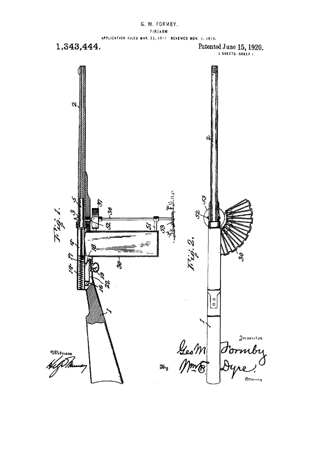
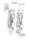
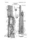
Figure 1 is a sectional elevation of uiy
improved gun shown supported upon the
ground; ti5
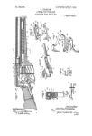
Fig. 2 is a top plan view thereof, show-
ing the multiple magazines to onesideof the
gun, and in a position to be moved beneath
the breech mechanism as the cartridges are
discharged. 70
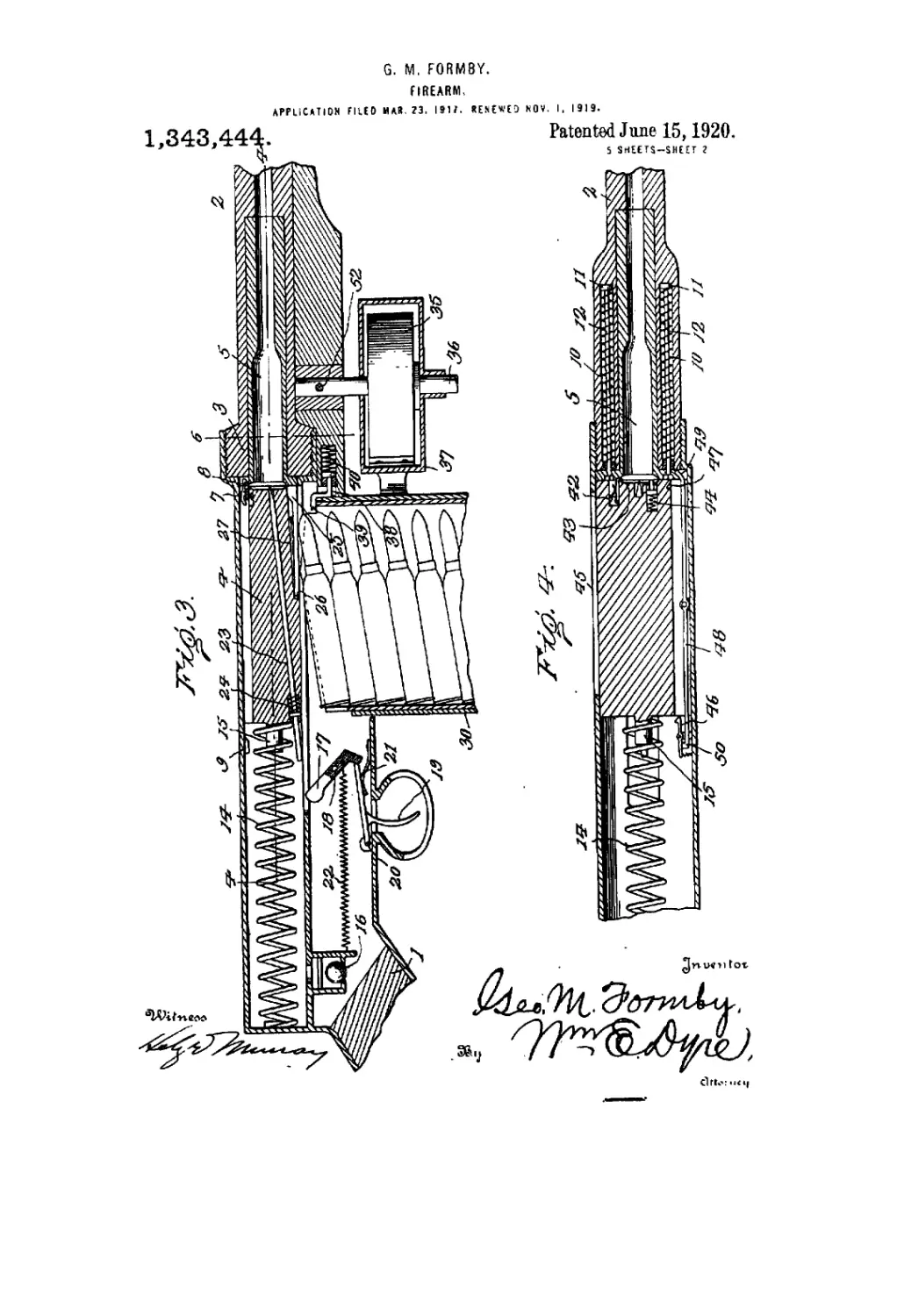
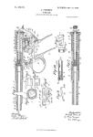
Fig. 3 is an enlarged sectional view
through the breech mechanism of the gun
showing the position of the firing chamber,
and breech-block when the cartridge is to
be fired. 75
Fig. 4 is a horizontal sectional view on
the line 4—4 of Fig. 3.
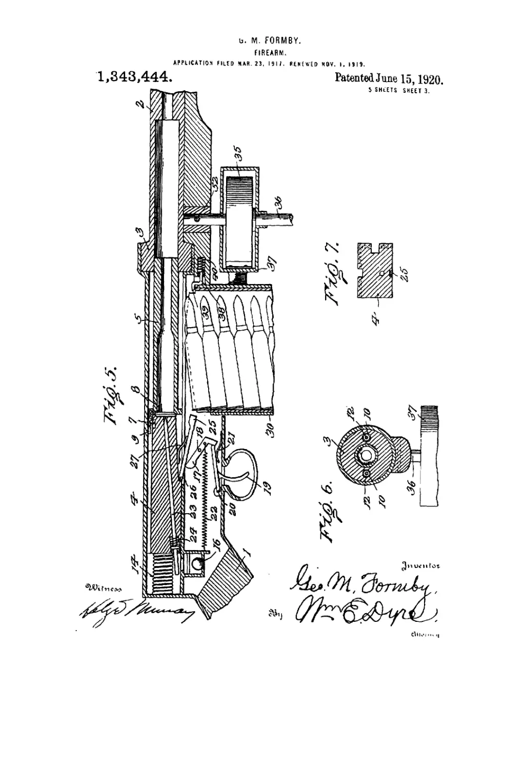
Fig. 5 is an enlarged sectional view simi-
lar to that of Fig. 3 showing the position of
the firing chamber and cooperating breech- 80
block when the cartridge has been fired and
the firing chamber is a short distance in the
barrel of the gun.
Fig. 6 is a detail sectional view on the
line 6—6 of Fig. 3. 85
Fig. 7 is a detail cross-sectional view
through the cooperating breech-block mem-
ber.
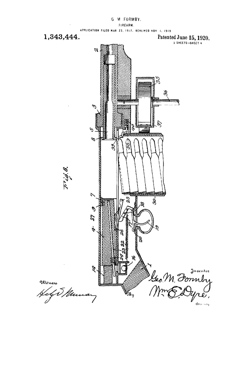
Fig. 8 is an enlarged sectional view
through the breech mechanism showing the so
position of the firing chamber and the co-
operating breech-block when the cartridge
is fed into the firing chamber^ the prior
empty shell having been ejected in the usual
manner. 05
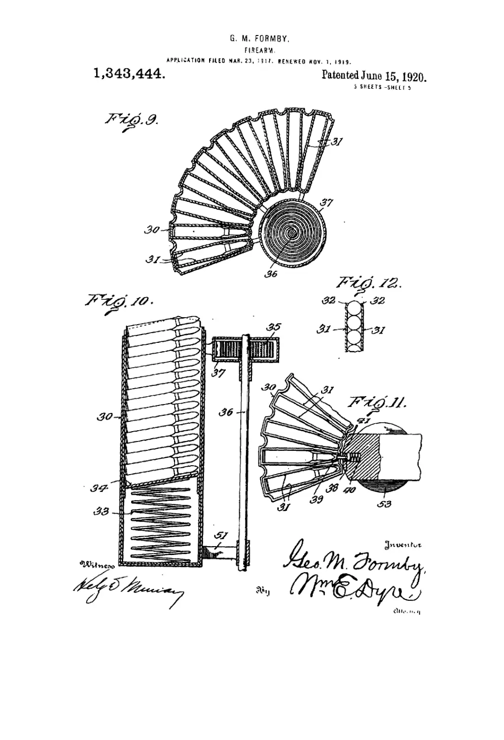
Fig. 9 is an enlarged detail horizontal
sectional view through the multiple maga-
zine holder and the spring for actuating tne
same.
Fig. 10 is a detail vertical sectional view 100
through the magazine holder.
Fig. .11 is a detail horizontal sectional
view showing the spring latch means for
successively locking the magazine holder as
the successive magazines are brought into 105
position, and
Fig. 12 is a detail sectional view through
the upper portion of one of the magazines.
The present invention has been designed
to facilitate the use of an automatic rifle 110
fi 1,848.4м
whereby continuous firing- may be engaged
in. It comprises, among other things, a
breech mechanism consisting of a movable
firing chamber; a breech mock; an auto-
4 matic cartridge magazine feeding mecha-
nism for successively bringing the loaded
magazines beneath the breech mechanism;
and means for actuating the aforesaid de-
vices, os will more fully hereinafter appear.
10 Referring to the drawings, the gun may be
of a standard type and comprises the usual
stock 1, barrel 2, and the other usnal parts,
all of which may be of the ordinary meas-
urements required for army and other rises.
15 The improvements eohteiuplated comprise a
novel breeeh-mechnnian for successively po-
sitioning the cartridges within the firing
chamber in & continuous manner for rapid
firing. The mechanism for accomplishing
SO this comprises a breech block, a breech
chamber 3 which may be formed as a' part
of the barrel 2. and file former of which is
relative!}' movable as each cartridge is fired
and another one |Misit-ioued in the firing
35 chamber. Cooperating with the movable
breech block is a filing chamber ft. The
firing chamber 5 is movable within the per-
manent breech chamber 8 and is withdrawn
therefrom after each discharge of a car-
30 tridge by the breech block 4. Spring latch
mechanism 7 is carried by the breech block 4
and engages the flnnged end 8 of the firing
chamber, as shown in Figs. 3 and S. A re-
leasing lug or cam 0 is provided in the path
35 of this latch 7, and as the breech block 4
and firing chamber 5 are moved rearwardly
by the recoil from the discharge of the
cartridge, the latch 7 will be operated by
contacting with the cam or trip 0 and the
40 firing chamber returned to its position in
the permanent breech chamber 3. Suitable
springs 10 are oppositely disposed within re-
cesses formed in tins wall of breech chamber
3, and serve to return the firing chamber 5
45 (see Fig. 4). These springs 10 are inter-
posed. between heads 11 provided on rods 12
secured to the flanged end 8 of the firing
chamber. The recoil of the breech block 4 is
absorbed by the spring 14 interposed be-
50 tween the end wall of the gun casing and
the protruding stud 16 carried by the breech
block 4.
As shown in Fig. 5 of the drawings, the
spring 14 is compressed when the breech
56 block 4 has readied its rearward position.
A suitable valve 16 is provided adjacent
tjie chamber in which the spring 14 operates
and serves to admit sir when tlie cooperat-
ing breech block 4 returns to its position
60 carrying with it a cartridge to be positioned
in the firing chamber S.
The trigger mechanism designed to fire
the cartridge wheu positioned ni the firing
chamber may lx* of the usual construction
65 and for the purpose shown herein is con-
ventionally illustrated as comprising a ham-
mer 17 pivoted at 18 (see Fig. 3). The
trigger 19 is pivoted at 20 and as it is pulled
by the action of the finger against the ten-
sion of the spring 21 the lower end of the 70
hammer 17 is released and pulled by the
action of a spring 22, thereby giving a blow
to the firing pm 23 for discharging the
cartridge. The firing pin 23 may be of
usual construction, and is herein shown as 75
returned to its normal position by the
spring 24.
The mechanism for positioning a car-
tridge as it is ted upwardly from the maga-
zine comprises a lever 25 pivoted at 26 80
to the cooperating breech block 4 and held
against the hammer 17 by a suitable spring
27. It will be seen that as the cooperating
breech block 4 moves forwardly the front
end of the lever 25 engages the cap end 85
of the cartridge and moves it forwardly into
the firing- chamber. While the cartridge is
being positioned within the firing chamber
the movable breech block 4 is momentarily
held in the position shown in Figs. 5 and 8 90
by a spring latch device 46 designed to drop
into a recess 47 formed in the breech block 4
wheu it is driven rearwardly by the recoil
from the discharge of the cartridge. After
the cartridge has been properly positioned 95
within tiie firing chamber of the block 6,
the breech block 4 is released by means of
tlie lever 48 being moved by the flange 8 of
the firing chamber 5 ns it is retracted and
seated against the breech chamber member 3 100
by the springs 10. It will be seen that as
the end 49 of the lever 48 is pressed out-
wardly by the flange 8 of the chamber 5, the
opposite end 50 of the lever will release the
spring latch 46 and allow the recoil spring 10&
14. to force the breech block 4 forward car-
rying with it a cartridge to be seated
-against the permanent breech chamber 8.
The multiple magazine holder comprises
the casing 80 into which a plurality or cart- 110
ridge holding magazines are placed. These
magazines are arranged radially with re-
spect to the support for the gun to be pres-
ently described. Each magazine comprises
guiding mils 31. the upper ends of which 115
are slightly inwardly curved as at 32, and
open at their forward ends to facilitate the
withdrawal of the cartridge as it is caught
by the lever 26 and positioned in the firing
chamber. A spring 38 is interposed between 120
the magazine follower 84 and the bottom of
the magazine. Tlie purpose of this spring
is to feed the cartridges upwardly as they
are successively discharged from'the guii.
the curved portions 32 serving to hold them 125
until the uppermost cartridge is removed.
The magazine holder is adapted to be
moved after each magazine has been ex-
hausted of its contents, and the. mechanism
for operating the same comprises a spring iso
1,343,444
G
35 one end of which is secured to the sup-
port 36 and the other end of which is secured
to the casing 37 secured to the magazine
holder. A spring latch 38 is carried by the
Б gun (see Tigs. 1, 8 and 11), and serves to
lock the magazine holder during the dis-
charge of the cartridges from the magazines
as they are successively brought beneath the
breech-block mechanism. As the last cur
10 tridge in the magazine is fired, the follower
34 is designed to engage the protruding end
39 of the latch 38 and press it inwardly
against the action of the spring 40. When
the latch 38 is thereby released the spring 3л
16 will move the magazine holder in an art unite
direction until the next magazine is reached,
when the latch 38, having been freed, will
engage the recess 41 formed in said maga-
zine holder and hold the same in position
20 until the contents of that magazine are dis-
charged, after which a similar operation oc-
curs until the entire contents of the maga-
zines carried by the holder are discharged.
The mechanism for ejecting the shell from
26 the firing chamber comprises a spring latch
42 pivoted in the cooperating breech-block
member 4. The latch 42 is designed to en-
gage the flange of the shell and hold the
same within the recess 43 until the firing
80 chamber 5 has been returned to its position,
after which the spring-pressed pin 44 oppo-
sitely arranged with relation to the latch 42
tends to kick the shell outwardly through
the opening 45 in the gun casing.
86 While I have shown this means for eject-
ing the shell it will be readily understood
that other forms may be employed. The
support 36 for the gun is braced., at its lower
end by the connection 51 extending from the
40 magazine holder. It comprises a rod, the
upper end of which is detachably secured to
the gun by means of a bolt 52 as shown in
Figs. 1 and 2, and the .lower end of which is
provided with a suitable supporting surface
45 53 preferably of disk like formation. As
shown in Fig. 1, the gun is resting upon the
ground thereby affording a convenient and
stable support for the gun when being dis-
charged from a lying down position. Whep
60 the gun is fired from a squatting position,
the supporting surface S3 is rested upon the
knee,.thereby giving to the gun a steadiness
which is always desirable. When the gun is
fired from a standing position it will readily
66 be understood that the loaded magazine
holder naturally swings beneath the arm in
a substantially balanced position, thereby
facilitating the aim and gripping of the gun
for accurate shooting.
во The operation of the gun follows: Refer-
ring to Figs. 3, 5 and В of the drawings,
three positions of the breech mechanism and
associated parts are shown. In Fig. 3 the
breech mechanism is shown closea in the
65 position for discharging a cartridge. The
chamber 5 is shown firmly seated in the
breech chamber 3. ike cooperating breech
block 4 is shown jammed aeainst the flange
8 of the firing chamber 5, the spring hitch 7
thereof having engaged the flange 8 as 70
shown It will be seen that as the trigger 19
is pulled the firing pin 23 will be struck a
blow by the hammer 17 and the ciiitridge
discharged.
As the bullet leaves the shell of the cur 75
tridge and has proceeded but a short dis
tnnee in the barrel of the gun the movable
breech block 4 will recoil against the tension
of the spring 14 drawing with it the firing
chamber 5 by virtue of the spring latch con 8ii
nection hereinbefore described. It will be
noted that one end of the firing chamber 5
remains within the breech-chamber 3, there-
by confining all of the gases of the explo-
sion until the bullet leaves the muzzle of the 8t
gup. As the breech-block 4 reaches its rear-
most position the latch 7 is operated by con-
tacting with the lug 9, thereby releasing the
firing chamber 5 which is then returned to
its seated position within the permanent 90
breech-chamber 3 by the action of the
springs Ю. Just prior to the firing chamber
5 completely seating in the breech-chamber
3 the flange 8 of the said firing chamber
strikes the end 49 of the lever 48 and presses 95
it outwardly, thereby releasing the spring
latch device 46 from within the recess 47
and allowing the cooperating breech block
4 to be forced by the action of the recoil
spring 14 against the flange 8 of the firing 100
chamber. Before the cooperating breech-
block 4 is released, however, a cartridge
from the magazine beneath the breech
mechanism has been positioned for loading
the gun, and it will be seen that as the co- 105
operating breech block 4 is forced forwardly
the end of the lever 25 engages the capped
end of the positioned cartridge and pushes
it from the magazine directing it into the
firing chamber 5 just prior to the flange 8 no
seating against the breech-chamber 3. As
the cooperating breech block 4 moves for-
wardly the cartridge is forced into the fir-
ing chamber and the spring latch 42 engages
the flange of the shell for holding it within 115
the recess 43. When the cartridge has been
discharged and the coSperating or movable
breech block 4 recoils, the spring latch 42
serves to hold the empty shell within the re-
cess 43 until the firing chamber 5 has been 120
returned by action or the spring 10, after
which the ejecting pin 44 serves to kick the
shell outwardly through t(ie opening 45 in
the cosing of the gun.
When the last cartridge in the magazine 125
immediately beneath the breech mechanism
has been discharged, the forward end of
the follower 34 is designed to engage the
protruding end 39 of the spring latch 38
and.press it inwardly against the action of iso
4 1,848,444
the spring 40, thereby permitting the con-
trolling spring 36 of the magazine holder
to urcuutely move the said holder until the
succeeding' inagazine is positioned beneath
5 the breech mechanism, at which time the
spring latch 38 will engage the recces 41
formed in the upper end of the holder
and maintain it m permanent relation to
the firing chamber of the gun until the car-
lo tridges in that magnsine have been dis-
charged, whereupon the operation is re-
peated until the entire contents1 of the mag-
azine holder have been exhausted.
Whim it is desired to detach the magazine
15 holder and support 30 from the gun, the
liolt 52 is withdrawn, as will be readily
understood. From the foregoing it will be
obvious that I have produced an automatic
gun capable of effecting a continuous dis-
90 charge of cartridges and at the same time
possessing novel features of action for read-
ily receiving the cartridges in succession.
What I claim is:
1. An automatic gun of the class do-
25 srrilred including in combination a broach
iiioelmnism consisting of a permanent
breeeh-chaiiilx'r and a movable breech-
block, и firing cliamlrer movable ip said per-
manent brooch-chamber, moans for locking
so the movable breech-block to the firing cham-
l>er for moving tire latter from the per-
manent breech-chamber when the cartridge
is exploded, releasing means for said firing
chandler, means for returning the firing
35 elmiiilier from its moved position, retaining
menus for holding the movable breech block
in its recoil position, means for releasing
the movable breech-block, and a cartridge
feed ing; de vice for positioning the loaded
40 cartridge in the firing chamber.
2. An automatic gun of the class de-
serilmd including in combination a breech
mechanism consisting of a permanent
breech-chamber and . a movable breech-
46 block, a firing chamber, means including a
spring latch for locking the movable breech-
block to the firing chamber iter moving the
latter in the permanent breech-chamber
when the rertrulge is exploded, releasing
SO means for said firing chamber designed to
operate the spring latch when the movable
breech-block has readied its recoil position,
means including a spring for returning the
firing chamber fromits recoil position into
66 the iwrmanont breech-ehamber. retaining
iiiwms including a spring latch for holding
the movable breech-block in the recoil posi-
tion. means for ejecting the empty she!] os
the firing chamber is returned to its normal
so position in tiie permanent breech-chamber,
ntwins for releasing the movable brooch-
block, said means being operated by the
liriiig chamber, and n cartridge feeding de-
vire for positioiiitig the loaded cartridge in
66 the tiring chamber.
3. An automatic gun of the class de-
scribed including in combination a breech
mechanism consisting of a fixed breech-
duunbor and a movable breech-block, a
firing chamber, means including a spring 70
latch for locking the movable breech-block
to tiie firing chamber for moving the latter
out of the permanent breech-chamber when
the cartridge is exploded, releasing means
for said finng chamber designed to operate 76
the spring latch when the movable breech-
block has reached its recoil position, means
including a spring for returning the firing
chamber from its recoil position into the
permanent breech-chaniber, retaining means so
including a spring latch for holding the
movable breech-block in the recoil position,
means carried by the movable breech-block
for ejecting the empty shell when the firing
chamber is returned to its normal position 85
in the permanent breech-chamber, means
for releasing the movable breech-block, said
means being operated by the firing chamber
immediately before it reaches its normal
position in* the permanent breech-chainher, 90
and a cartridge positioning device carried
by the movable breech-block for directing a
loaded cartridge within the firing chamlier.
4. An automatic gun of the class described
including in combination a breech meeha- 96
nism consisting of a breech-chamber and n
movable breech-Ыоск. a firing chamlier,
means including a spring latch for locking
the movable breech-block to the firing cham-
lier for moving the latter from the perms- 100
nent breech-chambey when the cartridge is
exploded, releasing means for said firing
chamber designed to operate the spring latch
when the movable breech-block lias reached
its recoil position, moans including a spring 105
for returning the firing chamber from its
recoil position into the breech-chamber, re-
taining means including a spring hitch for
holding the movable breech-block in the re-
coil position, means curried by the movable 110
breech-block for ejecting the empty shell
when the firing chandler is returned to its
normal position in the breech-chamber,
means for releasing the movable breech-
block, said means being operated by the fir- 115
ing chamber immediately before it reaches
its normal position in die breech-chaniber,
and means carried by the movable breed»
block for engaging a loaded cartridge and
directing it within the firing chamber. and 120
о cartridge magazine feeding dev ire for suc-
cessively positioning the loaded cartridge
within the path of the means corned by
the movable breech-block for engaging a
loaded cartridge and directing it within the 126
firing chamlier.
5. An automatic gun pf the class described
including in combination n breech mecha-
nism consisting of it brrech-chundiet and a
movable breech-block, a tiring chamber mov- iso
1,943,444
5
10
15
20
able in said breech-chamber, means for lock-
ing the movable breech block to the firing
chamber for moving the latter from the
breech-chamber when the cartridge is ex-
ploded, releasing means for said firing cham-
ber, means for returning the firing chamber
from its recoil position, retaining means for
holding the movable breech-Ыоск in its re-
coil position, means for releasing the mov-
able breech-block, a cartridge positioning de-
vice carried by the movable breech-block for
engaging a loaded cartridge and directing it
within the firing chamber, a multiple maga-
zine cartridge holder, and means for auto-
matically positioning a loaded magazine be-
neath the cartridge positioning device car-
ried by the movable breech-block.
6. An automatic gun of the class described
including in combination a breech mecha-
nism consisting of a breech-chamber and a
movable breech-block, a firing chamber de-
signed to be moved by the movable breech-
block by the recoil from the explosion, means
including a spring for absorbing the recoil
S
of the movable breech-block, a chamber for 25
said spring, and a valve provided in said
chamber for admitting air to the said cham-
ber when the spring returns the movable
breech-block to its normal position,
7. A gun of the class described in combi- 30
nation with a cartridge feeding device
comprising a multiple magazine cartridge
holder, a support for said holder, means in-
cluding a spring secured to said holder and
the said support for successively moving the 35
holder, releasing means for said holder and
means for operating the releasing means
when the last cartridge in a magazine has
been delivered to the gun for permitting the
aforesaid spring to move the multiple maga- 40
zine holder.
In testimony whereof I affix my signature,
in presence of two subscribing witnesses.
GEORGE M. FORMBY.
Witnesses:
Margaret D. Ballauf,
Wm. E. Dyre.