/


Tags: weapons military affairs patent
Year: 1905
Text
No. 80'2,279.
PATENTED OCT. 17, 1905.
R. FROMMER.
FIREARM.
APPLICATION FILED FEB, 13, 1902.
5 SHEETS—SHEET 1.
ANOREW В GRAHAM CO, PHOTO LITHOGRAPHERS, WASHINGTON, D C
1V0»
Г А х £114 IJjU
В. FR0MMER.
FIREARM.
APPLICATION PILED РЕВ. 13, 1902,
ANCRSW и GHAPJU CO
PHOTO LITHOGRAPHERS WASHINGTON. Q
No. 802,279.
PATENTED OCT. 17, 1905.
R. FROMMER.
FIREARM.
APPLICATION PILED EEB. 13, 1902.
No. 802,279.
PATENTED OCT. 17, 1905.
R. FROMMER.
FIREARM.
APPLICATION FILED FEB. 13, 1902.
No. 802,279.
PATENTED OCT. 17, 1905.
R. FROMMER.
FIREARM.
APPLICATION FILED FEB. 13, 1902.
5 SHEETS—SHEET 5.
7^22.
IdU/ltMU/,’
Ircw,nXo-r-:
Tu^e^tCctne^jJ.
UNITED STATES PATENT OFFICE.
RUDOLF FROMMER, OF BUDAPEST, AUSTRIA-HUNGARY.
FIREARM.
No. 802,279.
Specification of Letters Patent.
Application filed February 13, 1902. Serial Ko. 93,823.
Patented Oct. 17, 1905.
To all whom it may concern:
Be it known that I, Rudolf Fbommek, a citi-
zen of the Empire of Austria-Hungary, resid-
ing atIX Soroksari ut 100, Budapest, Austria-
5 Hungary, have invented certain new and use-
ful Improvements in Firearms; and I do here-
by declare the following to be a full, clear,
and exact description of the invention, such
as will enable others skilled in the art to which
io it appertains to make and use the same.
The present invention relates to firearms,
and is designed to provide an automatic fire-
arm distinguished from those of former con-
struction by the special simplicity, compact-
15 ness and accessibility of all its parts, and the
easy manner in which it can be put together
and taken to pieces.
With these objects in view my invention con-
sists in the features, means, and combinations
20 of parts, as hereinafter described and as par-
ticularly pointed out in the claims hereunto
annexed.
Two forms of construction of a firearm made
according to this invention and constituting
25 the preferred embodiment thereof are illus-
trated in the accompanying drawings, in which
Figures 1 to 14 show it as a firearm adapted
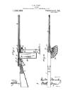
for use as a pistol, and Figs. 15 to 19 as a shoul-
der-firearm.
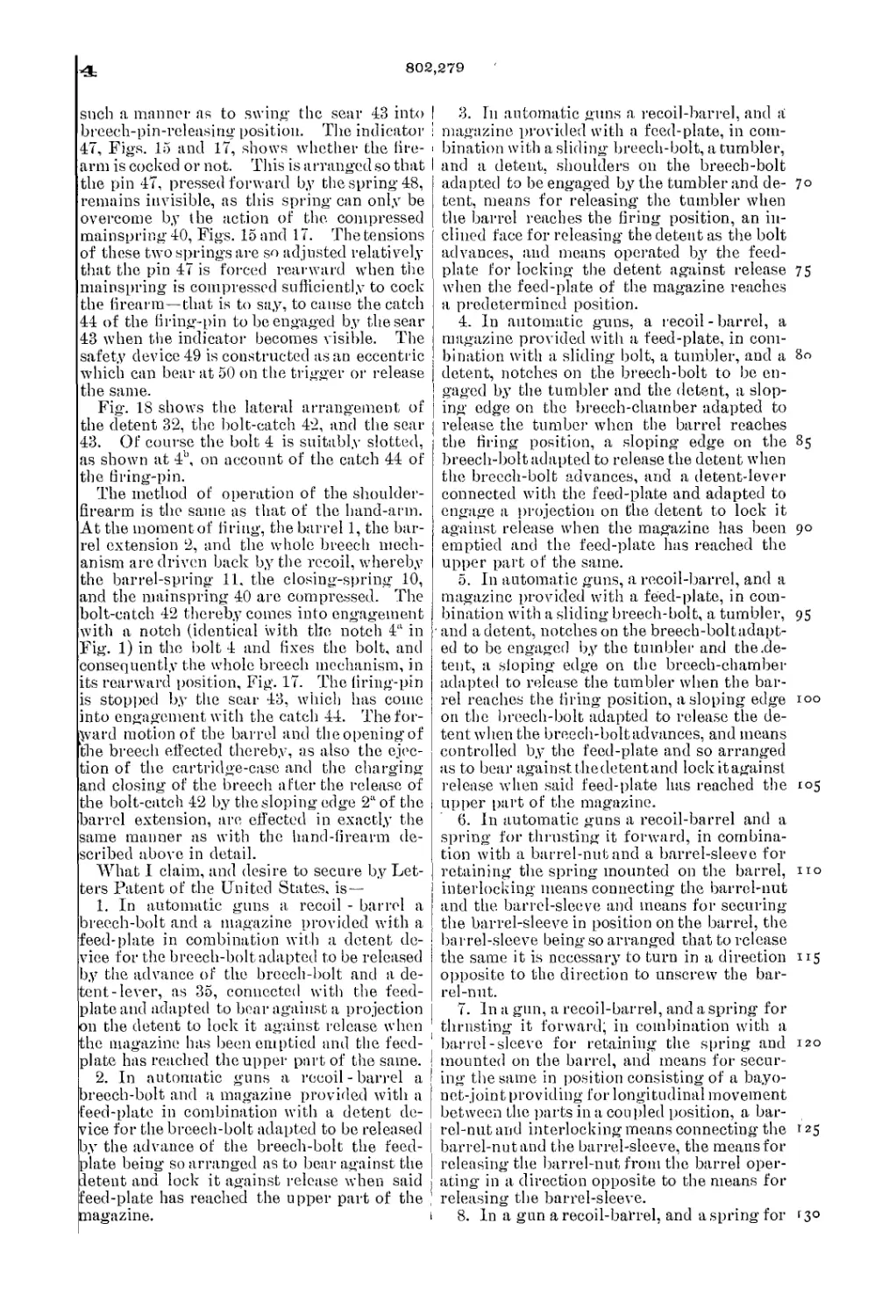
30 Fig. 1 is a central vertical longitudinal sec-
tion of the first form of construction. Fig.
2 is a horizontal section on the line A В of
Fig. Г. Fig. 3 is a-vertical longitudinal sec-
tion of the same when open after the last car-
35 tridge has been fired or with empty magazine.
Fig. 4 is a vertical longitudinal section show-
ing how in the same kind of firearm after the
last cartridge has been fired the breech mech-
anism rigidly connected with the barrel and
4° breech - chamber arrives, (together with the
latter parts,) by means of the recoil in its rear-
most position and how the breech after fir-
ing the last shot is automatically kept open
by the cooperation of the detent-lever and de-
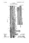
45 tent. Figs. 5 to 14 are details of the same
firearm. Figs.'5 and 5a show, in side eleva-
tion and bottom plan view, respectively, the
notches on the bolt. Fig. 6 is a perspective
view of the connection between breech-block
50 and bolt. Fig. 7 shows the means of connec-
tion of the barrel-casing and barrel-casing nut
with the barrel. Figs. 8 and 14 illustrate the
coOperation between detent-lever and'feed-
plate. Fig. 9 is a perspective view of the car-
55 tridge-extractor. Fig. 10 shows the means of
connection of the firing-pin and the cartridge-
extractor. Fig. 11 is a vertical section of the
breech-chamber on the line C D of Fig. 1.
Fig. 12 is an elevation of the feed-plate. Fig.
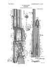
13 is an elevation of the detent-lever. Fig. 60
15 is a vertical longitudinal section of a shoul-
der-firearm also embodying my invention.
Fig. 16 is a section on the line A' B' of Fig.
15. Fig. 17 is a vertical longitudinal section
of the firearm before the last cartridge is in- 65
troduced into the charge-chamber. Fig. 18
illustrates the arrangement of the detent, the
bolt-catch, and the sear. Fig. 19 is a verti-
cal section of the firing-pin from behind the
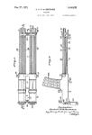
firing-pin catch. Fig. 20 is a vertical section 70
of the breech-chamber and the breech-bolt
and a back view of the tumbler and the de-
tent. Fig. 21 is a side elevation of the parts
shown in Fig. 20, and Fig. 22 is a plan view
of the tumbler and detent. 75
The barrel 1, Fig. 1, and the barrel exten-
sion 2, which is made in one piece with or
screwed onto the barrel, are adjustably placed
in suitable guides of the frame 3. An annu-
lar groove 2b, Fig. 3, is made in the barrel 80
extension 2, which groove is connected with
a series of longitudinal rearwardly-opening
grooves 2°, Figs. 3 and 11. The bolt 4 is
pushed into the barrel extension 2 and is
coupled with the breech-block 5 by means of 85
the arrangement, Fig. 6, of suitably-placed
ribs 4£ on the bolt 4, which engage in spiral
grooves 5b of the breech-block 5. Owing to
this arrangement, the breech-block 5 has to
revolve on its longitudinal axis in the bolt 90
with each displacement.
If now during the forward movement in a
straight line of the breech-block 5 (coupled,
by means of the spiral groovesand ribs, with
the bolt 4) the studs 5a on the breech-block 95
have passed the grooves 2°, the breech-block
5 strikes against the front face of the annular
groove 2b and is thus checked in its movement
forward; but the bolt 4 is still driven forward
under the action of the spring 10, and by 100
means of this relative motion of the two parts,
owing to their connection by spiral grooves
and ribs, the breech-block 5 revolves on its
longitudinal axis, whereby the studs 5a firmly
rest against the rear end of the annular groove 105
2b between the grooves 2°, and the breech is
rigidly locked. The firing-pin 8 passes through
the breech-block 5, Fig. 1, and through the
plate 6, which is fixed in the frame 3.by means
of the screw-bolt 7. The firing-pin is nor- no
mally held in retracted position by means of
the spring 9.
£3
802,279
5
IO
15
20
25
3°
35
4°
45
5°
55
60
б5
Of the springs 10 and 11 the former (one
end of which rests against a shoulder within
the bolt 4 and the other end against the plate
6) operates the breech mechanism, while the
latter 11 (which with its rear end rests against
a shoulder of the frame 3 and with its front
end against the barrel-sleeve 12) serves for
bringing back the barrel 1 and the barrel ex-
tension 2 into the position they were in before
the recoil. As it is of great importance that
the barrel-sleeve 12, which forms the stop for
the barrel-spring 11, should be connected in an
absolutely-reliable manner with the barrel 1,
the barrel-sleeve 12, Fig. 7, which is provided
with a bayonet-groove and placed on the boss
1“ of the barrel, is furthermore secured by a
nut 13, both of which, as shown, engage with-
in one another at one or more places by in-
terlocking tenon-and-mortise connections in
the manner of a clutch-coupling. In order
to obtain an absolutely secure joint with the
barrel, the direction of rotation of the bayo-
net-groove is contrary to that of the thread-
ing of the nut 13. For instance, if the bayo-
net-joint is to turn to the right then the nut
13 has a left-hand screw-threading, and vice
versa. It is thus obvious that the nut 13 can-
not come off the barrel-sleeve 12 by accident;
but even if it should the bayonet-joint alone
would insure a secure connection between the
barrel-sleeve 12 and barrel 1. In order to
remove the barrel-sleeve 12, as well as the
nut 13, the barrel - sleeve must be pressed
against the barrel - spring 11, when the rib
and groove of the barrel-sleeve and the nut
will come out of engagement. The nut 13
can then be unscrewed and the barrel-sleeve
12 twisted out of the stud la.
The ejector 14, Fig. 2, is inserted in the bar-
rel extension 2, and preferably under spring
force, while the cartridge-extractor 15, Fig.
9, is embedded in the breech-block and en-
gages with its projection 15“, Fig. 10, in a
corresponding notch in the firing-pin 8 in or-
der to prevent the latter falling out back-
ward.
The trigger 16, pivoted on the trigger-pin
17, forming one piece with the frame 3, is
controlled by the trigger-spring 18 and has a
catch 20 controlled by a spring 19, which
catch is arranged to swing on the pivot 21.
The sear 22 is pivoted on the pin 23 of the
frame and is controlled by the sear-spring 24,
which constantly presses it against the ham-
mer 25. This latter is pivoted on the pin 26
of the frame and is controlled by the main-
spring 28, coiled round the forcing-bolt 27.
The hammer 25 is limited in its swinging
motion by the mantle 3 at 3d.
The tumbler 29, Fig. 1, is pivoted on the
pin 30 of the frame and is constantly pressed
upward by the spring 31. The back part of
the tumbler 29 is in the form of a segmental
arc concentric with the pin 30, and it has also
a lateral reinforcement with oblique contact-
surface, as shown in the dotted line 29'*. Also
pivoted on the pin 30 is the detent 32, Fig. 3,
(not shown in Fig. 1,) which is controlled by
a spring 33, which is embedded in a suitable
underflap 29b of the tumbler 29. 70
One operative edge of the detent 32 is formed
with a sloping end 32“, while the other is formed
as a catch at 32b. The sloping edge 32“ en-
gages in the notch 4b, Figs. 5, .5“, and 6, with
every backward motion of the bolt 4, but is 75
again pressed down by the inclined rear end
of the notch 4b of the bolt when the bolt
moves forward, as long as the detent-lever
35, Fig. 3, does not come into engagement
with the catch 32b. On the bolt 34, forming 8°
one piece with the frame which passes through
an oval aperture 16“ of the trigger, Fig. 1,
is pivoted the detent-lever 35, the downward
movement of which is limited at 3'*, Fig. 3,
by the frame. The magazine 36 contains the 85
feed-spring 37 and the feed-plate 38, which is
illustrated in Figs. 8 and 14 in its coopera-
tion with the detent-lever 35.
It will be seen from Fig. 12 that the feed-
plate 38, which is inside the magazine 36, has 90
a lateral tailpiece 38b, which projects through
the slot of the magazine and is reinforced out-
wardly by a shoulder at 38'*, while it will be
seen from Fig. 13 that the detent-lever 35 is
reinforced inwardly by a shoulder, as shown 95
by the dotted line. These two reinforcements
come into engagement with each other (see,
Figs. 8 and 14) when the feed-plate 38, con-
trolled by the feed-spring 37, goes up as the
magazine empties. Consequently the detent- r°°
lever 35 is also lifted up as the magazine 36
is about to be emptied. The tooth 35“ of the
detent-lever is hereby caused to make an arc-
shaped movement around the bolt 34, thereby
coming under the lower edge of the tailpiece 105
38b of the feed-plate 38, and so that when the
feed-plate 38 is pressed down the detent-lever
35 is likewise pressed down. The feed-plate
38 can also be pressed down by pressing down-
ward the knob 35b of the detent-lever 35. no
In the T-groove 3b of the frame 3, Figs. 1,
3, and 4, is movably arranged the safety de-
vice 39, Figs. 3 and 4. The latter has three
projections 39“ 39b 39е, Fig. 4, of which one,
39“, stops the action of the detent 32 and the 115
others that of the sear 22 and the hammer 25,
respectively, according as the safety-piece 39
by being moved forward, Fig. 4, or backward,
Fig. 3, is put out of or into action. A flat
spring 52, Fig. 1, serves to retaip the safety- 120
piece in its operative or inoperative position
and is arranged in a groove cut in the frame
at 3° and extending into the T-groove 3h. The
knurled button 39d of the safety-piece 39, as
well as the knurled button 35” of the detent- 125
lever 35, project through suitable apertures
in the frame. When the bolt 4 is in its for-
ward closed position, (as in Fig. 1,) the sloping
end 32“ of the detent 32 engages in the notch
4°, Fig. 3, of the bolt 4. When this is secured 13°
602,279
О
and the safety-slide moved back, the upper
projection 39“ of the safety-piece 39 engages
under the downwardly-bent projection 32° of
the detent 32, and thereby the bolt 4, and there-
5 fore all the parts which are movable rearward,
(breech-block 5, barrel 1, barrel extension 2,)
are immovably fixed. The sear 22 (at 22a) and
the hammer 25 (whether cocked at 25a or at
half-cock at 25b) are also fixed by the two lower
io projections 39b and .39° of the safety-piece 39.
Consequently the movable parts, as well as the
trigger mechanism, are made safe.
The method of operation of the firearm is
as follows: At the moment of firing the barrel
15 1, the barrel extension 2, and the whole breech
mechanism are thrown back by the recoil, Fig.
4, whereby the barrel-spring 11, the spring
10, the hammer 25, and consequently the main
spring 28, are set. The tumbler 29 thereby
2o comes into engagement with the notch 4a (see
Figs. 1, 5, 5a, and 6) of the bolt and fixes the
bolt and the whole breech mechanism in its
rearward position. The force of the recoil
then immediately ceases, and the barrel 1 and
25 the barrel extension 2 are again driven for-
ward by the barrel-spring 11. The barrel ex-
tension 2 takes with it the breech-block 5, con-
sequently drawing it out of the bolt 4, Figs. 3
and 6, whereby the breech-block twists round
30 until the studs 5a pass into the grooves 2° or
into the cross-head guides in the barrel exten-
sion 2, forming continuations thereof. As the
barrel 1 and barrel extension 2 are now driven
forward by the barrel-spring 11 and the empty
35 cartridge-case, firmly held by the cartridge-
extractor, is thrown out by the ejector 14, Fig.
2, arranged in the barrel extension 2 and op-
erating in the well-known manner, the breech
mechanism remains fixed in its rearward po-
4° sition by means of the tumber 29 until the
sloping edge 2a of the breech, Figs. 1,15, and
17, reaches the sloped raised surface 29a of
the tumbler 29, whereby the latter is pressed
down, the mainspring 10 can come into oper-
45 ation and drive forward the breech mechanism,
which pushes into the charge-chamber the
fresh cartridge, (which has meanwhile been
raised from the magazine,) whereby the studs
5a of the breech-block, which have passed into
5° the grooves 2°, Fig. 11, in the annular groove
2b turn in the said groove and become firmly
locked with the barrel extension 2. The arm
is now ready for firing—that is, cocked—rig-
idly closed and charged, and cap again be fired
55 off by pulling the trigger, and the above-de-
scribed operation is repeated as long as there
is ammunition in the magazine.
In order to insure that the hammer 25 is
held securely by the sear 22 after every shot,
60 so that there may never be more than one shot
each time the trigger 16 is pulled, there is
a catch 20 pivoted on the trigger and which
when the trigger is pulled comes into engage-
ment with the sear 22 and lifts the latter only
65 to the intersecting-point of the arcs of two
circles, (the pivots 17 and 23 being taken as
centers,) whereupon the sear 22, actuated by
the spring 24, springs off the projection 20 at
the moment when the notch of the hammer
25 is released from the nose of the sear 22, 70
the hammer being consequently released. The
sear 22, however, at the same moment being
released from the trigger is returned to its op-
erative position by means of the spring 24
and remains ready to again hold the hammer 75
25, which will be driven back by the recoil.
The arrangement of the projection 20 being
such that the same is held rigidly against
movement in one direction enables the trigger
16 to return to its original position without 80
thereby affecting the sear 22.
In order that the firearm after the last car-
tridge has been fired may remain open and
ready for recharging, it is so arranged that
after firing the last cartridge, Fig. 3, the de- 85
“tent-lever 35 is brought into engagement with
the projection 32b of the detent 32 by means
of the feed-plate 38.
The detent 32, which with every backward
motion of “the bolt 4 passes into its notch 4b, 9c
Fig. 5, but is pressed down on its sloping part
32a by the slope of this notch, owing to the
action of the spring 10 forcing the bolt 4 for-
ward, must now remain in its upper position,
owing to the engagement of the detent-lever 95
35 in the projection 32b, and consequently re-
tains the breech mechanism in its rearward
position until by inserting fresh ammunition
or by pressing on the knurled button 35b of
the detent-lever 35 the feed-plate 38 is pressed r00
down. Until the breech mechanism is closed
the lugs 4d of the bolt prevent the forward
motion of the hammer 25 even if the trigger
is pulled.
The second form of construction of the auto- 1 ° 5
maticfirearm forming the subject of this in ven:
tion is in essentials the same as that described
above, except that the hammer is in this in-
stance replaced by a firing-pin. Figs. 15 to 19
of the drawings illustrate those modifications no
required by the omission of the hammer and the
substitution therefor of a firing-pin 41, con-
trolled by the mainspring 40. In this form,
Fig. 17, 42 is the bolt-catch, which in this case
performs thefunctionof thetumbler29.Fig.l; 115
43 the sear, which engages with the catch 44 of
the firing-pin, and 32 the detent, which after
firing the last shot is rigidly held by the pro-
jection 38° of the feed-plate in the correspond-
ing notch of the bolt 4 and keeps the breech 12c
open until fresh, ammunition is supplied or
the feed-plate 38 is pressed down. The oper-
ation of the trigger mechanism is substantially
the same under this construction as in the con-
struction first described, only in the present 125
case the movable catch 20 instead of being
mounted directly on the trigger 16 is arranged
on a separate lever 53, yieldingly actuated by
a spring 54. This trip-lever 53 is actuated by
the trigger 16 when the latter is pressed in 130
<1
802,279
such a manner as to swing the sear 43 into
breech-pin-releasing position. The indicator
47, Figs. 15 and 17, shows whether the fire-
arm is cocked or not. This is arranged so that
the pin 47, pressed forward by the spring 48,
remains invisible, as this spring can only be
overcome by the action of the compressed
mainspring 40, Figs. 15 and 17. The tensions
of these two springs are so adjusted relatively
that the pin 47 is forced rearward when the
mainspring is compressed sufficiently to cock
the firearm—that is to say, to cause the catch
44 of the firing-pin to be engaged by the sear
43 when the indicator becomes visible. The
safety device 49 is constructed as an eccentric
which can bear at 50 on the trigger or release
the same.
Fig. 18 shows the lateral arrangement of
the detent 32, the bolt-catch 42, and the sear
43. Of course the bolt 4 is suitably slotted,
as shown at 41’, on account of the catch 44 of
the tiring-pin.
The method of operation of the shoulder-
firearm is the same as that of the hand-arm.
At the moment of firing, the barrel 1, the bar-
rel extension 2, and the whole breech mech-
anism are driven back by the recoil, whereby
the barrel-spring 11. the closing-spring 10,
and the mainspring 40 are compressed. The
bolt-catch 42 thereby comes into engagement
with a notch (identical with the notch 4“ in
Fig. 1) in the bolt 4 and fixes the bolt, and
consequently the whole breech mechanism, in
its rearward position, Fig. 17. The firing-pin
is stopped by the sear 43, which has come
into engagement with the catch 44. The for-
ward motion of the barrel and the opening of
the breech effected thereby, as also the ejec-
tion of the cartridge-case and the charging
and closing of the breech after the release of
the bolt-catch 42 by the sloping edge 2aof the
barrel extension, are effected in exactly the
same manner as with the hand-firearm de-
scribed above in detail.
What I claim, and desire to secure by Let-
ters Patent of the United States, is —
1. In automatic guns a recoil - barrel a
breech-bolt and a magazine provided with a
feed-plate in combination with a detent de-
vice for the breech-bolt adapted to be released
by the advance of the breech-bolt and a de-
tent-lever, as 35, connected with the feed-
plate and adapted to bear against a projection
on the detent to lock it against release when
the magazine has been emptied and the feed-
plate has reached the upper part of the same.
2. In automatic guns a recoil - barrel a
breech-bolt and a magazine provided with a
feed-plate in combination with a detent de-
vice for the breech-bolt adapted to be released
by the advance of the breech-bolt the feed-
plate being so arranged as to bear against the
detent and lock it against release when said
feed-plate has reached the upper part of the ,
magazine. i
3. In automatic guns a recoil-barrel, and a
magazine provided with a feed-plate, in com-
bination with a sliding breech-bolt, a tumbler,
and a detent, shoulders on the breech-bolt
adapted to be engaged by the tumblerand de- 7°
tent, means for releasing the tumbler when
the barrel reaches the firing position, an in-
clined face for releasing the detent as the bolt
advances, and means operated by the feed-
plate for locking the detent against release 75
when the feed-plate of the magazine reaches
a predetermined position.
4. In automatic guns, a recoil - barrel, a
magazine provided with a feed-plate, in com-
bination with a sliding bolt, a tumbler, and a 80
detent, notches on the breech-bolt to be en-
gaged by the tumbler and the detent, a slop-
ing edge on the breech-chamber adapted to
release the tumber when the barrel reaches
the firing position, a sloping edge on the 85
breech-bolt adapted to release the detent when
the breech-bolt advances, and a detent-lever
connected with the feed-plate and adapted to
engage a projection on the detent to lock it
against release when the magazine has been 90
emptied and the feed-plate has reached the
upper part of the same.
5. In automatic guns, a recoil-barrel, and a
magazine provided with a feed-plate, in com-
bination with a sliding breech-bolt, a tumbler, 95
and a detent, notches on the breech-boltadapt-
ed to be engaged by the tumbler and the.de-
tent, a sloping edge on the breech-chamber
adapted to release the tumbler when the bar-
rel reaches the firing position, a sloping edge i°°
on the breech-bolt adapted to release the de-
tent when the breech-bolt advances, and means
controlled by the feed-plate and so arranged
as to bear against thedetentand lock itagainst
release when said feed-plate has reached the 105
upper part of the magazine.
6. In automatic guns a recoil-barrel and a
spring for thrusting it forward, in combina-
tion with a barrel-nut and a barrel-sleeve for
retaining the spring mounted on the barrel, no
interlocking means connecting the barred-nut
and the barrel-sleeve and means for securing
the barrel-sleeve in position on the barrel, the
barrel-sleeve being so arranged that to release
the same it is necessary to turn in a direction 115
opposite to the direction to unscrew the bar-
rel-nut.
7. In a gun, a recoil-barrel, and a spring for
thrusting it forward; in combination with a
barrel-sleeve for retaining the spring and 120
mounted on the barrel, and means for secur-
ing the same in position consisting of a bayo-
net-joint providing for longitudinal movement
between the parts in a coupled position, a bar-
rel-nut and interlocking means connecting the 125
barrel-nut and the barrel-sleeve, the means for
releasing the barrel-nut from the barrel oper-
ating in a direction opposite to the means for
releasing the barrel-sleeve.
8. In a gun a recoil-barrel, and a.spring for f3°
802,279
5
thrusting it forward, in combination with a
barrel-sleeve bayonet-jointed to the barrel in
such manner as to provide for a limited rela-
tive longitudinal movement of the parts in
5 their coupled position and a barrel-nut thread-
ed on the end of the barrel and connected with
the barrel-sleeve by a cluteh-coupling, the
bayonet-joint on the sleeve and the thread on
the barrel-nut being so arranged as to turn in
io opposite directions on being released.
9. In automatic guns, a magazine feed-plate
having a laterally-extending shoulder, in com-
bination with a detent for locking the breech-
bolt in its open position, a detent-lever piv-
15 oted to one side of the path of the feed-plate,
a shoulder on the lever arranged to be en-
gaged by the shoulder of the feed-plate in the
upward movement of the latter, and a tooth
projecting from the lever arranged to clear
20 the feed-plate shoulder in its upward move-
ment and to be engaged thereby in its down-
ward movement whereby a depression of the
feed-plate will operate to positively depress
the detent-lever.
10. In an automatic gun, a cock, a sear for 25
the same, and a detent for the breech-bolt, in
combination with a safety-piece mounted for
movement into and out of engagement with
the cock, sear and detent.
11. In a gun, an indicator engaging a slot 30
in the same and a spring for retracting the
same into the firearm, in combination with a
firing-pin and a spring arranged between the
firing-pin and the indicator, the two springs
being of such relative strength that in com- 35
pressing the latter by retracting the firing-
pin, the indicator is thrust out of the firearm.
In testimony whereof I affix my signature in
presence of two witnesses.
RUDOLF FROMMER.
Witnesses:
Frank Dy er Chester,
Schon Furosz.