/
Tags: weapons military affairs
Year: 1941

Text
ТМ 9—1595!
WAR DEPARTMENT
TECHNICAL MANUAL
ORDNANCE MAINTENANCE
PRISMATIC COMPASS, M1918
July 17, 1Э41
TM 9-1595
TECHNICAL MANUAL
No. 9-1595
..WAR DEPARTMENT,
; SVXeHINGTON, 1941.
, s • • ...
ORDNANCE MAINTENANCE
PRISMATIC COMPASS, M1918
Prepared under direction of the
Chief of Ordnance
Section I. General. Paragraph
Purpose________________________________________ 1
Scope------------------------------------------ 2
References_____________________________________ 3
II. Description.
Description_____________________________________________ 4
III. Operation and adjustment.
Operation______________________________________ 5
Field test and adjustment_____________________ 6
IV. Inspection.
Inspection_____________________________________ 7
V. Maintenance and repair.
Disassembly and assembly---------------------- 8
Adjustment_____________________________________ 9
VI. Care and preservation. Page
Care and preservation_______________________ 10
Appendix. List of references__________________________ 12
Section I
GENERAL
Paragraph
Purpose________________________________________________________________ 1
Scope_________________________________________________________________ 2
References_____________________________________________________________ 3
1. Purpose.—This manual is published primarily for the informa-
tion and guidance of ordnance maintenance personnel.
325897—41
1
ТМ 9-1595
2—4 ORDNANCE DEPARTMENT
2. Scope.—This .manual supplements the technical manuals which
are ргерагей ifar "the .vising aijm. It contains descriptive matter, oper-
ating instructions, and' detailed instructions for maintenance and
repair-by ordn^ncd-pej^brinsL'
3. 'References.—Th’e‘appendix lists the publications pertaining to
the prisiiiatin compass.
"Section II
DESCRIPTION
Paragraph
Description_________________________________________________ 4
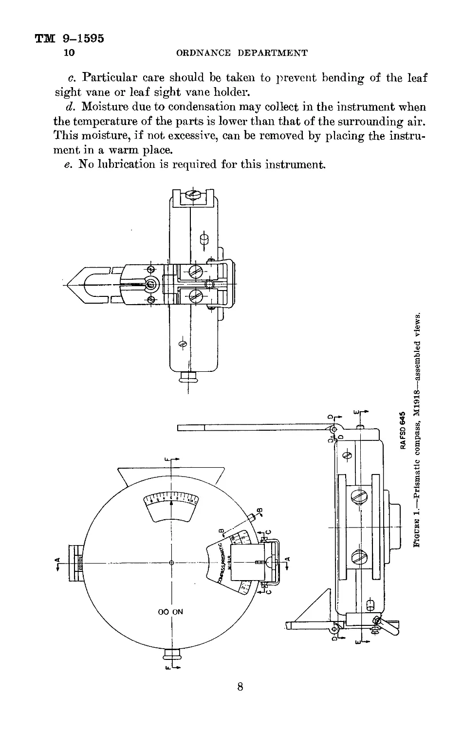
4. Description.—a. The prismatic compass is a multiple-purpose
instrument for obtaining clinometer, angle of site, and magnetic
azimuth readings. It may be used with 155-mm howitzers, M1917,
M1918 and modifications; 75-mm guns, M1897, M1897A2, M1917 and
modifications; 75-mm pack howitzers, Ml and M1A1; and with other
field artillery.
Ъ. The instrument contains a compass dial, B137958, and a clin-
ometer dial, C70112. The clinometer dial carries a lead weight,
B137954, which causes it to indicate vertical angles when the instru-
ment is held vertically. In order to make the instrument compact,
the clinometer dial is mounted just above the compass dial. A por-
tion of the clinometer dial is cut away so that the compass dial
below may be viewed. The compass dial is colored green, and the
clinometer dial is white.
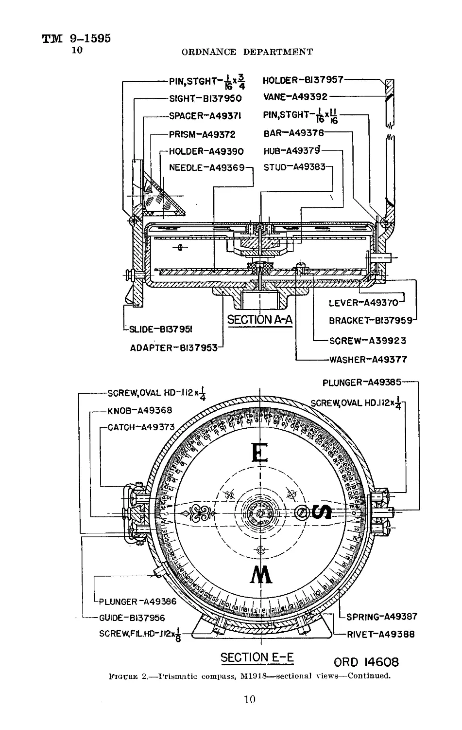
c. Folding sights are provided at front and rear. The rear sight,
B137950, is hinged to the rear sight slide, B137951, and can be raised
pr lowered To focus the magnifying prism, A49372, on either the
compass dialer the clinometer dial. The function of the prism is
to superimpose upon the field, as viewed through the sight, the image
of the clinometer -compass s0 that accurate readings may be
taken by usijig thAvape of the front sight as it appears on the image
of fhe dial* The sight, assembly, consisting of the leaf sight
vane, A49392, and le@ sight vane holder, B137957, is hinged to the
front sight bracketyB137959. When turned down, the leaf sight
Engages the compass lift bar, A49378, which lifts the compass dial
from its Jjjvot^-tfid clamps it. The dial remains clamped until the
leaf sight is opened for operation.
d. A compass dial locking plunger, A49386, protrudes through the
case, C70110, near the rear sight, and a similar plunger, A49385,
protrudes through the front sight bracket, B137959. When either
plunger is pressed, it causes a flat spring, A49387, to bear against
the edge of the compass dial, and acts as a brake for damping.
2
ТМ 9-1595
PRISMATIC COMPASS, M1918 4-5
e. The clinometer wedge knob, A49374, when fully depressed
clamps the clinometer dial against rotation, and when partially
depressed acts as a brake for damping.
f. The plane supporting surface of the case support, В137952, is
parallel to the line of sight passing through the front and rear sights.
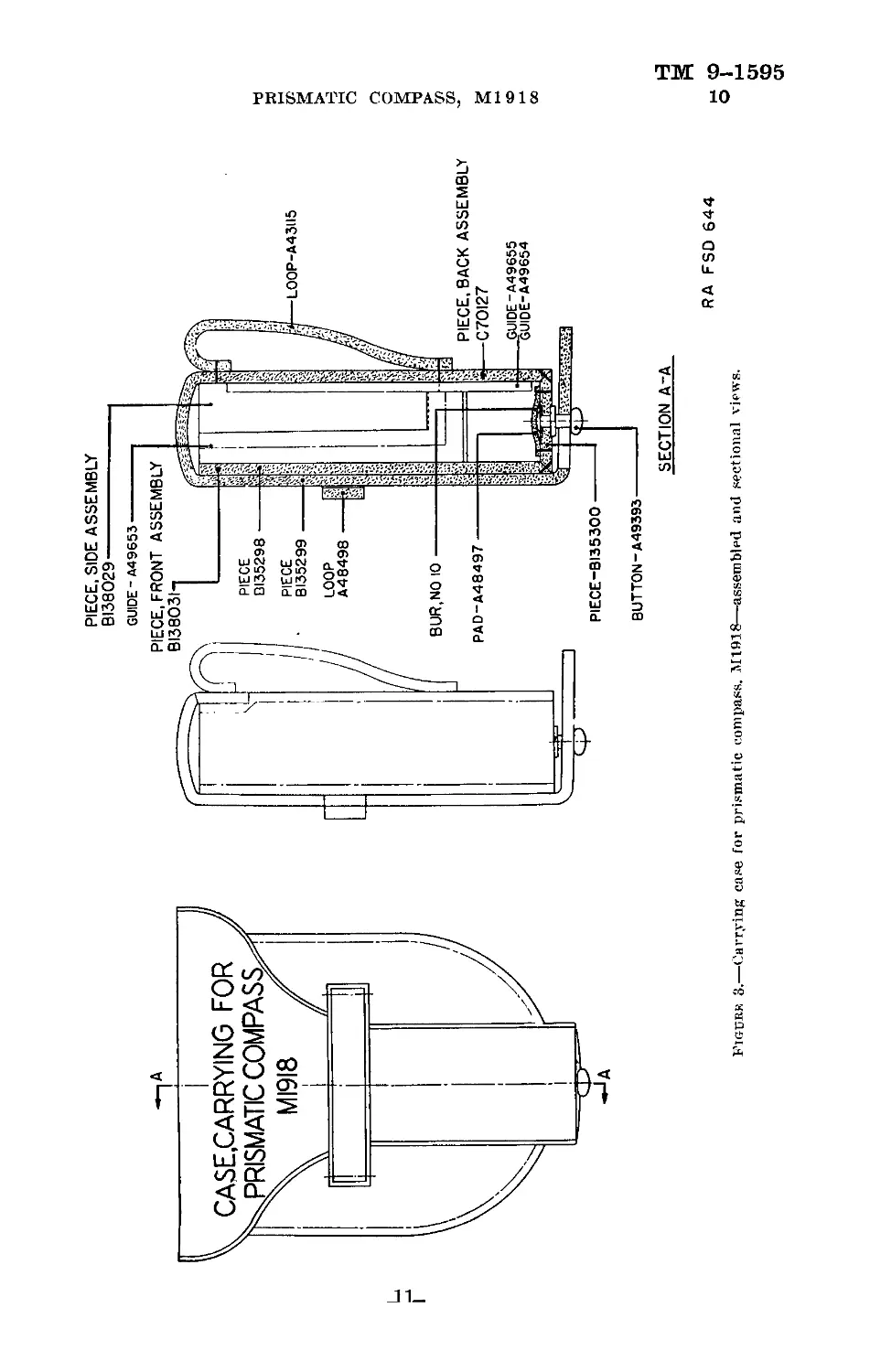
g. The instrument is furnished complete with carrying case (fig. 3).
h. Prismatic compass, M1918, without tripod, and manufactured
by the Sperry Gyroscope Company, is a limited standard item for
issue by the Ordnance Department. These compasses are graduated
in mils and are distinguished from the compasses issued by the
Engineer Corps which are graduated in degrees. The tripod
previously issued with this item is now not authorized.
Section III
OPERATION AND ADJUSTMENT
Paragraph
Operation_________________________________________________ 5
Field test and adjustment--------------------------------- 6
5. Operation.—a. To measure angles of site, raise the leaf sight
and the rear sight. Pull out the clinometer wedge knob to permit
free rotation of the clinometer dial. Focus the rear sight on the
clinometer (white) dial, sliding the sight as required. Hold the in-
strument with the dials in a vertical plane, look through the niche in
the rear sight, and elevate or depress the instrument until the object
observed is in line with the leaf sight vane. The angle of site, re-
flected in the rear sight prism, will also be visible in the center of
the field of view. The angle of site scale (the outer scale on the cli-
nometer dial) is graduated at 5-mil intervals and numbered at 100-mil
intervals; the 50-mil points are also marked. A 300-mil indication
corresponds to a level line of sight, as on the corresponding scales of
range quadrants. The clinometer wedge knob may be partially de-
pressed to damp out oscillations; it must not be depressed when taking
the reading.
b. To measure azimuths, first operate the instrument in angle of
site until the compass (green) dial is exposed at the rear sight by
the cutaway portion of the clinometer (white) dial. Depress the
clinometer wedge knob. Raise the leaf sight and the rear sight.
Focus the rear sight on the compass (green) dial, sliding the sight as
required. Hold the instrument in the hand or support it on a con-
venient nonmagnetic body, look through the niche in the rear sight,
and rotate the instrument in azimuth until the object observed is in
line with the leaf sight vane. The magnetic azimuth, reflected in
3
ТМ 9—1595
5—7
ORDNANCE DEPARTMENT
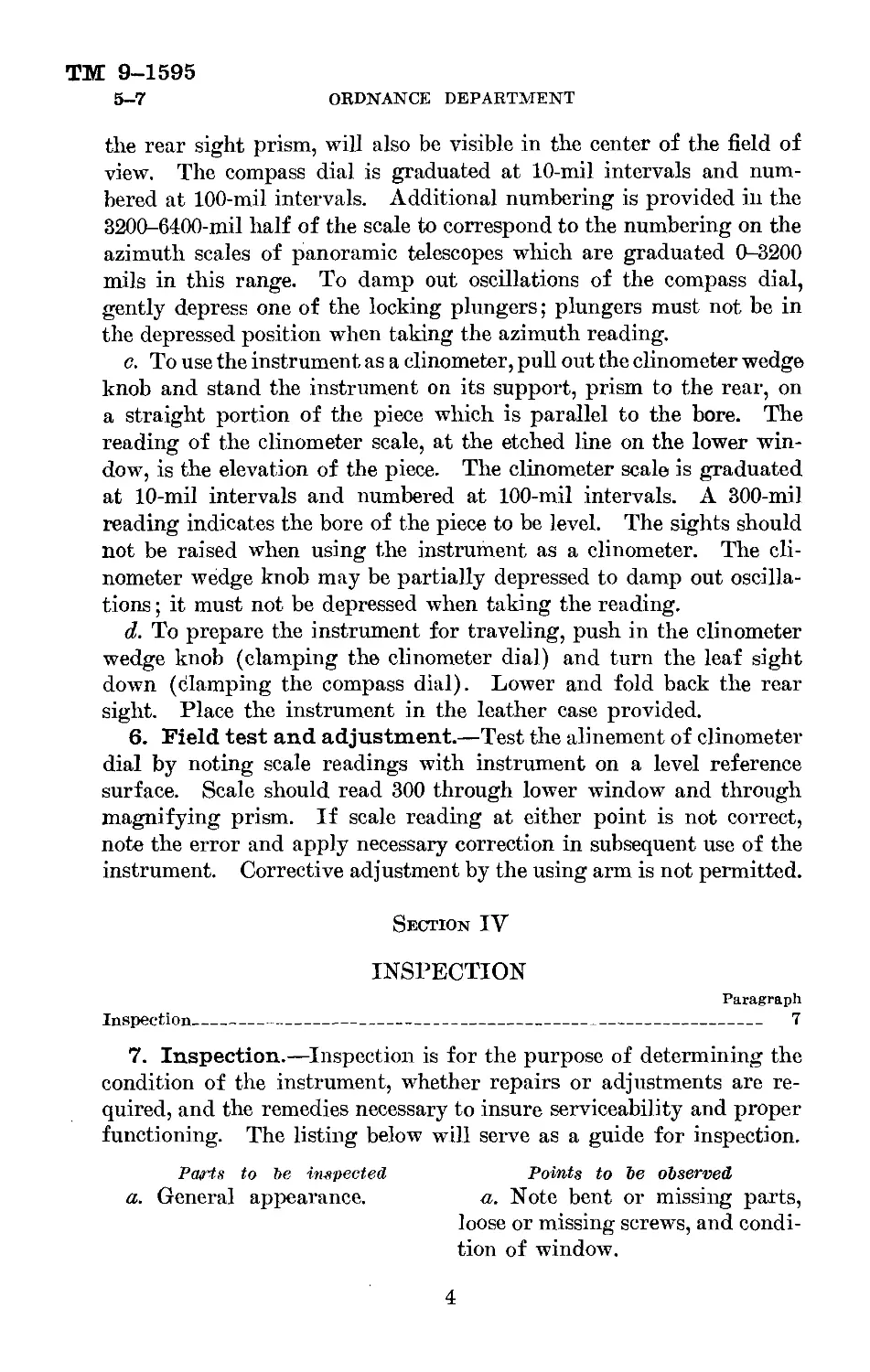
the rear sight prism, will also be visible in the center of the field of
view. The compass dial is graduated at 10-mil intervals and num-
bered at 100-mil intervals. Additional numbering is provided in the
3200-6400-mil half of the scale to correspond to the numbering on the
azimuth scales of panoramic telescopes which are graduated 0-3200
mils in this range. To damp out oscillations of the compass dial,
gently depress one of the locking plungers; plungers must not be in
the depressed position when taking the azimuth reading.
c. To use the instrument as a clinometer, pull out the clinometer wedge
knob and stand the instrument on its support, prism to the rear, on
a straight portion of the piece which is parallel to the bore. The
reading of the clinometer scale, at the etched line on the lower win-
dow, is the elevation of the piece. The clinometer scale is graduated
at 10-mil intervals and numbered at 100-mil intervals. A 300-mil
reading indicates the bore of the piece to be level. The sights should
not be raised when using the instrument as a clinometer. The cli-
nometer wedge knob may be partially depressed to damp out oscilla-
tions ; it must not be depressed when taking the reading.
d. To prepare the instrument for traveling, push in the clinometer
wedge knob (clamping the clinometer dial) and turn the leaf sight
down (clamping the compass dial). Lower and fold back the rear
sight. Place the instrument in the leather case provided.
6. Field test and adjustment.—Test the alinement of clinometer
dial by noting scale readings with instrument on a level reference
surface. Scale should read 300 through lower window and through
magnifying prism. If scale reading at either point is not correct,
note the error and apply necessary correction in subsequent use of the
instrument. Corrective adjustment by the using arm is not permitted.
Section IV
INSPECTION
Paragraph
Inspection___________________________________________________ 7
7. Inspection.—Inspection is for the purpose of determining the
condition of the instrument, whether repairs or adjustments are re-
quired, and the remedies necessary to insure serviceability and proper
functioning. The listing below will serve as a guide for inspection.
Parts to be inspected Points to Ъе observed
a. General appearance. a. Note bent or missing parts,
loose or missing screws, and condi-
tion of window.
4
TM 9-1595
7
PRISMATIC COMPASS, M1918
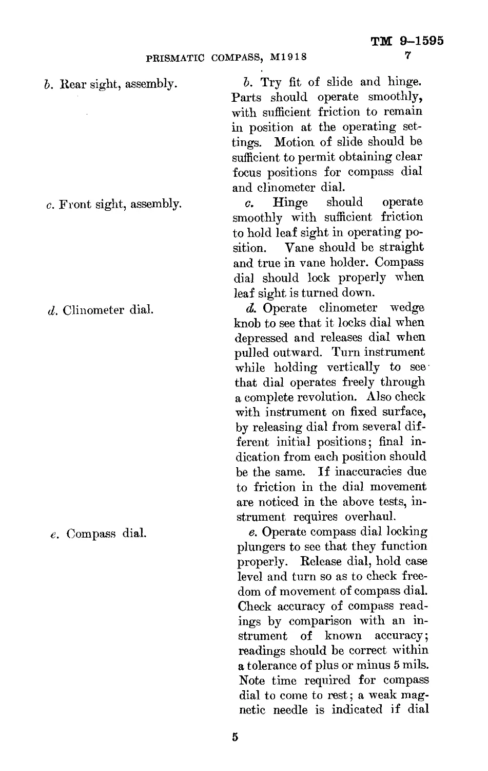
Ъ. Rear sight, assembly. Ъ. Try fit of slide and hinge. Parts should operate smoothly, with sufficient friction to remain in position at the operating set- tings. Motion of slide should be sufficient to permit obtaining clear focus positions for compass dial and clinometer dial.
c. Front sight, assembly. c. Hinge should operate smoothly with sufficient friction to hold leaf sight in operating po- sition. Vane should be straight and true in vane holder. Compass dial should lock properly when leaf sight is turned down.
d. Clinometer dial. d. Operate clinometer wedge knob to see that it locks dial when depressed and releases dial when pulled outward. Turn instrument while holding vertically to see that dial operates freely through a complete revolution. Also check with instrument on fixed surface, by releasing dial from several dif- ferent initial positions; final in- dication from each position should be the same. If inaccuracies due to friction in the dial movement are noticed in the above tests, in- strument requires overhaul.
e. Compass dial. e. Operate compass dial locking plungers to see that they function properly. Release dial, hold case level and turn so as to check free- dom of movement of compass dial. Check accuracy of compass read- ings by comparison with an in- strument of known accuracy; readings should be correct within a tolerance of plus or minus 5 mils. Note time required for compass dial to come to rest; a weak mag- netic needle is indicated if dial
5
ТМ 9-1595
7-8 ORDNANCE DEPARTMENT
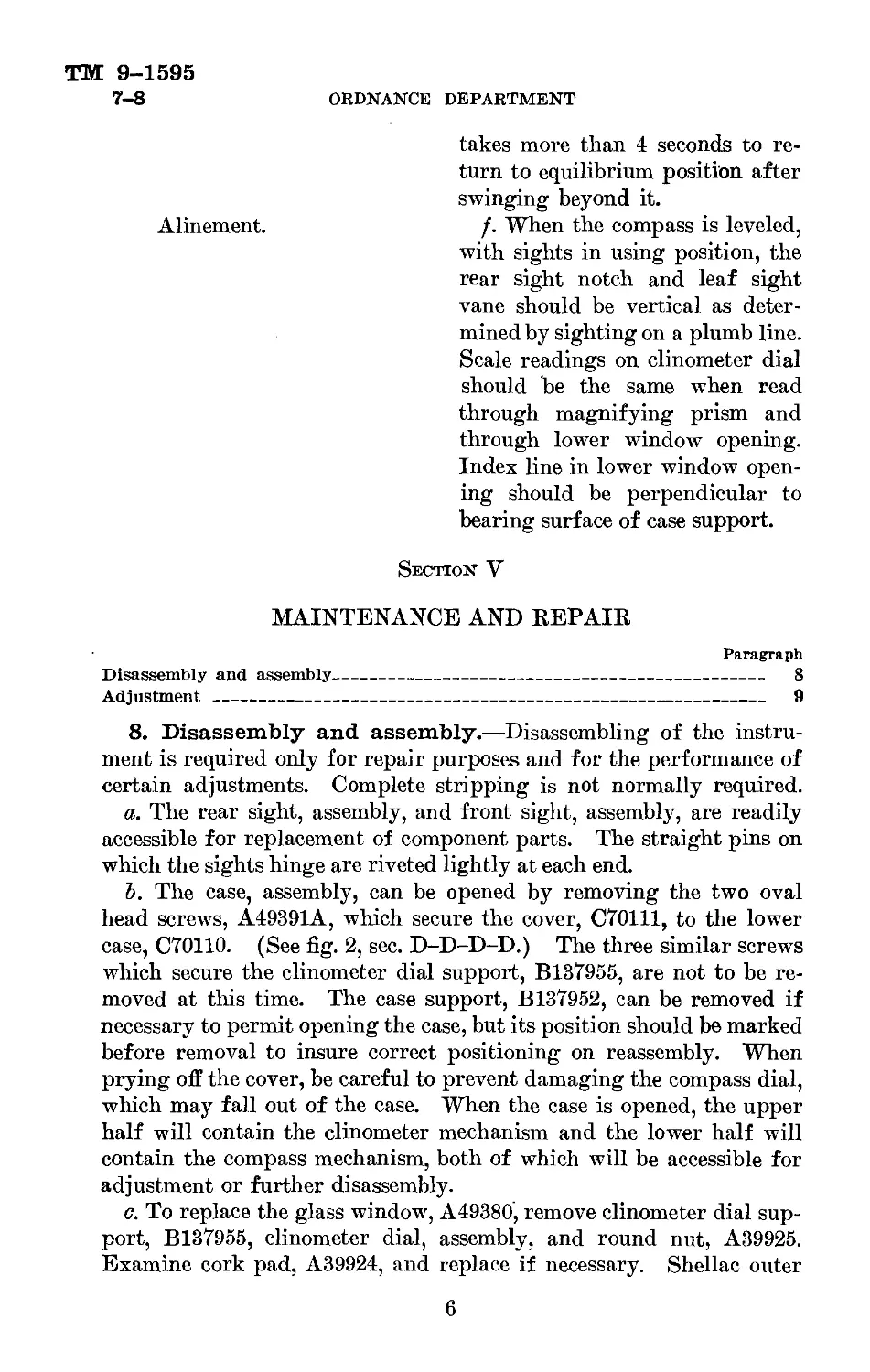
takes more than 4 seconds to re-
turn to equilibrium position after
swinging beyond it.
Alinement. f. When the compass is leveled,
with sights in using position, the
rear sight notch and leaf sight
vane should be vertical as deter-
mined by sighting on a plumb line.
Scale readings on clinometer dial
should be the same when read
through magnifying prism and
through lower window opening.
Index line in lower window open-
ing should be perpendicular to
bearing surface of case support.
Section V
MAINTENANCE AND REPAIR
Paragraph
Disassembly and assembly_____________________________________________ 8
Adjustment----------------------------------------------------------- 9
8. Disassembly and assembly.—Disassembling of the instru-
ment is required only for repair purposes and for the performance of
certain adjustments. Complete stripping is not normally required.
a. The rear sight, assembly, and front sight, assembly, are readily
accessible for replacement of component parts. The straight pins on
which the sights hinge are riveted lightly at each end.
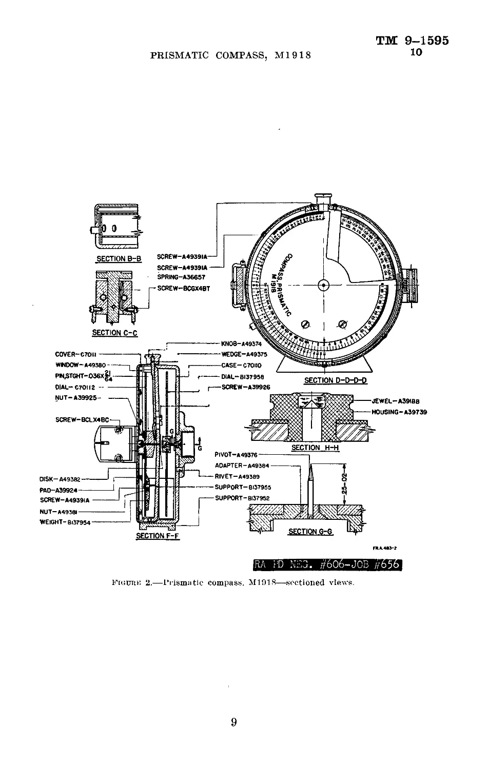
Ъ. The case, assembly, can be opened by removing the two oval
head screws, A49391A, which secure the cover, C70111, to the lower
case, C70110. (See fig. 2, sec. D-D-D-D.) The three similar screws
which secure the clinometer dial support, B137955, are not to be re-
moved at this time. The case support, B137952, can be removed if
necessary to permit opening the case, but its position should be marked
before removal to insure correct positioning on reassembly. When
prying off the cover, be careful to prevent damaging the compass dial,
which may fall out of the case. When the case is opened, the upper
half will contain the clinometer mechanism and the lower half will
contain the compass mechanism, both of which will be accessible for
adjustment or further disassembly.
c. To replace the glass window, A49380, remove clinometer dial sup-
port, B137955, clinometer dial, assembly, and round nut, A39925.
Examine cork pad, A39924, and replace if necessary. Shellac outer
6
ТМ 9-1595
PRISMATIC COMPASS, Ml 9 18 8-10
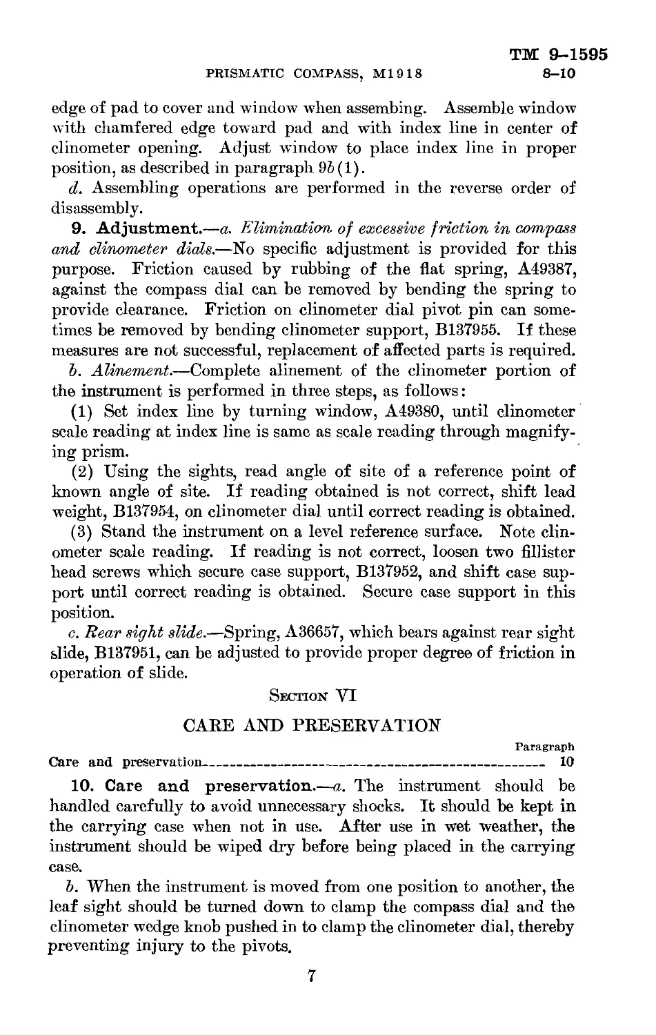
edge of pad to cover and window when assembing. Assemble window
with chamfered edge toward pad and with index line in center of
clinometer opening. Adjust window to place index line in proper
position, as described in paragraph 96(1).
d. Assembling operations are performed in the reverse order of
disassembly.
9. Adjustment.—a. Elimination of excessive friction in compass
and clinometer dials.—No specific adjustment is provided for this
purpose. Friction caused by rubbing of the flat spring, A49387,
against the compass dial can be removed by bending the spring to
provide clearance. Friction on clinometer dial pivot pin can some-
times be removed by bending clinometer support, B137955. If these
measures are not successful, replacement of affected parts is required.
Ъ. Alinement.—Complete alinement of the clinometer portion of
the instrument is performed in three steps, as follows:
(1) Set index line by turning window, A49380, until clinometer
scale reading at index line is same as scale reading through magnify-
ing prism.
(2) Using the sights, read angle of site of a reference point of
known angle of site. If reading obtained is not correct, shift lead
weight, B137954, on clinometer dial until correct reading is obtained.
(3) Stand the instrument on a level reference surface. Note clin-
ometer scale reading. If reading is not correct, loosen two fillister
head screws which secure case support, B137952, and shift case sup-
port until correct reading is obtained. Secure case support in this
position.
c. Rear sight slide.—Spring, A36657, which bears against rear sight
slide, В137951, can be adjusted to provide proper degree of friction in
operation of slide.
Section VI
CARE AND PRESERVATION
Paragraph
Care and preservation_____________________________________ 10
10. Care and preservation.—a. The instrument should be
handled carefully to avoid unnecessary shocks. It should be kept in
the carrying case when not in use. After use in wet weather, the
instrument should be wiped dry before being placed in the carrying
case.
Ъ. When the instrument is moved from one position to another, the
leaf sight should be turned down to clamp the compass dial and the
clinometer wedge knob pushed in to clamp the clinometer dial, thereby
preventing injury to the pivots.
7
ТМ 9-1595
10
ORDNANCE DEPARTMENT
c. Particular care should be taken to prevent bending of the leaf
sight vane or leaf sight vane holder.
d. Moisture due to condensation may collect in the instrument when
the temperature of the parts is lower than that of the surrounding air.
This moisture, if not excessive, can be removed by placing the instru-
ment in a warm place.
e. No lubrication is required for this instrument.
8
TM 9-1595
10
PRISMATIC COMPASS, Ml 9 18
SECTION B-B
SCREW-A4939IA—
SCREW—BCGX4BT
SECTION C-C
SCREW-A4939IA----
SPRWG-A36G57
DIAL—BI37958
I---SCREW-A39926
C0VER-C7OHI
-CASE-C 70U0
SECTION D-D-D-D
NUT-A39925-
DISK—A49382
SffitKA
KN0B-A49374
• WEDGE-A49375
NUT—A493BI—
WEIGHT- BI37954
WND0W-A49380-
PWiSTGHT-jO36X^-
OIAL—C7O1I2----
JEWEL—A39IBB
H0USING-A39739
SECTION H-H
PlVOT—A49376
ADAPTER-A49384
RIVET—A493S9
SUPPORT-BI37955
SUPP0RT-BI37952
SECTION F-F
SCREW-BCLX4BC
PAD-A39924
SCREW-A4939IA
<M
SECTION G-G
FRA.4N-2
RA PD NEG. ff'6O6-JOB ff656j
Figure 2.—Prismatic compass. M1918—sectioned views.
9
ТМ 9-1595
10
ORDNANCE DEPARTMENT
pin.stght-tUI
io 4
SIGHT- BI37950
HOLDER-6137957
VANE-A49392---
----SPACER-A4937I PIN,STGHT-^xll
----PRISM-A49372 BAR-A49378
ADAPTER-BI37953-J
— SCREW—A39923
•WASHER-A49377
SECTION E-E
ORD 14608
Figure 2.—Prismatic compass, M1918—sectional views—Continued.
10
PIECE, SIDE ASSEMBLY
BI38029-----------
GUIDE - A49653
PIECE, FRONT ASSEMBLY
BUTTON-A49393
SECTION A~A
RA FSD 644
О
Figukh 3.—Carrying case for prismatic compass. 311918—assembled and sectional views.
CO
СЛ
ТМ 9-1595
ORDNANCE DEPARTMENT
Appendix
LIST of REFERENCES
1. Standard Nomenclature List.
Compass, prismatic, M1918 (Sperry type)_____________SNL F-23
2. Technical Manuals.
Materiel inspection and repair______________________TM 9-1100
[A. G. 062.11 (5-26-41).]
By ORDER OF THE SECRETARY OF War :
G. C. MARSHALL,
Chief of Staff.
Official :
E. S. ADAMS,
Major General,
The Adjutant General.
Distribution :
В and H (6); R 2,4-7,17 (2); Bn 9 (2); IC 9 (4).
(For explanation of symbols, see FM 21-6.)
12
V. S. GOVERNMENT PRINTING OFFICE: 194!
For sale by the Superintendent of Documents, Washington, D. C.
Price 5 cents