/


Tags: radio
Year: 1024


Text
UNITED STATES ARMY
TRAINING MANUAL No. 26
RADIO OPERATOR
STUDENTS MANUAL
FOR Al L ARMS
Part I. RADIO SETS
пгглио t хики так oimxctio» or
TDK CHIFF SIGNAL OFFICER
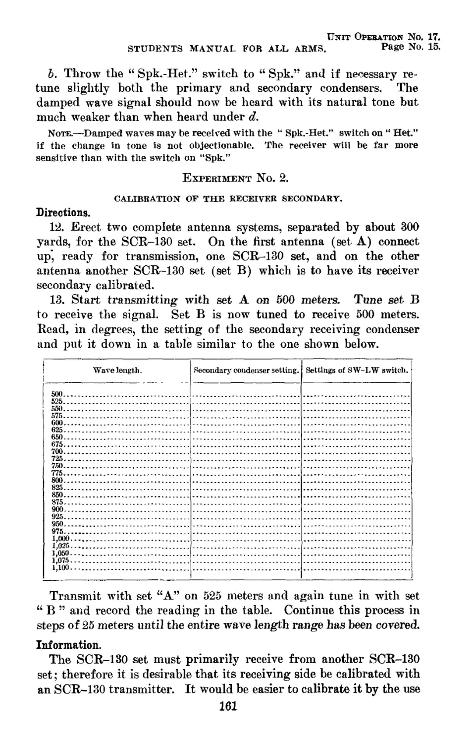
1924
STANFORD J.
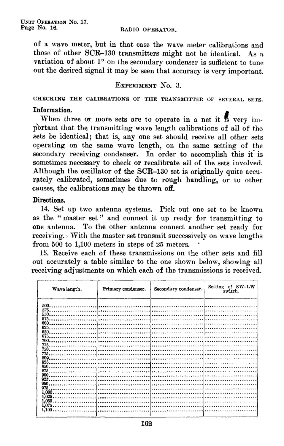
JUN I . '
WKMilNDT >X
GOVEKSMFST rWNTIS . ОГПСЕ
I.T4
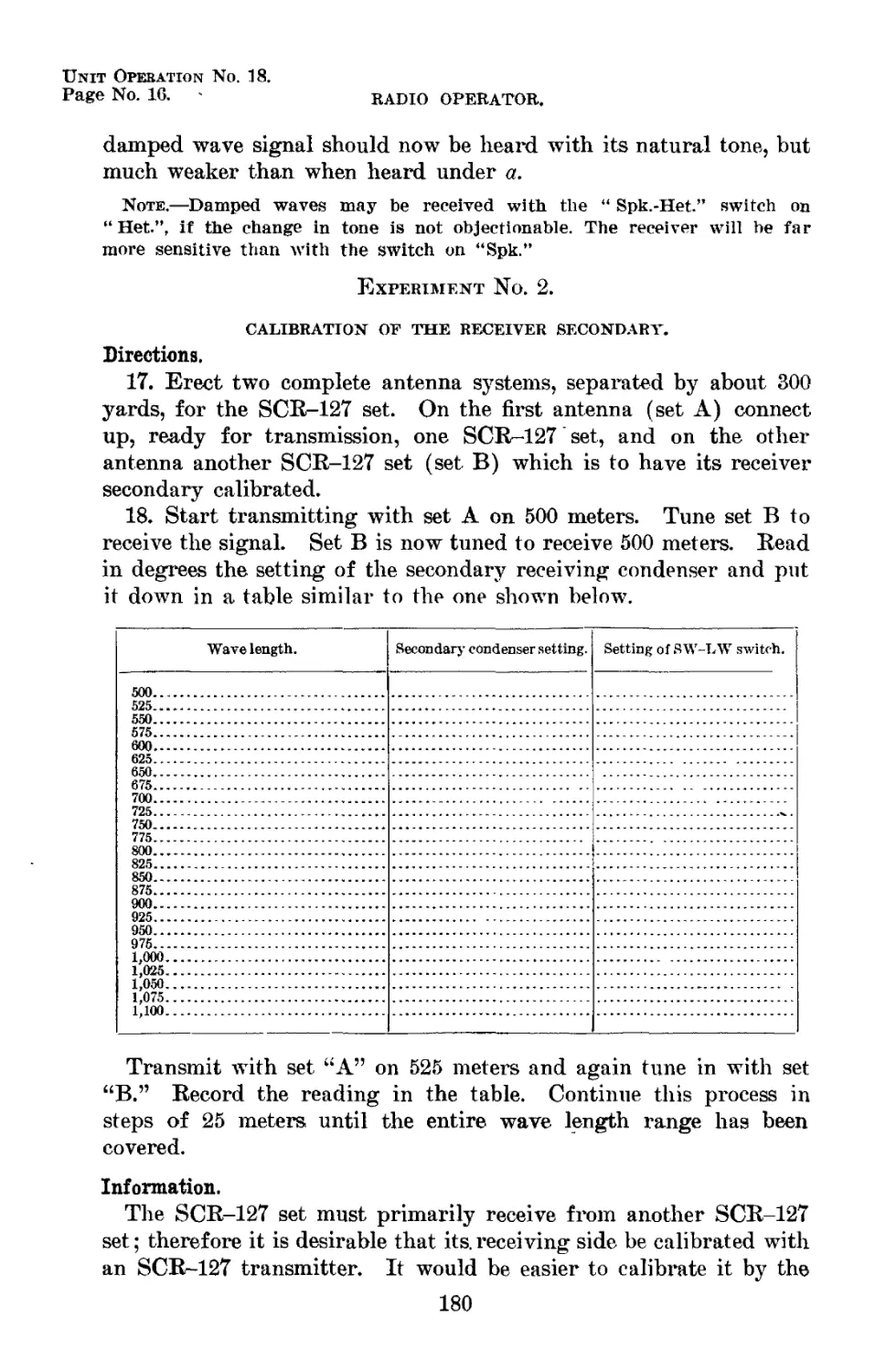
UNITED STATES ARMY
TRAINING MANUAL No. 26
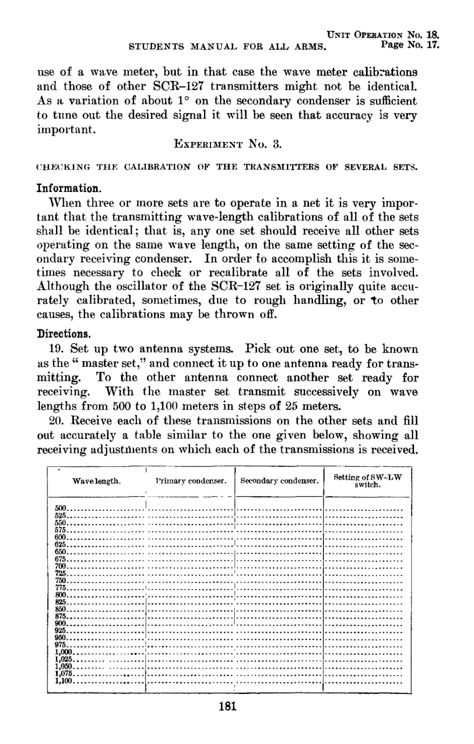
RADIO OPERATOR
STUDENTS MANUAL
FOR ALL ARMS
Part I. RADIO SETS
PREPARED UNDER THE DIRECTION OF
THE CHIEF SIGNAL OFFICER
1924
STANFORD J. WOOD
WASHINGTON
GOVERNMENT PRINTING OFFICE
1924
Certificate : By direction of the Secretary of War, the matter
contained herein is published as administrative Information and
is required for the proper transaction of the public business.
(n)
WAR DEPARTMENT,
Washington, December 27,1923.
Manuals for training in the Army are to be prepared and revised
from time to time by the branches of the service concerned, and
when approved, published by The Adjutant General of the Army
in pamphlet form in a series of training manuals.
In accordance with this plan there has been prepared by the
Signal Corps a series of pamphlets relating to signal communication
specialists.
The pamphlets in this series are titled as follows:
Training Manual No, 20—Basic Signal Communication, Students
Manual.
Training Manual No. 21—Basic Signal Communication, Instruc-
tors Guide.
Training Manual No. 22—Telephone Switchboard Operator, Stu-
dents Manual.
Training Manual No. 23—Telephone Switchboard Operator, In-
structors Guide.
Training Manual No. 24—Message Center Specialist, Students
Manual.
Training Manual No. 25—Message Center Specialist, Instructors
Guide.
Training Manual No. 26—Radio Operator, Students Manual.
Training Manual No. 27—Radio Operator, Instructors Guide.
Training Manual No. 32—The Pigeoneer, Students Manual.
This pamphlet is published for the information and guidance of
all concerned.
By order or the Secretary of War:
JOHN J. PERSHING,
General of the Armies,
Chief of Staff.
Official :
ROBERT C. DAVIS,
The Adjutant General.
(m)
5. The several unit operations constituting this manual have been
prepared in accordance with the minimum specifications for the
Radio Operator published by the Adjutant General of the Army.
These specifications do not require instruction in radio theory. In
this connection it should be noted that the Signal Corps policy with
respect to instruction, as embodied in this manual, departs from the
usual procedure which consists in teaching theory first and practice
second, by teaching the practical first and permitting theoretical
knowledge to grow spontaneously out of this practical training.
6. The essential element in training radio operators is the reduc-
tion of the time required for training to the minimum. What this
minimum is and the best ways of attaining it must be determined
in peace time and not left undecided until a national emergency
arises. The second essential element in any program of training is
the complement of the first, that the method adopted for war train-
ing shall be identical with that for peace training. The methods
devised in peace must be so well tried and so trustworthy that they
will not be abandoned when an emergency arises. At such a time
to devise and install new methods and to spread these throughout
the Army requires considerable time that had better be spent upon
the actual training itself.
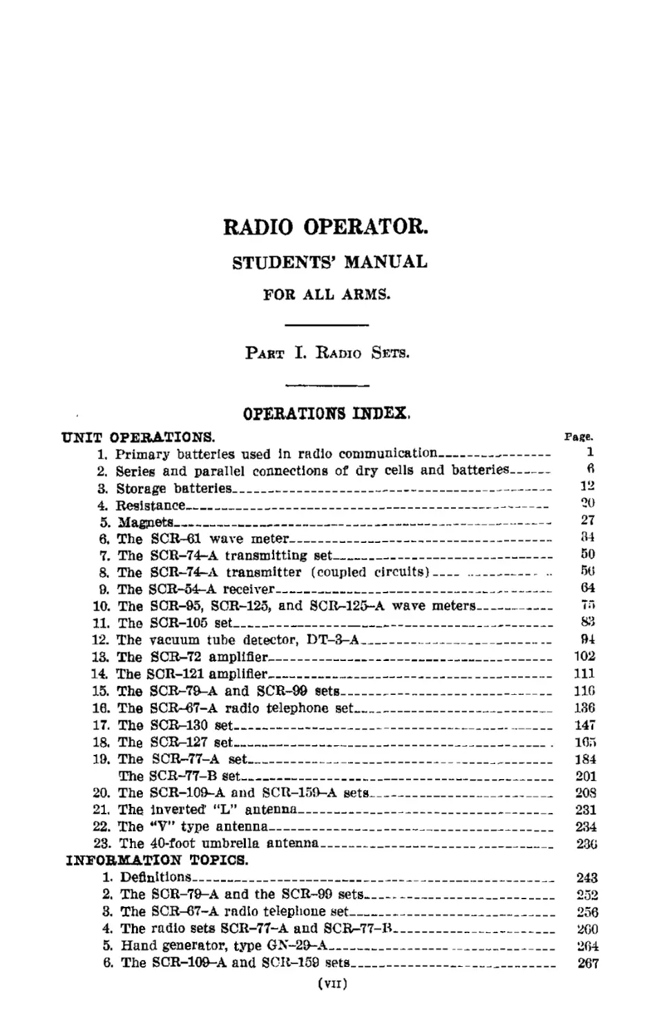
RADIO OPERATOR.
STUDENTS’ MANUAL
FOR ALL ARMS.
Раит I. Radio Sets.
OPERATIONS INDEX.
UNIT OPERATIONS. Page.
1. Primary batteries used in radio communication------------- 1
2. Series and parallel connections of dry cells and batteries- 6
3. Storage batteries__________________________________________ 1^
4. Resistance------------------------------------------------- 20
5. Magnets---------------------------------------------------- 27
6. The SCR-61 wave meter-------------------------------------- 34
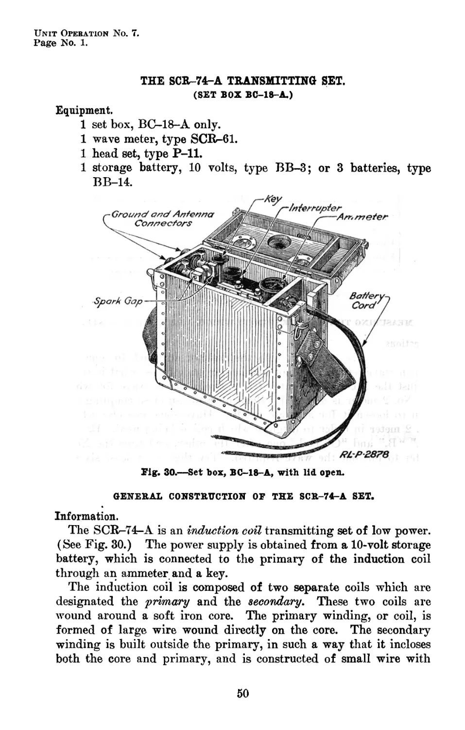
7. The SCR-74r-A transmitting set----------------------------- 50
8. The SCR-74-A transmitter (coupled circuits)------------ - 56
9. The SOR-54-A receiver-------------------------------------- 64
10. The SOR-95, SCR-125, and SCRr-125-А wave meters----------- 73
11. The SOR-105 set__________________________________________ 813
12. The vacuum tube detector, DT-3-A___________________ 94
13. The SCR-72 amplifier_____________________________________ 102
14. The SOR-121 amplifier,___________________________________ 111
15. The SCR-79-A and SCR-99 sets______.________________________ 116
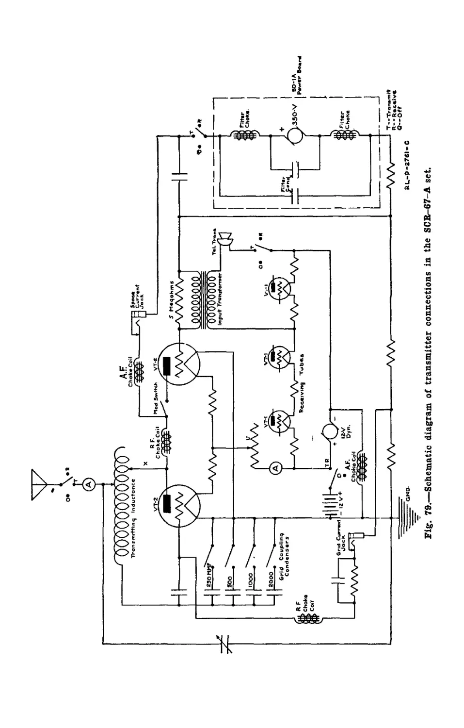
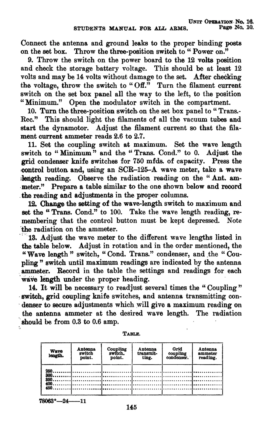
16. The SCR-67-A radio telephone set_________________________ 136
17. The SCRr-130 set_________________________________________ 147
18. The SCR-127 set__________________________________________ 165
19. The SCRr-77-А set_______________________________________ 184
The SCR-77-B set_________________________________________ 201
20. The SCR-109-A and SCR-159-A sets_________________________ 208
21, The inverted’ “L” antenna-------------------------------- 231
22. The “V” type antenna------------------------------------- 234
23. The 40-foot umbrella antenna-----------------,------------ 236
INFORMATION TOPICS.
1. Definitions----------------------------------------------- 243
2. The SOR-79-A and the SCR-99 sets__________________________ 252
3. The SCR-67-A radio telephone set__________________________ 256
4. The radio sets SCR-77-A and SCB-77-B---------------------- 260
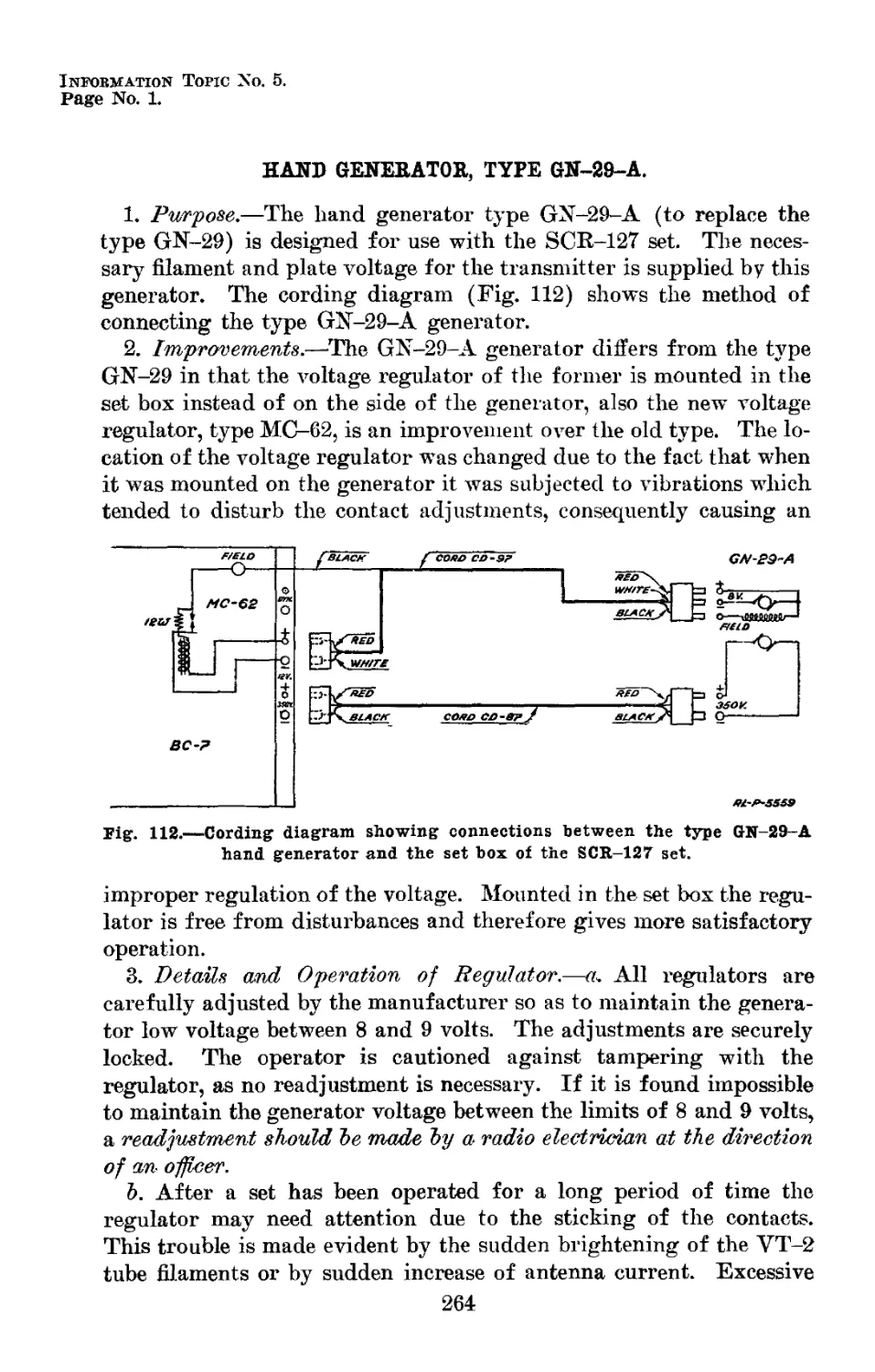
5. Hand generator, type GN-29-A______________________________ 264
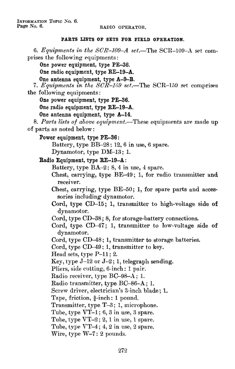
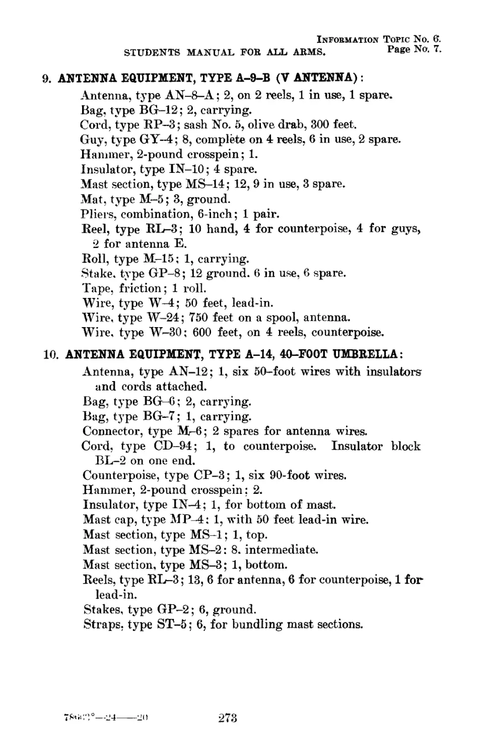
6. The SCR-109-A and SCR-159 sets____________________________ 267
(vii)
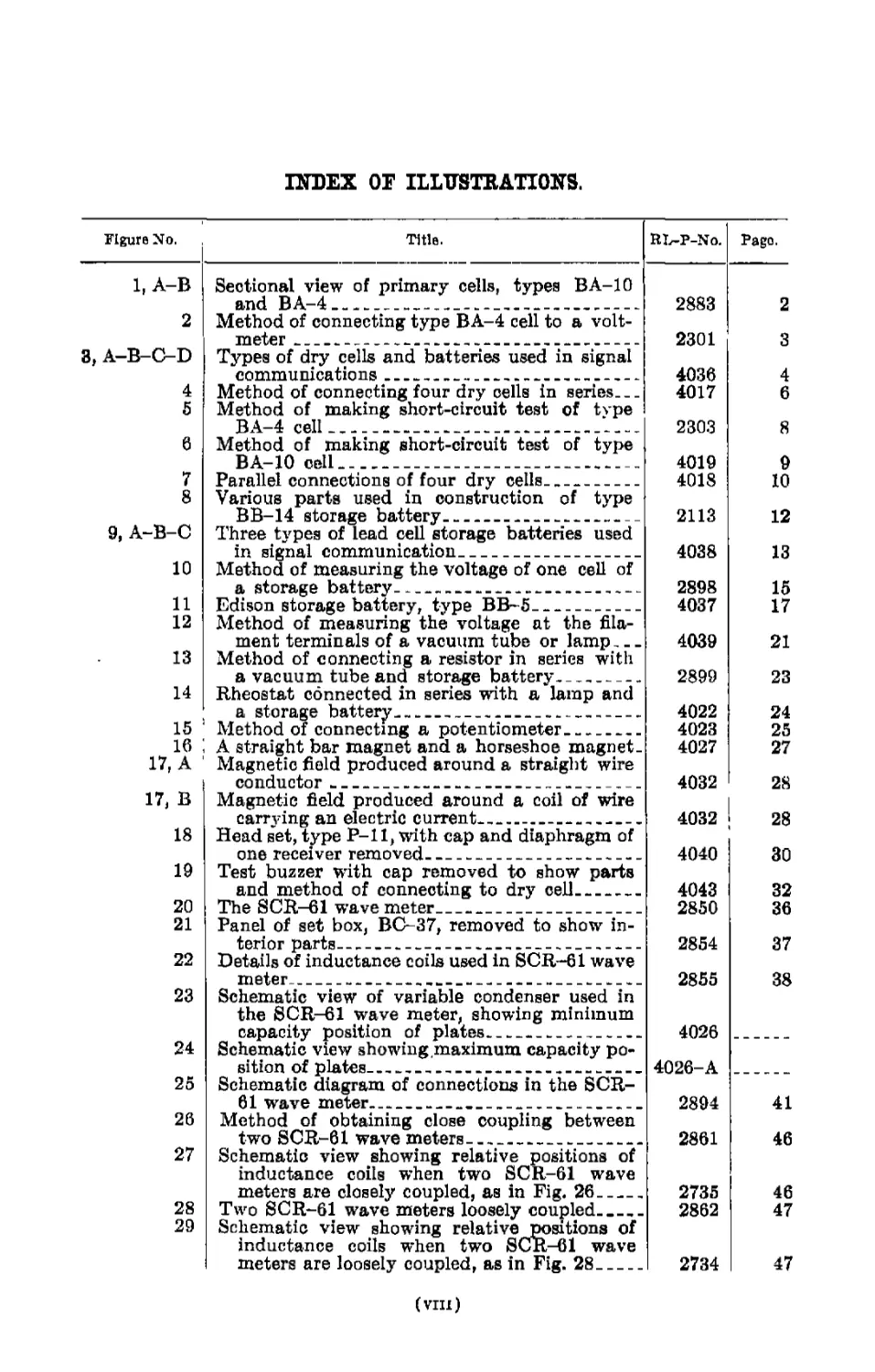
INDEX OF ILLUSTRATIONS.
Figure No. Title. RL-P-No. Pago.
1, A-B Sectional view of primary cells, types BA-10
2 and BA-4 Method of connecting type BA-4 cell to a volt- 2883 2
meter 2301 3
3, A-B-C-D Types of dry cells and batteries used in signal
communications 4036 4
4 Method of connecting four dry cells in series 4017 6
5 Method of making short-circuit test of type
BA-4 cell 2303 8
6 Method of making short-circuit test of type
BA-10 cell 4019 9
7 Parallel connections of four dry cells 4018 10
8 Various parts used in construction of type
9, A-B-C BB-14 storage battery 2113 12
Three types of lead cell storage batteries used
10 in signal communication 4038 13
Method of measuring the voltage of one cell of
a storage battery 2898 15
11 Edison storage battery, type BB-5 4037 17
12 Method of measuring the voltage at the fila-
ment terminals of a vacuum tube or lamp 4039 21
13 Method of connecting a resistor in series with
a vacuum tube and storage battery 2899 23
14 Rheostat connected in series with a lamp and
a storage battery 4022 24
15 Method of connecting a potentiometer 4023 25
16 A straight bar magnet and a horseshoe magnet. 4027 27
17, A Magnetic field produced around a straight wire
conductor 4032 28
17, В Magnetic field produced around a coil of wire
18 carrying an electric current 4032 28
Head set, type P-11, with cap and diaphragm of
19 one receiver removed 4040 30
Test buzzer with cap removed to show parts
and method of connecting to dry cell 4043 32
20 The SCR-61 wave meter 2850 36
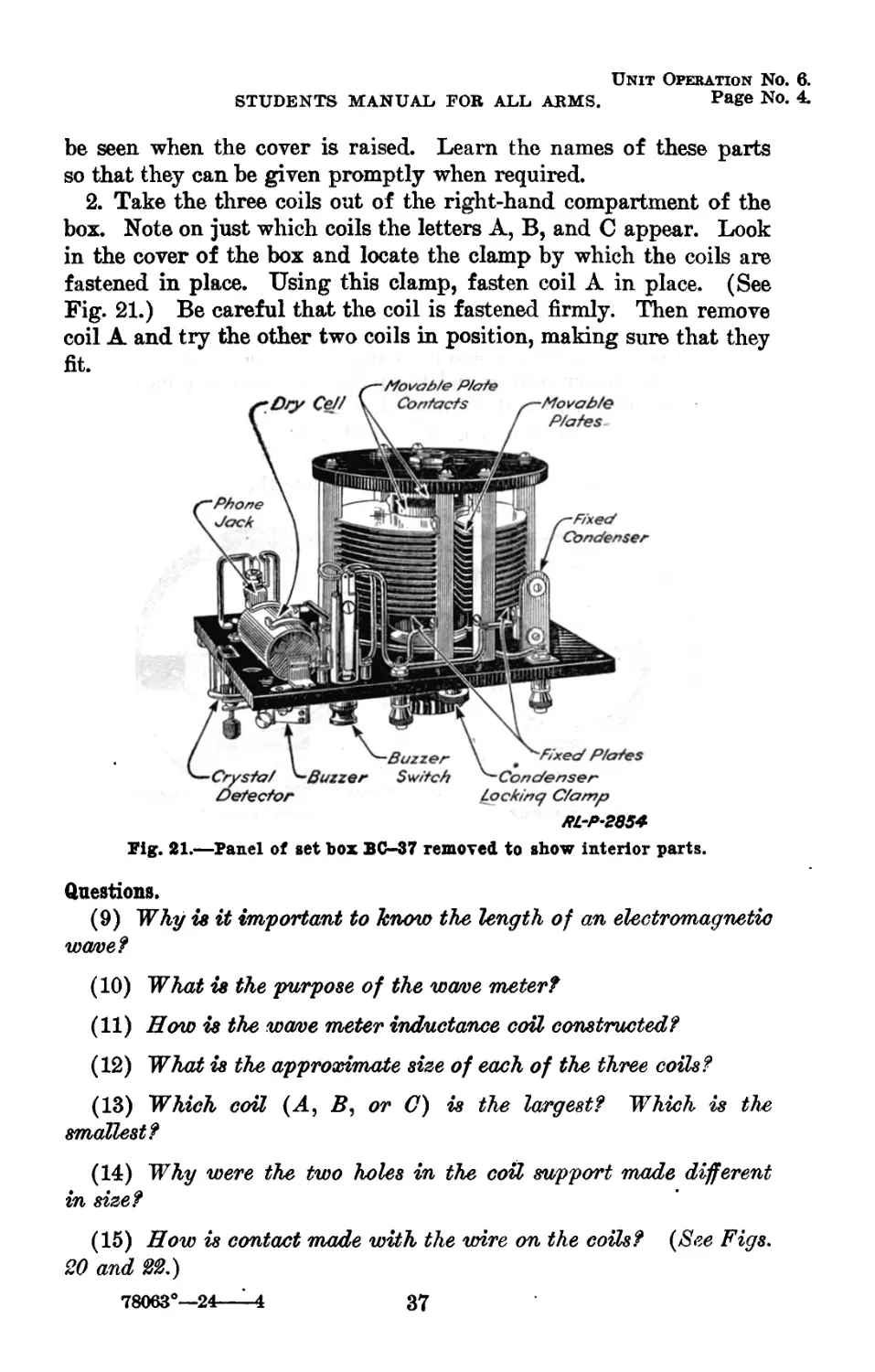
21 Panel of set box, BC-37, removed to show in-
22 terior parts 2854 37
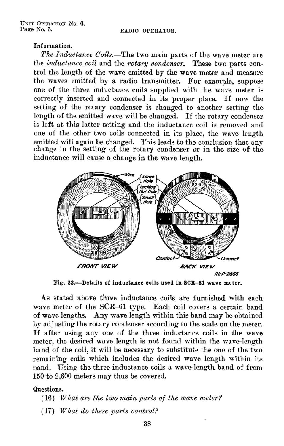
Details of inductance coils used in SCR-61 wave
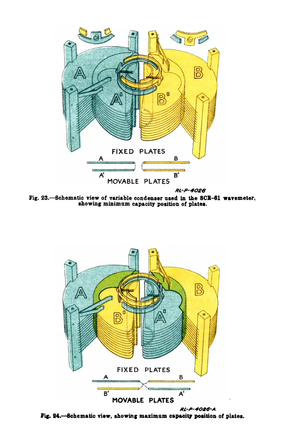
23 meter Schematic view of variable condenser used in 2855 38
the SCR-61 wave meter, showing minimum
24 capacity position of plates 4026
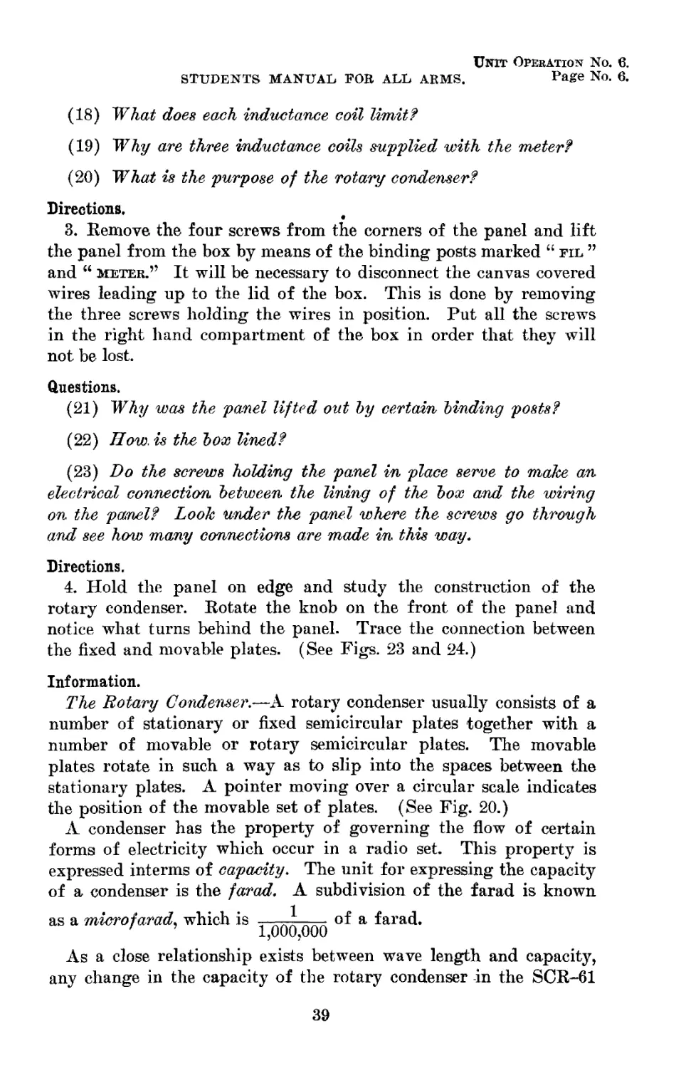
Schematic view showing,maximum capacity po-
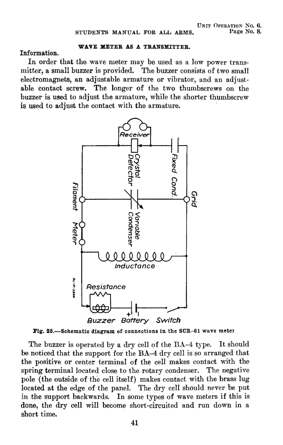
25 sition of plates Schematic diagram of connections in the SCR- 4026-A —
61 wave meter 2894 41
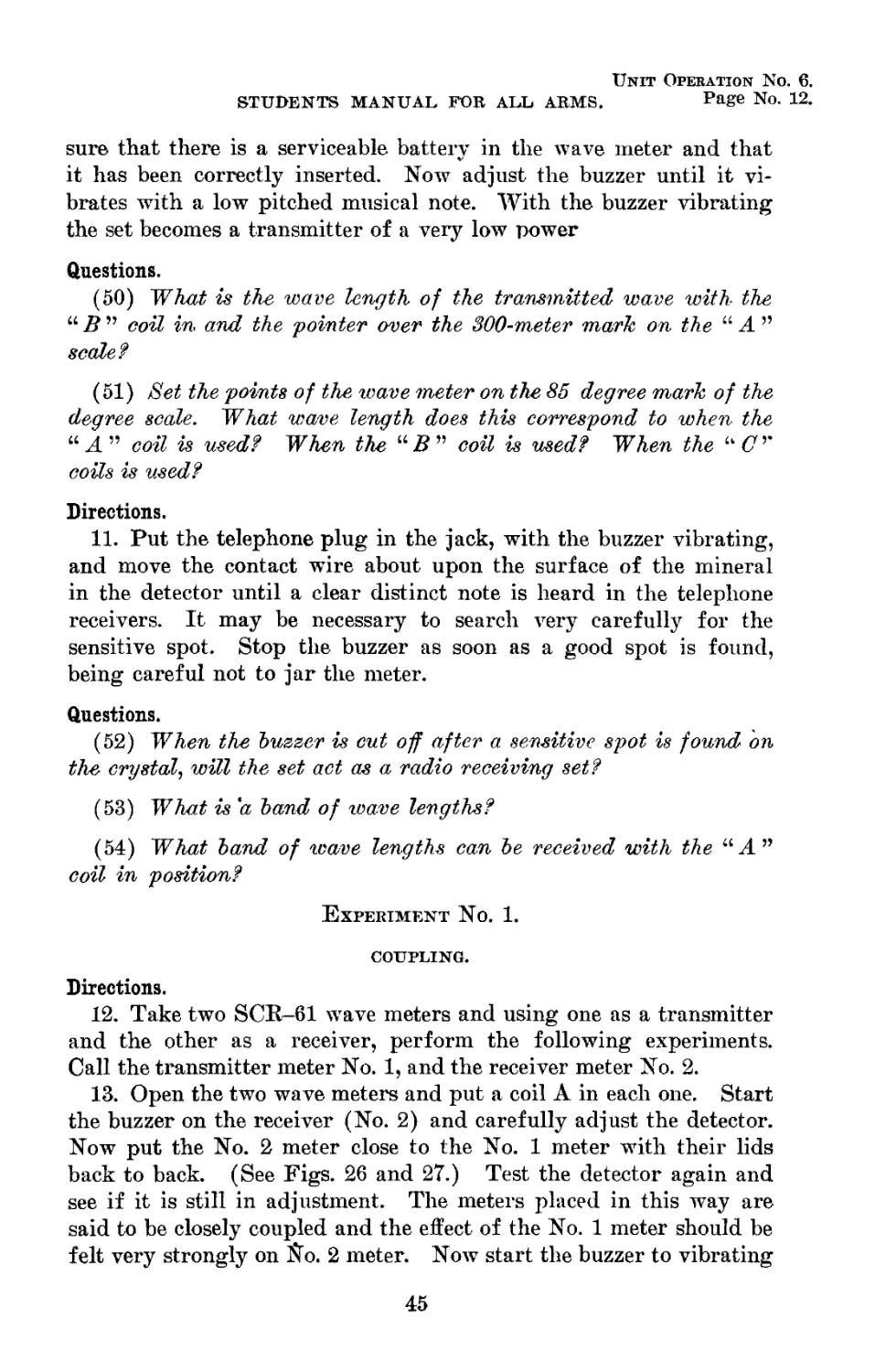
26 Method of obtaining close coupling between
27 two SCR-61 wave meters 2861 46
Schematic view showing relative positions of
inductance coils when two SCR-61 wave
meters are closely coupled, as in Fig. 26 2735 46
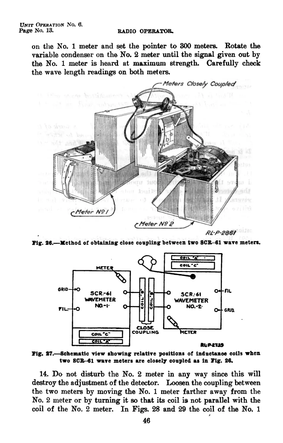
28 Two SCR-61 wave meters loosely coupled 2862 47
29 Schematic view showing relative positions of inductance coils when two SCR-61 wave
meters are loosely coupled, as in Fig. 28 2734 47
(VIII)
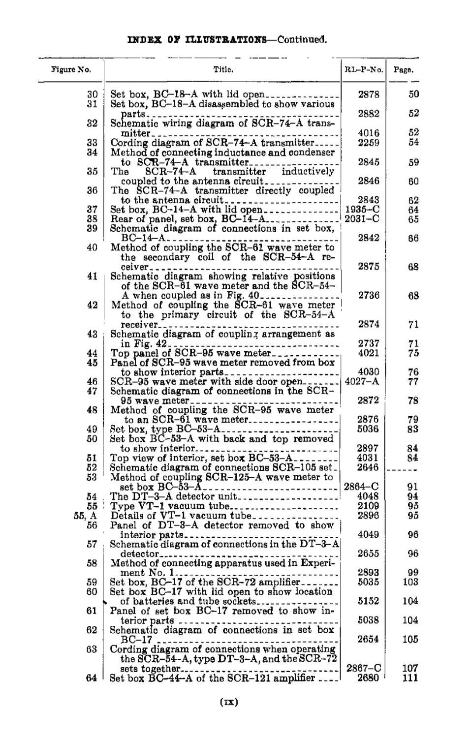
INDEX OF nXTTSTBATIONS—Continued.
Figure No.
Title.
RL-P-No.
Page.
30
31
32
33
34
35
36
37
38
39
40
41
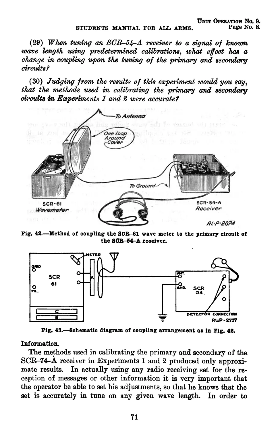
42
43
44
45
46
47
48
49
50
51
52
53
54 .
55
55, A
56
57
58
59
60
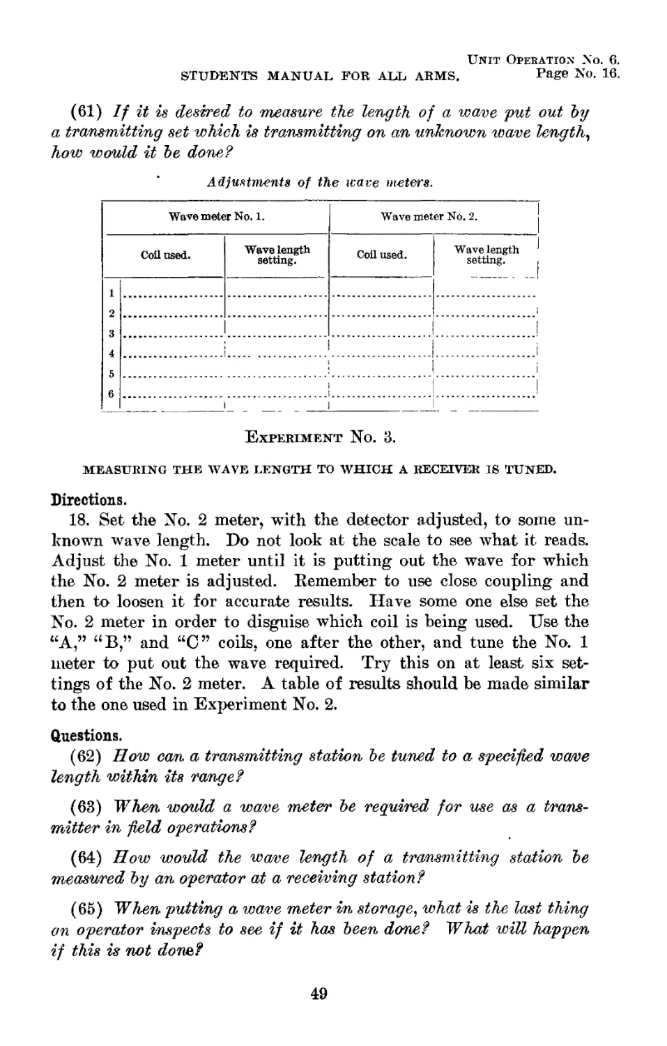
61
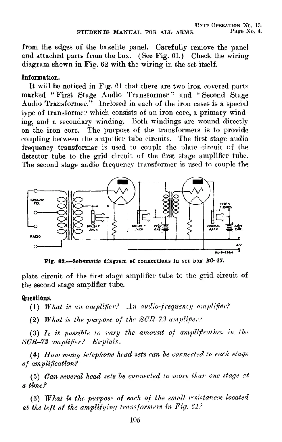
62
63
64
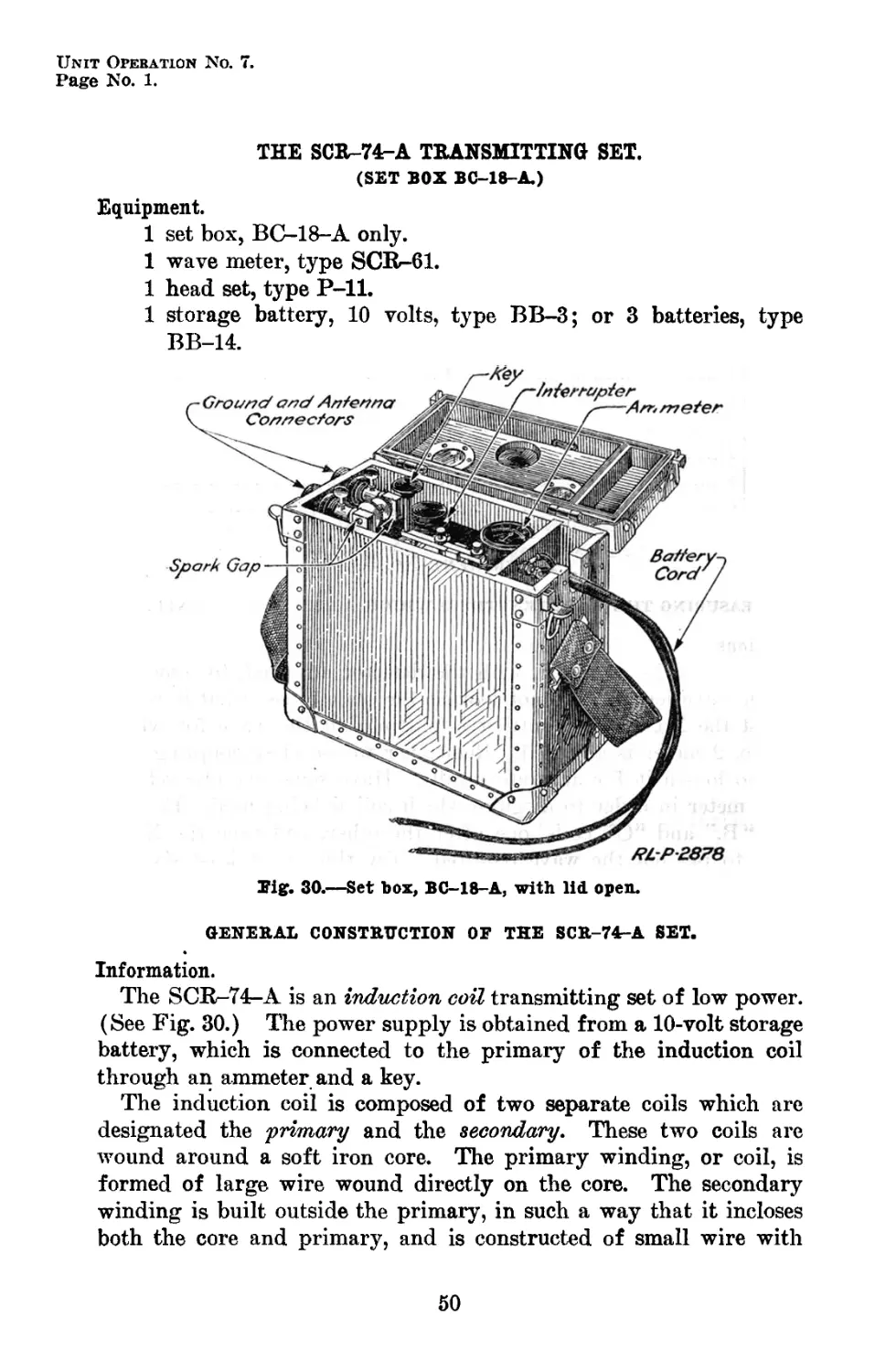
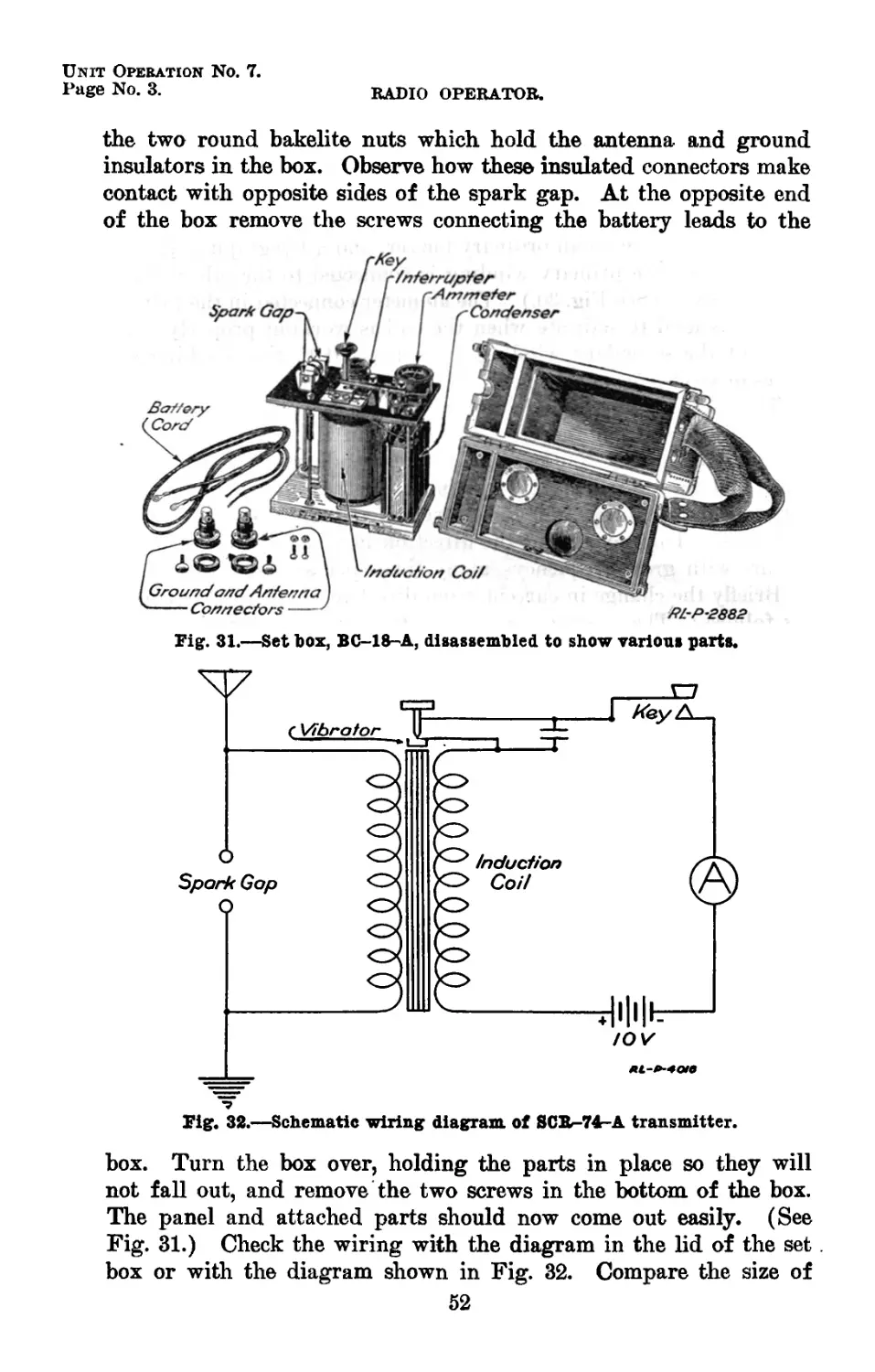
Set box, BC-18-A with lid open______________
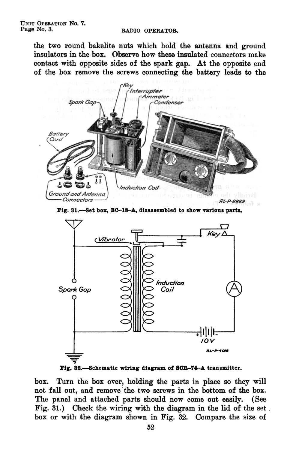
Set box, BC-IS-Л disassembled to show various
parts_______________________________________
Schematic wiring diagram of SCR-74-A trans-
mitter______________________________________
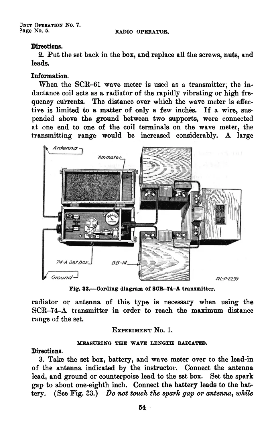
Cording diagram of SCR-74-A transmitter-----
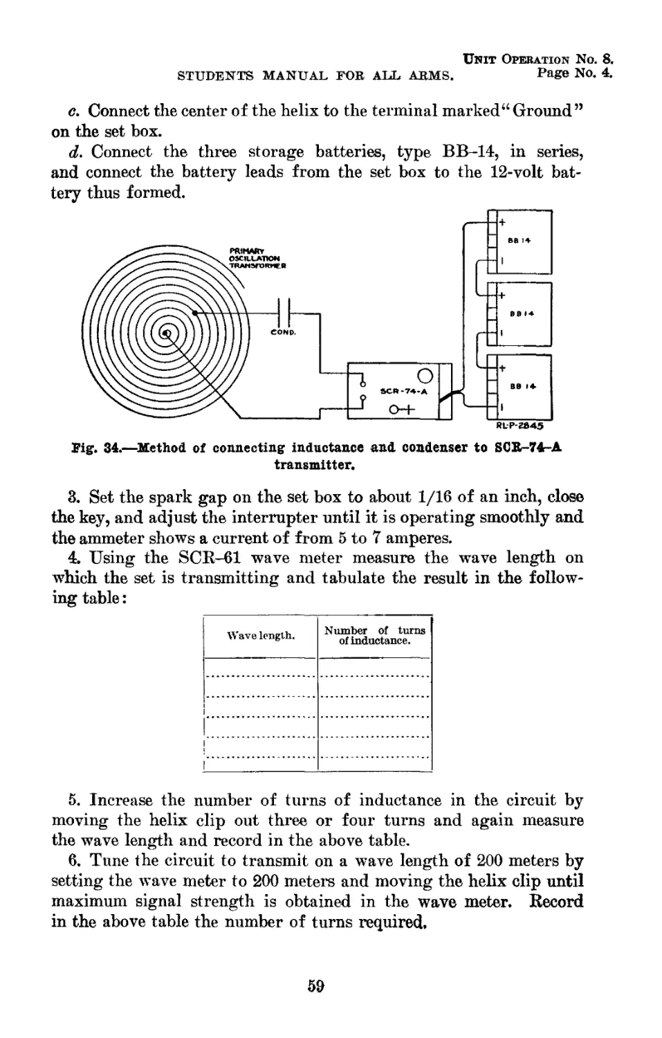
Method of connecting inductance and condenser
to SCR-74-A transmitter___________________
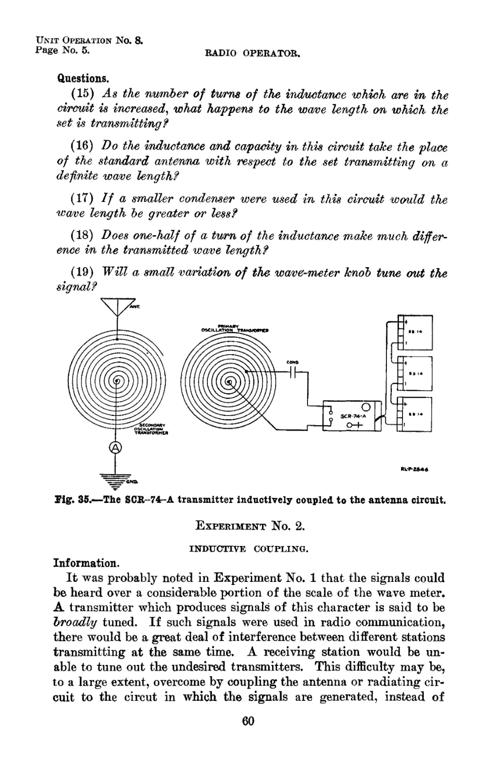
The SCR-74-A transmitter inductively
coupled to the antenna circuit______________
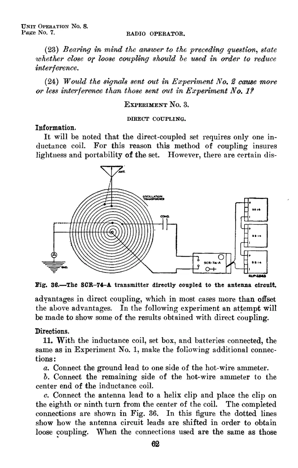
The SCR-74-A transmitter directly coupled
to the antenna circuit______________________
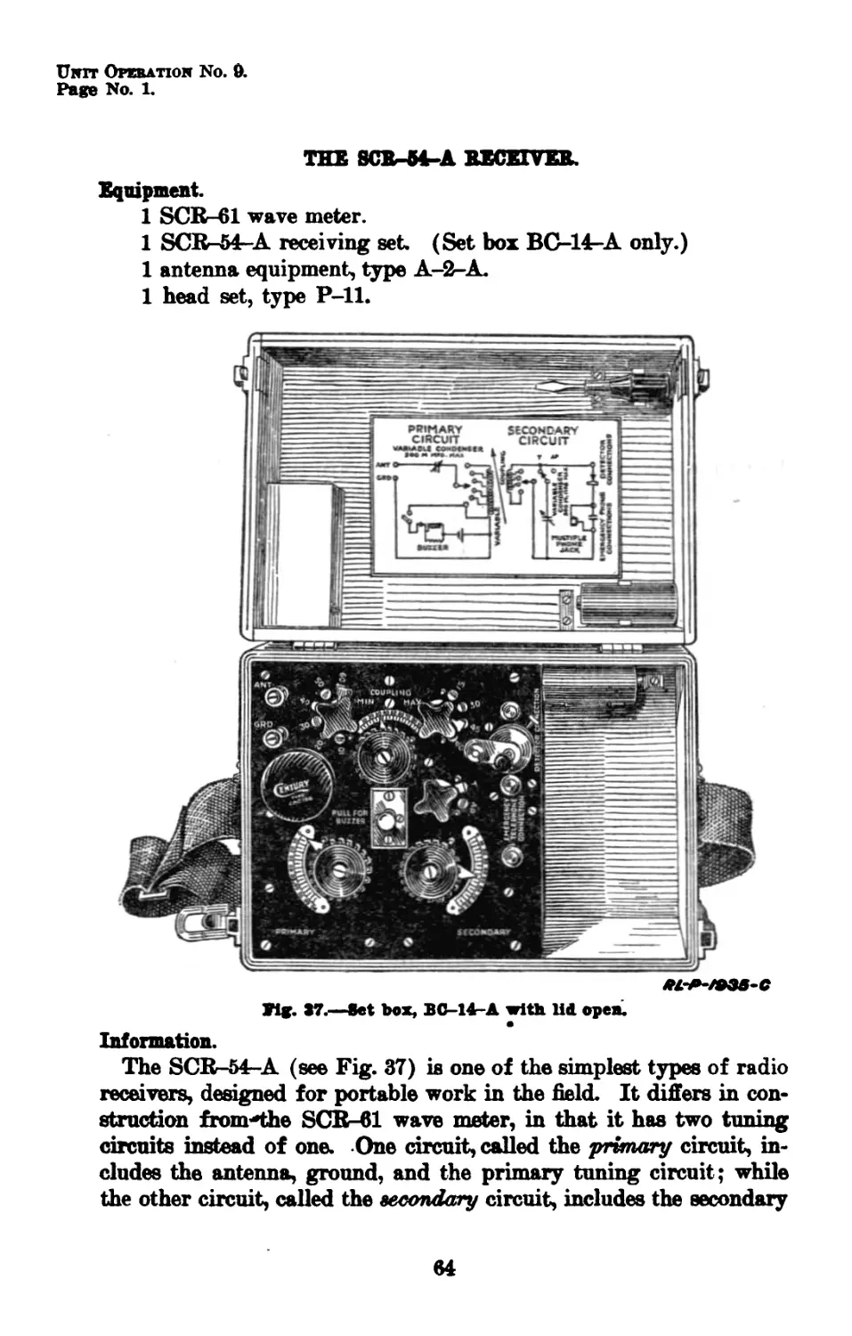
Set box, BC-14-A with lid open______________
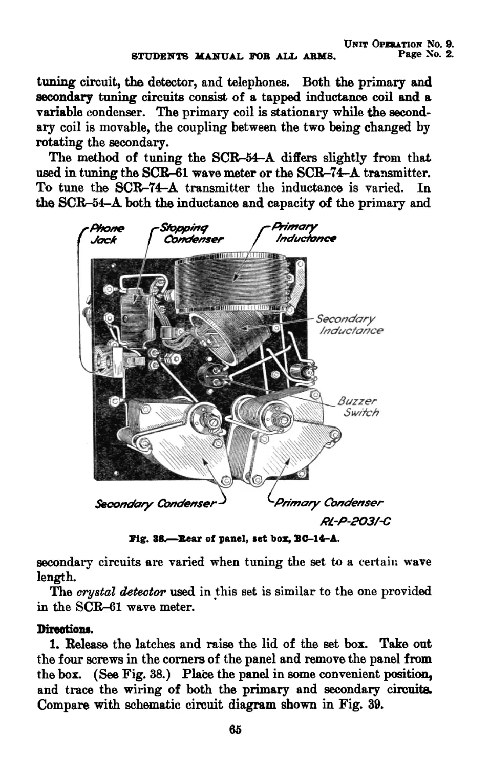
Rear of panel, set box, BC-14-A_____________
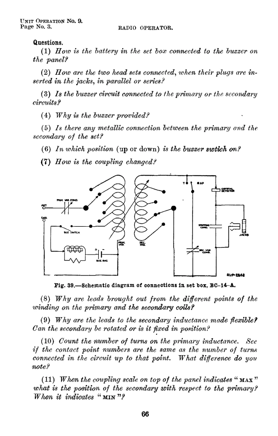
Schematic diagram of connections in set box,
BC-14-A_____________________________________
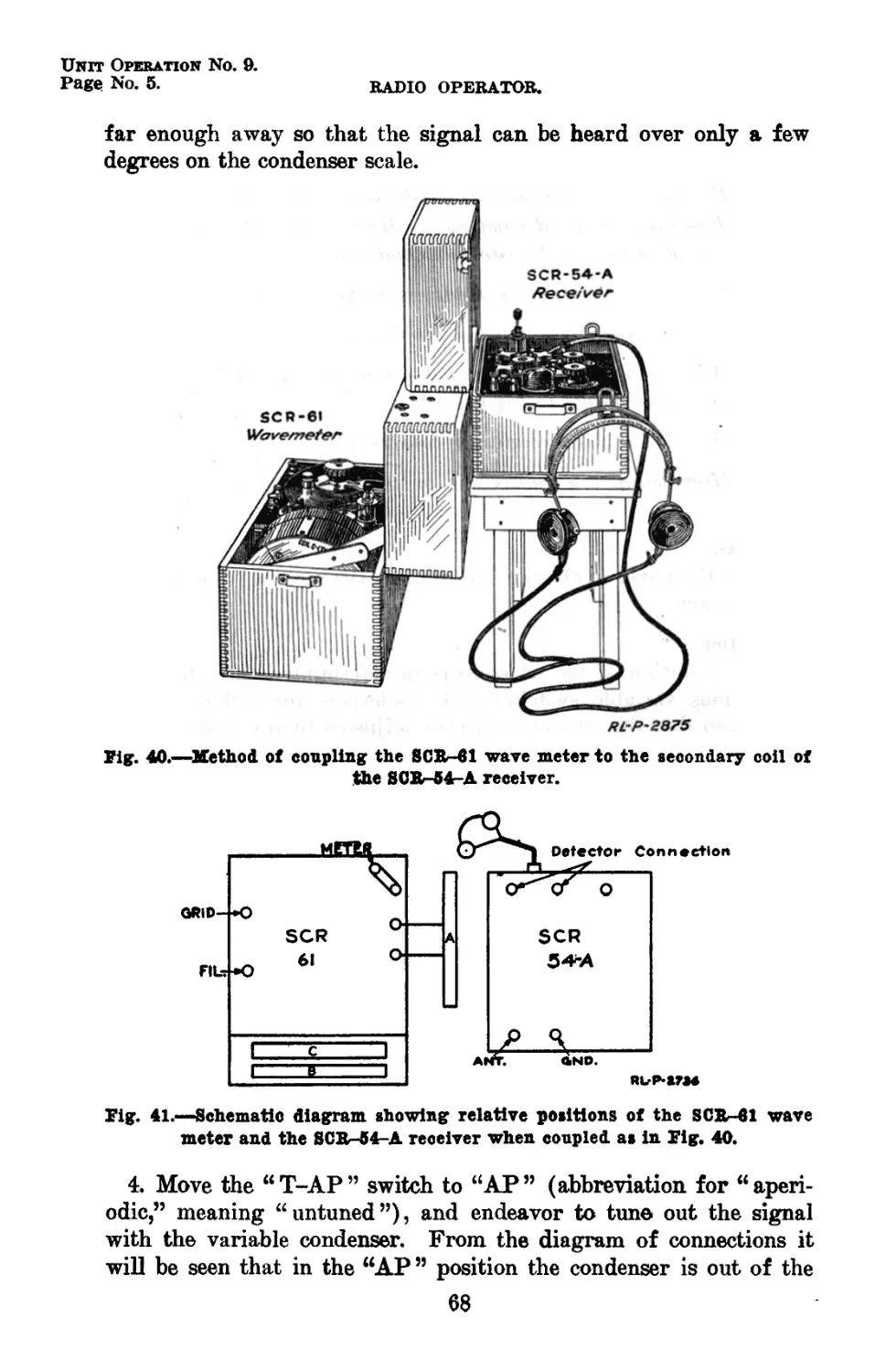
Method of coupling the SCR-61 wave meter to
the secondary coil of the SCR-54-A re-
ceiver______________________________________
Schematic diagram showing relative positions
of the SCR-61 wave meter and the SCR-54-
A when coupled as in Fig. 40______________
Method of coupling the SCR-61 wave meter J
to the primary circuit of the SCR-54-A
receiver____________________________________
Schematic diagram of coupling arrangement as
in Fig. 42----------------------------------
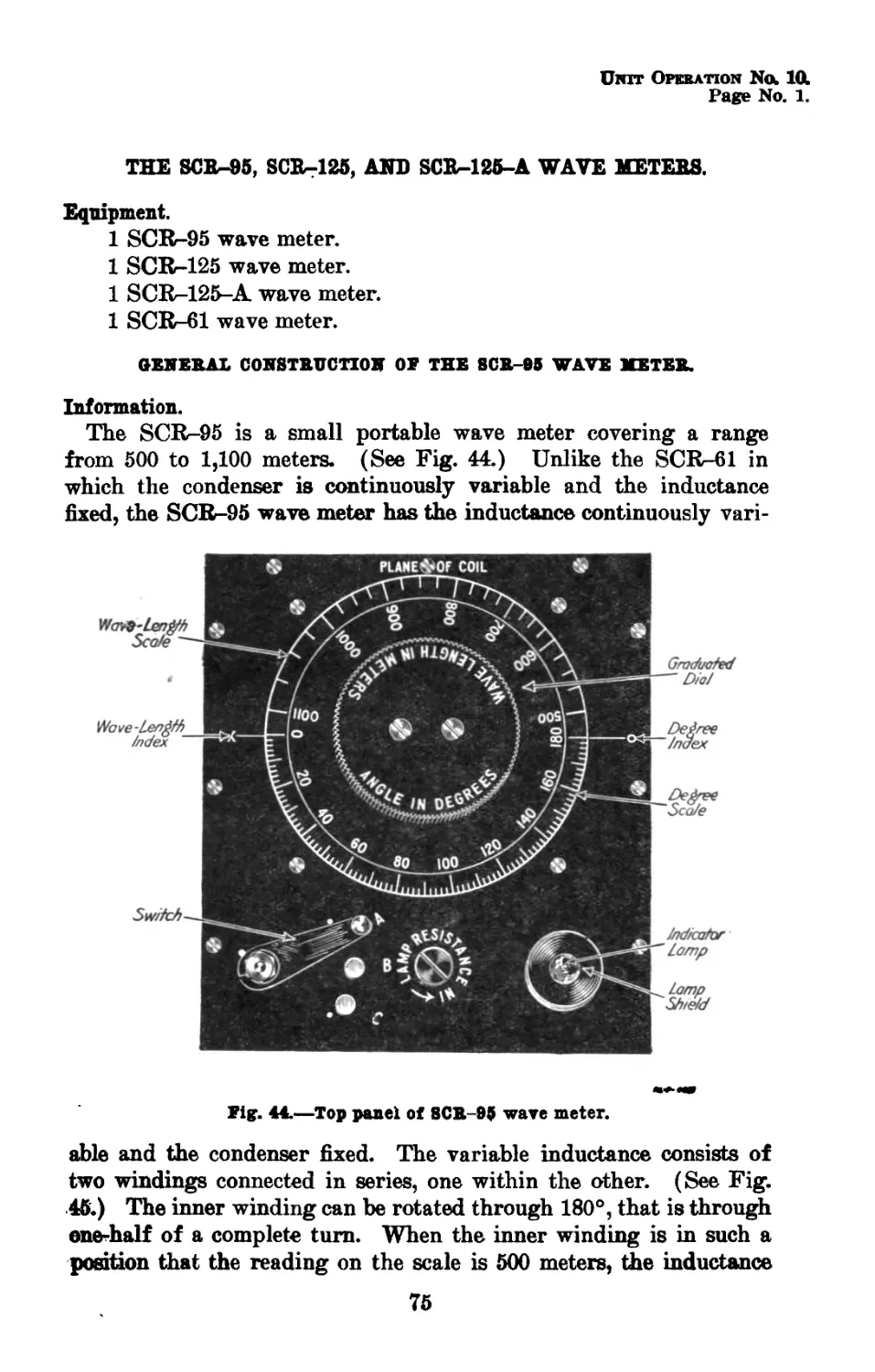
Top panel of SCR-95 wave meter______________
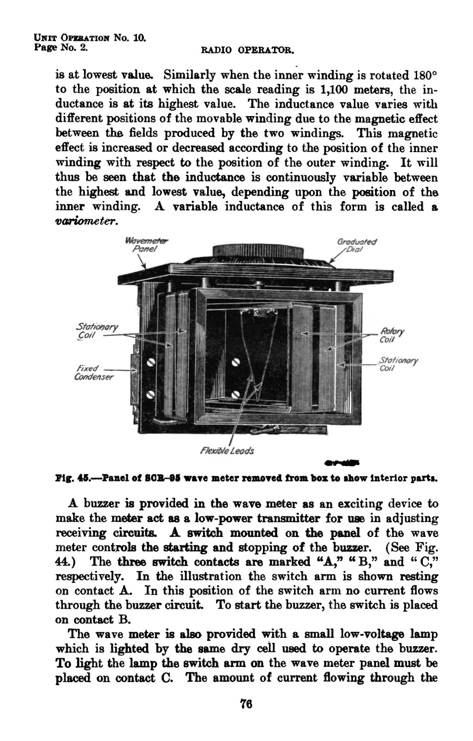
Panel of SCR-95 wave meter removed from box
to show interior parts______________________
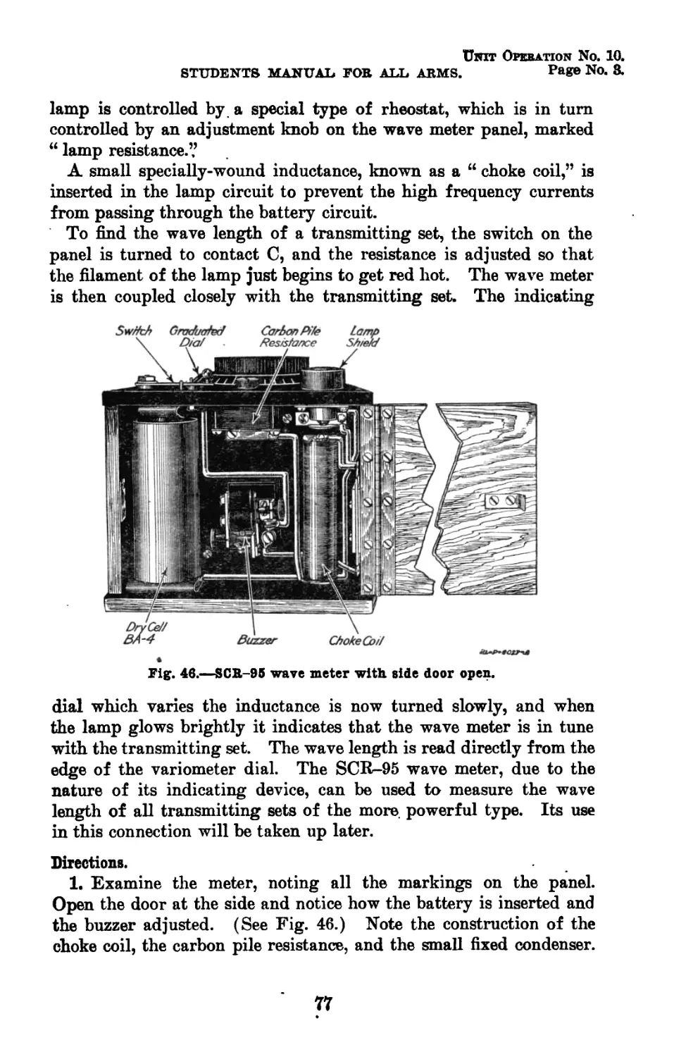
SCR-95 wave meter with side door open-------
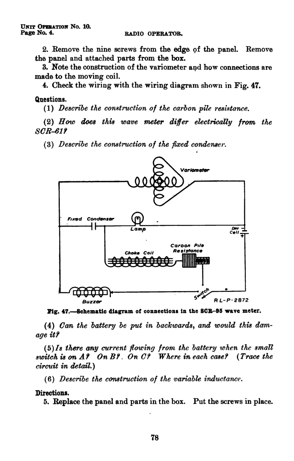
Schematic diagram of connections in the SCR-
95 wave meter-------------------------------
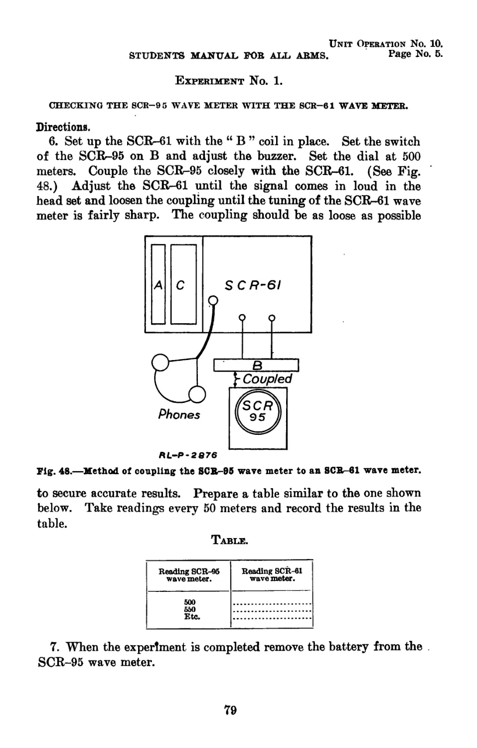
Method of coupling the SCR-95 wave meter
to an SCR-61 wave meter_____________________
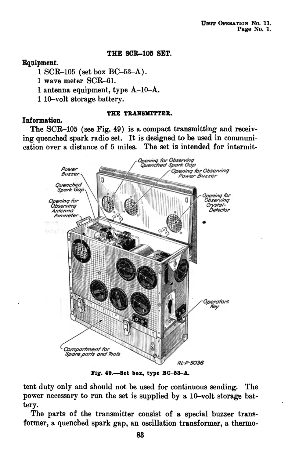
Set box, type BC-53-A-----------------------
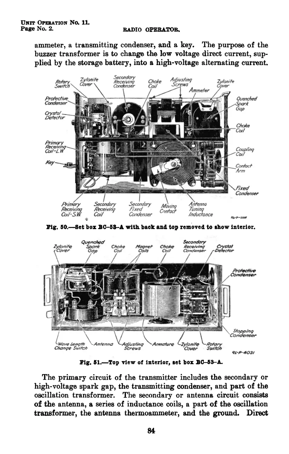
Set box BC-53-A with back and top removed
to show interior----------------------------
Top view of interior, set box BC-53-A_______
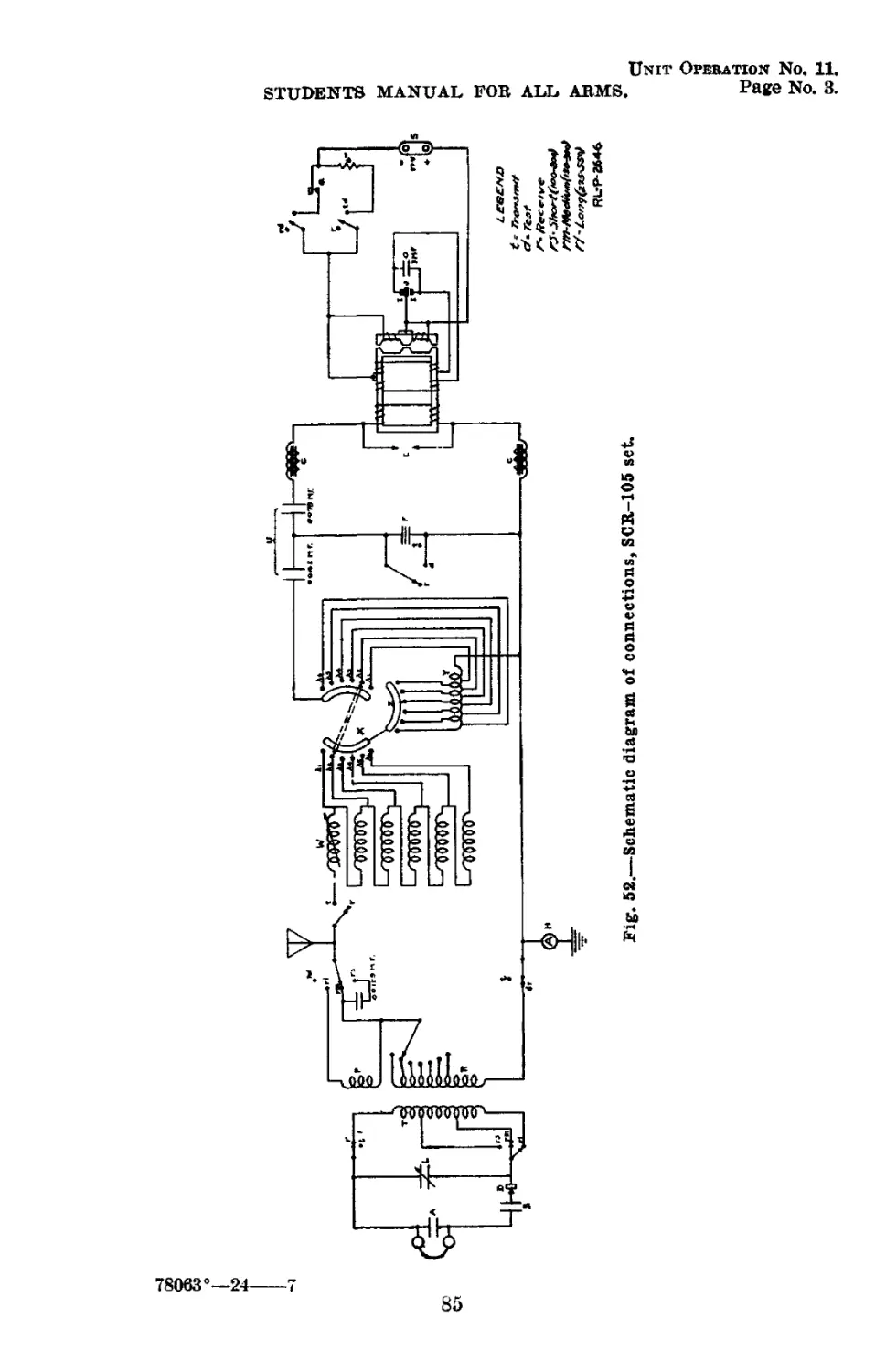
Schematic diagram of connections SCR-105 set.
Method of coupling SCR-125-A wave meter to
set box BC-53-A-----------------------------
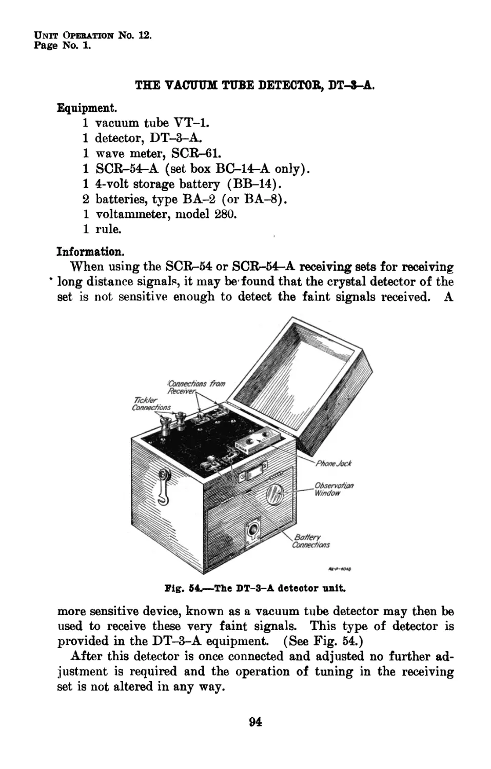
The DT-3-A detector unit____________________
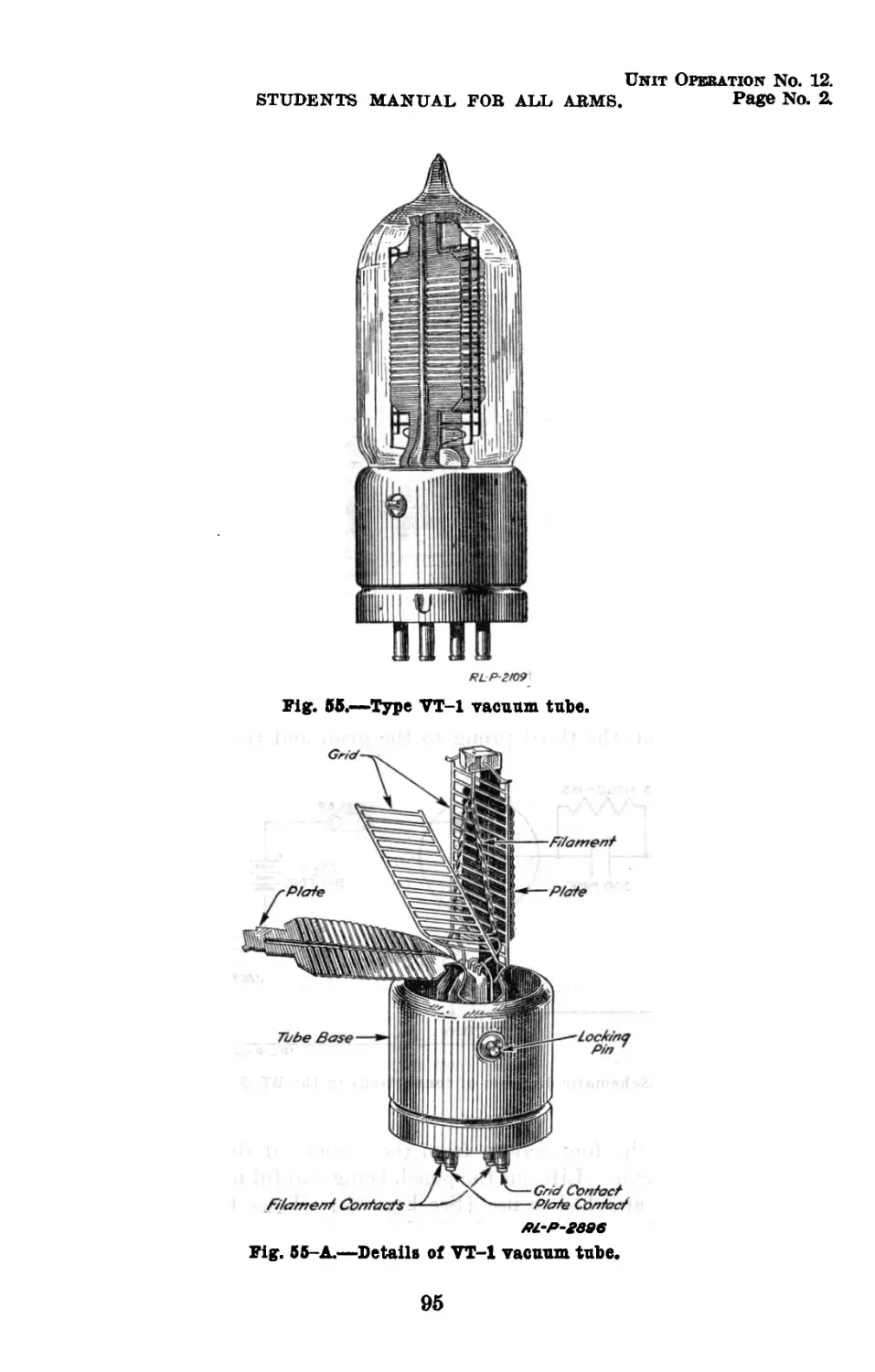
Type VT-1 vacuum tube_______________________
Details of VT-1 vacuum tube_________________
Panel of DT-3-A detector removed to show I
interior parts______________________________'
Schematic diagram of connections in the DT-3-A
detector____________________________________
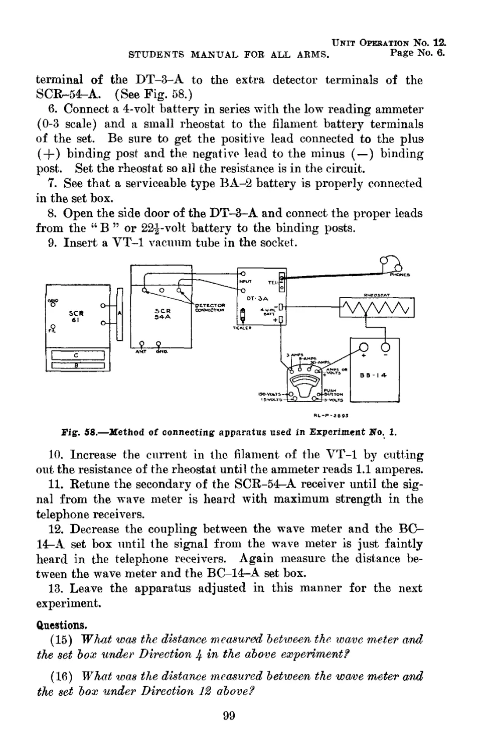
Method of connecting apparatus used in Experi-
ment No. 1----------------------------------
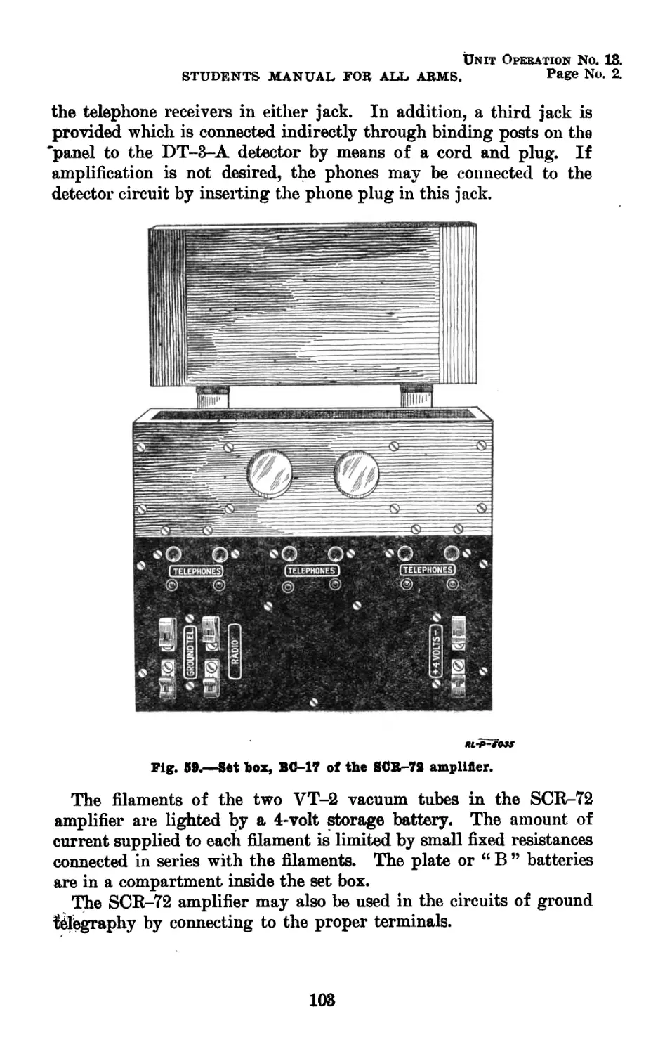
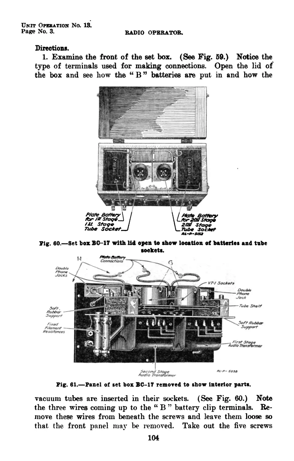
Set box, BC-17 of the SCR-72 amplifier—_____
Set box BC-17 with lid open to show location
of batteries and tube sockets_______________
Panel of set box BC-17 removed to show in-
terior parts —______________________________
Schematic diagram of connections in set box
BC-17_____________________________________
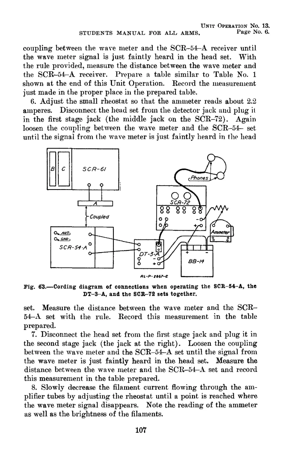
Cording diagram of connections when operating
the SCR-5A-A, type DT-3-A, and the SCR-72
sets together_______________________________
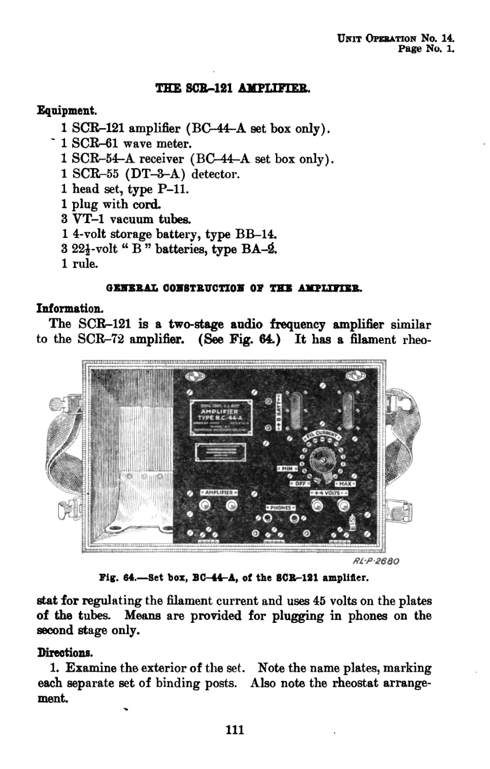
Set box BC-44-A of the SCR-121 amplifier----
2878
2882
4016
2259
2845
2846
2843
1935-C
2031-C
2842
2875
2736
2874
2737
4021
4030
4027-A
2872
2876
5036
2897
4031
2646
2864-C
4048
2109
2896
4049
2655
2893
5035
5152
5038
2654
2867-C
2680
50
52
52
54
59
60
62
64
65
66
68
68
71
71
75
76
77
78
79
83
84
84
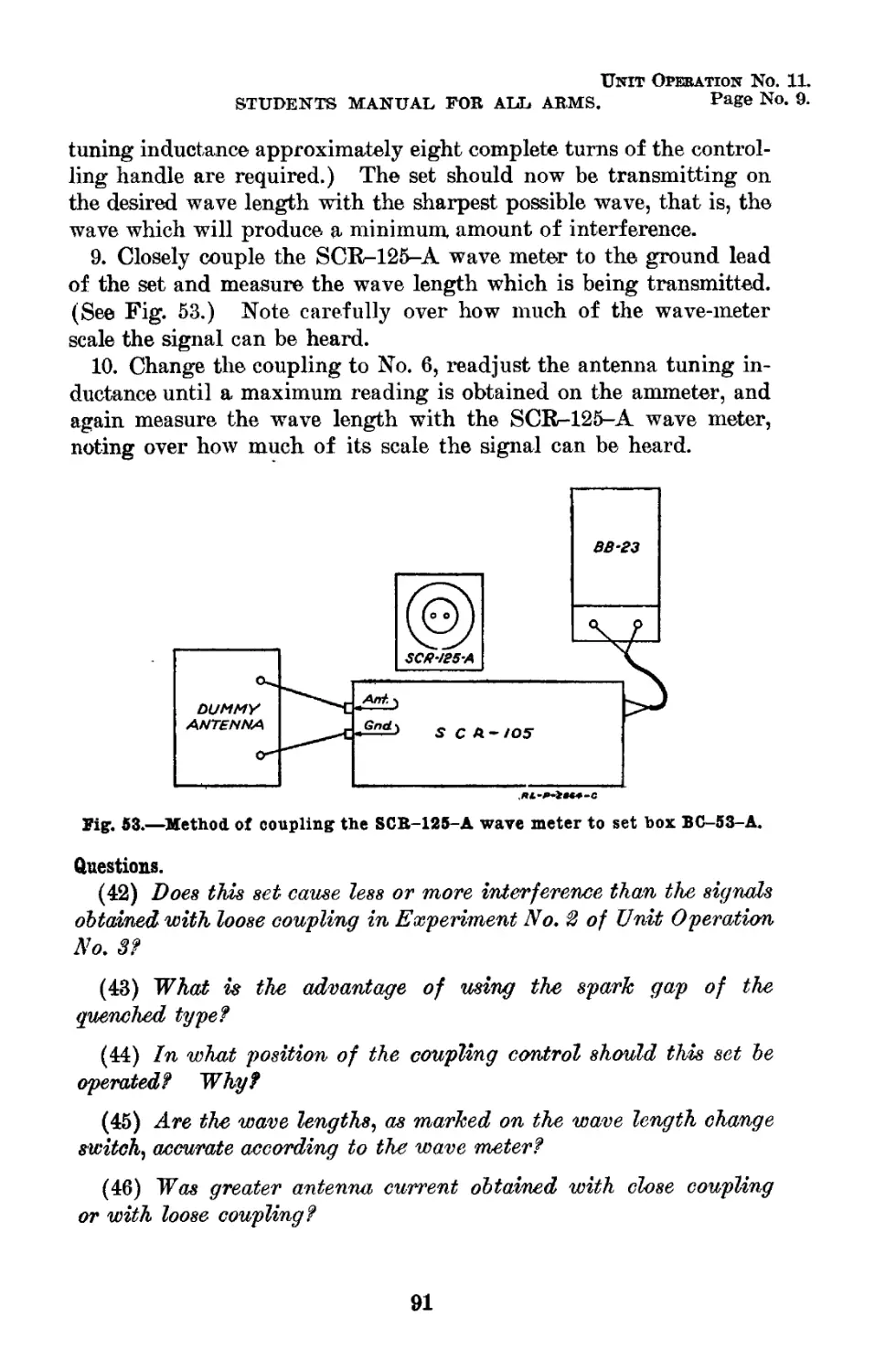
91
94
95
95
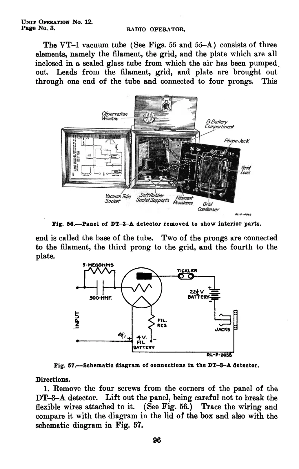
96
96
99
103
104
104
105
107
111
(IX)
INDEX OF ILLUSTRATIONS—Continued.
Figure No. Title. RL-P-No. Page.
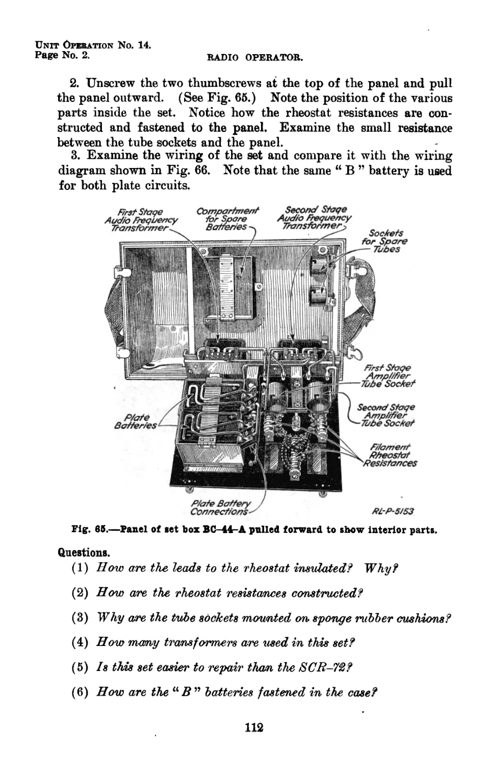
65 Panel of set. box BC-44-A pulled forward to show interior parts 5153 112
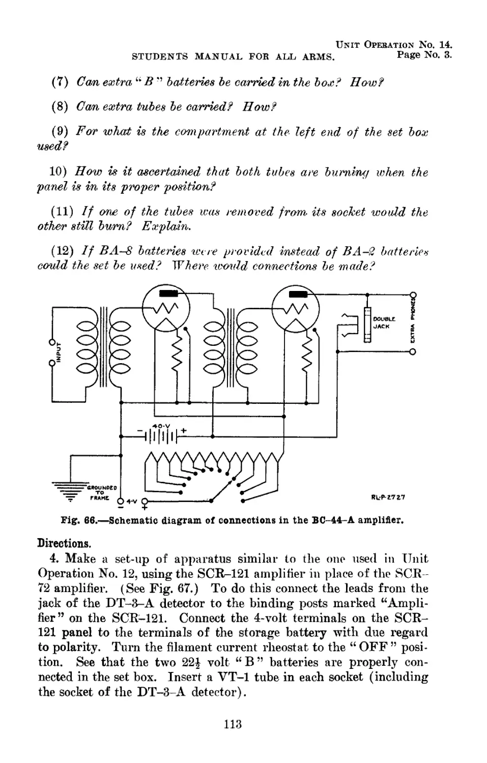
66 Schematic diagram of connfections in the BC-44- A amplifier 2727 113
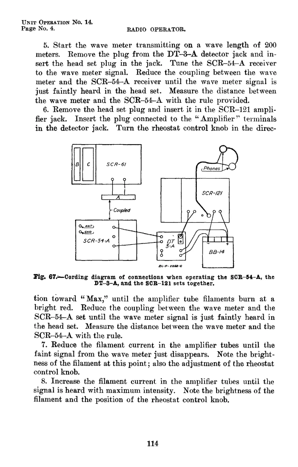
67 Cording diagram of connections when operating the SCR-54-A, the DT—3-A, and the SCR.-121 sets together 2868-C 114
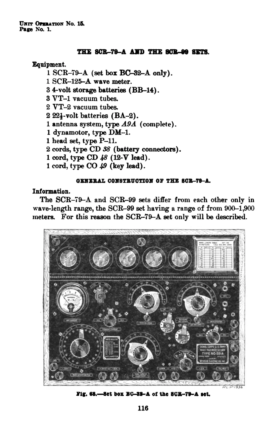
68 Set box BC-32-A of the SCR-79-A set..* 1936 116
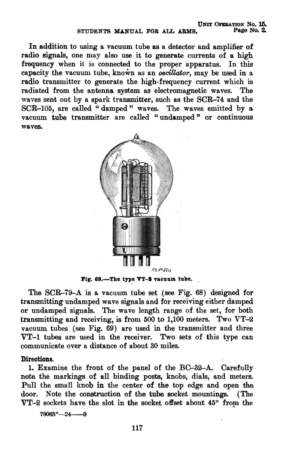
69 The type VT-2 vacuum tube 2111 117
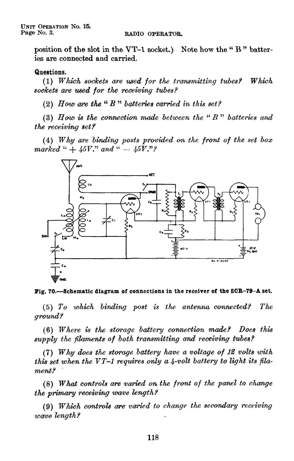
70 Schematic diagram of connections in the re- ceiver of the SCR-79-A set 2499 118
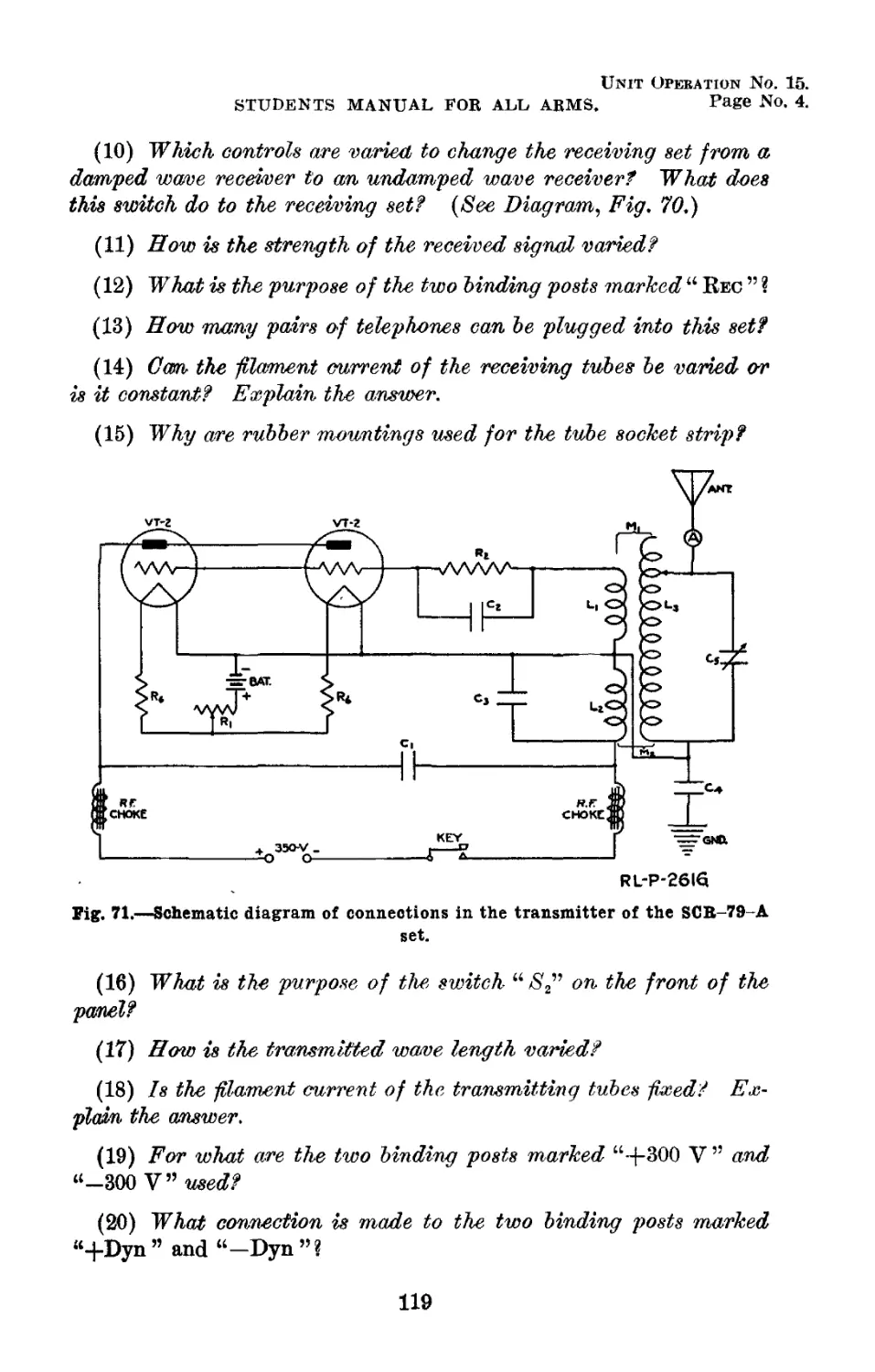
71 Schematic diagram of connections in the trans- mitter of the SCR-7&-A set. 2616 119
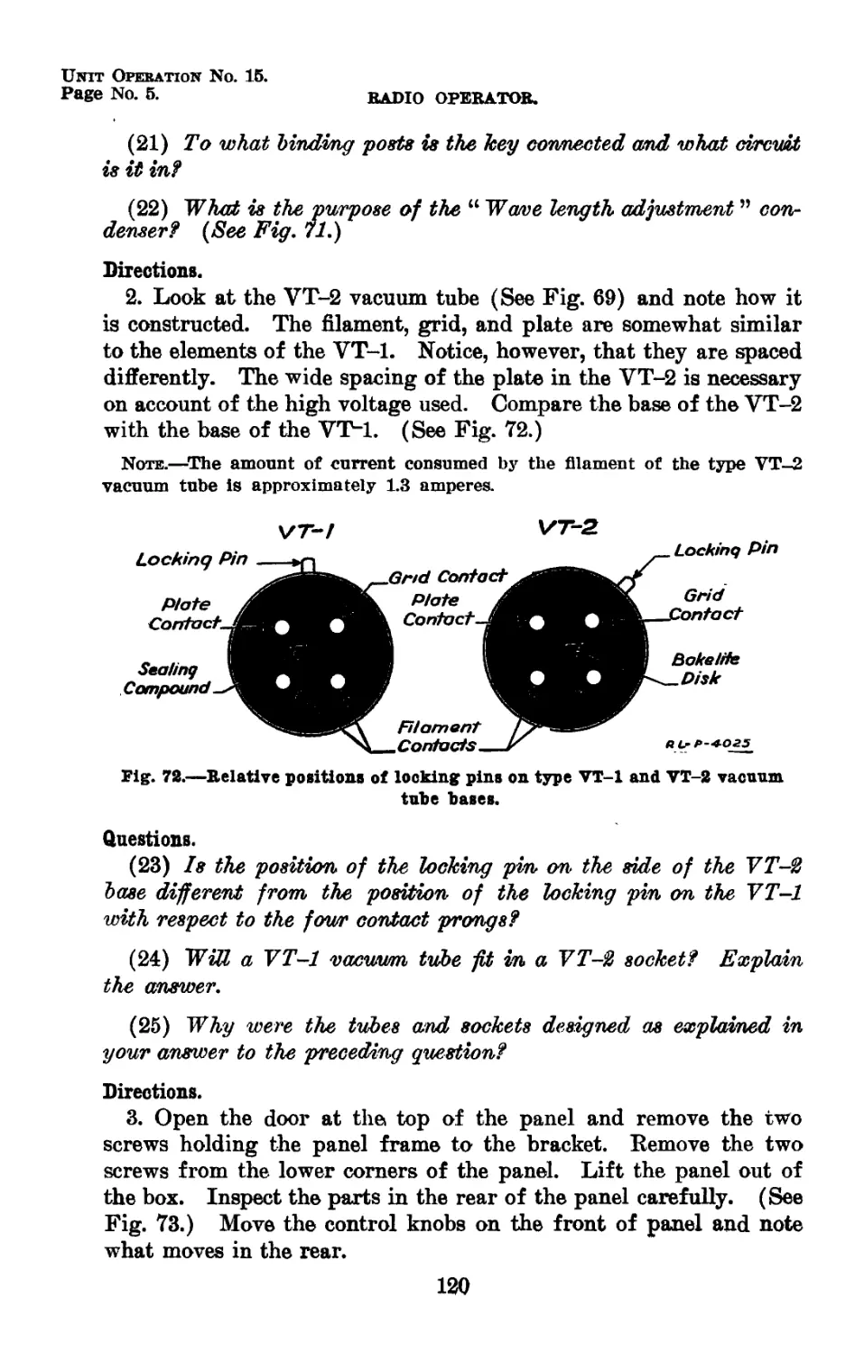
72 Relative positions of locking pins on type VT-1 and VT-2 vacuum tube bases 4025 120
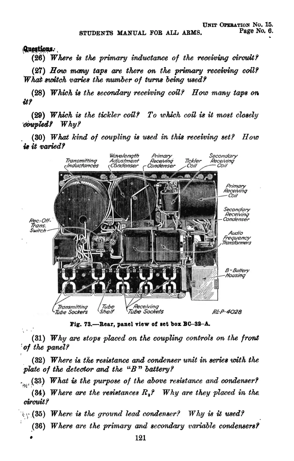
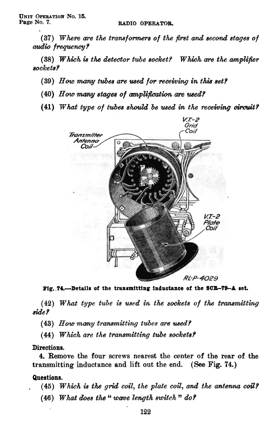
73 Rear panel view of set box BC-32-A Details of the transmitting inductance of the SCR-79-A set 4028 121
74 4029 122
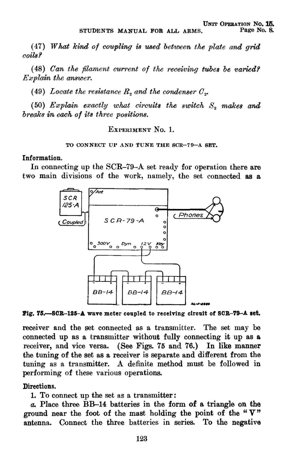
75 SCR--125--A wave meter coupled to receiving circuit of SCR-79-A set 2880 123
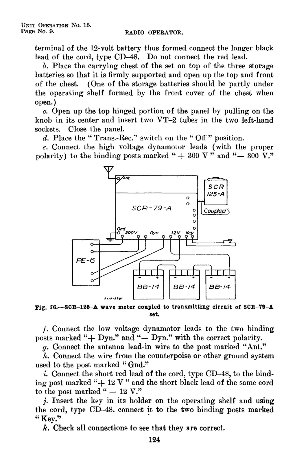
76 SCR-125-A wave meter coupled to transmitting circuit of SCR-79-A get 2881 124
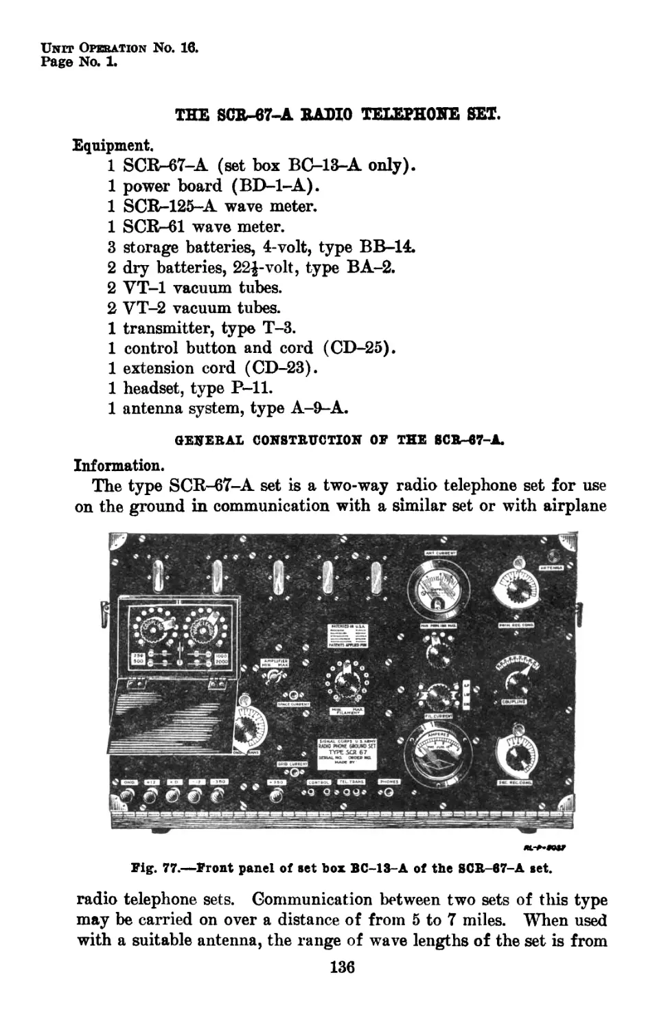
77 Front panel of set box BC-13-A of the SCR-67- A set. __ 5037 136
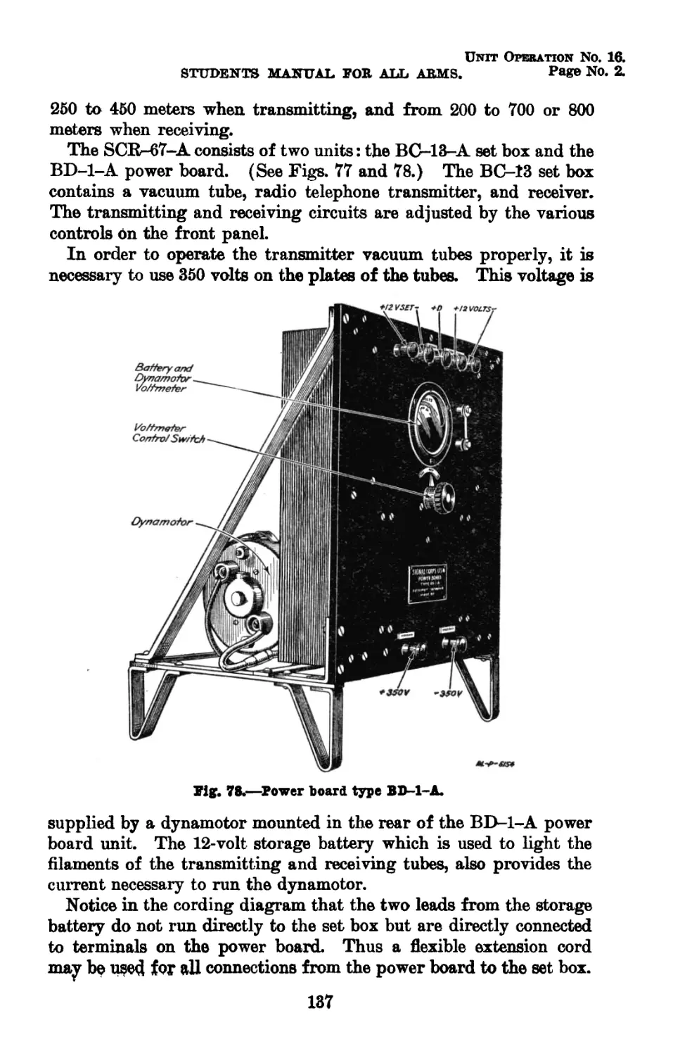
78 Power board, type BD-l-A 5154 137
79 Schematic diagram of transmitter connections in the SCR-67-xi set 2761-C 13S
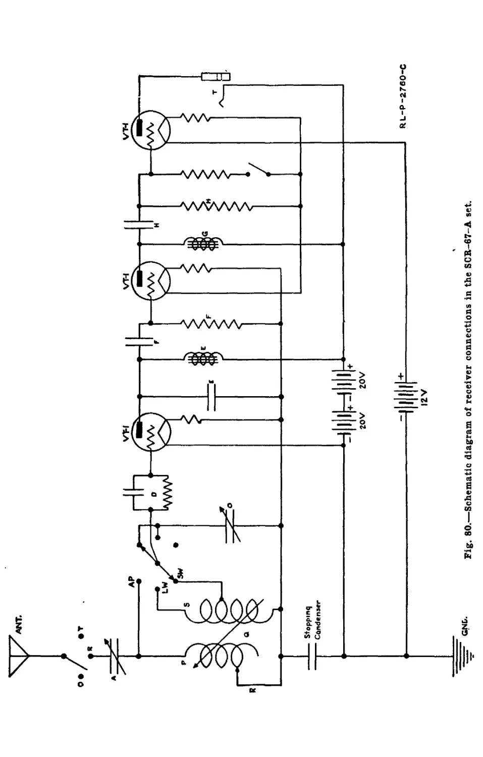
80 Schematic diagram of receiver connections in the SCR-67-A set 2760-C 140
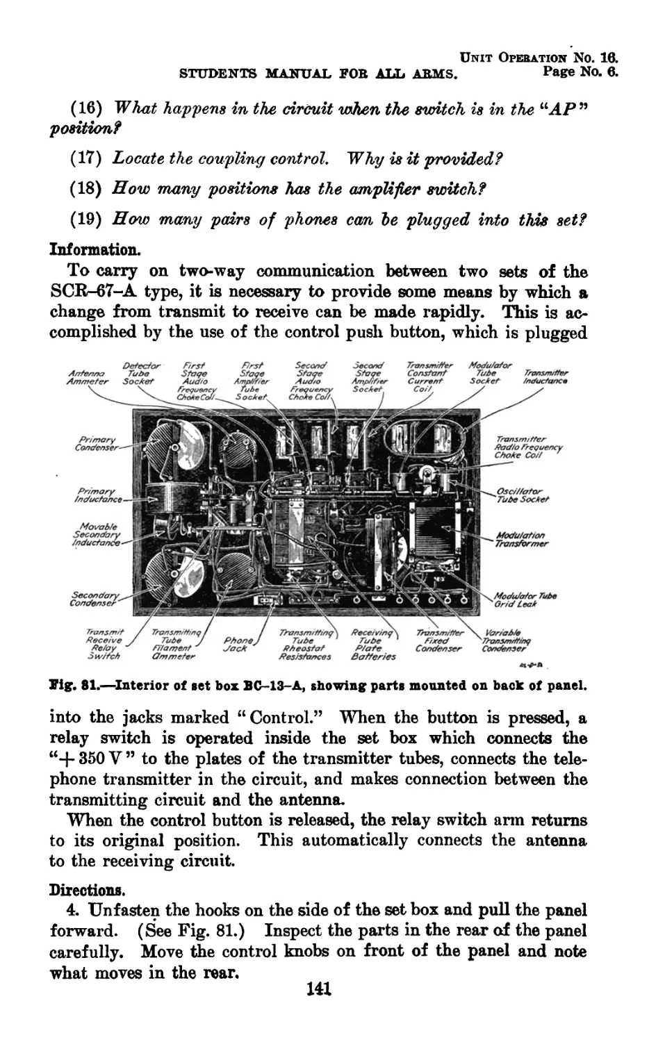
81 Interior of set box, BC-13-A showing parts mounted on back of panel 5151 141
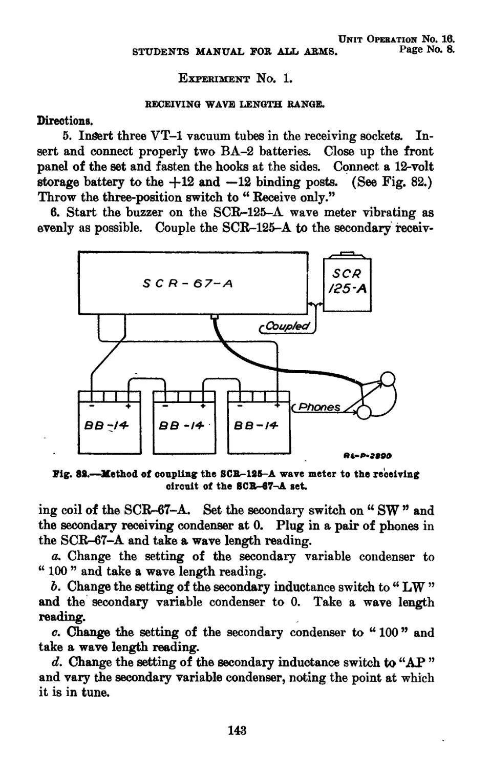
82 Method of coupling the SCR-125-A wave meter to the receiving circuit of the 8CR-67- A set.. 2890 143
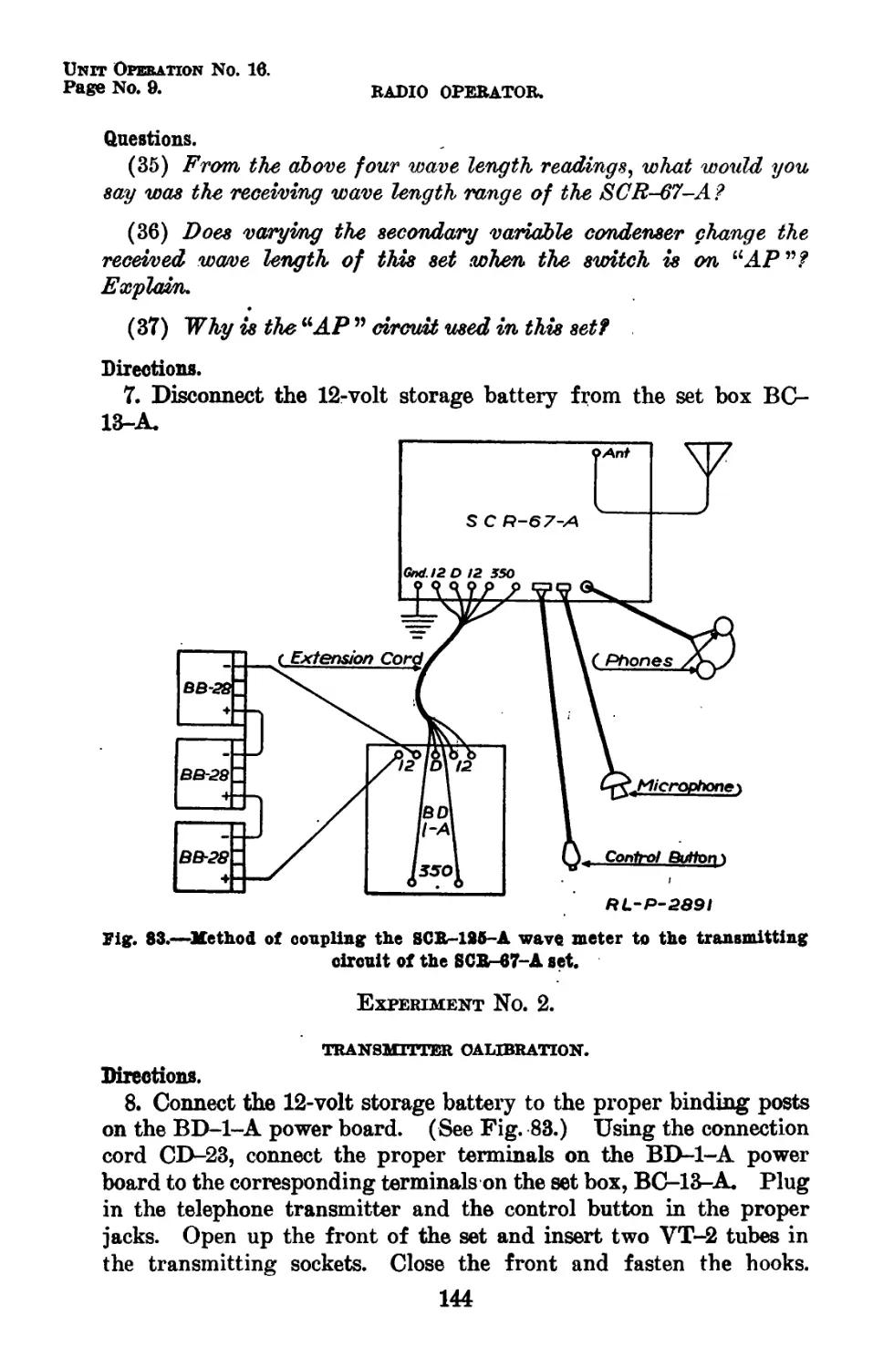
83 Method of coupling the SCR-125-A wave meter to the transmitting circuit of the SCR- 6 7-A set 2891 144
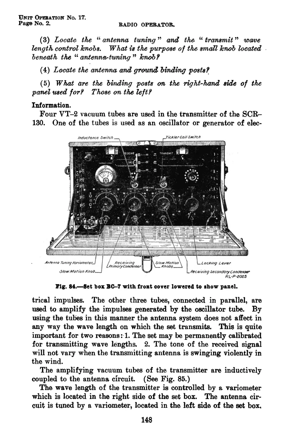
84 Set box BC-7 with front cover lowered to show panel. . 2025 148
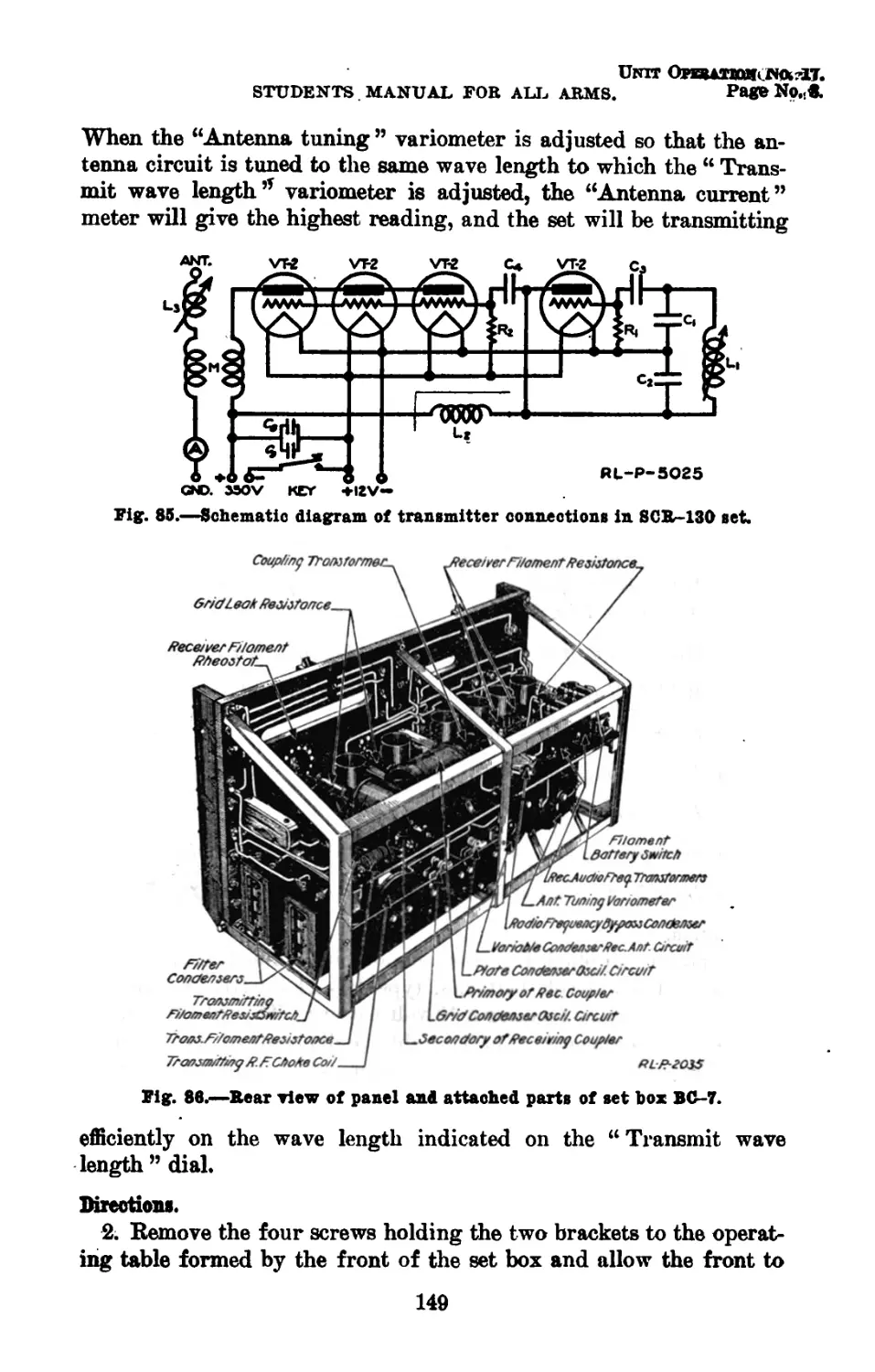
85 Schematic diagram of transmitter connections in SCR-130 set 5025 149
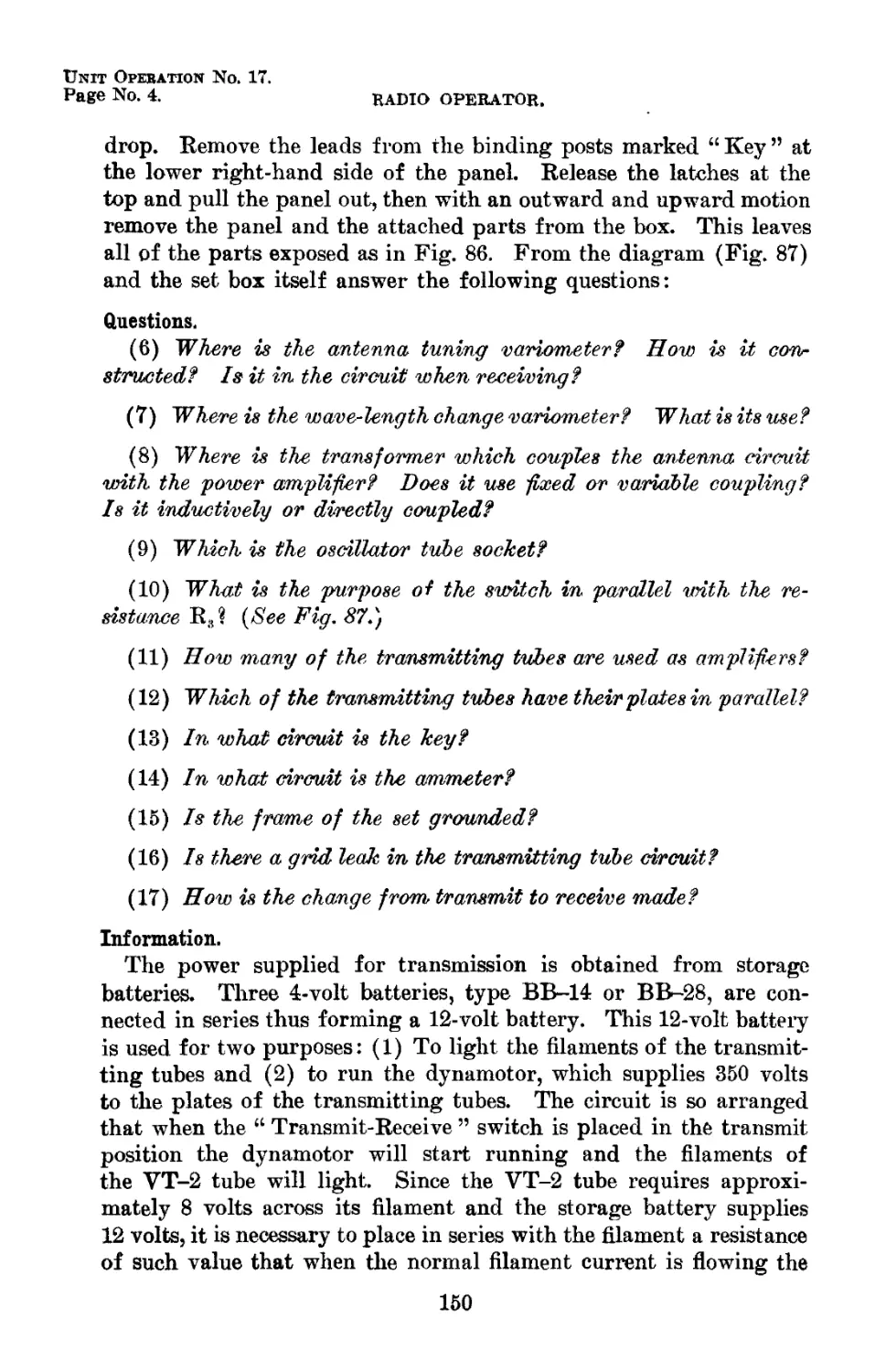
86 Rear view of panel and attached parts of set box BC-7 2035 149
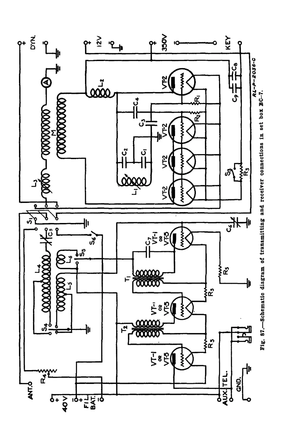
87 Schematic diagram of transmitter and receiver connections in set box BC-7 2036-C 150
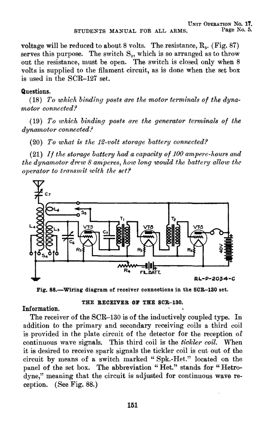
88 Wiring diagram of the receiver connections in the SCR-130 set 2034-C 151
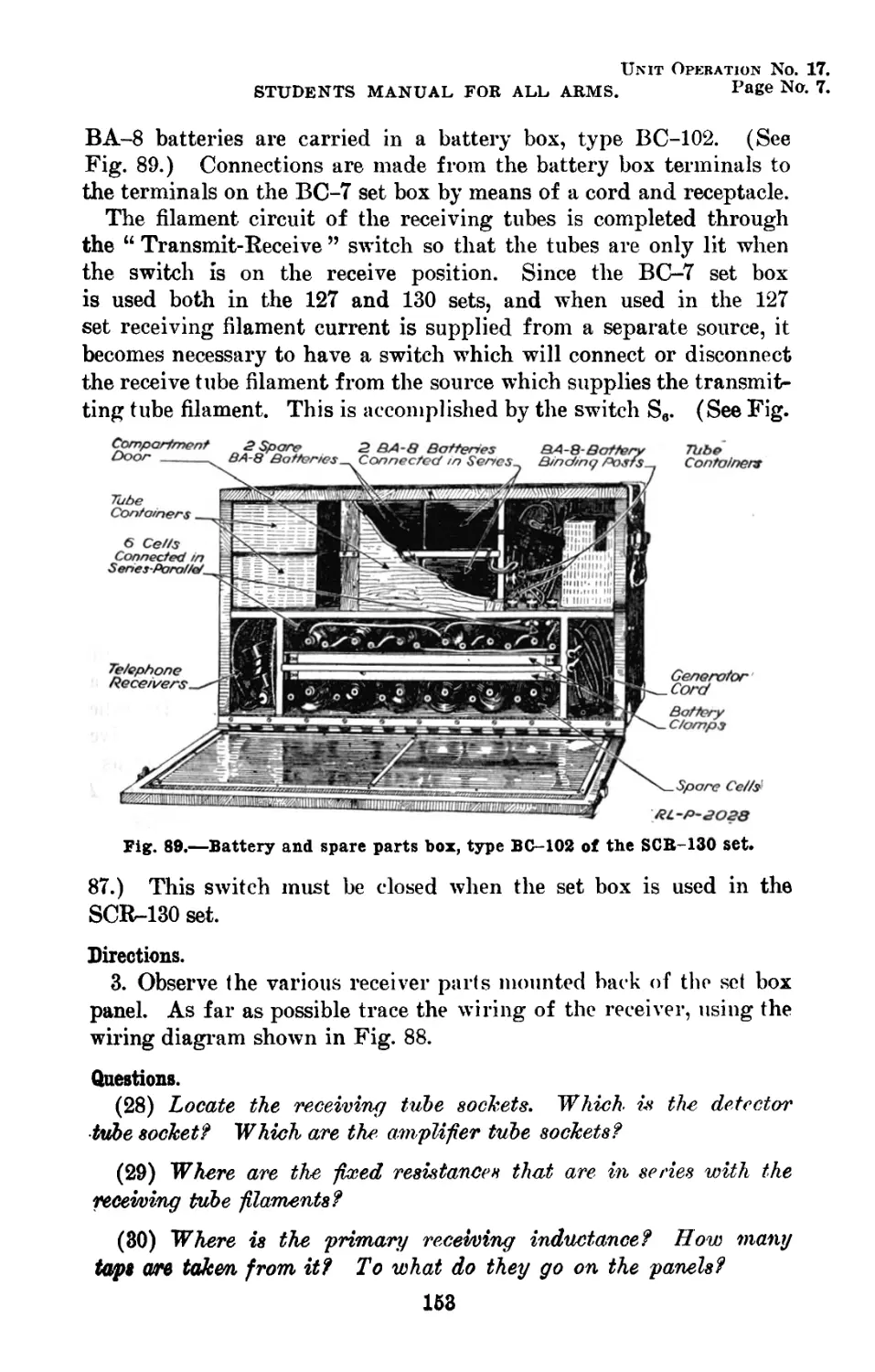
89 Battery and spare parts box, type BC-102 of the SCR-130 set 2028 153
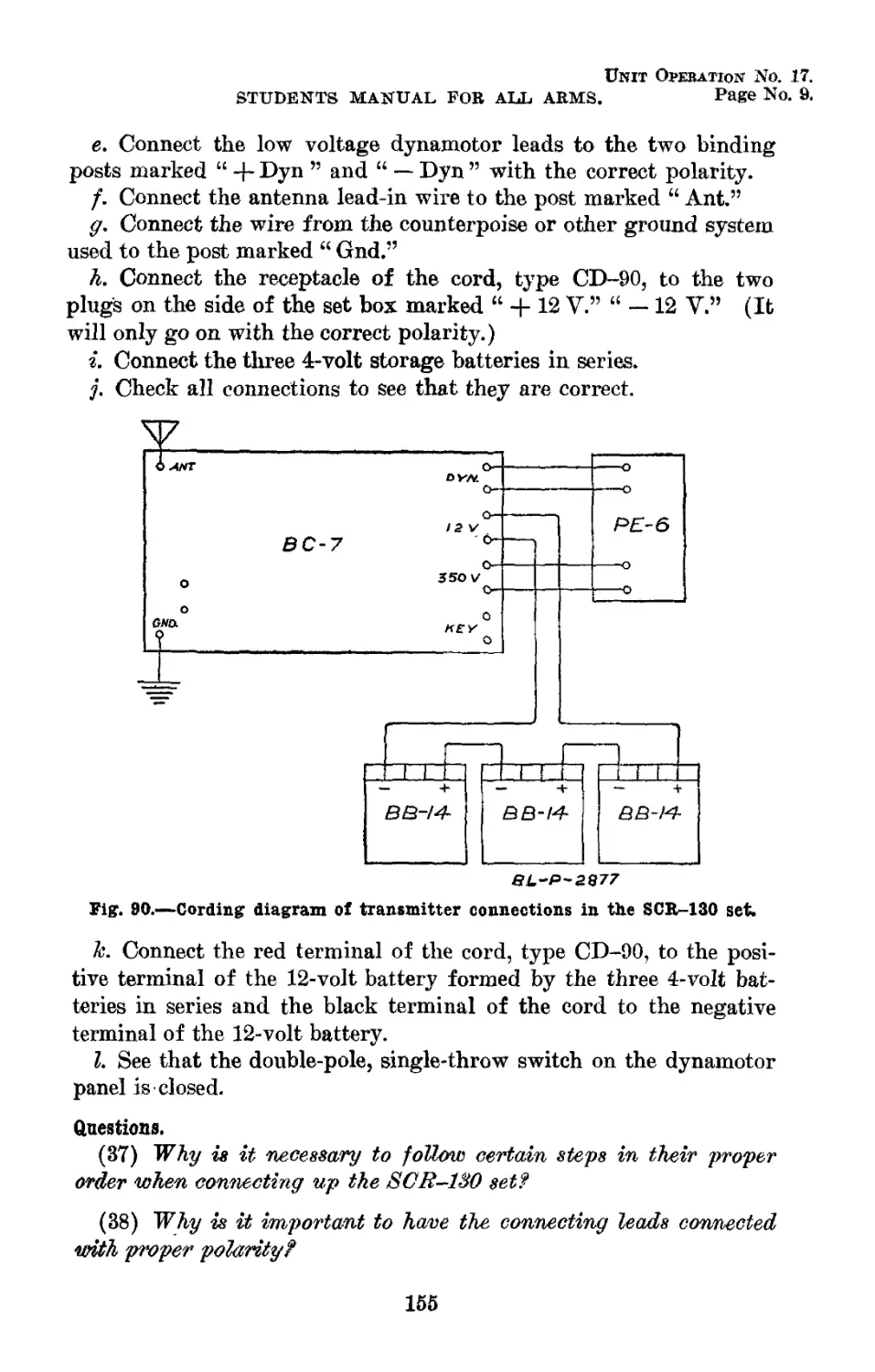
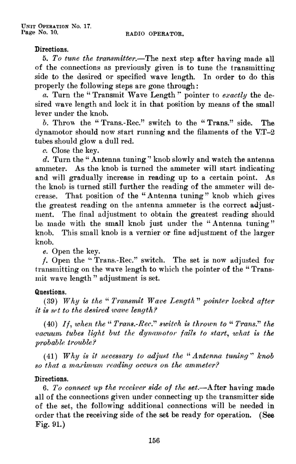
90 Cording diagram of transmitter connections in the SCR-130 set 2877 155
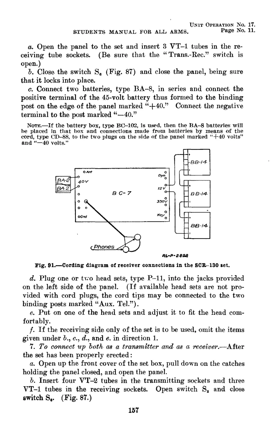
91 Cording diagram of receiver connections in the SCR-130 set 2892 157
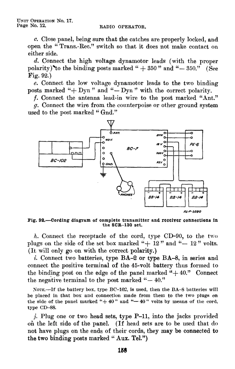
92 Cording diagram of complete transmitter and receiver connections in-the SCR-130 set 5290 158
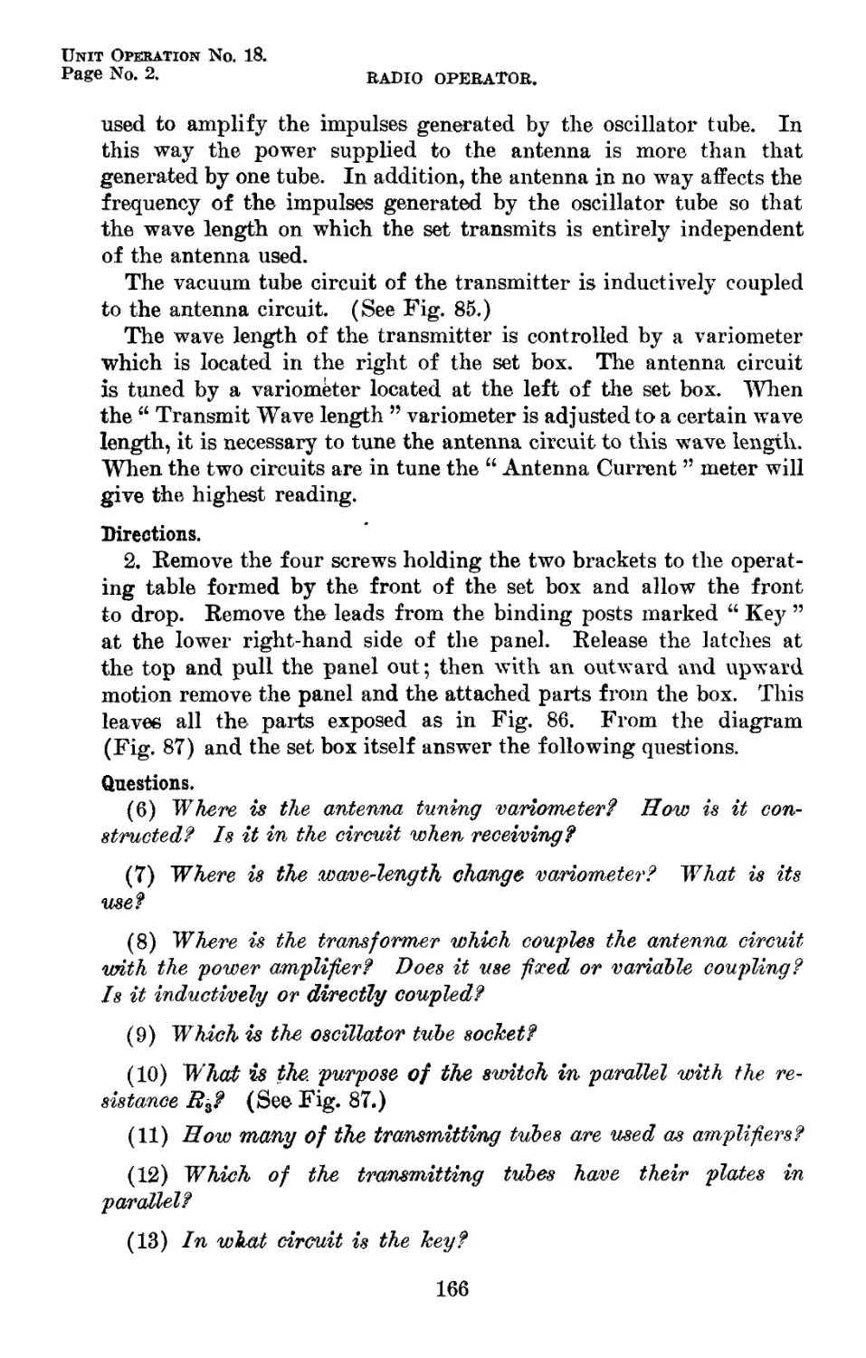
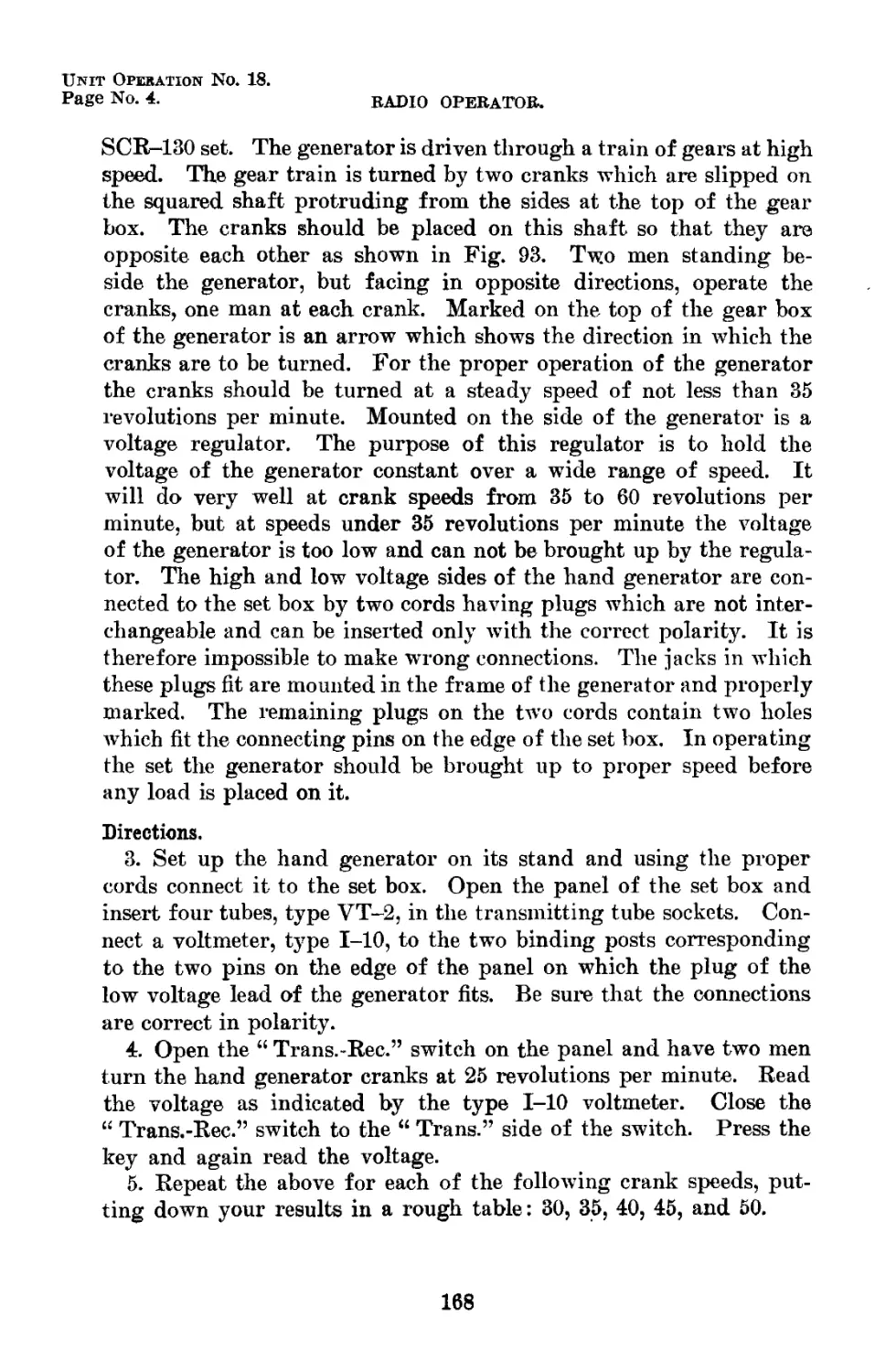
93 Hand-driven generator, type GN-29 . _ 5155 167
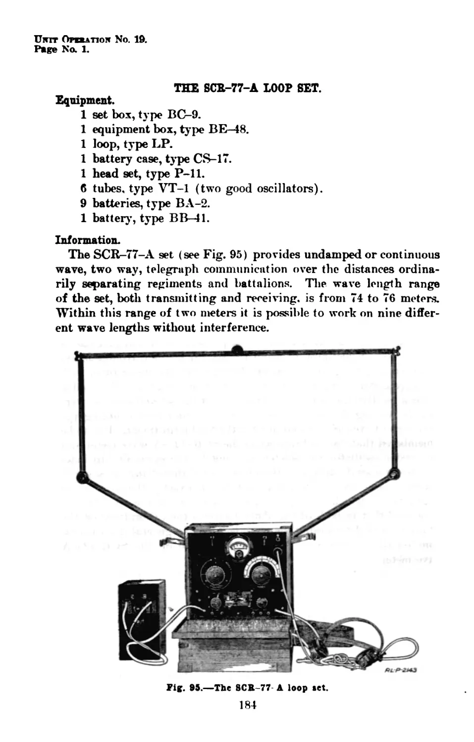
94 The type VT-5 vacuum tube The SCR-77-A loop set 2110 171
95 2143 184
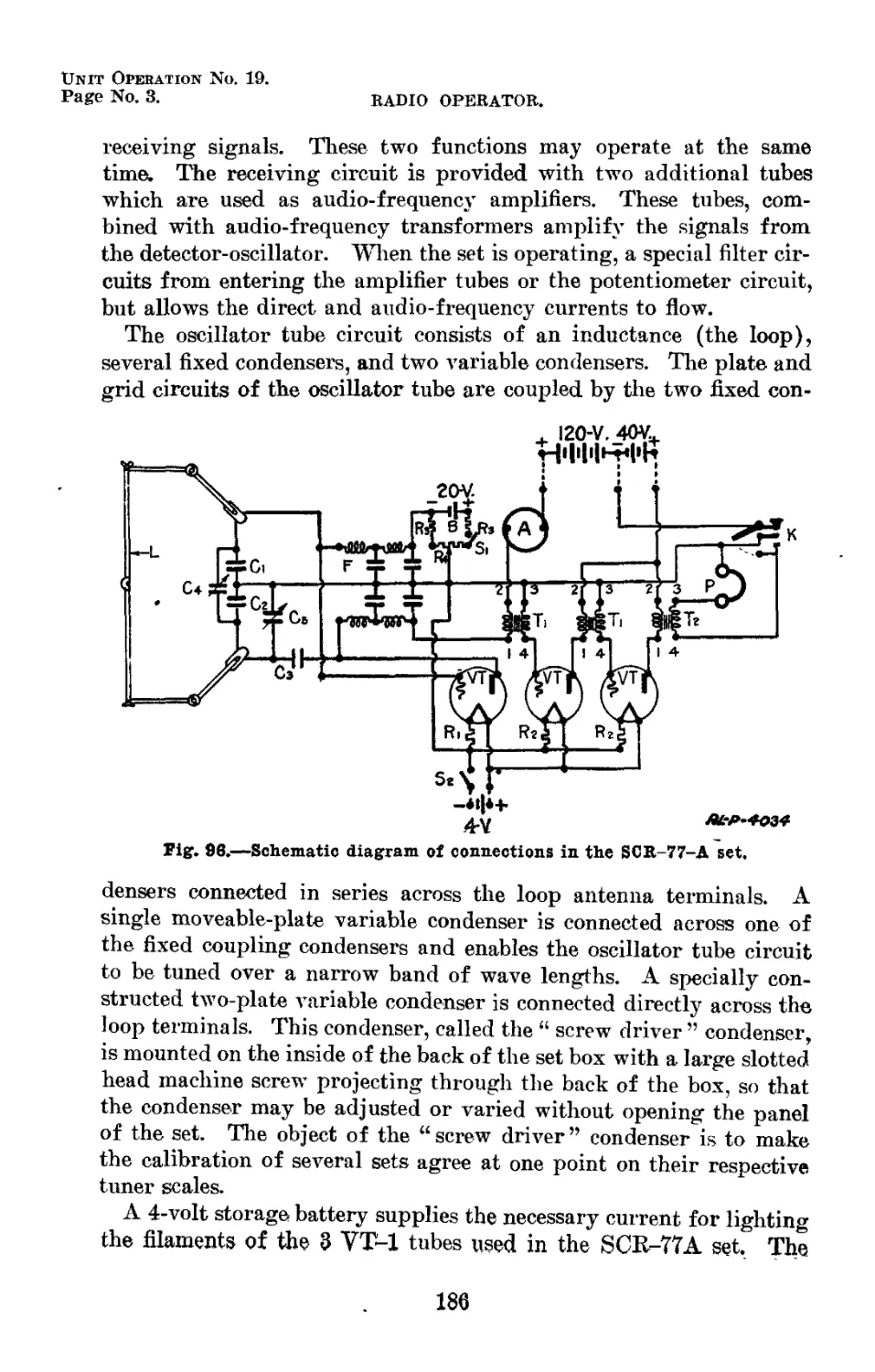
96 Schematic diagram of connections in the SCR- 77-A set . 4034 186
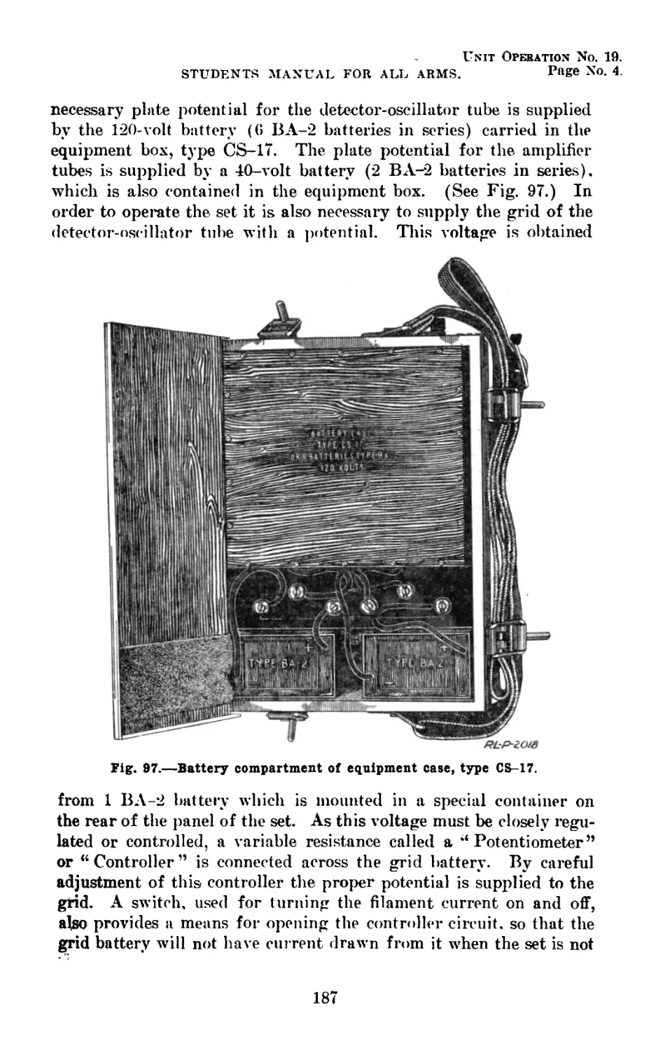
97 Battery compartment of equipment case, type CS—17 ..... 2018 187
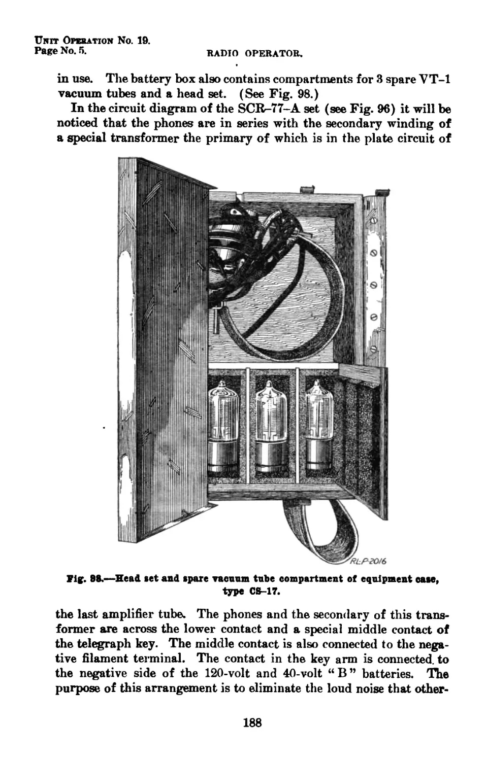
98 Head set and spare vacuum tube compartment of equipment case, CS-17 .... 2016 188
(X)
INDEX OF ILLUSTRATIONS—Continued.
Figure N o. Title. RL-P-No, Page.
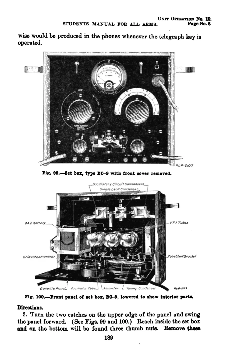
99 Set box, type BC-9, with front cover removed-- 2107 189
100 Front panel of set box, BC-9, lowered to show interior parts 2175 189
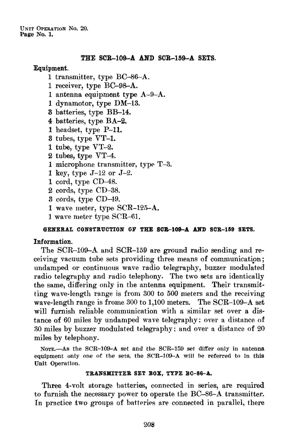
101 Front panel of transmitter set box, type BC- 86~A _ 2026 209
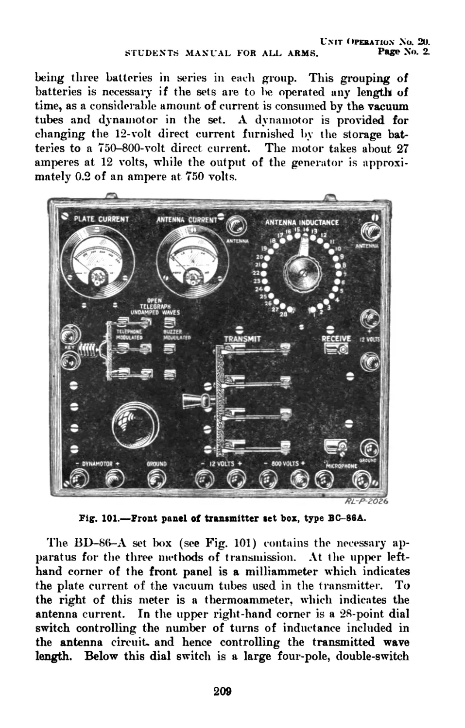
102 Type VT-4 vacuum tube 2112 210
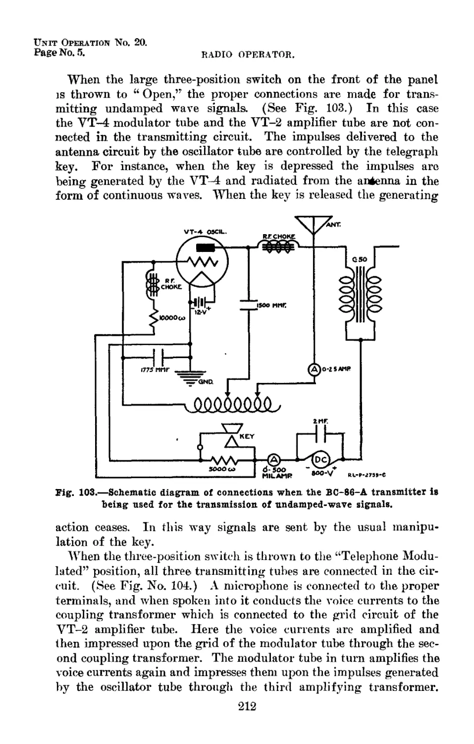
103 Schematic diagram of connections when the BC-86-A transmitter is being used for the transmission of undamped wave signals 2759-C 212
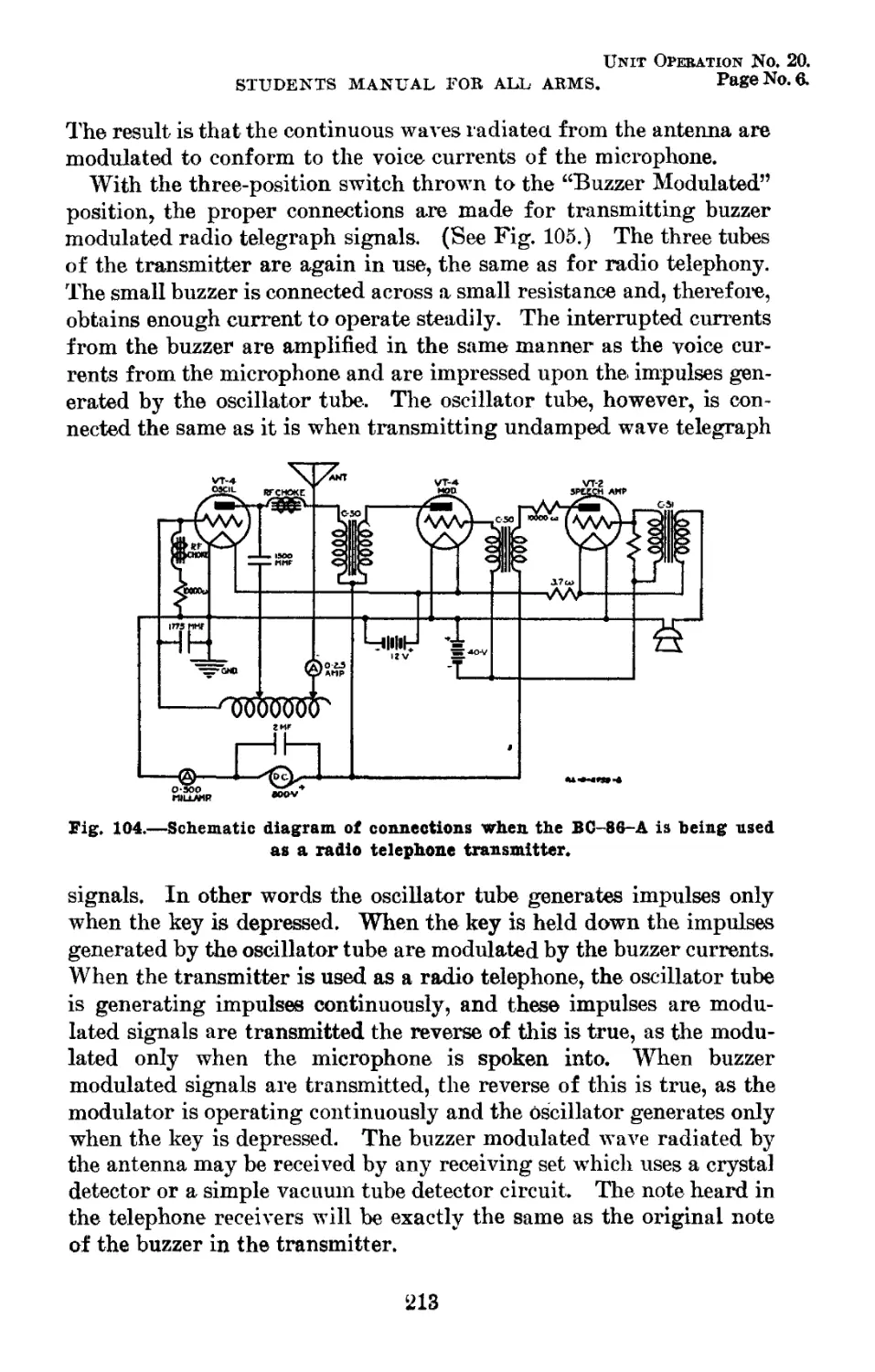
104 Schematic diagram of connections when the BC-86-A is being used as a radio telephone transmitter 2758-C 213
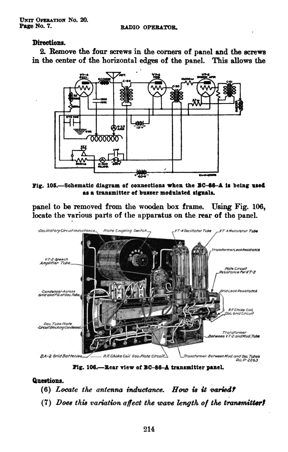
105 Schematic diagram of connections when the BC-86-A is being used as a transmitter of buzzer modulated signals 2757-C 214
100 Rear view of BC-86-A transmitter panel 2263 214
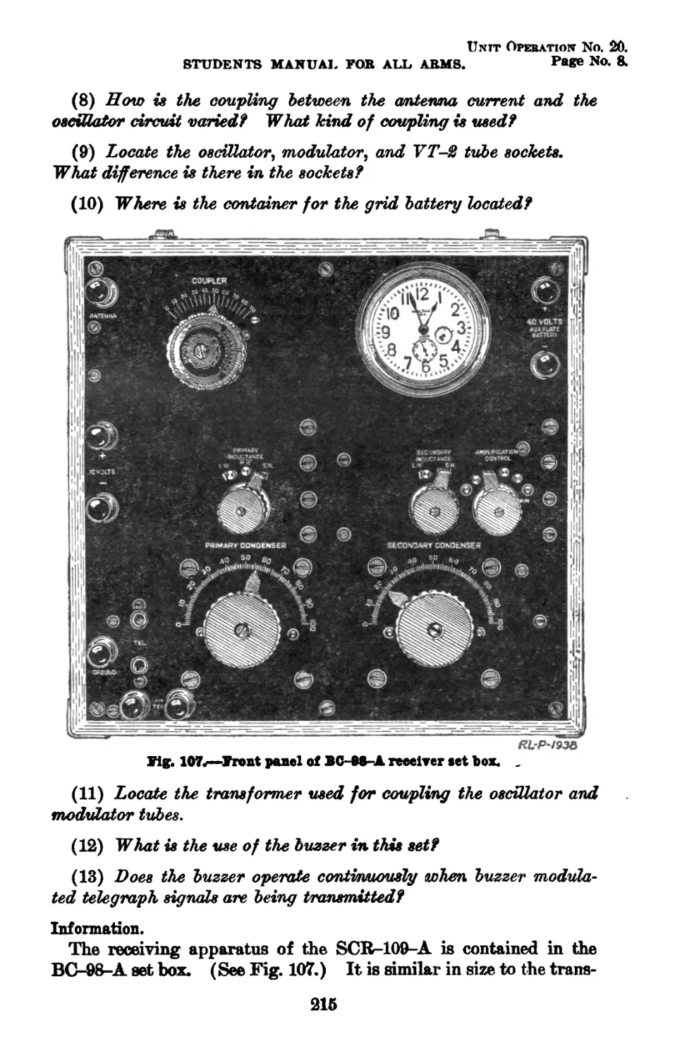
107 Front panel of BC-98-A receiver set box 1938 215
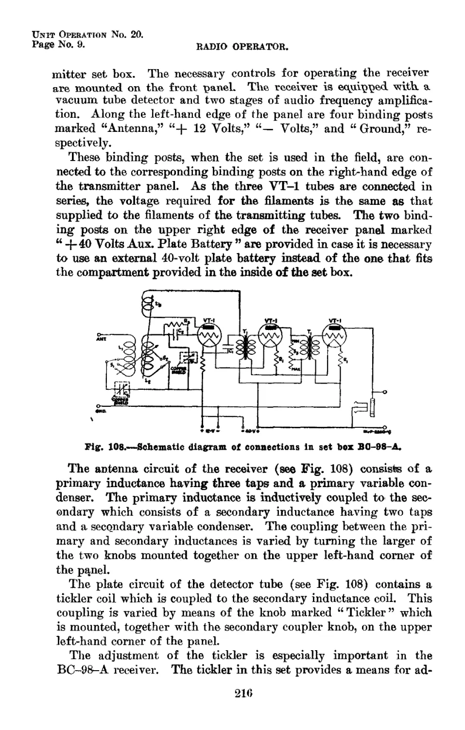
108 Schematic diagram of connections in set box BC-98-A 2860-C 216
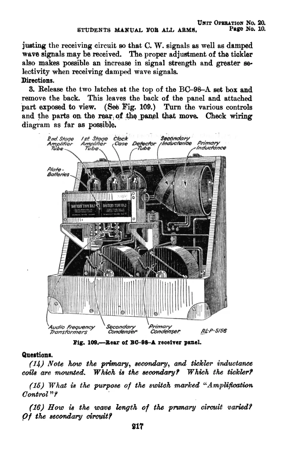
109 Rear of BC-98-A receiver panel 5156 217
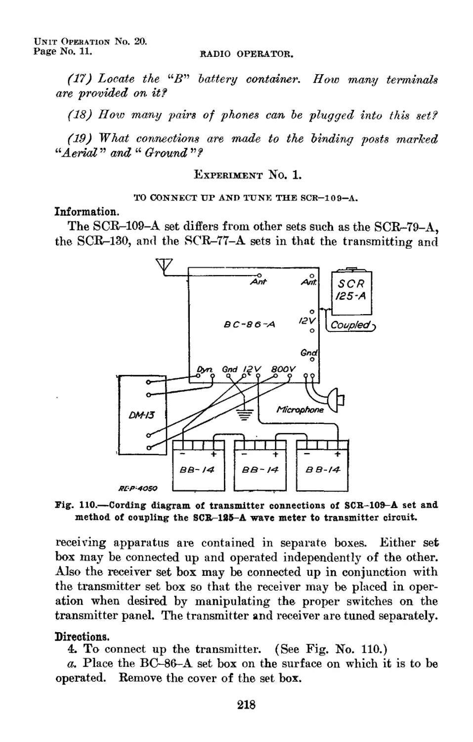
110 Cording diagram of transmitter connections of 8CR-109-A set and method of coupling the SCR-125-A wave meter to transmitter cir- cuit - _ 4050 218
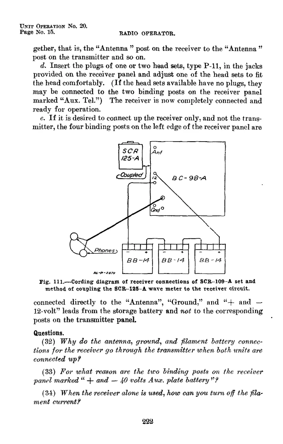
111 Cording diagram of receiver connections of 8CR-109-A set and method of coupling the SCR-125-A wave meter to receiver circuit 2879 222
(XI)
Unit Operation No. 1.
Page No. 1.
RADIO OPERATOR.
STUDENTS MANUAL
FOR ALL ARMS.
Part I.—Radio Sets.
UNIT OPERATIONS.
PRIMARY BATTERIES USED IN RADIO COMMUNICATION.
Information.
Effects of electricity.—The word electricity has been applied to a
form of energy, but just exactly what electricity is we can not say.
Electricity is known to exist for the simple reason that it can be ob-
served and measured. For example, electricity lights lamps, drives
motors, raises to a high temperature all sorts of electrical heating
devices, and energizes the telephone, the telegraph, and the electric
bell. It also makes radio communication possible.
Electricity produces these various effects only when it is in motion,
just as air must be in motion in order that wind may be produced.
Moving air causes the windmill to revolve, and propels the sailing
vessel. However, if air is not in motion no such effects are produced.
In a similar way, electricity at rest has few effects of practical value.
Electricity in motion is spoken of as a current of electricity.
Conductors; nonconductors.—In order to transfer electricity from
its source to the point at which it is to be used, a path or conductor
must be provided. For convenience and efficiency this conductor
usually consists of a copper wire. Gold, silver, iron, lead, brass,
zinc, carbon, and the earth are also conductors of electricity. Cer-
tain substances, such as glass, porcelain, hard rubber, bakelite, mica,
and sealing wax, are poor conductors of electricity and are therefore
called nonconductors or insulators.
Questions.
(1) What is energy?
(2) What are some forms of energy other than electrical energy?
(3) What is meant Ъу “ energizing the telephone ”?
1
Unit Operation No. 1.
Page No. 2. RADIO OPERATOR.
(4) What are the usual sources of electricity?
(5) Why is it evident that such a thing as electricity exists?
(6) TF7ZZ electricity produce any practical effects if no current is
flowing?
(7) What is a conductor?
Batteries.—The electricity necessary to operate the radio sets used
in the Army is obtained from two sources, namely, an electric battery
or a generator. For portable and small type sets the necessary
electrical energy is supplied by a battery. Two types of batteries
are used in general, one a primary battery and the other a secondary
or storage battery.
DRY CELL
TYRE BA-4
RESERVE DRY
CELL TYPE-BA40
- Cork
~ Brass Cap------------------
-Sealing Compound
—Paraffin ------
fHollow Carbon Rod
I Positive Pole
Solid Carbon Rod )
Positive Pole f
/Zinc Jar-
I. Negative Pole
—Active Materials
В
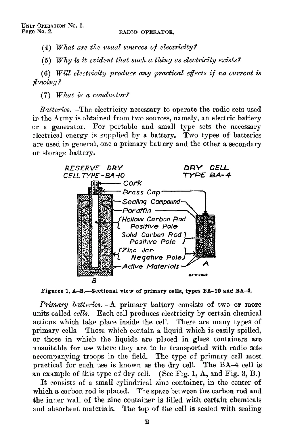
Figures 1, A-B.—Sectional view of primary cells, types BA-10 and BA-4.
Primary batteries.—A primary battery consists of two op more
units called cells. Each cell produces electricity by certain chemical
actions which take place inside the cell. There are many types of
primary cells. Those which contain a liquid which is easily spilled,
or those in which the liquids are placed in glass containers are
unsuitable for use where they are to be transported with radio sets
accompanying troops in the field. The type of primary cell most
practical for such use is known as the dry cell. The BA-4 cell is
an example of this type of dry cell. (See Fig. 1, A, and Fig. 3, B.)
It consists of a small cylindrical zinc container, in the center of
which a carbon rod is placed. The space between the carbon rod and
the inner wall of the zinc container is filled with certain chemicals
and absorbent materials. The top of the cell is sealed with sealing
2
Unit Operation No. 1.
STUDENTS MANUAL FOR ALL ARMS. PaS© No. 3.
wax. The carbon rod is equipped with a small brass cap which
acts as one terminal of the cell. The other terminal of the cell is
formed by the zinc container itself.
EXPERIMENT NO. 1.
Equipment.
1 cell, type BA-4, serviceable, with leads soldered to terminals.
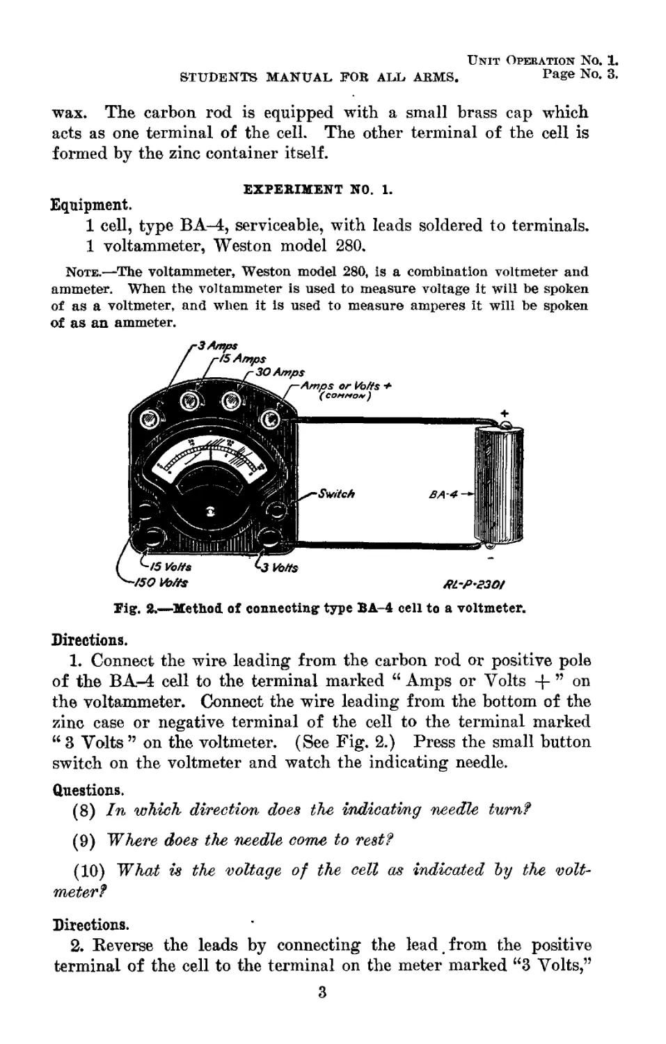
1 voltammeter, Weston model 280.
Note.—The voltammeter, Weston model 280, is a combination voltmeter and
ammeter. When the voltammeter is used to measure voltage it will be spoken
of as a voltmeter, and when it Is used to measure amperes it will be spoken
of as an ammeter.
Tig. 2.—Method, of connecting type BA-4 cell to a voltmeter.
Directions.
1. Connect the wire leading from the carbon rod or positive pole
of the BA-4 cell to the terminal marked “ Amps or Volts + ” on
the voltammeter. Connect the wire leading from the bottom of the
zinc case or negative terminal of the cell to the terminal marked
“ 3 Volts ” on the voltmeter. (See Fig. 2.) Press the small button
switch on the voltmeter and watch the indicating needle.
Questions.
(8) In which direction does the indicating needle turn?
(9) ~Where does the needle come to rest?
(10) What is the voltage of the cell as indicated Ъу the volt-
meter?
Directions.
2. Reverse the leads by connecting the lead t from the positive
terminal of the cell to the terminal on the meter marked “3 Volts,”
3
Unit Operation No. 1.
Page No. 4.
RADIO OPERATOR.
and the negative lead from the cell to the terminal on the meter
marked “ Volts.” Again press the small button switch and observe
the needle.
Questions.
(11) TFAen the, connections are reversed, in which direction does
the indicating needle move?
(12) Which is the proper way to connect the meter, as described
in direction 1 or as in direction, £?
Information.
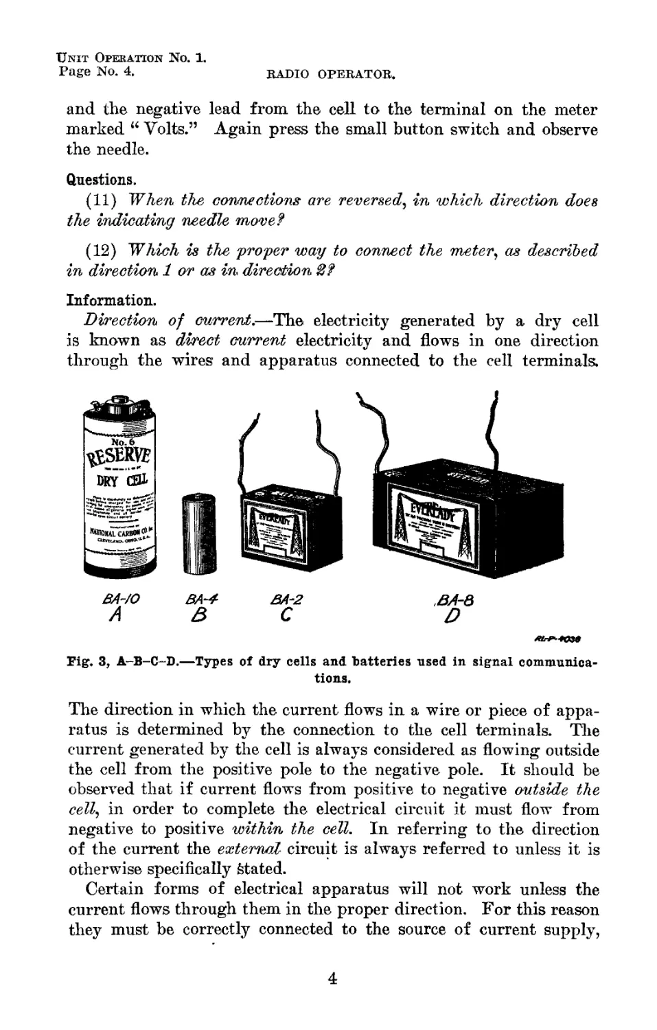
Direction of current.—The electricity generated by a dry cell
is known as direct current electricity and flows in one direction
through the wires and apparatus connected to the cell terminals.
BA-/O
A
Fig. 3, A-B-C-D.—Types of dry cells and batteries used in signal communica-
tions.
The direction in which the current flows in a wire or piece of appa-
ratus is determined by the connection to the cell terminals. The
current generated by the cell is always considered as flowing outside
the cell from the positive pole to the negative pole. It should be
observed that if current flows from positive to negative outside the
cell, in order to complete the electrical circuit it must flow from
negative to positive within the cell. In referring to the direction
of the current the external- circuit is always referred to unless it is
otherwise specifically Stated.
Certain forms of electrical apparatus will not work unless the
current flows through them in the proper direction. For this reason
they must be correctly connected to the source of current supply,
4
Unit Operation No. 1.
STUDENTS MANUAL FOR ALL ARMS. Page No. 5.
with respect to the positive and negative poles. The voltmeter in
Experiment No. 1 is an example of this.
Question.
(13) If the current generated Ъу the cell flows from the positive
to the negative terminal, why did the needle move to the left of
the zero of the scale in Direction 2?
Information.
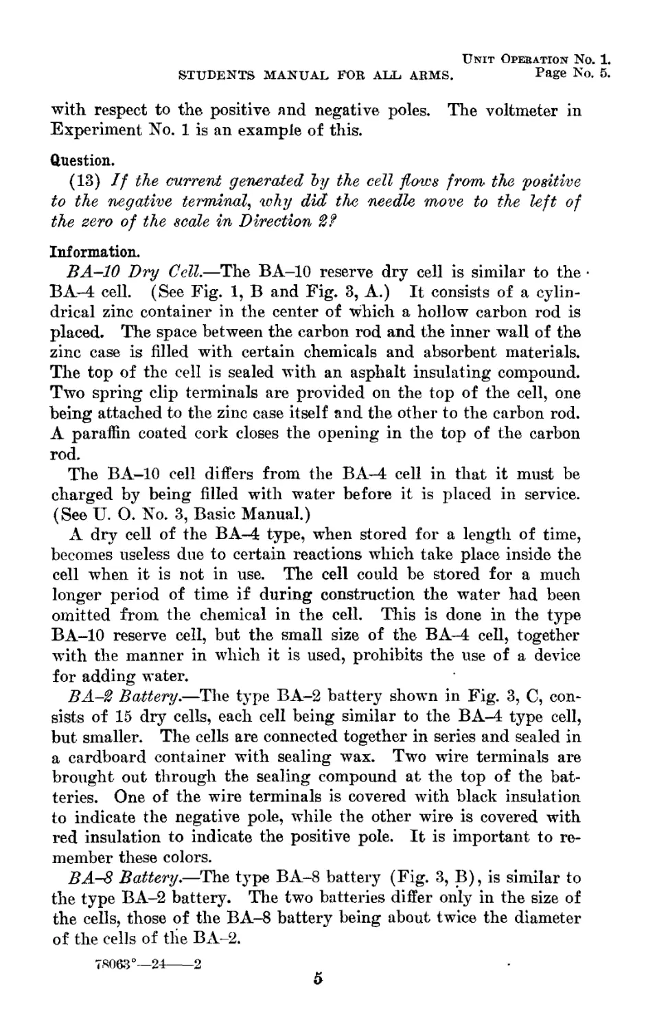
BA-10 Dry Cell.—The BA-10 reserve dry cell is similar to the •
BA-4 cell. (See Fig. 1, В and Fig. 3, A.) It consists of a cylin-
drical zinc container in the center of which a hollow carbon rod is
placed. The space between the carbon rod and the inner wall of the
zinc case is filled with certain chemicals and absorbent materials.
The top of the cell is sealed with an asphalt insulating compound.
Two spring clip terminals are provided on the top of the cell, one
being attached to the zinc case itself and the other to the carbon rod.
A paraffin coated cork closes the opening in the top of the carbon
rod.
The BA—10 cell differs from the BA-4 cell in that it must be
charged by being filled with water before it is placed in service.
(See U. O. No. 3, Basic Manual.)
A dry cell of the BA-4 type, when stored for a length of time,
becomes useless due to certain reactions which take place inside the
cell when it is not in use. The cell could be stored for a much
longer period of time if during construction the water had been
omitted from the chemical in the cell. This is done in the type
BA-10 reserve cell, but the small size of the BA-4 cell, together
with the manner in which it is used, prohibits the use of a device
for adding water.
BA-2 Battery.—The type BA-2 battery shown in Fig. 3, C, con-
sists of 15 dry cells, each cell being similar to the BA-4 type cell,
but smaller. The cells are connected together in series and sealed in
a cardboard container with sealing wax. Two wire terminals are
brought out through the sealing compound at the top of the bat-
teries. One of the wire terminals is covered with black insulation
to indicate the negative pole, while the other wire is covered with
red insulation to indicate the positive pole. It is important to re-
member these colors.
BA-8 Battery.—The type BA-8 battery (Fig. 3, B), is similar to
the type BA-2 battery. The two batteries differ only in the size of
the cells, those of the BA-8 battery being about twice the diameter
of the cells of the BA-2.
78063°—24-
-2
5
Unit Operation No. 2.
Page No. 1.
SERIES AND PARALLEL CONNECTIONS OF DRY CELLS AND
BATTERIES.
Equipment.
1 type BA-4 cell (serviceable).
4 type BA-10 cells (serviceable).
2 type BA-2 batteries (serviceable).
1 type BA-8 battery (serviceable).
1 voltammeter, Weston, model 280.
1 ammeter, 0-50 scale.
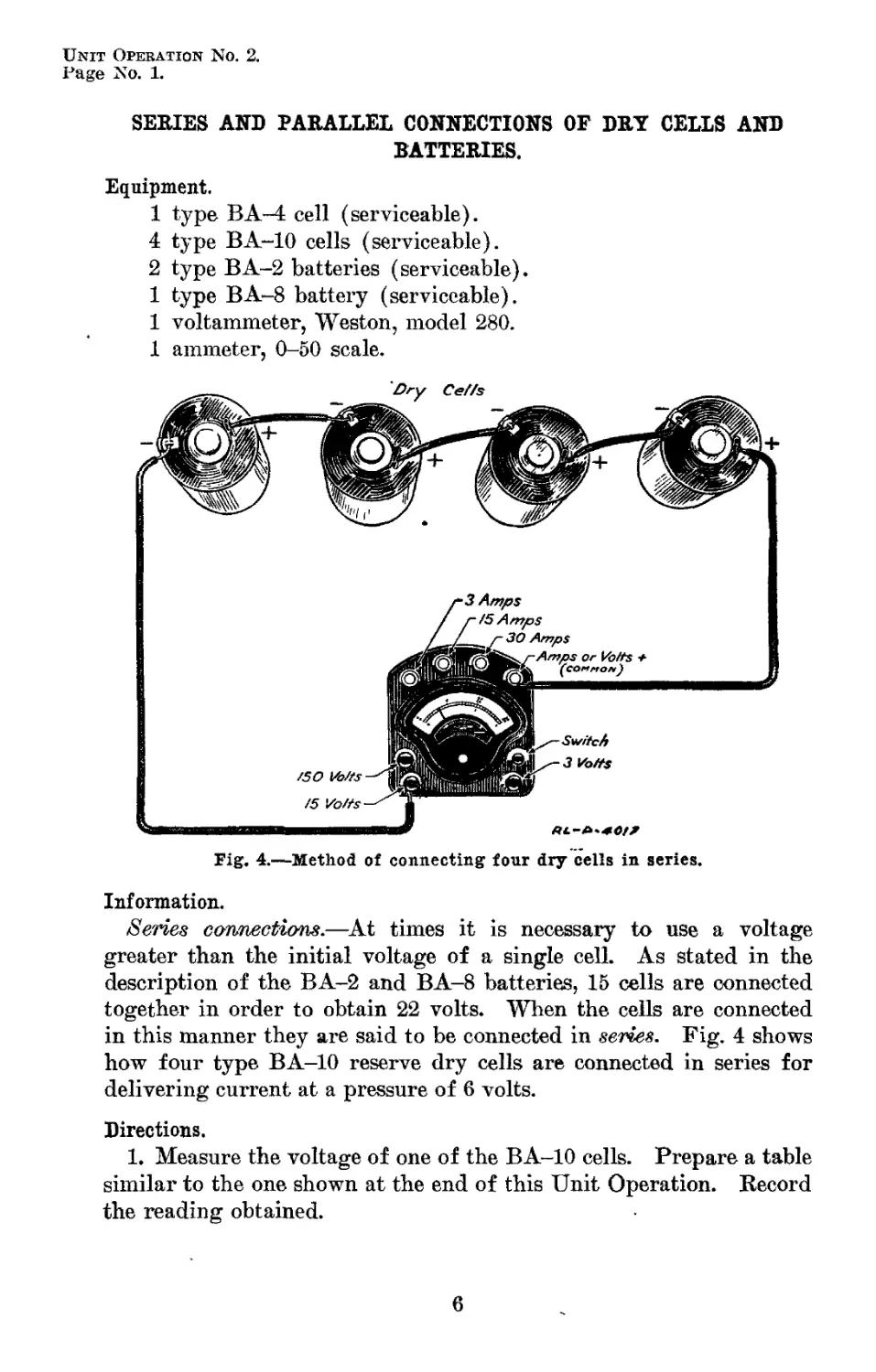
Fig. 4.—Method of connecting four dry cells in series.
Information.
Series connections.—At times it is necessary to use a voltage
greater than the initial voltage of a single cell. As stated in the
description of the BA-2 and BA-8 batteries, 15 cells are connected
together in order to obtain 22 volts. When the cells are connected
in this manner they are said to be connected in series. Fig. 4 shows
how four type BA-10 reserve dry cells are connected in series for
delivering current at a pressure of 6 volts.
Directions.
1. Measure the voltage of one of the BA-10 cells. Prepare a table
similar to the one shown at the end of this Unit Operation. Record
the reading obtained.
6
Unit Opebation No. 2.
STUDENTS MANUAL FOB ALL ARMS. Page No. 2.
2. Connect four type BA-10 cells in series as shown in Fig. 4. The
positive terminal of one cell is connected to the negative terminal of
the second cell. The negative terminal of the second cell is con-
nected to the positive terminal of the third cell and so on. Measure
the voltage of the four cells in series using the terminals marked
“ 15 Volts ” and “ -|-Volts ” on the voltammeter.
3. Record the reading in the table prepared.
Questions.
(1) What voltage does the meter italic ate?
(2) Multiply the voltage of one cell Ъу the number of cells (4).
What is the answer?
(3) Compare the answers to Questions 1 and 2. Would the same
relation hold true if site cells were used in Direction %?
Information.
When measuring the voltage of a battery such as the type BA-2
or the type BA-8 battery, the terminals marked “ Volts -j- ” and
“ 150 Volts ” are used. The “ Volts ” terminal is connected to the
positive terminal of the battery while the “ 150 Volts ” terminal is
connected to the negative pole of the battery. With these connec-
tions the figures at the top above the scale are used. When meas-
uring the voltage of a battery consisting of less than 10 dry cells,
connections are made from the battery to the “ Volts -f- ” and the
“ 15 Volts ” terminals on the meter. The “ 3 Volts ” terminal and
the “ Volts -f- ” terminal are used when measuring the voltage of
one or two dry cells. In this last case, the figures below the scales
are used. When measuring the voltage of a battery, the voltmeter
is always connected across the terminals of the battery.
Directions.
4. Measure the voltage of one of the BA-2 batteries using the ter-
minals “ 150 Volts ” and “ Volts -{- ” on the meter.
5. Record the reading in the table prepared.
6. Connect two of the BA-2 batteries in series. The positive or
red wire lead of one battery should be connected to the “ Volts + ”
terminal of the meter. The black or negative lead should be con-
nected to the red or positive terminal of the second battery. The
remaining black lead should be connected to the “ 150 Volts ” termi-
nal on the meter. Take the voltage reading and record it in the
table prepared.
7. Measure the voltage of the BA-8 battery.
8. Record the reading in the table prepared.
7
Unit Operation No. 2.
Page No. 3.
RADIO OPERATOR.
Question.
(4) What difference is there between the voltage of a BA-2 bat-
tery and a BA-8 battery?
Information.
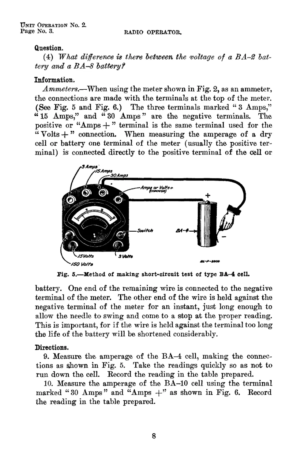
Ammeters.—When using the meter shown in Fig. 2, as an ammeter,
the connections are made with the terminals at the top of the meter.
(See Fig. 5 and Fig. 6.) The three terminals marked “ 3 Amps,”
“ 15 Amps,” and “ 30 Amps ” are the negative terminals. The
positive or “Amps -p ” terminal is the same terminal used for the
“ Voltsconnection. When measuring the amperage of a dry
cell or battery one terminal of the meter (usually the positive ter-
minal) is connected directly to the positive terminal of the cell or
Pig. 5.—Method of making short-circuit test of type BA-4 cell.
battery. One end of the remaining wire is connected to the negative
terminal of the meter. The other end of the wire is held against the
negative terminal of the meter for an instant, just long enough to
allow the needle to swing and come to a stop at the proper reading.
This is important, for if the wire is held against the terminal too long
the life of the battery will be shortened considerably.
Directions.
9. Measure the amperage of the BA-4 cell, making the connec-
tions as shown in Fig. 5. Take the readings quickly so as not to
run down the cell. Record the reading in the table prepared.
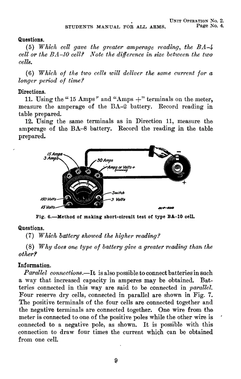
10. Measure the amperage of the BA-10 cell using the terminal
marked “ 30 Amps ” and “Amps +” as shown in Fig. 6. Record
the reading in the table prepared.
8
, Unit Operation No. 2.
STUDENTS MANUAL FOB ALL ARMS. PaSe No. 4.
Questions.
(5) Which cell gave the greater amperage reading, the BA-4
cell or the BA-10 cell? Note the difference in size between the two
cells.
(6) Which of the two cells will deliver the same current for a
longer period of time?
Directions.
11. Using the “ 15 Amps ’’ and “Amps -f-” terminals on the meter,
measure the amperage of the BA-2 battery. Record reading in
table prepared.
12. Using the same terminals as in Direction 11, measure the
amperage of the BA- -8 battery. Record the reading in the table
prepared.
Fig. 6.—Method of making short-circuit test of type BA-10 cell.
Questions.
(7) Which battery showed the higher reading?
(8) Why does one type of battery give a greater reading than the
other?
Information.
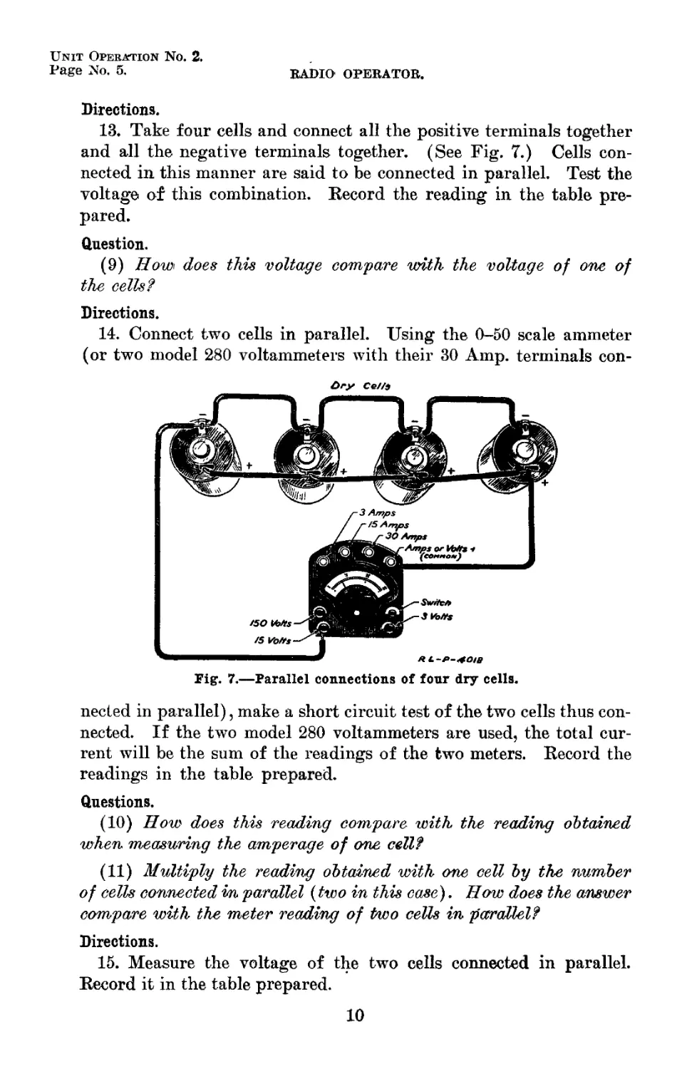
Parallel connections.—It is also possible to connect batteries in such
a way that increased capacity in amperes may be obtained. Bat-
teries connected in this way are said to be connected in parallel.
Four reserve dry cells, connected in parallel are shown in Fig. 7.
The positive terminals of the four cells are connected together and
the negative terminals are connected together. One wire from the
meter is connected to one of the positive poles while the other wire is
connected to a negative pole, as shown. It is possible with this
connection to draw four times the current which can be obtained
from one cell.
Unit Operation No. 2.
Page No. 5.
RADIO OPERATOR.
Directions.
13. Take four cells and connect all the positive terminals together
and all the negative terminals together. (See Fig. 7.) Cells con-
nected in this manner are said to be connected in parallel. Test the
voltage of this combination. Record the reading in the table pre-
pared.
Question.
(9) How does this voltage compare with the voltage of one of
the cells?
Directions.
14. Connect two cells in parallel. Using the 0-50 scale ammeter
(or two model 280 voltammeters with their 30 Amp. terminals con-
£>ry Celli
Fig. 7.—Parallel connections of four dry cells.
nected in parallel), make a short circuit test of the two cells thus con-
nected. If the two model 280 voltammeters are used, the total cur-
rent will be the sum of the readings of the two meters. Record the
readings in the table prepared.
Questions.
(10) How does this reading compare with, the reading obtained
when measuring the amperage of one cell?
(11) Multiply the reading obtained with one cell by the number
of cells connected in parallel {two in this case). How does the answer
compare with the meter reading of two cells in parallel?
Directions.
15. Measure the voltage of the two cells connected in parallel.
Record it in the table prepared.
10
Unit Operation No. 2.
STUDENTS MANUAL FOR ALL ARMS. Page No. 6.
Question.
(12) How does this reading compare with the voltage of one cell?
Information.
From the above experiments it may be seen that when cells are con-
nected in series the voltage of the combined cells is equal to the volt-
age of one cell multiplied by the number of cells connected in series.
The amperage of the cells in series, however, is the same as that of
one cell.
When the cells are connected in parallel the voltage of the com-
bined cells is the same as that of one cell, while the amperage is
equal to the amperage of one cell multiplied by the number of cells.
Directions.
16. Using the “ 15 Amps ” and “Amps -f- ” terminals on the volt-
ammeter measure the short circuit current of the BA-2 battery.
17. Using the same terminals measure the short circuit current
of the BA-8 battery.
18. Record the readings in the table prepared.
Questions.
(13) Which battery gave the higher reading?
(14) Upon what does the capacity in amperes of a battery such as
the BAS or the BAS depend?
Directions.
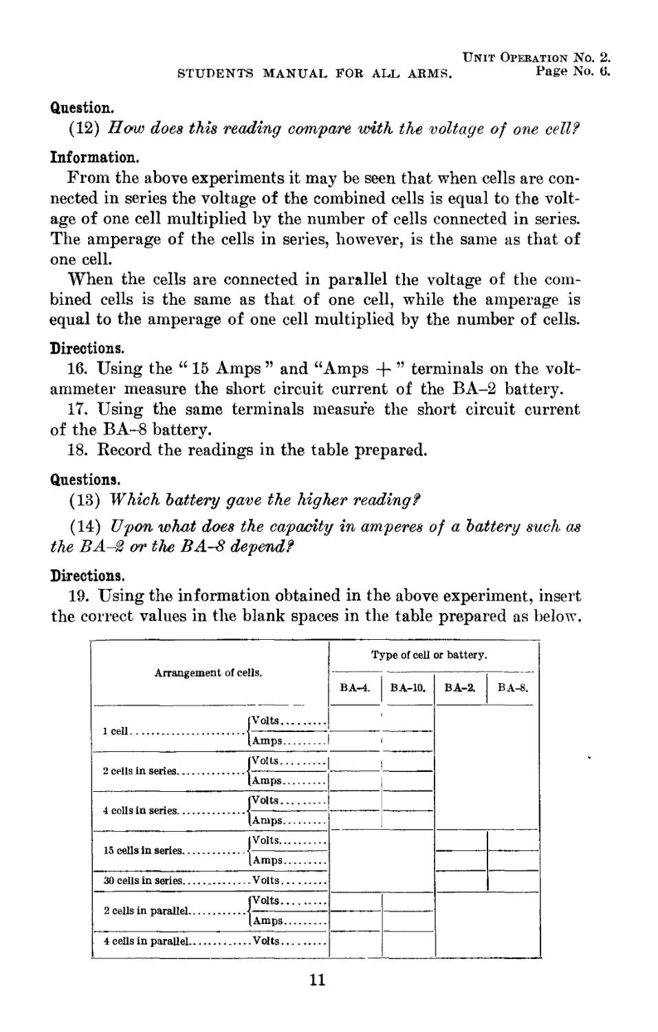
19. Using the information obtained in the above experiment, insert
the correct values in the blank spaces in the table prepared as below.
Arrangement of cells. Type of cell or battery.
BA-4. BA-10. BA-2. BA-8.
1 cell | Volts 1
(Amps
2 cells in series.. [Volts
[Amps
4 cells in series.. [Volts
(Amps
15 cells in series. [Volts
[Amps
30 cells in series Volts
2 cells in parallel [Volts
[Amps
4 cells in parallel Volts
11
Unit Operation No. 3.
Page No. 1.
STORAGE BATTERIES.
Equipment.
1 storage battery, type BB-14 (fully charged).
1 storage battery, type BB-28 (fully charged).
1 storage battery, type BB-41 (fully charged).
1 storage battery, type BB-5 (fully charged).
- 1 voltammeter, Weston model 280 (with leads)
1 pair battery leads, with clip terminals.
1 ruler.
Information.
Storage batteries.—The secondary battery or storage battery is
somewhat similar to a primary battery. The storage battery, like the
Jar
Complete Battery
Complete Assembly
RL-P-2H3
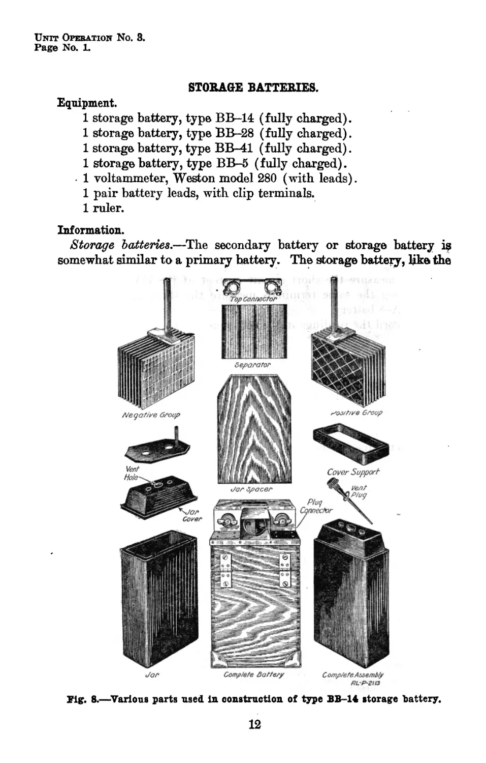
Tig. 8.—Various parts used in construction of type BB-14 storage battery.
12
Unit Operation No. 3.
STUDENTS MANUAL FOB ALL ABMs. Page No. 2.
primary battery, generates electricity by chemical reaction. The
principal difference, however, is that before the storage battery can
generate electricity it must first be charged. In other words, a direct
current from an outside source of electricity, commonly a generator,
must be sent through the battery. Usually this current is applied for
a number of hours until the necessary chemical changes have taken
place inside the battery. The battery is then ready for use. When
current is taken from a storage battery, the battery is said to be dis-
charging. After a battery has been used for a certain number of
hours, it becomes discharged and can not be used again until the
charging* process is repeated. 1
' Lead cell battery.—-There are two types of storage batteries, one
the. lead cell type, and the other the Edison battery in which the
as-у/
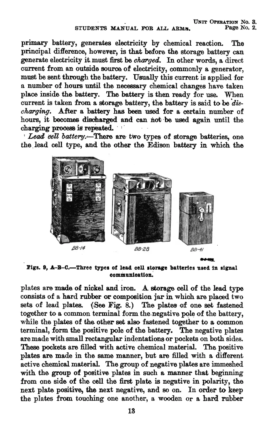
Figs. 9, A-B-C.—Three types of lead cell storage batteries used in signal
communication.
plates are made of nickel and iron. A storage cell of the lead type
consists of a hard rubber or composition jar in which are placed two
sets of lead plates. (See Fig. 8.) The plates of one set fastened
together to a common terminal form the negative pole of the battery,
while the plates of the other set also fastened together to a common
terminal, form the positive pole of the battery. The negative plates
are made with small rectangular indentations or pockets on both sides.
These pockets are filled with active chemical material. The positive
plates are made in the same manner, but are filled with a different
active chemical material The group of negative plates are immeshed
with the group of positive plates in such a manner that beginning
from one side of the cell the first plate is negative in polarity, the
next plate positive, the next negative, and so on. In order to keep
the plates from touching one another, a wooden or a hard rubber
13
Unit Operation No. 3.
Page No. 3. RADIO OPERATOR.
separator is placed between the plates. The cell jar is filled with a
dilute solution of sulphuric acid and water.
The majority of storage batteries used in the Signal Corps for
radio purposes consist of two cells. In order to protect the cells
against damage, they are inclosed in a strong wooden box at the
top of which terminals for connections are provided. The battery
shown in Fig. 8 and Fig. 9, A, is the type BB-14 storage battery.
The type BB-28 storage battery shown in Fig. 9, B, is similar in
construction to the type BB-14 battery. The type BB-Al is a port-
able, two-cell, storage battery which is much smaller in size than
the other type of batteries. This battery is shown in Fig. 9, C.
As the short circuit amperage of a storage battery is very high it
is impractical to determine its serviceability by the short-circuit test.
Under no conditions should an ammeter be connected across the ter-
minals of a storage battery, as this action will result in the burning
out of the meter.
Question.
(1) When dry cells are replaced by storage batteries what addi-
tional equipment must be provided?
Directions.
1. Measure the height, length, and width of each of the three lead
type batteries.
2. Open the cover of the BB-14 battery and note how the ter-
minals on the cover are connected to the terminals of the cells. Also
note the connection between the two cells.
3. Using the leads without the clips, connect the voltmeter to the
outside cover terminals of the battery. A strip of red fiber marks
the positive terminal of the battery, and a strip of black fiber marks
the negative terminal. Measure the voltage of the battery.
4. Prepare a table similar to the one shown below and record the
readings taken in this experiment and those following.
Type of storage battery. No. of cells. Voltage of one cell. Voltage of battery. Ampere-hour capacity.
BB-14
BB-28
BB-41
BB-5
5. Using the leads provided with the clip terminals, connect the
voltmeter to the inside battery terminals, being careful to get the
polarity right. Measure the voltage of the battery and record it
in the table.
14
Unit Opekation No. 3.
STUDENTS MANUAL FOR ALL ARMS. PaSe No. 4.
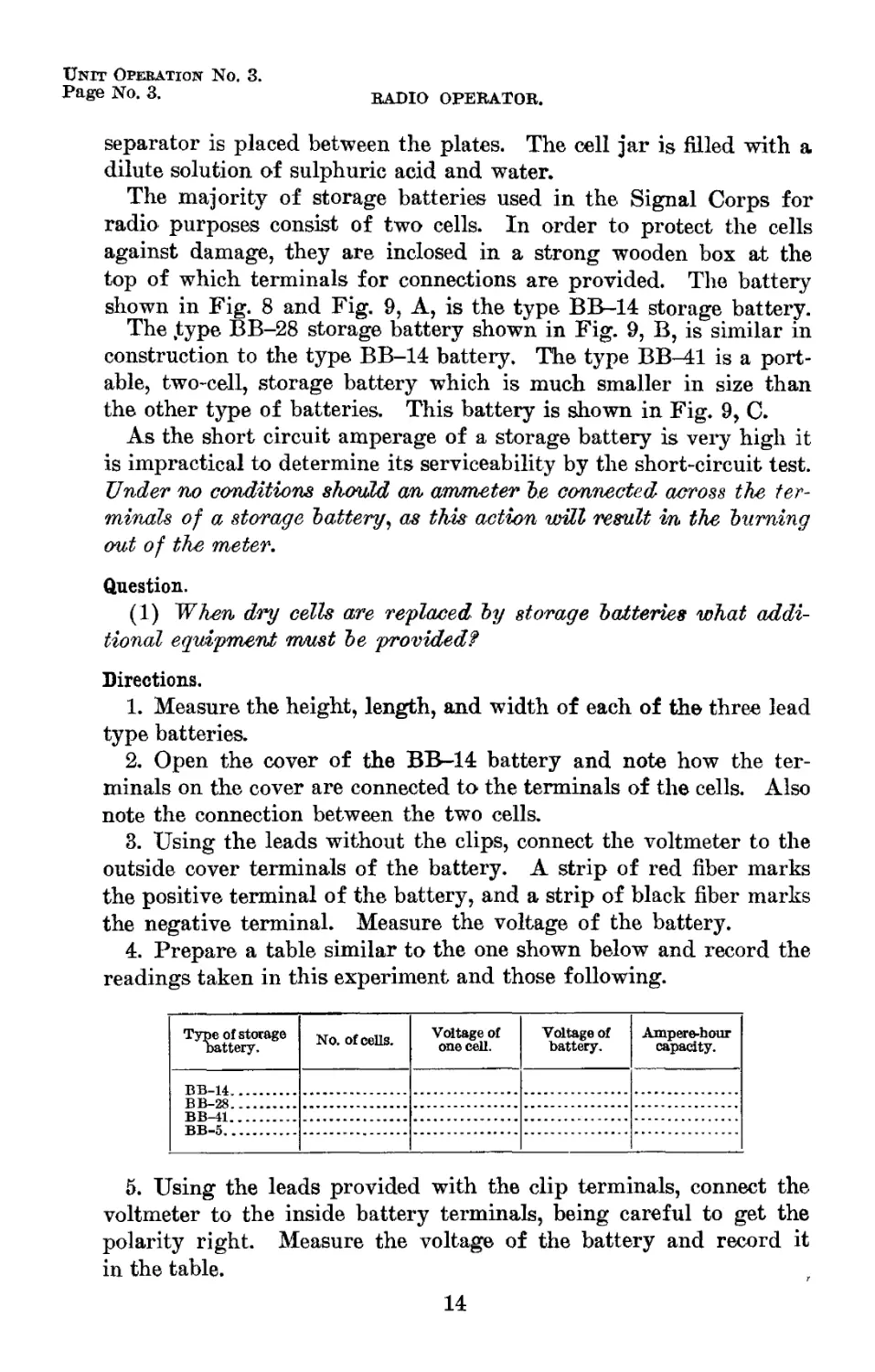
6. Measure the voltage of one cell by clipping the meter leads to
the cell terminals as shown in Fig. 10. Record the reading in the
table.
7. Connect the voltammeter to the outside terminals of the BB-28
battery. The positive and negative poles are clearly marked on the
cover. Read and record the voltage.
8. Open the cover of the BB-28 battery and connect the voltmeter
to either one of the cells using the leads with the clip terminals. (See
direction 5.) Measure and record the voltage.
9. Repeat directions 6, 7, and 8, using the BB-41 battery in place
of the BB-28 battery.
Information.
Voltage and amperage.—The voltage of a lead storage cell when
fully charged is about 2 volts. The capacity of a storage battery is
represented by its rating in “ ampere-hours.” This rating theoreti-
Fig. 10.—Method of measuring the voltage of one cell of a storage battery.
cally represents any discharge rate in amperes multiplied by the
number of hours the battery may be discharged at that rate. For
instance, a 100 ampere-hour battery will deliver 100 amperes for 1
hour, 50 amperes for 2 hours, 25 amperes for 4 hours, 10 amperes for
10 hours, or 2 amperes for 50 hours. It is not practical, however, to
draw as many as 100 amperes for 1 hour from a storage battery
of the small portable type, such as is used with radio sets. This rate
of discharge is too great, and in a very short time would cause the
battery to become completely ruined. It is necessary therefore to
discharge the battery at a lower rate. A normal rate of discharge
is usually specified by the manufacturer of the storage battery. The
normal discharge rate is the rate at which experience has shown can
not be exceeded without more or less injury to the battery. For in-
stance, if the normal discharge rate of a 100 ampere-hour battery is
15
Unit Operation No. 3.
Page No. 5.
RADIO OPERATOR.
20 amperes, in no case should the battery be discharged at a higher
rate than at 20 ampers.
The ampere-hour capacity of a battery depends mainly upon the
size and number of plates in the cells. The greater the size and num-
ber of plates there are in a cell the greater will be the ampere-hour
capacity of the battery.
Tile type BB-14 storage battery is a 100 ampere-hour battery con-
sisting of two cells. Since the voltage of one cell is 2 volts and the
cells are in series, the battery is rated at 4 volts.
The type BB-28 storage battery is a 90 ampere-hour battery.
Since it contains two cells, the battery is rated at 4 volts.
The type BB-41 storage battery is a 2-cell, 4-volt, 16 ampere-hour
battery. The plates are smaller in size and therefore the capacity of
the battery is much less than the type BB-14 or BB-28 batteries.
Directions.
10. Fill in the ampere-hour capacity for all three batteries in the
table prepared under Direction 4.
Questions.
(2) Upon what does the voltage of a storage battery depend?
(3) Upon what does the ampere-hour capacity of a storage battery
depend?
(4) A certain lead-cell type of storage batvery has three cells con-
nected in series and is rated at 60 ampere-hours. 'What is the voltage
of the battery? For how many hours will it deliver 2 amperes of
current?
(5) Which would be the easiest to carry in the field, the BB-Uh
BB-28, or BB~U?
(6) (л) A radio set which uses the type BB-Jfl battery is to be
placed in service for continuous use with a combat unit in the
field. This set requires 4 amperes for operation. Batteries can be
delivered only once each night. How many batteries should be
supplied in order to operate the set?
(b) If a BB-28 is used, how many batteries should be supplied
for the same set?
(c) If a BB-1A is used, how many batteries should be supplied
for the same set?
16
Unit Operation No. 3.
STUDENTS MANUAL FOR ALL ARMS. Page No. 6.
(7) (a) How many men would be required to carry the batteries
in question (6) (л)?
(d) How many men would be required to carry the batteries in
question (6) (Ъ)?
(c) How many men would be required to carry the batteries in
question (6) (с)?
(8) Which type of battery would a.radio section chief decide to
carry for the set in Question (6) if he were gi/ven his choice? Why?
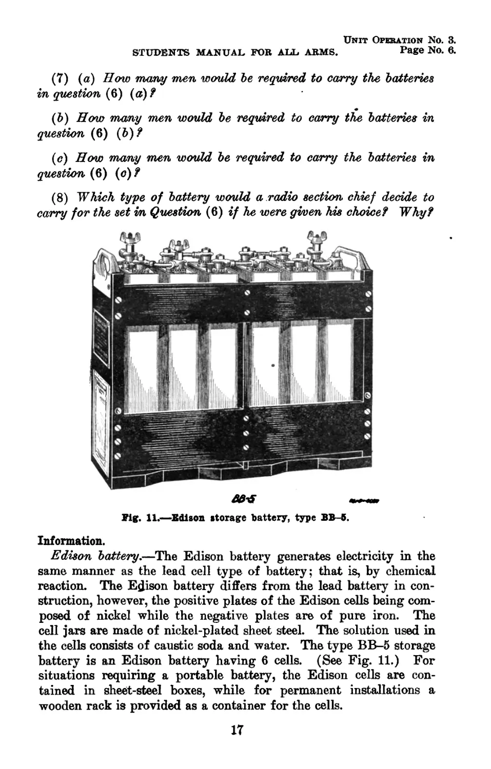
Fig. 11.—Edison storage battery, type BB-5.
Information.
Edison battery.—The Edison battery generates electricity in the
same manner as the lead cell type of battery; that is, by chemical
reaction. The Edison battery differs from the lead battery in con-
struction, however, the positive plates of the Edison cells being com-
posed of nickel while the negative plates are of pure iron. The
cell jars are made of nickel-plated sheet steel. The solution used in
the cells consists of caustic soda and water. The type BB-5 storage
battery is an Edison battery having 6 cells. (See Fig. 11.) For
situations requiring a portable battery, the Edison cells are con-
tained in sheet-steel boxes, while for permanent installations a
wooden rack is provided as a container for the cells.
17
Unit Operation No. 3.
Page No. 7. RADIO OPERATOR.
Questions.
(9) What is the chief advantage of the storage cell?
(10) What is the chief disadvantage?
Directions.
11. Measure the voltage of the type BB-5 Edison battery. Meas-
ure the voltage of any one cell. Record the measurements in the
table prepared under Direction 4.
The type BB-5 storage battery is a 6-cell, 8-volt, 100 ampere-hour
Edison battery. The voltage of each cell is about 1.25 volts. Since
there are 6 cells, the battery is rated at 7.5 volts.
Questions.
(11) What is the difference between a secondary battery and a
primary battery?
(12) How is a storage battery charged?
(13) How does the Edison storage battery differ from, the lead
cell type of battery?
(14) What is the approximate voltage of a fully charged lead
type cell? Of an Edison cell?
CARE OF STORAGE BATTERIES IN THE FIELD.
Information.
Spilling of aeid.—Some of the lead storage batteries used by the
Army for field service are of the nonspill type. However, this will
not prevent the acid from leaking should the battery be overturned.
To avoid this always keep the storage battery in an upright position.
If any acid should spill or leak from the cell it must be carefully
wiped off at once as it causes corrosion of the cell terminals. Take
care never to get the acid on the hands or clothes as it may cause a
burn or eat holes in the clothing.
Keeping terminals clean.—The action of the acid on the terminals
of the cell is such as to cause a green insulating material to collect
upon them. Should this material collect to too great a degree it
will thoroughly insulate the terminal thus making it impossible to
secure a good contact. Care must be taken that both terminals of
the storage battery are kept clean as all times.
Testing.—Never short-circuit a storage battery to determine its
state of charge as this may buckle the plates and permanently ruin
the battery. The testing of a storage battery in the field should be
by means of a voltmeter. When the battery is fully charged the
18
Unit Operation No. 3.
STUDENTS MANUAL FOR ALL ARMS. page No. 8.
voltage should be from about 2.0 to 2.2 volts per cell. The voltage
drops as the battery is used until at discharge it is about 1.8 volts
per cell.
Using one cell.—Sometimes it may be necessary to use only two
volts instead of four volts. If only one cell of the battery is used
the cells should be used alternately so as to discharge the cells to
the same degree. This is to facilitate charging.
Dropping of batteries.—The case of each cell is made of hard
rubber which if subjected to severe usage will crack and allow the
acid to leak. Never throw the battery down on the ground or
drop it.
19
Unit Operation No. 4.
Page No. 1.
RESISTANCE.
Equipment.
1 4-volt storage battery.
1 VT-1 vacuum tube.
1 VT-1 vacuum tube socket, attached to small board; the fila-
ment terminals on the socket should be wired to Fahnestock
terminals on the board.
1 voltammeter, Weston model No. 280.
2 5-foot lengths No. 18 B. & S. magnet wire.
2 1-foot lengths No. 18 B. & S. magnet wire.
1 5-foot length No. 32 B. & S. magnet wire.
1 10-foot length No. 32 B. & S. magnet wire.
2 battery clips.
1 resistor (approx. 0 to 20 ohms).
Information.
Electrical resistance and conductors.—It is well known that pipes
offer opposition or resistance to the flow of water through them, due
•to the friction between the running water and the sides of the pipes.
In a somewhat similar way all bodies offer some opposition to the
passage of an electric current through them. Hence all conductors of
electricity, even the best, offer some opposition to the flow of an elec-
tric current. This opposition is termed the electrical resistance of a
substance. Electrical resistance is measured in units called ohms. The
resistances of different conductors vary according to the substances
of which the conductors are composed. A pure silver conductor, for
instance, offers less resistance to a flow of current than any other
conductor of the same size. Due to its low resistance, silver makes
the best conductor of electricity. For this reason silver is used as a
standard with which to compare the resistances of other conductors.
Next in order to silver in its readiness to conduct electricity ranks
copper. While its resistance is higher than that of silver, yet it is
somewhat lower than the resistance of any other substance. Because
of this low resistance, together with its comparatively small cost,
copper wire is the most commonly used conductor of electricity in
general ийе. Other substances which may be used as conductors, but
which offer higher resistances than do silver and copper, are men-
tioned here in the order in which their resistances compare with
that of silver beginning with the material having the least resistance.
These substances are: Aluminum, zinc, brass, platinum, iron, nickel,
tin, lead, German silver, and carbon.
20
Unit Opebation No. 4.
STUDENTS MANUAL FOB ALL ABMS. I’age No. 2.
Resistance of wire.—The resistance of a conductor depends not
only upon the nature of the substance of which it is made but also
upon the size and length of the conductor. Thus the resistance of a
copper wire depends upon its size (or cross sectional area) and its
length. If two pieces of copper wire have the same length, but the
diameter of the one is greater than the diameter of the other, then
the resistance of the larger wire will be less than will that of the
smaller wire. That is, the resistance of a wire conductor decreases
with any increase in the size (or cross sectional area) of the wire.
Also a piece of copper wire of a certain diameter and 10 feet long
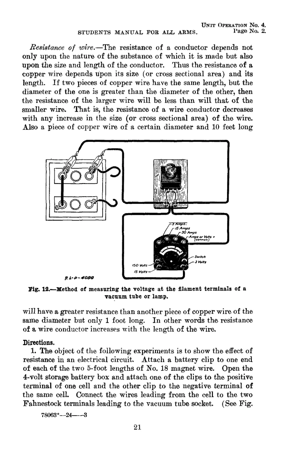
Jig. 1Й.—Method of measuring the voltage at the filament terminals of a
vacuum tube or lamp.
will have a greater resistance than another piece of copper wire of the
same diameter but only 1 foot long. In other words the resistance
of a wire conductor increases with the length of the wire.
Directions.
1. The object of the following experiments is to show the effect of
resistance in an electrical circuit. Attach a battery clip to one end
of each of the two 5-foot lengths of No. 18 magnet wire. Open the
4-volt storage battery box and attach one of the clips to the positive
terminal of one cell and the other clip to the negative terminal of
the same cell Connect the wires leading from the cell to the two
Fahnestock terminals leading to the vacuum tube socket. (See Fig.
78063°—24---3
21
Unit Operation No. 4.
STUDENTS MANUAL FOB ALL ABMS. Page No. 4.
Questions.
(1) Look at the table which you have completed. Is there a dif-
ference in the readings of the voltmeter in Directions 2 and i? If
there is a difference, to what is it duel
(2) Why did the filament light up in the experiment under Direc-
tion 4, but not light in the experiment under Direction 5?
(3) What does the voltmeter show regarding two pieces of wire
which are of the same length but of different sizes?
(4) Which wire delivers the smallest amount of current to the
tube, ths 5-foot No. 32 wire or the 10-foot No. 32 wire?
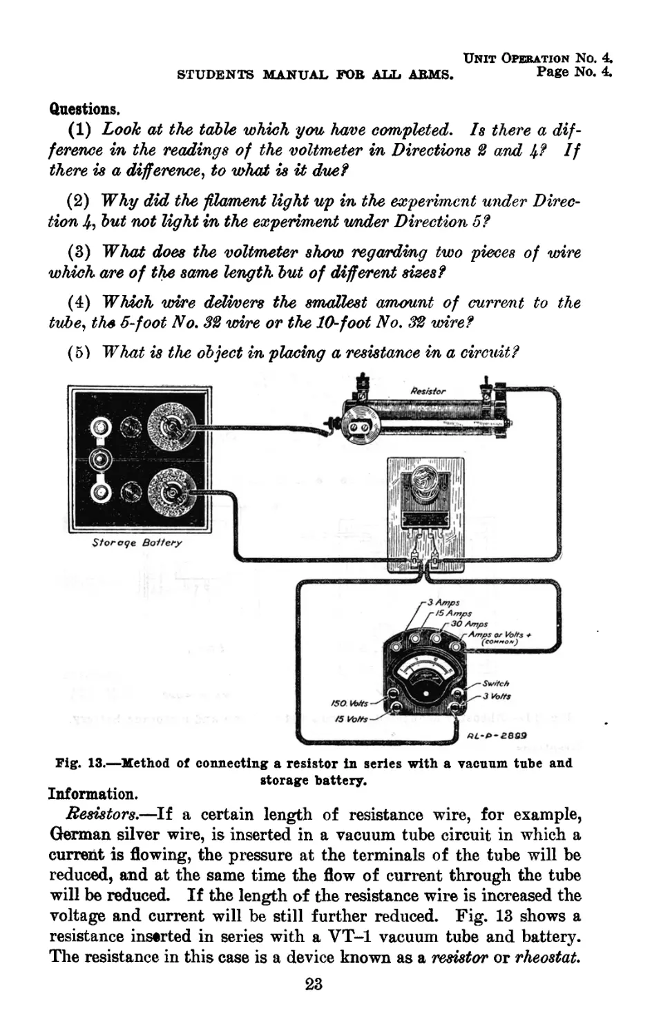
(5) What is the object in placing a resistance in a circuit?
Fig. 13.—Method of connecting a resistor in series with a vacuum tube and
storage battery.
Information.
Resistors.—If a certain length of resistance wire, for example,
German silver wire, is inserted in a vacuum tube circuit in which a
current is flowing, the pressure at the terminals of the tube will be
reduced, and at the same time the flow of current through the tube
will be reduced. If the length of the resistance wire is increased the
voltage and current will be still further reduced. Fig. 13 shows a
resistance inserted in series with a VT-1 vacuum tube and battery.
The resistance in this case is a device known as a resistor or rheostat.
23
Unit Operation No. 4.
Page No. 5.
RADIO OPERATOR.
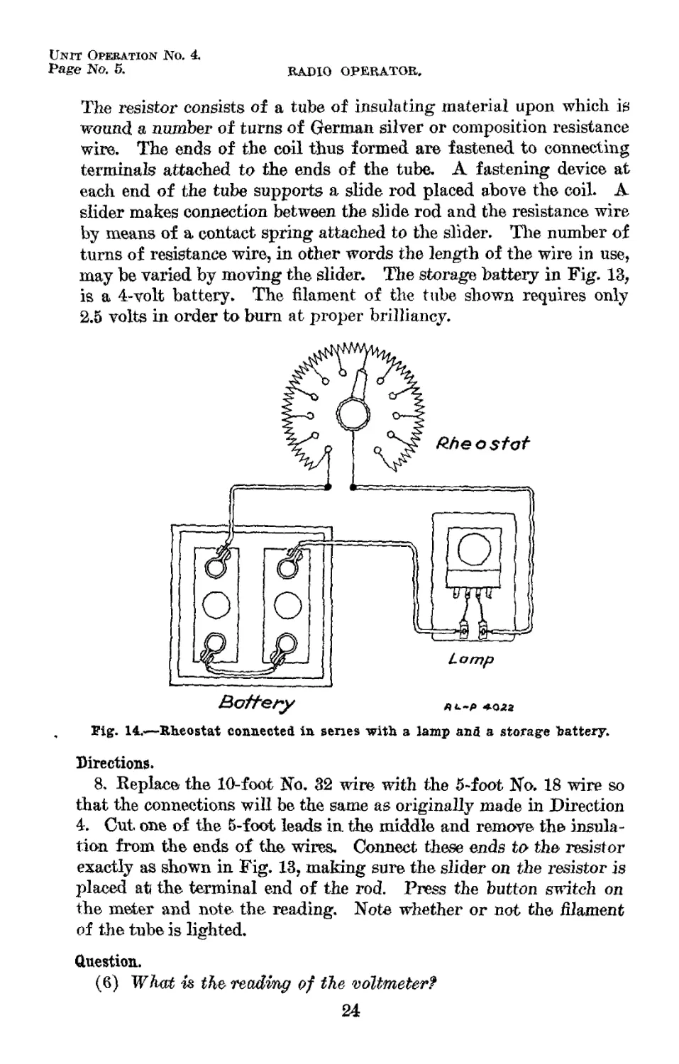
The resistor consists of a tube of insulating material upon which is
wound a number of turns of German silver or composition resistance
wire. The ends of the coil thus formed are fastened to connecting
terminals attached to the ends of the tube. A fastening device at
each end of the tube supports a slide rod placed above the coil. A
slider makes connection between the slide rod and the resistance wire
by means of a contact spring attached to the slider. The number of
turns of resistance wire, in other words the length of the wire in use,
may be varied by moving the slider. The storage battery in Fig. 13,
is a 4-volt battery. The filament of the tube shown requires only
2.5 volts in order to burn at proper brilliancy.
Battery
ЛА-Р -ФО22
Fig. 14.'—Rheostat connected in series with a lamp and a storage battery.
Directions.
8. Replace the 10-foot No. 32 wire with the 5~foot No. 18 wire so
that the connections will be the same as originally made in Direction
4. Cut one of the 5-foot leads in the middle and remove the insula-
tion from the ends of the wires. Connect these ends to the resistor
exactly as shown in Fig. 13, making sure the slider on the resistor is
placed ati the terminal end of the rod. Press the button switch on
the meter and note the reading. Note whether or not the filament
of the tube is lighted.
Question.
(6) TF/tut is the reading of the voltmetert
24
Unit Operation No. 4.
STUDENTS MANUAL FOR ALL ARMS. Page No. 6.
Directions.
9. Move the slider about one-fourth of an inch toward the oppo-
site end of tire rod and notice any change in the voltmeter reading
as well as any change in the lighting of the filament.
10. Move the slider gradually in the same direction until the fila-
ment of the tube glows a bright red. Caution: Do not move the
slider beyond a point at which the voltmeter needle swings to the
end of the scale (3 volts), as there will then be danger of burning
out the filament of the tube.
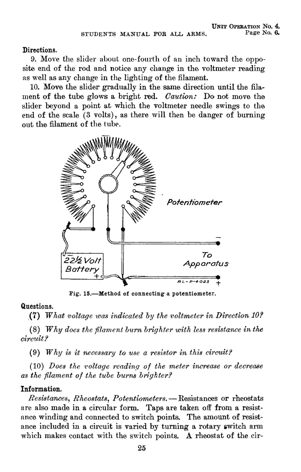
Fig. 15.—Method of connecting a potentiometer.
Questions.
(7) What voltage was Indicated by the voltmeter in Direction 10?
(8) Why does the -filament bum brighter with less resistance in the
circuit?
(9) Why is it necessary to use a resistor in this circuit?
(10) Does the voltage reading of the meter increase or decrease
as the filament of the tube burns brighter?
Information.
Resistances, Rheostats, Potentiometers. — Resistances or rheostats
are also made in a circular form. Taps are taken off from a resist-
ance winding and connected to switch points. The amount of resist-
ance included in a circuit is varied by turning a rotary switch arm
which makes contact with the switch points. A rheostat of the cir-
25
Unit Opekation No. 4.
Page No. 7. RADIO OPERATOR.
cular type properly connected in series with a VT-1 vacuum tube and
battery is shown in Fig. 14.
Another method of connecting resistance in a circuit is shown in
Fig. 15. The resistor when used in this manner is called a poten-
tiometer. With the connections shown, it is possible to obtain any
voltage desired from zero up to the full voltage of the battery. The
potentiometer is similar in construction to the rotary type of rheostat.
The resistance wire of the potentiometer is much greater than that of
the rheostat. This high resistance is necessary due to the fact that
the wire is connected directly across the terminals of the battery. As
shown in Fig. 15, the resistance winding of the potentiometer is con-
nected directly across the 22|-volt battery. The switch arm is con-
nected to one terminal of the apparatus to be used while the other
terminal is connected to one side of the battery. By turning the
switch arm the voltage delivered to the terminal of the apparatus
is varied accordingly.
Questions.
(11) TFAy is the circular form, of rheostat more practical for use
in a radio set than the straight type resistor?
(12) Why could not a potentiometer, used as in Fig. 15, be con-
structed with a low resistance similar to a, rheostat?
26
Unit Operation No. 5.
Page No. 1.
MAGNETS.
Equipment.
30 feet No. 24 copper magnet wire.
1 small bobbin or spool (with removable iron core).
1 type BA-10 reserve dry cell (charged).
1 small piece of iron (iron nail).
1 head set, type P-11.
1 test buzzer.
Information.
Two sorts of magnets will be discussed in this Unit Operation:
Permanent magnets and electromagnets.
Permanent Magnets.—Nearly every one is familiar with the per-
manent type of magnet. Usually, it consists of a magnetized steel
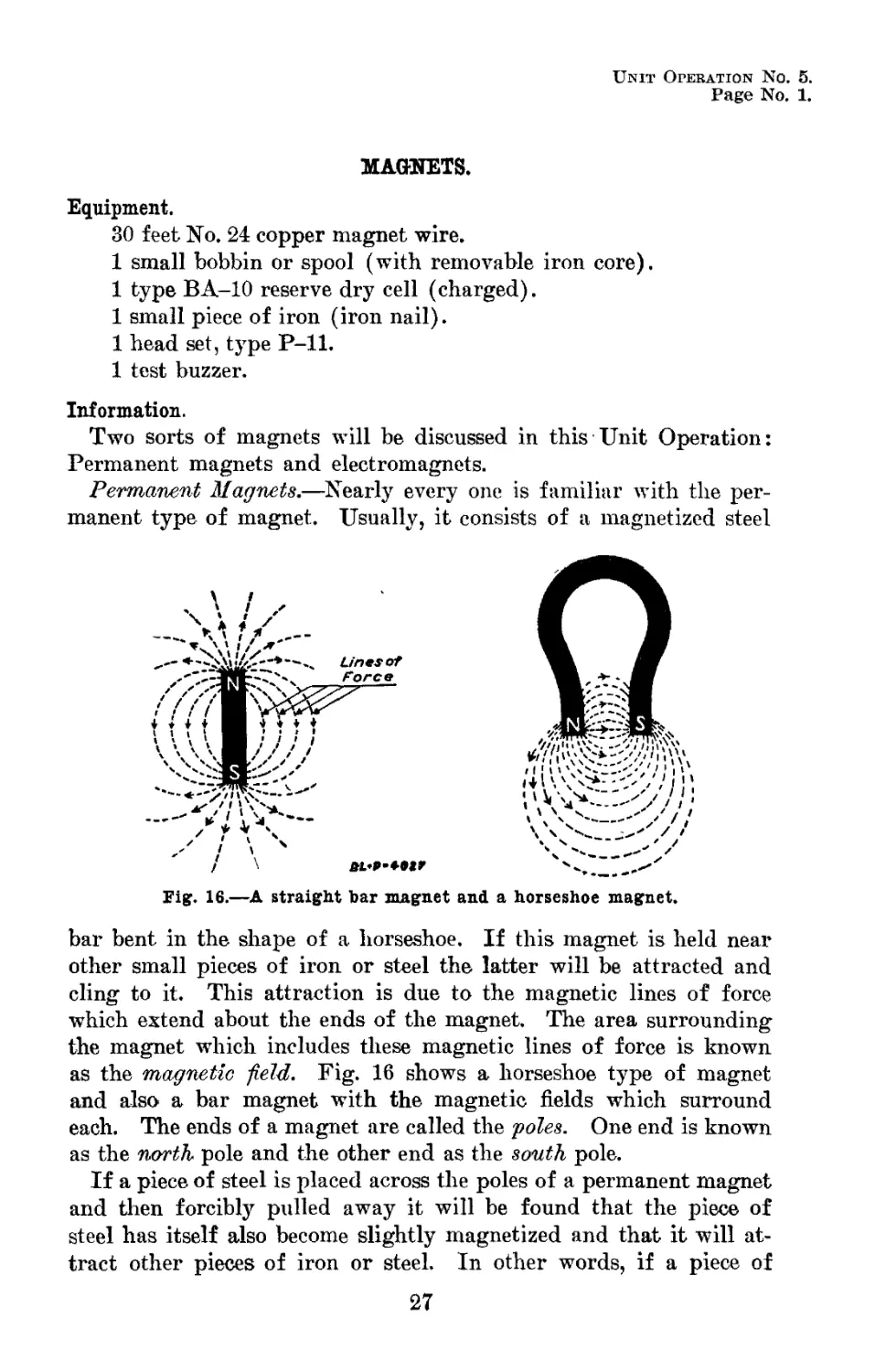
Fig. 16.—A straight bar magnet and a horseshoe magnet.
bar bent in the shape of a horseshoe. If this magnet is held near
other small pieces of iron or steel the latter will be attracted and
cling to it. This attraction is due to the magnetic lines of force
which extend about the ends of the magnet. The area surrounding
the magnet which includes these magnetic lines of force is known
as the magnetic field. Fig. 16 shows a horseshoe type of magnet
and also a bar magnet with the magnetic fields which surround
each. The ends of a magnet are called the poles. One end is known
as the north pole and the other end as the south pole.
If a piece of steel is placed across the poles of a permanent magnet
and then forcibly pulled away it will be found that the piece of
steel has itself also become slightly magnetized and that it will at-
tract other pieces of iron or steel. In other words, if a piece of
27
Unit Operation No. 5.
Page No. 2.
RADIO OPERATOR.
steel comes in contact with the poles of a magnet or is placed within
the fields of a magnet, it will still rdftin some of the magnetism
after it has been removed. In this respect steel differs from pure
iron. A piece of pure iron which has been placed across the poles
of a magnet will at once lose all traces of magnetism when it is
pulled away.
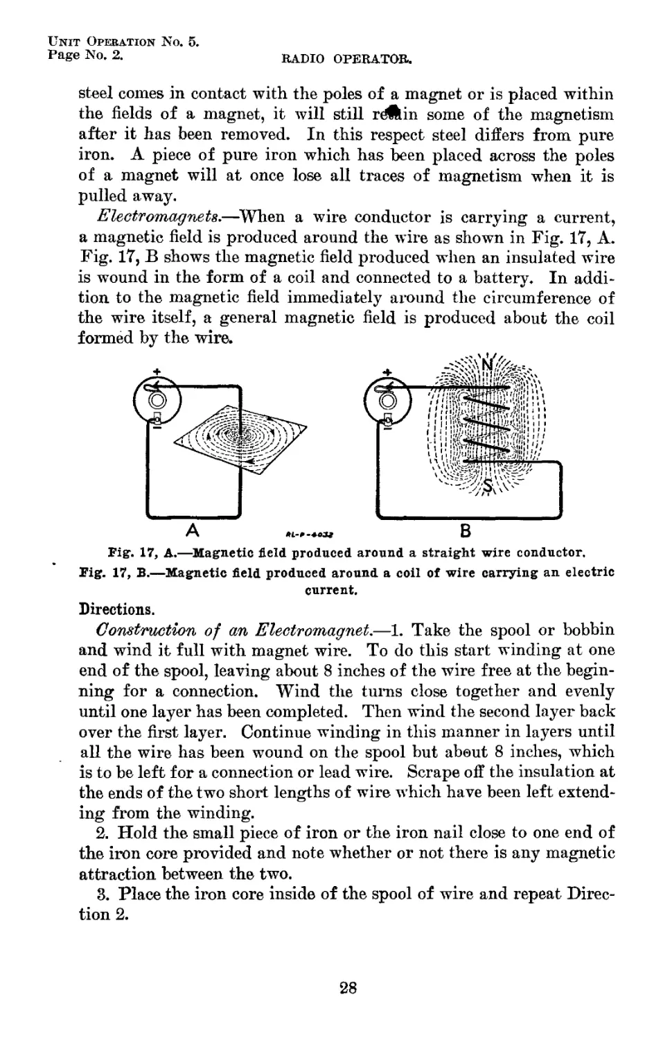
Electromagnets.—When a wire conductor is carrying a current,
a magnetic field is produced around the wire as shown in Fig. 17, A.
Fig. 17, В shows the magnetic field produced when an insulated wire
is wound in the form of a coil and connected to a battery. In addi-
tion to the magnetic field immediately around the circumference of
the wire itself, a general magnetic field is produced about the coil
formed by the wire.
Fig. 17, A.—Magnetic field produced around a straight wire conductor.
Fig. 17, B.—Magnetic field produced around a coil of wire carrying an electric
current.
Directions.
Construction of an Electromagnet.—1. Take the spool or bobbin
and wind it full with magnet wire. To do this start winding at one
end of the spool, leaving about 8 inches of the wire free at the begin-
ning for a connection. Wind the turns close together and evenly
until one layer has been completed. Then wind the second layer back
over the first layer. Continue winding in this manner in layers until
all the wire has been wound on the spool but about 8 inches, which
is to be left for a connection or lead wire. Scrape off the insulation at
the ends of the two short lengths of wire which have been left extend-
ing from the winding.
2. Hold the small piece of iron or the iron nail close to one end of
the iron core provided and note whether or not there is any magnetic
attraction between the two.
3. Place the iron core inside of the spool of wire and repeat Direc-
tion 2.
28
Unit Operation No. 5.
students manual for all arms. Page No. 3.
Question.
(1 ) Was there any magnetic attraction between the iron core and
the piece of iron in the above experiment?
Direction.
4. Connect the leads from the coil to the terminals on the battery.
Repeat Direction 2.
Questions.
(2 ) Does the flow of current through the coil have any effect on
the iron core? Explain.
(3 ) Why is the piece of iron not attracted by the iron core when
no current is flowing through the coil? {See Direction 3.)
Information.
Electromagnet.—If a bar of iron is placed inside a coil of wire which
is connected to a battery, the iron will be found to be magnetized and
will attract other pieces of iron or steel. Now if the current passing
through the coil is switched off, the field around the coil will dis-
appear or collapse and the iron bar will be found to be no longer
magnetized. The iron bar will remain magnetized just so long as the
current is turned on, but as soon as the current is turned off the iron
loses its magnetism. A bar of iron surrounded by a coil of insulated
wire, as described above, is an example of an electromagnet. The
principle of the electromagnet is made use of every day in the con-
struction and operation of electric bells, telephones, arc lamps, mo-
tors, generators, etc.
Question.
(4 ) If an unmagnetized steel core were placed inside a coil and
a current sent through the coil, would the steel core retain any mag-
netism after the current was turned off?
Information.
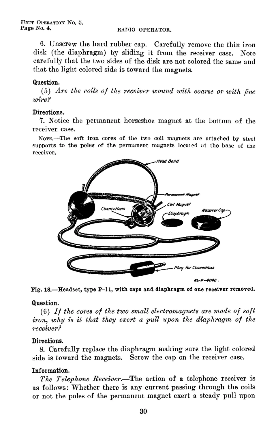
Telephone receivers.—Telephone receivers, which are necessary
with every type of radio receiving set used in the Signal Corps,
depend both upon the electromagnet and the permanent magnet for
their operation. One of the standard types of telephone receivers
for radio work is illustrated in Fig. 18.
Directions.
5. Remove one of the telephone receivers from the head band and
examine it closely. Notice the two wires leading into the receiver
through the holes in the case.
29
Unit Operation No. 5.
Page No. 4. RADIO OPERATOR.
6. Unscrew the hard rubber cap. Carefully remove the thin iron
disk (the diaphragm) by sliding it from the receiver case. Note
carefully that the two sides of the disk are not colored the same and
that the light colored side is toward the magnets.
Question.
(5) Are the coils of the receiver wound with coarse or with fine
wire?
Directions.
7. Notice the permanent horseshoe magnet at the bottom of the
receiver case.
Note.—The soft iron cores of the two coil magnets are attached by steel
supports to the poles of the permanent magnets located at the base of the
receiver.
HL-P-4040,
Tig. 18.—Headset, type P-11, with caps and. diaphragm of one receiver removed.
Question.
(6) If the cores of the two small electromagnets are made of soft
iron, why is it that they exert a pull upon the diaphragm of the
receiver?
Directions.
8. Carefully replace the diaphragm making sure the light colored
side is toward the magnets. Screw the cap on the receiver case.
Information.
The Telephone Receiver.—The action of a telephone receiver is
as follows: Whether there is any current passing through the coils
or not the poles of the permanent magnet exert a steady pull upon
30
Unit Operation No. 5.
STUDENTS MANUAL FOR ALL ARMS. Page No. 5.
the diaphragm. This causes the diaphragm to be curved slightly
inward toward the poles of the magnet, but without quite touching
them. If a small current is now passed through the coils, the
magnetic field produced by the coils will either help or hinder the
magnetic effect of the permanent magnet, depending upon the di-
rection of current through the coils. If the permanent magnet
field is strengthened by the field of the coils, a stronger pull will be
exerted upon the diaphragm causing it to move closer to the magnet
poles. If the permanent magnet field is weakened by the field of
the coils the magnetic pull on the diaphragm will be reduced, thus
causing the diaphragm to move away from the poles of the magnet.
The rapid opening and closing of a switch placed in series with a
telephone receiver and battery will cause an intermittent or broken-
up current to pass through the coils of the magnet. This intermit-
tent current in turn will produce a series of back and forth motions
of the diaphragm. The motions of the diaphragm will set up
vibrations in the air and these vibrations will become noticeable to
the ear in the form of a series of clicks. By substituting in place
of the switch a make-and-break device which will interrupt the
current very rapidly, a note will be heard in the receiver, the pitch
of which will depend upon how rapidly the current is being inter-
rupted.
Since only very small currents are available, from a radio receiv-
ing set, a great many turns of insulated wire must be wound on the
telephone receiver magnets in order to produce a magnetic field
strong enough to cause a movement of the diaphragm. A fine wire
is used in order that the necessary number of turns may be wound in
the small space provided. Since the wire is very fine the resistance
of the coils is high. For example, the resistance of the type of re-
ceivers shown in Fig. 18, is approximately 1,100 ohms.
The receivers used in a head set are connected in series. In this
case the total resistance of the receivers is 2,200 ohms.
Directions.
9. Connect one of the phone cord terminals to one of the dry-cell
terminals. Place the receivers on the head. Touch the other termi-
nal of the dry cell several times with the remaining cord terminal.
Question.
(7) What happens when, this is done?
Information.
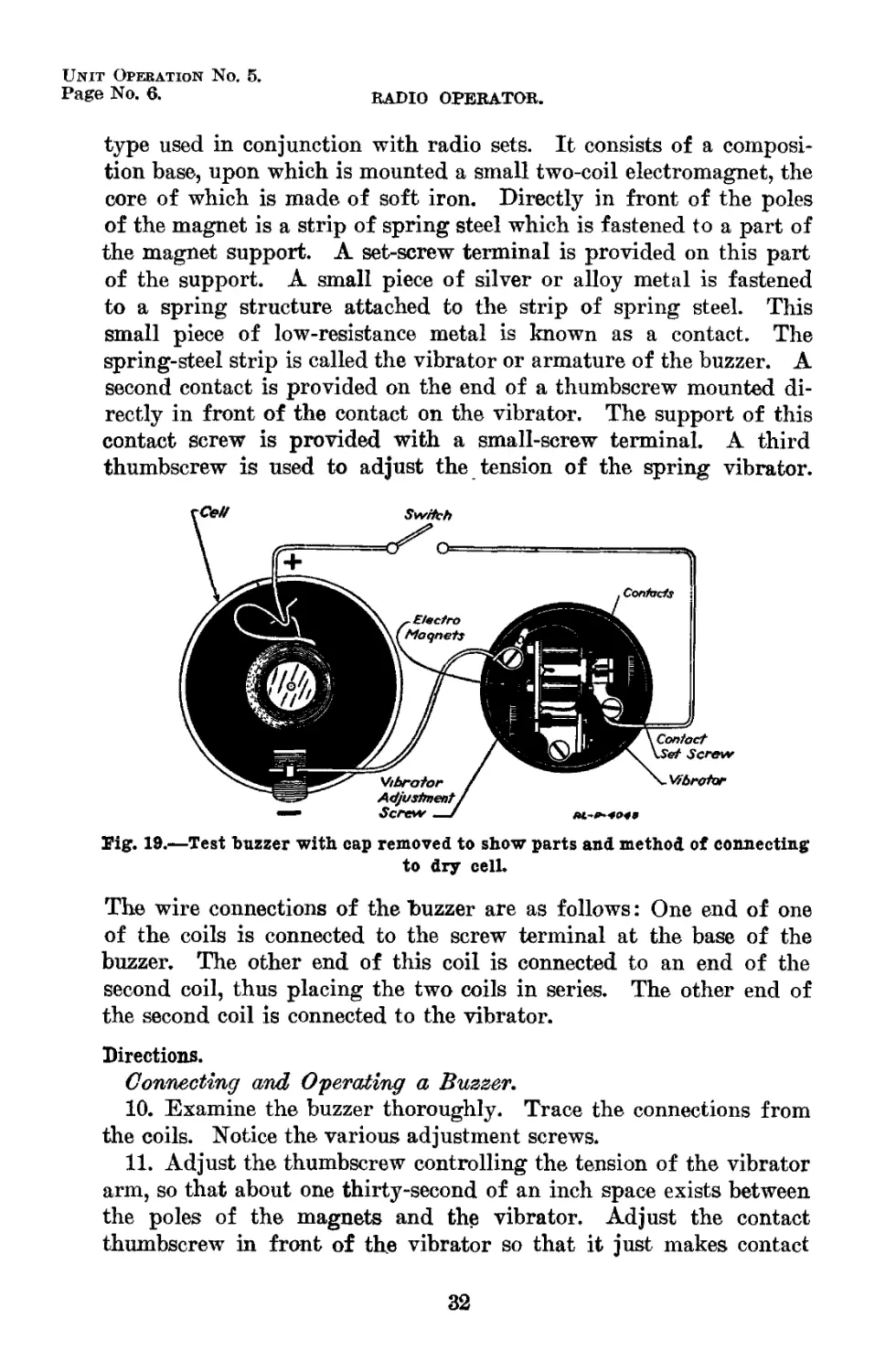
The Electric Buzzer.—The buzzer is another electrical device which
utilizes the electromagnet. The buzzer shown in Fig. 19 is the
31
Unit Operation No. 5.
Page No. 6.
RADIO OPERATOR.
type used in conjunction with, radio sets. It consists of a composi-
tion base, upon which is mounted a small two-coil electromagnet, the
core of which is made of soft iron. Directly in front of the poles
of the magnet is a strip of spring steel which is fastened to a part of
the magnet support. A set-screw terminal is provided on this part
of the support. A small piece of silver or alloy metal is fastened
to a spring structure attached to the strip of spring steel. This
small piece of low-resistance metal is known as a contact. The
spring-steel strip is called the vibrator or armature of the buzzer. A
second contact is provided on the end of a thumbscrew mounted di-
rectly in front of the contact on the vibrator. The support of this
contact screw is provided with a small-screw terminal. A third
thumbscrew is used to adjust the tension of the spring vibrator.
Fig. 19.—Test buzzer with cap removed to show parts and method of connecting
to dry cell.
The wire connections of the buzzer are as follows: One end of one
of the coils is connected to the screw terminal at the base of the
buzzer. The other end of this coil is connected to an end of the
second coil, thus placing the two coils in series. The other end of
the second coil is connected to the vibrator.
Directions.
Connecting and Operating a Buzzer.
10. Examine the buzzer thoroughly. Trace the connections from
the coils. Notice the various adjustment screws.
11. Adjust the thumbscrew controlling the tension of the vibrator
arm, so that about one thirty-second of an inch space exists between
the poles of the magnets and the vibrator. Adjust the contact
thumbscrew in front of the vibrator so that it just makes contact
32
Unit Operation No. 5.
STUDENTS MANUAL FOR ALL ARMS. Page No. 7.
with the vibrator. Connect one terminal of the dry cell to one ter-
minal of the buzzer as shown in Fig. 19. Connect one end of a lead
wire to the other terminal of the battery. Touch the vibrator ter-
minal with the other end of the lead wire.
Question.
(8) What happens when the 'vibrator terminal is touched with the
end of the lead wire?
Direction.
12. Connect the lead wire to the terminal of the contact screw lo-
cated in front of the vibrator.
Question.
(9) What happens when the above connection is made?
Direction.
13. With the buzzer still running try adjusting the set screws on
the buzzer and notice the pitch of the note obtained with each adjust-
ment.
Information.
The Action of a Buzzer.—The action of a buzzer is as follows:
When the switch in Fig. 19 is closed, the current passes through the
positive lead to the contact screw, through the contact screw and
vibrator, then through the coils in series, and back through the nega-
tive lead to the dry cell. When the current passes through the
magnet coils the iron cores of the magnet become magnetized and
attract the vibrator or armature. This attraction pulls the armature
away from the contact thumbscrew and thus causes the circuit to be
broken. As soon as the circuit is broken the electromagnets lose
their magnetism and no longer attract the armature. The tension
of the armature causes it to return to its original position, that is,
resting against the contact screw. This movement results in the
circuits again being completed and the armature again is attracted
to the magnets. This action is repeated over and over again, caus-
ing the armature to emit a sound or note.
Question.
(10) Upon what does the speed at which the armature vibrates
depend?
33
Unit Operation No. 6.
Page No. 1.
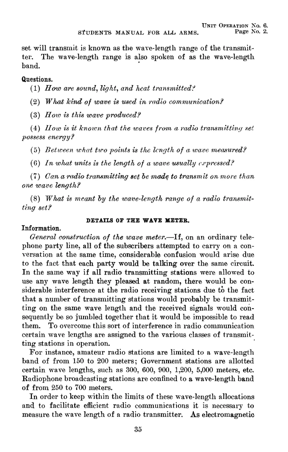
THE SCK-61 WAVE МЕТЕК.
Equipment.
2 wave meters, type SCR-61.
1 small screw driver.
1 head set, type P-11.
Information,
ELECTROMAGNETIC WAVES.
It is a well-known fact that when a stone is thrown into a pond
a series of ripples or waves is created. Similarly, if air is disturbed
by the vibrating of a bell or the blowing of a whistle, sound waves
are produced in the air. Light and heat are also transmitted by
waves. In fact, many of the most familiar phenomena of everyday
life are caused by wave motion.
The particular form of waves which have to do with radio com-
munication are known as electromagnetic or radio waves. Electro-
magnetic waves travel through a medium called the ether which,
though it is invisible, is supposed to exist everywhere throughout all
space. Electromagnetic waves may be produced in the ether by
electrical disturbances such as are caused by the electrical currents
of a radio transmitting set. These waves possess energy and are
capable of doing work. In other words, a radio transmitting set
sends out energy in the form of wave motion. A radio receiving set
placed at a considerable distance from the transmitting set inter-
cepts the waves of the transmitter. The energy which has been trans-
mitted over this distance by means of the wave motion operates the
radio receiver and causes it to produce a perceptible signal.
Every wave has a length and this length can be measured. For
instance, in the case of water waves, the wave length is usually de-
termined as the distance between the tops of the crests of two succes-
sive waves. The'wave length of any other kind of wave can be de-
termined in the same way. It is common practice to use the sym-
bol X (the Greek letter lambda, pronounced lam-da) to represent
wave length. This length is generally expressed in meters instead
of feet.
A radio transmitting set is usually designed to send out waves of
different lengths. For instance, a message may be sent on a wave
length of 250 meters. By properly adjusting the transmitter the
length of the wave may be changed to 300 meters, 500 meters, or
some other desired length. The series of wave lengths over which a
34
Unit Operation No. 6.
STUDENTS MANUAL FOR ALL ARMS. Page No. 2.
set will transmit is known as the wave-length range of the transmit-
ter. The wave-length range is also spoken of as the wave-length
band.
Questions.
(1) How are sound, light, and heat transmitted?
(2) What kind of wave is used in radio communication?
(3) Ноге is this wave produced?
(4) How is it known that the waves from a radio transmitting set
possess energy?
(5) Between what two points is the length of a wave measured?
(G) In what units is the length of a wave usually expressed?
(7) Can a radio transmitting set he made to transmit on more than
one wave length?
(8) What is meant hy the wave-length range of a radio transmit-
ting set?
DETAILS OF THE WAVE METER.
Information.
General construction of the wave meter.—If, on an ordinary tele-
phone party line, all of the subscribers attempted to carry on a con-
versation at the same time, considerable confusion would arise due
to the fact that each party would be talking over the same circuit.
In the same way if all radio transmitting stations were allowed to
use any wave length they pleased at random, there would be con-
siderable interference at the radio receiving stations due to the fact
that a number of transmitting stations would probably be transmit-
ting on the same wave length and the received signals would con-
sequently be so jumbled together that it would be impossible to read
them. To overcome this sort of interference in radio communication
certain wTave lengths are assigned to the various classes of transmit-
ting stations in operation.
For instance, amateur radio stations are limited to a wave-length
band of from 150 to 200 meters; Government stations are allotted
certain wave lengths, such as 300, 600, 900, 1,200, 5,000 meters, etc.
Radiophone broadcasting stations are confined to a wave-length band
of from 250 to 700 meters.
In order to keep within the limits of these wave-length allocations
and to facilitate efficient radio communications it is necessary to
measure the wave length of a radio transmitter. As electromagnetic
35
Unit Operation No. 6.
Page No. 3.
RADIO OPERATOR.
waves are invisible and can not be measured with ordinary measuring
instruments an electrical instrument known as a wave meter is used.
The wave meter is an instrument by means of which it is possible
to measure the length of electromagnetic waves generated by some
outside agency, such as a transmitting set. The wave meter may also
be used to generate and to emit (send out) waves of a known length.
The radio operator uses the wave meter for both of these purposes
when he measures the wave length of transmitting sets (both local
and distant), and when he calibrates transmitting and receiving
sets.
Spring Contacts
flexible Lead-
Indicator
Carrying
Strap
Large Pin
Locking Nat
Small Pin
Condenser
Locking
C/amp
Crystal
Detector
Buzzer Switch Buzzer
Pig. 20.—The SCBr-61 wave meter.
PL-P~285O
Phone
Jack
Coil-C
Coil-В
Coil- A
The most important parts of an SCR-61 wave meter are the rotary
condenser, inductance coil, buzzer, crystal detector, and the dry cell.
See Figs. 20, 21, and 22.
Directions.
1. Unbuckle the leather carrying strap. Release the two latches
on the front of the box and raise the cover. Study Figs. 20, 21, and
22 to learn the names of the important parts of the meter which can
36
Unit Operation No. 6.
STUDENTS MANUAL FOR ALL ARMS. Page No. 4.
be seen when the cover is raised. Learn the names of these parts
so that they can be given promptly when required.
2. Take the three coils out of the right-hand compartment of the
box. Note on just which coils the letters A, B, and C appear. Look
in the cover of the box and locate the clamp by which the coils are
fastened in place. Using this clamp, fasten coil A in place. (See
Fig. 21.) Be careful that the coil is fastened firmly. Then remove
coil A and try the other two coils in position, making sure that they
fit.
M.-P-2854
Fig. 21.—Panel of set box BC-37 removed to show interior parts.
Questions.
(9) Why is it important to know the length of an electromagnetic
wave?
(10) What is the purpose of the wa/ve meter!
(11) How is the wave meter inductance coil constructed?
(12) What is the approximate size of each of the three coils?
(13) Which coil (A, B, or C) is the largest? Which is the
smallest?
(14) Why were the two holes in the coil support made different
in size?
(15) How is contact made with the wire on the coils? {See Figs.
20 and 22.)
78063°—24——4 37
Unit Operation No. 6.
Page No. 5.
RADIO OPERATOR.
Information.
The Inductance Coils.—The two main parts of the wave meter are
the inductance coil and the rotary condenser. These two parts con-
trol the length of the wave emitted by the wave meter and measure
the waves emitted by a radio transmitter. For example, suppose
one of the three inductance coils supplied with the wave meter is
correctly inserted and connected in its proper place. If now the
setting of the rotary condenser is changed to another setting the
length of the emitted wave will be changed. If the rotary condenser
is left at this latter setting and the inductance coil is removed and
one of the other two coils connected in its place, the wave length
emitted will again be changed. This leads to the conclusion that any
change in the setting of the rotary condenser or in the size of the
inductance will cause a change in the wave length.
FRONT V/EW
BACK VIEW
JfL-A-ZeSS
I*ig. 22.—Details of inductance coils used in SCR-61 wave meter.
As stated above three inductance coils are furnished with each
wave meter of the SCR-61 type. Each coil covers a certain band
of wave lengths. Any wave length within this band may be obtained
by adjusting the rotary condenser according to the scale on the meter.
If after using any one of the three inductance coils in the wave
meter, the desired wave length is not found within the wave-length
band of the coil, it will be necessary to substitute the one of the two
remaining coils which includes the desired wave length within its
band. Using the three inductance coils a wave-length band of from
150 to 2,600 meters may thus be covered.
Questions.
(16) What are the two main parts of the wave meter?
(17) What do these parts control?
38
MOVABLE PLATES
RL-P-4O26
Fig. 23. —Schematic view of variable condenser used in the SCR-61 wavemeter,
showing minimum capacity position of plates.
BLrP-+oee-A
Fig. 24. —Schematic view, showing maximum capacity position of plates.
Unit Operation No. 6.
STUDENTS MANUAL FOR ALL ARMS. Page No. 6.
(18) What does each inductance coil limit?
(19) Why are three inductance coils supplied with the meter?
(20) What is the purpose of the rotary condenser?
Directions.
3. Remove the four screws from the corners of the panel and lift
the panel from the box by means of the binding posts marked “ fil ”
and “ meter.” It will be necessary to disconnect the canvas covered
wires leading up to the lid of the box. This is done by removing
the three screws holding the wires in position. Put all the screws
in the right hand compartment of the box in order that they will
not be lost.
Questions.
(21) Why was the panel lifted out by certain binding posts?
(22) How. is the box lined?
(23) Do the screws holding the panel in place serve to make an
electrical connection between the lining of the box and the wiring
on the panel? Look Under the panel where the screws go through
and see how many connections are made in this way.
Directions.
4. Hold the panel on edge and study the construction of the
rotary condenser. Rotate the knob on the front of the panel and
notice what turns behind the panel. Trace the connection between
the fixed and movable plates. (See Figs. 23 and 24.)
Information.
The Hotary Condenser—A. rotary condenser usually consists of a
number of stationary or fixed semicircular plates together with a
number of movable or rotary semicircular plates. The movable
plates rotate in such a way as to slip into the spaces between the
stationary plates. A pointer moving over a circular scale indicates
the position of the movable set of plates. (See Fig. 20.)
A condenser has the property of governing the flow of certain
forms of electricity which occur in a radio set. This property is
expressed interms of capacity. The unit for expressing the capacity
of a condenser is the farad. A subdivision of the farad is known
as a microfarad, which is
1
1,000.000
of a farad.
As a close relationship exists between wave length and capacity,
any change in the capacity of the rotary condenser in the SCR-61
39
Unit Operation No. 6.
Page No. 7. RADIO OPERATOR.
wave meter will cause a change in the length of the wave emitted
by the wave meter. The capacity of the rotary condenser may be
changed by changing the position of the rotary plates with respect
to the position of the fixed plates.
The details of the mechanical construction of the rotary con-
denser employed in the SCR-61 wave meter are rather complicated
and do not come within the scope of this course. An understanding
of the general principle involved will be sufficient.
From a careful study of the condenser in the wave meter itself
together with the illustrations in Figs. 23 and 24, it will be evident
that the condenser consists of two sets of fixed plates and two sets of
movable plates. In the illustrations the sets of fixed plates are
marked “A” and “ В ” while the movable plates are marked “A'” and
‘£ B'.” The two sets of fixed plates have been separated at one end to
show more clearly the details of the movable plates. Connections to
the wave meter circuit are made from the two sets of fixed plates.
The set of fixed plates marked A is connected to the set of movable
plates marked A' through a contact device. In the same manner the
other set of fixed plates В are connected to the movable plates B'
through a similar contact device. When the movable plates A' are
entirely covered by the fixed plates A and the movable plates B' are
entirely covered by the fixed plates В the capacity of the condenser
is at a minimum. (See Fig. 22.) When the movable plates are rotated
to the opposite position so that the plates A' are entirely covered by
the fixed plates В and the plates B' are entirely covered by the fixed
plates A, the capacity of the condenser is at a maximum.
Questions.
(24) How many sets of fixed plates are there in the rotary con-
denser of the SCR-61 wave meter?
(25) How many fixed plates are there in each set?
(26) How many sets of movable plates are there in the condenser?
(27) How many movable plates are there is each set?
(28) Are the movable and fixed plates connected together?
(29) How is the position of the movable plates varied?
(30) TFAatf is meant by the capacity of a condenser?
(31) What is the unit used for expressing capacity? What is a
microfarad?
(32) What is the purpose of the rotary condenser in the SCR-61
wave meter?
40
Unit Opekation No. 6.
STUDENTS MANUAL FOB ALL ARMS. Page No. 8.
WAVE METER AS A TRANSMITTER.
Information.
In order that the wave meter may be used as a low power trans-
mitter, a small buzzer is provided. The buzzer consists of two small
electromagnets, an adjustable armature or vibrator, and an adjust-
able contact screw. The longer of the two thumbscrews on the
buzzer is used to adjust the armature, while the shorter thumbscrew
is used to adjust the contact with the armature.
Fig. 25.—Schematic diagram of connections in. the SCR-61 wave meter
The buzzer is operated by a dry cell of the BA-4 type. It should
be noticed that the support for the BA—4 dry cell is so arranged that
the positive or center terminal of the cell makes contact with the
spring terminal located close to the rotary condenser. The negative
pole (the outside of the cell itself) makes contact with the brass lug
located at the edge of the panel. The dry cell should never be put
in the support backwards. In some types of wave meters if this is
done, the dry cell will become short-circuited and run down in a
short time.
41
Jnit Opkbation No. 6.
*age No. 9.
RADIO OPERATOR.
A push-pull buzzer switch is provided on the panel of the wave
meter to turn the current from the dry cell on or off. On some
wave meters the buzzer is operated by pulling out the switch button.
On others the button must be pushed in.
Sometimes an operator leaves the switch closed so that the current
flows through the buzzer circuit. The wave meter may then be
stored away without this fact being detected. Later some other
operator may try to use the wave meter, but will be unable to do so
for the reason that the cell will have become corroded and the
contacts destroyed. To prevent an occurrence of this kind, always
see that the Ъ-uzzer switch is open or else remove the battery.
Directions.
5. Trace the wiring diagram of the wave meter with particular
reference to the buzzer, buzzer switch, battery, small resistance, leads
to the inductance coils, meter connections, and the variable con-
denser. Omit the wiring to the detector, fixed condenser, and phones,
Bemember that there must be a complete metallic circuit in order
that the buzzer may operate,
Questions.
(38) Will the circuit from the battery to the buzzer be complete
if there is no inductance coll in place in the top of the set? Explain
your answer.
(34) Why are the leads going to the inductance. coils made flex-
ible? Why are they inclosed in canvas?
(35) WUl the buzzer operate if the two binding posts marked
“ Meter ” are not connected by the brass strap?
(36) What must be the position of the buzzer switch in order that
current may pass through the buzzer?
(37) Could the battery be put in the meter, backwards? If so,
what damage would result?
WAVE METER AS A RECEIVER.
Information,
When the wave meter is used to receive signals, the circuit must
include, in addition to the inductance coil and the variable con-
denser, a fixed condenser, a detector, and a pair of telephone receivers.
The purpose of the telephone receivers is to convert interrupted
or vibrating electrical currents into sound waves, as explained in
Unit Operation No. 5. However, the electrical currents picked up by
the inductance coil of a wave meter from a transmitting set are
vibrating at an exceedingly high rate of speed. These vibrations
42
Unit Operation No. 6.
STUDENTS MANUAL FOR ALL ARMS. No. Ю.
are much too rapid for the diaphragm of the telephone receiver to
follow. Due to this fact it becomes necessary to use a device which
will alter the rapidly interrupted or high-frequency currents so that
they will cause the diaphragm of the telephone receiver to respond
and produce sound waves. The device used for this purpose is
known as a detector.
There are various types of detectors. The one used in the SCR-61
wave meter is called a crystal detector. The crystal detector con-
sists of two essential parts—a piece of mineral or crystal and a con-
tact wire or point. The mineral or crystal is mounted in soft metal
at the base of the detector, while the contact is fastened to an adjust-
ing device just above the crystal. By the use of the adjustment
knob, the contact wire may be brought to bear upon any point on the
exposed surface of the crystal. This adjustment is provided for the
reason that some points on the crystal are more sensitive to the tiny
currents than are others.
Directions.
6. Trace the connection of the wave meter with respect to the
detector, telephone jack, variable condenser, fixed condenser, and the
inductance coils.
7. Turn the panel over and look at the top. Notice how the de-
tector is constructed. Unscrew the nut at the top and take the de-
tector apart. Remove the mineral and notice how it is mounted.
Do not touch the surface of the mineral, since grease, dust, or other
foreign matter on the surface of the crystal will impair its sensi-
tivity.
Questions.
(38) WAy should the student be careful not to touch the surface
of the mineral?
(39) Describe in detail the construction of the small -fixed con-
denser, and name its principal parts.
(40) Are all the joints soldered firmly in place? Why?
(41) How are telephones connected to the wave meter?
(42) Why is the crystal detector used in this set?
(43) Why is the metallic contact or “ cat whisker” mounted in a
ball-anjd-socket joint?
(44) Why is the detector inclosed in a glass case?
Note.—There are times when an operator using a wave meter or crystal
receiver experiences difficulty in locating a sensitive spot on the surface of the
43
Unit Operation No. 6.
Page No. 11. RADIO OPERATOR.
crystal, due to the fact that it has become covered with a film of dirt, grease,
or other foreign matter. If the operator is unable to obtain a new crystal it
is possible to restore the original sensitivity of the old one by cleaning it with
gasoline or alcohol. The solution used in Pyrene fire extinguishers may also
be used for this purpose with good results. The crystal should first be im-
mersed in the solution for about one minute. It should then be brushed thor-
oughly with an old toothbrush and allowed to dry.. Damp weather also has
a tendency to impair the sensitivity of a crystal. In this case the crystal
should be dried thoroughly and then covered with a thin film of oil, such as
paraffin oil or linseed oil. This film will keep out the moisture.
A CALIBRATION OF WAVE-METER SCALE.
Information.
The dial on the variable condenser has four different scales. The
outer scale is marked in degrees and the three inner scales are marked
in meters. Each of the three inner scales has a letter at the left-hand
end showing with which inductance coil it should be used. The hair
line in the center of the pointer indicates the reading corresponding
to any wave-meter setting.
It is difficult to obtain an accurate reading near the ends of the
scales on the variable condenser. For this reason, part of the maxi-
mum readings on scale “A” are included in scale “ В ” and part of the
maximum readings on scale “ В ” are included in scale “ C.” This is
called the “ overlapping ” of the wave-length ranges.
Directions.
8. Look at the dial on the variable condenser and carefully notice
the markings.
Questions.
(45) In what kind of units are the three inner scales calibrated?
(46) Which scale would be used if coil “4” was fastened in the lid?
(47) What is the lowest wave length that can be read with coil
ti. Q T)<i)
(48) What is the highest wave length that can be read with coil
“ В ”?
(49) For what is the small locking nut used?
Directions.
9. Kepiace the panel in the box. Fit the screws in their proper
holes and tighten them up. Connect the flexible leads as they were
before.
10. Examine the buzzer and its adjustment. Put one of the coils
in the lid of the box and turn on the switch to start the buzer. Be
44
Unit Operation No. 6.
STUDENTS MANUAL FOR ALL ARMS. Page No. 12.
sure that there is a serviceable battery in the wave meter and that
it has been correctly inserted. Now adjust the buzzer until it vi-
brates with a low pitched musical note. With the buzzer vibrating
the set becomes a transmitter of a very low power
Questions.
(50) What is the wave length of the transmitted wave with the
“ B” coil in and the pointer over the 300-meter mark on the “ A ”
scale?
(51) Set the points of the wave meter on the 85 degree mark of the
degree scale. What wave length does this correspond to when the
“A” coil is used? When the coil is used? When the
coils is used?
Directions.
11. Put the telephone plug in the jack, with the buzzer vibrating,
and move the contact wire about upon the surface of the mineral
in the detector until a clear distinct note is heard in the telephone
receivers. It may be necessary to search very carefully for the
sensitive spot. Stop the buzzer as soon as a good spot is found,
being careful not to jar the meter.
Questions.
(52) When the buzzer is cut off after a sensitive spot is found on
the crystal, will the set act as a radio receiving set?
(53) What is 'a band of wave lengths?
(54) What band of wave lengths can be received with the “A”
coil in position?
Experiment No. 1.
COUPLING.
Directions.
12. Take two SCR-61 wave meters and using one as a transmitter
and the other as a receiver, perform the following experiments.
Call the transmitter meter No. 1, and the receiver meter No. 2.
13. Open the two wave meters and put a coil A in each one. Start
the buzzer on the receiver (No. 2) and carefully adjust the detector.
Now put the No. 2 meter close to the No. 1 meter with their lids
back to back. (See Figs. 26 and 27.) Test the detector again and
see if it is still in adjustment. The meters placed in this way are
said to be closely coupled and the effect of the No. 1 meter should be
felt very strongly on $o. 2 meter. Now start the buzzer to vibrating
45
Unit Operation No. 6.
Page No. 13.
RADIO OPERATOR.
on the No. 1 meter and set the pointer to 300 meters. Rotate the
variable condenser on the No. 2 meter until the signal given out by
the No. 1 meter is heard at maximum strength. Carefully check
the wave length readings on both meters.
RL-P-286f
Fig. 26.—Method of obtaining close coupling between two SCBr-61 wave meters.
Fig. 27.—Schematic view showing relative positions of Inductance coils when
two SCBr-61 wave meters are closely coupled as in Fig. 26.
14. Do not disturb the No. 2 meter in any way since this will
destroy the adjustment of the detector. Loosen the coupling between
the two meters by moving the No. 1 meter farther away from the
No. 2 meter or by turning it so that its coil is not parallel with the
coil of the No. 2 meter. In Figs. 28 and 29 the coil of the No. 1
46
Unit Opebation No. 6.
STUDENTS MANUAL FOB ALL ABMS. Page NO. 14.
meter is at right angles to the coil of the No. 2 meter. When two
coils are closely coupled, the magnetic lines of force from one will
pass through the other iif large numbers; when they are loosely
coupled very few of the lines of one coil will affect the other coil.
PL-P-2d68
Fig. 28.—Two SCR-81 wave meters, loosely coupled.
Fig. 29.—Schematic view-showing relative positions of inductance coils when
two SCBr-81 wave meters are loosely coupled as in Fig. 28.
With the coils closely coupled the signal put out by the No. 1 meter
should be heard over a number of degrees on the scale, but with the
coils very loosely coupled the signal should be heard over only a
very few degrees.
15. Put the “ В ” coil in meter No. 1 and set its pointer at 450
meters. JTow rotate the condenser of meter No. 2 until a maximum
47
Unit Operation No. 6.
Page No. 15. RADIO OPERATOR.
sound is heard. Compare the readings on the two meters. Be sure
to read the scale corresponding with the coil used. When the maxi-
mum sound is heard in the No. 2 wavemeter, its circuit is said to be
in tune with the circuit of the No. 1 meter.
Questions.
(55) How is the detector most likely to be put out of adjustment?
(56) If the No. 2 meter gives a strong audible signal from say
250 meters to 350 meters in the above test when the No. 1 meter is
putting out a 300-meter wave, what should be done to the coupling
in order to obtain a more accurate reading?
(57) Is the wave length of the signal transmitted by the No. 1
meter found in practically the same way that the length of the wave
emitted by any transmitting station is found?
(58) With the “A” coil in the No. 1 meter and the “ В ” coil in the
No. 2 meter is it possible to bring the two meters in tune by adjusting
them?
Experiment No. 2.
MEASURING THE LENTH OF A TRANSMITTED WAVE.
Directions.
16. Have some one insert any one of the coils in the No. 1 meter
and start the buzzer vibrating. Do not look to see which coil is put
in nor what wave length the pointer is over. Adjust the detector
of the No. 2 meter very carefully. Couple the meters closely. Put
the “A” coil in the No. 2 meter and search the scale to see if the length
of the wave that the No. 1 meter is emitting can be found. If it
is not found with the “A” coil, try the “ В ” coil, and, if still unsuc-
cessful, try the “ C ” coil. Always follow this plan of using the “A”
coil first, then the “ В ” coil, and then the “ C ” coil. As soon as an
audible signal is heard, loosen the coupling between the meters and
take an accurate reading. Check this reading with the reading on
the No. 1 meter.
17. Get some one to change the wave length of the transmitting
meter and try the above experiment several times. Get at least six
readings of this kind and make a table similar to the one shown be-
low, including the readings of both wave meters. In this way it
can be determined whether or not accurate values are being obtained.
Questions.
(59) Why is it better to make the coupling close to start with?
(60) Can the No. 1 meter emit a wave that the No. 2 meter cam.
not pick up?
48
Unit Operation No. 6.
STUDENTS MANUAL FOR ALL ARMS. Page No. 16.
(61) If it is desired to measure the length of a wave put out Ъу
a transmitting set which is transmitting on an unknown wave length,
how would it be done?
Adjustments of the ware meters.
Wave meter No. 1. Wave meter No. 2.
Coil used. Wave length setting. Coil used. Wave length setting.
1 2 3 4 5 6
i
Experiment No. 3.
MEASURING THE WAVE LENGTH TO WHICH A RECEIVER IS TUNED.
Directions.
18. Set the No. 2 meter, with the detector adjusted, to some un-
known wave length. Do not look at the scale to see what it reads.
Adjust the No. 1 meter until it is putting out the wave for which
the No. 2 meter is adjusted. Remember to use close coupling and
then to loosen it for accurate results. Have some one else set the
No. 2 meter in order to disguise which coil is being used. Use the
“A,” “B,” and “C” coils, one after the other, and tune the No. 1
meter to put out the wave required. Try this on at least six set-
tings of the No. 2 meter. A table of results should be made similar
to the one used in Experiment No. 2.
Questions.
(62) How can a transmitting station be tuned to a specified wave
length within its range?
(63) When would a wave meter be required for use as a trans-
mitter in field operations?
(64) How would the wave length of a transmitting station Ъе
measured by an operator at a receiving station?
(65) When putting a wave meter in storage, what is the last thing
an operator inspects to see if it has been done? What will happen
if this is not done,?
49
Unit Operation No. 7.
Page No. 1.
THE SCR-74-A TRANSMITTING SET.
(SET BOX BC-18-A.)
Equipment.
1 set box, BC-18-A only.
1 wave meter, type SCB-61.
1 head, set, type P-11.
1 storage battery, 10 volts, type BB-3; or 3 batteries, type
BB-14.
Big. 30.—Set box, BC-18-A, with lid open.
GENERAL CONSTRUCTION OF THE SCR-74-A SET.
Information.
The SCBr-74-А is an induction coil transmitting set of low power.
(See Fig. 30.) The power supply is obtained from a 10-volt storage
battery, which is connected to the primary of the induction coil
through an ammeter and a key.
The induction coil is composed of two separate coils which are
designated the primary and the secondary. These two coils are
wound around a soft iron core. The primary winding, or coil, is
formed of large wire wound directly on the core. The secondary
winding is built outside the primary, in such a way that it incloses
both the core and primary, and is constructed of small wire with
50
Unit Operation No. 7.
STUDENTS MANUAL FOR ALU ARMS. 1’age No. 2.
many more turns than the primary. After the winding has been
completed the two coils and the core are dipped in wax, paraffin,
or some other good insulator. One end of the primary winding is
connected to one of the battery terminals through an interrupter,
similar to the one on an ordinary buzzer, and a telegraph key. The
other end of the primary winding is connected to the other side of
the battery. (See Fig. 30.) The ammeter connected in the primary
circuit is used to indicate when the coil is working properly. The
ends of the secondary winding are connected to the sparking sur-
faces or electrodes of the spark gap.
The function of the induction coil is to change the low voltage
direct current from the storage battery in the primary coil to. a
high voltage alternating current in the secondary. It suffices to say
here that an alternating current is an electric current which flows
first in one direction and then reverses and flows in the opposite
direction. This reversal of the direction in which the current flows
occurs with great frequency—many times per second.
Briefly the change in current from direct to alternating is effected
as follows: The interrupter alternately breaks and makes the elec-
trical circuit of the primary, thereby causing a pulsating current
to flow whenever the current is stopped and started with the open-
ing and closing of the circuit. The magnetic fields created by this
pulsating current cut the secondary coil winding and induce in it
an alternating current. There are more turns of wire on the sec-
ondary than on the primary. Consequently the induced voltage is
much higher than that supplied to the primary since the voltage
induced in the secondary depends upon how many more turns there
are in the secondary than in the primary. As an example, if there
are ten times as many turns on the secondary as there are on the
primary, the voltage of the secondary will be about ten times as
great as that supplied to the primary. Some idea can be had of the
secondary voltage of this coil from the fact that 20,000 volts will
cause a spark to jump a gap of 1 inch.
Questions.
(1) What does each of the following mean? Interrupter, spark
gap, electrode, function, magnetic field.
(2) What is the difference between a direct current and an alter-
nating current?
Directions.
1. Open the set box by undoing the latches and throw back the
lid. (See Fig. 30.) Unscrew the two thumbscrews and remove
51
Unit Operation No. 7.
Page No. 3.
RADIO OPERATOR.
the two round bakelite nuts which hold the antenna and ground
insulators in the box. Observe how these insulated connectors make
contact with opposite sides of the spark gap. At the opposite end
of the box remove the screws connecting the battery leads to the
Fig. 31.—Set Ъох, BC-18-A, disassembled to show various parts.
Fig. 32.—Schematic wiring diagram of SCR-74-A transmitter.
box. Turn the box over, holding the parts in place so they will
not fall out, and remove the two screws in the bottom of the box.
The panel and attached parts should now come out easily. (See
Fig. 31.) Check the wiring with the diagram in the lid of the set
box or with the diagram shown in Fig. 32. Compare the size of
52
Unit Opebation No. 7.
STUDENTS MANUAL FOB ALL ARMS. Page No. 4.
the wire coming out near the center of the coil with that on the
outside. Note which winding is connected in the primary circuit
and which is connected to the spark gap. Examine the interrupter
and note how it is constructed and how it operates. Note how the
key is connected, constructed, and adjusted, and how the condenser
is connected in the primary circuit.
Questions.
(3) What is the 'meaning of each of the following? Bakelite,
ground, insulators, antenna, ground lead.
(4) How is the key operated when the box is closed?
(5) Is the ammeter in the primary or secondary circuit?
(6) For what purpose is the fixed condenser used?
(7) What is the purpose of the interrupter?
(8) How is contact made between the spark gap and the antenna
and ground leads?
(9) How is the spark gap adjusted?
(10) How is the interrupter adjusted? Does the lock nut on the
interrupter contact screw up or down to lock the contact screw in
position?
(11) Can the spark gap be seen when the lid is closed?
(12) Why are there thumbscrews on the antenna and ground lead
in terminals?
(13) For what is the little compartment- on the right of the box
used?
(14) How is the distance between the contacts of the key adjusted?
(15) Does it make any difference which battery lead is connected
to the positive pole of the battery?
(16) Which coil is wound with the larger wire, the primary or
the secondary?
(17) Why are the windings of the induction coil dipped in wax or
paraffin?
(18)" Which two screws hold the apparatus in the set box?
(19) What is the voltage of the storage battery used with this set?
(20) What would be the effect of connecting a 20-volt battery in
the primary instead of the 10-volt battery?
78063°—24--5 53
Unit Operation No. 7.
Page No. 5.
RADIO OPERATOR.
Directions.
2. Put the set back in the box, and replace all the screws, nuts, and
leads.
Information.
When the SCBr-61 wave meter is used as a transmitter, the in-
ductance coil acts as a radiator of the rapidly vibrating or high fre-
quency currents. The distance over which the wave meter is effec-
tive is limited to a matter of only a few inches. If a wire, sus-
pended above the ground between two supports, were connected
at one end to one of the coil terminals on the wave meter, the
transmitting range would be increased considerably. A large
Fig. 33.—Cording diagram of SCR-74-A transmitter.
radiator or antenna of this type is necessary when using the
SCR^-74-А transmitter in order to reach the maximum distance
range of the set.
Experiment No. 1.
MEASURING THE WAVE LENGTH RADIATED.
Directions.
3. Take the set box, battery, and wave meter over to the lead-in
of the antenna indicated by the instructor. Connect the antenna
lead, and ground or counterpoise lead to the set box. Set the spark
gap to about one-eighth inch. Connect the battery leads to the bat-
tery. (See Fig. S3.) Do not touch the spark gap or antenna, while
64
Unit Operation No. 7.
STUDENTS MANUAL FOB ALL ARMS. Page No. 6.
there is current in the primary, as there is danger of receiving a
severe shock.
4. Never close the key until both the antenna and counterpoise
are connected to the set, and be sure that the length of the spark
gap is not over one-eighth inch. If the gap is greater than this
there is danger of breaking down the insulation in the secondary
winding of the spark coil.
5. Close the key and adjust the interrupter until it is giving a
clear steady pitched note and the ammeter registers about 5 to 7
amperes. Adjust the spark gap, being careful not to touch it while
the current is on, until it has a good blue-white spark playing
steadily between the sparking surfaces.
6. By means of the wave meter take a reading of the wave
length being transmitted by the set. Begin by trying to obtain
this reading close to the set and then move out toward the end
of the antenna until the reading is fairly sharp. Record the results.
Experiment No 2.
7. Repeat the work performed in Experiment No. 1 on another
antenna indicated by the instructor. Measure the wave length as
in Experiment No. 1 and compare this wave length with the wave
length measured on the antenna of Experiment No. 1.
Questions.
(21) 'Why is it dangerous to touch the antenna when the key is
down?
(22) On which antenna was the largest wave length reading ob-
tained?
(23) Is the wave length on which this set transmits dependent
on the antenna used?
(24) Is the signal readily tuned out?
(25) Could many of these sets work close together without inter-
ference?
(26) What is a high frequency current?
Unit Operation No. 8.
Page No. 1.
THE SCB^74-A TRANSMITTER.
(COUPLED CIRCUITS.)
Equipment.
1 Set box, type BC-18-A.
1 antenna equipment, type A-3-A.
2 helical inductances with clips (bare wire or a copper strip).
1 hot-wire ammeter, scale 0-0.5.
1 wave meter, type SCRr-61.
1 transmitting condenser, fixed, capacity approximately 0.004
mfd. (microfarad).
1 storage battery, type BB-3; or 3 storage batteries, type BB-14.
Information.
The SCK-74—A is an untuned induction coil or spark coil trans-
mitter. This means that no provisions are made in the set box itself
for tuning to any particular wave length. The only way in which
the wave length of this set can be changed is by altering the dimen-
sions of the antenna provided with the set. However, the set box
of the SCR-74-A may be used with some additional apparatus to
form different types of transmitting circuits which may be operated
On more than one wave length.
The method of tuning certain circuits in conjunction with the
SCR-74-A is somewhat similar to that used in tuning the wave meter
to transmit any given wave length. In the wave meter three induc-
tance coils are used which are not variable; that is, the number of
turns of wire in each coil can not be varied. The capacity of the
rotary condenser, however, can be varied, and thereby cause the wave
meter to be tuned to a given wave length. In tuning the SCR-74-A to
a given wave length one or two variable inductances and a condenser
which can not be varied are used. In construction the inductance
coils used with the SCR-74-A differ from the coils used in the
SCR-61 wave meter. The coils of the wave meter are wound with
small wire for the reason that the current carried is very small.
The large coils used with the SCR-74—A are wound with large wire
or brass strips in order to carry the large currents.
Directions.
1. Examine one of the large inductance coils.
56
Unit Opebation No. 8.
STUDENTS MANUAL FOR ALL ARMS. Page No. 2.
Questions.
(1) How does the manner in which the larger coil is wound differ
from the winding of the wave meter coils?
(2) What part of a clock or watch is wound simitar to the large
coil?
(3) Why is the coil constructed of such heavy wire or strip?
(4) What means are provided to make the inductance coil variable?
Information.
Coupling.—When a radio set contains more than one circuit there
must be a way provided to transfer the energy from one circuit to
the other. This transfer of energy from one circuit to another is
accomplished by what is known as coupling. Two circuits are said
to be coupled when it is possible for the energy of one circuit to be
transferred to the other circuit. Transfer of energy may be accom-
plished in any one of the following methods of coupling:
Direct coupling.—Two circuits are directly coupled when a part
of one circuit is also a part of the other circuit.
Inductive coupling.—Two circuits are inductively coupled when
the energy of one circuit is transferred to the other by means of a
magnetic field.
Capacitive coupling.—Two circuits are capacitively coupled when
the energy of one circuit is transferred to the other by means of
condensers.
Note.—This form of coupling is limited in use and will therefore not be dis-
cussed further.
In some radio sets the coupling used between two circuits is a com-
bination of all three of the above methods.
The degree of coupling between the two circuits is measured by
the amount of energy that is transferred from one circuit to the
other. When the greater part of the energy in one circuit is trans-
ferred to the other circuit the coupling is referred to as close or tight
coupling. When only a small part of the energy is transferred the
coupling is referred to as loose coupling.
The SCR-74-A set contains only one high frequency circuit; con-
sequently no coupling is involved. In the experiments which follow,
the set box, type BC-18-A, of the SCR-74-A, will be used with some
additional apparatus to illustrate the subject of'boupling.
57
Unit Operation No. 8.
Page No. 3.
RADIO OPERATOR.
Questions.
(5) How many high frequency circuits are there in the SCR-7^-
A?
(6) Can the wave length an which the SCR-IA—A transmits be
changed?
(7) What is inductive coupling?
(8) What is direct coupling?
(9) What is capacitive coupling?
(10) How is inductive coupling varied?
(11) How is direct coupling varied?
(12) Ноге many inductance coils are needed in a direct coupled
set?
(13) In what two ways may the coils of an inductively coupled
set be moved in order to change the coupling?
(14) Whem an SCR-61 wave meter is used, what kind of coupling
exists between it and the circuit which is being measured?
Experiment No. 1.
TUNING.
Information.
As previously mentioned a circuit may be tuned by changing either
the capacity or the inductance. In high power spark transmitting
circuits it is impractical to construct the condensers so that they may
be continuously varied. It is therefore necessary to tune the trans-
mitting circuit by changing the inductance of the circuit. In the
following experiment the set box, type BC-18-A is used to set up
radio currents in the circuit to which it is connected. This was done
similarly in Unit Operation No. 7 when the set box was connected to
the antenna system. The circuit used in this experiment can be con-
sidered as equivalent to the antenna circuit, with the exception that
this circuit can be varied while the antenna circuit can not.
Directions.
2. Make the following connections as shown in Fig. 34.
a. Connect the antenna terminal on the set box, type BC-18-A, to
one side of the transmitting condenser.
Ь. Connect the remaining side of the transmitting condenser to one
of the clips which fit on the helix and place the clip on the fourth or
fifth turn (counting from the center) of the helix.
58
Unit Operation No. 8.
STUDENTS MANUAL FOR ALL ARMS. Page NO. 4.
c. Connect the center of the helix to the terminal marked^ Ground ”
on the set box.
d. Connect the three storage batteries, type BB-14, in series,
and connect the battery leads from the set box to the 12-volt bat-
tery thus formed.
RLP-2845
Fig. 34.—Method of connecting inductance and condenser to SCR-74-A
transmitter.
3. Set the spark gap on the set box to about 1/16 of an inch, close
the key, and adjust the interrupter until it is operating smoothly and
the ammeter shows a current of from 5 to 7 amperes.
4. Using the SCR-4>1 wave meter measure the wave length on
which the set is transmitting and tabulate the result in the follow-
ing table:
Wave length. Number of turns of inductance.
1
i
1
5. Increase the number of turns of inductance in the circuit by
moving the helix clip out three or four turns and again measure
the wave length and record in the above table.
6. Tune the circuit to transmit on a wave length of 200 meters by
setting the wave meter to 200 meters and moving the helix clip until
maximum signal strength is obtained in the wave meter. Record
in the above table the number of turns required.
59
Unit Operation No. 8.
Page No. 5.
RADIO OPERATOR.
Questions.
(15) As the number of turns of the inductance which are in the
circuit is increased, what happens to the wave length on which the
set is transmitting?
(16) Do the inductance and capacity in this circuit take the place
of the standard antenna with 'respect to the set transmitting on a
definite wave length?
(17) If a smaller condenser were used in this circuit would the
wave length be greater or less?
(18) Does one-half of a turn of the inductance make much differ-
ence in the transmitted wave length?
(19) Will a small variation of the wave-meter knob tune out the
signal?
Jig. 35.—The SCR-74-A transmitter inductively coupled to the antenna circuit.
Experiment No. 2.
INDUCTIVE COUPLING.
Information.
It was probably noted in Experiment No. 1 that the signals could
be heard over a considerable portion of the scale of the wave meter.
A transmitter which produces signals of this character is said to be
broadly tuned. If such signals were used in radio communication,
there would be a great deal of interference between different stations
transmitting at the same time. A receiving station would be un-
able to tune out the undesired transmitters. This difficulty may be,
to a large extent, overcome by coupling the antenna or radiating cir-
cuit to the circut in which the signals are generated, instead of
60
Unit Operation No. 8.
STUDENTS MANUAL FOE ALL ARMS. Page No. 6.
having them generated directly in the radiating circuit. In the fol-
lowing experiment inductive coupling is used to accomplish this
result.
Directions.
7. With the inductance coil, set box, and batteries connected the
same as in Experiment No. 1, place the second helical inductance coil
close to and with its plane parallel to the first coil. Connect the
antenna lead-in wire to the clip on the second coil and place the
clip on about the eighth or ninth turn from the center. Connect the
center end of the coil to one side of the hot-wire ammeter and the
other side of the ammeter to the ground. (See Fig. 35.)
8. Start the set and observe the ammeter in the ground lead. Vary
the number of turns in the secondary or antenna inductance until
the highest possible reading is obtained on the ammeter. When the
ammeter reads a maximum, the antenna or secondary circuit is in
tune with the primary or closed circuit. Couple the SCR-61 wave
meter to the antenna circuit by wrapping a turn of the ground wire
around the lid of the wave-meter box and measure the wave length
on which signals are being transmitted. Note particularly over how
much of the wave-meter scale the signals can be heard. Vary the
amount of inductance in the primary circuit without changing the
antenna circuit, and note what happens to the signal strength.
9. With the planes of the two inductance coils still parallel, move
the antenna circuit coil until they are about 3 inches apart and again
adjust the number of turns in the antenna coil until the ammeter
reads a maximum. Measure the wave length and again note over
how much of the w’ave-meter scale the signals can be heard. Note
how the signal strength compares with that obtained when the two
coils were close together.
10. Adjust the set to transmit on a wave length of 250 meters with
the greatest possible current as indicated by the ammeter in the
ground lead. Have the coupling fairly loose.
^Questions.
(20) Could the signals be heard over as much of the wave meter
scale in this experiment as in Experiment No. 1?
(21) Were the signals heard in the wave meter in this experiment
as loud as those obtained in Experiment No. 1?
(22) When Directions 7, above, were followed, were the signals
heard over as much of the wave meter scale as when Directions 6 were
followed?
61
Unit Operation No. 8.
Page No. 7. RADIO OPERATOR.
(23) Bearing in mind the answer to the preceding question, state
whether close or loose coupling should Ъе used in order to reduce
interference,
(24) Would the signods sent out in Experiment No. & cause more
or less interference than those sent out in Experiment No. 1?
Experiment No. 3.
DIRECT COUPLING.
Information.
It will be noted that the direct-coupled set requires only one in-
ductance coil. For this reason this method of coupling insures
lightness and portability of the set. However, there are certain dis-
и.*гмэ
Tiff. 36.—The SCR-74-A transmitter directly coupled to the antenna circuit,
advantages in direct coupling, which in most cases more than offset
the above advantages. In the following experiment an attempt will
be made to show some of the results obtained with direct coupling.
Directions.
11. With the inductance coil, set box, and batteries connected, the
same as in Experiment No. 1, make the following additional connec-
tions :
a. Connect the ground lead to one side of the hot-wire ammeter.
Ъ. Connect the remaining side of the hot-wire ammeter to the
center end of the inductance coil.
c. Connect the antenna lead to a helix clip and place the clip on
the eighth or ninth turn from the center of the coil. The completed
connections are shown in Fig. 36. In this figure the dotted lines
show how the antenna circuit leads are shifted in order to obtain
loose coupling. When the connections used are the same as those
62
Unit Operation No. 8.
STUDENTS MANUAL FOR ALL ARMS. Page No. 8.
shown by the solid lines, all of the turns of the inductance of the
closed circuits are also included in the antenna circuit, while with the
dotted line connections only a part of the closed circuit inductance
is common to the antenna circuit.
12. With the connections given by the solid lines in Fig. 36, adjust
the antenna lead clip until the hot-wire ammeter shows a maximum
reading. Using the SCR-61 wave meter, measure the wave length
on which the set is transmitting, and carefully note over how much
of the wave meter scale the signals can be heard.
13. Place a heliz clip on the lead from the hot-wire ammeter to the
center of the coil, and connect the lead to the third or fourth turn
from the center instead of to the center. Vary the position of the
antenna lead clip until the ammeter gives a maximum reading.
Using the wave meter, again measure the wave length and note over
how much of the scale the signal can be heard.
14. Disconnect the antenna and ground clips and vary the clip on
the lead from the antenna side of the spark gap until the wave meter
when coupled to the inductance coil shows a wave length of 250
meters. Connect the ground lead clip to the third or fourth turn from
the center and vary the position at which the antenna clip is con-
nected until the ammeter shows a maximum reading. The set is now
transmitting on 250 meters with loose coupling. Couple the wave
meter to the ground lead of the set and measure the wave length, not-
ing over how much of the wave meter scale the signal can be heard.
Questions.
(25) When measuring the wave length of a direct coupled trans-
mitter, over approximately what number of degrees on the wave
meter scale can the signals be heard when the coupling is loose?
When the coupling is close?
(26) Which signal was heard over a greater portion of the wave
meter scale when direct, loose coupling was used or when inductive,
loose coupling was used?
(27) Was more antenna current obtained with direct coupling
or with inductive coupling?'
(28) What type of coupling should be used in order to produce
the minimum of interference ?
(29) Is it as easy to change the degree of coupling with direct
coupling as it is with inductive coupling?
(30) How is a direct-coupled set turned to transmit on a given
wave length?
63
Unit Operation No. 7.
Page No. 1.
THE SCR-74-A TRANSMITTING SET.
(SET BOX BC-18-A.)
Equipment.
1 set box, BC-18-A only.
1 wave meter, type SCB-61.
1 head set, type P-11.
1 storage battery, 10 volts, type BB-3; or 3 batteries, type
BB-14.
Fig. 30.—Set box, BC-18-A, with lid open.
GENERAL CONSTRUCTION OF THE SCR-74-A SET.
Information.
The SCR^-74-А is an induction coil transmitting set of low power.
(See Fig. 30.) The power supply is obtained from a 10-volt storage
battery, which is connected to the primary of the induction coil
through an ammeter and a key.
The induction coil is composed of two separate coils which are
designated the primary and the secondary. These two coils are
wound around a soft iron core. The primary winding, or coil, is
formed of large wire wound directly on the core. The secondary
winding is built outside the primary, in such a way that it incloses
both the core and primary, and is constructed of small wire with
50
Unit Operation No. 7.
STUDENTS MANUAL FOR ALU ARMS. 1’age No. 2.
many more turns than the primary. After the winding has been
completed the two coils and the core are dipped in wax, paraffin,
or some other good insulator. One end of the primary winding is
connected to one of the battery terminals through an interrupter,
similar to the one on an ordinary buzzer, and a telegraph key. The
other end of the primary winding is connected to the other side of
the battery. (See Fig. 30.) The ammeter connected in the primary
circuit is used to indicate when the coil is working properly. The
ends of the secondary winding are connected to the sparking sur-
faces or electrodes of the spark gap.
The function of the induction coil is to change the low voltage
direct current from the storage battery in the primary coil to. a
high voltage alternating current in the secondary. It suffices to say
here that an alternating current is an electric current which flows
first in one direction and then reverses and flows in the opposite
direction. This reversal of the direction in which the current flows
occurs with great frequency—many times per second.
Briefly the change in current from direct to alternating is effected
as follows: The interrupter alternately breaks and makes the elec-
trical circuit of the primary, thereby causing a pulsating current
to flow whenever the current is stopped and started with the open-
ing and closing of the circuit. The magnetic fields created by this
pulsating current cut the secondary coil winding and induce in it
an alternating current. There are more turns of wire on the sec-
ondary than on the primary. Consequently the induced voltage is
much higher than that supplied to the primary since the voltage
induced in the secondary depends upon how many more turns there
are in the secondary than in the primary. As an example, if there
are ten times as many turns on the secondary as there are on the
primary, the voltage of the secondary will be about ten times as
great as that supplied to the primary. Some idea can be had of the
secondary voltage of this coil from the fact that 20,000 volts will
cause a spark to jump a gap of 1 inch.
Questions.
(1) What does each of the following mean? Interrupter, spark
gap, electrode, function, magnetic field.
(2) What is the difference between a direct current and an alter-
nating current?
Directions.
1. Open the set box by undoing the latches and throw back the
lid. (See Fig. 30.) Unscrew the two thumbscrews and remove
51
Unit Operation No. 7.
Page No. 3.
RADIO OPERATOR.
the two round bakelite nuts which hold the antenna and ground
insulators in the box. Observe how these insulated connectors make
contact with opposite sides of the spark gap. At the opposite end
of the box remove the screws connecting the battery leads to the
Fig. 31.—Set Ъох, BC-18-A, disassembled to show various parts.
Fig. 32.—Schematic wiring diagram of SCR-74-A transmitter.
box. Turn the box over, holding the parts in place so they will
not fall out, and remove the two screws in the bottom of the box.
The panel and attached parts should now come out easily. (See
Fig. 31.) Check the wiring with the diagram in the lid of the set
box or with the diagram shown in Fig. 32. Compare the size of
52
Unit Opebation No. 7.
STUDENTS MANUAL FOB ALL ARMS. Page No. 4.
the wire coming out near the center of the coil with that on the
outside. Note which winding is connected in the primary circuit
and which is connected to the spark gap. Examine the interrupter
and note how it is constructed and how it operates. Note how the
key is connected, constructed, and adjusted, and how the condenser
is connected in the primary circuit.
Questions.
(3) What is the 'meaning of each of the following? Bakelite,
ground, insulators, antenna, ground lead.
(4) How is the key operated when the box is closed?
(5) Is the ammeter in the primary or secondary circuit?
(6) For what purpose is the fixed condenser used?
(7) What is the purpose of the interrupter?
(8) How is contact made between the spark gap and the antenna
and ground leads?
(9) How is the spark gap adjusted?
(10) How is the interrupter adjusted? Does the lock nut on the
interrupter contact screw up or down to lock the contact screw in
position?
(11) Can the spark gap be seen when the lid is closed?
(12) Why are there thumbscrews on the antenna and ground lead
in terminals?
(13) For what is the little compartment- on the right of the box
used?
(14) How is the distance between the contacts of the key adjusted?
(15) Does it make any difference which battery lead is connected
to the positive pole of the battery?
(16) Which coil is wound with the larger wire, the primary or
the secondary?
(17) Why are the windings of the induction coil dipped in wax or
paraffin?
(18)" Which two screws hold the apparatus in the set box?
(19) What is the voltage of the storage battery used with this set?
(20) What would be the effect of connecting a 20-volt battery in
the primary instead of the 10-volt battery?
78063°—24--5 53
Jnit Operation No. 7.
?age No. 5.
RADIO OPERATOR.
Directions.
2. Put the set back in the box, and replace all the screws, nuts, and
leads.
Information.
When the SCR-61 wave meter is used as a transmitter, the in-
ductance coil acts as a radiator of the rapidly vibrating or high fre-
quency currents. The distance over which the wave meter is effec-
tive is limited to a matter of only a few inches. If a wire, sus-
pended above the ground between two supports, were connected
at one end to one of the coil terminals on the wave meter, the
transmitting range would be increased considerably. A large
fig. 33.—Cording diagram of SCR-74-A transmitter.
radiator or antenna of this type is necessary when using the
SCR^-74-А transmitter in order to reach the maximum distance
range of the set.
Experiment No. 1.
MEASURING THE WAVE LENGTH RADIATED.
Directions.
3. Take the set box, battery, and wave meter over to the lead-in
of the antenna indicated by the instructor. Connect the antenna
lead, and ground or counterpoise lead to the set box. Set the spark
gap to about one-eighth inch. Connect the battery leads to the bat-
tery. (See Fig. 33.) Do not touch the spark gap or antenna, whale
54
Unit Operation No. 7.
STUDENTS MANUAL FOR ALL ARMS. Page No. 6.
there is current in the primary, as there is danger of receiving a
severe shock.
4. Never close the key until both the antenna and counterpoise
are connected to the set, and be sure that the length of the spark
gap is not over one-eighth inch. If the gap is greater than this
there is danger of breaking down the insulation in the secondary
winding of the spark coil.
5. Close the key and adjust the interrupter until it is giving a
clear steady pitched note and the ammeter registers about 5 to 7
amperes. Adjust the spark gap, being careful not to touch it while
the current is on, until it has a good blue-white spark playing
steadily between the sparking surfaces.
6. By means of the wave meter take a reading of the wave
length being transmitted by the set. Begin by trying to obtain
this reading close to the set and then move out toward the end
of the antenna until the reading is fairly sharp. Record the results.
Experiment No 2.
7. Repeat the work performed in Experiment No. 1 on another
antenna indicated by the instructor. Measure the wave length as
in Experiment No. 1 and compare this wave length with the wave
length measured on the antenna of Experiment No. 1.
Questions.
(21) 'Why is it dangerous to touch the antenna when the key is
down?
(22) On which antenna was the largest wave length reading ob-
tained?
(23) Is the wave length on which this set transmits dependent
on the antenna used?
(24) Is the signal readily tuned out?
(25) Could many of these sets work close together without inter-
ference?
(26) What is a high frequency current?
Unit Operation No. 8.
Page No. 1.
THE SCBr-74-А TRANSMITTER.
(COUPLED CIRCUITS.)
Equipment.
1 Set box, type BC-18-A.
1 antenna equipment, type A-3-A.
2 helical inductances with clips (bare wire or a copper strip).
1 hot-wire ammeter, scale 0-0.5.
1 wave meter, type SCR-61.
1 transmitting condenser, fixed, capacity approximately 0.004
mfd. (microfarad).
1 storage battery, type BB-3; or 3 storage batteries, type BB-14.
Information.
The SCR-74—A is an untuned induction coil or spark coil trans-
mitter. This means that no provisions are made in the set box itself
for tuning to any particular wave length. The only way in which
the wave length of this set can be changed is by altering the dimen-
sions of the antenna provided with the set. However, the set box
of the SCR-74-A may be used with some additional apparatus to
form different types of transmitting circuits which may be operated
On more than one wave length.
The method of tuning certain circuits in conjunction with the
SCR-74-A is somewhat similar to that used in tuning the wave meter
to transmit any given wave length. In the wave meter three induc-
tance coils are used which are not variable; that is, the number of
turns of wire in each coil can not be varied. The capacity of the
rotary condenser, however, can be varied, and thereby cause the wave
meter to be tuned to a given wave length. In tuning the SCR-74-A to
a given wave length one or two variable inductances and a condenser
which can not be varied are used. In construction the inductance
coils used with the SCR-74-A differ from the coils used in the
SCR-61 wave meter. The coils of the wave meter are wound with
small wire for the reason that the current carried is very small.
The large coils used with the SCR-74-A are wound with large wire
or brass strips in order to carry the large currents.
Directions.
1. Examine one of the large inductance coils.
56
Unit Opebation No. 8.
STUDENTS MANUAL FOR ALL ARMS. Page No. 2.
Questions.
(1) How does the manner in which the larger coil is wound differ
from the winding of the wave meter coils?
(2) What part of a clock or watch is wound similar to the large
coil?
(3) Why is the coil constructed of such heavy wire or strip?
(4) What means are provided to make the inductance coil variable?
Information.
Coupling.—When a radio set contains more than one circuit there
must be a way provided to transfer the energy from one circuit to
the other. This transfer of energy from one circuit to another is
accomplished by what is known as coupling. Two circuits are said
to be coupled when it is possible for the energy of one circuit to be
transferred to the other circuit. Transfer of energy may be accom-
plished in any one of the following methods of coupling:
Direct coupling.—Two circuits are directly coupled when a part
of one circuit is also a part of the other circuit.
inductive coupling.—Two circuits are inductively coupled when
the energy of one circuit is transferred to the other by means of a
magnetic field.
Capacitive coupling.—Two circuits are capacitively coupled when
the energy of one circuit is transferred to the other by means of
condensers.
Note.—This form of coupling is limited in use and will therefore not be dis-
cussed further.
In some radio sets the coupling used between two circuits is a com-
bination of all three of the above methods.
The degree of coupling between the two circuits is measured by
the amount of energy that is transferred from one circuit to the
other. When the greater part of the energy in one circuit is trans-
ferred to the other circuit the coupling is referred to as close or tight
coupling. When only a small part of the energy is transferred the
coupling is referred to as loose coupling.
The SCR-74-A set contains only one high frequency circuit; con-
sequently no coupling is involved. In the experiments which follow,
the set box, type BC-18-A, of the SCR-74-A, will be used with some
additional apparatus to illustrate the subject of'Coupling.
57
Unit Operation No. 8.
Page No. 3.
RADIO OPERATOR.
Questions.
(5) How many high frequency circuits are there in the SCR-7d-
A?
(6) Can the wave length an which the SCR-llf-A transmits Ъе
changed?
(7) What is inductive coupling?
(8) What is direct coupling?
(9) What is capacitive coupling?
(10) How is inductive coupling varied?
(11) How is direct coupling varied?
(12) How many inductance colds are needed in a direct coupled
set?
(13) In what two ways may the coils of an inductively coupled
set Ъе moved in order to change the coupling?
(14) When an SCR-61 wave meter is used, what kind of coupling
exists between it and the circuit which is being measured?
Experiment No. 1.
TUNING.
Information.
As previously mentioned a circuit may be tuned by changing either
the capacity or the inductance. In high power spark transmitting
circuits it is impractical to construct the condensers so that they may
be continuously varied. It is therefore necessary to tune the trans-
mitting circuit by changing the inductance of the circuit. In the
following experiment the set box, type BC-18-A is used to set up
radio currents in the circuit to which it is connected. This was done
similarly in Unit Operation No. 7 when the set box was connected to
the antenna system. The circuit used in this experiment can be con-
sidered as equivalent to the antenna circuit, with the exception that
this circuit can be varied while the antenna circuit can not.
Directions.
2. Make the following connections as shown in Fig. 34.
a. Connect the antenna terminal on the set box, type BC-18-A, to
one side of the transmitting condenser.
Ъ. Connect the remaining side of the transmitting condenser to one
of the clips which fit on the helix and place the clip on the fourth or
fifth turn (counting from the center) of the helix.
58
Unit Operation No. 8.
STUDENTS MANUAL FOR ALL ARMS. Page NO. 4.
c. Connect the center of the helix to the terminal marked^ Ground ”
on the set box.
6?. Connect the three storage batteries, type BB-14, in series,
and connect the battery leads from the set box to the 12-volt bat-
tery thus formed.
RLP-2845
Fig. 34.—Method of connecting inductance and condenser to SCR-74-A
transmitter.
3. Set the spark gap on the set box to about 1/16 of an inch, close
the key, and adjust the interrupter until it is operating smoothly and
the ammeter shows a current of from 5 to 7 amperes.
4. Using the SCR-4>1 wave meter measure the wave length on
which the set is transmitting and tabulate the result in the follow-
ing table:
Wave length. Number of turns of inductance.
1
i
1
5. Increase the number of turns of inductance in the circuit by
moving the helix clip out three or four turns and again measure
the wave length and record in the above table.
6. Tune the circuit to transmit on a wave length of 200 meters by
setting the wave meter to 200 meters and moving the helix clip until
maximum signal strength is obtained in the wave meter. Record
in the above table the number of turns required.
59
Unit Operation No. 8.
Page No. 5.
RADIO OPERATOR.
Questions.
(15) As the number of turns of the inductance which are in the
circuit is increased, what happens to the wave length on which the
set is transmitting?
(16) Do the inductance and capacity in this circuit take the place
of the standard antenna with 'respect to the set transmitting on a
definite wave length?
(17) If a smaller condenser were used in this circuit would the
wave length be greater or less?
(18) Does one-half of a turn of the inductance make much differ-
ence in the transmitted wave length?
(19) Will a small variation of the wave-meter knob tune out the
signal?
Hg. 35.—The SCR-74r-A transmitter inductively coupled to the antenna circuit.
Experiment No. 2.
INDUCTIVE COUPLING.
Information.
It was probably noted in Experiment No. 1 that the signals could
be heard over a considerable portion of the scale of the wave meter.
A transmitter which produces signals of this character is said to be
broadly tuned. If such signals were used in radio communication,
there would be a great deal of interference between different stations
transmitting at the same time. A receiving station would be un-
able to tune out the undesired transmitters. This difficulty may be,
to a large extent, overcome by coupling the antenna or radiating cir-
cuit to the circut in which the signals are generated, instead of
60
Unit Operation No. 8.
STUDENTS MANUAL FOE ALL ARMS. Page No. 6.
having them generated directly in the radiating circuit. In the fol-
lowing experiment inductive coupling is used to accomplish this
result.
Directions.
7. With the inductance coil, set box, and batteries connected the
same as in Experiment No. 1, place the second helical inductance coil
close to and with its plane parallel to the first coil. Connect the
antenna lead-in wire to the clip on the second coil and place the
clip on about the eighth or ninth turn from the center. Connect the
center end of the coil to one side of the hot-wire ammeter and the
other side of the ammeter to the ground. (See Fig. 35.)
8. Start the set and observe the ammeter in the ground lead. Vary
the number of turns in the secondary or antenna inductance until
the highest possible reading is obtained on the ammeter. When the
ammeter reads a maximum, the antenna or secondary circuit is in
tune with the primary or closed circuit. Couple the SCR-61 wave
meter to the antenna circuit by wrapping a turn of the ground wire
around the lid of the wave-meter box and measure the wave length
on which signals are being transmitted. Note particularly over how
much of the wave-meter scale the signals can be heard. Vary the
amount of inductance in the primary circuit without changing the
antenna circuit, and note what happens to the signal strength.
9. With the planes of the two inductance coils still parallel, move
the antenna circuit coil until they are about 3 inches apart and again
adjust the number of turns in the antenna coil until the ammeter
reads a maximum. Measure the wave length and again note over
how much of the w’ave-meter scale the signals can be heard. Note
how the signal strength compares with that obtained when the two
coils were close together.
10. Adjust the set to transmit on a wave length of 250 meters with
the greatest possible current as indicated by the ammeter in the
ground lead. Have the coupling fairly loose.
^Questions.
(20) Could the signals be heard over as much of the wave meter
scale in this experiment as in Experiment No. 1?
(21) Were the signals heard in the wave meter in this experiment
as loud as those obtained in Experiment No. 1?
(22) When Directions 7, above, were followed, were the signals
heard over as much of the wave meter scale as when Directions 6 were
followed?
61
Unit Operation No. 8.
Page No. 7. RADIO OPERATOR.
(23) Bearing in mind the answer to the preceding question, state
whether close or loose coupling should Ъе used in order to reduce
interference.
(24) Would the signals sent out in Experiment No. 2 cause more
or less interference than those sent out in Experiment No. 1?
Experiment No. 3.
DIRECT COUPLING.
Information.
It will be noted that the direct-coupled set requires only one in-
ductance coil. For this reason this method of coupling insures
lightness and portability of the set. However, there are certain dis-
Tiff. 36.—The SCR-74-A transmitter directly coupled to the antenna circuit,
advantages in direct coupling, which in most cases more than offset
the above advantages. In the following experiment an attempt will
be made to show some of the results obtained with direct coupling.
Directions.
11. With the inductance coil, set box, and batteries connected, the
same as in Experiment No. 1, make the following additional connec-
tions :
a. Connect the ground lead to one side of the hot-wire ammeter.
Ъ. Connect the remaining side of the hot-wire ammeter to the
center end of the inductance coil.
c. Connect the antenna lead to a helix clip and place the clip on
the eighth or ninth turn from the center of the coil. The completed
connections are shown in Fig. 36. In this figure the dotted lines
show how the antenna circuit leads are shifted in order to obtain
loose coupling. When the connections used are the same as those
62
Unit Operation No. 8.
STUDENTS MANUAL FOR ALL ARMS. Page No. 8.
shown by the solid lines, all of the turns of the inductance of the
closed circuits are also included in the antenna circuit, while with the
dotted line connections only a part of the closed circuit inductance
is common to the antenna circuit.
12. With the connections given by the solid lines in Fig. 36, adjust
the antenna lead clip until the hot-wire ammeter shows a maximum
reading. Using the SCR-61 wave meter, measure the wave length
on which the set is transmitting, and carefully note over how much
of the wave meter scale the signals can be heard.
13. Place a heliz clip on the lead from the hot-wire ammeter to the
center of the coil, and connect the lead to the third or fourth turn
from the center instead of to the center. Vary the position of the
antenna lead clip until the ammeter gives a maximum reading.
Using the wave meter, again measure the wave length and note over
how much of the scale the signal can be heard.
14. Disconnect the antenna and ground clips and vary the clip on
the lead from the antenna side of the spark gap until the wave meter
when coupled to the inductance coil shows a wave length of 250
meters. Connect the ground lead clip to the third or fourth turn from
the center and vary the position at which the antenna clip is con-
nected until the ammeter shows a maximum reading. The set is now
transmitting on 250 meters with loose coupling. Couple the wave
meter to the ground lead of the set and measure the wave length, not-
ing over how much of the wave meter scale the signal can be heard.
Questions.
(25) When measuring the wa,ve length of a direct coupled trans-
mitter, over approximately what number of degrees on the wave
meter scale can the signals be heard when the coupling is loose?
When the coupling is close?
(26) Which signal was heard over a greater portion of the wave
meter scale when direct, loose coupling was used or when inductive,
loose coupling was used?
(27) Was more antenna current obtained with direct coupling
or with inductive coupling?'
(28) What type of coupling should be used in order to produce
the minim/um of interference ?
(29) Is it as easy to change the degree of coupling with direct
coupling as it is with inductive coupling?
(30) How is a direct-coupled set tuned to transmit on a given
wave length?
63
Unit Operation No. 9.
Page No. 1.
THE SCR-M-A BECEIVER.
Equipment.
1 SCR-61 wave meter.
1 SCR-54—A receiving set. (Set box BC-14-A only.)
1 antenna equipment, type A-2-A.
1 head set, type P-11.
Tig. 17.—Set box, BC-14-A with lid open.
Information.
The SCR-54-A (see Fig. 37) is one of the simplest types of radio
receivers, designed for portable work in the field. It differs in con-
struction from'4he SCR-61 wave meter, in that it has two tuning
circuits instead of one. One circuit, called the primary circuit, in-
cludes the antenna, ground, and the primary tuning circuit; while
the other circuit, called the secondary circuit, includes the secondary
64
Unit Operation No. 9.
STUDENTS MANUAL FOB ALL ASMS. Pa8e No- 2-
tuning circuit, the detector, and telephones. Both the primary and
secondary tuning circuits consist of a tapped inductance coil and a
variable condenser. The primary coil is stationary while the second-
ary coil is movable, the coupling between the two being changed by
rotating the secondary.
The method of tuning the SCRr-54—A differs slightly from that
used in tuning the SCRr-61 wave meter or the SCR-74r-A transmitter.
To tune the SCR-74r-A transmitter the inductance is varied. In
the SCR-бФ-А both the inductance and capacity of the primary and
M-P-2O3/-C
Fig. 38.—Bear of panel, set box, BC-14-A.
secondary circuits are varied when tuning the set to a certain wave
length.
The crystal detector used in this set is similar to the one provided
in the SCR-61 wave meter.
Directions.
1. Release the latches and raise the lid of the set box. Take out
the four screws in the comers of the panel and remove the panel from
the box. (See Fig. 38.) Place the panel in some convenient position,
and trace the wiring of both the primary and secondary circuits.
Compare with schematic circuit diagram shown in Fig. 39.
65
Unit Operation No. 9.
Page No. 3.
RADIO OPERATOR.
Questions.
(1) How is the battery in the set box connected to the buzzer on
the panelf
(2) How are the two head sets connected, when their plugs are in-
serted in the jacks, in parallel or series?
(3) Is the buzzer circuit connected to the primary or the secondary
circuits ?
(4) Why is the buzzer provided?
(5) Is there any metallic connection between the primary and the
secondary of the set?
(6) In which position (up or down) is the buzzer swtich on?
(7) How is the coupling changed?
Fig. 39.—Schematic diagram of connections in set box, BC-14-A.
(8) Why are leads brought out from the different points of the
winding on the primary and the secondary cents?
(9) Why are the leads to the secondary inductance made flexible?
Can the secondary be rotated or is it fixed in position?
(10) Count the number of turns on the primary inductance. See
if the contact point numbers are the same as the number of turns
connected in the circuit up to that point. What difference do you
note?
(11) When the coupling scale on top of the panel indicates “ max ”
what is the position of the secondary with respect to the primary?
When it indicates “ min
66
Unit Operation No. 9.
STUDENTS MANUAL FOR ALL ARMS. Page No. 4.
(12) Is the primary inductance parallel with the back edge of
the box?
(13) Examine the two variable condensers. How do they differ?
Why? Examine the fixed condenser. How is the connection made
with the fixed plates of the variable condenser?
(14) How is the connection made with the movable plates?
(15) Are the movable plates insulated from the stationary plates?
(16) What connection is changed when the “T-AP” switch is
moved from one contact to the other?
(17) How is the fixed condenser constructed?
(18) How many telephones can be used simultaneously in this
set?
Directions.
2. Put the panel in the box and replace the screws. See that the
buzzer operates.
Information.
The calibration of the set consists in determining the settings of
the various variable switches and condensers for different .wave
lengths, so that the set can be readily adjusted to any desired wave
length each time it is operated, without the necessity of using a wave
meter. This is done by adjusting the variable members to the
settings found by calibration.
Experiment No. 1.
CALIBRATING THE SECONDARY.
Directions.
3. Put the wave meter with its coil as close to the back of the set
box as possible. (See Figs. 40 and 41.) Set the “T-AP” switch
to “T” (abbreviation for “tuned”). Adjust the detector of the
set by means of the buzzer test. Turn the coupling knob until the
indicator points to the 90° or maximum mark, and set the secondary
inductance on tap 15. Adjust the wave meter to emit a 200-meter
wave. Rotate the secondary variable condenser until the signal is
heard. If the signal can not be picked up with the secondary in-
ductance switch on tap 15, advance the switch to tap 30 or higher.
If the signal comes in too loudly over a large part of the condenser
scale, loosen the coupling between the wave meter and set box by
moving the wave meter away from the set box, It should be moved
67
Unit Operation No. 9.
Pago No. 5.
RADIO OPERATOR.
far enough away so that the signal can be heard over only a few
degrees on the condenser scale.
RL-P-23P5
Fig. 40.—Method, of coupling the SCRr-01 wave meter to the secondary coil of
the SCRr-54-А receiver.
Fig. 41.—Schematic diagram, showing relative positions of the SCBr-dl wave
meter and the SCRr-54-А receiver when coupled as in Fig. 40.
4. Move the “T-AP” switch to “AP” (abbreviation for “aperi-
odic,” meaning “untuned”), and endeavor to tune out the signal
with the variable condenser. From the diagram of connections it
will be seen that in the “AP ” position the condenser is out of the
68
Unit Operation No. 9.
STUDENTS MANUAL FOR ALL ARMS. Page No. 6.
circuit. Therefore the secondary circuit can not be tuned to the pri-
mary circuit. When a circuit can not be tuned it will respond to all
wave lengths. For the same reason that the SCR-74-A transmits
over a number of wave lengths when connected directly to the an-
tenna and ground, the secondary circuit of the SCR-54-A will re-
spond to a number of wave lengths when the variable condenser is
disconnected from the circuit. This is very useful when the set is
used to pick up a signal on an unknown wave length.
5. Make up a calibration table for the secondary of the SCR-54r-A
similar to the No. 1 shown at the end of this Unit Operation. Part of
the table will be used in the next experiment. Start at 200 meters
and determine the settings of the inductance tap and condenser to
tune the secondary to this wave length. Next set the wave meter
at 225 meters and determine the settings for this wave length.
Similarly determine the settings for 250 meters, 275 meters, etc.,
until all the wave lengths listed have been covered. Record the
readings in the table prepared. Remember to change inductance
coils in the wave meter when receiving.
Questions.
(19) Юу was the wave meter put back of the set box instead of
to one side? (See answer to Question 12.)
(20) What is the wave length range of the secondary of this set?
(21) What is the wave length range of the set?
(22) With the switch thrown to “AP” why is it impossible to
tune out the signal of the wave meter?
(23) What is the difference in the position of the secondary coil
when turned to “ max,” with respect to the back edge of the box?
Experiment No. 2.
CALIBRATING THE PRIMARY.
Directions.
6. As the wave meter is not to be used in this experiment it should
be placed several feet away from the BC-14—A set box. Connect
the antenna and ground leads to the proper terminals on the set
box. The “ T-AP ” switch should be turned to the “ T ” position.
Adjust the coupling control so that the indicator points to the 20°
mark. Adjust the secondary inductance switch and the secondary
condenser to the settings for 200 meters as recorded in Experiment
No. 1. Start the buzzer operating and adjust the crystal detector
until a sensitive spot is found. With the buzzer still in operation
78063°—24---6
69
Unit Operation No. 9.
Page No. 7. RADIO OPERATOR.
vary the primary inductance switch and the primary condenser until
the signal of the buzzes is heard in the headset with maximum in-
tensity. Record the settings in Table No. 1. (See Direction 5.)
Questions.
(24) In what way does the method used in calibrating the primary
circuit differ from that used in calibrating the secondary circuit with
the wave meter? Explain.
(25) Was the tuning of the primary circuit found to be fairly
sharp?
(26) Why was the antenna and ground connected in calibrating the
primary circuit?
Experiment No. 3.
EFFECT OF CHANGE IN COUPLING.
Directions.
7. Wind a complete turn of the antenna lead around the cover of
the wave meter as shown in Fig. 42. This provides coupling between
the antenna circuit and the inductance coil of the wave meter as
shown in Fig. 43.
8. Adjust the coupling of the BC-14-A set box so that the in-
dicator points to the 90° or maximum mark.
9. Adjust the primary and secondary controls to the settings
recorded for 300 meters.
10. Start the buzzer of the wave meter in operation and slowly
vary the control knob of the wave meter condenser until the signal
of the buzzer is heard with maximum intensity in the head set.
Note the wave length indicated on the wave meter scale.
11. Reduce the coupling in the BC-14-A set box by turning the
coupling knob until it points to the 40° mark. Again vary the wave
meter condenser until the buzzer signal is heard with maximum
intensity in the head set. Note the wave length indicated on the
wave meter scale.
Questions.
(27) Was the wave length indicated by the wave meter in the ex-
periment under Direction 77, the same as recorded in Table No. 1
for the control settings used?
(28) Were any of the following three changes noticed when the
coupling was reduced in the experiment under Direction 12?
a. Was the wave length changed?
b. Was the sharpness of tuning changed?
c. Was the intensity of the signal changed?
70
Unit Operation No. 9.
STUDENTS MANUAL FOR ALL ARMS. Page No. 8.
(29) When turning an SCR—54-A receiver to a signal of known
wave length using predetermined calibrations, what effect has a
change in coupling upon the tuning of the primary and secondary
circuits?
(30) Judging from the results of this experiment would you say,
that the methods used in calibrating the primary а/nd secondary
circuits in Experiments 1 and 2 were accurate?
Fig. 42.—Method of coupling the SCR-61 wave meter to the primary circuit of
the SCR-54-A receiver.
Fig. 43.—Schematic diagram of coupling arrangement as in Fig. 42.
Information.
The methods used in calibrating the primary and secondary of the
SCR^-74—A receiver in Experiments 1 and 2 produced only approxi-
mate results. In actually using any radio receiving set for the re-
ception of messages or other information it is very important that
the operator be able to set his adjustments, so that he knows that the
set is accurately in tune on any given wave length. In order to
71
Unit Operation No. 9.
Page No. 9. RADIO OPERATOR.
accomplish this it is necessary to calibrate the set so that the calibra-
tion covers all of the adjustments of the set which have any in-
fluence on the wave length on which it receives.
Experiment No. 4.
CALIBRATING THE SCR-54-A SET FOR USE IN THE FIELD.
Directions.
12. Use the same set up of apparatus as used in Experiment No. 3.
(See Fig. 42.)
13. Start the buzzer of the wave meter and adjust the wave meter
to 200 meters. Set the coupling on the BC-14-A set box at 40°.
Tune in the signal emitted by the wave meter in the following
manner:
a. Set the “ T-AP ” switch on “AP.”
b. Set the secondary inductance switch on tap 60.
c. Starting at the lowest tap, successively set the primary induc-
tance switch on each tap and with each adjustment of the switch
slowly turn the primary condenser over its entire scale. On one of
the taps and at some setting of the primary condenser the signal sent
out by the wave meter will be heard. When the signal is heard,
carefully adjust the primary condenser until it is heard with maxi-
mum intensity.
d. Without changing the adjustments of the primary circuit, place
the “ T-AP ” on “ T.” Starting at the lowest tap, successively set
the secondary inductance switch on each tap, and with each adjust-
ment of the switch slowly turn the secondary condenser over its entire
scale. On one of the taps and at some setting of the secondary con-
denser the signal emitted by the wave meter will be heard. When
the signal is heard, slightly vary both the primary and secondary
condensers until the maximum possible intensity is obtained. The
set is now tuned accurately to receive on 200 meters, which is the
wave length on which the wave meter is transmitting. Note the set-
tings of the primary and secondary inductance switches and the
primary and secondary condensers. Prepare a table similar to Table
No. 2 shown at the end of this Unit Operation and record in it the
settings obtained.
14. Repeat the above directions for each of the remaining wave
lengths in the table.
15. Due to slight changes which may occur each time the antenna
system is erected or when a different antenna system is used the cali-
72
Unit Operation No. 9.
STUDENTS MANUAL FOR ALL ARMS. 1>а£° No. 10.
brations of the antenna circuit may vary somewhat. However, the
calibrations obtained in this experiment will be nearly right for the
standard antenna. Each time a different standard antenna is used
the calibrations of the primary circuit may be readjusted in the
following manner:
a, Using the settings recorded in Table Ko. 2, adjust the primary
and secondary controls to any desired wave length. Set the coupling
to the reading given in the table.
Ъ. Start the buzzer on the set box and vary the primary condenser
until the signal from the buzzer is heard with greatest intensity in
the head set. If the values of the antenna system are the same as
those of the antenna used when the calibrations were made, the
buzzer signal should be heard with maximum intensity on the set-
ting for the condenser given in the table for that wave length. If
the values of the antenna system are different, the settings of the
primary condenser (and possibly the primary inductance switch)
will be different from the settings given in the calibration table, but
will be correct for that wave length and the new antenna system.
Questions.
(31) What is the wave-length range of this set?
(32) Why was the wave meter coupled to the ground lead?
(33) With the “T—AP” switch on “AP” did the primary con-
denser tune very sharply?
(34) Why was the “ T-AP” switch placed on “T” before at-
tempting to tune the secondary circuit?
(35) Why was the coupling left in one position?
(36) What would be the effect on the sharpness of the tuning of
the set if the coupling were decreased?
(37) If the set is used with other than the standard antenna equip-
ment, would the calibrations of the primary circuit be absolutely
accurate?
73
Unit Operation No. 9.
Page No. 11.
RADIO OPERATOR.
Table No. 1.
Settings for Experiment No. 1. Settings for Experiment No. 2.
Wavelength. Secondary inductance tap. Secondary condenser. Primary inductance tap. Primary condenser. Secondary inductance tap. Secondary condenser.
200
225..
250
275 1
300
325
350
375
400
425
450
475
500.
525
550-.
575
600
Table No. 2.
Settings for Experiment No. 4.
Wavelength. Primary inductance tap. Primary, condenser. Coupling. (degrees). Secondary inductance tap. Secondary condenser.
200 40 40 40 40 40 40 40 40 40 40 40 40 40 40 40 40 40
225
250
275
300
325. ...
350...
375
400.
425.
450
475..
500 . .
525.
550.
575.
600
74
Unit Operation Na 10.
Page No. 1.
THE SCR-95, SCTL-125, AND SCR^125-A WAVE METERS.
Equipment.
1 SCR-95 wave meter.
1 SCR-125 wave meter.
1 SCR^125-A wave meter.
1 SCR-61 wave meter.
GENERAL CONSTRUCTION ON THE SCR-95 WAVE KETER.
Information.
The SCRr-95 is a small portable wave meter covering a range
from 500 to 1,100 meters. (See Fig. 44.) Unlike the SCR-61 in
which the condenser is continuously variable and the inductance
fixed, the SCB-95 wave meter has the inductance continuously vari-
Wave-Leng
Lndex
Wavs-Lent
Sca/e
Graduated
DiaJ
/ndicnfor
Lamp
Lamp
M/e/d
Degree
Index
Nig. 44.—Top panel of SCR-95 wave meter.
able and the condenser fixed. The variable inductance consists of
two windings connected in series, one within the other. (See Fig.
45.) The inner winding can be rotated through 180°, that is through
one-half of a complete turn. When the inner winding is in such a
position that the reading on the scale is 500 meters, the inductance
75
Unit Operation No. 10.
Page No. 2.
RADIO OPERATOR.
is at lowest value. Similarly when the inner winding is rotated 180°
to the position at which the scale reading is 1,100 meters, the in-
ductance is at its highest value. The inductance value varies with
different positions of the movable winding due to the magnetic effect
between the fields produced by the two windings. This magnetic
effect is increased or decreased according to the position of the inner
winding with respect to the position of the outer winding. It will
thus be seen that the inductance is continuously variable between
the highest and lowest value, depending upon the position of the
inner winding. A variable inductance of this form is called a
variometer.
Pig. 45.—Panel of BCB-85 wave meter removed from box to show interior parts.
A buzzer is provided in the wave meter as an exciting device to
make the meter act as a low-power transmitter for use in adjusting
receiving circuits. A switch mounted on the panel of the wave
meter controls the starting and stopping of the buzzer. (See Fig.
44.) The three switch contacts are marked “A,” B,” and “ C,”
respectively. In the illustration the switch arm is shown resting
on contact A. In this position of the switch arm no current flows
through the buzzer circuit. To start the buzzer, the switch is placed
on contact B.
The wave meter is also provided with a small low-voltage lamp
which is lighted by the same dry cell used to operate the buzzer.
To light the lamp the switch arm on the wave meter panel must be
placed on contact C. The amount of current flowing through the
76
Unit Operation No. 10.
STUDENTS MANUAL FOB ALL ABMS. Page No. 8.
lamp is controlled by. a special type of rheostat, which is in turn
controlled by an adjustment knob on the wave meter panel, marked
“ lamp resistance.’,’
A small specially-wound inductance, known as a “ choke coil,” is
inserted in the lamp circuit to prevent the high frequency currents
from passing through the battery circuit.
To find the wave length of a transmitting set, the switch on the
panel is turned to contact C, and the resistance is adjusted so that
the filament of the lamp just begins to get red hot. The wave meter
is then coupled closely with the transmitting set. The indicating
Fig. 46.—SCB-95 wave meter with side door open.
dial which varies the inductance is now turned slowly, and when
the lamp glows brightly it indicates that the wave meter is in time
with the transmitting set. The wave length is read directly from the
edge of the variometer dial. The SCR-95 wave meter, due to the
nature of its indicating device, can be used to measure the wave
length of all transmitting sets of the more, powerful type. Its use
in this connection will be taken up later.
Directions.
1. Examine the meter, noting all the markings on the panel.
Open the door at the side and notice how the battery is inserted and
the buzzer adjusted. (See Fig. 46.) Note the construction of the
choke coil, the carbon pile resistance, and the small fixed condenser.
77
Unit Opdation No. 10.
Page No. 4.
RADIO OPERATOR.
2. Remove the nine screws from the edge of the panel. Remove
the panel and attached parts from the box.
3. Note the construction of the variometer and how connections are
made to the moving coil.
4. Check the wiring with the wiring diagram shown in Fig. 47.
Questions.
(1) Describe the construction of the carbon pile resistance.
(2) How does this wave meter differ electrically from the
SCR-61?
(3) Describe the construction of the fixed condenser.
Fig. 47.—Schematic diagram of connections in the SCR-95 wave meter.
(4) Can the battery be put in backwards, and would this dam-
age it?
(5) Is there any current flowing from the battery when the small
switch is on A? On B?. On C? Where in each case? {Trace the
circuit in detail.)
(6) Describe the construction of the variable inductance.
Directions.
5. Replace the panel and parts in the box. Put the screws in place.
78
Unit Operation No. 10.
STUDENTS MANUAL FOB ALL ABMS. Page No. 6.
Experiment No. 1.
CHECKING THE SCR-9 5 WAVE METER WITH THE SCR-61 WAVE METER.
Directions.
6. Set up the SCR-61 with the “ В ” coil in place. Set the switch
of the SCRr-95 on В and adjust the buzzer. Set the dial at 500
meters. Couple the SCRr-95 closely with the SCR-61. (See Fig.
48.) Adjust the SCRr-61 until the signal comes in loud in the
head set and loosen the coupling until the tuning of the SCRr-61 wave
meter is fairly sharp. The coupling should be as loose as possible
Fig. 48.—Method of coupling the SCR-95 wave meter to an SCB-в! wave meter.
to secure accurate results. Prepare a table similar to the one shown
below. Take readings every 50 meters and record the results in the
table.
Table.
Reading SCR-95 wave meter. Reading SCR-61 wave meter.
500 550 Etc.
7. When the experiment is completed remove the battery from the
SCR-95 wave meter.
79
Unit Operation No. 10.
Page No. 0. RADIO OPERATOR.
Questions.
(7) How do the readings of the SCR-95 wave meter compare with
the readings of the SCR-61 wave meter?
(8) Can the SCR-95 wave meter Ъе used to receive the buzzer
signals from the SCR-61 wave meter? Explain your answer.
THE SCR-125 WAVE METER.
Information.
The SCR-125 wave meter is very similar to the SCR-95 wave
meter both in appearance and construction. The main difference
is in the wave-length ranges, the SCR-125 meter having three wave-
length ranges which are as follows: 70 to 140 meters, 140 to 280
meters, and 280 to 560 meters. Thus the total range of the meter
is 70 to 560 meters.
Close to the dial on the panel of the SCR-125 wave meter is a 3-
point switch, marked “Multiply X.” The three positions of the
switch are marked “2,” “1,” and respectively. When the switch
is adjusted to the middle position, marked “ 1,” the 140 to 280 meter
range is in use and the wave length is read directly on the dial. The
wave-length dial reads directly in meters and its divisions are marked
140, 180, 200, 220, 240, 260, and 280 meters, respectively.
If the 70 to 140 meter wave-length range is desired, the switch
must be placed in the position marked and the reading on the
wave-length dial multiplied by (the same as dividing by 2). For
example, if the wave length to be measured lies within the 70 to 140
ineter range, the switch is placed in the position marked and
the dial is adjusted until the indicating lamp glows brightest. The
wave-length reading on the dial may be, say 220 meters. Dividing
this reading by 2, the correct wave-length reading is obtained—110
meters.
When the wave meter is being used to emit a wave within the 70-
140 meter range, the desired wave length must be multiplied by 2 and
the dial adjusted accordingly. For example, the desired wave length
is 130 meters, which, multiplied by 2, is 260 meters. The wave-length
dial is then adjusted so that the 260-meter mark is exactly opposite
the “X” mark on the panel.
If the wave length desired lies within the 280 to 560 meter range,
the switch is placed in the position marked “ 2 ” and the reading on
the wave-length dial must be multiplied by 2.,
Directions.
8. Repeat directions 1, 2, 3, and 5, using the SCR-125 wave meter
in place of the SCR-95 wave meter.
80
Unit Operation No. 10.
STUDENTS MANUAL FOR ALL ARMS. Page NO. 7.
Questions.
(9) Describe the construction of the carbon pile resistance.
(10) How does the SCR-1%5 wane meter differ from the SCR-95
wave meter?
(11) Locate the three email fixed condensers. Describe this con-
struction and use.
(12) Can the battery be put in backwards and would this damage
it?
(13) Is there any current flowing from the battery when the small
switch is placed on A? On B? On C? 'Where in each case?
(Trace the circuit in detail.')
(14) Describe the construction of the variable inductance.
Directions.
9. Replace the panel and Darts in the box. Put the screws in
place.
THE SCR-125-A WAVE METER.
Information.
The SCR-125-A wave meter is similar to the SCRr-95 and SCRr-
125 wave meters both in appearance and construction. This meter
has three wave-length ranges, 50 to 150 meters, 150 to 450 meters, and
450 to 1,350 meters, making the total wave-length range 50 to 1,350
meters. The three positions of the multiplier switch are marked
“i,” “1,” and “3,” respectively. If the wave length desired lies
within the 150 to 450 meter range the multiplier switch is placed in
the position marked “ 1 ” and the wave length is read directly on the
dial The wave-length dial reads directly in meters and is marked
in divisions from 150 to 450 meters consecutively. When the 50
to 150 meter range is desired the multiplier switch is placed in the
position marked “ The wave length reading on the dial is then
multiplied by “ (the same as dividing by 3). Similarly, if the
450 to 1,350 meter range is desired the multiplier switch is placed in
the position marked “3” and the wave length reading on the dial
must be multiplied by 3.
Directions.
10. Repeat directions 1, 2, 3, and 5, using the SCR-125-A wave
meter in place of the SCRr-95 wave meter.
81
Unit Opebation No. 10.
Page No. 8.
RADIO OPERATOR.
Questions.
(15) Describe the construction of the carbon pile resistance.
(16) How does the SCR-125-A wave meter differ from the SCR-
125 wave meter?
(17) Locate the three small fixed condensers. Describe their con-
struction and use.
(18) What type of switch is used to control the current to the
buzzer and indicator lamp?
(19) Is the battery entirely disconnected from the buzzer and lamp
circuits when the switch is in the middle position? (Trace the wiring
and see.)
(20) Describe the construction of the variable inductance.
Directions.
11. Replace the panel and parts in the box. Put the screws in
place.
82
Unit Opebation No. 11.
Page No. 1.
THE SCIU-105 SET.
Equipment.
1 SCRr-105 (set box BC-53-A).
1 wave meter SCR-61.
1 antenna equipment, type A-10-A.
1 10-volt storage battery.
THE TRANSMITTER.
Information.
The SCRr-105 (see Fig. 49) is a. compact transmitting and receiv-
ing quenched spark radio set. It is designed to be used in communi-
cation over a distance of 5 miles. The set is intended for intermit-
Power
Buzzer
Opening for
Observing
Antenna
Ammeter
Opening for
Observing
Crystaf-
Detector
Spare parts and Toots
PLP-5O36
Fig. 49.—Set box, type BC-53-A.
tent duty only and should not be used for continuous sending. The
power necessary to run the set is supplied by a 10-volt storage bat-
tery.
The parts of the transmitter consist of a special buzzer trans-
former, a quenched spark gap, an oscillation transformer, a thermo-
83
Unit Operation No. 11.
Page No. 2.
RADIO OPERATOR.
ammeter, a transmitting condenser, and a key. The purpose of the
buzzer transformer is to change the low voltage direct current, sup-
plied by the storage battery, into a high-voltage alternating current.
Fig. 50.—Set Ъох BC-53-A with, back and. top removed to show interior.
Fig. 51.—Top view of interior, set box BC-53-A.
The primary circuit of the transmitter includes the secondary or
high-voltage spark gap, the transmitting condenser, and part of the
oscillation transformer. The secondary or antenna circuit consists
of the antenna, a series of inductance coils, a part of the oscillation
transformer, the antenna thermoammeter, and the ground. Direct
84
Unit Operation No. 11.
STUDENTS MANUAL FOB ALL ARMS. Page No. 3.
"8063 °-24----7
85
Unit Operation No. 11.
Page No. 4.
RADIO OPERATOR.
coupling is employed between the primary and secondary circuits of
the transmitter. One of the inductance coils is permanently con-
nected in the antenna circuit and is made continuously variable over
its entire range by means of an adjustment controlled from the panel
of the set. The primary and secondary are both tuned to the same
wave length at the same time, by one switch, known as a “ wave-
change ” switch. The primary circuit is accurately tuned to the
desired wave length by this switch, but the secondary circuit is only
roughly tuned to the same wave length. For this reason the calibra-
tions of the wave-change switch refer to the wave length settings of
the primary circuit. The fine tuning of the antenna circuit is accom-
plished by means of the variable antenna inductance. A handle lo-
cated on the left side of the set box controls the coupling between
the primary and antenna circuits.
Directions.
1. Remove the eight screws from the back of the set box, also the
canvas cover from the front of the box. Unlatch the lid of the box
and remove the top, back, and bottom of the set box. This will
expose the parts to view as shown in Fig. 50 and in Fig. 51.
2. Move the various adjusting knobs on the front of the box and
note carefully what they control inside of the box.
3. Observe the various parts in Figs. 49, 50, 51, and the wiring
diagram in Fig. 52. Answer the following questions:
Questions.
(1) Locate the uurve-change switch inside the set box. What are
the calibrations marked on the indicator of this switch?
(2) What contacts move when the wave-change switch is adjusted?
(3) Locate the antenna tuning inductance. How, is it made con-
tinuously variable?
(4) Locate the control switch. What is its purpose?
(5) Locate the antenna ammeter. What is the range of its scale?
How is it connected in the circuit?
(6) How are the transmitting inductances constructed?
(7) Why are the coils of the oscillation transformer insulated so
heavily?
(8) How many turns has the antenna tuning inductance?
(9) How is the coupling of the transmitting circuit varied?
86
Unit Opebation No. 11.
STUDENTS MANUAL FOR ALL ARMS. Page No. 5.
(10) How many coils are there in the primary of the oscillation
transformer?
(11) How is the key connected in the circuit ?
(12) Can the key Ъе adjusted easily? How?
(13) How many sections form the primary winding of the buzzer
transformer?
(14) How many sections in the secondary winding?
(15) To what is the moving armature of the interrupter connected?
(16) How many stationary contacts has the interrupter?
(17) Of what material are the contacts made?
(18) Why are the adjustment screws of the stationary contacts
heavily insulated?
(19) ~What is the purpose of the safety gap?
(20) Where and how are the secondary condensers connected?
(21) How is the quench gap constructed?
(22) How are the spark disks insulated from each other?
' (23) How is the quench gap connected in the circuit?
(24) How many contacts has the rotary switch? (Count them
on the instrument}.
(25) How are they insulated from the pin passing through them?
THE RECEIVER.
Information,
The receiving side of the set contains two tuned circuits, one, the
antenna or primary circuit, and the other, the secondary circuit.
The antenna circuit consists of the inductance (which is varied by
the handle on the front of the set marked “ primary tuning induc-
tance ”); either a small fixed condenser or another inductance known
as a loading coil, depending on the position of the “ change over ”
switch; and the antenna system. For the reception of short waves
the change over switch is placed on the receiving position marked
“ 100-200,” In this position the loading coil is not used and the
small fixed condenser is connected in series with the antenna. For
the reception of medium length waves the switch is placed on the
87
Unit Operation No. 11.
Page No. 6. RADIO OPERATOR.
receiving position, marked “ 150-300.” In this position the series
condenser is cut out and the antenna is connected directly to the
primary inductance coil. The third position on the receiving side,
marked “275-550,” is the long wave position, and when used the
loading coil is connected in series with the antenna.
The secondary circuit of the receiver consists of a secondary in-
ductance and a variable condenser. Connected across the variable
condenser are the crystal detector, two small fixed condensers, and
the head set. The secondary inductance has two taps so that ap-
proximately one-third, two-thirds, or all of the inductance may be
used. The amount of inductance used is controlled by the change
over switch. The switch positions correspond to the three positions
used to control the primary inductance. Inductive coupling is em-
ployed between the primary and secondary circuits and is varied
by the handle on the front of the set box marked “ Receiver cou-
pling.” A head set is connected in the circuit by means of a plug
supplied with the set which fits in the double jack in the front of the
set box marked “ Telephone or Amplifier.” The adjusting handle of
the crystal detector protrudes from the right side of the set box so
that the detector may be adjusted with the lid of the box closed.
Directions.
4. Note the various receiving controls and their markings.
Questions.
(26) Locate the control switch. What are the wave-length mark-
ings?
(27) How many points has the receiver primary inductance switch?
(28) How is the receiver coupling control calibrated?
(29) How is the secondary condenser control calibrated?
(30) How is the crystal detector adjusted from the outside of the.
set box?
(31) How many headsets may be used with the receiver of the
8 CH-105 set?
Directions.
5. Turn the various controls and note what moves in the rear of
the panel. Note the various stationary parts.
6. From observations made and a careful study of the diagram
shown in Fig. 52 answer the questions below.
88
Unit Operation No. 11.
STUDENTS MANUAL FOR ALL ARMS. Page No. 7.
Questions.
(32) How is the crystal detector adjusted?
(33) How is a new crystal put in?
(34) How is the long wave coil of the receiving circuit wound and
where is it located?
(35) From the diagram of connections (Fig. 58) when 'Is the long-
wave coil in the circuit?
(36) Where is the short-wave condenser?
(37) When is the short-wave condenser in the circuit?
(38) Would the coils of the set be damaged if the battery was
plugged in the wrong place?
(39) Is it possible to put the battery lead plug in the telephone,
or amplifier jack?
(40) How would you connect other telephone receivers if it were
necessary?
(41) How is connection made with the movable plates of the
secondary condenser?
Directions.
7. Replace the back and bottom of the set. Replace the screws.
Leave the top open.
Experiment No. 1.
TRANSMITTING.
Information.
Successful transmission with the SCR-105 set depends to a very
great extent upon the ability of both the transmitting and receiv-
ing operators. The transmitter must be properly adjusted and tuned
for steady, reliable operation. Also great care must be exercised
when tuning the transmitter in order to obtain a sharp wave of a
desired length and thus avoid interference.
Other than tuning adjustments, the only adjustment needed in
the transmitting side of the set is that of the buzzer transformer.
This instrument is adjusted by means of the two large insulated
thumbscrews on either side of the vibrating contact and by means
of the small screw near the upper pivot of the armature which con-
trols the position of the armature. The buzzer transformer should
be so adjusted that it will operate smoothly and evenly with very
89
Unit Operation No. 11.
Page No. 8. RADIO OPERATOR.
little sparking. When the control switch is placed in the test or
tr&nsmit position the buzzer transformer should start operating and
should not require tapping on the armature.
The control switch in addition to changing from transmit to
receive, also has a position marked “ Test.” When in this position
the receiving side of the set is in operation and the buzzer trans-
former should be vibrating feebly. The reason for this is to allow
adjustment of the crystal detector. The switch should be left in this
position only when the detector is being adjusted.
Directions.
8. To place the transmitting side of the set in operation and to
tune it for transmission on a given wave length proceed as follows:
a. Erect the standard antenna system of the set.
Ъ. Place the set box on the ground in one of the three following
positions:
(1) If it is desired to transmit in one direction only, the antenna
wire should be erected pointing in that direction with the lead-in end
toward the station with which it is desired to communicate. The
lead-in wire should be stretched out as a continuation of the antenna
wire in the direction of the desired station and the set box placed on
the ground at the end of the lead-in wire.
(2) Where directional effects not quite so pronounced (as in direc-
tion 1) are required, the set box should be placed on the ground near
the foot of the mast supporting the lead-in end of the antenna wire.
(3) 'Where transmission in all directions is desired the set box
should be placed on the ground underneath and as near the center of
the antenna wire as the length of the lead-in wire will permit.
e. Connect the antenna lead-in to the post on the left side of the
set box marked “Ant.” and ground lead to the post marked “ Gnd.”
d. Connect the battery terminals of the battery cord to the 10-volt
storage battery and insert the plug in the jack just below and to the
right of the key on the right side of the box. Open up the key.
e. Set the wave-length change switch inside of the box to the de-
sired wave length.
/. Set the antenna coupling switch on the left side of the box to
the No. 1 position.
g. Throw the control switch to the transmit position. The buzzer
transformer should now start operating, and when the key is pressed
sparks should be visible in the quenched spark gap.
h. Keeping the key closed, vary the antenna tuning inductance
until the maximum possible reading is obtained on the thermoammeter.
(Remember that in order to cover the entire range of the antenna
90
Unit Operation No. 11.
STUDENTS MANUAL FOB ALL ARMS. Page No. 9.
tuning inductance approximately eight complete turns of the control-
ling handle are required.) The set should now be transmitting on
the desired wave length with the sharpest possible wave, that is, the
wave which will produce a minimum, amount of interference.
9. Closely couple the SCR-125-A wave meter to the ground lead
of the set and measure the wave length which is being transmitted.
(See Fig. 53.) Note carefully over how much of the wave-meter
scale the signal can be heard.
10. Change the coupling to No. 6, readjust the antenna tuning in-
ductance until a maximum reading is obtained on the ammeter, and
again measure the wave length with the SCBr-125-А wave meter,
noting over how much of its scale the signal can be heard.
Fig. 53.—Method of coupling the SCB-125-A wave meter to set box BC-53-A.
Questions.
(42) Does this set cause less or more interference than the signals
obtained with loose coupling in Experiment No. 2 of Unit Operation
No. St
(43) What is the advantage of using the spark gap of the
quenched type?
(44) In what position of the coupling control should this set be
operated? Why?
(45) Are the wave lengths^ as marked on the wave length change
switch, accurate according to the wave meter?
(46) Was greater antenna current obtained with close coupling
or with loose coupling?
91
Unit Operation No. 11.
Page No. 10.
RADIO OPERATOR.
Experiment No. 2.
CALIBRATING THE RECEIVER.
Directions.
10. With the antenna, ground, and battery connected to the set as
in Experiment No. 1, proceed with the following directions:
Insert the plug of a head set in the jack marked “ Telephone
or Amplifier ” and adjust the head set to fit the head comfortably.
Ъ. Turn the control switch to the test position. The buzzer should
operate feebly.
c. Adjust the crystal detector until a sensitive spot is found on the
surface of the crystal.
d. Turn the control switch to the 100-200 wave-length mark in the
receive position.
e. Couple an SCR-125-A wave meter to a few turns in the ground
lead of the set. Start the buzzer of the wave meter in operation.
Set the wTave meter to transmit on 150 meters.
/. Set the receiver coupling control so that the arrow points to the
30° mark.
g. Turn the primary tuning inductance switch to about the No. 5
mark.
Л. Slowly rotate the secondary tuning condenser control until the
wave-meter signal is heard with maximum intensity in the head
receivers.
i. Readjust the coupling, primary inductance, and secondary con-
denser in the order mentioned until any small change in the adjust-
ment of any one of the controls will cause the signal to disappear.
j. Prepare a table similar to the one shown below. Readjust the
wave meter to the next wave length indicated in the table and tune
the receiver to the signal using the method outlined in the above
directions. Proceed in this manner until adjustments have been
made for each of the wave lengths listed. Record the control set-
tings in the table.
Wave length (wave meter). Wave length setting “control” switch. Receiver coupling. Primary tuning inductance. Secondary tuning condenser.
150
180
210
240
270
300
1
92
Unit Operation No. 11.
STUDENTS MANUAL FOR ALL ARMS. Page No. 11.
Questions.
(47) Was there any change in the signal strength when the pri-
mary inductance switch was slightly readjusted?
(48) When final tuning adjustments were being made, was the.
signal heard over a large or a small portion of the secondary con-
denser scale?
(49) Does the test position of the control switch give an indica-
tion as to the sensitivity of the detector?
93
Unit Operation No. 12.
Page No. 1.
THE VACUUM TUBE DETECTOR, DT-3-A.
Equipment.
1 vacuum tube VT-1.
1 detector, DT-3-A.
1 wave meter, SCR-61.
1 SCR-54—A (set box BC-14—A only).
1 4-volt storage battery (BB-14).
2 batteries, type BA-2 (or BA-8).
1 voltammeter, model 280.
1 rule.
Information.
When using the SCRr-54 or SCR-54-A receiving sets for receiving
’ long distance signals, it may be-found that the crystal detector of the
set is not sensitive enough to detect the faint signals received. A
Fig. 54г—The DT-3-A detector unit.
more sensitive device, known as a vacuum tube detector may then be
used to receive these very faint signals. This type of detector is
provided in the DT-3-A equipment. (See Fig. 54.)
After this detector is once connected and adjusted no further ad-
justment is required and the operation of tuning in the receiving
set is not altered in any way.
94
Unit Operation No. 12.
STUDENTS MANUAL FOB ALL ARMS. Page No. 2.
RLP-IK»
Fig. 65.—Type VT-1 vacuum tube.
pi-p-eeoe
Fig. 5 5-A.—Details of VT-1 vacuum tube.
95
Unit Operation No. 12.
Page No. 3.
RADIO OPERATOR.
The VT-1 vacuum tube (See Figs. 55 and 55-A) consists of three
elements, namely the filament, the grid, and the plate which are all
inclosed in a sealed glass tube from which the air has been pumped
out. Leads from the filament, grid, and plate are brought out
through one end of the tube and connected to four prongs. This
Fig. 56.—Panel of DT-3-A detector removed to show interior parts.
end is called the base of the tube. Two of the prongs are connected
to the filament, the third prong to the grid, and the fourth to the
plate.
Fig. 57.—Schematic diagram of connections in the DT-3-A detector.
Directions.
1. Remove the four screws from the corners of the panel of the
DT-3-A detector. Lift out the panel, being careful not to break the
flexible wires attached to it. (See Fig. 56.) Trace the wiring and
compare it with the diagram in the lid of the box and also with the
schematic diagram in Fig. 57.
96
Unit Operation No. 12.
STUDENTS MANUAL FOR ALL ARMS. Page No. 4.
2. Examine the resistance in series with the filament battery.
Also examine the resistance across the grid condenser. Note how
these resistances differ.
Questions.
(1) What kind of clips are used to make the connection to the
input circuit and the battery circuits?
(2) How many telephones can be plugged into this detector unit?
(3) How is the grid leak resistance constructed? What is its
resistance?
(4) How is the filament resistance constructed? What is its re-
sistance?
(5) How is the vacuum tube socket fastened in the box? Why?
(6) Which contacts on the vacuum tube socket make contact with
the 'filament leads? Which with the plate? Which with the grid?
(7) How is the fixed condenser constructed?
(8) Which lead of the plate battery goes to the plate?
(9) Can the filament current be varied? How?
Information.
When properly connected, the vacuum tube, type VT-1, has the
property of conducting current in one direction only. The amount
of current which it will conduct depends upon the amount of plate
battery used and the filament current. These values vary with
different tubes.
Directions.
3. Examine the VT-1 vacuum tube and note exactly how it is con-
structed. .The filament is in the center and on each side of it are the
grids. Outside of the grids can be seen the two plates. Both grids
are connected together and the two plates are also connected to-
gether. (See Fig. 55-A.)
Questions.
(10) Why is there a pin on the side of the base?
(11) Which two contacts on the bottom of the base go to the
filament leads? {Insert the tube in the socket if necessary to discover
this. Use the pin on the side as a reference point.)
97
Unit Operation No. 12.
Page No. 5.
RADIO OPERATOR.
(12) Which contact goes to the grid? Which contact goes to the
plate?
(13) How many cross bars are there in each side of the grid?
(14) Is there a grid on each side of the filament? Is there a plate
on each side?
Information.
The results obtained in the following experiments will depend
upon the hearing ability of the student. Inasmuch as the sensitivity
of the ear varies with different individuals the results recorded will
only be approximate. However, they will be sufficiently accurate
to bring out the idea intended.
Experiment No. 1.
COMPARISON OF SIGNAL STRENGTHS BETWEEN THE CRYSTAL DETECTOR
AND THE VACUUM TUBE DETECTOR.
Directions.
4. Set up the SCR-61 wave meter as a transmitter and the SCR-
54—A as a receiver, as shown in Fig. 40 of Unit Operation No. 9.
Plug in a pair of receivers in the jacks of the SCR-54-A set. Start
the buzzer of the SCR-54-A operating and locate a sensitive spot on
the crystal detector. Turn off the current to the buzzer. Adjust the
SCR-61 wave meter to a wave length of 250 meters and start its
buzzer in operation. Tune the secondary of the SCR-54-A set so
that the signal from the wave meter can be heard with maximum
volume. Without changing any other adjustments reduce the
coupling between the SCR^54—A set and the wave meter until the
wave meter signal is just faintly heard in the telephone receivers.
Try increasing the signal strength by readjusting the detector of
the SCR-54r-A set and by retuning the secondary. If an increase in
signal strength is obtained, again reduce the coupling between the
receiver and the wave meter until the signal is just faintly heard.
This signal may be compared to the faint signal of a distant trans-
mitting station which is received by an SCR-54-A receiver using-
a crystal detector. Measure the distance between the wave meter
and the BD-14-A set box with the rule.
5. Without disturbing the tuning adjustments or the location of
either the wave meter or the SCR-54-A set open the crystal de-
tector circuit in the latter by removing the contact from the surface
of the crystal. Remove the head set plug from the SCR-54-A set
and insert it in the jack of the DT-3-A detector. Connect the input
98
Unit Operation No. 12.
STUDENTS MANUAL FOB ALL ARMS. Page No. 6.
terminal of the DT-3-A to the extra detector terminals of the
SCR-54-A. (See Fig. 58.)
6. Connect a 4-volt battery in series with the low reading ammeter
(0-3 scale) and a small rheostat to the filament battery terminals
of the set. Be sure to get the positive lead connected to the plus
(-J-) binding post and the negative lead to the minus (—) binding
post. Set the rheostat so all the resistance is in the circuit.
7. See that a serviceable type BA-2 battery is properly connected
in the set box.
8. Open the side door of the DT-3-A and connect the proper leads
from the “ В ” or 22g-volt battery to the binding posts.
9. Insert a VT-1 vacuum tube in the socket.
Fig*. 58.—Method of connecting apparatus used in Experiment No. 1.
10. Increase the current in the filament of the VT-1 by cutting
out the resistance of the rheostat until the ammeter reads 1.1 amperes.
11. Retune the secondary of the SCR-54-A receiver until the sig-
nal from the wave meter is heard with maximum strength in the
telephone receivers.
12. Decrease the coupling between the wave meter and the BC-
14—A set box until the signal from the wave meter is just faintly
heard in the telephone receivers. Again measure the distance be-
tween the wave meter and the BC-14-A set box.
13. Leave the apparatus adjusted in this manner for the next
experiment.
Questions.
(15) What was the distance 'measured between the wave meter and
the set box under Direction 4 in the above experiment?
(16) What was the distance measured between the wave meter and
the set box under Direction 12 above?
99
Unit Operation No. 12.
Page No. 7.
RADIO OPERATOR.
(17) From your observations in the above experiment, which is the
more sensitive to a weak signal, the vacuum tube detector or the
crystal detector?
(18) Which detector requires the more adjustment? Explain.
(19) Why was the coupling between the wave meter and the
iSCR-5Jf—A set loosened?
(20) Is the tuning of the set any sharper when using a. vacuum
tube detector than when using a crystal detector?
Experiment No. 2.
SIGNAL STRENGTH WITH DIFFERENT VALUES OF FILAMENT CURRENT.
Directions.
14. Increase the coupling between the wave meter and the set box
until the signal from the wave meter is fairly loud in the telephone
receivers.
15. Decrease the current in the filament of the VT-1 by increasing
the resistance of the rheostat until the ammeter reads about 0.1
ampere.
16. Start decreasing the resistance of the rheostat until the point is
reached where the wave meter signal is just faintly heard in the tele-
phone receivers. Note the reading of the ammeter and the brightness
of the detectbr tube filament.
17. Again slowly decrease the resistance until all of the resistance
is cut out of the circuit. Note the reading of the ammeter at the
point where no increase in signal strength is perceptible. Also note
the brightness of the detector filament.
18. Turn off the filament current and be careful not to disturb any
of the other adjustments as the same set-up will be used in the next
experiment.
Questions.
(21) (a) What is the lowest value of filament current for which
the VT-1 will act as a detector?
(Z>) Did the filament burn with a bright red color or with a very
dull red color at this value?
(22) (a) What value of filament cwrrent gives a signal of greatest
strength?
(6) How bright did the filament bum at this value?
100
Unit Operation No. 12.
STUDENTS MANUAL FOR ALL ARMS. Page No. 8.
(23) What is the value of the filament current with the rheostat
resistance cut out?
(24) What is the best value of filament current?
(25) Would it be safe to connect a Ip-volt battery direct to the
filament battery contacts of the set? Does the small resistance in the
set boa;, in series with the filament., protect it from being burned out?
Experiment No. 3.
SIGNAL STRENGTH WITH DIFFERENT VALUES OF PLATE VOLTAGE.
Directions.
19. Adjust the rheostat until the ammeter shows the reading which
was found to be the best value of filament current in Experiment
No. 2.
20. Reduce the coupling between the wave meter and the SCR-
54-A set until the signal from the wave meter is just faintly heard in
the telephone receivers.
21. Connect a serviceable type BA-2 battery in series with the
BA-2 battery in the set box. To do this remove the negative lead of
the BA-2 battery from the clip binding post on the side of the con-
tainer. Connect this lead by means of a short piece of wire to the
positive lead of the second BA-2 battery. With another piece of
wire connect the remaining lead from the second battery to the nega-
tive clip binding post.
22. Note any change in the strength of the signal from the wave
meter when the additional battery is used.
23. Turn off the filament current and disconnect the apparatus.
Questions.
(26) Was there an increase in signal strength when the plate
voltage was increased to Ifi volts?
(27) From the observations made what would you say is the best
plate voltage to use in conjunction with a VT-1 vacuum tube as a
detector?
78063°—24---8
101
Unit Operation No. 13.
Page No. 1.
THE SCR-72 AMPLIFIER.
Equipment.
1 SCR-72 amplifier (set box BC-17 only).
1 SCR-61 wave meter.
1 SCR-54-A receiver (set box BC-14-A only).
1 SCR-55 detector (set box DT-3-A).
1 headset, type P-11.
1 4-volt battery, storage type BB-14.
1 plug with cord.
3 VT-1 vacuum tubes.
1 small rheostat.
5 22|-volt “ В ” batteries.
1 ammeter (0-5 amps, scale).
1 rule.
GENERAL CONSTRUCTION OF THE AMPLIFIER.
Information.
Radio signals are often so weak, due to the distance they are trans-
mitted or for other reasons, that, although the detector will respond
feebly, the converted currents from the detector are too weak to
actuate the diaphragm of the telephone receivers. In such cases it
is necessary to use some device which will increase the strength of
the weak signals in the detector circuit in order that they may be
heard in the telephone receivers. The device used for this purpose
is known as an amplifier.
A vacuum tube when properly connected is an amplifier as well
as a detector; accordingly the strength of the signals from a vacuum
tube detector can be increased by the addition of one or more vacuum
tubes connected as amplifiers. An amplifier consisting of one vac-
uum tube is known as a one-stage amplifier, while an amplifier con-
sisting of two vacuum tubes is known as a two-stage amplifier.
When the currents in a radio circuit are vibrating slow enough to
produce a sound in a pair of telephone receivers connected in the
circuit, the currents are said to be vibrating at low or audio jrequency.
For this reason an amplifier, used to increase the values of the slowly
vibrating currents in a detector circuit, is termed an “Audio Fre-
quency Amplifier.”
The SCR-72 amplifier is a two-stage audio frequency amplifier
which will increase materially the strength of detected signals. (See
Fig. 59.) A telephone jack is connected in the circuit of each stage;
consequently the amount of amplification may be varied by plugging
102
Unit Operation No. 13.
STUDENTS MANUAL FOB ALL ABMS. Page No. 2.
the telephone receivers in either jack. In addition, a third jack is
provided which is connected indirectly through binding posts on the
'panel to the DT-8-A detector by means of a cord and plug. If
amplification is not desired, the phones may be connected to the
detector circuit by inserting the phone plug in this jack.
Fig. 59.-—Set box, BC-17 of the SCB-72 amplifier.
The filaments of the two VT-2 vacuum tubes in the SCR-72
amplifier are lighted by a 4-volt storage battery. The amount of
current supplied to each filament is limited by small fixed resistances
connected in series with the filaments. The plate or “ В ” batteries
are in a compartment inside the set box.
The SCR-72 amplifier may also be used in the circuits of ground
telegraphy by connecting to the proper terminals.
108
Unit Operation No. 13.
Page No. 3.
RADIO OPERATOR.
Directions.
1. Examine the front of the set box. (See Fig. 59.) Notice the
type of terminals used for making connections. Open the lid of
the box and see how the “ В ” batteries are put in and how the
Tig. 60.—Set box BC-17 with, lid open to show location of batteries and tnbe
sockets.
Pig. 61.—Panel of set box BC-17 removed to show interior parts.
vacuum tubes are inserted in their sockets. (See Fig. 60.) Note
the three wires coming up to the “ В ” battery clip terminals. Re-
move these wires from beneath the screws and leave them loose so
that the front panel may be removed. Take out the five screws
104
U мт Operation No. 13.
STUDENTS MANUAL FOR ALL ARMS. Page No. 4.
from the edges of the bakelite panel. Carefully remove the panel
and attached parts from the box. (See Fig. 61.) Check the wiring
diagram shown in Fig. 62 with the wiring in the set itself.
Information.
It will be noticed in Fig. 61 that there are two iron covered parts
marked “ First Stage Audio Transformer ” and “ Second Stage
Audio Transformer.” Inclosed in each of the iron cases is a special
type of transformer which consists of an iron core, a primary wind-
ing, and a secondary winding. Both windings are wound directly
on the iron core. The purpose of the transformers is to provide
coupling between the amplifier tube circuits. The first stage audio
frequency transformer is used to couple the plate circuit of the
detector tube to the grid circuit of the first stage amplifier tube.
The second stage audio frequency transformer is used to couple the
RL-F-2M4 *
Fig. 62.—Schematic diagram of connections in set box BC-17.
plate circuit of the first stage amplifier tube to the grid circuit of
the second stage amplifier tube.
Questions.
(1) What is an amplifier? Aw audio-frequency amplifier?
(2) What is the purpose of the SCR-72 amplifier?
(3) Is it possible to vary the amount of amplification in the
SCR-72 amplifier? Explain.
(4) How many telephone head sets can be connected to each stage
of amplification?
(5) Can several head sets be connected to more than one stage at
a time?
(6) What is the purpose of each of the small resistances located
at the left of the amplifying transformers in Fig. 61?
105
Unit Operation No. 13.
Page No. 5. RADIO OPERATOR.
(7) How many volts are used in the plate circuit of this amplifier?
(8) For what type vacuum tube is this amplifier constructed?
(9) How many stages of amplification are provided?
(10) Does the amplifier contain any device for varying the fila-
ment current?
(11) How is the filament current kept low enough so as not to
damage the vacuum tubes?
(12) How are the tube sockets mounted? Why are they mounted
in this manner?
(13) What type of coupling is used in the amplifier circuits?
*(14) What is the name of the device which provides this coupling?
(15) Why are two of these devices necessary in the SCR-72 am-
plifier?
Experiment No. 1.
AMPLIFICATION WITH 22J VOLTS IN PLATE CIRCUIT
Directions.
2. Replace the panel of the set box, being sure to get the leads w
the “ В ” batteries back properly. If these leads are reversed the
amplifier will not operate.
3. Make the same set-up of apparatus as in Unit Operation No.
11, with the following exceptions: (Also see Fig. 63.)
a. Connect leads from the telephone jack of the DT-3-A detector
to the terminals marked “ Radio ” on the SCR-72 amplifier.
b. Connect a 4-volt storage battery direct to the DT-3-A detector.
Also connect the positive terminal of the same battery direct to the
positive terminal of the “4 Volts” terminal on the SCR-72 panel.
Connect the negative terminal on the SCRr-72 panel to one of the
rheostat terminals and the remaining rheostat terminal to the positive
terminal of the ammeter. Connect the negative terminal of the am-
meter to the negative terminal of the 4-volt battery.
c. See that the plate or “ В ” batteries are connected in the set box
with due regard to polarity.
4. Start the wave meter transmitting on 250 meters. Plug a head
set in the first jack at the left on the SCR-72 amplifier. Adjust the
rheostat so that no current flows through the amplifier tube filaments.
5. Tune the SCR—54A receiver until the signal from the wave
meter is heard with maximum intensity in the head set. Loosen the
106
Unit Operation No. 13.
STUDENTS MANUAL FOB ALL ARMS. Page No. 6.
coupling between the wave meter and the SCR-54—A receiver until
the wave meter signal is just faintly heard in the head set. With
the rule provided, measure the distance between the wave meter and
the SCR-54—A receiver. Prepare a table similar to Table No. 1
shown at the end of this Unit Operation. Record the measurement
just made in the proper place in the prepared table.
6. Adjust the small rheostat so that the ammeter reads about 2.2
amperes. Disconnect the head set from the detector jack and plug it
in the first stage jack (the middle jack on the SCR-72). Again
loosen the coupling between the wave meter and the SCR-54- set
until the signal from the wave meter is just faintly heard in the head
Fig1. 6‘3.—Cording diagram of connections when operating the SCR-54-A, the
DT-3-A, and the SCR-72 sets together.
set. Measure the distance between the wave meter and the SCR-
54-A set with the rule. Record this measurement in the table
prepared.
7. Disconnect the head set from the first stage jack and plug it in
the second stage jack (the jack at the right). Loosen the coupling
between the wave meter and the SCR-54-A set until the signal from
the wave meter is just faintly heard in the head set. Measure the
distance between the wave meter and the SCR-54-A set and record
this measurement in the table prepared.
8. Slowly decrease the filament current flowing through the am-
plifier tubes by adjusting the rheostat until a point is reached where
the wave meter signal disappears. Note the reading of the ammeter
as well as the brightness of the filaments.
107
Unit Operation No. 13.
Page No. 7.
RADIO OPERATOR.
Questions.
(16) Was the distance between the wave meter and the SCR-5^.-A
set greater in Direction 6 than in Direction 5?
(17) Does this distance increase as the number of amplifier tubes
is increased?
(18) What does the increase in this distance indicate regarding the
action of the SCR-7H?
(19) What reading did the ammeter show when the filament cur-
rent was reduced according to Direction 8?
(20) When receiving a weak signal, what effect is produced in the
SCR-72 amplifier if the filament current is slightly lowered?
Experiment No. 2.
EFFECT OF CHANGING VACUUM TUBES.
Directions.
9. Interchange the vacuum tubes in the detector and amplifier units
by placing the detector tube in the first stage socket, the first stage
tube in the second stage socket, and the second stage tube in the
detectoi* socket. Repeat Directions 4, 5, 6, and 7 and record observa-
tions in the table prepared.
Questions.
(21) Are the measurements recorded in this experiment different
from those recorded on Experiment No. 1?
(22) If there is a difference, what does this indicate?
(23) Judging from the results obtained, what is a good plan to
follow when using radio equipment provided with several vacuum
tubes?
Experiment No. 3.
AMPLIFICATION WITH 46 VOLTS IN PLATE CIRCUITS.
Directions.
10. Repeat Experiment No. 1, using 45 volts in the plate circuit
of each amplifier tube. The additional voltage may be obtained as
follows: Remove the two 22|-volt batteries from the container in
the SCR-72 amplifier. Connect these two batteries in series, and
with short pieces of wire connect their two remaining wire terminals
to the clip terminal used for the first stage plate connections. Con-
nect the two spare 224-volt batteries in series and connect the two
108
Unit Operation No. 13.
STUDENTS MANUAL FOR ALL ARMS. Pa£e No. 8.
remaining leads to the clip terminals used for the second stage plate
connections. Care should be taken that the connections are correct
in polarity. Prepare a table similar to Table No. 2, shown at the
end of this Unit Operation, and record all observations made in this
Experiment.
Questions.
(24) Do the results recorded in the table for this experiment show
that there is an increase in amplification when the additional plate
voltage is used?
(25) Is the increase in amplification sufficient to warrant using the,
^5-volt plate battery, if the signals are weak when using the 22-^-volt
battery?
Experiment No. 4.
EFFECT OF WRONG CONNECTIONS ON AMPLIFIER.
Directions.
11. Increase the coupling between the wave meter and the SCR-
54-A. receiver until the signal from the wave meter is heard with fair
volume in the head set. Reverse the filament connections to the am-
plifier and note any change in the signal strength in the head set.
12. Again reverse the filament connections to the amplifier, so that
they are correct in polarity. Reverse the plate battery connections
and note any effect on the signal strength.
13. Again reverse the plate battery connections, so that they are
correct in polarity. Remove the second stage amplifier tube from
its socket and note whether or not the wave meter signal can be
heard. Replace this tube in its socket and remove the first stage
tube from its socket. Note whether or not the signal can be heard.
Replace the first stage tube in its socket.
14. Insert the head set plug in the first stage jack. Remove the
first stage tube from its socket and note any effect on the signal
strength. Replace this tube and remove the second stage tube from
its socket. Note whether or not the signal can be heard.
Questions.
(26) What is the effect of reversing the, flament connections to
the amplifier?
(27) What is the effect of reversing the amplifier plate battery
leads?
(28) Will the amplifier operate with the head set plugged in the
second stage jack if either tube is removed?
109
Unit Operation No. 13.
Page No. 9.
RADIO OPERATOR.
(29) If the head set is plugged in the first stage jack, will the
amplifier operate when the second stage tube is removed?
(30) If when using the SCR~7% amplifier the second stage tube
suddenly burns out and a new tube is not available, what should the
operator do?
Table No. 1.
Observations (ammeter reading 2.2 amperes). Brightness of filaments. Distance between wave meter and SCR-54-A receiver.
Detector /Experiment No. I
vuiei.wi (Experiment No. 2 _*
Table No. 2.
Observations (ammeter reading 2.2 amperes). Brightness of filaments. Distance between wave meter and SCR-54-A receiver.
Detector Experiment No. 3 First stage... .Experiment No. 3 Second stage. .Experiment No. 3
110
Unit Operation No. 14.
Page No. 1.
THE SCH-121 AMPLIFIER.
Equipment.
1 SCR-121 amplifier (BC-44r-A set box only).
1 SCBr-61 wave meter.
1 SCRr-54r-A receiver (BC 44 A set box only).
1 SCR-55 (DT-3-A) detector.
1 head set, type P-11.
1 plug with cord.
3 VT-1 vacuum tubes.
1 4-volt storage battery, type BB-14.
3 22|-volt “ В ” batteries, type BA-£
1 rule.
GENERAL CONSTRUCTION OP THE АМШИИ.
Information.
The SCR-121 is a two-stage audio frequency amplifier similar
to the SCRr-72 amplifier. (See Fig. 64.) It has a filament rheo-
PL P 2660
Fig. 64.—Set box, BC-44-A, of the BCR-121 amplifier.
stat for regulating the filament current and uses 45 volts on the plates
of the tubes. Means are provided for plugging in phones on the
second stage only.
Directions.
1. Examine the exterior of the set. Note the name plates, marking
each separate set of binding posts. Also note the rheostat arrange-
ment.
Ill
Unit Operation No. 14.
Page No. 2.
RADIO OPERATOR.
2. Unscrew the two thumbscrews at the top of the panel and pull
the panel outward. (See Fig. 65.) Note the position of the various
parts inside the set. Notice how the rheostat resistances are con-
structed and fastened to the panel. Examine the small resistance
between the tube sockets and the panel.
3. Examine the wiring of the set and compare it with the wiring
diagram shown in Fig. 66. Note that the same “ В ” battery is used
for both plate circuits.
First Stage
Audio Frequency
Transformer
Compartment Second Stage
' Audio Frequency
Transformer
P/afe
Batteries
F/iamenf
Rheostat
'Resistances
First Stage
Amp/ifier
Tube Socket
P/afe Battery ,
Connections^
Second Stage
Amp/rfier
Tube Socket
Sockets
for Spare
Tubes
fil-P-5/53
Fig. 65.—Panel of set box BC-44-A pulled forward to show interior parts.
Questions.
(1) How are the leads to the rheostat insulated? Why?
(2) How are the rheostat resistances constructed?
(3) Why are the tube sockets mounted on sponge rubber cushions?
(4) Hout many transformers are used in this set?
(5) Is this set easier to repair than the SCR-78?
(6) Hour are the UB” batteries fastened in the case?
112
Unit Operation No. 14.
STUDENTS MANUAL FOR ALL ARMS. Page No. 3.
(7) Can extra “ В ” batteries be carried in the box? How?
(8) Cam, extra tubes be carried? How?
(9) For what is the compartment at the left end of the set box
used?
10) How is it ascertained that both tubes are burning when the
panel is in its proper position?
(11) If one of the tubes was removed from, its socket would the
other still burn? Explain.
(12) If BAS batteries were provided instead of BAS batteries
could the set be used? Where would connections be made?
Fig. 66.—Schematic diagram of connections in the BC-44-A amplifier.
Directions.
4. Make a set-up of apparatus similar to the one used in Unit
Operation No. 12, using the SCR-121 amplifier in place of the SCR -
72 amplifier. (See Fig. 67.) To do this connect the leads from the
jack of the DT-3-A detector to the binding posts marked “Ampli-
fier” on the SCR-121. Connect the 4-volt terminals on the SCR-
121 panel to the terminals of the storage battery with due regard
to polarity. Turn the filament current rheostat to the “ OFF ” posi-
tion. See that the two 221 volt “ В ” batteries are properly con-
nected in the set box. Insert a VT-1 tube in each socket (including
the socket of the DT-3-A detector).
113
Unit Operation No. 14.
Page No. 4. RADIO OPERATOR.
5. Start the wave meter transmitting on a wave length of 200
meters. Remove the plug from the DT-3-A detector jack and in-
sert the head set plug in the jack. Tune the SCR-54—A receiver
to the wave meter signal. Reduce the coupling between the wave
meter and the SCR-54-A receiver until the wave meter signal is
just faintly heard in the head set. Measure the distance between
the wave meter and the SCR-54-A with the rule provided.
6. Remove the head set plug and insert it in the SCR-121 ampli-
fier jack. Insert the plug connected to the “Amplifier” terminals
in the detector jack. Turn the rheostat control knob in the direc-
Fig. б?.11—Cording diagram of connections when operating the SCR-54-A, the
DT-3-A, and the SCR-121 sets together.
tion toward “ Max,” until the amplifier tube filaments burn at a
bright red. Reduce the coupling between the wave meter and the
SCR-54-A set until the wave meter signal is just faintly heard in
the head set. Measure the distance between the wave meter and the
SCR-54—A with the rule.
7. Reduce the filament current in the amplifier tubes until the
faint signal from the wave meter just disappears. Note the bright-
ness of the filament at this point; also the adjustment of the rheostat
control knob.
8. Increase the filament current in the amplifier tubes until the
signal is heard with maximum intensity. Note the brightness of the
filament and the position of the rheostat control knob.
114
Unit Operation No. 14.
STUDENTS MANUAL FOR ALL ARMS. Page No. 5.
Questions.
(13) How does the SCR-121 amplifier compare with the SCR-72
amplifier? {Compare the measurements taken in the above experi-
ment with those taken in the experiment using both stages in Unit
Operation No. 13.)
(14) How bright do the filaments of the amplifier tubes bum when
the amplifier ceases to operate?
(15) How bright do the filaments bum when maximum amplifica-
tion is obtained?
(16) How many pairs of phones can be plugged in the SCR-121
amplifier?
(17) If a choice of amplifiers were left to the radio operator,
which type would he most likely use, the SCR-72 or the SCR-121?
115
Unit Оиеватюх No. 15.
Page No. 1.
THE SCR-79-A AHD THE SCHU99 SETS.
Equipment.
1 SCR-79-A (set box BC-32-A only).
1 SCR-125-A wave meter.
3 4-volt storage batteries (BB-14).
3 VT-1 vacuum tubes.
2 VT-2 vacuum tubes.
2 22 j-volt batteries (BA-2).
1 antenna system, type A9A (complete).
1 dynamotor, type DM-1.
1 head set, type P-11.
2 cords, type CD 38 (battery connectors).
1 cord, type CD (12-V lead).
1 cord, type CO 1(9 (key lead).
GXHSBAL COHSTHUCTIOH OF THE BC1L-79-A.
Information.
The SCR-79-A and SCRr-99 sets differ from each other only in
wave-length range, the SCRr-99 set having a range of from 900-1,900
meters. For this reason the SCR-79-A set only will be described.
Fig. «8,—Set DOX BC-8S-A of tbe 8G&-79-A set.
lie
Unit Operation No. 15.
STUDENTS MANUAL FOR ALL ARMS. Page No. 2.
In addition to using a vacuum tube as a detector and amplifier of
radio signals, one may also use it to generate currents of a high
frequency when it is connected to the proper apparatus. In this
capacity the vacuum tube, known as an osciUaior, may be used in a
radio transmitter to generate the high-frequency current which is
radiated from the antenna system as electromagnetic waves. The
waves sent out by a spark transmitter, such as the SCR-74 and the
SCR-105, are called “ damped ” waves. The waves emitted by a
vacuum tube transmitter are called “undamped” or continuous
waves.
RLP-i/H
Fig. 69.—The type VT-2 vacuum tube.
The SCBr-79-А is a vacuum tube set (see Fig. 68) designed for
transmitting undamped wave signals and for receiving either damped
or undamped signals. The wave length range of the set, for both
transmitting and receiving, is from 500 to 1,100 meters. Two VT-2
vacuum tubes (see Fig. 69) are used in the transmitter and three
VT-1 tubes are used in the receiver. Two sets of this type can
communicate over a distance of about 30 miles.
Directions.
1. Examine the front of the panel of the BC-32-A. Carefully
note the markings of all binding posts, knobs, dials, and meters.
Pull the small knob in the center of the top edge and open the
door. Note the construction of the tube socket mountings. (The
VT-2 sockets have the slot in the socket offset about 45° from the
78063е—24---9
117
Unit Operation No. 15.
Page No. 3.
RADIO OPERATOR.
position of the slot in the VT-1 socket.) Note how the “ В ” batter-
ies are connected and carried.
Questions.
(1) ТРЛгсЛ sockets are used for the transmitting tubes? Which
sockets are used for the receiving tubes?
(2) Dow are the w В ” batteries carried in this set?
(3) Hou> is the connection made between the “ В ” batteries and
the receiving setf
(4) Why are binding posts provided on the front of the set box
marked “ + 4-57.” and “ - 4-57.”?
Fig. 70.—Schematic diagram of connections in the receiver of the SCR-79-A set.
(5) To which binding post is the antenna connected? The
ground?
(6) Where is the storage battery connection made? Does this
supply the filaments of both transmitting and receiving tubes?
(7) Why does the storage battery have a voltage of 12 volts with
this set when the VT-l requires only a 4-volt battery to light its fila-
ment?
(8) What controls are varied on the front of the panel to change
the primary receiving wave length?
(9) Which controls are varied to change the secondary receiving
wave length?
118
Unit Opekation No. 15.
STUDENTS MANUAL FOR ALL ARMS. Page No. 4.
(10) Wid controls are varied to change the receiving set from a
damped wave receiver to an undamped wave receiver? What does
this switch do to the receiving set? (See Diagram, Fig, 70,}
(11) How is the strength of the received signal varied?
(12) What is the purpose of the two binding posts marked “ Rec ” ?
(13) How many pairs of telephones can be plugged into this set?
(14) Cam the filament current of the receiving tubes be varied or
is it constant? Explain the answer.
(15) Why are rubber mountings used for the tube socket strip?
RL-P-26IS
Fig. 71.—Schematic diagram of connections in the transmitter of the SCR-79A
set.
(16) What is the purpose of the, switch “ S” on the front of the
panel?
(17) How is the transmitted wave length varied?
(18) Is the filament current of the transmitting tubes fixed? Ex-
plain the answer.
(19) For what are the two binding posts marked “-J-300 V” and
“—300 V ” used?
(20) What connection is made to the two binding posts marked
“+Dyn” and Dyn”?
119
Unit Operation No. 15.
Page No. 5.
RADIO OPERATOR.
(21) To what binding posts is the key connected and what circuit
is it in?
(22) What is the purpose of the “ T7owe length adjustment ” con-
denser? (See Fig. 71.)
Directions.
2. Look at the VT-2 vacuum tube (See Fig. 69) and note how it
is constructed. The filament, grid, and plate are somewhat similar
to the elements of the VT-1. Notice, however, that they are spaced
differently. The wide spacing of the plate in the VT-2 is necessary
on account of the high voltage used. Compare the base of the VT-2
with the base of the VT~1. (See Fig. 72.)
Note.—The amount of current consumed by the filament of the type VT-2
vacuum tube is approximately 1.3 amperes.
Fig. 72.—Relative positions of locking pins on type VT-1 and VT-2 vacuum
tube bases.
Questions.
(23) Is the position of the locking pin on the side of the VT-2
base different from the position of the locking pin on the VT-1
with respect to the fov/r contact prongs?
(24) 17 Ш a VT-1 vacuum tube fit in a VT-2 socket? Explain
the answer.
(25) Why were the tubes and sockets designed as explained in
your answer to the preceding question?
Directions.
3. Open the door at the top of the panel and remove the two
screws holding the panel frame to the bracket. Remove the two
screws from the lower corners of the panel. Lift the panel out of
the box. Inspect the parts in the rear of the panel carefully. (See
Fig. 73.) Move the control knobs on the front of panel and note
what moves in the rear.
120
Unit Opebation No. 15.
STUDENTS MANUAL FOB ALL ABMS. Pa&e No' 6'
(26) Where is the primary inductance of the receiving circuit?
(27) How many taps are there on the primary receiiving coil?
What switch varies the number of turns being used?
(28) Which is the secondary receiving coU? How many taps on
it?
(29) Which is the tickler coU? To which coil is it most closely
coupled? Why?
(30) What kind of coupling is used in this receiving set? How
is it varied?
Rec-Off-
Trans.
Switch
Secondary
Tick/er Receiving
ry~“ Cott r
TransmttHng __________________________________
inductances Condenser r- Condenser Cott
Secondary
Receiving
Condenser
Audio
Frequency
Transformers
В-Battery
Housing
Primary
Receiving
— Cott
vReceiving
Tube Sockets
r Transmitting / Tube
Tube Sockets ^Sheff
RL-P-4Q28
Fig. 73.—Bear, panel view of set box BC-32-A.
(31) Why are stops placed on the coupling controls on the front
of the panel?
(32) Where is the resistance and condenser unit in series with the
plate of the detector and the “B ” battery?
(33) What is the purpose of the above resistance and condenser?
(34) Where are the resistances B3? Why are they placed m the.
circuit?
4 7 (35) Where is the ground lead condenser? Why is it used?
(36) Where are the primary and secondary variable condensers?
• 121
Unit Operation No. 16.
Page No. 7.
RADIO OPERATOR.
(37) Where are the transformers of the first and second stages of
audio frequency ?
(38) Which is the detector tube socket? Which are the amplifier
sockets?
(39) How many tubes are used for receiving in this set?
(40) How many stages of amplification are used?
(41) What type of tubes should be used in the receiving circuit?
Fig. .74.—Details of the transmitting inductance of the SCB<-79—A set.
(42) What type tube is used in the sockets of the transmitting
side?
(43) How many transmitting tubes are used?
(44) Which are the transmitting tube sockets?
Directions.
4. Remove the four screws nearest the center of the rear of the
transmitting inductance and lift out the end. (See Fig. 74.)
Questions.
(45) Which is the grid coil, the plate сой, and the antenna coil?
(46) What does the “ wave length switch ” do?
122
Unit Operation No, IB.
STUDENTS MANUAL FOR ALL ARMS. Page No. 8.
(47) What kind of coupling is used between the plate and grid
coils?
(48) Can the filament current of the receiving tubes be varied?
Explain the answer.
(49) Locate the resistance H. and the condenser C2.
(50) Explain exactly what circuits the switch S2 makes and
breaks in each of its three positions.
Experiment No. 1.
TO CONNECT UP AND TUNE THE SCR-79-A SET.
Information.
In connecting up the SCR-79-A set ready for operation there are
two main divisions of the work, namely, the set connected as a
Fig. 75,—SCR-125-A wave meter coupled to receiving circuit of SCR-79-A set.
receiver and the set connected as a transmitter. The set may be
connected up as a transmitter without fully connecting it up as a
receiver, and vice versa. (See Figs. 75 and 76.) In like manner
the tuning of the set as a receiver is separate and different from the
tuning as a transmitter. A definite method must be followed in
performing of these various operations.
Directions.
1. To connect up the set as a transmitter:
a. Place three BB-14 batteries in the form of a triangle on the
ground near the foot of the mast holding the point of the “ V ”
antenna. Connect the three batteries in series. To the negative
123
Unit Operation No. 15.
Page No. 9.
RADIO OPERATOR.
terminal of the 12-volt battery thus formed connect the longer black
lead of the cord, type CD-48. Do not connect the red lead.
Ъ, Place the carrying chest of the set on top of the three storage
batteries so that it is firmly supported and open up the top and front
of the chest. (One of the storage batteries should be partly under
the operating shelf formed by the front cover of the chest when
open.)
e. Open up the top hinged portion of the panel by pulling on the
knob in its center and insert two VT-2 tubes in the two left-hand
sockets. Close the panel.
d. Place the “ Trans.-Rec.” switch on the “ Off ” position.
e. Connect the high voltage dynamotor leads (with the proper
polarity) to the binding posts marked “ + 300 V” and “— 300 V.”
Fig. 76.—SCR-125-A wave meter coupled to transmitting circuit of SCR-79-A
set.
/. Connect the low voltage dynamotor leads to the two binding
posts marked “+ Dyn.” and Dyn.” with the correct polarity.
g. Connect the antenna lead-in wire to the post marked “Ant.”
h. Connect the wire from the counterpoise or other ground system
used to the post marked “ Gnd.”
i. Connect the short red lead of the cord, type CD-48, to the bind-
ing post marked “-k 12 V ” and the short black lead of the same cord
to the post marked “ — 12 V.”
j. Insert the key in its holder on the operating shelf and using
the cord, type CD-48, connect it to the two binding posts marked
“Key.”
k. Check all connections to see that they are correct.
124
Unit Operation No. 15.
STUDENTS MANUAL FOB ALL ASMS. Page No. 10.
I. See that the double-pole single-throw switch on the dynamotor
is closed.
m, . Connect the long red lead, of the cord, type CD-48, to the
positive terminal of the 12-volt battery. The set should now be
ready to transmit by throwing the “ Trans.'Bec.” switch to the
“ Trans.” position and by pressing the key.
Questions.
(1) Why is it necessary to follow certain steps in a definite and
particular order when connecting up this set?
(2) Why is the proper polarity important on any radio set?
(3) Why is the 1%-volt battery circuit left incomplete until the
last step in connecting up the set?
(4) Why is the “ Trans.-Rec?* switch placed on the “ Off*’ position
while connecting up the set?
(5) Why is the carrying chest placed on top of the storage
batteries?
Information.
The transmitter of the SCR-79-A is of such a type that the wave
length on which it transmits is dependent upon the antenna sys-
tem with which the set is used. It is therefore impossible to cali-
brate the transmitter permanently, and it is consequently necessary
to use a wave meter to set it for any one of a number of wave lengths
each time the antenna system is moved or changed in any way.
Moreover, it is advisable to determine the settings of the transmitter
for the different wave lengths on which it may be required, to work
before actually starting to handle traffic in a net.
Directions.
2. To tune the transmitter to a given wave length:
Set the filament rheostat at “ Max.”
b. Set the “Wave Length Switch” approximately at the wave
length desired. (Suppose that the wave length desired is 700 meters.
Seven hundred meters is a little less than halfway along the wave-
length range of the set. Therefore, place the “ Wave Length
Switch,” as a trial setting, a little less than halfway around toward
“Max.”)
c. Set the control of the “ Wave Length Adjustment ” condenser
at the middle point of the scale.
d. Light the lamp in the SCR-126-A wave meter and adjust it to
a dull red glow.
125
Unit Operation No. 15.
Page No. 11. radio OPERATOR.
e. Close the key and throw the “ Trans.-Rec.” switch to the
“ Trans.” position.
f. Couple the wave meter to the transmitter by holding the side
marked “Plane of coil” against the knob of the “Wave Length
Switch ” with the dial of the wave meter up.
g. Slowly turn the wave meter dial until the lamp glows most
brightly.
h. If the wave meter lamp glows brightly at a wave length greater
than that desired, decrease the antenna inductance by turning the
“Wave Length Switch” down two or three taps; and if it glows
brightly at a shorter wave length than the desired value, increase the
antenna inductance by turning the “ Wave Length Switch ” up two
or three taps.
i, Again turn the wave meter dial until the lamp glows most
brightly. Continue this process until two inductance taps are found,
one of which is above and the other below the desired wave length.
j. Set the “ Wave Length Switch ” on either of the two taps found
in Direction i above. Set the wave meter to the exact wave length
desired and vary the “ Wave Length Adjustment ” condenser until
the lamp on on the wave meter glows brightly. The set is now
transmitting on the desired wave length.
Questions.
(6 ) ТТЛ?/ is the “ Wave Length Switch ” first set on approximately
the correct position?
(7 ) Why is the control of the “ Wave Length Adjustment'” con-
denser first set at the middle point of the scale?
(8 ) What condition exists when the wave meter lamp glows most
brightly?
(9 ) Why is the transmitter of this set not calibrated for use at all
times?
(1 0) Why must the key he closed when tuning the transmitter?
Information.
Although the receiver of the SCR-79-A is built in the same box
as the transmitter and some of the parts are common to both, yet
it is possible to connect up the set for receiving only when it is so
desired. (See Fig. 75.) However, it is only for some special purpose
that the receiver alone is connected up. The following directions
explain how to connect up the receiver after the transmitter has
been connected. Connections of the complete set are a combination
126
Unit Operation No. 15.
STUDENTS MANUAL FOB ALL ABMS. PaSe No. 12.
of the operations involved in connecting up the receiver and the
transmitter, and will be given later.
Directions.
3. To connect up the set as a receiver: After having made all of
the connections given under the directions for connecting up the
set as a transmitter the following additional connections will be
needed in order to place the receiver in operation:
a. Open up the top hinged portion of the panel and insert three
VT-1 tubes in the three right-hand sockets. Place two BA-2 bat-
teries in the compartment, which is on the right side of the opening,
and connect the leads from the batteries to the Fahnstock clips
on the side of the compartment, making sure that the connections
are correct in polarity. The two BA-2 batteries are thus connected
in series in the receiver circuit. Close the panel.
b, Plug in one or two head sets, type P-11, into the jacks provided
on the face of the panel. (If the cords of available head sets are
not provided with plugs, the cord tips may be connected to the two
binding posts marked "Aux. Tel.”)
c. Put on one of the head sets and adjust it to fit the head com-
fortably. (The stirrups holding each receiver should slant “ in ”
and not “ out.” If they slant “ out,” remove the receiver from its
stirrup and turn the stirrup halfway around and replace the re-
ceiver.)
d. If the receiver only of the set is to be used, omit the items given
under directions <?, e, /, y, and Z, describing the connections of the
set as a transmitter.
Questions.
(11) Why are the items given under Direction d. above, omitted
where the set is to be used as a receiver only?
(12) For what reason are the two binding posts on the edge of
the panel marked 4* and — ^5 volts?
(13) Must the VT-& tubes be placed in their sockets when the
set is used as a receiver only?
Directions.
4. To connect up the set both as a transmitter and as a receiver—
a. Place three BB—14 batteries on the ground in the form of a
triangle near the foot of the mast holding the point of the “ V ” an-
tenna. Connect the three batteries in series; and to the negative
terminal of the 12-volt battery thus formed, connect the longer black
lead of the cord, type CD-48. Do not connect the red lead.
127
Unit Operation No. 15.
Page No. 13. RADIO OPERATOR.
b. Place the carrying chest of the set on top of the three storage
batteries so that it is firmly supported and open up the top and the
front of the chest. (One of the storage batteries should be partly
under the operating shelf formed by the front cover of the chest
when open.)
c. Open up the top hinged portion of the panel by pulling on the
knob in its center and insert two VT-2 tubes in the two left-hand
sockets. Insert three VT-1 tubes in the three right-hand sockets.
Place two BA-2 batteries in the compartment which is on the right
side of the opening and connect the leads of the batteries to the
Fahnstock clips on the side of the compartment, making sure that
the connections are correct in polarity.
d. Place the “ Trans.-Rec.” switch on the “ Off ” position.
e. Connect the high voltage dynamotor leads (with the correct
polarity) to the binding posts marked -h and — 350.
/. Connect the low voltage dynamotor leads to the two binding
posts marked “+ Dyn.” and “— Dyn.” with the correct polarity.
g. Connect the antenna lead-in wire to the post marked “Ant.”
h. Connect the wire from the counterpoise or other ground system
used to the post marked “ Gnd.”
i. Connect the short red lead of the cord, type CD-48, to the
binding post marked 12 volts ” and the short black lead of the
same cord to the post marked “— 12 volts.”
j. Plug in one or two head sets, type P-11, into the jacks provided
on the face of the panel. (If the cords of available head sets are not
provided with plugs, the cord tips may be connected to the two bind-
ing posts marked “Aux. Tel.”)
k. Put on one of the head sets and adjust it to fit the head com-
fortably.
I. Check all connections to see that they are correct.
m. See that the double-pole single-throw switch on the dynamotor
is closed.
n. Connect the long red lead of the cord, type CD-48, to the posi-
tive terminal of the 12-volt battery. The set is now completely con-
nected and ready to operate both as a transmitter and as a receiver.
Information.
In tuning the receiver to pick up desired signals several different
cases will occur. They are as follows:
<t. Tuning in a C. W. signal of known wave length.
b. Tuning in a damped wave signal of known wave length.
Tuning in a C. W. signal of unknown wave length.
d, Tuning in a damped wave signal of unknown wave length.
128
Unit Operation No. 15.
STUDENTS MANUAL FOB ALL ABMS. Page NO. 14.
Each of the above cases will be taken up separately and the neces-
sary operations given under each case.
In the following tuning operations it will be noted that nothing
is said about either the “ Coupling Control ” or the “Amplification ”
switch. The coupling control should be set on “ Max.’’ in all cases
and only placed on “Min.” after the desired signal has been tuned
in and it is necessary to get rid of interference. When the coupling
is changed from “ Max.” to “ Min.” it will require some little read-
justment of the primary and secondary condensers. The “ Amplifi-
cation ” switch should normally be left on “ Max.” and only turned
toward “Min.” when signals come in with so much volume that
wearing the head set or reading the signals is uncomfortable.
Directions.
5. To tune the receiver of the set to a C. W. signal of known wave
length proceed as follows. After the receiving side has been con-
nected up as directed above:
a. Throw the “ Trans.-Rec.” switch to the “ Rec.” side.
Ъ. Place the “ Spk.-Het.” switch on “ Het.”
c. Set the “LW-SW” switch and the secondary condenser to the
desired wave length as given by the calibration of the set.
d. Vary the primary condenser until a distinct double click is
heard and set the primary condenser about 5° to either side of the
point where this double click is heard.
e. The receiving side of the set should now be in tune on the
desired wave length, but due to inaccuracies which may occur the
setting may not be exact enough to pick up the signal sought. It
is therefore advisable to swing the secondary condenser slowly over
an arc of about 10° (the middle point of which is the setting given
by the set’s calibration) until the sought for signal is heard.
f. A small further adjustment of the primary condenser may now
be made in order to increase the loudness of the signal.
6. To tune the receiver to a damped wave signal of known wave
length proceed as follows:
a. Same as a above.
Ъ. Same as Ъ above.
c. Same as c above.
d. Same as d above.
e. Place the “ Spk.-Het." switch on “ Spk.”
/. Same as e above.
g. Same as / above.
129
Unit Operation No. 15.
Page No. 15.
RADIO OPERATOR.
7. To tune the receiver to a C. AV. signal of unknown wave length
proceed as follows:
a. Same as a under Direction 5.
b. Same as b under Direction 5.
c. Set the “ LW-SW ” switch on “ SW.” Set the secondary con-
denser on about 5° and vary the primary condenser until the double
click indicating resonance is heard.
Note.—For every position of the secondary condenser there should be a cor-
responding position of the primary condenser at which the primary or antenna
circuit is in tune with the secondary circuit. In searching for a signal of
unknown wave length the method should be to vary both condensers at the
same time, attempting always to keep the primary condenser close to that point
where its circuit is in tune with the secondary.
d. Starting with the secondary condenser at about 5° and the
primary condenser at the point where it is in tune, slowly turn both
condensers as outlined above over their entire scale. Repeat this
several times until you are sure that the signal is not obtainable.
(The primary condenser should increase as the secondary is in-
creased.)
e. Set the “ LW-SW ” switch on “ LW ” and repeat d.
/. When the desired signal is found under either d or e, adjust
very carefully the primary and secondary condensers for a loud,
clear signal of a readable pitch.
8. To tune the receiver to a damped wave signal of unknown wave
length proceed as follows:
a. Follow exactly the procedure outlined under Direction 3 until
the desired signal is found. When found the natural tone of the
damped wave will be badly distorted.
b, Throw the “ Spk.-Het.” switch to “ Spk.” and if necessary
retune slightly both the primary and secondary condensers. The
damped wave signal should not be heard with its natural tone but
much weaker than when heard under a.
Note.—Damped waves may be received with the “ Spk.-Het.” switch on
“Het.”, if change in tone is not objectionable. The receiver will be far more
sensitive than with the switch on “ Spk.”
Questions.
(14) Why is it necessary to use different methods in tuning
11 known ” and “ unknown ” wave lengths?
(15) If your receiver is not calibrated, what method would you
use to tune in a C. W. signal of known wave length?
(16) After setting the secondary circuit of a receiver to any given
wave length, why is it necessary to vary the primary circuit until a
double click is heard in the head set?
130
Unit Operation No. 15.
STUDENTS MANUAL FOE ALL AEMS. Page No. 16.
(17) In tuning in a signal of unknown wave length, why is it
necessary to vary both primary and secondary controls at the same
time?
(18) In tuning in a. damped wave signal, why is the ilSpk.-Het”
first turned to'the “ Het?"1 position?
Experiment No. 2.
CALIBRATION OF RECEIVER.
Directions.
9. Connect up the SCR-79-A set for receiving only as outlined
under Direction 3 d, of this Unit Operation. Throw the “ Trans.-
Rec.” switch to “ Rec.”
method “a.”
About 5 feet away from the set, couple the SCR-125-A wave meter
to the ground lead by wrapping one or two turns of the lead around
the wave meter. Set the wave meter on 500 meters and start the
buzzer going with a smooth even note. Return to the set and place
the coupling on maximum with the “ Het-Spark ” switch on “ Het.”
Place the “ SW-LW ” switch on “ SW ” for wave lengths up to 800
meters and on “ LW ’’ for the wave lengths above 800 meters unless
it is found impossible to tune in the primary circuit on the position
stated. Vary the secondary condenser until the note of the wave
meter is heard and then vary the primary condenser until a maxi-
mum signal strength is obtained. After adjusting the primary con-
denser it will be found that the secondary condenser will need a
slight readjustment. In a table similar to the one shown below fill
in the settings of the primary and secondary condenser and the
“LW-SW” switch which have been found to give the greatest
signal strength with the wave meter.
Wavelength. Primary condenser setting. Secondary condenser setting. Setting of "SW-LW” switch.
500
550
600
650
7ОЛ .
750
800
850
900
950
1000
1050
1100 •
131
Unit Operation No. 15.
Page No. 17. RADIO OPERATOR.
Adjust to 500 meters. Repeat the above operations with the
wave meter adjusted successively to wave lengths 50 meters apart
until the entire wave length range of the set has been covered.
method “ в.”
Set the SCR-125-A wave meter on 500 meters and start the buzzer
going. With the various switches set as given in “ Method A,” hold
the wave meter about 1 foot in front of the panel of the set. Vary
the secondary condenser until maximum signal strength is attained.
Shut off the wave meter buzzer and without moving the secondary
condenser vary the primary condenser until a sharp and definite
double click is heard. This click indicates that the primary circuit
is now in tune with the secondary. Prepare a table similar to the
one prepared under “Method A.” Repeat the above operations for
successive settings of the wave meter, 50 meters apart, and record in
the table. Proceed until the entire wave-length range of the set
has been covered.
Information.
In “ Method A” both the primary and secondary circuits are
tuned by reference to the wave meter, while in “ Method В ” the sec-
ondary circuit only is tuned to the wave meter, and the primary cir-
cuit is then tuned to the secondary. The normal way of tuning or
calibrating the receiving side of the set should be by “ Method B.”
However, if it is found impossible to obtain the definite click indi-
cating that the primary circuit is in tune then “ Method A ” should be
used. If, in “ Method B,’’ trouble is experienced in finding the point
of maximum strength, due to interference from other radio sets,
the antenna may be disconnected while the secondary circuit is being
calibrated, but it must be connected again for calibration of the
primary circuit.
Questions.
(19) Can the primary circuit be set t& a given vaave length by
holding the wave meter in front of the panel of the set?
(20) Why is the receiver calibrated with the coupling control
on maximum?
(21) Why is the receiver calibrated with the “ Spk.-Het.” switch
placed on the “II et." position?
132
Unit Operation No. 15.
STUDENTS MANUAL FOR ALL ARMS. Page No. 18.
(22) Why is the wave meter coupled to the ground lead when
calibrating a set by “Method A.''1?
(23) Which, “Method4” or “Method Bf' gives the more accurate
setting of the primary condenser?
Experiment No. 3.
TO TUNE THREE OR MORE SETS TO THE SAME WAVE LENGTH.
Information.
A number of SCR-79-A se‘s are operating in a net. They are all
operating on the same wave length. In other words, all the sets
are adjusted to transmit and to receive on exactly the same wave
length. Any set in the net may start transmitting. All of the re-
maining sets in the net will receive the transmitted signals without
readjustments of the secondary condenser control.
A number of SCR-79-A sets are being operated in a net on slightly
different wave lengths. In other words all of the transmitters are
not adjusted to exactly the same wave length. As a result, every
time a different set starts transmitting, it is necessary for the re-
maining sets to readjust the secondary condenser control when re-
ceiving the transmission.
Questions.
(24) Which of the two conditions, as outlined above, is the better
for rapid and accurate er change of messages in a net?
(25) If an operator is listening in under the second condition (as
outlined above) during a silent period, what does he have to do con-
stantly in order to receive any communications which may be trans-
mitted?
Information.
In tuning the SCR-79-A receiver it was noticed that the slightest
movement of the secondary condenser caused the beat note to disap-
pear. From this fact an idea may be obtained as to the amount of
accuracy necessary when tuning to the same wave length all SCR-
79-A transmitters in a net. There is sometimes a variation of as
much as 25 or 30 meters between the readings of different SCR-125-A
wave meters when they are used to measure the same wave length.
For this reason it is not possible to tune all the transmitters in a net
to exactly the same wave length by using a different wave meter for
78063°—24--------10
133
Unit Operation No. 15.
Page No. 19.
RADIO OPERATOR.
each set. In the following experiment a method will be used by
which it is possible to adjust all sets in a net to exactly the same
wave length.
Directions.
10. Set up and place in operation three or more SCR-79-A sets
at a distance of at least 300 yards between each set.
11. One set is designated as the NCS (net control station) of the
net and all stations are advised regarding the wave length to be
used. Call signs are assigned to each station.
12. Tire NCS uses his SCR_125-A wave meter and tunes his
transmitter to the designated net wave length (explained under
“Tuning the transmitter” in Experiment No. 1). The NCS station
then transmits as follows: VE ZVL ZVL V NCS NCS II ZVL
ZVL ZVL (transmit signal ZVL for one minute) II AR.
13. Each of the other or “secondary’’ stations must tune in the
above transmission on the NCS in such a way that the best possible
signal will be received.
14. The operator at each secondary station, without disturbing
the adjustments of his receiver in any way, now tunes his transmitter
to the designated net wave length in the usual way, that is by the
use of a wave meter. The “ Trans.-Rec.” switch is then thrown to
“ Rec.” and the buzzer on one SCR-125-A wave meter started. The
wave meter is held in front of the panel and its dial slowly turned
until the maximum sound is heard in the head set. Without chang-
ing the adjustment or position of the wave meter, throw the “ Trans. -
Rec.” switch to the “ Trans.” position. Since the transmitter is
already on about the correct wave length, it will only require, a slight
readjustment to make it exact. The “ Wave Length Adjustment ”
condenser is therefore turned until the wave meter lamp glows most
brightly and is then locked in this position. The adjustment of the
transmitter and receiver should now be exactly on the wave length
on which the NCS station is transmitting. Since all of the secondary
stations are adjusted to the wave length of the NCS station, they
should all be on the same wave length.
15. The NCS station will call each secondary station in turn, and
when the secondary station replies, will note the position of the
secondary condenser on which the reply is received. All secondary
stations other than the transmitting station will also note the posi-
tion of their secondary condenser dials where the transmission is
received.
134
Unit Operation No. 15.
STUDENTS MANUAL FOB ALL ARMS, Page No. 20.
16. If all stations are received on the same setting of the secondary
condenser by the NCS station, the experiment will be considered com-
plete ; if not, it will be repeated until they are so received.
Questions.
(26) Why is it important that when, a net is working on one wave
length all of the stations in the net transmit on exactly the same wave
length?
(27) Are the calibrations on the SCR-95 wave meters at sec-
ondary stations used in making the final accurate setting of their
transmitting wave length?
(28) Did your wave meter check with the calibrations of the wave
meter used by the NOS?
(29) Were you able to hear all of the stations in the net without
moving the secondary condenser?
(30) How much was it necessary to move the “ Wave Length
Adjustment ” condenser from the position on which it was set with
the wave meter when it was changed to the wave length of the NCS?
135
Unit Operation No. 16.
Page No. 1.
THE SCR-67-A RADIO TELEPHONE SET.
Equipment.
1 SCR-67-A (set box BC-13-A only).
1 power board (BD-l-A).
1 SCR-125-A wave meter.
1 SCR-61 wave meter.
3 storage batteries, 4-volt, type BB-14.
2 dry batteries, 22^-volt, type BA-2.
2 VT-1 vacuum tubes.
2 VT-2 vacuum tubes.
1 transmitter, type T-3.
1 control button and cord (CD-25).
1 extension cord (CD-23).
1 headset, type P-11.
1 antenna system, type A-O-A.
GENERAL CONSTRUCTION OF THE BCR-67-A.
Information.
The type SCR-67-A set is a two-way radio telephone set for use
on the ground in communication with a similar set or with airplane
Fig. 77.—Front panel of set box BC-13-A of the S0R-67-A set.
radio telephone sets. Communication between two sets of this type
may be carried on over a distance of from 5 to 7 miles. When used
with a suitable antenna, the range of wave lengths of the set is from
136
Unit Operation No. 16.
STUDENTS MANUAL FOB ALL ARMS. Page No. 2.
250 to 450 meters when transmitting, and from 200 to 700 or 800
meters when receiving.
The SCR-67-A consists of two units: the ВС—13-A set box and the
BD-l-A power board. (See Figs. 77 and 78.) The BC-t3 set box
contains a vacuum tube, radio telephone transmitter, and receiver.
The transmitting and receiving circuits are adjusted by the various
controls on the front panel.
In order to operate the transmitter vacuum tubes properly, it is
necessary to use 350 volts on the plates of the tubes. This voltage is
Fig. 78.—Tower board type BD-l-A.
supplied by a dynamotor mounted in the rear of the BD-l-A power
board unit. The 12-volt storage battery which is used to light the
filaments of the transmitting and receiving tubes, also provides the
current necessary to run the dynamotor.
Notice in the cording diagram that the two leads from the storage
battery do not run directly to the set box but are directly connected
to terminals on the power board. Thus a flexible extension cord
may be used for 811 connections from the power board to the set box.
137
Unit Operation No. 16.
Page No. 3. RADIO OPERATOR.
With this arrangement the apparatus can be easily set up in a short
time.
A voltmeter which reads, from 0-50 volts is mounted on the power
board. When the switch directly underneath the meter is turned
to the position marked “ 12 volts ” the meter will indicate the voltage
of the storage battery. When the switch is turned to the position
marked “ 350 V ” the meter will indicate the high voltage of the
dynamotor. It will be necessary to multiply the latter reading by 10,
as only one scale is provided on the meter. The meter is disconnected
from the circuits when the switch is in the “ Off ” position.
Directions.
1. Look at the front of the panel of the BC-13-A. Carefully
observe the marking of all the binding posts, knobs, dials, and meters.
Questions.
(1) Where is the antenna connected? The ground?
(2) Where are the filament lighting battery connections made?
(3) What circuit is controlled by the 13-point switch located at
the center of the panel? Explain.
(4) Locate the ammeter marked “ Fil. current У Does it indicate
the filament current used by the transmitting tubes alone? Explain.
(5) What connections are made to the binding posts marked
“+ 350 ” and “ —350 ”1
(6) What connection is made to the post marked u D ”?
(7) What position should the three-position switch be in for re-
ception only? [This switch is located below the compartment on the
left of the panel.)
Information.
In the SCR-67-A transmitter, the antenna circuit is coupled to
the vacuum tube circuit through a single inductance coil. (See Fig.
79.) A wave-length change switch controls the number of turns in
the inductance coil and thus controls the wave-length range of the
transmitter. A variable condenser, marked “Antenna Cond.,” con-
nected directly between the antenna and ground terminals, provides
a means for fine adjustment of the wave length.
There are two VT-2 vacuum tubes used in the transmitting cir-
cuit. The vacuum tube which is coupled to the antenna circuit is
called the oscillator tube. The term “ oscillator ” implies that the
tube is a generator of electrical impulses. As long as the filament of
138
о*
Fig. 79.—Schematic diagram of transmitter connections in the SCB-67-A set
Unit Opebation No. 16.
STUDENTS MANUAL FOR ALL ARMS. Pa8e No- '
the oscillator tube remains lighted and the proper plate voltage is
applied with proper coupling between grid and plate circuit, a con-
tinuous stream of electrical impulses will be generated and conveyed
to the antenna, from which they will be radiated in the form of con-
tinuous waves. It will be noticed that there are four condensers in
the grid circuit of the oscillator tube which are controlled by four
single-pole switches. They are used to obtain the proper coupling
between the grid and plate circuits, so that the tube will generate the
electrical impulses.
The second vacuum tube in the transmitter is known as the modu-
lator tube. The grid circuit of this tube is connected with a tele-
phone transmitter through an induction coil or modulation, trans-
former as it is called. When the telephone transmitter is spoken
into, the voice vibrations are converted or changed into electrical
voice currents. The modulator tube amplifies these currents and then
combines them with the impulses generated by the oscillator tube.
This is done in such a way that the combined currents are radiated
from the antenna in the form of waves, the continuous waves formed
serving as a carrier for the voice current waves. This process of
impressing the voice currents upon the continuous or carrier wave
is called modulation.
It will be noticed in the schematic diagram that the microphone or
telephone transmitter is connected across the filament terminals and
resistances of the detector tube in the receiving circuit. This was
done to obtain the current required to operate the telephone trans-
mitter. It is necessary, therefore, to have the filaments of the re-
ceiver tubes lighted or the telephone transmitter can not be made to
operate. Notice also that there is a switch called the modulator
switch in the plate circuit of the modulator tube. The operation
of the modulator tube may be stopped by opening this switch.
Wave length readings of the transmitter are taken with this switch
open. It is also an aid in locating trouble if the transmitter is not
working properly.
Directions.
2. Observe the transmitting controls on the panel of the BC-13-A
set box. Pull the knob in the upper left-hand corner and open the
door to the wave length adjusting compartment.
Questions.
(8) How many points has the “Wave-length” switch? The
“ Coupling ” switch?
(9) 'What is the purpose of the four small horizontal knife
switches in the compartment?
139
Unit Operation No. 16.
• Page No. 5.
RADIO OPERATOR.
(10) What connections are made in the transmitting circuit when
the small vertical knife switch is closed?
(И) Locate the “ Con.-Trans.'' condenser. What is its purpose?
(12) What is the use of the meter marked “Ant. Ammeter”?
Why is the red line drawn on its scale?
Information.
The receiving circuit of the SCR-67-A is of the inductively
coupled type. (See Fig. 80.) The primary circuit comprises the
antenna, a variable condenser, an inductance coil variable in four
steps, and the ground. The secondary circuit consists of an in-
ductance coil (inductively coupled to the primary), variable in
two steps, and a variable condenser. A three-position switch is
provided so that for short waves one-half of the secondary coil is
used, while for the longer waves the entire coil is used.
When the switch is in the “ AP ” (aperiodic or untuned) position,
the secondary circuit is entirely disconnected and the primary cir-
cuit is directly connected to the detector. This position of the switch
is used when searching for signals of unknown wave length.
A vacuum tube detector is used in the receiver. In addition, two
stages of audio frequency amplification are provided. The 40-volt
“ В ’’ battery (made up of two type BA-2 batteries in series), neces-
sary to operate the receiver tubes, is contained in a holder inside
the set box. In the amplifier circuit, choke coils are made use of
instead of amplifying transformers. While the choke coils have
only one winding and are connected differently in the circuit, the
effect produced is similar to that when using transformers.
An “ amplifier ” switch is provided in the circuit between the
two amplifier tubes. When this switch is closed, a high grid lead
resistance is shunted by a comparatively low resistance, thereby
decreasing amplification of the second stage.
Directions.
3. Observe the receiver controls on the panel of the BC-13-A set
box.
Questions.
(13) Locate the primary and secondary condenser dials. How
many degrees are marked on each?
(14) How many switch points has the primary inductance switch?
(15) How. many positions has the short and long wave switch?
140
ANT.
12V
Fig. 80.—Schematic diagram of receiver connections in the SCR-67-A set.
Unit Opebation No. 16.
STUDENTS MANUAL FOR ALL ARMS. Page No. 6.
(16) What happens in the circuit when the switch is in the “AP”
position?
(17) Locate the coupling control. Why is it provided?
(18) How many positions has the amplifier switch?
(19) How many pairs of phones can Ъе plugged into this set?
Information.
To carry on two-way communication between two sets of the
SCR-67-A type, it is necessary to provide some means by which a
change from transmit to receive can be made rapidly. This is ac-
complished by the use of the control push button, which is plugged
Tig. 81.—Interior of set box BC-13-A, showing parts mounted on back of panel.
into the jacks marked “Control.” When the button is pressed, a
relay switch is operated inside the set box which connects the
350 V ” to the plates of the transmitter tubes, connects the tele-
phone transmitter in the circuit, and makes connection between the
transmitting circuit and the antenna.
When the control button is released, the relay switch arm returns
to its original position. This automatically connects the antenna
to the receiving circuit.
Directions.
4. Unfasten the hooks on the side of the set box and pull the panel
forward. (See Fig. 81.) Inspect the parts in the rear of the panel
carefully. Move the control knobs on front of the panel and note
what moves in the rear.
141
Unit Operation No. IS.
Page No. 7.
RADIO OPERATOR.
Questions.
(20) Locate the relay switch. What connections are made to the
contacts on the movable arm?
(21) 'Which, is the primary recewing coib? How many taps on it?
(22) Which is the secondary receiving coil? How many taps
on it?
(23) Locate the primary and secondary variable receiving con-
densers. What is the purpose of each condenser?
(24) Locate the receiving grid condenser and grid leak. How
are they connected in the circuit?
(25) What type of tubes are used in the receiving circuit?
(26) Locate the receiver-tube sockets. Which is the detector-tube
socket? Which are the amplifier sockets?
(27) Why is a 12-volt battery connected in the recewing filament
circuit, when a VT-1 vacuum tube requires only a 4-volt battery to
operate the filament?
(28) What kind of coupling is used between the different stages
of amplification? Locate these choke coils.
(29) Locate the resistance and condenser in the plate circuit Of the
detector tube. What is the value of the resistance?
(30) Locate the resistance and condenser in the plate circuit of
the first amplifier tube. What is the value of the resistance?
(31) Locate the transmitter inductance coil.
(32) Which socket is the oscillator-tube socket? The modulator-
tube socket?
(33) Locate the oscillator-tube grid condenser. Why are there a
number of small condensers provided? How are they connected with
respect to each other?
(34) Locate the modulation transformer and the resistance con-
nected across its secondary winding. What is the value of this re-
sistance?
142
Unit Operation No. 18.
STUDENTS MANUAL FOB ALL ASMS. PaSe No. 8.
Experiment No. 1.
RECEIVING WAVE LENGTH RANGE.
Directions.
5. Insert three VT-1 vacuum tubes in the receiving sockets. In-
sert and connect properly two BA-2 batteries. Close up the front
panel of the set and fasten the hooks at the sides. Connect a 12-volt
storage battery to the +12 and —12 binding posts. (See Fig. 82.)
Throw the three-position switch to “ Receive only.”
6. Start the buzzer on the SCR-125-A wave meter vibrating as
evenly as possible. Couple the SCR-125-A to the secondary receiv-
Fig. 89.—Method of coupling the SCR-125-A wave meter to the receiving
circuit of the BCR-67-A set.
ing coil of the SCR-67-A. Set the secondary switch on “ SW ” and
the secondary receiving condenser at 0. Plug in a pair of phones in
the SCRr-67-А and take a wave length reading.
a. Change the setting of the secondary variable condenser to
“ 100 ” and take a wave length reading.
Ъ. Change the setting of the secondary inductance switch to “ LW ”
and the secondary variable condenser to 0. Take a wave length
reading.
c. Change the setting of the secondary condenser to u 100 ” and
take a wave length reading.
d. Change the setting of the secondary inductance switch to “AP ”
and vary the secondary variable condenser, noting the point at which
it is in tune.
143
Unit Operation No. 16.
Page No. 9.
RADIO OPERATOR.
Questions.
(35) From the above four wave length readings, what would you
say was the receiving wave length range of the SCR-67-A?
(36) Does varying the secondary variable condenser change the
received wave length of this set when the switch is on “AP”?
Explain.
(37) Why is the“AP” circuit used in this set?
Directions.
7. Disconnect the 12-volt storage battery from the set box BC-
13-A.
Fig. 83.—Method of coupling the SCR-185-A wave meter to the transmitting
circuit of the SCE-67-A set.
Experiment No. 2.
TRANSMITTER CALIBRATION.
Directions.
8. Connect the 12-volt storage battery to the proper binding posts
on the BD-l-A power board. (See Fig. 83.) Using the connection
cord CD-23, connect the proper terminals on the BD-l-A power
board to the corresponding terminals on the set box, BC-13-A. Plug
in the telephone transmitter and the control button in the proper
jacks. Open up the front of the set and insert two VT-2 tubes in
the transmitting sockets. Close the front and fasten the hooks.
144
Unit Operation No. 16.
STUDENTS MANUAL FOB ALL ABMS. Pag® No. 10.
Connect the antenna and ground leaks to the proper binding posts
on the set box. Throw the three-position switch to “ Power on.”
9. Throw the switch on the power board to the 12 volts position
and check the storage battery voltage. This should be at least 12
volts and may be 14 volts without damage to the set. After checking
the voltage, throw the switch to “ Off.” Turn the filament current
switch on the set box panel all the way to the left, to the position
“Minimum.” Open the modulator switch in the compartment.
10. Turn the three-position switch- on the set box panel to “ Trans.-
Rec.” This should light the filaments of all the vacuum tubes and
start the dynamotor. Adjust the filament current so that the fila-
ment current ammeter reads 2.6 to 2.7.
11. Set the coupling switch at maximum. Set the wave length
switch to “ Minimum ” and the “ Trans. Cond.” to 0. Adjust the
grid condenser knife switches for 750 mfds. of capacity. Press the
control button, and, using an SCR-125-A wave meter, take a wave
ilength reading. Observe the radiation reading on the “Ant. am-
meter.” Prepare a table similar to the one shown below and record
the reading and adjustments in the proper columns.
12. Change the setting of the wave-length switch to maximum and
set the “ Trans. Cond.” to 100. Take the wave length reading, re-
membering that the control button must be kept depressed. Note
the radiation on the ammeter.
13. Adjust the wave meter to the different wave lengths listed in
the table below. Adjust in rotation and in the order mentioned, the
“ Wave length ” switch, “ Cond. Trans.” condenser, and the “ Cou-
pling ” switch until maximum readings are indicated by the antenna
ammeter. Record in the table the settings and readings for each
wave length under the proper heading.
14. It will be necessary to readjust several times the “ Coupling ”
Switch, grid coupling knife switches, and antenna transmitting con-
denser to secure adjustments which will give a maximum reading on
the antenna ammeter at the desired wave length. The radiation
should be from 0.3 to 0.6 amp.
Table.
Wave length. Antenna switch point. Coupling switch, point. Antenna transmit- ting. Grid coupling condenser. Antenna ammeter reading.
260
300
860
400
460
78063е—24---11
145
Unit Operation No. 16.
Page No. 11. RADIO OPERATOR.
Questions.
(38) From the above operation, what is the transmitting wave
length range of the SOR-ffl-A?
(39) On what wane length tap, condenser settings, and grid ca-
pacity was the highest radiation obtained? "What was this radia-
tion?
Experiment No. 3.
MODULATION.
Directions.
15. Adjust the transmitter to the wave length which gave the
greatest radiation in Experiment No. 2. Close the modulator
switch in the wave length adjustment compartment. Press the con-
trol button. With lips close to the telephone transmitter, whistle
into it and note the movement if any of the radiation ammeter
needle. Speak into the transmitter in an even tone of voice, not
too high or loud, and note the action of the ammeter needle. Adjust
the set to other wave lengths and note in each case the modulation
indicated by the ammeter. Whistle and talk into the transmitter,
listening carefully in the phones for clear and sustained speech
modulation.
Questions.
(40) Boes the needle of the am/meter rise or fall as the trans-
mitter is whistled into?
(41) Compare the movement of the needle when speaking into the
transmitter with the movement made when whistling.
(42) Boes the needle fluctuate more or less violently as the sound
of the voice becomes clear and even in the phones?
(43) Is the set modulating well or poorly when the needle
fluctuates a great deal and the sound in the phones is clear and even?
Caution.—Bo not touch the modulator and grid condenser
switches with bare hands when the power is on. A severe shock
will result unless the operator is caneful in this respect.
146
Unit Operation No. 17.
Page No. 1.
THE SCR-130 SET.
Equipment.
1 SCR-130 (set box BC-7 only).
4 legs for set box, type BC-7.
3 vacuum tubes, type VT-1.
4 vacuum tubes, type VT-2.
3 storage batteries, type BB-14 or BB-28.
1 set box, type BC-102 with BA-8 batteries.
1 dynamotor, type PE-6.
1 head set, type P-11.
1 cord, type CD-88.
1 cord, type CD-90.
1 cord, type CD-91.
1 cord, type CD-92.
1 antenna system, type A-l-A.
1 wave meter, type SCR-95 or SCR-125-A.
GENERAL CONSTRUCTION OF THE SCR-130 SET.
Information.
The SCR-130 set is designed to transmit continuous wave radio
telegraph signals and to receive continuous wave radio telegraph and
telephone signals. The wave-length range for both transmitting
and receiving is from 550 to 1,100 meters. The SCR-130 is intended
for use with such organizations as require a set of this power and
have ample motor or animal-drawn transportation to carry it.
The transmitting and receiving circuits are connected to the
antenna, as desired, by a triple-pole, double-throw switch, mounted
on the front of the set box panel. (See Fig. 84.)
Directions.
1. Place the set box, type BC-7, on some convenient support. Un-
fasten the canvas cover and the three latches and lower the front
door. (See Fig. 84.) Study the various controls on the panel and
their markings. Notice the four large tuning knobs on the lower
edge of the panel and determine the use of the smaller knobs located
under the large knobs.
Questions.
(1) What current does the ammeter on the panel indicate?
(2) What are the maximum and minimum amounts this meter
will read?
147
Unit Opebation No. 17:
Page No. 2.
RADIO OPERATOR.
(3) Locate the “ antenna, tuning ” and the “ transmit ” wave
length control knobs. What is the purpose of the small knob located
beneath the “ antenna-tuning ” knob?
(4) Locate the antenna and ground binding posts?
(5) What are the binding posts on the right-hand side of the
panel used for? Those on the left?
Information.
Four VT-2 vacuum tubes are used in the transmitter of the SCR-
130. One of the tubes is used as an oscillator or generator of elec-
focfuctance Switch —Tickler Coil Switch
RL-P-202.5
Fig. 84.—Set box BC-7 with, front cover lowered to show panel.
trical impulses. The other three tubes, connected in parallel, are
used to amplify the impulses generated by the oscillator tube. By
using the tubes in this manner the antenna system does not affect in
any way the wave length on which the set transmits. This is quite
important for two reasons: 1. The set may be permanently calibrated
for transmitting wave lengths. 2. The tone of the received signal
will not vary when the transmitting antenna is swinging violently in
the wind.
The amplifying vacuum tubes of the transmitter are inductively
coupled to the antenna circuit. (See Fig. 85.)
The wave length of the transmitter is controlled by a variometer
which is located in the right side of the set box. The antenna cir-
cuit is tuned by a variometer, located in the left side of the set box.
148
Unit Огпихкя(,пл?п.
STUDENTS. MANUAL FOR ALL ARMS. Page No.,«.
When the “Antenna tuning ” variometer is adjusted so that the an-
tenna circuit is tuned to the same wave length to which the “ Trans-
mit wave length’5 variometer is adjusted, the “Antenna current”
meter will give the highest reading, and the set will be transmitting
Fig. 85.—Schematic diagram of transmitter connections in SCR-130 set.
Fig. 88,—Rear view of panel and attached parts of set box BC-7.
efficiently on the wave length indicated on the “ Transmit wave
length ” dial.
Directions.
2. Remove the four screws holding the two brackets to the operat-
ing table formed by the front of the set box and allow the front to
149
Unit Opebation No. 17.
Page No. 4. RADIO OPERATOR.
drop. Remove the leads from the binding posts marked “ Key ” at
the lower right-hand side of the panel. Release the latches at the
top and pull the panel out, then with an outward and upward motion
remove the panel and the attached parts from the box. This leaves
all of the parts exposed as in Fig. 86. From the diagram (Fig. 87)
and the set box itself answer the following questions:
Questions.
(6) Where is the antenna tuning variometer? How is it con-
structed? Is it in the circuit when receiving?
(7) Where is the wave-length change variometer? What is its use?
(8) Where is the transformer which couples the antenna circuit
with the power amplifier? Does it use fixed or variable coupling?
Is it inductively or directly coupled?
(9) Which is the oscillator tube socket?
(10) What is the purpose of the switch in parallel with the re-
sistance R3? {See Fig. 87.}
(11) How many of the transmitting tubes are used as amplifiers?
(12) Which of the transmitting tubes have their plates in parallel?
(13) In what circuit is the key?
(14) In what circuit is the ammeter?
(15) Is the frame of the set grounded?
(16) Is there a grid leak in the transmitting tube circuit?
(17) How is the change from transmit to receive made?
Information.
The power supplied for transmission is obtained from storage
batteries. Three 4-volt batteries, type BB-14 or BB-28, are con-
nected in series thus forming a 12-volt battery. This 12-volt battery
is used for two purposes: (1) To light the filaments of the transmit-
ting tubes and (2) to run the dynamotor, which supplies 350 volts
to the plates of the transmitting tubes. The circuit is so arranged
that when the “ Transmit-Receive ” switch is placed in the transmit
position the dynamotor will start running and the filaments of
the VT-2 tube will light. Since the VT-2 tube requires approxi-
mately 8 volts across its filament and the storage battery supplies
12 volts, it is necessary to place in series with the filament a resistance
of such value that when the normal filament current is flowing the
150
R5 Rs
Fig. 87.—Schematic diagram, of transmitting and. receiver connections in set box BC-7.
Unit Operation No. 17.
STUDENTS MANUAL FOB ALL ABMS. Page No. 5.
voltage will be reduced to about 8 volts. The resistance, R3. (Fig. 87)
serves this purpose. The switch S8, which is so arranged as to throw
out the resistance, must be open. The switch is closed only when 8
volts is supplied to the filament circuit, as is done when the set box
is used in the SCR-127 set.
Questions.
(18) To which binding posts are the motor terminals of the dyna-
motor connected?
(19) To which binding posts are the generator terminals of the
dynamotor connected?
(20) To what is the 12-volt storage battery connected?
(21) If the storage battery had a capacity of 100 ampere-hours and
the dynamotor drew 8 amperes, how long would the battery allow the
operator to transmit with the set?
"£ C5
hr RL-P-205-4-C
Fig. 88.—Wiring diagram of receiver connections in the SCRr-130 set.
THE RECEIVER OF THE SCR-130.
Information.
The receiver of the SCR-130 is of the inductively coupled type. In
addition to the primary and secondary receiving coils a third coil
is provided in the plate circuit of the detector for the reception of
continuous wave signals. This third coil is the tickler coil. When
it is desired to receive spark signals the tickler coil is cut out of the
circuit by means of a switch marked “ Spk.-Het.” located on the
panel of the set box. The abbreviation “ Het.” stands for “ Hetro-
dyne,” meaning that the circuit is adjusted for continuous wave re-
ception. (See Fig. 88.)
151
Unit Opebatton No. 17.
Page No. 6. RADIO OPERATOR.
The primary circuit is tuned by adjusting the variable condenser,
which is in series with the primary coil, and by adjusting the amount
of inductance in the primary coil. The primary coil has one tap,
which is connected to a switch on the panel of the set box. (See S4,
Fig. 88.) When the switch is thrown to “ SW” (short wave) only
part of the coil is in use, and when thrown to “LW” (long wave)
the entire coil is in use. • The secondary circuit is tuned by adjusting
the variable condenser, connected across the secondary coil. In a
later model of this set box the secondary coil also has one tap, which
is connected to the same switch provided for the primary coil. (See
S4, Fig. 88.) This is so arranged that when the switch is in the posi-
tion “ S. W ” only parts of each of the primary and secondary coils
are in use. When it is in the “ LW ” position the entire circuits of
the primary and secondary coils are in use.
Questions.
(22) Locate the primary and secondary condenser controls. Haw
are the scales marked?
(23) What is the purpose of the small кпоЪ located beneath the
large condenser control knob?
(24) To which side must the large three-pole switch be thrown
when using the set as a receiver?
(25) Locate the “ 8W-LW ” switch. What is the purpose of this
switch?
(26) Locate theli SP-HET” switch. What is the purpose of this
switch?
(27) For what are the binding posts located at the left of the panel
used?
Information.
Two stages of audio frequency amplification are provided in the
receiver, the coupling between stages being provided by audio fre-
quency transformers. The filaments of the three receiving tubes
are connected in series. In the SCR-130 set, VT-1 tubes are used
for receiving. Since the filament voltage required by the VT-1
tube is 4 volts, the three tubes in series will require 12 volts which
is just the amount furnished by the storage batteries which supply
power for transmitting. It is therefore possible to use the 12 volts
from the storage battery directly on the receiving tube filaments.
The plate voltage is supplied by two batteries, type BD-8, connected
in series, thus giving 45 volts for the plate. In field operations the
152
Unit Operation No. 17.
STUDENTS MANUAL FOR ALL ARMS. No. 7.
BA-8 batteries are carried in a battery box, type BC-102. (See
Fig. 89.) Connections are made from the battery box terminals to
the terminals on the BC-7 set box by means of a cord and receptacle.
The filament circuit of the receiving tubes is completed through
the “ Transmit-Receive ” switch so that the tubes are only lit when
the switch is on the receive position. Since the BC-7 set box
is used both in the 127 and 130 sets, and when used in the 127
set receiving filament current is supplied from a separate source, it
becomes necessary to have a switch which will connect or disconnect
the receive tube filament from the source which supplies the transmit-
ting tube filament. This is accomplished by the switch Se. (See Fig.
Fig. 89.—Battery and spare parts box, type BC-102 of the SCR-130 set.
87.) This switch must be closed when the set box is used in the
SCR-130 set.
Directions.
3. Observe the various receiver parts mounted back of the set box
panel. As far as possible trace the wiring of the receiver, using the
wiring diagram shown in Fig. 88.
Questions.
(28) Locate the receiving tube sockets. Which is the detector
tube socket? "Which, are the amplifier tube sockets?
(29) Where are the fixed resistances that are in series with the
receiving tube filaments?
(30) Where is the primary receiving inductance? How many
taps are taken from it? To what do they go on the panels?
158
Unit Opeeation No. 17.
Page No. 8. RADIO OPERATOR.
(31) Where is the secondary receiving inductance? Is it coupled
inductively or conductively with the primary? Is the coupling
variable or fixed?
(32) Where is the tickler coil? Where are its terminals? Is it
fixed in position with respect to the secondary?
(33) How many headsets can be connected to this set?
(34) What is the plate potential of the receiving tubes? Of the
transmitting tubes?
(35) How are the filaments of the receiving tubes connected?
Of the transmitting tubes?
(36) Where are the audio frequency transformers?
Experiment No. 1.
TO CONNECT UP AND TUNE THE SCR-130 SET.
Information.
In connecting up, ready for operation the SCRr-130 set, there are
two main divisions of the work; namely, (1) the set connected as
a receiver, and (2) the set connected as a transmitter. In either
case this may be done without fully connecting it up as a receiver
or as a transmitter. In a like manner the tuning of the set as a
transmitter differs from the tuning of the set as a receiver. A
definite method should be followed in doing all of these things.
Directions.
4. To connect up the set as a transmitter.—Erect the set box on
its legs. The set box should be so placed that the antenna and
ground leads will easily reach the proper binding posts on the panel.
(See Fig. 90.) Place the dynamotor and storage batteries under the
set.
a. Open up the front cover of the set box, pull down on the catches
. which hold the panel closed, and open the panel.
b. Insert four VT-2 tubes in the four transmitting tube sockets in
the set. Open switch “ S3 ” (Fig. 87).
c. Close the panel, being sure that the catches are properly locked,
and open the “ Trans.-Rec.” switch so that it does not make con-
tact on either side.
d. Connect the high voltage dynamotor leads (with the proper
polarity) to the binding posts marked “ -f- 350 ” and “ — 350,”
154
Unit Operation No. 17.
STUDENTS MANUAL FOB ALL ARMS. Page No. 9.
e. Connect the low voltage dynamotor leads to the two binding
posts marked “ + Dyn ” and “ — Dyn ” with the correct polarity.
/. Connect the antenna lead-in wire to the post marked “ Ant.”
g. Connect the wire from the counterpoise or other ground system
used to the post marked “ Gnd.”
h. Connect the receptacle of the cord, type CD-90, to the two
plugs on the side of the set box marked “ + 12 V.” “ —12 V.” (It
will only go on with the correct polarity.)
i. Connect the three 4-volt storage batteries in series.
j. Check all connections to see that they are correct.
Fig. 90.—Cording diagram of transmitter connections in the SCR-130 set.
k. Connect the red terminal of the cord, type CD-90, to the posi-
tive terminal of the 12-volt battery formed by the three 4-volt bat-
teries in series and the black terminal of the cord to the negative
terminal of the 12-volt battery.
I. See that the double-pole, single-throw switch on the dynamotor
panel is closed.
Questions.
(37) Why is it necessary to follow certain steps in their proper
order when connecting up the SCR-130 set?
(38) Why is it important to have the connecting leads connected
with proper polarity f
155
Unit Operation No. 17.
Page No. 10. RADIO OPERATOR.
Directions.
5. To tune the transmitter.—The next step after having made all
of the connections as previously given is to tune the transmitting
side to the desired or specified wave length. In order to do this
properly the following steps are gone through:
a. Turn the “ Transmit Wave Length ’’ pointer to exactly the de-
sired wave length and lock it in that position by means of the small
lever under the knob.
b. Throw the “ Trans.-Rec.” switch to the “ Trans.” side. The
dynamotor should now start running and the filaments of the VT-2
tubes should glow a dull red.
c. Close the key.
d. Turn the “ Antenna tuning ’’ knob slowly and watch the antenna
ammeter. As the knob is turned the ammeter will start indicating
and will gradually increase in reading up to a certain point. As
the knob is turned still further the reading of the ammeter will de-
crease. That position of the “ Antenna tuning ” knob which gives
the greatest reading on the antenna ammeter is the correct adjust-
ment. The final adjustment to obtain the greatest reading should
be made with the small knob just under the “Antenna tuning”
knob. This small knob is a vernier or fine adjustment of the larger
knob.
e. Open the key.
/. Open the “ Trans.-Rec.” switch. The set is now adjusted for
transmitting on the wave length to which the pointer of the “ Trans-
mit wave length ” adjustment is set.
Questions.
(39) Why is the u Transmit Wave Length ” pointer locked after
it is set to the desired wave length?
(40) Z/, when the “ Trans.-Rec?'1 switch is thrown to “ Trans.” the
vacuum tubes light but the dynamotor fails to start, what is the
probable trouble?
(41) Why is it necessary to adjust the “Antenna. tuning” knob
so that a maximum reading occurs on the ammeter?
Directions.
6. To connect up the receiver side of the set.—After having made
all of the connections given under connecting up the transmitter side
of the set, the following additional connections will be needed in
order that the receiving side of the set be ready for operation. (See
Fig. 91.)
156
Unit Operation No. 17.
STUDENTS MANUAL FOB ALL ABMS. PaSe No. 11.
a. Open the panel to the set and insert 3 VT-1 tubes in the re-
ceiving tube sockets. (Be sure that the “ Trans.-Rec.” switch is
open.)
b. Close the switch Se (Fig. 87) and close the panel, being sure
that it locks into place.
c. Connect two batteries, type BA-8, in series and connect the
positive terminal of the 45-volt battery thus formed to the binding
post on the edge of the panel marked “+40.” Connect the negative
terminal to the post marked “—40.”
Note.—If the battery box, type BC-102, is used, then the BA-8 batteries will
be placed in that box and connections made from batteries by means of the
cord, type CD-88, to the two plugs on the side of the panel marked “4-40 volts”
and “—40 volts.”
Fig. 91.—Cording diagram of receiver connections in the SCR-130 set.
d. Plug one or two head sets, type P-11, into the jacks provided
on the left side of the panel. (If available head sets are not pro-
vided with cord plugs, the cord tips may be connected to the two
binding posts marked “Aux. Tel.”).
c. Put on one of the head sets and adjust it to fit the head com-
fortably.
/. If the receiving side only of the set is to be used, omit the items
given under &., <?., d., and e. in direction 1.
7. To connect up both as a transmitter and as a receiver.—After
the set has been properly erected:
a. Open up the front cover of the set box, pull down on the catches
holding the panel closed, and open the panel.
b. Insert four VT-2 tubes in the transmitting sockets and three
VT-1 tubes in the receiving sockets. Open switch Ss and close
switch Se. (Fig. 87.)
157
Unit Operation No. 17.
Page No. 12.
RADIO OPERATOR.
c. Close panel, being sure that the catches are properly locked, and
open, the “ Trans.-Rec.” switch so that it does not make contact on
either side.
d. Connect the high voltage dynamotor leads (with the proper
polarity)*to the binding posts marked “ 350 ” and 350.” (See
Fig. 92.)
e. Connect the low voltage dynamotor leads to the two binding
posts marked “+ Dyn ” and Dyn ” with the correct polarity.
/. Connect the antenna lead-in wire to the post marked “Ant.”
g. Connect the wire from the counterpoise or other ground system
used to the post marked “ Gnd.”
su-p-isso
Fig. 92.—Cording diagram of complete transmitter and receiver connections in
the SCR-130 set.
h. Connect the receptacle of the cord, type CD-90, to the two
plugs on the side of the set box marked “+ 12 ” and 12 ” volts.
(It will only go on with the correct polarity.)
i. Connect two batteries, type BA-2 or type BA-B, in series and
connect the positive terminal of the 45-volt battery thus formed to
the binding post on the edge of the panel marked “-J- 40.” Connect
the negative terminal to the post marked 40.”
Note.—If the battery box, type BC-102, is used, then the BA-8 batteries will
be placed in that box and connection made from them to the two plugs on
the side of the panel marked “+ 40” and “—40” volts by means of the cord,
type CD-88.
j. Plug one or two head sets, type P-11, into the jacks provided
oh the left side of the panel. (If head sets are to be used that do
not have plugs on the ends of their cords, they may be connected to
the two binding posts marked “ Aux. Tel.”)
168
Unit Operation No. 17.
STUDENTS MANUAL FOB ALL ASMS. PaSe No. 13.
k. Connect the three 4-volt storage batteries in series.
Z. Check all connections to see that they are correct.
m. Connect the red terminal of the cord, type CD-90, to the posi-
tive terminal of the 12-volt battery formed by the three 4-volt bat-
teries in series and the black terminal of the cord to the negative
terminal of the 12-volt battery.
n. See that the double-pole, single-throw switch on the dynamotor
panel is closed.
o. Put on one of the head sets and adjust it to fit the head com-
fortably.
Question.
(42) Why is it necessary to have the “ Trans.-Rec.” switch open
as in Direction 3, a?
Information.
To tune the receiver.—In tuning the receiver several different cases
will occur. They are as follows:
a. Tuning in a C. W. signal of known wave length.
b. Tuning in a damped wave signal of known wave length.
c. Tuning in a C. W. signal of unknown wave length.
d. Tuning in a damped wave signal of unknown wave length.
8. To tune the receiver of the set to a C. W. signal (of known wave
length proceed as follows. After the receiving side has been con-
nected up as directed above:
a. Throw the “ Trans.-Rec.’’ switch to the “ Rec.” side.
b. Place the “ Spk.-Het.” switch on “ Het.”
c. Set the “LW-SW ” switch and the secondary condenser to the
desired wave length as given by the calibration of the set.
d. Vary the primary condenser until a distinct double click is
heard, and set the primary condenser about 5° to either side of the
point where this double click is heard.
e. The receiving side of the set should now be in tune on the de-
sired wave length, but due to inaccuracies which may occur the set-
ting may not be exact enough to pick up the signal sought. It is
therefore advisable to swing slowly the secondary condenser over
an arc of about 10° (the middle point of which is the setting given
by the set’s calibration, until the sought-for signal is heard.
f. Upon hearing the desired signal, stop turning the secondary
condenser bt its knob and make the final accurate adjustment by
means of the small vernier knob located just under the secondary
condenser knob.
78063’—24---12
169
Unit Operation No. 17.
Page No. 14. RADIO OPERATOR.
g. A small further adjustment of the primary condenser may now
be made in order to increase the loudness of the signal.
9. To tune the receiver to a damped wave signal of known wave
length proceed as follows:
a. Same as a above.
Ъ. Same as Ъ above.
c. Same as c above.
d. Same as d above.
e. Place the “ Spk.-Het.” switch on “ Spk.”
/. Same as e above.
g. Same as f above.
A Same as g above.
10. To tune the receiver to a C. W. signal of unknown wave length
proceed as follows:
a. Same as a under Direction 4.
Ъ. Same as Ъ under Direction 4.
c. Set the “ LW-SW ” switch on “ SW.” Set the secondary con-
denser at about 5° and vary the primary condenser until the double
click is heard, indicating the primary circuit is in tune with the
secondary circuit.
Note.—For every position of the secondary condenser there should be a cor-
responding position of the primary condenser at which the primary or antenna
circuit is in tune with the secondary circuit. In searching for a signal of
unknown wave length the method should be to vary both condensers at the
same time, attempting at all times to keep the primary condenser close to
that point where its circuit is in tune with the secondary.
d. Starting with the secondary condenser at about 5° and the
primary condenser at the point where it is in tune, slowly turn both
condensers as outlined above, over their entire scale. Repeat this
several times until you are sure that the signal is not obtainable.
(The primary condenser should increase as the secondary is
increased.)
e. Set the “ LW-SW ” switch on “ LW ” and repeat d.
/. When the desired signal is found under either d or e, engage
the vernier knobs of the primary and secondary condensers and make
the final adjustments for a loud, clear signal for a readable pitch
with these knobs.
11. To tune the receiver to a damped wave signal of Jinknown
wave length for Direction 4, proceed as follows:
a. Follow exactly the procedure outlined under Direction 3 until
the desired signal is found. When found, the natural tone of the
damped wave will be badly distorted.
160
Unit Operation No. 17.
STUDENTS MANUAL FOR ALL ARMS. Page No. 15.
b. Throw the “ Spk.-Het.” switch to “ Spk.” and if necessary re-
tune slightly both the primary and secondary condensers. The
damped wave signal should now be heard with its natural tone but
much weaker than when heard under d.
Note.—Damped waves may be received with the “ Spk.-Het.” switch on “ Het.”
if the change in tone is not objectionable. The receiver will be far more
sensitive than with the switch on “Spk.”
Experiment No. 2.
CALIBRATION OF THE RECEIVER SECONDARY.
Directions.
12. Erect two complete antenna systems, separated by about 300
yards, for the SCR-130 set. On the first antenna (set A) connect
up, ready for transmission, one SCR-130 set, and on the other
antenna another SCR-130 set (set B) which is to have its receiver
secondary calibrated.
13. Start transmitting with set A on 500 meters. Tune set В
to receive the signal. Set В is now tuned to receive 500 meters.
Read, in degrees, the setting of the secondary receiving condenser
and put it down in a table similar to the one shown below.
Wave length. 500 Secondary condenser setting. Settings of SW-LW switch.
525
550
575
600
625
650
675
700 . .
725
750
775
800
825
850
875
900
925
950
975
1,000
1,025
1'050
1,075
1,100
Transmit with set “A” on 525 meters and again tune in with set
“ В ” and record the reading in the table. Continue this process in
steps of 25 meters until the entire wave length range has been covered.
Information.
The SCR-130 set must primarily receive from another SCR-130
set; therefore it is desirable that its receiving side be calibrated with
an SCR-130 transmitter. It would be easier to calibrate it by the use
161
Unit Operation No. 17.
Page No. 16.
RADIO OPERATOR.
of a wave meter, but in that case the wave meter calibrations and
those of other SCR-130 transmitters might not be identical. As a
variation of about 1° on the secondary condenser is sufficient to tune
out the desired signal it may be seen that accuracy is very important.
Experiment Xo. 3.
CHECKING THE CALIBRATIONS OF THE TRANSMITTER OF SEVERAL SETS.
Information. *
When three or more sets are to operate in a net it re very im-
portant that the transmitting wave length calibrations of all of the
sets be identical; that is, any one set should receive all other sets
operating on the same wave length, on the same setting of the
secondary receiving condenser. In order to accomplish this it is
sometimes necessary to check or recalibrate all of the sets involved.
Although the oscillator of the SCR-130 set is originally quite accu-
rately calibrated, sometimes due to rough handling, or to other
causes, the calibrations may be thrown off.
Directions.
14. Set up two antenna systems. Pick out one set to be known
as the “ master set ” and connect it up ready for transmitting to
one antenna. To the other antenna connect another set ready for
receiving, ; With the master set transmit successively on wave lengths
from 500 to 1,100 meters in steps of 25 meters. *
15. Receive each of these transmissions on the other sets and fill
out accurately a table similar to the one shown below, showing all
receiving adjustments on which each of the transmissions is received.
Wave length. Primary condenser. Secondary condenser. Setting of SW-LW switch.
500
525
550
575
600
625
650
675
700.,
725
750
775
800
825
850 .
875
900
925
950
975
1,000
1,025
1,050
1,075
1,100
162
Unit Opeeation No. 17.
STUDENTS MANUAL FOR Abb ARMS. Page No. 17.
Disconnect the master set and place it aside. Connect to the
antenna of the master set one of the sets whose calibrations have
been checked and start it transmitting on 500 meters according to
its new calibration. Tune in the transmitted signal with the re-
maining receiving set. If it is received on the same adjustments
used for the master set when it was transmitting on 500 meters,
then the 500-meter calibration of the set under test is correct. If
it is received on a different adjustment the calibration is inaccurate
and must corrected.
16. To do this, adjust the receiving sets to the settings on which
the master set was received on 500 meters. Gradually vary the
transmitted wave length of the set under test until it is heard by the
adjusted receiving sets. It will then be transmitting on 500 meters
by the calibrations of the master set. A piece of paper should be
pasted over the scale of the master oscillator and a mark made on
the paper exactly opposite the end of the pointer, this mark being
labeled “ 500 ”. The above process is repeated in steps of 25 meters
until the entire wave length range of the set has been covered. The
next set to be checked is then put through the same process.
Experiment No. 4.
TUNING A SET HAVING A BURNT OUT ANTENNA AMMETER.
Directions.
17. Connect up the set properly for transmitting, and if the burnt
out antenna ammeter has not been short-circuited, do so with a piece
of fairly heavy copper wire. Throw the “ Trans.-Rec.” switch to the
“ Trans.” and hold down the key.
method “a."
Slowly turn the antenna variometer (with the wave length vario-
meter set at the desired wave length) until on listening to the dyna-
motor a very perceptible slowing up is noticed. As the antenna
variometer is still further turned the dynamotor will again increase
its speed. At the position of the antenna variometer half way be-
tween the points where the slowing up is first noticed and where
the dynamotor again speeds up, the antenna circuit is approximately
in tune with the master oscillator circuit. The set is then trans-
mitting fairly well on the desired wave length.
method “ в.”
Light and adjust the lamp on an SCR-95 wave meter and couple
the wave meter to the master oscillator circuit of the set by holding
163
Unit Opebation No. 17.
Page No. 18. RADIO OPERATOR.
the side of the wave meter marked “ Plane of coil ” against the knob
of the wave length variometer. Start the set transmitting and close
the key. Set the wave meter to the desired wave length and vary
the wave length variometer until the wave meter lamp burns bright-
est. Then, without disturbing the adjustments of either the wave
meter or the wave length variometer, move the wave meter over and
couple it to the antenna circuit by wrapping one or two turns of
the lead-in wire around it. Slowly turn the “ Antenna tuning ” va-
riometer until the wave meter lamp again indicates that the circuits
are in tune. The set is then transmitting on the desired wave length
with all circuits in tune.
Information.
With the SCR 127 and 130 sets, tuning the set to transmit on
a given wave length is entirely dependent on readings of the an-
tenna ammeter. Accordingly some method becomes necessary to
tune the set when this meter is out of service. Of the two methods
given, the first may be employed with no additional apparatus and
will give fairly good results. The second method is dependent on
the availability of an SCR-125-A wave meter, but when properly
used will give excellent results. Sometimes, in using the second
method, trouble is experienced in getting an indication that the cir-
cuits are in tune with the wave meter coupled to the wave length
variometer. This is due to weak oscillations in the oscillator tube
of the set and may be overcome by tuning the set by the first method
and then coupling the wave meter to the antenna circuit for the
final adjustment. It is to be remembered that the calibrations on
the SCR-125-A wave meter and the master oscillator variometer may
not be the same, due to inaccuracies in manufacture, and therefore
a set transmitting on, say, 800 meters by the wave meter may not
be on exactly the same wave length as one which was set by the
calibrations on the set. It will be noticed that in both of the above
methods the calibrations on the set are used in determining the
wave length. In general, the calibrations on the set are more accu-
rate than those on the SCR-125-A wave meter.
164
Unit Operation No, IS.
Page No. 1.
THE SCR-127 SET.
Equipment.
1 set, type SCR-127 less the following equipment:
3 cincha bands, type ST-7.
1 equipment, type LE-1.
3 frames, type M-l.
6 straps, with snap hooks at each end.
1 wave meter, type SCRtT25—A.
1 head set, type P-11.
GENERAL CONSTRUCTION OF THE SCRr-127 SET.
Information.
The SCR-127 set is designed to transmit and to receive continu-
ous wave radio telegraph signals. It is intended for communication
between cavalry organizations and is built to be packed and trans-
ported on mules. The wave length range for both transmitting and
receiving is from 550 to 1,100 meters.
The transmitting and receiving circuits are connected to the an-
tenna, as desired, by a triple-pole, double-throw switch, mounted on
the front of the set box panel. (See Fig. 84.)
Directions.
1. Place the set box type BC-7 on some convenient support. Un-
fasten the three latches and lower the front door. (See Fig. 84.)
Study the various controls on the panel and their markings. Notice
the four large tuning knobs on the lower edge of the panel.
Questions.
(1) Which current does the ammeter on the panel read?
(2) ЪосаЬе the “ antenna tuning '' and the “ transmit ” ware length
control knobs. What is the purpose of the small knob located be-
neath the “ antenna tuning ” knob?
(3) What is the purpose of the lever located beneath the transmit
wave length knob?
(4) Locate the antenna and ground binding posts.
(5) For what are the binding posts on the right-hand side of the
panel used?
Information.
Four VT-2 vacuum tubes are used in the transmitter of the SCR-
127. One of the tubes is used as an oscillator or generator of elec-
trical impulses. The other three tubes, connected in parallel, are
165
Unit Opebation No. 18.
Page No. 2.
RADIO OPERATOR.
used to amplify the impulses generated by the oscillator tube. In
this way the power supplied to the antenna is more than that
generated by one tube. In addition, the antenna in no way affects the
frequency of the impulses generated by the oscillator tube so that
the wave length on which the set transmits is entirely independent
of the antenna used.
The vacuum tube circuit of the transmitter is inductively coupled
to the antenna circuit. (See Fig. 85.)
The wave length of the transmitter is controlled by a variometer
which is located in the right of the set box. The antenna circuit
is tuned by a variometer located at the left of the set box. When
the “ Transmit Wave length ” variometer is adjusted to a certain wave
length, it is necessary to tune the antenna circuit to this wave length.
When the two circuits are in tune the “ Antenna Current ” meter will
give the highest reading.
Directions.
2. Remove the four screws holding the two brackets to the operat-
ing table formed by the front of the set box and allow the front
to drop. Remove the leads from the binding posts marked “ Key ”
at the lower right-hand side of the panel. Release the latches at
the top and pull the panel out; then with an outward and upward
motion remove the panel and the attached parts from the box. This
leaves all the parts exposed as in Fig. 86. From the diagram
(Fig. 87) and the set box itself answer the following questions.
Questions.
(6) Where is the antenna tuning variometer/ How is it con-
structed? Is it in the circuit when receiving?
(7) Where is the wave-length change variometer? What is its
use?
(8) Where is the transformer which couples the antenna circuit
with the power amplifier? Does it use fired or variable coupling?
Is it inductivel/y or directly coupled?
(9) Which is the oscillator tube socket?
(10) What is the. purpose of the switch in parallel with the re-
sistance Rz? (See Fig. 87.)
(11) How many of the transmitting tubes are used as amplifiers?
(12) Which of the transmitting tubes have their plates in
parallel?
(13) In what circuit is the key?
166
Unit Operation No. 18.
STUDENTS MANUAL FOB ALL ARMS. Pa8e No. 8.
(14) In what circuit is the ammeter?
(15) Is the frame of the set grounded?
(16) Is there any grid leak in the tramsmitting tube circuit?
(17) How is the change from transmit to receive made?
Information.
Power is supplied to the transmitter of the set by the hand-
driven generator, type GN-29. (See Fig. 93.) This unit consists of
Removable
Cranks
a double current generator supplying direct current at 8 volts and
at 350 volts pressure. The 8-volt side of the generator is used to
light the filaments of the transmitting tubes, while the 350-volt side
supplies the plate current for the same tubes. When the set box,
type BC-7, is used in the SCR-130 set, 12 volts are supplied to the
transmitting tube filaments; while as stated above, only 8 volts are
supplied when used in the SCR-127 set. To make iip for this differ-
ence in voltage the switch Ss (Fig. 87) must be closed when the set
box is used with the hand generator and opened when used in the
167
Unit Operation No. 18.
Page No. 4.
RADIO OPERATOR.
SCR-130 set. The generator is driven through a train of gears at high
speed. The gear train is turned by two cranks which are slipped on
the squared shaft protruding from the sides at the top of the gear
box. The cranks should be placed on this shaft so that they are
opposite each other as shown in Fig. 93. Two men standing be-
side the generator, but facing in opposite directions, operate the
cranks, one man at each crank. Marked on the top of the gear box
of the generator is an arrow which shows the direction in which the
cranks are to be turned. For the proper operation of the generator
the cranks should be turned at a steady speed of not less than 35
revolutions per minute. Mounted on the side of the generator is a
voltage regulator. The purpose of this regulator is to hold the
voltage of the generator constant over a wide range of speed. It
will do very well at crank speeds from 35 to 60 revolutions per
minute, but at speeds under 35 revolutions per minute the voltage
of the generator is too low and can not be brought up by the regula-
tor. The high and low voltage sides of the hand generator are con-
nected to the set box by two cords having plugs which are not inter-
changeable and can be inserted only with the correct polarity. It is
therefore impossible to make wrong connections. The jacks in which
these plugs fit are mounted in the frame of the generator and properly
marked. The remaining plugs on the two cords contain two holes
which fit the connecting pins on the edge of the set box. In operating
the set the generator should be brought up to proper speed before
any load is placed on it.
Directions.
3. Set up the hand generator on its stand and using the proper
cords connect it to the set box. Open the panel of the set box and
insert four tubes, type VT-2, in the transmitting tube sockets. Con-
nect a voltmeter, type 1-10, to the two binding posts corresponding
to the two pins on the edge of the panel on which the plug of the
low voltage lead of the generator fits. Be sure that the connections
are correct in polarity.
4. Open the “ Trans.-Rec.” switch on the panel and have two men
turn the hand generator cranks at 25 revolutions per minute. Read
the voltage as indicated by the type 1-10 voltmeter. Close the
“ Trans.-Rec.” switch to the “ Trans.” side of the switch. Press the
key and again read the voltage.
5. Repeat the above for each of the following crank speeds, put-
ting down your results in a rough table: 30, 35, 40, 45, and 50.
168
Unit Operation No. 18.
STUDENTS MANUAL FOR ALL ARMS. Pa&e No- 5.
Questions.
(18) Was the voltage high enough to light the tube flaments
properly at a crank speed of 25 revolutions per minute?
(19) What change took place in the voltage reading when the
“ Trans -Rec” switch and the key were closed?
(20) With the “ Trans.-Rec.” switch and the key closed when the
crank speed was changed f rom 35 to 50 revolutions per minute, was
there much change in the voltage?
(21) Did the generator turn much harder when the “ Trans.-
Rec.” switch and key were closed than when they were open? Why?
(22) Should the “ Trans.-Rec.” switch be closed before or after
the generator has reached full speed? Why?
(23) How many revolutions does the generator make for a com-
plete revolution of the crank?
THE BECEIVEB OF THE SCR-127.
Information.
The receiver of the SCR-127 is of the inductively coupled type.
In a later model, however, conductive coupling as well as the second-
ary receiving coil, is provided in the plate circuit of the detector
tube for the reception of continuous wave signals. When it is
desired to receive spark signals the tickler coil is cut out of the
circuit by means of a switch marked “ Spk-Het ” located on the
panel of the set box. The abbreviation “ Het.” stands for “ Hetero-
dyne,” meaning that the circuit is adjusted for continuous wave
reception. (See Fig. 88.)
The primary circuit is tuned by adjusting the variable condenser
which is in series with the primary coil and by adjusting the amount
of inductance in the primary coil. The primary coil has one tap
which is connected to a switch on the panel of the set box. When
the switch is thrown to “ SW ” (short wave) only part of the
coil is in use, and when thrown to “ LW ” (long wave) the entire
coil is in use. The secondary circuit is tuned by adjusting the
variable condenser, connected across the secondary coil. In a later
model of the SCR-127 set the secondary coil also has one tap which
is connected to the same switch provided for the primary coil. This
is so arranged that when the switch is in the position “ SW ” only
parts of each of the primary and secondary coils are in use. When
it is in the “ LW ” position the entire circuits of the primary and
secondary coils are in use.
169
Unit Operation No. 18.
. Page No. 8.
RADIO OPERATOR.
Information.
Power for the receiver is supplied entirely by dry cells so that
no storage batteries are needed. This is made possible by the fact
that the normal filament current of the VT-5 tube is 0.2 of an
ampere, and that this amount of current can be supplied by the dry
cell for some length of time. The battery box, type BC-102 (see
Fig. 89) is designed to carry 12 batteries, type BA-10. Three
of these batteries are connected in series and used to supply the
filament current to the VT-5 tubes. The remaining nine batteries
are spares and are used as needed. The plate current for the re-
ceiving tubes is supplied by two batteries, type BA-8 in series.
Space is provided in the battery box for carrying type BA-8 bat-
teries, the two in use and two spares. The negative side of the
45-volt plate battery is connected to the negative side of the filament
battery so that only one lead is needed to connect this point to the
set box. The cord provided for connecting the battery box to the
set box consists of three braid-covered wires, one for the common
lead mentioned above, one for the positive 45-volt connection, and
one for the positive filament connection. This cord has a plug on
one end which fits on three pins extending out from the edge of
the set box. Terminals are provided on the other end of the cord
for connecting to terminals in the battery box. A small groove is
provided in the end of the battery box through which this cord may
be laid when the lid of the battery box is closed. The compart-
ments of the battery box not used for batteries are to be used for
carrying tubes, head sets, etc.
Directions.
8. Place the battery box type BC-102 on some convenient support.
Release the catches on the sides of the box and drop down the front
cover. Notice the positions of the batteries and parts (including
spare parts).
Questions.
(39) Where are, the terminals to which the BA-10 batteries are
connected? •
(40) Where are the terminals to which the BA-8 batteries are
connected?
(41) How are the BA-10 cells held in place?
(42) Where are spare vacuum tubes kept?
(43) Is it possible to close the cover of the battery box when the
battery cord is connected from the box to the receiver? Explain
your answer.
172
Unit Operation No. 18.
STUDENTS MANUAL FOB ALL ARMS. PaS® No- 9-
Experiment No. 1.
TO CONNECT UP AND TUNE THE SCR-127 SET.
Information.
In connecting up the SCR-127 set, ready for operation, there are
two main divisions of the work; namely, connecting the set as a
receiver and connecting the set as a transmitter. The set may be
connected up as a transmitter without fully connecting it up as a
receiver and vice versa. In like manner the tuning of the set as a
transmitter differs from the tuning of the set as. a receiver. A defi-
nite method should be followed in doing all these things.
Directions.
9. To connect up the set as a transmitter,—Erect the set box on its
legs. The set box should be so placed that the antenna and ground
leads will easily reach the proper binding posts on the panel. Place
the hand generator on the right side of the set box and the battery,
box on the left.
a. Open up the front cover of the set box, pull down on the catches
which hold the panel closed, and open the panel.
Ъ. Insert four VT-2 tubes in the four transmitting tube sockets in
the set. Close switch “ S3.” (Fig. 87.)
c. Close the panel, being sure that the catches are properly locked,
and open the “ Trans.-Rec.” switch so that it does not make contact
on either side.
d. Connect the high voltage generator lead to the two pins marked
“4-350 ” and “—350.”
e. Connect the low voltage generator lead to the two pins marked
“-J-12” and “—12” volts.
f. Connect the antenna lead-in wire to the post marked “Ant ”
g. Connect the wire from the counterpoise or other ground system
used to the post marked “ Gnd.”
Questions.
(44) Why is it necessary to follow certain steps in their proper
order when connecting up the SCR-127 set?
(4^) Why is it important to have the connecting leads connected
with proper polarity? Can this be done incorrectly? If so, how?
Directions.
(10) To tune the transmitter.—The next step, after having made
all of the connections as previously given, is to tune the transmitting
173
Unit Operation No. 18.
Page No. 10. RADIO OPERATOR.
side to the desired or specified wave length. In order to do this prop-
erly the following steps are gone through:
a. Turn, the “Transmit Wave Length” pointer to exactly the desired
wave length and lock it in that position by means of the small lever
under the knob.
b. Have the generator cranks turned at 35 to 40 revolutions per
minute.
c. Throw the “Trans.-Rec.” switch to the “Trans.” side. The fila-
ments of the VT-2 tubes should glow a dull red.
d. Close the key.
e. Turn the “Antenna Tuning” knob slowly and watch the antenna
ammeter. As the knob is turned the ammeter will start indicating
and will gradually increase in reading up to a certain point. As the
knob is turned still further the reading of the ammeter will decrease.
That position of the “Antenna Tuning” knob which gives the greatest
reading on the antenna ammeter is the correct adjustment. The final
adjustment to obtain the greatest reading should be made with the
small knob just under the “Antenna Tuning” knob. This small knob
is a vernier or fine adjustment of the larger knob.
/. Open the key.
g. Open the “Trans.-Rec.” switch and have the generator stopped.
The set is now adjusted for transmitting on the wave length to which
the pointer of the “Transmit Wave Length” adjustment is set.
Questions.
(46) Why is the “Transmit Wave Length” pointer locked after
it is set to the desired wave length?
(47) How long did it take the men turning the generator to bring
it up to the required speed?
(48) Why is it necessary to adjust the “Antenna. Tuning ” knob
so that a maximum reading occurs on the ammeter?
Directions.
11. To connect up the set as a receiver.—After having made all of
the connections given under the paragraphs entitled “ To Connect
Up the Set as a Transmitter,” the following additional connections
will be needed in order that the receiving side of the set maybe ready
for operation:
a. Open the panel to the set and insert three VT-5 tubes and
adapters in the receiving tube sockets. (Be sure that the “ Trans.-
Rec.” switch is open.)
b. Open the switch Se (Fig. 87) and close the panel, being sure
that it locks into place.
174
Unit Operation No. 18.
STUDENTS MANUAL FOB ALL ARMS. Pa&e No- H.
c. Open the battery box, type BC-102, and then remove the lid
of the “ В ” battery compartment, placing the box so that it appears
as in Fig. 89. Insert a battery, type BA-8, in the lower of the
“ В ” battery compartments. The battery should be inserted with its
top up and with the negative lead toward the back of the box. Guide
the negative lead through the hole in the bottom of the right side of
the compartment and pull the battery up aganst that side. Insert
another battery, type BA-8, in the upper “B ” battery compartment
with its top down and with the positive lead toward the back of the
box. Guide the positive lead through the hole in the bottom of the
right side of the compartment and pull the battery up against that
side of the compartment. Connect the positive and negative leads
coming through the holes to the binding post marked “ Black —”
“ Bed +•” Connect the remaining red lead to the post marked
40 V Bed ” and the remaining black lead to the post marked
40 V Black.’’ When spare batteries, type BA-8, are carried, they
are placed alongside the two just connected in the “ В ” battery com-
partment. Replace the cover to the “ В ” battery compartment.
d. After having prepared six cells, type BA-10, for service, place
them in the upper long narrow compartment in the battery box.
Numbering the six cells from left to light, connect them in series-
parallel as follows, using pieces of insulated wire cut to the necessary
lengths:
(1) Carbon of No. 1 to carbon of No. 4.
(2) Zinc of No. 1 to carbon of No. 2.
(3) Zinc of No. 2 to carbon of No. 3.
(4) Zinc of No. 3 to zinc of No. 6.
(5) Carbon of No. 4 to wing nut back of binding post
marked “ Carbon +?’
(6) Zinc of No. 4 to carbon of No. 5.
(7) Zinc of No. 5 to carbon of No. 6.
(8) Zinc of No. 6 wing nut back of binding post marked
“ Zinc —
Note.—If only three cells are used, connect them in series and make con-
nections to the wing nut terminals with proper polarity. The remaining cells
should be left disconnected as spares.
When the six cells, type BA-10, have been connected as described
above clamp them in place by means of the wooden rod which fits
over their tops. If spare batteries, type BA-10, are to be carried,
they should be placed in the lower compartment and clamped in
place with the wooden rod provided.
7806,4°—24----13
175
Unit Operation No. 18.
Page No. 12. RADIO OPERATOR.
e. The cord, type CD-88, has a connecting block on one end and
three leads of different colors on the other end. Connect the red and
white lead to the binding post marked “ + 40 V Red,” the white
lead to the post marked “ Carbon +,” and the black lead to the post
marked “ Zinc —.” Lay the cord in the groove in the upper edge
of the right side of the battery box and close the lid of the box,
clamping it shut.
/. Plug the connecting block of the cord, type CD-88, on the
three pins marked “ +40 V,” “ +Fil.,” and “ — Fil.” into the recep-
tacle on the left edge of the panel of the set box.
g. Plug one or two head sets, type P-11, into the jacks provided
on the left side of the panel. (If available head sets are not pro-
vided with cord plugs, the cord clips may be connected to the two
binding posts marked “Aux. Tel.”)
h. Put on one of the head sets and adjust it to fit the head com-
fortably.
i. If the receiving side only of the set is to be used, omit the items
given under Z>, c, tZ, and e, in Direction 9.
12. To connect up the set both as a transmitter and as a receiver.—
After the set has been properly erected:
a. Open up the front cover of the set box, pull down on the catches
holding the panel closed, and open the panel.
b. Insert four VT-2 tubes in the transmitting tube sockets and
three VT-5 tubes and adapters in the receiving tube sockets. Close
switch S3 and open switch Se. (Fig. 87.)
c. Close the panel, being sure that the catches are properly locked,
and open the “ Trans.-Rec.” switch so that it does not make contact
on either side.
d. Connect the high voltage generator lead to the pins marked
“ +350 ” and “ -350.”
e. Connect the low voltage generator lead to the two pins marked
“+ 12 ” and 12 ” volts.
f. Connect the antenna lead-in wire to the post marked “Ant.”
g. Connect the wire from the counterpoise, or other ground system
used, to the post marked “ Gnd."
h. Open the battery box, type BC-102, and then remove the lid of
the “ В ” battery compartment, placing the box so that it appears as
in Fig. 89. Insert a battery, type BA-8, in the lower of the “ В ” bat-
tery compartments. The battery should be inserted with its top up
and with the negative lead toward the back of the box. Guide the
negative lead through the hole in the bottom of the right side of the
176
Unit Operation No. 18.
STUDENTS MANUAL FOR ALL ARMS. Pa&e No. 13.
compartment and pull the battery up against that side. Insert an-
other battery, type BA-8, in the upper “B” battery compartment
with its top down and with the positive lead toward the back of the
box. Guide the positive lead through the hole in the bottom of the
light side of the compartment and pull the battery up against that
side of the compartment. Connect the positive and negative leads
coming through the holes to the binding post marked “ Black—”
“Red +”. Connect the remaining red lead to the post marked
“4~ 40 V Red ” and the remaining black lead to the post marked
w —40 V Black.” When spare batteries, type BA-8, are carried, they
are placed alongside the two just connected in the “B” battery com-
partment. Replace the cover to the “B” battery compartment.
i. After having prepared six cells, type BA-10, for service, place
them in the upper long narrow compartment in the battery box.
Numbering the six cells from left to right connect them in series-
parallel as follows, using pieces of insulated wire cut to the necessary
lengths:
(1) Carbon of No. 1 to carbon of No. 4.
(2) Zinc of No. 1 to carbon of No. 2.
(3) Zinc of No. 2 to carbon of No. 3.
(4) Zinc of No. 3 to zinc of No. 6.
(5) Carbon of No. 4 to wing nut back of binding post marked
“Carbon
(6) Zinc of No. 4 to carbon of No. 5.
(7) Zinc of No. 5 to carbon of No. 6.
(8) Zinc of No. 6 wing nut back of binding post marked
“ Zinc
Note.—If only three cells are used, connect them in series and make connec-
tions to the wing-nut terminals with proper polarity. The remaining cells
should be left disconnected as spares.
When the six cells, type BA-10, have been connected as described
above, clamp them in place by means of the wooden rod which fits
over their tops. If spare batteries, type BA-10, are to be carried,
they are placed in the lower compartment and clamped in place with
the wooden rod provided.
j. The cord, type CD-88, has a connecting block on one end and
three leads of different colors on the other end. Connect the red
and white lead to the binding post marked “+ 40 V Red.”, the
white lead to the post marked “Carbon 4-,” and the black lead to
the post marked “Zinc —Lay the cord in the groove in the upper
edge of the right side of the battery box and close the lid of the box,
clamping it shut.
177
Unit Operation No. 18.
Page No. 14. RADIO OPERATOR.
k. Plug the connecting block of the cord, type CD-88, on the three
pins marked “fi-40 V”, “-f-Fil.,” and Fill.’’ into the receptacle
on the left edge of the panel of the set box.
I, Plug one or two head sets, type P-11, into the jacks provided
on the left side of the panel. (If head sets are to be used not having
plugs on the end of their cords they may be connected to the two
binding posts marked “Aux. Teh”)
m. Check all connections to see that they are correct.
n. Put on one of the head sets and adjust it to fit the head com-
fortably.
Question.
(49) Why is it necessary to have the Trans.-Rec.” switch open
as in Direction 77, a?
Information.
To tunc the receiver,—In tuning the receiver several different
cases will occur. They are as follows:
a. Tuning in а С. IV. signal of known wave length.
b. Tuning in a damped wave signal of known wave length.
c. Tuning in a C. IV. signal of unknown wave length.
d. Tuning in a damped wave signal of unknown wave length.
Directions.
13. To tune the receiver of the set to a C. IV. signal of known
wave length proceed as follows. After the receiving side has been
connected up as directed above:
a. Throw the “ Trans.-Kec.” switch to the “ Rec.” side.
b. Place the “ Spk.-Het.” switch on “ Het.”
c. Set the “ LW-SW ” switch and the secondary condenser to the
desired wave length as given by the calibration of the set.
d. Vary the primary condenser until a distinct double click is
heard, and set the primary condenser about 5° to either side of the
point where this double slick is heard.
e. The receiving side of the set should now be in tune on the de-
sired wave length, but due to inaccuracies which may occur, the set-
ting may not be exact enough to pick up the signal sought. It
is therefore advisable to swing the secondary condenser slowly over
an arc of about 10° (the middle point of which is the setting given
by the calibration of the set) until the sought-for signal is heard.
/. Upon hearing the desired signal, stop turning the secondary
condenser by its knob and make the final accurate adjustment by
means of the small vernier knob located just under the secondary
condenser knob.
178
Unit Operation No. 18.
STUDENTS MANUAL FOR ALL ARMS. Page No. 15.
g. A small further adjustment of the primary condenser may now
be made in order to increase the loudness of the signal.
14. To tune the receiver to a damped wave signal of known wave
length proceed as follows:
a. Same as a above.
b. Same as b above.
e. Same as c above.
d. Same as d above.
e. Place the “Spk.-Het." switch on “Spk.’’
/. Same as e above.
g. Same as f above.
h. Same as g above.'
15. To tune the receiver to a C. AV. signal of unknown wave length
proceed as follows:
a. Same as a under Direction 12.
b. Same as b under Direction 12.
c. Set the “LW-SW” switch on “SW.” Set the secondary con-
denser on about 5° and vary the primary condenser until the double
click is heard, indicating that the circuits are in tune.
Note.—For every position of the secondary condenser there should be a corre-
sponding position of the primary condenser at which the primary or antenna
circuit is in tune with the secondary circuit. In searching for a signal of
unknown wave length, the method should be to vary both condensers at the
same time, attempting at all times to keep the primary condenser close to that
point where its circuit is in tune with the secondar5T.
d. Starting with the secondary condenser at about 5° and the
primary condenser at the point where it is in tune, slowly turn both
condensers, as outlined above, over their entire scale. Repeat this
several times until you are sure that the signal is not obtainable.
(The primary condenser should increase as the secondary is in-
creased.)
e. Set the “ LW-SW ” switch on “ LW ” and repeat d.
f. When the desired signal is found under either d or e, en-
gage the vernier knobs of the primary and secondary condensers
and make the final adjustments for a loud, clear signal of a read-
able pitch wTith these knobs.
16. To tune the receiver to a damped wave signal of unknown
wave length, proceed as follows:
a. Follow exactly the procedure outlined under Direction 11 until
the desired signal is found. Wben found, the natural tone of the
damped wave will be badly distorted.
b. Throw the “ Spk.-Het.” switch to “ Spk.”, and, if necessary, re-
tune slightly both the primary and secondary condensers. The
179
Unit Operation No. 18.
Page No. 16.
RADIO OPERATOR.
damped wave signal should now be heard with its natural tone, but
much weaker than when heard under a.
Note.—Damped waves may be received with the “ Spk.-Het.” switch on
“Het.”, if the change in tone is not objectionable. The receiver will be far
more sensitive than with the switch on “Spk.”
Experiment No. 2.
CALIBRATION OF THE RECEIVER SECONDARY.
Directions.
17. Erect two complete antenna systems, separated by about 300
yards, for the SCR-127 set. On the first antenna (set A) connect
up, ready for transmission, one SCR-127 set, and on the other
antenna another SCR-127 set (set B) which is to have its receiver
secondary calibrated.
18. Start transmitting with set A on 500 meters. Tune set В to
receive the signal. Set В is now tuned to receive 500 meters. Read
in degrees the setting of the secondary receiving condenser and put
it down in a table similar to the one shown below.
Transmit with set “A” on 525 meters and again tune in with set
“B.” Record the reading in the table. Continue this process in
steps of 25 meters until the entire wave length range has been
covered.
Information.
The SCR-127 set must primarily receive from another SCR-127
set; therefore it is desirable that its. receiving side be calibrated with
an SCR-127 transmitter. It would be easier to calibrate it by the
180
Unit Operation No. 18.
STUDENTS MANUAL FOB ALL ARMS. page No. 17.
use of a wave meter, but in that case the wave meter calibrations
and those of other SCR-127 transmitters might not be identical.
As a variation of about 1° on the secondary condenser is sufficient
to tune out the desired signal it will be seen that accuracy is very
important.
Experiment No. 3.
(HECKING THE CALIBRATION OP' THE TRANSMITTERS OF SEVERAL SETS.
Information.
When three or more sets are to operate in a net it is very impor-
tant that the transmitting wave-length calibrations of all of the sets
shall be identical; that is, any one set should receive all other sets
operating on the same wave length, on the same setting of the sec-
ondary receiving condenser. In order to accomplish this it is some-
times necessary to check or recalibrate all of the sets involved.
Although the oscillator of the SCR-127 set is originally quite accu-
rately calibrated, sometimes, due to rough handling, or to other
causes, the calibrations may be thrown off.
Directions.
19. Set up two antenna systems. Pick out one set, to be known
as the “ master set,” and connect it up to one antenna ready for trans-
mitting. To the other antenna connect another set ready for
receiving. With the master set transmit successively on wave
lengths from 500 to 1,100 meters in steps of 25 meters.
20. Receive each of these transmissions on the other sets and fill
out accurately a table similar to the one given below, showing all
receiving adjustiiients on which each of the transmissions is received.
Wavelength. Primary condenser. Secondary condenser. Setting of SW-LW switch.
500
525
550 ..
575
500
625
650
675 -
700
725
750
775
800
825
850 1
875 .. ... 1
900 1 . .
925
950
975 1
1,000
1^025
1,050
1,075
1,100
1
181
Unit Operation No. 18.
Page No. 18.
RADIO OPERATOR.
Disconnect the master set and place it aside. Connect to the
antenna of the master set one of the sets whose calibrations have
been checked and start it to transmitting on 500 meters according
to its new calibration. Tune in the transmitted signal with the
remaining receiving set. If it is received on the same adjustments
used for the master set when it was transmitting on 500 meters,
then the 500-meter calibration of the set under test is correct. If it
is received on a different adjustment, the calibration is inaccurate
and must be corrected.
21. To do this, adjust the receiving sets to the settings on which
the master set was received on 500 meters. Gradually vary the
transmitted wave length of the set under test until it is heard by
the adjusted receiving sets. . It will then be transmitting on 500
meters by the calibrations of the master set. A piece of paper
should be pasted over the scale of the master oscillator and a mark
made oi^ the paper exactly opposite the end of the pointer, this
mark being labeled “ 500 ”. The above process is repeated in steps
of 25 meters until the entire wave length range of the set has been
covered. The next set to be checked is then put through the same
process.
Experiment No. 4.
TUNING A SET HAVING A BURNED OUT ANTENNA AMMETER.
Directions.
22. Connect up the set properly for transmitting, and if the burned
out antenna ammeter has not been short-circuited, do so with a piece
of fairly heavy copper wire. Throw the “ Trans.-Rec.” switch to
“ Trans.”, have the generator turned, and hold down the key.
METHOD “a”.
Slowly turn the antenna variometer (with the wave length vario-
meter set at the desired wave length) until the men turning the gen-
erator notice a very perceptible increase in the load. As the antenna
variometer is still further turned the generator load will again become
lighter. At the position of the antenna variometer half way between
the points where the increased load is first noticed and where the load
again becomes lighter, the antenna circuit is approximately in tune
with the master oscillator circuit. The set is then transmitting fairly
well on the desired wave length.
method “в”.
Light and adjust the lamp on an SCR^125-A wave meter and
couple the wave meter to the master oscillator circuit of the set by
182
Unit Operation No. 18.
STUDENTS MANUAL FOR ALL ARMS. Page No. 19.
holding the side of the wave meter marked “ Plane of Coil ” against
the knob of the wave length variometer. Start the set to transmit-
ting and close the key. Set the wave meter to the desired wave
length and vary the wave length variometer until the wave meter
lamp indicates that the circuits are in tune. Then, without disturb-
ing the adjustments of either the wave meter or the wave length
variometer, move the wave meter over and couple it to the antenna
circuit by wrapping one or two turns of the lead-in wire around it.
Slowly turn the “Antenna Tuning ” variometer until the wave meter
lamp again indicates that the circuits are in tune. The set is then
transmitting on the desired wave length with all circuits in tune.
Information.
With the SCR-127 and 130 sets, tuning the set to transmit on a
given wave length is entirely dependent on readings of the antenna
ammeter. Accordingly, some method becomes necessary to tune the set
when this meter is out of service. Of the two methods given, the first
may be employed with no additional apparatus and will give fairly
good results. The second method is dependent on the availability of
an SCR-125-A wave meter, but when properly used will give excel-
lent results. Sometimes, in using the second method, trouble is ex-
perienced in getting an indication that the circuits are in tune, with
the wave meter coupled to the wave length variometer. This is due
to weak oscillations in the oscillator tube of the set and may be over-
come by tuning the set by the first method and then coupling the
wave meter to the antenna circuit for the final adjustment. It is to be
remembered that the calibrations on the SCR-125-A wave meter and
the master oscillator variometer may not be the same, due to inac-
curacies in manufacture, and therefore a set transmitting on, say, 860
meters by the wave meter, may not be on exactly the same wave
length as one which was set by the calibrations on the set. It will
be noticed that in both of the above methods the calibrations on the
set are used in determining the wave length. In general, the calibra-
tions on the set are more accurate than those on the SCR—125-A
wave meter.
Ш
Uktt Орпаттом No. Id.
Page No. 1.
THE SCB-77-A LOOP SET.
Equipment.
1 set box, type BC-9.
1 equipment box, type BE—48.
1 loop, type LP.
1 battery case, type CS-17.
1 head set, type P-11.
6 tubes, type VT-1 (two good oscillators).
9 batteries, type BA-2.
1 battery, type BB—41.
Information.
The SCR-77-A set (see Fig. 95) provides undamped or continuous
wave, two way, telegraph communication over the distances ordina-
rily separating regiments and battalions. The wave length range
of the set, both transmitting and receiving, is from 74 to 76 meters.
Within this range of two meters it is possible to work on nine differ-
ent wave lengths without interference.
Unit Operation No. 19.
students manual FOB all ABMS. Page No. 2.
The type of antenna used with the SCR-77-A set is called a loop
antenna. This consists of a single turn of metallic tubing the ends
of which are provided with suitable connection lugs for mounting
the loop on the set box and making contact to the circuits in the
box. The loop is assembled in three sections which are joined to-
gether by bolts and wing nuts. Each section is hinged so that it may
be folded for packing.
Directions.
1. Look at the front, top, and rear of the set box. Note carefully
how the various controls are marked, how the ammeter is marked,
how the key is constructed, and how the sockets for the loop antenna
in the rear are constructed.
Questions.
(1) Into how many positions is the tuner scale divided?
(2) How is the -filament lighting current connection made?
(3) How many pair of telephones can Ъе connected to this set?
(4) Why are the luminous paint lines placed on the ammeter scale?
(5) Why are these lines placed at the scale markings 4, <?, and 6?
(6) Where is the loop connection made to the inside of the set Ъох?
Directions.
2. Look at the loop antenna of this set. Note the construction and
the method of attachment to the set box.
Questions.
(7) Of how many distinct parts does the loop consist?
(8) Why is this type of construction preferred in this case?
(9) How is the loop fastened on to the set box proper?
(10) Why are wing nuts used on this antenna instead of ordinary
hexagonal nuts?
(11) Where is the antenna carried during transportation of the
set?
(12) Why is the antenna given a black finish?
Information.
In the SCE-77-A the same circuit is used for both transmitting
and receiving. (See Fig. 96.) In other words, the oscillator tube
.which furnishes power for transmitting serves as a detector when
185
Unit Opebation No. 19.
Page No. 3.
RADIO OPERATOR.
receiving signals. These two functions may operate at the same
time. The receiving circuit is provided with two additional tubes
which are used as audio-frequency amplifiers. These tubes, com-
bined with audio-frequency transformers amplify the signals from
the detector-oscillator. When the set is operating, a special filter cir-
cuits from entering the amplifier tubes or the potentiometer circuit,
but allows the direct and audio-frequency currents to flow.
The oscillator tube circuit consists of an inductance (the loop),
several fixed condensers, and two variable condensers. The plate and
grid circuits of the oscillator tube are coupled by the two fixed con-
densers connected in series across the loop antenna terminals. A
single moveable-plate variable condenser is connected across one of
the fixed coupling condensers and enables the oscillator tube circuit
to be tuned over a narrow band of wave lengths. A specially con-
structed two-plate variable condenser is connected directly across the
loop terminals. This condenser, called the “ screw driver ” condenser,
is mounted on the inside of the back of the set box with a large slotted
head machine screw projecting through the back of the box, so that
the condenser may be adjusted or varied without opening the panel
of the set. The object of the “screw driver” condenser is to make
the calibration of several sets agree at one point on their respective
tuner scales.
A 4-volt storage battery supplies the necessary current for lighting
the filaments of the 3 VT-1 tubes used in the SCR-77A set. The
186
Unit Operation No. 19.
STUDENTS MANUAL FOR ALL ARMS. No. 4.
necessary plate potential for the detector-oscillator tube is supplied
by the 120-volt battery (6 BA-2 batteries in series) carried in the
equipment box, type CS-17. The plate potential for the amplifier
tubes is supplied by a 40-volt battery (2 BA-2 batteries in series),
which is also contained in the equipment box. (See Fig. 97.) In
order to operate the set it is also necessary to supply the grid of the
detector-oscillator tube with a potential. This voltage is obtained
Fig. 97.—Battery compartment of equipment case, type CS-17.
from 1 BA-2 battery which is mounted in a special container on
the rear of the panel of the set. As this voltage must be closely regu-
lated or controlled, a variable resistance called a “ Potentiometer ”
or “Controller” is connected across the grid battery. By careful
adjustment of this controller the proper potential is supplied to the
grid. A switch, used for turning the filament current on and off,
also provides a means for opening the controller circuit, so that the
grid battery will not have current drawn from it when the set is not
187
Unit Operation No. 19.
Page No. 5.
RADIO OPERATOR.
in use. The battery box also contains compartments for 3 spare VT-1
vacuum tubes and a head set. (See Fig. 98.)
In the circuit diagram of the SCR-77-A set (see Fig. 96) it will be
noticed that the phones are in series with the secondary winding of
a special transformer the primary of which is in the plate circuit of
Fig. 98.—Head, get and spare vacuum tube compartment of equipment case,
type CS-17.
the last amplifier tube. The phones and the secondary of this trans*
former are across the lower contact and a special middle contact of
the telegraph key. The middle contact is also connected to the nega-
tive filament terminal. The contact in the key arm is connected, to
the negative side of the 120-volt and 40-volt “ В ” batteries. The
purpose of this arrangement is to eliminate the loud noise that other-
188
Unit Operation No. 19.
STUDENTS MANUAL FOR ALL ARMS. Page No. 6.
wise would be produced in the phones whenever the telegraph key is
operated.
Piff. 99.—Set box, type BC-9 with front cover removed.
Pip. 100.—Front panel of set box, BC-9, lowered to show interior parts.
Directions.
3. Turn the two catches on the upper edge of the panel and swing
the panel forward. (See Figs. 99 and 100.) Beach inside the set box
and on the bottom will be found three thumb nuts. Remove these
189
Unit Opebation No. 19.
Page No. 7. RADIO OPERATOR.
thumb nuts and lift off the wires connected to the bolts. The panel
may now be lifted up and forward and removed from the box. Note
the construction of the various parts mounted on the panel and those
mounted on the inside of the back of the set box.
Questions.
(13) How is the loop antenna connected into the circuit/
(14) How is the key connected to the circuits which it controls/
(15) In which circuits is the key?
(16) In what circuit is the milliammeter?
(17) What current does the milliammeter read?
(18) Locate the 11 screw driver ” condenser. What is its use in
this set?
(19) What kind of coupling is used between the grid and plate of
the oscillator tube?
.(20 ) Locate the coupling condensers of the oscillator circuit.
(21) How is the transmitting wave length of the set varied/
(22) How is the receiving wave length of the set varied/
(231 Where are the plate voltage supply batteries carried in this
set?
(24) Where is the grid voltage supply battery carried in this set?
(25) How are the plate voltage supply batteries connected to the
circuits of the set?
(26) How many volts are used on the plate of the detector-oscil-
lator tube in this set?
(27) What batteries supply this voltage?
(28) How many volts are used on the plate of each amplifier tube?
(29) If one tube is' removed from its socket, will the others still
bum? Explain.
(30) Locate the potentiometer and the fixed resistances in series
with it.
(31) Why are the fixed resistances used?
(32) What kind of coupling is used between the different stages
of the amplifier?
190
Unit Operation No, 19.
STUDENTS MANUAL TOR ALL ARMS. Ра&е No. 8.
(33) Locate the audio frequency transformers?
(34) Which is the oscillator tube socket?
(35) Which are the amplifier tube sockets?
(36) Are the amplifier tubes being used when the set is trans^
mitting ? E wplain.
(37) In general., what circuit is mounted on the inside of the back
of the set bow?
(38) How should the contacts of the key be adjusted?
(39) Should the joints of the loop be kept tight? Why?
(40) Where are the “ В ” batteries carried in this set?
(41) How are the “5” batteries connected to the circuits of the
set?
(42) Which binding posts are positive and which are negative,
as the student looks from the front of the set?
(43) How many volts are used on the plate of the oscillator tube
in this set?
(44) Which “ В " batteries in the set supply this?
(45) How many volts are used on the plate of each amplifier tube?
Which batteries supply this?
(46) If one amplifier tube is removed from its socket will the set
still function? Explain.
(47) Locate the grid resistances and the potentiometer. Why are
they provided in this set?
(48) Why is the piece of varnished cambric placed between the
bottom choke coil and the aluminum of the battery container?
(49) How is the receiving wave length of this set varied?
Information,
A brief description of the operation of the SCR-77-A set follows:
When an SCR-77-A set, which is called “A,” for example, is set up
and properly connected and the key is closed, the set will transmit
and receive at the same time. In other words, the oscillator tube is
generating impulses which leave the the loop antenna in the form of
continuous waves, while at the same time, the tube is acting as a de-
tector of incoming waves. If another SCR-77-A set, “ B,” is erected
78063°—24---14
191
Unit Operation No. 19.
Page No. 9.
RADIO OPERATOR.
and put in operation at a suitable distance from set A and its key
closed, it will send out continuous waves* and detect incoming signals
at the same time.
If set В is now tuned to almost the same wave length as set A. a
musical or whistling note, called a “ beat ” note, will be heard in the
telephone receivers of both sets. The action taking place in set В is
as follows: The impulses generated by the oscillator tube of set В are
combined with the impulses received from set A. This combination
of impulses is detected by the oscillator tube of set В and causes a
musical beat note to be heard in the telephone receivers of the set.
The action in set A takes place in the same way. The impulses gen-
erated by the oscillator tube of set A are combined with the impulses
received from set В and a beat note is heard in the receivers of set A
due to the detector action of the oscillator tube in this set. When the
two sets are operating as described above a beat note will be heard in
the telephone receivers of both sets at the same time. If the key of
either set is opened the beat note in the telephone receivers of both
sets will cease.
If communication is to be established between the two sets, the
levers on the sides of the keys of both sets are first closed. The tuner
knob of one set is adjusted to any given setting on the dial and is left
in that position. The tuner knob of the other set is adjusted until a
strong beat note is heard. This beat note should be heard in the tele-
phone receivers of both sets except under certain conditions which
will be described later. If the operator of set A desires to send a
message, he opens his key lever and proceeds to transmit. When he
has finished, he closes the key lever and is ready for receiving. The
operator at set В opens his key lever as soon as the operator at set A
has finished and proceeds to answer. In this way it may be seen that
in order to transmit the key lever must be open and to receive, it must
be closed.
This method of operation of the SCR-77-A set makes possible
the “break-in” system. Either operator, when two sets are in com-
munication, may interrupt or “break-in” on the sending of the
other. For instance, if the operator of set A is sending a message
and the operator of set В misses a word, the operator of set В im-
mediately opens his key lever and after waiting a few seconds ad-
vises the operator at set A of that fact. As the operator of set
A can not hear his own transmitted signals when the key switch
of set В is opened, he will thus know that the operator of set В
is breaking in, and will accordingly close the key switch of set A
and stand by for signals from set B. In the same way the oper-
ator of set A can break-in when set В is transmitting.
192
Unit Operation No. 19.
STUDENTS MANUAL FOB ALL ARMS. Page No. 10.
In order to obtain maximum efficiency in the operation of the
SCBr-77-А set it is necessary to use a VT-1 tube in the oscillator
socket which has been especially selected for this purpose. Since
this tube must fulfill two functions, i. e., as an oscillator and as
a detector, two sets of conditions will be given for selecting the
tube. These two sets of conditions are opposed to each other so
that the best that can be done is to compromise between the two
in the final selection.
The best oscillator tube, that is, the one which will transmit the
best, is the tube which, when placed in the oscillator socket and
with the set in operation can be made (by adjusting the controller)
to draw the greatest plate current and at the same time to show the
greatest drop in plate current when the loop is touched with the
bare hand. If one tube can be made to draw 8 milliamperes and
drops to 6 milliamperes when the loop is touched, it is a better
oscillator than a second tube which will draw 6 milliamperes and
drops to 4 milliamperes when the loop is touched. However, if
the second tube drew 6 milliamperes and dropped to 3 milliamperes
when the loop was touched it would probably be a better trans-
mitter tube than the first tube.
The best detector tube, that is, the one which will receive the
best, is the tube which, when placed in the oscillator tube socket
and with all connections properly arranged, can be made (by ad-
justing the controller) to draw the least plate current and still
show a slight drop when the loop is touched. Thus a certain tube
may draw only one milliampere. The meter needle indicates a
slight decrease in reading when the loop is touched and returns to
the one milliampere reading when the hand is removed from the
loop. Another tube can not be made to draw less than 0 milli-
amperes. The meter needle indicates a slight decrease in reading
when the loop is touched and returns to the 2 milliampere reading
when the hand is removed from the loop. The first tube is the
better detector of the two and since it is a poorer oscillator than
the second tube it will cause less interference on any tuner setting
when listening in on the transmission of another station.
The tube, therefore, finally selected for the oscillator should be
one which will best fulfill both the oscillator and detector conditions
with different settings of the controller.
Due to the fact that the plate current is supplied by BA-2 bat-
teries and that these batteries will not supply over 6 milliamperes
without greatly shortening their life, it is best to use in transmitting
not more than the above value of plate current. Occasionally,
193
Unit Operation No. 19.
Page No. 11.
RADIO OPERATOR.
when a distant station can not be reached with signals loud enough
scale slowly, and if there is another SCR-77-A set transmitting
only, to 8 or 9 milliamperes, provided that the tube used is a better
oscillator at that value of plate current.
To place the set in operation, insert and connect the necessary
batteries in the equipment box. (See Fig. 95.) Place the set box
on top of the equipment box and clamp the two together; and
connect, with the proper polarity, a 4-volt storage battery to the
battery leads from the set. Open the panel and insert a selected
oscillator tube in the oscillator tube socket, insert two amplifier
tubes in the amplifier tube sockets. Close the panel. Insert the
plug of the plate-battery connecting cord in the jack provided in
the equipment box and plug in a headset. With the key lever closed,
turn the filament switch to the “ On ” position and adjust the con-
troller until the tube is oscillating strongly as shown by touching
the loop and noting the meter deflection. Turn the tuner over its
scale slowly, and if there is another SCR-77A set transmitting
within range, a beat note will be heard in the headset.
Experiment No. 1.
THE SELECTION OF OSCILLATOR TUBES FOR THE SCR-77-A.
Information.
Oscillator tubes for the SCR-77-A must be selected before the set
is sent into the field for operation. At the most, only one out of
every ten or fifteen tubes tested will prove satisfactory for use in
the oscillator tube socket of this set. Every SCR-77-A set going into
the field should have with it at least two and. if possible, three or
four selected oscillator tubes.
The selection of the oscillator tubes should be based on the infor-
mation given on this subject earlier in this Unit Operation, and
should be carried out in the following manner:
Directions.
4. To connect up the set ready for operation proceed as follows:
a. Open up the rear compartment of the equipment box, type
BE-48, and insert a battery case, type CS-17, which shows a reading
of at least 110 volts when tested with a voltmeter. Connect the
positive and negative leads to the two binding posts marked “+ 120”
and “—120” volts, with the proper polarity. Place two BA-2 bat-
teries in the small compartment and connect their leads with the
correct polarity to the four binding posts marked “40 volts.” Close
the compartment.
194
Unit Operation No. 19.
STUDENTS MANUAL FOB ALL ARMS. Page No. 12.
b. Place the set box on top of the equipment box in the correct
position and clamp, the two together.
c. Remove the loop from its carrying bag, straighten out the three
pieces to their correct shape, and clamp their hinged joints tightly.
Place the two sides of the loop in their respective sockets on the back
of the set box and put the top bar in place, at the same time tighten-
ing up the wing nuts which hold it. Go over the entire loop and
see that all joints are tight.
d. Open up the front cover of the set box sufficiently to pull out
the plate battery connecting cord and plug and lay it to the right
of the set. Open up the front compartment of the equipment box,
remove the tubes and head sets which are to be used in operating
the set, and plug in the plate battery connecting plug into the jack
provided. Lay the cord in the little notch on the right side of the
compartment and close the compartment.
e. Let down the front cover of the set box all the way and open
the panel. (See Fig. 100.) Place a BA-2 battery in the compart-
ment attached to the panel and connect the leads from this battery
to the two binding posts on the side of the compartment with the
polarity as marked. Place two VT-1 tubes in the two amplifier tube
sockets.
/. Connect the red terminal of the storage battery cord which ex-
tends from the panel to the positive terminal of a 4-volt storage
battery and the black terminal of the cord to the negative terminal
of the battery.
g. See that the filament current switch is in the “On” position.
A The set is now ready to operate with the exception of placing
a selected oscillator tube in the oscillator tube socket, closing the
panel, and plugging in a head set.
5. The student will be supplied with 20 VT-1 tubes out of which
the tubes suitable for use in the SCR-77—A set must be selected.
Each tube has a number written on a small piece of paper pasted
on the glass of the tube. Refer to the tubes by their number in
stating the qualifications of each tube in this experiment.
6. Insert one of the tubes in the oscillator tube socket of the set,
close the panel and see that the key lever is closed. Vary the con-
troller and determine if the tube will oscillate at any value of plate
current within the range of the set. If it does oscillate (as shown by
the decrease in plate current when the loop is touched) determine
the points at which it is the best oscillator and the best detecor. Re-
195
Unit Operation No. 19.
Page No. 13. BADIO OPERATOR.
peat the above for each of the 20 tubes given you and fill out a table
similar to the one shown below.
Tube No. For best oscillations. For best detection.
Plate current. Deflection. Plate current. Deflection.
Note.—If a tube can not be made to oscillate with any adjustment, write down its number and put
an x in each of the columns opposite that number.
Questions.
Study carefully the table which has been filled out and answer the
following questions:
(50) State by number, in the order of your choice, the three tubes
which are the best oscillators.
(51) State by number, in the order of your choice, the four tubes
which are the best detectors.
(52) State by number, in the order of your choice, the three tubes
which best fulfill both qualifications as a detector and an oscillator.
(53) State your reasons for choosing the tubes selected in response
to question 52.
(54) If all of the stations which are to be communicated with are
very close to each other, which tube would you use? State the num-
ber of the tube.
(55) Which tube would you use in order to cover the extreme
range of an SCR-77-A set? Stale the number of the tube.
(56) Suppose that the plate current milliammeter shows no read-
ing, but that otherwise the set is working, could you tell by listening
in the headset whether or not a tube was oscillating? If so, how?
(57) Out of the 100 VT-1 tubes, how many would you expect to be
suitable for use in the SCR-77—A set as oscillators?
196
Unit Operation No. 19.
STUDENTS MANUAL FOR ALL ARMS. PaSe No- 14-
Experiment No. 2.
CHOOSING A “ MASTER ” SET AND CALIBRATING ALL SETS.
Information.
With the SCR-77-A set the different wave lengths are referred to
as “tuner settings.” Due to the fact that these tuner settings are
very close together and that the set always works on a tuner setting
which is not assigned to any other set within range, it is of extreme
importance that the tuner settings of all sets within range check to-
gether. Whenever intercommunicating radio sets are working on
different wave lengths it becomes very important that the different
wave length settings on all of the sets be exactly alike, so that when
one of the sets tunes to the wave length of another it is really on the
wave length desired.
As mentioned before, the SCR-77-A set covers a wave length range
of 2 meters, but due to slight and unavoidable differences which arise
in manufacture, some sets will cover a slightly greater and some a
smaller wave length range. Therefore it is necessary when select-
ing a set as the “ master set,” with which all other sets are to be oscil-
lated, to choose the one which covers the smallest or shortest wave
length range. This is necessary, for the reason that, if some of the
sets to be checked cover a smaller range than the master set, it
would be impossible to check them on all of the calibrations of the
scale of the master set. After the master set has once been chosen
the same set should be kept as the master set as long as it operates
or does not become damaged in any way which affects its cali-
bration.
Directions.
7. To choose the “ master setT—1. Set up any one set as a tempo-
rary master set and place it in operation. Turn the adjustment screw
of the screw driver condenser in a clockwise direction as far as it will
go and then give the screw exactly four complete turns in a counter-
clockwise direction. With the screw in this position the screw driver
condenser is adjusted at one-half its total capacity, which is the
correct adjustment for the master set.
8. Set up one of the sets to be tested about 200 yards from the
master set and place it in operation. Turn the tuner knob of the
master set to tuner setting No. 5. Slowly turn the tuner knob of the
set being calibrated until the beat note is heard. If the beat note is
197
Unit Operation No. 19.
Page No. 15. RADIO OPERATOR.
heard on a setting below the No. 5 setting, the adjustment screw of
the screw driver condenser of the set under test must be turned in a
counterclockwise direction. If the beat note occurs above the No.
5 setting, the adjustment screw of the screw driver condenser must
be turned in a clockwise direction. The adjustment screw of the
screw driver condenser must be turned in the directions stated until
a “ zero ” beat note is obtained with the tuner knob set on exactly
the No. 5 setting. The explanation of the term “ zero beat note ” is as
follows:
9. When one set is being tuned to another the beat note is at first
heard in the form of a very high pitched whistle as the tuner dial
is slowly turned. If the operator continues turning the dial in
the same direction, the whistle will become lower and lower in pitch
until a point is reached where no sound is heard at all in the receivers.
When the beat note disappears at this point, it is at zero value and
is known, therefore, as the “ zero beat note.” If the dial is turned
beyond this point, the whistle or beat note will again be heard, first
as a very low whistle, and then gradually going higher in pitch until
it is inaudible.
10. When the set under test has been adjusted to a zero beat note on
tuner setting No. 5, turn the tuner knob of the master set to the
No. 1 setting and vary the tuner knob of the set under test until a
zero beat note is again obtained. Note whether the zero beat note is
obtained above or below the No. 1 setting on the scale of the set under
test.
11. Repeat Direction 10 with the tuner of the master set on setting
No. 9.
Questions.
(58) If in Direction 10 and 11 the zero beat note settings were
below setting No. 1 and above setting No. 9. has the set under test a
smaller wave-length range than the set selected for the temporary
master set or greater?
(59) If the zero beat note settings were above setting No. 1 and
below setting No. .9, has the set under test a smaller or greater wave
length than the temporary master set?
(60) If both zero beat note settings of the set under test were either
above or below Nos. 1 and 9, has the set under test a smaller or greater
wave-length range than the temporary master set?
198
Unit Operation No. 19.
STUDENTS MANUAL FOB ALL ARMS. PaSe NO. 16.
Directions.
12. If settings are obtained as outlined under either Question 59
or Question 60 above, place the set tested to one side. Proceed to
test another set, following the instructions as given in Directions 7, 8,
and 9.
13. If settings are obtained as outlined under Question 58 above,
take the set tested and substitute it in place of the temporary master
set. Adjust the new temporary master set as explained in Direction
7, and continue the testing of sets.
14. If, while testing the remaining sets, another set is found which
has a shorter wave-length range than the sets which have already
been tested, substitute this set as before in place of the temporary
master set. This process should be repeated until a set is found which
has the shortest wave-length range of all the sets tested. The set
having the shortest wave-length range should be chosen as the perma-
nent master set.
15. To calibrate all sets.—Set up the master set and place it in op-
eration. Adjust the screw-driver condenser of the master set as ex-
plained in Direction 1 above.
16. About 200 yards away set up and place in operation one of
the sets to be calibrated. No sets other than the two already men-
tioned should be in operation.
17. Adjust the tuner knobs of both the master set and the set to
be calibrated to setting No. 5 and vary the screw-driver condenser of
the set to be calibrated until a zero beat note is obtained.
18. Adjust the tuner knob of the master set to setting No. 1 and
turn the tuner knob of the set under calibration until a zero beat
note is obtained. When adjusting the tuner knob of the set under
calibration, the zero beat note may not occur exactly on the No. 1
setting. If this happens, mark the exact position of the tuner pointer
where the beat note does occur by drawing a single pencil mark on
the scale of the tuner extending from the black line in the center of
the scale to the inner edge of the scale. Opposite the outer end of
this mark place the figure “1.”
19. Repeat Direction 18 above, with the tuner of the master set
adjusted successively set on tuner settings Nos. 2, 3, 4, 6, 7, 8, and 9.
The result should show that the set being calibrated checks with the
master set setting on No. 5 and either checks or has a pencil calibra-
tion which does check with all other settings on the master set.
Note.—-SCR-77-A sets are never calibrated on settings Nos. 0 and 10, due to
the fact that at these positions of the tuner the amount of change obtained
by turning the tuner is very little and quite erratic.
199
Unit Opebation No. 19.
Page No. 17. RADIO OPERATOR.
20. Repeat directions 15 to 19 above for all sets which have to be
calibrated, taking one set at a time and completing its calibration be-
fore going to the next.
Questions.
(61) Why is it necessary to select, a set as the master set?
(62) What should be the qualifications of the set to be used as
the master set?
(63) If the movable plate of the master set tuner condenser should
become bent, would a new master set have to be selected?
(64) Does the position of the controller affect, the tuner settings of
a set?
(65) In selecting a master set, why are the sets first made to agree
on the No-. 5 setting?
(66) the screw-driver condenser adjustment is turned clockwise
does the capacity of the condenser increase, or decrease?
(67) In checking calibrations by means of the screw-driver con-
denser, why is it necessary to turn the screw-driver condenser ad-
justment in a clockwise direction if the position of the tuner pointer
of the set being calibrated is too high?
(68) Why can only one set be calibrated at a time?
(69) If only a few of the tuner settings were to be used, would it
be necessary to calibrate all of them?
(70) Why are the sets separated by several hundred yards while
calibration is going on?
200
Unit Operation No. 19.
STUDENTS MANUAL FOR ALL ARMS. Pa^e No- 18-
THE SCB-77-B SET.
Equipment.
1 set box, type BC-9-A.
1 equipment box, type BE-48.
1 loop type LP-2.
1 battery case, type CS-17.
1 head set, type P-11.
3 tubes, type VT-1.
9 batteries, type BA-2.
1 battery, type BB-41.
Information.
Purpose of Set.—The SCR-77-B set is a modification of the SCR-
77-A set. It was designed to furnish radio telegraph communica-
tion between units whose headquarters are usually from three to
five miles apart. Reliable communication may be maintained up to
three miles. Under favorable conditions, such as open terrain, etc.,
this distance is increased to approximately five miles. The average
working wave length of this set is about 65 meters (about 4,600
kilocycles) and the set is so arranged that there are nine different
wave-length settings available. It will be noted that the working
wave length has been changed, and that the modified sets will there-
fore not work with the original SCR-77-A set which use the 74 to 76
meter band.
Reasons for Modification.—The original SCR-77-A set has been
modified in order to remedy certain faults. As the sets were trans-
mitting at full power at the time they were receiving, only nine
sets (corresponding to nine available tuner settings) could be oper-
ated at one time within the distance range of the set, without setting
up excessive interference. Due to the constants of the circuits the
sets were very critical in operation and only a small percentage of
tubes would operate satisfactorily as oscillators. Also trouble was
experienced with the mechanical adjustment of the key. The modi-
fied sets have been developed overcoming these difficulties and are
now being issued for service trial.
Special Features of the Set.—Similar to the SCR-77-A set the
SCR-77-B set is very portable and is quickly set up. A moving unit
furnished with the SCR-77-B set can keep in constant communi-
cation within its transmitting range, with every unit furnished with
a like set. The break-in system of the SCR-77-B set is more efficient
and reliable than the SCR-77-A set, especially at maximum dis-
tances. This greatly facilitates communication. There is no change
201
Unit Opebation No. 19.
Page No. 19. RADIO OPERATOR.
in adjustment needed to reverse the direction of communication. The
set is oscillating weakly with the key up and strongly when the key
is pressed. This reduces interference while receiving. Consequently
it is possible to operate all stations in a net on a common tuner
setting. As an entire net requires only one tuner setting it is possi-
ble to operate a number of sets simultaneously.
Questions.
(1) What is the purpose of the SCR-77-B set?
(2) For what reasons was the SCR-77-A set modified?
(3) State the two most important features of the SCR-77-B set.
Information.
Principles of operation.—Similar to the SCR-77-A set the SCR-
77-B set uses three type VT-1 vacuum tubes. One of these is con-
nected as an oscillator, using capacity coupling between the plate and
grid. The other two tubes are used as audio frequency amplifiers.
The oscillating circuit is so designed that when receiving it is oscillat-
ing weakly, consequently the oscillator tube will act as a detector.
It is evident from this that the SCR-77-B set does not emit strong
continuous waves at all times but only when the key is pressed.
Connected across the loop is the grid condenser and the plate con-
denser, which supply the coupling between the plate and grid. A
condenser of large capacity is connected in the lead from the plate
to the oscillating circuit. This condenser prevents the 120-volt
direct current potential from passing through the loop to the grid.
A small, single leaf or screw-driver condenser is connected across the
loop to permit an adjustment for calibration. A variable condenser
is also connected across the plate coupling condenser. This con-
denser, controlled by the tuner knob on the front of the panel, is
used to vary the wave-length adjustment of the set.
The plate voltage of the oscillator tube is supplied by a 120-volt
battery which is also connected to the filament. When the trans-
mitting key is up for receiving the plate current passes through a
100,000 ohm resistance. This greatly reduces the voltage on the
plate so that very weak oscillations will be obtained. The small
plate current thus obtained passes through the transformer primary
and the milliammeter. Across the resistance is connected a fixed
condenser which acts as a by-pass for the audio frequency current.
When the transmitting key is pressed the circuit, including the
100,000 ohm resistance, the primary and the milliammeter becomes
short-circuited. The full plate voltage is then impressed on the
202
Unit Operation No. 19.
STUDENTS MANUAL FOB ALL ABMS. Page N°- 20-
plate. The short-circuiting of the transformer primary avoids pass-
ing the large current through the winding which might cause the
winding to become open-circuited in time. It is necessary to short-
circuit the milliammeter when transmitting because of the low range
of the meter.
A potentiometer or controller on the panel of the set box con-
trols the grid potential of the oscillator tube. A change in this
grid potential will produce a change in the plate current of the
oscillator tube. This adjustment is needed so that the plate current
in the oscillator tube, when receiving, will be as weak as possible.
When transmitting the potentiometer has very little effect on the
power.
A single-pole knife switch is mounted on the face of the panel.
When closed the switch short-circuits the 0.5 ohm resistance in series
with the oscillator tube. This has very slight effect on the receiving
adjustment but greatly influences the transmitted signal. This is
particularly helpful when the storage battery is nearly discharged
as the switch may be closed in order to make use of the additional
current. However, with the filament resistance short-circuited when
using a fully-charged battery, the filament current is high and as a
consequence the life of the tube filament will be considerably short-
ened. The switch should therefore only be closed when it is neces-
sary, as in working with a distant station.
The SCR-77-B set is operated in much the same manner as the
SCR-77-A set, the beat note method of reception being used. It is
not necessary, however, to close the lever on the side of the key for
reception. To establish communication it is only necessary to set
the wave-length control to the allocated tuner setting and to begin
sending. If for any reason it is desired to interrupt or “ Break ”
the sending operator, simply send a series of dots with the key.
The sending operator will hear the dots during the intervals when
his key is up. He then immediately stops sending to receive the
message from the interrupting station.
SETTING UP THE SCR-77-B SET.
Directions.
1. Preparing the Equipment Box.—a. Place the battery case (type
CS-17) containing the 120-volt unit in its compartment in the equip-
ment box. Connect the terminals of the binding post marked “—120
volts-}-,” being sure to observe the correct polarity and make firm
connections.
b. Place two BA-2 batteries in the smaller compartment on the
same side of the equipment box. Connect the terminals of one bat-
203
Unit Operation No. 19.
Page No. 21.
RADIO OPERATOR.
tery to the left-hand pair of binding posts marked “—20 volts+,”
and the terminals of the other battery to the right-hand pair of con-
nectors. Close and fasten the cover of this side of the equipment
box.
c. Open the other side of the equipment box, remove the telephone
headset and also the vacuum tube (if same are not already in the
operating chest). Plug in the plate battery cord (the one attached
to the lower right side of the operating chest). Having run the
cord through the slot provided in the cover of the equipment box,
close and fasten it. Place the box on a level spot of ground with
its fasteners up.
2. Preparing the Operating Chest,—a. Place the operating chest
on the top of the equipment box and fasten it in place by means of
the catches provided. If the operating chest is not absolutely firm
it will rock when the key is operated, causing an unsteady beat note.
Open the cover of the operating chest, allowing it to rest on the
end of the equipment box. Turn the “ Off-On ” switch to the “ Off ”
position. Turn the handles of the two fasteners at the top of the
box to a horizontal position and pull the panel forward. Place a
BA-2 battery in its holder alongside of the vacuum tube. Connect
its terminal to the binding posts located alongside the holder. Ob-
serve the correct polarity and make tight connections. Secure the
battery in place by means of the clamp. Place a VT-1 vacuum tube
in each of the three sockets. Close the front panel and lock it in
place by turning the handles of the fasteners downward. Pull the
top of the telegraph key downward to its operating position. Plug
in the telephone headset.
Ъ. Place the storage battery carrying case near the operating chest
and connect to one of the storage batteries the terminals of the cord
which extend from the left-hand side of the operating chest. Ob-
serve the correct polarity as marked. The cover of the operating
chest should then be closed.
c. Remove the loop from its case and unfold it. Jam the ends of
the loop firmly into the sockets in the end of the operating chest.
Tighten up all wing nuts on the loop. The set is now ready for
operation.
3. Adjustment For Reception.—Turn the filament circuit switch
to the “ On ” position. Slowly turn the potentiometer adjustment in
a clockwise direction from the “ Off ” position until the circuit starts
oscillating. When the circuit is oscillating a click is heard in the
head set when the loop is touched with the bar finger and an equally
loud click is heard when the finger is removed. If the circuit is os-
204
Unit Operation No. 19.
STUDENTS MANUAL FOR ALL ARMS. Page No. 22.
cilia ting strongly a slight decrease in reading of the plate current
milliammeter is obtained when the loop is touched. If the circuit
is oscillating weakly the decrease of plate current obtained when the
loop is touched is too small to be perceptible. Even this weak os-
cillation will be radiated and will cause interference over a consider-
able distance and it is therefore desirable that the oscillation be made
as weak as possible. If necessary, while receiving signals, the poten-
tiometer can be turned back until the signal just begins to weaken.
This precaution is necessary only when one station is located near
another station in the same net and consequently uses the same tuner
setting. The set should now be in proper adjustment for receiving.
Turning the tuner adjustment slowly will bring in the signals trans-
mitted from other modified SCR—77-A sets within the distance range
of the sets. Slight readjustment of the potentiometer is necessary
from time to time as the storage battery is discharged.
4. Adjustment for Transmission.—The only operating adjustment
of the set is that required for receiving, described in Direction 3.
In order to transmit after this adjustment has been obtained it is
simply necessary to press the key.
Questions.
(4) Why is it necessary to have the oscillator tube oscillating very
weakly when receiving?
(5) Has the adjustment of the controller, any effect on the trans-
mitted signal?
Information.
Operation of a Single Net.—When only one net is to be operated
no special tuner calibration is required. All stations in a net work
on the same tuner setting. The Net Control Station operator should
adjust his tuner to the number 5 setting and should then send
a series of long dashes. All other station operators should
adjust their tuners until the signal from the NCS is picked up
and a beat note of readable pitch obtained. This adjustment can
be marked on the white celluloid dial by means of a lead pencil.
Each station then reports in regular order to the NCS and the
net is ready for traffic, which is carried on in accordance with
specified net regulations. Any station can then work with the NCS
without readjustment of the tuner. When working a station other
than the NCS it may be desirable to slightly readjust the tuner in
order to obtain a beat note of readable pitch. Only one message at
a time is handled in the net.
205
Unit Operation No, 19.
Page No, 23.
RADIO OPERATOR.
Operation of a number of nets.—When a number of nets are
required to operate at the same time each net is assigned an indi-
vidual tuner setting. All stations in each net are then to be tuned to
the same tuner setting. All sets to be used as Net Control Stations
should be brought together for calibrations. One set should be
placed in operation, oscillating weakly with the key up. The tuner
pointer should be adjusted to the number 5 position. The other sets
should be operated, one at a time, not less than 20 feet from the
master set and with the loop at right angles to the loop of the master
set. Each of these sets, as they are operated, should also be adjusted
to oscillate weakly with the key up. The tuner of each set should be
adjusted carefully until a very low beat note or zero beat adjustment
is obtained. The single plate condenser should then be adjusted by
means of the screw provided in the back of the set, until beat adjust-
ment is obtained as near as possible to the number 5 mark on the
scale. The exact point located should be marked by a pencil on the
white celluloid dial. The tuner of the master set can then be placed
on points 1 to 4 and 6 to 9 in turn and corresponding points marked
in pencil on the tuner dial of the set being calibrated. It will be
noted that a total of nine nets can be operated at once, all operating
on different tuner settings. Use of a greater number of nets than
nine makes necessary the use of more than one net having a certain
tuner setting. Care must then be taken that two nets using the
same tuner setting are not located sufficiently close to each other to
cause mutual interference. It may be found by experience that some
other set is more satisfactory for use as a master set than the one
first selected. This would be true if most of the sets tune in with
the master set when their tuners are either above or below the number
5 mark. All sets in each net can be calibrated by the NCS to operate
at the tuner setting assigned the net as described previously. If it
is required that any set in a net other than the NCS be able to com-
municate with a set in a different net, the additional calibration re-
quired can be obtained by comparison with the NCS.
Trial Operation.—After all sets that may be required to work have
been calibrated it is well to try out intercommunication between the
different sets while the sets are all in the same vicinity. Any faulty
calibration can then be checked up and corrected without the confu-
sion that would result if the sets were taken into the field before
the faulty calibration were discovered.
Permanency and Limits of Calibration.—The calibration of the
set, as described above, is quite permanent and reliable. However,
any heavy jar or shaking up of the set is liable to disarrange the ad-
206
Unit Operation No. 19.
STUDENTS MANUAL FOR ALL ARMS. ра&е No. 24.
justment. If the set is operated at a station where the surroundings
or earth conditions are different from those under which the set was
calibrated the wave length adjustment of the set will probably be
slightly altered. This is most apt to occur when the loop of the set
is near some object. The position of the set should be changed if
practicable. In some cases it will be necessary to recalibrate the set
in the location at which it is to be used. This should be done under
the direction of the officer in charge of the net. In extended opera-
tions the calibration of the sets should be checked up at least every
day by comparison with the master set. This may be done by the
operator transmitting for a definite length of time with his tuner
upon each position. The other stations should then, one at a time,
make any corrections to the markings on their scale that may be
necessary.
Questions.
(6) How many SCR-77-B sets can Ъе operated, each with a dif-
ferent tuner setting?
(7) Is it possible to operate more than one set in the same net on
the same turner setting? Explain.
(8) Is it possible to have more nets in operation than there are
tuner settings on the tuner dial? Explain.
78063°—24---15
207
Unit Operation No. 20.
Page No. 1.
THE SCR-109-A AND SCR-159-A SETS.
Equipment.
1 transmitter, type BC-86-A.
1 receiver, type BC-98-A.
1 antenna equipment type A-9-A.
1 dynamotor, type DM-13.
3 batteries, type BB-14.
4 batteries, type BA-2.
1 headset, type P-11.
3 tubes, type VT-1.
1 tube, type VT-2.
2 tubes, type VT-4.
1 microphone transmitter, type T-3.
1 key, type J~12 or J-2.
1 cord, type CD-48.
2 cords, type CD-38.
3 cords, type CD-49.
1 wave meter, type SCR-125-A.
1 wave meter type SCR-61.
GENERAL CONSTRUCTION GF THE SCRr-100-А AND SCR-159 SETS.
Information.
The SCR-T09-A and SCR-159 are ground radio sending and re-
ceiving vacuum tube sets providing three means of communication;
undamped or continuous wave radio telegraphy, buzzer modulated
radio telegraphy and radio telephony. The two sets are identically
the same, differing only in the antenna equipment. Their transmit-
ting wave-length range is from 300 to 500 meters and the receiving
wave-length range is frome 300 to 1,100 meters. The SCR-109-A set
will furnish reliable communication with a similar set over a dis-
tance of 60 miles by undamped wave telegraphy; over a distance of
30 miles by buzzer modulated telegraphy; and over a distance of 20
miles by telephony.
Note.—As the SCR-109-A set and the SCR-159 set differ only in antenna
equipment only one of the sets, the SCR-109-A will be referred to in this
Unit Operation.
TRANSMITTER SET BOX, TYPE BC-86-A.
Three 4-volt storage batteries, connected in series, are required
to furnish the necessary power to operate the BC-86-A transmitter.
In practice two groups of batteries are connected in parallel, there
208
Unit Ореватю.ч Ха 20.
STUDENTS MANUAL FOR ALL ARMS. Page No. 2.
being three batteries in series in each group. This grouping of
batteries is necessary if the sets are to lx? operated any length of
time, as a considerable amount of current is consumed by the vacuum
tubes and dynamotor in the set. A dynamotor is provided for
changing the 12-volt direct current furnished by the storage bat-
teries to a 750-800-volt direct current. The motor takes about 27
amperes at 12 volts, while the output of the generator is approxi-
mately 0.2 of an ampere at 750 volts.
Fig. 101.—Front panel of transmitter set box, type BC- 86A.
The BD-80-A set box (see Fig. 101) contains the necessary ap-
paratus for the three methods of transmission. At the upper left-
hand corner of the front panel is a milliammeter which indicates
the plate current of the vacuum tubes used in the transmitter. To
the right of this meter is a thermoammeter, which indicates the
antenna current. In the upper right-hand corner is a 28-point dial
switch controlling the number of turns of inductance included in
the antenna circuit, and hence controlling the transmitted wave
length. Below this dial switch is a large four-pole, double-switch
209
Unit Operation No. 20.
Page No. 3.
HADI О OPERATOR.
marked “ Transmit-Receive." When thrown to w Transmit/’ the
upper blade connects the antenna to the transmitting apparatus;
the second blade closes the 800-volt plate circuit; the third blade
closes the circuit of the 12-volt supply to the dynamotor, thus caus-
ing it to start up; and the bottom blade closes the filament circuit
of the transmitting tubes. When thrown to “ Receive,” the upper
Fig. 102.—Type VT-4 vacuum tube.
blade connects the antenna to the receiving apparatus (in the
BD-98-A set box), and the lower blade closes the filament circuit of
the receiver vacuum tubes.
Beneath the two ammeters is a small three-pole double-throw
switch which must be considered as having three positions—closed
to the left, closed to the right, and open. This switch controls the
three methods of transmission which are properly marked on the
210
Unit Operation No. 20.
STUDENTS MANUAL FOB ALL ARMS. Pa^e No. 4.
switch positions. The buzzer used in buzzer modulated telegraphy
is mounted just below the three-pole switch. The necessary binding
posts for connections are mounted along the edges of the panel and
are plainly marked.
Directions.
1. Examine the panel of the BC-86-A (see Fig. 101), and note the
marking of the various switches, knobs, and controls. Also observe
carefully tlfe positions and markings of the various binding posts.
Questions.
(1) What is the range 'of the. meter marked “Plate Current”?
Of the meter marked “ Antenna Current”?
(2) What connections are made to the four binding posts on
the right-hand side of the panel?
(3) Where is the key connected to the set?
(4) For what purpose are the tiro binding posts marked and
Dynamotor? ”
(5) Where are the filament current connections made for the
transmitting tubes?
Information.
Three vacuum tubes are used in the BC-86-A transmitter—two
type VT-4 tubes and one type BT-2 tube. The VT4 vacuum tube
is a high-power tube. (See Fig. 102.)
Its output is rated at 50 watts. One of the VT4 tubes is used
as an oscillator while the other is used as a modulator. The purpose
of the VT-2 tube in this circuit is to amplify the voice or buzzer
currents' which are impressed upon the grid of the oscillator tube.
The proper grid potential for the modulator and VT-2 amplifier
tubes in the transmitter is obtained from a 40-volt battery (two
type BA-2 batteries in series), which is placed in a container inside
the set box.
Capacity coupling is used between the grid and plate circuits of
the oscillator tube. The antenna circuit acts as part of the capacity
coupling, and therefore is a factor in determining the wave length
of the transmitter. The plate circuit of the oscillator tube is directly
coupled to the antenna circuit through the antenna inductance.
The coupling is varied by means of an 8-point switch. This switch
is located at the rear of the antenna inductance inside the set box.
The coupling between the oscillator, modulator, and amplifier tubes
is obtained by the use of audio frequency transformers.
211
Unit Operation No. 20.
Page No. 5.
RADIO OPERATOR.
When the large three-position switch on the front of the panel
is thrown to “ Open,” the proper connections are made for trans-
mitting undamped wave signals. (See Fig. 103.) In this case
the VT-4 modulator tube and the VT-2 amplifier tube are not con-
nected in the transmitting circuit. The impulses delivered to the
antenna circuit by the oscillator tube are controlled by the telegraph
key. For instance, when the key is depressed the impulses are
being generated by the VT-4 and radiated from the antenna in the
form of continuous waves. When the key is released the generating
Fig. 103.—Schematic diagram of connections when, the BC-86-A transmitter is
being used for the transmission of undamped-wave signals.
action ceases. In this way signals are sent by the usual manipu-
lation of the key.
When the three-position switch is thrown to the “Telephone Modu-
lated” position, all three transmitting tubes are connected in the cir-
cuit. (See Fig. No. 104.) A microphone is connected to the proper
terminals, and when spoken into it conducts the voice currents to the
coupling transformer which is connected to the grid circuit of the
VT-2 amplifier tube. Here the voice currents are amplified and
then impressed upon the grid of the modulator tube through the sec-
ond coupling transformer. The modulator tube in turn amplifies the
voice currents again and impresses them upon the impulses generated
by the oscillator tube through the third amplifying transformer.
212
Unit Operation No. 20.
STUDENTS MANUAL FOR ALL ARMS. Page No. 6.
The result is that the continuous waves radiated from the antenna are
modulated to conform to the voice currents of the microphone.
With the three-position switch thrown to the “Buzzer Modulated”
position, the proper connections are made for transmitting buzzer
modulated radio telegraph signals. (See Fig. 105.) The three tubes
of the transmitter are again in use, the same as for radio telephony.
The small buzzer is connected across a small resistance and, therefore,
obtains enough current to operate steadily. The interrupted currents
from the buzzer are amplified in the same manner as the voice cur-
rents from the microphone and are impressed upon the impulses gen-
erated by the oscillator tube.. The oscillator tube, however, is con-
nected the same as it is when transmitting undamped wave telegraph
Fig. 104.—Schematic diagram. of connections when the BC-86-A is being used
as a radio telephone transmitter.
signals. In other words the oscillator tube generates impulses only
when the key is depressed. When the key is held down the impulses
generated by the oscillator tube are modulated by the buzzer currents.
When the transmitter is used as a radio telephone, the oscillator tube
is generating impulses continuously, and these impulses are modu-
lated signals are transmitted the reverse of this is true, as the modu-
lated only when the microphone is spoken into. When buzzer
modulated signals are transmitted, the reverse of this is true, as the
modulator is operating continuously and the oscillator generates only
when the key is depressed. The buzzer modulated wave radiated by
the antenna may be received by any receiving set which uses a crystal
detector or a simple vacuum tube detector circuit. The note heard in
the telephone receivers will be exactly the same as the original note
of the buzzer in the transmitter.
213
Unit Operation No. 20.
Page No. 7.
RADIO OPERATOR.
Directions.
2. Remove the four screws in the corners of panel and the screws
in the center of the horizontal edges of the panel. This allows the
Fig. 105.—Schematic diagram of connections when the BC-86-A is being used
as a transmitter of buxzer modulated signals.
panel to be removed from the wooden box frame. Using Fig. 106,
locate the various parts of the apparatus on the rear of the panel.
Fig. 106.—Rear view of BC-88-A transmitter panel.
Questions.
(6) Locate the antenna inductance. How is it varied?
(7) Does this variation affect the wave length of the transmitter^
214
Unit Operatiox No. 20.
STUDENTS MANUAL FOB ALL ARMS. Page No. 8.
(8) How is the coupling between the antenna current and the
oscillator circuit varied? What hind of coupling is used?
(9) Locate the oscillator, modulator, and VT-2 tube sockets.
What difference is there in the sockets?
(10) Where is the container for the grid battery located?
RL-P-193O
Fig. 107^—Front panel of ВС-М-Л receiver set box. _
(11) Locate the transformer used for coupling the oscillator and
modulator tubes.
(12) What is the use of the buzzer in this set?
(13) Does the buzzer operate continuously when buzzer modula-
ted telegraph signals are being transmitted?
Information.
The receiving apparatus of the SCR-109-A is contained in the
BC-98-A set box. (See Fig. 107.) It is similar in size to the trans-
216
Unit Operation No. 20.
Page No. 9. RADIO OPERATOR.
mitter set box. The necessary controls for operating the receiver
are mounted on the front panel. The receiver is equipped, with. a.
vacuum tube detector and two stages of audio frequency amplifica-
tion. Along the left-hand edge of the panel are four binding posts
marked “Antenna,” “4- 12 Volts,” Volts,” and “ Ground,” re-
spectively.
These binding posts, when the set is used in the field, are con-
nected to the corresponding binding posts on the right-hand edge of
the transmitter panel. As the three VT-1 tubes are connected in
series, the voltage required for the filaments is the same as that
supplied to the filaments of the transmitting tubes. The two bind-
ing posts on the upper right edge of the receiver panel marked
“ 4-40 Volts Aux. Plate Battery ” are provided in case it is necessary
to use an external 40-volt plate battery instead of the one that fits
the compartment provided in the inside of the set box.
Fig. 108.—Schematic diagram of connections in set box В0-98- A.
The antenna circuit of the receiver (see Fig. 108) consists of a
primary inductance having three taps and a primary variable con-
denser. The primary inductance is inductively coupled to the sec-
ondary which consists of a secondary inductance having two taps
and a secondary variable condenser. The coupling between the pri-
mary and secondary inductances is varied by turning the larger of
the two knobs mounted together on the upper left-hand comer of
the panel.
The plate circuit of the detector tube (see Fig. 108) contains a
tickler coil which is coupled to the secondary inductance coil. This
coupling is varied by means of the knob marked “ Tickler ” which
is mounted, together with the secondary coupler knob, on the upper
left-hand comer of the panel.
The adjustment of the tickler is especially important in the
BC-98-A receiver. The tickler in this set provides a means for ad-
216
Unit Operation No. 20.
STUDENTS MANUAL fOB ALL ASMS. pa8e No. 10.
justing the receiving circuit so that C. W. signals as well as damped
wave signals may be received. The proper adjustment of the tickler
also makes possible an increase in signal strength and greater se-
lectivity when receiving damped wave signals.
Directions.
3. Release the two latches at the top of the BC-98-A set box and
remove the back. This leaves the back of the panel and attached
part exposed to view. (Sefe Fig. 109.) Turn the various controls
and the parts on the rear, of .the ^panel that move. Check wiring
diagram as far as possible.
fig. IOS.—Bear of BC-98-A receiver panel.
Questions.
(Ц) Nate how the primary, secondary, and tickler inductance
coils are mounted. Which is the secondary? Which the tickler?
(15) What is the purpose of the switch marked “Amplification
Control ”?
(16) How is the wave length of the prvmary circuit varied?
pf the secondary circuit?
81T
Unit Operation No. 20.
Page No. 11.
RADIO OPERATOR.
(17) Locate the “B” battery container. How many terminals
are provided on it?
(18) How many pairs of phones can be plugged into this set?
(19) What connections are made to the binding posts marked
“Aerial ” and “ Ground ”?
Experiment No. 1.
TO CONNECT UP AND TUNE THE SCR-109-A.
Information.
The SCR-109-A set differs from other sets such as the SCR-79-A,
the SCRr-130, and the SCR-77-A sets in that the transmitting and
Fig. 110.—Cording diagram, of transmitter connections of SCR-109-A set and
method of coupling the SCR-125-A wave meter to transmitter circuit.
receiving apparatus are contained in separate boxes. Either set
box may be connected up and operated independently of the other.
Also the receiver set box may be connected up in conjunction with
the transmitter set box so that the receiver may be placed in oper-
ation when desired by manipulating the proper switches on the
transmitter panel. The transmitter and receiver are tuned separately.
Directions.
4. To connect up the transmitter. (See Fig. No. 110.)
a. Place the BC-86-A set box on the surface on which it is to be
operated. Remove the cover of the set box.
218
Unit Operation No. 20.
STUDENTS MANUAL FOR ALL ARMS. Page No. 12.
b. Insert two VT-4 tubes in the two large sockets on the tube
shelf and insert a VT-2 tube in the small socket.
c. Place two BA-2 batteries in the compartment back of the tube
shelf and connect the leads from the batteries to the four binding
posts provided in the correct order indicated. Make sure that the
connections are correct in polarity.
d. Open the “Trans.-Rec.” switch.
e. Connect three 4-volt storage batteries in series and using the
cord, type CD-48, connect the 12-volt battery thus formed to the two
binding posts on the lower edge of the panel marked “—12 volts
Do not complete the circuit, but leave the negative lead disconnected
at the battery.
/. Connect the antenna lead-in to the binding post in the center of
the top of the panel marked “Ant.”
ff. Connect the wire from the counterpoise or other ground system
used to the binding post on the lower edge of the panel marked
“ Gnd.”
Л. With the proper cord connect the motor (or low voltage side
of the dynamotor) to the two binding posts on the panel marked
“—Dynamotorwith the correct polarity.
i. With the proper cord connect the generator (or high voltage
side of the dynamotor) to the two posts on the panel marked “— 800
volts -j-” with the correct polarity.
j. Connect the key to the proper binding posts on the panel and
plug the microphone in the jack provided.
k. Check all connections to see that they are correct.
1. Connect the negative lead of the cord, type CD-48, to the nega-
tive terminal of the 12-volt battery. The transmitter should now be
ready for operation.
Information.
The transmitter of the SCR-109-A besides having an adjustment
for wave length, also has one for coupling. This coupling adjust-
ment is made by the 8-point switch located on the rear of the an-
tenna inductance. Its position has some influence on the transmit-
ting wave length, so that, it is necessary to note its position if it is
desired to return to any given wave length.
The wave length on which the BC-86-A set box transmits is de-
pendent on the type of antenna used and it is, therefore, impos-
sible to calibrate it for use with any antenna. It is necessary to make
a table of settings corresponding to the wave lengths on which the set
will be required to transmit for each antenna system used. The set-
tings for each of these wave lengths should be obtained in the man-
ner explained below.
219
Unit Opebation No. 20.
Page No. 13. RADIO OPERATOR.
Directions.
5. To tune the transmitter to a given wave length.
a. Set the antenna inductance switch approximately at the wave
length desired. (Suppose that the wave length desired is 400 meters.
Four hundred meters is halfway along the wave-length range of the
set. Therefore, as a trial setting, place the antenn?r inductance switch
halfway around “ Max.”)
b. Throw the small double-pole switch on the panel to the “ C. W.”
position and the “ Trans.-Rec.” switch to the “ Trans.” position.
The dynamotor should now start running and the filament of the
oscillator tube should light with a dull red glow.
c. Close the key and vary the coupling switch (on the back of the
of the antenna inductance) until the plate milliameter on the panel
reads about 125 milliamperes.
d. Light the lamp of the SCR-125-A wave meter and adjust it to a
dull red glow.
e. Couple the SCK-125 -A wTave meter to the antenna inductance
and vary the wave meter dial until the lamp glows brightly. If this
occurs at a wave length greater than that desired, reduce the antenna
inductance. If it occurs at a wave length less than the wave length
desired, increase the antenna inductance.
f. After adjusting the antenna inductance, measure the wave
length again and continue this process until the inductance tap is
found which gives the wave length nearest that desired.
g. If the plate milliammeter does not indicate a reading of about
125 milliamperes, readjust the coupling until this value is obtained.
If the coupling switch is adjusted in order to get the correct plate
current, the antenna inductance switch may require readjustment in
order to maintain the correct wave length.
h. After the above adjustments have been made the transmitter
should be sending continuous waves on the desired wave length. If
it is desired to send buzzer or telephone modulated waves, the small
double-pole switch on the panel is thrown to the proper position for
the type of modulation desired and the wave length again checked
and adjusted if necessary.
Questions.
(20) Why I» the “ Trans.-Rec.” switch left open until all connec-
tions have been made?
(21) Would the set transmit any kind of signal without the key
being connected?
(22) What is the range of the antenna current ammeter?
(23) Why can not the transmitter be permanently calibrated?
220
Unit Operation No. 20.
STUDENTS MANUAL FOR ALL ARMS. Page No. 14.
(24) What is the wave length range of the iSCR-125-А wave
meter?
(25) What is the purpose of the coupling switch?
(26) What plate current does the oscillator tube normally draw?
(27) Does the plate milliammeter read only the plate current of
the oscillator tube?
(28) How much difference in wave length does one tap of the
antenna inductance make?
(29) TFAm the coupling switch is varied, does it vary the trans-
mitting wave length?
(30) When transmitting continuous waves, do the filaments of all
three tubes light?
(31) What value of antenna current did you obtain in tuning the
transmitter?
Information.
The receiver of the SCR-109-A is contained in a separate box
known as set box, type BC-98-A. It may be used either separately or
with its transmitter. When connected up with the transmitter it
forms a complete unit for transmission and reception. The trans-
mitter is provided with the necessary binding post for connecting the
receiver. In the following directions it is assumed that the trans-
mitter has already been connected up and that it is desired to com-
plete the set by connecting up the receiver.
Directions.
6. To connect up the receiver. (See Fig. 111.)
a. Place the set box, type BC-98-A on the right side of the trans-
mitter and with their panels in line. Open up the cover to the re-
ceiver.
b. Place two BA-2 batteries in the compartment back of the panel
and connect the leads of the batteries to the binding posts provided
in the correct order and with the proper polarity. Insert three VT-2
tubes in the three sockets and close the cover of the receiver.
c. On the left edge of the panel of the receiver are four binding
posts marked “Antenna,” “+ 12 volts”, 12 volts,” and “Ground.”
On the right edge of the transmitter panel are four binding posts cor-
responding to the first four. After making sure that the “ Trans.-
Rec,” switch is open, connect the corresponding binding posts to-
221
Unit Operation No. 20.
Page No. 15.
RADIO OPERATOR.
gether, that is, the “Antenna ” post on the receiver to the “Antenna ”
post on the transmitter and so on.
d. Insert the plugs of one or two head sets, type P-11, in the jacks
provided on the receiver panel and adjust one of the head sets to fit
the head comfortably. (If the head sets available have no plugs, they
may be connected to the two binding posts on the receiver panel
marked “Aux, Tel.”) The receiver is now completely connected and
ready for operation.
e. If it is desired to connect up the receiver only, and not the trans-
mitter, the four binding posts on the left edge of the receiver panel are
Fig. 111.—Cording diagram of receiver connections of SCR-109 A set and
method of coupling the SCR-125-A wave meter to the receiver circuit.
connected directly to the “Antenna”, “Ground,” and “+ and —
12-volt” leads from the storage battery and not to the corresponding
posts on the transmitter panel.
Questions.
(32) Why do the antenna, ground, and -filament battery connec-
tions for the receiver go through the transmitter when both units are
connected up?
(33) For what reason are the two binding posts on the receiver
panel marked “ + and — 40 volts Amr. plate battery ”?
(34) When the receiver alone is used, how can you turn off the fila-
ment current?
222
Unit Operation No. 20.
STUDENTS MANUAL FOR ALL ARMS. Pa&e No. 16.
(35) What kind of connectors did you use between the correspond-
ing binding posts on the receiver and transmitter panels?
(36) What is the advantage of having the transmitter in a separate
bor?
(37) What is the disadvantage of having the receiver in a separate
box?
Directions.
7. To connect up the complete set
a. Connect up the transmitter as previously given.
b. When the transmitter has been completely connected up, connect
up the receiver as given above and the complete set will be ready for
operation.
Information.
In tuning the receiver, several different cases will occur. They are
as follows:
a. Tuning in a C.W. signal of known wave length.
b. Tuning in a damped wave signal of known wave length.
c. Tuning in a C.W. signal of unknown wave length.
d. Tuning in a damped wave signal of unknown wave length.
Directions.
8. To tune the receiver to a C.W. signal of known wave length.
a. Throw the “ Trans.-Rec.” switch to the “ Rec.” position (if the
transmitter is connected up).
b. Set the secondary coupling on the 20° mark.
c. Set the secondary “ LW-SW ” switch and the secondary con-
denser to the desired wave length as given by the calibration of
the set.
d. Beginning at “ 0 ” on the scale, increase the tickler coupling
until a distinct double click is heard in the head set, and then set
the coupling adjustment two scale divisions beyond the point where
the click is heard.
e. Vary the primary inductance switch and the primary conden-
ser at the same time until a distinct double click is heard. With-
out moving the secondary condenser, set the primary condenser about
5° to either side of the point where this click was heard.
/. The receiver should now be in tune on the desired wave length,
but due to inaccuracies which may occur, the tuning may not be ex-
act enough to pick up the signal desired. If the signal is not heard,
the secondary condenser control should be slowly rotated, covering
78063°—24---1(1
223
Unit Opebation No. 20.
Page No. 17. RADIO OPERATOR.
an arc of 10°, about 5° either side of the setting given by the cali-
bration of the set.
g, A small further adjustment of the primary condenser, the sec-
ondary coupling, and the tickler coupling should now be made in
order to increase the loudness of the signal.
9. To tune the receiver to a damped wave signal of known wave
length:
a. Same as a above.
Z>. Same as Ъ above.
c. Same as c above.
d. Same as d above.
e. Same as в above.
/. Decrease the tickler coupling to a point just below where the
double click is heard.
g. Same as / above.
h. Same as g above.
10. To tune the receiver to a C.W. signal of unknown wave length:
a. Same as a under Direction 8.
Ъ. Same as Ъ under direction 8.
c. Set the primary inductance switch on “ SW.”
d. Set the secondary inductance switch on “ SW.”
e. Set the secondary condenser on about 5° and increase the tickler
coupling until a click is heard.
f. Vary the primary inductance switch and the primary condenser
until the double click indicating resonance is heard.
Note.—For every adjustment of the secondary circuit there should be a
corresponding adjustment of the primary circuit at which the two are in tune.
In searching for a signal of unknown wave length, both condensers should be
varied at the same time, attempting always to keep the primary condenser
close to that point where its circuit is in tune with the secondary.
g. Starting with the secondary condenser at about 5° and the
primary condenser at the point where it is in tune, slowly turn both
condensers as outlined in the note above, over their entire scale.
It may be necessary to increase the primary inductance as the
secondary condenser reaches the higher part of its scale in order that
the primary circuit may remain in tune with the secondary.
h. If the desired signal is not heard as under Direction g above,
set the secondary inductance switch on “ LW ” and repeat Direction
g, being sure that at all times the primary circuit is in tune.
i. When the desired signal is found, adjust very carefully the
primary and secondary condensers, and the secondary and tickler
couplings for a loud clear signal of good readable pitch.
224
Unit Operation No. 20.
STUDENTS MANUAL FOR ALL ARMS. Page No. 18.
11. To tune the receiver to a damped wave signal of unknown wave
length:
a. Follow exactly the procedure outlined under Direction 10 above
until the desired signal is found. When found the natural tone of
the damped wave will be very badly distorted.
b. Decrease the tickler coupling until the natural tone of the
damped wave appears and if necessary readjust the primary and
secondary condensers and the secondary coupling.
Note.—Damped waves may be received with the tickler coupling adjusted
so that the receiver is oscillating, if the change in tone is not objectionable.
In receiving telephone signals the tickler coupling must be reduced until the
distortion of signals is eliminated.
Questions.
(38) Why is a different method of tuning followed when looking
for a signal of unknown wave length than when looking for one of
known wave length?
(39) If your receiver1 were not calibrated how would you tune in
a signal of known wave length?
(40) Which condenser has the greatest effect on the tuning?
(41) When you tune in a telephone signal with the tickler cou-
pling to near maximum, what happens?
(42) Is the adjustment of the secondary condenser as critical
when tuning in a telephone signal as when tuning in a C. W. signal?
Experiment No. 2.
OPERATION OF TRANSMITTER.
Directions.
12. Place the BC-86-A transmitter in operation as given in Ex-
periment No. 1. (See Fig. No. 110.)
a. Pull open the small 3-pole switch. Throw the large switch
to the “ Transmit ” position. The dynamotor should start and the
oscillator tube should light up. Turn the “ Antenna Inductance ”
switch to stud No. 1 (Min.). Close the key of the transmitter and
adjust the 8-point coupling switch until the “ Plate Current ” amme-
ter shows a reading of 125 milliamperes or as near this value as can
be obtained. With this adjustment the “ Antenna Current ” meter
should show a reading of over one ampere.
b. Throw the small switch to the “ Buzzer Modulated ” position
and note any changes in the reading of the two meters on the panel
when the telegraph key is alternately opened and closed
225
Unit Operation No. 20.
Page No, 19,
RADIO OPERATOR,
c. Thraw the small switch to the “ Telephone Modulated ” posi-
tion and note any further changes in the reading of the two amme-
ters. Speak and whistle into the microphone and note variation of
the plate current reading, if any.
Questions.
(43) Is there any difference between the readings of the two meters
when using the modulated methods of transmission and when using
the continuous wave method?
(44) Do the readings of the meters change when the key is opened
and closed while using “ Buzzer Modulation ”?
(45) Does any change take place in the reading of the “ Plate Cur-
rent” ammeter when using telephone modulation?
(46) Which method of transmission would cover the greatest dis-
tance?
Experiment No. 3.
DETERMINING THE WAVE LENGTH RANGE OF THE TRANSMITTER.
Information.
The transmitter of the SCR-109-A, like that of the SCR-79-A, is
dependent on its antenna system for the wave length on which it
transmits. It is accordingly impossible to calibrate permanently the
transmitter, and it is therefore necessary to calibrate it each time the
antenna is erected and the set put in operation. This calibration
will hold only so long as no change is made in the antenna or ground
systems. In actual operation in the field it will not be necessary to
calibrate the set for all possible wave lengths but only for those upon
which it may be necessary to communicate. It is to be noted with
this set that it is impossible to set the transmitting wave length
exactly on any given wave length within its range unless the given
wave length happens to fall on one of the taps of the antenna in-
ductance.
Directions.
13. Throw “ Transmit-Receive ” switch to “ Transmit ” and open
the small three-pole switch. Adjust the coupling switch so that the
plate current meter shows a reading of about 125 milliamperes. Turn
the “ Antenna Inductance ” switch to the No. 1 stud.
14. With the telegraph key closed take a reading of the wave
length using the SCR-125-A wave meter.
15. Take wave length readings for the remaining adjustments of
the “ Antenna Inductance ” switch and record in the table below.
226
Unit Operation No. 20.
STUDENTS MANUAL FOR ALL ARMS. Page No. 20.
Also record the readings of the two meters and the plate coupling
tap used for each wave length setting. Remember that the plate
coupling may have to be readjusted when changing the wave length
adjustment in order to keep the reading of the “plate current”
meter around 125 milliamperes.
16. Throw the small three-pole switch to the “ Buzzer Modulated ”
position. Using the SCR-61 wave meter, check a few of the wave
length readings taken in the above experiment. Also check the
wave length readings with the small switch thrown to the “Tele-
phone Modulated Position.”
Wave length.
Primary
inductance tap.
Plate coupling
tap.
Plate current
Antenna current.
3.
4.
5.
6.
7.
8.
9.
10.
II.
12.
13.
14.
15.
16.
17.
18.
19.
20.
21.
22.
23.
24.
25.
26.
27.
28.
Questions.
(47) From E\rperiment Xo. J, what is the wave length range of
the set?
(48) RV/.s* there, any difference in the wave length readings for
the same setting of the antenna inductance when the continuous wave
system was used, and when the buzzer and, telephone modulated sys-
tems were used?
(49) If an SCR-126-A wave meter were not on h,and. would it
be possible to adjust the transmitter to a certain wave length for all
three systems by using an SCR-61 wave meter? Explain.
227
Unit Operation No. 20.
Page No. 21. RADIO OPERATOR.
Experiment No. 4.
CALIBRATION OF THE RECEIVER.
Information.
Where possible the receiver of any radio set should be permanently
calibrated over its entire wave length range. With the receiver of
the SCR-109--A this is possible only for the secondary circuit and
for fixed adjustments of the secondary and tickler couplings.
Directions.
17. Connect up the receiver ready for operation as given in Ex-
periment No. 1.
a. Set the secondary coupling on 20°.
Ъ. Set the secondary inductance switch on “ SW.”
c. With an SCR-125-A wave meter measure the wave length of the
secondary circuit for each 10° of the secondary condenser. For
each setting of the secondary condenser set the tickler coupling 5°
beyond the point where a double click is heard.
d. Record the settings obtained in table similar to the one shown
below.
Secondary inductance switch on “ SW.’
Secondary condenser.
Wave length.
0.
10.
20.
30.
40.
50.
60
70.
80.
90.
100.
e. Set the secondary inductance switch on “ LW.”
/. Repeat c. above.
<j. Record the settings obtained in a table similar to the one shown
below.
Secondary inductance switch on “ LW."
Secondary condenser.
Wave length.
228
Unit Operation No. 20.
STUDENTS MANUAL FOB ALL ARMS. Page No. 22.
Questions.
(50) From the above experiment what is the wave length range of
the receiver of the SCR-109A?
(51) At what wave length was the change made from “ &TK ” to
“L W *’ on the secondary inductance?
(52) Did the tickler coupling vary with the wave length?
Experiment No. 5.
receiving.
Directions.
18. Set up and connect for operation the transmitter of an
SCR-109-A, using the standard antenna. Three or four hundred
yards away set up and connect for operation the receiver of an
SCR-109-A, using either the standard antenna supplied with the set
or a 150-foot “V*' type antenna.
19. The operator of the transmitter will send buzzer modulated
signals on a given wave length. Tune the receiver to the transmitted
signals.
Questions.
(53) After tuning the primary and secondary circuits, did the
signal strength increase with increase of the tickler coupling?
(54) With the tickler coupling below the, point where a click
is obtained, do the received sgncds sound exactly like the buzzer on
the transmitter?
(55) As the tickler coupling was changed, did the secondary
condenser need any readjustment?
(56) Was the sound of the signal greatly changed as the tickler
coupling was increased beyond the point where, the click was ob-
tained?
Directions.
20. The operator of the transmitter will send continuous wave
signals. Tune the receiver to these signals.
Questions.
(57) Where was the tickler coupling when the continuous wave
signals were first heard?
(58) Can these signals be heard with the tickler coupling below
the point ivhere the click is obtained?
229
Unit Operation No. 20.
Page No. 23. RADIO OPERATOR.
(59) When these signals are properly tuned in, what is the effect
of slight changes in the tickler coupling?
(60) If the tickler control is adjusted anywhere between the
point where the click is heard and its maximum position, can the
signals still be heard?
Directions.
21. The operator of the transmitter will change over to telephone
modulated signals. Tune the receiver to these signals.
Questions.
(61) What is the best position of the tickler for the reception
of these signals?
(62) Can you recognize the voice of the transmitting operator?
(63) Can you understand all of his words?
(64) With the tickler coupling beyond the point where the click
is heard, what do you hear?
(65) Tune the set as though you were looking for a continuous
wave signal^. What do you hear?
(66) With the tuning as in Question {65) decrease the tickler
coupling below the point where the click is obtained. What do you
hear?
(67) Based bn your answers to Questions (65) and (66), what
would, be a good method of tuning the set when trying to pick up a
weak telephone signal?
230
Unit Operation No. 21.
Page No. 1.
THE INVERTED “L” ANTENNA.
Equipment.
1 inverted “ L ” antenna, type AN-7, consisting of 75 feet, type
W-24 wire, attached insulators (IN-10), and 25 feet lead-in
type W-4 wire.
4 mast sections, type MS-14.
2 guys, rope, double, type GY-4.
1 counterpoise, wire, insulated, 75 feet long, type CP-5.
2 ground mats, copper screening, type MT-5.
2 insulators, type IN-7 (for mast tops).
4 stakes, ground, type GP-8.
1 hammer, type HM-1.
GENERAL CONSTRUCTION OF THE ANTENNA.
Information.
This type antenna is used with the SCR-105 radio telegraph set.
The erection of the inverted “ L” antenna requires the above listed
material. The mast sections are carried strapped together, while the
rest of the equipment is carried in a canvas bag.
The mast sections are fastened together by using the metal clamps
provided. The top of each mast section is so prepared that the mast
top insulator may be screwed in place. When the mast is raised, the
guy rope should make an angle of about 45° with the direction of
the antenna. The antenna is made of stranded insulated wire be-
cause of its greater flexibility and less liability to become kinked as
compared with single wire. Each of the type IN-10 insulators used
between the antenna and masts consists of a 7 by | by | inch micarta
strip with galvanized steel clevises and harness hooks at each end.
For a ground with this antenna either the insulated counterpoise
wire or the ground mats may be used. Where the ground is dry, or
the installation only temporary, the counterpoise is used. In case
the ground is moist, and consequently a good conductor, or where the
installation is semipermanent, the ground mats may be used. When
the counterpoise wire is used, care must be taken to ascertain that
it is well insulated and that it will not become grounded. The
counterpoise or ground mats connect to the “ ground ” binding post
of the set which is in use. Ground mats and counterpoise wires will
not both be used at the same time. The antenna and counterpoise
as well as the guys are placed on hand reels for transportation.
231
Unit Operation Ng. 21.
Page No. 2. RADIO OPERATOR.
Questions.
(1) What hind of wire is used, with this antenna? Why?
(2) What insulators are used with this antenna? Where are they
used?
(3) Where is the “lead in” and what is its purpose?
(4) How many mast sections are used ad each end of the antenna^
and how are the sections fastened together?
(5) Why are sectional masts used instead of one mast 20 feet long
for each end of the antenna?
(6) Why is a copper wire screen used for the ground mat?
(7) What is the purpose of the insulation on the conn terpoise wire?
(8) Explain how the counterpoise wire replaces a ground connec-
tion.
Information.
Two men are required to erect efficiently the inverted “L” antenna.
The antenna equipment is taken to the field and removed from the
carrying bags. The mast sections are assembled and connected into
two masts with the clamps and the mast insulators screwed into place.
One guy and the lead-in end of the antenna is connected to the mast
insulator of one mast. While one man (No. 1) holds this mast erect,
the other man (No. 2) should stake down the guys, so that they will
make an angle of about 45° with the direction of the antenna. Lean
the pole so that its weight pulls against the guys. Then man No. 2
takes the reel on which the antenna is to extend, unreeling the an-
tenna as he goes. No. 1 follows with the other mast, guys, two ground
stakes, and the hammer. Connect the guys and antenna to the mast
as was done at the first mast. The guys are tightened enough to take
up the slack of the antenna after which the first mast is straightened
up.
While the operator connects up the set and gets it adjusted, the
other man should unroll the counterpoise wire, stretching it on the
ground directly underneath the antenna. If the ground mats are used
they should be spread out on the ground, or buried lightly, under the
antenna.
A convenient method of placing the ground mats is to have them
rolled up and then to start a trench about 8 inches deep and the width
of the mats. The trench can be dug for about 2 feet and then a
start made to unroll the mats in it. As the digging proceeds, the
232
Unit Ofebation No. 21.
STUDENTS MANUAL FOR ALL ARMS. Pag® No. 3.
loose earth is thrown back on that portion of the mats which is un-
rolled. The operation is kept up until the mats are completely un-
rolled and covered by the loose earth. This saves handling the earth
more than once. The ground mats should be connected together with
wire, leaving a space about the width of one mat between them.
When the antenna has been erected, the work will be inspected by the
instructor, after which it will be taken down and prepared for trans-
portation.
Experiment No. 1.
TO ERECT AN INVERTED “ L ” ANTENNA.
Directions^
1. Erect the inverted “ L ” antenna assigned by the instructor in
accordance with the procedure outlined above. One man of the team
will act as No. 1 and the other as No. 2.
2. After the work has been inspected, remove the antenna and
prepare it for transportation.
3. Unpack the equipment and again erect the antenna with man
No. 1 now assuming the duties of No. 2, and former No. 2 assuming
the duties of No. 1.
4. Remove the antenna and pack the equipment for transportation
as before.
233
nit Operation No. 22.
age No. 1.
THE “V” TYPE ANTENNA.
Equipment.
1 “V” type antenna—type A-N-8, including wire, attached in-
sulators (IN-10), and lead-in.
6 mast sections, type MS-14.
3 guys, rope, double, type GY-4.
1 counterpoise wire, insulated, double, type CP-4.
2 ground mats, copper screening, type MT-3.
3 insulators for mast tops, type IN-7.
6 stakes, ground, type GP-3.
1 hammer, type HM-1.
GENERAL CONSTRUCTION OF THE ANTENNA.
Information.
The “ V ” antenna is used with SCR-79-A, SCR-99, SCR-109-A,
and SCR-67-A sets. Each leg of the V is 150 feet long and requires
a double counterpoise wire of the same length. Insulated stranded
wire is used rather than single wire in this antenna because of its
greater flexibility and its less liability to become tangled. The type
IN-10 insulators used between the ends of the antenna and the masts
are micarta strip 7 by | by | inch, with galvanized steel clevises and
harness hooks at each end.
The stranded “ V ’’ antenna may be erected rapidly and efficiently
by two men. Generally a two-wire counterpoise is used, but some-
times three wires may be used. In this case, one wire is laid on the
ground, midway between the antenna wires, while the other two are
laid outside the antenna wires, making angles of about 30° with the
antenna legs. When the ground mats are used they should be spread
out on the ground in the space bounded by the legs of the antenna.
The two-wire “ V ” antenna is used with the above sets instead of
the one-wire inverted “ L ” antenna, since due to the two wires in par-
allel, the antenna has greater capacity and less resistance than would
one wire having a length equal to the two wires together. Therefore
it radiates stronger signals in the direction of the point of the
“ V ” than would be the case if an inverted “ L ” antenna were used.
Questions.
(1) Why is stranded wire used in this antenna?
(2) What type of insulators are used with the “ V ” antenna?
(3) Gould the antenna Ъе used without insulators on the antenna
wires?
234
Unit Opebation No. 22.
STUDENTS MANUAL FOR ALL ARMS. Page No. 2-
(4) Why is this type antenna used rather than the inverted “ L ”?
(5) Into how many sections is each mast divided? Why not use
a single section mast 20 feet long?
(6) Why are counterpoise wire and ground mats both provided?
Information.
The various parts of the equipment should first be examined and
their functions understood. After this the equipment is taken into
the field and the antenna is erected. A convenient method for the
erection of the “ V ” antenna is to treat is as two inverted “ L’s.”
First the mast at the lead-in end is raised, and then each leg in turn,
as was done in raising the end of the inverted “ L.” After the two
end masts are erected, the mast at the lead-in end is straightened
up, if necessary. While the operator connects up the set, the second
man should lay out the counterpoise wires or the ground mats,
whichever it has been decided to use.
After the antenna has been erected, the work will be inspected
by the instructor. When this inspection has been completed, the
equipment should be taken down and prepared for transportation.
Experiment No. 1.
TO ERECT A “ V ” ANTENNA.
Directions.
1. Go to the equipment assigned by the instructor and inspect it
carefully, checking up the parts. Then take it into the field, un-
pack the equipment required, and erect the antenna. One man will
act as No. 1 of the group and the other as No. 2.
2. After the work has been inspected, remove the antenna and
prepare it for transportation.
3. Unpack the equipment and again erect the antenna, reversing
the positions of the No. 1 and No. 2 men in the operation.
4. Remove the antenna and pack the equipment for transportation.
235
Unit Operation No. 23.
Page No. 1.
THE 40-F00T UMBRELLA ANTENNA.
Equipment.
1 equipment, type A-l-A consisting of: 1 antenna, type AN-4;
six 75-foot lengths and antenna cord, complete with insulators
and guy ropes.
1 counterpoise, type CP-3; six 90-foot lengths of counterpoise
wire.
1 cord, type CD-89; set box to counterpoise block, type BL-2
on one cord.
13 reels, type RL-3; 6 for antenna, 6 for counterpoise, 1 for
antenna lead-in.
6 stakes, type CP-2.
2 hammers, engineer’s, 2-pound, 2-face.
2 bags, BG-6.
1 bag, BG-7.
2 connectors, type M-6, spares for antenna wires.
1 mast section, type MS-1.
12 mast sections, type MS-2.
1 mast section, type MS-3.
1 mast cap, type MF-4; complete with 50-foot lead-in wire.
GENERAL CONSTRUCTION OF THE ANTENNA.
Information.
The umbrella antenna is used with the SCR-127, SCR-159, and
SCR-130 sets. The antenna equipment consists of a 40-foot sec-
tional mast, antenna wire, counterpoise, guy ropes, and ground
stakes. The mast consists of 10 sections of wooden tubing each 4
feet 2 inches long. With the metal coupling tube this length is
increased to 5 feet 2 inches over all. Of the 10 sections used for the
mast there are 8 central sections, 1 bottom section, and 1 top section.
The central sections have a metal coupling tube on one end and a
hole in the other end. The top section has a hole in both ends. One
end of the top section slips on the coupling tube of the upper central
section. A mast cap (coupling block for the antenna wires) is
fitted into the other end. The bottom section has a coupling tube
similar to those of the central sections, while its lower end is fitted
with an electrose insulator.
The antenna is of the umbrella type with six radiating wires, each
75 feet long, suitably insulated at the open ends, and held as nearly
236
Unit Operation No. 23.
STUDENTS MANUAL FOR ALL ARMS. Page No. 2.
horizontal as possible by guy-rope extensions, 90 feet long, the outer
ends of which are made fast to ground stakes. The standard coun-
terpoise has six radiating insulated* wires. Both antenna and
counterpoise wires are carried on hand reels for convenience in pack-
ing for quick reeling and unreeling when setting up and taking
down the mast.
Directions.
1. Examine the various parts of the antenna equipment and deter-
mine the relation of the various parts to one another.
Questions.
(1) How many radiating wires are there in the antenna?
(2) What is this type of antenna called?
(3) How many sections are used in the Ifi-foot mast? How do
the top and bottom sections differ from the others? How are the
sections connected together?
(4) How are the antenna wires supported at the end away from
the mast?
(5) How are the antenna wires fastened to the mast?
(6) How is the mast insulated from the ground?
(7) How many counterpoise wires are used? What types of
wires a,re used for the counterpoise?
(8) How is the. counterpoise system placed?
(9) How are the counterpoise and the antenna wires carried?
(10) How are the antenna wires insulated from the mast?
(11) How is the mast raised, and how are the sections addled?
(12) How many men are. needed to erect the 4?)-foot umbrella,
antenna?
(13) With which sets is the 40-foot umbrella, antenna used?
Information.
The antenna should be erected in a clear space at least 225 feet
in diameter. The antenna wires must not touch an object such as a
tree, building, etc., nor should they cross over any power lines or
roads. The lead-in wires must be pin as directly to the set as pos-
sible. In case of severe climatic conditions, such as strong winds,
a guy plate may be placed between the fourth and fifth sections of
the mast (counting from the top) and additional guy ropes attached.
237
nit Operation No. 23.
ige No. 3.
RADIO OPERATOR.
In rainy weather, it is advisable to loosen the guy ropes. If this is
not done, the water will shrink the guy ropes, and this will cause
the mast either to buckle or to break.
The minimum number of men that can erect the 40-foot mast
for the antenna is five. Six or more should be used whenever pos-
sible. Three men are stationed at the end of the antenna and guy
ropes, two men raise the mast and add the sections, while one man
directs the operations so that the mast will be erect and straight
at all times. The procedure is as follows:
a. Before going into the field, the men are numbered from 1 to
6; No. 1 is the section chief, No. 2 the key operator, and No. 3
the log operator. The other three men may be assigned at will.
Ъ. When the suitable location is selected, No. 1 will order the
truck stopped near the point at x^liich the.mast is to be erected. All
of the men will then get off the truck except No. 6 who will hand
out the equipment to the others. No. 2 arranges the mast sections
in the order in which they are to go up, being sure the bottom
insulator is screwed on. Nos. 3, 4, and 5 open the bags and place
the antenna wires, counterpoise wires, and stakes in separate piles.
No. 2 takes the top section, and placing the mast cap on one end
of it, puts the other end on the ground. The mast cap has eight
sockets which hold the metal balls on the ends of the antenna wires.
The antenna lead-in wire is permanently fastened to it. Men, Nos.
4, 5, and 6 will each attach an antenna wire to the mast cap by
means of the ball and socket provided. No. 2 puts his in the second
socket from the lead-in; No. 5 in the second from that of No. 4’s;
No. 6 two sockets from that of No. 5. Nos. 4, 5, and 6 unreel and
lay out on the ground these three antenna wires and the guy ropes
fastened to them. The antenna wires extend radially from the
mast and should divide the circle into three equal parts, that is,
they should make angles of 120° with each other. While Nos. 4,
5, and 6 are laying out the first three wires, No. 2 holds the top
section and No. 3 attaches the other three antenna wires to the mast
cap. There will be one vacant socket. Nos. 4, 5, and 6 lay out
the last three antenna wires and remain in position at the end of
their guy ropes. The last wires should go half way between the
other wires, thus dividing the circle into six equal parts. Each
time Nos. 4, 5, and 6 lay out an antenna wire, they will also take
a stake with them and leave it at the end of the wire. The guy
ropes will be fastened to these stakes after the mast is erected. All
hand reels should be left at the ends of the wires.
c. It is the duty of the three men at the end of the guy ropes to
keep the mast upright while the sections are being added. They do
238
Unit Operation No. 23,
STUDENTS MANUAL FOR ALL ARMS. Pa£e NO. 4.
this by keeping the correct strain on the guy ropes, walking toward
or away from the mast as directed by No. 1.
<L The mast is set up by adding the sections. No. 2 raises the mast,
and No. 3 adds the sections. Having added all the sections, includ-
ing the bottom one, the base of the mast is permitted to rest on the
ground. No. 2 now takes out both hammers, one of which he lays
down for No. 4. No. 2 then drives the stake for No. 4, who ties down
his attenna. No. 2 then goes toward No. 5, driving stakes and tying
down, while No. 4 takes the second hammer and goes toward No.
6, driving stakes and tying down the antenna wires. Stakes should
be driven at an angle slanting away from the mast. After all the
stakes have been driven, No. 2 and No. 4 bring the hammers back and
leave them near the base of the mast. No. 2 will then connect up the
set that is to be used. No. 3 lays out the counterpoise connection
block and attaches the counterpoise wires. He will then assist No. 2
in connecting up the net. Nos. 4, 5, and 6, after all the guy ropes
are tied down, will lay out the counterpoise wires directly under the
antenna wires which they have carried out.
e. In taking down the antenna, it is not necessary to untie the guy
ropes from the stakes. Nos. 4, 5, and 6 take their positions at the
ends of the guy ropes which they held before. They will steady the
mast while No. 2 raises it and No. 3 withdraws the sections. No.
2 holds the top section until all antenna wires are reeled in and the
connectors removed from the mast cap. The antenna wires and guy
ropes are untied and reeled up by the men who laid them. Each time
Nos. 4, 5, and 6 reel up an antenna wire, they will bring a stake with
them. After they have completed the antenna wires, they will reel
up the counterpoise wires. Nos. 2 and 3 disconnect the set and pack
the equipment.
Experiment No. 1.
SETTING UP THE 40-F00T MAST.
Directions.
2. Erect the 40-foot mast for the umbrella antenna as described
in the procedure given above. The duties of each member of the
group will be in accordance with this procedure.
3. Remove the mast and antenna and prepare them for transporta-
tion.
4. Repeat this experiment acting each time as a different number
in the group, the particular assignment of numbers being designated
by the instructor.
5. Dismantle the equipment and prepare it for transportation.
78063°-—24-
•17
239
Infobmation Topic No. 1.
Page No. 1.
INFORMATION TOPICS.
DEFINITIONS.
Note.—The definitions given below are the common meanings of
words as used in this Manual.
Alternating current.—An electric current which flows first in one
direction, reverses, reverses again, and continues flowing in this
manner regularly, first in one direction and then in the other.
Ammeter.—A device for measuring the number of amperes which
are passing through a circuit and showing the same by a direct
reading on a scale. Similarly a milliammeter and microammeter
show the number of milliamperes and microamperes passing through
the circuit. (See thermo ammeter.)
Ampere.—The practical unit of electric current; it is the current
produced by an electric pressure of one volt in a circuit having a
resistance of one ohm.
Amplifier.—The means by which signals are amplified. In radio
sets, vacuum tubes used in connection with transformers serve this
purpose.
Amplify.—To increase the strength of signals received or trans-
mitted.
Antenna.—Usually a wire conductor or a group of wire con-
ductors supported on masts or towers for the purpose of radiating
into space or receiving the electromagnetic waves conveying the
signals. Also constructed in other forms. (See Loop antenna.)
Aperiodic.—A circuit is said to be aperiodic when it can not be
tuned; a receiving circuit which will respond to a number of differ*
ent wave lengths at the same time.
Audible,.—Capable of being heard; perceptible to the ear.
Audio frequency.—A vibration falling within the limits of audi-
bility that is between 40 and 20,000 cycles. The average person can
hear all vibrations within these limits.
Bakelite.—An insulating, moisture-proof material made of a hard-
pressed, artificial composition, and which is used especially for the
front panels of radio sets.
“ В ” Battery.—The battery placed in the plate circuit of a vacuum
tube receiving set specially made up in 22|-volt units.
Battery.—Two or more primary or secondary cells connected in
series or parallel, or both.
243
Infobmation Topic No. 1.
Page No. 2. RADIO OPERATOR.
Beat note.—The resultant audible note heard, in the headset in
continuous wave reception. The electrical vibrations of the incom-
ing continuous waves are combined with the electrical vibrations
produced locally by the vacuum tube detector, thereby resulting in
an electrical beat vibration which is in turn converted by the de-
tector action of the vacuum tube to an audible beat note.
Binding post.—A connection device used to secure the end of a
connecting wire; usually mounted on the front panels of radio sets.
Buzzer.—An electromagnetic vibrating device. Used in radio sets
for testing purposes. Also used in wave meters as producing rapidly
vibrating currents.
By-pass.—An auxiliary path to provide means for the outlet of
radio or audio frequency.
Calibrate.—To ascertain by special measurement, or by comparison
with a standard, variations in the readings of an instrument used
for electrical or radio measurements.
Capacity.—The quantity of electricity which a condenser is able
to store or condense is known as its electrostatic capacity, and is
measured in farads or microfarads.
Carbon pile resistance.—A variable resistance which depends for
its operation on the compactness of small carbon granules or carbon
disks. When the carbon granules or disks are pressed tightly to-
gether the resistance is much less than when loosely packed.
Cell.—A single element of an electric battery, either primary or
secondary, usually the former. It generally consists of a container
filled with a liquid or pasty electrolyte in which two electrodes,
usually carbon and zinc, are inserted.
Choke coil.—A coil of wire usually provided with an iron core,
used to impede the passage of high frequency currents in radio
circuits.
Circuit.—The entire course traversed by an electric current. It
consists usually of a source of electricity, as a battery or dynamo, the
conductors for conveying the current, and the devices in which it is
utilized, lamps, bell, motors, etc. When it is complete, so that cur-
rent will flows h is said to be made or closed; when interrupted, so
that the current stops, it is broken or open.
Clevis.—A loop galvanized iron clasping the end of a pole, beam,
etc.
Condenser.—An accumulator of electrical energy, and is always
made up of two conductors separated by some nonconducting medium
such as air, mica, glass, etc.
244
Information Topic No. 1.
STUDENTS MANUAL FOR ALL ARMS. Page No. 3.
Conductive coupling.—A means of transferring energy from one
circuit to another. Two circuits are said to be conductively coupled
when they have a part of each circuit common to both, or are joined
together electrically.
Connection.—Two or more conductors touching each other in such
manner as to close an electric circuit.
Continuous waves.—Waves which are all of the same electrical
dimensions. Waves emitted by a vacuum tube radio telegraph set.
Continuous waves are also called undamped waves.
Cording diagram.—A diagram which shows how the external
apparatus, such as storage batteries, dynamotor, etc., are connected to
the set box, by the operator.
Counterpoise.—Metallic conductors placed either on or a few feet
above or below the ground, directly under and parallel to the antenna
wires, and used in place of the earth as a ground.
Coupling.—The term applied to the method in which electrical
energy is transferred from one circuit to another. Coupling may be
direct, inductive, capacitive, or resistance.
Crystal detector.—A form of detector which uses certain kinds of
crystals, as carborundum, galena, which have the property of allow-
ing current to flow in one direction, but oppose the current flow in
the opposite direction to a greater or less degree. A means of con-
verting a high frequency current to a low or audio frequency current.
Current.—A flow of electricity usually measured in amperes.
Cycle.—The term applied to a complete vibration in an alternating
current when the current starting first in one direction rises to maxi-
mum value, falls to zero value, reverses, rises again to maximum
value and returns to zero value.
Damped waves.—Waves which are not all of the same electrical di-
mensions. Waves emitted by a spark transmitter. Also called dis-
continuous waves.
Detector.—A device used to convert the high frequency currents to
low or audio frequency currents.
Dielectric.—Any nonconducting medium.
Direct current.—A current flowing in one direction.
Double-throw switch.—A knife switch which may be thrown over
into either of two opposite sets of contacts.
Dynamotor. — A combination of dynamo and motor on the same
shaft, one receiving current or voltage and the other delivering cur-
rent or voltage, usually of different value.
Electrodes.—The term applied to the metal parts immersed in the
active material of a primary cell, also the spark terminals of a spark
gap.
245
Information Topic No. 1.
Page No. 4. RADIO OPERATOR.
Electrose.—A trade name for a substance manufactured into high-
power transmission insulators. It has a brown, smooth polished sur-
face, is very strong, does not absorb moisture, and possesses good in-
sulating properties.
Fahnstock clip.—A form of binding post involving a spring catch
in which a wire is placed and held.
Farad.—The unit of capacity.
FUarnent current.—The electric current which flows in the filament
circuit and which causes the filament to light up.
Filter circuit.—A circuit containing inductance and capacity in
series, which serves as a trap for some certain frequency, thus “ filter-
ing ” it out of the rest of the circuit.
Fixed resistance.— An electrical resistance which is of constant
value and can not be varied.
Frequency.—The number of cycles per second made by an alter-
nating current.
Grid circuit.—That part of a vacuum tube circuit which is in-
cluded between the filament and grid, both internally and externally.
Grid circuit.—That part of a vacuum tube circuit which is in-
cluded between the filament and grid, both internally and externally.
Grid leak.—A resistance of the order of a megohm, which allows
electricity to leak away slowly, usually placed around the grid con-
denser, but sometimes connected between the filament and the grid
lead at the point between the grid condenser and the grid of the tube.
Ground.—A connection with the earth, either intentional or ac-
cidental.
Ground telegraphy.—Exactly the same as radio telegraphy except
that the ground is used as a medium which carries the waves in-
stead of the ether, or air.
Henry.—A unit of measure of inductance.
High frequency.—Radio frequency.
Induction coil.—A coil having two separate coils wound about
a common iron core. The primary consists of a few turns of coarse
wire, and the secondary of many turns of fine wire, the two coils
being insulated from each other. The primary is connected to a
battery through a contact breaker which magnetizes and demagne-
tizes the core at a rate governed by a spring. The lines of force thus
created cut the secondary and set up in it an induced voltage which
may be great enough to cause sparks of considerable length to jump
between the electrodes of a spark gap.
Inductive coupling.—Two circuits are inductively coupled when
the energy of one circuit is transferred to the other by means of a
magnetic field.
246
Information Topic No. 1.
students manual for all arms. Page No. 5.
Input.—The terminals of an electrical instrument which receive
current from some other instrument, or the entering point for in-
coming current from another instrument.
Insulate.—To safeguard an instrument, wire, or other part against
the escape of electricity from them or the conduction of electricity
to them.
Insulation.—Material used in insulating.
Insulator.—A contrivance usually made of glass or porcelain or
bakelite for supporting wires and at the same time preventing escape
of current; a nonconductor.
Interference.—Noises heard in a receiving set due to several sta-
tions transmitting on the same wave length or to static or other un-
desirable noise which decreases the clearness of the particular in-
coming signal which it is desired to receive.
Interrupter.—An apparatus for producing sudden interruptions
in the primary of an induction coil or similar type of step-up trans-
former.
Jack {telephone).—A form of metallic spring contact receptacle
which is adapted to fit the plug of the telephone receiver and con-
nects the latter in the circuit.
Lead.—A conducting wire which leads from an electric source to
any instrument or circuit. The leads from a storage battery to a
radio set, etc.
Lead-in.—The wire which connects the antenna to the radio set.
Long waves.—Six hundred meters and up, usually.
Loop antenna.—An antenna with two separate vertical “legs” con-
nected at the top by a more or less horizontal wire; the lower ends
of the legs are usually connected through the apparatus in the set
box. These antennse are extremely directive.
Magnetic field.—Magnetic lines of force produced about a con-
ductor carrying current. Any change in this current, as in intensity,
direction, or make and break, will cause corresponding changes in
the magnetic field.
Megohm.—One million ohms.
Meter.—A measure of length; 39.37 inches.
Micarta.—An insulating composition made of paper impregnated
with mica.
Microampere.—One one-millionth of an ampere.
Microfarad.—One one-millionth of a farad; the unit of capacity
more commonly used.
Micro-microfarad.—One one-millionth of a microfarad; the unit
of measure of very small capacities encountered in radio work.
247
Infobmation Topic No. 1.
Page No. 6. RADIO OPERATOR.
Microphone..—An electrical device for converting sound waves in-
to corresponding electrical currents or waves.
Milliampere.--One one-thousandth of an ampere.
Madulation.—The process of impressing variations due to the
voice, buzzer, etc., upon a continuous or carried wave.
Modulator.—A device which serves to vary in tone, inflection,
pitch, or other quality of sound; a modulator tube in a radiotele-
phone transmitting set.
Net.—N group of two or more radio stations, which may or may
not operate on the same wave length, and which habitually inter-
communicate with each other.
Ohm.—The practical unit of electrical resistance.
Oscillation.—When the frequency of an alternating current rises
to the value included in radio-frequency the current is termed an
electric oscillation.
Oscillator.—A device for creating electrical impulses or oscilla-
tions, such as a vacuum tube.
Panel.—The front side usually of a radio set, made of bakelite or
some similar insulating material, and on which are mounted the
knobs, switches, etc., used in the operation of the set.
Parallel.—Au electric circuit is said to be connected in parallel
when all the positive poles, terminals, etc., in the circuit are con-
nected to one conductor, and all the negative terminals to the other.
Pitch.—The highness or lowness of a musical note; the vibration
frequency of a note.
Plate battery.—See “ В ” battery.
Plate circuit.—The complete electric circuit from the filament to
the plate, both externally and internally.
Plate potential.—See “ plate voltage.”
Plate voltage.—The voltage measured across filament and plate.
Plug.—A terminal, consisting of a metal tip and sleeve, insulated
from each other, and connected to a flexible cord, for inserting in a
spring jack, thus placing the instrument to which the plug is at-
tached in the circuit.
Polarity.—The quality of having opposite poles. In a cell or bat-
tery the terminals from which the current flows is of positive
polarity, and the other terminal is of the negative polarity.
Positive pole {of a battery).—That terminal of a battery from
which the electric current flows: usually marked with a “ Ц- ” sign.
Potentiometer.—A variable resistance shunted around a battery by
means of which any desired voltage can be obtained within the limits
of the voltage of the battery.
248
Infobmation Topic No. 1.
STUDENTS MANUAL FOB ALL ARMS. PaSe No- 7«
Primary battery.—A group of primary cells connected in series,
or parallel, or both, each of which is a device for transforming
chemical energy into electric current.
Primary inductance.—The inductance placed in the antenna cir-
cuit of a receiving set, or in the closed circuit of a transmitting set
which is coupled electromagnetically to the inductance in the antenna,
circuit.
Pulsating current.—An electric current whose intensity changes at
fixed intervals, but whose direction is constant.
Quenched spark.—The result of any type of spark gap which em-
ploys some method for extinguishing the spark quickly. It can be
done by providing a large cooling surface on the electrodes, or by
inclosing the spark in a vacuum, etc.
Radiation {current).—The current in the antenna of a transmit-
ting set when transmitting.
Radio frequency.—A frequency of 20,000 cycles and up.
Radio telegraphy.—A system of telegraphy in which signals are
transmitted by means of electromagnetic waves set up by an instru-
ment for generating impulses at the sending station, passing through
free space, and received by a delicate detecting instrument at the
receiving station.
Relay switch.—A switch which depends for its operation on an.
armature being attracted to a pole piece of an electromagnet when,
the latter is energized by current flowing through it.
Resistance.—That property of a substance which opposes the flow
of an electric current, usually measured in or spoken of as ohms.
Rheostat.—A variable resistance.
Secondary inductance.—The inductance coil in the secondary cir-
cuit of a receiving set which is electromagnetically coupled to the
primary inductance coil, or the inductance in the antenna circuit of
a transmitting set.
Selectivity.—Property of a receiving circuit which can be tuned
sharply.
Series.—An electric circuit is said to be connected in series when
all the sources or utilizers of electricity in the circuit are arranged
in succession. Cells are said to be in series when the positive ter-
minal of one cell is connected to the negative terminal of the next.
Set box.—The box or container which contains the radio set, usu-
ally all the parts which are permanently connected and are not to be
changed.
Sharp {in tuning).—A receiving set is said to tune sharply when
a slight variation of inductance or capacity will entirely tune out a
249
Information Topic No. 1.
Page No. 8. RADIO OPERATOR.
signal or is capable of tuning out all undersirable signals except the
one which is being received.
Short waves.—Up to 600 meters, usually.
Signals.—The sound vibrations heard in the telephone receivers,
radio telegraph, or telephone.
Signal strength.—The degree of audibility or loudness of signals
heard, in the receivers of a radio receiving set. Also in reference to
the intensity of a signal before it is converted into sound waves.
Socket.—The cuplike base in which a vacuum tube is placed, and
which makes contact connections with the four terminals in the base
of the tube.
Spark gap.—The space between two electrodes through which a
spark discharge takes place.
Spark signals.—Signals sent out by a spark transmitter.
Spark transmitter.—A radio sending set which employs the use
of an electric spark discharging through inductance and capacity in
series to produce electric impulses or oscillations.
Stage (of amplification).—An amplifier contains from one to
six tubes, each of which, with its transformer, amplifies the signal
a certain amount, and is called a stage of amplification.
Storage battery.—A type of battery in which electricity may be
stored up in the form of chemical energy, as a secondary battery
distinguished from a primary battery. A direct current must be
passed through the battery for a certain length of time before the re-
action of the chemicals will cause a flow of current from the battery.
Switch.—Any device by means of which an electric circuit may be
opened or closed.
Tap.—A connection made to any turn of an inductance coil. By
making a number of these connections any portion of a coil may be
included in a circuit as desired.
Thermoammeter.—An ammeter which depends for its operation
on the heating of a wire by the current passing through it.
Traffic.—Business handled in a radio net, consisting of official mes-
sages, or radio service messages necessary to the maintenance of the
system.
Transformer.—An apparatus similar to the induction coil com-
monly used in radio sets to raise the voltage from one circuit to
another, also as a means of coupling between amplifier circuits.
Tuning.—The adjusting of the receiving apparatus of one station
to the sending apparatus of another, so that the detector at the
receiving station shall respond only to the waves sent from that
250
Information Topic No. 1.
STUDENTS MANUAL FOR ALL ARMS. Page No- 9-
particular transmitter, without interference of waves of other fre-
quencies ; or to adjust two circuits to the same wave length.
TJntv/rved.—See “aperiodic.”
Vacuum.—A container from which the air has been exhausted to
i very high degree by means or an air pump of some other efficient
ievice.
Variable resistance.—An electrical resistance whose value can be
varied by any device which will serve to use any part as desired.
Variometer.—A variable inductance coil.
Volt.—The unit of electrical pressure.
Voltage.—The electrical pressure of circuit measured in volts.
V oltammeter.—An instrument which will measure either volts or
imperes, depending on the manner in which the binding posts thereon
ire used.
V oltrneter.—An instrument of high resistance for measuring dif-
ferences in potential in volts.
Wave length.—The distance in meters covered by one cycle, meas-
ired in a straight line.
Wave meter.—A device for measuring the wave length of trans-
nitted waves.
Winding.—Any part of an electrical circuit which is in the form
)f a coil.
Wiring diagram.—A diagram which shows in detail the manner in
vhich the parts of any circuit are connected up.
251
Infobmation Topic No. 2.
Page No. 1.
THE SCR-79-A AND THE SCR99 SETS.
1. Antenna Equipment. Type A-3-A.—The same antenna equip-
ment is used with the SCK-79-A and SCK -99 sets. The essential
component parts are the antenna, masts, counterpoise, ground mats,
guys, and stakes. The antenna itself is a V with a 60-degree open-
ing, 20 feet high, 100 feet long on each side, and with a 25-foot lead-
in wire. Under some conditions, such as a limited space or for
short-distance work, an inverted L may be used. This should be 20
feet high, 100 feet long, and with a 25-foot lead-in wire. The V
antenna is supported on three masts, 20 feet high, each with two
guys. The antenna wire is a bare stranded wire, and the lead-in
is a lightly insulated wTire or lamp cord. One end of both legs
of the antenna wire forms the point of the V and to this is joined
the lead-in wire. The two outer ends of the antenna and the point
of the V are provided with strain insulators, which have a snap or
harness hook for fastening them to the tops of the masts. The
antenna, lead-in, etc., are wound on two hand reels for convenience
in storing away in transportation. The masts are of spruce and in
three sections, each about 61 feet long, all sections being inter-
changeable. Each section is fitted at one end with a spike and at
the other end with a steel tube that is tapered slightly to take the
spike of the next section, and is pierced with three holes to take the
snap hooks of the antenna insulators and guy ropes. The mast
sections are carried in a carrying roll, which has both a handle and
a shoulder strap of nonelastic webbing. The guys are of No. 5 sash
cord, 40 feet long, provided at one end with a snap or harness hook,
for fastening in the holes in the steel tube of the topmast section and
at the other end with a tent slide for adjusting the tension on the
guy after it has been passed around the ground stake. In storing
away they are wound on the same type of hand reels as the antenna.
The ground stakes are of galvanized pipe, 18 inches long, and are
provided with a binding post that makes it possible to use them as
a ground rod if desired.
The counterpoise consists of two lengths of 150 feet of heavily
insulated wire which is laid out on the ground in a V shape with a
60-degree opening under the antenna. In storing away they are
wound on two hand reels. As an alternative for the counterpoise,
three ground mats, which are of a fine copper gauze, each 13 feet
long and 3 feet wide are furnished. These have wood strips at both
ends to keep the mats flat and are provided with binding posts at
both ends for convenience in making quick connections. The mats
252
Information Topic No. 2.
STUDENTS MANUAL FOR ALL ARMS. Page No. 2.
are generally rolled up for transportation and carried in the roll
with the mast sections. The antenna and counterpoise wires, guys,
stakes, hammer, etc., are carried in a carrying bag. The essential
electrical constants of the V antenna are approximately: Induct-
ance, 0.04 millihenry; capacity, 0.0004 microfarad; fundamental
wave length, 240 meters; and average resistance, 50 ohms.
2. The Dynamotor, Type DM-1.—The dynamotor, type DM-1, is a
combined motor and generator that, together with certain accesso-
ries, is contained in a cast aluminum alloy case. With the motor
running light—that is, with no generator load—it takes a current of
about 4 amperes at 10 or 12 volts from the storage battery. At full
load the motor takes about 10 amperes at 10 or 12 volts, and the gen-
erator delivers about one-sixth ampere (167 milliamperes) at 300 to
350 volts to the plate circuit of the vacuum tubes of the transmitter.
The motor input is therefore about 120 watts, the generator output
about 50 watts, and the over-a 11 efficiency is between 40 and 50 per
cent. The machine is a converter from a low to a high direct-current
voltage. It has separate motor and generator armature windings and
commutators mounted on the same shaft, revolving in a single com-
mon magnetic field. The speed of the machine is 2,550 R. P. M.
(revolutions per minute). The motor end is marked but can still
further be identified by the heavier wires at the brushes. Generator
ends are marked on the end shield. The necessary wiring from the
motor and generator is brought up onto a bakelite panel that carries
a fuse block, with 15-ampere fuse wire, a switch in the motor leads
extension cords, oiling holes, etc. Spare fuse wire is wound on a
small spool in the co ver of the box. On the panel the motor terminals
are marked “ 10 Volts,” “ Plus,” and “ Minus.” An extension cord is
provided to connect them to the binding posts on the operating chest
(set box) marked, respectively. “Plus 10 V” and “Minus 10 V.”
The generator terminals are marked “ 300 Volts,” “ Plus,” and
“Minus.” An extension cord is provided to connect them to the
binding posts on the operating chest (set box) marked, respectively,
“Plus 300 V” and “Minus 300 V.” In both cords the red wire is
positive and the black is negative. Both cords are permanently
fastened to the dynamotor terminals and are to be stored away on
top of the panel. The polarity of the dynamotor terminals is marked
on the panel, but in both cases they can be identified by noting that
with the cover of the case opened away from the operator the right-
hand post of each pair is positive. The dynamotor is secured in place
in the lower part of its carrying case by two heavy machine screws
through the bottom. The approximate over-all dimensions are 7 by
253
Infobmation Topic No. 2.
Page No. 3. RADIO OPERATOR.
11 inches by 9 inches high, its weight is about 24 pounds, and it is
provided with a carrying strap.
PARTS LIST OF SETS FOR FIELD OPERATION.
Equipments in 79-A Set.—The SCR-79-A comprises the following
equipment:
One equipment, Type PE-7.
One equipment, Type RE-5-A.
One equipment, Type A-9-A.
Equipments in 99 set.—The SCR-99 comprises the following equip-
ment :
One equipment, Type PE-7.
One equipment, Type RE-7.
One equipment, Type A-9-A.
Parts Comprising Above Equipments.—These equipments are made
up of parts as noted below:
Equipment, Type PE-7.
Battery, Type BB-14 (9).
Box, type BC-25 or BC-25-A (1).
Dynamotor, Type DM-1 (1).
Equipment, Type A-9-A.
Antenna, Type AN-8 (2).
Bag, Type BG-12 (2).
Cord, sash, No. 5, olive drab (300 feet).
Guy, Type GY-4 (8).
Hammer, 2-face, 2-pound (1).
Insulator, Type IN-10 (4).
Mast section, Type MS-14 (12) 9 in use; 3 spare.
Mat, Type MT-5 (3).
Pliers, combination, 6-inch (1 pair).
Reel, Type RL-3 (8).
Roll, Type M-15 (1).
Stake, Type GP-8 (12).
Tape, friction (1 roll).
Wire, Type W-4 (50 feet).
Wire, Type W-6 (300 feet).
Wire, Type W-24 (750 feet).
Equipment, Type RE-5-A.
Battery, Type BA-2 (4), 2 in use; 2 spare.
Battery, Type BA-4 (4), 1 in use; 3 spare.
Chest, Type BC-43 (1).
Clock, Type 1-15 (1).
254
Infobmation Topic No. 2.
STUDENTS MANUAL FOR ALL ARMS. Page No. 4.
Cord, Type CD-15 (3).
Cord, Type CD-38 (5).
Cord, Type CD-47 (2).
Cord, Type CD-48 (2).
Cord, Type CD-49 (2).
Head set, Type P-11 (2).
Key, Type J-12 (1).
Lamp, Type LM-4 (4) (for wavemeter), 1 in use; 3 spare.
Pliers, combination, 6-inch (1 Pair).
Screw driver, 2|-inch blade (1).
Set box (operating chest), Type BC-32-A (1).
Set box (wavemeter), Type BD-40 (1).
Tape, friction (| pound).
Tube, Type VT-1 (6), 3 in use; 3 spare.
Tube, Type VT-2 (4), 2 in use; 2 spare.
Voltmeter, Type 1-10 (1).
Wire, Type W-7 (2 pounds).
Radio Communication Pamphlet No. 17 (1).
Equipment, Type RE-7.
Battery, Type BA-2 (4), 2 in use; 2 spare.
Battery, Type BA-4 (4), 1 in use; 3 spare.
Chest, Type BC-43 (1)
Clock, Type 1-15 (1).
Cord, Type CD-15 (3).
Cord, Type CD-38 (5).
Cord, Type CD-47 (2).
Cord, Type CD-48 (2).
Cord, Type CD-49 (2).
Head set, Type P-11 (2).
Key, Type J-12 (1).
Lamp, Type LM-4 (4) (for wavemeter). 1 in use; 3 spare.
Pliers, combination, 6-inch (1 pair).
Screw* driver, 2|-inch blade (1).
Set box (operating chest), Type BC-45 (1).
Set box (wavemeter), Type’BC-49 (1).
Tape, friction (| pound).
Tube, Type VT-1 (6), 2 in use; 3 spare.
Tube, Type VT-2 (4), 2 in use; 2 spare.
Voltmeter. Type 1-10 (1).
Wire. Type W-7 (2 pounds).
255
Information Topic No. 3.
Page No. 1.
THE SCR-67-A RADIOTELEPHONE SET.
POSSIBLE SOURCE OF TROUBLE.
1. Frequently the set does not operate satisfactorily on account of
incomplete adjustment of the transmitting circuit. In making ad-
justments, each setting affects all the others, and it is therefore neces-
sary to go over all adjustments in the same order until proper con-
ditions are obtained. Once the set is adjusted, it will therefore save
time to record the settings and corresponding wave length. These
settings will, of course, change if the antenna is changed.
2. With a set properly adjusted, the results are still dependent on
the voice of the operator. The speech should be clear, rather slow,
and in an even, moderate tone, and with the lips close to the telephone
transmitter.
3. In general, it may be said that the set is operating properly
when, with the switch on £< Power on ” and the control push button
closed and the amplification switch on “ Minimum,"' the operator
hears himself distinctly in the telephone receiver while talking in the
transmitter in a low tone of voice. The test is a check on the working
condition of the circuits, but may not be considered as a conclusive
proof that the circuits are perfectly adjusted.
4. Noise in Receiver.
a. Worn-out dry batteries. Voltage should not be less than 17.5
volts per battery.
Ъ. Noisy leak resistance.
c. Loose connections in plate, filament, or grid circuits. Inspect
soldered connections, especially of long wires which may vibrate
loose. Inspect connection clips of grid leak and telephone jack.
d. Poor contact between vacuum tube and spring contacts in
socket.
e. Broken-down grid leak condenser. Remove condenser and test
for click, using telephones.
f. Noisy detector vacuum tube.
g. Sparking at dynamotor commutator, due to poor brushes or
dirty commutator.
5. Failure to Receive.
a. Tap on the detector tube. If a loud ringing noise is heard,
the trouble is probably in the antenna primary and secondary cir-
cuits. If no noise is heard, the trouble is probably between the de-
tector and telephones.
256
Information Topic No. 8.
STUDENTS MANUAL FOR ALL ARMS. Page No. 2.
b. Failure of filaments to light; due to broken filament in one of
the receiver tubes (VT-1) or open in filament circuit. May also be
due to broken-down antenna stopping condenser.
c. Blocking of detector tube; due to too high resistance grid leak
or open in grid circuit. Examine grid leak connecting clips.
d. Receiving condenser short-circuited, due to buckled plates; or
antenna stopping condenser broken down.
6. Failure of Amplifier.
a. Amplifier resistances may be burned out, or short-circuited, or
the connections may be broken.
b. Condenser terminals grounded to metal frame.
c. Loose connections. Condenser terminal connections broken off.
7. Failure to Oscillate.
a. Failure to have any plate current with modulator switch open
may be due to a failure to impress the plate voltage on the tube. Test
direct current plate circuit for an open by shunting the plate and
filament terminals of the tube socket with a buzzer or receiver. Test
dynamotor voltage on power board. The milliammeter circuit may
be open. Inspect plate current jack and plug. The contacts on the
control relay may not operate properly. Too small a plate current
may be due to too small a filament current.
b. Failure to have any grid current may be due to a burned-out
grid resistance. Test the latter by clicking through with the tele-
phones. It may also be due to an imperfect grid current jack or
burned-out ammeter.
c. Oscillator tube filament may not light due to an open in the
filament circuit.
d. No reading on antenna ammeter, may be due to an open in the
antenna circuit. Ammeter may be burned out or antenna inductance
coil may be open. Test by buzzer. Antenna condenser may be
shorted. Antenna switches may be faulty.
e. Test grid coupling condenser by buzzer.
/. Circuit may not be adjusted properly.
g. Antenna insulator may leak or antenna may be grounded.
8. Overheating of Oscillator Tube.
a. Too much plate voltage.
b. Improper adjustment of circuit.
c. Lack of grid current or excessive grid current due to improper
adjustment of circuit.
d. Faulty tube.
9. Failure to Modulate.
a. Receiving tube filaments may not light.
b. Control relay contacts may not work.
78063°—24---19 257
Information Topic No. 3.
Page No. 3.
RADIO OPERATOR.
c. Open in modulator plate circuit. Modulator knife switch
should be closed. If the latter is open, plate current ammeter should
read 40 to 50 milliamps. When closed, space current should be 60 to
70 milliamps.
d. Iron core choke coil may be short-circuited.
e. Faulty or burned-out input transformer.
/. Short circuit on input transformer secondary.
<7. Open circuit between transformer and grid of modulator tube.
h. Faulty telephone transmitter.
i. Faulty tube.
y. Blocking of modulator may be due to too high or too low a plate
current or to improper resistance in plate circuit. A tendency of
the tube to block will be evidenced by a high and unsteady reading
on the plate current ammeter when blowing or whistling on the tele-
phone transmitter. Blocking of the modulator is also evidenced by
the fact that when the operator talks into the transmitter while send-
ing he hears his speech interruptedly. A remedy, if the tube is not
faulty, is to interchange the oscillator and modulator tubes.
PARTS LISTS OF SET FOR FIELD OPERATION.
SET, RADIOTELEPHONE, TYPE 8СВ-в7-А.
1 Equipment, Type PE-2-A; power.
6 Batteries, Type BB-5 or Type BB-14.
1 Powerboard, Type BD-l-A.
1 Cord, Type CD--48.
2 Cords, Type CD-38; 1 in use, 1 spare.
1 Equipment, Type RE-2-A; radio.
1 Set Box, Type BC-13-A.
1 Cord, Type CD-23; powerboard to set box.
1 Cord, Type CD-25; set box to operator’s cut-in switch.
1 Cord, Type CD-24; set box to operator’s jack.
2 Head sets, Type P-11; 1 in use, 1 spare.
1 Radio Communication Pamphlet No. 22.
2 Transmitters. Type T-3; 1 in use. 1 spare.
16 Tubes, Type VT-1; 3 in use, 13 spare.
16 Tubes. Type VT-2; 2 in use, 14 spare.
8 Batteries, Type BA-2; 2 in use, 6 spare.
1 Equipment, Type A-9; antenna.
6 Insulators, Type IN-5.
6 Insulators, Type IN-7.
6 Couplers, Type FT-2.
3 Mats, Type MT-3.
750 feet Wire, Type W-l.
2 Reels, Type RL-3.
300 feet Wire, Type W-6.
258
Information Topic No. 3.
STUDENTS MANUAL FOR ALL ARMS. PaSe No-
6 Mast Sections, Type MS-5.
2 Bags, Type BG-14.
12 Stakes, Type GP-3.
1 Bag, Type BG-8.
50 feet Wire, Type W-4.
1 Hammer Type HM-1.
| pound Marlin. Type BP-2.
300 feet, Cord Type BP-3.
259
Information Topic No. 4.
Page No. 1.
THE RADIO SETS SCR-77-A AND SCR-77-B.
THE SCR-77-A SET.
1. Carrying Units of set—Weight and bulk.—The whole set is as-
sembled in five carrying units, each provided with a carrying strap.
The loop antenna folds up and is carried in a bag, which is 28-J
inches long, 4| inches in diameter, and weighs 6 pounds with the
loop in it. The transmitting and receiving apparatus is in an op-
erating chest measuring 14§ inches by 9Ц inches by 123% inches
high and weighs 201 pounds complete. The four-volt storage bat-
teries are carried in a case measuring 5/2- by inches by
inches high and weighing 27 pounds with the batteries in it. The
equipment box has two distinct compartments, one of which carries
the dry batteries and the other the spare vacuum tubes and the tele-
phone head set. Its dimensions are 13 by 4f inches by 15-p(i inches
high, and when filled it weighs 17 j pounds. The spare transmitting
dry batteries, which like those in use are contained in a wooden case,
are carried in a carrying bag which measures 10 by 3| inches by 8
inches, and weighs 71 pounds with the case in it. The case contain-
ing the transmitting dry batteries in use is contained in the equip-
ment box. There is room for two extra BA-2 dry batteries in the
carrying bag in addition to the case. It is a wise precaution to carry
these two extra batteries, though they are not provided in the parts
list. They weigh only 15 ounces each.
2. Troubles and remedies.—a. If the set is inoperative after being
installed, go over carefully all connections made in installing the set.
Especially examine the loop joints to see that they are clear and
bright and make electrical contact. If the set is still inoperative,
pull forward the operating chest panel and see if all their filaments
are lighted. If not, trace out the circuit for poor or broken connec-
tions. The tube socket contact springs sometimes make poor con-
tact with the contact pins of the tube, due to dirty contacts or weak-
spring tension. Of course, a run-down storage battery may be the
cause of the failure of the tubes to light up.
Ъ. If the instrument still fails to operate properly, as indicated by
failure of meter to read as much as 5 milliamperes and by failure
to obtain a marked drop in plate current when the left-hand side
of the loop is touched with the bare hand, note whether the telephone
click produced in this manner is louder while operating the key
when the meter is shunted. If so, the meter is burned out. If the
clicking is the same and quite weak, the trouble probably lies in
260
Information Topic No. 4»
STUDENTS MANUAL FOR ALL ARMS. Pa£e No- 2.
faulty or run-down BA-2 batteries or faulty connections between
the batteries or otherwhere in this circuit.
c. If the milliameter is burned out or otherwise becomes open-
circuited, it can be shunted until replaced or repaired. To shunt the
meter, connect its two terminal posts together by a piece of wire.
To test whether or not the set is oscillating when there is no meter,
touch the left-hand side of the loop with the bare hand. A distinc-
tive click in the telephone receiver is heard if the set is oscillating.
d. If it is impossible to cause the meter to read as low as 5
milliamperes by adjustment of the plate-control current knob, it is
due either to reverse polarity of storage-battery connections or a
run-down or wrongly-connected grid potentiometer battery. It may
happen, however, that an exceptionally good oscillator tube will
cause a plate current that can not be reduced to the proper value.
3. General care of the set.—The sets are made as rugged as pos-
sible with this type of apparatus. However, they should not be sub-
ject to any heavy jars or severe shaking, as this will break connec-
tion or injure the apparatus. The set should not be unnecessarily
exposed to rain or dampness. If it becomes wet it should be
thoroughly dried out but not exposed to intense direct heat. Care
should be taken to keep all terminals bright and clean, including the
joints of the loop. If the sets are stored they must be kept in a dry
place.
PARTS LISTS OF SET FOR FIELD OPERATION.
4. Equipments in the 8СР-77-Л set.—There are two equipments
in the set, as follows:
Power equipment, type PE-37.
Radio equipment, type RE-23.
5. Parts lists of equipments.—These equipments are made up of
parts as noted below:
Power Equipment, Type PE-37:
3 batteries, type BB-41; 1 in use, 2 spare.
1 case, type CS-19.
Radio equipment, type RE-23, comprises:
1 bag, type BG-13; for carrying battery case, type CS-17.
1 bag, type BG-18; for carrying loop.
15 batteries, type BA-2; 9 in use, 6 spare.
2 battery cases, type CS-17: 1 in use, 1 spare.
1 equipment box, type BE-48.
2 head sets, type P-11.
261
Information Topic No. 4.
Page No. 3.
RADIO OPERATOR.
1 loop, type LP-2.
1 radio transmitter and receiver, type BC-9.
6 tubes, type VT-1: 3 in use, 3 spare.
THE SCR-77-B SET.
TROUBLES AND REMEDIES.
1. If the set is inoperative after being installed, go over carefully
all connections made in installing the set. Especially examine the
loop joints to see that they are clean and bright and make good
electrical contact. If the set is still inoperative, pull forward the
operating chest panel and see if all their filaments are lighted. If
not, trace out the circuit for poor or broken connections. The tube
socket contact springs sometimes make poor contact with the con-
tact pins of the tube, due to dirty contacts or weak-spring tension.
Of course, a run-down storage battery may be the cause of the failure
of the tubes to light up.
2. If no reading of the milliammeter can be obtained with the
key up by adjusting the potentiometer, the milliammeter or the
C-21-A transformer primary may be open. Or the trouble may be
due to faulty connection with the 120-volt “ В ” battery, or the bat-
tery may be run down. If the milliammeter is burned out or other-
wise becomes open-circuited, it can be shunted until replaced or re-
paired. To shunt the meter, connect its two terminal posts together
by a piece of wire.
3. If it is impossible to cause the meter to read as low as 0.5 milli-
ampere by adjustment of the plate control knob, it is due either to
reverse polarity of storage battery connections or a run-down or
wrongly connected grid potentiometer battery.
4. When the amplifier stages are operating, a ringing sound will
be heard when the oscillator tube or the panel is tapped. When the
storage battery runs down, the set will usually continue oscillating
even after the amplifier has ceased functioning as evidenced by the
tapping test.
5. A small percentage of tubes will not oscillate with key up for
any position of the potentiometer. Another tube should then be
tried. Tubes which have a gas leak will ionize when the key is
pressed. This is evidenced by a blue glow in the tube when the key
is pressed.
6. If the set becomes noisy the following procedure is suggested as
useful in locating the trouble. When the key is pressed the noise
practically always stops since this shorts the primary of the first
C-21 transformer. If it is still heard the noise is in the two-stage
262
Information Topic No. 4.
STUDENTS MANUAL FOR ALL ARMS. Page No. 4.
amplifier, the 40-volt amplifier plate battery, or the storage battery
circuit. If the noise largely disappears when the key is closed, it is
due to irregularity of the oscillator plate current passing through
the C-21 primary when receiving. One side of the grid BA-2 bat-
tery should be disconnected. If the noise is still heard, the grid
potentiometer circuit is probably working normally. If the noise
disappears when the oscillator tube socket plate terminal is connected
to filament, the noise is then either in the tube or in the plate 1,000
mmf. R. F. by-pass condenser or the 20,000 mmf. stopping condenser.
Then, removing the special connection to filament, if the noise con-
tinues when the tube is removed from the socket the noise is located
in one of the two condensers mentioned. Several of the plate 1,000
mmf. condensers have been found to cause noise because of low in-
sulation resistance due to corrosion. When the sets are working nor-
mally the most frequent source of noise is the oscillator tube. Often
pressing the key momentarily will reduce the noise. Some tubes are
very noisy when jarred. All tubes developing unusual noise should
of course be replaced. The discarded tube will probably work satis-
factorily in one of the audio amplifier sockets. The new set is found
to be considerably more quiet than the BC-9, due to careful test of
condensers before installation, and because the D. C. voltage im-
pressed on the oscillator tube and condenser while receiving is much
reduced.
7. The sets are made as rugged as possible with this type of ap-
paratus. However, they should not be subjected to any heavy jars
or severe shaking, as this will break connections or injure the appa-
ratus. The set should not be unnecessarily exposed to rain or damp-
ness. If it becomes wet it should be thoroughly dried out but not
exposed to intense direct heat. Care should be taken to keep all
terminals bright and clean, including the joints of the loop. If the
sets are stored they must be kept in a dry place.
263
Information Topic No. 5.
Page No. 1.
HAND GENERATOR, TYPE GN-29-A.
1. Purpose.—The hand generator type GX-29-A (to replace the
type GN-29) is designed for use with the SCR-127 set. The neces-
sary filament and plate voltage for the transmitter is supplied by this
generator. The cording diagram (Fig. 112) shows the method of
connecting the type GX-29-A generator.
2. Improvements.—'The GN-29-A generator differs from the type
GN-29 in that the voltage regulator of the former is mounted in the
set box instead of on the side of the generator, also the new voltage
regulator, type MC-62, is an improvement over the old type. The lo-
cation of the voltage regulator was changed due to the fact that when
it was mounted on the generator it was subjected to vibrations which
tended to disturb the contact adjustments, consequently causing an
Fig. 112.—Cording diagram showing connections between the type GN-29-A
hand generator and the set box of the SCR-127 set.
CH
36OV.
О-----
IU.-P-SSS9
improper regulation of the voltage. Mounted in the set box the regu-
lator is free from disturbances and therefore gives more satisfactory
operation.
3. Details and Operation of Regulator.—a. All regulators are
carefully adjusted by the manufacturer so as to maintain the genera-
tor low voltage between 8 and 9 volts. The adjustments are securely
locked. The operator is cautioned against tampering with the
regulator, as no readjustment is necessary. If it is found impossible
to maintain the generator voltage between the limits of 8 and 9 volts,
a readjustment should Ъе made Ъу a radio electrician at the direction
of an officer.
Ъ. After a set has been operated for a long period of time the
regulator may need attention due to the sticking of the contacts.
This trouble is made evident by the sudden brightening of the VT-2
tube filaments or by sudden increase of antenna current. Excessive
264
Information Topic No. 5.
STUDENTS MANUAL FOR ALL ARMS. Page No. 2.
sparking will also be caused at the same time at the telegraph send-
ing key contacts. The transmit-receive switch should be opened mo-
mentarily, which will probably correct the trouble. If the trouble
still persists and the generator fails to develop the proper voltage
it is probable that the regulator contacts have become roughened.
If this is the case, the contacts should be lightly smoothed with a
very fine file or very fine emery paper. The, work should be done by
i radio electrician at the direction of an officer.
c. The operation of the regulator is as follows: The electromagnet
winding is connected across the generator low-voltage brushes. A
resistance of 12 ohms is connected across the contacts of the regula-
tor, so that when the contacts are closed the resistance is short-
jircuited. The contacts are connected in series with the generator
field. When the generator is turned at slow speed the voltage de-
veloped is insufficient to cause the electromagnet to pull the armature
separating the contacts. When the generator speed is above a cer-
ain minimum value (about 35 revolutions per minute of the handles)
the voltage developed pulls the armature closer, thus opening the
contacts. This places the resistance in series with the shunt field
ind reduces the generated voltage sufficiently so that the electro-
nagnet allows the armature to move back again, thus closing the con-
acts. This process occurs at a sufficient rate to maintain the voltage
it a value practically unchanged by an increasing generator speed.
The regulator, therefore, operates to maintain the generator voltage
it a fixed value for all generator speeds above a certain minimum
value.
4. Voltage adjustment.—a. The curved spring adjusts the air gap
between armature and core. Decreasing the air gap will cause a
over voltage to exert the same pull on the armature as previously
>btained with a higher voltage.
b. When the contact screw barely touches the armature contact,
i slight pull will open the circuit. When the screw is turned in
further, the pressure at the contacts is greater, consequently making
greater the magnetic pull necessary to open the circuit.
c. The transmit-receiver switch of the radio set must be open dur-
ng the adjustment of the regulator in order to prevent damage
vhich may be caused by excessive filament and plate voltage. A
lirect-current voltmeter, having a range of not less than 0-10 volts,
hould be connected to the 12-volt binding posts on the radio set.
d. The adjustment screw which bears on the small curved spring
hould be turned in until the air gap between the armature and the
ore is about 1/16"; the contact screw should then be turned in (with
265
iNroBMATiON Topic No. 5.
Page No. 3. RADIO OPERATOR.
the generator running at high speed) until the contact adjustment
giving the highest voltage is found. It is desired that the maximum
voltage thus tested be 9| volts.
(1) If the voltage is greater than 9| volts, it is necessary to turn
in the screw bearing on the curved spring, about one turn, decreas-
ing the air gap slightly. Another test should be made to see if the
maximum voltage obtainable is, 9| volts. If the maximum voltage
is still above 9| volts, it is necessary to turn in still further, the screw
bearing on the adjusting spring.
(2) If the voltage is less than 9| volts, it is necessary to turn out
the screw bearing on the curved spring, about one turn, increasing
the air gap slightly. Again a test should be made to see if the
maximum voltage obtainable is 94 volts. If the maximum voltage
is still below 94 volts, it is necessary to turn out. still further, the
screw bearing on the adjusting spring.
e. The maximum voltage adjustment having been obtained at 9|
volts, the contact screw should be turned outward until the voltage
has decreased to 8| volts.
/. This process insures proper spring tension. A certain minimum
tension is necessary in order to prevent sticking at the contacts. The
screw adjustments should be secured by means of the lock nuts
provided.
266
Information Topic No. 6.
Page No. 1.
THE SCR-1O9-A AND SCIU159 SETS.
DESCRIPTION OF ANTENNA EQUIPMENT.
1. a The T antenna- (used in the SCR-109-A set),—This antenna
is a V-shaped antenna supported on three masts, each 20 feet high.
The length of each leg is 175 feet. There is a lead-in wire 25 feet
long. Each mast is made of three spruce sections, which are fitted
with a spike at one end and a steel tube at the other to join with the
next section. Six hundred feet of heavily insulated counterpoise
wire is provided, which should be made in a V-shaped counterpoise
with a third leg bisecting the V. The auxiliary antenna equipment
comprises spare parts and such carrying rolls, reels, guy ropes, etc.,
as are needed to support or pack away the antenna. Ground mats,
which may be used in place of the counterpoise under favorable con-
ditions, are also a part of the antenna equipment.
b The umbrella antenna (used in the SCR-J 59 set).—The umbrella
antenna consists of six antenna wires each 50 feet long spread radially
from the top of a 40-foot mast. At the end of each antenna wire
there is attached a properly insulated guy rope, 95 feet long, by
which the antenna wires are kept stretched out from the mast. The
mast is composed of 10 spruce sections, each having a coupling tube
to engage the next section. These sections are all alike except the
top and bottom sections; the top section is fitted to receive the mast
cap; the bottom section carries a heavy insulator on which it rests.
The counterpoise system consists of six heavily insulated wires, each
90 feet long, radiating out from a central connecting block. Neces-
sary spare parts and accessories are provided as a part of the antenna
equipment.
2. Erecting the antenna and ground system, of the SCR-109-A
set.—The V antenna is used. This antenna can be installed for either
of two purposes: (1) General use and (2) directional use. For
the former the orientation of the wire is not important, but for the
latter the point of the V should be directed toward the other station.
Measure the antenna wires to insure that each leg is 175 feet long
and that the lead-in wire is 25 feet long. Correct any departure from
this standard length.
Stretch out the antenna wires on the ground with an opening of
about 60°. Couple three mast sections together for each mast and
lay them on the ground alongside the wire and in the same straight
line with it. Attach the antenna wires with their insulators to the
tops of the three masts by means of the snap hooks and also attach
267
Information Topic No. 6.
Page No. 2. RADIO OPERATOR.
two guys to each mast. Drive two ground stakes near each ma>t
about 20 feet beyond the end of the wire, so that the guys will lie
at an angle of about 45° with the line of the wire. Attach the
lead-in wire to the antenna wires at the front of the V. Having
raised the mast at the point of the V, raise the other mast tops gradu-
ally by using a light strain on the guys and, keeping the bottom ends
of the masts on the ground, move them toward the points where they
are to be when the mast is in the vertical position. Pass the guys
around the ground stakes and take up the slack with the tent slides.
If necessary, straighten up the masts and tighten the guys so that
the antenna wires are nearly horizontal. Care should be taken in
raising the masts to keep them in the prolongation of the antenna
wires, as then there will be little or no stress tending to bend the
masts.
For general use the three counterpoise wires should be laid out
on the ground under the antenna with the point of the V-like
arrangement near the radio transmitter. The counterpoise wires,
each of which should be made 175 feet long, are arranged in a
V with the third wire bisecting the angle made by the two legs of
the V. For directional use the three wires should be laid out in the
V-like arrangement with the point near the radio transmitter as be-
fore and with the free ends opening out toivard the other station.
The legs of the counterpoise are connected together electrically at
the point of the V. Wherever possible the counterpoise wires should
be supported on wood stakes about 1 foot high. This will give
greater distance of transmission as well as better telephone com-
munication.
Although ground mats are provided as a part of the antenna
equipment, the}7 are seldom used, for it is only under exceptional con-
ditions that they will give as good results as the counterpoise. When
used they should be buried under a few inches of earth, which
should be well packed down on them. For general use the ground
mats may be buried under the antenna wires. For directional use
they should extend away from the radio transmitter toward the
receiving station.
3. Erecting the antenna and ground system of the SCR-l-59-set.—
At least five men are needed to erect the antenna. Three men are
at the end of the antenna wires and guy ropes, two men raising the
mast and adding the sections. The following directions should be
observed:
Select clear space in which the antenna is to be erected. This
clear space should be at least 200 feet in diameter. Place the mast
268
Information Topic No. 6.
STUDENTS MANUAL FOB ALL ARMS. PiiSe N<>. 3.
and antenna equipment in the center of the space where the mast
is to be erected. Take the top section (the one which has no iron
pipe projecting from either end) and place the mast cap in one end
of it. (The mast cap has eight sockets, which will hold the metal
balls on the end of the antenna wires. It should have the 50-foot
antenna lead-in wire permanently fastened to it.) Attach the six
antenna wires to the mast cap by means of the ball and sockets pro-
vided. Unreel and lay out on the ground the six antenna wires and
the guy ropes fastened to them. They should extend out radially
from the mast, dividing the circle in equal parts—that is, they should
make angles of 60° with each other.
Place a man at every other guy rope at the end of the guy rope.
It is the duty of these three men to keep the mast upright as the
sections are added. They do this by keeping the correct strain on
the guy ropes, walking toward the mast as necessary. Select the
eight other sections to be added (all alike) and the bottom section.
(This has an insulator screwed on the bottom of it. If it is not
screwed on, this should be done before adding the sections to the
mast.) The mast will contain, when erected. 10 sections in all, 8
besides the top and bottom sections.
Add the sections, one man raising the mast directly upward and
the other man adding the sections. Keep the mast upright, giving
any directions that may be necessary to the men at the end of the
guy ropes to do this. Having added all the sections, including the
bottom one, allow the mast to rest on the ground. The two men
at the mast then go out to the end of a guy rope and drive a stake
in the ground and by means of the metal tent slide tighten the
guy to the proper tension. This is done for each of the six guy
ropes. Be careful that the mast is upright and that it is not bent.
Make any changes in the strain on the guys necessary to insure this.
It is to be noted that on each guy rope there is an insulator be-
tween it and the antenna wire to which it is fastened. The rope is
also divided by insulators. It is absolutely necessary that the
antenna wires be well insulated. The antenna wires must not touch
an object such as a tree, building, etc. The lead-in wire hangs
down beside the mast.
Having erected the antenna, place the counterpoise connecting
block on the ground near the mast. (This is fitted with holes in
which the ends of the counterpoise wire are plugged.) A short
wire leading to the set box is attached to it. Reel out the six counter-
poise wires to their full extent—90 feet. Each rests directly under
an antenna wire. The counterpoise connecting block should be raised
269
Information Topic No. 6.
Page No. 4. RADIO OPERATOR.
off the ground to properly insulate it. Wherever possible the coun-
terpoise wires should be supported on wood stakes about 1 foot high.
This will give greater distance of transmission as well as better tele-
phone transmission.
4. Notes on operation.—For efficient operation, the SCR-109-A
and SCR-159 sets require experienced operators who are familiar
with the sets. If the operators are not familiar with the sets, it may
be expected that at first only poor results will be obtained. The
sets should be studied and their adjustments and peculiarities
learned. The sets are capable of excellent transmission and recep-
tion. If a set fails to operate satisfactorily the following points
should be noted:
Carefully go over all connections made when installing the set.
Check up as to correct connections, including correct polarity, and as
to clean and tight connections.
Test the voltage of all batteries—both storage and dry.
See that the dynamotor is running properly and easily. See that
it is properly oiled. The end covers of the dynamotor may be re-
moved for ventilation if conditions are such that dirt, etc., will not
get into the dynamotor.
Note that all switches make good contact. Press the double-throw
switches firmly in their positions. Clean their contacts frequently.
Inspect the antenna. Check it as to correct length of legs and
lead-in wire. See that the antenna wires are properly insulated.
Improve the ground system if it admits of improvement.
When using the microphone, speak distinctly and directly into the
transmitter. It is well to tap the transmitter smartly with the heel
of the hand to make sure that its microphone element is not stuck.
Do not overlook the fact that the tickler adjustment is very critical,
especially in receiving undamped wave radio telegraphy.
In transmitting, if any of the three tubes fail to light, it may be
due to a bad connection in the socket or a dirty contact pin. Clean
the contact pin and replace the tube properly in the socket. If this
does not remedy the defect,, try a new tube. In exchanging tubes
always pull the Transmit-Receive ” switch so that it makes no
contact.
In receiving, all three of the tubes will light or none of them will,
because their filaments are connected in series. Examine and clean
the tube contact pins.
Sometimes a tube is defective. Find the defective one by trial
of other tubes known to be in good condition.
270
Information Topic No. 6.
STUDENTS MANUAL FOR ALL ARMS. Page No. 5.
Interchange the receiving tube until you have found the com-
bination that works the best. Some tubes are better detectors than,
others. One of the receiving sockets is connected so that its tube
is a detector.
Be careful not to touch any of the metal parts of the transmitter
when transmitting, as a shock will result. This applies particularly
to the ammeters, the double-throw switches, and the various induc-
tance taps. Even when not transmitting, if the dynamotor is run-
ning, a shock is likely to be received. Thus it is well to open the
u Transmit-Receive ” switch if it is necessary to make any adjust-
ments other than by the control handles.
In transmitting radio telephony, the plate current should con-
tinually vary. If it does not, the set is not working properly.
During a thunderstorm or other severe electrical disturbance,
disconnect the antenna and ground wires from their binding posts
and connect them directly to each other. This should always be
done if the set is left installed without an operator being present.
5. Care of sets.—a The radio equipment must be handled with great
care. The various parts are of delicate construction and rough
handling will make the set inoperative. The transmitter and receiver
boxes contain many parts closely packed together and with a great
many connections. These are liable to become dislodged and the
connection broken. The set should not be stored in a damp place
nor unnecessarily exposed to rain. If the set becomes wet it should
be carefully dried out but never exposed to intense heat.
Ъ The storage batteries must receive proper attention and care.
The dynamotor panel should be kept clean and the dynamotor
properly oiled. Use a good grade of oil and apply one or two
drops after two hours’ operation. It is important that not too
much oil be used. It is much better to oil frequently with a small
amount than to oil less frequently using a larger amount of oil.
c The clock needs no attention other than winding and setting.
It is wound by a key fastened at the top of the clock, access to which
is gained by turning the rim counterclockwise about 45° and pull-
ing outward. The clock is set in the usual manner by pulling the
key up until a click is heard.
d Great accuracy has been observed in assembling the telephones
and the microphone. There is a right and wrong polarity in con-
necting the cords of the telephones. If the cords are removed for
any reason this must be taken into account in replacing them. The
microphone must be carefully handled and packed. It should need
no other attention.
271
Infobmation Topic No. 6.
Page No. 6.
RADIO OPERATOR.
PARTS LISTS OF SETS FOR FIELD OPERATION.
6. Equipments in the SCR-109~A set.—The SCR-109-A set com-
prises the following equipments:
One power equipment, type PE-36.
One radio equipment, type RE-19-A.
One antenna equipment, type A-9-B.
7. Equipments in the SCR-169 set.—The SCR-159 set comprises
the following equipments:
One power equipment, type PE-36.
One radio equipment, type RE-19-A.
One antenna equipment, type A-14.
8. Parts lists of above equipment.—These equipments are made up
of parts as noted below:
Power equipment, type PE-36:
Battery, type BB-28: 12, 6 in use, 6 spare.
Dynamotor, type DM-13; 1.
Radio Equipment, type RE-19-A:
Battery, type BA-2; 8, 4 in use, 4 spare.
Chest, carrying, type BE-49; 1, for radio transmitter and
receiver.
Chest, carrying, type BE-50; 1, for spare parts and acces-
sories including dynamotor.
Cord, type CD-15; 1, transmitter to high-voltage side of
dynamotor.
Cord, type CD-38; 8, for storage-battery connections.
Cord, type CD-47; 1, transmitter to low-voltage side of
dynamotor.
Cord, type CD-48; 1, transmitter to storage batteries.
Cord, type CD-49; 1, transmitter to key.
Head sets, type P-11; 2.
Key, type J-12 or J-2; 1, telegraph sending.
Pliers, side cutting, 6-inch: 1 pair.
Radio receiver, type BC-98-A; 1.
Radio transmitter, type BC-86-A; 1.
Screw driver, electrician’s 3-inch blade; 1.
Tape, friction, f-inch: 1 pound.
Transmitter, type T-3; 1, microphone.
Tube, type VT—1; 6, 3 in use, 3 spare.
Tube, type VT-2; 2,1 in use, 1 spare.
Tube, type VT-4; 4, 2 in use, 2 spare.
Wire, type W-7: 2 pounds.
272
Information Topic No. 6.
STUDENTS MANUAL FOB ALL ABMS. Pa&e Na- 7-
9. ANTENNA EQUIPMENT, TYPE A-9-B (V ANTENNA) :
Antenna, type AN-8-A; 2, on 2 reels, 1 in use, 1 spare.
Bag, type BG-12; 2, carrying.
Cord, type RP-3; sash No. 5, olive drab, 300 feet.
Guy, type GY-4; 8, complete on 4 reels, 6 in use, 2 spare.
Hammer, 2-pound crosspein; 1.
Insulator, type IN-10; 4 spare.
Mast section, type MS-14; 12, 9 in use, 3 spare.
Mat, type M-5; 3, ground.
Pliers, combination, 6-inch; 1 pair.
Reel, type RLr-3; 10 hand, 4 for counterpoise, 4 for guys,
2 for antenna E.
Roll, type M-15; 1, carrying.
Stake, type GP-8; 12 ground. 6 in use, 6 spare.
Tape, friction; 1 roll.
Wire, type W-4; 50 feet, lead-in.
Wire, type W-24; 750 feet on a spool, antenna.
Wire, type W-30; 600 feet, on 4 reels, counterpoise.
10. ANTENNA EQUIPMENT, TYPE A-14, 40-F00T UMBRELLA:
Antenna, type AN-12; 1, six 50-foot wires with insulators
and cords attached.
Bag, type BG-6; 2, carrying.
Bag, type BG-7; 1, carrying.
Connector, type MH>; 2 spares for antenna wires.
Cord, type CD-94; 1, to counterpoise. Insulator block
BL-2 on one end.
Counterpoise, type CP-3; 1, six 90-foot wires.
Hammer, 2-pound crosspein; 2.
Insulator, type IN-A; 1, for bottom of mast.
Mast cap, type MP-4; 1, with 50 feet lead-in wire.
Mast section, type MS-1; 1, top.
Mast section, type MS-2: 8. intermediate.
Mast section, type MS-3; 1, bottom.
Reels, type RL-3; 13, 6 for antenna, 6 for counterpoise, 1 for
lead-in.
Stakes, type GP-2; 6, ground.
Straps, type ST-5; 6, for bundling mast sections.
7S'Gi;?°—24----2(!
273
Page No. 1.
INDEX.
Subject.
Unit
Operation.
I
“A” batteries. (See Batteries.)
Alternating current---------------------------------------
Ammeter (see also Voltammeter) _ _________________________
How connected_______________________________________
Milliammeter________________________________________
Thermo______________________________________________
Ampere-hour capacity, batteries---------------------------
Amplification, audio frequency____________________________
Amplification control_____________________________________
Amplifier:
Purpose of__________________________________________
Use of telephone jacks in---------------------------
Use of transformer in_______________________________
Vacuum tube_________________________________________
Power_______________________________________________
Speech___________________________?------------------
Antennse:
The inverted “L” antenna, type AN-7_________________
General construction------------------------------
How erected_____________________________________
The 40-foot umbrella antenna, type A-l-A____________
General construction____________________________
How erected-------------------------------------
The “V” antenna, type AN-8__________________________
General construction_________________________ ___
How erected_____________________________________
Why necessary_______________________________________
Aperiodic circuit_____.___________________________________
Armature, buzzer__________________________________________
Automatic filament control________________________________
B.
“ В ’’ batteries. (See Batteries.)
Batteries:
Dry cell_____________________________________________
Care of in the field_________________________________
How to measure amperage of___________________________
How to measure voltage of batteries__________________
Primary______________________________________________
Secondary or storage---------------------------------
Types of dry cells___________________________________
Types of storage_____________________________________
Beat note__________________________________________________
Break-in___________________________________________________
Buzzers:
Action of____________________________________________
Construction of______________________________________
How connected________________________________________
Modulation___________________________________________
Transformer__________________________________________
Page No.
7 51
1 3
2 8,9
19 190
11 83,90
3 15
13 102
16 140
13 102
13 102
13 105
13 102
17 147
20 212
22 234
22 234
22 235
23 236
23 236
23 237
21 231
21 231
21 232
7 54
9 68
16 140
6 32
20 210
1
3
2
1
2
3
1
1
3
1
3
19
19
4,5
18
11
3
10
14
2
2
12
4, 5
14, 16, 17
192
192
5
5
5
20
11
32
32
32
213
83, 89
78063°—24---21
275
Page No. 2.
INDEX.
Subject.
Unit
Operation.
Page No.
c.
Calibrations:
Receiving sets______,___________________________________
Transmitting sets___________________________________
Wavemeter____________________________________________
Capacity:
Condenser____________________________________________
Storage battery______________________________________
Carbon pile resistance___________________________________
Cells:
Dry--------------------------------------------------
How to determine + and — terminals of________________
How to measure short-circuit amperage of_____________
How to measure,voltage of____________________________
Storage______________________________________________
Types of_____________________________________________
Charge, storage battery__________________________________
Choke coils_______________________i______________________
Condenser:
Fixed type_________________________________________।
Rotary or variable type____________________________|
Use of, in radio circuits__________________________!
Conductance______________________________________________
Conductor________________________________________________
Connections:
Ammeter______________________________________________
Parallel_____________________________________________
Series_______________________________________________
Voltmeter____________________________________________
Continuous waves_________________________________________
Counterpoise---------------------------------------------
Coupled circuits_________________________________________
Coupling: i
Capacitive___________________________________________।
Direct-----------------------------------------------
Inductive--------------------------------------------
What it is___________________________________________
Coupling coil--------------------------------------------
Crystal detector-----------------------------------------
Current: I
Alternating------------------------------------------
Direct-----------------------------------------------
Direction of-----------------------------------------
High frequency---------------------------------------
Low frequency----------------------------------------
Short circuit of cells in parallel-------------------
Short circuit of cells in series---------------------
D.
Damped waves--------------------------------------------
Detectors:
Comparison of---------------------------------------
Crystal type----------------------------------------
9
11
17
20
15
17
20
6
6
3
10
1
1
2
1
3
1
3
10
16
6
8
6
6
4
1
2
2
15
20
21
8
8
8
8
8
20
6
11
1
1
6
13
2
2
72
92
161
228
133
162
226
34
39
15
77
4, 5
4
8
3
13, 17
4, 5
13
77
140
43
56
40
39
20
1
8
9
6
6
117
213
231
56
57
57, 62
57, 60
57
211
43
88
51
4
4
43
102
10
11
15 117
12 98
6 43
276
INDEX.
Page No. 3.
Subject.
Detectors—Continued.
Purpose of___________
Vacuum tube type-----
Diaphragm________________
Direct current___________
Directional effect of antennae.
Discharge of storage batteries.
Dry cells. (See Cells).
Dynamotor________________
E.
Edison storage batteries_____________
Electricity:
Conductors and nonconductors of
Effects of electricity___________
Electromagnetic waves----------------
Electromagnets________________________ _
Ether________________________________
Farad-----------------------
Filament____________________
Filament control, automatic
Filament resistance, fixed__
Filament rheostat___________
Flow, current, direction of__
Frequency___________________
F.
G.
Generator, hand—
Grid______________
Grid coupling-----
Grid leak_________
Ground------------
Ground, telegraphy.
Guy ropes_________
Heterodyne.
H.
I.
Inductance coils.
Induction coils---
Inductive coupling
Insulators
Interference
Interrupter,
Jacks, telephone
Unit
Operation.
Page No.
6 42
12 94
5 30
1 4
7 51
22 234
3 15
16 137
20 209
3 17
i 1
i 1
6 34
15 117
5 28
6 34
6 39
12 15 } 120
20 210
13 103
17 150
14 111
1 4
6 42
17 152
18 167
I. T. 264
12 96
16 139
12 97
21 231
22 234
13 103
21 232
17 151
6 ! 38
8 56
16 138
7 50
16 140
1 1
21 231
22 234
6 35
7 51
13 102
277
Page No. 6.
INDEX.
Subject.
Unit operation. Page No.
19 184
19 191
19 185
19 184
19 197
19 197
19 194
19 194
I. T. 261
I. T. 260
19 201
19 204
19 205
19 206
19 205
19 206
19 203
19 204
19 202
19 201
19 201
19 201
19 206
I. T. 262
I. T. 252
15 131
15 121, 128
15 117
I. T. 253
15 127
I. T. 254
15 127
15 125
15 133
15 116
11 92
11 87
11 83
11 90, 92
11 90
I. T. 267
20 228
I. T. 271
20 215
20 211
20 226
20 208
20 221
20 218
I. T. 270
I. T. 272
20 220
1 20 211
Sets—Continued
Type SCR-77-A—Continued
Description of the loop antenna__________________
Description of the operation_____________________
Description of transmitting and receiving circuits_
General construction_____________________________
How to calibrate all sets with the master set____
How to choose a master set_______________________
How to connect the set ready for operation_______
How to select oscillator tubes___________________
Parts lists of set for field operation_______.___
Troubles and remedies____________________________
Type SCR-77-B________________________________________
Adjustment for reception_________________________
Adjustment for transmission______________________
Operation of a number of nets________________...
Operation of a single net________________________
Permanency and limits of calibration_____________
Preparing the equipment box______________l_______
Preparing the operating chest____________________
Principles of operation__________________________
Purpose of set___________________________________
Reasons for modification_________________________
Special features of set__________________________
Trial operation______________________ ___________
Troubles and remedies________________________ __
Types SCR-79-A and SCR-99—
Antenna equipment________________________________
Calibration of the receiver______________________
Description of the receiving circuit_____________
Description of the transmitting circuit__________
Dynamotor, type DM—1_____________________________
How to connect up the receiver___________________
Parts list of sets for field operation___________
To connect up the set both as a transmitter and as a
receiver________________________________________
To tune the transmitter to a given wave length__
To tune three or more sets to the same wave length.
Use of vacuum tube in transmitting circuit_______
Type SCR-105—
Calibrating the receiver_________________________
Construction of receiver_________________________
Construction of transmitter______________________
How connected____________________________________
Operating the transmitter________________________
Types SCR-109-A and SCR-159-A—
Antenna equipment________________________________
Calibration of the receiver______________________
Care of sets_____________________________________
Description of receiving circuit_________________
Description of transmitting circuit______________
Determining the wave-length range of the trans-
mitter__________________________________________
General construction_____________________________
How to connect up and tune the receiver__________
How to connect up and tune the transmitter_______
Notes on operation_______________________________
Parts lists of sets for field operation__________
^Operation of the transmitter____________________
Use of vacuum tube, type VT-4____________________
280
INDEX.
Page No. 7.
Subject.
Unit
operation.
Page No.
Sets—Continued.
Type SCR-121_______________________________________________
Construction of__________________________________
How connected____________________________________
Use of telephone jacks____________________________
Type SCR-127—
Calibration of the receiver secondary circuit_____
Checking the calibration of several transmitting
circuits__________________________________________
Description of hand generator, type GN-29_________
Description of receiving circuit__________________
Description of set box, type BC-102______________
Description of transmitting circuit______________
General construction_____________________________
Hand generator, type GN-29-A______________________
How to connect up the set as a receiver___________
How to connect up and tune the transmitter________
How to connect up and. tune the receiver to a
C. W. signal of known wave length______________
How to connect up and wne the receiver to a
damped wavo signal of unknown wave length_________
Tuning a set having a burned-out antenna ammeter.
Use of vacuum tube, type VT-5____________________
Type SCR-130—-
Calibration of the receiver secondary circuit_____
Checking the calibration of the transmitters of sev-
eral sets_________________________________________
Description of receiving circuit__________________
Description of set box, type BC-102______________
Description of transmitting circuit______________
General construction_____________________________
How to connect up the receiver___________________
How to connect up and tune the transmitter_______
How to connect up the set both as a transmitter and
a receiver________________________________________
How to tune the receiver to a C. W. signal of a
known wave length_________________________________
How to tune the receiver to a C. W. signal of an
unknown wave length_______________________________
How to tune the receiver to a damped wave signal
of known wave length______________________________
How to tune the receiver to a damped wave signal
of unknown wave length____________________________
Tuning a set having a burned-out antenna ammeter.
Spark gap_________________________________________________
Spark, quenched___________________________________________
Speech amplifier__________________________________________
Storage batteries:
Care of storage batteries in the field________________
Edison________________________________________________
How to determine positive and negative terminals of___
Lead-cell battery_____________________________________
Types of lead cell____________________________________
Using one cell of_____________________________________
14
14
14
14
18
18
18
18
18
18
18
I. T.
18
18
18
18
18
18
17
17
17
17
17
17
17
17
17
17
17
17
17
17
7
11
20
3
3
3
3
3
3
111
180
181
167
169
172
165
165
264
174
173
178
178
182
172
161
162
151
153
148
147
156
154
157
159
160
160
161
163
51
83, 90
212
18
17
14
13
14
15
T.
Telegraphy, ground_________________________________________
Telephone, radio___________________________________________
Telephone receivers:
Action of______________________________________________
Construction of________________________________________
13
20
5
103
208
30
29
281
Page No. 8.
INDEX.
Subject.
Unit
operation.
Page No.
Terminals*.
Buzzer______________________________________________
Corrosion of cell and battery_______________________
How to determine positive and negative battery______
How to determine positive and negative cell_________
Phone_______________________________________________
Voltmeter___________________________________________
Thermoammeter___________________________________________
Transformer:
Audio frequency_____________________________________
Buzzer______________________________________________
Oscillation_________________________________________
Tuning_____________
U.
Undamped waves_________________________________
5
3 18
6 42
3 14
1 3
5
2 6
11 83
20 209
13 102
17 152
11 83, 89
11 83, 86
8 58
9 65
15 123
17 154
18 173
15 117
V.
Vacuum tube:
General construction______________________________
Type VT-1_________________________________________
Type VT-2_________________________________________
Type VT-4_________________________________________
Type VT-5_________________________________________
Variable condenser____________________________________
Variometer--------------------------------------------
W.
Waves, damped_________________________________________
Waves, direction for measuring------------------------
Waves, electromagnetic--------------------------------
Wave length-------------------------------------------
Wavemeters:
Type SCR-61—
Calibration of scale__________________________
Construction of_______________________________
How coupled to a set__________________________
Used as a receiver----------------------------
Type SCR-95—.
Checking with an SCR-61 wavemeter-------------
Construction of-------------------------------
How used to measure wave length of radio trans-
mitter_________________________________________
Type SCR-125—
Construction of_______________________________
How used____________________________________- -
Type SCR-125-A—
Construction of-----------------------------------
How used______________________________________
12
12
13
15
20
18
6
10
17
18
15
6
10
6
15
6
17
6
6
6
6
10
10
10
10
10
10
10
94
94
102
116,120
211
172
39
76
149
166
48
79
34
117
34
148
44
35
45
42
77
80
80
282
SIGNAL COMMUNICATION TRAINING MANUALS
(Corrected to January, 1924.)
No. 20. Basic Signal Communication, Students Manual.
21. Basic Signal Communication, Instructors Guide.
22. Telephone Switchboard Operator, Students Manual.
23. Telephone Switchboard Operator, Instructors Guide.
24. Message Center Specialist, Students Manual.
25. Message Center Specialist, Instructors Guide.
26. Radio Operator, Students Manual.
27. Radio Operator, Instructors Guide.
32. The Pigeoneer, Students Manual.
42. The Lineman, Students Manual.
ADDITIONAL COPIES
OF THIS PUBLICATION MAY BE PROCURED FROM
THE SUPERINTENDENT OF DOCUMENTS
GOVERNMENT PRINTING OFFICE
WASHINGTON, D. C.
AT
75 CENTS PER COPY
V
283